05_Standard_Flow_Chart_Symbols_For_RECOMP_II_Jan60 05 Standard Flow Chart Symbols For RECOMP II Jan60
User Manual: 05_Standard_Flow_Chart_Symbols_For_RECOMP_II_Jan60
Open the PDF directly: View PDF ![]() .
.
Page Count: 5
.Y.
.Q.
1.
A
DIVISION
OF
NORTH
AMERICAN
AVIATION,
INC.
INDUSTRIAL
PRODUCTS
3584
Wilshire
Blvd
0,
Los
Angeles
5,
Calif
0
January
4,
1960
RECOMP
TECHNICAL
BULLETIN
NO
0 5
TITLE:
STANDARD
FLOW
CHART
SYMBOLS
FOR
RECOMP
II
PURPOSE:
The
purpose
of
this
bulletin
is
to
specify
standards
for
RECOMP
II
Flow Chart Symbols 0
EFFECTIVE
DATE
:
January
4,
1960
CONTENTS:
The
symbols
defined
below
are
intended
to
agree
with,
and
augment
the
symbols
in
Reference
10
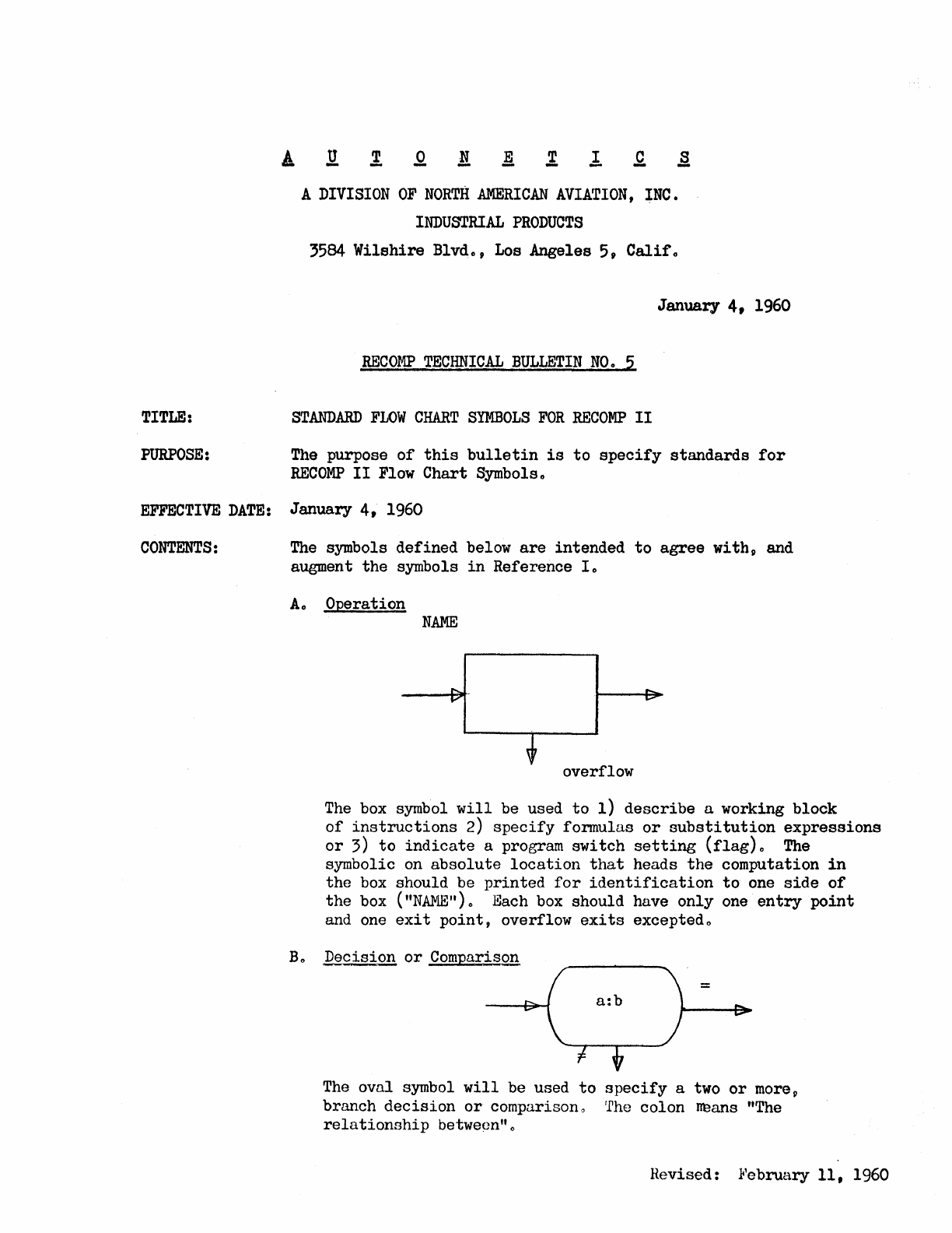
Ao
Operation
NAME
overflow
The
box symbol
will
be used
to
1)
describe
a working block
of
instructions
2)
specify
formulas
or
substitution
expressions
or
3)
to
indicate
a program
switch
setting
(flag)o
The
symbolic on
absolute
location
that
heads
the
computation
in
the
box
should be
printed
for
identification
to
one
side
of
the
box
("NAME")o
Each
box
should have
only
one
entry
point
and
one
exit
point,
overflow
exits
exceptedo
Bo
Decision
or
Comparison
The
oval symbol
will
be used
to
specify
a
two
or
more,
branch
decision
or
comparison 0 rfhe colon
tn1ans
"The
relationship
betweon"o
Revised:
}l'e
bruary
11,
1960
RECOMP
TECmnCAL
BULLETIN
NO"
1
(Cant,,)
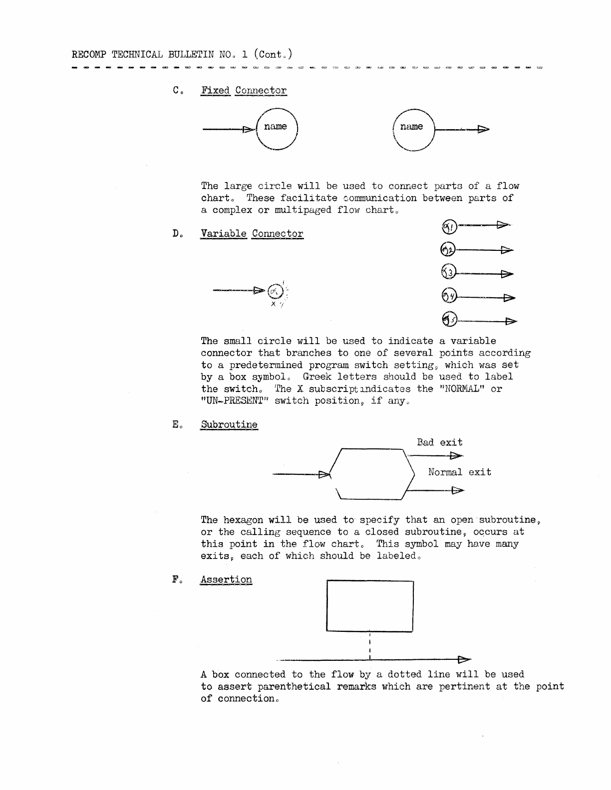
The
large
circle
will
be
used
to
connect
parts
of
a flow
chart
0 These
facilitate
communication between
parts
of
a complex
or
multipaged
flow
charto
Variable
Connector
---~f>""
€).~
x
'/
®--------t:C>-~.
@----if>~
@~----II>~
6J)-~[>~
6)~--~l>;:;r...
The
small
circle
will
be
used
to
indicate
a
variable
connector
that
branches
to
one
of
several
points
according
to
a
predetermined
program
switch
setting
9 which was
set
by
a box
s~mbolo
Greek
letters
should be
used
to
label
the
switcho
rl'he
X
subscriptlndicates
the
uNOR1flAL"
or
uUN_PRESBNTvi
switch
position
9
if
any 0
Eo
Subroutine
The hexagon
will
be
used
to
specify
that
an
open
subroutine
9
or
the
calling
sequence
to
a
closed
subroutine?
oqcurs
at
this
point
in
the
flow
charto
This
symbol
may
have
many
exitsp
each
of
which
should
be
labeled
o
F 0
Assertion
I>
A box
connected
to
the
flow
by a
dotted
line
will
be
used
to
assert
parenthetical
remarks which
are
pertinent
at
the
point
of
connectiono
RECOMP
TECHNICAL
BULLETIN
NOD
1 (Conto)
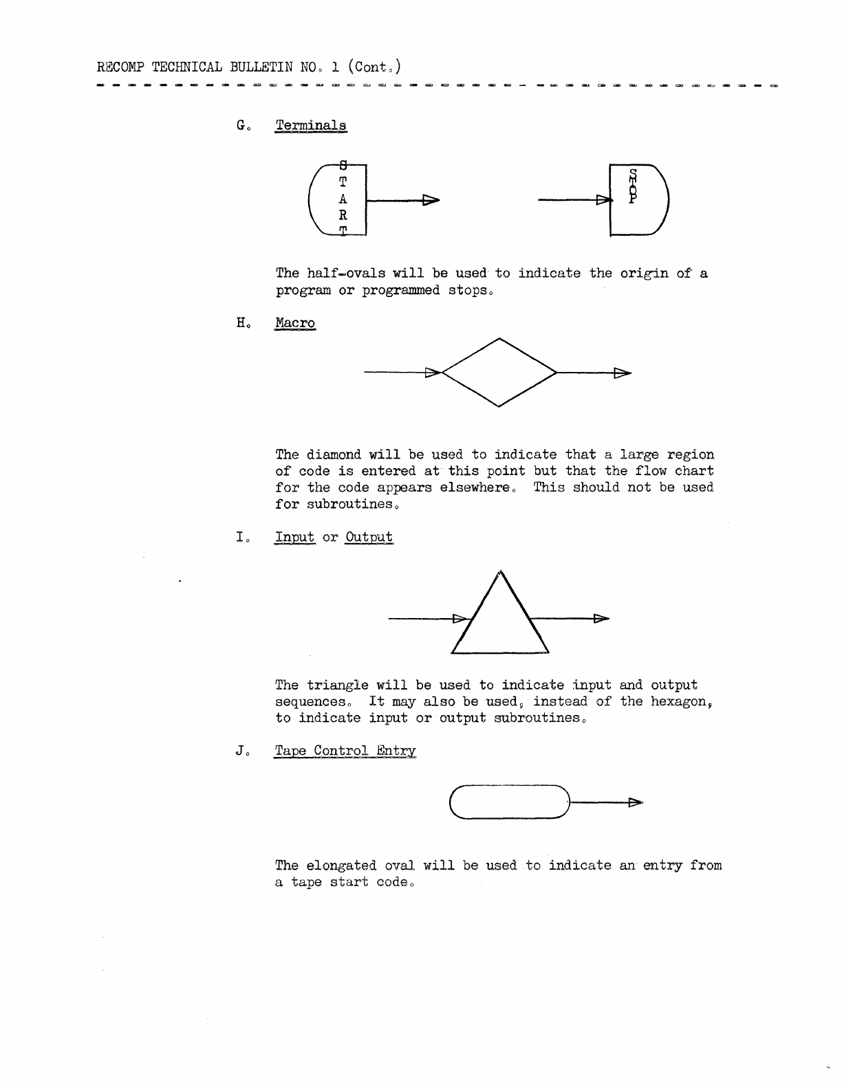
Go
Terminals
The
half~ovals
will
be
used
to
indicate
the
origin
of
a
program
or
programmed stopso
The
diamond
will
be
used
to
indicate
that
a
large
region
of
code
is
entered
at
this
point
but
that
the
flow
chart
for
the
code
appears
elsewhereo
This
should
not
be used
for
subroutines
o
10
Input
or
Output
The
triangle
will
be used
to
indicate
input
and
output
sequences 0
It
may
also
be used 9
instead
of
the
hexagong
to
indicate
input
or
output
subroutines
o
Jo
Tape
Control
Ent~
c
The
elongated
oval
will
be used
to
indicate
an
entry
from
a
tape
start
codeo
RECOIllP
TECHnICAL
BULlliTIN
NO
0 1 (Cont
0)
RBFERENCES:
INFORIvlATION
TO
~
WRITTEN
BY~
1VACM
First
Glossary
of
Programming Terminologyli
reprinted
as
"Proposed
Standard
Flow
Chart
Symbolso U
ACM
Communications~
October
19590
All
Concerned
Mo
Berman
Advanced Systems
EXAMPLE:
COMPU'I'E
A
COMPUTE
B
A B
=
A --7 A
2
stop
RECOMP
TECHNICAL
BULLETIN
115
APPENDIX
1
tape
has
final
"B"
for
automatic
start
Average
two
numbers
SUBROUTINE
t(A+B)
~
A
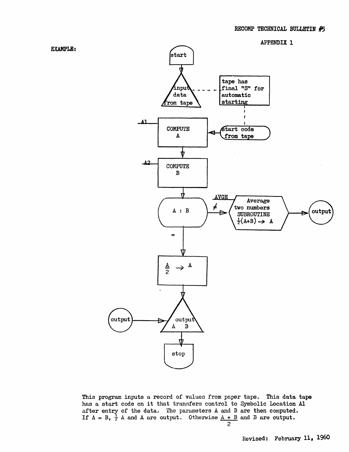
This program
inputs
a
record
of
values
from paper tapeo This
data
tape
has a
start
code
on
it
that
transfers
control
to
Symbolic Location
Al
after
entry
of
the
datao
The
parameters A and B
are
then
computedo
If
A =
B,
t A and A
are
output 0 Otherwise A + B and B
are
output
0
2
Revised:
!t'ebruary
11,
1960
