RL 740 Brochure 0740 RL_bro Bro
User Manual: 0740-RL_bro
Open the PDF directly: View PDF ![]() .
.
Page Count: 2
Du
e t
o
ou
r
poli
cy
of
co
ntinuin
g
d
eve
lop
ment, t
h
e
s
e
sp
ec
ifi
c
ations
a
re
subj
ect t
o
c
han
ge w
i
t
hou
t
noti
ce
.
IR
T
El
ectr
oni
c
s
Pty
L
t
d
|
www
.i
rte
l
ectr
oni
c
s.
c
o
m
RL-740
FEATURES
• Suitable for general purpose switching
and isolation
.
• TTL or direct relay switching
.
• Front panel LED status indicators
.
GENERAL
The RL-740 relay card is designed to
interface with the IRT Eurocard VG-737
video and AG-738 audio program fail
modules.
Front panel LED indicators are used to
indicate the status of each relay circuit.
The RL-740 utility relay card is designed to
provide two isolated contact sets and
contains 5 DPST relays which can be
controlled individually, both the make and
break contacts are available either directly
or by on board link selection.
One of the contact sets can also have the
relay common contacts bussed to facilitate
connection to the input circuit of the IRT
5x1 video and audio switchers.
When the relay is NOT ENERGISED relay 1
circuit switches input 1 to the output thus
providing a secure path when power is not
present on the module.
The relays used are bifurcated contact low
energising current relays designed for long
life and high reliability.
Note: For relay switching of video, data and
HF, see the AVS-3170 relay switcher.
See also other 3000 series switching
products.
General Purpose Switching
Relay Card
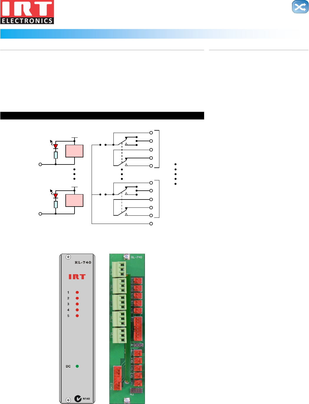
BLOCK DIAGRAM RL-740 SIGNAL PATH
Link
Link
Relay 1
+12V
Relay 5
+12V
RL1
RL5
Relay 1 Control
Relay 5 Control
Relay 1 Contacts
Relay 5 Contacts
Relay Commons
No Longer Available - For Reference Purposes Only

Du
e t
o
ou
r
poli
cy
of
co
ntinuin
g
d
eve
lop
ment, t
h
e
s
e
sp
ec
ifi
c
ations
a
re
subj
ect t
o
c
han
ge w
i
t
hou
t
noti
ce
.
IR
T
El
ectr
oni
c
s
Pty
L
t
d
|
www
.i
rte
l
ectr
oni
c
s.
c
o
m
RL-740
TECHNICAL SPECIFICATIONS
RL-740:
Control inputs Ground active control to the relay coil with the common of the coil circuit connected to +12 volts.
Control connections 2 pin socket strip with mating locking plug assembly.
Outputs Two relay contact sets from each relay.
One set with the common, normally open and normally closed contacts available.
The other set with the common available individually or bussed, and the make or break contact
available by link selection on the RL-740 circuit board.
Output connections Terminal strips accepting spade terminals for one contact set and 2 or 8 pin socket strip with mating
locking plug assembly for the other.
Relay contact rating 24 Vdc - 1A, 100Vac - 0.3 A.
Visual indicators RELAY CIRCUIT ENABLED.
POWER.
Power requirements:
Voltage 28 Vac CT (14-0-14) or ± 16 Vdc.
Power consumption 1 VA.
Other:
Temperature range 0 - 50° C ambient.
Mechanical Suitable for mounting in IRT 19" rack chassis with input, output and power connections on the rear panel.
Finish Front panel Grey background, black lettering & red IRT logo.
Rear assembly Detachable silk-screened PCB with direct mount connectors to Eurocard and external signals.
Dimensions 6 HP x 3 U x 220 mm IRT Eurocard.
No Longer Available - For Reference Purposes Only
