094 903123C_Hallicrafters_SX 117_Operating_And_Service_Instructions_Nov1968 903123C Hallicrafters SX 117 Operating And Service Instructions Nov1968
User Manual: 094-903123C_Hallicrafters_SX-117_Operating_And_Service_Instructions_Nov1968
Open the PDF directly: View PDF ![]() .
.
Page Count: 33
OPERATING
AND
SERVICE
INSTRUCTIONS
FOR
•••
COMMUNICATION
RECEIVER
MODEL 5X-117

"The
Hallicrafter's
Company
warrants each
new
radio product manu-
factured
by
it to be free. from defective material
and
workmanship
and
agrees to remedy
any
such defect or to furnish a
new
part in ex-
change
for
any
part
of
any
unit of its manufacture which under nor-
mal installation, use
and
service discloses such defect, provided the
unit
is
delivered
by
the owner to our allthorized radio dealer, whole-
saler, from whom purchased, or, authorized service center, illtact, for
examination, with all transportation charges prepaid within ninety
days from tile date
of
sale to original purchaser Imd provided that
such examillation discloses in our judgment that it
is
thus defective.
This warranty 'does not
extend
to allY
of
Ollr
radio products which
have been subjected to misuse, neglect, accident, illcorrect wiring
IIOt
our own, improper installation,
or
to use in violation of instrllctions
furnished by us, nor
extended
to units which have been repaired or
altered alit side
of
Ollr
factory
or
authorized service center, nor to cases
where the serial number thereof has bel'li removed, defaced or changed,
nor to accessories used therewith
IIOt
of our
own
manufacture.
Any
part of a unit al'llroved for remedy or exchange hereunder will
be remedied or exchanged
by
the
authorized radio dealer or whole-
saler without charge to the owner.
This warranty
is
in lieu of all other u:arranties expressed
or
iml,lied
and
no representative
or
I,erson
is
allthorized to assllme
for
liS
allY
other liability in connection witl. tl.e sale of our radio products:'
092-016679
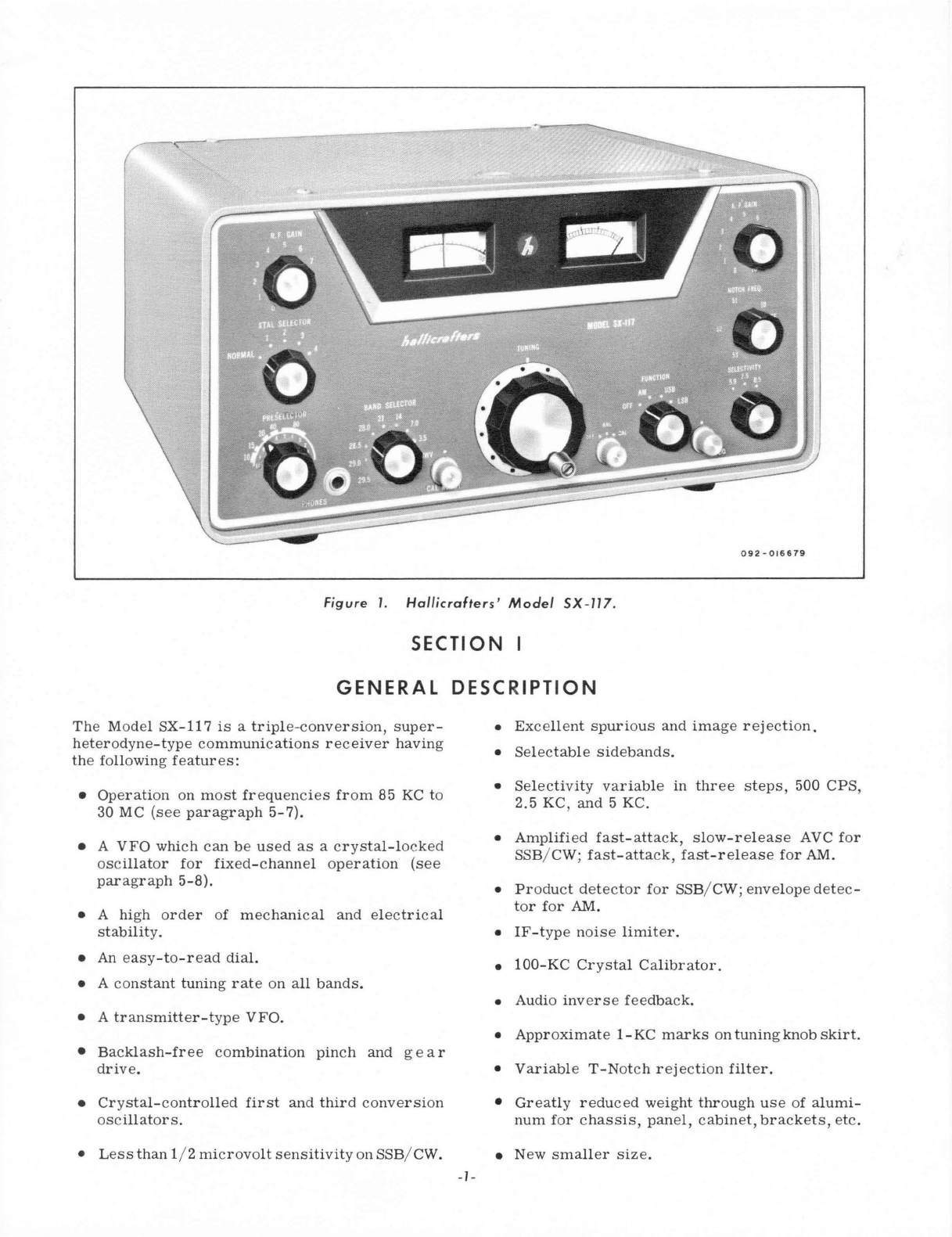
Figure
1.
Hal/icrafters'
Model
SX
-
117.
SECTION I
GENERAL
DESCRIPTION
The
Model
SX-117
is
a
triple--conversion,
super-
heterodyne-type
comm
uni
cations
receiver
having
the
following
features:
• Op
eration
on
most
fr
eq
u
encies
from
85
KC
to
30 MC
(see
paragraph
5-7).
• A
VFO
which
can
be
used
as
a
crystal-
l
ocked
oscillator
for
fixed-channel
operation
(see
paragraph
5-8).
• A
high
order
of
mechanical
and
elect
ri
cal
stability.
• An
easy
-t
o-
r
ead
dial.
• A
constant
tuning
rate
on
a
ll
bands.
• A
transmitter-type
VFO.
• B
acklash
-fr
ee
combi
nati
on
pinch
and
g
ear
drive.
•
Crystal-controlled
first
and
third
conversion
oscillators
.
•
Less
than
1/ 2
microvolt
sensitivity
on SSB/
CWo
-/
-
•
Excellent
spurious
and
image
rejection.
•
Selectable
sidebands.
•
Selectivity
variable
in
thr
ee
steps,
500
CPS,
2.5 KC,
and
5 KC.
•
Amplified
fast
-att
ack,
slow-release
AVC
for
SSB/CW;
fast-attack,
fast-release
for
AM.
•
Pr
oduct
detector
for
SSB/CW;
enve
l
ope
detec-
tor
for
AM.
•
IF-type
noise
limiter.
•
100-KC
Crystal
Calibrator.
• Audio
inv
erse
feedback.
•
Approximate
1-KC
marks
on
tuning
knob
skirt.
•
Variable
T-Notch
rejection
filter.
•
Gr
ea
tly
r
ed
u
ced
weight
through
us
e
of
a
lumi-
num
for
c
hassis,
panel,
cab
in
et,
brackets,
etc
.
• New
smaller
size.
SECTION II
TECHNICAL
SPECIFICATIONS
Basic
Frequency
Coverage
*WWV
.....................................
9.5
MC
to
10.0
MC
80-Meter
Band.
. . . . . . . . . . . . . . . . . . . . . . . . . . . .
..
3.5
MC
to
4.0
MC
40-Meter
Band
20-Meter
Band
15-Meter
Band
*10-Meter
Band
10-Meter
Band
*10-Meter
Band
*10-Meter
Band
*Crystals
not
supplied.
7.0
MC
to
7.5
MC
14.0
MC
to
14.5
MC
21.0
MC
to
21.5
MC
28.0
MC
to
28.5 MC
28.5
MC
to
29.0
MC
29.0 MC
to
29.5
MC
29.5
MC
to
30.0
MC
Note
-
See
paragraph
5-7
for
additional
information.
IF
Frequencies:
..........
.
Reception:
..•............
Sensitivity
-AM:
.......•...
3 MC
to
30 MC
Sensitivity
-SSB/CW:
...•...
3
MC
to
30 MC
Sensitivity
(with HA-10):
85
KC
to
3
MC
Selectivity:
Stability:
......•.........
Calibration
Accuracy:
......
.
IF
Rejection:
............
.
In-Band
Tweets:
..........
.
Audio
Power
Output:
.......
.
AVC
Figure
of
Merit:
Power
Source:
...........
.
Power
Consumption:
..•.....
Number
of
Tubes:
.....•....
Audio
Output
Impedance:
Headphone Output:
..•.......
Antenna
Input
Impedance:
(High
Frequency)
6.5
MC
to
6.0 MC
(Variable),
1650 KC,
and
50.75 KC.
AM, CW,
and
Single
Sideband
(SSB).
Less
than
1
microvolt
for
10-DB
signal-to-noise
ratio
(30%
modulation).
Less
than
1/2
microvolt.
5
to
10
microvolts.
Variable
in
three
steps
providing
0.5 KC, 2.5 KC, and 5
KC
at
6 DB down.
Better
than
300 CPS
after
warmup.
Better
than
2
KC
between
adjacent
100-KC
calibration
points
after
indexing.
More
than
50 DB.
Less
than
1/2
microvolt
equivalent
(within
amateur
bands).
3/4
watt
with
less
than
10%
distortion.
More
than
80 DB.
105
volts
to
125
volts,
50/60
cycles~
70
watts.
14 (one
not
supplied),
plus
four
silicon
diodes.
3.2
ohms
and
500
ohms;
rear-mounted
screw
terminals.
50
ohms
to
2000
ohms;
panel-mounted
jack
accepts
standard
1/4-inch
plug.
50
ohms
to
70
ohms
unbalanced;
rear-mounted
RCA-type
phono
jack
accepts
RCA-type
phono plug.
NOTE:
Chassis
punched
to
accept
Amphenol
Type
SO-239
coaxial
receptacle;
for
use
from
3.0
MC
to
30 MC.
-2-
Low
Frequency
Input:
Remote
Standby
Control:
Demensions:
Net
Weight:
Shipping Weight:
CATHODE
FOLLOWER
CRYSTAL
OSCILLATOR
(OPTIONAL)
High
impedance
to
first
mixer
grid;
for
use
with
external-
tuned
circuit
from
85
KC
to
3.0
MC.
RCA-type
phono
jack
accepts
RCA-type
phono
plug.
Rear-mounted
screw
terminals.
7-3/4
inches
high,
15
inches
wide,
and
14-3/4
inches
deep.
18-1/2
pounds.
21
pounds
(approximately).
CATHODE
FOLLOWER
VARIABLE
FREQUENCY
OSCILLATOR
tVfO)
I
PRODUCT
DETECTOR
BEAT
FREQUENcY
OSCILLATOR
{BFO!
L
________
-1
6DC6
RF
Amplifier
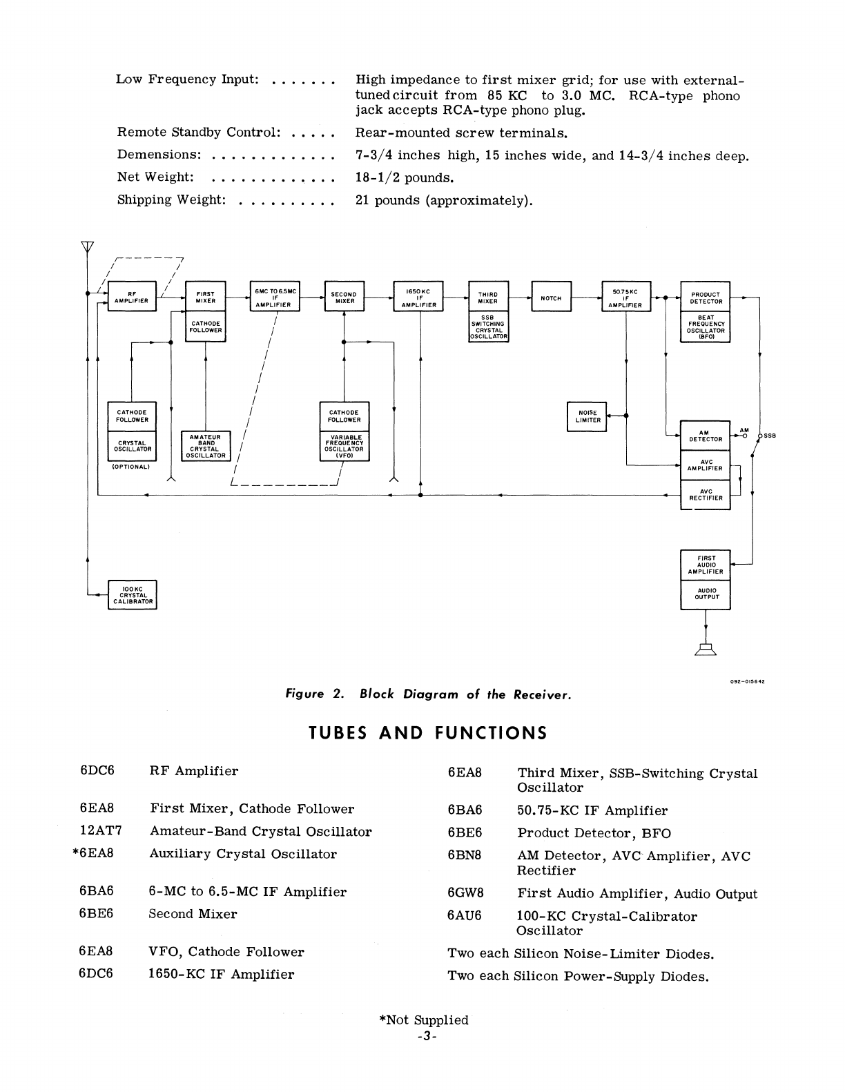
Figure
2.
Block
Diagram
of
the
Receiver.
TUBES
AND
FUNCTIONS
FIRST
AUDIO
AMPLIFIER
AUDIO
OUTPUT
092-015642
6EA8
Third
Mixer,
SSB-Switching
Crystal
Oscillator
6EA8
12AT7
*6EA8
First
Mixer,
Cathode
Follower
Amateur-Band
Crystal
Oscillator
Auxiliary
Crystal
Oscillator
6BA6
6BE6
6BN8
50.75-KC
IF
Amplifier
Product
Detector,
BFO
AM
Detector,
AVe
Amplifier,
AVC
Rectifier
6BA6
6BE6
6EA8
6DC6
6-MC
to
6.5-MC
IF
Amplifier
Second
Mixer
VFO,
Cathode
Follower
1650-KC
IF
Amplifier
6GW8
6AU6
First
Audio
Amplifier,
Audio
Output
100-KC
Crystal-Calibrator
Oscillator
Two
each
Silicon
Noise-
Limiter
Diodes.
Two
each
Silicon
Power-Supply
Diodes.
*Not
Supplied
-3-
SECTION
III
INSTALLATION
3-1.
UNPACKING
.
After
unpacking
the
receiver,
examine
it
for
damage
which
may
have
occurred
in
transit.
Should
any
sign
of
damage
be
apparent,
file
a
cla
im
immediately
with
the
carrier
stating
the
extent
of
damage.
Carefully
check
all
shipping
labels
and
tags
for
instructions
before
removing
or
destroy-
ing
them.
IMPORTANT
To
remove
top
cover,
turn
screws
approximately
one
quarter
turn
counterclockw
is
e.
Do
not
attempt
to
remove
screws
.
3-2.
LOCATION.
The
receiver
may
be
placed
in
any
location
that
will
permit
free
air
circulation
through
the
ventilation
holes
and
openings
in
the
cabinet.
Avoid
excessively
warm
locations
such
as
those
near
radiators
and
heating
vents.
Also
avoid
direct
blasts
of
air
from
circulating
fans,
etc.
Do
not
place
speakers
or
any
other
objects
on
the
cabinet
cover
in
a
manner
that
will
impair
natural
venti-
lation.
• •••
wr.·
3-3.
ANTENNAS
.
The
Model
SX-117
uses
an
input
circuit
de-
signed
for
an
unbalanced
50-ohm
to
70-ohm
input.
Any of
the
popular
dipole
or
beam
antennas
using
50-ohm
to
70-ohm
coaxial
transmission
line
will
suffice.
It
should
be
remembered,
however,
that
these
antennas
will
give
optimum
results
over
a
limited
frequency
range
only.
Generally
speaking,
the
same
rules
that
apply
to
transmitting
antennas
will
hold
true
for
receiving
antennas.
For
further
information
on
this
subject,
refer
to
the
"Radio
Amateur's
Handbook"
or
the
"
A.
R. R. L.
Antenna
B
ook,"
both
published
by
the
American
Radio
Re-
lay
L
eague,
West
Hartford,
Connecticut,
U.S.A.
IMPORTANT
Some
form
of
lightning
protection
should
be
provided
which
will
comply
with
local-code
requirements.
3-4.
GROUNDS
.
All
station
equipment
should
be
bonded
to-
gether
with
heavy
copper
wire
or
braid
and
con-
nected
to
a
cold
-w
ater
pipe
or
earth
ground.
An
external
chassis
ground
terminal
is
provided
on
the
rear
of
the
Model
SX-117
for
this
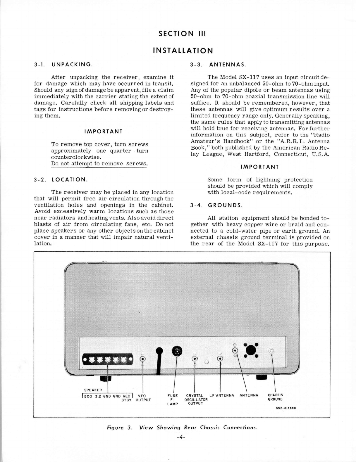
purpose.
o
~e·
• •
CRYSTAL
LF
ANTENNA
ANTENNA
VFO
OUTPUT
FUSE
FI
OSCILL
ATOR
CHASSIS
GROUND
I AMP
OUTPUT
092-016680
Figure
3.
View
Showing
Rear
Chassis
Connections
.
-4-
3-5.
POWER
SOURCE.
The
SX-117
is
designed
to
operate
from
a
105-volt
to
125-volt,
50/60-cycle,
AC
power
source.
Power
consumption
is
70
watts.
NOTE
If
in
doubt about
your
power
source,
contact
your
local
power
company
prior
to
inserting
the
power
cord
into
any
power
outlet.
Plugging
the
power
cord
into
the
wrong
source
can
cause
extensive
damage
to
the
unit.
3-6.
SPEAKER.
A
terminal
strip,
marked
G,
3.2,
and 500,
is
provided
at
the
rear
of
the
receiver
for
connecting
an
external
speaker
or
line
(see
figure
3). Any
per-
manent-magnet
type
speaker
with
a 3.
2-ohm
voice
coil
can
be
used
by
connecting
the
two
leads
from
the
speaker
voice
coil
to
the
terminals
marked
3.2
and
G.
If
it
is
desired
to
use
a
speaker
with
a
voice-coil
impedance
other
than
3.2
ohms,
a
matching
transformer
should
be
employed
to
in-
sure
optimum
performance.
The
transformer
should
be
mounted
on
or
near
the
speaker,
should
have
a
500-ohm
primary
impedance,
and
should
have
a
secondary
impedance
to
match
that
of
the
speaker
voice
coil.
Connect
the
primary
of
the
matching
transformer
to
the
terminals
marked
500
and
G and
the
secondary
to
the
speaker
voice
coil
terminals.
SPEAKER
The
Hallicrafters
Model R47
Speaker
is
particularly
suited
for
voice
and
CW
use.
Model
R48A
Speaker,
with
its
two-position
VOICE-
FI-
DELITY
switch
will give
excellent
results
for
all
modes
of
operation.
The
leads
of
either
speaker
are
to
be
connected
to
the
terminals
marked
3.2
and
G.
3-7.
HEADPHONES.
The
headphone
jack
marked
PHONES
is
lo-
cated
on
the
front
panel
and
is
wired
so
that
the
3.2-ohm
speaker
output
is
automatically
disabled
when
the
headphones
are
inserted.
The
headphone
impedance
is
not
critical,
and any
headphones
ranging
in
impedance
from
50
ohms
to 2000
ohms
will
provide
satisfactory
performance.
It
should
be
noted
that,
although
insertion
of
the
headphone
plug
into
the
front
panel
jack
will
silence
the
3.2-ohm
speaker
output,
the
500-ohm
output will
remain
in
operation
at
all
times.
3-8.
REMOTE
RECEIVE-STAN
DB
Y
SWITCHING.
The
receiver
may
be
disabled
from
a
re-
mote
location
by
removing
the
jumper
between
the
terminals
marked
STANDBY and G on
the
rear
of
the
chassis
and
then
connecting
a SPST
switch
or
relay
between
these
terminals.
The
switch
or
re-
lay
contacts
should
be
so
wired
as
to
close
in
Re-
ceive
and
open
in
Transmit.
The
receiver
may
also
be
disabled
in
Trans-
mit
by
turning
the
RF
GAIN
control
to
0 (fully
counterclockwise).
~
V.cy
3.2fi
r-
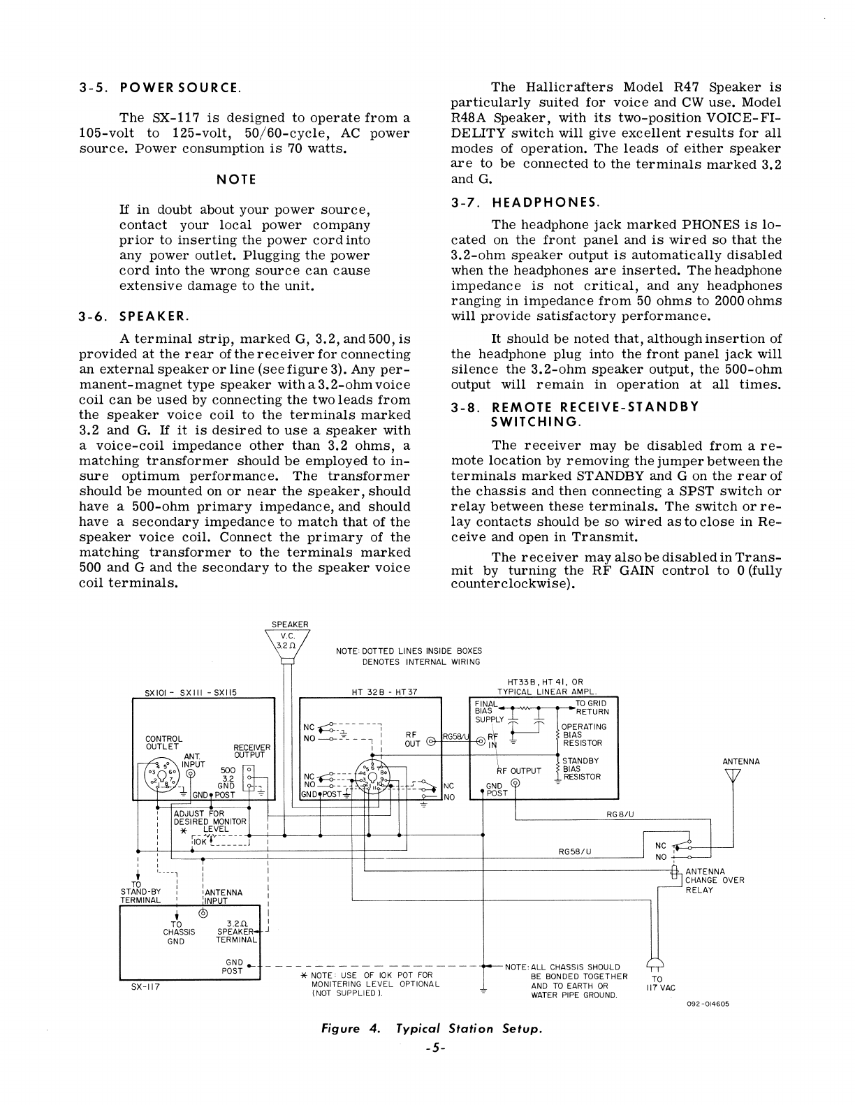
NOTE: DOTTED LINES INSIDE
BOXES
DENOTES INTERNAL WIRING
SXIOI-
SXIII
-SXI15
CONTROL
OUTLET
RECEIVER
HT
32B
-
HT37
HT33B,HT4I,
OR
TYPICAL
LINEAR
AMPL.
FINAL
BIAS -........"
T""'-'-
T---'---
SUPPLY
'*'
'*'
NC~_~----,
' T T
NO
--0-
_~
____
I:
R F
""
RG58IL
""
R~
.r---'
I I
OUT
~ ~
I,
~
TO
GRID
RETURN
OPERATING
BIAS
RESISTOR
STANDBY ANT ENNA
~
ANT.
OUTPUT
03
50so INPUT
500
0
02Q
70
3.2
':Jl.-
-
GND-,
~tND'POST
l BIAS \,7
RESISTOR
~
NC4---~
~FOUTPUT
NO---o-:-:'
~r:;~~~-.r:4
NC
GND
@
GND
POST-*-
W'
~NO
.....,...;.PO..;,.S;;...T-t-
______
.......
ADJUST
FOR
RG8/U
* LEVEL
~~~~
I
~,-::-i==~it:OK~~=L=-==~====-=J~I===========+~====~--------~--------~R~G5~8~/~U
____
~J
~~~
l
:----,:
:
~,:,
ANTENNA
rb
I I I
CHANGE
OVER
STAND-BY]
iANTENNA I RELAY
TERMINAL 1 'INPUT :
,
TO
CHASSIS
GND
@ I
3.2!l
I
SPEAKER4 J
TERMINAL
p~~~-
-----------
--------
-NOTE:
ALL
CHASSIS SHOULD
L-
________
...
* NOTE: USE
OF
10K
POT
FOR
BE BONDED TOGETHER
SX-117
MONITERING
LEVEL
OPTIONAL AND
TO
EARTH
OR
(NOT SUPPLIED
l.
WATER
PIPE
GROUND.
Figure
4.
Typical
Station
Setup.
-5-
TO
117VAC
092-014605
R.f.
GAIN
4 5 ,
:,0:'
10
XTAL
SELECTOR
1
ha//;craliers
TUNING
.
MODEL
SX-117
HGAIN
,',0:'
10
NOTCH
fREO.
·"~·o·'
• •
"ot'
BANOSELECTOR
20
21
14
':':u:
"::0:"
(j19:9·~L~WWO
PHONES
CAL
RESET
53
54
fUNCTION
SELECTIVITY
AM
USB
5.0
1.5
0.5
·
""6·:'0"'(:)
0
BfO
092-015915
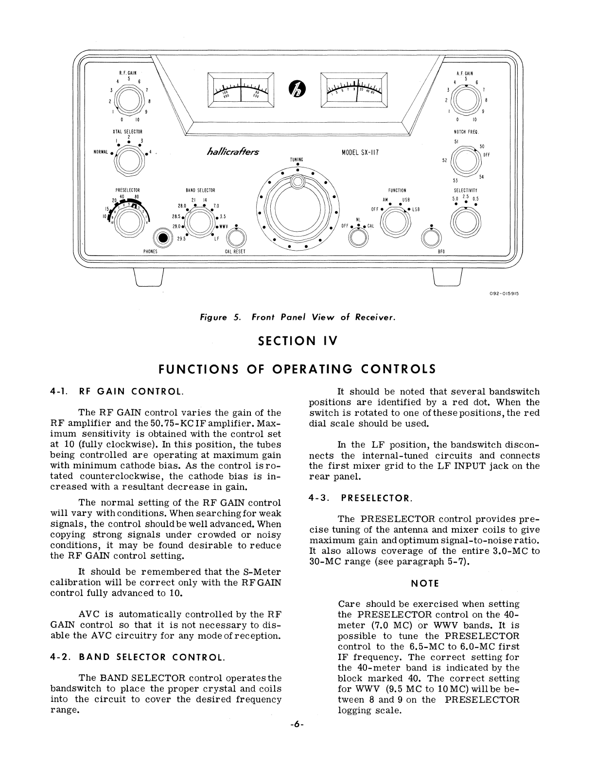
Figure 5. Front
Panel
View
of
Receiver.
SECTION
IV
FUNCTIONS
OF
OPERATING
CONTROLS
4-1.
RF
GAIN
CONTROL.
The
RF
GAIN
control
varies
the
gain
of
the
RF
amplifier
and
the
50.
75-KC
IF
amplifier.
Max-
imum
sensitivity
is
obtained
with
the
control
set
at
10 (fully
clockwise).
In
this
position,
the
tubes
being
controlled
are
operating
at
maximum
gain
with
minimum
cathode
bias.
As
the
control
is
ro-
tated
counterclockwise,
the
cathode
bias
is
in-
creased
with
a
resultant
decrease
in
gain.
The
normal
setting
of
the
RF
GAIN
control
will
vary
with
conditions.
When
searching
for
weak
signals,
the
control
should
be
well
advanced.
When
copying
strong
signals
under
crowded
or
noisy
conditions,
it
may
be
found
desirable
to
reduce
the
RF
GAIN
control
setting.
It
should
be
remembered
that
the
S-Meter
calibration
will
be
correct
only
with
the
RF
GAIN
control
fully
advanced
to 10.
AVC
is
automatically
controlled
by
the
RF
GAIN
control
so
that
it
is
not
necessary
to
dis-
able
the
AVC
circuitry
for
any
mode
of
reception.
4-2.
BAND
SElECTOR
CONTROL.
The
BAND
SELECTOR
control
operates
the
bandswitch
to
place
the
proper
crystal
and
coils
into
the
circuit
to
cover
the
desired
frequency
range.
-6-
It
should
be
noted
that
several
bandswitch
positions
are
identified
by
a
red
dot. When
the
switch
is
rotated
to
one
ofthese
positions,
the
red
dial
scale
should
be
used.
In
the
LF
position,
the
bandswitch
discon-
nects
the
internal-tuned
circuits
and
connects
the
first
mixer
grid
to
the
LF
INPUT
jack
on
the
rear
panel.
4-3.
PRESElECTOR.
The
PRESELECTOR
control
provides
pre-
cise
tuning
of
the
antenna
and
mixer
coils
to
give
maximum
gain
and
optimum
signal-to-noise
ratio.
It
also
allows
coverage
of
the
entire
3.0-MC
to
30-MC
range
(see
paragraph
5-7).
NOTE
Care
should
be
exercised
when
setting
the
PRESELECTOR
control
on
the
40-
meter
(7.0 MC)
or
WWV
bands.
It
is
possible
to
tune
the
PRESELECTOR
control
to
the
6.5-MC
to
6.0-MC
first
IF
frequency.
The
correct
setting
for
the
40-meter
band
is
indicated
by
the
block
marked
40.
The
correct
setting
for
WWV
(9.5 MC
to
10
Me)
will
be
be-
tween
8
and
9
on
the
PRESELECTOR
logging
scale.
·
Under
certain
conditions
where
excessive
noise
or
interference
is
encountered,
it
may
be
found
desirable
to
slightly
detune
the
PRESEL-
ECTOR
control
for
optimum
reception.
4-4.
AF
(AUDIO)
GAIN
CONTROL.
The
AF
GAIN
control
adjusts
the
audio
out-
put
level
at
the
speaker
terminals
and
PHONES
jack.
Clockwise
rotation
increases
the
signal
voltage
applied
to
the
grid
of
the
audio
am-
plifier,
thus
increasing
the
audio output.
4-5.
SELECTIVITY
SWITCH.
The
SELECTIVITY
switch
is
used
to
vary
the
IF
bandwidth to
suit
receiving
conditions.
Three
degrees
of
selectivity
are
available,
rang-
ing
from
500
CPS
for
CW
reception
under
crowded-band
conditions
to
5
kilocycles
for
maxi-
mum
fidelity
on
voice
or
music-modulated
signals
where
conditions
permit.
The
three
positions
are
marked
on
the
front
panel
and
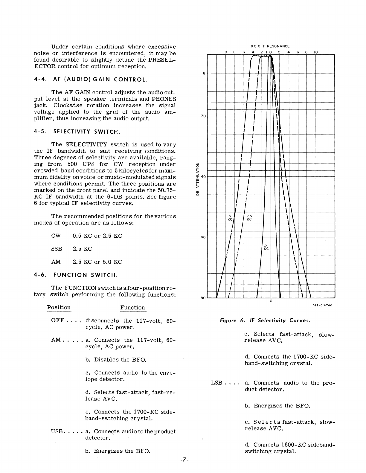
indicate
the
50.75-
KC
IF
bandwidth
at
the
6-DB
points.
See
figure
6
for
typical
IF
selectivity
curves.
The
recommended
positions
for
the
various
modes
of
operation
are
as
follows:
CW
0.5
KC
or
2.5
KC
SSB 2.5
KC
AM
2.5
KC
or
5.0
KC
4-6.
FUNCTION
SWITCH.
The
FUNCTION
switch
is
afour-positionro-
tary
switch
performing
the
following
functions:
Position
Function
OFF.
.
•.
disconnects
the
117-volt,
60-
cycle,
AC
power.
AM
.....
a.
Connects
the
117-volt,
60-
cycle,
AC
power.
b.
Disables
the
BFa.
c.
Connects
audio
to
the
enve-
lope
detector.
d.
Selects
fast-attack,
fast-re-
lease
AVC.
e.
Connects
the
1700-
KC
side-
band-switching
crystal.
USB
.....
a.
Connects
audio
to
the
product
detector.
b.
Energizes
the
BFa.
-7-
z
o
~
6
30
~
40
w
I-
!i
III
a
60
80
KC OFF RESONANCE
10
8 6 4 2 + 0 - 2 4 6 8
10
i (
,
I ;
~
j I
\\
J ; \
I 1 ! ,
I:
I
I;
i
\ I
1\
I
; I
1\
\
I
I \
I I ,
; I ' ,
!
1\
! I \
I \
1\
5 2.5 \ \
KC
KC
! f ;
I !
1\
\
II
; \
.5
\
1\
I
KC
1 I
\\
J "
\
I I \ \
I I \ \
o
092-016760
Figure
6.
IF
Selectivity
Curves.
c.
Selects
fast-attack,
slow-
release
AVC.
d.
Connects
the
1700-KC
side-
band-switching
crystal.
LSB . .
..
a.
Connects
audio
to
the
pro-
duct
detector.
b.
Energizes
the
BFa.
c.
S e I e c t s
fast-attack,
slow-
release
AVC.
d.
Connects
1600-
KC
sideband-
switching
crystal.
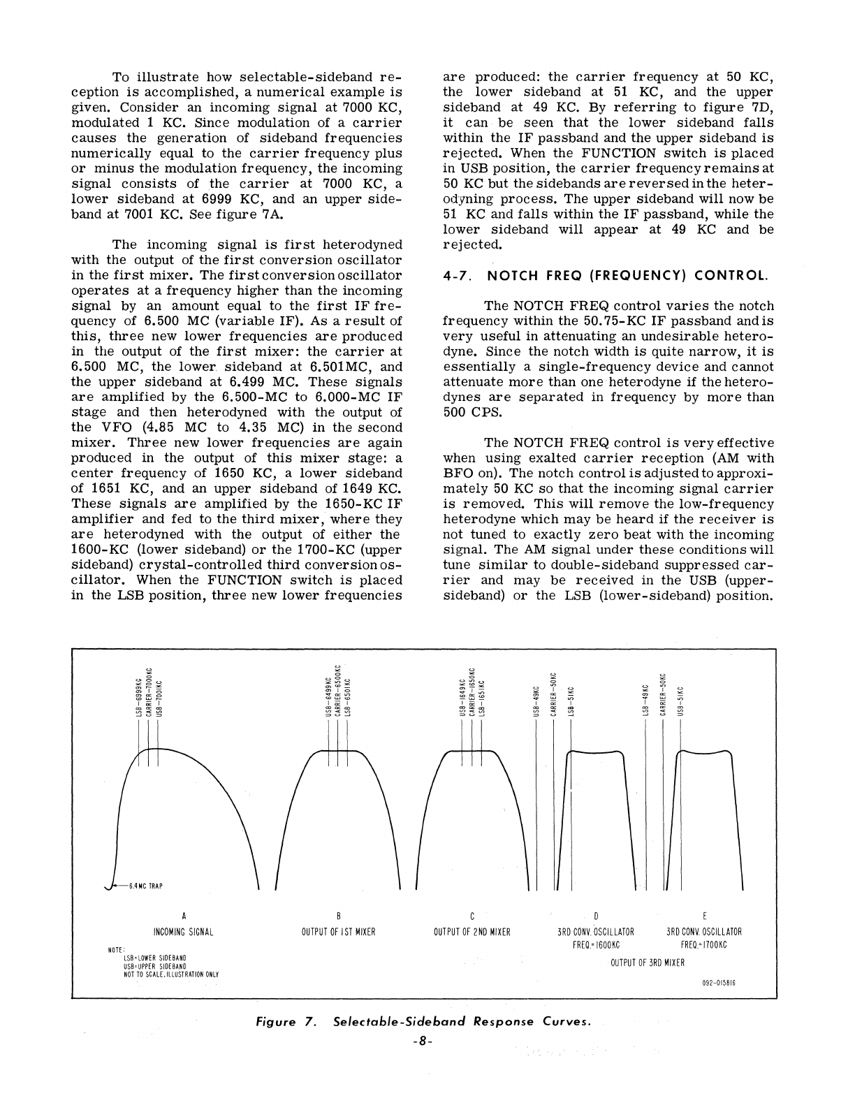
To
illustrate
how
selectable-sideband
re-
ception
is
accomplished,
a
numerical
example
is
given.
Consider
an
incoming
signal
at
7000 KC,
modulated
1
KC.
Since
modulation
of a
carrier
causes
the
generation
of
sideband
frequencies
numerically
equal to
the
carrier
frequency
plus
or
minus
the
modulation
frequency,
the
incoming
signal
consists
of ,the
carrier
at
7000 KC, a
lower
sideband
at
6999 KC, and an
upper
side-
band
at
7001
KC.
See
figure
7
A.
The
incoming
signal
is
first
heterodyned
with
the
output of
the
first
conversion
oscillator
in
the
first
mixer.
The
first
conversion
oscillator
operates
at
a
frequency
higher
than
the
incoming
signal
by
an
amount
equal to
the
first
IF
fre-
quency of 6.500
MC
(variable
IF). As a
result
of
this,
three
new
lower
frequencies
are
produced
in
the
output of
the
first
mixer:
the
carrier
at
6.500 MC,
the
lower
sideband
at
6.501MC, and
the
upper
sideband
at
6.499 MC.
These
signals
are
amplified
by
the
6.500-MC
to
6.000-MC
IF
stage
and
then
heterodyned
with
the
output of
the
VFO
(4.85
MC
to 4.35
MC)
in
the
second
mixer.
Three
new
lower
frequencies
are
again
produced
in
the
output of
this
mixer
stage:
a
center
frequency
of 1650 KC, a
lower
sideband
of 1651 KC, and an
upper
sideband
of 1649
KC.
These
signals
are
amplified
by
the
1650-KC
IF
amplifier
and
fed
to
the
third
mixer,
where
they
are
heterodyned
with
the
output of
either
the
1600-KC (lower sideband)
or
the
1700-KC (upper
sideband)
crystal-controlled
third
conversion
os-
cillator.
When
the
FUNCTION
switch
is
placed
in
the
LSB
position,
three
new
lower
frequencies
S,4NC
TRAP
INCOMING
SIGNAL
NOTE:
LSB-LOWER
SIDEBAND
USB-UPPER
SIDEBAND
NOT
TO
SCALE.
ILLUSTRATION
ONLY
OUTPUT
OF
I
ST
MIXER
are
produced:
the
carrier
frequency
at
50 KC,
the
lower
sideband
at
51
KC, and
the
upper
sideband
at
49
KC.
By
referring
to
figure
7D,
it
can
be
seen
that
the
lower
sideband
falls
within
the
IF
passband
and
the
upper
sideband
is
rejected.
When
the
FUNCTION
switch
is
placed
in
USB
position,
the
carrier
frequency
remains
at
50
KC
but
the
sidebands
are
reversed
in
the
heter-
odyning
process.
The
upper
sideband
will now
be
51
KC
and
falls
within
the
IF
passband,
while
the
lower
sideband
will
appear
at
49
KC
and
be
rejected.
4-7.
NOTCH
FREQ
(FREQUENCY)
CONTROL.
The
NOTCH
FREQcontrol
varies
the
notch
frequency
within
the
50.75-KC
IF
passband
and
is
very
useful
in
attenuating
an
undesirable
hetero-
dyne. Since
the
notch
width
is
quite
narrow,
it
is
essentially
a
single-frequency
device
and cannot
attenuate
more
than one
heterodyne
if
the
hetero-
dynes
are
separated
in
frequency
by
more
than
500 CPS.
The
NOTCH
FREQ
control
is
very
effective
when
using
exalted
carrier
reception
(AM
with
BFO
on). The
notch
control
is
adjusted
to
approxi-
mately
50
KC
so
that
the
incoming
signal
carrier
is
removed.
This
will
remove
the
low-frequency
heterodyne
which
may
be
heard
if
the
receiver
is
not
tuned
to
exactly
zero
beat
with
the
incoming
signal.
The
AM
signal
under
these
conditions
will
tune
similar
to
double-sideband
suppressed
car-
rier
and
may
be
received
in
the
USB
(upper-
sideband)
or
the
LSB
(lower-sideband)
position.
OUTPUT
OF
2ND
MIXER
3RD
CONV,
OSCILLATOR
FREQ,=
1600KC
3RD
CONV,
OSCILLATOR
FREO,=1700KC
OUTPUT
OF
3RD
MIXER
092-01581S
Figure
7.
Selectable-Sideband
Response
Curves.
-8-
""
C>
>=
c
~
:z
...
.....
.....
..,
CD
co
If
-KC
---.t
t--
NOTCH
fREQUENCY
RANGE
58 54
50
46
42
3KC
CURVE
r-~
WITHOUT
NOTCH
--:
'
6r-------------~_,~---J~----~--~
20
::E
~
~
~
::E
co
c
0
40
..,
60r----7----------+-------~----~--~
80~----------------------------~--~
092-203878
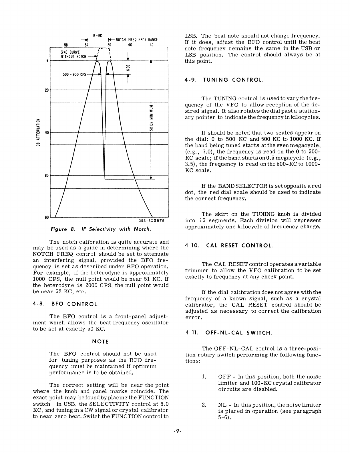
Figure 8.
IF
Selectivity
with
Notch.
The
notch
calibration
is
quite
accurate
and
may
be
used
as
a
guide
in
determining
where
the
NOTCH
FREQ
control
should
be
set
to
attenuate
an
interfering
signal,
provided
the
BFO
fre-
quency
is
set
as
described
under
BFO
operation.
For
example,
if
the
heterodyne
is
approximately
1000
CPS,
the
null
point
would
be
near
51
KC.
If
the
heterodyne
is
2000
CPS,
the
null
point
would
be
near
52 KC,
etc.
4-8.
BFa
CONTR
OL.
The
BFO
control
is
a
front-panel
adjust-
ment
which
allows
the
beat
frequency
oscillator
to
be
set
at
exactly
50 KC.
NOTE
The
BFO
control
should
not
be
used
for
tuning
purposes
as
the
BFO
fre-
quency
must
be
maintained
if
optimum
performance
is
to
be
obtained.
The
correct
setting
will
be
near
the
point
where
the
knob
and
panel
marks
coincide.
The
exact
point
may
be
found
by
placing
the
FUNCTION
switch
in
USB,
the
SELECTIVITY
control
at
5.0
KC,
and
tuning
in
a
CW
signal
or
crystal
calibrator
to
near
zero
beat.
Switch
the
FUNCTION
control
to
-9-
LSB.
The
beat
note
should
not
change
frequency.
If
it
does,
adjust
the
BFO
control
until
the
beat
note
frequency
remains
the
same
in
the
USB
or
LSB
position.
The
control
should
always
be
at
this
point.
4-9.
TUNING
CONTROL.
The
TUNING
control
is
used
to
vary
the
fre-
quency
of
the
VFO
to
allow
reception
of
the
de-
sired
signal.
It
also
rotates
the
dial
past
a
station-
ary
pointer
to
indicate
the
frequency
in
kilocycles.
It
should
be
noted
that
two
scales
appear
on
the
dial:
0
to
500
KC
and
500
KC
to
1000 KC.
If
the
band
being
tuned
starts
at
the
even
megacycle,
(e.g.,
7.0),
the
frequency
is
read
on
the
0
to
500-
KC
scale;
ifthe
band
starts
on
0.5
megacycle
(e.g.,
3.5),
the
frequency
is
read
on
the
500-KC
to
1000-
KC
scale.
If
the
BAND
SELECTOR
is
set
opposite
ared
dot,
the
red
dial
scale
should
be
used
to
indicate
the
correct
frequency.
The
skirt
on
the
TUNING knob
is
divided
into 15
segments.
Each
division
will
represent
approximately
one
kilocycle
of
frequency
change.
4-10.
CAL
RESET
CONTROL.
The
CAL
RESET
control
operates
a
variable
trimmer
to
allow
the
VFO
calibration
to
be
set
exactly
to
frequency
at
any
check
point.
If
the
dial
calibration
does
not
agree
with
the
frequency
of
a known
signal,
such
as
a
crystal
calibrator,
the
CAL
RESET
control
should
be
adjusted
as
necessary
to
correct
the
calibration
error.
4-11.
OFF-NL-CAL
SWITCH.
The
OFF-NL-CAL
control
is
a
three-posi-
tion
rotary
switch
performing
the
following
func-
tions:
1.
OFF
-
In
this
position,
both
the
noise
limiter
and
100-KC
crystal
calibrator
circuits
are
disabled.
2.
NL
-In
this
position,
the
noise
limiter
is
placed
in
operation
(see
paragraph
5-6).
3.
CAL
-
In
this
position,
the
100-KC
crystal
calibrator
is
placed
in
oper-
ation
to
provide
marker
signals
at
every
100-KC
point
on
the
dial.
NOTE
The
100-KC
crystal
calibrator
should
not
be
left
in
the
ON
position
after
dial
calibration
is
completed.
Under
certain
conditions
it
can
cause
spur-
ious
responses
to
be
developed.
4-12.
XTAL
SElECTOR
SWITCH.
The
XTAL
SELECTOR
switch
is
a
five-
position
rotary
switch
performing
the
following
functions:
1.
NORMAL -In
the
NORMAL
position,
plate
voltage
is
removed
from
the
auxiliary
crystal
oscillator
(6EA8
2.
3.
not
supplied)
and
the
receiver
will
operate
on
the
ranges
indicated
by
the
BAND
SELECTOR
knob.
1 AND 2 -
Positions
1
and
2
of
the
XT
AL
SELECTOR
switch
will
disable
the
12AT7
fir
st
crystal
oscillator,
apply
voltage
to
the
6EA8
auxiliary
os-
cillator,
and
select
crystals
inserted
in
auxiliary
crystal
sockets
1
or
2.
Use
only
type
CR-18/U
crystals
whose
frequencies
fall
between
6.5
MC
and
20.00 MC
(inclusive)
in
these
sockets
(see
paragraph
5-7).
3 AND 4 -
Positions
3
and
4
also
dis-
able
the
12AT7
first
crystal
oscil-
lator,
apply
plate
voltage
to
the
6EA8
auxiliary
oscillator,
and
select
cry-
stals
inserted
in
auxiliary
crystal
sockets
3
and
4.
Use
only
type
CR-
23/U
crystals
whose
frequencies
fall
between
20.5 MC
and
34.0 MC
(inclu-
sive)
in
these
sockets
(see
paragraph
5-7).
SECTION
V
OPERATION
5 -1.
SINGLE-SIDEBAND
RECEPTION.
Set
the
front
panel
controls
as
outlined
below.
RF
GAIN.
. . . . •
..
Usually
at
10
(maybe
reduced
as
noise
and
QRM
dictate).
NOTE
S-Meter
reading
will
be
correct
only
with
the
RF
GAIN
control
set
at
10.
BAND
SELECTOR
•.
To
desired
band.
AUDIO GAIN . . •
..
Approximately
2.
SELECTIVITY
....
2.5 KC.
FUNCTION . . . .
..
Usually
LSB
for
80
and
40
meters
and
USB
for
20,
15and10
meters.
BFO
. . . . . . . . .
..
Center
or
0
position
(do
not
use
BFO
con-
trol
for
tuning
pur-
poses).
NOTCH
.........
OFF
PRESELECTOR
.
..
Peaked
for
maximum
signal.
-10-
XTAL
CAL
OFF
NL
(Noise
Limiter).
Use
as
noise
condi-
tions
dictate.
TUNING . . . . . .
..
As
desired.
Slowly
adjust
the
TUNING
control
until
the
voice
modulation
sounds
natural.
Peak
the
PRE-
SELECTOR
for
maximum
S-Meter
indication
and
adjust
the
AUDIO GAIN
control
as
desired.
If
an
undesirable
heterodyne
appears,
ad
jus
t
the
NOTCH
control
for
maximum
attenuation.
It
should
be
remembered
that
an
SSB
signal
will
convey
intelligence
only
when
the
correct
sideband
position
has
been
selected
on
the
FUNC-
TION
switch.
If
the
signal
does
not
tune
in
pro-
perly,
change
the
FUNCTION
switch
to
the
other
SSB
position
and
retune.
The
RF
GAIN
control
should
normally
be
set
at
10
(maximum
sensitivity).
Under
adverse
conditions,
it
may
be
found
advantageous
to
reduc
e
the
RF
GAIN to
improve
reception.
It
should
be
remembered
that,
as
the
RF
GAIN
is
reduced,
the
AVC will
be
reduced.
Also,
correct
S-Meter
readings
will
be
indicated
only
with
the
RF
GAIN
at
10.
5-2.
CW
RECEPTION.
Set
all
controls
as
described
under
single-
sideband
reception
except
for
the
SELECTIVITY
and
noise
limiter
controls.
The
SELECTIVITY
control
will
usually
be
in
the
0.5
KC
position
for
CWo
The
NL
(noise
limiter)
can
be
used
to
ad-
vantage
at
all
times
in
CW
reception
and
will
be
very
effective
in
reducing
impulse
noise,
key
clicks,
etc.
The
NOTCH
control
should
be
used
as
necessary
to
attenuate
interfering
signals
and
heterodynes.
The
RF
GAIN
control
should
be
adjusted
as
conditions
dictate
for
best
reception.
NOTE
Do
not
use
the
BFO
control
for
tuning
purposes.
5-3.
AM
RECEPTION.
Set
all
controls
as
described
under
single-
sideband
reception
except
for
the
FUNCTION
con-
trol.
The
FUNCTION
control
should
be
placed
in
the
AM
position.
The
SELECTIVITY
control
maybeplacedin
the
5.0-KC
position
for
improved
fidelity
where
band
conditions
permit.
The
RF
GAIN
control
will
normally
be
set
at
10
for
AM
reception
except
on
extremely
strong
local
signals.
If
the
NL
(noise
limiter)
is
used
on AM,
distortion
can
be
reduced
by
reducing
the
RF
GAIN
control
setting
to
the
lowest
practical
level.
The
NOTCH
control
should
be
used
as
nec-
essary
for
removing
undesirable
heterodynes.
5-4.
EXALTED
CARRIER
AM
RECEPTION.
In
short-wave
reception,
it
frequently
hap-
pens
that
transmission
conditions
are
different
for
waves
of
slightly
different
frequencies.
As
a
result,
in
the
case
of
voice
modulated
transmis-
sions,
AM
particularly,
which
involve
sideband
frequencies
differing
slightly
from
the
carrier
frequency,
the
carrier
and
sideband
components
may
not
be
received
in
the
same
relative
ampli-
tudes
and
phases
that
were
present
at
the
trans-
mitter.
This
effect,
known
as
selective
fading,
causes
severe
distortion
of
the
signal.
-11-
This
type
of
distortion
can
be
reduced
con-
siderably
by
utilizing
the
selectable-sideband
feature
of
the
Model
SX-117
receiver
operating
in
an
exalted
carrier
mode
(i.
e.,
the
transmitted
car-
rier
is
positioned
out
of
the
receiver's
IF
pass-
band
along
with
one
sideband,
producing
a
sup-
pressed
carrier
single-sideband
signal).
The
car-
rier
is
subsequently
reinserted
by
the
receiver's
BFO
and
the
signal
is
detected
in
the
same
manner
as
a
single-sideband
signal.
All
controls
should
be
set
as
described
un-
der
single-sideband
reception.
Place
the
FUNC-
TION
switch
in
the
SSB
position
that
gives
best
reception.
In
addition,
the
NOTCH
control
should
be
adjusted
to
the
carrier
frequency
(approxi-
mately
50
KC)
to
null
out
the
incoming
signal
carrier.
If
noise
conditions
warrant,
the
noise
limiter
should
be
used.
5-5.
USE
AND
ADJUSTMENT
OF
S-METER.
The
S-Meter
provides
a
visual
means
of
determining
whether
or
not
the
receiver
is
properly
tuned,
as
well
as
providing
an
indication
of
the
signal
strength.
The
S-Meter
is
calibrated
in
S-units
to
9
and
in
decibels
to 70 DB
above
S9.
The
meter
calibration
will
be
correct
only
when
the
RF
GAIN
control
is
set
at
10 (fully
clockwise).
S9
represents
a
50-microvolt
signal
at
the
antenna
input.
Each
S-unit
represents
approxi-
mately
6 DB
change
in
signal
strength.
For
accurate
readings,
the
meter
zero
should
be
checked
periodically.
To
adjust
the
electrical
zero
on
the
meter,
turn
the
RF
GAIN
control
to 0 (fully
counterclockwise).
Rotate
the
Meter
Zero
control
as
necessary
so
that
the
meter
pointer
is
aligned
with
the
last
calibration
mark
on
the
left
side
of
the
meter
scale.
IMPORTANT
To
remove
top
cover,
turn
screws
a p
pro
x i
mat
ely
one
quarter
turn
counterclockwise.
Do
not
attempt
to
remove
screws.
The
Meter
Zero
control
may
be
found
di-
rectly
under
the
rear
of
the
meter
housing.
CAUTION
Do
not
disturb
the
adjustment
of
the
Notch
Depth
or
Factory
Gain
controls.
5-6.
USE
OF
NOISE
LIMITER
(NL).
The
noise
limiter
is
an
IF-type
limiter
and
is
very
effective
in
reducing
impulse-type
noise
particularily
on
SSB
and
CWo
It
will
be
found
use-
ful
on
AM
as
well.
Recommended
use
is
as
fol-
ows:
For
CW
Operation:
The
noise
limiter
should
be
on
at
all
times
for
elimination
of
impulse
noise
and
key
clicks.
For
SSB
Operation:
Use
the
noise
limiter
as
noise
condi-
tions
dictate.
For
AM
Operation:
Use
the
noise
limiter
as
noise
condi-
tions
dictate.
It
will
be
noticed
that
the
noise
limiter
will
introduce
consi-
derable
distortion
on
a
fully
modu-
lated
AM
Signal.
Distortion
may
be
reduced
by
decreasing
the
RF
GAIN
control
setting.
Signal
Crystal Crystal
Frequency Frequency
Type
85
KC
to
500
KC
6.5 MC
CR-18/U
500
KC
to
1.0
MC 7.0 MC
CR-18/U
1.0
MC to
1.5
MC 7.5 MC
CR-18/U
1.5
MC
to
2.0 MC
8.0
MC
CR-18/U
2.0 MC to 2.5 MC
8.5
MC
CR-18/U
2.5 MC to
3.0
Me
9.0
MC
CR-18/U
3.0
MC
to
3.5
MC 9.5 MC
CR-18/U
3.5 MC
to
4.0
MC -- --
4.0
MC
to
4.5
MC
10.5
MC
CR-18/U
4.5 MC
to
5.0
MC
11.0
MC
CR-18/U
5.0 MC
to
5.5 MC 11.5 MC
CR-18/U
7.0 MC
to
7.5 MC
-- --
7.5 MC
to
8.0
MC
14.0
MC
CR-18/U
8.0
MC
to
8.5
MC
14.5
MC
CR-18/U
8.5
MC
to
9.0
MC
15.0
MC
CR-18/U
9.0
MC
to
9.5 MC
15.5
MC
CR-18/U
9.5 MC
to
10 MC
--
--
10 MC to
10.5
MC
16.5
MC
CR-18/U
10.5 MC
to
11
MC
17.0
MC
CR-18/U
11
MC
to
11.5
MC
17.5
MC
CR-18/U
11.5 MC
to
12 MC
18.0
MC
CR-18/U
12 MC
to
12.5
MC
18.5
MC
CR-18/U
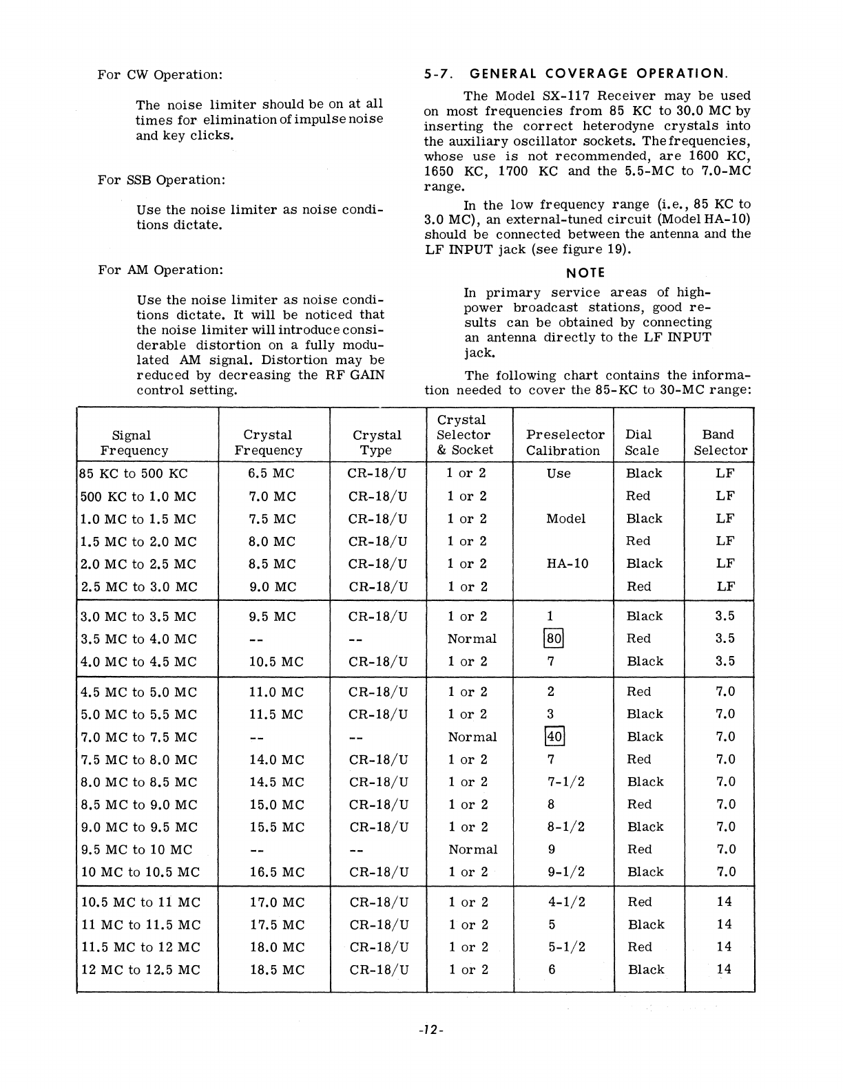
5-7.
GENERAL
COVERAGE
OPERATION.
The
Model
SX-117
Receiver
may
be
used
on
most
frequencies
from
85
KC
to
30.0
MC
by
inserting
the
correct
heterodyne
crystals
into
the
auxiliary
oscillator
sockets.
The
frequencies,
whose
use
is
not
recommended,
are
1600 KC,
1650 KC, 1700
KC
and
the
5.5-MC
to
7.0-MC
range.
In
the
low
frequency
range
(i.
e.,
85
KC
to
3.0
MC),
an
external-tuned
circuit
(Model
HA-I0)
should
be
connected
between
the
antenna
and
the
LF
INPUT
jack
(see
figure
19).
NOTE
In
primary
service
areas
of
high-
power
broadcast
stations,
good
re-
sults
can
be
obtained
by
connecting
an
antenna
directly
to
the
LF
INPUT
jack.
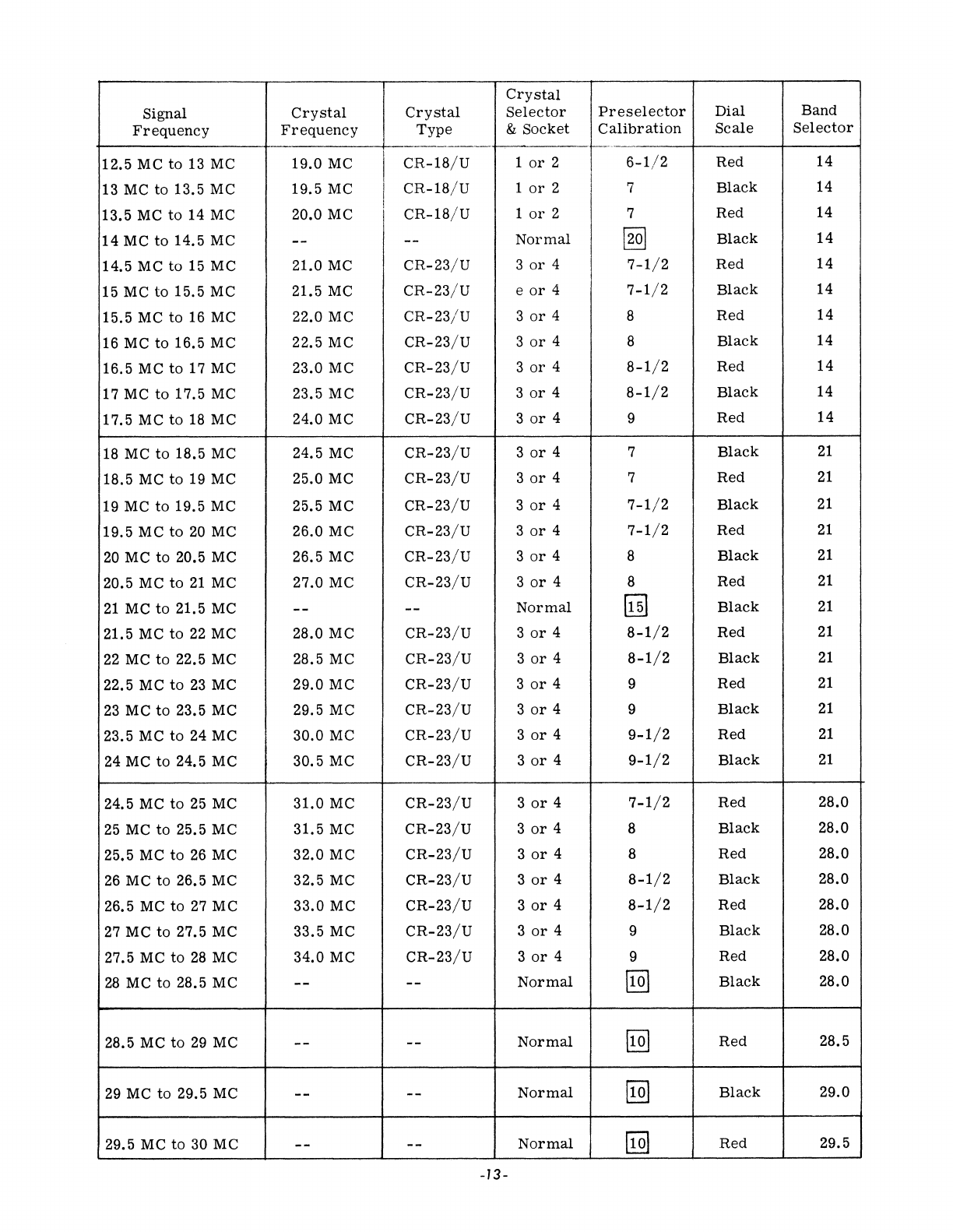
The
following
chart
contains
the
informa-
tion
needed
to
cover
the
85-KC
to
30-MC
range:
Crystal
Selector
Preselector
Dial
Band
&
Socket
Calibration
Scale
Selector
1
or
2
Use
Black
LF
1
or
2
Red
LF
1
or
2
Model
Black
LF
1
or
2
Red
LF
1
or
2
HA-I0
Black
LF
1
or
2
Red
LF
1
or
2 1
Black
3.5
Normal
§]
Red
3.5
1
or
2 7
Black
3.5
1
or
2 2
Red
7.0
1
or
2 3
Black
7.0
Normal
@:2]
Black
7.0
1
or
2 7 Red
7.0
1
or
2
7-1/2
Black
7.0
1
or
2 8
Red
7.0
1
or
2
8-1/2
Black
7.0
Normal
9
Red
7.0
1
or
2
9-1/2
Black
7.0
1
or
2
4-1/2
Red
14
1
or
2 5
Black
14
1
or
2
5-1/2
Red
14
1
or
2 6
Black
14
-12-
Crystal
Signal
Crystal Crystal
Selector
Preselector
Dial
Band
Frequency
Frequency
Type
&
Socket
Calibration
Scale
Selector
-f-------
1---
12.5 MC
to
13 MC
19.0
MC
CR-18/U
1
or
2
6-1/2
Red 14
13 MC
to
13.5 MC
19.5
MC
CR-18/U
1
or
2 7
Black
14
13.5 MC
to
14 MC 20.0 MC
CR-18/U
1
or
2 7 Red 14
14
MC
to
14.5 MC -- --
Normal
~
Black
14
14.5 MC to 15 MC 21.0 MC
CR-23/U
3
or
4
7-1/2
Red
14
15 MC
to
15.5 MC 21.5 MC
CR-23/U
e
or
4
7-1/2
Black
14
15.5 MC to 16 MC 22.0 MC
CR-23/U
3
or
4 8
Red
14
16 MC
to
16.5 MC 22.5 MC
CR-23/U
3
or
4 8
Black
14
16.5 MC
to
17 MC 23.0 MC
CR-23/U
3
or
4
8-1/2
Red
14
17M
C
to
17.5 M C 23.5 MC
CR-23/U
3
or
4
8-1/2
Black
14
17.5 M C
to
18 M C 24.0 MC
CR-23/U
3
or
4 9
Red
14
18
MC
to
18.5 MC 24.5 MC
CR-23/U
3
or
4 7
Black
21
18.5 MC to 19 MC 25.0 MC
CR-23/U
3
or
4 7
Red
21
19 MC
to
19.5 MC 25.5 MC
CR-23/U
3
or
4
7-1/2
Black
21
19.5
MC
to
20
MC 26.0 MC
CR-23/U
3
or
4
7-1/2
Red
21
20
MC
to
20.5 MC 26.5 MC
CR-23/U
3
or
4 8
Black
21
20.5 MC
to
21
MC 27.0 MC
CR-23/U
3
or
4 8
Red
21
21
MC
to
21.5 MC -- --
Normal
~
Black
21
21.5 MC
to
22
MC 28.0 MC
CR-23/U
3
or
4
8-1/2
Red
21
22
MC to 22.5 MC 28.5 MC
CR-23/U
3
or
4
8-1/2
Black
21
22.5 MC
to
23
MC 29.0 MC
CR-23/U
3
or
4 9
Red
21
23
MC
to
23.5 MC 29.5 MC
CR-23/U
3
or
4 9
Black
21
23.5 MC
to
24 MC
30.0
MC
CR-23/U
3
or
4
9-1/2
Red
21
24 MC to 24.5 MC 30.5 MC
CR-23/U
3
or
4
9-1/2
Black
21
24.5 MC
to
25 MC
31.0
MC
CR-23/U
3
or
4
7-1/2
Red
28.0
25
MC to 25.5 MC 31.5 MC
CR-23/U
3
or
4 8
Black
28.0
25.5 MC
to
26
MC
32.0
MC
CR-23/U
3
or
4 8
Red
28.0
26
MC
to
26.5 MC 32.5 MC
CR-23/U
3
or
4
8-1/2
Black
28.0
26.5 MC
to
27
MC
33.0
MC
CR-23/U
3
or
4
8-1/2
Red
28.0
27
MC
to
27.5 MC
33.5
MC
CR-23/U
3
or
4 9
Black
28.0
27.5 MC
to
28
MC
34.0
MC
CR-23/U
3
or
4 9 Red 28.0
28
MC
to
28.5 MC
--
--
Normal
[!Q]
Black
28.0
28.5 MC
to
29
MC
--
--
Normal
[Q]
Red
28.5
29 MC
to
29.5 MC
--
--
Normal
[Q]
Black
29.0
29.5 MC
to
30 MC
--
--
Normal
[!Q]
Red
29.5
-13-
Crystals
for
General
Coverage
Operation
should
be
ordered
through
an
authorized
Halli-
crafters
Dealer,
allowing
reasonable
time
for
delivery.
Because
of
the
large
quantity
of
crystal
required
to
satisfy
varied
user
requirements,
neither
The
Hallicrafters
Company
nor
its
dealers
will
normally
stock
crystals
for
general
coverage
service.
Substitution
of
crystal
types
other
than
specified
should
be
avoided.
Proper
operation
and
frequency
correlation
is
dependentonprecise
characteristics
of
the
CR-18/U
and
CR-23/U
types
as
listed.
NOTE
Those
crystals
which
are
shipped
with
the
Model SX-117
Receiver
and
the
ad-
ditional
10-meter
and
WWV
crystals
are
available
at
The
Hallicrafters
Company. See
the
Service
Repair
Parts
List
for
part
numbers
of
these
crystals.
5-8.
USE·
OF
VFO
AS
CRYSTAL-LOCKED
OSCILLATOR.
The
VFO
(variable
frequency
oscillator)
may
be
used
as
a
crystal-controlled
oscillator
for
fixed-frequency
operation.
This
may
be
accomplished
as
follows:
1.
Insert
a
4.5-MCtypeCR-18/Ucrystal
in
the
VFO
crystal
socket,
SOL
2. Add 6.15
megacycles
(IF
frequency)
to
the
desired
signal
frequency.
This
will
determine
the
heterodyning
crystal
frequency.
3.
4.
5.
6.
If
the
heterodyning
crystal
frequency
is
20 MC
or
less,
specify
type
CR-
18/U
and
insert
in
auxiliary
oscillator
crystal
socket
1
or
2.
If
the
heterodyning
crystal
frequency
is
more
than
20 MC,
specify
type
CR-23/U
and
insert
in
auxiliary
os-
cillator
crystal
socket
3
or
4.
The
PRESELECTOR
calibration
and
BAND
SELECTOR
setting
may
be
de-
termined
from
the
general-coverage
chart
(paragraph
5-7).
The
VFO
dial
should
be
set
at
approx-
imately
375. Slight
frequency
warping
may
be
achieved
by
moving
the
dial
slightly
from
this
point.
Example
1 -
The
desired
signal
frequency
is
12.950 MC;
the
heterodyning
crystal
frequency
is
12.950 MC + 6.15 MC =19.100 MC.
From
the
gen-
eral-coverage
chart,
it
can
be
determined
that,
for
a
signal
frequency
of 12.950 MC,
the
PRE-
SELECTOR
should
be
set
at
6
1/2
and
the
BAND
SELECTOR
should
be
at
14.
The
correct
crystal
would
be
a
19.100-MC
type
CR-18/U
crystal
in-
serted
in
either
crystal
socket
1
or
2.
Example
2 -
The
desired
signal
frequency
is
18.4 MC;
the
heterodyning
crystal
frequency
is
18.4
MC + 6.15 MC = 24.55MC.
From
the
general
coverage
chart,
it
can
be
determined
that,
for
a
signal
frequency
of
18.4
MC,
the
PRESELECTOR
should
be
set
at
7
and
the
BAND
SELECTOR
at
21.
The
correct
crystal
would
be
a
24.55-MC
type
CR-23/U
crystal
inserted
in
either
crystal
socket
3
or
4.
SECTION
VI
ALIGNMENT
6-1.
GENERAL.
Alignment
should
not
be
attempted
until
all
other
possible
causes
of
faulty
operation
have
been
exhausted.
NOTE
Do
not
make
any
adjustments
unless
the
operation
of
this
receiver
is
fully
understood
and
adequate
test
equip-
ment
is
available.
6-2.
TEST
EQUIPMENT
REQUIRED.
1. Signal
generator
with
50-KC
to
30-MC
coverage,
a
calibrated
output
level
meter,
and a
50-ohm
termination.
-14-
2.
Vacuum
tube
voltmeter
(VTVM).
3. Output
meter
(or
AC
scale
of VTVM).
If
a VTVM
is
used,
connect
it
to
terminals
500
and
G and
terminate
the
output with a
500-ohm,
2-watt,
dummy
load.
4.
9.5-MC
and
18-MC
type
CR-18/U
cry-
stals.
5.
Alignment
tool,
such
as
GENERAL
CEMENT #8606, and a
small
screwdriver.
6-3.
INITIAL
CONTROL
SETTINGS.
BAND
SELECTOR.
As
indicated
in
chart.
AUDIO AND
RF..
10
(maximum).
GAIN
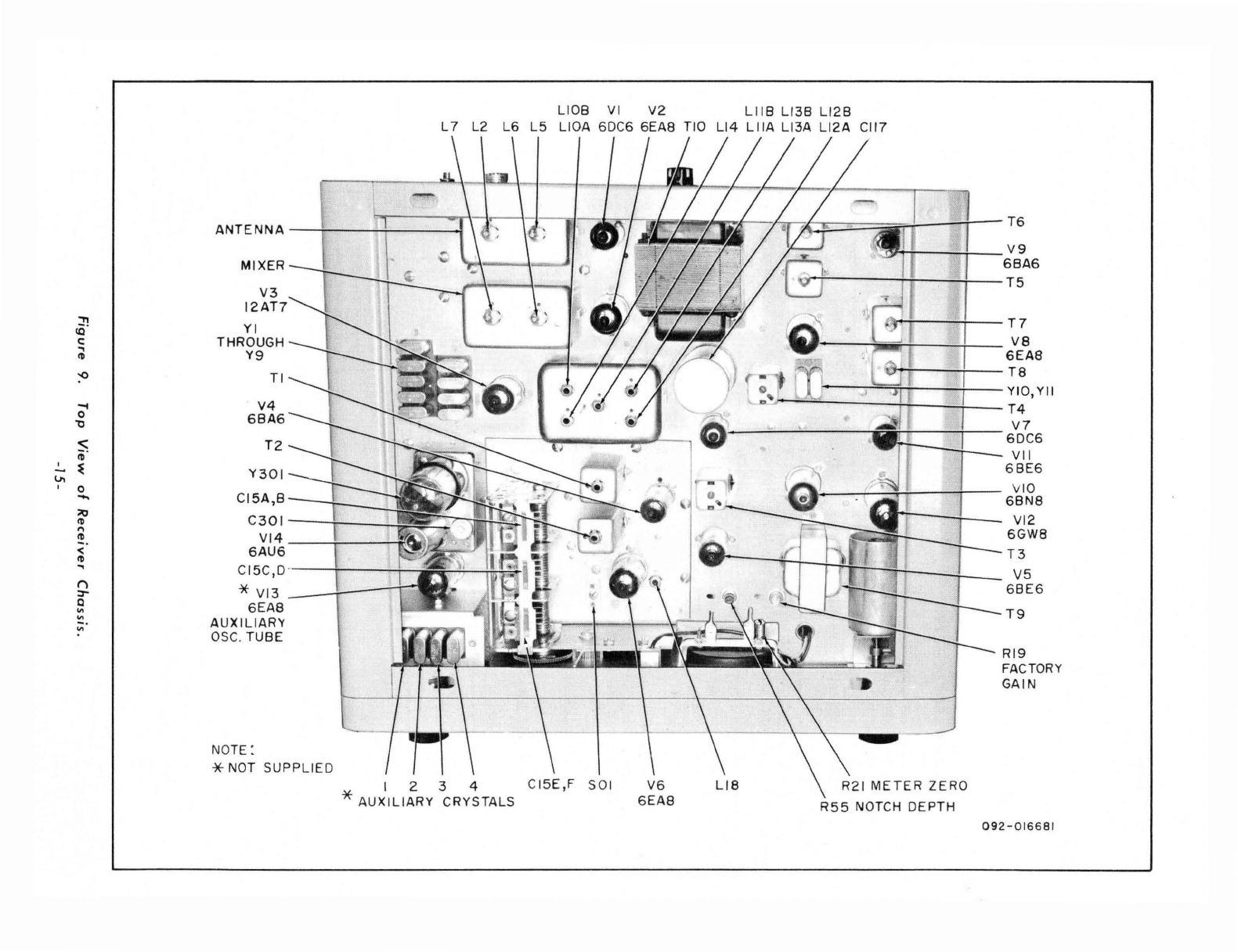
ANTENNA
MIXER
V3
12AT7
:n
<Q
YI
c:
THROUGH
.,
Y9
~
:0
TI
-4
V4
0
6BA6
"0
$
T2
~
.!...
~
Y301
v.
0
-.
CI5A,B
~
~
C301
"
~
VI4
<
6AU6
~
.,
CI5C,D
Ii
*
VI3
:r
Q 6EAS
VI
VI
AUXILIARY
VI
OSC
. TUBE
NOTE
:
*
NOT
SUPPLIED
L10B VI V2
LIIB
L13B L12B
L 7 L2
L6
L5
L10A 6DC6 6EAS TIO
Ll4
LilA
L13A L12A
CII7
CI5E,F
501
R21
METER
ZERO
R55
NOTCH DEPTH
T6
V9
6BA6
T5
T7
va
6EAS
T8
YIO,YII
T4
V7
6DC6
VII
68E6
VIO
6BN8
VI2
6GWS
T3
V5
68E6
T9
RI9
FACTORY
GAIN
092-016681
SELECTIVITY
..••
As
indicated
in
chart.
FUNCTION
•.••••
AM
TUNING. • • • • • • • As
indicated
on
chart.
NOTCH
•......•
OFF.
XT
AL
CAL-NL
.••
OFF.
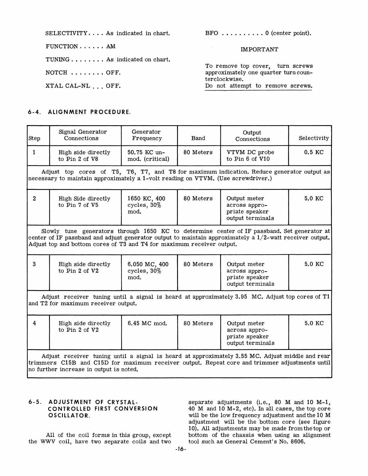
6-4.
ALIGNMENT
PROCEDURE.
Signal
Generator Generator
step
Connections
Frequency
1 High
side
directly
50.75
KC
un-
to
Pin
2 of
V8
mod.
(critical)
Band
BFO
.•.••••.•.
0
(center
point).
IMPORTANT
To
remove
top
cover,
turn
screws
approximately
one
quarter
turn
coun-
terclockwise.
Do not
attempt
to
remove
screws.
Output
Connections
Selectivity
80
Meters
VTVM
DC
probe
0.5
KC
to
Pin
6 of
VI0
Adjust top
cores
of T5,
T6,
T7, and T8
for
maximum
indication. Reduce
generator
output
as
necessary
to
maintain
approximately
a
I-volt
reading
on VTVM. (Use
screwdriver.)
2 High Side
directly
1650 KC, 400 80
Meters
Output
meter
5.0
KC
to
Pin
7 of
V5
cycles,
30%
across
appro-
mod.
priate
speaker
output
terminals
Slowly
tune
generators
through
1650
KC
to
determine
center
of
IF
passband.
Set
generator
at
center
of
IF
passband
and
adjust
generator
output
to
maintain
approximately
a
1/2-watt
receiver
output.
Adjust top and
bottom
cores
of T3 and T4
for
maximum
receiver
output.
3 High
side
directly
6.050 MC, 400 80
Meters
Output
meter
5.0
KC
to
Pin
2 of
V2
cycles,
30%
across
appro-
mod.
priate
speaker
output
terminals
Adjust
receiver
tuning
until
a
signal
is
heard
at
approximately
3.95 MC. Adjust top
cores
of
Tl
and T2
for
maximum
receiver
output.
4 High
side
directly
6.45
MC
mod. 80
Meters
Output
meter
5.0
KC
to
Pin
2 of
V2
across
appro-
priate
speaker
output
terminals
Adjust
receiver
tuning
until
a
signal
is
heard
at
approximately
3.55 MC. Adjust
middle
and
rear
trimmers
C15B and C15D
for
maximum
receiver
output.
Repeat
core
and
trimmer
adjustments
until
no
further
increase
in output
is
noted.
6-5.
ADJUSTMENT
OF
CRYSTAL-
CONTROLLED
FIRST
CONVERSION
OSCILLATOR.
All of
the
coil
forms
in
this
group,
except
the
WWV
coil,
have two
separate
coils
and two
-16-
separate
adjustments
(i.e.,
80 M and 10
M-l,
40 M and 10
M-2,
etc).
In
all
cases,
the
top
core
will
be
the
low
frequency
adjustment
and the 10 M
adjustment
will
be
the
bottom
core
(see
figure
10). All
adjustments
may
be
made
from
the
top
or
bottom
of
the
chassis
when
using
an
alignment
tool
such
as
General
Cement's
No. 8606.
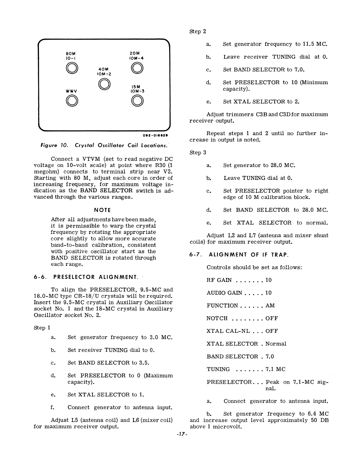
80M
20M
10-1
IONl-4
0
40Nl
0
IOM-2
0 15M
WWV
IONl-3
0 0
O'I-Ollen
Figure 10.
Crystal
Oscillator
Coil Locations.'
Connect
a VTVM
(set
to
read
negative
DC
voltage
on
10-volt
scale)
at
point
where
R30
(1
megohm)
connects
to
terminal
strip
near
V2.
Starting
with
80 M,
adjust
each
core
in
order
of
increasing
frequency,
for
maximum
voltage
in-
dication
as
the
BAND
SELECTOR
switch
is
ad-
vanced
through
the
various
ranges.
NOTE
After
all
adjustments
have
been
made,
it
is
permissible
to
warp
the
crystal
frequency
by
rotating
the
appropriate
core
slightly
to
allow
more
accurate
band-to-band
calibration,
consistent
with
positive
oscillator
start
as
the
BAND
SELECTOR
is
rotated
through
each
range.
6-6.
PRESELECTOR
ALIGNMENT.
'
To
align
the
PRESELECTOR,
9.5-MC
and
18.0-MC
type
CR-18/U
crystals
will
be
required.
Insert
the
9.5-MC
crystal
in
Auxiliary
Oscillator
socket
No. 1 and
the
18-MC
crystal
in
Auxiliary
Oscillator
socket
No.2.
Step 1
a.
Set
generator
frequency
to
3.0 MC.
b. Set
receiver
TUNING
dial
to
O.
c.
Set
BAND
SELECTOR
to
3.5.
d. Set
PRESELECTOR
to
0 (Maximum
capacity).
e.
Set
XTAL
SELECTOR
to 1.
f.
Connect
generator
to
antenna
input.
Adjust
L5
(antenna
coil) and L6
(mixer
coil)
for
maximum
receiver
output.
-17-
Step 2
a. Set
generator
frequency
to
11.5 MC.
b.
Leave
receiver
TUNING
dial
at
O.
c.
Set BAND
SELECTOR
to 7.0.
d.
Set
PRESELECTOR
to
10 (Minimum
capacity).
e. Set XT
AL
SE LE CTOR
to
2.
Adjust
trimmers
C3B and
C3Dfor
maximum
receiver
output.
Repeat
steps
1 and 2
until
no
further
in-
crease
in
output
is
noted.
Step 3
a.
b.
c.
d.
Set
generator
to
28.0 MC.
Leave
TUNING
dial
at
O.
Set
PRESELECTOR
pointer
to
right
edge
of 10 M
calibration
block.
Set
BAND
SELECTOR
to 28.0 MC.
e. Set
XTAL
SELECTOR
to
normal.
Adjust
L2 and L7
(antenna
and
mixer
shunt
coils)
for
maximum
receiver
output.
6-7.
ALIGNMENT
OF IF TRAP.
Controls
should
be
set
as
follows:
RF
GAIN
......•
10
AUDIO GAIN
•...•
10
FUNCTION
..•..•
AM
NOTCH
.•....•.
OFF
XT
AL
CAL-NL
...
OFF
XTAL
SELECTOR.
Normal
BAND SE LECTOR . 7.0
TUNING
••.....
7.1 MC
PRESELECTOR
.•.
Peak
on
7.1-MC
sig-
nal.
a.
Connect
generator
to
antenna
input.
b.
Set
generator
frequency
to
6.4 MC
and
increase
output
level
approximately
50 DB
above 1
microvolt.
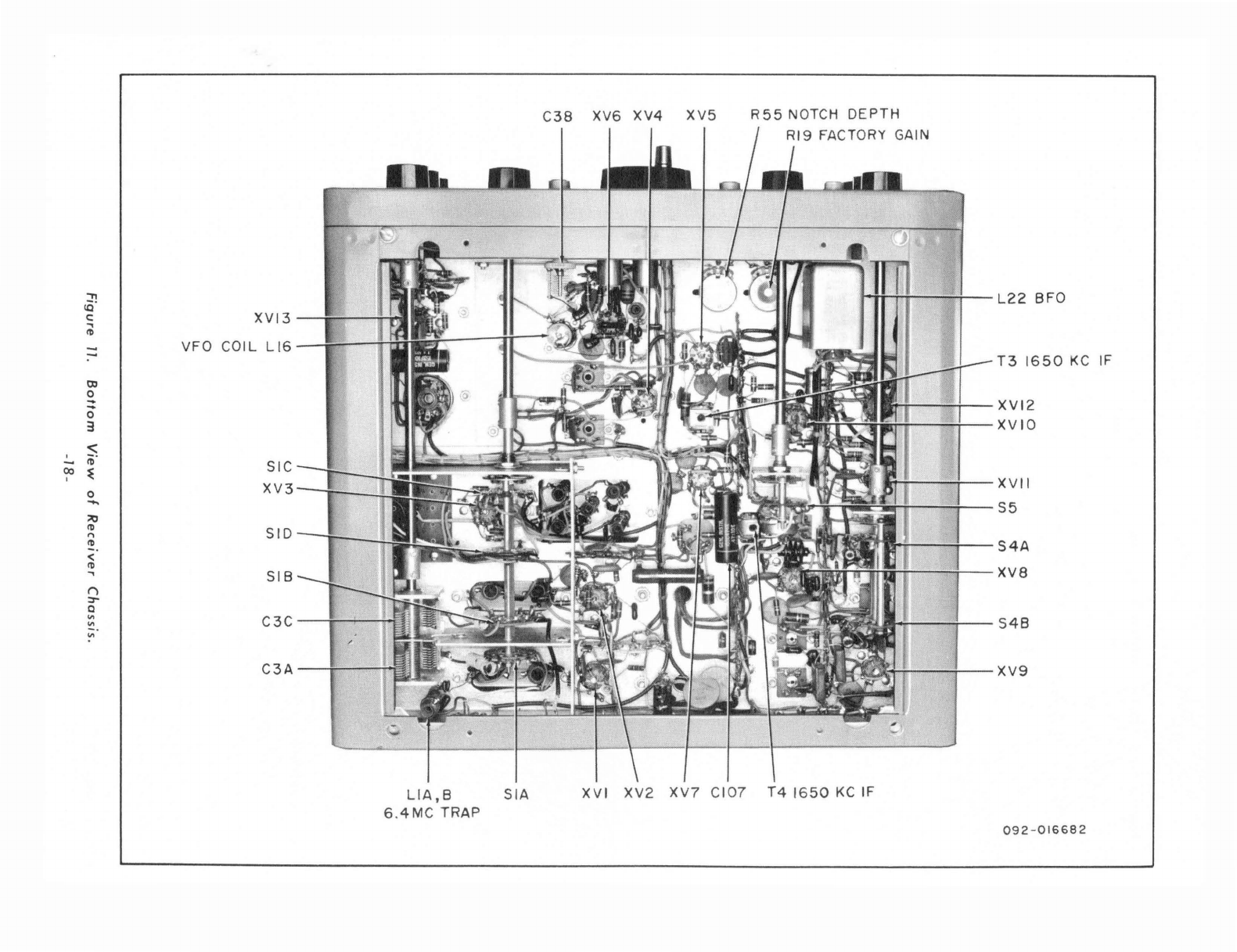
C38
XV6
XV4
XV5
R55
NOTCH
DEPTH
::!'!
L22
BFO
IQ
c:
XVI3
..,
~
VFO COIL
LI6
:-
T3
1650
KC
IF
~
0
-
-
XVI2
0
3
XVIO
<:
!..
~.
SIC
00
~
I
0
XV3
XVII
......
S5
;10
~
,.,
SID
~
S4A
<
~
..,
SIB
XV8
(')
::r
Q
'"
C3C
'"
S4B
~.
C3A
XV9
LlA,B
SIA
XVI
XV2
XV?
CI07
T4
1650
KC
IF
6.4MC
TRAP
092-016682
c.
Adjust
both
cores
in
L1
(IF
Trap)
for
mInImUm
receiver
audio output.
Repeat
adjust-
ments
until
no
further
decrease
in
output
is
ob-
tained.
6-8.
VFO
CALIBRATION
ALIGNMENT.
If
the
electrical
index
check
at
the
100-KC
check
points
on
all
bands
shows
that
the
calibra-
tion
marks
consistently
fall
to
one
side
of
the
pOinter,
a
trimmer
adjustment
is
indicated.
(This
will
be
necessary
only
if
the
calibration
is
beyond
tuning
range
of
the
CAL
RESET
control.)
Proceed
as
follows:
a.
Adjust
TUNING
until
dial
is
at
500 (3.5
MC).
b.
Set
BAND
SELECTOR
at
3.5,
FUNC-
TION
to
USB,
SELECTIVITY
to
2.5,
and
XTAL
CAL
to
ON.
c.
Carefully
adjust
C15F
(fronttrimmer
on
top
of
three-section
gang)
in
very
small
incre-
ments
until
zero
beat
is
heard.
Care
should
be
exercised
to
make
sure
that
the
correct
100-KC
beat
note
is
tuned
in
with
the
trimmer.
d.
Check
across
the
dial
at
the
100-KC
check
points.
If
the
frequency
error
is
less
than
3000
CPS,
the
calibration
is
within
acceptable
limits.
If
the
error
at
the
high
frequency
end
of
the
dial
(4.0 MC)
is
greater
than
3000
CPS,
the
VFO
may
require
a
coil
adjustment
in
addition
to
the
trimmer
adjustment.
6-9.
CONDITIONS
REQUIRING
COIL
AND
TRIMMER
ADJUSTMENT.
If
the
dial
error
progressively
increases
in
the
same
direction
with
the
high
frequency
end
running
out
more
than
3000
CPS,
both
L16
and
C15 F
should
be
adjusted.
a.
Tune
dial
to 1000 (4.0 MC)
and
adjust
L16
to
zero
beat.
b.
Tune
dial
to
500 (3.5 MC)
and
adjust
C15F
to
zero
beat.
c.
Repeat
steps
a
and
b
until
both
3.5 MC
and
4.0
MC
are
exactly
on
frequency.
d.
Check
across
the
dial
at
the
100-
KC
points.
If
the
frequency
error
is
less
than
3000
CPS,
the
calibration
is
within
acceptable
limits.
If
the
error
is
in
excess
of 3000
CPS
at
any of
the
mid-points,
with
the
end
limits
at
zero
error,
the
VFO
capacitor
should
be
knifed.
This
operation
should
not
be
attempted
by
other
than
qualified
per-
sonnel
thoroughly
familiar
with
the
technique.
-19-
NOTE
When
the
VFO
dial
is
at
3.5
MC,
the
VFO
frequency
should
be
4.85 MC.
With
the
VFO
dial
set
at
4.0
MC,
the
VFO
frequency
should
be
4.35 MC.
6-10.
ADJUSTMENT
OF
FACTORY
GAIN
METER
CONTROL.
Controls
should
be
set
as
follows:
AUDIO GAIN
.........
0
RF
GAIN
...........
10
FUNCTION
........•.
AM
SELECTIVITY
.......
2.5
KC
TUNING
............
14.3 MC
BAND SE
LE
CTOR . . . . . 20 M
NOTCH
............
OFF
XT
AL
CAL-NL
.......
OFF
a.
Connect
signal
generator
to
the
an-
tenna
input.
Set
generator
output
level
to
50
mi-
crovolts
unmodulated
and
tune
to
14.3
MC.
b.
Carefully
adjust
TUNING
for
maxi-
mum
S-Meter
deflection
and
peak
PRESELEC-
TOR.
c.
If
S-Meter
does
not
read
S9,
adjust
Factory
Gain
control
for
correct
reading.
d.
Turn
RF
GAIN
control
to
0
and
check
for
electrical
zero
at
left
end
of
meter
scale.
e.
Adjust
Meter
Zero
control
as
neces-
sary
and
repeat
the
above
steps
until
the
meter
reads
S9
with
the
RF
GAIN
control
at
10
and
0
with
the
RF
GAIN
control
at
O.
6-11.
BFO
FREQUENCY
ADJUSTMENT.
The
beat
frequency
oscillator
(BFO)
has
been
adjusted
at
the
factory
so
that
its
frequency
is
exactly
50
KC
when
the
BFO
knob
is
set
at
O.
A
slight
readjustment
may
be
necessary
occasion-
ally
because
of
normal
component
aging.
To
deter-
mine
if
adjustment
is
required,
proceed
as
follows.
With
the
SELECTIVITY
control
at
5 KC,
FUNCTION
at
USB,
XTAL
CAL.
at
ON,
and
PITCH
control
at
0,
adjust
TUNING
to
zero
beat
at
any
100-KC
check
point.
Leaving
the
receiver
TUNING
unchanged,
switch
the
FUNCTION
switch
to LSB.
If
the
beat
oscillator
frequency
is
correct,
zero
beat
will
be
maintained
in
both
the
USB
and
LSB
positions.
If
the
beat
oscillator
is
off
fre-
quency, a
beat
note will
be
heard
when
switching
from
USB to LSB.
Adjustment
of
the
oscillator
is
recommended
only if
the
frequency
of
the
aud-
ible
beat
note
exceeds
200
CPS
with
the
BFO
knob
at
O.
NOTE
In
instances
where
the
beatfrequency
oscillator
is
considerably
off
fre-
quency,
it
may
not
be
possible
to
ob-
tain
a
zero
beat
when
tuning
through
a
signal.
If
this
is
the
case,
it
will
be
necessary
to
roughly
set
the
BFO
to
50
KC
as
follows:
Set
SELECTIVITY
to
0.5
KC, FUNCTION
to
USB, and
tune
receiver
to a
noisy
part
of
band
(not
to
a
signal).
Remove
the
BFO
knob and
adjust
the
BFO
slug
for
min-
imum
noise.
Set
the
SELECTIVITY
control
to 5
KC
and
make
the
BFO
fre-
quency
check
as
outlined
above.
If
the
BFO
frequency
check
indicates
adjust-
ment
is
necessary,
proceed
as
follows:
a.
Remove
the
BFO
control
knob,
turn
the
BFO
slug
a few
degrees
in
the
direction
that
lowers
the
beat
note
frequency,
and
repeat
the
BFO
frequency
check.
b. Continue
varying
thp.
setting
of
the
slug
in
small
steps
and
repeat
the
BFO
frequency
check
until
zero
beat
is
obtained
in
both
USB
and
LSB pOSitions.
c.
After
the
correct
slug
setting
has
been
determined,
replace
the
BFO
knob with 0
in
the
top
center
position,
being
careful
not
to
disturb
the
slug
setting.
6-12.
NOTCH
FREQUENCY
AND
DEPTH
A
DJ
UST
MENTS.
Readjustment
of
the
notch
filter
circuit
is
not
normally
necessary
unless
the
components
in
the
notch
circuit
are
replaced.
To
check
the
cir-
cuit,
proceed
as
follows:
a.
Check
the
BFO
frequency
as
pre-
viously
described
so
that
zero
beat
is
maintained
in
either
sideband
position.
b. Set FUNCTION to USB, SELECTIVITY
to 2.5 KC, and tune
in
an
unmodulated
Signal
(strength
approximately
S9)
to
zero
beat.
c. Tune NOTCH
control
for
minimum
audio
output.
d.
Adjust
notch
depth
(on top
of
chassis,
right
side
of
VFO)
for
further
decrease
in
audio
output.
e.
Repeat
steps
c and d
until
no
further
decrease
in
audio output
is
noted. At
this
point,
the
notch
frequency
should
indicate
50
KC.
If
the
notch
frequency
does
not
indicate
50
KC
with
the
receiver
at
zero
beat
as
described
above,
loosen
knob and
reset
it
to
50
KC.
6-13.
CRYSTAL
CALIBRATOR
ADJUSTMENT.
The
crystal
adjust
trimmer
is
used
to
ad-
just
the
100-KC
crystal
exactly
to
frequency
by
comparison
with
the
10-MC
signal
transmitted
by
WWV.
a. Set
all
receiver
controls
for
AM
re-
ception,
set
BAND
SELECTOR
to WWV, and
adjust
TUNING
to
WWV
signal.
b.
During
the
period
of no
signal
modu-
lation,
turn
XT AL CAL.
ON
and
carefully
set
the
crystal
adjust
so
that
the
crystal
calibrator
zero
beats
with
the
signal
received
from
WWV.
NOTE
If
this
adjustment
is
attempted
during
periods
that
WWV
is
modulated,
an
erroneous
zero
beat
may
be
obtained
with
the
modulating
frequency
instead
of
the
desired
carrier
frequency.
SECTION
VII
SERVICE
DATA
7-1.
SO.7S-KC
IF
SYSTEM,
Figure
12
shows
the
type
of
coupling
used
in
the
50.75-KC
IF
system.
Note
that
inductive
coupling
is
avoided
by
careful
shielding
of
the
IF
coils
and
signal
transfer
occurs
only
through
ca-
pacitance
and
resistance.
By
increasing
the
value
of
"C"
and
decreasing
"R",
the
selectivity
is
made
-20-
sharper;
by
decreasing
"C"
and
increasing
"R",
the
selectivity
is
made
broader.
The
proper
values
of
"C"
and
"R"
are
switched
in
the
circuit
by
means
of
the
SELECTIVITY
control.
"R"
varies
the
"Q"
of
the
tuned
circuit
and
"C"
varies
the
coupling.
This
R-C
coupling
arrangement
affords
a
more
accurate
means
of
selectivity
control
than
that
readily
obtainable
by any
other
method.
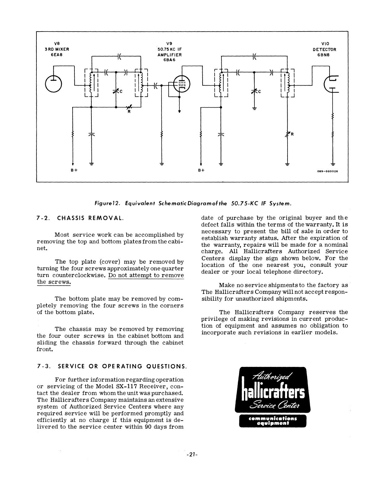
VS
3RD MIXER
6EAS
R
I
s+
V9
50.75
KC
IF
AMPLIFIER
6BA6
S+
I R
VIO
DETECTOR
089-003026
Figurel2.
Equivalent
SchematicDiagramofthe
SO.7S-KC
IF
System.
7
-2.
CHASSIS
REMOV
AL.
Most
service
work
can
be
accomplished
by
removing
the
top
and
bottom
plates
from
the
cabi-
net.
The
top
plate
(cover)
may
be
removed
by
turning
the
four
screws
approximately
one
quarter
turn
counterclockwise.
Do
not
attempt
to
remove
the
screws.
The
bottom
plate
may
be
removed
by
com-
pletely
removing
the
four
screws
in
the
corners
of
the
bottom
plate.
The
chassis
may
be
removed
by
removing
the
four
outer
screws
in
the
cabinet
bottom
and
sliding
the
chassis
forward
through
the
cabinet
front.
7-3.
SERVICE
OR
OPE
RATING
QUESTIONS.
For
further
information
regarding
operation
or
servicing
of
the
Model SX-117
Receiver,
con-
tact
the
dealer
from
whom
the
unit
was
purchased.
The
Hallicrafters
Company
maintains
an
extensive
system
of
Authorized
Service
Centers
where
any
required
service
will
be
performed
promptly
and
efficiently
at
no
charge
if
this
equipment
is
de-
livered
to
the
service
center
within
90
days
from
-21-
date
of
purchase
by
the
original
buyer
and
th
e
defect
falls
within
the
terms
of
the
warranty.
It
is
necessary
to
present
the
bill
of
sale
in
order
to
establish
warranty
status.
Mter
the
expiration
of
the
warranty,
repairs
will
be
made
for
a
nominal
charge.
All
Hallicrafters
Authorized
Service
Centers
display
the
sign
shown below.
For
the
location
of
the
one
nearest
you,
consult
your
dealer
or
your
local
telephone
directory.
Make
no
service
shipments
to
the
factory
as
The
Hallicrafters
Com-pany
will
not
accept
respon-
sibility
for
unauthorized
shipments.
The
Hallicrafters
Company
reserves
the
privilege
of
making
revisions
in
current
produc-
tion
of
equipment
and
assumes
no
obligation
to
incorporate
such
revisions
in
earlier
models.
c
.......
unlc.ti.ns
equlp
...
ent
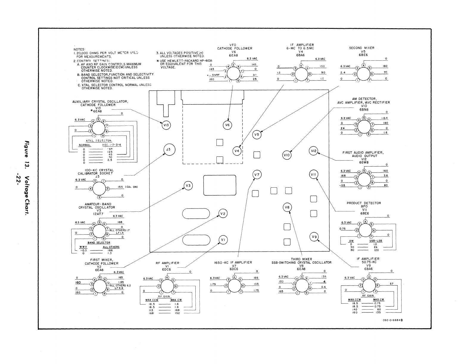
::n
co
c:
~
NOTES'
L
20,000
OHMS
PER
VOLT
METER uc;l:J
FOR
MEASUREM£NTS.
2.
CONTROl
SETTlf\Jr~:
A.
AF
AN9
RF GAIN
caNTRa~S
MAXIMUM
COUNTER CLOCKWISE(CCW) UNLESS
OTHERWISE NOTED.
B. BAND SELECTOR,FUNCTION
AND
SELECTIVITY
CONTROL SETTINGS NOT CRITICAL UNLESS
OTHERWISE NOTED.
C.
XTAL SELECTOR CONTROL NORMAL UNLESS
OTHERWISE NOTED.
AUXIL
IARY CRYSTAL OSCILLATOR,
CATHODE FOLLOWER
VI3
*SEA8
3. ALL
VOLTAGES
POSITIVE
i+)
UNLESS OTHERWISE NOTED.
*
USE
HEWLETT-PACKARD HP-410B
OR
EQUIVALENT
FOR
THIS
VOLTAGE.
VFO
CATHODE FOLLOWER
V6
6EA8
6.3
VAC
145
IF
AMPLIFIER
6-MC
TO
6.5MC
V4
68A6
VI3
I
I
I
I
I
I
i D V
IOO-KC
CRYSTAL
CALIBRATOR SOCKET
J3
AMATEUR- BAND
CRYSTAL OSCILLATOR
L
WWV
-0.3
o
V3
12AT7
ALL OTHERS
168
1.3
FIRST MIXER,
CATHODE FOLLOWER
V2
SEA8
(CAL
ON)
6.3
VAC
J3
RF AMPLIFIER
VI
6DC6
I
V4
I I
: D I
L
_____________
...J
V3
D
( )
V2
----
C
__
)
VI
1650-KC
IF
AMPLIFIER
V7
6DC6
RF
GAIN
~I
MAX
CCW~AX
CW
~
18.5
1.6
18.5
1.6
[13
168
168 152
D
V7
0
VI2
VIO
VII
0 0 o
j
0
o
V9
0
THIRD MIXER
SSB-SWITCHING
CRYSTAL
OSCILLATOR
V8
6EAS
6.3
VAC
120
165
SECOND MiXER
V5
68E6
AM
DETECTOR,
AVC
AMPLIFIER,
AVC RECTIFIER
VIO
68N8
FIRST
AUDIO AMPLIFIER,
AUDIO OUTPUT
VI2
6GW8
PRODUCT DETECTOR
8FO
VII
6BE6
~
F
AMPLIFIER
50.75-KC
V9
6eA6
6.3
VAC
~
IS.5
---
0.75
18.5
---
0.75
140
60
160
---
135
57
092-0166848
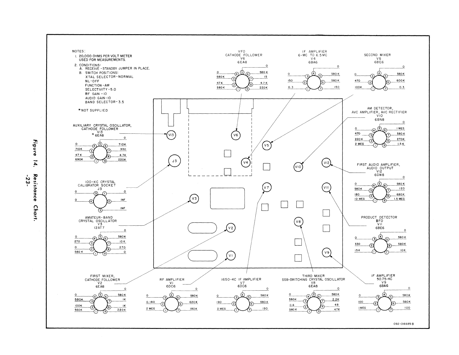
:n
CQ
c:
.,
CD
~
,
lIO
"J
CD
W
III
,
III
Q
::J
n
CD
()
:r
Q
~
NOTES:
20,000
OHMS
PER
VOLT METER
USED
FOR
MEASUREMENTS.
2. CONDITIONS'
A. RECEIVE -STANDBY JUMPER
IN
PLACE.
B.
SWITCH POSITIONS:
XTAL
SELECTOR-
NORMAL
NL
-OFF
FUNCTION
-AM
SELECTIVITY
-5.0
RF
GAIN
-10
AUDIO GAIN
-10
BAND
SELECTOR-
3.5
"NOT
SUPPLIED
AUXILIARY
CRYSTAL OSCILLATOR,
CATHODE FOLLOWER
VI3
* SEA8
IOO-KC
CRYSTAL
CALIBRATOR
SOCKET
J3
~
AMATEUR-
BAND
CRYSTAL OSCILLATOR
V3
12AT7
FIRST
MIXER,
CATHODE FOLLOWER
V2
SEAS
INF
o
0.180
2
MEG
VI3
J3
./
RF
AMPLIFIER
VI
6DC6
I
I
I
I
I
I
I
I
I
I
I
I
I
5aOK
47
K
VFO
CATHODE FOLLOWER
VS
SEAS
D
V4
:
D:
L
_____________
-1
V3
D
V7
D D
C~)
V2
C_)
VI
IS50-KC
IF
AMPLIFIER
V7
6DC6
D
I F
AMPLIFIER
S-MC
TO
S.5MC
V4
6BAS
VI2
VIO
VII
D D
V8
D
D
V9
D
THIRD MIXER
SSB-SWITCHING CRYSTAL OSCILLATOR
V8
SEAS
SECOND MIXER
V5
SBES
AM
DETECTOR,
AVC
AMPLIFIER,
AVC
RECTIFIER
VIO
SBNS
FIRST AUDIO
AMPLIFIER,
AUDIO OUTPUT
VI2
SGW8
PRODUCT DETECTOR
BFO
VII
SBE6
IF
AMPLIFIER
50.75-KC
V9
SBAS
092-016685
B
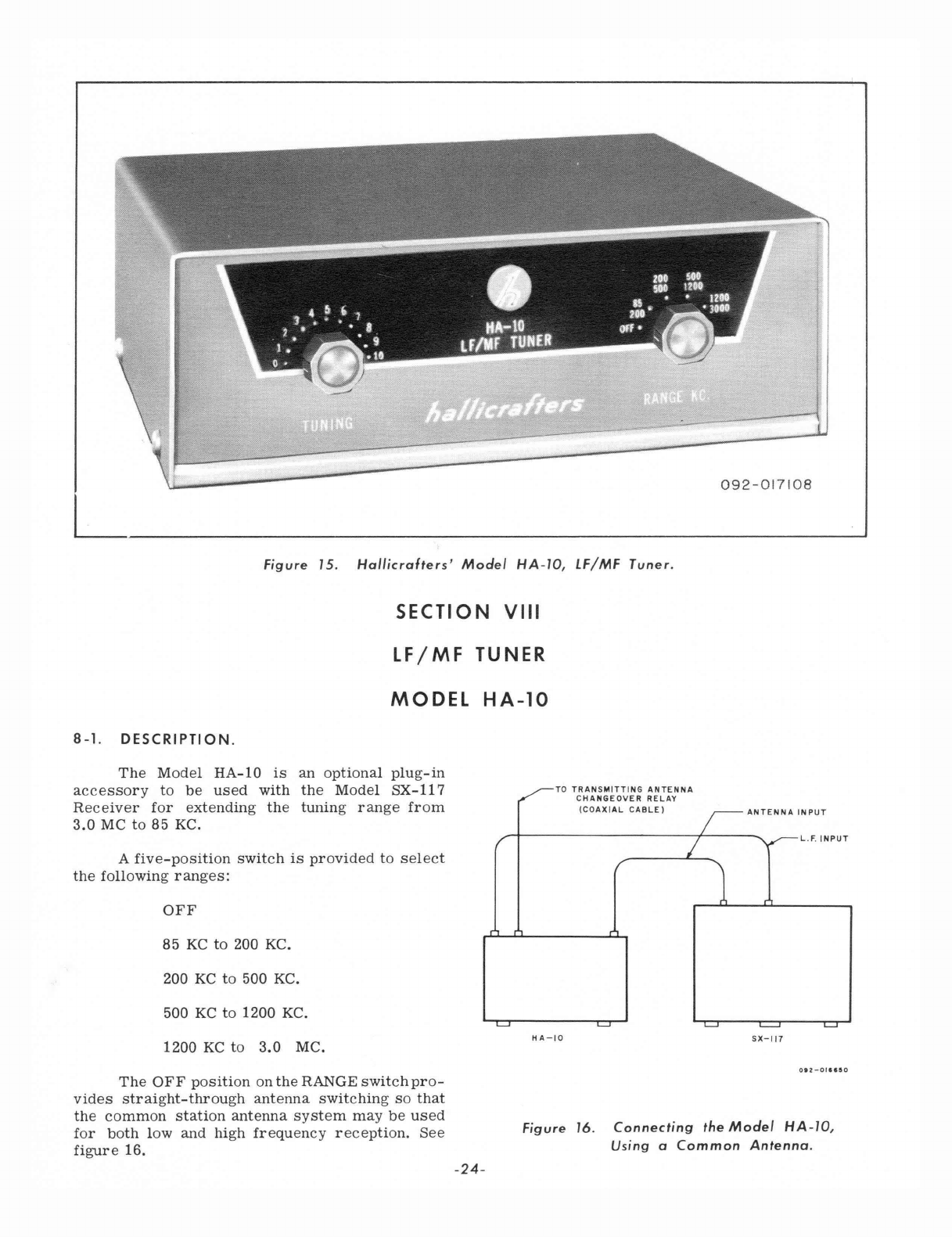
092-017
1
08
L
______________
~
Figure
15.
Hal/icrafters'
Model
HA-lO,
LF/MF
Tuner.
SECTION
VIII
LF/MF
TUNER
MODEL
HA-10
8-1.
DESCRIPTION.
The
Model
HA-10
is
an
optional
plug-in
accessory
to
be
used
with
the
Model
SX-117
Receiver
for
extending
the
tuning
range
from
3.0
MC
to
85
KC.
TO
TRANSMITTING
ANTENNA
A
five-position
switch
is
provided
to
select
the
following
ranges:
OFF
85
KC
to
200 KC.
200
KC
to
500 KC.
500
KC
to
1200 KC.
1200
KC
to
3.0
MC.
L..J
CHANGEOVER
RELAY
(COAXIAL
CABLE)
I
LI
HA-IO
~ANTENNAINPUT
,~L.F
.
INPUT
)
I.......J
~
~
SX-117
The
OFF
position
on
the
RANGE
switch
pro-
vides
straight-through
antenna
switching
so
that
the
common
station
antenna
system
may
be
used
for
both
low
and
high
frequency
reception.
See
figure
16.
Figure
16
.
Connecting
the
Model
HA-l0,
Using
a
Common
Antenna.
-24-
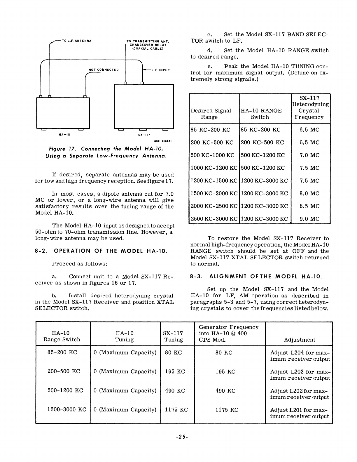
.......--TO
L.F.
ANTENNA
TO
TRANSMITTING
ANT.
CHANGEOVE R
RELAY
(COAXIAL
CABLE)
f "
NOT
CONNECTED
-L.F.
INPUT
~
~
~
~
~
HA-IO
SX-117
012-0"'11
Figure 17.
Connecting
the
Model
HA-IO,
Using
a
Separate
low-Frequency
Antenna.
If
desired,
separate
antennas
may
be
used
for
low
and
high
frequency
reception.
See
figure
17.
In
most
cases,
a
dipole
antenna
cut
for
7.0
MC
or
lower,
or
a
long-wire
antenna
will
give
satisfactory
results
over
the
tuning
range
of
the
Model
HA-10.
The
Model
HA-10
input
is
designed
to
accept
50-ohm
to
70-ohm
transmission
line.
However,
a
long-wire
antenna
may
be
used.
8-2.
OPERATION
OF
THE
MODEL
HA-10.
Proceed
as
follows:
a.
Connect
unit
to
a
Model
SX-117
Re-
ceiver
as
shown
in
figures
16
or
17.
b.
Install
desired
heterodyning
crystal
in
the
Model
SX-117
Receiver
and
position
XTAL
SELECTOR
switch.
HA-10
HA-10
SX-117
Range
Switch
Tuning Tuning
85-200
KC
o
(Maximum
Capacity)
80
KC
200-500
KC
o
(Maximum
Capacity)
195
KC
500-1200
KC
o
(Maximum
Capacity)
490
KC
1200-3000
KC
o
(Maximum
Capacity)
1175
KC
-25-
c.
Set
the
Model
SX-117
BAND
SELEC-
TOR
switch
to
LF
.
d.
Set
the
Model
HA-10 RANGE
switch
to
desired
range.
e.
Peak
the
Model
HA-10
TUNING
con-
trol
for
maximum
signal
output.
(Detune on
ex-
tremely
strong
signals.)
SX-117
Heterodyning
Desired
Signal
HA-10
RANGE
Crystal
Range
Switch
Frequency
85
KC-200
KC
85
KC-200
KC
6.5
MC
200 KC-500
KC
200
KC-500
KC
6.5
MC
500
KC-1000
KC
500
KC-1200
KC
7.0
MC
1000
KC-1200
KC
500
KC-1200
KC
7.5
MC
1200
KC-1500
KC
1200
KC-3000
KC
7.5
MC
1500
KC-2000
KC
1200
KC-3000
KC
8.0
Me
2000
KC-2500
KC
1200
KC-3000
KC
8.5
MC
2500
KC-3000
KC
1200
KC-3000
KC
9.0
MC
To
restore
the
Model
SX-1l7
Receiver
to
normal
high-frequency
operation,
the
Model
HA-10
RANGE
switch
should
be
set
at
OFF
and
the
Model
SX-117
XT
AL
SELECTOR
switch
returned
to
normal.
8-3.
ALIGNMENT
OF
THE
MODEL
HA-10.
Set
up
the
Model
SX-117
and
the
Model
HA-10
for
LF,
AM
operation
as
described
in
paragraphs
5-3
and
5-7,
using
correct
heterodyn-
ing
crystals
to
cover
the
frequencies
listed
below.
Generator
Frequency
into
HA-10
@ 400
CPS
Mod.
Adjustment
80
KC
Adjust
L204
for
max-
imum
receiver
output
195
KC
Adjust
L203
for
max-
imum
receiver
output
490
KC
Adjust
L202
for
max-
imum
receiver
output
1175
KC
Adjust
L201
for
max-
imum
receiver
output
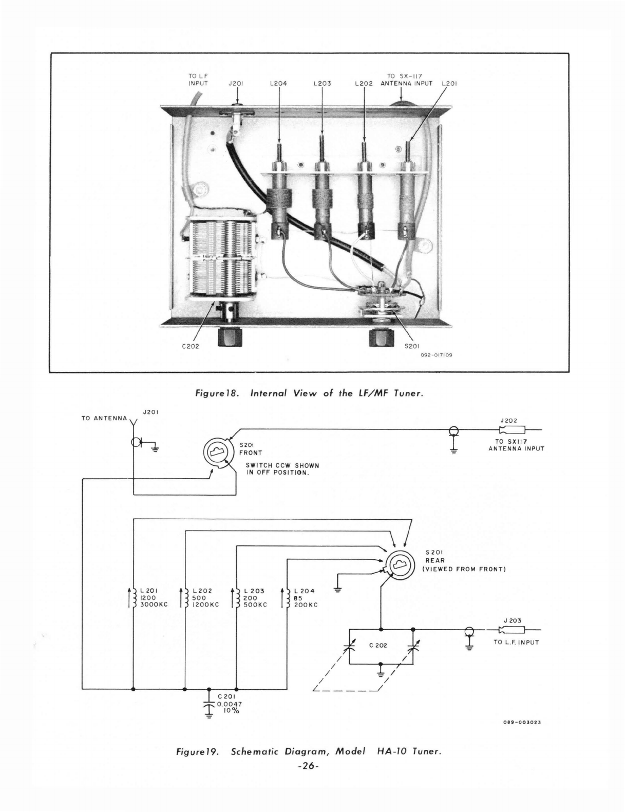
TO
ANTENNA
r
J2
01
L
20
I
1200
3000KC
r
TO
L F
INPUT
J201
L20
4
L2
0 3
TO
SX -117
L
202
A
NTENNA
INPUT
L201
092-017109
Figure
18.
Internal
View
of
the
IF/MF
Tuner.
L202
500
1200KC
f
5201
FRONT
SWITCH
CCW SHOWN
IN
OFF
POSITION
.
L
203
200
500K
C f L
204
8 5
200KC
/
S
201
REAR
J202
TO
SXI17
ANTENNA
INPUT
(VIEWED
FROM
FRONT)
J
203
'---~--~-------T~~
C
202
TO
L
.F.
I N
PUT
/ /
/
-=
/
/ /
C 201
'1'
0.0047
...L
10%
L
____
~
0
89-003023
Figure
19.
Schematic
Diagram,
Model
HA
-IO Tuner.
-26-
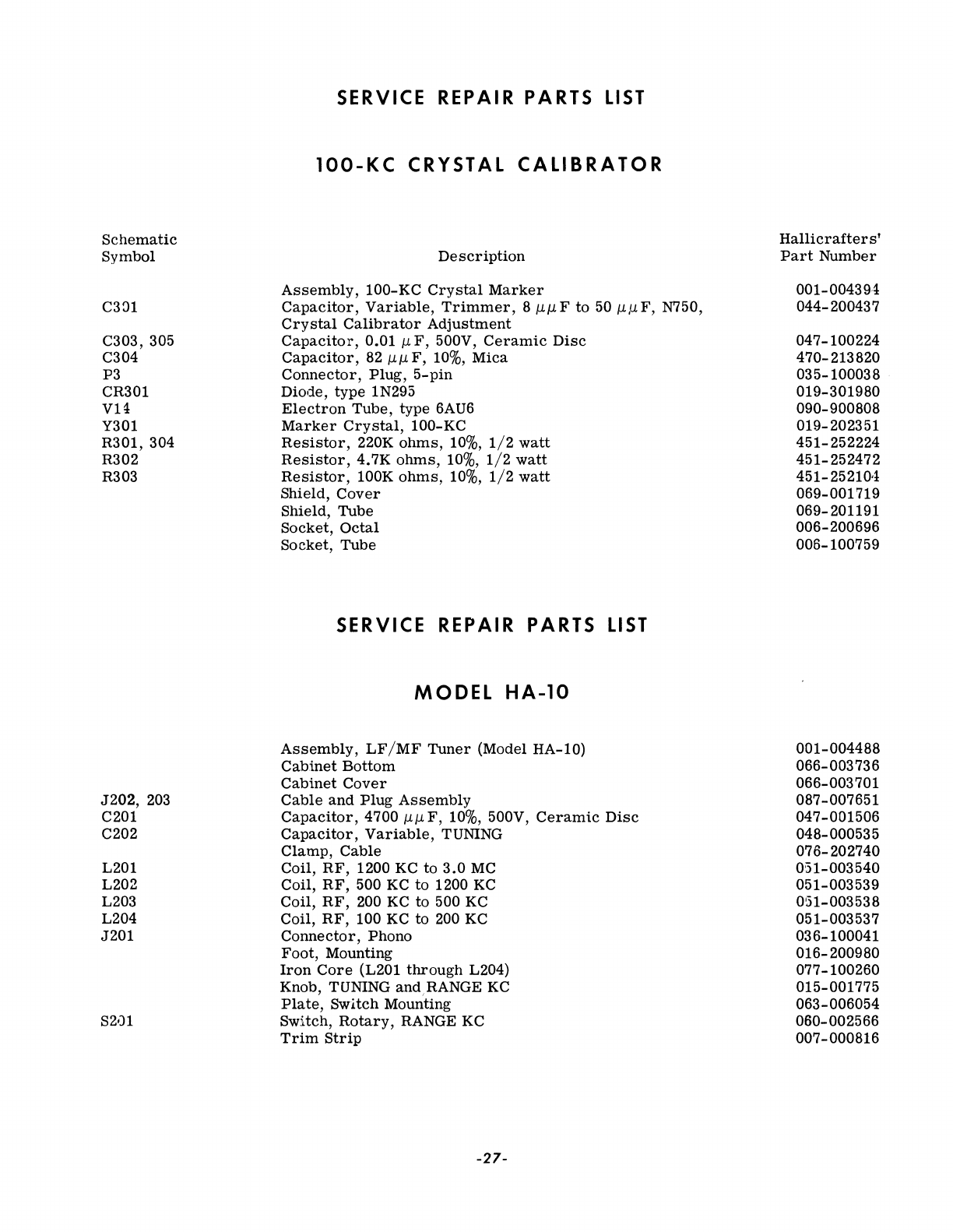
Schematic
Symbol
C381
C303, 305
C304
P3
CR301
VB
Y301
R301, 304
R302
R303
J202,
203
C201
C202
L201
L202
L203
L204
J201
SERVICE REPAIR PARTS
LIST
lOO-KC
CRYSTAL
CALIBRATOR
Description
Assembly,
100-KC
Crystal
Marker
Capacitor,
Variable,
Trimmer,
8
jJ.jJ.F
to
50 jJ.,uF, N750,
Crystal
Calibrator
Adjustment
Capacitor,
0.01
jJ.F,
500V,
Ceramic
Disc
Capacitor,
82
jJ.
jJ.
F,
10%,
Mica
Connector,
Plug,
5-pin
Diode,
type
1N295
Electron
Tube,
type
6AU6
Marker
Crystal,
100-KC
Resistor,
220K
ohms,
10%,
1/2
watt
Resistor,
4.7K
ohms,
10%,
1/2
watt
Resistor,
lOOK
ohms,
10%,
1/2
watt
Shield,
Cover
Shield,
Tube
Socket,
Octal
Socket,
Tube
SERVICE REPAIR PARTS
LIST
MODEL
HA-10
Assembly,
LF/MF
Tuner
(Model HA-10)
Cabinet
Bottom
Cabinet
Cover
Cable
and
Plug
Assembly
Capacitor,
4700
J.1.J.1.F,
10%, 500V,
Ceramic
Disc
Capacitor,
Variable,
TUNING
Clamp,
Cable
Coil,
RF,
1200 KC
to
3.0
MC
Coil,
RF,
500 KC
to
1200 KC
Coil,
RF,
200 KC
to
500 KC
Coil,
RF,
100 KC
to
200 KC
Connector,
Phono
Foot,
Mounting
Iron
Core
(L201
through
L204)
Knob, TUNING
andRANGE
KC
Plate,
Switch
Mounting
Switch,
Rotary,
RANGE KC
Trim
Strip
-27-
Hallicrafter
s'
Part
Number
001-004394
044-200437
047-100224
470-213820
035-100038
019-301980
090-900808
019-202351
451-252224
451-252472
451-25210'i
069-001719
069-201191
006-200696
006-100759
001-004488
066-003736
066-003701
087-007651
047-001506
048-000535
076-202740
051-003540
051-003539
051-003538
051-003537
036-100041
016-200980
077-100260
015-001775
063-006054
060-002566
007-000816

NOTES:
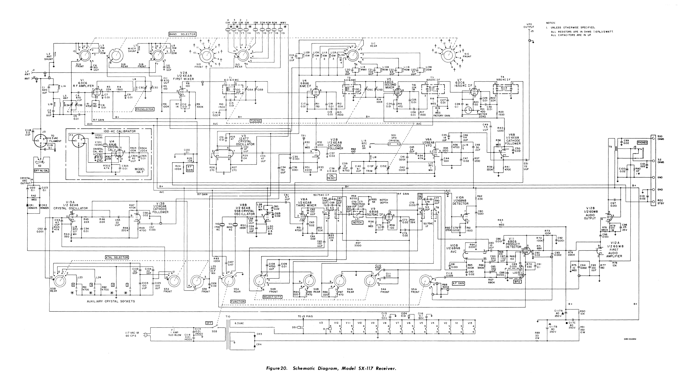
LF
JI
ANT
':
AN
T
>,J..,2'e--T_-'c1-,
VI
6
DC6
L6
,--------------,
r---+-.
'+'
CI;Ol
L1A R F
AMPLIFER
R3
6 22K
R4
I
II
OC
1
1500
~
~1
620
UUF
---,
LIB
1
L5
C4
q1
~B~~:
L.
______
_
J3
UUF~~~---~C~5-1f--1
0.01
AVC
I
-~
1,kC7
2
~0.01
R F GAIN
B+
,kC9
~0.01
IOO-KC
CALIBRATOR
C30
IBAND
V2A
112
6EAS
4 3 2 1
10M
10M 10M
10M
15M
20M
40M
80M
WWV
TI
F I
RSTrM~1
X~E_R_---j:r-_I-
__
--:-i6.
0-6.5
r.:M,-,C'---~r--T---'
R5
61
I~~
't
r
--~-l
II
"-'0_0
__
"-I2~rI-",-,,-lr--'
L IlL
100'
CI5A
'\!7F--
--~!!~'
I CI58
R6
lOOK
-
R7
IK CI2
0.01
R9
330K
2 4 /
RIO
1500
C14~
0.02~
AVC
CI3
/
0.01 I
,
B+
,
ITUNINGI
L
_______________________
_
V4
6SA6
6MCIF
CI5C
CI5D
7
~6
IW
I I F I 2
,=
6
L'
~J3lL.::
I
_-c.!-'_UF, I
;="j'
,
"----+--,r--
I
2
'-'4
-'
, I
~
""3
--
,-.....
I\,
7 3
---"i--'
L
,6'1011[c~I~~M2~'-'0-0'l-I~'I--t----')~:~~\~D
15
i~~
~~65~~tL~Im:-l
1~~g~KC
IF
5
f'~~S-
'RI4
C25
RIB
~
~
b
C29 R22
CI7
RII cia RI2 /
lOOt<
C24{
RI5 0.01
M~G
~
.•
0.011
C28
MI
~52g
001
22K
t--~--+--__1I-1>---'
/
'--t---
.......
--J~-1----'
R~9'"
- + >----r-R21 0.01
0.01
150
0.01
22K
I
0.01
470 0 I V C30
C
19
RI3
"
C26
R
17
MEG
___
J
M~~~R
0.01
1500,
B+
0,01 1500
FACTORY
GAIN
ZERO
- - - - - - - - - - - - - - - - - -
_.1
- - - - - - - - - - - - - -
-'---------
---
7-
A
-Y-C---+--------------C-4-9-,
I
~5
UUF
R23
1500
R40
1200
VFO
OUTPUT
J5
NOTES'
I.
UNLESS OTHERWISE SPECIFIED;
ALL
RESISTORS ARE
IN
OHMS!
IO%,1/2WATT.
ALL
CAPACITORS
ARE
IN
UF
118
2.2
UF
~
o
4 5 6.3VAC
3 FILAMENT
2 I
-----,
~
I~
CR301
IN295'1
I
Y301
VI4
I R28
47
V3
TPI SOl
C45:k
12AT7
~
V2B
YFO
V6A
U'UBF~
, C46
~
5_6
UUF
CRYSTAL
L
15
CRYSTAL
,
L-._-.".t----'O..=S...,CI
LCL3A2
TOR
R(O
~2~0
laT~~~~
~~C
I ,
1/~6ftS.1
R36
ILl8
C48
C31.,kr
0.01
~
V6B
112
6EAS
R38
CATHODE
MkG
FOLLOWER
r;:-
500
r-T
:k-C-g-g------+<:.I
OHMS
l'
0.02
IpHONESl
R42
~
CR
I
CR
2
CI19
0.1
HD6225
HD6225
I
100KC=
6AU6
CRYSTAL 5 R303
R304
g~~s;~
CAW,:...':\6
lOOK
220K
I
1:¥~:g6
R301
~
004
C305 I
.~7~r;
2OK~
~3
1'u~~
tOOl
R302
~
C3.03
L 4.7K : -
1'001
MODEL~I
HA-7
-'-----
---
--
--
---------
=--=---~..j..=---~~~~~---
8+
AYC
VI3A
VI3B
1/26EAS
R47
1/26EAS
CRYSTAL
OS<-'C"""'LL::;:Ac:.T
__
O'--R_+-
___
-.
470K
CATHODE
el20
~1~"
-
R25
10K
R24
i
fRTl
lOOK
~
R F
GAIN
'I
6
47
MEG
I
t--!F'OLLOWER
R92
UH'"
C43
:~~
R35
4700
30
1!?~'~~_---~_~
__
~~7_-+~u,-,U~F
__
+-~I~-~-~~==~--~>-~9~~-:1
,kC37
r-
___
~IOMO~
___
t-
_______
~'
__
~U~~~4F~~-~~~2~~~~3~12~0~0'---4---+-_~
UUF
I..J..
'-1-'
~IJ
R29 C33
r---
05
-=
8
1'002
11
L16
'C41
R34
-.:=-
I
3 8
10K
47 0.001
aool
47K
7
:kC44
C47 R37
UUF
C39,'
LI7
TL_
0
_.
0_
'
....,.._--lTo02
1200
'---
R26
R27
270 270
'---",'""-
--'
VSB
L2S
112
6EAS
0.7
C60
S S B
CRYSTAL
M H
1'0.02
I
C34
g~~,
~i6K
R33 C38
i~
JDF C
;,
0
CI5F
CI5E
;'0402,
F
RiC
l
150
IK
2.3-14.2
N750
UUF
TRIM
MH
UUF
L-----~----~----~----~----
____
~
__________
__1
rcALl
~
C61
4.7
UUF
B+
VBA
1/26
EAS
THIRD
MIXER
5075KCIF1~r-
C66 C67
390
390
UUF
~L
UUF
T5 .
,'~
T6
2
3.3
2
r lUUFr ,
R F GAIN AvC
V
lOA
1/26BNB
DETECTOR
R62
22K
....
1::--
,k,C50
y-+---=9
t
',"___
1'0.02
iF-
R39
220K
R41
4700
C51
22
UUF
T9
OSCILLATOR
9 I
1'C125
1;~~r--16-~-'0-'
~~T'--,-~O-5~-''''~'''¥''-~-+~-.:...f8--L20
0.02
6 I
-::
I
C56~~OLLO'WER
r-+-.-_~--,2~1
;Ec---"3--r-
.....
---_~
.....
_~r--1~9'-
002
~
R45
R46
C55
--=
8
"
,*,C62
6
1"00
2
__
3 UUF
'-=--~'
r---
3~1
i
'3
:.
~
1:..:
C80
0.001
V
12B
1/26GWS
AUDIO
OUTPUT
C53
4.7
UUF
R43
47K
~7
22K
22K
22
~----~I~~~------~
LI9
UUF
RFC
C54
0.7 0.01
R44
MH
R48
220
K
330
t-----+-----------------------4-----'
IXTAL SELECTORl
R49
4700
C57
0.001
KC KC
120
RFC
L..=U,,-UF'-1~_--'
~.~
-'-- C63
'---
0.02
R51
4700
C64
0.02
R52
22K
C65
100
UUF
4 4
R53
22K
IW
R57
3300
R60
C79
270K
0002
VIOB
1/26BNS
AVC
9
R61
1500
R63
I
MEG
R73
lOOK
C86
.,k
V
II
R
72
C92
j
:C83
0001l'
6BE6
lOOK
10.
001
IR64
10
PRODUCT
5 J 9
21
220K.
UUF
DETEC
TOR
7ti
=
~~~,j=b-
V 12 A
1/26GW8
FIRST
AUDIO
AMPLIFIER
r-----------------
CI02
22
UUF
CI04
22
UUF
-------7
---------:
,---~~2
"
('.....
:..
C84
r'o:{~?
R6~r~'yl-t.;'6t"...g-6-~--<>---t-g-.6-5-2--t-:~"'~-6---'K
.------+\2F:-
R83
l~
220
100
15K
...
,t_:-------{J>
lOOK CI07 I 6
UUF
UUF
~I
1:.---+----.
+---"""'R"7"'8------'
'L25
1
047
F
CI08
CI09
CliO
,kC81 R65 R66
C89
r"
.~_;91
R75
C94
C95
R77
12K
/
~Ft
~"
12
I 2 _
SJ'
2
GI,~O
0.01
~;
I l
~~G:O
g'h:
cOlIT.
\'-3----;1
Lrg:.:~:~:·0~0~'~~~~:1'_20_~8_:2_:_3_9_0_K
...
~_~~C~a8-5~_+_,0._5_g_~_'o:I::+_:~-=0==·~_:::=';:-:!:!~:Tlr
330
0.1
~~G
([F}-(0_.00_2
.....
_0_~0_F-;'BO
L23
L24
GJ
R81
[]
~R82
rn
(j]
i-
C103
100
f-J
10
0'
CI05
100
UUF
*T~~47_00~*_T~:~
r4_70_0~*_~j-*~1--~-----'
~
UUF
S3A
FRONT
~
'
3
C106
'O
/ 0 3
~8·
/
~'
/
~r-'--
,'4
R88
IAF
GAINI
~:6K
~,j..'
IBF;j
lB.
7
S'8
JO.02
4
~L:'
4
51
--"
/ S5A ' 6
S4B
7
S48
7
S4A
'S4A
S5A
: 5
500K
FRONT I REAR I FRONT
R64
I Ra5 REAR RSS I RS7 REAR /
fRONT
FRONT / T
" , ISELECT1VIT't'1
220,
470
220
"
470,/
/
fr-4--+-~
AUXILIARY
CRYSTAL
SOr:KETS
I IFUNCTION I
~
- - - - - - -
--
- - - - - - - -
~
- - - - - - - - - - -
_L
- - - - - - - - - - - J ,
'---------------------------t---------'
B+
117
VAC
10
60
CP
S
f - -- - - - - - - - - - - - - - - - - - - - - - - - - - - - - -- - - - - - - - - - - - - - - - - - - - - - - - - - - - - - - - - - - - - - - - - - - -
__
J
6.3VAC
r-------~F~,
-----To
I
CC"II'3---r
0-----,
I
AMP
'tP>i8bv
S5B
SLO-BLOW
CII4
~
1~c?6VT
~
1
L,
f"'
L.C
_____
__'~
CR4
Figure
20.
Schematic
Diagram,
Moclel SX-117
Receiver.
4
<
3
V2 VI
4
VI3
4J
51
R89
33
2W
CI17A
-R90
60
...
10K
250V
-
C
1178
80
250Y
• CII7C
80
250V
R91
350
lOW
B+
B+
c~to
6~t~
3.2
OHMS
GNO
REC
STBY
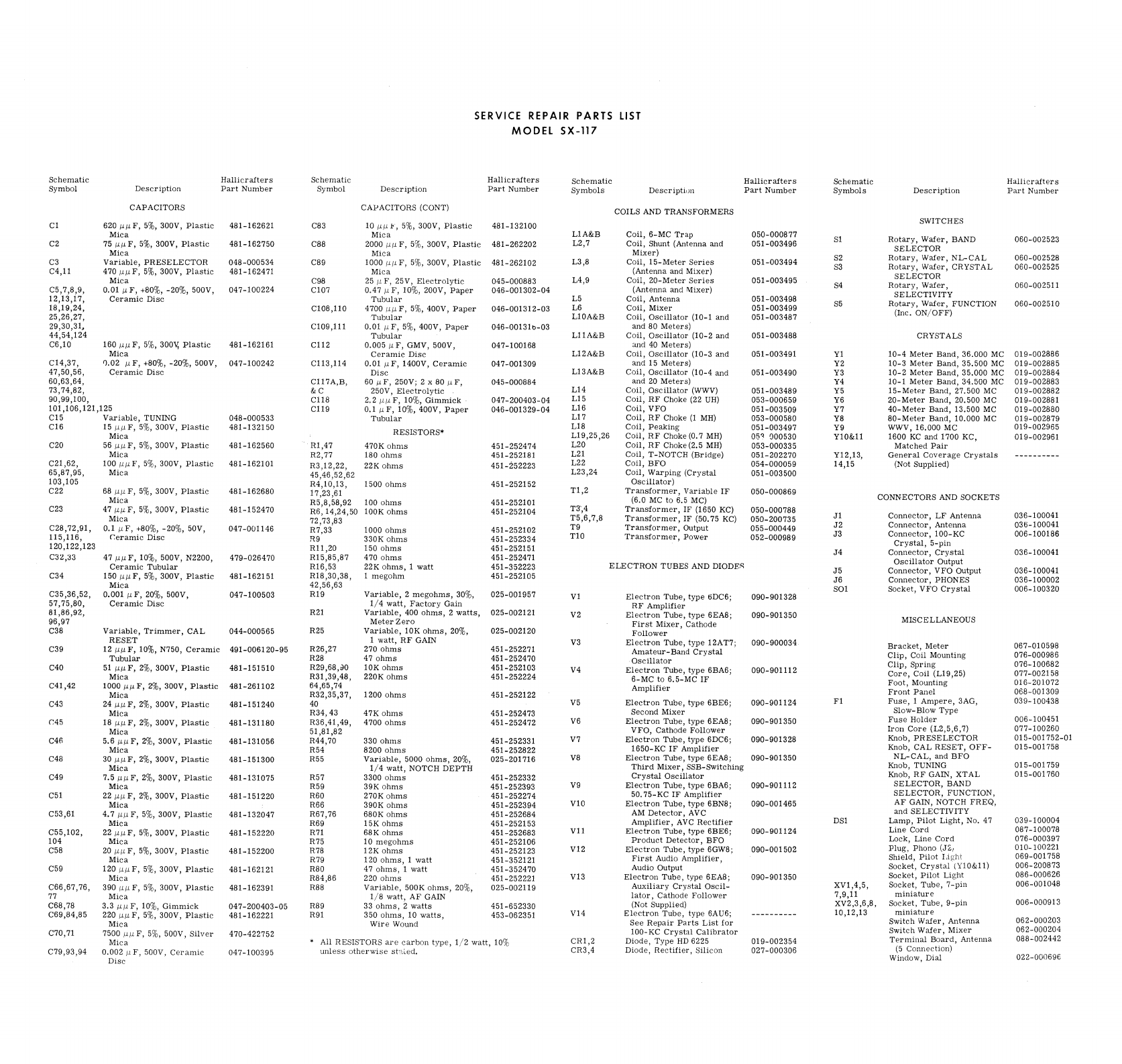
SERVICE REPAIR PARTS
LIST
MODEL
SX-117
Schematic
Hallicrafters
Schematic
Hallicraiters
Schematic
Hallicrafters
Schematic
Hallicrafters
Symbol
Description
Part
Number
Symbol
Description
Part
Number
Symbols
Descripti()Jl
Part
Number
Symbols
Description
Part
Number
CAPACITORS
CAPACITORS
(CONT)
COILS
AND
TRANSFORMERS
CI
6201111
F,
5%,
300V,
Plastic
481-162621
C83 10
/ljll",
5%,
300V,
Plastic
481-132100
SWITCHES
Mica
Mica
LIA&B
Coil,
6-MC
Trap
050-000877
C2
751111
F,
5%, 300V,
Plastic
481-162750
C88
2000
J.111
F,
5%,
300V,
Plastic
481-262202
L2,7
Coil,
Shunt
(Antenna
and
051-003496
SI
Rotary,
Wafer
J
BAND
060-002523
Mica
Mica
Mixer)
SELECTOR
C3
Variable,
PRESELECTOR
048-000534
C89
1000/1/1
F,
5%,
300V,
Plastic
481-262102
L3,8
Coil,
15-Meter
Series
051-003494
S2
Rotary,
Wafer,
NL-
CAL
060-002528
C4,11
470
I1I1F, 5%,
300V,
Plastic
481-162471
Mica
(Antenna
and
MIxer)
S3
Rotary
J
Wafer
J
CRYSTAL
060-002525
Mica
C98 25
,/1
F,
25 V,
Electrolytic
045-000883
L4,9
Coil,
20-Meter
Series
051-003495
SELECTOR
C5,7,8,9,
O,OII1F,
+80%,
-20%,
500V,
047-100224
CI07
0,4711
F,
10%, 200V,
Paper
046-001302-04
(Antenna
and
Mixer)
S4
Rotary,
Wafer,
060-002511
12,13,17,
Ceramic
Disc
Tubular
L5
Coil,
Antenna
051-003498
SELECTIVITY
18,19,24,
CI08,110
4700
11ll
F,
5%,
400V,
Paper
046-001312-03
L6
Coil,
Mixer
051-003499
S5
Rotary,
Wafer,
FUNCTION
060-002510
25,26,27,
Tubular
LlOA&B
Coil,
Oscillator
(10-1
and
051-003487
(Inc,
ON/OFF)
29,30,31,
CI09,111
0,01 it
F,
5%,
400V,
Paper
046-0013Ib-03
and
80
Meters)
44,54,124
Tubular
L11A&B
Coil,
Oscillator
(10-2
and
051-003488
CRYSTALS
C6,10
1601111
F,
5%, 300Y,
Plastic
481-162161
CI12
0,005I1F,
GMV,
500V,
047-100168
and
40
Meters)
Mica
Ceramic
Disc
LI2A&B
Coil,
Oscillator
(10-3
and
051-003491
YI
10-4
Meter
Band,
36,000
MC
019-002886
CI4,37,
0,02
11
F,
+80%,
-20%,
500V,
047-100242
C113,114
0,01
)l
F,
1400V,
Ceramic
047-001309
and
15
Meters)
Y2
10-3
Meter
Band,
35,500
MC
019-002885
47,50,56,
Ceramic
Disc
Disc
LI3A&B
Coil,
Oscillator
(10-4
and
051-003490
Y3
10-2
Meter
Band,
35,000
MC
019-002884
60,63,64,
CI17A,B,
60
11
F,
250V; 2 x
80
11
F,
045-000884
and
20
Meters)
Y4
10-1
Meter
Band,
34,500
MC
019-002883
73,74,82,
&C
250V,
Electrolytic
Ll4
Coil,
Oscillator
(WWV)
051-003489
Y5
15-Meter
Band,
27,500
MC
019-002882
90,99,100,
C11B 2.2
/-L{.1
F,
10%,
Gimmick
047-200403-04
L15
Coil,
RF
Choke
(22
UH)
053-000659
Y6
20-Meter
Band,
20,500
MC
019-002881
101,106,121,125
CI19
0,111
F,
10%,
400V,
Paper
046-001329-04
Ll6
Coil,
VFO
051-003509
Y7
40-Meter
Band,
13,500
MC
019-002880
CI5
Variable,
TUNING
048-000533
Tubular
Ll7
Coil,
RF
Choke
(I MH)
053-000580
Y8
80-Meter
Band,
10.000
MC
019-002879
CI6
151111
F,
5%,
300V,
Plastic
481-132150
Ll8
Coil,
Peaking
051-003497
Y9 WWV,
16,000
MC
019-002965
RESISTORS'
Mica
LI9,25,26
Coil,
RF
Choke (0,7 MH)
05'
000530
YIO&l1
1600
KC
and
1700
KC,
019-002961
C20
561111
F,
5%, 300V,
Plastic
481-162560
RI,47
470K
ohms
451-252474
L20
Coil,
RF
Choke
(2.5 MH)
053-000335
Matched
Pair
Mica
R2,77
180
ohms
451-252181
L21
Coil,
T-NOTCH
(Bridge)
051-202270
YI2,13,
General
Coverage
Crystals
----------
C21,62,
1001111
F,
5%,
300V,
Plastic
481-162101
R3,12,22,
22K
ohms
451-252223
L22
Coil,
BFO
054-000059
14,15
(Not
Supplied)
65,87,95,
Mica
45,46,52,62
L23,24
Coil,
Warping
(Crystal
051-003500
103,105
R4,10,13,
1500
ohms
451-252152
Oscillator)
C22 681111F, 5%, 300V,
Plastic
481-162680
17,23,61
TI,2
Transformer,
Variable
IF
050-000869
Mica
R5,8,58,92
100
ohms
451-252101
(6,0
MC
to
6.5 MC)
CONNECTORS
AND
SOCKETS
C23
471111
F,
5%,
300V,
Plastic
481-152470
R6,14,24,50
lOOK
ohms
451-252104
T3',4
Transformer,
IF
(1650 KC)
050-000788
Mica
72,73,83
T5,6,7,8
Transformer,
IF
(50.75 KC)
050-200735
JI
Connector,
LF
Antenna
036-100041
C28,72,91,
0,111
F,
+80%,
-20%,
50V,
04'7-001146
R7,33
1000
ohms
451-252102
T9
Transformer,
Output
055-000449
J2
Connector,
Antenna
036-100041
115,116,
r:eramic
Disc
R9
330K
ohms
451-252334
TI0
Transformer,
Power
052-000989
J3
Connector,
lOO-KC
006-100186
120,122,123
R11 ,20 150
ohms
451-252151
Crystal,
5-pin
C32,33
471111
F,
10%, 500V,
N2200,
479-026470
RI5,85,87
470
ohms
451-252471
J4
Connector,
Crystal
036-100041
Ceramic
Tubular
R16,53 22K
ohms,
1
watt
451-352223
ELECTRON
TUBES
AND DIODE,q
Oscillator
Output
C34 1501111
F,
5%,
300V,
Plastic
481-162151
RI8
,30,38,
1
megohm
451-252105
J5
Connector,
VFO Output
036-100041
Mica
42,56,63
J6
Connector,
PHONES
036-100002
C35,36,52,
O,OOII1F, 20%, 500V,
047-100503
RI9
Variable,
2
megohms,
30%,
025-001957
SOl
Socket,
VFO
Crystal
006-100320
57,75,80,
Ceramic
Disc
1/4
watt,
Factory
Gain
VI
Electron
Tube,
type
6DC6;
090-901328
RF
Amplifier
81,86,92,
R21
Variable,
400
ohms,
2
watts,
025-002121
V2
Electron
Tube,
type
6EA8;
090-901350
96,97
Meter
Zero
Fir
st
Mixer,
Cathode
MISC E LLAl'IEOUS
C38
Variable,
Trimmer,
CAL
044-000565
R25
Variable,
10K
ohms,
20%,
025-002120
Follower
RESET
I
watt,
RF
GAIN V3
Electron
Tube,
type
12AT7;
090-900034
C39 12
1111
F,
10%, N750,
Ceramic
491-006120-95
R26,27
270
ohms
451-252271
Amateur-Band
Crystal
Bracket,
Meter
067-010598
Tubular
R28 47
ohms
451-252470
Oscillator
Clip,
Coil
Mounting
076-000986
C40
51
1111
F,
2%,
300V,
Plastic
481-151510
R29,68,ilO
10K
ohms
451-252103
V4
Electron
Tube,
type
6BA6;
090-901112
Clip,
Spring
076-100682
Mica
R31,39,48,
220K
ohms
451-252224
6-MC
to
6.5-MC
IF
Core,
Coil
(Ll9,25)
077-002158
C41,42
10001111
F,
2%,
300V,
Plastic
481-261102
64,65,74
Amplifier
Foot,
Mounting
016-201072
Mica
R32,35,37,
1200
ohms
451-252122
Front
Panel
068-001309
C43
241111
F,
2%,
300V,
Plastic
481-151240
40 V5
Electron
Tube,
type
6BE6;
090-901124
FI
Fuse,
1
Ampere,
3AG,
039-100438
Mica
R34,43
47K
ohms
451-252473
Second
Mixer
Slow-Blow
Type
r45
18 I1I1F,
2%,
300V,
Plastic
481-131180
R36,41,49,
4700
ohms
451-252472
V6
Electron
Tube,
type
6EAB;
090-901350
Fuse
Holder
006-100451
Mica
51,81,82
VFO,
Cathode
Follower
Iron
Core
(L2,5,6,7)
077-100260
C4B
5,611I1F,
2%,
300V,
Plastic
481-131056
R44,70
330
ohms
451-252331
V7
Electron
Tube,
type
6DC6;
090-901328
Knob,
PRESELECTOR
015-001752-01
Mica
R54
8200
ohms
451-252822
1650-KC
IF
Amplifier
Knob,
CAL
RESET,
OFF-
015-001758
C48 30 I1I1F, 2%,
300V,
Plastic
481-151300
R55
Variable,
5000
ohms,
20%,
025-201716
V8
Electron
Tube,
type
6EA8;
090-901350
NL-CAL,
and
BFO
Mica
1/4
watt,
NOTCH
DEPTH
Third
Mixer,
SSB-Switching
Knob, TUNING
015-001759
C49 7,5
ill1F,
2%,
300V,
Plastic
481-131075
R57
3300
ohms
451-252332
Crystal
Oscillator
Knob,
RF
GAIN,
XTAL
015-001760
Mica
R59
39K
ohms
451-252393
V9
Electron
Tube,
type
6BA6;
090-901112
SELECTOR,
BAND
C51
221111
F,
2%,
300V,
Plastic
481-151220
R60
270K
ohms
451-252274
50,
75-KC
IF
Amplifier
SELECTOR,
FUNCTION,
Mica
R66
390K
ohms
451-252394
VIO
Electron
Tube,
type
6BNB;
090-001465
AF
GAIN,
NOTCH
FREQ,
C53,61
4.7
1111
F,
5%,
300V,
Plastic
481-132047
R67,76
680K
ohms
451-252684
AM
Detector,
AVC
and
SELECTIVITY
Mica
R69
15K
ohms
451-252153
Amplifier,
AVe
Rectifier
DSI
Lamp,
Pilot
Light,
No, 47
039-100004
C55,102,
22
/lI1F,
5%,
300V,
Plastic
481-152220
R71
68K
ohms
451-252683
V11
Electron
Tube,
type
6BE6;
090-901124
Line
Cord
087-100078
104
Mica
R75 10
megohms
451-252106
Product
Detector,
BFO
Lock,
Line
Cord
076-000397
C58
201111
F,
5%,
300V,
Plastic
481-152200
R78
12K
ohms
451-252123
VI2
Electron
Tube,
type
6GW8;
090-001502
Plug,
Phono
(J~I
010-100221
Mica
R79 120
ohms,
I
watt
451-352121
First
Audio
Amplifier,
Shield,
Pilot
I,ighT
069-001758
C59 1201111
F,
5%,
300V,
Plastic
481-162121
R80
47
ohms,
1
watt
451-352470
Audio
Output
Socket,
Crystal
(YlO&l1)
006-200873
Mica
R84,86
220
ohms
451-252221
VI3
Electron
Tube,
type
6EAB;
090-901350
Socket,
Pilot
Light
086-000626
C66,67,76,
390/111
F,
5%,
300V,
Plastic
481-162391
R88
Variable,
500K
ohms,
20%,
025-002119
Auxiliary
Crystal
Oscil-
XVl,4,5,
Socket,
Tube,
7-pin
006-001048
77
Mica
1/8
watt,
AF
GAIN
lator,
Cathode
Follower
7,9,11
miniature
C68,78
3.3
!J./J.
F,
10%,
Gimmick
047-200403-05
R89 33
ohms,
2
watts
451-652330
(Not
Supplied)
XV2,3,6,8,
Socket,
Tube,
9-pin
006-000913
C69,84,85
2201111
F,
5%,
300V,
Plastic
481-162221
R91
350
ohms,
10
watts,
453-062351
VI4
Electron
Tube,
type
6AU6; ----------
10,12,13
miniature
Mica
Wire
Wound
See
Repair
Parts
List
for
Switch
Wafer,
Antenna
062-000203
C70,71 75001111
F,
5%,
500V,
Silver
470-422752
100-KC
Crystal
Calibrator
Switch
Wafer,
Mixer
062-000204
Mica
* All
RESISTORS
are
carbon
type,
1/2
watt,
10%
CRI,2
Diode,
Type
HD
6225
019-002354
Terminal
Board,
Antenna
088-002442
C79,93,94
0,002
II
F,
SOOV,
Ceramic
047-100395
unless
otherwise
st"i.ed.
CR3,4
Diode,
Rectifier,
Silicon
027-000306
(5
Connection)
Disc
Window,
Dial
022-000696

094.903123C
1168
Printed
in
U.S.A.
