100 Series Instruction Manual Rev S (7.24.18)
User Manual:
Open the PDF directly: View PDF ![]() .
.
Page Count: 108 [warning: Documents this large are best viewed by clicking the View PDF Link!]

Sierra Instruments Instruction Manual SmartTrak® 100 Series
1
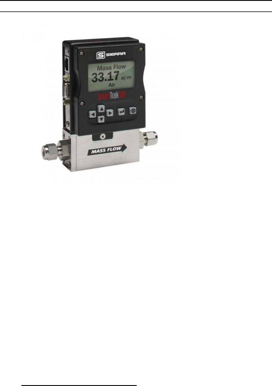
SmartTrak® Series 100
Mass Flow Meters and Controllers
Models: C100, M100, 100 HP, C101, M101, C140
Instruction Manual
IM-100, Revision: S
August 2018

Sierra Instruments Instruction Manual SmartTrak® 100 Series
2
Global Support
CORPORATE HEADQUARTERS
5 Harris Court, Building L Monterey, CA 93940
Phone (831) 373-0200 (800) 866-0200 Fax (831) 373-4402
www.sierrainstruments.com
EUROPE HEADQUARTERS
Bijlmansweid 2 1934RE Egmond aan den Hoef
The Netherlands
Phone +31 72 5071400 Fax +31 72 5071401
ASIA HEADQUARTERS
Second Floor Building 5, Senpu Industrial park
25 Hangdu Road Hangtou Town
Pu Dong New District
Shanghai, P.R. China Post Code 201316
Phone: + 8621 5879 8521 Fax: +8621 5879 8586
IMPORTANT CUSTOMER NOTICE: OXYGEN SERVICE
Sierra Instruments, Inc. is not liable for any damage or personal injury, whatsoever, resulting from the use of Sierra
Instruments standard mass flow meters or controllers for oxygen gas. You are responsible for determining if this mass
flow meter or controller is appropriate for your oxygen application. You are responsible for cleaning the mass flow
meter or controller to the degree required for your oxygen flow application.
© COPYRIGHT SIERRA INSTRUMENTS 2016
No part of this publication may be copied or distributed, transmitted, transcribed, stored in a retrieval system, or
translated into any human or computer language, in any form or by any means, electronic, mechanical, manual, or
otherwise, or disclosed to third parties without the express written permission of Sierra Instruments. The information
contained in this manual is subject to change without notice.
TRADEMARKS
SmartTrak® 100 Series and Dial-A-Gas® is a Registered Trademark of Sierra Instruments, Inc. Other product and
company names listed in this manual are trademarks or trade names of their respective manufacturers.
SMART-TRAK® 2 NAME CHANGE
Please note that the family name of the Smart-Trak Series has been renamed from Smart-Trak® 2 to SmartTrak® 100
Series. It is the same great product, but with a new look (label).

Sierra Instruments Instruction Manual SmartTrak® 100 Series
3
Table of Contents
Chapter 1: Introduction ..................................................................................................... 5
Welcome to the future of gas flow measurement! ................................................................. 5
Using This Manual ................................................................................................................. 5
Safety Information .................................................................................................................. 6
Receipt of your instrument ..................................................................................................... 7
The SmartTrak Flow Sensing Principle ................................................................................. 9
Chapter 2: Installation ...................................................................................................... 11
Before You Begin Installation .............................................................................................. 11
Pre-Installation Check List ................................................................................................... 11
Installing the Instrument—Plumbing ................................................................................... 12
Compression Fittings ............................................................................................................ 13
VCO Fittings ........................................................................................................................ 13
VCR Fittings ......................................................................................................................... 13
1/4 Inch Female NPT ........................................................................................................... 14
Installing your Instrument—Mechanical Mounting ............................................................. 14
Installing your Instrument—Electrical Connections ............................................................ 15
Figure 2-3: HD DB-15 Connector Pin Configuration (on the instrument) .......................... 17
Figure 2-4: Wiring Definitions for Optional Communication Cable ................................... 17
Figure 2-5: Power Supply Requirements ............................................................................. 18
Chapter 3: Analog Operation ......................................................................................... 21
Analog Operation, Mass Flow Controller ............................................................................ 22
SmartTrak Features .............................................................................................................. 23
Setpoint Adjustment ............................................................................................................. 23
Changing the Output or Setpoint Signals ............................................................................. 23
Over-Range Condition ......................................................................................................... 23
Manual Valve Override—Valve Close ................................................................................ 23
Manual Valve Override—Valve Purge Function ................................................................. 24
Important Notes About Purging ........................................................................................... 24
Purging Non-Reactive Gases: .............................................................................................. 24
Purging Reactive Gases: ....................................................................................................... 24
Chapter 4: Digital Operation with Pilot Module ........................................................... 26
Introduction to Pilot Module Features and Capabilities ....................................................... 26
Pilot Module Operation, Mass Flow Meters ........................................................................ 29
Pilot Module Operation, Mass Flow Controllers: ................................................................ 30
Making Changes Using the Lower Level Screens: ...................................................................... 37

Sierra Instruments Instruction Manual SmartTrak® 100 Series
4
Lost Passwords and General Customer Service: ........................................................................ 47
Chapter 5: Digital Operation RS-232 & SmartTrak Software ................................... 47
Power Up Your Instrument ................................................................................................. 47
Power Up Your Computer ................................................................................................... 50
Loading the SmartTrak Software ........................................................................................ 50
Connecting SmartTrak to Your Computer .......................................................................... 51
If your computer has a serial port… ..................................................................................... 50
If your computer has no serial port, but has a USB port… .................................................. 51
If you plan to control more than one SmartTrak instrument from your computer… ........... 52
Running The SmartTrak Software ....................................................................................... 53
Chapter 6: Technical Support & Service ...................................................................... 68
Factory Calibration—All Models ......................................................................................... 69
Instructions for Returning Your Instrument for Service ...................................................... 69
Appendix A: C100 & M100 SmartTrak® Product Specs, Dimensions and Mounting
Appendix B: C101 & M101 Ultra-Low Flow Product Specs, Dimensions and Mounting
Appendix C: C140M Ultra-Low ΔP Product Specs, Dimensions and Mounting
Appendix D: 100HP Ultra-High Pressure Product Specs, Dimensions and Mounting
Appendix E: High Pressure Safety Guide for the 100HP
Appendix F: Gas Tables & K-Factors (ALL 100 Series)
Appendix G: Flow Chart for Pilot Module User Interface (ALL 100 Series)
Appendix H: PIN Configuration (ALL 100 Series)
Appendix I: SmartTrak Basic Commands (ALL 100 Series)
Appendix J: Warranty Policy

Sierra Instruments Instruction Manual SmartTrak® 100 Series
5
CHAPTER 1: INTRODUCTION
Welcometothefutureofgasflowmeasurement!
This manual is your guide to SmartTrak. Visit the Sierra Instruments website
www.sierrainstruments.com any time for more information about this product.
The SmartTrak instruments offer a variety of features for ease of operation. Among these
features:
Dial-A-Gas®: allows a user to change from among 10 gases while maintaining
accuracy.
The Optional Pilot Module: control electronics that offers both display and control
options at the user’s fingertips.
Digital Electronics: maximum performance with minimum noise plus exceptional
tuning capability.
Choice of Analog Communications Options and RS-232 with every SmartTrak
instrument.
Flexible Design with many functions that can be re-configured on-site by the user.
Compact Footprint that allows SmartTrak to fit almost anywhere.
Wide range of sizes for gas flow from 0.1 sccm to 1400 slpm.
And many more
Using This Manual
This manual is organized into six chapters:
Chapter 1: Introduction and Theory of Operation.
Chapter 2: Installation, Plumbing & Wiring instructions.
Chapter 3: Analog Operation.
Chapter 4: Digital Operation with the Optional Pilot Module.
Chapter 5: Digital Operation with RS-232 & SmartTrak Software.
Chapter 6: Technical Support and Service.
Appendix A,B,C,D,E,F,G,H,I,J
Throughout this manual, we use the word instrument as a generic term to represent all
models of Sierra Instruments’ SmartTrak Series 100 mass flow meters and
controllers.
Sierra Instruments Instruction Manual SmartTrak® 100 Series
6
SAFETY INFORMATION
Caution and warning statements are used throughout this book to draw your attention to
important information.
Warning!
Caution!
This statement appears with information that
is important to protect people and equipment
from damage. Pay very close attention to all
warnings that apply to your application.
This statement appears with information that is
important for protecting your equipment and
performance. Read and follow all cautions that
apply to your application.

Sierra Instruments Instruction Manual SmartTrak® 100 Series
7
RECEIPT OF YOUR INSTRUMENT
When receiving the instrument, carefully check the outside packing carton for damage that
may have incurred during shipment. If the carton is damaged, notify the local carrier and
submit a report to the factory or distributor. Remove the packing slip and check that all
ordered components are present and match your specifications (as ordered). Make sure
any spare parts or accessories are not discarded with the packing material. Do not return
any equipment to the factory without first contacting one of Sierra’s Technical Support
Centers:
USA (Headquarters) Customer Service:
TOLL FREE: 800-866-0200
PHONE: 831-373-0200
FAX: 831-373-4402
EMAIL: service@sierrainstruments.com
European Customer Service:
PHONE: +31 72 5071400
FAX: +31 72 5071401
EMAIL: service@sierra-instruments.nl
Asia Customer Service:
PHONE: + 8621 5879 8521
FAX: +8621 5879 8586
EMAIL: www.sierra-asia.com
Sierra Instruments Instruction Manual SmartTrak® 100 Series
8
DEFINITIONS USED IN THIS MANUAL
The following terms are used frequently in this manual. They are presented here with
their definitions for your information.
Setpoint—The command or control signal supplied to a flow controller is called its
setpoint. The controller will maintain the flow at this value.
Full scale—The highest flow that an instrument will meter within its specified accuracy.
It is often possible for an instrument to measure a flow beyond its full scale value, but the
accuracy of this measurement may be outside of published specifications.
Purge—The SmartTrak Mass Flow Controller is supplied with the ability to open the
valve far beyond the full scale position to allow them to be cleaned. This is usually
accomplished by blowing clean, dry nitrogen through the instrument. When the valve is
opened to this cleaning position, it is said to be in the Purge mode.
LFE—Laminar Flow Element (LFE) or bypass generates pressure drop forcing a small
fraction of the total flow to pass through the sensor capillary tube.
Sierra Instruments Instruction Manual SmartTrak® 100 Series
9
THE CAPILLARY THERMAL OPERATING PRINCIPLE
Watch Video: www.sierrainstruments.com/CapPrinciple.
The operating principle of the SmartTrak instruments is based on heat transfer and the first
law of thermodynamics. During operation process gas enters the instrument’s flow body
and divides into two flow paths, one through the sensor tube, and the other through the
laminar flow bypass. The laminar flow bypass (often called LFE which stands for
“laminar flow element”) generates a pressure drop, P1–P2, forcing a small fraction of the
total flow to pass through the sensor tube (m1).
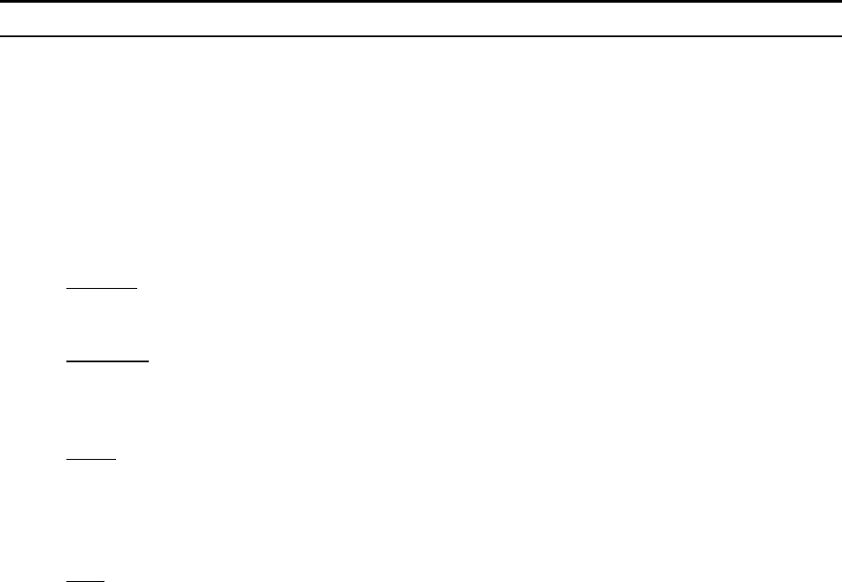
Figure 1-1. Flow Paths through the Instrument
Two resistance temperature detector (RTD) coils around the sensor tube direct a constant
amount of heat (H) into the gas stream. During operation, the gas mass flow carries heat
from the upstream coil to the downstream coil. The resulting temperature difference (∆T)
is measured by the SmartTrak microprocessor. From this, SmartTrak calculates the output
signal. Since the molecules of the gas carry away the heat, the output signal is linearly
proportional to gas mass flow.
Figure 1-2. Flow Measuring Principle
Sierra Instruments Instruction Manual SmartTrak® 100 Series
10
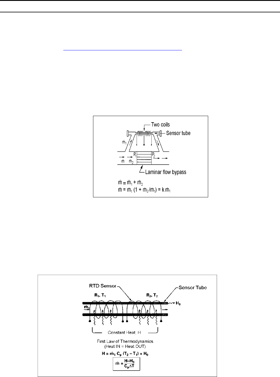
Figure 1-3. Sensor Temperature Distribution
Figures 1-2 and 1-3 show the mass flow through the sensor tube as inversely proportional to
the temperature difference of the coils. The coils are legs of a bridge circuit with an output
voltage in direct proportion to the difference in the coils’ resistance; the result is the
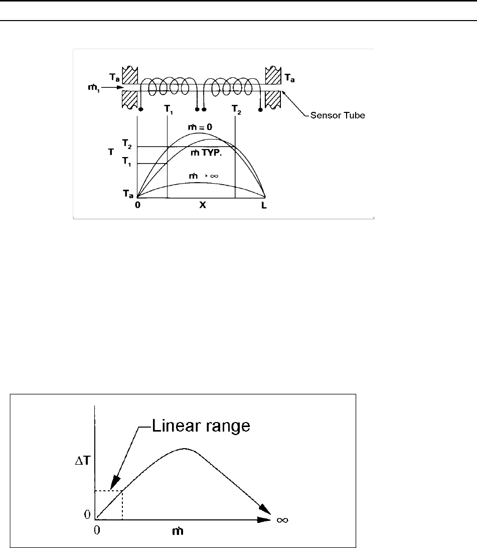
temperature difference (∆T). Two other parameters, heat input (H) and coefficient of
specific heat (Cp) are both constant. Through careful design and attention to these
parameters, this output signal is made linear over the transducer’s normal operating range
(Figure 1-4). As a result, the measured flow through the sensor tube is directly proportional
to the gas flow in the main body.
Figure 1-4. Linear Range of the Transducer’s Output Signal
In the SmartTrak mass flow controllers, the gas which flows through the monitoring
section is precisely regulated by the built-in electromagnetic valve. The normally closed
valve is similar to an on/off solenoid valve, except that the current to the valve coil, and
hence the magnetic field, is modulated so that the ferromagnetic valve armature, or valve
plug, assumes the exact height above the valve’s orifice required to maintain the valve’s
command flow (set point). The result is excellent resolution.
Sierra Instruments Instruction Manual SmartTrak® 100 Series
11
CHAPTER 2 INSTALLATION
Before You Begin Installation
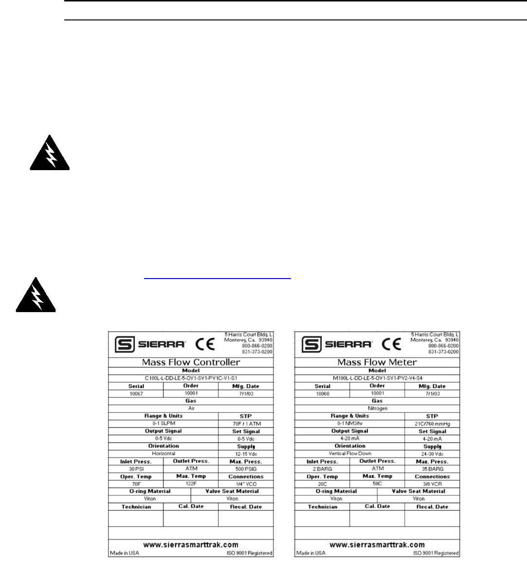
Before installing the instrument, ensure that the installation site conforms to the specific
operating parameters recorded on the instrument’s Data Label. The Data Label is mounted
on the back of the instrument electronics enclosure (see sample Data Labels in Figure: 2-
1). This is critical because each instrument is configured for a specific application range.
Please review the gas or gases, the mounting orientation, the maximum flow range(s), the
inlet and outlet pressure(s), and the operating temperature(s). The line pressure should not
exceed 500 psig (34 barg) except for SmartTrak100 High Pressure version instruments
(refer to Appendix D). The temperature should not exceed 122°F (50°C). The minimum
operating temperature is 32°F (0°C) and ambient temperature is 0-50°C. If your
application exceeds any of these parameters, contact your Sierra Sales Agent before
installation. You may also contact one of Sierra’s Technical Support Centers. FACTORY
USA: TOLL FREE: 800-866-0200 or PHONE: 831-373-0200 or FAX: 831-373-4402 or
EMAIL: service@sierrainstruments.com
Figure 2-1: Examples of SmartTrak Data Labels
Pre-Installation Check List
1. Double-check to be sure that the O-ring material used in your instrument is
compatible with the gas to be measured. The O-ring material used in your
Warning!
Injury can result if line
pressure exceeds the
maximum rating of
500 psig (34 barg)
for standard
SmartTrak 100.
Warning!
If installing a
SmartTrak 100 HP,
read Appendix E:
SmartTrak 100 High
Pressure Version
Safe Use before
installing instrument.
Warning!
Injury can result if line
pressure exceeds the
maximum rating of
5000 psig (345 barg)
when using the
SmartTrak 100 High
Pressure.

Sierra Instruments Instruction Manual SmartTrak® 100 Series
12
SmartTrak can be found in the Data Label. See Appendix A for a table of elastomer
compatibility with a wide variety of gases.
2. Sierra strongly recommends you install an in-line filter upstream of the
instrument. Recommended filter size: 10 micron. A 10 micron filter is available
from Sierra as an accessory. See Appendix B or contact your local Sierra
distributor.
3. Do not locate the instrument in areas subject to sudden temperature changes,
excessive moisture or near equipment radiating significant amounts of heat.
Be sure to allow adequate space for cable connectors and wiring.
4. For controllers, use a properly sized pressure regulator. Make sure the pressure
regulator is not too small or too big. There can be no restrictions (such as valves,
tubing or pipe internal diameters, reducers, etc.) upstream or downstream of the
controller with a dimension that is less than the valve orifice diameter. To
determine orifice diameter, consult the calibration certificate included with your
instrument. If restricted, controller will not reach full scale.
5. Output Signals: The SmartTrak has two analog outputs that are linearly
proportional to the gas mass flow rate, one voltage and one current. Choose from 0-
20 mA or 0/0/4-20 mA for current plus one voltage signal: 0-5 VDC or 0-10 VDC
or 1-5 VDC. The output signals specified at time of order will be indicated on the
data label. You may change among the current and the voltage output signal at
your discretion after receipt of the instrument using the Pilot Module or the
SmartTrak Software (see Chapters 4 & 5). Changing the output signals has no
influence on the instrument’s accuracy.
NOTE: For the SmarTrak 100 plus Compod, the 0-5 VDC I/O cannot be used. Only
0/4-20 mA I/O is available.
6. The CAT-5 connector on the side of the SmartTrak is NOT an Ethernet connector.
It is for use with the optional Remote Pilot Module. Do not plug an Ethernet cable
here as damage may result. Keep this connector covered if possible whenever it is
not in use.
7. The instrument has specific power supply requirements. See the table later in
this chapter for a complete listing of power requirements.
Installing the Instrument—Plumbing
SmartTrak instruments are supplied with compression, VCO®, VCR®, or female NPT
process connections. To ensure a successful installation, inlet and outlet tubing should be
clean prior to plumbing the instrument into the system. The shipping caps covering the
inlet/outlet fittings should not be removed until immediately before installation.
Sierra Instruments Instruction Manual SmartTrak® 100 Series
13
Follow the installation instructions that are applicable to your instrument’s process
connection. Ensure that the tubing is free from burrs or sharp rims that may result from
cutting.
CAUTION: Before use, all plumbing should be checked carefully for leaks, especially
at the connecting fittings. All instruments are leak-tested prior to shipping. It is not a
requirement to leak test your instrument. Do not use liquid leak detectors such as
Snoop® to search for leaks inside or outside the SmartTrak. Instead, monitor pressure
decay.
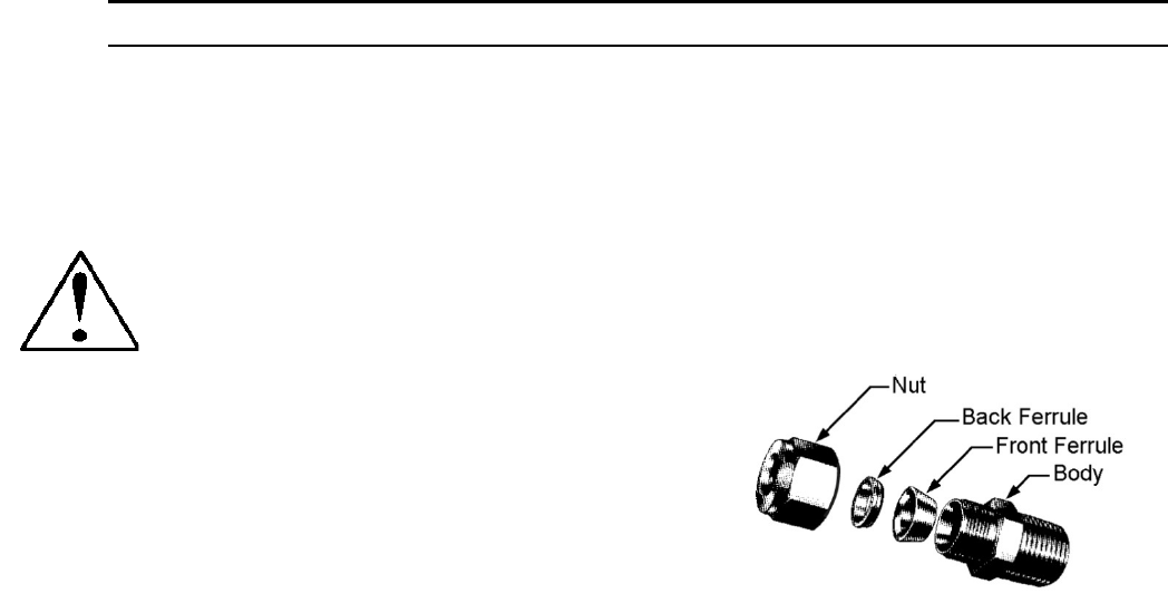
Compression Fittings
1. Position the instrument with the flow
direction arrow pointing in the direction
of flow.
2. Verify the position of the front and back ferrule. Insert the tubing into the fitting.
Be sure that the tubing rests firmly on the shoulder of the fitting and that the nut is
finger-tight. Scribe the nut at the six o’clock position.
3. While holding the fitting body steady with a backup wrench, tighten the nut 1-1/4
turns, watching the scribe mark make one complete revolution and continue to the
nine o’clock position. For 1/16-inch, 1/8-inch and 3/16-inch (2, 3 and 4 mm) sizes,
tighten only 3/4 turns from finger-tight. Do not over-tighten!
4. If you use flexible tubing (Example: Polyflow) use an “Insert” (see
www.swagelok.com)
5. Check the system’s entire flow path thoroughly for leaks. Do not use liquid leak
detectors. Instead, monitor pressure decay. Exposing the instrument to leak
detector fluid may cause damage.
VCO Fittings
1. Position the instrument with the flow direction arrow pointing in the direction of
flow.
2. Tighten the nut finger-tight, and then 1/8 turn tighter with a wrench. Do not over-
tighten!
3. Check the system’s entire flow path thoroughly for leaks. Do not use liquid leak
detectors. Instead, monitor pressure decay. Exposing the instrument to leak
detector fluid may cause damage.
VCR Fittings

Sierra Instruments Instruction Manual SmartTrak® 100 Series
14
1. Position the instrument with the flow direction arrow pointing the direction of
flow.
2. Install new gaskets that are compatible with the gas to be used.
3. Tighten the nut finger-tight, and then 1/8 turn tighter with a wrench. Do not over-
tighten!
4. Check the system’s entire flow path thoroughly for leaks. Do not use liquid leak
detectors. Instead, monitor pressure decay. Exposing the instrument to leak
detector fluid may cause damage.
1/4InchFemaleNPT
1. Position the instrument with the flow direction arrow pointing the direction of
flow.
2. Apply high quality Teflon tape to the male NPT fitting. Alternatively, use a high
quality paste pipe thread sealant suitable for the application and gas, and apply this
compound to the inlet and outlet fittings. Avoid getting the tape or the thread
sealant onto the first two threads to keep it out of your process gas.
3. Tighten each fitting by hand. Then, tighten no more than one (1) turn. Do not
over-tighten.
4. Check the system’s entire flow path thoroughly for leaks. Do not use liquid leak
detectors. Instead, monitor pressure decay. Exposing the instrument to leak
detector fluid may cause damage.
Installing your Instrument—Mechanical Mounting
Mounting your Instrument
The base plate or bottom of the instrument has 4 mounting holes. Two are SAE thread and
two are metric thread. For location and dimensions, please see Appendix A.
Your SmartTrak instrument is made from premium 316 stainless steel. As a result, it may
require substantial mounting brackets to properly support its weight. Exercise caution when
installing to avoid damage or injury.
Mounting the Optional Remote Pilot Module

Sierra Instruments Instruction Manual SmartTrak® 100 Series
15
If you have the optional Remote Pilot Module control unit, you have several mounting
options.
1. Wall or Panel mounting—your Remote Pilot Module may be mounted to a flat
surface using the supplied plate and 2 special “shoulder” screws. Simply screw the
shoulder screws into the plate. Then, attach the plate to the wall by driving 2
screws (not included) through the 2 large central holes. MAKE SURE THE UP
ARROW IMPRINTED ON THE MOUNTING BRACKET POINTS
UPWARD. Your Remote Pilot Module will slip onto the shoulder screws. Push
against the plate and then down. To remove, push up and pull. Attach the CAT-5
cable to the socket on the bottom of the Remote Pilot Module.
2. Rack mounting—to mount your Remote Pilot Module to a standard 19”
laboratory rack, first purchase a “blank” panel from your industrial supplier.
Decide where the Remote Pilot Module will be attached, then follow the procedure
listed above for wall mounting. When you are ready, insert the CAT-5 cable into
the socket in the Remote Pilot Module.
3. Desktop mounting—the Remote Pilot Module will sit on a desk in a fashion that
makes it convenient to view and operate. Insert the CAT-5 cable into the socket in
the back of the Module. Use the cable as a “kickstand.” Gently bend the cable to
recline the Remote Pilot Module to an angle suitable for easy viewing.
Alternately, you can lay the Remote Pilot Module on its back and insert the CAT-5
cable into the socket in the bottom.
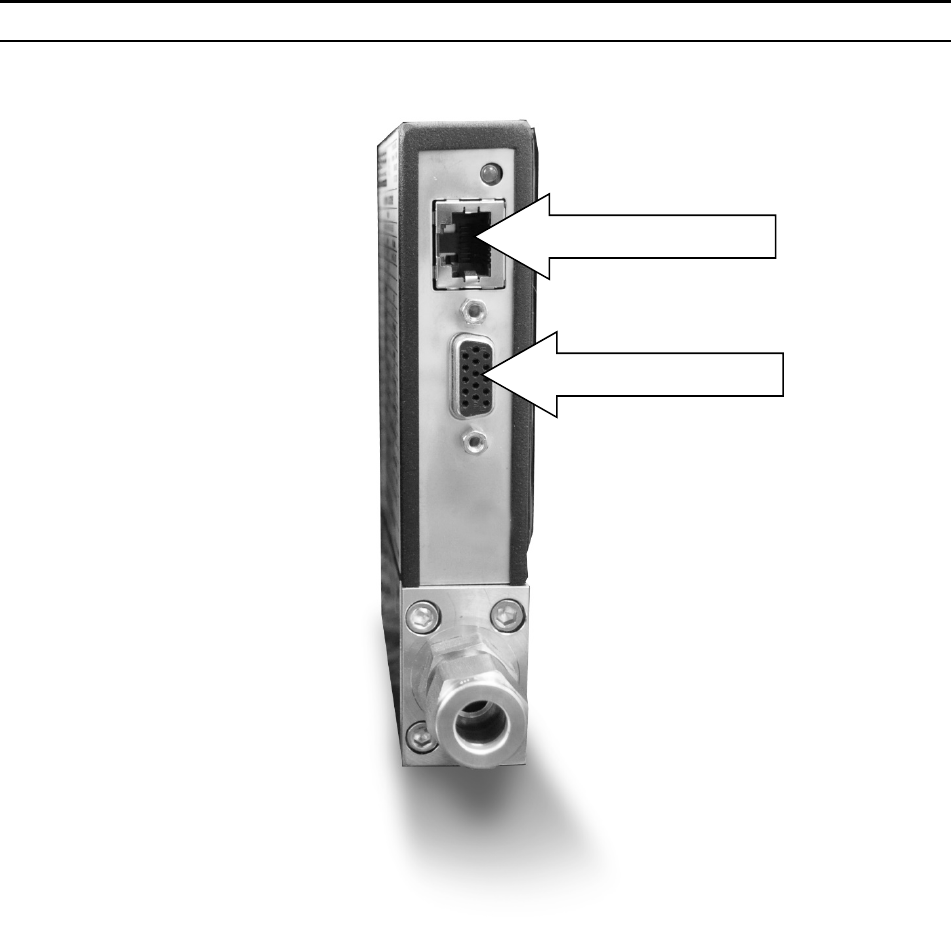
Installing your Instrument—Electrical Connections
All electrical connections for your SmartTrak instrument are made on the left (inlet) side
panel. See Figure 2-2: SmartTrak Connections below for the location of all connections.
Note that the CAT-5 connector is not an ethernet connector.
Sierra Instruments Instruction Manual SmartTrak® 100 Series
16
Figure 2-2: SmartTrak connections
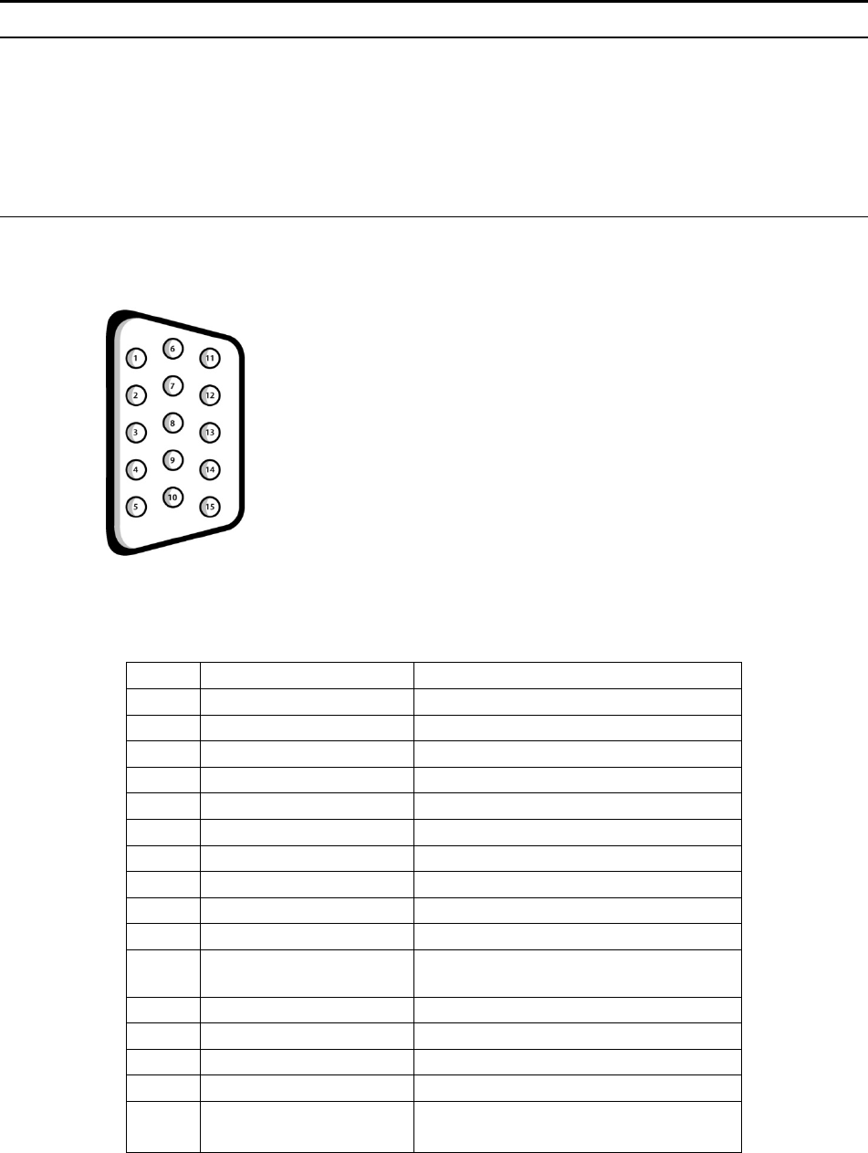
SmartTrak is provided with a high density 15-pin D Connector called an “HD DB-15”
located on the side of the enclosure and either one of our optional pre-assembled
communications cables or an empty mating connector. Power must be supplied to the HD
DB-15 connector. Other features may be accessed there as well. The pin numbers and
assignments for the HD DB-15 connector are shown in Figure 2-3: HD DB-15 Connector
Pin Configuration (on the instrument). The corresponding colors of the optional
communication cable wires and the functions of each are listed in Figure 2-4: Wiring
Definitions for Optional Communication Cable. The connections for input power, analog
CAT 5
HD DB 15
Sierra Instruments Instruction Manual SmartTrak® 100 Series
17
output signal and analog input signal (controllers only) are all made at the HD DB-15
connector. There is a second copy of these 2 figures in Appendix D for your convenience
Figure2‐3:HDDB‐15ConnectorPinConfiguration(ontheinstrument)
Figure2‐4:WiringDefinitionsforOptionalCommunicationCable
Pin # Wire Color in Cable Function
1. Brown Analo
g
Ground
/
Output
2. Re
d
0-5 VDC Output (or 0-10, 1-5 VDC)
3. Oran
g
e Analo
g
Ground
/
RS232
4. Pin
k
Valve Override Pur
g
e
5. Yellow Power Return (-)
6. Green Power Input (+)
7. Green/White RS-232 Transmit (out)
8. Blue Setpoint
9. Purple Not Use
d
10. Gra
y
Analo
g
Ground
/
Setpoint
11. White Reference Voltage
(5 VDC External Setpoint & Valve Pur
g
e)
12. Blac
k
Valve Override Close
13. Brown/white RS-232 Receive (in)
14. Red/white 0/4-20 mA Output
15. Red/Blac
k
Not Use
d
Shield Wire
(no insulation)
Chassis (Earth) Ground
Sierra Instruments Instruction Manual SmartTrak® 100 Series
18
NOTE: Pins 1, 3, and 10 are connected together
inside the instrument. Do not tie these grounds
together outside the instrument. Must have one
connection per analog ground. Recommended
use listed.
Instrument Power:
The SmartTrak requires a 15-24 VDC power supply. If you are using the power supply
supplied by Sierra, connect it to the 15-pin HD DB-15 connector on the side of the
instrument. If you are supplying your own power source, it must be a regulated 15-24 VDC
with ripple not to exceed 100 mV peak-to-peak. It must be capable of producing the current
specified for the appropriate voltage shown in Figure 2-5: Power Supply Requirements.
Apply power as follows: positive (+) to the green (pin 6) and negative (-) to the yellow (pin
5) wires. The instrument is polarity sensitive. If you reverse this wiring, the instrument will
not be damaged, but it will not function.
Instrument Grounding:
The SmartTrak has very high levels of RFI and EMI shielding built into the metal electronics
cover (meets or exceeds the CE Standard EN 61326-1; 2006). To maintain the integrity of
this CE rating, it is critical that a path be provided for any residual internal noise to exit the
instrument or it may register on the outputs. Grounding provides this path.
To properly ground your instrument, secure the chassis to solid earth ground using the
mounting holes on the bottom of the flow body. If the instrument will be used without
permanent mounting (on a laboratory bench, for instance) then, using the provided cable,
connect the shield wire (no insulation) to earth ground in your facility. If you purchased a
Sierra power supply, a ground wire is provided for your convenience.
Figure 2-5: Power Supply Requirements
Instrument Type Recommended Input
Volta
g
e
Minimum Current
Required (mA)
M100L Meter 15-24 VDC (+ 10%) 230
M100M Meter 15-24 VDC (+ 10%) 230
M100H Meter 15-24 VDC (+ 10%) 230
C100L Controller 24 + 10% VDC 500
C100M Controller 24 + 10% VDC 800
C100H Controller 24 + 10% VDC 1260
NOTE: The Compod™ adds an additional 100mA to the ST2 current ratings.
Sierra Instruments Instruction Manual SmartTrak® 100 Series
19
CAUTION: This instrument is not a loop-powered
device! Do NOT apply power to the 0/4-20 mA output or
input connections.
Analog Output Signals:
Output Signal—Voltage: Measure the voltage output signal across the red (pin 2) wire and
any of the analog grounds: brown (pin 1), orange (pin 3) or gray (pin 10). The minimum
load is 1000 Ohms. We recommend pin 1. DO NOT USE THE SAME ANALOG GROUND
FOR CURRENT OUTPUT, SETPOINT OR RS232.
Output Signal—Current: Measure the current output signal, 0/4-20 mA or 0-20 mA,
across the red/white stripe (pin 14) wire and any of the analog grounds: pin 1, 3, or 10. The
maximum load is 500 Ohms. We recommend pin 1. DO NOT USE THE SAME ANALOG
GROUND FOR VOLTAGE OUTPUT, SETPOINT OR RS232.
For Mass Flow Controllers, the following analog features are also available
at the HD DB-15 connector:
Setpoint: To transmit an analog setpoint, supply the voltage or current signal (check the data
label and/or setting) across the blue (pin 8) wire and pin 10.
Valve Close: To force the valve closed, connect the black (pin 12) wire to pin 10
Purge: To force the valve to its maximum open position which we call “Purge,” connect the
pink (pin 4) wire to the white (pin 11) wire. Note that this will allow much greater flow than
the rated full-scale value.
ForDigitalCommunicationUsingYourPersonalComputer:
You can communicate with your instrument using the SmartTrak Software package and your PC
running the Windows operating system. Simply connect the light green (pin 7) wire, the
brown/white stripe (pin 13) wire and one of the analog grounds (pin 1,3, or 10) to a standard DB-
9 connector according to Figure 2-6: Digital Communication.
Sierra Instruments Instruction Manual SmartTrak® 100 Series
20
Figure 2-6: Digital Communication
RS-232 Transmit (pin 7) to DB-9 pin #2
RS-232 Receive (pin 13) to DB-9 pin #3
Analog ground (pin 3) to DB-9 pin #5
With the connections in Figure 2-6 in place, plug the DB-9 connector into an appropriate serial
port on your PC.
To minimize the potential for RF interference, it is recommended to shield these wires. Use a
metal DB-9 connector and connect one end of the shield to the DB-9 shell and the other end to
the outer shell of the SmartTrak HD DB-15 connector.
NOTE: Transit and Receive may need to be reversed,
depending on which type of device or cable is connected. (No
damage will result—attempt communication after reversal.
CAUTION: The CAT-5 connector on the side of the SmartTrak
i
NOT an Ethernet connector. It is for use with the optional
Remote Pilot Module or CRN cable. Do not plug an Ethernet
cable here as damage may result.

Sierra Instruments Instruction Manual SmartTrak® 100 Series
21
CHAPTER 3: ANALOG OPERATION
Your SmartTrak instrument may be operated in three different ways:
THREE CONTROL OPTIONS
A. Analog Input/Output Operation (This Chapter): Using analog input/output signals at the
15-pin mini-D connector.
B. Digital Operation with Pilot Module (Chapter 4): Using the optional Pilot Module.
C. Digital Operation with RS-232 and SmartTrak Software (Chapter 5): Using the RS-232
link, the supplied SmartTrak Software package, and a PC-style computer running
Windows operating system.
This chapter will discuss the first of these—Analog Operation. Please see subsequent chapters
for other options.
Regardless of control options, the standard output for all SmartTrak instruments are two linear
analog output signals corresponding to 0% to 100% of the mass flow full-scale range. Please
note that one of these output signals is a current signal of either 0/4-20 or 0-20 mA. The other
is a voltage signal of 0-5 VDC, 0-10 VDC or 1-5 VDC. You can choose any combination of
these signals at any time in your facility.
For mass flow controllers, one input signal of 0/4-20 mA, 0-20 mA, 0-5 VDC, 0-10 VDC or 1-
5 VDC (selectable by user) may be chosen to set the gas mass flow rate to any desired value
within the range of the device. This input signal must be a direct linear representation of 0% to
100% of the desired gas mass flow full-scale value. For the location of these signals on the HD
DB-15 connector, refer to Figure 2-4 or Appendix D.
Analog Operation, Mass Flow Meter
After your instrument is installed and the system has undergone a complete leak check as
discussed in detail in Chapter 2, you are ready to supply power.
Power Your Instrument: Provide adequate power per Figure 2-5. Apply power using
Sierra’s power supply or your own power source. The green LED at the top of the inlet side
will light to confirm power. If your instrument has a Pilot Module, it will begin its start-up
cycle. See Chapter 4 for details on Pilot Module operation. NOTE: It is highly recommended
you connect power to the SmartTrak, and then power your supply (plug into wall or switch
on). The opposite may cause the unit to take longer to power on. Let the instrument warm up
for at least 15 minutes for optimal performance.
Your SmartTrak instrument is now ready for use!
Sierra Instruments Instruction Manual SmartTrak® 100 Series
22
Analog Operation, Mass Flow Controller
After your instrument is installed and the system has undergone a complete leak check as
discussed in detail in Chapter 2, follow these steps:
1. The valve will remain closed until power is supplied. See Chapter 2 for wiring
instructions. Remember that the valve in the SmartTrak is not a positive shut-off
device. When power is applied, the flow control valve will operate per any
instructions it receives. When the SmartTrak is delivered, the valve will be in the
Automatic (Normal) state and the Pilot Module or analog signal will provide the
correct zero setpoint reference for the instrument. As a result, the valve will be closed.
However, upon subsequent power-ups, the valve will return to the state it was in the
last time the instrument was operated.
CAUTION: If you do not know the value of the setpoint or the valve state given
to the SmartTrak when it was last operated, you must assume that the valve will
open when power is applied. Take necessary precautions. You may use the Pilot
Module or the SmartTrak Software to check the setpoint or the valve state
currently on your instrument. See Chapter 4 or Chapter 5 for information on
Setpoint and Valve State.
2. Power Your Instrument: Provide adequate power per Figure 2-5. Apply power using
Sierra’s power supply or your own power source. The green LED at the top of the
inlet side will light to confirm power. If your instrument has a Pilot Module, it will
begin its start-up cycle. See Chapter 4 for details on Pilot Module operation. NOTE:
It is highly recommended you connect power to the SmartTrak, and then power your
supply (plug into wall or switch on). The opposite may cause the unit to take longer to
power on. Let the instrument warm up for at least 15 minutes for optimal performance.
3. Adjust the controller setpoint to the desired flow rate by supplying an appropriate
signal (mA or VDC). The effective control range of the unit is 2% to 100% of the
calibrated full scale flow range. Automatic shut-off occurs at 1.9% of the factory full
scale calibrated range unless specifically modified at time of order. SmartTrak will
immediately begin accurately monitoring and controlling the gas mass flow rate. Let
the instrument warm up for at least 15 minutes for optimal performance.
4. After 30 minutes, if your zero reading and/or calibration are off (i.e. show flow at
zero), we recommend that you perform the re-zeroing procedure. Refer to page 45
“Zero Meter Screen” for instructions.
Your SmartTrak instrument is now ready for use!
Sierra Instruments Instruction Manual SmartTrak® 100 Series
23
SmartTrak Features
Setpoint Adjustment
The setpoint (command) input signal you supply to SmartTrak must be a direct linear
representation of 0% to 100% of the mass flow full-scale value. Apply the setpoint signal
from pin 8 to any of the analog grounds (see Chapter 2 for wiring details). A setpoint value
of 0 VDC or mA (or 1 VDC or 4 mA) will regulate the flow to 0% and a setpoint value of
5.00 VDC (or 10 VDC or 20 mA) will adjust the flow to 100% of the instrument’s full
scale range.
When the setpoint (command) signal is applied, the flow controller will reach the setpoint
value within two seconds to within ±2% of the selected flow rate.
CAUTION: DO NOT LEAVE A SETPOINT APPLIED FOR AN EXTENDED
PERIOD OF TIME TO A CONTROLLER WHEN THE GAS SUPPLY IS
SHUT OFF OR BLOCKED. Damage may result and the instrument will become
hot to the touch. Instead, see below for use of the “Valve Close” feature which
allows you to disable the valve while maintaining the setpoint signal. This may be
set by the Pilot Module, the SmartTrak Software, or an external analog signal.
Changing the Output or Setpoint Signals
To modify the analog output or setpoint signals (from 0/4-20mA to 0-10Vdc, for
example), you must use the Pilot Module or the SmartTrak Software. The data label will
indicate the form these signals had when the instrument was last calibrated. We strongly
recommend that you adapt the data label if the configuration is changed for future
reference. See Chapter 4 or 5 for the necessary procedure.
Over-Range Condition
If the mass flow rate exceeds the full-scale range listed on the SmartTrak data label (see
samples on page 2-1), the output signal will measure above full-scale. However, the
device has not been calibrated for flows in excess of the calibrated full scale value and the
value will be both non-linear and inaccurate if an over-range condition exists. Please be
aware that the analog outputs can exceed full scale by as much as 20%, or more.
Once the over-range condition has been removed, it may take up to 30 seconds for the
SmartTrak to recover and resume normal operation. An over-range condition will not
harm the instrument.
Manual Valve Override—Valve Close
Manual valve override is provided for all Sierra mass flow controllers. This feature
includes both a valve close command and a valve maximum open command (called
purge). When the valve is directed to close or to purge, it will no longer respond to a
setpoint command.
Sierra Instruments Instruction Manual SmartTrak® 100 Series
24
FOR VALVE CLOSE: connect pin 12 to analog ground
Remember that the valve in the SmartTrak is not a positive shut-off device. The
Controller will return to normal automatic operation about 4 seconds after pin 12 is
left floating.
Manual Valve Override—Valve Purge Function
The purge function opens the controller valve completely for the purpose of quickly
flushing unwanted gas from the flow path. When the valve is opened for purging, it
allows flows far in excess of the rated full scale of the controller.
FOR VALVE PURGE: connect pin 4 to pin 11.
CAUTION: PURGE MODE ALLOWS FAR MORE GAS TO FLOW
THROUGH THE CONTROLLER! BEFORE USING VALVE PURGE
OPERATION, INSURE PROPER DOWNSTREAM CAPACITY AND
VENTILATION. SPECIAL CARE SHOULD BE TAKEN WITH HP100
INSTRUMENTS, WHICH CAN ALLOW BOTH HIGH PRESSURES AND
FLOW RATES TO ESCAPE WHEN THE VALVE IS IN PURGE MODE.
IMPORTANT NOTES ABOUT PURGING
Purging Non-Reactive Gases:
Purge your SmartTrak with clean, dry nitrogen for a minimum of two hours.
Purging Reactive Gases:
One of the following methods may be used:
Cycle purge. This is done by alternately evacuating and purging the instrument
for 2 to 4 hours with clean, dry nitrogen.
Purge the instrument with clean, dry nitrogen for 18 to 24 hours.
Evacuate the instrument for 18 to 24 hours.
Caution!
Sierra Instruments Instruction Manual SmartTrak® 100 Series
25
IMPORTANT SAFETY NOTES ABOUT PURGING
WARNING: When toxic or corrosive gases are used, purge
unit thoroughly with inert dry gas before disconnecting
from the gas line to prevent personnel from being injured
when coming in contact with the instrument.
WARNING: If an instrument used with a toxic or corrosive
gas is returned to the factory, a Material Safety Data Sheet
(MSDS) must be enclosed & attached to the outside of the
box to alert Sierra personnel of the potential hazard. Also,
make sure the inlet & outlet are securely sealed.
Sierra Instruments Instruction Manual SmartTrak® 100 Series
26
CHAPTER 4: Digital Operation with Pilot Module
Your SmartTrak instrument may be operated in three different ways:
THREE CONTROL OPTIONS
A. Analog Input/Output Operation (Chapter 3): Using analog input/output
signals at the HD DB-15 connector.
B. Digital Operation with Pilot Module (This Chapter): Using the optional Pilot
Module.
C. Digital Operation with RS-232 and SmartTrak Software (Chapter 5):
Using the RS-232 SmartTrak Software package and a computer running the
Windows operating system.
This chapter will discuss the second of these—Digital Operation with the optional Pilot
Module. Please see alternate chapters for other options.
Although you have chosen to use the optional Pilot Module, please note that all the Analog
control functions are still available on your instrument. Consult Chapter 3 for details on
Analog operation. Also, computer control using the RS-232 communication is available.
See Chapter 5 for details on operation with a computer.
CAUTION—If RS-232 digital communication is to be used in conjunction with the Pilot
Module, the HD DB15 connector must be properly wired with a three wire serial DB9
cable to your computer. Often, this is done with the same HD DB15 that supplies power to
your instrument. You can run both RS-232 communication and Pilot Module
communications in parallel, but the unit will only respond to one set of commands at a
time. DO NOT attempt to control the unit simultaneously with both the Pilot Module and
the computer, this can lock up the unit.
Introduction to Pilot Module Features and Capabilities
The optional Pilot Module functions as both display and a control unit for your SmartTrak
instrument. The standard Pilot Module is available mounted directly on the face of your
instrument or as a handheld / remote mountable control interface attached to the
SmartTrak via a detachable cable.
If your instrument has a standard Pilot Module mounted locally on the face of the unit, no
additional set-up is required. See picture below.
Sierra Instruments Instruction Manual SmartTrak® 100 Series
27
On the other hand, if your instrument has a Remote Pilot Module, attach one end of the
included Category 5 (CAT 5, also called RJ-45) connecting cable into the jack at the top
of the instrument’s left side, immediately above the HD DB-15 connector.
Next, place the other end into one of the two matching jacks on the Pilot Module. For your
convenience, Sierra has provided two jacks—one on the back and one on the bottom of
the Remote Pilot Module. You may use whichever jack is most convenient for your
application as they both have identical functions.
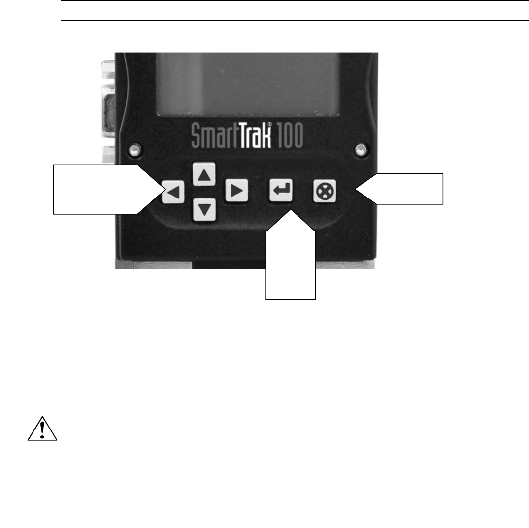
The Pilot Module includes a large LCD graphic display screen and six buttons. The LCD
will show a variety of information and the buttons can be used to view and modify this
information. The convenient buttons are:
Left arrow
Right arrow
Up arrow
Down arrow
Enter button
Escape button
These are shown in the photo below:
Sierra Instruments Instruction Manual SmartTrak® 100 Series
28
Pilot Module Operation, Mass Flow Meter
After your instrument is installed and the system has undergone a complete leak check as
discussed in detail in Chapter 2, follow these steps:
1. Power Up Your Instrument: Apply power to your instrument. See Chapter 2, Figure
2-5: Power Supply Requirements. When power is first applied, the Pilot Module will
display:
Version
2.04X
Read Parameters
Assuming no gas is flowing, after another 5-10 seconds the display will read:
Mass Flow
0.000 sl/m
Air
Up, Down
Left, Right
Enter
Escape
Caution!
The SmartTrak is
not a loop-powered
device. Do not
apply power to the
4-20 mA outputs.
Sierra Instruments Instruction Manual SmartTrak® 100 Series
29
NOTE: If gas is flowing the Pilot Module will immediately begin to accurately display
the gas mass flow rate on the LCD panel. If you have chosen alternate units or another
gas, the display will show the selected units instead of the above.
2. Open the gas supply: SmartTrak is now ready to monitor the gas mass flow rate. Let
the instrument warm up for at least 15 minutes for optimal performance.
3. After 30 minutes, if your zero reading and/or calibration are off (i.e. show flow at
zero), we recommend that you perform the re-zeroing procedure. Refer to page 45
“Zero Meter Screen” for instructions.
Your SmartTrak instrument is now ready for use!
Pilot Module Operation, Mass Flow Controllers
After your instrument is installed and the system has undergone a complete leak check as
discussed in detail in Chapter 2, follow these steps:
1. The valve will remain closed until power is supplied. See Chapter 2 for
wiring instructions.
CAUTION: Remember that the valve in the SmartTrak is not a guaranteed positive
shut-off device. For dangerous applications, Sierra recommends use of an external
shut-off safety valve.
When power is applied, the flow control valve will operate per the instructions it receives
from the Pilot Module. When the SmartTrak is delivered, the valve will be in the
Automatic (Normal) state and the Pilot Module will provide the correct zero setpoint
reference. As a result, the valve will be closed. However, the valve will return to the state
it was in the last time the instrument was operated.
WARNING: If you do not know the setpoint or the valve state of the Mass Flow
Controller before it was shut down, you must assume that the valve will open when
power is applied. TAKE NECESSARY PRECAUTIONS.
2. Power Up Your Instrument: Apply power to your instrument using Sierra’s
power supply or your own input power source. See Chapter 2, Figure 2-5:
Power Supply Requirements. When power is first applied, the Pilot Module
will display:
Version
2.04X
Read Parameters
If no gas is flowing, after another 5-10 seconds the display will read:
Sierra Instruments Instruction Manual SmartTrak® 100 Series
30
Mass Flow
0.000 sl/m
Air
NOTE: If gas is flowing and the Pilot Module has a setpoint greater than zero, it will
immediately begin to accurately display the gas mass flow rate on the LCD panel. If you
have chosen alternate units or another gas, the display will show the selected units instead
of those above.
3. Open the gas supply. SmartTrak is now ready to monitor and control the gas
mass flow rate. The display will show 0.000 until it is given a setpoint. Let the
instrument warm up for at least 15 minutes for optimal performance.
4. After 30 minutes, if your zero reading and/or calibration are off (i.e. show
flow at zero), we recommend that you perform the re-zeroing procedure. Refer
to page 45 “Zero Meter Screen” for instructions.
Your SmartTrak instrument is now ready for use!
CAUTION: DO NOT LEAVE A SETPOINT APPLIED FOR AN EXTENDED
PERIOD OF TIME TO A CONTROLLER WHEN THE GAS SUPPLY IS SHUT
OFF OR BLOCKED. Damage may result and the instrument will become hot to the
touch. Instead, see below for use of the “Valve Close” feature which allows you to disable
the valve while maintaining the setpoint signal. This may be set by the Pilot Module, the
SmartTrak Software, or an external analog signal.
Using the Pilot Module Menus & User Interface
The features of the Pilot Module can be considered in three groups:
1 Upper Level Screens: display information (no password is required to view this information).
These include:
Mass flow rate
Gas (10 options pre-programmed)
Engineering units (mass per unit time)
Current Setpoint with units

Sierra Instruments Instruction Manual SmartTrak® 100 Series
31
Source of Setpoint (analog or digital and type)
Valve operation mode (normal, valve close or purge)
Current meter full scale value with units (user selectable)
2 Lower Level Screens: permit changes to instrument operation. They are password protected.
These include:
Setpoint value
Engineering units
Gas
Valve operation
Source of the setpoint signal
Form of the output signals
Full scale of the instrument
Password
Zero
Span
3 Maintenance Features:
Re-boot the SmartTrak microprocessor. Press the LEFT ARROW, DOWN
ARROW, ENTER, AND ESCAPE keys at the same time.
Move the decimal point. Navigate to the “change the setpoint” menu. Press ENTER
to make one of the digits flash. While it is flashing, press ESCAPE at the same time you press
LEFT ARROW or RIGHT ARROW.
Return all parameters to the factory default values. Navigate to the “Change the
Setpoint” menu. Press LEFT ARROW, UP ARROW, and ENTER at the same time. Choose
“yes” to restore factory default settings.
If you are trying to navigate using the pilot but the message appears, “Must be
in Pilot Mode,” use the LEFT ARROW from this screen to navigate to the “Change Setpoint
Source” and change to “Pilot / RS-232.” Escape and try again.
Sierra Instruments Instruction Manual SmartTrak® 100 Series
32
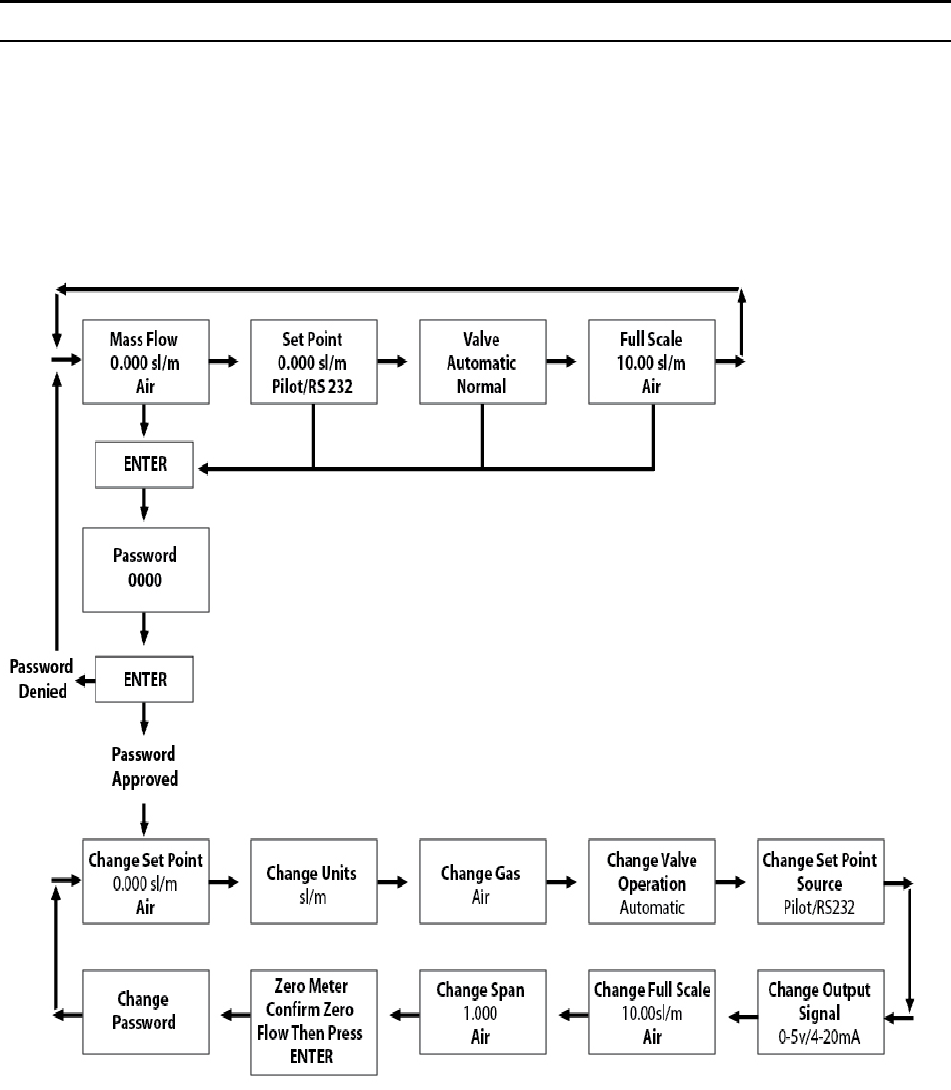
Map of the Pilot Module Interface
The Pilot Module user interface is presented below in a graphical format. Once you have
some familiarity with the user interface, you may find you want to make a copy of this and
keep it with the instrument for reference. You can find a larger version of this Flow Chart
in Appendix G.

Sierra Instruments Instruction Manual SmartTrak® 100 Series
33
The seven Upper Level Screens display a variety of information. You are able to move
between the screens by pressing the left or right arrows. No password is required for the
Upper Level Screens.
Mass Flow Screen
When the instrument is powered up, or whenever the escape button is pressed, it always
returns to the Mass Flow Screen. This screen displays the mass flow rate, the engineering
units and your gas choice. It looks something like this:
Mass Flow
0.000 sl/m
Air
Setpoint Screen
Pushing the right arrow takes you to the Setpoint Screen. The Setpoint Screen displays
the current setpoint given to the controller, the engineering units and the source of the
setpoint signal.
The source of the setpoint can be:
Pilot Module/RS-232
0/4-20 mA
1-5 Vdc
0-5 Vdc
0-10 Vdc
For operation with the Pilot Module, the display will look something like this:
Setpoint
10.00 sl/m
Pilot Module/RS-232
If this screen does not show “Pilot Module/RS-232” at the bottom, you will not be able to
give the controller a setpoint command from the Pilot Module because the instrument is
waiting for an analog setpoint. See section below titled “Change Setpoint Source Screen”
to change the source of the setpoint signal. Alternately, you may supply an analog
setpoint to the HD DB-15 connector (see Chapter 3).
Valve Position Screen (Mass Flow Controllers only)
Pushing the right arrow again takes you to the Valve Position Screen, if you have a Mass
Flow Controller. This screen will display the current state of the SmartTrak valve.
Sierra Instruments Instruction Manual SmartTrak® 100 Series
34
The state of the valve can be:
1. Closed (Remember that the SmartTrak is not a positive shut-off device).
2. Purge--Maximum Open (recommended 120% of the calibrated full scale value, but
can be much more and can be dangerous)
3. Automatic (the normal position, where the controller responds to a setpoint signal).
WARNING: The flow rate in Purge is much greater than the calibrated
full scale value and as a result can be dangerous.
For normal operation of the flow controller, this screen should display:
Valve
Automatic
Normal
If this is visible, the instrument will automatically control flow as soon as a setpoint is
given to it. If this screen displays Closed or Purge, the instrument has been placed into an
override position and it will not respond to any setpoint signal. The valve state may be
changed using the “Change Valve Operation” as described on page 4-16.
Full Scale Screen
Pressing the right arrow again takes you to the Full Scale Screen. This screen displays the
current full scale value of the instrument with engineering units. It also displays the gas.
Note that this is not necessarily the factory calibrated full scale value. The screen will
display:
Full Scale
10.00 sl/m
Nitrogen
To change the full scale value, see the section below titled “Change Full Scale Screen.”
Pressing the right arrow again takes you back to the Mass Flow Screen.

Sierra Instruments Instruction Manual SmartTrak® 100 Series
35
Lower Level Screens (Changing Parameters)
Getting to the Lower Level Screens:
Your instrument is password protected so that unauthorized personnel will be unable to
change the operating parameters of SmartTrak. To enter the Lower Level Screens at any
time you must first supply the correct password.
Password Screen: By pressing the “enter” key from any of the Upper Level Screens
you will come to the Password Screen. (If you do not know if you are in an Upper Level
Screen, press escape and you always automatically go to the Mass Flow Screen in the
Upper Level) The display will show:
Enter Password
0000
The first digit will blink. At this point, you must enter the correct password to gain access to
the Lower Level Screens.
If the instrument is being operated for the first time or if no password has ever been
set on the instrument: You can use the factory default password. The factory default
password is “0000.” To proceed to the Lower Level Screens by using the factory default
password, simply press the “enter” key a second time. If you want rapid access to permit
regular changes to your instrument and you do not desire a password, this is the fastest
way to enter the lower level.
If You Have a Password: If you have already set a password, enter it now. To enter the
password, push the up arrow to increase the blinking digit or the down arrow to decrease
the blinking digit. To move to the next digit, press the left or right arrow and repeat the
process. When you have selected your four digit password, press the enter key.
If You Want to Set a New Password: If you want to change the password, you must first
get to the Lower Level Screens. Proceed by entering your known password or if no
password has ever been set on the instrument, us the factory default password. Follow the
instructions in the “Change Password Screen” section found later in this chapter.
If the password you have entered is correct, you will enter the Lower Level at the Change
Setpoint Value Screen.
If the password is not correct, the display will show:
Sierra Instruments Instruction Manual SmartTrak® 100 Series
36
Access Denied
Press any button
To continue
When you press any button, you will return to the Mass Flow Screen in the Upper Level. Press
the “enter” key to try again.
LOST PASSWORDS & GENERAL CUSTOMER SERVICE: If you lose your password, it
will be necessary to contact one of Sierra’s Technical Support Centers.
Email Customer Service: service@sierrainstruments.com
FACTORY USA Customer Service:
TOLL FREE: 800-866-0200
PHONE: 831-373-0200
FAX: 831-373-4402
EMAIL: service@sierrainstruments.com
European Customer Service:
PHONE: +31 72 5071400
FAX: +31 72 5071401
EMAIL: service@sierra-instruments.nl
Asia Customer Service:
PHONE: + 8221 5879 8521
FAX: +8621 5879 8586
EMAIL: www.sierra-asia.com

Sierra Instruments Instruction Manual SmartTrak® 100 Series
37
Making Changes Using the Lower Level Screens:
The ten Lower Level Screens are at the heart of Dial-A-Gas®, allowing you complete
control of your SmartTrak instrument. It is possible to make several changes on different
Lower Level Screens before exiting.
For example, you could change between one of the ten pre-programmed gases, change the
engineering units, and change the setpoint all in one visit to the Lower Level Screens. The
SmartTrak will make each adjustment as you complete it. At any time, you may press the
escape button to return to the Upper Level.
Change Setpoint Value Screen
This screen is the entry point to the Lower Level. As soon as a correct password is
entered, you will arrive here. If you are already in the Lower Level Screens, push the right
or left arrow until you reach the Change Setpoint Value screen. The display will show:
Change Setpoint
00.00 sl/m
Air
This is the position where you can change the setpoint value of the mass flow controller.
To make a change to the displayed value, press the enter key. The first number in the
display will blink. Use the up and down arrows to change the value of this digit or the left
and right arrows to move to another digit. For example, if you wish to enter a setpoint of
12.5 sl/m, push the “up” arrow once when the first digit is blinking. You will see:
Change Setpoint
10.00 sl/m
Air
Next, press the “right” arrow so that the second digit blinks. Push the up arrow twice.
You will now see:
Change Setpoint
12.00 sl/m
Air
Press the right arrow again. The first digit after the decimal point will now blink. Press the
up arrow 5 times until you see:
Change Setpoint
12.50 sl/m
Sierra Instruments Instruction Manual SmartTrak® 100 Series
38
Air
Now that you have made your selection, press the enter key. The display from our
example will show:
Change Setpoint
12.50 sl/m
Air
If you are finished or wish to observe the changes you have made on the LCD panel, press
the escape key to return to the Upper Level Mass Flow Screen.
If you prefer to make additional changes, use the left and right arrow keys to move to
other Lower Level Screens.
Note: If you enter a Setpoint that exceeds the full scale value (displayed in
the “Full Scale” screen in the Upper Level), the SmartTrak will
automatically modify this value to equal the current full scale value. For
example, if the current full scale value of your instrument is 10 slpm and
you have entered a setpoint of 15 slpm, the SmartTrak will modify your
setpoint to 10 slpm when you implement the change. The Setpoint Value
screen will show 10 slpm, not 15 slpm.
Change Units Screen
If you are already in the Lower Level Screens, push the right or left arrow until you reach
the Change Units screen. To get to this screen at any time, Press Escape—Press Enter—
type password and Press Enter. Then, press the Right or Left arrow until you reach the
Change Units Screen.
The display will show:
Change Units
sl/m
Caution!
The SmartTrak will not
allow you to enter a
setpoint greater than the
current full scale value
set on the instrument.

Sierra Instruments Instruction Manual SmartTrak® 100 Series
39
If you wish to change the engineering units, press the enter button at this point. The “mass
units” will begin to blink. Use the up or down arrows to select an alternate unit. You can
choose from the following mass units:
sl
NL
g
kg
lb
scc
Ncc
SCF
NM3
SM3
When you are satisfied, push the left or right arrow. You will now see the “time unit”
blink. Use the up or down arrows to select your choice of time units. You can choose
from the following time units:
m (minutes)
H (hours)
S (seconds)
When you are finished, press the enter button again. You will see:
Change Units
XXX/x
You can make additional changes by using the left and right arrow keys to move to other
Lower Level Screens. You may also choose to press the escape key to return to the Upper
Level Screens and to observe your change.
NOTE: If a small unit is chosen, the device might not be able to display the valve and
might show 9999. You might need to restore factory defaults. See Maintenance Functions
starting on page 47.
Change Gas Screen (Dial-A-Gas®)
If you are already in the Lower Level Screens, push the right or left arrow until you reach
the Change Gas screen. To get to this screen at any time: Press Escape—Press Enter—
type password and Press Enter. Then, press the Right or Left arrow until you reach this
screen. The display will show:
Change Gas
Nitrogen
Sierra Instruments Instruction Manual SmartTrak® 100 Series
40
If you wish to change the gas used in the instrument, press enter. The name of the gas will
blink. Use the up and down arrows to make your selection. When you reach the desired
gas, press enter. You will see:
Change Gas
XXXX
You can make additional changes by using the left and right arrow keys to move to other
Lower Level Screens. You may also choose to press the escape key to return to the Upper
Level Screens and to observe your change.
Note: your instrument comes with 10 pre-programmed standard gases. These are listed in
the Specifications in Appendix B. SmartTrak may be ordered with alternate gases
programmed. If your device was so ordered, you may choose from these 10 gases instead.
You may see the 10 gases programmed in your instrument by using this screen and simply
scrolling up or down.
Change Valve Operation-Close, Purge
If you are already in the Lower Level Screens, push the right or left arrow until you reach
the Change Valve Operation screen. To get to this screen at any time: Press Escape—
Press Enter—enter password and Press Enter. Then, press the Right or Left arrow until
you reach this screen. The display will show:
Change Valve
Operation
Automatic
From this screen you may set the valve to open all the way (“Purge”), force the valve to
remain closed until further changes are made (“Valve Closed”) or set the valve to control
flow when it receives a setpoint from some source (“Automatic”). To make a change to
the valve operation, press the enter key. Use the up and down arrows to make your
selection. When you are satisfied, press the enter key again. You will see:
Change Valve
Operation
XXXXX
You can make additional changes by using the left and right arrow keys to move to other
Lower Level Screens. You may also choose to press the escape key to return to the Upper
Level Screens.
Caution!
The SmartTrak
v
alve is not a positive
shut-off device.
Sierra Instruments Instruction Manual SmartTrak® 100 Series
41
NOTE: The valve will move to the desired position immediately when you press the enter
key.
IMPORTANT SAFETY NOTES ABOUT PURGING
WARNING: When toxic or corrosive gases are used, purge unit
thoroughly with inert dry gas before disconnecting from the gas
line to prevent personnel from being injured when coming in
contact with the instrument. Chapter 3 discusses how to purge
your instrument. Always neutralize any toxic gas trapped inside
the instrument before removing it from the gas line.
WARNING: The flow rate in Purge is much greater than the
calibrated full scale value and as a result can be dangerous.
Change Setpoint Source Screen (mass flow controllers only)
If you are already in the Lower Level Screens, push the right or left arrow until you reach
the Change Setpoint Source screen. To get to this screen at any time: Press Escape—Press
Enter—enter password and Press Enter. Then, press the Right or Left arrow until you
reach this screen. The Change Setpoint Source screen allows you to re-configure the
location and type of the setpoint for the SmartTrak controller. If you intend to supply the
setpoint command signal from the Pilot Module or a computer using the RS-232 link, the
display must show:
Change Setpoint
Source
Pilot/RS232
If, instead of using the Pilot Module or the RS-232 link, you prefer to supply an analog
setpoint signal to the SmartTrak, press the enter button. “Pilot/RS232” will begin to blink.
Use the up and down arrows to make your selection from the following choices:
0-5 VDC
0-10 VDC
1-5 VDC
0/4-20 mA
Pilot/RS232
Sierra Instruments Instruction Manual SmartTrak® 100 Series
42
When you are satisfied, press enter. You will see:
Change Setpoint
Source
X-XX XX
You can make additional changes by using the left and right arrow keys to move to other
Lower Level Screens. You may also choose to press the escape key to return to the Upper
Level Screens.
Caution: If you change the source of the setpoint to an analog value, you
will not be able to control your SmartTrak mass flow controller via the
Pilot Module or the RS-232 link.
Change Output Signals Screen
If you are already in the Lower Level Screens, push the right or left arrow until you reach
the Change Output Signals screen. To get to this screen at any time: Press Escape—Press
Enter—enter password and Press Enter. Then, press the Right or Left arrow until you
reach this screen. The display will show:
Change Output
Signals
0-5 VDC/0/4-20 mA
Here you can re-configure the analog output signals for the instrument. The SmartTrak
always outputs one current signal of 0/4-20mA but the voltage signal may be selected
using this screen. Use the up and down arrows to make your selection. You can choose
between:
0-5VDC and 0/4-20mA
0-10VDC and 0/4-20mA
1-5VDC and 0/4-20mA
When you are finished making your selection, press enter. The screen will read:
Sierra Instruments Instruction Manual SmartTrak® 100 Series
43
Change Output
Signals
X-XX XX/X-XX XX
You can make additional changes by using the left and right arrow keys to move to other
Lower Level Screens. You may also choose to press the escape key to return to the Upper
Level Screens.
Change Full Scale Screen
If you are already in the Lower Level Screens, push the right or left arrow until you reach
the Change Full Scale screen. To get to this screen at any time: Press Escape—Press
Enter—enter password and Press Enter. Then, press the Right or Left arrow until you
reach this screen. The display will show:
Change Full Scale
XX.XX sl/m
Air
This screen allows you to re-range the outputs of your instrument. You may select any
full-scale value between 100% and 50% of the displayed maximum value (this is the
factory full-scale calibration value).
The new full-scale value that you select will re-define the analog outputs of the
instrument. The 20 mA signal and the corresponding voltage signal (5 VDC, 1-5 VDC or
10 VDC) will now represent this new full-scale value.
Caution: Changing the full-scale value of the instrument does not affect the
accuracy.
The accuracy is always 1% of full scale under calibration conditions of the original
factory full-scale calibration value.
Caution: For any instrument, if a value greater than the factory full scale calibration
value is entered on this screen, the SmartTrak will modify the requested value to
equal the factory full scale calibration value.
If you choose to change the full-scale value, press the enter key. The first digit will blink.
Use the up and down arrows to adjust the value of the digit or the left and right arrows to
choose another digit. When you have completed your modification, press the enter key.
The display will show:
Change Full Scale
XX.XX sl/m

Sierra Instruments Instruction Manual SmartTrak® 100 Series
44
Air
You can make additional changes by using the left and right arrow keys to move to other
Lower Level Screens. You may also choose to press the escape key to return to the Upper
Level Screens.
Change Span Screen
If you are already in the Lower Level Screens, push the right or left arrow until you reach
the Change Span screen. To get this screen at any time: Press Escape—Press Enter—enter
password and Press Enter. Then, press the Right or Left arrow until you reach this screen.
From this screen you can change the instrument’s span distance by a percentage factor
ratio. For example, if your meter is reading 1% high of reading, change span to 0.990
(99.0%) and the full scale value should be reduced by 1%. If your controller is controlling
1% below of reading, the same change will bring it in. If the meter is reading 1% low
(controller controls 1% high), then change span to 1.010 (101.0%). The display will show:
Change Span
1.000
Air
To make a change, press the enter key. The first digit will begin to blink. Use the up and
down arrows to modify this digit or the left and right arrows to choose another digit.
When you are satisfied, press enter. The display will show:
Change Span
X.XXX
Air
Keep in mind that you can change the span for each individual gas, thus, a change in the
span to one gas will not affect the span of another gas. You can make additional changes
by using the left and right arrow keys to move to other Lower Level Screens. You may
also choose to press the escape key to return to the Upper Level Screens.
Zero Meter Screen
If you are already in the Lower Level Screens, push the right or left arrow until you reach
the Zero Meter screen. To get this screen at any time: Press Escape—Press Enter—enter
password and Press Enter. Then, press the Right or Left arrow until you reach this screen.
From this screen you can change the zero flow bridge differential value to match the zero
flow conditions of your application. Mount (or place) the instrument where it is intended

Sierra Instruments Instruction Manual SmartTrak® 100 Series
45
to be used, minding orientation, tilt, etc.; The accuracy of this function is dictated on how
close to operating conditions the unit is when the meter is zeroed. The display will show:
Zero Meter
Confirm zero flow
Then press enter
Once you push enter, the unit will monitor the sensor bridge differential value. The
display will show:
Zero Meter
Confirm zero flow
New Zero
Upon pressing the enter key again, the unit will record the bridge differential value to the
zero flow condition, leaving you with a freshly “zeroed” instrument! You can make
additional changes by using the left and right arrow keys to move to other Lower Level
Screens. You may also choose to press the escape key to return to the Upper Level
Screens.
Change Password Screen
If you are already in the Lower Level Screens, push the right or left arrow until you reach
the Change Password screen. To get to this screen at any time: Press Escape—Press
Enter—enter password and Press Enter. Then, press the Right or Left arrow until you
reach this screen.
From this screen you can change the instrument password from the factory default to any
four-digit password of your choice. The display will show the factory default password of
four zero’s: “0000”. The display will show:
Change Password
0000
To make a change, press the enter key. The first digit will begin to blink. Use the up and
down arrows to modify this digit or the left and right arrows to choose another digit.
When you are satisfied, press enter. The display will show:
Change Password
0000
You can make additional changes by using the left and right arrow keys to move to other
Lower Level Screens. You may also choose to press the escape key to return to the Upper
Level Screens.
Sierra Instruments Instruction Manual SmartTrak® 100 Series
46
Caution: Once you change the Password, you will not be able to enter the Lower
Level without it. Be certain the new password is recorded.
Lost Passwords and General Customer Service
The “creator” password is 6363- this will override all other passwords. If this does not
work, it will be necessary to contact one of Sierra’s Technical Support Centers.
Email Customer Service: service@sierrainstruments.com
FACTORY USA Customer Service:
TOLL FREE: 800-866-0200
PHONE: 831-373-0200
FAX: 831-373-4402
EMAIL: service@sierrainstruments.com
European Customer Service:
PHONE: +31 72 5071400
FAX: +31 72 5071401
EMAIL: service@sierra-instruments.nl
Asia Customer Service:
PHONE: + 8221 5879 8521
FAX: +8621 5879 8586
EMAIL: www.sierra-asia.com

Sierra Instruments Instruction Manual SmartTrak® 100 Series
47
CHAPTER 5: Digital Operation RS-232 & SmartTrak Software
Your SmartTrak instrument may be operated in three different ways:
THREE CONTROL OPTIONS
A. Analog Input/Output Operation (Chaper 3): Using analog input/output signals at the
15-pin mini- D connector.
B. Digital Operation with Pilot Module (Chapter 4): Using the optional Pilot Module.
C. Digital Operation with RS-232 and SmartTrak Software (This Chapter): Using the RS-
232 SmartTrak Software package and a PC-style computer running the Windows
operating system.
This chapter will discuss “C” above—Digital Operation with your computer via RS-232
and SmartTrak Software. Although you have chosen to use the RS-232 option, please note
that all the Analog control functions are still available on your instrument. Consult Chapter
3 for details on Analog operation. Also, the Pilot Module may be used so long as you
make RS-232 communication with the supplied CRN cable. See Chapter 4 for details on
operation using the Pilot Module.
If you prefer to write your own software to communicate with the SmartTrak over the RS-
232 link, this is certainly possible. Sierra Instruments will provide the Source Code
including the Command Set upon request. Unfortunately, this is the limit of software
Technical Support we can extend.
Summary of the SmartTrak Features
Your SmartTrak instrument may be easily monitored and adjusted using the supplied
SmartTrak Software package. You should note that the SmartTrak Software was designed
with all the same functions as the Pilot Module. The software allows you to see all
changes & parameters at a glance and will allow you to make changes quickly and easily.
For review, the features of the SmartTrak include:
1. Top Level Screens that display information In our software, these screens appear as
yellow boxes. They include:
Mass flow rate
Gas (10 options pre-programmed, one must be AIR)
Sierra Instruments Instruction Manual SmartTrak® 100 Series
48
Engineering units (mass per unit time)
Current Setpoint with units
Source of Setpoint (analog or digital and type)
Valve operation mode (normal, valve shut or purge)
Current meter full scale value with units (user selectable)
2. Lower level Screens that permit changes to instrument operation In our software, these
screens appear as white boxes. They include:
Setpoint value
Engineering units
Gas
Valve operation
Source of the setpoint signal
Form of the output signals
Full scale of the instrument
Zero meter
Span meter
3. Additional Features include:
Re-boot the SmartTrak microprocessor
Change the Communication Port
Links to Sierra Instruments’ Web Site
Specifications
Power Up Your Instrument
CAUTION: The SmartTrak is not a loop-powered device. Do not apply power to the
0/4-20mA outputs.
After your instrument is installed and the system has undergone a complete leak check
(discussed in detail in Chapter 2), apply power using Sierra’s power supply or your own
input power source. See Chapter 2, for power supply requirements. The green LED at the
top of the left side will light. If your instrument has a Pilot Module, it will begin its start-
up cycle. See Chapter 4 for details on Pilot Module operation.
If you have a Mass Flow Controller, the valve will remain closed until power is supplied.
Remember that the valve in the SmartTrak controller is not a positive shut-off device.
When power is applied, the flow control valve will operate per any instructions it receives.
When the SmartTrak is delivered, the valve will be in the Automatic (Normal) state and
the Pilot Module will provide the correct zero setpoint reference for the instrument. As a
result, the valve will be closed. However, the valve will return to the state it was in the
last time the instrument was operated.
Sierra Instruments Instruction Manual SmartTrak® 100 Series
49
CAUTION: If you do not know the position of the valve before it was shut down, you
must assume that the valve will open when power is applied. Take necessary
precautions.
Power Up Your Computer
Apply power to your computer per the manufacturer’s recommendations. The SmartTrak
Software is compatible with any computer running a windows operating system of 2000 or
above.
Loading the SmartTrak Software
If you are using your SmartTrak instrument or your computer for the first time, it is
necessary to install the SmartTrak Software into your computer. If this software is already
installed, skip this section. If you want to upgrade the SmartTrak Software because you
have a higher revision, continue below.
Each SmartTrak order is shipped with a CD-ROM containing the SmartTrak Software.
Locate this disk. At this point, EXIT OUT OF ANY OPEN APPLICATIONS BEING
RUN ON YOUR COMPUTER.
PROCEDURE:
1. Insert the SmartTrak Software CD into your CD-ROM
2. Open “My Computer” on your desktop
3. Open the CD Named: “SmartTrak” on your D-drive
4. Run “setup.exe”
5. Follow the instructions on screen
CAUTION: It is recommended that you do not change the default installation
directory for this software. The default directory is:
C-drive:\ Program Files.
Changing the installation directory may lead to malfunctions in the software.
Sierra Instruments Instruction Manual SmartTrak® 100 Series
50
Connecting SmartTrak to Your Computer
If your computer has a serial port…
We suggest you use the optional Sierra Instruments RS-232 communication cable (part
number CRN). This pre-manufactured cable has the correct DB9 connection to mate with
most computers and a CAT 5 connector which should be connected to the jack on the side
of your new instrument.
With your SmartTrak POWERED, plug CAT 5 connector into the receptacle on the side
of your SmartTrak instrument (See Figure 5-1: SmartTrak Connections). Next, plug the
DB-9 connector to an appropriate serial port on your computer. Note the serial port
channel number, especially if there is more than one serial port available. If your
computer has only one serial port, it is often named “Comm Port 1.” You will need to
know the Comm Port number to communicate with your SmartTrak instrument.
CAUTION: The CAT-5 connector on the side of the SmartTrak is NOT an Ethernet
connector. Do not plug an Ethernet cable here as damage may result.
All electrical connections for your SmartTrak instrument are made on the left (inlet) side
panel.
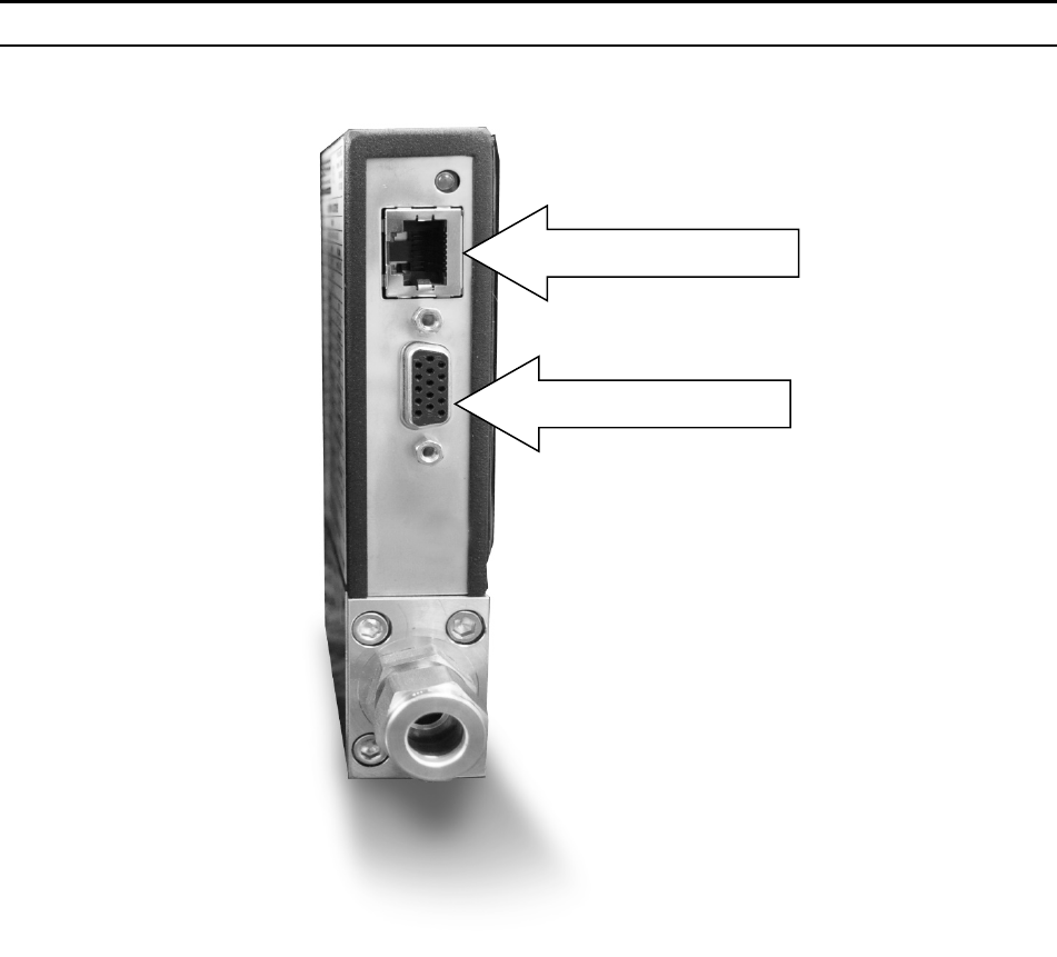
Sierra Instruments Instruction Manual SmartTrak® 100 Series
51
Figure 5-1: SmartTrak Connections
If you do not have the Pilot Module display, you can connect pins 7 (serial transmit), 13
(serial receive) and 3 (analog ground) on the instrument’s 15-pin mini- D Connector to an
appropriate serial port using a standard DB-9 connector instead of using the supplied CRN
cable (see Chapter 2 for wiring instructions). If you use the mini-D connector for your
RS-232 communication, please shield the cable to prevent EMI from disrupting
communications.
If your computer has no serial port, but has a USB port…
Perform the identical connections as if your computer has a serial port (see previous
paragraph), but do not plug the DB-9 connector into your computer. Instead, purchase an
appropriate Serial to USB converter. Plug the DB-9 connector into your Serial to USB
converter and then plug the USB connector into your computer. Load the necessary
CAT 5
HD DB 15

Sierra Instruments Instruction Manual SmartTrak® 100 Series
52
software driver into your computer to operate the converter (software and instructions
should come with the converter).
Your computer will assign a Comm Port number to your USB adapter, but it will probably
not be “Comm Port 1.” Use the Control Panel feature of your computer to identify which
Comm Port number has been assigned to your USB adapter.
Open “My Computer” from your desktop.
Next, open “Control Panel.”
Then, open “System.”
Click on the tab labeled “Device Manager.”
Scan down the list until you see the word “Ports,” then right double-click to examine the
available Com Ports. Record the number(s). You will need to enter this number or one of
these numbers to communicate with your SmartTrak instrument.
If you plan to control more than one SmartTrak instrument from your
computer…
If your computer has a number of serial ports equal to the number of instruments you wish
to operate, simply plug each instrument into a separate serial port as directed above in “If
your Computer has a Serial Port…”
If you wish to operate more instruments than your computer has serial ports, you will
usually have to use USB ports instead. If the number of USB ports in your computer
equals the number of instruments, then purchase one serial to USB converter per
SmartTrak and follow the instructions above. If you have more instruments than ports,
you will need to acquire an edge port device (converts one USB port into several serial
ports) or a USB hub (converts one USB port into many USB ports). Once you have
attached the necessary device and loaded the proper drivers, connect your SmartTrak
instruments to the serial or USB ports as outlined in the sections above. Open a separate
software window for each meter and you can monitor all of them at one time.
If connecting your computer to the SmartTrak creates any confusion, please contact Sierra
Instruments or your IT person for assistance.
Running the SmartTrak Software
Locate the file named “SmartTrak” and open it. You will see the following screen: This is
the main data screen. First, you must select the proper comport.
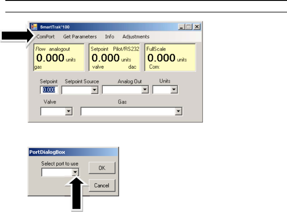
Sierra Instruments Instruction Manual SmartTrak
®
100 Series
53
Select the comport pull down menu:
Use the pull-down menu to choose the port number that corresponds to the serial port
channel your SmartTrak is connected to (from 1 to 255). If you have only one serial port,
select “Comm Port 1.” When finished, click on the box marked “OK.”
You will be returned to the the SmartTrak Master Screen. The screen is the same for both
meters and controllers. Controller functions will not be active for meters and vice versa
Establishing Communication
If the Screen appears with all the yellow and white boxes full, the SmartTrak instrument
has established communication with your computer.
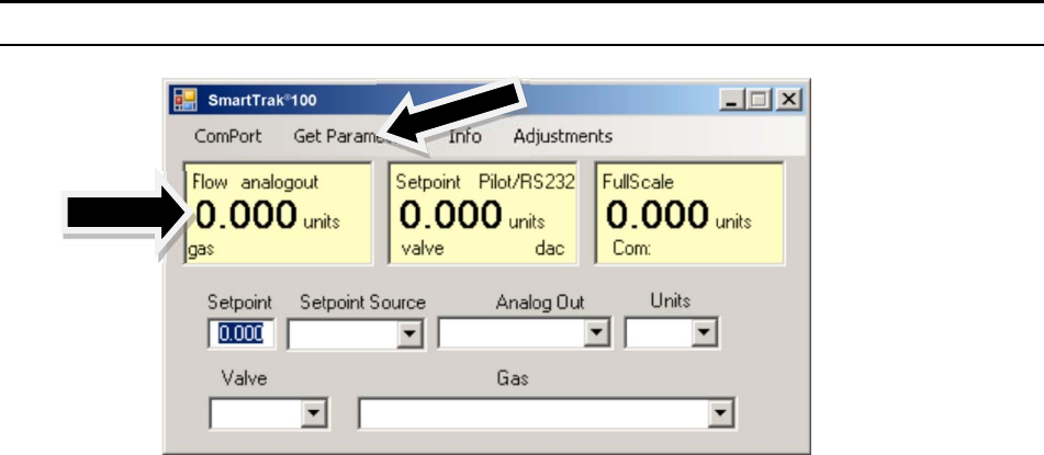
Sierra Instruments Instruction Manual SmartTrak
®
100 Series
54
Proceed to the next section.
If the screen appears, but the yellow and white boxes are all empty, you have selected the
wrong “Com Port number.” See the section titled “Com Port” on page 5-16 for
instructions on how to change the communication port number.
If the screen appears, but only the Mass Flow box shows a value, you are using the correct
Com Port, but your computer is not talking to the SmartTrak. To begin communication,
move the mouse pointer to the top center screen and left click on the words “Get
Parameters.” then values will fill all the boxes on the screen. Communication has been
established. Your computer is now able to control your SmartTrak instrument.
Your SmartTrak instrument is now ready for use!
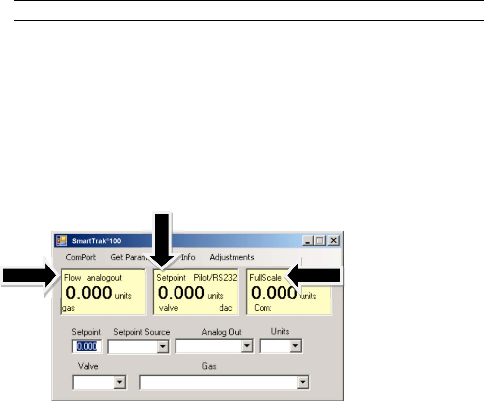
Sierra Instruments Instruction Manual SmartTrak
®
100 Series
55
Using the SmartTrak Software
A. Upper Section of Software Window
Across the upper half of the SmartTrak Software window you will see 3 yellow boxes.
These are titled:
Flow
Setpoint (flow controllers only. Will show zero for meters)
Full Scale
These boxes display the current operating conditions of your SmartTrak instrument. If you
have the Pilot Module, these boxes on the upper half of the software screen are identical to the
Upper Level Screens on the Pilot Module discussed in Chapter 4. The features of these boxes
are described below.
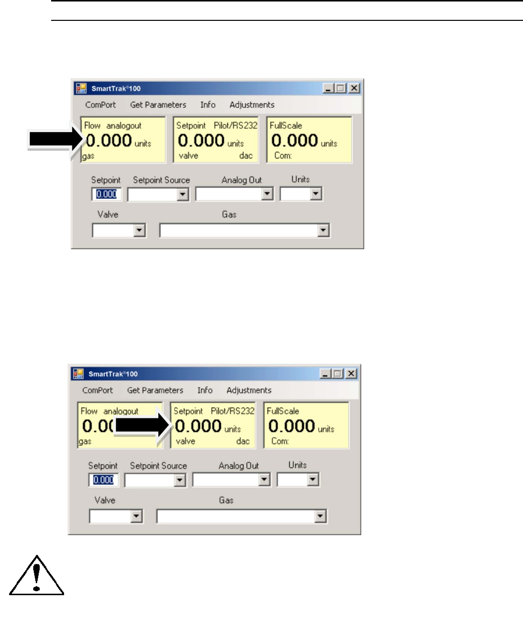
Sierra Instruments Instruction Manual SmartTrak
®
100 Series
56
Flow
The box displays the mass flow rate, the engineering units, the gas choice and the analog
output choice.
Setpoint
If you have a Mass Flow Meter, this box is zero (as shown above). The Setpoint box displays
the current setpoint given to the flow controller, the engineering units, the source of the
setpoint signal, the current valve state (open, closed or purge) and the dac values for the valve
(for Sierra troubleshooting only).
CAUTION: If this box does not show Pilot Module/RS-232 on the first line, you will
not be able to give the controller a setpoint command from your computer. This is
because you SmartTrak is expecting an analog setpoint at the 15-pin mini- D-
connector. To supply a setpoint from your computer, see “Change Setpoint Source”
on page 5-13.
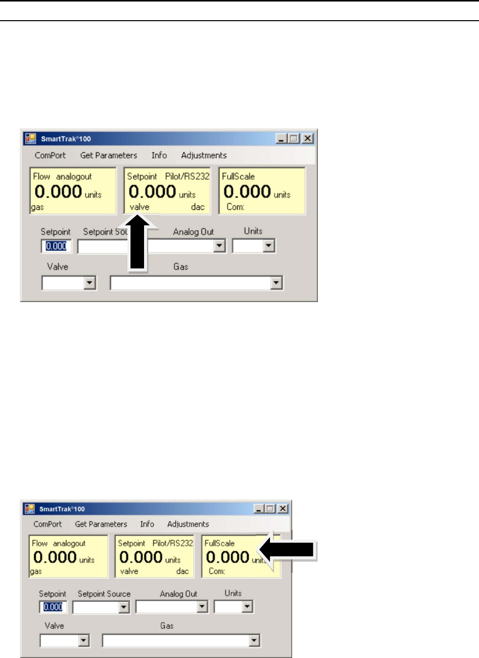
Sierra Instruments Instruction Manual SmartTrak
®
100 Series
57
Note on Valve
If you have a Mass Flow Meter, this information can be bypassed. For normal operation of
the flow controller, this line should display
Automatic.
If this is visible, the instrument
will automatically control flow as soon as a setpoint is given to it.
If this box does not display “Automatic,” it will not be possible to control gas flow. Your
valve is locked open (Purge) or closed (Closed). See the section titled “Change Valve
Operation” below for further instructions
Full Scale
This screen displays the current full-scale value of the instrument with engineering units. It
also displays the com port selected and a counter for the com port (for Sierra Troubleshooting
only).
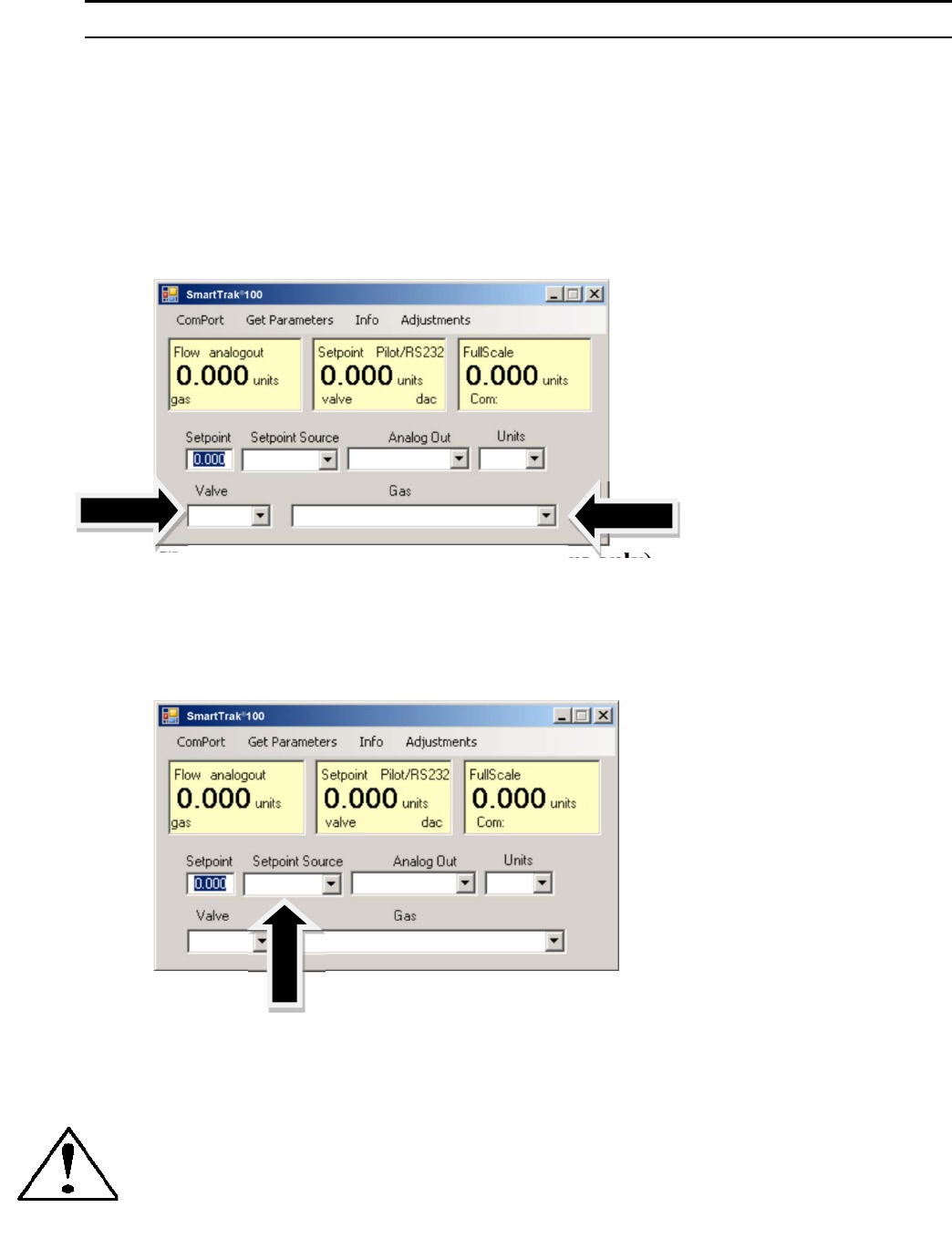
Sierra Instruments Instruction Manual SmartTrak
®
100 Series
58
B. Lower Section of Software Window– Changing
Parameters
Across the bottom half of the screen you will find a number of white boxes. Each box
allows you to adjust one or more meter functions. The various functions are reviewed in
the following section.
Change Setpoint Value (flow controllers only)
This is the box that allows you to change the setpoint of the mass flow controller. To
make a change to the setpoint value, move your pointer to this box and left click. You
may change a digit or delete the current setpoint and key in a new one. When you have
made your selection, press the enter key to implement it.
If, instead of using the RS-232 link or the Pilot Module, you prefer to supply analog set
point signal to the SmartTrak, activate the pull-down menu. Make your selection carefully
and click. Your selection will appear in the box and, after a few seconds, it will also
appear in the yellow setpoint box.
CAUTION: If you change the source of the setpoint to one of the analog values, you
will not be able to control your SmartTrak with your computer.
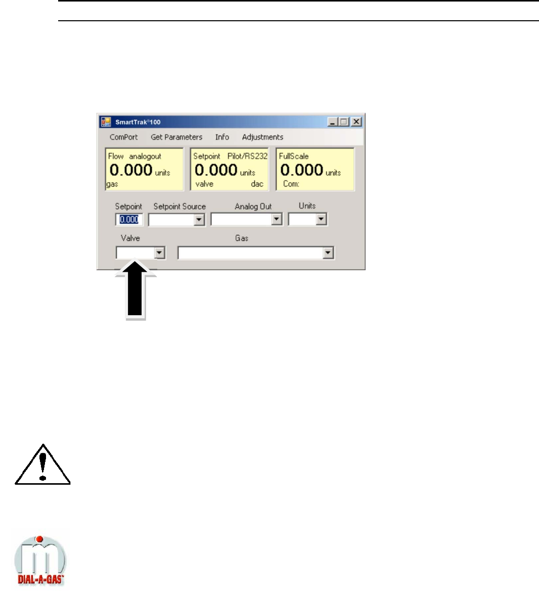
Sierra Instruments Instruction Manual SmartTrak
®
100 Series
59
Change Valve Operation –Automatic, Close, Purge
This function enables or overrides any setpoint command given to the SmartTrak. At
start-up, the box will show Automatic:
In this normal operating position, the valve is ready to control flow when it receives a
setpoint from some source. Using this box, you may set the valve to open well beyond its
normal maximum position (“Purge”) or force the valve to remain shut regardless of
setpoint (“Closed”). Use the pull down menu to make this change. Choose “purge” to
fully open the valve regardless of the given setpoint or choose “closed” to override any
setpoint command and close the valve.
CAUTION: Do not activate the valve state pull-down menus unless you are ready to
make this change. Once in the pull-down menu, if you click on one of the selections,
the valve operation will change immediately. Remember that the SmartTrak is not a
positive shut-off device.
Change Gas (Dial-A-Gas
®
)
This box will display the current gas selection. If you wish to change the gas used in the
instrument, activate the pull-down menu. The 10 gases programmed into the memory of
your SmartTrak will be displayed.
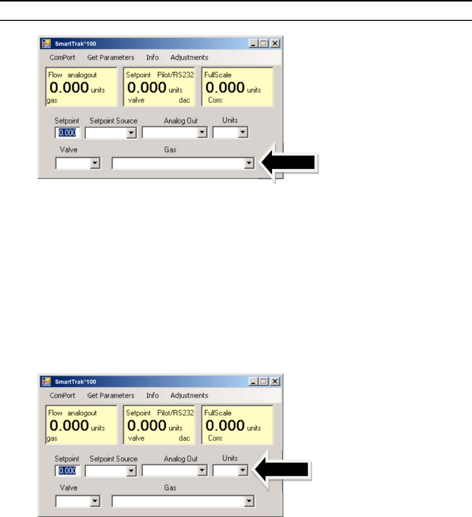
Sierra Instruments Instruction Manual SmartTrak
®
100 Series
60
Choose the correct gas for your current application and click. The new gas selection will
appear in the box. Within a few seconds, the new gas selection will also appear in the
yellow Flow box and the values of the mass flow, setpoint and the full scale will be
adjusted for this new gas. This is normal. In some cases, where the thermal properties of
one gas are very similar to another, these values may not change very much.
Change Units
This box will show the current engineering units. Should you wish to change the
engineering units, use the pull-down menu.
Make your selection, noting that each engineering unit is available with 3 different time
constants: seconds, minutes and hours. Choose the combination of units and time
constants you desire, then click. The box will display your new selection. Within a few
seconds, the units will change in the Flow, Setpoint, and Full Scale boxes and the
numerical values will be adjusted into the new units.
Change Analog Out
This box will show the two analog output signals currently selected for your instrument.
To re-configure the analog output signals, use the pull-down and make your selection. The
SmartTrak will adjust the analog output voltage signal per your instruction.
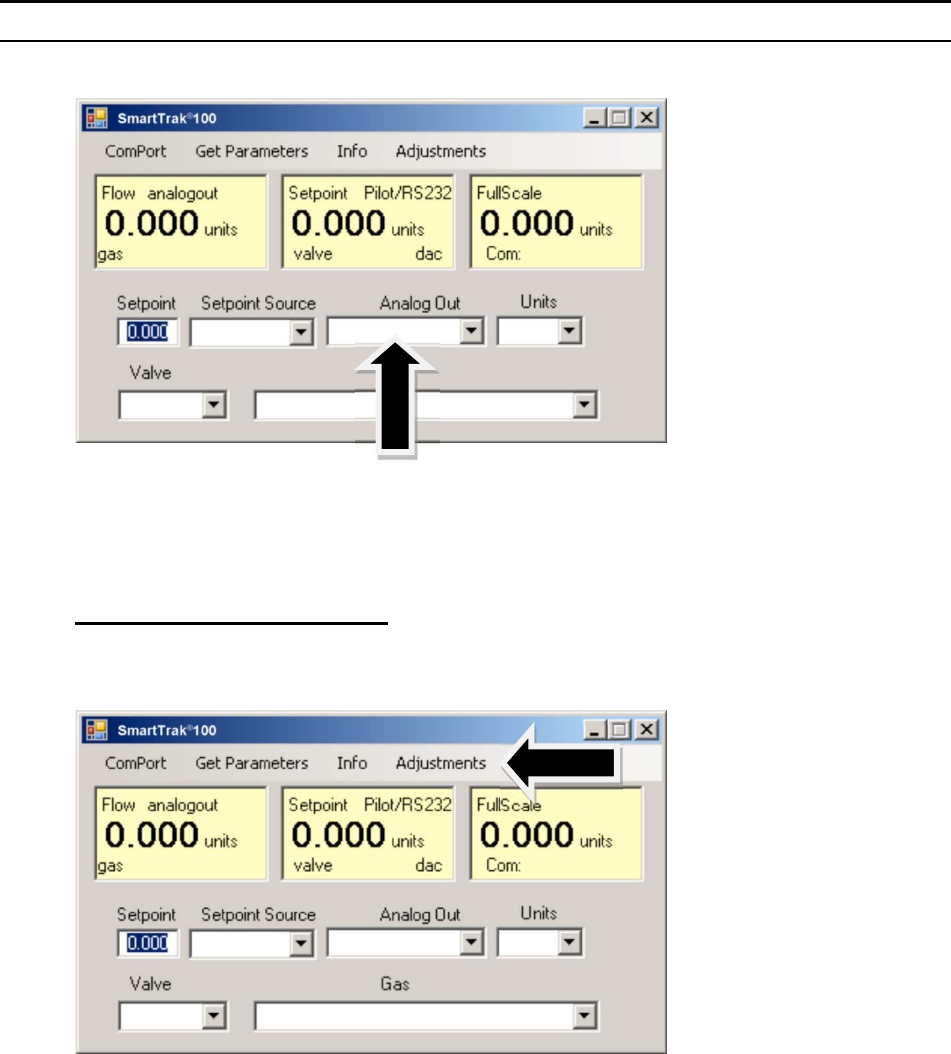
Sierra Instruments Instruction Manual SmartTrak
®
100 Series
61
C: ADJUSTMENTS:
Clicking on “adjustments” brings up the meter settings screen.
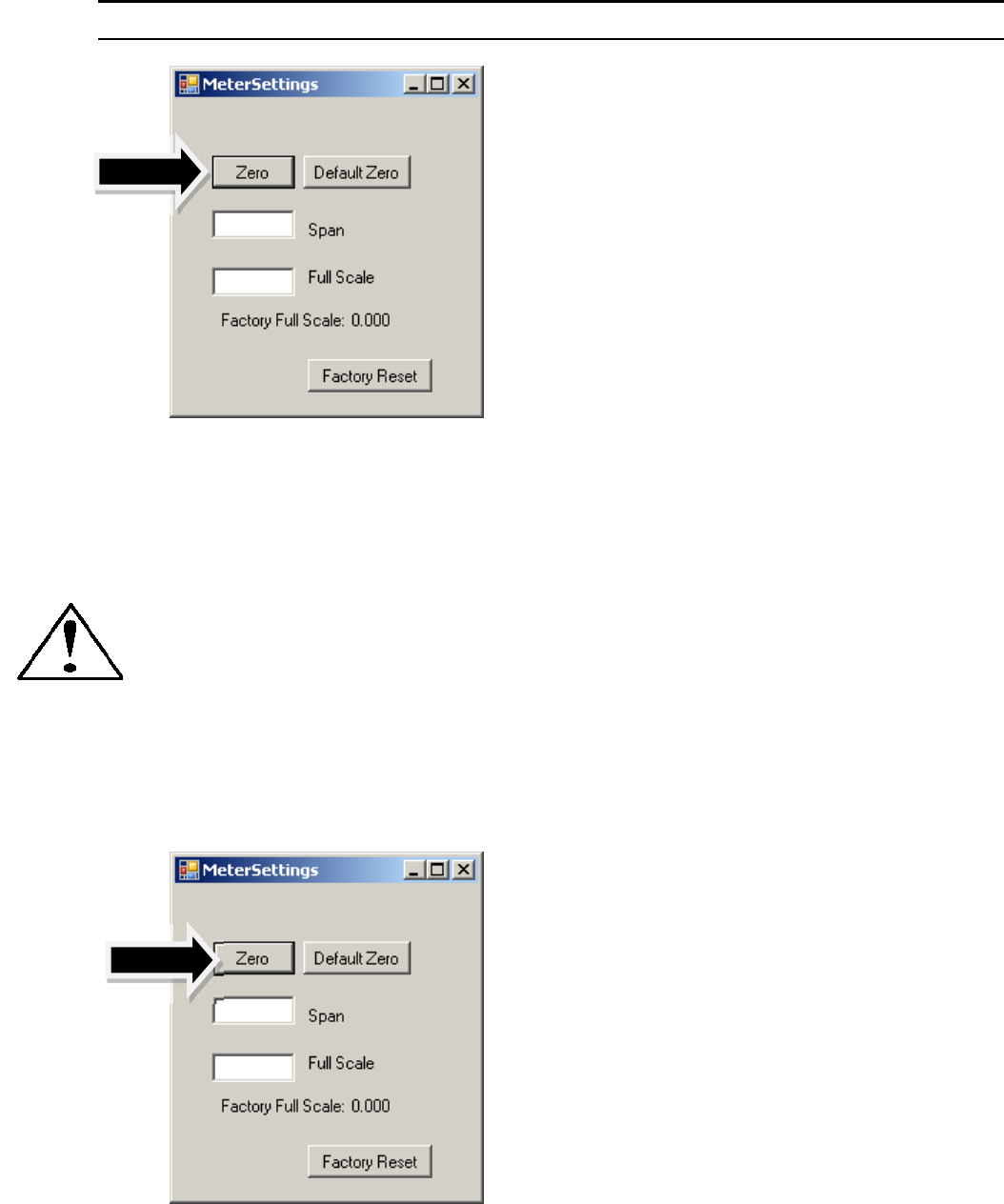
Sierra Instruments Instruction Manual SmartTrak
®
100 Series
62
This screen allows for zeroing, spanning and adjusting the full scale for each of the 10
gases in the gas table individually. The screen will be displayed for the gas selected in the
gas table on the main screen
Caution: the values in this screen can be set individually for each of the 10 gases.
MODIFICATIONS of this screen will only be applicable to the gas displayed. To modify
other gases, change the gas in the pull down menu and repeat.
Change Zero:
This button automatically zeros the meter.
To perform this zero procedure, you must make sure that the actual flow is zero.
Attempting to zero the meter or controller while there is a flow condition will cause an
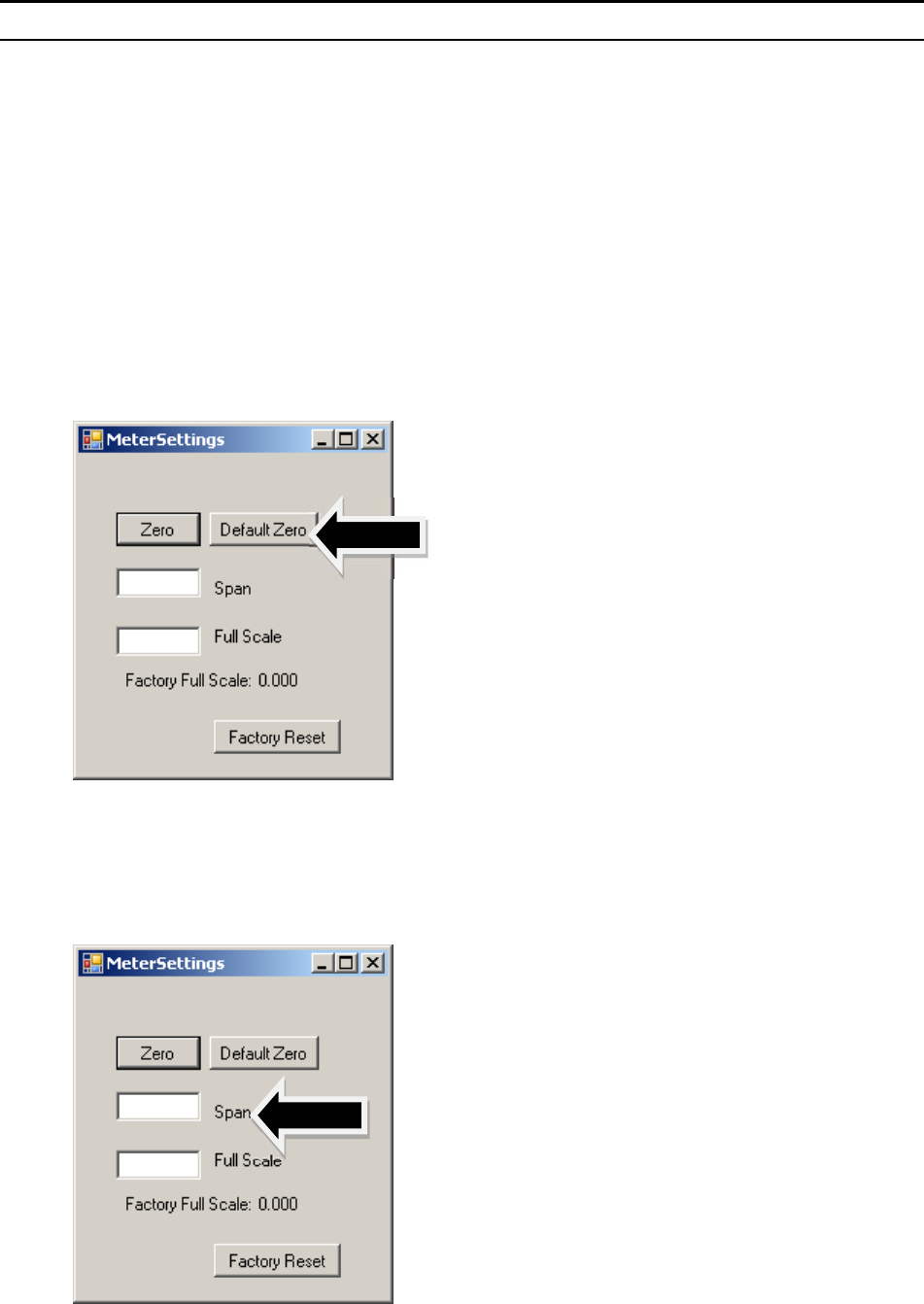
Sierra Instruments Instruction Manual SmartTrak
®
100 Series
63
offset. Also, the best zero is obtained by using the actual gas at the listed operating
pressure.
After 30 minutes, if your zero reading and/or calibration are off (i.e. show flow at
zero), we recommend that you perform the re-zeroing procedure. Refer to page 45 “Zero
Meter Screen” for instructions.
Default zero:
This will set the zero value back to factory conditions. Use this in order to recover from a
mistaken entry.
Span:
This allows the user to enter an offset to the span to adjust the meter outputs to match
another device or field conditions. The span is a MULITPLIER and will multiply all
outputs by the entered amount.
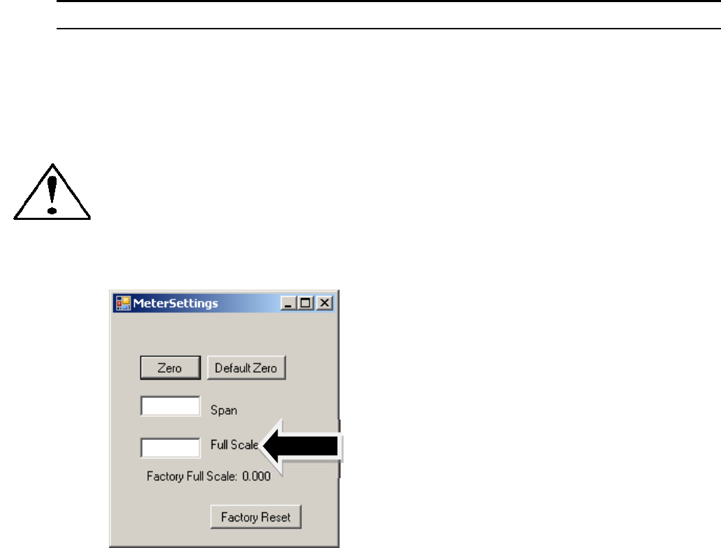
Sierra Instruments Instruction Manual SmartTrak
®
100 Series
64
For example, the meter reads 98. The desired reading is 100. A span value of 1.02 will
adjust the meter output to read 100.
Caution: this number should not be adjusted beyond 0.8 to 1.2.
Change full scale:
This setting allows you to change the full scale of your instrument
The instrument will display its current full-scale value. If your instrument is new or this
value has never been modified, the value displayed will be 100% of the maximum flow
rate your SmartTrak can measure or control without factory re-calibration. This is the
number listed here:
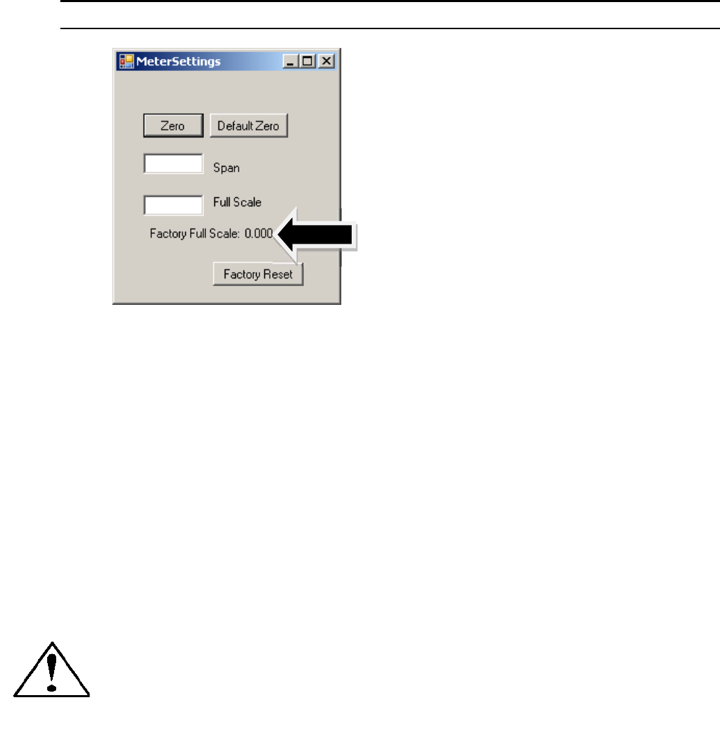
Sierra Instruments Instruction Manual SmartTrak
®
100 Series
65
The instrument’s maximum flow rate is also recorded on the data label (at the back of the
instrument) and on the calibration certificate.
You may select any full-scale value between 100% and 50% of the maximum full-scale
value. If you select a new full-scale value, it will re-define the analog outputs of the
instrument. The 20 mA signal and the corresponding voltage signal (5 or 10 VDC) will
now represent this new full-scale value.
To change the full-scale value of your device, modify one digit or erase the current value
displayed and type in your desired full-scale value. When you are satisfied with your
selection, press the enter key. The new full-scale value will appear in the white box. A
few seconds later, the same value will appear in the yellow box in the upper half of the
screen titled “Full Scale.”
CAUTION: The Change Full Scale function allows you to re-range your instrument,
but it is important to be aware of the limitations of this function.
Changing beyond recommended values may require a new LFE or even flow body be
installed. If in doubt, select factory reset and both zero and span values are reset to
factory values
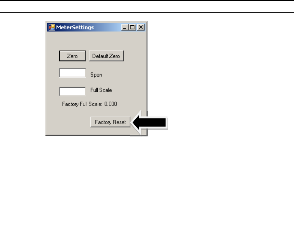
Sierra Instruments Instruction Manual SmartTrak
®
100 Series
66
Here are some guidelines to remember if you choose to modify the Full Scale Value:
Changing the full-scale value of the instrument does not affect the accuracy of the
measurement. Instrument accuracy is a percentage of the original factory full-scale value
If you enter a full-scale value beyond the instrument’s calibrated maximum range, the
SmartTrak will automatically modify the full-scale to equal the factory full-scale value.
Below 1% of the original factory full-scale value for a meter and 2% for a controller, your
SmartTrak is programmed to read zero because the error in the measurement may exceed
the measurement itself.
Other Useful Features
There are several additional features that you may utilize via the SmartTrak Software.
Across the top of the SmartTrak Master Screen, you can see these options:
Com Port
Read Parameters
Info
To use any of these functions, simply place the mouse pointer onto the name of the feature
you wish and left click.
Com Port
To change the communication port for the SmartTrak, click on this feature. Use the pull
down menu to choose the Comm Port that your SmartTrak’s serial connector is plugged
into. Remember that the software asks you to confirm your Comm Port every time you re-
start. This feature is designed for situations when you have multiple Comm Ports available
and you wish to move the SmartTrak from one to another or you are controlling more than
one SmartTrak at one time.

Sierra Instruments Instruction Manual SmartTrak® 100 Series
67
Read Controller Parameters
Use this function if you believe your computer and your SmartTrak instrument may have
stopped communicating. It is essentially a re-boot command for the SmartTrak
microprocessor. When you switch Comm Ports, it is recommended that you use this
function. If your computer requires a re-boot and you do not unplug your SmartTrak, the
communication link will be broken. Use this function to re-establish communication. If
at any time, the instrument does not appear to be sending correct information to the
SmartTrak software, try this command to ensure communication.
Info
This gives information about the meter serial and software revisions.

Sierra Instruments Instruction Manual SmartTrak® 100 Series
68
CHAPTER 6: TECHNICAL SUPPORT & SERVICE
Technical Support
If you encounter any problem with your instrument, review the configuration information
for each step of the installation, operation, and set up procedures as explained in this
manual. Verify that your settings and adjustments are consistent with factory
recommendations.
If the problem persists, Sierra is eager to help you. You may contact us at any of the
following Technical Support Centers. It may also help to call your Sierra Sales Agent, who
is also well trained in the operation of the product.
IMPORTANT: When contacting Technical Support, make sure you have
included the following information:
The flow range, serial number, Sierra order number and model number (all marked on
the instrument data label).
The problem you are encountering and any corrective action taken.
Application information (gas, pressure, temperature, pipe and fitting configuration).
CUSTOMER SERVICE AND SUPPORT INFORMATION:
Email Technical Support: service@sierrainstruments.com
Email Sales: sales@sierrainstruments.com
FACTORY USA
TOLL FREE: 800-866-0200
PHONE: 831-373-0200
FAX: 831-373-4402
EMAIL: service@sierrainstruments.com
European Sales & Service Center:
PHONE: +31 72 5071400
FAX: +31 72 5071401
EMAIL: service@sierra-instruments.nl
Asia Sales & Service Center:
PHONE: + 8221 5879 8521
FAX: +8621 5879 8586
EMAIL: www.sierra-asia.com
Sierra Instruments Instruction Manual SmartTrak® 100 Series
69
Sierra Website
www.sierrainstruments.com
Returning Equipment to the Factory
Factory Calibration—All Models
Sierra Instruments maintains a fully-equipped calibration laboratory. All measuring and
test equipment used in the calibration of Sierra transducers are traceable to NIST
Standards. Sierra is ISO-9001 registered and conforms (but is not certified) to the
requirements of ISO 17025.
Instructions for Returning Your Instrument for Service
The following information will help you return your instrument to Sierra Instruments'
Factory Service Center and will ensure that your order is processed promptly. Prices may
vary depending on the flow range, type of gas and operating pressure of your unit. To
request a rough estimate of the pricing, contact your local Sierra Instruments distributor or
contact one of our offices directly. A detailed quote will be provided following a full
evaluation of your instrument.
Please follow these easy steps to return your instrument for factory service:
Obtain a Return Materials Authorization (RMA) number from the Sierra Instruments
website at http://www.sierrainstruments.com/rma/login.php
If you require service beyond calibration, but do not know which service(s) will be
required, describe the symptoms as accurately as possible on the RMA form.
Pack your instrument carefully. Use the original packaging and foam or bubble wrap
(packing peanuts NOT recommended) and include a copy of the RMA form (complete
with Sierra supplied RMA number) with the unit(s).
Ship the unit(s) to the following address:
Sierra Instruments, Inc.
Attention: Factory Service Center
5 Harris Court, Building L
Monterey, CA 93940 USA
RE: RMA# (your number)
Sierra Instruments Instruction Manual SmartTrak® 100 Series
70
IMPORTANT SAFETY NOTE ABOUT PURGING
WARNING: When toxic or corrosive gases are used, purge unit
thoroughly with inert dry gas before disconnecting from the gas line
to prevent personnel from being injured when coming in contact with
the instrument.
WARNING: If an instrument used with a toxic or corrosive gas is
returned to the factory, a Material Safety Data Sheet (MSDS) must be
enclosed & attached to the outside of the box to alert Sierra
personnel of the potential hazard. Also, make sure the inlet & outlet
are solidly plugged off.
Sierra Instruments Instruction Manual SmartTrak® 100 Series
71
Appendix A: C100/M100 SmartTrak Product Specifications,
Dimensions and Mounting
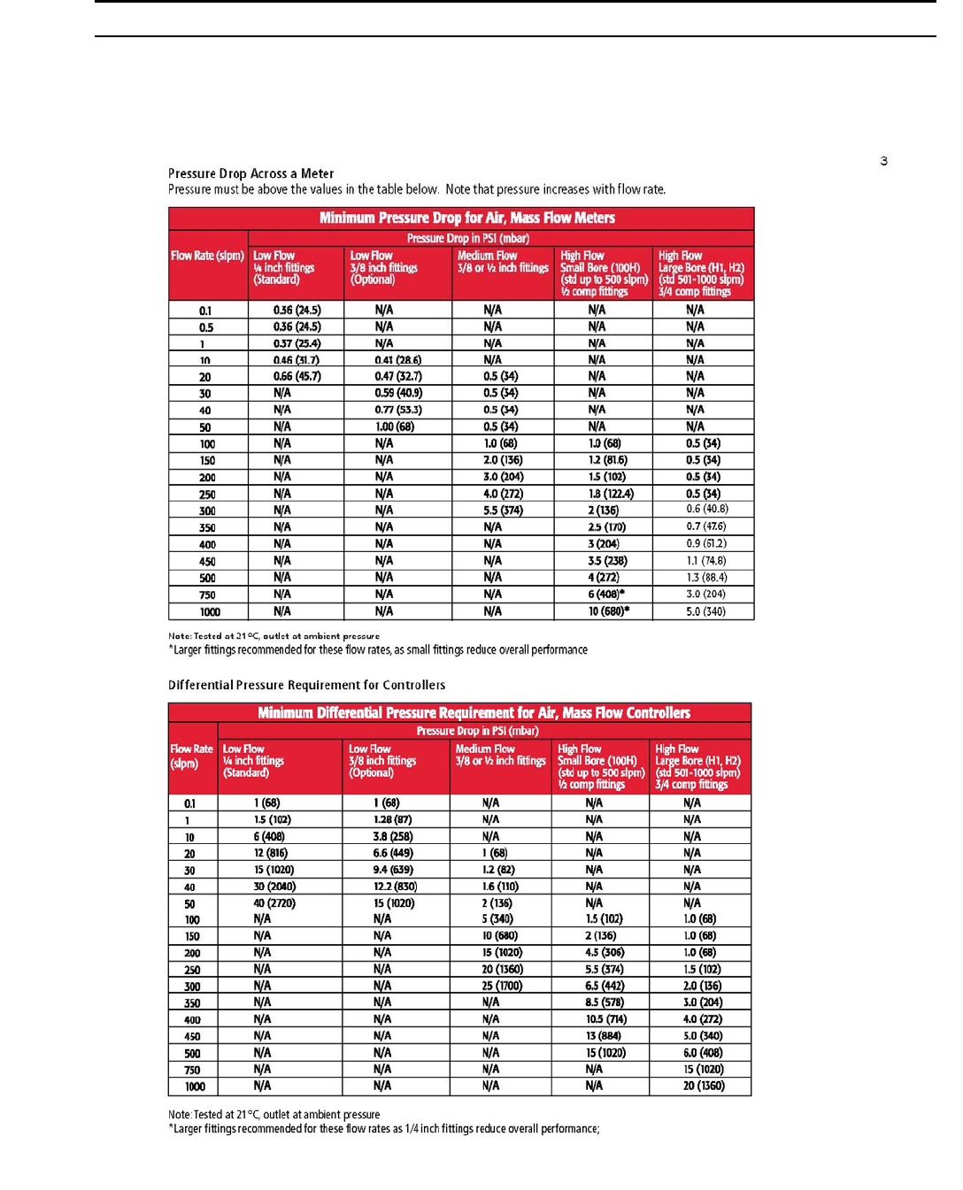
Sierra Instruments Instruction Manual SmartTrak® 100 Series
72

Sierra Instruments Instruction Manual SmartTrak® 100 Series
73
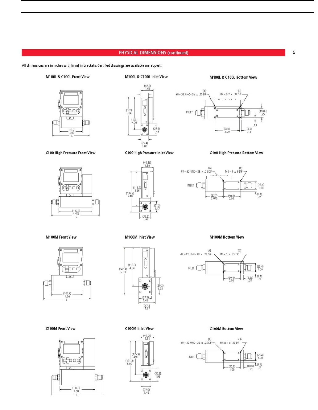
Sierra Instruments Instruction Manual SmartTrak® 100 Series
74
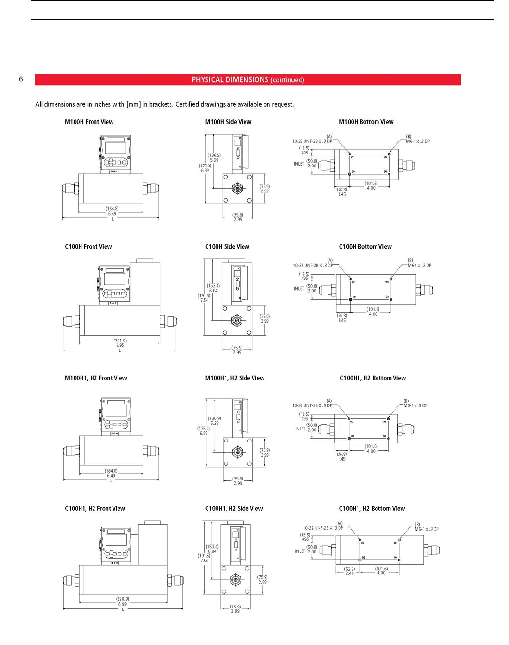
Sierra Instruments Instruction Manual SmartTrak® 100 Series
75
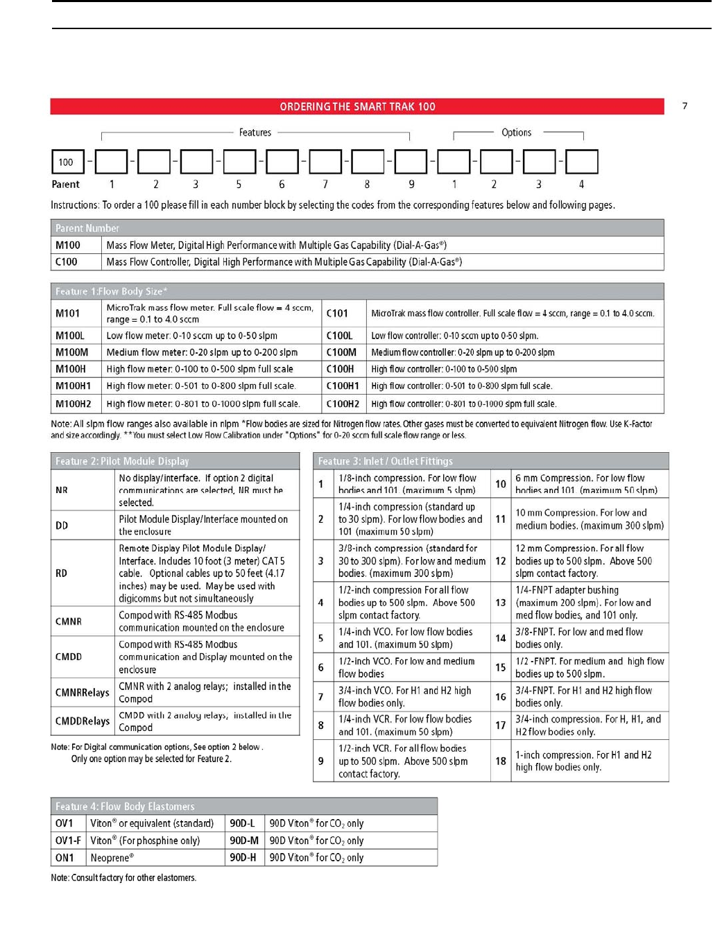
Sierra Instruments Instruction Manual SmartTrak® 100 Series
76
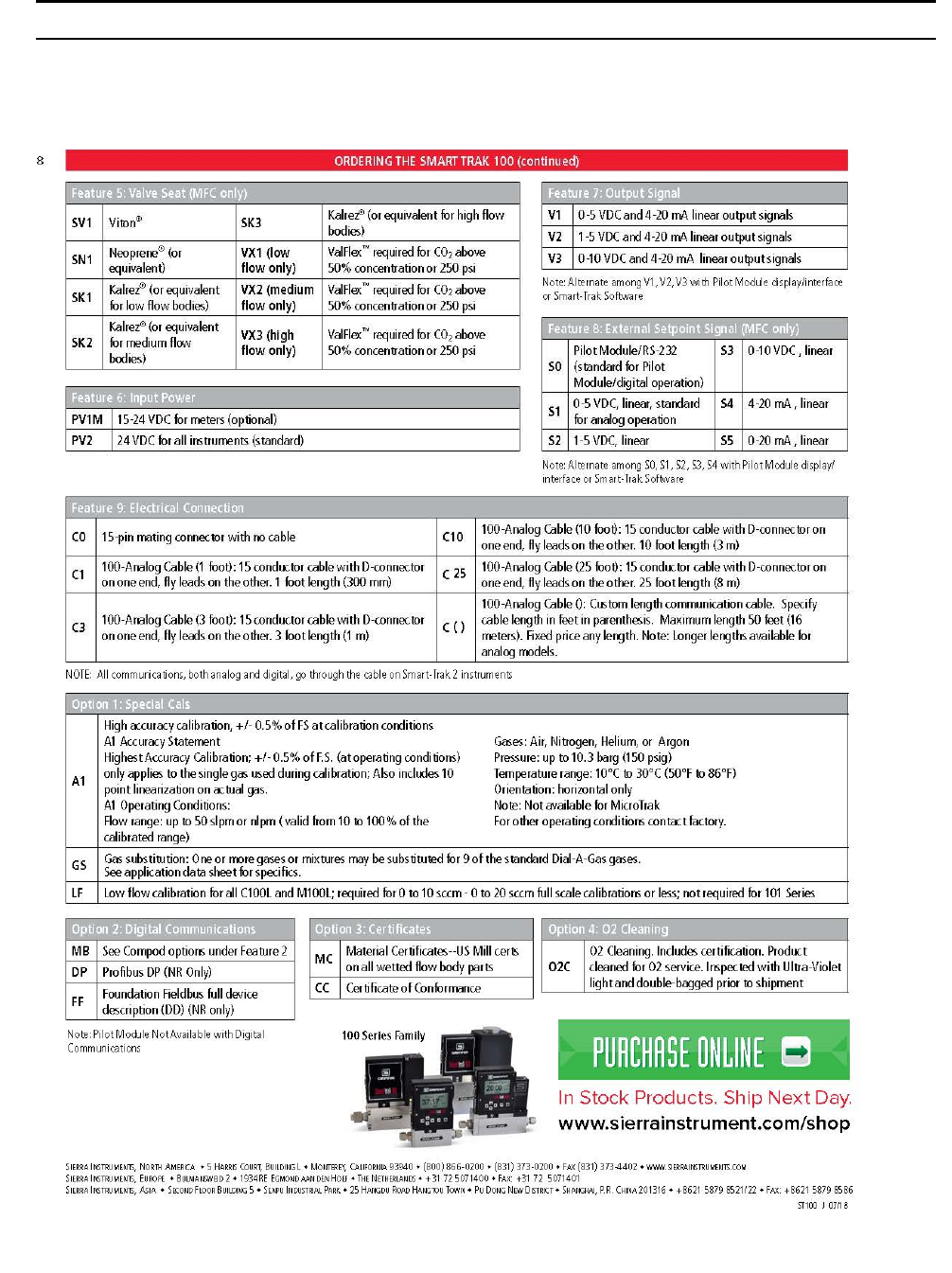
Sierra Instruments Instruction Manual SmartTrak® 100 Series
77
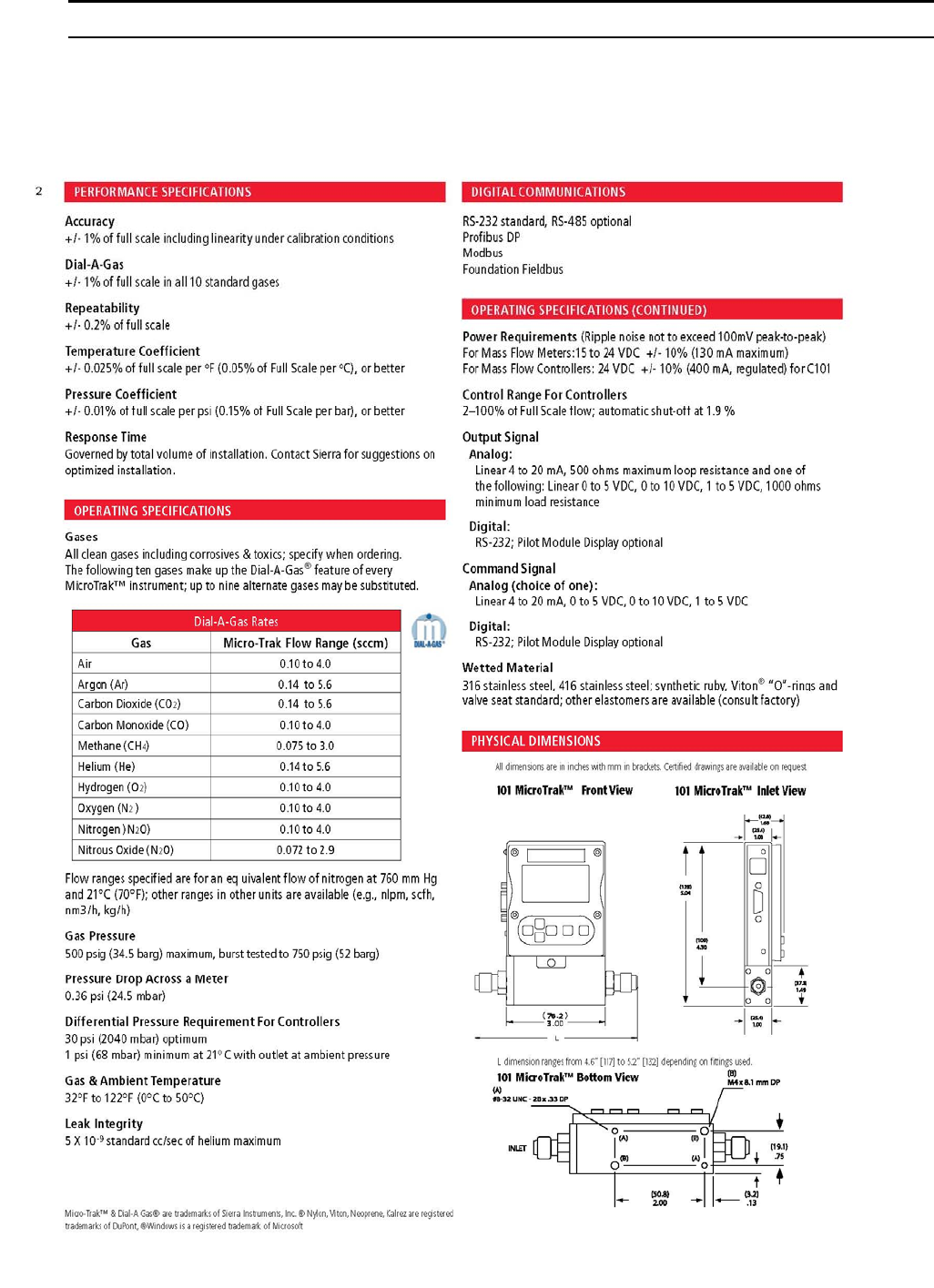
Sierra Instruments Instruction Manual SmartTrak® 100 Series
78
Appendix B: C101/M101 MicroTrak™ Product Specifications
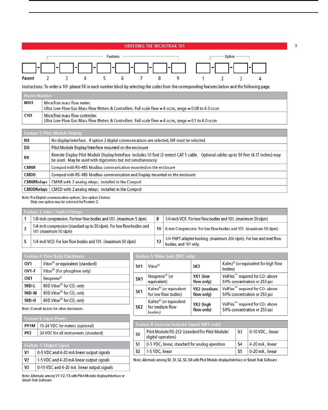
Sierra Instruments Instruction Manual SmartTrak® 100 Series
79
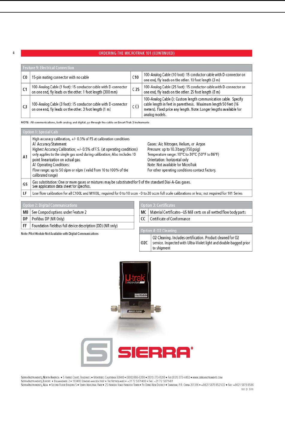
Sierra Instruments Instruction Manual SmartTrak® 100 Series
80
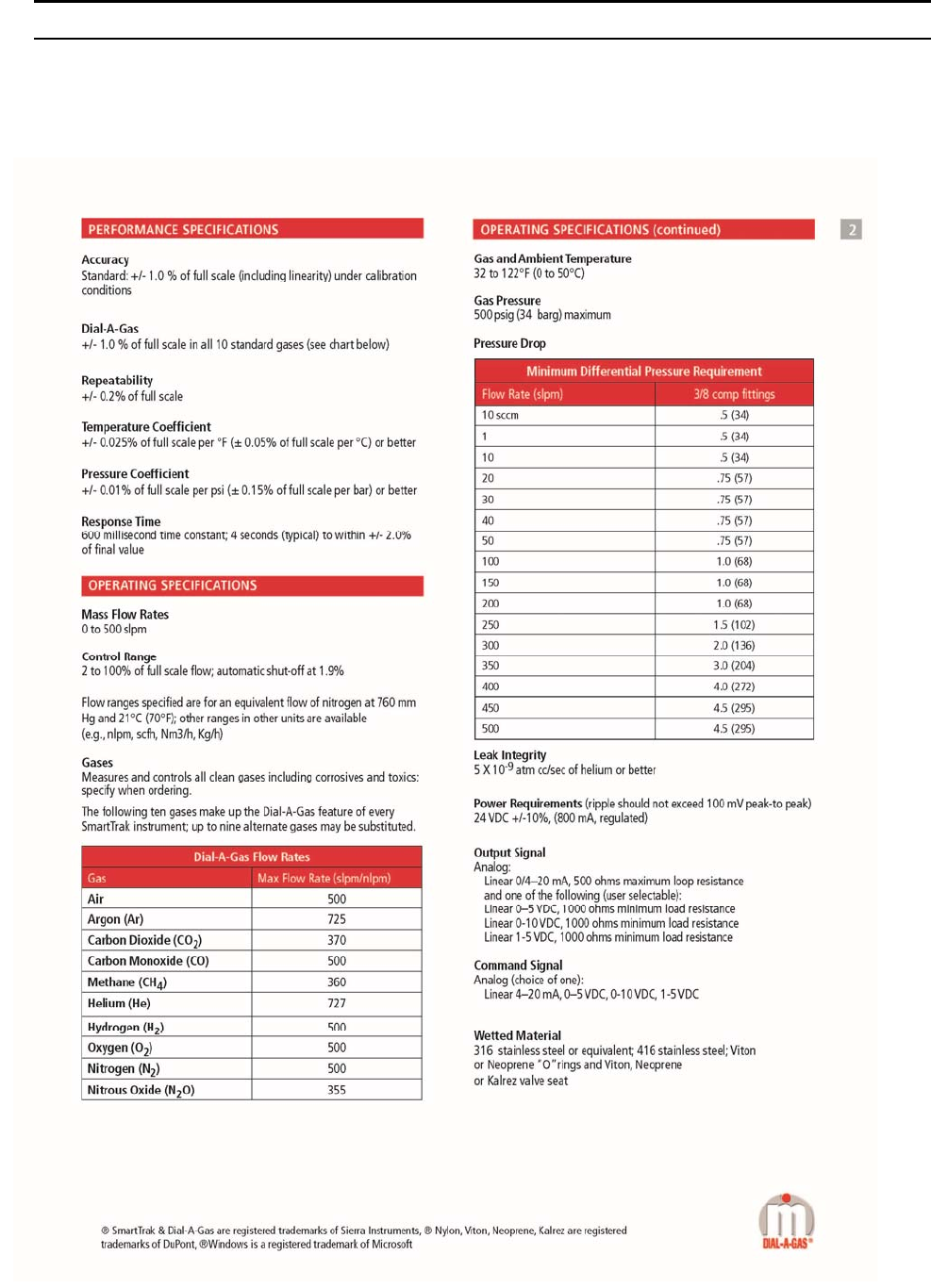
Sierra Instruments Instruction Manual SmartTrak® 100 Series
81
Appendix C: C140M Ultra-Low ΔP Product Specifications, Dimensions and
Mounting
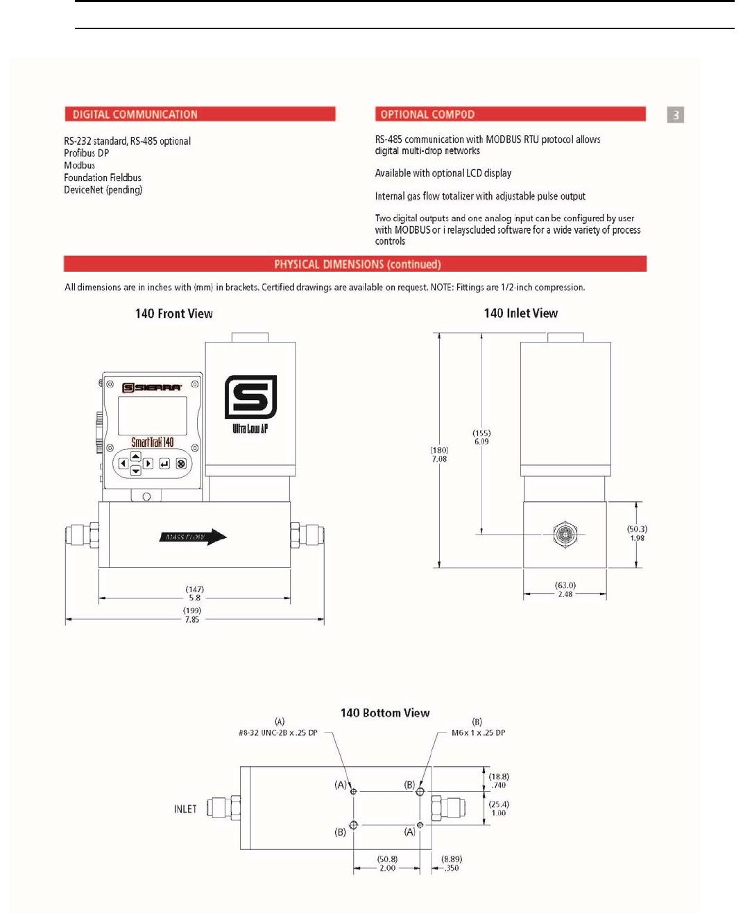
Sierra Instruments Instruction Manual SmartTrak® 100 Series
82
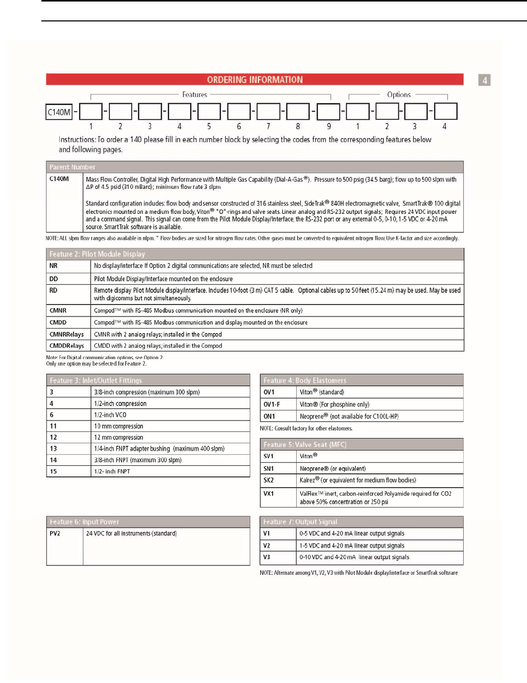
Sierra Instruments Instruction Manual SmartTrak® 100 Series
83
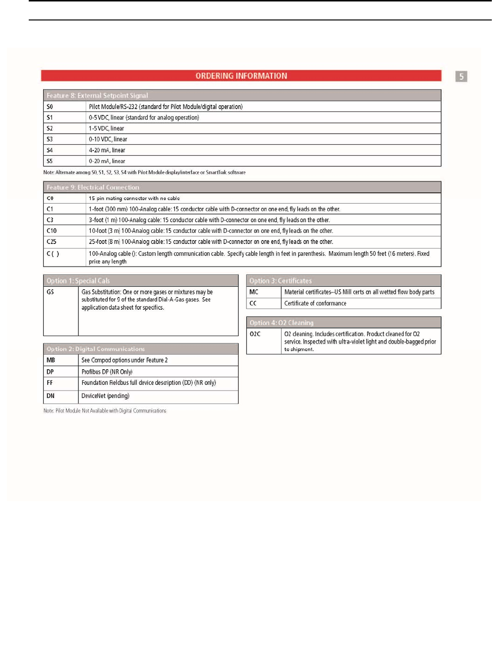
Sierra Instruments Instruction Manual SmartTrak® 100 Series
84
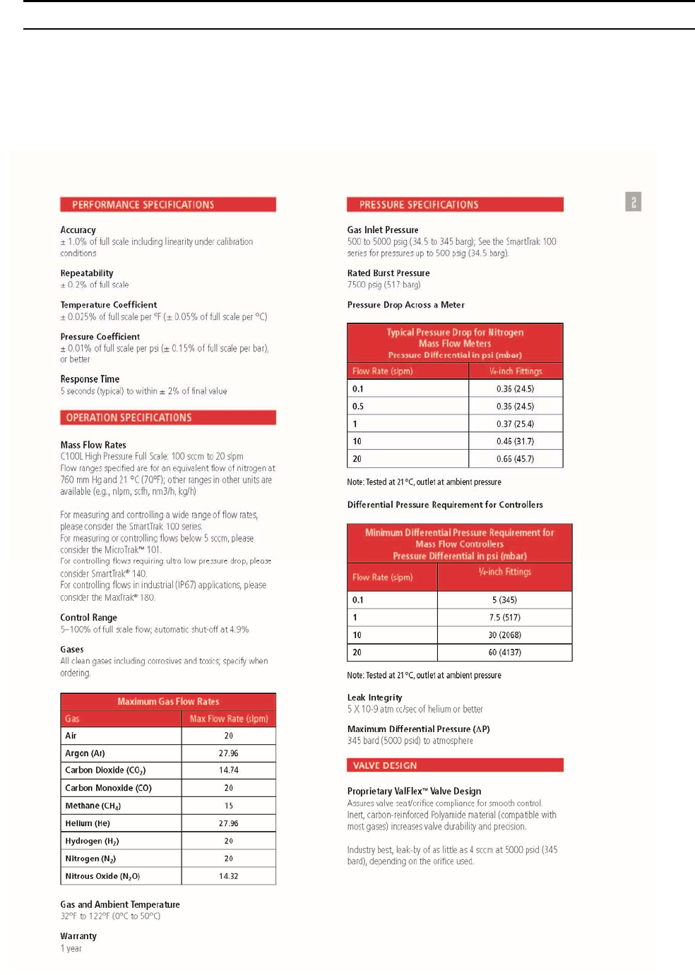
Sierra Instruments Instruction Manual SmartTrak® 100 Series
85
Appendix D: 100HP SmartTrak Product Specifications, Dimensions and
Mounting
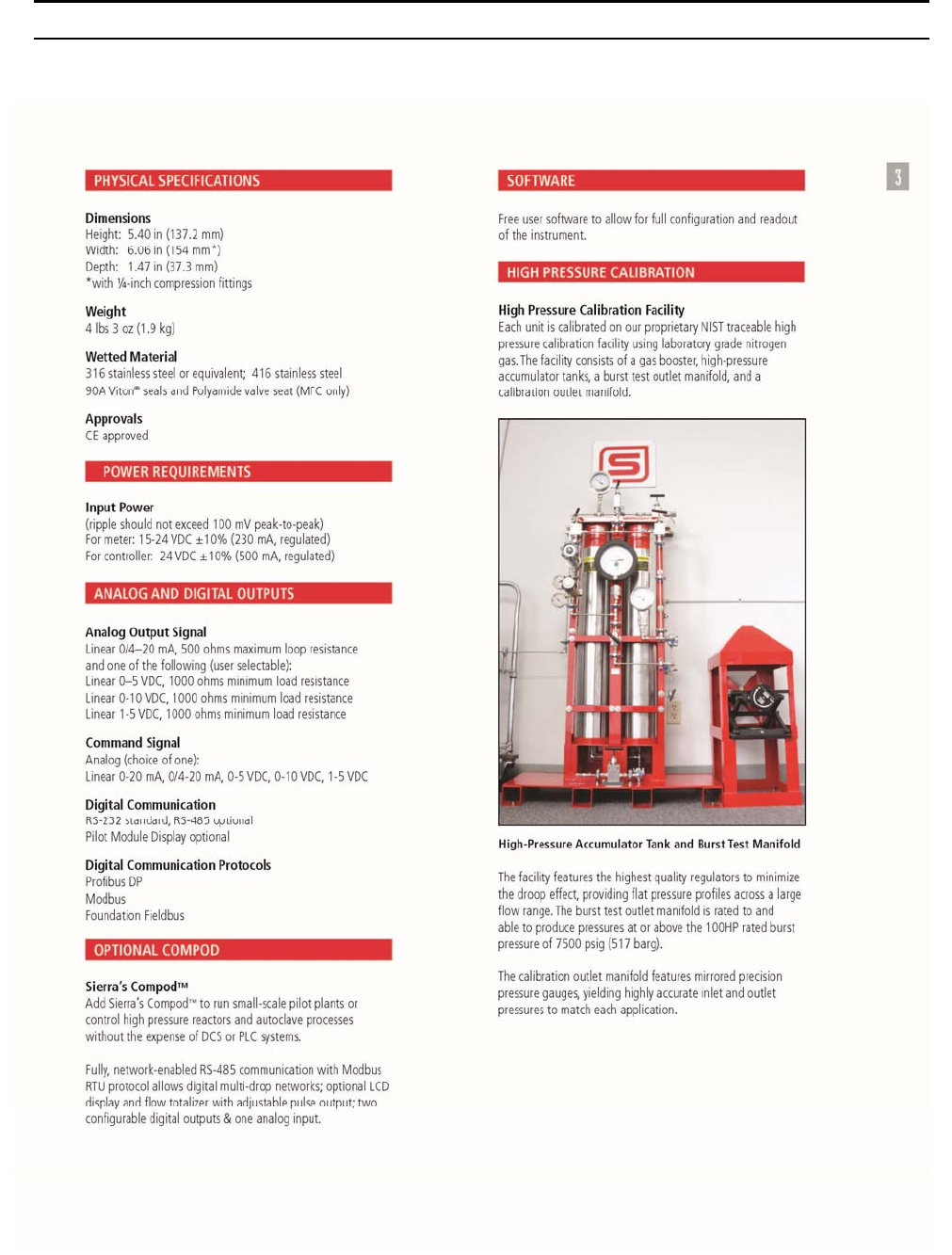
Sierra Instruments Instruction Manual SmartTrak® 100 Series
86
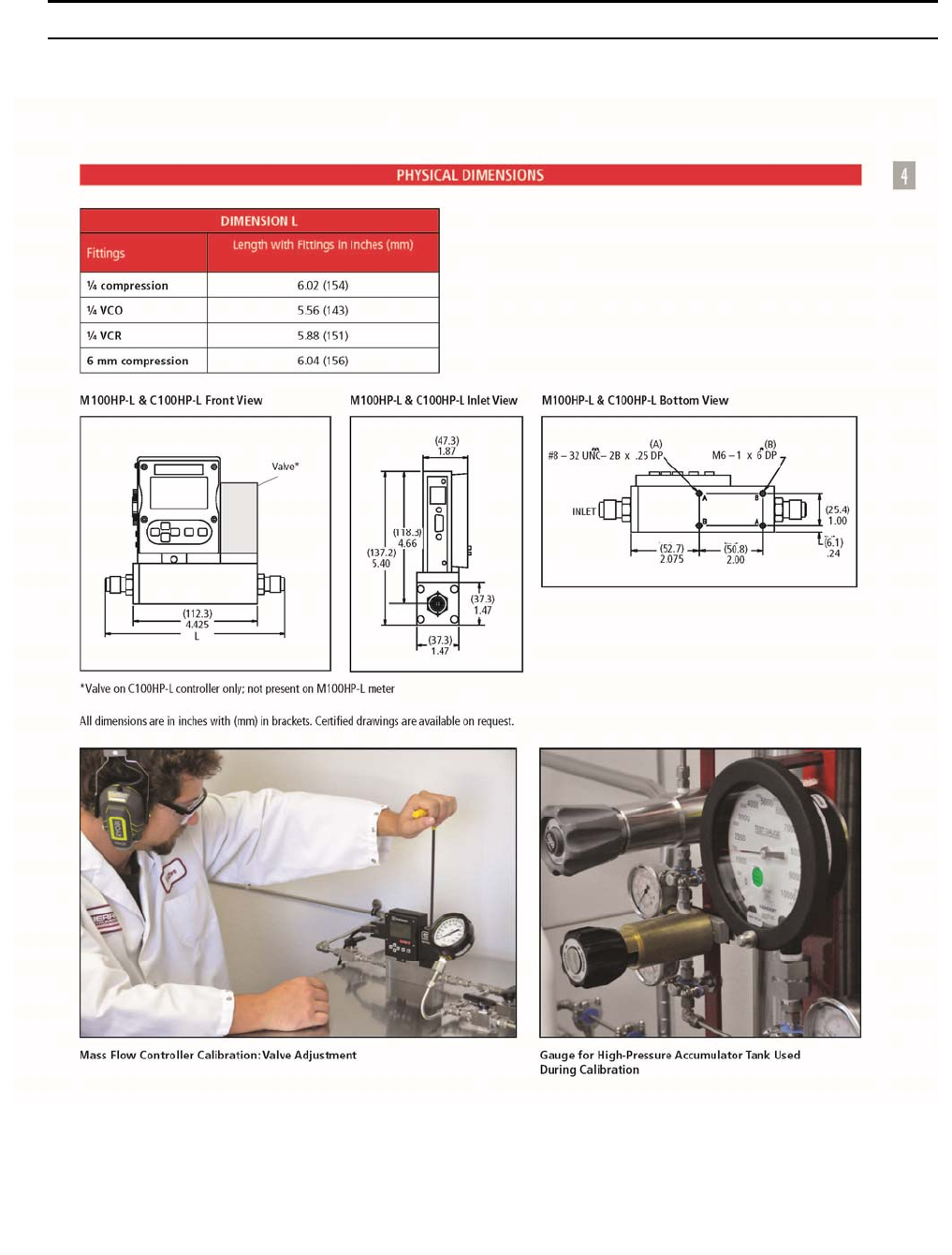
Sierra Instruments Instruction Manual SmartTrak® 100 Series
87
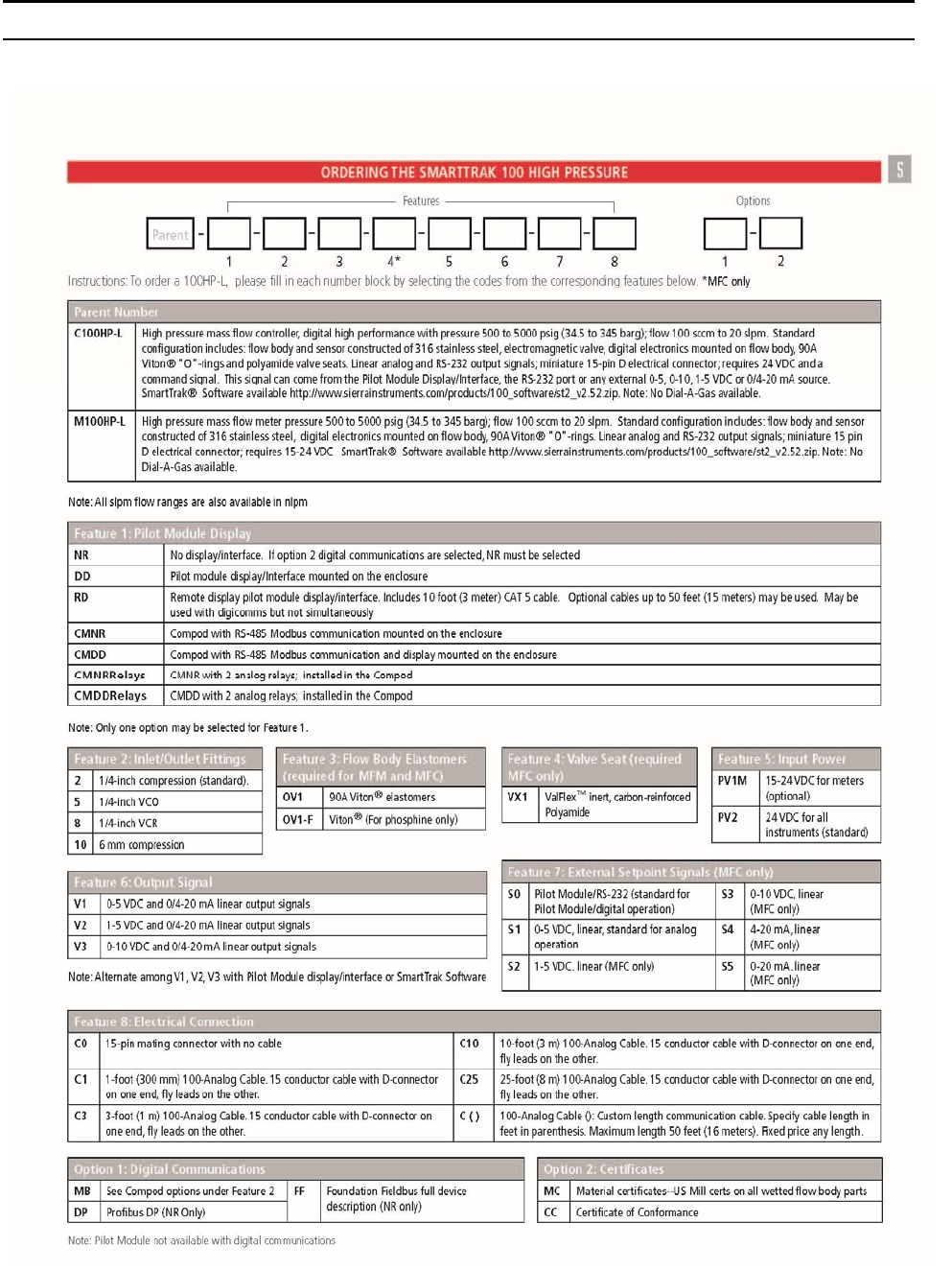
Sierra Instruments Instruction Manual SmartTrak® 100 Series
88
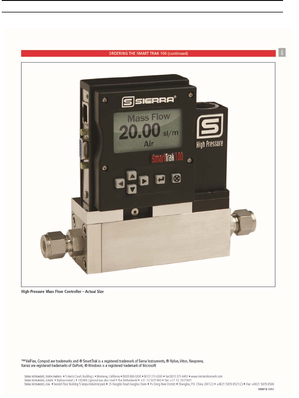
Sierra Instruments Instruction Manual SmartTrak® 100 Series
89
Sierra Instruments Instruction Manual SmartTrak
®
100 Series
90
Appendix E: Safety Guide for the 100HP
This Safety Guide is applicable for SmartTrak
®
100HP Ultra-High Pressure Mass Flow Meters
and Controllers.
Ultra-High Pressure Safety
Operating equipment under very high pressures does have safety risks of which you should be aware. This
guide is intended to educate the end-user in general terms of the risks of high pressure applications and is not
a complete registry of all high pressure do’s and don’ts. It is recommended that end-users educate
themselves on the specifics of their application and read any information their employer provides on the
subject.
Please read this Safety Guide in its entirety, the Quick Install Guide, and refer to the SmartTrak 100 Series
Instruction Manual, Chapter 2 for complete installation and operation instructions.
Ultra-High Pressure Specifications
The 100HP mass flow controller or meter can be used for a variety of flow rates, pressure drops, inlet
pressures, and gas types. However, each unit must be tuned specifically for each of these different
applications. The 100HP is rated to 5000 psig (345 barg) operating pressure, 7500 psig (517.1 barg) burst
pressure (unless otherwise listed on the enclosure data label). You must know the capacity of each specific
model, as it will vary for specific gases and applications.
Warning!
The working pressure is stated on the flow meter and controller label. Check label and
process pressure before installing in the line. If the pressure values listed do not match
that of your application, the instrument should not be used. Consult the factory for the
next steps.
Specified leak rate maximum: As little as 4 sccm at 5000 psid (345 bard) with a maximum of 5% of full
scale flow. Sierra recommends the use of a positive shut-off valve in series with the 100HP. Make sure the
Cv of the shut-off valve is sufficiently large so as to not cause a choked flow condition at rates less than the
full scale of the 100HP.
Gas Cylinder Pressure Specifications
No mass flow meter or controller is universally functional for every application and this is particularly true
when dealing with pressures above 1500 psig (103 barg). The 100HP is designed to be used at or below
5000 psig (345 barg).
Thus, the 100HP is fully capable of controlling GSA standard, lower-pressure gas cylinders. However, some
gas cylinders can reach pressures exceeding 6000 psig (413.7 barg) and therefore are not incompatible with
the 100HP. While the 100HP is designed for use with most gas cylinders, never use the 100HP to control
pressures exceeding 5000 psig (354 barg).
It’s important to note that gas properties are pressure-dependent. All pressure ratings are based on
compressed nitrogen, and many gases cannot be used with the 100HP at 5000 psig (345 barg). Oxygen is a
good example of this. Please consult the data label of your meter or controller for the most specific ratings,
or consult the factory.
Sierra Instruments Instruction Manual SmartTrak
®
100 Series
91
Pre-Installation Safety Procedures
1. Please read all instructions and cautionary markings on the instrument, as well as all appropriate
sections of the SmartTrak 100 Series Instruction Manual, Chapter 2 and Appendix D before using this
product.
2. General operation, display interface, PC software and electrical installation are same as a standard
SmartTrak 100 Series mass flow meter and controller.
3. Verify proper connection of all pressure sources and electrical signals prior to applying pressure or
power to the 100HP. See SmartTrak 100 Series Instruction Manual, Chapter 2 for complete installation
and operating instructions.
4. Pressurization Procedures
Slowly apply pressure to the system. Open process valves slowly to avoid flow surges. When
applying pressure to the system, take care to avoid unnecessary pressure shocks in the system.
Check for leaks around the meter inlet and outlet connections. If no leaks are present, bring the
system up to operating pressure.
Never test for leaks with a liquid leak detector
. If liquid seeps into the electronics or the sensor
compartment, the instrument may be damaged. Instead, use a pressure---decay test (if liquid MUST be
used at all, limit it to the fittings and keep it off the body of the instrument).
Increase pressure gradually up to the level of actual operating conditions. Follow standard practice
for pressurized systems.
Warning!
Do not operate this instrument in excess of the specifications listed on the data
label, in this addendum, or in the SmartTrak 100 Series instructional manual.
Failure to heed this warning can result in equipment damage, failure, serious
injury or death.
5. Apply power only after reviewing wiring diagrams in the SmartTrak 100 Series Instruction
Manual, Chapter 2 .
6.
Do not apply power to the output loop.
This is NOT a loop-powered device.
7. Apply gas flow only after checking plumbing connections for leaks.
8. Field service of this unit by the customer voids this unit’s warranty and is not advised. Send unit to
Sierra Instruments for service.
Warning!
If this equipment is not properly serviced, serious personal injury and/or
damage to the equipment can result from the potentially high operating
pressures. Please insure that the process line pressure is removed prior to
removal for
s
ervice.
Warning!
Always bleed your pressure line down to atmospheric pressure BEFORE installation.

Sierra Instruments Instruction Manual SmartTrak® 100 Series
92
Pressure Drop & Hyper-Cooling Cautions
For specific minimum required pressure drops for given flow rate, gas and known inlet pressure, consult the
factory. Flow of high pressure gases through a constriction causes cooling, because the gas robs latent
energy as it transitions energy from potential to kinetic. This is a function of compressibility, the heat
transfer coefficient, thermal expansion coefficient, and other gas properties. Simply put, as gas expands
rapidly, it cools down. This effect is known as hyper-cooling or more technically known as the Joule-
Thomson effect.
This effect is magnified by the flow rate vs. pressure, with the largest magnitude of hyper-cooling occurring
in cases of high flow rates with large pressure drops across the flow meter or controller control valve. For
best accuracy and performance, it is recommended that a form of thermal packing, gas temperature
conditioning, convective heating, or line heating be employed to mitigate this effect. Sierra is not
responsible for variation in calibration due to gas or system conditions.

Sierra Instruments Instruction Manual SmartTrak® 100 Series
93
Appendix F: Gas Tables & K-factors (same for all 100 Series)
SmartTrak Pre-programmed Gases: Dial-A-Gas
The following gases have been programmed into the SmartTrak instrument in this order.
If you are using one of these gases, you may use the Dial-A-Gas feature in either the Pilot
Module or the Software Package and the instrument will adjust the outputs automatically.
1. Air
2. Argon
3. CO2
4. CO
5. Helium
6. Hydrogen
7. Methane
8. Nitrogen
9. Nitrous Oxide
10. Oxygen
K-Factor Calculations--
Using SmartTrak with Other Gases
If you will be using SmartTrak with a gas not on this list, you may use the tables below.
They provide K-factors and thermodynamic properties of gases commonly used with mass
flow meters and controllers. This is particularly useful if the actual gas is not a common
gas or if it is toxic, flammable, corrosive, etc. The tables can also be used to interpret the
reading of a flow meter or flow controller that has been calibrated with a gas other than
the actual gas.
Before applying the tables, set the instrument for Air. Then, the following fundamental
relationship may be used:
Q
1/QN = K1/KN
Where:
Q = The volumetric flow rate of the gas referenced to normal
conditions of 0°C and 760 mm Hg (nccm or nlm),
K = The K-factor from the following tables, referenced to Air
( ) 1 = Refers to the “actual” gas, and
( ) N = Refers to the “reference” gas, Air in this case.

Sierra Instruments Instruction Manual SmartTrak® 100 Series
94
Gas Tables and K-factors
If no O-ring material is specified then O-ring to be used is Viton. NEO is neoprene or equivalent. KR is DuPont Kalrez or
equivalent. Valve Seat applies only to controllers.
Actual Gas
Chemical
Symbol
K-factor
Relative
to Air
Cp
(Cal/g)
Density
(g/l) @
70°F
Density
(g/l) @
0°C
Elastomers*
O-ring Valve
Seat
Acetylene C2H2 .581 .4036 1.079 1.162
Ai
r
1.000 .240 1.200 1.293
Allene (Propadiene) C3H4 .431 .352 1.659 1.787 KR
Ammonia NH3 .732 .492 .706 .760 NEO KR/NEO
Argon A
r
1.398 .1244 1.655 1.782
Arsine AsH3 .671 .1167 3.229 3.478 KR
Boron Trichloride BCl3 .411 .1279 4.852 5.227 800 Series Recommended
Boron Trifluoride BF3 .511 .1778 2.808 3.025 KR
Boron Tribromide B
r
3 .381 .0647 10.378 11.18 KR
Bromine Br2 .812 .0539 6.619 7.130
Bromine Pentafluoride BrF5 .261 .1369 7.244 7.803 KR
Bromine Trifluoride BrF3 .381 .1161 5.670 6.108 KR
Bromotrifloromethane
(Freon-13 B1)
CBrF3 .371 .1113 6.168 6.644
1,3-Butadiene C4H6 .321 .3514 2.240 2.413
Butane C4H10 .261 .4007 2.407 2.593 Viton® Viton®
1-Butane C4H8 .301 .3648 2.324 2.503 Viton® Viton®
2-Butane C4H8 CIS .325 .336 2.324 2.503 Viton® Viton®
2-Butane C4H8 TRANS .292 .374 2.324 2.503 Viton® Viton®
Carbon Dioxide CO2 .737 .2016 1.835 1.964
Carbon Disulfide CS2 .601 .1428 3.153 3.397
Carbon Monoxide CO 1.002 .2488 1.160 1.250
Carbon Tetrachloride CCl4 .311 .1655 6.368 6.860 KR
Carbon Tetrafluoride
(Freon-14)
CF4 .421 .1654 3.645 3.926 KR
Carbonyl Fluoride COF2 .541 .1710 2.734 2.945
Carbonyl Sulfide COS .661 .1651 2.488 2.680
Chlorine CL2 .862 .114 2.936 3.163 800 Series Recommended
Chlorine Trifluoride CIF3 .401 .1650 3.829 4.125 KR
Chlorodifluoromethane
(Freon-22)
CHClF2 .461 .1544 3.581 3.858 KR
Chloroform CHCI3 .391 .1309 4.944 5.326 KR
Chloropentafluoroethane
(Freon-115)
C2CIF5 .241 .164 6.398 6.892 KR
Chlorotrifluromethane
(Freon-13)
CCIF3 .381 .153 4.326 4.660 KR
Cyanogen C2N2 .611 .2613 2.156 2.322 KR
Cyanogen Chloride CICN .611 .1739 2.545 2.742
Cychlopropane C3H5 .461 .3177 1.742 1.877 KR
Deuterium D2 1.002 .1722 1.670 1.799
Diborane B2H6 .441 .508 1.147 1.235 KR
Dibromodifluoromethane CB
r
2F2 .190 .15 8.691 9.362 KR
Dibromethane .471 .075 7.204 7.76 KR
Dichlorodifluoromethane
(Freon-12)
CCI2F2 .351 .1432 5.008 5.395 KR
Dichlorofluoromethane
(Freon-21)
CHCl2F .421 .140 4.597 4.952 KR

Sierra Instruments Instruction Manual SmartTrak® 100 Series
95
If no O-ring material is specified then O-ring to be used is Viton. NEO is neoprene or equivalent. KR is DuPont Kalrez or
equivalent. Valve Seat applies only to controllers.
Actual Gas Chemical
Symbol
K-factor
Relative
Air
Cp
(Cal/g)
Density
(g/l) @
70°F
Density
(g/l) @
0°C
Elastomers*
O-ring Valve
Seat
Dichloromethylsilane (CH3) 2SiCl2 .251 .1882 5.345 5.758 KR
Dichlorosilane SiH2Cl2 .401 .150 4.183 4.506 KR
Dichlorotetrafluoroethane
(Freon-114)
C2Cl2F4 .220 .1604 7.079 7.626 KR
1,1-Difluoroethylene
(Freon-1132A)
C2H2F2 .185 .224 2.652 2.857 KR
Dimethylamine (CH3) 2NH .371 .366 1.867 2.011 KR
Dimethyl Ethe
r
(CH
3) 2O .391 .3414 1.908 2.055 KR
2,2-Dimethylpropane C3H12 .220 .3914 2.988 3.219 KR
Ethane C2H6 .501 .4097 1.246 1.342
Ethanol C2H6O .391 .3395 1.908 2.055 KR
EthylAcetylene C4H6 .321 .3513 2.240 2.413 KR
Ethyl Chloride C2H5CI .391 .244 2.673 2.879 KR
Ethylene C2H4 .601 ~.358 1.161 1.251
Ethylene Oxide C2H4O .521 .268 1.824 1.965 KR
Fluorine F2 .982 .1873 1.574 1.695 800 Series Recommended
Fluoroform (Freon-23) CHF3 .501 .176 2.903 3.127 KR
Freon-11 CCI3F .331 .1357 5.690 6.129 KR
Freon-12 CCI2F2 .351 .1432 5.008 5.395 KR
Freon-13 CCIF3 .381 .153 4.326 4.660 KR
Freon-13 B1 CFrF3 .371 .1113 6.168 6.644 KR
Freon-14 CF4 .421 .1654 3.645 3.926
Freon-21 CHCI2F .421 .140 4.597 4.952 KR
Freon-22 CHCIF2 .461 .1544 3.581 3.858 KR
Freon-113 CCI2FCCIF2 .200 .161 7.761 8.360 KR
Freon-114 C2Cl2F4 .220 .160 7.079 7.626 KR
Freon-115 C2ClF5 .241 .164 6398 6.892 KR
Freon-C318 C4F6 .170 .185 7.795 8.397 KR
Germane GeH4 .571 .1404 3.173 3.418
Germanium Tetrachloride GeCL4 .271 .1071 8.879 9.565 KR
Helium He 1.399 1.241 .164 .1786
Hexafluoroethane
(Freon-116)
C2F6 .241 .1834 5.716 6.157 KR
Hexane C6H14 .180 .3968 3.569 3.845 KR
Hydrogen H2 1.001 3.419 .083 .0899
Hydrogen Bromide HB
r
1.002 .0861 3.351 3.610 KR
Hydrogen Chloride HCl 1.002 .1912 1.510 1.627 800 Series Recommended
Hydrogen Cyanide HCN 1.072 .3171 1.120 1.206 KR
Hydrogen Fluoride HF 1.002 .3479 .829 .893 800 Series Recommended
Hydrogen Iodide HI 1.002 .0545 5.298 5.707 KR
Hydrogen Selenide H2Se .792 .1025 3.354 3.613 KR
Hydrogen Sulfide H2S .802 .2397 1.411 1.520 NEO KR
Iodine Pentafluoride IF5 .251 .1108 9.190 9.90 KR
Isobutane CH(CH3)3 .271 .3872 3.335 2.593 KR
Isobutylene C4H8 .291 .3701 2.324 2.503 KR
Krypton K
r
1.456 .0593 3.471 3.739
Methane CH4 .754 .5328 .665 .715
Methanol CH3OH .581 .3274 1.327 1.429
Methyl Acetylene C3H4 .431 .3547 1.659 1.787 KR
Methyl Bromide CH3Br .581 .1106 3.932 4.236
Methyl Chloride CH3Cl .193 2.253 2.092 KR
Methyl Fluoride CH3F .681 .3221 1.409 1.518 KR

Sierra Instruments Instruction Manual SmartTrak® 100 Series
96
Actual Gas
Chemical
Symbol
K-factor
Relative
Air
Cp
(Cal/g)
Density
(g/l) @
70°F
Density
(g/l) @
0°C
Elastomers*
O-ring Valve
Seat
Methyl Mercaptan CH3SH .521 .2459 1.992 2.146 KR
Methyl Trichlorosilane (CH3) SiCl3 .251 .164 6.191 6.669 KR
Molybdenum Hexafluoride MoF6 .210 .1373 8.695 9.366 KR
Monoethylamine C2H5NH2 .351 .387 1.867 2.011 KR
Monomethylamine CH3NH2 .511 .4343 1.287 1.386 KR
Neon NE 1.463 .245 .836 .900
Nitric Oxide NO .992 .2328 1.243 1.339
Nitrogen N2 1.002 .2485 1.161 1.25
Nitrogen Dioxide NO2 .742 .1933 1.905 2.052 800 Series Recommended
Nitrogen Trifluoride NF3 .481 .1797 2.941 3.168 KR
Nitrosyl Chloride NOCl .611 .1632 2.711 2.920 KR
Nitrous Oxide N2O .716 .2088 1.836 1.964
Octafluorocyclobutane
(Freon-C318)
C4F8 .170 .185 7.795 8.397 KR
Oxygen Difluoride OF2 .631 .1917 2.234 2.406
Oxygen O2 .998 .2193 1.326 1.427
Ozone O3 .447 .3 1.990 2.144
Pentaborane B5H9 .261 .38 2.614 2.816 KR
Pentane C5HI2 .210 .398 2.988 3.219 KR
Perchloryl Fluoride CIO3F .391 .1514 4.243 4.571 KR
Perfluoropropane C3F8 .174 .197 7.787 8.388 KR
Phosgene COCl2 .441 .1394 4.101 4.418 KR
Phosphine PH3 .762 .2374 1.408 1.517 KR
Phosphorous Oxychloride POCl3 .361 .1324 6.352 6.843 KR
Phosphorous
Pentafluoride
PH5 .301 .1610 5.217 5.620 KR
Phosphorous Trichloride PCl5 .301 .1250 5.688 6.127 KR
Propane C3H8 .335 .3885 1.826 1.967
Propylene C3H6 .411 .3541 1.742 1.877
Silane SiH4 .601 .3189 1.330 1.433 KR
Silicon Tetrachloride SiCl4 .281 .1270 7.037 7.580 KR
Silicon Tetrafluoride SiF4 .351 .1691 4.310 4.643 KR
Sulfur Hexafluoride SF6 .261 .1592 6.049 6.516 KR
Sulfur Dioxide SO2 .691 .1488 2.653 2.858 KR NOTE: Limited
Warranty on SO2
Sulfuryl Fluoride SO2F2 .391 .1543 4.235 4.562 KR
Teos .090 800 Series Recommended
Tetrafluorahydrazine N2F4 .321 .182 4.307 4.64 KR
Trichlorofluormethane
(Freon-11)
CCl3F .331 .1357 5.690 6.129 KR
Trichlorisilane SiHCl3 .331 .1380 5.610 6.043 KR
1,1,2-Trichloro-1,2,2
Trifluorethane (Freon-113)
CCl2FCClF2 .200 .161 7.761 8.360 KR
Trisobutyl Aluminum (C4H9)Al .061 .508 8.214 8.848 KR
Titanium Tetrachloride TiCl4 .271 .120 7.858 8.465 KR
Trichloro Ethylene C2HCl3 .321 .163 5.523 5.95 KR
Trimethylamine (CH3)3N .281 .3710 2.450 2.639 KR
Tungsten Hexasfuoride WF6 .251 .0810 12.328 13.28 800 Series Recommended
Uranium Hexafluoride UF6 .200 .0888 14.574 15.70 KR
Vinyl Bromide CH2CHBr .461 .1241 4.430 4.772 KR
Vinyl Chloride CH2CHCl .481 .12054 2.588 2.788 KR
Xenon Xe 1.443 .0378 5.438 5.858
If no O-ring material is specified then O-ring to be used is Viton. NEO is neoprene or equivalent. KR is DuPont
Kalrez or equivalent. Valve Seat applies only to controllers.
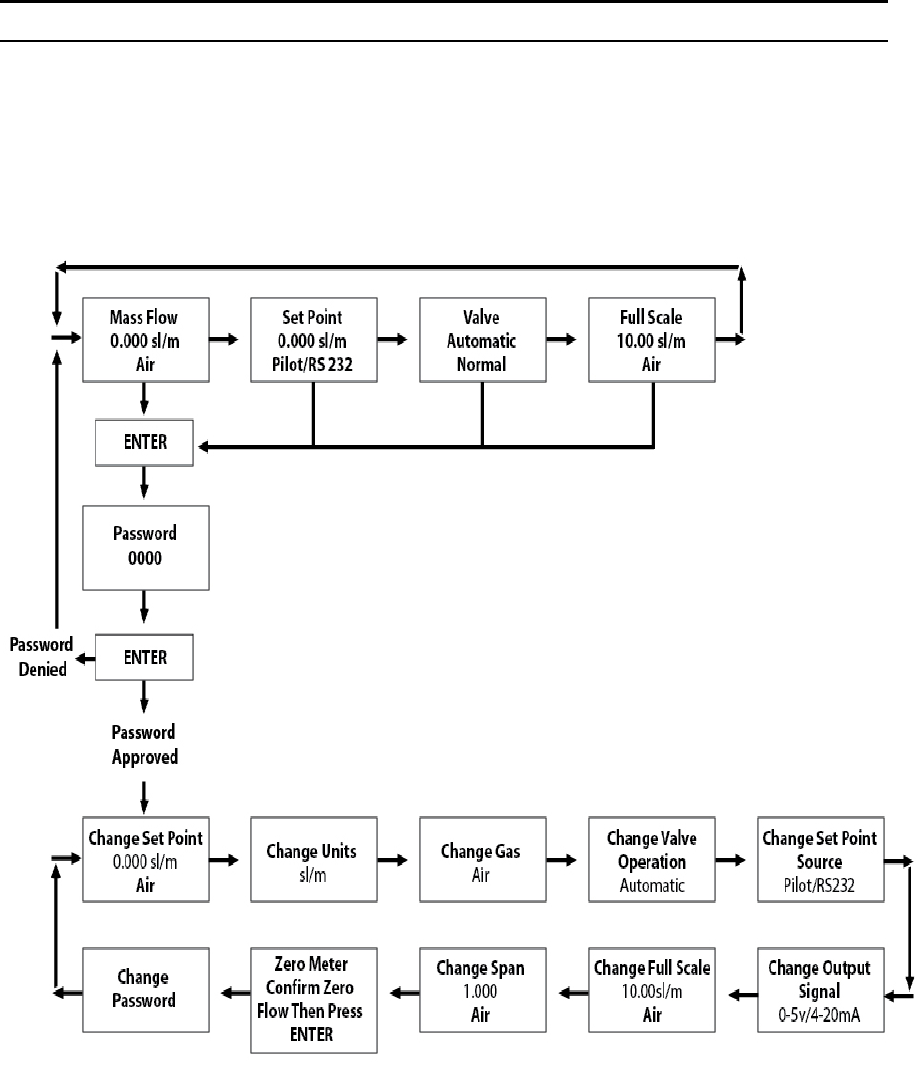
Sierra Instruments Instruction Manual SmartTrak® 100 Series
97
Appendix G: Flow Chart for Pilot Module User Interface (same for all
100 Series)
NOTE: If you press the escape key at any time, you will immediately return to the main
Mass Flow screen in the Upper Level.
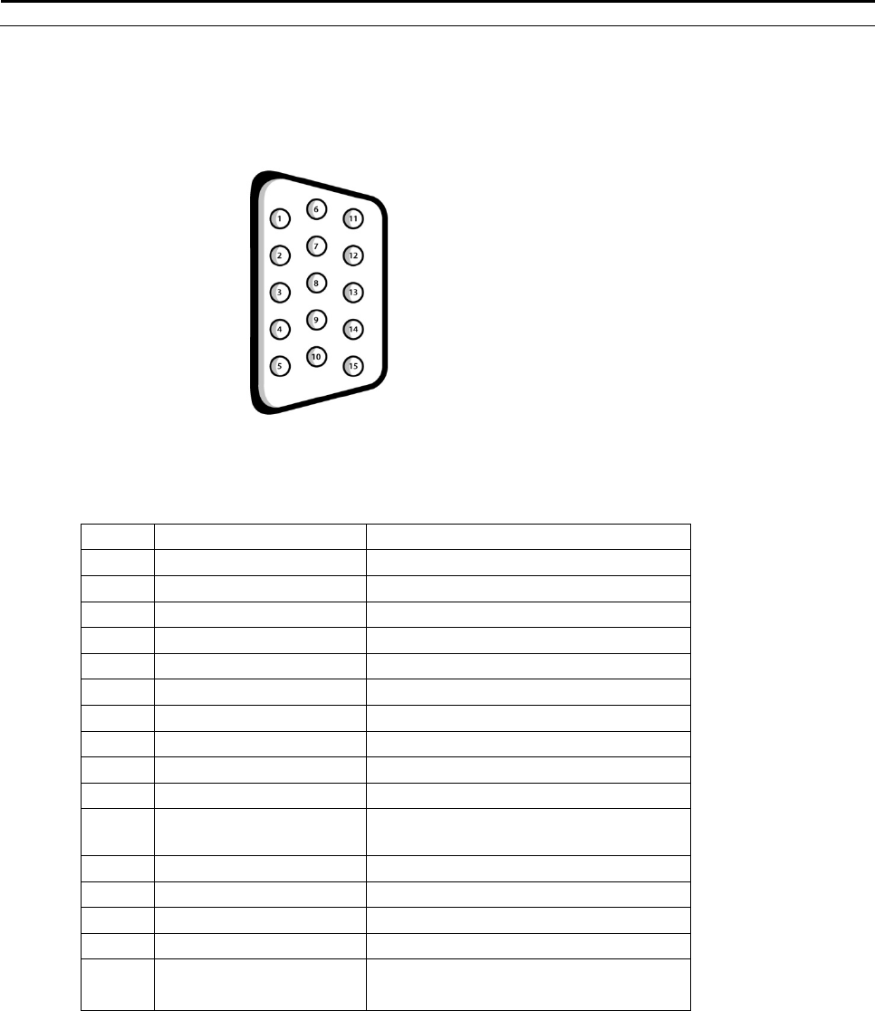
Sierra Instruction Manual SmartTrak® Series 100
98
Appendix H: PIN Configuration (same for all 100 Series)
Figure2‐4:WiringDefinitionsforOptionalCommunicationCable
Pin # Wire Color in Cable Function
1. Brown Analo
g
Ground/Output
2. Re
d
0-5 VDC Output (or 0-10, 1-5 VDC)
3. Oran
g
e Analo
g
Ground/RS232
4. Pin
k
Valve Override Pur
g
e
5. Yellow Power Return (-)
6. Green Power Input (+)
7. Green/White RS-232 Transmit (out)
8. Blue Setpoint
9. Purple Not Use
d
10. Gra
y
Analo
g
Ground/Setpoint
11. White Reference Voltage
(5 VDC External Setpoint & Valve Pur
g
e)
12. Blac
k
Valve Override Close
13. Brown/white RS-232 Receive (in)
14. Red/white 0/4-20 mA Output
15. Red/Blac
k
Not Use
d
Shield Wire
(no insulation)
Chassis (Earth) Ground
NOTE: Pins 1, 3, and 10 are connected together inside the instrument. Do not tie these
grounds together outside the instrument. Must have one connection per analog ground.
Recommended use listed.
NOTE: Unused cable wires should be isolated and insulated from one another or
damage could occur.

Sierra Instruction Manual SmartTrak® Series 100
99
Appendix I: SmartTrak Basic Commands (same for all 100
Series)
IMPORTANT CUSTOMER NOTICE
This document is for firmware version 2.044. Sierra Instruments, Inc. reserves the right to
change the command set without notification to the user. However, Sierra will also make every
effort to maintain backwards compatibility with previously published command sets for
SmartTrak®. There is no implied warranty or guarantee regarding the use of this commands set.
Sierra Instruments, Inc. is not liable for any damage or personal injury, whatsoever, resulting
from the use of this command set.
PROTOCOL
The SmartTrak communication is based on a standard RS232 port. All bytes are ASCII except
the two CRC bytes used for a redundancy check. Each command starts with four bytes of
command type, followed by a variable length value section. The two CRC bytes follow the
value string and a carriage return ends the string. Each command string will vary in length but,
can not exceed 26 bytes.
Command String = {4 command bytes + variable length value + 2 CRC bytes + carriage return}
< 26 bytes.
The RS232 port does not depend on hardware handshaking and uses only three wires on the port:
transmit, receive and ground. The port on the host needs to be configured to (9600,n,8,1) : 9600
baud, no parity, eight bit characters, one stop bit.
DESCRIPTION
Commands for the Meter. There are SmartTrak commands (version 1.xx), SmartTrak 2
commands (version 2.xx), and SmartTrak 100 commands (2.xx). The 2.xx commands
will support some of the 1.xx commands. If a 1.xx commands is not shown below, it is
not supported in the 2.xx commands. CMNDS is a class included in the class of Meter.
This page shows all types, fields, and values as derived from Meter. Version 2.xx
commands that start with a '?' are read commands and commands that start with a '!' are
write commands. This is list of the most commonly used commands, which are relative
safe.

Sierra Instruction Manual SmartTrak® Series 100
100
FLOW
DESCRIPTION
FLOW makes the streaming mode data = flow only. If meter is in streaming mode, this
data will stream until a FLOWwSETPOINT, FLOWwSETPOINTwDAC or
TOTALwDIFFwDAC is sent to the meter. If not in streaming mode then one flow will be
return with each FLOW command sent. ReadMeter, WriteMeter both will set flow as the
streaming data.
ASCII STRING COMMANDS
'?Flow + CRC + cr' Version 2.xx read command
'!Flow + value + CRC + cr' Version 2.xx write command
'?Flow + CRC + cr' Version 1.xx read command
Returns ASCII string 'Flow + value + CRC + cr'
Values are a string of digits and an optional decimal place: '10.00'
SETPOINT
DESCRIPTION
SETPOINT sets the control setpoint. The set point is store in the flash memory. This
command is not recommended for version 2.xx,. Use SETPOINT_FLASH.
ASCII STRING COMMANDS
'?Sinv + CRC + cr' Version 2.xx read command
'!Sinv + value + CRC + cr' Version 2.xx write command
'?Sinv + CRC + cr' Version 1.xx read command
'Sinv + value + CRC + cr' Version 1.xx write command
Returns ASCII string 'Sinv + valueSetpoint + CRC + cr'
Values are a string of digits and an optional decimal place: '10.00'
CRC=redundancy check bytes; cr=carrage return byte.
SETPOINT_FLASH
DESCRIPTION
SETPOINT_FLASH returns the current flash memory value setpoint with read
command. The write command sets the flash memory value and makes it the active
setpoint. This would be the setpoint after a power down.
ASCII String commands
'?Setf + CRC + cr' Version 2.xx read command
'!Setf + value + CRC + cr' Version 2.xx write command

Sierra Instruction Manual SmartTrak® Series 100
101
Returns ASCII string 'Setf + valueSetpoint + CRC + cr'
Values are a string of digits and an optional decimal place: '10.00'
CRC=redundancy check bytes; cr=carrage return byte.
SETPOINT_RAM
DESCRIPTION
SETPOINT_RAM returns the current ram memory value setpoint with read command.
The write command sets the ram memory value and makes it the active setpoint.
ASCII STRING COMMANDS
'?Setr + CRC + cr' Version 2.xx read command
'!Setr + value + CRC + cr' Version 2.xx write command
Read returns ASCII string 'Setr + valueSetpoint + CRC + cr'
Write returns ASCII string 'Sinv + valueSetpoint + CRC + cr'
Values are a string of digits and an optional decimal place: '10.00'
CRC=redundancy check bytes; cr=carrage return byte.
UNIT_INDEX
DESCRIPTION
UNIT_INDEX selects the units the meter displays. The index value is between 1 and 30
and is assigned as shown. scc/s = 1, scc/m = 2, scc/H = 3, Ncc/s = 4, Ncc/m = 5, Ncc/H =
6, SCF/s = 7, SCF/m = 8, SCF/H = 9, NM3/s = 10, NM3/m = 11, NM3/H = 12, SM3/s =
13, SM3/m = 14, SM3/H = 15, sl/s = 16, sl/m = 17, sl/H = 18, NL/s = 19, NL/m = 20,
NL/H = 21, g/s = 22, g/m = 23, g/H = 24, kg/s = 25, kg/m = 26, kg/H = 27, lb/s = 28,
lb/m = 29, lb/H = 30
ASCII STRING COMMANDS
'?Unti + CRC + cr' Version 2.xx read command
'!Unti + unitIndex + CRC + cr' Version 2.xx write command
'?Unti + CRC + cr' Version 1.xx read command
'Unti + unitIndex + CRC + cr' Version 1.xx write command
Returns ASCII string 'Unti + unitIndex + CRC + cr'
unitIndex is an integer string value of 1 to 30
CRC=redundancy check bytes; cr=carrage return byte.

Sierra Instruction Manual SmartTrak® Series 100
102
VALVE_INDEX
DESCRIPTION
VALVE_INDEX selects the state of the valve. Automatic = 1, Closed = 2, Purge = 3.
This is a write to flash memory command. For version 2.xx, this command is not
recommended. See VALVE_FLASH_INDEX and VALVE_RAM_INDEX.
ASCII STRING COMMANDS
'?Vlvi + CRC + cr' Version 2.xx read command
'!Vlvi + valveIndex + CRC + cr' Version 2.xx write command
'?Vlvi + CRC + cr' Version 1.xx read command
'Vlvi + valveIndex + CRC + cr' Version 1.xx write command
Returns ASCII string 'Vlvi + valveIndex + CRC + cr'
valveIndex is an integer string value of 1 to 3
CRC=redundancy check bytes; cr=carrage return byte.
GAS_INDEX
DESCRIPTION
GAS_INDEX selects the current gas.
ASCII STRING COMMANDS
'?Gasi + CRC + cr' Version 2.xx read command
'!Gasi + gasIndex + CRC + cr' Version 2.xx write command
'?Gasi + CRC + cr' Version 1.xx read command
'Gasi + gasIndex + CRC + cr' Version 1.xx write command
Returns ASCII string 'Gasi + gasIndex + CRC + cr'
gasIndex value is 1 through 10
CRC=redundancy check bytes; cr=carrage return byte.
STREAM
DESCRIPTION
Communications can be in one of three mode set by this STREAM command. In off
mode, the meter will respond when queried with a read command. In echo mode, the
meter will respond with either a read or a write command. In stream mode, the meter will
continuously send data back. If a read or write command needs to update more than one
value, all values with be sent back on write command.

Sierra Instruction Manual SmartTrak® Series 100
103
ASCII STRING COMMANDS
'?Strm + CRC + cr' Version 2.xx read command
'!Strm + streamString + CRC + cr' Version 2.xx write command
Returns ASCII string 'Strm + streamString + CRC + cr'
streamString = "On", "Off", "Echo"
CRC=redundancy check bytes; cr=carrage return byte.
VERSION_NUMBER
DESCRIPTION
VERSION_NUMBER returns the firmware version. This is useful when Ver. 1.xxx and
2.xxx are in the same system to determine which command to send.
ASCII STRING COMMANDS
'?Vern + CRC + cr' Version 2.xx read command
Returns ASCII string 'Vern + alphaNumericString + CRC + cr'
alphaNumericString is alpha numeric string
CRC=redundancy check bytes; cr=carrage return byte.
SERIAL_NUMBER
DESCRIPTION
SERIAL_NUMBER returns the serial number
ASCII STRING COMMANDS
'?Srnm + CRC + cr' Version 2.xx read command
Returns ASCII string 'Srnm + SERIAL_NUMBER + CRC + cr'
alphaNumericString is alpha numeric string
CRC=redundancy check bytes; cr=carrage return byte.
SYNC
DESCRIPTION
Sync returns the following events, VersionNumberEvent, SerialNumberEvent,
DataEvent, ManufactureNumberEvent, TypeEvent, PassWordEvent, SetpointEvent,
FullScaleEvent, GasNameEvent(10 times for all gas names), GasIndexEvent,
GasSpanEvent(current gas only), SetpointIndexEvent, OuputIndexEvent,
UnitIndexEvent, ValveFlashEvent, StreamEvent, SyncEvent

Sierra Instruction Manual SmartTrak® Series 100
104
ASCII STRING COMMANDS
'?Sync + CRC + cr' Version 2.xx read command
Returns ASCII string 'Sync + "" + CRC + cr'
SyncEvent returned last to indicate all events have been sent
CRC=redundancy check bytes; cr=carrage return byte.
ZERO
DESCRIPTION
ZERO sets the flow offset value to a zero flow reading. Warning: All flow must be shut
off, the unit needs to be at pressure with the gas being used.
ASCII STRING COMMANDS
'!Zero + "" + CRC + cr' Version 2.xx write command
CRC=redundancy check bytes; cr=carrage return byte.
RESET_ZERO
DESCRIPTION
Reset zero flow offset value to zero
ASCII STRING COMMANDS
'!Rezr + "" + CRC + cr' Version 2.xx write command
Returns ASCII string 'Rezr + "" + CRC + cr'
CRC=redundancy check bytes; cr=carrage return byte
CRC CALCULATIONS
Below is the routine used to calculate the CRC bytes in C#.
Comments are between the /* */.
private static uint CalcCRC(byte[] cmnd)
/* cmnd is a byte array containing the command ASCII string … cmnd[]=”Sinv2.000” */
/* An unsigned 32 bit integer is return to the calling program */
/* only the lower 16 bits contain the crc */
{
int i,j; /* interating indexes for the for loops */

Sierra Instruction Manual SmartTrak® Series 100
105
uint crc; /* crc variable that will be returned */
crc=0xffff; /* initialize crc to hex value 0xffff */
for (i=0; i<cmnd.Length; i++)
/* this for loop starts with ASCCII ‘S’ and loops through to the last ASCII ‘0’ */
{
crc=crc^((uint)(cmnd[i]*0x0100));
/* the ASCII value is times by 0x0100 first then XORED to the current crc value */
for(j=0; j<8; j++)
/* the crc is hashed 8 times with this for loop */
/* if the 15th bit is set (tested by ANDING with hex 0x8000 and testing for 0x8000 result)
then crc is shifted left one bit (same as times 2) XORED with hex 0x1021 and ANDED
to hex 0xffff to limit the crc to lower 16 bits. If the 15th bit is not set then the crc is shifted
left one bit and ANDED with hex 0xffff to limit the crc to lower 16 bits. */
{
if((crc&0x8000)==0x8000)
crc=((crc<<1)^0x1021)&0xffff;
else
crc=(crc<<1)&0xffff;
/* end of j loop */ }
/* end of i loop */ }
/* There are some crc values that are not allowed, 0x00 and 0x0d */
/* These are byte values so the high byte and the low byte of the crc must be checked and
incremented if the bytes are either 0x00 0r 0x0d. */
if((crc&0xff00)==0x0d00) crc +=0x0100;
if((crc&0x00ff)==0x000d) crc +=0x0001;
if((crc&0xff00)==0x0000) crc +=0x0100;
if((crc&0x00ff)==0x0000) crc +=0x0001;
return crc;
}
/* If the string Sinv2.000 is sent through this routine the crc = 0x8f55 */
/* The complete command “Sinv2.000” will look like this in hex
0x53 0x69 0x6E 0x76 0x32 0x2e 0x30 0x30 0x30 0x8f 0x55 0x0d */
Below is the c# routine with no comments.
private static uint CalcCRC(byte[] cmnd)
{
int i,j;
uint crc;
crc=0xffff;
for (i=0; i<cmnd.Length; i++)
{
crc=crc^((uint)(cmnd[i]*0x0100));

Sierra Instruction Manual SmartTrak® Series 100
106
for(j=0; j<8; j++)
{
if((crc&0x8000)==0x8000)
crc=((crc<<1)^0x1021)&0xffff;
else
crc=(crc<<1)&0xffff;
}
}
if((crc&0xff00)==0x0d00) crc +=0x0100;
if((crc&0x00ff)==0x000d) crc +=0x0001;
if((crc&0xff00)==0x0000) crc +=0x0100;
if((crc&0x00ff)==0x0000) crc +=0x0001;
return crc;
CRC ROUTINE IN MS VISUAL BASIC:
Public Sub SendPacket(packet As String)
Dim crcBytes() As Byte
Dim crcLen, vpacket
Dim crcWord As Long
Dim i, j
packet = Replace(packet, ",", ".") ' if commas are used as decimal place holder
crcLen = Len(packet) - 1 ' zero based counter
ReDim crcBytes(0 To crcLen)
For i = 0 To crcLen ' convert string to bytes
crcBytes(i) = Asc(Mid(packet, i + 1, 1)) ' get character
Next
' calc crc
crcWord = (&H1FFFE) / 2 ' not -1
For j = 0 To crcLen
crcWord = crcWord Xor CLng(crcBytes(j)) * &H100
For i = 1 To 8
If (crcWord And &H8000) Then
crcWord = (crcWord * 2) Xor &H1021 ' prime number
Else
crcWord = crcWord * 2
End If
crcWord = (((crcWord * 2) And &H1FFFE)) / 2
Next i
Next j
If (crcWord And &HFF00) = &HD00 Then ' carriage char not allowed
crcWord = crcWord + &H100 ' make this byte &h0exx
End If
If (crcWord And &HFF00) = &H0 Then ' zero char is death

Sierra Instruction Manual SmartTrak® Series 100
107
crcWord = crcWord + &H100 ' make this byte &h01xx
End If
If (crcWord And &HFF) = &HD Then ' carriage char not allowed
crcWord = crcWord + 1 ' make this byte &hxx0e
End If
If (crcWord And &HFF) = &H0 Then ' zero char is death
crcWord = crcWord + 1 ' make this byte &hxx01
End If
ReDim Preserve crcBytes(0 To crcLen + 3) ' make room for crc and carriage return
crcBytes(crcLen + 1) = Int(crcWord / &H100) ' high byte
crcBytes(crcLen + 2) = (crcWord And &HFF) ' low byte
crcBytes(crcLen + 3) = 13 ' carriage return
vpacket = crcBytes
commQueue.Add vpacket
End Sub
.

Sierra Instruction Manual SmartTrak® Series 100
108
Appendix J: Warranty Policy
LIMITED WARRANTY POLICY- REGISTER ONLINE
All Sierra products are warranted to be free from defects in material and workmanship and will
be repaired or replaced at no charge to Buyer, provided return or rejection of product is made
within a reasonable period but no longer than one (1) year for calibration and non-calibration
defects, from date of delivery. To assure warranty service, customers must register their products
online on Sierra’s website. Online registration of all of your Sierra products is required for our
warranty process. Register now at www.sierrainstruments.com/register. Learn more about
Sierra’s warranty policy at www.sierrainstruments.com/warranty
