Jetstream JetVision User’s Guide, Release 2.6 1010 A2 GB21 10
1010-A2-GB21-10 1010-A2-GB21-10
User Manual: 1010-A2-GB21-10
Open the PDF directly: View PDF ![]() .
.
Page Count: 347 [warning: Documents this large are best viewed by clicking the View PDF Link!]
- Preface
- Getting Acquainted
- Administration
- CPX-1000 Configuration
- Protection Group Provisioning
- Interface Groups Provisioning
- Creating T-1 Interface Groups
- Creating STS-1 Interface Groups
- Assigning Ports/Channels to a GR303 Interface Group
- Removing Ports/Channels from GR303 Interface Groups
- Assigning Ports/Channels to the T1 CAS Interface Group
- Removing Ports/Channels from the T1 CAS Interface Group
- Modifying GR303 Interface Groups
- Deleting GR303 Interface Groups
- Switching Over
- IAD Profile Provisioning
- IAD Provisioning
- Network Resource Manager
- JetVision Groups and Users
- CPX1000 Users
- Web Browser Users
- Alarms
- Reports
- Statistics
- Statistics Summary
- Accessing Interface Groups
- Accessing Network Protection Groups
- Accessing PSTN Protection Groups
- Accessing STS1 Port
- Accessing DS1 Port
- Accessing IADs
- Polling Real- time Statistics
- Understanding Historical Data Monitors
- Filtering Graph Parameters
- Accessing MP or CP Cards
- Accessing DS1 Graphs
- Resetting DS1 Registers
- Maintenance
- CPX-1000 Configuration Backup
- Creating a Destination Profile
- Performing an On-demand Backup
- Creating a Backup Schedule
- Reviewing Active Tasks
- Reviewing Backup Files
- Restoring CPX Configuration
- Performing a File Transfer
- Rebooting the CPX1000
- Rebooting the MP or CP Card
- Resynchronizing a CPX-1000
- Setting the CPX1000 Internal Clock
- Switching
- Hot Swapping
- Performing Loop Back Test
- Tracing STS-1 Path
- CPX1000 Management States
- Downloading IAD Software
- Automated IAD Software Download
- Remote Restarting of IADs
- Increasing the Historical Data Buffer
- Integrated Monitoring
- InfoCenter Services
- Starting InfoCenter from Windows
- Starting InfoCenter from Solaris
- Using InfoCenter
- Setting a Refresh Time
- Checking Services
- Starting and Stopping Services
- Backing Up Oracle Database
- Restoring Oracle Database
- Adjusting the Thresholds of Historical Data
- Changing the Geographic Map
- Changing the Data Collector Server Values
- Customizing Colors on Integrated Monitor
- Jetutil Diagnostics
- JetVision Menu Map
- Statistics Descriptions
- Alarm Summary
- Index

Jetstream® JetVision
User’s Guide
Release 2.6
Document No. 1010-A2-GB21-10
June 2005

A June 2005
1010-A2-GB21-10
Copyright © 2002 Paradyne Corporation.
All rights reserved.
Printed in U.S.A.
Notice
This publication is protected by federal copyright law. No part of this publication may be copied or distributed,
transmitted, transcribed, stored in a retrieval system, or translated into any human or computer language in any form or
by any means, electronic, mechanical, magnetic, manual or otherwise, or disclosed to third parties without the express
written permission of Paradyne Corporation, 8545 126th Ave. N., Largo, FL 33773.
Paradyne Corporation makes no representation or warranties with respect to the contents hereof and specifically
disclaims any implied warranties of merchantability or fitness for a particular purpose. Further, Paradyne Corporation
reserves the right to revise this publication and to make changes from time to time in the contents hereof without
obligation of Paradyne Corporation to notify any person of such revision or changes.
Changes and enhancements to the product and to the information herein will be documented and issued as a new
release to this manual.
Warranty, Sales, Service, and Training Information
Contact your local sales representative, service representative, or distributor directly for any help needed. For
additional information concerning warranty, sales, service, repair, installation, documentation, training, distributor
locations, or Paradyne worldwide office locations, use one of the following methods:
Internet: Visit the Paradyne World Wide Web site at www.paradyne.com. (Be sure to register your warranty at
www.paradyne.com/warranty.)
Telephone: Call our automated system to receive current information by fax or to speak with a company
representative.
— Within the U.S.A., call 1-800-870-2221
— Outside the U.S.A., call 1-727-530-2340
Document Feedback
We welcome your comments and suggestions about this document. Please mail them to Technical Publications,
Paradyne Corporation, 8545 126th Ave. N., Largo, FL 33773, or send e-mail to userdoc@paradyne.com. Include the
number and title of this document in your correspondence. Please include your name and phone number if you are
willing to provide additional clarification.
Trademarks
Jetstream is a registered trademark of Paradyne Corporation. All other products and services mentioned herein are the
trademarks, service marks, registered trademarks, or registered service marks of their respective owners.

June 2005 B
1010-A2-GB21-10
JetVision/JetWay Software License Agreement
CAREFULLY READ THE FOLLOWING TERMS AND CONDITIONS. BY USING ANY OF THE JETVISION/JETWAY
SOFTWARE, YOU AGREE TO BE BOUND BY THESE TERMS AND CONDITIONS. IF YOU DO NOT AGREE TO
THESE TERMS AND CONDITIONS, DO NOT USE OR INSTALL ANY OF THE SOFTWARE. IN SUCH EVENT, YOU
MAY RETURN THE SOFTWARE TO THE SELLER OR TO PARADYNE (UNUSED) FOR A REFUND OF THE PRICE
PAID.
This Software License Agreement (“Agreement”) grants you certain license rights in connection with the Paradyne
Corporation (“Paradyne”) JetVision/JetWay software and related documentation to be installed (the “Software”).
Where third-party software is pre-installed into Paradyne hardware (“Third Party Software”) and a separate End User
License Agreement (“Third Party EULA”) is included with the Paradyne hardware, Licensee agrees to comply with the
terms and conditions of the Third Party EULA with respect to its use of the Third Party Software.
1. Grant of License
Subject to the terms and conditions of this License, Paradyne hereby grants to Licensee, and Licensee hereby
accepts from Paradyne, a personal, nonexclusive license to install, use and execute Software in machine readable
object code form, on that number and type of stations or access ports for which a licensee fee has been paid,
solely for Licensee’s use in connection with the use of Paradyne hardware or a Paradyne-compatible integrated
access device (“IAD”). Licensee shall have the right to make a reasonable number of copies of the Software for
backup purposes. This license shall continue unless and until terminated in accordance with Section 4 of this
Agreement.
2. Proprietary Rights Notices
Licensee agrees (a) to respect all confidentiality notices or legends placed upon the Software; (b) not to conceal
from view any copyright, trademark or confidentiality notices placed on the Software media or on any output
generated by the Software; and (c) to reproduce all copyright, trademark or confidentiality notices on all copies of
the Software, or any portion thereof, made by Licensee as permitted hereunder.
3. Proprietary Rights
Licensee acknowledges that Paradyne (and, as applicable, its licensor(s)) retains exclusive right, title and interest
in and to the Software and all copies or portions thereof, including all intellectual property rights. By accepting this
license, Licensee does not become the owner of the Software, but has the right to use the Software as outlined
and limited in this Agreement. Licensee further acknowledges and agrees that the Software contains confidential
information and trade secrets developed and acquired by Paradyne (and, as applicable, its licensor(s)) through the
expenditure of a great deal of time and money. Accordingly, Licensee agrees to treat the Software as confidential
and not to disclose all or any portion of the Software to any third party or entity, except as such disclosure may be
necessary to Licensee’s employees and consultants in the course of their employment. To the extent permitted by
applicable law, Licensee agrees not to modify, decompile, disassemble or otherwise reverse engineer the
Software. Licensee further agrees not to lend, rent, lease, sublicense or otherwise transfer any copies of the
Software or any portion thereof in any form to any person, except as permitted in Section 9 of this Agreement.
Licensee will use its best efforts and take all reasonable steps to protect the Software and to prevent any
unauthorized reproduction, publication, disclosure, or distribution of the Software or any portion thereof.
4. Term and Termination
This Agreement is effective upon the earlier of (a) the installation of the Software by Licensee (including, but not
limited to, loading the Software on a hard disk), or (b) acceptance of delivery of any Software by Licensee, and
shall continue unless and until terminated in accordance with the provisions of this Section 4. This Agreement shall
automatically terminate and Licensee shall lose its license rights hereunder if (i) Licensee transfers possession of
the Software, any copy of the Software, or any portion or merged portion of the Software to another party, except
as provided in Section 9, or (ii) violates the provisions of Section 3. Additionally, Paradyne shall be entitled to
terminate this Agreement upon written notice to Licensee in the event that Licensee breaches any material
obligation under this Agreement. Licensee shall be entitled to terminate this Agreement upon written notice given
by Licensee to Paradyne. Within ten (10) days after termination of this Agreement, Licensee shall destroy all
copies of the affected Software and related documentation, or any portion thereof, in any form, and shall certify
such destruction upon the request of Paradyne.

C June 2005
1010-A2-GB21-10
5. Limited Warranty and Disclaimer of Warranties
The media upon which any Software is contained is warranted to be free from defects in material and
workmanship for a period of thirty (30) days from the date of delivery to Licensee (the “Warranty Period”). The
entire liability of Paradyne (and, as applicable, its licensor(s)) and Licensee’s exclusive remedy for breach of the
foregoing limited warranty shall be for Paradyne to replace any defective media which is returned to Paradyne
during the Warranty Period. PARADYNE DOES NOT WARRANT THAT ANY SOFTWARE WILL OPERATE
ERROR-FREE, WILL OPERATE UNINTERRUPTED IN YOUR OPERATING ENVIRONMENT, IS COMPATIBLE
WITH ANY SOFTWARE OR HARWARE CONFIGURATION, OR IS FREE OF ERRORS OR “BUGS.” EXCEPT
AS PROVIDED HEREIN, THE SOFTWARE IS PROVIDED “AS IS” AND PARADYNE MAKES NO WARRANTY,
EXPRESS, IMPLIED, OR STATUTORY, WITH RESPECT TO THE SOFTWARE AND SPECIFICALLY
DISCLAIMS THE IMPLIED WARRANTIES OF MERCHANTABILITY AND FITNESS FOR A PARTICULAR
PURPOSE AND ANY WARRANTY OF NON-INFRINGEMENT.
6. Availability of Support
No support (such as ongoing maintenance and delivery of upgrades) is provided for the Software under this
Agreement. Any support for the Software must be purchased separately.
7. Intellectual Property Indemnification
Paradyne shall defend or settle, at its own expense, any action brought against Licensee to the extent arising out
of or based on any claim alleging that the unmodified Software or any portion thereof, as used within the scope of
this Agreement, infringes or misappropriates any third-party rights in copyrights, patents, or trade secrets in the
United States. Additionally, Paradyne shall pay any damages finally awarded against Licensee and attributable to
such claim, or any costs of settlement to which Paradyne agrees; provided, that (a) Licensee gives prompt written
notice of any such claim, demand, or action to Paradyne; (b) Licensee provides Paradyne with sole control of the
defense and settlement thereof; and (c) Licensee reasonably cooperates with Paradyne in the defense or
settlement thereof. In the event that any Software is held in such suit or proceeding to infringe or misappropriate
such intellectual property right, and the use of the Software, or portion thereof, is enjoined, Paradyne shall, at its
sole option and expense (i) procure for Licensee the right to continue using the Software, or portion thereof; (ii)
replace the same with noninfringing programs of reasonably equivalent functionality; or (iii) accept return of the
Software, or portion thereof. In the event that Paradyne accepts return of the Software, or portion thereof, Licensee
shall receive a refund of that portion of any fee paid in connection with the license for such Software, or portion
thereof. Paradyne assumes no liability hereunder for claims which result from the use or combination of the
Software with other than Paradyne hardware or Paradyne-compatible IADs. THIS SECTION 7 SETS FORTH
THE ENTIRE LIABILITY AND OBLIGATION OF PARADYNE AND LICENSEE’S SOLE REMEDY FOR ANY
CLAIM OF INFRINGEMENT OR MISAPPROPRIATION OF PATENT, COPYRIGHT, TRADE SECRET OR
OTHER INTELLECTUAL PROPERTY RIGHTS.
8. Limitation of Liability
IN NO EVENT WILL PARADYNE (OR, AS APPLICABLE, ITS LICENSORS) BE LIABLE TO LICENSEE OR ANY
OTHER PARTY FOR ANY CONSEQUENTIAL, INCIDENTAL, PUNITIVE, SPECIAL OR INDIRECT DAMAGES
ARISING OUT OF THIS AGREEMENT OR THE USE OR INABILITY TO USE THE SOFTWARE, INCLUDING,
BUT NOT LIMITED TO, ANY LOST PROFITS OR COST SAVINGS, EVEN IF PARADYNE HAS BEEN ADVISED
OF THE POSSIBILITY OF SUCH DAMAGES.
IN NO EVENT SHALL THE PARADYNE LIABILITY TO LICENSEE, WHETHER BASED ON AN ACTION OR
CLAIM IN CONTRACT OR TORT (INCLUDING, WITHOUT LIMITATION, NEGLIGENCE AND, TO THE EXTENT
PERMITTED BY LAW, STRICT LIABILITY) OR OTHERWISE, ARISING OUT OF OR RELATED TO THIS
AGREEMENT EXCEED THE AGGREGATE FEES PAID BY LICENSEE FOR THE SOFTWARE AS OF THE
DATE SUCH ACTION OR CLAIM WAS FILED.
9. Transfer and Assignment
Neither the licenses granted hereunder nor this Agreement (nor any portion of the Software) may be assigned or
transferred by Licensee except in connection with the sale or transfer of the Paradyne hardware or
Paradyne-compatible IAD with which the Software is used, and then only if (a) the entire Software and all copies
thereof, and related documentation, are transferred; and (b) the transferee agrees to be bound by the terms of this
Agreement.

June 2005 D
1010-A2-GB21-10
10. U.S. Government Restricted Rights
The following terms shall apply where Licensee is an agency or unit of the U.S. government.
a. Units of the DoD. Use, duplication or disclosure by the government is subject to restrictions as set forth in
paragraph (c)(1)(ii) of the Rights in technical Data and Computer Software clause at DFARS 252.227-7013.
Paradyne Corporation, 8546 126th Avenue North, Largo, Florida 33773.
b. Civilian agencies. Use, reproduction or disclosure is subject to restrictions as set forth in subparagraphs (a)
through (d) of the Commercial Computer Software-Restricted Rights clause at FARS 52.227-19 and the
limitations set forth in the Paradyne standard commercial agreement for this Software. Unpublished-rights
reserved under the copyright laws of the United States.
11. Compliance with Laws and Payment of Taxes
Licensee agrees to comply with all applicable laws in connection with its license and use of the Software. Licensee
represents and warrants that it is authorized under applicable United States export laws and regulations to obtain
and use the Software licensed hereunder and, and agrees that it will not export or re-export the Software in
violation of those laws and regulations. Licensee shall be responsible for payment of all sales or use taxes, duties
or other governmental assessments upon the license of the Software to Licensee (exclusive of taxes on the net
income of Paradyne), and any property or other taxes assessed upon Licensee’s possession or use of the
Software.
12. Miscellaneous
In the event that any provision of this Agreement is found invalid or unenforceable pursuant to judicial decree or
decision, the remainder of this Agreement shall remain valid and enforceable according to its terms. This
Agreement shall be construed and enforced in accordance with the laws of the State of Florida, exclusive of its
choice of law rules. The application of the United Nations Convention on the International Sale of Goods is
expressly excluded. Any action or proceeding arising out of or related to this Agreement shall be brought in a state
or federal court of competent jurisdiction located in the County of Pinellas, Florida and both parties hereby submit
to the in personam jurisdiction of such courts for purposes of any such action or proceeding. Notwithstanding the
foregoing, if Licensee resides outside the United States, any such action or proceeding shall be submitted to
binding arbitration in Pinellas County, Florida, and the arbitration hearing shall be conducted in the English
language and pursuant to the International Rules of the American Arbitration Association (as then in effect) and
judgment on the award may be entered by any court of appropriate jurisdiction. This Agreement may not be
modified, amended or altered except by a writing signed by a duly authorized representative of Paradyne and
Licensee. No waiver of any provision of this Agreement or any right or obligation of either party shall be effective
except pursuant to a writing signed by a duly authorized representative of Paradyne and Licensee. This
Agreement constitutes the entire agreement between Paradyne and Licensee with respect to the transactions
contemplated herein and supersedes any and all prior or contemporaneous oral or written communications with
respect to the subject matter hereof.

E June 2005
1010-A2-GB21-10

Preface
Audience ....................................................................................xi
JetVision Bundled Utilities ......................................................xi
New in This Release ................................................................xii
JetVision features .....................................................................xii
Organization ............................................................................xiv
Related Documents..................................................................xv
Symbols ....................................................................................xvi
Chapter 1 Getting Acquainted
Windows Platform ..................................................................1-2
Starting JetVision Server .................................................1-2
Starting JetVision Client ...................................................1-3
Solaris Platform .......................................................................1-4
Starting JetVision Server ..................................................1-4
Starting JetVision Client ..................................................1-5
Reconnecting to JetVision Server .........................................1-6
JetVision Screens .....................................................................1-7
Menu Bar ............................................................................1-8
Toolbar Icons......................................................................1-8
Tree View ............................................................................1-9
Geographic Map View....................................................1-10

Textual View .................................................................... 1-11
Network Map View ........................................................1-12
Shelf View.........................................................................1-13
Alarm Indicators ............................................................1-14
Status Bar..........................................................................1-15
Where to go Next ..................................................................1-16
Chapter 2 Administration
Adding a CPX-1000 ...............................................................2-2
Updating CPX-1000 Information..........................................2-3
Removing a CPX-1000 ...........................................................2-4
Adding a Group ......................................................................2-4
Modifying a Group .................................................................2-5
Deleting a Group.....................................................................2-6
Moving a Group......................................................................2-6
Finding CPX-1000 ...................................................................2-7
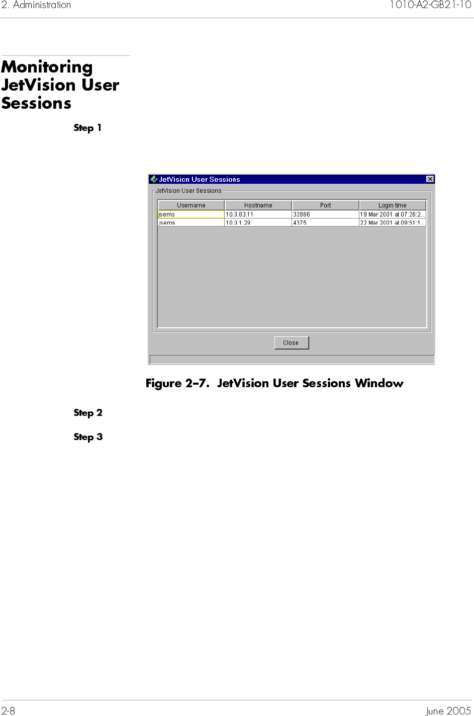
Monitoring JetVision User Sessions .....................................2-8
Chapter 3 CPX-1000 Configuration
Changing the CPX-1000 IP Address.....................................3-2
Configuring Global VCI Settings..........................................3-3
Setting CDV Value ..................................................................3-5
Setting LBO Value ..................................................................3-6
Configuring STS-1 Card.........................................................3-7
Setting Clock Source...............................................................3-8
Annotating CPX-1000 Location ..........................................3-12
Reviewing CPX-1000 Information .....................................3-14
Chapter 4 Protection Group Provisioning
Assigning Network Protection Group Members ...............4-2

Assigning PSTN Protection Group Members.....................4-5
Swapping Protection Group Member ...............................4-7
Removing Protection Group Members .............................4-9
Chapter 5 Interface Groups Provisioning
Creating T-1 Interface Groups...............................................5-2
Creating STS-1 Interface Groups ..........................................5-7
Assigning Ports/Channels to a GR-303 Interface Group 5-11
Removing Ports/Channels from GR-303 Interface Groups 5-
13
Assigning Ports/Channels to the T1 CAS Interface Group 5-
15
Removing Ports/Channels from the T1 CAS Interface Group
5-17
Modifying GR-303 Interface Groups..................................5-19
Deleting GR-303 Interface Groups......................................5-22
Switching Over......................................................................5-24
Performing an EOC Switchover....................................5-25
Performing a TMC Switchover .....................................5-26
Configuring PPS Settings ..............................................5-28
Chapter 6 IAD Profile Provisioning
Adding IAD Profiles ..............................................................6-2
Modifying IAD Profiles..........................................................6-4
Deleting IAD Profiles .............................................................6-6
Chapter 7 IAD Provisioning
IAD Admin States ..................................................................7-2
Provisioning IADs...................................................................7-4
Creating Voiceband IADs Using the Wizard ................7-5
Creating LES CAS IADs Using the Wizard................. 7-11

Creating a Voiceband IAD Using the Create IAD
Command ........................................................................7-19
Creating a LES CAS IAD Using the Create IAD Command
7-24
Creating Bulk IADs.........................................................7-30
Cloning IADs.........................................................................7-37
Modifying IADs ....................................................................7-40
Modifying an IAD...........................................................7-40
Modifying Multiple IADs ..............................................7-42
Deleting IADs ........................................................................7-47
Filtering IADs .......................................................................7-49
Chapter 8 Network Resource Manager
Overview..................................................................................8-1
Provisioning.............................................................................8-2
Modifying a Network Resource......................................8-3
Deleting a Network Resource .........................................8-3
Viewing Online Performance Charts ...................................8-4
Viewing Historical Performance Charts ..............................8-4
Chapter 9 JetVision Groups and Users
JetVision Groups .....................................................................9-2
Adding JetVision Groups.................................................9-2
Modifying JetVision Groups............................................9-4
Deleting JetVision Groups ...............................................9-6
Reviewing JetVision Groups .................................................9-6
JetVision Users.........................................................................9-7
Adding JetVision Users ....................................................9-7
Modifying JetVision Users.............................................9-10
Deleting JetVision Users................................................. 9-11
Reviewing JetVision Users...................................................9-12
Changing JetVision Default Password...............................9-12

Chapter 10 CPX-1000 Users
Creating CPX-1000 Users.....................................................10-2
Modifying CPX-1000 Users .................................................10-4
Deleting CPX-1000 Users .....................................................10-6
Reviewing CPX-1000 Users .................................................10-6
Chapter 11 Web Browser Users
Modifying User ID and Password ..................................... 11-2
Adding Users to Apache...................................................... 11-3
Deleting Users From Apache .............................................. 11-4
Chapter 12 Alarms
Alarm Indicators ...................................................................12-1
JetVision Alarm Browsers....................................................12-4
Customizing Alarm Filters ..................................................12-4
Creating Active and Historical Data Filters ...............12-5
Creating Event Filters.....................................................12-6
Viewing Alarms From Filters ..............................................12-7
Deleting an Alarm Filter ......................................................12-8
Chapter 13 Reports
Generating and Viewing Reports ......................................13-2
Alarm Reports .......................................................................13-3
Historical Alarm Reports.....................................................13-4
Action Reports.......................................................................13-5
Event Reports ........................................................................13-6
IAD Reports ...........................................................................13-6
Card Reports..........................................................................13-7
CPX Reports...........................................................................13-8

Interface Groups Reports.....................................................13-8
CRV Reports...........................................................................13-9
Protection Groups Reports ................................................13-10
Chapter 14 Statistics
Statistics Summary................................................................14-3
Accessing Interface Groups.................................................14-7
Accessing Network Protection Groups..............................14-8
Accessing PSTN Protection Groups ...................................14-9
Accessing STS-1 Port ..........................................................14-10
Accessing DS-1 Port............................................................14-10
Accessing IADs.................................................................... 14-11
Polling Real-time Statistics ................................................14-13
Understanding Historical Data Monitors........................14-15
DbMonitor Window .....................................................14-15
PM Data Collector Window.........................................14-16
Filtering Graph Parameters ...............................................14-17
Accessing MP or CP Cards ................................................14-18
Accessing DS1 Graphs........................................................14-19
Resetting DS1 Registers......................................................14-21
Chapter 15 Maintenance
CPX-1000 Configuration Backup........................................15-2
Creating a Destination Profile .............................................15-2
Modifying Destination Profile ......................................15-4
Deleting Destination Profile ..........................................15-6
Performing an On-demand Backup ...................................15-7
Creating a Backup Schedule................................................15-8
Disabling a Backup Schedule ......................................15-12
Enabling a Backup Schedule .......................................15-13
Modifying a Backup Schedule ....................................15-14

Deleting a Backup Schedule ........................................15-16
Reviewing Active Tasks .....................................................15-17
Reviewing Backup Files .....................................................15-18
Restoring CPX Configuration ...........................................15-19
Performing a File Transfer .................................................15-21
Rebooting the CPX-1000 ...................................................15-23
Rebooting the MP or CP Card...........................................15-24
Resynchronizing a CPX-1000 ............................................15-24
Setting the CPX-1000 Internal Clock ................................15-25
Switching..............................................................................15-26
Ensuring Redundancy .................................................15-26
Changing CP Card States.............................................15-27
Performing a CP Switchover.......................................15-29
Hot Swapping......................................................................15-30
Hot Swapping MP Card ..............................................15-30
Hot Swapping CP and HSC Cards ............................15-31
Hot Swapping Line Cards ...........................................15-32
Performing Loop Back Test................................................15-33
Tracing STS-1 Path ..............................................................15-35
CPX-1000 Management States...........................................15-35
Changing to the Unmanaged State ............................15-36
Changing to the Managed State..................................15-36
Downloading IAD Software..............................................15-37
Automated IAD Software Download ..............................15-41
Configuring the IAD Auto Download Profiles ........15-43
Add .....................................................................15-44
Modify ................................................................15-44
Delete ..................................................................15-45
Close....................................................................15-45
Remote Restarting of IADs................................................15-46
Increasing the Historical Data Buffer...............................15-49
Keeping the Same Data File.........................................15-50
Adding Extra Data File ................................................15-53

Chapter 16 Integrated Monitoring
Launching Integrated Monitor............................................16-2
Interpreting Integrated Monitor Data................................16-4
Refreshing Integrated Monitoring......................................16-5
Chapter 17 InfoCenter Services
Starting InfoCenter from Windows ...................................17-2
Starting InfoCenter from Solaris.........................................17-2
Using InfoCenter...................................................................17-3
Setting a Refresh Time..........................................................17-6
Checking Services .................................................................17-7
Starting and Stopping Services ...........................................17-7
Backing Up Oracle Database...............................................17-8
Restoring Oracle Database ................................................17-10
Adjusting the Thresholds of Historical Data .................. 17-11
Changing the Geographic Map.........................................17-13
Changing the Data Collector Server Values ...................17-14
Customizing Colors on Integrated Monitor....................17-16
Chapter 18 Jetutil Diagnostics
Windows Environment ........................................................18-2
Checking Operating System Information....................18-3
Checking Windows Services .........................................18-4
Checking JetVision Database.........................................18-5
Understanding Oracle Error Messages........................18-6
Running Health Check Report......................................18-6
Solaris Environment .............................................................18-7
Checking Operating System Information....................18-8
Checking Background Processes ..................................18-9
Checking JetVision Database.......................................18-10


This JetVision User’s Guide provides instructions for using JetVision
software on Windows or Solaris computers. This guide explains
how to use JetVision to configure, provision, and monitor
Paradyne Jetstream equipment in broadband networks.
For information on how to install JetVision on Windows and
Solaris platforms, refer to JetVision Installation.
The JetVision User’s Guide is written for network operations center
personnel who manage and maintain voice gateway networks. It is
assumed that these personnel are familiar with telecom
equipment, telecom network management software, and telecom
terminology. In particular, the reader should be familiar with
Paradyne Jetstream equipment and terminology.
JetVision provides two utility programs that are automatically
installed with the JetVision server: InfoCenter and jetutil. You can
use InfoCenter to
Start and stop JetVision and its related services
Back up or restore Oracle database
Adjust the size of historical alarm
Add the geographical network map
Change Data Collector Server values
Customize colors on Integrated Monitor
You can run jetutil anytime to help with system diagnostics. Jetutil
enables you to check the following:
Operating system information (i.e., memory, disk space,
etc.)
Individual services (i.e., Apache and Oracle)
JetVision Database (i.e., Oracle version, schema structure,
etc.)
Oracle error messages
System health check
System requirement (perform this check before installing
JetVision)
Release 2.6 of JetVision includes the following enhancements:
T1 Channel Associated Signaling (CAS) Interface Group
Loop Emulation Service (LES) CAS Integrated Access
Device (IAD)
E&M Wink Start Signaling
The following table lists JetVision features.
CPX-1000 Configuration JetVision Server can manage up to 100 CPX-1000 units at a time.
With backward compatibility, the JetVision 2.6 Client allows you
to configure the CPX-1000 2.5 release.
Besides BITS clock and multiple VPI/VCI settings, JetVision
also supports Common Language Location Identifier (CLLI),
Cell Delay Variation (CDV) for Frame Relay and ATM protocols
and Line Build Out (LBO).
Provisioning
Interface Groups for T1
and STS-1
JetVision supports RT provisioning and up to nine IGs can be
provisioned, including T1 CAS.
JetVision enables PPS settings and allows switchover on selected
EOC and TMC.
Protection Groups for
PSTN and ATM
A Protection Group provides a logical mapping for two ports,
where only one port is active at a time and another port is in a
standby state. Up to six PSTN and four ATM PGs can be
provisioned. JetVision also supports ATM APS configuration.
IAD Profiles JetVision provides a variety of default profiles.
IADs JetVision supports RT provisioning and up to 8,192 IADs can be
provisioned.
Besides dynamic compression, JetVision also supports a null (0)
Call Reference Value (CRV). This feature allows for a more
effective use of the CRV IAD assignments when less than a full
set of ports are required to be provisioned for the IAD.
JetVision allows bulk IAD provisioning and IAD cloning.
Performance monitoring JetVision includes performance monitoring tools to analyze the
performance of CPX-1000. When initiated, JetVision polls
various statistics for both the real-time performance monitoring
and historical data monitoring.
Alarms reporting JetVision enables browsers to monitor both the active and
historical alarms. Each browser provides filtering capability so
that you can define the criteria for which the browser displays
alarms.
Troubleshooting and
maintenance
Auto and manual backup of CPX-1000 configuration.
Switchover: JetVision allows you to initiate a switchover, where
two redundant cards exchange their active/standby states.
Hot swap: JetVision allows you to hot swap (planned or
unplanned) a card on module without affecting the operation of
the CPX-1000.
Loop back: JetVision provides a diagnostics tool to test the
inbound traffic.
In addition, you can maintain and upgrade the software for
associated IADs.
Integrated Monitor A diagnostic tool to provide an a real-time view of the health of
a CPX-1000 and its associated managed domain.
Security JetVision provides multiple user-privilege levels to control
access to JetVision and CPX-1000, and for report viewing.
The JetVision User’s Guide is organized as follows:
Chapter 1, Getting Acquainted, provides information about
the JetVision graphical user interface (GUI), as well as
information about starting JetVision Server, and starting
JetVision Client for Windows and Solaris computers.
Chapter 2, Administration, provides instructions to add
CXP-1000 to the JetVision managed domain and to create
grouping of CPX-1000 units in a network.
Chapter 3, CPX-1000 Configuration, provides instructions to
configure a CPX-1000.
Chapter 4, Protection Group Provisioning, provides
instructions to provision ATM and PSTN Protection Groups.
Chapter 5, Interface Groups Provisioning, provides
instructions to provision the T1, T1 CAS, and STS-1 Interface
Groups.
Chapter 6, IAD Profile Provisioning, provides instructions
to provision IAD Profiles.
Chapter 7, IAD Provisioning, provides instructions to
provision and clone a single or multiple IADs.
Chapter 8, Network Resource Manager, shows how to use
the Network Resource Manager for Call Admission Control.
Chapter 9, JetVision Groups and Users, provides
instructions to create and administer JetVision user groups
and users.
Chapter 10, CPX-1000 Users, provides instructions to create
and administer CPX-1000 users.
Chapter 11, Web Browser Users, provides instructions to
add, modify, and delete Apache Web server user IDs and
passwords.
Chapter 12, Alarms, provides alarms information and
instructions to customize alarm filters to view both active
and historical alarms.
Chapter 13, Reports, provides instructions to generate and
view different reports.
Chapter 14, Statistics, provides instructions to poll error and
performance statistics for real-time and historical data
monitoring.
Chapter 15, Maintenance, provides instructions to hot swap
cards, back up and restore the CPX-1000 configuration, and
switch the CP cards.
Chapter 16, Integrated Monitoring, provides instructions to
launch the Integrated Monitor and interpret the operational
status of each entity it monitors.
Chapter 17, InfoCenter Services, provides instructions to
use InfoCenter.
Chapter 18, Jetutil Diagnostics, provides instructions to use
a utility tool to help with system diagnostics.
Appendix A, JetVision Menu Map, provides a hierarchical
overview of the JetVision Client menu options.
Appendix B, Statistics Descriptions, provides descriptions
for statistics used in JetVision.
Appendix C, Alarm Summary, provides a summary of
event and error alarms used in JetVision.
Index
Complete documentation for this product is available online at
www.paradyne.com. Select Support → Technic al Ma nual s →
Jetstream Media Gateway Systems.
JetVision Installation
Describes how to install JetVision on Windows and Solaris
platforms.
CPX-1000 Voice Services Platform Installation and Operation
Describes features and characteristics of the CPX-1000
equipment, provides procedures to install the equipment,
and provides instructions to troubleshoot and repair the
CPX-1000.
JetCraft User’s Guide
Describes how to install and use JetCraft.
To order a paper copy of a Paradyne document, or to talk to a sales
representative, please call 1-727-530-2000.
Pay special attention to symbols with text next to them, because
they contain important information. This document uses the
following special symbols:
Note
Throughout this guide, the pointing finger highlights
important information. Be sure to read this information.
Tip
This symbol points to helpful information.

This chapter provides information about the JetVision graphical
user interface (GUI), as well as information about starting JetVision
Server, and starting JetVision Client on Windows and Solaris
computers. This chapter includes these topics:
Starting JetVision (Server and Client) on Windows
(page 1-2)
Starting JetVision (Server and Client) on Solaris (page 1-4)
Reconnecting to JetVision Server (page 1-6)
JetVision screens (page 1-7)
JetVision configuration task flow (page 1-16)
JetVision is a Java application that provides the primary element
management interface to the CPX-1000. It can be used to centrally
manage the CPX-1000 equipment at multiple locations. JetVision
provides a full suite of management capabilities, as well as
supporting interfaces, to higher-level Network Management
Systems (NMS). The client-server architecture of JetVision
supports multiple remote and local client sessions on Windows
and Solaris environments.
Starting JetVision Server requires that you log on with
administrator privileges.
If the autostart option was selected with the JetVision installation,
JetVision Server automatically starts after you boot the host
computer (refer to JetVision Installation). If the autostart option was
not selected, you can start JetVision Server one of three ways:
Click the JetVision Server icon (Figure 1–1) on the desktop.
Click Start > Programs > Jetstream > JetVision Server from
the JetVision Programs menu.
Type startemsserver.bat at the command window.
A PM History and DbMonitor windows appear, followed by a
JetVision Server window, showing the status of the Apache http
server and three Oracle instances. After which, the server is ready.
Notes
You can minimize all console windows or keep them in
the background; but do not close them. Closing any of
these windows will terminate the corresponding
application.
The JetVision Server will stop running if the window is
closed. Because both the PM History and DbMonitor
interact with JetVision Server; their functions will be
compromised if JetVision Server is closed.
Before you can start JetVision Client, JetVision Server must be
running on the host computer.
To start JetVision Client:
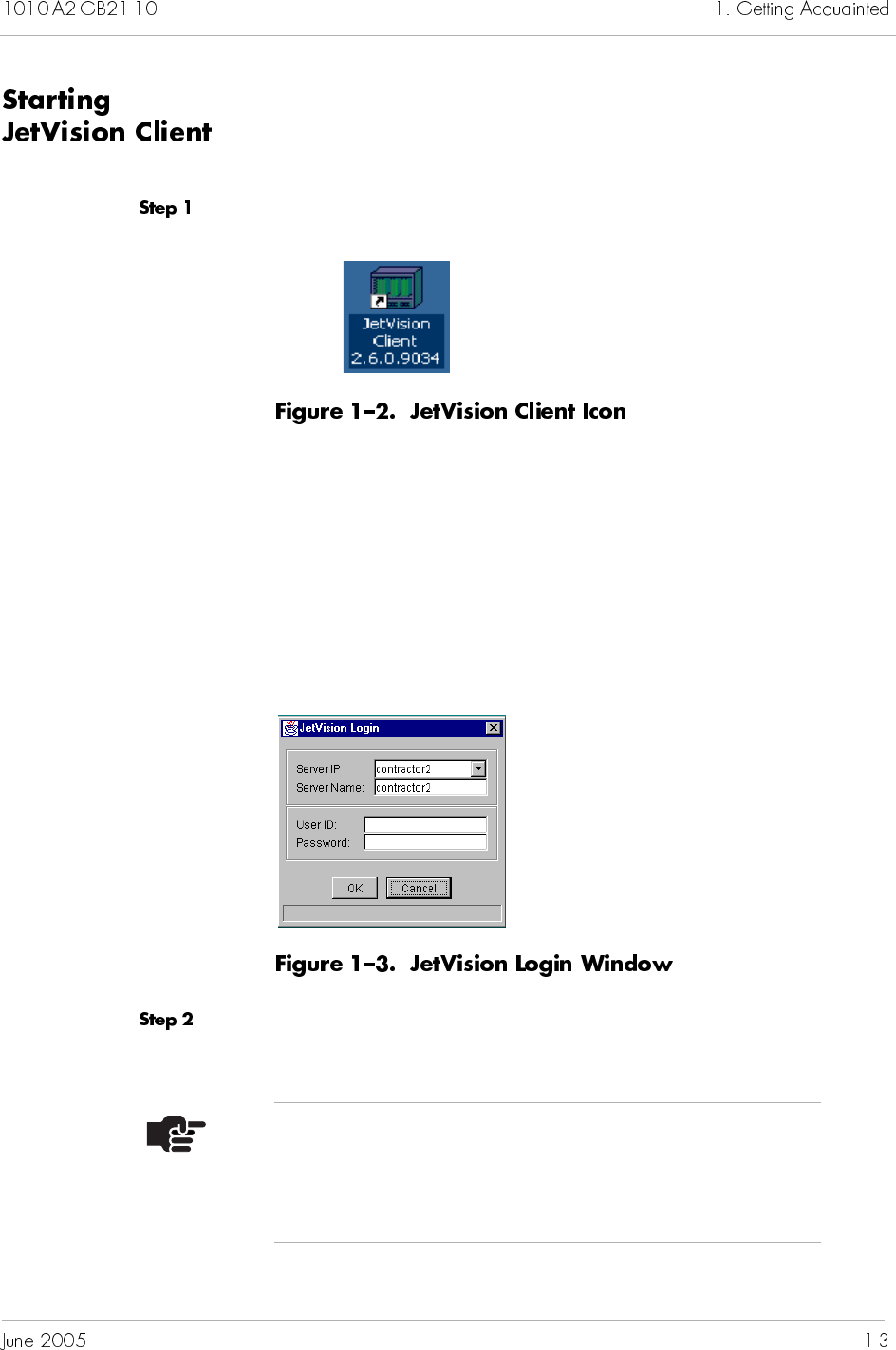
Double-click the JetVision Client icon (Figure 1–2) on the desktop.
– Or –
Click Start > Programs > Jetstream > JetVision Client from the
JetVision Programs menu.
– Or –
Type startemsclient.bat at the command window.
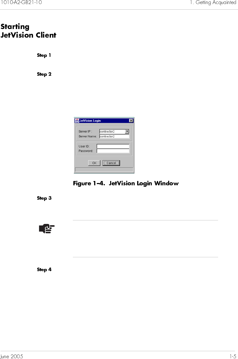
The JetVision Login window (Figure 1–3) appears.
Type the IP address or host name of the JetVision Server in the
Server IP field.
Note
If you are connecting via NAT, type the address that is
outside of the NAT network, i.e., the unused address
local to the NAT subnet.
Type the server name of the computer into the Server Name field.
The default server name is the same as the host computer.
Type the user ID and password in their respective fields.
If this is the first time you are starting JetVision Client, type
jsems (default user ID) in the User ID field. Otherwise,
type your assigned JetVision user ID.
If this is the first time you are starting the JetVision Client,
type jsems123 (default password) in the Password field.
Otherwise, type your assigned JetVision password.
Click OK.
Starting JetVision Server requires that you log on with
administrator privileges.
If the autostart option was selected with the JetVision installation,
verify the JetVision Server has started by using this command:
ps -eaf | grep startemsserver
If the autostart option was not selected with the JetVision
installation, follow these steps:
Go to the JetVision Server installation directory and find the
startemsserver.sh file.
Type the appropriate UNIX shell command. For example,
cd /opt/jetstream/emsserver_v25/bin
./startemsserver.sh
Verify that JetVision Server started by using the following
command:
ps -eaf | grep startemsserver
Notes
The Server name is the same as the Host name.
To find the JetVision Server ID and Host names, go to
Control panel > Network > Identification.
Before you can start JetVision Client, JetVision Server must be
running on the host computer.
To start JetVision Client:
Locate the startemsclient.sh file in the JetVision Client
installation directory.
Type the appropriate UNIX shell commands. For example:
cd /opt/jetstream/emsclient_v25/bin
./startemsclient.sh
The JetVision Login window appears (Figure 1–4).
Type the IP address or host name of the JetVision Server in the
Server IP field.
Type the server name of the computer into the Server Name field.
The default server name is the same as the host computer.
Note
If you are connecting via NAT, type the address that is
outside of the NAT network (i.e., the unused address
local to the NAT subnet).
Type the user ID and password in their respective fields.
If this is the first time you are launching JetVision Client,
type jsems (default user ID) in the User ID field.
Otherwise, type your assigned JetVision user ID.
If this is the first time you are starting the JetVision Client,
type jsems123 (default password) in the Password field.
Otherwise, type your assigned JetVision password.
Click OK.
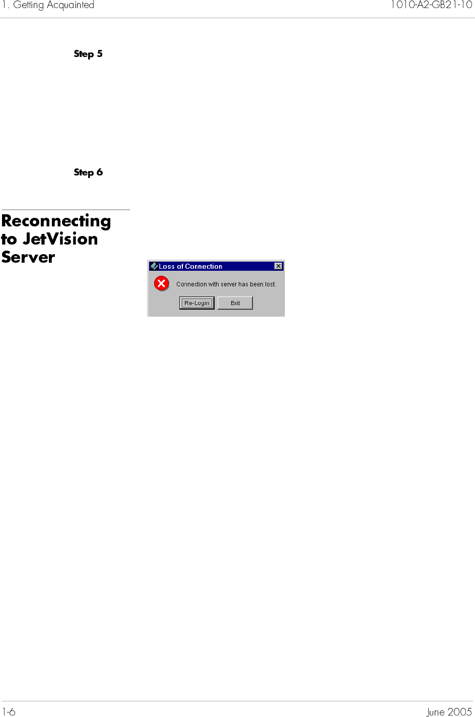
When connectivity is lost to the JetVision Server, the following
dialog box appears:
Click Re-Login.
For Windows, type your user ID and password in their
respective fields when the JetVision Login window
reappears.
For Solaris:
— Verify that JetVision Server started by using the
following command:
ps -eaf | grep startemsserver
— If PID (Process ID) is missing, change to the appropriate
directory and invoke the shell command. For example,
cd /opt/jetstream/emsserver_v25/bin
./startemsserver.sh
— When the JetVision Login window appears, type your
user ID and password in their respective fields.
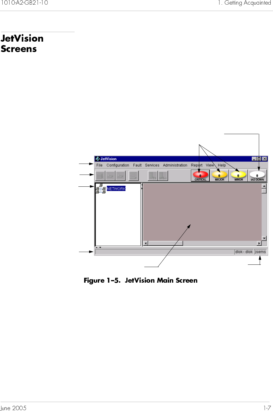
After successfully logging on to JetVision Client, JetVision Main
screen appears (Figure 1–5). This screen is divided into six sections:
the menu bar
toolbar icons
Tree View, Map View (changes to Shelf View when the Shelf
icon is selected)
alarm indicators
status bar
You can access commands from the menu bar, toolbar icons, and
by right-clicking objects in the Tree and Map views. For a complete
listing of options available for each menu and icons, refer to
Appendix A, JetVision Menu Map.
You can choose to view JetVision objects either in geographical or
textual presentation, but only one presentation is visible at one
time. You can switch between the two presentation at any time,
and the presentation you selected will remain in effect until you
change it.
To switch between the two presentations, select the desired option
from the View menu.
Network alarm indicators
Menu bar
Toolbar icons
Status bar
Double-click to expand your
network to view the CPX-1000
and its associated components
User ID
Map or textual display area
Number inside indicating
number of IAD down
To use the JetVision menus to perform an operation, make sure
that you have access to this operation and that you have selected
an appropriate CPX-1000 managed object for the operation. If
your access to the operation is restricted, that menu selection is
grayed out.
Seven menus provide JetVision operations:
File
Configuration
Fault
Services
Administration
Report
View
The Help menu provides a quick look-up of JetVision procedures.
It also provides an easy and convenient way to view information
about JetVision.
For a complete listing of the options available for each menu, refer
to Appendix A, JetVision Menu Map.
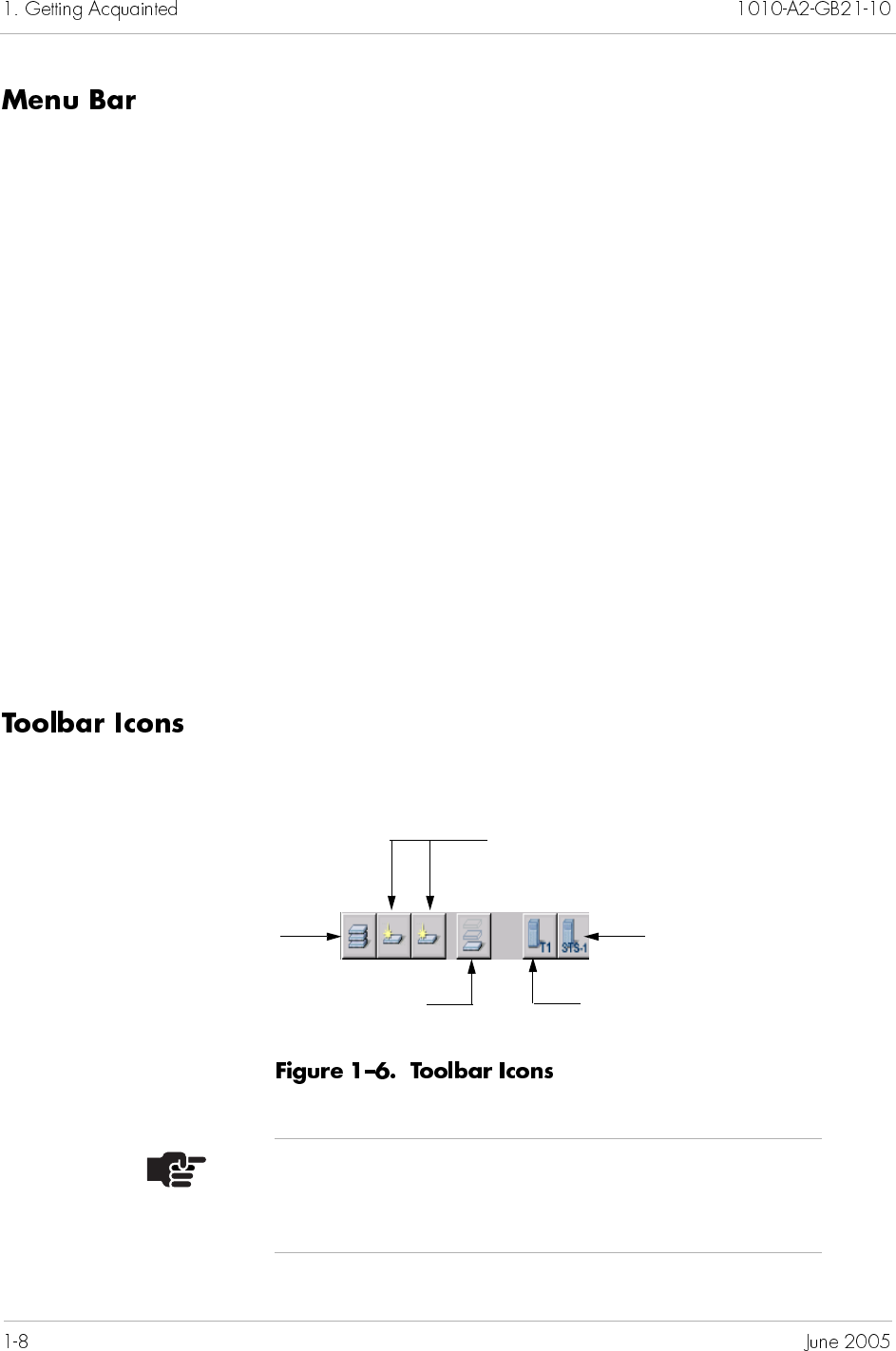
Click a CPX-1000 icon in the Tree view to display the toolbar icons.
Five icons are used as shortcuts to some menu selections
(Figure 1–6).
Click here to create an IAD
Click here to create an IAD Profile Click here to create a T1
Interface Group
Click here to perform IAD
management functions
Click here to create an
STS-1 Interface Group
Note
All toolbar icons are enabled only when the CPX-1000
icon is selected.
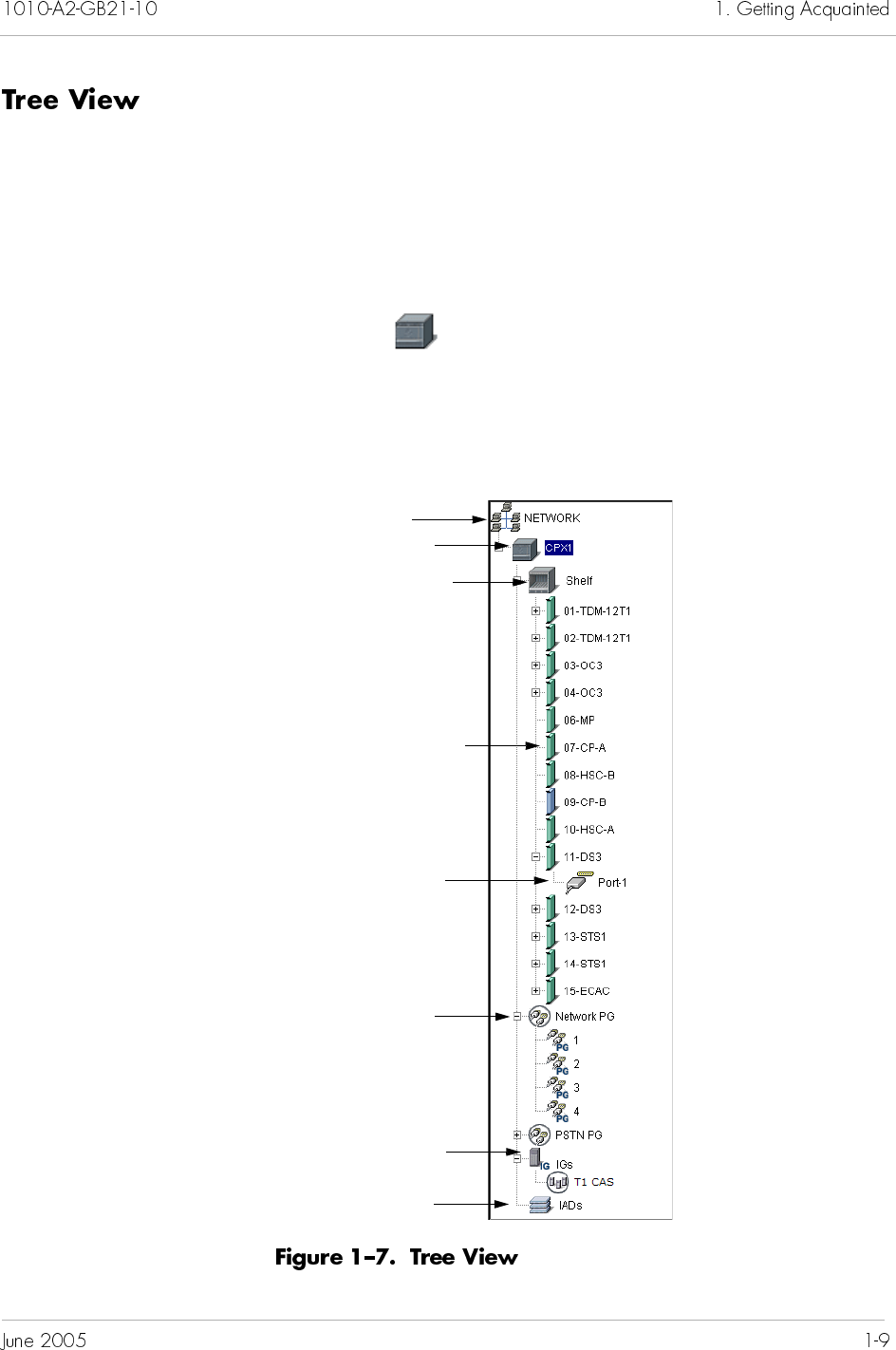
The Tree view (Figure 1–7) provides a hierarchal “exploded” view of
the CPX-1000 shelf. A plus sign (+) next to the CPX-1000 icon
indicates that shelves are assigned to that CPX-1000. The name of
the card includes the slot number and the name and number of the
port. For example: a card labelled “07-CP-A” indicates that slot 7
contains the primary Control Processor (CP) card.
Double-click the network icon to expand and view your network.
To expand and view the structure of the CPX-1000 cards, either
double-click on the Tree View or click the plus sign (+) next to
that icon.
You can also use the Tree View to quickly find specific shelf or
alarm information. Right-click an element icon to select a graph
from the menu or select a report from the Fault or Services menu.
CPX-1000
Shelf icon associated
with the CPX-1000
Card icon
Port icon
IAD icon
Protection Group
icon
Interface Group
icon
Network Group
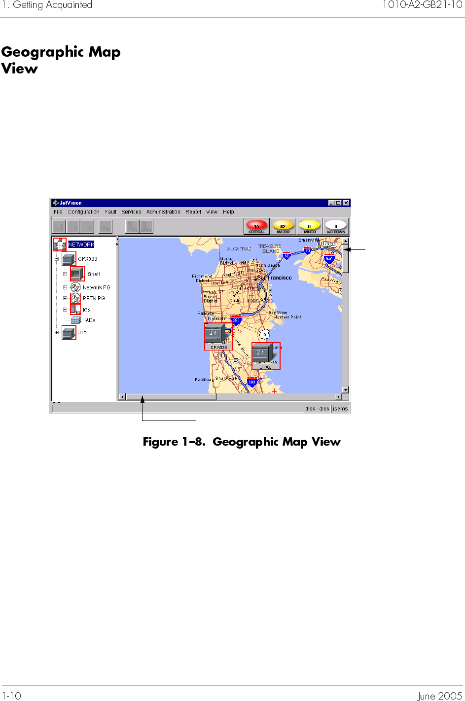
When Map View is selected from the View menu, a geographic
map is displayed in the background and the CPX-1000 units you
have created are displayed (Figure 1–8). If necessary, you can move
the CPX-1000 to any location on the map, and the CPX-1000 will
remain on that location until you move it the next time.
JetVision provides one background geographic map. For
instructions to change the background map, refer to Chapter 2,
Administration, For instructions about adding maps to the
depository, refer to Chapter 17, InfoCenter Services.
Use this scroll bar to view the map horizontally
Use this scroll bar to
view the map vertically
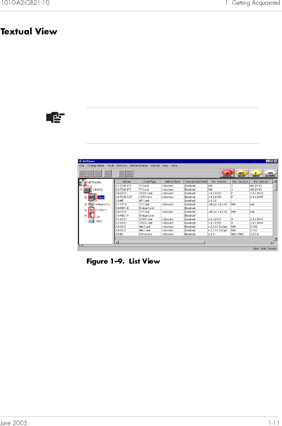
The textual view allows you to view all information related to the
selected JetVision objects simultaneously (Figure 1–9). To display
the textual view, select List View from the View menu.
You can sort, rearrange, and resize the columns. Click the column
header to sort the columns. The sorting order is toggled between
descending and ascending orders. You can also rearrange the order
of the columns by dragging-and-dropping a column in the header
area. To resize the columns, drag the divider between the columns.
Note
The rearrangement and resizing of the column are not
persistent in the current release.
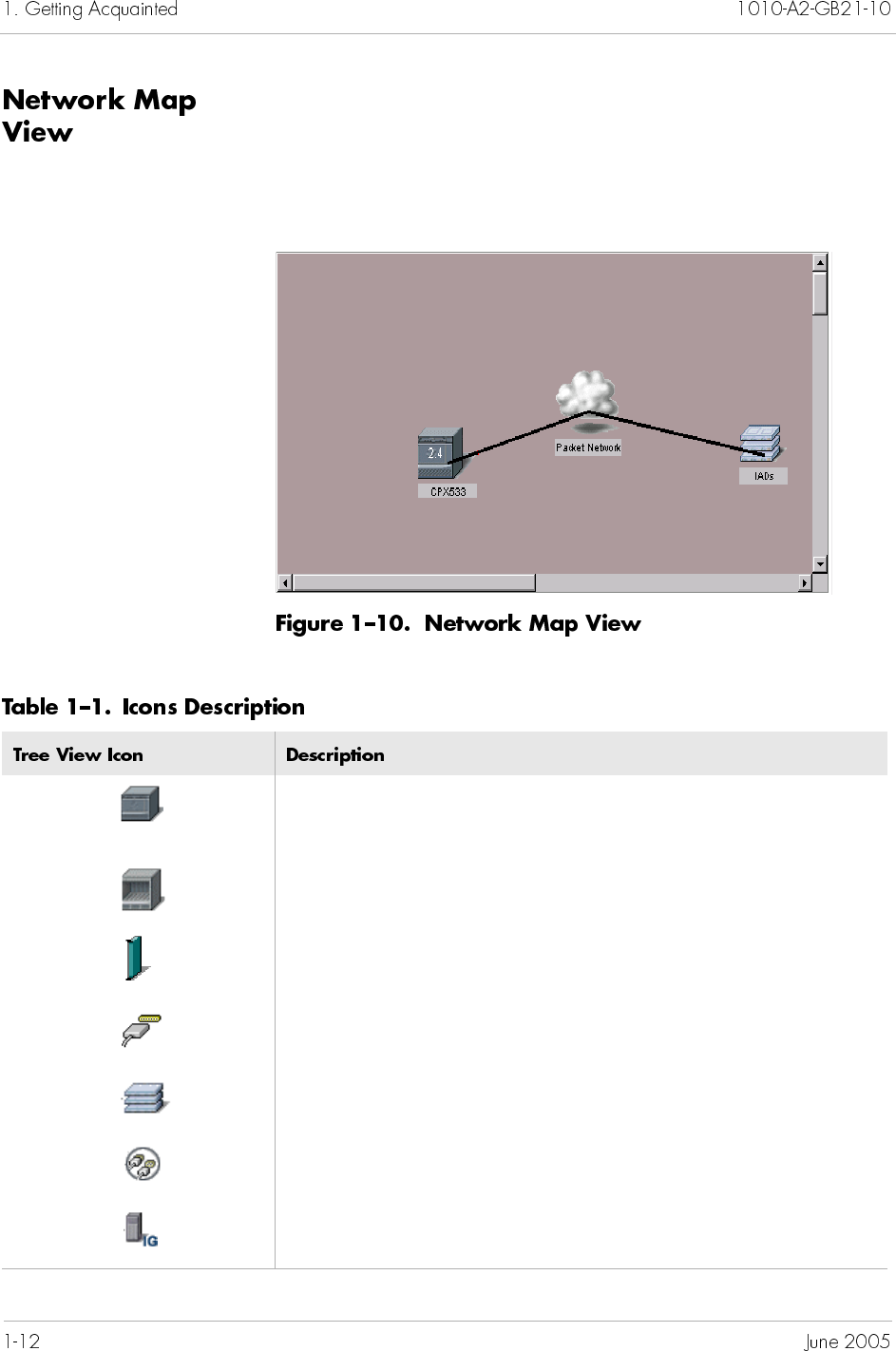
When the IAD icon on the Tree View is selected, the map is
changed to the Network Map View. Use the Network Map view
(Figure 1–10) to select and view configuration, performance, and
alarm information about the CPX-1000 and IADs. Right-click an
element and view configuration or report information.
Table 1–1 describes icons in the Tree and Map views.
CPX-1000 icon: displays the Tree View to select a specific
managed object (shelf, Interface Group, Protection Group, or
IAD).
Shelf icon: displays the Shelf view to select a specific shelf (card
or port).
Card icon: selects a card and view the card configuration or
report information.
Port icon: selects a port to perform an operation.
IAD icon: selects a specific IAD to perform an operation.
Protection Group icon: selects a Protection Group (ATM or
PSTN) to perform an operation.
Interface Group icon: selects an Interface Group (STS-1 or T1) to
perform an operation.
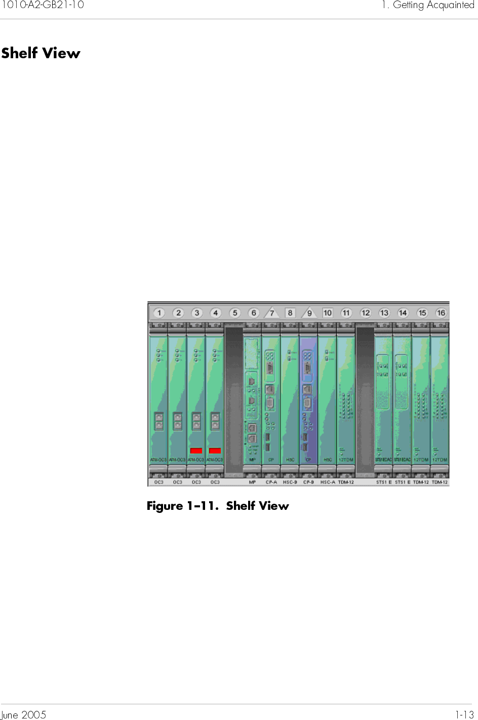
Use the Shelf view (Figure 1–11) to select and view configuration,
performance, and alarm information about CPX-1000 cards and
ports. Right-click a card or port to view configuration or status
information.
The color shown indicates the states of the cards: green for active
and blue for standby. The two CP and an MP cards are located in
fixed slots assignment. The primary CP occupies slot 7 with its
corresponding primary HSC card in slot 10. The secondary CP
occupies slot 9 with its corresponding secondary HSC card in slot
8. The MP card occupies slot 6. Other line cards slot assignments
does not have fixed slot assignments and are detected at startup.
The ECAC card requires two side-by-side slots.
For a description of individual cards, refer to CPX-1000 Voice
Services Platform Introduction and Technical Description.
Table 1–2 lists the types of cards that are currently available.
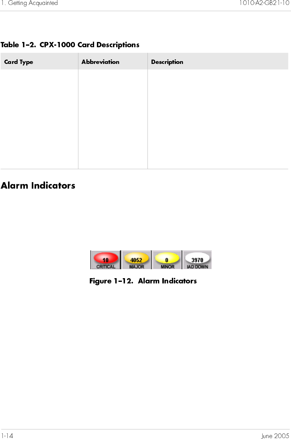
Network alarms appear as colored oval indicators (Figure 1–12) on
the right-hand side of the menu bar. Each color indicates the
severity of the alarm (Table 1–3). A number displayed inside the
oval indicates the number of alarms reported for that level of
severity.
For more information on alarms, refer to Chapter 12, Alarms.
ATM-DS3 ATM-DS3 ATM DS-3 card
ATM-OC3 ATM-OC3 ATM OC-3 card
Call Processor CP-A and CP-B Control Processor card
HSC HSC-A and HSC-B Hot Swap Controller card
Management Processor MP Management Processor card
STS-1 STS-1 Synchronous Transport Signal Level 1 card
TDM-12T1 TDM-12T1 12-Port TDM T1 card
Alarm events and messages are displayed in the status bar. Two
colors are used to indicate the type of message: blue for status and
red for error. The names of the login user and JetVision Server are
also displayed at the right side of the status bar.
Red (Critical) A severe, service-affecting condition has
occurred; require immediate corrective
action regardless of the time of day or day
of the week.
Yellow (Major) A serious disruption of service or a
malfunction or failure of important
circuits has occurred; require immediate
corrective action and response to restore
or maintain system capabilities.
Light yellow
(Minor)
A non-service-affecting condition has
occurred; no immediate corrective action
is necessary.
White (IAD Down) An IAD is no longer in service; require
immediate corrective action.
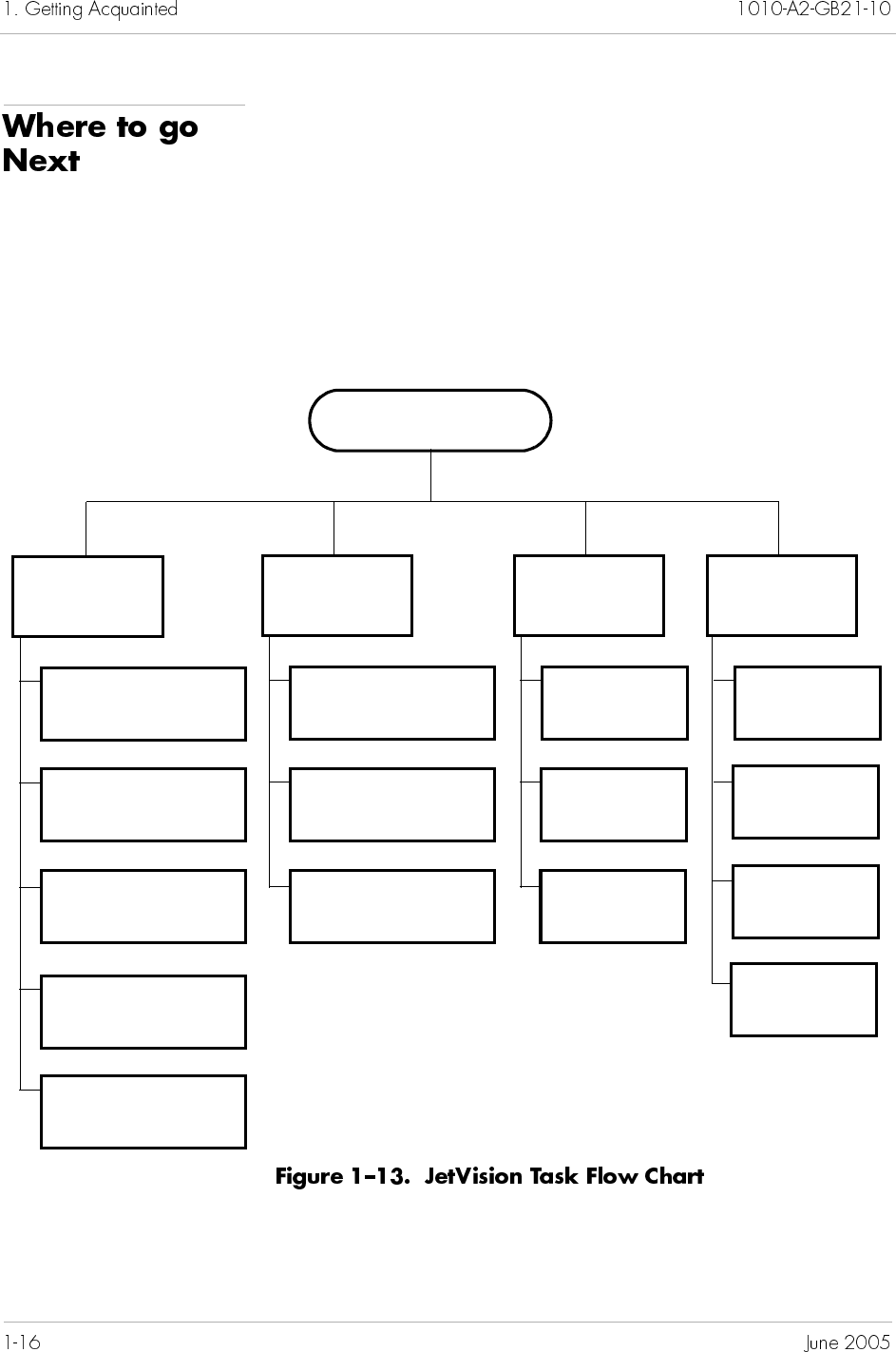
First, follow the instructions in Chapter 2, Administration, to add
CXP-1000 to the JetVision managed domain. Then follow the task
flow shown in Figure 1–13. It’s your preference whether to first
perform configuration and provisioning or to set up groups and
users. However, when you are within the task group, make sure to
perform the tasks in the order presented. For example, if you
choose to perform configuration and provisioning first, you must
finish configuring the CPX-1000 before provisioning the Interface
Groups.
Starting JetVision Server
and JetVision Client
Configuration
and
Provisioning
Chapter 3
CPX-1000 Configuration
Chapter 4
Protection Groups
Provisioning
Chapter 5
Interface Group
Provisioning
Chapter 6
IAD Profile Provisioning
Chapter 7
IAD Provisioning
Security
Management
Chapter 9
CPX-1000 Users
Chapter 10
Web Browser Users
Chapter 8
JetVision Groups, Users,
and Passwords
Performance
Monitoring
Chapter 11
Alarms
Chapter 12
Reports
Chapter 13
Statistics
Maintenance
and
Service
Chapter 14
Maintenance
Chapter 16
Services with
InfoCenter
Chapter 15
Integrated
Monitoring
Chapter 17
Diagnostics
with Jetutil

The JetVision Server can manage up to 20 CPX-1000 units at a time.
To manage a large number of CPX-1000s, JetVision allows arbitrary
and logical grouping of CPX-1000s in a network. These logical
groups can be nested within other groups to form a hierarchy of
groups of CPX-1000. Up to six levels can be nested within a group.
The maximum number of nodes supported in a group is two times
the CPX-1000 in the system. For example, if you have 10 CPX-1000
units in your system, you can create 20 nodes.
This chapter provides instructions to include these tasks:
Adding a CPX-1000 (page 2-2)
Updating CPX-1000 information (page 2-3)
Removing a CPX-1000 (page 2-4)
Adding a group (page 2-4)
Modifying a group (page 2-5)
Deleting a group (page 2-6)
Moving a group (page 2-6)
Finding a CPX-1000 location (page 2-7)
Monitoring JetVision Sessions (page 2-8)
JetVison automatically discovers all CPX-1000 managed elements
when a CPX-1000 is added to the JetVision managed domain. The
state of each CPX-1000 managed element is continuously
monitored. The CPX-1000 managed elements include
MP card
CP cards
Line cards and ports
Associated IADs
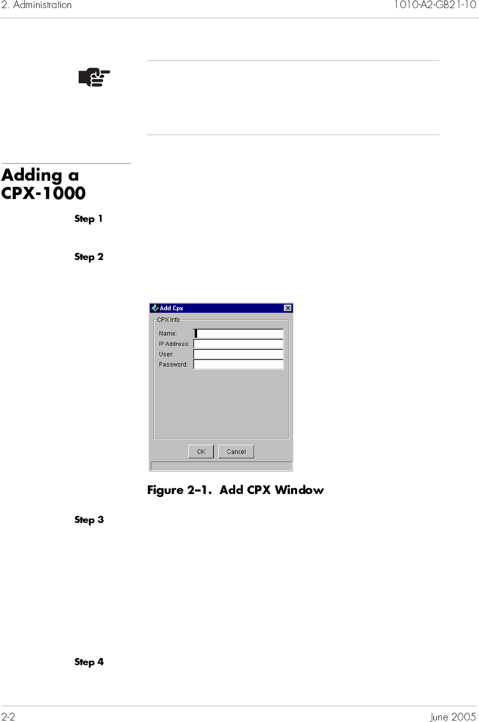
To add a CPX-1000:
Click the group icon from the Tree View where the CPX-1000 will
be added.
Select Create CPX from the Configuration menu. The Add CPX
window appears (Figure 2–1).
Enter information in the following fields:
Name: An identifier for the CPX-1000 consisting of 4 to 16
alphanumeric characters (no spaces, hyphens, or special
characters).
IP Address: If DNS is running, enter the CPX-1000 name in
this field.
User: Type cpxuser (default user ID).
Password: Type cpxuser (default password).
Click OK. The CPX-1000 you created appears in the Tree and Map
views.
Note
Before putting the CPX-1000 to service, ensure that the
IP address (Chapter 3, CPX-1000 Configuration) as well
as date and time is accurate (Chapter 15, Maintenance).
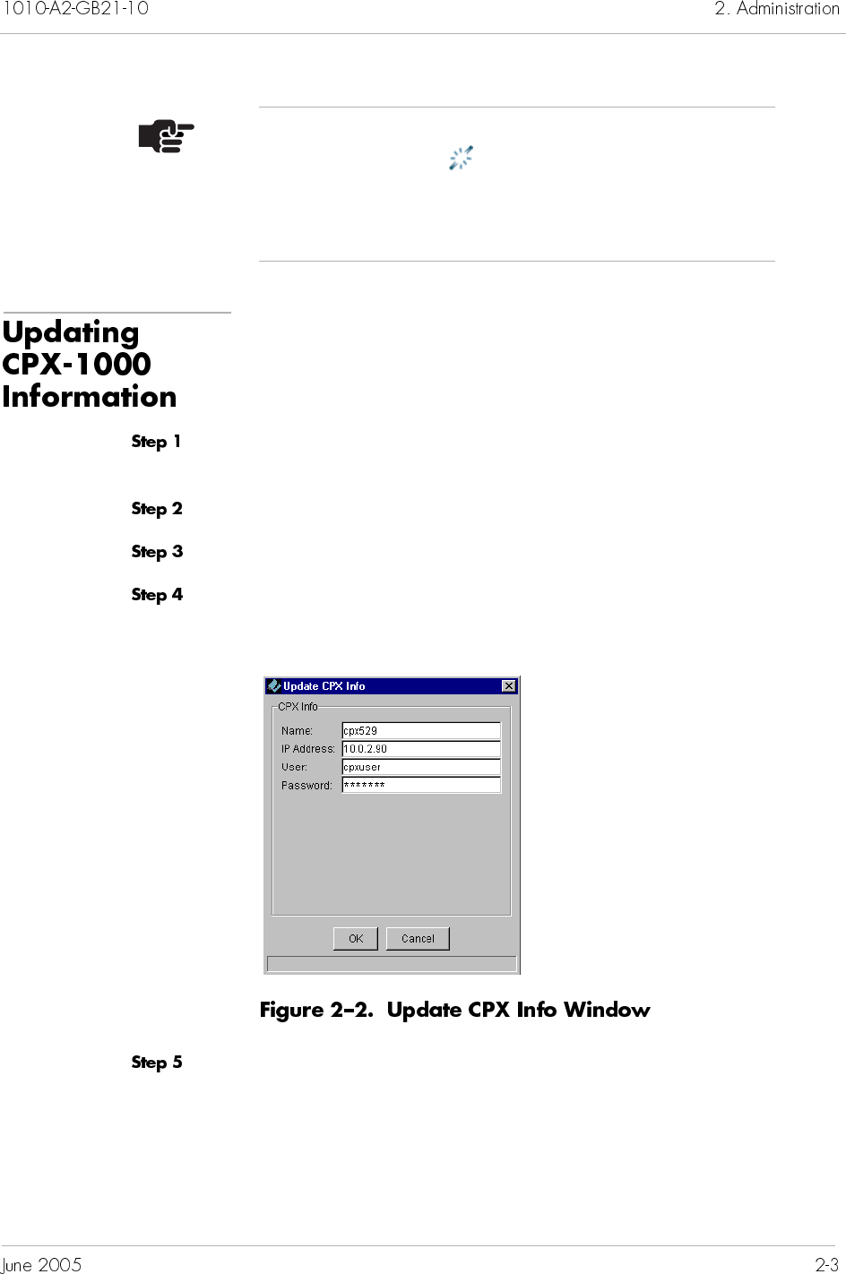
When you use JetCraft to change CPX-1000 information, such as IP
address, you can update the CPX-1000 with JetVision.
To update CPX-1000 information:
Locate the CPX-1000 by clicking the group icon from the Tree View
where the CPX-1000 resides.
Click a CPX-1000 and expand the tree.
Click the CPX-1000 icon from the Tree View.
Select Update CPX Info from the Administration menu. The
Update CPX Info window appears (Figure 2–2).
Click OK to accept the changes.
Note
An out-of-sync icon and a gray-out CPX-1000 image
appear in the Map View during initialization. When the
initialization process completes, the icon disappears and
the color of the CPX-1000 returns to gray.
To remove a CPX-1000:
Locate the CPX-1000 by clicking the group icon from the Tree View
where the CPX-1000 resides.
Click a CPX-1000 and expand the tree.
Click the CPX-1000 icon from the Tree View.
Select Remove CPX from the Configuration menu. A prompt
appears, asking if you want to remove the CPX-1000.
Click Yes to remove the CPX-1000. The CPX-1000 icon is removed
from the Tree, Geographic, and Network Map views.
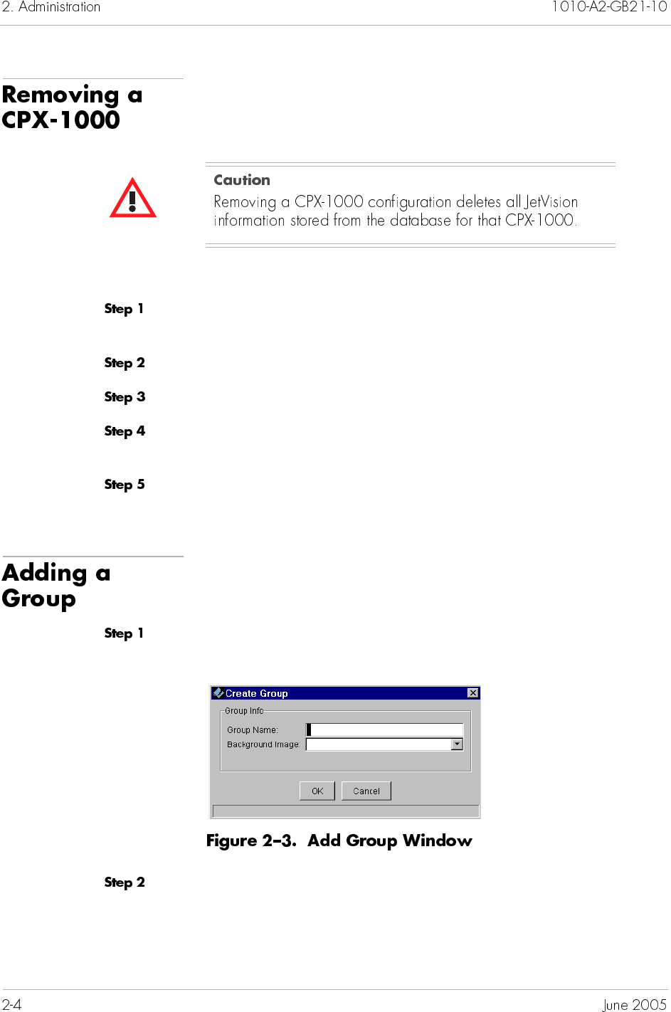
To add a group:
Select Create Group from the Administration menu. The Add
Group window appears (Figure 2–3).
Type the name of the group in the Group Name field. (The name
consists of 4—16 alphanumeric characters.)
Optionally, select the background map from the drop-down list.
(The background map displays in the Map View when this group
is selected.)
Observe the Tree and Map views. A network icon with the
new group name is inserted in both views.
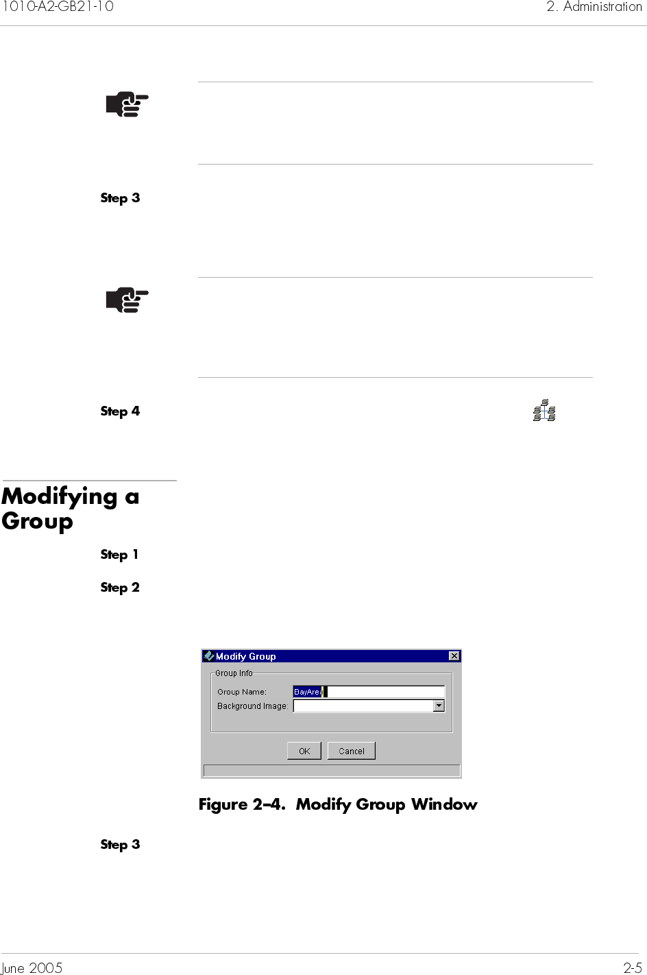
To modify a group:
Click a group icon in the Tree or Map views.
Select Modify Group from the Administration menu. The Modify
Group window appears (Figure 2–4).
Modify the fields, as necessary (Adding a Group on page 2-4).
Note
You can use two special characters dash (–) and
underscore (_) with the name of the group.
Note
The map images are stored in a repository. Refer to
Chapter 17, InfoCenter Services, for depositing images
into the repository.
You cannot delete the default Network group or a group with
CPX-1000 units and sub-groups associated to it.
To delete a group,
Click a group icon in the Tree or Map views.
Select Remove Group from the Administration menu. A message
appears, asking if you want to delete the selected group.
Click Yes. The group is deleted.
JetVision allows you to move one group to another after a group is
created. The move does not affect the tree structure or the alarms
information; however, the move changes the location of the group
node within the group hierarchy.
When a group is moved, all the sub-groups and the CPX-1000 units
in the group move with it, and the sub-tree remains the same after
the move. All propagated alarms of this groups also go with the
new group.
There are three conditions when a move is not allowed:
You cannot move the default Network group.
You cannot move to a group where the new parent group
already contains a group with the same name.
You cannot move a group to under any of its descendant
groups.
To move a group, drag the desired group node and drop it on the
new parent group node or the Network node in the Tree View.
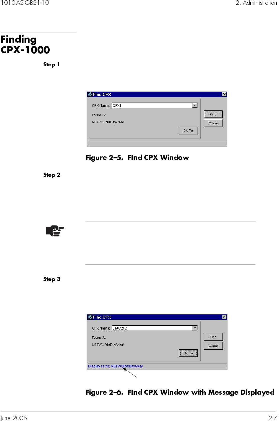
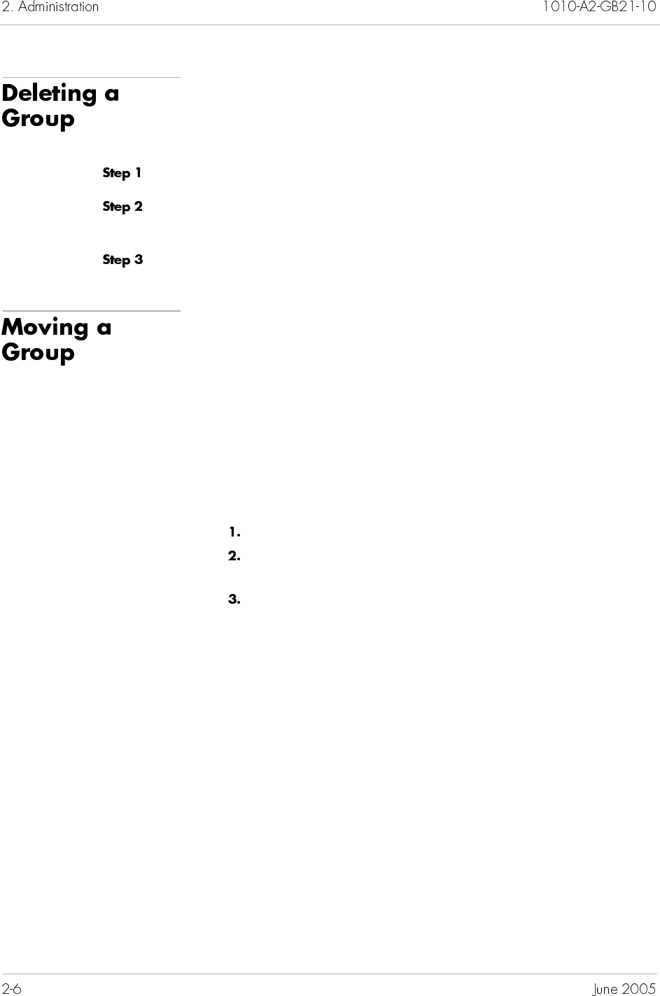
JetVision allows you to locate a CPX-1000 in the group hierarchy
by name. To locate a CPX-1000:
Select Find CPX from the Administration menu. The Find CPX
window appears (Figure 2–5).
Type or select the name of the CPX-1000 from the CPX Name
drop-down list.
When the CPX-1000 is found, its full path is displayed in the Found
panel.
Click Go To. A message appears on the status line as shown in
Figure 2–6, and the found CPX-1000 is highlighted and displayed
in the Main screen.
Note
Wild card searching is not supported. Ensure to enter
the name of the CPX-1000 exactly the same as it appears
in the Tree View.
Displayed message

This chapter provides instructions to configure the CPX-1000 Voice
Services Platform. This chapter includes these tasks:
Changing the IP address (page 3-2)
Configuring global VCI settings (page 3-3)
Setting CDV value (page 3-5)
Setting LBO value (page 3-6)
Configuring STS-1 card (page 3-7)
Setting the clock source (page 3-8)
Annotating CPX-1000 location (page 3-12)
The JetVision Server can manage up to 100 CPX-1000 units at a
time. With backward compatibility, JetVision 2.6 Client allows you
to configure the CPX-1000 2.5 release. However, you can configure
only features that exist in the loaded release. For example, the
T1 CAS Interface Group is a 2.6 feature which can be used on the
2.6 release but not on the 2.5 release.
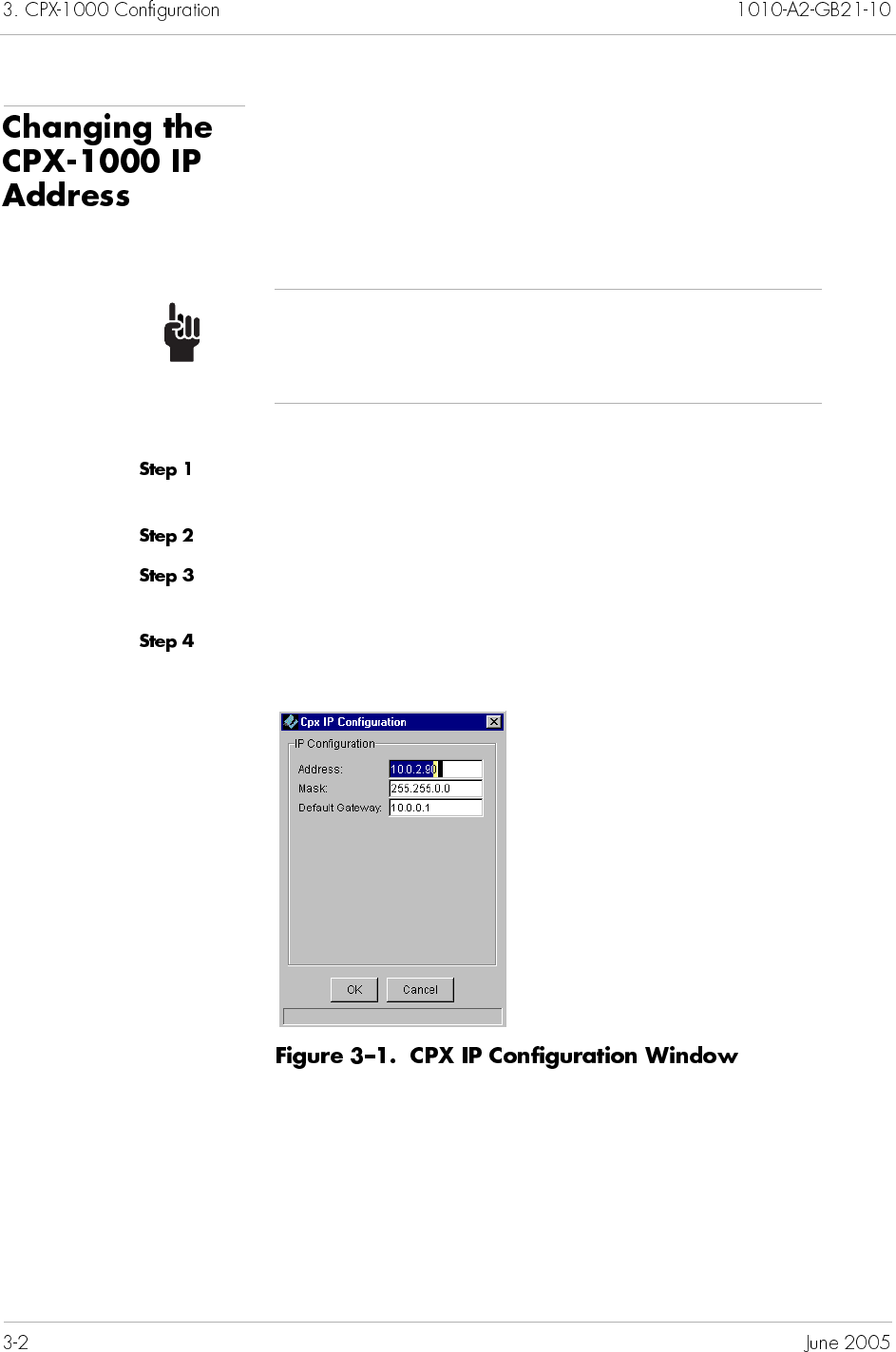
Each CPX-1000 is shipped with a default IP address (10.0.10.100)
that is used during turn-up. Because there might be more than one
CPX-1000 installed in the network, we recommend changing the
default IP address as soon as possible to a unique address to avoid
addressing conflicts.
To change the CPX-1000 IP address:
Click the network icon from the Tree View where the CPX-1000
resides and expand the tree by clicking the + key.
Click a CPX-1000 and expand the tree.
Click the Shelf icon associated with the CPX-1000, and select the
MP card from the Tree or Shelf View.
Select IP Configuration from the Services menu. The CPX IP
Configuration window appears (Figure 3–1).
Tip
Before changing the IP address, obtain a list of IP
addresses for each CPX-1000 in the network.
Type the IP address, subnet mask, and default gateway in the
appropriate fields.
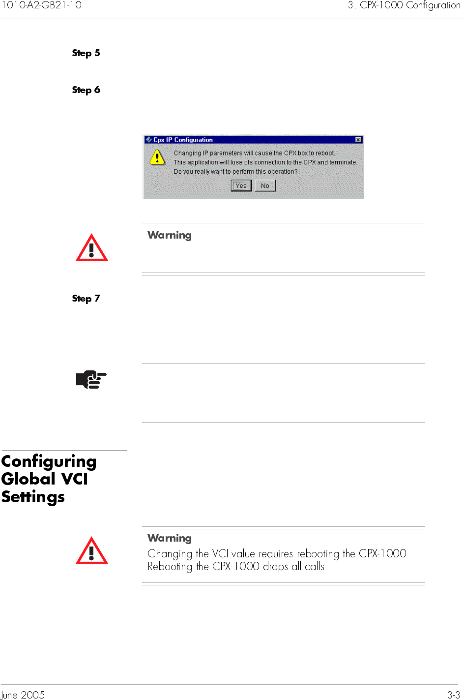
Click OK. A dialog box appears, asking you if you want to reboot
the CPX-1000.
Click Yes.
When the CPX-1000 reboots, your changes are accepted.
If you click No, your changes will not take effect.
The default VCI value is 1024.
You can change the VCI value only when there are no IADs
provisioned to the CPX-1000.
Rebooting the MP card interrupts service.
Note
After you reboot the CPX-1000, we recommend that you
exit and re-login to JetCraft.
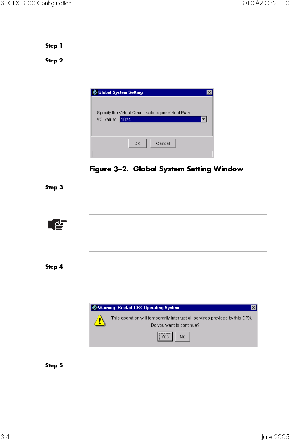
To set the VCI value:
Click a desired CPX-1000 from the Tree View.
Select Configure Global System from the Services menu. The
Global System Setting window appears (Figure 3–2).
Type the VCI value or select one from the drop-down list. Your
options are 64, 128, 256, 512, 1024.
Click OK. The following dialog box appears, informing you that a
reboot is required and asking if you want to continue with the
update.
Click Yes.
Note
This value determines the number of VCIs allowed per
VPI.
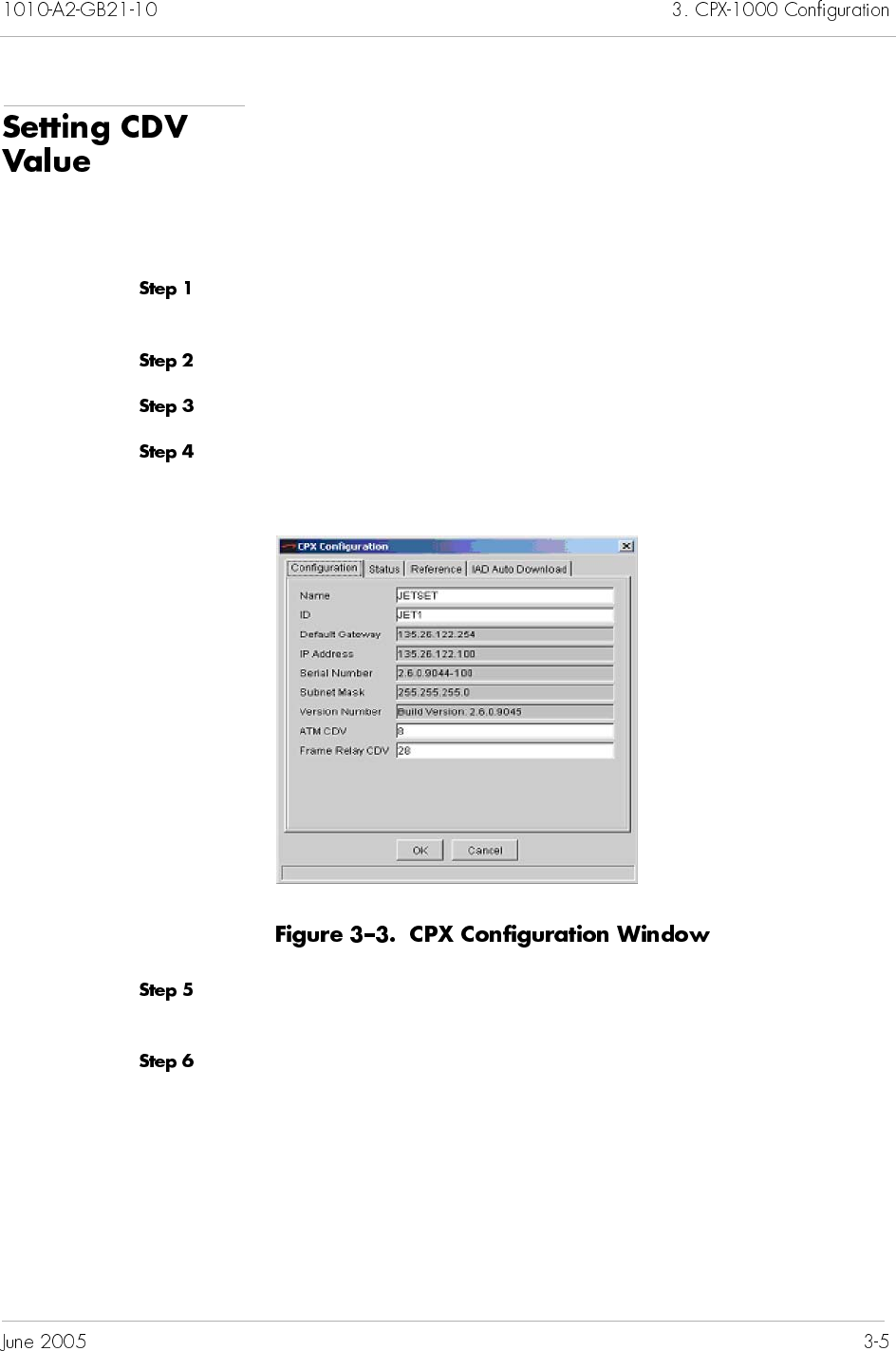
Cell Delay Variation (CDV) is a QoS parameter that measures the
time needed for each cell to travel over the Virtual Circuit (VC).
The value expressed is in the microsecond (ms). The higher the
CDV value, the less the calls allowed.
To set the CDV value:
Locate the CPX-1000 by clicking the group icon from the Tree View
where the CPX-1000 resides.
Click a CPX-1000 and expand the tree.
Click the CPX-1000 icon from the Tree View.
Select Configure from the Configuration menu. The CPX
Configuration window appears (Figure 3–3).
Type the values between 1 – 60 in both the ATM and Frame Relay
fields (default for ATM is 8 ms and frame relay is 28 ms).
Click OK.
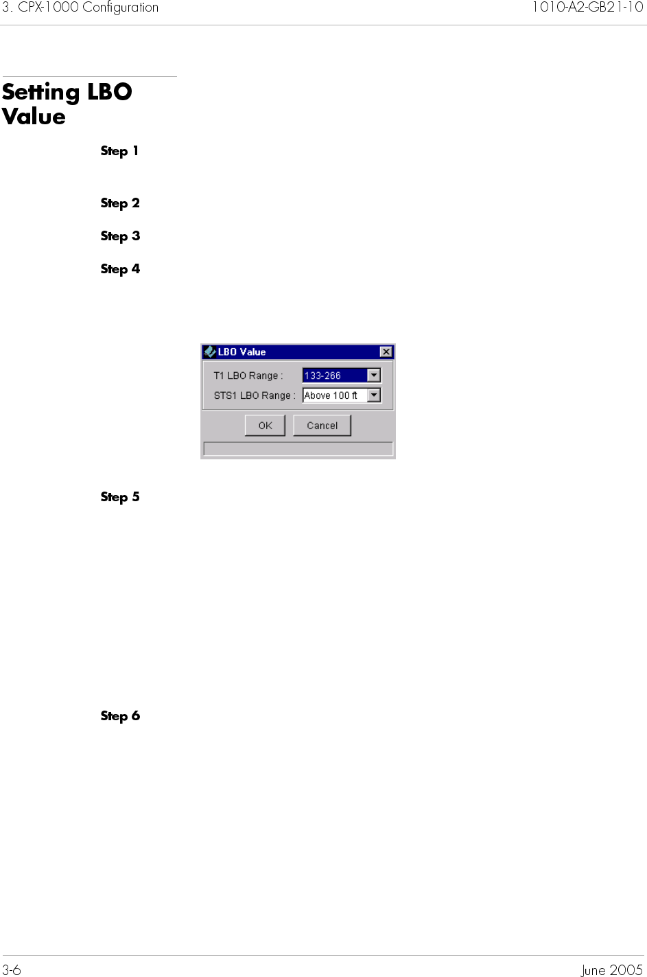
Line Build Out (LBO) is used to offset the output attenuation.
To set the LBO value:
Locate the CPX-1000 by clicking the group icon from the Tree View
where the CPX-1000 resides.
Click a CPX-1000 and expand the tree.
Click the CPX-1000 icon from the Tree View.
Select LBO Value from the Configuration menu.
The following diaglog box appears.
Select the linear measurement (feet) from the drop-down lists.
Ranges for T1 LBO are:
— 0–133
— 133–266 (default)
— 266–366
— 399–533
— 533–655
Options for STS1 LBO are Above 100 ft. (default) or Below
100 ft.
Click OK.
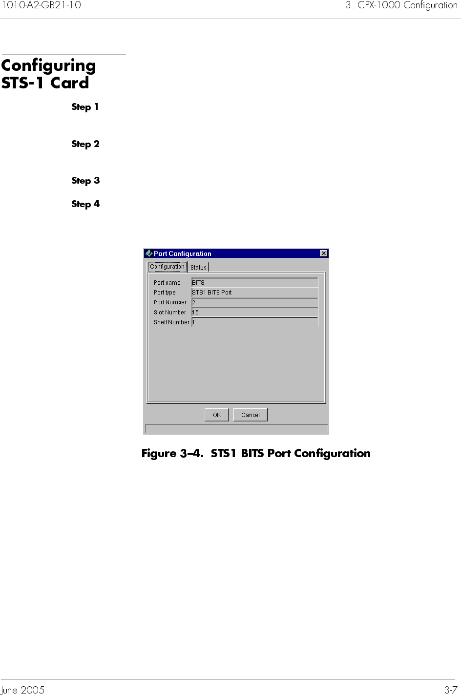
To change the frame format and line encoding on the STS-1 card:
Click a CPX-1000 from the Tree View and expand the tree by
clicking the + sign.
Click the Shelf icon associated with the CPX-1000 and expand the
tree by clicking the + sign.
Expand the STS-1 card on the Tree View, and select BITs.
Select Configure from the Configuration menu. The Port
Configuration window appears (Figure 3–4).
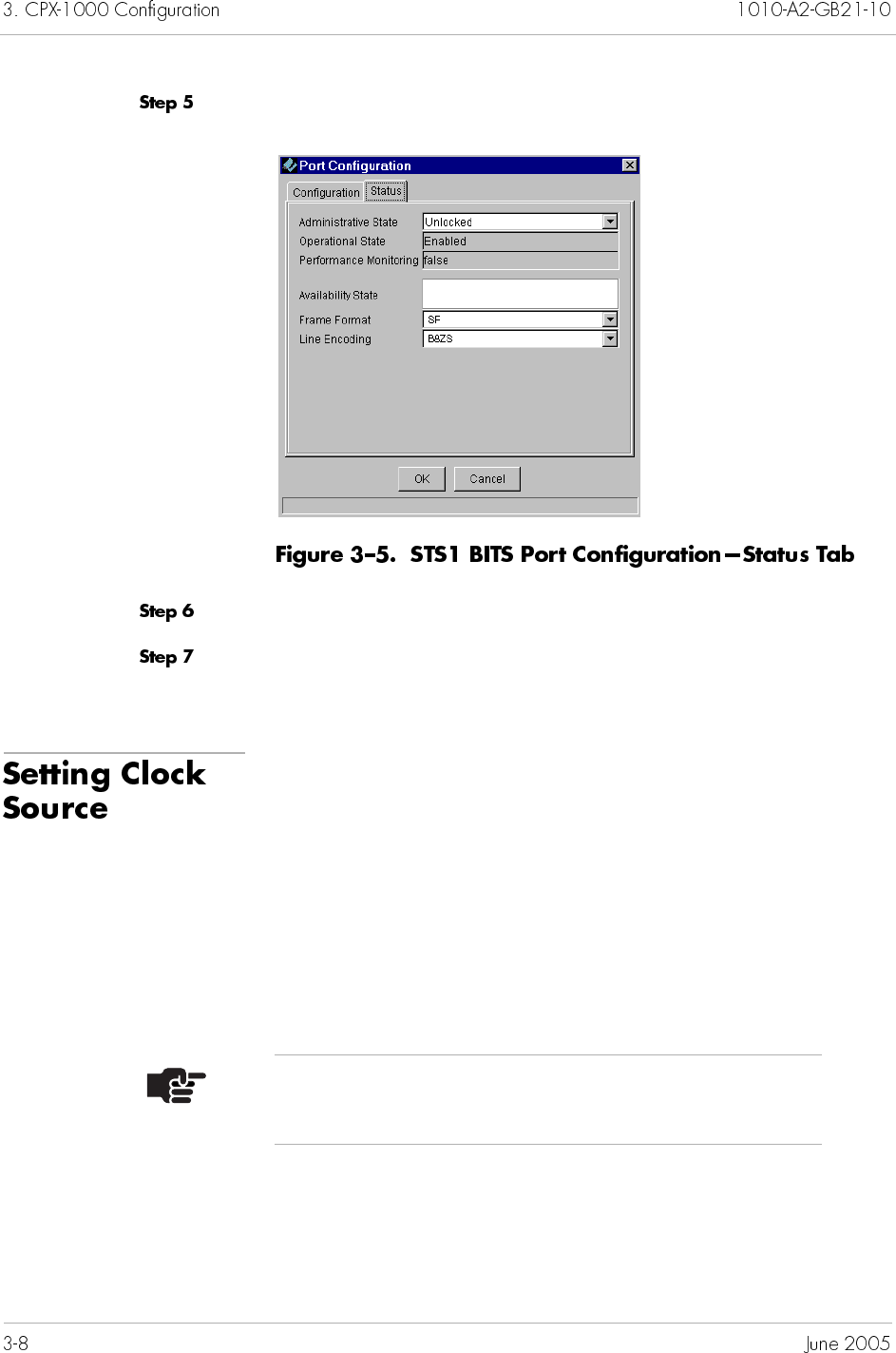
Click Status. The Status tab appears (Figure 3–5).
Select the frame format options (SF or ESF) from its drop-down list.
Select the line encoding options (AMI or B8ZS) from its drop-down
list.
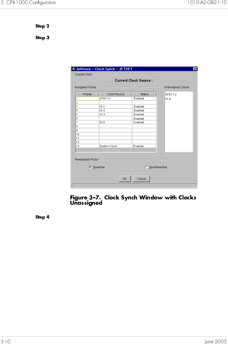
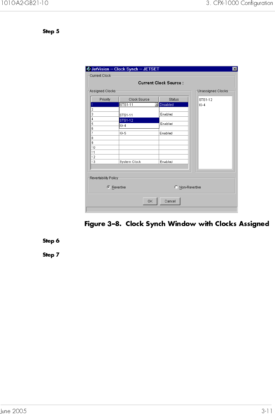
Clock source comes from BITS (STS-1 cards) and Interface Groups.
There are 13 possible priorities. When present, priorities 1 through
4 are used for STS-1 cards and 5 through 12 for interface groups.
Priority 13 is reserved for system clock and is not user-
configurable.
When “Revertive” is set, it takes place across all priorities. For
example, priorities 1 and 2 lose the clock, and priority 3 takes over
and is actively driving the bus. When priority 1 regains its clock,
then priority 1 will then take control of driving the bus.
Note
The revertive behavior is on a CPX-1000 basis.
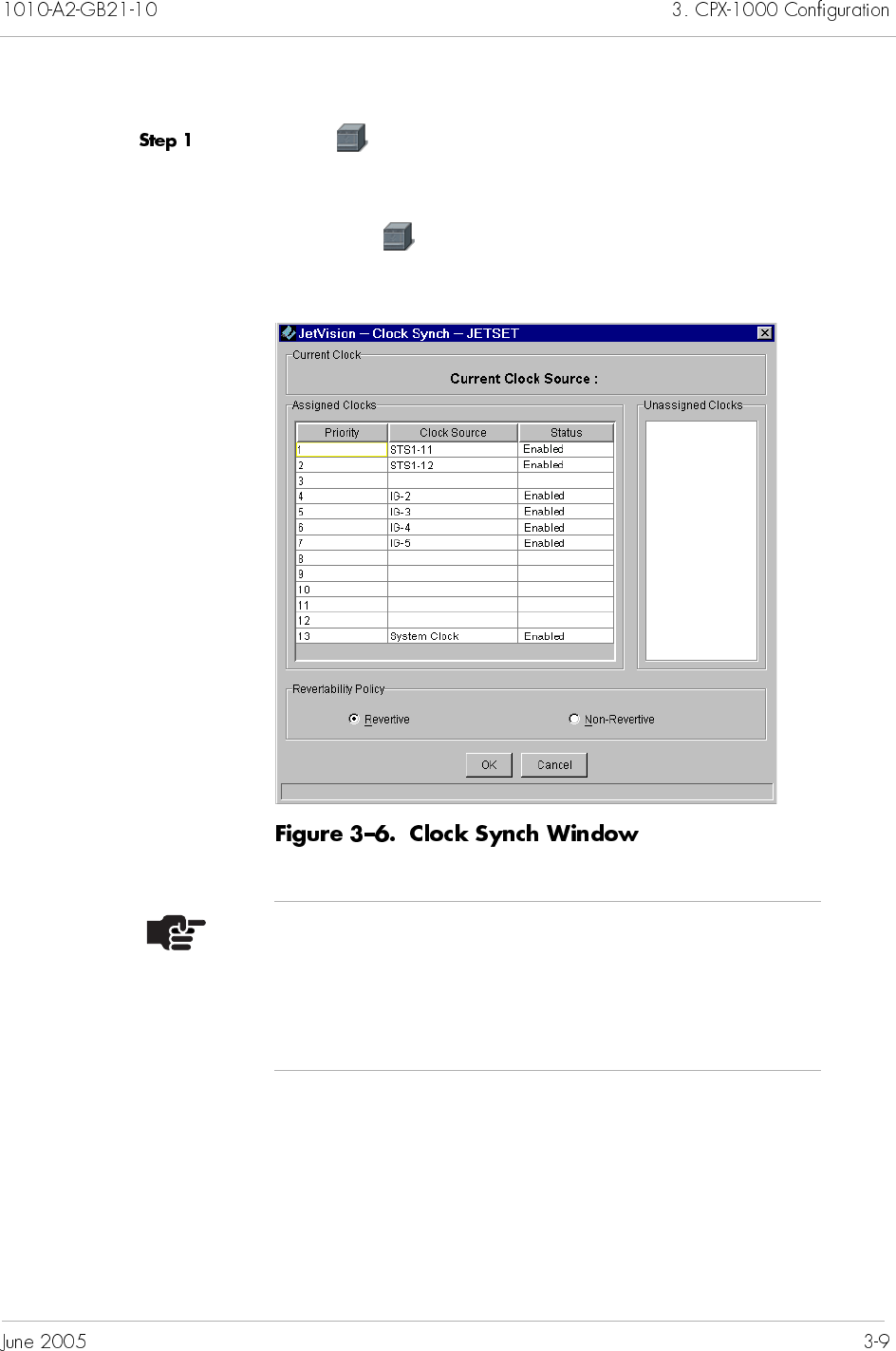
To assign priority of CPX clock source:
Select in the Tree View, then select Clock Synch from the
Configuration menu.
– Or –
Right-click in the Tree View and select Clock Synch.
The Clock Synch window similar to Figure 3–6) appears.
Notes
The Priority and Status fields are read only.
The number of clock source available depends on the
number of STS-1 cards and Interface Groups you have
configured on your CPX-1000.
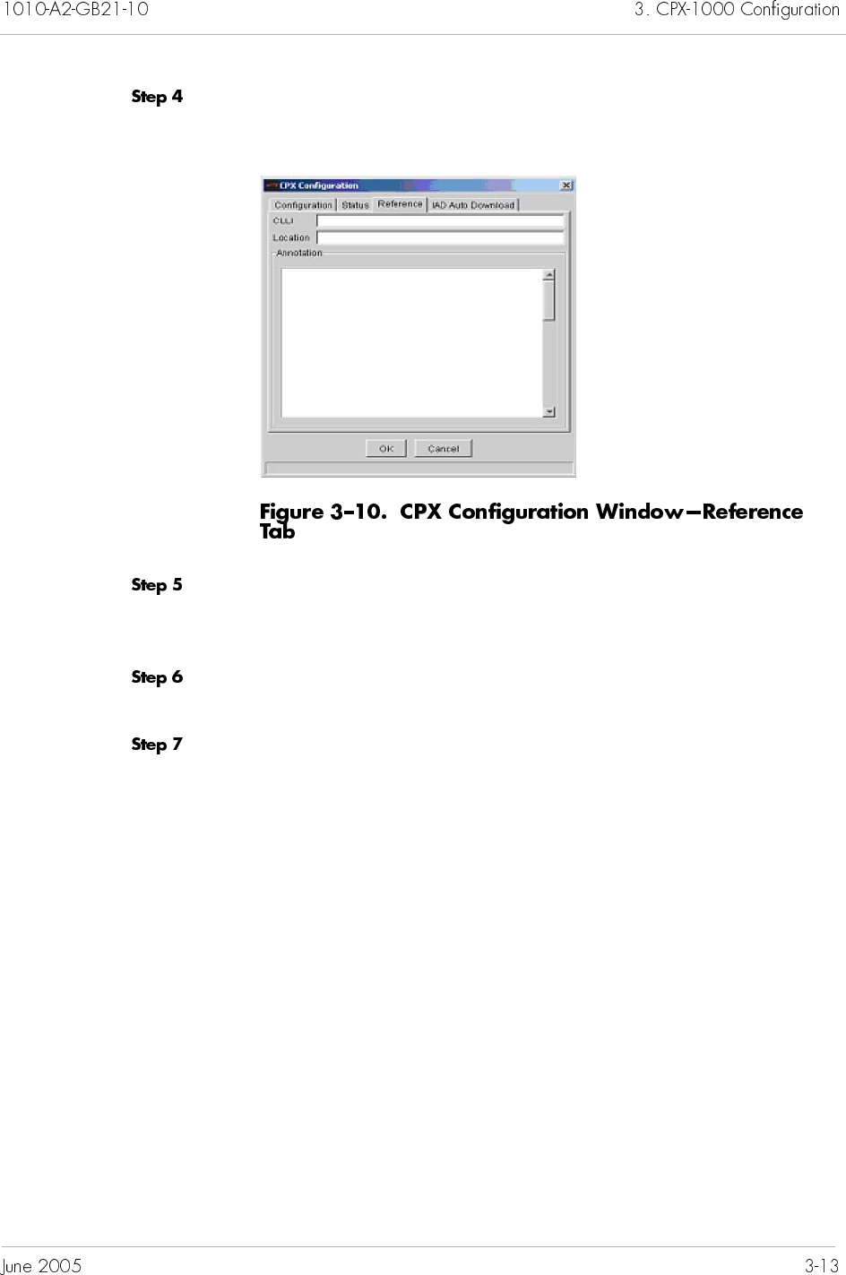
Click Reference, and the Reference tab window appears
(Figure 3–10).
Type a string of up to 11 alphanumeric characters that identify the
CPX-1000 in the CLLI (Common Language Location Identifier)
field.
Type the physical location of the CPX-1000 of up to 32
alphanumeric characters in the Location field.
Type any notes of up to 200 characters in the Annotation field.
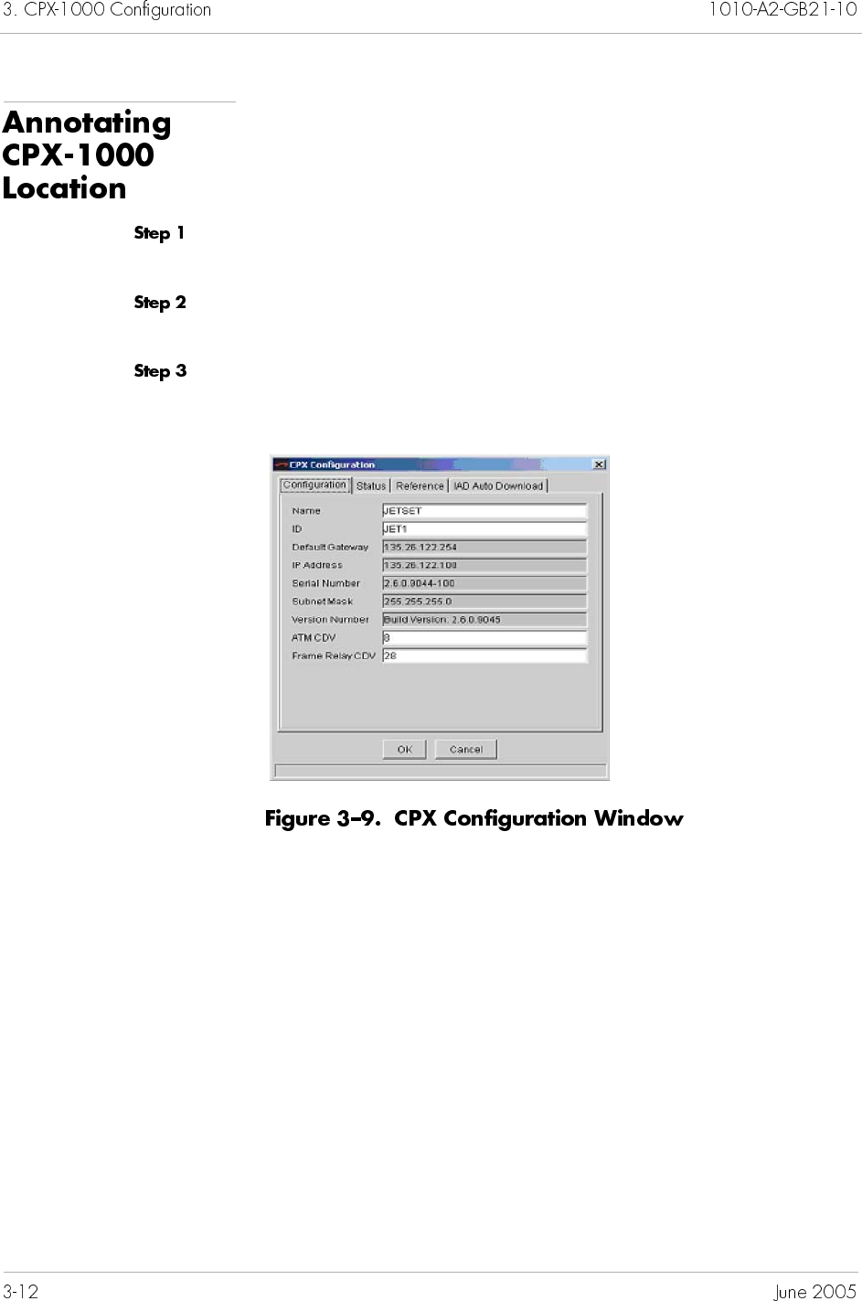
To review the CPX-1000 information, click a CPX-1000 icon from
the Tree View, then select CPX Configuration from
Configuration menu. The CPX Configuration window appears,
displaying the CPX-1000 read-only information.
This chapter provides instructions to provision Network (ATM)
and PSTN Protection Groups. This chapter includes the following
tasks:
Assigning members to the ATM Network Protection Group
(page 4-2)
Assigning members to the PSTN Protection Group
(page 4-5)
Swapping Protection Group members (page 4-7)
Removing members from the Protection Group (page 4-9)
The ATM redundancy uses duplicate links between the ATM
network and ATM card (OC-3 or DS-3) whereby you can assign
which ATM interfaces on the CPX-1000 are associated with a
particular Protection Group.
Table 4–1 describes the fields in the Protection Group.
ID Four network and six PSTN protection
groups are assigned by CPX Management
Entity (CME), you cannot add or delete
protection groups.
Primary
Member
The active port of the Protection Group is
specified by slot_number/port_number and
indicated by a green background.
Secondary
Member
The standby port of the Protection Group is
indicated by a blue background. “Not
assigned” indicates that the Protection Group
has no members.
Before assigning members to the ATM Network Protection Group,
make sure that the CPX-1000 is up with redundant ATM cards
(OC-3 or DS-3).
To assign members to the ATM Protection Group:
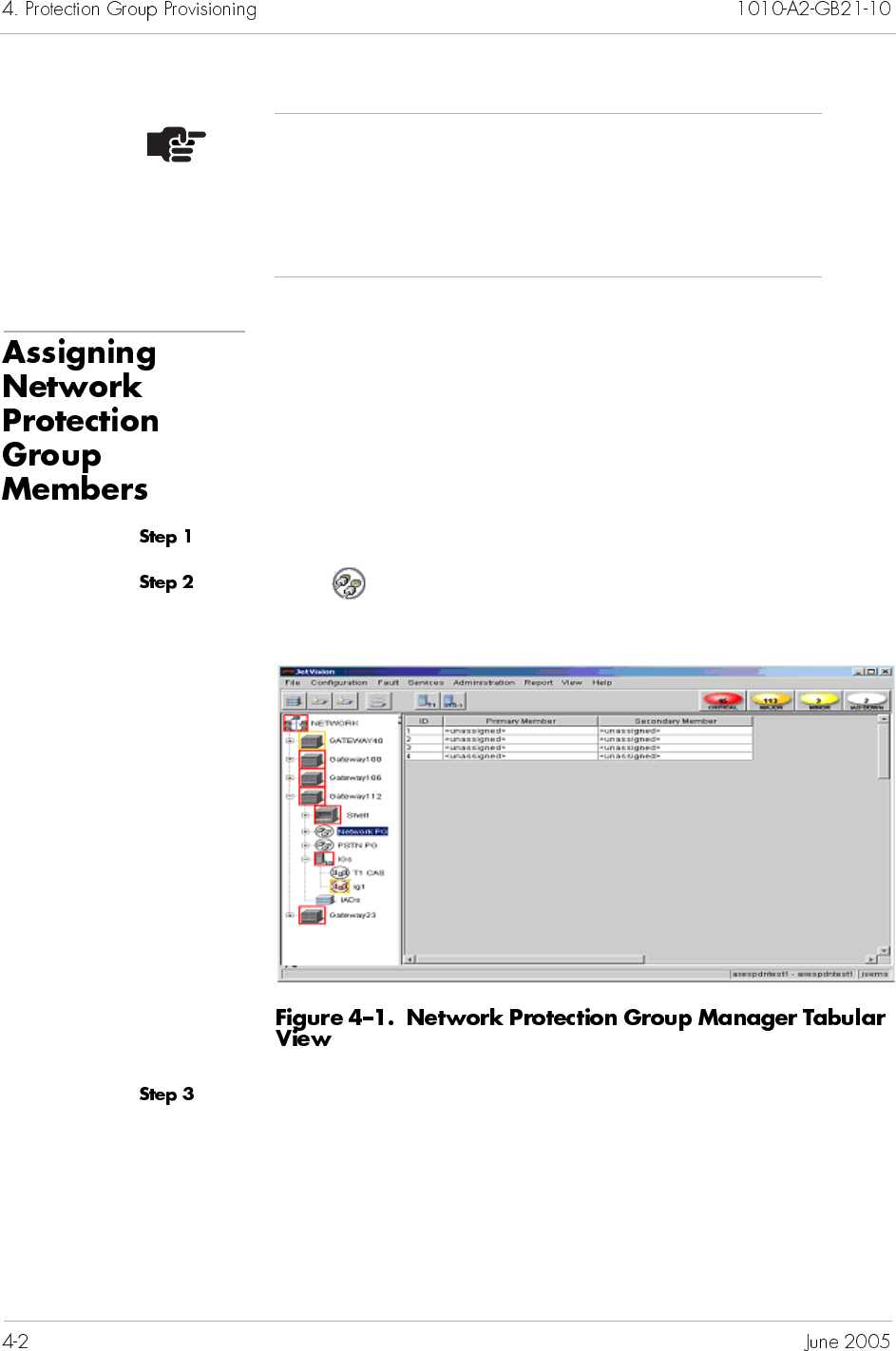
Expand the desired CPX-1000 from the Tree View.
Click Network PG on the Tree View, the right-hand pane
changes to the Protection Group tabular view (Figure 4–1).
Select a Protection Group ID to which you want to assign member.
Note
The gray background indicates that the states (active/
standby) of the card are unknown because the card
corresponding to a member has been removed;
however, the slot/port information continues to display.
Select Configure from the Configuration menu.
– Or –
Right-click the highlighted selection and select Configure from
the pop-up menu.
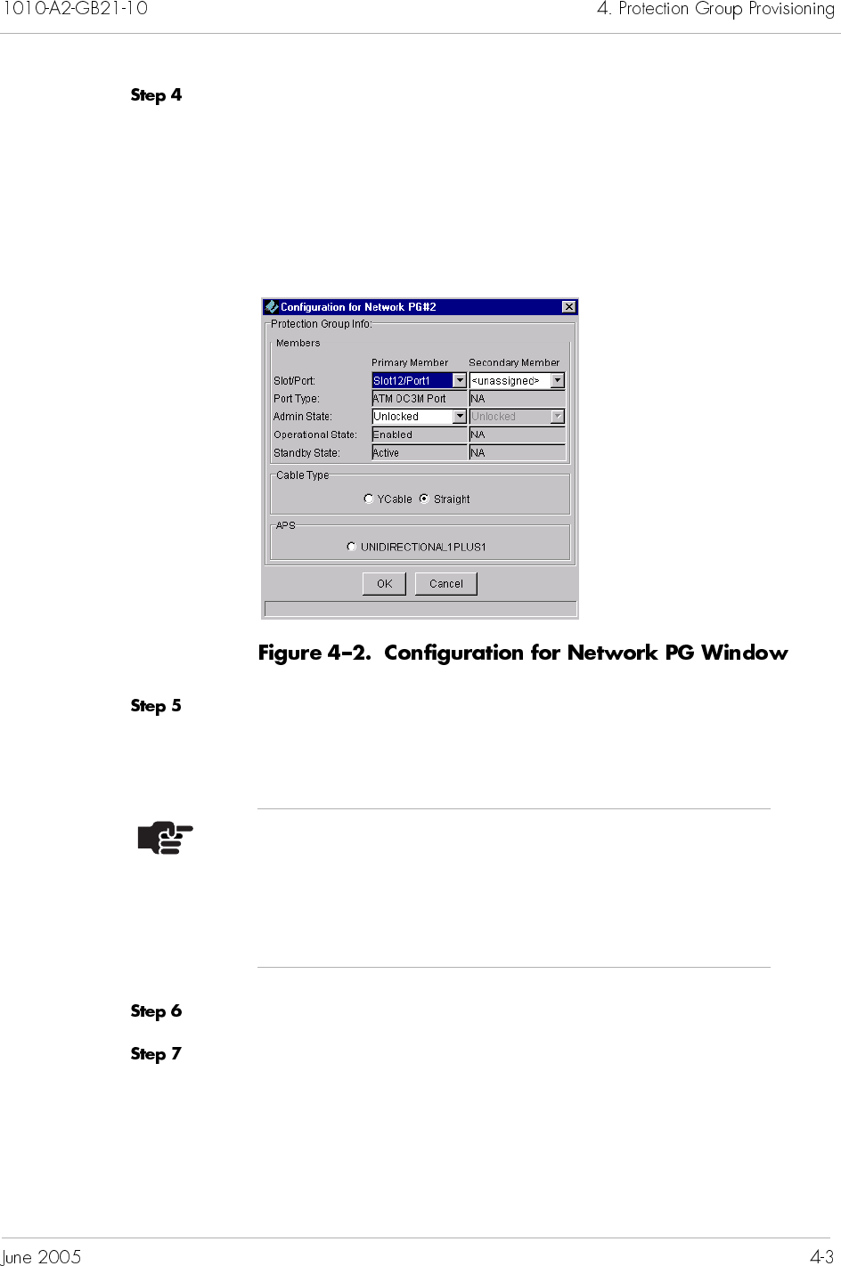
The Configuration for Network PG window appears (Figure 4–2).
Select a slot and port number for the Primary Member from the
Slot/Port drop-down list. Once a port assignment is selected, all
other fields in the area are automatically populated.
Select Unlocked from the Admin State drop-down list.
Repeat Step 5 for the Secondary Member.
Notes
You cannot assign ports that are already members of
some other Protection Group.
Ensure that you assign the same port type to the same
Protection Group.
Select a cable type.
For OC3 ports, select Straight.
For DS3 ports, select either Ycable or Straight.
Click to select the Unidirectional 1 Plus 1 to enable the
ATM switch to automatically switch the active to standby if the
card fails.
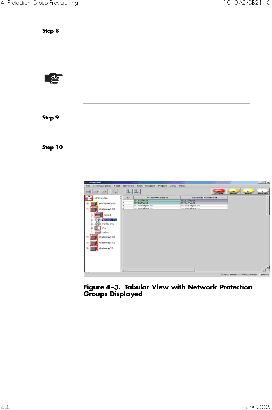
Click OK to accept the configuration. The newly created Protection
Group displays in the Protection Group Manager tabular view
(Figure 4–3).
Note
The APS selection is enabled only when straight cable is
selected.
Before assigning members to the PSTN network Protection Group,
make sure that the CPX-1000 is up with redundant STS-1 cards.
To assign members to the PSTN Protection Group:
Expand the desired CPX-1000 from the Tree View.
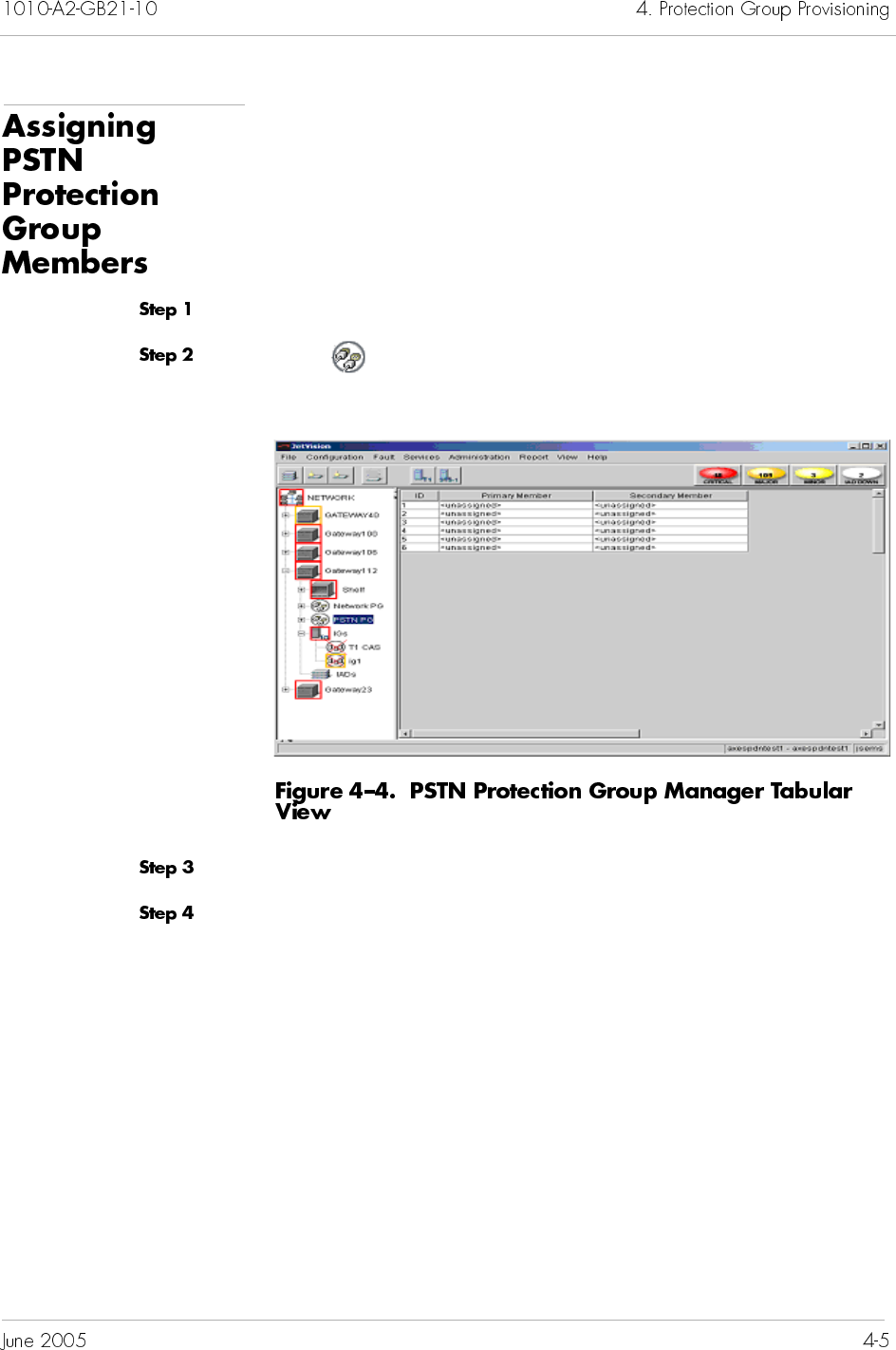
Click Network PSTN on the Tree View, the right-hand pane
changes to the Protection Group tabular view (Figure 4–4).
Select a Protection Group ID to which you want to assign member.
Select Configure from the Configuration menu.
– Or –
Right-click the highlighted selection and select Configure from
the pop-up menu.
The Configuration for Network PG window appears (Figure 4–5).
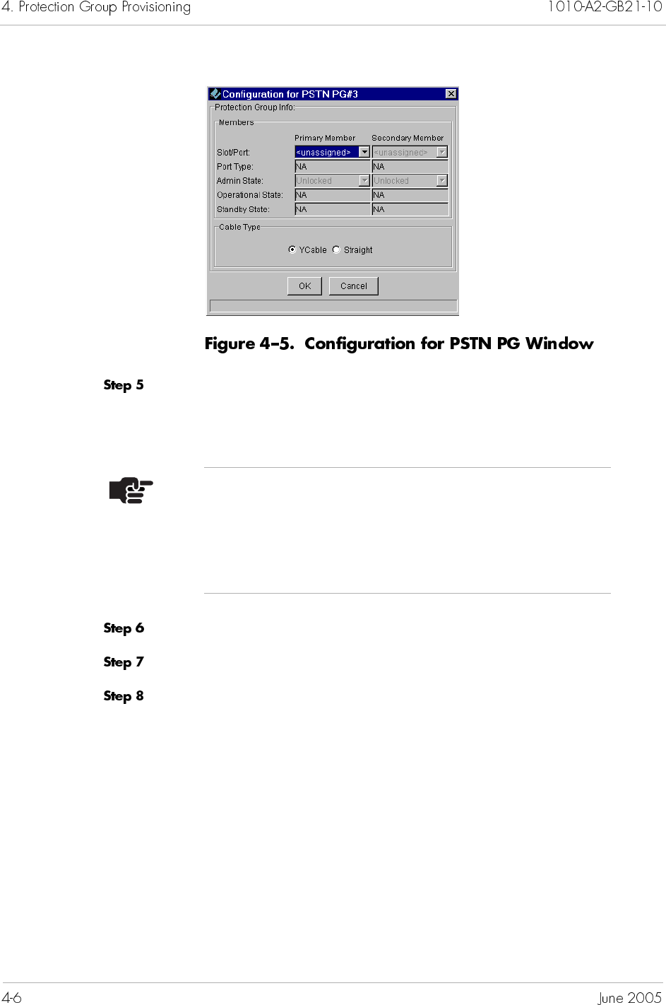
Select a slot and port number for the Primary Member from the
Slot/Port drop-down list. Once a port assignment is selected, all
other fields in the area are automatically populated.
Select Unlocked from the Admin State drop-down list.
Repeat Step 5 for the Secondary Member.
Select Ycable.
Notes
You cannot assign ports that are already members of
some other Protection Group.
Ensure that you assign the same port type to the same
Protection Group.
Click OK to accept the configuration. The updated PG is displayed
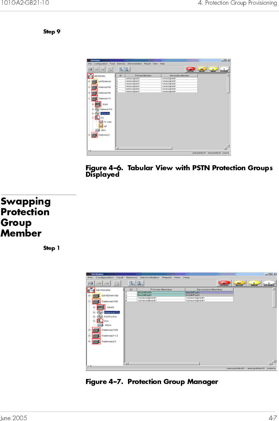
in the Protection Group Manager tabular view (Figure 4–6).
To swap between the primary and secondary members of the
Protection Group:
Click the desired PG icon (Network or PSTN) on the Tree View, the
Protection Group Manager view similar to Figure 4–7 appears.
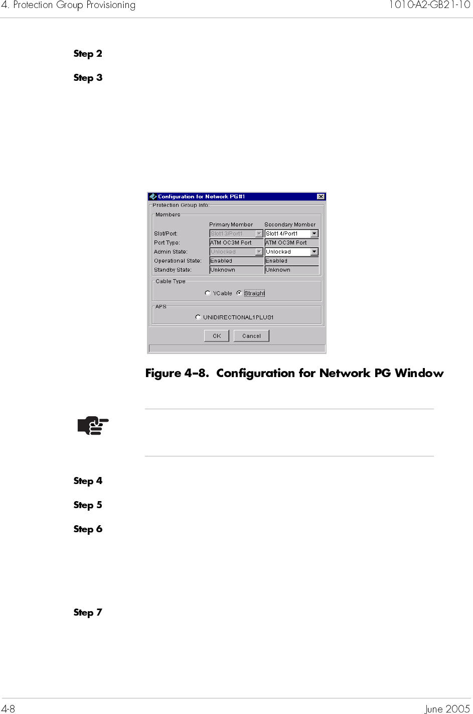
Select a Protection Group ID to which you want to switch member.
Select Configure from the Configuration menu.
– Or –
Right-click the highlighted selection and select Configure.
The Protection Group Manager window similar to Figure 4–8
appears.
Select Locked from the Admin State drop-down list.
Click OK to return to the Protection Group Manager window.
Select PG Swap from the Configuration menu.
– Or –
Right-click the highlighted selection and select PG Swap from the
pop-up menu.
Observe the colors. The Primary Member is now blue and the
Secondary Member green.
Note
The APS feature is not applicable for the PSTN PG.
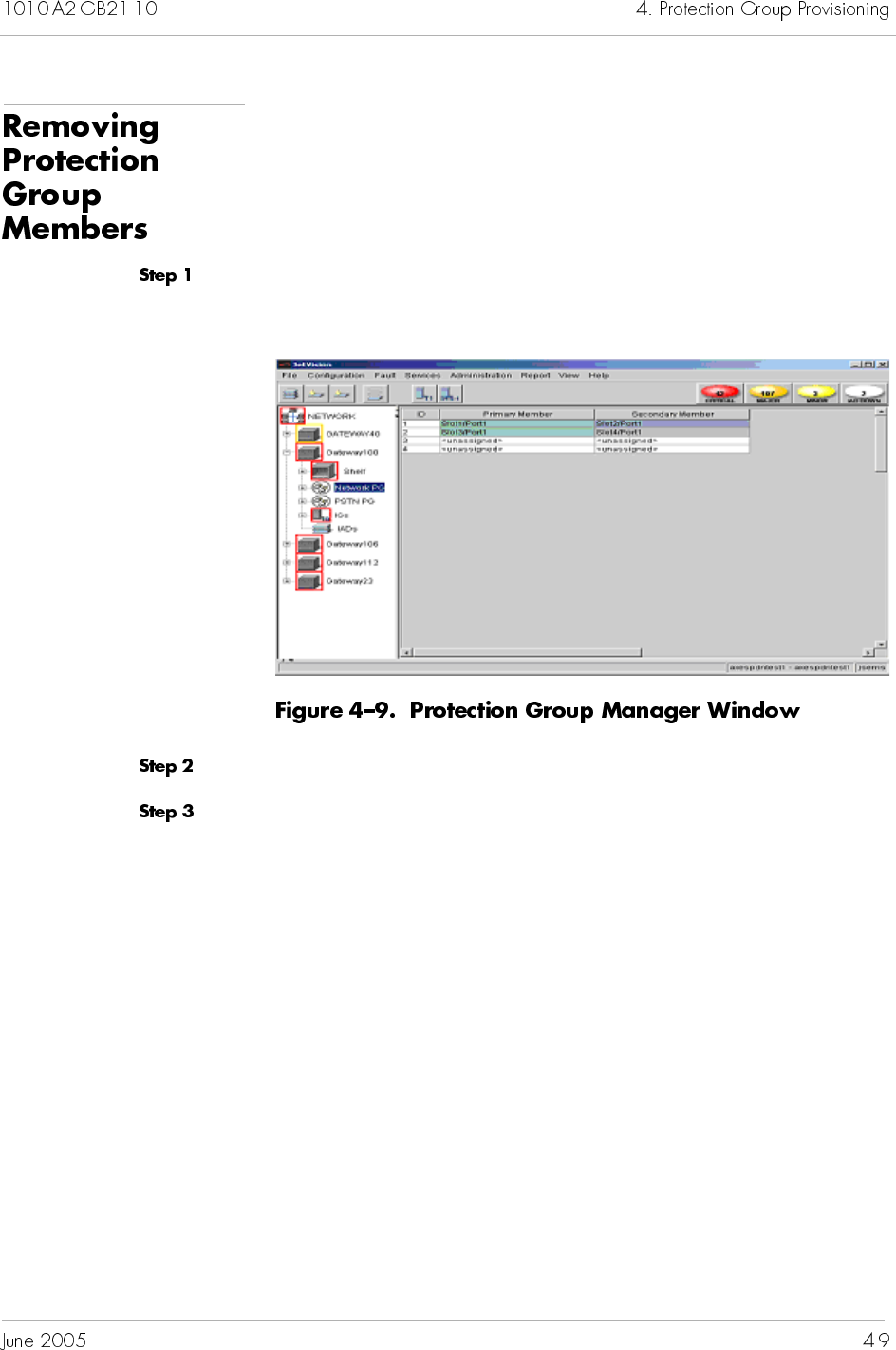
Before removing members from a Protection Group, ensure that
the port assigned to the group member is Locked.
To remove members from a Protection Group:
Click the desired PG icon (Network or PSTN) on the Tree View, the
Protection Group Manager view similar to Figure 4–9 appears.
Select a Protection Group member that you want to remove.
Select Configure from the Configuration menu.
– Or –
Right-click the highlighted selection and select Configure from
the pop-up menu.
The Protection Group Manager window similar to Figure 4–10
appears.
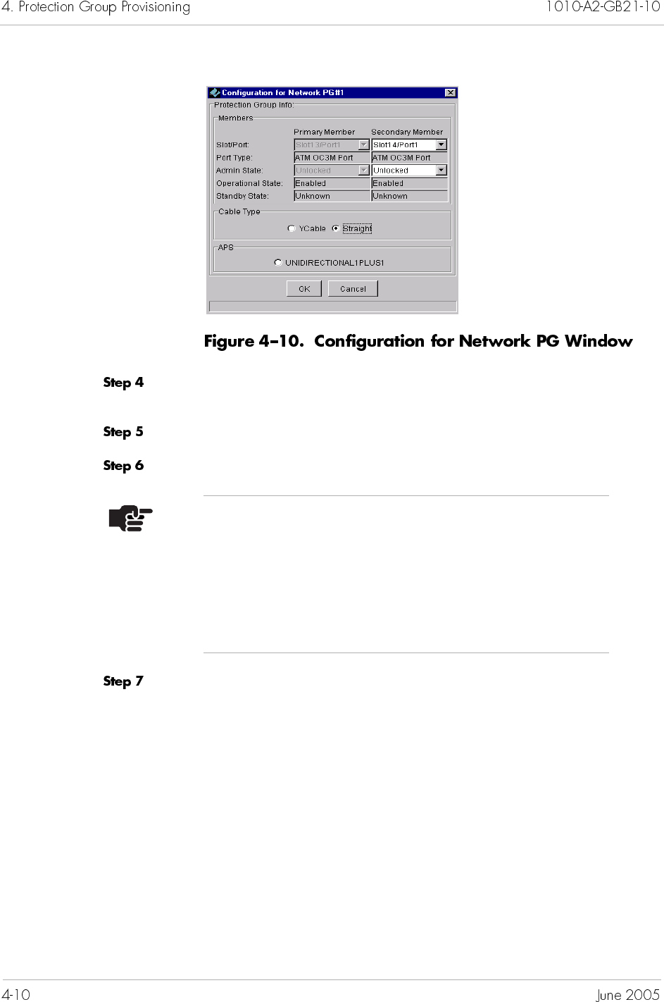
Select Unassigned from the Slot/Port drop-down list for the
Secondary Member.
Select Locked from the Admin State drop-down list.
Repeat Step 5 for the Primary Member.
Click OK.
Note
The unassigned list does not appear in the Slot/
Port drop-down list in the Primary Member area
until after you select unassigned for the Secondary
Member. This selection ensures that the primary port
(Primary Member) remains assigned when the
secondary port is unassigned.
This chapter provides detailed instructions to provision Interface
Groups. This chapter includes the following tasks:
Creating T1 Interface Groups (page 5-2)
Creating STS-1 Interface Groups (page 5-7)
Assigning ports/channels to GR-303 Interface Groups
(page 5-11)
Removing ports/channels from GR-303 Interface Groups
(page 5-13)
Assigning ports/channels to T1 CAS Interface Groups
(page 5-15)
Removing ports/channels from T1 CAS Interface groups
(page 5-17)
Modifying GR-303 Interface Groups (page 5-19)
Deleting GR-303 Interface Groups (page 5-22)
Performing an EOC switchover on GR-303 Interface Groups
(Figure 5–23)
Performing a TMC switchover on GR-303 Interface Groups
(Figure 5–24)
Configuring PPS settings (Figure 5–25)
JetVision supports up to nine Interface Groups for each CPX-1000.
Each Interface Group supports up to 28 DS1 lines or 28 channels
from the CPX-1000.
Typically, the Interface Groups are created without a physical
connection. As a result, the Interface Groups are alarmed as they
are created, then cleared when they are connected to the cable.
Note
An empty T1 CAS Interface Group (Interface Group 9) exists by
default. Modification of a T1 CAS Interface Group entails only
Assigning and Removing DS1s.
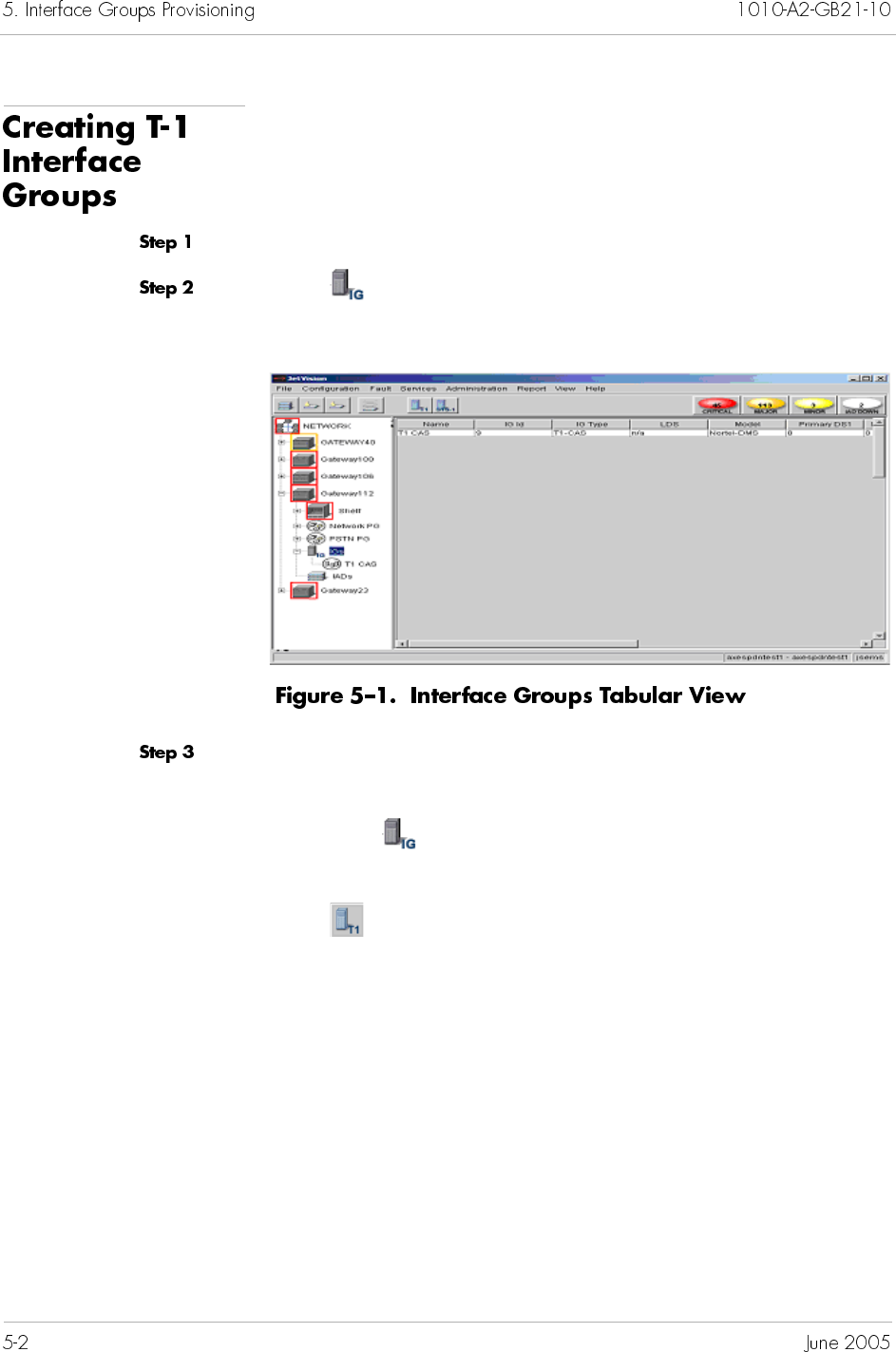
To create a T-1 Interface Group:
Expand the desired CPX-1000 from the Tree View.
Click on the Tree View, the right-hand pane changes to the
Interface Group tabular view (Figure 5–1).
Select Create T1 IG from the Configuration menu.
– Or –
Right-click on the Tree View and select Create T1 IG.
– Or –
Click on the toolbar.
The View/Update Interface Groups window appears (Figure 5–2).
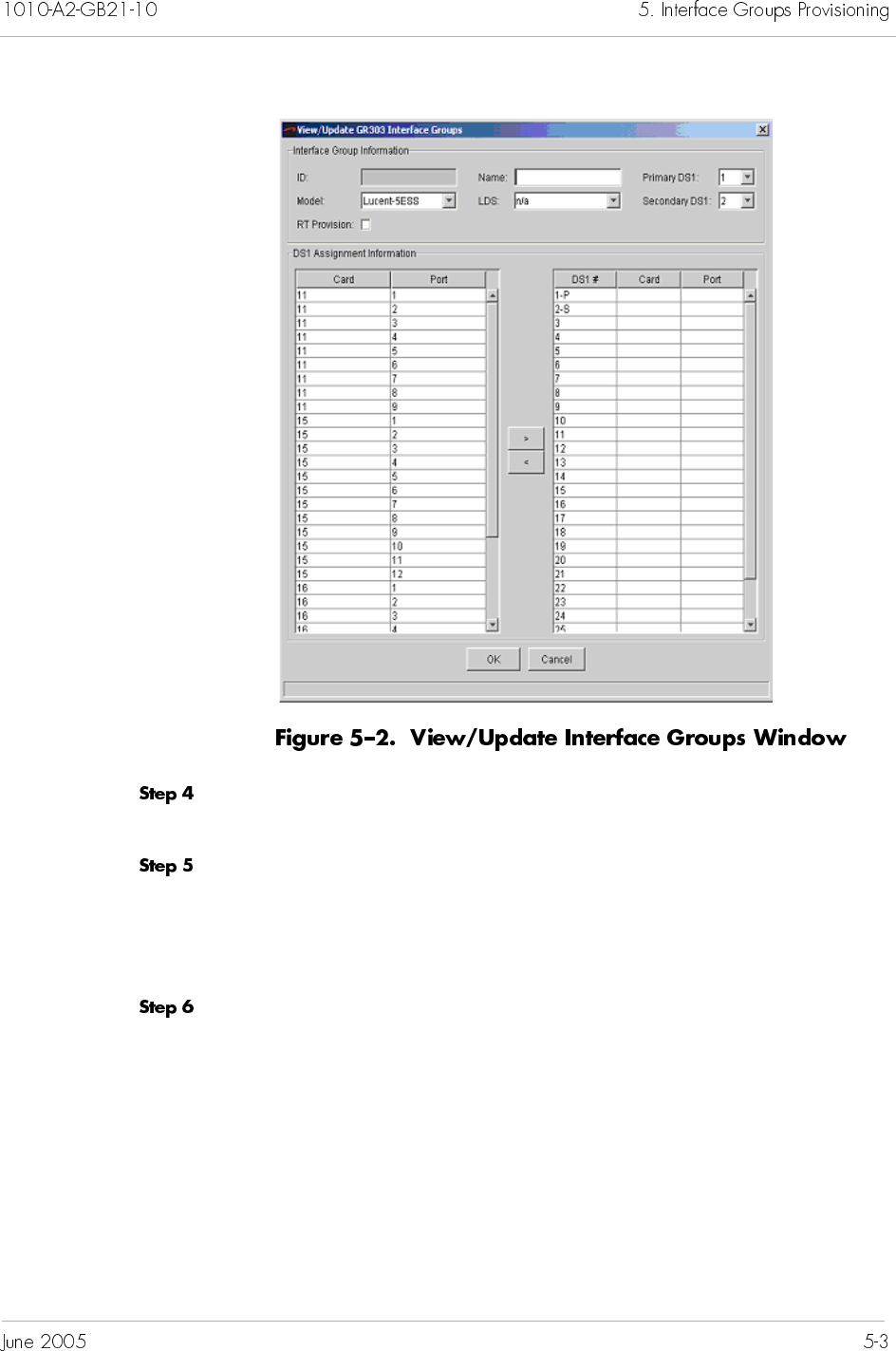
Type a name up to 32 alphanumeric characters (including spaces
and/or hyphens) for the Interface Group in the Name field.
Type a new name or select the type of Class 5 switch used from the
Model drop-down list.
If no Class 5 switches have been created, type a name in the Model
field.
Type a new name or select the name of the Local Digital Switch
(LDS) to which the Interface Group connects from the LDS drop-
down list.
If no LDS names have been created, type a name in the LDS field.
Click to select the RT Provision checkbox if you want to enable
the Class 5 switch to assign CRVs on the CPX-1000.
Select a secondary DS1 number from the Secondary DS1 drop-
down list. For example, selecting 4 means that port 4 will be
assigned as the secondary DS1 channel.
Select a DS1 by clicking the card/port, then make the assignment
by clicking the > button.
Notes
You can select Real Time (RT) provisioning only at the
initial creation of the Interface Group. You can neither
modify nor remove RT provisioning once it’s selected.
If you want to remove RT provisioning after the creation
of Interface Group, you must first delete the desired
Interface Group, then reprovision it without the RT
provisioning option.
You cannot change the primary DS1.
Note
The DS1 port assignment is populated sequentially. For
example, the first assignment is for the primary and the
second assignment is the secondary.
Note
If the port is assigned to the unintended DS1, click the <
button to return the port to the DS1 Assignment area.
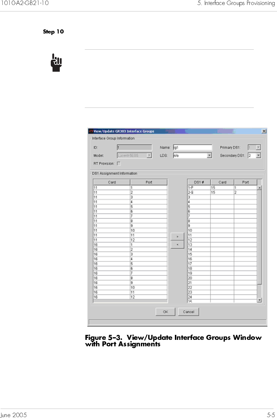
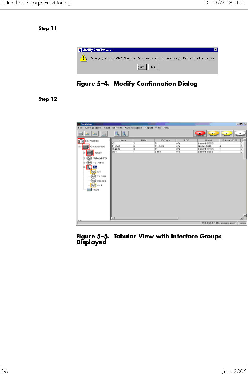
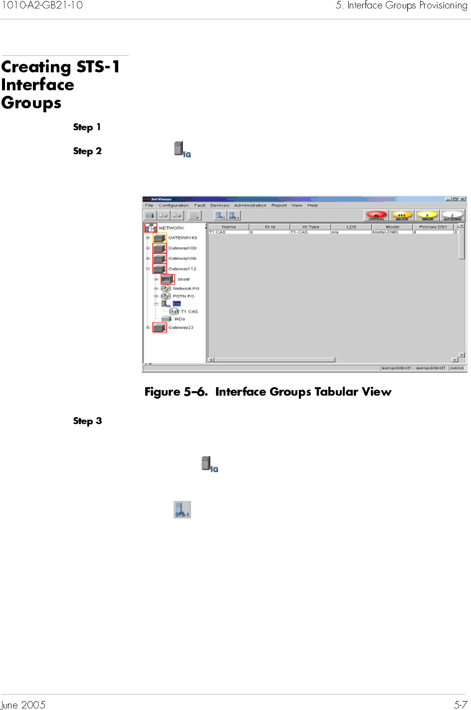
To create a STS-1 Interface Group:
Expand the desired CPX-1000 from the Tree View.
Click on the Tree View, the right-hand pane changes to the
Interface Group tabular view (Figure 5–6).
Select Create STS1 IG from the Configuration menu.
– Or –
Right-click on the Tree View and select Create STS1 IG.
– Or –
Click on the toolbar.
The View/Update Interface Groups window appears (Figure 5–7).
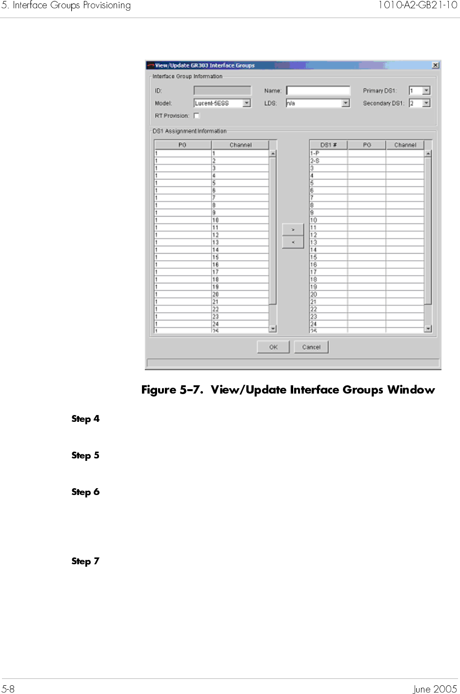
Type a name up to 32 alphanumeric characters (including spaces
and/or hyphens) for the Interface Group in the Name field.
Type a new name or select the type of Class 5 switch used from the
Model drop-down list.
Type a new name or select the name of the Local Digital Switch
(LDS) to which the Interface Group connects from the LDS drop-
down list.
If no LDS names have been created, type a name in the LDS field.
Click to select the RT Provision checkbox if you want to enable
the Class 5 switch to assign CRVs on the CPX-1000.
Select a secondary DS1 number from the Secondary DS1 drop-
down list. For example, selecting 4 means that port 4 will be
assigned as the secondary DS1 channel.
Select a channel by clicking the PG/channel, then make the
assignment by clicking the > button.
Notes
You can select Real Time (RT) provisioning only at the
initial creation of the Interface Group. You can neither
modify nor remove RT provisioning once it’s selected.
If you want to remove RT provisioning after the creation
of Interface Group, you must first delete the desired
Interface Group then reprovision it without the RT
provisioning option.
You cannot change the primary DS1.
Note
The DS1 port assignment is populated sequentially. For
example, the first assignment is for the primary and the
second assignment is the secondary.
Note
If the channel is assigned to the unintended DS1, click
the < button to return the port to the DS1 Assignment
area.
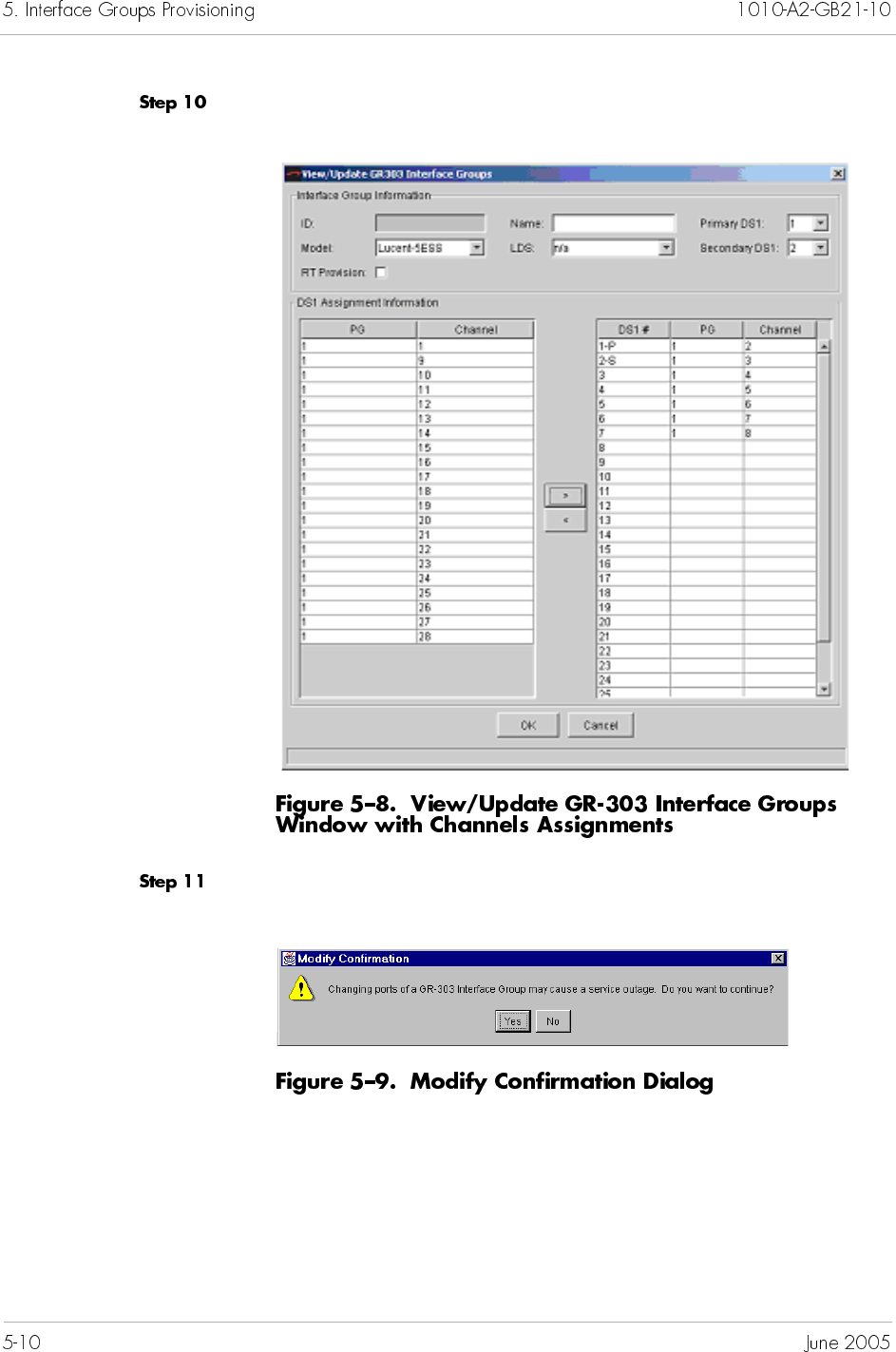
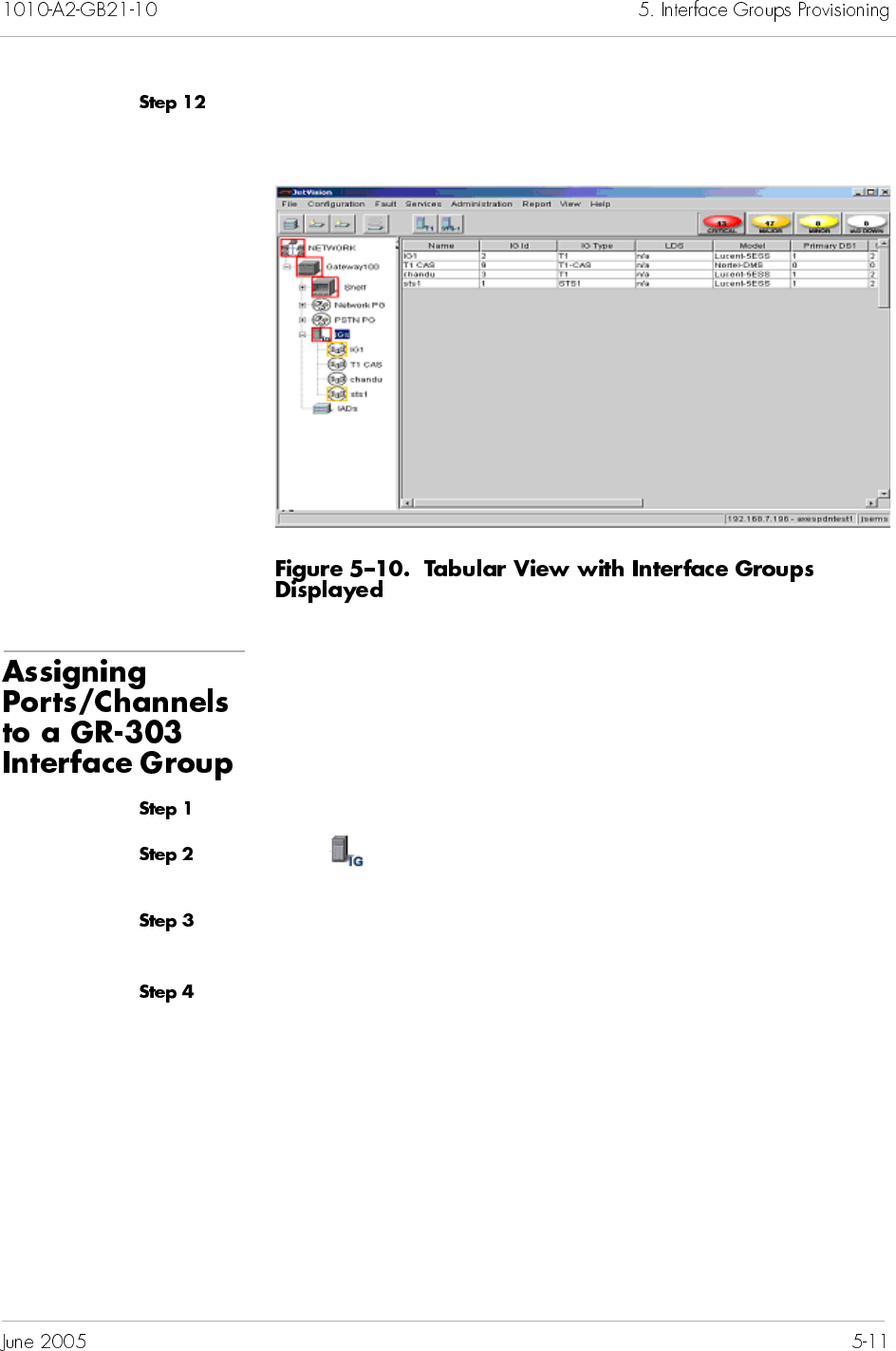
Click Yes. The Interface Group tabular view appears, displaying
the newly created Interface Group information (Figure 5–10).
To assign ports/channels to GR-303 Interface Groups:
Expand the desired CPX-1000 from the Tree View.
Click on the Tree View, the right-hand pane changes to the
Interface Group tabular view (Figure 5–10 on page 5-11).
Select the name of the GR-303 Interface Group to which you want
to assign ports/channels.
Select Modify IG from the Configuration menu.
– Or –
Right-click the highlighted selection and select Modify IG from
the pop-up menu.
The View/Update GR-303 Interface Groups window similar to
Figure 5–11 appears.
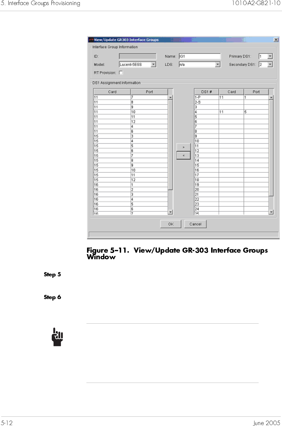
Select a port/channel by clicking the Card/Port or PG/channel,
then make the assignment by clicking the > button.
Assign as many ports/channels (up to 28) as needed to the
Interface Group.
Tip
To assign multiple ports/channels, hold down the
Shift or Ctrl key while making your selections. Using
the Shift key lets you make your selections in
contiguous order; the Ctrl key lets you select ports/
channels in a random order.
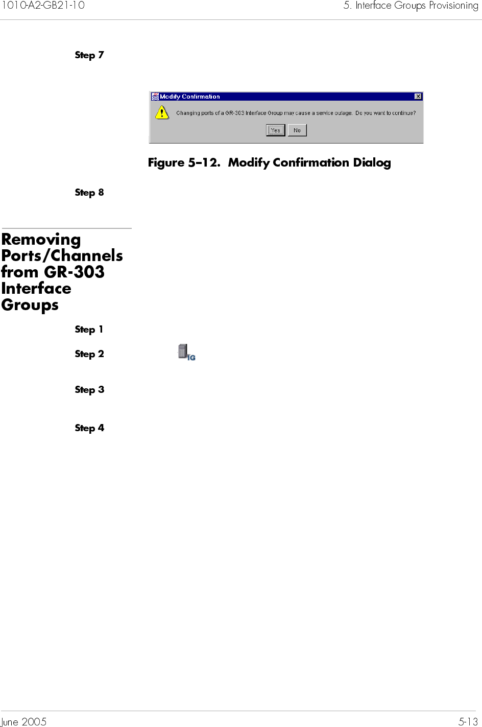
Click OK to save your settings. The following dialog box appears,
asking if you want to continue with the changes (Figure 5–12).
Click Yes.
To remove ports/channels from an Interface Group:
Expand the desired CPX-1000 from the Tree View.
Click on the Tree View, the right-hand pane changes to the
Interface Group tabular view (Figure 5–10 on page 5-11).
Select the name of the Interface Group to which you want to
remove ports/channels.
Select Modify IG from the Configuration menu.
– Or –
Right-click the highlighted selection and select Modify IG from
the pop-up menu.
The View/Update Interface Groups window appears
(Figure 5–13).
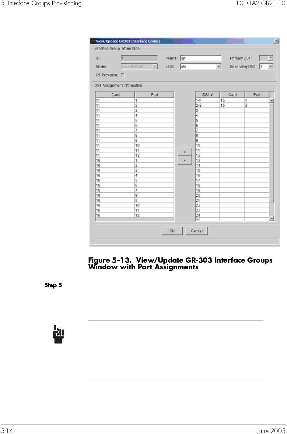
Select the port/channel number that you want to remove in the
DS1 area and click the < button. The removed DS1 returns to the
DS1 Assignment area.
Tip
To select multiple ports/channels, hold down the Shift
or Ctrl key while making your selections. Using the
Shift key lets you make your selections in contiguous
order; the Ctrl key lets you select ports/channels in a
random order.
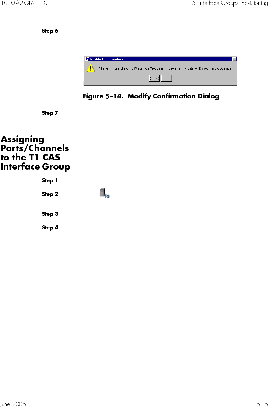
Click OK to save your settings. The following dialog box appears,
asking if you want to continue with the changes (Figure 5–14).
Click Yes.
To assign ports/channels to the T1 CAS Interface Group:
Expand the desired CPX-1000 from the Tree View.
Click on the Tree View. The right-hand pane changes to the
Interface Group tabular view (Figure 5–10 on page 5-11).
Expand the Interface Group in the tree view.
Click on the T1 CAS IG, then select Modify from the
Configuration menu.
– Or –
Right-click the highlighted selection and select Modify IG from
the pop-up menu.
The View/Update T1 CAS Interface Groups window similar to
Figure 5–15 appears.
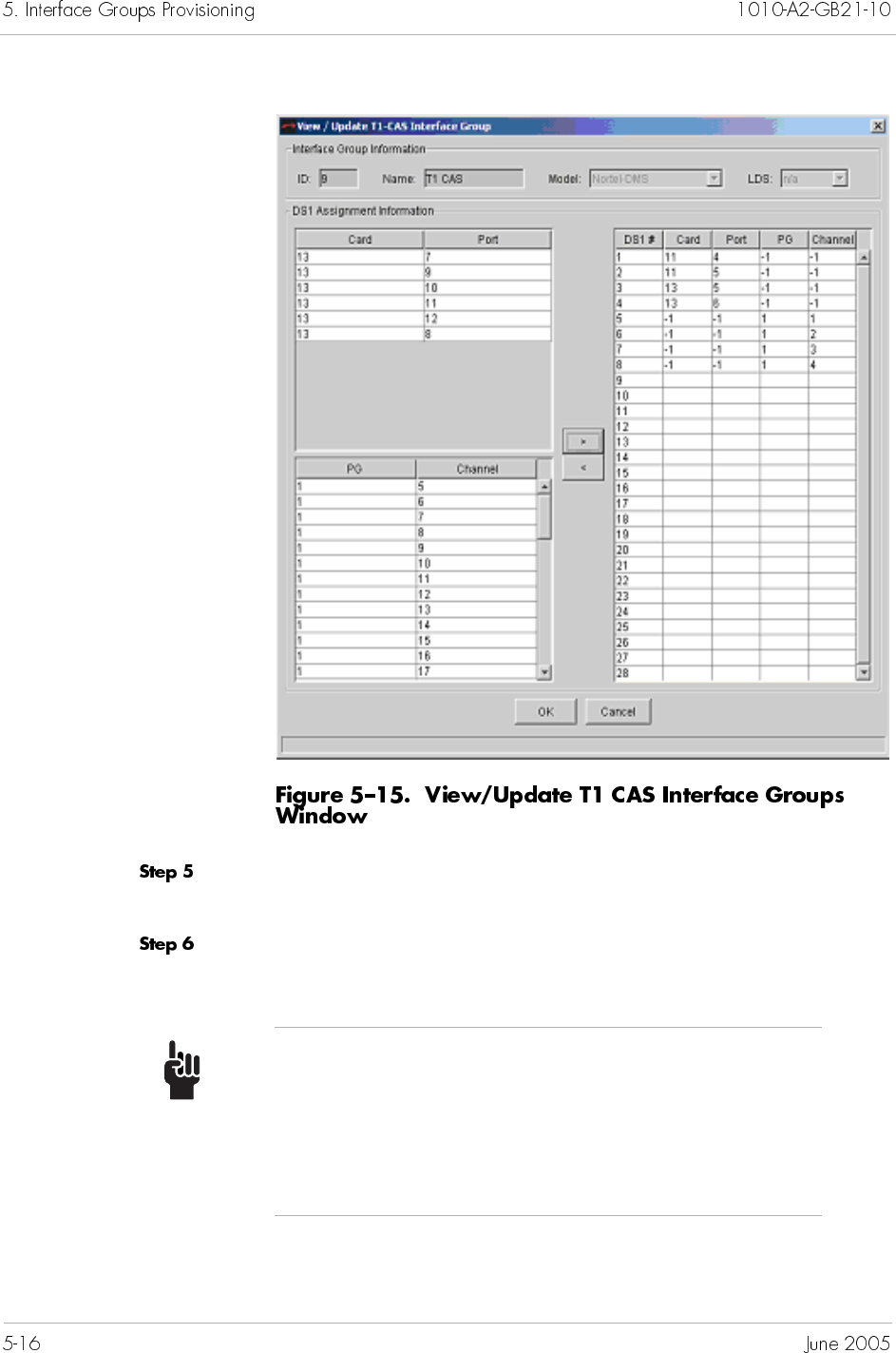
Select a port/channel by clicking the Card/Port or PG/channel,
then make the assignment by clicking the > button.
Assign as many ports/channels (up to 28) as needed to the
Interface Group.
Tip
To select multiple ports/channels, hold down the Shift
or Ctrl key while making your selections. Using the
Shift key lets you make your selections in contiguous
order; the Ctrl key lets you select ports/channels in a
random order.
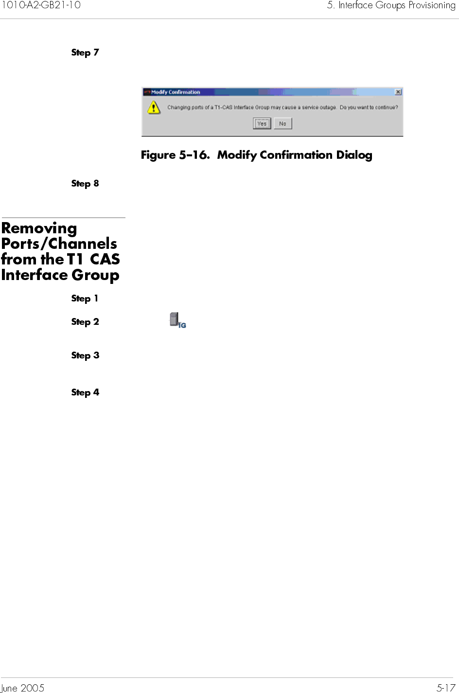
Click OK to save your settings. The following dialog box appears,
asking if you want to continue with the changes (Figure 5–16).
Click Yes.
To remove ports/channels from the T1 CAS Interface Group:
Expand the desired CPX-1000 from the Tree View.
Click on the Tree View, the right-hand pane changes to the
Interface Group tabular view (Figure 5–10 on page 5-11).
Expand the Interface Group in the tree view. The T1 CAS group is
displayed.
Click on teh T1 CAS IG, then select Modify from the
Configuration menu.
– Or –
Right-click the highlighted selection and select Modify IG from
the pop-up menu.
The View/Update T1 CAS Interface Groups window appears
(Figure 5–17).
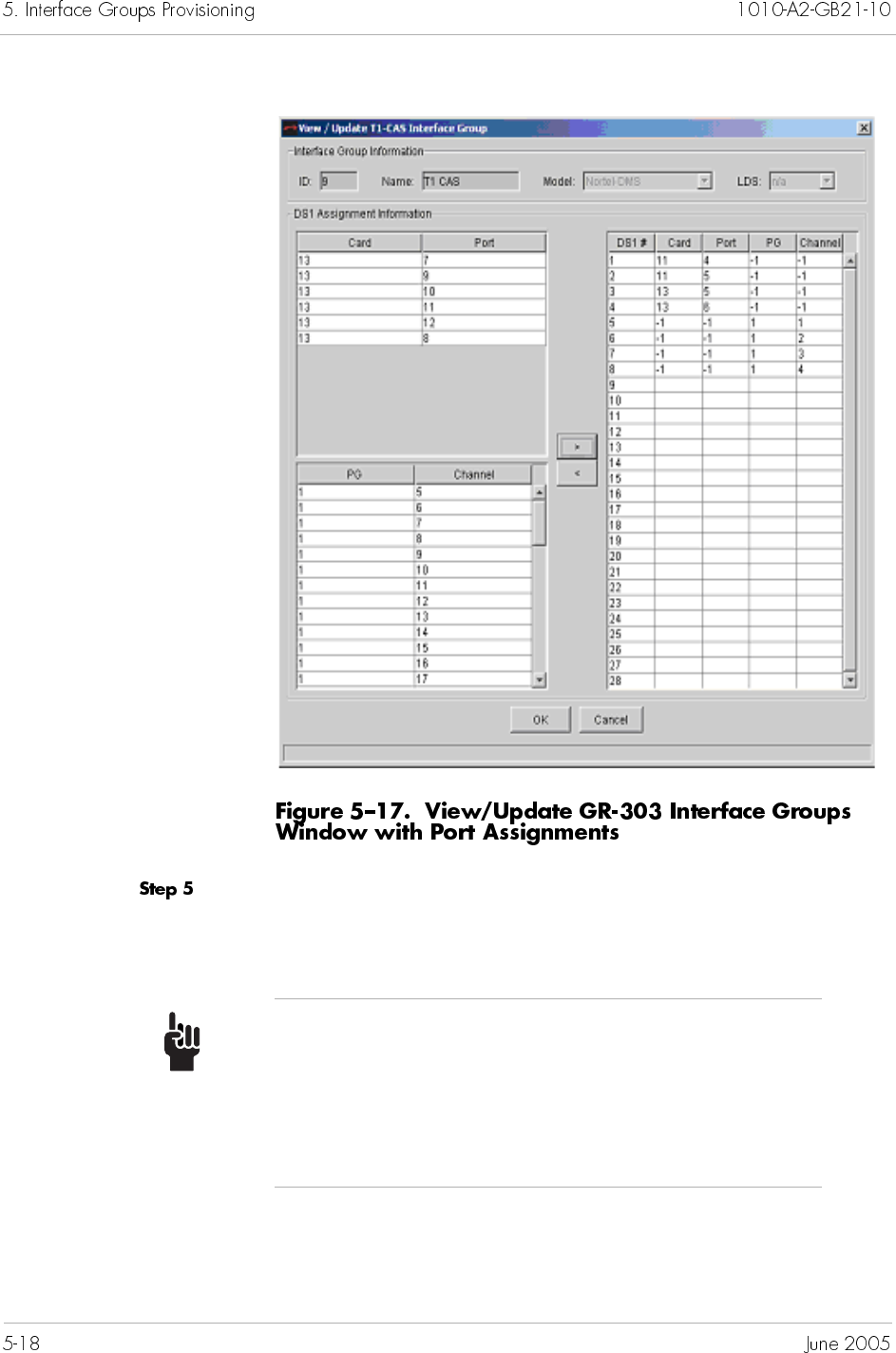
Select the port/channel number that you want to remove in the
DS1 area and click the < button. The removed DS1 returns to the
DS1 Assignment area.
Tip
To select multiple ports/channels, hold down the Shift
or Ctrl key while making your selections. Using the
Shift key lets you make your selections in contiguous
order; the Ctrl key lets you select ports/channels in a
random order.
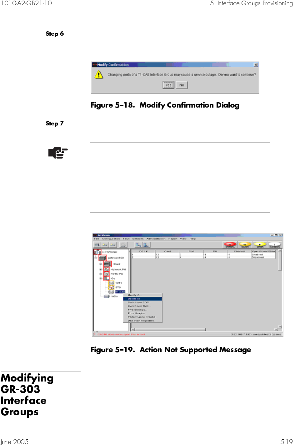
Click OK to save your settings. The following dialog box appears,
asking if you want to continue with the changes (Figure 5–18).
Click Yes.
To modify a GR-303 Interface Group:
Note
Delete IG, Switchover EOC, Switchover TMC, PPS
settings, Error graphs, Performance graph, DS1 path
registers actions are not supported for a T1 CAS
Interface Group. The error message "T1CAS IG does not
support this action!" is displayed in the status bar if any
of the above actions is attempted (Figure 5–19).
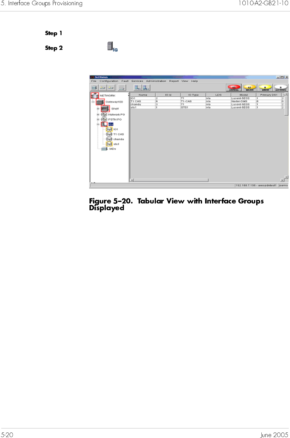
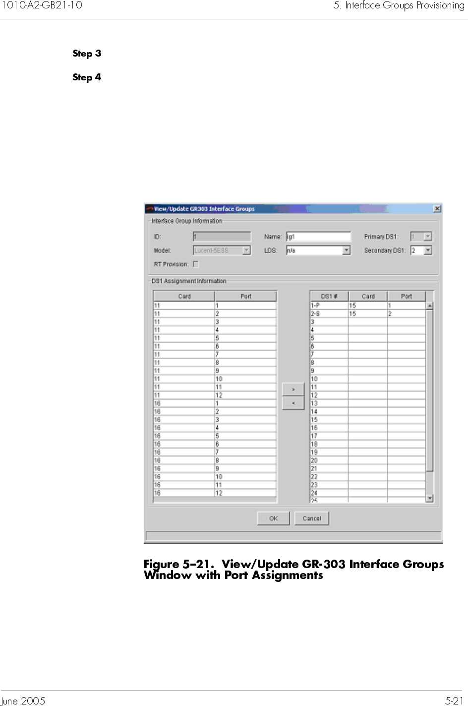
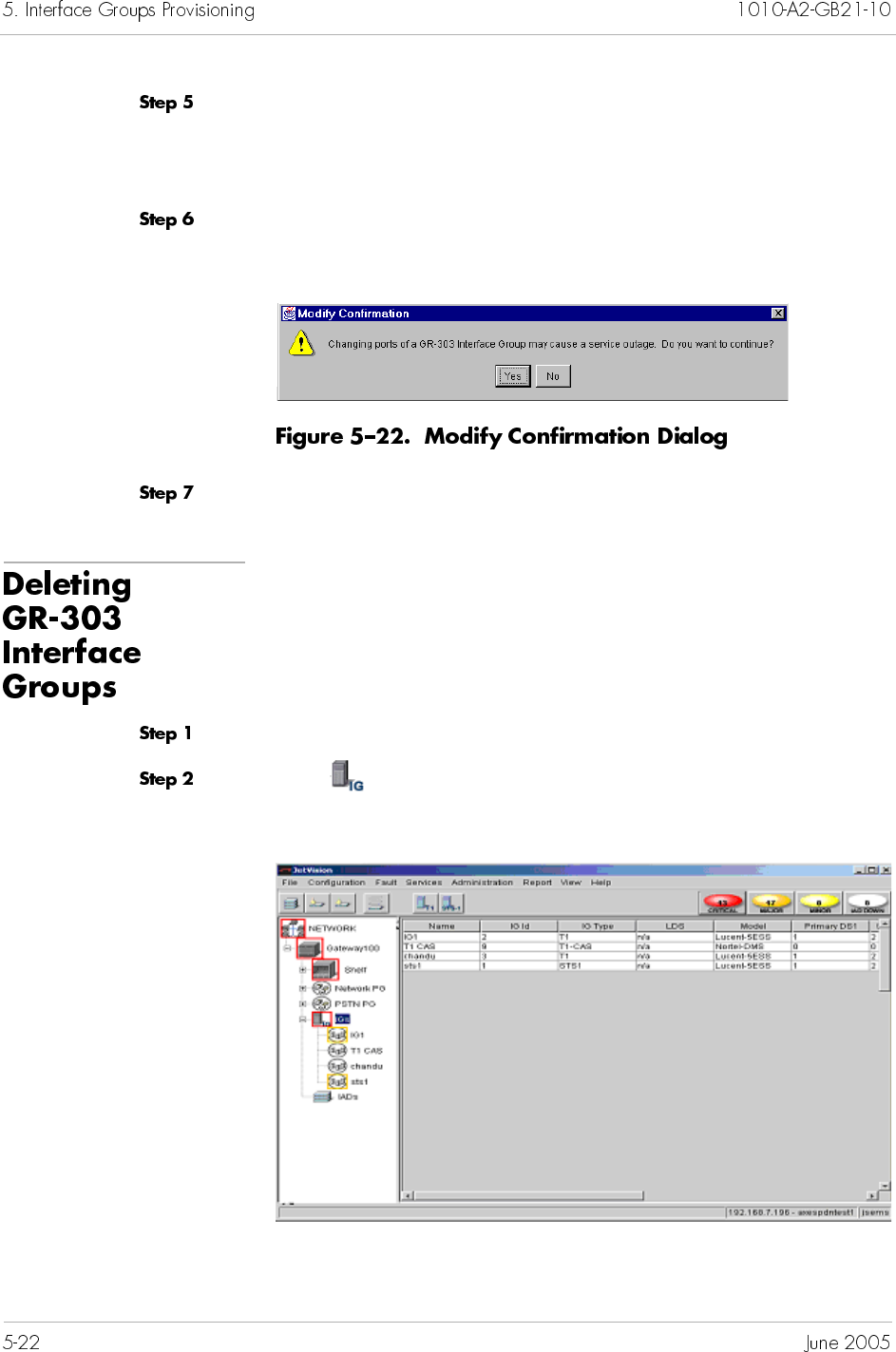
Modify the following fields, if necessary:
Name
Secondary DS1 Number
Click OK to save your settings. The following dialog box appears,
asking if you want to continue with the changes (Figure 5–22).
Click Yes.
To delete an Interface Group:
Expand the desired CPX-1000 from the Tree View.
Click on the Tree View, the right-hand pane changes to the
Interface Group tabular view (Figure 5–23).
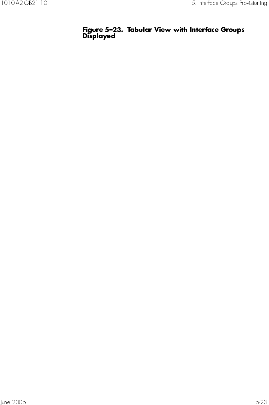
Click the name of the Interface Group that you want to delete.
Select Delete IG from the Configuration menu.
– Or –
Right-click the highlighted selection and select Delete IG from
the pop-up menu. A prompt appears, asking if you want to delete
the Interface Group.
Click Yes to delete the Interface Group.
Each GR-303 Interface Group has a primary and secondary
channel. When a primary channel fails, the secondary channel
takes over and vice versa. This switchover is automatic and
requires no user intervention or control over which channel to
switch. The new switching capabilities enables you to switch the
Embedded Operations Channel (EOC) and Timeslot Management
Channel (TMC) on a specified Interface Group.
Note
You can only delete Interface Groups that are not
associated with IADs.
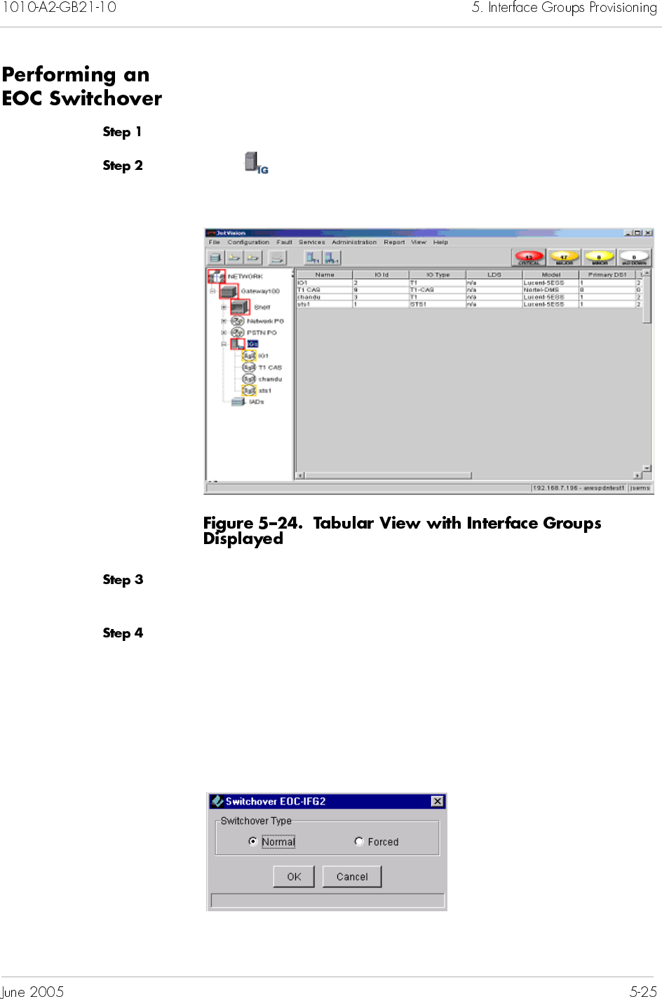
To perform an EOC switchover:
Expand the desired CPX-1000 from the Tree View.
Click on the Tree View, the right-hand pane changes to the
Interface Group tabular view (Figure 5–24).
Select the name of the GR-303 Interface Group that you want to
switch.
Select Switchover EOC from the Configuration menu.
– Or –
Right-click the highlighted selection and select Switchover EOC
from the pop-up menu.
The following dialog box appears.
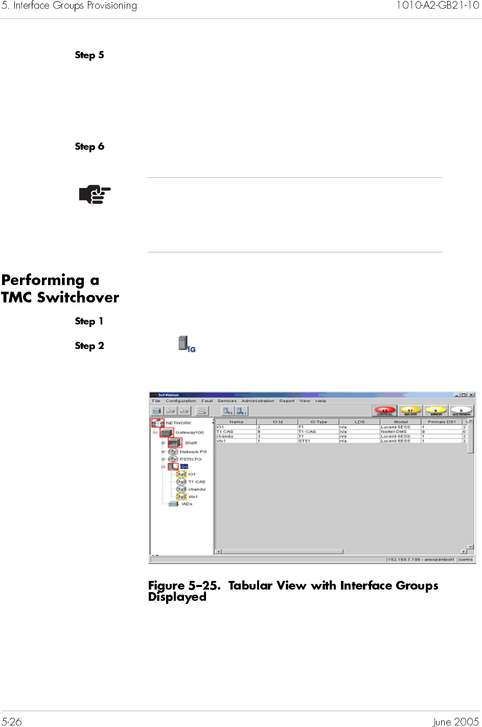
Select the type of switchover you want to perform.
Normal means that the switchover takes place under
normal working conditions (i.e., TMC/EOC is up).
Forced means that the switchover takes place even when the
standby TMC/EOC is down.
Click OK.
To perform a TMC switchover:
Expand the desired CPX-1000 from the Tree View.
Click on the Tree View, the right-hand pane changes to the
Interface Group tabular view (Figure 5–25).
Note
You can launch the Integrated Monitor to view the
status of the switchover (Chapter 16, Integrated
Monitoring).
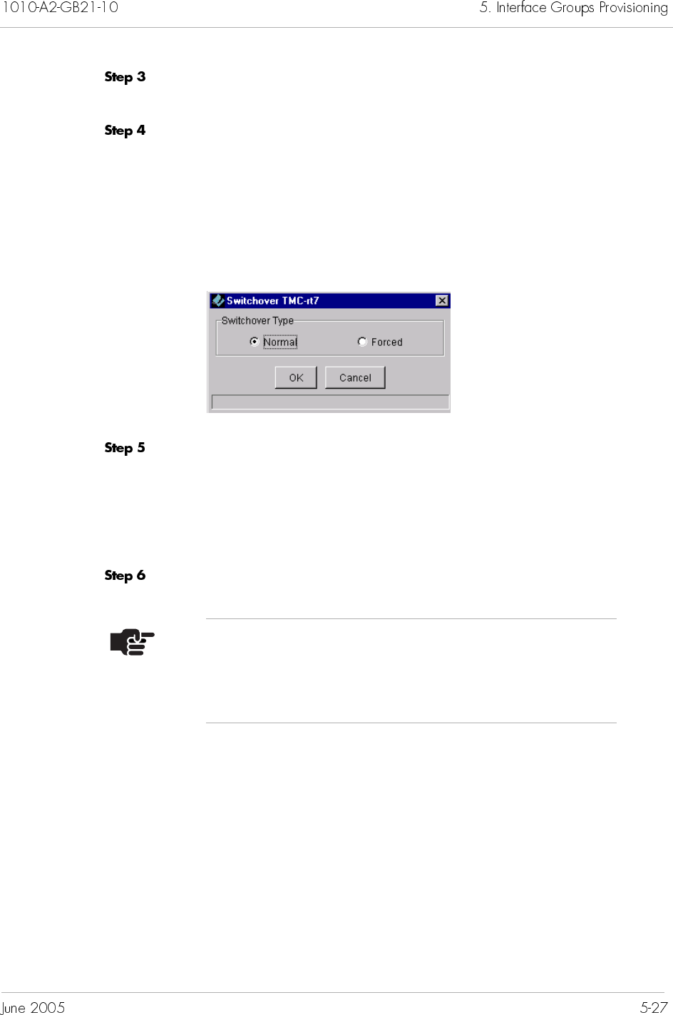
Select the name of the GR-303 Interface Group that you want to
switch.
Select Switchover TMC from the Configuration menu.
– Or –
Right-click the highlighted selection and select Switchover EOC
from the pop-up menu.
The following dialog box appears.
Select the type of switchover you want to perform.
Normal means that the switchover takes place under
normal working conditions (i.e., TMC/EOC is up).
Forced means that the switchover takes place even when the
standby TMC/EOC is down.
Click OK.
Note
You can launch the Integrated Monitor to view the
status of the switchover (Chapter 16, Integrated
Monitoring).
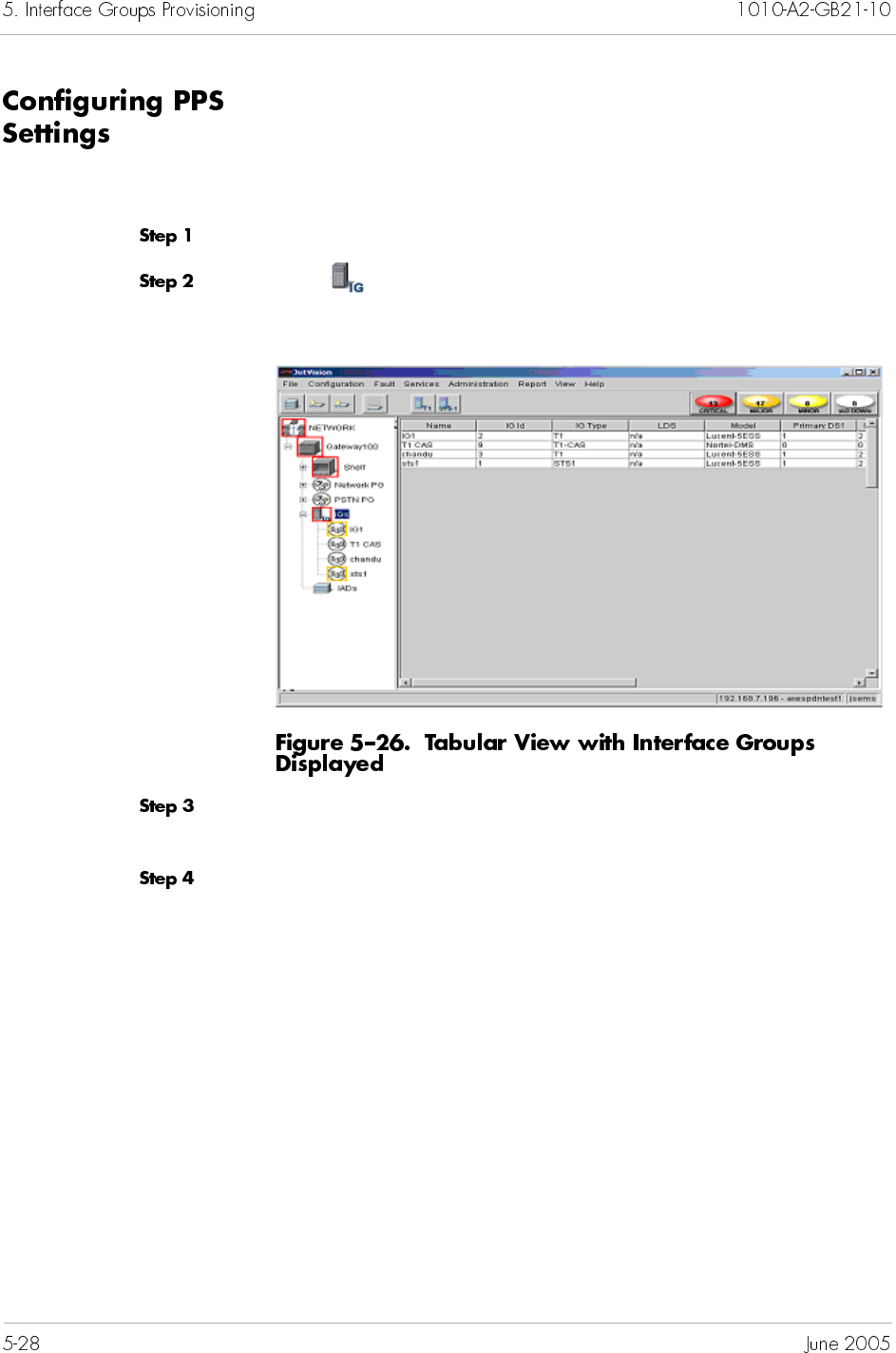
The Path Protection Switchover (PPS) capability enables you to
determine which channel (i..e, EOC and TMC) that you do not
want switched.
To configure the PPS settings:
Expand the desired CPX-1000 from the Tree View.
Click on the Tree View, the right-hand pane changes to the
Interface Group tabular view (Figure 5–26).
Select the name of the GR-303 Interface Group that you want to
switch.
Select PPS Settings from the Configuration menu.
– Or –
Right-click the highlighted selection and select PPS Settings
from the pop-up menu.
The PPS Settings window appears, displaying the current settings
(Figure 5–27).
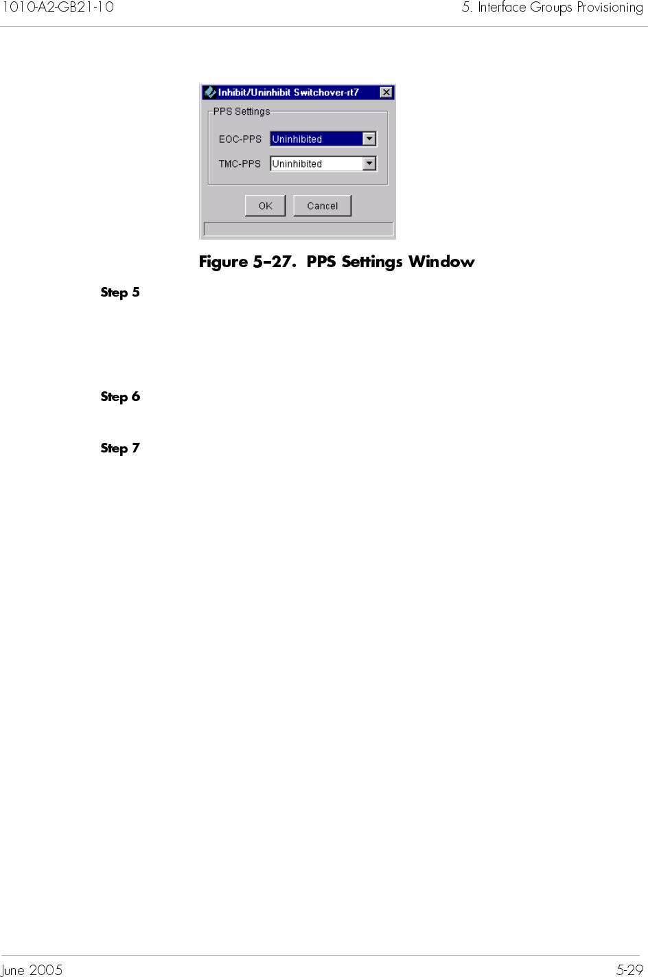
Select the settings from the drop-down list.
Uninhibited (default) means that the switchover is allowed,
when initiated.
Inhibit means that no switchover is allowed.
Click OK. A dialog box appears, asking if you want to change the
current state.
Click Yes.


This chapter provides instructions to provision Integrated Access
Device (IAD) Profiles. This chapter includes the following tasks:
Adding IAD Profiles on page 6-2
Modifying IAD Profiles on page 6-4
Deleting IAD Profiles on page 6-6
JetVision uses IAD Profiles to specify common default parameters
for identical IAD models. Once an IAD profile is created, you can
customize the profile parameters for each IAD port. You can create
as many IAD Profiles as you want or use one of the following
default IAD Profiles provided by JetVision:
Generic DSX
Jetstream IAD-1601
Jetstream IAD-402
Jetstream IAD-801
Jetstream IAD-802
Jetstream IAD-flex
LES CAS E&M Wink
LES CAS Loop Start
Netopia WIAD
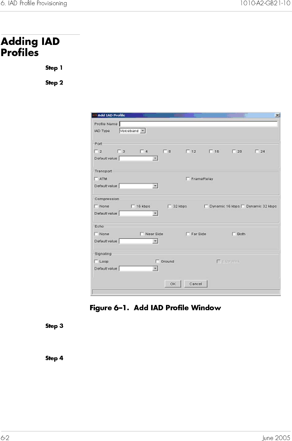
To add an IAD Profile:
Click a desired CPX-1000 icon in the Tree view.
Select Create IAD Profile from the Configuration menu.
The Add IAD Profile window appears (Figure 6–1).
Type the name of the profile that you are creating (up to 32
alphanumeric characters, including spaces, ampersands, and
hyphens) in the Name field.
Select an IAD Type of Voiceband or LES CAS. The E&M Wink
selection box becomes available if you select E&M Wink.
Click to select the number of ports available for the profile.
Click to select the data transport type.
Click to select the compression type.
Click to select the echo cancellation.
Click to select the signaling type. The E&M Wink selection is
available only if the IAD type selected is LES CAS.
Click OK to save your IAD Profile.
Note
You can select a combination of options available. For
example, if your profile uses ATM and Frame Relay,
select them both. Your selection appears in the Default
Value field.
Note
Dynamic compression enables the immediate change
from a compressed to an uncompressed call when fax or
modem tones are detected. While adding a LES CAS
profile, do not select Dynamic 16kbps or Dynamic
32kbps should not be selected. LES CAS does not
support dynamic compression.
To modify an IAD Profile:
Click a desired CPX-1000 icon in the Tree view.
Select IAD Profile Manager from the Configuration menu.
– Or –
Click on the toolbar.
The Modify IAD Profile window appears (Figure 6–2).
From this window, you can also:
add a profile (page 6-2)
delete a profile (page 6-6)
Note
You cannot modify any default IAD Profiles. IAD
Profiles associated with an IAD cannot be modified
unless all of the IADs that use that IAD Profile have
been deleted.
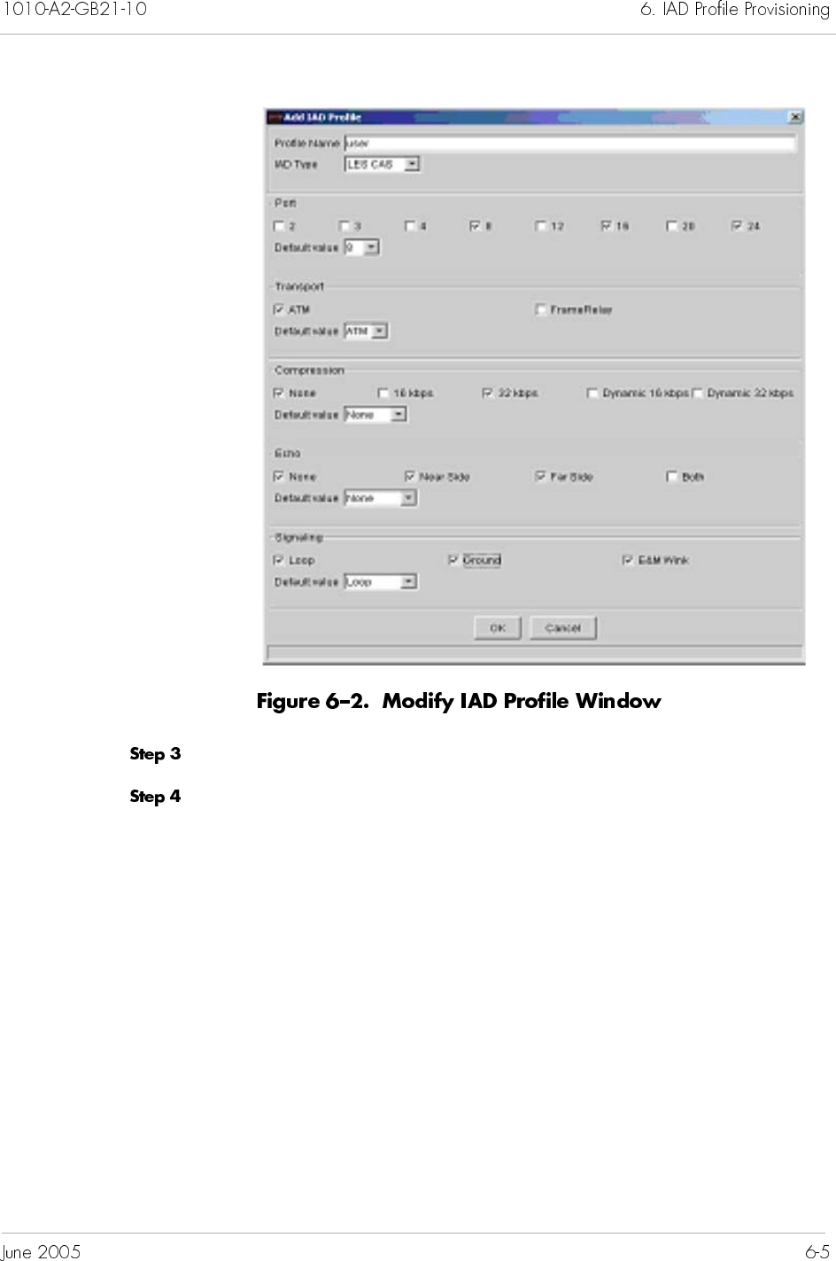
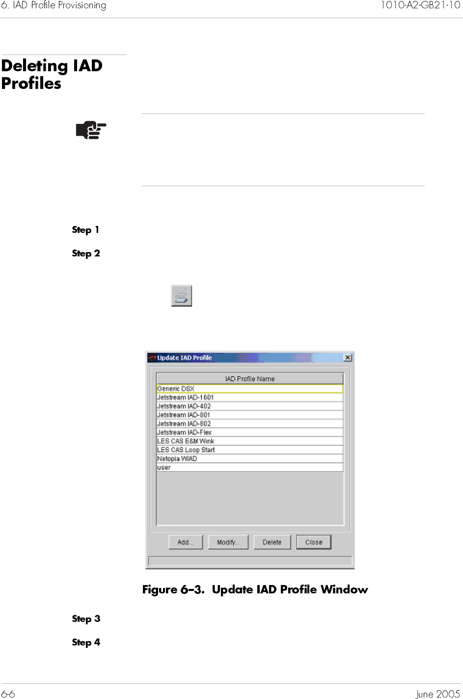
To delete an IAD Profile:
Click a desired CPX-1000 icon in the Tree view.
Select IAD Profile Manager from the Configuration menu.
– Or –
Click on the toolbar.
The Update IAD Profile window appears (Figure 6–2).
Click the name of the IAD Profile that you want to delete.
Click Delete. A message appears, asking if you want to delete the
profile.
Note
You cannot delete any default IAD Profiles. IAD Profiles
associated with an IAD cannot be deleted unless all of
the IADs that use that IAD Profile have been deleted.
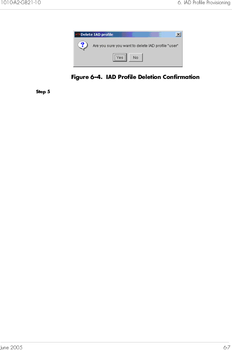
Click Yes to delete the profile.

This chapter provides instructions for provisioning IADs. JetVision
allows you to create one IAD at a time or multiple IADs at a time.
You can also clone one or more IADs based on an existing IAD’s
provisioning attributes. This chapter includes these tasks:
Creating single IADs (page 7-4):
—Voiceband IAD
— LES CAS Loop Start/Ground Start IAD
— LES CAS E&M Wink IAD
— LES CAS Mixed Port IAD
Creating bulk IADs (page 7-30)
Cloning IADs (page 7-37)
Modifying single IAD (page 7-40)
Modifying multiple IADs (page 7-42)
Deleting IADs (page 7-47)
Filtering IADs (page 7-49)
For downloading IAD software instructions, refer to Chapter 15,
Maintenance. For IADs reports and statistics information, refer to
Chapter 13, Reports, and Chapter 14, Statistics, respectively.
Integrated Access Devices (IADs) are installed at the customer/
subscriber premises. Figure 7–1 shows the relationship of an IAD
to a Voice-over-Broadband (VoBB) network.
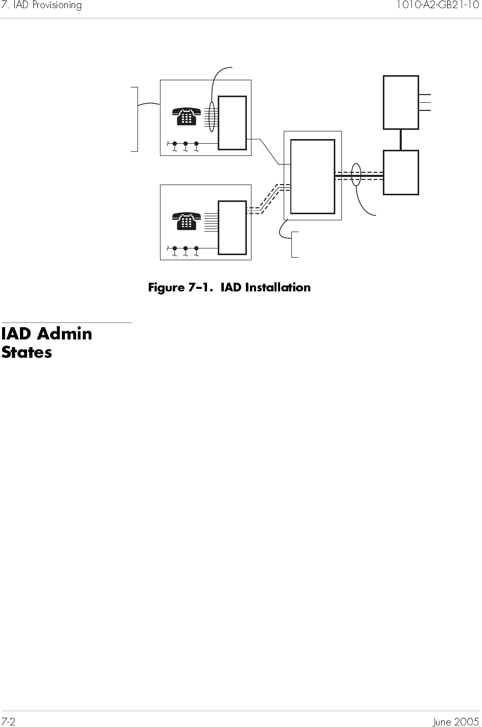
The IAD administrative state determines which IAD and IAD port
options can be modified. Four administrative states are available:
Provisional
Unlocked
Locked
Shutting Down
When an IAD is created before its physical installation, the
administrative state is Provisional, and the operational state is
Disabled. When the IAD is discovered and initialized, the
administrative state automatically changes to Unlocked, and the
operational state changes to Enabled.
Some options can be modified while others cannot, regardless of
the administrative state of the IAD and its ports (Table 7–1).
0059
DSLAM
- DSLAM Name
- ILEC Company
-ID
- Serial No.
- Interface
Group
- State
Permanent Virtual
Circuit (PVC) per IAD
- ATM/port
- VPI
- VCI
Directory Number per Port
CPX-
1000
AT M
Switch
LAN
Phone
Sys
IAD
LAN
Phone
Sys
IAD
ATM Transport
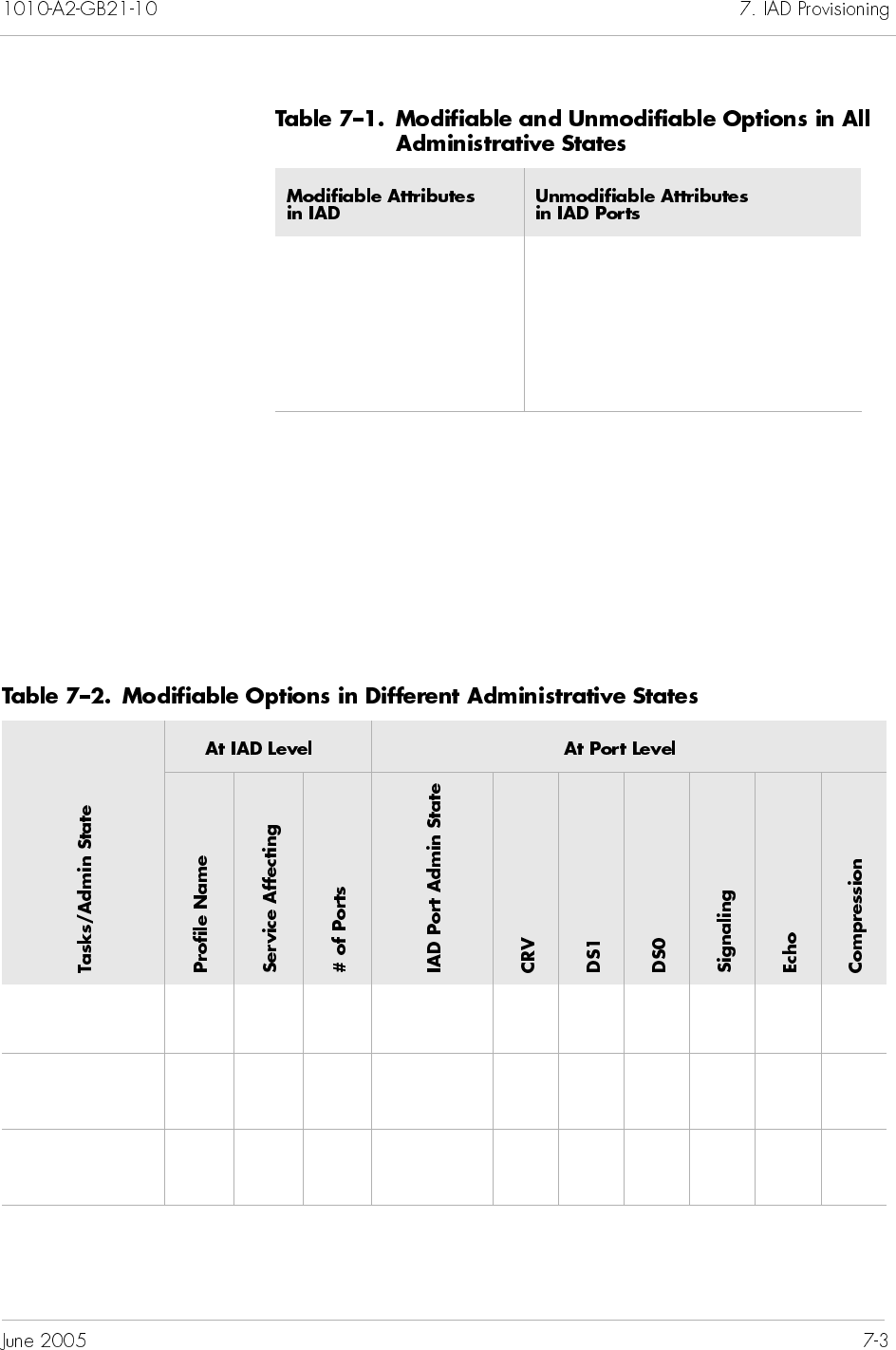
An IAD administrative state determines attributes that can be
modified. The IAD and its port administrative states determine the
CRV and signaling. For example, when an IAD administrative
state is Unlocked, and the port administrative state is Locked,
both CRV and signaling can be modified for that port. When the
administrative state of the IAD and its ports are Unlocked, the
CRV and signaling cannot be modified (Table 7–2).
Admin Compression
Company Echo cancellation
DSLAM
Subscriber
… …
Create IAD/
Provisional
Yes Yes Yes Locked or
Unlocked
Yes Yes Yes Yes Yes Yes
Modify IAD/
Provisional
No No Yes Locked
Unlocked
Yes
No
Yes
No
Yes
No
Yes
No
Yes Yes
No
Modify IAD/
Unlocked
No No No Locked
Unlocked
Yes
No
Yes
No
Yes
No
Yes
No
Yes Yes
No
The CPX-1000 supports up to 8,192 IADs. The maximum number
of provisioned IADs is limited by the CRVs available (4096).
Each IAD has a VPI and VCI assigned to it. An IAD group is a set
of IADs with the same VCI but different VPIs. The maximum
number of active calls supported in an IAD Group is limited to 63.
You provision IADs on the CPX-1000 before the IADs are
physically installed. You can install an IAD first, but it will not
function until it is provisioned on the CPX-1000.
There are two ways to create IADs: one IAD at a time or multiple
IADs at a time (Creating Bulk IADs on page 7-30). Depending on
your preference and experience, you can choose the following
methods when creating an IAD:
Modify IAD/
Locked
No Yes Yes Locked or
Unlocked
Yes Yes Yes Yes Yes Yes
Create/
Modify IAD
w/RT
Provisioned
Yes Yes Yes Locked or
Unlocked
Yes NANANo No No
… …
Note
You can provision more than 63 ports in an IAD group;
however, only 63 of those ports can have active calls on
them at one time.
Using IAD Wizard provides a step-by-step instruction to set
up an IAD. This method is suited for new or less experience
users.
Using Create IAD, better suited for experience users,
enables the IAD creation in an one-shot approach.
To create a single Voiceband Loop Start/Ground Start IAD using
the wizard:
Click to expand a desired CPX-1000 icon in the Tree view.
Click in the Tree View.
Select IAD Wizard from the Configuration menu.
– Or –
Right-click and select IAD Wizard from the pop-up menu.
– Or –
Click (IAD wizard icon) from the toolbar.
The IAD Creation Wizard–Introduction screen appears
(Figure 7–2).
Select a Jetstream IAD (for VB) Profile from the IAD Profile drop-
down list. The IAD Type field is automatically populated.
Click Next. The IAD Creation Wizard–Interface Group Selection
screen appears (Figure 7–5).
Select a Interface Group from the Interface Group Name
drop-down list. The other two fields (Interface Group version and
Switch Provisioned) are automatically populated.
Click Next. The IAD Creation Wizard–ATM Protection Group
Configuration screen appears (Figure 7–6).
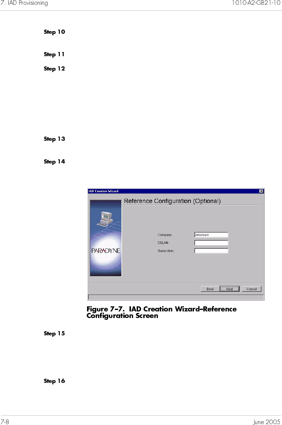
Select the Protection Group that the IAD is assigned from the ATM
Protection Group drop-down list.
Type the VPI value between 0 to 255 in the VPI field.
Type the VCI value in the VCI field. This identifies the
subscriber-specific virtual circuit between the CPX-1000 and the
ATM network.
If VPI is 0, then the VCI range is 32 to 1023.
If VPI is greater than 0, then the VCI range is 0 to 1023.
(Refer to Chapter 3, CPX-1000 Configuration, for VCI
setting.)
Select either ATM or Frame Relay from the Transport drop-down
list. Transport selections are dependant upon the IAD Profile.
Click Next. The Reference Configuration screen appears
(Figure 7–7).
Type the optional information in their associated fields.
Company—the company providing the voice service
DSLAM—the DSLAM serving the subscribers
Subscriber—the name of the subscriber
Click Next. The IAD Creation Wizard - Associate Network
Resources screen appears (Figure 7–8).
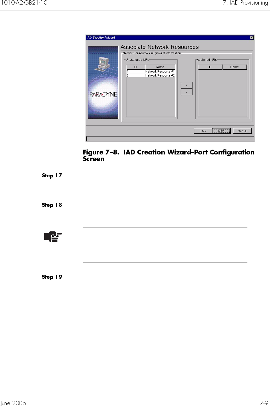
Select the appropriate Network Resources from the Unassigned
NRs column and the right-arrow button to move the Network
Resource to the Assigned NRs column.
Click Next.
Click Next. The IAD Creation Wizard–Port Configuration screen
appears (Figure 7–9).
Note
Assignment of Network Resources is optional. A
maximum of eight NRs can be assigned to an IAD.
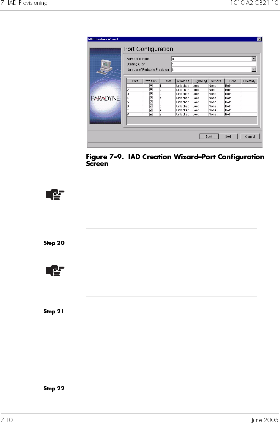
Type the starting CRV in the Starting CRV field.
Click to select the values for the following IAD port parameters
from the associated drop-down list.
Provisioning
Admin State
Signaling
Compression
Echo Cancellation
Click Next. The IAD Creation Summary screen appears, listing the
IAD parameters you’ve just created (Figure 7–10).
Note
The number of ports is dependant upon the IAD Profile.
The field is automatically populated based on the profile
selection.
Note
All CRV must be unique across IADs within the same
Interface Group.
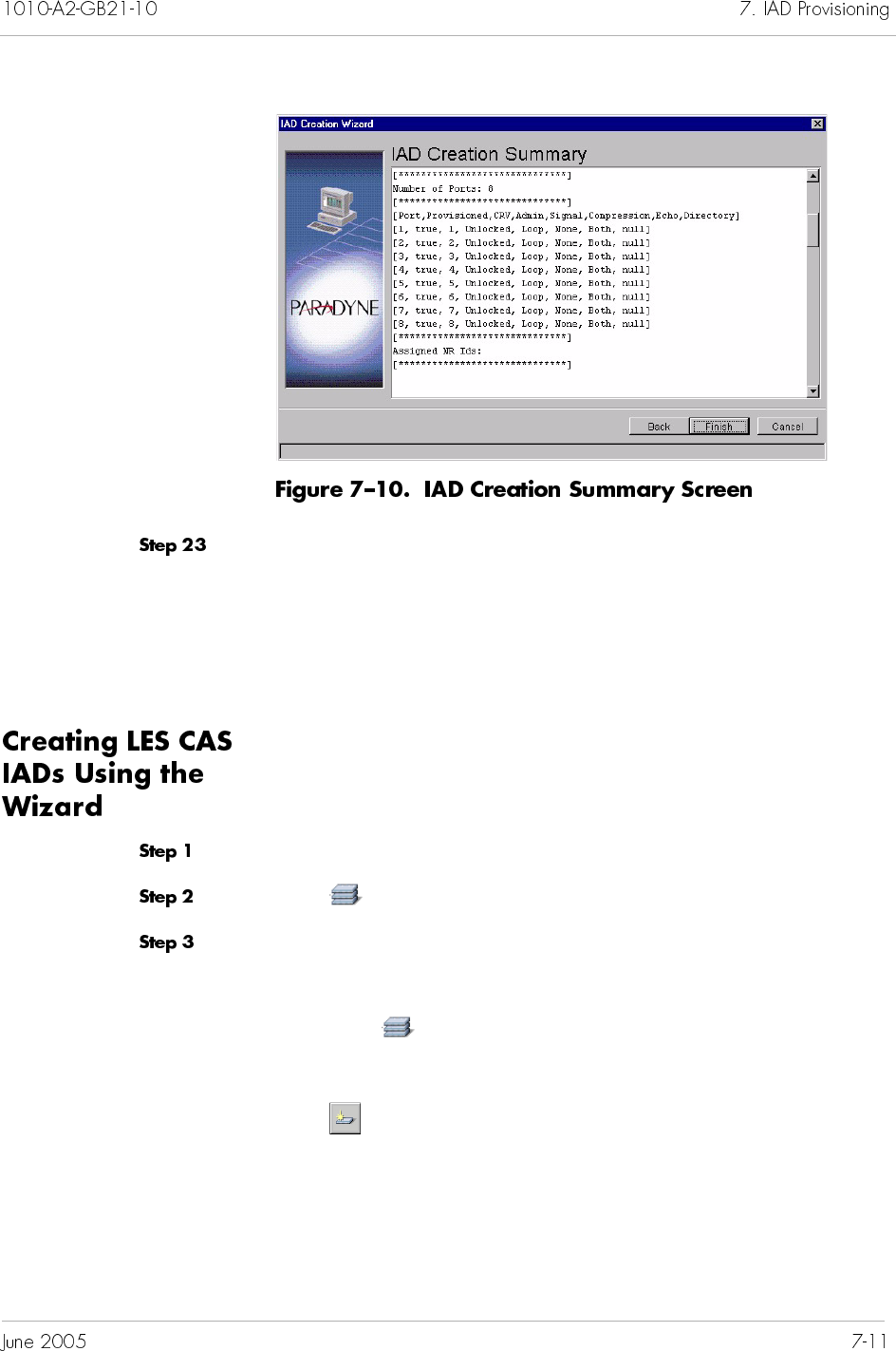
Review the IAD parameters.
If parameters are correct, click Finish.
If any of parameters are incorrect, click Back until you reach
the screen in question and correct the parameters, then
proceed from that point forward.
To create a single LES CAS IAD using the wizard:
Click to expand a desired CPX-1000 icon in the Tree view.
Click in the Tree View.
Select IAD Wizard from the Configuration menu.
– Or –
Right-click and select IAD Wizard from the pop-up menu.
– Or –
Click (IAD wizard icon) from the toolbar.
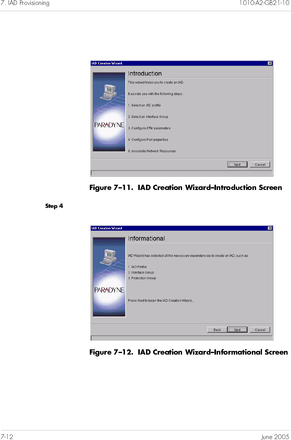
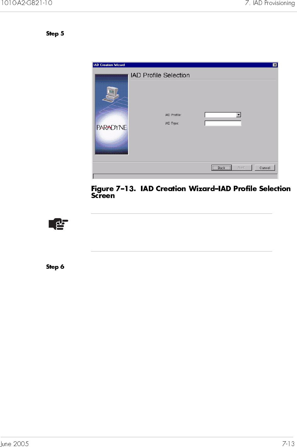
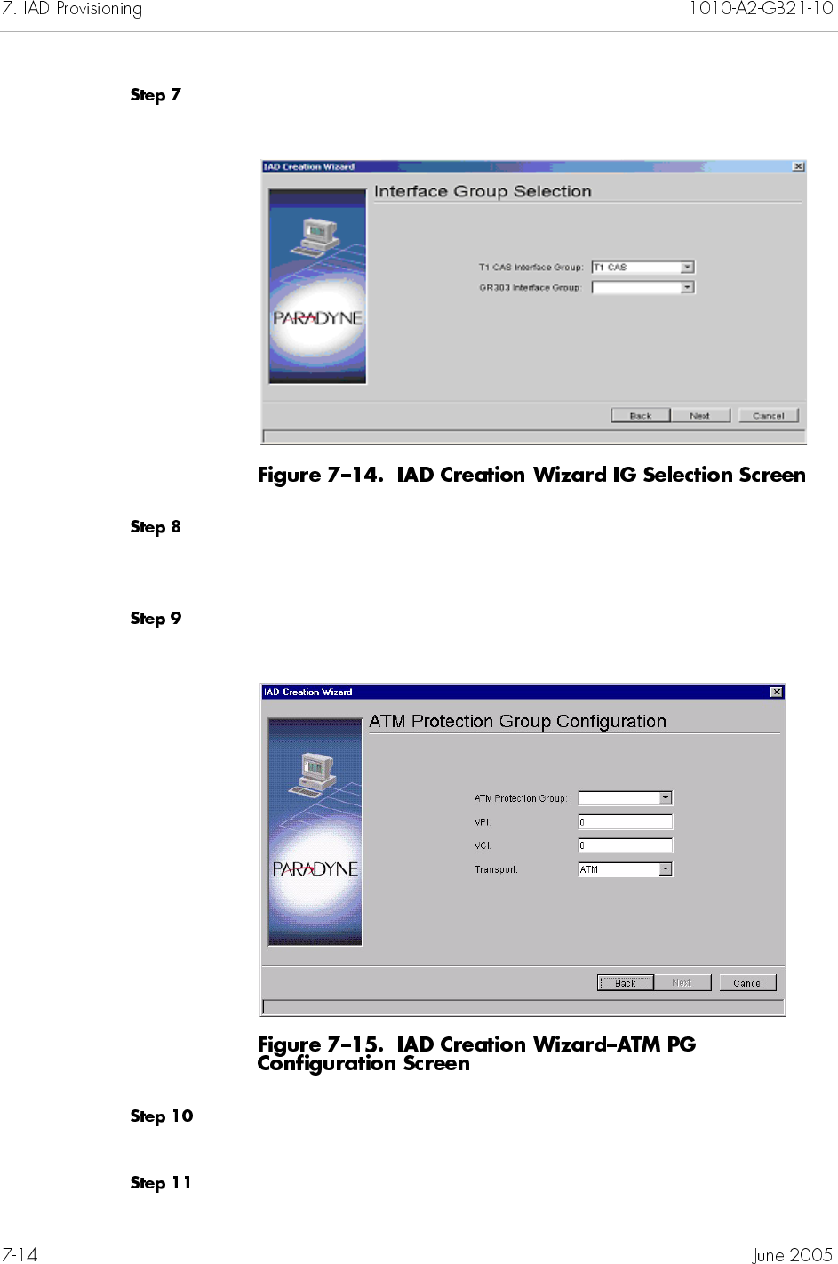
Click Next. The IAD Creation Wizard–Interface Group Selection
screen appears (Figure 7–5).
The T1 CAS Interface Group is populated automatically. For a
Loop/Ground Start or Mixed Port IAD, select a GR-303 Interface
Group name from the GR-303 Interface Group drop-down list.
Click Next. The IAD Creation Wizard–ATM Protection Group
Configuration screen appears (Figure 7–15).
Select the Protection Group that the IAD is assigned from the ATM
Protection Group drop-down list.
Type the VPI value between 0 to 255 in the VPI field.
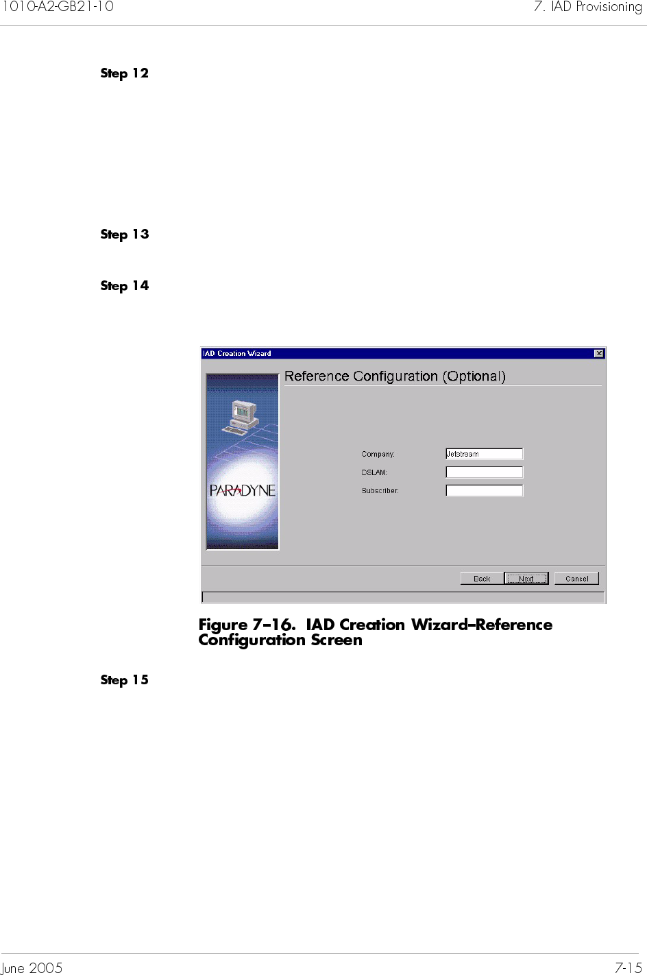
Type the VCI value in the VCI field. This identifies the
subscriber-specific virtual circuit between the CPX-1000 and the
ATM network.
If VPI is 0, then the VCI range is 32 to 1023.
If VPI is greater than 0, then the VCI range is 0 to 1023.
(Refer to Chapter 3, CPX-1000 Configuration, for VCI
setting.)
Select either ATM or Frame Relay from the Transport drop-down
list. Transport selections are dependant upon the IAD Profile.
Click Next. The Reference Configuration screen appears
(Figure 7–16).
Type the optional information in its associated fields.
Company—the company providing the voice service
DSLAM—the DSLAM serving the subscribers
Subscriber—the name of the subscriber
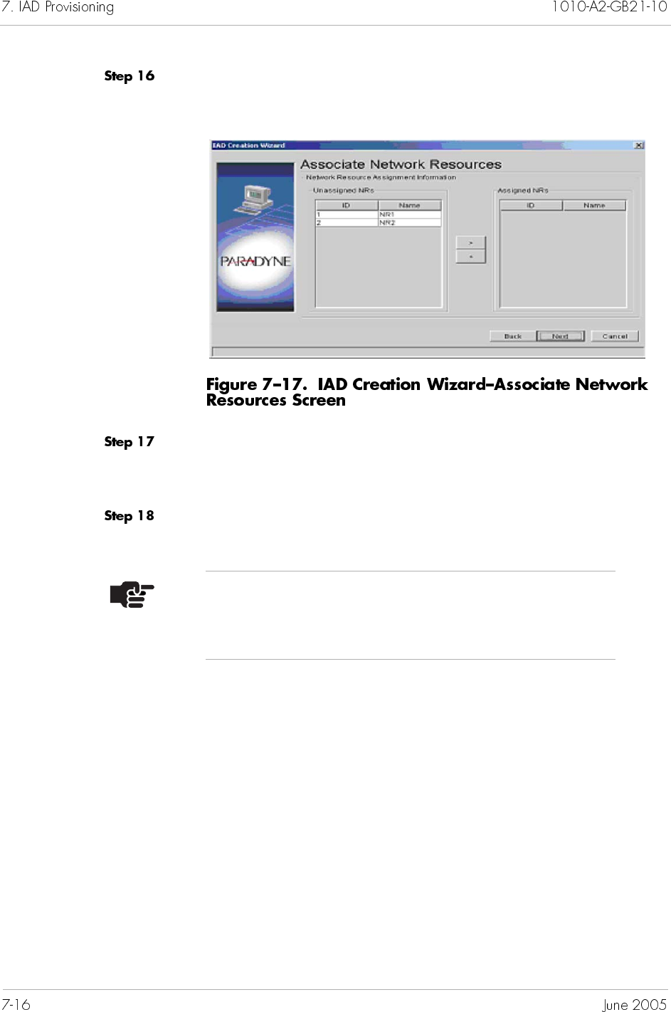
Click Next. The IAD Creation Wizard - Associate Network
Resources screen appears (Figure 7–17).
Select the appropriate Network Resources from the Unassigned
NRs column and click on the right-arrow button to move the
Network Resource to the Assigned NRs column.
Click Next.
Note
Assignment of Network Resources is optional. Up to
eight Network Resources can be assigned to an IAD.
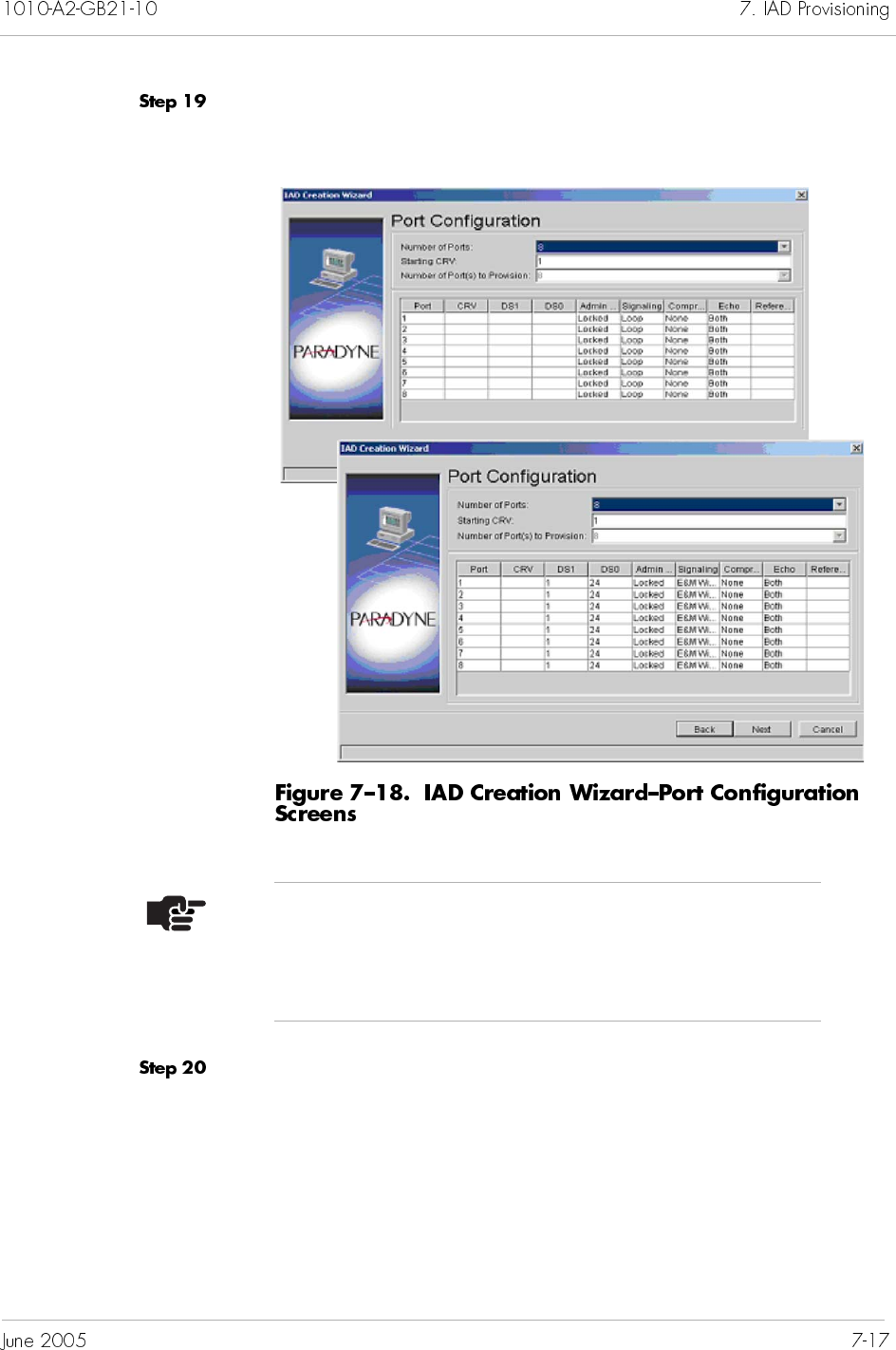
Click Next. The IAD Creation Wizard–Port Configuration screen
appears (Figure 7–18).
Click to select the values for the following IAD port parameters
from the associated drop-down list.
Provisioning
Admin State
Signaling
Compression
Echo Cancellation
Note
The number and type of ports is dependant upon the
IAD Profile. The field is automatically populated based
on the profile selection.
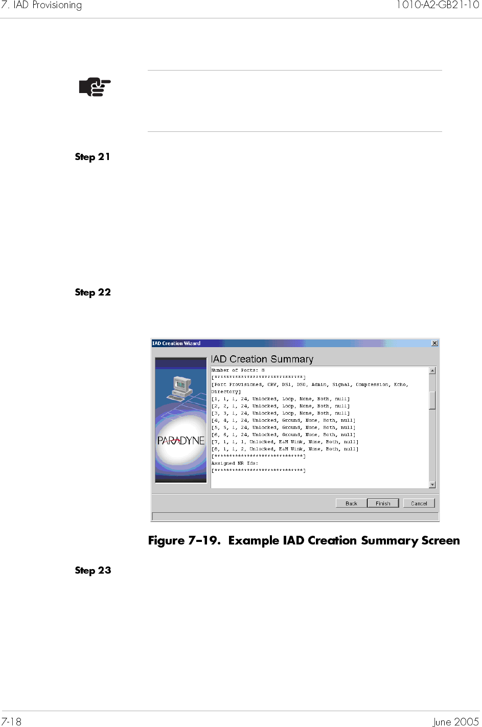
For:
Loop or Ground Start ports – Type the starting Cell
Reference Value (CRV) in the Starting CRV field. All
CRVs must be unique across IADs within the same Interface
Group.
E&M Wink Start ports – Enter the proper DS1/DS0 values.
All DS1/DS0 pairs must be unique across IADs within the
same Interface Group.
Click Next. The IAD Creation Summary screen appears, listing the
IAD parameters you’ve just created (Figure 7–19).
Review the IAD parameters.
If parameters are correct, click Finish.
If any of parameters are incorrect, click Back until you reach
the screen in question and correct the parameters, then
proceed from that point forward.
Note
Do not select static 16 kbps compression for LES CAS
IADs. LES CAS does not support 16 kbps compression.
To create a single Voiceband Loop Start/Ground Start IAD:
Click a desired CPX-1000 icon in the Tree view.
Select Create IAD from the Configuration menu.
– Or –
Right-click on the Tree View or Map View and select Create
IAD.
– Or –
Click on the toolbar.
The Create IAD window appears (Figure 7–20).
Note
The operational state of ports must be locked before
modifying CRV, DS1, DS0, or Signaling type when
creating an IAD through the Create IAD process. After
the modification is done the ports must be unlocked.
Switch Provision Info tab is
grayed out if Interface Group
is not RT provisioned.
Select an IAD Profile from the Profile Name drop-down list.
Select an Interface Group from the GR-303 Interface Group
drop-down list.
Select the number of ports for the IAD from the Number of
Ports drop-down list.
Select the values for the following IAD port parameters from the
associated drop-down list.
CRV
Admin State
Signaling
Compression
Echo Cancellation
Optionally, type a directory number in the Reference field.
Click PVC. The PVC tab appears (Figure 7–21).
Notes
If the Interface Group you selected is not RT
provisioned, the Switch Provision Info tab is
grayed out.
The IAD ID and serial number appear in their respective
fields after you finish creating the IAD, and it is
successfully initialized.
Notes
If you do not know the CRV or want to enter it later,
enter 0 (null). The Admin state of the port with CRV 0 is
automatically locked.
If the CRV is provisioned by the Class 5 switch, CME
returns the available CRVs and their corresponding
signaling types.
Select a Protection Group to which the IAD is assigned from the
Network Protection Group drop-down list.
Type the VPI value between 0 to 255 in the VPI field.
Type the VCI value in the VCI field. This identifies the
subscriber-specific virtual circuit between the CPX-1000 and the
ATM network.
If VPI is 0, then the VCI range is 32 to 1023.
If VPI is >0, then the VCI range is 0 to 1023.
Select either ATM or Frame Relay from the Transport
drop-down list. Transport selections are dependant upon the IAD
Profile.
Click Reference (Optional). The Create IAD Reference tab
appears (Figure 7–22).
Note
The information on the Reference and Annotation tab is
optional and does not affect the operation of IADs. It
provides easy record-keeping when using multiple
DSLAMs or having different subscriber’s locations.
Select the company providing the voice service from the Company
drop-down list. If the company is not listed, type the name of the
company in the Company field.
Select the DSLAM serving the subscriber from the DSLAM
drop-down list. If the DSLAM is not listed, type the name of the
DSLAM in the DSLAM field.
Select the subscriber from the Subscriber drop-down list. If the
subscriber is not listed, type the name of the subscriber in the
Subscriber field.
Click Annotation. The Annotation tab appears (page 7-23).
Note
When creating an IAD before its physical installation,
the administrative state is Provisional (default). When
the CPX-1000 discovers and recognizes the IAD, the
administrative state automatically changes to Unlocked
(IAD Admin States on page 7-2).
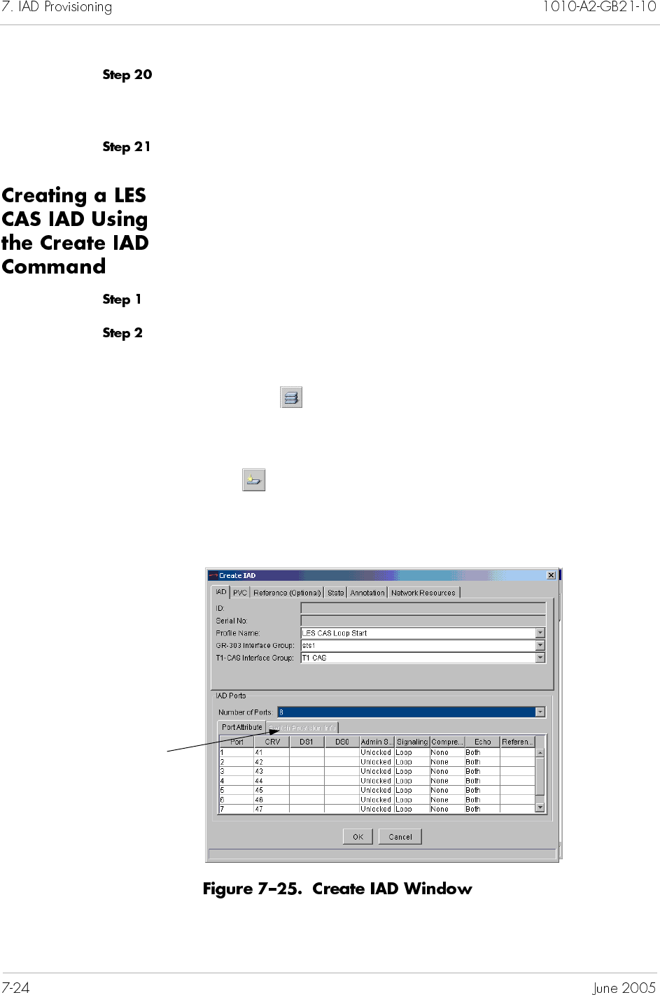
Select the appropriate Network Resources from the Unassigned
NRs column and click on the right-arrow button to move the
Network Resource to the Assigned NRs column.
Click on OK to create the IAD.
To create a single LES CAS Loop/Ground Start or E&M Wink Start
IAD:
Click a desired CPX-1000 icon in the Tree view.
Select Create IAD from the Configuration menu.
– Or –
Right-click on the Tree View or Map View and select Create
IAD.
– Or –
Click on the toolbar.
The Create IAD window appears (Figure 7–20).
Switch Provision Info tab is
grayed out if Interface Group
is not RT provisioned.
Select a LES CAS IAD Profile from the Profile Name drop-down
list.
For a Loop/Ground Start or Mixed Port IAD, select a GR-303
Interface Group from the GR-303 Interface Group drop-
down list.
Select the number of ports for the IAD from the Number of
Ports drop-down list.
As appropriate for the IAD type, select the values for the following
IAD port parameters from the associated drop-down lists.
CRV (Loop/Ground Start)
DS1 (E&M Wink Start)
DS0 (E&M Wink Start)
Admin State
Signaling
Compression
Echo Cancellation
Optionally, type a directory number in the Reference field.
Notes
If the Interface Group you selected is not RT
provisioned, the Switch Provision Info tab is
grayed out.
The IAD ID and serial number appear in their respective
fields after you finish creating the IAD and it is
successfully initialized.
Notes
If you do not know the CRV or want to enter it later,
enter 0 (null). The Admin state of the port with CRV 0 is
automatically locked.
If the CRV is provisioned by the Class 5 switch, CME
returns the available CRVs and their corresponding
signaling types.
Do not specify static 16 kbps compression for a LES CAS
IAD.
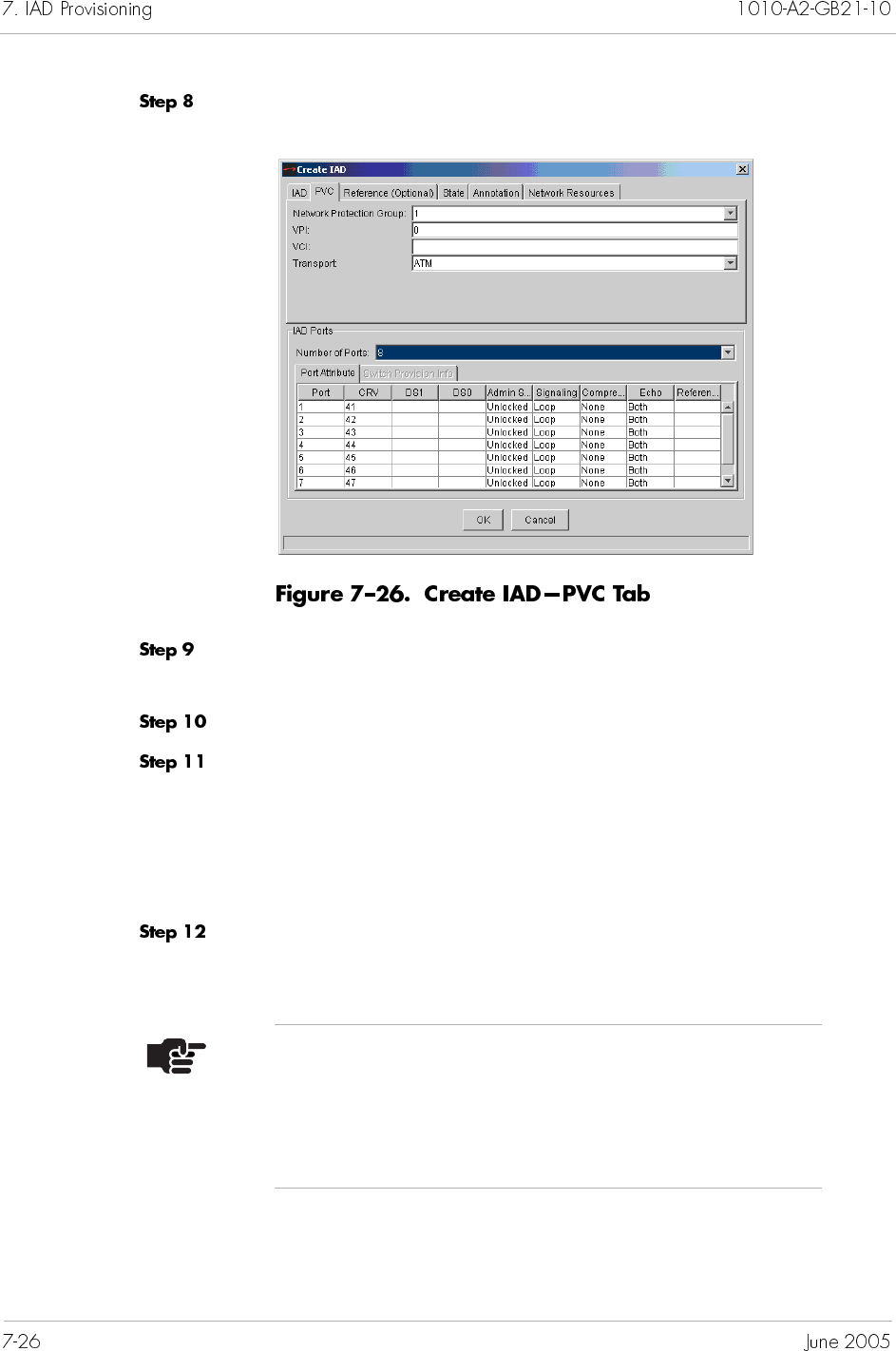
Click PVC. The PVC tab appears (Figure 7–21).
Select a Protection Group to which the IAD is assigned from the
Network Protection Group drop-down list.
Type the VPI value between 0 to 255 in the VPI field.
Type the VCI value in the VCI field. This identifies the
subscriber-specific virtual circuit between the CPX-1000 and the
ATM network.
If VPI is 0, then the VCI range is 32 to 1023.
If VPI is >0, then the VCI range is 0 to 1023.
Select either ATM or Frame Relay from the Transport
drop-down list. Transport selections are dependant upon the IAD
Profile.
Note
The information on the Reference and Annotation tab is
optional and does not affect the operation of IADs. It
provides easy record-keeping when using multiple
DSLAMs or having different subscriber’s locations.
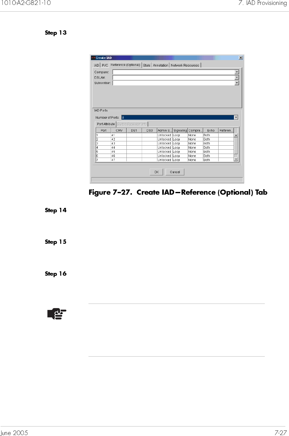
Click Reference (Optional). The Create IAD Reference tab
appears (Figure 7–22).
Select the company providing the voice service from the Company
drop-down list. If the company is not listed, type the name of the
company in the Company field.
Select the DSLAM serving the subscriber from the DSLAM
drop-down list. If the DSLAM is not listed, type the name of the
DSLAM in the DSLAM field.
Select the subscriber from the Subscriber drop-down list. If the
subscriber is not listed, type the name of the subscriber in the
Subscriber field.
Note
When creating an IAD before its physical installation,
the administrative state is Provisional (default). When
the CPX-1000 discovers and recognizes the IAD, the
administrative state automatically changes to Unlocked.
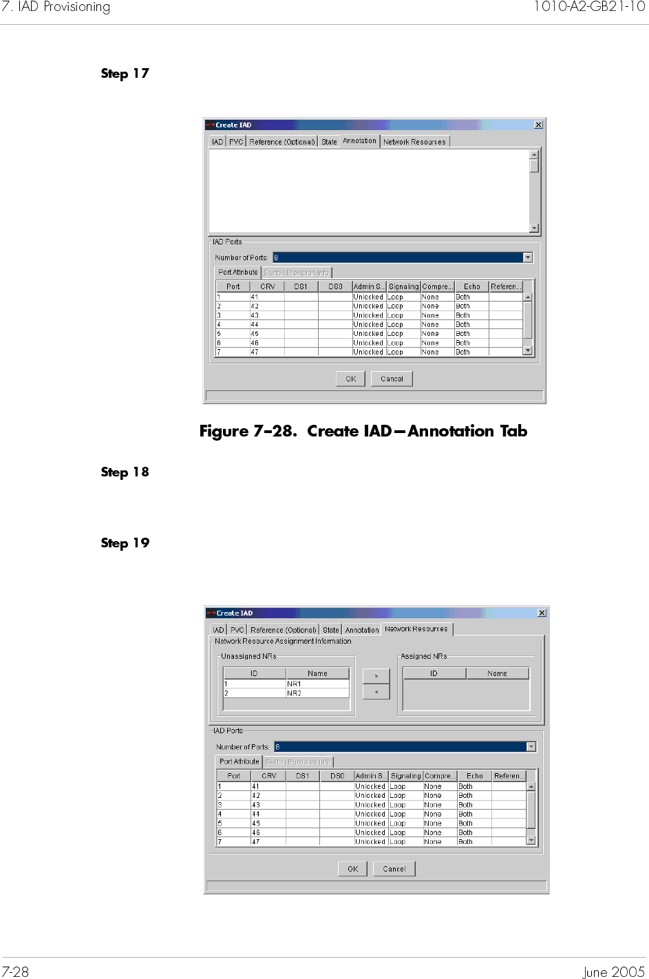
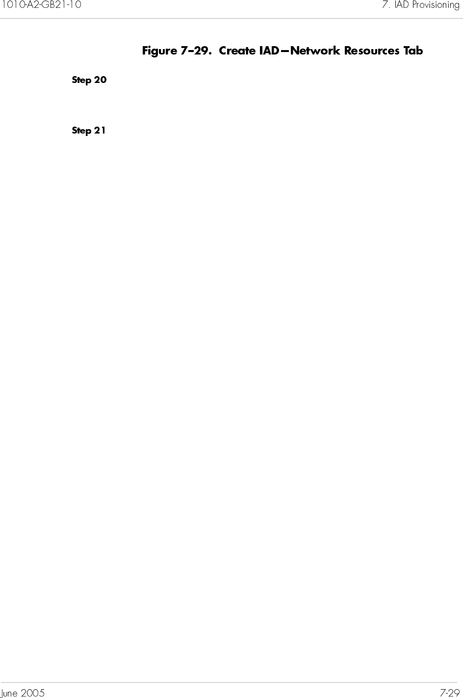
Select the appropriate Network Resources from the Unassigned
NRs column and click on the right-arrow button to move the
Network Resource to the Assigned NRs column.
Click on OK to create the IAD.
You can specify a contiguous order or a range of CRVs when
creating multiple IADs. Regardless of your options, you must
specify at least 1 CRV and cannot exceed 2,048 CRVs per IG.
When specifying a range of CRV and some of the CRVs in between
are already taken, then those CRVs are omitted during the bulk
creation. You can use one and/or any combinations of syntax listed
in Table 7–3 when creating bulk IADs.
N or N– The CRV starts from a continues ascending order.
For example, if N=1. The CRV starts from the first
available one until it reaches the maximum CRV
available.
N N N The CRV starts with multiple digits from a
continues ascending order. A space is placed
between each digit.
For example, if N N N= 1 2 3. The CRV starts from
the first available one until it reaches the maximum
CRV available.
N, The specified CRV is used.
For example, if N=40, then CRV used is 40.
N, R1–R2 A specified CRV, then followed by a range of
CRVs.
For example, if N=1, R1=100, and R2=200. The
CRV starts with 1, then move to 100 and continues
through 200 until the maximum CRV is reached.
N, R1–R2 A specified CRV, then descends to a range of CRVs.
For example, if N=200, R1=250, and R2=100. The
CRV starts with 200, then goes to 250 and descends
to 100 until the minimum CRV is reached.
≤NAny available/not-used CRV less than or equal to
the number specified.
For example, if N=1024. The CRV starts with 1024
and descends until the minimum CRV is reached.
You can create multiple IADs based on a common IAD Profile.
To create multiple IADs:
Click a CPX-1000 icon in the Tree View.
Select IAD Manager from the Configuration menu.
– Or –
Right-click on the Tree View or Map View and select IAD
Manager from the pop-up menu.
– Or –
Click on the toolbar.
The IAD Configuration Manager window appears (Figure 7–30).
<N Any available CRV less than the number specified.
For example, if N=1024. The CRV starts with 1023
and descends until the minimum CRV is reached.
≥NAny available/not-used CRV more than or equal
to the number specified.
For example, if N=1024. The CRV starts with 1024
and continues until the minimum CRV is reached.
>N Any available CRV more than the number
specified.
For example, if N=1024. The CRV starts with 1025
and continues until the maximum CRV is reached.
Note
Bulk creation of LES CAS E&M Wink and Mixed Port
IADs is not supported.
RT Provisioning is not supported when creating
multiple IADs.
Type the VPI value between 0 to 255 in the VPI field.
Select an IAD Profile association for the IADs from the Profile
Name drop-down list.
Select an Interface Group association from the Interface Group
drop-down list.
Select a Protection Group association from the ATM Protection
Group drop-down list.
Select Ascending or Descending from the Ordering VCI
drop-down list.
Select the starting VCI value from the Starting VCI drop-down list.
Type the number of IADs you want to create in the Num of IADs
to create field.
Select ATM or Frame Relay from the Transport drop-down list.
Note
The number of IADs you can create is the lower value
between PG and IG/CRV limits.
Click IAD Port Attribute. The IAD Port Attribute tab appears
(Figure 7–32).
Select the number of IAD ports that will be used by each IAD from
the Num of IAD Ports drop-down list.
Type the number of ports with “null” CRVs in the Null CRV Port
list field.
Notes
Null ports can be manually assigned CRVs from the
Modify IAD window (page 7-40).
You can specify a range of CRV by using commas (,) and
dashes (–).
Type the starting CRV number if you want to change the value
shown in the CRV Range field. (By default, this field shows the
first available CRV.)
Select Both or None echo support from the Echo drop-down list.
Select Loop or Ground from the Signaling drop-down list.
Select a compression type from the Compression drop-down list.
Click Reference (Optional). The Reference (Optional) tab
appears (Figure 7–33).
Note
The information on the Reference tab is optional and
does not affect the operation of IADs. It provides easy
record-keeping when using multiple DSLAMs or having
different subscriber’s locations.
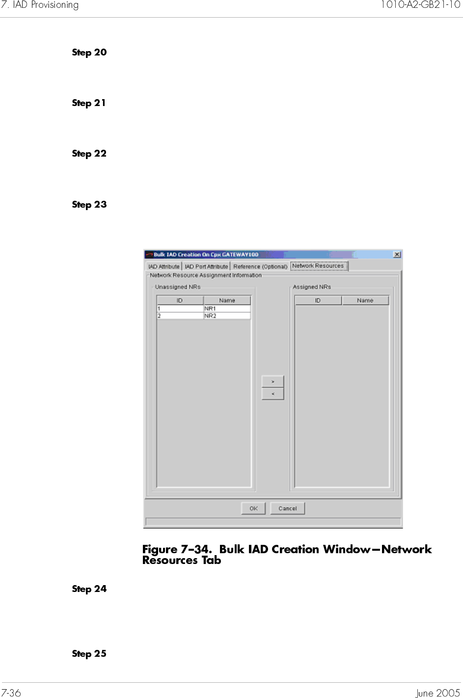
Select the company providing the voice service from the Company
drop-down list. If the company is not listed, type the name of the
company in the Company field.
Select the DSLAM serving the subscriber from the DSLAM
drop-down list. If the DSLAM is not listed, type the name of the
DSLAM in the DSLAM field.
Select the subscriber from the Subscriber drop-down list. If the
subscriber is not listed, type the name of the subscriber in the
Subscriber field.
Click on the Network Resources tab. The Network Resources
screen appears (Figure 7–34).
Select and assign NRs as required. The Assign button (>) moves a
selected NR from the Unassigned column to the Assigned column.
The Unassign button (<) moves a selected NR from the Assigned
column to the Unassigned column.
Click OK to create the IADs.
Cloning IADs lets you create one or more IADs based on an
existing IAD’s provisioning attributes. IADs cloned from an
existing IAD have the same attributes as the original.
To clone an existing IAD:
Click a desired CPX-1000 icon in the Tree view.
Select IAD Manager from the Configuration menu.
– Or –
Right-click on the Tree View or Map View and select IAD
Manager from the pop-up menu.
– Or –
Click on toolbar.
The IAD Configuration Manager window appears (Figure 7–35).
Note
RT Provisioning is not supported when cloning IADs.
Cloning of LESCAS E&M Wink and Mixed Port IADs is
not supported.
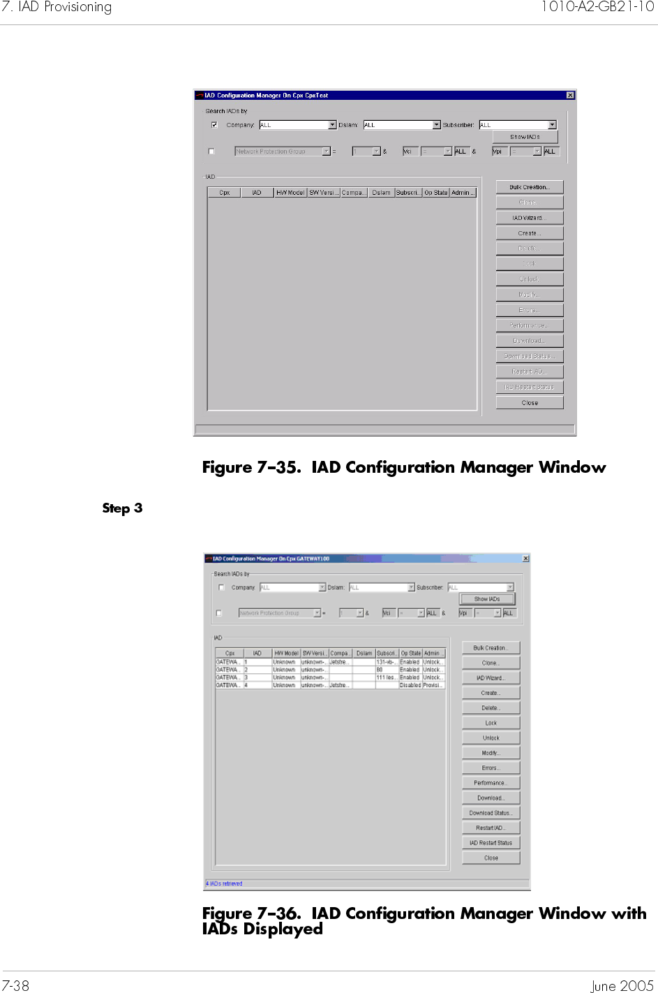
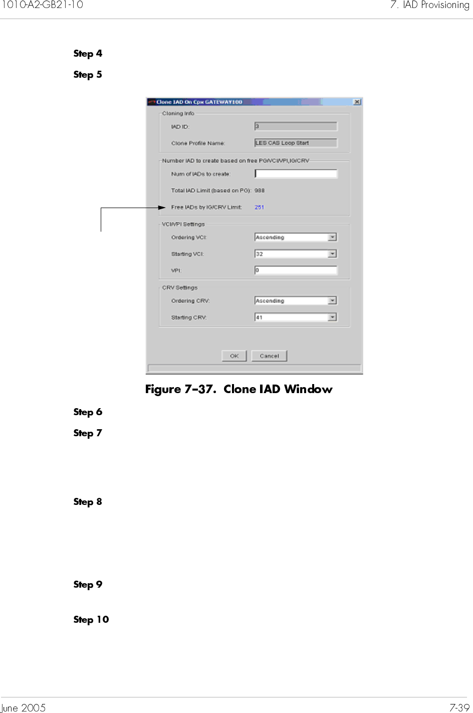
Select an IAD that you want to use for cloning from the IAD list.
Click Clone. The Clone IAD window appears (Figure 7–37).
Type the VPI value between 0 to 255 in the VPI field.
Select the following VCI settings.
Ascending or Descending from the Ordering VCI
drop-down list.
the starting VCI value from the Starting VCI drop-down list.
Select the following CRV settings.
Ascending or Descending from the Ordering CRV
drop-down list.
the starting CRV number from the Starting CRV drop-down
list.
Type the number of IADs you want to create in the Num of IADs
to create field.
Click OK. A progress window appears, indicating the cloning
status.
When cloning is complete, the new IADs appear in the IAD list in
the IAD Configuration Manager window.
Indicates the number of IADs that
you can clone
You can modify one IAD or multiple IADs at a time (Modifying
Multiple IADs on page 7-42).
To modify an IAD:
Click a desired CPX-1000 icon in the Tree view.
Select IAD Manager from the Configuration menu.
– Or –
Right-click on the Tree View or Map View and select IAD
Manager from the pop-up menu.
– Or –
Click on the toolbar.
The IAD Configuration Manager window appears (Figure 7–38).
Note
The Modification of DS1/DS0s in LES CAS E&M Wink
or Mixed Port IADs is not supported. If modification for
those ports is required, the IAD must be deleted and
recreated.
Select the IAD that you want to modify.
Click Modify. The Modify IAD window appears (Figure 7–40).
Modify any information, as necessary (Provisioning IADs on page
7-4).
Click OK to accept the changes and return to the IAD Configuration
Manager window.
Click Close.
To modify multiple IADs:
Click a desired CPX-1000 icon in the Tree view.
Select IAD Manager from the Configuration menu.
Notes
The Admin state of the IAD port must be locked before
the CRV can be changed
The PVC tab cannot be modified.
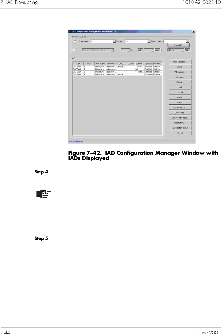
Select the IADs that you want to modify.
Click Modify. The Bulk IAD Modification window appears
(Figure 7–43).
Note
To select multiple IADs, hold down the Shift or Ctrl
key while making your selections. Using the Shift key
lets you make your selections in contiguous order; the
Ctrl key lets you select IADs in a random order.
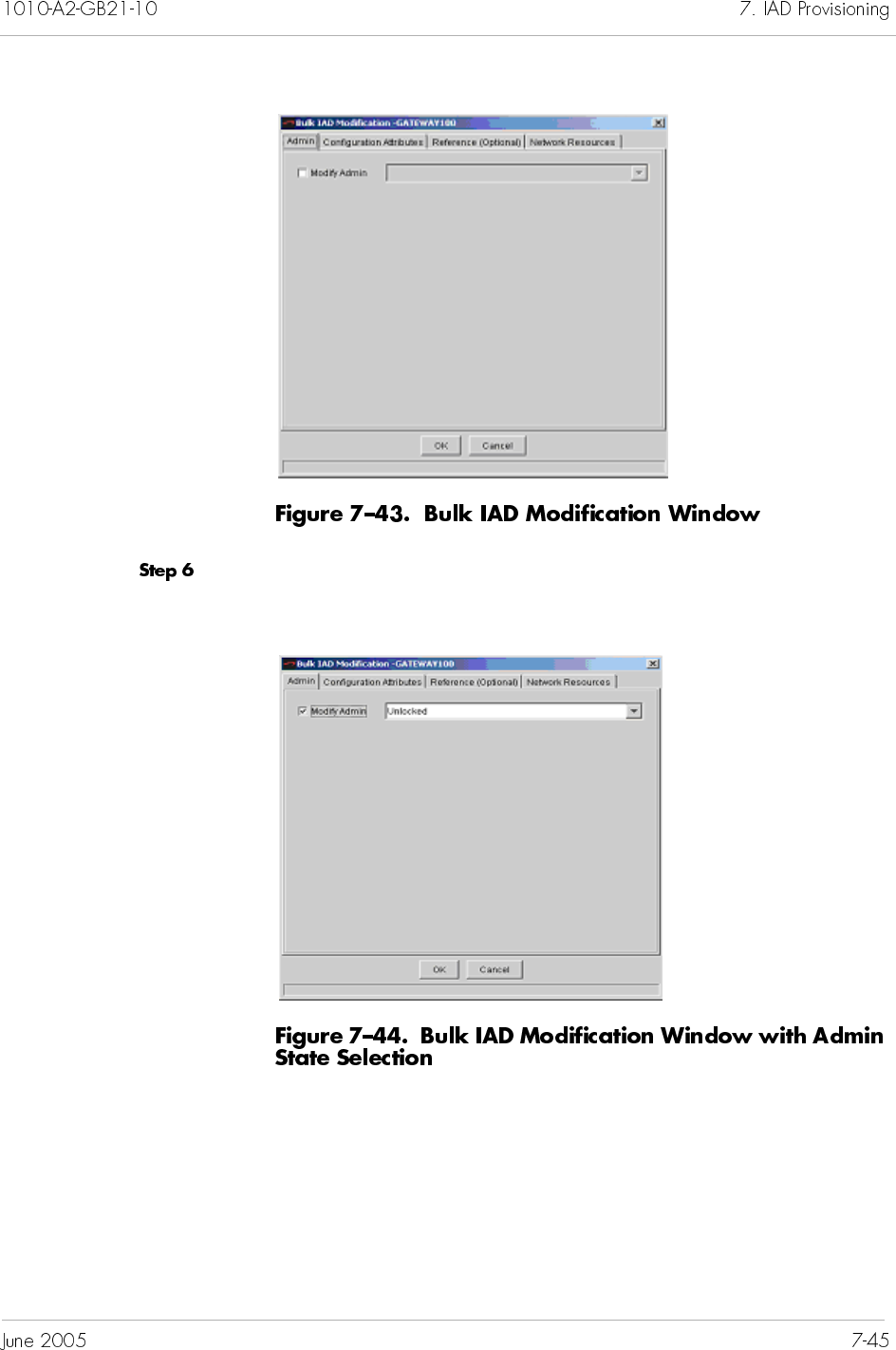
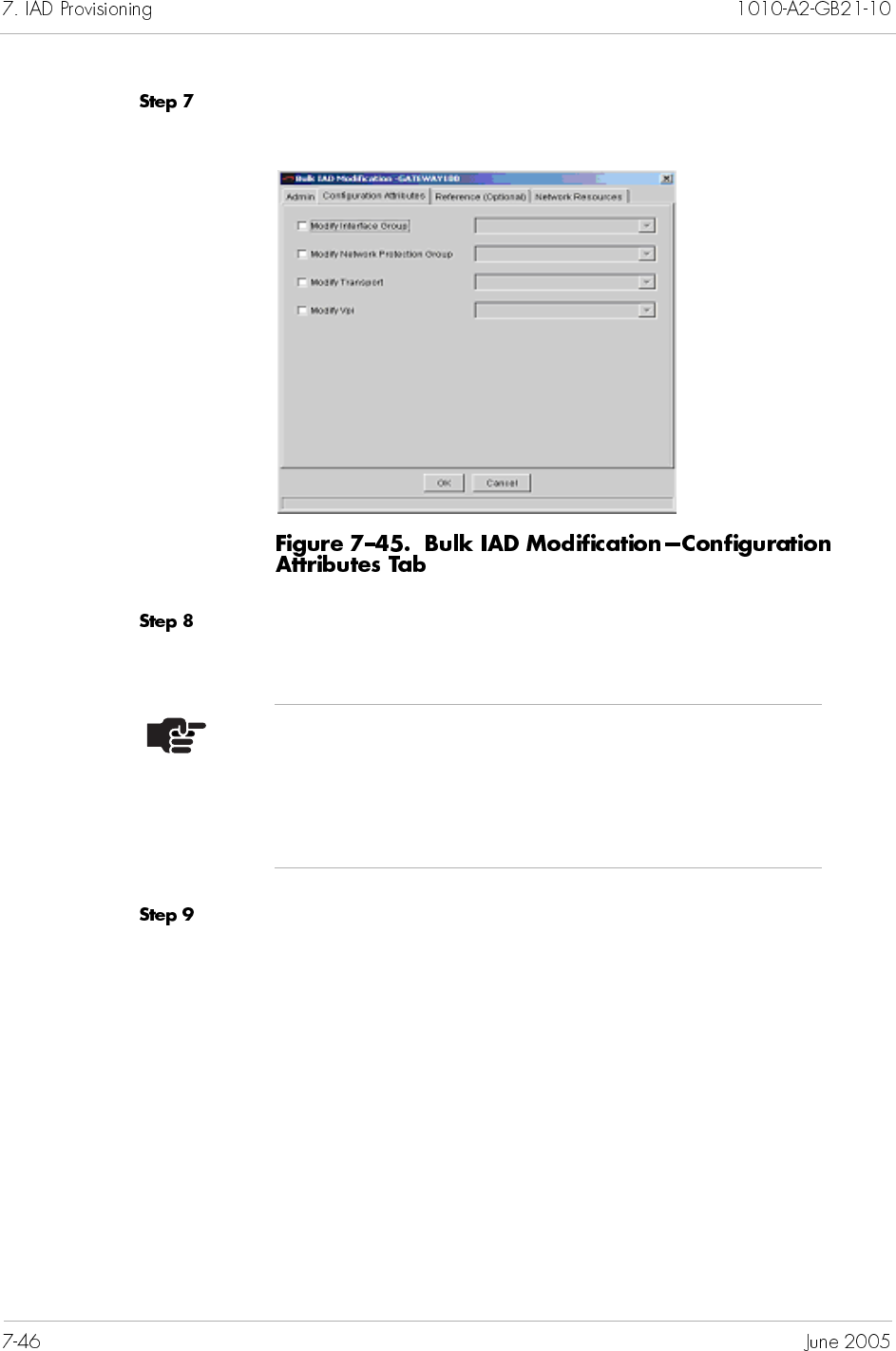
Click Configuration Attributes. The Configuration
Attributes window appears (Figure 7–45).
Click to select the appropriate modification checkbox and make a
selection from the accompanying drop-down list.
Click Reference (Optional). The Reference (Optional)
window appears (Figure 7–46).
Note
The information on the Reference tab is optional and
does not affect the operation of IADs. It provides easy
record-keeping when using multiple DSLAMs or having
different subscriber’s locations.
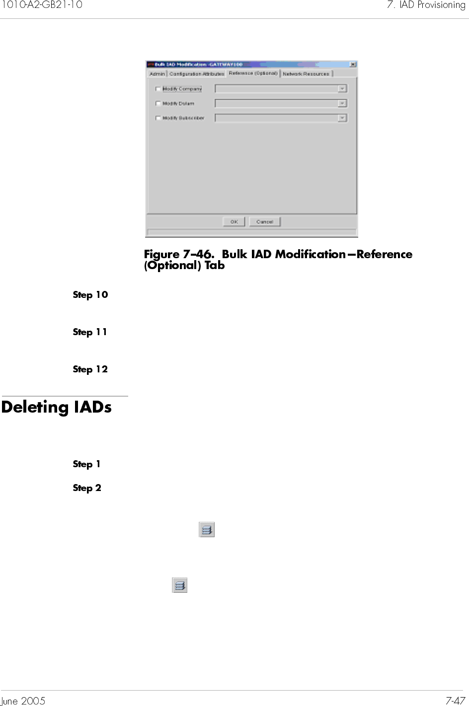
Select the appropriate modification checkbox and make a selection
from the accompanying drop-down list.
Click the Admin tab and select Unlocked from the accompanying
drop-down list.
Click OK to modify the IADs.
Before deleting an IAD, set its administrative state to Locked
(Modifying IADs on page 7-40).
To delete an IAD:
Click a desired CPX-1000 icon in the Tree view.
Select IAD Manager from the Configuration menu.
– Or –
Right-click on the Tree View or Map View and select IAD
Manager from the pop-up menu.
– Or –
Click on the toolbar.
The IAD Configuration Manager window appears (Figure 7–47).
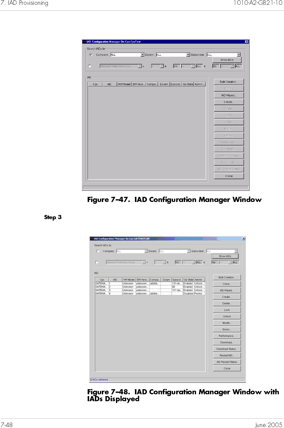
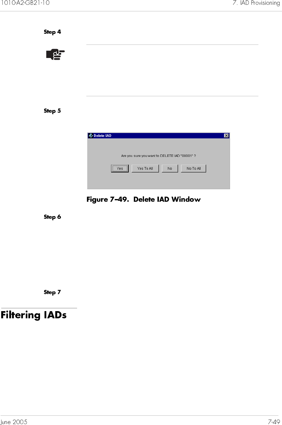
Select the IADs that you want to delete.
Click Delete IAD. The Delete IAD window appears
(Figure 7–49).
Click one of the following:
Yes: deletes a single IAD and returns you to the IAD
Configuration Manager window.
Yes To All: deletes all selected IADs.
No: returns you to the IAD Configuration Manager window.
No To All: returns you to the IAD Configuration Manager
window.
Click Close to exit the IAD Configuration Manager window.
You can customize the search of IADs by using one or a
combination of the following areas:
Company and DSLAM and Subscriber
ATM Protection Group, Interface Group, IAD hardware
model and software version
Searching of LES CAS IADs based upon IAD hardware model and
software version is not supported.
Note
To select multiple IADs, hold down the Shift or Ctrl
key while making your selections. Using the Shift key
lets you make your selections in contiguous order; the
Ctrl key lets you select IADs in a random order.
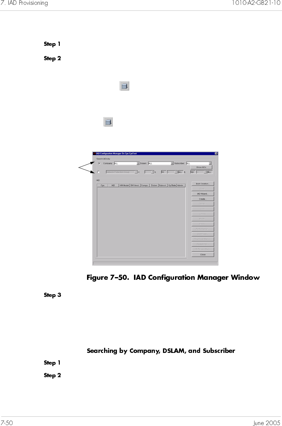
To search for IADs:
Click a desired CPX-1000 icon in the Tree view.
Select IAD Manager from the Configuration menu.
– Or –
Right-click on the Tree View or Map View and select IAD
Manager from the pop-up menu.
– Or –
Click on the toolbar.
The IAD Configuration Manager window appears (Figure 7–47).
Specify your search by clicking one or a combination of the
following areas:
Company and DSLAM and Subscriber
Network Protection Groups, Interface Group, hardware
(HW) model and software (SW) version
Proceed as Steps 1 and 2 in Filtering IADs on page 7-49.
Click the checkbox next to Company, and select the name of the
company assigned to the IADs from the drop-down list. The DSLAM
and the subscriber for that company is automatically selected.
Click one or both
checkboxes to filter IADs.
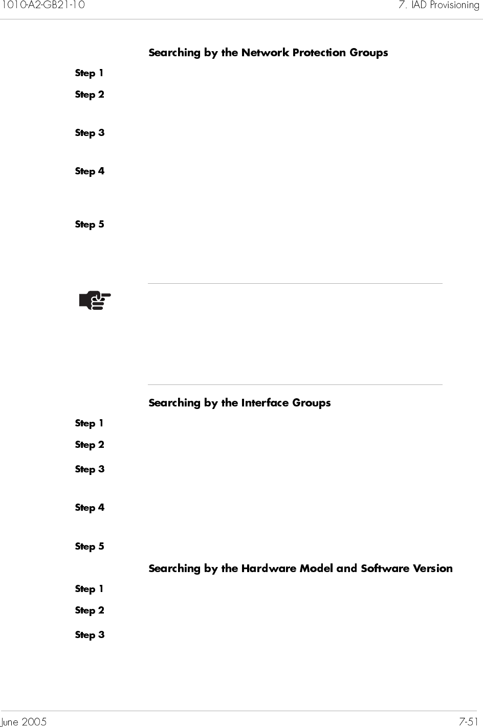
Proceed as Steps 1 and 2 in Filtering IADs on page 7-49.
Select Network Protection Group from the drop-down list.
Both the VCI and VPI fields are enabled.
Type the Network Protection Group identifier, or select it from the
drop-down list.
Select a range of VCI values by using the less than (<) or greater
than (>) symbols from the drop-down list, then type a VCI value in
the text field.
Select a range of VPI values by using the less than (<) or greater
than (>) symbols from the drop-down list, then type a VPI value in
the text field.
Proceed as Steps 1 and 2 in Filtering IADs on page 7-49.
Select Interface Group from the drop-down list.
Type the Interface Group identifier, or select it from the drop-down
list.
Select a range of CRV by using the less than (<) or greater than (>)
symbols from the drop-down list.
Type a CRV number, or select it from the drop-down list.
Proceed as Steps 1 and 2 in Filtering IADs on page 7-49.
Select HW Model from the drop-down list.
Type the model type, or select it from the drop-down list.
Note
When the CRV/VCI/VPI value is not specified, All
(default) is used. The default indicates that the filter
only applies to the Interface Group or Network
Protection Group, regardless of the CRV/VCI/VPI
value.
To further refine the search, select a software version from
the SW Version drop-down list, or leave the default as ALL to
select all software versions..
The software version(s) available in the list depends upon the
hardware model chosen.
The Network Resource Manager (NRM) is a mechanism to allow
carriers to manage constraints within their network. These
constraints may be bandwidth or number of calls a network
resource can handle without service degradation.
In typical VoBB deployments, the first method of defense against
bandwidth over-allocation is prioritization: voice traffic is granted
priority over data traffic, so as more calls are allowed to enter the
network, data traffic is reduced.
However, it is critical that Call Admission Control be properly
performed. If a packet link is overloaded with high priority traffic,
the network cannot identify which packets to throw away, so all
calls are affected (not just those recently added). The results can be
catastrophic, with dozens of calls rendered unintelligible.
While the CPX-1000 does not have direct knowledge of the
network, it can track resources that are common to IADS. The CPX
can learn the topology of the network and the associated network
constraints and perform the Call Admission Control (CAC).
The CPX can support up to 256 network resources with a
provisionable bandwidth thresholds. The CPX can then track
utilization of each network resource. Before starting a call, it
verifies that there is sufficient bandwidth available for the
associated network resource to accept the call. If not, the call is
rejected.
This chapter describes:
Provisioning network resources
Configuring network resources for IADs
Viewing online performance charts for network resources
Viewing historical performance charts for network
resources
The user can create, modify and delete network resources from the
NRM window. These operations can be performed using the tool
bar or the Operations menu in the Network Resource Manager
window.
To provision network resources:
Click a desired CPX-1000 icon in the Tree view.
Select Network Resource Manager from the Services menu. The
Network Resource Manager window appears (Figure 8–1).
Select Create from the Operations menu
- Or -
Click the Create icon on the toolbar. A Create dialog box
appears.
Enter the following information:
Network Resource Name. Enter from 4 to 63 alphanumeric
characters (including no spaces, hyphens, or special
characters).
Maximum Bandwidth (Cells/sec). Enter a number between
200 and 1466981, inclusive.
Click on OK. The new network resource you created appears in the
Network Resource Manager Window.
To modify a provisioned network resource:
Select a network resource in the Network Resource Manager
window.
Select Modify from the Operations menu
– Or –
Click on the toolbar. The Modify dialog window appears.
Make your desired modifications.
Click on OK.
To delete a provisioned network resource:
Select a network resource in the Network Resource Manager
window.
Click the Delete icon. A deletion confirmation window appears.
Click on OK.
Click on Close to exit the Network Resource Manager.
The CPX Network Management system provides the user with
current statistics of Allocated Bandwidth and Rejected Calls.
To view online performance charts for NRM:
Click a CPX node icon from the Tree View for the CPX-1000 that
the Network Resources is associated with.
Select Network Resource Manager from the Services menu. The
Network Resource Manager window appears.
Select a network resource in the Network Resource Manager
window
Select Online Performance Graphs from Statistics menu
- Or -
Click on the Current PM icon on the toolbar. The Performance
Graphs window appears.
Click on the Show button to view the graphs.
Click on the Close button to exit the window.
Jetvision can also provide the user with 15-minute and 24-hour
historical performance charts for each network resource. The
following values are displayed:
Allocated Bandwidth
Released Bandwidth
Number of Rejected Calls
Peak Bandwidth
To view historical performance charts for NRM:
Click a CPX node icon from the Tree View for the CPX-1000 that
the Network Resource is associated with.
Select Network Resource Manager from the Services menu. The
Network Resource Manager window appears.
Select a network resource in the Network Resource Manager
window, then click on the Historical PM icon from the toolbar, or
select Historical Performance Graphs from Statistics menu. The
Performance Graphs window appears.
The display can be shown in a table format (Figure 8–3), bar graph
(Figure 8–4) or line graph (Figure 8–5). The tool bar in this
window has zoom, filter and summary features which can be used
to further refine the displayed data.

This chapter provides instructions on how to create and administer
JetVision user groups and users. This chapter includes the
following tasks:
Creating or adding JetVision groups (page 9-2)
Modifying JetVision group’s information (page 9-4)
Deleting JetVision groups (page 9-6)
Reviewing JetVision group’s information (page 9-6)
Creating or adding JetVision users (page 9-7)
Modifying JetVision user’s information (page 9-10)
Deleting JetVision users (page 9-11)
Reviewing JetVision user’s information (page 9-12)
Changing default password (page 9-12)
When you first start JetVision, you log on using the default
JetVision user ID (jsems) and password (jsems123). To control
access to your CPX-1000 networks, we recommend changing the
default password as soon as possible (Changing JetVision Default
Password on page 9-12).
JetVision comes with one default Admin group, which has access
to all JetVision operations. JetVision group specifies a profile of
operations that a user can perform.
To create or add a JetVision groups:
Select Create JetVision Group from the Services menu. The
Create Group window appears (Figure 9–1).
Type the group name between 4 to 16 alphanumeric characters (no
spaces, hyphens, or special characters) in the Name field.
Optionally, type a description of the user group in the
Description field.
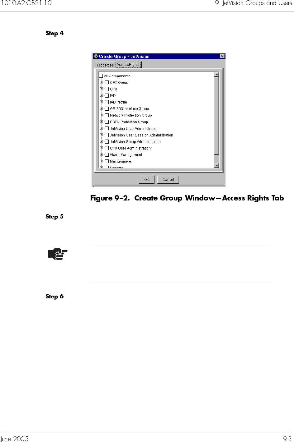
Click Access Rights. The Access Right tab appears (Figure 9–2).
Select the operations that the group provides its users by clicking
the checkbox next to the operation.
Click OK to create the group.
After a group is created, you can assign users to it (Adding
JetVision Users on page 9-7).
Note
Click the plus (+) symbol to view the subtasks of each
category.
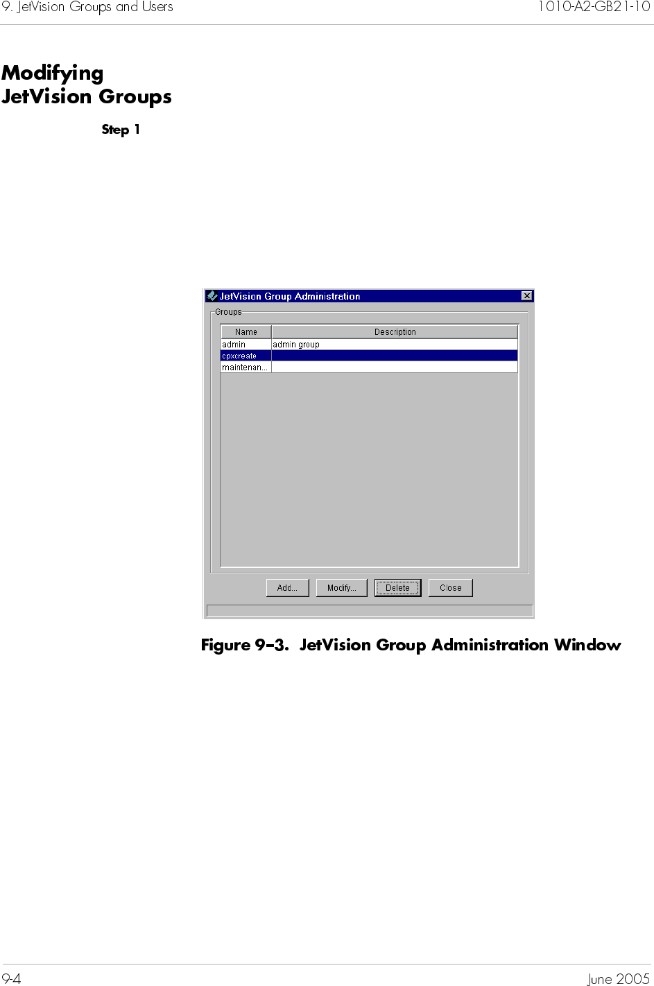
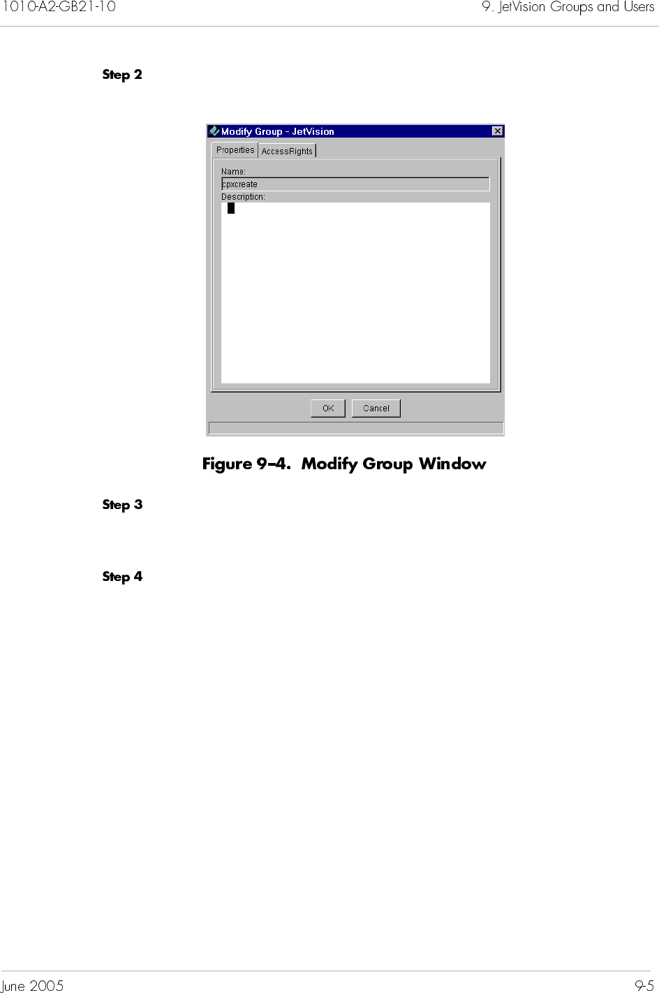
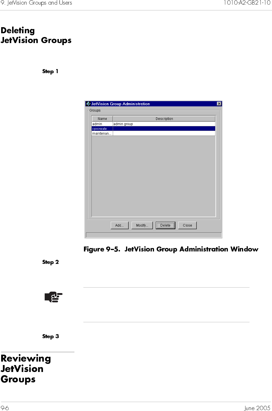
When deleting a JetVision group, all users associated with that
group are deleted. When a user from a group is logged on to
JetVision, that group cannot be deleted.
To delete a JetVision group:
Select JetVision Group Administration from the Services
menu. The JetVision Group Administration window appears
(Figure 9–5).
Select a group you want to delete and click Delete. A prompt
appears, asking if you want to delete the selected user group.
Click Yes to delete the group.
To review the JetVision groups that you have created, select
JetVision Group Administration from the Services menu.
The JetVision Group Administration window (Figure 9–5 on page
9-6) appears displaying the group information.
Note
You cannot delete the default “admin” group unless
another group with the same admin privileges is added.
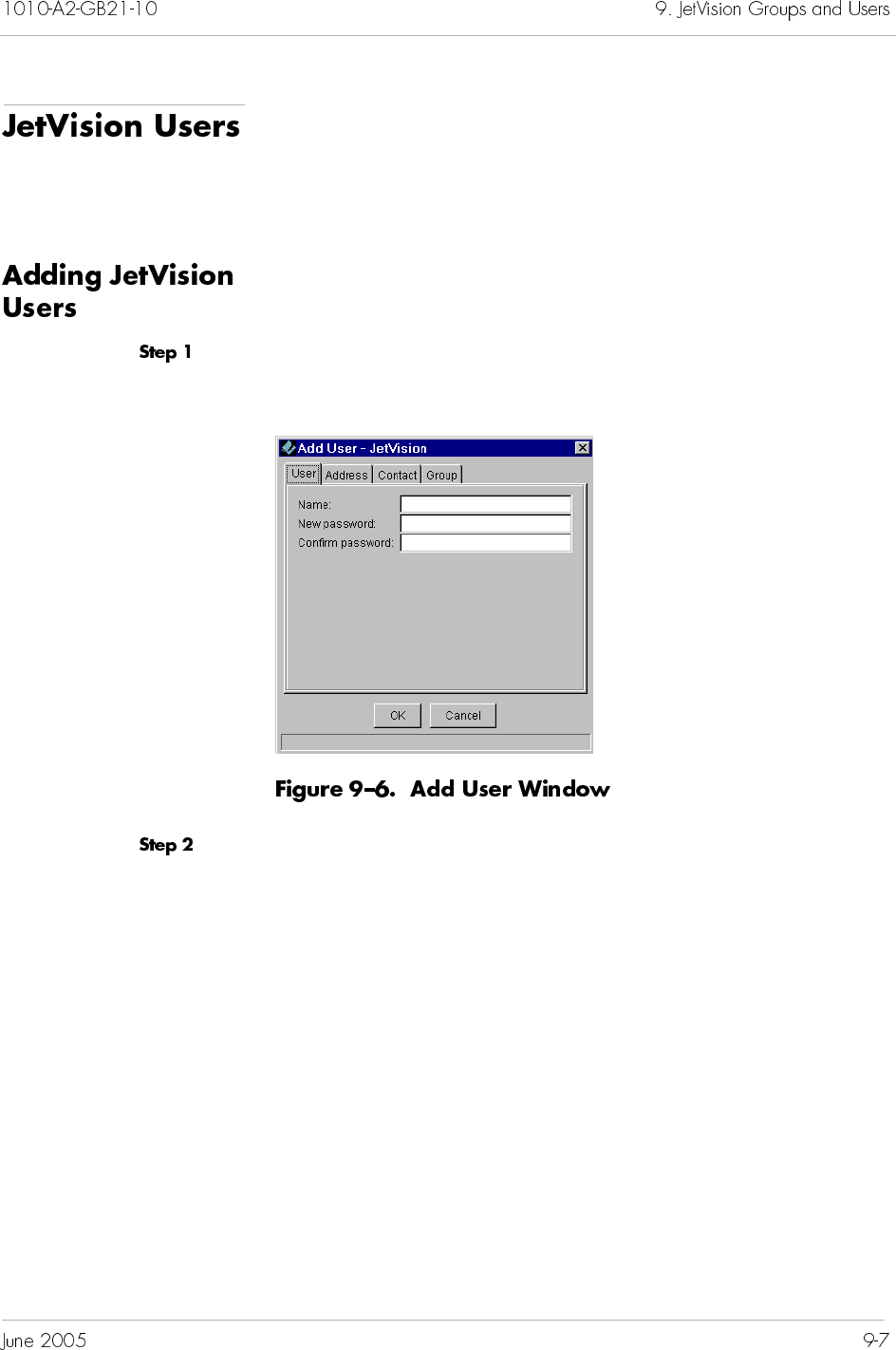
When creating a JetVision user, you assign that user to the
appropriate JetVision group. JetVision groups contain operational
profiles that the users perform. You can assign a user to multiple
groups.
To add a JetVision user:
Select Create JetVision User from the Services menu. The
Add User window appears (Figure 9–6).
Enter the following user information in their respective fields.
Name: user log in name (up to 16 alphanumeric characters)
Password: up to 16 alphanumeric characters
Re-enter the password
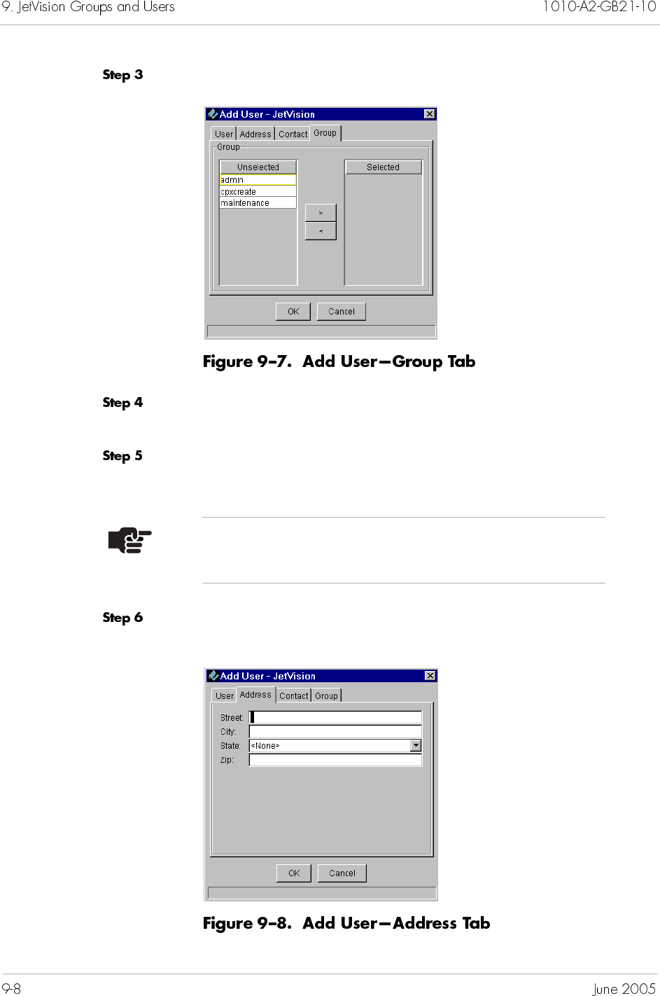
Click Group. The Group information fields appear (Figure 9–7).
Select one or more groups for this user from the Unselected list
in the Group field.
Move each selected user group to the Selected list by clicking the
right-arrow (>).
Click Address. The Address information fields appear
(Figure 9–8).
Note
The address and contact information are optional.
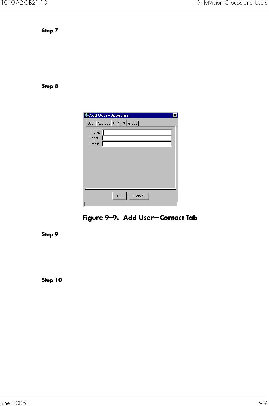
Enter the following optional information (up to 32 characters):
Street: user’s street number and name
City: user’s city
State: select from the drop-down list
Zip: user’s zip code
Select Contact. The Contact information fields appear
(Figure 9–9).
Enter the following optional information:
Phone: user’s phone number (up to 16 characters)
Pager: user’s pager number (up to 32 characters)
Email: user’s e-mail address (up to 32 characters)
Click OK to add this user.
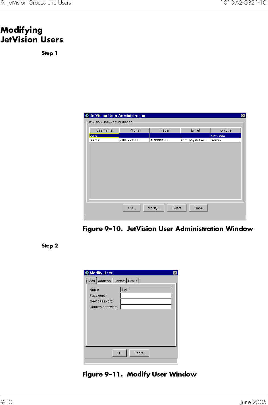
To modify a JetVision user’s information:
Select JetVision User Administration from the Services
menu. The User Info window appears (Figure 9–10).
From this window, you can also
add a new user (page 9-7)
delete an existing user (page 9-11)
Select the user whose information you want to modify, then click
Modify. The Modify User window appears (Figure 9–11).
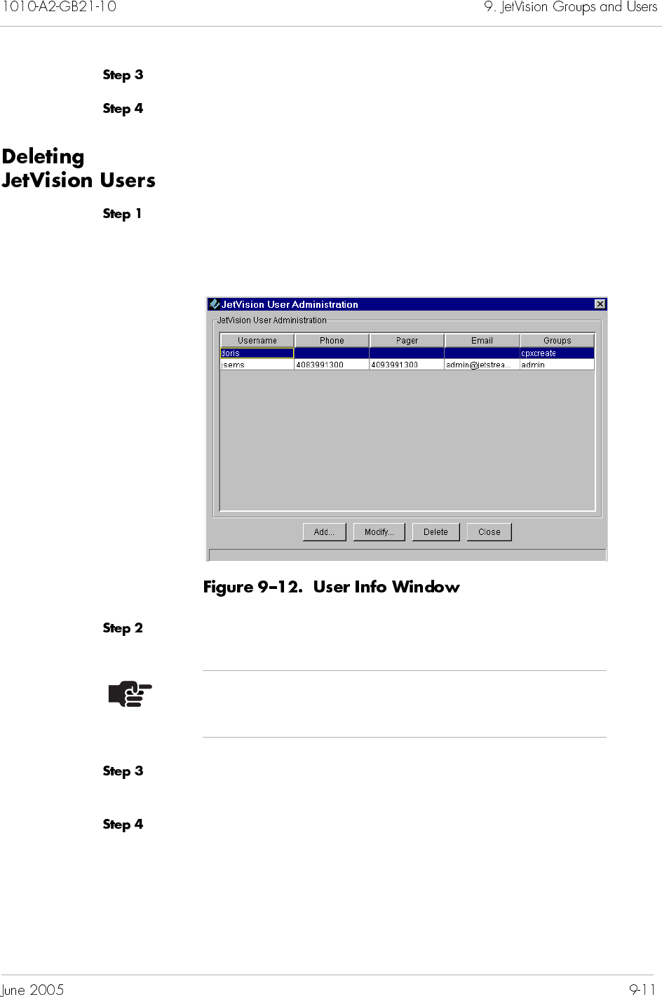
Modify the fields in any of the Modify User tabs.
Click OK to accept the changes.
To delete a JetVision user:
Select JetVision User Administration from the Services
menu. The JetVision User Administration window appears
(Figure 9–12).
Select the user that you want to delete.
Click Delete. A prompt appears, asking if you want to delete the
selected user.
Click Yes to delete the user.
Note
jsems is the JetVision default user and cannot be deleted.
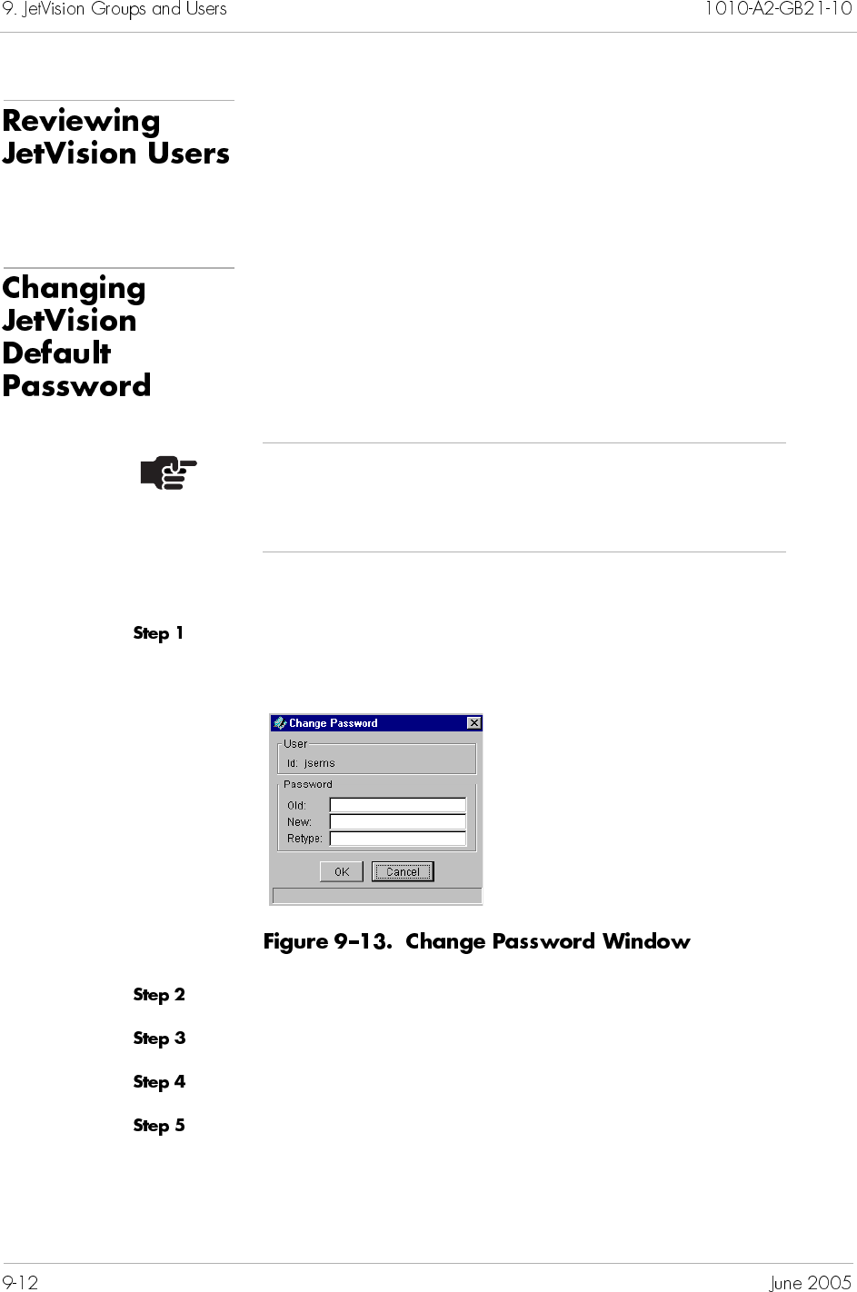
To review the JetVision users that you have created, select
JetVision User Administration from the Services menu.
The JetVision User Administration window (User Info Window on
page 9-11) appears, displaying the user information.
This section provides instructions to change the default password.
To change another user’s password, refer to Modifying JetVision
Users on page 9-10.
To change the default password:
Select Change JetVision User Password from the Services
menu. The Change Password window appears (Figure 9–13).
Type your old password.
Type your new password.
Retype your new password again.
Click OK to change your password.
Note
Changing the default password requires that you have
Admin privileges.
This chapter provides instructions on how to administer CPX-1000
users. This chapter includes the following tasks:
Creating or adding CPX-1000 users (page 10-2)
Modifying CPX-1000 users (page 10-4)
Deleting CPX-1000 users (page 10-6)
Reviewing CPX-1000 users (page 10-6)
When you initially configure a CPX-1000, you log on to the
CPX-1000 using the default CPX-1000 user ID (cpxuser) and
password (cpxuser). To restrict access to the CPX-1000, you can
use JetVision to change the CPX-1000 user ID, password, and
define the user operational privileges.
Each CPX-1000 comes with three groups that define the tasks that
users can perform (Table 10–1). You can create up to 17 users per
CPX-1000.
Admin Full read-write access. This group can
perform all operations; can add, modify,
and delete all users.
Operations Full read-write access. This group can
perform all operations, but cannot add,
modify, and delete other users.
Reports Read-only access.
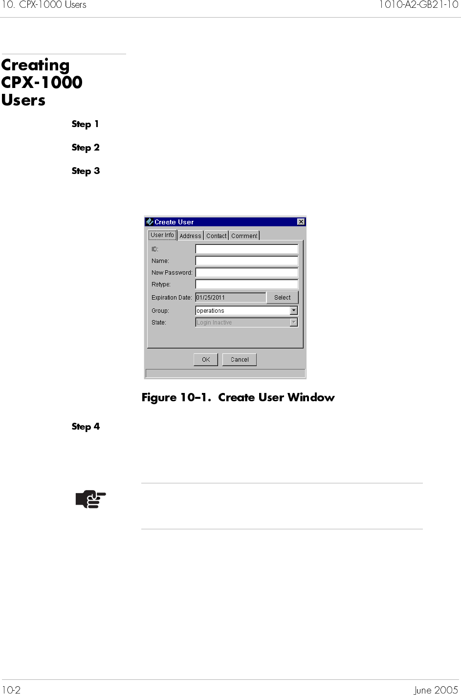
To create a CPX-1000 user:
Select the network in which the CPX-1000 reside.
Select a CPX-1000 from the Tree view.
Select Create CPX-1000 User from the Services menu. The
Create User window appears (Figure 10–1).
Enter the user information (up to 32 alphanumeric characters) in
their respective fields. (The default for the expiration date is 10
years from the date when this user is created.)
Note
The address, contact, and comments fields are optional.
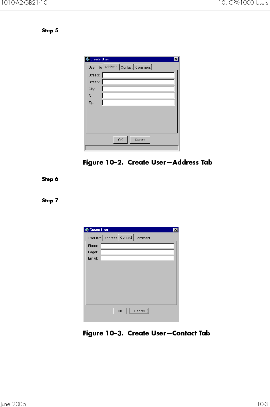
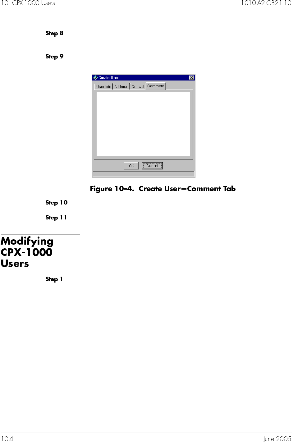
Type the optional contact information (up to 32 alphanumeric
characters) in their respective fields.
Click Comments. The Comment field appears (Figure 10–4).
.
Type any comments related to the user.
Click OK to create the CPX-1000 user.
To modify a CPX-1000 user:
Select CPX User Administration from the Services menu. The
Update User Information window (Figure 10–5) appears.
From this window, you can also
add a CPX-1000 user (page 10-2)
delete a CPX-1000 user (page 10-6)
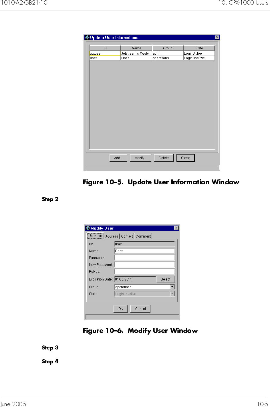
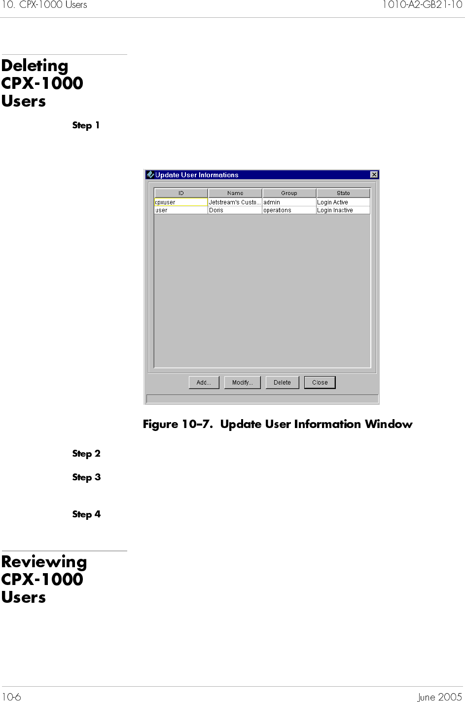
To delete a CPX-1000 user:
Select CPX User Administration from the Services menu. The
Update User Information window appears (Figure 10–7).
Select the CPX-1000 user that you want to delete.
Click Delete. A prompt appears, asking if you want to delete the
selected CPX-1000 user.
Click Yes to delete the CPX-1000 user.
To review the CPX-1000 users that you have created, select CPX
User Administration from the Services menu. The Update
User Information window (Figure 10–7 on page 10-6) appears,
displaying the user information.

Reports generated by JetVision can be viewed with any Web
browser. JetVision provides a default user ID and password
(jsreport) to view reports, both of which can be modified. This
chapter provides instructions for the following tasks:
Modifying the Apache user ID and password (page 11-2)
Adding users to Apache (page 11-2)
Deleting users from Apache (page 11-2)
Note
Because the Apache Web server is included with the
JetVision application, it is used throughout this section.
To modify a user ID and password in the Web server:
Open a console window and change the directory to the Apache’s
“bin” directory.
For Windows, type
CD C:\Jetstream\Apache1312\bin
For Solaris, type
CD /opt/Jetstream/Apache1312/bin
Invoke the Apache utility to change the password.
Syntax for Windows,
htpasswd.exe –bc <userfile><loginid><password>
Syntax for Solaris,
htpasswd –bc <userfile><loginid><password>
Where
Note
We recommend that you have an understanding of basic
Web security, such as login authentications, when
interacting with the Web server.
–b indicates don’t prompt the user for the
password
-c indicates to create a new User File; use
only if you want to overwrite any existing
users information.
<userfile> an ASCII file that keeps track of the user
ID and encrypted password
<loginid> a login user ID
<password> a login password
Example on Windows,
htpasswd.exe –b C:\Jetstream\Apache1312\users
jsreport js123
Example on Solaris,
htpasswd –b /opt/Jetstream/Apache1312/users
jsreport js123
To add users to the Apache Web server:
Change the directory to <JetVision Server>\reports. For example,
C:\Jetstream\emsserver_2.5\reports
Locate the.htaccess file, edit the line that reads “require user
jsreport” to “require user jsreport newuser.”
Where
newuser is the new user ID.
Proceed as steps 1 and 2 in Modifying User ID and Password on
page 11-2 to add a user to the Apache Web server.
Note
When adding multiple users, make sure to put a space
between each new user.

To delete users from the Apache Web server:
Open a console window and change to the Apache’s root directory.
In Windows, for example,
CD C:\Jetstream\Apache1312
In Solaris, for example,
cd /opt/jetstream/apache1312
Locate the user file that was created initially (for example, “users”).
Open the “users” file by using a text editor.
For Windows, use notepad
For Solaris, use vi
Delete the line that is associated with the user ID you want to
delete.
Change the directory to <JetVision Server>\reports. For example,
In Windows, for example,
C:\Jetstream\emsserver_2.5\reports
In Solaris, for example,
cd /opt/jetstream/emsclient_v25/reports
Locate the.htaccess file, edit the line that reads “require user
<namedelete> <namedelete> <name> <name>” to “require user
<name> <name>.”
Where <namedelete> is the deleted user, and <name> is the
remaining user.

This chapter provides alarms information and instructions to
customize alarm filters to view both active alarms and historical
data. This chapter includes these topics:
Alarm indicators and alarmed elements (page 12-1)
Alarm browsers (page 12-4)
Customizing alarm filters (page 12-4)
Viewing active alarms and historical data (page 12-7)
Deleting alarm filters (page 12-8)
JetVision monitors both the active alarms and historical data.
Active alarms are current alarms that are updated dynamically.
JetVision displays up to 1000 active alarms and/or events from the
Oracle database.
Historical data are cleared alarms. The historical data buffer size is
determined during JetVision installation (default is 150 MB). You
can increase the buffer size (Chapter 15, Maintenance) and/or
adjust the historical data disk threshold (Chapter 17, InfoCenter
Services).
Refer to Appendix C, Alarm Summary, for a list of alarm
messages.
When alarms are detected, they can be viewed in several areas:
Geographic Map, Network Map, Tree View, and Shelf View. As
shown in Figure 12–1, network alarms are displayed as colored
ovals that appear on the top-right side of the menu bar. Each color
indicates the severity of the network alarm. A number displayed
inside the oval indicates the number of alarms reported for that
level of severity.
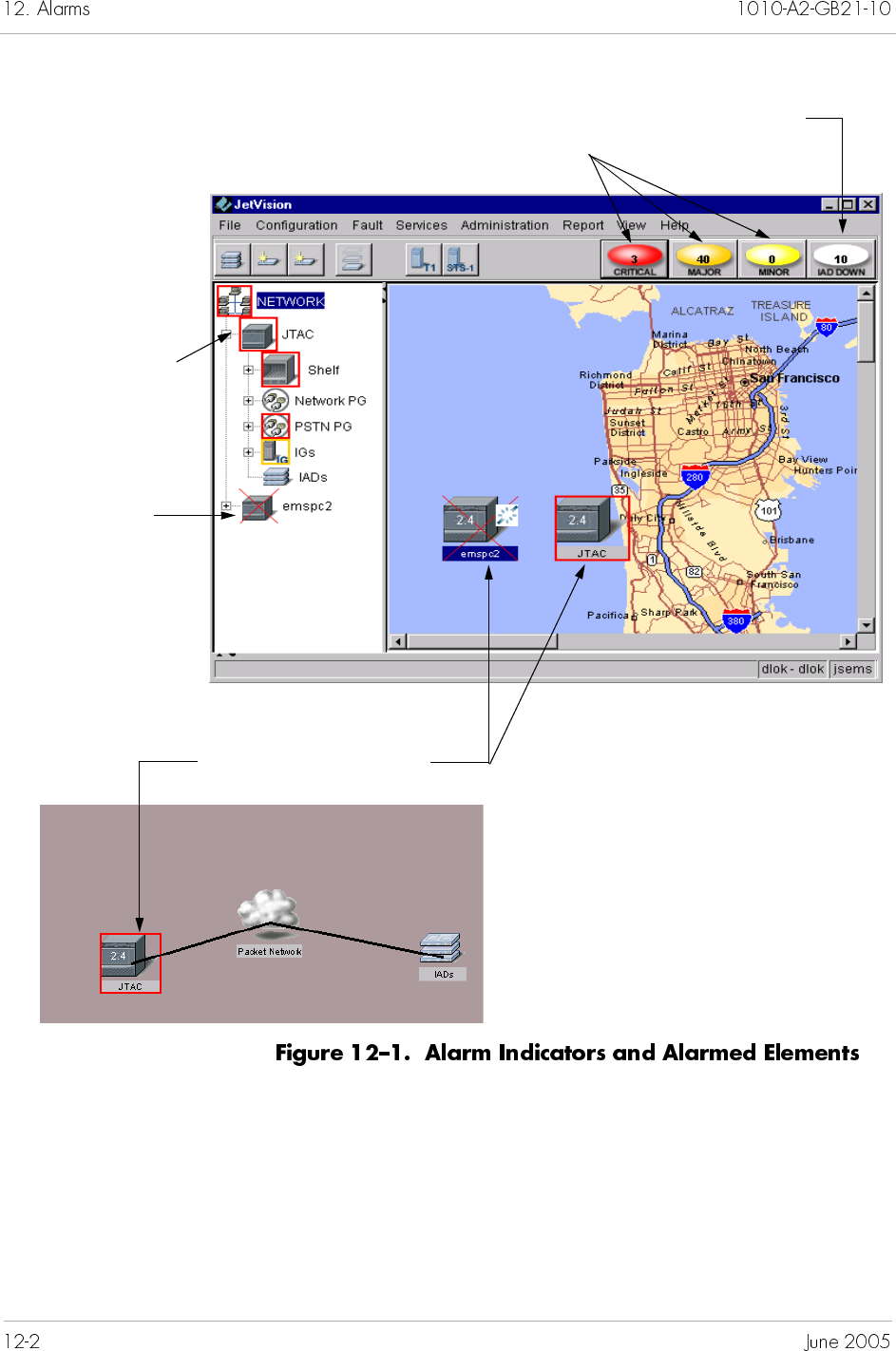
In the Tree View, a propagated alarm is indicated as a colored
boundary around an icon (e.g., CPX-1000, shelf, or card). A source
alarm is displayed as an “X” drawn over the managed object. The
color of the boundary or “X” indicates the severity of the alarm.
Colored boundary indicating a
“propagated” alarm
Number inside indicating number
of network reported alarms
N
um
b
er
i
ns
id
e
i
n
di
cat
i
ng
number of IAD down
Colored boundary
indicating a “propagated”
alarm
Colored “X”
indicating a source
alarm
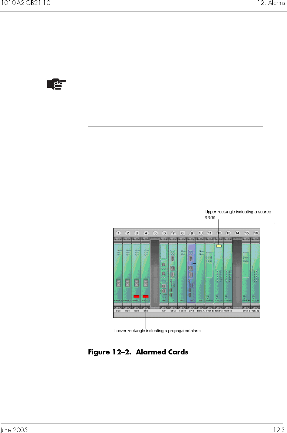
Typically, the Interface Groups are created without a physical
connection. As a result, the Interface Groups are alarmed as they
are created, then cleared when they are connected to the host Class
5 switch.
The Shelf View (Figure 12–2) displays alarm indicators on
individual MP, CP, and line cards. Indicators appear as colored
rectangles in the upper and lower regions on the card. The upper
rectangle indicates a source alarm; the lower rectangle indicates a
propagated alarm.
Table 12–1 describes the alarm severity associated with each color.
Note
Network alarms propagate from an originating source
up to its CPX-1000, which reports the alarm. The
alarmed element shows the most severe alarm
condition.
JetVision provides three methods (called “browsers”) to view
alarms and event:
active alarm browser displays active (current) alarms and is
updated dynamically
historical alarm browser displays both past and cleared alarms
event browser displays the events information
Each browser provides filtering capability so that you can define
the criteria for which the browser displays alarms.
To customize an alarm filter for an alarm browser:
Click the Network icon or a CPX-1000 icon in the Tree View.
Select a browser type from the Fault menu. A browser window
appears (Figure 12–3, an active alarm browser is shown).
Red (Critical) A severe, service-affecting condition has occurred; require immediate
corrective action regardless of the time of day or day of the week.
Yellow (Major) A serious disruption of service or a malfunction or failure of important
circuits has occurred; require immediate corrective action and response
to restore or maintain system capabilities.
Light yellow
(Minor)
A non-service-affecting condition has occurred; no immediate
corrective action is necessary.
White (IAD Down) An IAD is no longer in service; require immediate corrective action.
Type the name of the filter in the Name field.
Select the start and end dates (e.g., month, day, and year) from
their respective drop-down lists.
– Or –
Click Select to enter your dates from the calendar.
Type the start and end times in their respective fields or use the
drop-down lists to select the time.
Select the filtering criteria by clicking the checkboxes in the Alarm
Severity area, or click Select All to select all criteria.
Click OK.
To create event filters:
Proceed as Steps 1 and 2 in Customizing Alarm Filters on page
12-4.
Click . and the Event Filter window appears (Figure 12–5).
Select the start and end dates (e.g., month, day, and year) from
their respective drop-down lists.
– Or –
Click Select to enter your dates from the calendar.
Type the Event ID (this is a unique sequence ID).
In the IAD Download Type section, place a check in the boxes for
the types of download events that you wish to view.
Click OK.
To view alarms from a customized filter:
Click the Network icon or a CPX-1000 icon in the Tree View.
Select the alarm browsers type from the Fault menu. The browser
window appears, displaying alarms per your filtering criteria.
Select Active Alarm Browser to view the current alarms
Select Historical Alarm Browser to view current and past
alarms
Select Event Browser to view the current event information
Click . The Alarm Filter Manager window appears
Note
Clicking the Network icon displays current alarms for
the entire CPX-1000 network. Clicking a CPX-1000 icon
displays alarms for that CPX-1000.
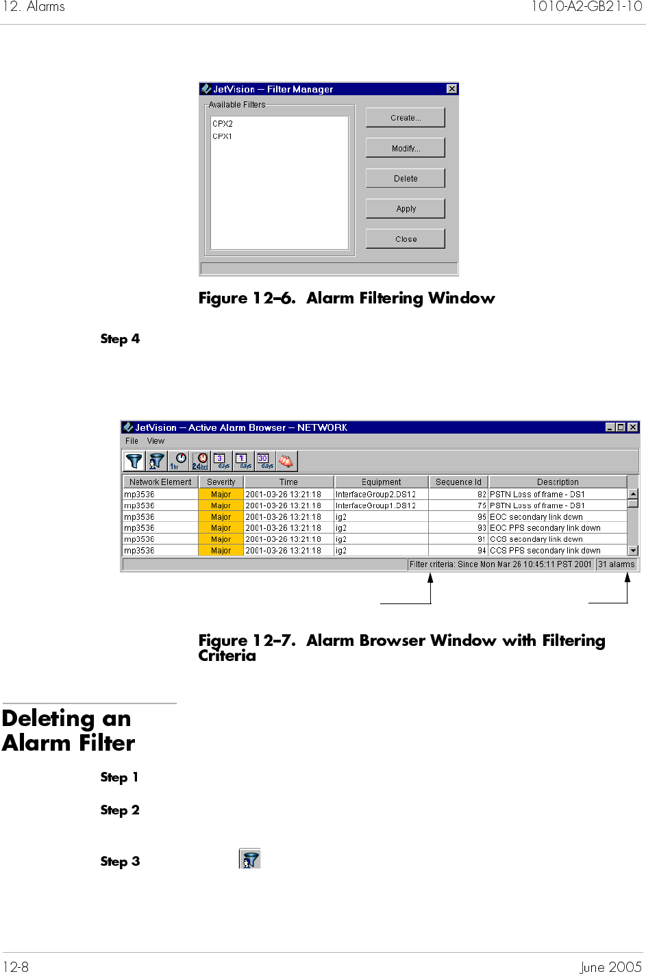
Select the desired filter and click Apply. The browser window
displays the alarms based on your criterion, as indicated in the
status bar (Figure 12–7).
To delete an alarm filter:
Click on the Network icon or a CPX-1000 icon in the Tree View.
Select the alarm browser types from the Fault menu. The browser
window appears.
Click . The Filter Manager appears (Figure 12–6 on page 12-8).
Number of alarms displayed
Filtering criteria
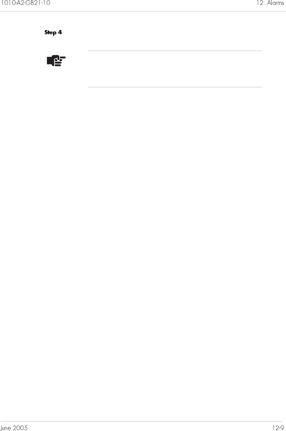
Select the filter that you want to delete and click Delete.
Note
JetVision provides no confirmation for deletion. Once
you click delete, the selected filter is deleted.


JetVision provides a variety of informational reports that are used
for monitoring and analyzing the CPX-1000 managed elements.
This chapter provides instructions on how to generate and view
reports. This chapter includes these topics:
Generating and viewing reports (page 13-2)
Alarm Report (page 13-3)
Historical Alarm Report (page 13-4)
Action Report (page 13-5)
Event Report (page 13-6)
IAD Report (page 13-6)
Card Report (page 13-7)
CPX Report (page 13-8)
Interface Groups Report (page 13-8)
CRV Report (page 13-9)
Protection Groups Report (page 13-10)
Reports generated by JetVision can be viewed with any Web
browsers. JetVision provides a default user ID and password
(jsreport) to view reports, both of which can be modified. You
can also add users to and delete users from the Apache Web server
(Chapter 11, Web Browser Users).
To generate or view a report:
Click the Network icon or CPX-1000 icon in the Tree View.
To set the viewing criteria for Alarm, Historical Alarm,
Action, and Event reports, continue with Step 2.
For other reports, proceed to Step 5.
Select a report type from the Report menu. The Report Generator
window similar to Figure 13–1 appears.
Click Select to set the start and end date of the reports.
Note
The Action and Event logs have slightly different GUI
appearance.
Note
Skip Step 4 for the Action Log Report and Event Report.
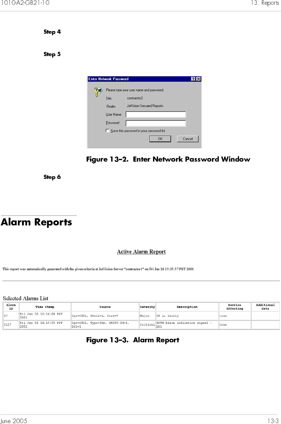
Select the filtering criteria by clicking any or all of the checkboxes
in the Alarm Severity area.
Click OK. The Enter Network Password window appears,
(Figure 13–2).
Type the user name and password in the respective fields (default
is jsreport) and click OK. The report is displayed in your Web
browser.
Alarm reports (Figure 13–3) provide information about alarms
reported by the CPX-1000 managed domain.
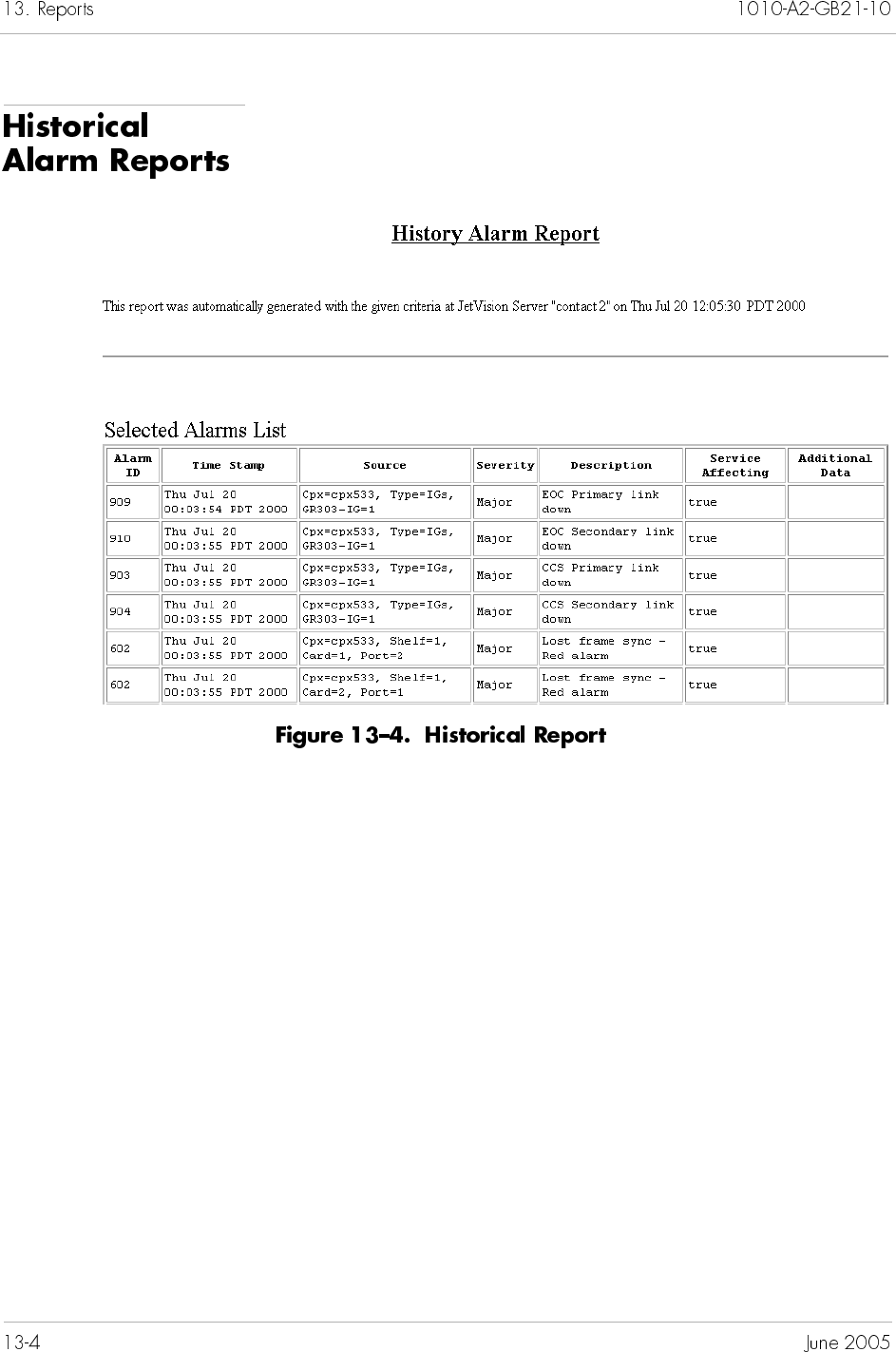
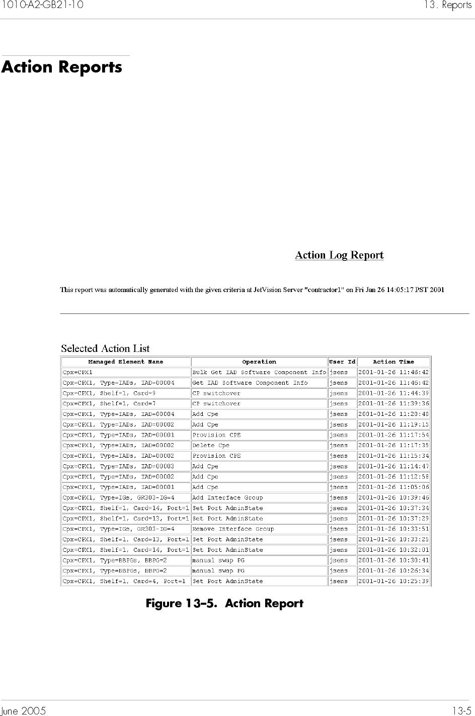
Action reports (Figure 13–5) provide information about JetVision
operations that were performed on a CPX-1000 managed element.
You can use this report to list all operations for a specific time
interval or to customize the report, specifying which operation(s)
you want displayed. Operations that can be included:
Add Network Element
Add CPE-(IAD)
Add IAD Profile
Add/Modify IG
Add New User
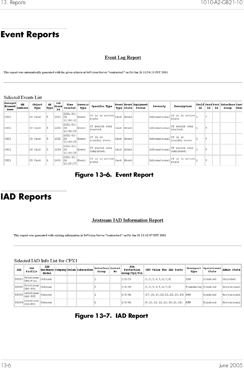
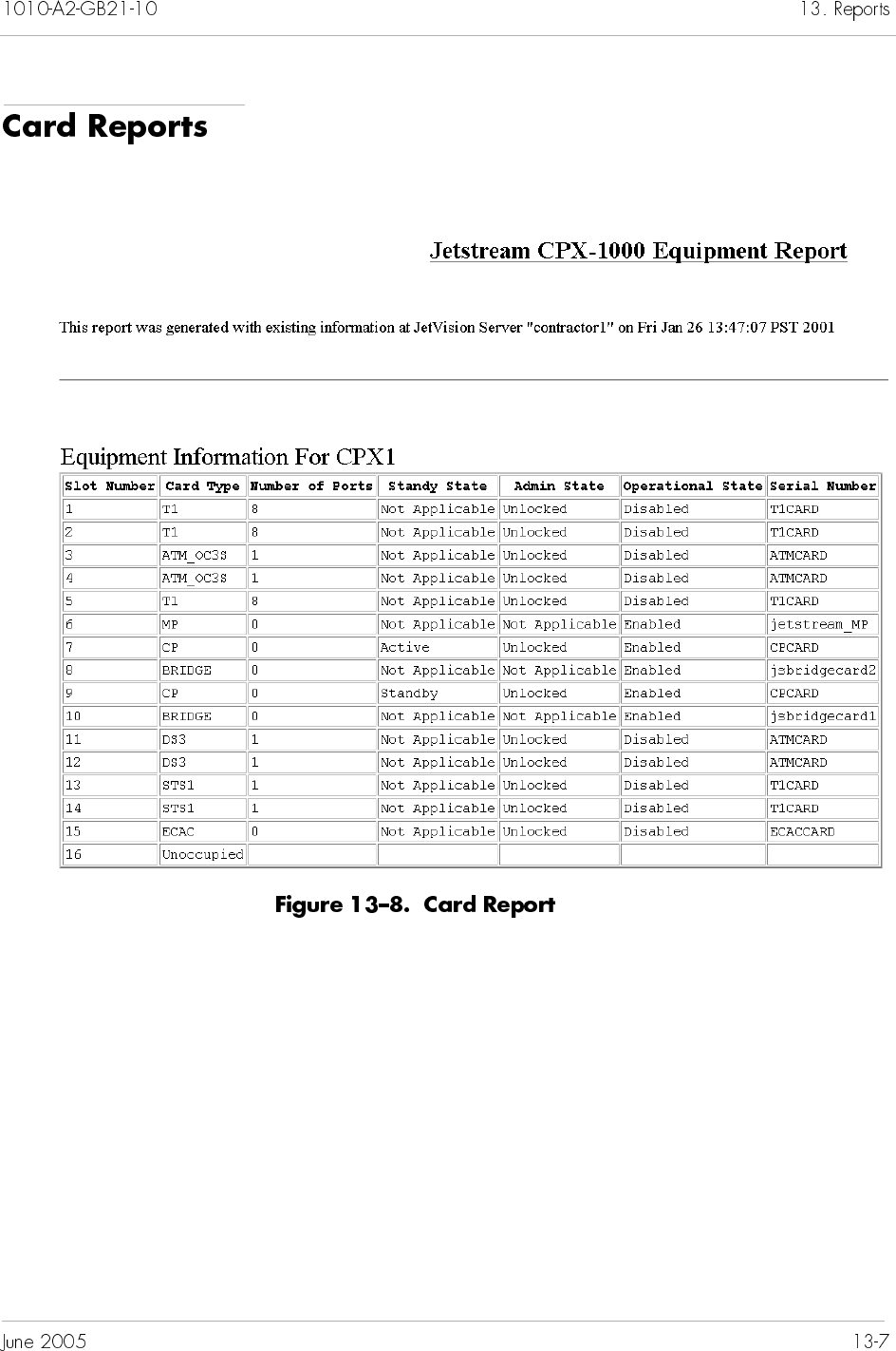
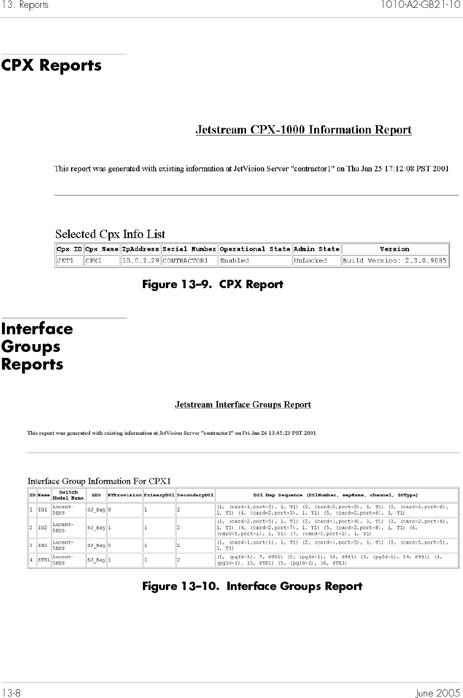
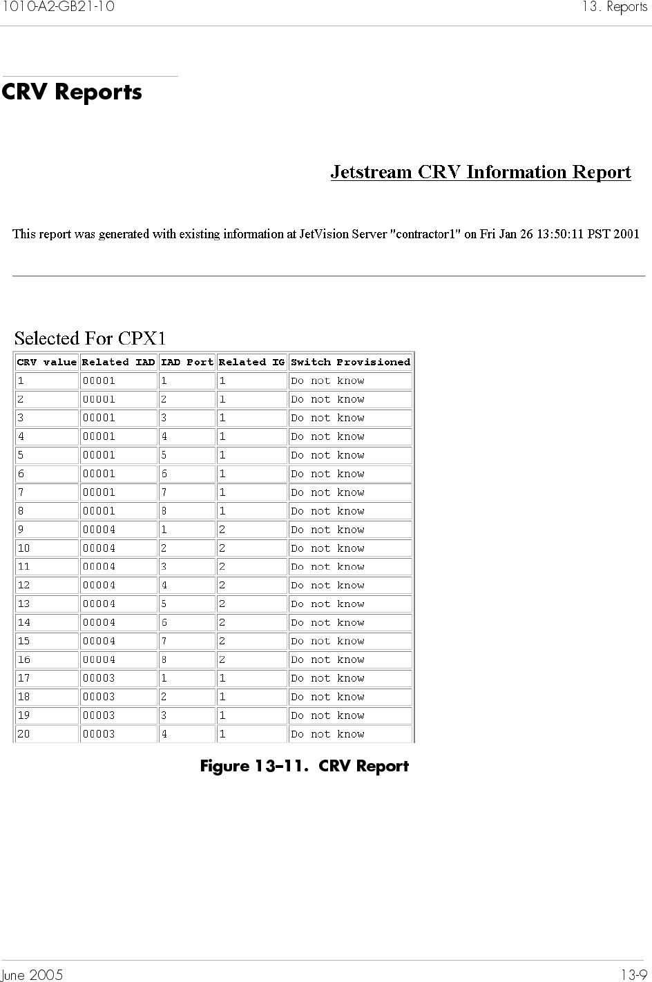
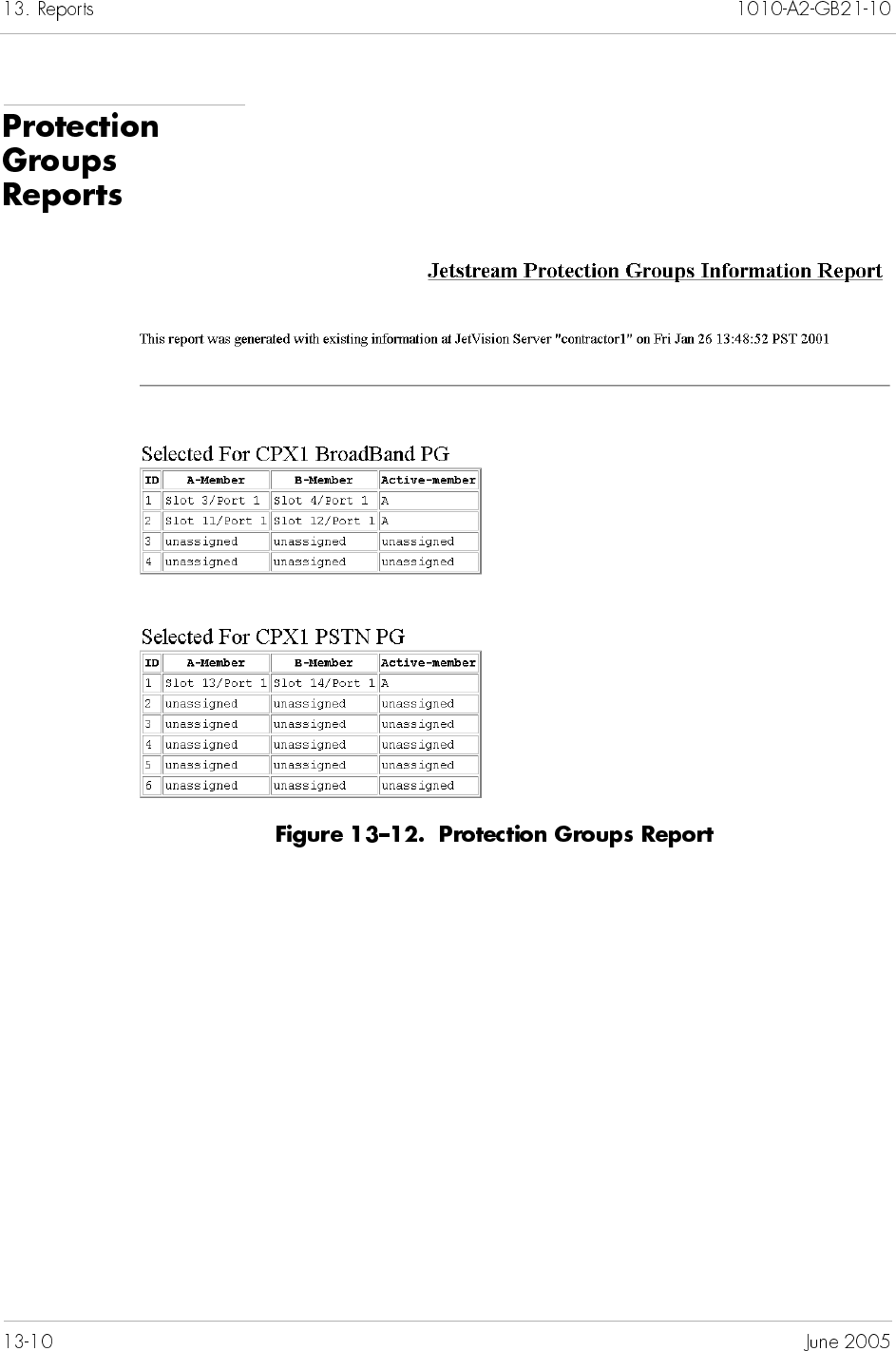

JetVision provides two monitors to analyze the performance of
CPX-1000: real-time performance monitoring and historical data
monitoring. This chapter provides instructions to poll various
statistics for both the real-time performance monitoring and
historical data monitoring.
The real-time monitoring includes these elements:
Interface Groups (page 14-7)
Network Protection Group (page 14-8)
PSTN Protection Group (page 14-9)
STS 1 ports (page 14-10)
DS-1 ports (page 14-10)
IADs (page 14-11)
CPX-1000, T-1 ports, CP, and MP card (page 14-13)
The historical data monitoring includes these elements:
MP card (page 14-18)
CP card (page 14-18)
DS1 lines or paths (page 14-19)
Graphs display absolute and relative values. Clicking Show marks
the initial absolute value. Clicking Reset freezes the absolute
value, and starts marking new relative values. Subsequent resets
add the last relative value to the absolute value, and start marking
new relative values (Figure 14–1). These values are in minutes.
Only online graphing is available for current data. Online graphs
are charted over a user-defined interval, up to a maximum of
fifteen minutes.
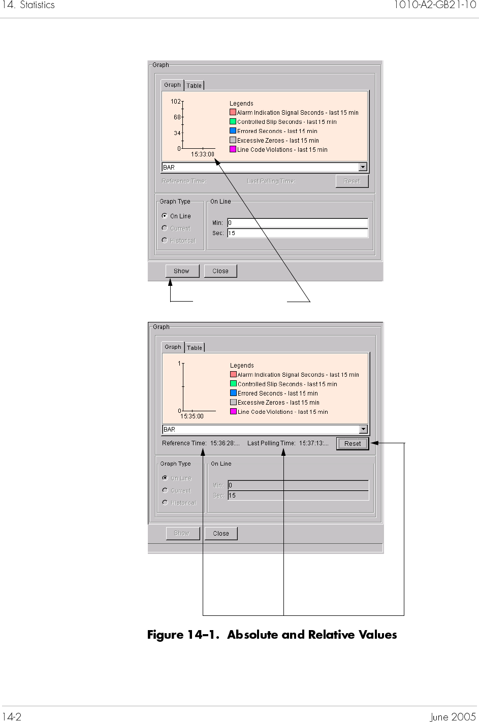
Click Show to mark the
initial absolute value
Absolute Relative
Click Reset to displa
y
the relative value
Table 14–1 lists error and performance statistics that you can graph
for various CPX-1000 managed entities. The statistics that are
available for you to graph depend on the currently selected
network element. For example, if you select a port, that port
statistics will be available for you to graph. Refer to Appendix B,
Statistics Descriptions, for definitions of errors and performace
statistics.
CPX-1000 Assembly errors
Blocked incalls
Blocked outcalls
CRC errors
IADs down
Non echo calls
Rejected compress calls
Uncompressed calls
Unsuccessful calls insufficient
bandwidth
Active calls
Active compress calls
Ctrl cells rcvd
Ctrl cells sent
Cumulative compress calls
Cumulative outcalls
IADs Provisioned
IADs Up
Peak calls
MP card Not applicable Available physical memory (MB)
CPU usage (percent)
Disk size (MB)
Disk usage (MB)
Disk usage (percent)
Free disk space (MB)
Free page size (MB)
Page size (MB)
Page usage (MB)
Page usage (percent)
Physical memory (MB)
Physical memory usage (MB)
Physical memory usage (percent)
CP card Not applicable Percent CPU used
Percent flash used
Percent memory used
Interface Group CCS PPS to Primary
CCS PPS to Secondary
EOC PPS to Primary
EOC PPS to Secondary
Timer timeouts
CCS PPS msgs rcvd
CCS PPS msgs sent
CCS msgs rcvd
CCS msgs sent
EOC PPS msgs rcvd
EOC PPS msgs sent
EOC msgs rcvd
EOC msgs sent
DS-1 Alarm Indication Signal Seconds—
last 15 minutes
Bipolar Violations—last 15 minutes
Controlled Slips Seconds—last 15
minutes
Controlled Slips—last 15 minutes
Degraded Minutes—last 15 minutes
Errored Seconds—last 15 minutes
Excessive Zeroes—last 15 minutes
Line Coding Violations—last 15
minutes
Line Errored Seconds—last 15
minutes
Out Of Frame Seconds—last 15
minutes
Severely Errored Framing
Seconds—last 15 minutes
Severely Errored Seconds—last 15
minutes
Unavailable Seconds—last 15
minutes
DS0s in use
Network
Protection
Group
Not applicable Automatic switches
Manual switches
Switches to primary
Switches to secondary
PSTN Protection
Group
Coding Violations—Path
Errored Seconds—Path
Severely Errored Seconds—Path
Unavailable Seconds—Path
Not applicable
STS-1 Port Coding Violations—Line
Errored Seconds—Line
Severely Errored Seconds—Line
Unavailable Seconds—Line
Coding Violations—Section
Errored Seconds—Section
Severely Errored Framed Seconds—
Section
Severely Errored Seconds—Section
Not applicable
IAD Assembly errors
Blocked incalls
Blocked outcalls
CRC errors
I-Frames retrans
Invalid frames
MDL Error A–O
Non echo calls
OutOfSeq I-Frames
Rejected compress calls
Uncompressed calls
Unsuccessful calls insufficient
bandwidth
Active calls
Active compress calls
Cells rcvd
Cells sent
Ctrl cells rcvd
Ctrl cells sent
Cumulative calls
Cumulative compress calls
Frames rcvd
Frames sent
I-Frames rcvd
I-Frames sent
Peak calls
IAD Port Blocked incalls
Blocked outcalls
Active calls
Peak calls
Cumulative calls
ATM DS-3 Far end alarm indication
Far end receive failure
Loss of cell delineation
Loss of frame
Loss of signal
Out of cell delineation
Red count
Not applicable
ATM OC-3 AAL1 byte CRC errors
AAL1 byte parity errors
AAL1 byte seq errors
Clock generation failures
Correctable errors
OAM line AIS
OAM line RDI
OAM path AIS
OAM path RDI
Overrun counter rollover
Overrrun errors
Physical service
Pointer byte parity errors
Pointer byte range errors
Ref cells loss
Ref cells out of sync
Rx Utopia FIFO overrun
Rx Utopia overrun
SONET loss frame
SONET loss pointer
SONET loss signal
TDM master clocks absent
Tx bandwidth errors
TxFIFO overrun
Uncorrectable errors
Underrun counter rollover
Underrun errors
Cells rcvd
Cells sent
Open Rx VCs
Open Tx VCs
Open Rx Chans
Open Rx Inactive Chans
Open Tx Chans
Open Tx Inactive Chans
Interrupt count
Counter rollover
Cells rcvd in FIFO
Physical service
Cells rcvd by PHY
Cells sent by PHY
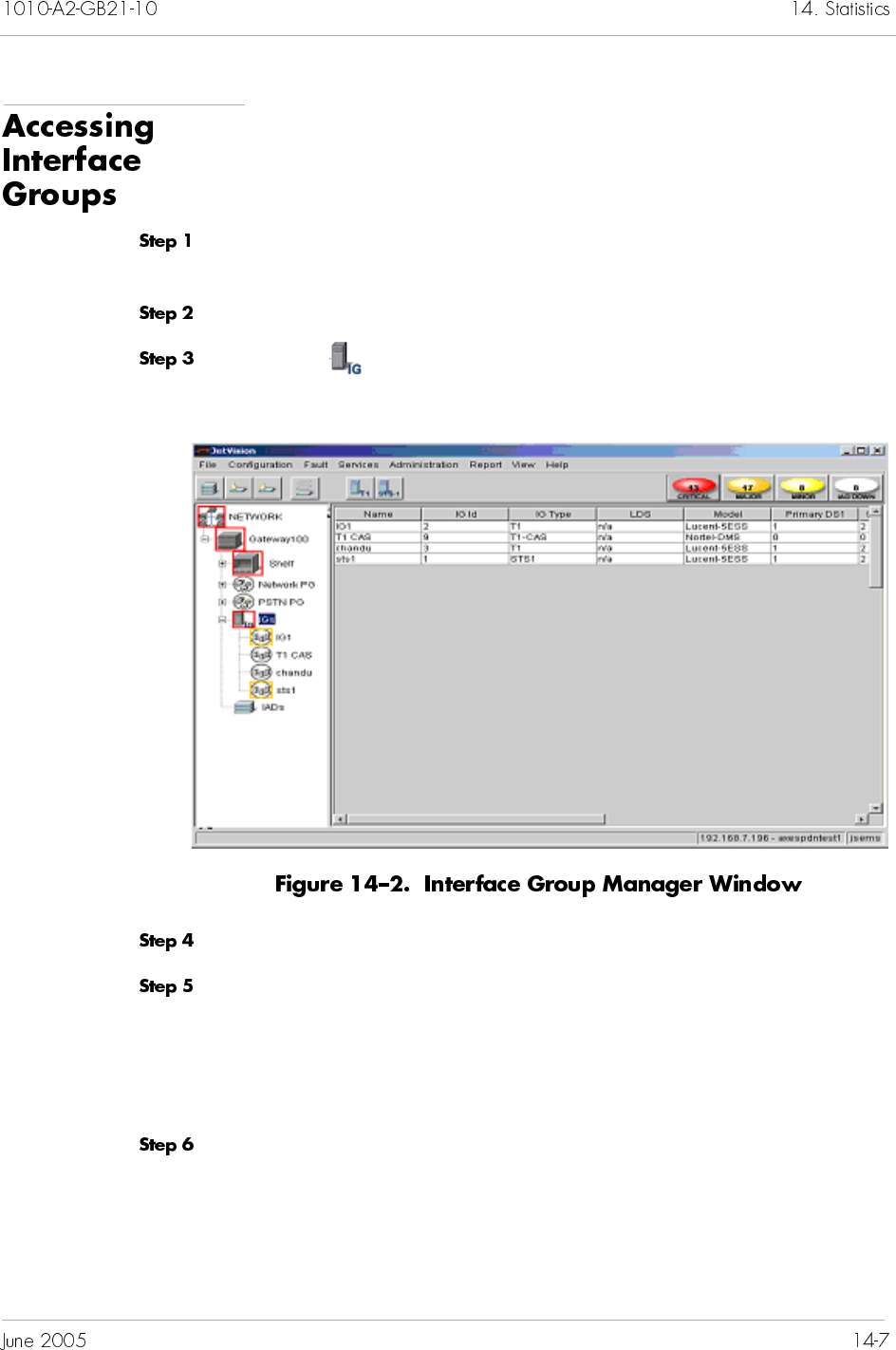
To access Interface Groups statistics:
Click the network icon from the Tree View where the CPX-1000
resides and expand the tree by clicking the + key.
Click a CPX-1000 and expand the tree.
Click on the Tree View to display the Interface Group list
(Figure 14–2).
Select the Interface Group on which you want to poll the statistics.
Select Error Graphs or Performance Graphs from the Report
menu.
– Or –
Right-click the highlighted selection and select the desired graphs.
Continue with Step 5 in Polling Real-time Statistics on page 14-13.
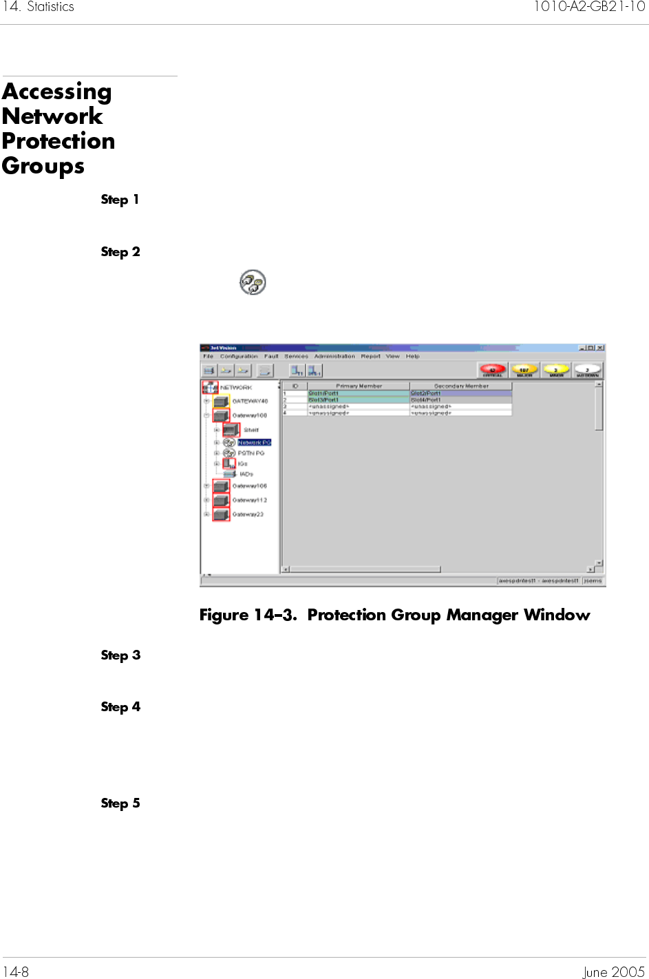
To access the network Protection Group statistics:
Click the network icon from the Tree View where the CPX-1000
resides and expand the tree by clicking the + key.
Click a CPX-1000 and expand the tree.
Click Network PG on the Tree View to display the
Protectionn Group list (Figure 14–3).
Select a Protection Group member on which you want to poll
statistics (only Performance statistics is available).
Select Performance Graphs from the Report menu.
– Or –
Right-click the highlighted selection and make your selection.
Continue with Step 5 in Polling Real-time Statistics on page 14-13.
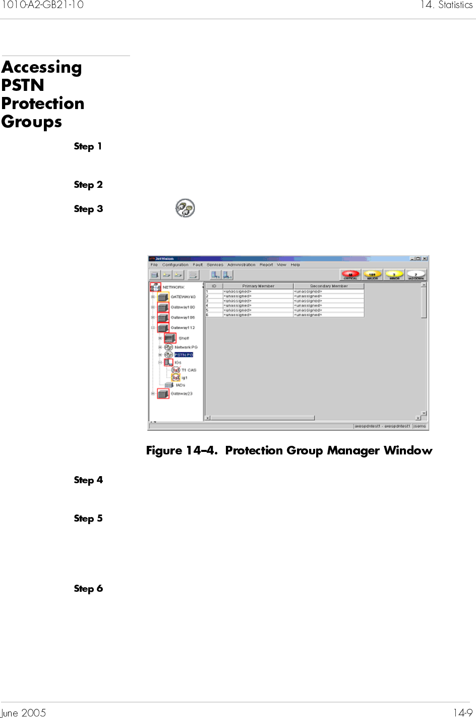
To access the PSTN Protection Group statistics:
Click the network icon from the Tree View where the CPX-1000
resides and expand the tree by clicking the + key.
Click a CPX-1000 and expand the tree.
Click PSTN PG on the Tree View to display the Protection
Group list (Figure 14–3).
Select a Protection Group member on which you want to poll
statistics (only Performance statistics is available).
Select Performance Graphs from the Report menu.
– Or –
Right-click the highlighted selection and make your selection.
Continue with Step 5 in Polling Real-time Statistics on page 14-13.
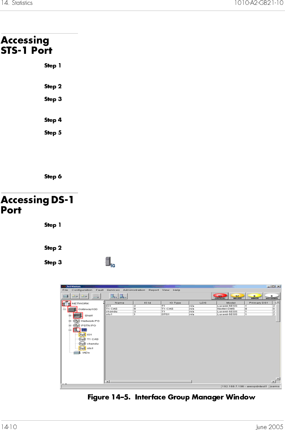
To access the STS-1 port statistics:
Click the network icon from the Tree View where the CPX-1000
resides and expand the tree by clicking the + key.
Click a CPX-1000 and expand the tree.
Click the Shelf icon associated with the CPX-1000 and expand
the tree.
Click a STS-1 card on which you want to poll statistics.
Click the desired port and select Line Error Graphs or
Section Error Graphs from the Report menu.
– Or –
Right-click the selected port and make your selection.
Continue with Step 5 in Polling Real-time Statistics on page 14-13.
To access the DS-1 port statistics:
Click the network icon from the Tree View where the CPX-1000
resides and expand the tree by clicking the + key.
Click a CPX-1000 and expand the tree.
Click on the Tree View to display the Interface Group list
(Figure 14–5).
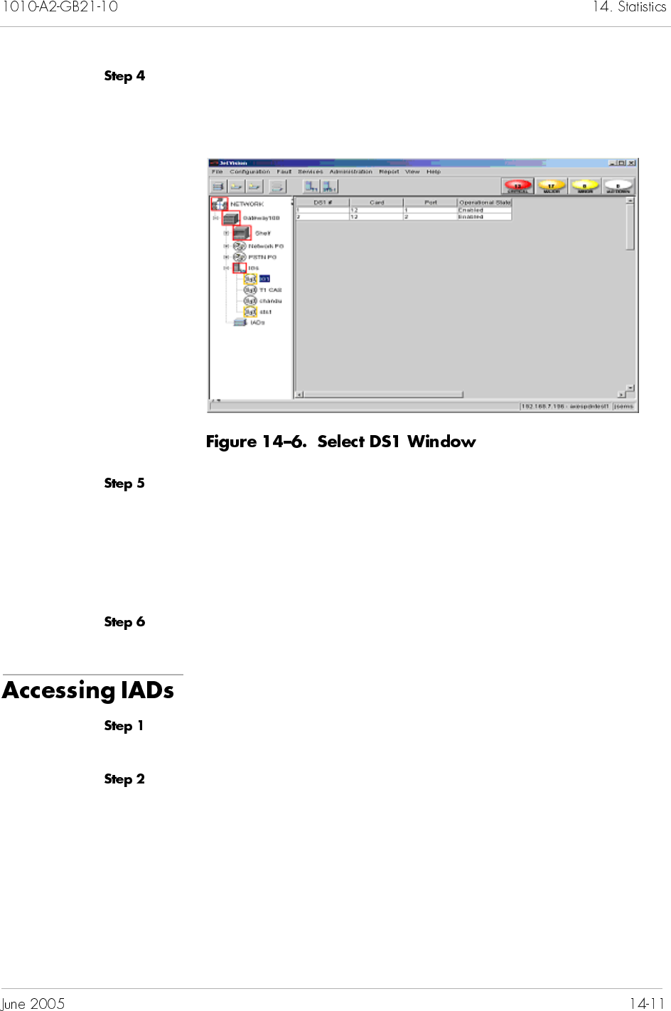
Select the Interface Group (from the Map or List View) on which
you want to poll the statistics. The Select DS1 window appears
(Figure 14–6).
Select the desired DS1 #, then select DS1 Error Graphs or DS1
Performance Graphs from the Configuration menu.
– Or –
Right-click the highlighted selection and select the desired graphs
from the pop-up menu.
Continue with Step 5 in Polling Real-time Statistics on page 14-13.
To access the IADs statistics:
Click the network icon from the Tree View where the CPX-1000
resides and expand the tree by clicking the + key.
Click a CPX-1000 and expand the tree.
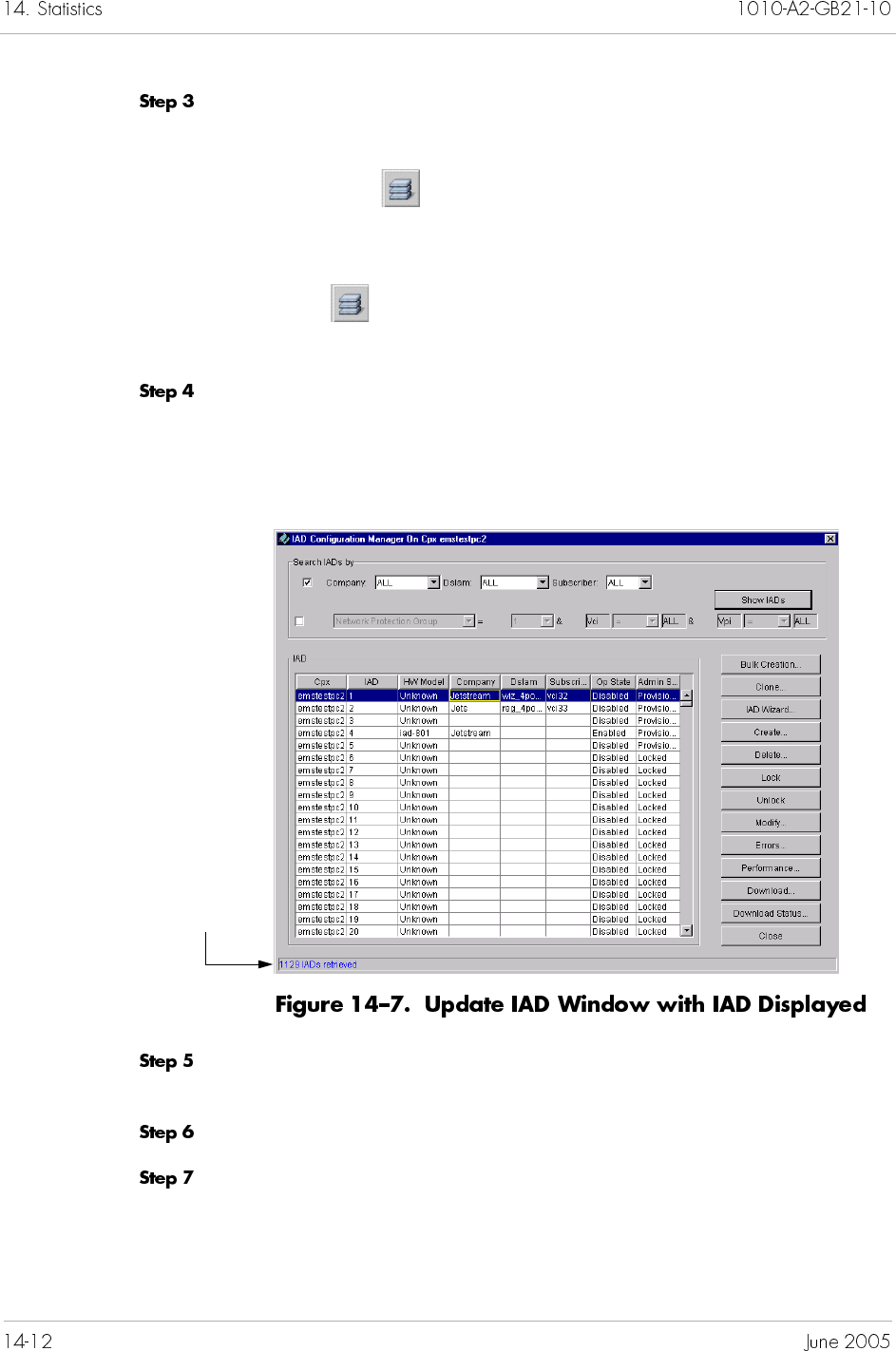
Select IAD Manager from the Configuration menu.
– Or –
Right-click on the Tree View or Map View and select IAD
Manager.
– Or –
Click on the toolbar.
The View/Update IADs window appears.
Click Show IADs. The View/Update IADs window appears
(Figure 14–7). The configured IADs are displayed, and a message
appears in the status bar indicating how many IADs have been
retrieved.
Select the IAD on which you want to poll statistics, the option
buttons are enabled.
Select Errors or Performance. The graphing window appears.
Continue with Step 5 in Polling Real-time Statistics on page 14-13.
Number of IADs
retrieved
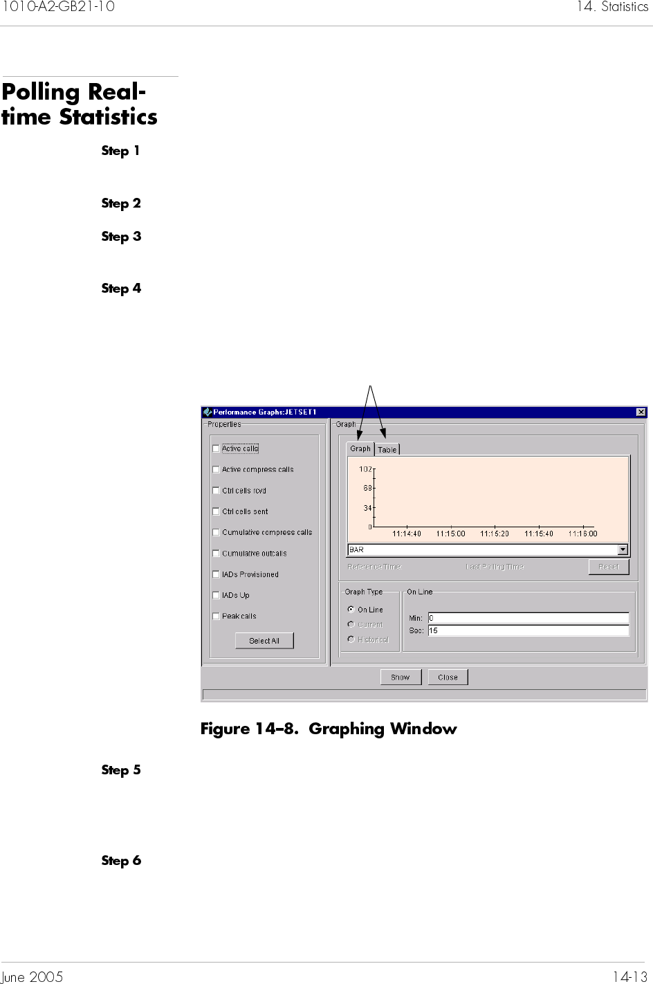
To poll statistics on CPX-1000, T-1 ports, CP, or MP card:
Locate the CPX-1000 by clicking the group icon from the Tree View
where the CPX-1000 resides.
Click a CPX-1000 and expand the tree.
Select the desired icon in the Tree View. For example, to poll
statistics on a port, select the port icon in the Tree View.
Select the type of graph from the Report menu or right-click the
appropriate icon. The graphing window similar to Figure 14–8
appears.
Select the items on which you want to poll statistics from the
Properties panel by clicking the adjacent box. Or click Select
All if you want to poll all items listed. (A maximum of 20
properties can be graphed at a time.)
Choose the type of graph you want to generate (format options are
a bar graph or a plot).
Graph format selections
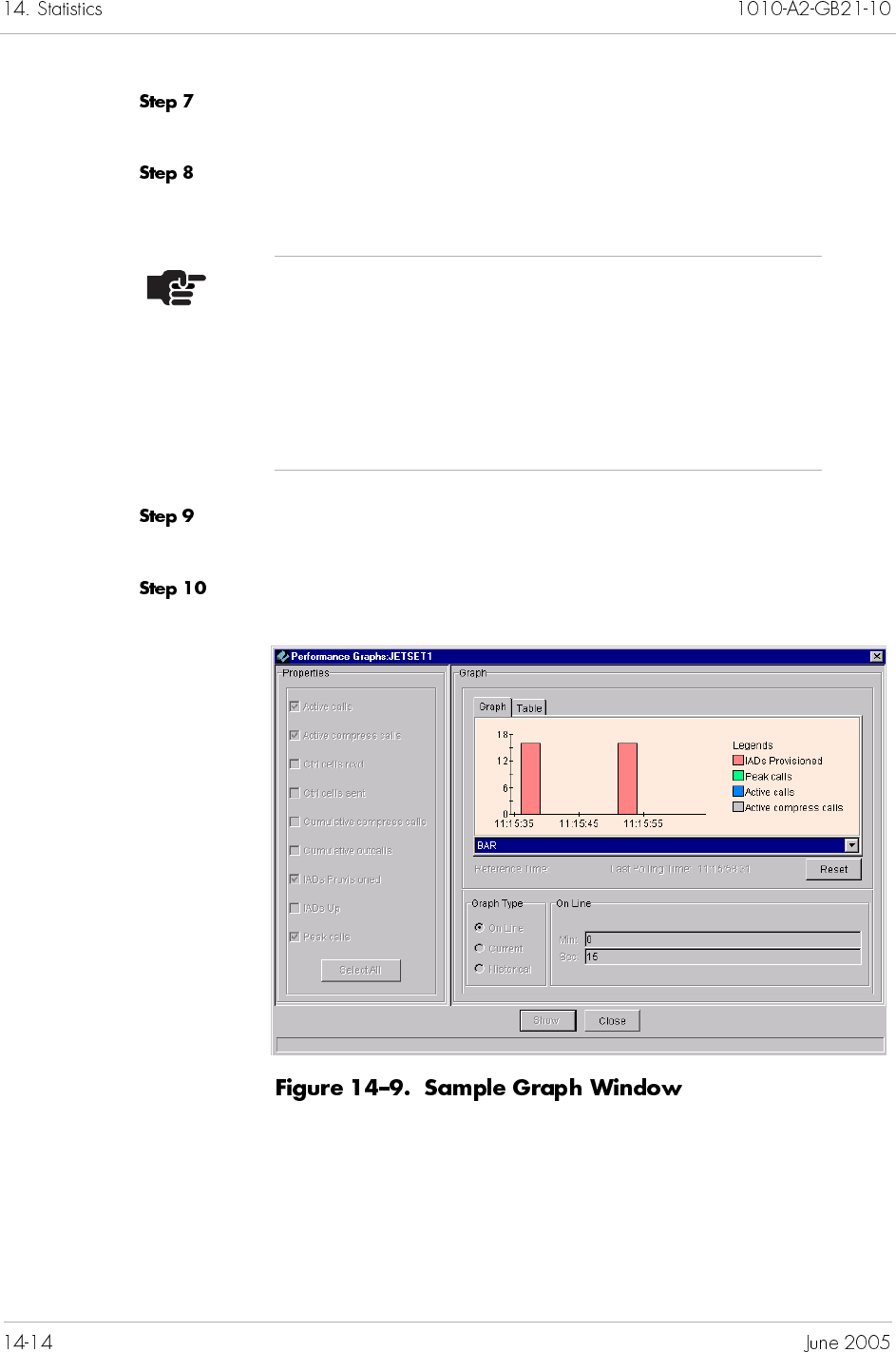
Choose the frequency of the data that will be graphed from the
options in the On Line panel (your option is 15 seconds).
Select a method to view your statistical presentation. Your options
are Graph or Table.
Click Show. JetVision displays the graph based on the options you
selected (Figure 14–9 and Figure 14–10).
Click Close to exit this window.
Note
Graphs display absolute and relative values. Clicking
Show marks the initial absolute value. Clicking Reset
freezes the absolute value, and starts marking new
relative values. Subsequent resets add the last relative
value to the absolute value, and start marking new
relative values.
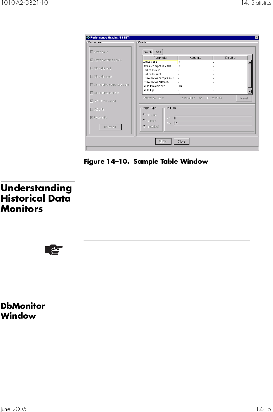
JetVision uses two tools to monitor historical data: DbMonitor
and Performance Management (PM) history. Both monitors start
simultaneously as JetVision Server. You can minimize these
console windows or keep them in the background, but do not
close them. Closing these windows will terminate the
corresponding application.
DbMonitor monitors JetVision Server disk usage, which includes
data size and report html files. It also gathers Oracle database
statistics so that Oracle can come up with optimal query execution
plans. When the data exceeds the high threshold limit, data are
truncated to the low threshold. When data is at the low threshold,
the data is purged in a FIFO (First In First Out) manner. Refer to
Chapter 17, InfoCenter Services, to change the threshold limits.
Note
Do not close the JetVision Server console window.
Because DbMonitor and PM history interact with
JetVision Server, their functions will be compromised if
JetVision Server is closed.
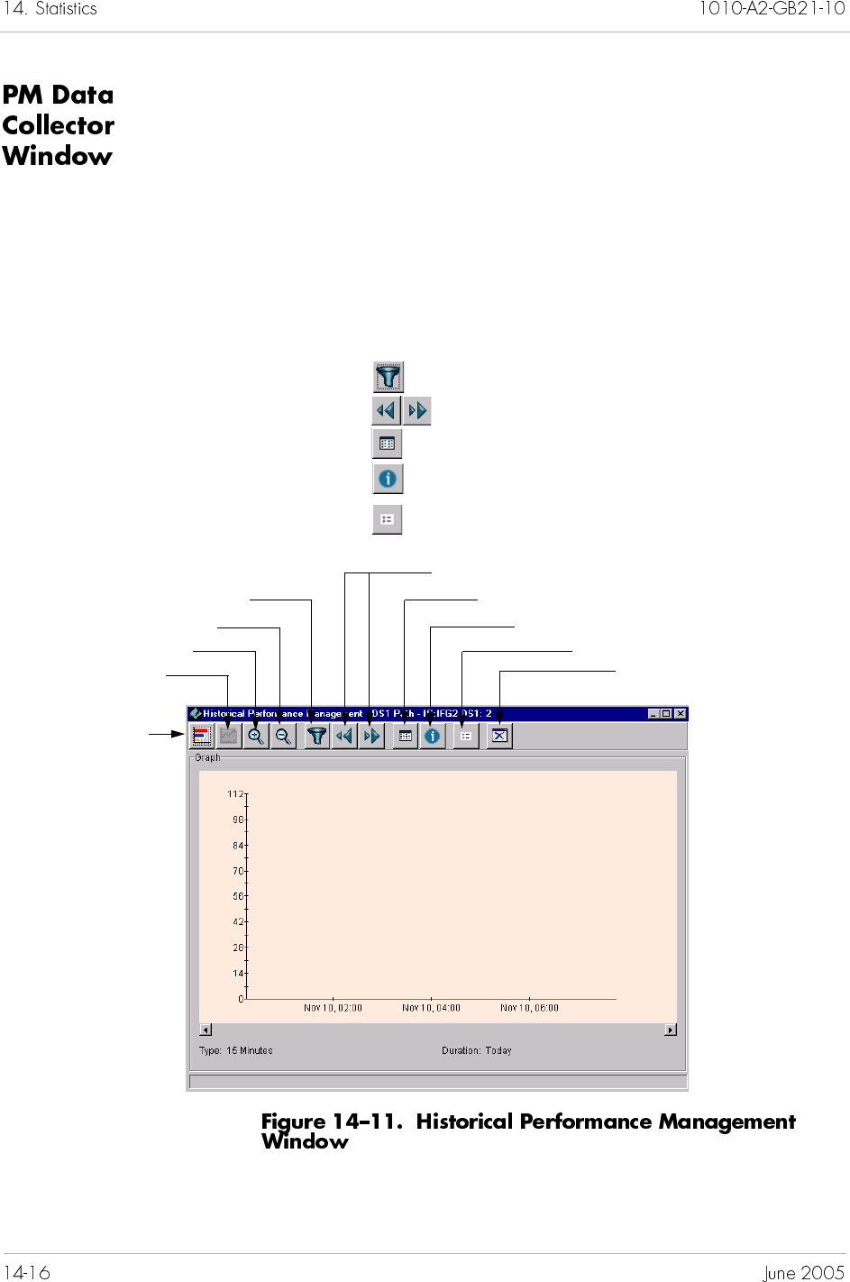
Historical data is a useful tool for performance analysis. The size of
historical data buffer is specified during installation. Refer to
Chapter 17, InfoCenter Services, to increase the buffer size. The
historical performance monitors these elements:
MP card
CP card
DS1 ports
Figure 14–11 shows a historical performance management window
where you determine how your graph is displayed. For example,
Click to filter the parameters.
Click to view the predefined interval.
Click to view the graph in tabular form.
Click to view the chart summary.
Click to display the legends in the graph.
Click to view bar-
graph format
Click to display the predefined interval
Click to view line-
graph format
Click to enlarge the view
Click to compress the view
Click to filter the parameters Click to display the tabular view
Click to display summary information
Click to display the graph legends
Click to close
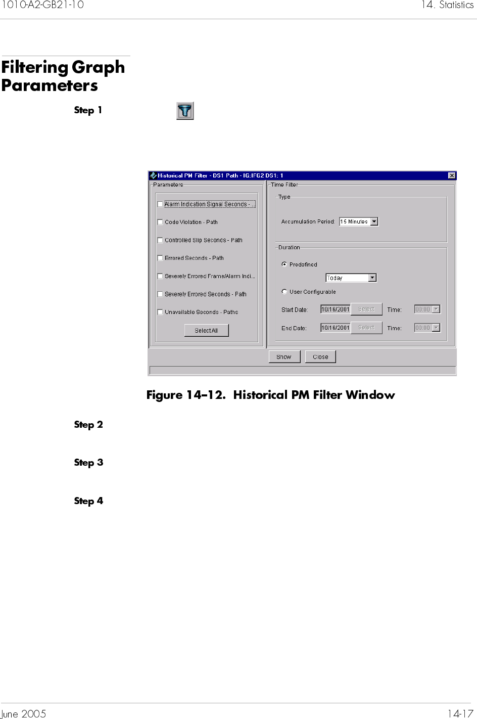
JetVision enables you to select a range of parameters to present in
the graph. To filter the graph parameters:
Click at the historical performance management window
(Figure 14–11 on page 14-16). A Historical PM Filter window
similar to Figure 14–12 appears.
Click to select the parameters for which you want to poll statistics,
or click Select All.
Select the time filter from the associate drop-down lists, or click
User Configurable to define your time preference.
Click Show. JetVision displays the graph based on the options you
selected.
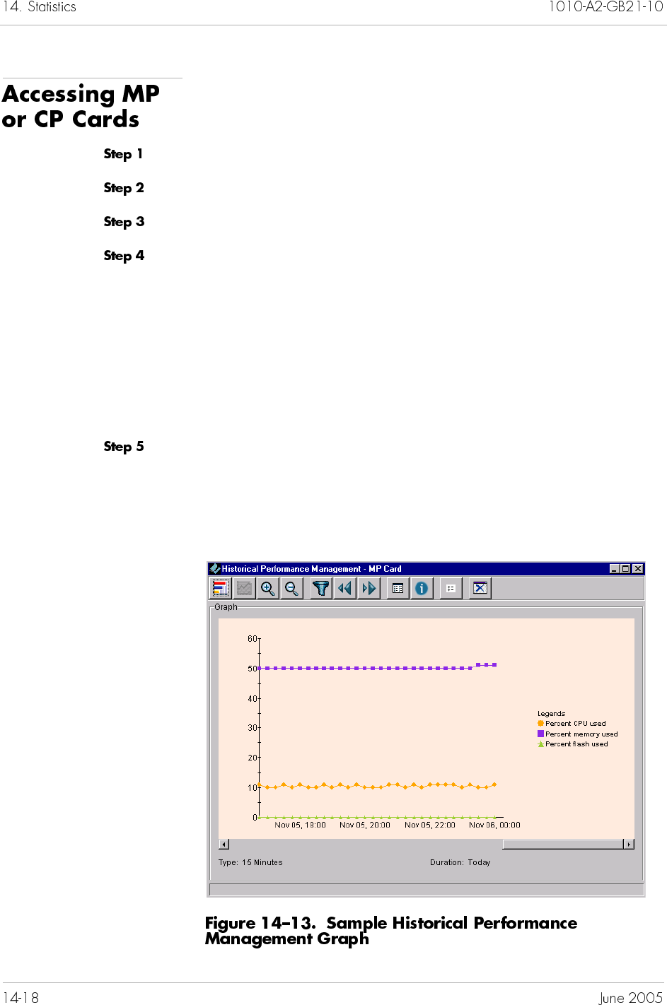
To poll historical performance data on the MP and CP cards:
Expand the desired CPX-1000 from the Tree View.
Click to expand the shelf associated with the CPX-1000.
Select the desired card (MP or CP) from the Tree or Shelf views.
Select Historical Performance Graphs (MP or CP) from the Report
menu.
– Or –
Right-click your selection and select Historical Performance
Graphs (MP or CP) from the pop-up menu.
A Historical Performance Management window of your selection
appears (Figure 14–11 on page 14-16).
Filter the graphing parameters (Filtering Graph Parameters on
page 14-17).
Figure 14–13 shows a sample of a historical performance
management graph of the MP card.
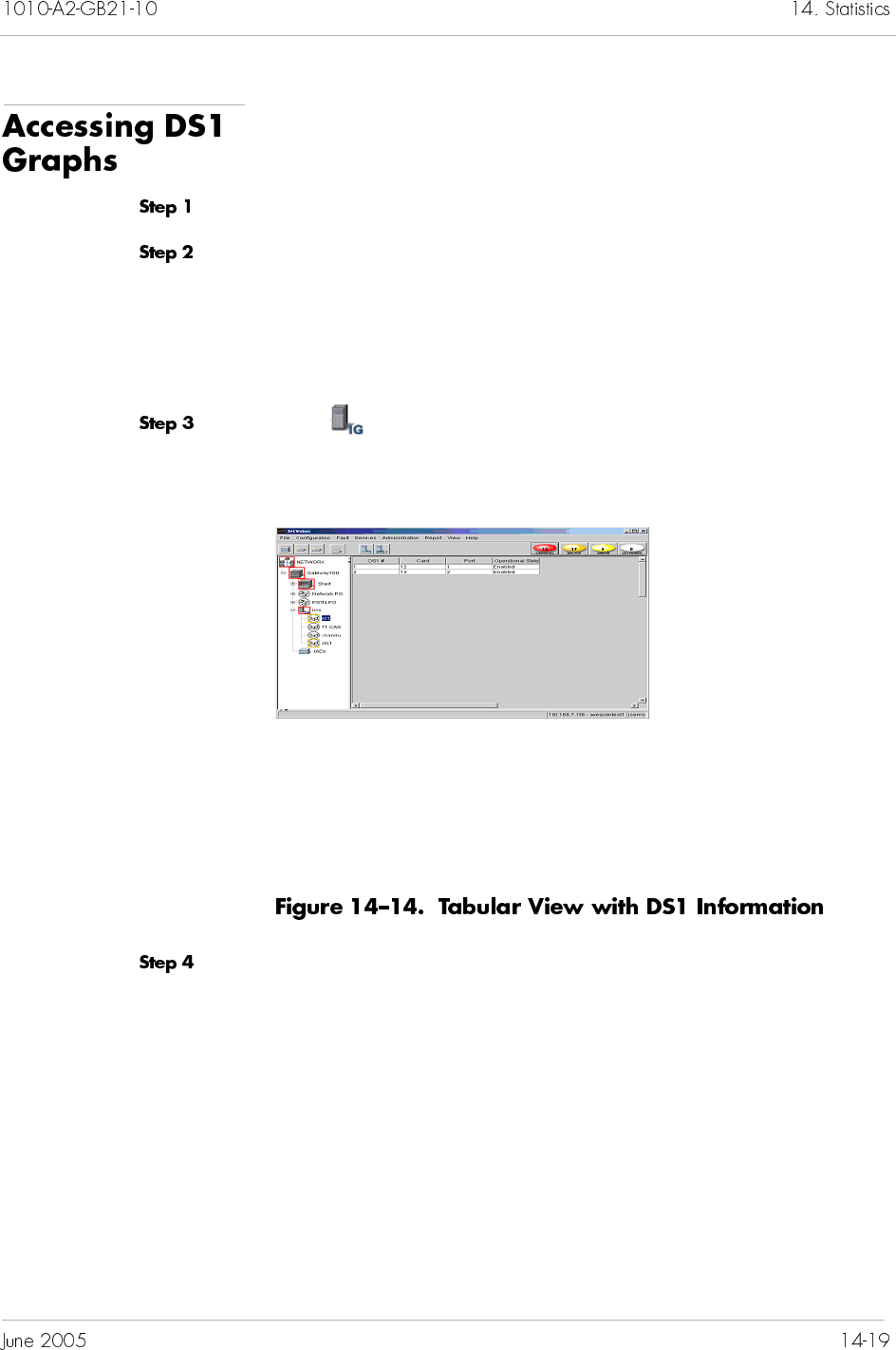
To poll historical performance data on DS1s:
Expand the desired CPX-1000 from the Tree View.
Determine the type of DS1 graph you want to poll.
To poll DS1 lines, expand the shelf as well as the desired
TDM-T1 card, and select the DS1 port on which you want to
poll statistics. Then go to Step 5.
To poll DS1 paths, continue with the next step.
Click on the Tree View, and select the Interface Group on
which you want to poll statistics. the right-hand pane displays the
DS1 information (Figure 14–14).
Select the desired DS1 #, then select DS1 Historical
Performance Graph from the Report menu.
– Or –
Right-click the DS1# and select DS1 Historical Performance
Graph from the pop-up menu.
The Historical Performace Management window appears (Figure
14–11 on page 14-16).
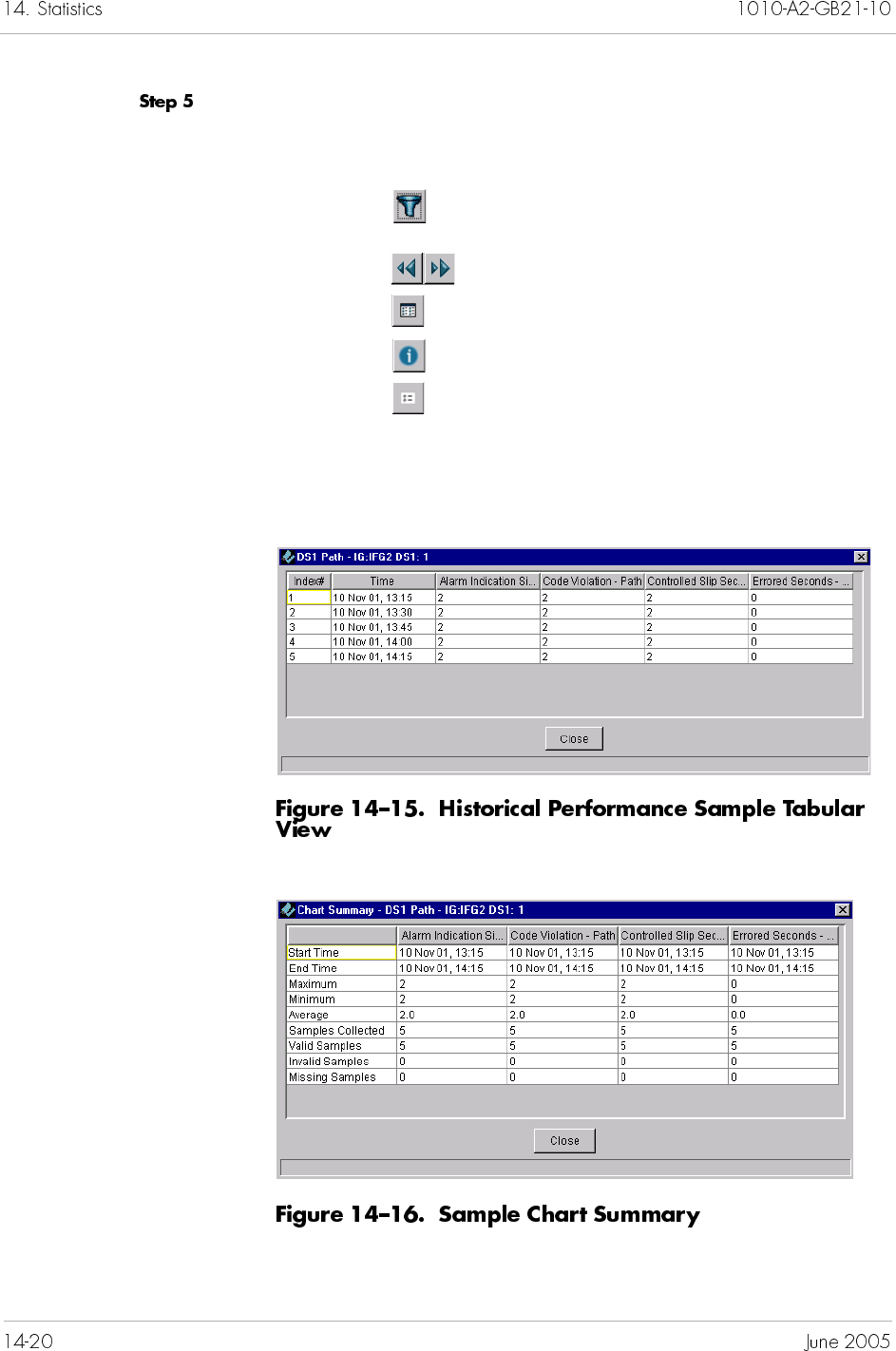
Select one of the following buttons from the toolbar to perform a
desired operation.
Select the type of graphs (bar or line) to display.
Click to filter the parameters (Filtering Graph
Parameters on page 14-17).
Click to view the predefined interval.
Click to view the graph in tabular form.
Click to view the chart summary.
Click to display the legends in the graph.
Figure 14–15 shows a sample of the graph in tabular format;
Figure 14–16 shows a sample of the chart summary, and
Figure 14–17 shows a sample of the graph with legends displayed.
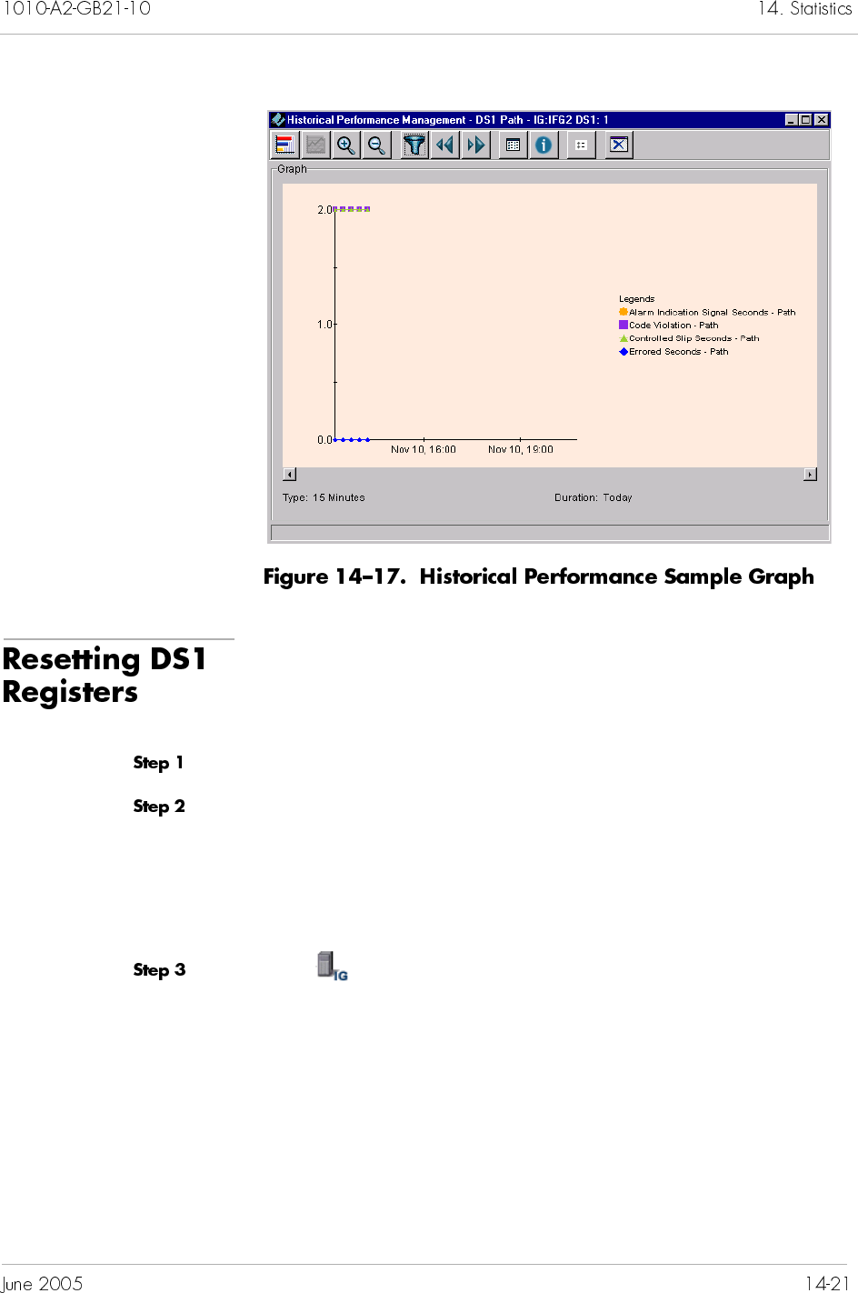
Once initiated, the historical database in the register is reset to
zero.
To reset DS1 registers:
Expand the desired CPX-1000 from the Tree View.
Determine which register you want to reset.
To reset line registers, expand the shelf as well as the desired
TDM-T1 card, and select the DS1 port on which you want to
reset registers. Then go to Step 5.
To reset path registers, continue with the next step.
Click on the Tree View, the right-hand pane changes to the
Interface Group tabular view (Figure 14–18).
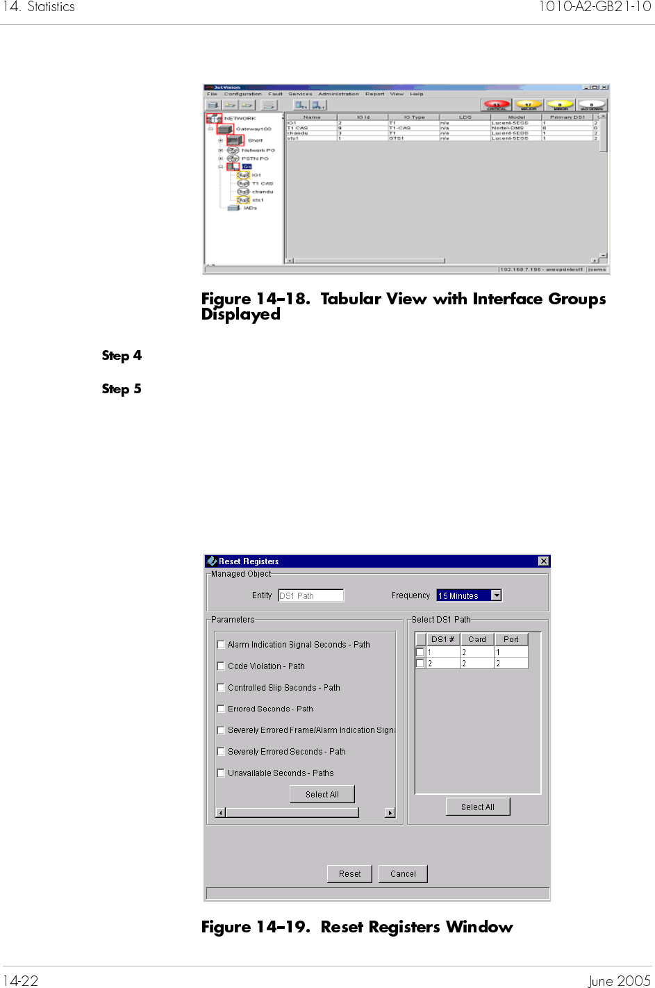
Select the Interface Group that you want to reset the register.
Select DS1 Registers from the Configuration menu.
– Or –
Right-click the Interface Group and select DS1 Registers from
the pop-up menu.
The Reset Registers window of your specification appears.
Figure 14–19 shows a sample of the DS1 path register.

Set the time frequency (15 minutes or 24 hours) for which you
want the register to reset.
Click Reset.


Some maintenance tasks, such as backing up CPX-1000
configuration files, are performed routinely while others are
performed as needed. This chapter provides instructions to
perform the following tasks:
Creating a CPX-1000 configuration destination profile
(page 15-2)
Performing an on-demand CPX-1000 configuration backup
(page 15-7)
Creating a CPX-1000 configuration backup schedule
(page 15-8)
Reviewing active tasks (page 15-17)
Reviewing backup files (page 15-18)
Restoring CPX-1000 configuration (page 15-19)
Rebooting the CPX-1000 (page 15-23)
Rebooting the MP or CP card (page 15-24)
Setting the CPX-1000 internal clock (page 15-25)
Performing a switchover (page 15-26)
Changing CP card states (page 15-27)
Performing a hot swap (page 15-30)
Performing a loop back test (page 15-33)
Performing a path trace on STS-1 card (page 15-35)
Changing the CPX-1000 managing states (page 15-35)
Downloading IAD software (page 15-37)
Automated IAD software download (page 15-41)
Remote restart of IADs (page 15-46)
Increasing the historical buffer (page 15-49)
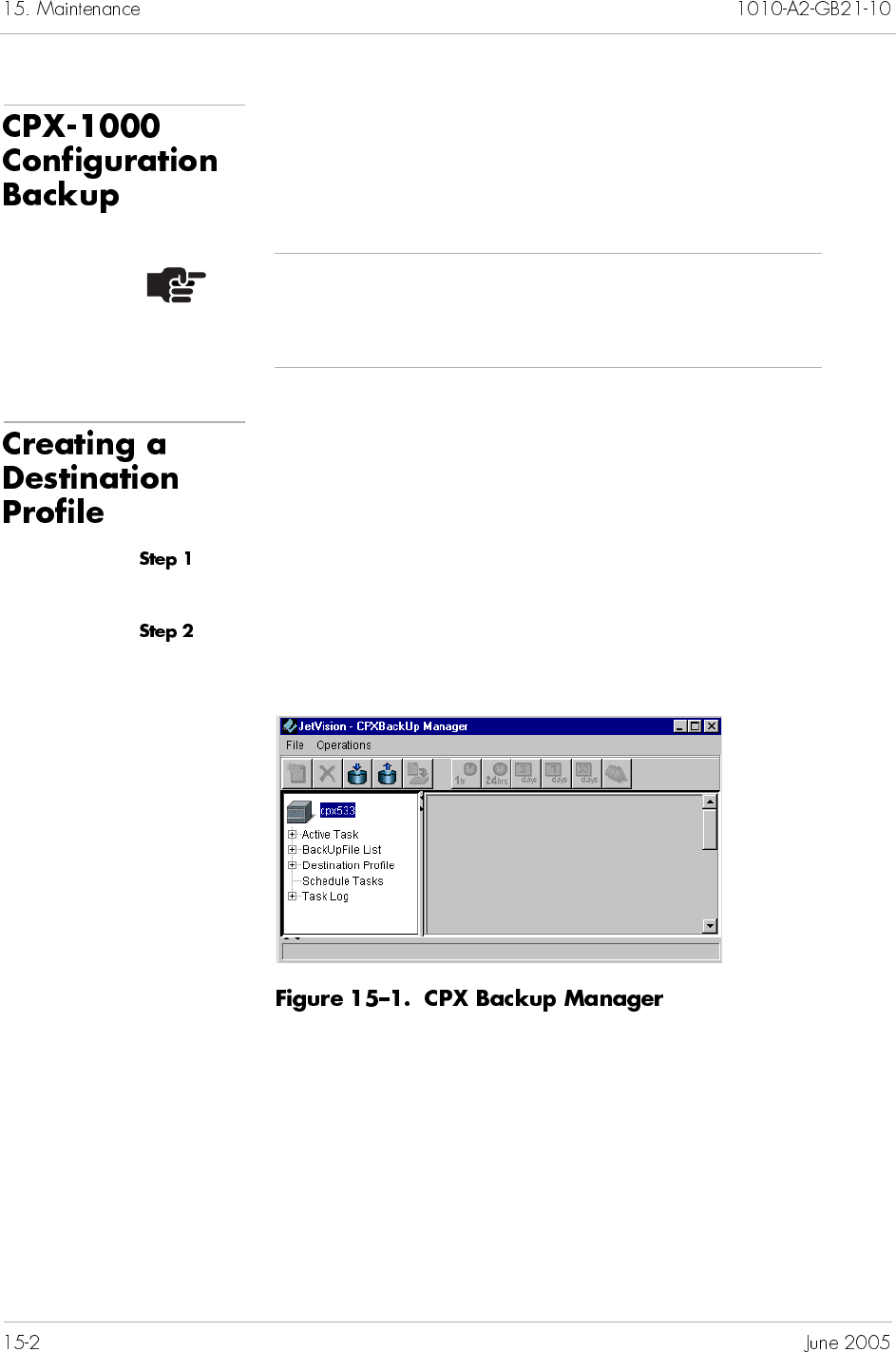
You can perform an on-demand backup or a scheduled backup.
Before performing a remote backup, you need to create a
destination profile first.
A destination profile contains common parameters for the backup
operation.
To create a destination profile:
Locate the CPX-1000 by clicking the group icon from the Tree View
where the CPX-1000 resides.
Select CPXBackUpManager from the Services Menu. The CPX
Backup Manager window appears (Figure 15–1).
Note
Ensure that your user account have been created in the
FTP server.
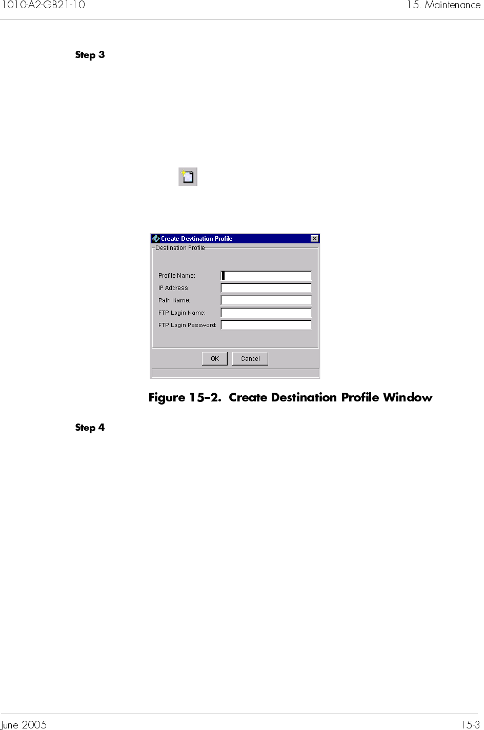
Right-click Destination Profile and select Create from the pop-up
menu.
– Or –
Click Destination Profile and select Create from the Operations
menu.
– Or –
Click from the toolbar.
The Create Destination Profile window appears (Figure 15–2).
Type the information in the following fields.
Profile Name: the name of the profile consists between 4 to
32 alphanumeric characters, including dashes (-) and
underscores (_). No spaces allowed.
IP Address: the IP address of the FTP server.
Path Name: the relative path to the FTP directory. For
example, if the FTP working directory is /usr/jsems and
you want to transfer the file to it, then the path name is
./usr/jsems.
FTP Login Name: this is the same login identifier as the FTP
server.
FTP Login Password: this is the same login password as the
FTP server.
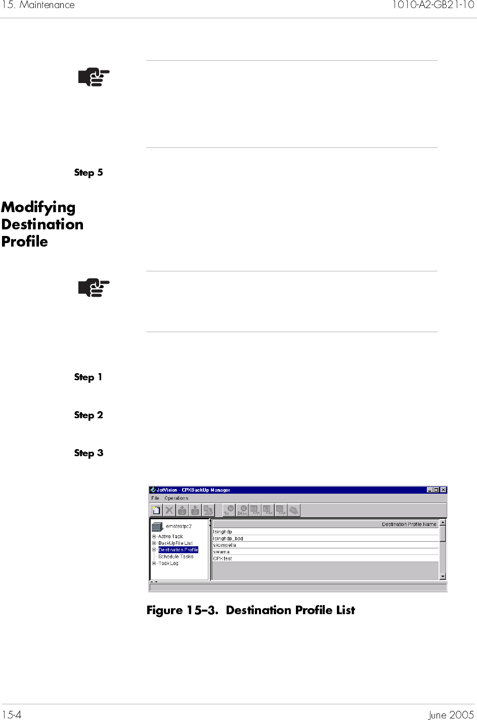
Click OK.
To modify destination profiles:
Locate the CPX-1000 by clicking the group icon from the Tree View
where the CPX-1000 resides.
Select CPXBackUpManager from the Services Menu. The CPX
Backup Manager window appears (Figure 15–2 on page 15-3).
Click Destination Profile to display the profile list (Figure 15–3).
Note
A forward slash (/) is used for both Windows and
Solaris environments. In Windows, the forward slash
signifies a relative path in respect to the configuration of
the FTP server.
Note
You cannot modify a destination profile if it is associated
with any schedules.
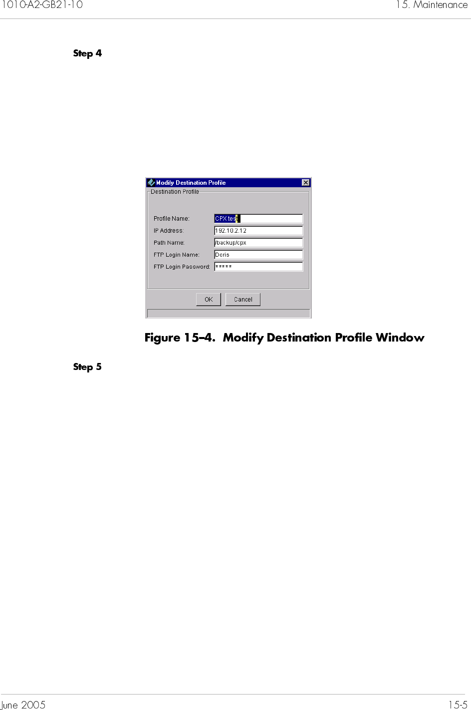
To delete destination profiles:
Locate the CPX-1000 by clicking the group icon from the Tree View
where the CPX-1000 resides.
Select CPXBackUpManager from the Services Menu. The CPX
Backup Manager window appears (Figure 15–2 on page 15-3).
Click Destination Profile to display the profile list (Figure 15–3 on
page 15-4).
Right-click the profile name you want to delete, and select Delete
from the pop-up menu.
– Or –
Select the profile you want to delete, and select Delete from the
Operations menu.
– Or –
Click from the toolbar.
A dialog box appears, asking if you want to delete the selected
profile.
Click Yes.
Note
You cannot delete a destination profile if it is associated
with any schedules.
To perform an on-demand backup:
Locate the CPX-1000 by clicking the group icon from the Tree View
where the CPX-1000 resides.
Select CPXBackUpManager from the Services Menu. The CPX
Backup Manager window appears (Figure 15–5).
Right-click the CPX icon and select Backup CPX
Configuration from the pop-up menu.
– Or –
Click the shelf icon and select Backup CPX Configuration
from the Operations menu.
– Or –
Click from the toolbar.
The Backup CPX Configuration window appears (Figure 15–6).
Type the name of the backup file in the File Name field.
Select a file backup location.
Local: the file is backed up to the MP backup directory. Then
go to Step 7.
Remote: the file is backed up to the FTP server. The
Destination Profile is enabled when Remote is selected.
Continue with the next step.
Select the destination profile from its drop-down list.
Click OK.
JetVision enables you to schedule a backup operation on a
predefined interval. Once a schedule is defined, the configuration
is automatically backed up to the specified destination.
To schedule a backup interval:
Locate the CPX-1000 by clicking the group icon from the Tree View
where the CPX-1000 resides.
Click the CPX-1000 icon you want to schedule a task.
Select CPXBackUpManager from the Services Menu. The CPX
Backup Manager window appears (Figure 15–7).
Click Schedule Tasks. The Introduction to the Scheduled Task
Wizard (1st of 6) screen appears (Figure 15–8).
Click Next. The Scheduled Task Wizard screen appears
(Figure 15–9).
Type the name of this task in the name field. (The name has no
restriction of number of characters; however, you cannot place
space between characters.)
Click Next. The Scheduled Task Wizard — Interval screen appears
(Figure 15–10).
Select the interval, then click Next. The Scheduled Task Wizard —
Location screen appears (Figure 15–11).
Notes
The name must be unique for every CPX-1000. No
CPX-1000 can share the same name.
The Next button is enabled when the schedule name is
entered.
Select one of the following backup location.
Select the destination profile from the drop-down list
(enabled when File Transfer is selected).
Local Backup (default): type the prefix of the file name in
the name field.
Type the prefix of the file name in the name field and select
the destination profile from the drop-down list (enabled
when Remote Backup is selected).
Click Next. The Scheduled Task Wizard — Time screen appears
(Figure 15–12).
Select the starting time and date as well as the end date from the
drop-down lists. Or, click Select to choose the dates. The
Schedule Summary appears (Figure 15–13).
Review the summary.
If the scheduled data is correct, click Finish. The
scheduled task is started and active from the 1st effective
date, and listed on the CPX Backup Manager window.
If any of parameters are incorrect, click Back until you reach
the screen in question and correct the parameters, then
proceed from that point forward.
To disable a backup schedule:
Locate the CPX-1000 by clicking the group icon from the Tree View
where the CPX-1000 resides.
Click the CPX-1000 icon you want to disable a scheduled task.
Select CPXBackUpManager from the Services Menu. The CPX
Backup Manager window appears (Figure 15–14).
Click Schedule Tasks. A list of scheduled tasks appears on the
right panel (Figure 15–15).
Click the scheduled task you want to stop, disable the admin state
by selecting Disable from the Operations menu.
Right-click the scheduled task you want to disable, and select
Stop Schedule. A dialog box appears, asking if you want to
disable the selected scheduled task.
Click Yes.
After a backup schedule have been disabled, you need to enable it
to resume its operation. To enable a schedule:
Locate the CPX-1000 by clicking the group icon from the Tree View
where the CPX-1000 resides.
Click a CPX-1000 and expand the tree.
Click the CPX-1000 icon you want to enable a scheduled task.
Select CPXBackUpManager from the Services Menu. The CPX
Backup Manager window appears (Figure 15–16).
Note
You cannot disable a backup operation when it is in
progress. The disabled schedule takes effect from the
next schedule.
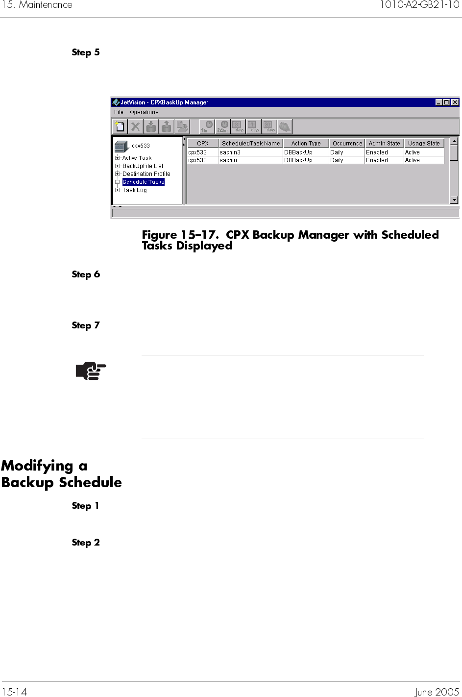
Click Schedule Tasks. A list of scheduled tasks appears on the
right panel (Figure 15–17).
Right-click the scheduled task you want to enable, and select
Start Schedule. A dialog box appears, asking if you want to
enable the selected scheduled task.
Click Yes.
To modify a backup schedule:
Locate the CPX-1000 by clicking the group icon from the Tree View
where the CPX-1000 resides.
Click the CPX-1000 icon you want to schedule a task.
Note
You can start a scheduled task only when the admin
state of the intended scheduled task is disabled. The
Start Schedule option is disabled if the scheduled task is
already in the start state.
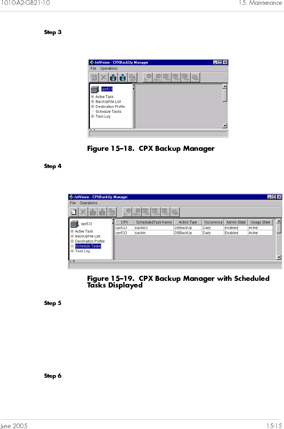
Select CPXBackUpManager from the Services Menu. The CPX
Backup Manager window appears (Figure 15–18).
Click Schedule Tasks. A list of scheduled tasks appears on the
right panel (Figure 15–19).
Right-click the scheduled task you want to modify, and select
Modify Schedule from the pop-up menu.
– Or –
Click the scheduled task you want to modify, and select Modify
Schedule from the Operations menu.
The Scheduled Task Wizard (1st of 6) screen appears.
Refer to Creating a Backup Schedule on page 15-8 to modify any
information.
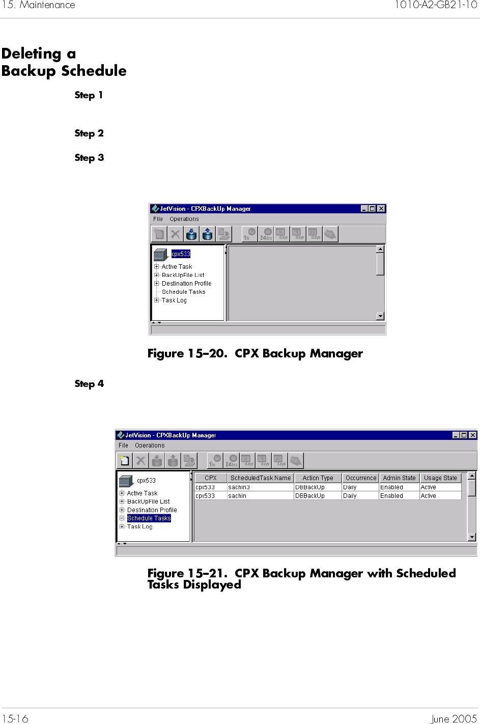
To delete a backup schedule:
Locate the CPX-1000 by clicking the group icon from the Tree View
where the CPX-1000 resides.
Click the CPX-1000 icon you want to delete a scheduled task.
Select CPXBackUpManager from the Services Menu. The CPX
Backup Manager window appears (Figure 15–20).
Click Schedule Tasks. A list of scheduled tasks appears on the
right panel (Figure 15–21).
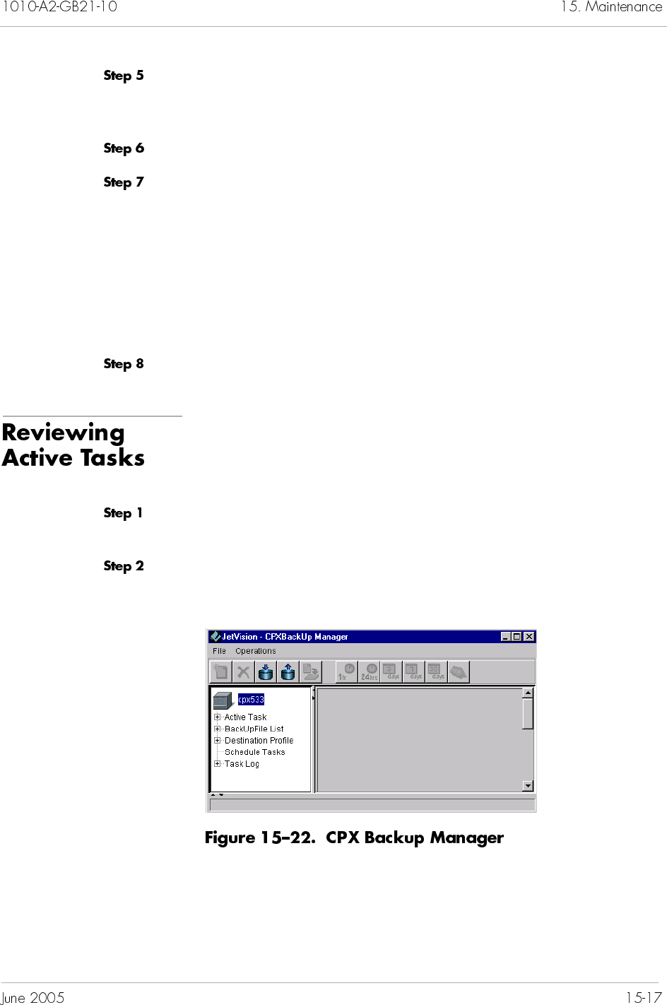
Right-click the scheduled task you want to delete, and select Stop
Schedule from the pop-up menu. A dialog box appears, asking if
you want to stop the selected scheduled task.
Click Yes.
Right-click the scheduled task you want to delete, and select
Delete Schedule from the pop-up menu.
– Or –
Click the scheduled task you want to delete, and select Delete
Schedule from the Operations menu.
A dialog box appears, asking if you want to delete the selected
scheduled task.
Click Yes.
When the backup are being executed, you can view the progress
status.
To review the active tasks:
Locate the CPX-1000 by clicking the group icon from the Tree View
where the CPX-1000 resides.
Select CPXBackUpManager from the Services Menu. The CPX
Backup Manager window appears (Figure 15–22).
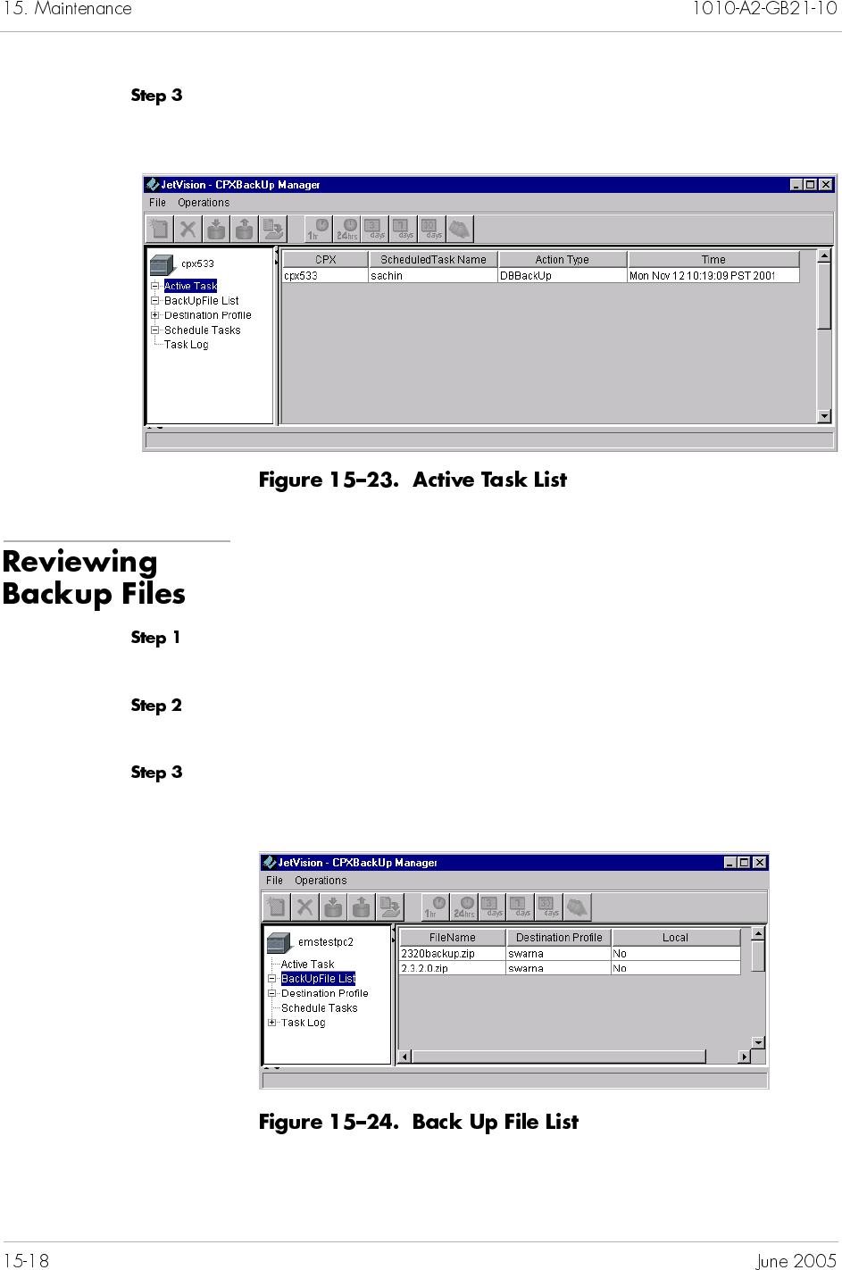
Click Active Tasks. The right panel shows the status of the
current task being performed (Figure 15–23).
To review the backup file location:
Locate the CPX-1000 by clicking the group icon from the Tree View
where the CPX-1000 resides.
Select CPXBackUpManager from the Services Menu. The CPX
Backup Manager window appears (Figure 15–22 on page 15-17).
Click BackUpFileList. The right panel shows a list of files that
have been backed up (Figure 15–24).
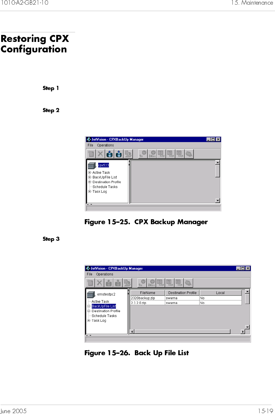
You can restore the configuration file on a CPX-1000 if you lose or
change it. Unless specified, the files are restored to the local disk.
Refer to Performing a File Transfer on page 15-21 to send files to a
remote location.
To restore a CPX-1000 configuration file:
Locate the CPX-1000 by clicking the group icon from the Tree View
where the CPX-1000 resides.
Select CPXBackUpManager from the Services Menu. The CPX
Backup Manager window appears (Figure 15–25).
Click BackUpFileList. The right panel shows a list of files that
have been backed up (Figure 15–26).
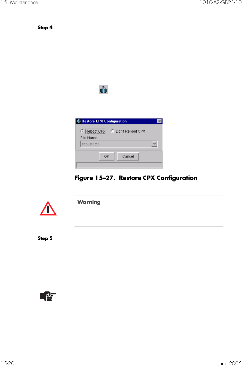
Right-click the file you want to restore, and select Restore CPX
Configuration from the pop-up menu.
– Or –
Click the file you want to restore, and select Restore CPX
Configuration from the Operations menu.
– Or –
Click the from the toolbar.
The Restore CPX Configuration window appears (Figure 15–27)
Select the reboot option, then click OK.
Reboot CPX starts the rebooting process.
Don’t Reboot CPX means that you will reboot the CPX-1000
manually at a later time (Rebooting the CPX-1000 on page
15-23).
Restoring CPX-1000 configuration requires rebooting
the MP card, which interrupts service.
Note
Make sure to reboot, or the configuration files will not
be restored.
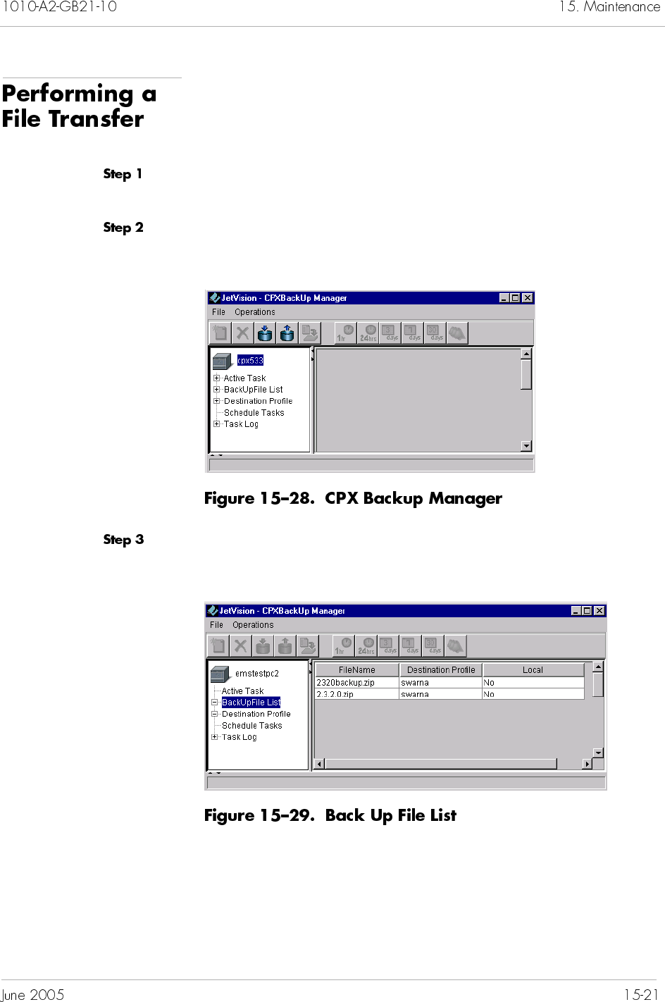
JetVision enables you to send the backup files to any remote
locations so long they are included in the destination profile.
To perform a file transfer:
Locate the CPX-1000 by clicking the group icon from the Tree View
where the CPX-1000 resides.
Select CPXBackUpManager from the Services Menu. The CPX
Backup Manager window appears (Figure 15–28).
Click BackUpFileList. The right panel shows a list of files that
have been backed up (Figure 15–29).
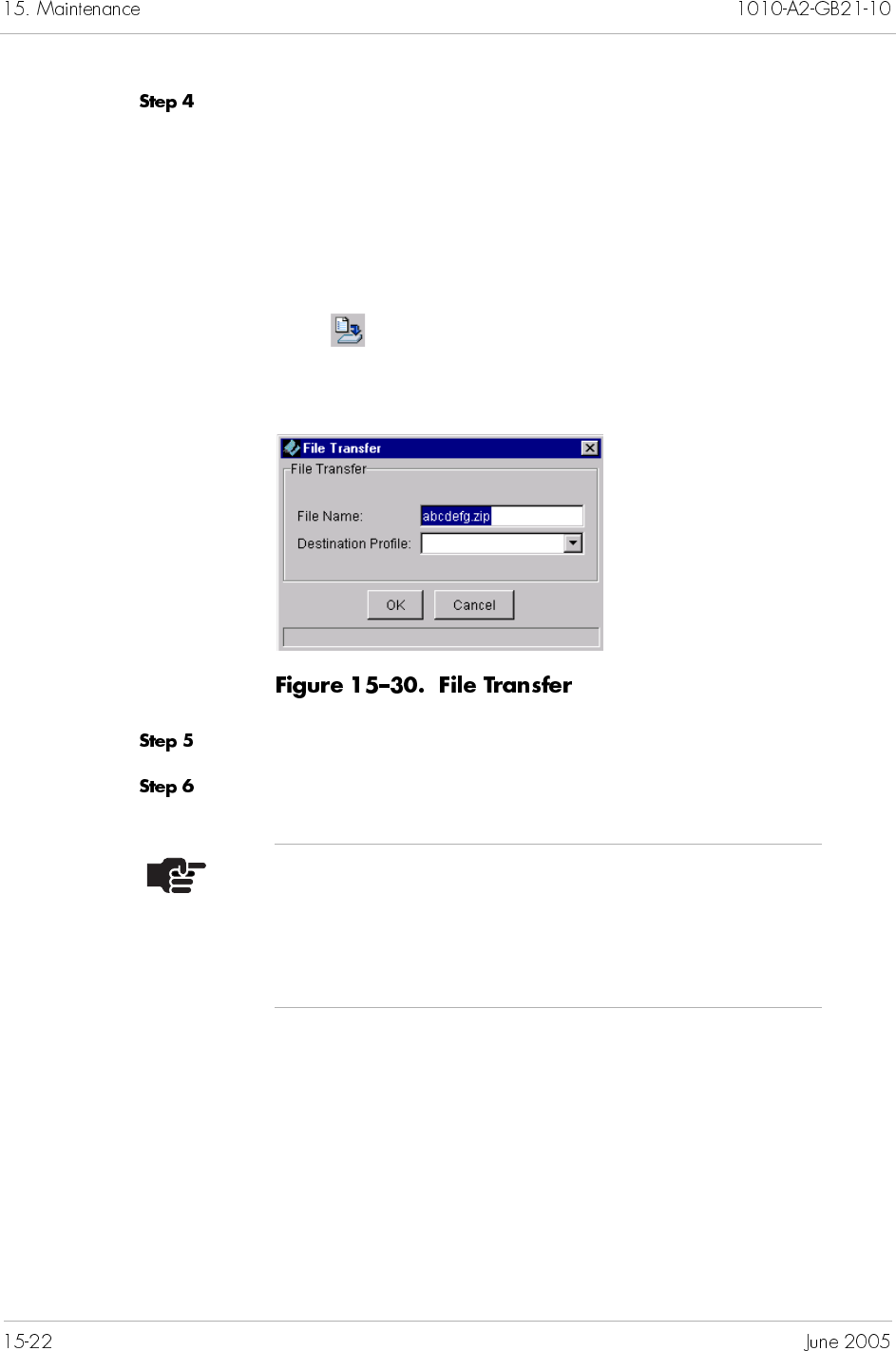
Right-click the file you want to restore, and select File
Transfer from the pop-up menu.
– Or –
Click the file you want to restore, and select File Transfer
from the Operations menu.
– Or –
Click from the toolbar.
The File Transfer window appears (Figure 15–30)
Select a profile from the Destination Profile drop-down list.
Click OK.
Note
You do not need to select the destination profile when
restoring file from the FTP server to local machine. The
destination profile associated to the selected file is
automatically displayed.

To reboot the CPX-1000:
Click the icon from the Tree View.
Select Reboot from the Services menu. The following dialog box
appears, asking if you want to continue.
Click Yes.
You can reboot either the MP card or the standby CP card. Before
rebooting the standby CP card, put it to the Locked state
(Changing CP Card States on page 15-27).
To reboot the MP or CP card:
Click a CPX-1000 from the Tree View and expand the tree by
clicking the + sign.
Click the Shelf icon associated with the CPX-1000.
Click either the MP or CP card icon from the Tree or Shelf views.
Select Reboot from the Services menu. A prompt appears, asking
if you want to continue.
Click Yes to reboot.
Depending on the size of the CPX-1000 managed domain,
resynchronizing might take a few minutes.
To resynchronize a CPX-1000:
Click a CPX-1000 icon in the Tree view.
Select Resynch CPX from the Administration menu. A prompt
appears, asking if you want to resynchronize the CPX-1000.
Click Yes to resynchronize the CPX-1000.
Rebooting the MP card interrupts service.
Note
An out-of-sync icon and a gray-out CPX-1000 image
appear in the Map View during initialization. When the
initialization process completes, the icon disappears and
the color of the CPX-1000 returns to gray.
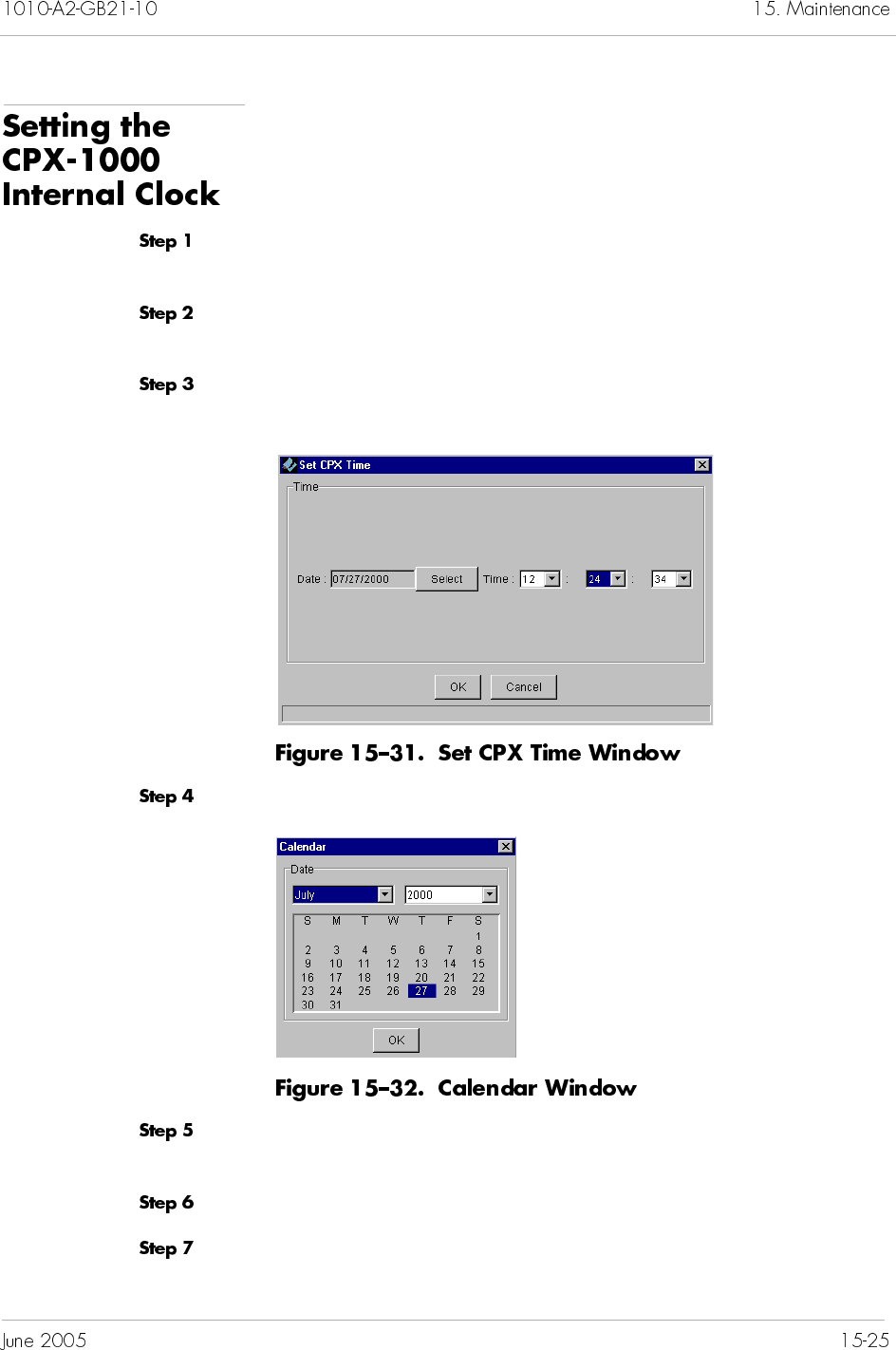
To set the time and date:
Click a CPX-1000 from the Tree view, and expand the tree by
clicking the + sign.
Click the Shelf icon associated with the CPX-1000, and click the MP
card.
Select Time Configuration from the Services menu. The Set
CPX Time window appears (Figure 15–31).
Click Select. The Calendar window appears (Figure 15–32).
Select the current month and year from the appropriate drop-down
lists.
Select the current day by clicking the date in the calendar.
Click OK to return to the Set CPX Time window.
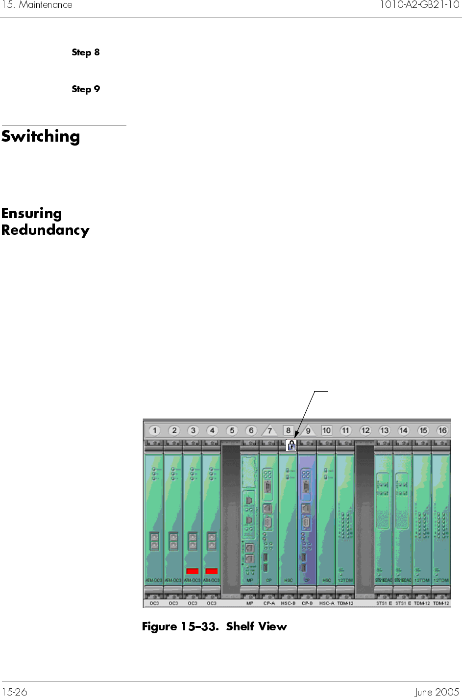
Set the time from the appropriate hour, minute, and seconds
drop-down lists.
Click OK to set the time and date.
When a forced switchover is performed, call control is transferred
to the standby CP card, regardless of call progress. Calls being set
up are dropped during a forced switchover (Performing a CP
Switchover on page 15-29).
To ensure redundancy on the CPX-1000, both CP cards need to be
inserted in their assigned slots. Figure 15–33 shows the slot
assignments of CPX-1000 cards. The color shown indicates the
states of the cards: green for active and blue for standby. The two
CP and an MP cards are located in fixed slots assignment. The
primary CP occupies slot 7 with its corresponding primary HSC
card in slot 10. The secondary CP occupies slot 9 with its
corresponding secondary HSC card in slot 8. The MP card occupies
slot 6.
For a description of individual cards, refer to CPX-1000 Voice
Services Platform Introduction and Technical Description.
The lock indicates this card is
out of service
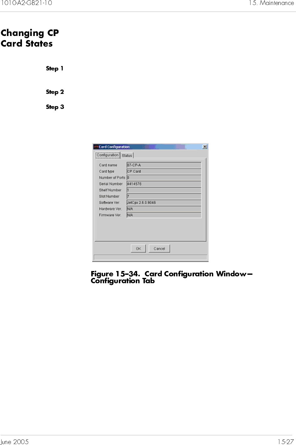
A card is locked when a lock icon appears on the card just below
the slot number.
To change the CP cards administrative states:
Click a CPX-1000 from the Tree View and expand the tree by
clicking the + sign.
Click the Shelf icon associated with the CPX-1000.
Right-click the desired card in the Tree or Shelf views and select
Card Configuration. The Card Configuration window similar
to Figure 15–34 appears, displaying the read-only information.
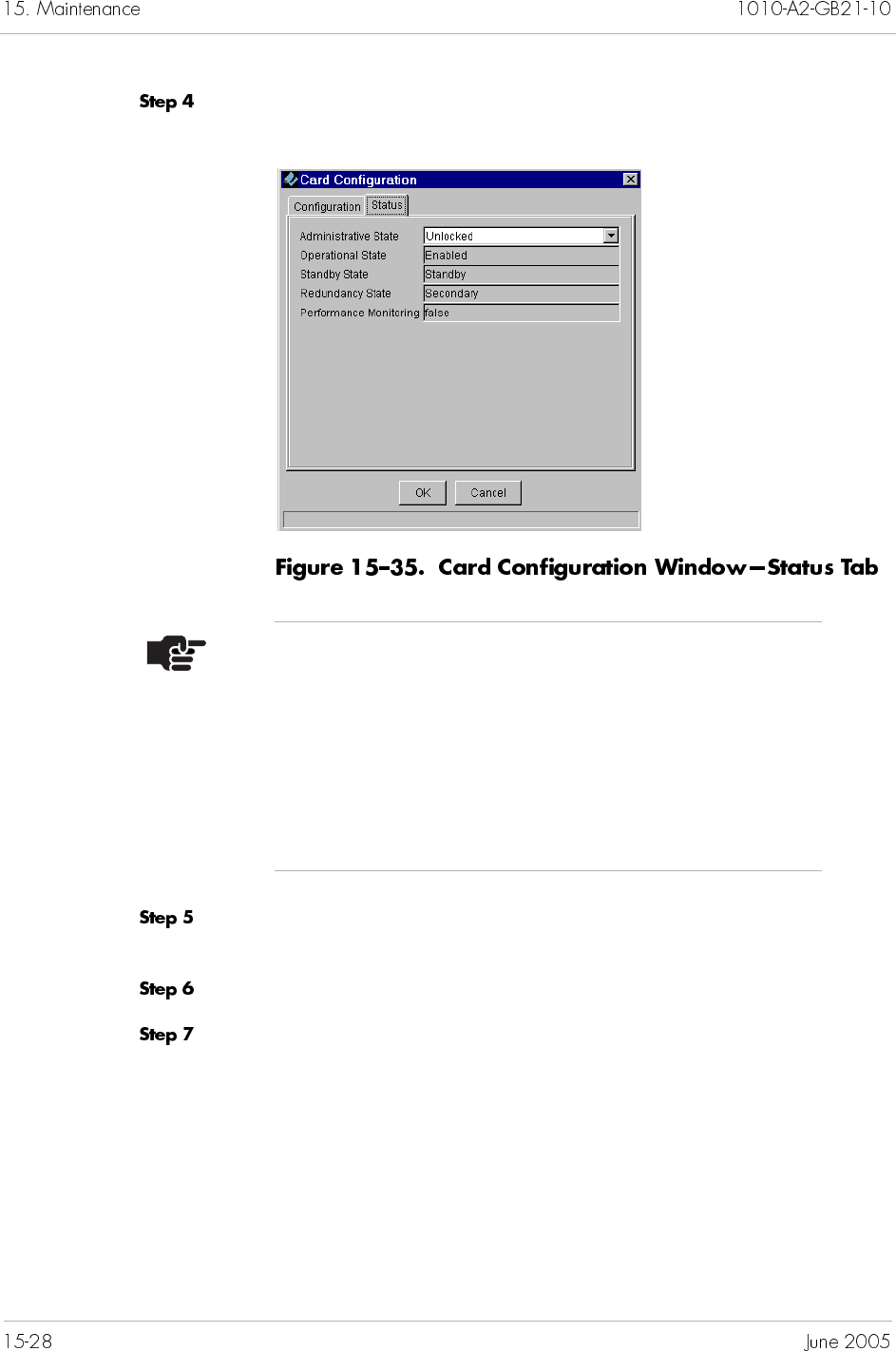
Select Status. The Status tab similar to Figure 15–35 appears,
displaying the current service state of the card.
Select the service state from the Administrative State drop-down
list. Your options are Locked or Unlocked.
Click OK. A prompt appears asking if you want to change the state.
Click Yes.
Notes
The Performance Monitoring field (true or false)
indicates whether the statistics are available for that
card: True indicates statistics are available.
The Administrative state is only displayed if it can be
modified.
The Operational state is set to Enabled when the card is
discovered.
Before performing a switchover on a CP card, make sure that the
following conditions are present:
two CP cards are inserted in their assigned slots
there are no alarms on either CP card
the states of CP cards if switching from CP-A to CP-B:
the states of CP cards if switching from CP-B to CP-A:
To perform a switchover:
Ensure that the standby CP card is “unlocked” (Changing CP Card
States on page 15-27).
Select the active card.
Active Standby
Administrative Unlocked Unlocked
Operational Enabled Enabled
Primary Primary Secondary
Active Standby
Administrative Unlocked Unlocked
Operational Enabled Enabled
Primary Secondary Primary
Click the active CP card in the Tree or Shelf views and select
Switchover from the Configuration menu.
– Or –
Right-click the active CP card in the Tree or Shelf views and select
Switchover from the pop-up menu.
A prompt appears, asking if you want to continue the operation.
Click Yes to perform the switchover.
Observe the colors of the cards. The previously active card
becomes the standby card and the previously standby card is now
the active card.
Hot swapping lets you remove and replace cards without shutting
down and reconfiguring the CPX-1000. JetVision supports hot
swapping on all cards.
To hot swap a MP card, go to page 15-30
To hot swap CP and HSC cards, go to page 15-31
To hot swap line cards, go to page 15-32
To hot swap the MP card:
Back up the current CPX-1000 database (Performing an On-
demand Backup on page 15-7).
Locate the CPX-1000 by clicking the group icon from the Tree View
where the CPX-1000 resides.
Click the Shelf icon associated with the CPX-1000.
Note
Arrange uninterruptible voice communications between
yourself and a counterpart who will physically remove
and replace the card.
Click the MP card from the Tree or Shelf views and select Remove
Resources from the Configuration menu.
– Or –
Right-click the MP card from the Tree or Shelf views and select
Remove Resources from the pop-up menu.
A prompt appears, asking if you want to remove all resources
associated with the card.
Click Yes. The card is removed from the Tree and Shelf views.
Instruct your counterpart to physically remove and replace the MP
card.
Confirm the MP card reinsertion from your counterpart.
Restore the CPX-1000 configuration (Restoring CPX Configuration
on page 15-19).
HSC cards are paired with CP cards. After the HSC card is
replaced, pairing with the CP card is automatically restored.
To hot swap CP and HSC cards:
Click a CPX-1000 from the Tree View and expand the tree by
clicking the + sign.
Click the Shelf icon associated with the CPX-1000.
Click the CP card icon from the Tree or Shelf view.
If hot swapping an active CP or HSC card, continue with
Step 4.
If hot swapping a standby CP or HSC card, continue with
Step 5.
Switch to place the active card in standby (Performing a CP
Switchover on page 15-29).
Place the CP card to the Locked state (Changing CP Card States on
page 15-27).
Select Remove Resources from the Configuration menu. A
prompt appears, asking if you want to remove all resources
associated with the card.
Click Yes. The card is removed from the Tree and Shelf views.
Instruct your counterpart to physically remove and replace the CP
or HSC card.
Confirm the card reinsertion from your counterpart. (Continue
with Step 10 if this is a standby CP or HSC card.)
Place the CP card to the Unlocked state (Changing CP Card States
on page 15-27).
Line cards include:
ATM (OC-3 and DS-3)
TDM-12T1
STS-1
To hot swap a line card:
Click a CPX-1000 from the Tree View and expand the tree by
clicking the + sign.
Click the Shelf icon associated with the CPX-1000.
Click a line card that you want to hot swap from the Tree or Shelf
views.
Place the selected line card to the Locked state (Changing CP Card
States on page 15-27).
Select Remove Resources from the Configuration menu. A
prompt appears, asking if you want to remove all resources
associated with the card.
Click Yes. The card is removed from the Tree and Shelf views.
Instruct your counterpart to physically remove and replace the line
card.
Once the card is replaced, it is automatically “unlocked,” and all
resources for that card are restored. The card reappears in the Tree
and Shelf views.
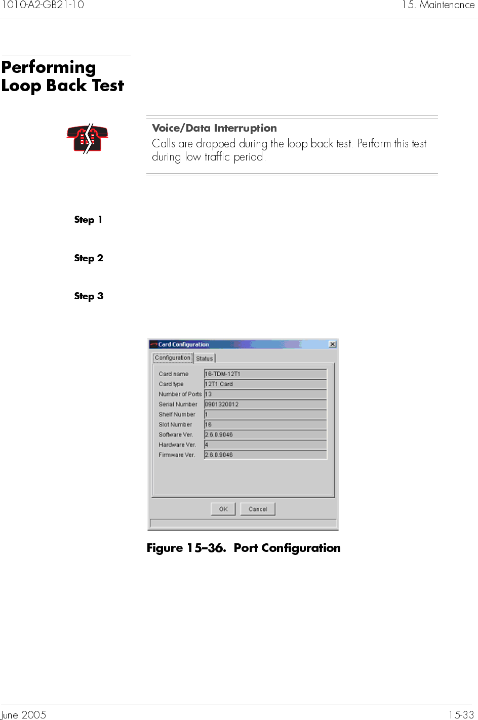
A loop back test is a diagnostics tool to test the inbound traffic. You
can perform loop back test on T-1 and STS-1 cards.
To perform the loop back test:
Click a CPX-1000 from the Tree View and expand the tree by
clicking the + sign.
Click the Shelf icon associated with the CPX-1000 and expand the
tree by clicking the + sign.
Right-click the desired port icon and select Configure. The Port
Configuration window similar to Figure 15–36 appears.
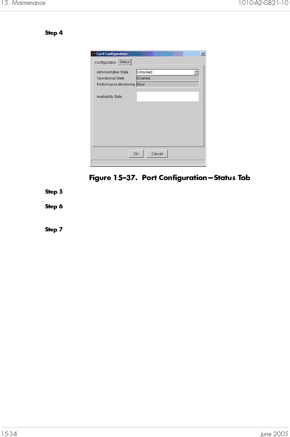
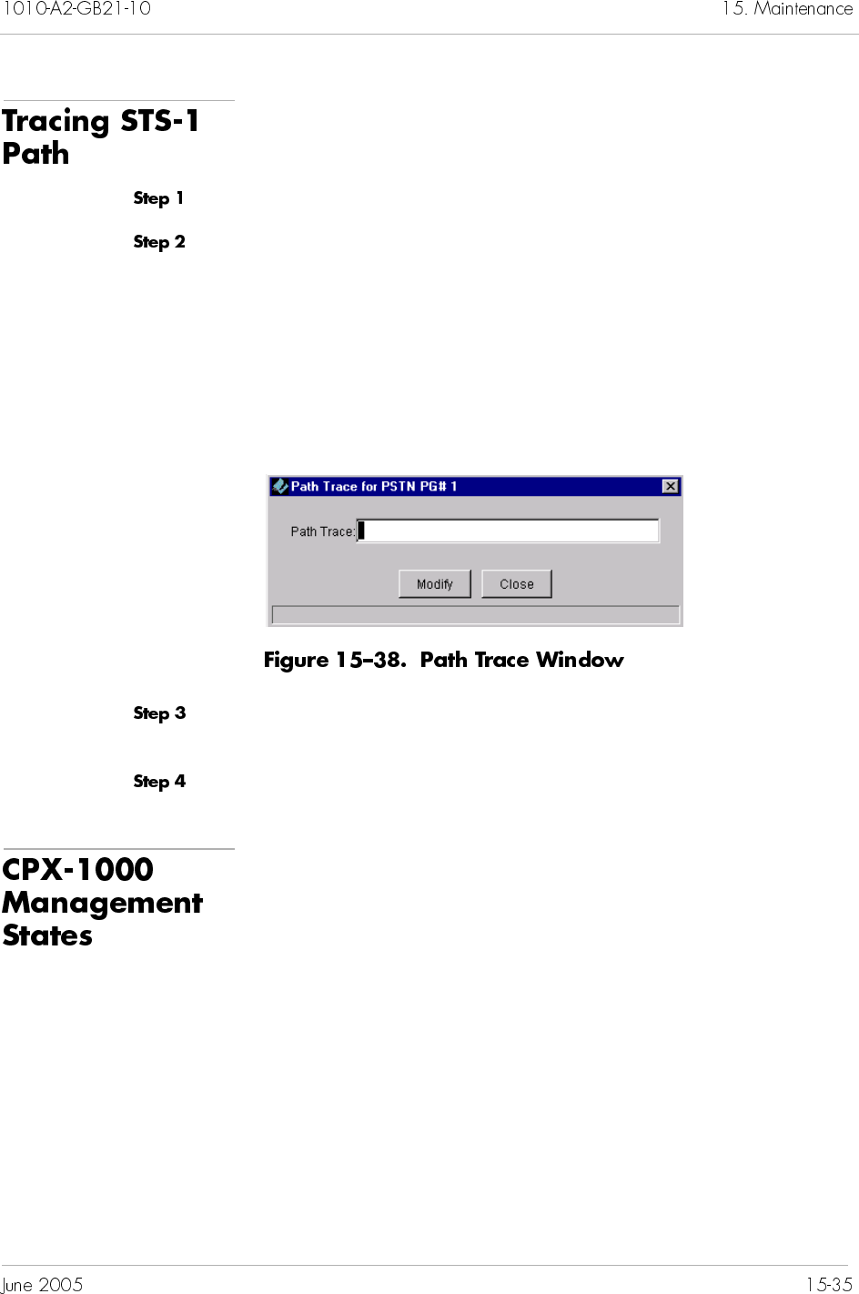
To trace an STS-1 path:
Click to expand the PSTN PG icon by clicking the + sign.
Click the desired Protection Group on the Tree View and select
Path Trace from the Configuration menu.
– Or –
Right-click the desired Protection Group on the Tree View and
select Path Trace.
The Path Trace window appears (Figure 15–38).
Type a character string of up to 62 characters in the Path Trace
field.
Click Modify.
Before performing service-affecting operation, such as hot software
upgrade, and to avoid the unnecessary alarms, you can place the
CPX-1000 in the “unmanaged” state. After the operation, you can
then place the CPX-1000 in the “managed” state.
Unmanaged means that the CPX-1000 is temporarily
disconnected (i.e., taken offline).
Managed means that putting the CPX-1000 back online and
resuming its live operations (JetVision continues to receive
alarms for that CPX-1000).
To change the CPX-1000 to the unmanaged state:
Locate the CPX-1000 by clicking the group icon from the Tree View
where the CPX-1000 resides.
Click a CPX-1000 and expand the tree.
Click a CPX-1000 to which you want to place to the Unmanaged
state.
Select Unmanaged CPX from the Administration menu.
Observe the Map View. The CPX-1000 is now offline, indicated by
the gray-out image and a lock icon next to the image.
To change the CPX-1000 to the managed state:
Locate the CPX-1000 by clicking the group icon from the Tree View
where the CPX-1000 resides.
Click a CPX-1000 and expand the tree.
Click a CPX-1000 to which you want to place to the Managed state.
Select Managed CPX from the Administration menu.
Observe the Map View. The color of the CPX-1000 returns to its
original gray, and the lock icon disappears.
Note
While in the Unmanaged state (offline), you still can
view configuration on cards and ports.
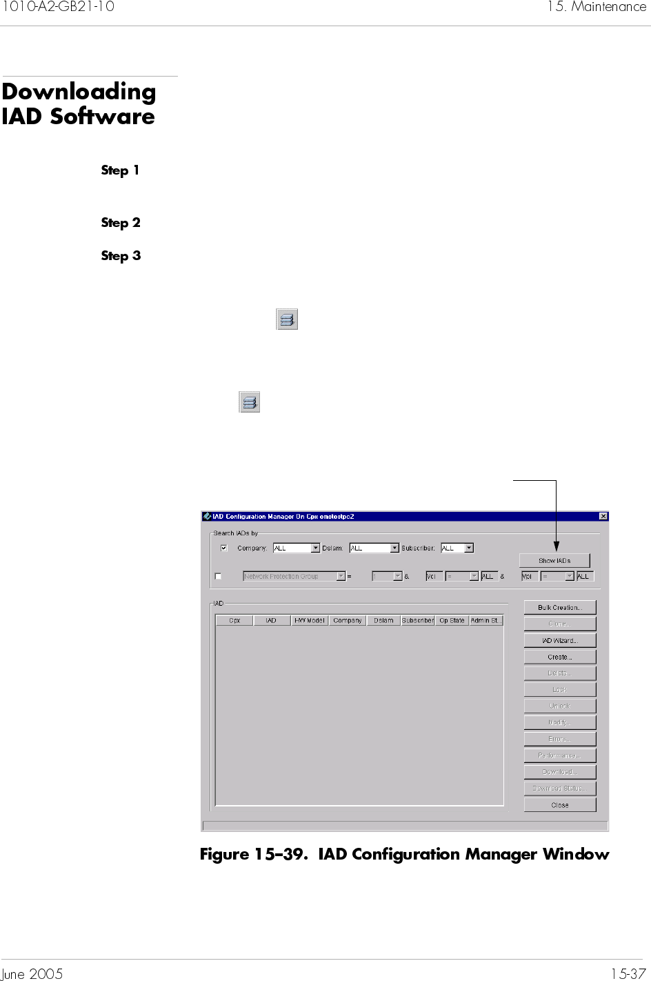
JetVision provides bulk download capabilities for downloading
software to multiple IADs of the same type.
To download IAD software:
Click a CPX-1000 from the Tree View and expand the tree by
clicking the + sign.
Click a CPX-1000 icon in the Tree view.
Select IAD Manager from the Configuration menu.
– Or –
Right-click on the Tree View or Map View and select IAD
Manager.
– Or –
Click on the toolbar.
The IAD Configuration Manager window appears (Figure 15–39).
Click here to display IADs
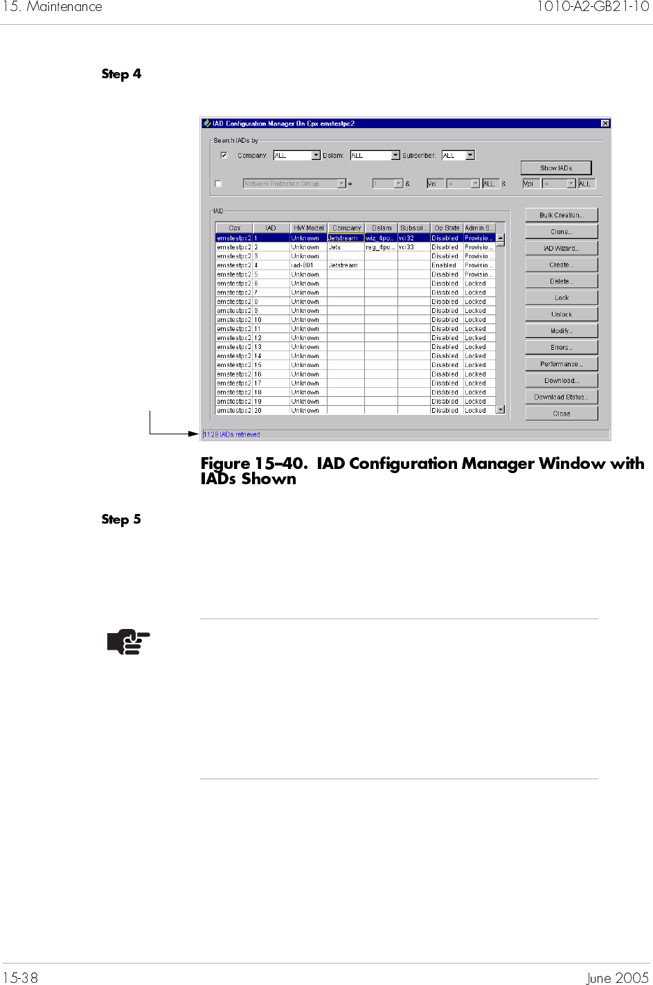
Click Show IADs. A list of available IADs appears (Figure 15–40).
Select IADs to which you want to upgrade the software. Ensure
that the operational state of the IADs you select is Enabled and the
administrative state is Unlocked (refer to Chapter 7, IAD
Provisioning, for more information).
Number of IADs
retrieved
Notes
To select multiple IADs, hold down the Shift or Ctrl
key while making your selections. Using the Shift key
lets you make your selections in contiguous order; the
Ctrl key lets you select IADs in a random order.
The IAD model number and current code version must
be identical before performing a download.
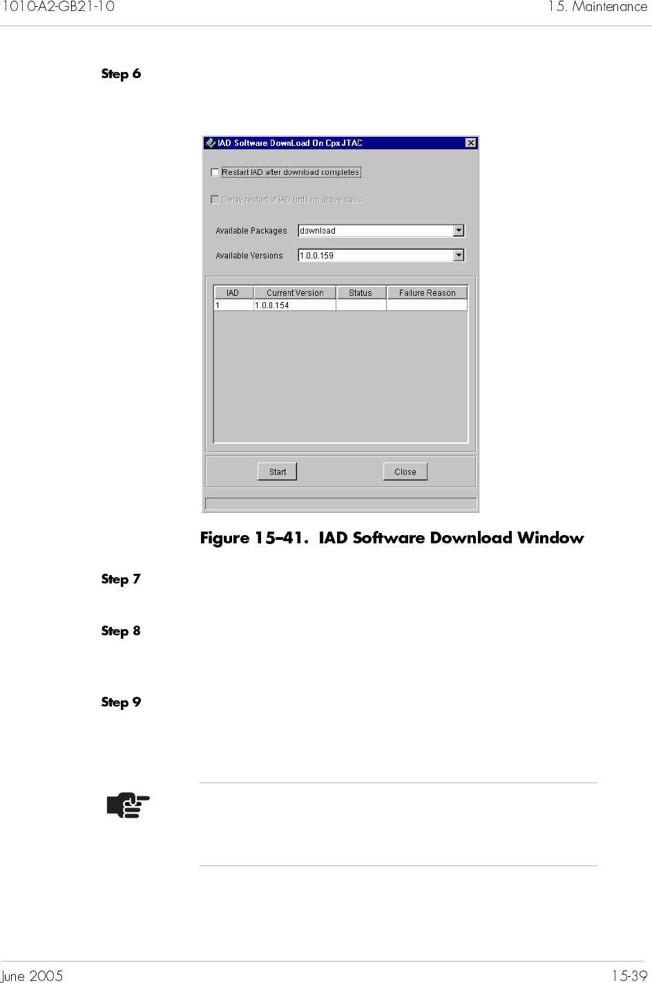
Click Download. The IAD Software Download window appears
(Figure 15–41), displaying the IADs packages and versions.
Select the Restart IAD after download completes
checkbox.
Select the Delay restart of IAD until no active calls
checkbox. (This option is dependent upon the option in Step 7
being selected.)
Select the package you want to download from the Available
Packages drop-down list. (The packages are IAD dependant. These
four packages are download, config, kernel, and asic.)
Note
You can download the packages in any order sequence;
however, you can download only one package at a time.
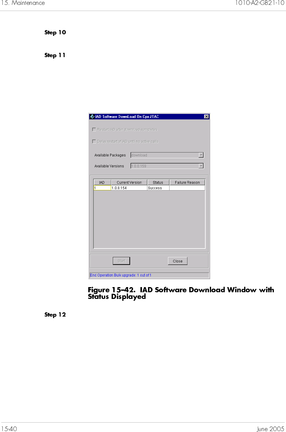
Select the version associated with the package from the
Available Versions drop-down list.
Click Start to begin the download. The operational status,
Waiting, is displayed in the Status column.
When completed, The operation status is displayed as shown in
Figure 15–42. Or if the operation fails, the reason is listed in the
Failure Reason column.
Click Close to return to the IAD Configuration Manager window.
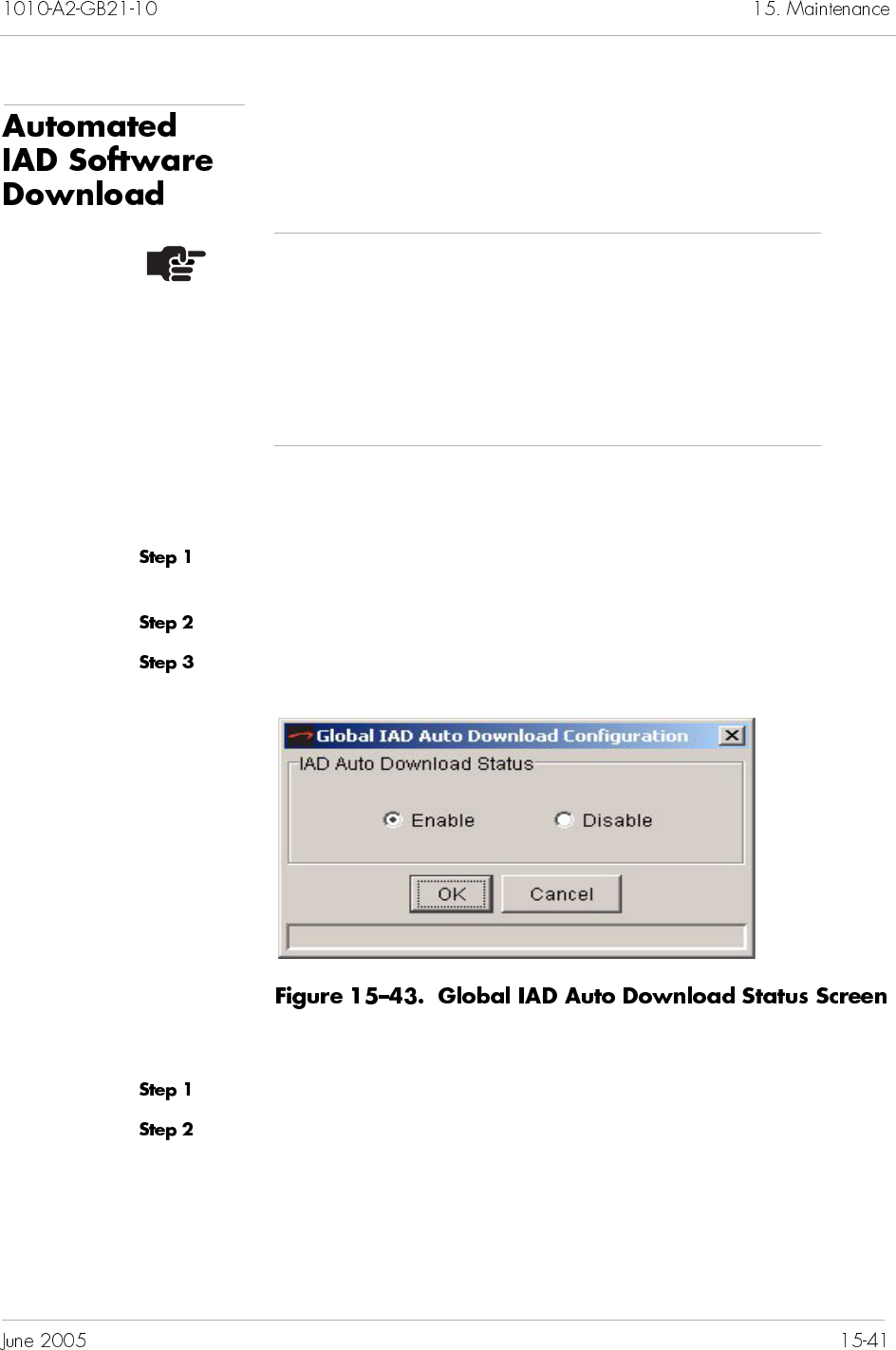
To enable support for IAD Auto Download, you must enable the
Download Status for both the JetVision Server and the CPX.
To enable or disable this feature for the JetVision Server, follow
these steps.
Select Configure Global IAD Auto Download from the Services
menu.
Select Enable or Disable.
Click OK.
To enable or disable this feature for a CPX, follow these steps:
Click the desired CPX-1000 icon from the Tree View.
Select Configure from the Configuration menu.
Notes
Before you use the Automated IAD Software Download
tool, you must use the CPX IAD Firmware Loader
(located on the CPX Installer CD) to load the IAD
software into the correct directory on the MP. For further
information, see the Jetstream CPX-1000 Voice Services
Platform Installation and Operation manual.
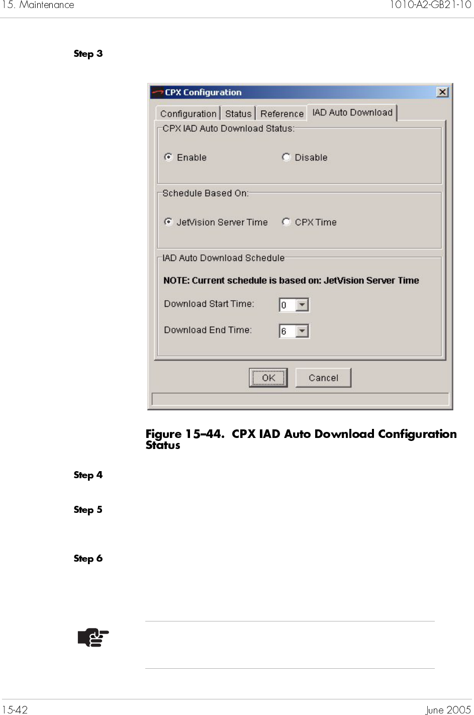
Select the IAD Auto Download tab.
In the CPX IAD Auto Download Status section select Enable or
Disable.
Choose which system to base the IAD Auto Download Schedule
on. You can choose to have the schedule time based on the CPX-
1000 or the JetVision Server time.
Configure the start and stop time to have the download occur.
Choose the Download Start Time: (0:00 - 23:00)
Choose the Download End Time: (0:00 - 23:00)
Notes
Download start and end times cannot be the same.
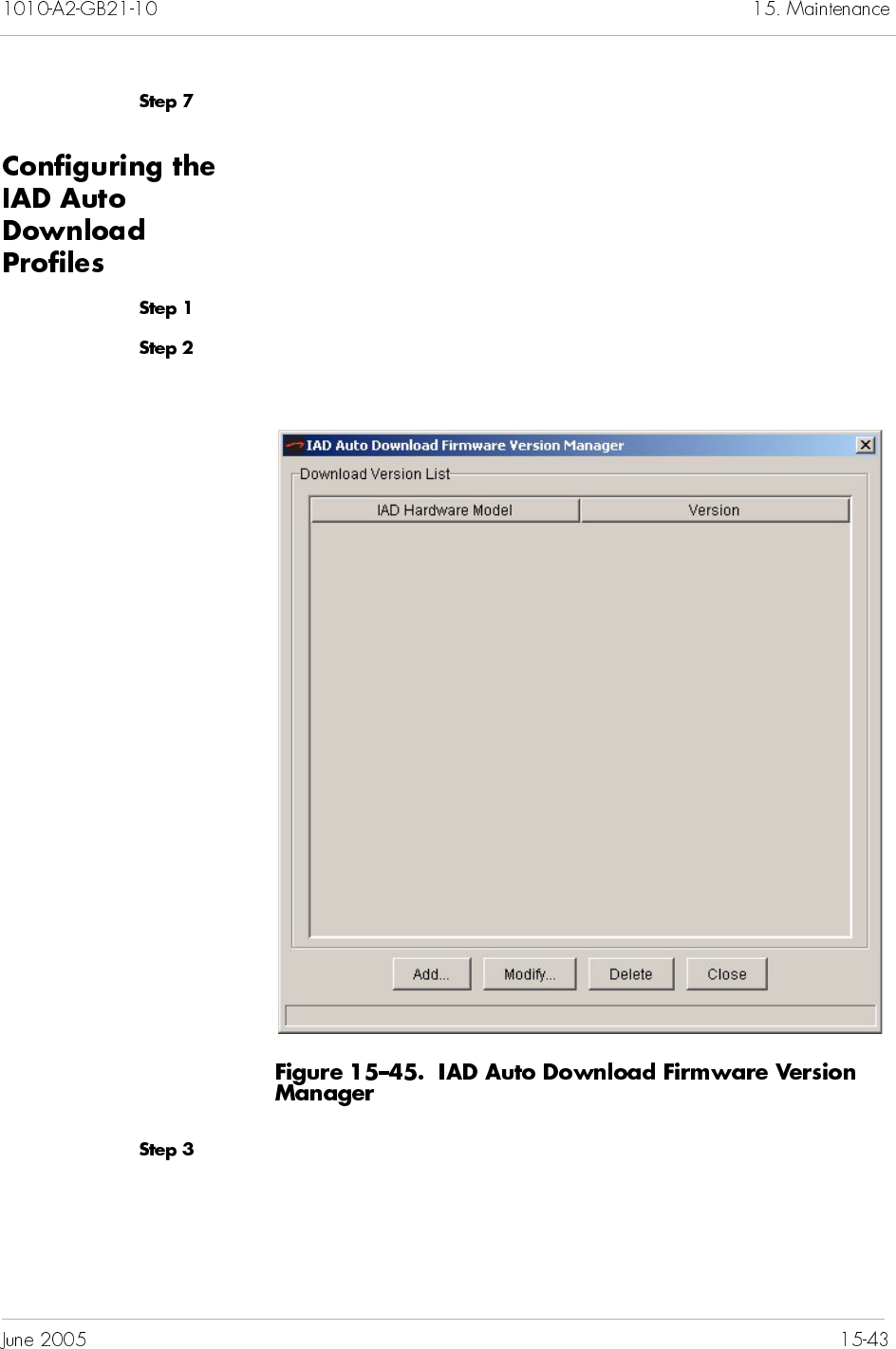
Click OK.
To configure the IAD Auto Download Profiles:
Click the desired CPX-1000 icon from the Tree View.
2.Select Configure IAD Download Versions from the Services
menu.
Select an action button from the bottom of the dialog.
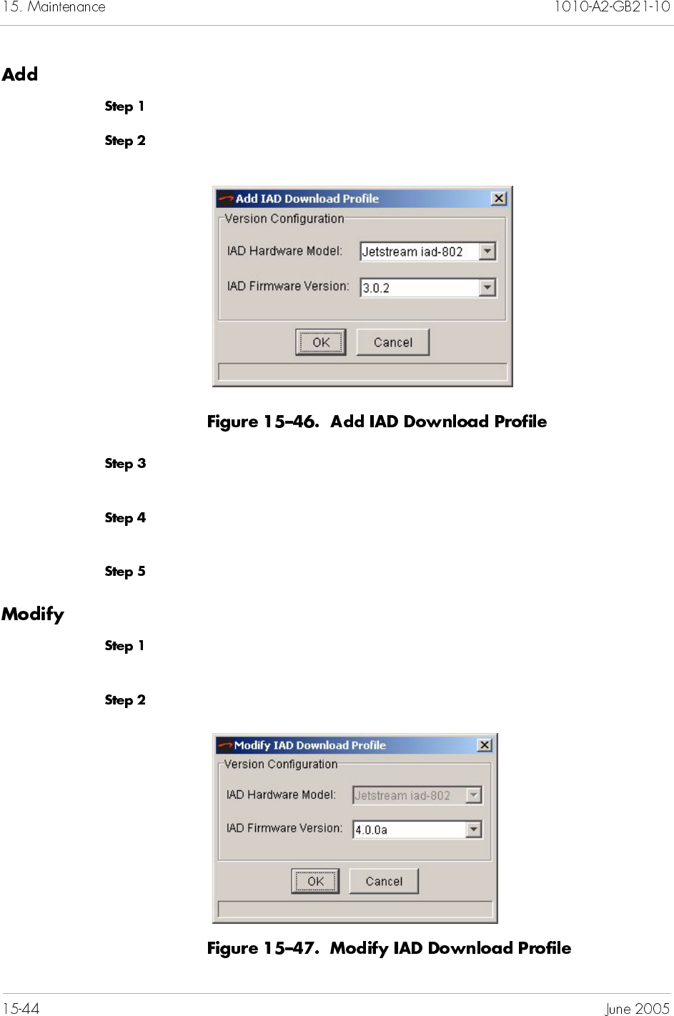
To create an IAD Auto Download Profile:
Click on the Add button.
The following dialog appears:
Select the IAD model. A list of IAD firmware present on the CPX
for this IAD model appears.
Choose the IAD Firmware Version you want to associate with this
IAD model.
Click OK.
To modify an existing IAD Auto Download Profile:
Select the IAD download profile you wish to modify and click on
the Modify button.
The following dialog appears:
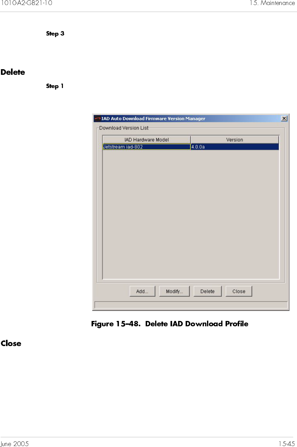
Choose a different IAD Firmware Version to be associated with this
IAD model. (The IAD Hardware Model cannot be changed from
this dialog.)
To remove an IAD Auto Download Profile associated with a CPX:
Select the IAD Auto Download Profile you wish to remove, and
Click Delete.
Click on the Close button to close the IAD Auto Download Profile
Manager dialog.
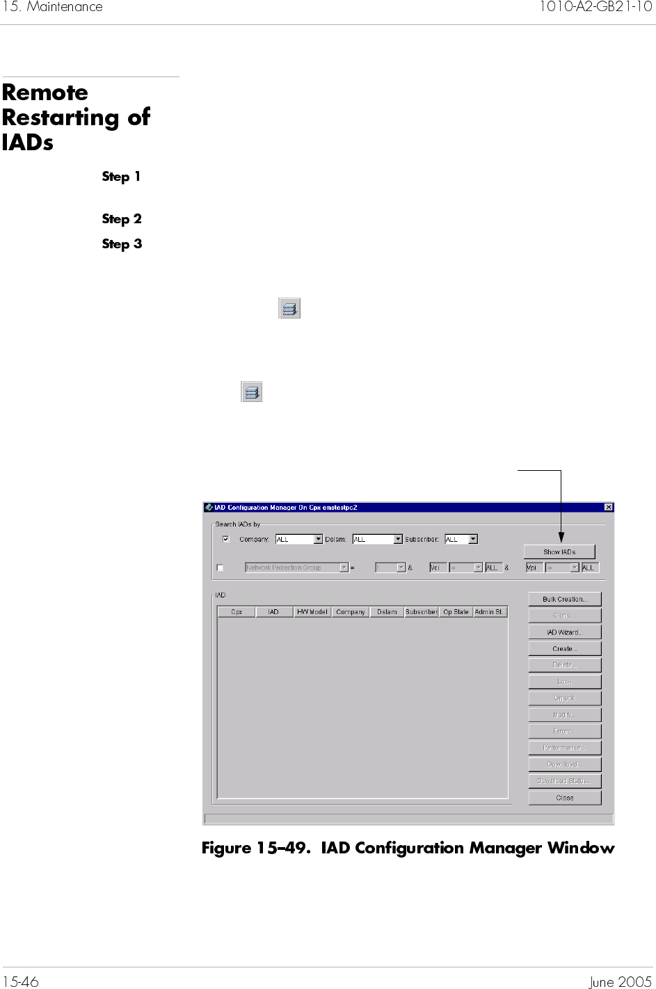
JetVision allows remote restarting of IADs.
To remote restart an IAD:
Click a CPX-1000 from the Tree View and expand the tree by
clicking the + sign.
Click a CPX-1000 icon in the Tree view.
Select IAD Manager from the Configuration menu.
– Or –
Right-click on the Tree View or Map View and select IAD
Manager.
– Or –
Click on the toolbar.
The IAD Configuration Manager window appears (Figure 15–39).
Click here to display IADs
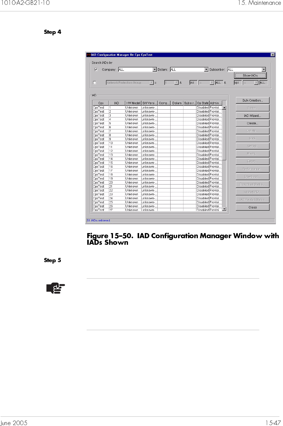
Click Show IADs. A list of available IADs appears (Figure 15–50).
Select the IAD you would like to restart.
Notes
To select multiple IADs, hold down the Shift or Ctrl
key while making your selections. Using the Shift key
lets you make your selections in contiguous order; the
Ctrl key lets you select IADs in a random order.
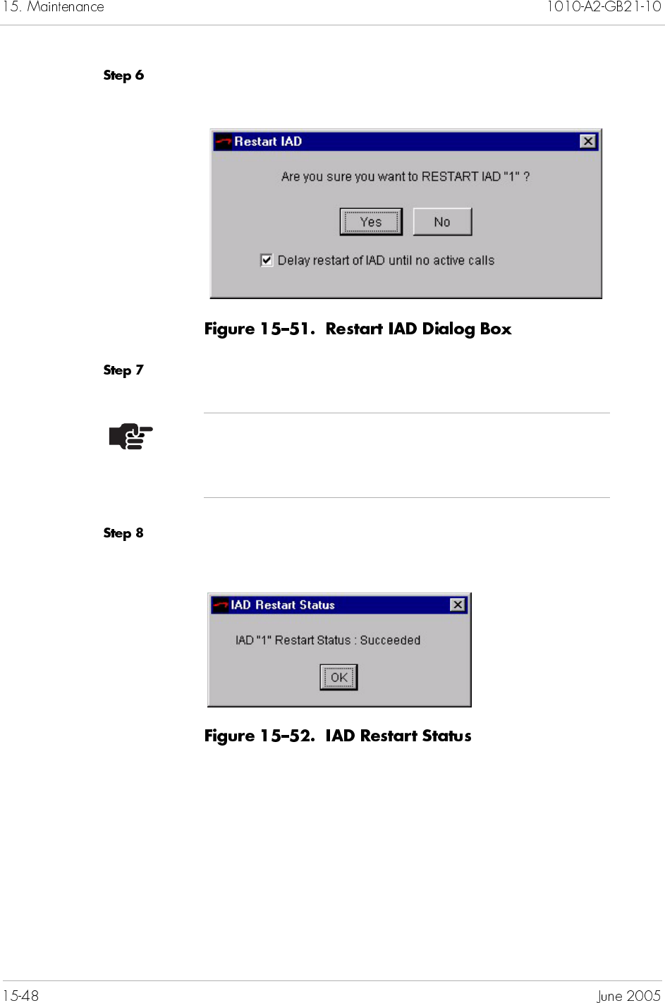
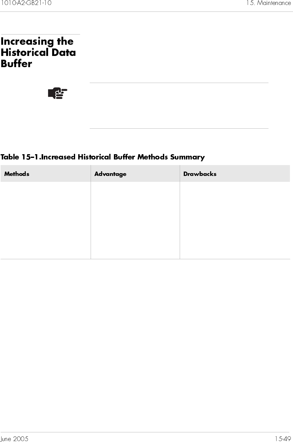
Two methods are used to increase the buffer size; each with its
advantage and drawback (Table 15–1).
Note
With the following procedures, we recommend that you
have working experience with Oracle, UNIX, and/or
Windows.
Keeping the same data file
and control file contents
but increasing the size of
data file
Cold backup not required Historical data not preserved;
need to export data before
operations.
Adding another data file to
existing tablespace
Preserve data Changes in the control file; you
need to save a control file and
perform a complete cold backup
before operations.
To increase the historical buffer size:
Use InfoCenter to stop JetVision Server service (Chapter 17,
InfoCenter Services).
Back up the Oracle historical data (Chapter 17, InfoCenter
Services).
Create an sql file (e.g., recreate.sql) similar to Figure 15–53 for
Windows or Figure 15–54 for Solaris.
Save the sql file to the appropriate directory.
For Solaris: /tmp/recreate.sql
For Windows: c:\temp\recreate.sql
Type the following entry:
For Solaris: #su – oracle
$cd /tmp
$svrmgrl
svrmgrl>@recreate
For Windows: C:\temp>svrmgrl
svrmgrl>@recreate
Save and back up the control.trc file to the appropriate
directory.
For Solaris: /opt/control.trc
For Windows: c:\temp\control.trc
Note
The sample files show the historical buffer capacity is
increased to 250 MB.
connect internal/oracle;
alter tablespace JSDBLOG_TS offline;
drop tablespace JSDBLOG_TS INCLUDING CONTENTS;
CREATE TABLESPACE JSDBLOG_TS
DATAFILE ’d: \orant\database\logjet2.dat’ SIZE 25M reuse autoextend
on next 5M maxsize 250M
DEFAULT STORAGE (INITIAL 200K NEXT 100K
MINEXTENTS 1 MAXEXTENTS 999
PCTINCREASE 10)
ONLINE;
alter database backup controlfile to ’c:\temp\control.trc’;
alter database backup controlfile to TRACE;
connect jsdbuser/jsdbuser;
CREATE TABLE “JSDBUSER”.EVENTLOG
(KEY VARCHAR2(200) NOT NULL,
LO_TIME NUMBER NULL,
ST_EVENT VARCHAR2(2000) NULL,
PRIMARY KEY (KEY))
STORAGE ( INITIAL 200K NEXT 100K MINEXTENTS 1
MAXEXTENTS 999 ) TABLESPACE “JSDBLOG_TS”;
CREATE TABLE “JSDBUSER”.OMACTIONEVENT
(KEY VARCHAR2(200) NOT NULL,
ST_RDN VARCHAR2(2000) NULL,
ST_TIME VARCHAR2(2000) NULL,
ST_USERID VARCHAR2(2000) NULL,
ST_OPERATION VARCHAR2(2000) NULL,
PRIMARY KEY (KEY))
STORAGE ( INITIAL 200K NEXT 100K MINEXTENTS 1
MAXEXTENTS 999 ) TABLESPACE "JSDBLOG_TS";
CREATE TABLE "JSDBUSER".historyalarms
(KEY VARCHAR2(200) NOT NULL,
LO_TIMESTAMP NUMBER,
ST_SOURCE VARCHAR2(2000),
IN_SEVERITY NUMBER,
IN_SEQUENCEID NUMBER,
ST_DESCRIPTION VARCHAR2(2000),
IN_ID NUMBER,
BO_SERVICEAFFECTING VARCHAR2(6),
ST_EXTRADATA VARCHAR2(2000),
PRIMARY KEY(KEY))
STORAGE ( INITIAL 200K NEXT 100K MINEXTENTS 1
MAXEXTENTS 999 ) TABLESPACE "JSDBLOG_TS";
connect internal/oracle;
alter tablespace JSDBLOG_TS offline;
drop tablespace JSDBLOG_TS INCLUDING CONTENTS;
CREATE TABLESPACE JSDBLOG_TS
DATAFILE ’/opt/jetstream/ora_unix/oracle/oradata/jet2/logjet2.dat’
SIZE 25M reuse autoextend on
next 5M maxsize 250M
DEFAULT STORAGE (INITIAL 200K NEXT 100K
MINEXTENTS 1 MAXEXTENTS 999
PCTINCREASE 10)
ONLINE;
alter database backup controlfile to ’/opt/control.trc’;
alter database backup controlfile to TRACE;
connect jsdbuser/jsdbuser;
CREATE TABLE "JSDBUSER".EVENTLOG
(KEY VARCHAR2(200) NOT NULL,
LO_TIME NUMBER NULL,
ST_EVENT VARCHAR2(2000) NULL,
PRIMARY KEY (KEY))
STORAGE ( INITIAL 200K NEXT 100K MINEXTENTS 1
MAXEXTENTS 999 ) TABLESPACE "JSDBLOG_TS";
CREATE TABLE "JSDBUSER".OMACTIONEVENT
(KEY VARCHAR2(200) NOT NULL,
ST_RDN VARCHAR2(2000) NULL,
ST_TIME VARCHAR2(2000) NULL,
ST_USERID VARCHAR2(2000) NULL,
ST_OPERATION VARCHAR2(2000) NULL,
PRIMARY KEY (KEY))
STORAGE ( INITIAL 200K NEXT 100K MINEXTENTS 1
MAXEXTENTS 999 ) TABLESPACE "JSDBLOG_TS";
CREATE TABLE "JSDBUSER".historyalarms
(KEY VARCHAR2(200) NOT NULL,
LO_TIMESTAMP NUMBER,
ST_SOURCE VARCHAR2(2000),
IN_SEVERITY NUMBER,
IN_SEQUENCEID NUMBER,
ST_DESCRIPTION VARCHAR2(2000),
IN_ID NUMBER,
BO_SERVICEAFFECTING VARCHAR2(6),
ST_EXTRADATA VARCHAR2(2000),
PRIMARY KEY(KEY))
STORAGE ( INITIAL 200K NEXT 100K MINEXTENTS 1
MAXEXTENTS 999 ) TABLESPACE "JSDBLOG_TS";
To increase the historical buffer size:
Stop JetVision Server service by using InfoCenter (Chapter 17,
InfoCenter Services).
Back up the Oracle historical data (Chapter 17, InfoCenter
Services).
Create an sql file (e.g., incr.sql) similar to Figure 15–55 for
Windows or Figure 15–56 for Solaris.
Save the sql file to the appropriate directory.
For Solaris: /tmp/incr.sql
For Windows: c:\temp\incr.sql
Type the following entry:
For Solaris: #su – oracle
$cd /tmp
$svrmgrl
svrmgrl>@incr
For Windows: C:\temp>svrmgrl
Svrmgrl>@incr
Note
The sample files show that 150 MB is added to the
existing historical buffer.
connect internal/oracle;
alter tablespace JSDBLOG_TS
add datafile ’c:\orant\database\log2add.dat’ size 150M ;
alter database backup controlfile to ’c:\temp\control.trc’;
alter database backup controlfile to TRACE;
connect internal/oracle;
alter tablespace JSDBLOG_TS
add datafile ’/opt/jetstream/ora_unix/oracle/oradata/jet2/
log2add.dat’ size 150M ;
alter database backup controlfile to ’/tmp/control.trc’;
alter database backup controlfile to TRACE;

This chapter provides instructions to perform the following tasks:
Launching Integrated Monitor (page 16-2)
Interpreting Integrated Monitor information (page 16-2)
Refreshing Integrated Monitor (page 16-5)
Integrated Monitor serves as an “indicator panel” for a CPX-1000.
The Integrated Monitor consists of three sections, showing the
status of:
GR-303 EOC and TMC links for each Interface Group
Network Protection Group and PSTN Protection Group
CPX-1000 connection
Integrated Monitoring is not supported for the T1 CAS Interface
Group.
Table 16–1 lists the monitoring operations of each entity. Entirely
passive, Integrated Monitor does not provide control over the
CPX-1000 or associated managed domain. Rather, it provides an
“at a glance” real-time view of the health of a CPX-1000 and its
associated managed domain.
Integrated Monitor uses colors as visual cues to indicate the
different states of each entity. Refer to Chapter 17, InfoCenter
Services, to customize colors of your preference.
To launch the Integrated Monitor:
Ensure the service of JetVision Server is started (Chapter 17,
InfoCenter Services).
Locate the CPX-1000 by clicking the group icon from the Tree View
where the CPX-1000 resides.
…
GR-303 Interface
Groups
It provides the physical mapping of the TMC/EOC/TMCPPS/
EOCPPS with the DS1 # to an IG (i.e., T1 IG) and the physical
port to logical channel (i.e., STS IG). The Lock symbol indicates
that the particular channel is down as it has been locked.
the operational state of each TMC and EOC (i.e., Up or Down)
the operational state for the PPS of the TMC and EOC (i.e., Up
or Down)
the standby state of each TMC and EOC (i.e., active or standby)
the redundancy state of each TMC and EOC (i.e., primary or
secondary)
Protection Groups
(Network and PSTN)
the operational state of the Protection Groups (i.e., Up or Down)
the standby state of the Protection Groups (i.e., active or
standby)
the redundancy state of the Protection Groups (i.e., primary or
secondary)
CPX-1000 the connection status of each entity
Note
The Integrated Monitor will not run if the JetVision
service is not running.
Click the desired CPX-1000, and select Integrated
Monitoring from the Configuration menu.
– Or –
Right-click the desired CPX-1000, and select Integrated
Monitoring from the pop-up menu.
The Integrated Monitor view similar to Figure 16–1 opens in a
separate window.
Click here to close.
The lock indicates
the Admin state.
Click here to refresh
Note
Place your cursor over the entity to display the tool tip
information.
The active links are bordered by yellow lines and the status area is
displayed in white when the status cannot be retrieved for an
entity. The entity is displayed in x(y, z) format (Table 16–2).
Table 16–3 describes the meaning of different states.
* channel is a logical identifier in a STS-1 link.
X Indicating the DS1
number.
Not applicable Not applicable
Y Indicating the card
number on which the
DS1 is provisioned.
Indicating the card
number to which the
Network link is
connected.
Indicating the card
number to which the
STS-1 link is connected.
Z Indicating the port/
channel* number to
which the DS1 is
connected.
Indicating the port
number of the
Network link.
Indicating the port
number of the STS-1 link.
JetVision retrieves and updates the status at regular interval. If
Integrated Monitor and the CPX-1000 become unsynchronized,
click on the Integrated Monitor toolbar to retrieve and display
the latest status information.
Interface
Groups
Operational state: Up
Standby state: Active
The CPX-1000 is
transmitting/receiving
EOC/TMC messages
from the Class 5 switch
on this link.
Operational state: Up
Standby state: Standby
The CPX-1000 is
transmitting/receiving
EOC/TMC messages
from the Class 5 switch
on this link if the active
link fails.
Operational state: Down
Standby state: Active/
Standby
The CPX-1000 is not
transmitting/receiving
EOC/TMC messages
from the Class 5 switch
on this link.
Network
Protection
Group
Operational state: Up
Standby state: Active
The network link is
functioning.
Operational state: Up
Standby state: Standby
The network link is up
but kept as standby to
the active link.
Operational state: Down
Standby state: Active/
Standby
The network link is
down.
PSTN
Protection
Group
Operational state: Up
Standby state: Active
The provisioned link is
functioning.
Operational state: Up
Standby state: Standby
The provisioned link is
up but kept as standby
to the active link.
Operational state: Down
Standby state: Active/
Standby
The provisioned link is
down.

This chapter describes InfoCenter—a diagnostic utility that
monitors the status of JetVision and related services. You use
InfoCenter to perform the following tasks:
Starting InfoCenter on Windows (page 17-2)
Starting InfoCenter on Solaris (page 17-2)
Starting and stopping JetVision and its related services
(page 17-7)
Backing up Oracle database (page 17-8)
Restoring Oracle database (page 17-10)
Adjusting the size of historical data (page 17-11)
Adding the geographical network map (page 17-13)
Changing Data Collector Server values (page 17-14)
Customizing colors on Integrated Monitor (page 17-14)
To start InfoCenter from a Windows computer, double-click the
JetVision InfoCenter icon on your computer’s desktop, or open a
command window and type:
c:\Jetstream\common\InfoCenter_2.5\bin\
startinfocenter.bat
The JetVision InfoCenter main window appears (Figure 17–1).
To start InfoCenter from a Solaris computer, open a console
window, go to the InfoCenter directory, and invoke the
startinfocenter.sh command. For example:
cd /opt/jetstream/common/InfoCenter_v25/bin
./startinfocenter.sh
The JetVision InfoCenter main window similar to the one in
Figure 17–1 appears.
Note
Depending on the application installed on your
workstation, your InfoCenter might appear different
from Figure 17–1. For example, if you don’t have JetWay
installed, the JetWay Proxy will not displayed.
JetVision InfoCenter is a diagnostic utility that monitors the status
of JetVision and related services. You can start and/or stop services
from InfoCenter. You can use InfoCenter to refresh the application
and change the application property settings of:
JetVision Server
JetVision Client
Database Monitor
Data Collector Server
Integrated Monitoring
JetWay Server
Third-party software
Table 17–1 describes the property settings of each application.
JetVision
Server
JetVision Server ID This field shows the current JetVision Server ID,
which you can change.
Oracle Connection String This read-only field shows the Oracle connection
string.
DB Stats Gathering Time This field controls the time frequency that the
database monitor gathers database statistics.The
default is 10,800,000 ms (180 mins).
DB Size Check Timer This field controls the time frequency that the
database monitor checks whether the historical
data and performance management data need to
be purged.The default is 86,400,000 ms (24 hrs).
Log DB Size This field specifies the size of the historical
database is expressed in megabytes.
The size of historical data buffer is specified
during installation. Refer to Chapter 15,
Maintenance, to increase the buffer size.
JetVision
Server
(continued)
Upper Log DB Size Limit This field sets the historical data buffer upper
limit and is expressed as a % (the default is 90%).
When the threshold exceeds the size specified
(i.e., 90% of the historical buffer size), the alarms
are truncated to the low threshold. No alarms are
generated.
Lower Log DB Size Limit This field is expressed as a % (the default is 70).
When the threshold goes below the size specified,
the alarms are purged in a First in, First Out
manner.
PM DB Size This field specifies the size of the database of
historical performance management and is
expressed in megabytes.
The size of database buffer is specified during
installation. The default values are:
small network (<15 CPX-1000)
medium network (15–30 CPX -1000)
large network (30–50 CPX-1000)
Refer to Changing the Data Collector Server
Values to increase the database buffer.
Upper PM DB Limit This field sets the database buffer upper limit and
is expressed as a % (the default is 80%). When the
threshold exceeds the size specified (i.e., 80% of
the historical buffer size), the alarms are
truncated to the low threshold.
Refer to Changing the Data Collector Server
Values to change the upper limit.
Lower PM DB Limit This field is expressed as a % (the default is 70).
When the threshold goes below the size specified,
the alarms are purged in a First in, First Out
manner.
Refer to Changing the Data Collector Server
Values to change the lower limit.
JetVision
Server
(continued)
Filter Duration This field specifies the time frequeny (e.g., to poll
the historical performance management statistics.
The changes made in InfoCenter reflect on the
historical PM filter window.
Refer to Changing the Data Collector Server
Values to change the filter duration.
Register Type This field specifies how much data (e.g., 15
minutes) to poll the historical performance
management statistics.
The changes made in InfoCenter reflect on the
historical PM filter window.
Refer to Changing the Data Collector Server
Values to change the register type.
Network Background
Bitmap
Use this field to change a different network map
background.
Refer to Customizing Colors on Integrated
Monitor for instructions.
JetVision
Client
JetVision Server ID Use this field to change the Server ID that binds
the JetVision Client.
Web Browser Path Use this field to change the path of the Web
browser.
DataCollector
Server
JetVision Server ID This field shows the current JetVision Server ID.
Integrated
Monitoring
Color for different
operational states
Use these fields to customize colors for the
Integrated Monitor.
Refer to Customizing Colors on Integrated
Monitor for instructions.
JetWay Server
JetVision Server ID This field shows the ID of the current JetVision
Server to which you are connecting.
JetWay Server ID This field shows the ID of the JetWay Server.
JetVision Server
Hostname
Use this field to change the Server ID that binds
the JetVision Client.
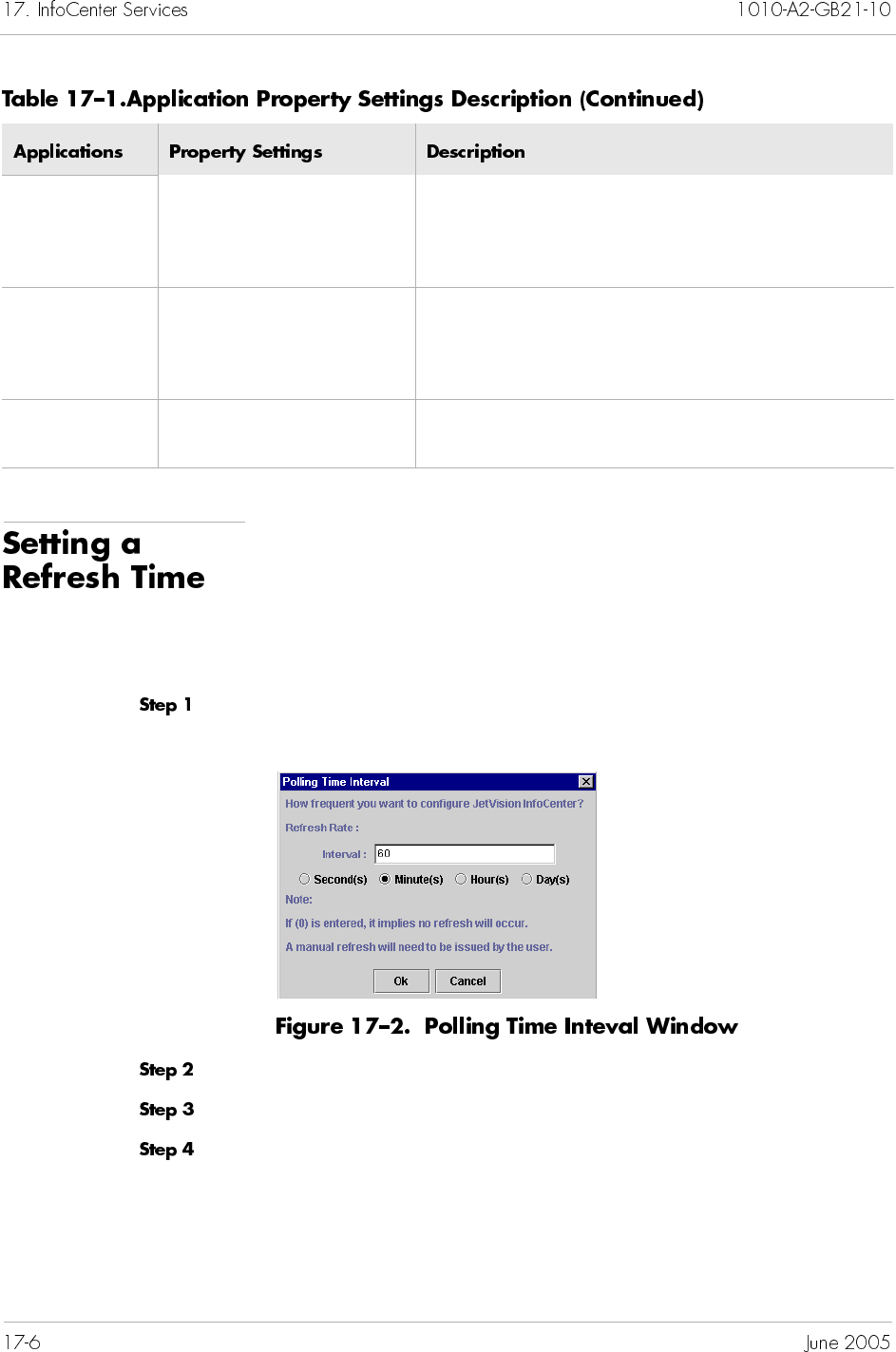
When starting and/or stopping JetVision related services and
applications outside of InfoCenter, you need to refresh the Oracle
database to update the changes. By default, InfoCenter refreshes
every 60 minutes.
To change the default time interval:
Select Configure Refresh Rate from the Setting menu. The
Polling Time Interval window appears (Figure 17–2).
Delete the previous refresh rate in the Interval field.
Type a new value, and select a polling interval.
Click OK.
Apache Web
Server
Web Httpd Port Use this field to change the port number.
Document Path This read-only field shows the path to the
Apache Web server.
Oracle Server
Oracle SID This read-only field shows the ID of Oracle
server.
Oracle User ID This read-only field shows the ID of Oracle user.
VisiBroker for
Java
Not applicable
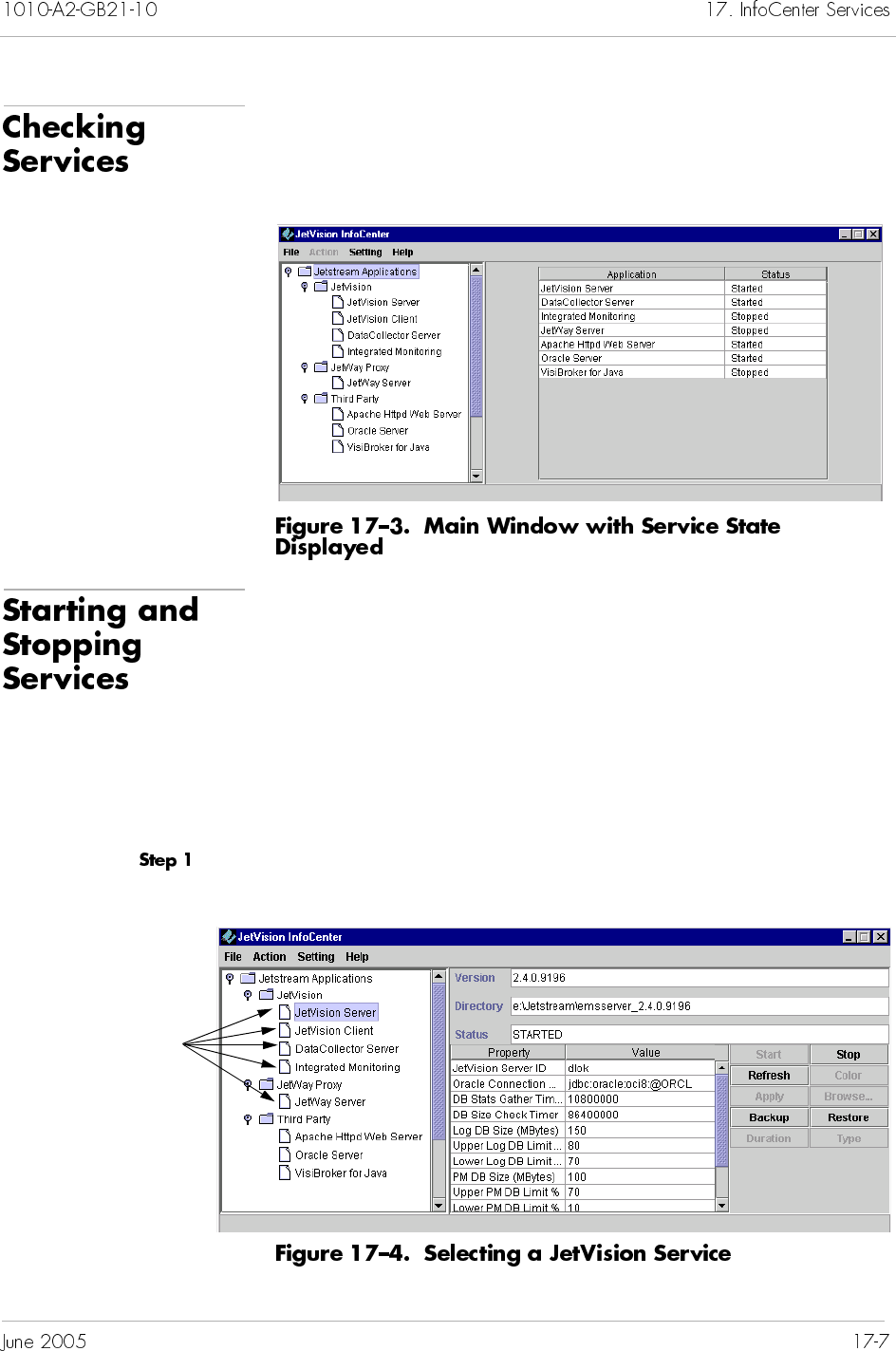
To check the state of each service, click Jetstream
Applications at the main window. The right panel displays the
state of each service (Figure 17–3).
You can use InfoCenter to start and stop services of
JetVision Server
DataCollector Server
Integrated Monitoring
JetWay Server
Third-party software
To start or stop service:
Select a JetVision service that you want to start or stop
(Figure 17–4).
Click to select a
JetVision service
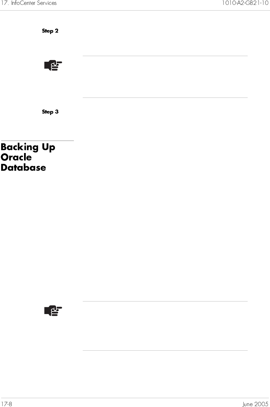
Click an operation button (Start or stop). A prompt appears,
asking if you want to perform the service.
Click Yes. After the service completes, the operation appears in
the Status field.
This section provides instruction for backing up Oracle database.
Besides the Oracle databse, the backup data also includes JetVision
user information and CPX IP addresses and logons. To back up the
CPX-1000 configuration files, refer to Chapter 15, Maintenance.
Since InfoCenter can be launched with either JetVision Client or
JetVision Server, the location of the backup/restore database
depends on where both the JetVsion Server and Client are installed
and which server to which the client binds. For example,
Both JetVision client and server are installed on the same
machine, and the client binds to the server on the same
machine. In this case, the database is backed up to or
restored from the server installed on the same machine.
Both JetVision client and server are installed on the same
machine, but the client binds to a server on different
machine. In this case, the database is backed up to or
restored from the local server and not the server to which
the client binds.
Note
When stopping JetVision Server, you will need to enter
your login ID and password before the stopping process
starts.
Note
You will be unable to perform the backup/restore
operation when only JetVision Client is installed on one
machine, and it binds to a JetVision Server on a different
machine.
To back up Oracle database:
Select JetVision Server from the JetVision InfoCenter window
(Figure 17–5).
Click Backup. The Backup window appears, displaying the
backup file name and default directory path (Figure 17–6).
Click OK if you want to back up the server data to the default
directory, or click Browse to navigate to a different directory.
Click OK to complete the operation.
View-only fields
To restore Oracle database:
Select JetVision Server from the JetVision InfoCenter window
(Figure 17–5 on page 17-9).
Click Stop to stop the service of JetVision server (Starting and
Stopping Services on page 17-7).
. Click Restore. The Restore window appears, listing the last
backup file name and its location (Figure 17–7).
Click OK if you want to restore the server data to the default
directory, or click Browse to navigate to a different directory.
Click OK to return to the JetVision InfoCenter window.
Click Start to start the service of JetVision server (Starting and
Stopping Services on page 17-7).
Note
Refer to Backing Up Oracle Database on page 17-8 for
restored database location.
JetVision lets you adjust the size of historical data stored in the
database by setting the folowing following DbMonitor properties:
Log DB Size
Upper Log DB Limit
Lower Log DB Limit
Upper PM DB Limit
Lower PM DB Limit
To adjust the size of the history data:
Start JetVision InfoCenter. The JetVision InfoCenter main window
appears (Figure 17–8).
Click here to display the
property settings
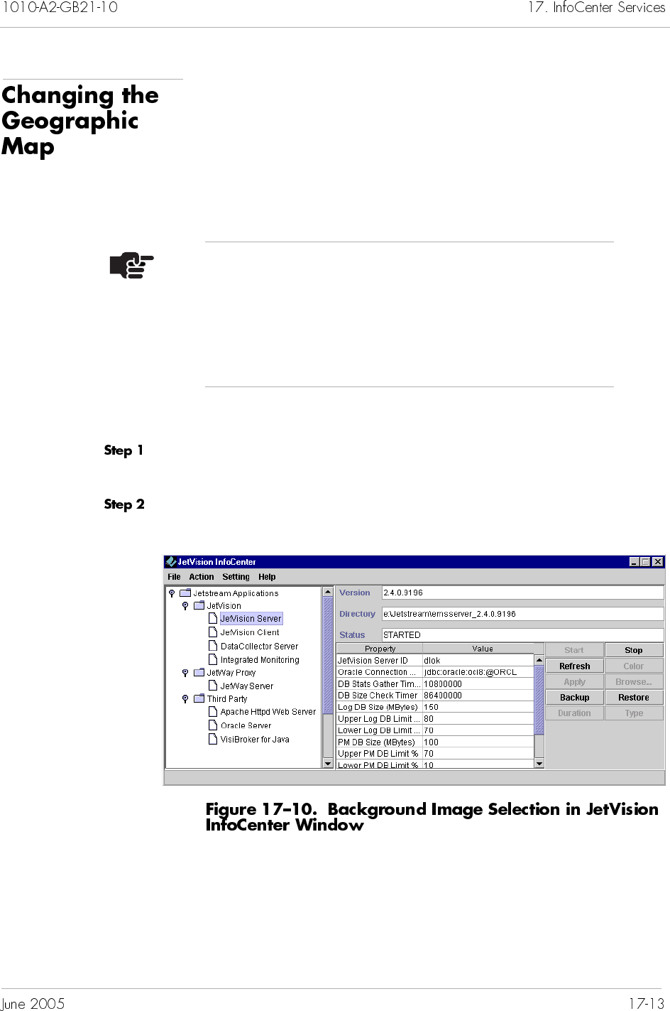
JetVision InfoCenter lets you change the geographic map image
that is displayed in the JetVision Server Main window.
Geographic image files can be stored in any network or local
directory. When changing the image, InfoCenter copies the image
file from its original location to InfoCenter’s default directory:
Jetstream/emsserver_2.5.X/images
To change the geographic image:
Launch JetVision InfoCenter. The JetVision InfoCenter main
window appears (Figure 17–8 on page 17-11).
Click JetVision Server and its view-only status and property
settings display on the right side (Figure 17–10).
Notes
JetVision provides only one geographic map image file.
If you want to display an image of your geographic area,
use image files from a third-party vendor.
JetVision supports only GIF or JPEG formats. The BMP
format is not supported.
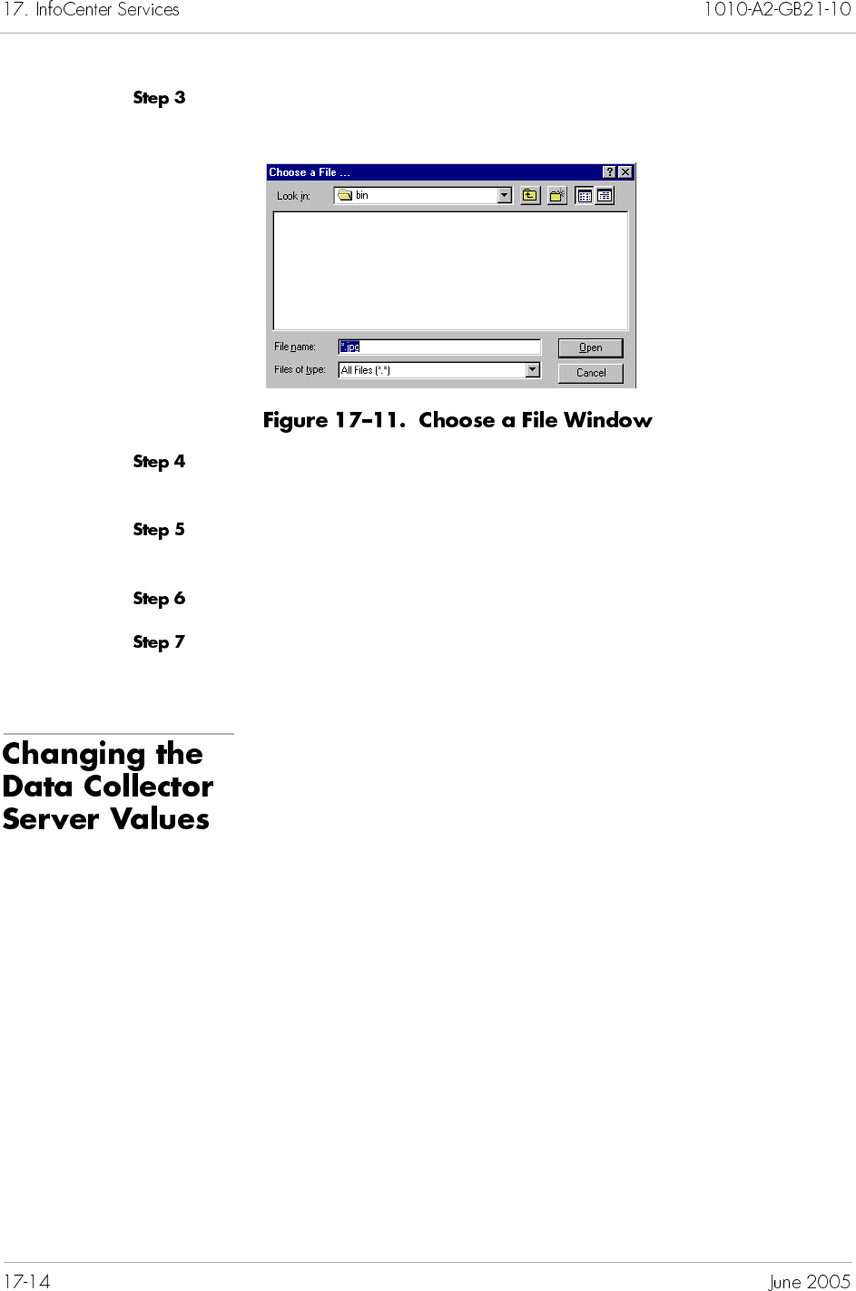
Click Background Image then click Browse. The Choose a File
window appears (Figure 17–11).
Navigate to the directory where the new image file is located, and
select the image file name from the list.
Click Open. InfoCenter copies the new image file to its default
directory.
Click Apply.
Click Yes to continue. The new image file name appears in the
Background Image property value field in InfoCenter.
The Data Collector Server maintains the buffer size of the historical
performance management on MP and CP cards, as well as on the
DS1 lines and paths. You can specify how much database to keep
before they are purged. You can also specify how much and how
frequent to poll historical performance management statistics.
Refer to Table 17–1 on page 17-3 for a description of each field.
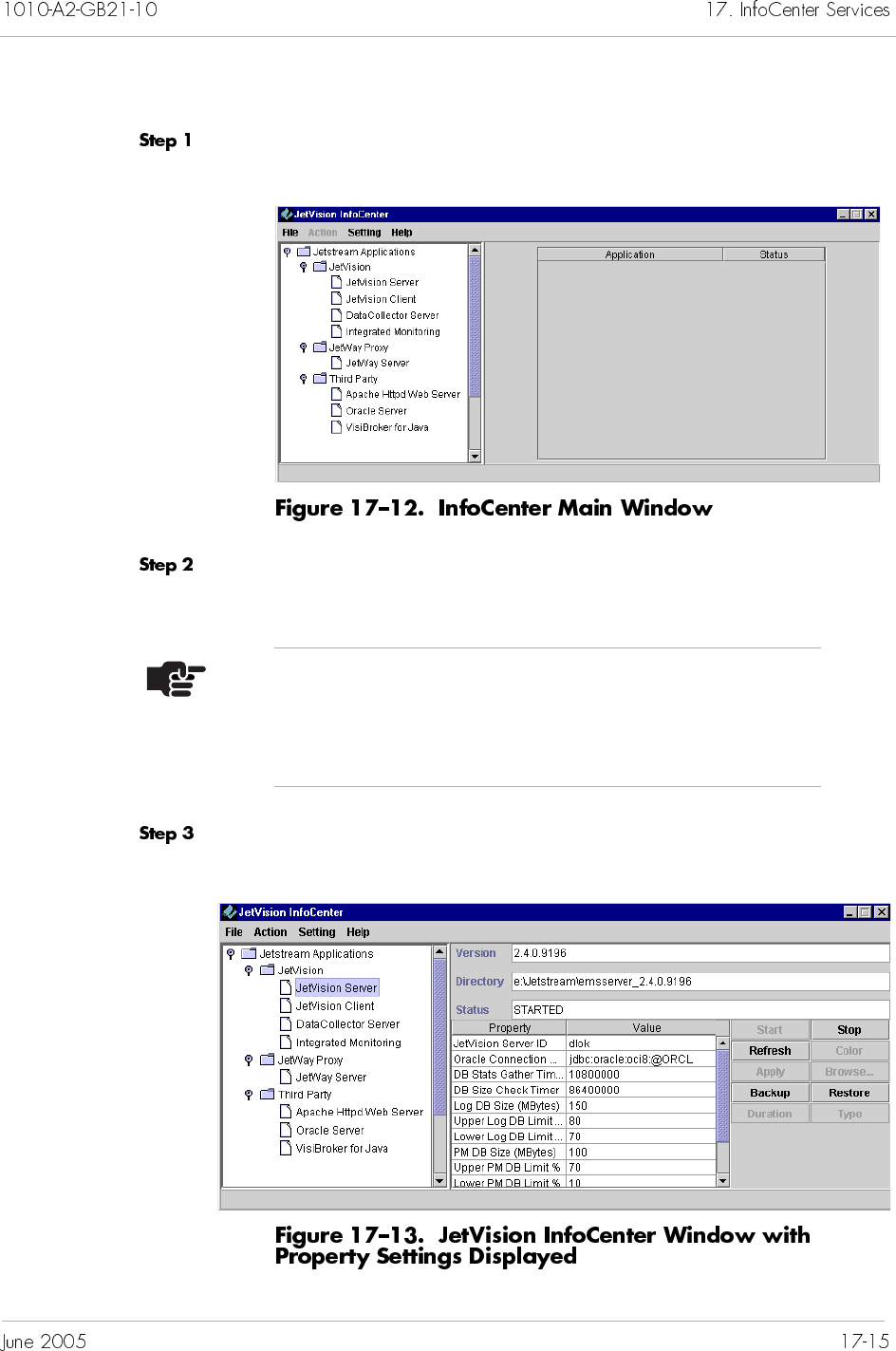
To change the property values of Data Collector Server:
Launch JetVision InfoCenter. The JetVision InfoCenter main
window appears (Figure 17–12).
Verify and ensure the service of JetVision Server is started (Starting
and Stopping Services on page 17-7).
Click JetVision Server. The right panel displays the Data
Collector Server property (Figure 17–13).
Note
The Data Collector server will not run if the PM history
console window is closed and/or the service of JetVision
Server is stopped.
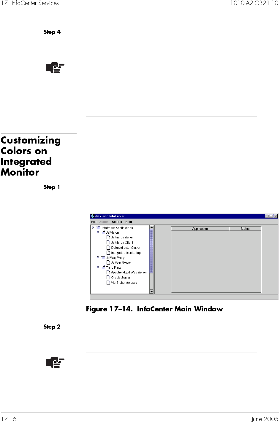
Place the cursor inside the desired Value field and type the new
value.
By default, Intergrated Monitor uses four colors to indicate the
states of each entity: green, blue, gray, and yellow. You can
customize the color settings to represent each state.
To customize Integrated Monitor colors:
Launch JetVision InfoCenter. The JetVision InfoCenter main
window appears (Figure 17–14).
Verify and ensure the service of JetVision Server is started (Starting
and Stopping Services on page 17-7).
Note
When changing values in the Filter Duration and
Register Type protperties, you can click the Duration
and Type buttons, respectively, to display the selection.
The changes made in Filter Duration and Register Type
reflect on the historical PM filter window.
Note
The Integrated Monitor will not run if the PM history
console window is closed and/or the service of JetVision
Server is stopped.
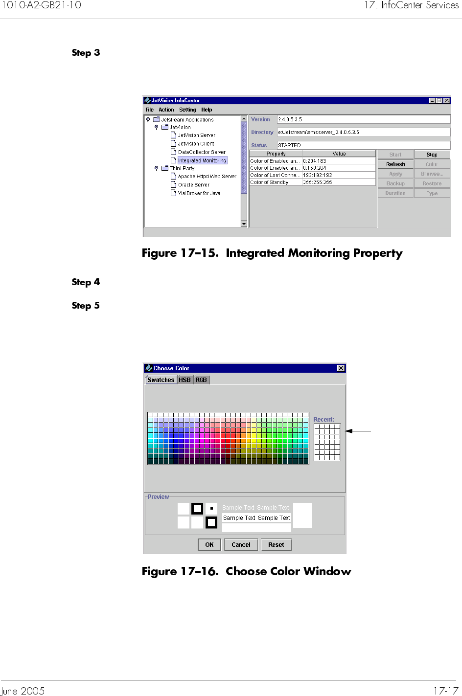
Click Integrated Monitoring. The right panel displays the
Integrated Monitoring property (Figure 17–15).
Click Refresh to enable the coloring operation.
Select the Integrated Monitoring operational state to which you
want to change color, then click Color. The Choose Color window
appears (Figure 17–16).
This panel shows the
recent selected
colors.
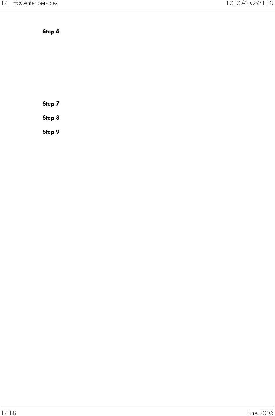
Select the color from one of the following:
Swatches: the color appears on the right panel and preview
area.
HSB: the Hue-Saturation-Brightness is an alternative to RGB
for specifying colors. HSB ranges from 0.0 to 1.0.
RGB: represents the primary colors: red (R), green (G), and
blue (B). Type numbers between 0–255 in each field.
Click OK to return to the main window.
Click Apply to set the color selection.
Repeat Step 5 through Step 8 to customize color on another state.

Jetutil is a utility tool that is automatically installed with the
JetVision server. You can run jetutil anytime to help with system
diagnostics. Jetutil enables you to check the following:
Operating system information (i.e., memory, disk space,
etc.)
Individual services (i.e., Apache and Oracle)
JetVision Database (i.e., Oracle version, schema structure,
etc.)
Oracle error messages
System health check
System requirement (perform this check before installing
JetVision)
While most checks are on individual services, system health check
provides the comprehensive check on the whole system. When in
doubt as to which service to check, perform a system health check.
Although the operation between Windows and Solaris platforms is
similar, but they are not identical.
For Windows environment, go to page 18-2
For Solaris environment, go to page 18-7
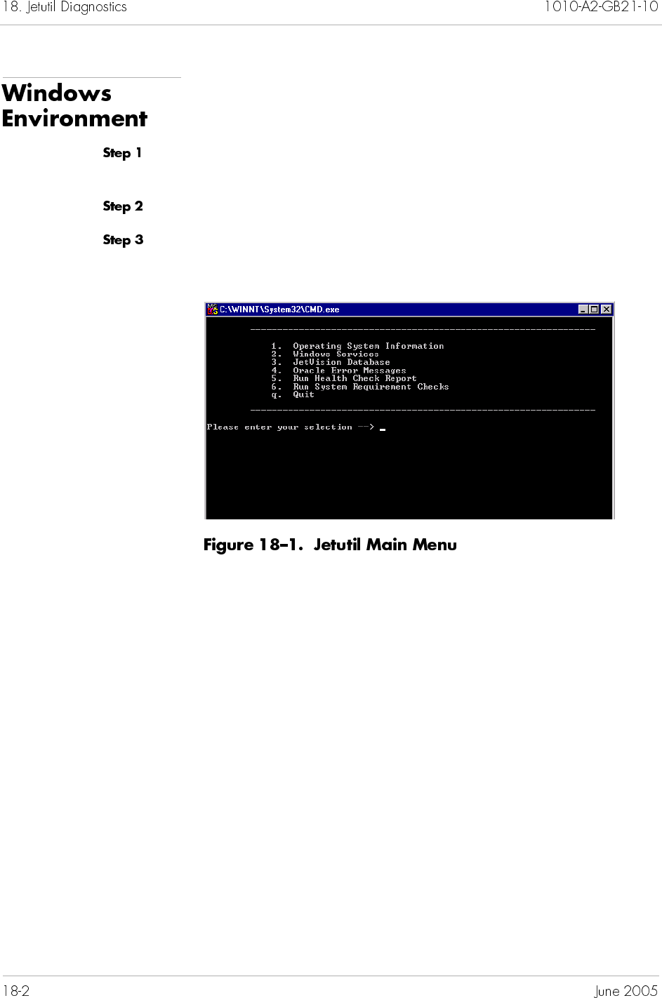
To access jetutil from Windows:
Go to the drive where the JetVision application is installed, and
locate the jetutil folder (under Common).
Expand the jetutil folder and click bin to display the content.
Double-click startjetutil.bat. A console window appears,
displaying the menu selection (Figure 18–1).
From this menu, you can perform the following checks:
Operating system information (page 18-3)
Windows services (page 18-4)
JetVision database (page 18-5)
Oracle error messages (page 18-6)
Health check report (page 18-6)
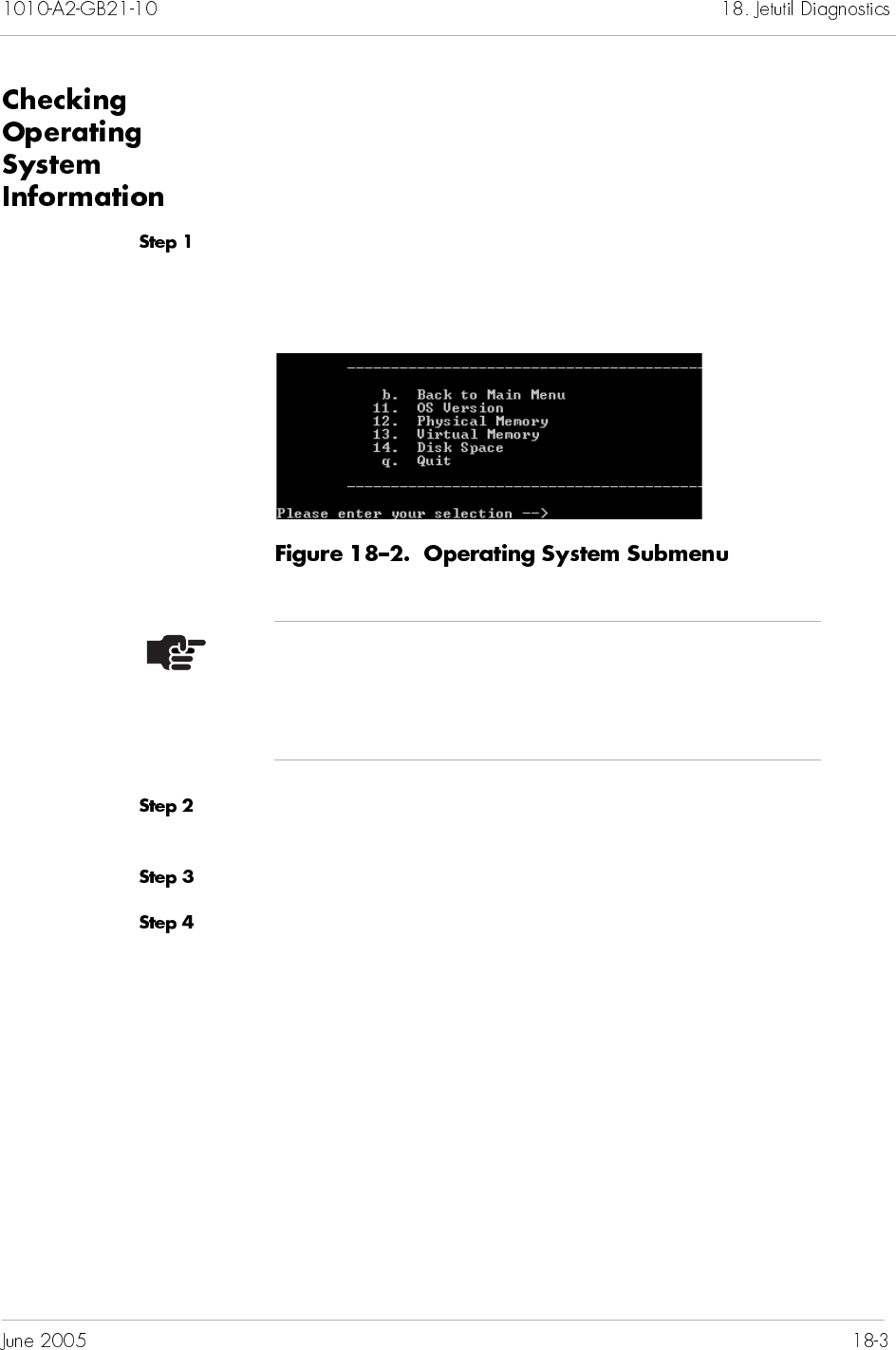
To check operating system information,
Type 1 at the main menu to select Operating System
Information, then press <Enter>. The operating submenu
appears (Figure 18–2).
Type a number that corresponds to your intended check. The
console displays the result of your selection.
Press any key to return to the main menu.
Type q, then press <Enter> to quit. Or repeat Step 2 to continue
with system check.
Note
Jetutil displays only the current operating system
information, it does not display the operating system
requirement.
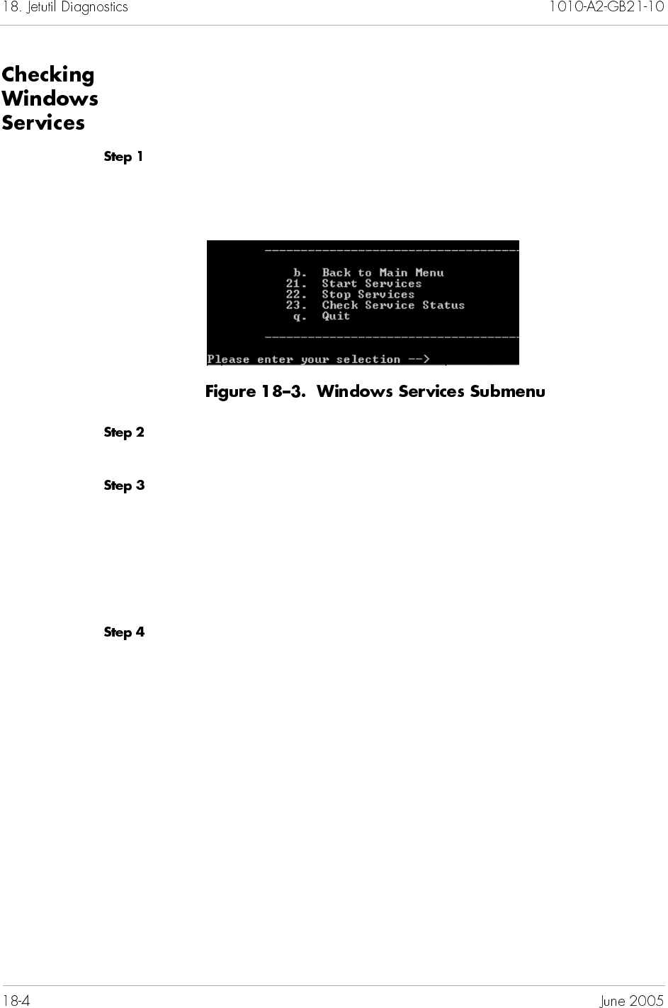
To check Windows Services,
Type 2 at the main menu to select Windows Services, then press
<Enter>. The Windows Services submenu appears
(Figure 18–3).
Type 23 to select Check Service Status, then press <Enter>.
The console displays the status of services.
Press any key to return to the main menu.
If any services are down, type 21 to start the services.
Contact JTAC if services do not start.
If all services are up and JetVision Server does not, type 5 at
the main menu to run a set of diagnostic operations and
save it to a file. Send that file to JTAC.
Type q, then press <Enter> to quit. Or type a number to continue
with another service check.
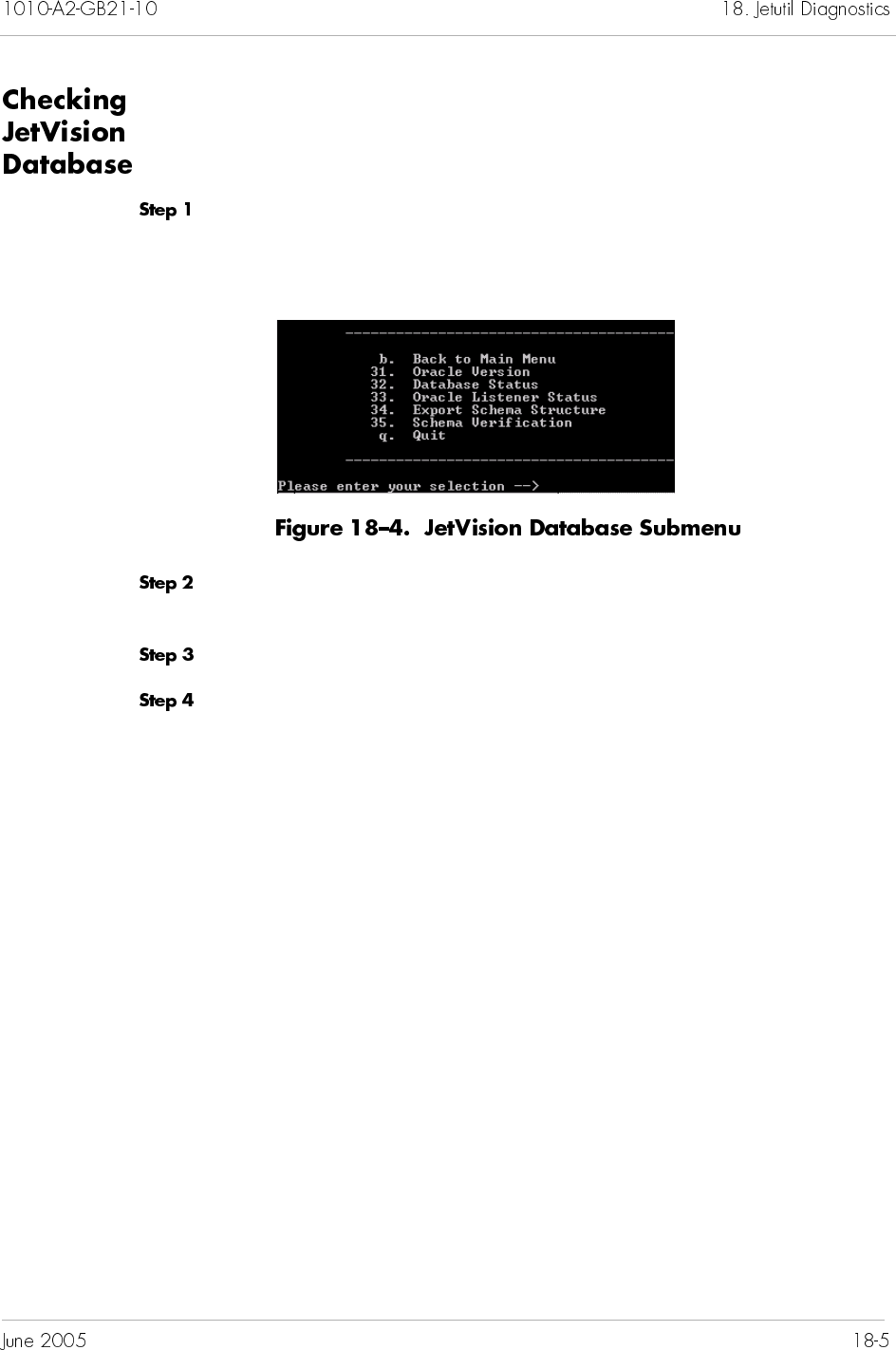
To check JetVision database,
Type 3 at the main menu to select JetVision Database, then
press <Enter>. The JetVision Database submenu appears
(Figure 18–3).
Type a number that corresponds to your intended check. The
console displays the result of your selection.
Press any key to return to the main menu.
Type q, then press <Enter> to quit. Or repeat Step 2 to continue
with database check.

To understand Oracle error messages,
Locate the Logs folder. For example,
c: /Jetstream/emsserver_2.5/logs
Write down the ORA-XXXX exception number, where XXXX is the
number.
Start jetutil (page 18-2).
Type 4 at the main menu to select JetVision Database, then
press <Enter>. You are prompted to enter the Oracle error
number (from Step 2).
Enter the number, and press <Enter>. The error statement
appears.
Press any key to return to the main menu.
Type q, then press <Enter> to quit.
To run a health check report,
Type 5 at the main menu to select Run Health Check Report,
then press <Enter>. You are prompted to enter a file name.
Type the location to where the report will be written and file name
for the report, then press <Enter>. You are prompted to enter the
database connection string. Jetutil displays the result and the
location to where the report is written.
Press any key to return to the main menu.
Type q, then press <Enter> to quit.
Note
Call JTAC if you need help to understand the error
messages. Make sure to write down the messages and
their associated numbers.
Note
If you did not enter the file location, the report will be
written to the default folder (i.e., jetutil/Common/bin)
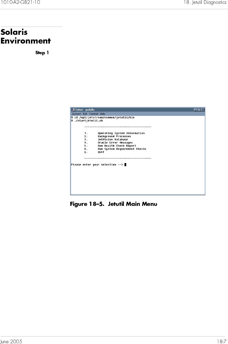
To check background processes:
Use the appropriate UNIX shell command to start the utility. For
example:
cd /opt/jetstream/common/jetutil/bin
./startjetutil.sh
A console window appears, displaying the menu selection
(Figure 18–5).
From this menu, you can perform the following checks:
Operating system information (page 18-8)
Background Processes (page 18-9)
JetVision database (page 18-10)
Oracle error messages (page 18-11)
Health check report (page 18-11)
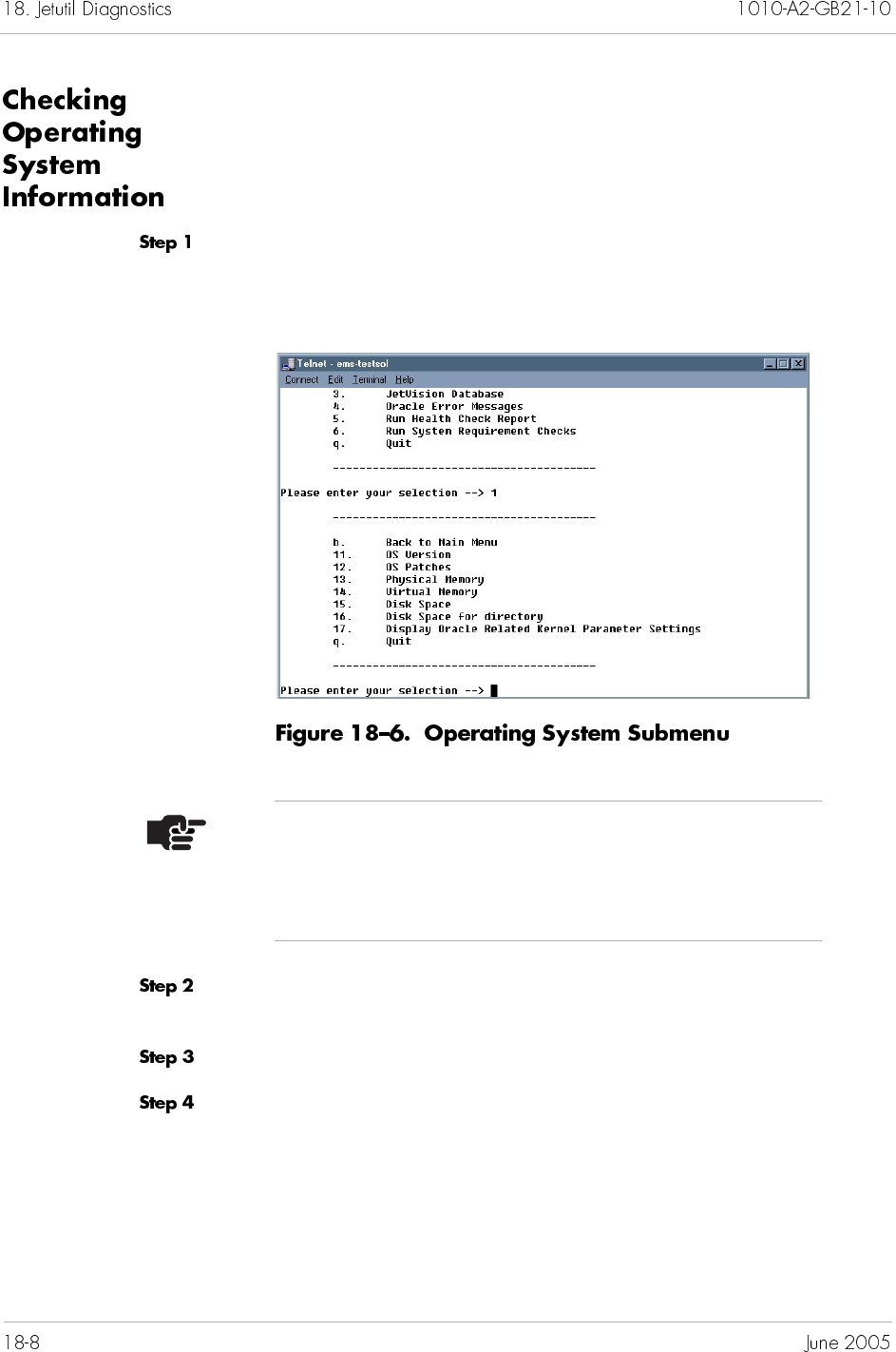
To check operating system information,
Type 1 at the main menu to select Operating System
Information, then press <Enter>. The operating submenu
appears (Figure 18–6).
Type a number that corresponds to your intended check. The
console displays the result of your selection.
Press any key to return to the main menu.
Type q, then press <Enter> to quit. Or repeat Step 2 to continue
with system check.
Note
Jetutil displays only the current operating system
information, it does not display the operating system
requirement.
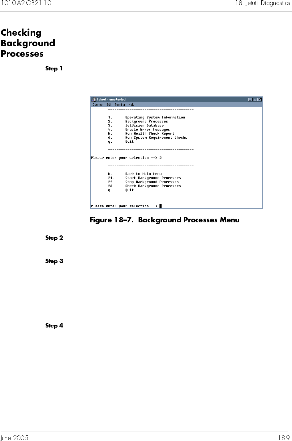
To check background processes,
Type 2 at the main menu to select Background Processes, then
press <Enter>. The menu selection appears (Figure 18–7).
Type 23 to select Check Background Processes, then press
<Enter>. The console displays the status of services.
Press any key to return to the main menu.
If any services are down, type 21 to start the services.
Contact JTAC if services do not start.
If all services are up and JetVision Server does not, type 5 at
the main menu to run a set of diagnostic operations and
save it to a file. Send that file to JTAC.
Type q, then press <Enter> to quit. Or type a number to continue
with another service check.
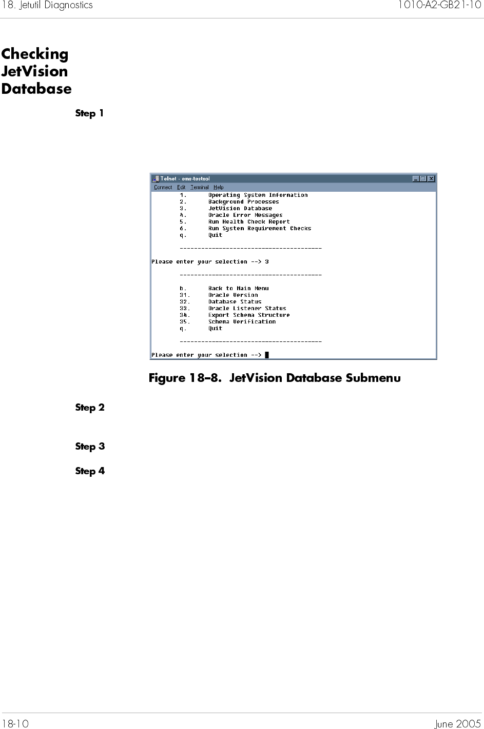
To check JetVision database,
Type 3 at the main menu to select JetVision Database, then
press <Enter>. The JetVision Database submenu appears
(Figure 18–8).
Type a number that corresponds to your intended check. The
console displays the result of your selection.
Press any key to return to the main menu.
Type q, then press <Enter> to quit. Or repeat Step 2 to continue
with database check.
To understand Oracle error messages,
Locate the Logs directory. For example,
/opt/Jetstream/emsserver_v25/Logs
Write down the ORA-XXXX exception number, where XXXX is the
number.
Start jetutil (page 18-7).
Type 4 at the main menu to select JetVision Database, then
press <Enter>. You are prompted to enter the Oracle error
number (from Step 2).
Enter the number, and press <Enter>. The error statement
appears.
Press any key to return to the main menu.
Type q, then press <Enter> to quit.
To run a health check report,
Type 5 at the main menu to select Run Health Check Report,
then press <Enter>. You are prompted to enter a file name.
Type the location to where the report will be written and file name
for the report, then press <Enter>. You are prompted to enter the
database connection string. Jetutil displays the result and the
location to where the report is written.
Press any key to return to the main menu.
Type q, then press <Enter> to quit.
Note
Call JTAC if you need help to understand the error
messages. Make sure to write down the messages and
their associated numbers.
Note
If you did not enter the file location, the report will be
written to the default folder (i.e., jetutil/Common/bin)


The following menu map provides a linear, hierarchical overview
of the tasks and subtasks associated with JetVision.
0447
Log On
Main Menu
(JetVision User ID/Password)
File
Menu
Configuration
Menu
Services
Menu
Fault
Exit Active Alarm
Browser
Historical
Alarm Browser
Event Browser
Help
Menu
Contents &
Index
About
Configure
Switchover
Clock Synch
Integrated Monitoring
LBO Value
Create STS1 IG
Create T1 IG
Modify IG
Delete IG
Switchover EOC
Switchover TMC
PPS Settings
DS1 Line Registers
DS1 Path Registers
PG Swap
Path Trace
Create IAD Profile
IAD Profile Manager
IAD Wizard
Create I AD
IAD Manager
Remove Resources
CpxBackupManager
IP Configuration
Time Configuration
Reboot
Create JetVision User
Change JetVision
User Password
JetVision User
Administration
JetVision User
Session
Create JetVision Group
JetVision Group
Administration
Create CPX User
CPX User Administration
Configure Global System
Administration
Menu
Create CPX
Remove CPX
Update CPX Info
Resynch CPX
Manage CPX
Unmanage CPX
Create Group
Remove Group
Modify Group
Find CPX
Reports
Menu
Alarm Report
Historical Alarm Report
Action Report
Event Report
IAD Report
CPX Report
Card Report
Interface Groups Report
Protection Groups Report
CRV Report
Error & Performance Graphs
Line, Section, & Path
Error Graphs
DS1 Error & Performance
Graphs
CP Perf. & Historical Graphs
MP Historical Graphs
DS1 Line & Path Historical Graphs
Map View
List View
View
Menu
Table B–1 and Table B–2 describe JetVision error and performance
statistics.
Assembly errors Number of Assembly errors
Blocked incalls Number of Blocked incalls
Blocked outcalls Number of Blocked outcalls
CRC errors Number of CRC errors
IADs Down Number of IADs down
Non echo calls Number of echo calls
Rejected compress calls Number of compress calls rejected
Uncompressed calls Number of uncompressed calls
Unsuccessful calls
insufficient bandwidth
Number of unsuccessful calls due to insufficient bandwidth
CCS PPS to Primary Number of CCS PPS messages sent to the Primary channel
CCS PPS to Secondary Number of CCS PPS messages sent to the Secondary
channel
EOC PPS To Primary Number of EOC PPS messages sent to the Primary channel
EOC PPS to Secondary Number of EOC PPS messages sent to the Secondary
channel
Timer timeouts Timer timeouts
Alarm Indication Signal
Seconds—last 15 minutes
Number of one-second intervals with one or more incoming
AIS signals detected in the last 15 minutes
Bipolar Violations—last 15
minutes
Number of Bipolar Violations in the last 15 minutes
Controlled Slip Seconds—
last 15 minutes
Number of Controlled Slips Seconds in the last 15 minutes
Controlled Slips—last 15
minutes
Number of Controlled Slips in the last 15 minutes
Degraded Minutes—last
15 minutes
Number of Degraded Minutes in the last 15 minutes
Errored Seconds—last 15
minutes
Number of one-second intervals with at least one line
condition in the last 15 minutes
Excessive Zeroes—last 15
minutes
Number of Excessive Zeroes in the last 15 minutes
Line Coding Violations—
last 15 minutes
Number of times the received DS1 signal contained a
bipolar violation (BPV) or an excessive number of zeroes
(EXZ)
Line Errored Seconds—
last 15 minutes
Number of one-second intervals with a least one line code
violation
Out Of Frame Seconds—
last 15 minutes
Number of Out Of Frame Seconds in the last 15 minutes
Severely Errored Framing
Seconds —last 15 minutes
Number of one-second intervals containing one or more
severely errored framing (SEF) events in the last 15 minutes
Severely Errored Seconds
—last 15 minutes
Number of one-second intervals with 15 or more line code
violations, as well as when the device receives an incoming
OOF or AIS signal in the last 15 minutes
Unavailable Seconds—last
15 minutes
Number of one-second intervals during which the service is
unavailable, determined by a transmission failure condition
in the last 15 minutes
Far end alarm indication Number of far-end-alarm indications.
Far end receive failure Number of far-end-receive failures
Loss of cell delineation Number of cell delineation losses.
Loss of frame No incoming frame is detected by the received end.
Loss of signal No incoming signal is detected by the received end.
Out of cell delineation Number of out-of-cell delineations.
Red count Number of red counts.
AAL1 byte CRC errors Number of AAL1 CRC errors
AAL1 byte parity errors Number of AAL1 byte parity errors
AAL1 byte seq errors Number of AAL1 byte sequence number errors
Cells rcvd in FIFO Number of cells received in Rx FIFO
Clock generation failures Number of times the clock generation module failed
Correctable errors Number of single bit errors in the UNIX header (cell passed)
Counter rollover Number of miscellaneous counter rollover events
OAM line AIS Number of times OAM alarm Line AIS required service
OAM line RDI Number of times OAM alarm Line RDI required service
OAM path AIS Number of times OAM alarm Path AIS required service
Overrun errors Number of overrun errors
Overrun counter rollover Number of overrun counter rollover events
Pointer byte parity errors Number of pointer byte parity errors
Pointer byte range errors Number of pointer byte out of range errors
Physical service Number of times physical required service
Ref cells loss Number of timing reference cells lost
Ref cells out of sync Number of times reference cells went out of sync
Rx Utopia FIFO overrun Number of FIFO overruns
Rx Utopia overrun Number of Rx Utopia module overruns
SONET loss signal Number of times SONET alarm Loss of Signal required
service
SONET loss frame Number of times SONET alarm Loss of Frame required
service
SONET loss pointers Number of times SONET alarm Path Loss of Pointer
required service
TDM master clocks absent Number of times TDM clock became absent
Tx FIFO overrun Number of overruns on Tx FIFO
Tx bandwidth errors Number of Tx bandwidth errors
Uncorrectable errors Number of multi-bit errors in the UNIX header cell (cell
dropped)
Underrun counter rollover Number of underrun counter rollover events
Underrun errors Number of underrun errors
Assembly errors Number of Assembly errors
Blocked incalls Number of Blocked incalls
Blocked outcalls Number of Blocked outcalls
CRC errors Number of CRC errors
Ctrl cells rcvd Number of Cells received
Ctrl cells sent Number of Cells sent
I-Frames retrans Number of I-Frames retrans
Invalid frames Number of Invalid frames
MDL Error A Unsolicited S Frame (F=1)
MDL Error B Unsolicited DM (F=1)
MDL Error C Unsolicited VA (F=1)
MDL Error D Unsolicited VA (F=0)
MDL Error E Unsolicited DM (F=0)
MDL Error F Peer Re-established
MDL Error G SABME retrans limit
MDL Error H DISC retrans limit
MDL Error I Enquiry retrans limit
MDL Error J N(R) error
MDL Error K FRMR received
MDL Error L Undefined frame received
MDL Error M I field not permitted
MDL Error N Frame size error
MDL Error O N201 error
OutOfSeq I-Frames Number of OutOfSeq I-Frames
Blocked incalls Number of Blocked incalls
Blocked outcalls Number of Blocked outcalls
Coding Violations—Path Number of times the received DS1 signal contained a
bipolar violation (BPV) or an excessive number of zeroes
(EXZ)
Errored Seconds—Path Number of one-second intervals with at least one line
condition occurred
Severely Errored
Seconds—Path
Number of one-second intervals with 15 or more line code
violations, as well as when the device receives an incoming
OOF or AIS signal occurred
Unavailable Seconds—
Path
Number of one-second intervals during which the service is
unavailable, determined by a transmission failure condition
occurred
Coding Violations—Line Number of times the received DS1 signal contained a
bipolar violation (BPV) or an excessive number of zeroes
(EXZ)
Errored Seconds—Line Number of one-second intervals with at least one line
condition occurred
Severely Errored
Seconds—Line
Number of one-second intervals with 15 or more line code
violations, as well as when the device receives an incoming
OOF or AIS signal occurred
Command Violations—
Line
Number of one-second intervals during which the service is
unavailable, determined by a transmission failure condition
occurred
Coding Violations—
Section
Number of times the received DS1 signal contained a
bipolar violation (BPV) or an excessive number of zeroes
(EXZ)
Errored Seconds—Section Number of one-second intervals with at least one line
condition occurred
Severely Errored Frame
seconds—Section
Number of one-second intervals containing one or more
severely errored framing (SEF) events occurred
Severely Errored seconds
—Section
Number of one-second intervals with 15 or more line code
violations, as well as when the device receives an incoming
OOF or AIS signal occurred
Active calls Number of active calls
Active compress calls Number of active compress calls
Ctrl cells rcvd Number of Ctrl cells received
Ctrl cells sent Number of Ctrl cells sent
Cumulative compress calls Number of cumulative compress calls
Cumulative outcalls Number of cumulative outgoing calls
IADs Provisioned Number of IADs provisioned
IADs Up Number of IADs up
Peak calls Number of peak calls
Percent CPU used Percentage of CPU usage
Percent flash used Percentage of flash memory used
Percent memory used Percentage of physical memory used
CCS PPS msgs rcvd Number of CCS PPS messages received
CCS PPS msgs sent Number of CCS PPS messages sent
CCS msgs rcvd Number of CCS messages received
CCS msgs sent Number of CCS messages sent
EOC PPS msgs rcvd Number of EOC PPS messages received
EOC PPS msgs sent Number of EOC PPS messages sent
EOC msgs rcvd Number of EOC messages received
EOC msgs sent Number of EOC messages sent
DS0s In Use How many DS0s (channels) on a DS1 (T1 lines) are
currently active (a call is in progress)
Active calls Number of active calls
Active compress calls Number of active compress calls
Cells rcvd Number of cells received
Cells sent Number of cells sent
Ctrl cells rcvd Number of Ctrl cells received
Ctrl cells sent Number of Ctrl cells sent
Cumulative calls Number of cumulative calls
Cumulative compress calls Number of cumulative compress calls
Frames rcvd Number of Frames received
Frames sent Number of Frames sent
I-Frames rcvd Number of I-Frames received
I-Frames sent Number of I-Frames sent
Peak calls Number of peak calls
Active calls Number of active calls
Peak calls Number of peak calls
Cumulative calls Number of cumulative calls
Automatic switches Number of switchovers invoked by the CPX-1000
Manual switches Number of switchovers invoked by users
Switches to primary Number of switchovers invoked by the Primary member
Switches to secondary Number of switchovers invoked by the Secondary member
Available physical memory
(MB)
Available RAM expressed in megabyte
CPU usage (percent) CPU usage expressed in percentage
Disk size (MB) Total hard disk space expressed in megabyte
Disk usage (MB) Hard disk space usage expressed in megabyte
Disk usage (percent) Hard disk space usage expressed in percentage
Free disk space (MB) Available hard disk space expressed in megabyte
Page size (MB) Total page size expressed in megabyte
Free page size (MB) Available page size expressed in megabyte
Page usage (MB) Page size usage expressed in megabyte
Page usage (percent) Page size usage expressed in percentage
Physical memory (MB) Total RAM expressed in megabyte
Physical memory usage
(MB)
RAM usage expressed in megabyte
Physical memory usage
(percent)
RAM usage expressed in percentage
Cells rcvd Number of cells received
Cells sent Number of cells sent
Cells rcvd by PHY Number of cells received by physical device
Cells sent by PHY Number of cells sent by physical device
Cells rcvd in FIFO Number of cells in FIFO
Counter rollover Number of miscellaneous counter rollover events
Interrupt count Total number of interrupts coming from any source
Open Rx Chans Number of open Rx channels
Open Rx Inactive Chans Number of open Rx inactive channels
Open Rx VCs Number of open Rx VCs
Open Tx Chans Number of open Tx channels
Open Tx Inactive Chans Number of open Tx inactive channels
Open Tx VCs Number of open Tx VCs
Physical service Number of times physical service required
Table C–1 provides a summary of JetVision alarms.
Note
The CPX-1000 database alarm can be cleared only by
Paradyne. Call Technical Support Center (TSC) at
1-800-870-2221 (U.S. and Canada) or 1-727-530-2340
(worldwide) to clear the CPX-1000 database alarm.
CPX-1000 General system alarm Indicates general system
alarm.
Major CORE
CPX is down Indicates CME lost
connection to all CPs.
Critical CME
Error in <detailed
description> <to | from>
database
Indicates error in database
during startup and
initialization.
Major CME
CP card Lost connection to a CP Indicates lost connection to
CP.
Major CME
CP lost heartbeat to peer Indicates CP lost heartbeat
to peer CP.
Major CORE
CP found the peer CP faulty Indicates CP found the peer
CP faulty.
Major CORE
CP detected that the peer
CP has been removed
Indicates CP has detected
the removal of peer CP.
Major CORE
IAD IAD <name> unknown
alarm
Indicates the IAD has not
been initialized or
recognized.
Major CORE
Lost link with IAD <name> Indicates a lost link with the
IAD.
Major CORE
Provisioned ports <ID> are
greater than the reported
ports <ID>
Indicates the number of
provisioned ports is greater
than the number of
reported ports.
Major CME
Voice Quality Alarm VQA is triggered whenever
ATM overruns and
underruns exceed
predefined thresholds
Minor CORE
IAD Ports IAD <name> port <ID>
alarm
Indicates the IAD port has
not been initialized or
recognized.
Major CORE

ATM
Ports
<card type> <slot ID> <port
ID> — Lost ATM
connection
Indicates lost ATM
connection between the
ATM card and ATM port.
Critical CORE
<card type> <slot ID> <port
ID> — No adapter is
driving the TDM master
clock
Indicates no adapter is
driving the TDM master
clock between the ATM
card and ATM port.
Critical CORE
<card type> <slot ID> <port
ID> — ATM adaptive
recovery scheme alarm
Indicates an ATM adaptive
recovery scheme alarm
between the ATM card and
ATM port.
Critical CORE
<card type> <slot ID> <port
ID> — SONET lost signal
Indicates SONET lost signal
between the ATM card and
ATM port.
Critical CORE
<card type> <slot ID> <port
ID> — SONET lost frame
Indicates SONET lost frame
between the ATM card and
ATM port.
Critical CORE
<card type> <slot ID> <port
ID> — SONET path lost
pointer
Indicates SONET path lost
pointer between the ATM
card and ATM port.
Critical CORE
<card type> <slot ID> <port
ID> — OAM Line AIS
alarm
Indicates OAM Line AIS
alarm between the ATM
card and ATM port.
Critical CORE
ATM
Ports
<card type> <slot ID> <port
ID> — OAM Path AIS
alarm
Indicates OAM Path AIS
alarm between the ATM
card and ATM port.
Critical CORE
<card type> <slot ID> <port
ID> — OAM Line RDI
alarm
Indicates OAM Line RDI
alarm between the ATM
card and ATM port.
Critical CORE
<card type> <slot ID> <port
ID> — Unknown alarm
Indicates the ATM card/
port has not been initialized
or recognized.
Critical CORE
T1
Interface
Group
Alarm Indicates the Interface
Group has not been
initialized or recognized.
Major CORE
Card <slot ID> missing Indicates a TDM-T1 card is
missing during startup
verification against card
information from discovery.
Major CME
Card <slot ID> <port ID>
missing
Indicates a T1 port is
missing during startup
verification against card
information from discovery.
Major CORE
CCS active link down Indicates the active Control
Channel Signaling (CCS)
link is down.
Major CORE
CCS backup link down Indicates the backup
Control Channel Signaling
(CCS) link is down.
Major CORE
EOC active link down Indicates the active
Embedded Operations
Channel (EOC) link is
down.
Major CORE
EOC backup link down Indicates the backup
Embedded Operations
Channel (EOC) link is
down.
Major CORE
T1
Interface
Group
<Link ID> — Unknown
alarm
Indicates the Interface
Group link has not been
initialized or recognized.
Major CORE
CCS Primary link down Indicates the primary
Control Channel Signaling
(CCS) link is down.
Major CORE
CCS Secondary link down Indicates the secondary
Control Channel Signaling
(CCS) link is down.
Major CORE
CCS PPS Primary link
down
Indicates the primary
Control Channel Signaling
(CCS) and Path Protection
Signaling (PPS) links are
down.
Major CORE
CCS PPS Secondary link
down
Indicates the secondary
Control Channel Signaling
(CCS) and Path Protection
Signaling (PPS) links are
down.
Major CORE
EOC Primary link down Indicates the primary
Embedded Operations
Channel (EOC) link is
down.
Major CORE
EOC Secondary link down Indicates the secondary
Embedded Operations
Channel (EOC) link is
down.
Major CORE
EOC PPS Primary link
down
Indicates the primary
Embedded Operations
Channel (EOC) and Path
Protection Signaling (PPS)
links are down.
Major CORE
EOC PPS Secondary link
down
Indicates the secondary
Embedded Operations
Channel (EOC) and Path
Protection Signaling (PPS)
links are down.
Major CORE
DS1 Ports <DS1 ID> — Lost frame
sync — Red alarm
Indicates the T1 has lost
sync with the host. (The
remote end displays a
yellow alarm.)
Major CORE
<DS1 ID> — Received
remote alarm indication —
Yellow alarm
Indicates a Remote Alarm
Indication (RAI) signal is
being received on the line.
The remote end displays a
red alarm; which means the
remote end cannot
synchronize with the signal
originating from the T1
card.
Major CORE
<DS1 ID> — Received
remote alarm signal — Blue
alarm
Indicates an Alarm
Indication Signal (AIS) is
being received. This means
the remote end has lost
connection with its data
source or is in a test mode
and is transmitting all 1s
(AIS) instead.
Major CORE
<DS1 ID> — Software error
in DS0 read. Please call
Technical Support
Indicates an attempt to read
data from a T1 card has
failed.
Major CORE
<DS1 ID> — Unknown
alarm
Indicates the DS1 has not
been initialized or
recognized.
Major CORE
Protection
Group
The <Card Shelf ID> <Card
ID> does not exist
Indicates the card does not
exist during startup
verification against card
information from discovery.
Critical CME
The <Port Shelf ID> <Card
ID> <Port ID> does not
exist
Indicates the port does not
exist during startup
verification against card
information from discovery.
Critical CME

active alarm filters 12-5
active alarms 12-1, 12-7
number displayed 12-1
active backup tasks 15-17
adding
Apache Web server users 11-3
CPX-1000 2-2
CPX-1000 users 10-2
JetVision groups 9-2
JetVision users 9-7
STS-1 Interface Groups 5-7
T-1 Interface Groups 5-2
Web browser users 11-3
adjusting CPX-1000 clock setting 15-25
administrative states
CP cards 15-27
IAD 7-2
alarm browsers 12-4
viewing alarms 12-7
alarm filters 12-4
active alarm filters, creating 12-5
event filters, creating 12-6
historical data filters, creating 12-5
alarm indicators 1-14, 12-1
alarm severity 1-15, 12-4
alarm types 1-15, 12-4
alarms condition
propagated 12-3
source 12-3
AMI 3-8
annotating
CPX-1000 location 3-12
Apache utility 11-2
Apache Web server
adding users 11-3
password 11-2
start and stop services 17-7
user ID, modifying 11-2
users, deleting 11-4
APS 4-4
assigning primary T-1 port 5-4, 5-9
assigning STS-1 channels 5-11, 5-15
assigning T-1 ports 5-11, 5-15
ATM 7-8, 7-15, 7-21, 7-26, 7-33
ATM DS-3
error statistics summary 14-6
ATM OC-3
error statistics summary 14-6
performance statistics summary 14-6
ATM Protection Group
assigning members 4-2
assigning slot/port number 4-3, 4-6
cable selection 4-4, 4-6
deleting members 4-9
filtered by 7-51
members removal 4-9
performance statistics summary 14-4
searched by 7-51
statistics polling 14-8
swapping members 4-7
ATM Protection Switching 4-4
ATM redundancy 4-1, 4-2
auto download profiles 15-43
Automated IAD Software Download tool 15-41
B8ZS 3-8

back up
CPX configuration 15-2
creating backup schedule 15-8
deleting backup schedule 15-16
destination profile 15-2, 15-4, 15-6
disabling backup schedule 15-12
enabling backup schedule 15-13
file transfer 15-21
immediate operation 15-7
modifying backup schedule 15-14
Oracle data 17-8
reviewing active tasks 15-17
reviewing backup file location 15-18
Background processes 18-9
backup location
remote 15-21
BITS 3-8
buffer
PM, change size 17-14
bulk IAD creation 7-30
maximum number allowed 7-33
bulk IAD deletion 7-49
bulk IAD modification 7-42
bulk IAD software download 15-37
cable type 4-4, 4-6
Call Admission Control (CAC)
performed by CPX 8-1
CDV
setting value 3-5
Cell Delay Variation. See also CDV
changing administrative states
CP cards 15-27
changing CPX-1000 management states 15-36
changing geographic map 17-13
changing IP address 3-2
changing JetVision default password 9-12
changing VCI value 3-3
checking background processes, Solaris 18-9
checking JetVision database, Solaris 18-10
checking JetVision database, Windows 18-5
checking operating system information, Solaris 18-
8
checking operating system information,
Windows 18-3
checking services, Windows 18-4
CLLI 3-13
clock setting 15-25
clock source 3-8
removing 3-10
cloning
IADs 7-37
cloning IADs
maximum number allowed 7-39
color indicators
Integrated Monitor 17-16
Common Language Location Identifier 3-13
configuring
IAD auto download profiles 15-43
T-1 Interface Groups 5-2
control file 15-49
CP card
performance statistics summary 14-3
PM polling 14-18
CP cards
administrative states 15-27
hot swap 15-31
reboot 15-24
slot assignments 1-13, 15-26
switching 15-29
CPX backup schedule
creating 15-8
deleting 15-16
disabling 15-12
enabling 15-13
modifying 15-14
reviewing active tasks schedule 15-17
reviewing backup file location 15-18

CPX-1000
adding 2-2
adding a group 2-4
CP cards reboot 15-24
creating 2-2
creating users 10-2
deleting 2-4
deleting a group 2-6
deleting users 10-6
error statistics summary 14-3
group hierarchy 2-4
group location 2-7
IP address, changing 3-2
managed elements 3-1
managed state, changing 15-36
maximum number supported 3-1
modifying a group 2-5
modifying information 2-3
modifying user information 10-4
moving a group 2-6
MP card reboot 15-24
performance statistics summary 14-3
reboot 15-23
redundancy 15-26
removing 2-4
removing users 10-6
reviewing information 3-14
setting time and date 15-25
statistics polling 14-13
unmanaged state, changing 15-36
updating information 2-3
users allowed, number of 10-1
users privileges 10-1
CPX-1000 configuration
backing up 15-2
creating backup schedule 15-8
disabling backup schedule 15-12
enabling backup schedule 15-13
modifying backup schedule 15-14, 15-16
restore 15-19
reviewing active tasks 15-17
reviewing backup file location 15-18
CPX-1000 group
adding 2-4
deleting 2-6
finding 2-7
modifying 2-5
moving 2-6
creating
active alarm filters 12-5
CPX backup schedule 15-8
CPX-1000 2-2
CPX-1000 users 10-2
destination profile 15-2
event filters 12-6
historical data filters 12-5
IAD Profiles 6-2
JetVision groups 9-2
JetVision users 9-7
multiple IADs 7-30
single IAD 7-19, 7-24
STS-1 Interface Groups 5-7
T-1 Interface Groups 5-2
CRV 7-20, 7-25, 7-34, 7-51
number of 7-4
customizing
alarm filters 12-4
data file 15-49
DbMonitor 14-15
default
CPX-1000 password 2-2
CPX-1000 user ID 2-2, 10-1
IAD Profiles 6-1
JetVision password 1-4, 1-6, 9-1
JetVision user ID 1-4, 1-6, 9-1
defining
alarm filters 12-4
CPX-1000 users 10-2
deleting
Apache Web server users 11-4
CPX backup schedule 15-16
CPX-1000 2-4
CPX-1000 users 10-6
customized alarm filter 12-8
destination profile 15-6
IAD Profiles 6-6
IADs 7-47
Interface Groups 5-22
JetVision groups 9-6
JetVision users 9-11
Protection Group 4-9
T-1 ports 5-13, 5-17
Web browser users 11-4
deleting CPX-1000 group 2-6

deleting RT provisioning 5-4, 5-9
destination profile
creating 15-2
deleting 15-6
modifying 15-4
diagnostics
loop back 15-33
DNS 2-2
downloading IAD software 15-37
DS1
maximum number allowed 5-1
PM polling 14-19
DS-1 port
statistics polling 14-10
DS1 registers 14-21
EOC
switchover 5-25
error messages
Oracle 18-6, 18-11
error statistics summary 14-3
ESF option 3-8
event filters 12-6
file transfer
remote location 15-21
filter duration
PM 14-17, 17-5
filtering graph parameters 14-17
filtering IADs 7-49
finding CPX-1000 2-7
forced switchover 15-29
format options
STS-1 card 3-8
frame format 3-7
Frame Relay 7-8, 7-15, 7-21, 7-26, 7-33
FTP 15-21
generating JetVision reports 13-2
geographic map
changing image 17-13
GIF 17-13
GR-303 Interface Groups
configuration instructions 5-7
error statistics summary 14-4
maximum number allowed 5-1
performance statistics summary 14-4
primary T-1 port assignment 5-4, 5-9
graphics file formats 17-13
group hierarchy 2-4
grouping CPX-1000 2-4
historical alarms 12-1, 12-7
default buffer capacity 12-1
disk threshold definitions 17-4
disk timer definitions 17-3
log size 17-3
historical data
adjusting disk thresholds 17-11
historical data buffer
increasing capacity 15-49
historical data filters 12-5
historical performance charts 8-4
Host name 1-4
hot swapping
CP cards 15-31
HSC cards 15-31
line cards 15-32
MP card 15-30
HSC cards
hot swap 15-31
slot assignments 1-13, 15-26

IAD
administrative states 7-2
auto download profiles 15-43
automated software download 15-41
bulk deletion 7-49
cloning 7-37
creating multiple devices 7-30
creating single device 7-19, 7-24
creating using IAD Wizard 7-5, 7-11
deleting 7-47
error statistics summary 14-5
filtering 7-49
hardware model 7-51
LES CAS 7-11
locked state 7-2
maximum numbers supported 7-4
models 6-1
modifiable options 7-42
modifying multiple devices 7-42
modifying single device 7-40
multiple selection 7-44
performance statistics summary 14-5
provisional state 7-2
provisioning 7-4
remote restart 15-46
searching 7-49
software download 15-37
statistics polling 14-11
unlocked state 7-2
IAD port
error statistics summary 14-5
performance statistics summary 14-5
IAD Profiles
creating 6-2
deleting 6-6
modifying 6-4
removing 6-6
image file formats 17-13
image file supported 17-13
InfoCenter
property settings, description 17-3
setting refresh time 17-6
Integrated Monitor
customizing colors 17-16
interpreting data 16-4
operation 16-2
starting 16-2
Interface Group
statistics polling 14-7
Interface Groups 5-19
deleting 5-22
DS1 PM polling 14-19
EOC switchover 5-25
error statistics summary 14-4
filtered by 7-51
maximum number allowed 5-1
modifying 5-19
performance statistics summary 14-4
PPS settings
primary T-1 port assignment 5-4, 5-9
removing 5-22
searched by 7-51
statistics polling 14-7
STS-1 channels deletion 5-13, 5-17
STS-1 channels removal 5-13, 5-17
T-1 ports deletion 5-13, 5-17
T-1 ports removal 5-13, 5-17
TMC switchover 5-26
jetutil
checking background processes, Solaris 18-9
checking JetVision database, Solaris 18-10
checking JetVision database, Windows 18-5
checking operating system information,
Solaris 18-8
checking operating system information,
Windows 18-3
checking services, Windows 18-4
locale, Solaris 18-7
locale, Windows 18-2
running health check, Solaris 18-11
running health check, Windows 18-6
starting, Solaris 18-7
starting, Windows 18-2
JetVision Admin group privileges 9-2

JetVision Client
relogging 1-6
Solaris, starting 1-5
tasks flow 1-16
Windows NT, starting 1-3
JetVision database, Solaris 18-10
JetVision database, Windows 18-5
JetVision groups
adding 9-2
deleting 9-6
modifying 9-4
operations 9-3
privileges 9-3
JetVision report types
action report 13-5
alarm report 13-3
card report 13-7
CPX report 13-8
CRV report 13-9
event report 13-6
historical alarm report 13-4
IAD report 13-6
Interface Groups report 13-8
Protection Group report 13-10
JetVision reports
generating 13-2
setting viewing criteria 13-2
viewing criteria 13-2
JetVision Server
backing up Oracle data 17-8
managed CPX-1000, number of 3-1
restoring Oracle data 17-10
Solaris, starting 1-4
start and stop services 17-7
Windows NT, starting 1-2
JetVision user sessions 2-8
JetVision users
adding 9-7
assigning to multiple groups 9-8
creating 9-7
deleting 9-11
modifying 9-10
removing 9-11
JPEG 17-13
LBO
setting value 3-6
LDS 5-3, 5-8
LES CAS IAD 7-11
line build out. See also LBO
line cards
hot swap 15-32
line encoding 3-7
line error graphs 14-10
line error statistics 14-5
Local Digital Switch 5-3, 5-8
locating CPX-1000 2-7
loop back test 15-33
maximum number allowed
DS1 5-1
GR-303 Interface Groups 5-1
modifying 5-19
CPX backup schedule 15-14
CPX-1000 information 2-3
CPX-1000 user information 10-4
destination profile 15-4
IAD Profiles 6-4
Interface Groups 5-19
JetVision groups information 9-4
JetVision user information 9-10
multiple IADs 7-42
single IAD 7-40
Web browser user ID and password 11-2
modifying CPX-1000 group 2-5
monitoring JetVision user sessions 2-8
moving CPX-1000 group 2-6
MP card
hot swap 15-30
performance statistics summary 14-3
PM polling 14-18
reboot 15-24
slot assignments 1-13, 15-26
statistics polling 14-13

Network Protection Group
assigning members 4-2
deleting members 4-9
members removal 4-9
performance statistics summary 14-4
statistics polling 14-8
swapping members 4-7
switching members 4-7
Network Resource Manager 8-1
NRM 8-1
defining resources 8-2
on-demand backup operation 15-7
online performance charts 8-4
operating system information, Solaris 18-8
operating system information, Windows 18-3
operations
JetVision groups, selecting for 9-3
Oracle
start and stop services 17-7
Oracle data
backing up 17-8
Oracle error messages
understanding with jetutil, Solaris 18-11
understanding with jetutil, Windows 18-6
password
Apache Web server 11-1
CPX-1000 2-2, 10-1
JetVision 1-4, 1-6, 9-1
JetVision, changing 9-12
modifying 11-2
path error 14-5
Path Protection Switchover. See also PPS settings
performance charts 8-4
performance statistics summary 14-3
PM
database buffer 17-4
filter duration 14-17, 17-5
filter duration, changing 17-14
lower threshold definitions 17-4
lower threshold, changing 17-14
monitored elements 14-16
register type 14-17, 17-5
register type, changing 17-14
upper threshold definitions 17-4
upper threshold, changing 17-14
PM buffer
changing size 17-14
PM polling
CP card 14-18
DS1 card 14-19
MP card 14-18
PPS settings 5-28
privileges
JetVision Admin group 9-2
JetVision groups, selecting for 9-3
propagated alarm 12-3
Protection Group
deleting members 4-9
error statistics summary 14-5
filtered by 7-51
members assignment 4-2, 4-5
members removal 4-9
members swapped 4-7
members switched 4-7
searched by 7-51
slot/port assignment 4-3, 4-6
statistics polling 14-8, 14-9
provisional state 7-2
provisioning network resources 8-2
PSTN Protection Group
assigning members 4-5
deleting members 4-9
members removal 4-9
path error statistics summary 14-5
statistics polling 14-9
swapping members 4-7
switching members 4-7

reboot 3-3
CP cards 15-24
CPX-1000 15-23
MP card 15-24
refresh time
InfoCenter 17-6
register type
PM 14-17, 17-5
remote backup location 15-21
remote restart of IADs 15-46
removing
Apache Web server users 11-4
CPX-1000 2-4
CPX-1000 users 10-6
customized alarm filter 12-8
IAD Profiles 6-6
IADs 7-47
Interface Groups 5-22
JetVision groups 9-6
JetVision users 9-11
Protection Group 4-9
RT provisioning 5-4, 5-9
T-1 ports 5-13, 5-17
Web browser users 11-4
report types
action report 13-5
alarm report 13-3
card report 13-7
CPX report 13-8
CRV report 13-9
event report 13-6
historical alarm report 13-4
IAD report 13-6
Interface Groups report 13-8
Protection Group report 13-10
reports
generating 13-2
setting viewing criteria 13-2
viewing criteria 13-2
restart 15-46
restore
CPX configuration 15-19
Oracle data 17-8, 17-10
reviewing
CPX-1000 information 3-14
RT provisioning
deleting 5-4, 5-9
running health check, Solaris 18-11
running health check, Windows 18-6
searching IADs 7-49
section error graphs 14-10
section error statistics 14-5
Server name 1-4
setting clock source 3-8
setting VCI value 3-3
SF option 3-8
slot assignments
CP cards 1-13, 15-26
HSC cards 1-13, 15-26
MP card 1-13, 15-26
Solaris
Apache users and password, modifying 11-2
deleting Apache Web server users 11-4
deleting Web browser users 11-4
InfoCenter, starting 17-2
jetutil, starting 18-7
JetVision Client, starting 1-5
JetVision Server, starting 1-4
Web browser users and password,
modifying 11-2
source alarm 12-2
starting services
Apache Web server 17-7
JetVision Server 17-7
Oracle 17-7
VisiBroker 17-7
statistics polling
error 14-13
performance 14-13
stopping services
Apache Web Server 17-7
JetVision Server 17-7
Oracle 17-7
Visibroker 17-7
STS-1
line error statistics summary 14-5
section error statistics summary 14-5

STS-1 card
format options 3-8
frame format 3-7
line encoding 3-7
loop back 15-33
path trace 15-35
STS-1 channels
assignment 5-11, 5-15
STS-1 Interface Groups
adding 5-7
creating 5-7
STS-1 channels assignment 5-11, 5-15
STS-1 port
statistics polling 14-10
swapping
ATM Protection Group members 4-7
Network Protection Group members 4-7
PSTN Protection Group members 4-7
switching
CP cards 15-29
Network Protection Group members 4-7
PSTN Protection Group members 4-7
switching over
CP cards 15-29
switchover
EOC 5-25
TMC 5-26
T-1 card
loop back 15-33
T1 CAS Interface Group 5-15, 5-17
T-1 Interface Groups 5-2
adding 5-2
creating 5-2
T-1 ports assignment 5-11, 5-15
T-1 ports
assignment 5-11, 5-15
assignment, primary 5-4, 5-9
deleting 5-13, 5-17
error statistics summary 14-4
performance statistics summary 14-4
removing 5-13, 5-17
T1 ports
statistics polling 14-13
tablespace 15-49
TMC
switchover 5-26
tracing STS-1 path 15-35
updating
CPX-1000 information 2-3
user ID
Apache Web server 11-1
CPX-1000 2-2
CPX-1000default
CPX-1000 password 10-1
JetVision 1-4, 1-6, 9-1
user sessions
monitoring 2-8
users access
CPX-1000 10-1
VCI 3-3, 7-21, 7-26, 7-51
verifying CPX-1000 time and date 15-25
viewing alarms
with customized filter 12-7
viewing JetVision reports 13-2
VisiBroker
start and stop services 17-7
Web browser
adding users 11-3
password, modifying 11-2
user ID, modifying 11-2
users, deleting 11-4
Windows
InfoCenter, starting 17-2
jetutil, starting 18-2
Windows NT
deleting Apache Web server users 11-4
deleting Web browser users 11-4
JetVision Client, starting 1-3
JetVision Server, starting 1-2
Web browser users and password,
modifying 11-2
Windows services 18-4
Wizard
IAD 7-5, 7-11
