1050 CPS & 1052 CPS.ib.Rev9 CPS_1052 CPS_ib_Rev9 Ib Rev9
User Manual: 1050-CPS_1052-CPS_ib_Rev9
Open the PDF directly: View PDF ![]() .
.
Page Count: 17

1050-cps & 1052-cps.ib.rev9.doc Page 1 of 16 17/10/2007
IRT
Types CPS-1050& CPS-1052
1 RU Remote Control Panels
Designed and manufactured in Australia
IRT can be found on the Internet at:
http://www.irtelectronics.com
I R T Electronics Pty Ltd A.B.N. 35 000 832 575
26 Hotham Parade, ARTARMON N.S.W. 2064 AUSTRALIA
National: Phone: (02) 9439 3744 Fax: (02) 9439 7439
International: +61 2 9439 3744 +61 2 9439 7439
Email: sales@irtelectronics.com
Web: www.irtelectronics.com
1050-cps & 1052-cps.ib.rev9.doc Page 2 of 16 17/10/2007
IRT
Types CPS-1050 & CPS-1052
Remote Control Panels
Instruction Book
Table of Contents
Section Page
General description 3
Technical specifications 4
Technical description 5
Power supplies 5
Switching logic 5
Configuration 6
Interconnecting control panels 6
Interconnecting switchers 6
Power on reset 6
Safety enable switching 6
Multiple switcher set-ups 7
Link settings 7
Wire per crosspoint operation 8
Installation 9
Pre-installation 9
Connector pin assignments 10
Cable connections to switchers 11
Front & rear panel connector diagrams 14
Equipment return 15
Drawing index 16
This instruction book applies to units later than S/N 9600000.
1050-cps & 1052-cps.ib.rev9.doc Page 3 of 16 17/10/2007
General Description
CPS-1050: Remote control panel 1 RU. Equipped with 10 push buttons with tally LED’s and inserts for labels.
Controls two 3000 series switchers for 10 x 1 operation. Multiple panels may be used with tally to
each panel. Wire per crosspoint and tally out connectors are provided for external interfacing.
May also be used with VA-410 and AA-294 1RU switchers.
May be upgraded to CPS-1052 using CPS-1051 conversion kit
CPS-1051: Conversion kit to upgrade CPS-1050 to CPS-1052. Consists of second PCB assembly with 10 control
switches and new front panel escutcheon and mounting hardware.
CPS-1052: Remote control panel 1 RU. Equipped with two banks of 10 push buttons with tally LED’s and inserts
for labels. Controls four 3000 series switchers for 20 x 1 operation or for 10 x 1 audio breakaway or
as two separate 10 x 1 switchers. Multiple panels may be used with tally to each panel. Wire per
crosspoint and tally out connectors are provided for external interfacing.
May also be used with VA-410 and AA-294 1RU switchers for 20 x 1 or audio breakaway operation.
Configurations: CPS-1050 10 way control.
CPS-1052 2 x 10 way controls or
1 x 20 way control or
10 way control with breakaway.
Compatible switchers:
Note: 3000 series 5 x 1 switchers may be connected to form 10 x 1 , 15 x 1 or 20 x 1 switchers.
AVS-3010/3011: 5 x 1 analogue video switch with looping inputs. Internal vertical interval switching or
external synchronisation for use in RGB, YUV & YC applications.
AAS-3020/3021: 5 x 1 stereo analogue audio switch with looping inputs.
DDS-3030/3031: 5 x 1 RS422 / RS485 Serial bi-directional data switch. Only the selected bi-directional path
is active at any time with unselected data outputs reverting to tri-state. This allows
switchers to be used in multiple combinations (subject to logical conflicts).
DVS-3040/3041: 5 x 1 serial digital switch. Primarily designed for 270 Mbit serial digital video with input
equalisation to 50 metres. As no re-clocking is provided on this model it may also be used
for a variety of serial digital signals over a wide range of data rates.
VA-400: 10 x 1 1 RU video switch with local control panel. May be used with one CPS-1050
control panel only.
VA-410/AVS-1210: 10 x 1 1 RU video switch. May be used with CPS-1050 or CPS-1052 control panels.
AA-293: 10 x 1 1 RU stereo balanced audio switch with local control panel. May be used with one
CPS-1050 control panel only.
AA-294/AAS-1220: 10 x 1 1 RU stereo balanced audio switch. May be used with CPS-1050 or CPS-1052
control panels.
Applications:
• Input switching in edit suites.
• YUV & RGB synchronised switching.
• Simultaneous digital path and analogue monitoring switching.
• Computer controlled switching.
• Remote site switching and monitoring via modem.
• Automatic sequential switching with override for path monitoring.
1050-cps & 1052-cps.ib.rev9.doc Page 4 of 16 17/10/2007
Technical Specifications
IRT Remote Control Panels
Types CPS-1050 & CPS-1052
Controllable switchers:
Video: AVS-3010, DVS-3040, VA-400, VA-410,
AVS-3011, DVS-3041, AVS-1210.
Audio: AAS-3020, AA-293, AA-294,
AAS-3021, AAS-1220.
RS422: DDS-3030, DDS-3031.
Control inputs/outputs:
Switcher connections: Type 5 bit BCD coded parallel TTL level.
Number 1 “input” & 1 “output”.
Connectors Plug in 10 pin dual IDC.
Switches:
Type Momentary action with removable clear cap for
legend insert. Red LED indicator in one corner.
Number CPS-1050: 10.
CPS-1052: 20 - in two groups of 10.
Performance:
Configuration CPS-1050 10 way control for switchers.
Wire per crosspoint input option.
Individual tally out option.
CPS-1052 Consists of two CPS-1050 controls as above. May
be wired as:
2 x 10 way controls
1 x 20 way control
10 way control with breakaway.
Switching Determined by type of switchers connected, but not
more than 25 ms. Timing of connected switchers
may be synchronised to a master switcher.
Power requirements Derived from connected switcher.
Up to 4 x CPS-1050’s or 2 x CPS-1052’s may be
connected to one switcher (or CDC-3060) without
exceeding power rating specified for switcher.
Other:
Temperature range 0 - 50° C ambient
Mechanical
Finish: Front panel Grey enamel, silk screened black lettering & red
IRT logo
Dimensions 1 RU standard x 50 mm clearance depth.
Supplied accessories Matching connectors for control inputs & outputs.
Optional accessories Connectors for wire per crosspoint control input and
individual tally output.
Breakaway logic IC type 74HC365 and connector
for breakaway operation.
Instruction manual
TME-6 module extender card
1050-cps & 1052-cps.ib.rev9.doc Page 5 of 16 17/10/2007
Technical Description
The CPS-1052 is constructed using two identical CPS-1050 PCB assemblies. The following descriptions therefore
only refer to the CPS-1050. Additional functions available on the CPS-1052 are provided by interconnection
between the two CPS-1050 assemblies and identical functionality could be obtained using two CPS-1050’s.
Power supplies:
The CPS-1050 does not have its own power supply, but uses either +10 Vdc or +12 Vdc power from the first
connected switcher through the remote control logic connectors PL 4 and PL 5.
Pins 1A on both connectors are joined and are the power supply pins for the panel. This is to allow the power
supply to continue to the next control panel where more than one panel is required.
The +12 Vdc input (the only supply required) is reduced to +5 Vdc by a three terminal regulator.
A number of 10 µF and 100 nF tantalum tag capacitors are located at key points in the circuit to suppress
interference on the DC rails. Should any of these fail they should be replaced by high quality tantalum tag
capacitors of at least 16 Vdc rating.
Switching Logic:
Control logic for each switcher module is performed by a Programmable Logic Array (PLA) which has been
programmed for the required operations. This component will only function correctly when loaded with the correct
program and is therefore only available through IRT.
Each module of the switcher group has two control connectors on its rear assembly.
They are labelled PL 4 and PL 5. For descriptive purposes PL 4 is called the “input” connector and PL 5 the
“output” connector.
The pins on these connectors have the following functions:
PL 4 PL 5
1A +12 Vdc NC
1B Ground Ground
2A Data 4 Data 4
2B Data 3 Data 3
3A Data 2 Data 2
3B Data 1 Data 1
4A Data 0 Data 0
4B Switch pulse in Switch pulse out
5A Busy out Busy in
5B Unlatch in Unlatch out
The CPS-1050 remote control panel also has PL 4 and PL 5 but Pins 1A on both connectors are joined and are the
power supply pins for the panel. This is to allow the power supply to continue to the next control panel where more
than one panel is required. This is necessary as the CPS-1050 does not have its own power supply, but derives its
power from the first connected switcher.
The 5 bit codes on Pins 2A to 4A represent the input selected. This code is in BCD (Binary Coded Decimal) where
the Data 0 to 3 represent the binary numbers 0 to 9 (Inputs 1 to 10 if Data 4 is 0 or Inputs 11 to 20 if Data 4 is 1).
The unlatch out signal is asserted by a switcher if any of its front panel switches is operated or if its unlatch in
signal is asserted. The presence of an unlatch in signal causes any switcher to release control of the data lines (if it
had control of them).
A switcher signals that it has control of the data lines by asserting busy out. Busy out also ripples busy in.
The operation of a push-button ripples unlatch to modules farther down the chain, causing any of them with control
of the bus to release it, and in so doing clear the busy line.
As soon as the requesting module sees its busy in line clear, it takes control of the bus and asserts its busy out. The
busy out signal then ripples up the chain causing any other modules release control (if they had it).
1050-cps & 1052-cps.ib.rev9.doc Page 6 of 16 17/10/2007
Configuration
A CPS-1050 remote control panel must be powered by either:
(a) Connecting its PL 5 to PL 4 on a powered 3000 series module (i.e. one of the switcher group or a
CDC-3060 logic control module).
or
(b) Connecting its PL 5 to PL 4 on another CPS-1050 or CPS-9001 that is configured as in (a).
or
(c) Connecting its PL5 to a 1 RU series 10 x 1 switcher.
Connection details are provided in the following sections.
Interconnecting control panels:
Note: All connections between PL 4, PL 5 and PL 6 connectors are on a pin for pin basis.
Cables may be wired using the connectors provided or may be ordered from IRT using the following part number:
GDW-3011 300 mm cable for joining modules in 1 RU frames.
Multiple 10 x 1 control: Control panels are looped by joining PL 5 (data out) on one CPS-1050 to PL 4 (data in)
on the next. Link LK 2 is set to out on each panel.
PL 5 on the last control panel is then connected to the first switcher to be controlled.
20 x 1 control: Control panels are looped by joining PL 5 (data out) on one CPS-1050 to PL 4 (data in)
on the next and setting link LK 2 out on the 1 to 10 panel and in on the 11 to 20 panel.
PL 5 on the last control panel is then connected to the first switcher to be controlled.
10 x 1 breakaway: Control panels are looped by joining PL 6 (data out) on one CPS-1050 to PL 4 (data in)
on the next and setting link LK 2 out on both panels.
In addition IC U 2 type 74HC365 must be fitted to the control panel on which PL 6 is
used. This is the control panel for the video switcher and PL 5 on this control panel is
then connected to the first video switcher to be controlled.
PL 5 on the other panel is connected to the first audio switcher to be controlled.
Interconnecting switchers:
For 3000 series modules see separate manual.
Power on reset:
Power on reset is needed so that at power on only one switcher or control panel drives the buss. LK 3 on each of the
3000 series Switcher Group or the CPS-1050 remote control panel is used to select which unit is in control at power
on.
If LK 3B is not installed and the control panel is configured to be for Inputs 1-10 then at power on that unit will
take control of the buss and select input 1.
In the case of a multi-panel set up all of the panels except one should have LK 3B installed.
Safety enable switching:
LK 3 has another function. If LK 3A is not installed then any CPS-1050 switcher will act as tally only -- the
operation of any of its buttons will have no effect. This feature may be used to provide a safety enable switch.
The metalwork for the CPS-1050 & CPS-1052 panel is provided with a 6.35 mm hole at each end of the panel so
that a toggle or push-button switch may be mounted.
This switch may be connected in place of link LK 3A.
In operation the panel will display tally only and the front buttons will not effect a change in switcher output unless
the enable switch is operated whilst the selection is made.
1050-cps & 1052-cps.ib.rev9.doc Page 7 of 16 17/10/2007
Multiple switcher set ups
Eurocard 3000 series switchers may be combined to form 10 x 1, 15 x 1 and 20 x 1 switchers. For details of the
inter-module connections and link settings required see 3000 Series Switcher Manual.
Link Settings:
LK 2:
Sets the crosspoint range of the control panel as follows:
1 - 10 OUT
11 - 20 IN
LK 3:
Local / remote control selection.
If the switchers on the front of this unit are to be active then install LK 3A, otherwise install LK 3B.
1050-cps & 1052-cps.ib.rev9.doc Page 8 of 16 17/10/2007
Wire per crosspoint operation
In most cases the BCD encoded remote control system offers the most satisfactory way of controlling one or more
switchers. There are however, situations where it is necessary to provide a wire per crosspoint access for control and
/ or a line per crosspoint tally system.
Both of these facilities may be made available on the 3000 series and the AVS-1210, AAS-1220, VA-400, VA-410,
AA-293 and AA-294 - for details see the manuals on these switchers.
The CPS-1050 module provides direct access to both wire per crosspoint control and individual tally outputs via
connectors PL3 and PL7 respectively. These connectors are not normally fitted to the CPS-1050 but may be ordered
as follows: RS532-080 HE14 16 way 2 row header straight PCB mount.
RS532-327 HE14 16 way 2 row IDC socket.
These connectors may be specified when ordering from IRT or may be obtained from RS Components direct.
In addition to these connectors RS Components have termination tools and HE14 connectors with crimp termination
instead of the IDC types supplied by IRT.
Connection pinout details are shown in the Installation section following.
When wiring the wire per crosspoint input a choice may be made between connecting directly to ground on pin 6B
or via LK 3 using pin 5B. If connection is made via LK 3 then a supplementary contact closure may be used to
enable or disable the remote control function as described in Safety enable switching.
The tally out indication is normally high (+5 Vdc) for un-selected inputs and falls to ground for the selected input.

1050-cps & 1052-cps.ib.rev9.doc Page 9 of 16 17/10/2007
Installation
Operational Safety:
WARNING
Operation of electronic equipment involves the use of voltages and currents that
may be dangerous to human life. Note that under certain conditions dangerous
potentials may exist in some circuits when power controls are in the OFF position.
Maintenance personnel should observe all safety regulations.
Do not make any adjustments inside equipment with power ON unless proper
precautions are observed. All internal adjustments should only be made by suitably
qualified personnel. All operational adjustments are available externally without the
need for removing covers or use of extender cards.
Pre-Installation:
Handling:
This equipment may contain static sensitive devices and proper static free handling precautions should be observed.
Where individual circuit cards are stored, they should be placed in antistatic bags and proper antistatic procedures
should be followed when inserting or removing cards from these bags.
Power:
AC mains supply: Ensure that operating voltage of unit and local supply voltage match and that correct rating
fuse is installed for local supply.
DC supply: Ensure that correct polarity is observed and that DC supply voltage is maintained within the
operating range specified.
Earthing:
The earth path is dependent on the type of frame selected. In any case particular care should be taken to ensure that
the frame is connected to earth for safety reasons. See frame manual for details.
Signal earth: For safety reasons a connection is made between signal earth and chassis earth. No attempt should be
made to break this connection.
Installation in frame or chassis:
See details in separate manual for selected frame type.
1050-cps & 1052-cps.ib.rev9.doc Page 10 of 16 17/10/2007
Connections:
PL 3 Wire per crosspoint control input:
1A SW 1
1B SW 2
2A SW 3
2B SW 4
3A SW 5
3B SW 6
4A SW 7
4B SW 8
5A SW 9
5B SW 10
6A Switch common
6B Ground
7A No connection
7B “
8A “
8B “
PL 4 IN & PL 5 OUT switcher control bus input & output:
PL 4 PL 5
1A +12 Vdc Same as PL 4
1B Ground “
2A E - Data 4 “
2B D - Data 3 “
3A C - Data 2 “
3B B - Data 1 “
4A A - Data 0 “
4B Switch pulse in Switch pulse out
5A Busy out Busy in
5B Unlatch in Unlatch out
PL 6 - Audio Breakaway Output:
1A
1B Ground
2A E - Data 4
2B D - Data 3
3A C - Data 2
3B B - Data 1
4A A - Data 0
4B No connection
5A Busy in
5B Unlatch out
1B 2B 3B 4B 5B
1
A
2
A
3
A
4
A
5
A
1B 2B 3B 4B 5B
1
A
2
A
3
A
4
A
5
A
8B
7B
6B
5B
4B
3B
2B
1B
8A
7A
6A
5A
4A
3A
2A
1A
1050-cps & 1052-cps.ib.rev9.doc Page 11 of 16 17/10/2007
PL 7 Tally out :
1A SW 1
1B SW 2
2A SW 3
2B SW 4
3A SW 5
3B SW 6
4A SW 7
4B SW 8
5A SW 9
5B SW 10
6A +5 Vdc
6B “
7A No connection
7B “
8A “
8B “
Cable connections to switchers:
Connection to 3000 series Eurocard switchers:
Connection to the 3000 series Eurocard switchers is made using 10 way ribbon cables observing the direction of
PL 5 (out) connects to PL 4 (in) on either switchers or control panels.
The cables are wired on a pin for pin basis.
Before activating the switchers and control panels a check should be made of all link settings on both switchers and
panels to ensure that no conflicting settings are present.
Daisy chain wiring from the control panel to the switchers may be used for all normal requirements except audio
breakaway operation where it is necessary to provide separate connections to the audio and video switchers from
the two CPS-1050 PL 5 (out) connectors.
In all cases the number of switchers connected to one control panel should not exceed 10.
8B
7B
6B
5B
4B
3B
2B
1B
8A
7A
6A
5A
4A
3A
2A
1A
1050-cps & 1052-cps.ib.rev9.doc Page 12 of 16 17/10/2007
Connections to 1 RU series 10 x 1 switchers:
The AVS-1210, AAS-1220, VA-400, VA-410, AA-293 and AA-294 switchers may be used with the CPS-1050 and
CPS-1052 for 10 x 1, 20 x 1 or 10 x 1 with audio breakaway switching.
These switchers use a similar protocol to the 3000 series, but there are important differences which place limitations
on their use and preclude a simple pin for pin wiring system.
Each configuration of these switchers needs to be wired separately according to the following tables.
10 x 1 operation:
The following connection may be used to connect a CPS-1050 to the following combinations:
1 x VA-410
1 x VA-410 plus y x VA-400 plus z x AA-294 (where y + z <=4)
n x VA-400 (where n <=5)
1 x AA-293
1 x AA-293 plus n x AA-294 (where n <=4)
n x AA-294 (where n <=5)
y x VA-400 plus z x AA-294 (where y + z <=5)
The following cable is required between the first VA-410 or AA-294 and the CPS-1050.
1 RU switcher Remote panel (CPS-1050) PL 5.
25 Pin "D" (male) to 10 Pin HE14 (female)
Pin to Pin
"A" 21 to 4A "A"
"B" 20 to 3B "B"
"C" 19 to 3A "C"
"D" 18 to 2B "D"
"GND" 15 to 1B "GND"
"+V" 14 to 1A "+V"
The following cable is required between the first VA-400 or AA-293 and the CPS-1050.
1 RU switcher Remote panel (CPS-1050) PL 5.
25 Pin "D" (male) to 10 Pin HE14 (female)
Pin to Pin
“Unlatch” 25 to 5B “unlatch out”
“Strobe” 24 to 5A “busy in”
4B
"A" 21 to 4A "A"
"B" 20 to 3B "B"
"C" 19 to 3A "C"
"D" 18 to 2B "D"
2A don’t connect
"GND" 15 to 1B "GND"
"+V" 14 to 1A "+V"
Connections to other switchers are as described in their separate manual.
1050-cps & 1052-cps.ib.rev9.doc Page 13 of 16 17/10/2007
10 x 1 Audio breakaway operation:
This accomplished by logic control in the two CPS-1050’s (or CPS-1052). Connection to the video and audio
switchers is made separately from each CPS-1050 PL 5 (out). The wiring to the switchers is as described above.
20 x 1 operation:
This requires a different program to be present in PLA U 1 of each half of a CPS-1052. This must be specially
ordered from IRT and details of connections will be supplied with the replacement PLA chip (CPS1050U).
A cable as specified above will be required between each 10x1 switchers and their respective PL 5 connector on the
CPS-1052. In addition a cable as specified below is required between PL 6 on each half.
CPS-1050 (1-10) PL 6 CPS-1050(11-20) PL 6
"Unlatch out" 5B to 5A "Busy In "
"Busy In" 5A to 5B "Unlatch Out"
1050-cps & 1052-cps.ib.rev9.doc Page 14 of 16 17/10/2007
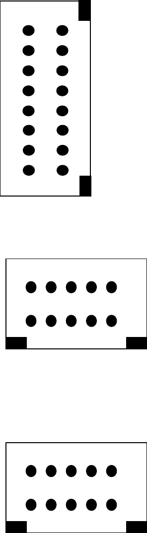
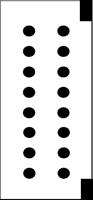
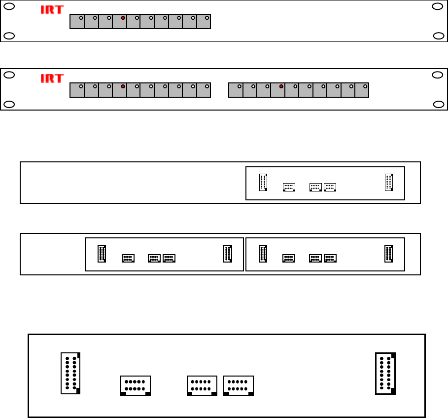
Front & rear panel connector diagrams
The following front panel and rear assembly drawings are not to scale and are intended to show relative positions of
connectors, indicators and controls only.
CPS-1050
CPS-1052
CPS-1050
CPS-1052
CPS-1050 / 1052 connectors - rear view
PL 4 INPL 5 OUTPL 6 B’WAY OUT
CONTROL
PL 3
TALLY
PL 7
PL 4 INPL 5 OUTPL 6 B’WAY OUT
CONTROL
PL 3
TALLY
PL 7
PL 4 INPL 5 OUT PL 6 B’WAY OUT CONTROL
PL 3
TALLY
PL 7
PL 4 INPL 5 OUTPL 6 B’WAY OUT
CONTRO
PL 3
TALLY
PL 7
1050-cps & 1052-cps.ib.rev9.doc Page 15 of 16 17/10/2007
Maintenance & Storage
Maintenance:
No regular maintenance is required.
Care however should be taken to ensure that all connectors are kept clean and free from contamination of any kind.
This is especially important in fibre optic equipment where cleanliness of optical connections is critical to
performance.
Storage:
If the equipment is not to be used for an extended period, it is recommended the whole unit be placed in a sealed
plastic bag to prevent dust contamination. In areas of high humidity a suitably sized bag of silica gel should be
included to deter corrosion.
Where individual circuit cards are stored, they should be placed in antistatic bags. Proper antistatic procedures
should be followed when inserting or removing cards from these bags.
Warranty & Service
Equipment is covered by a limited warranty period of three years from date of first delivery unless contrary
conditions apply under a particular contract of supply. For situations when “No Fault Found” for repairs, a
minimum charge of 1 hour’s labour, at IRT’s current labour charge rate, will apply, whether the equipment is within
the warranty period or not.
Equipment warranty is limited to faults attributable to defects in original design or manufacture. Warranty on
components shall be extended by IRT only to the extent obtainable from the component supplier.
Equipment return:
Before arranging service, ensure that the fault is in the unit to be serviced and not in associated equipment. If
possible, confirm this by substitution.
Before returning equipment contact should be made with IRT or your local agent to determine whether the
equipment can be serviced in the field or should be returned for repair.
The equipment should be properly packed for return observing antistatic procedures.
The following information should accompany the unit to be returned:
1. A fault report should be included indicating the nature of the fault
2. The operating conditions under which the fault initially occurred.
3. Any additional information, which may be of assistance in fault location and remedy.
4. A contact name and telephone and fax numbers.
5. Details of payment method for items not covered by warranty.
6. Full return address.
7. For situations when “No Fault Found” for repairs, a minimum charge of 1 hour’s labour will apply,
whether the equipment is within the warranty period or not. Contact IRT for current hourly rate.
Please note that all freight charges are the responsibility of the customer.
The equipment should be returned to the agent who originally supplied the equipment or, where this is not
possible, to IRT direct as follows.
Equipment Service
IRT Electronics Pty Ltd
26 Hotham Parade
ARTARMON
N.S.W. 2064
AUSTRALIA
Phone: 61 2 9439 3744 Fax: 61 2 9439 7439
Email: service@irtelectronics.com
1050-cps & 1052-cps.ib.rev9.doc Page 16 of 16 17/10/2007
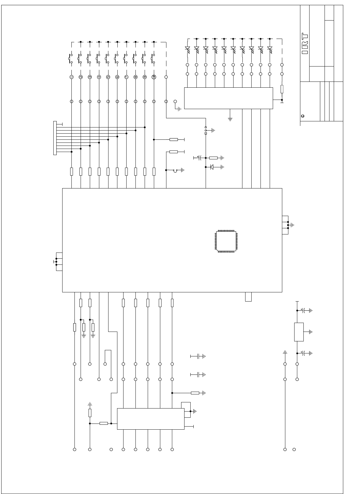
Drawing Index
Drawing # Sheet # Description
804042 1 CPS-1050A circuit schematic
TITLE
SCALE
SIZE
SHEET
DRAWN
CHECKED
ENG. APP.
CONTRACT No.
DO NOT COPY NOR
DISCLOSE TO ANY
THIRD PARTY
WITHOUT WRITTEN
CONSENT
OF11
IRT Electronics Pty. Ltd.
804042DRAWING No.
COPYRIGHT
ARTARMON NSW AUSTRALIA 2064
RBB
ST1
UL1
UL2
ST2
DI0
DI1
DI2
DI3
DI4
POR
T3
T2
T1
SW0
SW1
SW2
SW3
SW4
ONETO10
+5
T0
+5
EPM7032
36
2
6
5
4
20
18
19
21
24
33
25
34
26
31
27
32
28
29
LK3
+5
23 15 35 3
22 30 10 42
P2
PL4 PL5
U1
IN OUT
1A
1B
2A
2B
3A
3B
4A
4B
5A
5B
5A
4B
5B
AB
REMOTE CONTROL PANEL
+5
+5+5
+5
+5 +5
DOT0
DOT1
DOT2
DOT3
DOT4
41 MINEOUT
74HC42
1
2
3
4
5
6
7
9
10
11
16
12
13
14
15
8
P1
PL3
1 26/11/96
PC803962
U3
7
8
17
39
38
37
44 MINEIN
SW5
SW6
SW7
SW8
SW9
PL6
4A
3B
3A
2B
2A
U2
5A
5B
4B
1B
1A
+5
16 1 8
15
23
45
7
10
74HC365
OUT
1
11
2
3
4
5
6
7
8
9
101A
1B
2A
2B
3A
3B
4A
4B
5A
5B
PL7 P1
1A
1B
2A
3A
3B
4A
5A
5B
11
2B
4B
11 12
6
9
14
9
11
12
13
14
6A
6B
6AB
40
B,WAY
CPS-1050A
FOR BREAKAWAY OPERATION CONNECT
PL6 ON THE MAIN CP TO PL4
ON THE B'WAY CP
2 23/09/99
SW1
SW2
SW3
SW4
SW5
LK2
C7
22u
2 1
D1
1N4148
R8
10K
C1
10u
C2
10u
C3
100n
C4
100n
R1 10K
R2 10K
SW7
SW6
SW8
SW9
SW10
21
LD1
21
LD2
21
LD3
21
LD4
21
LD5
21
LD6
21
LD7
21
LD8
21
LD9
21
LD10
1
2
4
3
5
6
7
8
9
10
RP1
4K7
R10
4K7
R9
10K
R11 4K7
R12 4K7
R13 4K7
R14 4K7
R15 4K7
R16 4K7
R17 4K7
R18 4K7
R19 4K7
R20 4K7
R22 10K
R23 10K
I
3
G
2
O1
U4
78L05
R21 470
R24
10K
R25
10K
R26
22K
R27 470
R3 470
R4 470
R5 470
R6 470
R7 470
