Instructions For EPROM Replacement In OmniScan Simulator Controller Assembly Service Kit 569000689 108738
User Manual: 569000689
Open the PDF directly: View PDF ![]() .
.
Page Count: 12
Simulator EPROM Replacement Instructions Page 1
Instructions for EPROM Replacement in
OmniScaW Simulator Controller Assembly
Service Kit P/N 143 113
1. Introduction This publication contains instructions for replacing EPROMs
in the controller assembly of the OmniScan@ Simulator.
This kit contains:
Seven EPROMs labeled:
MEDIA NUMBER 1
MEDIA NUMBER 2
MEDIA NUMBER 3
MEDIA NUMBER 4
MEDIA NUMBER 5
MEDIA NUMBER 6
MEDIA NUMBER 7
An Electrostatic Discharge (ESD) Wrist Strap,
An EPROM Insertion Tool, and
An EPROM Extraction Tool
Reference Drawings:
P/N 125 214 EPROM Placement
P/N 161 539 Board Switch Settings
Additional tools required to perform the EPROM replacement are:
* l/4-in. open-end wrench
* small flathead screwdriver
2. Safety Precautions Before beginning EPFlOM replacement, remove all power from the
system and lock out external power to the electrical cabinet.
WARNING: Risk of electrical shock. Failure to disconnect
external power may present a serious shock hazard that could
result in personal injury or death.
A WARNING: Static electricity can damage EPROMs and boards.
I Before handling or transporting any board or EPROM, put on
0 the grounded electrostatic discharge (ESD) wrist strap supplied
with this kit. For maximum protection, work on a grounded
ESD surface.
Q Nordson Corporation 1994
All Rights Reserved 46-226
Issued 2i94 P/N 108 738A
Page 2 Simulator EPROM Replacement Instructions
3. Recording Your
Con troller User Settings
4. EPROM Replacement
When you replace the existing simulator controller board EPROMs, the
user settings will be lost and reset to the Nordson defaults. Unlike
OmniScan Controller operation with an melter, this is generally not a
problem with the simulator lbecause new user settings are normally
entered at the start of a practice session. Therefore, it is usually not
necessary to maintain a record of user settings for the simulator as you
should for your melter. However, if you did maintain some initial user
settings, you should record these settings prior to installing new
EPROMs. To do this you can make a copy of Table 4.7 Default Settings
for OmniScan Control System from section 4 of your melter system
manual (these are the pages where you entered data on your initial
setup), and then go through the menus and record this information for
use in re-entering the data after installing the new EPROMs.
This procedure is for replacing the EPROMs on the boards of the
simulator controller assembly, and involves:
l gaining access to the controller boards,
l removing the boards from the controller,
l replacing the board EPROMs, and
l reinstalling the boards
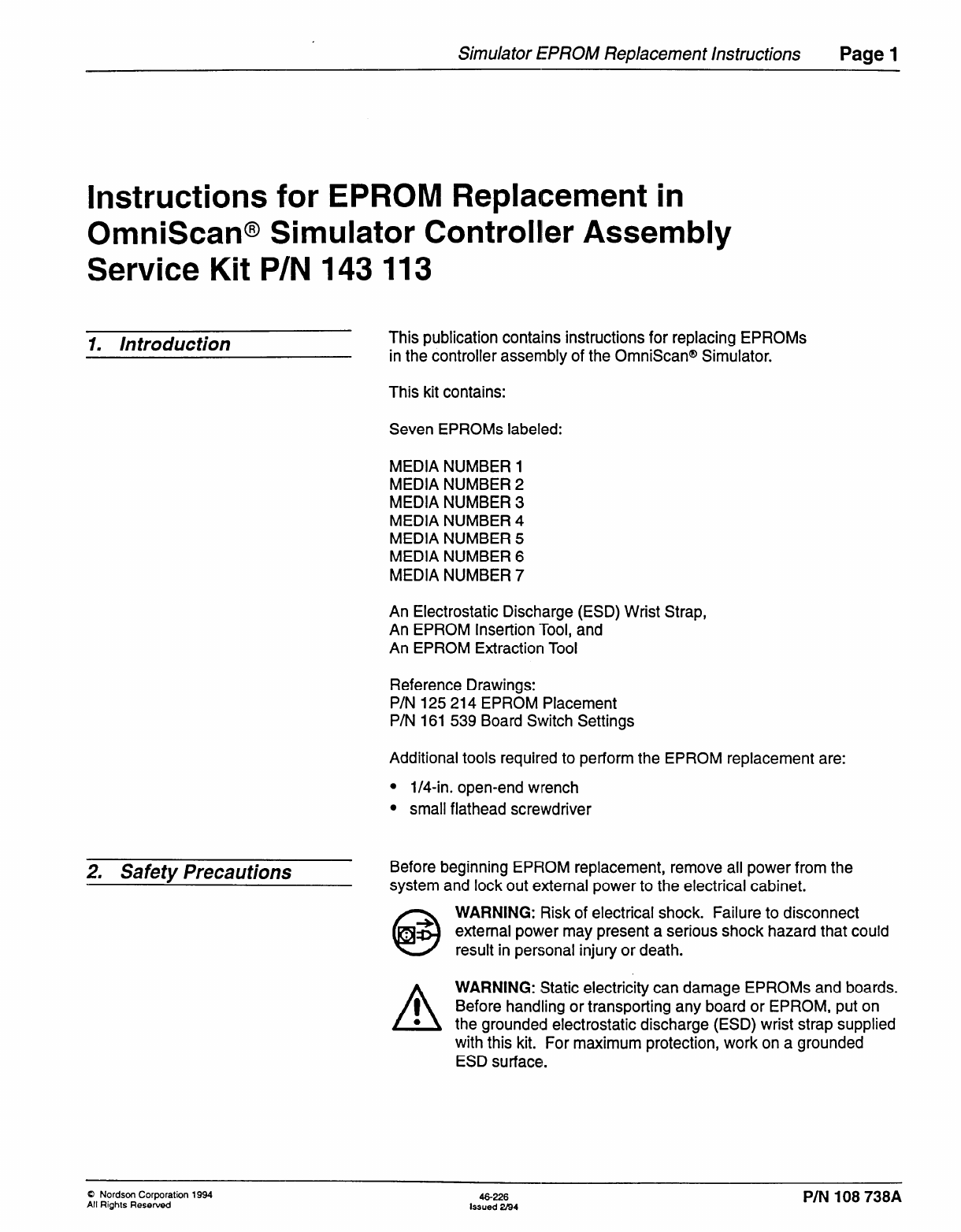
1. Disconnect the input power cord to the simulator.
2. Switch the circuit breaker to the OFF position.
3. Remove the clear cover by removing the four screws. See Figure 1.
Gaining Access to Controller
Boards
Figure 7. Removing the clear cover
A 5
CAUTION: Wear the grounded wrist strap during the following
steps. Failure to wear the grounded wrist strap may result in
electrostatic damage to the boards.
4. Ground the wrist strap to the simulator frame and put it on your wrist.
P/N 108 738A Pub. No. 46-226
Issued 2/94
Q Nordson Corporation 1994
All Rights Reserved
Simulator EPROM Replacement Instructions Page 3
Gaining Access to Controller
Boards (contd.)
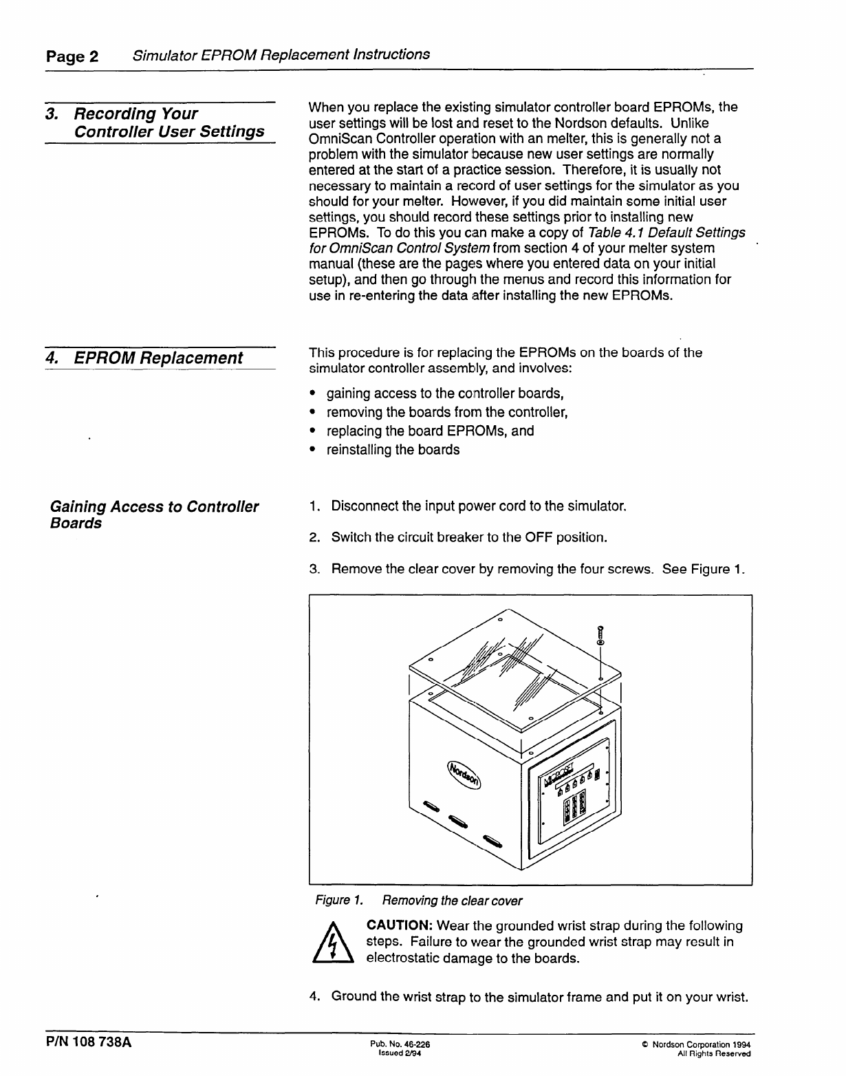
5. Disconnect all cable connectors from the top, bottom, and side edges
of the individual boards of the controller assembly. See Figure 2, and
note that for clarity not all connectors to be removed are shown.
Figure 2. Disconnecting controller’s external cables and connectors
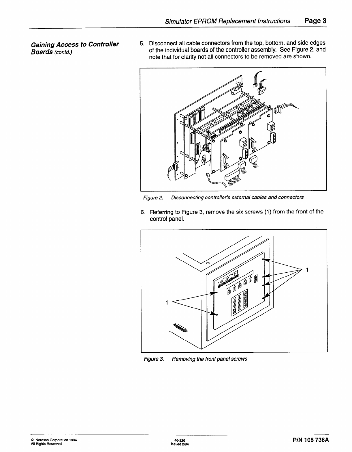
6, Referring to Figure 3, remove the six screws (I) from the front of the
control panel.
Figure 3. Removing the front panel screws
0 Nordson Corporation 1994
All Rights Reserved 46-226
Issued 2B4 P/N 108 738A
Page 4 Simulator EPROM Replacement Instructions
Gaining Access to Controller
Boards (contd.)
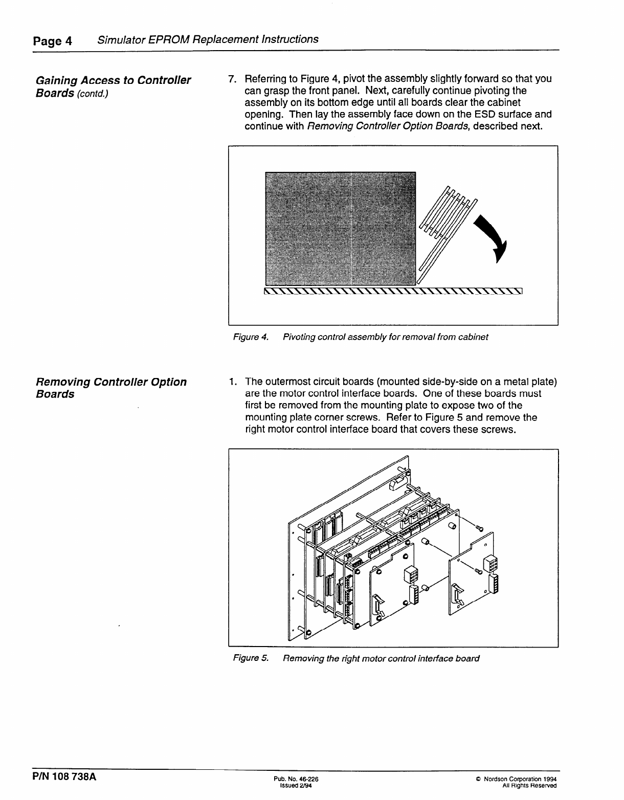
7. Referring to Figure 4, pivot the assembly slightly foward so that you
can grasp the front panel. Next, carefully continue pivoting the
assembly on its bottom edge until all boards clear the cabinet
opening. Then lay the assembly face down on the ESD surface and
continue with Removing Controller Option Boards, described next.
Figure 4. Pivoting control assembly for removal from cabinet
Removing Con troller Option
Boards
1. The outermost circuit boards (mounted side-by-side on a metal plate)
are the motor control interface boards. One of these boards must
first be removed from thle mounting plate to expose two of the
mounting plate corner screws. Refer to Figure 5 and remove the
right motor control interface board that covers these screws.
Figure 5. Removing the right motor control interface board
P/N 108 738A Pub. No. 46-226
Issued 2194
0 Nordson Corporation 1994
All Rights Reserved
Simulator EPROM Replacement Instructions Page 5
Removing Con troller Option
Boards (chtd.)
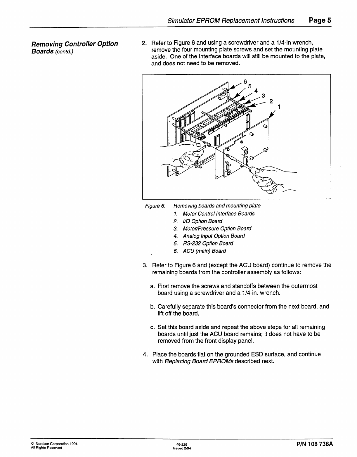
2. Refer to Figure 6 and using a screwdriver and a l/4-in wrench,
remove the four mounting plate screws and set the mounting plate
aside. One of the interface boards will still be mounted to the plate,
and does not need to be removed.
Figure 6. Removing boards and mounting plate
1. Motor Control interface Boards
2. I/O Option Board
3. MotorPressure Option Board
4. Analog Input Option Board
5. RS-232 Option Board
6. ACU (main) Board
3. Refer to Figure 6 and (except the ACU board) continue to remove the
remaining boards from the controller assembly as follows:
a. First remove the screws and standoffs between the outermost
board using a screwdriver and a l/4-in. wrench.
b. Carefully separa’te this board’s connector from the next board, and
lift off the board.
c. Set this board aside and repeat the above steps for all remaining
boards until just the ACU board remains; it does not have to be
removed from the front display panel.
4. Place the boards flat on the grounded ESD surface, and continue
with Replacing Board EPROMs described next.
0 Nordscm Corporation 1994
All Rights Reserved 46-226
Issued 2m.4 PIN 108 738A
Page 6 Simulator EPROM Replacement Instructions
Replacing Board EPROMs
A
CAUTION: Wear the grounded wrist strap during this
/; procedure. Failure to wear the grounded wrist strap may result
/A\ in electrostatic damage to the boards. Also be sure to place
the boards flat on the grounded ESD surface when removing
and installing the EPROMs.
This kit contains seven EPROMs that are to be installed on the
corresponding boards as follows:
ACU Board MEDIA NUMBER 1
MEDIA NUMBER 2
MEDIA NUMBER 3
I/O Board MEDIA NUMBER 4
RS-232 Board MEDIA NUMBER 5
Motor Pressure Board MEDIA NUMBER 6
Analog Input Board MEDIA NUMBER 7
1. Refer to drawing 125 2’14, sheet 1 and locate the EPROMs labeled
MEDIA NUMBER 1,2, and 3 on the ACU board.
2. Refer to drawing 125 2’14, sheet 2 and locate the EPROM labeled
MEDIA NUMBER 5 on the RS-232 board.
3. Refer to drawing 125 2’14, sheet 2 and locate the EPROM labeled
MEDIA NUMBER 7 on ‘the Analog board.
4. Refer to drawing 125 2’14 sheet 1 and locate the EPROM labeled
MEDIA NUMBER 6 on ‘the Motor/Pressure circuit board.
5. Refer to drawing 125 2’14 sheet 1 and locate the EPROM labeled
MEDIA NUMBER 4 on ‘the I/O board.
6. Except for MEDIA NUMBER 3 (on the ACU board), remove all the
other EPROMs as follows:
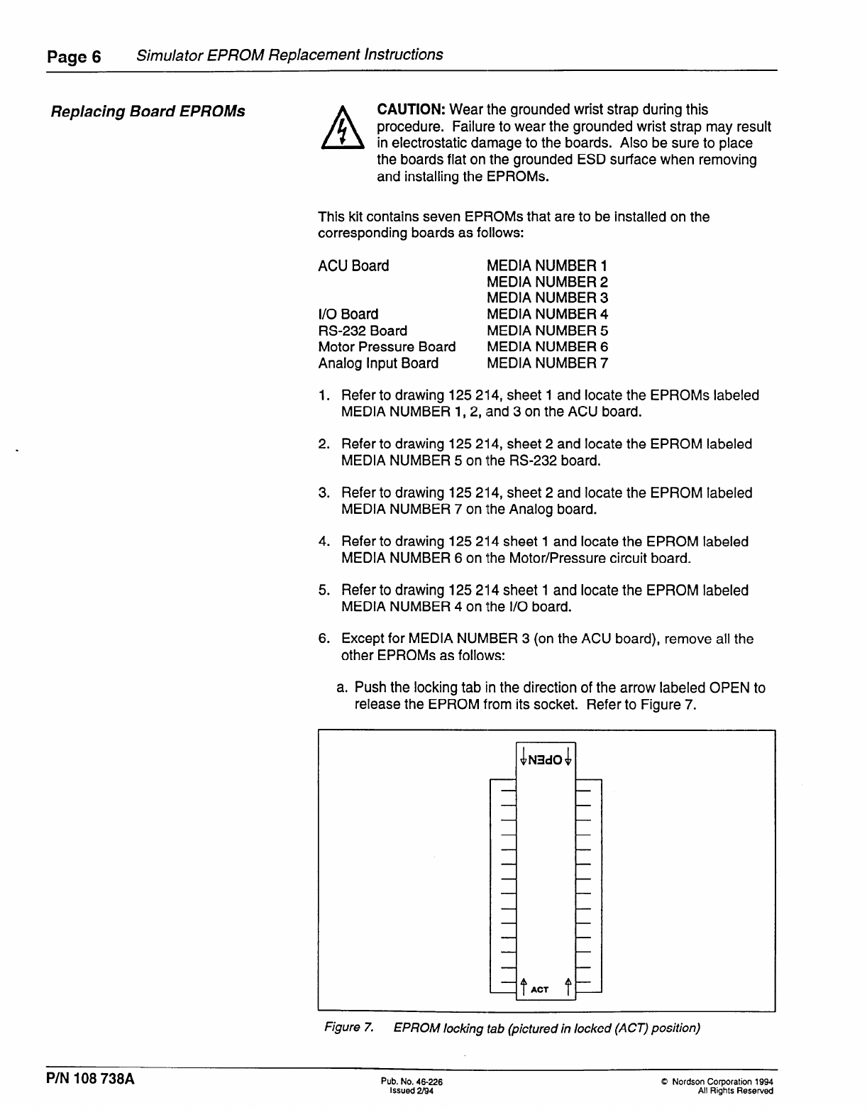
a. Push the locking tab in the direction of the arrow labeled OPEN to
release the EPROM from its socket. Refer to Figure 7.
Figure 7. EPROM locking tab (pictured in locked (ACT) position)
P/N 108 738A Pub. No. 46-226
Issued 294
0 Nordson Corporation 1994
All Rights Reserved
Simulator EPROM Replacement Instructions Page 7
Replacing Board EPROMs
(contd.)
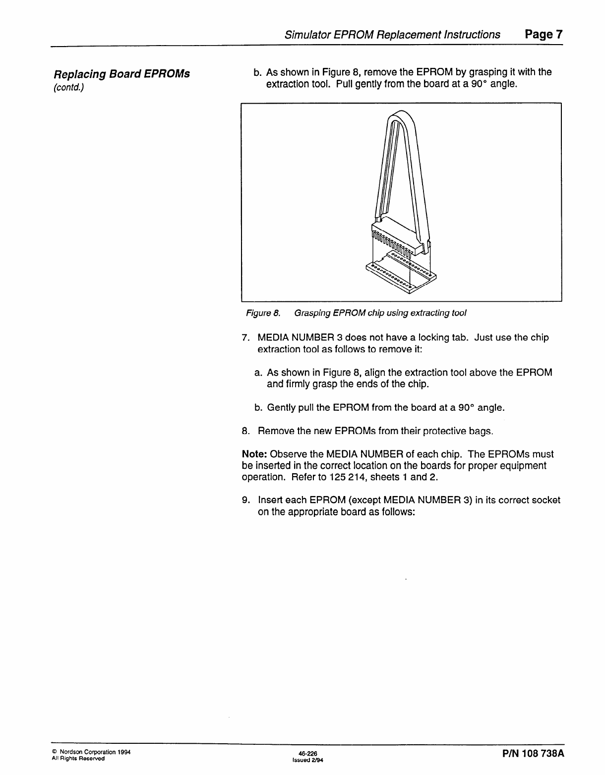
b. As shown in Figuire 8, remove the EPROM by grasping it with the
extraction tool. F’ull gently from the board at a 90” angle.
Figure 8. Grasping EPROM chip using extracting tool
7. MEDIA NUMBER 3 does not have a locking tab. Just use the chip
extraction tool as follows to remove it:
a. As shown in Figure 8, align the extraction tool above the EPROM
and firmly grasp the ends of the chip.
b. Gently pull the EIPROM from the board at a 90” angle.
8. Remove the new EPROMs from their protective bags.
Note: Observe the MEDIA NUMBER of each chip. The EPROMs must
be inserted in the correct location on the boards for proper equipment
operation. Refer to 125 214, sheets 1 and 2.
9. Insert each EPROM (except MEDIA NUMBER 3) in its correct socket
on the appropriate board as follows:
0 Nordsm Corporation 1994
All Rights Resewed 46-226
Issued 2194 P/N 108 738A
Page 8 Simulator EPROM Replacement Instructions
Rep/acing Board EPROMs
(con td.) A CAUTION: Be sure that you insert the EPROMs correctly in
1 their respective socket, see Figure 9. If they are installed
0 wrong they will be damaged when power is applied to the
controller.
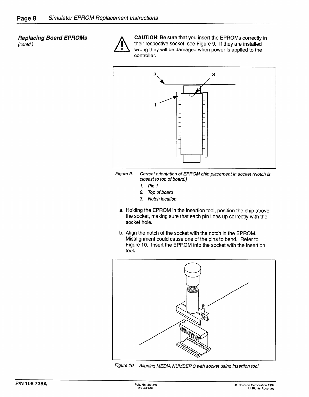
Figure 9. Correct orientation of EPROM chip placement in socket (Notch is
closest to top of board.)
1. Pin 1
2. Top of board
3. Notch location
a. Holding the EPROM in the insertion tool, position the chip above
the socket, making sulre that each pin lines up correctly with the
socket hole.
b. Align the notch of the socket with the notch in the EPROM.
Misalignment could cause one of the pins to bend. Refer to
Figure 10. Insert the EPROM into the socket with the insertion
tool.
Figure 10. Aligning MEDIA NUMBER 3 with socket using inseflion tool
PIN 108 738A Pub. No. 46-226
Issued U94
0 Nordson Corporation 1994
All Rights Resewed
Simulator EPROM Replacement Instructions Page 9
Replacing Board EPROMs
(con td.)
Checking the Option Board
Switch Settings
c. Press the EPROM firmly and evenly into the socket.
d. Ensure that the pins are fully bottomed in the socket.
e. Lock the EPROM in its socket by pushing the tab in the direction of
the arrow markecl ACT.
10. Insert MEDIA NUMBER 3 as follows:
a. Holding the EPROM in the insertion tool, align the chip above the
socket, making sure that each of the pins line up correctly with the
socket holes. Misalignment could cause one of the pins to bend.
Refer to Figure 110.
b. Insert the EPROM into the socket with insertion tool.
c. Press the EPROM firmly and evenly into the socket.
11. This completes EPROM installation. Continue with Checking the
Option Board Switch Settings described next.
Note: During the disassembly/assembly of the controller assembly, the
switch settings on the option boards can be disturbed, causing system
malfunction. As a precaution, be sure to verify the switch settings before
restarting unit.
Check the switch settinigs (and applicable jumper positions) on the I/O,
Motor/Pressure, Analog, and RS-232 boards before installing them. The
switches should be set as shown in drawing 161 539 sheets 1 and 2.
After verifying for correct switch settings, go to Reinstalling Controller
Option Boards described next.
Reins tailing Con troller Option
Boards
1. Reinstall the I/O, Motor/Pressure, Analog, and RS-232 boards by
referring back to figure 6 and performing its associated procedural
steps in reverse order.
A
CAUTION: Sometimes the standoffs used for mounting the
I boards have been shipped with washers for use between the
0 standoff and the board; however, it has been found that this
slight spacing distance that the washer adds can cause
problems with proper mating of the board’s 64-pin connector Jl .
Therefore, be sure not to use any washers between the board
and standoff when reinstalling boards.
2.
3.
Inspect the 64-pin connector Jl to ensure that all pins mate
correctly with the corresponding socket. View the mated
connector from several angles to ensure correct mating.
Reinstall the mounting plate containing the Motor Control Interface
board.
Reinstall the second Motor Control Interface board to the mounting
plate.
a Nordson Corporation 1994
All Rights Reserved PIN 108 738A
Page IO Simulator EPROM Replacement Instructions
4. Reinsert the controller assembly into the cabinet and secure, figures
3 and 4.
Reins tailing Con troller Option
Boards (con td.)
5. Reconnect all cables and connectors, Figure 2.
6. Perform a visual inspection of cabinet for loose cables, parts or tools
left in enclosure.
7. Replace the clear enclosure cover and secure with screws.
8. Restore external power.
9. This completes installation of the boards. Proceed with Checking
installation and Configuring Software described next.
5. Checking Ins talla tion This procedure serves as a final operational check for the controller and
and Configuring should be performed after either installing a new option board and/or new
Software EPROMs, or a new complete controller assembly.
1. Restore external power. The unit will now automatically perform
power up self-test. When the self test is finished and if no problems
were encountered, the controller display begins monitoring the
configured parameters, or displays the default present configuration
code menu.
2. Depending on the software version and the service activity
performed, Table 1 describes what action you should take next:
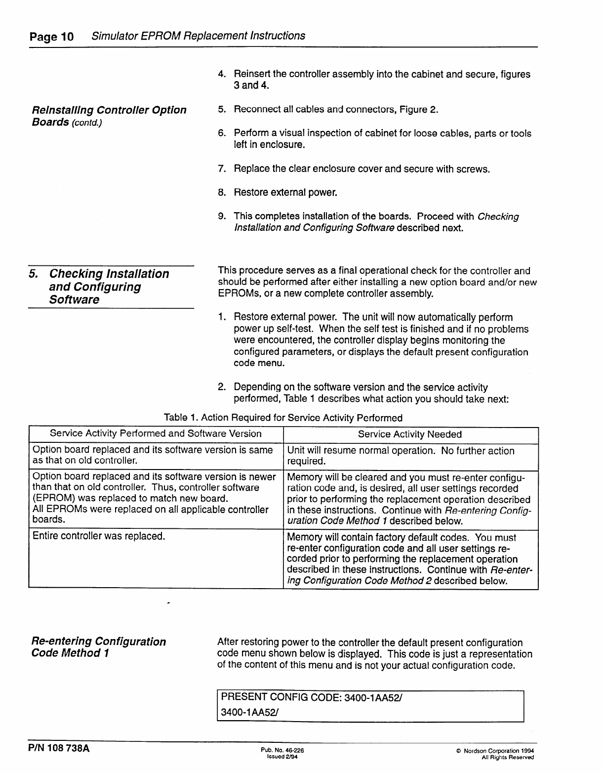
Table 1. Action Required for Service Activity Performed
Service Activity Performed and Software Version Service Activity Needed
Option board replaced and its software version is same Unit will resume normal operation. No further action
as that on old controller. required.
Option board replaced and its software version is newer
than that on old controller. Thus, controller software Memory will be cleared and you must re-enter configu-
(EPROM) was replaced to match new board. ration code and, is desired, all user settings recorded
All EPROMs were replaced on all applicable controller prior to performing the replacement operation described
boards. in these instructions. Continue with Re-entering Config-
uration Code Method I described below.
Entire controller was replaced. Memory will contain factory default codes. You must
re-enter contfiguration code and all user settings re-
corded prior to performing the replacement operation
described ini these instructions. Continue with Re-enter-
ing Configuration Code Method 2 described below.
Re-en tering Configuration
Code Method 1
After restoring power to the Icontroller the default present configuration
code menu shown below is displayed. This code is just a representation
of the content of this menu and is not your actual configuration code.
PRESENT CONFIG CODE: 3400-lAA52/
3400-l AA52/
PIN 108 738A Pub. No. 46-226
Issued 2194
Q Nordson Corporation 1994
All Rights Reserved
Simulator EPROM Replacement Instructions Page 11
Re-en tering Configuration
Code Method I (contd.)
Re-entering Configuration
Code Method 2
The configuration code for the simulator is always SIML-1 AA52/QAJ.
Option Codes: The portion of the configuration code following the slash
(/) is reserved for melter options. These option code letters can be
arranged in any order.
1. Enter configuration code SIML-1 AA52/QAJ for your simulator. Then
press ENTER repeatedly until the controller resumes normal
operation. Note that the dash (-) and forward slash (/) must be
included in the configuration code.
2. The start-up software will run and the unit will resume normal
operation using factory default parameters. If you desire to maintain
some initial user settings, you now need to re-enter these settings, so
go to Re-enferbng IJser Settings described at the end of this
document.
Note: This method is only to be performed when you replaced the entire
controller and the configuration is incorrect.
Begin at the Run Mode with Operator Menu and access the Factory
Menu as follows:
1. Press number 1, then 2, then 7. The display will show the following:
ACCESSCODE:XXXX
CALL NORDSON FOR PASSWORD: ****
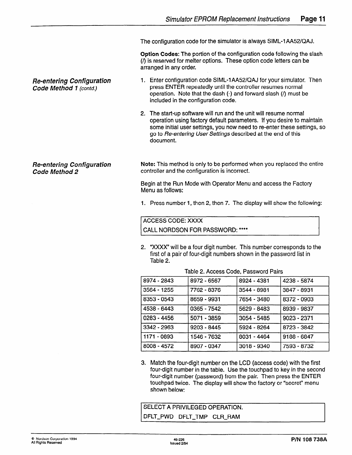
2. “XxXx” will be a four digit number. This number corresponds to the
first of a pair of four-digit numbers shown in the password list in
Table 2.
Table 2. Access Code, Password Pairs
I
8974-2843 I
89172 - 6567 I
8924-4381 I
4238-5874 I
13564-1255 I7762 - 8376 13544-8981 13847-8931 1
I
8353-0543 I
8659 - 9931 I
7654-3480 I
8372-0903 I
I
4538-6443 I
0365 - 7542 I
5629-8483 I
8939 - 9837 1
10283-4456 I5071 - 3859 13054-5485 19023-2371 1
I
3342-2963 I
9203 - 8445 I
5924-8264 I
8723-3842 I
I
1171-0893 I
1546 - 7632 I
8031 -4464 I
9188-6847 I
18008-4572 I8907- 0347 13018-9340 17593-8732 1
3. Match the four-digit number on the LCD (access code) with the first
four-digit number in the table. Use the touchpad to key in the second
four-digit number (password) from the pair. Then press the ENTER
touchpad twice. The display will show the factory or “secret” menu
shown below:
SELECT A PRIVILEGED OPERATION.
DFLT-PWD DFLT-TMP CLR-RAM
Q Nordson Corporation 1994 46-226
All Rights Resewed Issued 2I94 P/N 108 738A
Page 12 Simulator EPROM Replacement Instructions
Re-entering User Settings
4. Select the CLR-RAM function using the touchpad. A warning
message will appear and a YES/NO confirmation will be requested as
shown below:
Note: If you mistakenly choose the wrong function and do NOT want to
change it, press the CANCEiL touchpad. The factory menu will again be
displayed. Either choose thie function that you intend to change, or press
CANCEL again if no changes are desired.
The CLR-RAM function re-iinitializes the battery-backed RAM. When the
battery-backed RAM is re-initialized, the configuration code and all
user-defined values are reset to factory defaults. In addition, any stored
information that may be useful for determining the cause of the problem
will also be cleared.
CLEAR ALL RAM VALUES: NO
ARE YOU SURE? NO
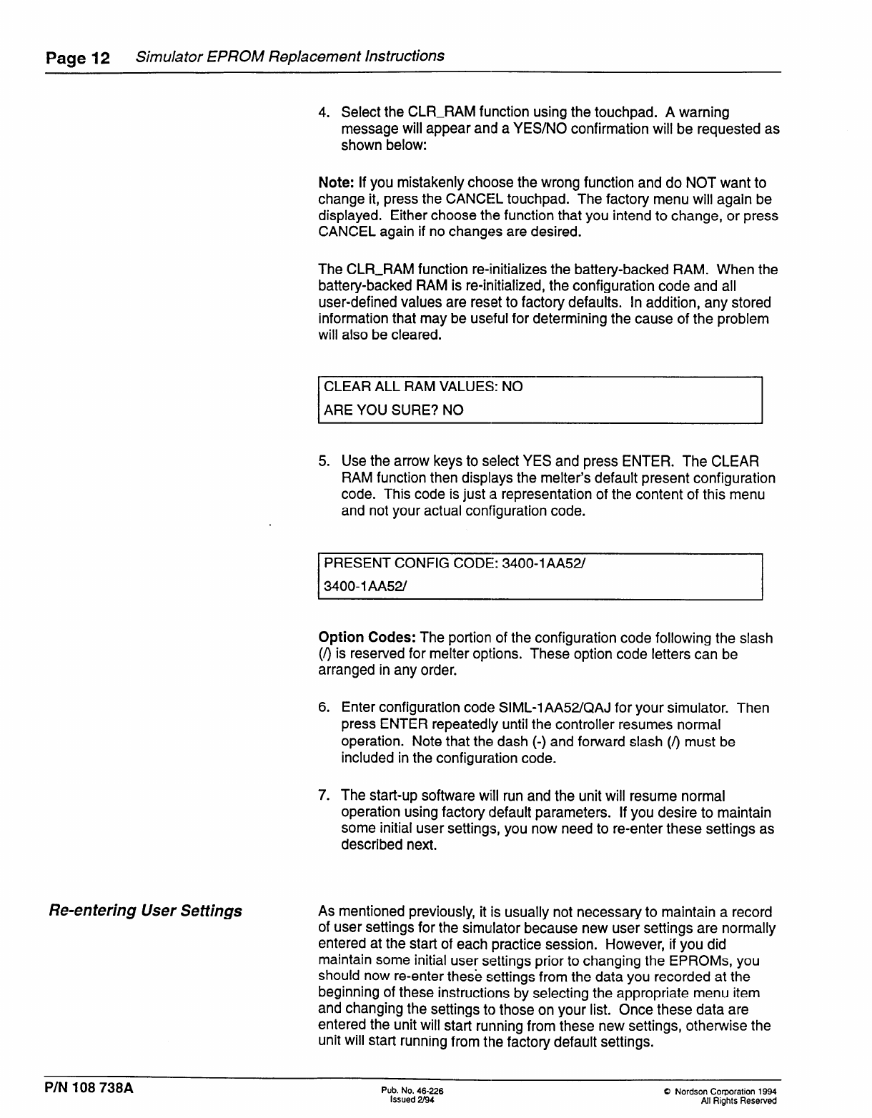
5. Use the arrow keys to select YES and press ENTER. The CLEAR
RAM function then displays the melter’s default present configuration
code. This code is just a representation of the content of this menu
and not your actual configuration code.
PRESENT CONFIG CODE:: 3400-lAA521
3400-I AA52/
Option Codes: The portion of the configuration code following the slash
(I) is reserved for melter options. These option code letters can be
arranged in any order.
6. Enter configuration code SIML-1 AA52/QAJ for your simulator. Then
press ENTER repeatedly until the controller resumes normal
operation. Note that the dash (-) and forward slash (/) must be
included in the configuration code.
7. The start-up software wiill run and the unit will resume normal
operation using factory default parameters. If you desire to maintain
some initial user settings, you now need to re-enter these settings as
described next.
As mentioned previously, it is usually not necessary to maintain a record
of user settings for the simullator because new user settings are normally
entered at the start of each practice session. However, if you did
maintain some initial user settings prior to changing the EPROMs, you
should now re-enter these settings from the data you recorded at the
beginning of these instructions by selecting the appropriate menu item
and changing the settings to those on your list. Once these data are
entered the unit will start running from these new settings, otherwise the
unit will Start running from the factory default settings.
PIN 108 738A Pub. No. 46-226
Issued 2/94 Q Nordson Corporation 1994
All Rights Reserved
