Dionex AS AP Autosampler Operator's Manual 110753 Man IC Ops Sept2012 DOC065361 07
User Manual: 110753
Open the PDF directly: View PDF ![]() .
.
Page Count: 276 [warning: Documents this large are best viewed by clicking the View PDF Link!]
- Dionex AS-AP Autosampler Operator's Manual
- Contents
- 1 • Introduction
- 2 • Description
- 3 • Operation and Maintenance
- 3.1 Operation Checklist
- 3.2 Preparing to Run
- 3.3 Operating the Dionex AS-AP
- 3.3.1 Turning On the Power
- 3.3.2 Connecting to Chromeleon
- 3.3.3 Priming the Syringe
- 3.3.4 Running a Manual Wash Cycle
- 3.3.5 Filling the Vials or Wells
- 3.3.6 Installing a Sample Tray
- 3.3.7 Loading the 8-Position Vial Holders
- 3.3.8 Turning On the Sample Temperature Control Option
- 3.3.9 Equilibrating the System
- 3.3.10 Running a Sequence of Injections
- 3.4 Selecting Operating Parameters
- 3.4.1 Selecting the Injection Mode
- 3.4.2 Specifying Syringe Speeds
- 3.4.3 Specifying Sample (Needle) Heights
- 3.4.4 Selecting the Inject Wash Mode
- 3.4.5 Determining Sample Volumes Used for Each Injection Mode
- 3.4.6 Defining Sample Preparation Operations
- 3.4.7 Selecting Mixing Properties
- 3.4.8 Specifying Vial Positions
- 3.4.9 Specifying Injection Volumes
- 3.4.10 Determining Maximum Injection and Reagent Flush Volumes
- 3.5 Syringe Speed and Tubing Size Guidelines
- 3.6 System Shutdown
- 3.7 Routine Maintenance
- 4 • Troubleshooting
- 5 • Service
- 5.1 Tubing and Fittings
- 5.2 Replacing the Sampling Needle
- 5.3 Aligning the Needle
- 5.4 Replacing the Syringe
- 5.5 Replacing the Buffer Line
- 5.6 Replacing the Syringe Valve Waste Line
- 5.7 Replacing the Wash Reservoir Line
- 5.8 Replacing the Sample Transfer Line (Push Modes)
- 5.9 Calibrating the Sample Transfer Line Volume (Push Modes)
- 5.10 Replacing the Sample Transfer Line (Pull Mode)
- 5.11 Rebuilding a High-Pressure Valve
- 5.12 Updating the Autosampler Firmware
- 5.13 Changing the Main Power Fuses
- A • Specifications
- B • Installation
- B.1 Facility Requirements
- B.2 Unpacking the Dionex AS-AP
- B.3 Plumbing Schematics
- B.4 Syringe, Buffer Line, and Sample Loop Guidelines
- B.5 Installation Checklist
- B.6 Setting Up the Wash Liquid Reservoir
- B.7 Connecting to the Injection Valve
- B.8 Connecting the Drain Line
- B.9 Connecting the USB Cable
- B.10 Connecting the Power Cord
- B.11 Setting Up Chromeleon
- B.12 Checking the Needle Alignment
- B.13 Priming the Syringe
- B.14 TTL and Relay Connections (Optional)
- C • Installing Optional Valves
- D • Fraction Collection Option
- E • Reducing Contamination
- F • Reordering Information
- Index

Dionex AS-AP Autosampler
Operator's Manual
Document No. 065361
Revision 07
September 2012
© 2012 by Thermo Fisher Scientific Inc. All rights reserved.
Chromeleon and Nalgene are registered trademarks of Thermo Fisher Scientific
Inc. in the United States.
Microsoft, Windows, Windows 2000, and Windows XP are registered
trademarks of Microsoft Corporation in the United States and other countries.
Adobe, Acrobat, and Adobe Reader are registered trademarks of Adobe Systems,
Incorporated in the United States and other countries.
The following are registered trademarks in the United States and possibly other
countries: Nitrilite is a registered trademark of Ansell Limited. VWR and
CERTICLEAN are registered trademarks of VWR International, LLC.
Dionex PolyVial is a trademark of Thermo Fisher Scientific.
PEEK is a trademark of Victrex PLC.
All other trademarks are the property of Thermo Fisher Scientific and its
subsidiaries.
Thermo Fisher Scientific Inc. provides this document to its customers with a
product purchase to use in the product operation. This document is copyright
protected and any reproduction of the whole or any part of this document is
strictly prohibited, except with the written authorization of Thermo Fisher
Scientific Inc.
The contents of this document are subject to change without notice. All technical
information in this document is for reference purposes only. System
configurations and specifications in this document supersede all previous
information received by the purchaser.
Thermo Fisher Scientific Inc. makes no representations that this document
is complete, accurate or error-free and assumes no responsibility and will
not be liable for any errors, omissions, damage or loss that might result
from any use of this document, even if the information in the document is
followed properly.
This document is not part of any sales contract between Thermo Fisher Scientific
Inc. and a purchaser. This document shall in no way govern or modify any Terms
and Conditions of Sale, which Terms and Conditions of Sale shall govern all
conflicting information between the two documents.
Revision history: Revision 01 released April 2011
Revision 02 released May 2011
Revision 03 released June 2011
Revision 04 released December 2011
Revision 05 released February 2012
Revision 06 released July 2012
Revision 07 released September 2012
For Research Use Only. Not for use in diagnostic procedures.

Doc. 065361-07 9/12 i
1 • Introduction . . . . . . . . . . . . . . . . . . . . . . . . . . . . . . . . . . . . . . . . . . . . 1
1.1 Overview of the Thermo Scientific Dionex AS-AP Autosampler . . . . 1
1.2 The Dionex AS-AP Operator’s Manual . . . . . . . . . . . . . . . . . . . . . . . . 2
1.3 Safety and Regulatory Information . . . . . . . . . . . . . . . . . . . . . . . . . . . 3
1.3.1 Safety Messages and Notes . . . . . . . . . . . . . . . . . . . . . . . . . . . 3
1.3.2 Safety Symbols . . . . . . . . . . . . . . . . . . . . . . . . . . . . . . . . . . . . 5
1.3.3 Declaration of Conformity . . . . . . . . . . . . . . . . . . . . . . . . . . . 6
1.4 Deionized Water Requirements for IC . . . . . . . . . . . . . . . . . . . . . . . . . 7
2•Description . . . . . . . . . . . . . . . . . . . . . . . . . . . . . . . . . . . . . . . . . . . . . 9
2.1 Operating Features . . . . . . . . . . . . . . . . . . . . . . . . . . . . . . . . . . . . . . . . 9
2.1.1 Status Bar . . . . . . . . . . . . . . . . . . . . . . . . . . . . . . . . . . . . . . . 12
2.1.2 Carousel, Sample Trays, Vials, and Well Plates . . . . . . . . . . 14
2.1.3 Syringe and Syringe Valve . . . . . . . . . . . . . . . . . . . . . . . . . . 16
2.1.4 Sampling Needle and Needle Arm . . . . . . . . . . . . . . . . . . . . 17
2.1.5 Wash, Waste, Injection, and Leak Ports . . . . . . . . . . . . . . . . 18
2.1.6 Leak Sensor . . . . . . . . . . . . . . . . . . . . . . . . . . . . . . . . . . . . . . 19
2.1.7 Compartment Lights . . . . . . . . . . . . . . . . . . . . . . . . . . . . . . . 19
2.2 Rear Panel Features . . . . . . . . . . . . . . . . . . . . . . . . . . . . . . . . . . . . . . 20
2.2.1 Fuse Holder, Main Power Switch, and Power Receptacle . . 21
2.2.2 TTL Input and Relay Output Connectors . . . . . . . . . . . . . . . 21
Contents

Dionex AS-AP Operator’s Manual
ii Doc. 065361-07 9/12
2.2.3 USB Connections . . . . . . . . . . . . . . . . . . . . . . . . . . . . . . . . . 22
2.3 Autosampler Options . . . . . . . . . . . . . . . . . . . . . . . . . . . . . . . . . . . . . 23
2.3.1 Sample Temperature Control Option . . . . . . . . . . . . . . . . . . 23
2.3.2 Simultaneous Injection Option . . . . . . . . . . . . . . . . . . . . . . . 23
2.3.3 Sequential Injection Option . . . . . . . . . . . . . . . . . . . . . . . . . 24
2.3.4 Concentrator Injection Option . . . . . . . . . . . . . . . . . . . . . . . 24
2.3.5 Sample Conductivity and pH Accessory Option . . . . . . . . . 25
2.3.6 Fraction Collection Option . . . . . . . . . . . . . . . . . . . . . . . . . . 25
2.3.7 High-Pressure Valve Options . . . . . . . . . . . . . . . . . . . . . . . . 25
2.4 Operating Principles . . . . . . . . . . . . . . . . . . . . . . . . . . . . . . . . . . . . . . 31
2.4.1 Overview of Injection Modes . . . . . . . . . . . . . . . . . . . . . . . . 31
2.4.2 Push Mode Sampling Principle . . . . . . . . . . . . . . . . . . . . . . . 35
2.4.3 Pull Mode Sampling Principle . . . . . . . . . . . . . . . . . . . . . . . 38
2.4.4 Sequential Mode Sampling Principle . . . . . . . . . . . . . . . . . . 41
2.4.5 Simultaneous Mode Sampling Principle . . . . . . . . . . . . . . . . 43
2.5 Chromeleon Software . . . . . . . . . . . . . . . . . . . . . . . . . . . . . . . . . . . . 44
2.5.1 Software Control Modes . . . . . . . . . . . . . . . . . . . . . . . . . . . . 44
2.5.2 System Wellness and Predictive Performance . . . . . . . . . . . 46
3 • Operation and Maintenance . . . . . . . . . . . . . . . . . . . . . . 47
3.1 Operation Checklist . . . . . . . . . . . . . . . . . . . . . . . . . . . . . . . . . . . . . . 47
3.2 Preparing to Run . . . . . . . . . . . . . . . . . . . . . . . . . . . . . . . . . . . . . . . . 48
3.2.1 Setting Up the Wash Liquid Reservoir . . . . . . . . . . . . . . . . . 48
3.2.2 Checking the Syringe Valve Connections . . . . . . . . . . . . . . 49

Contents
Doc. 065361-07 9/12 iii
3.2.3 Checking the Drain Lines . . . . . . . . . . . . . . . . . . . . . . . . . . . 49
3.3 Operating the Dionex AS-AP . . . . . . . . . . . . . . . . . . . . . . . . . . . . . . 50
3.3.1 Turning On the Power . . . . . . . . . . . . . . . . . . . . . . . . . . . . . . 50
3.3.2 Connecting to Chromeleon . . . . . . . . . . . . . . . . . . . . . . . . . . 50
3.3.3 Priming the Syringe . . . . . . . . . . . . . . . . . . . . . . . . . . . . . . . 52
3.3.4 Running a Manual Wash Cycle . . . . . . . . . . . . . . . . . . . . . . 53
3.3.5 Filling the Vials or Wells . . . . . . . . . . . . . . . . . . . . . . . . . . . 54
3.3.6 Installing a Sample Tray . . . . . . . . . . . . . . . . . . . . . . . . . . . . 56
3.3.7 Loading the 8-Position Vial Holders . . . . . . . . . . . . . . . . . . 59
3.3.8 Turning On the Sample Temperature Control Option . . . . . 60
3.3.9 Equilibrating the System . . . . . . . . . . . . . . . . . . . . . . . . . . . . 61
3.3.10 Running a Sequence of Injections . . . . . . . . . . . . . . . . . . . . . 61
3.4 Selecting Operating Parameters . . . . . . . . . . . . . . . . . . . . . . . . . . . . . 62
3.4.1 Selecting the Injection Mode . . . . . . . . . . . . . . . . . . . . . . . . 62
3.4.2 Specifying Syringe Speeds . . . . . . . . . . . . . . . . . . . . . . . . . . 65
3.4.3 Specifying Sample (Needle) Heights . . . . . . . . . . . . . . . . . . 67
3.4.4 Selecting the Inject Wash Mode . . . . . . . . . . . . . . . . . . . . . . 68
3.4.5 Determining Sample Volumes Used for Each Injection
Mode . . . . . . . . . . . . . . . . . . . . . . . . . . . . . . . . . . . . . . . . . . . 70
3.4.6 Defining Sample Preparation Operations . . . . . . . . . . . . . . . 76
3.4.7 Selecting Mixing Properties . . . . . . . . . . . . . . . . . . . . . . . . . 79
3.4.8 Specifying Vial Positions . . . . . . . . . . . . . . . . . . . . . . . . . . . 81
3.4.9 Specifying Injection Volumes . . . . . . . . . . . . . . . . . . . . . . . . 83
3.4.10 Determining Maximum Injection and Reagent Flush
Volumes . . . . . . . . . . . . . . . . . . . . . . . . . . . . . . . . . . . . . . . . 84

Dionex AS-AP Operator’s Manual
iv Doc. 065361-07 9/12
3.5 Syringe Speed and Tubing Size Guidelines . . . . . . . . . . . . . . . . . . . . 85
3.6 System Shutdown . . . . . . . . . . . . . . . . . . . . . . . . . . . . . . . . . . . . . . . . 86
3.7 Routine Maintenance . . . . . . . . . . . . . . . . . . . . . . . . . . . . . . . . . . . . . 88
3.7.1 Daily . . . . . . . . . . . . . . . . . . . . . . . . . . . . . . . . . . . . . . . . . . . 88
3.7.2 Weekly . . . . . . . . . . . . . . . . . . . . . . . . . . . . . . . . . . . . . . . . . 89
3.7.3 Periodically . . . . . . . . . . . . . . . . . . . . . . . . . . . . . . . . . . . . . . 89
3.7.4 Annually . . . . . . . . . . . . . . . . . . . . . . . . . . . . . . . . . . . . . . . . 89
4 • Troubleshooting . . . . . . . . . . . . . . . . . . . . . . . . . . . . . . . . . . . . . 91
4.1 Audit Trail Error Messages . . . . . . . . . . . . . . . . . . . . . . . . . . . . . . . . 91
4.1.1 General Troubleshooting Information . . . . . . . . . . . . . . . . . 92
4.1.2 Error Messages . . . . . . . . . . . . . . . . . . . . . . . . . . . . . . . . . . . 92
4.2 Liquid Leaks . . . . . . . . . . . . . . . . . . . . . . . . . . . . . . . . . . . . . . . . . . 105
4.2.1 Leaking Syringe or Syringe Valve . . . . . . . . . . . . . . . . . . . 105
4.2.2 Leaking Drain Line Connection . . . . . . . . . . . . . . . . . . . . . 105
4.2.3 Leaking Injection Port . . . . . . . . . . . . . . . . . . . . . . . . . . . . . 106
4.2.4 Leaking Fitting . . . . . . . . . . . . . . . . . . . . . . . . . . . . . . . . . . 106
4.2.5 Broken Liquid Line . . . . . . . . . . . . . . . . . . . . . . . . . . . . . . . 106
4.2.6 Leaking High-Pressure Valve . . . . . . . . . . . . . . . . . . . . . . . 106
4.3 Condensation on Vial Tops and Well Plate Covers . . . . . . . . . . . . . 107
5•Service. . . . . . . . . . . . . . . . . . . . . . . . . . . . . . . . . . . . . . . . . . . . . . . . . 109
5.1 Tubing and Fittings . . . . . . . . . . . . . . . . . . . . . . . . . . . . . . . . . . . . . 109
5.2 Replacing the Sampling Needle . . . . . . . . . . . . . . . . . . . . . . . . . . . . 112

Contents
Doc. 065361-07 9/12 v
5.3 Aligning the Needle . . . . . . . . . . . . . . . . . . . . . . . . . . . . . . . . . . . . . 115
5.3.1 Aligning the Needle in the Injection Port . . . . . . . . . . . . . . 115
5.3.2 Aligning the Needle in the Wash Port . . . . . . . . . . . . . . . . 121
5.3.3 Adjusting the Needle Height Over the Vial . . . . . . . . . . . . 122
5.3.4 Aligning the Needle in the Tray . . . . . . . . . . . . . . . . . . . . . 125
5.4 Replacing the Syringe . . . . . . . . . . . . . . . . . . . . . . . . . . . . . . . . . . . 127
5.4.1 Removing the Existing Syringe . . . . . . . . . . . . . . . . . . . . . 127
5.4.2 Installing the New Syringe . . . . . . . . . . . . . . . . . . . . . . . . . 129
5.5 Replacing the Buffer Line . . . . . . . . . . . . . . . . . . . . . . . . . . . . . . . . 132
5.5.1 Removing the Old Buffer Line . . . . . . . . . . . . . . . . . . . . . . 133
5.5.2 Connecting a 500 L or 1200 L Buffer Line . . . . . . . . . . 136
5.5.3 Connecting an 8500 L Buffer Line . . . . . . . . . . . . . . . . . . 141
5.5.4 Configure the New Buffer Line in Chromeleon . . . . . . . . . 142
5.6 Replacing the Syringe Valve Waste Line . . . . . . . . . . . . . . . . . . . . 143
5.7 Replacing the Wash Reservoir Line . . . . . . . . . . . . . . . . . . . . . . . . . 147
5.8 Replacing the Sample Transfer Line (Push Modes) . . . . . . . . . . . . 148
5.9 Calibrating the Sample Transfer Line Volume (Push Modes) . . . . . 153
5.10 Replacing the Sample Transfer Line (Pull Mode) . . . . . . . . . . . . . . 157
5.11 Rebuilding a High-Pressure Valve . . . . . . . . . . . . . . . . . . . . . . . . . . 159
5.12 Updating the Autosampler Firmware . . . . . . . . . . . . . . . . . . . . . . . . 160
5.13 Changing the Main Power Fuses . . . . . . . . . . . . . . . . . . . . . . . . . . . 160
A • Specifications. . . . . . . . . . . . . . . . . . . . . . . . . . . . . . . . . . . . . . . 163

Dionex AS-AP Operator’s Manual
vi Doc. 065361-07 9/12
B • Installation . . . . . . . . . . . . . . . . . . . . . . . . . . . . . . . . . . . . . . . . . . . 167
B.1 Facility Requirements . . . . . . . . . . . . . . . . . . . . . . . . . . . . . . . . . . . 167
B.2 Unpacking the Dionex AS-AP . . . . . . . . . . . . . . . . . . . . . . . . . . . . . 168
B.3 Plumbing Schematics . . . . . . . . . . . . . . . . . . . . . . . . . . . . . . . . . . . . 173
B.4 Syringe, Buffer Line, and Sample Loop Guidelines . . . . . . . . . . . . 177
B.5 Installation Checklist . . . . . . . . . . . . . . . . . . . . . . . . . . . . . . . . . . . . 179
B.6 Setting Up the Wash Liquid Reservoir . . . . . . . . . . . . . . . . . . . . . . 179
B.6.1 Connecting the Reservoir for Offline Degassing . . . . . . . . 179
B.6.2 Connecting the Reservoir for Online Degassing . . . . . . . . 181
B.7 Connecting to the Injection Valve . . . . . . . . . . . . . . . . . . . . . . . . . . 184
B.7.1 Connecting to a Single Injection Valve for Push Mode . . . 185
B.7.2 Connecting to Two Injection Valves for Sequential
Injections . . . . . . . . . . . . . . . . . . . . . . . . . . . . . . . . . . . . . . . 188
B.7.3 Connecting to Two Injection Valves for Simultaneous
Injections . . . . . . . . . . . . . . . . . . . . . . . . . . . . . . . . . . . . . . . 190
B.7.4 Connecting to the Injection Valve for Pull Mode . . . . . . . . 195
B.8 Connecting the Drain Line . . . . . . . . . . . . . . . . . . . . . . . . . . . . . . . . 198
B.9 Connecting the USB Cable . . . . . . . . . . . . . . . . . . . . . . . . . . . . . . . 200
B.10 Connecting the Power Cord . . . . . . . . . . . . . . . . . . . . . . . . . . . . . . . 201
B.11 Setting Up Chromeleon . . . . . . . . . . . . . . . . . . . . . . . . . . . . . . . . . . 202
B.11.1 Installing the Software and License . . . . . . . . . . . . . . . . . . 202
B.11.2 Installing the Dionex AS-AP Device Driver . . . . . . . . . . . 202
B.11.3 Configuring the Dionex AS-AP in Chromeleon . . . . . . . . . 204
B.11.4 Connecting to the ePanel Set or Panel Tabset . . . . . . . . . . 209
B.12 Checking the Needle Alignment . . . . . . . . . . . . . . . . . . . . . . . . . . . 211

Contents
Doc. 065361-07 9/12 vii
B.13 Priming the Syringe . . . . . . . . . . . . . . . . . . . . . . . . . . . . . . . . . . . . . 211
B.14 TTL and Relay Connections (Optional) . . . . . . . . . . . . . . . . . . . . . . 212
C • Installing Optional Valves . . . . . . . . . . . . . . . . . . . . . . . 215
C.1 Setting the Valve Electronics Board Jumpers . . . . . . . . . . . . . . . . . 215
C.2 Installing a Valve with Mounting Bracket . . . . . . . . . . . . . . . . . . . . 217
C.3 Installing a Second Valve on the Valve Mounting Bracket . . . . . . . 223
C.3.1 Removing the Valve Mounting Bracket from the
Dionex AS-AP (If Installed) . . . . . . . . . . . . . . . . . . . . . . . . 224
C.3.2 Installing a Second Valve on an Uninstalled Mounting
Bracket . . . . . . . . . . . . . . . . . . . . . . . . . . . . . . . . . . . . . . . . 226
D • Fraction Collection Option . . . . . . . . . . . . . . . . . . . . . . 229
D.1 Installing and Plumbing the Valves . . . . . . . . . . . . . . . . . . . . . . . . . 229
D.1.1 Plumbing the Valves for Push Mode with Fraction
Collection . . . . . . . . . . . . . . . . . . . . . . . . . . . . . . . . . . . . . . 230
D.1.2 Plumbing the Valves for Pull Mode with Fraction
Collection . . . . . . . . . . . . . . . . . . . . . . . . . . . . . . . . . . . . . . 236
D.2 Setting Up Fraction Collection in Chromeleon 6.8 . . . . . . . . . . . . . 238
D.3 Performing Fraction Collection with the Dionex AS-AP . . . . . . . . 241
D.3.1 Sampling Principle for Fraction Collection in Push Mode . 241
D.3.2 Sampling Principle for Fraction Collection in Pull Mode . 244
D.3.3 Manual Control . . . . . . . . . . . . . . . . . . . . . . . . . . . . . . . . . . 247
D.3.4 Programmed Control . . . . . . . . . . . . . . . . . . . . . . . . . . . . . . 247


Doc. 065361-07 9/12 1
1 • Introduction
1.1 Overview of the Thermo Scientific Dionex AS-AP
Autosampler
The Thermo Scientific Dionex™ AS-AP Autosampler is designed for high-
precision, reliability, ruggedness, and ease of use. The Dionex AS-AP can be
used with the entire ICS product family and provides high-performance,
automated sample processing for ion chromatography applications.
The Dionex AS-AP is controlled with a PC configured with Thermo
Scientific Dionex Chromeleon™ 7 Chromatography Data System (release 7.1
DU0a or later) or Chromeleon 6.8 Chromatography Data System (release 6.80
DU10c or later). The Dionex AS-AP connects to the Chromeleon PC with a
USB cable.
Key Features:
•Excellent reproducibility with RSDs less than 0.3% for full-loop
injections
•All-PEEK™ flow paths, compatible with aqueous and reversed-phase
eluents, safe from metal contamination
•Carousel and moving-needle design to guarantee reliable sampling from a
variety of vial sizes and well plates
•10 mL polystyrene sample vials with wide openings for large-volume
injections and trace analysis
•High sample capacity, from 81 (10 mL vials) to 1152 (three 384-position
well plates)
•Sample preparation function to automate sample and standard
preparations, saving time and labor
•Optional sample tray temperature control for thermally-sensitive samples
that offers precise, reliable control over a temperature range of 4 °C to
60 °C. The sample tray temperature control option must be ordered at the
same time as the Dionex AS-AP module and installed at the factory
•Optional simultaneous injections

Dionex AS-AP Operator’s Manual
2Doc. 065361-07 9/12
•Optional sample conductivity and pH measurement with conditional
dilutions
•Optional fraction collection and reinjection
•Optional 6-port or 10-port valves (up to two) for sample injection,
sequential injections, sample preparation, or fraction collection
•Optional chemistry switching to provide fully-automated switching
between two independent applications on the same dual channel IC
system
1.2 The Dionex AS-AP Operator’s Manual
The electronic version (i.e., PDF file) of the Dionex AS-AP operator’s manual
contains numerous links that you can click to go to other locations within the
manual. These links include:
•Table of contents entries
•Index entries
•Cross-references (underlined in blue) to sections, figures, tables, etc.
If you are not familiar with how to navigate PDF files, refer to the Help
system for Adobe® Acrobat® or Adobe Reader® for assistance.
Chapter 1
Introduction Introduces the Dionex AS-AP; explains the
conventions used in this manual, including safety-
related information.
Chapter 2
Description Describes Dionex AS-AP operating features and the
software required for Dionex AS-AP control.
Chapter 3
Operation and
Maintenance
Provides operating instructions for the Dionex AS-
AP and describes routine preventive maintenance
procedures.
Chapter 4
Troubleshooting Lists problems and presents step-by-step procedures
for how to isolate and eliminate the cause of each
problem.
Chapter 5
Service Provides step-by-step instructions for routine service
and parts replacement procedures that the user can
perform.

1 • Introduction
Doc. 065361-07 9/12 3
1.3 Safety and Regulatory Information
The Thermo Scientific Dionex AS-AP Autosampler was manufactured by
Thermo Fisher Scientific at the following location: 527 Lakeside Drive,
Sunnyvale, CA 94088-3603 U.S.A. The Dionex AS-AP is designed for IC
(ion chromatography) and HPLC (high-performance liquid chromatography)
applications and should not be used for any other purpose. Operation of a
Dionex AS-AP in a manner not specified by Thermo Fisher Scientific may
result in personal injury.
If there is a question regarding appropriate usage, contact Technical Support
for Dionex products. In the U.S. and Canada, call 1-800-346-6390. Outside
the U.S. and Canada, call the nearest Thermo Fisher Scientific office.
1.3.1 Safety Messages and Notes
This manual contains warnings and precautionary statements that can prevent
personal injury and/or damage to the Dionex AS-AP when properly followed.
Appendix A
Specifications Contains the Dionex AS-AP specifications and
facility requirements.
Appendix B
Installation Provides installation instructions for the Dionex AS-
AP.
Appendix C
Installation of
Optional Valves
Provides installation instructions for high-pressure
valve options.
Appendix D
Sample
Conductivity and pH
Accessory
Provides installation, configuration, and operating
instructions for the Dionex AS-AP Sample
Conductivity and pH Accessory option.
Appendix E
Fraction Collection Provides installation, configuration, and operating
instructions for the fraction collection option.
Appendix F
Reducing
Contamination
Lists steps for reducing ionic contamination in the
autosampler.
Appendix G
Reordering
Information
Lists part numbers of sample vials and other supplies
for convenience when reordering.
Dionex AS-AP Operator’s Manual
4Doc. 065361-07 9/12
Safety messages appear in bold type and are accompanied by icons, as shown
below.
Messages d'avertissement en français
Warnhinweise in Deutsch
Indicates an imminently hazardous situation which, if not avoided, will
result in death or serious injury.
Indicates a potentially hazardous situation which, if not avoided, could
result in death or serious injury.
Indicates a potentially hazardous situation which, if not avoided, may
result in minor or moderate injury. Also used to identify a situation or
practice that may seriously damage the instrument, but will not cause
injury.
Indicates that the function or process of the instrument may be
impaired. Operation does not constitute a hazard.
Signale une situation de danger immédiat qui, si elle n'est pas évitée,
entraînera des blessures graves à mortelles.
Signale une situation de danger potentiel qui, si elle n'est pas évitée,
pourrait entraîner des blessures graves à mortelles.
Signale une situation de danger potentiel qui, si elle n'est pas évitée,
pourrait entraîner des blessures mineures à modérées. Également
utilisé pour signaler une situation ou une pratique qui pourrait
gravement endommager l'instrument mais qui n'entraînera pas de
blessures.
Bedeutet unmittelbare Gefahr. Mißachtung kann zum Tod oder
schwerwiegenden Verletzungen führen.
Bedeutet eine mögliche Gefährdung. Mißachtung kann zum Tod oder
schwerwiegenden Verletzungen führen.
1 • Introduction
Doc. 065361-07 9/12 5
Notes
Informational messages also appear throughout this manual. These are labeled
NOTE and are in bold type:
NOTE NOTES call attention to certain information. They alert you
to an unexpected result of an action, suggest how to optimize
instrument performance, etc.
1.3.2 Safety Symbols
These symbols appear on the Dionex AS-AP or on labels affixed to the
module:
Bedeutet eine mögliche Gefährdung. Mißachtung kann zu kleineren
oder mittelschweren Verletzungen führen. Wird auch verwendet, wenn
eine Situation zu schweren Schäden am Gerät führen kann, jedoch
keine Verletzungsgefahr besteht.
Alternating current
Primary protective conductor terminal
Secondary protective conductor terminal
Power supply is on
Power supply is off
Indicates a potential hazard. Refer to this operator’s
manual for an explanation of the hazard and how to
proceed.
Dionex AS-AP Operator’s Manual
6Doc. 065361-07 9/12
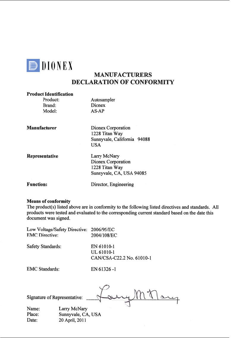
1.3.3 Declaration of Conformity
The cETLus or cTUVus and CE marks on the model/data labels on the
Dionex AS-AP indicate that the module is in compliance with the following
standards.
1 • Introduction
Doc. 065361-07 9/12 7
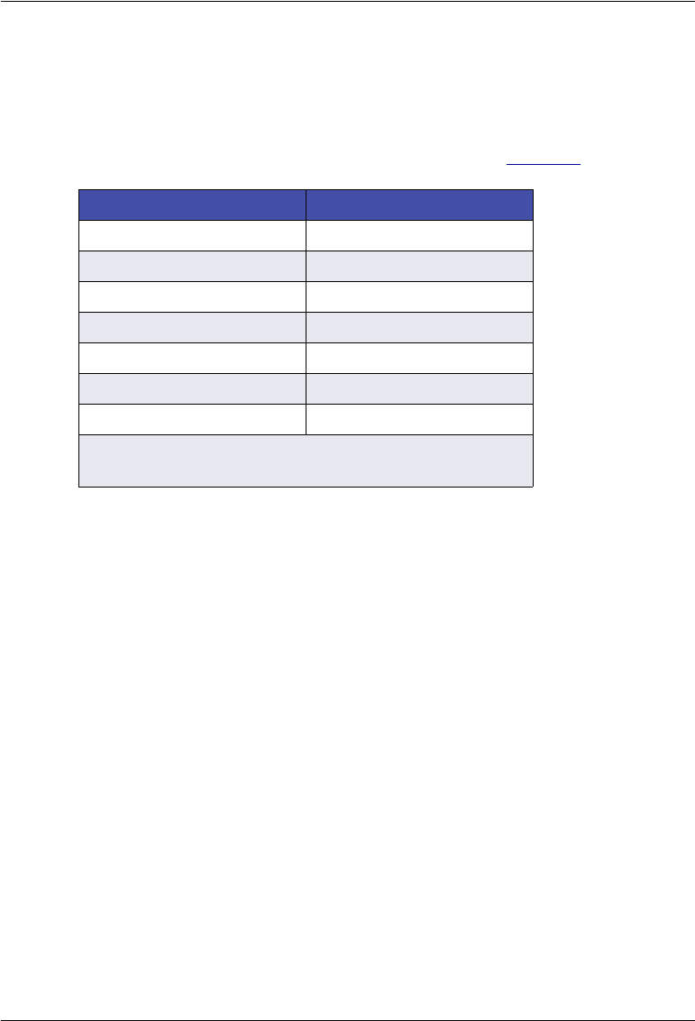
1.4 Deionized Water Requirements for IC
For autosampler wash liquid, eluent generation, or when manually preparing
eluent and regenerant, use ASTM Type I (18 megohm-cm) filtered and
deionized water that meets the specifications listed in Table 1-1.
Contaminant Specification
Ions–Resistivity >18.0 (megohm-cm)
Organics–TOC <10 ppb
Iron/Transition Metals* <1 ppb
Pyrogens <0.03 (Eu/mL)
Particulates > 0.2 µm <1 (units/mL)
Colloids–Silica <10 ppb
Bacteria <1 (cfu/mL)
* Iron/transition metal content not specified for ASTM
Type I Water
Table 1-1. ASTM Filtered, Type I Deionized Water
Specifications for Ion Chromatography

Dionex AS-AP Operator’s Manual
8Doc. 065361-07 9/12
Dionex AS-AP Operator’s Manual
10 Doc. 065361-07 9/12
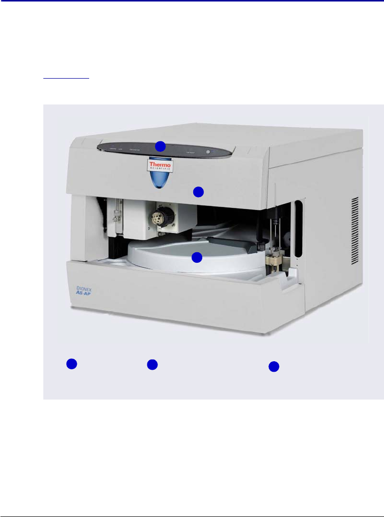
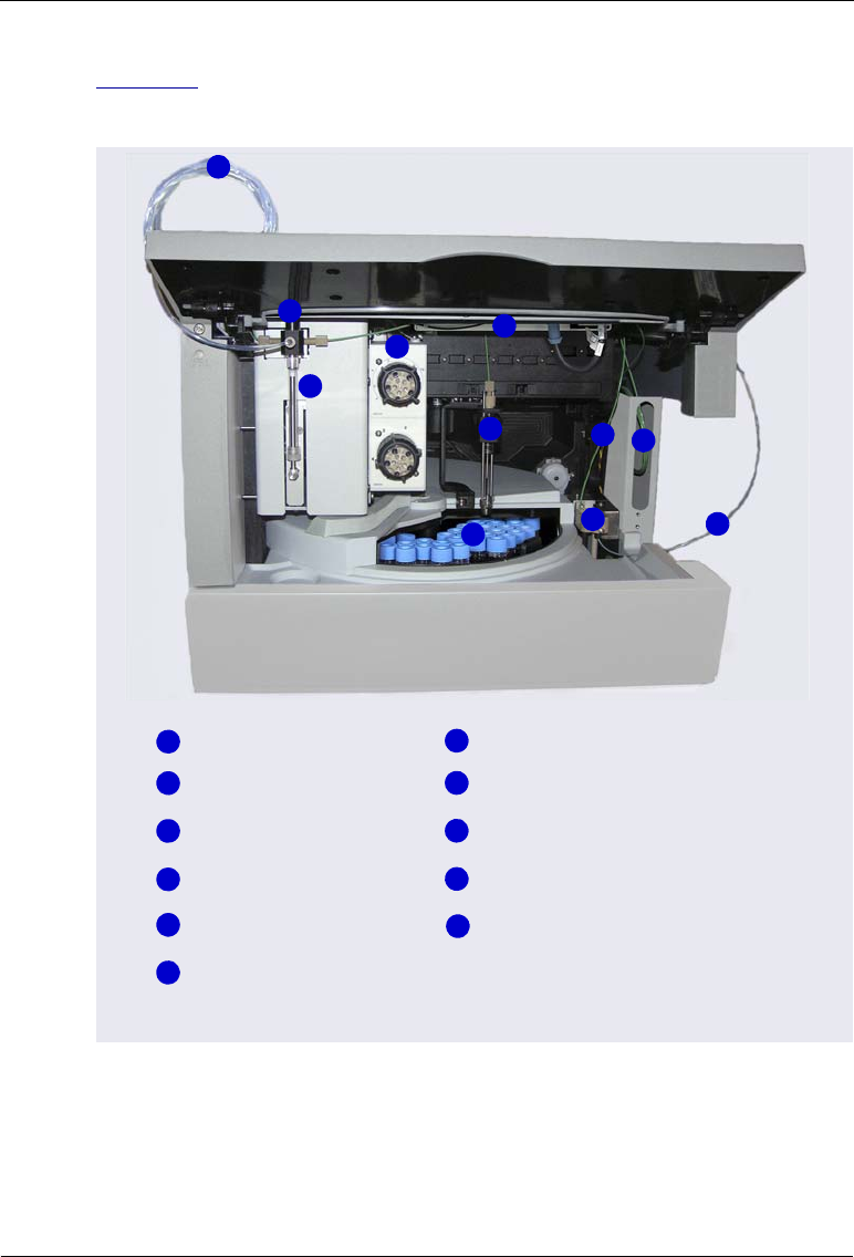
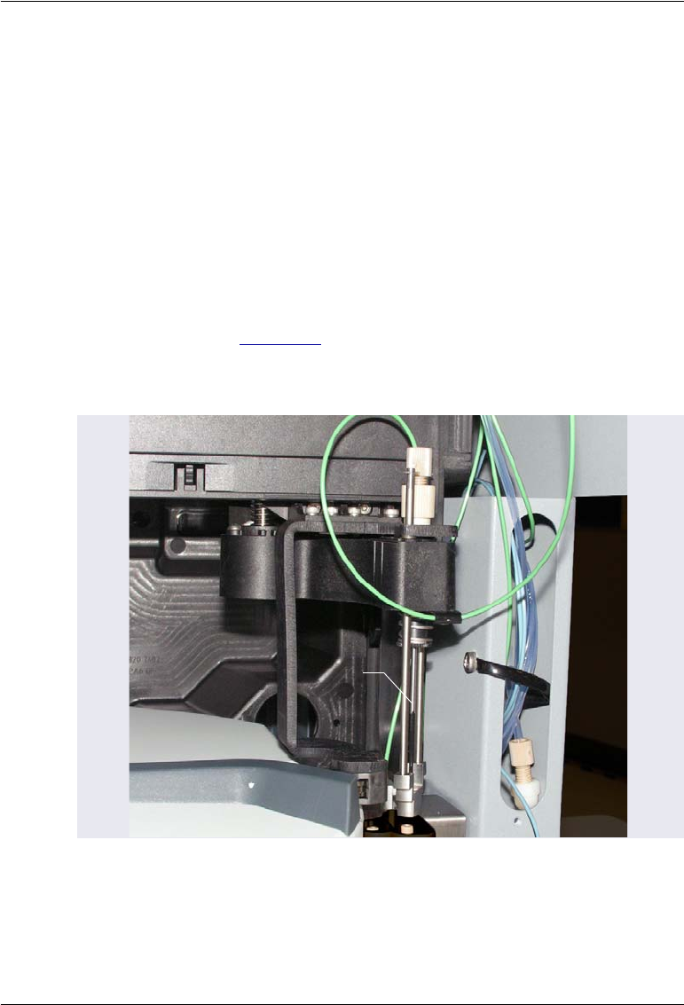
Figure 2-2 illustrates the main operating features of the Thermo Scientific
Dionex AS-AP Autosampler.
Figure 2-2. Dionex AS-AP Front View (Front Panel Lifted)
Wash Liquid Line
Syringe Valve
Optional Valves
Syringe
1
3
2
4
Sampling Needle
5
1
2
3
4
5
Syringe Waste Line
Buffer Line
Sample Transfer Line (Push Mode)
Wash, Waste, and Injection Ports
7
9
8
67
9
10
Sample Carousel and Vial Trays
6
10
8
Sample Conductivity and pH Accessory
(Optional)
11
11

2• Description
Doc. 065361-07 9/12 11
Table 2-1 describes the standard components included with the Dionex AS-
AP.
Component Description
Wash liquid line Transports wash liquid from the wash liquid reservoir.
Wash liquid is used to rinse the inside and outside of
the needle and to remove sample and eluent from the
buffer and sample transfer lines.
Syringe valve and
syringe
Controls the movement of fluid (wash liquid, sample,
waste) between Dionex AS-AP components.
Sampling needle Draws fluid from a vial or well plate well, dispenses
fluid to a vial or well plate well, dispenses fluid to the
injection port.
Syringe waste line Transports waste fluid from the syringe to waste.
Buffer line
(push mode injections)
Provides a fluid connection between the syringe and
the needle.
Buffer line
(pull mode injections)
Provides a fluid connection between the syringe and
the sample loop or the injection valve.
Wash port Rinses the outside of the needle with wash liquid.
Waste port Directs fluid from the needle to waste.
Injection port (For push mode injections only) Accepts sample from
the sampling needle and delivers it through the
sample transfer line to the injection valve.
Sample transfer line
(push mode injections)
Transports sample from the injection port to the
injection valve.
Sample transfer line
(pull mode injections)
Transports sample from the needle to the injection
valve.
Sample carousel Holds the sample vial trays or well plate trays.
Table 2-1. Dionex AS-AP Standard Components
Dionex AS-AP Operator’s Manual
12 Doc. 065361-07 9/12
Table 2-1 describes the optional components available for the Dionex AS-AP
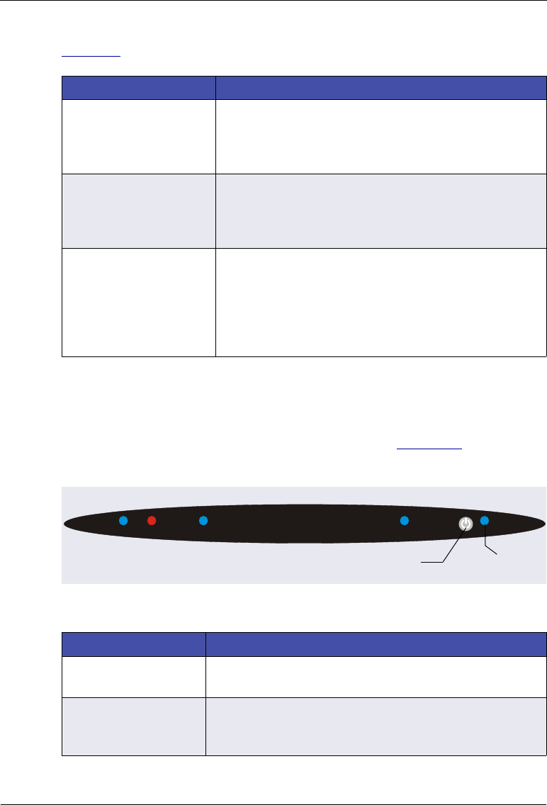
2.1.1 Status Bar
The status bar on the front of the Dionex AS-AP (see Figure 2-3) provides
LEDs that indicate the status of several autosampler functions.
Component Description
Sample Conductivity
and pH Accessory
Measures the pH and conductivity of samples loaded
into the Dionex AS-AP. The accessory can be
ordered at the same time as the Dionex AS-AP or at a
later time.
Temperature control Provides heating and cooling of samples loaded into
the Dionex AS-AP. The temperature control option
must be ordered at the same time as the Dionex AS-
AP module and installed at the factory.
Valves One or two high-pressure valves can be installed.
Depending on the Dionex AS-AP injection mode, the
valves can be configured as injection, fraction
collection, diverter, or auxiliary valves. Valves can be
ordered at the same time as the Dionex AS-AP or at a
later time.
Table 2-2. Dionex AS-AP Optional Components
Figure 2-3. Dionex AS-AP Status Bar
Button/LED Label Function
Connected This LED is on when the Dionex AS-AP is connected to
Chromeleon.
Alarm This LED is on when an error condition exists (for
example, the leak sensor is wet). Check the
Chromeleon Audit Trail for the cause.
CONNECTED ALARM TEMP READY
SAMPLER IN MOTION
Standby Standby/Power
2• Description
Doc. 065361-07 9/12 13
Other status information and alarm messages are displayed in the Audit Trail
in Chromeleon. For a description of these messages, see Section 4.1.
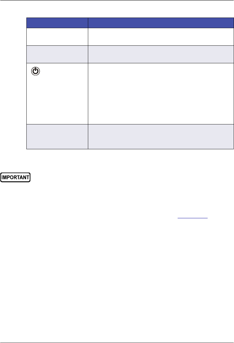
Sampler in Motion This LED is on when the syringe, needle, or carousel is
in motion and it is not safe to access the carousel.
Temp Ready This LED is on when the carousel temperature is at the
setpoint temperature.
Standby Press this button to put the Dionex AS-AP into standby
mode. This stops all autosampler motion and
temperature control and disconnects the Dionex AS-AP
from Chromeleon. The fan for the power supply slows
and all front panel LEDs turn off. Use the Standby
button for routine on/off control of the Dionex AS-AP.
Note: The main power switch is on the Dionex AS-AP
rear panel.
Standby / Power This LED is on when the Dionex AS-AP is operational
(the main power is on and the Dionex AS-AP is not in
standby mode).
Button/LED Label Function
The main power switch is on the Dionex AS-AP rear panel. Use the main
power switch to turn off all power to the autosampler (for example,
when performing a service procedure).

Dionex AS-AP Operator’s Manual
14 Doc. 065361-07 9/12
2.1.2 Carousel, Sample Trays, Vials, and Well Plates
The carousel has three color-coded sections (red, green, and blue) that can
hold three sample trays in any combination of tray types.
Figure 2-4 shows an example rack preview from the Chromeleon 6.8
Sequence Wizard. The red section contains a 1.5 mL vial tray, the blue section
contains a well plate, and the green section contains a 10 mL vial tray.
Each color-coded section also accommodates a wedge-shaped vial holder
(P/N 069877) that holds eight 10 mL vials. You can reserve these positions for
special purposes (for example, for reagent or diluent vials) or use them for
regular sample positions.
The available tray types are listed below.
Figure 2-4. Example Rack Preview in the Chromeleon 6.8 Sequence Wizard
Sample Tray for Capacity Part Number
Tray for 0.3 mL or 1.5 mL vials
Tray for micro well plates
40 vials
96 wells
074936
Tray for 10 mL vials 19 vials 074938
Tray for deep well plates 96 074939

2• Description
Doc. 065361-07 9/12 15
The following vials and well plates are available from Thermo Fisher
Scientific:
NOTE Well plates with 384 well capacity are available from third-
party suppliers.
Vial or Well Plate Type Quantity Part Number
10 mL polystyrene vials with caps
and septa
Package of 100 055058
10 mL polystyrene vials with caps
and septa for capillary systems or
trace analysis applications
Package of 100 074228
1.5 mL glass vials with caps and
septa
Package of 100 055427
1.5 mL polypropylene vials with caps
and septa
Package of 100 079812
0.3 mL polypropylene vials with caps
and septa
Package of 100 055428
96 micro well plates, 0.5 mL round
(U-shaped) wells (not suitable for IC
applications)
Package of 10 066332
96 micro well plates, 0.45 mL conical
(V-shaped) wells (not suitable for IC
applications)
Package of 20 066333
96 deep well plates, 2 mL wells
(suitable for IC applications where
ion concentration is above 1 ppm)
Package of 5 066334

Dionex AS-AP Operator’s Manual
16 Doc. 065361-07 9/12
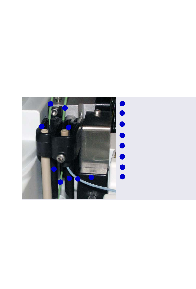
2.1.3 Syringe and Syringe Valve
The syringe moves fluid
through the autosampler
components (needle, buffer
line, sample transfer line, etc.).
The syringe also moves fluid to
the injection valve to load a
sample loop or concentrator
column. Figure 2-5 shows the
tubing connections to the
syringe valve.
Figure 2-5. Syringe Valve Connections
The following syringe volumes are available:
For correct operation, the syringe size must be the right volume for the
installed buffer line and sample loop. For the recommended syringe, buffer
line, and sample loop combinations, see Section B.4.
Syringe Volume Part Number
100 µL 074305
250 µL 074306
1000 µL 074307
5000 µL 074308
Wash Reservoir
Line
Buffer LIne
Waste LIne
Do not install a syringe from a thermo Scientific Dionex AS
Autosampler or a third-party autosampler in the Dionex AS-AP.
Although the syringes for the autosamplers are similar, they are not the
same length and the AS (or third-party) syringe will break if you attempt
to use it with the Dionex AS-AP. For identification, Dionex AS-AP
syringes are labeled on the bottom of the glass barrel.
Do not install a syringe from a thermo Scientific Dionex WPS-3000
Autosampler in the Dionex AS-AP, as there might be slight
contamination when used for trace IC applications.
2• Description
Doc. 065361-07 9/12 17
2.1.4 Sampling Needle and Needle Arm
The sampling needle performs the following functions:
•Draws sample from vials or well plates and delivers it to the injection port
(if the Dionex AS-AP is configured for push mode) or directly to the
injection valve (if the Dionex AS-AP is configured for pull mode)
•Dispenses fluid into vials (for example, when diluting a sample or
collecting fractions)
•Pipettes fluid between vials
•Delivers wash liquid to the wash port
The needle arm (see Figure 2-6) moves the needle in two directions:
horizontally to position the needle over a vial, wash port, or injection port;
and vertically to move the needle into and out of the vial or port.
Figure 2-6. Sampling Needle and Needle Arm
Needle Arm
Needle
Dionex AS-AP Operator’s Manual
18 Doc. 065361-07 9/12
2.1.5 Wash, Waste, Injection, and Leak Ports
To wash the outside of the sampling needle, the needle enters the wash port
(see Figure 2-7) and fluid from the wash reservoir is dispensed into the port.
The waste port directs excess fluid from the needle and the injection valve
waste line to the waste tray. The syringe waste line drains directly into the
waste tray (see Figure 2-8).
The injection port is used for push mode injections. It accepts the sample from
the sampling needle and delivers it through the sample transfer line to the
injection valve. If any overflow occurs, it is directed through the leak port to
the drip tray and leak sensor.
Figure 2-7. Wash, Waste, Injection, and Leak Ports
Sample Transfer Line
Leak Sensor
Injection Valve Waste Line
Syringe Waste Line
Injection Port
Wash Port
1
3
2
4
Leak Port
5
6
Waste Port
1
3
2
4
5
6
7
8
78
2

2• Description
Doc. 065361-07 9/12 19
2.1.6 Leak Sensor
A leak sensor is installed above the drip tray inside the autosampler (see
Figure 2-8). If liquid collects in the drip tray, the leak sensor reports the leak
to Chromeleon, and an error message is displayed in the Audit Trail. In
addition, the Alarm LED on the Dionex AS-AP status bar lights.
2.1.7 Compartment Lights
Two LEDs are installed on the inside front panel to illuminate the sample
compartment during autosampler operation. To signal needle arm movement,
the lights turn off and on again before the needle arms moves to a different
position.
Figure 2-8. Waste Tray, Drip Tray, and Leak Sensor
Leak Sensor
Waste Tray
Drip Tray
To avoid personal injury, do not reach inside the autosampler during a
running analysis.
Afin d'éviter des blessures corporelles, ne mettez pas la main à
l'intérieur du compartiment à échantillons lorsqu'une analyse est en
cours.
Um Verletzungen zu vermeiden, greifen Sie bitte niemals während einer
laufenden Analyse in den Probenraum.
Dionex AS-AP Operator’s Manual
20 Doc. 065361-07 9/12
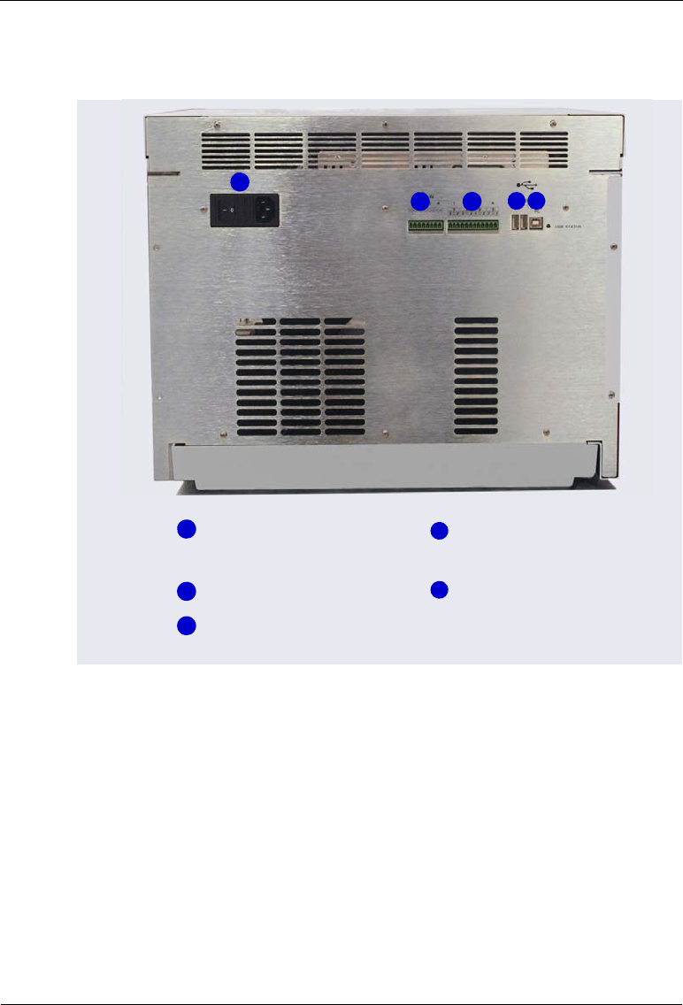
2.2 Rear Panel Features
Figure 2-9. Dionex AS-AP Rear Panel
1
2
3
4
TTL Input Connector
Relay Output Connector
Fuse Holder, Main
Power Switch, and
Power Receptacle
1
USB Receptacle
(“B” Connector)
USB Ports (2)
(“A” Connectors)
5
2
3
4 5
2• Description
Doc. 065361-07 9/12 21
2.2.1 Fuse Holder, Main Power Switch, and Power Receptacle
The fuse holder contains two 4 A IEC 60127-2 fast-blow fuses (P/N 954763).
For instructions on how to change the fuses, see Section 5.12.
The power switch on the rear panel is the main power switch for the Dionex
AS-AP. Turn on the main power switch before initial operation. For routine
on/off control, use the Standby button on the front of the Dionex AS-AP (see
Figure 2-3). Turn off the main power switch before performing a service
procedure or when the autosampler will not be used for one week or more.
The power cord plugs into the IEC 320 three-prong receptacle.
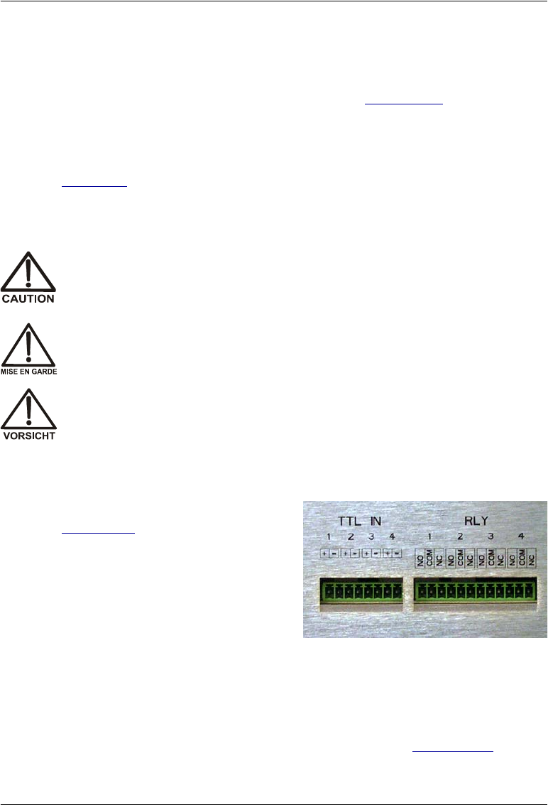
2.2.2 TTL Input and Relay Output Connectors
The 8-pin connector (see
Figure 2-10) provides four TTL
inputs and the 12-pin connector
provides four relay outputs.
Figure 2-10. TTL Input and Relay Output on Rear Panel
When connected to a controlling device, the TTL inputs are used to start
functions or triggers in a Chromeleon instrument method or program. The
relay outputs are used to control functions in other relay- or TTL-controllable
devices. For TTL and relay connection instructions, see Section B.14.
The power supply cord is used as the main disconnect device. Make
sure the socket-outlet is located near the Dionex AS-AP and is easily
accessible.
Le cordon d'alimentation principal est utilisé comme dispositif principal
de débranchement. Veillez à ce que la prise de base soit située/installée
près du module et facilement accessible.
Das Netzkabel ist das wichtigste Mittel zur Stromunterbrechung. Stellen
Sie sicher, daß sich die Steckdose nahe am Gerät befindet und leicht
zugänglich ist.
Dionex AS-AP Operator’s Manual
22 Doc. 065361-07 9/12
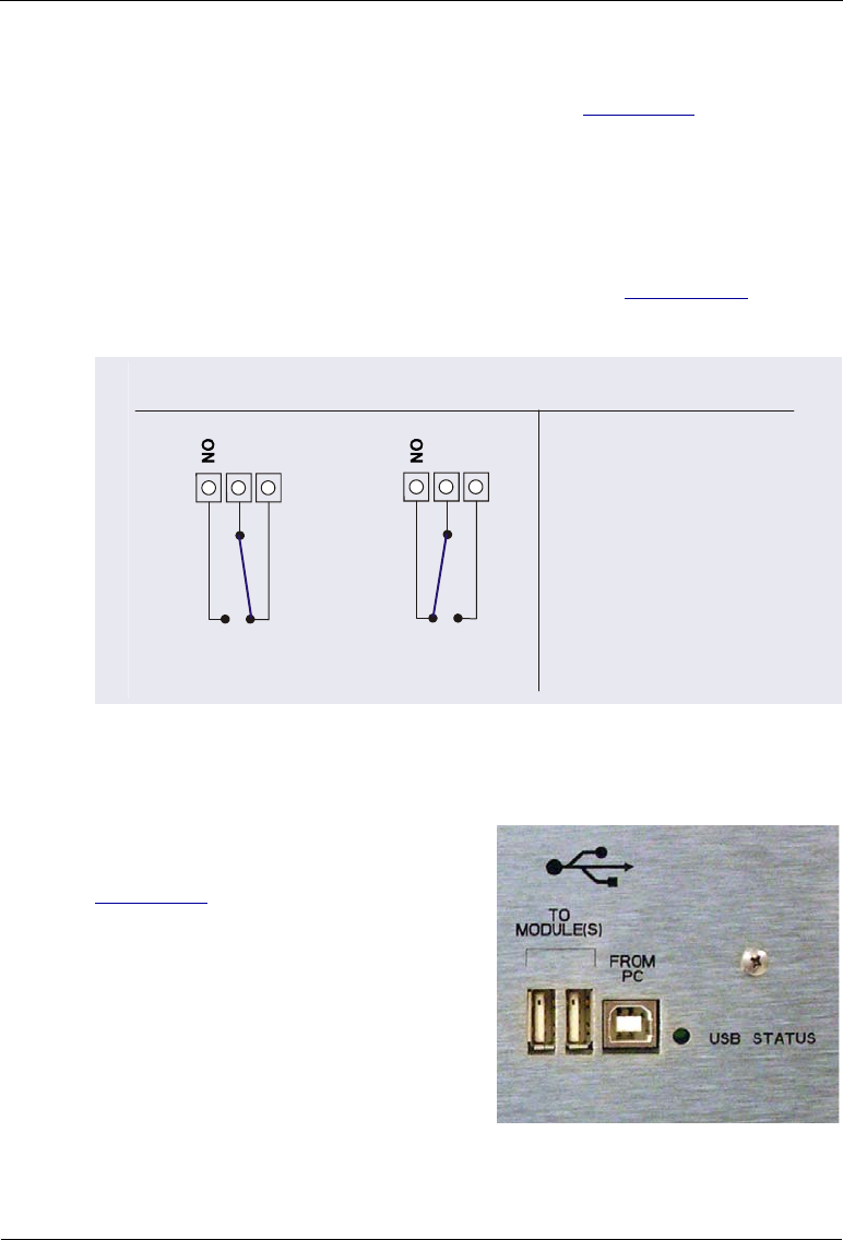
Depending on which pins are connected, a relay connection can be either
normally open (NO) or normally closed (NC) (see Figure 2-11). Choose NO
or NC based on what you want the state of the connected device to be when
the Dionex AS-AP power is turned off. A normally open relay is open when
the relay is turned off and closed when the relay is turned on. A normally
closed relay is closed when the relay is off and is open when the relay is on.
The relays can be programmed to switch any low-voltage device. Switched
current must be no more than 2 A at 24 VDC. Refer to Section B.14 and the
documentation for the external device for connection instructions.
2.2.3 USB Connections
The USB (Universal Serial Bus)
receptacle (labeled FROM PC) (see
Figure 2-12) allows connection to the
PC on which Chromeleon software is
installed.
An internal USB 1.1 hub provides two
USB ports (labeled TO MODULE(S)) that
allow connection to other USB devices
in the system (for example, a pump and
detector).
Figure 2-12. USB Connectors on Rear Panel
Figure 2-11. Relay Output Configuration
RELAY OUTPUT CONFIGURATION
The relays are capable of
switching 2 A at 24 VDC.
For a normally open
connection, connect a
COM pin and an NO pin.
For a normally closed
connection, connect a
COM pin and an NC pin.
NOTES
NC
COM
Rear Panel
Pins
Relay Output
(on AS-AP
Electronics)
Non-Energized Relay Energized Relay
NC
COM

2• Description
Doc. 065361-07 9/12 23
The USB STATUS LED is on when the autosampler is connected to the PC and
the LED flashes when information is being transferred.
A 1.8 m (6 ft) USB cable (P/N 960777) is included in the Dionex AS-AP Ship
Kit (P/N 074929).
2.3 Autosampler Options
2.3.1 Sample Temperature Control Option
The sample temperature control option provides heating and cooling of the
sample carousel. You can program the temperature set point from 4 °C to 60
°C. Samples in the carousel are uniformly heated or cooled to the
programmed set point (to a minimum of 20 °C below ambient temperature
and a maximum of 35 °C above ambient temperature). The absolute range is
4°C to 60 °C.
The sample temperature control option must be ordered at the same time as
the Dionex AS-AP module and installed at the factory. The option consists of
the following components:
•A heating/cooling carousel with fluid channels built into the base
•A pump that circulates the fluid through the carousel channels
•A thermoelectric device that heats or cools the fluid as required to achieve
the correct temperature
2.3.2 Simultaneous Injection Option
When the Dionex AS-AP is configured for simultaneous injections, a single
Dionex AS-AP can deliver sample to two independent chromatography
systems. The sample is injected simultaneously in both systems (one injection
valve in each system is required). Dual analyses can be performed with only
one sample, thus increasing sample throughput and eliminating the need to
label, fill, and track two sample vials.
In Chromeleon, the two chromatography systems and the Dionex AS-AP are
configured into a single instrument (Chromeleon 7) or timebase (Chromeleon
6.8). Each system is assigned a unique device name and channel. This lets you
monitor and control both systems from one Dionex AS-AP ePanel (in

Dionex AS-AP Operator’s Manual
24 Doc. 065361-07 9/12
Chromeleon 7) or Control panel (in Chromeleon 6.8) and run all samples in
one sequence.
To prevent contamination of the syringe, syringe, valve, and wash tubing
simultaneous injections require either a 1000 µL syringe and a 1200 L buffer
line or a 5000 µL syringe and an 8500 L buffer line. Full-loop injections are
required with this option.
NOTE To perform simultaneous injections, the Dionex AS-AP
Simultaneous Injection Kit (P/N 075008) must be installed.
2.3.3 Sequential Injection Option
When the Dionex AS-AP is configured for sequential injections, a single
Dionex AS-AP can deliver sample to two independent chromatography
systems. With sequential injections, sample is delivered to the first system,
flow is rerouted (diverted), and sample is then delivered to the second system.
Sequential injection allows different samples to be injected into each system.
Sequential injections require two injection valves and a diverter valve (for
switching sample flow between the two systems). The diverter valve is
installed in the Dionex AS-AP. The injection valves must be installed in the
chromatography systems. For additional information about the diverter valve,
see “Operation as a Diverter Valve” on page 29.
2.3.4 Concentrator Injection Option
The Dionex AS-AP can deliver sample and reagent to a Dionex ultra-low
pressure concentrator column. With this option, a concentrator column is
installed on the injection valve instead of a sample loop. A 5000 L syringe
can be installed to allow larger sample loading volumes. If the 5000 L
syringe is installed, an 8500 L buffer line must also be installed.
The Dionex AS-AP is capable of delivering at a maximum pressure of
690 kPa (100 psi). When setting up concentrator injections, always select
syringe speeds that will keep the backpressure below 690 kPa (100 psi),
taking into account the pressure from the installed tubing and the concentrator
column. A dispense speed of 5 to 10 L/sec is required. Specify the dispense
speed in the Chromeleon 7 instrument method or Chromeleon 6.8 program
(see Section 3.4.1). Recommended syringe speeds are provided in the
Chromeleon 7 Instrument Method Wizard or Chromeleon 6.8 Program

2• Description
Doc. 065361-07 9/12 25
Wizard. For additional guidelines for selecting syringe speeds, see
Section 3.5.
2.3.5 Sample Conductivity and pH Accessory Option
The Dionex AS-AP Sample Conductivity and pH Accessory (P/N 074923)
measures the conductivity and pH of a sample before it is loaded into the
injection valve. Conditional steps programmed into Chromeleon specify
actions to be taken if the conductivity and/or pH is not within a specified
range. The Dionex AS-AP Sample Conductivity and pH Accessory mounts in
the upper right corner of the autosampler. It connects to the Dionex AS-AP
and Chromeleon through a USB cable installed inside the Dionex AS-AP.
For details about the accessory, refer to the Dionex AS-AP Sample
Conductivity and pH Accessory Setup and Operation Guide (Document No.
065470). The guide is shipped with the accessory and also included on the
Thermo Scientific Reference Library DVD (P/N 053891).
2.3.6 Fraction Collection Option
When configured for fraction collection, the Dionex AS-AP is connected to
two high-pressure valves installed in the Dionex AS-AP: an injection valve
and a fraction collection valve. To operate the Dionex AS-AP with fraction
collection, a fraction collection license for Chromeleon 6.8 is required, and a
fraction collection driver must be configured in the Chromeleon 6.8 timebase.
Installation of the injection valve, fraction collection valve, license, and driver
allows automation of injection, fraction collection, and reinjection in one
system.
For details about high-pressure valves, see Section 2.3.7. For details about the
fraction collection option, see Appendix D.
NOTE Support for fraction collection is not available with
Chromeleon 7.
2.3.7 High-Pressure Valve Options
Up to two optional high-pressure valves can be installed in the Dionex AS-
AP. A 6-port valve and a 10-port valve are available. Valves can be ordered at
the same time as the Dionex AS-AP module and installed at the factory, or

Dionex AS-AP Operator’s Manual
26 Doc. 065361-07 9/12
ordered at a later time and installed at the installation site. For part numbers
for the valve options, see Appendix F. For installation instructions, see
Appendix C.
A high-pressure valve can function as an injection valve, a diverter valve, a
fraction collection valve, or an auxiliary valve. The functions available for a
particular valve depend on the injection mode selected in the Chromeleon
configuration (see Table 2-3).
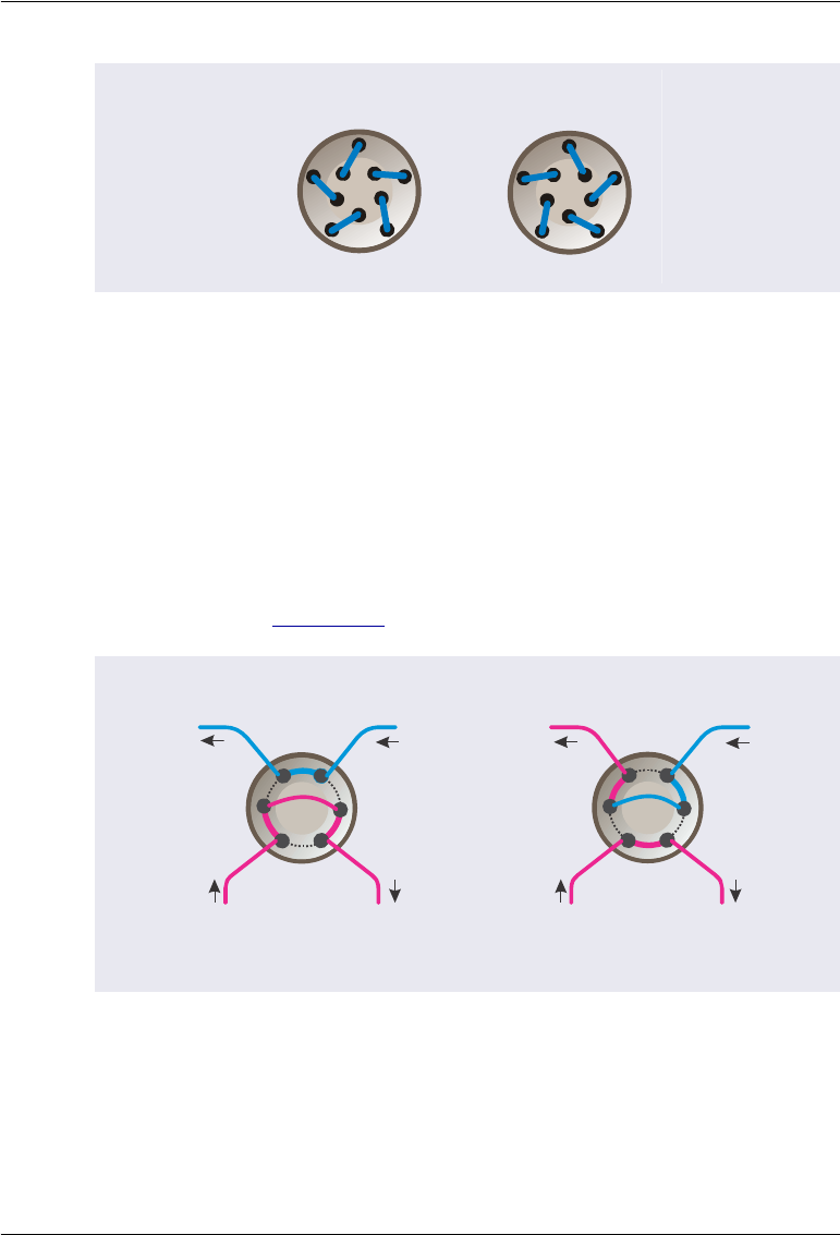
Each valve has two operating positions. The selected operating position
determines the flow path through the valve ports. Figure 2-13 and Figure 2-14
show the flow schematics for the 6-port and 10-port valves, respectively.
Injection Mode Available Valve Function
Pull Injection
Fraction collection
Push Injection
Fraction collection
Auxiliary
Push Simultaneous Injection
Auxiliary
Push Sequential Injection
Diverter
Auxiliary
Table 2-3. High-Pressure Valve Functions
Figure 2-13. 6-Port High-Pressure Valve Flow Schematics
1
2
3
4
56
Position A Position B
1
2
3
4
56
2• Description
Doc. 065361-07 9/12 27
A valve’s intended function (for example, injection valve or diverter valve)
determines how the valve ports are plumbed. The following sections provide
overviews of the valve plumbing and the theory of operation for each valve
function.
Operation as an Injection Valve (Push Mode)
When an optional high-pressure valve is configured as an injection valve for
push mode injections, the two valve operating positions are used to load and
inject sample (see Figure 2-15).
Figure 2-14. 10-Port High-Pressure Valve Flow Schematics
Figure 2-15. Injection Valve Flow Schematics for Push Mode Injections
(6-Port Valve Connections Shown)
Position A Position B
7
9
1
3
5
8
10
2
4
679
1
3
5
2
8
10
4
6
L
P
C
L
SW
Load Position Inject Position
P
C
L
SW
To Waste
Sample In from
Injection Port
To
Column From
Pump
To Waste
From
Pump
To
Column
Sample In from
Injection Port
3
4
56
2
L
1
2
4
5
6
1
3

Dionex AS-AP Operator’s Manual
28 Doc. 065361-07 9/12
Eluent flows through either the Load or Inject path, depending on the valve
position:
•In the Load position, the syringe pushes sample from the needle through
the Dionex AS-AP injection port, through the valve, and into the sample
loop, where it is held until injection. Any excess sample flows out to
waste. Eluent flows from the pump, through the valve, and to the column,
bypassing the sample loop.
•In the Inject position, sample is swept to the column for analysis. Eluent
flows from the pump, through the sample loop, and on to the column,
carrying the contents of the sample loop with it.
Operation as an Injection Valve (Pull Mode)
When an optional high-pressure valve is configured as an injection valve for
pull mode injections, the two valve operating positions are used to load and
inject sample (see Figure 2-16).
Eluent flows through either the Load or Inject path, depending on the valve
position:
•In the Load position, the syringe pulls sample from the needle, through
the valve, and into the sample loop, where it is held until injection. Eluent
flows from the pump, through the valve, and to the column, bypassing the
sample loop.
Figure 2-16. Injection Valve Flow Schematics for Pull Mode Injections
(6-Port Valve Connections Shown)
Load Position
L
P
C
L
S
To Syringe
Sample In
from Needle
To
Column From
Pump
1
4
5
32
6
SYR
L
P
C
L
S
SYR
Inject Position
1
To Syringe
Sample In
from Needle
From
Pump
To
Column
4
5
6
3
2
2• Description
Doc. 065361-07 9/12 29
•In the Inject position, sample is swept to the column for analysis. Eluent
flows from the pump, through the sample loop, and on to the column,
carrying the contents of the sample loop with it.
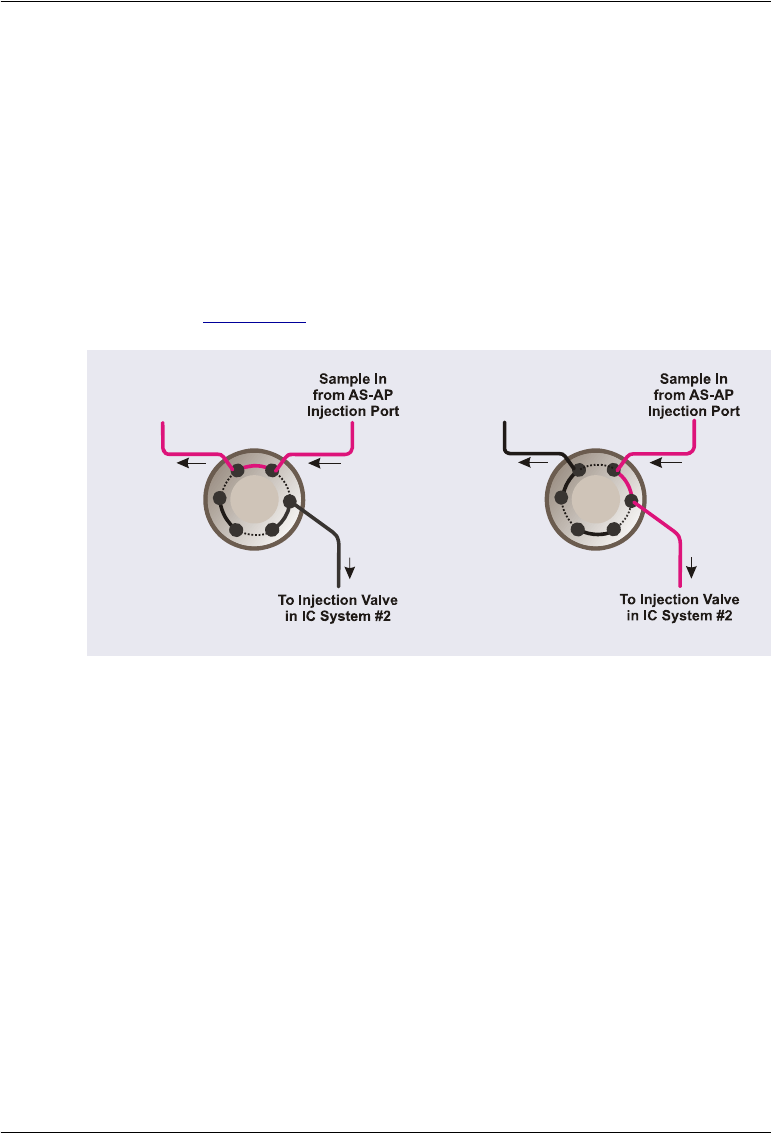
Operation as a Diverter Valve
When the Dionex AS-AP is configured for push mode injections, an optional
high-pressure valve can be configured as a diverter valve. In this
configuration, the valve’s two operating positions are used to sequentially
route sample to the injection valves of two independent chromatography
systems (see Figure 2-17).
•In position 1, the syringe pushes sample from the needle through the
Dionex AS-AP injection port, through the valve, and into the sample in
port of the injection valve in IC system #1.
•In position 2, the syringe pushes sample from the needle through the
Dionex AS-AP injection port, through the valve, and into the sample in
port of the injection valve in IC system #2.
Figure 2-17. Diverter Valve Flow Schematics for Sequential Injections
(6-Port Valve Connections Shown)
Position 1
P
P
1S
2
6
To Injection
Valve in IC
System #1
(Plug)
(Plug)
4
5
P
(Plug)
1
2
3
Position 2
P
P
1S
2
6
To Injection
Valve in IC
System #1
(Plug)
(Plug)
4
5
P
(Plug)
1
3
2

Dionex AS-AP Operator’s Manual
30 Doc. 065361-07 9/12
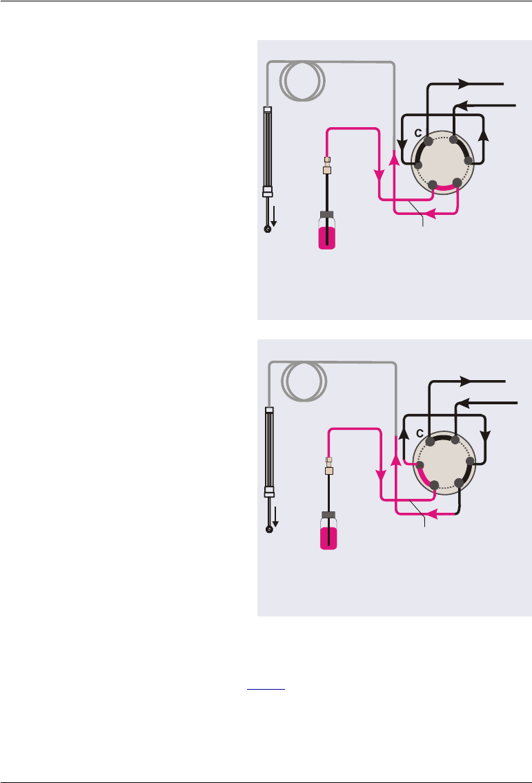
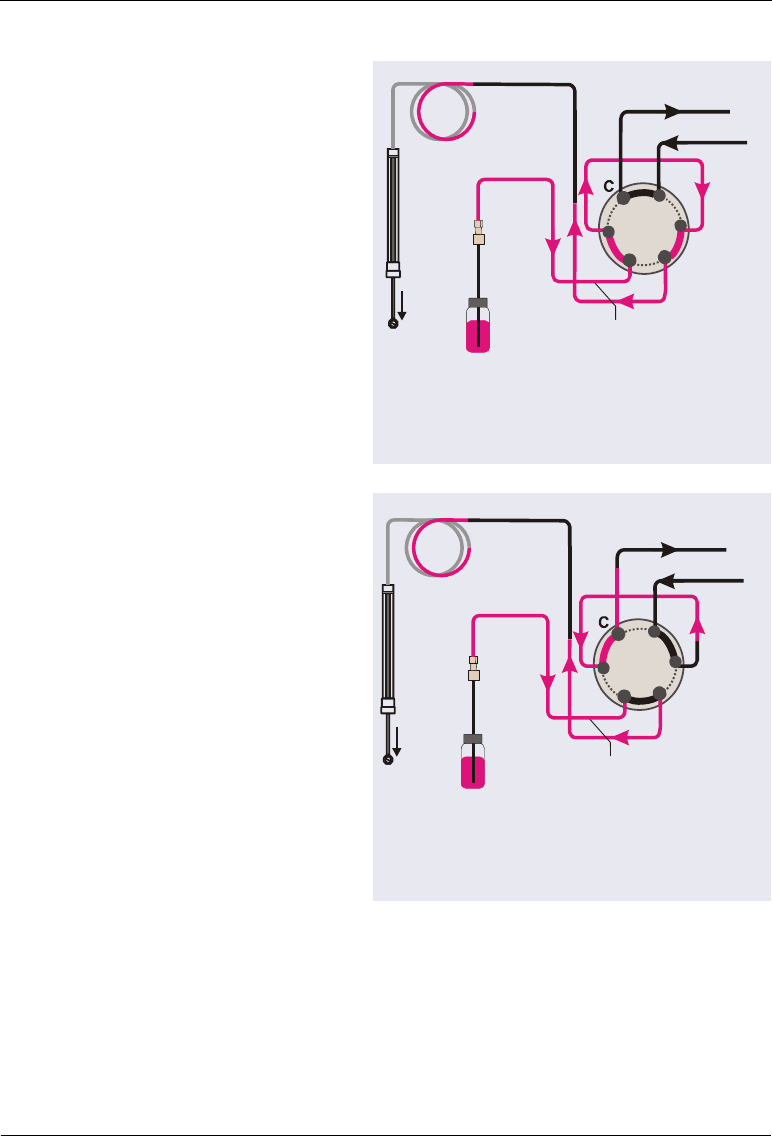
Operation as a Fraction Collection Valve
When an optional high-pressure valve is configured as a fraction collection
valve, the valve’s two operating positions are used to either collect fractions
from the detector outlet flow or to route the detector outlet flow to waste. The
fraction collection valve can be configured for push mode injections (see
Figure 2-18) or pull mode injections (see Figure 2-19).
•In position 1 (Drain), flow from the detector outlet line is routed to waste.
This position is used during loading of the injection valve sample loop
and during injection of the sample onto the column.
Figure 2-18. Fraction Collection Valve Flow Schematics for Push Mode
(6-Port Valve Connections Shown)
Figure 2-19. Fraction Collection Valve Flow Schematics for Pull Mode
(6-Port Valve Connections Shown)
Position 1
(Drain)
6
32
1
To AS-AP
Needle
5
4
Position 2
(Collect)
6
3
2
1
5
4
To AS-AP
Needle
Position 1
(Drain)
6
32
1
To AS-AP
Needle
5
4
Position 2
(Collect)
6
3
2
1
5
4
To AS-AP
Needle

2• Description
Doc. 065361-07 9/12 31
•In position 2 (Collect), flow from the detector outlet line is routed through
the needle and into vials for fraction collection.
For details about the fraction collection option, see Appendix D.
Operation as an Auxiliary Valve
When the Dionex AS-AP is configured for push mode injections, the optional
high-pressure valves can be configured as auxiliary valves and used for
various application functions (for example, concentrator column loading or
matrix elimination).
Plumbing configurations for the valves depend on the components to be
connected and the application to be run. Refer to the appropriate Thermo
Scientific Application Note for more information.
2.4 Operating Principles
2.4.1 Overview of Injection Modes
The injection mode specifies the method the Dionex AS-AP will use to load
sample to the injection valve (or valves). The two main types of injection
modes are:
•Push mode (sample is pushed into the sample loop) (see Section 2.4.2)
•Pull mode (sample is pulled into the sample loop) (see Section 2.4.3)
In general, push mode is recommended for high accuracy, minimizing sample
use, injecting viscous samples, and loading a concentrator column. Pull mode
is recommended for high precision, minimizing carryover and contamination,
and minimizing cycle time.
In addition to specifying pull or push mode, the injection mode also specifies
other parameters that determine how samples are injected (for example, full-
loop or partial-loop injections, simultaneous or sequential loading of two
valves, loading of a concentrator column, or loading to a capillary system).
The setting selected in the Chromeleon configuration determines the available
injection modes for a particular Dionex AS-AP. The configuration injection
mode is set once and does not change unless the autosampler plumbing is
changed. Table 2-4 describes the modes selected in the configuration. For

Dionex AS-AP Operator’s Manual
32 Doc. 065361-07 9/12
instructions on how to configure the Dionex AS-AP in Chromeleon, see
Section B.11.3.
NOTE The Dionex AS-AP is shipped from the factory with the
plumbing required for push mode injections. To perform
other injection modes, the autosampler must be replumbed.
For plumbing instructions, see Section B.7.4.
Configuration
Injection Mode Description
Pull Sample is pulled from the sampling needle assembly
into the sample loop.
Push Sample is pushed from the sampling needle
assembly into a sample loop or concentrator column.
Push Simultaneous Sample is pushed from the sampling needle
assembly into the sample loops of two systems
simultaneously. To perform simultaneous injections,
the Dionex AS-AP Simultaneous Injection Kit (P/N
075008) must be installed.
Push Sequential Sample is pushed from the sampling needle
assembly into the sample loops of two systems
alternately. To perform sequential injections, the
Dionex AS-AP must be equipped with a 6-port high-
pressure valve configured as a diverter valve.
Table 2-4. Injection Modes Selected in the Configuration

2• Description
Doc. 065361-07 9/12 33
Table 2-5 describes all of the possible injection modes supported by the
Dionex AS-AP. The modes available for your Dionex AS-AP depend on the
selected Chromeleon configuration injection mode described in Table 2-4.
Dionex AS-AP Injec-
tion Mode Description Configuration
Mode Required
PullFull Using the pull mode, perform a
full-loop injection to one system.
Pull
PullPartial Using the pull mode, perform a
partial-loop injection to one
system.
Pull
PushFull Using the push mode, perform a
full-loop injection to one system.
Push
PushPartial Using the push mode, perform a
partial-loop injection to one
system.
Push
PushPartial_ls Using the push mode, perform a
partial-loop, limited-sample
injection to one system. Limited-
sample specifies that no extra
sample is drawn.
Push
PushConcentrate Using the push mode, perform a
concentrate injection to one
system.
Push
PushCap Using the push mode, perform an
injection to a capillary system.
Push
PushSimultaneous Using the push mode, perform
full-loop injections to two systems
simultaneously.
Push
Simultaneous
PushSeqFull Using the push mode, perform
full-loop injections to two systems
alternately.
Push Sequential
PushSeqPartial Using the push mode, perform
partial-loop injections to two
systems alternately.
Push Sequential
Table 2-5. Summary of Dionex AS-AP Injection Modes

Dionex AS-AP Operator’s Manual
34 Doc. 065361-07 9/12
For information about selecting an injection mode, see Section 3.4.1.
PushSeqPartial_ls Using the push mode, perform
partial-loop, limited-sample
injections to two systems
alternately. Limited-sample
specifies that no extra sample is
drawn.
Push Sequential
PushSeqConcentrate Using the push mode, perform a
concentrate injection to two
systems alternately.
Push Sequential
PushSeqCap Using the push mode, perform
injections to two capillary
systems alternately.
Push Sequential
Dionex AS-AP Injec-
tion Mode Description Configuration
Mode Required
Table 2-5. Summary of Dionex AS-AP Injection Modes (Continued)
2• Description
Doc. 065361-07 9/12 35
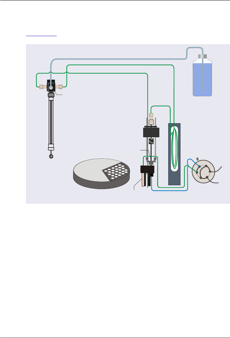
2.4.2 Push Mode Sampling Principle
Figure 2-20 illustrates the Dionex AS-AP plumbing schematic for push mode.
When configured for push mode, the Dionex AS-AP performs the following
operations to sample from a vial:
1. Rotates the carousel so that the vial to be sampled is positioned parallel to
the sampling needle.
2. Moves the needle horizontally to position it over the vial.
Figure 2-20. Sampling Principle: Push Mode Configuration
Sampling Needle
Syringe
Syringe
Valve
Wash
Reservoir
Injection Port
Sample Transfer Line
Buffer Line
Syringe Waste Line
Wash Liquid Line
Injection Valve
(Inject Position)
W
L
P
C
1
2
3
4
5
6
L
Carousel
Dionex AS-AP Operator’s Manual
36 Doc. 065361-07 9/12
3. With the injection valve in
the Inject position, lowers
the needle into the vial and
then draws the sample into
the needle and buffer line.
4. Moves the needle to the
injection port.
5. With the injection valve
still in the Inject position,
pushes the sample out of
the buffer line and needle,
through the sample
transfer line, and to the
valve.
Needle
Syringe
W
L
P
C
L
6
5
Inject
To Waste
Sample
Injection
Port
Sample
Transfer Line
2
1
3
4
Buffer
Line
Push Mode: Draw sample into needle and buffer line.
Sample Loop
Buffer
Line
Syringe
W
L
P
C
L
6
5
Inject
To Waste
Injection
Port
Sample
Transfer Line
2
1
3
4
Needle
Sample
Push Mode: Push sample to the valve.
Sample Loop

2• Description
Doc. 065361-07 9/12 37
6. When the injection valve
is switched to the Load
position, pushes the
sample into the sample
loop.
7. When the injection valve
is switched to the Inject
position, sample is swept
out of the loop and
delivered to the column.
Syringe
W
L
P
C
L
6
5
Load
To Waste
Injection
Port
Sample
Transfer Line
2
1
3
4
Buffer
Line
Sample
Needle
Push Mode: Load (push) sample into the loop
(full-loop injection shown).
Sample Loop
Syringe
W
L
P
C
L
6
5
Inject
To Waste
Injection
Port
Sample
Transfer Line
2
1
3
4
Buffer
Line
Sample
Needle
Push Mode: Inject sample onto the column.
Sample Loop
Dionex AS-AP Operator’s Manual
38 Doc. 065361-07 9/12
2.4.3 Pull Mode Sampling Principle
Figure 2-21 illustrates the Dionex AS-AP plumbing schematic for pull mode.
When configured for pull mode, the Dionex AS-AP performs the following
operations to sample from a vial:
1. Rotates the carousel so that the vial to be sampled is positioned parallel to
the sampling needle.
2. Moves the needle horizontally to position it over the vial.
3. Lowers the needle into the vial (see Figure 2-21).
Figure 2-21. Plumbing Schematic: Pull Mode Configuration
Syringe
Syringe
Valve
Wash
Reservoir
Sample Transfer Line
Buffer Line
Syringe Waste Line
Wash Liquid Line
Injection Valve
(Inject Position)
Carousel
L
S
S
Y
R
L
1
4
P
Sampling Needle
Wash Port
5
3
6
2
2• Description
Doc. 065361-07 9/12 39
4. With the injection valve in
the Inject position, the
syringe draws sample from
the vial into the needle,
sample transfer line, and
buffer line. This flushes
the needle and sample
transfer line of any
residual wash fluid and
fills them with sample.
5. The injection valve is then
switched to the Load
position.
6. With the injection valve in
the Load position, the
syringe pulls sample
through the needle and the
sample transfer line. The
eluent previously in the
sample loop is washed into
the buffer line.
NOTE In pull-partial mode, when the injection valve is switched
from inject to load (in Step 5), a small amount of sample can
be pushed back toward the needle. This can cause a slight off-
set in an injector linearity run.
Needle
Syringe
L
S
S
Y
R
L
P
4
Inject
Sample
Sample
Transfer Line
6
1
2
Buffer
Line
5
3
To Column
From Pump
Pull Mode: Draw sample into needle and buffer line.
Sample
Loop
Pull Mode: Pull eluent out of the loop.
Needle
Syringe
L
S
S
Y
R
L
P
4
Load
Sample
Sample
Transfer Line
6
1
Buffer
Line
5
To Column
From Pump
2
3
Sample
Loop
Dionex AS-AP Operator’s Manual
40 Doc. 065361-07 9/12
7. Sample is then pulled into
the sample loop and buffer
line.
8. When the injection valve
is switched to the Inject
position, sample is swept
out of the loop and
delivered to the column.
Pull Mode: Pull sample into the loop
(full-loop injection shown).
Needle
Syringe
L
S
S
Y
R
L
P
Load
Sample
Sample
Transfer Line
6
1
Buffer
Line
5
4
To Column
From Pump
2
3
Sample
Loop
Needle
Syringe
L
S
S
Y
R
L
P
Inject
Sample
Sample
Transfer Line
6
1
Buffer
Line
5
4
To Column
From Pump
2
3
Pull Mode: Inject sample onto the column.
Sample
Loop
2• Description
Doc. 065361-07 9/12 41
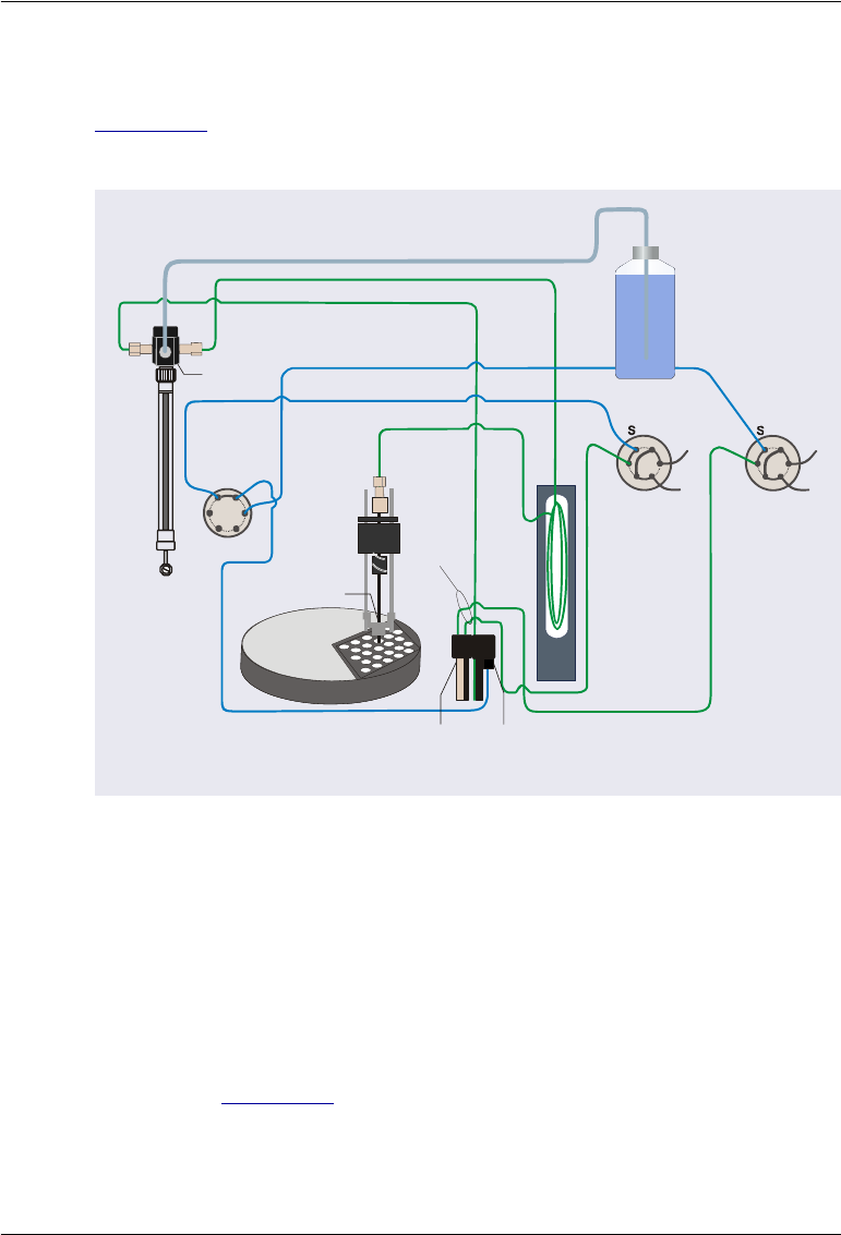
2.4.4 Sequential Mode Sampling Principle
Figure 2-22 illustrates the Dionex AS-AP plumbing schematic for sequential
injections.
When configured for sequential mode, the Dionex AS-AP performs the
following operations to sample from a vial:
1. Rotates the carousel so that the vial to be sampled is positioned parallel to
the sampling needle.
2. Moves the needle horizontally to position it over the vial.
3. With the injection valve in the Inject position, lowers the needle into the
vial (see Figure 2-22) and then draws the sample into the needle and
buffer line.
4. Moves the needle to the injection port.
Figure 2-22. Plumbing Schematic: Sequential Mode Configuration
Syringe
Syringe
Valve
Sample Transfer Line
Buffer Line
Syringe Waste Line
Wash Liquid Line
Buffer Line
Injection Valve in
IC System #1
Injection Valve in
IC System #2
Sample Transfer Line #1
Sample Transfer Line #2
W
L
P
C
1
2
3
4
5
6
L
1S
2
P
P
P
Diverter Valve
in AS-AP
W
L
P
C
1
2
3
4
5
6
L
Wash
Reservoir
Injection
Valve
Waste Lines
Injection
Port
Wash
Port
Carousel
Sampling
Needle

Dionex AS-AP Operator’s Manual
42 Doc. 065361-07 9/12
5. With the injection valve still in the Inject position, pushes the sample out
of the buffer line and needle, through the sample transfer line to the
diverter valve, where it is then routed to the injection valve of either IC
system #1 or IC system #2 (depending on the selected diverter valve
position).
6. With the injection valve in the Load position, pushes the sample into the
sample loop.
7. When the injection valve is switched to the Inject position, sample is
swept out of the loop and delivered to the column.
8. To load sample to the other IC system injection valve, the diverter valve
position is switched and then the sampling process described above is
repeated.
2• Description
Doc. 065361-07 9/12 43
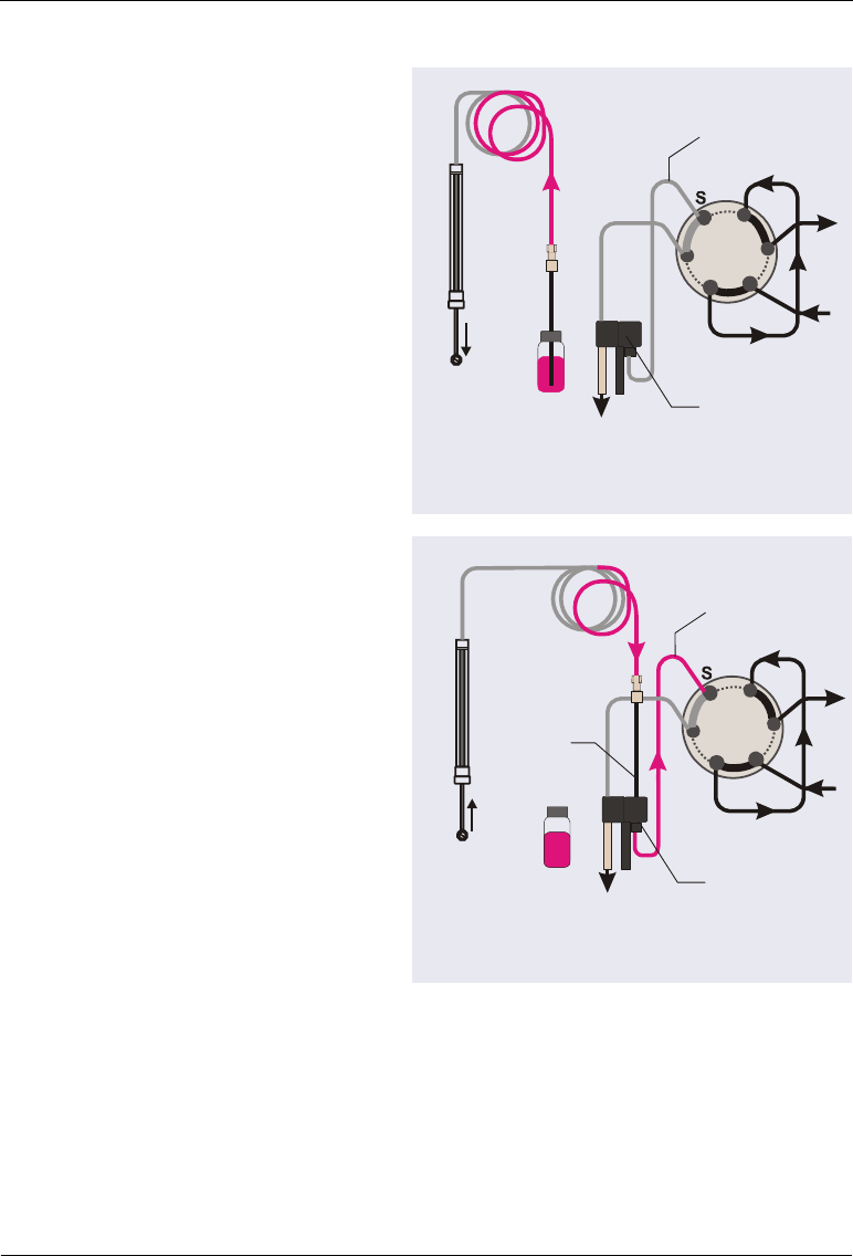
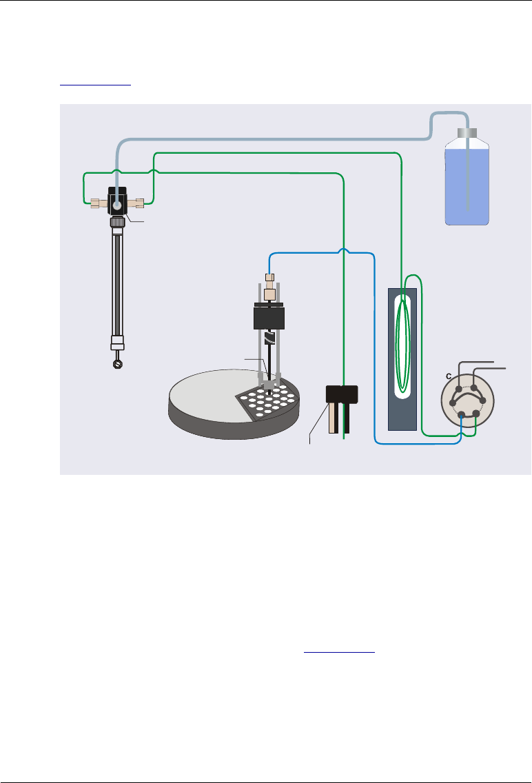
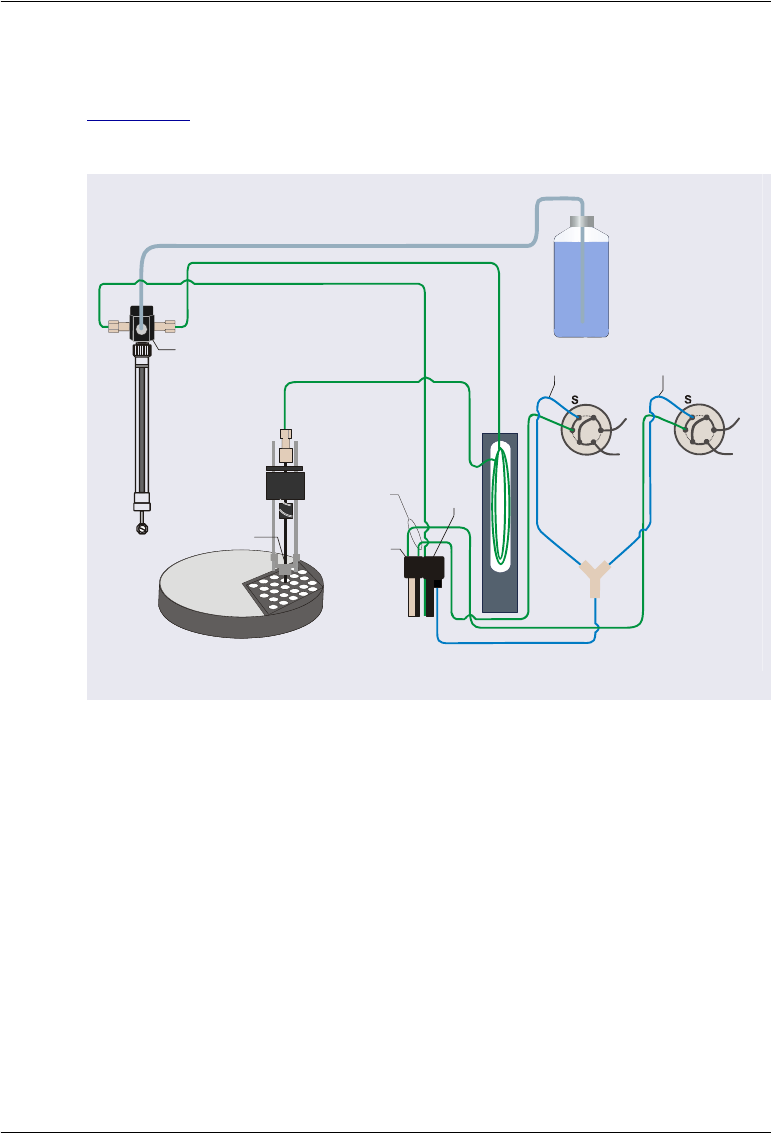
2.4.5 Simultaneous Mode Sampling Principle
Figure 2-23 illustrates the Dionex AS-AP plumbing schematic for
simultaneous injections.
When configured for simultaneous mode, the Dionex AS-AP performs the
following operations to sample from a vial:
1. Rotates the carousel so that the vial to be sampled is positioned parallel to
the sampling needle.
2. Moves the needle horizontally to position it over the vial.
3. With the injection valve in the Inject position, lowers the needle into the
vial and then draws the sample into the needle and buffer line.
4. Moves the needle to the injection port.
5. With the injection valve still in the Inject position, pushes the sample out
of the buffer line and needle, through the sample transfer line, and into the
Figure 2-23. Plumbing Schematic: Simultaneous Mode Configuration
Syringe
Syringe
Valve
Wash Port
Injection
Port
Sample Transfer Line
Injection
Valve
Waste Lines
Buffer Line
Syringe Waste Line
Wash Liquid Line
Buffer Line
Injection Valve in
IC System #1 Injection Valve in
IC System #2
Wash
Reservoir
W
L
P
C
1
2
3
4
5
6
L
Sample Transfer
Line #1
Sample Transfer
Line #2
W
L
P
C
1
2
3
4
5
6
L
Carousel
Sampling
Needle

Dionex AS-AP Operator’s Manual
44 Doc. 065361-07 9/12
Y-connector. The Y-connector splits the sample evenly and routes half of
the sample to the injection valve in IC system #1 and the other half to the
injection valve in IC system #2.
6. With the injection valve in the Load position, pushes the sample into the
sample loops in both systems.
7. When the injection valves are switched to the Inject position, sample is
swept out of the loops and delivered to the columns.
NOTE To ensure that sample is delivered to both systems evenly in
simultaneous mode, flow after the Y-connector must be the
same. Make sure that the backpressure after the Y-connector
is the same in both systems. For details, see page 191).
2.5 Chromeleon Software
The Dionex AS-AP is controlled by a PC running Chromeleon 7
Chromatography Data System (release 7.1 DU0a or later) or Chromeleon 6.8
Chromatography Data System (release 6.80 DU10c or later).
2.5.1 Software Control Modes
Two modes of software control are available:
•Direct Control
With direct control, you select operating commands and parameters from
the Dionex AS-AP ePanel (in Chromeleon 7) or Control panel (in
Chromeleon 6.8). Direct control commands can also be issued from the
Command window (in Chromeleon 7) or the Commands dialog box in

2• Description
Doc. 065361-07 9/12 45
(Chromeleon 6.8). Direct control commands are executed immediately.
Figure 2-24 shows the Dionex AS-AP Control panel in Chromeleon 7.
•Automated Control
With automated control, you create a list of injections (a sequence) to be
processed automatically. For each injection, the sequence specifies the
vial or well to be sampled, as well as other injection parameters (name,
type, volume, and so on). Each injection is also assigned an instrument
method (in Chromeleon 7) or program (in Chromeleon 6.8) that specifies
operating commands for controlling the Dionex AS-AP. The commands
in the instrument method or program are executed in chronological order.
Figure 2-24. Dionex AS-AP Control panel in Chromeleon 7
Dionex AS-AP Operator’s Manual
46 Doc. 065361-07 9/12
2.5.2 System Wellness and Predictive Performance
Use the Dionex AS-AP Wellness panel (see Figure 2-25) to perform the
following tasks:
•Monitor autosampler lifetime counters (operating hours, standby hours,
and total injections).
•Monitor how many times or hours a replaceable part has been used since
it was last replaced. Chromeleon monitors usage of the syringe, needle,
injection port, drain pump, and injection valve rotor seal.
•Set usage warnings and limits for monitored parts. A warning message
appears in the Chromeleon Audit Trail when a monitored part reaches the
warning limit. A message appears and the autosampler cannot be operated
if the usage limit is reached.
•Reset the usage counter after a part has been replaced.
Figure 2-25. Wellness Panel (Chromeleon 7 Version Shown)

Doc. 065361-07 9/12 47
3 • Operation and Maintenance
This chapter describes routine operating and maintenance procedures for the
Thermo Scientific Dionex AS-AP Autosampler.
3.1 Operation Checklist
Install and fill the wash liquid eservoir (see Section 3.2.1)
Check the fluid connections to the syringe valve (see Section 3.2.2)
Check the fluid connections to the injection valve and to any other valves
configured in your system (second injection valve, diverter valve,
auxiliary valve, and/or fraction collection valve) (see Section 3.2.2)
Check the drain line connections (see Section 3.2.3)
Turn on the autosampler power (see Section 3.3.1)
Connect to Chromeleon (see Section 3.3.2)
Prime the syringe (see Section 3.3.3)
Run a manual wash cycle (see Section 3.3.4)
Fill the vials or well plates (see Section 3.3.5) and load the trays into the
carousel (see Section 3.3.6)
Turn on the sample temperature control option (if installed) (see
Section 3.3.8) and equilibrate the chromatography system (see
Section 3.3.9)
Create and run a Chromeleon sequence (see Section 3.3.10)

Dionex AS-AP Operator’s Manual
48 Doc. 065361-07 9/12
3.2 Preparing to Run
3.2.1 Setting Up the Wash Liquid Reservoir
1. Rinse the wash liquid reservoir with ASTM Type 1 (18 meghom-cm)
filtered and deionized water.
2. If the reservoir is connected to an online degasser, fill the reservoir with
ASTM Type 1 (18 meghom-cm) filtered and deionized water.
If the reservoir is not connected to an online degasser, degas the deionized
water offline.
3. Install the reservoir cap. Make sure that the end of the wash liquid line
extends to the bottom of the reservoir. Hand-tighten the cap.
4. Place the reservoir in the system’s reservoir holder or in appropriate
secondary containment.
5. Verify that the wash liquid line from the Dionex AS-AP is connected. The
connection depends on whether the wash liquid is degassed offline or
online. For connection instructions, see Section B.6.
NOTE Replace the wash liquid in the reservoir weekly to prevent
microbial growth and gas absorption buildup. Clean the res-
ervoir if needed.
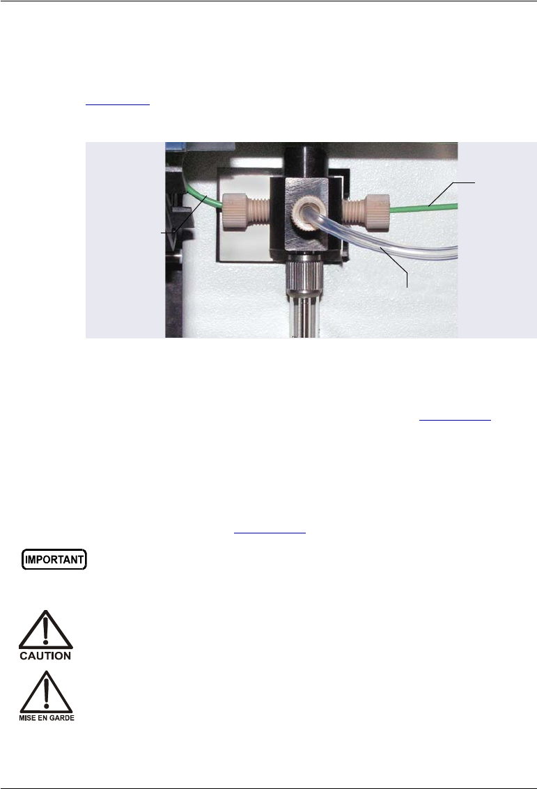
3 • Operation and Maintenance
Doc. 065361-07 9/12 49
3.2.2 Checking the Syringe Valve Connections
1. Verify that all liquid lines to the syringe valve are connected (see
Figure 3-1). Check for fluid around the fittings, indicating leaking. If
needed, finger-tighten the fittings a little further.
2. Verify that all liquid lines to the injection valve and other configured
valves are connected. For connection instructions, see Section B.7.
3.2.3 Checking the Drain Lines
Verify that the drain lines that extend from the bottom right side of the
autosampler are properly connected and the lines are routed to waste. For
connection instructions, see Section B.8.
Figure 3-1. Syringe Valve Connections
Wash
Reservoir Line
Buffer
LIne
Waste LIne
For correct drainage, make sure the tubing is not bent, pinched, or
elevated at any point. Make sure the end of the waste line is not
submerged in waste liquid.
Neutralize acidic and caustic wastes before disposal. Dispose of all
wastes in accordance with local regulations.
Neutralisez les déchets acides ou caustiques avant de les jeter. Jetez
les déchets aux règlements locaux.

Dionex AS-AP Operator’s Manual
50 Doc. 065361-07 9/12
3.3 Operating the Dionex AS-AP
3.3.1 Turning On the Power
To start the autosampler for the first time, turn on the main power switch on
the rear panel of the autosampler (see Figure 2-9). For routine on/off control,
leave the main power switch on and use the Standby button on the front panel
status bar (see Figure 2-3).
When the power is turned on, the autosampler runs a series of tests. During
these self-tests, all of the main components are checked.
If an error is detected, the Alarm LED on the front panel lights and a message
is logged in the Chromeleon Audit Trail. For troubleshooting information, see
Section 4.1.
NOTE When the Dionex AS-AP is powered up for the first time, the
J-clip is installed on the needle arm, which causes an error
during the self test. When this happens, ignore the error and
go on to checking the needle alignment (see Section 5.3).
3.3.2 Connecting to Chromeleon
Configuring the Dionex AS-AP in Chromeleon
Before operating the autosampler for the first time, configure the Dionex AS-
AP in the Chromeleon 7 Instrument Configuration Manager or the
Chromeleon 6.8 Server Configuration program. In addition, update the
configuration whenever a configured option changes. For example, update the
configuration if you change the injection mode plumbing, the sample loop
size, or the vials or well plates assigned to each color section in the carousel.
For details about configuring the Dionex AS-AP in Chromeleon, see
Section B.11.3. Also, refer to the Chromeleon Help.
Neutralisieren Sie säurehaltige und ätzende Abfälle vor ihrer
Entsorgung. Entsorgen Sie alle Abfälle entsprechend den lokalen
Bestimmungen.
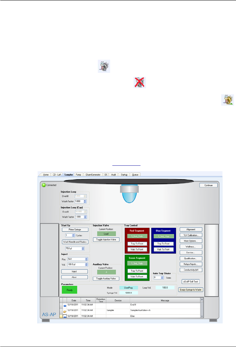
3 • Operation and Maintenance
Doc. 065361-07 9/12 51
Connecting to Chromeleon 7
1. Turn on the PC.
2. Check the Chromeleon 7 Instrument Controller Service icon on the
Windows taskbar and start the service, if it is not already running.
•If the icon is gray , the Instrument Controller Service is running
(idle).
•If the icon is crossed out in red , the Instrument Controller
Service is not running. Right-click the icon and click Start
Chromeleon Instrument Controller. The icon changes to gold
to indicate that the Instrument Controller Service is starting.
3. To start the Chromeleon 7 client, click Start > All Programs >
Chromeleon 7 > Chromeleon 7.
4. To display the Dionex AS-AP ePanel, click the Instruments category bar
on the Console. In the Navigation Pane, click your instrument.
Chromeleon 7 connects to the instrument and displays the ePanel Set.
Click the Sampler tab (see Figure 3-2).
Figure 3-2. Example Chromeleon 7 ePanel Set: Dionex AS-AP ePanel

Dionex AS-AP Operator’s Manual
52 Doc. 065361-07 9/12
Connecting to Chromeleon 6.8
1. Turn on the PC.
2. Check the Chromeleon 6.8 Server Monitor icon on the Windows taskbar
and start the server, if it is not already running:
•If the icon is gray , the server is already running (idle).
•If the icon is crossed out in red , the server is stopped. To start the
server, right-click the icon and select Start Server. The icon changes
to gold to indicate that the Chromeleon 6.8 Server is starting.
3. To start the Chromeleon client, click Start and select All Programs >
Chromeleon > Chromeleon.
4. To display the panel tabset, select View > Default Panel Tabset or click
the Default Panel Tabset toolbar button.
5. To display the Dionex AS-AP Control panel, click the Autosampler tab
3.3.3 Priming the Syringe
During priming, the syringe and the buffer are flushed with wash liquid. This
removes air bubbles from the syringe and tubing. Prime the syringe at startup
or after a period of inactivity, before running a sequence, or if an air bubble is
present in the syringe.
1. Open the Dionex AS-AP ePanel (in Chromeleon 7) or Control panel (in
Chromeleon 6.8) (see Section 3.3.2).
2. In the Cycles box under Prime Syringe, enter the number of times the
syringe should empty and fill during priming. The number required
depends on the size of the syringe and the length of the wash liquid line.
3. Click Start. The syringe empties and fills the specified number of cycle
times, and then priming stops. Repeat as required until no more bubbles
are seen in the wash liquid line.
4. If bubbles still remain in the syringe, prime for an additional two cycles.
5. If bubbles still remain after priming, follow the steps in Section 5.4.1 to
remove the syringe. Then, follow the steps in Section 5.4.2 to remove the
bubbles from the syringe and reinstall the syringe. When the bubbles are
gone, perform a manual wash operation (see Section 3.3.4).

3 • Operation and Maintenance
Doc. 065361-07 9/12 53
3.3.4 Running a Manual Wash Cycle
During the wash cycle, the buffer line and sample transfer line are flushed
with wash liquid, and then the outside of the needle is washed.
Perform a manual wash after priming the syringe and after filling the wash
reservoir.
1. Open the Dionex AS-AP ePanel (in Chromeleon 7) or Control panel (in
Chromeleon 6.8).
2. Under Wash Needle and Fluidics, enter a Volume. Click Wash Needle
and Fluidics (in Chromeleon 7) or Start (Chromeleon 6.8).
The volume required for a manual wash depends on the status of the buffer
line.
•If the buffer line is dry (for example, after changing the line), enter a wash
volume that is 1.5 times the buffer line tubing.
•If the buffer line contains sample or other liquid that you want to flush
out, enter a volume large enough to flush the sample or other liquid from
the line.
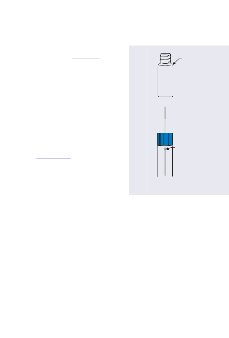
Dionex AS-AP Operator’s Manual
54 Doc. 065361-07 9/12
3.3.5 Filling the Vials or Wells
Filling Vials
1. Fill the vials to the vial shoulder
or lower (see Figure 3-3). Do not
fill to the top.
During sampling, make sure the
needle’s vent is not immersed in
liquid.
For 10 mL vials only: If
necessary, raise the needle height
inside the vial to position the vent
above the liquid. You can set the
height in a Chromeleon 7
instrument method or
Chromeleon 6.8 program (see
Section 3.4.3).
Figure 3-3. Maximum Level to Fill Vials
2. Screw a cap onto each vial and tighten. To prevent septa from falling into
the vials when they are pierced by the sampling needle, make sure the cap
septa are pushed fully into the caps and the caps are securely tightened.
3. Place the vials in a vial tray.
Filling Well Plates
1. Put on powder-free latex gloves before handling well plates and covers to
minimize sample contamination.
2. Rinse the well plates and covers thoroughly with deionized water before
use to remove any contaminants.
3. Air dry the well plates completely to prevent any changes in sample
concentration. You can use 690 kPa (100 psi) nitrogen gas to assist in
drying.
Never fill
above
this point
All vial sizes
Needle vent
(Do not immerse)
10 mL vial
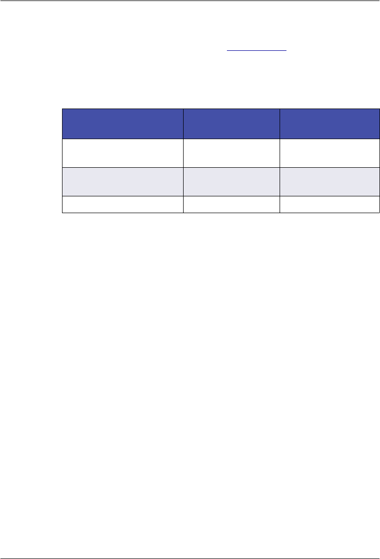
3 • Operation and Maintenance
Doc. 065361-07 9/12 55
4. Use a pipet to fill the wells in the well plate. In general, pipet the amount
of sample to be drawn plus 70 L. See Section 3.4.5 for details about the
sample volumes drawn for each type of injection.
The table below lists the maximum fluid volumes for each well size and
the maximum sample volumes available when the well is filled:
NOTE Changing the needle height is not recommended when
sampling from a micro well plate, because the well
depth is shallow. You can adjust the needle height in a
deep well plate as required, provided the needle
remains submerged in sample. This ensures accurate
sample draw.
5. Place a cover over the well plate and firmly press the indentations on the
cover into each well. This creates a tight seal and prevents sample
evaporation.
NOTE Replace covers after each use to prevent contamina-
tion and sample evaporation. Well plates can be
reused.
6. Install a micro well plate on a 40-vial sample tray (P/N 074936). Install a
deep well plate on the tray made specifically for deep well plates
(P/N 074939). Align position A1 on the well plate with position A1 on the
Well Plate Type Maximum Volume
per well (L)
Sample Available
(L)a
a. Assumes the well contains the maximum volume and the needle height is
2 mm (the default).
0.45 mL micro-well with
conical (V-shaped) wells
320 250
0.5 mL micro-well with
round (U-shaped) wells
320 250
2.0 mL deep-well 1800 1700
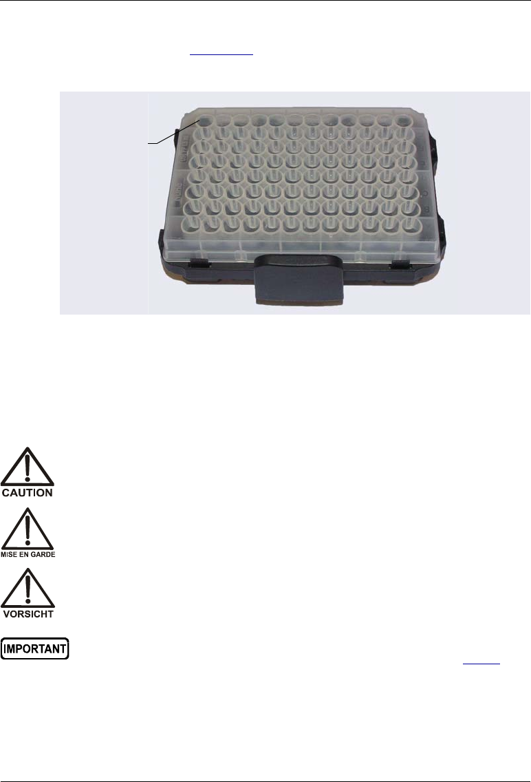
Dionex AS-AP Operator’s Manual
56 Doc. 065361-07 9/12
tray, as shown in Figure 3-4. Press the well plate onto the tray until it
locks into position.
3.3.6 Installing a Sample Tray
Follow the steps below to install a sample tray. The installation procedure is
similar for all tray types.
1. Slide the carousel cover to the left until it stops.
Figure 3-4. Well Plate Installed on a Sample Tray
Position A1
To avoid personal injury, do not reach inside the autosampler during a
running analysis.
Afin d'éviter des blessures corporelles, ne mettez pas la main à
l'intérieur du compartiment à échantillons lorsqu'une analyse est en
cours.
Um Verletzungen zu vermeiden, greifen Sie bitte niemals während einer
laufenden Analyse in den Probenraum.
After installing sample trays, verify that the correct tray types are
specified for each color section of the carousel. For details, see Step 7
of this section. If the configured types and the installed types do not
match, the autosampler will not operate correctly.
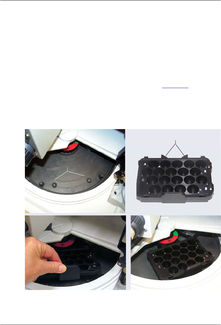
3 • Operation and Maintenance
Doc. 065361-07 9/12 57
2. Rotate the carousel until the section that you want to load (red, green, or
blue) is in front. Use one of the following methods:
•On the Dionex AS-AP ePanel (in Chromeleon 7) or Control panel (in
Chromeleon 6.8), under Tray Control, click the Tray To Front
button for the section.
•Manually turn the carousel until the section is in front.
3. Install the sample tray in the carousel as follows:
a. Note the positioning pins on the carousel (see Figure 3-5) and the
corresponding indentations on the bottom of the tray.
b. Align the sample tray’s positioning brackets with the section color
disk in the center of the carousel. Slide the tray into place and lower it
over the positioning pins on the carousel. It will click in place.
Figure 3-5. Installing a Sample Tray in the Carousel
(10 mL Vial Tray Shown)
Positioning Pins
Positioning Brackets
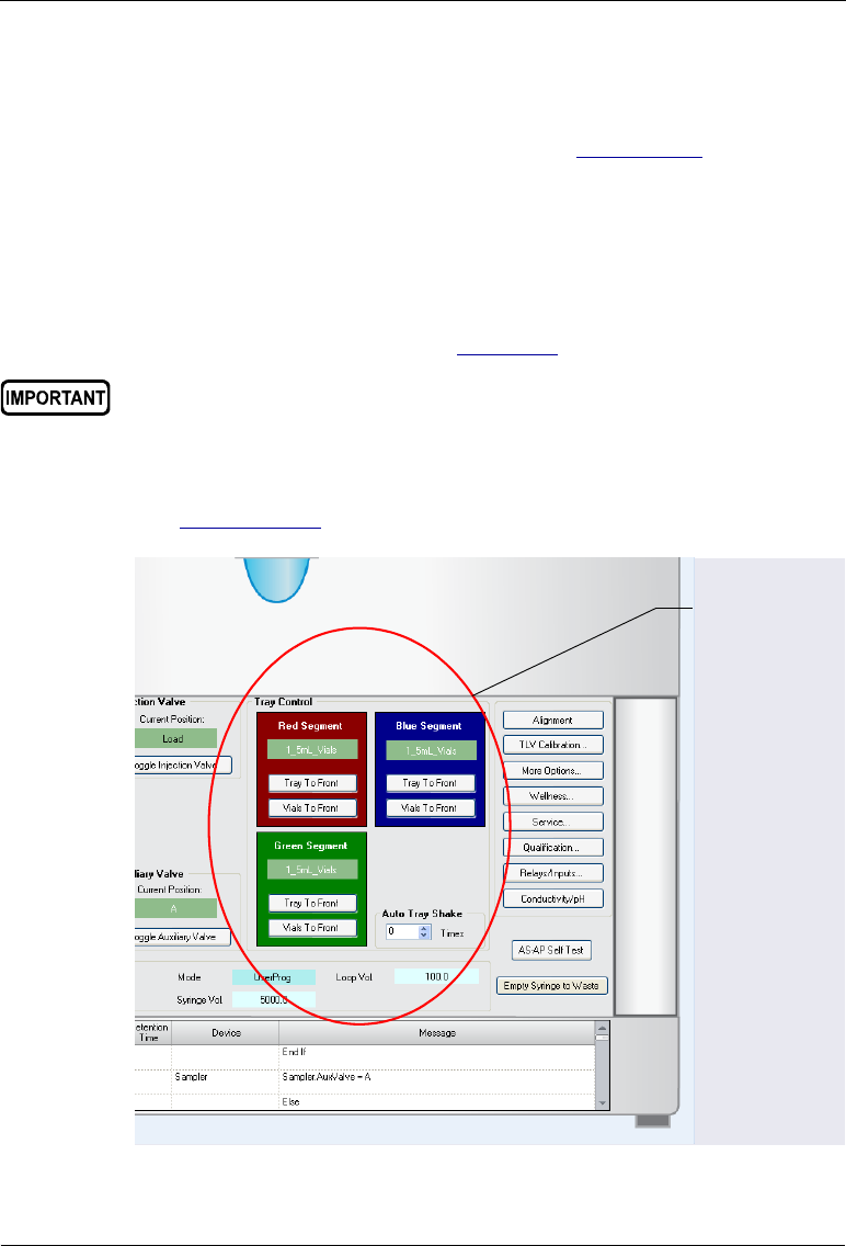
Dionex AS-AP Operator’s Manual
58 Doc. 065361-07 9/12
4. If you have not done so already, load the vials into the tray.
5. If you are going to use an 8-position vial holder, install it in the carousel
and load the vials into it (for instructions, see Section 3.3.7).
6. Close the carousel cover by sliding it to the right until the cover is
captured by the magnet on the needle arm.
7. On the Dionex AS-AP ePanel (in Chromeleon 7) or Control panel (in
Chromeleon 6.8), under Tray Control, verify that the tray type specified
for each color section matches the tray type installed in the corresponding
color section of the carousel (see Figure 3-6).
If the tray types shown on the panel do not match the types installed in the
carousel, change the tray type settings in the Chromeleon configuration
(see Section B.11.3).
For correct operation, the configured tray types and the installed tray
types must match.
Figure 3-6. Tray Type Configuration Shown on a Chromeleon 7 ePanel
Verify that the
installed trays
match the
configuration
settings.

3 • Operation and Maintenance
Doc. 065361-07 9/12 59
3.3.7 Loading the 8-Position Vial Holders
The carousel includes three wedge-shaped, 10 mL vial holders with a capacity
of eight vials each.
Before sampling from vials in these holders, set the TransLiquidHeight
parameter in the Chromeleon 7 Command window or Chromeleon 6.8
Commands dialog box (press F8 to open the window or dialog box). This
parameter specifies the sample height for the vial holders. Sample height (also
called needle height) is the distance (in mm) from the bottom of the vial to the
tip of the needle. For details about sample height, see Section 3.4.3.
1. Slide the carousel cover to the left until it stops.
2. Rotate the carousel until the vial holder section that you want to load (red,
green, or blue) is in front. Use one of the following methods:
•On the Dionex AS-AP ePanel (in Chromeleon 7) or Control panel (in
Chromeleon 6.8), under Tray Control, click the Vials To Front
button for the section (red, green, or blue) in which the holder is
installed.
•Manually turn the carousel until the vial
holder section is in front. The vial
holder section is to the left of the vial
tray position of the same color.
To avoid personal injury, do not reach inside the autosampler during a
running analysis.
Afin d'éviter des blessures corporelles, ne mettez pas la main à
l'intérieur du compartiment à échantillons lorsqu'une analyse est en
cours.
Um Verletzungen zu vermeiden, greifen Sie bitte niemals während einer
laufenden Analyse in den Probenraum.
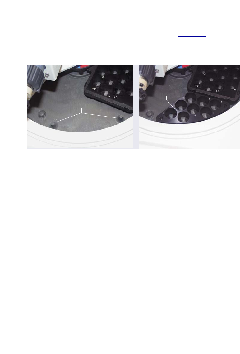
Dionex AS-AP Operator’s Manual
60 Doc. 065361-07 9/12
3. To install the vial holder in the carousel:
a. Note the positioning pins on the carousel (see Figure 3-7) and the
corresponding holes in the holder.
b. Align the holder over the pins and lower it into place.
4. Load 10 mL vials into the holder.
5. Close the carousel cover by sliding it to the right until the cover is
captured by the magnet on the needle arm.
3.3.8 Turning On the Sample Temperature Control Option
Before starting an analysis, turn on the temperature control option (if
installed), enter the temperature set point, and allow the temperature to
equilibrate. Use one of the following methods to turn on sample temperature
control:
•Turn on the sample temperature control and set the temperature on the
Dionex AS-AP ePanel (in Chromeleon 7) or Control panel (in
Chromeleon 6.8). To use the temperature currently selected in the
Nominal Temp box, select On in the Temp. Control box and press
Enter. To select a different temperature set point, select a temperature in
the Nominal Temp box and press Enter. Entering a new set point
automatically turns on the temperature control mode.
•In an equilibration instrument method or program, enter commands to
select the temperature and turn on the temperature control mode.
Figure 3-7. Installing an 8-Position Vial Holder in the Carousel
Positioning Pins
Vial Holder

3 • Operation and Maintenance
Doc. 065361-07 9/12 61
3.3.9 Equilibrating the System
Before starting an analysis, equilibrate the chromatography system (flush the
system, turn on all temperature-controlled devices, monitor the pump pressure
and detector signal, and so on). For details about the steps required to
equilibrate a particular system, refer to the operator’s manual for the system.
Select one of the following methods to perform equilibration:
•Select operating commands and parameters directly from the Dionex AS-
AP ePanel (in Chromeleon 7) or Control panel (in Chromeleon 6.8).
•Create and run an equilibration instrument method or program to
automate the process.
•If available for your system, you can use the Chromeleon Smart Startup
feature to automate system startup and equilibration. Smart Startup is
supported for the Dionex AS-AP. To verify whether other devices in the
system are supported, refer to the Chromeleon Help.
3.3.10 Running a Sequence of Injections
This section provides a brief description of the steps required to create and run
a sequence of injections in Chromeleon. For detailed instructions, refer to the
Chromeleon Help.
1. Create an instrument method (in Chromeleon 7) or program (in
Chromeleon 6.8) that specifies the functions the autosampler (and other
system devices) should perform at a specific time. Instrument methods or
programs can be created automatically (with the help of a software
wizard).
In the instrument method or program, specify operating commands and
parameters for the Dionex AS-AP, including the injection mode (see
Section 3.4.1), syringe speeds (see Section 3.4.2), sample height (see
Section 3.4.3), inject wash mode, (see Section 3.4.4), and sample
preparation operations (pipetting, mixing, diluting) (see Section 3.4.6).
2. Create a sequence (a list of injections). For each injection, specify the vial
or well position (see Section 3.4.7), the injection volume (see
Section 3.4.9), the instrument method or program to run, and other
parameters. Sequences can be created automatically (with the help of a
software wizard).

Dionex AS-AP Operator’s Manual
62 Doc. 065361-07 9/12
3. Load the sequence into a queue (in Chromeleon 7) or batch (in
Chromeleon 6.8).
4. Start the queue or batch.
3.4 Selecting Operating Parameters
3.4.1 Selecting the Injection Mode
The injection mode specifies the method the Dionex AS-AP will use to load
sample to the injection valve (or valves). For an overview of all of the
injection modes the Dionex AS-AP can perform, refer to Section 2.4.
Answers to the following questions will determine the injection mode to
select for a particular injection:
•What type of plumbing configuration does the Dionex AS-AP have (push
mode, pull mode, simultaneous injection, sequential injection)?
•Is a concentrator column installed on the injection valve (instead of a
sample loop)?
•Is the Dionex AS-AP connected to an analytical system or to a capillary
system?
•Is the available sample volume plentiful or limited?
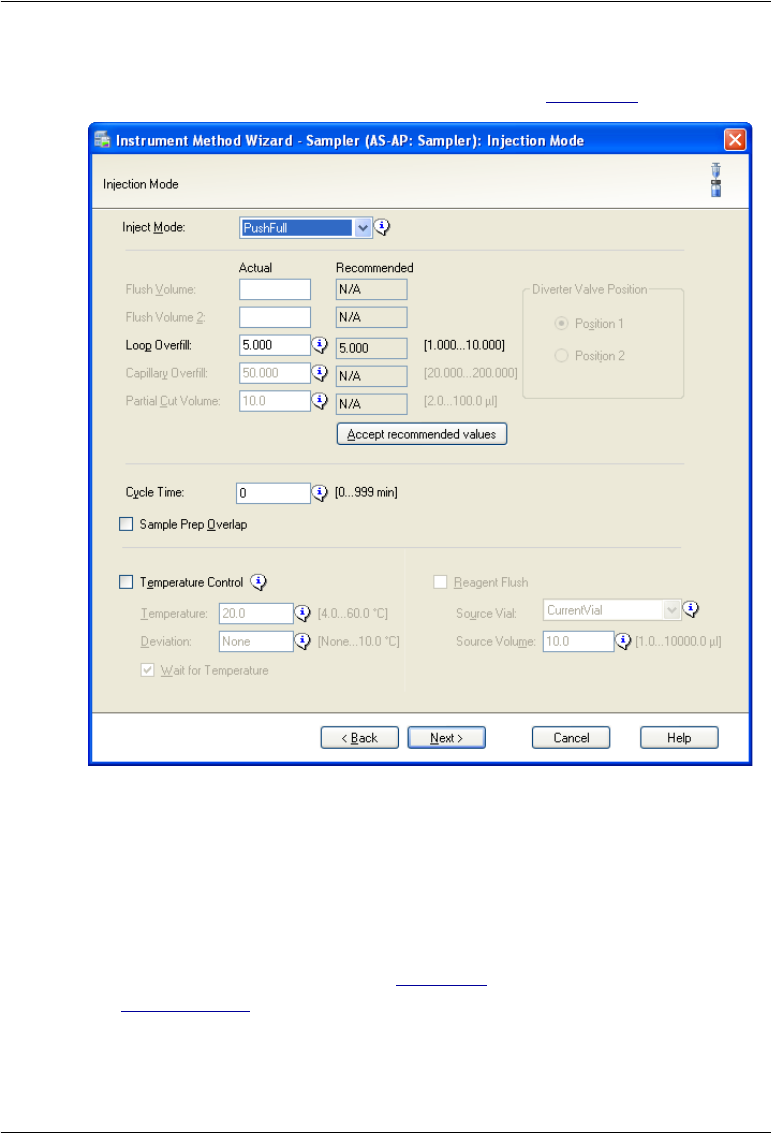
3 • Operation and Maintenance
Doc. 065361-07 9/12 63
You select the injection mode on the first sampler options page in the
Instrument Method Wizard or Program Wizard (see Figure 3-8).
When you select an injection mode, the operating parameters required for the
mode are enabled. For details about selecting injection mode parameters,
click Help on the page.
The injection mode selected in the Chromeleon configuration determines the
modes available in the wizard (see Table 3-1). For configuration instructions,
see Section B.11.3.
Figure 3-8. Dionex AS-AP Sampler Options (First Page): Injection Mode
(Chromeleon 7 Instrument Method Wizard Shown)
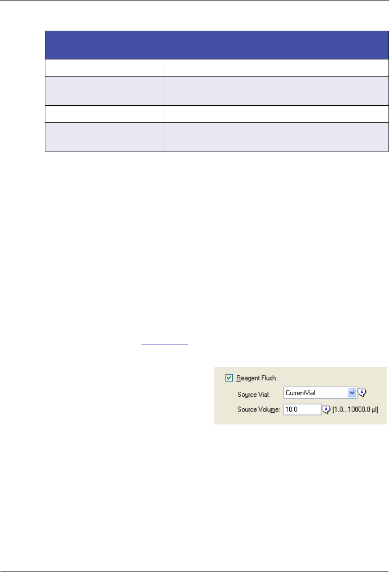
Dionex AS-AP Operator’s Manual
64 Doc. 065361-07 9/12
Options for Reagent Flushing in Concentrate Mode Injections
The Dionex AS-AP provides the following options for configuring a reagent
flush operation in concentrate mode injections.
•Option 1 (the most typical)—the sample is loaded onto the concentrator
column, the reagent flush is performed, and then the sample is injected.
•Option 2—the reagent flush is performed first, and then the sample is
loaded onto the concentrator column and injected.
To set up option #1 (perform reagent flush after sample loading):
1. In the Instrument Method Wizard or Program Wizard, on the first sampler
options page (see Figure 3-8), select the PushConcentrate or
PushSeqConcentrate injection mode.
2. Select the Reagent Flush check
box, and specify the Source Vial
(the reservoir from which to pick
up the reagent) and Source
Volume (the volume (µL) of
reagent to be flushed through the concentrator column).
NOTE If the total of the sample injection volume and reagent
flush volumes is less 80% of the buffer line size, the
autosampler delivers the injection and reagent flush vol-
umes to the injection port in one operation, before the
needle moves to the injection port. If the injection and
reagent flush volumes exceed 80% of the buffer line size,
the volumes are delivered in separate operations.
Selected Configuration
Injection Mode Injection Modes Available in the Instrument
Method or Program
Pull PullFull, PullPartial
Push PushFull, PushPartial, PushPartial_ls,
PushConcentrate, PushCap
Push Simultaneous PushSimultaneous
Push Sequential PushSeqFull, PushSeqPartial, PushSeqPartial_ls,
PushSeqConcentrate, PushSeqCap
Table 3-1. Injection Modes per Mode Selected in the Configuration

3 • Operation and Maintenance
Doc. 065361-07 9/12 65
To set up option #2 (perform reagent flush before sample loading):
1. In the Instrument Method Wizard or Program Wizard, on the first sampler
options page (see Figure 3-8), select the PushConcentrate or
PushSeqConcentrate injection mode.
2. On the third sampler options page (see Figure 3-11), insert a Reagent
Flush operation and specify the Source Vial (the reservoir from which to
pick up the reagent) and Source Volume (the volume (µL) of reagent to
be flushed through the concentrator column).
3.4.2 Specifying Syringe Speeds
In the Instrument Method Wizard or Program Wizard, the second sampler
options page (see Figure 3-9) provides options for controlling the speed of the
syringe for various operations (drawing, dispensing, washing, etc.).
Chromeleon lists recommended speeds based on the selected injection mode,
syringe size, and loop size. In most cases, you can click Accept
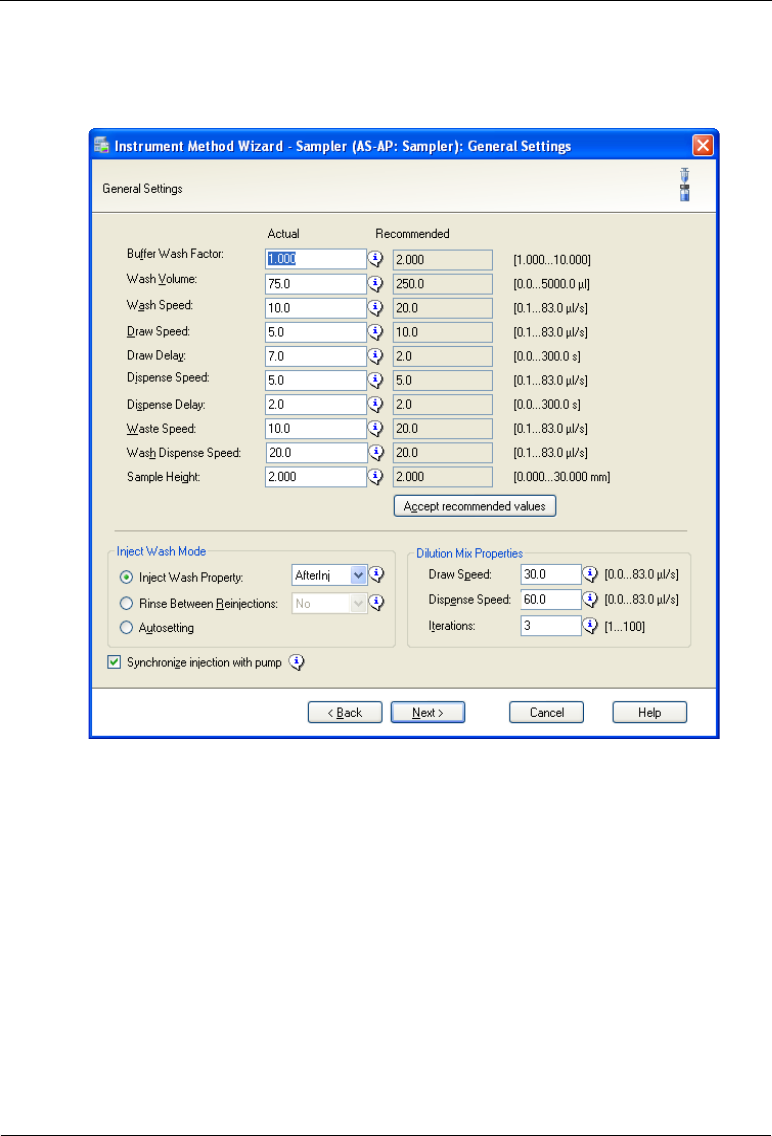
Dionex AS-AP Operator’s Manual
66 Doc. 065361-07 9/12
recommended values. For a description of each option, click the Help button
on the page.
NOTE For injections that are run after a viscous sample, select a
larger Buffer Wash Factor (1.5 to 3.0) to ensure the previous
viscous sample is completely washed out of the buffer line.
Figure 3-9. Dionex AS-AP Sampler Options (Second Page): General
Settings (Chromeleon 7 Instrument Wizard Shown)
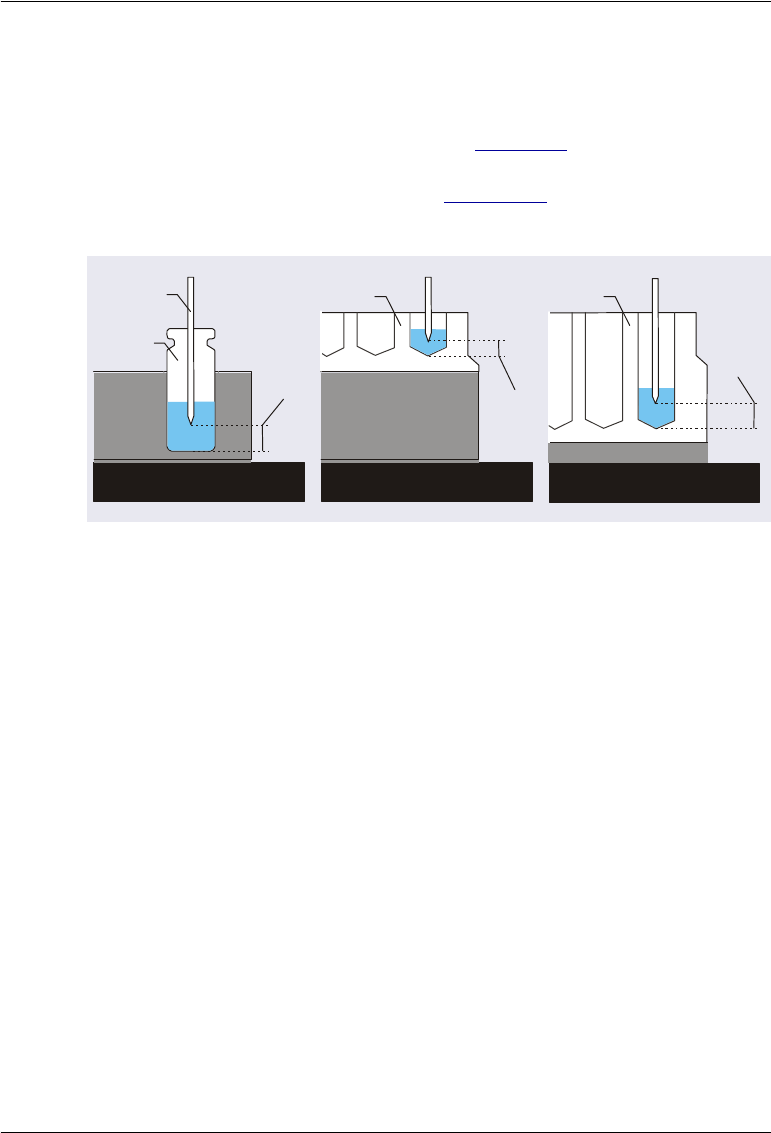
3 • Operation and Maintenance
Doc. 065361-07 9/12 67
3.4.3 Specifying Sample (Needle) Heights
The Sample Height parameter on the second sampler options page of the
Instrument Method or Program Wizard (see Figure 3-9) specifies the distance
(in mm) from the bottom of the sample container (vial, well plate, or deep
well plate) and the tip of the needle (see Figure 3-10). This distance is also
referred to as the needle height.
Sample Height Notes:
•For most analyses, set the Sample Height to 2.0 mm.
•Do not set the Sample Height parameter to 0. When the parameter is set
to 0, the needle touches the bottom of the container. The tip of the needle
is fragile and may be easily damaged.
•If you want to sample only once from a container, select a Sample Height
that lowers the needle into the container only as far as required, thus,
minimizing sample carryover.
•If you want to sample several times from the same container, select a
Sample Height that lowers the needle as far as possible into the container
(but without touching the container bottom). This lets you withdraw the
maximum possible volume from the container.
•The Sample Height parameter does not apply to the vials in the 8-
position vial holder. Instead, use the TransLiquidHeight parameter to set
the height for these vials. The parameter is available in the Chromeleon 7
Figure 3-10. Determining the Sample Height Parameter
(Distance from the Bottom of the Vial or Well to the Needle Tip)
Carousel
Tray
Needle
Sample
Height
Vial
Well Plate Deep Well Plate
Sample
Height
Sample
Height
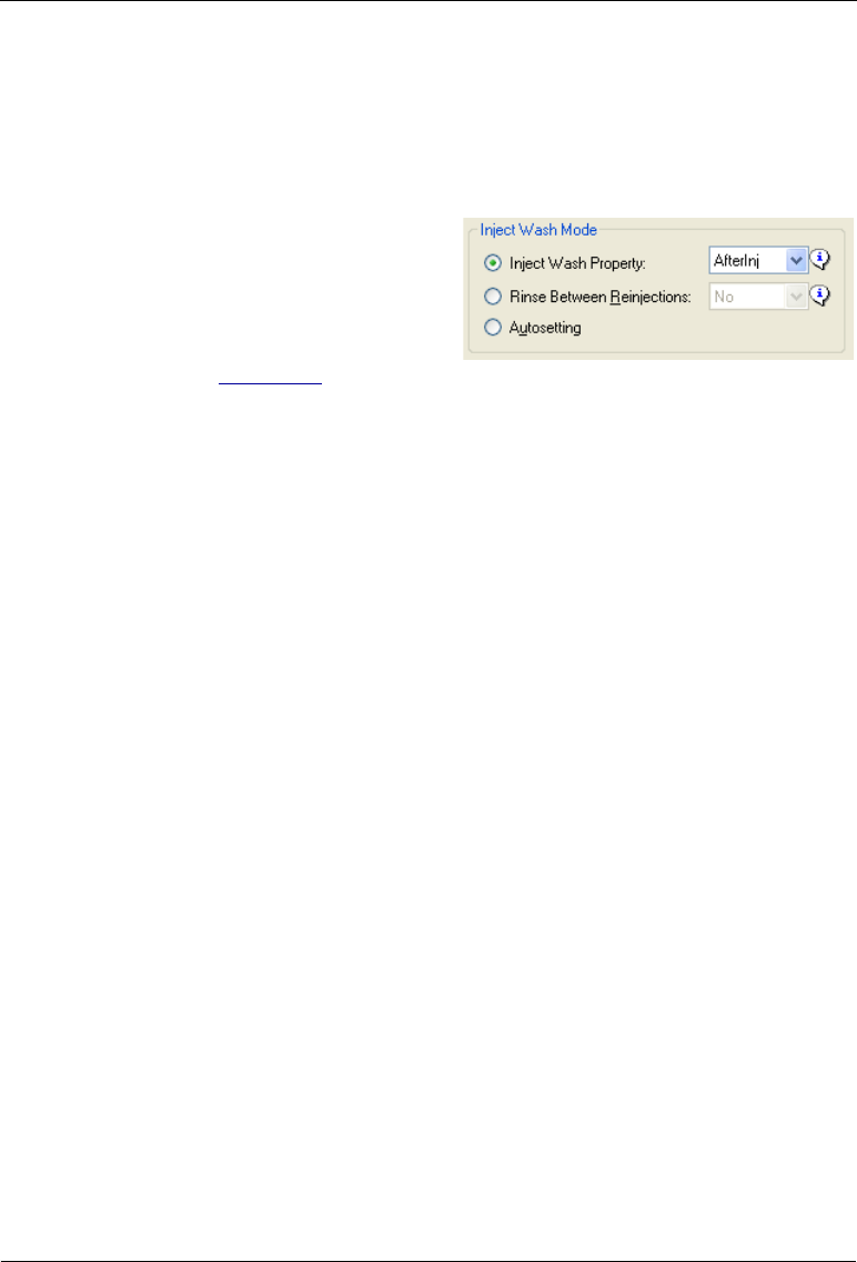
Dionex AS-AP Operator’s Manual
68 Doc. 065361-07 9/12
Command window or Chromeleon 6.8 Commands dialog box (press F8
to open the window or dialog box).
3.4.4 Selecting the Inject Wash Mode
To determine when the autosampler
performs a wash cycle, select an
Inject Wash Mode on the second
sampler options page of the
Instrument Method or Program
Wizard (see Figure 3-9).
General Recommendations
•For push mode injections, select Inject Wash Property and select either
BeforeInj, AfterInj, or Both (before and after injection). AfterInj
provides the fastest cycle times between injections. Both is recommended
if you are performing trace analyses.
•For pull mode injections, select Rinse Between Reinjections and select
the No option.
Inject Wash Mode Details
Inject Wash Property: Select this mode to specify when the autosampler will
perform a wash cycle. Automatic washes will not be performed. This mode
adds an InjectWash command with the selected parameter (described below)
to the Chromeleon 7 instrument method or Chromeleon 6.8 program.
•NoWash: The autosampler does not perform a wash cycle (either
before or after the injection). This option is recommended only if you
are taking sample injections from a single vial or well.
•BeforeInj: The autosampler performs a wash cycle before drawing
sample into the needle for the injection. This option helps to reduce
any contamination of the needle that may occur between injections.
However, with this option, the cycle time between injections is longer
than if the wash cycle is performed after the injection.
•AfterInj: The autosampler performs a wash cycle after the injection
(while the current analysis is running). This decreases the cycle time
between injections.

3 • Operation and Maintenance
Doc. 065361-07 9/12 69
•Both: The autosampler performs a wash cycle before the injection
and then again after the injection is completed. This option reduces
contamination and is recommended if you are performing trace
analyses. This is the slowest option. For additional steps for reducing
contamination, refer to Appendix E.
Rinse Between Reinjections: Select this option to specify whether to
perform a wash cycle between consecutive injections from the same vial or
well.
•Yes: The autosampler performs a wash cycle after each injection
(even if the next injection is from the same vial or well).
•No: The autosampler does not perform a wash cycle after the current
injection if the next injection will be taken from the same vial or well.
If the next injection will be from a different vial or well, a wash cycle
is performed after the current injection and again after the last
injection in the sequence. This option is recommended for pull mode
injections.
In addition, when the Rinse Between Reinjections mode is selected (with
either the Yes or No option), Chromeleon determines whether the autosampler
automatically performs a wash before the current injection, based on factors
such as the contamination level of the loop, whether the current injection is
from the same vial as the one before, and the position of the sample in the
sequence.
Autosetting: Select this mode to have Chromeleon always determine when a
wash cycle is performed. An InjectWash command is not added to the
Chromeleon 7 instrument method or Chromeleon 6.8 program.
Chromeleon determines whether to perform a wash cycle before the current
injection, based on factors such as the contamination level of the loop,
whether the current injection is from the same vial as the one before, and the
position of the sample in the sequence.
If the next injection will be from a different vial or well, the autosampler
performs a wash cycle after the current injection.

Dionex AS-AP Operator’s Manual
70 Doc. 065361-07 9/12
3.4.5 Determining Sample Volumes Used for Each Injection Mode
PushFull Injection Mode
A portion of sample is first flushed through the sample transfer line. The
Dionex AS-AP draws a volume of sample from the sample vial or well plate
well. A portion of the sample is then flushed through the loop, the loop is
filled, and an additional portion remains before the loop. The sample in the
loop is injected onto the column. For details about the injection sequence for
push mode, see Section 2.4.2.
The volume of sample drawn for a PushFull injection is:
LoopVolume x LoopOverfill + 30
L
Where:
•LoopVolume is the size of the loop installed on the injection valve. Enter
the loop volume on the Options page in the Chromeleon configuration
(see page 208).
•LoopOverfill is a volume of sample to push through the loop before
injection. The default factor is 5, which means that the loop is flushed
four times and then filled. Enter the loop overfill factor in the instrument
method or program (see Figure 3-8).
•30 L is the volume of sample initially flushed through the sample
transfer line, plus the volume remaining before the loop.
Example:
•Loop volume = 10 L
•Loop overfill factor = 5.000
10
L x 5.000 + 30
L = 80
L
PushPartial Injection Mode
The Dionex AS-AP draws a volume of sample from the sample vial or well
plate well. A portion of the sample is first flushed through the sample transfer
line. The sample to be injected is then loaded into the loop. An additional
portion of sample remains before the loop. The sample in the loop is then
injected onto the column. The injection volume entered in the sequence
determines the volume injected. You do not need to install a different sample
loop to change the injection volume.

3 • Operation and Maintenance
Doc. 065361-07 9/12 71
The amount of sample required for a PushPartial injection is:
InjectionVolume + (2 x PartialCutVolume)
Where:
•InjectionVolume must be less than one-half of the sample loop
volume. Enter the injection volume in the sequence (see Section 3.4.9).
•PartialCutVolume is the volume of sample to be “cut” (or omitted)
from each side of the sample during the injection process. The middle
portion of the sample is positioned in the loop and injected. Enter the
partial cut volume in the instrument method or program (see Figure 3-8).
Using a smaller partial cut volume minimizes the amount of total sample
drawn from the vial or well. However, better precision is achieved with a
larger partial cut volume.
Example:
•Injection volume = 4 L (the sample loop volume is 10 L)
•Partial cut volume = 5
4
L + (2 x 5
L) = 14
L
PushPartial_ls (limited-sample) Injection Mode
A partial loop is injected onto the column and no extra sample is taken from
the vial or well. The injection volume entered in the sequence determines the
volume injected. You do not need to install a different sample loop to change
the injection volume.
The amount of sample required for a PushPartial_ls injection is:
InjectionVolume
Where:
InjectionVolume is less than one-half of the sample loop volume. Enter
the injection volume in the sequence (see Section 3.4.9).
PushConcentrate Injection Mode
The Dionex AS-AP draws the volume to be injected from the sample vial and
delivers it to a concentrator column.
The amount of sample required for a PushConcentrate injection is:

Dionex AS-AP Operator’s Manual
72 Doc. 065361-07 9/12
InjectionVolume
Where:
InjectionVolume is entered in the sequence (see Section 3.4.9).
PushCap Injection Mode
A full loop is injected onto the column in a capillary system. The injection
sequence is the same as for the PushFull injection mode.
The amount of sample required for a PushCap injection is:
LoopVolume x CapillaryOverfill + 10 L
Where:
•LoopVolume is the size of the loop in the injection valve. Enter the loop
volume on the Options page in the Chromeleon configuration (see
page 208). In a capillary system, the injection valve has a fixed internal
loop volume of 0.4 L.
•Enter the CapillaryOverfill volume in the instrument method or
program (see Figure 3-8).
•10 L is the volume of sample initially flushed through the sample
transfer line, plus the volume remaining before the loop.
Example:
•Loop volume = 0.4 L
•Loop overfill factor = 50.000
0.4
L x 50.000 + 10
L = 30
L
PushSequential Injection Modes
When configured for push sequential mode, the Dionex AS-AP delivers
sample to two separate chromatography systems. Each system is operated
independently and can have different samples and sample volumes injected.
All of the injection modes available for push mode (full, partial, partial
limited-sample, concentrate, and capillary) are also available for push
sequential mode. Refer to the previous sections for details.

3 • Operation and Maintenance
Doc. 065361-07 9/12 73
NOTE When performing partial injections in push sequential mode,
a larger partial cut volume is recommended. This will help to
achieve comparable precision to that of partial injections in
push (non-sequential) mode.
PushSimultaneous Injection Mode
The Dionex AS-AP draws the injection volume specified in the sequence
from the sample vial and delivers equal volumes of sample to the injection
valves in two systems. A full loop is injected onto the column in both systems
simultaneously. The flow through both systems must be the same. For details
about balancing the flow to the two systems, see page 191.
Use the following formula to calculate the amount of sample needed for a
PushSimultaneous injection and then enter this volume for the injection
volume in the sequence:
Connector Tubing Volume + ((Loop Volume #1 + Loop Volume
#2) x 5) + 50 L
Where:
•Connector Tubing Volume is the volume of the tubing from the
injection port to each injection valve. This includes the tubing from the
injection port to the Y-connector and then to each system. Use the
following formula to estimate the connector tubing volume:
(line length from injection port to Y-connector in mm + line length to
injection valve #1 in mm + line length to injection valve #2 in mm) x
((Tubing ID in mm /2)2) x 3.14159
•Loop Volume #1 and Loop Volume #2 are the sizes of the loops
installed on each injection valve. Enter the loop volumes on the Options
page in the Chromeleon configuration (see page 208).
•50 L is the volume of sample initially flushed through the sample
transfer line, plus the volume remaining before the loop.
Example:
•Tubing volume from injection port to Y-connector: 250 mm of 0.33 mm
(0.013 in) ID PEEK tubing = 21 μL
•Tubing from Y-connector to injection valve for both systems: 762 mm of
0.33 mm (0.013 in) ID PEEK tubing x 2 = 66 μL x 2 = 131 L

Dionex AS-AP Operator’s Manual
74 Doc. 065361-07 9/12
NOTE To estimate the volume of 0.33 mm (0.013 in) ID
PEEK tubing (blue), you can use a conversion factor
of 0.86 L/cm (2.2 L/in).
•Loop volume #1 = 10 μL
•Loop volume #2 = 25 μL
152 μL + ((10 μL +25 L) x 5)) + 50 L = 377 μL
In this example, the Dionex AS-AP draws 377 L from the vial and delivers it
approximately equally to the two sample loops, depending on the
backpressure of the two systems.
PullFull Injection Mode
A full loop is injected onto the column. Pull mode generally requires more
sample than push mode, but is faster than push mode. The amount of sample
required for a PullFull injection is:
FlushVolume + (LoopVolume x LoopOverfill)
Where:
•FlushVolume is the volume of sample to flush through the needle and
sample transfer line tubing. The recommended volume is 2 x (Needle
Volume + Sample Transfer Line Volume). Enter the flush volume
in the instrument method or program (see Figure 3-8).
•LoopVolume is the size of the loop installed on the injection valve. Enter
the loop volume on the Options page in the Chromeleon configuration
(see page 208).
•LoopOverfill is a volume of sample to pull through the loop before
injection. The default factor is 5, which means that the loop is flushed
four times and then filled. Enter the loop overfill factor in the instrument
method or program (see Figure 3-8).
Example:
•Needle volume = 30 μL
•Sample transfer line volume = 22 μL (254 mm of 0.33 mm (0.013 in) ID
PEEK tubing)

3 • Operation and Maintenance
Doc. 065361-07 9/12 75
NOTE To estimate the volume of 0.33 mm (0.013 in) ID blue PEEK
tubing, use a conversion factor of 0.86 L/cm (2.2 L/in).
•Loop volume = 10 μL
•Loop overfill factor = 5
(2 x (30 μL + 22 μL)) + (10 μL x 5) = 154 μL
For additional PullFull injections from the same sample container, the
amount of sample required is:
Flush Volume 2 + Loop Volume x Loop Overfill
Flush Volume 2 can be less than the flush volume for the first injection
(assuming no wash cycle between injections). A volume equal to or greater
than the needle volume is recommended (for example, 30 to 40 L). Enter
Flush Volume 2 in the instrument method or program (see Figure 3-8).
PullPartial Injection Mode
A partial loop is injected. The injection volume specified in the sequence
determines the volume injected. You do not need to install a different sample
loop to change the injection volume. The amount of sample required for a
PullPartial injection is:
Flush Volume + Injection Volume
Where:
•Flush Volume is the volume of sample to flush through the needle and
sample transfer line tubing. The recommended volume is 2 x (Needle
Volume + Sample Transfer Line Volume). Enter the flush volume
in the instrument method or program (see Figure 3-8).
•InjectionVolume is entered in the sequence (see Section 3.4.9).
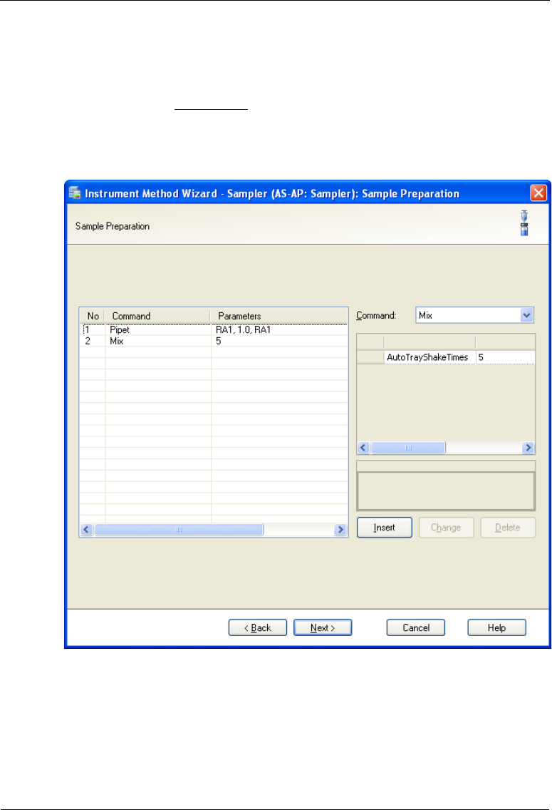
Dionex AS-AP Operator’s Manual
76 Doc. 065361-07 9/12
3.4.6 Defining Sample Preparation Operations
In the Instrument Method Wizard or Program Wizard, the third sampler
options page (see Figure 3-11) provides commands and parameters for
preparing samples before injection. When multiple sample preparation steps
are required (for example, pipetting into a vial and then mixing the vial
contents), list the operations in the order in which they should be performed.
Figure 3-11. Dionex AS-AP Sampler Options (Third Page): Sample
Preparation (Chromeleon 7 Instrument Method Wizard Shown)

3 • Operation and Maintenance
Doc. 065361-07 9/12 77
Table 3-2 describes the available sample preparation operations.
Sample Preparation
Operation Description and Parameters
Dilute Move a volume of diluent from a vial to a destination vial
and then move a volume of sample (or other
concentrate) to the destination vial. The total volume of
sample and diluent should be 1000 L, if possible.
SourceVial: The vial from which to pick up the sample.
SourceVol: The volume (µL) of sample to be pipetted.
DestVial: The vial in which to add the sample and
diluent.
Diluent: The vial that contains the diluent.
ReagentVolume: The volume (µL) of diluent to use.
After moving the diluent and sample to the destination
vial, the autosampler mixes the contents. The
DilutionMixMode determines the type of mixing
performed after a dilution. With the recommended
default setting of Auto, a draw-and-dispense operation
is used to mix 0.3 mL and 1.5 mL vials and a carousel
shake operation is used to mix 10 mL vials. For details,
see Section 3.4.7).
DiluteWithWash Dispense a volume of wash liquid to a destination vial
and then move a volume of sample (or other
concentrate) to the destination vial. The total volume of
sample and diluent should be 1000 L, if possible.
SourceVial: The vial from which to pick up the sample.
SourceVol: The volume (µL) of sample to be pipetted.
DestVial: The vial in which to add the sample and wash
liquid.
ReagentVolume: The volume (µL) of wash liquid to use.
After moving the wash liquid and sample to the
destination vial, the autosampler mixes the contents.
The DilutionMixMode determines the type of mixing
performed after a dilution. With the recommended
default setting of Auto, a draw-and-dispense operation
is used to mix 0.3 mL and 1.5 mL vials and a carousel
shake operation is used to mix 10 mL vials. For details,
see Section 3.4.7).
Table 3-2. Sample Preparation Operations

Dionex AS-AP Operator’s Manual
78 Doc. 065361-07 9/12
Mix Mix the contents of a vial by shaking the carousel.
AutoTrayShakeTimes: The number of times to shake
the carousel.
NOTE Use Mix when using10 mL vials.
Mix_DrawDispense Mix the contents of a vial by repeatedly drawing and
dispensing a volume of the contents.
SourceVial: The vial to be mixed.
Volume: The volume (L) of the vial contents to draw
and dispense. The Mix_DrawDispense volume must be
the lesser of these two values: 70% of the volume in the
vial or 70% of the buffer line volume.
NOTE
•Use Mix_DrawDispense when using 0.3 mL and
1.5 mL vials.
•Properties for specifying the number of mixing
iterations, the speed of the syringe, and the needle
height during drawing and dispensing are available.
For details, see Section 3.4.7.
Pipet Move a volume of fluid from one vial to another.
SourceVial: The vial from which to pick up the fluid.
SourceVol: The volume (L) of fluid to be pipetted.
DestVial: The vial in which to add the fluid.
ReagentFlush Transfer a volume of reagent from a vial to the injection
port. This operation is typically used to flush reagent
onto a concentrator column.
SourceVial: The reservoir from which to pick up reagent.
SourceVol: The volume (µL) of reagent to be pipetted.
Note: The ReagentFlush command is performed before
sample is drawn and delivered for the injection
procedure. For details, see “Options for Reagent
Flushing in Concentrate Mode Injections” on page 64.
Sample Preparation
Operation Description and Parameters
Table 3-2. Sample Preparation Operations

3 • Operation and Maintenance
Doc. 065361-07 9/12 79
3.4.7 Selecting Mixing Properties
The autosampler automatically mixes vials after performing a Dilute or
DiluteWithWash sample preparation operation. You can also add a separate
mix operation to the sample preparation steps. For details about the sample
preparation operations, see Section 3.4.6.
Two mixing methods are available. The autosampler can:
•Mix vials by shaking the carousel.
•Mix a vial by drawing and dispensing a volume of the vial contents.
After a dilution, the DilutionMixMode (described below) determines the
method used. When you add a separate mix operation, you can select either
Mix (to mix by shaking the carousel) or Mix_DrawDispense.
Mixing Mode for Dilutions
The DilutionMixMode determines the type of mixing performed after a
dilution. With the recommended default setting of Auto, the autosampler
selects the type of mixing, based on the vial size:
•For 10 mL vials, the autosampler mixes by shaking the carousel.
•For 0.3 mL and 1.5 mL vials, the autosampler mixes by drawing and
dispensing.
To change the mode, open the autosampler ePanel (in Chromeleon 7) or
Control panel (in Chromeleon 6.8) and press F8. Under Sampler, select a
DilutionMixMode.
NOTE If the DilutionMixMode property is not visible in Chrome-
leon, right-click in the list of devices and select Expert.
Properties for Draw-and-Dispense Dilution Mixing
The properties used for controlling mixing by drawing and dispensing are
listed below. Values selected for these properties are used for all draw-and-
dispense mixing. This includes mixing after dilution operations and the
Mix_DrawDispense operation specified in the sample preparation steps.
•DilutionMixSpeed is the speed at which the sample is drawn into the
needle when using the draw-and-dispense mixing method. The speed
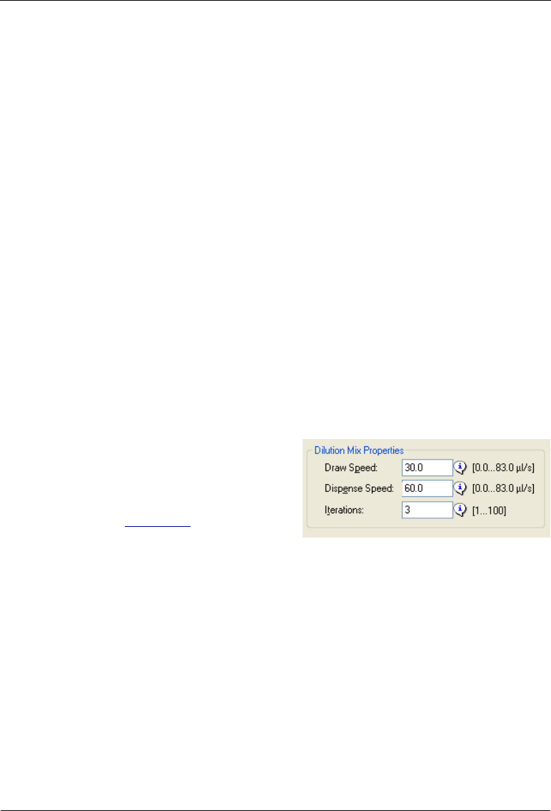
Dionex AS-AP Operator’s Manual
80 Doc. 065361-07 9/12
should not be set so fast that cavitation occurs. 30 L/s is a good
maximum value.
•DilutionMixDispenseSpeed is the speed at which the sample is
dispensed into the needle when using the draw-and-dispense mixing
method. The dispense can be set faster than the draw speed to increase
mixing. 60 L/s is a good starting value.
•DilutionMixDrawHeight is the distance from the bottom of the sample
container to the needle tip when drawing using the draw-and-dispense
mixing method. The height should be set so that the needle remains
submerged at all times during the draw operation. 2 mm is a good starting
value.
•DilutionMixDispenseHeight is the distance from the bottom of the
sample container to the needle tip when dispensing using the draw-and-
dispense mixing method. The height should be set so that the needle is
submerged at the end of the dispense operation. This prevents leaving a
drop on the end of the needle, which can lead to inaccurate results. For a
1000 L total volume in a 1.5 mL vial, 12 mm is a good starting value.
•Iterations is the number of times the draw-and-dispense operation is
repeated.
You can select the syringe speeds
and the iterations in the Instrument
Method or Program Wizard on the
Sampler Options (General Settings)
page (see Figure 3-9).
To select the DilutionMixDrawHeight and DilutionMixDispenseHeight,
manually enter the properties in the Chromeleon 7 Instrument Method Editor
or the Chromeleon 6.8 Program Editor, or enter values for these properties in
the Chromeleon 7 Commands window or the Chromeleon 6.8 Command
dialog box.
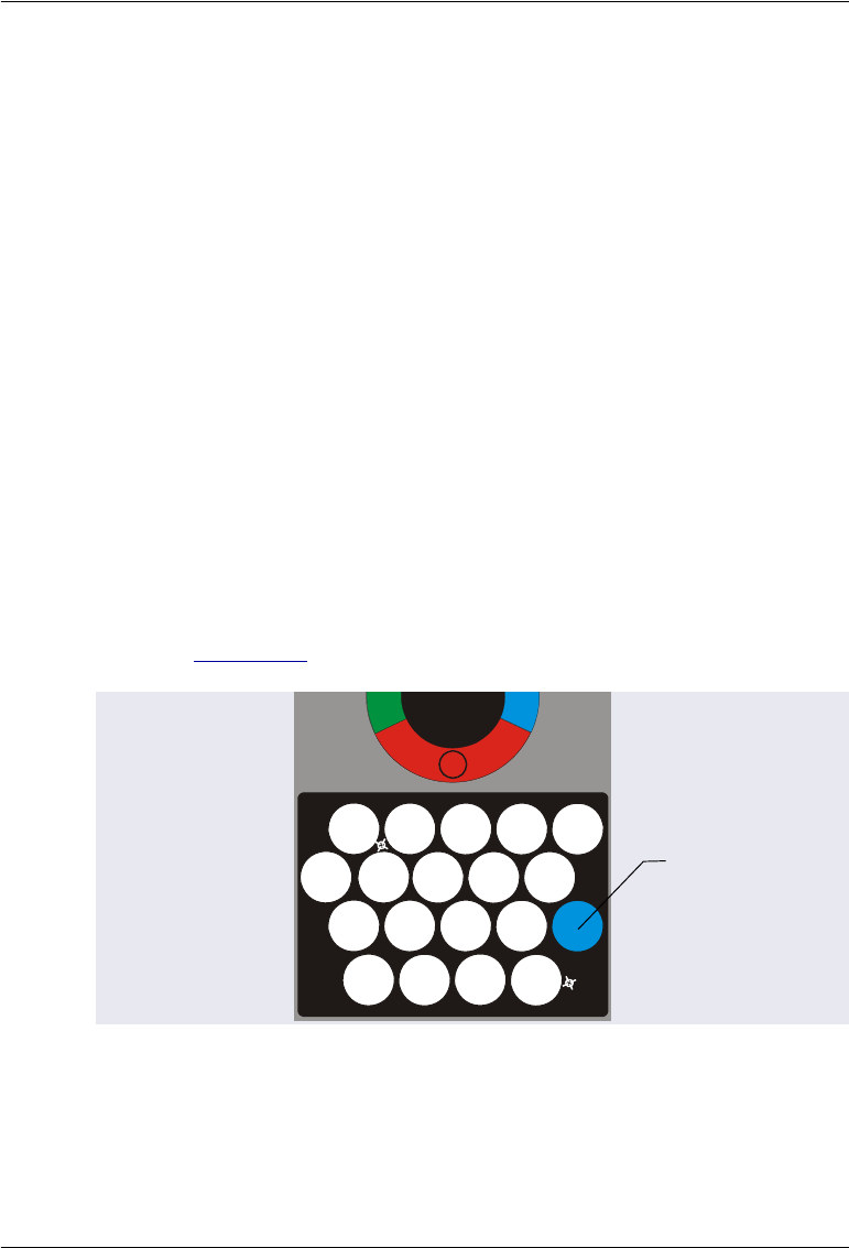
3 • Operation and Maintenance
Doc. 065361-07 9/12 81
3.4.8 Specifying Vial Positions
Follow the guidelines below to specify a vial or well position in a sequence,
direct control command, or sample preparation operation.
Specifying Vial or Well Positions in a Vial Tray or Well Plate Tray
Positions in a vial tray or well plate consist of a three-character identifier code
(for example, RC5):
•The first character indicates the carousel color section in which the tray is
installed (R for red, G for green, or B for blue).
•The second character indicates the row in which the vial or well is located
(A, B, C, etc.). Rows are lettered starting with A in the upper left corner
and continuing down.
•The third character indicates the column in which the vial or well is
located (1, 2, 3, etc.). Columns are numbered starting with 1 in the upper
left corner and continuing across.
For example, to sample from the tray installed in the red section, and from the
vial in the third row down from the top and the fifth column across, specify
RC5 (see Figure 3-12).
Figure 3-12. Sample Position Example
(10 mL Vial Tray Installed in the Red Section)
A
B
C
D
12345
12345
12345
1234
R
Position RC5
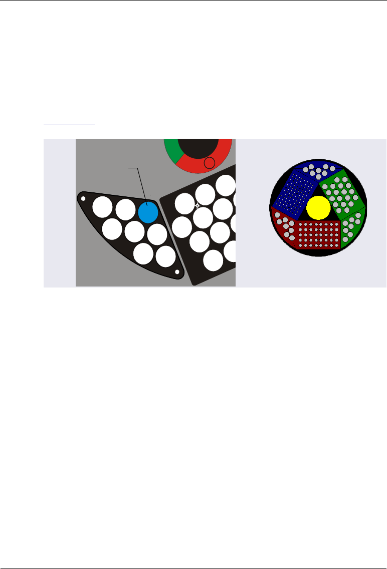
Dionex AS-AP Operator’s Manual
82 Doc. 065361-07 9/12
Specifying Vial Positions in an 8-Position Vial Holder
Vial positions in an 8-position vial holder consist of a two-character identifier
code (for example, R3). The first character indicates the carousel color
section in which the holder is installed (R, G, or B). The second character is
the numbered position in which the vial is installed. The color section of the
8-position vial holder is the color section of the tray on its right (see
Figure 3-13).
Specifying Vial Positions in Sample Preparation Operations
When you specify a vial position in a sample preparation operation (for
example, the source vial for a pipet operation), you can enter a fixed position
in a sample tray or 8-position vial holder as described in the previous sections.
You can also enter a position relative to the current vial (for example,
CurrentVial + 1).
For example, to pipet from the current vial into the next vial in the tray,
specify CurrentVial for the source vial and CurrentVial +1 for the
destination vial.
Figure 3-13. Sample Position Example
(8-Position Vial Holder Installed in the Red Section)
1
2
4
5
3
6
7
8
A
C
1234
1
2
34
1
23
1
2
R
Position R3
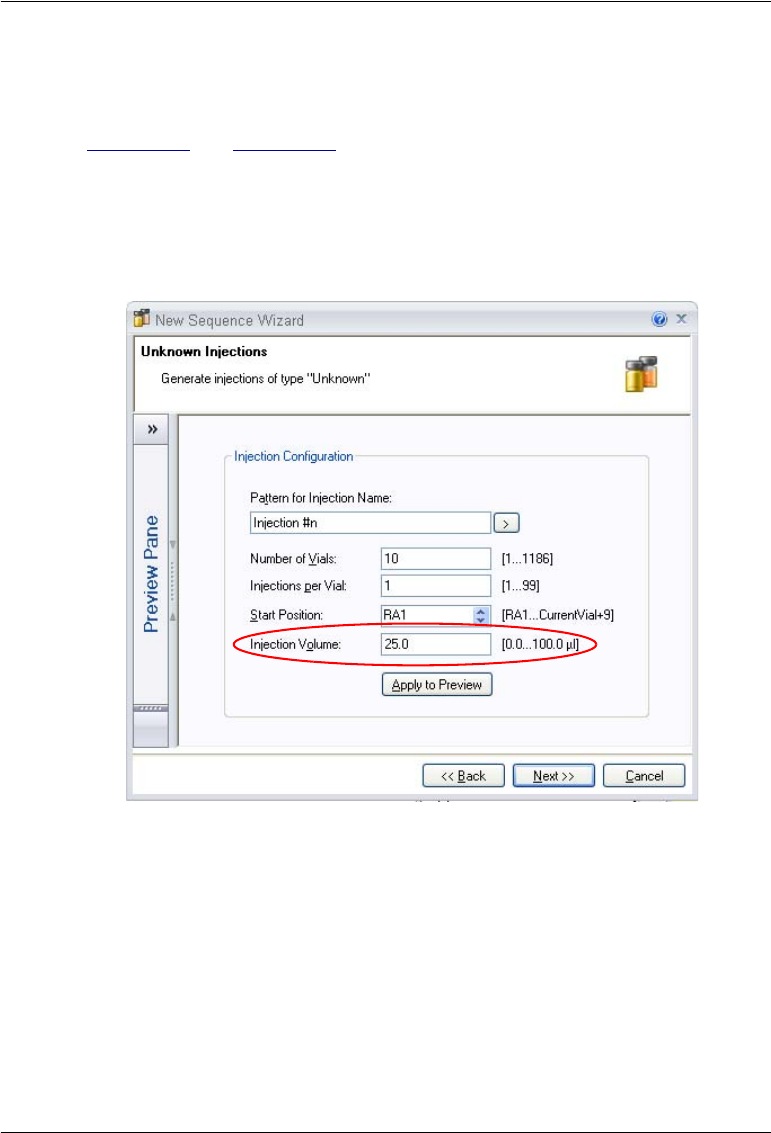
3 • Operation and Maintenance
Doc. 065361-07 9/12 83
3.4.9 Specifying Injection Volumes
Specify the volume of sample to inject in the Chromeleon sequence (see
Figure 3-14 and Figure 3-15).
•For full-loop injections, specify the volume of the loop installed on the
injection valve.
•For partial-loop and concentrate injections, specify the volume of sample
to be injected onto the column or loaded to the concentrator column.
Figure 3-14. Specifying the Injection Volume in the Sequence Wizard
(Chromeleon 7 Version Shown)
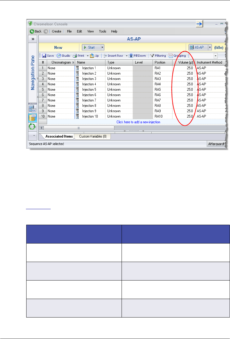
Dionex AS-AP Operator’s Manual
84 Doc. 065361-07 9/12
3.4.10 Determining Maximum Injection and Reagent Flush
Volumes
Table 3-3 shows the formulas used to calculate the maximum injection and
reagent flush volumes for each injection mode and reagent flush operation.
Figure 3-15. Injection Volume in the Chromeleon Sequence
(Chromeleon 7 Version Shown)
Injection Mode or Reagent Flush
Operation Maximum Injection Volume or
Reagent Flush Volume (in L)
PullFull Injection Volume ((0.883 * Buffer Size)
- Flush Volume)/ LoopOverfill
PullPartial Injection Volume (0.883 * Buffer Size) -
FlushVolume
PushFull
PushSeqFull
Injection Volume ((0.883 * Buffer Size)
- 30) / LoopOverfill
PushPartial
PushSeqPartial
Injection Volume (0.883 * Buffer Size)
- (2 * PartialCutVolume)
Table 3-3. Maximum Injection and Reagent Flush Volumes

3 • Operation and Maintenance
Doc. 065361-07 9/12 85
3.5 Syringe Speed and Tubing Size Guidelines
The Dionex AS-AP is capable of delivering sample at a maximum pressure
of 690 kPa (100 psi). Several factors affect the backpressure, including the
syringe speed, the tubing ID and length of the sample loop, and the ID and
length of the tubing used to connect the injection port and the injection valve.
PushPartial_ls
PushSeqPartial_ls
PushSimultaneous
PushConc (no Reagent Flush)
PushSeqConc (no Reagent Flush)
Injection Volume 0.883 * Buffer Size
PushCap
PushSeqCap
Normally fixed at 0.4 L
Injection Volume ((0.883 * Buffer Size)
- 10) / CapillaryOverfill
PushConc with Reagent Flush
PushSeqConc with Reagent Flush
When (Injection Volume + Reagent
Volume) < 0.8 * Buffer Sizea
(Injection Volume + Reagent Volume)
(0.8 * Buffer Size)
PushConc with Reagent Flush
PushSeqConc with Reagent Flush
When (Injection Volume + Reagent
Volume) > 0.8 * Buffer Sizeb
Injection Volume 0.883 * Buffer Size
Reagent Volume 0.883 * Buffer Size
SpReagentVolume propertycSpReagentVolume 0.883 * Buffer Size
a. When the injection volume plus the reagent volume is less than 80% of the buf-
fer size, the autosampler performs a single syringe draw operation to load the two
volumes in the buffer line.
b. When the injection volume plus the reagent volume is greater than 80% of the
buffer size, the autosampler first loads the injection volume and performs the in-
jection. After injection, the reagent volume is loaded with separate syringe oper-
ations.
c. The SpReagentVolume property is selected on the third sampler options page
in the Instrument Method Wizard or Program Wizard (see Figure 3-11).
Injection Mode or Reagent Flush
Operation Maximum Injection Volume or
Reagent Flush Volume (in L)
Table 3-3. Maximum Injection and Reagent Flush Volumes (Continued)
Dionex AS-AP Operator’s Manual
86 Doc. 065361-07 9/12
Use the following formula to determine the backpressure produced by these
factors:
backpressure = cm of tubing x kPa (psi)/mL/min/cm (from Table 3-4) x
mL/min (from Table 3-5)
Example: 30 cm of 0.254 mm ID tubing x 1.6 kPa/mL/min/cm x 2.40 L/s =
115 kPa
3.6 System Shutdown
No special shutdown procedure is required for the Dionex AS-AP. To
automatically shut down the system, you can run a shutdown instrument
method or program at the end of a sequence. The shutdown instrument
method or program turns off the pump flow, the suppressor current (if
installed), the Dionex AS-AP sample temperature control option (if installed),
and other system devices.
Tubing ID Backpressure in kPa (psi) per
mL/min per cm of tubing Volume in L
per cm of
tubing
0.127 mm (0.005 in) 25 kPa (3.6 psi) 0.13
0.178 mm (0.007 in) 6.5kPa (0.94psi) 0.25
0.254 mm (0.010 in) 1.6 kPa (0.23 psi) 0.51
0.330 mm (0.013 in) 0.55 kPa (0.079 psi) 0.86
0.508 mm (0.020 in) 0.10 kPa (0.014 psi) 2.03
Table 3-4. Tubing Volume and Backpressure
Syringe Size (L) Syringe Speed Range (L/s)
100 0.1 to 33
250 0.1 to 83
1000 0.1 to 100
5000 0.1 to 100
Table 3-5. Flow Rates Provided by the Sample Syringe
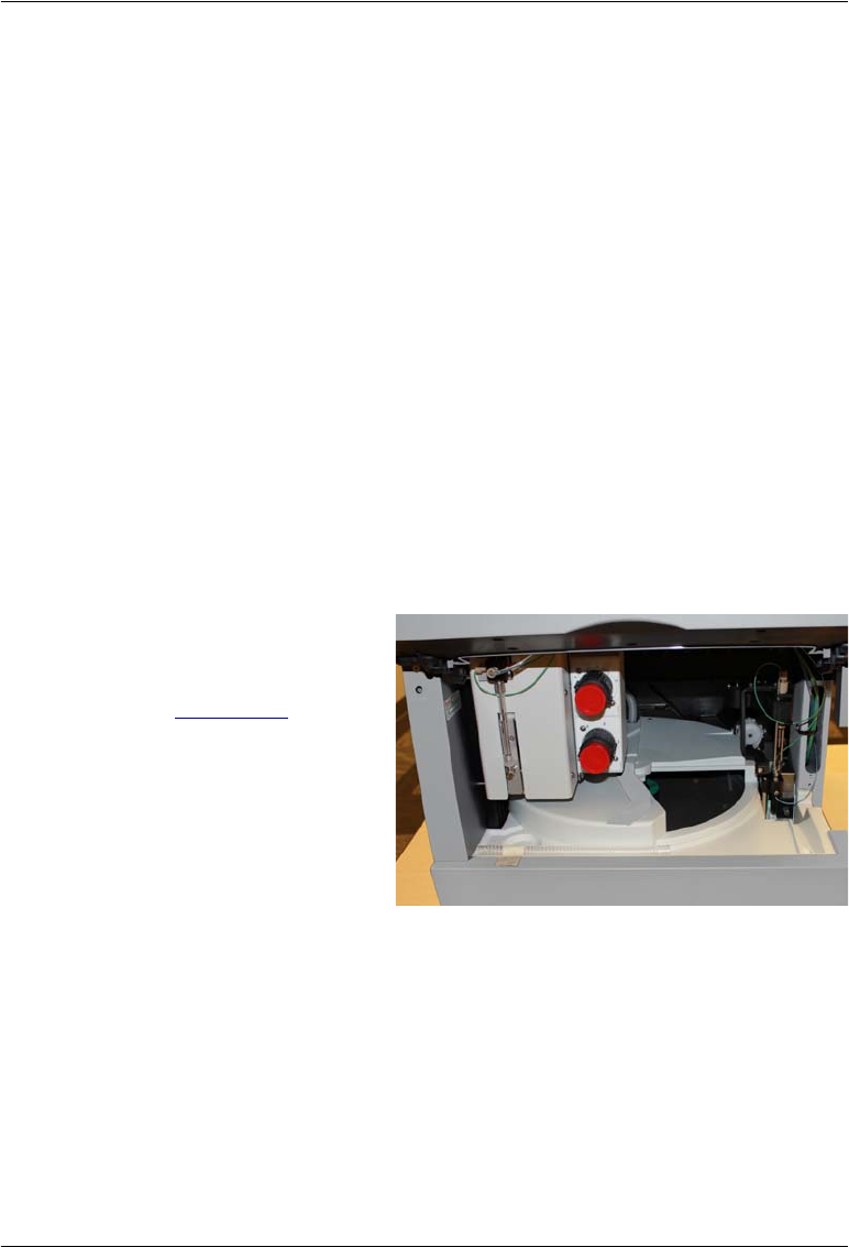
3 • Operation and Maintenance
Doc. 065361-07 9/12 87
You can use the Smart Shutdown feature to assist you in creating and running
a shutdown instrument method or program. Refer to the Chromeleon Help for
details.
Before moving or shipping the autosampler, follow the steps below:
1. Press the Standby button on the front panel. This moves the needle arm
and needle to the positions required for moving the module.
2. Turn off the main power switch on the rear panel and disconnect the
power cable.
3. Disconnect the drain hose.
4. Remove the sample racks and 8-position vial holders from the carousel.
5. Disconnect the wash reservoir and remove it from the autosampler.
6. Disconnect any liquid lines connected to other modules in the system.
7. Locate the foam insert that was installed inside the autosampler when it
was shipped from the factory and follow the instructions below to install
it:
a. Open the carousel
cover to the position
shown in
Figure 3-16.
Figure 3-16. Carousel Cover in Correct Position for
Installing Foam Insert
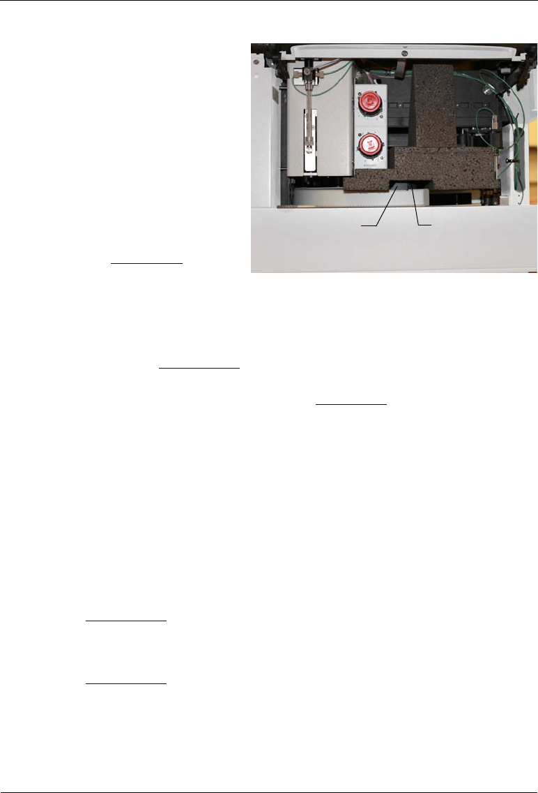
Dionex AS-AP Operator’s Manual
88 Doc. 065361-07 9/12
b. Align the groove in
the bottom of the
insert with the
carousel cover
handle and align the
right side of the
insert with the left
side of the needle.
c. Push the insert into
the Dionex AS-AP
body (see
Figure 3-17).
Figure 3-17. Foam Insert Installed for Moving or
Shipping the Dionex AS-AP
8. If you are going to ship the autosampler, install the J-clip on the vial
pusher (see Section 5.3.1), and repack the autosampler in its original
shipping container, using the foam pads and polyethylene bag. For details,
refer to the unpacking instructions in Section B.2.
3.7 Routine Maintenance
This section describes routine maintenance procedures that the user can
perform. Any other maintenance procedures must be performed by Thermo
Fisher Scientific personnel.
3.7.1 Daily
•Check for air bubbles in the syringe and remove them if they appear (see
Section 3.3.3).
•Check the volume of liquid in the wash liquid reservoir and refill when
needed. After refilling the reservoir, run a manual wash cycle (see
Section 3.3.4).
•Check the volume of liquid in the waste container and empty when
needed.
Foam Insert
Groove in
foam Insert
Carousel
cover handle

3 • Operation and Maintenance
Doc. 065361-07 9/12 89
3.7.2 Weekly
•Replace the wash liquid in the reservoir to prevent microbial growth and
gas absorption buildup. Clean the reservoir if needed.
3.7.3 Periodically
•Check the alignment of the sampling needle. If the needle is not centered
in the wash port or injection port opening when it enters the port, realign
the needle. For instructions, see Section 5.3.
•Check for leaks from the injection port, the syringe, the syringe valve, and
the liquid lines. If leaks occur, see Section 4.2.
•Monitor the usage of replaceable parts. The Chromeleon Wellness panel
displays the usage counters for the various parts. Replace or service parts
when recommended and reset the usage counter afterwards.
3.7.4 Annually
Perform the Dionex AS-AP preventive maintenance procedure. A Dionex
AS-AP Preventive Maintenance Kit (P/N 075000) is available for this
purpose. The kit provides parts and instructions for performing the procedure.
Neutralize acidic and caustic wastes before disposal. Dispose of all
wastes in accordance with local regulations.
Neutralisez les déchets acides ou caustiques avant de les jeter. Jetez
les déchets aux règlements locaux.
Neutralisieren Sie säurehaltige und ätzende Abfälle vor ihrer
Entsorgung. Entsorgen Sie alle Abfälle entsprechend den lokalen
Bestimmungen.
For correct drainage, make sure the end of the waste line is not
submerged in waste liquid.

Dionex AS-AP Operator’s Manual
90 Doc. 065361-07 9/12
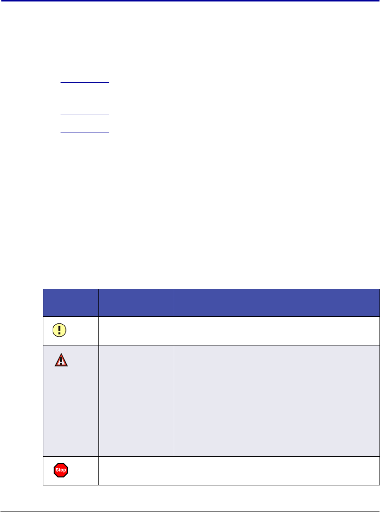
Doc. 065361-07 9/12 91
4 • Troubleshooting
This chapter is a guide to troubleshooting issues that may arise during
operation of the Thermo Scientific Dionex AS-AP Autosampler.
•Section 4.1 describes error messages displayed in the Chromeleon Audit
Trail and how to troubleshoot them.
•Section 4.2 describes how to troubleshoot liquid leaks.
•Section 4.3 describes how to eliminate condensation if it occurs on vial
tops or well plate covers.
If you are unable to resolve a problem by following the instructions here,
contact Technical Support for Dionex products. In the U.S. and Canada, call
1-800-346-6390. Outside the U.S. and Canada, call the nearest Thermo Fisher
Scientific office.
4.1 Audit Trail Error Messages
Each error message displayed in the Audit Trail is preceded by an icon that
identifies the seriousness of the underlying problem (see the table below).
Icon Default
Severity Level Description
Warning A message is displayed in the Audit Trail, but
the current run is not interrupted.
Error A message is displayed in the Audit Trail, and
the system attempts to correct the problem
(sometimes by using an alternative parameter),
but the current injection is not interrupted. If a
missing vial error occurs, the autosampler
continues to the next vial in the queue or batch.
If an error occurs during the Ready Check, the
queue or batch will not be started until the error
is resolved.
Abort A message is displayed in the Audit Trail, and
the running queue or batch is aborted.

Dionex AS-AP Operator’s Manual
92 Doc. 065361-07 9/12
4.1.1 General Troubleshooting Information
Many error messages include troubleshooting tips (for example, the message
may say to perform a self-test or call service). Unless additional
troubleshooting information is required, these errors are not listed separately
in this manual.
1. Check Table 4-1 for the error you are troubleshooting. If the error is
listed, go to the page indicated in the table for specific troubleshooting
information.
2. If the error message is not included in Table 4-1, perform the
troubleshooting steps included in the error message (if any) or follow the
general troubleshooting steps below:
a. Perform a self-test by clicking the Service button on the Dionex AS-
AP ePanel (in Chromeleon 7) or Control panel (in Chromeleon 6.8)
and then clicking the Reset / Self Test button.
b. Turn the autosampler power off and on again by pressing the main
power switch on the Dionex AS-AP rear panel.
c. If the error recurs, contact Thermo Fisher Scientific for assistance.
4.1.2 Error Messages
Table 4-1 lists error messages related to the Dionex AS-AP for which specific
troubleshooting information is provided. For troubleshooting assistance, refer
to the page indicated in the table.
NOTE The troubleshooting steps under each error in this section are
listed in the order they should be performed. If a step does not
resolve the problem, continue to the next step.
Dionex AS-AP Audit Trail Error Message Default
Severity Level See
A self test is required. Abort page 94
Access denied. Abort page 94
Alignment positions not precise. Abort page 94
(The) buffer loop is not empty. Error page 95
Table 4-1. Dionex AS-AP Error Messages
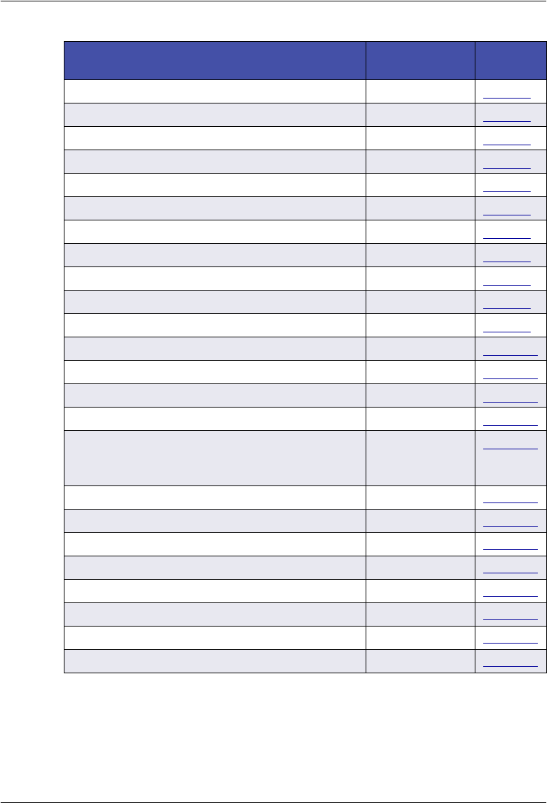
4 • Troubleshooting
Doc. 065361-07 9/12 93
Buffer loop is too full. Error page 95
Cooling system overheated. Error page 95
(The) device is busy. Error page 96
xxEnd point not reached. Dest:xx Realxx. Abort page 96
Illegal syringe speed. Error page 96
Inject port is not aligned. Abort page 96
Inject port missed. Abort page 97
Inject volume must be equal to loop volume. Error page 97
Invalid mix target. Error page 98
Leak detected. Warning page 98
Motor switching valve malfunction. Error page 99
Motor switching valve timeout. Abort page 100
Reagent vial not found. Abort page 100
Sample height out of reach. Error page 100
Syringe is too empty. Error page 101
(The) syringe size is too small or fluid volume
in the syringe is not enough for TLV
calibration.
Warning page 101
Syringe valve malfunction. Abort page 101
Transport liquid vial not found. Error page 102
Unknown vial position. Error page 102
Vial not found. Error page 103
Wash port is not aligned. Abort page 104
Wash port missed. Abort page 104
Wrong tray type detected. Abort page 104
Wrong vial height. Abort page 105
Dionex AS-AP Audit Trail Error Message Default
Severity Level See
Table 4-1. Dionex AS-AP Error Messages (Continued)
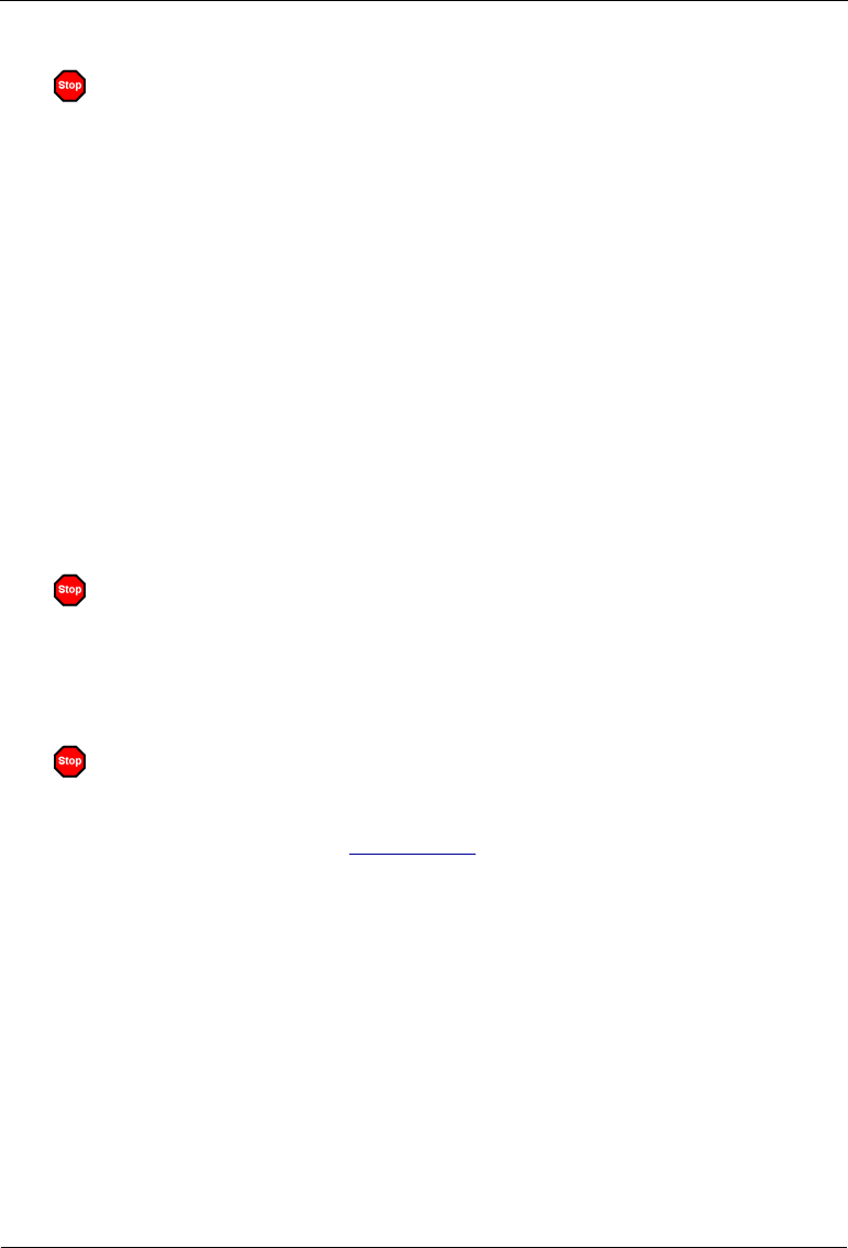
Dionex AS-AP Operator’s Manual
94 Doc. 065361-07 9/12
A self test is required. The autosampler will not be ready for
operation until the self test is successful. Turn the autosampler
off and on again or perform a self test. If a fault or mechanical
failure is detected during the self test, a message appears.
To troubleshoot:
1. Check the Audit Trail for previous error messages, which may indicate
why a self-test is required. Correct the error condition, if possible.
2. Perform a self-test by clicking the Service button on the Dionex AS-AP
ePanel (in Chromeleon 7) or Control panel (in Chromeleon 6.8) and then
clicking the Reset / Self Test button.
3. Turn the autosampler power off and on again by pressing the main power
switch on the Dionex AS-AP rear panel.
4. If the error recurs, contact Thermo Fisher Scientific for assistance.
Access denied.
The requested command requires service-level access. Contact Thermo Fisher
Scientific for assistance.
Alignment positions not precise.
This error can occur during the needle alignment procedure, when aligning
the needle in the tray (see Section 5.3.4). This message occurs when the
difference between the first alignment position and the second alignment
position is too large.
To troubleshoot:
1. If this error occurs after you accept the first alignment position, continue
on to the next step of the procedure (aligning the second position).
2. If the error occurs after you accept the second alignment position, repeat
the alignment procedure.
3. If the error recurs, contact Thermo Fisher Scientific for assistance.
4 • Troubleshooting
Doc. 065361-07 9/12 95
(The) buffer loop is not empty. Perform a Wash operation.
To troubleshoot:
1. For instructions on performing a wash, see Section 3.3.4.
2. Check the commands in the instrument method (in Chromeleon 7) or
program (in Chromeleon 6.8) to verify that they do not specify incorrect
volumes and that the order of commands is correct.
Buffer loop is too full. Perform a wash.
This error occurs if the command would cause the buffer loop to draw more
sample than it can hold, causing contamination of the syringe.
To troubleshoot:
1. Perform a wash cycle (see Section 3.3.4).
2. Perform a self-test by clicking the Service button on the Dionex AS-AP
ePanel (in Chromeleon 7) or Control panel (in Chromeleon 6.8) and then
clicking the Reset / Self Test button.
Cooling system overheated. Verify that the ventilation slots are
not obstructed. Turn the autosampler off and on again or perform
a self test.
To troubleshoot:
1. Check the ventilation slots on the sides of the autosampler and remove
any obstruction.
2. Make sure there is at least 6 cm (2.4 in) of clearance behind and to the
sides of the autosampler for ventilation.
3. Perform a self-test by clicking the Service button on the Dionex AS-AP
ePanel (in Chromeleon 7) or Control panel (in Chromeleon 6.8) and then
clicking the Reset / Self Test button.
4. Turn the autosampler power off and on again by pressing the main power
switch on the Dionex AS-AP rear panel.
Dionex AS-AP Operator’s Manual
96 Doc. 065361-07 9/12
(The) device is busy.
To troubleshoot:
The autosampler is busy performing another command. Wait until the current
command has been completed and then try again.
xxEnd point not reached. Dest:xx Realxx. Turn the autosampler
off and on again or perform a self test.
To troubleshoot:
1. Perform a self-test by clicking the Service button on the Dionex AS-AP
ePanel (in Chromeleon 7) or Control panel (in Chromeleon 6.8) and then
clicking the Reset / Self Test button.
2. Turn the autosampler power off and on again by pressing the main power
switch on the Dionex AS-AP rear panel.
3. Align the needle. See Section 5.3 for instructions.
4. If the error recurs, contact Thermo Fisher Scientific for assistance.
Illegal syringe speed. Change the syringe speed.
This error occurs if the specified syringe speed is greater than one-third
syringe vol/s.
To troubleshoot:
Enter a syringe speed within the allowed range for your syringe.
Recommended syringe speeds are displayed in the Instrument Method Wizard
or Program Wizard (see Section 3.4.2). Chromeleon provides recommended
speeds based on the selected injection mode, syringe size, and loop size.
Inject port is not aligned.
To troubleshoot:
Align the needle. See Section 5.3.2 for instructions.
4 • Troubleshooting
Doc. 065361-07 9/12 97
Inject port missed. Verify that the needle is installed and intact.
Replace the needle if necessary. Turn the autosampler off and on
again or perform a self test.
To troubleshoot:
1. If the needle is not installed or is damaged, replace the needle. See
Section 5.2 for instructions.
2. Perform a self-test by clicking the Service button on the Dionex AS-AP
ePanel (in Chromeleon 7) or Control panel (in Chromeleon 6.8) and then
clicking the Reset / Self Test button.
3. Turn the autosampler power off and on again by pressing the main power
switch on the Dionex AS-AP rear panel.
4. Align the needle. See Section 5.3.2 for instructions.
5. If the error recurs, contact Thermo Fisher Scientific for assistance.
Inject volume must be equal to loop volume. Change the injection
volume.
This error occurs if a full loop injection is specified and the injection volume
entered does not match the loop volume.
To troubleshoot:
1. Change the injection volume in the sequence or on the Dionex AS-AP
ePanel (in Chromeleon 7) or Control panel (in Chromeleon 6.8) (if you
are performing a manual injection).
2. Check the Chromeleon configuration to verify that the selected loop size
matches the loop size installed on the injection valve. To configure the
Dionex AS-AP in Chromeleon, see Section B.11.3.
Dionex AS-AP Operator’s Manual
98 Doc. 065361-07 9/12
Invalid mix target. Check the program.
This error occurs if there is an attempt to draw from the injection port, waste
port or wash port, or to dispense into air or the wash bottle.
To troubleshoot:
Check the commands in the instrument method (in Chromeleon 7) or program
(in Chromeleon 6.8) to verify that the order of commands is correct and that
you have entered the correct parameters for the draw and dispense commands.
To ensure the correct order of commands and that valid parameters are
entered, use the Chromeleon 7 Instrument Method Wizard or Chromeleon 6.8
Program Wizard to create an instrument method or program.
Leak detected. Find and eliminate the leak. Dry the leak sensor
and tray.
To troubleshoot:
1. Inspect the autosampler to determine the source of the leak. See
Section 4.2 for possible causes of leaks and the corrective actions to take.
2. Press the main power switch on the rear panel to turn off the autosampler.
Then, tighten or replace the leaking connection or other part as required.
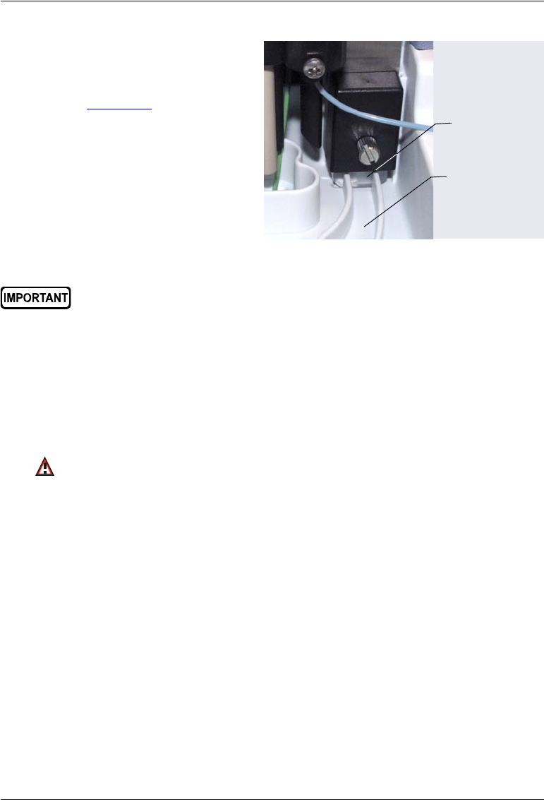
4 • Troubleshooting
Doc. 065361-07 9/12 99
3. After eliminating the leak,
wipe up all liquid and dry
the leak sensor (see
Figure 4-1). To do so, use a
cloth or tissue to absorb
any liquid that has
accumulated in the tray.
Figure 4-1. Leak Sensor and Leak Tray
4. Allow the sensor to adjust to the ambient temperature for a few minutes.
5. Turn on the autosampler.
6. If no error is reported after turning on the autosampler, operation can be
resumed. If the error recurs, check for additional sources of leaks.
Motor switching valve malfunction. Check whether the spanner
has been tightened too firmly. In this case, the valve cannot
switch. Slightly loosen the spanner, and then turn the
autosampler off and on again or perform a self test.
To troubleshoot:
NOTE The spanner can only be adjusted by a Thermo Fisher Scien-
tific Service Representative.
1. Perform a self-test by clicking the Service button on the Dionex AS-AP
ePanel (in Chromeleon 7) or Control panel (in Chromeleon 6.8) and then
clicking the Reset / Self Test button.
2. Turn the autosampler power off and on again by pressing the main power
switch on the Dionex AS-AP rear panel.
3. If the error recurs, contact Thermo Fisher Scientific for assistance.
Leak Sensor
Leak Tray
When drying the tray and leak sensor, make sure you do not bend or
damage the sensor.
Dionex AS-AP Operator’s Manual
100 Doc. 065361-07 9/12
Motor switching valve timeout. Turn the autosampler off and on
again or perform a self test.
To troubleshoot:
1. Try to manually switch the valve position by clicking the button on the
Dionex AS-AP ePanel (in Chromeleon 7) or Control panel (in
Chromeleon 6.8).
2. Perform a self-test by clicking the Service button on the Dionex AS-AP
ePanel or Control panel and then clicking the Reset / Self Test button.
3. Turn the autosampler power off and on again by pressing the main power
switch on the Dionex AS-AP rear panel.
4. If the error recurs, contact Thermo Fisher Scientific for assistance.
Reagent vial not found. Place a vial at the specified position or
specify a different position.
This error occurs if a reagent vial is not installed in the tray position specified
for the current operation.
To troubleshoot:
1. For instructions on how to specify vial positions, see Section 3.4.7.
Sample height out of reach. Install an appropriate vial or change
the sample height setting
This error can occur if a sample height is specified that places the needle
above the height of the installed vial.
To troubleshoot:
1. Verify that the correct size vial is installed in the tray.
2. For instructions on how to change the sample height setting, see
Section 3.4.3.
4 • Troubleshooting
Doc. 065361-07 9/12 101
Syringe is too empty. Change the program (volume to be
dispensed).
This error occurs if the syringe does not contain enough fluid to dispense the
volume required for the current operation.
To troubleshoot:
1. Perform a self-test by clicking the Service button on the Dionex AS-AP
ePanel (in Chromeleon 7) or Control panel (in Chromeleon 6.8) and then
clicking the Reset / Self Test button.
2. Check the commands in the program to verify that they do not specify
incorrect volumes and that the order of commands is correct.
(The) syringe size is too small or fluid volume in the syringe is not
enough for TLV calibration.
To troubleshoot:
1. If you are performing the sample transfer line volume (TLV) calibration
procedure, check that you have entered the correct estimate of the tubing
volume installed between the injection port and the injection valve. For
instructions, see Section 5.9.
2. Install a larger syringe. For information about selecting a syringe size, see
Section B.4.
Syringe valve malfunction. Check the syringe valve. Also, verify
that the connections on the valve are not over-tightened.
To troubleshoot:
1. Verify that the connections to the syringe valve are tightened correctly.
Tighten the connections fingertight.
2. If the problem persists, the valve may need to be replaced. Contact
Thermo Fisher Scientific for assistance.

Dionex AS-AP Operator’s Manual
102 Doc. 065361-07 9/12
Transport liquid vial not found. Place a vial at the specified
position or specify a different position.
This error occurs if a vial is not installed in the 8-position (wedge shaped) tray
position specified for the current operation. The autosampler continues to the
next vial in the sequence.
To troubleshoot:
Check the sequence to verify that the correct position is specified. For
instructions on how to specify vial positions for the 8-position tray, see
page 82.
Unknown vial position. Check the specified position. On the
Segments/Pump Link page, check and correct the segment
settings if necessary.
This error occurs if the vial position specified does not exist in the current
configuration. Either the vial position specified is incorrect or the tray type
specified in the configuration does not match the tray type installed in the
autosampler.
To troubleshoot:
1. Verify that the vial position specified is valid. For instructions on how to
specify vial positions, see Section 3.4.7.
2. On the Dionex AS-AP ePanel (in Chromeleon 7) or Control panel (in
Chromeleon 6.8), verify that the tray types currently installed in the
autosampler match the tray type assignments. If they do not match, you
can do one of the following:
•Change the tray types in the Chromeleon configuration. For
instructions, see “Segments/Pump Link Page” on page 207.
•Install the tray type that matches the configured tray type.

4 • Troubleshooting
Doc. 065361-07 9/12 103
Vial not found. Place a vial at the specified position or specify a
different position. Check and correct the segment settings if
necessary.
This error occurs if a vial is not installed in the tray position specified for the
current operation. The autosampler continues to the next vial in the sequence.
To troubleshoot:
1. Check the sequence to verify that the correct position is specified. For
instructions on how to specify vial positions, see Section 3.4.7.
2. On the Dionex AS-AP ePanel (in Chromeleon 7) or Control panel (in
Chromeleon 6.8), verify that the tray type currently installed in the
autosampler matches the selected tray type. If they do not match, you can
do one of the following:
•Change the tray type assignments specified in the Chromeleon
configuration. For instructions, see “Segments/Pump Link Page” on
page 207.
•Install the tray type that matches the type selected in the Chromeleon
configuration.
Vial pusher obstructed. Remove the obstruction.
To troubleshoot:
1. Remove anything obstructing the movement of the vial pusher when it is
performing the self-test.
2. Repeat the self-test by clicking the Service button on the Dionex AS-AP
ePanel (in Chromeleon 7) or Control panel (in Chromeleon 6.8) and then
clicking the Reset / Self Test button.
3. Turn the autosampler power off and on again by pressing the main power
switch on the Dionex AS-AP rear panel.
4. If the error recurs, contact Thermo Fisher Scientific for assistance.

Dionex AS-AP Operator’s Manual
104 Doc. 065361-07 9/12
Wash port is not aligned.
To troubleshoot:
Align the needle. See Section 5.3.2 for instructions.
Wash port missed. Turn the autosampler off and on again or
perform a self test.
To troubleshoot:
1. Perform a self-test by clicking the Service button on the Dionex AS-AP
ePanel (in Chromeleon 7) or Control panel (in Chromeleon 6.8) and then
clicking the Reset / Self Test button.
2. Turn the autosampler power off and on again by pressing the main power
switch on the Dionex AS-AP rear panel.
3. Align the needle. See Section 5.3.2 for instructions.
4. If the error recurs, contact Thermo Fisher Scientific for assistance.
Wrong tray type detected. On the Segments/Pump Link tab, check
and correct the segment settings if necessary.
The type of tray installed in the carousel does not match the type specified in
the Chromeleon configuration. For example, a well plate tray is installed in
the carousel, but a 1.5 mL vial tray is specified in Chromeleon.
To troubleshoot:
1. Change the tray type assignments specified in the Chromeleon
configuration. For instructions, see “Segments/Pump Link Page” on
page 207.
2. Install the configured tray type.

4 • Troubleshooting
Doc. 065361-07 9/12 105
Wrong vial height.
To troubleshoot:
Check the vial height entered in the needle alignment procedure (see
Section 5.3.3); either the entered height or the measured height is incorrect.
4.2 Liquid Leaks
4.2.1 Leaking Syringe or Syringe Valve
Possible Causes:
•Cracked syringe or leaking plunger seal
•Missing or worn gasket in the syringe valve
Actions:
•Check for a crack or a leaking plunger seal in the syringe. If found,
replace the syringe (see Section 5.4).
•If the leak is from the syringe valve where the syringe is installed, remove
the syringe (see Section 5.4.1), remove the existing gasket from inside the
valve, and replace it with a new gasket. Gaskets are supplied with the
syringe. Reinstall the syringe (see Section 5.4.2). If the valve continues to
leak, the syringe valve may need to be replaced. Contact Thermo Fisher
Scientific for assistance.
4.2.2 Leaking Drain Line Connection
•Make sure the drain line is not crimped or otherwise blocked.
•Make sure the drain line is not submerged in liquid in the waste container.
Empty the container, if needed.
•Make sure the drain line is pushed tightly onto the fitting and that the line
is not elevated at any point after it exits the autosampler.

Dionex AS-AP Operator’s Manual
106 Doc. 065361-07 9/12
4.2.3 Leaking Injection Port
•Check for a leaking fitting and tighten.
•Check the sampling needle; if the needle tip appears worn or damaged,
replace the sampling needle (see Section 5.2).
•If fluid appears on the top of the injection port during injection, the needle
may not be reaching the correct depth in the port or may not be aligned
over the injection port. Realign the sampling needle (see Section 5.3).
•Air in the sample transfer line can cause continued flow after the syringe
pump has stopped. Make sure all lines are primed and free of air bubbles.
See Section B.13 for priming instructions.
4.2.4 Leaking Fitting
Locate the source of the leak. Tighten or replace the liquid line connection
(see Section 5.1).
4.2.5 Broken Liquid Line
Replace the line and fittings (see Section 5.1).
4.2.6 Leaking High-Pressure Valve
•Make sure the liquid line connections to the valve are tight. Replace any
damaged fittings (see Section 5.1).
•If the leak is from behind the valve stator, the rotor seal may be scratched.
Rebuild the valve (see Section 5.11).

4 • Troubleshooting
Doc. 065361-07 9/12 107
4.3 Condensation on Vial Tops and Well Plate Covers
Under certain operating conditions, condensation can form on the vial tops or
well plate covers. For example, this can occur if the tray temperature set point
is at 4 °C and the ambient temperature and relative humidity in the laboratory
are above 25 °C and 60% humidity. To prevent condensation from forming,
use one or more of the following methods:
•Ensure that the laboratory temperature remains below 25 °C and the
humidity below 60%.
•Increase the tray temperature set point (if the option is installed).
•Turn on the condensation fan. The fan blows air recycled from the
carousel area onto the top of the vials or well plates and prevents
condensation from forming.
To turn on the condensation fan, open the autosampler ePanel (in
Chromeleon 7) or Control panel (in Chromeleon 6.8) and press F8. Under
Sampler, set the CondensationFan property to Normal or Max.
•On each injection, the carousel cover is opened to allow the needle to
access the vial. This introduces additional moist air from the lab
environment into the vial area. If the tray temperature control option is
installed and the condensation fan is set to Normal or Max, the carousel
automatically rotates after the injection operation is complete. This
distributes the moist air and prevents it from condensing on the vial caps
directly under the opening. The TrayRotationNumber property controls
the number of rotations (either 2 times, 1 time, or 0 times). The default is
2 rotations.

Dionex AS-AP Operator’s Manual
108 Doc. 065361-07 9/12
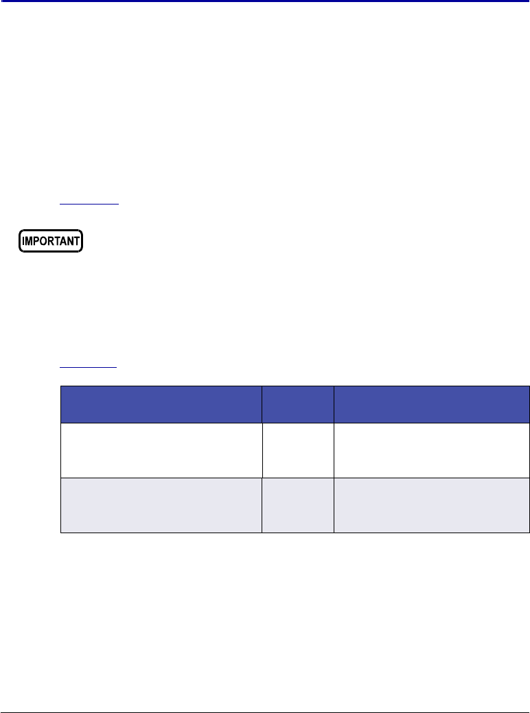
Doc. 065361-07 9/12 109
5•Service
This chapter describes Thermo Scientific Dionex AS-AP Autosampler service
and repair procedures that users may perform. Procedures not included here,
including electronics-related repair procedures, must be performed by
Thermo Fisher Scientific personnel. For assistance, contact Technical Support
for Dionex products. In the U.S. and Canada, call 1-800-346-6390. Outside
the U.S. and Canada, call the nearest Thermo Fisher Scientific office.
Before replacing any part, refer to the troubleshooting information in
Chapter 4 to correctly identify the cause of the problem.
5.1 Tubing and Fittings
Table 5-1 lists tubing and fittings used to plumb a Dionex AS-AP.
Substitution of non-Dionex/Thermo Fisher Scientific parts may impair
system performance, thereby voiding the product warranty. Refer to
the warranty statement in the Dionex Terms and Conditions for more
information.
Tubing/Fitting Type Part
Number Used to connect…
1.55 mm (0.062 in) ID
Perfluoroalkoxy (PFA) tubing,
colorless
052112
(2.54 cm)
(1 in)
Wash reservoir to syringe
valve: 75 mm (30 in)
1/8 in flangeless fitting bolt
(short), tan
1/8 in flangeless ferrule, yellow
057934
048949
Wash reservoir line to syringe
valve
Table 5-1. Tubing and Fittings for the Dionex AS-AP

Dionex AS-AP Operator’s Manual
110 Doc. 065361-07 9/12
0.75 mm (0.030 in) ID PEEK
tubing, green
044777
(2.54 cm)
(1 in)
•Syringe valve to waste port:
75 mm (30 in)
•500 L buffer line: 109 cm
(43 in)
•1200 L buffer line: 264 cm
(104 in)
•Injection valve to waste port
(push modes): length
depends on system
1/16 in flangeless fitting bolt
(short), tan
Two-piece ferrule (clear cone
and tan flat)
071358
062511 •Waste line to syringe valve
•Buffer line to syringe valve
•Y-connector ports
1/16 in flangeless fitting bolt, tan
Two-piece ferrule (clear cone
and tan flat)
052230
062511 •Buffer line to needle (push
modes)
•Sample transfer line to
needle (pull modes)
500 L buffer line 074994 Syringe valve to needle
1200 L buffer line 074989 Syringe valve to needle
8500 L buffer line (must be
assembled at the factory)
075520 Syringe valve to needle
0.33 mm (0.013 in) ID PEEK
tubing, blue
049714
(2.54 cm)
(1 in)
•Sample transfer lines (length
varies depending on system)
•Fraction collection valve to
needle
•Bridge line (fraction
collection valve to injection
valve)
10-32 fitting bolt, black
Split cone ferrule, black
062980
062978
Sample transfer line to injection
port (push modes)
10-32 fitting bolt, short thumb
head, black
Split-cone ferrule, black
074322
062978
Needle to needle holder
10-32 fitting bolt, blue
10-32 ferrule, double-cone, blue
074449
074373
Injection valve or diverter valve
connections
Tubing/Fitting Type Part
Number Used to connect…
Table 5-1. Tubing and Fittings for the Dionex AS-AP (Continued)

5 • Service
Doc. 065361-07 9/12 111
Tightening Guidelines for Fittings
Use high-pressure (blue) 10-32 fitting bolts (P/N 074449) and high-pressure
(blue) double-cone ferrules (P/N 074373) for connections to the high-pressure
valves (injection, diverter, fraction collection, or auxiliary). Use these fittings
for both high-pressure and low-pressure connections to valves. To tighten the
fittings, follow these guidelines:
1. Use your fingers to tighten the fitting bolt as tight as you can.
2. After finger-tightening, use a wrench to tighten the fitting an additional
3/4 turn (270 degrees).
3. If leaks occur, replace the fitting bolt (P/N 074449), ferrule (P/N 074373),
and tubing.
Cutting Tubing
Use a tubing cutter to cut tubing to the required length. Make sure the cut is at
a right angle to the length of the tubing and there are no nicks or burrs on the
end.
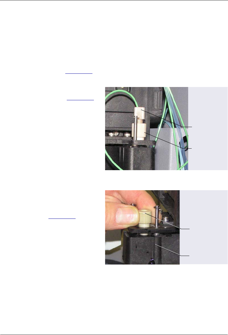
Dionex AS-AP Operator’s Manual
112 Doc. 065361-07 9/12
5.2 Replacing the Sampling Needle
1. Lift up the Dionex AS-AP front panel.
2. To position the needle in a convenient position for servicing, open the
Dionex AS-AP ePanel (in Chromeleon 7) or Control panel (in
Chromeleon 6.8) and click Alignment. The Sampler Alignment panel
opens (see Figure 5-6). Click Move to Wash Port. The needle moves to
above the wash port.
3. While holding the needle
holder (see Figure 5-1)
to prevent twisting of the
needle, disconnect the
liquid line from the
needle.
Figure 5-1. Liquid Line Connected to the Needle
4. Unscrew the needle
holder from the
horizontal needle arm
(see Figure 5-2).
5. Lift up the needle holder
and pull the needle up
and out of the needle
arm.
Figure 5-2. Removing the Needle
Disconnect
this fitting
Needle
Holder
Unscrew and
then lift up the
needle holder
Needle Arm
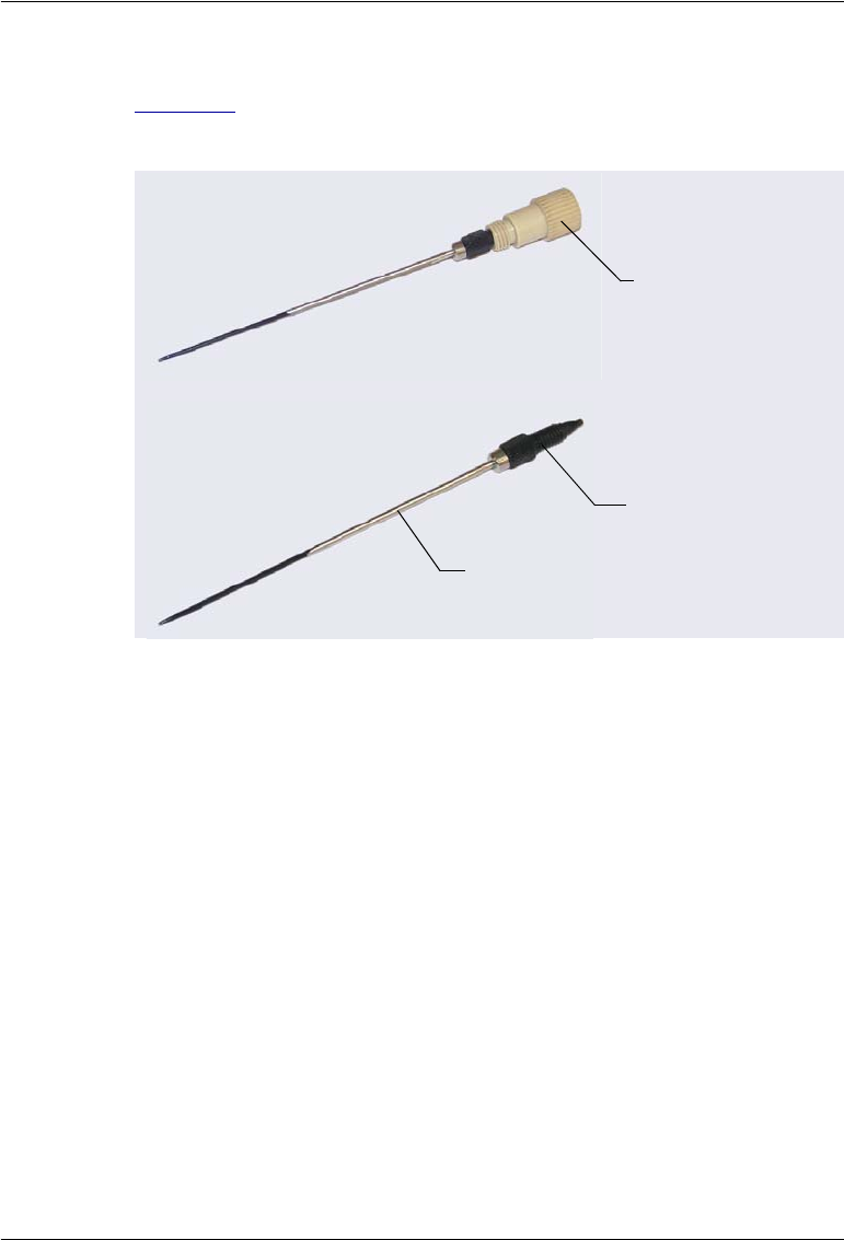
5 • Service
Doc. 065361-07 9/12 113
6. Unscrew the needle holder and remove it from the needle (see
Figure 5-3). Remove the fitting bolt and ferrule from the needle. Save the
fittings to use with the new needle.
7. Slide the fitting bolt (P/N 074322) and ferrule (P/N 062978) onto the new
needle (P/N 069914). Hold the needle firmly near the fitting bolt and
ferrule to maintain contact with the needle holder, and screw the needle
holder onto the needle. Tighten fingertight.
8. From the top, insert the new needle and the holder down into the needle
arm. Tighten the needle holder firmly.
Figure 5-3. Needle Removed from Autosampler
Unscrew the
needle holder
Pull off the fitting
bolt (P/N 074322) and
ferrule (P/N 062978)
Needle
(P/N 069914)
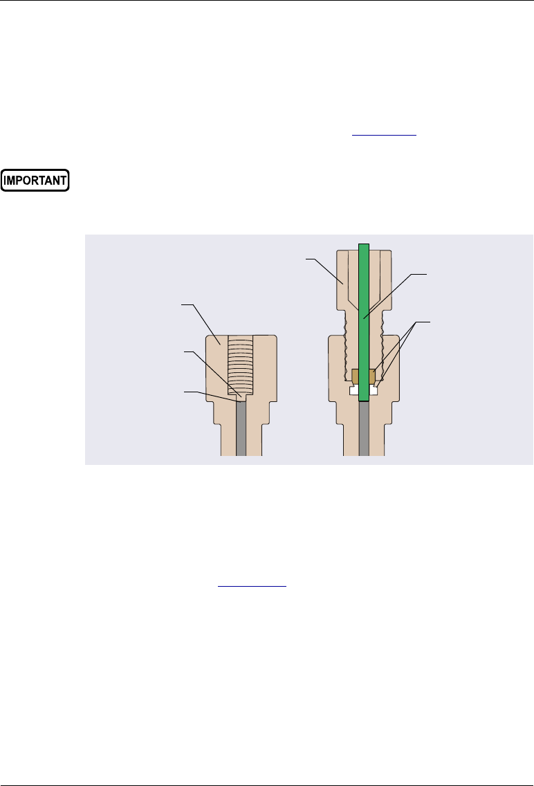
Dionex AS-AP Operator’s Manual
114 Doc. 065361-07 9/12
9. Follow the steps below to reconnect the liquid line to the top of the
needle:
a. Insert the tubing and fitting down into the center of the needle holder.
When you insert the tubing, you should feel the tubing drop into a
small indentation inside the holder (see Figure 5-4). If not, move the
tubing slightly until it does.
b. While holding the needle holder to prevent twisting of the needle,
tighten the liquid line fitting fingertight.
10. Align the needle (see Section 5.3).
When connecting the liquid line to the needle, make sure the tubing
slides into the indentation inside the needle holder before tightening
the fitting.
Figure 5-4. Cross-Section of Needle Holder and Liquid Line Fitting
(Buffer Line Shown)
Fit the tubing
into this
indentation
Needle
Holder
Top of the
needle
Liquid Line
(Buffer Line
Shown)
Two-Piece
Ferrule
(P/N 062511)
Flangeless
Fitting Bolt
(P/N 052230)

5 • Service
Doc. 065361-07 9/12 115
5.3 Aligning the Needle
The needle alignment procedure consists of the following main steps:
•Aligning the needle in the injection port
•Aligning the needle in the wash port
•Adjusting the needle height over the vial
•Aligning the needle in the tray
You will need the following items to complete the procedure:
•J-clip (P/N 074976), installed at the factory and removed after initial
needle alignment
•2.5 mm Allen wrench (P/N 052952), included in the Dionex AS-AP Ship
Kit (P/N 074929)
•10 mL or 1.5 mL vial with the septum removed from the cap
•Flashlight
•Magnifying glass (optional)
•Right-angle mirror (optional)
5.3.1 Aligning the Needle in the Injection Port
1. The needle alignment procedure requires the Dionex AS-AP to be
configured for push mode in the Chromeleon configuration.
If your autosampler is configured for pull mode, go to the Options page
in the Chromeleon configuration properties and select Push under
Injection Mode. For details, see Section B.11.3. You do not need to
change the autosampler’s plumbing.
2. If the Dionex AS-AP power is off and the J-clip is not already installed,
install the J-clip on the vial pusher before turning on the power. Installing
the J-clip prevents possible needle damage during the self-test run at
power up.
To install the J-clip:
a. Lift up the vial pusher and attach the J-clip to the front most metal rod
of the vial pusher (see Figure 5-5). During the alignment procedure,
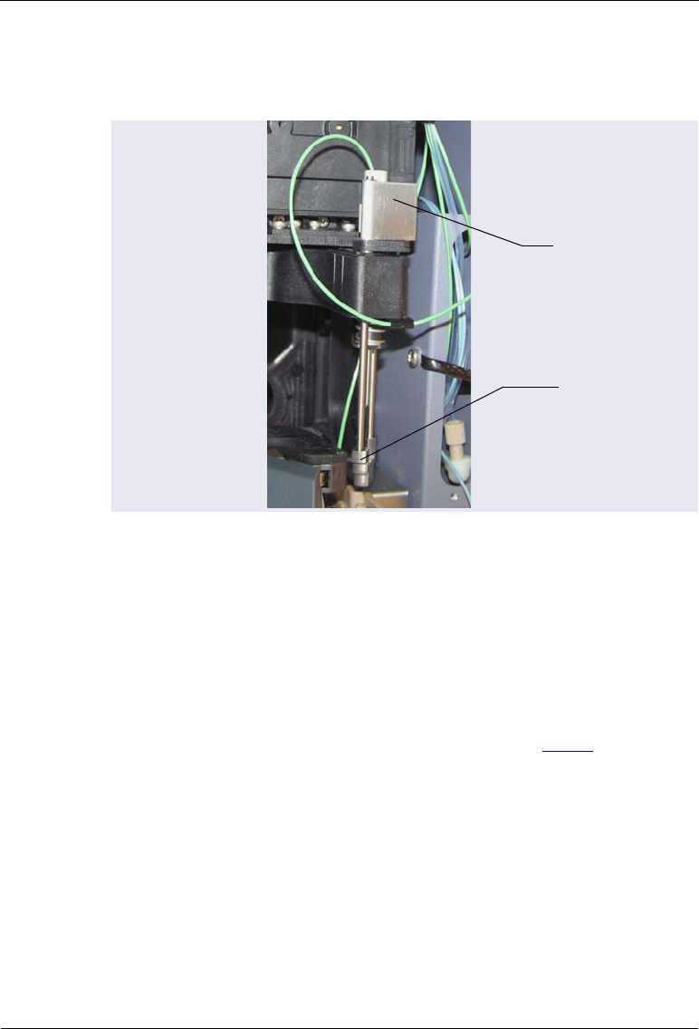
Dionex AS-AP Operator’s Manual
116 Doc. 065361-07 9/12
the J-clip prevents the vial pusher from dropping down over the
needle tip and allows a better view of the needle.
b. After installing the J-clip, turn on the Dionex AS-AP power and wait
while the autosampler performs the self-test. Because the J-clip
prevents the needle from descending into the injection port during the
self-test, the following error message appears in the Audit Trail:
Needle Drive: Pusher sensor malfunction. Turn the
autosampler off and on again or perform a self test.
c. You can ignore the error message and continue to Step 3. After you
complete the alignment procedure, a self-test will be required.
Figure 5-5. J-Clip Installed on Vial Pusher
J-Clip
Vial
Pusher
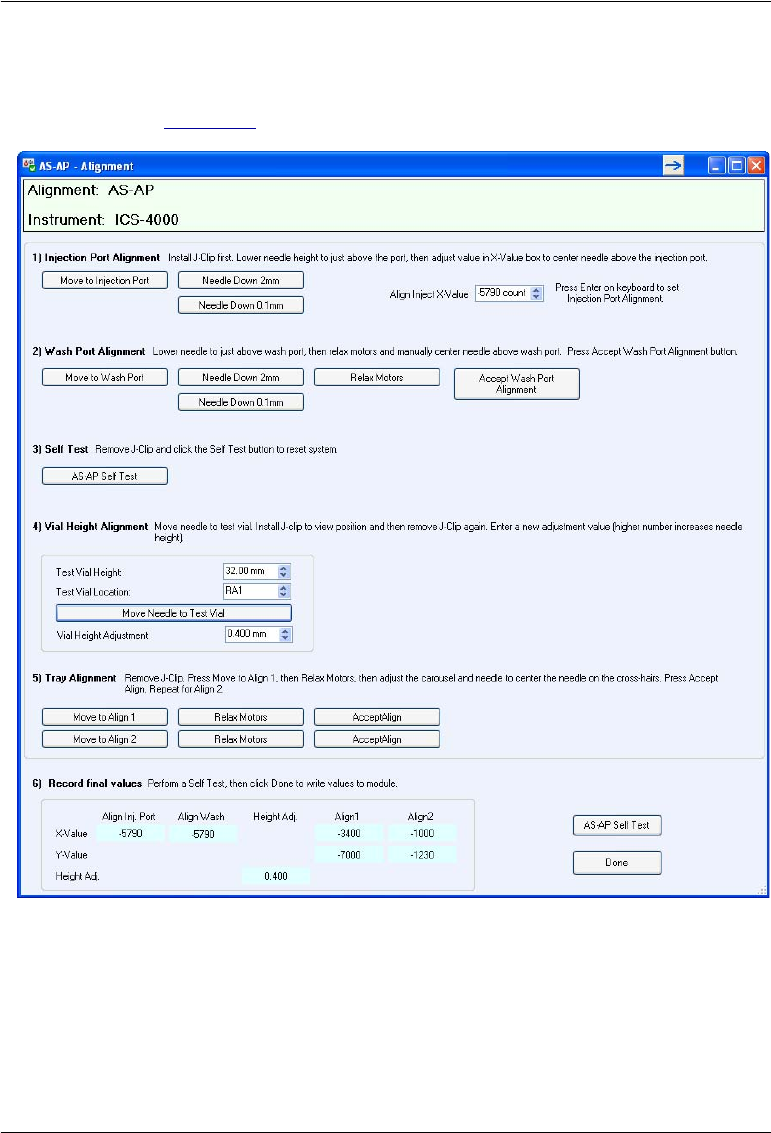
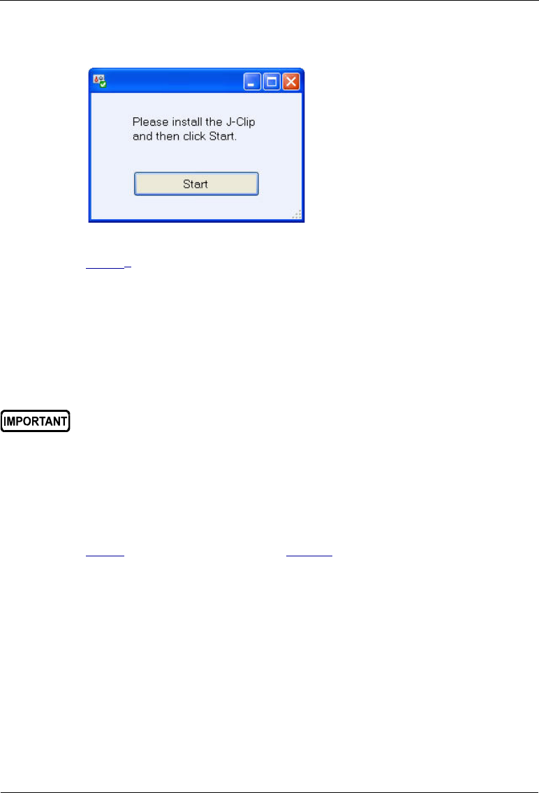
Dionex AS-AP Operator’s Manual
118 Doc. 065361-07 9/12
4. On the panel, click Move to Injection Port. A message appears.
5. If you have not already done so, install the J-clip on the vial pusher (see
Step 2a). Click Start. The needle moves to above the injection port.
6. On the panel, click Needle Down 2mm. The needle moves down 2 mm.
7. If the needle is still too far above the injection port to allow you to judge
whether it is centered, move the needle down further. If there is no
possibility of the needle hitting the surface of the injection port, click
Needle Down 2 mm. Otherwise, click Needle Down 0.1 mm repeatedly
until the needle is very close to the top of the port.
8. Using the flashlight and magnifying glass, check the position of the
needle from the side to verify that it is centered front to back (Y-position)
in the port. To do this, you can use a right-angle mirror to view the needle
directly from the side. If the needle is not centered front to back, go on to
Step 9. If it is centered, go on to Step 10.
Do not execute another Needle Down command if there is a chance the
needle will hit the surface of the injection port. Moving the needle down
too far will jam it onto the port surface and damage the needle tip.
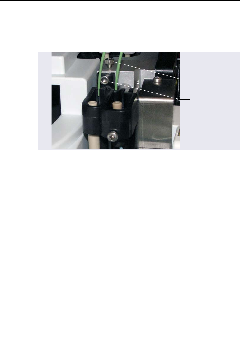
5 • Service
Doc. 065361-07 9/12 119
9. To center the needle front to back in the port:
a. Locate the two screws that attach the wash and injection ports to the
autosampler (see Figure 5-7).
b. Use the Allen wrench to loosen the back screw (turn the screw
counterclockwise). Then, use the Allen wrench to loosen or tighten
the front screw to adjust the position of the port. Loosening the screw
moves the port forward. Tightening it moves the port back.
c. When the port is centered front to back under the needle, retighten the
back screw.
Figure 5-7. Wash and Injection Port Attachment Screws
Front
Screw
Back
Screw
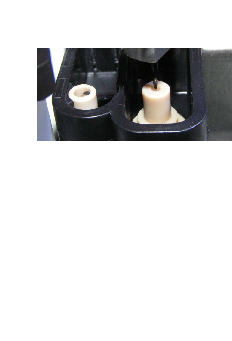
Dionex AS-AP Operator’s Manual
120 Doc. 065361-07 9/12
10. Using the flashlight and magnifying glass, check the position of the
needle to verify that it is centered left to right above the port. Figure 5-8
shows a needle that is correctly centered above the injection port.
NOTE When the needle is close to alignment and there is no
possibility of it hitting the injection port, you can
move the needle down into the port slightly to center it
more easily.
11. If it is not centered, adjust the needle position by changing the number in
the Align Inject box on the panel. To move the needle to the right, enter a
larger negative number. To move the needle to the left, enter a smaller
negative number. Changing the number by four counts moves the needle
about 0.1 mm. Press the Enter key after changing the number to execute
the change.
12. When you press Enter, the needle will be raised and moved to the new
position. You will need to then move the needle back down to check the
centering.
Figure 5-8. Needle Centered Above the Injection Port

5 • Service
Doc. 065361-07 9/12 121
5.3.2 Aligning the Needle in the Wash Port
1. Verify that the J-clip is installed on the vial pusher (see Figure 5-5).
2. On the panel, click Move to Wash Port. The needle moves to above the
wash port.
3. Click Needle Down 2mm.
4. If the needle is still too far above the port to allow you to judge whether it
is centered, move the needle down further. If there is no possibility of the
needle hitting the surface of the port, click Needle Down 2 mm.
Otherwise, click Needle Down 0.1 mm repeatedly until the needle is very
close to the top of the port. Use the flashlight and magnifying glass to
verify the position.
5. Click Relax Motors. This allows you to adjust the needle position to the
left or right.
6. To move the needle, tap lightly on the needle arm.
NOTE When the needle is close to alignment and there is no
possibility of it hitting the wash port, you can move
the needle down into the port to center it more easily.
7. When the needle is aligned left to right in the port, click Accept Wash
Port Alignment. This records a new alignment value for Align Wash on
the panel.
8. Check the alignment:
a. Click Move to Injection Port.
b. Wait until the needle is finished moving and then click Move to
Wash Port.
c. Move the needle down (see Step 3) and verify that the needle is
centered correctly.
d. If it is not centered, click Relax Motors and move the needle as
needed. Click Accept Wash Port Alignment. Repeat the alignment
check.
Do not execute another Needle Down command if there is a chance the
needle will hit the surface of the injection port. Moving the needle down
too far will jam it onto the port surface and damage the needle tip.

Dionex AS-AP Operator’s Manual
122 Doc. 065361-07 9/12
9. After verifying the alignment, click AS-AP Self Test. A message appears:
10. Remove the J-clip from the vial pusher and click Start.
5.3.3 Adjusting the Needle Height Over the Vial
1. Before beginning, make sure to:
•Align the needle in the inject port and wash port (see Section 5.3.1
and Section 5.3.2)
•Remove the J-clip from the vial pusher
2. Run a manual self-test (click AS-AP Self Test on the Alignment panel).
3. Install an empty vial tray in the red section of the carousel. You can use
either a 10 mL or 1.5 mL tray.
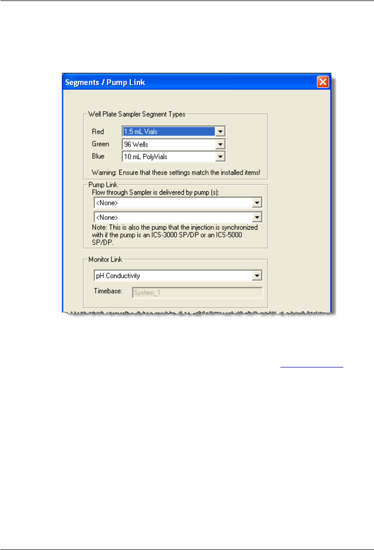
5 • Service
Doc. 065361-07 9/12 123
4. Verify that the setting on the Segments / Pump Link page of the
Chromeleon configuration matches the installed tray type (see the
following example).
5. If needed, select the correct tray type and click OK. Click Yes to confirm
sending the new configuration to the autosampler. For details about
configuring the Dionex AS-AP in Chromeleon, see Section B.11.3.
6. Verify that the septum is removed from the cap of a 10 mL or 1.5 mL vial
and the cap is tightened onto the vial. Use the size of vial that corresponds
to the installed tray size.
7. Measure the height of the vial, including the cap, to the nearest 0.1 mm.
8. Place the vial into any position in the tray (for example, position RB1).
9. Enter the measured vial height in the Test Vial Height box and press
Enter.
10. Enter the vial position in the Test Vial Location box and press Enter.
11. Click Move Needle to Test Vial.
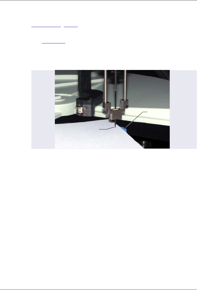
Dionex AS-AP Operator’s Manual
124 Doc. 065361-07 9/12
12. To view the needle height, install the J-clip on the vial pusher (see
Section 5.3.1, Step 5).
13. Slide a piece of paper between the top of the vial cap and the needle tip
(see Figure 5-9). If the needle is at the correct height, the paper should
slide in with slight resistance. If there is no resistance, the needle is too
high. If you cannot slide the paper under the needle or if the paper is
buckled slightly, the needle is too low.
14. If you need to adjust the position, remove the J-clip and enter a new value
in the Vial Height Adjustment box. To raise the needle, increase the
number. To lower the needle, decrease the number (a negative number can
be used). Press Enter after changing the number to execute the change.
To check the position, install the J-clip.
15. After the needle is positioned correctly over the vial, remove the J-clip.
NOTE Save the J-clip. It is required for aligning the needle in
the future and for other service procedures.
16. Click Move to Injection Port and then remove the test vial.
Figure 5-9. Checking the Vial Height Alignment
Vial Top
Paper
Needle Tip

5 • Service
Doc. 065361-07 9/12 125
5.3.4 Aligning the Needle in the Tray
1. Before beginning, make sure the J-clip is not installed on the vial pusher.
If the J-clip is installed, please remove it before proceeding.
2. Verify that the setting on the Segments / Pump Link page of the
Chromeleon configuration matches the installed tray type (10 mL or
1.5 mL). For details, see Step 4 on page 123.
3. Note the two alignment targets imprinted on the first and last rows of
the vial tray (see Figure 5-10).
4. On the panel, click Move to Align1. The needle moves to the target in the
last row and is positioned slightly above the tray.
5. Click Relax Motors. You can now adjust the position of the needle left to
right (X-position) and rotate the carousel front to back (Y-position) to
center the needle in the target.
6. If the needle is too far to the left or right of the target, move the needle
arm to correct the position. If the needle is too far to the front or back of
Figure 5-10. Alignment Targets on Empty 10 mL Tray Installed
in Red Section
Alignment Targets

Dionex AS-AP Operator’s Manual
126 Doc. 065361-07 9/12
the target, rotate the carousel to correct the position. Use the flashlight
and magnifying glass to verify the position.
NOTE When checking the alignment of the needle over the
target, be sure to check from two different angles that
are 90° apart.
7. After the needle is aligned correctly, click Accept Align. This records a
new X-Value and Y-Value for Align1 on the panel.
NOTE If the error message “Alignment positions not pre-
cise,” appears in the Audit Trail after you click Accept
Align, you can ignore the message and continue to the
next step of the procedure. This error occurs when
there is a large difference between the first alignment
position and the second alignment position.
8. Click Move to Align2. The needle moves to slightly above the target in
row A.
9. Repeat Step 6 for the new target. After the needle is aligned correctly,
click Accept Align to record an X-Value and Y-Value for Align2. If the
error message described above appears, repeat the alignment procedure.
10. When the needle alignment is complete, click AS-AP Self Test.
11. Click Done.

5 • Service
Doc. 065361-07 9/12 127
5.4 Replacing the Syringe
The following syringe volumes are available:
To complete this procedure you will need a size 8 open-end wrench. Use of a
mirror is helpful, but optional.
5.4.1 Removing the Existing Syringe
1. Lift up the Dionex AS-AP front panel.
2. On the Dionex AS-AP ePanel (in Chromeleon 7) or Control panel (in
Chromeleon 6.8), click Wellness. The Wellness panel opens (see
Figure 5-11).
Syringe Volume Part Number
100 µL 074305
250 µL 074306
1000 µL 074307
5000 µL 074308
Figure 5-11. Wellness Panel (Chromeleon 7 Version Shown)
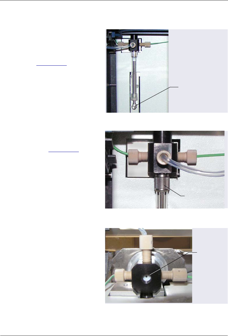
Dionex AS-AP Operator’s Manual
128 Doc. 065361-07 9/12
3. Under Syringe, click Start Change. The syringe moves down.
4. Use the open-end
wrench to loosen the
syringe plunger
mounting bolt (see
Figure 5-12) by turning
it counterclockwise, and
then use your fingers to
unscrew and remove the
bolt. Save the bolt.
Figure 5-12. Syringe Plunger Mounting Bolt
5. Unscrew the syringe
from the syringe valve
(see Figure 5-13) and
remove the syringe.
Figure 5-13. Removing the Syringe from the Syringe Valve
6. Verify that the gasket is
still in place in the
bottom bore of the
syringe valve. You can
use a mirror to view the
bottom of the valve. The
gasket is white. If the
inside of the valve is
black, a gasket is not
present.
Figure 5-14. Syringe Valve Gasket
(Bottom View of Syringe Valve)
Syringe Plunger
Mounting Bolt
Unscrew the
syringe from
the valve here
Syringe
Valve
Gasket
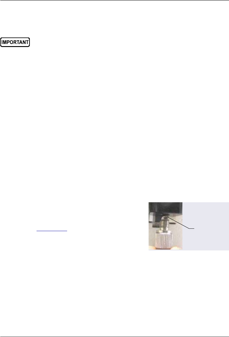
5 • Service
Doc. 065361-07 9/12 129
7. If a gasket is not present, install one. Gaskets are shipped with the
syringe.
5.4.2 Installing the New Syringe
1. Follow the steps below to remove air from the new syringe:
a. Fill a container with deionized water or a 50:50 mixture of deionized
water and methanol.
b. Place the threaded end of the syringe into the container.
c. Push the plunger completely into the syringe body and move the
syringe several times rapidly to dislodge any air bubbles that might
have gathered at the syringe inlet.
d. Fill the syringe and empty it completely several times. Push the
syringe plunger up and pull down rapidly with short movements to
dislodge the bubbles.
2. Fill the syringe completely.
3. Orient the syringe with the threaded end toward the top and position the
syringe under the valve.
4. While holding the syringe vertically,
push a small amount of liquid out the top
to make sure that no air is present (see
Figure 5-15).
Figure 5-15. Liquid Film Covering the Syringe Inlet
Make sure that you install only one gasket in the syringe valve. If you
install two or more gaskets, the valve and/or syringe will be damaged.
Liquid Film

Dionex AS-AP Operator’s Manual
130 Doc. 065361-07 9/12
5. Hold the bottom of the
syringe with one hand to
keep it vertical, then
place the other hand at
the top of the syringe
and screw the syringe
into the valve. Tighten
the syringe fingertight.
Do not overtighten.
Figure 5-16. Installing the Syringe in the Syringe Valve
6. Align the end of the syringe plunger with the mounting bolt opening,
insert the mounting bolt, and tighten the bolt fingertight. If needed, use
the open-end wrench to tighten the bolt slightly more (less than one-
quarter turn).
7. On the Wellness panel, under Syringe, click Finish Change. The syringe
moves up.
8. Click Log Syringe Change. This resets the syringe movement counter to
0.
9. If the new syringe is a different size than the previous syringe, select the
new size on the Options page in the Chromeleon configuration (see the
example in Figure 5-17). Click OK and then click Yes to confirm sending
Screw the
syringe into
the valve
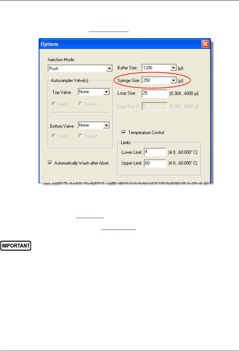
5 • Service
Doc. 065361-07 9/12 131
the new configuration to the autosampler. For details about Chromeleon
configuration, see Section B.11.3.
In addition, verify that the correct sample loop and buffer line are
installed (see Table 5-2).
10. Prime the syringe (see Section B.13).
Figure 5-17. Example Chromeleon Configuration Options Page
Air in the syringe has a strong effect on the measurement results.
Therefore, before you start your analysis, make sure there is no air in
the syringe.

Dionex AS-AP Operator’s Manual
132 Doc. 065361-07 9/12
5.5 Replacing the Buffer Line
The following buffer line sizes can be used in the Dionex AS-AP. The
appropriate size depends on the size of the syringe and sample loop (see
Table 5-2):
Notes
•A 250 L syringe and a 1200 L buffer line are standard.
•You can order a pre-cut 500 L buffer line (P/N 074994) or 1200 L
buffer line (P/N 074989). Pre-cut buffer lines are recommended because
they are precision cut at the factory and provide the best tubing
connections for improved precision. It is also possible to create a 500 L
or 1200 L line from tubing provided in the Dionex AS-AP Ship Kit
(P/N 074929). Instructions are provided in Section 5.5.2.
•The 8500 L buffer line must be assembled at the factory. If you need to
install this buffer line size, order P/N 075520.
Buffer Line Syringe Sample Loop
500 L100 L1–5L
1200 L250 L5–25 L
1200 L 1000 L5–100L
8500 L5000 L100–4000 L
also for concentrator columns
Table 5-2. Recommended Buffer Line, Syringe, and
Sample Loop Combinations
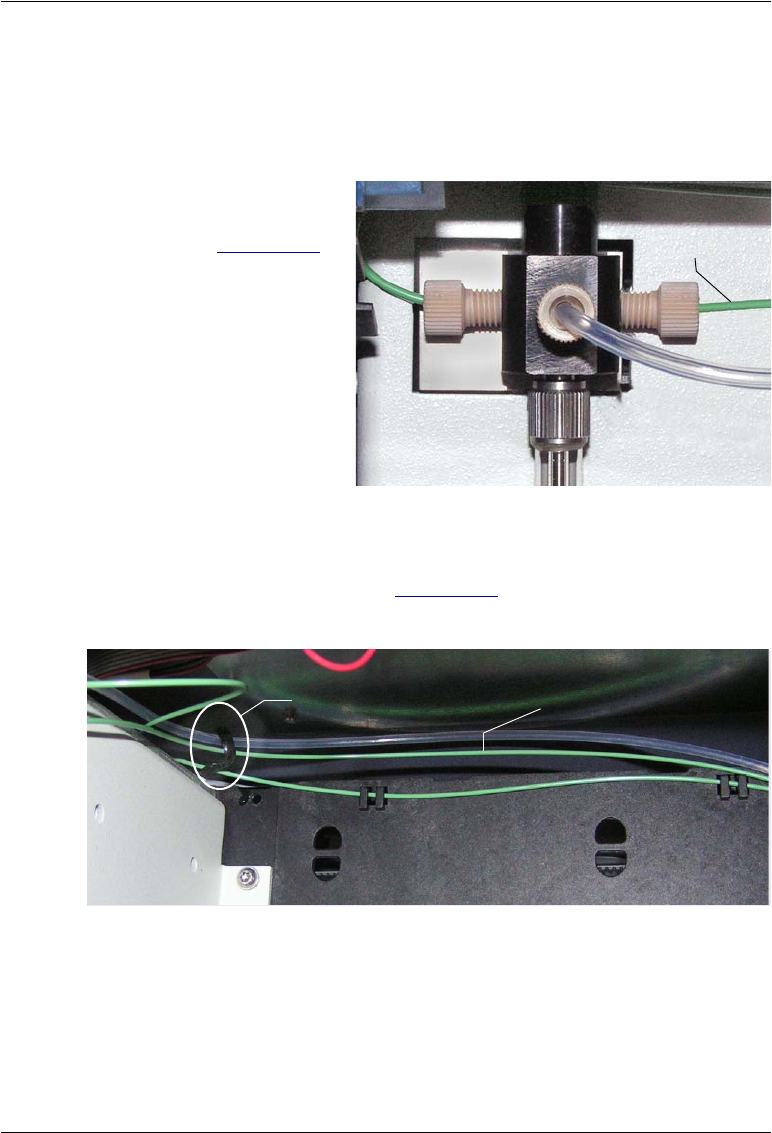
5 • Service
Doc. 065361-07 9/12 133
5.5.1 Removing the Old Buffer Line
1. Press the Standby button on the status bar.
2. Lift up the Dionex AS-AP front panel.
3. Disconnect the buffer
line from the syringe
valve (see Figure 5-18).
Remove the fitting bolt
and ferrule.
Figure 5-18. Buffer Line Connected to the Syringe Valve
4. Remove the buffer tubing from the flexible tubing tie in the upper-left
corner of the autosampler (see Figure 5-19). To open the tie, pull the end
of the tie down.
Figure 5-19. Tubing Tie in Upper-Left Corner Inside the Dionex AS-AP
Buffer Line
Flexible Tubing Tie Buffer LIne
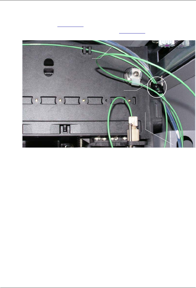
Dionex AS-AP Operator’s Manual
134 Doc. 065361-07 9/12
5. Remove the buffer tubing from the flexible tubing tie in the upper-right
corner (see Figure 5-20) and then remove the coiled tubing from the
slotted compartment below the tie (see Figure 5-20).
6. If the Dionex AS-AP is configured for pull mode, you can now remove
the buffer line from the autosampler. Then, disconnect the buffer line
from the injection valve.
Figure 5-20. Tubing Tie in Upper-Right Corner Inside the Dionex AS-AP
(Dionex AS-AP Configured for Push Mode Shown)
Flexible Tubing Tie
Buffer LIne
Slotted
Compartment
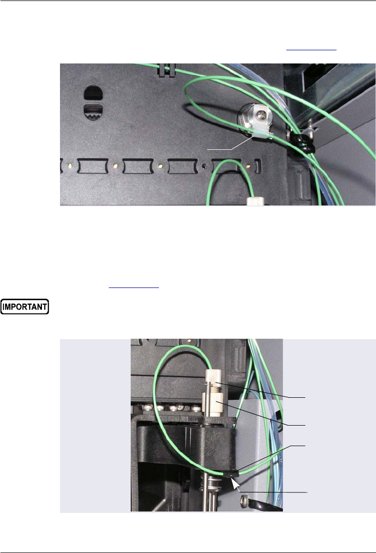
5 • Service
Doc. 065361-07 9/12 135
7. If the Dionex AS-AP is configured for push mode, lift up the tubing to
remove it from the tubing clip above the needle (see Figure 5-21).
8. To disconnect the line from the needle, hold the needle holder with one
hand to prevent twisting of the needle, and then disconnect the buffer line
fitting (see Figure 5-22). Remove the fitting bolt and ferrule.
Figure 5-21. Tubing Clip Above Needle Inside the Dionex AS-AP
(Dionex AS-AP Configured for Push Mode Shown)
Tubing Clip
Make sure the needle holder does not turn while disconnecting (or
reconnecting) the buffer line. If the needle holder turns, the needle may
need to be realigned.
Figure 5-22. Buffer Line Connected to the Needle (Push Mode)
Buffer Line
Fitting
Needle
Holder
Tubing Clip
Screw
(not visible in
the photo)

Dionex AS-AP Operator’s Manual
136 Doc. 065361-07 9/12
9. Use the 2.5 mm Allen wrench (P/N 052952) to loosen (but not remove)
the screw on the underside of the tubing clip on the front of the needle
arm (see Figure 5-22). Slide the tubing out of the clip and remove the
buffer line from the Dionex AS-AP.
10. Slide the short piece of clear tubing off of the line. Save this tubing piece
to use when installing the new line.
5.5.2 Connecting a 500 L or 1200 L Buffer Line
Creating a Buffer Line (Optional)
Pre-cut buffer lines are recommended, but you can create a buffer line if a pre-
cut line is not available.
1. Locate the 0.75 mm (0.030 in) ID green PEEK tubing (P/N 044777) in
the Dionex AS-AP Ship Kit (P/N 074929).
2. Cut the length of tubing required for your configuration:
•To create a 500 L buffer line, cut a 109 cm (43 in) length of tubing.
•To create a 1200 L buffer line, cut a 264 cm (104 in) length of
tubing.
Connecting the Buffer Line to the Syringe
1. Locate the following items in the Dionex AS-AP Ship Kit:
For push mode configurations:
•One tan 1/16 in short flangeless fitting bolt (P/N 071358)
•One tan 1/16 in flangeless fitting bolt (P/N 052230)
•Two two-piece ferrules (P/N 062511)
•Two small cable ties (P/N 013331)
For pull mode configurations:
•One tan 1/16 in short flangeless fitting bolt (P/N 071358)
•One two-piece ferrule (P/N 062511)
•One 10-32 fitting bolt (P/N 074449) and one double-cone ferrule
(P/N 074373)

5 • Service
Doc. 065361-07 9/12 137
•Two small cable ties (P/N 013331)
2. To connect the buffer line to the syringe, use the short 1/16 in tan fitting
bolt (P/N 071358) and a two-piece ferrule (P/N 062511).
a. Slide the fitting bolt onto the tubing as shown in Figure 5-24.
b. Observe that one side of the
small tan ferrule is beveled
and one side is flat (see
Figure 5-23). Hint: The flat
side appears shiny.
Figure 5-23. Small Tan Ferrule (Enlarged)
c. With the flat side of the small tan ferrule facing toward the fitting
bolt, slide the ferrule onto the tubing. Then, slide the clear cone
ferrule onto the tubing with the cone toward the flat ferrule and fitting
bolt (see Figure 5-24).
NOTE To make it easier to connect to the syringe port, you
can pre-make the fitting using a 1/4 x 28 union. Slide
the tubing with fitting into the union and tighten fin-
gertight. Then, remove the union. This secures the fer-
Figure 5-24. Fitting for Buffer Line
(Shorter Fitting Bolt Shown)
Beveled Side Flat Side
Fitting Bolt
(P/N 071358 Shown)
Flat Ferrule Cone Ferrule
Flat Side
(P/N 062511)

Dionex AS-AP Operator’s Manual
138 Doc. 065361-07 9/12
rules so they do not fall off the tubing during
installation in the syringe port.
3. Connect this fitting to the syringe port. Tighten fingertight.
4. Route the new buffer line toward the back of the autosampler and over to
the right side. Secure the line in the flexible tubing ties as described in the
instructions in Section 5.5.1 for removing the old buffer line.
5. If the autosampler is configured for push mode, continue to the following
section. If the autosampler is configured for pull mode, go on to
“Connecting the Buffer Line to the Injection Valve (Pull Modes)” on
page 141.
Connecting the Buffer Line to the Needle (Push Modes)
1. Slide the small piece of clear tubing onto the free end of the buffer line.
Position the clear tubing 46 cm (18 in) from the end of the buffer line.
2. Slide the free end of the tubing through the tubing clip on the front of the
needle arm (see Figure 5-22).
3. Install the longer 1/16 in tan flangeless fitting bolt (P/N 052230) and a
two-piece ferrule (P/N 062511) on the tubing as described in Step 2 on
page 137.
a. Position the bolt and ferrules away from the end of the tubing (so they
do not fall off when you insert the tubing into the needle holder).
b. Insert the tubing down into the center of the needle holder. When you
insert the tubing, you should feel the tubing drop into a small
indentation inside the holder (see Figure 5-25). If not, move the
tubing slightly until it does.
When connecting the buffer line to the needle, make sure the buffer line
slides into the indentation inside the needle holder before tightening
the fitting.
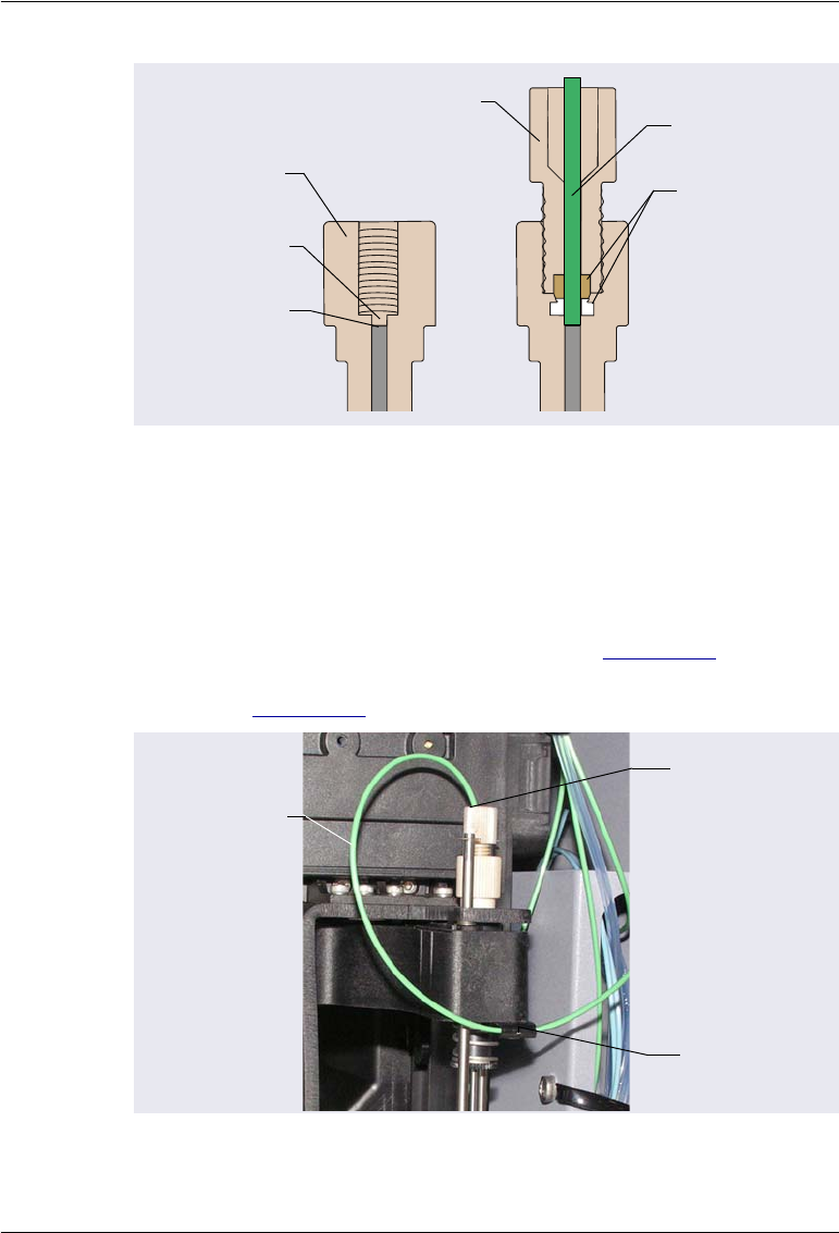
5 • Service
Doc. 065361-07 9/12 139
c. Slide the ferrules and fitting bolt down into the needle holder.
d. While holding the needle holder to prevent twisting of the needle,
tighten the fitting fingertight.
4. Position the tubing so there is 15 cm (6 in) from the buffer line fitting to
the tubing clip on the front of the needle arm (see Figure 5-26). Make sure
the tubing loops toward the front of the autosampler at about a 30° angle
as shown in Figure 5-26.
Figure 5-25. Cross-Section of Needle Holder and Buffer Line Fitting
Figure 5-26. Buffer Line Positioned in Tubing Clip on Needle Arm
(Push Mode)
Fit the tubing
into this
indentation
Needle
Holder
Top of the
needle
Buffer Line
Two-Piece
Ferrule
(P/N 062511)
Flangeless
Fitting Bolt
(P/N 052230)
Buffer Line
Fitting
Tubing Clip
15 cm (6 in)
between fitting
and clip

Dionex AS-AP Operator’s Manual
140 Doc. 065361-07 9/12
5. Tighten the screw on the tubing clip just enough to prevent the tubing
from sliding. Do not overtighten the screw.
6. Loop the buffer line up to the tubing clip on the back wall of the
autosampler. Verify that the short piece of clear tubing is positioned
30.5 cm (12 in) from the tubing clip on the front of the needle arm and
then push the tubing into the clip (see Figure 5-21).
7. Coil the excess tubing, secure the coil with the small cable ties, and place
the coil in the slotted compartment on the right side of the autosampler.
8. Check the left to right movement of the needle arm by sliding the arm
back and forth to make sure the buffer line moves freely and does not
catch on any part of the autosampler. Adjust the buffer line routing as
required (change the angle at which the line curves from the top of the
needle arm, change the curve from the needle arm to the back tubing clip,
verify the distances between the needle fitting and tubing clip and
between the two clips).
9. Press the Standby button on the status bar. The autosampler will perform a
self-test. Observe the needle arm movement to make sure the buffer line
moves freely.
10. When the self-test is complete, run a manual wash cycle (see
Section 3.3.4). Observe the needle arm movement when the needle
descends into the wash port and verify that the buffer line moves freely.
11. If the new buffer line is a different size than the previous buffer line, go
on to Section 5.5.4 to configure the line in Chromeleon.

5 • Service
Doc. 065361-07 9/12 141
Connecting the Buffer Line to the Injection Valve (Pull Modes)
1. Coil the excess tubing, leaving enough tubing extending from the coil to
connect to the injection valve.
2. Secure the coil with the small cable ties and place the coil in the slotted
compartment on the right side of the autosampler.
3. Install a 10-32 fitting bolt and double-cone ferrule on the tubing and
connect the line to the injection valve. For tightening requirements, refer
to the guidelines on page 111.
4. Press the Standby button on the status bar.
5. If the new buffer line is a different size than the previous buffer line, go
on to Section 5.5.4 to configure the line in Chromeleon.
5.5.3 Connecting an 8500 L Buffer Line
The 8500 L buffer line is pre-assembled at the factory (P/N 075520) and
includes the fittings required to connect the line to the syringe and needle.
1. Remove the acorn nut from the PFA tubing end of the buffer line.
2. Connect this end of the buffer line to the syringe valve. Tighten the fitting
fingertight.
3. Route the buffer line toward the back of the autosampler and over to the
right side. Secure the line in the flexible tubing ties as described in the
instructions in Section 5.5.1 for removing the old buffer line.
4. Place the coil of PFA tubing in the slotted compartment on the right side
of the autosampler.
5. If the autosampler is configured for push mode, remove the acorn nut
from the green PEEK tubing end of the buffer line. Slide the ferrule and
fitting bolt off of the end of the tubing. Then, follow the instructions in
“Connecting the Buffer Line to the Needle (Push Modes)” on page 138 to
complete the connections.
6. If the autosampler is configured for pull mode, follow the instructions in
“Connecting the Buffer Line to the Injection Valve (Pull Modes)” on
page 141 to complete the connections.
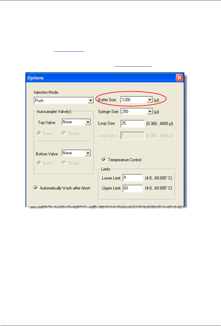
Dionex AS-AP Operator’s Manual
142 Doc. 065361-07 9/12
5.5.4 Configure the New Buffer Line in Chromeleon
If the new buffer line is a different size than the previous buffer line, select the
new size on the Options page in the Chromeleon configuration (see the
example in Figure 5-27). Click OK and then click Yes to confirm sending the
new configuration to the autosampler. For details about configuring the
Dionex AS-AP in Chromeleon, see Section B.11.3.
Figure 5-27. Example Chromeleon Configuration Options Page
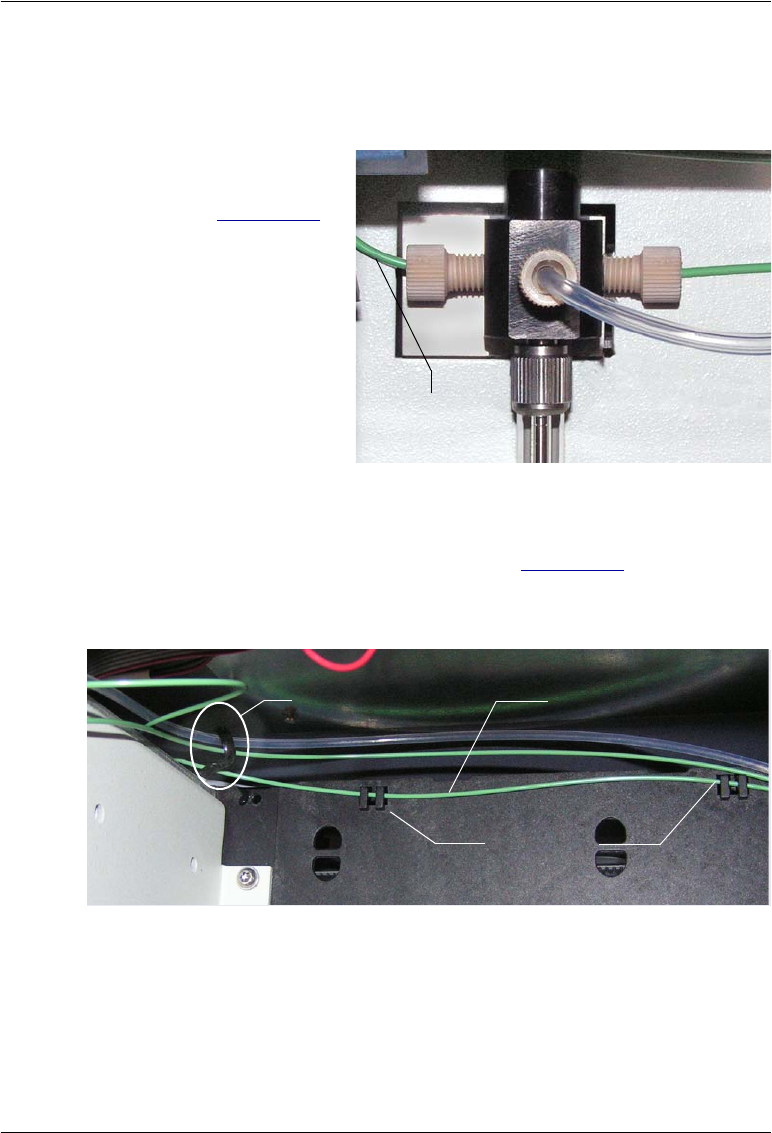
5 • Service
Doc. 065361-07 9/12 143
5.6 Replacing the Syringe Valve Waste Line
1. Lift up the Dionex AS-AP front panel.
2. Disconnect the waste
line from the syringe
valve (see Figure 5-28).
Figure 5-28. Waste Line Connected to the Syringe Valve
3. Remove the syringe valve waste line from the flexible tubing tie in the
upper-left corner inside the autosampler (see Figure 5-29). To open the
tie, pull down on the end of the tie. Lift the tubing out of the two clips on
the back wall of the autosampler
Figure 5-29. Flexible Tubing Tie and Tubing Clips in Upper-Left Corner
Inside the Dionex AS-AP
Waste Line
Flexible Tubing Tie
Tubing Clips
Syringe Waste Line
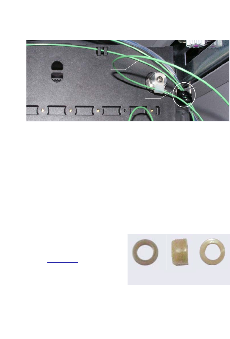
Dionex AS-AP Operator’s Manual
144 Doc. 065361-07 9/12
4. Remove the syringe valve waste line from the flexible tubing tie in the
upper-right corner inside the autosampler.
5. Remove the syringe valve waste line from the autosampler.
6. Locate the following items in the Dionex AS-AP Ship Kit (P/N 074929):
•0.75 mm (0.030 in) ID green PEEK tubing (P/N 044777)
•One 1/16 in tan short flangeless fitting bolt (P/N 071358)
•One two-piece ferrule (P/N 062511)
7. Cut a 76 cm (30 in) piece of tubing for the new waste line.
8. Follow the steps below to connect the waste line to the syringe:
a. Slide the fitting bolt onto the tubing as shown in Figure 5-32.
b. Observe that one side of the
small tan ferrule is beveled
and one side is flat (see
Figure 5-31). Hint: The flat
side appears shiny.
Figure 5-31. Small Tan Ferrule (Enlarged)
c. With the flat side of the small tan ferrule facing toward the fitting
bolt, slide the ferrule onto the tubing. Then, slide the clear cone
Figure 5-30. Tubing Tie in Upper-Right Corner Inside the Dionex AS-AP
Flexible Tubing Tie
Syringe Valve
Waste Line
Beveled Side Flat Side
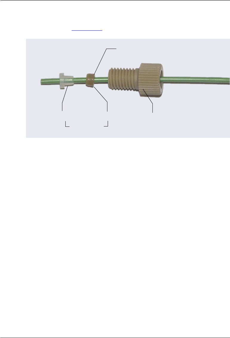
5 • Service
Doc. 065361-07 9/12 145
ferrule onto the tubing with the cone toward the flat ferrule and fitting
bolt (see Figure 5-32).
d. Connect this fitting to the syringe port. Tighten the fitting fingertight.
NOTE To make it easier to connect to the syringe port, you
can pre-make the fitting using a 1/4 x 28 union. Slide
the tubing with fitting into the union and tighten fin-
gertight. Then, remove the union. This secures the fer-
rules so they do not fall off the tubing during
installation in the syringe port.
9. Route the new waste line toward the back of the autosampler and then
down to the wash port. Use the flexible tubing ties and tubing clips to
secure the line.
Figure 5-32. Fitting for Waste Line
Fitting Bolt
(P/N 071358)
Flat Ferrule Cone Ferrule
Flat Side
(P/N 062511)

Dionex AS-AP Operator’s Manual
146 Doc. 065361-07 9/12
10. Insert the waste line into the right-most opening in the wash port (see
Figure 5-33) and then down into the drain opening in the waste tray (see
Figure 5-34).
Figure 5-33. Syringe Waste Line in Wash Port
Figure 5-34. Syringe Waste Line in Waste Tray
Syringe Waste Line
Syringe Waste Line
Drain
Opening
Waste Tray
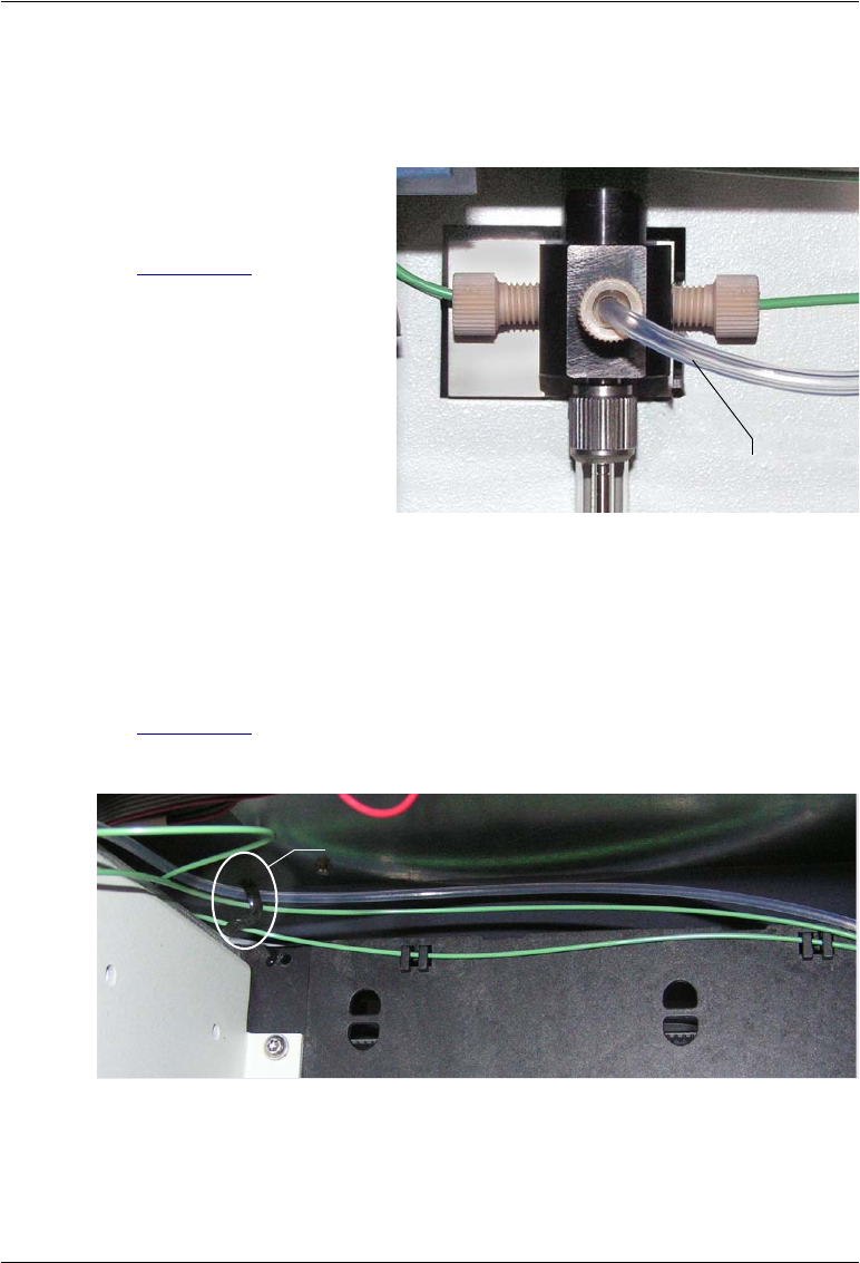
5 • Service
Doc. 065361-07 9/12 147
5.7 Replacing the Wash Reservoir Line
1. Lift up the Dionex AS-AP front panel.
2. Disconnect the wash
reservoir line from the
syringe valve (see
Figure 5-35).
Figure 5-35. Wash Reservoir Line Connected
to the Syringe Valve
3. Disconnect the other end of the line from the wash reservoir or degas
channel.
4. Remove the wash reservoir line from the flexible tubing ties (see
Figure 5-36), which hold the wash reservoir line and other tubing in place
in the autosampler. To open a tie, pull down on the end of the tie.
5. Remove the wash reservoir line from the autosampler.
Figure 5-36. Flexible Tubing Tie Inside the Dionex AS-AP
Wash Reservoir Line
Flexible Tubing Tie
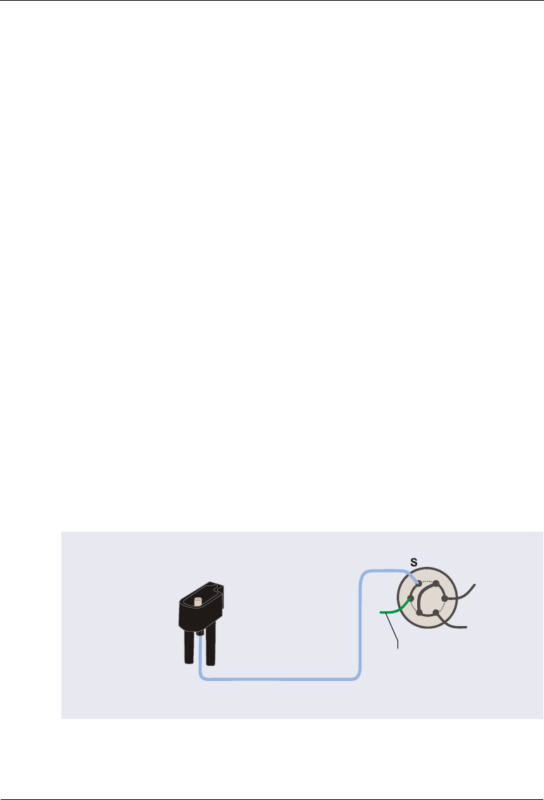
Dionex AS-AP Operator’s Manual
148 Doc. 065361-07 9/12
6. Locate the following items in the Dionex AS-AP Ship Kit (P/N 074929):
•1.55 mm (0.062 in) ID colorless PFA tubing (P/N 052112)
•1/8 in tan short flangeless fitting bolt (P/N 057934)
•1/8 in yellow flangeless ferrule (P/N 048949)
7. Cut a piece of tubing long enough to connect from the syringe to the
reservoir or degas channel. The standard length is 76 cm (30 in).
8. Install the fitting bolt and ferrule onto the tubing and connect the fitting to
the syringe valve. Tighten the fitting fingertight.
9. Route the new wash reservoir line to the back of the autosampler. Use the
flexible tubing ties to secure it, and then route the line to the wash
reservoir or degas channel.
10. Connect the new wash reservoir line to the wash reservoir or degas
channel.
5.8 Replacing the Sample Transfer Line (Push Modes)
In push mode configurations, the sample transfer line connects the injection
port to the injection valve. For a push sequential mode or push simultaneous
mode configuration, the sample transfer line includes the line from the
injection port to the diverter valve or Y-connector, and the line from the
diverter valve or Y-connector to the injection valve. Refer to the following
figures.
Figure 5-37. Sample Transfer Line Connections for Push Mode
Sample Transfer Line
AS-AP Injection Port
Injection Valve
W
L
P
C
1
2
3
4
5
6
L
To AS-AP
Waste Port
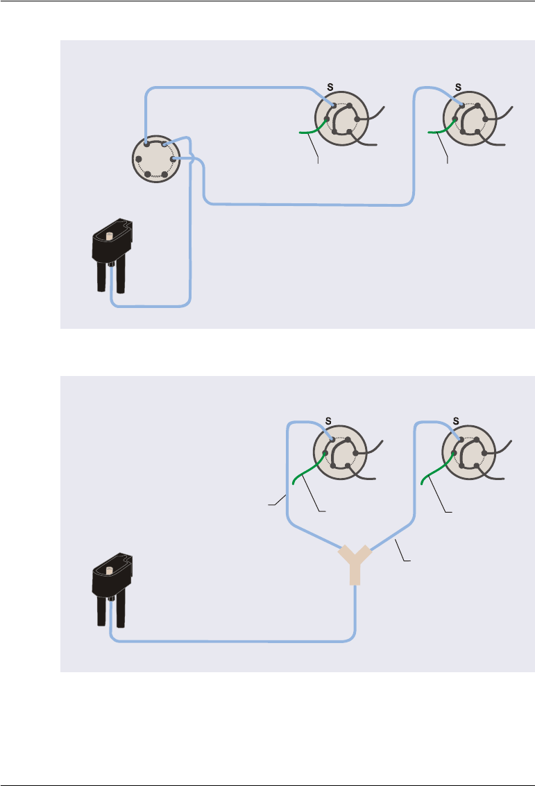
5 • Service
Doc. 065361-07 9/12 149
Figure 5-38. Sample Transfer Line Connections for Push Sequential Mode
Figure 5-39. Sample Transfer Line Connections for
Push Simultaneous Mode
Sample Transfer Line
1S
2
P
P
P
Diverter Valve
in AS-AP
Injection Valve in
IC System #1 Injection Valve in
IC System #2
Sample Transfer Line #1
Sample Transfer Line #2
W
L
P
C
1
2
3
4
5
6
L
W
L
P
C
12
3
4
5
6
L
To AS-AP
Waste Port
To AS-AP
Waste Port
AS-AP
Injection
Port
Sample Transfer Line
Injection Valve in
IC System #1
Injection Valve in
IC System #2
Sample Transfer
Line #1
Sample Transfer
Line #2
Y-Connector
W
L
P
C
12
3
4
5
6
L
W
L
P
C
1
2
3
4
5
6
L
To AS-AP
Waste Port To AS-AP
Waste Port
AS-AP Injection Port
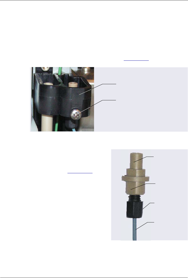
Dionex AS-AP Operator’s Manual
150 Doc. 065361-07 9/12
1. Disconnect the sample transfer line from the injection valve, diverter
valve (if the Dionex AS-AP is configured for sequential injections), or Y-
connecter (if the Dionex AS-AP is configured for simultaneous
injections). Use a 5/16 in wrench to loosen the fitting and then complete
the removal with your fingers. Save the fitting bolt and ferrule.
2. Using a small Phillips head screwdriver, loosen—but do not remove—the
screw on the front of the injection port (see Figure 5-40).
3. Push up the injection port from
below and pull the port and the
sample transfer line out of the
autosampler (see Figure 5-41).
4. Disconnect the sample transfer line
from the injection port. Use a 1/4 in
wrench to loosen the fitting and then
complete the removal with your
fingers. Save the fitting bolt.
Figure 5-41. Injection Port and Sample
Transfer Line (Removed)
Figure 5-40. Injection Port Screw
Injection Port Screw
Injection Port
Fitting Bolt
Injection Port
Flat Side
Sample
Transfer Line
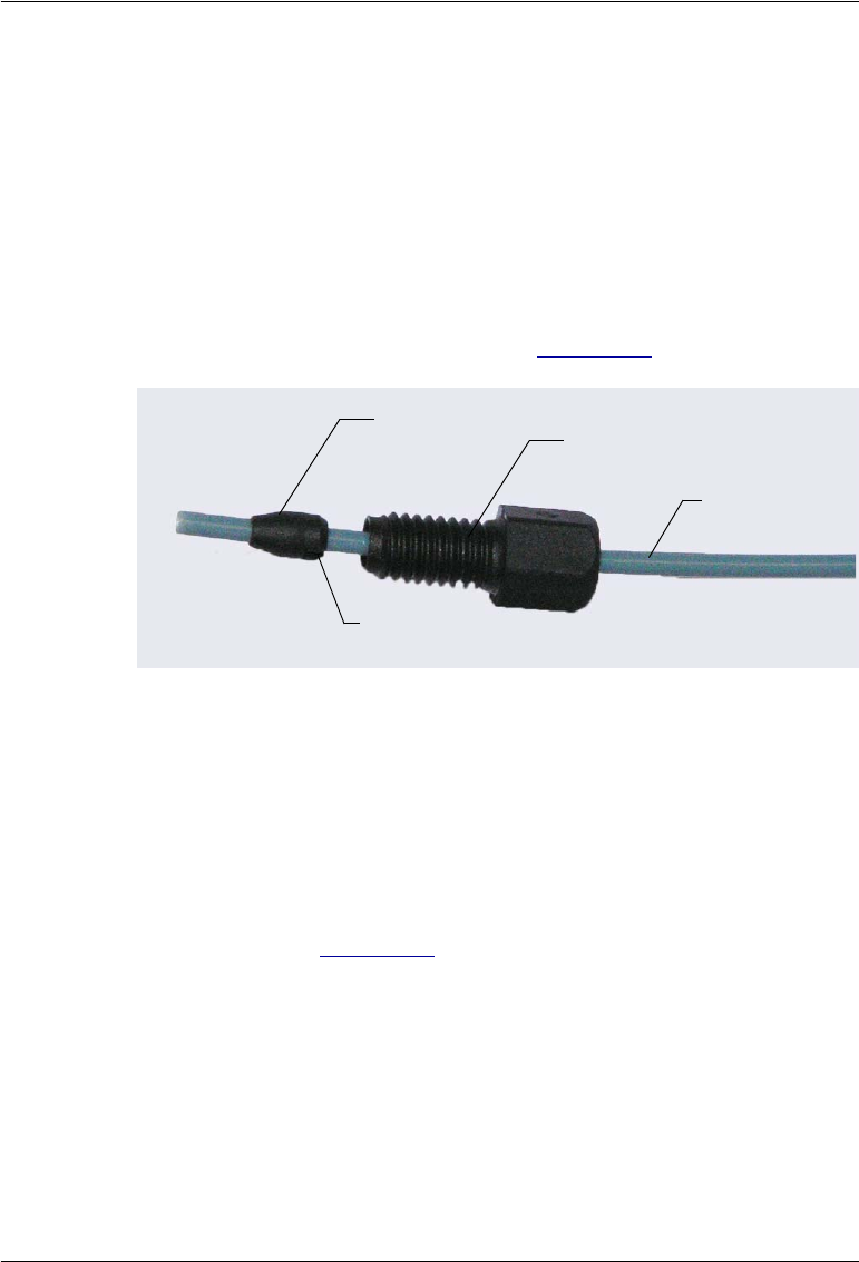
5 • Service
Doc. 065361-07 9/12 151
5. Follow the steps below to create a new sample transfer line:
a. Locate the 0.33 mm (0.013 in) ID blue PEEK tubing (P/N 049714) in
the Dionex AS-AP Ship Kit (P/N 074929) and a split-cone ferrule
(P/N 062978).
b. Cut a piece of tubing to the length required for your system
configuration.
c. Slide the fitting bolt onto one end of the tubing. Orient the new split-
cone ferrule with the split side facing toward the fitting bolt, and then
slide the ferrule onto the tubing (see Figure 5-42).
d. Connect this fitting to the injection port. Make sure the tubing
bottoms out in the injection port and there is no gap between the
tubing and the port. Tighten fingertight and then use a 1/4 in wrench
to tighten slightly more (one-quarter turn or less).
6. Thread the free end of the sample transfer line through the top opening
where you removed the injection port. Make sure the flat side of the
injection port (see Figure 5-41) is facing toward the front and then insert
the injection port into the opening until it stops.
Figure 5-42. Sample Transfer Line Fitting
Fitting Bolt
Split-cone Ferrule
Split side of
ferrule
Sample
Transfer Line
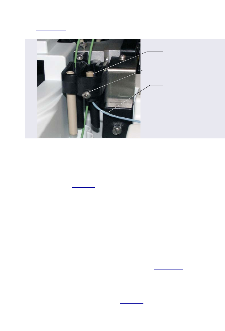
Dionex AS-AP Operator’s Manual
152 Doc. 065361-07 9/12
7. Gently tighten the screw on the front of the injection port (see
Figure 5-43). Do not overtighten the screw.
8. Use a 10-32 fitting bolt (P/N 074449) and double-cone ferrule
(P/N 074373) to connect the new sample transfer line to the injection
valve or diverter valve. For tightening requirements, refer to the
guidelines on page 111.
To connect to a Y-connector, you can reuse the fitting bolt and ferrule
provided with the Y-connector or use a 1/16 in flangeless fitting bolt
(short) (P/N 071358) and tan two-piece ferrule (P/N 062511).
9. For a sequential or simultaneous mode configuration, also replace the
sample transfer lines that connect from the diverter valve or Y-connector
to the injection valves, as required.
10. Perform a manual wash cycle (see Section 3.3.4).
11. If the autosampler is configured for push mode or push sequential mode,
calibrate the sample transfer line volume (see Section 5.9).
12. If the autosampler is configured for push simultaneous mode, calibration
of the sample transfer line is not required. However, the flow to each
valve must be balanced, so that equal flow moves through each valve. To
do this, follow the guidelines on page 191.
Figure 5-43. Sample Transfer Line Installed
Injection Port
Sample
Transfer LIne
Injection Port Screw
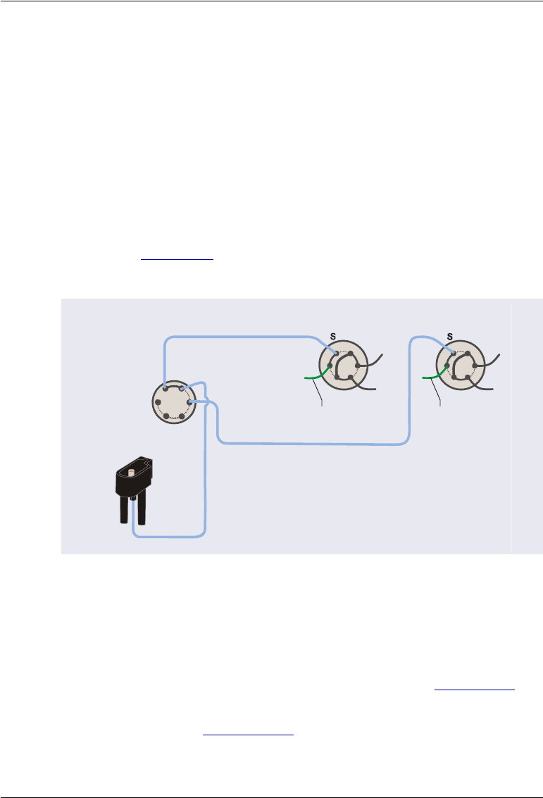
5 • Service
Doc. 065361-07 9/12 153
5.9 Calibrating the Sample Transfer Line Volume (Push
Modes)
Calibrate the sample transfer line volume if the Dionex AS-AP is configured
for push mode or push sequential mode. Sample transfer line calibration is not
required for other injection mode configurations.
NOTE For push sequential mode, the sample transfer line for each
system includes the tubing from the Dionex AS-AP injection
port to the diverter valve, the path through the diverter valve,
and the tubing from the diverter valve to the injection valve
(see Figure 5-44). The sample transfer line volume to each
injection valve must be calibrated separately.
Preparation
Before performing the calibration, complete the following:
•Prime the syringe to make sure it is free of bubbles (see Section B.13).
•Verify that the correct injection mode is selected in the Chromeleon
configuration (see Section B.11.3).
Figure 5-44. Sample Transfer Line Connections for
Sequential Injections to Two Injection Valves
Sample Transfer Line
1S
2
P
P
P
Diverter Valve
in AS-AP
Injection Valve in
IC System #1 Injection Valve in
IC System #2
Sample Transfer Line #1
Sample Transfer Line #2
W
L
P
C
1
2
3
4
5
6
L
W
LP
C
123
4
5
6
L
To AS-AP
Waste Port
To AS-AP
Waste Port
AS-AP
Injection
Port
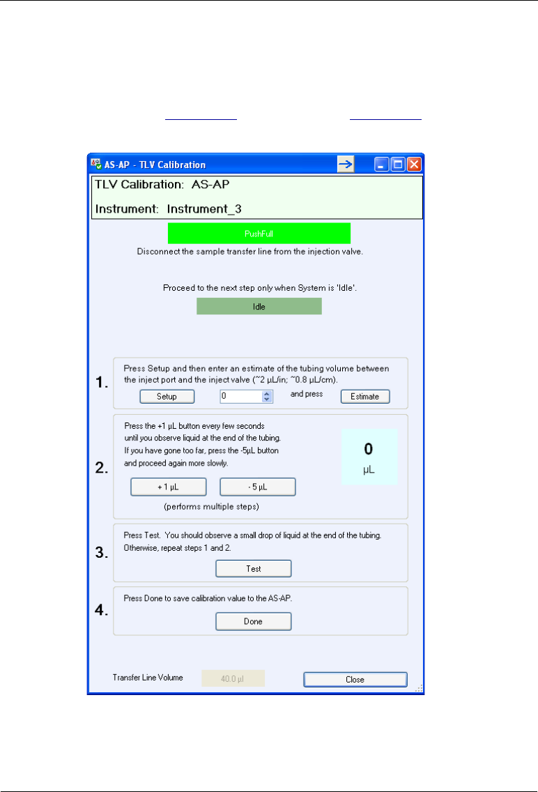
Dionex AS-AP Operator’s Manual
154 Doc. 065361-07 9/12
Calibration Procedure
1. On the Dionex AS-AP ePanel (in Chromeleon 7) or Control panel (in
Chromeleon 6.8), click TLV Calibration. The TLV Calibration panel
appears (see Figure 5-45 for push mode or Figure 5-46 for push
sequential mode).
Figure 5-45. TLV Calibration Panel (Push Injection Mode)
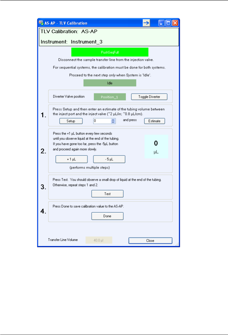
5 • Service
Doc. 065361-07 9/12 155
2. Disconnect the sample transfer line from the injection valve and route the
line outside the autosampler or chromatography compartment.
3. Follow the instructions on the panel to complete the calibration. Also
refer to the notes below.
Figure 5-46. TLV Calibration Panel
(Push Sequential Injection Mode)

Dionex AS-AP Operator’s Manual
156 Doc. 065361-07 9/12
Notes for sample transfer line volume calibration:
•In Step 1, after you click Setup, the Dionex AS-AP prepares for
calibration by flushing and then emptying the sample transfer line. When
you click Estimate, the Dionex AS-AP dispenses 10 L less than your
estimate into the injection port. This partially fills the sample transfer line.
•In Step 2, after you click +1 L, wait until the status is Idle before
clicking +1 L again.
Continue clicking +1 L until a tiny drop of liquid appears at the end of
the needle seal line.
If you click +1 L too rapidly and more than a single small drop of liquid
appears, click -5 L. The Dionex AS-AP will empty the line and then fill
the line with about 5 μL less than was cleared. You can then begin again
(repeat the steps 1 and 2 of the procedure on the TLV Calibration panel).
4. Reconnect the sample transfer line to the injection valve. For tightening
guidelines, see page 111.
5. For sequential mode only: After completing the procedure for system #1
and clicking Done, click Toggle Diverter and repeat the calibration
procedure for system #2.
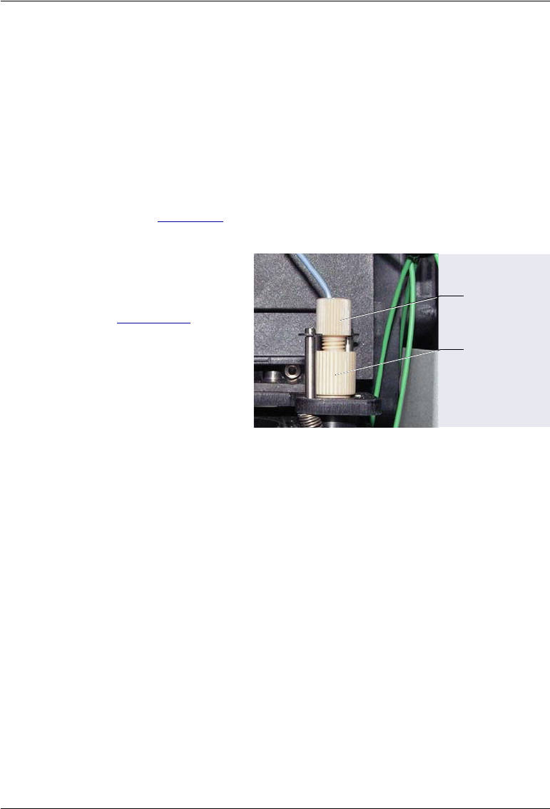
5 • Service
Doc. 065361-07 9/12 157
5.10 Replacing the Sample Transfer Line (Pull Mode)
In pull mode configurations, the sample transfer line connects the needle to
the injection valve.
1. Lift up the Dionex AS-AP front panel.
2. To position the needle in a convenient position for servicing, open the
Dionex AS-AP ePanel (in Chromeleon 7) or Control panel (in
Chromeleon 6.8) and click Alignment. The Sampler Alignment panel
opens (see Figure 5-6). Click Move to Wash Port. The needle moves to
above the wash port.
3. While holding the needle
holder to prevent
twisting of the needle
(see Figure 5-47),
disconnect the sample
transfer line from the
needle. Remove the
fitting from the line
(save the fitting bolt).
Figure 5-47. Sample Transfer Line Connected to the Needle
4. Disconnect the other end of the sample transfer line from port S (5) on the
injection valve and remove the line from the autosampler. Remove the
fitting from the line (save the fitting bolt).
5. Locate the following items in the Dionex AS-AP Ship Kit (P/N 074929):
•0.33 mm (0.013 in) ID blue PEEK tubing (P/N 049714)
•One two-piece ferrule (clear cone and tan flat) (P/N 062511)
•One double-cone ferrule (P/N 074373)
6. Cut a piece of tubing to the length required for your configuration.
Sample
Transfer Line
and Fitting
Needle
Holder
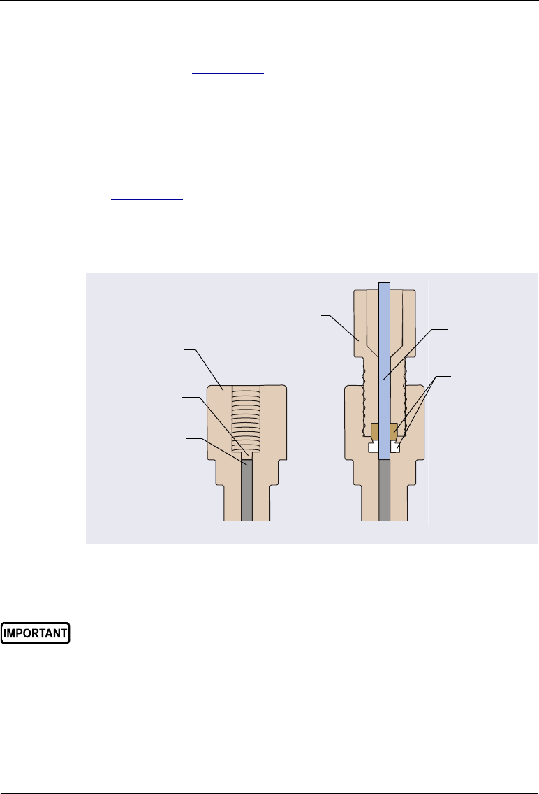
Dionex AS-AP Operator’s Manual
158 Doc. 065361-07 9/12
7. Slide the fitting bolt and two-piece ferrule onto one end of the sample
transfer line (see Figure 5-32). Follow the steps below to connect the line
to the needle:
a. Position the fitting bolt and ferrules away from the end of the tubing
(so they do not slide off when you insert the tubing into the needle
holder).
b. There is a small indentation in the center of the needle holder (see
Figure 5-48). The sample transfer line must be placed in the
indentation before you tighten the fitting. When you slide the tubing
into the needle holder, you should feel the tubing drop into the
indentation. If not, move the tubing until it drops into the indentation.
c. Slide the ferrules and fitting bolt down into the needle holder.
d. While holding the needle holder to prevent twisting the needle,
connect the sample transfer line. Tighten the fitting fingertight.
Figure 5-48. Cross-Section of Needle Holder and Sample
Transfer Line Fitting
Fit the tubing
into this
indentation
Needle
Holder
Top of the
needle
Sample
Transfer
Line
Two-Piece
Ferrule
Flangeless
Fitting Bolt
When connecting the sample transfer line to the needle, make sure you
fit the tubing into the indentation inside the needle holder before
tightening the fitting.

5 • Service
Doc. 065361-07 9/12 159
8. Route the other end of the sample transfer line to the injection valve
9. Use the 10-32 fitting bolt and double-cone ferrule to connect the line to
port S (5). For tightening guidelines, see page 111.
5.11 Rebuilding a High-Pressure Valve
Thermo Fisher Scientific recommends rebuilding a high-pressure valve
annually. High-pressure valves are the optional valves (injection, diverter,
fraction collection, or auxiliary) installed in the Dionex AS-AP. The Valve
Rebuild Kit (P/N 075973, 6-port valve; P/N 079054, 10-port valve) contains
all required replacement parts.
NOTE Substitution of non-Dionex/Thermo Fisher Scientific parts
may impair valve performance and void the product war-
ranty.
1. Turn off the pump flow.
2. Press the main power switch on the rear panel of the Dionex AS-AP to
turn off the Dionex AS-AP power.
3. Disconnect each liquid line connected to the valve.
4. Follow the instructions provided in the Rebuild Kit to replace the rotor
seal, isolation seal, and stator face.
5. Reconnect all liquid lines to the valve.
6. Turn on the power to the Dionex AS-AP.
7. Turn on the pump flow.
8. Check for leaks from the valve. Tighten fittings as required. For
tightening guidelines, see page 111.
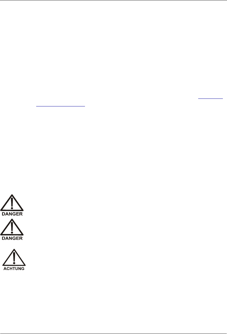
Dionex AS-AP Operator’s Manual
160 Doc. 065361-07 9/12
5.12 Updating the Autosampler Firmware
The autosampler is shipped with the most recent firmware version. The
firmware is also included with Chromeleon. Whenever a new firmware
version is released for the autosampler, the new version will be provided with
the next Chromeleon update and described in the related release notes.
The new firmware will not be downloaded automatically to the autosampler
when you install a Chromeleon update. To update the firmware in the Dionex
AS-AP:
1. Go to the General page of the Chromeleon configuration (see “General
Page” on page 205).
2. Before starting the download, click the Help button on the General page
for detailed instructions.
5.13 Changing the Main Power Fuses
1. Press the main power switch on the rear panel of the Dionex AS-AP to
turn off the power.
2. Disconnect the main power cord from both its source and from the
Dionex AS-AP rear panel.
HIGH VOLTAGE—Disconnect the main power cord from its source and
also from the rear panel of the Dionex AS-AP.
HAUTE TENSION—Débranchez le cordon d'alimentation principal de sa
source et du panneau arrière du Dionex AS-AP.
HOCHSPANNUNG—Ziehen Sie das Netzkabel aus der Steckdose und
der Netzbuchse auf der Rückseite des Dionex AS-AP.
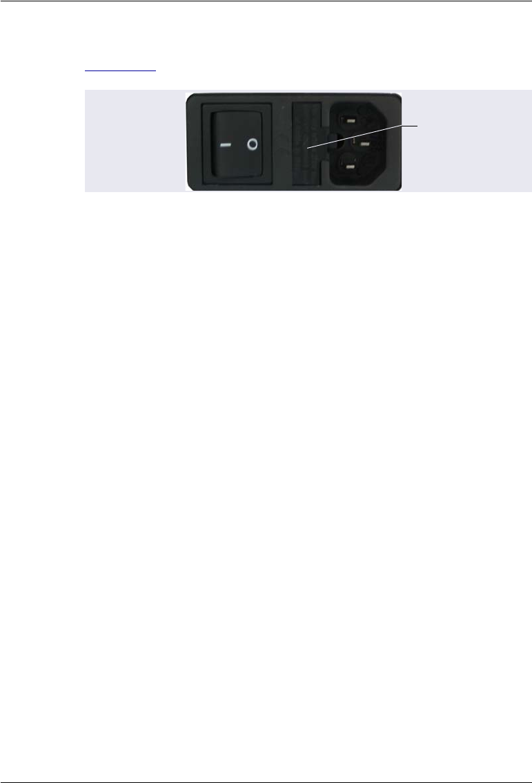
5 • Service
Doc. 065361-07 9/12 161
3. The fuse cartridge is located next to the main power switch (see
Figure 5-49). Use a small screwdriver to remove the fuse cartridge.
4. Replace the two fuses with new 4 A IEC 60127-2 fast-blow fuses
(P/N 954763). Thermo Fisher Scientific recommends always replacing
both fuses.
5. Reinstall the fuse cartridge.
6. Reconnect the main power cord and turn on the power.
Figure 5-49. Dionex AS-AP Fuse Cartridge
Fuse Cartridge

Dionex AS-AP Operator’s Manual
162 Doc. 065361-07 9/12

Doc. 065361-07 9/12 163
A • Specifications
Thermo Scientific Dionex AS-AP Autosampler Specifications
Injection
Sample Capacity 10 mL vials: 81
1.5 mL vials: 120
0.3 mL vials: 120
Well Plates: 288 - 3 x 96 standard or deep well
Well Plates: 1152 - 3 x 384 standard well
Minimum Sample
Volume
10 µL can be sampled from a 300 µL micro vial
20 µL can be sampled from a 500 µL micro vial
Maximum Injection
Volume
7500 µL
Variable Volume Range 1-100 µL in 0.1 µL increments
100-7500 µL in 1 µL increments
Injection Cycle Time
(including sample
preparation such as
dilution)
15 s, with sample overlap function
60 s for a 5 µL full loop without sample overlap
Injection modes Full Loop
Partial Loop
Limited Sample
Capillary
Sampling Technique Pull Mode
Push Mode
Injection Precision Fixed Loop: <0.3%
RSD at 20 µL
Partial Loop: <0.5%
RSD at 20 µL
Capillary Mode: <0.5%
RSD at 0.4 µL
Dilution 1:1 to 1:1000

Dionex AS-AP Operator’s Manual
164 Doc. 065361-07 9/12
AutoDilution With post-run functionality and Chromeleon
AutoDilution License
Dilution Precision <1.0% RSD for a 1:10 dilution
Carryover <0.01% with 500 µL flush volume
Valves (Optional)
Injection Valves One or two two-position six-port or ten-port
Diverter Valve One two-position six-port or ten-port
Fraction Collection Valve One two-position six-port or ten-port
Auxiliary Valve One or two two-position six-port or ten-port
Sampling Features
Sample Preparation Dilution, addition of internal standards,
concentration/matrix elimination, derivatization,
etc.
Inline Sample Filtration Dual filter, back flush
Sample Degassing CRD 200/300, upgradeable, user installable
Dual Instrument Support Sequential (asynchronous) and Simultaneous
modes, field upgradeable
Fraction Collection With reinjection and Chromeleon Fraction
Collection License
Sample Tray
Thermostatting
(Optional)
4 °C to 60 °C
Sample Conductivity and
pH (Optional)
Inline measurement of sample conductivity and pH
with post-run functionality
System Software
Software Chromeleon Chromatography Data System
software, supports Microsoft Windows WP or Vista
Automated Procedure
Wizards
Yes, standard features
System Smart Startup
and Smart Shutdown
Yes, standard feature
System Wellness and
Predictive Performance
Yes, standard feature
Thermo Scientific Dionex AS-AP Autosampler Specifications

A • Specifications
Doc. 065361-07 9/12 165
Application Templates Yes, standard feature
Automation Support of
Third-Party Instruments
Yes, fully controls >300 different instruments from
more that >30 manufactures, including GC, HPLC
and MS.
Customizable System
Control Panels
Yes, standard feature
Data Trending Plots Yes, all device numerical parameters
Power Failure Protection Yes, standard feature
System Trigger
Commands and
Conditional
Yes, standard feature (Chromeleon 6.8 only)
Daily Audit Trail Yes, standard feature
Sample Audit Trail Yes, standard feature
System Calibration
Storage
Yes, factory, current and previous. Completely user
selectable.
Customized Reporting Yes, standard feature with unlimited report
workbooks
GLP Compliance Yes, optional
Electrical
Main Power
Requirements
90–265 VAC, 47–63 Hz (Auto-sensing power
supply; no manual voltage or frequency adjustment
required)
Typical input power: 160 W
Maximum line draw: 2 A at 110 VAC
Fuse Requirements Two IEC 60127-2 fast-blow fuses (P/N 954763)
rated at 4 A, 250 V
Physical Specifications
Dimensions
(h × w × d):
44.5 × 35.9 × 51.6 cm (17.5 × 14.1 × 20.3 in)
Weight 25.2 kg (55.5 lb) without sample temperature
control
26.8 kg (59.0 lb) with sample temperature control
Flow Path All polymeric (PEEK), anion
or cation configurations
Thermo Scientific Dionex AS-AP Autosampler Specifications

Dionex AS-AP Operator’s Manual
166 Doc. 065361-07 9/12
Environmental
Operating Temperature 4–40 °C (40–104 °F)
Operating Humidity 5–95% relative humidity (noncondensing)
Thermo Scientific Dionex AS-AP Autosampler Specifications

Doc. 065361-07 9/12 167
B • Installation
This chapter provides installation instructions for the Thermo Scientific
Dionex AS-AP Autosampler.
NOTE The order of the steps is important. It is especially important
to install the Chromeleon Chromatography Data System
before connecting the USB cable and turning on the system
power.
B.1 Facility Requirements
•Make sure the Dionex AS-AP installation site meets the electrical and
environmental specifications listed in Appendix A.
•Install the Dionex AS-AP on a sturdy workbench at a height that ensures
convenient access to the interior.
•For optimum operation, place the Dionex AS-AP as close as possible to
the left side of the IC system. The Dionex AS-AP can also be placed on
top of or underneath the Thermo Scientific Dionex ICS-5000
Detector/Chromatography Module (DC).
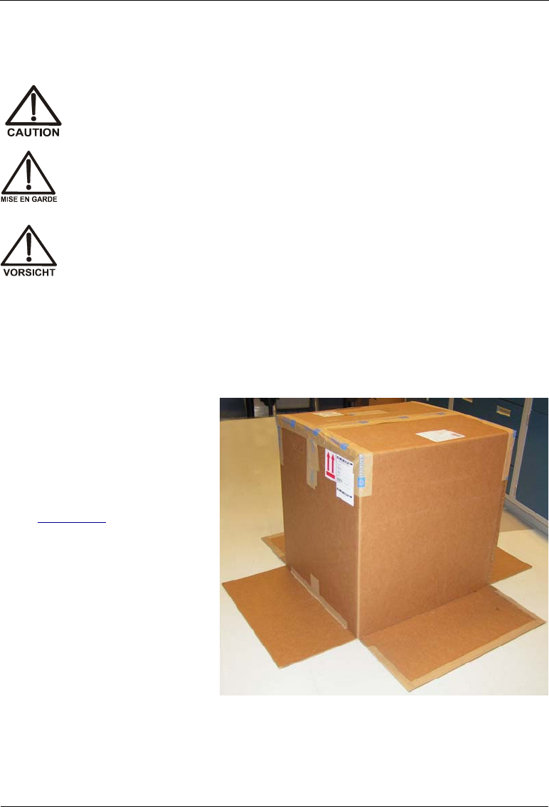
Dionex AS-AP Operator’s Manual
168 Doc. 065361-07 9/12
B.2 Unpacking the Dionex AS-AP
NOTE Check the shipping container for any external signs of dam-
age. If the container shows signs of damage, contact Dionex
immediately.
Two or more persons must lift the Dionex AS-AP, which weighs more
than 23 kg (50 lb). Lift the AS-AP only from each side of the cabinet
bottom. Lifting from the front door will damage the door hinges.
Au moins deux personnes peuvent soulever l'Dionex AS-AP, qui pèse
plus de 32 kg (50 lb). Ne soulevez l'AS-AP que par chaque côté du fond
de l'armoire. Son soulèvement par la porte du panneau avant
endommagera les charnières de la porte.
Der Dionex AS-AP wiegt über 23 kg. Daher sollte das Gerät nur von
zwei oder mehr Personen angehoben werden. Greifen Sie dazu an
beiden Seiten unter das Gerät. Heben Sie den Autosampler nicht an der
Vordertür an, da dadurch die Türangeln beschädigt werden könnten.
1. Follow the instructions
printed on the shipping
container to turn the
container on its side, open
the bottom flaps, and turn it
right side up again (see
Figure B-1).
Figure B-1. Shipping Container with Bottom
Flaps Opened

B • Installation
Doc. 065361-07 9/12 169
2. Lift up the shipping
container to remove it (see
Figure B-2) and set the
container aside. Remove
the top foam packing insert.
Figure B-2. Lift Up the Shipping Container
3. Remove the ship kit box
from the top of the module
(see Figure B-3).
Figure B-3. Ship Kit on Top of the Module
Ship Kit
Foam Packing Cage
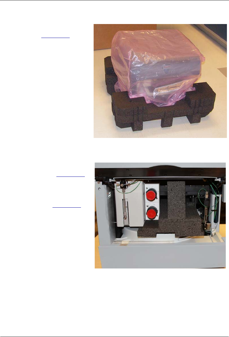
Dionex AS-AP Operator’s Manual
170 Doc. 065361-07 9/12
4. Remove the foam packing
cage (see Figure B-4).
5. With two or more persons,
grasp each side of the
Dionex AS-AP cabinet
bottom, lift up the module,
and then place it on the
bench.
6. Remove the polyethylene
bag the module is shipped
in.
7. Check that the main power
switch on the rear panel is
turned off. Figure B-4. Module with Packing Cage
Removed
8. Lift up the Dionex AS-AP
front panel (see Figure B-5)
and pull out the foam insert
that secures the needle arm
and carousel cover during
shipment (see Figure B-6)).
NOTE Save the foam insert.
It is required to protect
the needle when the
autosampler is moved
or shipped.
Figure B-5. Dionex AS-AP with Foam Insert for
Protecting the Needle Arm and Carousel
(Dionex AS-AP with Optional Valves Shown)
Front Panel (Lifted)
Foam Insert

B • Installation
Doc. 065361-07 9/12 171
Figure B-6. Dionex AS-AP with Foam Insert Removed
9. Unpack the Dionex AS-AP
Ship Kit (P/N 074929) (see
Figure B-7 and
Figure B-8).
10. Place the items in a
convenient location and
check them against the
packing list (see
Figure B-9). Report any
discrepancies to Dionex
immediately.
Figure B-7. Ship Kit with Packing List
Foam Insert
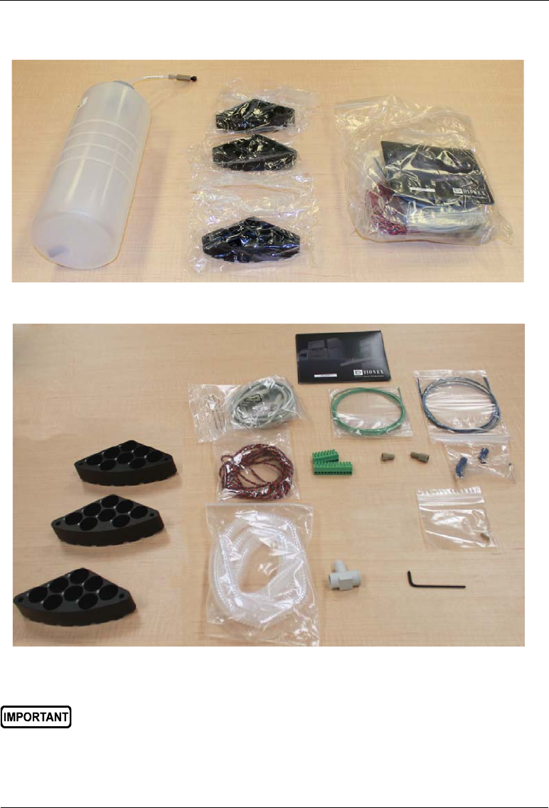
Dionex AS-AP Operator’s Manual
172 Doc. 065361-07 9/12
Figure B-8. Ship Kit Items Removed from Box
Figure B-9. Ship Kit Items Unpacked
Save the shipping container and all other shipping materials for later
use. Should it be necessary to return the Dionex AS-AP during the
warranty period, Dionex recommends repacking the autosampler in the
original shipping container.
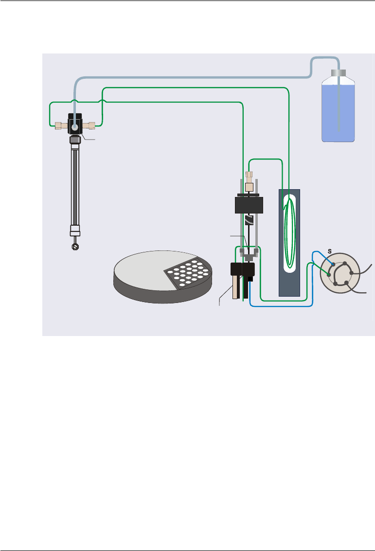
B • Installation
Doc. 065361-07 9/12 173
B.3 Plumbing Schematics
Figure B-10. Dionex AS-AP Plumbing Schematic for Push Mode
Sampling Needle
Syringe
Syringe
Valve
Wash
Reservoir
Injection Port
Sample Transfer Line
Buffer Line
Syringe Waste Line
Wash Liquid Line
Injection Valve
(Inject Position)
W
L
P
C
1
2
3
4
5
6
L
Carousel
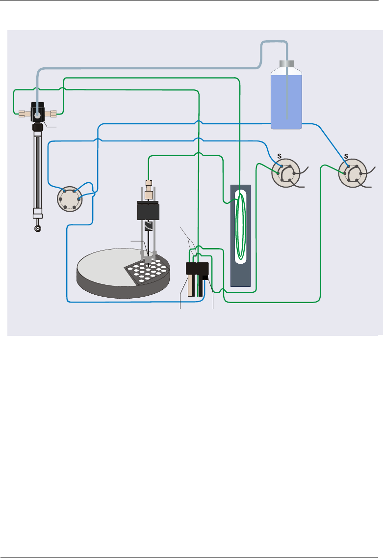
Dionex AS-AP Operator’s Manual
174 Doc. 065361-07 9/12
Figure B-11. Dionex AS-AP Plumbing Schematic for Push Sequential Mode
Syringe
Syringe
Valve
Sample Transfer Line
Buffer Line
Syringe Waste Line
Wash Liquid Line
Buffer Line
Injection Valve in
IC System #1
Injection Valve in
IC System #2
Sample Transfer Line #1
Sample Transfer Line #2
W
L
P
C
1
2
3
4
5
6
L
1S
2
P
P
P
Diverter Valve
in AS-AP
W
L
P
C
1
2
3
4
5
6
L
Wash
Reservoir
Injection
Valve
Waste Lines
Injection
Port
Wash
Port
Carousel
Sampling
Needle

B • Installation
Doc. 065361-07 9/12 175
Figure B-12. Dionex AS-AP Plumbing Schematic for Push Simultaneous Mode
Syringe
Syringe
Valve
Wash Port
Injection
Port
Sample Transfer Line
Injection
Valve
Waste Lines
Buffer Line
Syringe Waste Line
Wash Liquid Line
Buffer Line
Injection Valve in
IC System #1 Injection Va
IC System
Wash
Reservoir
W
L
P
C
1
2
3
4
5
6
L
Sample Transfer
Line #1
Sample Transfer
Line #2
W
L
P
1
2
3
4
5
6
L
Carousel
Sampling
Needle
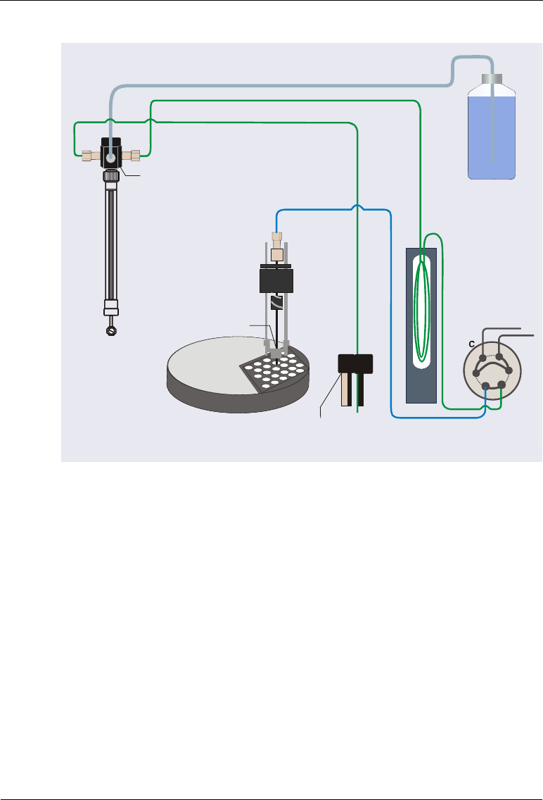
Dionex AS-AP Operator’s Manual
176 Doc. 065361-07 9/12
Figure B-13. Dionex AS-AP Plumbing Schematic for Pull Mode
Syringe
Syringe
Valve
Wash
Reservoir
Sample Transfer Line
Buffer Line
Syringe Waste Line
Wash Liquid Line
Injection Valve
(Inject Position)
Carousel
L
S
S
Y
R
L
1
4
P
Sampling Needle
Wash Port
5
3
6
2

B • Installation
Doc. 065361-07 9/12 177
B.4 Syringe, Buffer Line, and Sample Loop Guidelines
Table B-1 lists the recommended syringe, buffer line, and sample loop
combinations required for correct Dionex AS-AP operation.
•A 250 L syringe and a 1200 L buffer line are standard. Verify that your
sample loop size falls into the recommended volume range for this
combination. If it does not, make the appropriate change (either replace
the sample loop or replace the syringe and/or buffer line).
•For all capillary applications, a 100 L or 250 L syringe is
recommended.
•For all partial-loop injections, a 250 L syringe is recommended.
•If a Sample Conductivity and pH Accessory is installed, install a 1000 L
or 5000 L syringe.
•If you are loading a 4 mm concentrator column, install a 5000 L syringe
and an 8500 L buffer line.
•For the best precision, use a syringe, buffer line, and sample loop
combination that requires only a single syringe pull (see Table B-1).
However, if the sample volume specified for an injection exceeds the
installed syringe size, the autosampler will draw multiple syringe
volumes to achieve the required injection volume. This may result in
slightly reduced precision.
Syringe Buffer Line Sample Loopa
a The autosampler will use multiple syringe draws to fill the loop, as required.
100 L500L0.4–50L
250 L1200 L0.4–1.50 L
1000 L 1200 L5–500L
1000 and 5000 L8500 L100–7000 Lb
also for concentrator columns
b In this configuration, if the sample loop volume is over 4000 L, the autosam-
pler will use multiple syringe draws to fill the loop.
Table B-1. Recommended Syringe, Buffer Line, and
Sample Loop Combinations

Dionex AS-AP Operator’s Manual
178 Doc. 065361-07 9/12
Syringe Size Notes
If the syringe is required to draw a volume that is 95% of its capacity, Dionex
recommends installing the next larger syringe size. To estimate the volume of
liquid the syringe will draw during operation, use the following formula:
Syringe Draw Volume (full-loop injection) = (Transfer Line Volume) + (Loop
Overfill Factor * Loop Size) +40
L
To estimate the transfer line volume, use the following formula:
Tubing Volume (
L) = ((Tubing ID in mm /2)2) x 3.14159 * Tubing Length in
mm
The tubing volume of the 0.33 mm (0.013 in) ID blue PEEK tubing used for
the sample transfer line is approximately 0.8 L per cm (2 L per in).
Buffer Line Notes
•A 1200 L buffer line is installed at the factory. This line is 263 cm
(103.5 in) of 0.75 mm (0.030 in) ID PEEK tubing (green) (P/N 044777).
A replacement 1200 L buffer line (P/N 074989) is available.
•If a 500 L buffer line is required, order a pre-cut 500 L buffer line
(P/N 074994) (recommended) or you can cut a 109 cm (43 in) length of
0.75 mm (0.030 in) ID PEEK tubing (green) (P/N 044777).
•If an 8500 L buffer line is required, order P/N 075520. The 8500 L
buffer line must be pre-assembled at the factory. The assembly consists of
two sizes of tubing joined by a special union and includes the fittings
required for installation in the autosampler.
For buffer line installation instructions, see Section 5.4
Tightening Guidelines for Fittings
High-pressure (blue) 10-32 fitting bolts (P/N 074449) and high-pressure
(blue) double-cone ferrules (P/N 074373) are used for connections to the
injection and diverter valves. These fittings are used for both high-pressure
and low-pressure connections to the valves. To tighten the fittings, follow
these guidelines:
1. First, use your fingers to tighten the fitting bolt as tight as you can. Then,
use a wrench to tighten the fitting an additional three-quarter turn (270°).
2. If leaks occur, replace the fitting bolt, ferrule, and tubing.
B • Installation
Doc. 065361-07 9/12 179
B.5 Installation Checklist
B.6 Setting Up the Wash Liquid Reservoir
The 2 L wash liquid reservoir (P/N 062510) provided in the Dionex AS-AP
Ship Kit (P/N 074929) can be set up for offline degassing (see Section B.6.1)
or for online degassing (see Section B.6.2).
B.6.1 Connecting the Reservoir for Offline Degassing
1. Rinse the wash liquid reservoir with ASTM Type 1 (18 meghom-cm)
filtered and deionized water.
2. Degas the deionized water offline first and then fill the reservoir.
3. Install the reservoir cap. Make sure that the end of the liquid line inside
the reservoir extends to the bottom of the reservoir. Hand-tighten the cap.
4. Place the reservoir in the system’s reservoir holder or in appropriate
secondary containment.
Installation Step Page
Set up the wash liquid reservoir page 179
Connect to the injection valve page 184
Connect the drain line page 198
Connect the USB cable page 200
Plug the power cord into a grounded power source page 201
Set up the Dionex AS-AP in Chromeleon page 202
Check the needle alignment page 211
Prime the syringe and remove any bubbles page 211
Connect TTL and relays (optional) page 212
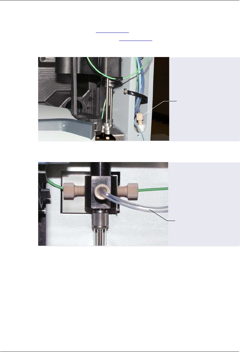
Dionex AS-AP Operator’s Manual
180 Doc. 065361-07 9/12
5. Locate the wash liquid line that extends out of the slot on the right side of
the autosampler (see Figure B-14). This line is connected to the center
port on the syringe valve (see Figure B-15). Route the line to the reservoir
and connect it to the union on the line from the reservoir cap.
Figure B-14. Wash Liquid Line on Right Side of Autosampler
Figure B-15. Syringe Valve Connections
Wash Liquid Line
Wash Liquid Line

B • Installation
Doc. 065361-07 9/12 181
B.6.2 Connecting the Reservoir for Online Degassing
Two methods are available for online degassing of the wash liquid:
•If an unused vacuum degas channel is available in the pump, you can
connect the Dionex AS-AP wash liquid line to the unused channel (see
page 181).
•If an unused vacuum degas channel is not available, you can share a
channel by installing a tee on the eluent line after the degasser. A Degas
Tee Kit (P/N 075010) that includes the tee, fittings, and tubing is
available. For connection instructions, see page 182.
NOTE The reservoir connected to the degas channel must contain
ASTM Type 1 (18 meghom-cm) filtered and deionized water.
You can use the 2 L reservoir (P/N 062510) provided in the
Dionex AS-AP Ship Kit or a reservoir provided with the
pump.
To connect the reservoir to an unused degas channel:
1. In the pump, disconnect the outlet line from the degas out port of the
unused degas channel. See the example in Figure B-16.
2. In the Dionex AS-AP, locate the wash liquid line that extends out of the
slot on the right side of the autosampler (see Figure B-14). This line is
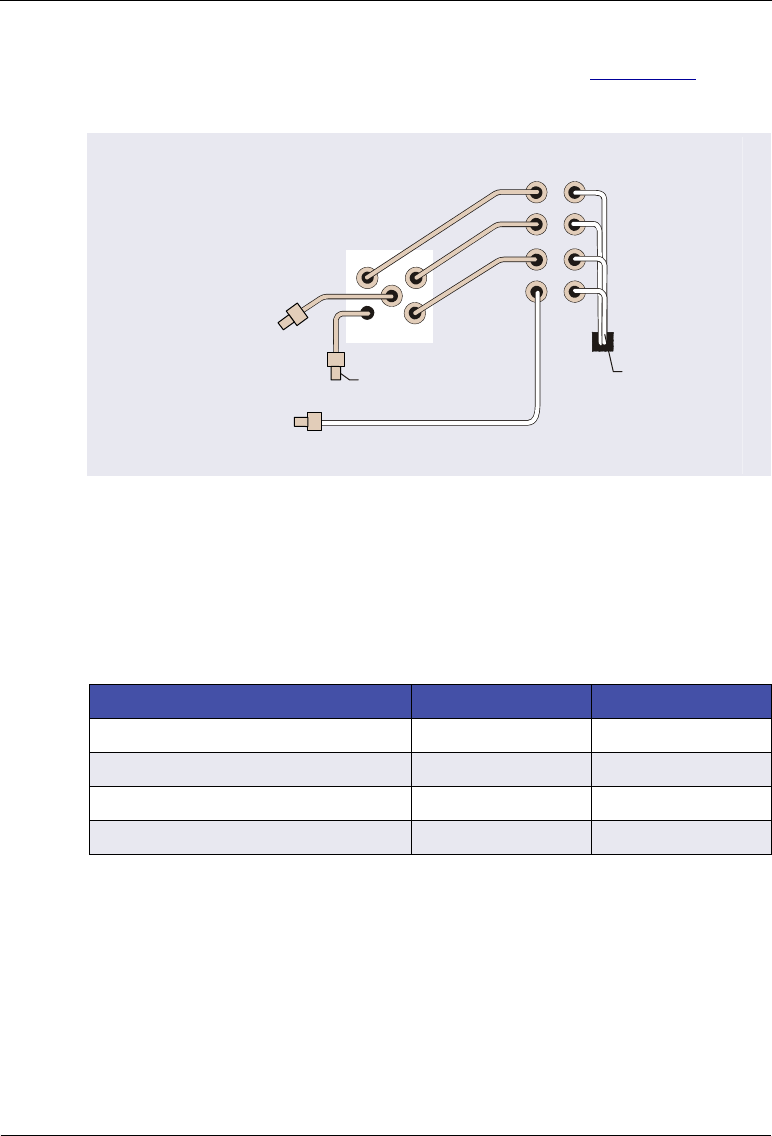
Dionex AS-AP Operator’s Manual
182 Doc. 065361-07 9/12
connected to the center port on the syringe valve (see Figure B-15). Route
the wash liquid line to the pump and connect it to the degas outlet port.
To share a pump degas channel:
A Degas Tee Kit (P/N 075010) is required for this configuration. Order the kit
separately.
Figure B-16. Connections for Online Degassing Using an
Unused Pump Degas Channel (Example Using Degas Channel D Shown)
Tubing/Fitting Type Part Number Quantity
Tee, 3-way manifold, 1/4-28 port 024313 1
Fitting nut, 1/4-28 x 1/8 flangeless 052267 3
Ferrule, 1/8 in flangeless ferrule 048949 3
Tubing, 1.55 mm (0.062 in) ID PFA 052112 15 cm (6 in)
Table B-2. Contents of Degas Tee Kit (P/N 075010)
Degas
Connected to
Syringe ValveAS-AP
Wash Liquid Line
from AS-AP
A
B
C
D
A
In Out
Proportioning
Valve
Connected to
Pump Inlet
Disconnected
Degas Outlet Line
To AS-AP
Wash Liquid
Reservoir

B • Installation
Doc. 065361-07 9/12 183
1. Connect the short piece of
PFA tubing (P/N 052112)
to the tee (see
Figure B-17).
Figure B-17. Tee with Connector Tubing Attached
2. Connect the short piece of PFA tubing with degas tee to the degas channel
outlet port (see Figure B-18).
3. Disconnect the degasser outlet line from the pump degas channel. For
example, if you have a gradient pump and you want to share channel A,
disconnect the line from degas outlet port A.
4. Connect the pump degas outlet line to the tee.
5. Locate the wash liquid line that extends out of the slot on the right side of
the autosampler (see Figure B-14). This line is connected to the center
port on the syringe valve (see Figure B-15). Connect the line to the
remaining port on the tee.
Figure B-18. Connections for Sharing a Degas Channel Using a Tee
PFA Tubing
1/4-28 x 1/8 Fitting Nuts
and Ferrules
Tee
Degas Out
Degas
Tee
Connected to
Syringe ValveAS-AP
Connected to Eluent On/Off Valve
Proportioning Valve or
Existing Degas
Outlet Line from Pump
Wash Liquid
Line from
AS-AP
PFA Tubing from
Degas Tee Kit

Dionex AS-AP Operator’s Manual
184 Doc. 065361-07 9/12
B.7 Connecting to the Injection Valve
Injection valve connections depend on your system configuration.
•To connect to a single injection valve for push mode, see Section B.7.1.
•To connect to two injection valves for push sequential injections, see
Section B.7.2.
•To connect to two injection valves for push simultaneous injections, see
Section B.7.3.
•To connect to a single injection valve for pull mode, see Section B.7.4.
•To connect to a fraction collection valve, refer to Appendix D.
NOTE To connect to a Sample Conductivity and pH Accessory,
refer to the Dionex AS-AP Sample Conductivity and pH
Accessory Setup and Operation Guide (Document No.
065470). The guide is shipped with the accessory and also
included on the Thermo Scientific Reference Library DVD
(P/N 053891).
Notes for Push Mode Configurations
A 91 cm (36 in) sample transfer line is connected to the injection port at the
factory. The volume of this line is calibrated and recorded in the
autosampler’s memory.
You can reduce the length of the installed sample transfer line by cutting it, or
you can install a new longer line. If you change the length of the sample
transfer line, calibrate the volume of the line before connecting it to the
injection valve. For sample transfer line replacement instructions, see
Section 5.8. For calibration instructions, see Section 5.9.
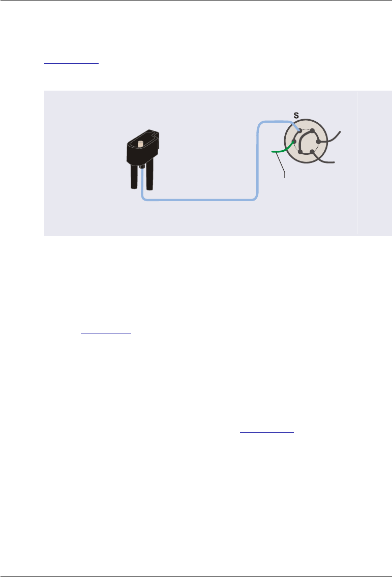
B • Installation
Doc. 065361-07 9/12 185
B.7.1 Connecting to a Single Injection Valve for Push Mode
Figure B-19 shows the completed injection valve connections for push mode
injections to a single injection valve.
NOTE If you reduced the length of the sample transfer line or
installed a longer sample line, calibrate the volume of the line
before proceeding. For calibration instructions, see
Section 5.9.
1. If the injection valve is installed in the IC system, route the sample
transfer line from the Dionex AS-AP injection port out the right side of
the Dionex AS-AP and then to the injection valve in the IC system.
2. Install a 10-32 fitting bolt (P/N 074449) and double-cone ferrule
(P/N 074373) on the end of the sample transfer line and connect the line
to port S (5) on the injection valve (see Figure B-19).
NOTE In a capillary system, port 5 is labeled Sample In.
Figure B-19. Sample Transfer Line Connections for
Push Mode Injections to a Single Injection Valve
Sample Transfer Line
AS-AP Injection Port
Injection Valve
W
L
P
C
1
2
3
4
5
6
L
To AS-AP
Waste Port

Dionex AS-AP Operator’s Manual
186 Doc. 065361-07 9/12
3. If a waste line is not already connected to port W (6) on the injection
valve, follow the steps below to create the line:
a. Locate the following items in the Dionex AS-AP Ship Kit
(P/N 074929):
•0.75 mm (0.030 in) ID green PEEK tubing (P/N 044777)
•0.25 mm (0.010 in) ID black PEEK tubing (P/N 042690)
•10-32 fitting bolt (P/N 074449) and double-cone ferrule
(P/N 074373)
b. For an analytical system, cut a length of green tubing long enough to
reach from the injection valve to the Dionex AS-AP waste port.
NOTE To improve sample loading precision in analytical sys-
tems, add a 51 cm (20 in) piece of 0.25 mm (0.010 in)
ID black PEEK tubing to the green waste line.
c. For a capillary system, cut a 61 cm (24 in) length of black tubing. If
this is not long enough to reach from the injection valve to the Dionex
AS-AP waste port, cut an additional length of green tubing and use a
union to connect it to the black tubing.
d. Connect one end of the waste line to port W (6) on the injection
valve. For a capillary system with a two-piece waste line, connect the
black tubing to the injection valve.
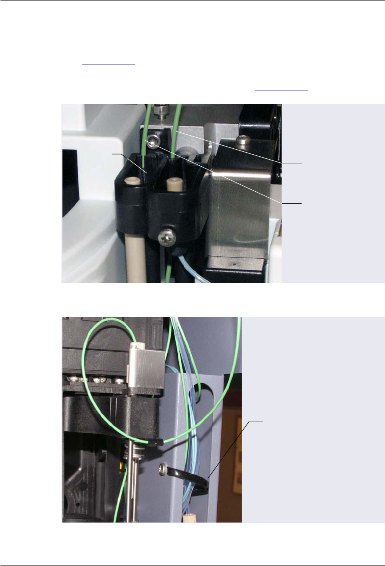
B • Installation
Doc. 065361-07 9/12 187
4. Route the waste line from the injection valve to the Dionex AS-AP waste
port and insert the line into one of the round openings in the waste port
(see Figure B-20). To ensure the waste lines do not interfere with needle
arm movement, secure the excess tubing with the flexible tubing tie in the
slotted compartment next to the needle (see Figure B-21).
Figure B-20. Injection Valve Waste Line Installed in Waste Port
Figure B-21. Flexible Tubing Tie in Slotted Compartment
Waste line from
injection valve
Waste line from
syringe
Waste
Port
Flexible Tubing
Tie
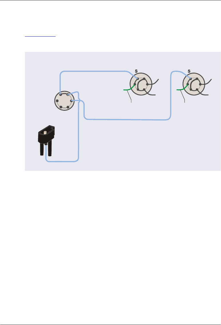
Dionex AS-AP Operator’s Manual
188 Doc. 065361-07 9/12
B.7.2 Connecting to Two Injection Valves for Sequential Injections
Figure B-22 shows the completed injection valve connections for sequential
injections.
1. Locate the following items in the Dionex AS-AP Ship Kit (P/N 074929)
or in the 6-Port Valve Plumbing kit (P/N 075527) provided with the
diverter valve:
•Five 10-32 fitting bolts (P/N 074449) and five double-cone ferrules
(P/N 074373)
•0.33 mm (0.013 in) ID blue PEEK tubing (P/N 049714)
2. Install a fitting bolt and ferrule on the end of the sample transfer line from
the injection port and connect the line to port S on the diverter valve.
3. Follow the steps below to create two sample transfer lines for connecting
the diverter valve to each injection valve:
a. Cut a length of tubing long enough to connect from the diverter valve
to the injection valve in system #1. Connect this line between port 1
on the diverter valve and port S (5) on the injection valve.
Figure B-22. Sample Transfer Line Connections for
Sequential Injections to Two Injection Valves
Sample Transfer Line
1S
2
P
P
P
Diverter Valve
in AS-AP
Injection Valve in
IC System #1 Injection Valve in
IC System #2
Sample Transfer Line #1
Sample Transfer Line #2
W
L
P
C
1
2
3
4
5
6
L
W
L
P
C
12
3
4
5
6
L
To AS-AP
Waste Port
To AS-AP
Waste Port
AS-AP
Injection
Port
Note: Sample loops on the two
valves can be different sizes.

B • Installation
Doc. 065361-07 9/12 189
b. Cut a length of tubing long enough to connect from the diverter valve
to the injection valve in system #2. Connect this line between port 2
on the diverter valve and port S (5) on the injection valve.
NOTE In a capillary system, port 5 is labeled Sample In.
4. If a waste line is not already connected to port W (6) on each injection
valve, follow the steps below to create the lines:
a. Locate the following items in the Dionex AS-AP Ship Kit (P/N
074929):
•0.75 mm (0.030 in) ID green PEEK tubing (P/N 044777)
•0.25 mm (0.010 in) ID black PEEK tubing (P/N 042690)
•10-32 fitting bolt (P/N 074449) and double-cone ferrule
(P/N 074373)
b. For an analytical system, cut a length of green tubing long enough to
reach from the injection valve to the Dionex AS-AP waste port.
NOTE To improve sample loading precision in analytical sys-
tems, add a 51 cm (20 in) piece of 0.25 mm (0.010 in)
ID black PEEK tubing to the green waste line.
c. For a capillary system, cut a 61 cm (24 in) length of black tubing. If
this is not long enough to reach from the injection valve to the Dionex
AS-AP waste port, cut an additional length of green tubing and use a
union to connect it to the black tubing.
d. Connect one end of the waste line to port W (6) on the injection
valve. For a two-piece waste line, connect the black tubing to the
injection valve.
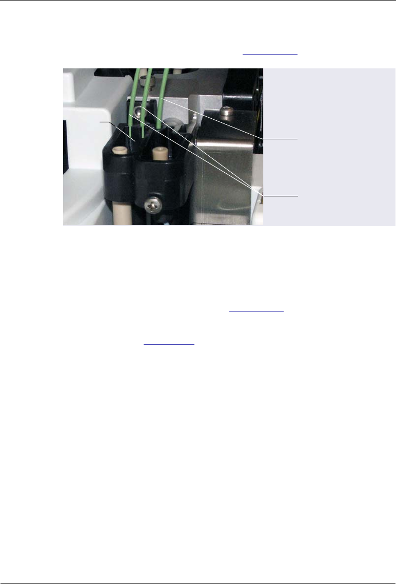
Dionex AS-AP Operator’s Manual
190 Doc. 065361-07 9/12
5. Route the waste lines to the Dionex AS-AP waste port and insert the lines
into the round openings in the port (see Figure B-23).
6. To ensure the waste lines do not interfere with needle arm movement,
secure the excess tubing with the flexible tubing tie in the slotted
compartment next to the needle (see Figure B-21).
7. Calibrate the volume of each sample transfer line and enter the volumes in
Chromeleon. See Section 5.9 for instructions.
B.7.3 Connecting to Two Injection Valves for Simultaneous
Injections
To configure the Dionex AS-AP for simultaneous injections, a Dionex AS-AP
Simultaneous Injection Kit (P/N 075008) is required. This kit must be ordered
separately. The kit consists of the following parts:
•Y-connector (P/N 061538) for splitting the sample stream to two injection
valves. Fitting bolts and ferrules are included with the Y-connector.
•0.33 mm (0.013 in) ID blue PEEK tubing (P/N 049714) for connecting
the Y-connector to each valve
•10-32 fitting bolts (P/N 074449) and double-cone ferrules (P/N 074373)
are installed on the ends of each line for connecting the Dionex AS-AP
sample transfer line to the injection valves.
Figure B-23. Waste Lines from Each Injection Valve
Installed in Waste Port
Waste lines from
injection valves
Waste
Port Waste line from
syringe
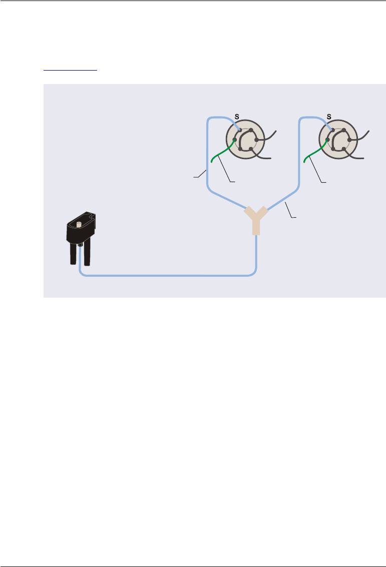
B • Installation
Doc. 065361-07 9/12 191
•Two Phillips head screws (P/N 045685) for mounting the Y-connector on
the Dionex AS-AP
Figure B-24 shows an example of the completed connections.
Before beginning, refer to the following guidelines for information about
balancing the flow to each system.
Guidelines for Balancing the Flow to Each Valve for Simultaneous
Injections
For simultaneous injections, the sample transfer lines to the injection valves
do not need to be calibrated. However, the flow to each valve must be
balanced, so that equal flow moves through each valve. To do this, follow the
guidelines below:
•The total length of each type (color/size) of tubing connected to each
system must be equal after the Y-connector splits the sample stream. This
includes the sample transfer lines from the Y-connector to each injection
valve, the sample loops installed on the valves, and the waste lines (if the
tubing IDs of the waste lines are less than 0.75 mm (0.030 in).
Figure B-24. Example Sample Transfer Line Connections for
Simultaneous Injections to Two Injection Valves
Sample Transfer Line
Injection Valve in
IC System #1
Injection Valve in
IC System #2
Sample Transfer
Line #1
Sample Transfer
Line #2
Y-Connector
W
LP
C
12
3
4
5
6
L
W
L
P
C
1
2
3
4
5
6
L
To AS-AP
Waste Port To AS-AP
Waste Port
AS-AP Injection Port

Dionex AS-AP Operator’s Manual
192 Doc. 065361-07 9/12
•Place any tubing used strictly to match the tubing of the other system after
the injection valve (connect it to the waste line) (see Figure B-25).
•The balance of flow to each system will not be perfect because of the
differences in tubing IDs from nominal. In addition, any differences in the
ambient temperature where each tubing is located after the Y-connector
will cause a variation.
Connection Instructions
1. Locate the blue sample transfer line that is connected to the Dionex AS-
AP injection port. This line will be connected to the Y-connector
(P/N AAA-061538) of the Simultaneous Injection Kit. The Y-connector
mounts onto the right side of the Dionex AS-AP (see Figure B-26). To
reduce the excess tubing length, you can shorten the sample transfer line
by cutting it.
2. Remove the fitting bolt and ferrule from the unconnected leg of the Y-
connector and install them onto the end of the sample transfer line.
Connect the line to the Y-connector and tighten the fitting fingertight.
Figure B-25. Example Sample Transfer Line Connections for
Simultaneous Injections with Tubing Added for Balancing Flow
Sample Transfer Line
Injection Valve in
IC System #1
Injection Valve in
IC System #2
Y-Connector
W
LP
C
123
4
5
6
L
W
L
P
C
1
2
3
4
5
6
L
AS-AP
Injection Port
same type
and length
8 in of black
tubing to match
loopsystem #2
10 in of red
tubing to match
loopsystem #1
Waste Port
Green Waste Lines
(lengths do not matter)
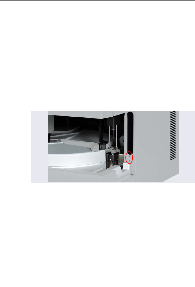
B • Installation
Doc. 065361-07 9/12 193
3. Remove the fitting cap and union from one of the lengths of tubing
installed on the Y-connector. Connect this line to port S (5) on the
injection valve of system #1. Repeat this step for system #2.
NOTE If the fitting bolts and ferrules provided with the Y-
connector ever need replacement, use 1/16 in flange-
less fitting bolts (short) (P/N 071358) and tan two-
piece ferrules (P/N 062511).
4. Locate the two mounting holes on the right side of the Dionex AS-AP
(see Figure B-26). Orient the Y-connector with the double-legs pointed
toward the right and mount the Y-connector using the two screws
provided. Coil the excess sample transfer line tubing and place it in the
slotted compartment above the Y-connector.
5. If waste lines are not already connected to port W (6) on each injection
valve, follow the steps below to create the lines:
a. Locate the following items in the Dionex AS-AP Ship Kit (P/N
074929):
•0.75 mm (0.030 in) ID green PEEK tubing (P/N 044777)
•Two 10-32 fitting bolts (P/N 074449) and two double-cone
ferrules (P/N 074373)
Figure B-26. Y-Connector Mounting Location on Right Side of
Dionex AS-AP
Mounting holes
for Y-connector
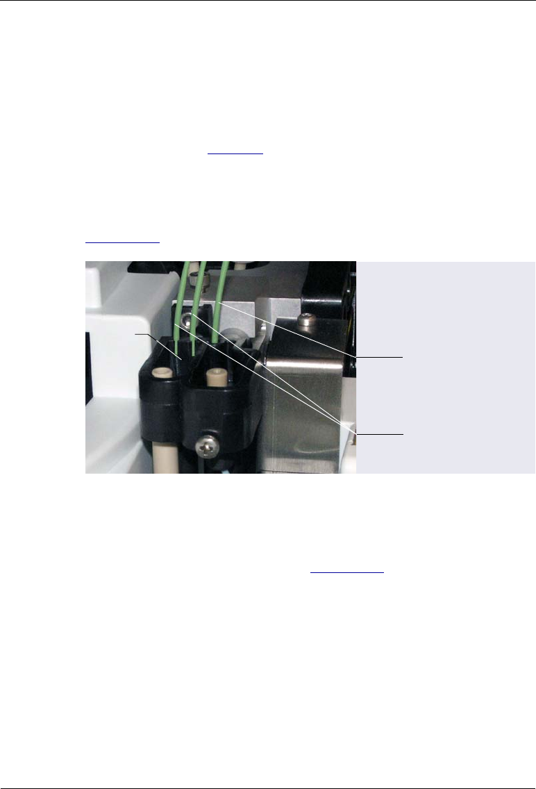
Dionex AS-AP Operator’s Manual
194 Doc. 065361-07 9/12
b. Cut a length of tubing long enough to reach from the injection valve
in IC system #1 to the Dionex AS-AP waste port. Repeat this step for
system #2.
c. If required for your system, connect matching tubing to the waste
lines to balance the flow on both systems. Refer to the guidelines and
the example on page 191.
d. Connect each waste line to port W (6) on the system’s injection valve.
6. Route the waste line from each injection valve to the Dionex AS-AP
waste port and insert the lines into the round openings in the port (see
Figure B-27).
7. To ensure the waste lines do not interfere with needle arm movement,
secure the excess tubing with the flexible tubing tie in the slotted
compartment next to the needle (see Figure B-21).
Figure B-27. Injection Valve Waste Lines Installed in Waste Port
Waste lines from
injection valves
Waste
Port Waste line from
syringe
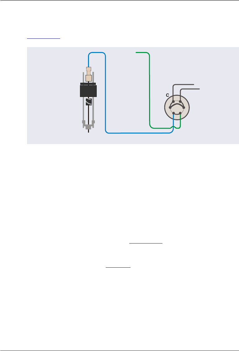
B • Installation
Doc. 065361-07 9/12 195
B.7.4 Connecting to the Injection Valve for Pull Mode
Figure B-28 shows the completed injection valve connections for pull mode.
1. Locate the following items in the Dionex AS-AP Ship Kit (P/N 074929):
•Two 10-32 fitting bolts (P/N 074449) and two double-cone ferrules
(P/N 074373)
•0.33 mm (0.013 in) ID blue PEEK tubing (P/N 049714)
•One tan 1/16 in flangeless fitting bolt (P/N 052230) and one two-
piece ferrule (clear cone and tan flat) (P/N 062511)
2. Using a 10-32 bolt and double-cone ferrule, connect the buffer line to
port 6 on the injection valve (see Figure B-13). If the injection valve is
installed in the IC system, this port is labeled W. If the injection valve is
installed in the Dionex AS-AP, this port is labeled SYR. Refer to the
tightening guidelines on page 178.
3. To create a sample transfer line, cut a length of 0.33 mm (0.013 in) ID
blue PEEK tubing long enough to connect from the top of the needle to
the injection valve. Minimize the length of this tubing as much as
possible.
Figure B-28. Injection Valve Connections for Pull Mode
Sample Transfer Line
Injection Valve
L
S
S
Y
R
L
1
4
P
5
3
6
2
To Syringe
Buffer
Line
Needle
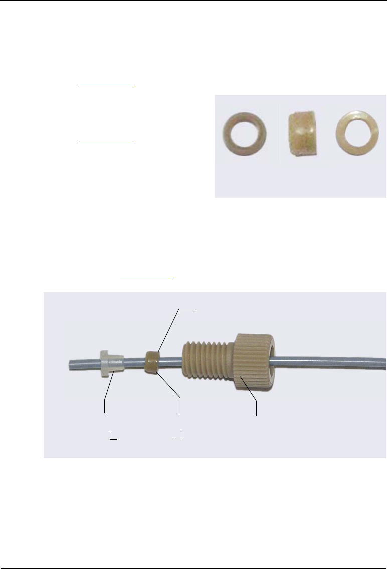
Dionex AS-AP Operator’s Manual
196 Doc. 065361-07 9/12
4. Follow the steps below to connect this line to the needle:
a. Use the 1/16 in flangeless fitting bolt and two-piece ferrule for the
connection. Slide the fitting bolt onto the tubing as shown in
Figure B-30.
b. Observe that one side of the
small tan ferrule is beveled
and one side is flat (see
Figure B-29). Hint: The flat
side appears shiny.
Figure B-29. Small Tan Ferrule (Enlarged)
c. With the flat side of the small tan ferrule facing toward the fitting
bolt, slide the ferrule onto the tubing. Then, slide the clear cone
ferrule onto the tubing with the cone toward the flat ferrule and fitting
bolt (see Figure B-30).
d. Position the bolt and ferrules away from the end of the tubing (so they
do not fall off when you insert the tubing into the needle holder).
Figure B-30. Fitting for Sample Transfer Line (Pull Mode)
Beveled Side Flat Side
Fitting Bolt
(P/N 052230)
Flat Ferrule Cone Ferrule
Flat Side
(P/N 062511)

B • Installation
Doc. 065361-07 9/12 197
e. Insert the tubing down into the center of the needle holder. When you
insert the tubing, you should feel the tubing drop into a small
indentation inside the holder (see Figure B-31). If not, move the
tubing slightly until it does.
f. Slide the ferrules and fitting bolt down into the needle holder.
When connecting the sample transfer line to the needle, make sure the
line slides into the indentation inside the needle holder before
tightening the fitting.
Figure B-31. Cross-Section of Needle Holder and
Sample Transfer Line Fitting
Fit the tubing
into this
indentation
Needle
Holder
Top of the
needle
Sample
Transfer Line
Two-Piece
Ferrule
(P/N 062511)
Flangeless
Fitting Bolt
(P/N 052230)
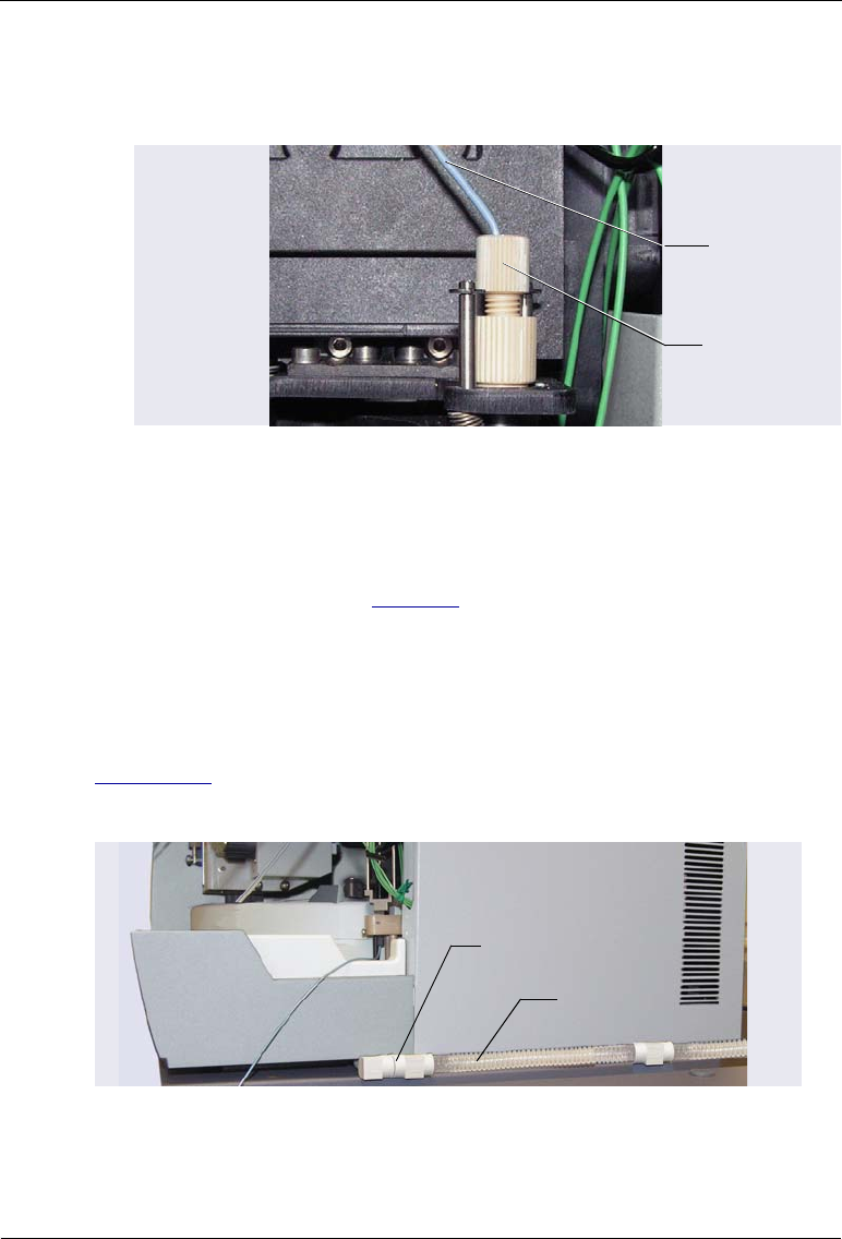
Dionex AS-AP Operator’s Manual
198 Doc. 065361-07 9/12
g. While holding the needle holder to prevent twisting the needle,
tighten the fitting. Tighten the fitting fingertight to set the ferrules.
5. Using a 10-32 fitting bolt and double-cone ferrule, connect the other end
of the sample transfer line to port S (5) on the injection valve. Refer to the
tightening guidelines on page 178.
B.8 Connecting the Drain Line
Connections for a Dionex AS-AP Without Sample Temperature Control
Figure B-33 shows the completed drain line connections for a Dionex AS-AP
without sample temperature control.
Figure B-32. Sample Transfer Line Connected to the Needle
for Pull Mode
Sample
Transfer Line
and Fitting
Needle
Holder
Figure B-33. Drain Line Connection for a Dionex AS-AP
Without Sample Temperature Control
Drain Line
Drain Line Fitting

B • Installation
Doc. 065361-07 9/12 199
1. Locate the convoluted drain line (P/N 055075) in the Dionex AS-AP Ship
Kit (P/N 074929).
2. Locate the rubber drain line fitting that extends from the right side of the
autosampler (see Figure B-33).
3. Connect the drain line to this fitting.
4. Place the free end of the drain line into a waste container or appropriate
drain.
5. Make sure that the outlet of the drain line is below the level of the Dionex
AS-AP and is not elevated at any point.
Connections for a Dionex AS-AP with Sample Temperature Control
Figure B-34 shows the completed drain line connections for a Dionex AS-AP
with sample temperature control.
1. Locate the convoluted drain line (P/N 055075) and the drain line tee
fitting (P/N 074978) in the Dionex AS-AP Ship Kit (P/N 074929).
2. Push the tee fitting onto the small stainless steel drain tube that extends
from the back right side of the autosampler.
3. Connect the convoluted drain line to the right side of this tee.
Figure B-34. Drain Line Connections for a Dionex AS-AP
with a Sample Temperature Option
Drain Line Connector
Tee Fitting
Drain Line
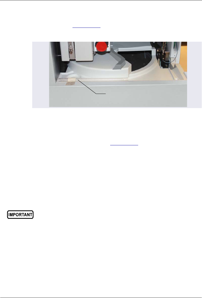
Dionex AS-AP Operator’s Manual
200 Doc. 065361-07 9/12
4. Untape the short length of convoluted drain line from the front of the
autosampler (see Figure B-35) and connect this line to the left side of the
tee.
5. Connect the other end of the short drain line to the fitting on the front
right side of the autosampler (see Figure B-34).
6. Place the free end of the drain line into a waste container or appropriate
drain.
7. Make sure that the outlet of the drain line is below the level of the Dionex
AS-AP and is not elevated at any point.
B.9 Connecting the USB Cable
1. Locate the USB cable (P/N 960777) in the Dionex AS-AP Ship Kit (P/N
074929).
2. Connect the USB cable between the USB connector on the Dionex AS-
AP rear panel and a USB port on either the Chromeleon computer or the
host IC system.
Figure B-35. Drain Line Connector Hose for the Sample
Temperature Control Option
Drain Line
Connector Hose
Do not turn on the power to the Dionex AS-AP until after you connect
the USB cable.
Before connecting the USB cable, verify that Chromeleon is installed
on the PC. If not, Windows will be unable to identify the new USB
device when the power is turned on.
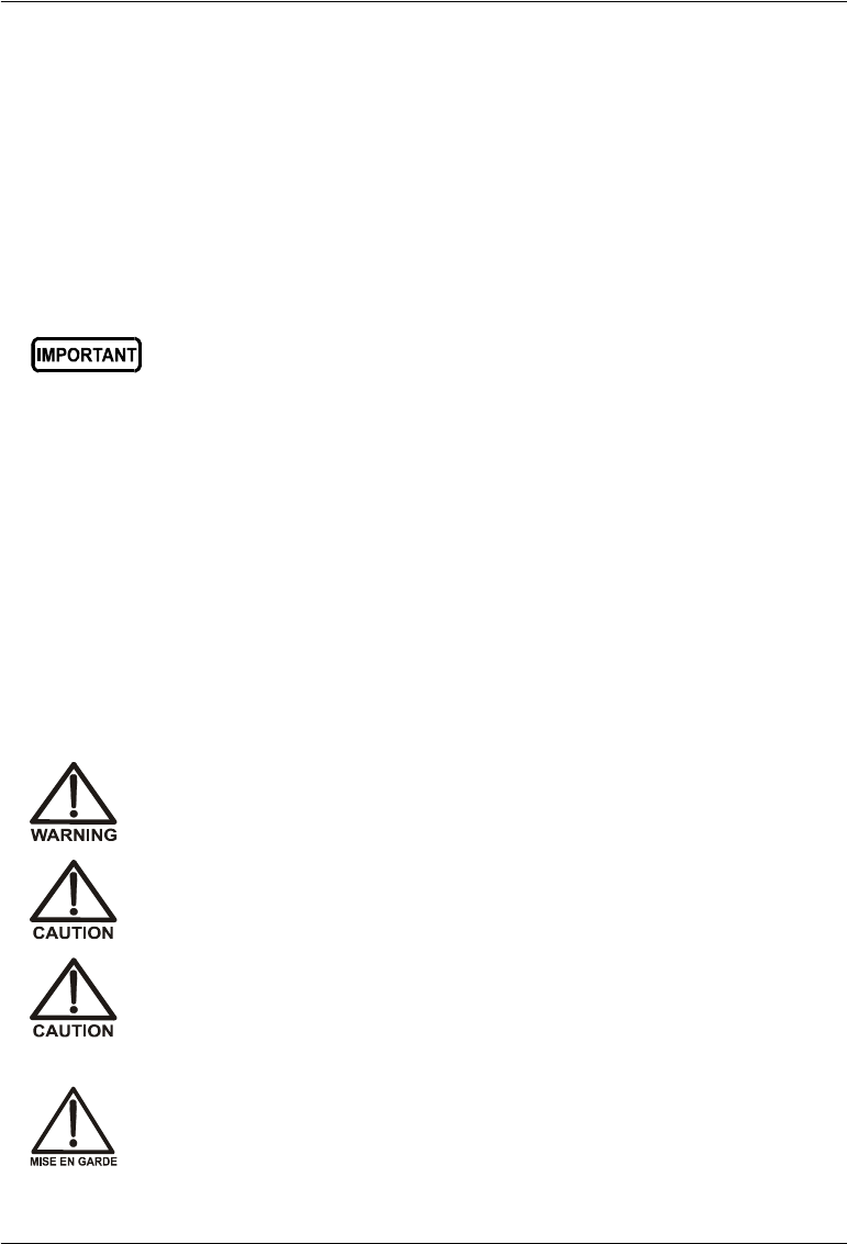
B • Installation
Doc. 065361-07 9/12 201
A USB 2.0 or USB 1.1 external hub can be used to connect the Dionex AS-
AP to the PC. Refer to the manual provided by the hub vendor for complete
installation instructions. One or more hubs is required in the following
situations:
•Use a hub if the number of USB devices in the system exceeds the
number of available USB ports.
•Use a hub if the Dionex AS-AP is more than 5 meters (16 ft) from the PC.
B.10 Connecting the Power Cord
1. Verify that the main power switch on the rear panel of the Dionex AS-AP
is turned off. (The power switch may be turned on accidentally when the
module is unpacked.)
2. Connect the power cord (IEC 320 C13) (ordered separately) from the
main power receptacle on the rear panel to a grounded power source. The
Dionex AS-AP power supply is auto-sensing, so no adjustment is
required to select the line voltage.
The USB standard limits the USB cable length to 5 meters (16 ft). Each
USB device can be separated from the PC by no more than five hubs.
Thus, each USB device can be located no more than 30 meters
(32 yds) from the PC.
SHOCK HAZARD—To avoid electrical shock, use a grounded
receptacle. Do not operate the Dionex AS-AP or connect it to AC
power mains without an earthed ground connection.
The power supply cord is used as the main disconnect device. Make
sure the socket-outlet is located near the Dionex AS-AP and is easily
accessible.
Operation at AC input levels outside of the specified operating voltage
range may damage the Dionex AS-AP.
DANGER D'ÉLECTROCUTION—Pour éviter toute électrocution, il faut
utiliser une prise de courant avec prise de terre. Ne l'utilisez pas et ne
le branchez pas au secteur C.A. sans utiliser de branchement mis à la
terre.
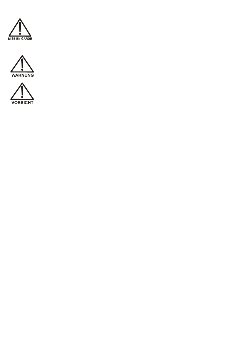
Dionex AS-AP Operator’s Manual
202 Doc. 065361-07 9/12
B.11 Setting Up Chromeleon
This section provides brief instructions for setting up Chromeleon. For details
about any of these steps, refer to the appropriate installation guide and to the
Chromeleon Help. The installation guides are provided on the Thermo
Scientific Reference Library DVD (P/N 053891).
•For Chromeleon 7, refer to Chromeleon 7 Installation Guide.
•For Chromeleon 6.8, refer to Installing Chromeleon with a Dionex Ion
Chromatograph (Document No. 031883).
B.11.1 Installing the Software and License
When you purchase Chromeleon and a PC from Dionex, the chromatography
software and the computer hardware are installed at the factory. In this case,
you may omit this section.
To install Chromeleon software and the software license, follow the
instructions in the appropriate installation guide.
B.11.2 Installing the Dionex AS-AP Device Driver
1. If you have not already done so, turn on the PC power.
2. For a local PC: Log onto Windows as an administrator.
For a network PC: Log on as a user with local PC administrator
privileges.
Le cordon d'alimentation principal est utilisé comme dispositif
principal de débranchement. Veillez à ce que la prise de base soit
située/installée près du module et facilement accessible.
STROMSCHLAGGEFAHR—Zur Vermeidung von elektrischen
Schlägen ist eine geerdete Steckdose zu verwenden. Das Gerät darf
nicht ohne Erdung betrieben bzw. an Wechselstrom angeschlossen
werden.
Das Netzkabel ist das wichtigste Mittel zur Stromunterbrechung.
Stellen Sie sicher, daß sich die Steckdose nahe am Gerät befindet und
leicht zugänglich ist.
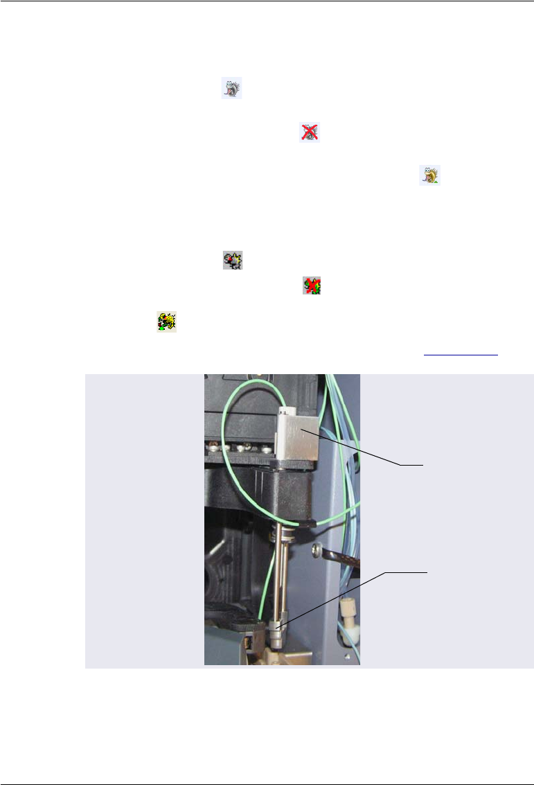
B • Installation
Doc. 065361-07 9/12 203
3. If Chromeleon 7 is installed, check the Instrument Controller Service icon
on the Windows taskbar and start the service, if it is not already running:
•If the icon is gray , the Instrument Controller Service is running
(idle).
•If the icon is crossed out in red , the Instrument Controller Service
is not running. Right-click the icon and click Start Chromeleon
Instrument Controller. The icon changes to gold to indicate
that the Instrument Controller Service is starting.
4. If Chromeleon 6.8 is installed, check the Server Monitor icon on the
Windows taskbar and start the server, if it is not already running:
•If the icon is gray , the server is already running (idle).
•If the icon is crossed out in red , the server is stopped. To start the
server, right-click the icon and select Start Server. The icon changes
to gold to indicate that the Chromeleon 6.8 server is starting.
5. Verify that the J-clip is installed on the vial pusher (see Figure B-36).
6. Press the main power switch on the Dionex AS-AP rear panel to turn on
the power. The autosampler will begin running a self test. Because the J-
Figure B-36. J-Clip Installed on Vial Pusher
J-Clip
Vial
Pusher

Dionex AS-AP Operator’s Manual
204 Doc. 065361-07 9/12
clip prevents the needle from descending into the injection port during the
self test, the following error message appears in the Audit Trail:
Needle Drive: Pusher sensor malfunction. Turn the
autosampler off and on again or perform a self test.
You can ignore the error message and continue with the installation. After
you complete the installation and check the needle alignment (see
Section 5.3), a self test will be required.
7. Windows automatically detects the new USB device. A message flashes
on the screen to inform you that new hardware was found.
8. Depending on the Windows version, Windows either automatically
installs the device driver or it launches the Found New Hardware Wizard.
Complete the wizard (if it appears) by selecting the following options:
•If asked whether Windows can connect to Windows Update to search
for software, select No, not this time.
•Accept the default option (Install the software automatically) and
click Next >. It is not necessary to insert a hardware installation disk.
B.11.3 Configuring the Dionex AS-AP in Chromeleon
1. Start the Chromeleon 7 Instrument Configuration Manager or the
Chromeleon 6.8 Server Configuration program:
•For Chromeleon 7, click Start on the Windows taskbar and click All
Programs > Chromeleon 7 > Instrument Configuration Manager.
•For Chromeleon 6.8, click Start on the Windows taskbar and click
All Programs > Chromeleon > Server Configuration.
2. Add the Dionex AS-AP to an existing instrument or timebase or create a
new instrument or timebase.
3. After you add the Dionex AS-AP to an instrument or timebase,
Chromeleon connects to the autosampler and starts a configuration wizard
that guides you through the installation. Refer to the following
descriptions to complete each wizard page.
4. After completing all wizard pages, click Finish.
5. On the File menu, click Save Installation and then close the program.
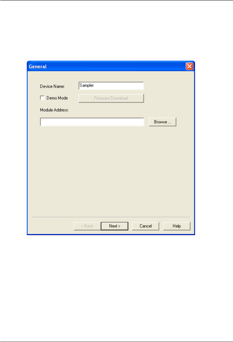
B • Installation
Doc. 065361-07 9/12 205
NOTE To change settings after finishing the wizard, double-click the
Dionex AS-AP device in the instrument or timebase. The
configuration properties dialog box opens.
General Page
Click Browse and double-click the USB address of the Dionex AS-AP. Click
Next. A message is displayed. After reading the message, click OK to go to
the next wizard page.
Figure B-37. Example Chromeleon Configuration Wizard:
General Page
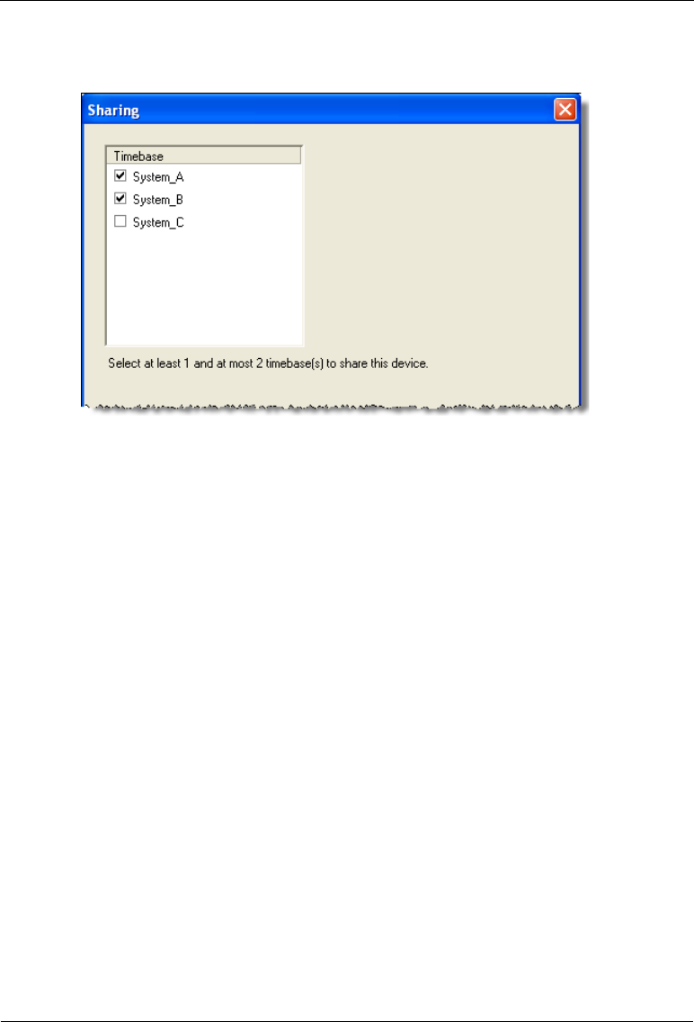
Dionex AS-AP Operator’s Manual
206 Doc. 065361-07 9/12
Sharing Page
Verify that the instrument or timebase in which the Dionex AS-AP is installed
is selected. To share the Dionex AS-AP between two instruments or
timebases, select a second instrument or timebase. When the autosampler is
shared, it appears in both instruments or timebases and can be controlled from
either one. In the example above, the Dionex AS-AP is shared between two
timebases (System_A and System_B).
Figure B-38. Example Chromeleon Configuration Wizard:
Sharing Page
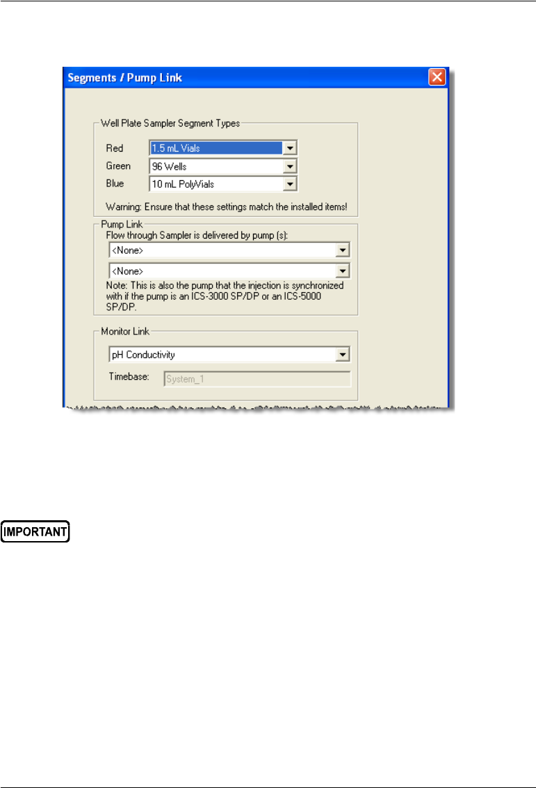
B • Installation
Doc. 065361-07 9/12 207
Segments/Pump Link Page
•Well Plate Sampler Segment Types: Select the type of tray that will be
installed in each color section (segment) of the carousel.
•Pump Link: (Optional) If the autosampler is connected to a Dionex ICS-
3000 or Dionex ICS-5000 DP or SP, select the pump that delivers the flow
to the injection valve. If the autosampler is connected to two injection
valves, also select the pump for the second injection valve. For a DP, the
bottom pump (Pump 1) is DPSP3000_L_STRK and the top pump (Pump
2) is DPSP3000_R_STRK.
When the pump is linked, the injection command can be synchronized
with the pump strokes. Synchronization ensures that all injections are
performed at the same phase of the pump cycle. This increases retention
Figure B-39. Example Chromeleon Configuration Wizard:
Segments/Pump Link Page
For correct operation, Chromeleon must know the type of tray installed
in each carousel section. If you later choose to install different tray
types, you must change the settings here to match the new types.
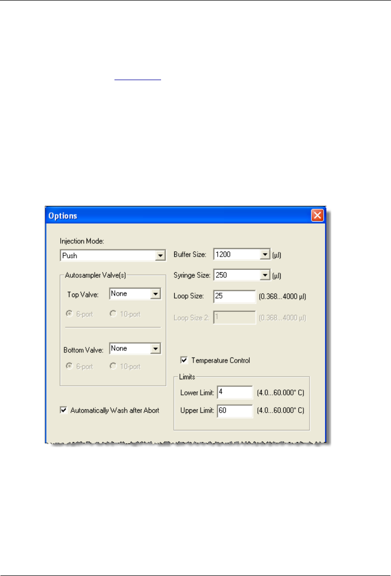
Dionex AS-AP Operator’s Manual
208 Doc. 065361-07 9/12
time precision in gradient applications. Synchronization of injections is
enabled and disabled in the Sampler Options of the Chromeleon 7
Instrument Method Wizard or Chromeleon 6.8 Program Wizard. See the
example in Figure 3-9.
NOTE For capillary systems, enabling synchronization of
injections with the pump may delay the start of a run
by several minutes.
•Monitor Link: If a Sample Conductivity and pH Accessory is installed,
select pH Conductivity in the list.
Options Page
•Injection Mode: Select the mode that corresponds to your autosampler’s
plumbing configuration.
•Autosampler Valve(s): Select the function of each optional high-pressure
valve installed in the autosampler. The valve function depends on the
Figure B-40. Example Chromeleon Configuration Wizard:
Options Page

B • Installation
Doc. 065361-07 9/12 209
autosampler’s plumbing configuration. Also, select whether the valve is a
6-port or 10-port valve.
•Automatically Wash after Abort: Select the check box to perform a
wash cycle after an Abort error occurs.
•Buffer Size: Select the volume of the installed buffer line.
•Syringe Size: Select the volume of the installed syringe.
•Loop Size: Enter the volume of the loop installed on each injection valve.
•Bridge Size (available if a fraction collection valve is configured and pull
mode is selected): Enter the volume of the installed bridge tubing. To
estimate the volume of 0.33 mm (0.013 in) ID blue PEEK tubing, use a
conversion factor of 0.86 L/cm (2.2 L/in).
•Temperature Control (available if the temperature control option is
installed and configured): Set the range of allowed temperature set points
for the sample carousel.
B.11.4 Connecting to the ePanel Set or Panel Tabset
Connecting to the Chromeleon 7 ePanel Set
1. To start the Chromeleon 7 client, click Start > All Programs >
Chromeleon 7 > Chromeleon 7.
2. To display the Dionex AS-AP ePanel, click the Instruments category bar
on the Console. Click your instrument in the Navigation Pane.
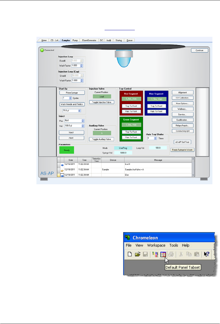
Dionex AS-AP Operator’s Manual
210 Doc. 065361-07 9/12
Chromeleon 7 connects to the instrument and displays the ePanel Set.
Click the Sampler tab (see Figure B-41).
Connecting to the Chromeleon 6.8 Control Panel
1. To start the Chromeleon client, click Start and select All Programs >
Chromeleon > Chromeleon.
2. To display the panel tabset, select
View > Default Panel Tabset or
click the Default Panel Tabset
toolbar button.
3. To display the Dionex AS-AP Control panel, click the Autosampler tab
Figure B-41. Example Chromeleon 7 ePanel Set: Dionex AS-AP ePanel

B • Installation
Doc. 065361-07 9/12 211
B.12 Checking the Needle Alignment
1. The needle may become misaligned during shipping and installation.
Before priming the syringe or performing any other autosampler
operations, check the needle alignment and realign the needle if needed.
For instructions, see Section 5.3.
2. After checking the needle alignment, remove the J-clip from the vial
pusher.
NOTE Save the J-clip. It is required for aligning the needle in
the future and for other service procedures.
3. Because the J-clip was installed when the power was turned, the self test
did not complete successfully. A self test must be completed before the
autosampler can start operation. To run a self test, open the Dionex AS-
AP ePanel (in Chromeleon 7) or Control panel (in Chromeleon 6.8), click
the Service button, and then click the Reset / Self Test button.
B.13 Priming the Syringe
During priming, the syringe, the syringe wash liquid line, and the syringe
waste tubing are flushed with wash liquid. This removes air bubbles from the
syringe and tubing.
1. Open the Dionex AS-AP ePanel (in Chromeleon 7) or Control panel (in
Chromeleon 6.8).
2. In the Cycles box under Prime Syringe, enter the number of times the
syringe should empty and fill during priming. The number of times
required depends on the size of the syringe and the length of the wash
liquid line.
3. Click Start. The syringe empties and fills the specified number of cycle
times and then priming stops. Repeat as required until no more bubbles
are seen in the wash liquid line.
4. If bubbles still remain in the syringe, prime for an additional two cycles.
5. If bubbles still remain after priming, follow the steps in Section 5.4.1 to
remove the syringe. Then, follow the steps in Section 5.4.2. To remove
the bubbles from the syringe and reinstall the syringe.

Dionex AS-AP Operator’s Manual
212 Doc. 065361-07 9/12
6. When the bubbles are gone, perform a manual wash operation (under
Wash Needle and Fluidics, enter a Volume, and click Start). The
volume required for a manual wash depends on the status of the buffer
line.
•If the buffer line is dry (for example, after changing the line), enter a
wash volume that is 1.5 times the buffer line tubing.
•If the buffer line has sample or other liquid in it that you want to flush
out, enter a volume large enough to flush the sample from the line.
B.14 TTL and Relay Connections (Optional)
1. Locate the following items in the Dionex AS-AP Ship Kit:
•Twisted pair of wires (P/N 043598)
•(For a TTL input) 8-position connector plug (P/N 924133)
•(For a relay output) 12-position connector plug (P/N 923686)
2. For each TTL or relay to be used, connect an active wire (red) and a
ground wire (black) to the connector plug at the appropriate pin locations.
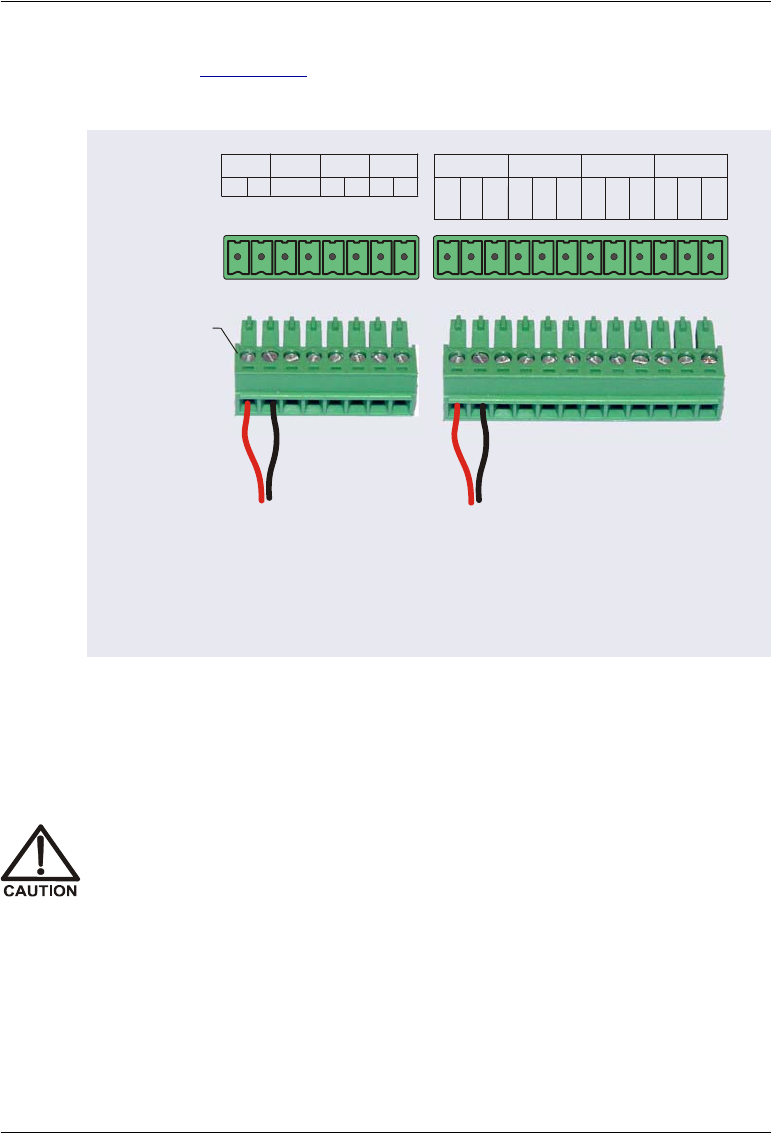
B • Installation
Doc. 065361-07 9/12 213
Refer to Figure B-42 or the label on the Dionex AS-AP rear panel for the
connector pin assignments.
To attach a wire to the plug, strip the end of the wire, insert it into the
plug, and use a screwdriver to tighten the locking screw.
3. Plug the connector plug into the connector on the Dionex AS-AP rear
panel.
4. Connect the wires from the Dionex AS-AP connector plug to the
appropriate connector pins on the other modules. Additional connector
plugs are provided with other Dionex modules.
Figure B-42. Dionex AS-AP Relay and TTL Connector Strips and Connector
Plugs
Connector Plug
Position
12 435678 9 10 11 12
NO
NC
COM
NO
NC
COM
NO
NC
COM
NO
NC
COM
RLY
1234
Connector Pins
TTL
134
+–+–+–+–
2
12 435678
12
4
3
5
6
7
8
9
10
11
12
12 435678
Locking
Screws
Relay Connection Notes:
• Each relay is a solid-state relay contact output
• Connect a relay to be either normally open (NO pin and
COM pin) or normally closed (NC pin and COM pin)
• Relays are capable of switching 2 A at 24 VDC
When attaching wires to the connector plug, be careful not to allow
stray strands of wire to short to an adjoining position on the connector.

Dionex AS-AP Operator’s Manual
214 Doc. 065361-07 9/12
NOTE For TTL connections, check the polarity of each con-
nection. Connect signal wires to signal (+) pins and
ground wires to ground (-) pins.
5. In the Chromeleon 7 Instrument Configuration program or the
Chromeleon 6.8 Server Configuration program, double-click the Dionex
AS-AP device to open the configuration properties dialog box.
•On the Relays page, select the check box for each connected relay.
•On the Inputs page, select the check box for each connected input.
Installation of the Dionex AS-AP is now complete. For operating instructions,
refer to Chapter 3.
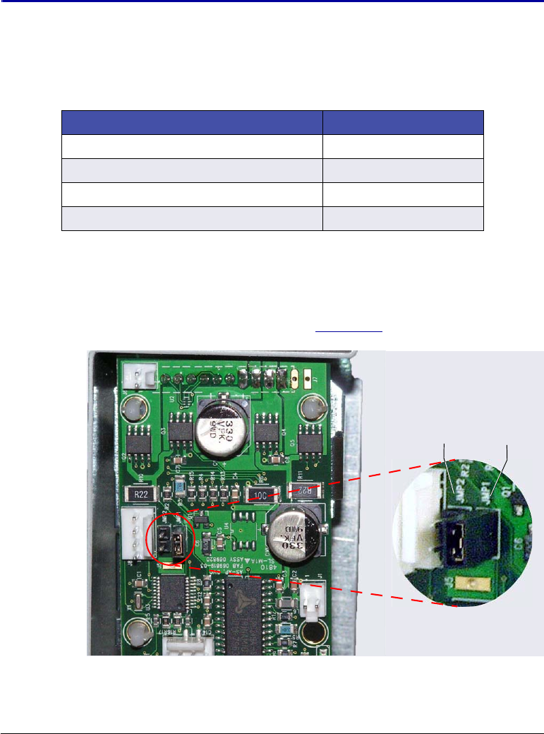
Doc. 065361-07 9/12 215
C • Installing Optional Valves
This chapter provides installation instructions for the following Thermo
Scientific Dionex AS-AP Autosampler valve options.
C.1 Setting the Valve Electronics Board Jumpers
1. Locate the two jumpers (labeled JMP1 and JMP2) on the electronics board
attached to the rear of the valve (see Figure C-1).
Valve Option Part Number
6-port valve with mounting bracket 074123
10-port valve with mounting bracket 074122
6-port valve without mounting bracket 070209
10-port valve without mounting bracket 070208
Figure C-1. Jumpers on Valve Electronics Board
(Jumper Installed on JMP1 in the Photo)
Detail view of jumper
installed on JMP1
JMP1JMP2

Dionex AS-AP Operator’s Manual
216 Doc. 065361-07 9/12
Table C-1 shows the required jumper settings for each valve
configuration.
NOTE To change a jumper location, pull the jumper off of the
pins and then push it onto the other set of pins.
2. For a single valve, install the jumper on JMP1 as shown in the detail view
in Figure C-1.
3. For two valves, install the jumpers as follows:
•Top valve: Install the jumper on JMP2
•Bottom valve: Install the jumper on JMP1
NOTE If you are installing a second valve onto an existing
valve with mounting bracket, install the top valve’s
jumper on JMP2 after removing the valve with mount-
ing bracket from the Dionex AS-AP.
4. If you are installing a single valve with mounting bracket, go on to
Section C.2 to install the valve with mounting bracket in the Dionex AS-
AP.
5. If you are installing a second valve (on either a new uninstalled mounting
bracket or on an existing mounting bracket), go on to Section C.3.
Number of Valves Valve Position Jumper Setting
One valve Either top or bottom JMP1
Two valves Top valve
Bottom valve
JMP2
JMP1
Table C-1. Required Jumper Settings on Valve Electronics Boards
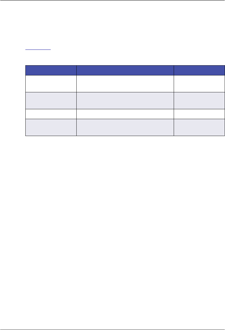
C • Installing Optional Valves
Doc. 065361-07 9/12 217
C.2 Installing a Valve with Mounting Bracket
Included Parts
Table C-2 lists the additional parts included with the 6-port or 10-port valve
with mounting bracket.
Additional Items Required
•Phillips head screwdriver
•3 mm Allen wrench
Part Number Item Quantity
075524 Phillips head screw (for attaching
mounting bracket to Dionex AS-AP)
4
050481 Cap socket head screw, M04 (for
attaching grounding strap)
1
070042 Dionex AS-AP labels 1
075527
075528
Plumbing kit for 6-port valve
Plumbing kit for 10-port valve
1
Table C-2. Additional Parts Included with the Valve with Mounting Bracket
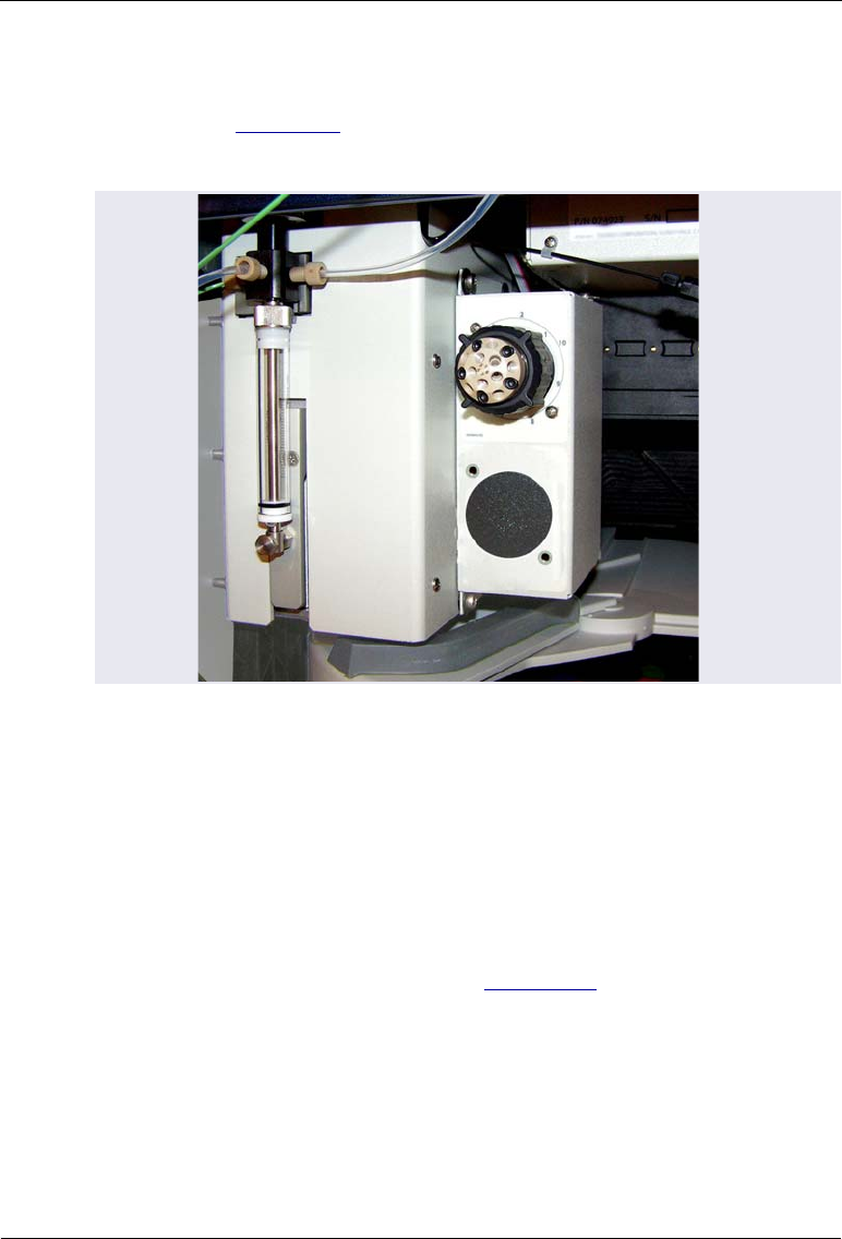
Dionex AS-AP Operator’s Manual
218 Doc. 065361-07 9/12
Installation Procedure
For reference, Figure C-2 shows the Dionex AS-AP interior after installation
of the valve with mounting bracket is complete.
1. Turn off the pump flow.
2. Press the main power switch on the rear panel to turn off the Dionex AS-
AP power.
3. Lift up the Dionex AS-AP front panel.
4. Verify that the jumpers on the valve electronics board for each valve
being installed are set correctly (see Section C.1).
Figure C-2. Optional Valve Installed in the Dionex AS-AP
(10-Port Valve Shown)
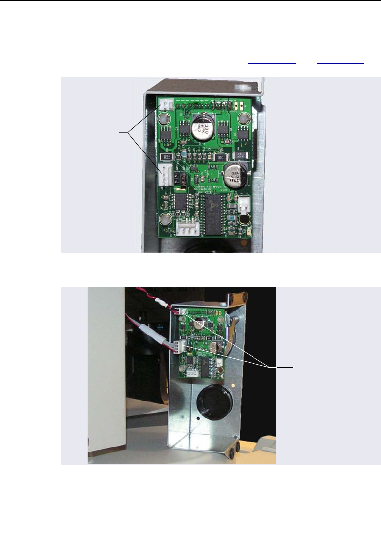
C • Installing Optional Valves
Doc. 065361-07 9/12 219
5. Locate the two valve cables inside the Dionex AS-AP in the upper-left
back corner. Connect these two cables to the connectors on the electronics
board attached to the rear of the valve (see Figure C-3 and Figure C-4).
Figure C-3. Cable Connectors on Valve Electronics Board
Figure C-4. Valve Cables Connected to Valve Electronics Board
(Single Valve Configuration Shown)
Cable
Connectors
for a Single
Valve or
Valve #1
Valve cables from
inside the Dionex

Dionex AS-AP Operator’s Manual
220 Doc. 065361-07 9/12
6. Before continuing, note the
raised opening on the top of the
mounting bracket (see
Figure C-5). Later in the
procedure, you will connect a
grounding strap here. The
grounding strap is a flat cable
located inside the Dionex AS-AP
in the upper-left back corner
(where the valve cables are
located).
Figure C-5. Grounding Strap Connection Location
7. Note the four mounting screw openings on the side of the syringe
assembly box (see Figure C-6) and the corresponding openings on the
mounting bracket (see Figure C-7).
Figure C-6. Mounting Location for the Valve with Mounting Bracket
Opening for
connecting
a grounding
strap
Openings for
the mounting
bracket screws
Syringe
Assembly Box

C • Installing Optional Valves
Doc. 065361-07 9/12 221
8. Locate the four Phillips head screws
(P/N 075524) provided with the valve
with mounting bracket.
9. Align the mounting bracket on the
side of the syringe assembly
enclosure (see Figure C-8). Using a
Phillips head screwdriver, attach the
upper-left screw first (to help hold the
valve with mounting bracket in
place), and then attach the remaining
screws.
Tighten the screws just enough to
secure the mounting bracket to the
enclosure. Do not overtighten the
screws.
Figure C-8. Valve with Mounting Bracket Installed
10. Locate the grounding strap inside the Dionex AS-AP in the upper-left
back corner.
Figure C-7. Valve with Mounting Bracket Side View
Openings for the
valve mounting
bracket screws
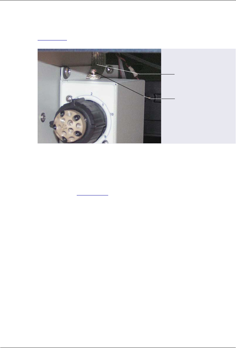
Dionex AS-AP Operator’s Manual
222 Doc. 065361-07 9/12
11. Using the cap socket head screw (P/N 050481) provided, attach the
grounding strap to the connection location on the mounting bracket (see
Figure C-9). Use a 3 mm Allen wrench to tighten the screw.
12. Plumb the valve ports as required for your application, using the
plumbing kit provided with the valve with mounting bracket. If you
installed a 6-port injection valve, diverter valve, or fraction collection
valve, refer to Section B.7 for plumbing instructions. For a 6-port or 10-
port auxiliary valve, refer to the documentation for your application for
plumbing instructions.
Figure C-9. Grounding Strap Attached to Valve Mounting Bracket
Socket Head
Screw
Grounding Strap
C • Installing Optional Valves
Doc. 065361-07 9/12 223
C.3 Installing a Second Valve on the Valve Mounting
Bracket
Included Parts
Table C-2 lists the additional parts included with the valve.
Additional Items Required
•Phillips head screwdriver
•3 mm Allen wrench
Part Number Item Quantity
030207 Phillips head screw (for attaching
valve to mounting bracket)
2
045691 Washer (for attaching valve to
mounting bracket)
2
075496 Valve cable 1
075497 Valve cable 1
Table C-3. Additional Parts Included with the Valve
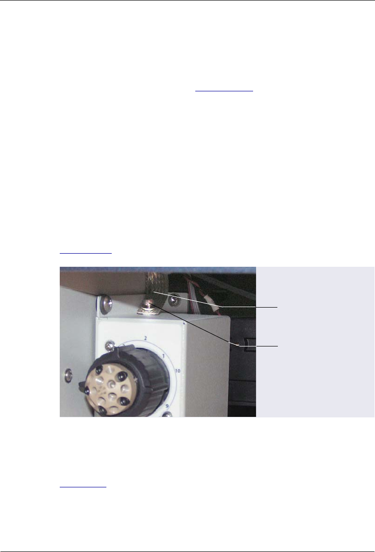
Dionex AS-AP Operator’s Manual
224 Doc. 065361-07 9/12
C.3.1 Removing the Valve Mounting Bracket from the Dionex AS-
AP (If Installed)
NOTE If you are installing a second valve on a new valve with
mounting bracket, go on to Section C.3.2.
If the valve with mounting bracket is already installed in the Dionex AS-AP,
follow the instructions in this section to remove it from its mounting location
before installing the second valve.
1. Turn off the pump flow.
2. Press the main power switch on the rear panel to turn off the Dionex AS-
AP power.
3. Lift up the Dionex AS-AP front panel.
4. Using a 3 mm Allen wrench, remove the screw from the grounding strap
connected to the top of the valve with mounting bracket (see
Figure C-10).
5. Using a Phillips head screwdriver, remove the four screws that attach the
valve with mounting bracket to the side of the syringe assembly box (see
Figure C-8).
Figure C-10. Grounding Strap Attached to Valve Mounting Bracket
Socket Head
Screw
Grounding Strap
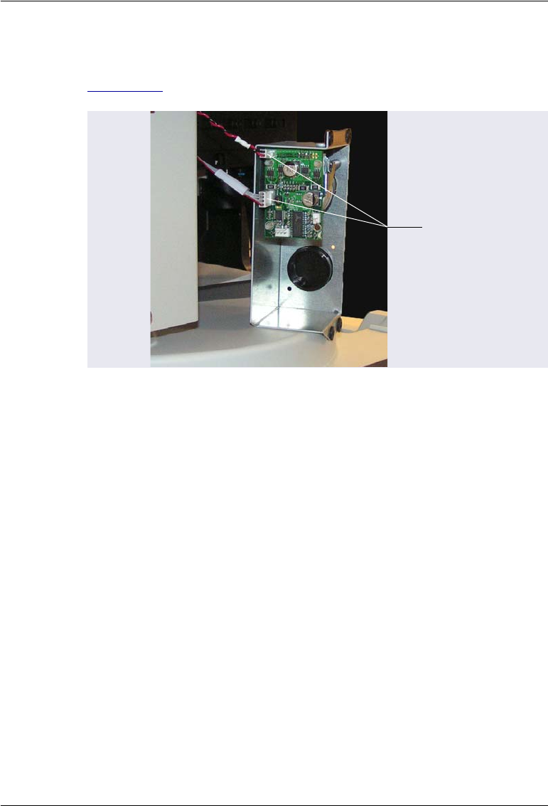
C • Installing Optional Valves
Doc. 065361-07 9/12 225
6. Remove the valve with mounting bracket and disconnect the two cables
connected to the valve electronics board on the rear of the valve (see
Figure C-11).
Figure C-11. Valve Cables Connected to Valve Electronics Board
Valve cables
(remove)
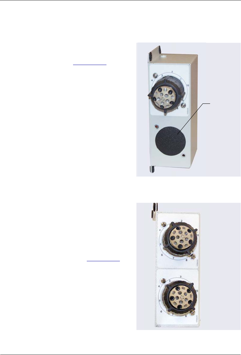
Dionex AS-AP Operator’s Manual
226 Doc. 065361-07 9/12
C.3.2 Installing a Second Valve on an Uninstalled Mounting
Bracket
1. Remove the black cover from the
valve opening on the mounting
bracket (see Figure C-12) by
pushing from the rear of the
bracket.
2. Locate the sheet of labels
(P/N 070042) provided with the
valve with mounting bracket.
Remove the label for the type of
valve you are installing and attach
it to the front of the mounting
bracket.
3. Locate the two screws
(P/N 030207) and washers
(P/N 045691) provided with the
valve.
Figure C-12. Mounting Bracket with Valve
Opening Cover
4. Slide the washers onto the screws.
5. From the rear of the bracket, slide
the valve through the valve
opening. Using a Phillips head
screwdriver, secure the valve to
the bracket with the two screws
and washers (see Figure C-13).
Figure C-13. Second Valve Installed on Mounting Bracket
Valve
Opening
Cover
(remove)
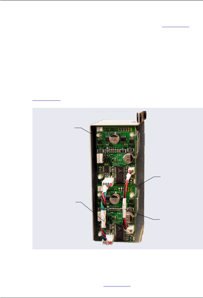
C • Installing Optional Valves
Doc. 065361-07 9/12 227
6. Check the settings of the two jumpers (labeled JMP1 and JMP2) on the
electronics board attached to the rear of each valve (see Section C.1).
Install the jumpers as follows:
•Top valve: Install the jumper on JMP2
•Bottom valve: Install the jumper on JMP1
NOTE To change a jumper location, pull the jumper off of the
pins and then push it onto the other set of pins.
7. Locate the two cables provided with the valve. Connect each cable
between the electronics boards on the top and bottom valves as shown in
Figure C-14.
8. The valves with mounting bracket can now be installed in the Dionex AS-
AP. Follow the instructions in Section C.2.
Figure C-14. Rear of Valve Mounting Bracket with Cables for the
Second Valve Connected
Top Valve
Electronics
Board
Bottom Valve
Electronics
Board
Cable
(P/N 075497)
Cable
(P/N 075496)

Dionex AS-AP Operator’s Manual
228 Doc. 065361-07 9/12
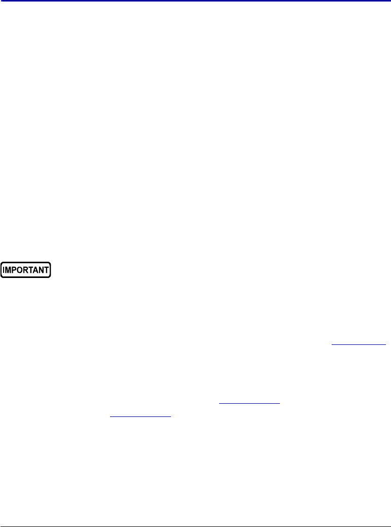
Doc. 065361-07 9/12 229
D • Fraction Collection Option
When configured for fraction collection, the Dionex AS-AP is connected to
two high-pressure valves (injection and fraction collection), which are
installed in the Dionex AS-AP. In addition, to operate the Dionex AS-AP with
fraction collection, a fraction collection license for Chromeleon 6.8 is
required, and a fraction collection driver must be configured in the
Chromeleon 6.8 timebase. Installation of the injection valve, fraction
collection valve, license, and driver allows automation of injection, fraction
collection, and reinjection in one system.
NOTE Support for the fraction collection option is not available in
Chromeleon 7.
NOTE Because of the flow volume required for adequate recoveries,
Thermo Fisher Scientific recommends performing fraction
collection on systems configured for 4-mm columns.
D.1 Installing and Plumbing the Valves
To install the two high-pressure valves, follow the instructions in Appendix C.
Designate the top valve as the injection valve and the bottom valve as the
fraction collection valve.
To plumb the valves, follow the instructions for the type of injection mode to
be used. For push mode injections, see Section D.1.1. For pull mode
injections, see Section D.1.2.
If a suppressor is configured in the system, it must be plumbed for
external water mode.

Dionex AS-AP Operator’s Manual
230 Doc. 065361-07 9/12
D.1.1 Plumbing the Valves for Push Mode with Fraction Collection
Figure D-1 illustrates the Dionex AS-AP plumbing schematic for fraction
collection in push mode.
Plumbing the Injection Valve
To plumb the injection valve, follow the instructions in Section B.7.1. The
injection valve plumbing is the same as that for push mode without fraction
collection.
Plumbing the Fraction Collection Valve
1. Locate the following items in the Dionex AS-AP Ship Kit (P/N 074929)
or the plumbing kit provided with the valve (P/N 075527):
•0.25 mm (0.010 in) ID black PEEK tubing (P/N 042690)
Figure D-1. Plumbing Schematic: Fraction Collection in Push Mode
Syringe
Syringe
Valve
Wash
Reservoir
Needle Line
Buffer Line
Syringe Waste Line
Wash Liquid Line
Fraction
Collection Valve
Carousel
6
3
2
1
5
4
Sampling Needle
Wash
Port
Injection Valve
(Inject Position)
Detector
P
S
L
C
L
W
1
4
5
Sample
Transfer
Line
Injection
Port
Inject
Collect
2
3
6

D • Fraction Collection Option
Doc. 065361-07 9/12 231
•0.33 mm (0.013 in) ID blue PEEK tubing (P/N 049714)
•0.75 mm (0.030 in) ID green PEEK tubing (P/N 044777)
•A tan 1/16 in flangeless fitting bolt (P/N 052230) and a two-piece
ferrule (clear cone and tan flat) (P/N 062511)
•Six 10-32 fitting bolts (P/N 074449) and six double-cone ferrules
(P/N 074373)
NOTE Use 10-32 fitting bolts (P/N 074449) and six double-
cone ferrules (P/N 074373) for all valve connections
described below. For tightening requirements, refer to
the guidelines on page 111.
2. Follow the steps below to disconnect the buffer line from the needle and
reconnect it to the fraction collection valve:
a. To position the needle in a convenient position for servicing, open the
Dionex AS-AP ePanel (in Chromeleon 7) or Control panel (in
Chromeleon 6.8) and click Alignment. The Sampler Alignment panel
opens. Click Move to Wash Port. The needle moves to above the
wash port.
b. To prevent twisting
of the needle, hold
the needle holder (see
Figure D-2) with one
hand and then
disconnect the buffer
line from the needle.
Figure D-2. Buffer Line Connected to the Needle
c. Remove the fitting and ferrules from the line.
d. Use a 10-32 fitting bolt and double-cone ferrule to connect the buffer
line to port 2 on the fraction collection valve.
3. Cut a length of 0.33 mm (0.013 in) ID blue PEEK tubing long enough to
connect from the top of the needle to the fraction collection valve.
Disconnect
this fitting
Needle
Holder
Buffer Line
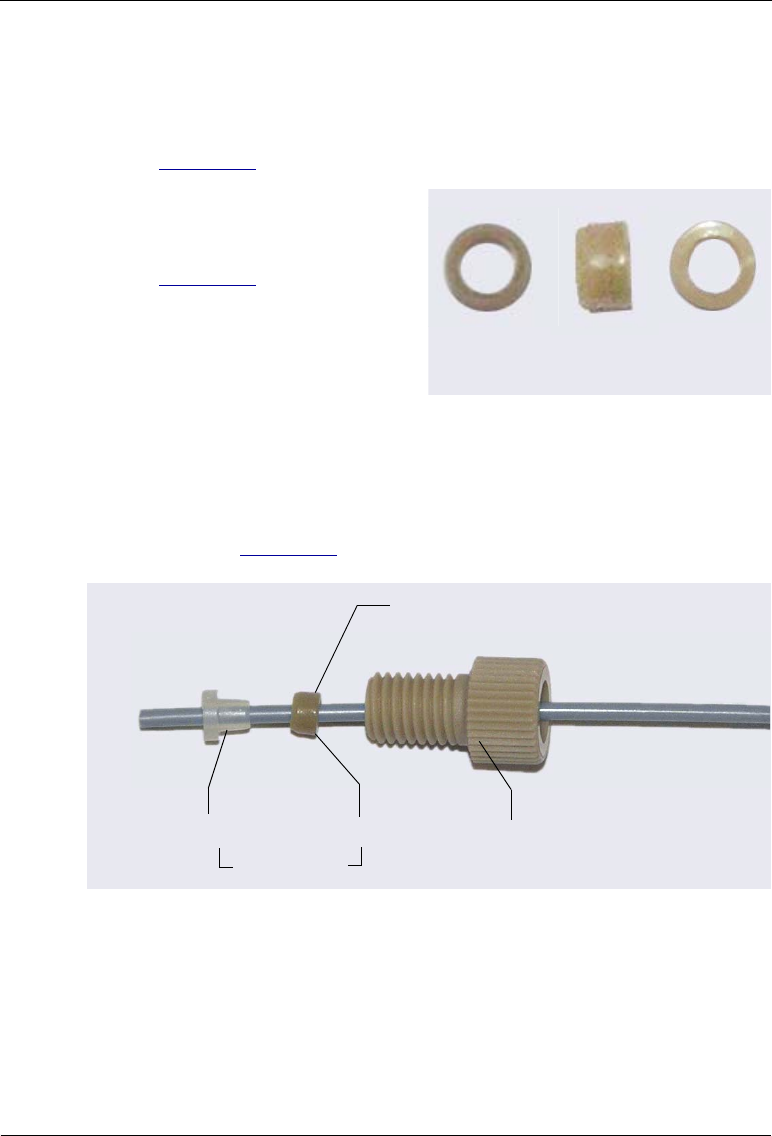
Dionex AS-AP Operator’s Manual
232 Doc. 065361-07 9/12
4. Follow the steps below to connect this line to the needle:
a. Use the 1/16 in flangeless fitting bolt and two-piece ferrule for the
connection. Slide the fitting bolt onto the tubing as shown in
Figure D-4.
b. Observe that one side of the
small tan ferrule is beveled
and one side is flat (see
Figure D-3). Hint: The flat
side appears shiny.
Figure D-3. Small Tan Ferrule (Enlarged)
c. With the flat side of the small tan ferrule facing toward the fitting
bolt, slide the ferrule onto the tubing. Then, slide the clear cone
ferrule onto the tubing with the cone toward the flat ferrule and fitting
bolt (see Figure D-4).
d. Position the bolt and ferrules away from the end of the tubing (so they
will not fall off when you insert the tubing into the needle holder).
e. Insert the tubing down into the center of the needle holder. When you
insert the tubing, you should feel the tubing drop into a small
Figure D-4. Fitting for Needle Line
Beveled Side Flat Side
Fitting Bolt
(P/N 052230)
Flat Ferrule Cone Ferrule
Flat Side
(P/N 062511)
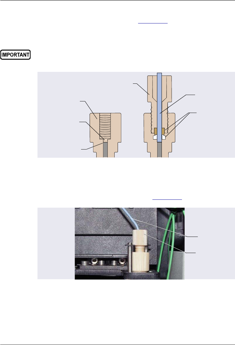
D • Fraction Collection Option
Doc. 065361-07 9/12 233
indentation inside the holder (see Figure D-5). If not, move the tubing
slightly until it does.
f. Slide the ferrules and bolt into the needle holder.
g. To prevent twisting of the needle, hold the needle with one hand and
then tighten the fitting fingertight (see Figure D-6).
5. Use a 10-32 fitting bolt and double-cone ferrule to connect the other end
of the needle line to port 3 on the fraction collection valve.
When connecting the line to the needle, make sure the line slides into
the indentation inside the needle holder before tightening the fitting.
Figure D-5. Cross-Section of Needle Holder and
Needle Line Fitting
Figure D-6. Needle Line Connected to the Needle
Fit the tubing
into this
indentation
Needle
Holder
Top of the
needle
Needle Line
Two-Piece
Ferrule
Flangeless
Fitting Bolt
Needle Line
and Fitting
Needle
Holder

Dionex AS-AP Operator’s Manual
234 Doc. 065361-07 9/12
6. Cut a length of 0.75 mm (0.030 in) ID green PEEK tubing (P/N 044777)
long enough to connect the detector outlet to the fraction collection valve
and at least 25 cm (10 in) long. Measure the length of the line. You will
need this information to calculate the delay time (see the following note).
NOTE The line between the detector outlet and the fraction collec-
tion valve must be long enough to provide adequate delay
time (6 sec or more) between the detector outlet and the
valve. For example, a 25 cm (10 in) length of 0.75 mm
(0.030 in) ID tubing has a tubing volume of about 116 L. At
a flow rate of 1 mL/min, this length will create a delay time
of 7 sec. You enter the delay time (or delay volume) when
you set up a fraction collection program in Chromeleon 6.8
(see Section D.3.4).
7. Use 10-32 fitting bolts and double-cone ferrules to connect this line
between the detector cell outlet.and port 4 on the fraction collection valve.
8. Cut a length of 0.75 mm (0.030 in) ID green PEEK tubing long enough to
reach from the fraction collection valve to the Dionex AS-AP waste port.
This is a waste line.
9. Use a 10-32 fitting bolt and double-cone ferrule to connect one end of this
line to port 5 on the fraction collection valve.
10. Route the waste line to the Dionex AS-AP waste port and insert the line
into the round opening in the port (see Figure D-7). To ensure the waste
lines do not interfere with needle arm movement, secure the excess tubing

D • Fraction Collection Option
Doc. 065361-07 9/12 235
with the flexible tubing tie in the slotted compartment next to the needle
(see Figure D-8).
11. Cut a short length of 0.25 mm (0.010 in) ID black PEEK tubing. Use 10-
32 fitting bolts and double-cone ferrules to connect this line between
port 1 and port 6 on the fraction collection valve.
Figure D-7. Waste Lines Installed in the Waste Port
Figure D-8. Flexible Tubing Tie in Slotted Compartment
Waste line from
injection valve
Waste
Port Waste line from
syringe
Waste line from
fraction collection
valve
Flexible Tubing
Tie
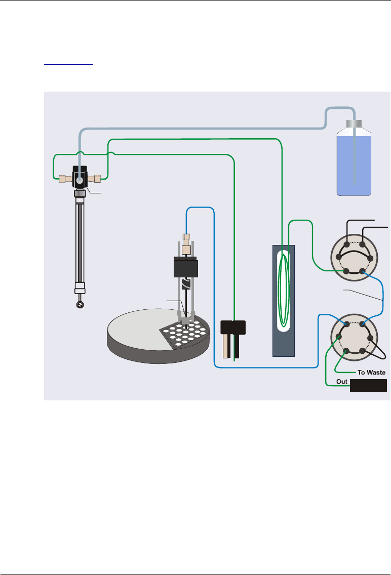
Dionex AS-AP Operator’s Manual
236 Doc. 065361-07 9/12
D.1.2 Plumbing the Valves for Pull Mode with Fraction Collection
Figure D-4 illustrates the Dionex AS-AP plumbing schematic for fraction
collection in pull mode.
1. Locate the following items in the Dionex AS-AP Ship Kit (P/N 074929)
or the plumbing kit provided with the valve (P/N 075527):
•0.25 mm (0.010 in) ID black PEEK tubing (P/N 042690)
•0.33 mm (0.013 in) ID blue PEEK tubing (P/N 049714)
•0.75 mm (0.030 in) ID green PEEK tubing (P/N 044777)
•Six 10-32 fitting bolts (P/N 074449) and six double-cone ferrules
(P/N 074373)
Figure D-9. Sampling Principle: Fraction Collection in Pull Mode
Syringe
Syringe
Valve
Wash
Reservoir
Sample Transfer Line
Buffer Line
Syringe Waste Line
Wash Liquid Line
Fraction
Collection Valve
Carousel
Sampling Needle
Injection Valve
SYR
CP
L
S
L
5
1
3
Bridge Line
4
2
Collect
Inject
6
2
3
4
5
6
1
Detector

D • Fraction Collection Option
Doc. 065361-07 9/12 237
NOTE Use 10-32 fitting bolts (P/N 074449) and double-cone
ferrules (P/N 074373) for all valve connections,
described below. For tightening requirements, refer to
the guidelines on page 111.
2. If the injection valve is already plumbed for pull mode, disconnect the
buffer line from port SYR (6). Also, disconnect the sample transfer line
from port S (5).
3. Connect the buffer line to port S (5) on the injection valve.
4. Connect the sample transfer line to port 3 on the fraction collection valve.
5. Cut a length of 0.75 mm (0.030 in) ID green PEEK tubing (P/N 044777)
long enough to connect the detector outlet to the fraction collection valve
and at least 25 cm (10 in) long. Measure the length of the line. You will
need this information to calculate the delay time (see the following note).
NOTE The line between the detector outlet and the fraction collec-
tion valve must be long enough to provide adequate delay
time (6 sec or more) between the detector outlet and the
valve. For example, a 25 cm (10 in) length of 0.75 mm
(0.030 in) ID tubing has a tubing volume of about 116 L. At
a flow rate of 1 mL/min, this length will create a delay time
of 7 sec. You enter the delay time (or delay volume) when
you set up a fraction collection program in Chromeleon 6.8
(see Section D.3.4).
6. Connect this line between the detector cell outlet and port 4 on the
fraction collection valve.
7. Cut a length of 0.75 mm (0.030 in) ID green PEEK tubing long enough to
reach from the fraction collection valve to the Dionex AS-AP waste port.
This is a waste line. Connect one end of this line to port 5 on the fraction
collection valve.
8. Route the waste line to the Dionex AS-AP waste port and insert the line
into the round opening in the port (see Figure D-7). To ensure the waste
lines do not interfere with needle arm movement, secure the excess tubing
with the flexible tubing tie in the slotted compartment next to the needle
(see Figure D-8).

Dionex AS-AP Operator’s Manual
238 Doc. 065361-07 9/12
9. Cut a length of 0.33 mm (0.013 in) ID blue PEEK tubing long enough to
connect between the injection valve and the fraction collection valve.
This is the bridge line. Measure the length of this line. You will need to
enter the bridge line volume in the Chromeleon 6.8 configuration (see
Section D.2).
10. Connect the bridge line between port SYR (6) on the injection valve and
port 2 on the fraction collection valve.
11. Cut a length of 0.25 mm (0.010 in) ID black PEEK tubing about 15 cm
(6 in) long. Connect this line between port 1 and port 6 on the fraction
collection valve.
D.2 Setting Up Fraction Collection in Chromeleon 6.8
To use fraction collection with Chromeleon 6.8, the following software
requirements must be met:
•Chromeleon 6.8 Chromatography Data System (version 6.80 DU10c or
later) must be installed. Fraction collection is not available in Chromeleon
7.
•The fraction collection driver installed in the same timebase as the Dionex
AS-AP in the Chromeleon 6.8 Server Configuration program.
•One of the following fraction collection licenses:
Basic Fraction Collection: Includes wizard-based program setup and
fraction reporting.
Extended Fraction Collection: Includes basic fraction collection and
additional functions, such as automatic sample purification using the
associated post-acquisition steps, color-coded sample and fraction
tracking, and sophisticated fractionation algorithms with peak shoulder
detection.
Configuring Fraction Collection in Chromeleon 6.8
1. In the Chromeleon 6.8 Server Configuration program, configure the two
high-pressure valves on the Options page in the Dionex AS-AP
configuration properties dialog box (see Figure D-10). Under
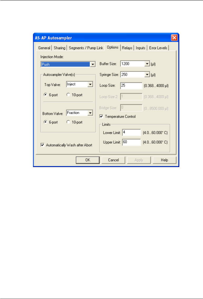
D • Fraction Collection Option
Doc. 065361-07 9/12 239
Autosampler Valve(s), select Inject for the top valve and Fraction for
the bottom valve.
For pull mode only: In the Bridge Size box, enter the volume of the
bridge line that connects the injection valve to the fraction collection
valve. To estimate the volume of 0.33 mm (0.013 in) ID blue PEEK
tubing, use a conversion factor of 0.86 L/cm (2.2 L/in).
NOTE If you install a different length bridge line at a later
time, make sure you enter the correct Bridge Size for
the new line. If you disconnect the fraction collection
valve and use only the injection valve, set Bridge Size
to 0.
2. In the Chromeleon 6.8 Server Configuration program, install the Fraction
Collection driver in the same timebase in which the Dionex AS-AP is
installed. In the Add device to timebase dialog box, the Fraction
Figure D-10. Example Chromeleon 6.8 Dionex AS-AP Configuration
Properties Dialog Box: Options Page
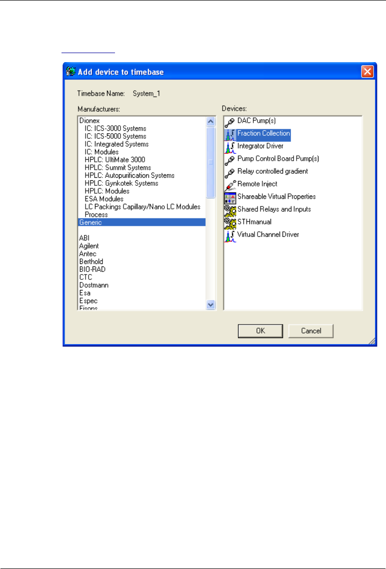
Dionex AS-AP Operator’s Manual
240 Doc. 065361-07 9/12
Collector driver is listed under Generic in the Manufacturers list (see
Figure D-11).
Figure D-11. Chromeleon 6.8 Server Configuration:
Add device to timebase dialog box

D • Fraction Collection Option
Doc. 065361-07 9/12 241
D.3 Performing Fraction Collection with the Dionex AS-
AP
This section provides an overview of the principles of fraction collection with
the Dionex AS-AP. Brief operating instructions are included. For details
about performing fraction collection, refer to the Chromeleon 6.8 Help.
D.3.1 Sampling Principle for Fraction Collection in Push Mode
When configured for push mode and fraction collection, the Dionex AS-AP
performs the following operations to sample from a vial and collect fractions:
1. Rotates the carousel so that the vial to be sampled is positioned parallel to
the sampling needle.
2. Moves the needle horizontally to position it over the vial.
3. Lowers the needle into the vial.
4. With the fraction
collection valve in the
Drain position, draws the
sample into the needle and
buffer line.
5. Moves the needle to the
injection port.
Fraction Collection Push Mode:
Draw sample into needle and buffer line.
Needle
Syringe
W
L
P
C
L
6
5
Inject
Needle
Line
Sample
Sample
Transfer Line
2
1
3
4
Buffer
Line
6
3
2
1
5
4
Detector
Drain
To Waste
Sample
Loop

Dionex AS-AP Operator’s Manual
242 Doc. 065361-07 9/12
6. With the injection valve in
the Load position and the
fraction collection valve in
the Drain position, the
syringe pushes the sample
out of the buffer line,
through the needle and
sample transfer line, and
into the sample loop.
7. When the injection valve
is switched to the Inject
position, sample is swept
out of the loop and
delivered to the column.
The fraction collection
valve remains in the Drain
position during injection.
Fraction Collection Push Mode:
Load (push) sample into the sample loop.
Syringe
W
L
P
C
L
6
5
Load
Needle
Line
Sample
Sample
Transfer Line
2
1
3
4
Buffer
Line
6
3
2
1
5
4
Detector
Drain
To Waste
Sample
Loop
Fraction Collection Push Mode:
Inject the sample onto the column.
Syringe
W
L
P
C
L
6
5
Inject
Needle
Line
Sample
Sample
Transfer Line
2
1
3
4
Buffer
Line
6
3
2
1
5
4
Detector
Drain
To Waste
Sample
Loop
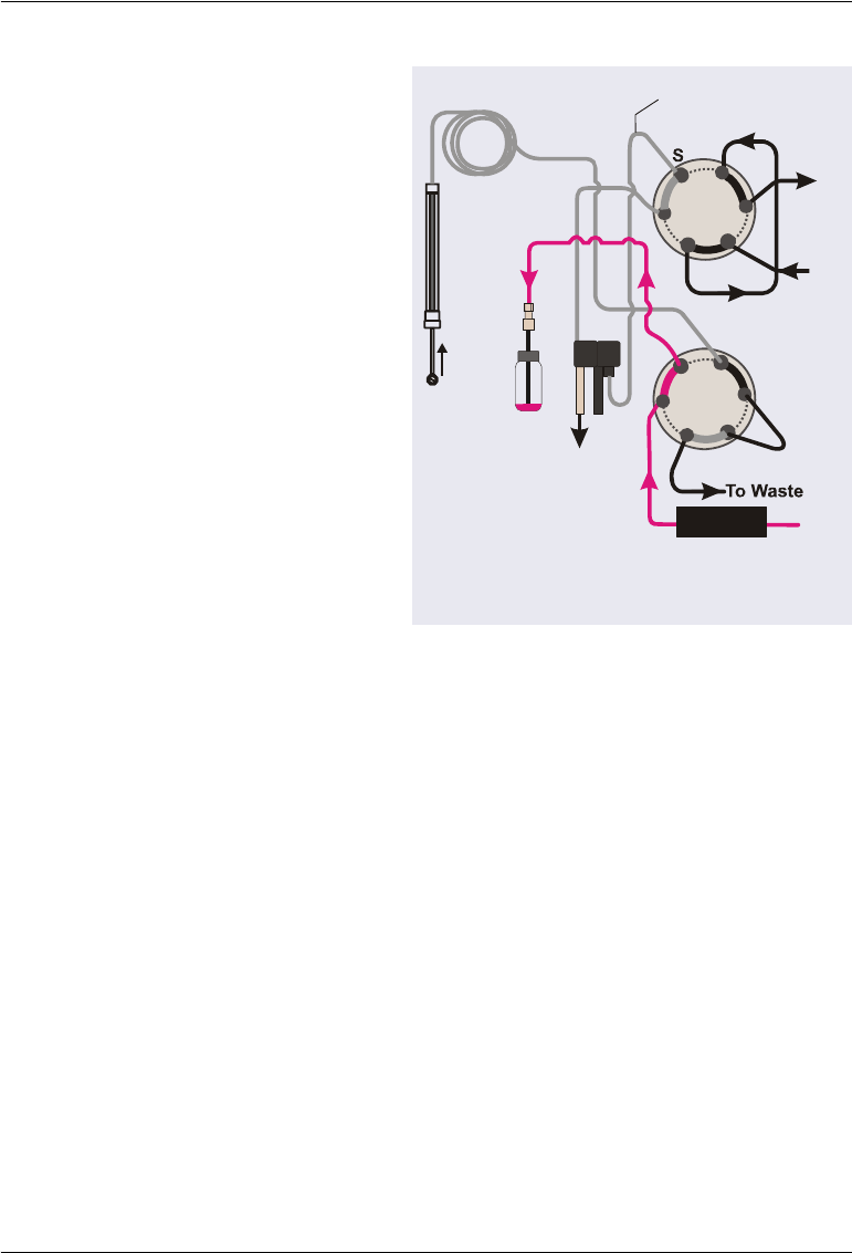
D • Fraction Collection Option
Doc. 065361-07 9/12 243
8. After injection, the
fraction collection valve is
switched to the Collect
position and the Dionex
AS-AP collects fractions
from the detector outlet
line through the needle and
into vials.
Fraction Collection Push Mode:
Collect fractions from the detector.
Syringe
W
L
P
C
L
6
5
Inject
Sample
2
1
3
4
6
3
2
1
5
4
Detector
Collect
To Waste
Sample
Transfer Line
Buffer
Line
Sample
Loop
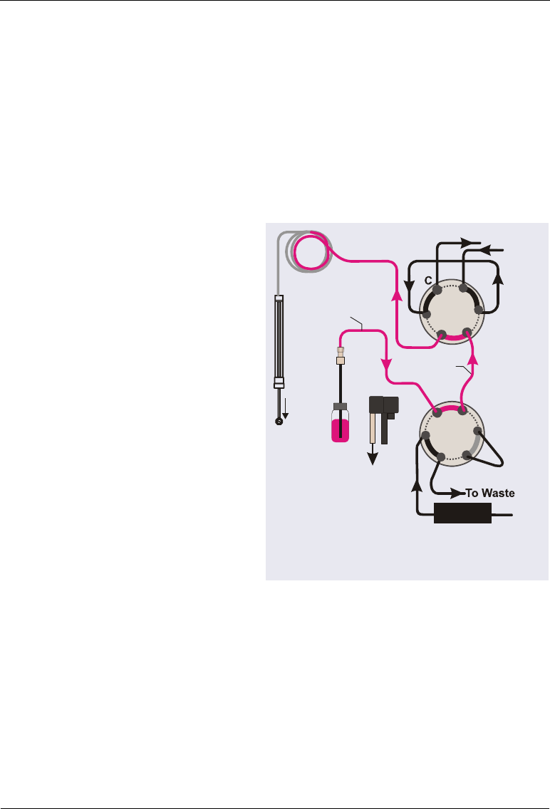
Dionex AS-AP Operator’s Manual
244 Doc. 065361-07 9/12
D.3.2 Sampling Principle for Fraction Collection in Pull Mode
When configured for pull mode and fraction collection, the Dionex AS-AP
performs the following operations to sample from a vial and collect fractions:
1. Rotates the carousel so that the vial to be sampled is positioned parallel to
the sampling needle.
2. Moves the needle horizontally to position it over the vial.
3. Lowers the needle into the vial.
4. With the fraction
collection valve in the
Drain position and the
injection valve in the
Inject position, draws the
sample into the needle,
sample transfer line,
bridge line, and buffer
line.
Fraction Collection Pull Mode:
Draw sample into needle and buffer line.
Needle
Syringe
L
S
SYR
L
P
4
Inject
Sample
Sample
Transfer Line
6
5
1
Buffer Line
6
32
1
5
4
Detector
Drain
To Waste
Bridge
Line
3
2
Sample
Loop

D • Fraction Collection Option
Doc. 065361-07 9/12 245
5. When the injection valve
is switched to the Load
position, the syringe pulls
the sample out of the
needle, sample transfer
line, bridge line, and
buffer line, and into the
sample loop. The fraction
collection valve remains in
the Drain position during
loading.
6. When the injection valve
is switched to the Inject
position, sample is swept
out of the loop and
delivered to the column.
The fraction collection
valve remains in the Drain
position during injection.
Fraction Collection Pull Mode:
Load (pull) sample into the sample loop.
Needle
Syringe
Sample
Sample
Transfer Line
Buffer Line
6
3
2
1
5
4
Detector
Drain
To Waste
L
S
S
Y
R
L
P
Load
1
Bridge
Line
3
2
4
5
6
Sample
Loop
Fraction Collection Pull Mode:
Inject sample onto the column.
Needle
Syringe
Sample
Sample
Transfer Line
Buffer Line
6
3
2
1
5
4
Detector
Drain
To Waste
L
S
S
Y
R
L
P
Inject
Bridge
Line
3
2
4
5
6
1
Sample
Loop
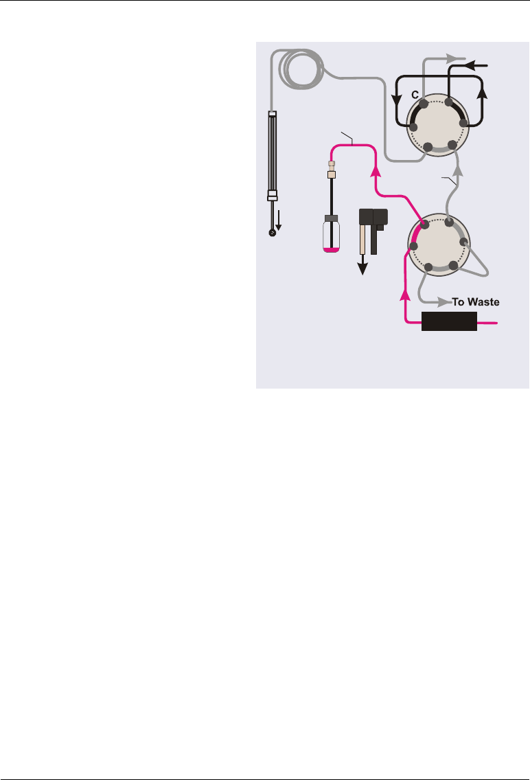
Dionex AS-AP Operator’s Manual
246 Doc. 065361-07 9/12
7. After injection, the
fraction collection valve is
switched to the Collect
position and the Dionex
AS-AP collects fractions
from the detector outlet
line through the needle and
into vials.
Fraction Collection Pull Mode:
Collect fractions from the detector.
Needle
Syringe
Sample
Sample
Transfer Line
Buffer Line
6
3
2
1
5
4
Detector
Drain
To Waste
L
S
S
Y
R
L
P
Inject
Bridge
Line
3
2
4
5
6
1
Sample
Loop

D • Fraction Collection Option
Doc. 065361-07 9/12 247
D.3.3 Manual Control
When the Dionex AS-AP is configured for fraction collection, the
Chromeleon 6.8 panel tabset includes a Fractionation panel that provides
commands for manual control of certain functions (for example, switching the
fraction collection valve position). To open the panel, click Fractionation on
the Autosampler Control panel.
D.3.4 Programmed Control
When the Dionex AS-AP is configured for fraction collection, the
Chromeleon 6.8 Program Wizard includes tab pages for determining how and
when fractions are collected. The fraction collection wizard pages are
included with the wizard pages for the other devices (pump, detector, and so
on) in the timebase.

Dionex AS-AP Operator’s Manual
248 Doc. 065361-07 9/12
Selecting When Fractions are Collected
The Fraction Collection: General Options page (see Figure D-12) provides
options for selecting when to collect fractions.
NOTE For details about the options on a wizard page, click the Help
button.
You can choose to collect fractions when a peak is detected or for a specified
time period. You can also specify the time range or ranges during data
acquisition at which to collect fractions. Additional options for controlling
collection are available on subsequent pages in the wizard.
Figure D-12. Chromeleon 6.8 Program Wizard:
Fraction Collection: General Options
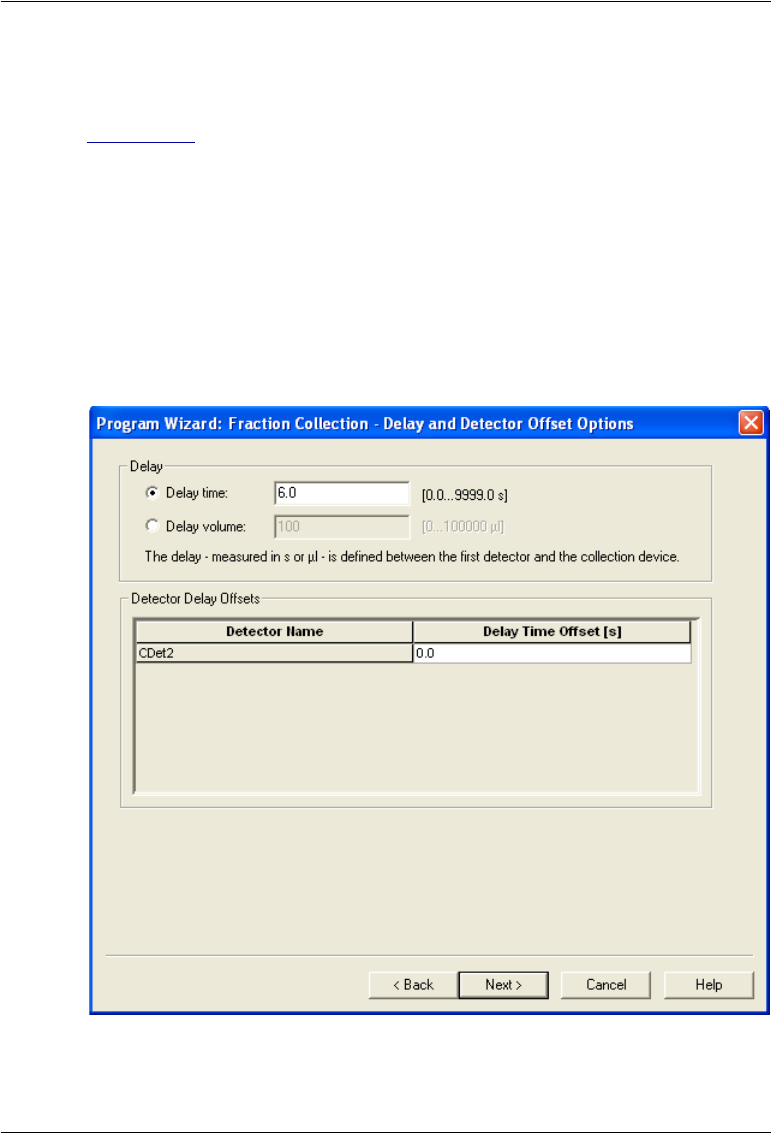
D • Fraction Collection Option
Doc. 065361-07 9/12 249
Entering the Delay Time
On the Fraction Collection: Delay and Detector Offset Options page (see
Figure D-13), enter the Delay time (the time required for fluid to travel from
the detector outlet to the fraction collection valve). Alternatively, you can
enter the Delay volume (the volume of the tubing connecting the detector
outlet and the fraction collection valve). If you enter a Delay volume,
Chromeleon 6.8 will calculate the delay time based on the flow rate entered in
the program.
NOTE To estimate the volume of 0.75 mm (0.030 in) ID PEEK tub-
ing (green), use a conversion factor of 0.4.6 L/cm (11.6
L/in).
Figure D-13. Chromeleon 6.8 Program Wizard:
Fraction Collection: Delay and Detector Offset Options

Dionex AS-AP Operator’s Manual
250 Doc. 065361-07 9/12
After you complete the wizard, you can modify the program
using the Program Editor. Open the program in the editor and
then click the Fraction Collection device in the list to see the
fraction collection tab pages.

Doc. 065361-07 9/12 251
E • Reducing Contamination
Use the following steps to reduce ionic contamination levels in the AS-AP.
1. When handling any system components, wear clean, powder-free gloves,
preferably made of a non-colored nitrile material.1 Wash the outside of
the gloves in clean DI water and air dry. After washing the gloves,
minimize handling of any surface other than system components.
2. Use ASTM Type 1 (18 megohm-cm) filtered and deionized (DI) water to
clean all components (as described below) and to fill the wash liquid
reservoir.
3. Use a polystyrene wash liquid reservoir. Polystyrene reservoirs are
available from third-party suppliers.2 Rinse the reservoir three to five
times with DI water to clean it.
4. Fill the reservoir with fresh DI water every one to two days.
5. Use 0.75 mm (0.030 in) ID PEEK, green tubing between the reservoir and
the syringe valve. The tubing is provided in the Dionex AS-AP Ship Kit
(P/N 074929). The standard length for the line is 76 cm (30 in).
6. Before connecting the green tubing to the reservoir, follow the steps
below to clean the fittings and tubing:
a. To clean new fittings, fill a separate polystyrene reservoir with DI
water and soak the fittings for at least 24 hours.
b. Fill a separate polystyrene reservoir with DI water. Swish at least
15 cm (6 in) of one end of the green tubing in the DI water for 30 to
60 sec to clean it.
c. Insert this cleaned end of tubing into the wash reservoir. Use the cap
from the reservoir provided in the Dionex AS-AP Ship Kit.
d. Install the cleaned fittings on the other end of the tubing.
1. Examples: VWR® CERTICLEAN® Class 100 Nitrile Gloves, Catalog
No. 40101-(220-228); VWR® CERTICLEAN® Class 10 Nitrile Gloves,
Catalog No. 40101-(352-358); Ansell Nitrilite® Cleanroom Gloves, Catalog
No. 93-311.
2. Example: Nalgene® Labware, Catalog No. 455-1000.

Dionex AS-AP Operator’s Manual
252 Doc. 065361-07 9/12
e. Attach a syringe to the other end of the tubing and pull wash liquid
through the tubing. Remove the syringe, direct the end of the tubing
to waste, and let about 100 mL of DI water drip through the tubing.
f. Connect the tubing to the middle (front) port of the syringe valve. For
connection instructions, see Section 5.7.
7. Use the Wash Needle and Fluidics button on the ePanel (in Chromeleon
7) or Control panel (in Chromeleon 6.8) to run a manual wash cycle.
Enter a wash volume of 5,000 L. If necessary, remove each fitting and
wash the end of the fitting tube, the fitting bolt, and ferrule in a clean
polystyrene reservoir filled with fresh DI water. Repeat the manual wash
as required.
8. Use only 10 mL Thermo Scientific Dionex PolyVials™ (polystyrene) and
blue septa (PN 074228, package of 100). For an even cleaner alternative
to the blue septa, PTFE (polytetrafluoroethylene) sealing disks
(P/N 074927) are available. PTFE sealing disks should only be used for
one injection per vial, because the sealing disk does not reseal after the
first injection.
9. Soak vials and septa or sealing disks in a clean polystyrene reservoir filled
with DI water for a few days or up to one week or more. For best results,
use a continuous DI water flush. If a continuos flush is unavailable,
change the DI water twice a day (morning and evening).
10. Use stainless steel tweezers to remove the vials and septa from the
soaking reservoir. Do not touch the septa with gloves. Touch the vials
with gloves only on the outside of the vials.
11. Set up the instrument method (in Chromeleon 7) or program (in
Chromeleon 6.8) to wash before and after injection by setting the Inject
Wash mode to Both (see Section 3.4.4). This minimizes the time between
the wash process and the injection.
12. Keep the carousel closed to minimize any environmental contamination.
13. When replacing buffer lines and sample loops, use tubing assemblies
provided by Thermo Fisher Scientific. These buffer lines and loops are
precision cut and will wash out more quickly than those made with
standard laboratory tools. To wash these tubing assemblies:

E • Reducing Contamination
Doc. 065361-07 9/12 253
a. Remove the wash reservoir line from the syringe valve and use
couplers to connect the new buffer line and/or sample loop to the
wash reservoir line.
b. Pull wash fluid through the connected assemblies and then let 100 mL
drip through them to waste. Uncouple the assemblies and install them
in the autosampler.
c. Rewash the autosampler as described in Step 7.

Dionex AS-AP Operator’s Manual
254 Doc. 065361-07 9/12

Doc. 065361-07 9/12 255
F • Reordering Information
Part Number Item
Vials, Well Plates, and Trays
055058 Vials, 10 mL polystyrene, with caps and septa (package
of 100)
074228 Vials, 10 mL polystyrene, with caps and septa for
capillary systems or trace analysis applications
(package of 100)
074927 Sealing disks, PTFE, for 10 mL vials
055427 Vials, 1.5 mL glass, with caps and septa (package of
100)
079812 Vials, 1.5 mL polypropylene, with caps and septa
(package of 100)
055428 Vials, 0.3 mL polypropylene, with caps and septa
(package of 100)
066332 Well plates, 96 micro-well, 0.5 mL round (U-shaped)
wells (package of 10) (not suitable for IC applications)
066333 Well plates, 96 micro-well, 0.45 mL conical (V-shaped)
wells (package of 20) (not suitable for IC applications)
066334 Well plates, 96 deep-well, 2 mL wells (package of 5)
(suitable for IC applications where ion concentration
is above 1 ppm)
066335 Well plate covers for 0.45 mL and 0.5 mL well plates
(package of 10)
066330 Well plate covers for 2 mL well plates (package of 10)
074936 Tray for 0.3 mL or 1.5 mL vials, 40-vial capacity
Tray for micro well plates, 96-well capacity
074938 Tray for 10 mL vials, 19-vial capacity
074939 Tray for deep well plates, 96-well capacity
069877 Tray (wedge-shaped), for 10 mL vials, 8-vial capacity

Dionex AS-AP Operator’s Manual
256 Doc. 065361-07 9/12
Syringes
074305 Syringe, 100 µL
074306 Syringe, 250 µL
074307 Syringe, 1000 µL
074308 Syringe, 5000 µL
Tubing and Fittings
NOTE When ordering tubing, order the required length (in
inches).
044777 Tubing, 0.75 mm (0.030 in) ID PEEK, green
049714 Tubing, 0.33 mm (0.013 in) ID PEEK, blue
052112 Tubing, 1.55 mm (0.062 in) ID PFA, colorless
042690 Tubing, 0.25-mm (0.010-in) ID PEEK, black
074994 Buffer line, 500 L, tubing assembly
074989 Buffer line, 1200 L, tubing assembly
075520 Buffer line, 8500 L, tubing assembly
057934 Fitting nut, 1/8 in flangeless (short), tan
048949 Ferrule, 1/8 in flangeless, yellow
052230 Fitting nut, 1/16 in flangeless, tan
071358 Fitting nut, 1/16 in flangeless (short), tan
062511 Ferrule, two-piece (clear cone and tan flat)
074449 Fitting bolt, high-pressure, 10-32, blue
074373 Ferrule, high-pressure, 10-32 double-cone, blue
062980 Fitting bolt, 10-32, black
062978 Ferrule, split-cone, black
074322 Fitting bolt, 10-32, short thumb head, black
Part Number Item

F • Reordering Information
Doc. 065361-07 9/12 257
Valves
074123 6-port valve with mounting bracket
074122 10-port valve with mounting bracket
070209 6-port valve with cables (no mounting bracket)
070208 10-port valve with cables (no mounting bracket)
Kits and Accessories
075008 Dionex AS-AP Simultaneous Injection Kit
075000 Dionex AS-AP Preventive Maintenance Kit
075973 Valve Rebuild Kit (for 6-port high-pressure valves)
079054 Valve Rebuild Kit (for 10-port high-pressure valves)
075010 Degas tee kit (for online degassing of wash liquid)
074923 Dionex AS-AP Sample Conductivity and pH Accessory
075529 pH electrode for the Sample Conductivity and pH
Accessory
Miscellaneous Items
069914 Sampling needle
055075 Drain tube, 122 cm (48 in)
074982 Drain tube extension, 20 cm (8 in) (for sample
temperature control)
960777 USB cable, 6 ft
923686 12-position connector plug (for relay connections)
924133 8-position connector plug (for TTL connections)
043598 Twisted pair of wires (for relay and TLL connections)
074976 J-clip bracket (for needle alignment)
062581 Reservoir, 2 L
954763 Fuse, 4 A IEC 60127-2 fast-blow
Part Number Item

Dionex AS-AP Operator’s Manual
258 Doc. 065361-07 9/12

Doc. 065361-07 9/12 Index-1
Numerics
10-port valve, 25
Flow schematic, 27
6-port valve, 25
Flow schematic, 26
8-position vial holder, 82
A
Alarm LED is lighted, 12
Annual maintenance, 89
AS-AP
Key features, 1
Manufacturing location, 3
Moving or shipping, 87
Operator’s manual description, 2
Simultaneous Injection Kit, 190
Software control, 1
Audit Trail
Error messages, 91
Icons, 91
Automated control mode, 45
Autosetting (inject wash mode), 69
Auxiliary valve, 31
B
Backpressure
Calculating, 86
Guidelines for controlling, 85
Maximum allowed, 24
Batch (Chromeleon 6.8), 62
Bottle, 48, 251
Bridge line
Bridge Size parameter, 239
Configuring in Chromeleon, 209
Connecting, 238
Buffer line
Configuring in Chromeleon, 142, 209
Ordering pre-cut, 178
Recommended size, 132, 177
Replacement procedure, 132 – 142
C
Cables
Power cord, 160
USB, 200
Calibration
Sample transfer line (push mode), 153
Caps (for vials), 54
Carousel
Color sections, 81
Description of, 14
Temperature control option, 23
CE mark, 6
cETLus mark, 6
Chromeleon, 1
AS-AP device driver installation, 202
Audit Trail error messages, 91
Automated control, 45
Configuring the AS-AP in, 204
Configuring the injection mode, 208
Configuring valves, 208
Connected LED, 12
Connecting to the software, 50, 209
Control panel, 210
Creating sequences, 61
Defining sample preparation operations,
76
Panel tabset, 210
Sampler Options page, 63, 65
Software control modes, 44
USB connections, 22
Version required, 1
Index

Dionex AS-AP Operator’s Manual
Index-2 Doc. 065361-07 9/12
Chromeleon 6.8
Batch, 62
Connecting to, 52
Control panel, 45
Fraction collection setup, 238
Panel Tabset connection, 209
Program, 61
Chromeleon 6.8 Server Configuration, 214
Chromeleon 7, 62
Connecting to, 51
ePanel Set, 51
ePanel Set connection, 209
Instrument method, 61
Chromeleon 7 Instrument Configuration, 214
Chromeleon Server Monitor, 52
Chromeleon versions, 1
Cleaning
Polystyrene reservoir, 251
Reservoir, 89
To reduce ionic contamination, 251
Well plates, 54
Compartment lights, 19
Concentrator column, 24
Loading, 71
Concentrator injection
Overview of, 24
Condensation on vials or well plates
(preventing), 107
Conductivity and pH accessory, 25
Configuration
AS-AP in Chromeleon, 204
Connected LED
LED is lighted, 12
Contamination, reducing, 251
Control modes in Chromeleon, 44
Control panel
AS-AP, 52, 210
Cooling the sample tray, 23
Covers
For well plates, 55
D
Daily maintenance, 88
Declaration of Conformity, 6
Degas Tee Kit, 181
Degassing wash liquid, 179, 181
Sharing a degas channel, 182
Deionized water requirements, 7
Delay time (fraction collection), 249
Device driver installation, 202
Diluting, 77
Diluting with wash liquid, 77
Direct control mode, 44
Diverter valve, 24, 29
Drain lines, 49, 105
Drain port
Drain line connection, 198
Drying well plates, 54
E
ePanel Set, 209
Error messages
Audit Trail description, 91
Evaporation of sample from well plates
(preventing), 55
F
Facility requirements, 167
Factory plumbing configuration, 32
Firmware, 160
Fittings
Leaking, 106
Replacing, 109
Requirements, 109
Tightening guidelines, 111
Fraction collection
Bridge line configuration, 209
Delay time, 249
Delay volume, 249
General Options page, 248
Installation instructions, 229

Index
Doc. 065361-07 9/12 Index-3
Manual control of, 247
Overview of, 25
Programmed control of, 247
Pull mode plumbing schematic, 236
Push mode plumbing schematic, 230
Sampling principle in pull mode, 244
Sampling principle in push mode, 241
Setting up in Chromeleon 6.8, 238
Valve operation, 30
Valve plumbing (pull mode), 236
Valve plumbing (push mode), 230
Valve plumbing overview, 229
Front description
Buttons and LEDs, 12
Front view, 10
Fuses, 21
Replacement procedure, 160
G
Gloves, 251
Wearing when handling well plates, 54
H
Heating the sample tray, 23
Height of needle in vial (specifying), 67
High-pressure fittings, 111
High-pressure valves
Configuring in Chromeleon, 208
Functions of, 26
Installation instructions, 215 – 218, 220 –
227
Leaking, 106
Operating positions, 26
Overview of, 25
Rebuilding, 159
I
Inject wash modes, 68
Injection modes, 31
Chromeleon configuration types, 32
Configuring in Chromeleon, 208
Overview of, 31
Pull Full, 74
Pull Partial, 75
Push Capillary, 72
Push Concentrate, 71
Push Full, 70
Push Partial, 70
Push Partial Limited Sample, 71
Push Sequential, 72
Push Simultaneous, 73
Sample volumes used in, 70
Selecting, 62 – 63
Summary of all types, 33
Injection port
Aligning the needle in, 115
Description of, 18
Leaking, 106
Injection valve
Connection instructions, 184
Flow description, 28
Pull mode schematic, 28
Push mode connection, 185
Push mode schematic, 27
Rebuilding, 159
Valve flow description, 29
Injection volume, 83
Injections
Running a Chromeleon sequence, 61
Installation checklist, 179
Installation instructions, 167
Chromeleon setup, 202
Configuring the AS-AP in Chromeleon,
204
Drain line connection, 198
Drain lines for sample temperature
control option, 199
Facility requirements, 167
Fraction collection, 229
Injection valve connections, 184
Online degassing connections, 181
Power cord, 201

Dionex AS-AP Operator’s Manual
Index-4 Doc. 065361-07 9/12
Pull mode connections, 195
Push mode connections, 185
Sequential injection connections, 188
Simultaneous injection connections, 190
Unpacking procedure, 168
USB cable, 200
Valves, 215–218, 220–227
Wash liquid reservoir, 179
Instrument method (Chromeleon 7)
Creating, 61
Ionic contamination, reducing, 251
Isopropyl alcohol, 129
J
J-clip, 203, 211
Jumper settings for valve board, 215
L
Leak port
Description of, 18
Leak sensor
Description of, 19
Leaks
Drain line connection, 105
Fittings, 106
Injection port, 106
Liquid line, 106
Syringe, 105
Syringe valve port, 105
LED descriptions, 12
LED display, 12
Lights (LEDs) inside compartment, 19
Limited sample injection mode, 71
Linking the pump, 207
Loading the concentrator, 71
Loading the loop
Pull mode, 28
Push mode, 28
Loop size
Configuring in Chromelelon, 209
M
Main power receptacle, 21
Main power switch (rear panel), 21
Maintenance, 88
Annual, 89
Daily, 88
Periodic, 89
Weekly, 89
Mixing, 78
Monitor Link, 208
Monitor parts usage, 46
Moving the AS-AP, 87
N
Needle
Alignment procedure, 115, 117, 119 –
122, 124 – 125
Replacement procedure, 112 – 114
Needle arm
Description of, 17
Needle height (specifying), 67
Nitrile gloves, 251
O
Operating features, 9
Optional components, 12
Overview of, 10 – 12
Standard components, 11
Operating principles, 31
Operation, 47
Defining sample preparation steps, 76
Manual wash, 53
Power up, 50
Preparing to run, 48
Priming the syringe, 52
Running a Chromeleon sequence, 61
Selecting the wash mode, 68
Setting up the reservoir, 48
Specifying sample heights, 67
Specifying syringe speeds, 65

Index
Doc. 065361-07 9/12 Index-5
System equilibration, 61
Operation checklist, 47
Optional components, 12
Options
Concentrator injection, 24
Fraction collection, 25
Sample Conductivity and pH Accessory,
25
Sample temperature control, 23
Sequential injection, 24
Simultaneous injection, 23
P
Panel tabset, 209
Parts reordering, 251, 255
Periodic maintenance, 89
pH and conductivity accessory, 25
Pipetting, 78
Plumbing
Replacing tubing and fittings, 109
Plumbing schematics, 173
Fraction collection (pull mode), 236
Fraction collection (push mode), 230
Pull mode, 176
Push mode, 173
Push Sequential mode, 174
Push Simultaneous mode, 175
Polystyrene reservoir, 251
Power cord, 160
Connection instructions, 201
Power receptacle, 21, 201
Power switch (rear panel), 21
Power up, 50
Predictive performance, 46
Pressure
Guidelines for controlling, 85
Maximum allowed, 24, 85
Priming the syringe, 52, 211
Problems
See Troubleshooting
Product warranty, voiding, 109
Program (Chromeleon 6.8)
Creating, 61
Program Wizard, 63
PTFE sealing disks, 252
Pull Full mode
Sample volume used in, 74
Pull mode
Injection valve schematic, 28
Overview of, 31 – 32
Plumbing connections, 195
Plumbing schematic, 38, 176
Sampling principle, 38 – 40
Pull Partial mode
Sample volume used in, 75
Pump link, 207
Push Cap (capillary) mode
Sample volume used in, 72
Push Concentrate mode
Sample volume used in, 71
Push Full mode
Sample volume used, 70
Push mode
Injection valve connections, 185
Injection valve schematic, 27
Overview of, 31 – 32
Plumbing schematic, 35, 173
Sampling principle, 35
Push Partial mode
Sample volume used in, 70
Push Partial_ls mode
Sample volume used in, 71
Push Sequential mode
Overview of, 32
Plumbing schematic, 174
Sample volume used in, 72
Push Simultaneous mode
Overview of, 32
Plumbing schematic, 175
Sample volume used in, 73
Q
Queue (Chromeleon 7), 62

Dionex AS-AP Operator’s Manual
Index-6 Doc. 065361-07 9/12
R
Rear panel, 20
Fuses, 21
Power receptacle, 21
Power switch, 21
USB connections, 22
Rebuilding the injection valve, 159
Reducing contamination, 251
Regulatory information, 3
Relay connectors, 212
Relay output configuration, 22
Relay output connector, 21
Connection instructions, 212
Reordering parts, 251, 255
Repair procedures, 109
Reservoir, 48, 251
Polystyrene for trace analyses, 251
Rinse between reinjections, 69
Rinsing well plates and covers, 54
S
Safety messages, 3
Sample carousel
Color sections, 81
Controlling temperature, 23
Description of, 14
Sample Conductivity and pH Accessory, 12
Configuring in Chromeleon, 208
Overview of, 25
Sample evaporation (preventing), 55
Sample height (specifying), 67
Sample loop
Configuring in Chromeleon, 209
Loading in pull mode, 28
Loading in push mode, 28
Size selection guidelines, 177
Sample preparation
Defining operation in Chromeleon, 76
Defining vial positions for, 82
Sample temperature control, 23
Configuring in Chromeleon, 209
Drain line connections, 199
Sample transfer line
Calibrating the volume (push mode), 153
Replacement procedure (pull mode),
157 – 158
Replacement procedure (push mode),
148, 150 – 151
Sample trays
See Trays
Sample vials
Types of, 15
Sample volume used, 70
Sampler in Motion LED is lighted, 13
Sampler Options page in Chromeleon, 63, 65
Sampling needle
Alignment procedure, 115, 117, 119 –
122, 124 – 125
Description of, 17
Replacement procedure, 112 – 114
Sampling principle
Pull mode, 38
Push mode, 35–37
Sequential mode, 41
Simultaneous mode, 43
Segments/Pump Link page, 207
Septa (for vial caps), 54
Sequence of injections (Chromeleon)
Creating, 61
Sequential injection mode
Diverter valve operation, 29
Injection valve connections, 188
Overview of, 24
Sequential mode
Plumbing schematic, 41
Sampling principle, 41 – 42
Service procedures, 109
Buffer line replacement, 132 – 142
Fuse replacement, 160
Needle alignment, 115, 117, 119 – 122,
124 – 125
Needle replacement, 112 – 114
Sample transfer line replacement (pull
mode), 157 – 158

Index
Doc. 065361-07 9/12 Index-7
Sample transfer line replacement (push
mode), 148, 150 – 151
Syringe replacement, 127 – 131
Syringe waste line replacement, 143 –
146
Tubing and fittings replacement, 109
Valve rebuilding, 159
Wash reservoir line replacement, 147
Sharing a degas channel, 182
Sharing the AS-AP, 206
Ship Kit, 23
Shipping the AS-AP, 87
Shutdown, 86
Shutdown instrument method, 86
Shutdown program, 86
Simultaneous Injection Kit, 190
Simultaneous injection mode
Balancing flow to valves, 191
Overview of, 23
Plumbing connections, 190
Plumbing schematic, 43
Sampling principle, 43
Smart Shutdown, 87
Smart Startup, 61
Software control, 1
Software license, 202
Specifications, 163
Speed of syringe movement, 65
Standby button, 13
Standby/Power LED is lighted, 13
Status bar
LEDs described, 12
Syringe
Configuring in Chromeleon, 209
Description of, 16
Priming instructions, 52, 211
Replacement procedure, 127 – 131
Size selection guidelines, 177
Sizes of, 16
Specifying speeds, 65
Syringe leaks, 105
Syringe speeds
Guidelines for controlling backpressure,
85
Specifying, 65
Syringe valve
Connections to, 49
Description of, 16
Syringe waste line
Replacement procedure, 143 – 146
System shutdown, 86
System wellness, 46
T
Technical Support, 3, 91, 109
Temp Ready LED is lighted, 13
Temperature control
Configuring in Chromeleon, 209
Description, 23
Thermo Fisher Scientific Technical Support,
3, 91
Thermo Fisher ScientificTechnical Support,
109
Tightening fittings, 111
Trace analyses, 1
Reducing contamination, 251
Vials for, 15
Wash mode recommendations, 68
Trays
Configuring in Chromeleon, 207
Specifying positions in, 81
Types of, 14
Troubleshooting, 91
Condensation, 107
Error message list, 92
General information, 92
TTL and relay connectors, 21
Installation instructions, 212
TTL input connector, 21
Tubing
Backpressure produced by, 86
Guidelines for selecting, 85
Replacing, 109

Dionex AS-AP Operator’s Manual
Index-8 Doc. 065361-07 9/12
U
Unpacking procedure, 168
Updating firmware, 160
USB cable, 23, 201
Connection instructions, 200
USB connections, 22
V
Valve electronics board
Jumper settings, 215
Valves
Auxiliary valve, 31
Available functions per mode, 26
Configuring in Chromeleon, 208
Diverter valve, 24, 29
Fraction collection, 30
Functions of, 26
Installation instructions, 215 – 218, 220 –
227
Leaking, 106
Operating positions, 26
Overview of, 25
Rebuilding, 159
See also Injection valve
Vials
Condensation on, 107
Filling instructions, 54
For trace analyses, 15
Maximum fill level, 54
Specifying positions in trays, 81
Types of, 15
Volume of injections
Per syringe size and injection mode, 83
W
Waranty, voiding, 109
Wash cycle
Modes for injections, 68
Running manually, 53
Wash liquid
Degassing offline, 179
Degassing online, 181
Diluting with, 77
Wash liquid reservoir
Cleaning, 89
Connecting for offline degassing, 179
Connecting for online degassing, 181
Line replacement procedure, 147
Polystyrene for trace analyses, 251
Setting up, 48, 179
Wash modes, 68
Autosetting, 69
Both before and after, 69
Rinse between reinjections, 69
Wash after injection, 68
Wash before injection, 68
Wash port
Description of, 18
Waste lines
Leaking connection, 105
Waste port
Description of, 18
Weekly maintenance, 89
Well plates
Cleaning, 54
Condensation on, 107
Configuring in Chromeleon, 207
Covers, 55
Drying, 54
Filling, 54 – 55
Maximum volume per well, 55
Sample volumes available, 55
Specifying positions in, 81
Types of, 15
Wellness panel, 46
Y
Y-connector, 190
Mounting location, 193
