ASR 9000 NV Edge Scripted Rack By Upgrade Or Reload SMU Application Configuration Example 9001 Router 9001S 117643 Config Nvedge 00
User Manual: Asr 9001 Router 9001S
Open the PDF directly: View PDF ![]() .
.
Page Count: 7

ASR 9000 nV Edge Scripted Rack−by−Rack
Upgrade or Reload SMU Application Configuration
Example
Document ID: 117643
Contributed by Aaron Foss and Samuel Milstead, Cisco TAC Engineers.
Jul 10, 2014
Contents
Introduction
Prerequisites
Requirements
Components Used
Background Information
Rack−by−Rack Upgrade Overview
Rack 1 Shutdown Phase
Rack 1 Activate Phase
Critical Failover Phase
Rack 0 Activate Phase
Cleanup Phase
Configure
Network Diagram
Verify
Troubleshoot
Caveats
Introduction
This document describes how to perform a scripted rack−by−rack upgrade or activate a reload Software
Maintenance Upgrade (SMU) on an ASR 9000 Series Aggregation Services Router nV Edge cluster. A
rack−by−rack upgrade might be used to install a new software release or a software patch (SMU) on each rack
one at a time. Packet loss is minimized in the software upgrade for network topologies that incorporate
cabling redundancy to each rack in the cluster.
As of the initial publication date of this document, May 2014, there are three supported methods to upgrade or
activate a SMU on a cluster:
A standard software upgrade or SMU activation with the install activate command. Both racks should
be powered on.
1.
A standard software upgrade or SMU activation of the ASR 9000 requires the backup−Designated
Shelf Controller (DSC) rack to be powered down, the software on the primary−DSC rack (system
reload) to be upgraded, and the backup−DSC rack to be powered back up in order to synchronize.
2.
The scripted rack−by−rack method.3.
Method three is discussed in this document.
Note: It is not advisable to perform the rack−by−rack upgrade without the script.
Note: In−Service Software Upgrade (ISSU) is not supported on cluster even for SMU activation.
Packet loss varies based on scale and features, but is expected to be anywhere from 8s <> 180s.
Prerequisites
Requirements
Cisco recommends that you have knowledge of these topics:
Release 4.2.3 nV Edge Umbrella DDTS #1• Release 4.3.1 and later
Note: ASR 9001 support is added in Release 4.3.2. The script should not be used on the ASR 9001 in
earlier releases.
Note: ASR 9001 support for Ethernet out−of−band channel (EOBC) Unidirectional Link Detection
(UDLD) link flap history (Control Link Manager (CLM) Table version) is added in Release 5.1.0.
•
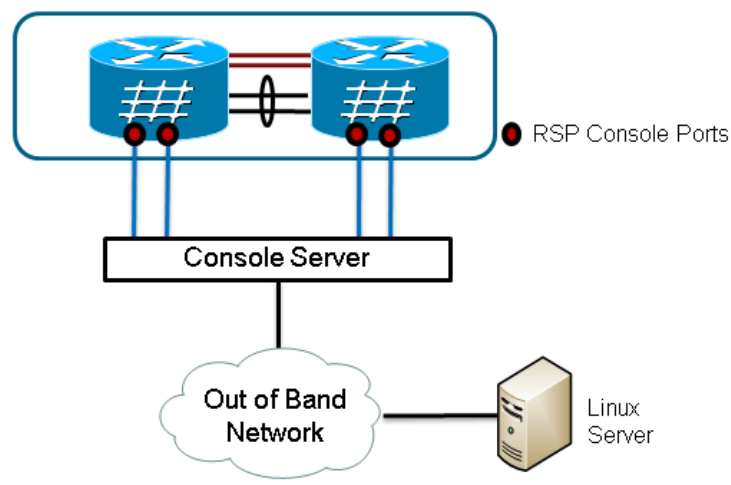
Linux workstation• Console server• Two ASR 9000s in a cluster•
Components Used
The information in this document is based upon two ASR 9001s, Cisco IOS XR Release 4.3.2 to 5.1.0, and an
Ubuntu Linux workstation.
The information in this document was created from the devices in a specific lab environment. All of the
devices used in this document started with a cleared (default) configuration. If your network is live, make sure
that you understand the potential impact of any command.
Background Information
Rack−by−Rack Upgrade Overview
Rack 1 Shutdown Phase
Rack 1 is isolated from the cluster and the external network, and is made into a standalone node.• Inter Rack Links (IRLs) are disabled.• External facing Line Card (LC) interfaces are disabled.• Control link interfaces are disabled.•
Rack 1 Activate Phase
The target software is activated on Rack 1.• Install Activate occurs on Rack 1 with the parallel reload method.• If Auto−FPD (Field Programmable Device) is configured, it occurs now.•
Critical Failover Phase
Traffic is migrated to Rack 1.• All interfaces on Rack 0 are shut down.• All interfaces on Rack 1 are brought into service.• Protocols relearn routes from neighboring routers and convergence begins.•
Rack 0 Activate Phase
The target software is activated on Rack 0.• Install Activate occurs on Rack 0 with the parallel reload method.•
Cleanup Phase
Control links are reactivated.• IRLs are reactivated.• Rack 0 rejoins the cluster as Backup.• Any external links disabled as part of the upgrade are brought back into service.•
Configure
Network Diagram
Note: Use the Command Lookup Tool (registered customers only) in order to obtain more information on the
commands used in this section.
Note: An ASR 9001 only has 1 console port per chassis.
Retrieve a copy of the script.
Enter into KSH and copy the script to disk0:
From exec mode type 'run' to enter KSH.
Copy the file from /pkg/bin/ folder using the following command:
cp /pkg/bin/nv_edge_upgrade.exp <destination>
eg: cp /pkg/bin/nv_edge_upgrade.exp /disk0:
After this the script can be copied off the router and modified.
1.
Install the expect script software on the Linux server.
sudo yum install expect
2.
or
sudo apt−get install expect
Determine where the expect script was installed on the Linux server.
root@ubuntu:~$ whereis expect
expect: /usr/bin/expect /usr/bin/X11/expect /usr/share/man/man1/expect.1.gz
root@ubuntu:~$
3.
Modify the first line in the nv_edge_upgrade.exp script to match the correct home directory of the
expect script software.
#!/usr/bin/expect −f
4.
Modify the script to match the console server's settings.
Note: If you upgrade an ASR 9001 cluster, you can leave the standby addressing unchanged. The
script runs successfully with bogus standby addressing.
set rack0_addr "172.18.226.153"
set rack0_port "2049"
set rack0_stby_addr "172.27.152.19"
set rack0_stby_port "2004"
set rack1_addr "172.18.226.153"
set rack1_port "2050"
set rack1_stby_addr "172.27.152.19"
set rack1_stby_port "2007"
5.
Modify the script to include login credentials.
set router_username "cisco"
set router_password "cisco"
6.
Modify the script to include the new image list
set image_list "disk0:asr9k−mini−px−5.1.0 \
disk0:asr9k−fpd−px−5.1.0 \
disk0:asr9k−mpls−px−5.1.0 \
disk0:asr9k−mgbl−px−5.1.0 \
disk0:asr9k−bng−px−5.1.0 \ "
or the reload SMU(s) to be activated.
set image_list "disk0:asr9k−px−5.1.0−CSCxxXXXXX−1.0.0 \ "
7.
Modify the script to include the IRLs. Enter the show nv edge data forwarding location
0/RSP0/CPU0 command in order to check the links.
set irl_list {{TenGigE 0/0/2/0} {TenGigE 0/0/2/1} {TenGigE 1/0/2/0} {TenGigE 1/0/2/1} }
8.
Modify the script to include a Linux Telnet disconnect sequence. The octal value 35 is the equivalent
of a Ctrl−] key combination, which is used to gracefully terminate the console reverse Telnet
connection and allow the script to complete successfully. The modification should be around line 162
in the script.
proc router_disconnect { } {
global debug_mode
global connected_rack
if {$debug_mode == 1} { return }
send −− "\35"
sleep 1
9.
expect −exact "telnet> "
send −− "quit\r"
expect eof
set connected_rack −1
sleep 5
Install add the new software or the SMU(s) to the ASR 9000 cluster.
admin
install add tar ftp://cisco:cisco@10.118.12.236/5.1.0.tar sync
10.
Disconnect any active terminal sessions to the console ports of the cluster after the install add
operation completes.
11.
Activate the script from the Linux server.
root@ubuntu:~/nV$ expect nv_edge_upgrade.exp
########################
This CLI Script performs a software upgrade on
an ASR9k Nv Edge system, using a rack−by−rack
parallel reload method. This script will modify
the configuration of the router, and will incur
traffic loss.
Do you wish to continue [y/n] y
12.
Verify
Use this section to confirm that your configuration works properly.
The progress of the script/upgrade is visible from the Linux workstation. The rack−by−rack upgrade takes
about 45 to 60 minutes to complete.
On the ASR 9000, complete these steps in order to confirm the software upgrade/SMU activation and nV
Edge system status:
Verify the XR software.
RP/0/RSP0/CPU0:ASR9006#show install active summary
Mon Mar 31 12:43:43.825 EST
Default Profile:
SDRs:
Owner
Active Packages:
disk0:asr9k−fpd−px−5.1.0
disk0:asr9k−mgbl−px−5.1.0
disk0:asr9k−mpls−px−5.1.0
disk0:asr9k−mini−px−5.1.0
disk0:asr9k−bng−px−5.1.0
disk0:asr9k−px−5.1.0−CSCxxXXXXX−1.0.0
RP/0/RSP0/CPU0:ASR9006#show install committed summary
Mon Mar 31 12:44:07.250 EST
Default Profile:
SDRs:
Owner
Committed Packages:
disk0:asr9k−fpd−px−5.1.0
disk0:asr9k−mgbl−px−5.1.0
disk0:asr9k−mpls−px−5.1.0
disk0:asr9k−mini−px−5.1.0
disk0:asr9k−bng−px−5.1.0
disk0:asr9k−px−5.1.0−CSCxxXXXXX−1.0.0
1.
Verify the data plane.
show nv edge data forwarding location all
<Snippet>
−−−−−−−−−−−−−−−−−node0_RSP0_CPU0−−−−−−−−−−−−−−−−−−
nV Edge Data interfaces in forwarding state: 4
TenGigE0_0_1_3 <−−> TenGigE1_0_0_3
TenGigE0_1_1_3 <−−> TenGigE1_1_0_3
TenGigE0_2_1_3 <−−> TenGigE1_2_0_3
TenGigE0_3_1_3 <−−> TenGigE1_3_0_3
<Snippet>
In this output, the IRLs should show in the forwarding state.
2.
Verify the control plane.
show nv edge control control−link−protocols location 0/RSP0/CPU0
<Snippet>
Port enable administrative configuration setting: Enabled
Port enable operational state: Enabled
Current bidirectional state: Bidirectional
Current operational state: Advertisement − Single neighbor detected
Priority lPort Remote_lPort UDLD STP
======== ===== ============ ==== ========
0 0/RSP0/CPU0/0 1/RSP0/CPU0/0 UP Forwarding
1 0/RSP0/CPU0/1 1/RSP1/CPU0/1 UP Blocking
2 0/RSP1/CPU0/0 1/RSP1/CPU0/0 UP On Partner RSP
3 0/RSP1/CPU0/1 1/RSP0/CPU0/1 UP On Partner RSP
From this output, the 'Current bidirectional state' should show as Bidirectional and only one of the
ports should be in the Forwarding state.
3.
Verify the cluster status.
RP/0/RSP0/CPU0:ASR9006#admin show dsc
−−−−−−−−−−−−−−−−−−−−−−−−−−−−−−−−−−−−−−−−−−−−−−−−−−−−−−−−−
Node ( Seq) Role Serial State
−−−−−−−−−−−−−−−−−−−−−−−−−−−−−−−−−−−−−−−−−−−−−−−−−−−−−−−−−
0/RSP0/CPU0 ( 0) ACTIVE FOX1613G35U PRIMARY−DSC
0/RSP1/CPU0 (10610954) STANDBY FOX1613G35U NON−DSC
1/RSP0/CPU0 ( 453339) STANDBY FOX1611GQ5H NON−DSC
1/RSP1/CPU0 (10610865) ACTIVE FOX1611GQ5H BACKUP−DSC
This command displays both the DSC (inter rack) status and the redundancy role (intra rack) for all
Route Switch Processors (RSPs) in the system.
In this example:
RSP0 on rack 0 is the primary−DSC and the active RSP for the rack.♦ RSP1 on rack 0 is a non−DSC and the standby RSP for the rack.♦ RSP0 on rack 1 is a non−DSC and the standby RSP for the rack.♦ RSP1 on rack 1 is the backup−DSC and the active RSP for the rack.♦
Note: The DSC role is used for tasks that only need to be completed once in the system, such as apply
the configuration or perform installation activities.
Note: The role of primary RSP is determined by the order the racks and the RSPs are booted.
4.

Troubleshoot
There is currently no specific troubleshooting information available for this configuration.
Caveats
Rack−by−Rack upgrade is not compatible with the Management LAN Split Brain detection feature.
This feature should be disabled prior to this upgrade.
•
Auto−FPD is not enabled by the script by default. This should be enabled prior to this upgrade.• Any install operations in progress need to completed prior to this upgrade.• All active packages must be committed prior to this upgrade procedure (admin install commit).• The script completes a minimal check for any errors that occur. It is recommended to enter the install
activate test command on the router prior to script execution in order to validate the set of images.
•
It is highly recommended to back up the router's configuration prior to upgrade.• ISSU is not supported on cluster even for SMU activation.•
Updated: Jul 10, 2014 Document ID: 117643
