Nano Series GigE Vision Camera 122239 Teledyne DALSA Genie Manual Rsb X3Gk
User Manual:
Open the PDF directly: View PDF ![]() .
.
Page Count: 282 [warning: Documents this large are best viewed by clicking the View PDF Link!]
- Genie Nano Series Overview
- Genie Nano Specifications
- Common Specifications
- Specifications: M1450, C1450
- Specifications: M1920, C1920
- Specifications: M1940, C1940
- Specifications: M2020, C2020
- Specifications: M2050
- Specifications: C2050
- Specifications: M2420, C2420
- Specifications: M2450
- Specifications: C2450
- Specifications: M4060
- Specifications: C4060
- Specifications: M4040
- Specifications: C4040
- Specifications: M4030, C4030
- Specifications: M4020, C4020
- Specifications: M640, M640-NIR, C640
- Specifications: M800, M800-NIR, C800
- Specifications: M1240, C1240
- Specifications: M1280, M1280-NIR, C1280
- Specifications: M1930, M1930-NIR, C1930
- Specifications: M2590, M2590-NIR, C2590
- NanoXL Specifications: M5100, M5100-NIR, C5100, M4090, M4090-NIR, C4090
- Specifications: C4900
- Comparison of Similar On-Semi and Sony Sensors
- Nano Quick Start
- Connecting the Genie Nano Camera
- Using Nano with Sapera API
- Operational Reference
- Using CamExpert with Genie Nano Cameras
- Camera Information Category
- Sensor Control Category
- Sensor Control Feature Descriptions
- Offset/Gain Control Details (Sony sensors)
- Offset/Gain Control Details (On-Semi Python sensors)
- Bayer Mosaic Pattern
- OnSemi Python P1 Sensor Artifacts with Fast Readout Mode
- Exposure Alignment: Overview
- Sensor Exposure Timing: Sony Sensor Models
- Sensor Exposure Timing: OnSemi Python Models
- Auto-Brightness Control Category
- I/O Control Category
- Counter and Timer Control Category
- Advanced Processing Control Category
- Color Processing Control Category
- Flat Field Correction Category
- Cycling Preset Mode Control Category
- Image Format Control Category
- Image Format Control Feature Description
- Width and Height Features for Partial Scan Control
- Vertical Cropping (Partial Scan)
- Maximum Frame Rate Examples (Models M/C 1920 & 1940)
- Maximum Frame Rate Examples (Models M2420 & M2450)
- Maximum Frame Rate Examples (Models M2020 & M2050)
- Maximum Frame Rate Examples (Models M/C 4040 & 4060)
- Maximum Frame Rate Examples (Models M/C 4020 & 4030)
- Maximum Frame Rate Examples (Model M/C 2590)
- Maximum Frame Rate Examples (Model C 4900)
- Maximum Frame Rate Examples (Model M/C 1930)
- Maximum Frame Rate Examples (Model M/C 1240)
- Maximum Frame Rate Examples (Model M/C 1280)
- Maximum Frame Rate Examples (Model M/C 800)
- Maximum Frame Rate Examples (Model M/C 640)
- Maximum Frame Rate Examples (NanoXL–M5100)
- Maximum Frame Rate Examples (NanoXL–M4090)
- Horizontal Cropping (Partial Scan)
- Using the Multiple ROI Mode
- Horizontal and Vertical Flip
- Binning Function and Limitations
- Internal Test Pattern Generator
- Metadata Control Category
- Acquisition and Transfer Control Category
- Action Control Category
- Event Control Category
- GigE Vision Transport Layer Control Category
- GigE Vision Host Control Category
- File Access Control Category
- Implementing Trigger-to-Image Reliability
- Sapera Tools for Networking
- Technical Specifications
- Mechanical Specifications — C & CS Mount:
- Mechanical Specifications — NanoXL:
- Additional Notes on Genie Nano Identification and Mechanical
- Sensor Alignment Specification
- Connectors
- Computer Requirements for Nano Cameras
- EC & FCC Declarations of Conformity
- Additional Reference Information
- Choosing a Lens with the Correct Image Circle
- Lens Options for Models ‘M/C1940’ & ‘M/C1920’
- Lens Options for Models ‘2450/2420’ & ‘2050/2020’
- Lens Options for Models ‘4060/4040/4030/4020’
- Lens Options for Models ‘M/C1450’
- Lens Options for XL Models ‘M/C 5100’ and ‘M/C 4090
- Lens Options for Model ‘C4900’
- Lens Options for Models ‘M/C2590’ & ‘M/C 2540’
- Lens Options for Models ‘M/C1930’
- Lens Options for Models ‘M/C1280’ & ‘M/C1240’
- Lens Options for Models ‘M/C800’
- Lens Options for Models ‘M/C640’
- Additional Lens Parameters (application specific)
- Optical Considerations
- Lens Modeling
- Sensor Handling Instructions
- Ruggedized Cable Accessories
- Choosing a Lens with the Correct Image Circle
- Troubleshooting
- Addendums
- Revision History
- Contact Information
- Index
Notice
© 2015-2017 Teledyne DALSA
All information provided in this manual is believed to be accurate and reliable. No responsibility is
assumed by Teledyne DALSA for its use. Teledyne DALSA reserves the right to make changes to
this information without notice. Reproduction of this manual in whole or in part, by any means, is
prohibited without prior permission having been obtained from Teledyne DALSA.
Microsoft and Windows are registered trademarks of Microsoft Corporation in the United States and
other countries. Windows, Windows 7, Windows 10 are trademarks of Microsoft Corporation.
All other trademarks or intellectual property mentioned herein belong to their respective owners.
Document Date: December 4, 2017
Document Number: G3-G00M-USR00
About Teledyne DALSA
Teledyne DALSA is an international high performance semiconductor and Electronics Company that
designs, develops, manufactures, and markets digital imaging products and solutions, in addition
to providing wafer foundry services.
Teledyne DALSA Digital Imaging offers the widest range of machine vision components in the
world. From industry-leading image sensors through powerful and sophisticated cameras, frame
grabbers, vision processors and software to easy-to-use vision appliances and custom vision
modules.

Nano Series GigE Vision Camera Contents
•
1
Contents
GENIE NANO SERIES OVERVIEW 8
DESCRIPTION 8
GigE with TurboDrive 8
Genie Nano Overview 9
Camera Firmware 9
MODEL PART NUMBERS 10
Monochrome Cameras 10
Color Cameras 12
Accessories 15
SOFTWARE REQUIREMENTS 16
Sapera LT Development Software 16
Third Party GigE Vision Development 16
About GigE Vision 16
GENIE NANO SPECIFICATIONS 17
COMMON SPECIFICATIONS 17
Sensor Cosmetic Specifications 19
Dynamic Range & Signal to Noise Ratio Measurement Conditions 19
EMI, Shock and Vibration Certifications 20
Mean Time between Failure (MTBF) 21
SPECIFICATIONS: M1450, C1450 22
Firmware Files for Models 1450 23
Spectral Response 23
SPECIFICATIONS: M1920, C1920 24
SPECIFICATIONS: M1940, C1940 25
Firmware Files for 1920, 1940 27
Spectral Response 28
SPECIFICATIONS: M2020, C2020 29
Firmware Files for Models 2020 30
SPECIFICATIONS: M2050 30
Firmware Files for Model M2050 31
SPECIFICATIONS: C2050 32
Firmware Files for Model C2050 33
Spectral Responses 34
SPECIFICATIONS: M2420, C2420 35
Firmware Files for Models 2420 36
SPECIFICATIONS: M2450 36
Firmware Files for Model M2450 37
SPECIFICATIONS: C2450 38
Firmware Files for Model C2450 39
Spectral Responses 40
SPECIFICATIONS: M4060 41
Firmware Files for Model M4060 42
SPECIFICATIONS: C4060 42
Firmware Files for Model C4060 43
SPECIFICATIONS: M4040 44
Firmware Files for Model M4040 45

2
•
Contents Nano Series GigE Vision Camera
SPECIFICATIONS: C4040 46
Firmware Files for Model C4040 47
Spectral Responses 4060 & 4040 48
SPECIFICATIONS: M4030, C4030 49
SPECIFICATIONS: M4020, C4020 50
Firmware Files for Model 4030 & 4020 51
Spectral Response 52
SPECIFICATIONS: M640, M640-NIR, C640 53
SPECIFICATIONS: M800, M800-NIR, C800 54
Firmware Files for Models 640, 800 56
SPECIFICATIONS: M1240, C1240 56
Firmware Files for Models 1240 57
SPECIFICATIONS: M1280, M1280-NIR, C1280 58
SPECIFICATIONS: M1930, M1930-NIR, C1930 59
SPECIFICATIONS: M2590, M2590-NIR, C2590 61
Firmware Files for Models 1280, 1930, 2590 62
NANOXL SPECIFICATIONS: M5100, M5100-NIR, C5100, M4090, M4090-NIR, C4090 63
Spectral Response 65
Defective Pixel Specification for Models 5100/4090 66
Firmware Files for Models 5100/4090 67
SPECIFICATIONS: C4900 68
Spectral Response 69
Supplemental Usage Notes: 70
Model C4900 Sensor Cosmetic Specifications 70
Firmware Files for This Model 71
Guide to Using a Rolling Shutter Camera 72
Overview of Electronic Rolling Shutter (ERS) Exposures 73
Overview of Global Reset Release (GRR) Exposures 74
COMPARISON OF SIMILAR ON-SEMI AND SONY SENSORS 75
NANO QUICK START 77
TESTING NANO WITHOUT A LENS 77
TESTING NANO WITH A LENS 77
THE CAMERA WORKS — NOW WHAT 77
CONNECTING THE GENIE NANO CAMERA 78
GIGE NETWORK ADAPTER OVERVIEW 78
PAUSE Frame Support 78
CONNECT THE GENIE NANO CAMERA 78
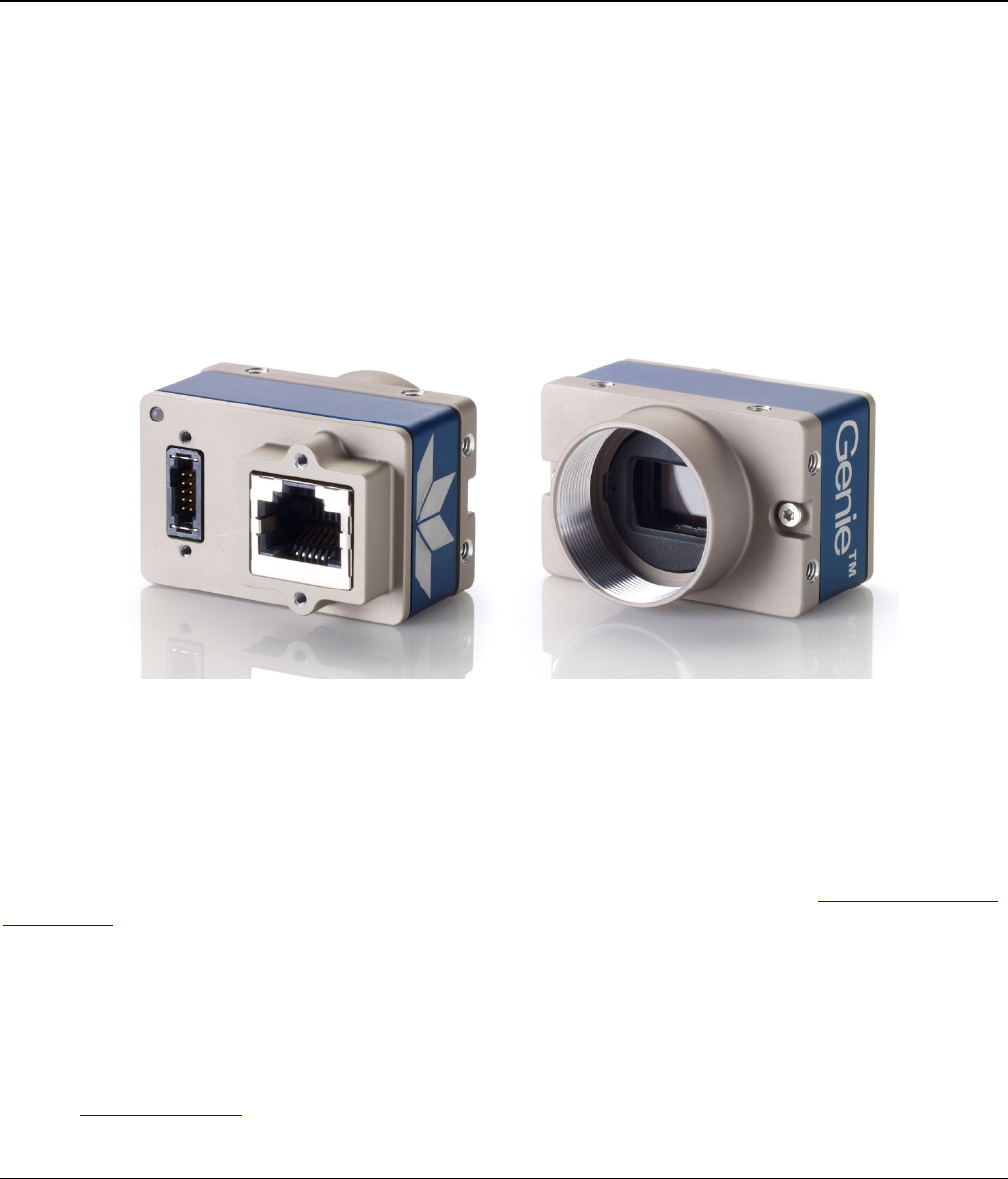
Connectors 79
LED Indicators 80
Camera Status LED Indicator 80
LED States on Power Up 80
Genie Nano IP Configuration Sequence 81
Supported Network Configurations 81
PREVENTING OPERATIONAL FAULTS DUE TO ESD 82
USING NANO WITH SAPERA API 83
NETWORK AND COMPUTER OVERVIEW 83
INSTALLATION 84
Procedure 84
Camera Firmware Updates 84
Firmware via Linux or Third Party Tools 84

Nano Series GigE Vision Camera Contents
•
3
GigE Server Verification 85
GigE Server Status 85
OPTIMIZING THE NETWORK ADAPTER USED WITH NANO 86
QUICK TEST WITH CAMEXPERT (WINDOWS) 86
About the Device User ID 87
OPERATIONAL REFERENCE 88
USING CAMEXPERT WITH GENIE NANO CAMERAS 88
CamExpert Panes 88
CamExpert View Parameters Option 89
CAMERA INFORMATION CATEGORY 90
Camera Information Feature Descriptions 90
Power-up Configuration Dialog 94
Camera Power-up Configuration 94
Load / Save Configuration 94
SENSOR CONTROL CATEGORY 95
Sensor Control Feature Descriptions 96
Offset/Gain Control Details (Sony sensors) 99
Sony Sensors Gain Stage Diagram 99
Offset/Gain Control Details (On-Semi Python sensors) 100
On-Semi Python Sensors Gain Stage Diagram 100
Bayer Mosaic Pattern 101
OnSemi Python P1 Sensor Artifacts with Fast Readout Mode 101
Fast Readout Mode Artifacts Correction 102
Exposure Alignment: Overview 102
Synchronous Exposure Alignment 102
Reset Exposure Alignment 103
Sensor Exposure Timing: Sony Sensor Models 103
Trigger Characteristics: Start of Exposure 103
Sensor Exposure Timing: OnSemi Python Models 104
Trigger Characteristics: Start of Exposure 104
AUTO-BRIGHTNESS CONTROL CATEGORY 105
Auto-Brightness Feature Descriptions 105
Using Auto-Brightness 107
General Preparation 107
Auto-Brightness with Frame Luminance Averaging 108
Auto-Gain 108
Auto-Brightness by using Auto-Exposure and Auto-Gain 108
I/O CONTROL CATEGORY 109
I/O Control Feature Descriptions 110
I/O Module Block Diagram 114
Trigger Mode Details 114
Trigger Source Types (Trigger Mode=On) 114
Input Line Details 115
Trigger Overlap: Feature Details 116
Output Line Details 123
Output High and Output Low Block Diagram 123
COUNTER AND TIMER CONTROL CATEGORY 124
Counter and Timer Control Feature Description 124
Counter and Timer Group Block Diagram 128
Example: Counter Start Source = OFF 129
Example: Counter Start Source = CounterEnd (itself) 129
Example: CounterStartSource = EVENT and Signal (Edge Base) 130
Example: CounterStartSource = Line (Edge Base) Example 130
ADVANCED PROCESSING CONTROL CATEGORY 131

4
•
Contents Nano Series GigE Vision Camera
Advanced Processing Control Feature Descriptions 131
Lookup Table (LUT) Overview 134
LUT Size vs. Output Pixel Format 134
Defective Pixel Replacement (Method 3) 135
Example User Defective Pixel Map XML File 135
Defective Pixel Replacement Algorithm Description 136
COLOR PROCESSING CONTROL CATEGORY 137
Color Processing Control Feature Description 137
Color Processing Functional Overview 138
White Balance Operation 139
Simplified RGB Design Firmware Block Diagram 139
Saturation and Luminance Operation 140
FLAT FIELD CORRECTION CATEGORY 141
Flat Field Correction Feature Description 141
CYCLING PRESET MODE CONTROL CATEGORY 143
Cycling Preset Mode Control Feature Description 144
Using Cycling Presets—a Simple Example 148
Multi-Exposure Cycling Example Setup 148
Cycling Reset Timing Details 149
Case 1: Cycling with Internal Synchronous Increment 149
Case 2: Cycling with External Asynchronous Increment 149
Using Cycling Presets with Output Controls 150
Feature Settings for this Example 150
Cycling Mode Constraints with a changing ROI 151
Specifics Concerning OnSemi Sensor Models 151
Specifics Concerning Sony Sensor Models 151
IMAGE FORMAT CONTROL CATEGORY 152
Image Format Control Feature Description 153
Width and Height Features for Partial Scan Control 158
Vertical Cropping (Partial Scan) 158
Maximum Frame Rate Examples (Models M/C 1920 & 1940) 159
Maximum Frame Rate Examples (Models M2420 & M2450) 159
Maximum Frame Rate Examples (Models M2020 & M2050) 160
Maximum Frame Rate Examples (Models M/C 4040 & 4060) 160
Maximum Frame Rate Examples (Models M/C 4020 & 4030) 161
Maximum Frame Rate Examples (Model M/C 2590) 161
Maximum Frame Rate Examples (Model C 4900) 162
Maximum Frame Rate Examples (Model M/C 1930) 162
Maximum Frame Rate Examples (Model M/C 1240) 163
Maximum Frame Rate Examples (Model M/C 1280) 163
Maximum Frame Rate Examples (Model M/C 800) 164
Maximum Frame Rate Examples (Model M/C 640) 164
Maximum Frame Rate Examples (NanoXL–M5100) 165
Maximum Frame Rate Examples (NanoXL–M4090) 166
Horizontal Cropping (Partial Scan) 167
Using the Multiple ROI Mode 167
Important Usage Details 168
Example: Two Horizontal ROI Areas (2x1) 168
Example: Four ROI Areas (2x2) 169
Example: Actual Sample with Six ROI Areas (3x2) 169
Horizontal and Vertical Flip 171
Image Flip – Full Frame 171
Image Flip – Multi-ROI Mode 172
Binning Function and Limitations 173
Horizontal Binning Constraints 173
Vertical Binning Constraints 173

Nano Series GigE Vision Camera Contents
•
5
Internal Test Pattern Generator 174
METADATA CONTROL CATEGORY 175
Metadata Control Category Feature Descriptions 175
Important Metadata Notes: 178
Extracting Metadata Stored in a Sapera Buffer 179
ACQUISITION AND TRANSFER CONTROL CATEGORY 181
Acquisition and Transfer Control Feature Descriptions 182
Acquisition Buffering 183
Using Transfer Queue Current Block Count with CamExpert 184
“Acquisition Abort” Execution Exception with Model C4900 184
Features that cannot be changed during a Transfer 184
ACTION CONTROL CATEGORY 185
Action Control Feature Descriptions 186
GigE Vision Action Command Reference 186
Nano Features supporting Action Command 186
EVENT CONTROL CATEGORY 187
Event Control Feature Descriptions 188
Basic Exposure Events Overview 193
Events Associated with Triggered Synchronous Exposures 193
Events Associated with Triggered Multiple Frame Synchronous Exposures 194
Overview of Precision Time Protocol Mode (IEEE 1588) 195
PTP Master Clock Identity 195
An Example with two Nano Cameras 195
IEEE 1588 Reference Resources 196
Examples using Timestamp Modulo Event for Acquisitions 196
Case Examples Overview 196
Case 1: Simple Repeating Acquisitions as Upcoming Events 196
Case 2: Potential Uncertainness to the Start Time 197
Case 3: Timer Reset before the Actual Start Time 198
Case 4: Timer Reset after the Actual Start Time 199
Case 5: Changing ‘timestampModulo’ during Acquisitions 200
GIGE VISION TRANSPORT LAYER CONTROL CATEGORY 201
GigE Vision Transport Layer Feature Descriptions 201
Defaults for devicePacketResendBufferSize 206
GIGE VISION HOST CONTROL CATEGORY 207
Teledyne DALSA TurboDrive 207
FILE ACCESS CONTROL CATEGORY 207
File Access Control Feature Descriptions 208
Updating Firmware via File Access in CamExpert 211
Overview of the deviceUserBuffer Feature 211
Overview of Color Correction Coefficients 211
IMPLEMENTING TRIGGER-TO-IMAGE RELIABILITY 212
OVERVIEW 212
T2IR with Genie Nano 212
NANO FEATURES FOR T2IR MONITORING 212
SAPERA TOOLS FOR NETWORKING 214
NANO IP CONFIGURATION MODE DETAILS 214
TECHNICAL SPECIFICATIONS 215
MECHANICAL SPECIFICATIONS — C & CS MOUNT: 215
MECHANICAL SPECIFICATIONS — NANOXL: 217
ADDITIONAL NOTES ON GENIE NANO IDENTIFICATION AND MECHANICAL 218
Temperature Management 218

6
•
Contents Nano Series GigE Vision Camera
SENSOR ALIGNMENT SPECIFICATION 218
CONNECTORS 219
10-pin I/O Connector Details 221
Camera DC Power Characteristics 221
I/O Mating Connector Specifications & Sources 222
Power over Ethernet (PoE) Support 223
Input Signals Electrical Specifications 224
External Input Details 224
External Input DC Characteristics 224
External Input AC Timing Characteristics 225
External Inputs: Using TTL/LVTTL Drivers 225
External Inputs: Using Common Collector NPN Drivers 226
External Inputs: Using Common Emitter NPN Driver 226
External Inputs: Using a Balanced Driver 227
Output Signals Electrical Specifications 227
External Output Details and DC Characteristics 227
External Output AC Timing Characteristics 228
External Outputs: Using External TTL/LVTTL Drivers 229
External Outputs: Using External LED Indicators 229
Using Nano Outputs to drive other Nano Inputs 231
COMPUTER REQUIREMENTS FOR NANO CAMERAS 232
Host PC System 232
Recommended Network Adapters 232
Ethernet Switch Requirements 233
IEEE 802.3x Pause Frame Flow Control 233
Ethernet to Fiber-Optic Interface Requirements 233
EC & FCC DECLARATIONS OF CONFORMITY 234
Models: M/C1920, M/C1940 234
Models: M/C2590, M/C1930, M/C1280, M/C800, M/C640 235
Models: M/C2020, M/C2050, M/C2420, M/C2450 236
Models: M/C4020, M/C4030, M/C4040, M/C4060 237
Models: M/C5100, M/C4090 238
ADDITIONAL REFERENCE INFORMATION 239
CHOOSING A LENS WITH THE CORRECT IMAGE CIRCLE 239
Lens Options for Models ‘M/C1940’ & ‘M/C1920’ 239
Lens Options for Models ‘2450/2420’ & ‘2050/2020’ 240
Lens Options for Models ‘4060/4040/4030/4020’ 240
Lens Options for Models ‘M/C1450’ 241
Lens Options for XL Models ‘M/C 5100’ and ‘M/C 4090 241
Lens Options for Model ‘C4900’ 242
Lens Options for Models ‘M/C2590’ & ‘M/C 2540’ 242
Lens Options for Models ‘M/C1930’ 243
Lens Options for Models ‘M/C1280’ & ‘M/C1240’ 243
Lens Options for Models ‘M/C800’ 244
Lens Options for Models ‘M/C640’ 244
Additional Lens Parameters (application specific) 245
OPTICAL CONSIDERATIONS 245
Illumination 245
Light Sources 246
IR Cut-off Filters 246
Nano Models with Built-in IR Cut-off Filters 246
Guidelines for Choosing IR Cut-off Filters 247
Back Focal Variance when using any Filter 248
LENS MODELING 249

Nano Series GigE Vision Camera Contents
•
7
Magnification and Resolution 249
SENSOR HANDLING INSTRUCTIONS 250
Electrostatic Discharge and the Sensor 250
Protecting Against Dust, Oil and Scratches 250
Cleaning the Sensor Window 251
RUGGEDIZED CABLE ACCESSORIES 251
Cable Assembly G3-AIOC-BLUNT2M 252
Cable Assembly G3-AIOC-BRKOUT2M 254
Nano Generic Power Supply with no I/O 256
Components Express Right-Angle Cable Assemblies 257
Cable Assembly: Right-Angle I/O Bunt End 257
Cable Assembly: Right-Angle I/O to Euro Block 258
Ruggedized RJ45 Ethernet Cables 259
Components Express Contact Information 259
Cable Assembly: Right-Angle Ethernet 260
Right-Angle Cable-Set (Mounted) 261
TROUBLESHOOTING 262
OVERVIEW 262
Problem Type Summary 262
Verifying Network Parameters 264
Before Contacting Technical Support 264
DEVICE AVAILABLE WITH OPERATIONAL ISSUES 264
Firmware Updates 264
Power Failure during a Firmware Update–Now What? 265
Cabling and Communication Issues 265
Acquisition Error without Timeout Messages 265
Grab has Random Bad Data or Noise 266
No camera exposure when expected 266
Camera is functional but frame rate is lower than expected 267
Camera acquisition is good but frame rate is lower than expected 267
Camera is functional, frame rate is as expected, but image is black 267
Model C4900 Column Noise in Saturated Areas 268
Other Problems or Issues 269
Preventing Dropped Packets by adjusting Power Options 269
Random Invalid Trigger Events 270
Minimum Sapera Version Required 270
Issues with uninstalling Cognex VisionPro with Sapera LT CamExpert 270
ADDENDUMS 271
AC CHARACTERISTICS OF 1 INPUT / 3 OUTPUT MODELS 271
DEFECTIVE PIXEL REPLACEMENT (METHOD 4) 272
Example User Defective Pixel Map XML File 272
Monochrome Defective Pixel Replacement Algorithm Description 272
Color Defective Pixel Replacement Algorithm Description 275
REVISION HISTORY 276
CONTACT INFORMATION 277
SALES INFORMATION 277
TECHNICAL SUPPORT 277
INDEX 278
8
•
Genie Nano Series Overview Nano Series GigE Vision Camera
Genie Nano Series Overview
Description
The Genie Nano series, a member of the Genie camera family, provides a new series of affordable
easy to use digital cameras specifically engineered for industrial imaging applications requiring
improved network integration.
Genie Nano cameras use the industries’ latest leading sensors such as the Sony Pregius series and
On-Semi Python series of global shutter active pixel-type CMOS image sensors.
Genie Nano cameras combine standard gigabit Ethernet technology (supporting GigE Vision 1.2)
with the Teledyne DALSA Trigger-to-Image-Reliability framework to dependably capture and
transfer images from the camera to the host PC. Genie Nano cameras are available in a number of
models implementing different sensors, image resolutions, and feature sets, either in monochrome,
monochrome NIR, or color versions.
GigE with TurboDrive
Genie Nano cameras include TurboDrive™ technology, delivering high speed data transfers
exceeding the GigE limit. TurboDrive uses advanced data modeling to boost data transfers up to 2
or 3 times faster than standard GigE Vision speeds – with no loss of image quality. These
breakthrough rates are achieved using a proprietary process that assembles data from the sensor
to optimize throughput, simultaneously taking full advantage of both the sensor’s maximum frame
rate and the camera’s maximum GigE data transfer speed (up to 115 Mbytes/s). Teledyne DALSA’s
TurboDrive increases system dependability and robustness similar to Camera Link throughput on a
GigE network.
Important: Actual Transfers with TurboDrive is image content dependent but in the best case
scenario, transfers over a GigE Network can reach the camera’s internal acquisition limit of up to
252MB/sec. If transfers are less than the camera maximum acquisition rate, camera memory will
be used as a circular frame buffer. Note: Not supported with RGB output firmware on any model
due to camera resource limitations.
Refer to TurboDrive Primer on the Teledyne DALSA web site for more details.

Nano Series GigE Vision Camera Genie Nano Series Overview
•
9
Genie Nano Overview
• Optimized, rugged design with a wider operating temperature
• Available in multiple sensors/resolutions, monochrome and color
• Higher frame rates with Teledyne DALSA GigE Vision TurboDrive Technology
• Visual camera multicolor status LED on back plate
• Multi-ROI support
• 2 (default models) general purpose opto-coupled inputs
• 2 (default models) general purpose opto-coupled outputs (user, counter, or timer driven for
Strobe and Flash triggering)
• Flexible general purpose Counter and Timer functions available for internal and external
controls
• Software and hardware Events available to support imaging applications
• Cycling mode supports 64 multiple camera setups (including Multi-Exposure)
• Auto brightness (i.e. auto exposure and AGC) available on many models
• In-sensor and/or FPGA (digital) Binning available on monochrome models
• Supports Image Time-Stamp based on IEEE1588-2008 (PTP: Precise Time Protocol) or an
Internal Timer
• Programmable Look-Up-Table (programmable LUT or preset Gamma) available
• Defective Pixel replacement available on some models
• Multicast and Action Command supported
• Image metadata supported
• Supports Power Over Ethernet (PoE) or auxiliary power input
• Implements 32 MB of Flash Memory
• 2 User Settings sets to store and recall camera configurations
• Supports the Gigabit Ethernet PAUSE Frame feature
• GigE Vision 1.2 compliant
• Gigabit Ethernet (GigE) interconnection to a computer via standard CAT5e or CAT6 cables
• Gigabit Ethernet (GigE) transfer speed up to 115 MB/second
• Application development with the freely available Sapera™ LT software libraries
• Native Teledyne DALSA Trigger-to-Image Reliability design framework
• Refer to the Operation Reference and Technical Specifications section of the manual for full
details
• Refer to the Sapera LT 8.10 release notes for information on GigE Vision and TurboDrive
Technology support.
Camera Firmware
Teledyne DALSA Genie Nano camera firmware contains open source software provided under
different open source software licenses. More information about these open source licenses can be
found in the documentation that accompanies the firmware, which is available on the Teledyne
DALSA website at www.teledynedalsa.com.
Genie Nano firmware updates are available for download from the Teledyne DALSA web site
www.teledynedalsa.com/imaging/support/downloads. Choose Genie Nano Firmware from the
available download sections, then choose the zip file download specific to your camera model.
When using Sapera LT, update the camera firmware using CamExpert (see File Access via the
CamExpert Tool). The Camera firmware can also be easily upgrade/downgrade within your own
application via the API. The camera has a failsafe scheme which prevents unrecoverable camera
errors even in the case of a power interruption.

10
•
Genie Nano Series Overview Nano Series GigE Vision Camera
Model Part Numbers
This manual covers the released Genie Nano monochrome and color models summarized in the two
tables below. These tables list models in increasing resolution. Nano common specifications and
details for each Genie Nano model follow these tables.
Monochrome Cameras
Model
Full Resolution Sensor Size/Model Lens Part Number
M640
672 x 512 On-Semi 0.3M
(Python300 P1) C-mount G3-GM10-M0640
CS-mount G3-GM10-M0641
M640 NIR
672 x 512 On-Semi 0.3M
(Python300 P1) C-mount G3-GM12-M0640
CS-mount G3-GM12-M0641
M800
832 x 632 On-Semi 0.5M
(Python500 P1) C-mount G3-GM10-M0800
CS-mount G3-GM10-M0801
M800 NIR
832 x 632 On-Semi 0.5M
(Python500 P1) C-mount G3-GM12-M0800
CS-mount G3-GM12-M0801
M1240
1280 x 1024 On-Semi 1.3M
(Python1300 P3) C-mount G3-GM11-M1240
CS-mount G3-GM11-M1241
M1280
1280 x 1024 On-Semi 1.3M
(Python1300 P1) C-mount G3-GM10-M1280
CS-mount G3-GM10-M1281
M1280 NIR
1280 x 1024 On-Semi 1.3M
(Python1300 P1) C-mount G3-GM12-M1280
CS-mount G3-GM12-M1281
M1450
1456 x 1088 Sony 1.6M
(IMX273) C-mount G3-GM10-M1450
CS-mount G3-GM10-M1451
M1930
1984 x 1264 On-Semi 2.3M
(Python2000 P1) C-mount G3-GM10-M1930
CS-mount G3-GM10-M1931
M1930 NIR
1984 x 1264 On-Semi 2.3M
(Python2000 P1) C-mount G3-GM12-M1930
CS-mount G3-GM12-M1931
M1940
1936 x 1216 Sony 2.3M
(IMX174) C-mount G3-GM10-M1940
CS-mount G3-GM10-M1941
M1920
1936 x 1216 Sony 2.3M
(IMX249) C-mount G3-GM11-M1920
CS-mount G3-GM11-M1921
M2050
2048 x 1536 Sony 3.2M
(IMX252) C-mount G3-GM10-M2050
CS-mount G3-GM10-M2051
M2020
2048 x 1536 Sony 3.2M
(IMX265) C-mount G3-GM11-M2020
CS-mount G3-GM11-M2021
Nano Series GigE Vision Camera Genie Nano Series Overview
•
11
Monochrome Cameras Continued
M2450
2448 x 2048 Sony 5.1M
(IMX250) C-mount G3-GM10-M2450
CS-mount G3-GM10-M2451
M2420
2448 x 2048 Sony 5.1M
(IMX264) C-mount G3-GM11-M2420
CS-mount G3-GM11-M2421
M2590
2592 x 2048 On-Semi 5.1M
(Python5000 P1) C-mount G3-GM10-M2590
CS-mount G3-GM10-M2591
M2590 NIR
2592 x 2048 On-Semi 5.1M
(Python5000 P1) C-mount G3-GM12-M2590
CS-mount G3-GM12-M2591
M4060
4112 x2176 Sony 8.9M
(IMX255) C-mount G3-GM10-M4060
CS-mount G3-GM10-M4061
M4030
4112 x2176 Sony 8.9M
(IMX267) C-mount G3-GM11-M4030
CS-mount G3-GM11-M4031
M4040
4112 x 3008 Sony 12M
(IMX253) C-mount G3-GM10-M4040
CS-mount G3-GM10-M4041
M4020
4112 x 3008 Sony 12M
(IMX304) C-mount G3-GM11-M4020
CS-mount G3-GM11-M4021
NanoXL Model
Full Resolution Sensor Size/Model Lens Part Number
M4090
4096 x 4096 On-Semi 16M
(Python 16K) M42 mount G3-GM30-M4095
M4090-NIR
4096 x 4096 On-Semi 16M
(Python 16K) M42 mount G3-GM32-M4095
M5100
5120 x 5120 On-Semi 25M
(Python 25K) M42 mount G3-GM30-M5105
M5100-NIR
5120 x 5120 On-Semi 25M
(Python 25K) M42 mount G3-GM32-M5105

12
•
Genie Nano Series Overview Nano Series GigE Vision Camera
Color Cameras
Model
Full Resolution Sensor Size/Model Lens Part Number Notes
C640
672 x 512 On-Semi 0.3M
(Python300 P1)
C-mount G3-GC10-C0640
G3-GC10-C0640IF with IR Cut-off Filter
CS-mount G3-GC10-C0641
G3-GC10-C0641IF with IR Cut-off Filter
C800
832 x 632 On-Semi 0.5M
(Python500 P1)
C-mount G3-GC10-C0800
G3-GC10-C0800IF with IR Cut-off Filter
CS-mount G3-GC10-C0801
G3-GC10-C0801IF with IR Cut-off Filter
C1240
1280 x 1024 On-Semi 1.3M
(Python1300 P3)
C-mount G3-GC10-C1240
G3-GC10-C1240IF with IR Cut-off Filter
CS-mount G3-GC10-C1241
G3-GC10-C1241IF with IR Cut-off Filter
C1280
1280 x 1024 On-Semi 1.3M
(Python1300 P1)
C-mount G3-GC10-C1280
G3-GC10-C1280IF with IR Cut-off Filter
CS-mount G3-GC10-C1281
G3-GC10-C1281IF with IR Cut-off Filter
C1450
1456 x 1088 Sony 1.6M
(IMX273)
C-mount G3-GM10-C1450
G3-GM10-C1450IF with IR Cut-off Filter
CS-mount G3-GM10-C1451
G3-GM10-C1451IF with IR Cut-off Filter
C1930
1984 x 1264 On-Semi 2M
(Python2000 P1)
C-mount G3-GC10-C1930
G3-GC10-C1930IF with IR Cut-off Filter
CS-mount G3-GC10-C1931
G3-GC10-C1931IF with IR Cut-off Filter
C1940
1936 x 1216 Sony 2.3M
(IMX174)
C-mount G3-GC10-C1940
G3-GC10-C1940IF with IR Cut-off Filter
CS-mount G3-GC10-C1941
G3-GC10-C1941IF with IR Cut-off Filter
C1920
1936 x 1216 Sony 2.3M
(IMX249)
C-mount G3-GC11-C1920
G3-GC11-C1920IF with IR Cut-off Filter
CS-mount G3-GC11-C1921
G3-GC11-C1921IF with IR Cut-off Filter

Nano Series GigE Vision Camera Genie Nano Series Overview
•
13
Color Cameras Continued
C2050
2048 x 1536 Sony 3.2M
(IMX252)
C-mount G3-GC10-C2050
G3-GC10-C2050IF with IR Cut-off Filter
CS-mount G3-GC10-C2051
G3-GC10-C2051IF with IR Cut-off Filter
C2020
2048 x 1536 Sony 3.2M
(IMX265)
C-mount G3-GC11-C2020
G3-GC11-C2020IF with IR Cut-off Filter
CS-mount G3-GC11-C2021
G3-GC11-C2021IF with IR Cut-off Filter
C2450
2448 x 2048 Sony 5.1M
(IMX250)
C-mount G3-GC10-C2450
G3-GC10-C2450IF with IR Cut-off Filter
CS-mount G3-GC10-C2451
G3-GC10-C2451IF with IR Cut-off Filter
C2420
2448 x 2048 Sony 5.1M
(IMX264)
C-mount G3-GC11-C2420
G3-GC11-C2420IF with IR Cut-off Filter
CS-mount G3-GC11-C2421
G3-GC11-C2421IF with IR Cut-off Filter
C2590
2592 x 2048 On-Semi 5.1M
(Python5000 P1)
C-mount G3-GC10-C2590
G3-GC10-C2590IF with IR Cut-off Filter
CS-mount G3-GC10-C2591
G3-GC10-C2591IF with IR Cut-off Filter
C4060
4112 x 2176 Sony 8.9M
(IMX255)
C-mount G3-GC10-C4060
G3-GC10-C4060IF with IR Cut-off Filter
CS-mount G3-GC10-C4061
G3-GC10-C4061IF with IR Cut-off Filter
C4030
4112 x 2176 Sony 8.9M
(IMX267)
C-mount G3-GC11-C4030
G3-GC11-C4030IF with IR Cut-off Filter
CS-mount G3-GC11-C4031
G3-GC11-C4031IF with IR Cut-off Filter
C4040
4114 x 3008 Sony 12M
(IMX253)
C-mount G3-GC10-4040C
G3-GC10-C4040IF with IR Cut-off Filter
CS-mount G3-GC10-C4041
G3-GC10-C4041IF with IR Cut-off Filter

14
•
Genie Nano Series Overview Nano Series GigE Vision Camera
Color Cameras Continued
C4020
4114 x 3008 Sony 12M
(IMX304)
C-mount G3-GC11-4020C
G3-GC11-C4020IF with IR Cut-off Filter
CS-mount G3-GC11-C4021
G3-GC11-C4021IF with IR Cut-off Filter
C4900
4912 x 3682
On-Semi 18M
(AR1820HS)
Rolling Shutter
C-mount G3-GC10-C4900
G3-GC10-C4900IF with IR Cut-off Filter
CS-mount G3-GC10-C4901
G3-GC10-C4901IF with IR Cut-off Filter
NanoXL Model
Full Resolution Sensor Size/Model Lens Part Number
C4090
4096 x 4096 On-Semi 16M
(Python 16K) M42 mount G3-GC30-C4095
C5100
5120 x 5120 On-Semi 25M
(Python 25K) M42 mount G3-GC30-C5105
Nano Series GigE Vision Camera Genie Nano Series Overview
•
15
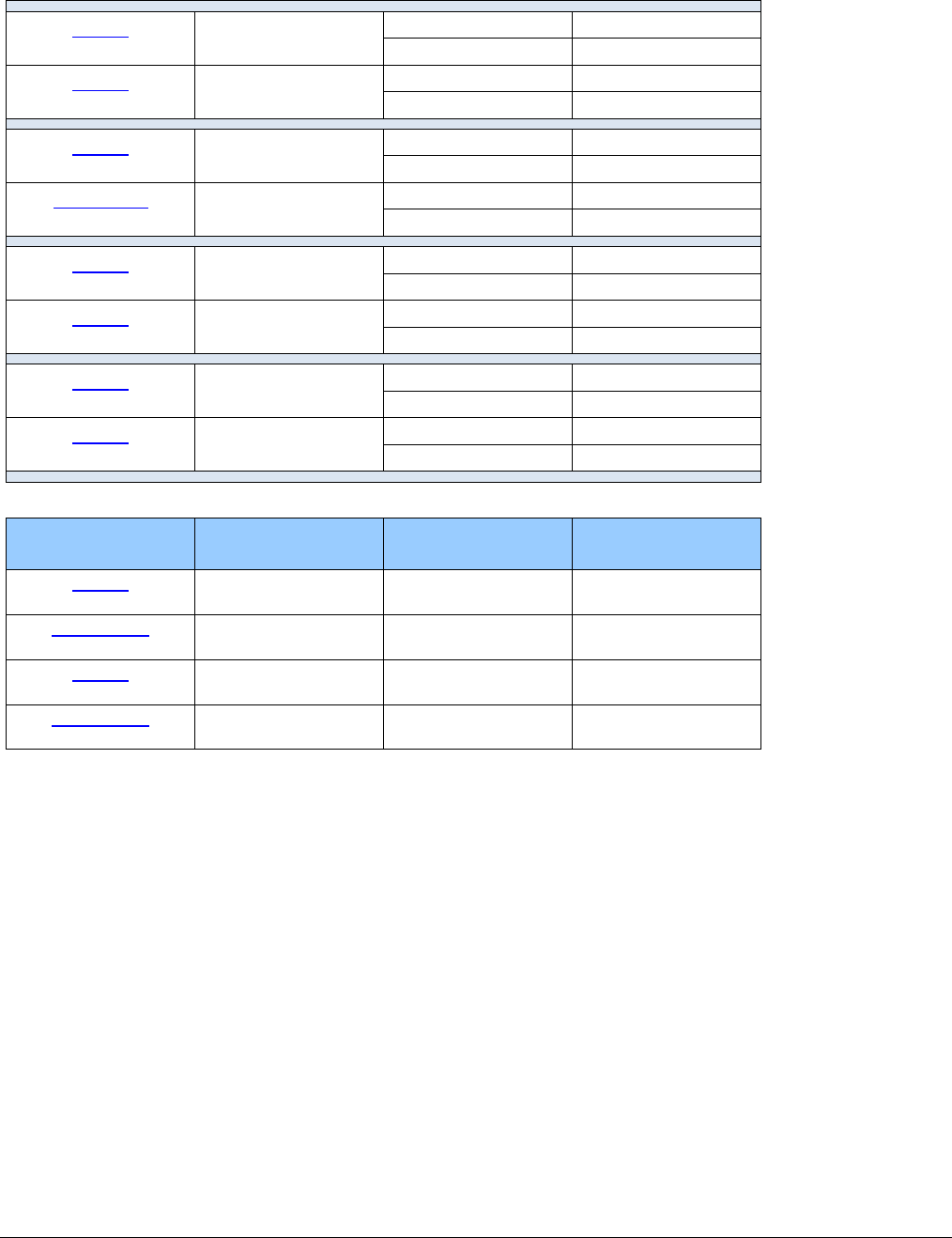
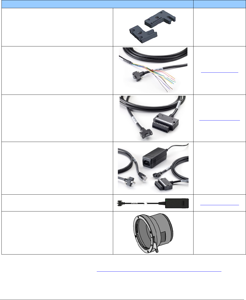
Accessories
Nano Accessories & Cables (sold separately) Order Number
Mounting Bracket Plate
(2 or 3 screw camera mount),
with ¼ inch external device screw mount
(also known as a tripod mount)
G3-AMNT-BRA01
I/O Blunt End Cable
(2 meter Screw Retention to Flying Leads)
G3-AIOC-BLUNT2M
I/O Breakout Cable
(2 meter Screw Retention to Euroblock connector)
G3-AIOC-BRKOUT2M
Power and Cable Evaluation Kit
• Includes a Power Supply (12V),
• an Ethernet Cable (RJ-45, 2 meter),
• and a 2 meter I/O Breakout Cable (Euroblock)
G3-ACBL-EVALKIT
Generic 12 volt power supply for Genie Nano–Aux
connector (Samtec 10-Pin) – 4 Meter length
G3-APWS-S10S04M
NanoXL — M42 to F-mount (Nikon) adapter
(same adapter part as used with Genie TS)
Note that there is no support for Nikon lens features
such as focus and aperture motor controls.
G2-AM42-MOUNT4
Right angle I/O cables and Ethernet cables (including combo evaluation packages) are available
directly from our preferred source (see Components Express Right-Angle Cable Assemblies).
16
•
Genie Nano Series Overview Nano Series GigE Vision Camera
Software Requirements
Sapera LT Development Software
Teledyne DALSA Software Platform for Microsoft Windows
Sapera LT version 8.00 or later (8.10 or later recommended),
for Windows. Includes Sapera Network Imaging Package and
GigE Vision Imaging Driver, Sapera Runtime and CamExpert.
Provides everything you will need to develop imaging applications
Sapera documentation provided in compiled HTML help,
and Adobe Acrobat® (PDF)
Available for download
http://www.teledynedalsa.com/imaging/support/
Sapera Processing Imaging Development Library
(available for Windows or Linux – sold separately): Contact Teledyne DALSA Sales
Teledyne DALSA Software Platform for Linux
GigE-V Framework Ver. 2.0 (for both X86 or Arm type processor) Available for download
http://teledynedalsa.com/imaging/products/softwar
e/linux-gige-v/
Third Party GigE Vision Development
Third Party GigE Vision Software Platform Requirements
Support of GenICam GenApi version 2.3 General acquisition and control
Support of GenICam GenApi version 2.3 File access: firmware, configuration data, upload &
download
Support of GenICam XML schema version 1.1
GenICam™ support — XML camera description file Embedded within Genie Nano
About GigE Vision
Genie Nano cameras are 100% compliant with the GigE Vision 1.2
specification which defines the communication interface protocol used by any
GigE Vision device. The device description and capabilities are contained in an
XML file. For more information see:
https://www.visiononline.org/vision-standards-details.cfm?type=5
Genie Nano cameras implement a superset of the GenICam™ specification
which defines device capabilities. This description takes the form of an XML
device description file respecting the syntax defined by the GenApi module of
the GenICam™ specification. For more information see www.genicam.org.
The Teledyne DALSA GigE Vision Module provides a license free development platform for Teledyne
DALSA GigE hardware or Sapera vision applications. Additionally supported are Sapera GigE Vision
applications for third party hardware with the purchase of a GigE Vision Module license, or the
Sapera processing SDK with a valid license.
The GigE Vision Compliant XML device description file is embedded within Genie Nano firmware
allowing GigE Vision Compliant applications access to Genie Nano capabilities and controls
immediately after connection.

Nano Series GigE Vision Camera Genie Nano Specifications
•
17
Genie Nano Specifications
The Nano common specifications listed first are followed by model specific tables of functional
features and timing details.
Common Specifications
Camera Controls
Synchronization Modes Free running, External triggered, Software trigger through Ethernet, Precision Time
Protocol (PTP)
Exposure Control Internal – Programmable via the camera API
External (Global Shutter models) – based on Trigger Width
Exposure Time Maximum 16 sec (Global Shutter models)
0.5 sec (Rolling Shutter model – C4900)
Exposure Modes Programmable in increments of 1µs
minimum (in µs) is model specific
Pulse controlled via Trigger pulse width (Global Shutter models).
Trigger Inputs Opto-isolated, 2.4V to 24V typical, 16mA min.
Debounce range from 0 up to 255 µs
Trigger Delay from 0 to 2,000,000 µs
Strobe Outputs
Output opto-isolated:
Aligned to the start of exposure with a programmable delay, duration and polarity
(using “start of exposure on output line source” feature)
Features
Image Buffer
(VGA to 5M models)
(8.9M to 18M models)
(NanoXL models)
Refer to transferQueueMemorySize feature.
90 MB total on-board memory for acquisitions and packet resend buffering
200 MB total
500 MB total
Reserved Private User Buffer 4 kB flash memory for OEM usage (deviceUserBuffer)
Flash memory 32 MB flash memory implemented
Gain In Sensor gain (model dependent) and Digital gain up to 4x
Auto-Brightness Yes , with Auto-Exposure and AGC (Sensor Gain or FPGA Gain)
Note1: Sensor Gain AGC only with Sony sensors
Note2: Not applicable to model C4900 (rolling shutter sensor)
Color model output Color cameras support Bayer output or RGB output firmware.
Binning (monochrome models) Support for both Horizontal and Vertical Binning: 1x, 2x, and 4x in FPGA
Models M640, M800, M1280, M1930, M2590, M4040, M4060 have in-sensor binning
LUT Programmable LUT (Look-up-table) up to 12-Bit (model dependent)
Defective Pixel Replacement Available on some models — up to 1024 entries (2048 for NanoXL)
Automatic White Balance Available on Color models
Counter and Timer 1 Counter, and 1 Timer. User programmable, acquisition independent, with event
generation, and can control Output I/O pins
Timestamp Timer to Timestamp images and events (1μs tics using Internal Clock, 8 nanosecond
tics when using IEEE1588 ( PTP: Precise time Protocol)
Metadata Metadata Output at the end of the Images (also known as GenICam Chunk Data)
Cycling Mode Automatic cycling between 64 camera setups
Multicast Programming support for multicasting images (requires Multicast host support: refer to

18
•
Genie Nano Specifications Nano Series GigE Vision Camera
the SDK documentation – if supported)
Action Command Programmable for up to 2 GenICam Action Commands (requires host support: refer to
the SDK documentation – if supported)
Test image Internal generator with choice of static and shifting patterns
User settings Select factory default or either of two user saved camera configurations
TurboDrive Technology Supported with 8-bit or 16-bit buffer format (see Sapera 8.10 release notes)
Not supported with RGB output firmware for any Nano model due to limitations of
camera resources.
Back Focal Distance
17.52 mm (C-mount models), 12.52 mm (CS-mount models)
12 mm (model NanoXL)
Mechanical Interface
Camera (L x H x W)
see Mechanical Specifications 21.2 mm x 29 mm x 44 mm (without lens mount or Ethernet connector)
38.9 mm x 29 mm x 44 mm (with C-mount and Ethernet connector)
23.7 mm x 59 mm x 59 mm (NanoXL without Ethernet connector)
38.3 mm x 59 mm x 59 mm (NanoXL with Ethernet connector)
Mass (approximate value due to
sensor variations) ~ 46g (C-mount with no lens)
~ 163g — model NanoXL
Power connector via the 10-pin I/O connector, or RJ45 in PoE mode
Ethernet connector RJ45
Electrical Interface
Input Voltage +12 to +36 Volts DC (+10%/- 10%)
+10 to +56 Volts DC (Absolute min/max Range) on Auxiliary connector
Supports the Power Over Ethernet standard. (PoE Class 3 as per IEEE 802.3af)
Inputs/Outputs Default models have 2 Inputs and 2 Outputs
Optional models have 1 Input and 3 Outputs
XL models have 2 Inputs and 3 Outputs
Power Dissipation (typical) Nano: PoE Class 2
From 3.8W to 4.9W dependent on Nano model and power supply voltage
NanoXL: PoE Class 3 (Up to 7W) or external 24Volt power (6.6W)
Data Output Gigabit Ethernet 1000Mbps (10/100 Mbps are not supported) 115 MB/sec max.
Ethernet Option supported PAUSE Frame support (as per IEEE 802.3x)
Data and Control GigE Vision 1.2 compliant
Environmental Conditions
Operating Temperature
(at camera front plate) All Models: -20°C to +65°C (-4°F to +149°F)
Model C4900 Exception: -20°C to +50°C (-4°F to +122°F)
Temperature range specification based on an auxiliary input voltage of +20 to +36Vdc
or PoE.
Any metallic camera mounting provides heat-sinking therefor reducing the internal
temperature.
Operating Relative Humidity 10% to 80% non-condensing
Storage -40°C to +80°C (-4°F to +176°F) temperature at 20% to 80% non-condensing
relative humidity
Conformity CE, FCC, GenICam, GigE Vision, IP30, IEEE 802.3af (PoE)

Nano Series GigE Vision Camera Genie Nano Specifications
•
19
Sensor Cosmetic Specifications
After Factory Calibration and/or Corrections are Applied (if applicable — dependent on sensor)
Blemish Specifications Maximum Number of
Defects Blemish Description
Hot/Dead Pixel defects Typical 0.0025%
Max 0.005% Any pixel that deviates by ±20% from the average of
neighboring pixels at 50% saturation including pixel stuck at 0
and maximum saturated value.
Spot defects none Grouping of more than 8 pixel defects within a sub-area of 3x3
pixels, to a maximum spot size of 7x7 pixels.
Clusters defects none Grouping of more than 5 single pixel defects in a 3x3 kernel.
Column defects none Vertical grouping of more than 10 contiguous pixel defects
along a single column.
Row defects none Horizontal grouping of more than 10 contiguous pixel defects
along a single row.
• Test conditions
• Nominal light = illumination at 50% of saturation
• Temperature of camera is 45°C
• At exposures lower than 0.1 seconds
• At nominal sensor gain (1x)
• For Model C4900 (Rolling Shutter sensor) see Model C4900 Sensor Cosmetic Specifications
• On-Semi Python Sensor Limitations:
• Guarantied pixel saturation: from a minimum exposure to 100 millisecond (Gain1.0)
for the 0.3M to 5M models
• Guarantied pixel saturation: from a minimum exposure to 10 millisecond (Gain1.0)
for the 16M to 25M models
• Sony Sensor Limitation:
• Max pixel saturated values: Max Pixel format bit depth – 1DN (either 10-bit or 12-bit, as
designed by Sony)
Dynamic Range & Signal to Noise Ratio Measurement Conditions
Specifications calculated according to EMVA-1288 standard, using white LED light
Dynamic Range Test Conditions
• Exposure 100µs
• 0% Full Light Level
SNR Test Conditions
• Exposure 2000µs
• 80% saturation

20
•
Genie Nano Specifications Nano Series GigE Vision Camera
EMI, Shock and Vibration Certifications
Compliance Directives Standards ID Overview
CE
EN61000-4-2 : 2008 Electrostatic discharge immunity test
EN61000-4-3 : 2006 A1 : 2007 A2 :
2010 Radiated, radio-frequency, electromagnetic field
immunity test
EN61000-4-4 : 2004 Electrical fast transient/burst immunity test
EN61000-4-5 : 2005 Surge immunity
EN61000-4-6 : 2008 Immunity to conducted disturbances, induced by
radio-frequency fields
EN61000-4-8 : 2009 Power frequency magnetic field immunity
EN61000-4-11 : 2004 Voltage variations immunity
EN61000-6-2 : 2005 Electromagnetic immunity
EN61000-6-4: 2007 Electromagnetic emissions
CISPR 11: 2009 A1 :
group 1 FCC, part 15, subpart B:2010 Limit: class A Conducted Emissions
CISPR 22 : 2008 Limit: class A LAN port Conducted Emissions
FCC Part 15, class A
RoHS Compliancy as per European directive 2011/65/EC
For an image of Genie Nano certificates see “EC & FCC Declarations of Conformity” on page 234
Vibration & Shock Tests Test Levels (while operating) Test Parameters
Random vibrations Level 1: 2 grms 60 min.
Level 2: 4 grms 45 min.
Level 3: 6 grms 30 min.
Frequency range: 5 to 2000 Hz
Directions: X, Y, and Z axes
Shocks Level 1: 20 g / 11 ms
Level 2: 30 g / 11 ms
Level 3: 40 g / 60 ms
Shape: half-sine
Number: 3 shocks (+) and 3 shocks (-)
Directions: ±X, ±Y, and ±Z axes
Additional information concerning test conditions and methodologies is available on request.
Nano Series GigE Vision Camera Genie Nano Specifications
•
21
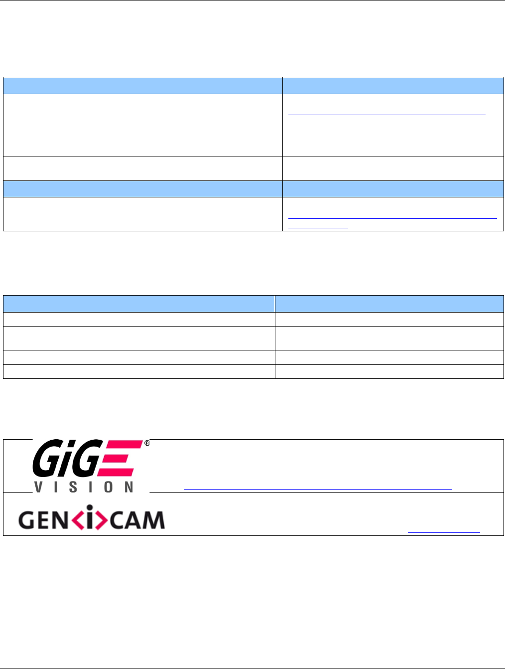
Mean Time between Failure (MTBF)
The analysis was carried out for operating temperatures varying from 0 to 80ºC. The following
table presents the predicted MTBF and failure rate values.

22
•
Genie Nano Specifications Nano Series GigE Vision Camera
Specifications: M1450, C1450
Supported Features M1450 C1450
Resolution 1456 x 1088
Sensor Sony IMX273 (1.6M)
Pixel Size 3.45 µm x 3.45 µm
Shutter type Full frame electronic global shutter function
Full Well charge 11ke (max)
Firmware option
(Field programmable) Standard Design Monochrome Standard Design Bayer
Max. Internal Frame Rate
Full resolution 161 fps at 1456 x 1088 resolution
Maximum Sustained Frame Rate
Output (with TurboDrive v1) * 161 fps at 1456 x 1088 resolution (8-bits)
80 fps at 1456 x 1088 resolution (12-bits)
Maximum Sustained Frame Rate
Output (without TurboDrive) 75 fps at 1456 x 1088 resolution (8-bits)
36 fps at 1456 x 1088 resolution (12-bits)
Pixel Data Formats Monochrome 8-bit
Monochrome 12-bit Bayer 8-bit
Bayer 12-bit
Trigger to Exposure Minimum delay
(Synchronous Exposure Alignment) 2 line time (11 µs)
Trigger to Exposure Minimum delay
(Reset Exposure Alignment) 0 µs
Trigger to Exposure Start jitter (best
case with Synchronous Exposure
Alignment) Max 1 line time (0 to 5.5 µs)
Trigger to Exposure Start jitter
(Reset Exposure Alignment) 0 µs
Actual Exposure Time Minimum
(see “exposureTimeActual”
in Sensor Control) 19.7 µsec in 5.5 µsec steps (i.e. 1 line time + 14.26 µs)
Min. Time from End of Exposure to
Start of Next Exposure (second
frame) 18 line times – 14.26 µs (84.74 µs)
Horizontal Line Time: 5.5 µs
Readout Time (H line time) x (lines in frame + 22) in µs
Auto-Brightness Yes , with Auto-Exposure and AGC (FPGA Gain or Sensor Gain)
Black offset control Yes
Gain Control In-sensor Analog Gain (1x to 16x)
In-sensor Digital Gain (1 to 16x)
Binning Support Yes In-FPGA (summing and average)
2x2, 4x4 NO
Color Correction Support NO
Decimation Support NO
Defective Pixel Replacement NO
Image Correction NO
Image Flip Support Yes, In-Sensor, Vertical and Horizontal
Multi-ROI Support Yes, in sensor up to 4 ROI (2x2) (mutually exclusive with binning)
On-Board Image Memory 90 MB
Output Dynamic Range (dB) 73.60
Nano Series GigE Vision Camera Genie Nano Specifications
•
23
SNR (dB) 39.40
*TurboDrive internal limitation of 250MB/sec
Firmware Files for Models 1450
M1450
• Standard
Genie_Nano_Sony_IMX273_1.6M_Mono_STD_Firmware_10CA18.x.cbf
C1450
• Standard
Genie_Nano_Sony_IMX273_1.6M_Bayer_STD_Firmware_11CA18.x.cbf
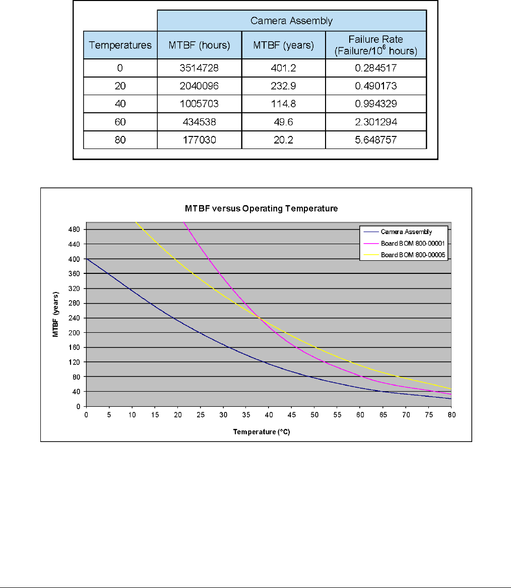
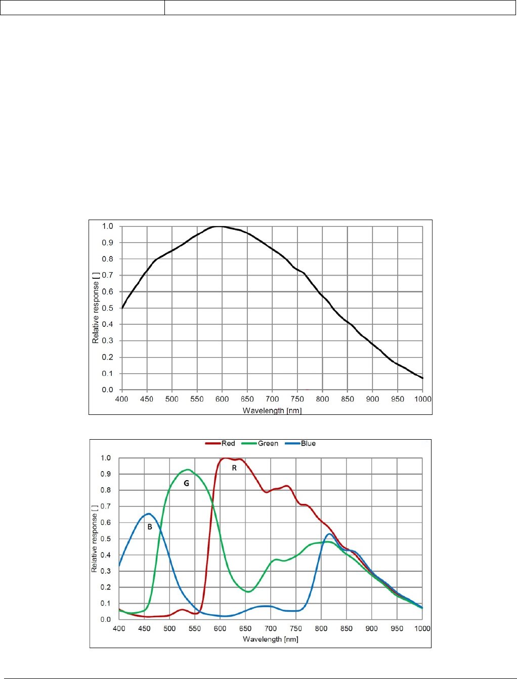
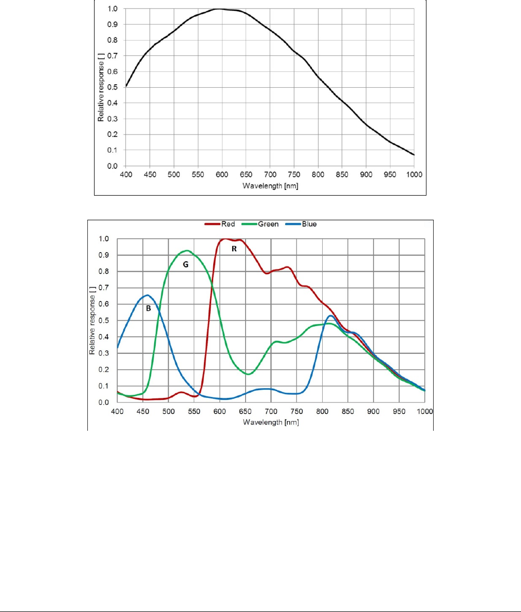
Spectral Response
Monochrome Model M1450, (Sony IMX273)
Color Model C1450, (Sony IMX273)

24
•
Genie Nano Specifications Nano Series GigE Vision Camera
Specifications: M1920, C1920
Supported Features M1920 C1920
Resolution 1936 x 1216
Sensor Sony IMX249 (2.3M)
Pixel Size 5.86 µm x 5.86 µm
Shutter type Full frame electronic global shutter function
Full Well charge 32ke (max)
Firmware option
(Field programmable) Standard Design
Monochrome Standard Design
Bayer RGB-Output
Design
Max. Internal Frame Rate
Full resolution 38.8 fps
Maximum Sustained Frame Rate
Output (with TurboDrive v1) 38.8 fps (8-bit)
38.8 fps (12-bit) N/A
Maximum Sustained Frame Rate
Output (without TurboDrive) 38.8 fps (8-bit)
25 fps (12-bit)
13 fps (RGBA)
19.5 fps (RGB)
26 fps (Yuv422)
38.8fps (8-bit mono)
Pixel Data Formats Mono 8-bit
Mono 12-bit Bayer 8-Bit
Bayer 12-Bit
RGBA 32-bit
RGB 24-bit
Yuv422 16-bit
Mono 8-bit
Trigger to Exposure Minimum delay
(Synchronous Exposure Alignment) 2 line time (41.5 µs)
Trigger to Exposure Minimum delay
(Reset Exposure Alignment) Not supported by this sensor
Trigger to Exposure Start jitter (best
case with Synchronous Exposure
Alignment)
Up to 1 line time
0 to 20.5 µs
Trigger to Exposure Start jitter
(Reset Exposure Alignment) Not supported by this sensor
Actual Exposure Time Minimum
(see “exposureTimeActual”
in Sensor Control)
34.23 µs (1 line time + 13.73 us)
(increment steps of 20.5 µs)
Min. Time from End of Exposure to
Start of Next Exposure 13 lines (266.5µs)
Horizontal Line Time: 20.5 µs
Readout Time (Horizontal Line Time) x (lines in frame +20) — in μs
Auto-Brightness Yes , with Auto-Exposure and AGC (FPGA Gain or Sensor Gain)
Black offset control Yes (in DN)
Gain Control In-sensor Gain (1.0x to 251x)
In-FPGA Digital Gain (1x to 4x) in 0.007x steps
Binning Support Yes In-FPGA
(summing and average)
2x2, 4x4 No
Color Correction Support No Yes
Decimation Support No
Defective Pixel Replacement No

Nano Series GigE Vision Camera Genie Nano Specifications
•
25
Image Correction No
Image Flip Support Yes, In-Sensor, Vertical and Horizontal
Multi-ROI Support Yes, in FPGA, up to 16 ROI (mutually exclusive with binning)
On-Board Image Memory 90MB
Output Dynamic Range (dB) 72.1 dB (in 12-Bit Pixel Format)
SNR (dB) 44.3 dB (in 12-Bit Pixel Format)
Specifications: M1940, C1940
Supported Features Nano-M1940 Nano-C1940
Resolution 1936 x 1216
Sensor Sony IMX174 (2.3M)
Pixel Size 5.86 µm x 5.86 µm
Shutter type Full frame electronic global shutter function
Full Well charge 32ke (max)
Firmware option
(Field programmable) Standard Design
Monochrome Standard Design
Bayer RGB-Output
Design
Max. Internal Frame Rate
Full resolution 83.9 fps
Maximum Sustained Frame Rate
Output (with TurboDrive v1) 83.9 fps (8-bit)
53 fps (10-bit) N/A
Maximum Sustained Frame Rate
Output (without TurboDrive) 52 fps (8-bit)
26 fps (10-bit)
13 fps (RGBA)
19.5 fps (RGB)
26 fps (Yuv422)
38.8fps (8-bit mono)
Pixel Data Formats Mono 8-bit
Mono 10-bit Bayer 8-Bit
Bayer 10-Bit
RGBA 32-bit
RGB 24-bit
Yuv422 16-bit
Mono 8-bit
Trigger to Exposure Minimum delay
(Synchronous Exposure Alignment) 2 line time (19 µs)
Trigger to Exposure Minimum delay
(Reset Exposure Alignment) Not supported by this sensor
Trigger to Exposure Start jitter (best
case with Synchronous Exposure
Alignment)
Up to 1 line time
0 to 9.5 µs
Trigger to Exposure Start jitter
(Reset Exposure Alignment) Not supported by this sensor
Actual Exposure Time Minimum
(see “exposureTimeActual”
in Sensor Control)
23.23 µs (1 line time + 13.73 us)
(increment steps of 9.5 µs)
Min. Time from End of Exposure to
Start of Next Exposure (second
frame) 13 lines (123.5µs)
Horizontal Line Time: 9.5 µs
Readout Time (Horizontal Line Time) x (lines in frame +20) — in μs
Auto-Brightness Yes , with Auto-Exposure and AGC (FPGA Gain or Sensor Gain)
Black offset control Yes (in DN)

26
•
Genie Nano Specifications Nano Series GigE Vision Camera
Gain Control In-sensor Gain (1.0x to 251x)
In-FPGA Digital Gain (1x to 4x) in 0.007x steps
Binning Support Yes In-FPGA
(summing and average)
2x2, 4x4 No
Color Correction Support No Yes
Decimation Support No
Defective Pixel Replacement No
Image Correction No
Image Flip Support Yes, In-Sensor, Vertical and Horizontal
Multi-ROI Support Yes, in-sensor, up to 16 ROI (mutually exclusive with binning)
On-Board Image Memory 90MB
Output Dynamic Range (dB) 68.3 dB (in 10-Bit Pixel Format)
SNR (dB) 43.9 dB (in 10-Bit Pixel Format)
Notes:
* Entire Resolution includes Over-scan pixels:
• Active resolution is 1920 x 1200. The 8 + 8 additional pixels per line and 8 + 8 additional
vertical lines are available for preprocessing and/or camera mechanical alignment
operations in a system.
** Limited to the Genie Nano Architecture:
• ~250MB/sec Sustained into the TurboDrive Engine
• Additional note: This transfer was achieved using 1500 Byte Packet Size.
*** Actual Exposure Time:
• The actual internal minimum exposure may be different than what is programmed. Use the
feature “exposureTimeActual” from the Sensor Control category to read back the actual
sensor exposure.

Nano Series GigE Vision Camera Genie Nano Specifications
•
27
Firmware Files for 1920, 1940
The latest firmware files for all Nano models are available on the Teledyne DALSA support web site:
http://www.teledynedalsa.com/imaging/support/downloads/firmware/
The firmware files for these models are listed below. The xx denotes the current build number.
M1920
• Standard
“Genie_Nano_Sony_IMX249-2M_Mono_STD_Firmware_3CA18.xx.cbf”
C1920
• Bayer Output
“Genie_Nano_Sony_IMX249-2M_Bayer_STD_Firmware_4CA18.xx.cbf”
• RGB Output
“Genie_Nano_Sony_IMX249-2M_RGB_Output_Firmware_4CA18.xx.cbf”
M1940
• Standard
“Genie_Nano_Sony_IMX174-2M_Mono_STD_Firmware_1CA18.xx.cbf”
C1940
• Bayer Output
“Genie_Nano_Sony_IMX174-2M_Bayer_STD_Firmware_2CA18.xx.cbf”
• RGB Output
“Genie_Nano_Sony_IMX174-2M_RGB_Output_Firmware_4CA18.xx.cbf”
28
•
Genie Nano Specifications Nano Series GigE Vision Camera
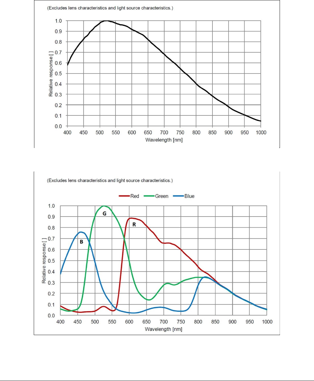
Spectral Response
Monochrome Models M194x & M192x, (Sony IMX174 & IMX249)
Measured Fill-Factor x Quantum Efficiency (FF x QE)
Color Models C194x & C192x, (Sony IMX174 & IMX249)
Measured Fill-Factor x Quantum Efficiency (FF x QE)

Nano Series GigE Vision Camera Genie Nano Specifications
•
29
Specifications: M2020, C2020
Supported Features Nano-M2020 Nano-C2020
Resolution 2064 x 1544
Sensor Sony IMX265 (3.2M)
Pixel Size 3.45 µm x 3.45 µm
Shutter type Full frame electronic global shutter function
Full Well charge 11ke (max)
Firmware option
(Field programmable) Standard Design
Monochrome Standard Design
Bayer RGB-Output
Design
Max. Internal Frame Rate
Full resolution 53.3 fps
Maximum Sustained Frame Rate
Output (with TurboDrive v1) * 53.3 fps (8-bit)
41.0 fps (12-bit) N/A
Maximum Sustained Frame Rate
Output (without TurboDrive) 38 fps (8-bit)
18 fps (12-bit)
9 fps (RGBA)
13.5 fps (RGB)
18 fps (Yuv422)
38 fps (mono8)
Pixel Data Formats Mono 8-bit
Mono 12-bit Bayer 8-Bit
Bayer 12-Bit
RGBA 32-bit
RGB 24-bit
Yuv422 16-bit
Mono 8-bit
Trigger to Exposure Minimum delay
(Synchronous Exposure Alignment) 2 line time (23.8 µs)
Trigger to Exposure Minimum delay
(Reset Exposure Alignment) 0 µs
Trigger to Exposure Start jitter (best
case with Synchronous Exposure
Alignment)
Up to 1 line time
0 to 11.9 µs
Trigger to Exposure Start jitter
(Reset Exposure Alignment) 0 µs
Actual Exposure Time Minimum
(see “exposureTimeActual”
in Sensor Control)
25.65µs (1 line time + 13.73 us)
(increment steps of 11.9µs)
Min. Time from End of Exposure to
Start of Next Exposure (second
frame) 8 lines (81.6 µs)
Horizontal Line Time: 11.9 µs
Readout Time (Horizontal Line Time) x (lines in frame +17) — in μs
Auto-Brightness Yes , with Auto-Exposure and AGC (FPGA Gain or Sensor Gain)
Black offset control Yes (in DN)
Gain Control In-sensor Gain (1.0x to 251x)
In-FPGA Digital Gain (1x to 4x) in 0.007x step
Binning Support Yes In-FPGA (summing and average)
2x2, 4x4 No
Color Correction Support No Yes
Decimation Support No
Defective Pixel Replacement No
Image Correction No
Image Flip Support Yes, In-Sensor, Vertical and Horizontal

30
•
Genie Nano Specifications Nano Series GigE Vision Camera
Multi-ROI Support Yes, in FPGA, up to 16 ROI (mutually exclusive with binning)
On-Board Image Memory 90MB
Output Dynamic Range (dB) 76.4 dB (in 12-Bit Pixel Format)
SNR (dB) 39.6 dB (in 12-Bit Pixel Format)
* Limited to the Genie Nano Architecture:
~250MB/sec Sustained into the TurboDrive Engine achieved using 1500 Byte Packet Size
Firmware Files for Models 2020
The latest firmware files for all Nano models are available on the Teledyne DALSA support web site:
http://www.teledynedalsa.com/imaging/support/downloads/firmware/
The firmware files for these models are listed below. The xx denotes the current build number.
M2020
• Standard
“Genie_Nano_Sony_IMX264-265_3.2M-5.1M_Mono_STD_Firmware_9CA18.xx.cbf”
C2020
• Bayer Output
“Genie_Nano_Sony_IMX264-265_3.2M-5.1M_Bayer_STD_Firmware_ACA18.xx.cbf”
• RGB Output
“Genie_Nano_Sony_IMX264-265_3.2M-5.1M_RGB_Firmware_ACA18.xx.cbf”
Specifications: M2050
Supported Features Nano-M2050
Resolution 2064 x 1544
Sensor Sony IMX252 (3.2M)
Pixel Size 3.45 µm x 3.45 µm
Shutter type Full frame electronic global shutter function
Firmware option
(Field programmable) High Sensitivity Design Standard Design
Full Well charge; dependent on
Firmware Design Loaded 2750e- (max) 11ke (max)
Sensitivity to Saturation 4x 1x
Max. Internal Frame Rate
Full resolution 143 fps 116 fps
Maximum Sustained Frame Rate
Output (with TurboDrive v1) * 82 fps (8-bit)
Maximum Sustained Frame Rate
Output (without TurboDrive) 38 fps (8-bit)
Pixel Data Formats Mono 8-bit
Trigger to Exposure Minimum delay
(Synchronous Exposure Alignment) 2 line time
(8.8 µs) 2 line time
(10.8 µs)
Trigger to Exposure Minimum delay
(Reset Exposure Alignment) 0 µs

Nano Series GigE Vision Camera Genie Nano Specifications
•
31
Trigger to Exposure Start jitter (best
case with Synchronous Exposure
Alignment)
Max 1 line
(0 to 4.4µs) Max 1 line
(0 to 5.4µs)
Trigger to Exposure Start jitter
(Reset Exposure Alignment) 0 µs
Actual Exposure Time Minimum
(see “exposureTimeActual”
in Sensor Control)
18.1µs (1 line time + 13.73 us)
(increment of 4.4µs steps) 19.1µs (1 line time + 13.73 us)
(increment of 5.4µs steps)
Min. Time from End of Exposure to
Start of Next Exposure 10 lines–13.73µs
(30.3 µs) 10 lines–13.73µs
(40.4 µs)
Horizontal Line Time: 4.4µs 5.4µs
Readout Time (H Line Time) x (lines in frame +23) — in μs
Auto-Brightness Yes , with Auto-Exposure and AGC (FPGA Gain or Sensor Gain)
Black offset control Yes (in DN)
Gain Control In-sensor Gain (1.0x to 251x)
In-FPGA Digital Gain (1x to 4x) in 0.007x steps
Binning Support Yes In-FPGA (summing and average)
2x2, 4x4
Decimation Support No
Color Correction Support No
Defective Pixel Replacement No
Image Correction No
Image Flip Support Yes, In-Sensor, Vertical and Horizontal
Multi-ROI Support Yes, In-Sensor, up to 16 ROI (mutually exclusive with in-sensor binning)
On-Board Image Memory 90MB
Output Dynamic Range (dB) 56.7 75.4 dB (in 8-Bit Pixel Format)
SNR (dB) 33.01 39.6 dB (in 8-Bit Pixel Format)
* Limited to the Genie Nano Architecture:
~250MB/sec Sustained into the TurboDrive Engine achieved using 1500 Byte Packet Size
Firmware Files for Model M2050
The latest firmware files for all Nano models are available on the Teledyne DALSA support web site:
http://www.teledynedalsa.com/imaging/support/downloads/firmware/
The firmware files for this model are listed below. The xx denotes the current build number.
M2050
• Standard
“Genie_Nano_Sony_IMX25x_3.2M-5.1M-9M-12M _Mono_STD_Firmware_7CA18.xx.cbf”
• High Sensitivity
“Genie_Nano_Sony_IMX25x_3.2M-5.1M-9M-12M_Mono_HSD_Firmware_7CA18.xx.cbf”

32
•
Genie Nano Specifications Nano Series GigE Vision Camera
Specifications: C2050
Supported Features Nano-C2050
Resolution 2064 x 1544
Sensor Sony IMX252 (3.2M)
Pixel Size 3.45 µm x 3.45 µm
Shutter type Full frame electronic global shutter function
Firmware option
(Field programmable) High Sensitivity
Design (Bayer) Standard Design
(Bayer) RGB-Output
Standard Design
Full Well charge; dependent on
Firmware Design Loaded 2750e- (max) 11ke (max)
Sensitivity to Saturation 4x 1x
Max. Internal Frame Rate
Full resolution 143 fps 116 fps
Maximum Sustained Frame Rate
Output (with TurboDrive v1) * 82 fps (8-bit) 82 fps (8-bit) N/A
Maximum Sustained Frame Rate
Output (without TurboDrive) 38 fps (8-bit) 38 fps (8-bit)
9.7 fps (RGBA)
14.5 fps (RGB)
19 fps (Yuv422)
38 fps (mono8)
Pixel Data Formats Bayer 8-Bit Bayer 8-Bit
RGBA 32-bit
RGB 24-bit
Yuv422 16-bit
Mono 8-bit
Trigger to Exposure Minimum delay
(Synchronous Exposure Alignment) 2 line time
(8.8 µs) 2 line time
(10.8 µs)
Trigger to Exposure Minimum delay
(Reset Exposure Alignment) 0 µs
Trigger to Exposure Start jitter (best
case with Synchronous Exposure
Alignment)
Max 1 line
(0 to 4.4µs) Max 1 line
(0 to 5.4µs)
Trigger to Exposure Start jitter
(Reset Exposure Alignment) 0 µs
Actual Exposure Time Minimum
(see “exposureTimeActual”
in Sensor Control)
18.1µs (1 line time+13.73 us)
(increment of 4.4µs steps) 19.1µs (1 line time + 13.73 us)
(increment of 5.4µs steps)
Min. Time from End of Exposure to
Start of Next Exposure 10 lines–13.73µs
(30.3 µs) 10 lines–13.73µs
(40.4 µs)
Horizontal Line Time: 4.4µs 5.4µs
Readout Time (H Line Time) x (lines in frame +23) — in μs
Auto-Brightness Yes , with Auto-Exposure and AGC (FPGA Gain or Sensor Gain)
Black offset control Yes (in DN)
Gain Control In-sensor Gain (1.0x to 251x)
In-FPGA Digital Gain (1x to 4x) in 0.007x steps
Binning Support No
Color Correction Support No Yes
Decimation Support No
Defective Pixel Replacement No

Nano Series GigE Vision Camera Genie Nano Specifications
•
33
Image Correction No
Image Flip Support Yes, In-Sensor, Vertical and Horizontal
Multi-ROI Support Yes, In-Sensor, up to 16 ROI (mutually exclusive with in-sensor binning)
On-Board Image Memory 90MB
Output Dynamic Range (dB) 56.7 75.4 dB (in 8-Bit Pixel Format)
SNR (dB) 33.01 39.6 dB (in 8-Bit Pixel Format)
* Limited to the Genie Nano Architecture:
~250MB/sec Sustained into the TurboDrive Engine achieved using 1500 Byte Packet Size
Firmware Files for Model C2050
The latest firmware files for all Nano models are available on the Teledyne DALSA support web site:
http://www.teledynedalsa.com/imaging/support/downloads/firmware/
The firmware files for this model are listed below. The xx denotes the current build number.
C2050
• Bayer Output
“Genie_Nano_Sony_IMX25x_3.2M-5.1M-9M-12M _Bayer_STD_Firmware_8CA18.xx.cbf
• High Sensitivity Bayer Output
“Genie_Nano_Sony_IMX25x_3.2M-5.1M-9M-12M _Bayer_HSD_Firmware_8CA18.xx.cbf”
• RGB Output
“Genie_Nano_Sony_IMX25x_3.2M-5.1M-9M-12M _RGB_Output_Firmware_8CA18.xx.cbf”
34
•
Genie Nano Specifications Nano Series GigE Vision Camera
Spectral Responses
The response curves describe the sensor, excluding lens and light source characteristics.
Models M2020, M2050
Models C2020, C2050

Nano Series GigE Vision Camera Genie Nano Specifications
•
35
Specifications: M2420, C2420
Supported Features Nano-M2420 Nano-C2420
Resolution 2464x 2056
Sensor Sony IMX264 (5.1M)
Pixel Size 3.45 µm x 3.45 µm
Shutter type Full frame electronic global shutter function
Full Well charge 11ke (max)
Firmware option
(Field programmable) Standard Design
Monochrome Standard Design
Bayer RGB-Output
Design
Max. Internal Frame Rate
Full resolution 34.4 fps
Maximum Sustained Frame Rate Output
(with TurboDrive v1) * 34.4 fps (8-bit)
26.1 fps (12-bit) N/A
Maximum Sustained Frame Rate Output
(without TurboDrive) 22.5 fps (8-bit)
11 fps (12-bit)
5.5 fps (RGBA)
8 fps (RGB)
11 fps (Yuv422)
22 fps (mono8)
Pixel Data Formats Mono 8-bit
Mono 12-bit Bayer 8-Bit
Bayer 12-Bit
RGBA 32-bit
RGB 24-bit
Yuv422 16-bit
Mono 8-bit
Trigger to Exposure Minimum delay
(Synchronous Exposure Alignment) 2 line time (27.8 µs)
Trigger to Exposure Minimum delay
(Reset Exposure Alignment) 0 µs
Trigger to Exposure Start jitter (best case
with Synchronous Exposure Alignment) Up to 1 line time
0 to 13.9 µs
Trigger to Exposure Start jitter
(Reset Exposure Alignment) 0 µs
Actual Exposure Time Minimum
(see “exposureTimeActual”
in Sensor Control)
27.65µs (1 line time + 13.73 us)
(increment steps of 13.9 µs)
Min. Time from End of Exposure to Start of
Next Exposure (second frame) 8 lines (97.6 µs)
Horizontal Line Time: 13.9 µs
Readout Time (Horizontal Line Time) x (lines in frame +17) — in μs
Auto-Brightness Yes , with Auto-Exposure and AGC (FPGA Gain or Sensor Gain)
Black offset control Yes (in DN)
Gain Control In-sensor Gain (1.0x to 251x)
In-FPGA Digital Gain (1x to 4x) in 0.007x step
Binning Support Yes In-FPGA
(summing and average)
2x2, 4x4 No
Color Correction Support No Yes
Decimation Support No
Defective Pixel Replacement No
Image Correction No
Image Flip Support Yes, In-Sensor, Vertical and Horizontal
Multi-ROI Support Yes, in FPGA, up to 16 ROI (mutually exclusive with binning)

36
•
Genie Nano Specifications Nano Series GigE Vision Camera
On-Board Image Memory 90MB
Output Dynamic Range (dB) 76.8 dB (in 12-Bit Pixel Format)
SNR (dB) 39.5 dB (in 12-Bit Pixel Format)
* Limited to the Genie Nano Architecture:
~250MB/sec Sustained into the TurboDrive Engine achieved using 1500 Byte Packet Size
Firmware Files for Models 2420
The latest firmware files for all Nano models are available on the Teledyne DALSA support web site:
http://www.teledynedalsa.com/imaging/support/downloads/firmware/
The firmware files for these models are listed below. The xx denotes the current build number.
M2420
• Standard
“Genie_Nano_Sony_IMX264-265_3.2M-5.1M_Mono_STD_Firmware_9CA18.xx.cbf”
C2420
• Bayer Output
“Genie_Nano_Sony_IMX264-265_3.2M-5.1M_Bayer_STD_Firmware_ACA18.xx.cbf”
• RGB Output
“Genie_Nano_Sony_IMX264-265_3.2M-5.1M_RGB_Firmware_ACA18.xx.cbf”
Specifications: M2450
Supported Features M2450
Resolution 2464 x 2056
Sensor Sony IMX250 (5.1M)
Pixel Size 3.45 µm x 3.45 µm
Shutter type Full frame electronic global shutter function
Firmware option
(Field programmable) High Sensitivity
Design Standard Design
(Mono)
Full Well charge; dependent on
Firmware Design Loaded 2750e- (max) 11ke (max)
Sensitivity to Saturation 4x 1x
Max. Internal Frame Rate
Full resolution 93 fps 76 fps
Maximum Sustained Frame Rate
Output (with TurboDrive v1)* 49 fps (8-bit)
Maximum Sustained Frame Rate
Output (without TurboDrive) 22 fps (8-bit)
Pixel Data Formats Mono 8-bit
Trigger to Exposure Minimum delay
(Synchronous Exposure Alignment) 2 line time
(10.22 µs) 2 line time
(12.5 µs)
Trigger to Exposure Minimum delay
(Reset Exposure Alignment) 0 µs
Trigger to Exposure Start jitter (best
case with Synchronous Exposure
Alignment)
Max 1 line
(0 to 5.11µs) Max 1 line
(0 to 6.25µs)

Nano Series GigE Vision Camera Genie Nano Specifications
•
37
Trigger to Exposure Start jitter
(Reset Exposure Alignment) 0 µs
Actual Exposure Time Minimum
(see “exposureTimeActual”
in Sensor Control)
18.8µs (1 line time + 13.73 us)
(increment of 5.11µs steps) 19.9µs (1 line time + 13.73 us)
(increment of 6.2µs steps)
Min. Time from End of Exposure to
Start of Next Exposure 10 lines–13.73µs
(37.3 µs) 10 lines–13.73µs
(48.8 µs)
Horizontal Line Time: 5.11µs 6.2µs
Readout Time (H Line Time) x (lines in frame +23) — in μs
Auto-Brightness Yes , with Auto-Exposure and AGC (FPGA Gain or Sensor Gain)
Black offset control Yes (in DN)
Gain Control In-sensor Analog Gain (1.0x to 251x)
Binning Support Yes In-FPGA
(summing and average)
2x2, 4x4
Decimation Support No
Defective Pixel Replacement No
Image Correction no
Image Flip Support Yes, In-Sensor, Vertical and Horizontal
Multi-ROI Support Yes, In-Sensor, up to 16 ROI (mutually exclusive with in-sensor binning)
On-Board Image Memory 90MB
Output Dynamic Range (dB) 56.7 75.4 dB (in 8-Bit Pixel Format)
SNR (dB) 33.01 39.6 dB (in 8-Bit Pixel Format)
* Limited to the Genie Nano Architecture:
~250MB/sec Sustained into the TurboDrive Engine achieved using 1500 Byte Packet Size
Firmware Files for Model M2450
The latest firmware files for all Nano models are available on the Teledyne DALSA support web site:
http://www.teledynedalsa.com/imaging/support/downloads/firmware/
The firmware files for this model are listed below. The xx denotes the current build number.
M2450
• Standard
“Genie_Nano_Sony_IMX25x_3.2M-5.1M-9M-12M _Mono_STD_Firmware_7CA18.xx.cbf”
• High Sensitivity
“Genie_Nano_Sony_IMX25x_3.2M-5.1M-9M-12M_Mono_HSD_Firmware_7CA18.xx.cbf”

38
•
Genie Nano Specifications Nano Series GigE Vision Camera
Specifications: C2450
Supported Features C2450
Resolution 2464 x 2056
Sensor Sony IMX250 (5.1M)
Pixel Size 3.45 µm x 3.45 µm
Shutter type Full frame electronic global shutter function
Firmware option
(Field programmable) High Sensitivity Design
(Bayer) Standard Design
(Bayer) RGB-Output
Design
Full Well charge; dependent on
Firmware Design Loaded 2750e- (max) 11ke (max)
Sensitivity to Saturation 4x 1x
Max. Internal Frame Rate
Full resolution 93 fps 76 fps
Maximum Sustained Frame Rate
Output (with TurboDrive v1)* 49 fps (8-bit) 49 fps (8-bit) N/A
Maximum Sustained Frame Rate
Output (without TurboDrive) 22 fps (8-bit) 22 fps (8-bit)
5.5 fps (RGBA)
8.7 fps (RGB)
11 fps (Yuv422)
22 fps (mono8)
Pixel Data Formats Bayer 8-Bit Bayer 8-Bit
RGBA 32-bit
RGB 24-bit
Yuv422 16-bit
Mono 8-bit
Trigger to Exposure Minimum delay
(Synchronous Exposure Alignment) 2 line time
(10.22 µs) 2 line time
(12.5 µs)
Trigger to Exposure Minimum delay
(Reset Exposure Alignment) 0 µs
Trigger to Exposure Start jitter (best
case with Synchronous Exposure
Alignment)
Max 1 line
(0 to 5.11µs) Max 1 line
(0 to 6.25µs)
Trigger to Exposure Start jitter
(Reset Exposure Alignment) 0 µs
Actual Exposure Time Minimum
(see “exposureTimeActual”
in Sensor Control)
18.8µs (1 line time+13.73 us)
(increment of 5.11µs steps) 19.9µs (1 line time + 13.73 us)
(increment of 6.2µs steps)
Min. Time from End of Exposure to
Start of Next Exposure 10 lines–13.73µs
(37.3 µs) 10 lines–13.73µs
(48.8 µs)
Horizontal Line Time: 5.11µs 6.2µs
Readout Time (H Line Time) x (lines in frame +23) — in μs
Auto-Brightness Yes , with Auto-Exposure and AGC (FPGA Gain or Sensor Gain)
Black offset control Yes (in DN)
Gain Control In-sensor Analog Gain (1.0x to 251x)
Binning Support No
Color Correction Support No Yes
Decimation Support No
Defective Pixel Replacement No
Image Correction no

Nano Series GigE Vision Camera Genie Nano Specifications
•
39
Image Flip Support Yes, In-Sensor, Vertical and Horizontal
Multi-ROI Support Yes, In-Sensor, up to 16 ROI (mutually exclusive with in-sensor binning)
On-Board Image Memory 90MB
Output Dynamic Range (dB) 56.7 75.4 dB (in 8-Bit Pixel Format)
SNR (dB) 33.01 39.6 dB (in 8-Bit Pixel Format)
* Limited to the Genie Nano Architecture:
~250MB/sec Sustained into the TurboDrive Engine achieved using 1500 Byte Packet Size
Firmware Files for Model C2450
The latest firmware files for all Nano models are available on the Teledyne DALSA support web site:
http://www.teledynedalsa.com/imaging/support/downloads/firmware/
The firmware files for this model are listed below. The xx denotes the current build number.
C2450
• Bayer Output
“Genie_Nano_Sony_IMX25x_3.2M-5.1M-9M-12M _Bayer_STD_Firmware_8CA18.xx.cbf
• High Sensitivity Bayer Output
“Genie_Nano_Sony_IMX25x_3.2M-5.1M-9M-12M _Bayer_HSD_Firmware_8CA18.xx.cbf”
• RGB Output
“Genie_Nano_Sony_IMX25x_3.2M-5.1M-9M-12M _RGB_Output_Firmware_8CA18.xx.cbf”

40
•
Genie Nano Specifications Nano Series GigE Vision Camera
Spectral Responses
The response curves describe the sensor, excluding lens and light source characteristics.
Models M2450
Models C2450

Nano Series GigE Vision Camera Genie Nano Specifications
•
41
Specifications: M4060
Supported Features M4060
Resolution 4112 x 2176
Sensor Sony IMX255 (8.9M)
Pixel Size 3.45 µm x 3.45 µm
Shutter type Full frame electronic global shutter function
Firmware option
(Field programmable) High Sensitivity Design Firmware Standard Design Firmware
Full Well charge; dependent on
Firmware Design Loaded 2750e- (max) 11ke (max)
Sensitivity to Saturation
4x
1x
Max. Internal Frame Rate
Full resolution 56 fps 46 fps
Maximum Sustained Frame Rate
Output (with TurboDrive v1)* 28 fps (8-bit)
Maximum Sustained Frame Rate
Output (without TurboDrive) 13 fps (8-bit)
Pixel Data Formats Mono 8-bit
Trigger to Exposure Minimum delay
(Synchronous Exposure Alignment) 2 line time (15.8µs) 2 line time (19.5µs)
Trigger to Exposure Minimum delay
(Reset Exposure Alignment) 0 µs
Trigger to Exposure Start jitter (best
case with Synchronous Exposure
Alignment)
Max 1 line
0 to 7.89µs Max 1 line
0 to 9.72µs
Trigger to Exposure Start jitter
(Reset Exposure Alignment) 0 µs
Actual Exposure Time Minimum
(see “exposureTimeActual”
in Sensor Control)
22µs (1 line time + 14.26 us)
(increment of 7.89µs steps) 24µs (1 line time + 14.26 us)
(increment of 9.72µs steps)
Min. Time from End of Exposure to
Start of Next Exposure 16 lines –14.26µs
(112µs) 16 lines – 14.26µs
(141.3µs)
Horizontal Line Time:
Normal operation
(with In-Sensor Binning enable)
7.89µs
(4.95µs)
9.72µs
(5.27µs)
Readout Time (H Line Time) x (lines in frame +39) in μs
Auto-Brightness Yes , with Auto-Exposure and AGC (FPGA Gain or Sensor Gain)
Black offset control Yes (in DN)
Gain Control In-sensor Analog Gain (1.0x to 251x)
Binning Support Yes, In-sensor 2x2 (averaging)
Yes In-FPGA (summing and average, 2x2, 4x4 )
Decimation Support No
Defective Pixel Replacement Yes , up to 512 pixel position
Image Correction no
Image Flip Support Yes, In-Sensor, Vertical and Horizontal
Multi-ROI Support Yes, In-Sensor, up to 16 ROI (mutually exclusive with in-sensor binning)
On-Board Image Memory 220MB
Output Dynamic Range (dB) 56.43 76.46 dB (in 8-Bit Pixel Format)

42
•
Genie Nano Specifications Nano Series GigE Vision Camera
SNR (dB) 33.01 39.38 dB (in 8-Bit Pixel Format)
* Limited to the Genie Nano Architecture:
~250MB/sec Sustained into the TurboDrive Engine achieved using 1500 Byte Packet Size
Firmware Files for Model M4060
The latest firmware files for all Nano models are available on the Teledyne DALSA support web site:
http://www.teledynedalsa.com/imaging/support/downloads/firmware/
The firmware files for this model are listed below. The xx denotes the current build number.
M4060
• Standard
“Genie_Nano_Sony_IMX25x_3.2M-5.1M-9M-12M _Mono_STD_Firmware_7CA18.xx.cbf”
• High Sensitivity
“Genie_Nano_Sony_IMX25x_3.2M-5.1M-9M-12M_Mono_HSD_Firmware_7CA18.xx.cbf”
Specifications: C4060
Supported Features C4060
Resolution 4112 x 2176
Sensor Sony IMX255 (8.9M)
Pixel Size 3.45 µm x 3.45 µm
Shutter type Full frame electronic global shutter function
Firmware option
(Field programmable) High Sensitivity
Design (Bayer) Standard Design
(Bayer) RGB-Output
Design
Full Well charge; dependent on
Firmware Design Loaded 2750e- (max) 11ke (max)
Sensitivity to Saturation
4x
1x
Max. Internal Frame Rate
Full resolution 56 fps 46 fps
Maximum Sustained Frame Rate
Output (with TurboDrive v1)* 28 fps (8-bit) N/A
Maximum Sustained Frame Rate
Output (without TurboDrive) 13 fps (8-bit)
3.2fps (RGBA)
4.3 fps (RGB)
6.5 fps (Yuv422)
13 fps (mono8)
Pixel Data Formats Bayer 8-Bit Bayer 8-Bit
RGBA 32-bit
RGB 24-bit
Yuv422 16-bit
Mono 8-bit
Trigger to Exposure Minimum delay
(Synchronous Exposure Alignment) 2 line time (15.8µs) 2 line time (19.5µs)
Trigger to Exposure Minimum delay
(Reset Exposure Alignment) 0 µs
Trigger to Exposure Start jitter (best
case with Synchronous Exposure
Alignment)
Max 1 line
0 to 7.89µs Max 1 line
0 to 9.72µs
Trigger to Exposure Start jitter
(Reset Exposure Alignment) 0 µs

Nano Series GigE Vision Camera Genie Nano Specifications
•
43
Actual Exposure Time Minimum
(see “exposureTimeActual”
in Sensor Control)
22µs
(1 line time + 14.26 us)
(in 7.89µs steps)
24µs (1 line time + 14.26 us)
(in 9.72µs steps)
Min. Time from End of Exposure to
Start of Next Exposure 16 lines –14.26µs
(112µs) 16 lines – 14.26µs
(141.3µs)
Horizontal Line Time:
Normal operation
(with In-Sensor Binning enable)
7.89µs
(4.95µs)
9.72µs
(5.27µs)
Readout Time (H Line Time) x (lines in frame +39) in μs
Auto-Brightness Yes , with Auto-Exposure and AGC (FPGA Gain or Sensor Gain)
Black offset control Yes (in DN)
Gain Control In-sensor Analog Gain (1.0x to 251x)
Binning Support No
Color Correction Support No Yes
Decimation Support No
Defective Pixel Replacement Yes , up to 512 pixel position
Image Correction no
Image Flip Support Yes, In-Sensor, Vertical and Horizontal
Multi-ROI Support Yes, In-Sensor, up to 16 ROI (mutually exclusive with in-sensor binning)
On-Board Image Memory 220MB
Output Dynamic Range (dB) 56.43 76.46 dB (in 8-Bit Pixel Format)
SNR (dB) 33.01 39.38 dB (in 8-Bit Pixel Format)
* Limited to the Genie Nano Architecture:
~250MB/sec Sustained into the TurboDrive Engine achieved using 1500 Byte Packet Size
Firmware Files for Model C4060
The latest firmware files for all Nano models are available on the Teledyne DALSA support web site:
http://www.teledynedalsa.com/imaging/support/downloads/firmware/
The firmware files for this model are listed below. The xx denotes the current build number.
C4060
• Bayer Output
“Genie_Nano_Sony_IMX25x_3.2M-5.1M-9M-12M _Bayer_STD_Firmware_8CA18.xx.cbf”
• High Sensitivity Bayer Output
“Genie_Nano_Sony_IMX25x_3.2M-5.1M-9M-12M _Bayer_HSD_Firmware_8CA18.xx.cbf”
• RGB Output
“Genie_Nano_Sony_IMX25x_3.2M-5.1M-9M-12M _RGB_Firmware_8CA18.xx.cbf”

44
•
Genie Nano Specifications Nano Series GigE Vision Camera
Specifications: M4040
Supported Features M4040
Resolution 4112 x 3008
Sensor Sony IMX253 (12M)
Pixel Size 3.45 µm x 3.45 µm
Shutter type Full frame electronic global shutter function
Firmware option
(Field programmable) High Sensitivity
Design Standard Design
(Mono)
Full Well charge; dependent on
Firmware Design Loaded 2750e- (max) 11ke (max)
Sensitivity to Saturation 4x 1x
Max. Internal Frame Rate
Full resolution 41 fps 33 fps
Maximum Sustained Frame Rate
Output (with TurboDrive v1) * 21 fps (8-bit)
Maximum Sustained Frame Rate
Output (without TurboDrive) 9.7 fps (8-bit)
Pixel Data Formats Mono 8-bit
Trigger to Exposure Minimum delay
(Synchronous Exposure Alignment) 2 line time (15.8µs) 2 line time (19.5µs)
Trigger to Exposure Minimum delay
(Reset Exposure Alignment) 0 µs
Trigger to Exposure Start jitter (best
case with Synchronous Exposure
Alignment)
Max 1 line
0 to 7.89µs Max 1 line
0 to 9.72µs
Trigger to Exposure Start jitter
(Reset Exposure Alignment) 0 µs
Actual Exposure Time Minimum
(see “exposureTimeActual”
in Sensor Control)
22µs (1 line time + 14.26 us)
(increment of 7.89µs steps) 24µs (1 line time + 14.26 us)
(increment of 9.72µs steps)
Min. Time from End of Exposure to
Start of Next Exposure 16 lines –14.26µs
(112µs) 16 lines – 14.26µs
(141.3µs)
Horizontal Line Time:
Normal operation
(with In-Sensor Binning enabled)
7.89µs
(4.95µs)
9.72µs
(5.27µs)
Readout Time (H Line Time) x (lines in frame +39) in μs
Auto-Brightness Yes , with Auto-Exposure and AGC (FPGA Gain or Sensor Gain)
Black offset control Yes (in DN)
Gain Control In-sensor Analog Gain (1.0x to 251x)
Binning Support Yes In-FPGA (summing and average, 2x2, 4x4 )
Yes, In-sensor 2x2 (averaging)
Decimation Support No
Defective Pixel Replacement Yes , up to 512 pixel position
Image Correction no
Image Flip Support Yes, In-Sensor, Vertical and Horizontal
Multi-ROI Support Yes, In-Sensor, up to 16 ROI (mutually exclusive with in-sensor binning)

Nano Series GigE Vision Camera Genie Nano Specifications
•
45
On-Board Image Memory 220MB
Output Dynamic Range (dB) 56.43 76.46 dB (in 8-Bit Pixel Format)
SNR (dB) 32.01 39.50 dB (in 8-Bit Pixel Format)
* Limited to the Genie Nano Architecture:
~250MB/sec Sustained into the TurboDrive Engine achieved using 1500 Byte Packet Size
Firmware Files for Model M4040
The latest firmware files for all Nano models are available on the Teledyne DALSA support web site:
http://www.teledynedalsa.com/imaging/support/downloads/firmware/
The firmware files for this model are listed below. The xx denotes the current build number.
M4040
• Standard
“Genie_Nano_Sony_IMX25x_3.2M-5.1M-9M-12M _Mono_STD_Firmware_7CA18.xx.cbf”
• High Sensitivity
“Genie_Nano_Sony_IMX25x_3.2M-5.1M-9M-12M_Mono_HSD_Firmware_7CA18.xx.cbf”

46
•
Genie Nano Specifications Nano Series GigE Vision Camera
Specifications: C4040
Supported Features C4040
Resolution 4112 x 3008
Sensor Sony IMX253 (12M)
Pixel Size 3.45 µm x 3.45 µm
Shutter type Full frame electronic global shutter function
Firmware option
(Field programmable) High Sensitivity Design
(Bayer) Standard Design
(Bayer) RGB-Output
Design
Full Well charge; dependent on
Firmware Design Loaded 2750e- (max) 11ke (max)
Sensitivity to Saturation 4x 1x
Max. Internal Frame Rate
Full resolution 41 fps 33 fps
Maximum Sustained Frame Rate
Output (with TurboDrive v1) * 21 fps (8-bit) N/A
Maximum Sustained Frame Rate
Output (without TurboDrive) 9.7 fps (8-bit)
2.4fps (RGBA)
3.2fps (RGB)
4.3fps (Yuv422)
9.7fps (mono8)
Pixel Data Formats Bayer 8-bit Bayer 8-Bit
RGBA 32-bit
RGB 24-bit
Yuv422 16-bit
Mono 8-bit
Trigger to Exposure Minimum delay
(Synchronous Exposure Alignment) 2 line time (15.8µs) 2 line time (19.5µs)
Trigger to Exposure Minimum delay
(Reset Exposure Alignment) 0 µs
Trigger to Exposure Start jitter (best
case with Synchronous Exposure
Alignment)
Max 1 line
0 to 7.89µs Max 1 line
0 to 9.72µs
Trigger to Exposure Start jitter
(Reset Exposure Alignment) 0 µs
Actual Exposure Time Minimum
(see “exposureTimeActual”
in Sensor Control)
22µs
(1 line time + 14.26 us)
(increment of 7.89µs
steps)
24µs (1 line time + 14.26 us)
(increment of 9.72µs steps)
Min. Time from End of Exposure to
Start of Next Exposure 16 lines –14.26µs
(112µs) 16 lines – 14.26µs
(141.3µs)
Horizontal Line Time:
Normal operation
(with In-Sensor Binning enable)
7.89µs
(4.95µs)
9.72µs
(5.27µs)
Readout Time (H Line Time) x (lines in frame +39) in μs
Auto-Brightness Yes , with Auto-Exposure and AGC (FPGA Gain or Sensor Gain)
Black offset control Yes (in DN)
Gain Control In-sensor Analog Gain (1.0x to 251x)
Binning Support No
Color Correction Support No Yes
Decimation Support No

Nano Series GigE Vision Camera Genie Nano Specifications
•
47
Defective Pixel Replacement Yes , up to 512 pixel position
Image Correction no
Image Flip Support Yes, In-Sensor, Vertical and Horizontal
Multi-ROI Support Yes, In-Sensor, up to 16 ROI (mutually exclusive with in-sensor binning)
On-Board Image Memory 220MB
Output Dynamic Range (dB) 56.43 76.46 dB (in 8-Bit Pixel Format)
SNR (dB) 32.01 39.50 dB (in 8-Bit Pixel Format)
* Limited to the Genie Nano Architecture:
~250MB/sec Sustained into the TurboDrive Engine achieved using 1500 Byte Packet Size
Firmware Files for Model C4040
The latest firmware files for all Nano models are available on the Teledyne DALSA support web site:
http://www.teledynedalsa.com/imaging/support/downloads/firmware/
The firmware files for this model are listed below. The xx denotes the current build number.
C4040
• Bayer Output
“Genie_Nano_Sony_IMX25x_3.2M-5.1M-9M-12M _Bayer_STD_Firmware_8CA18.xx.cbf”
• High Sensitivity Bayer Output
“Genie_Nano_Sony_IMX25x_3.2M-5.1M-9M-12M _Bayer_HSD_Firmware_8CA18.xx.cbf”
• RGB Output
“Genie_Nano_Sony_IMX25x_3.2M-5.1M-9M-12M _RGB_Firmware_8CA18.xx.cbf”

48
•
Genie Nano Specifications Nano Series GigE Vision Camera
Spectral Responses 4060 & 4040
The response curves describe the sensor, excluding lens and light source characteristics.
Models M4060, M4040
Models C4060, C4040

Nano Series GigE Vision Camera Genie Nano Specifications
•
49
Specifications: M4030, C4030
Supported Features M4030 C4030
Resolution 4112 x 2176
Sensor Sony IMX267 (8.9M)
Pixel Size 3.45 µm x 3.45 µm
Shutter type Full frame electronic global shutter function
Full Well charge 11ke (max)
Firmware option
(Field programmable) Standard Design
Monochrome Standard Design
Bayer RGB-Output
Design
Max. Internal Frame Rate
Full resolution 30.1 fps
Maximum Sustained Frame Rate
Output (with TurboDrive v1) * 29.6 fps (8-bit)
14.8 fps (12-bit) N/A
Maximum Sustained Frame Rate
Output (without TurboDrive) 13 fps (8-bit)
6.5 fps (12-bit)
3 fps (RGBA)
5 fps (RGB)
6.5 fps (Yuv422)
13 fps (mono8)
Pixel Data Formats Mono 8-bit
Mono 12-bit Bayer 8-Bit
Bayer 12-Bit
RGBA 32-bit
RGB 24-bit
Yuv422 16-bit
Mono 8-bit
Trigger to Exposure Minimum delay
(Synchronous Exposure Alignment) 2 line time (30 µs) 2 line time
(44.84 µs)
Trigger to Exposure Minimum delay
(Reset Exposure Alignment) 0 µs
Trigger to Exposure Start jitter
(best case with Synchronous
Exposure Alignment)
Up to 1 line time
0 to 15 µs Up to 1 line time
0 to 22.42 µs
Trigger to Exposure Start jitter
(Reset Exposure Alignment) 0 µs
Exposure Time Minimum
(see “exposureTimeActual” in
Sensor Control) 29.26 µs (1 line time + 14.26 us)
(increment steps of 15µs)
36.68 µs
(1 line time + 14.26 us)
(increment steps of
22.42 µs)
Min. Time from End of Exposure to
Start of Next Exposure 10 lines (150 µs) 10 lines
(224.2 µs)
Horizontal Line Time: 15µs 22.42 µs
Readout Time (Horizontal Line Time) x (lines in frame +19) — in μs
Auto-Brightness Yes , with Auto-Exposure and AGC (FPGA Gain or Sensor Gain)
Black offset control Yes (in DN)
Gain Control In-sensor Gain (1.0x to 251x)
In-FPGA Digital Gain (1x to 4x) in 0.007x step
Binning Support Yes In-FPGA
(summing and average)
2x2, 4x4 No
Color Correction Support No Yes
Decimation Support No
Defective Pixel Replacement Yes, up to 512 positions
Image Correction No

50
•
Genie Nano Specifications Nano Series GigE Vision Camera
Image Flip Support Yes, In-Sensor, Vertical and Horizontal
Multi-ROI Support Yes, in FPGA, up to 16 ROI (mutually exclusive with binning)
On-Board Image Memory 220MB
Output Dynamic Range (dB) 76.4 dB (in 12-Bit Pixel Format)
SNR (dB) 39.6 dB (in 12-Bit Pixel Format)
* Limited to the Genie Nano Architecture:
~250MB/sec Sustained into the TurboDrive Engine achieved using 1500 Byte Packet Size
Specifications: M4020, C4020
Supported Features M4020 C4020
Resolution 4112 x 3008
Sensor Sony IMX304 (12M)
Pixel Size 3.45 µm x 3.45 µm
Shutter type Full frame electronic global shutter function
Full Well charge 11ke (max)
Firmware option
(Field programmable) Standard Design
Monochrome Standard Design
Bayer RGB-Output
Design
Max. Internal Frame Rate
Full resolution 21.9 fps
Maximum Sustained Frame Rate
Output (with TurboDrive v1) * 21.4 fps (8-bit)
10.7 fps (12-bit) N/A
Maximum Sustained Frame Rate
Output (without TurboDrive) 9.5 fps (8-bit)
4.5 fps (12-bit)
2.2 fps (RGBA)
3.4 fps (RGB)
4.5 fps (Yuv422)
9 fps (mono8)
Pixel Data Formats Mono 8-bit
Mono 12-bit Bayer 8-Bit
Bayer 12-Bit
RGBA 32-bit
RGB 24-bit
Yuv422 16-bit
Mono 8-bit
Trigger to Exposure Minimum delay
(Synchronous Exposure Alignment) 2 line time (30 µs) 2 line time
(44.84 µs)
Trigger to Exposure Minimum delay
(Reset Exposure Alignment) 0 µs
Trigger to Exposure Start jitter
(best case with Synchronous
Exposure Alignment)
Up to 1 line time
0 to 15 µs Up to 1 line time
0 to 22.42 µs
Trigger to Exposure Start jitter
(Reset Exposure Alignment) 0 µs
Exposure Time Minimum
(see “exposureTimeActual” in
Sensor Control) 29.26 µs (1 line time + 14.26 us)
(increment steps of 15µs)
36.68 µs
(1 line time + 14.26 us)
(increment steps of
22.42 µs)
Min. Time from End of Exposure to
Start of Next Exposure 10 lines (150 µs) 10 lines
(224.2 µs)
Horizontal Line Time: 15µs 22.42 µs
Readout Time (Horizontal Line Time) x (lines in frame +19) — in μs
Auto-Brightness Yes , with Auto-Exposure and AGC (FPGA Gain or Sensor Gain)
Black offset control Yes (in DN)

Nano Series GigE Vision Camera Genie Nano Specifications
•
51
Gain Control In-sensor Gain (1.0x to 251x)
In-FPGA Digital Gain (1x to 4x) in 0.007x step
Binning Support Yes In-FPGA
(summing and average)
2x2, 4x4 No
Color Correction Support No Yes
Decimation Support No
Defective Pixel Replacement Yes, up to 512 positions
Image Correction No
Image Flip Support Yes, In-Sensor, Vertical and Horizontal
Multi-ROI Support Yes, in FPGA, up to 16 ROI (mutually exclusive with binning)
On-Board Image Memory 220MB
Output Dynamic Range (dB) 76.4 dB
SNR (dB) 39.6 dB
* Limited to the Genie Nano Architecture:
~250MB/sec Sustained into the TurboDrive Engine achieved using 1500 Byte Packet Size
Firmware Files for Model 4030 & 4020
The latest firmware files for all Nano models are available on the Teledyne DALSA support web site:
http://www.teledynedalsa.com/imaging/support/downloads/firmware/
The firmware files for these models are listed below. The xx denotes the current build number.
M4020 & M4030
• Standard
“Genie_Nano_Sony_IMX267-304_9M-12M_Mono_STD_Firmware_ECA18.xx.cbf”
C4020 & C4030
• Bayer Output
“Genie_Nano_Sony_IMX267-304_9M-12M_Bayer_STD_Firmware_FCA18.xx.cbf”
• RGB Output
“Genie_Nano_Sony_IMX267-304_9M-12M_RGB_Output_Firmware_FCA18.xx.cbf”
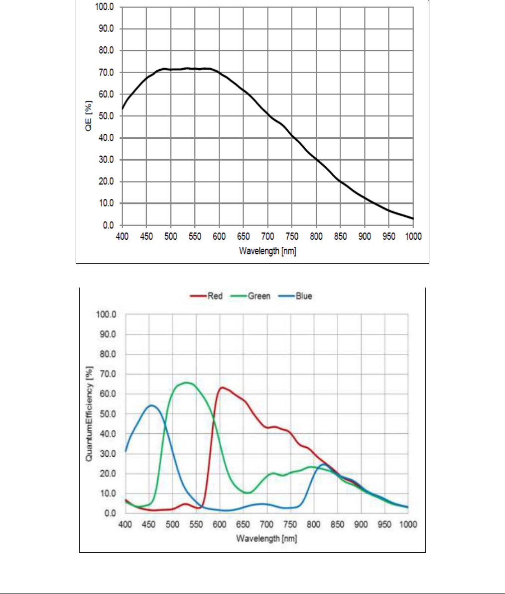
52
•
Genie Nano Specifications Nano Series GigE Vision Camera
Spectral Response
The response curves describe the sensor, excluding lens and light source characteristics.
Models M4030, M4020
Models C4030, C4020

Nano Series GigE Vision Camera Genie Nano Specifications
•
53
Specifications: M640, M640-NIR, C640
Supported Features M640, M640-NIR C640
Resolution 672 x 512
Sensor OnSemi Python300 P1 (0.3M)
Pixel Size 4.8 µm x 4.8 µm
Shutter type Full frame electronic global shutter function
Full Well charge 10ke (max)
Firmware option
(Field programmable) Standard Design
Monochrome Standard Design
Bayer RGB-Output
Design
Max. Internal Frame Rate 862 fps at 640 x 480 (Fast Readout Enable)
603 fps at 640 x 480 (Normal Readout Enable)
Maximum Sustained Frame Rate
Output (with TurboDrive v1) 720 fps (8-bit)
360 fps (10-bit) N/A
Maximum Sustained Frame Rate
Output (without TurboDrive) 345 fps (8-bit)
172 fps (10-bit)
86 fps (RGBA)
115 fps (RGB)
172 fps (Yuv422)
345 fps (8-bit mono)
Pixel Data Formats Mono 8-bit
Mono 10-bit Bayer 8-Bit
Bayer 10-Bit
RGBA 32-bit
RGB 24-bit
Yuv422 16-bit
Mono 8-bit
Trigger to Exposure Minimum delay
(Synchronous Exposure Alignment)
4 µs if exposureAlignment = Synchronous With No Overlap
between the new exposure and the previous readout
26.2 µs if exposureAlignment = Synchronous With Overlap
between the new exposure and the previous readout
Trigger to Exposure Minimum delay
(Reset Exposure Alignment) 4 µs
Trigger to Exposure Start jitter (best
case with Synchronous Exposure
Alignment) Up to 1 line time
Trigger to Exposure Start jitter
(Reset Exposure Alignment) * 0 µs
Exposure Time Minimum
(see “exposureTimeActual” in Sensor
Control)
34 µs
(increment steps of 1µs)
Min. Time from End of Exposure to
Start of Next Exposure (second
frame)
19 µs – Normal Readout
18 µs – Fast Readout
Horizontal Line Time: 3.3 µs – Normal Readout
2.28 µs – Fast Readout
Readout Time
1602 µs – Normal Readout for 640 x 480
Add 75µs when overlapping Exposure and Readout
1107 µs – Fast Readout for 640 x 480
Add 62µs when overlapping Exposure and Readout
Specifically: ( Horizontal line time at current resolution * number of lines ) + (3 *
( line time of the 1280 model ))
Auto-Brightness Yes , with Auto-Exposure and AGC (FPGA Gain)
Black offset control Yes (in DN)

54
•
Genie Nano Specifications Nano Series GigE Vision Camera
Gain Control In-sensor Analog Gain (1.0x to 8x) in 11 gain steps
(1.0, 1.14, 1.33, 1.6, 2.0, 2.29, 2.67, 3.2, 4.0, 5.33, 8.0)
In-sensor Digital Gain (1x to 32x) in 0.01x steps
In-FPGA Digital Gain (1x to 4x) in 0.007x steps
Binning Support Yes In-FPGA
(summing and average,
2x2, 4x4 )
Yes In- Sensor
(averaging 2x2)
No
Color Correction Support No Yes
Decimation Support No
Defective Pixel Replacement Yes, up to 512 positions
Image Correction Yes, Sensor FPN correction feature
Image Flip Support Yes, In-Sensor, Vertical Only
Multi-ROI Support Yes, in Sensor, up to 16 ROI (mutually exclusive with binning)
On-Board Image Memory 90MB
Output Dynamic Range (dB) 61.56 dB (in 10-Bit Pixel Format)
SNR (dB) 39.8 dB (in 10-Bit Pixel Format)
* Note: The actual internal minimum exposure may be different than what is programmed. Use the feature “exposureTimeActual” from the
Sensor Control category to read back the actual sensor exposure. The exposure start sensor event is delayed 4 µs from the actual start.
Specifications: M800, M800-NIR, C800
Supported Features M800, M800-NIR C800
Resolution 832 x 632
Sensor OnSemi Python500 P1 (0.5M)
Pixel Size 4.8 µm x 4.8 µm
Shutter type Full frame electronic global shutter function
Full Well charge 10ke (max)
Firmware option
(Field programmable) Standard Design
Monochrome Standard Design
Bayer RGB-Output
Design
Max. Internal Frame Rate 566 fps at 800 x 600 (Fast Readout Enable)
419 fps at 800 x 600 (Normal Readout Enable)
Maximum Sustained Frame Rate
Output (with TurboDrive v1) 461 fps (8-bit)
230 fps (10-bit) N/A
Maximum Sustained Frame Rate
Output (without TurboDrive) 221 fps (8-bit)
110 fps (10-bit)
55 fps (RGBA)
73 fps (RGB)
110 fps (Yuv422)
221 fps (8-bit mono)
Pixel Data Formats Mono 8-bit
Mono 10-bit Bayer 8-Bit
Bayer 10-Bit
RGBA 32-bit
RGB 24-bit
Yuv422 16-bit
Mono 8-bit
Trigger to Exposure Minimum delay
(Synchronous Exposure Alignment)
4 µs if exposureAlignment = Synchronous With No Overlap
between the new exposure and the previous readout
26.2 µs if exposureAlignment = Synchronous With Overlap
between the new exposure and the previous readout
Trigger to Exposure Minimum delay
(Reset Exposure Alignment) 4 µs

Nano Series GigE Vision Camera Genie Nano Specifications
•
55
Trigger to Exposure Start jitter (best
case with Synchronous Exposure
Alignment) Up to 1 line time
Trigger to Exposure Start jitter
(Reset Exposure Alignment) * 0 µs
Exposure Time Minimum
(see “exposureTimeActual” in Sensor
Control)
34 µs
(increment steps of 1µs)
Min. Time from End of Exposure to
Start of Next Exposure 19 µs – Normal Readout
18 µs – Fast Readout
Horizontal Line Time: 3.86 µs – Normal Readout
2.83µs – Fast Readout
Readout Time
2332 µs – Normal Readout for 800 x 600
Add 75µs when overlapping Exposure and Readout
1713 µs – Fast Readout for 800 x 600
Add 62µs when overlapping Exposure and Readout
Specifically: ( Horizontal line time at current resolution * number of lines ) + (3 *
( line time of the 1280 model ))
Auto-Brightness Yes , with Auto-Exposure and AGC (FPGA Gain)
Black offset control Yes (in DN)
Gain Control In-sensor Analog Gain (1.0x to 8x) in 11 gain steps
(1.0, 1.14, 1.33, 1.6, 2.0, 2.29, 2.67, 3.2, 4.0, 5.33, 8.0)
In-sensor Digital Gain (1x to 32x) in 0.01x steps
In-FPGA Digital Gain (1x to 4x) in 0.007x steps
Binning Support Yes In-FPGA
(summing and average,
2x2, 4x4 )
Yes In- Sensor
(averaging 2x2)
No
Color Correction Support No Yes
Decimation Support No
Defective Pixel Replacement Yes, up to 512 positions
Image Correction Yes, Sensor FPN correction feature
Image Flip Support Yes, In-Sensor, Vertical Only
Multi-ROI Support Yes, in Sensor, up to 16 ROI (mutually exclusive with binning)
On-Board Image Memory 90MB
Output Dynamic Range (dB) 62.1 dB (in 10-Bit Pixel Format)
SNR (dB) 38.8 dB (in 10-Bit Pixel Format)
* Note: The actual internal minimum exposure may be different than what is programmed. Use the feature
“exposureTimeActual” from the Sensor Control category to read back the actual sensor exposure. The exposure start sensor
event is delayed 4 µs from the actual start.

56
•
Genie Nano Specifications Nano Series GigE Vision Camera
Firmware Files for Models 640, 800
The latest firmware files for all Nano models are available on the Teledyne DALSA support web site:
http://www.teledynedalsa.com/imaging/support/downloads/firmware/. The firmware files for these
models are listed below. The xx denotes the current build number.
M640, M800
• Standard
“Genie_Nano_OnSemi_Python_0.3M-0.5M-1.3M-2M-5M_Mono_STD_Firmware_5CA18.xx.cbf”
C640, C800
• Bayer Output
“Genie_Nano_OnSemi_Python_0.3M-0.5M-1.3M-2M-5M_Bayer_STD_Firmware_6CA18.xx.cbf”
• RGB Output
“Genie_Nano_OnSemi_Python_0.3M-0.5M-1.3M-2M-5M_RGB_Output_Firmware_6CA18.xx.cbf”
Specifications: M1240, C1240
Supported Features Nano-M1240 Nano-C1240
Resolution 1280 x 1024
Sensor OnSemi Python1300 P3 (1.3M)
Pixel Size 4.8 µm x 4.8 µm
Shutter type Full frame electronic global shutter function
Full Well charge 10ke (max)
Firmware option
(Field programmable) Standard Design
Monochrome Standard Design
Bayer RGB-Output
Design
Max. Internal Frame Rate
Full Resolution (1280 x 1024) 87 fps (Normal Readout Enable)
Maximum Sustained Frame Rate
Output (with TurboDrive v1) 87 fps (8-bit)
87 fps (10-bit) N/A
Maximum Sustained Frame Rate
Output (without TurboDrive) 87 fps (8-bit)
45 fps (10-bit)
22 fps (RGBA)
33 fps (RGB)
45 fps (Yuv422)
87 fps (mono-8)
Pixel Data Formats Mono 8-bit
Mono 10-bit Bayer 8-Bit
Bayer 10-Bit
RGBA 32-bit
RGB 24-bit
Yuv422 16-bit
Mono 8-bit
Trigger to Exposure Minimum delay
(Synchronous Exposure Alignment)
6 µs if exposureAlignment = Synchronous With No Overlap
between the new exposure and the previous readout
65 µs if exposureAlignment = Synchronous With Overlap
between the new exposure and the previous readout
Trigger to Exposure Minimum delay
(Reset Exposure Alignment) 6 µs
Trigger to Exposure Start jitter
(best case with Synchronous
Up to 1 line time

Nano Series GigE Vision Camera Genie Nano Specifications
•
57
Exposure Alignment)
Trigger to Exposure Start jitter
(Reset Exposure Alignment) * 0 µs
Actual Exposure Time Minimum
(see “exposureTimeActual” feature)* 34 µs
(increment steps of 1µs)
Min. Time from End of Exposure to
Start of Next Exposure
(second frame) 165 µs – Normal Readout
Horizontal Line Time: 11.07 µs – Normal Readout
Readout Time
11351 µs – Normal Readout for 1280 x 1024
Add 150 µs when overlapping Exposure and Readout
Detailed formula : ( Horizontal line time at current resolution * number of lines ) +
(3 * ( line time of the 1280 model ))
Auto-Brightness Yes , with Auto-Exposure and AGC (FPGA Gain)
Black offset control Yes (in DN)
Gain Control In-sensor Analog Gain (1.0x to 8x) in 11 gain step
(1.0, 1.14, 1.33, 1.6, 2.0, 2.29, 2.67, 3.2, 4.0, 5.33, 8.0)
In-sensor Digital Gain (1x to 32x) in 0.01x step
In-FPGA Digital Gain (1x to 4x) in 0.007x step
Binning Support Yes In-FPGA
(summing and average,
2x2, 4x4 )
Yes In- Sensor
(averaging 2x2)
No
Color Correction Support No Yes
Decimation Support No
Defective Pixel Replacement Yes, up to 512 positions
Image Correction Yes, Sensor FPN correction feature
Image Flip Support Yes In-Sensor – Vertical Only
Multi-ROI Support Yes in Sensor, up to 16 ROI (mutually exclusive with binning)
On-Board Image Memory 90MB
Output Dynamic Range (dB) 61.8 dB (in 10-Bit Pixel Format)
SNR (dB) 39.7 dB (in 10-Bit Pixel Format)
* Note: The actual internal minimum exposure may be different than what is programmed. Use the feature “exposureTimeActual” from the
Sensor Control category to read back the actual sensor exposure. The exposure start sensor event is delayed 4 µs from the actual start.
Firmware Files for Models 1240
M1240
• Standard
Genie_Nano_OnSemi_Python_P3_1.3M_Mono_STD_Firmware_12CA18.x.cbf
C1240
• Standard
Genie_Nano_OnSemi_Python_P3_1.3M_Bayer_STD_Firmware_13CA18.x.cbf

58
•
Genie Nano Specifications Nano Series GigE Vision Camera
Specifications: M1280, M1280-NIR, C1280
Supported Features M1280, M1280-NIR C1280
Resolution 1280 x 1024
Sensor OnSemi Python1300 P1 (1.3M)
Pixel Size 4.8 µm x 4.8 µm
Shutter type Full frame electronic global shutter function
Full Well charge 10ke (max)
Firmware option
(Field programmable) Standard Design
Monochrome Standard Design
Bayer RGB-Output
Design
Max. Internal Frame Rate
Full Resolution (1280 x 1024) 213 fps (Fast Readout Enable)
174 fps (Normal Readout Enable)
Maximum Sustained Frame Rate
Output (with TurboDrive v1) 184 fps (8-bit)
92 fps (10-bit) N/A
Maximum Sustained Frame Rate
Output (without TurboDrive) 88 fps (8-bit)
44 fps (10-bit)
22 fps (RGBA)
33 fps (RGB)
44 fps (Yuv422)
88 fps (8-bit mono)
Pixel Data Formats Mono 8-bit
Mono 10-bit Bayer 8-Bit
Bayer 10-Bit
RGBA 32-bit
RGB 24-bit
Yuv422 16-bit
Mono 8-bit
Trigger to Exposure Minimum delay
(Synchronous Exposure Alignment)
4 µs if exposureAlignment = Synchronous With No Overlap
between the new exposure and the previous readout
26.2 µs if exposureAlignment = Synchronous With Overlap
between the new exposure and the previous readout
Trigger to Exposure Minimum delay
(Reset Exposure Alignment) 4 µs
Trigger to Exposure Start jitter (best
case with Synchronous Exposure
Alignment)
Up to 1 line time
Trigger to Exposure Start jitter
(Reset Exposure Alignment) * 0 µs
Exposure Time Minimum
(see “exposureTimeActual” in Sensor
Control)
34 µs
(increment steps of 1µs)
Min. Time from End of Exposure to
Start of Next Exposure (second
frame)
19 µs – Normal Readout
18 µs – Fast Readout
Horizontal Line Time: 5.53 µs – Normal Readout
4.5 µs – Fast Readout
Readout Time
5676 µs – Normal Readout for 1280 x 1024
Add 75µs when overlapping Exposure and Readout
4621 µs – Fast Readout for 1280 x 1024
Add 62µs when overlapping Exposure and Readout
Specifically: ( Horizontal line time at current resolution * number of lines ) + (3 *
( line time of the 1280 model ))
Auto-Brightness Yes , with Auto-Exposure and AGC (FPGA Gain)
Black offset control Yes (in DN)

Nano Series GigE Vision Camera Genie Nano Specifications
•
59
Gain Control In-sensor Analog Gain (1.0x to 8x) in 11 gain steps
(1.0, 1.14, 1.33, 1.6, 2.0, 2.29, 2.67, 3.2, 4.0, 5.33, 8.0)
In-sensor Digital Gain (1x to 32x) in 0.01x steps
In-FPGA Digital Gain (1x to 4x) in 0.007x steps
Binning Support Yes In-FPGA
(summing and average,
2x2, 4x4 )
Yes In- Sensor
(averaging 2x2)
No
Color Correction Support No Yes
Decimation Support No
Defective Pixel Replacement Yes, up to 512 positions
Image Correction Yes, Sensor FPN correction feature
Image Flip Support Yes, In-Sensor, Vertical Only
Multi-ROI Support Yes, in Sensor, up to 16 ROI (mutually exclusive with binning)
On-Board Image Memory 90MB
Output Dynamic Range (dB) 61.8 dB (in 10-Bit Pixel Format)
SNR (dB) 39.7 dB (in 10-Bit Pixel Format)
* Note: The actual internal minimum exposure may be different than what is programmed. Use the feature
“exposureTimeActual” from the Sensor Control category to read back the actual sensor exposure. The exposure start sensor
event is delayed 4 µs from the actual start.
Specifications: M1930, M1930-NIR, C1930
Supported Features M1930, M1930-NIR Nano-C1930
Resolution 1984 x 1264
Sensor OnSemi Python2000 P1 (2.3M)
Pixel Size 4.8 µm x 4.8 µm
Shutter type Full frame electronic global shutter function
Full Well charge 10ke (max)
Firmware option
(Field programmable) Standard Design
Monochrome Standard Design
Bayer RGB-Output
Design
Max. Internal Frame Rate
Full Resolution (1984 x 1264) 107 fps (Fast Readout Enable)
84.5 fps (Normal Readout Enable)
Maximum Sustained Frame Rate
Output (with TurboDrive v1) 107 fps (8-bit)
52 fps (10-bit) N/A
Maximum Sustained Frame Rate
Output (without TurboDrive) 46 fps (8-bit)
23 fps (10-bit)
12 fps (RGBA)
16 fps (RGB)
23 fps (Yuv422)
46 fps (8-bit mono)
Pixel Data Formats Mono 8-bit
Mono 10-bit Bayer 8-Bit
Bayer 10-Bit
RGBA 32-bit
RGB 24-bit
Yuv422 16-bit
Mono 8-bit

60
•
Genie Nano Specifications Nano Series GigE Vision Camera
Trigger to Exposure Minimum delay
(Synchronous Exposure Alignment)
8 µs if exposureAlignment = Synchronous With No Overlap
between the new exposure and the previous readout
26.2 µs if exposureAlignment = Synchronous With Overlap
between the new exposure and the previous readout
Trigger to Exposure Minimum delay
(Reset Exposure Alignment) 3 µs
Trigger to Exposure Start jitter (best
case with Synchronous Exposure
Alignment) Up to 1 line time
Trigger to Exposure Start jitter
(Reset Exposure Alignment) * 0 µs
Exposure Time Minimum
(see “exposureTimeActual” in Sensor
Control)
87 µs
(increment steps of 1µs)
Min. Time from End of Exposure to
Start of Next Exposure (second
frame)
49 µs – Normal Readout
47 µs – Fast Readout
Horizontal Line Time: 9 µs – Normal Readout
7 µs – Fast Readout
Readout Time
10831 µs – Normal Readout for 1920 x 1200
Add 76µs when overlapping Exposure and Readout
8428µs µs – Fast Readout for 1920 x 1200
Add 64µs when overlapping Exposure and Readout
Specifically: ( Horizontal line time at current resolution * number of lines ) + (3 *
( line time of the 2590 model ))
Auto-Brightness Yes , with Auto-Exposure and AGC (FPGA Gain)
Black offset control Yes (in DN)
Gain Control In-sensor Analog Gain (1.0x to 8x) in 11 gain steps
(1.0, 1.14, 1.33, 1.6, 2.0, 2.29, 2.67, 3.2, 4.0, 5.33, 8.0)
In-sensor Digital Gain (1x to 32x) in 0.01x steps
In-FPGA Digital Gain (1x to 4x) in 0.007x steps
Binning Support Yes In-FPGA
(summing and average,
2x2, 4x4 )
Yes In- Sensor
(averaging 2x2)
No
Color Correction Support No Yes
Decimation Support No
Defective Pixel Replacement Yes, up to 512 positions
Image Correction No
Image Flip Support Yes, In-Sensor, Vertical Only
Multi-ROI Support Yes, in Sensor, up to 16 ROI (mutually exclusive with binning)
On-Board Image Memory 90MB
Output Dynamic Range (dB) 62.1 dB (in 10-Bit Pixel Format)
SNR (dB) 39.8 dB (in 10-Bit Pixel Format)
* Note: The actual internal minimum exposure may be different than what is programmed. Use the feature “exposureTimeActual” from the
Sensor Control category to read back the actual sensor exposure. The exposure start sensor event is delayed 4 µs from the actual start.

Nano Series GigE Vision Camera Genie Nano Specifications
•
61
Specifications: M2590, M2590-NIR, C2590
Supported Features M2590, M2590-NIR Nano-C2590
Resolution 2592 x 2048
Sensor OnSemi Python5000 P1 (5.1M)
Pixel Size 4.8 µm x 4.8 µm
Shutter type Full frame electronic global shutter function
Full Well charge 10ke (max)
Firmware option
(Field programmable) Standard Design
Monochrome Standard Design
Bayer RGB-Output
Design
Max. Internal Frame Rate
Full Resolution (2592 x 2048) 51.8 fps (Fast Readout Enable)
24.7 fps (Normal Readout Enable)
Maximum Sustained Frame Rate
Output (with TurboDrive v1) 42.7 fps (8-bit)
24.9 fps (10-bit) N/A
Maximum Sustained Frame Rate
Output (without TurboDrive) 22 fps (8-bit)
5.5 fps (RGBA)
8.7 fps (RGB)
11 fps (Yuv422)
22 fps (8-bit mono)
Pixel Data Formats Mono 8-bit
Mono 10-bit Bayer 8-Bit
Bayer 10-Bit
RGBA 32-bit
RGB 24-bit
Yuv422 16-bit
Mono 8-bit
Trigger to Exposure Minimum delay
(Synchronous Exposure Alignment)
8 µs if exposureAlignment = Synchronous With No Overlap
between the new exposure and the previous readout
26.2 µs if exposureAlignment = Synchronous With Overlap
between the new exposure and the previous readout
Trigger to Exposure Minimum delay
(Reset Exposure Alignment) 3 µs
Trigger to Exposure Start jitter (best
case with Synchronous Exposure
Alignment)
Up to 1 line time
Trigger to Exposure Start jitter
(Reset Exposure Alignment) * 0 µs
Exposure Time Minimum
(see “exposureTimeActual” in Sensor
Control)
87 µs
(increment steps of 1µs)
Min. Time from End of Exposure to
Start of Next Exposure (second
frame)
49 µs – Normal Readout
47 µs – Fast Readout
Horizontal Line Time: 11.33 µs – Normal Readout
9.33 µs – Fast Readout
Readout Time
23242 µs – Normal Readout for 2592 x 2048
Add 76µs when overlapping Exposure and Readout
19142 µs µs – Fast Readout for 2592 x 2048
Add 64µs when overlapping Exposure and Readout
Specifically: ( Horizontal line time at current resolution * number of lines ) + (3 *
( line time of the 2590 model ))
Auto-Brightness Yes , with Auto-Exposure and AGC (FPGA Gain)
Black offset control Yes (in DN)

62
•
Genie Nano Specifications Nano Series GigE Vision Camera
Gain Control In-sensor Analog Gain (1.0x to 8x) in 11 gain steps
(1.0, 1.14, 1.33, 1.6, 2.0, 2.29, 2.67, 3.2, 4.0, 5.33, 8.0)
In-sensor Digital Gain (1x to 32x) in 0.01x steps
In-FPGA Digital Gain (1x to 4x) in 0.007x steps
Binning Support Yes In-FPGA
(summing and average,
2x2, 4x4 )
Yes In- Sensor
(averaging 2x2)
No
Color Correction Support No Yes
Decimation Support No
Defective Pixel Replacement Yes, up to 512 positions
Image Correction No
Image Flip Support Yes, In-Sensor, Vertical Only
Multi-ROI Support Yes, in Sensor, up to 16 ROI (mutually exclusive with binning)
On-Board Image Memory 90MB
Output Dynamic Range (dB) 62.1 dB (in 10-Bit Pixel Format)
SNR (dB) 39.8 dB (in 10-Bit Pixel Format)
* Note: The actual internal minimum exposure may be different than what is programmed. Use the feature
“exposureTimeActual” from the Sensor Control category to read back the actual sensor exposure. The exposure start sensor
event is delayed 4 µs from the actual start.
Firmware Files for Models 1280, 1930, 2590
The latest firmware files for all Nano models are available on the Teledyne DALSA support web site:
http://www.teledynedalsa.com/imaging/support/downloads/firmware/
The firmware files for these models are listed below. The xx denotes the current build number.
M1280, M1930, M2590
• Standard
“Genie_Nano_OnSemi_Python_0.3M-0.5M-1.3M-2M-5M_Mono_STD_Firmware_5CA18.xx.cbf”
C1280, C1930, C2590
• Bayer Output
“Genie_Nano_OnSemi_Python_0.3M-0.5M-1.3M-2M-5M_Bayer_STD_Firmware_6CA18.xx.cbf”
• RGB Output
“Genie_Nano_OnSemi_Python_0.3M-0.5M-1.3M-2M-5M_RGB_Output_Firmware_6CA18.xx.cbf”

Nano Series GigE Vision Camera Genie Nano Specifications
•
63
NanoXL Specifications: M5100, M5100-NIR, C5100,
M4090, M4090-NIR, C4090
Supported Features M5100, M5100-NIR & C5100 M4090, M4090-NIR & C4090
Resolution 5120 x 5120 4096 x 4096
Sensor On-Semi Python25K (25M) On-Semi Python16K (16M)
Pixel Size 4.5 µm x 4.5 µm
Shutter Type Full frame electronic global shutter function
Full Well charge 12ke (max)
Firmware options
(field programmable) Standard Design
(Mono & Bayer) High Speed Design
(Mono & Bayer) Standard Design
(Mono & Bayer) High Speed Design
(Mono & Bayer)
Max. Internal Frame Rate 10.2 fps 20.1 fps 15.6 fps 31.2 fps
Maximum Sustained Frame Rate
Output (with TurboDrive) ** 9.5 fps (8-bit)
4.7 fps (10-bit) 9.5 fps (8-bit) 15.6 fps (8-bit)
7.9 fps (10-bit) 15.6 fps (8-bit)
Maximum Sustained Frame Rate
Output (without TurboDrive) 4.5 fps (8-bit)
2.75 fps (10-bit) 4.5 fps (8-bit) 7.1 fps (8-bit)
3.5 fps (10-bit) 7.1 fps (8-bit)
Pixel Format (Mono)
Mono 8 & 10 bit Mono 8 bit Mono 8 & 10 bit Mono 8 bit
Pixel Format (Color)
Bayer 8 & 10 bit Bayer 8 bit Bayer 8 & 10 bit Bayer 8 bit
Trigger to Exposure Minimum
delay (Synchronous Exposure) 4 µs
Trigger to Exposure Minimum
delay (Reset Exposure) 4 µs
Trigger to Exposure Start jitter
(Synchronous Exposure) Up to 1 line time
Trigger to Exposure Start jitter
(Reset Exposure) 0 µs
Exposure Time Minimum
(see “exposureTimeActual” in
Sensor Control) 34 µs
Horizontal Line Time:
Normal Mode ‡‡ 33.1 µs 16.55 µs 29.55 µs 14.78 µs
Horizontal Line Time:
Fast Readout ‡‡ 19.1 µs 9.56 µs 15.55 µs 7.78 µs
Min. Time from End of Exposure to
Start of Next Exposure
Normal Readout:
120 us
Fast Readout:
92 us
Normal Readout:
79 us
Fast Readout:
65 us
Normal Readout:
120 us
Fast Readout:
92 us
Normal Readout:
79 us
Fast Readout:
65 us
Readout Time (Horizontal Line Time * NB Lines) + ( 2 * Horizontal Line Time at Maximum Sensor
Width ), in μs
Auto-Brightness Yes , with Auto-Exposure and AGC (FPGA Gain)
Black offset control Yes (in DN)
Gain Control In-sensor Analog Gain (1.0x to 3.17x) in 4 steps
(1.0x, 1.26x, 2.87x, 3.17x)
In-sensor Digital Gain (1x to 32x) in 0.01x steps
In-FPGA Digital Gain (1x to 4x) in 0.007x steps
Binning Support Monochrome models only — In-FPGA (summing and average, 2x2, 4x4)
Color Correction Support No
Decimation Support No

64
•
Genie Nano Specifications Nano Series GigE Vision Camera
Defective Pixel Replacement Yes , up to 2048 pixel positions
Image Correction Flat Line Correction (Factory and 4 User Defined entries)
Image Flip support Yes, vertical only (in-sensor)
Multi-ROI Support Yes, (in-sensor) up to 16 ROI
On-board Image memory 500MB
Output Dynamic Range (dB) 55.3 55.3 55.3 55.3
SNR (dB) 39.4 39.6 39.4 39.6
** Limited to the Genie Nano Architecture:
~250MB/sec Sustained into the TurboDrive Engine achieved using 1500 Byte Packet Size
‡‡ Horizontal Line Time: Table Values and Formulas
Values stated in the table are calculated for the maximum sensor widths, specifically:
• Model M5100=5120 pixels
• Model M4090=4096 pixels
The following formulas describe Horizontal Line Time. Note that in “Fast Readout” mode, the line
time does not reduce for widths below 4032 pixels, thus no need to calculate applicable time values
for shorter lines.
• Horizontal line time (Standard Firmware, Normal mode) =
• Horizontal line time** (Standard Firmware, Fast Readout mode) =
• Horizontal line time (High Speed Firmware, Normal mode) =
• Horizontal line time** (High Speed Firmware, Fast Readout mode) =
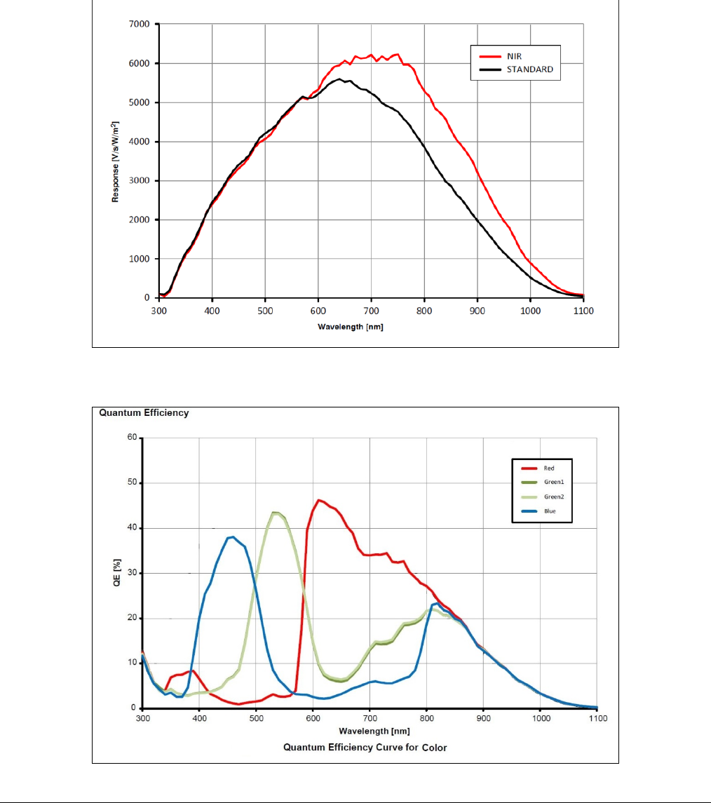
Nano Series GigE Vision Camera Genie Nano Specifications
•
65
Spectral Response
Model specific specifications and response graphics for the On-Semi Python (25K & 16K) series are
provided here. The response curves describe the sensor, excluding lens and light source
characteristics.
On-Semi Python Series (P1 & P3) — Monochrome and NIR
On-Semi Python Series (P1 & P3) — Bayer Color
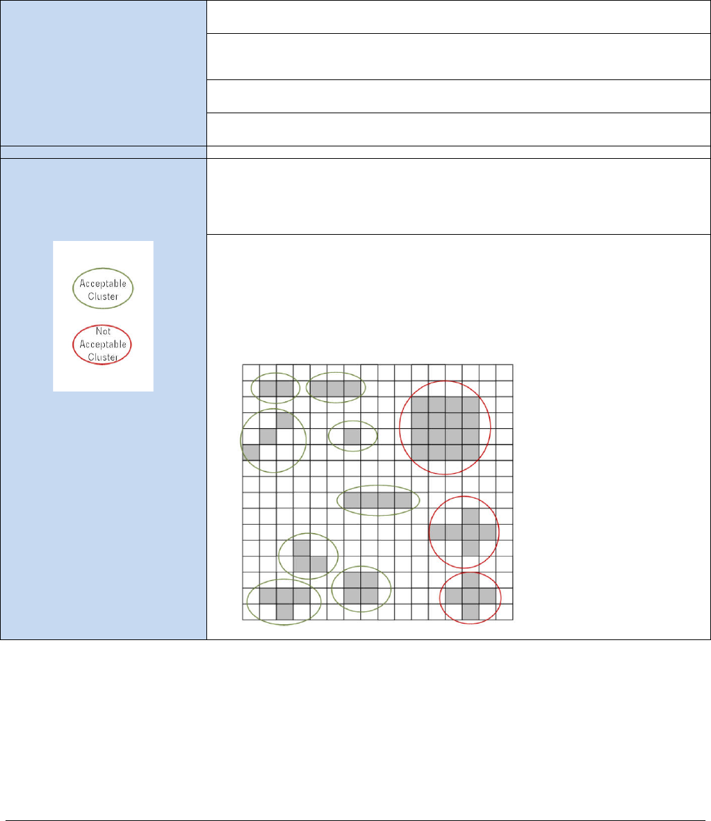
66
•
Genie Nano Specifications Nano Series GigE Vision Camera
Defective Pixel Specification for Models 5100/4090
These defective pixel specifications in the following table are as published by the sensor
manufacturer. Genie Nano cameras apply defective pixel corrections to improve the camera
performance.
Defective Pixels
(max: 1000)
Number of defective pixels allowed in the full window size of 5120 x 5120
(i.e. model 5100).
For mono devices: A defective pixel is defined as a pixel which has a response that
deviates 102 LSB10 in a dark image or a corrected gray image, or a saturated image,
from the local median of the neighboring pixels in a 7 x 7 block.
For color devices: The pixels are divided per color channels (R, G1, G2, B) and then
calculated with the same methodology as mono devices.
The defective pixels in dark, gray and saturated images are stored a in a global defect
map. The limit is applied to the global defect map.
Defective Cluster Definition
Number of clusters allowed in the full window size of 5120 X 5120. A cluster is defined
as a group of neighboring defective pixels (top, Bottom side, not diagonal), derived
from the global defect map.
For color devices: The pixels are divided per color channels (R, G1, G2, B) and then
calculated with the same methodology as mono devices.
Refer to the graphic below:
The number of defective pixels in one cluster is the class (F) of the cluster:
F2 (max 5): 2 defective pixels in the cluster
F3 (max 4): 3 defective pixels in the cluster
F4 (max 3): 4 defective pixels in the cluster
F5 (max 0): 5 or more defective pixels in the cluster

Nano Series GigE Vision Camera Genie Nano Specifications
•
67
Firmware Files for Models 5100/4090
The latest firmware files for all Nano models are available on the Teledyne DALSA support web site:
http://www.teledynedalsa.com/imaging/support/downloads/firmware/
The firmware files for these models are listed below. The xx denotes the current build number.
M4090 & M5100
• Standard
“Genie_Nano_OnSemi_Python_16M-25M_Mono_STD_Firmware_CCA18.xx.cbf”
• High Speed
“Genie_Nano_OnSemi_Python_16M-25M_Mono_HS_Firmware_CCA18.xx.cbf”
C4090 & C5100
• Bayer Output
“Genie_Nano_OnSemi_Python_16M-25M_Bayer_STD_Firmware_DCA18.xx.cbf”
• High Speed Bayer Output
“Genie_Nano_OnSemi_Python_16M-25M_Bayer_HS_Firmware_DCA18.xx.cbf”

68
•
Genie Nano Specifications Nano Series GigE Vision Camera
Specifications: C4900
Model specific specifications and response graphics for the On-Semi AR1820HS sensor are provided
here. The response curves exclude lens and light source characteristics.
Supported Features C4900
Full Active Resolution 4912 x 3684
Sensor On-Semi AR1820HS (18M)
Pixel Size 1.25 µm x 1.25 µm
Shutter Type Electronic Rolling Shutter function (ERS)
with Global Reset Release (GRR) function
Full Well charge 4.3ke (max)
Firmware Options (field programmable) Standard Bayer Output Design RGB Output Design
(includes monochrome output)
Max. Internal Frame Rate 13.3 fps at 4912 x 3684 resolution
42.2 fps at 2556 x 1842 resolution (Decimation 2x2)
116.8 fps at 1228 x 920 resolution (Decimation 4x4)
Maximum Sustained Frame Rate Output
Full Resolution with TurboDrive v1 13 fps N/A
Maximum Sustained Frame Rate Output
Full Resolution without TurboDrive 5.88 fps Bayer 8-bit
2.9 fps Bayer 12-bit
5.88 fps Monochrome 8-bit
2.9 fps YUV422
1.96 fps RGB 24-bit
1.47 fps RGBA 32-bit
Pixel Data Formats Bayer 8-Bit
Bayer 12-Bit
Monochrome 8-bit
YUV422 16-bit
RGB 24-bit
RGBA 32-bit (RGB 24 & Mono 8)
Trigger to Exposure Minimum delay
(Synchronous Exposure Alignment) Not Supported
Trigger to Exposure Minimum delay
(Reset Exposure Alignment) 790 µs (ERS mode) /450 µs (GRR mode)
Trigger to Exposure Start jitter (best case
with Synchronous Exposure Alignment) Not Supported
Trigger to Exposure Start jitter
(Reset Exposure Alignment) 0 µs (ERS mode) / 20 µs (GRR mode)
Actual Exposure Time Minimum
(see “exposureTimeActual”
in Sensor Control)
118 µs (ERS mode) / 836 µs (GRR mode) – Full Resolution
73 µs (ERS mode) / 483 µs (GRR mode) – (Decimation 2x2)
51 µs (ERS mode) / 318 µs (GRR mode) – (Decimation 4x4)
Exposure Time Maximum 0.5 seconds
Minimum Time from End of Exposure to
Start of Next Exposure (second frame) 74.76 ms (ERS mode) / 75.09 ms (GRR mode) – Full Resolution
23.5 ms (ERS mode) / 23.9 ms (GRR mode) – (Decimation 2x2)
8.87 ms (ERS mode) / 8.43 ms (GRR mode) – (Decimation 4x4)
Horizontal Line Time 20 µs
Readout Time (Horizontal Line readout) x (lines in frame) — in μs
Auto Brightness No
Black Offset control Yes (in DN)
Gain Control In-sensor Analog Gain (1.0x to 8x) in 0.01x steps
In-FPGA Digital Gain (1x to 4x) in 0.007x steps
Binning Support No
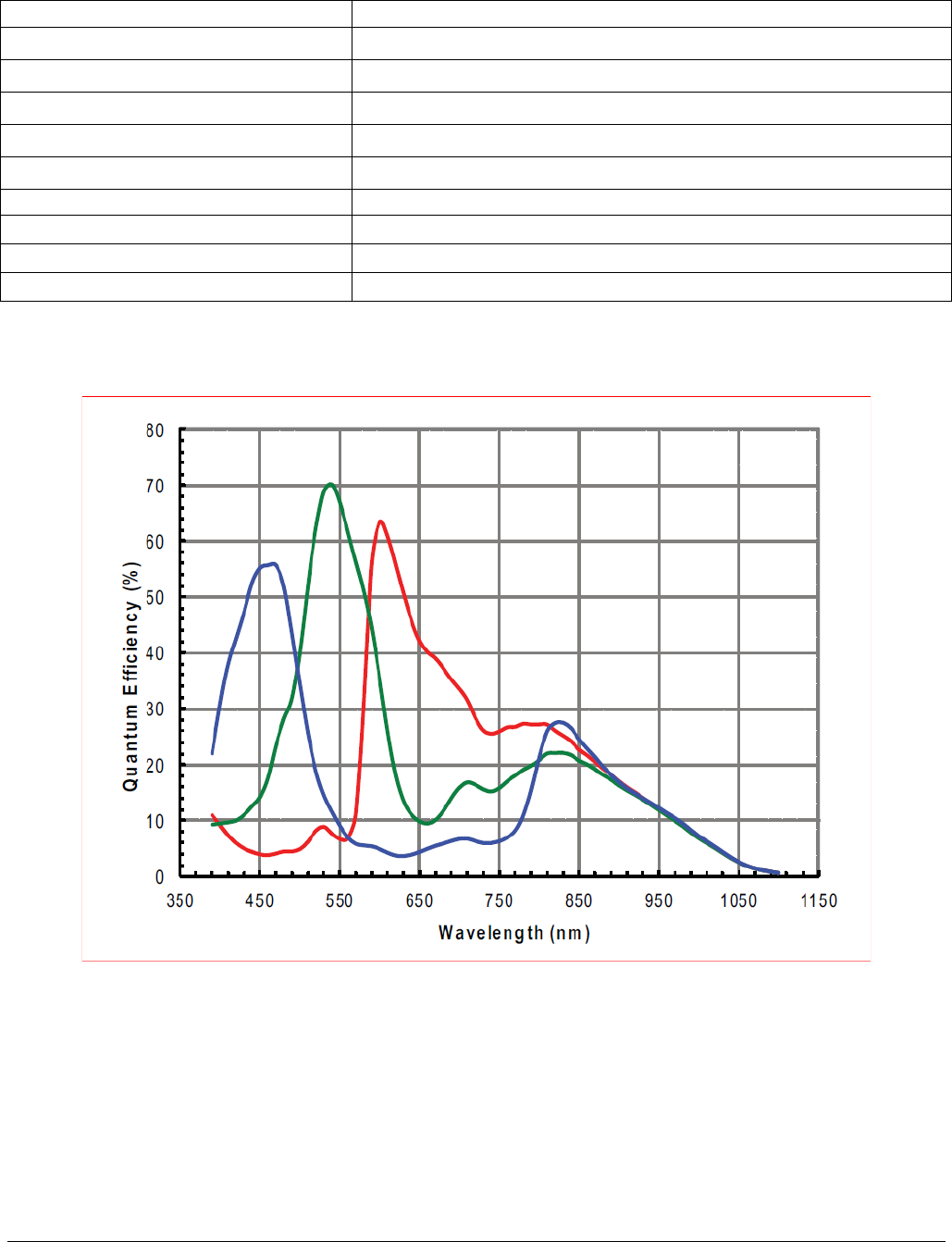
Nano Series GigE Vision Camera Genie Nano Specifications
•
69
Color Correction Support No
Decimation Support Yes, 2x2 and 4x4
Defective Pixel Replacement No
Image Correction No
Image Flip Support Yes, in-sensor, both vertical and horizontal
Multi-ROI Support No
On-board image memory 220MB
Dynamic Range 76.4 dB
Sensor SNR 39.6 dB
Responsivity see following graphic
Spectral Response

70
•
Genie Nano Specifications Nano Series GigE Vision Camera
Supplemental Usage Notes:
Reduced Operating Temperature: The model C4900 has a reduced maximum temperature
specification (-20°C to +50°C / -4°F to +122°F) as specified in section Genie Nano Common
Specifications. This temperature specification is measured at the front plate. If the camera
temperature is exceeded, the camera’s acquisition or any other camera operation may lock up.
Simply cool and reset the camera to resume normal operation.
Exposer Time Locked during Acquisition: Unlike other Nano models, the Nano C4900 does not
allow exposure time changes during an active acquisition. Freeze the acquisition first, then make
an exposure time change.
Model C4900 Sensor Cosmetic Specifications
Due to the significant engineering design differences of the Rolling Shutter – High Pixel Density
sensor used in the model C4900, its cosmetic specifications are not consistent with the other Nano
models. The following table applies only to the Nano model C4900 (AR1820HS sensor).
Blemish Specification Maximum Number
of Defects Blemish Description & Test Condition
(LSB values refer to 10-bit output)
Very Hot Pixel Defect 600 Defined as any single pixel greater than 500 LSBs above the mean
value of the array, with the sensor operated under no illumination.
(Analog gain = 8x; exposure time = 200ms)
Hot Pixel Defect 1500 Defined as any single pixel greater than 300 LSBs above the mean
value of the array, with the sensor operated under no illumination.
(Analog gain = 8x; exposure time = 200ms)
Very Bright Pixel Defect 600 Sensor illuminated to midlevel (450 LSBs to 650 LSBs).
Within a color plane, each pixel is compared to the mean of the
neighboring 11 x 11 pixels. A pixel value 50 percent or more above
the mean is considered a very bright pixel defect.
(Analog gain = 1x; exposure time = 12.5ms)
Bright Pixel Defect 1500 Sensor illuminated to midlevel (450 LSBs to 650 LSBs).
Within a color plane, each pixel is compared to the mean of the
neighboring 11 x 11 pixels. A pixel value 25 percent or more above
the mean is considered a bright pixel defect.
(Analog gain = 1x; exposure time = 12.5ms)
Very Dark Pixel Defect 600 Sensor illuminated to midlevel (450 LSBs to 650 LSBs).
Within a color plane, each pixel is compared to the mean of the
neighboring 11 x 11 pixels. A pixel value 50 percent or more below
the mean is considered a very dark pixel defect.
(Analog gain = 1x; exposure time = 12.5ms)
Dark Pixel Defect 600 Sensor illuminated to midlevel (450 LSBs to 650 LSBs).
Within a color plane, each pixel is compared to the mean of the
neighboring 11 x 11 pixels. A pixel value 25 percent or more below
the mean is considered a dark pixel defect.
(Analog gain = 1x; exposure time = 12.5ms)

Nano Series GigE Vision Camera Genie Nano Specifications
•
71
Model C4900 – On-Semi AR1820HS sensor Limitations:
• Under conditions combining high sensor temperatures and illumination exceeding (by a factor
of 5 or more) what is required to saturate sensor pixels, the sensor will produce column noise
which is seen as columns of dark pixels in areas where they should be saturated white. For an
example see Model C4900 Column Noise in Saturated Areas.
• This sensor is susceptible to the black sun effect (over-saturated pixels that revert to black
data) when the strobe lighting extends longer than the exposure period.
Firmware Files for This Model
The latest firmware files for all Nano models are available on the Teledyne DALSA support web site:
http://www.teledynedalsa.com/imaging/support/downloads/firmware/. The firmware files for this
model are listed below. The xx denotes the current build number.
C4900
• Bayer Output
“Genie_Nano_OnSemi_AR1820HS-18M_Bayer_STD_Firmware_BCA18.xx.cbf”
• RGB Output
“Genie_Nano_OnSemi_AR1820HS-18M_RGB_Output_Firmware_BCA18.xx.cbf”

72
•
Genie Nano Specifications Nano Series GigE Vision Camera
Guide to Using a Rolling Shutter Camera
The Genie Nano C4900 implements the On-Semi AR1820HS rolling shutter sensor to achieve a high
pixel density – low cost solution for a number of imaging implementations. These sensors have
different usage characteristics and thus provide different application solutions compared to the
Nano global shutter models. The following points highlight those differences:
Simpler Sensor Design Attributes
• Rolling shutter cameras have a simpler design with smaller pixels, allowing higher resolutions
for a given sensor physical area. As an example mobile phones use rolling shutter sensors.
• Depending on the imaging requirements, the higher density pixel array may require a higher
quality lens. Lens specifications define the Resolution and Contrast/Modulation attributes which
must be considered. This commonly used gauge is the Modulation Transfer Function (MTF)
which is extensively covered by lens suppliers to qualify their products. Consider reading
https://www.edmundoptics.com/resources/application-notes/optics/introduction-to-modulation-transfer-function/ as
an initial start to understanding MTF.
• A rolling shutter sensor exposes, samples, and reads out sequentially, as part of the design
criteria to achieve a higher pixel density via simplified circuitry.
• Rolling shutter sensors generate less heat which translates to a lower noise level (SNR).
• Global shutter CMOS sensors require a more complicated circuit architecture, thus limiting the
pixel density for a given physical size.
Rolling Shutter Trade-offs
When selecting a rolling shutter camera, the user needs to understand that the camera is not
suitable for all machine vision applications. Limitations are such as:
• A rolling shutter camera is unsuitable for applications like barcode scanning, machine vision, or
automated inspection systems, which require the imaging of rapidly moving objects.
• Moving objects are subject to temporal distortions best described as positional errors (shifts)
from the top of an object to its bottom, due to how individual lines are exposed (detailed
below).
• Rolling shutter cameras using Global Reset Release mode (GRR) are not suitable for moving
objects in well-lit environments.
• Degree of distortions change as exposure time is increased or decreased.
• Use of a strobe flash with a controlled duration, in a dark imaging environment, is required to
eliminate positional distortions.
• The Internet has many sources and examples of the visual distortions due to Rolling Shutter
sensors, mostly in reference to using cell phones and consumer cameras. The guidelines that
follow will permit the successful usage of rolling shutter cameras in machine vison applications.
Guide to ERS or GRR Exposure Modes.
The following two pages provide overviews and constraints on using either the typical Electronic
Rolling Shutter (ERS) Exposures or Global Reset Release (GRR) Exposures modes.
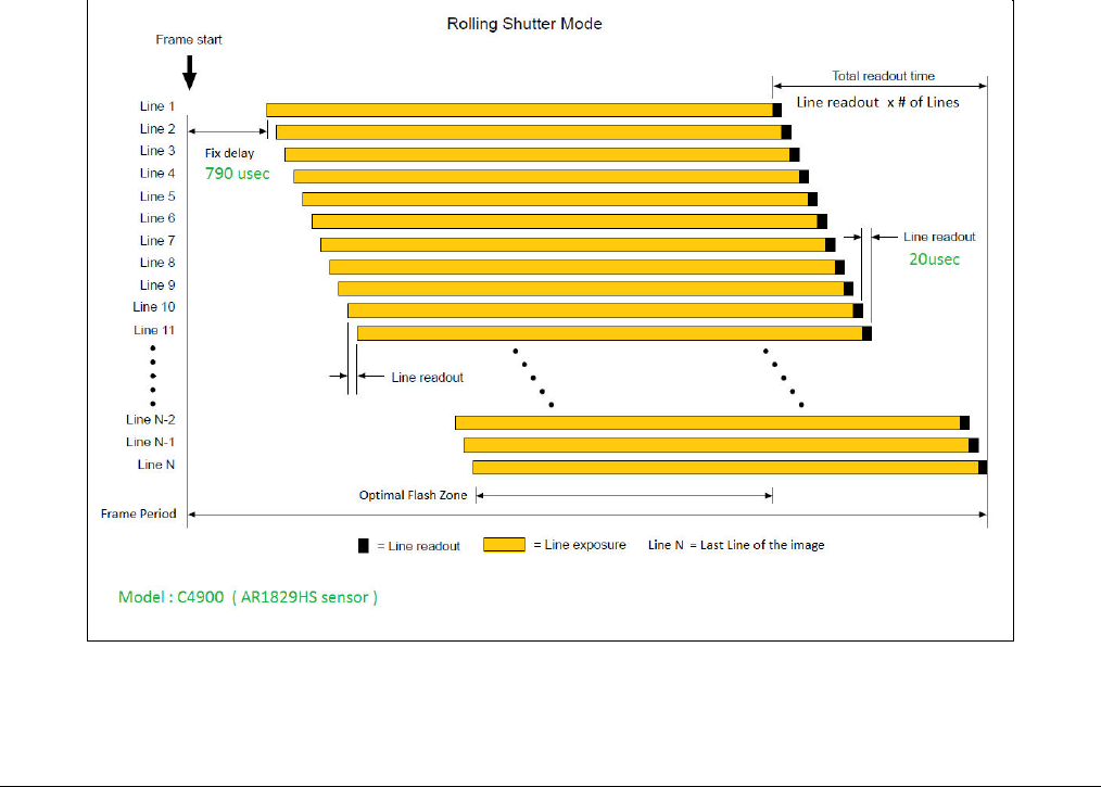
Nano Series GigE Vision Camera Genie Nano Specifications
•
73
Overview of Electronic Rolling Shutter (ERS) Exposures
Referring to the following graphic:
• Each sensor line is exposed for the programmed time integration period.
• Exposures start with Line 1. The sensor design uses a shared line readout circuit. Due to this
simplified circuitry, only a single line of pixel data can be readout at any given time. Therefore
the line 2 exposure (integration period) is delayed by the required readout time of line 1.
• This delayed line exposure is repeated from the sensor’s first line to its last sensor line.
• This sequence allows the common readout circuit to read the data from each row. This results
in an exposure start time delay between the first to last row – thus the name rolling shutter.
• To avoid motion artifacts the user needs to freeze motion using flash lighting of suitable length
in a dark environment. The flash is triggered at the start of the last line’s exposure and stops at
the end of the first line’s exposure. The flash must maintain a constant light output during this
period.
• To control the flash device, use the Genie Nano output signal with these feature selections:
outputLineSource=PulseOnStartofExposure, outputLinePulseDelay=flashZoneDelay (delay to
the start of the last line exposure), outputLinePulseDuration=flashZoneDuration (optimal
flash zone time as shown in the graphic below).
• The two new features mentioned, flashZoneDelay and flashZoneDuration, automatically
provide the optimal flash zone time values no matter the exposure duration and any vertical
cropping/offset settings. The user is free to use any delay or duration as required.
• The dark environment illumination ensures minimal exposure (and thus motion artifacts) during
the sensor lines integration time occurring before and after the flash period.
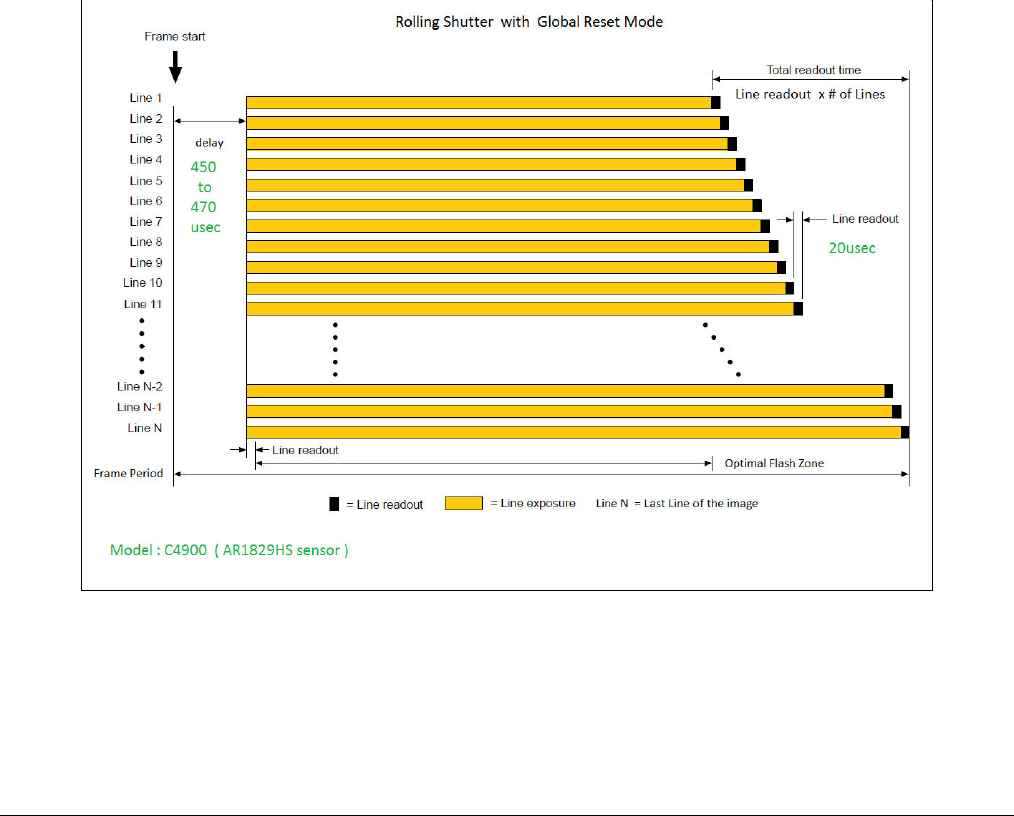
74
•
Genie Nano Specifications Nano Series GigE Vision Camera
Overview of Global Reset Release (GRR) Exposures
Referring to the following graphic:
• All sensor lines start integrating at the same time, therefore GRR mode is also known as Global
Start Mode.
• The first sensor line (line 1) only is exposed for the programmed time integration period.
• As mentioned previously, the sensor design uses a shared line readout circuit. Therefore again,
only a single line of pixel data can be readout at any given time.
• With each sensor line starting exposure integration at once, each following line’s exposure is
increased by the readout time required by the previous row.
• In a well-lit environment with static objects, there is a visible exposure increase from the top
sensor row to the bottom sensor row.
• And again, with moving objects in a well-lit environment, there is motion blurring from top to
bottom.
• Therefore as described previously, flash lighting in a dark environment is used to freeze motion.
The flash period matches the integration period for line 1. The increasing exposures for the
other sensor lines will not be visible without any other illumination source.
• Use a Genie Nano output signal for flash control as described above.

Nano Series GigE Vision Camera Genie Nano Specifications
•
75
Comparison of Similar On-Semi and Sony Sensors
The following table provides an overview comparison of the Nano cameras having a similar field of view (approximately 2K horizontal) using
On-Semi and Sony Sensors. Not all Nano cameras are presented so as to keep this table reasonable in size.
Parameters highlighted in green indicate specifications of interest when considering which Genie Nano camera may best match the imaging
requirement. Also consider Nano cameras in other resolutions to best match your imaging system.
Model Nano 1930 FRM †
(1984 x 1264)
On-Semi Python
Nano 1920
(1936 x 1216)
Sony Pregius
Nano 1940
(1936 x 1216)
Sony Pregius
Nano 2020
(2048 x 1536)
Sony Pregius
Nano 2050 HSD ‡
(2048 x 1536)
Sony Pregius
Max Acquisition Frame Rate
in Native Resolution 116 fps 38 fps 83 fps 53 fps 143 fps
Acquisition Frame Rate with
Region-of-Interest (ROI): 640 x 480 = 717 fps
1024 x 250 = 878 fps 640 x 480 = 94 fps
1024 x 250 = 169 fps 640 x 480 = 202 fps
1024 x 250 = 364 fps 640 x 480 = 164 fps
1024 x 248 = 301 fps 640 x 480 = 436 fps
1024 x 248 = 791 fps
Minimum Exposure 87 µs 34.23 µs 23.23 µs 25 µs 18 µs
Exposure Granularity 1 µs step 20.5 µs step 9.5 µs step 12 µs step 4.4 µs step
Trigger to Exposure
Minimum delay
(best case scenario **) 3 µs 2 line time (41 µs) 2 line time (19 µs) 0 µs 0 µs
Trigger to Exposure Start
jitter (best case scenario**) 0 µs Up to 1 line time
0 to 20.5 µs Up to 1 line time
0 to 9.5 µs 0µs 0 µs
Min. Time from End of
Exposure to Start of Next
Exposure 47 µs 512.5 µs 237.5 µs 81 µs 30 µs
Pixel Format 8 and 10 bit 8 and 12 bit 8 and 10 bit 8 and 12 bit 8 bit
Multi-ROI capability Yes, 16 ROIs Yes, 16 ROIs
(No FPS increase) Yes, 16 ROIs Yes, 16 ROIs Yes, 16 ROIs
Moving ROI (i.e. Cycling
Mode) supported in Sensor
thus maximizing fps Yes No No No No
Image Flipping Yes
Vertical only Yes
Horizontal and Vertical Yes
Horizontal and Vertical Yes
Horizontal and Vertical Yes
Horizontal and Vertical
Sensor Gain range
(in the Analog domain) 1 to 8x multiplying factor 1 to 15x multiplying factor 1 to 15x multiplying factor 1 to 16x multiplying factor 1 to 16x multiplying factor

76
•
Genie Nano Specifications Nano Series GigE Vision Camera
Sensor Gain range
(in the Digital domain) 1 to 16x multiplying factor 1 to 15x multiplying factor
(Applied after Maximum
Analog gain)
1 to 15x multiplying factor
(Applied after Maximum
Analog gain)
1 to 16x multiplying factor
(Applied after Maximum
Analog gain)
1 to 16x multiplying factor
(Applied after Maximum
Analog gain)
Dynamic Range 62.1 dB 75.5 dB 68.3 dB 76.4 dB 56.8 dB
Signal-to-noise Ration 39.8 dB 43.9 dB 43.9 dB 39.6 dB 33.1 dB
Full Well Charge (-e) 10 ke (max) 32ke (max) 32ke (max) 11ke (max) 2.75ke (max)
Pixel Size (µm) 4.8 x 4.8 5.86 x 5.86 5.86 x 5.86 3.45 x 3.45 3.45 x 3.45
**Excluding the input Opto-coupler’s propagation delay, trigger input jitter time is added to the fixed line count delay as shown by the linked graphic.
† FRM Fast Readout Mode
‡ HSD High Sensitivity Design

Nano Series GigE Vision Camera Nano Quick Start
•
77
Nano Quick Start
If you are familiar with GigE Vision cameras, follow these steps to quickly install and acquire
images with Genie Nano and Sapera LT in a Windows OS system. If you are not familiar with
Teledyne DALSA GigE Vision cameras go to Connecting the Genie Nano Camera.
• Your computer requires a second or unused Ethernet Gigabit network interface (NIC) that is
separate from any NIC connected to any corporate or external network.
• Install Sapera 8.01 (or later) and make certain to select the installation for GigE Vision support.
• Connect the Nano to the spare NIC and wait for the GigE Server Icon in the Windows tray to
show that the Nano is connected. The Nano Status LED will change to steady Blue.
Testing Nano without a Lens
• Start CamExpert. The Nano Status LED will be steady Green.
• From the Image Format Feature Category, select the Moving Grey Diagonal Ramp test pattern
from the Test Image Selector Parameter.
• Click grab. You will see the moving pattern in the CamExpert display window.
Testing Nano with a Lens
• Start CamExpert. The Nano Status LED will be steady Green.
• Click the Display Control button to show a full camera image on CamExpert display.
• Click grab.
• Adjust the lens aperture plus Focus, and/or adjust the Nano Exposure Time as required.
The Camera Works — Now What
Consult this manual for detailed Networking and Nano feature descriptions, as you write, debug,
and optimize your imaging application.
78
•
Connecting the Genie Nano Camera Nano Series GigE Vision Camera
Connecting the Genie Nano
Camera
GigE Network Adapter Overview
Genie Nano connects to a computer’s Gigabit Network Adapter (NIC). If the computer is already
connected to a network, the computer requires a second network adapter, either onboard or an
additional PCIe NIC adapter. Refer to the Teledyne DALSA Network Imaging manual for information
on optimizing network adapters for GigE Vision cameras.
PAUSE Frame Support
The Genie Nano supports (and monitors) the Gigabit Ethernet PAUSE Frame feature as per
IEEE 802.3x. PAUSE Frame is the Ethernet flow control mechanism to manage network traffic
within an Ethernet switch when multiple cameras are simultaneously used. This requires that the
flow control option in the NIC property settings and the Ethernet switch settings must be enabled.
The user application can monitor the Pause Frame Received Event as describe in Event Controls.
Refer to the Teledyne DALSA Network Imaging manual for additional information.
Note: Some Ethernet Switches may produce more Pause Frame requests than expected when Jumbo
Frames is enable. Setting the Ethernet Packet Size to the default of 1500, may minimize Pause Requests
from such a switch and improve overall transfer bandwidth.
Connect the Genie Nano Camera
Connecting a Genie Nano to a network system is similar whether using the Teledyne DALSA
Sapera LT package or a third party GigE Vision development package.
• Power supplies must meet the requirements defined in section Input Signals Electrical . Apply
power to the camera.
• Connect Nano to the host computer GigE network adapter or to the Ethernet switch via a CAT5e
or CAT6 Ethernet cable (the switch connects to the computer NIC to be used for imaging, not a
corporate network). Note: the cable should not be less than 1 meter (3 feet) long or more than
100 meters (328 feet) long.
• Once communication with the host computer is started the automatic IP configuration sequence
will assign an LLA IP address as described in section Genie Nano IP Configuration Sequence, or
a DHCP IP address if a DHCP server is present on your network (such as the one installed with
Sapera LT).
• Check the status LED which will be initially red then switch to flashing blue while waiting for IP
configuration. See Camera Status LED for Nano LED display descriptions.
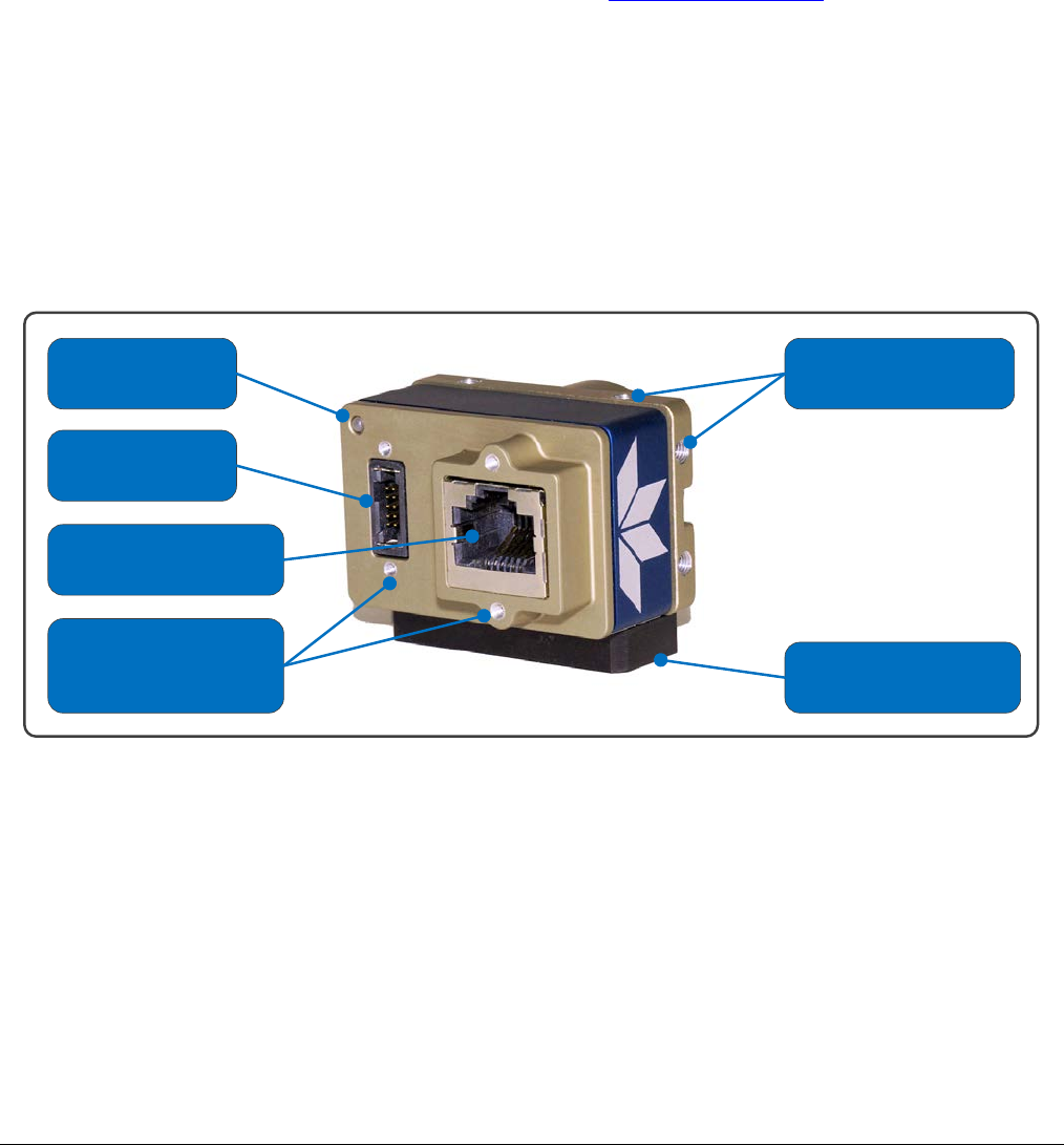
Nano Series GigE Vision Camera Connecting the Genie Nano Camera
•
79
• The factory defaults for Nano is Persistent IP disabled and DHCP enabled with LLA always
enabled as per the GigE Vision specification. For additional information see Nano IP
Configuration Mode Details. See the next section Connectors for an overview of the Nano
interfaces.
Connectors
The Nano has two connectors:
• A single RJ45 Ethernet connector for control and video data transmitted to/from the host
computer Gigabit NIC. The Genie Nano also supports Power over Ethernet (PoE).
See Ruggedized RJ45 Ethernet Cables for secure cables.
• A 10 pin I/O connector for camera power, plus trigger, strobe and general I/O signals. The
connector supports a retention latch, while the Nano case supports thumbscrews. Teledyne
DALSA provides optional cables (see Accessories). See 10-pin I/O Connector Details for
connector pin out specifications.
• Note that the NanoXL uses the same two connectors but on a larger camera body.
The following figure of the Genie Nano back end shows connector and LED locations. See
Mechanical Specifications for details on the connectors and camera mounting dimensions, including
the NanoXL.
Status LED
10 Pin
I/O & Power
Ethernet Connector
(supports PoE)
Supports
Thumbscrew
Secured Cables
Camera Mounts
(4 sides)
Optional Tripod
Mount
Genie Nano – Rear View
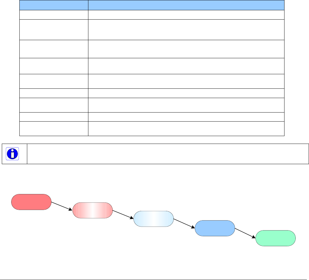
80
•
Connecting the Genie Nano Camera Nano Series GigE Vision Camera
LED Indicators
The Genie Nano has one multicolor LED to provide a simple visible indication of camera state, as
described below. The Nano Ethernet connector does not have indicator LEDs; the user should use
the LED status on the Ethernet switch or computer NIC to observe networking status.
Camera Status LED Indicator
The camera is equipped with one LED to display its operational status. When more than one
condition is active, the LED color indicates the condition with the highest priority (such as – an
acquisition in progress has more priority than a valid IP address assignment).
Once the Genie Nano connects to a network and an IP address is assigned, the Status LED will turn
to steady blue. Only at this time will it be possible by the GigE Server or any application to
communicate with the camera. The following table summarizes the LED states and corresponding
camera status.
LED State Definition
LED is off No power to the camera
Steady Red Initial state on power up before flashing.
Remains as steady Red only if there is a fatal error.
Camera is not initialized **
Flashing Red Initialization sequence in progress
** Wait less than a minute for the Nano to reboot itself.
Steady Red +
Flashing Blue Fatal Error. If the Genie Nano does not reboot itself contact Technical
Support.
Slow Flashing Blue Ethernet cable disconnected. The camera continuously attempts to assign
itself an IP address.
Fast Flashing Blue File Access Feature is transferring data such as a firmware update, etc.
Steady Blue IP address assigned;
no application connected to the camera
Steady Green Application connected
Flashing Green Acquisition in progress. Flashing occurs on frame acquisition but does not
exceed a rate of 100ms for faster frame rates.
Note: Even if the Nano has obtained an IP address, it might be on a different subnet than the NIC it is attached
to. Therefore, if the Nano LED is blue but an application cannot see it, this indicates a network configuration
problem. Review troubleshooting suggestions in the Network Imaging manual.
LED States on Power Up
The following LED sequence occurs when the Genie Nano is powered up connected to a network.
Flashing Red
initialization Flashing Blue
waiting for IP Blue
IP assigned Green
application
connected
Red
power connected

Nano Series GigE Vision Camera Connecting the Genie Nano Camera
•
81
Genie Nano IP Configuration Sequence
The Genie Nano IP (Internet Protocol) Configuration sequence to assign an IP address is executed
automatically on camera power-up or when connected to a network. As a GigE Vision compliant
device, Nano attempts to assign an IP address as follows.
For any GigE Vision device, the IP configuration protocol sequence is:
• Persistent IP (if enabled)
• DHCP (if a DHCP server is present such as the Teledyne DALSA Smart DHCP server)
• Link-Local Address (always enabled as default)
The factory defaults for Nano is Persistent IP disabled and DHCP enabled with LLA always enabled
as per the GigE Vision specification. For additional information see Nano IP Configuration Mode
Details.
Supported Network Configurations
The Genie Nano obtains an IP address using the Link Local Address (LLA) or DHCP, by default. If
required, a persistent IP address can be assigned (refer to the Network Imaging manual).
Preferably, a DHCP server is present on the network, where the Genie Nano issues a DHCP request
for an IP address. The DHCP server then provides the Nano an IP address. The Teledyne DALSA
Network Configuration tool, installed with the Sapera Teledyne DALSA Network Imaging
Package, provides a DHCP server which is easily enabled on the NIC used with the Genie Nano
(refer to the Teledyne DALSA Network Imaging user’s manual).
The LLA method, if used, automatically assigns the Nano with a randomly chosen address on the
169.254.xxx.xxx subnet. After an address is chosen, the link-local process sends an ARP query
with that IP onto the network to see if it is already in use. If there is no response, the IP is
assigned to the device, otherwise another IP is selected, and the ARP is repeated. Note that the
LLA mode is unable to forward packets across routers.

82
•
Connecting the Genie Nano Camera Nano Series GigE Vision Camera
Preventing Operational Faults due to ESD
Nano camera installations which do not protect against ESD (electrostatic
discharge) may exhibit operational faults. Problems such as random packet loss,
random camera resets, and random loss of Ethernet connections, may all be
solved by proper ESD management.
The Nano camera when used with a simple power supply and Ethernet cable, is
not properly connected to earth ground and therefore is susceptible to ESD
caused problems. An Ethernet cable has no ground connection and a power
supply’s 0 volt return line is not necessarily connected to earth ground.
Teledyne DALSA has performed ESD testing on Nano cameras using an 8 kilovolt ESD generator
without any indication of operational faults. The two following methods, either individually or
together will prevent ESD problems.
• Method 1: Use a shielded/grounded power supply that connects ground to pin-10 of the I/O
connector. The Nano case is now properly connected to earth ground and can withstand ESD of
8 kilovolts, as tested by Teledyne DALSA.
• Method 2: When using Power over Ethernet (PoE), Teledyne DALSA strongly recommends using
a shielded Ethernet cable to provide a ground connection from the controlling computer/power
supply, to the Genie Nano. PoE requires a powered computer NIC, or a powered Ethernet
switch, or an Ethernet power injector.
• Method 3: Mount the camera on a metallic platform with a good connection to earth ground.

Nano Series GigE Vision Camera Using Nano with Sapera API
•
83
Using Nano with Sapera API
A Genie Nano camera installation with the Teledyne DALSA Sapera API generally follows the
sequence described below.
Network and Computer Overview
• Nano needs to connect to a computer with a GigE network adapter, either built in on the
computer motherboard or installed as a third party PCI adapter. See the previous section
Connecting the Genie Nano Camera.
• Laptop computers with built in GigE network adapters may still not be able to stream full
frame rates from Nano, especially when on battery power.
• Nano also can connect through a Gigabit Ethernet switch. When using VLAN groups, the
Nano and controlling computer must be in the same group (refer to the Teledyne DALSA
Network Imaging Package user’s manual).
• If Genie Nano is to be used in a Sapera development environment, Sapera LT 8.10 needs to
be installed, which includes the GigE Vision Module software package with the Teledyne
DALSA GigE Vision TurboDrive Technology module.
• If Genie Nano will be used in a third party GigE Vision Compliant environment, Sapera or
Sapera runtime is not required and you need to follow the installation instructions of the third
party package.
• The Windows Firewall exceptions feature is automatically configured to allow the Sapera GigE
Server to pass through the firewall.
• Computers with VPN software (virtual private network) may need to have the VPN driver
disabled in the NIC properties. This would be required only on the NIC used with the Nano.
Testing by the user is required.
• Once a Nano is connected, look at the small camera icon added to the Windows tray (next to
the clock). Ensure the Nano camera has been found (right click the icon and select Status) Note
that in Windows 7, the icon remains hidden until a camera is connected.
• A new Nano installation may require a firmware update. The File Selector feature is used to
select a firmware file. See the CamExpert procedure Updating Firmware via File Access in
CamExpert for additional information.
• Use CamExpert (installed either with Sapera or Sapera runtime) to test the installation of the
Nano camera. Set the Nano to internal test pattern. See Internal Test Pattern Generator.
• Set up the other components of the imaging system such as light sources, camera mounts,
optics, encoders, trigger sources, etc. Test with CamExpert.

84
•
Using Nano with Sapera API Nano Series GigE Vision Camera
Installation
Note: to install Sapera LT and the GigE Vision package, logon to the workstation as an administrator or
with an account that has administrator privileges.
When Genie Nano is used in a Sapera development environment, Sapera LT 8.10 (or later)
needs to be installed, which automatically provides all GigE Vision camera support including
TurboDrive.
If no Sapera development is required. Then the Sapera LT SDK is not needed to control the
Linea GigE camera. Sapera runtime with CamExpert provides everything to control the camera.
Procedure
• Download and install Sapera LT 8.10 (or later) which automatically provides GigE Vision support
with Teledyne DALSA TurboDrive™ technology. Note that Nano features may change when an
older versions of Sapera LT is used.
• Optional: If the Teledyne DALSA Sapera LT SDK package is not used, click to install the Genie
Nano firmware and user manuals only. Follow the on screen prompts.
• Connect the camera to an available free Gigabit NIC that’s not part of some other corporate
network.
Refer to Sapera LT User’s Manual concerning application development with Sapera.
Note: The Teledyne DALSA Sapera CamExpert tool (used throughout this manual to describe Genie Nano
features) is installed with either the Sapera LT runtime or the Sapera LT development package.
Camera Firmware Updates
Under Windows, the user can upload new firmware, using the File Access Control features provided
by the Sapera CamExpert tool.
Download the latest firmware version released for any Nano model from the Teledyne DALSA
support web page: http://www.teledynedalsa.com/imaging/support/downloads/firmware/
Firmware via Linux or Third Party Tools
Consult your third party GigE Vision software package for file uploads to the connected device.

Nano Series GigE Vision Camera Using Nano with Sapera API
•
85
GigE Server Verification
After a successful Genie Nano Framework package installation, the GigE Server icon is visible in the
desktop taskbar tray area (note that in Windows 7 the icon remains hidden until a camera is
connected). After connecting a camera (see following section), allow a few seconds for the GigE
Server status to update. The Nano camera must be on the same subnet as the NIC to be
recognized by the GigE Server.
Device Available Device IP Error Device Not Available
GigE Server
Tray Icon:
The normal GigE server tray
icon when the Genie device is
found. It will take a few
seconds for the GigE Server to
refresh its state after the Genie
has obtained an IP address.
The GigE server tray icon
shows a warning when a device
is connected but there is some
type of IP error.
A red X will remain over the
GigE server tray icon when the
Genie device is not found. This
indicates a major network issue.
Or in the simplest case, the
Genie is not connected.
If you place your mouse cursor on this icon, the GigE Server will display the number of GigE Vision
devices found by your PC. Right click the icon and select status to view information about those
devices. See Troubleshooting for more information.
GigE Server Status
Once the Genie Nano is assigned an IP address (its Status LED is steady blue) the GigE server tray
icon will not have a red X through it, indicating that the Nano device was found. It might take a few
seconds for the GigE Server to refresh its state after the Nano has obtained an IP address.
Right-click the GigE Server tray icon to open the following menu.
Click on Show Status to open a window listing all devices connected to the host system. Each GigE
device is listed by name along with important information such as the assigned IP address and
device MAC address. The screen shot below shows a connected Nano with no networking problems.
In the event that the device is physically connected, but the Sapera GigE Server icon is indicating
that the connected device is not recognized, click Scan Network to restart the discovery process.
Note that the GigE server periodically scans the network automatically to refresh its state. See
Troubleshooting for network problems.

86
•
Using Nano with Sapera API Nano Series GigE Vision Camera
Optimizing the Network Adapter used with Nano
Most Gigabit network interface controllers (NIC) allow user modifications to parameters such as
Adapter Buffers and Jumbo Frames. These should be optimized for use with the Nano during the
installation. Refer to the NetworkOptimizationGuide.pdf for optimization information (available
with the Sapera LT installation [C:\Program Files\Teledyne DALSA\Network Interface]).
Quick Test with CamExpert (Windows)
When the Genie Nano camera is connected to a Gigabit network adapter on a host computer,
testing the installation with CamExpert is a straightforward procedure.
• Start Sapera CamExpert by double clicking the desktop icon created during the software
installation.
• CamExpert will search for installed Sapera devices. In the Device list area on the left side, the
connected Nano camera is shown or will be listed in a few seconds after CamExpert completes
the automatic device search (device discovery).
• Select the Nano camera device by clicking on the camera user defined name. By default the
Nano camera is identified by its serial number. The Nano status LED will turn green, indicating
the CamExpert application is now connected.
• Click on the Grab button for live acquisition (the Nano default is Free Running mode). Focus
and adjust the lens iris. See Operational Reference for information on CamExpert parameters
with the Nano camera.
• If the Nano has no lens, just select one of the internal test patterns available (Image Format
Controls – Test Image Selector). All but one are static images to use with the Snap or Grab
function of CamExpert. The single “moving” test image is a shifting diagonal ramp pattern,
which is useful for testing network/computer bandwidth issues (see following image).
• Refer to the Teledyne DALSA Network Imaging package manual if error messages are shown in
the Output Messages pane while grabbing.
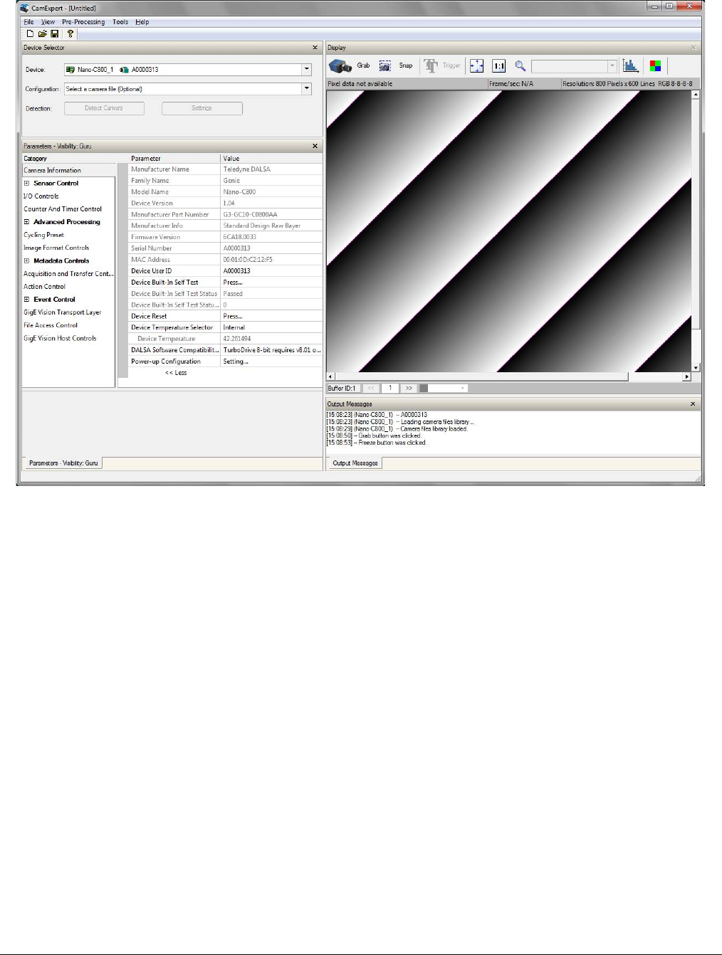
Nano Series GigE Vision Camera Using Nano with Sapera API
•
87
About the Device User ID
The Nano can be programmed with a user defined name to aid identifying multiple cameras
connected to the network. For instance, on an inspection system with 4 cameras, the first camera
might be labeled “top view”, the second “left view”, the third “right view” and the last one “bottom
view”. The factory default user name is set to match the camera serial number for quick initial
identification. Note that the factory programmed Genie Nano serial number and MAC address are
not user changeable.
When using CamExpert, multiple Genie Nano cameras on the network are seen as different
“Nano-xxxxx” devices as an example. Non Teledyne DALSA cameras are labeled as “GigEVision
Device”. Click on a device user name to select it for control by CamExpert.
An imaging application uses any one of these attributes to identify a camera: its IP address, MAC
address, serial number or User Name. Some important considerations are listed below.
• Do not use the camera’s IP address as identification (unless it is a persistent IP) since it can
change with each power cycle.
• A MAC address is unique to a single camera, therefore the control application is limited to the
vision system with that unique camera if it uses the camera’s MAC address.
• The User Name can be freely programmed to clearly represent the camera usage. This scheme
is recommended for an application to identify cameras. In this case, the vision system can be
duplicated any number of times with cameras identified by their function, not their serial
numbers or MAC address.
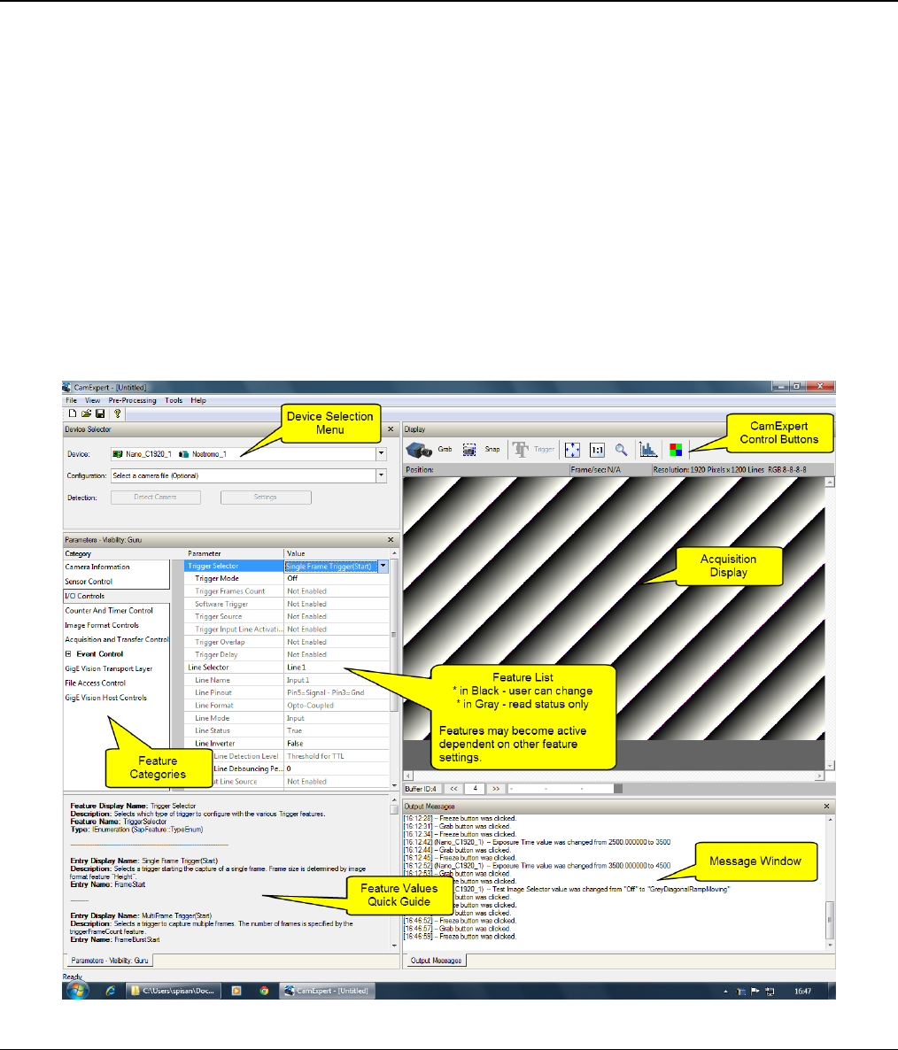
88
•
Operational Reference Nano Series GigE Vision Camera
Operational Reference
Using CamExpert with Genie Nano Cameras
The Sapera CamExpert tool is the interfacing tool for GigE Vision cameras, and is supported by the
Sapera library and hardware. CamExpert allows a user to test camera functions. Additionally
CamExpert saves the Nano user settings configuration to the camera or saves multiple
configurations as individual camera parameter files on the host system (*.ccf).
An important component of CamExpert is its live acquisition display window which allows
immediate verification of timing or control parameters without the need to run a separate
acquisition program.
CamExpert Panes
The various areas of the CamExpert tool are described in the summary figure below. GigE Vision
device Categories and Parameter features are displayed as per the device’s XML description file.
The number of parameters shown is dependent on the View mode selected
(i.e. Beginner, Expert, Guru – see description below).
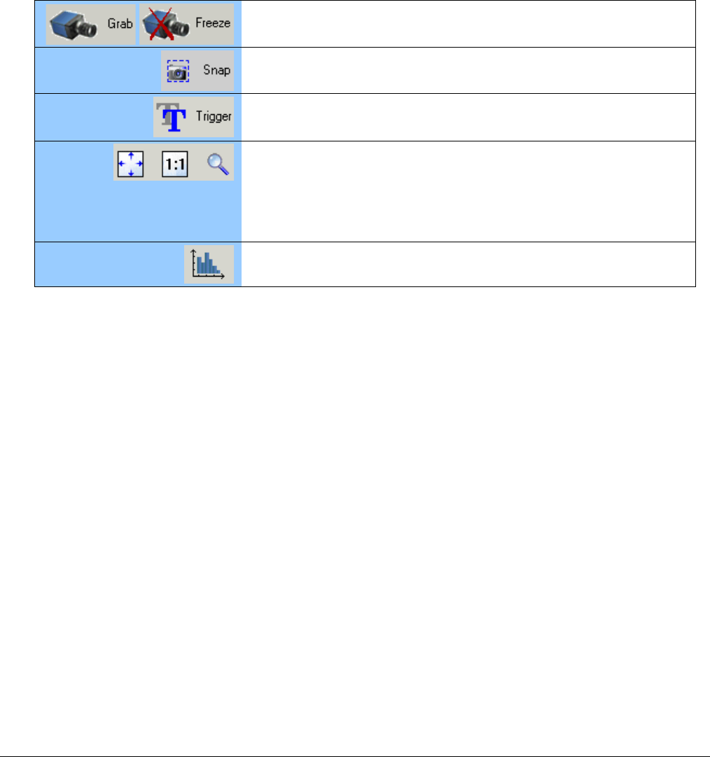
Nano Series GigE Vision Camera Operational Reference
•
89
• Device pane: View and select from any installed GigE Vision or Sapera acquisition device. After
a device is selected CamExpert will only present parameters applicable to that device.
• Parameters pane: Allows viewing or changing all acquisition parameters supported by the
acquisition device. CamExpert displays parameters only if those parameters are supported by
the installed device. This avoids confusion by eliminating parameter choices when they do not
apply to the hardware in use.
• Display pane: Provides a live or single frame acquisition display. Frame buffer parameters are
shown in an information bar above the image window.
• Control Buttons: The Display pane includes CamExpert control buttons. These are:
Acquisition control button:
Click once to start live grab, click again to stop.
Single frame grab:
Click to acquire one frame from device.
Software trigger button:
With the I/O control parameters set to Trigger Enabled / Software Trigger
type, click to send a single software trigger command.
CamExpert display controls:
(these do not modify the frame buffer data)
Stretch (or shrink) image to fit, set image display to original size, or zoom
the image to any size and ratio. Note that under certain combinations of
image resolution, acquisition frame rate, and host computer speed, the
CamExpert screen display may not update completely due to the host CPU
running at near 100%. This does not affect the acquisition.
Histogram / Profile tool:
Select to view a histogram or line/column profile during live acquisition.
• Output pane: Displays messages from CamExpert or the GigE Vision driver.
CamExpert View Parameters Option
All camera features have a Visibility attribute which defines its requirement or complexity. The
states vary from Beginner (features required for basic operation of the device) to Guru (optional
features required only for complex operations).
CamExpert presents camera features based on their visibility attribute and provides quick Visibility
level selection via controls below each Category Parameter list [ << Less More>> ]. The user can
also choose the Visibility level from the View ∙ Parameters Options menu.
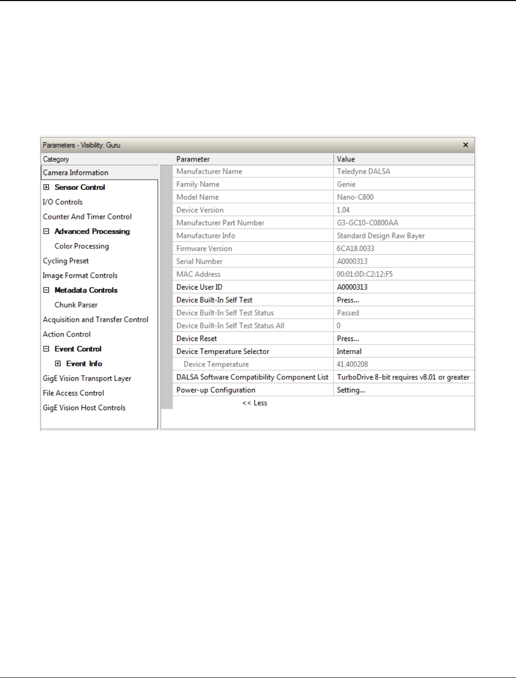
90
•
Operational Reference Nano Series GigE Vision Camera
Camera Information Category
Camera information can be retrieved via a controlling application. Parameters such as camera
model, firmware version, etc. are read to uniquely identify the connected Nano device. These
features are typically read-only. GigE Vision applications retrieve this information to identify the
camera along with its characteristics.
Features listed in the description table but tagged as Invisible are usually for Teledyne DALSA or
third party software usage—not typically needed by end user applications.
Camera Information Feature Descriptions
The following table describes these parameters along with their view attribute and in which device
version the feature was introduced. Additionally the Device Version column will indicate which
parameter is a member of the DALSA Features Naming Convention (indicated by DFNC), versus
the GenICam Standard Features Naming Convention (SFNC tag is not shown).
New features for a major device version release will be indicated by green text for easy
identification.

Nano Series GigE Vision Camera Operational Reference
•
91
Display Name Feature & Values Description Device
Version
& View
Manufacturer Name DeviceVendorName Displays the device vendor name. 1.00
Beginner
Family Name DeviceFamilyName Displays the device family name. 1.00
Beginner
Model Name DeviceModelName Displays the device model name. 1.00
Beginner
Device Version DeviceVersion Displays the device version. This tag will also
highlight if the firmware is a beta or custom
design. (RO)
1.00
Beginner
Manufacturer Part
Number deviceManufacturerPartNumber Displays the device manufacturer part
number. 1.00
DFNC
Beginner
Manufacturer Info DeviceManufacturerInfo This feature provides extended manufacturer
information about the device. Genie Nano
cameras show which firmware design is
currently loaded.
1.00
Beginner
Firmware Version DeviceFirmwareVersion Displays the currently loaded firmware version
number. Firmware files have a unique number
and have the .cbf file extension.
1.00
Beginner
Serial Number DeviceSerialNumber Displays the device’s factory set serial
number. 1.00
Expert
MAC Address deviceMacAddress Displays the unique MAC (Media Access
Control) address of the Device. 1.00
DFNC
Beginner
Device User ID DeviceUserID Feature to store a user-programmable
identifier of up to 15 characters. The default
factory setting is the camera serial number.
(RW)
1.00
Beginner
Device Built-In Self Test deviceBIST Command to perform an internal test which
will determine the device status. (W) 1.00
Beginner
Device Built-In Self Test
Status deviceBISTStatus Return the status of the device Built-In Self-
Test. Possible return values are device-
specific.
1.00
Beginner
Passed Passed No failure detected
Last firmware update
failed FirmwareUpdateFailure Last firmware update operation failed.
Unexpected Error Unexpected_Error Switched to recovery mode due to unexpected
software error.
Sensor Initialization
Failure SensorFailure There was an error initializing the sensor. The
camera may not be able to capture images.
(1.05)
Firmware Error FirmwareError Firmware encountered an error during
streaming.
(1.06)
Device Built-In Self Test
Status All deviceBISTStatusAll Return the status of the device Built-In Self-
Test as a bitfield. The meaning for each bit is
device-specific. A value of 0 indicates no
error.
Bit-0=1:Firmware Update Failure
Bit-2=1:Unexpected Error
1.00
DFNC
Beginner
Device Reset DeviceReset Resets the device to its power up state. (W) 1.00
Beginner
Device Temperature
Selector DeviceTemperatureSelector Select the source where the temperature is
read. 1.00
Beginner
Internal Internal Value from FPGA and or PHY temperature.
MaxInternal MaxInternal Records the highest device temperature since
power up. Value is reset on power off.

92
•
Operational Reference Nano Series GigE Vision Camera
Device Temperature DeviceTemperature The temperature of the selected source in
degrees Celsius. Maximum temperature
should not exceed +70°C for reliable
operation.
1.00
Beginner
DALSA Software
Compatibility
Component List
DALSASoftwareCompatibilityComponentList List the optional Teledyne DALSA software
functions that are supported. 1.00
Beginner
TurboDrive 8-bit
requires v8.01
or greater
Compatibility1 Teledyne DALSA Turbo Drive 8-bit
(Monochrome or Bayer) requires Sapera-LT
8.01 or greater.
TurboDrive 10-bit
requires v8.10 or
greater
Compatibility2 Teledyne DALSA Turbo Drive 10-bit
(Monochrome or Bayer) requires Sapera-LT
8.10 or greater.
TurboDrive 12-bit
requires v8.10 or
greater
Compatibility3 Teledyne DALSA Turbo Drive 12-bit
(Monochrome or Bayer) requires Sapera-LT
8.10 or greater.
Multicast requires a
newer version Compatibility4 Multicast feature support requires a newer
version of Sapera LT than currently installed.
Power-up Configuration
Selector UserSetDefaultSelector Selects the camera configuration set to load
and make active on camera power-up or
reset. The camera configuration sets are
stored in camera non-volatile memory. (RW)
1.00
Beginner
Factory Setting Default Load factory default feature settings.
UserSet1 UserSet1 Select the user defined configuration UserSet
1 as the Power-up Configuration.
UserSet2 UserSet2 Select the user defined configuration UserSet
2 as the Power-up Configuration.
User Set Selector UserSetSelector Selects the camera configuration set to load
feature settings from or save current feature
settings to. The Factory set contains default
camera feature settings. (RW)
1.00
Beginner
Factory Setting Default Select the default camera feature settings
saved by the factory.
UserSet 1 UserSet1 Select the User Defined Configuration space
UserSet1 to save to or load from features
settings previously saved by the user.
UserSet 2 UserSet2 Select the User Defined Configuration space
UserSet1 to save to or load from features
settings previously saved by the user.
Load Configuration UserSetLoad Loads the camera configuration set specified
by the User Set Selector feature, to the
camera and makes it active. Can not be
updated during a Sapera transfer. (W)
1.00
Beginner
Save Configuration UserSetSave Saves the current camera configuration to the
user set specified by the User Set Selector
feature. The user sets are located on the
camera in non-volatile memory. (W)
1.00
Beginner
Power-up Configuration
Selector
UserSetDefault
Specify the camera configuration set to load
and make active on camera power-up or
reset. The camera configuration sets are
stored in camera non-volatile memory.
1.00
Beginner
Serial Number DeviceID Displays the device’s factory set camera serial
number. 1.00
Invisible
Factory Setting Default Select the Factory Setting values as the
Power-up Configuration. 1.00
Invisible
UserSet1 UserSet1 Select the user defined configuration UserSet
1 as the Power-up Configuration.
UserSet2 UserSet2 Select the user defined configuration UserSet
2 as the Power-up Configuration.

Nano Series GigE Vision Camera Operational Reference
•
93
Calibration Date deviceCalibrationDateRaw Date when the camera was calibrated.
Device Acquisition Type deviceAcquisitionType Displays the Device Acquisition Type of the
product. 1.00
DFNC
Invisible
Sensor Sensor The device gets its data directly from a
sensor.
Device TL Type DeviceTLType Transport Layer type of the device. 1.00
DFNC
Invisible
GigE Vision GigEVision GigE Vision Transport Layer
Device TL Version Major DeviceTLVersionMajor Major version of the device’s Transport Layer. 1.00
Invisible
Device TL Version Minor DeviceTLVersionMinor Minor version of the device’s Transport Layer.
userSetError Error Flags for UserSetLoad & UserSetSave 1.00
Invisible
NoError No Error
LoadGenericError Unknown error
LoadBusyError The camera is busy and cannot perform the
action
LoadMemoryError Not enough memory to load set
LoadFileError Internal file I/O error
LoadInvalidSetError At least one register could not be restored
properly
LoadResourceManagerError An internal error happened related to the
resource manager
SaveGenericError Unknown error
SaveBusyError The camera is busy and cannot perform the
action
SaveMemoryError Camera ran out of memory while saving set
SaveFileError Internal file I/O error
SaveInvalidSetError An invalid user set was requested
SaveResourceManagerError An internal error happened related to the
resource manager
DFNC Major Rev deviceDFNCVersionMajor Major revision of Dalsa Feature Naming
Convention which was used to create the
device’s XML.
1.00
DFNC
Invisible
DFNC Minor Rev deviceDFNCVersionMinor Minor revision of Dalsa Feature Naming
Convention which was used to create the
device’s XML.
1.00
DFNC
Invisible
SFNC Major Rev DeviceSFNCVersionMajor Major Version of the Genicam Standard
Features Naming Convention which was used
to create the device’s XML.
1.00
DFNC
Invisible
SFNC Minor Rev DeviceSFNCVersionMinor Minor Version of the Genicam Standard
Features Naming Convention which was used
to create the device’s XML.
1.00
DFNC
Invisible
SFNC SubMinor Rev DeviceSFNCVersionSubMinor SubMinor Version of the Genicam Standard
Features Naming Convention which was used
to create the device’s XML.
1.00
Invisible
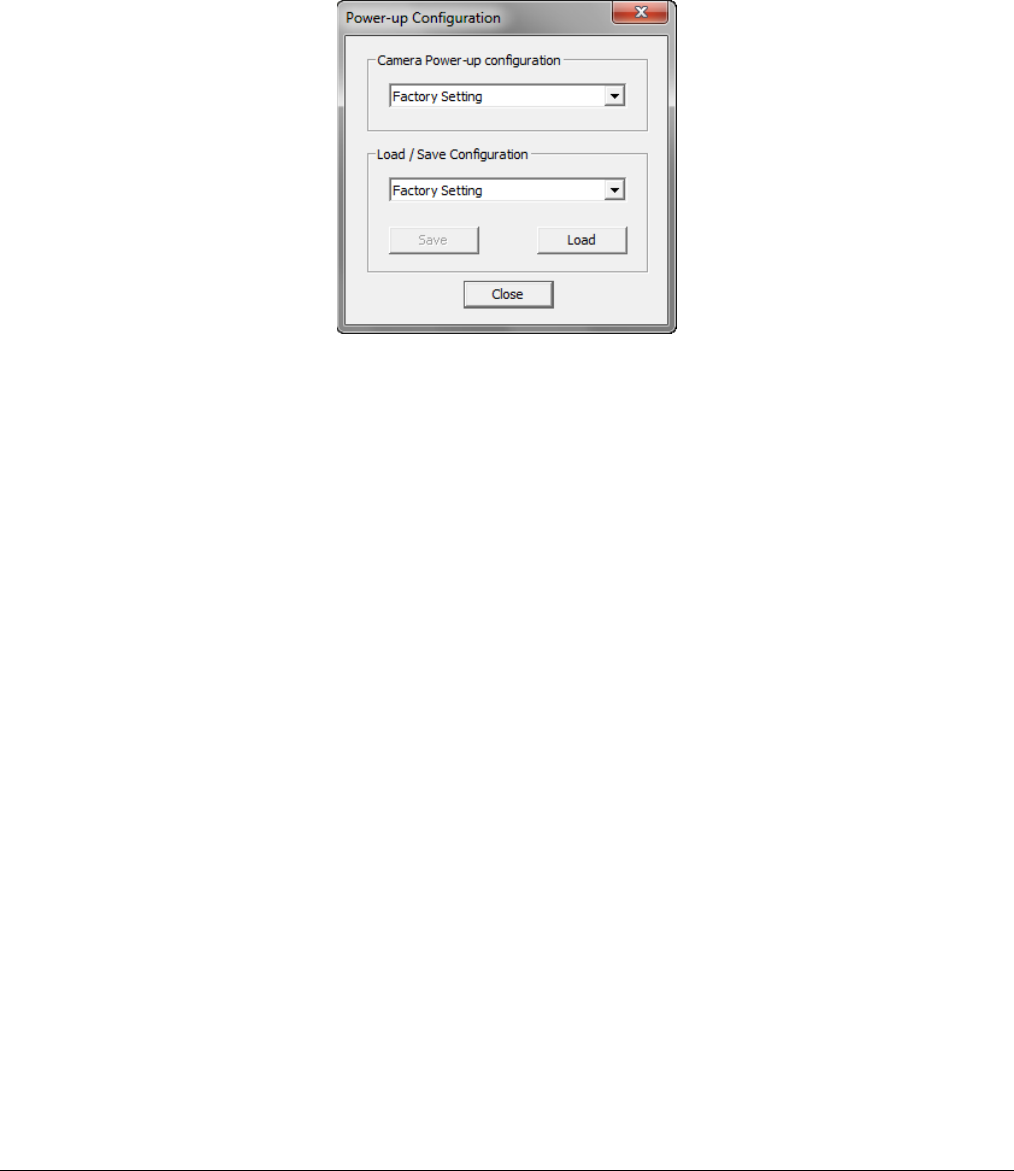
94
•
Operational Reference Nano Series GigE Vision Camera
Power-up Configuration Dialog
CamExpert provides a dialog box which combines the features to select the camera power-up state
and for the user to save or load a Nano camera state.
Camera Power-up Configuration
The first drop list selects the camera configuration state to load on power-up (see feature
UserSetDefaultSelector). The user chooses from one factory data set or one of two possible user
saved states.
Load / Save Configuration
The second drop list allows the user to change the camera configuration any time after a power-up
(see feature UserSetSelector). To reset the camera to the factory configuration, select Factory
Setting and click Load. To save a current camera configuration, select User Set 1 or 2 and click
Save. Select a saved user set and click Load to restore a saved configuration.
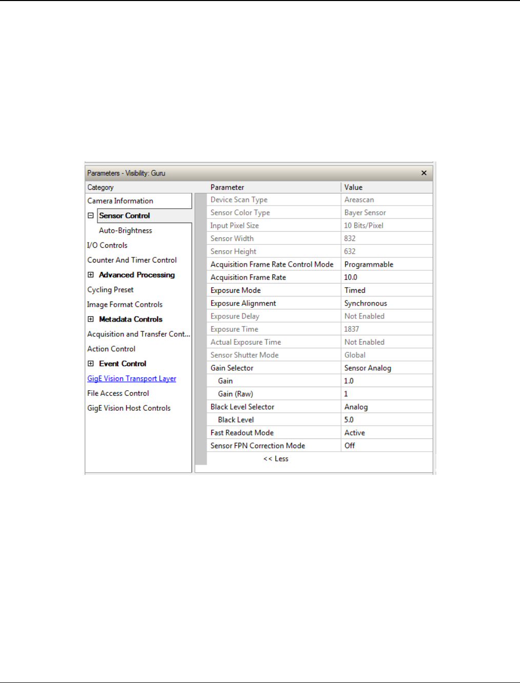
Nano Series GigE Vision Camera Operational Reference
•
95
Sensor Control Category
The Genie Nano sensor controls, as shown by CamExpert, groups sensor specific parameters. This
group includes controls for frame rate, exposure time, gain, etc. Parameters in gray are read only,
either always or due to other feature settings. Parameters in black are user set in CamExpert or
programmable via an imaging application.
Features listed in the description table that are tagged as Invisible are usually for Teledyne DALSA
or third party software usage—not typically needed by end user applications. Also important,
features shown by CamExpert may change with different Genie Nano models implementing
different sensors, image resolutions, and color versions.

96
•
Operational Reference Nano Series GigE Vision Camera
Sensor Control Feature Descriptions
The following table describes these features along with their view attribute and device version. For each feature the device version may differ
for each camera sensor available.
When a Device Version number is indicated, this represents the camera software functional group, not a firmware revision number. As Genie
Nano capabilities evolve the device version will increase, therefore identifying the supported function package. New features for a major
device version release will be indicated by green text for easy identification.
The first column indicates whether a feature applies to monochrome or color camera models via a symbol. No symbol indicates a common
feature. Additionally the description column will indicate which feature is a member of the DALSA Features Naming Convention (indicated by
DFNC), versus the GenICam Standard Features Naming Convention (SFNC tag is not shown).
B/W
Color Display Name Feature & Values Description Notes
Device Scan Type DeviceScanType Defines the scan type of the device’s sensor.
Genie Nano is an Areascan camera.
< RO, Beginner >
Areascan Areascan Device uses an Areascan sensor.
Sensor Color Type sensorColorType Defines the camera sensor color type.
< RO, DFNC, Beginner >
Monochrome Sensor Monochrome Sensor color type is monochrome.
Bayer Sensor CFA_Bayer Sensor color type is Bayer Color Filter Array (CFA).
Input Pixel Size pixelSizeInput Size of the image input pixels, in bits per pixel.
< RO, DFNC, Guru >
8 Bits/Pixel Bpp8 Sensor output data path is 8 bits per pixel.
10 Bits/Pixel Bpp10 Sensor output data path is 10 bits per pixel.
12 Bits/Pixel Bpp12 Sensor output data path is 12 bits per pixel.
Sensor Width SensorWidth Defines the sensor width in active pixels.
< RO, Expert >
Sensor Height SensorHeight Defines the sensor height in active lines.
< RO, Expert >
Acquisition Frame Rate
Control Mode acquisitionFrameRateControlMode Set the frame control method used in free running mode. Note that this feature applies only to
sensor acquisitions, not internal test images. < 1.01, DFNC, Guru >
Programmable Programmable The camera frame rate is controlled by the AcquisitionFrameRate feature.
Maximum Speed MaximumSpeed The camera operates at its maximum frame rate using the current exposure (time and delay)
configuration.
Acquisition Frame Rate AcquisitionFrameRate Specifies the camera internal frame rate, in Hz.
Any user entered value is automatically adjusted to a valid camera value. Note that a change in
frame rate takes effect only when the acquisition is stopped and restarted.
< Beginner >

Nano Series GigE Vision Camera Operational Reference
•
97
Exposure Mode ExposureMode Sets the operation mode for the camera’s exposure (or electronic shutter).
< Beginner >
Timed Timed The exposure duration time is set using the Exposure Time feature and the exposure starts with a
FrameStart event.
Trigger Width TriggerWidth Uses the width of the trigger signal pulse to control the exposure duration. Use the Trigger
Activation feature to set the polarity of the trigger.
The Trigger Width setting is applicable with Trigger Selector = Single Frame Trigger(Start).
Exposure Alignment exposureAlignment Exposure Alignment specifies how the exposure is executed in relationship to the sensor capabilities
and current frame trigger.
< DFNC Beginner >
Synchronous Synchronous Exposure is synchronous to the internal timing of the sensor. The readout is concurrent to the
exposure for the fastest possible frame rate. When a valid trigger is received and the ExposureTime
is shorter than the readout period, the ExposureStart event is latched in the previous frame’s
readout. That is; the ExposureStartEvent is delayed and is initiated when the actual exposure starts
such that the exposure ends and readout begins as soon as the previous readout has completed.
Reset Reset Sensor timing is reset to initiate exposure when a valid trigger is received. Readout is sequential to
exposure, reducing the maximum achievable frame rates. That is, a trigger received during
exposure or readout is ignored since data would be lost by performing a reset.
Exposure Delay exposureDelay Specifies the delay in microseconds (µs) to apply after the FrameStart event before starting the
ExposureStart event.
< DFNC Beginner >
Exposure Time ExposureTime Sets the exposure time (in microseconds) when the Exposure Mode feature is set to Timed.
< Beginner >
Actual Exposure Time exposureTimeActual Actual Exposure Time performed by sensor due to its design, based on the requested Exposure
Time.
< Beginner >
Sensor Shutter Mode SensorShutterMode States or selects the supported shutter mode of the device.
< Beginner >
Ver. 1.06
Global Global The shutter exposes all pixels at the same time.
Global Reset GlobalReset The shutter opens at the same time for all pixels but ends in a line sequential manner.
Rolling Rolling The shutter opens and closes sequentially for groups (typically lines) of pixels.
Gain Selector GainSelector Selects which gain is controlled when adjusting gain features.
< Beginner >
Sensor SensorAll Apply a gain adjustment within the sensor to the entire image. The first half of the gain range is
applied in the analog domain and the second half is digital.
Sensor Analog SensorAnalog Apply an analog gain adjustment within the sensor to the entire image. Ver. 1-02
Sensor Digital SensorDigital Apply a digital gain adjustment within the sensor to the entire image. Ver. 1.02
Digital DigitalAll Apply a digital gain adjustment to the entire image. This independent gain factor is applied to the
image after the sensor.
Gain Gain Sets the selected gain as an amplification factor applied to the image. User adjusts the Gain feature
or the GainRaw feature.
< Beginner >
Gain (Raw) GainRaw Raw Gain value that is set in camera (Model Specific for range and step values).
< Guru>

98
•
Operational Reference Nano Series GigE Vision Camera
Black Level Selector BlackLevelSelector Selects which Black Level to adjust using the Black Level features.
< Beginner >
Analog AnalogAll Sensor Dark Offset
Black Level BlackLevel Controls the black level as an absolute physical value. This represents a DC offset applied to the
video signal, in DN (digital number) units. The Black Level Selector feature specifies the channel to
adjust.
< Beginner >
Fast Readout Mode fastReadoutMode Selects the sensor’s readout mode.
< Guru, 1.01 >
ver. 1.02
Off Off When this mode is off, the row blanking and row readout occur sequentially in the sensor.
Active Active When this mode is active, the row blanking and row readout occur in parallel in the sensor. This
helps achieve a lower total frame readout time resulting in a faster maximum frame rate. There are
minor DN column artifacts, typically of no significance.
Sensor FPN Correction
Mode sensorFpnCorrectionMode Activation mode for the sensor Fixed Pattern Noise correction function.
< Guru, 1.01 >
ver. 1.02
Off Off Disables the sensor FPN Correction Mode
Active Active Enables the sensor FPN Correction Mode.
Note: Applicable to the models listed below
M640, M640 NIR, C640
M800, M800 NIR, C800
M1280, M1280 NIR, C1280
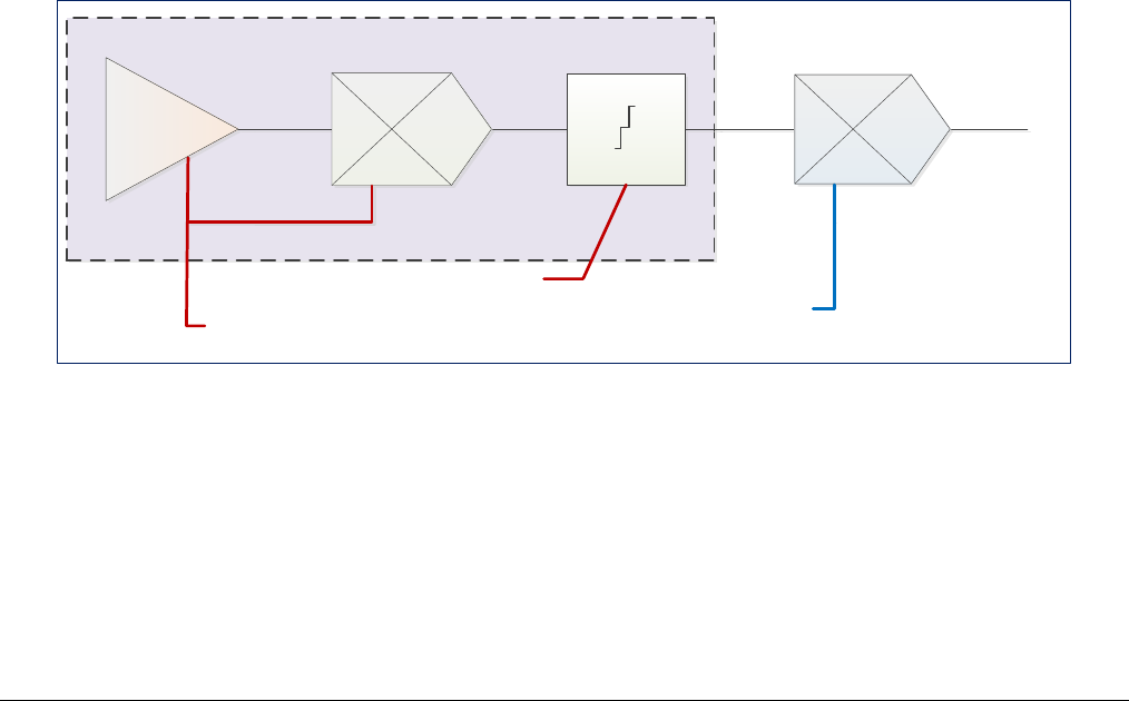
Nano Series GigE Vision Camera Operational Reference
•
99
Offset/Gain Control Details (Sony sensors)
The Gain and Black level functions are applied at the sensor and/or on the digital image values
output by the sensor, as described below.
• Gain Selector = Sensor: The gain function is a linear multiplier control in 0.01 steps within
the sensor hardware (range is “1-251”, which is a +48dB maximum gain).
• Gain: Sensor gain is applied first by an analog amplifier (multiplier range of “1-15.85”,
i.e. +24dB) and then continues automatically via a digital amplifier as shown in the graphic
below.
• Important: Digital noise increases linearly and quickly with higher gain values. Users should
evaluate image quality with added gain.
• Gain (Raw): Provides an alternative method to control sensor gain, where values entered are
in 0.1dB increments. Therefore the range is 0 to 480 which controls a 0 to 48dB gain range.
• Gain Selector = Digital: The gain function controls the post sensor digital amplifier (available
only on some models of Nano cameras). This gain factor is independent of any sensor gain set.
This setting is a linear multiplying number of 1 to 4, in 0.1 steps).
• Black Level: This offset variable exists within the sensor. The Sony sensors allow an offset
range between 0 and 511 DN. The factory settings default value for each sensor used by
various Nano models, is recommended as per the sensor manufacturer design specifications.
Note: With the factory default offset, testing a camera’s black output in 8-bit mode may show
a 2 DN value difference across the image. Changing the Black Level value up or down will push
sensor noise (present at the sensors native bits per pixel) to fall within one 8-bit value, thus the
noise becomes hidden.
Sony Sensors Gain Stage Diagram
Sensor Gain Control Post Digital Gain Control
Sony Sensor Gain Stages
Analog Digital
Black Level
Control
Digital
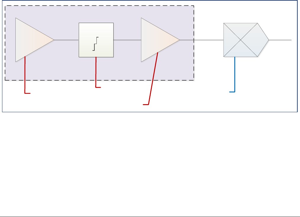
100
•
Operational Reference Nano Series GigE Vision Camera
Offset/Gain Control Details (On-Semi Python sensors)
The Gain and Black level functions are applied at the sensor and/or on the digital image values
output by the sensor, as described below.
• Gain Selector = Sensor Analog: The gain function is a linear multiplier control in 0.01 steps
within the sensor hardware (Gain range is “1-8”, which is a +18dB gain).
• Gain Selector = Sensor Digital: The gain function is a linear multiplier control in 0.01 steps
within the sensor hardware (Gain range is “1-31.99”, which is +30dB gain).
• Important: Digital noise increases linearly and quickly with higher gain values. Users should
evaluate image quality with added gain.
• Gain (Raw): Shows the raw sensor control for each gain stage or an alternative method to
control sensor gain.
• Black Level: This offset variable exists within the sensor. The On-Semi sensors allow an offset
range between 0 and 255 DN. The factory settings default value for each sensor used by
various Nano models, is recommended as per the sensor manufacturer design specifications.
Note: With the factory default offset, testing a camera’s black output in 8-bit mode may show
a 2 DN value difference across the image. Changing the Black Level value up or down will push
sensor noise (present at the sensors native bits per pixel) to fall within one 8-bit value, thus the
noise becomes hidden.
On-Semi Python Sensors Gain Stage Diagram
Analog Gain Control Post Digital Gain Control
On-Semi Sensor Gain Stages
Analog
Black Level
Control
Digital
Digital
Digital Gain Control
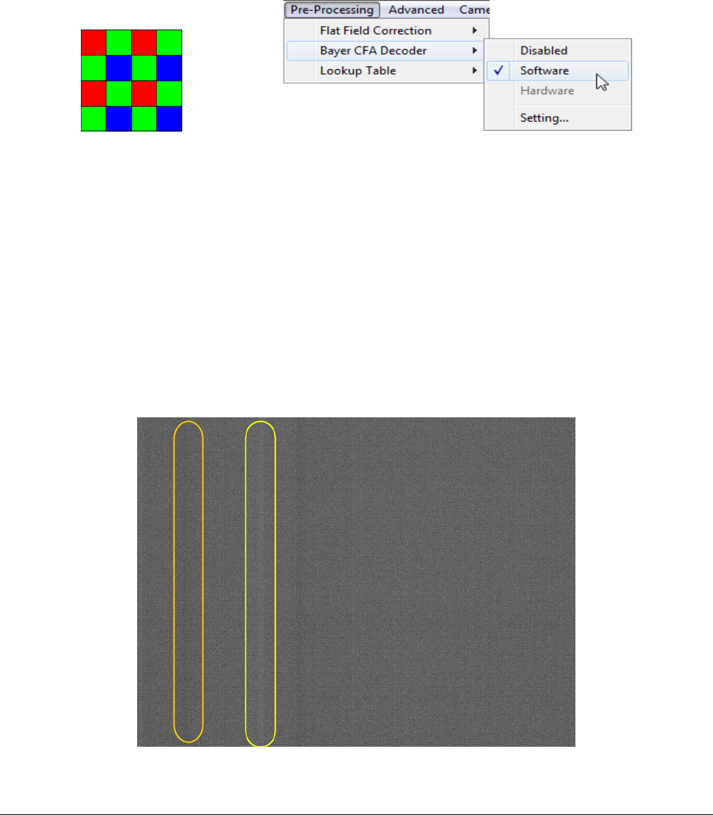
Nano Series GigE Vision Camera Operational Reference
•
101
Bayer Mosaic Pattern
Genie Nano Color cameras output raw Bayer image data using the mosaic pattern shown below.
Teledyne DALSA Sapera CamExpert tool interprets the raw Bayer output when the user enables the
Pre-Processing Software Bayer Decoder. CamExpert also provides an automatic white balance tool
to aid RGB gain adjustments.
Bayer Mosaic Pattern and the CamExpert processing function to decode the Genie Nano Color
OnSemi Python P1 Sensor Artifacts with Fast Readout Mode
Nano OnSemi (Python P1) sensor camera models with Fast Readout mode active have the row
blanking and row readout occur in parallel in the sensor. This reduces the total frame readout time
resulting in a faster maximum frame rate. As a consequence there are minor column artifacts (of
very low DN) which are typically of no significance and irrelevant for many imaging systems. Note
that these column artifacts will become more prominent as sensor gain is increased.
The image below shows a “dark” capture with Fast Readout Mode enabled and analog gain set to
maximum (8x). The artifacts will become visible as fixed pattern DN column variations near the left
edge of the video frame. There are darker columns followed by lighter columns as marked by the
overlay graphics. These DN variations are not random columns, but consistent between individual
OnSemi sensors operating in Fast Readout mode with high gain.

102
•
Operational Reference Nano Series GigE Vision Camera
Fast Readout Mode Artifacts Correction
With all Nano OnSemi sensor models: A simple software host based “Flat Line” correction available
with Sapera LT, can be used to eliminate this Fast Readout Mode artifact. Users can test this with
the Sapera CamExpert tool. Refer to the manual (Sapera Getting Started – Cameras) for
instructions in calibrating and using the software based Flat Line correction.
With specifically the NanoXL models: Enable the camera based Flat Line features as described in
the Flat Field Correction Category.
Alternatively for maximum acquisition quality, disable Fast Readout Mode to eliminate
acquisition DN variances, at a small reduction of the maximum frame rate. Also remember that
high gain settings will increase overall sensor noise therefore additional gain should be used only
as necessary.
Exposure Alignment: Overview
Exposure Control modes define the method and timing of controlling the sensor integration period.
The integration period is the amount of time the sensor is exposed to incoming light before the
video frame data is transmitted to the controlling computer.
• Exposure control is defined as the start of exposure and exposure duration.
• The feature Exposure Mode selects the controlling method for the exposure.
• The start of exposure is initiated by an internal timer signal, an external input trigger signal
(Trigger Mode=ON), or a software function call.
• The exposure duration can be programmable (Exposure Mode = Timed, free run or external
trigger) or controlled by the external input trigger pulse width (Exposure Mode = TriggerWidth).
Note that different Nano models will support different combinations of exposure controls.
See also Trigger Overlap: Feature Details.
Synchronous Exposure Alignment
Exposure is synchronous to the internal timing of the sensor. The readout is concurrent to the
exposure for the fastest possible frame rate.
When a valid trigger is received and the Exposure Time is shorter than the readout period, the
Exposure Start event is latched in the previous frame’s readout. That is; the Exposure Start Event
is delayed and is initiated when the actual exposure starts such that the exposure ends and
readout begins as soon as the previous readout has completed.
• For Sony sensor models the exposure is synchronous to the line timing of the sensor. The frame
exposure start is subject to 1 horizontal line jitter.
• Sony sensors also add an extra two line-time at the end of exposure. For short very exposures
the starting jitter and ending extension will be significant.
• The programmable exposure duration is in 1µs steps.
• Exposure duration is from a camera sensor specific minimum (in µs) up to 16 sec.
• Any trigger received before the start of frame readout is ignored and generates an invalid frame
trigger event.
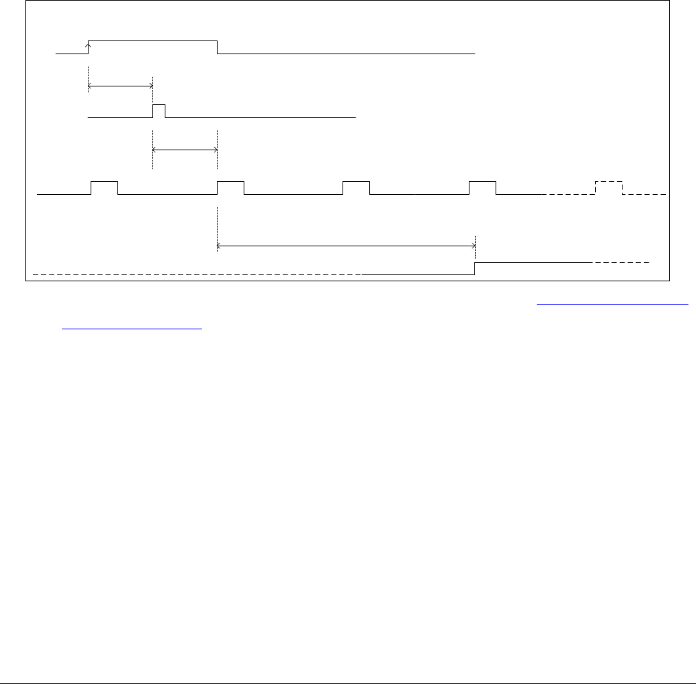
Nano Series GigE Vision Camera Operational Reference
•
103
Reset Exposure Alignment
Sensor timing is reset to initiate exposure when a valid trigger is received. Readout is sequential to
exposure, reducing the maximum achievable frame rates. That is, a trigger received during
exposure or readout is ignored since data would be lost by performing a reset.
Sensor Exposure Timing: Sony Sensor Models
Nano cameras with Sony sensors have general timing characteristics using synchronous exposure
mode, as described below.
Trigger Characteristics: Start of Exposure
External
Trigger Input
Input propagation Delay (see Input Signals Electrical Specifications)
Internal Trigger Control
Delay to Next Horizontal Time (delay jitter)
Re-alignment delay is maximum
of 1 Horizontal Line Time
Internal Continuous Horizontal Line Time Clock
Actual Sensor Exposure Start Delay
after 2 H -Time
<< Exposure Active >>
Sensor Exposure
Start of Exposure Details
for Nano Sony Sensor Models
rising edge active
Additional triggered exposure mode features and timing are described in the I/O Controls Category.
Refer to Model Part Numbers for the available Nano models using Sony sensors and their timing
specifications.
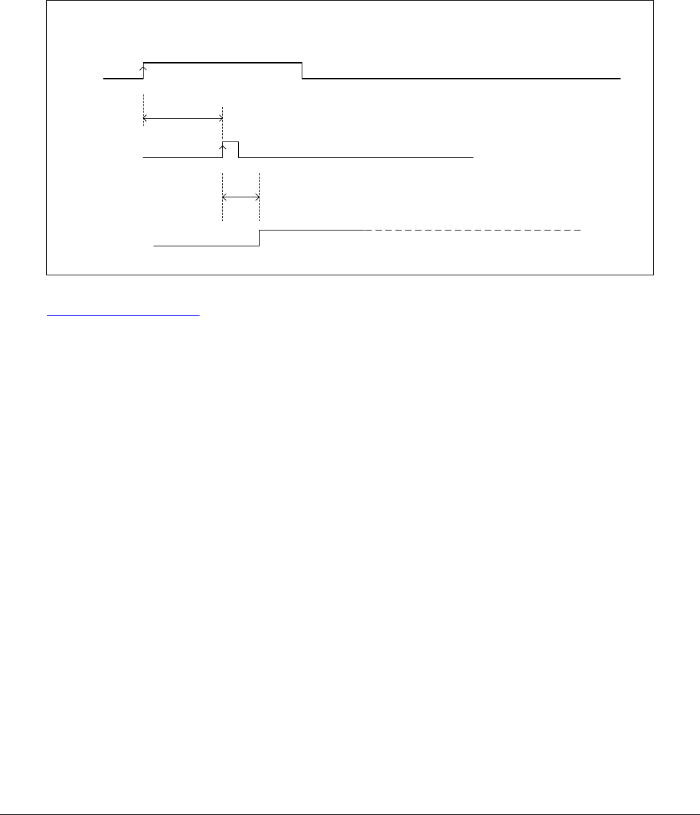
104
•
Operational Reference Nano Series GigE Vision Camera
Sensor Exposure Timing: OnSemi Python Models
Nano cameras with OnSemi sensors have general timing characteristics as described below.
Trigger Characteristics: Start of Exposure
External
Trigger Input
Input propagation Delay (see Input Signals Electrical Specifications)
Internal Trigger Control
<< Exposure Active >>
Start of Exposure Details
for Nano Models using OnSemi Python
rising edge active
Internal Delay (exposureAlignment = Reset or Synchronous With No Overlap)
Internal Delay (exposureAlignment = Synchronous With Overlap)
Additional triggered exposure mode features and timing specific to OnSemi sensors are described
in the I/O Controls Category.
See sections, Model Specifications: M/C640, M/C800, M/C1280, M/C1930, M/C2590 for specific
timing values.

Nano Series GigE Vision Camera Operational Reference
•
105
Auto-Brightness Control Category
The Genie Nano Auto-Brightness controls, as shown by CamExpert as a sub group to Sensor
Controls, has features used to configure the automatic gain function. Parameters in gray are read
only, either always or due to another parameter being disabled. Parameters in black are user set in
CamExpert or programmable via an imaging application.
Features listed in the description table but tagged as Invisible are usually for Teledyne DALSA or
third party software usage—not typically needed by end user applications. Also important, Genie
Nano cameras are available in a number of models implementing different sensors which may
support different features or none from this category.
Auto-Brightness Feature Descriptions
The following table describes these features along with their view attribute and device version. For
each feature the device version may differ for different camera sensors as they become available.
When a Device Version number is indicated, this represents the camera software functional group,
not a firmware revision number. As Genie Nano capabilities evolve the device version will increase,
therefore identifying the supported function package. New features for a major device version
release will be indicated by green text for easy identification.
Features are common for all Nano models unless indicated otherwise. Additionally the description
column will indicate which feature is a member of the DALSA Features Naming Convention
(indicated by DFNC), versus the GenICam Standard Features Naming Convention (SFNC tag is not
shown).
Note: Auto-Brightness not supported with model C4900 (18M Rolling Shutter).

106
•
Operational Reference Nano Series GigE Vision Camera
Display Name Feature & Values Description Device
Version
Auto-Brightness Mode autoBrightnessMode Sets the mode for the Auto-Brightness function. 1.04
Expert
DFNC
Off Off Disable the auto-brightness mode.
Active Active Activates the auto-brightness mode when the
AcquisitionStart or AcquisitionArm command is
received.
Auto-Brightness
Sequence autoBrightnessSequence Specifies the processing order for the auto-
brightness algorithm. Gain and Exposure are
adjusted sequentially, in the selected order, to
achieve the auto-brightness target value. If the
Gain or Exposure features are not available or
disabled, that feature is ignored in the processing
sequence.
< DFNC Expert >
1.04
Expert
DFNC
Exposure \ Gain Exposure_Gain_Iris Adjust Exposure, Gain, in that order to achieve
the auto-brightness target value.
Gain \ Exposure Gain_Exposure_Iris Adjust Gain, Exposure, in that order, to achieve
the auto-brightness target value.
Auto-Brightness Target
Source autoBrightnessTargetSource Specifies the source image color plane(s) used by
the Auto-Brightness algorithm to determine the
brightness adjustment required to obtain the
auto-brightness target value.
1.04
Expert
DFNC
Luminance Luminance The luminance or Y component of the image is
used as the auto-brightness target source.
Raw Bayer Pattern RawBayerPattern The Raw Bayer Pattern of the image is used as
the auto-brightness target source.
Auto-Brightness Target autoBrightnessTarget Sets the target image grayscale value, in DN, for
the auto-brightness algorithm. Features that use
auto-brightness include ExposureAuto, and
GainAuto.
1.04
Expert
DFNC
Auto-Brightness Target
Variation autoBrightnessTargetRangeVariation Sets the auto-brightness target Range Variation in
(DN). An autoBrightnessTarget value within this
range is considered valid and will not be
compensated.
1.04
Expert
DFNC
Auto-Brightness
Algorithm autoBrightnessAlgorithm Specifies the auto-brightness algorithm used to
calculate the brightness in the target image
source plane(s).
1.04
Expert
DFNC
Average Average The auto-brightness algorithm calculates the
average luminance from the camera image and
determines if the brightness should increase or
decrease based on the requested target
brightness.
Auto-Brightness
Minimum Time
Activation
autoBrightnessAlgoMinTimeActivation Specifies the time delay between an image
brightness change from the autoBrightnessTarget
and when compensation of Gain/Exposure starts.
This eliminates repetitive adjustments of short
term brightness variations.
1.04
Expert
DFNC
Auto-Brightness
Convergence Time autoBrightnessAlgoConvergenceTime Specifies the maximum time the
autoBrightnessAlgorithm should take to
compensate the image brightness as defined by
the autoBrightnessTarget. Actual times typically
are less but may on occasion be more.
1.04
Expert
DFNC
Auto-Exposure ExposureAuto Sets the automatic exposure mode when the
ExposureMode feature is set to Timed. 1.04
Expert
Off Off Exposure duration is manually controlled using
the ExposureTime feature.
Continuous Continuous Exposure duration is constantly adapted by the
camera to meet the auto-brightness target pixel
value.

Nano Series GigE Vision Camera Operational Reference
•
107
Auto-Exposure Time Min
Value exposureAutoMinValue Sets the minimum exposure time value allowed
by the user, in microseconds, for the Auto-
Exposure function.
1.04
Expert
DFNC
Auto-Exposure Time
Max Value exposureAutoMaxValue Sets the maximum exposure time value allowed
by the user, in microseconds, for the Auto-
Exposure function.
1.04
Expert
DFNC
Automatic Gain Control GainAuto Controls the state of the automatic gain control. 1.04
Expert
Off Off Gain is manually controlled using the Gain
feature.
Continuous Continuous Gain is constantly adjusted by the camera to
meet the auto-brightness target pixel value. The
initial starting gain can be set by setting GainAuto
to Off, changing the gain value and then setting it
back to Continuous.
Auto-Gain Source gainAutoSource Selects the gain to control. 1.06
Expert
Digital DigitalAll Digital
Sensor SensorAll Sensor (available in some models)
Auto-Gain Max Value gainAutoMaxValue Sets the maximum gain multiplier value for the
automatic gain algorithm. The automatic gain
function is an amplification factor applied to the
video signal to obtain the auto-brightness target
value.
1.04
Expert
DFNC
Auto-Gain Min Value gainAutoMinValue Sets the minimum gain multiplier value for the
automatic gain algorithm. The automatic gain
function is an amplification factor applied to the
video signal to obtain the auto-brightness target
value.
1.04
Expert
DFNC
Auto-Brightness
Algorithm Source autoBrightnessAlgoSource Specifies the source location of the Auto-
Brightness algorithm. 1.04
Invisible
DFNC
Local Local The auto-brightness algorithm runs in the
camera.
Ethernet Host The auto-brightness algorithm runs on a host
machine via the Ethernet connection.
Using Auto-Brightness
The Auto-Brightness features are designed to maintain consistent brightness (or image intensity) in
situations where lighting varies. These features benefit from being optimized for each applications
lighting. The information below describes making these adjustments and the feature
interdependencies. All feature example settings and acquisitions examples below are made using
the Sapera CamExpert tool.
Important: Setup is critical. The Auto-Brightness algorithm cannot converge unless control
features are set properly (as required by the imaging situation). The following cases describe
simple setups and the control feature considerations required to make them work.
General Preparation
• Before using any controls, a simple setup for experimentation is to have a reasonable free
running acquisition of n-frames per second (AcquisitionFrameRate) and an exposure time
(ExposureTime) that provides a viewable image.
• Take note of the frame rate and exposure time. If the frame rate is very slow due to a long
exposure, add analog gain (GainSelector and Gain) and adjust the exposure time again.
• Enable all Auto-Brightness features by setting autoBrightnessMode to active (live acquisition
must be off). This master feature only activates the auto-brightness, auto-exposure, and auto-
gain controls but doesn’t enable the processing.

108
•
Operational Reference Nano Series GigE Vision Camera
• The features autoBrightnessSequence, autoBrightnessTargetSource, autoBrightnessTarget,
autoBrightnessTargetRangeVariation, and autoBrightnessAlgorithm can remain at their default
settings for this demo.
• Note that the Auto-Brightness function is not available if “Cycling Mode” is active.
The Auto-Brightness examples below are summarized as follows:
• Auto-Brightness by Frame Luminance Averaging
• Auto-Brightness by Adjusting a Digital Gain
• Auto-Brightness by Adjusting both Gain and Exposure
Auto-Brightness with Frame Luminance Averaging
After the preparations described above, the Auto-Exposure function is tested as follows. These
setup steps are made before doing a live acquisition.
• Set the autoBrightnessAlgoConvergenceTime to a larger value than the default 2 seconds if
more time is required to ensure adequate time for convergence.
• Set ExposureAuto to Continuous to activate all Auto-exposure features.
• Referring to the ExposureTime value used to get a viewable image during the free-running
preparation stage, set exposureAutoMaxValue to a maximum exposure time longer than was
needed. This maximum exposure limit feature may be required in imaging situations where the
frame rate must not be forced below some minimum value. Also check that
exposureAutoMinValue is low enough to allow the auto exposure a wide range to function in
(but not too low else the algorithm will undershoot).
• Enable live acquisition (Grab button in CamExpert). The image exposure will adjust itself until
the autoBrightnessTarget value is achieved. During live acquisition, the autoBrightnessTarget
value can be changed to observe the algorithm converge to the new luminance value.
• Stop live acquisition (Freeze button in CamExpert). The feature ExposureTime is updated with
the last exposure time used by the auto exposure algorithm. Adjust frame rate and analog gain
settings as required to test again. Adjust other features mentioned as required.
Auto-Gain
An alternative method of automating exposure control is by varying the Nano Digital Gain. The user
needs to note that the digital gain stage is limited to a small positive multiplier and will have the
side effect of increasing digital noise.
• Setup will be similar to using auto exposure alone.
• Enable automatic digital gain by setting the feature GainAuto to Continuous.
• Limit the total digital gain range by adjusting the values for gainAutoMaxValue and
gainAutoMinValue.
Auto-Brightness by using Auto-Exposure and Auto-Gain
• Use both ExposureAuto and GainAuto together to maximize the range of the Auto-Brightness
range.
• Use autoBrightnessSequence to select the order of automation.
• Caution: Even with both automatic functions enabled, exposure convergence to a target value
requires proper setup.
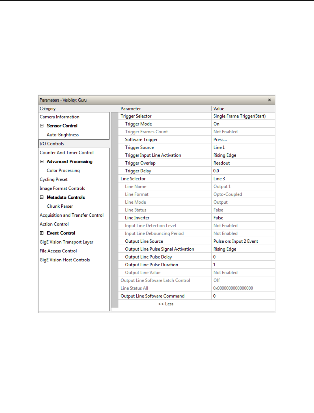
Nano Series GigE Vision Camera Operational Reference
•
109
I/O Control Category
The Genie Nano I/O controls, as shown by CamExpert, has features used to configure external
inputs and acquisition actions based on those inputs, plus camera output signals to other devices.
Parameters in gray are read only, either always or due to another parameter being disabled.
Parameters in black are user set in CamExpert or programmable via an imaging application.
Features listed in the description table but tagged as Invisible are usually for Teledyne DALSA or
third party software usage—not typically needed by end user applications. Also important, Genie
Nano cameras are available in a number of models implementing different sensors which may
support different features within this category.

110
•
Operational Reference Nano Series GigE Vision Camera
I/O Control Feature Descriptions
The following table describes these features along with their view attribute and minimum camera
firmware version required. Additionally the Device Version column will indicate which parameter is
a member of the DALSA Features Naming Convention (indicated by DFNC), versus the GenICam
Standard Features Naming Convention (SFNC tag is not shown).
The Device Version number represents the camera software functional group, not a firmware
revision number. As Genie Nano capabilities evolve the device version tag will increase, therefore
identifying the supported function package. New features for a major device version release will be
indicated by green text for easy identification.
Display Name Feature & Values Description Device
Version
& View
Trigger Selector TriggerSelector Selects which type of trigger to configure with the
various Trigger features.
1.00
Beginner
Single Frame Trigger(Start) FrameStart Selects a trigger starting the capture of a single
frame. Frame size is determined by image format
feature “Height”.
MultiFrame Trigger(Start) FrameBurstStart Selects a trigger to capture multiple frames. The
number of frames is specified by the
“triggerFrameCount” feature.
AcquisitionStart
Trigger(Start) AcquisitionStart Enables the selection of a trigger source that starts
the Acquisition of one or many frames. (Ver.1.05)
Trigger Mode TriggerMode Controls the enable state of the selected trigger.
1.00
Beginner
Off Off The selected trigger is turned off.
On On The selected trigger is turned active.
Trigger Frames Count triggerFrameCount Sets the total number of frames to acquire when a
valid trigger is received. This feature is available
when Trigger Selector = MultiFrame Trigger(Start).
1.00
DFNC
Beginner
Software Trigger TriggerSoftware Generate a software command internal trigger
immediately no matter what the TriggerSource
feature is set to.
1.00
Beginner
Trigger Source TriggerSource Specifies the internal signal or physical input line to
use as the trigger source. The selected trigger
must have its TriggerMode set to ON.
See Input Signals Electrical Specifications.
1.00
Beginner
Line 1 Line1 Select Line 1 (and associated I/O control block) to
use as the external trigger source. See
LineSelector feature for complete list.
Line 2 Line2 Select Line 2 (and associated I/O control block) to
use as the external trigger source. See
LineSelector feature for complete list.
Software Software The trigger command source is only generated by
software using the Trigger Software command.
Action 1 Action1 Select the GigEVision Action Command 1 as the
internal trigger source. This is a broadcast
command that multiple devices can respond to
simultaneously. (Ver. 1.03)
Action 2 Action2 Select the GigEVision Action Command 2 as the
internal trigger source. This is a broadcast
command that multiple devices can respond to
simultaneously. (Ver. 1.05)
Timestamp Modulo Event timestampModuloEvent Select the timestamp modulo event as the internal
trigger source. (Ver. 1.03)
Timer1End Event Timer1End Select the TimerEnd Event as the internal trigger
source.

Nano Series GigE Vision Camera Operational Reference
•
111
Counter1End Event Counter1End Select the CounterEnd Event as the internal trigger
source.
Trigger Input Line Activation TriggerActivation Select the activation mode for the selected Input
Line trigger source. This is applicable only for
external line inputs.
1.00
Beginner
Rising Edge RisingEdge The trigger is considered valid on the rising edge of
the line source signal (after any processing by the
line inverter module).
Falling Edge FallingEdge The trigger is considered valid on the falling edge
of the line source signal (after any processing by
the line inverter module).
Any Edge AnyEdge The trigger is considered valid on any edge of the
line source signal (after any processing by the line
inverter module).
Level High LevelHigh The trigger is considered valid on the high level of
the line source signal.
Level Low LevelLow The trigger is considered valid on the low level of
the line source signal.
Trigger Delay TriggerDelay Specifies the delay in microseconds to apply after
receiving the trigger and before activating the
triggerEvent. (min=0, max=2000000)
1.00
Beginner
Trigger Overlap TriggerOverlap States if a trigger overlap is permitted with the
Active Frame readout signal. This feature defines if
a new valid trigger will be accepted (or latched) for
a new frame.
1.00
Guru
Off Off No trigger overlap is permitted.
ReadOut ReadOut Trigger is accepted immediately after the start of
the readout.
End Of Exposure EndOfExposure Trigger is accepted immediately after the previous
exposure period. This will latch the Trigger and
delay the Exposure if the end of that exposure is
shorter than the previous readout.
Line Selector LineSelector Selects the physical line (or pin) of the external
device connector to configure.
1.00
Beginner
Line 1 Line1 Index of the physical line and associated I/O
control block to use. Pin 5 is the Input Signal and
Pin 3 is the common Ground on the I/O connector.
Line 2 Line2 Index of the physical line and associated I/O
control block to use. Pin 7 is the Input Signal and
Pin 3 is the common Ground on the I/O connector.
Line 3 Line3 Index of the physical line and associated I/O
control block to use. Pin 6 is the Output Signal and
Pin 4 is the common output power on the I/O
connector.
Line 4 Line4 Index of the physical line and associated I/O
control block to use. Pin 8 is the Output Signal and
Pin 4 is the common output power on the I/O
connector.
Line 5 Line5 (Optional Model – see Output3 below) Index of the
physical line and associated I/O control block to
use. Pin 9 is the Output Signal and Pin 4 is the
common output power on the I/O connector.
Line Name lineName Description of the physical Pin associated with the
logical line.
1.00
Beginner
DFNC
Input 1
Input 2 Input1
Input2 Associated with the logical line Input 1
Associated with the logical line Input 2
* “G3-GM2… or G3-GC2…” part numbers denote
optional “1 input / 3 output” special order models.
Output 1
Output 2
Output 3
Output1
Output2
Output3
Associated with the logical line Output 1
Associated with the logical line Output 2
* “G3-GM2… or G3-GC2…” part numbers denote
optional “1 input / 3 output” special order models.

112
•
Operational Reference Nano Series GigE Vision Camera
Line Format LineFormat Specify the current electrical format of the selected
physical input or output. (RO)
1.00
Expert
Opto-Coupled OptoCoupled The line is opto-Coupled.
Line Mode LineMode Reports if the physical Line is an Input or Output
signal. (RO)
See Input Signals Electrical Specifications.
See Output Signals Electrical Specifications.
1.00
Expert
Input Input The line is an input line.
Output Output The line is an output line.
Line Status LineStatus Returns the current status of the selected input or
output line.
1.00
Expert
False
The Line is logic LOW
True The Line is logic HIGH
Line Status All LineStatusAll Returns the current status of all available line
signals, at time of polling, in a single bitfield. The
order is Line1, Line2, Line3, ...
1.00
Expert
Line Inverter LineInverter Control to invert the polarity of the selected input
or output line signal.
1.00
Beginner
False / True
Input Line Detection Level lineDetectionLevel Specifies the voltage threshold required to
recognize a signal transition on an input line.
1.00
Beginner
DFNC
Threshold for TTL Threshold_for_TTL A signal below 0.8V will be detected as a Logical
LOW and a signal greater than 2.4V will be
detected as a Logical HIGH on the selected input
line.
Input Line Debouncing
Period lineDebouncingPeriod Specifies the minimum delay before an input line
voltage transition is recognizing as a signal
transition.
1.00
Beginner
DFNC
Output Line Source outputLineSource Selects which internal signal or event driven pulse
or software control state to output on the selected
line. Note, the LineMode feature must be set to
Output. The List of supported output line sources is
product-specific. The Event Control section
provides details and timing diagrams for the
supported trigger modes.
1.00
Beginner
DFNC
Off Off Line output is Open
Software Controlled SoftwareControlled The OutputLineValue feature changes the state of
the output
Pulse on: Start of Frame PulseOnStartofFrame Generate a pulse on the start of the Frame Active
event
Pulse on: Start of Exposure PulseOnStartofExposure Generate a pulse on the ExposureStart event. This
option is typically used to trigger a strobe light.
Pulse on: End of Exposure PulseOnEndofExposure Generate a pulse on the ExposureEnd event. This
option is typically used to trigger a strobe light.
(N/A for C4900 – 1.06)
Pulse on: Start of Readout PulseOnStartofReadout Generate a pulse on the ReadoutStart event.
Pulse on: End of Readout PulseOnEndofReadout Generate a pulse on the ReadoutEnd event.
Pulse on: Valid Frame
Trigger PulseOnValidFrameTrigger Generate a pulse on the ValidFrameTrigger event.
Pulse on: Rejected Frame(s)
Trigger PulseOnInvalidFrameTrigger Generate a pulse on the InvalidFrameTrigger
event.
Pulse on: Start of Acquisition PulseOnStartofAcquisition Generate a pulse when the AcquisiontStart event
occurs.
Pulse on: End of Acquisition PulseOnEndofAcquisition Generate a pulse when the AcquisiontStop event
occurs.
Pulse on: End of Timer 1 PulseOnEndofTimer1 Generate a pulse on the TimerEnd 1 event.
Pulse on: End of Counter 1 PulseOnEndofCounter1 Generate a pulse on the CounterEnd 1 event.
Pulse on: Input 1 Event PulseOnInput1 Generate a pulse on the Input signal 1 event
Pulse on: Input 2 Event PulseOnInput2 Generate a pulse on the Input signal 2 event

Nano Series GigE Vision Camera Operational Reference
•
113
Pulse on: Action 1 PulseOnAction1 Generate a pulse on the
GigEVision Action Command 1. (ver:1.03)
Pulse on: Action 2 PulseOnAction2 Generate a pulse on the
GigEVision Action Command 2. (ver:1.03)
Pulse on: Software
Command PulseOnSoftwareCmd Generate a pulse on the Input of a Software
Command
Exposure Active ExposureActive Generate a signal that is active when the Exposure
is active. <from v1.01> (N/A for C4900 – 1.06)
Output Line Pulse Signal
Activation outputLinePulseActivation Specifies the input line activation mode to trigger
the OutputLine pulse.
1.00
Beginner
DFNC
Rising Edge RisingEdge Specifies that the trigger is considered valid on the
rising edge of the source signal.
Falling Edge FallingEdge Specifies that the trigger is considered valid on the
falling edge of the source signal.
Any Edge AnyEdge Specifies that the trigger is considered valid on the
falling or rising edge of the source signal.
Output Line Pulse Delay outputLinePulseDelay Sets the delay (in µs) before the output line pulse
signal. Applicable for the OutputLineSource
feature.
1.00
Beginner
DFNC
Output Line Pulse Duration outputLinePulseDuration Sets the width (duration) of the output line pulse in
microseconds.
1.00
Beginner
DFNC
Output Line Value outputLineValue Sets the output state of the selected Line if the
outputLineSoftwareLatchControl = OFF.
OutputLineSource must be SoftwareControlled. If
the outputLineSoftwareLatchControl = Latch , the
state of the pin will change with the
outputLineSoftwareCmd command.
1.00
Beginner
DFNC
Active Active Sets the Output circuit to close
Inactive Inactive Sets the Output circuit to open
Output Line Software Latch
Control outputLineSoftwareLatchControl When Off, the selected output line is set with the
value in Output Line Value.
1.00
Guru
DFNC
Off Off Output pin state set by outputLineValue.
Latch Latch Output pin state set by outputLineSoftwareCmd.
Flash Zone Delay flashZoneDelay Returns the recommended output pulse delay,
corresponding to the delay of the last line exposure
start of a rolling shutter sensor, when the Output
Line Source = Pulse on Start of Exposure. (RO)
1.06
Guru
DFNC
Model C4900
Flash Zone Duration flashZoneDuration Returns the recommended output pulse duration
for controlling a flash device for the optimal flash
zone time. (RO)
1.06
Guru
DFNC
Model C4900
Output Line Software
Command outputLineSoftwareCmd Writing a value of 1 in the bit field applies the
Latch value of the outputLineSoftwareLatchControl
and/or executes the PulseOnSoftwareCmd for any
output line programmed for software control. The
feature outputLineSoftwareCmd can take any
binary value and each bit set to 1 corresponds to a
Icommand for an Output. Note that Outputs are
numbered from 1 to N, therefore Bit 1 of
outputLineSoftwareCmd corresponds to Output1.
This is applicable to OutputLineSource = Pulse On:
where Software Cmd (for Pulse mode) or
OutputLineSource = SoftwareControlled and
OutputLineSoftwareLatchControl = Latch (for static
states).
1.00
Expert
DFNC
Line Pinout linePinAssociation Enumeration of the physical line (or pin) on the
device I/O connector. (RO)
1.00
Invisible
Pin5=Signal – Pin3=Gnd Pin5Signal_Pin3Gnd Pin 5 is the Input Signal and Pin 3 is the common
input Ground on the I/O connector.
Pin7=Signal – Pin3=Gnd Pin7Signal_Pin3Gnd Pin 7 is the Input Signal and Pin 3 is the common
input Ground on the I/O connector.
Pin6=Signal – Pin4=Pwr Pin6Signal_Pin4Pwr Pin 6 is the Output Signal and Pin 4 is the common
output Power on the device connector.
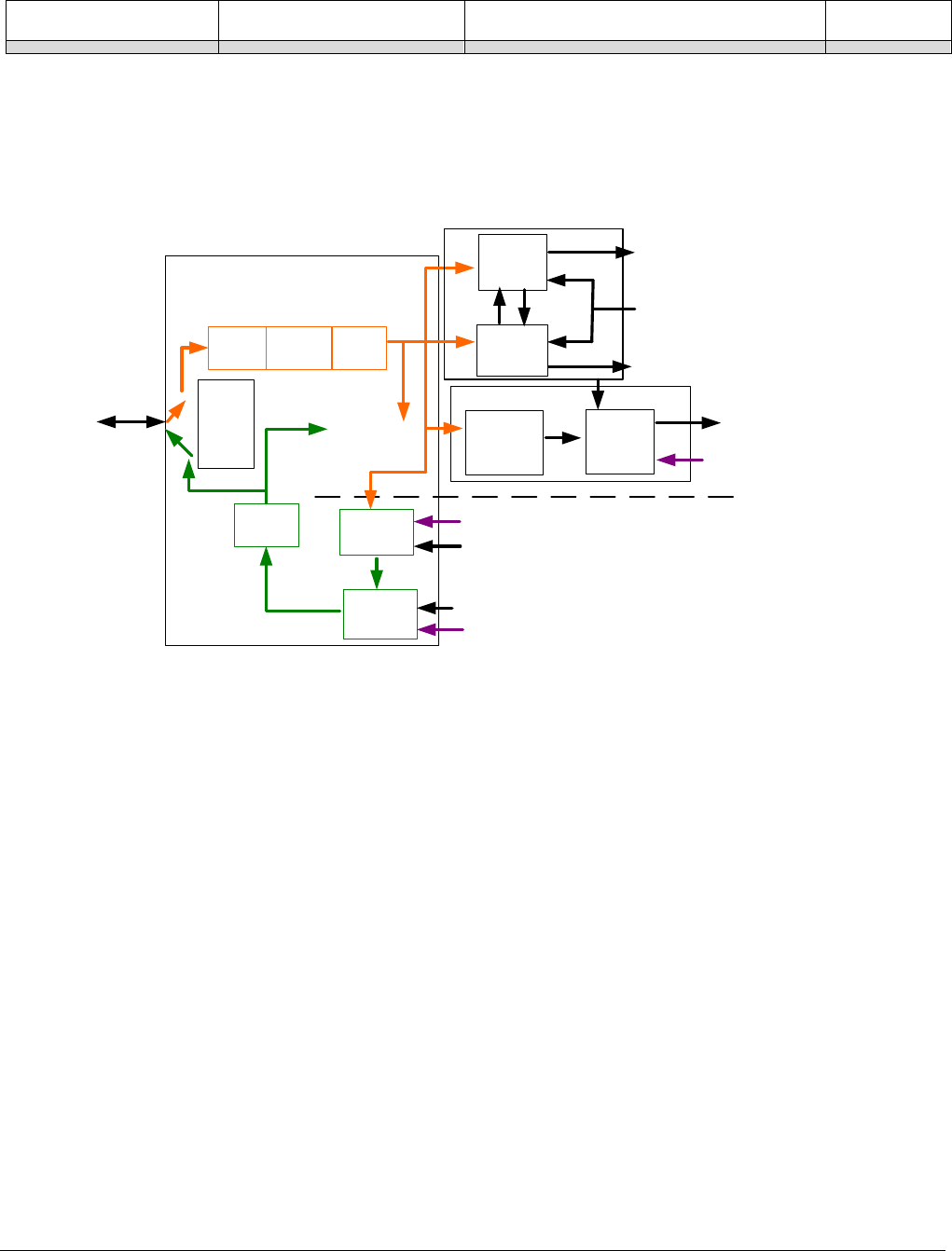
114
•
Operational Reference Nano Series GigE Vision Camera
Pin8=Signal – Pin4=Pwr Pin8Signal_Pin4Pwr Pin 8 is the Output2 Signal and Pin 4 is the
common output Power on the device connector.
I/O Module Block Diagram
Line Selector =
Line 1 to 4
Physical
Line
Event Driven
Input
inverter
Output
inverter Software Driven
Pulse
generator
LineStatus Trigger
Line
Activation
Trigger Signal
Timer TimerEnd Event
CounterEnd Event
Software Trigger
Cmd
Line
Mode
Input
or
ouput
Input
Output
Timer and Counter Module
Counter
Line
Debouncer
Event Driven
Trigger
Source
Trigger Module
Output
Line
Source
Signal Driven
Software Driven
Line
Detection
Level
Trigger Mode Details
Genie Nano image exposures are initiated by an event. The trigger event is either the camera’s
programmable internal clock used in free running mode, an external input used for synchronizing
exposures to external triggers, or a programmed function call message by the controlling
computer. These triggering modes are described below.
• Free running (Trigger Mode=Off): The Nano free-running mode has programmable internal
timers for frame rate and exposure period. Frame rate minimums, maximums, and increments
supported are sensor specific. Maximum frame rates are dependent on the required exposure.
• External trigger (Trigger Mode=On): Exposures are controlled by an external trigger signal
where the specific input line is selected by the Trigger Source feature. External signals are
isolated by an opto-coupler input with a time programmable debounce circuit.
Trigger Source Types (Trigger Mode=On)
• Trigger Source=Software: An exposure trigger is sent as a control command via the
Ethernet network connection. Software triggers cannot be considered time accurate due to
network latency and sequential command jitter. But a software trigger is more responsive than
calling a single-frame acquisition since the latter must validate the acquisition parameters and
modify on-board buffer allocation if the buffer size has changed since the last acquisition.
• Trigger Source = Line 1 or 2: An external trigger signal is opto-coupled and subject to a
signal debounce, input delay, plus inversion circuits.

Nano Series GigE Vision Camera Operational Reference
•
115
• Trigger Line Polarity: For external line signals, a rising edge signal is suggested to minimize
the time it takes for the opto-coupler to change state.
• Trigger Source=Timer1End Event: The Timer1 End Event is used as the internal trigger
source. Refer to Counter and Timer Controls for information on those features.
• Trigger Source=Counter1End Event: The Counter1 End Event is used as the internal trigger
source.
Input Line Details
The general purpose input line signals are connected to I/O lines 1 and 2, which have the following
features for control or status indication.
• Feature set: LineSelector (RW), LineName (RO), linePinAssociation (RO), LineFormat (RO),
LineMode (RO), lineDetectionLevel (RW), lineDebouncingPeriod (RW), LineInverter (RW),
LineStatus (RO).
• Connector: See 10-pin I/O Connector Details for connector pinout and electrical information.
The cable shell and shield should electrically connect the Genie Nano chassis to computer
chassis for maximum EMI protection.
• Line Transition Validation: Each input incorporates a signal debounce circuit (following the
opto-couple) to eliminate short noise transitions that could be wrongly interpreted as a valid
pulse. The duration is user-programmable from 0µs to 255µs with CamExpert.
• Line Signal Propagation & Timing: Maximum delay values are defined in Input Signals
Electrical Specifications.
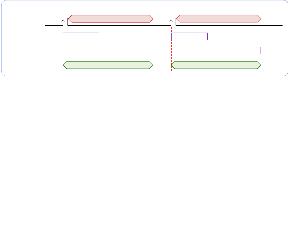
116
•
Operational Reference Nano Series GigE Vision Camera
Trigger Overlap: Feature Details
The Trigger Overlap feature defines how the Nano handles triggers that might occur more
frequently than the Frame Active period (an exposure plus readout period).
If TriggerOverlap=OFF, then triggers received before the end of the Frame Active period are
ignored. Other TriggerOverlap values are dependent on the Nano model and sensor used.
• TriggerOverlap=Off
• No trigger overlap is permitted.
Diagram Conditions:
• TriggerMode=On
• ExposureMode=Timed
• TriggerActivation=RisingEdge
• TriggerDelay=0
• TriggerSelector=FrameStart
• ExposureAlignment=Synchronous
Trigger Input
Trigger Exclusion Period
Exposure 1
Readout 1
Frame 1 Active period
Trigger Exclusion Period
Exposure 2
Readout 2
Frame 2 Active period
Frame Exposure
Frame Readout
TriggerOverlap=Off
Timing specific to OnSemi models
• Minimum Trigger to Exposure start delay: 3.23µs (shown as 4µs)
• Readout Time:
• M/C2590: 23242µs + 16.5µs
• M/C1930: 10831µs + 16.5µs
• M/C1280: 5676µs + 16.5µs
• M/C800: 2332µs + 16.5µs
• M/C640: 1602µs + 16.5µs
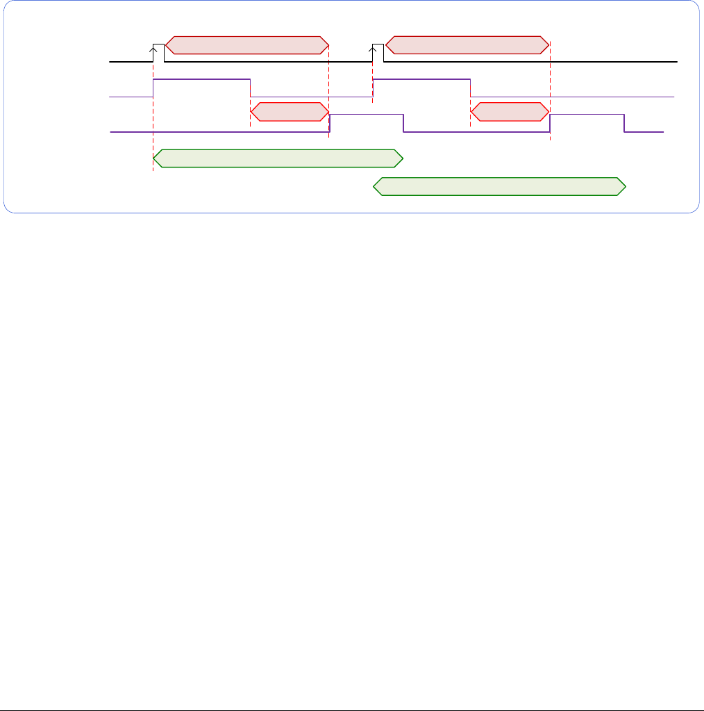
Nano Series GigE Vision Camera Operational Reference
•
117
• TriggerOverlap=ReadOut
• Trigger is accepted at the beginning of the frame Readout. The “End of Exposure to Start of
Readout” time is sensor dependent.
Diagram Conditions:
• TriggerMode=On
• ExposureMode=Timed
• TriggerActivation=RisingEdge
• TriggerDelay=0
• TriggerSelector=FrameStart
• ExposureAlignment=Synchronous
Trigger Input
Trigger Exclusion Period
Exposure 1
Readout 1
Frame 1 Active period
Exposure 2
Readout 2
Frame 2 Active period
Frame Exposure
Frame Readout
TriggerOverlap=Readout
Trigger Exclusion Period
End of Exposure
to Start of Readout
End of Exposure
to Start of Readout
Timing specific to OnSemi models
• Trigger to Exposure start has a delay which includes the sensor readout time plus a
minimum of 62µs. An exposure always starts after the readout of the previous frame.
• Trigger Delay Times (min. with normal ROT):
• M/C2590: 23318µs
• M/C1930: 10907µs
• M/C1280: 5751µs
• M/C800: 2407µs
• M/C640: 1677µs
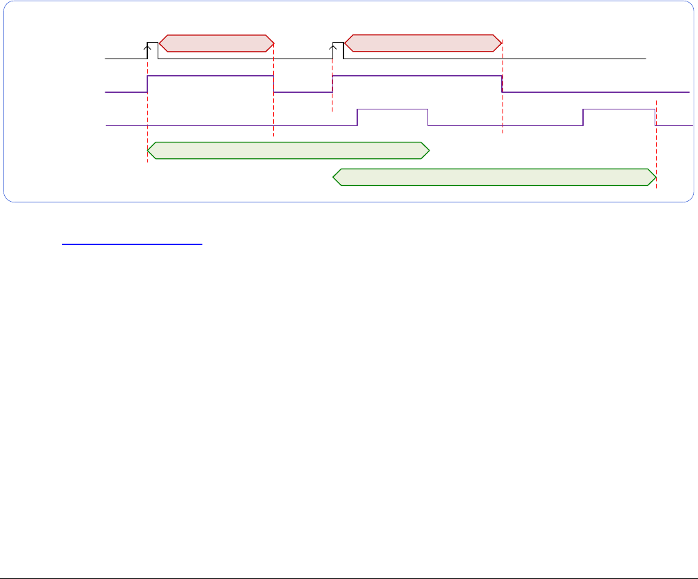
118
•
Operational Reference Nano Series GigE Vision Camera
• TriggerOverlap=EndOfExposure
• Trigger is accepted immediately after the previous exposure period. This will latch the Trigger
and delay the Exposure if the end of that exposure is shorter than the previous readout.
Diagram Conditions:
• TriggerMode=On
• ExposureMode=Timed
• TriggerActivation=RisingEdge
• TriggerDelay=0
• TriggerSelector=FrameStart
• ExposureAlignment=Synchronous
Applicable to current Sony sensor models
Sony sensor Nano models support a maximum trigger rate by allowing a trigger signal soon after
the exposure period. A trigger is accepted and buffered for a 12 line clock period (after the
exclusion period) at which the next exposure starts. As shown in the diagram below, the following
exposure can be active even before the frame readout of the previous exposure.
Trigger Input
Trigger Exclusion Period
Exposure 1
Readout 1
Frame 1 Active period
Exposure 2
Readout 2
Frame 2 Active period
Frame Exposure
Frame Readout
TriggerOverlap=EndOfExposure
Trigger Exclusion Period
Refer to Model Part Numbers for the available Nano models using Sony sensors and their timing
specifications.
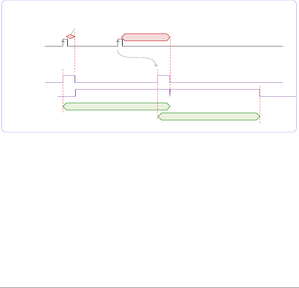
Nano Series GigE Vision Camera Operational Reference
•
119
• TriggerOverlap= EndOfExposure or Readout
• This special condition describes the case of a short exposure relative to the readout period. A
trigger received before the end of the frame readout is latched and delayed until such time that
the following short exposure will end with the end of the previous frame readout. The second
readout period will then start immediately.
Diagram Conditions:
• TriggerMode=On
• ExposureMode=Timed
• TriggerActivation=RisingEdge
• TriggerDelay=0
• TriggerSelector=FrameStart
• ExposureAlignment=Synchronous
Trigger Input
Exposure 1
Readout 1
Frame 1 Active period
Exposure 2
Readout 2
Frame 2 Active period
Frame Exposure
Frame Readout
TriggerOverlap= EndOfExposure or Readout
Trigger Exclusion Period
Trigger Exclusion Period
Trigger Latched
and Delayed
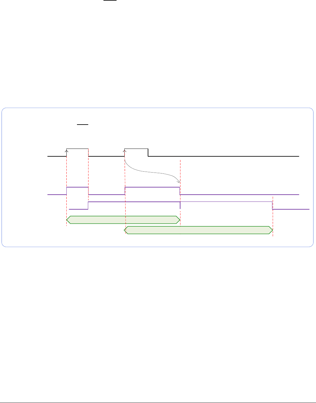
120
•
Operational Reference Nano Series GigE Vision Camera
• TriggerOverlap= Readout and ExposureMode=TriggerWidth
• This special condition describes the case of a short TriggerWidth exposure relative to the
readout period. If the next Trigger input signal occurs during the previous frame readout,
attempting to stop the frame active period before the current readout is completed, the camera
will continue the second exposure until the previous readout is completed. In this condition the
actual exposure time is longer than the trigger input width.
Diagram Conditions (Sony Sensors):
• TriggerMode=On
• ExposureMode=TriggerWidth
• TriggerActivation=RisingEdge
• TriggerDelay=0
• TriggerSelector=FrameStart
• ExposureAlignment=Synchronous
Trigger Input
Exposure 1
Readout 1
Frame 1 Active period
Exposure 2
Readout 2
Frame 2 Active period
Frame Exposure
Frame Readout
TriggerOverlap= Readout and ExposureMode=TriggerWidth
Exposure 2 extended until Readout 1 completes
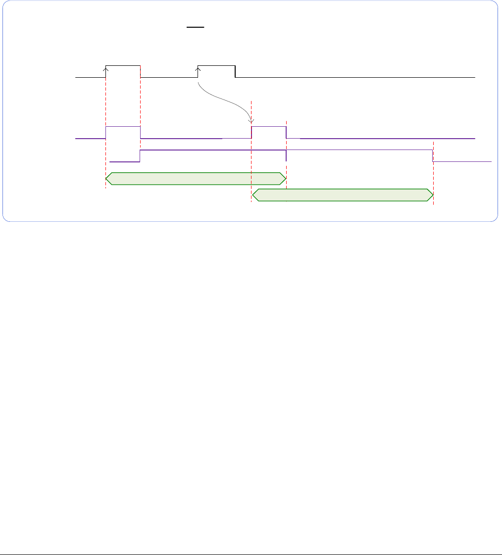
Nano Series GigE Vision Camera Operational Reference
•
121
Diagram Conditions (OnSemi Sensors):
• TriggerMode=On
• ExposureMode=TriggerWidth
• TriggerActivation=RisingEdge
• TriggerDelay=0
• TriggerSelector=FrameStart
• ExposureAlignment=Synchronous
Trigger Input
Exposure 1
Readout 1
Frame 1 Active period
Exposure 2
Readout 2
Frame 2 Active period
Frame Exposure
Frame Readout
OnSemi Sensor TriggerOverlap= Readout and ExposureMode=TriggerWidth
Exposure 2 delayed so that it ends when Readout 1 ends
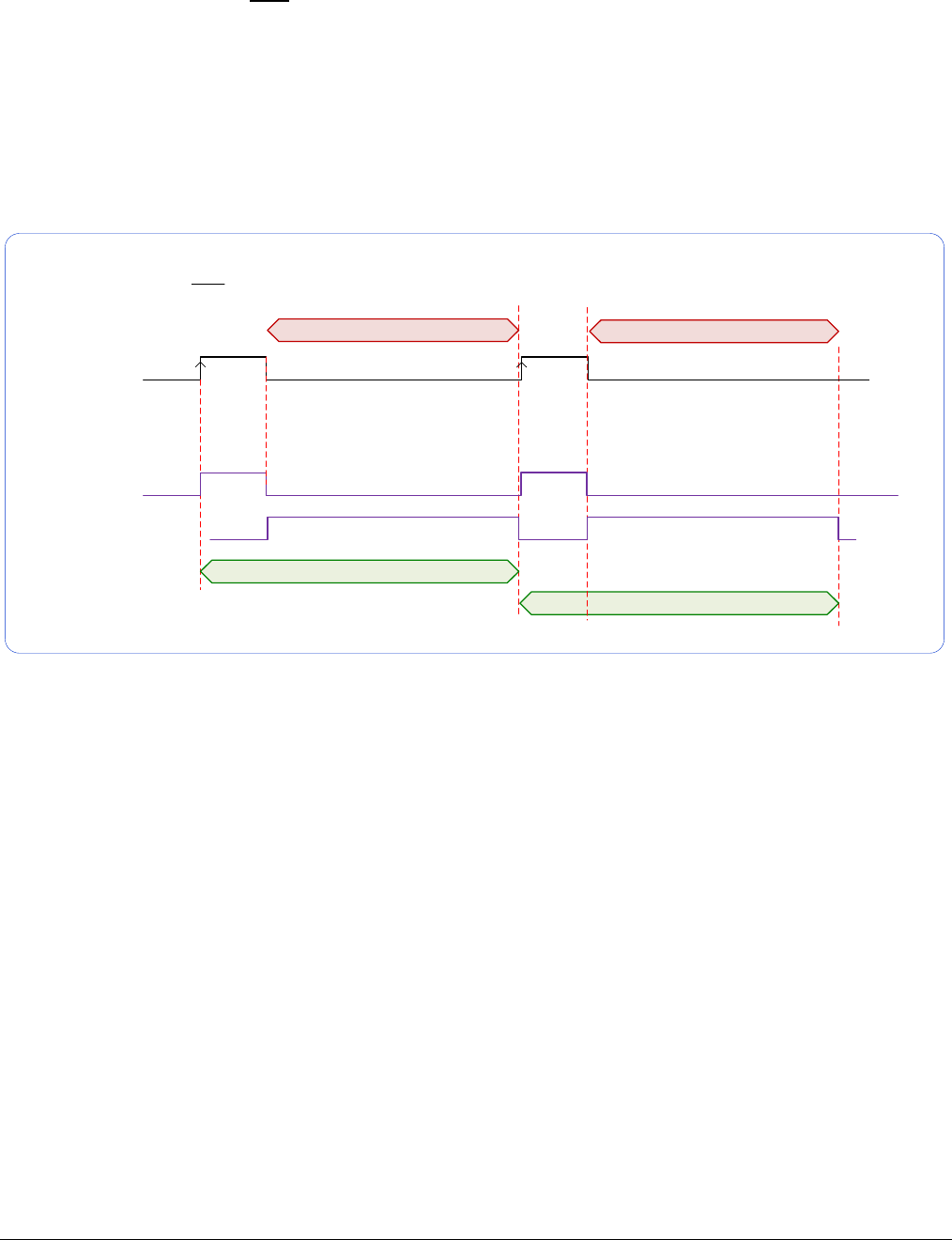
122
•
Operational Reference Nano Series GigE Vision Camera
• TriggerOverlap=Off and ExposureMode=TriggerWidth
Diagram Conditions:
• TriggerMode=On
• ExposureMode=TriggerWidth
• TriggerActivation=RisingEdge
• TriggerDelay=0
• TriggerSelector=FrameStart
• ExposureAlignment=Synchronous
Trigger Input
Exposure 1
Readout 1
Frame 1 Active period
Exposure 2
Readout 2
Frame 2 Active period
Frame Exposure
Frame Readout
TriggerOverlap= Off and ExposureMode=TriggerWidth
Exclusion Region Exclusion Region
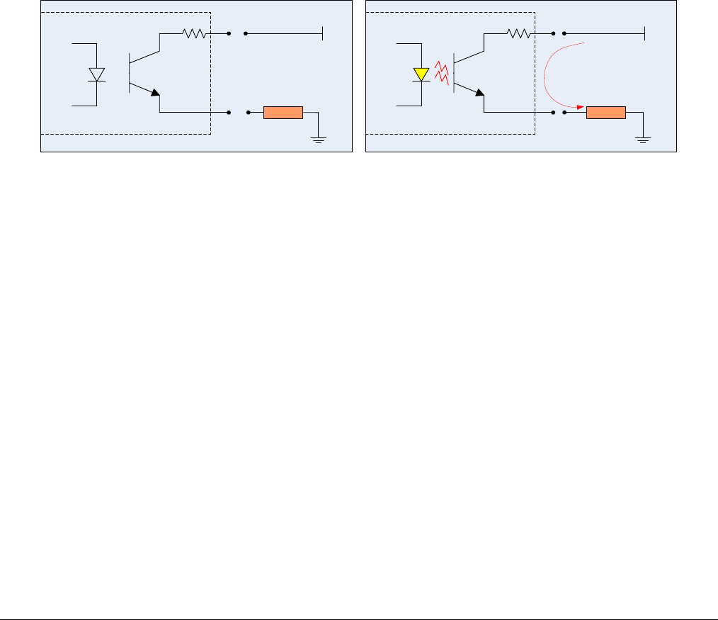
Nano Series GigE Vision Camera Operational Reference
•
123
Output Line Details
The general purpose output line signals are connected to I/O lines 3 and 4, which have the
following features for control or status indication.
• Feature set: LineInverter (RW), outputLineSource (RW), outputLinePulseDelay (RW),
outputLinePulseDuration (RW), outputLineValue (RW), outputLineSoftwareCmd (RW),
LineSelector (RW), LineName (RO), linePinAssociation (RO), LineFormat (RO), LineMode (RO),
LineStatus (RO). See Output Signals Electrical Specifications for more information.
• External outputs: Can be used as a strobe signals to control lighting or to generate
programmable pulses when specific events are generated by the camera.
• Output on Events: Each output can be set independently to one of the available event modes
defined by the ‘outputLineSource’ feature.
Output High and Output Low Block Diagram
Output signal lines when either in the High or Low state are shown in the following figures with an
simplified external circuit.
Camera Output
LOAD
VCC
Camera Output
LOAD
VCC
current flow
Examples of Logic HI and Logic LO output circuits
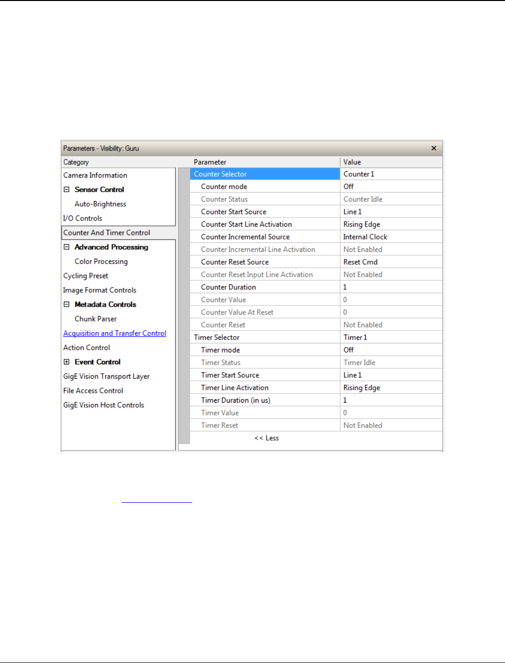
124
•
Operational Reference Nano Series GigE Vision Camera
Counter and Timer Control Category
The Genie Nano counter and timer controls, as shown by CamExpert, has parameters used to
configure acquisition counters and timers for various input lines and signal edge detection.
Parameters in gray are read only, either always or due to another parameter being disabled.
Parameters in black are user set in CamExpert or programmable via an imaging application.
Features listed in the description table but tagged as Invisible are usually for Teledyne DALSA or
third party software usage—not typically needed by end user applications. Also important, Genie
Nano cameras are available in a number of models implementing different sensors and image
resolutions which may not support the full feature set defined in this category.
Counter and Timer Control Feature Description
The following table and block diagram, describes these parameters along with their view attribute
and minimum camera firmware version required. Additionally the Device Version column will
indicate which parameter is a member of the DALSA Features Naming Convention (indicated by
DFNC), versus the GenICam Standard Features Naming Convention (SFNC tag is not shown).
The Device Version number represents the camera software functional group, not a firmware
revision number. As Genie Nano capabilities evolve the device version tag will increase, therefore
identifying the supported function package. New features for a major device version release will be
indicated by green text for easy identification.

Nano Series GigE Vision Camera Operational Reference
•
125
Display Name Feature & Values Description Device
Version
& View
Counter Selector counterSelector Selects the counter to configure.
1.00
Expert
DFNC
Counter 1 Counter1 Select counter 1
Counter mode counterMode Selects the counter mode. The selected Counter is
either Active or Disabled. When Disabled, the Counter
can be configured.
1.00
Expert
DFNC
Off Off The selected Counter is Disabled
Active Active The selected Counter is Enabled
Counter Status counterStatus Returns the current state of the counter.
1.00
Expert
DFNC
Counter Idle CounterIdle The counter is idle.
The counterStartSource feature is set to off.
Counter Trigger Wait CounterTriggerWait The counter is waiting for a start trigger.
Counter Active CounterActive The counter is counting for the specified duration.
Counter Completed CounterCompleted The counter reached the CounterDuration count.
Counter Overflow CounterOverflow The counter reached its maximum possible count.
Counter Start Source counterStartSource Select the counter start source. Counter increments
from 0 to the value of the counterDuration feature. 1.10
Expert
DFNC
Off Off Counter is stopped.
Acquisition Start AcquisitionStart Counter starts on the reception of the Acquisition
Start event.
Acquisition End AcquisitionEnd Counter starts on the reception of the Acquisition End
event.
Exposure Start ExposureStart Counter starts on the reception of the Exposure Start
event
Exposure End ExposureEnd Counter starts on the reception of the Exposure End
event.
Readout Start ReadoutStart Counter starts on the reception of the Readout Start
event.
Readout End ReadoutEnd Counter starts on the reception of the Readout End
event.
Frame Start FrameStart Counter starts on the reception of the Frame Start
event.
Valid Frame Trigger ValidFrameTrigger Counter starts on the reception of the Valid Frame
Trigger.
Rejected Frame Trigger InvalidFrameTrigger Counter starts on the reception of the Invalid Frame
Trigger.
Action 1 Action1 GigEVision Action Command 1. This is a broadcast
command that multiple devices can respond to
simultaneously. (1.03)
Action 2 Action2 GigEVision Action Command 2. This is a broadcast
command that multiple devices can respond to
simultaneously. (1.03)
Line 1 Line1 Counter starts on the specified transitions on Line 1
See Input Signals Electrical Specifications.
Line 2 Line2 Counter starts on the specified transitions on Line 2
Output 1 Line3 Counts the number of transitions (based on the
counterIncrementalLineActivation feature setting) of
Output 1.
Output 2 Line4 Counts the number of transitions (based on the
counterIncrementalLineActivation feature setting) of
Output 2.
Timer 1 End Timer1End Counter starts on the reception of the Timer 1 End
event.
Counter 1 End Counter1End Counter starts on the reception of the Counter 1 End
event.

126
•
Operational Reference Nano Series GigE Vision Camera
Counter Start Line
Activation counterStartLineActivation Selects the activation mode of the input line trigger
which starts the counter. This is only applicable when
the counterStartSource feature selects a physical
Line.
1.00
Expert
DFNC
Rising Edge RisingEdge Starts counting on rising edge of the selected Line.
Falling Edge FallingEdge Starts counting on falling edge of the selected Line.
Any Edge AnyEdge Starts counting on the falling or rising edge of the
selected Line.
Counter Incremental
Source counterIncrementalSource Select the event source which increments the
counter. The Event Control section provides details
and timing diagrams for the supported events.
1.00
Expert
DFNC
Off Off Counter is stopped.
Acquisition Start AcquisitionStart Counts the number of Acquisition Start events.
Acquisition End AcquisitionEnd Counts the number of Acquisition End events.
Exposure Start ExposureStart Counts the number of Exposure Start events.
ExposureEnd ExposureEnd Counts the number of Exposure End events.
Readout Start ReadoutStart Counts the number of Readout Start events.
Readout End ReadoutEnd Counts the number of Readout End events.
Frame Start FrameStart Counts the number of Frame Start events.
Valid Frame Trigger ValidFrameTrigger Counts the number of Valid Frame Triggers.
Rejected Frame(s)
Trigger InvalidFrameTrigger Counts the number of Rejected Frame(s) Trigger.
MultiFrame End Trigger FrameBurstEnd Counts the number of multi-frame end triggers
Line 1 Line1 Counts the number of transitions on Line 1 (based on
the counterIncrementalLineActivation feature setting)
See Input Signals Electrical Specifications.
Line 2 Line2 Counts the number of transitions on Line 2 (based on
the counterIncrementalLineActivation feature setting)
Output 1 Line3 Counts the number of transitions of Output 1 (based
on the counterIncrementalLineActivation feature
setting)
Output 2 Line4 Counts the number of transitions of Output 2 (based
on the counterIncrementalLineActivation feature
setting)
Internal Clock InternalClock The counter increments on each microsecond tick of
the device internal Clock.
Timer 1 End Timer1End Counts the number of Timer 1 End events.
Counter Incremental Line
Activation counterIncrementalLineActivation Selects the counter signal activation mode. The
counter increments on the specified signal edge or
level.
1.00
Expert
DFNC
Rising Edge RisingEdge Increment the counter on the rising edge of the
selected I/O Line.
Falling Edge FallingEdge Increment the counter on the falling edge of the
selected I/O Line.
Any Edge AnyEdge Increment the counter on the falling or rising edge of
the selected I/O Line.
Counter Duration counterDuration Sets the duration (or number of events) before the
CounterEnd event is generated.
1.00
Expert
DFNC
Counter Reset Source counterResetSource Selects the signal source to reset the counter. After a
reset the counter waits for the next countStartSource
signal or event.
1.10
Expert
DFNC
Reset Cmd Off Reset on reception of the Reset Icommand.
Acquisition Start AcquisitionStart Reset on reception of the Acquisition Start.
Acquisition End AcquisitionEnd Reset on reception of the AcquisitionEnd
Exposure Start ExposureStart Reset on reception of the Exposure Start event.
Exposure End ExposureEnd Reset on reception of the Exposure End event.

Nano Series GigE Vision Camera Operational Reference
•
127
Readout Start ReadoutStart Reset the counter on the reception of the Readout
Start event.
Readout End ReadoutEnd Reset the counter on the reception of the Readout
End event.
Frame Trigger FrameStart Reset on reception of the Frame Trigger.
Valid Frame Trigger ValidFrameTrigger Reset on reception of the Valid Frame Trigger.
Rejected Frame Trigger InvalidFrameTrigger Reset on reception of the Invalid Frame Trigger.
MultiFrame End Trigger FrameBurstEnd Reset on reception of the Frame Burst end.
Line 1 Line1 Reset counter on the specified transition on line 1.
See Input Signals Electrical Specifications.
Line 2 Line2 Reset counter on the specified transition on line 2.
Output 1 Line3 Counts the number of transitions of Output 1 (based
on the counterIncrementalLineActivation feature
setting).
Output 2 Line4 Counts the number of transitions of Output 2 (based
on the counterIncrementalLineActivation feature
setting).
Timer 1 End Timer1End Reset on reception of the Timer End.
Counter 1 End Counter1End Reset on the reception of the Counter end.
Counter Reset Input Line
Activation counterResetLineActivation Specify the edge transition on the selected line that
will reset the selected counter.
1.00
Expert
DFNC
Rising Edge RisingEdge Reset counter on rising edge of the selected signal.
Falling Edge FallingEdge Reset counter on falling edge of the selected signal.
Any Edge AnyEdge Reset counter on the falling or rising edge of the
selected signal
Counter Value counterValue Read the current value of the selected counter.
1.00
Expert
DFNC
Counter Value At Reset counterValueAtReset Stores the counter value of the selected counter when
it was reset by a trigger or by an explicit Counter
Reset command.
1.00
Expert
DFNC
Counter Reset counterReset Resets the selected counter to zero. The counter
starts immediately after the reset. To temporarily
disable the counter, set the Counter Event Source
feature to Off.
1.00
Expert
DFNC
Timer Selector timerSelector Selects which timer to configure.
1.00
Expert
DFNC
Timer 1 Timer1 Timer 1 selected
Timer Mode timerMode Select the Timer mode. The selected Timer is Active
or Disabled. When Disabled, the Timer can be
configured.
1.00
Expert
DFNC
Off Off The selected Timer is Disabled.
Active Active The selected Timer is Enabled.
Timer Status timerStatus Returns the current state of the timer.
1.00
Expert
DFNC
Timer Idle TimerIdle The timer is idle. The CounterStartSource feature is
set to off.
Timer Trigger Wait TimerTriggerWait The timer is waiting for a start trigger.
Timer Active TimerActive The timer is counting for the specified duration.
Timer Completed TimerCompleted The timer reached the TimerDuration count.
Timer Start Source timerStartSource Select the trigger source to start the timer. The Event
Control section provides details and timing diagrams
for the supported events.
1.00
Expert
DFNC
TimerReset Cmd Off Starts with the reception of the TimerReset
Icommand.
Acquisition Start AcquisitionStart Start Timer on Acquisition Start event.
Acquisition End AcquisitionEnd Start Timer on Acquisition End event
Exposure Start ExposureStart Start Timer on Exposure Start event.
Exposure End ExposureEnd Start Timer on Exposure End event.
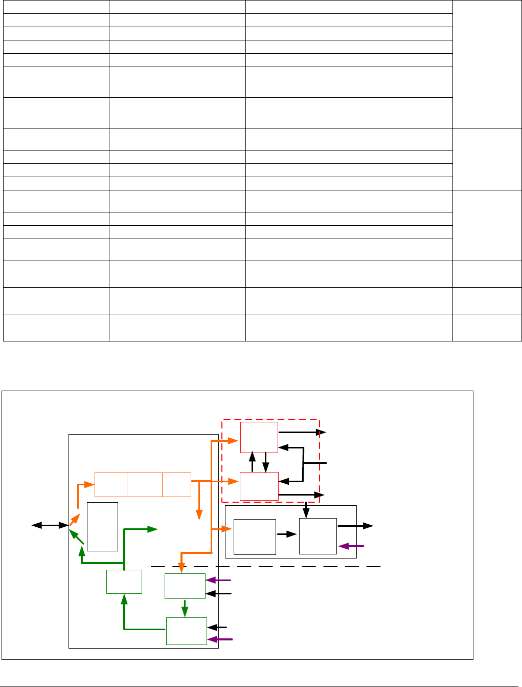
128
•
Operational Reference Nano Series GigE Vision Camera
Readout Start ReadoutEnd Start Timer on Readout Start event.
Readout End ReadoutStart Start Timer on Readout End event.
Frame Start FrameStart Start Timer on Frame Start event.
Frame Trigger ValidFrameTrigger Start Timer on Frame Trigger event.
Frame Burst End FrameBurstEnd Start Timer on Frame Burst End event.
Action 1 Action1 GigEVision Action Command 1. This is a broadcast
command that multiple devices can respond to
simultaneously. (1.03)
Action 2 Action2 GigEVision Action Command 2. This is a broadcast
command that multiple devices can respond to
simultaneously. (1.03)
Line 1 Line1 Start Timer on a transition of I/O Line 1 event.
See Input Signals Electrical Specifications.
Line 2 Line2 Start Timer on a transition of I/O Line 2 event.
Timer 1 End Timer1End Start Timer on Timer End event.
Counter 1 End Counter1End Start Timer on Counter 1 End event.
Timer Line Activation timerStartLineActivation Select the trigger activation mode which starts the
timer.
1.00
Expert
DFNC
Rising Edge RisingEdge Starts counter on rising edge of the selected signal.
Falling Edge FallingEdge Starts counter on falling edge of the selected signal.
Any Edge AnyEdge Starts counter on the falling or rising edge of the
selected signal.
Timer Duration timerDuration Sets the duration (in microseconds) of the timer
pulse.
1.00
Expert
DFNC
Timer Value timerValue Reads the current value (in microseconds) of the
selected timer.
1.00
Expert
DFNC
Timer Reset timerReset Resets the timer to 0 while timerStatus=TimerActive.
Timer then waits for the next timerStartSource event.
1.00
Expert
DFNC
Counter and Timer Group Block Diagram
Line Selector =
Line 1 to 4
Physical
Line
Event Driven
Input
inverter
Output
inverter Software Driven
Pulse
generator
LineStatus Trigger
Line
Activation
Trigger Signal
Timer TimerEnd Event
CounterEnd Event
Software Trigger
Cmd
Line
Mode
Input
or
ouput
Input
Output
Timer and Counter Module
Counter
Line
Debouncer
Event Driven
Trigger
Source
Trigger Module
Output
Line
Source
Signal Driven
Software Driven
Line
Detection
Level
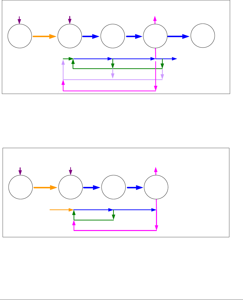
Nano Series GigE Vision Camera Operational Reference
•
129
Example: Counter Start Source = OFF
Countermode=OFF
Counter is
IDLE
Counter
Overflow
CounterEnd Event Generated
Counter is
Active
CounterStartSource=OFF
CounterWait
Trigger
Counter is incrementing
Countermode=Active
CounterResetSource=OFF
CounterResetSource=Event
Counter Reset CMD
Counter
Completed
CounterResetSource=CounterEnd
CounterStartSource=OFF
0
• The counter starts on the counterReset Cmd.
• The counter continues unless a new counterReset Cmd is received, which then restarts the
counter at 00.
• When Counter Reset Source= ‘Event’ or ‘CounterEnd’ the counter is reset to 00 but does
not restart counting, until the next CounterReset Cmd.
Example: Counter Start Source = CounterEnd (itself)
Countermode=OFF
Counter is
IDLE
CounterEnd Event Generated
Counter is
Active
CounterStartSource=
CounterEnd (itself)
CounterWait
Trigger
Counter is incrementing
Countermode=Active
Counter Reset CMD
Counter
Completed
CounterResetSource=CounterEnd
CounterStartSource=CounterEnd (itself)
0
• Counter starts when Counter Mode is set to Active.
• A Counter Reset CMD will reset the counter to 00 and it then continues counting.
• counterResetSource must be set to CounterEnd. When the counterValue feature reaches the
counterDuration value an event is generated and the counter is reset to 00, then continues.
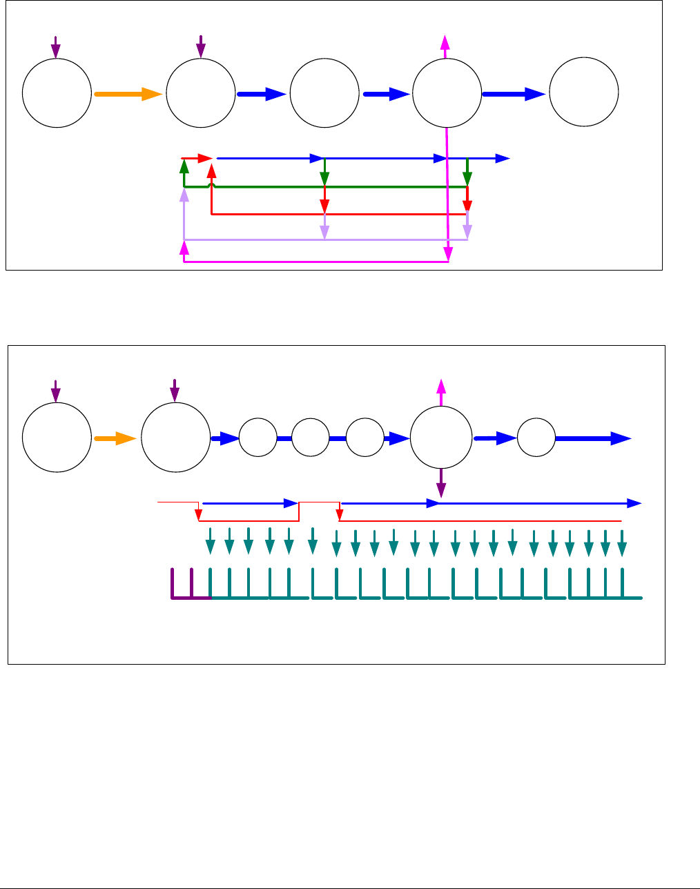
130
•
Operational Reference Nano Series GigE Vision Camera
Example: CounterStartSource = EVENT and Signal (Edge Base)
Countermode=OFF
Counter is
IDLE
Counter
Overflow
CounterEnd Event Generated
Counter is
Active
CounterStartSource= EVENT or
Signal (Edge Base )
CounterWait
Trigger
Counter is incrementing
Countermode=Active
CounterResetSource=OFF
CounterResetSource=Event
Counter Reset CMD
Counter
Completed
CounterResetSource=CounterEnd(Itself)
CounterStartSource= EVENT and Signal (Edge Base )
CounterResetSource=Event (Itself)
0
Example: CounterStartSource = Line (Edge Base) Example
Countermode=OFF
Counter is
IDLE
CounterEnd Event Generated
CounterStartSource=
Line 1
CounterWait
Start
Counter Register
Countermode=Active
Counter
Completed
CounterResetSource =CounterEnd(Itself)
CounterStartSource= Line (Edge Base ) Example 2
Active ActiveActive
CounterTriggerActivation=
Falling Edge
Counter STATUS
012
85 10
any Tick in
CounterEventSource
Active
1
1
CounterDuration=12
0
The Second StartSource Pulse is ignored
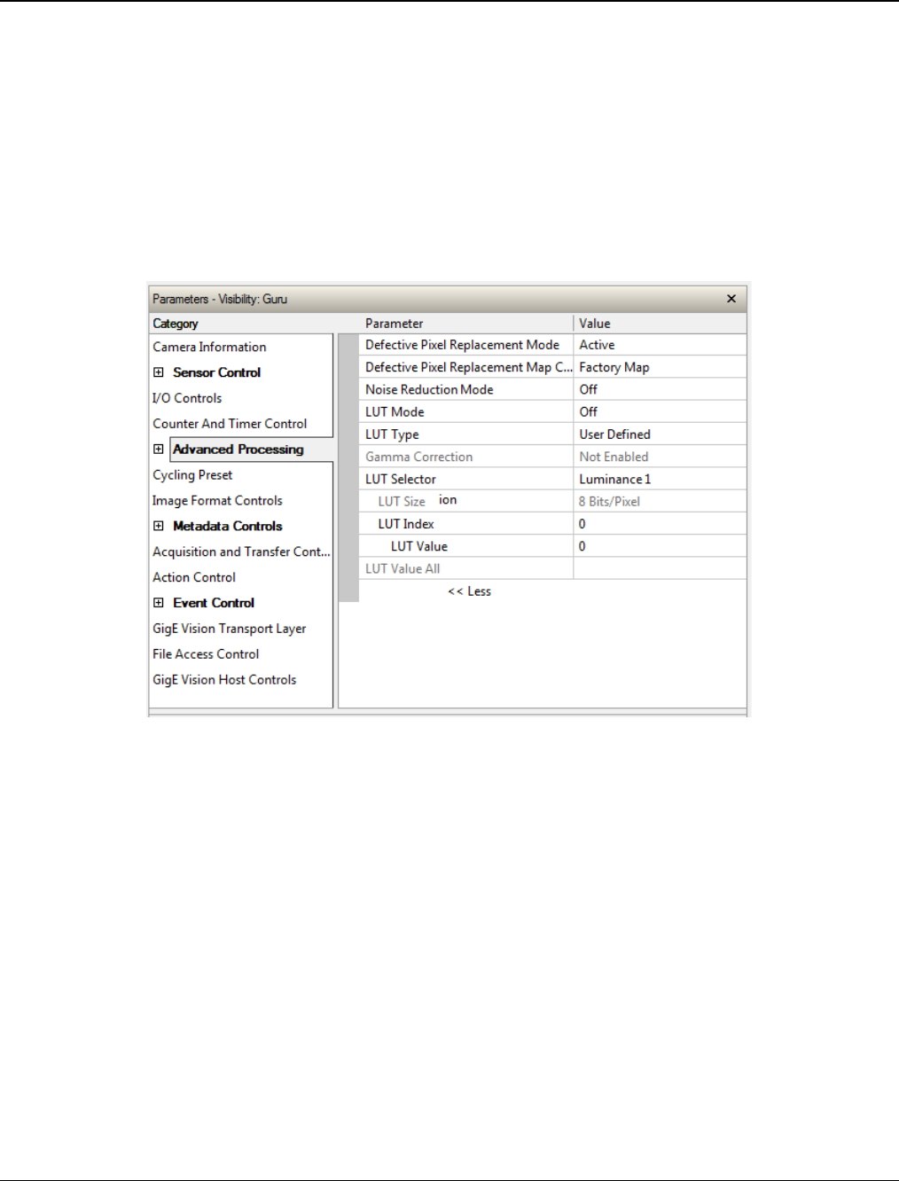
Nano Series GigE Vision Camera Operational Reference
•
131
Advanced Processing Control Category
The Genie Nano Advanced Processing controls, as shown by CamExpert, groups parameters used
to configure LUT mode controls on monochrome cameras. Parameters in gray are read only, either
always or due to another parameter being disabled. Parameters in black are user set in CamExpert
or programmable via an imaging application.
Features listed in the description table but tagged as Invisible are usually for Teledyne DALSA or
third party software usage—not typically needed by end user applications.
Also important, Genie Nano cameras are available in a number of models implementing different
sensors and image resolutions which may not support the full feature set defined in this category.
Advanced Processing Control Feature Descriptions
The following table describes these features along with their view attribute and device version. For
each feature the device version may differ for each camera sensor available. Such feature
differences will be clearly indicated.
As Genie Nano capabilities evolve the device firmware version will increase, therefore identifying
the supported function package. New features for a major device version release will be indicated
by green text for easy identification, for that new manual release.
The description column will indicate which feature is a member of the Teledyne DALSA Features
Naming Convention (indicated by DFNC), versus the GenICam Standard Features Naming
Convention (SFNC not shown).

132
•
Operational Reference Nano Series GigE Vision Camera
Display Name Feature & Values Description Version Model Notes
Defective Pixel Replacement
Mode defectivePixelReplacementMode Sets the mode for the defective pixel
replacement. Ver. 1.04
Expert
DFNC
OnSemi Python
monochrome and
Sony 9M & 12M
Off Off Defective Pixel Replacement is disabled.
Active Active Defective Pixel Replacement is enabled.
Defective Pixel Replacement
Map Current Active Set defectivePixelReplacementMapCurren
tActiveSet Sets the defective pixel replacement set. Ver. 1.04
Expert
DFNC
OnSemi Python
monochrome and
Sony 9M & 12M
Factory Map FactoryMap Sets the factory coefficient table as active.
User Map 1 UserMap1 Sets the User Map coefficient table as active.
Defective Pixel Replacement
Algorithm defectivePixelReplacementAlgorithm Specifies the defective pixel replacement
algorithm. Ver. 1.07
Expert
DFNC
OnSemi Python
monochrome and
Sony 9M & 12M
Method3: Neighboring Pixel Method3 This algorithm replaces a defective pixel with
a neighbor.
Noise Reduction Mode noiseReduction Sets the mode for the pixel noise reduction. Ver. 1.06
Expert
DFNC
M/C 5100 &
M/C 4900 only
Off Off Noise Reduction is disabled.
Active Active Noise Reduction is enabled.
LUT Mode lutMode Sets the enable state of the selected LUT
module (Lookup Table). Ver. 1.03
Expert
DFNC
Off Off Disables the LUT.
Active Active Enables the selected LUT module.
LUT Type lutType Displays the LUT type of the currently
selected Lookup Table. Ver. 1.03
Expert
DFNC
Ver. 1.06
Available with
Bayer Color
firmware – all
color models
User Defined UserDefined Uses the user programmable LUT.
Gamma Correction GammaCorrection Uses gamma LUT
LUT Selector LUTSelector Selects which LUT to control and adjust
features.
Ver. 1.03
Guru
Luminance 1 Luminance1 Luminance 1 is under control
RED RED LUT Red is under control
Green Green LUT Green is under control
Blue Blue LUT Blue is under control
LUT Size lutSize Specify the LUT size of the selected LUT
(Lookup Table). Available choices are model
dependent. Ver. 1.03
Guru
DFNC
8 Bits/Pixel
10 Bits/Pixel
12 Bits/Pixel
Bpp8
Bpp10
Bpp12
8 bits per pixel
10 bits per pixel
12 bits per pixel
LUT Index LUTIndex Selects the index (offset) of the coefficient to
access in the selected LUT. Ver. 1.03
Guru

Nano Series GigE Vision Camera Operational Reference
•
133
LUT Value LUTValue Returns the value at specified LUT index entry
of the LUT selected by the LUT Selector
feature.
Ver. 1.03
Guru
LUT Value All LUTValueAll Accesses all the LUT coefficients in a single
access without using individual LUT indices.
This feature accesses the LUT values in the
currently active LUT table set by the LUT
Current Active Set feature.
Ver. 1.03
Guru
Processing path bits per pixel processingPathBpp < >
Ver. 1.03
Invisible
DFNC
LUT Current Active Set lutCurrentActiveSet Specifies the current LUT to use.
< Invisible, DFNC > Ver. 1.05
Invisible
DFNC
Luminance 1 Luminance1 Sets the current LUT as Luminance 1.
LUT RGB RGB Sets the current LUT as RGB.
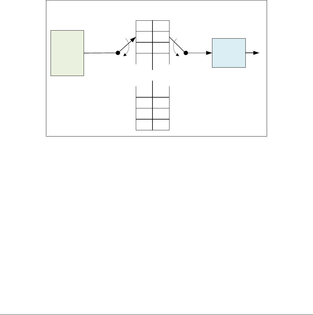
134
•
Operational Reference Nano Series GigE Vision Camera
Lookup Table (LUT) Overview
The Genie Nano cameras include a user programmable LUT table as a component of its embedded
processing features. A LUT is used for operations such as gamma adjustments, invert and
threshold processes.
The camera LUT table are dependent on the sensor (per pixel – see feature LUT Size) and is
illustrated in the following figure (see Processing path bits per pixel). Pixel data from the sensor is
passed through the LUT memory array, where the new programmed pixel value is then passed to
the Genie output circuit. The LUT data table is stored along with other parameters with the user
configuration function.
. . .
. . .
0
1
2
3
1020
1023
1022
1021
1023
1022
1021
1020
2
1
0
3
Output
Sensor
Pixel
Data
Simplified Nano LUT Block Diagram
(10-bit example)
LUT Programmed
as Invert Function
Simplified Example 10-bit LUT Block Diagram
LUT Size vs. Output Pixel Format
The LUT size will be the same as the camera’s sensor pixel size. All camera processing is performed
at the sensor pixel format of the camera, while the user chooses the output pixel format (such as
8-bit).
Using the example of a 10-bit Nano camera, the LUT table is also 10-bit. The Nano default neutral
LUT programming is as follows:
• When the Output Pixel format = 10-bit, the default LUT data value is equal to the LUT index
value for each index. This is a linear LUT that does not modify the sensor data.
• When the Output Pixel format = 8-bit, the default LUT data is programmed to map the 1024
sensor pixel values to 256 output values. Therefore LUT index “0 to 3” have the value “0”, LUT
index “4 to 7” have the value “1”, and so on until the last group where LUT index “1020 to
1023” have the value “255”.
LUT data is selected either as a predefined gamma correction, or is programmed with individual
values for various LUT index entries, or a user LUT data file is upload using the File Access controls.
Refer to the Sapera documentation for information about the SapLut Class. Note that a SapLut file
can be uploaded to the Nano but cannot be read back.

Nano Series GigE Vision Camera Operational Reference
•
135
Defective Pixel Replacement (Method 3)
The Pixel Replacement algorithm is based on a predefined bad pixel map (as an XML file), either
supplied by the factory (file loaded as “Factory Map”) or generated by the user (file uploaded as
“User Map 1”). The number of bad pixel entries is limited and varies dependent on the Nano model.
The following XML code sample forms the template for the user to build bad pixel maps for any of
their Nano cameras.
Note: Identifying bad pixels is left to the user’s discretion, but Teledyne DALSA technical support
can provide guidance.
Example User Defective Pixel Map XML File
The following example shows the required components of the defective pixel map file. Each bad
pixel position (relative to the image origin which is the upper left corner), must be identified by the
XML statement:
<DefectivePixel OffsetX=”
number
” OffsetY=”
number
”/>
The pixel format (whether 8, 10, 12-bit) is handled transparently, thus requires no special
consideration by the user.
This example XML listing has four “bad” pixels identified (maximum number of entries is model
dependent). The Algorithm descriptions that follows defines the rules used by the Nano firmware to
replace an identified bad pixel.
<?xml version=”1.0” encoding=”UTF-8” ?>
<!–-Example User Defective Pixel Map
<!-- maximum 512 coordinates
<!–-filename: NanoExampleBadPixels.xml
<Coordinates>
<DefectivePixel OffsetX=”100” OffsetY=”0”/>
<DefectivePixel OffsetX=”28” OffsetY=”345”/>
<DefectivePixel OffsetX=”468” OffsetY=”50”/>
<DefectivePixel OffsetX=”800” OffsetY=”600”/>
</Coordinates>
An sample editable defective pixel map replacement file will be available to download with Nano
firmware files.

136
•
Operational Reference Nano Series GigE Vision Camera
Defective Pixel Replacement Algorithm Description
The replacement algorithm follows a few basic rules as defined below, which in general provides
satisfactory results.
Monochrome Cameras
• If the bad pixel is the first of a line, it is replaced by the next whether good or not.
• If the bad pixel is not the first of a line, it is replaced by the previous pixel.
Sensor Row pix1 pix2 pix3 pix5 pix6 pix7
pix4pix0
Color Cameras
The replacement algorithm rules for Bayer a color sensor is similar to the monochrome rules with
the exception that replacement pixels of the same color as the bad are used. The two replacement
cases below describe general color pixel replacements.
• If the bad pixel is the first of a line, it is replaced by the next of the same color, whether good
or not.
• If the bad pixel is not the first of a line, it is replaced by the previous pixel of the same color.
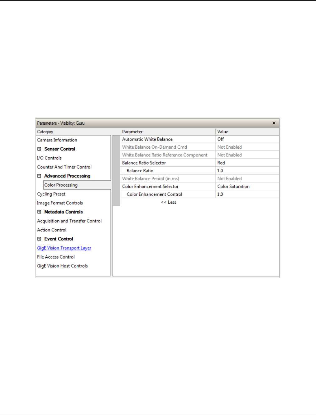
Nano Series GigE Vision Camera Operational Reference
•
137
Color Processing Control Category
The Nano Color Processing controls, as shown by CamExpert, has parameters used to configure the
color camera white balance/color balance features.
Parameters in gray are read only, either always or due to another parameter being disabled.
Parameters in black are user set in CamExpert or programmable via an imaging application
Features listed in the description table but tagged as Invisible are usually for Teledyne DALSA or
third party software usage—not typically needed by end user applications. Also important,
Genie Nano cameras are available in a number of models implementing different sensors and
image resolutions which may not support the full feature set defined in this category.
Note that the following screen shows a color Nano with the optional RGB-Output Design firmware
loaded (certain models only). The last two features (Color Enhancement) are not offered with the
Standard Bayer Color firmware (used with all color Nano cameras).
Color Processing Control Feature Description
The following table describes these features along with their view attribute and device framework
version. For each feature the device version may differ for each camera sensor available. Such
differences will be clearly indicated for any applicable feature.
As Genie Nano capabilities evolve the device firmware version will increase, therefore identifying
the supported function package. New features for a major device version release will be indicated
by green text for easy identification.
The description column will indicate which feature is a member of the Teledyne DALSA Features
Naming Convention (denoted by DFNC), versus the GenICam Standard Features Naming
Convention (SFNC not shown).

138
•
Operational Reference Nano Series GigE Vision Camera
Display Name Feature & Values Description Device
Version
& View
Automatic White Balance BalanceWhiteAuto Controls the mode for automatic white balancing
between the color channels. The color gains are
automatically adjusted.
1.04
Expert
Off Off White balancing is manually controlled using
BalanceRatio[Red], BalanceRatio[Green] and
BalanceRatio[Blue].
On Demand OnDemand White balancing is automatically adjusted once by the
device.
Periodic Periodic White balancing is periodically adjusted by the device
(i.e. when the scene is known to be neutral).
White Balance Period balanceWhitePeriod White balance correction period.
1.05
Expert
DFNC
White Balance On-
Demand Cmd balanceWhiteAutoOnDemandCmd Executes the automatic white balance function. The
first frame acquired is used to calculate the RGB gain
adjustments, which are then applied to subsequent
snaps or grabs.
1.04
Expert
DFNC
White Balance Ratio
Reference Component balanceRatioReference Selects which color component to use as the
reference point for BalanceWhiteAuto.
1.04
Expert
DFNC
Red Red Red component will remain constant after the white
balance adjustment.
Green Green Green component will remain constant after the white
balance adjustment.
Blue Blue Blue component will remain constant after the white
balance adjustment.
Automatic Auto The reference color component is automatically
selected so that the minimum component’s gain
becomes 1.00.
Balance Ratio Selector BalanceRatioSelector Selects which color gain is controlled with the
BalanceRatio feature.
1.04
Expert
Red Red RED gain is controlled by Balance Ratio.
Green Green Green gain is controlled by Balance Ratio.
Blue Blue BLUE gain is controlled by Balance Ratio.
Balance Ratio BalanceRatio Sets the digital gain of the selected color component
(BalanceRatioSelector).
1.04
Expert
White Balance Period balanceWhitePeriod White balance correction period in milliseconds. (RO)
1.05
Expert
DFNC
Color Enhancement
Selector colorEnhancementSelector Select the color attribute to control.
1.05
RGB Firmware
Expert
DFNC
Color Saturation Saturation User set gain of the color saturation component,
ranging from 1 to 4x.
Luminance Luminance User set gain of the luminance component.
Color Enhancement
Control colorEnhancementControl Control the color attribute selected by
colorEnhancementSelector.
1.05
RGB Firmware
Expert
DFNC
Color Processing Functional Overview
Nano color cameras provide White Balance controls (automatic or manual), and additionally with
supported models, the optional RGB firmware provides Saturation and Luminance controls. These
features are described below in more detail. Note that computer monitors have wide variations in
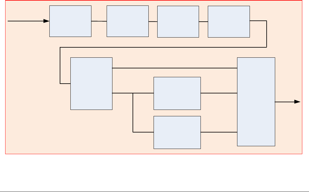
Nano Series GigE Vision Camera Operational Reference
•
139
displaying color. Users should consider using professional monitors which have factory calibrated
fixed presets conforming to sRGB or AdobeRGB color spaces.
White Balance Operation
The Nano white balance control allow either manual settings for the RGB gain levels, or an
automatic algorithm executing periodically or on demand. Automatic mode operates under the
assumption of a color neutral scene, where an IR filter installed on the Nano camera is
recommended for most applications.
For Manual Adjustments
• RGB values range from 1 to 4, in 0.01 increments.
• Use BalanceRatioSelector to select the RGB gain to adjust and use BalanceRatio to change the
gain value.
• The user selects one color to stay fixed at a gain of 1.00 (often green).
• Adjust the gain for R & B to achieve the white balance desired.
For Automatic Adjustments
With either periodic or on demand modes, the Nano will determine the color to set to a gain of
1.00, and then adjust the other two color gains. The BalanceRatio feature will show gain settings at
higher precision than user set values.
• Set BalanceWhiteAuto to Periodic or OnDemand.
• The periodic mode will recalculate every 10ms, while the on demand mode requires the
execution of balanceWhiteAutoOnDemandCmd.
• The user can override the automatic choice of the color referenced to a gain of zero via the
balanceRatioReference feature, but often the results look false colored.
Simplified RGB Design Firmware Block Diagram
Defective Pixel
Replacement Bayer Decoder User LUT
Color Space
Converter and
Saturation
Control
Y Packer
YCbCr to RGB
Converter and
Packer
YCbCr422
Color Output
Selector
YCbCr
Sensor Data
RGB Gains
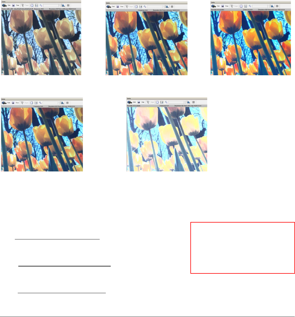
140
•
Operational Reference Nano Series GigE Vision Camera
Saturation and Luminance Operation
The optional RGB Output Design firmware for OnSemi sensor Nano models provides two additional
control features for color control. In simple terms these controls are:
• Saturation — Increases the color intensity relative to the default gain level
• Luminance — Increases the overall luminance gain level
Examples of Saturation and Luminance effects with integer value settings are shown below.
Saturation Control Examples
Saturation=1 Saturation=2 Saturation=3
Luminance Control Examples
Saturation=2, Luminance=1 Saturation=2, Luminance=2
The Math behind the Saturation/Luminance Controls
Nano RGB firmware combines user control inputs with captured video RGB values using the
formulas described below.
Luminance is applied to the Y and chrominance (saturation) is applied to Cb (U) and Cr (V).
=
9798 +19235 +3736
32768
= 5529 10855 +16384
32768 +
=
16384 13720 2664
32768 +
Where:
X is 128 if data path bit-depth is 8-bit
X is 512 if data path bit-depth is 10-bit
X is 2048 if data path bit-depth is 12-bit
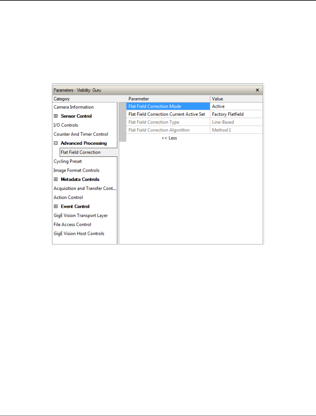
Nano Series GigE Vision Camera Operational Reference
•
141
Flat Field Correction Category
The Nano Flat Field Correction controls, as shown by CamExpert, has parameters used to correct
sensor or lens luminance differences. Currently these controls are available on the NanoXL models
M/C 5100 and M/C 4090.
Parameters in gray are read only, either always or due to another parameter being disabled.
Parameters in black are user set in CamExpert or programmable via an imaging application
Features listed in the description table but tagged as Invisible are usually for Teledyne DALSA or
third party software usage—not typically needed by end user applications.
Flat Field Correction Feature Description
The following table describes these features along with their view attribute and device framework
version. For each feature the device version may differ for each camera sensor available. Such
differences will be clearly indicated for any applicable feature.
As Genie Nano capabilities evolve the device firmware version will increase, therefore identifying
the supported function package. New features for a major device version release will be indicated
by green text for easy identification.
The description column will indicate which feature is a member of the Teledyne DALSA Features
Naming Convention (denoted by DFNC), versus the GenICam Standard Features Naming
Convention (SFNC not shown).

142
•
Operational Reference Nano Series GigE Vision Camera
Display Name Feature & Values Description Device
Version
& View
Flat Field Correction Mode flatfieldCorrectionMode Sets the mode for the Flat Field correction.
1.06
Beginner
DFNC
NanoXL
Off Off Flat Field Correction is disabled.
Active Active Flat Field Correction is enabled.
Calibration Calibration When this mode is selected, the camera is configured
for flat field correction calibration. The device may
automatically adjust some of its features when
calibrate mode is enabled. The features that are
automatically adjusted are device specific. The device
will not restore these features when the Flat Field
Correction Mode feature is changed from Calibrate
mode to another mode. <Expert>
Flat Field Correction
Current Active Set flatfieldCorrectionCurrentActiveSet Specifies the current set of Flat Field coefficients to
use.
1.06
Beginner
DFNC
NanoXL
Factory Flatfield FactoryFlatfield Sets the factory Flat Field coefficient table as the
current Flat Field.
User Flatfield 1 UserFlatfield1 Sets User Flat Field 1 coefficient table as the current
Flat Field.
Flat Field Correction Type flatfieldCorrectionType Specifies the Flat Field correction type.
1.06
Guru
DFNC
NanoXL
Line-Based LineBase Flat field correction is based on a single line of gain
and offset coefficients.
Flat Field Correction
Algorithm flatfieldCorrectionAlgorithm Specifies the Flat Field correction algorithm to use.
1.06
Guru
DFNC
NanoXL
Method 1 Method1 The following formula is used to calculate the flat field
corrected pixel: newPixelValue[x][y] =
(sensorPixelValue[x][y] – FFCOffset[x][y]) *
FFCGain[x][y]
Flat Field Algorithm Buffer
Format flatfieldAlgorithmBufferFormat
1.06
Invisible
DFNC
Mono8 Mono8
Flat Field Algorithm Buffer
Width flatfieldAlgorithmBufferWidth
1.06
Invisible
DFNC
Flat Field Algorithm Buffer
Height flatfieldAlgorithmBufferHeight
1.06
Invisible
DFNC
Flat Field Algorithm Gain
Max flatfieldAlgorithmGainMax
1.06
Invisible
DFNC
Flat Field Algorithm Gain
Min flatfieldAlgorithmGainMin
1.06
Invisible
DFNC
Flat Field Algorithm Gain
Divisor flatfieldAlgorithmGainDivisor
1.06
Invisible
DFNC
Flat Field Algorithm Gain
Base flatfieldAlgorithmGainBase
1.06
Invisible
DFNC
Flat Field Algorithm Offset
Max flatfieldAlgorithmOffsetMax
1.06
Invisible
DFNC
Flat Field Algorithm Offset
Min flatfieldAlgorithmOffsetMin
1.06
Invisible
DFNC
Flat Field Algorithm Offset
Factor flatfieldAlgorithmOffsetFactor
1.06
Invisible
DFNC
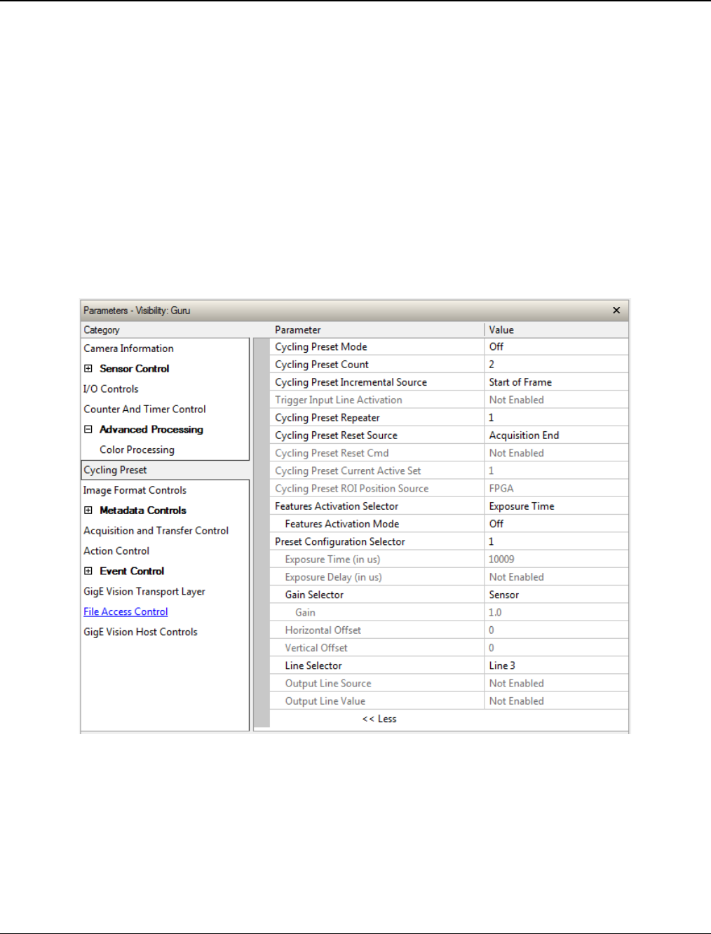
Nano Series GigE Vision Camera Operational Reference
•
143
Cycling Preset Mode Control Category
The Genie Nano Cycling Preset controls, as shown by CamExpert, has parameters used to configure
the camera Cycling features. Cycling controls allow the user to configure a number of camera
operational states and then have the camera automatically switch between states in real-time.
Only the features programmed to change are updated when switching between camera states, thus
ensuring immediate camera response. A setup example follows the feature table.
Parameters in gray are read only, either always or due to another parameter being disabled.
Parameters in black are user set in CamExpert or programmable via an imaging application
Features listed in the description table but tagged as Invisible are usually for Teledyne DALSA or
third party software usage—not typically needed by end user applications. Also important,
Genie Nano cameras are available in a number of models implementing different sensors and
image resolutions which may not support the full feature set defined in this category.
Note: This feature set is not available with the Nano C4900 (rolling shutter) camera.

144
•
Operational Reference Nano Series GigE Vision Camera
Cycling Preset Mode Control Feature Description
The following table describes these features along with their view attribute and device framework version. For each feature the device version
may differ for each camera sensor available. Such differences will be clearly indicated for any applicable feature.
As Genie Nano capabilities evolve the device firmware version will increase, therefore identifying the supported function package. New
features for a major device version release will be indicated by green text for easy identification.
The first column indicates whether a feature applies to monochrome or color camera models via a symbol. No symbol indicates a common
feature. Additionally the description column will indicate which feature is a member of the Teledyne DALSA Features Naming Convention
(denoted by DFNC), versus the GenICam Standard Features Naming Convention (SFNC not shown).
B/W
Color Display Name Feature & Values Description Sony
Sensors OnSemi
Sensors
Cycling Preset Mode cyclingPresetMode Sets the Cycling Presets module mode.
< Expert, DFNC >
Note: not available on rolling shutter model C4900 Ver. 1.01 Ver. 1.00
Off Off Disable the Cycling Preset module.
Active Active Enable the Cycling Preset module.
Cycling Preset Count cyclingPresetCount Specifies the number of Presets to use.
< Expert, DFNC > Ver. 1.01
Cycling Preset Incremental
Source cyclingPresetIncrementalSource Specifies the source that increments the currently active
cycling preset.
< Expert, DFNC > Ver. 1.01
None None Feature cyclingPresetCurrentActiveSet is used to select
the current active set.
Valid Frame Trigger ValidFrameTrigger Increment on a Valid Frame Trigger
Counter 1 End Counter1End Increment on the end of Counter 1.
Start of Frame StartOfFrame Increment on the Start of Frame event
Line2 Line2 Select Line 2 (and associated I/O control block) to use as
the external increment source.
Trigger Input Line Activation cyclingPresetIncrementalActivation Select the activation mode for the selected Input Line
source. This is applicable only for external line inputs.
< Expert, DFNC > Ver. 1.01
Rising Edge RisingEdge The source is considered valid on the rising edge of the
line source signal (after being process by the line inverter
feature).
Falling Edge FallingEdge The source is considered valid on the falling edge of the
line source signal (after being process by the line inverter
feature).
Any Edge AnyEdge The source is considered valid on any edge (falling or
rising) of the line source signal (after being process by
the line inverter feature).

Nano Series GigE Vision Camera Operational Reference
•
145
Cycling Preset Repeater cyclingPresetRepeater Specifies the required number of cycling preset increment
events (generated by the Cycling Preset Incremental
Source) to increment the index of the Cycling Preset
Current Active Set.
< Expert, DFNC >
Ver. 1.01
Cycling Preset Reset Source cyclingPresetResetSource Specifies the source that resets the currently active
preset. On reset the current preset index is set to 1.
< Expert, DFNC > Ver. 1.01
Valid Frame Trigger ValidFrameTrigger Reset when a Valid Frame Triggers occurs.
Counter 1 End Counter1End Reset when counter 1 ends.
Acquisition End EndOfAcquisition Use End of Acquisition as the reset source. An End of
Acquisition occurs on acquisition stop.
Software Software Use a software command as the reset source.
Cycling Preset Reset Cmd cyclingPresetResetCmd Reset the position of the preset cycling to 1 and the count
to 0.
< Guru, DFNC > Ver. 1.01
Cycling Preset Current Active
Set cyclingPresetCurrentActiveSet Returns the index of the currently active cycling preset.
< Guru, DFNC > Ver. 1.01
Cycling Preset ROI Source cyclingPresetRoiPositionSource Specifies the source that cycles the ROI position
(availability is sensor dependent). <Expert, DFNC>
Note: Only on OnSemi Python sensor models
— Ver. 1.05
OnSemi
Python
In-FPGA FPGA The FPGA cycles the ROI position.
In-Sensor Sensor The sensor cycles the ROI position.
Features Activation Selector cP_FeaturesActivationSelector Selects the feature to control by the
cP_FeaturesActivationMode feature.
< Expert, DFNC > Ver. 1.01
Exposure Time ExposureTime The cP_FeaturesActivationMode feature controls the
exposure time.
Exposure Delay ExposureDelay The cP_FeaturesActivationMode feature controls the
exposure delay.
ROI Position ROI_Position The cP_FeaturesActivationMode feature will control ROI
position.
Output Line3 OutputLine3Control The cP_FeaturesActivationMode feature controls the
output line 3.
Output Line4 OutputLine4Control The cP_FeaturesActivationMode feature controls the
output line 4.
Binning Horizontal BinningHorizontal The cP_FeaturesActivationMode controls the horizontal
binning. Ver. 1.03
Binning Vertical BinningVertical The cP_FeaturesActivationMode controls the vertical
binning. Ver. 1.03
Sensor Analog Gain SensorAnalogGain The cP_FeaturesActivationMode controls the sensor
analog gain. Ver. 1.04

146
•
Operational Reference Nano Series GigE Vision Camera
Features Activation Mode cP_FeaturesActivationMode Enables the selected feature to be part of the cycling.
When activating the selected feature, this will
automatically set the corresponding standard camera
feature to read only.
< Expert, DFNC >
Ver. 1.01
Off Off Exclude the selected feature from the cycling.
Active Active Include the selected feature in the cycling.
Preset Configuration Selector cP_PresetConfigurationSelector Selects the cycling preset to configure.
< Expert, DFNC > Ver. 1.01
Exposure Time cP_ExposureTime Sets the exposure time (in microseconds) for the selected
set. The maximum frame rate is dependent on the
longest cycling exposure time.
< Expert, DFNC >
Ver. 1.01
Exposure Delay cP_ExposureDelay Sets the exposure delay (in microseconds) for the
selected set.
< Expert, DFNC > Ver. 1.01
Gain Selector cP_GainSelector Selects which gain is controlled when adjusting cp_Gain
features.
< Expert, DFNC >
Ver. 1.04 Ver. 1.04
Sensor SensorAll Applies to Sony sensor models: Gain is adjusted within
the sensor. The first half of the gain range is applied in
the analog domain and the second half is digital.
Sensor Analog SensorAnalog Applies to OnSemi sensor models: Analog gain is adjusted
within the sensor.
Gain cP_Gain Sets the selected gain as an amplification factor applied
to the image. This gain is applied when the current
Cycling index is active.
< Expert, DFNC >
Ver. 1.04 Ver. 1.04
Horizontal Offset cP_OffsetX Horizontal offset from the origin to the region of interest
(ROI). The value in this feature is only used when the
currently selected cycling preset is active.
< Expert, DFNC >
Ver. 1.01 Ver. 1.05
Vertical Offset cP_OffsetY Vertical offset from the origin to the region of interest
(ROI). The value in this feature is only used when the
currently selected cycling preset is active.
< Expert, DFNC >
Ver. 1.01 Ver. 1.05
Binning Horizontal cP_BinningHorizontal Number of horizontal photo-sensitive cells to combine
together. This increases the intensity of the pixels but
reduces the horizontal resolution of the image.
< Expert, DFNC >
Ver. 1.03 Ver. 1.03
Binning Vertical cP_BinningVertical Number of vertical photo-sensitive cells to combine
together. This increases the intensity of the pixels but
reduces the vertical resolution of the image.
< Expert, DFNC >
Ver. 1.03 Ver. 1.03
Line Selector cP_LineSelector Selects which physical line (or pin) of the external device
connector to configure.
< Expert, DFNC > Ver. 1.01

Nano Series GigE Vision Camera Operational Reference
•
147
Line 3 Line3 Index of the physical line and associated I/O control block
to use. Pin 6 is the Output Signal and Pin 4 is the
common output power on the I/O connector.
Line 4 Line4 Index of the physical line and associated I/O control block
to use. Pin 8 is the Output Signal and Pin 4 is the
common output power on the I/O connector.
Output Line Source cP_OutputLineSource Selects which internal signal, or event driven pulse, or
software control state to output on the selected output
line.
< Expert, DFNC >
Ver. 1.01
Off Off Line output is Open – no output source selected.
Software Controlled SoftwareControlled The OutputLineValue feature changes the state of the
output.
Pulse On: Start of Exposure PulseOnStartofExposure Generate a pulse on the ExposureStart event. This is
typically used to trigger a strobe light.
Exposure Active ExposureActive Generate a signal that is active when the exposure is
active.
Output Line Value cP_OutputLineValue Sets the output state of the selected Line if the
outputLineSoftwareLatchControl = OFF. OutputLineSource
must be SoftwareControlled. If the
outputLineSoftwareLatchControl=Latch, the state of the
pin will change with the outputLineSoftwareCmd
command.
< Expert, DFNC >
Ver. 1.01
Active Active Sets the Output circuit to closed.
Inactive Inactive Sets the Output circuit to open.

148
•
Operational Reference Nano Series GigE Vision Camera
Using Cycling Presets—a Simple Example
As presented in this category’s overview, the cycling preset features allows setting up camera
configurations that can change dynamically and repeatedly, with minimum overhead. The features
that change along with the trigger for the feature change are preprogrammed in the camera.
Additionally a set of preset features can be updated while the camera is acquiring with a different
preset. Such dynamic feature changes allow applications to perform tracking algorithms.
The following example describes a simple cycling sequence (using free running acquisitions) with
exposure change steps which will repeat until stopped by the user. This example uses the Sapera
tool CamExpert to set features and test the sequence.
Multi-Exposure Cycling Example Setup
• For this example, first configure a free running acquisition of 20 fps with an exposure time
that’s somewhat short (dark). These controls are in the Sensor Control Category group within
CamExpert.
• Now select the Cycling Preset Category to setup and test the following example.
• Set cyclingPresetMode to Active. This feature enables the Cycling Preset Module.
• Set cyclingPresetCount to the number of presets which will be configured and used. For this
example set this to 4.
• Set the feature cyclingPresetIncrementalSource to the event which will be used to increment
the cycling presets index. For this example, set this feature to StartOfFrame which is a logical
choice in a free-running acquisition setup.
• Set the feature cyclingPresetRepeater to the number of incremental source events to count
before switching to the next preset. In this example we are counting StartOfFrame events, thus
a value of 20 (with a test setup of 20 fps) will switch presets every 1 second.
• The feature cyclingPresetResetSource is optional for this example. This defines the event which
will reset the preset index back to 1. In this example, by setting the feature to EndOfAcquisition
we know that when Freeze is clicked in CamExpert to stop the free-running acquisition, the
cycling preset index is returned to the start (1).
• Set PresetConfigurationSelector to index 1.
• Set FeaturesActivationSelector to ExposureTime (the exposure initially set as somewhat dark).
• Set FeaturesActivationMode to Active. This defines the camera exposure as one variable stored
in this preset index 1.
• The feature ExposureTime shows the last exposure time used by the camera (when cycling was
not enabled). This field now controls the camera exposure time. The primary exposure time
field in the Sensor Control Category is in gray text indicating a read only field.
• Set PresetConfigurationSelector to index 2.
• Set the feature ExposureTime to a higher value, increasing the acquisition brightness.
• Repeat for index 3 with an exposure a bit longer again, and index 4 with an even longer
exposure.
Test the Example
• With 4 different exposure times saved in four presets, click the CamExpert Grab button to start
the cycling free-running acquisition.
• The CamExpert live display window will show a live grab of 20 fps, where each second shows a
four step increase in exposure, which then returns to the first exposure cycling continuously
until stopped by the user.
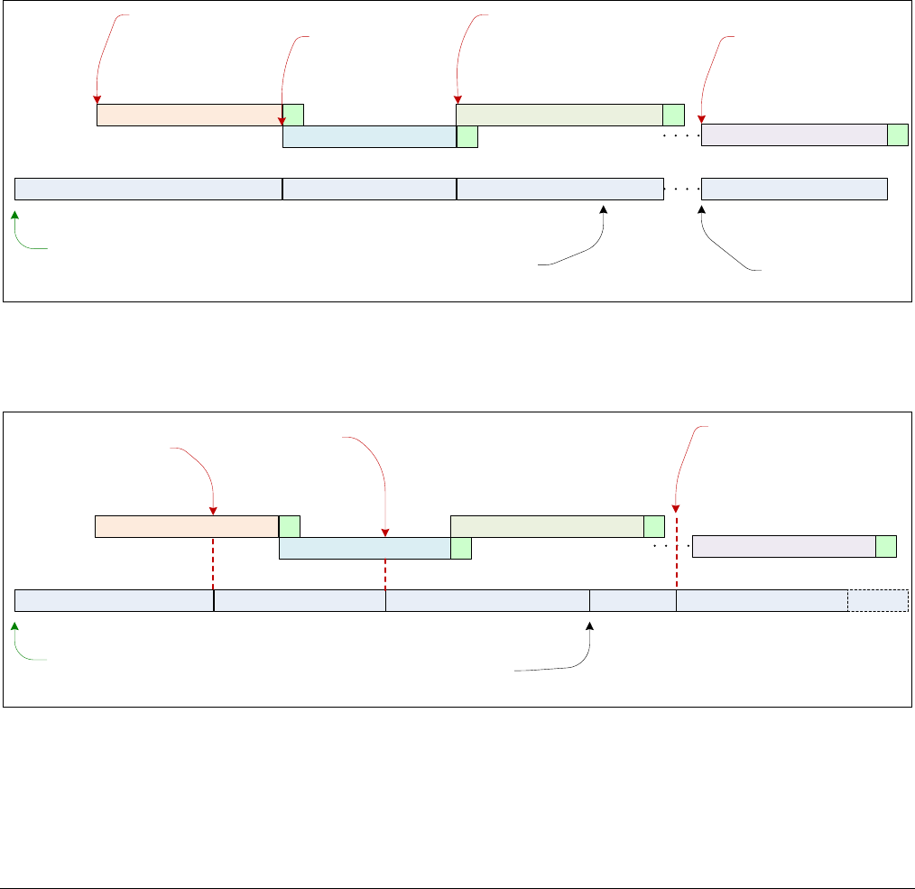
Nano Series GigE Vision Camera Operational Reference
•
149
Cycling Reset Timing Details
This section describes the Nano Cycling function with two cycling feature configurations. These
configurations (or cases) are dependent on the cycling preset increment source as follows:
• Internal Synchronous Increment: Where the preset increment source is either FrameStart
or ValidFrameTrigger (cyclingPresetIncrementalSource= StartOfFrame or ValidFrameTrigger).
• External Asynchronous Increment: Where the preset increment source is either Timer, Line
or Software (cyclingPresetIncrementalSource= Counter1End or Line2 or None).
Case 1: Cycling with Internal Synchronous Increment
With an Internal Synchronous Cycling Increment, a cycling reset command will execute on the next
cycling increment event.
Preset 1 (cycling status) Preset 2 Preset 3 Preset 1
Acquisition
Command
Frame Acquisition 1
Increment Source
cyclingPresetIncrementalSource
Frame Acquisition 2
Increment Source
cyclingPresetIncrementalSource
Frame Acquisition 3
Increment Source
cyclingPresetIncrementalSource
Frame Acquisition 4
Increment Source
cyclingPresetIncrementalSource
Asynchronous Cycling Reset
cyclingPresetResetSource
Reset Applied
cyclingPresetCurrentActiveSet
Case 2: Cycling with External Asynchronous Increment
With an External Asynchronous Cycling Increment, a cycling reset command executes immediately
and sets the cycling preset to set number 1.
Preset 1 (cycling status) Preset 2 Preset 3 Preset 1
Acquisition
Command
Frame Acquisition 1
Increment Source
cyclingPresetIncrementalSource
Frame Acquisition 2
Increment Source
cyclingPresetIncrementalSource
Frame Acquisition 3
Frame Acquisition 4
Increment Source
cyclingPresetIncrementalSource
Asynchronous Cycling Reset Applied
cyclingPresetResetSource
cyclingPresetCurrentActiveSet
Preset 2 Preset 3
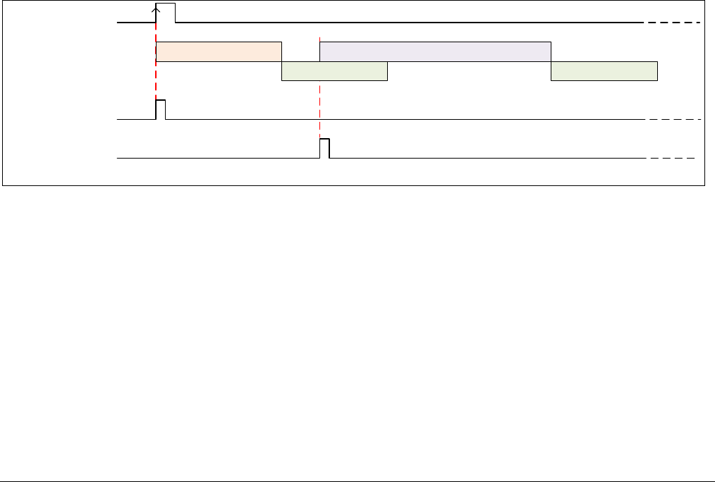
150
•
Operational Reference Nano Series GigE Vision Camera
Using Cycling Presets with Output Controls
The following graphic shows a Cycling Preset function setup where a two stage setup performs
exposures of different length and additionally provides an output pulse at the start of each
exposure.
As an example, by using both output lines, this setup can trigger two separate light strobes of
different wavelengths. This dual exposure sequence example is controlled by a single external
trigger.
Feature Settings for this Example
Below are listed key features for this setup. Other Nano features will be as required by the user.
• I/O Controls:
• TriggerSelector = FrameBurstStart
• TriggerMode = On
• triggerFrameCount = 2
• Cycling Preset
• cyclingPresetMode = Active
• cyclingPresetCount = 2
• cyclingPresetIncrementalSource = StartOfFrame
• cP_FeaturesActivationSelector = ExposureTime
• cP_FeaturesActivationMode = Active (plus set required exposure for each cycling preset)
• cP_LineSelector = Line3 (for preset 1) and Line4 (for preset 2)
• cP_OutputLineSource = PulseOnStartofExposure (line3–preset 1, line4-preset 2)
Acquisition 1 Exposure
Readout 1
Acquisition 2 Exposure
Readout 2
External Trigger
Output 1
(Line 3)
Output 2
(Line 4)
PulseOnStartofExposure
PulseOnStartofExposure

Nano Series GigE Vision Camera Operational Reference
•
151
Cycling Mode Constraints with a changing ROI
The Nano Cycling Mode features support a changing ROI from one cycling preset to the next. The
ROI in this case refers to a single acquisition area which is a subset of the complete image frame.
The initial ROI size and position (i.e. features Width, Height, OffsetX, OffsetY) is setup via the
Image Format group of features. Obviously the defined initial ROI area would be smaller so as to
allow it to be moved around via the Cycling Mode OffsetX and OffsetY features set for each Cycling
Preset.
Specifics Concerning OnSemi Sensor Models
Nano Models using OnSemi Python Sensors implement an in-sensor ROI mode which can maximize
the possible acquisition frame rate. The following characteristics apply:
• Since OnSemi sensors support in-sensor ROI mode, only the ROI bounded sensor data is read
out, which can increase the maximum possible frame rate.
• The firmware for Nano OnSemi sensors will load the ROI X and Y offset settings for the next
cycling mode preset frame, during the readout period of the current frame. Again this will
maximize possible frame rates.
• When enabling in sensor ROI, the exposureAlignment is set to Reset.
• The Frame Rate might decrease due to the maximum frame rate becoming lower. The original
value is not restored when Cycling Mode in-Sensor ROI mode is disabled.
• Exposure time might increase due to the minimum exposure time becoming higher. The original
value is not restored when the in-sensor ROI mode is disabled.
Specifics Concerning Sony Sensor Models
Sony sensors can only use in-FPGA ROI settings, thus the complete sensor area must be readout to
the processing FPGA. Then the defined ROI area is read out of the FPGA and transmitted to the
host computer. This characteristic of Sony sensors does not provide any frame rate advantage
when using various ROI selections with Cycling Mode acquisitions.

152
•
Operational Reference Nano Series GigE Vision Camera
Image Format Control Category
The Genie Nano Image Format controls, as shown by CamExpert, has parameters used to configure
camera pixel format, image cropping, image flip, Binning, multiple ROI and selecting a test output
image without a lens.
Parameters in gray are read only, either always or due to another parameter being disabled.
Parameters in black are user set in CamExpert or programmable via an imaging application.
Features listed in the description table but tagged as Invisible are usually for Teledyne DALSA or
third party software usage—not typically needed by end user applications. Also important, Genie
Nano cameras are available in a number of models implementing different sensors and image
resolutions which may not support the full feature set defined in this category.

Nano Series GigE Vision Camera Operational Reference
•
153
Image Format Control Feature Description
The following table describes these features along with their view attribute and device framework version. For each feature the device version
may differ for each camera sensor available. Such differences will be clearly indicated for any applicable feature.
A Revision Version number represents the camera software firmware revision. As Genie Nano capabilities evolve the version will increase,
therefore identifying the supported function package. New features for a major device version release will be indicated by green text for easy
identification.
The first column indicates whether a feature applies to monochrome or color camera models via a symbol. No symbol indicates a common
feature. Additionally the description column will indicate which feature is a member of the DALSA Features Naming Convention (denoted by
DFNC), versus the GenICam Standard Features Naming Convention (SFNC tag is not shown).
B/W
Color Display Name Feature & Values Description Sony
Sensors OnSemi
Sensors Nano
C4900
Data Stream Selector dataStreamSelector Select which data stream to control (default is Stream 1)
< RO, Beginner, DFNC >
Stream1 Stream1 Adjust parameters for Stream1.
Data Stream Type dataStreamType This feature is used to retrieve the transfer protocol used to
stream blocks.
< RO, Beginner, DFNC >
Image Image The Image data blocks are streamed using the payload type
“Image”.
Pixel Format PixelFormat Format of the pixel provided by the device. Contains all
format information as provided by PixelCoding, PixelSize,
PixelColorFilter, combined in one single value.
< Beginner >
Monochrome 8-Bit Mono8 Mono8: Monochrome 8-Bit 1.06
with RGB
firmware
1.06
with RGB
firmware
Ver. 1.06
Monochrome 10-Bit Mono10 Mono10: Monochrome 10-Bit
Monochrome 12-Bit Mono12 Mono12: Monochrome 12-Bit
BayerGR 8-Bit BayerGR8 Color camera: BayerGR8 1.05 1.05
BayerRG 8-Bit BayerRG8 Color camera: BayerRG8t
BayerGB 8-Bit BayerGB8 Color camera: BayerGB8 1.05 1.05
BayerBG 8-Bit BayerBG8 Color camera: BayerBG8 1.05 1.05
BayerGR 10-Bit BayerGR10 Color camera: BayerGR10 1.05 1.05
BayerRG 10-Bit BayerRG10 Color camera: BayerRG10

154
•
Operational Reference Nano Series GigE Vision Camera
BayerGB 10-Bit BayerGB10 Color camera: BayerGB10 1.05 1.05
BayerBG 10-Bit BayerBG10 Color camera: BayerBG10 1.05 1.05
BayerGR 12-Bit BayerGR12 Color camera: BayerGR12 1.05 1.05
BayerRG 12-Bit BayerRG12 Color camera: BayerRG12
BayerGB 12-Bit BayerGB12 Color camera: BayerGB12 1.05 1.05
BayerBG 12-Bit BayerBG12 Color camera: BayerBG12 1.05 1.05
BGR 8-Bit Packed BGR8 Color camera: BGR8 (RGB 24-bit) — 1.05
RGB Design Ver. 1.06
BGRA 8-Bit Packed BGRA8 Color camera: BGRA8 (RGBA 32-bit, [RGB 24 + Mono 8]) — 1.05
RGB Design Ver. 1.06
YUV422_8_YUYV YUV422_8 Color camera: YUV422_8_YUYV (16-bit) — 1.05
RGB Design Ver. 1.06
YUV422_8_UYVY YUV422_8_UYVY Color camera: YUV422_8_UYVY (16-bit) — 1.05
RGB Design Ver. 1.06
YUV422_Packed YUV422Packed Color camera: YUV422Packed (16-bit) Ver. 1.06
Pixel Size PixelSize Total size in bits of an image pixel.
< RO, Guru >
8 Bits/Pixel Bpp8 Bpp8: 8 bits per pixel
10 Bits/Pixel Bpp10 Bpp10: 10 bits per pixel
12 Bits/Pixel Bpp12 Bpp12: 12 bits per pixel
16 Bits/Pixel Bpp16 Bpp16: 16 bits per pixel
24 Bits/Pixel Bpp24 Bpp24: 24 bits per pixel
32 Bits/Pixel Bpp32 Bpp32: 32 bits per pixel
Horizontal Offset OffsetX Horizontal offset from the Sensor Origin to the Region Of
Interest (in pixels).
< Beginner >
Vertical Offset OffsetY Vertical offset from the Sensor Origin to the Region Of
Interest (in Lines).
< Beginner >
Width Width Width of the Image provided by the device (in pixels).
< Beginner >
Height Height Height of the Image provided by the device (in lines).
< Beginner >
Horizontal Flip ReverseX Horizontal image flip function (available on some models). NA Ver. 1.06
Vertical Flip ReverseY Vertical image flip function (available on some models). Ver. 1.01 Ver. 1.06
Multiple ROI Mode multipleROIMode Enable the Multiple ROI (Region of Interest) per image
feature. The ROI Count is set by the Multiple ROI Count
feature.
< Expert, DFNC >
—
Off Off Single ROI per image.

Nano Series GigE Vision Camera Operational Reference
•
155
Active Active The ROI per image feature is active.
ROI Count Horizontal multipleROICountHorizontal Specifies the number of ROI (Region of Interest) available
for the X axis.
< Expert, DFNC >
—
ROI Count Vertical multipleROICountVertical Specifies the number of ROI (Region of Interest) available
for the Y axis.
< Expert, DFNC >
—
ROI Count multipleROICount Specifies the number of possible ROI (Region of Interest)
available in an acquired image. One is minimum, while the
maximum is device specific.
< Expert, DFNC, RO >
ROI Selector multipleROISelector Select an ROI (Region of Interest) when Multiple ROI Mode
is enabled. Selector range is from 1 to the Multiple ROI
Count value.
< Expert, DFNC >
—
ROI (x1, y1) roi1_1 ROI (x1, y1)
ROI (x2, y1) roi2_1 ROI (x2, y1)
ROI (x3, y1) roi3_1 ROI (x3, y1)
ROI (x4, y1) roi4_1 ROI (x4, y1)
ROI (x1, y2) roi1_2 ROI (x1, y2)
ROI (x2, y2) roi2_2 ROI (x2, y2)
ROI (x3, y2) roi3_2 ROI (x3, y2)
ROI (x4, y2) roi4_2 ROI (x4, y2)
ROI (x1, y3) roi1_3 ROI (x1, y3)
ROI (x2, y3) roi2_3 ROI (x2, y3)
ROI (x3, y3) roi3_3 ROI (x3, y3)
ROI (x4, y3) roi4_3 ROI (x4, y3)
ROI (x1, y4) roi1_4 ROI (x1, y4)
ROI (x2, y4) roi2_4 ROI (x2, y4)
ROI (x3, y4) roi3_4 ROI (x3, y4)
ROI (x4, y4) roi4_4 ROI (x4, y4)
ROI Offset X multipleROIOffsetX Horizontal offset (in pixels) from the origin to the selected
ROI (Region of Interest).
< Expert, DFNC >
ROI Offset Y multipleROIOffsetY Vertical offset (in pixels) from the origin to the selected ROI
(Region of Interest).
< Expert, DFNC >
ROI Width multipleROIWidth Width of the selected ROI (Region of Interest) provided by
the device (in pixels).
< Expert, DFNC >
ROI Height multipleROIHeight Height of the selected ROI (Region of Interest) provided by
the device (in pixels).
< Expert, DFNC >

156
•
Operational Reference Nano Series GigE Vision Camera
Binning Selector binningSelector Select how the Horizontal and Vertical Binning is done. The
Binning function can occur in the Digital domain of a device
or at the actual sensor.
< Beginner >
Ver. 1.06
(Available
on some
models)
Ver. 1.03
(Available
on some
models)
Ver. 1.06
NanoXL
—
In Sensor InSensor The Binning function can be done inside the Sensor itself,
which often allows binning to increase the data rate from
the sensor.
In Digital Domain InDigitalDomain The Binning function can be done inside the device but with
a digital processing function. Binning doesn’t affect the
current data rate from the sensor or camera.
Binning Mode binningMode Sets the mode used to combine pixels together when
BinningHorizontal and/or BinningVertical is greater than 1.
< Beginner >
Ver. 1.07
(Available
on some
models)
Ver. 1.07
(Available
on some
models)
Ver. 1.07
NanoXL
—
Sum Sum The responses from the individual pixels are added
together, resulting in increased sensitivity.
Average Average The responses from the individual pixels are averaged,
resulting in increased signal to noise ratio.
Binning Horizontal BinningHorizontal Number of horizontal pixels to combine together using the
method selected by binningMode. This reduces the
horizontal resolution of the image.
< Beginner >
Ver. 1.03
Binning Vertical BinningVertical Number of vertical pixels to combine together using the
method selected by binningMode. This reduces the vertical
resolution of the image.
< Beginner >
Ver. 1.03
Decimation Selector decimationSelector Select how Horizontal and Vertical Decimation is done. The
Decimation function can operate in the Digital domain of a
device or directly at the sensor.
< Beginner >
— — Ver. 1.06
In Sensor InSensor The Decimation function operates directly in the Sensor,
thus reducing the pixel count from the sensor and camera.
In Digital Domain InDigitalDomain The Decimation function operates in the device with a
digital processing function. Decimation doesn’t affect the
current data rate from the sensor or camera.
Decimation Horizontal DecimationHorizontal Horizontal sub-sampling of the image. This reduces the
horizontal resolution of the image by the specified
horizontal decimation factor. For example, when set to 2,
every second pixel is discarded.
< Beginner >
Ver. 1.06
Decimation Vertical DecimationVertical Vertical sub-sampling of the image. This reduces the
vertical resolution of the image by the specified vertical
decimation factor. For example, when set to 2, every
second line is discarded.
< Beginner >
Ver. 1.06
Test Image Selector TestImageSelector Selects the type of test image generated by the camera.
< Beginner >
Off Off Image is from the camera sensor.

Nano Series GigE Vision Camera Operational Reference
•
157
Grey Horizontal Ramp GreyHorizontalRamp Image is filled horizontally with an image that goes from
the darkest possible value to the brightest.
Grey Vertical Ramp GreyVerticalRamp Image is filled vertically with an image that goes from the
darkest possible value to the brightest.
Grey Diagonal Ramp
Moving GreyDiagonalRampMoving Image is filled horizontally with an image that goes from
the darkest possible value to the brightest by 1 Dn
increment per pixel and that moves horizontally.
Width Max WidthMax The maximum image width is the dimension calculated after
horizontal binning, decimation or any other function
changing the horizontal dimension of the image.
< RO, Invisible >
Height Max HeightMax The maximum image height is the dimension calculated
after vertical binning, decimation or any other function
changing the vertical dimension of the image.
< RO, Invisible >
Pixel Coding PixelCoding Output image pixel coding format of the sensor.
< RO, Invisible >
Mono Mono Pixel is monochrome
MonoSigned MonoSigned Pixel is monochrome and signed
MonoPacked MonoPacked Pixel is monochrome and packed
Raw Bayer Raw Pixel is raw Bayer
BGR8 Packed BGR8Packed Pixel is BGR 24-bit 1.05
RGB Design
BGRA Packed BGRA8Packed Pixel is BGRA 32-bit 1.05
RGB Design
YUV422 Packed YUV422Packed Pixel is YUV422 16-bit UYVY 1.05
RGB Design
YUYV Packed YUYVPacked Pixel is YUV422 16-bit YUYV 1.05
RGB Design
Pixel Color Filter PixelColorFilter Indicates the type of color filter applied to the image.
< RO, Invisible >
None None No filter applied on the sensor.
Bayer GR BayerGR For BayerGR, the 2x2 mosaic alignment is GR/BG.
Bayer RG BayerRG For BayerRG, the 2x2 mosaic alignment is RG/GB.
Bayer GB BayerGB For BayerGB, the 2x2 mosaic alignment is GB/RG.
Bayer BG BayerBG For BayerBG, the 2x2 mosaic alignment is BG/GR.

158
•
Operational Reference Nano Series GigE Vision Camera
Width and Height Features for Partial Scan Control
Width and Height controls along with their respective offsets, allow the Genie Nano to grab a region
of interest (ROI) within the full image frame. Besides eliminating post acquisition image cropping
done by software in the host computer, a windowed ROI grab reduces the bandwidth required on
the Gigabit Ethernet link since less pixels are transmitted.
Vertical Cropping (Partial Scan)
The Height and Vertical Offset features, used for vertical cropping, reduce the number of video
lines grabbed for a frame. By not scanning the full height of the sensor, the maximum possible
acquisition frame rate is proportionately increased, up to the Genie Nano model maximum.
The following figure is an example of a partial scan acquisition using both Height and Vertical Offset
controls. The Vertical Offset feature defines at what line number from the sensor origin to acquire
the image. The Height feature defines the number of lines to acquire (to a maximum of the
remaining frame height). Note that only the partial scan image (ROI) is transmitted to the host
computer.
Partial Scan Illustration
Note: In general, using short exposures at high frame rates will exceed the maximum bandwidth to host
transfer speed, when the camera buffer memory is filled. The tables below (for different Genie Nano
models) describe frame rate maximums written to internal memory that can be sustained during continuous
acquisition. Increase the exposure time, decrease the frame rate, enable TurboDrive, or acquire a limited
number of frames, so as to not exceed the transfer bandwidth.

Nano Series GigE Vision Camera Operational Reference
•
159
Maximum Frame Rate Examples (Models M/C 1920 & 1940)
Vertical Lines
Acquired Internal Trigger / Minimum Exposure
Sony sensor – M/C1920 Models Internal Trigger / Minimum Exposure
Sony sensor – M/C1940 Models
1216 38 fps 83 fps
1080 43 fps 94 fps
900 51 fps 111 fps
600 75 fps 163 fps
450 98 fps 212 fps
300 141 fps 304 fps
150 249 fps 539 fps
74 409 fps 884 fps
32 632 fps 1366 fps
16 799 fps 1724 fps
Maximum Frame Rate Examples (Models M2420 & M2450)
Vertical Lines
Acquired Internal Trigger
Minimum Exposure
Sony sensor – M2420 Models
Internal Trigger
Minimum Exposure
Sony sensor – M2450 Models
Standard Design Firmware
Internal Trigger
Minimum Exposure
Sony sensor – M2450 Models
High Sensitivity Design
2048 34 fps 76 fps 94 fps
1536 45 fps 101 fps 124 fps
1024 68 fps 150 fps 184 fps
768 90 fps 198 fps 242 fps
512 132 fps 290 fps 355 fps
384 173 fps 379 fps 463 fps
256 251 fps 543 fps 664 fps
128 454 fps 963 fps 1177 fps
64 763 fps 1567 fps 1915 fps
32 1158 fps 2283 fps 2793 fps
16 1560 fps 2958 fps 3623 fps
8 1890 fps 3472 fps 4237 fps
4 2109 fps 3802 fps 4651 fps

160
•
Operational Reference Nano Series GigE Vision Camera
Maximum Frame Rate Examples (Models M2020 & M2050)
Vertical Lines
Acquired Internal Trigger
Minimum Exposure
Sony sensor – M2020 Models
Internal Trigger
Minimum Exposure
Sony sensor – M2050 Models
Standard Design Firmware
Internal Trigger
Minimum Exposure
Sony sensor – M2050 Models
High Sensitivity Design
1536 53 fps 116.6 fps 143 fps
1024 79 fps 173.8 fps 213 fps
768 105 fps 228.9 fps 280 fps
512 154 fps 335.4 fps 411 fps
384 202 fps 437.2 fps 536 fps
256 293 fps 627.7 fps 769 fps
128 530 fps 1111 fps 1362 fps
64 892 fps 1808 fps 2217 fps
32 1353 fps 2631 fps 3225 fps
16 1821 fps 3412 fps 4184 fps
8 2207 fps 4000 fps 4901 fps
4 2463 fps 4386 fps 5376 fps
Maximum Frame Rate Examples (Models M/C 4040 & 4060)
Increased frame rates with a reduced ROI available only when In-Sensor binning is not active.
Vertical Lines
Acquired Internal Trigger / Minimum Exposure
Sony sensor – M/C4040 Models Internal Trigger / Minimum Exposure
Sony sensor – M/C4060 Models
3008 33.6 fps —
2176 46.1 fps 46.1 fps
2048 48.9 fps 48.9 fps
1024 95.4 fps 95.4 fps
512 181.7 fps 181.7 fps
256 331.8 fps 331.8 fps
128 564.6 fps 564.6 fps
64 871.0 fps 871.0 fps
32 1194.7 fps 1194.7 fps
16 1468.4 fps 1468.4 fps
8 1658.3 fps 1658.3 fps
4 1773.0 fps 1773.0 fps

Nano Series GigE Vision Camera Operational Reference
•
161
Maximum Frame Rate Examples (Models M/C 4020 & 4030)
Vertical Lines
Acquired Internal Trigger / Minimum Exposure
Sony sensor – M/C4020 Models Internal Trigger / Minimum Exposure
Sony sensor – M/C4030 Models
3008 14.6 fps —
2176 20.1 fps 20.1 fps
2048 21.4 fps 21.4 fps
1024 42.1 fps 42.1 fps
512 81.5 fps 81.5 fps
256 153.2 fps 153.2 fps
128 273.6 fps 273.6 fps
64 450.2 fps 450.2 fps
32 665.3 fps 665.3 fps
16 873.3 fps 873.3 fps
8 1037.3 fps 1037.3 fps
4 1142.8 fps 1142.8 fps
Maximum Frame Rate Examples (Model M/C 2590)
Vertical Lines
Acquired Internal Trigger / Minimum Exposure
OnSemi sensor – M/C2590 Models Internal Trigger / Minimum Exposure
OnSemi sensor – M/C2590 Models
Fast Readout Mode Enabled
2048 42 fps 51 fps
1536 56 fps 69 fps
1024 85 fps 102 fps
768 112 fps 136 fps
512 167 fps 202 fps
256 325 fps 391 fps
128 616 fps 734 fps
64 1114 fps 1310 fps
32 1869 fps 2150 fps
16 2832 fps 3174 fps
8 3802 fps 4149 fps
4 4608 fps 4926 fps
2 5128 fps 5405 fps
Note: Fast Readout Mode will have low DN Fixed Pattern column artifacts as described here
OnSemi Sensor Fast Readout Mode.

162
•
Operational Reference Nano Series GigE Vision Camera
Maximum Frame Rate Examples (Model C 4900)
Vertical Lines Acquired Internal Trigger / Minimum Exposure
Aptina sensor – C4900 Model
3684 13.38 fps
2762 17.76 fps
1842 26.36 fps
1024 46.19 fps
768 60.45 fps
512 87.46 fps
256 158.0 fps
128 265.0 fps
64 400.6 fps
32 538.5 fps
16 650.1 fps
8 725.1 fps
4 769.8 fps
Maximum Frame Rate Examples (Model M/C 1930)
Vertical Lines
Acquired Internal Trigger / Minimum Exposure
OnSemi sensor – M/C1930 Models Internal Trigger / Minimum Exposure
OnSemi sensor – M/C1930 Models
Fast Readout Mode Enabled
1200 91 fps 116 fps
1024 106 fps 136 fps
768 141 fps 180 fps
512 209 fps 266 fps
256 403 fps 510 fps
128 755 fps 941 fps
64 1337 fps 1628 fps
32 2174 fps 2564 fps
16 3164 fps 3597 fps
8 4098 fps 4504 fps
4 4807 fps 5154 fps
2 5263 fps 5555 fps
Note: Fast Readout Mode will have low DN Fixed Pattern column artifacts as described here
OnSemi Sensor Fast Readout Mode.

Nano Series GigE Vision Camera Operational Reference
•
163
Maximum Frame Rate Examples (Model M/C 1240)
Vertical Lines
Acquired Internal Trigger / Minimum Exposure
OnSemi P3 sensor
1024 87.29 fps
768 115.9 fps
512 172.5 fps
256 337.2 fps
128 645.1 fps
64 1187 fps
32 2049 fps
16 3215 fps
8 4484 fps
4 5586 fps
2 6369 fps
Maximum Frame Rate Examples (Model M/C 1280)
Vertical Lines
Acquired Internal Trigger / Minimum Exposure
OnSemi sensor – M/C1280 Models Internal Trigger / Minimum Exposure
OnSemi sensor – M/C1280 Models
Fast Readout Mode Enabled
1024 174 fps 213 fps
768 231 fps 283 fps
512 345 fps 421 fps
256 674 fps 821 fps
128 1287 fps 1557 fps
64 2364 fps 2824 fps
32 4065 fps 4761 fps
16 6369 fps 7246 fps
8 8849 fps 9803 fps
4 10989 fps 11904 fps
2 12500 fps 13333 fps
Note: Fast Readout Mode will have low DN Fixed Pattern column artifacts as described here
OnSemi Sensor Fast Readout Mode.

164
•
Operational Reference Nano Series GigE Vision Camera
Maximum Frame Rate Examples (Model M/C 800)
Vertical Lines
Acquired Internal Trigger / Minimum Exposure
OnSemi sensor – M/C800 Models Internal Trigger / Minimum Exposure
OnSemi sensor – M/C800 Models
Fast Readout Mode Enabled
600 419 fps 566 fps
480 520 fps 701 fps
240 1004 fps 1340 fps
128 1776 fps 2331 fps
64 3164 fps 4048 fps
32 5181 fps 6369 fps
16 7633 fps 9009 fps
8 10000 fps 11236 fps
4 11904 fps 12987 fps
2 12987 fps 13888 fps
Note: Fast Readout Mode will have low DN Fixed Pattern column artifacts as described here
OnSemi Sensor Fast Readout Mode.
Maximum Frame Rate Examples (Model M/C 640)
Vertical Lines
Acquired Internal Trigger / Minimum Exposure
OnSemi sensor – M/C640 Models Internal Trigger / Minimum Exposure
OnSemi sensor – M/C640 Models
Fast Readout Mode Enabled
480 603 fps 862 fps
240 1160 fps 1631 fps
128 2032 fps 2801 fps
64 3558 fps 4716 fps
32 5714 fps 7194 fps
16 8196 fps 9803 fps
8 10526 fps 11904 fps
4 12195 fps 13333 fps
2 13157 fps 14285 fps
Note: Fast Readout Mode will have low DN Fixed Pattern column artifacts as described here
OnSemi Sensor Fast Readout Mode.

Nano Series GigE Vision Camera Operational Reference
•
165
Maximum Frame Rate Examples (NanoXL–M5100)
Using High Speed Firmware (8-bit only)
Vertical Lines
Acquired Internal Trigger / Minimum Exposure
Python 25k sensor – model M5100 Internal Trigger / Minimum Exposure
Python 25k sensor – model M5100
Fast Readout Mode Enabled
5120 11.8 20.4
3840 15.7 27.2
2560 23.5 40.7
1280 46.9 80.9
640 93.2 160.5
320 184.1 315.2
160 359.1 608.3
80 684.9 1137.7
40 1253.1 2012.1
20 2141.3 3267.9
10 3322.2 4761.9
5 4566.2 6134.9
Note: Fast Readout Mode will have low DN Fixed Pattern column artifacts as described here
OnSemi Sensor Fast Readout Mode.
Using Standard Firmware
Vertical Lines
Acquired Internal Trigger / Minimum Exposure
Python 25k sensor – model M5100 Internal Trigger / Minimum Exposure
Python 25k sensor – model M5100
Fast Readout Mode Enabled
5120 5.9 fps 10.2 fps
3840 7.8 fps 13.6 fps
2560 11.8 fps 20.4 fps
1280 23.5 fps 40.6 fps
640 46.8 fps 80.7 fps
320 92.7 fps 159.5 fps
160 182.1 fps 311.4 fps
80 351.6 fps 594.5 fps
40 657.9 fps 1089.3 fps
20 1165.5 fps 1865.6 fps
10 1901.1 fps 2907 fps
5 2770 fps 4016 fps

166
•
Operational Reference Nano Series GigE Vision Camera
Maximum Frame Rate Examples (NanoXL–M4090)
Using High Speed Firmware (8-bit only)
Vertical Lines
Acquired Internal Trigger / Minimum Exposure
Python 16k sensor –model M4090 Internal Trigger / Minimum Exposure
Python 16k sensor – model M4090
Fast Readout Mode Enabled
4096 16.5 31.2
3840 17.6 33.4
2560 26.3 49.9
1280 52.5 99.3
640 104.2 196.3
320 205.5 384.0
160 400.0 735.8
80 758.7 1356.8
40 1375.5 2347.4
20 2320.2 3703.7
10 3521.1 5181.3
5 4761.9 6493.5
Note: Fast Readout Mode will have low DN Fixed Pattern column artifacts as described here
OnSemi Sensor Fast Readout Mode.
Using Standard Firmware
Vertical Lines
Acquired Internal Trigger / Minimum Exposure
Python 16k sensor –model M4090 Internal Trigger / Minimum Exposure
Python 16k sensor – model M4090
Fast Readout Mode Enabled
4096 8.2 15.6
3840 8.8 16.7
2560 13.2 25.0
1280 26.3 49.8
640 53.3 98.2
320 103.6 194.9
160 203.0 378.5
80 390.6 715.3
40 725.7 1288.6
20 1272.2 2155.1
10 2036.6 3236.2
5 2915 4329

Nano Series GigE Vision Camera Operational Reference
•
167
Horizontal Cropping (Partial Scan)
Genie Nano supports cropping the acquisition horizontally by grabbing less pixels on each
horizontal line. Horizontal offset defines the start of the acquired video line while horizontal width
defines the number of pixels per line. Horizontal control features have the following independent
constants:
• Horizontal Offset is limited to pixel increment values of 4 to define the start of the video
line.
• Horizontal Width decrements from maximum in pixel counts of 8 (i.e. the video width is in
steps of 8 pixels).
Using the Multiple ROI Mode
Genie Nano monochrome cameras implement the Multiple ROI mode (region of interest) features,
which allow having 2 to 16 smaller image ROI areas versus the single ROI area possible with
vertical and horizontal crop functions.
These multiple areas are combined as one output image, reducing transfer bandwidth
requirements, plus with the added benefit that any reduction of the number of vertical lines output
will result in a greater possible camera frame rate. This increased frame rate increase (written to
internal memory) is similar to using the vertical crop feature.
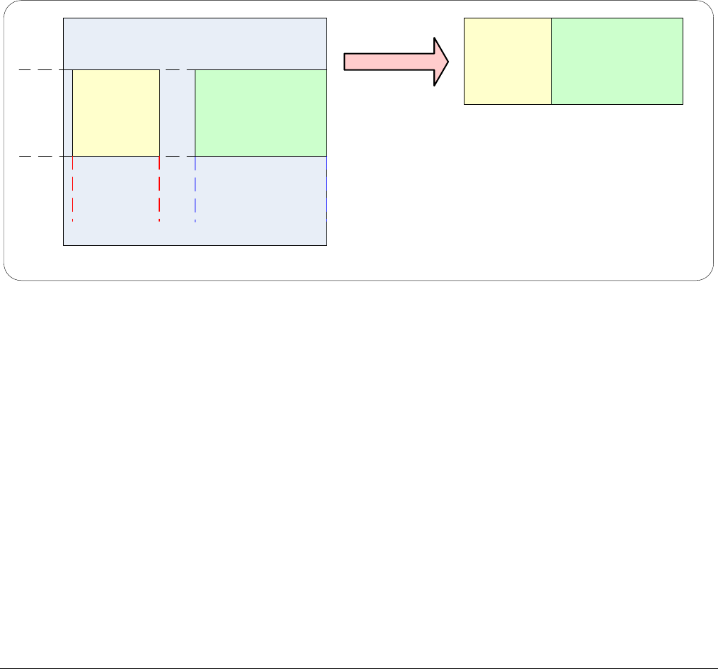
168
•
Operational Reference Nano Series GigE Vision Camera
Important Usage Details
• Two to 16 ROI areas are supported by the Genie Nano (4x4 matrix maximum).
• For any selected ROI, the Offset X/Offset Y features define the upper left corner of the ROI.
• Offset, Width, and Height features have individual increment values (step size) to consider.
• The first ROI of any row sets the “height value” for any other ROI in that row.
• The first ROI of any column sets the “width value” of any other ROI in that column.
• Note that the Nano firmware by default provides a 4x4 sample multi-ROI setup for easy
verification of this function.
The following graphics show examples of the multi-ROI function (2x1 and 2x2 areas), the resultant
camera output, and the constraints when configuring the ROI areas.
Example: Two Horizontal ROI Areas (2x1)
ROI (x1,y1) ROI (x2,y1)
ROI (x1,y1) ROI (x2,y1)
2 ROI Areas Defined
Camera Outputs only the 2 ROI Areas
• Note that ROI(x1, y1) defines the height of any ROI in that row.
• ROI(x2, y1) can have a different width.
• The camera output image frame consists only of the two ROI areas. The user must account for
the change between ROI data for each output image row.
• The output image being smaller, reduces the bandwidth requirements.
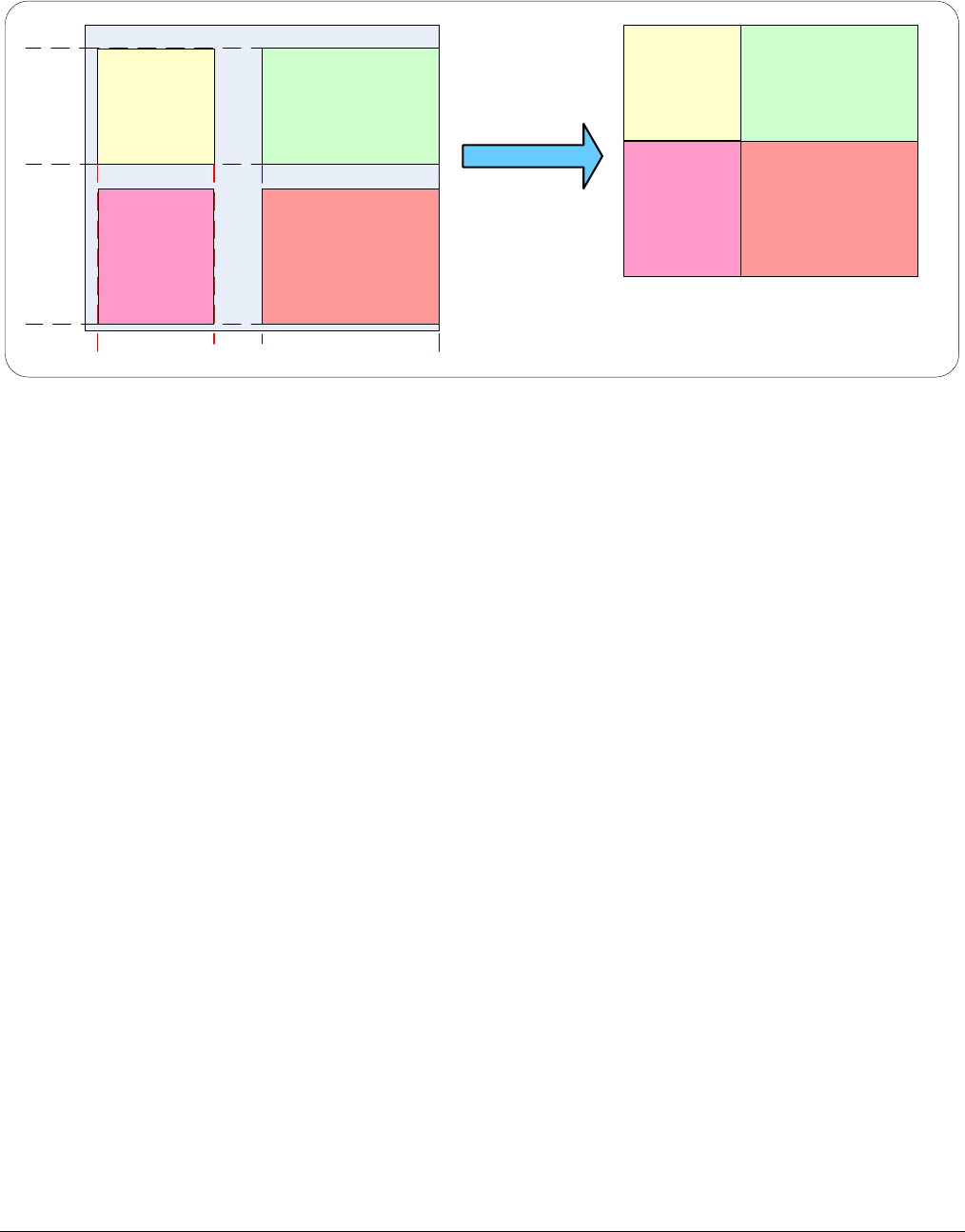
Nano Series GigE Vision Camera Operational Reference
•
169
Example: Four ROI Areas (2x2)
ROI (x1,y1)ROI (x2,y1)ROI (x1,y1) ROI (x2,y1)
4 ROI Areas Defined
Camera Outputs only the 4 ROI Areas
ROI (x1,y2) ROI (x2,y2)
ROI (x1,y2) ROI (x2,y2)
• Note that ROI(x1, y1) defines the height of any ROI in that row.
• ROI(x2, y1) can have a different width.
• ROI(x1, y2) can have a different height relative to ROI(x1,y1).
• The camera output image frame consists only of the ROI areas, in the same order as the ROI
rows and columns. The user must account for the change between ROI data for each output
image row.
• The output image being smaller, reduces the bandwidth requirements.
Example: Actual Sample with Six ROI Areas (3x2)
This example uses the example problem of solder inspection of certain components on a PCB. The
image below of a sample PCB shows 6 ROI areas highlighted by the yellow overlay graphics
(manually added to this example).
Note how the top row ROI areas may be larger than ideal due to height and width requirements of
ROI areas in the second row; constraints and interdependencies as defined in the preceding ROI
descriptions.
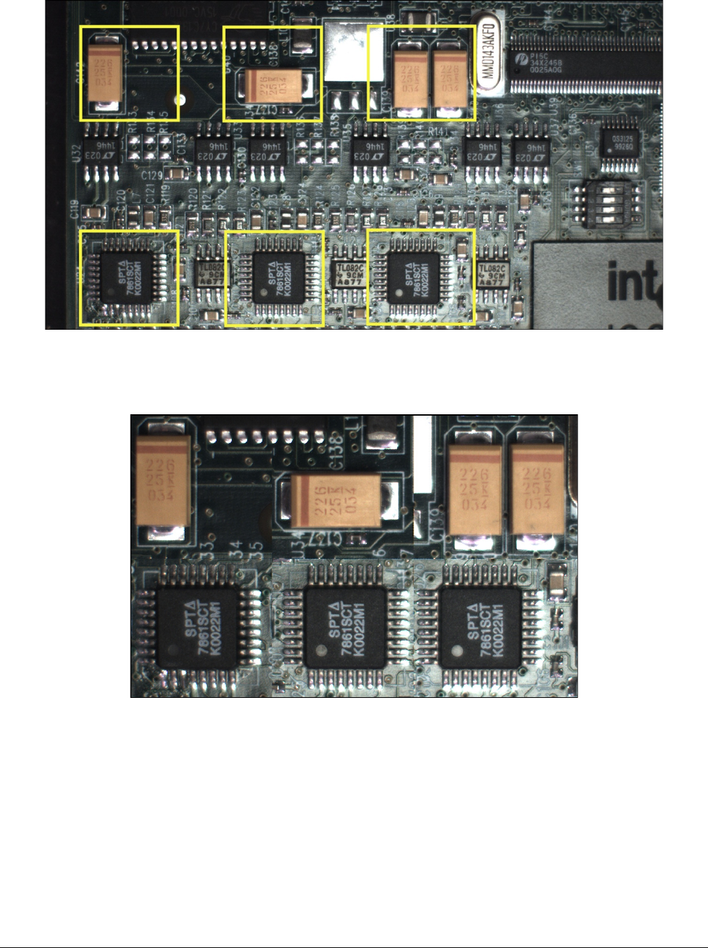
170
•
Operational Reference Nano Series GigE Vision Camera
With the ROI areas defined, the camera outputs an image consisting only of data within those ROI
areas, as shown below. Such data reduction improves transfer bandwidth and also reduces image
processing time for the host system imaging application.
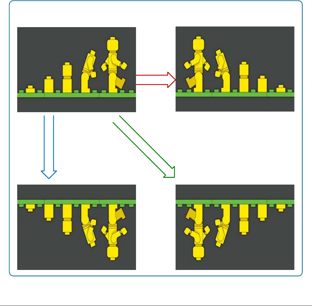
Nano Series GigE Vision Camera Operational Reference
•
171
Horizontal and Vertical Flip
The Image Flip features activate image acquisition with horizontal and/or vertical inversion.
• Support of one or both of these functions is Genie Nano model specific since it is a function of
sensor data readout, not post sensor processing (thus internal test images cannot be flipped).
• When image flip is supported directly at the sensor, activation of the flip function does not
reduce the maximum frame rate possible from that model of Nano.
• The Image flip functions operate both on full image acquisitions and when using multi-ROI.
Both modes are described below.
Image Flip – Full Frame
With full frame acquisitions, live horizontal and/or vertical image flips function as expected.
Horizontal Flip (Mirror)
Vertical Flip Both Horizontal & Vertical Flip
Acquisition Flip Features
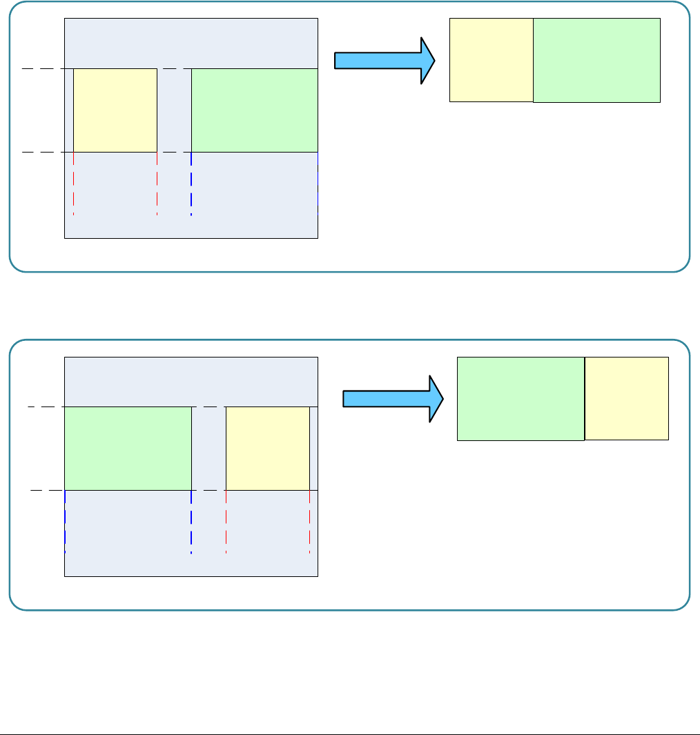
172
•
Operational Reference Nano Series GigE Vision Camera
Image Flip – Multi-ROI Mode
Image acquisition flips with multi-ROI enabled is implemented as follows:
• The first graphic below shows a simple multi-ROI of two areas, where the camera output is
composed of only those two areas.
• As shown in the second graphic, the multi-ROI implementation resizes the programmed ROI
areas so that the same exact image areas are output by the camera but flipped as expected.
• Note that the ROI indexes do not transpose—just their size and offsets.
• All multi-ROI setup constraints remain as described in the previous section describing the
Multi-ROI mode.
ROI (x1,y1) ROI (x2,y1)
ROI (x1,y1) ROI (x2,y1)
2 ROI Areas Defined
Camera Output
ROI (x2,y1)
ROI (x1,y1)
ROI (x2,y1)
ROI (x1,y1)
2 ROI Areas After Horizontal Flip
Camera Output
Horizontal Flip with Multi-ROI

Nano Series GigE Vision Camera Operational Reference
•
173
Binning Function and Limitations
Binning is the process where the charge on two (or more) adjacent pixels is combined. This results
in increased light sensitivity since there is twice the sensor area to capture photons. The sensor
spatial resolution is reduced but the improved low-light sensitivity plus lower signal-noise ratio may
solve a difficult imaging situation. The user can evaluate the results of the binning function on the
Genie Nano by using CamExpert.
Horizontal and vertical binning functions are independent, by factors of 2 or 4 in each axis.
Specifically if horizontal binning only is activated, a nominal 640x480 image is reduced to 320x480.
If vertical binning only is activated, the image is reduced to 640x240. With both binning modes
activated, the resulting image is 320x240.
Binning is performed digitally, therefore there is no increase in acquisition frame rate. The following
graphic illustrates binning.
1640
639432
1 2 320
Horizontal Binning
by 2
Line
1
Line
2
Line
3
Line
4
Line
479
Line
480
Line
1
Line
2
Line
240
Repeated for each
line of pixels
Repeated for each column of pixels
Vertical Binning
by 2
Horizontal and Vertical Binning Illustration
Horizontal Binning Constraints
• Horizontal Binning of 2 requires a minimum frame width of 128 pixels or more.
• Horizontal Binning of 4 requires a minimum frame width of 256 pixels or more.
Vertical Binning Constraints
• Vertical Binning of 4 is available if the image height before binning is a multiple of 4 lines.
• Vertical Binning of 2 is available if the image height before binning is a multiple of 2 lines.

174
•
Operational Reference Nano Series GigE Vision Camera
Internal Test Pattern Generator
The Genie Nano camera includes a number of internal test patterns which easily confirm camera
installations, without the need for a camera lens or proper lighting.
Use CamExpert to easily enable and select the any of the Nano test patterns from the drop menu
while the camera is not in acquisition mode. Select live grab to see the pattern output.
Note that internal test patterns are generated by the camera FPGA where the patterns are inserted
immediately after the sensor output in the processing chain and are the same maximum bit depth
as the sensor. The patterns are identical for monochrome or color camera models and subject to
processing operations.
• Note: Selecting the camera 8-bit output format displays the lower 8-bits of the processing path.
The Nano Test Patterns are:
• Grey Horizontal ramp: Image is filled horizontally with an image that goes from the darkest
possible value to the brightest.
• Grey Vertical ramp: Image is filled vertically with an image that goes from the darkest
possible value to the brightest.
• Grey Diagonal Ramp Moving: combination of the 2 previous schemes, but first pixel in image
is incremented by 1 between successive frames. This is a good pattern to indicate motion when
doing a continuous grab.
Important: When an internal Nano Test Image is selected, the Metadata feature values for Exposure
Time and Exposure Delay are not valid values and must be ignored.
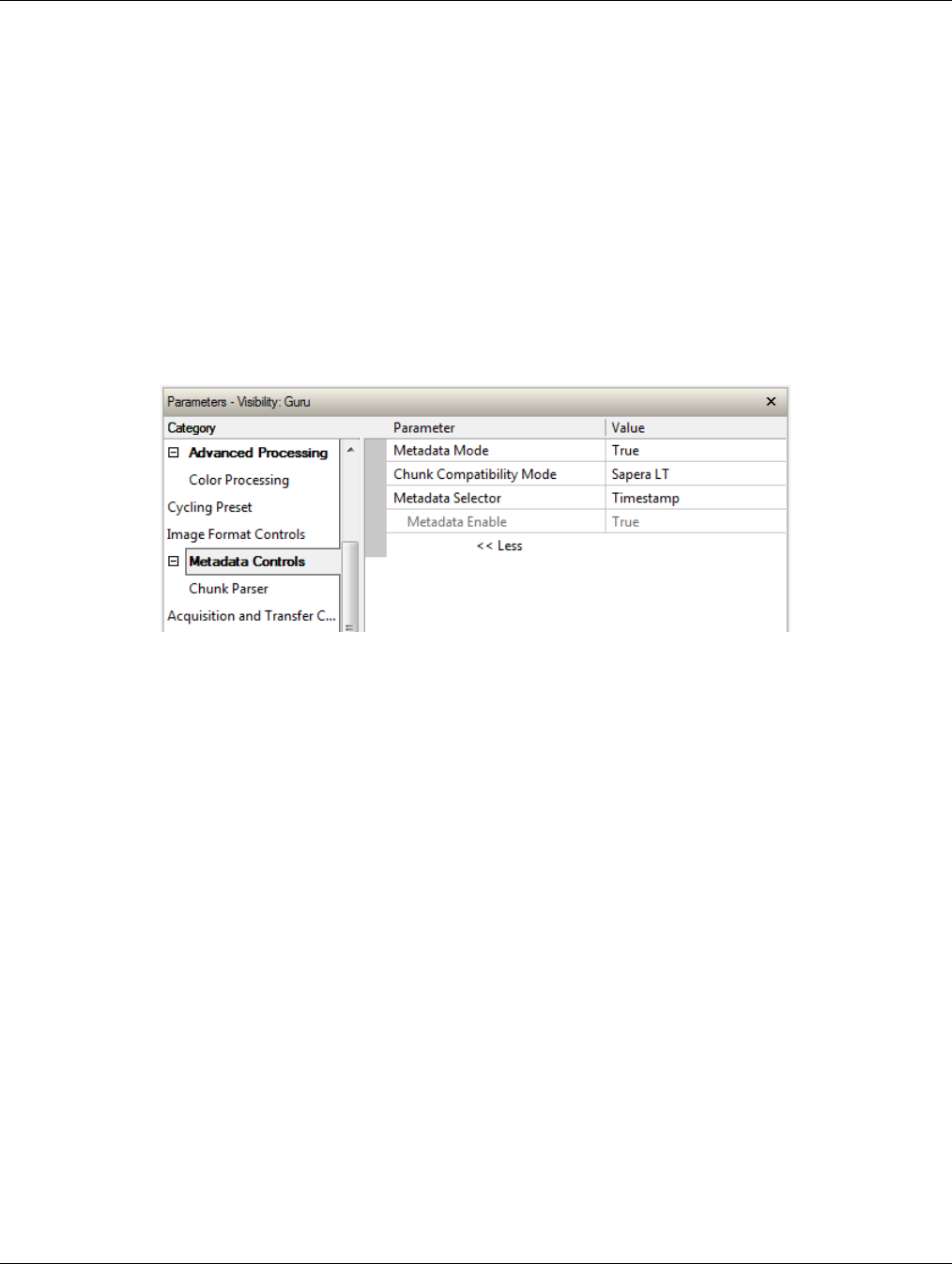
Nano Series GigE Vision Camera Operational Reference
•
175
Metadata Control Category
The Genie Nano Metadata controls as shown by CamExpert, has features to enable and select
inclusion of chunk data with the image payload (as specified by the specification GigE Vision 1.2).
Parameters in gray are read only, either always or due to another parameter being disabled.
Parameters in black are user set in CamExpert or programmable via an imaging application.
Note: Metadata and Turbo Drive features are available with firmware 1.07 and later. Sapera LT
8.31 is required (or GigE Vision driver 5.10).
Limitation: Metadata and Turbo Drive feature availability are currently mutually exclusive with
camera firmware versions 1.00 to 1.06.
Features listed in the description table but tagged as Invisible are usually for Teledyne DALSA or
third party software usage—not typically needed by end user applications. Also important, Genie
Nano cameras are available in a number of models implementing different sensors and image
resolutions which may not support the full feature set defined in this category.
Metadata Control Category Feature Descriptions
The following table describes these parameters along with their view attribute and minimum
camera firmware version required. Additionally the Device Version column will indicate which
parameter is a member of the Teledyne DALSA Features Naming Convention (denoted by DFNC),
versus the GenICam Standard Features Naming Convention (SFNC not shown).
Teledyne DALSA provides header files for developers managing Genie Nano LUT data and chunk
payload data as supported by GigE Vision 1.2. Refer to section following the table of metadata
features.
The Device Version number represents the camera software functional group, not a firmware
revision number. As Genie capabilities evolve the device version tag will increase, therefore
identifying the supported function package. New features for a major device version release will be
indicated by green text for easy identification.

176
•
Operational Reference Nano Series GigE Vision Camera
Display Name Feature & Values Description Device Version
& View
Metadata Mode ChunkModeActive Activates the inclusion of chunk data (metadata) in the
payload of the image.
1.01
Expert
False No chunk data.
True Chunk data included in payload
Chunk
Compatibility
Format
chunkCompatibilityMode Selects the format of the chunk data (metadata) in the
payload of the image.
1.04
Expert
DFNC
Sapera LT SaperaLT Metadata compatible with Teledyne DALSA Sapera LT 8.0.
Gen API GenAPI Metadata compatible with GenICam GenAPI.
Metadata
Selector ChunkSelector Selects the specific metadata to control, when enabled.
1.04
Expert
OffsetX Add the OffsetX value used during the image acquisition
to the metadata attached to the image
OffsetY Add the OffsetY value used during the image acquisition
to the metadata attached to the image.
Width Add the Width value used during the image acquisition to
the metadata attached to the image.
Height Add the Height value used during the image acquisition to
the metadata attached to the image.
PixelFormat Add the PixelFormat value used during the image
acquisition to the metadata attached to the image.
ExposureTime Add the ExposureTime value used during the image
acquisition to the metadata attached to the image.
ExposureDelay Add the ExposureDelay value used during the image
acquisition to the metadata attached to the image.
Supported only in GenAPI compatibility mode.
(N/A for C4900 – 1.06)
cyclingPresetCurrentActiveSet Add the cyclingPresetCurrentActiveSet value used during
the image acquisition to the metadata attached to the
image.
Timestamp Copies the timestampValue value at the start of exposure
to the metadata attached to the image.
LineStatusAll Copies the LineStatusAll value at the start of exposure to
the metadata attached to the image.
Gain Add the Gain feature value used during the image
acquisition to the metadata attached to the image.
Counter1ValueAtReset Copies the value of the feature ”counterValueAtReset” at
the start of Frame Readout, to the Metadata attached to
the image. Supported only in GenAPI compatibility mode.
DeviceID Add the DeviceID value to the metadata attached to the
image.
DeviceUserID Add the DeviceUserID value to the metadata attached to
the image.
TestImageSelector Add the TestImageSelector value used during the image
acquisition to the metadata attached to the image.
BinningVertical Add the BinningVertical value used during the image
acquisition to the metadata attached to the image.
<ver. 1.03>
BinningHorizontal Add the BinningHorizontal value used during the image
acquisition to the metadata attached to the image.
<ver. 1.03>
Metadata Enable ChunkEnable Sets the enable state of the selected metadata. When
enabled, the metadata is included in the payload of the
image.
1.01
Expert
False Selected metadata Disabled
True Selected metadata Enabled

Nano Series GigE Vision Camera Operational Reference
•
177
Chunk Exposure
Time ChunkExposureTime Returns the exposure time used to capture the image.
1.04
Guru
Chunk Cycling
Preset Current
Active Set
ChunkCyclingPresetCurrentActiveSet Returns the index of the cycling preset used for this
image.
1.04
Guru
Chunk Line
Status All ChunkLineStatusAll Returns the status of all available line signals, when the
image was exposed. The order is Line1, Line2, ....
1.04
Guru
Chunk Gain
Selector ChunkGainSelector Selects which gain is read by the ChunkGain feature.
1.04
Guru
Digital DigitalAll Apply a digital gain adjustment to the entire image. This
independent gain factor is applied to the image after the
sensor.
Sensor SensorAll This gain is applied to the image by the sensor.
Chunk Gain ChunkGain The selected gain value used for the image included in
the payload.
1.04
Guru
Chunk Horizontal
Offset ChunkOffsetX Horizontal offset from the Sensor Origin to the Region Of
Interest (in pixels).
1.04
Guru
Chunk Vertical
Offset ChunkOffsetY Vertical offset from the Sensor Origin to the Region Of
Interest (in lines).
1.04
Guru
Chunk Width ChunkWidth Image Width (in pixels) included in the payload.
1.04
Guru
Chunk Height ChunkHeight Image Height (in lines) included in the payload.
1.04
Guru
Chunk
Timestamp Value ChunkTimestamp Returns the 64-bit Timestamp value for the image
included in the payload.
1.04
Guru
Chunk Binning
Horizontal ChunkBinningHorizontal Number of horizontal pixels to combine in the payload
image.
1.04
Guru
Chunk Binning
Vertical ChunkBinningVertical Number of vertical pixels to combine in the payload
image.
1.04
Guru
Chunk Test
Image Selector ChunkTestImageSelector The selected test image included in the payload.
1.04
Guru
Off Off Image is from the camera sensor.
Grey Horizontal
Ramp GreyHorizontalRamp Image is filled horizontally with an image that goes from
the darkest possible value to the brightest.
Grey Vertical
Ramp GreyVerticalRamp Image is filled vertically with an image that goes from the
darkest possible value to the brightest.
Grey Diagonal
Ramp Moving GreyDiagonalRampMoving Image is filled horizontally and vertically with an image
that goes from the darkest possible value to the brightest
by 1 DN increment per pixel and that moves horizontally
from right to left at each frame by one pixel.
Chunk Serial
Number ChunkDeviceID Displays the factory set serial number of the device.
1.04
Guru
Chunk Device
User ID ChunkDeviceUserID Returns the user define name of the camera.
1.04
Guru
Chunk Pixel
Format ChunkPixelFormat Pixel format of payload image.
1.04
Guru
Monochrome
8-Bit Mono8 Mono8: Monochrome 8-Bit
Monochrome
10-Bit Mono10 Mono10: Monochrome 10-Bit
Monochrome
12-Bit Mono12 Mono12: Monochrome 12-Bit
BayerGR8
8-bit BayerGR8 Color camera: BayerGR8
BayerRG8
8-bit BayerRG8 Color camera: BayerRG8
BayerGB8
8-bit BayerGB8 Color camera: BayerGB8
BayerBG8
8-bit BayerBG8 Color camera: BayerBG8
BayerGR10
10-bit BayerGR10 Color camera: BayerGR10

178
•
Operational Reference Nano Series GigE Vision Camera
BayerRG10
10-bit BayerRG10 Color camera: BayerRG10
BayerGB10
10-bit BayerGB10 Color camera: BayerGB10
BayerBG10
10-bit BayerBG10 Color camera: BayerBG10
BayerGR12
12-bit BayerGR12 Color camera: BayerGR12
BayerRG12
12-bit BayerRG12 Color camera: BayerRG12
BayerGB12
12-bit BayerGB12 Color camera: BayerGB12
BayerBG12
12-bit BayerBG12 Color camera: BayerBG12
BGR 8-Bit Packed BGR8 Color camera: BGR8
BGRA 8-Bit
Packed BGRA8 Color camera: BGRA8
YUV422_8_YUYV YUV422_8 Color camera: YUV422_8_YUYV
YUV422_8_UYVY YUV422_8_UYVY Color camera: YUV422_8_UYVY
YUV422_8_UYVY YUV422Packed Color camera: YUV422_8_UYVY (same as previous for
compatibility with third party software)
1.06
Chunk Exposure
Delay chunkExposureDelay Specifies the delay in microseconds (µs) to apply after the
FrameStart event, before starting the ExposureStart
event.
1.04
Guru
counter1 Value At
Reset chunkCounter1ValueAtReset Copies the value of the feature ”counterValueAtReset” at
the start of Frame Readout, to the Metadata attached to
the image. Supported only in GenAPI compatibility mode.
1.04
Guru
Important Metadata Notes:
• For firmware revisions 1.04 OffsetX and OffsetY chuck data will return values without
accounting for any binning applied. Later versions of firmware will return metadata values
matching the OffsetX and OffsetY features.
• When using Metadata in conjunction with TurboDrive, the Nano driver (all models) requires that
the image acquisition width (horizontal crop) must be a minimum of 160 pixels in 8-bit mode or
96 pixels in 10/12-bit mode. The driver requires this minimum width to correctly apply the
TurboDrive compression algorithm. When acquisitions are cropped more than the minimum
widths, TurboDrive is automatically disabled while Metadata remains active.
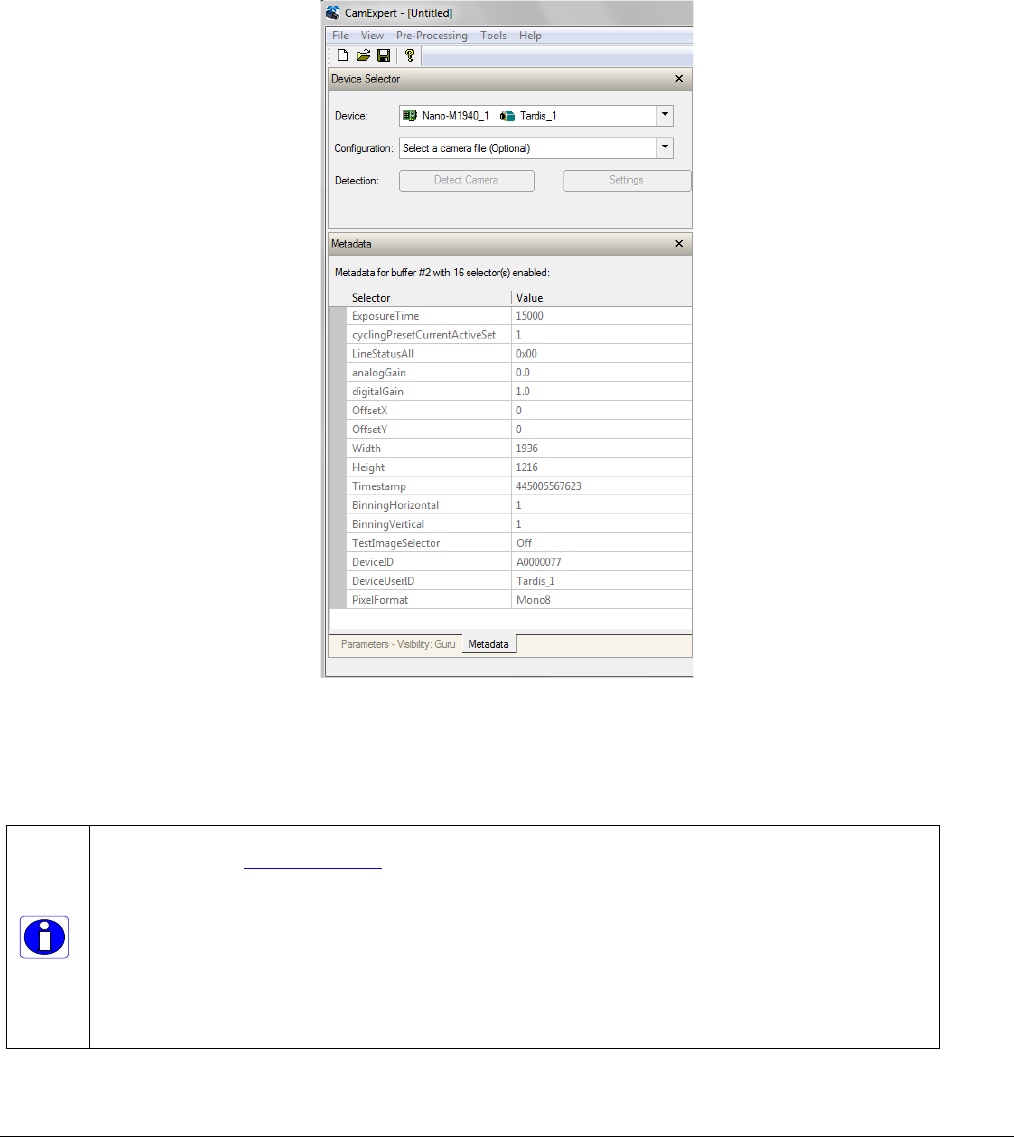
Nano Series GigE Vision Camera Operational Reference
•
179
Extracting Metadata Stored in a Sapera Buffer
For Sapera LT developers, a new class “SapMetadata” is now included with Sapera version 8.10.
For users of earlier versions of Sapera 8.xx, please contact Teledyne DALSA technical support.
Sapera also provides two methods to view metadata. The Sapera CamExpert tool provides a tab
(when the Metadata feature is enabled) to view the metadata of the last frame capture, as shown
by the following image.
Alternatively, Sapera LT provides a demo program called GigEMetaDataDemo.exe which will grab a
number of frames and display the metadata or save it to a file (.csv). In addition, source code and
C++ project files are included for a console based executable.
The following figure shows the Sapera Explorer tool screen with the Metadata Example highlighted.
Important:
When an internal Nano Test Image is selected, the Metadata feature values for Exposure Time
(ExposureTime) and Exposure Delay (exposureDelay) are not valid values and must be ignored.
When in free running (not triggered) mode, the Metadata value for feature Exposure Delay
(exposureDelay) is not a valid value and must be ignored.
The value of LineStatusAll is updated on the start of exposure.
Currently the metadata value for “analogGain” is invalid for all On-Semi sensor models.
For Sony sensor models, the metadata “analogGain” represents the raw gain value divided by 100.
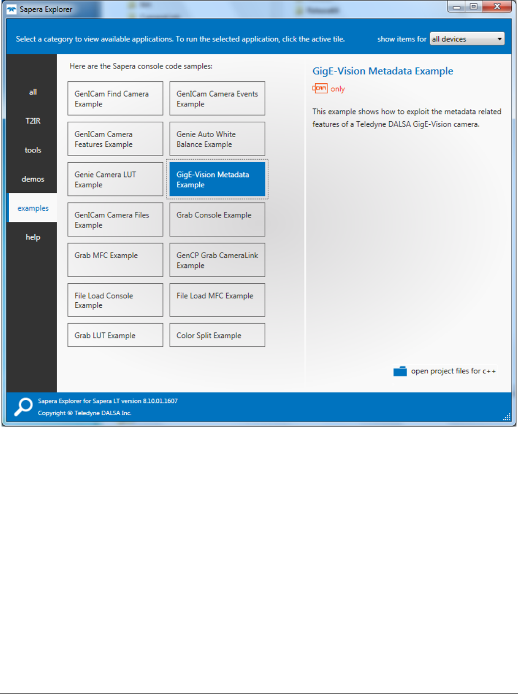
180
•
Operational Reference Nano Series GigE Vision Camera
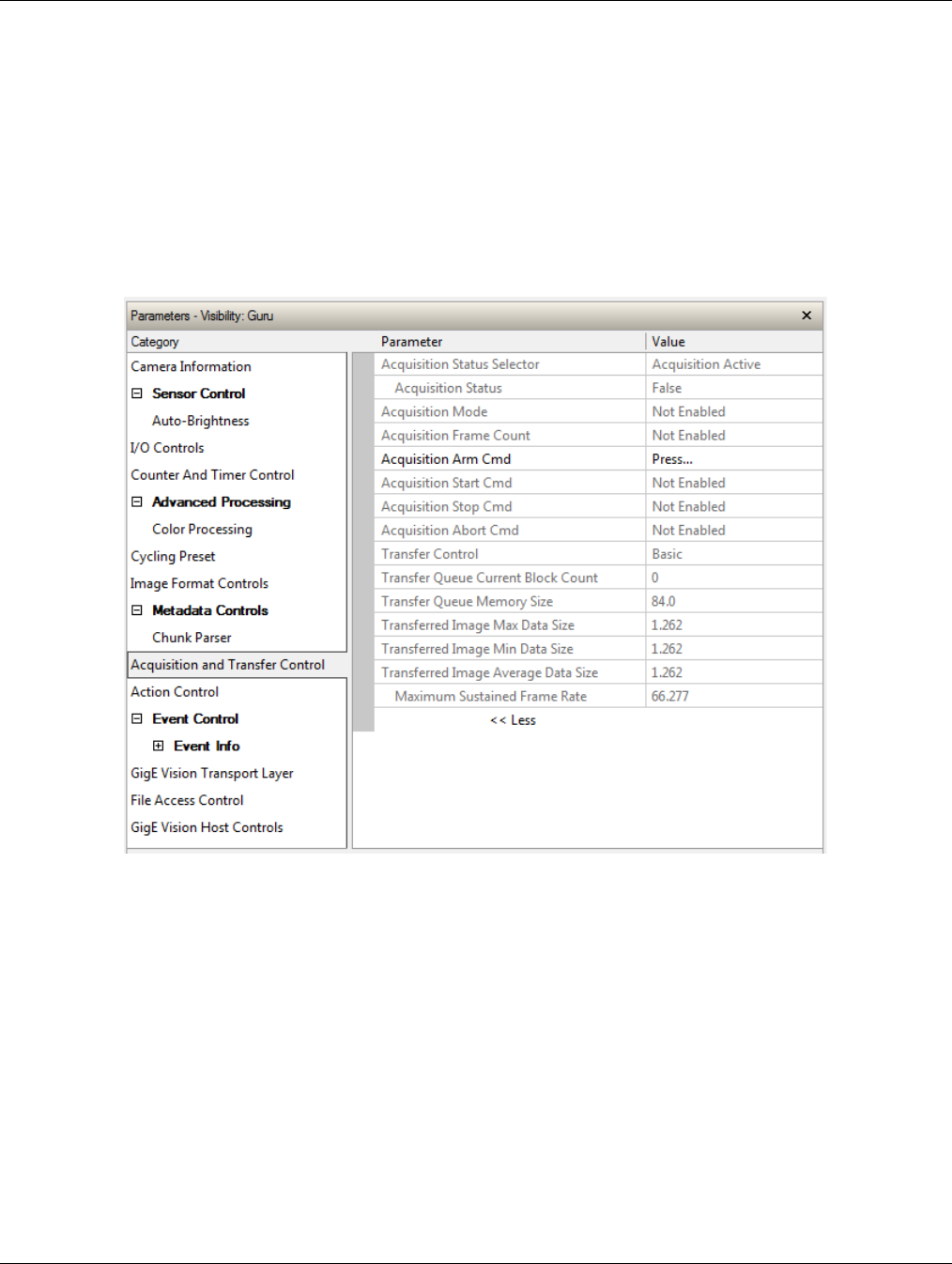
Nano Series GigE Vision Camera Operational Reference
•
181
Acquisition and Transfer Control Category
The Genie Nano Acquisition and Transfer controls, as shown by CamExpert, has parameters used to
configure the optional acquisition modes of the device.
Parameters in gray are read only, either always or due to another parameter being disabled.
Parameters in black are user set in CamExpert or programmable via an imaging application.
Features listed in the description table but tagged as Invisible are usually for Teledyne DALSA or
third party software usage—not typically needed by end user applications. Also important, Genie
Nano cameras are available in a number of models implementing different sensors and image
resolutions which may not support the full feature set defined in this category.

182
•
Operational Reference Nano Series GigE Vision Camera
Acquisition and Transfer Control Feature Descriptions
The following table describes these parameters along with their view attribute and minimum
camera firmware version required. Additionally the Device Version column will indicate which
parameter is a member of the DALSA Features Naming Convention (denoted by DFNC), versus the
GenICam Standard Features Naming Convention (SFNC tag is not shown).
The Device Version number represents the camera software functional group, not a firmware
revision number. As Genie Nano capabilities evolve the device version tag will increase, therefore
identifying the supported function package. New features for a major device version release will be
indicated by green text for easy identification.
Display Name Feature & Values Description Device Version
& View
Acquisition Status
Selector AcquisitionStatusSelector Selects the internal acquisition signal to read using
AcquisitionStatus. 1.00
Expert
Acquisition Active AcquisitionActive Device is currently doing an acquisition of one or
many frames.
Acquisition Trigger Wait AcquisitionTriggerWait Device is currently waiting for a trigger to start the
acquisition. (Ver. 1.05)
Acquisition Status AcquisitionStatus Reads the state of the internal acquisition signal
selected using the Acquisition Status Selector feature.
(i.e. False / True)
1.00
Expert
Acquisition Mode AcquisitionMode Set the acquisition mode of the device. It defines the
number of frames to capture during an acquisition
and the way the acquisition stops.
1.00
Beginner
Single Frame SingleFrame One frame is captured for each AcquisitionStart
Command. An AcquisitionStop occurs at the end of
the Active Frame.
Multi-Frame MultiFrame A sequence of frames is captured for each
AcquisitionStart Command. The number of frames is
specified by AcquisitionFrameCount feature. An
AcquisitionStop occurs at the end of the Active
Frame(s)
Continuous Continuous Frames are captured continuously with
AcquisitionStart until stopped with the AcquisitionStop
command.
Acquisition Frame Count AcquisitionFrameCount Number of frames to be acquired in MultiFrame
acquisition mode.
1.00
Beginner
Acquisition Arm Cmd AcquisitionArm Arms the device before an AcquisitionStart command.
This optional command validates all the current
features for consistency and prepares the device for a
fast start of the acquisition. If not used explicitly, this
command is automatically executed at the first
AcquisitionStart but will not be repeated for
subsequent ones unless a data transfer related
feature is changed in the device.
1.00
Guru
Acquisition Start Cmd AcquisitionStart Start image capture using the currently selected
acquisition mode. The number of frames captured is
specified by AcquisitionMode feature.
1.00
Beginner
Acquisition Stop Cmd AcquisitionStop Stops the Acquisition of the device at the end of the
current frame unless the triggerFrameCount feature is
greater than 1. (WO)
1.00
Beginner
Acquisition Abort Cmd AcquisitionAbort Aborts the acquisition immediately. This will end the
capture without completing the current Frame or
aborts waiting on a trigger. If no acquisition is in
progress, the command is ignored.
1.00
Beginner
Transfer Control TransferControlMode Sets the method used to control the transfer. 1.00

Nano Series GigE Vision Camera Operational Reference
•
183
Basic Basic Basic mode ensures maximum compatibility but does
not allow for control of the transfer flow.
Expert
Transfer Queue Current
Block Count transferQueueCurrentBlockCount Returns the current number of blocks in the transfer
queue. 1.00
DFNC
Expert
Transfer Queue Memory
Size transferQueueMemorySize Indicates the amount of device memory (in Mbytes)
available for internal image frame accumulation in the
transfer queue. Increasing or decreasing memory
reserved by devicePacketResendBufferSize will affect
total memory available here.
1.00
DFNC
Expert
Transferred Image Max
Data Size transferMaxBlockSize Biggest image (GVE blocks) data size sent on the
GigE cable. The value is displayed in Megabytes. Use
this value to calculate the frame rate transferred on
the GigE cable.
GigE Link speed (~115 MB) divided by Biggest Image
(value) = Max fps transferred.
Note: This statistic is reset when acquisitions are
stopped.
1.01
DFNC
Beginner
Transferred Image Min
Data Size transferMinBlockSize Smallest image (GVE blocks) data size sent on the
GigE cable. The value is displayed in Megabytes.
Note: This statistic is reset when acquisitions are
stopped.
1.01
DFNC
Beginner
Transferred Image
Average Data Size transferAverageBlockSize Average size of the last 16 images (GVE blocks) of
data sent on the GigE cable. The value is displayed in
Megabytes. Use this value to calculate the sustained
frame rate transferred on the GigE cable.
GigE Link speed (~115 MB) divided by Average size
(value) = Max fps transferred. When TurboDrive is
enabled, this feature allows monitoring the average
throughput.
1.01
DFNC
Beginner
Maximum Sustained
Frame Rate maxSustainedFrameRate Maximum sustained frame rate that can be achieved
by the camera in the current configuration
(Resolution, Pixel Format and the camera’s internal
bandwidth limitations). When TurboDrive is enabled,
this value also takes the feature
transferAverageBlockSize into account.
1.03
DFNC
Beginner
Device Registers
Streaming Start DeviceRegistersStreamingStart Announces the start of registers streaming without
immediate checking for consistency.
1.00
Invisible
Device Registers
Streaming End DeviceRegistersStreamingEnd Announces end of registers streaming and performs
validation for registers consistency before activating
them.
1.00
Invisible
Device Feature
Streaming Start DeviceFeaturePersistenceStart Announces the start of feature streaming without
immediate checking for consistency.
1.00
Invisible
Device Feature
Streaming End DeviceFeaturePersistenceEnd Announces end of feature streaming and performs
validation for feature consistency before activating
them.
1.00
Invisible
Register Check DeviceRegistersCheck Performs an explicit register set validation for
consistency.
1.00
Invisible
Registers Valid DeviceRegistersValid States if the current register set is valid and
consistent.
1.00
Invisible
Acquisition Buffering
All acquisitions are internally buffered and transferred as fast as possible to the host system. This
internal buffer allows uninterrupted acquisitions no matter of any transfer delays that might occur
(such as acquisition frame rates faster that the Gigabit Ethernet link or the IEEE Pause frame).
Only when the internal buffer is consumed would an Image Lost Event be generated.
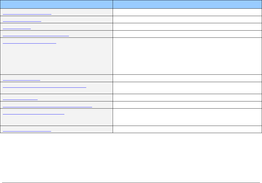
184
•
Operational Reference Nano Series GigE Vision Camera
Using Transfer Queue Current Block Count with CamExpert
This feature returns the number of frames buffered within the Genie Nano pending transfer to the
host system. Image frames are buffered in cases where the host system is temporarily busy or
cases of high network traffic with other devices through the same Ethernet switch. By buffering
image frames, the Genie Nano will not need to drop frames when there are temporary delays to
the transfer.
When using CamExpert, right click on this field and then click on Refresh from the pop-up menu.
The current frame count in the transfer buffer is displayed in the Value field. During live grab, if the
number of frames in the transfer buffer is increasing, then there is a problem with the network or
host bandwidth being exceeded. The ImageLost event occurs when all buffer space is consumed.
“Acquisition Abort” Execution Exception with Model C4900
For the model C4900 (Aptina sensor) the AcquisitionAbort feature does not execute immediately,
as is the case for all other Nano models.
When aborting an acquisition with the C4900, the application needs to follow this sequence:
• Set the feature AcquisitionStatusSelector=AcquisitionActive
• Send the command AcquisitionAbort
• Poll the status AcquisitionStatus until it is FALSE
Features that cannot be changed during a Transfer
The following features cannot be changed during an acquisition or when a transfer is connected.
Feature Group Features Locked During a Sapera Transfer
CAMERA INFORMATION UserSetLoad
SENSOR CONTROL NA
I/O CONTROL NA
COUNTER AND TIMER CONTROL NA
IMAGE FORMAT CONTROL PixelFormat
OffsetX (except within the Cycling Mode)
OffsetY (except within the Cycling Mode)
Binning (except within the Cycling Mode)
Width
Height
Multi-ROI functions
Metadata Controls ChunkModeActive
ACQUISITION AND TRANSFER CONTROL DeviceRegistersStreamingStart
DeviceRegistersStreamingEnd
EVENT CONTROL NA
GIGE VISION TRANSPORT LAYER CONTROL GevSCPSPacketSize
GIGE VISION HOST CONTROL InterPacketTimeout
InterPacketTimeoutRaw
ImageTimeout
FILE ACCESS CONTROL NA

Nano Series GigE Vision Camera Operational Reference
•
185
Action Control Category
The Genie Nano Action Control group, as shown by CamExpert, has features related to the control
of the Action Command mechanism for the device.
Parameters in gray are read only, either always or due to another parameter being disabled.
Parameters in black are user set in CamExpert or programmable via an imaging application.
Features listed in the description table but tagged as Invisible are usually for Teledyne DALSA or
third party software usage—not typically needed by end user applications. Also important, Genie
Nano cameras are available in a number of models implementing different sensors and image
resolutions which may not support the full feature set defined in this category.

186
•
Operational Reference Nano Series GigE Vision Camera
Action Control Feature Descriptions
The following table describes these parameters along with their view attribute and minimum
camera device version required. Additionally the Device Version column will indicate which
parameter is a member of the DALSA Features Naming Convention (denoted by DFNC), versus the
GenICam Standard Features Naming Convention (SFNC tag is not shown).
The Device Version number represents the camera software functional group, not a firmware
revision number. As Genie Nano capabilities evolve the device version tag will increase, therefore
identifying the supported function package. New features for a major device version release will be
indicated by green text for easy identification.
Display Name Feature & Values Description Device Version
& View
Action Device Key ActionDeviceKey Nano default=1
Writing 0 will disable action command.
Provides the device key that allows the device to
check the validity of action commands. (WO)
1.03
Guru
Action Selector ActionSelector Selects the action command to configure. Certain
Nano features support 2 Action commands.
1.03
Beginner
Action Group Key ActionGroupKey Nano default=0 for all action command.
Provides the key that the device uses to validate that
the action command message is part of the requested
group.
1.03
Guru
Action Group Mask ActionGroupMask Nano default=1 for action 1, or 2 for action 2.
Provides the mask used to filter particular action
command messages for the selected action.
1.03
Guru
GigE Vision Action Command Reference
An Action Command is a single Broadcast packet sent from the Host Software application to all
cameras connected on the same network. How cameras act on an Action Command depends on its
designed feature support. Cameras receiving the Action Command broadcast may have one or
multiple functions acting on that received command.
Please refer to the GigE Vision® Specification — version 2.0 RC6, for configuration and usage
details. Contact Teledyne DALSA Support and request example code for Action Command usage.
Nano Features supporting Action Command
Feature Category Feature Enum
I/O Control Trigger Selector Single Frame Trigger (Start)
MultiFrame Trigger (Start)
Trigger Source Action 1
Output Line Source Pulse On: Action 1
Pulse On: Action 2
Counter and Timer Control Counter Start Source Action 1
Action 2
Timer Start Source Action 1
Action 2
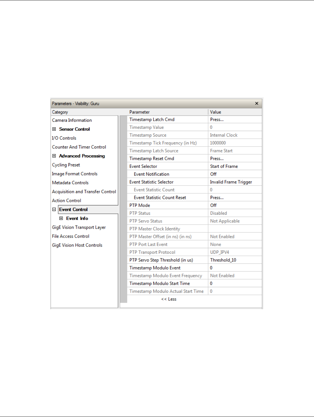
Nano Series GigE Vision Camera Operational Reference
•
187
Event Control Category
The Genie Nano Event control, as shown by CamExpert, has parameters used to configure Camera
Event related features. Parameters in gray are read only, either always or due to another
parameter being disabled. Parameters in black are user set in CamExpert or programmable via an
imaging application.
Features listed in the description table but tagged as Invisible are usually for Teledyne DALSA or
third party software usage—not typically needed by end user applications. Also important, Genie
Nano cameras are available in a number of models implementing different sensors and image
resolutions which may not support the full feature set defined in this category.

188
•
Operational Reference Nano Series GigE Vision Camera
Event Control Feature Descriptions
The following table describes these parameters along with their view attribute and minimum
camera firmware version required. Additionally the Device Version column will indicate which
parameter is a member of the DALSA Features Naming Convention (denoted by DFNC), versus the
GenICam Standard Features Naming Convention (SFNC tag is not shown).
The Device Version number represents the camera software functional group, not a firmware
revision number. As Genie Nano capabilities evolve the device version tag will increase, therefore
identifying the supported function package. New features for a major device version release will be
indicated by green text for easy identification.
Display Name Feature & Values Description Device
Version
& View
Timestamp Latch Cmd timestampControlLatch Latch the current timestamp internal counter value
in the timestampValue feature.
1.00
Expert
DFNC
Timestamp Value timestampValue Returns the 64-bit value of the timestamp, which
is the internal Clock timer or the PTP clock timer,
depending on the Timestamp Source selection.
1.00
Expert
DFNC
TimeStamp Source timestampSource Specifies the source used as the incrementing
signal for the Timestamp register.
1.00
Expert
DFNC
Internal Clock InternalClock The timestamp source is generated by the camera
internal clock. Refer to the
timestampTickFrequency feature for the time
base.
IEEE1588 IEEE1588 The timestamp source is controlled by the network
IEEE1588 protocol. This source is automatically
selected when PTP mode is enabled.
Timestamp Tick Frequency timestampTickFrequency Indicates the number of timestamp ticks (or
increments) during 1 second (frequency in Hz).
This feature changes depending on the TimeStamp
Source.
1.00
Expert
DFNC
Timestamp Latch Source timestampLatchSource Specifies the internal event or signal that will latch
the timestamp counter into the timestamp buffer.
1.00
Expert
DFNC
Frame Start FrameStart The timestamp is latched on frame start.
Timestamp Reset Cmd timestampControlReset Resets the timestamp counter to 0. This Feature
resets both the internal Clock timer and the PTP
clock timer. Note that the PTP Mode must be
disabled first to reset the PTP clock timer.
1.00
Expert
DFNC
Event Selector EventSelector Select the Event to enable/disable with the
EventNotification feature.
1.00
Expert
Start of Frame FrameStart Event sent on control channel on an Active Frame.
This occurs with the start of the exposure delay.
Start of Exposure ExposureStart Event sent on control channel on start of
exposure.
End of Exposure ExposureEnd Event sent on control channel on end of exposure.
(N/A for C4900 – 1.06)
Start of Readout ReadoutStart Event sent on control channel on start of sensor
readout.
End of Readout ReadoutEnd Event sent on control channel on end of sensor
readout.
Acquisition Start Next
Valid AcquisitionStartNextValid Event sent on control channel when the
AcquisitionStart command can be used again.
Valid Frame Trigger ValidFrameTrigger Event sent on control channel when a valid frame
trigger is generated.

Nano Series GigE Vision Camera Operational Reference
•
189
Invalid Frame Trigger InvalidFrameTrigger Event sent on control channel when a frame
trigger occurs in an invalid Trigger region.
Therefore the trigger is rejected and no frame
acquisition occurs.
Image Lost ImageLost Event sent on control channel when an image is
lost due to insufficient memory.
Counter 1 End Counter1End Event sent when counter 1 has reached the
counterDuration count. (ver. 1.06)
Events Overflow eventsOverflow Event sent on control channel when all previous
active events have been disabled because the
camera cannot send them fast enough, generating
in internal message overflow. Required events
must be re-enabled manually.
Event Notification EventNotification Enable Events for the event type selected by the
EventSelector feature.
1.00
Expert
Off Off The selected event is disabled.
On On The selected event will generate a software event.
GigEVisionEvent GigEVisionEvent The selected event will generate a software event.
This entry is deprecated.
Using “On” is recommended.
Event Statistic Selector eventStatisticSelector Selects which Event statistic to display. 1.00
Expert
DFNC
Invalid Frame Trigger InvalidFrameTrigger Counts the frame trigger occurring in an invalid
Trigger region.
Image Lost ImageLost Image is acquired but lost before it’s been
transferred.
Packet Resend PacketResend Counts the number of individual packets that are
resent.
Packet Resend Request
Dropped PacketResendRequestDropped Counts the number of packet resend requests
dropped. The camera queues the packet resend
requests until they are processed. There is a limit
to the number of requests that can be queued by
the camera. When a new request is received and
the queue is full, the request is dropped but this
statistic is still incremented.
Ethernet Pause Frame
Received EthernetPauseFrameReceived Counts the number of Ethernet Pause Frame
received. Feature limited to 65536 events. See
also PAUSE Frame Support for information on
Ethernet Packet size.
Event Statistic Count eventStatisticCount Display the count of the selected Event.
1.00
Expert
DFNC
Event Statistic Count
Reset eventStatisticCountReset Reset the count of the selected Event.
1.00
Expert
DFNC
PTP Mode ptpMode Specifies the PTP (IEEE-1588: Precision Time
Protocol) operating mode as implemented by the
Genie Nano.
1.03
Expert
DFNC
Off Off PTP is disabled on the device.
Automatic Automatic PTP is enabled on the device. The camera can
become a Master or Slave device. The Master
device is automatically determined as per IEEE-
1588.
Slave Slave Device will operate in PTP slave-only mode.
PTP Status ptpStatus Specifies dynamically the current PTP state of the
device. (ref: IEEE Std 1588-2008)
1.03
Expert
DFNC
Initializing Initializing The port initializes its data sets, hardware, and
communication facilities. No port of the clock shall
place any PTP messages on its communication
path. If one port of a boundary clock is in the
INITIALIZING state, then all ports shall be in the
INITIALIZING state.

190
•
Operational Reference Nano Series GigE Vision Camera
Faulty Faulty The fault state of the protocol. A port in this state
shall not place any PTP messages except for
management messages that are a required
response to another management message on its
communication path. In a boundary clock, no
activity on a faulty port shall affect the other ports
of the device. If fault activity on a port in this state
cannot be confined to the faulty port, then all
ports shall be in the FAULTY state.
Disabled Disabled The port shall not place any messages on its
communication path. In a boundary clock, no
activity at the port shall be allowed to affect the
activity at any other port of the boundary clock. A
port in this state shall discard all PTP received
messages except for management messages.
Listening Listening The port is waiting for the
announceReceiptTimeout to expire or to receive an
Announce message from a master. The purpose of
this state is to allow orderly addition of clocks to a
domain. A port in this state shall not place any PTP
messages on its communication path except for
Pdelay_Req, Pdelay_Resp,
Pdelay_Resp_Follow_Up, or signaling messages, or
management messages that are a required
response to another management message.
PreMaster PreMaster The port shall behave in all respects as though it
were in the MASTER state except that it shall not
place any messages on its communication path
except for Pdelay_Req, Pdelay_Resp,
Pdelay_Resp_Follow_Up, signaling, or
management messages.
Master Master The port is behaving as a master port.
Passive Passive The port shall not place any messages on its
communication path except for Pdelay_Req,
Pdelay_Resp, Pdelay_Resp_Follow_Up, or signaling
messages, or management messages that are a
required response to another management
message.
Uncalibrated Uncalibrated One or more master ports have been detected in
the domain. The appropriate master port has been
selected, and the local port is preparing to
synchronize to the selected master port. This is a
transient state to allow initialization of
synchronization servos, updating of data sets
when a new master port has been selected, and
other implementation-specific activity.
Slave Slave The port is synchronizing to the selected master
port.
GrandMaster GrandMaster The port is in the GrandMaster state (i.e. has the
best clock). The camera can become GrandMaster
only if the PTP Mode=Automatic and there’s
another device on the network that was Master.
Error Error One or more ports have an error state.
PTP Servo Status ptpServoStatus Specifies the IEEE1588 servo status.
1.03
Expert
DFNC
Unlocked Unlocked The servo is not yet ready to track the master
clock.
Synchronizing Synchronizing The servo is unlocked and synchronizing to the
master clock.
Locked Locked The servo is adjusting (synchronizing) to the
master clock.
Not Applicable NotApplicable The servo state is currently not applicable.
PTP Master Clock Identity ptpMasterClockId Port identity of the current best master. The clock
ID is an Extended Unique Identifier (EUI)-64 64-
bit ID, converted from the 48-bit MAC address, by
inserting 0xfffe at the middle of the MAC address.
1.03
Guru
DFNC

Nano Series GigE Vision Camera Operational Reference
•
191
PTP Master Offset ptpMasterOffsetNs Dynamically returns the 64-bit value of the PTP
offset with the master. This value is the input for
clock corrections for the slave device clock servo
algorithms.
1.03
Guru
DFNC
PTP Port Last Event ptpPortLastEvent Logs the last PTP changed state event defining the
last current status.
1.03
Expert
DFNC
None None None
Power up Powerup Power up
Initialize Initialize Initialize
Designated Enabled DesignatedEnabled Designated Enabled
Designated Disabled DesignatedDisabled Designated Disabled
Fault Cleared FaultCleared Fault Cleared
Fault Detected FaultDetected Fault Detected
State Decision Event StateDecisionEvent State Decision Event
Qualification Timeout
Expires QualificationTimeoutExpires Qualification Timeout Expires
Announce Receipt Timeout
Expires AnnounceReceiptTimeoutExpires Announce Receipt Timeout Expires
Synchronization Fault SynchronizationFault Synchronization Fault
Master Clock Selected MasterClockSelected Master Clock Selected
Recommended State
Master RS_Master Recommended State Master
Recommended State
Grand Master RS_GrandMaster Recommended State Grand Master
Recommended State
Slave RS_Slave Recommended State Slave
Recommended State
Passive RS_Passive Recommended State Passive
PTP Transport Protocol ptpTransportProtocol Describes the PTP Transport Protocol used.
1.03
Expert
DFNC
PTP Servo Step Threshold
(in us) ptpServoStepThreshold Specifies the servo step threshold (in us). When
the clock offset with the master exceeds the
threshold, the servo unlocks and offset adjustment
is started.
1.07
Expert
DFNC
Threshold_10 Threshold_10
Threshold_20 Threshold_20
Threshold_100 Threshold_100
Threshold_500 Threshold_500
Threshold_1000 Threshold_1000
Threshold_2000 Threshold_2000
Timestamp Modulo Event timestampModulo Specifies the additional interval between the
current timestamp tick and the event generated.
This interval has an 80ns accuracy. Note that the
value zero disables the event generator.
1.03
Expert
DFNC
Timestamp Modulo Event
Frequency timestampModuloFrequency Returns the frequency of the timestamp Modulo
Event (in Hz).
1.03
Expert
DFNC
Timestamp Modulo Start
Time timestampModuloStartTime Specifies the timestamp value that must be
exceeded by the incrementing timestamp counter
before the modulo event starts. This Feature is
also used for a “Future” Frame Acquisition.
1.03
Expert
DFNC

192
•
Operational Reference Nano Series GigE Vision Camera
Timestamp Modulo Actual
Start Time timestampModuloActualStartTime Displays the actual modulo event start time as
used by the device. When the user specified
“timestampModuloStartTime” is in the future,
timestampModuloActualStartTime=
timestampModuloStartTime. When the user
specified “timestampModuloStartTime” has already
past, the camera automatically recalculates a
future value for “timestampModuloStartTime”
using the user set “timestampModulo” feature
value. This new start time is reported by
“timestampModuloActualStartTime”.
1.03
Expert
DFNC
Frame Start Data EventFrameStartData Data of the frame start event
1.00
Guru
Frame Start Event ID EventFrameStart Represents the event ID to identify the
EventFrameStart software Event. (RO)
1.00
Guru
Frame Start Event
Timestamp EventFrameStartTimestamp Timestamp of the EventFrameStart event. (RO)
1.00
Guru
Exposure Start Event ID EventExposureStart Represents the event ID to identify the
EventExposureStart software Event. (RO)
1.00
Guru
Exposure Start Data EventExposureStartData Data of the exposure start event
1.00
Guru
Exposure Start Event
Timestamp EventExposureStartTimestamp Timestamp of the EventExposureStart event. (RO)
1.00
Guru
Exposure End Event ID EventExposureEnd Represents the event ID to identify the
EventExposureEnd software Event.
1.00
Guru
Exposure End Data EventExposureEndData Data of the exposure end event
1.00
Guru
Exposure End Event
Timestamp EventExposureEndTimestamp Timestamp of the EventExposureEnd event. (RO)
1.00
Guru
AcquisitionStartNextValid
Event ID EventAcquisitionStartNextValid Generate an event on acquisition start next valid.
1.00
Guru
Acquisition Start Next
Valid End Data EventAcquisitionStartNextValidData Data of the acquisition start next valid event.
1.00
Guru
AcquisitionStartNextValid
Event Timestamp EventAcquisitionStartNextValid
Timestamp Timestamp of the acquisition start next valid
event. (RO)
1.00
Guru
Valid Frame Trigger Event
ID EventValidFrameTrigger Generate an event on valid frame trigger.
1.00
Guru
Valid Frame Trigger Data EventValidFrameTriggerData Data of the valid frame trigger event.
1.00
Guru
Valid Frame Trigger Event
Timestamp EventValidFrameTrigger
Timestamp Timestamp of the Valid frame trigger event. (RO)
1.00
Guru
InvalidFrameTrigger Event
ID EventInvalidFrameTrigger Generate an event on invalid frame trigger.
1.00
Guru
Invalid Frame Trigger
Data EventInvalidFrameTriggerData Data of the invalid frame trigger event.
1.00
Guru
InvalidFrameTrigger Event
Timestamp EventInvalidFrameTrigger
Timestamp Timestamp of the invalid frame trigger event. (RO)
1.00
Guru
ImageLost Event ID EventImageLost Generate an event on image lost.
1.00
Guru
Image Lost Data EventImageLostData Data of the image lost event.
1.00
Guru
ImageLost Event
Timestamp EventImageLostTimestamp Timestamp of the image lost event. (RO)
1.00
Guru
Counter 1 End Data EventCounter1EndData Data of the Counter1 End event.
1.06
Guru
Counter 1 End ID EventCounter1End Generate an event on Counter 1 End.
1.06
Guru
Counter 1 End Event
Timestamp EventCounter1EndTimestamp Timestamp of the Counter 1 End event.
1.06
Guru
Events Overflow Event ID EventeventsOverflow Represents the event ID to identify the
EventeventsOverflow software Event. (RO)
1.00
Guru
Event Overflow Data EventeventsOverflowData Data of the event overflow event
1.00
Guru
Events Overflow Event
Timestamp EventeventsOverflowTimestamp Timestamp of the EventeventsOverflow event.
1.00
Guru

Nano Series GigE Vision Camera Operational Reference
•
193
I Timestamp Latch GevtimestampControlLatch Latch the current timestamp internal counter value
in the timestampValue feature.
1.00
Invisible
I Timestamp Value GevtimestampValue Returns the 64-bit value of the timestamp counter.
1.00
Invisible
I Timestamp Tick
Frequency GevtimestampTickFrequency Indicates the number of timestamp ticks (or
increments) during 1 second (frequency in Hz).
1.00
Invisible
I Timestamp Reset GevtimestampControlReset Resets the timestamp counter to 0.
1.00
Invisible
Basic Exposure Events Overview
The following timing graphic shows the primary events related to a simple acquisition.
`
FrameActive
Frame Inactive Frame Inactive
Exposure ReadOut
Exposure
Delay
FrameStart Event
ExposureStart
Event
ExposureEnd
Event
FrameActive
TimeStamp Latch
Events Associated with Triggered Synchronous Exposures
The following timing graphic shows the primary events and acquisition timing associated with a
synchronous exposure of two individually triggered frames.
FrameActive (1)
Frame Inactive
FrameTrigger Inactive
Frame Inactive
FrameActive (2)
FrameTrigger Active
Exposure(1) ReadOut (1)
Exposure
Delay
Exposure(2) ReadOut (2)
Exposure
Delay
FrameStart
Event (1) FrameStart
Event (2)
ExposureStart
Event (1) ExposureEnd
Event (1)
FrameTrigger Inactive
FrameActive (exposureAlignment=Synchronous )
Invalid Frame Trigger Period
ValidFrameTrigger
Event (1) ValidFrameTrigger
Event (2)
Invalid Frame Trigger Period

194
•
Operational Reference Nano Series GigE Vision Camera
Events Associated with Triggered Multiple Frame Synchronous
Exposures
The following timing graphic shows the primary events and acquisition timing associated with a
synchronous exposure of two frames from a single trigger event.
FrameActive (1)
Frame Inactive
FrameTrigger Inactive
Frame Inactive
TriggerDelay
FrameActive (2)
FrameTrigger Active
Exposure(1) ReadOut (1)
Exposure
Delay
Exposure(2) ReadOut (2)
Exposure
Delay
FrameStart
Event (1) FrameStart
Event (2)
ExposureStart
Event (1) ExposureEnd
Event (1)
Input Signal
Event
FrameTrigger Inactive
Multiple FrameActive (exposureAlignment=Synchronous )
Invalid Frame Trigger Period
ValidFrameTrigger
Event

Nano Series GigE Vision Camera Operational Reference
•
195
Overview of Precision Time Protocol Mode (IEEE 1588)
PTP Mode = Precision Time Protocol
• The PTP protocol synchronizes the Timestamp clocks of multiple devices connected via a switch
on the same network, where the switch supports PTP.
• For optimal clock synchronization the imaging network should use one Ethernet switch. Daisy-
chaining multiple small switches will degrade camera clock syncs.
• Additionally the Ethernet switch connecting cameras to the imaging network should implement
“PTP Boundary Clock” hardware.
• To use a multi-port NIC adapter or computer with multiple NIC ports instead of a switch, that
multiport NIC must be capable to be configured as the common Master PTP source for all its
networks. Such a configuration requires using the multi-port NIC’s configuration software.
• Genie Nano cameras can automatically organize themselves into a master-slave hierarchy, or
the user application configures a camera master with n-number of slaves. The auto-
configuration process typically happens within 2 seconds.
• The automatic organizing procedure is composed of steps (as defined by IEEE 1588) to identify
the best clock source to act as master. When only Nano cameras are used, since they are
equal, the last selection step is to identify the Nano with lowest value MAC address to be the
clock master.
• The feature TimeStamp Source is automatically changed to IEEE1588 when PTP Mode is
enabled. This timestamp tick (in ns) cannot be reset by the user.
• The Genie Nano cameras implement additional features designed to synchronize multiple
camera acquisitions via IEEE 1588 (PTP Mode) – not via external camera trigger signals.
PTP Master Clock Identity
The clock ID of the current best master is an Extended Unique Identifier (EUI)-64 “64-bit ID”,
converted from the 48-bit MAC address, by inserting 0xfffe at the middle of the MAC address.
• The standard MAC address in human-friendly form is six groups of two hexadecimal digits as
this example shows (excluding spaces): “0a 1b 2c 3d 4e 5f”
• The Extended Unique Identifier format is (excluding spaces): “0a 1b 2c fffe 3d 4e 5f”
An Example with two Nano Cameras
The following basic steps configure two Nano cameras connected to one computer via an Ethernet
switch, configured with two instances of CamExpert, to grab a frame every second, controlled by a
modulo event via PTP.
For each camera set features as follows:
I/O Controls — select Trigger Mode=ON, Tigger Source=Timestamp Modulo Event
Event Controls — select PTP Mode=Automatic
• Note how one Nano automatically becomes Master while the other becomes Slave
Event Controls — to have a modulo event every second, set Timestamp Modulo
Event=1000000000
Click Grab on each instance of CamExpert. With the two cameras aimed at the same moving
object, you see that each camera grabs a frame at the same time.
196
•
Operational Reference Nano Series GigE Vision Camera
IEEE 1588 Reference Resources
For additional information: http://standards.ieee.org
PTP Standard Reference: IEEE Std 1588-2008 — IEEE Standard for a Precision Clock
Synchronization Protocol for Networked Measurement and Control Systems
Examples using Timestamp Modulo Event for Acquisitions
The Timestamp Modulo event is used to synchronize multiple camera acquisitions and automate
repetitive acquisitions based on either the camera’s internal Timestamp counter or a system wide
PTP counter. The Nano internal Timestamp clock has a 1μs tic, while the PTP clock has 8
nanosecond tics (PTP: IEEE1588–Precise Time Protocol).
Both Timestamp counters increment continuously but can be reset to zero with
‘timestampControlReset’ if ‘ptpMode=Off’, else only the internal camera Timestamp counter resets.
Case Examples Overview
The following case examples use a simplified Timestamp timeline, which for clarity is shown with
time tics from 00 to 60 without units. A timeline scale based on real time is not required to
describe the usage concepts. These examples also apply equally to using an internal Timestamp
clock or a system PTP clock.
Case 1: Simple Repeating Acquisitions as Upcoming Events
Conditions:
• initial timestampControlReset resets Timestamp counter
• timestampModuloStartTime at 20
• timestampModulo = 10
• timestampModuloActualStartTime = First Event generated (F1)
After the Timestamp Reset, the first acquisition is made when the Modulo reaches the +10 tick
Timestamp count, following the programmed start time. Acquisitions repeat at every +10
Timestamp tick until stopped.
00 10 20 30 40 50 60
Reset
Start Time
Actual Start Time
F1 F2 F3 F4
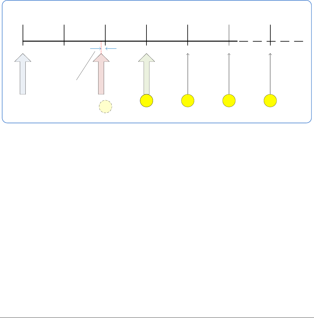
Nano Series GigE Vision Camera Operational Reference
•
197
Case 2: Potential Uncertainness to the Start Time
Conditions:
• initial timestampControlReset resets Timestamp counter
• timestampModuloStartTime at < 20
• timestampModulo = 10
• timestampModuloActualStartTime = first event (F1)
Case 2 differs only from case 1 by showing that there is a period of uncertainty if the start time is
too close to the first modulo count that follows. The first frame acquisition may occur at the first
modulo count time or at the following. The actual value for the uncertainty period may vary with
different camera and network conditions.
00 10 20 30 40 50 60
Reset
Start Time
Actual Start Time
F1 F2 F3 F4
Uncertainty
Period
F1
F1?
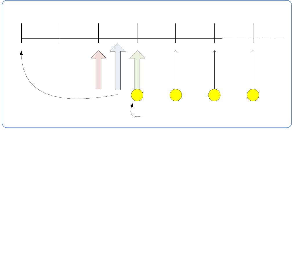
198
•
Operational Reference Nano Series GigE Vision Camera
Case 3: Timer Reset before the Actual Start Time
Conditions:
• initial timestampControlReset resets Timestamp counter
• timestampModuloStartTime at 20
• timestampModulo = 10
• second timestampControlReset at count 25
• timestampModuloActualStartTime = first event (F1)
After the initial Timestamp Reset which starts the Timestamp counter, the Modulo start time is at
20. The Modulo 10 actual start time for the first acquisition is at Timestamp 30 (as described in
Case 1).
Now if a new Timestamp reset happens between the Start Time and acquisition Actual Start Time,
the Timestamp counter will restart from time 00, but the Start Time value has already been stored,
thus the modulo Actual Start Time remains at 30. In this condition the Actual Start Time did not
reset as might be expected.
00 10 20 30 40 50 60
Timestamp Reset
Start Time
Actual Start Time
F1F2F3 F4
Timestamp counter resets
First modulo acquisition remains as it was — following the initial modulo start time
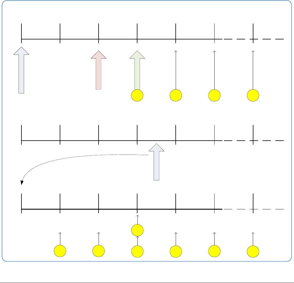
Nano Series GigE Vision Camera Operational Reference
•
199
Case 4: Timer Reset after the Actual Start Time
Conditions:
• initial timestampControlReset resets Timestamp counter
• timestampModuloStartTime at 20
• timestampModulo = 10
• timestampModuloActualStartTime = first event (F1)
• second timestampControlReset at 35
This case describes the Modulo process if there is a Timestamp counter reset after a modulo
controlled acquisition occurs.
• “A” shows the initial conditions with the first acquisition (F1) at the actual start time.
• “B” shows a Timestamp reset occurring after the first acquisition.
• “C” shows that acquisitions then continue at the first modulo 10 time after the reset due to
acquisitions already in progress compared to the example case 3 above.
00 10 20 30 40 50 60
Timestamp Reset
Start Time
Actual Start Time
F1 F2 F3 F4
Timestamp counter resets
“A”
00 10 20 30 40 50 60
“B”
Timestamp Reset
00 10 20 30 40 50 60
“C”
F1
F2 F3 F4 F5 F6 F6
Modulo acquisition
continues at new
Timestamp count
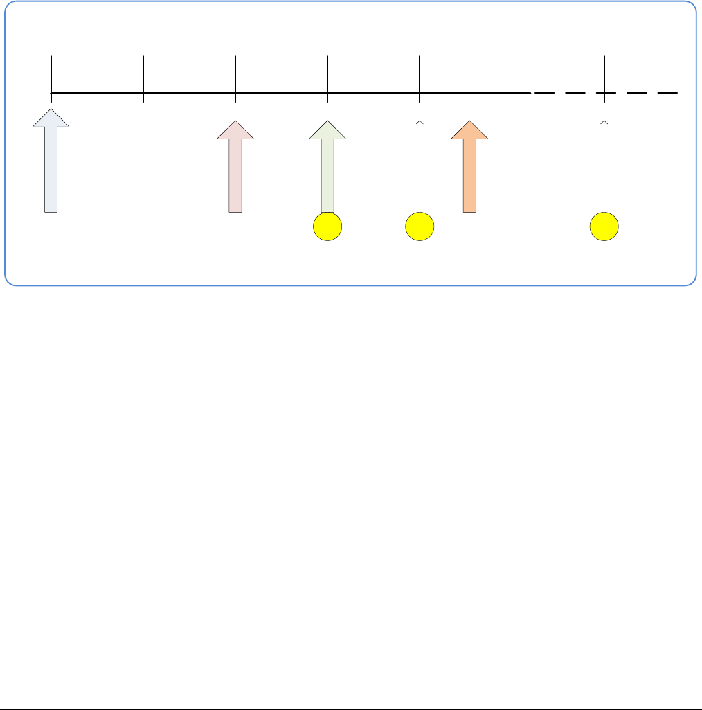
200
•
Operational Reference Nano Series GigE Vision Camera
Case 5: Changing ‘timestampModulo’ during Acquisitions
Conditions:
• initial timestampControlReset resets Timestamp counter
• timestampModuloStartTime at 20
• timestampModulo = 10
• timestampModuloActualStartTime = first event (F1)
• timestampModulo changes to 20
Case 5 shows that the Modulo value can be changed dynamically. Using the simple example of
case 1, after the second acquisition (F2) the Modulo value is changed from 10 to 20. The third
acquisition now occurs at modulo 20 time following the previous acquisition.
00 10 20 30 40 50 60
Timestamp Reset
Start Time
Actual Start Time
F1F2 F3
Modulo = 20
Modulo value changed
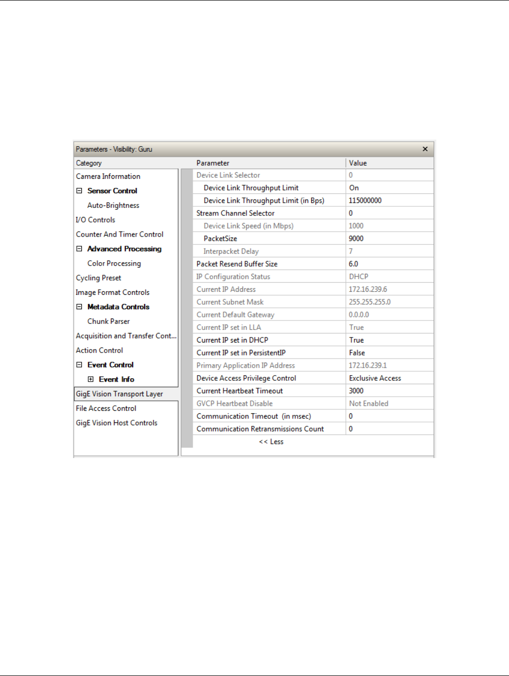
Nano Series GigE Vision Camera Operational Reference
•
201
GigE Vision Transport Layer Control Category
The Genie Nano GigE Vision Transport Layer control, as shown by CamExpert, has parameters used
to configure features related to GigE Vision specification and the Ethernet Connection. Parameters
in gray are read only, either always or due to another parameter being disabled. Parameters in
black are user set in CamExpert or programmable via an imaging application.
Features listed in the description table but tagged as Invisible are usually for Teledyne DALSA or
third party software usage—not typically needed by end user applications. Also important, Genie
Nano cameras are available in a number of models implementing different sensors and image
resolutions which may not support the full feature set defined in this category.
GigE Vision Transport Layer Feature Descriptions
The following table describes these parameters along with their view attribute and minimum
camera firmware version required. Additionally the Device Version column will indicate which
parameter is a member of the DALSA Features Naming Convention (denoted by DFNC), versus the
GenICam Standard Features Naming Convention (SFNC tag is not shown).
The Device Version number represents the camera software functional group, not a firmware
revision number. As Genie Nano capabilities evolve the device version tag will increase, therefore
identifying the supported function package. New features for a major device version release will be
indicated by green text for easy identification.

202
•
Operational Reference Nano Series GigE Vision Camera
Display Name Feature & Values Description Device Version
& View
Device Link Selector DeviceLinkSelector Selects which Link of the device to control
1.00
Expert
Device Link Throughput
Limit DeviceLinkThroughputLimitMode When disabled, lower level TL specific
features are expected to control the
throughput. When enabled,
DeviceLinkThroughputLimit controls the
overall throughput.
1.00
Guru
Device Link Throughput
Limit DeviceLinkThroughputLimit Limits the maximum bandwidth of the
data that will be streamed out by the
device.
1.03
Guru
Stream Channel Selector GevStreamChannelSelector Selects the stream channel to control. 1.00
Expert
Device Link Speed GevLinkSpeed Indicates the transmission speed
negotiated by the given network interface.
1.00
Expert
PacketSize GevSCPSPacketSize Specifies the stream packet size in bytes
to send on this channel.
1.00
Expert
Interpacket Delay GevSCPD Indicates the delay (in µs) to insert
between each packet for this stream
channel. Note that Interpacket delay
becomes a Read-Only value when the
feature “Device Link Throughput Limit” is
enable.
1.00
Expert
Packet Resend Buffer Size devicePacketResendBufferSize Indicates the amount of memory to
reserve in Mbytes for the packet resend
buffer. Changes in reserved memory
affects total memory available for
acquisition buffering.
1.00
DFNC
Guru
IP Configuration Status GevIPConfigurationStatus Reports the current IP configuration
status. (RO)
1.00
Guru
None None Device IP Configuration is not defined.
PersistentIP PersistentIP Device IP Address Configuration is set to
Persistent IP (static).
DHCP DHCP Device IP Address Configuration is set to
DHCP (Dynamic Host Configuration
Protocol). Network requires a DHCP
server.
LLA LLA Device IP Address Configuration is set to
LLA (Link-Local Address). Also known as
Auto-IP. Used for unmanaged networks
including direct connections from a device
to a dedicated NIC.
ForceIP ForceIP Device IP Address Configuration is set to
ForceIP. Used to force an IP address
change.
Current IP Address GevCurrentIPAddress Reports the IP address for the given
network interface.
1.00
Beginner
Current Subnet Mask GevCurrentSubnetMask Reports the subnet mask of the given
interface.
1.00
Beginner
Current Default Gateway GevCurrentDefaultGateway Reports the default gateway IP address to
be used on the given network interface.
1.00
Beginner
Current IP set in LLA GevCurrentIPConfigurationLLA Controls whether the LLA (Link Local
Address) IP configuration scheme is
activated on the given network interface.
1.00
Guru
Current IP set in DHCP GevCurrentIPConfigurationDHCP Controls whether the DHCP IP
configuration scheme (Dynamic Host
Configuration Protocol) is activated on the
given network interface.
1.00
Guru
Current IP set in
PersistentIP GevCurrentIPConfigurationPersistentIP Controls whether the PersistentIP
configuration scheme is activated on the
given network interface.
1.00
Guru
Primary Application IP
Address GevPrimaryApplicationIPAddress Returns the IP address of the device
hosting the primary application. (RO)
1.00
Guru

Nano Series GigE Vision Camera Operational Reference
•
203
Device Access Privilege
Control deviceCCP Controls the device access privilege of an
application.
1.00
Guru
DFNC
Exclusive Access ExclusiveAccess Grants exclusive access to the device to
an application. No other application can
control or monitor the device.
Control Access ControlAccess Grants control access to the device to an
application. No other application can
control the device.
Control Access Switchover
Active ControlAccessSwitchoverActive Enables another application to request
control access to the device.
Discovery Acknowledge
Delay GevDiscoveryAckDelay Indicates the maximum randomized delay
the device will wait to acknowledge a
discovery command. (RO)
1.00
Guru
Current Heartbeat Timeout GevHeartbeatTimeout Indicates the current heartbeat timeout in
milliseconds.
1.00
Guru
GVCP Heartbeat Disable GevGVCPHeartbeatDisable Disables the GVCP (GigE Vision Control
Protocol) heartbeat monitor. This allows
control switchover to an application on
another device.
1.00
Expert
Communication Timeout GevMCTT Provides the transmission timeout value in
milliseconds.
1.00
Guru
Communication
Retransmissions Count GevMCRC Indicates the number of retransmissions
allowed when a message channel message
times out.
1.00
Guru
I GVSP Extended ID Mode GevGVSPExtendedIDMode Enables the extended ID mode.
1.00
Expert
Fire Test Packet GevSCPSFireTestPacket When this feature is set to True, the
device will fire one test packet.
1.00
Invisible
Payload Size PayloadSize Provides the number of bytes transferred
for each image or chunk on the stream
channel.
1.00
Invisible
MAC Address GevMACAddress MAC address of the network interface.
1.00
Invisible
Current Camera IP
Configuration GevCurrentIPConfiguration Current camera IP configuration of the
selected interface.
1.00
Invisible
LLA LLA Link-Local Address Mode
DHCP DHCP Dynamic Host Configuration Protocol
Mode. Network requires a DHCP server.
PersistentIP PersistentIP Persistent IP Mode (static)
Persistent IP Address GevPersistentIPAddress Persistent IP address for the selected
interface. This is the IP address the
camera uses when booting in Persistent IP
mode.
1.00
Invisible
Persistent Subnet Mask GevPersistentSubnetMask Persistent subnet mask for the selected
interface.
1.00
Invisible
Persistent Default Gateway GevPersistentDefaultGateway Persistent default gateway for the selected
interface.
1.00
Invisible
Primary Application Socket GevPrimaryApplicationSocket Returns the UDP (User Datagram Protocol)
source port of the primary application.
1.00
Invisible
Device Access Privilege
Control GevCCP Controls the device access privilege of an
application.
1.00
Invisible
Open Access OpenAccess OpenAccess
Exclusive Access ExclusiveAccess Grants exclusive access to the device to
an application. No other application can
control or monitor the device.
Control Access ControlAccess Grants control access to the device to an
application. No other application can
control the device.
Control Access Switchover
Active ControlAccessSwitchoverActive Enables another application to request
control access to the device.

204
•
Operational Reference Nano Series GigE Vision Camera
Interface Selector GevInterfaceSelector Selects which physical network interface
to control.
1.00
Invisible
Number Of Interfaces GevNumberOfInterfaces Indicates the number of physical network
interfaces supported by this device. (RO)
1.00
Invisible
Message Channel Count GevMessageChannelCount Indicates the number of message
channels supported by this device. (RO)
1.00
Invisible
Stream Channel Count GevStreamChannelCount Indicates the number of stream channels
supported by this device (0 to 512). (RO)
1.00
Invisible
I Supported Option Selector GevSupportedOptionSelector Selects the I option to interrogate for
existing support. (RO)
1.00
Invisible
IPConfigurationLLA
IPConfigurationDHCP
IPConfigurationPersistentIP
StreamChannelSourceSocket
MessageChannelSourceSocket
CommandsConcatenation
WriteMem
PacketResend
Event
EventData
PendingAck
Action
PrimaryApplicationSwitchover
ExtendedStatusCodes
DiscoveryAckDelay
DiscoveryAckDelayWritable
TestData
ManifestTable
CCPApplicationSocket
LinkSpeed
HeartbeatDisable
SerialNumber
UserDefinedName
StreamChannel0BigAndLittleEndian
StreamChannel0IPReassembly
StreamChannel0UnconditionalStreaming
StreamChannel0ExtendedChunkData
I Supported Option GevSupportedOption Returns TRUE if the selected I option is
supported. (RO)
1.00
Invisible
LLA Supported GevSupportedIPConfigurationLLA Indicates if LLA (Auto-IP) is supported by
the selected interface. The LLA method
automatically assigns the Nano with a
randomly chosen address on the
169.254.xxx.xxx subnet. After an address
is chosen, the link-local process sends an
ARP query with that IP onto the network
to see if it is already in use. If there is no
response, the IP is assigned to the device,
otherwise another IP is selected, and the
ARP is repeated. Note that LLA is unable
to forward packets across routers. LLA is
the recommended scheme when only one
NIC is connected to GigE cameras; ensure
only one NIC is using LLA on your PC,
otherwise IP conflicts will result. (RO)
1.00
Invisible
DHCP Supported GevSupportedIPConfigurationDHCP Indicates if DHCP is supported by the
selected interface. This IP configuration
mode requires a DHCP server to allocate
an IP address dynamically over the range
of some defined subnet. The Nano must
be configured to have DHCP enabled. This
is the factory default settings. The DHCP
server is part of a managed network.
Windows itself does not provide a DHCP
server function therefore a dedicated
DHCP server is required. The DALSA
Network Configuration Tool can be
configured as a DHCP server on the NIC
used for the GigE Vision network. (RO)
1.00
Invisible

Nano Series GigE Vision Camera Operational Reference
•
205
Persistent IP Supported GevSupportedIPConfigurationPersistentIP Indicates if Persistent IP is supported by
the selected interface. This protocol is
only suggested if the user fully controls
the assignment of IP addresses on the
network and a GigE Vision camera is
connected beyond routers. The GigE
Vision camera is forced a static IP
address. The NIC IP address must use the
same subnet otherwise the camera is not
accessible. If the Nano camera is
connected to a network with a different
subnet, it cannot be accessed. (RO)
1.00
Invisible
GVCP Extended Status
Codes GevGVCPExtendedStatusCodes Enables generation of extended status
codes. (RO)
1.00
Invisible
GVCP Pending Timeout GevGVCPPendingTimeout Indicates the longest GVCP command
execution time before a device returns a
PENDING_ACK.
1.00
Invisible
I MCP HostPort GevMCPHostPort Indicates the port to which the device
must send messages. (RO)
1.00
Invisible
I MCDA GevMCDA Indicates the destination IP address for
the message channel. (RO)
1.00
Invisible
I MCSP GevMCSP This feature indicates the source port for
the message channel. (RO)
1.00
Invisible
Stream Channel Interface
Index GevSCPInterfaceIndex Index of network interface. (RO)
1.00
Invisible
I SCP HostPort GevSCPHostPort Indicates the port to which the device
must send the data stream. (RO)
1.00
Invisible
I SCDA GevSCDA Indicates the destination IP address for
this stream channel. (RO)
1.00
Invisible
I SCSP GevSCSP Indicates the source port of the stream
channel. (RO)
1.00
Invisible
I First URL GevFirstURL Indicates the first URL to the XML device
description file.
1.00
Invisible
I Second URL GevSecondURL Indicates the second URL to the XML
device description file.
1.00
Invisible
I Major Version GevVersionMajor Major version of the specification.
1.00
Invisible
I Minor Version GevVersionMinor Minor version of the specification.
1.00
Invisible
Manifest Entry Selector DeviceManifestEntrySelector Selects the manifest entry to reference.
1.00
Invisible
XML Major Version DeviceManifestXMLMajorVersion Indicates the major version number of the
XML file of the selected manifest entry.
1.00
Invisible
XML Minor Version DeviceManifestXMLMinorVersion Indicates the Minor version number of the
XML file of the selected manifest entry.
1.00
Invisible
XML SubMinor Version DeviceManifestXMLSubMinorVersion Indicates the SubMinor version number of
the XML file of the selected manifest
entry.
1.00
Invisible
Schema Major Version DeviceManifestSchemaMajorVersion Indicates the major version number of the
Schema file of the selected manifest
entry.
1.00
Invisible
Schema Minor Version DeviceManifestSchemaMinorVersion Indicates the minor version number of the
Schema file of the selected manifest
entry.
1.00
Invisible
Manifest Primary URL DeviceManifestPrimaryURL Indicates the first URL to the XML device
description file of the selected manifest
entry.
1.00
Invisible
Manifest Secondary URL DeviceManifestSecondaryURL Indicates the second URL to the XML
device description file of the selected
manifest entry.
1.00
Invisible
Device Mode Is Big Endian GevDeviceModeIsBigEndian Endianess of the device registers.
1.00
Invisible
Device Mode CharacterSet GevDeviceModeCharacterSet Character set used by all the strings of the
bootstrap registers.
1.00
Invisible

206
•
Operational Reference Nano Series GigE Vision Camera
reserved1
UTF8
reserved2
GevSCPSDoNotFragment GevSCPSDoNotFragment This feature state is copied into the “do
not fragment” bit of IP header of each
stream packet. (RO)
1.00
Invisible
I SCPS BigEndian GevSCPSBigEndian Endianess of multi-byte pixel data for this
stream. (RO)
1.00
Invisible
Defaults for devicePacketResendBufferSize
The default minimum for devicePacketResendBufferSize allows at least two maximum sized buffer.
Resend buffers hold the last images that have been transferred to host. More buffers allow more
possible resend packets.
But it is important to remember that increasing the packet resend buffer value consumes internal
memory used for image buffers waiting to transfer. This will reduce the number of frames acquired
at frame rates exceeding the transfer rates possible to the host computer. Memory size is
monitored with the feature “transferQueueMemorySize”.
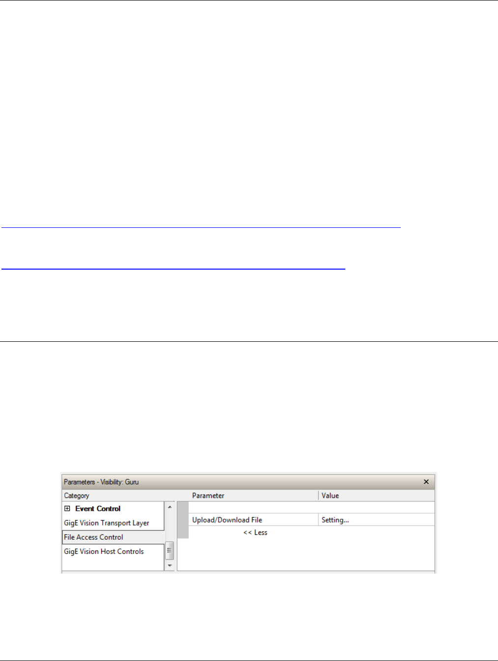
Nano Series GigE Vision Camera Operational Reference
•
207
GigE Vision Host Control Category
The GigE Vision Host controls as shown by CamExpert, has parameters used to configure the host
computer system GigE Vision features used for Genie Nano networking management. None of
these parameters are stored in any Genie Nano camera.
These features allow optimizing the network configuration for maximum Nano bandwidth. Settings
for these parameters are highly dependent on the number of cameras connected to a NIC, the data
rate of each camera and the trigger modes used.
Information on these features is found in the Teledyne DALSA Network Imaging Module User
manual.
Teledyne DALSA TurboDrive
For Genie Nano cameras supporting TurboDrive, ensure to set the feature “Turbo Transfer Mode”
to True.
For information on TurboDrive see our technology primer:
http://www.teledynedalsa.com/imaging/knowledge-center/appnotes/turbodrive/
Plus this application note reviews Teledyne DALSA’s continued development of TurboDrive:
G3-AN0004 – Genie Nano: Comparing TurboDrive v2.0 with TurboDrive v1.0 algorithm
http://www.teledynedalsa.com/imaging/knowledge-center/appnotes/
Important: When using Metadata in conjunction with TurboDrive, the Nano driver (all models)
requires that the image acquisition width (horizontal crop) must be a minimum of 160 pixels in
8-bit mode or 96 pixels in 10/12-bit mode. The driver requires this minimum width to correctly
apply the TurboDrive compression algorithm. When acquisitions are cropped more than the
minimum widths, TurboDrive is automatically disabled while Metadata remains active.
File Access Control Category
The File Access control in CamExpert allows the user to quickly upload various data files to the
connected Genie Nano. The supported data files are for firmware updates, and dependent on the
Nano model, LUT tables, Defective Pixel Maps, and other Sapera file types.
Features listed in the description table but tagged as Invisible are usually for Teledyne DALSA or
third party software usage—not typically needed by end user applications.
Also important, Genie Nano cameras are available in a number of models implementing different
sensors and image resolutions which may not support the full feature set defined in this category.

208
•
Operational Reference Nano Series GigE Vision Camera
File Access Control Feature Descriptions
The Device Version number represents the camera software functional group, not a firmware revision number. As Genie Nano
capabilities evolve the device version tag will increase, therefore identifying the supported function package. New features for a
major device version release will be indicated by green text for easy identification.
Display Name Feature & Values Description Device
Version
various
Models
Device
Version
NanoXL
File Selector FileSelector Selects the file to access. The file types which are
accessible are device-dependent. < Guru >
1.00
1.06
Firmware Firmware1 Upload new firmware to the camera which will execute on
the next camera reboot cycle. Select the DeviceReset
feature after the upload completes.
LUT Luminance 1 LutLuminance1 Select to write (upload) a Look-up-Table file (Sapera .LUT
file) into the camera’s internal LUT Luminance 1.
LUT RGB LutRGB Select to write (upload) a Look-up-Table file (Sapera .LUT
file) into the camera’s internal RGB LUT.
1.04
LUT Raw Bayer 1 LutRawBayer1 Select to write (upload) a Look-up-Table file (Sapera .LUT
file) into the camera’s internal LUT Raw Bayer 1.
Factory Defective Pixel Map BadPixelCoordinate0 Select the Factory Defective Pixel Map.
1.04
1.06
User Defective Pixel Map BadPixelCoordinate1 Select the User Defective Pixel Map XML file as defined in
Advanced Processing.
1.04
1.06
Color Correction Coefficients ColorCorrection Select the color correction coefficients (RGB Output
Firmware). 1.06 1.06
Factory Flat Line coefficients 1 FlatFieldCoefficients01 Select factory Flat Line coefficients 1. These are the
factory values used when the camera fastReadoutMode is
Off and sensor Gain is 1.0. — 1.06
Factory Flat Line coefficients 2 FlatFieldCoefficients02 Select factory Flat Line coefficients 2. These are the
factory values used when the camera fastReadoutMode is
Off and sensor Gain is 1.26. — 1.06
Factory Flat Line coefficients 3 FlatFieldCoefficients03 Select factory Flat Line coefficients 3. These are the
factory values used when the camera fastReadoutMode is
Off and sensor Gain is 1.87. — 1.06
Factory Flat Line coefficients 4 FlatFieldCoefficients04 Select factory Flat Line coefficients 4. These are the
factory values used when the camera fastReadoutMode is
Off and sensor Gain is 3.17. — 1.06
Factory Flat Line coefficients 5 FlatFieldCoefficients05 Select factory Flat Line coefficients 5. These are the
factory values used when the camera fastReadoutMode is
Active and sensor Gain is 1.0. — 1.06
Factory Flat Line coefficients 6 FlatFieldCoefficients06 Select factory Flat Line coefficients 6. These are the
factory values used when the camera fastReadoutMode is
Active and sensor Gain is 1.26. — 1.06

Nano Series GigE Vision Camera Operational Reference
•
209
Factory Flat Line coefficients 7 FlatFieldCoefficients07 Select factory Flat Line coefficients7. These are the factory
values used when the camera fastReadoutMode is Active
and sensor Gain is 1.87. — 1.06
Factory Flat Line coefficients 8 FlatFieldCoefficients08 Select factory Flat Line coefficients 8. These are the
factory values used when the camera fastReadoutMode is
Active and sensor Gain is 3.17.
— 1.06
User Flat Line coefficients 1 FlatFieldCoefficients1 Select user flatfield coefficients1. These are the coefficient
values used when the sensor analog Gain is 1.0. — 1.06
User Flat Line coefficients 2 FlatFieldCoefficients2 Select user flatfield coefficients2. These are the coefficient
values used when the sensor Gain is 1.26. — 1.06
User Flat Line coefficients 3 FlatFieldCoefficients3 Select user flatfield coefficients3. These are the coefficient
values used when the sensor Gain is 1.87. — 1.06
User Flat Line coefficients 4 FlatFieldCoefficients4 Select user flatfield coefficients4. These are the coefficient
values used when the sensor Gain is 3.17. — 1.06
User Defined Saved Image userDefinedSavedImage Upload and download an image in the camera.
1.04
1.06
File Operation Selector FileOperationSelector Selects the target operation for the selected file in the
device. This operation is executed when the File Operation
Execute feature is called. < Guru >
1.00
1.06
Open Open Select the Open operation – executed by
FileOperationExecute.
Close Close Select the Close operation – executed by
FileOperationExecute
Read Read Select the Read operation – executed by
FileOperationExecute.
Write Write Select the Write operation – executed by
FileOperationExecute.
Delete Delete Select the Delete operation – executed by
FileOperationExecute.
File Operation Execute FileOperationExecute Executes the operation selected by File Operation Selector
on the selected file. < Guru >
1.00
1.06
User Defined Saved Image userDefinedSavedImage Upload or download an image in the camera.
< DFNC – Guru >
1.00
1.06
File Open Mode FileOpenMode Selects the access mode used to open a file on the device.
< Guru >
1.00
1.06
Read Read Select READ only open mode
Write Write Select WRITE only open mode
File Access Buffer FileAccessBuffer Defines the intermediate access buffer that allows the
exchange of data between the device file storage and the
application. < Guru >
1.00
1.06
File Access Offset FileAccessOffset Controls the mapping offset between the device file
storage and the file access buffer. < Guru >
1.00
1.06
File Access Length FileAccessLength Controls the mapping length between the device file
storage and the file access buffer. < Guru >
1.00
1.06
File Operation Status FileOperationStatus Displays the file operation execution status. < Guru >
1.00
1.06
Success Success The last file operation has completed successfully.

210
•
Operational Reference Nano Series GigE Vision Camera
Failure Failure The last file operation has completed unsuccessfully for an
unknown reason.
File Unavailable FileUnavailable The last file operation has completed unsuccessfully
because the file is currently unavailable.
File Invalid FileInvalid The last file operation has completed unsuccessfully
because the selected file in not present in this camera
model.
File Operation Result FileOperationResult Displays the file operation result. For Read or Write
operations, the number of successfully read/written bytes
is returned. < Guru >
1.00
1.06
File Size FileSize Represents the size of the selected file in bytes. < Guru >
1.00
1.06
Device User Buffer deviceUserBuffer Unallocated memory available to the user for data storage.
< Invisible > 1.00
DFNC 1.06
User Defined Saved Image
Max Size userDefinedSavedImageMax
Size Maximum size of the user Defined Saved Image in the
flash memory. < Invisible > 1.00
DFNC 1.06
Save Last Image to Flash saveLastImageToFlash Command that saves the last acquired image to camera
flash memory. Use the file transfer feature to read the
image from camera. Maximum image size is 1024x768
pixels in the Nano’s model maximum pixel depth
(monochrome or raw Bayer). < Invisible >
1.05
DFNC 1.06
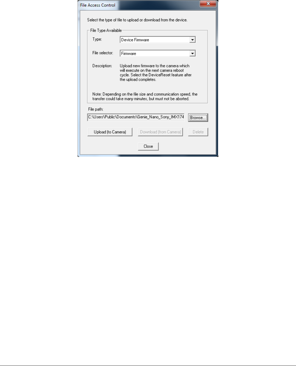
Nano Series GigE Vision Camera Operational Reference
•
211
Updating Firmware via File Access in CamExpert
• Click on the “Setting…” button to show the file selection menu.
• From the File Type drop menu, select the file Type that will be uploaded to the Genie Nano.
This CamExpert tool allows quick firmware changes or updates, when available for your Genie
Nano model.
• From the File Selector drop menu, select the Genie Nano memory location for the uploaded
data. This menu presents only the applicable data locations for the selected file type.
• Click the Browse button to open a typical Windows Explorer window.
• Select the specific file from the system drive or from a network location.
• Click the Upload button to execute the file transfer to the Genie Nano.
• Reset the Nano when prompted.
Overview of the deviceUserBuffer Feature
The feature deviceUserBuffer allows the machine vision system supplier access to 4 kB of reserved
flash memory within the Genie Nano. This memory is available to store any data required, such as
licensing codes, system configuration codes, etc. as per the needs of the system supplier. No Nano
firmware operation will overwrite this memory block thus allowing and simplifying product tracking
and control.
Overview of Color Correction Coefficients
The Sapera LT SDK provides a color correction tool and information about generating coefficients
for color cameras with RGB output design firmware.

212
•
Implementing Trigger-to-Image Reliability Nano Series GigE Vision Camera
Implementing Trigger-to-
Image Reliability
Overview
In a complex imaging system a lot can go wrong at all points – from initial acquisition, to camera
processing, to data transmission. Teledyne DALSA provides features, events, and I/O signals that
provide the system designer with the tools to qualify the system in real time.
The Teledyne DALSA website provides general information, FAQ, and White Paper download about
the Trigger-to-Image Reliability (T2IR) framework in hardware and Sapera LT software SDK.
http://www.teledynedalsa.com/imaging/knowledge-center/appnotes/t2ir/
T2IR with Genie Nano
Nano provides a number of features for system monitoring:
• Built-in Self-Test on power-up and reset after firmware change
• Image Buffer Accumulation – Count Status
• Image Buffer Memory Size
• Packet Resend Buffer Memory Size
• Internal Temperature Reporting
• In Camera Event Status Flags
• Invalid External Trigger
• Image Lost
• Packet Resend & Related Status
• Ethernet Pause Frame Requested
Nano Features for T2IR Monitoring
The following table presents some of the Nano camera features a developer can use for T2IR
monitoring. The output line signals would interface to other external devices.
Camera Status Monitoring
Device Built-In Self Test deviceBIST
Device Built-In Self Test Status deviceBISTStatus
Device Temperature Selector DeviceTemperatureSelector
Device Version DeviceVersion
Firmware Version DeviceFirmwareVersion
Last firmware update failed FirmwareUpdateFailure
Manufacturer Part Number deviceManufacturerPartNumber
Manufacturer Info DeviceManufacturerInfo
Events
Event Selector EventSelector
Event Notification EventNotification

Nano Series GigE Vision Camera Implementing Trigger-to-Image Reliability
•
213
Event Statistic Selector eventStatisticSelector
Event Statistic Count eventStatisticCount
Events Overflow eventsOverflow
Event Statistic Count Reset eventStatisticCountReset
Acquisition and Triggers
Valid Frame Trigger ValidFrameTrigger
Invalid Frame Trigger InvalidFrameTrigger
Image Lost ImageLost
Output Lines
Pulse on: Valid Frame Trigger PulseOnValidFrameTrigger
Pulse on: Rejected Frame(s) Trigger PulseOnInvalidFrameTrigger
Image Transfers
Transfer Queue Current Block Count transferQueueCurrentBlockCount
Transfer Queue Memory Size transferQueueMemorySize
Transferred Image Max Data Size transferMaxBlockSize
Transferred Image Min Data Size transferMinBlockSize
Transferred Image Average Data Size transferAverageBlockSize
Maximum Sustained Frame Rate maxSustainedFrameRate
Packet Resend PacketResend
Packet Resend Request Dropped PacketResendRequestDropped
Ethernet Pause Frame Received EthernetPauseFrameReceived
Precision Time Protocol (PTP)
PTP Status ptpStatus
PTP Servo Status ptpServoStatus
PTP Master Clock Identity ptpMasterClockId
PTP Master Offset ptpMasterOffsetNs
PTP Port Last Event ptpPortLastEvent

214
•
Sapera Tools for Networking Nano Series GigE Vision Camera
Sapera Tools for Networking
Nano IP Configuration Mode Details
In general automatic IP configuration assignment (LLA/DHCP) is sufficient for most Nano
installations. Please refer to the Teledyne DALSA Network Imaging Package manual for
information on the Teledyne DALSA Network Configuration tool and network optimization for GigE
Vision cameras and devices.
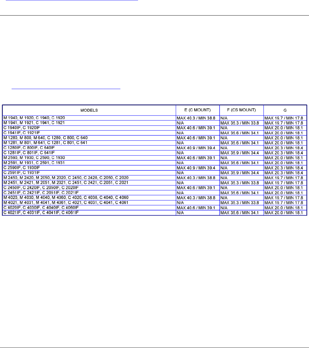
Nano Series GigE Vision Camera Technical Specifications
•
215
Technical Specifications
Both 2D and 3D design drawings are available for download from the Teledyne DALSA web site
[ http://www.teledynedalsa.com/genie-nano ].
Mechanical Specifications — C & CS Mount:
Nano models with C and CS mounts have slight variations to their body depths as detailed in the
following table. The three columns labeled “E”, “F”, and “G” list the dimensional depth variations
(in mm) corresponding to the same labels shown on the mechanical specification drawing shown on
the next page.
These physical variations compensate for different sensors boards and whether a model is shipped
with an IR filter, so as to maintain a constant back focal specification. See this technical description
for information on back focal variances when using IR or other filters between the lens and sensor.
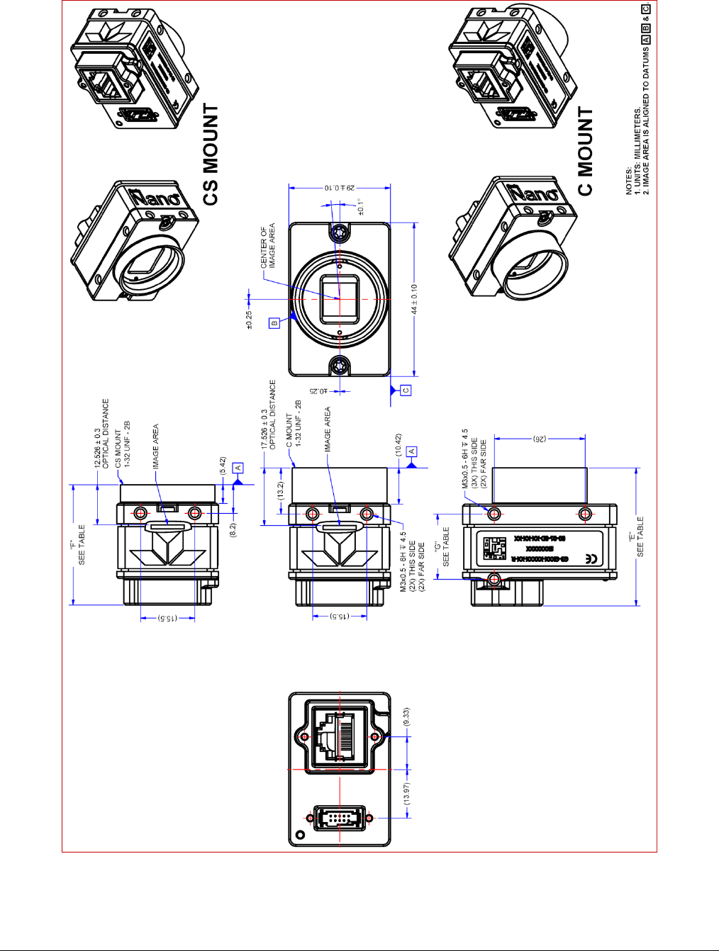
216
•
Technical Specifications Nano Series GigE Vision Camera
Note: Genie Nano with C or CS Mount
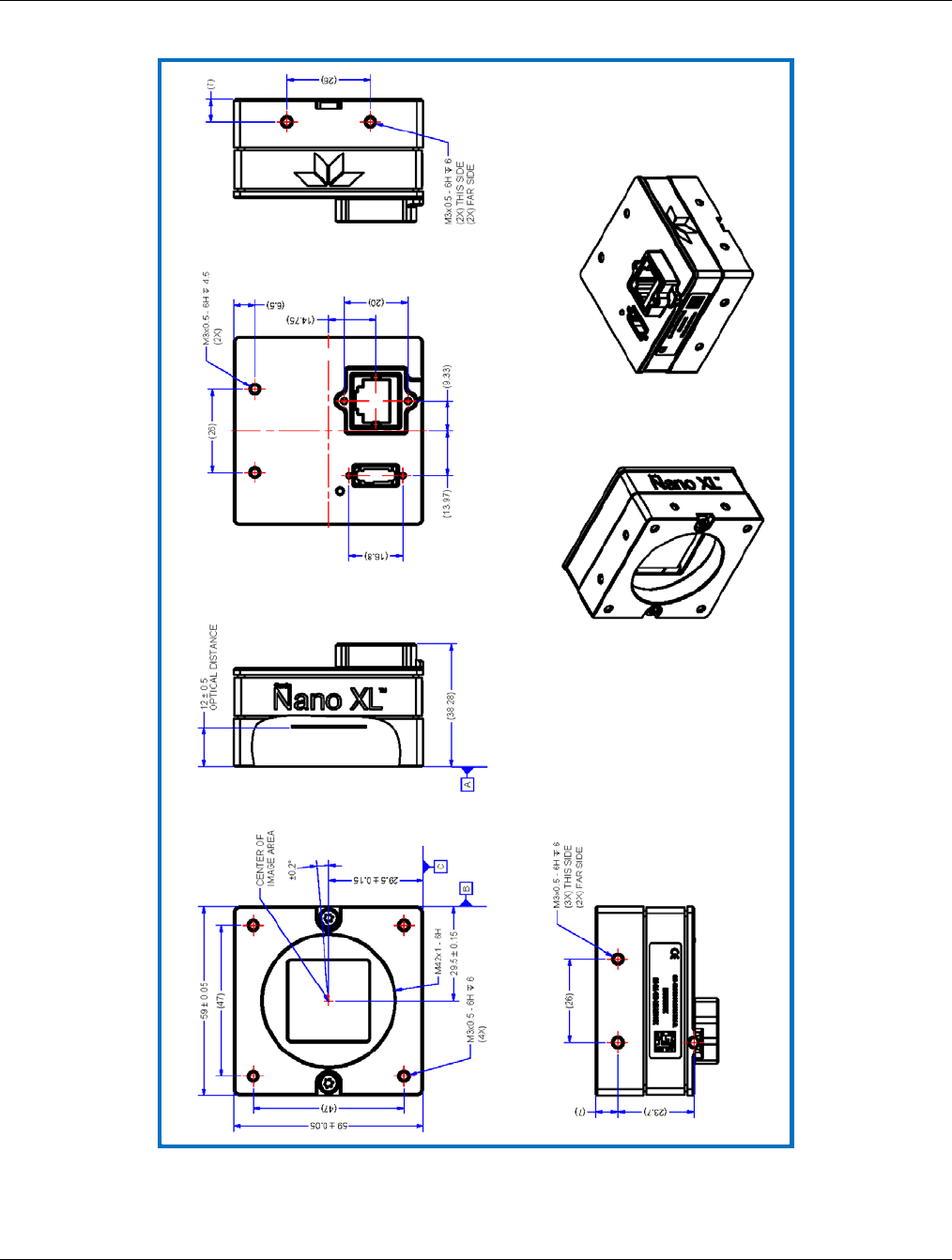
Nano Series GigE Vision Camera Technical Specifications
•
217
Mechanical Specifications — NanoXL:
Note: Genie NanoXL with M42 Mount
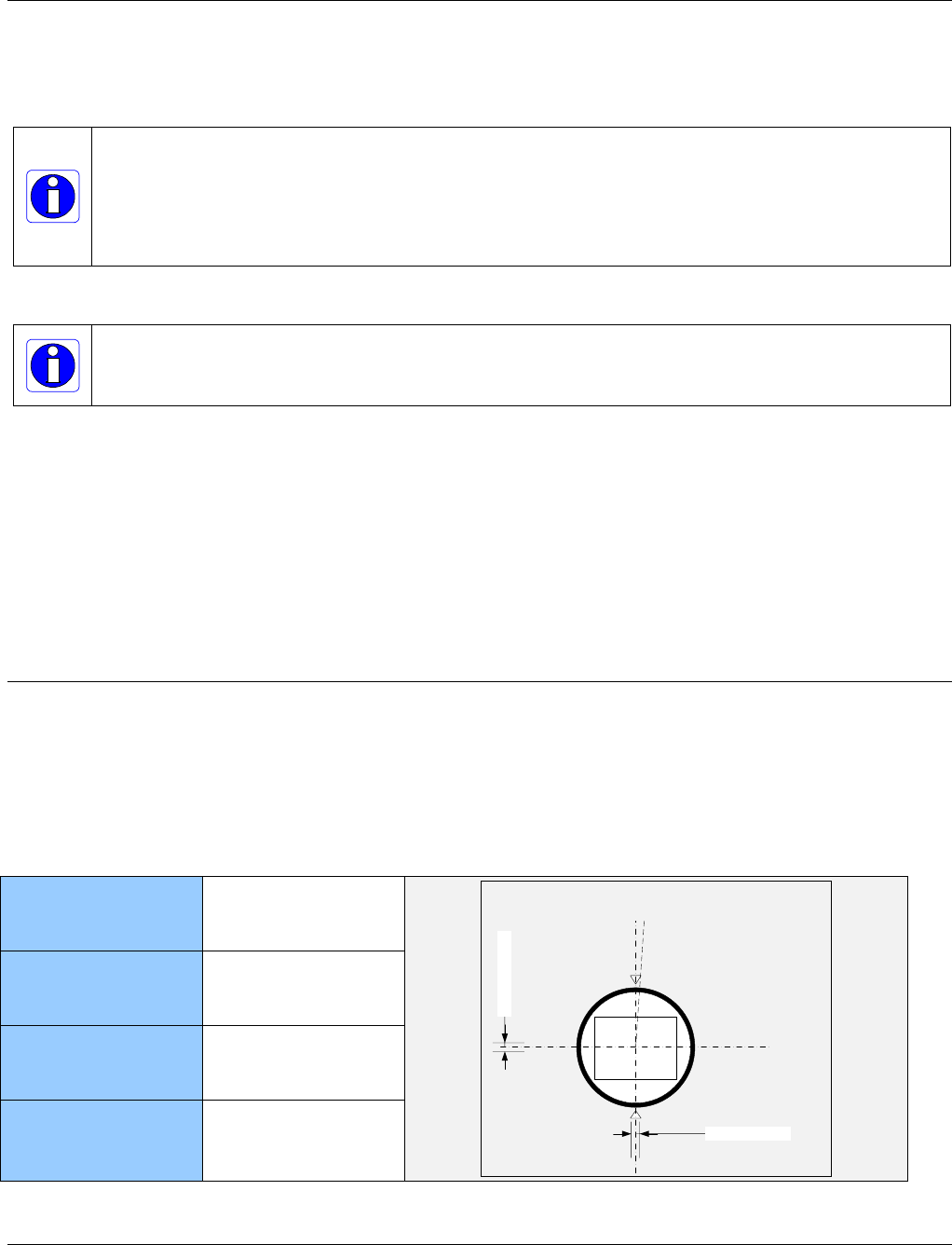
218
•
Technical Specifications Nano Series GigE Vision Camera
Additional Notes on Genie Nano Identification and
Mechanical
Identification Label
Genie Nano cameras have an identification label applied to the bottom side, with the following information:
Model Part Number
Serial number
MAC ID
2D Barcode
CE and FCC logo
Additional Mechanical Notes
Nano supports a screw lock Ethernet cable as described in Ruggedized RJ45 Ethernet Cables.
For information on Nano lens requirements see Optical Considerations.
Each camera side has two mounting holes in identical locations, which provide good grounding capabilities.
Overall height or width tolerance is ±0.05mm.
Temperature Management
Genie Nano cameras are designed to optimally transfer internal component heat to the outer
metallic body. If the camera is free standing (i.e. not mounted) it will be very warm to the touch.
Basic heat management is achieved by mounting the camera onto a metal structure via its
mounting screw holes. Heat dissipation is improved by using thermal paste between the camera
body (not the front plate) and the metal structure.
Sensor Alignment Specification
The following figure specifies sensor alignment for Genie Nano where all specifications define the
absolute maximum tolerance allowed for production cameras. Dimensions “x, y, z”, are in microns
and referenced to the Genie Nano mechanical body or the optical focal plane (for the z-axis
dimension). Theta specifies the sensor rotation relative to the sensor’s center and Nano
mechanical.
X variance +/- 250 microns
(+/-) Y variance
(+/-) X variance
Sensor Alignment Reference
Z variance not shown
(+/-) theta variance
Y variance +/- 250 microns
Z variance +/- 300 microns
Theta variance +/- 1 degree
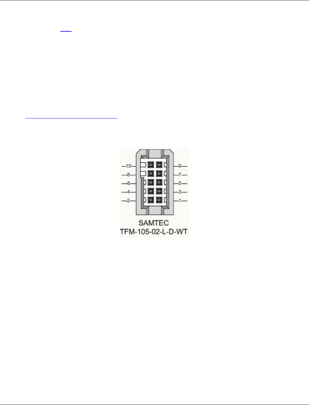
Nano Series GigE Vision Camera Technical Specifications
•
219
Connectors
• A single RJ45 Ethernet connector for control and video data to the host Gigabit NIC.
Additionally for PoE, the Genie Nano requires an appropriate PoE Class 0 or Class 3 (or greater)
power source device (such as a powered computer NIC, or a powered Ethernet switch, or an
Ethernet power injector). For industrial environments, Nano supports the use of screw lock
Ethernet cables (see Ruggedized RJ45 Ethernet Cables). Note that for PoE installations, a
shielded Ethernet cable is required to provide a camera ground connection to the controlling
computer.
• Note: Connect power via the I/O or PoE, not both. Although Nano has protection, differences
in ground levels may cause operational issues or electrical faults.
• The Nano has a single 10-pin connector (SAMTEC connector TFM-105-02-L-D-WT) for all I/O
signals and for an auxiliary DC power source. Nano supports connecting cables with retention
clips or screw locks.
• See I/O Mating Connector Sources for information about the mating connector or complete
cable solutions with retention clips. The following figure shows the pin number assignment
(external view of the camera body connector).
Face View of the Nano Back
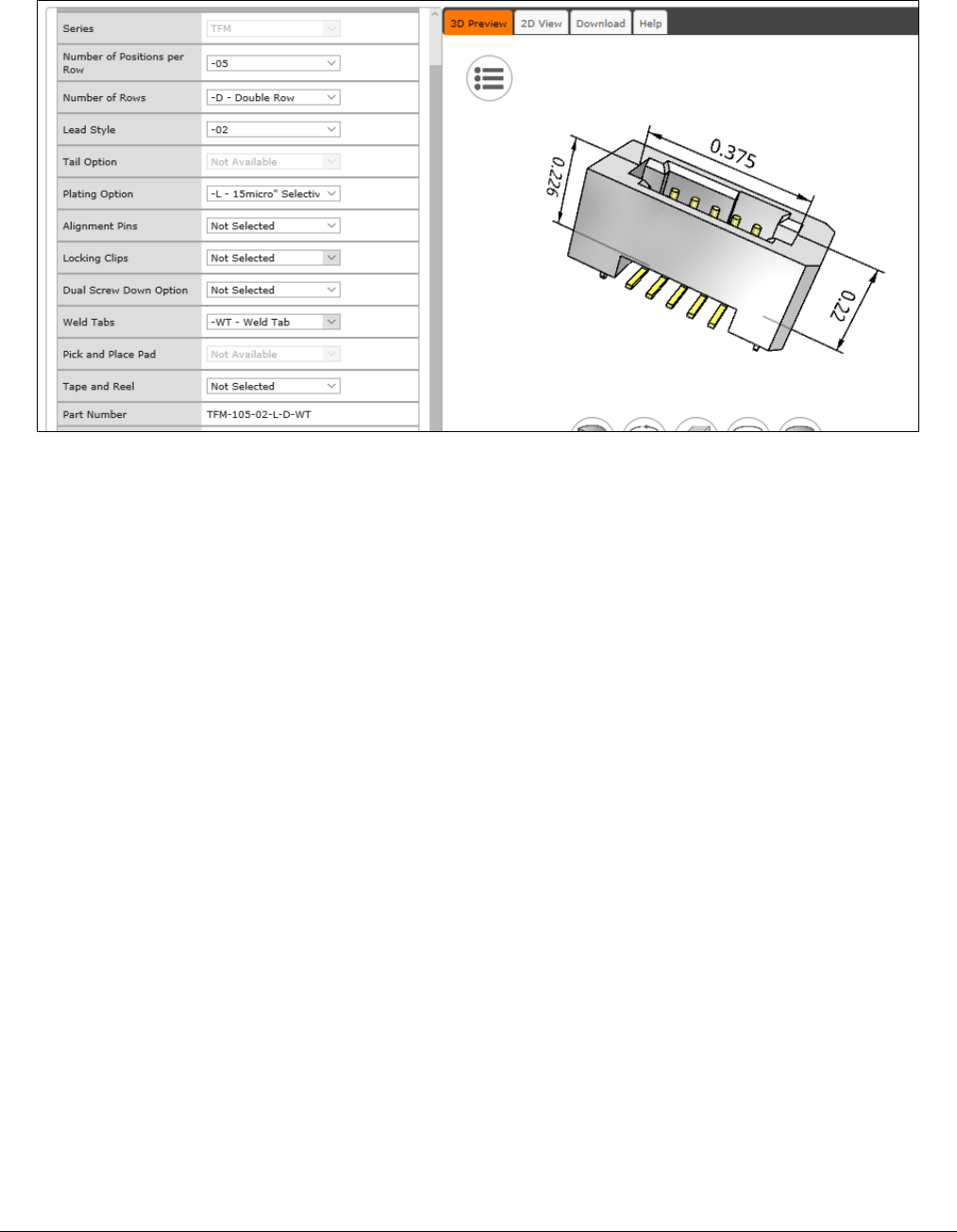
220
•
Technical Specifications Nano Series GigE Vision Camera
3D View of the camera’s connector TFM-105-02-L-D-WT

Nano Series GigE Vision Camera Technical Specifications
•
221
10-pin I/O Connector Details
Teledyne DALSA makes available optional I/O cables as described in Accessories. Contact Sales for
availability and pricing.
Pin Number Genie Nano Direction Definition
1 PWR-GND — Camera Power – Ground
2 PWR-VCC — Camera Power – DC +10 to +36 Volts
3 GPI-Common — General Input Common Ground
4 GPO-Power — General Output Common Power
5 GPI 1 In General External Input 1
6 GPO 1 Out General External Output 1
7 GPI 2 In General External Input 2
Reserved — N/A for G3-Gx2 or G3-Gx3 … models ‡
8 GPO 2 Out General External Output 2
9 Reserved
GPO 3 Out General External Output 3 for G3-Gx2 or G3-Gx3 ‡
10 Chassis Camera Chassis
‡ Note: Output 3 only supports Software Controlled logic High or Low signals.
Nano: “G3-GM2… or G3-GC2…” part numbers denote optional “1 input / 3 output” special order
models.
NanoXL: “G3-Gx3” models come standard with 2 Inputs and 3 Outputs
See AC Characteristics of 1 Input / 3 Output Models for additional information.
Camera DC Power Characteristics
DC Operating Characteristics
Input Voltage +10 Volts minimum
Input Power Consumption @ +12 Volt Supply 3.99 Watts typical
Input Power Consumption @ +24 Volt Supply 3.96 Watts typical
Input Power Consumption @ +48 Volt Supply 4.22 Watts typical
Absolute Maximum DC Power Supply Range before Possible Device Failure
Input Voltage –58 Volt DC +58 Volts DC
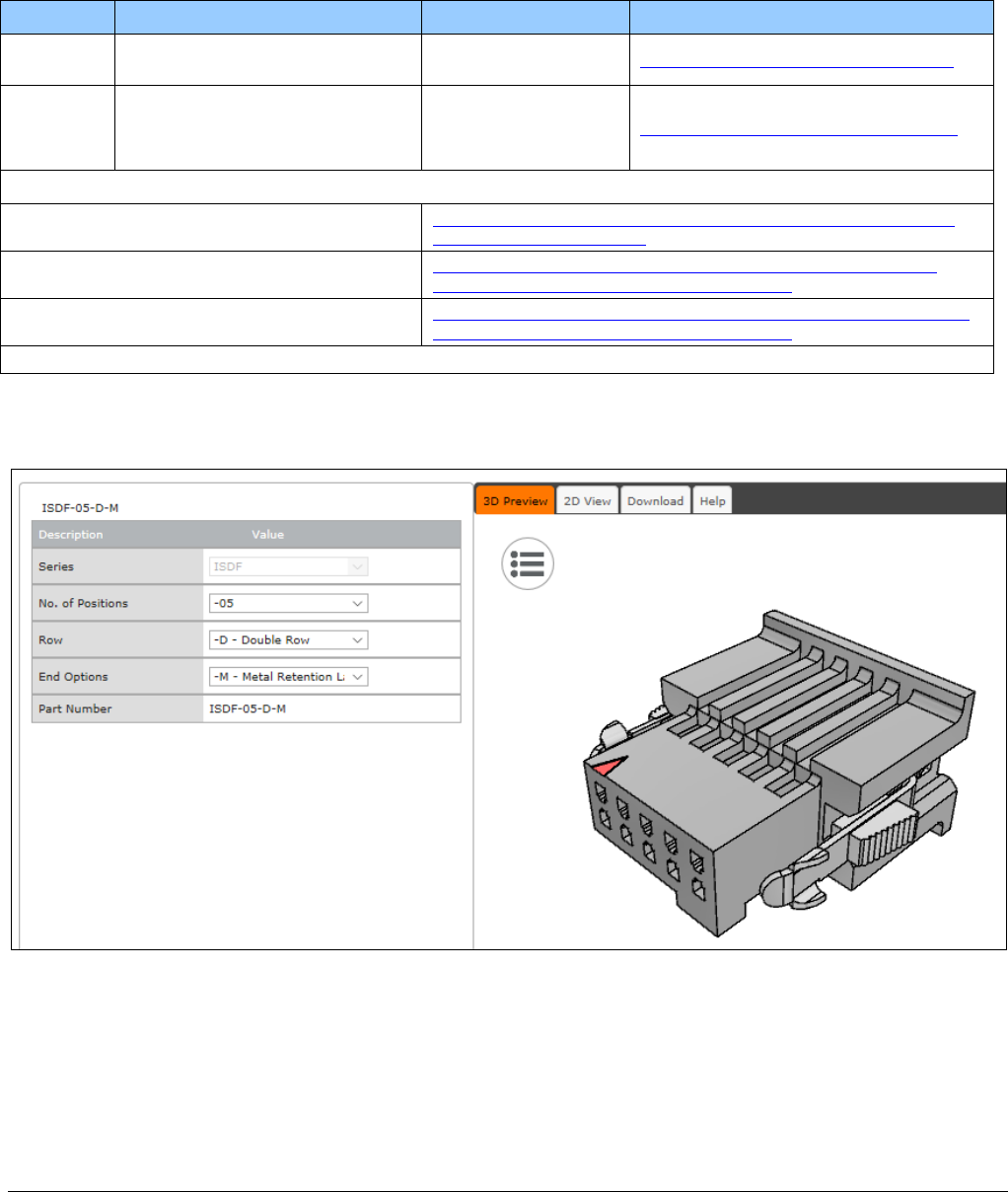
222
•
Technical Specifications Nano Series GigE Vision Camera
I/O Mating Connector Specifications & Sources
For users wishing to build their own custom I/O cabling, the following product information is
provided to expedite your cable solutions. Samtec web information for the discrete connector and a
cable assembly with retention clips follows the table.
MFG Part # Description Data Sheet
Samtec ISDF-05-D
ISDF-05-D-M (see image below) Discrete Connector
(see example below) https://www.samtec.com/products/isdf
Samtec SFSD-05-[WG]-G-[AL]-DR-[E2O]
WG : Wire Gauge
AL : Assembled Length
E2O : End 2 Option
Discrete Cable
Assembly
(see example below) https://www.samtec.com/products/sfsd
ISDF-05-D-M Connector Availability On-Line
North-America (specific country can be selected) http://www.newark.com/samtec/isdf-05-d-m/connector-housing-
receptacle-10/dp/06R6184
Europe (specific country can be selected) http://uk.farnell.com/samtec/isdf-05-d-m/receptacle-1-27mm-
crimp-10way/dp/2308547?ost=ISDF-05-D-M
Asia-Pacific (specific country can be selected) http://sg.element14.com/samtec/isdf-05-d-m/receptacle-1-27mm-
crimp-10way/dp/2308547?ost=ISDF-05-D-M
Important: Samtec ISDF-05-D-S is not compatible with Genie Nano
Samtec ISDF-05-D-M mating connector for customer built cables w/retention clips
“.050” Tiger Eye™ Discrete Wire Socket Housing”
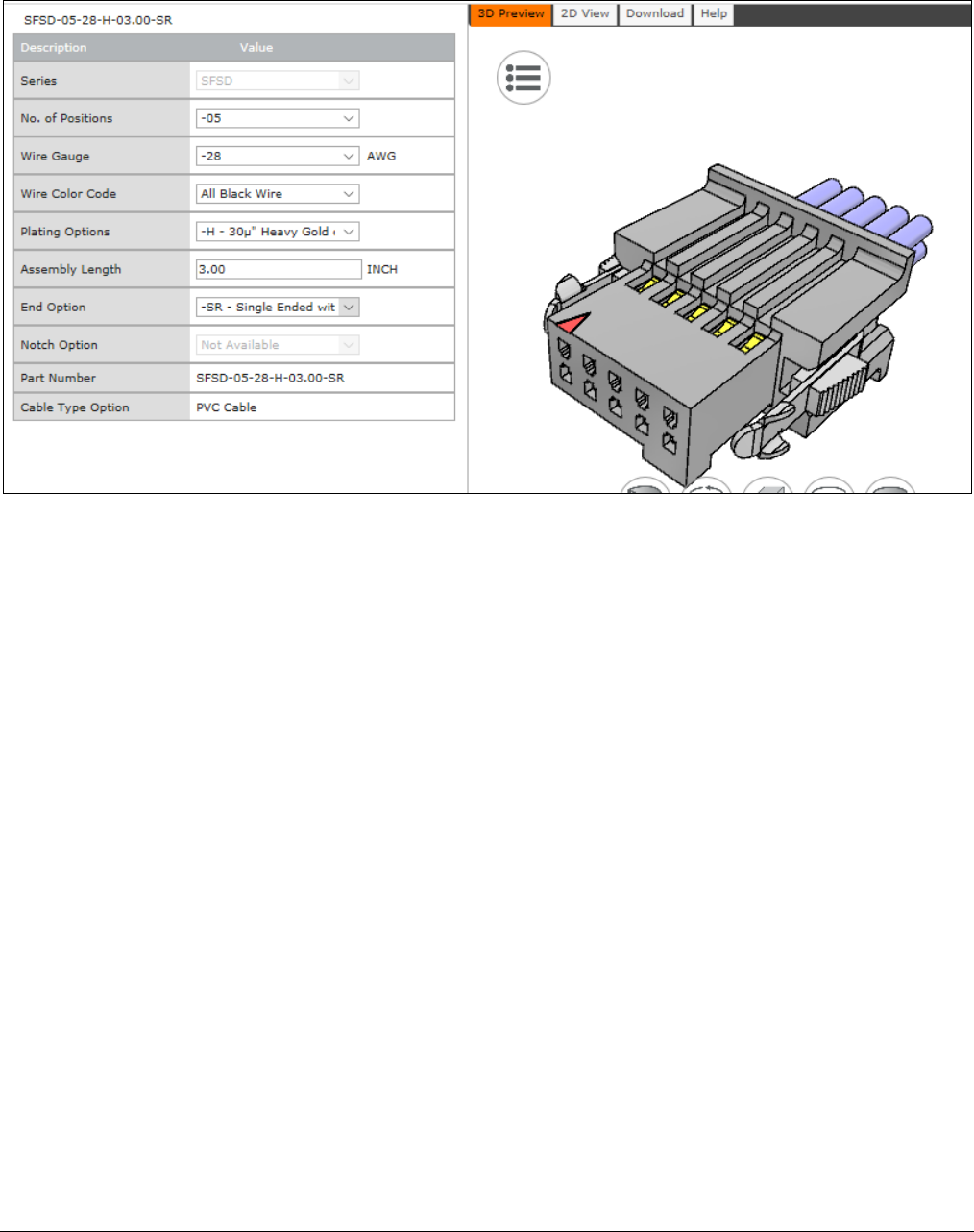
Nano Series GigE Vision Camera Technical Specifications
•
223
Samtec connector-cable assembly SFSD-05-28-H-03.00-SR w/retention clips
“.050” Tiger Eye™ Double Row Discrete Wire Cable Assembly, Socket”
Power over Ethernet (PoE) Support
• The Genie Nano requires a PoE Class 0 or Class 2 (or greater) power source for the network if
not using a separate external power source connected to pins 1 & 2 of the camera’s I/O
Connector.
• To use PoE, the camera network setup requires a powered computer NIC supporting PoE, or a
PoE capable Ethernet switch, or an Ethernet power injector.
• Important: Connect power via the I/O connector or PoE, but not both. Although Nano has
protection, differences in ground levels may cause operational issues or electrical faults.
• If both supplies are connected and active, the Nano will use the I/O power supply connector.
But as stated, ground differences may cause camera faults or failure.
• Important: When using PoE, the camera’s I/O pin 1 (Camera Power – Ground) must not be
connected to I/O pin 3 (General Input Common Ground).
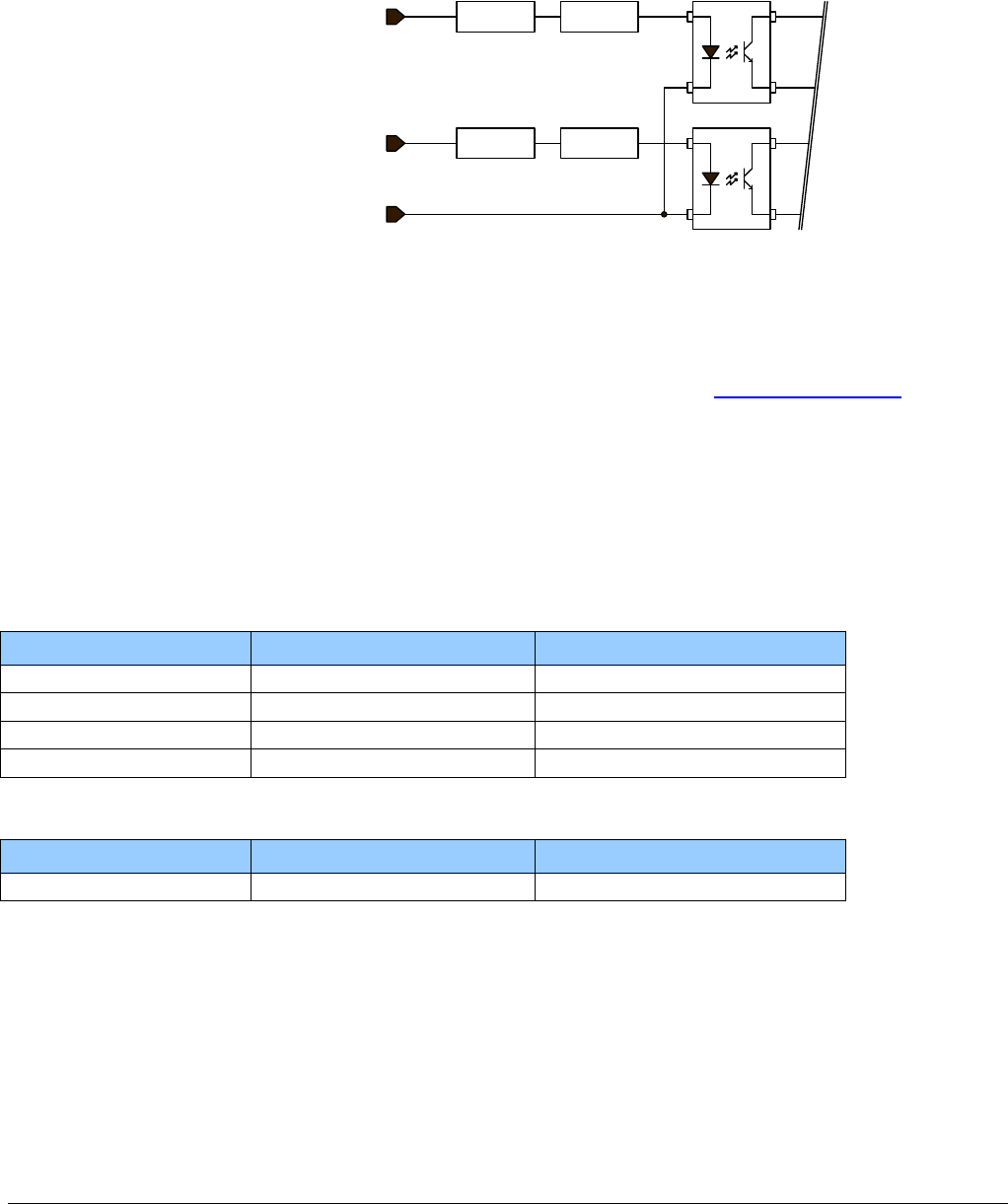
224
•
Technical Specifications Nano Series GigE Vision Camera
Input Signals Electrical Specifications
External Inputs Block Diagram
Protection Current
Limiter
Protection Current
Limiter
Input 2 (pin 7)
Input 1 (pin 5)
Common Ground (pin 3)
External Input Details
• Opto-coupled with internal current limit.
• Single input trigger threshold level
(TTL standard: <0.8V=Logical LOW, >2.4V=Logical HIGH. See lineDetectionLevel feature).
• Used as trigger acquisition event, counter or timestamp event, or integration control.
• User programmable debounce time from 0 to 255µs in 1µs steps.
• Source signal requirements:
• Single-ended driver meeting TTL, 12V, or 24V standards (see table below)
• If using a differential signal driver, only one input can be used due to the shared input
common (see details below)
External Input DC Characteristics
Operating Specification Minimum Maximum
Input Voltage +3 V +36 V
Input Current 7 mA 10.1 mA
Input logic Low 0.8 V
Input logic High 2.4 V
Absolute Maximum Range before Possible Device Failure
Absolute Ratings Minimum Maximum
Input Voltage –36 Volts +36 Volts

Nano Series GigE Vision Camera Technical Specifications
•
225
External Input AC Timing Characteristics
Conditions Description Min Unit
Input Pulse 0V – 3V Input Pulse width High 1.3 µs
Input Pulse width Low 1.7 µs
Max Frequency
315
KHz
Input Pulse 0V – 5V Input Pulse width High 0.6 µs
Input Pulse width Low 2 µs
Max Frequency 247 KHz
Input Pulse 0V -12V
Input Pulse width High
0.39
µs
Input Pulse width Low 3 µs
Max Frequency 160 KHz
Input Pulse 0V – 24V Input Pulse width High 0.39 µs
Input Pulse width Low 4.9 µs
Max Frequency
103
KHz
External Inputs: Using TTL/LVTTL Drivers
• External Input maximum current is limited by the Nano circuits to a maximum of 10mA.
User IO
Ground
User IO
Power
Imax = 10mA
Imax = 10mA
LVTTL / TTL
Push-Pull
Buffer
10 9
87
65
43
21
Camera IO
Interface
External Signal 2
External Signal 1
(Common Ground)
( Input 1 )
( Input 2 )
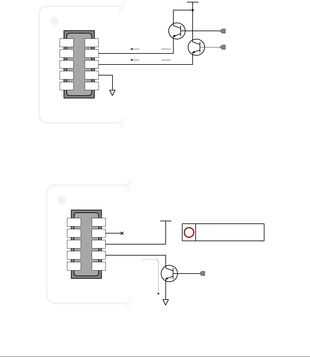
226
•
Technical Specifications Nano Series GigE Vision Camera
External Inputs: Using Common Collector NPN Drivers
• External Input maximum current is limited by the Nano circuits to a maximum of 10mA.
User IO
Ground
User IO
Power
(3V-28V)
Imax = 10mA
Imax = 10mA
10 9
8 7
65
43
2 1
Camera IO
Interface
B
E
C
B
E
C
External Signal 2
External Signal 1
( Common Ground )
( Input 1 )
( Input 2 )
External Inputs: Using Common Emitter NPN Driver
• External Input maximum current is limited by the Nano circuits to a maximum of 10mA.
• Warning: Only one External Signal can be used (input 1 or input 2).
User IO
Ground
User IO
Power
(3V-28V)
10 9
8 7
65
4 3
2 1
Camera IO
Interface
B
E
C
Imax =
10mA
Only one Input can be used
in this configuration.
!
External Signal
( Common Ground )
( Input 1 )
( Input 2 )
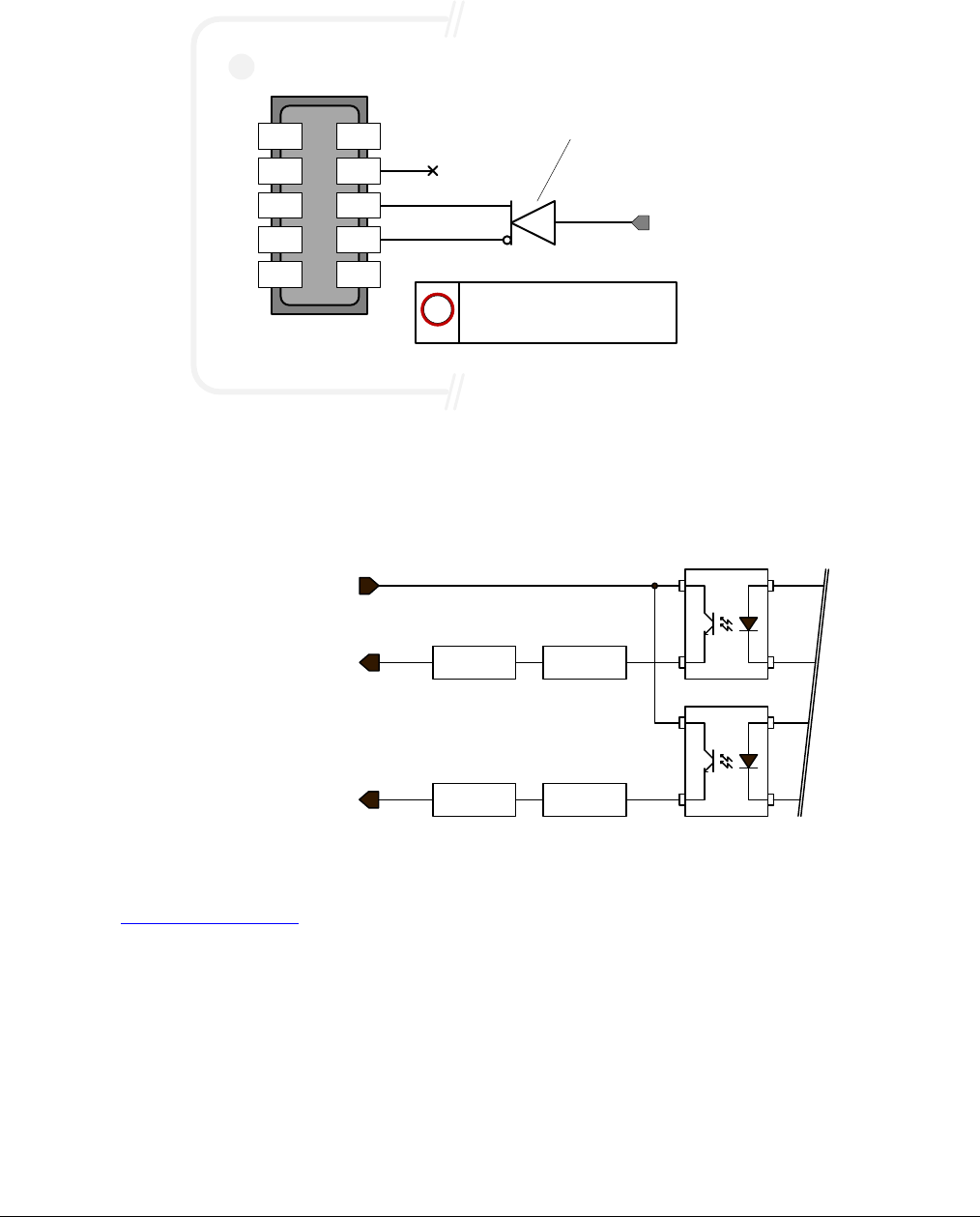
Nano Series GigE Vision Camera Technical Specifications
•
227
External Inputs: Using a Balanced Driver
• Warning: Only one External Signal can be used (input 1 or input 2).
RS-422
Compatible
Transmitter
10 9
8 7
6 5
43
21
Camera IO
Interface
Only one Input can be used
in this configuration.
!
External Signal
( Common Ground )
( Input 1 )
( Input 2 )
Output Signals Electrical Specifications
External Outputs Block Diagram
Protection Current
Limiter
Protection Current
Limiter
Output 2 (pin 8)
Output 1 (pin 6)
Output Common Power
(pin 4)
External Output Details and DC Characteristics
• Programmable output mode such as strobe, event notification, etc
(see outputLineSource feature)
• Outputs are open on power-up with the default factory settings
• A software reset will not reset the outputs to the open state if the outputs are closed
• A user setup configured to load on boot will not reset the outputs to the open state if the
outputs are closed
• No output signal glitch on power-up or polarity reversal
• Typical Operating Common Power Voltage Range: +3V to 28Vdc at 24mA
• Maximum Common Power Voltage Range : ±30Vdc
• Maximum Output Current: 36mA
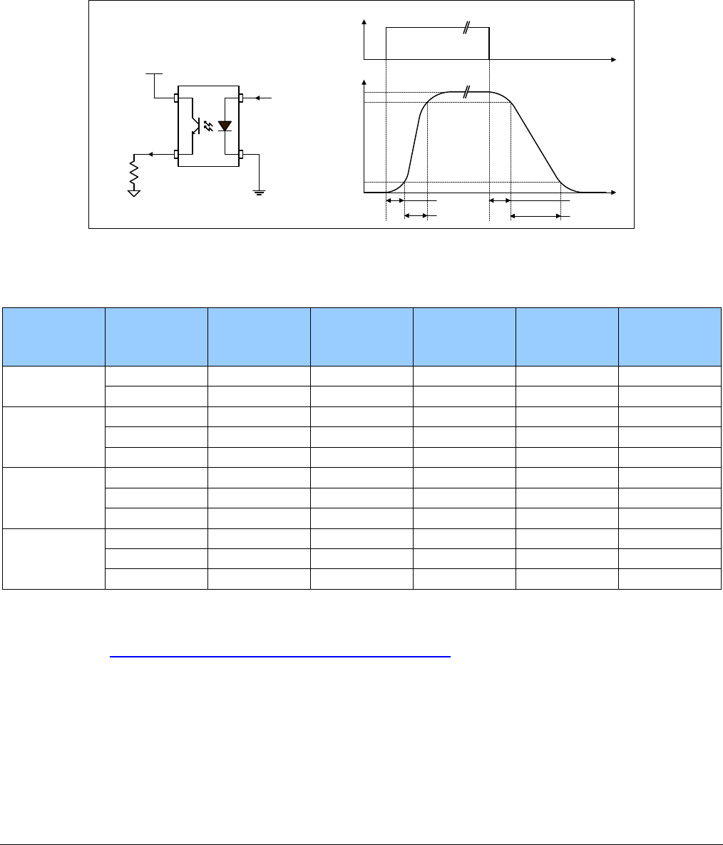
228
•
Technical Specifications Nano Series GigE Vision Camera
External Output AC Timing Characteristics
The graphic below defines the test conditions used to measure the Nano external output AC
characteristics, as detailed in the table that follows.
t
t
Output Control Signal
Output
100%
90%
10%
td1
trise tfall
td2
Output
Output Common Power
RLoad
Control
Signal
Opto-coupled Output: AC Characteristics at an internal FPGA temperature of 83C
Note: All measurements subject to some rounding.
Output
Common
Power
Output
Current Rload
Test td1 (µs)
Leading Delay
trise (µs)
Rise Time
td2 (µs)
Trailing Delay
tfall (µs)
Fall Time
3V 8 mA 250 ohm 0.47 2.9 11.4 26.6
16 mA 124 ohm 0.47 4.7 4.3 19.5
5V
8 mA 514 ohm 4.66 2.6 13.3 25.3
16 mA 236 ohm 0.5 7.0 4.4 17.9
21 mA 73 ohm 0.45 4.4 3.1 10.7
12V
8 mA 1.4K ohm 0.62 2.0 18.1 24.9
16 mA 677 ohm 0.54 4.8 7.5 19.9
24 mA 316 ohm 0.5 3.5 3.8 11.5
24V
8 mA 2.88K ohm 0.62 2.1 18.9 39.9
16 mA 1.42K ohm 0.63 4.7 10.9 27.1
24 mA 810 ohm 0.79 4.9 5.2 17.4
AC characteristics for optional models denoted by “G3-GM2… or G3-GC2…” part numbers is found
in addendum –AC Characteristics of 1 Input / 3 Output Models.
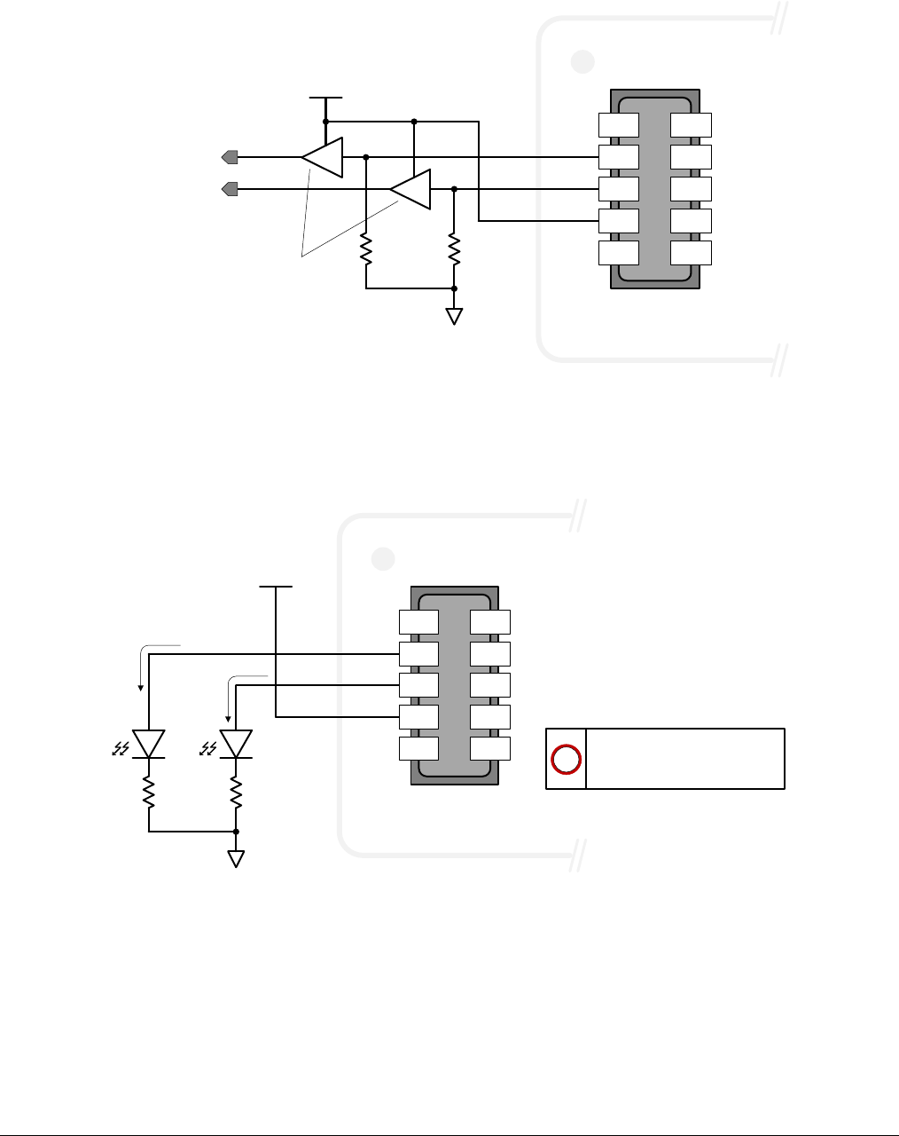
Nano Series GigE Vision Camera Technical Specifications
•
229
External Outputs: Using External TTL/LVTTL Drivers
User IO
Ground
User IO
Power
Signal 1
Camera IO
Interface
LVTTL/TTL
Buffer
R
(Pull-Down)
R
(Pull-Down)
Signal 2
10 9
8 7
65
4 3
2 1
( User IO Power )
( Output 1 )
( Output 2 )
External Outputs: Using External LED Indicators
• Two external LEDs can be connected in the Common Cathode configuration.
User IO
Ground
User IO
Power
Camera IO
Interface
R R
10 9
87
65
43
21
( User IO Power )
( Output 1 )
( Output 2 )
Set resistor (R) value to not
exceed output current of
I
F
= 30mA.
!
I
F
I
F
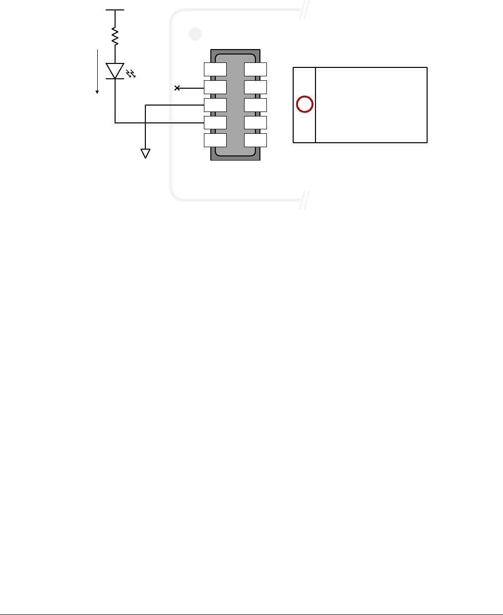
230
•
Technical Specifications Nano Series GigE Vision Camera
• Alternatively one external LED can be connected in the Common Anode configuration.
User IO
Ground
User IO
Power
Camera IO
Interface
R
10 9
8 7
6 5
4 3
2 1
( Output 1 )
( Output 2 )
!
IF
Set resistor (R) value to not
exceed output current of
I
F
= 30mA.
Only one Output (1 or 2) can
be used in this configuration.
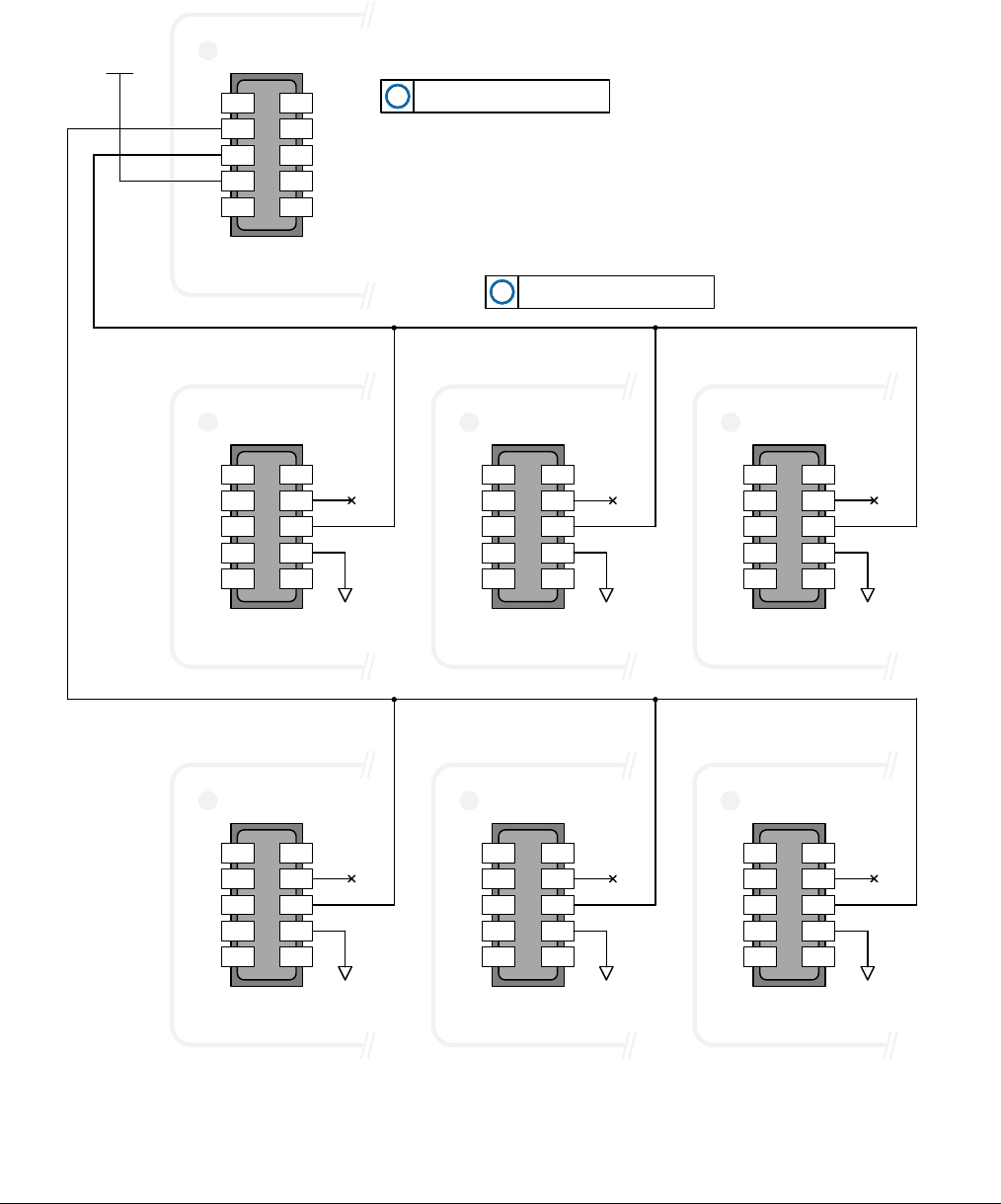
Nano Series GigE Vision Camera Technical Specifications
•
231
Using Nano Outputs to drive other Nano Inputs
• A synchronization method where one Nano camera signals other Nano cameras.
• Note: One Nano output can drive a maximum of three Nano inputs, as illustrated below.
User IO
Power
Camera IO
Interface
10 9
87
6 5
4 3
21
(GPO_CMD_PWR)
(GPO_P0)
(GPO_P1)
Do not exceed more then three
slave cameras per GPO line.
!
Camera IO
Interface
10 9
8 7
6 5
4 3
2 1
Camera (Slave 1)
Camera IO
Interface
10 9
8 7
6 5
4 3
2 1
Camera (Slave 2)
Camera IO
Interface
10 9
8 7
6 5
4 3
2 1
Camera (Slave 3)
Camera IO
Interface
10 9
87
6 5
43
2 1
Camera (Slave 4)
Camera IO
Interface
10 9
8 7
6 5
4 3
2 1
Camera (Slave 5)
Camera IO
Interface
10 9
8 7
6 5
4 3
2 1
Camera (Slave 6)
User IO
Ground
(GPI_CMD_GND)
(GPI_P0)
(GPI_P1)
User IO
Ground
(GPI_CMD_GND)
(GPI_P0)
(GPI_P1)
User IO
Ground
(GPI_P0)
(GPI_P1)
GPI P0 or GPI P1 can be used as
input trigger.
!
User IO
Ground
(GPI_CMD_GND)
(GPI_P0)
(GPI_P1)
User IO
Ground
(GPI_P0)
(GPI_P1)
User IO
Ground
(GPI_P0)
(GPI_P1)
(GPI_CMD_GND)
(GPI_CMD_GND)
(GPI_CMD_GND)

232
•
Technical Specifications Nano Series GigE Vision Camera
Computer Requirements for Nano Cameras
The following information is a guide to computer and networking equipment required to support the
Nano camera at maximum performance. The Nano camera series complies with the current Ipv4
Internet Protocol, therefore current Gigabit Ethernet (GigE) equipment should provide trouble free
performance.
Host PC System
• Refer to your GigE-Vision compliant SDK for computer requirements.
Recommended Network Adapters
• GigE network adapter (either add on card or on motherboard). The Intel PRO/1000 MT adapter
is an example of a high performance NIC. Typically a system will need an Ethernet GigE adapter
to supplement the single NIC on the motherboard.
• PCI Express adapters will outperform PCI adapters.
• Network adapters that support Jumbo Frames will minimize CPU utilization.
• 10/100 Ethernet is not supported by the Genie Nano series of cameras.

Nano Series GigE Vision Camera Technical Specifications
•
233
Ethernet Switch Requirements
When there is more than one device on the same network or a camera-to-PC separation greater
than 100 meters, an Ethernet switch is required. Since the Genie Nano GigE camera complies with
the Internet Protocol, it should work with all standard Ethernet switches. However, switches offer a
range of functions and performance grades, so care must be taken to choose the right switch for a
particular application.
IEEE 802.3x Pause Frame Flow Control
Ethernet Switches supporting Full-duplex IEEE 802.3x Pause Frame Flow Control must be used in
situations where multiple cameras may be triggered simultaneously. In such a case the NIC
maximum bandwidth would be exceeded if there was no mechanism to temporarily hold back data
from cameras. Nano cameras support the IEEE 802.3x pause frame flow control protocol
automatically so that images from many cameras can be transmitted through the switch to the NIC
efficiently, without data loss. As a working example, one such switch tested at Teledyne DALSA is
the NETGEAR GS716T.
Important: The maximum frame rate possible from a large number of Nano cameras which are
simultaneously triggered will depend on the Nano model, frame size, and network details.
Note: Some Ethernet Switches may produce more Pause Frame requests than expected when Jumbo
Frames is enable. Setting the Ethernet Packet Size to the default of 1500, may minimize Pause
Requests from such a switch and improve overall transfer bandwidth.
Ethernet to Fiber-Optic Interface Requirements
In cases of camera-to-PC separations of more than 100 meters but an Ethernet switch is not
desired, a fiber-optic media converter can be used. The FlexPoint GX from Omnitron Systems
(www.omnitron-systems.com) converts GigE to fiber transmission and vice versa. It supports
multimode (MM) fiber over distances of up to 220 m (720 ft.) and single-mode (SM) fiber up to 65
km (40 mi.) with SC, MT-RJ, or LC connector types.
Important: The inclusion in this manual of GigE to fiber-optic converters does not guarantee they
will meet specific application requirements or performance. The user must evaluate any
supplemental Ethernet equipment.
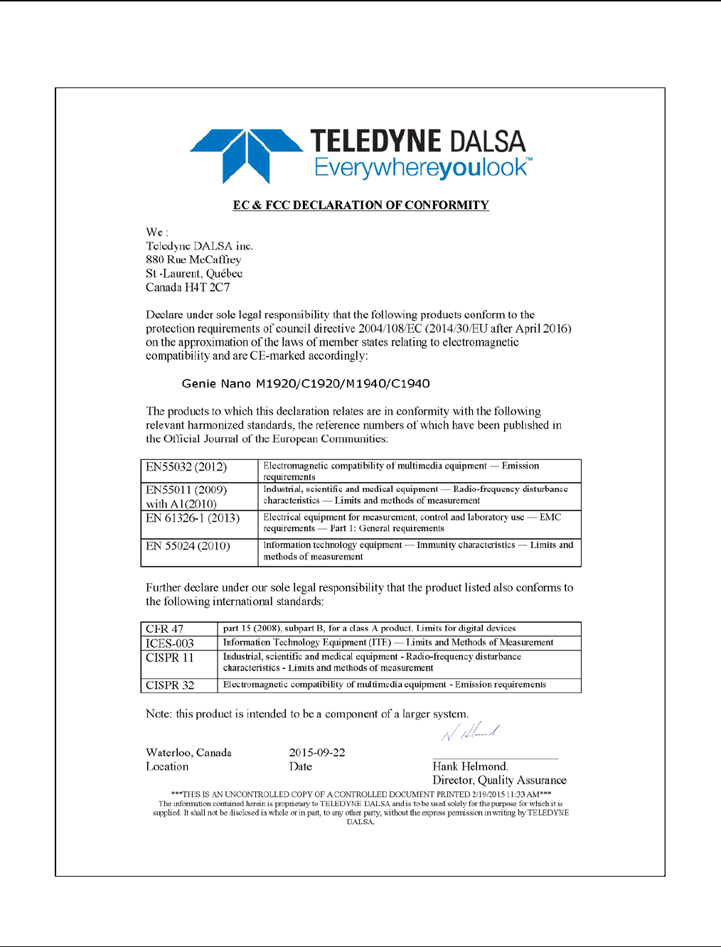
234
•
Technical Specifications Nano Series GigE Vision Camera
EC & FCC Declarations of Conformity
Models: M/C1920, M/C1940
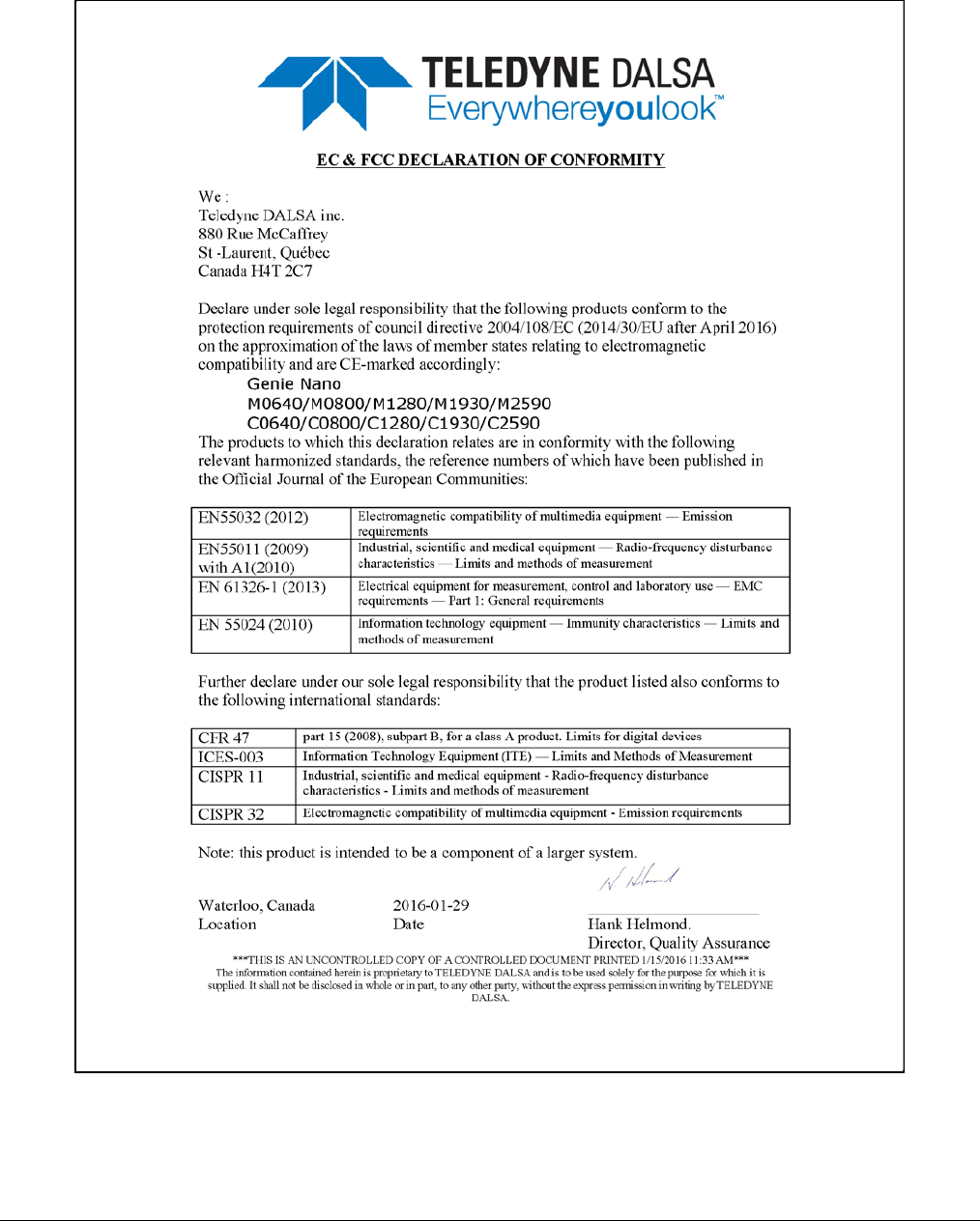
Nano Series GigE Vision Camera Technical Specifications
•
235
Models: M/C2590, M/C1930, M/C1280, M/C800, M/C640
236
•
Technical Specifications Nano Series GigE Vision Camera
Models: M/C2020, M/C2050, M/C2420, M/C2450
Nano Series GigE Vision Camera Technical Specifications
•
237
Models: M/C4020, M/C4030, M/C4040, M/C4060
238
•
Technical Specifications Nano Series GigE Vision Camera
Models: M/C5100, M/C4090
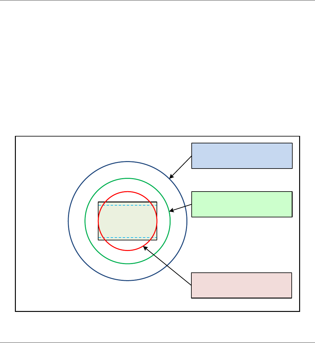
Nano Series GigE Vision Camera Additional Reference Information
•
239
Additional Reference
Information
Choosing a Lens with the Correct Image Circle
Each Nano model requires a lens with an image circle specification to fully illuminate the sensor.
The following section graphically shows the minimum lens image circle for each Nano model family
along with alternative lens types. Brief information on other lens parameters to consider follows
those sections.
Lens Options for Models ‘M/C1940’ & ‘M/C1920’
• The following figure shows the lens image circles relative to Genie Nano models using the Sony
IMX174 and IMX249 sensors respectively.
• A typical 1” lens will fully illuminate these sensors while the use of a 2/3” lens will have some
corner vignetting.
• Note the “horizontal blue dashed lines” defining the HD video format. These indicate setting the
Image Format controls to Height=1080 with a Vertical Offset=60.
IMX174
IMX249
1" Lens (~16mm)
Image Circle
1.3" Lens (~22.5mm)
Image Circle
2/3" Lens (~11mm)
Image Circle

240
•
Additional Reference Information Nano Series GigE Vision Camera
Lens Options for Models ‘2450/2420’ & ‘2050/2020’
• The following figure shows the lens image circles relative to Genie Nano models using the
Sony IMX250/264 and IMX252/265 sensors, in color or monochrome versions.
• A typical 2/3” lens will fully illuminate these sensors. A smaller 1/1.8” lens could be used with
Models 2050/2020.
1" Lens (~16mm)
Image Circle
2/3" Lens (~11mm)
Image Circle
Models 2050/2020
Models 2450/2420
1/1.8" Lens (~9mm)
Image Circle
Lens Options for Models ‘4060/4040/4030/4020’
• The following figure shows the lens image circles relative to Genie Nano models using the Sony
IMX255 (models 4060), IMX253 (models 4040), IMX267 (models 4030), and IMX304 (models
4020) sensors.
• A typical 1.1” lens will illuminate both sensors models while the 1” lens should only be used
with models 4060 & 4030 to avoid image vignetting.
1.3" Lens (~22.5mm)
Image Circle
Models
4040 & 4020
(17.6mm diagonal)
Models
4060 & 4030
(16.1mm diagonal)
1" Lens (~16mm)
Image Circle
1.1" Lens (~17mm)
Image Circle
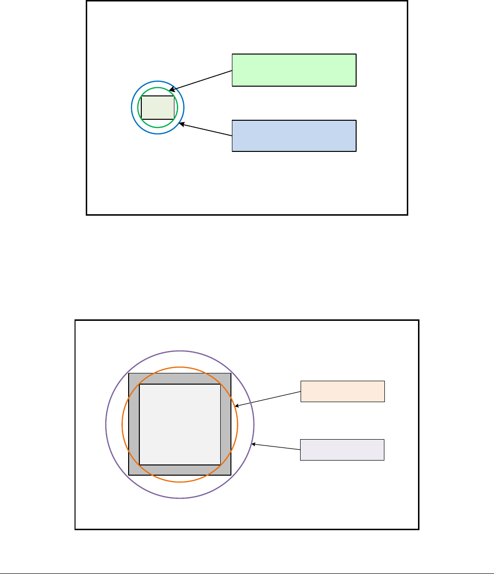
Nano Series GigE Vision Camera Additional Reference Information
•
241
Lens Options for Models ‘M/C1450’
• The following figure shows the lens image circles relative to Genie Nano models using the
Sony IMX273 sensor.
• A typical 1/3” lens will almost fully illuminate this sensor with just a small amount of vignetting
in the corners. A 1/2” lens exceeds the required image circle.
1/2" Lens (~8mm)
Image Circle
1/3" Lens (~6mm)
Image Circle
Lens Options for XL Models ‘M/C 5100’ and ‘M/C 4090
• The following figure shows the lens image circles relative to Genie NanoXL models using the
OnSemi Python 25K and Python 16K sensors.
• These NanoXL models have a M42 screw mount where M42 lens or F-mount lens (via an
adapter) need to have image circles exceeding the diameter of either of these larger sensors.
26.2mm minimum
Image Circle
32.6mm minimum
Image Circle
Model 4090
Model 5100

242
•
Additional Reference Information Nano Series GigE Vision Camera
Lens Options for Model ‘C4900’
• The following figure shows the lens image circles relative to Genie Nano model using the
OnSemi AR1820HS sensor.
2/3" Lens (~11mm)
Image Circle
1/2.3" Lens (~7.8mm)
Image Circle
1/2" Lens (~8mm)
Image Circle
Lens Options for Models ‘M/C2590’ & ‘M/C 2540’
• The following figure shows the lens image circles relative to Genie Nano models using the
OnSemi Python5000 sensor.
• A typical 1” lens will fully illuminate these sensors.
1" Lens (~16mm)
Image Circle
1.3" Lens (~22.5mm)
Image Circle
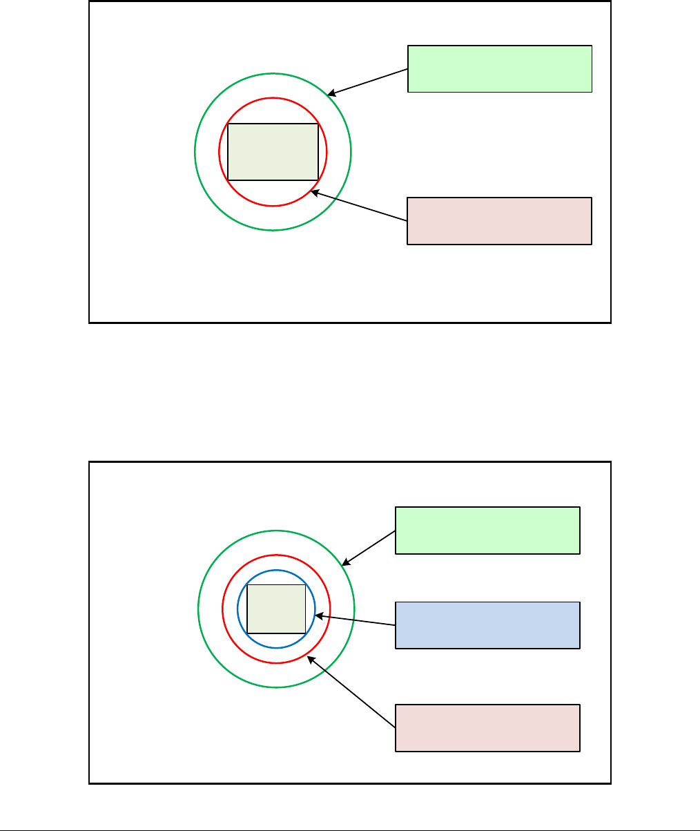
Nano Series GigE Vision Camera Additional Reference Information
•
243
Lens Options for Models ‘M/C1930’
• The following figure shows the lens image circles relative to Genie Nano models using the
OnSemi Python2000 sensor.
• A typical 2/3” lens will fully illuminate these sensors.
1" Lens (~16mm)
Image Circle
2/3" Lens (~11mm)
Image Circle
Lens Options for Models ‘M/C1280’ & ‘M/C1240’
• The following figure shows the lens image circles relative to Genie Nano models using the
OnSemi Python1300 sensor.
• A typical ½” lens will fully illuminate these sensors.
1" Lens (~16mm)
Image Circle
2/3" Lens (~11mm)
Image Circle
1/2" Lens (~8mm)
Image Circle

244
•
Additional Reference Information Nano Series GigE Vision Camera
Lens Options for Models ‘M/C800’
• The following figure shows the lens image circles relative to Genie Nano models using the
OnSemi Python500 sensor.
• A typical 1/3” lens will fully illuminate these sensors.
1/3" Lens (~6mm)
Image Circle
2/3" Lens (~11mm)
Image Circle
1/2" Lens (~8mm)
Image Circle
Lens Options for Models ‘M/C640’
• The following figure shows the lens image circles relative to Genie Nano models using the
OnSemi Python300 sensor.
• A typical ¼” lens will fully illuminate these sensors.
1/3" Lens (~6mm)
Image Circle
1/4" Lens (~4.5mm)
Image Circle
1/2" Lens (~8mm)
Image Circle

Nano Series GigE Vision Camera Additional Reference Information
•
245
Additional Lens Parameters (application specific)
There are other lens parameters that are chosen to meet the needs of the vision application. These
parameters are independent of the Nano model (assuming that the Lens Mount and Lens Sensor
Size parameters are correct, as previously covered in this section). A vision system integrator or
lens specialist should be consulted when choosing lenses since there is a trade-off between the
best lenses and cost. An abridged list of lens parameters follows – all of which need to be matched
to the application.
• Focal Length: Defines the focus point of light from infinity. This parameter is related to the
Nano mount (C or CS mount). See Genie Nano Specifications — Back Focal Distance.
• Field of View: A lens is designed to image objects at some limited distance range, at some
positive or negative magnification. This defines the field of view.
• F-Number (aperture): The lens aperture defines the amount of light that can pass. Lenses
may have fixed or variable apertures. Additionally the lens aperture affects Depth of Field
which defines the distance range which is in focus when the lens is focus at some specific
distance.
• Image Resolution and Distortion: A general definition of image quality. A lens with poor
resolution seems to never be in focus when used to image fine details.
• Aberrations (defect, chromatic, spherical): Aberrations are specific types of lens faults
affecting resolution and distortion. Lens surface defects or glass faults distort all light or
specific colors. Aberrations are typically more visible when imaging fine details.
• Spatial Distortions: Describes non-linear lens distortions across the field of view. Such
distortion limits the accuracy of measurements made with that lens.
Optical Considerations
This section provides an overview to illumination, light sources, filters, lens modeling, and lens
magnification. Each of these components contribute to the successful design of an imaging
solution.
Illumination
The amount and wavelengths of light required to capture useful images depend on the particular
application. Factors include the nature, speed, and spectral characteristics of objects being imaged,
exposure times, light source characteristics, environmental and acquisition system specifics, and
more. The Teledyne DALSA Web site, http://mv.dalsa.com/, provides an introduction to this
potentially complicated issue. Click on Knowledge Center and then select Application Notes and
Technology Primers. Review the sections of interest.
It is often more important to consider exposure than illumination. The total amount of energy
(which is related to the total number of photons reaching the sensor) is more important than the
rate at which it arrives. For example, 5mJ/cm2 can be achieved by exposing 5mW/cm2 for 1ms just
the same as exposing an intensity of 5W/cm2 for 1ms.
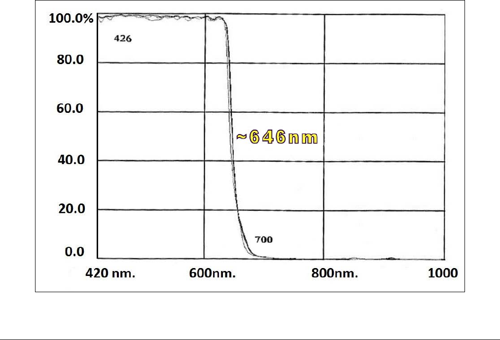
246
•
Additional Reference Information Nano Series GigE Vision Camera
Light Sources
Keep these guidelines in mind when selecting and setting up light source:
• LED light sources are relatively inexpensive, provide a uniform field, and longer life span
compared to other light sources. However, they also require a camera with excellent sensitivity.
• Halogen light sources generally provide very little blue relative to infrared light (IR).
• Fiber-optic light distribution systems generally transmit very little blue relative to IR.
• Some light sources age such that over their life span they produce less light. This aging may
not be uniform—a light source may produce progressively less light in some areas of the
spectrum but not others.
IR Cut-off Filters
Genie Nano cameras are responsive to near infrared (IR) wavelengths. To prevent infrared from
distorting the color balance of visible light acquisitions, use a “hot mirror” or IR cut-off filter that
transmits visible wavelengths but does not transmit near infrared wavelengths and above.
Genie Nano color cameras have a spectral response that extends into near IR wavelengths (as
defined for each sensor model in the sensor specification descriptions). Images captured will have
washed out color if the sensor response is not limited to the visible light band.
Nano Models with Built-in IR Cut-off Filters
Choose Nano color cameras with built-in IR Cut-off Filters for an optimized solution. The following
graphic shows these models having an IR filter with a specified cut-off of about 646nm.

Nano Series GigE Vision Camera Additional Reference Information
•
247
Guidelines for Choosing IR Cut-off Filters
The following graphic, using a color sensor response spectrum, shows the transmission response of
typical filters designed for CMOS sensor cameras. When selecting an IR cut-off filter, choose a near
infrared blocking specification of ~650nm. Filters that block at 700nm or longer wavelengths,
designed for CCD cameras, are not recommended for Genie Nano color cameras.
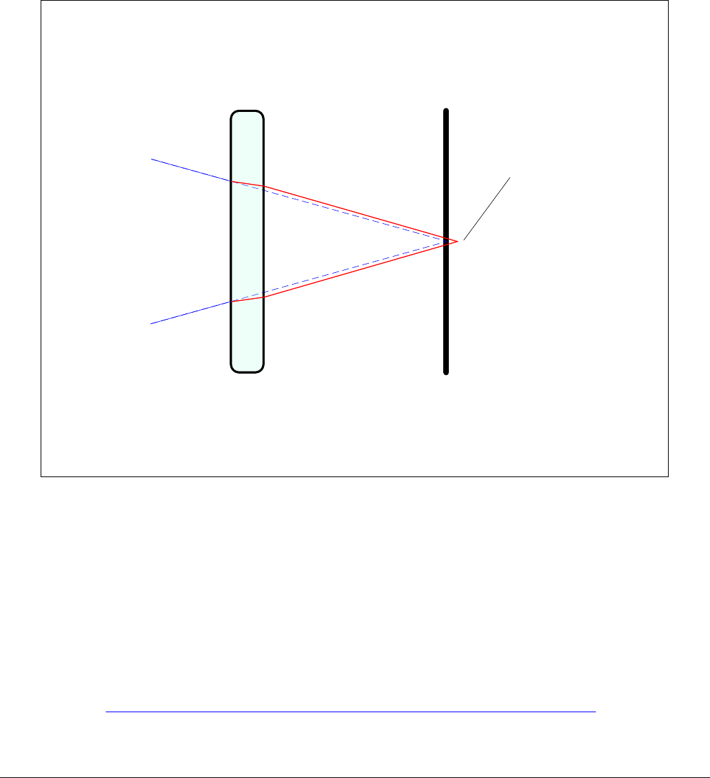
248
•
Additional Reference Information Nano Series GigE Vision Camera
Back Focal Variance when using any Filter
Inserting a filter between a lens and sensor changes the back focal point of the lens used. A
variable focus lens simply needs to be adjusted, but in the case of a fixed focus lens, the changed
focal point needs correction.
The following simplified illustration describes this but omits any discussion of the Optics, Physics,
and the math behind the refraction of light through glass filter media.
sensor surface
(focal plane)
Focal Point with
filter is behind
sensor surface
Filter
Illustration: Change of Focal
Point with inserted filter
Incident Light
(from Lens)
In this example when a glass filter is inserted between the lens and the camera sensor, the focal
point is now about 1/3 of the filter thickness behind the sensor plane. Genie Nano filters are
specified as 1mm thick.
Genie Nano models with factory installed filters automatically compensate for the focal point
variance by having the sensor PCB mounted deeper within the camera body.
For Nano models normally shipped without filters, when a filter is installed a fixed focus lens
requires a 1/3mm C-mount shim (spacer) added to move the lens focal point back to the sensor
surface. Such shims are available from filter and lens suppliers. Alternatively use a variable focus
lens and secure its focus ring after adjustment.
For users interested in installing their own choice of filters, please refer to application note:
G3-AN0001 – Installing Custom Filters into Genie Nano.pdf
available here http://www.teledynedalsa.com/imaging/knowledge-center/appnotes/

Nano Series GigE Vision Camera Additional Reference Information
•
249
Lens Modeling
Any lens surrounded by air can be modeled for camera purposes using three primary points: the
first and second principal points and the second focal point. The primary points for a lens should be
available from the lens data sheet or from the lens manufacturer. Primed quantities denote
characteristics of the image side of the lens. That is, h is the object height and h′ is the image
height.
The focal point is the point at which the image of an infinitely distant object is brought to focus.
The effective focal length (f′) is the distance from the second principal point to the second focal
point. The back focal length (BFL) is the distance from the image side of the lens surface to the
second focal point. The object distance (OD) is the distance from the first principal point to the
object.
Primary Points in a Lens System
Magnification and Resolution
The magnification of a lens is the ratio of the image size to the object size:
h
h
m'
=
Where m is the magnification, h’ is the image height (pixel
size) and h is the object height (desired object resolution
size).
By similar triangles, the magnification is alternatively given by:
OD
f
m'
=
These equations can be combined to give their most useful form:
OD
f
h
h'' =
This is the governing equation for many object and image
plane parameters.
Example: An acquisition system has a 512 x 512 element, 10m pixel pitch area scan camera, a
lens with an effective focal length of 45mm, and requires that 100mm in the object space
correspond to each pixel in the image sensor. Using the preceding equation, the object distance
must be 450mm (0.450m).
OD
mm
m
m45
100
10 =
m
m
)450.0(450 mmmOD =
250
•
Additional Reference Information Nano Series GigE Vision Camera
Sensor Handling Instructions
This section reviews proper procedures for handling, cleaning, or storing the Genie Nano camera.
Specifically the Genie Nano sensor needs to be kept clean and away from static discharge to
maintain design performance.
Electrostatic Discharge and the Sensor
Cameras sensors containing integrated electronics are susceptible to damage from electrostatic
discharge (ESD).
Electrostatic charge introduced to the sensor window surface can induce charge buildup on the
underside of the window that cannot be readily dissipated by the dry nitrogen gas in the sensor
package cavity. With charge buildup, problems such as higher image lag or a highly non-uniform
response may occur. The charge normally dissipates within 24 hours and the sensor returns to
normal operation.
Important: Charge buildup will affect the camera’s flat-field correction calibration. To avoid an
erroneous calibration, ensure that you perform flat-field correction only after a charge buildup has
dissipated over 24 hours.
Protecting Against Dust, Oil and Scratches
The sensor window is part of the optical path and should be handled like other optical components,
with extreme care.
Dust can obscure pixels, producing dark patches on the sensor response. Dust is most visible when
the illumination is collimated. The dark patches shift position as the angle of illumination changes.
Dust is normally not visible when the sensor is positioned at the exit port of an integrating sphere,
where the illumination is diffuse.
Dust can normally be removed by blowing the window surface using a compressed air blower,
unless the dust particles are being held by an electrostatic charge, in which case either an ionized
air blower or wet cleaning is necessary.
Oil is usually introduced during handling. Touching the surface of the window barehanded will leave
oily residues. Using rubber finger cots and rubber gloves can prevent oil contamination. However,
the friction between the rubber and the window may produce electrostatic charge that may
damage the sensor.
Scratches can be caused by improper handling, cleaning or storage of the camera. When handling
or storing the Nano camera without a lens, always install the C-mount protective cap. Scratches
diffract incident illumination. When exposed to uniform illumination, a sensor with a scratched
window will normally have brighter pixels adjacent to darker pixels. The location of these pixels
changes with the angle of illumination.

Nano Series GigE Vision Camera Additional Reference Information
•
251
Cleaning the Sensor Window
Even with careful handling, the sensor window may need cleaning. The following steps describe
various cleaning techniques to clean minor dust particles to accidental finger touches.
• Use compressed air to blow off loose particles. This step alone is usually sufficient to clean the
sensor window. Avoid moving or shaking the compressed air container and use short bursts of
air while moving the camera in the air stream. Agitating the container will cause condensation
to form in the air stream. Long air bursts will chill the sensor window causing more
condensation. Condensation, even when left to dry naturally, will deposit more particles on the
sensor.
• When compressed air cannot clean the sensor, Teledyne DALSA recommends using lint-free
ESD-safe cloth wipers that do not contain particles that can scratch the window. The Anticon
Gold 9”x 9” wiper made by Milliken is both ESD safe and suitable for class 100 environments.
Another ESD acceptable wiper is the TX4025 from Texwipe.
• An alternative to ESD-safe cloth wipers is Transplex swabs that have desirable ESD properties.
There are several varieties available from Texwipe. Do not use regular cotton swabs, since
these can introduce static charge to the window surface.
• Wipe the window carefully and slowly when using these products.
Ruggedized Cable Accessories
Teledyne DALSA provides optional I/O cable assemblies for Genie Nano. Users wishing to build
their I/O cabling by starting from available cable packages should consider these popular
assemblies described below. Contact Sales for pricing and delivery.
Users also may order cable assembly quantities directly from Components Express. In such cases
use the manufacturer’s part number shown on the cable assembly engineering drawing.
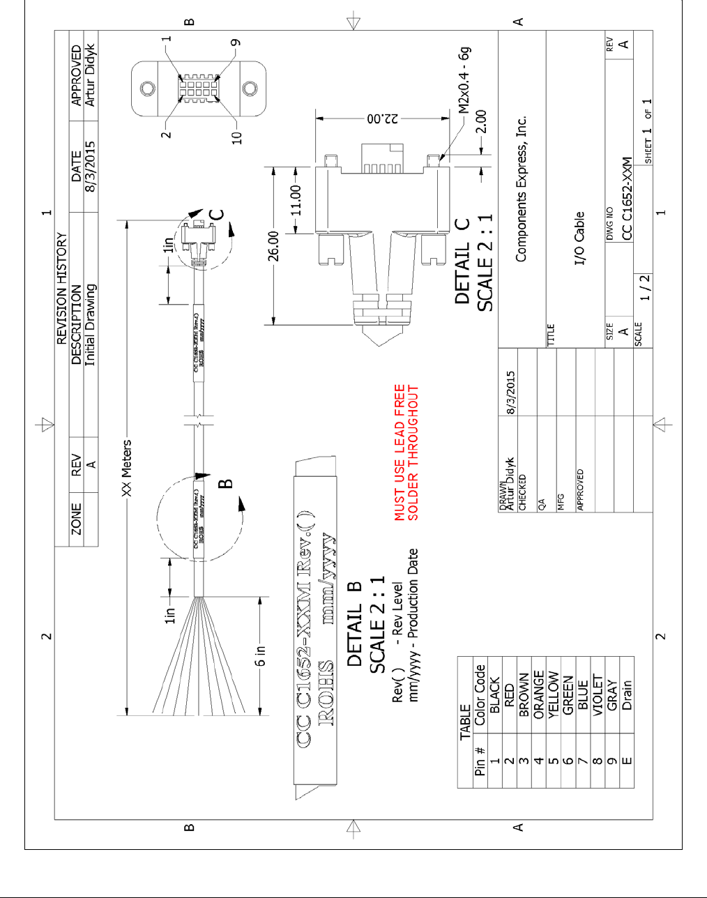
252
•
Additional Reference Information Nano Series GigE Vision Camera
Cable Assembly G3-AIOC-BLUNT2M
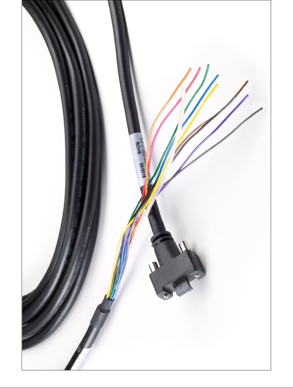
Nano Series GigE Vision Camera Additional Reference Information
•
253
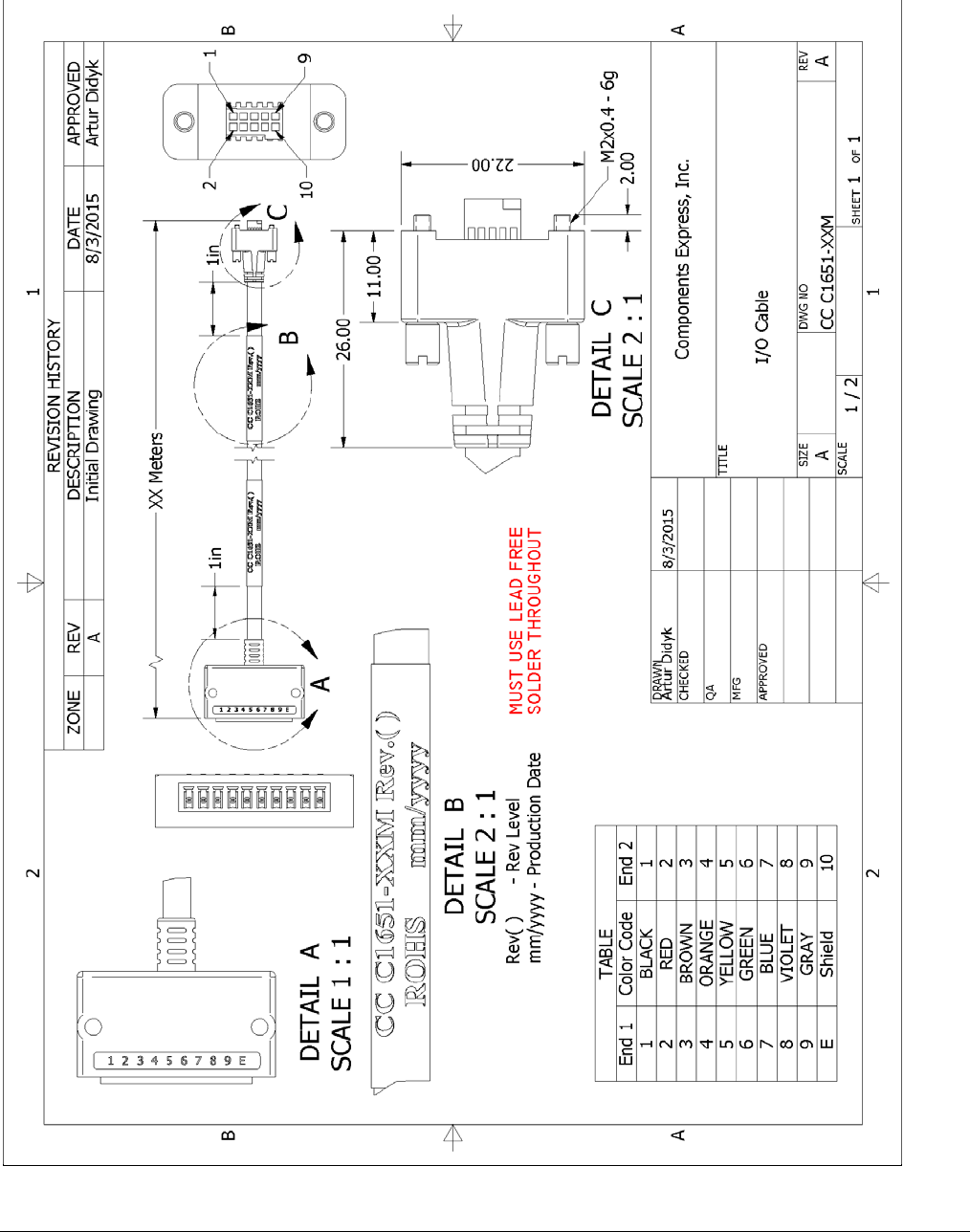
254
•
Additional Reference Information Nano Series GigE Vision Camera
Cable Assembly G3-AIOC-BRKOUT2M
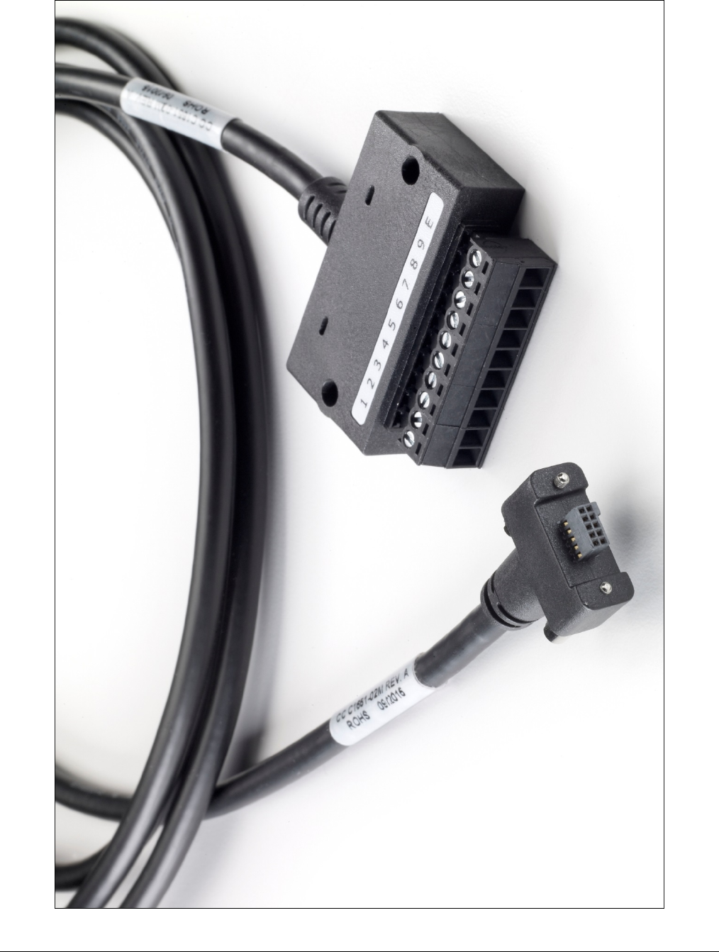
Nano Series GigE Vision Camera Additional Reference Information
•
255
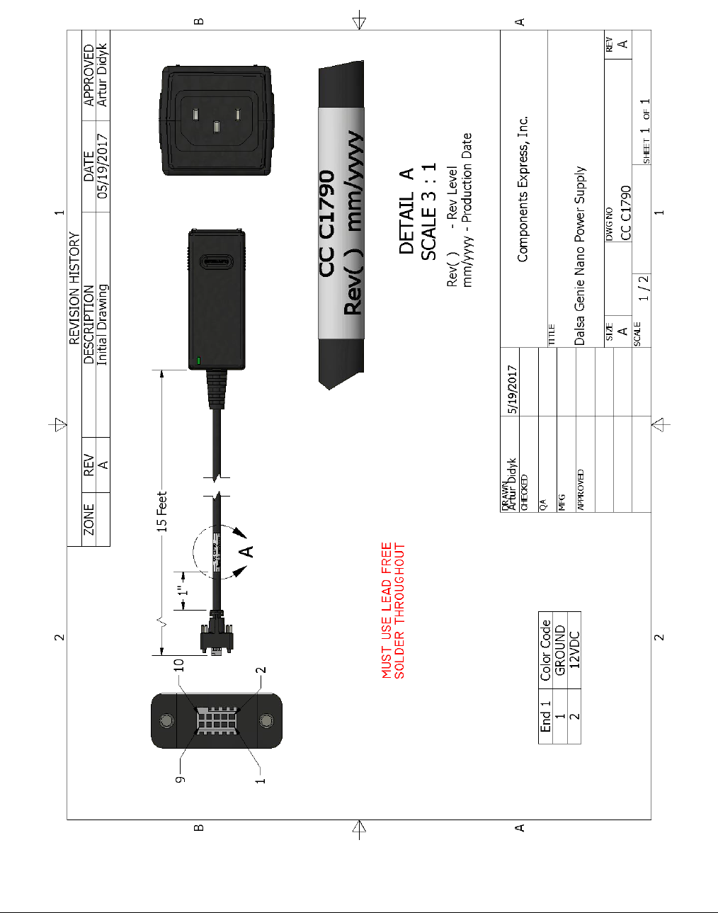
256
•
Additional Reference Information Nano Series GigE Vision Camera
Nano Generic Power Supply with no I/O
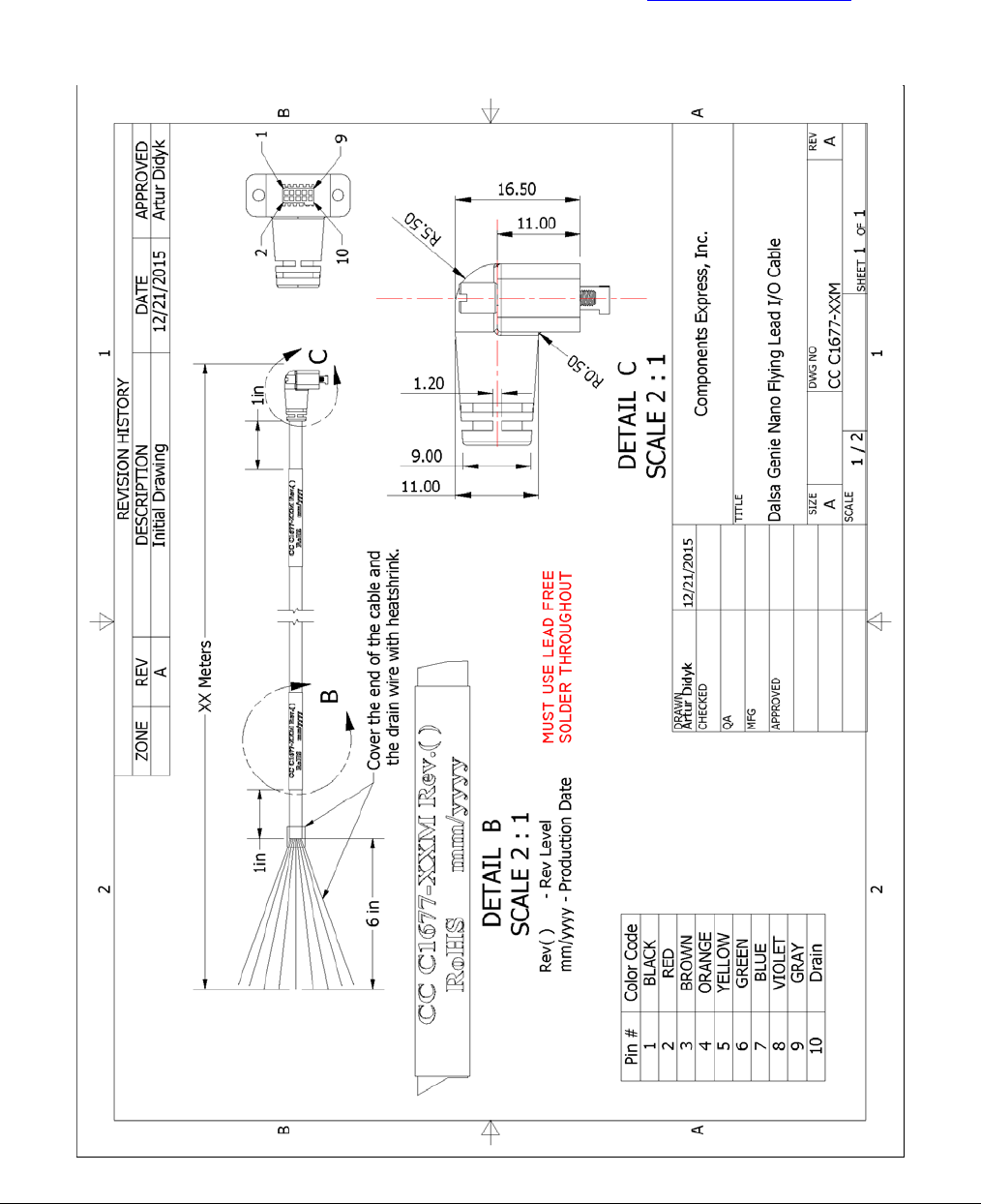
Nano Series GigE Vision Camera Additional Reference Information
•
257
Components Express Right-Angle Cable Assemblies
These cable assemblies can be acquired directly from our partner Components Express. In such
cases use the manufacturer’s part number shown on the cable assembly engineering drawing.
Cable Assembly: Right-Angle I/O Bunt End
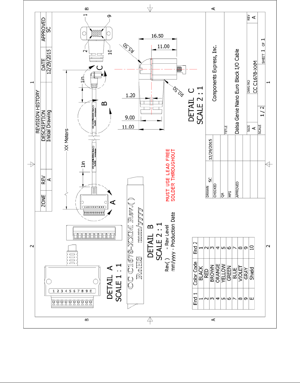
258
•
Additional Reference Information Nano Series GigE Vision Camera
Cable Assembly: Right-Angle I/O to Euro Block
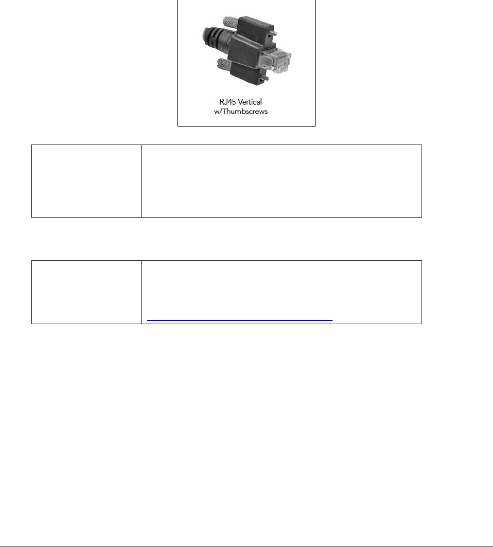
Nano Series GigE Vision Camera Additional Reference Information
•
259
Ruggedized RJ45 Ethernet Cables
Components Express Inc. has available industrial RJ45 CAT6 cables that on one end have a molded
shroud assembly with top/bottom thumbscrews, while the other end is a standard RJ45 (one
example shown below). These cables are recommended when Nano is installed in a high vibration
environment. All Nano versions support this secure Ethernet cable. Review their catalog for all
available versions of vertical thumbscrew RJ45 cable sets.
All cables made in
U.S.A. – all cables
RoHS compliant.
CAT6 certified
(tested for near end / far end crosstalk and return loss).
IGE-3M (3meters)
IGE-10M (10meters)
IGE-25M (25meters)
IGE-50M (50meters)
IGE-100M (100meters)
Components Express Contact Information
For Information
contact: Components Express, Inc. (CEI)
10330 Argonne Woods Drive, Suite 100
Woodridge, IL 60517-4995
Phone: 630-257-0605 / 800.578.6695 (outside Illinois)
Fax: 630-257-0603
http://www.componentsexpress.com/
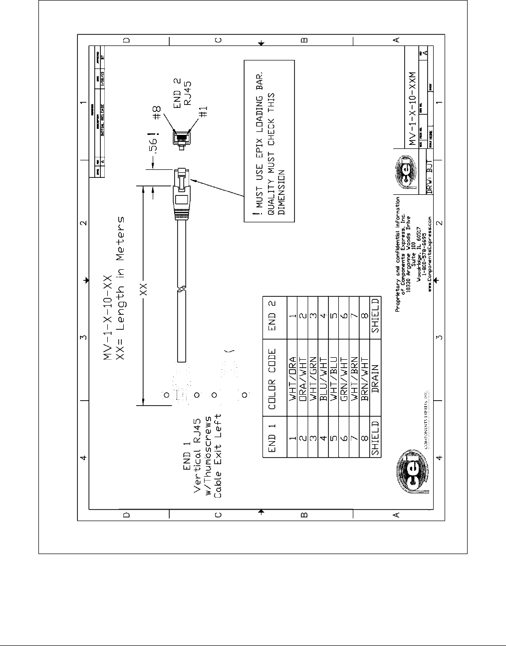
260
•
Additional Reference Information Nano Series GigE Vision Camera
Cable Assembly: Right-Angle Ethernet
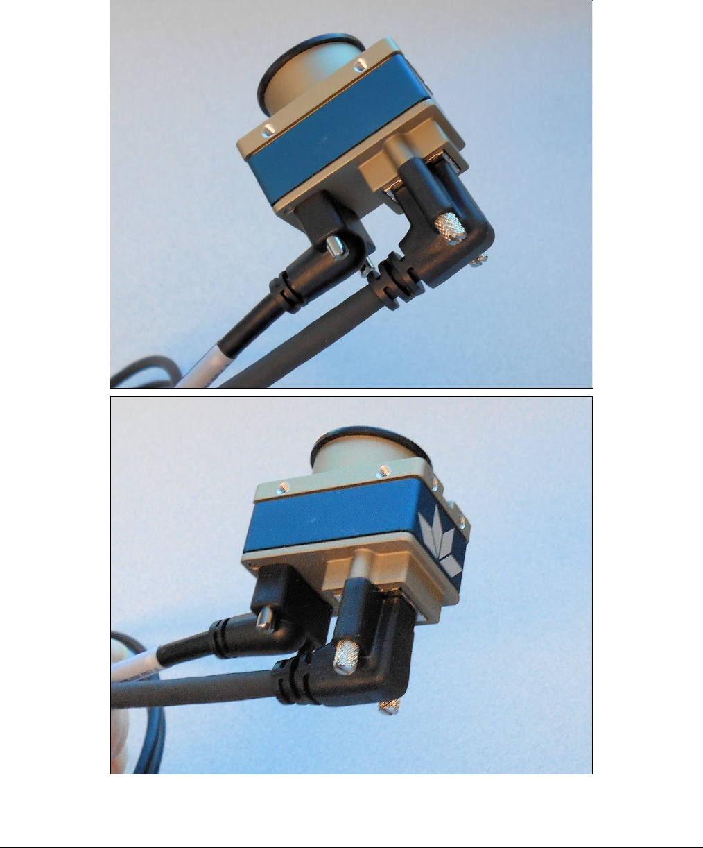
Nano Series GigE Vision Camera Additional Reference Information
•
261
Right-Angle Cable-Set (Mounted)
Photos show the Components Express Right-Angle combo package (CC C1679-xxM) consisting of
a Right-Angle Ethernet cable, Right-Angle I/O to Euro Block, and power supply (not shown).
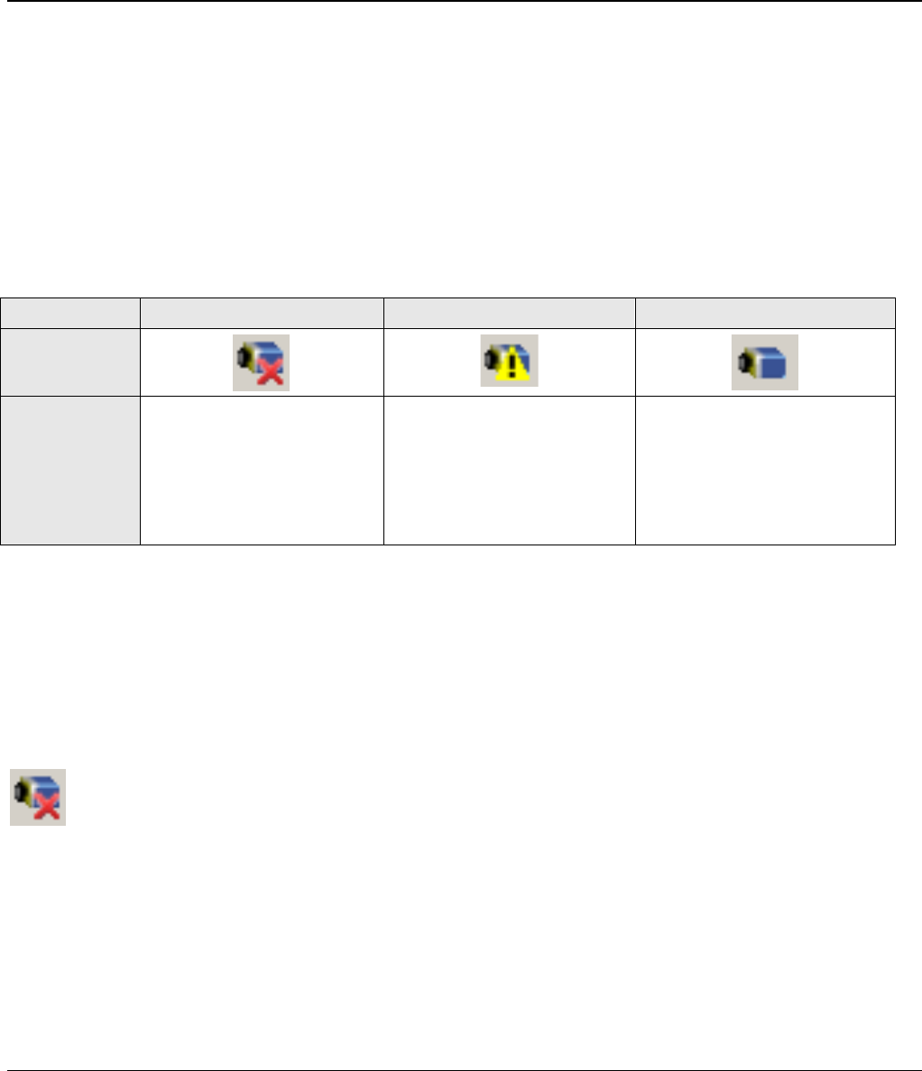
262
•
Troubleshooting Nano Series GigE Vision Camera
Troubleshooting
Overview
In rare cases an installation may fail or there are problems in controlling and using the Nano
camera. This section highlights issues or conditions which may cause installation problems and
additionally provides information on computers and network adapters which have caused problems
with Nano. Emphasis is on the user to perform diagnostics with the tools provided and methods are
described to correct the problem.
The GigE Server status provides visual information on possible Nano problems. The three states
are shown in the following table. Descriptions of possible conditions causing an installation or
operational problem follow. Note that even a Nano installation with no networking issue may still
require optimization to perform to specification.
Device Not Available Device IP Error Device Available
GigE Server
Tray Icon:
Note: It will
take a few
seconds for the
GigE Server to
refresh its state
after any
change.
A red X will remain over the
GigE server tray icon when
the Nano device is not found.
This indicates a network issue
where there is no
communication with Nano. Or
in the simplest case, the
Nano is not connected.
The GigE server tray icon
shows a warning when a device
is connected but there is some
type of IP error.
The GigE server tray icon when
the Nano device is found. The
Nano has obtained an IP address
and there are no network issues.
Optimization may still be
required to maximize
performance.
Problem Type Summary
Nano problems are either installation types where the Nano is not found on the network or setup
errors where the Nano device is found but not controllable. Additionally a Nano may be properly
installed but network optimization is required for maximum performance. The following links jump
to various topics in this troubleshooting section.
Device Not Available
A red X over the GigE server tray icon indicates that the Nano device is not found. This indicates
either a major camera fault or condition such as disconnected power, or a network issue where
there is no communication.
• Review the section Using Nano to verify required installation steps.
• Refer to the Teledyne DALSA Network Imaging manual to review networking details.
• In multiple NIC systems where the NIC for the Nano is using LLA mode, ensure that no
other NIC is in or switches to LLA mode. It is preferable that the Teledyne DALSA DHCP
Nano Series GigE Vision Camera Troubleshooting
•
263
server is enabled on the NIC used with the Nano instead of using LLA mode, which prevents
errors associated with multiple NIC ports.
• Verify that your NIC is running the latest driver available from the manufacturer.
Device IP Error
The GigE server tray icon shows a warning with IP errors. Review the following topics on network
IP problems to identify and correct the condition.
Please refer to the Teledyne DALSA Network Imaging Package manual for information on the
Teledyne DALSA Network Configuration tool and network optimization foe GigE Vision cameras and
devices.
Multiple Camera Issues
• When using multiple cameras with a computer with multiple NIC ports, confirm each Nano
has been assigned an IP address by checking the GigE server.
• To reduce network traffic in configured problem free systems, use the Network
Configuration tool to stop camera discovery broadcasts. Refer to the Teledyne DALSA
Network Imaging manual.
• When using multiple cameras connected to an VLAN Ethernet switch, confirm that all
cameras are on the same subnet setup on that switch. See the Teledyne DALSA Network
Imaging package manual for more information. .
• If a Nano camera installed with other GigE Vision cameras cannot connect properly with the
NIC or has acquisition timeout errors, there may be a conflict with the third party camera’s
filter driver. In some cases third party filter drivers modify the NIC properties such that the
Teledyne DALSA Sapera Network Imaging Driver does not install. Verify such a case by
uninstalling the third party driver and installing the Nano package again.
• Verify that your NIC is running the latest driver available from the manufacturer.
Device Available but with Operational Issues
A properly installed Nano with no network issues may still not perform optimally. Operational
issues concerning cabling, Ethernet switches, multiple cameras, and camera exposure are
discussed in the following sections:
Always Important
• Why should Nano firmware be updated? See Firmware Updates.
• Power Failure during a Firmware Update–Now What?
• Cabling and Communication Issues
• See Preventing Operational Faults due to ESD to avoid random packet loss, random camera
resets, and random loss of Ethernet connections.
No Timeout messages
• I can use CamExpert to grab but the image is corrupted with bad data. See Grab has
Random Bad Data or Noise.
• I can use CamExpert to grab (with no error message) but there is no image (display window
stays black). See Acquisition Error without Timeout Messages.
• I can use CamExpert to grab (with no error message) but the frame rate is lower than
expected. See Camera acquisition is good but frame rate is lower than expected.
• There is no image and the frame rate is lower than expected.
See Camera is functional but frame rate is lower than expected.
264
•
Troubleshooting Nano Series GigE Vision Camera
• There is no image but the frame rate is as expected.
See Camera is functional, frame rate is as expected, but image is black.
Other problems
• Unexpected or missing ‘Trigger Events’. See Random Invalid Trigger Events.
• Dropped packets or lost frames when using newer CPU system. See Preventing Dropped
Packets by adjusting Power Options.
Verifying Network Parameters
Teledyne DALSA provides the Network Configuration tool to verify and configure network devices
and the Nano network parameters. See section Network Configuration Tool of the Teledyne DALSA
Network Imaging manual, if there were any problems with the automatic Nano software
installation.
Before Contacting Technical Support
Carefully review the issues described in this Troubleshooting section. To aid Teledyne DALSA
personnel when support is required, the following should be included with the request for support.
• From the Start menu, go to Programs • Dalsa • Sapera LT • Tools and run the Log Viewer
program. From its File menu click on Save Messages to generate a log text file.
• Report the version of Genie Nano Framework and Sapera version used.
Device Available with Operational Issues
This section considers issues with cabling, Ethernet switches, multiple cameras, and camera
exposure. All information concerning the Teledyne DALSA Network Configuration Tool and other
networking considerations, is available in the Teledyne DALSA Network Imaging manual.
Firmware Updates
As a general rule any Nano installation must include the firmware update procedure
(see File Access Control Category). Nano camera firmware that does not match a newer version of
installed Nano Framework software is likely to have unpredictable behavior.
Problems might be:
• Nano is not found by the device discovery process.
• Nano is found by the Sapera GigE Server but an application such as CamExpert does not see
the camera.
• A Nano that had a fault with a firmware update will automatically recover by booting with the
previous firmware version.
Important: New Nano cameras installed in previously deployed systems are fully backward
compatible with the older vision application.

Nano Series GigE Vision Camera Troubleshooting
•
265
Power Failure during a Firmware Update–Now What?
Don’t panic! There is far greater chance that the host computer OS is damaged during a power
failure than any permanent problems with the Nano. When electrical power returns and the host
computer system has started, follow this procedure.
• Connect power to the Nano. The Nano processor knows that the firmware update failed.
• The Genie Nano will boot with the previous version of firmware and will operate normally.
• The Nano Self Status (deviceBISTStatus) will return that the last firmware update failed.
• Perform the firmware update procedure (see File Access Control Category) again.
Cabling and Communication Issues
With only two cables connected to Nano, possible cabling issues are limited.
Power supply problems:
• If the Nano status LED is off, the DC supply power is not connected or faulty. Verify the power
supply voltage.
Communication Problems:
• Use a shielded cable where the connector shell electrically connects the Nano chassis to the
power supply earth ground. This can eliminate trigger issues in a high EMI environment.
• Check that the Ethernet cable is clipped both to the Nano and the NIC or switch on the other
end.
• Verify the Ethernet cabling. Poor cables will cause connections to auto-configure at lower
speeds.
• Use a secured Ethernet cable when the Nano is in a high vibration environment.
See Ruggedized RJ45 Ethernet Cables.
• Check the Ethernet status LEDs on the NIC used with the camera. The Link Status indicator is
on and the activity LED should flash with network messages.
• Verify that the Ethernet cable is CAT5e or CAT6. This is very important with long cable lengths.
• When using very long cables, up to the maximum specified length of 100m for gigabit Ethernet,
different NIC hardware and EMI conditions can affect the quality of transmission.
• Minimum recommended Ethernet cable length is 3 feet (1 meter).
• Use the Log Viewer tool (see point below) to check on packet resend conditions.
• Run the Sapera Log Viewer: Start•Programs•Teledyne DALSA•Sapera LT•Tools•Log
Viewer. Start the Nano acquisition program, such as CamExpert. There should not be any
“packet resend” messages, else this indicates a control or video transmission problem due to
poor connections or extremely high EMI environments.
Acquisition Error without Timeout Messages
Streaming video problems range from total loss of image data to occasional loss of random video
data packets. The following section describes conditions identified by Teledyne DALSA engineering
while working with Nano in various computers and setups. See the Teledyne DALSA Network
Imaging manual for information on network optimizations.
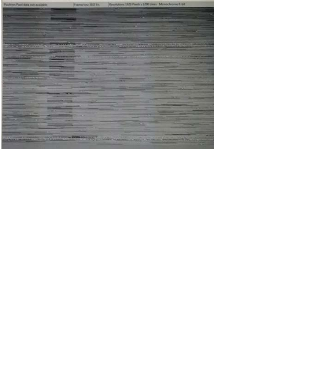
266
•
Troubleshooting Nano Series GigE Vision Camera
Grab has Random Bad Data or Noise
The problem is seen as random noise and missing sections of video data from the acquisition. All
configuration parameters seem correct and the Ethernet cable is secure. The following image
shows an example of this type of bad acquisition while testing a Genie installation with CamExpert.
• This problem has been seen with network adapters that do not support jumbo frames but still
report a false maximum packet frame size.
• Test for a good acquisition by reducing the camera packet size used. Set the value to the
default value of 1500 to verify acquisition before trying a higher value.
• Other marginal NIC boards or ports can cause problems with packet transfers. Try alternative
NIC adapters.
Review other reasons for such acquisition errors as described in the Teledyne DALSA Network
Imaging Module for Sapera LT manual.
No camera exposure when expected
• Verify by using the camera in free-running mode. Do not use external trigger mode when
testing a camera setup.
• If using free-running mode, verify that the exposure period is set to the maximum possible
for the set frame rate.
• Load the factory default from the Power-up Configuration in CamExpert. This will reset the
camera to its nominal acquisition rate.

Nano Series GigE Vision Camera Troubleshooting
•
267
Camera is functional but frame rate is lower than expected
• Verify Ethernet link speed. If the LAN connection is limited to 100 Mbps, the Genie Nano
frame rate maximum will be limited once the internal buffers are filled. See the Teledyne
DALSA Network Imaging manual for information on network optimizations.
• If using an external trigger, verify the trigger source rate and Nano parameters such as
trigger to exposure delay.
• USB to Ethernet adapters are not recommended nor guaranteed. Even in cases where the
camera seems to be connected and transferring images, reports of random disconnections
are common. If the user wishes to try such an interface, limit this to just one high quality
unit, never more. Multiple units have not worked in a machine vision environment.
Camera acquisition is good but frame rate is lower than expected
• While running CamExpert and grabbing in free-run mode at the maximum frame rate, start
the Sapera Monitor tool from the Sapera Tools installed with Sapera.
• Make sure the Memory Overflow event monitor is enabled.
• Continue grabbing from the Nano at maximum frame rate. If any memory overflow events
are counted, then the Nano internal buffer could not be transmitted on time and was
discarded. Such a condition may occur with large frame color or high frame rate Nano
cameras.
• Note that the Sapera CamExpert tool has limits to the maximum frame rate possible due to
CamExpert generating an interrupt for each acquired frame. The Sapera Grab Demo may be
better suited for testing at higher frame rates.
• Verify that network parameters are optimal as described in the Teledyne DALSA Network
Imaging Module manual. Ensure the host computer is not executing other network intensive
tasks. Try a different Gigabit NIC.
• Note that a changed acquisition frame rate becomes active only when the acquisition is
stopped and then restarted.
Camera is functional, frame rate is as expected, but image is black
• Verify that the lens iris is open.
• Aim the Nano at a bright light source.
• Check that the programmed exposure duration is not too short or set it to maximum.
See Sensor Control Category.
• Using CamExpert set the Nano to output its Internal Pattern Generator. This step is typically
done for any camera installation to quickly verify the Nano and its software package. See
Internal Test Pattern Generator for information on using CamExpert to select internal
patterns from Nano.

268
•
Troubleshooting Nano Series GigE Vision Camera
Model C4900 Column Noise in Saturated Areas
Model C4900 cameras used in high temperature environments and exposed to light many times
brighter than the pixel saturation threshold, might exhibit sensor artifacts visible as dark column
noise in the saturated areas.
This is not a camera fault but just a sensor limitation, which varies from one camera to another.
The image below shows an example of these artifacts in a lighting setup which over saturates the
whole sensor.
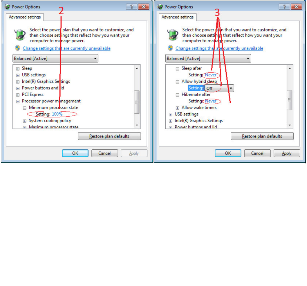
Nano Series GigE Vision Camera Troubleshooting
•
269
Other Problems or Issues
This section describes problems that do not fit any of the categories above. Typically these are
issues found in the field under specific or unusual conditions.
Preventing Dropped Packets by adjusting Power Options
New computers using new generation CPU chips such as Intel Skylake require adjustments to the
default Power Options to avoid possible dropped packets or frames.
• Open Control Panel – Power Options and select advanced settings, as shown below.
• Scroll down to the Processor Power Management control and change the Minimum Processor
State to 100%.
• Disable the Sleep and Hibernate options to ensure continuous system operation.

270
•
Troubleshooting Nano Series GigE Vision Camera
Random Invalid Trigger Events
• Do not change the exposure time while grabbing, else an Invalid Trigger Event may be
generated. This applies to any exposure mode or trigger source. The Invalid Trigger Event is
not catastrophic and only indicates the loss of a video frame. Stopping acquisitions first will
avoid this error.
• Version 1.00 firmware may not correctly generate Invalid Trigger Events when triggers are
received early (i.e. within the trigger exclusion period). All trigger management issues will be
resolved with firmware 1.01.
Minimum Sapera Version Required
Save User Configuration Failed: An unusual error that occurred with no other Nano control
problem. The solution is to verify the minimum Sapera version used with the Nano Framework. The
Genie Nano requires Sapera version 8.00 or later.
Issues with uninstalling Cognex VisionPro with Sapera LT CamExpert
When the Cognex VisionPro package is uninstalled, the Genie Nano becomes not available within
CamExpert due to the Cognex uninstaller removing GigE Vision components. This forces a Genie
Nano user to reinstall the Network Imaging package (or execute a repair within Sapera LT).
Cognex VisionPro remains a useable third party product except for their uninstaller fault. Genie
Nano users just need to account for this issue until resolved by Cognex.

Nano Series GigE Vision Camera Addendums
•
271
Addendums
This section provides supplemental information about alternative Nano specifications pertaining to
various models or legacy firmware revisions. For purchasing information and lead times of optional
Nano models that are not part of the typical production cycle, contact Teledyne DALSA Sales.
AC Characteristics of 1 Input / 3 Output Models
Optional Nano models denoted by part numbers “G3-GM2… or G3-GC2…” have output signal AC
characteristics as defined in the following table. Input characteristics remain equal to standard
Nano models.
t
t
Output Control Signal
Output
100%
90%
10%
td1
trise tfall
td2
Output
Output Common Power
RLoad
Control
Signal
Opto-coupled Output: AC Characteristics at an internal FPGA temperature of 83C
Note: All measurements subject to some rounding.
Output
Common
Power
Output
Current Rload
Test
Teledyne
DALSA1
(µs)
Leading Delay
trise (µs)
Rise Time
Teledyne
DALSA2
(µs)
Trailing Delay
tfall (µs)
Fall Time
3V 8 mA 250 ohm 0.5 3.4 8.5 13.4
16 mA 43 ohm 0.48 5.2 2.7 7.1
5V
8 mA 500 ohm 0.56 2.9 10.3 14.6
16 mA 170 ohm 0.52 4.9 3.3 7.4
21 mA 6.5 ohm 0.44 3.4 2.4 4.4
12V
8 mA 1.4K ohm 0.64 2.4 13.7 16.3
16 mA 625 ohm 0.61 5.4 5.2 11.1
24 mA 206 ohm 0.52 3.0 2.7 4.7
24V
8 mA 2.87K ohm 0.69 2.5 15.2 24.2
16 mA 1.35K ohm 0.69 4.7 6.2 14.4
24 mA 700 ohm 0.65 4.6 9.7 9.4

272
•
Addendums Nano Series GigE Vision Camera
Defective Pixel Replacement (Method 4)
Important: The algorithms used exclusively with Nano firmware versions 1.00 to 1.06 are now
identified as Method 4, as described in this addendum. Nano firmware 1.07 and later implements
algorithms now identified as Method 3 and which are described in the image processing category.
The Pixel Replacement algorithm (Method 4) is based on a predefined bad pixel map (as an XML
file), either supplied by the factory (file loaded as “Factory Map”) or generated by the user (file
uploaded as “User Map 1”). The number of bad pixel entries is limited and varies dependent on the
Nano model. The following XML code sample forms the template for the user to build bad pixel
maps for any of their Nano cameras.
Note: Identifying bad pixels is left to the user’s discretion, but Teledyne DALSA technical support
can provide guidance.
Example User Defective Pixel Map XML File
The following example shows the required components of the defective pixel map file. Each bad
pixel position (relative to the image origin which is the upper left corner), must be identified by the
XML statement:
<DefectivePixel OffsetX=”
number
” OffsetY=”
number
”/>
The pixel format (whether 8, 10, 12-bit) is handled transparently, thus requires no special
consideration by the user.
This example XML listing has four “bad” pixels identified (maximum number of entries is model
dependent). The Algorithm descriptions that follow define the rules used by the Nano firmware to
replace an identified bad pixel.
<?xml version=”1.0” encoding=”UTF-8” ?>
<!–-Example User Defective Pixel Map
<!-- maximum 512 coordinates
<!–-filename: NanoExampleBadPixels.xml
<Coordinates>
<DefectivePixel OffsetX=”100” OffsetY=”0”/>
<DefectivePixel OffsetX=”28” OffsetY=”345”/>
<DefectivePixel OffsetX=”468” OffsetY=”50”/>
<DefectivePixel OffsetX=”800” OffsetY=”600”/>
</Coordinates>
An sample editable defective pixel map replacement file will be available to download with Nano
firmware files.
Monochrome Defective Pixel Replacement Algorithm
Description
The replacement algorithm follows a few basic rules as defined below, which in general provides
satisfactory results. There is no embedded intelligence to adapt the rules to avoid replacing a bad
pixel with possibly other bad data.
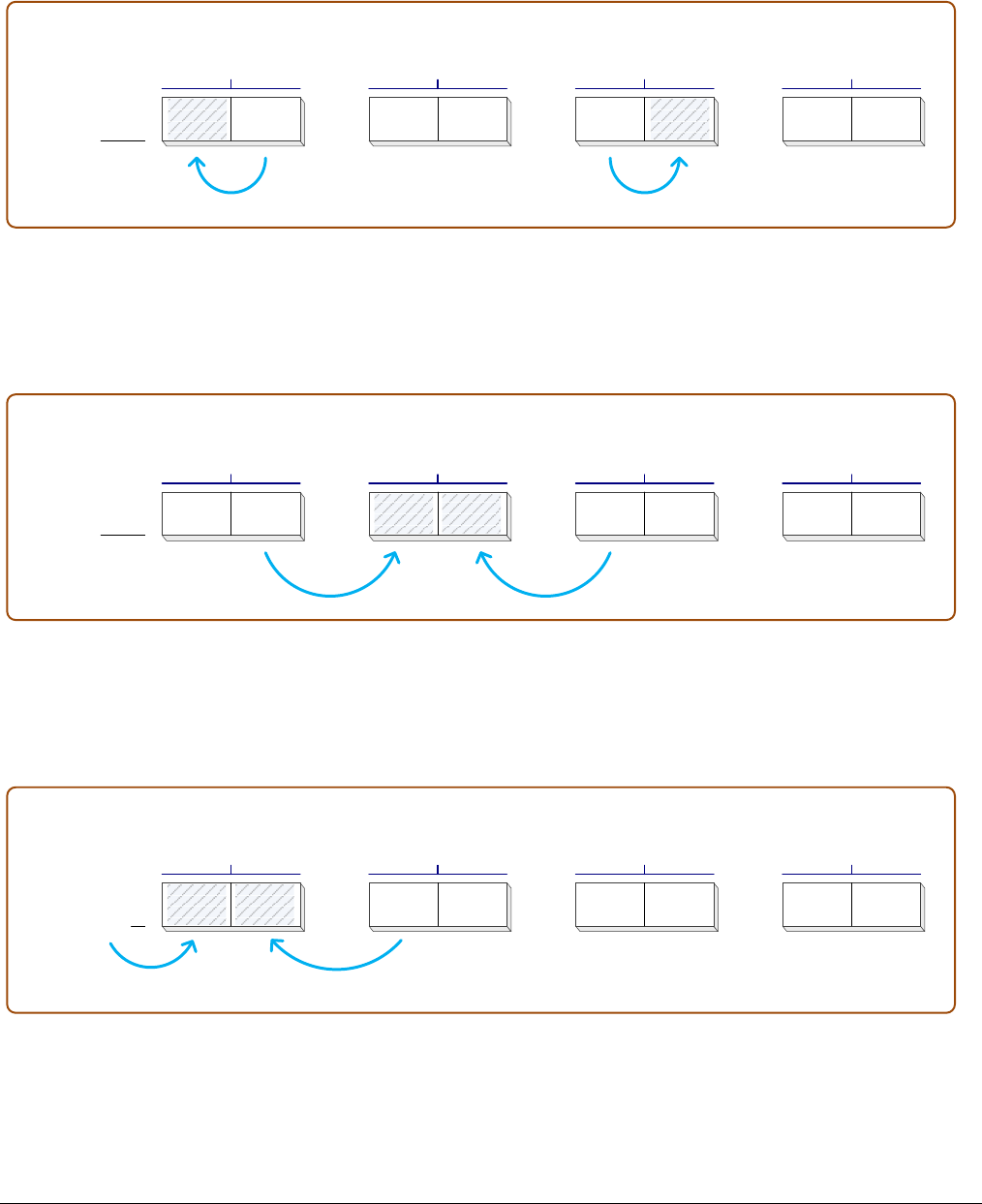
Nano Series GigE Vision Camera Addendums
•
273
Monochrome Sensors (case 1: single bad pixel)
• A bad even pixel is replaced by the good odd pixel of the same pixel pair.
• A bad odd pixel is replaced by the good even pixel of the same pixel pair.
Sensor Row pix0 pix1
Pixel Pair 1
even odd
pix2 pix3
Pixel Pair 2
even odd
pix4 pix5
Pixel Pair 3
even odd
pix6 pix7
Pixel Pair 4
even odd
Monochrome Sensors (case 2: bad pixel pair)
• When a pixel pair has both even and odd pixels marked as bad, the even pixel is replaced by
the preceding odd pixel and the odd pixel is replaced by the following even pixel (even if it is
marked as a bad pixel).
Sensor Row pix0 pix1
Pixel Pair 1
even odd
pix2 pix3
Pixel Pair 2
even odd
pix4 pix5
Pixel Pair 3
even odd
pix6 pix7
Pixel Pair 4
even odd
Monochrome Sensors (case 3: bad pixel pairs at boundaries)
• When the first pixel pair of the first image row has both even and odd pixels marked as bad,
the even pixel is replaced by indeterminate data from the preceding memory location. The bad
odd pixel is replaced by the following even pixel (even if it is also marked as a bad pixel).
First Sensor Row pix0 pix1
Pixel Pair 1
even odd
pix2 pix3
Pixel Pair 2
even odd
pix4 pix5
Pixel Pair 3
even odd
pix6 pix7
Pixel Pair 4
even odd
Indeterminate Data
• When the first pixel pair of an image row has both even and odd pixels marked as bad, the
even pixel is replaced by pixel from the preceding row’s last pixel. The bad odd pixel is replaced
by the following even pixel (even if it is also marked as a bad pixel).

274
•
Addendums Nano Series GigE Vision Camera
Sensor Row pix0 pix1
Pixel Pair 1
even odd
pix2pix3
Pixel Pair 2
even odd
pix4 pix5
Pixel Pair 3
even odd
pix6 pix7
Pixel Pair 4
even odd
Pixel Data from last pixel
in previous row
• When a row’s last pixel pair has both even and odd pixels marked as bad, the even pixel is
replaced by preceding odd pixel and the odd pixel is replaced by the following even pixel which
is the following row’s first pixel (even if it is also marked as a bad pixel).
Sensor Row pix0 pix1
Pixel Pair
even odd
pix(N-3) pix(N-2)
Pixel Pair
even odd
pix(N-1) pix(N)
Last Pixel Pair in Row
even odd
Pixel from next Row
• When the sensor’s last row’s last pixel pair has both even and odd pixels marked as bad, the
even pixel is replaced by preceding odd pixel and the bad odd pixel is replaced by
indeterminate data in the following memory location.
LAST Sensor Row pix0 pix1
Pixel Pair
even odd
pix(N-3) pix(N-2)
Pixel Pair
even odd
pix(N-1) pix(N)
Last Pixel Pair in Sensor
even odd
Indeterminate Data
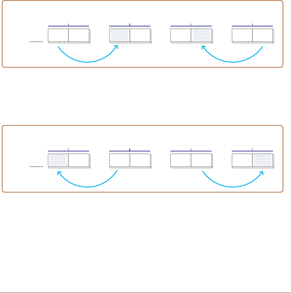
Nano Series GigE Vision Camera Addendums
•
275
Color Defective Pixel Replacement Algorithm Description
The replacement algorithm rules for Bayer color sensors is similar to the monochrome rules with
the exception that replacement pixels of the same color as the bad are used. The two replacement
cases below describe general color pixel replacements.
Again there is no embedded intelligence to adapt the rules to avoid replacing a bad pixel with
possibly other bad data, but in general these rules provide satisfactory results.
Color Sensors (case 1: single bad pixel)
• A bad even pixel is replaced by the previous even pixel.
• A bad odd pixel is replaced by the following odd pixel.
Sensor Row pix0 pix1
Pixel Pair 1
even odd
pix2 pix3
Pixel Pair 2
even odd
pix4 pix5
Pixel Pair 3
even odd
pix6 pix7
Pixel Pair 4
even odd
Color Sensors (case 2: bad pixels at line ends)
• If the line’s first pixel is bad then the following even pixel (same color) is used as the
replacement pixel.
• If the line’s last pixel is bad then the preceding odd pixel (same color) is used as the
replacement pixel.
Sensor Row pix0 pix1
Pixel Pair 1
even odd
pix2 pix3
Pixel Pair 2
even odd
Pixel Pair (N-1)
even odd
pix(N-1) pix(N)
Last Pixel Pair (N)
even odd
pix(N-3) pix(N-2)

276
•
Revision History Nano Series GigE Vision Camera
Revision History
Revision Date Major Change Description
R:0001 September 15, 2015 Initial release
R:0002 September 17, 2015 Additional I/O technical specifications, etc.
R:0003 September 18, 2015 Additional information on optional accessories, etc.
R:0004 September 23, 2015 Added “EC & FCC Declaration of Conformity” (models M/C1920 & M/C1940), etc.
R:0005 October 1, 2015 Correction to S/N spec. Expansion of TriggerOverlap feature.
R:0006 November 11, 2015 Addition of Cycling, Flip and Metadata features. Additional I/O details on
interfacing and operational specifications. Updates to various specifications.
R:0007 January 21, 2016 Addition of OnSemi sensor models with their unique features and specifications.
R:0008 February 22, 2016 Addition of OnSemi sensor models 2M and 5M.
R:0009 March 29, 2016 Additional features and functionality
(LUT, Action Commands, PTP support, Modulo Timestamp acquisition control).
R:0010 April 29, 2016 Addition of 4 Sony monochrome sensor models 5.1M and 3.2M w/two sensitivities
R:0011 June 10, 2016 Addition of 4 Sony color sensor models 5.1M and 3.2M w/two sensitivities
R:0012 July 8, 2016 Driver 1.04 adds Auto Brightness, White Balance, Pixel Replacement, etc. features
to various camera models.
R:0013 November 3, 2016 Driver 1.05 adds various color model features, plus addition of 4 Sony sensor
(Mono/Color) models with 9m and 12M sensors.
Optional hardware model with “3 outputs / 1 Input” introduced.
R:0014 January 30, 2017 Addition of low cost Sony sensor Nano models 8.9M and 12M.
Addition of NanoXL models using OnSemi 25M and 16M sensors.
R:0015 May 4, 2017 Driver 1.06 adds a few features and improvements.
Improvements to information specific to individual models.
Introduction of the OnSemi low cost 18M model (with rolling shutter).
R:0016 July 11, 2017 Improvements to information specific to various individual models.
Expansions of specification tables to separate firmware versions for readability.
Corrections to various model specifications.
R:0017 August 1, 2017 Improvements and corrections to I/O mating connector details and other
Hyperlinks.
R:0018 November 7, 2017 Driver 1.07 adds various features.
Addition of new models with OnSemi P3 sensors.
Addition of Defective Pixel Replacement algorithm Method 3 replacing Method 4.
R:0019 December 4, 2017 Improved camera model specifications.
‘Open Source Software Licenses’ statement added to camera firmware overview.

Nano Series GigE Vision Camera Contact Information
•
277
Contact Information
Sales Information
Visit our web site: www.teledynedalsa.com/mv
Email: mailto:info@teledynedalsa.com
Canadian Sales
Teledyne DALSA — Head office
605 McMurray Road
Waterloo, Ontario, Canada, N2V 2E9
Tel: 519 886 6000
Fax: 519 886 8023
Teledyne DALSA — Montreal office
880 Rue McCaffrey
Saint-Laurent, Quebec, Canada, H4T 2C7
Tel: (514) 333-1301
Fax: (514) 333-1388
USA Sales European Sales
Teledyne DALSA — Billerica office
700 Technology Park Drive
Billerica, Ma. 01821
Tel: (978) 670-2000
Fax: (978) 670-2010
Teledyne DALSA GMBH
Lise-Meitner-Str. 7
82152 Krailling (Munich), Germany
Tel: +49 – 89 89545730
Fax:+49 – 89 895457346
Asian Sales
Teledyne DALSA Asia Pacific
Ikebukuro East 13F
3-4-3 Higashi Ikebukuro,
Toshima-ku, Tokyo, Japan
Tel: +81 3 5960 6353
Fax: +81 3 5960 6354
Shanghai Industrial Investment Building
Room G, 20F, 18 North Cao Xi Road,
Shanghai, China 200030
Tel: +86-21-64279081
Fax: +86-21-64699430
Technical Support
Submit any support question or request via our web site:
Technical support form via our web page:
Support requests for imaging product installations,
Support requests for imaging applications
http://www.teledynedalsa.com/mv/support
Camera support information
Product literature and driver updates

278
•
Index Nano Series GigE Vision Camera
Index
1
10-pin connector, 219
3
3 output models, 271
A
AC Timing Characteristics, 225, 228
Action Command, 186
Action controls, 185
administrator, 84
AdobeRGB, 139
Advanced Processing controls, 131
alternative Nano models, 271
artifacts, 101
Auto Gain, 108
auto image intensity, 107
auto-brightness, 107
B
back focal length, 249
back focal variation, 215
bad pixel map, 135, 272
Bayer output, 101
best clock source, 195
Binning, 173
binning modes, 173
body depth variation, 215
C
Cable options, 15
camera configuration, 94
camera interfacing tool, 88
camera state LED, 80
CamExpert parameters, 86
chuck data – binning, 178
Cognex uninstaller, 270
Color controls, 137, 141
column artifacts, 101
command jitter, 114
Communication problems, 265
Components Express, 257
Components Express Inc., 259
controlling event, 114
counter/timer controls, 124
Cycling Constraints, 151
Cycling controls, 143
cycling preset, 148
cycling setup, 148
cycling timing, 149
D
debounce circuit, 115
defective pixel map file, 135, 272
development platform, 16
device discovery, 86
DHCP, 81
diagnostic LED, 78
dimension, 215
Dust problems, 250
E
effective focal length, 249
electrostatic discharge, 82
embedded processing, 134
ESD, 250
ESD testing, 82
Ethernet cable length, 78
Ethernet link speed, 267
Ethernet switch, 233
event controls, 187
event notification, 227
exposure convergence, 108
exposure duration, 102
exposure period, 266
Extended Unique Identifier, 195
external trigger, 266
F
fast frame rate, 158
Fast Readout Mode artifacts, 101
fiber-optic light sources, 246
file uploads-Linux, 84
firewall exceptions, 83
firmware update, 83
flash memory, 211
flow control protocol, 233
focal point, 249
format controls, 152
Frame Trigger modes, 114
G
gain, 99, 100
gamma adjustments, 134
GenICam Specification, 16, 83
Genie identifier, 86
GigE server tray icon, 85, 262, 263
GigE to fiber-opti, 233
GigE Vision compliant, 81
GigE Vision Host controls, 207
GigE Vision Specification, 9, 16
GigEMetaDataDemo, 179

Nano Series GigE Vision Camera Index
•
279
Global Reset Release, 72
H
halogen light sources, 246
HD video format, 239
heat management, 218
heat transfer, 218
high EMI, 265
high frame rate, 158
horizontal and vertical binning, 173
horizontal crop, 167
hot mirror, 246
HTML help, 16
I
I/O cable assemblies, 251
I/O cable options, 221
I/O cabling, 222
I/O connector, 219
I/O controls, 105, 109
I/O signals, 79
IEEE 1588, 195
IEEE 802.3x, 233
image circles, 239, 240
image exposures, 114
image inversion, 171
Image Lost Event, 183
ImageLost, 184
industrial RJ-45, 259
infrared filters, 246
internal buffer, 183
internal memory, 17
internal pattern, 267
ionized air blower, 250
IP configuration, 78
IP configuration protocol, 79, 81
IR cut-off, 247
IR cut-off filter, 246
IR filter, 139
L
LED light sources, 246
LED states, 80
lens parameters, 245
light source aging, 246
line signals, 115
Link-Local Address, 81
Log Viewer tool, 265
long cable lengths, 265
low frame rates, 267
low-light sensitivity, 173
Luminance, 138, 140
LUT controls, 131
LUT size, 134
LUT table, 134
M
MAC address, 87
Metadata, 175
Metadata controls, 175
Modulation Transfer Function, 72
MTBF, 21
Multiple ROI, 167
N
Nano connectors, 79
Nano rear view, 79
Network Configurations, 81
NIC optimization, 86
O
object distance, 249
operational status, 80
optimize network, 207
opto-coupled outputs, 123
P
packet resend buffer, 206
packet resend conditions, 265
Pause Frame Flow Control, 233
PAUSE Frame support, 78
PDF, 16
Persistent IP, 81
PoE Class 0, 223
power failure during update, 265
Power Over Ethernet, 9
power-up state, 94
Precision Time Protocol, 195
Pre-Processing, 101
procedures for handling, 250
PTP Boundary Clock, 195
PTP Mode, 195
Q
quick start, 77
R
reducing bandwidth, 169
Reliability, 212
Responsivity, 245
retention latches, 219
RGB gain, 139
RGB-Output Design, 137
Right-Angle Cable, 261
RJ45 Ethernet, 219
ROI modes, 167
rolling shutter sensor, 17, 72

280
•
Index Nano Series GigE Vision Camera
S
Sapera LT User’s manual, 84
Sapera version, 16
SapLut file, 134
Saturation, 138, 140
screw locks, 219
secure Ethernet cable, 259
secured Ethernet cable, 265
sensor cleaning, 251
sensor controls, 95
Sensor gain, 99
sensor integration period, 102
sensor tolerance, 218
signal debounce circuit, 115
Software Platforms, 16
software triggers, 114
Sony Pregius, 8
spatial resolution, 173
sRGB, 139
status LED, 80
status LED sequence, 80
subnet, 85
synchronous exposure, 102
T
T2IR, 212
T2IR monitoring, 212
Temperature Management, 218
temporal distortion, 72
test pattern generator, 174
third party filter driver, 263
threshold processes, 134
Timestamp Modulo, 196
transfer controls, 181
Transfer Queue, 184
transport layer controls, 201
Trigger-to-Image Reliability, 212
TurboDrive, 8
TurboDrive enable, 207
TurboDrive support, 8
TurboDrive Technology Support, 18
U
Updates, 9
upload files, 207
user defined name, 87
User Map 1, 135, 272
User Name, 87
V
vertical and horizontal cropping, 158
vertical cropping, 158
view metadata, 179
vignetting, 239, 240, 241, 242, 243, 244
visibility attribute, 89
W
White Balance, 138
workstation, 84
X
XML device file, 16
