A FRONT 8 66B 12 64B Guide (06EN003322)
User Manual: 8-66B
Open the PDF directly: View PDF ![]() .
.
Page Count: 38

INSTALLATION, OPERATION AND
MAINTENANCE MANUAL
© Copyright 1995 Fluid Components Intl
a limited liability company
All Rights Reserved
Notice of Proprietary Rights
This document contains confidential technical data, including trade
secrets and proprietary information which are the property of Fluid
Components Intl (FCI).
Disclosure of this data to you is expressly conditioned upon your assent
that its use is limited to use within your company only (and does not
include manufacture or processing uses). Any other use is strictly
prohibited without the prior written consent of FCI.
Model 12-64 Basic
Flow Switch and
Model 8-66 Basic Level/
Interface Switch
Doc. No. 06EN003264 Rev. A

FLUID COMPONENTS INTL
Models 12-64/8-66 Basic Switch i i Doc. No. 06EN003264 Rev. A
1264BASA.PUB

FLUID COMPONENTS INTL
Doc. No. 06EN003264 Rev. A i i i Models 12-64/8-66 Basic Switch
CUSTOMER COMMITMENT PLEDGE
We will work closely with our customers to provide the best products and service
• at a competitive value
• on time
• with unquestioned support
in full compliance with our COMPLETE CUSTOMER COMMITMENT.
COMMITMENT TO QUALITY
In keeping with the overall commitment of management and employees of Fluid Components Intl to Total Quality
Management, the Manual Committee (Quality Circle) expresses its pledge and mission to you, our customer:
“To support the creation and publication of world-class technical material which is technically accurate and
practical, concise and user-friendly, attractive and professional in appearance, and consistent in form, format,
content, and style.”
QUALITY IMPROVEMENT
We appreciate your comments and suggestions which support our effort to constantly improve our product and
services. Please address comments and suggestions to your nearest field representative or in-house technical support
representative. Thank you. FCI Technical Publications Department

FLUID COMPONENTS INTL
Models 12-64/8-66 Basic Switch i v Doc. No. 06EN003264 Rev. A
CUSTOMER SERVICE/TECHNICAL SUPPORT
FCI provides full in-house technical support for our products 7 a.m. to 5 p.m. PST, Monday through Friday (except-
ing holidays and an annual plant closure between Christmas and New Year's day). Also, additional technical
representation is provided by FCI field representatives. Before contacting one of our field or in-house representa-
tives, please ensure that you have performed the troubleshooting techniques outlined in this document.
By MailBy Mail
By MailBy Mail
By Mail
Fluid Components Intl
1755 La Costa Meadows Dr.
San Marcos, CA 92069
Attn: Customer Service Department
By PhoneBy Phone
By PhoneBy Phone
By Phone
Contact the FCI regional representative in your area. If your are unable to contact the field representative or
are unable to satisfactorily resolve the situation, contact the FCI Customer Service Department at
(619) 736-6116 or call toll free (800) 854-1993.
By FaxBy Fax
By FaxBy Fax
By Fax
To describe your problems in a more graphic or pictorial manner, send your regional representative a fax.
The fax should include your phone and fax number. Again FCI is available through facsimile if you have
exhausted your possibilities with the authorized factory representative. Our fax number is (619) 736-6250;
it is available 7 days a week, 24 hours a day.
International supportInternational support
International supportInternational support
International support
For product information or product support outside the contiguous United States, Alaska, or Hawaii, contact
your country’s FCI International Representative or the one nearest to you. See list on following pages.
Appendix C contains a detailed explanation of the FCI customer service policy on returns, adjustments, in-field or
factory repair, in- or out-of-warranty.

FLUID COMPONENTS INTL
Doc. No. 06EN003264 Rev. A v Models 12-64/8-66 Basic Switch
Reserved for Domestic Rep Map

FLUID COMPONENTS INTL
Models 12-64/8-66 Basic Switch v i Doc. No. 06EN003264 Rev. A
Reserved for International Rep Map

FLUID COMPONENTS INTL
Doc. No. 06EN003264 Rev. A v i i Models 12-64/8-66 Basic Switch
REVISIONS
REV. DESCRIPTION DATE AUTHOR
AAdded information on the Model 8-66 level/interface switch, and Appendix D, CE
Conformance.
12/12/95 R. Sanders

FLUID COMPONENTS INTL
Models 12-64/8-66 Basic Switch viii Doc. No. 06EN003264 Rev. A
Contents
Chapter 1 - General Information
Description .........................................................................................................................1 - 1
Sensing Element .........................................................................................................1 - 1
Control Circuit ............................................................................................................1 - 2
Specifications ......................................................................................................................1 - 2
Chapter 2 - Installation
Receiving/Inspection ........................................................................................................2 - 1
Packing/Shipping/Returns .............................................................................................2 - 1
Required Materials ............................................................................................................2 - 1
Pre-Installation Procedure ................................................................................................2 - 1
Use Standard ESD Precautions ................................................................................2 - 1
Verify Installation Location ......................................................................................2 - 2
Sensing Element Installation ............................................................................................2 - 2
Control Circuit Installation ..............................................................................................2 - 2
Wiring Installation .............................................................................................................2 - 2
Conduit Routing .........................................................................................................2 - 2
Minimum Wire Size ...................................................................................................2 - 3
Cable Connections ......................................................................................................2 - 3
Chapter 3 - Operation
Factory Calibrations ..........................................................................................................3 - 1
12-64 Alarm Set Point Procedure ....................................................................................3 - 1
8-66 Alarm Set Point Procedure ......................................................................................3 - 1
Adjustment With The Sensing Element Wet ..........................................................3 - 1
Adjustment With The Sensing Element Dry ..........................................................3 - 2
8-66 Interface Applications Adjustment ........................................................................3 - 2
Chapter 4 - Maintenance
Maintenance .......................................................................................................................4 - 1
Alarm Set Point Verification .....................................................................................4 - 1
Local Enclosure ...........................................................................................................4 - 1
Electrical Wiring .........................................................................................................4 - 1
Electrical Connections ...............................................................................................4 - 1
Process Connection ....................................................................................................4 - 1
Sensing Element .........................................................................................................4 - 1
Chapter 5 - Troubleshooting
Tools Needed .....................................................................................................................5 - 1
Quick Check .......................................................................................................................5 - 1
Non-maintenance Observations ......................................................................................5 - 1
Check Input Power .....................................................................................................5 - 1
Check the Instrument Installation ............................................................................5 - 1
Check for Moisture .....................................................................................................5 - 1
Check Application Design Requirements ...............................................................5 - 1
Verification of Sensing Element Resistance ...................................................................5 - 2
Verification of Sensing Element Voltage ........................................................................5 - 2
Spares ..................................................................................................................................5 - 4
Defective Parts ...................................................................................................................5 - 4
Customer Service ...............................................................................................................5 - 4
Appendix A - Drawings
Outline Drawing and Wiring Diagram ..........................................................................A - 1
Appendix B - Glossary
Standard Usage Definitions .............................................................................................B - 1

FLUID COMPONENTS INTL
Doc. No. 06EN003264 Rev. A i x Models 12-64/8-66 Basic Switch
Appendix C - Customer Service
Policies and Procedures ....................................................................................................C - 1
Appendix D - CE Conformance
Qualification ....................................................................................................................... D - 1
Figures
1-1 Process Installation Showing the Sensing Point ................................................................1 - 1
2-1 Sensing Element Threaded Mounting .................................................................................2 - 2
3-1 Setting Alarm Switch Point ...................................................................................................3 - 2
3-2 Control Circuit Outline Drawing .........................................................................................3 - 2
5-1 Troubleshooting Flow Chart ................................................................................................5 - 3
A-1 Threaded Process Connection ..............................................................................................A - 1
A-2 Wiring Diagram ......................................................................................................................A - 1
Tables
2-1 Interconnecting Cable Size .......................................................................................................2 - 3
2-2 Relay Energization .....................................................................................................................2 - 3
5-1 Sensing Element Resistance Values in Ohms ........................................................................5 - 2
5-2 Sensing Element Voltages .........................................................................................................5 - 2

FLUID COMPONENTS INTL
Models 12-64/8-66 Basic Switch x Doc. No. 06EN003264 Rev. A
Symbols
The following symbols are used throughout the manual to draw attention to items or procedures that require special
notice or care.
Warning:
Warns of possible personal danger to those handling the equipment.
Caution:
Cautions against possible equipment damage.
Note:
Contains important information.
Doc. No. 06EN003264 Rev. N/C
1 - 1
Model 12-64 Basic Flow Switch
CHAPTER 1 - GENERAL INFORMATION FLUID COMPONENTS INTL
1. General Information
Description
This document explains the operating principle of the Model 12-64 Basic Flow Switch and the 8-66 Basic Level/
Interface Switch. The following pages also present the recommended procedures for the installation, operation,
maintenance, and troubleshooting of the Model 12-64 Basic and the Model 8-66 Basic switchs.
The Model 12-64 Basic is an instrument that is capable of detecting liquid, gaseous or slurry environments. The
Model 8-66 Basic is an instrument that is capable of detecting liquid level at a single point or can also detect media
interfaces. The instruments have field adjustable alarm set points for control of the media.
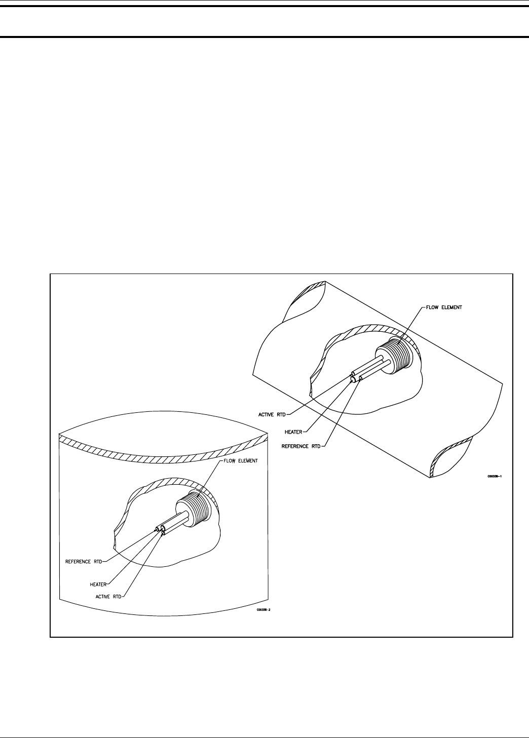
Sensing Element
The operational part of the sensing element is the sensing point. The sensing point consists of 3 thermowells (hollow
tubes). Two of the thermowells are welded together. One of the welded thermowells contains a heater and the other
contains a Resistance Temperature Detector (RTD). The third thermowell contains a reference RTD for measuring
the media temperature. There is a delta R (DR) difference between the active and reference RTD resistances. See
Figure 1-1 for the sensing point arrangement.
Figure 1-1. Process Installation Showing the Sensing Point
When the sensing point is in a media that is not flowing (or dry), the media density across the thermowells is low,
causing the active RTD to be at a higher temperature than the reference RTD. In this case, the DR is at its largest
value. When the media starts to flow (or is wet) across the sensing point, the media density across the thermowells
increases, conduction and convection cools the active RTD in proportion to the density of the fluid, and the DR
decreases.
8-66 BASIC
12-64 BASIC

FLUID COMPONENTS INTL CHAPTER 1 - GENERAL INFORMATION
Model 12-64 Basic Flow Switch
1 - 2
Doc. No. 06EN003264 Rev. N/C
•Service:
- 12-64 - Liquid, gas or slurry flow detection.
- 8-66 - Point liquid level or interface detection.
•Process Connections:
1 inch male NPT.
•Insertion Length:
1.2 inch (30mm) or 2.0 inch (51mm) U-length.
•Material of Construction:
All wetted surfaces are 316 series stainless steel with
nickel braze per process specifications AMS 4777.
•Alarm Set Points:
Setable to any value within the indicated flow range,
(for 12-64). Setable to anyinterface value, (for 8-66).
5mV hysteresis.
•Time Response:
10 to 300 seconds.
•Flow Rate (12-64 only):
Minimum: .010 ft/sec (.003 m/sec) in oil,
Maximum: 125 ft/sec (38 m/sec) in air.
•Electrical Connection:
1 inch female NPT
•Relay Rating:
DPDT contacts rated at 2A at 115 Vac.
•Power Input:
100-132 Vac, 50/60 Hz, 6 watts maximum. 230 Vac
or 24 Vdc are optional power inputs.
•Local Enclosure:
NEMA 4X (approximately equal to IP66) and
suitable for hazardous locations.
•Operating Temperatures:
Sensing element: -100° to +350°F (-73° to +177°C).
Control circuit: -40° to +140°F (-40° to +60°C).
•Operating Pressure:
To 3000 psig (207 bar).
•Approvals:
FM, CSA and CE / CENELEC.
Control Circuit
The basic functions of the control circuit are to provide power to the sensing element, measure the DR between the
two RTDs, condition the sensing point signals, and provide relay alarm contacts for customer uses.
A double pole double throw (DPDT) relay is available in the instrument for connections to the customer alarm
systems. The relay coil can be set for either energized or de-energixed when there is either flow (wet) or no flow
(dry) of the process media. [The factory set condition is the coil being de-energized at no-flow (dry).]
The place where the relay changes state will vary depending on the type of media as well as air or liquid turbulence.
Therefore the instrument has a field adjustable alarm set point.
Specifications

Doc. No. 06EN003264 Rev. A 2 - 1 Models 12-64/8-66 Basic Switch
CHAPTER 2 - INSTALLATION FLUID COMPONENTS INTL
2. Installation
Receiving/Inspection
•Unpack carefully.
•Verify that all items in the packing list are received and are correct.
•Inspect all instruments for damage or contaminants prior to installation.
If the above three items are satisfactory, proceed with the installation. If not, then stop and contact a customer
service representative.
Packing/Shipping/Returns
These issues are addressed in Appendix C - Customer Service
Required Materials
Appropriate wire, cable, conduit, and a mating interface on the vessel.
Note:
Potting Y's for all the interconnecting wires are recommended when installing the instrument. Other
requirements may vary based on local wiring codes. An appropriate mating surface on the vessel is
also required.
Pre-Installation Procedure
Warning:
Only qualified personnel should install this instrument. Install and follow safety procedures in
accordance with the current National Electrical Code. Ensure that power is off during
installation. Any instances where power is applied to the instrument will be noted in this manual.
Where the instructions call for the use of electrical current, the operator assumes all responsibility
for conformance to safety standards and practices.
Caution:
The control circuit contains electrostatic discharge (ESD) sensitive devices. Use standard ESD
precautions when handling the control circuit. See below for ESD details.
The instrument is not designed for weld-in-place applications. Never weld to process connection
or a structural support.
Damage resulting from moisture penetration of the local enclosure is not covered by product
warranty.
Use Standard ESD Precautions
Use standard ESD precautions when opening an instrument enclosure or handling the level transmitter. FCI
recommends the use of the following precautions: Use a wrist band or heel strap with a 1 megohm resistor connected
to ground. If the instrument is in a shop setting there should be static conductive mats on the work table and floor
with a 1 megohm resistor connected to ground. Connect the instrument to ground. Apply antistatic agents to hand
tools to be used on the instrument. Keep high static producing items away from the instrument such as non-ESD
approved plastic, tape and packing foam.
FLUID COMPONENTS INTL CHAPTER 2 - INSTALLATION
Models 12-64/8-66 Basic Switch 2 - 2 Doc. No. 06EN003264 Rev. A
The above precautions are minimum requirements to be used. The complete use of ESD precautions can be found in
the U.S. Department of Defense Handbook 263.
Verify Installation Location
Prepare the vessel for installation, or inspect the already prepared location to ensure that the instrument will fit into
the system. Prepare the necessary sealants or gaskets to provide a leakproof installation for the application if
required. The location of the 12-64 that should have been prepared at the time of order should be at least 20 pipe
diameters downstream and 10 pipe diameters upstream from any bends or interference in the process pipe or duct to
achieve the greatest accuracy.
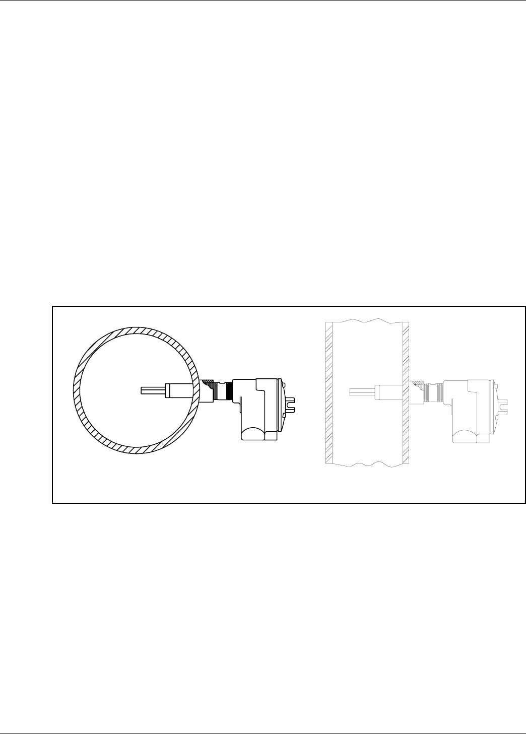
Sensing Element Installation
Install the sensing element in the process piping at the desired location. Verify that the flat area machined into the
sensing element is flat and level. If the flat is present it is machined on the sensing element near where it is screwed
into the enclosure. "FLAT UP & LEVEL" is also etched on the flat surface.
Apply a lubricant/sealant compatible with the process to all threads. Use a pipe wrench for 1-1/4 inch (32 mm) NPT
and larger connections, or an open-end wrench for 1-1/4 inch (32mm) NPT and smaller connections. All
connections should be tightened firmly. To avoid leaks, do not overtighten or cross-thread connections. The figures
in Appendix A and Figure 2-1, show this configuration.
If the sensing element is mounted in a downward direction, moisture build up in the enclosure needs to be avoided.
FCI recommends that an O-ring be used on the enclosure cover. In addition, attached conduits must be isolated by
using a conduit potting Y.
Figure 2-1. Sensing Element Threaded Mounting
Control Circuit Installation
The configuration of the instrument is with the control circuit already installed in the local enclosure (the control
circuit is physically mounted with the sensing element).
Wiring Installation
Conduit Routing
All socket and/or terminal block connections are to be made through the 1 inch female NPT openings in the
enclosure. FCI strongly recommends that all electrical cables be run through an appropriate conduit for the
protection of the instrument and personnel.
Protection of the control circuit from moisture is an important consideration. Keep the entry of the conduit into the
12-64 BASIC 8-66 BASIC
C00166-1C00033-1
Doc. No. 06EN003264 Rev. A 2 - 3 Models 12-64/8-66 Basic Switch
CHAPTER 2 - INSTALLATION FLUID COMPONENTS INTL
enclosures in the downward direction so condensed moisture that collects in the conduit will not drain into the
enclosure. The local enclosure may be turned not more than 180° using the threads on the sensing element stand
pipe to gain an acceptable orientation. In addition, FCI recommends sealing off the conduit with a potting Y or other
sealing method to prevent moisture from entering the enclosure.
Minimum Wire Size
Table 2-1 shows the smallest gauge (maximum AWG number) copper wire used in the electrical cables that connect
the instrument to the customer alarms and to power. Use a lower gauge of wire for less of a voltage drop. Contact
FCI concerning greater distances than those listed in the table.
Table 2-1. Interconnecting Cable Size (AWG)
Cable Connections
Note:
The installation of an AC line switch between the AC power source and the instrument is
recommended. This facilitates easy power disconnection for maintenance, troubleshooting and is an
added safety feature.
Connect the relay output to the customer alarm per the following procedure:
1. Remove the control circuit from it's socket.
2. Install conduit between the local enclosure, the power source and monitoring circuit. Provide watertight
hardware and apply thread sealant to all connections to prevent water damage.
Warning:
Ensure that all power is off before wiring any circuit.
3. When connecting the relay wiring, do so with complete understanding of what the process requires of the
instrument. The instrument has double pole, double throw relay output contacts. See Appendix A, Figure A-2.
For the relay logic, refer to Table 2-2 and in Chapter 3 refer to Figure 3-2. Relay contacts are shown in the relay
de-energized. Wire in accordance with the system requirements.
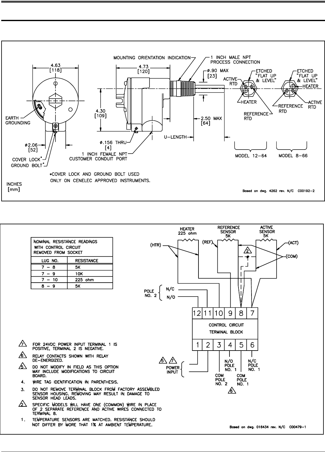
4. Connect the specified operating power and earth ground to the socket and ground lug. Refer to Figure A-2 for
connection information.
5. Plug the control circuit back into it's socket.
6. Verify proper installation. Ensure that the assemblies are secure and the wiring is correct.
Table 2-2. Relay Energization
Connection
Maximum Distance for AWG
10 ft.
(3m) 50 ft.
(15m) 100 ft.
(31m) 250 ft.
(76m) 500 ft.
152m) 1000 ft.
(305m)
AC Power 22 22 22 20 18 16
Relay (2A) 24 22 20 16 12 10
JUMPER POSITION RELAY STATE
J 12 RELAY DE-ENERGIZED AT NO FLOW / DRY
J13 RELAY DE-ENERGIZED AT FLOW / WET

FLUID COMPONENTS INTL CHAPTER 2 - INSTALLATION
Models 12-64/8-66 Basic Switch 2 - 4 Doc. No. 06EN003264 Rev. A

Doc. No. 06EN003264 Rev. A 3 - 1
Models 12-64/8-66 Basic Switch
CHAPTER 3 - OPERATION FLUID COMPONENTS INTL
3. Operation
Caution:
The control circuit contains electrostatic discharge (ESD) sensitive devices. Use standard ESD
precautions when handling the control circuit. See Chapter 2, Installation for ESD details.
Factory Calibrations
The 12-64 Basic Flow Switch and 8-66 Basic Level/Interface Switches are delivered in their standard factory set
point form. The standard factory setting is mid-range between no flow ( dry) and full flow (wet). See Figures 3-1.
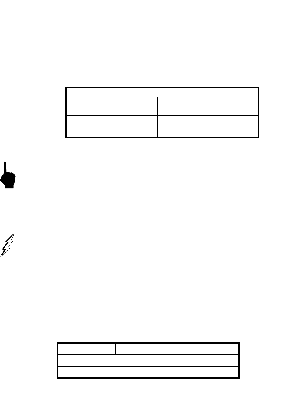
12-64 Alarm Set Point Procedure
1. Flow the pipeline at the desired rate of flow.
2. Apply power to the instrument and allow 10 minutes for the sensing element to become active and stabilize.
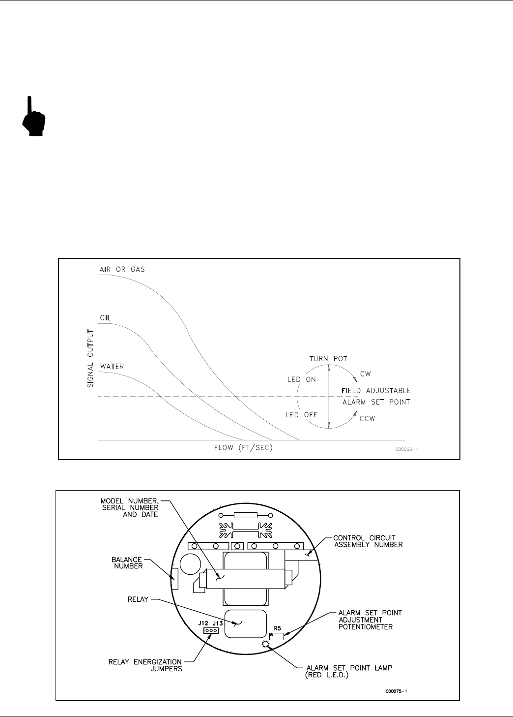
3. Locate the potentiometer (R5) and the red LED on the control circuit. (See Figure 3-2.)
4. Choose procedure A or B below.
A. Detecting No Flow or Decreasing Flow Rate
If the LED is off, turn the potentiometer clockwise until the LED turns on. If the LED is on, turn the potentiometer
counterclockwise until the LED turns off, then turn the potentiometer clockwise until the LED just turns on. With the
LED on, turn the potentiometer slowly counterclockwise until the LED just turns off. Turn the potentiometer one-
half turn past the point at which the LED just turns off. Be aware that the potentiometer may have up to one quarter
turn of hysteresis. If the mark is overshot, the procedure should be repeated. (See Figure 3-1.)
B. Detecting Maximum Flow or Increasing Flow Rate
If the LED is on, turn the potentiometer counterclockwise until the LED turns off. If the LED is off, turn the
potentiometer clockwise until the LED turns on, then turn the potentiometer counter clockwise until the LED just
turns off. With the LED off, turn the potentiometer slowly, clockwise until the LED just turns on. Turn the
potentiometer one-half turn past the point at which the LED just turns on. Be aware that the potentiometer may have
up to one quarter turn of hysteresis. If the mark is overshot, the procedure should be repeated. (See Figure 3-1.)
8-66 Alarm Set Point Procedure
Adjustment With The Sensing Element Wet
1. Determine that the sensing element is wet
2. Apply power to the instrument and allow 10 minutes for the sensing element to become active and stabilize.
3. Locate the potentiometer (R5) and the red LED on the control circuit. (See Figure 3-2.)
4. If the LED is off, turn the potentiometer clockwise until the LED turns on. With the LED on, turn the
potentiometer slowly, counterclockwise one quarter turn past the point at which the LED just turns off. The
potentiometer may have up to a quarter turn of hysteresis in either direction. If the mark is overshot, repeat the
procedure.
Note:
Consideration should be given to the fact that air or gas flowing over the sensing element may lower the
sensor dry signal, resulting in a false indication of wet at the sensing element. In cases where the
sensing element is exposed to air flow in the dry condition, or where the service product is highly
viscous, switch adjustments should be made in the wet condition only.
FLUID COMPONENTS INTL CHAPTER 3 - OPERATION
Models 12-64/8-66 Basic Switch 3 - 2 Doc. No. 06EN003264 Rev. A
Adjustment With The Sensing Element Dry
1. Determine that the sensing element is dry.
2. Apply power to the instrument and allow 10 minutes for the sensing element to become active and stabilize.
3. Locate the potentiometer (R5) and the red LED on the control circuit. (See Figure 3-2.)
4. If the LED is on, turn the potentiometer slowly, clockwise until the LED goes off.
Note:
If the LED does not turn off set the switch in the wet condition.
With the LED off, turn the potentiometer slowly, clockwise one quarter turn past the point at which the LED just
goes on. The potentiometer may have up to a quarter turn of hysteresis in either direction. If the mark is
overshot, repeat the procedure.
8-66 Interface Applications Adjustment
Alarm switch point adjustments are conducted in the same manner as liquid level/interface applications with the
exception that better thermal conducting media should be considered as in a dry condition.
Figure 3-1. Setting Alarm Switch Point
Figure 3-2. Control Circuit Outline Drawing

Doc. No. 06EN003264 Rev. A 4 - 1 Models 12-64/8-66 Basic Switch
CHAPTER 4 - MAINTENANCE FLUID COMPONENTS INTL
4. Maintenance
Warning:
To avoid hazards to personnel, ensure that all environmental isolation seals are properly
maintained.
Caution:
The control circuit contains electrostatic discharge (ESD) sensitive devices. Use standard ESD
precautions when handling the control circuit. See Chapter 2, Installation for ESD details.
The instrument requires very little maintenance. There are no moving parts or mechanical parts subject to wear.
Maintenance
Without detailed knowledge of the environmental parameters of the application, surroundings, and process media,
FCI cannot make specific recommendations for periodic inspection, cleaning, or testing procedures. However, some
suggested general guidelines for maintenance steps are offered below. Use operating experience to establish the
frequency of each type of maintenance.
Alarm Set Point Verification
Periodically verify the alarm set point.
Local Enclosure
Periodically verify that the moisture barriers and seals of the local enclosure is adequate and that no moisture is
entering the enclosure.
Electrical Wiring
Periodically inspect the power, sensing element, and output wiring for signs of corrosion or deterioration.
Electrical Connections
Periodically inspect wire connections on the socket. Verify that terminal connections are tight and physically sound
with no sign of corrosion.
Process Connection
Periodically verify that all seals are performing properly and that there is no leakage of the process media. Check for
deterioration of the gaskets and environmental seals used.
Sensing Element
Periodically remove the sensing element for inspection based on historical evidence of debris, foreign matter, or
scale buildup and appropriate plant shutdown schedules and procedures. Check for corrosion, stress cracking, and/or
buildup of oxides, salts, or foreign substances. The heater and RTD thermowells must be free of excessive
contaminants and be physically intact. Any debris or residue buildup could cause inaccurate switching. Clean the
sensing element, as necessary, with a soft brush and available solvents (compatible with stainless steel).

FLUID COMPONENTS INTL CHAPTER 4 - MAINTENANCE
Models 12-64/8-66 Basic Switch 4 - 2 Doc. No. 06EN003264 Rev. A

Doc. No. 06EN003264 Rev. A 5 - 1 Models 12-64/8-66 Basic Switch
CHAPTER 5 - TROUBLESHOOTING FLUID COMPONENTS INTL
5. Troubleshooting
Warning:
Only qualified personnel should attempt to test this instrument. The operator assumes all
responsibilities for safe practices while troubleshooting.
Caution:
The control circuit contains electrostatic discharge (ESD) sensitive devices. Use standard ESD
precautions when handling the control circuit. See Chapter 2, Installation for ESD details.
Tools Needed
Digital Multimeter (DMM)
Quick Check
Check the jumper positions of J12 and J13. Jumper J12 energizes the relay at flow. Jumpers J13 energizes the relay
at no flow.
Check that the control circuit is firmly seated into it's socket.
Check if power is present and customer fuses are good, if they are used.
Follow the trouble shooting flow chart in Figure 5-1 near the end of this chapter.
Non-maintenance Observations
At this point, observe the system setup to verify operation. No disassembly or testing is required at this time.
Check Input Power
Verify that the correct power source is turned on and connected.
Check the Instrument Installation
Review the information on instrument installation in Chapter 2 to verify correct mechanical and electrical
installation.
At the time of order the sensing element placement should have been determined. However, if not, the 12-64 sensing
element should be mounted at least 20 diameters downstream and 10 diameters upstream from any bends or
interference in the process pipe or duct.
Check for Moisture
Check for moisture on the control circuit. Moisture on the control circuit may cause intermittent operation.
Check for moisture on the sensing element. If a component of the process media is near its saturation temperature it
may condense on the sensing element. Place the sensing element where the process media is well above the
saturation temperature of any of the process gases.
Check Application Design Requirements
Application design problems may occur with first time application instruments, although the design should also be
checked on instruments that have been in operation for some time. If the application design does not match field
conditions, errors occur.
FLUID COMPONENTS INTL CHAPTER 5 - TROUBLESHOOTING
Models 12-64/8-66 Basic Switch 5 - 2
Doc. No. 06EN003264 Rev. A
1. Review the application design with plant operation personnel and plant engineers.
2. Ensure that plant equipment such as pressure and temperature instruments conform to the actual conditions.
3. Verify operating temperature, operating pressure, line size, and gas medium.
Verification of Sensing Element Resistance
The measurements are based on a standard (5K ohm RTD at 70°F, or 21°C) sensing element. Variation of ±100
ohms from nominal is to be expected, depending on temperature. The maximum allowable difference in resistance
between matched RTD's is 1% at ambient temperature (immersed in water). The heater resistance should be 225 ±5
ohms. Be sure to subtract the cable resistance to get the true resistance.
1. Turn off the operating power to the instrument.
2. Gently remove (pull straight out) the control circuit from the socket. Using a DMM, measure the resistance of
the active and reference RTD sensing elements and the heater as found in Table 5-1 to determine if the sensing
element is functional.
Note:
The resistance of the active RTD will be greater than the resistance of the reference RTD whenever the
heater is on.
If there is an indication of an open or short in the RTD, the sensing element will need to be replaced.
After replacing the sensing element, it will be necessary to follow the alarm set point adjustment procedures found in
the Operation Chapter before returning the instrument to service.
If the sensing element resistance is correct, proceed to the voltage verification test.
Table 5-1. Sensing Element Resistances In Ohms
*Resistance varies with temperature. These values should be ±5 ohms at 70 °F (21 °C).
Verification of Sensing Element Voltage
If the above resistance checks are good, plug in the control circuit and apply power. Measure the voltages in
Table 5-2. If the voltages are not correct, then remove and replace the control circuit.
Table 5-2. Sensing Element Voltages
From Terminal Pin To Terminal Pin Voltage Expected**
9 (+) 7 (-) 22VDC
7 (+) 8 (-) 12VDC
9 (+) 8 (-) 10VDC
10 (+) 7 (-) 19VDC
**Voltages are dependent on temperature.
From Terminal (Pin) To Terminal (Pin) Expected Ohms*
Heater (7) Heater (10) 225
Ref Sen (9) Com Sen (8) 5000
Ref Sen (9) Act Sen (7) 10000
Act Sen (7) Com Sen (8) 5000
Doc. No. 06EN003264 Rev. A 5 - 3 Models 12-64/8-66 Basic Switch
CHAPTER 5 - TROUBLESHOOTING FLUID COMPONENTS INTL
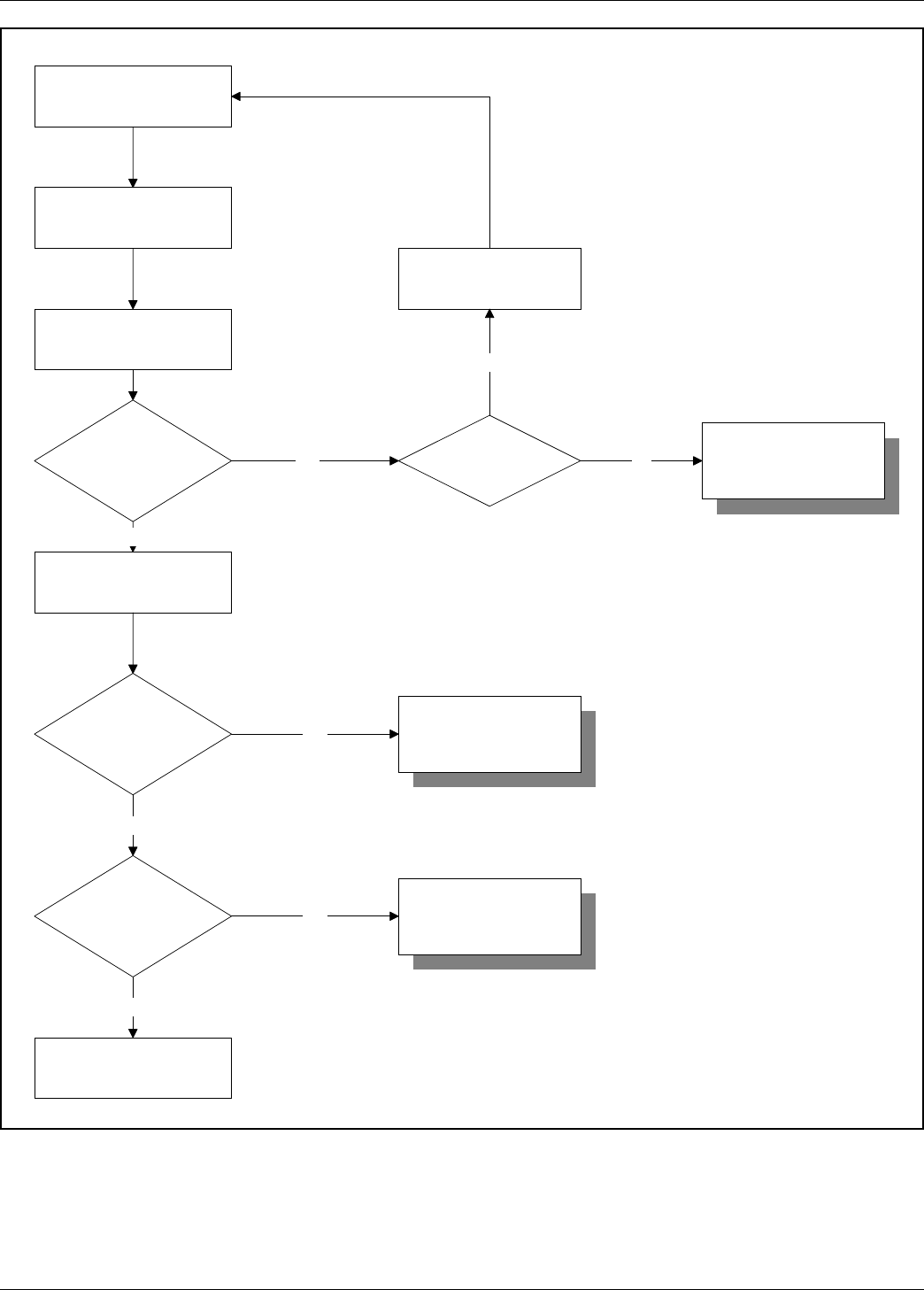
Problem?
Verify input power to
the instrument.
Turn power OFF.
Remove control circuit.
Reinstall control circuit.
Turn power ON.
END
Verify control circuit
voltages.
Simulate alarm
condition.
STOP
Call FCI for
instructions.
Fix cable, reconnect
control circuit, and
turn power ON.
Is flow
element cable
damaged?
Fail
Yes
STOP
Call FCI for
instructions.
Pass
Pass
Fail
Fail
STOP
Call FCI for
instructions.
No
Vtsfd.vsd
Pass
Verify HTR and RTD
Resistances.
Figure 5-1. Troubleshooting Flow Chart

FLUID COMPONENTS INTL CHAPTER 5 - TROUBLESHOOTING
Models 12-64/8-66 Basic Switch 5 - 4
Doc. No. 06EN003264 Rev. A
Spares
FCI recommends that one control circuit, part number 5181-XA3A2A2, be kept as a spare. The X in the part
number depends on the input voltage. The X will be a 1 for 115 Vac, 2 for 230Vac or 6 for 24Vdc. Contact FCI for
specific recommendations.
Defective Parts
Before returning any equipment to FCI, obtain an return authorization (RA) number for authorization, tracking, and
repair/replacement instructions. If a return is required, remove the defective part or instrument, replace it with a
spare, calibrate, and then return the defective part or instrument to FCI freight prepaid for disposition.
Customer Service
1. In the event of problems or inquiries regarding the instrument, please contact the Regional or Country
Authorized FCI Field Agent. There is an extensive list of these representatives at the front of this manual.
2. Before contacting the FCI representative, be sure that all the applicable information is near so that a more
effective, efficient and timely response may be provided.
3. Refer to Appendix C for specific Customer Service policy provisions.
Doc. No. 06EN003264 Rev. A A - 1 Modesl 12-64/8-66 Basic Switch
APPENDIX A - DRAWINGS FLUID COMPONENTS INTL
Appendix A. Drawings
Figure A-1. Threaded Process Connection
Figure A-2. Wiring Diagram

FLUID COMPONENTS INTL APPENDIX A - DRAWINGS
Models 12-64/8-66 Basic Switch A - 2 Doc. No. 06EN003264 Rev. A

Doc. No. 06EN003264 Rev. A
B - 1
Models 12-64/8-66 Basic Switch
APPENDIX B - GLOSSARY FLUID COMPONENTS INTL
ABBREVIATIONS
Delta R (DD
DD
DR) Resistance differential
Delta T (D(D
(D(D
(DT) Temperature differential
DMM Digital Multimeter
FCI Fluid Components Intl
HTR Heater
LED Light Emitting Diode
RA Repair Authorization
RTD Resistance Temperature Detector
DEFINITIONS
Active RTD The sensing element part that senses the fluid flow rate or wet/dry condition.
Balance A number that is used to balance or match the
active and reference RTDs when the heater is off.
Control circuit The portion of the flow switch that conditions, converts, and scales
the sensing element signal.
Heater (HTR) The sensing element part that heats the active RTD.
Local enclosure The enclosure attached to the sensing element.
Reference RTD The sensing element part that senses the fluid temperature.
Resistance differential
Delta -R (DD
DD
DR) The sensing element signal.
Resistance Temperature
Detector (RTD) A sensor whose resistance changes proportionally to detector
temperature changes.
Sensing element The portion of the flow switch that contains the thermowells, RTDs,
and produces a signal with a defined relationship to the
flow rate or wet/dry condition.
Temperature differential
Delta -T (DD
DD
DT) The difference in temperature between the active and
reference RTDs.
Thermowell The sensing element part that protects the heater and RTD's
from the process fluid.
Appendix B. Glossary

FLUID COMPONENTS INTL APPENDIX B - GLOSSARY
Models 12-64/8-66 Basic Switch B - 2 Doc. No. 06EN003264 Rev. A

Doc. No. 06EN003264 Rev. A C - 1 Model 12-64/8-66 Basic Switch
APPENDIX C - CUSTOMER SERVICE FLUID COMPONENTS INTL
Appendix C. Customer Service
Point of Contact
Your point of contact for service, or return of equipment to FCI is your authorized FCI service representative (see list
in the front matter of this manual).
Reference Documents
Return Authorization Request/Certificate of Non-Contamination (Document 1)
FCI Hazardous Materials Control Procedure for Repair Items (Document 2)
Warranties (Document 3)
Documents 1, 2 and 3 are included in this appendix.
Hardware Return Procedure
1. Complete a Return Authorization (RA) Request/Certificate of Non-Contamination form (Document 1) and mail
or fax it to an FCI field representative. After FCI issues you an RA number, complete the following steps.
2. Thoroughly clean the hardware.
3. Package each instrument with protective packing material similar to the original FCI shipment carton. All
damage occurring in transit is the customer’s responsibility.
a. Cover instruments weighing less than 80 pounds with protective wrap, such as bubble wrap or surround
it with “popcorn.” Secure instruments weighing greater than 80 pounds in wooden crates by bolting
them in place.
b. Protect the sensing element with a cardboard tube or other sturdy wrapping.
c. Do not pack more than four small instruments in each carton.
d. Ship packages weighing more than 50 pounds via carriers who specialize in the transport of industrial
instruments.
e. Note the RA number on the packing list and mark it clearly on the outside of the box.
4. Prepay freight to the FCI receiving door.
Shipping/Handling Charges
All Shipping (Warranty and Nonwarranty Repairs or Returns)
The customer prepays all shipping, freight, duty/entry and handling charges from the customer site to the FCI door.
If the customer does not prepay, FCI will invoice the customer for the charges that appear on the freight bill.

FLUID COMPONENTS INTL APPENDIX C - CUSTOMER SERVICE
Model 12-64 Basic Switch C - 2 Doc. No. 06EN003264 Rev. A
Warranty Repairs or Returns
FCI prepays ground transportation charges for return of freight to the customer’s door. FCI reserves the right to
return equipment by the carrier of our choice.
International freight, handling charges, duty/entry fees for return of equipment are paid by the customer.
Nonwarranty Repairs or Returns
FCI returns repaired equipment to the customer either collect or prepaid and adds freight charges to the customer
invoice.
Return to Stock Equipment
The customer is responsible for all shipping and freight charges for equipment that is returned to FCI stock from the
customer site. These items will not be credited to customer’s account until either all freight charges are cleared or
until the customer agrees to have any freight costs incurred by FCI deducted, along with applicable return to stock
charges, from the credit invoice. (Exceptions are made for duplicate shipments made by FCI.)
If any repair or return equipment is received at FCI, freight collect, without prior factory consent, FCI bills the
sender for these charges.
Field Service Procedures
Field Service Requests
Contact your FCI field representative to request field service.
A field service technician is dispatched to the site from either the FCI factory or one of the FCI representative
offices. After the work is complete, the technician completes a preliminary field service report at the customer site
and leaves a copy with the customer.
Following the service call, the technician completes a formal, detailed service report. The formal report is mailed to
the customer within five days of the technician’s return to the factory or office.
Rates
All field service calls are billed at the prevailing rates as listed in the FCI Price Book unless specifically excepted by
the FCI Customer Service Manager. FCI reserves the right to bill for travel times at our discretion.
Customers are charged for shipping costs related to the transfer of equipment to and from the job site. They are also
invoiced for field service work and travel expenses by FCI’s Accounting Department.

Doc. No. 06EN003264 Rev. A C - 3 Model 12-64/8-66 Basic Switch
APPENDIX C - CUSTOMER SERVICE FLUID COMPONENTS INTL
Document 1.
Return Authorization Request/Certificate of Non-Contamination
1. Company Name: _______________________________________________________________________
2. Contact Name: _________________________________________________________________________
3. Contact Phone No. __________________________________ Fax No.: ___________________________
4. Bill to Address: ________________________________________________________________________
_____________________________________________________________________________________
5. Ship to Address: ________________________________________________________________________
_____________________________________________________________________________________
6. Model Number: _______________________________ Serial Number: ___________________________
7. Equipment Symptom: ___________________________________________________________________
Please detail the Troubleshooting Checks that were made: _______________________________________
_____________________________________________________________________________________
Action To Be Taken By FCI:______________________________________________________________
_____________________________________________________________________________________
Note: If calibration is required, please complete an Application Data Sheet.
8. Warranty: ___YES ___NO Purchase Order No. _______________
Note: FCI Will Assess A Minimum Charge Of $110.00 On All Nonwarranty Repairs Or Evaluations.
9. Have you contacted your local representative regarding this return?
___YES ___NO
Certificate Of Non-Contamination
____I certify that the item(s) listed below has (have) not been contaminated by a hazardous material, hazardous
substance or a toxic material or substance as defined by Federal and State law.
____I certify that the item(s) has (have) been thoroughly and completely cleaned and if the item(s) has (have) been
exposed to hazardous material, hazardous substance or toxic materials or substances that the undersigned have
thoroughly and completely neutralized such substances and any contamination which may have occurred to the
returned items. Furthermore, I understand that this Certificate shall not waive our responsibility to provide a
decontaminated product for repair to FCI.
Process Medium: ___________________________________________________________________________
Company Name: ___________________________________________________________________________
Authorized Signature: _______________________________________________________________________

FLUID COMPONENTS INTL APPENDIX C - CUSTOMER SERVICE
Model 12-64 Basic Switch C - 4 Doc. No. 06EN003264 Rev. A
Document 2.
FCI Hazardous Materials Control Procedure for Repair Items
In order for FCI to process your repair expeditiously, the returned item must be accompanied by documentation
regarding hazardous materials to which the item was exposed.
Hazardous materials are regulated by Federal, State (California), County, and City laws. These laws provide our
employees the right to know the materials with which they come in contact while handling our products.
Consequently, our Repair Department employees must have access to data regarding the materials with which they
may come in contact while processing your repair.
In accordance with FCI's Hazardous Materials Control procedures, we request that you thoroughly clean and
neutralize any process material on your equipment before returning it to FCI. Further, you are required to choose
one of the following options for declaring the hazardous condition of the hardware:
1. Complete and sign the Certificate of Non-Contamination (at the bottom of Document 1) evidencing your
compliance.
or
2. Complete a Material Safety Data Sheet (MSDS) which covers all process materials exposed on the instrument.
Send the completed MSDS to your field service representative with a completed RA form.
Note: Submission of an MSDS or Certificate of Non-Contamination will not waive your responsibility for
proper decontamination of the instrument. The cleanliness of a returned item or the acceptability of the
MSDS will be at the sole discretion of FCI.
Returned items that do not comply with these procedures will be returned to you at your expense. FCI does
not wish to inconvenience you; however, we are required by law to adhere to hazardous material handling procedures
to protect our employees.

Doc. No. 06EN003264 Rev. A C - 5 Model 12-64/8-66 Basic Switch
APPENDIX C - CUSTOMER SERVICE FLUID COMPONENTS INTL
Document 3. Warranties
Goods furnished by the Seller are to be within the limits and of the sizes published by the Seller and subject to the
Seller’s standard tolerances for variations. All items made by the Seller are inspected before shipment, and should
any of said items prove defective due to faults in manufacture or performance under Seller approved applications, or
fail to meet the written specifications accepted by the Seller, they will be replaced or repaired by Seller at no charge
to Buyer provided return or rejection of said material is made within a reasonable period but in no event longer than
three (3) years for non-calibration defects and one (1) year for calibration defects from date of delivery to Buyer, and
provided further, that an examination by Seller discloses to Seller’s reasonable satisfaction that the defect is covered
by this warranty and that the Buyer has not returned the equipment in a damaged condition due to exposure to
corrosive or abrasive environments for due to Buyer’s or Buyer’s employees, agents, or representative negligence
and Buyer has not tampered, modified, redesigned, misapplied, abused, or misused the goods as to cause the goods
to fail. Seller shall in no event be responsible for (1) the cost of any work done by Buyer on material furnished
hereunder (unless specifically authorized in writing in each instance by Seller), (2) the costs of any work done by a
Distributor, (3) for any consequential or incidental damages, losses, or expenses in connection with or by reason of
the use of or inability to use goods purchased for any purpose, and Seller’s liability shall be specifically limited to
free replacement, or refund of the purchase price, at Seller’s option, provided returned or rejection of the goods is
made consistent with this paragraph, and the Seller shall in no event be liable for transportation, installation,
adjustment, loss of good will or profits, or other expenses which may arise in connection with such returned goods,
or (4) for the design of products or their suitability for the purpose for which they are intended or used. Should the
Buyer receive defective goods as defined by this paragraph, the Buyer shall notify the Seller and Distributor
immediately, stating full particulars in support of his claim, and should the Seller agree to a return of the goods, the
Buyer shall follow Seller’s packaging and transportation directions explicitly. In no case are the goods to be returned
without first obtaining permission of the Seller. Any repair or replacement shall be at Seller’s factory, unless
otherwise directed, and shall be returned to Seller transportation prepaid by Buyer and subject to the provisions
herein. If the returned goods shall prove defective under this clause they will be replaced or repaired by Seller at no
charge to Buyer provided the return or rejection of such material is made within a reasonable period, but in no event
longer than one (1) year from the date of delivery of the returned goods or the unexpired term of the original
warranty period whichever is later.
If the goods prove to be defective under this paragraph, the Buyer shall remove the goods immediately from the
process and prepare the goods for shipment to Seller for repair. Continued use or operation of defective goods is not
warranted by Seller and damage occurring due to continued use or operation shall be for Buyer’s account.
Any description of the goods contained in the offer is for the sole purpose of identifying them, and any such
description is not part of the basis of the bargain, and does not constitute a warranty that the goods will conform to
that description. The use of any sample or model in connection with this offer is for illustrative purposes only, is not
part of the basis of the bargain, and is not to be construed as a warranty that the goods will conform to the sample or
model. No affirmation of that fact or promise made by Seller, whether or not in this offer, will constitute a warranty
that the goods will conform to the affirmation or promise.
THIS WARRANTY IS EXPRESSLY IN LIEU OF ANY AND ALL OTHER EXPRESS OR IMPLIED
WARRANTIES WITH RESPECT TO THE GOODS OR THEIR INSTALLATION, USE, OPERATION,
REPLACEMENT OR REPAIR, INCLUDING ANY IMPLIED WARRANTY OF MERCHANTABILITY OR
FITNESS OF PURPOSE; AND THE GOODS ARE BEING PURCHASED BY BUYER “AS IS”. FCI WILL
NOT BE LIABLE BY VIRTUE OF THIS WARRANTY OF OTHERWISE FOR ANY SPECIAL OR
CONSEQUENTIAL LOSS OR DAMAGE RESULTING FROM THE USE OR LOSS OF USE OF THE
GOODS.

FLUID COMPONENTS INTL APPENDIX C - CUSTOMER SERVICE
Model 12-64 Basic Switch C - 6 Doc. No. 06EN003264 Rev. A
Doc. No. 06EN003264 Rev. A D - 1 Models 12-64/8-66 Basic Switch
APPENDIX D - CE Conformance FLUID COMPONENTS INTL
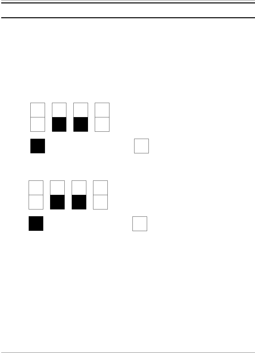
Approved CE marking 12-64 and 8-66 Configurations
Approved Options
1) all insertion U-lengths
2) all specified application combinations
3) 115/230 VAC power input.
Approved Part Numbers
Conditionally Approved CE marking - 24 VDC Factory Selectable Options
Input power of 24 VDC may be optionally selected. Since the manufacturer does not supply the power source or
transformer for these connections, the responsibility for the conditioning of these sources and associated compliance
to the EMC Directive shall be the responsibility of the user.
Appendix D. CE Conformance
1 2 3 4
12-64-4
or
12-64B
All options conform to CE marking
requirements. X Y X or Y options only conform to CE marking
All other configurations must be approved for CE marking conformity by FCI's Engineering Department.
1or 2B
1 2 3 4
8-66
or
8-66B
All options conform to CE marking
requirements. X Y X or Y options only conform to CE marking
All other configurations must be approved for CE marking conformity by FCI's Engineering Department.
1or 2B

FLUID COMPONENTS INTL APPENDIX D - CE Conformance
Models 12-64/8-66 Basic Switch D - 2 Doc. No. 06EN003264 Rev. A
INSTALLATION CONFORMITY CRITERIA
Grounding
The enclosure must be grounded to earth ground through a path of less than 1 ohm.
Interconnecting Cables
All interconnecting cables between the local enclosure, power source and monitoring device shall be enclosed in
metal conduit. AC power input cabling shall be enclosed separately in conduit before entrance into the instrument
and is not to be combined with switch or monitor output cabling.
Location of CE mark documentation (European Location)
The technical documentation file part A resides at Fluid Components Intl, European Service Center, Beatrix De
Rijkweg 8, 5657 Eg Einhoven, Netherlands, Phone: 31-40-2-571-972 FAX: 31-40-2-517-809.
Location of CE mark documentation (Manufacturer Location)
The technical documentation file part B resides at the Configuration Management department of Fluid Components
Intl, 1755 La Costa Meadows Dr. San Marcos, CA. 92069 USA, Phone: 1 (800) 854-1993
FAX: 1 (619) 736-6250.
(Apply to Doc. No. 06EN003264 Rev. A)
1 Models 12-64/8-66 Basic Switch
FLUID COMPONENTS INTERNATIONAL LLC ERRATA 17EN000036 Rev. -
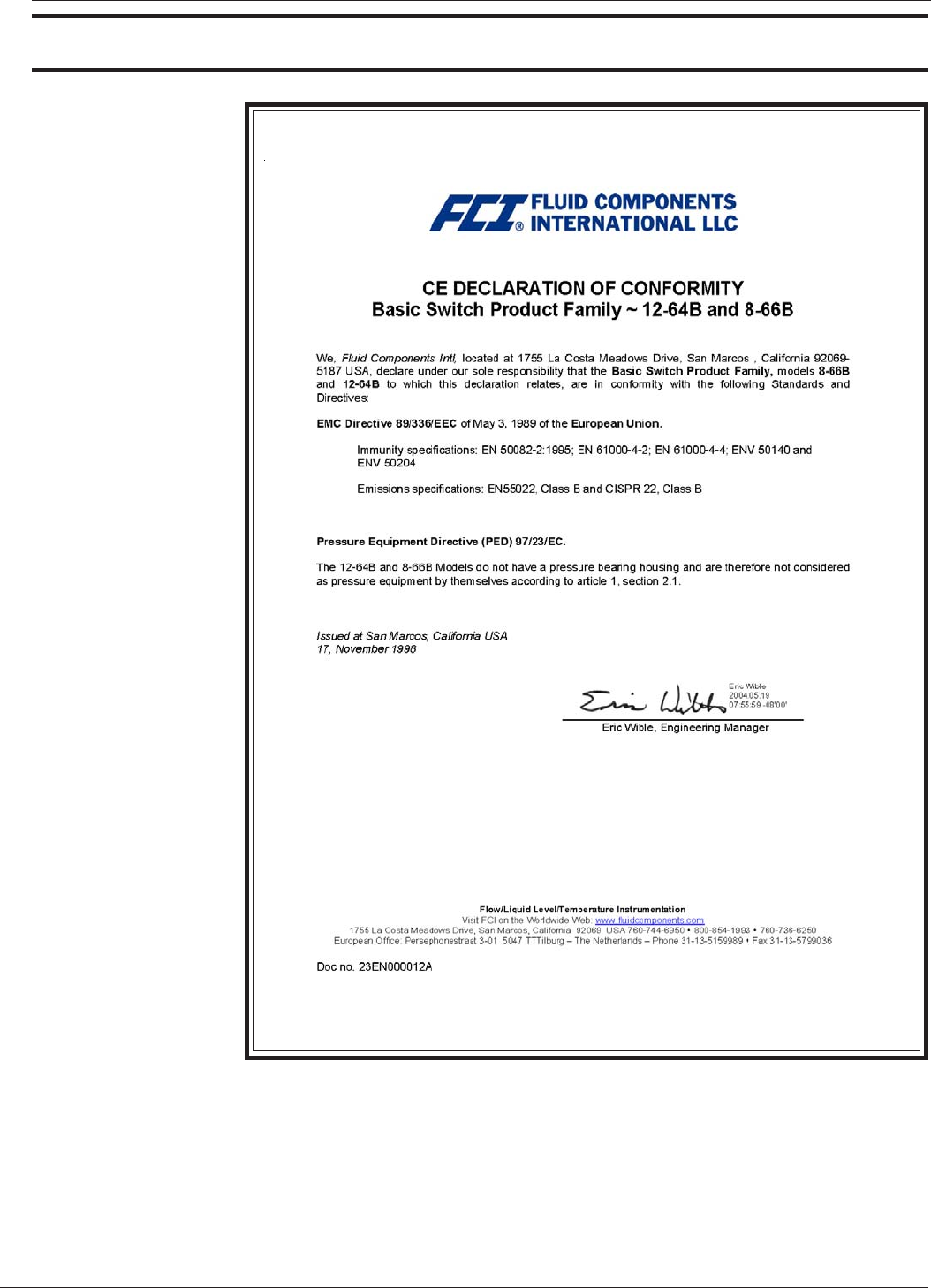
Approval Information
CE
Information

FLUID COMPONENTS INTERNATIONAL LLC ERRATA 17EN000036 Rev. -
Models 12-64/8-66 Basic Switch
2 (Apply to Doc. No. 06EN003264 Rev. A)
THIS PAGE LEFT INTENTIONALLY BLANK
