133_Type_1201_Central_Processor_ _Hardware_Bulletin 133 Type 1201 Central Processor Hardware Bulletin
133_Type_1201_Central_Processor_-_Hardware_Bulletin 133_Type_1201_Central_Processor_-_Hardware_Bulletin
User Manual: 133_Type_1201_Central_Processor_-_Hardware_Bulletin
Open the PDF directly: View PDF ![]() .
.
Page Count: 2
HONEYWELL
1201
CENTRAL
PROCESSOR
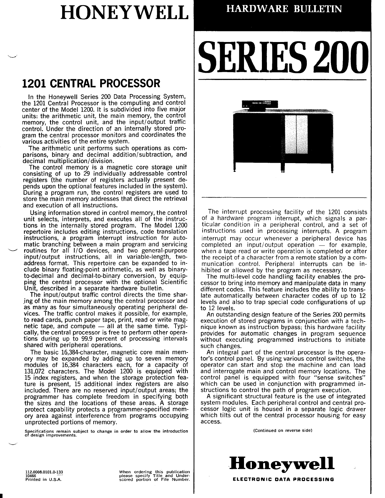
In
the Honeywell Series
200
Data Processing System,
the
1201
Central Processor is the computing and control
center
of
the Model
1200.
It is subdivided into five major
units: the arithmetic unit, the main memory, the control
memory, the control unit, and the
input/output
traffic
control. Under the direction of
an
internally stored pro-
gram the central processor monitors and coordinates the
various activities of the entire system.
The arithmetic
unit
performs such operations
as
com-
parisons, binary and decimal addition/subtraction, and
decimal multiplication/division.
The control memory is a magnetic core storage
unit
consisting of up
to
29
individually addressable control
registers (the number
of
registers actually present de-
pends upon the optional features included in the system).
During a program run, the control registers are used to
store the main memory addresses that direct the retrieval
and execution of all instructions.
Using information stored in control memory, the control
unit
selects, interprets, and executes all of the instruc-
tions in the internally stored program. The Model
1200
repertoire includes editing instructions, code translation
instructions, a program interrupt instruction for auto-
matic branching between a main program and servicing
'----"
routines for all
I/O
devices, and two general-purpose
input/output
instructions, all
in
variable-length, two-
address format. This repertoire can
be
expanded to in-
clude binary floating-point arithmetic,
as
well
as
binary-
to-decimal and decimal-to-binary conversion, by equip-
ping the central processor with the optional Scientific
Unit, described in a separate hardware bulletin.
The
input/output
traffic control directs the time shar-
.ing of the main memory among the central processor and
as
many
as
four simultaneously operating peripheral de-
vices. The traffic control makes it possible, for example,
to
read cards, punch paper tape, print, read or write mag-
netic tape, and compute -all at the same time. Typi-
cally, the central processor is free to perform other opera-
tions during up to
99.9
percent of processing intervals
shared with peripheral operations.
The basic 16,384-character, magnetic core main mem-
ory may
be
expanded by adding up
to
seven memory
modules of
16,384
characters each,
for
a capacity of
131,072
characters. The Model
1200
is equipped with
15
index registers, and when the storage protection fea-
ture is present,
15
additional index registers are also
included. There are no reserved
input/
output areas; the
programmer has complete freedom in specifying both
the sizes and the locations
of
these areas. A storage
protect capability protects a pr.0grammer-specified mem-
ory area against interference from programs occupying
unprotected portions of memory.
Specifications
remain
subject
to
change
in
order
to
allow
the
introduction
of
design
improvements.
112.0008.0101.0·133
10466
Printed
in
U.S.A.
When
ordering
this
publication
please
specify
Title
and
Under-
scored
portion
of
File
Number.
HARDWARE
BULLETIN
SERIES
200
The interrupt processing
facility
of the
1201
consists
of a hardware program interrupt, which signals a par-
ticular
condition in a peripheral control, and a set of
instructions used in processing interrupts. A program
interrupt may occur whenever a peripheral device has
completed
an
input/output
operation -for example,
when a tape read or write operation is completed or
after
the receipt of a character from a remote station by a com-
munication control. Peripheral interrupts can
be
in-
hibited or allowed
by
the program
as
necessary.
The multi-level code handling
facility
enables the pro-
cessor to bring into memory and manipulate data in many
different codes. This feature includes the
ability
to trans-
late automatically between character codes of up to
12
levels and also to trap special code configurations of up
to
12
levels.
An
outstanding design feature of the Series
200
permits
execution
of
stored programs in conjunction with a tech-
nique known
as
instruction bypass;
this
hardware facility
provides
for
automatic changes in program sequence
without executing programmed instructions to initiate
such changes.
An
integral part of the central processor is the opera-
tor's control panel.
By
using various control switches, the
operator can start and stop the machine and can load
and interrogate main and control memory locations. The
control panel is equipped with
four
"sense switches"
which can
be
used in conjunction with programmed in-
structions to control the path of program execution.
A significant structural feature is the use of integrated
system modules. Each peripheral control and central pro-
cessor logic
unit
is housed in a separate logic drawer
which
tilts
out of the central processor housing
for
easy
access.
(Continued
on
reverse
side)
.Honey~ell
ELECTRONIC
DATA
PROCESSING
II
SPECIFICATIONS
PROCESSING
UNIT: Six-bit character.
DATA
FORMAT:
Variable-length data fields of from
one
to virtually the maximum number of characters
in
the
main memory.
INSTRUCTION
FORMAT:
Variable-length, two-address in-
structions. Typical format consists of
op
code, two ad-
dresses, and a variant character.
MAIN
MEMORY
SIZE: Basic memory,
16,384
characters.
Additional memory available consisting of
up
to seven
16,384-character modules, providing a memory size of
131,072
characters.
INTERNAL OPERATIONS: Decimal and binary add/sub-
tract, decimal multiply/divide, binary floating-point arith-
metic, logic, program control, peripheral control, and edit-
ing.
ADDRESS
ASSIGNMENTS: Sixteen. Peripheral controls
capable of both reading and writing require two address
assignments.
READ/WRITE CHANNELS: Four.
MAIN
MEMORY
CYCLE
TIME:
1.5
microseconds.
CONTROL
MEMORY
ACCESS
TIME:
250
nanoseconds.
CHECKING: Parity
bit
generated for each character
as
it
is
stored in memory. Character parity checked
on
read-
out.
ADDRESSING MODES: 2-character address specifies
any
of
4,096
memory locations, 3-character address specifies
any of
32,768
memory locations, 4-character address spec-
ifies any of
131,072
memory locations.
TYPICAL
OPERATING
SPEEDS:
See
accompanying table.
SPECIAL FEATURES:· Silicon semiconductor circuitry,
15
(or
30)
index registers, four simultaneous
input/output
operations concurrent with computing, program interrupt,
indirect addressing, multi-level code handling, scientific
unit, storage protect.
INSTRUCTION
REPERTOIRE
MODEL
1200
The execution times listed in this table are based
on
realistic situations involving three-character addressing
mode. The data fields referenced
by
both the A and B
addresses are five characters long. Times for indexed
operations assume that all address fields are indexed. In
actual practice, higher speeds will
be
attained because
in
many cases abbreviated instruction formats can
be
used, thus shortening execution times.
NAME
OF
OPERATION EXECUTION
TIME
(MICROSECONDS)
STANDARD
ADDRESSES
ADDRESSES
FORMAT
NOT
INDEXED INDEXED
Arithmetic Functions
Decimal Add 1
Decimal Subract1
Binary Add
Binary Subtract
Zero and Add
Zero and Subtract
Multiply2
Divide
Logical Functions
Half
Add
Extract
Compare
Substitute
Branch
Branch
on
Condition Test
Branch
on
Character Condition
Branch
if
Character Equal
Branch
if
Bit
Equal
General Control Functions
Set Word Mark
Set Item Mark
Clear Word Mark
Clear Item Mark
Halt
No
Operation
Store Control Registers
Load Control Registers
Change Addressing Mode
Change Sequencing Mode
Interrupt
Control Functions
Resume Normal Mode
Restore Variant and Indicators
Store Variant and Indicators
Monitor Call
Storage Protect Functions
A/A,B
S/A,B
BA/A,B
BS/A,B
ZA/A,B
ZSI
A,B
M/A,B
D/A,B
HA/A,B
EXT/A,B
C/A,B
SST/A,B,V
B/A
BCT/A,V
BCC/A,B,V
BCE/A,B,V
BBE/A,B,V
SW/A,B
SI/A,B
CW/A,B
CI/A,B
H/A
NOP
SCR/A,V
LCR/A,V
CAM/V
CSM/A,B,V
RNM/A,B
RVI/A,B
SVI/V
MC
Load I ndex/Barricade Register LI
B/
A
Store Index/Barricade Register
SIB/A
Internal
Interrupt
Call IIC
Data
Move
Instructions
34.5
34.5
34.5
34.5
27.0
27.0
315.8
164.0
34.5
34.5
28.5
18.0
9.0
10.5
18.0
18.0
18.0
13.5
13.5
15.0
15.0
9.0
3.0
15.0
15.0
4.5
15.0
13.5
13.5
15.0
3.0
9.0
9.0
3.0
Move
Characters to Word Mark
Load Characters to A-Field MCW/A,B
27.0
Word Mark
Move Item and Translate3
Move
and Translate
Extended Move
Editing
LCA/A,B
27.0
MIT/A,B,V"V"V:
37.5
MAT
/ A,B,V"V,
36.0
EXM/A,B,V
28.5
Move Characters and
Edit'
MCElA,B
64.5
Input/Output
Peripheral Data Transfer
PDT
/ A,C"C,
Peripheral Control and Branch PCB/A,C"C,
Scientific Instructions
13.5
10.5
43.5
43.5
43.5
43.5
36.0
36.0
324.8
173.0
43.5
43.5
37.5
27.0
13.5
15.0
27.0
27.0
27.0
22.5
22.5
24.0
24.0
13.5
19.5
19.5
24.0
22.5
18.0
13.5
13.5
36.0
36.0
46.5
45.0
37.5
73.5
18.0
15.0
See
the hardware
bulletin
entitled: Scientific
Unit
for
Models
1200
and
2200
(feature
1100)
-File
No.
112.0005.1539.00.00.
1. Times indicate
no
recomplement cycle required;
if
required.
add
15 microseconds.
2.
Based
on
each
multiplier
dig,t
having a median value of 4.5.
3.
Based
on
each B·item information unit occupying two
six·bit
character locations.
4.
Based
on
5 characters scanned
in
both second
and
third
passes.
