Qtegra Scripting Manual 1383460 Rev A
User Manual:
Open the PDF directly: View PDF ![]() .
.
Page Count: 134 [warning: Documents this large are best viewed by clicking the View PDF Link!]

Qtegra Scripting
Language
Software Manual
1383460 Revision A October 2015

1383460 Revision A October 2015
Qtegra Scripting
Language
Software Manual
Legal Notices
© 2015 Thermo Fisher Scientific Inc. All rights reserved.
Microsoft and Windows are registered trademarks of Microsoft Corporation in the United States and
other countries.
All other trademarks are the property of Thermo Fisher Scientific Inc. and its subsidiaries.
Thermo Fisher Scientific Inc. provides this document to its customers with a product purchase to use
in the product operation. This document is copyright protected and any reproduction of the whole or
any part of this document is strictly prohibited, except with the written authorization of Thermo
Fisher Scientific Inc.
Release History: Revision A released in October 2015.
For Research Use Only. Not for use in diagnostic procedures.
Thermo Scientific Qtegra Scripting Language Software Manual (P/N 1383460, Revision A) i
Read This First
Welcome to the Thermo Scientific Qtegra Scripting Language Software
Manual.
About This Guide
This Qtegra Scripting Language Software Manual contains an
introduction and a description of the Qtegra Scripting Language.
Who Uses This Guide
This Qtegra Scripting Language Software Manual is intended for
advanced users who want to integrate their existing systems with Qtegra
ISDS (Intelligent Scientific Data Solution). This manual should be kept
near the instrument to be available for quick reference.
Related Documentation
In addition to this guide, Thermo Fisher Scientific provides the
following documents for Qtegra Scripting Language:
•PeriCon Operating Manual
•NG PREP SYSTEM Operating Manual
•NG FURNACE Operating Manual
•Jumo dTron 304/308/316 Operating Manual
The software also provides Help.
Read This First
Contacting Us
ii Qtegra Scripting Language Software Manual (P/N 1383460, Revision A) Thermo Scientific
Contacting Us
There are several ways to contact Thermo Fisher Scientific.
Assistance
For technical support and ordering information, please visit:
www.thermoscientific.com/irms
Service contact details are available under:
www.unitylabservice.com
For brochures, application notes and other material, please visit:
www.thermoscientific.com
Visit our customer SharePoint to download current revisions of user
manuals and other customer-oriented documents for your product.
Translations into other languages and software packages may be
available there as well.
With the serial number (S/N) of your instrument, request access as a
customer via www.thermoscientific.com/Technicaldocumentation. For
the first login, you have to create an account. Follow the instructions
given on screen. Please accept the invitation within six days and log in
with your created Microsoft™ password.
Suggestions to the Manual
❖To suggest changes to this manual
•Send your comments to:
Editors, Technical Documentation
Thermo Fisher Scientific (Bremen) GmbH
Hanna-Kunath-Str. 11
28199 Bremen
Germany
•Send an e-mail message to the Technical Editor at
documentation.bremen@thermofisher.com
You are encouraged to report errors or omissions in the text or index.
Thank you.
Read This First
Typographical Conventions
Thermo Scientific Qtegra Scripting Language Software Manual (P/N 1383460, Revision A) iii
Typographical Conventions
This section describes typographical conventions that have been
established for Thermo Fisher Scientific manuals.
Signal Word
Make sure you follow the precautionary statements presented in this
manual. The special notices appear different from the main flow of text:
NOTICE Points out possible material damage and other important
information in connection with the instrument. ▲
Data Input
Throughout this manual, the following conventions indicate data input
and output via the computer:
•Messages displayed on the screen are represented by capitalizing the
initial letter of each word and by italicizing each word.
•Input that you enter by keyboard is identified by quotation marks:
single quotes for single characters, double quotes for strings.
•For brevity, expressions such as “choose File > Directories” are used
rather than “pull down the File menu and choose Directories.”
•Any command enclosed in angle brackets < > represents a single
keystroke. For example, “press <F1>” means press the key labeled
F1.
•Any command that requires pressing two or more keys
simultaneously is shown with a plus sign connecting the keys. For
example, “press <Shift> +<F1>” means press and hold the <Shift>
key and then press the <F1> key.
•Any button that you click on the screen is represented in bold face
letters. For example, “click Close”.
Read This First
Typographical Conventions
iv Qtegra Scripting Language Software Manual (P/N 1383460, Revision A) Thermo Scientific
Topic Headings
The following headings are used to show the organization of topics
within a chapter:
Chapter 1 Chapter Name
Second Level Topics
Third Level Topics
Fourth Level Topics
Thermo Scientific Qtegra Scripting Language Software Manual (P/N 1383460, Revision A) v
Contents
Chapter 1 Getting Started...........................................................................1-1
The Structure of Qtegra Tools .......................................... 1-2
The Core Programs........................................................ 1-2
Ancillary Tools............................................................... 1-3
Chapter 2 Workflow Editor ........................................................................2-1
Opening the Workflow Editor .......................................... 2-1
Workflow File................................................................... 2-3
The Workflow List............................................................ 2-4
Using a Workflow in a LabBook .................................... 2-5
Workflow Commands....................................................... 2-8
Workflow Hardware ......................................................... 2-9
Edit DIO List ................................................................ 2-9
Edit DAC List.............................................................. 2-10
Modifying the Lists ...................................................... 2-10
Chapter 3 Configuration Tool ....................................................................3-1
Hardware Database Editor ................................................ 3-2
Hardware Configurator.................................................. 3-2
Using the PeriCon ....................................................... 3-20
Hardware Panel Configurator ...................................... 3-22
Scripting Engine ............................................................. 3-40
What is Scripting? ........................................................ 3-40
Introduction into C# ................................................... 3-41
Command Overview.................................................... 3-41
Concept and Structure of Script Files........................... 3-42
Script Editor ................................................................ 3-43
Qtegra Scripts .............................................................. 3-43
Generic Instruments........................................................ 3-49
Implication for the Scripting Sequence......................... 3-51
Customizing Sample Lists ............................................ 3-51
Chapter 4 Acquisition System...................................................................4-1
General Remarks............................................................... 4-1
The Phase Model .............................................................. 4-3
The Three Steps Approach............................................. 4-3
Chapter 5 Examples ....................................................................................5-1
A Simple Approach ........................................................... 5-2
Hardware Script Example ................................................. 5-5
Contents
vi Qtegra Scripting Language Software Manual (P/N 1383460, Revision A) Thermo Scientific
Hardware Control via Ethernet......................................... 5-8
Example for RS232 Communication .............................. 5-24
Furnace Control via PeriCon .......................................... 5-28
Design Goal ................................................................. 5-28
The Jumo dTron Controller ........................................ 5-28
Customizing Sample Lists ............................................ 5-29
Preparation Flowchart.................................................. 5-29
Control via IEEE-488 Interface....................................... 5-36
Goal............................................................................. 5-36
Examples...................................................................... 5-36
Chapter 6 Appendix.................................................................................... 6-1
Analog and Digital World................................................. 6-1
Optional System Components .......................................... 6-5
NG PREP SYSTEM ...................................................... 6-5
NG FURNACE............................................................. 6-6
Thermo Scientific Qtegra Scripting Language Software Manual (P/N 1383460, Revision A) 1-1
Chapter 1 Getting Started
The Qtegra ISDS (Intelligent Scientific Data Solution) is a useful tool
for small batch analysis with an attendant operator providing support.
The flexibility allows a set of hardware to run linear analysis routine
with hardware connected to the noble gas mass spectrometer directly,
and to an extent saves users from needing to dig into deep mass
spectrometer operations. Analysis workflow and basic hardware
configurator operations should target this group.
In this Software Manual, it is shown how to control the hardware
attached to your instrument. The Qtegra ISDS provides three different
options to control:
•A script supplied with your peripheral hardware may control Qtegra
ISDS and its own hardware. This is not part of this Software
Manual.
•Several pre-configured workflows are delivered with Qtegra ISDS
and are simply used and modified via the Workflow Editor. See
“Workflow Editor” on page 2-1.
•Additionally, you can create your own hardware items in the
Configurator tool to steer analog and digital devices via scripts. See
“Scripting Engine” on page 3-40.
Finally, the LabBook opened in the Qtegra ISDS displays workflow
settings in the Sample List in its own column. See “Customizing Sample
Lists” on page 5-29.
With this tool, you may specify and control analog and digital hardware
that is named DAC for the Digital Analog Converter, ADC for the
Analog Digital Converter (used to read voltages), and DIO for the
Digital Input Output hardware (used to open or close valves.
Getting Started
The Structure of Qtegra Tools
1-2 Qtegra Scripting Language Software Manual (P/N 1383460, Revision A) Thermo Scientific
The Structure of Qtegra Tools
Qtegra ISDS consists of 3 core programs and several ancillary tools.
The Core Programs
The Instrument Control provides controls to check your configuration
settings in real time.
This program communicates with the noble gas instrument. It acts as an
arbitrator between the user, scripts, and different hardware
configurations and the instrument. The Instrument Control acts as an
abstraction layer between the discrete components of the instrument
and other peripherals and the scripting and analysis systems. It provides
a common interface to work with.
The Instrument Control loads instrument configurations from the
libraries created by the Hardware Editor HelixSFT.imhwd,
PeriCon.imhwd etc. It provides panel interfaces for commonly used
hardware items. The program provides wizards to acquire and set tuning
of IS, magnet, SEM, and Cups. It retains settings and tunes over time.
The Instrument Control sends notification of important events to
external logger service.
The Experiment Editor is the second core program and called Qtegra
as a synonym.
This program defines and runs sequences of events (called Workflows)
to acquire data from the instrument defined by the hardware
configuration and running in the Instrument Control. It defines how
data is handled after acquisition.
The Qtegra ISDS environment uses the following terms to describe a
complex measurement sequence. All actions associated with the
measurement of a single set of data is a sample. The Experiment Editor
collects samples data with associated evaluated data in the LabBook. It
uses Templates as a set of instructions to define a LabBook, which is
useful in a controlled laboratory environment with hierarchy levels. The
program manages experimental data storage location. It provides
reprocessing and graphing capability.
The Configurator defines the communication with physical and virtual
instruments over the mass spectrometer and PC interfaces.
The program defines panels that can be used to set and read instrument
actuals. It is useful for isolating subsets of hardware for specific analysis.
Definitions (*.imhwd files) are used by the Instrument Control. The
Configurator comes with *.imhwd files for Helix, PeriCon, and other
Thermo Scientific hardware.
Getting Started
The Structure of Qtegra Tools
Thermo Scientific Qtegra Scripting Language Software Manual (P/N 1383460, Revision A) 1-3
Ancillary Tools
The Logger is a Windows service that uses OPC to accept events from
Instrument Control.
The Bootloader updates the firmware on the mass spectrometer
communication interface board.
Getting Started
The Structure of Qtegra Tools
1-4 Qtegra Scripting Language Software Manual (P/N 1383460, Revision A) Thermo Scientific

Thermo Scientific Qtegra Scripting Language Software Manual (P/N 1383460, Revision A) 2-1
Chapter 2 Workflow Editor
The Workflow Editor is a tool, which was created to simplify the use of
scripting. Originally invented by our users, Thermo Fisher Scientific
adapted the code and made it available for public use.
Opening the Workflow Editor
The Workflow Editor window is opened from the Qtegra ISDS
Dashboard.
❖To open the Workflow Editor
1. In the Qtegra ISDS Dashboard, click the Work Flow Editor
button.
Contents
•Opening the Workflow Editor
•Workflow File
•The Workflow List
•Using a Workflow in a LabBook
•Workflow Commands
•Workflow Hardware
Figure 2-1. Button to open the Workflow Editor
Workflow Editor
Opening the Workflow Editor
2-2 Qtegra Scripting Language Software Manual (P/N 1383460, Revision A) Thermo Scientific
The Workflow Editor window opens.
2. To load, create, modify, or save your workflow select one of the
command buttons on the right-hand pane.
The Workflow Commands (see “Workflow Commands” on page 2-8),
Workflow Hardware (see “Workflow Hardware” on page 2-9) and
Workflow File (see “Workflow File” on page 2-3) sections are described
in the following.
Figure 2-2. Button to load a workflow

Workflow Editor
Workflow File
Thermo Scientific Qtegra Scripting Language Software Manual (P/N 1383460, Revision A) 2-3
Workflow File
This group of five buttons is used to manage the workflow file.
Qtegra ISDS is shipped with three example workflows. Start with
selecting the workflow file.
❖To load a workflow file
1. From the gray buttons on the right window pane, click Load to
open the Open dialog.
2. Navigate to the C:\ProgramData\Thermo\Qtegra\_Application Data\
folder and select the folder that represents your hardware. In this
example, NobleGasWorkflow is opened.
If sub-directories are displayed, select the Workflow folder.
Several text files are listed.
3. Double-click the Example_Blank.txt to load this file into the
Workflow Editor.
The workflow list is displayed in the main window area.
Table 2-1. Workflow File
Command Used for
Delete Line(s) Removes the selected line from the workflow
list.
Clear Removes all commands from the currently
displayed workflow.
Load Opens a standard Windows dialog to load a
workflow file. By default, the files are stored
under
C:\ProgramData\Thermo\Qtegra\_Application Data\
Save Saves the currently displayed workflow to the
file. The file name is shown in the window
title.
Validate Checks the current workflow.
Workflow Editor
The Workflow List
2-4 Qtegra Scripting Language Software Manual (P/N 1383460, Revision A) Thermo Scientific
The Workflow List
The Workflow list uses the main area of the Workflow Editor window.
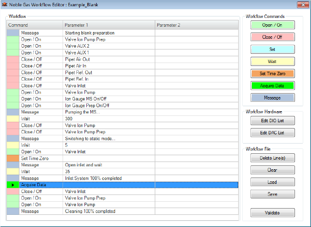
The workflow is shown as a list consisting of Command and Parameter
columns. Commands are indicated by a color code for easier identifying.
Use the seven colored buttons top right of this window as a legend
referring to the command.
❖To read and understand a workflow
1. Select a row by clicking the colored left most column.
A triangle indicates your selection. The row changes to a blue
background.
2. Double-click the Parameter 2 cell to enter a display message that will
be shown in the Log View of Qtegra ISDS when the script is
executed.
It is not possible to modify the value or string of the Parameter 1.
❖To modify commands in a workflow
1. If values or strings need to be changed, select the desired row, add a
copy of this command, and delete the original row.
For example, select the yellow row with the Wait 300 command.
2. From the Workflow Commands section, click the Wait button.
The WA I T dialog opens.
3. Type the desired value (for example 200) and click OK.
Figure 2-3. Example file opened in the Workflow Editor
Workflow Editor
The Workflow List
Thermo Scientific Qtegra Scripting Language Software Manual (P/N 1383460, Revision A) 2-5
4. The WA I T dialog remains open.
Optionally, type a display message that is shown in the Parameter 2
column.
5. Click OK to close the dialog.
A new row is added below your selection and shows the command,
its value and optionally a second parameter string.
6. Select the original row and click Delete Line(s) from the Workflow
File list.
The Wait 300 row is replaced by the Wait 200 row.
Using a Workflow in a LabBook
In addition to the creation or modification of a workflow file, the
workflow needs to get into your LabBook.
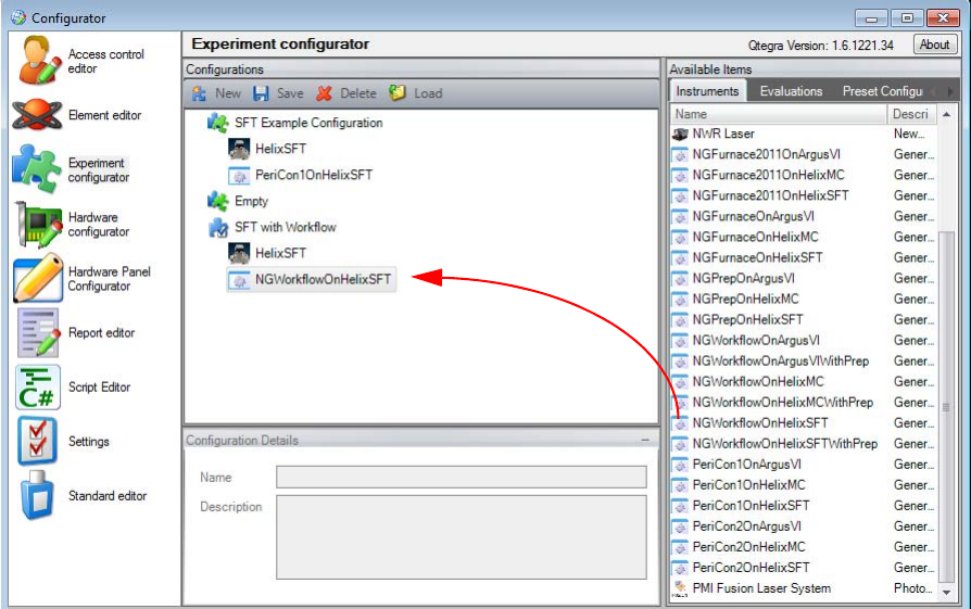
❖To use this workflow in a LabBook
1. Open the Configurator tool and select the Experiment
Configurator applet.
2. Create a new configuration and type a name, for example, SFT with
Workflow.
3. Drag and drop to add both your instrument and the
NGWorkflowOnHelixSFT from the available instruments items list.
See Figure 2-4.
Figure 2-4. New configuration with Workflow item
Workflow Editor
The Workflow List
2-6 Qtegra Scripting Language Software Manual (P/N 1383460, Revision A) Thermo Scientific
4. Save the new configuration.
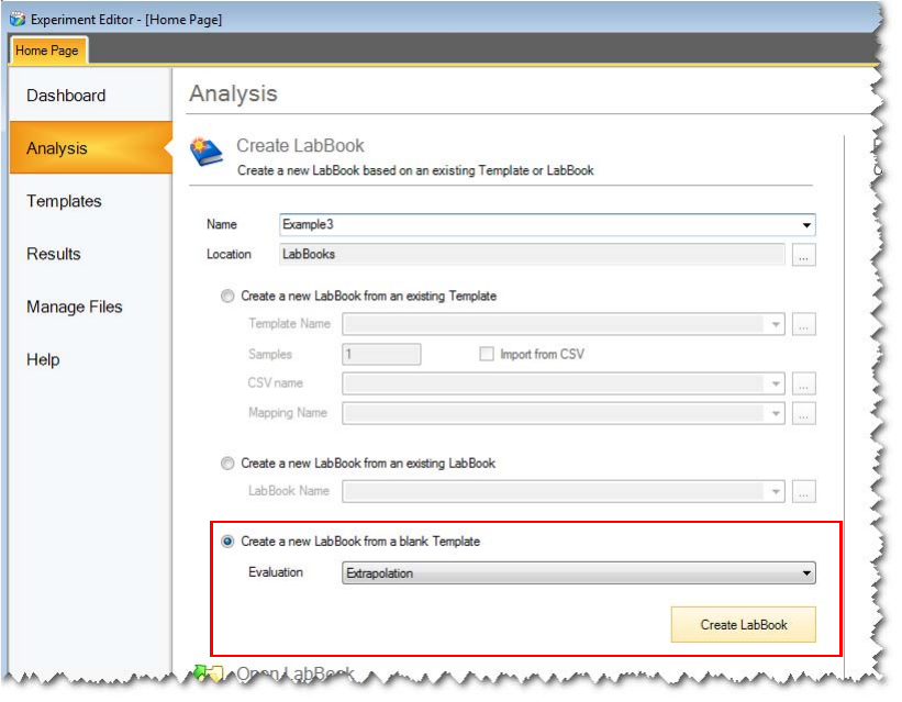
5. In the Qtegra ISDS, select the Dashboard.
6. Click Change Configuration and select the new configuration.
7. When the new configuration is loaded, select the Analysis pane.
The Analysis page opens.
8. Create a new LabBook from a blank Template.
From the Evaluation listbox, select an evaluation and click Create
LabBook.
Figure 2-5. Analysis page to create a new LabBook
Workflow Editor
The Workflow List
Thermo Scientific Qtegra Scripting Language Software Manual (P/N 1383460, Revision A) 2-7
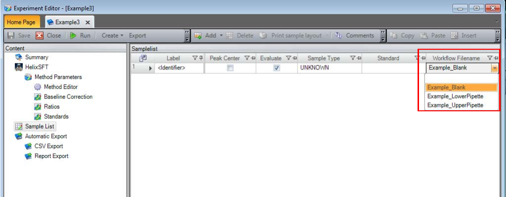
The LabBook is opened, see Figure 2-6.
9. From the Content pane, select Sample List to display the list (see
Figure 2-6). The rightmost column of the Sample list shows
Workflow Filename as a new item. This item provides a listbox to
select one of the available workflows.
When the LabBook runs, certain sections of the script are executed prior
to data acquisition and following data acquisition. Note the green
indicated line “Acquire Data” in the workflow, see Figure 2-3. Every
workflow must contain one such line.
This entry specifically triggers the mass spectrometer data acquisition
while all commands below the line are executed following successful
data acquisition. In this behavior, the workflow script replaces both the
“Prepare” and the “PostAcquisition” scripts.
Figure 2-6. New LabBook with Workflow Filename dropdown selection

Workflow Editor
Workflow Commands
2-8 Qtegra Scripting Language Software Manual (P/N 1383460, Revision A) Thermo Scientific
Workflow Commands
The Workflow Editor offers seven types of commands, which are
presented by buttons in seven different colors.
The Open and Close commands allow to manipulate all valves on the
instrument itself and its peripherals, including the PeriCon. For a more
detailed description of available items, see “Hardware Database Editor”
on page 3-2.
Likewise the Set command allows to set all analog values that are defined
as described above.
Table 2-2. Workflow Commands
Command Used for
Open / On Opens a window to select a DIO (valve,
gauge, pipet, or pump) to be opened in the
selected workflow step.
After your selection a dialog opens to enter
specific values to set the hardware item.
Your selection is specified in parameter 1.
Close / Off Opens a window to select a DIO (valve,
gauge, pipet, or pump) to be closed in the
selected workflow step. Your selection is
specified in parameter 1.
Set Opens a window to select a DAC from the
list. Your selection is specified in parameter 1.
Wait Waits for the specified time (in milliseconds)
without initiating further commands.
Set Time Zero Inserts a Set Time Zero command into your
workflow.
Acquire Data Runs the data acquirement, i.e., measures the
sample.
Message Message displayed in the Log View when
LabBook runs.
Workflow Editor
Workflow Hardware
Thermo Scientific Qtegra Scripting Language Software Manual (P/N 1383460, Revision A) 2-9
Workflow Hardware
This section of the Workflow Editor offers two buttons to assign digital
or analog hardware items.
Edit DIO List
❖To assign specific digital input output hardware (DIO) to a default item
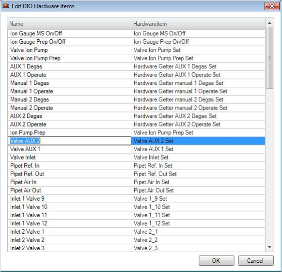
1. Click Edit DIO List to open the Edit DIO Hardware items
window, see Figure 2-7.
The right column lists all hardware items connected to your
hardware device.
2. Double-click the left cell to assign the desired hardware item
according your hardware device.
3. Edit the entry and click outside this cell to close the edit mode.
4. Click OK to save your settings.
Figure 2-7. DIO Hardware items window
Workflow Editor
Workflow Hardware
2-10 Qtegra Scripting Language Software Manual (P/N 1383460, Revision A) Thermo Scientific
Edit DAC List
❖To assign specific digital analog converter hardware (DAC) to a default
item
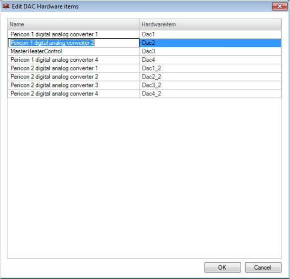
1. Click Edit DAC List to open the Edit DAC Hardware items
window, see Figure 2-8.
The right column lists all hardware items connected to your
hardware device.
2. Double-click the left cell to assign the desired hardware item
according to your hardware device.
3. Edit the entry and click outside this cell to close the edit mode.
4. Click OK to save your settings.
Modifying the Lists
Two test files are delivered with Qtegra ISDS. You will find them in this
folder:
C:\ProgramData\Thermo\Qtegra\_Application Data\NobleGasWorkflow\Parameter
Figure 2-8. DAC Hardware items window
Workflow Editor
Workflow Hardware
Thermo Scientific Qtegra Scripting Language Software Manual (P/N 1383460, Revision A) 2-11
You can extend the files according to your needs. For each line one item
is listed where an arbitrary name is followed by a colon, followed by a
valid hardware item name (from the hardware editor). See the following
examples:
•PeriCon 1 digital analog converter 1:Dac1
•PeriCon 1 digital analog converter 2:Dac2
•MasterHeaterControl:Dac3
•PeriCon 1 digital analog converter 4:Dac4
•PeriCon 2 digital analog converter 1:Dac1_2
•PeriCon 2 digital analog converter 2:Dac2_2
•PeriCon 2 digital analog converter 3:Dac3_2
•PeriCon 2 digital analog converter 4:Dac4_2
Workflow Editor
Workflow Hardware
2-12 Qtegra Scripting Language Software Manual (P/N 1383460, Revision A) Thermo Scientific

Thermo Scientific Qtegra Scripting Language Software Manual (P/N 1383460, Revision A) 3-1
Chapter 3 Configuration Tool
The Configurator enables access to a number of tools that give access to
a wide variety of internal editors that allow to modify important aspects
of the Qtegra software environment. The Access Control editor, the
Element Editor and the Experiment Configurator are commonly used
and explained in the Qtegra base documentation.
This chapter explains the Hardware Database editor that gives access to
the underlaying hardware as well as the Hardware Panel editor that
enables you to create graphic representations (GUI) of your hardware.
The Script editor provides easy access to the scripting structure. The
reason for not having covered these 3 items in the base documentation is
that any change to the hardware database, the panel files or the scripts
can inevitably disrupt the operation of Qtegra or even harm the
instrument itself.
Contents
•Hardware Database Editor
•Scripting Engine
•Generic Instruments
Configuration Tool
Hardware Database Editor
3-2 Qtegra Scripting Language Software Manual (P/N 1383460, Revision A) Thermo Scientific
Hardware Database Editor
Hardware Configurator
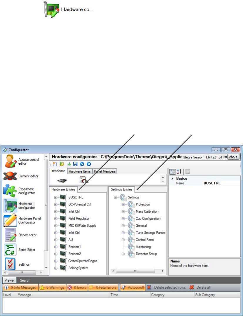
Qtegra allows you to edit the low level hardware configuration. This is
controlled within the Hardware Configurator.
To start the Hardware Configurator, click the respective icon.
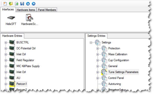
The Hardware Entries section in the left pane lists the actual electronic
systems fitted (1 in Figure 3-9). It is possible to fully edit the list of
hardware entries. However, as this requires in-depth knowledge of the
underlying hardware we will not encourage you to do so. There are a few
details of those entries that might prove useful to modify for instance
when you use our PeriCon to control your own hardware. See “Using
the PeriCon” on page 3-20.
The Settings Entries section in the right pane contains the hardware
parameters that will be displayed in Instrument Control (2 in
Figure 3-9).
Labeled Components: 1=hardware entries, 2=settings entries
Figure 3-9. Hardware entries and settings entries
21
Configuration Tool
Hardware Database Editor
Thermo Scientific Qtegra Scripting Language Software Manual (P/N 1383460, Revision A) 3-3
By dragging the required hardware entries from the left pane into the
right pane, you can configure the parameters to be presented in the
Instrument Control (2 in Figure 3-10).
The rightmost pane (1 in Figure 3-10) lists the basic I/O settings
including Bit mask, Interface settings etc.
Manipulating the Hardware Database
It is possible to add additional hardware to the hardware database. In
order to perform this successfully, you need to know how to access this
hardware from the control computer. In the example below (see
Figure 3-11), an additional PCB that extends the internal bus
capabilities of the instrument itself was added as an example. But it is
also possible to add hardware items that are controlled via scripts. These
Labeled Components: 1=basic I/O settings, 2=hardware entry dragged to settings entry
Figure 3-10. Dragging hardware entries from left pane to right pane
1
2
Configuration Tool
Hardware Database Editor
3-4 Qtegra Scripting Language Software Manual (P/N 1383460, Revision A) Thermo Scientific
scripts (see “Hardware Script Example” on page 5-5) in turn can use any
hardware items that can be physically accessed from a Windows
computer.
In this Software Manual, you find code examples to access hardware via
a TCP/IP connection or via a serial connection (RS232), see “Examples”
on page 5-1. Additionally, you can access hardware over the USB if you
have the required hardware and drivers. The only precaution is that you
are able to write a script that performs the necessary control action.
Additionally, the scripting tool has no integrated hardware check. As an
example of troubles, you can open any hardware configuration and use
the PeriCon panel. This panel allows switches to be set and
measurements to be performed, even the PeriCon is not connected. Your
script must therefore strictly follow the structure and should be tested
via the debugging feature (see “To edit a script in the Instrument
Control tool” on page 3-43).
Whenever you need assistance, please do not hesitate to contacting the
Thermo Fisher Scientific support team.
Figure 3-11. Initial view of the hardware configurator

Configuration Tool
Hardware Database Editor
Thermo Scientific Qtegra Scripting Language Software Manual (P/N 1383460, Revision A) 3-5
Commands to Control the Mass Spectrometer
To be able to control the important aspects of our mass spectrometer, a
small number of commands have been implemented as addition to the
C# and .NET environments. Following is a list of commonly used
commands to control the mass spectrometer.
Table 3-3. BUSCTRL commands
Hardware Item Name Functional Description
Parent: BUSCTRL Name refers to the bus controller situated on
the emission regulator, all functions refer to
Drawing S2077000.
Filament Status
Register Readback
Emission status register with emission status
on bit 3. Bit 0 is always true, the rest of the
bits are always False.
Filament enabled
Readback
Trap Current Set Set value for the emission current. On the
board itself it can be selected if trap or total
current is regulated using this value. The
maximum current is hard wired and
corresponds to 4096 set on the DAC.
Trap Voltage Set Set value for the difference in voltage between
trap and ionization housing
Electron Energy Set Set value for the difference in voltage between
filament and ionization housing.
Electron Energy
Readback
True value for Electron Energy
50 eV = 1.35 V
Trap Current
Readback
Current of electrons reaching the electron trap
of the source.
Trap Voltage
Readback
True value for the trap voltage. Reading is
1/10 of the trap Voltage.
Source Current
Readback
Current of electrons reaching the ionization
volume housing (box) of the source.
Table 3-4. DC-Potential commands
Hardware Item Name Functional Description
Parent: DC-Potential
Ctrl
The DC potential controller controls all
aspects of high voltage generation. Refer to
Drawing S2041520.
HV Control Register
Set
Configuration Tool
Hardware Database Editor
3-6 Qtegra Scripting Language Software Manual (P/N 1383460, Revision A) Thermo Scientific
HV on Set Direct access to the HV ON trigger of the
accelerating voltage board.
HV off Set Direct access to the HV OFF trigger of the
accelerating voltage board.
Acceleration
Reference Set
Set value for the accelerating voltage.
Y-Plate 1 Set Set control voltage for the Y-Plate 1. Full
range is maximum output of the module used,
voltage depending on module setting.
Y-Plate 2 Set Set control voltage for the Y-Plate 2. Full
range is maximum output of the module used,
voltage depending on module setting.
Z-Plate 1 Set Set control voltage for the Z-Plate 1. Full
range is maximum output of the module used,
voltage depending on module setting.
Z-Plate 2 Set Set control voltage for the Z-Plate 2. Full
range is maximum output of the module used,
voltage depending on module setting.
Ion Repeller Set Set control voltage for the Ion Repeller. Full
range is maximum output of the module used,
voltage depending on module setting.
Source Status Register
Readback
HV Status Readback Readback of the HV status bit of the
accelerating voltage controller board.
HV Ramp Status
Readback
Readback of the overload bit for the respective
plate.
Y-Plate 1 Overload
Readback
Y-Plate 2 Overload
Readback
Z-Plate 1 Overload
Readback
Z-Plate 2 Overload
Readback
Ion Repeller Overload
Readback
Acceleration Monitor
Readback
Table 3-4. DC-Potential commands, continued
Hardware Item Name Functional Description
Configuration Tool
Hardware Database Editor
Thermo Scientific Qtegra Scripting Language Software Manual (P/N 1383460, Revision A) 3-7
Extraction Lens Set
Y-Symmetry Set Virtual controls that utilize scripts to control
the Y and Z plates listed above to provide a
better user interface.
Z-Focus Set
Z-Symmetry Set
HV Set
HV Script
Table 3-5. Inlet Ctrl commands
Hardware Item Name Functional Description
Parent: Inlet Ctrl Various instrument internal
connections to valves and gauges.
Refer to Drawing S2041320.
Temp2
HV Status
Output 9 Register Set
Temp1
Output 1 Register Set
Valve Ion Pump Set
Source Electronics Reset Set
Source Electronics Off Set
Output 2 Register Set
Hardware Getter 1 Degas Set
Hardware Getter 1 Operate Set
Output 3 Register Set
Ion Gauge MS enable / disable
Set
Input 1 Register Readback
Ion Gauge MS Enabled
Readback
Ion Gauge MS Readback
Ion Gauge MS Degas
Ion Getter Pump On / Off
Table 3-4. DC-Potential commands, continued
Hardware Item Name Functional Description

Configuration Tool
Hardware Database Editor
3-8 Qtegra Scripting Language Software Manual (P/N 1383460, Revision A) Thermo Scientific
Table 3-6. Field Regulator commands
Hardware Item Name Functional Description
Parent: Field
Regulator
Lupe Set Access to hardware addresses, do not use.
HiByte Set Access to hardware addresses, do not use.
LowByte Set Access to hardware addresses, do not use.
Field Set Virtual control to set a field value via a script.
0 to 10 volts corresponds to the full range of
the field regulator.
Table 3-7. MIC KillPlate Supply commands
Hardware Item Name Functional Description
Parent: MIC KillPlate
Supply
Deflection CDD Set Controls the deflection voltage in front of the
CDD.
Deflection L2 Set Controls the deflection voltage in front of the
L2 cup.
Deflection L1 Set Controls the deflection voltage in front of the
L1 cup.
Deflection AX Set Controls the deflection voltage in front of the
axial cup.
Deflection H1 Set Controls the deflection voltage in front of the
H1 cup.
Deflection H2 Set Controls the deflection voltage in front of the
H2 cup.
CDD Supply Set Controls the CDD supply voltage.
Table 3-8. Inlet Ctrl commands
Hardware Item Name Functional Description
Parent: Inlet Ctrl Various instrument
external connections to
valves and gauges. Refer to
Drawing S2041320 and
S2120540.
Output 4 Register Set Not usable, conflict with
NGPrep connectors.

Configuration Tool
Hardware Database Editor
Thermo Scientific Qtegra Scripting Language Software Manual (P/N 1383460, Revision A) 3-9
Hardware Getter AUX 1 Degas Set Reserved for use of
NGPrep.
Hardware Getter AUX 1 Operate Set Reserved for use of
NGPrep.
Hardware Getter manual 1 Degas Set Reserved for use of
NGPrep.
Hardware Getter manual 1 Operate Set Reserved for use of
NGPrep.
Output 5 Register Set Not usable, conflict with
NGPrep connectors.
Hardware Getter manual 2 Degas Set Reserved for use of
NGPrep.
Hardware Getter manual 2 Operate Set Reserved for use of
NGPrep.
Hardware Getter AUX 2 Degas Set Reserved for use of
NGPrep.
Hardware Getter AUX 2 Operate Set Reserved for use of
NGPrep.
Output 6 Register Set Not usable, conflict with
NGPrep connectors.
Valve AUX 2 Set Not usable, conflict with
NGPrep connectors.
Valve Ion Pump Prep Set Reserved for use of
NGPrep.
Valve Inlet Set Reserved for use of
NGPrep.
Valve AUX 1 Set Reserved for use of
NGPrep.
Valve 2_9 Set Not usable, conflict with
NGPrep connectors.
Valve 2_10 Set Not usable, conflict with
NGPrep connectors.
Valve 2_11 Set Not usable, conflict with
NGPrep connectors.
Valve 2_12 Set Not usable, conflict with
NGPrep connectors.
Output 7 Register Set Not usable, conflict with
NGPrep connectors.
Table 3-8. Inlet Ctrl commands, continued
Hardware Item Name Functional Description

Configuration Tool
Hardware Database Editor
3-10 Qtegra Scripting Language Software Manual (P/N 1383460, Revision A) Thermo Scientific
Pipet Ref. In Set Reserved for use of
NGPrep.
Pipet Ref. Out Set Reserved for use of
NGPrep.
Pipet Air In Set Reserved for use of
NGPrep.
Pipet Air Out Set Reserved for use of
NGPrep.
Valve 1_9 Set Not usable, conflict with
NGPrep connectors.
Valve 1_10 Set Not usable, conflict with
NGPrep connectors.
Valve 1_11 Set Not usable, conflict with
NGPrep connectors.
Valve 1_12 Set Not usable, conflict with
NGPrep connectors.
Output 8 Register Set Not usable, conflict with
NGPrep connectors.
Valve 2_1 Not usable, conflict with
NGPrep connectors.
Valve 2_2 Not usable, conflict with
NGPrep connectors.
Valve 2_3 Not usable, conflict with
NGPrep connectors.
Valve 2_4 Not usable, conflict with
NGPrep connectors.
Valve 2_7 Not usable, conflict with
NGPrep connectors.
Valve 2_8 Not usable, conflict with
NGPrep connectors.
Valve 2_5 Not usable, conflict with
NGPrep connectors.
Valve 2_6 Not usable, conflict with
NGPrep connectors.
Output 3 Register - 2 Set Not usable, conflict with
NGPrep connectors.
Ion Gauge Prep enable / disable Set Reserved for use of
NGPrep.
Table 3-8. Inlet Ctrl commands, continued
Hardware Item Name Functional Description

Configuration Tool
Hardware Database Editor
Thermo Scientific Qtegra Scripting Language Software Manual (P/N 1383460, Revision A) 3-11
Input 1 Register - 2 Readback Not usable, conflict with
NGPrep connectors.
Ion Gauge Prep Enabled Readback Reserved for use of
NGPrep.
Ion Gauge Prep Readback Reserved for use of
NGPrep.
Pirani Furnace Readback Reserved for use of
NGPrep.
Pirani Furnace 2011 Readback Reserved for use of
NGPrep.
Hardware Pipet Air Out Set Reserved for use of
NGPrep.
Hardware Pipet Air In Set Reserved for use of
NGPrep.
Hardware Pipet Ref Out Set Reserved for use of
NGPrep.
Hardware Pipet Ref In Set Reserved for use of
NGPrep.
Ion Gauge MS On/Off Reserved for use of
NGPrep.
Ion Gauge Prep On/Off Reserved for use of
NGPrep.
Table 3-9. AU commands
Hardware Item NameaFunctional Description
Parent: AU
AU-Register
Offset L2 Set
Settling Time L2 Set
Offset L1 Set
Settling Time L1 Set
Offset AX Set
Settling Time AX Set
Offset H1 Set
Settling Time H1 Set
Offset H2 Set
Table 3-8. Inlet Ctrl commands, continued
Hardware Item Name Functional Description

Configuration Tool
Hardware Database Editor
3-12 Qtegra Scripting Language Software Manual (P/N 1383460, Revision A) Thermo Scientific
Settling Time H2 Set
Register ICA Test Inputs Set
Register Board Test Set
Relay Current Source Set
Relay Register Set
UFC Zero Set
Board Test Set
Intensity Cup 0 Readback Results a voltage (0 - 55 V)
Intensity Cup 1 Readback Results a voltage (0 - 55 V)
Intensity Cup 2 Readback Results a voltage (0 - 55 V)
Intensity Cup 3 Readback Results a voltage (0 - 55 V)
Intensity Cup 4 Readback Results a voltage (0 - 55 V)
Intensity Cup 5 Readback Results a voltage (0 - 55 V)
Intensity Cup 6 Readback Results a voltage (0 - 55 V)
Intensity Cup 7 Readback Results a voltage (0 - 55 V)
Intensity Cup 8 Readback Results a voltage (0 - 55 V)
Intensity Cup 9 Readback Results a voltage (0 - 55 V)
Intensity CDD 0 Readback Results a count rate
(0-2
24 cps), but limited to
protect the cup.
Intensity CDD 1 Readback Results a count rate
(0-2
24 cps), but limited to
protect the cup.
Intensity CDD 2 Readback Results a count rate
(0-2
24 cps), but limited to
protect the cup.
Intensity CDD 3 Readback Results a count rate
(0-2
24 cps), but limited to
protect the cup.
Intensity CDD 4 Readback Results a count rate
(0-2
24 cps), but limited to
protect the cup.
Intensity CDD 5 Readback Results a count rate
(0-2
24 cps), but limited to
protect the cup.
Table 3-9. AU commands, continued
Hardware Item NameaFunctional Description

Configuration Tool
Hardware Database Editor
Thermo Scientific Qtegra Scripting Language Software Manual (P/N 1383460, Revision A) 3-13
Intensity CDD 6 Readback Results a count rate
(0-2
24 cps), but limited to
protect the cup.
Intensity CDD 7 Readback Results a count rate
(0-2
24 cps), but limited to
protect the cup.
aDepending on the available hardware, not all controls are configured. For example, the ArgusVI has 5
cups and 1 CDD only, the Helix SFT has 1 cup and 1 CDD only, hte Helix MC has 5 cups and 5 CDDs.
Table 3-10. PeriCon1 and PeriCon2 commands
Hardware Item Name Functional Description
Parent: PeriCon1 For all functions refer to the PeriCon
Operating Manual.
Add suffix “_2” for PeriCon2 hardware item
name.
InD0
InD1
InD2
InD3
InD4
InD5
InD6
InD7
Analog Range 1
Analog Range 2
Analog Range 3
Analog Range 4
Adc4
Dac4
Adc3
Dac3
Adc2
Dac2
Adc1
Dac1
Table 3-9. AU commands, continued
Hardware Item NameaFunctional Description

Configuration Tool
Hardware Database Editor
3-14 Qtegra Scripting Language Software Manual (P/N 1383460, Revision A) Thermo Scientific
P16
P15
P14
P13
P12
P11
P10
P9
P8
P7
P6
P5
P4
P3
P2
P1
Table 3-11. GetterOperateDegas commands
Hardware Item Name Functional Description
Parent:
GetterOperateDegas
Functions controlled via the Power distributor
and common to all Noble Gas Instruments,
refer to Drawing S2041320, S2130960.
Getter 1 Operate Set Controls for the getter attached to source of
the instrument itself
Getter 1 Degas Set Controls for the getter attached to source of
the instrument itself
Getter AUX 1 Degas
Set
Controls for the getter attached to the Inlet 1
of a NG PrepBench
Getter AUX 1
Operate Set
Controls for the getter attached to the Inlet 1
of a NG PrepBench.
Getter manual 1
Degas Set
Controls for the getter attached to the main
manifold of a NG PrepBench.
Getter manual 1
Operate Set
Controls for the getter attached to the main
manifold of a NG PrepBench.
Getter manual 2
Degas Set
Controls for the getter attached to the main
manifold of a NG PrepBench.
Table 3-10. PeriCon1 and PeriCon2 commands, continued
Hardware Item Name Functional Description

Configuration Tool
Hardware Database Editor
Thermo Scientific Qtegra Scripting Language Software Manual (P/N 1383460, Revision A) 3-15
Getter manual 2
Operate Set
Controls for the getter attached to the main
manifold of a NG PrepBench.
Getter AUX 2 Degas
Set
Controls for the getter attached to the Inlet 2
of a NG PrepBench.
Getter AUX 2
Operate Set
Controls for the getter attached to the Inlet 2
of a NG PrepBench.
Table 3-12. BakingSystem commands
Hardware Item Name Functional Description
Parent: BakingSystem Baking system is currently only available
for the HELIX MC.
Fan State Readback RDB_FAN_STATUS is of type DIO
Read with the bit range 0 to 7, where
0: Fan 1 (1=okay, 0=error)
1: Fan 2 (1=okay, 0=error)
2: Fan 3 (1=okay, 0=error)
3: Fan 4 (1=okay, 0=error)
4: Fan 5 (1=okay, 0=error)
5: Fan 6 (1=okay, 0=error)
6: free
7: free
Input State Readback RDB_INPUT is of type DIO Read with
the bit range 0 to 15, where
0: SWITCH_HEATER (1=on, 0=off)
1: OVERHEAT_ERROR (1=error,
0=okay)
2: GETTER_FUSE_1_OKAY (1=okay,
0=error
3: GETTER_FUSE_2_OKAY (1=okay,
0=error
4: GETTER_FUSE_3_OKAY (1=okay,
0=error
5: GETTER_FUSE_4_OKAY (1=okay,
0=error
6: free
7: free
8: SENSOR_OKAY1 (1=okay, 0=error)
9: SENSOR_OKAY2 (1=okay, 0=error)
10: SENSOR_OKAY3 (1=okay, 0=error)
11: SENSOR_OKAY4 (1=okay, 0=error)
12..14: free
15: SW_TOGGLE (state indicator)
Table 3-11. GetterOperateDegas commands, continued
Hardware Item Name Functional Description

Configuration Tool
Hardware Database Editor
3-16 Qtegra Scripting Language Software Manual (P/N 1383460, Revision A) Thermo Scientific
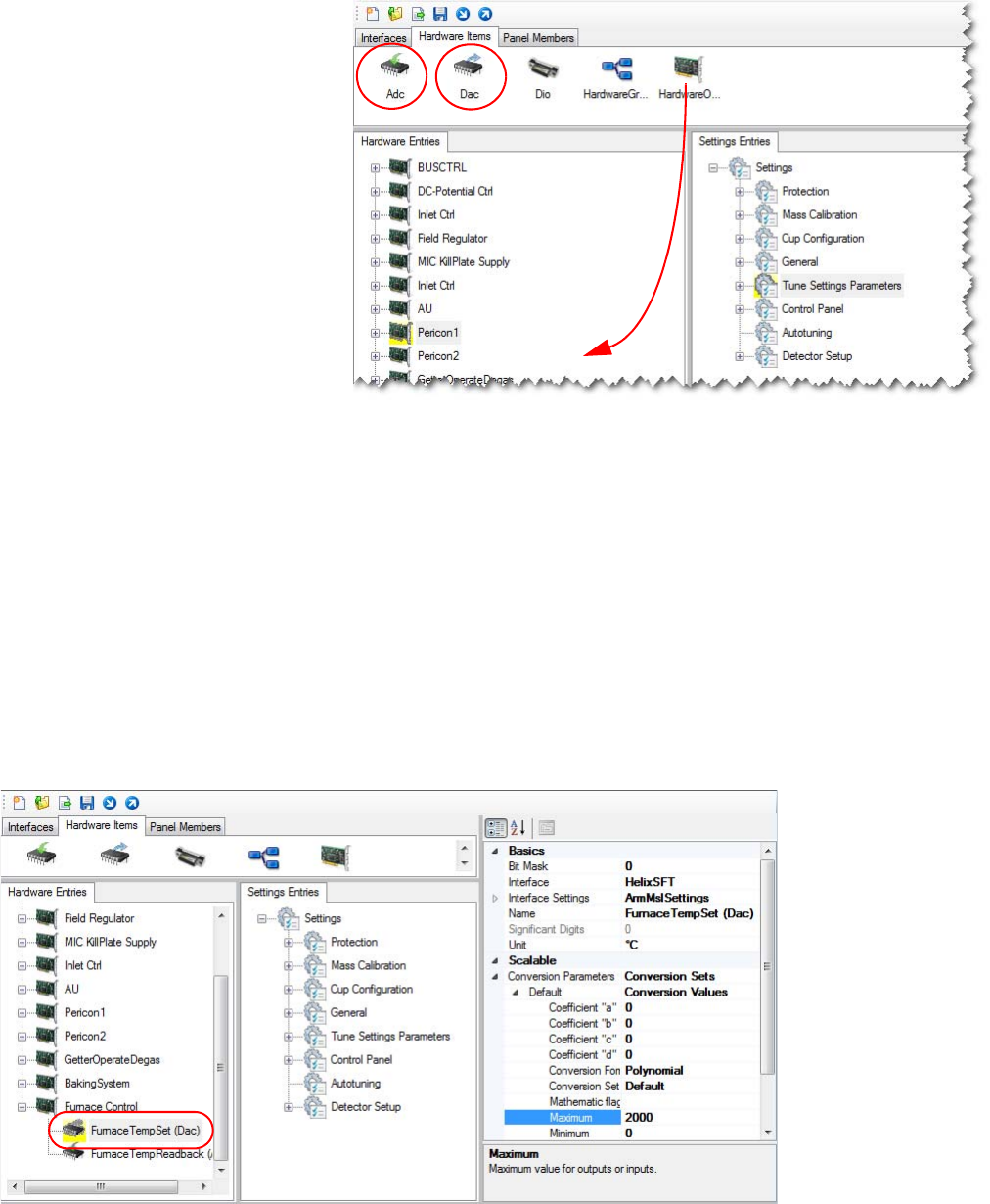
Adding an Object
❖Step 1: To add a hardware container
1. Open the Hardware Configurator and select the Hardware Items
tab.
Heater State Readback RDB_HEATERSTATUS is of type Adc
Read with the bit range 0 to 15, where
1=okay, 0=error:
0: HEATER_SENSOR_OKAY1
1: HEATER_SENSOR_OKAY2
2: HEATER_SENSOR_OKAY3
3: HEATER_SENSOR_OKAY4
4: SENSOR_ELECTRONIC_OKAY1
5: SENSOR_ELECTRONIC_OKAY2
6: SENSOR_ELECTRONIC_OKAY3
7: SENSOR_ELECTRONIC_OKAY4
8: HEATER_OKAY1
9: HEATER_OKAY2
10: HEATER_OKAY3
11: HEATER_OKAY4
12..15: free
Heater Temperature
Readback 01
RDB_HEATTEMP1 is of type Adc
Read, bit: 0.1 °C, range 0..5000
Heater Temperature
Readback 02
RDB_HEATTEMP2 is of type Adc
Read, bit: 0.1 °C, range 0..5000
Heater Temperature
Readback 03
RDB_HEATTEMP3 is of type Adc
Read, bit: 0.1 °C, range 0..5000
Heater Temperature
Readback 04
not supported
Temperature Readback 01 RDB_TEMP1 is of type Adc Read, bit:
0.1 °C, range 0..5000
Temperature Readback 02 RDB_TEMP2 is of type Adc Read, bit:
0.1 °C, range 0..5000
Temperature Readback 03 RDB_TEMP3 is of type Adc Read, bit:
0.1 °C, range 0..5000
Temperature Readback 04 not supported
EnableHeaterRibbon
EnableFilamentHeater
Table 3-12. BakingSystem commands, continued
Hardware Item Name Functional Description
Configuration Tool
Hardware Database Editor
Thermo Scientific Qtegra Scripting Language Software Manual (P/N 1383460, Revision A) 3-17
2. Drag a hardware object into the list of Hardware Entries.
The new object is shown as My Virtual Instrument. Select the object
and press <F2> to enter the desired name.
3. From the Hardware Items, select the required elements and drag
them to the hardware object.
In the example, an ADC is used to read back (0 to 10 V) the actual
temperature from the furnace and a DAC is used to set the desired
temperature (0 to 10 V) on the furnace.
All other functionality is provided by the furnace controller itself.
❖Step 2: To add the required hardware information
Figure 3-12. Initial view of the hardware configurator
Figure 3-13. Adding the Furnace Temperature Set

Configuration Tool
Hardware Database Editor
3-18 Qtegra Scripting Language Software Manual (P/N 1383460, Revision A) Thermo Scientific
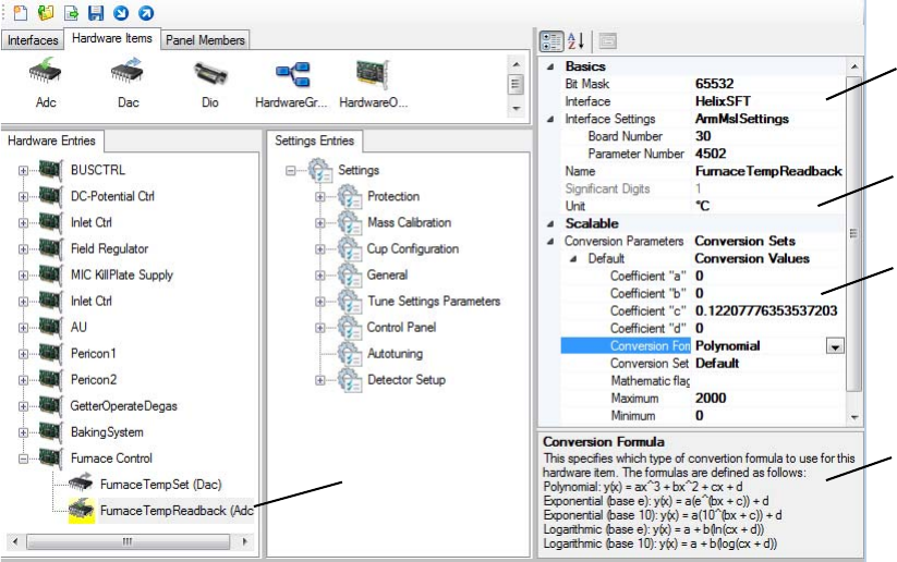
1. Select one hardware object and view the property pane on the right
side.
For the DAC that sets the temperature the following entries are
made (1 in Figure 3-14):
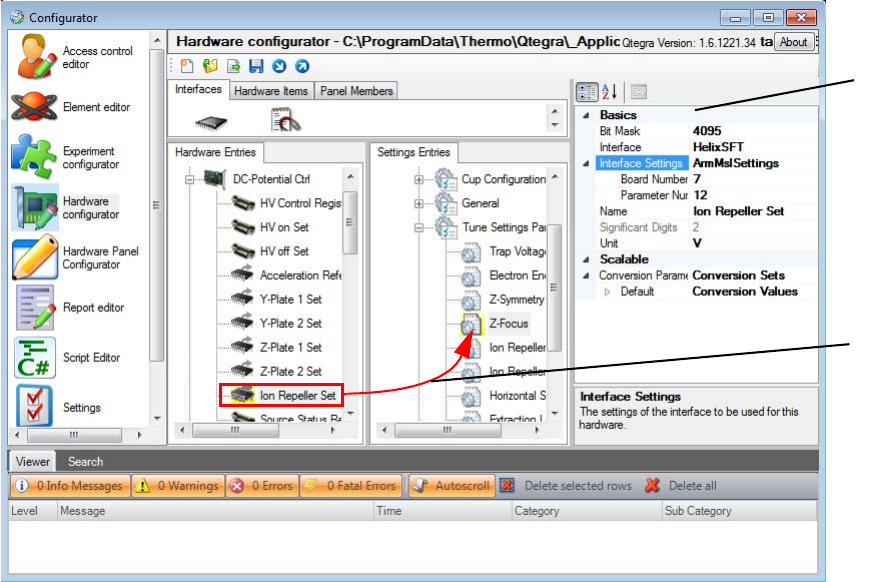
a. The DAC has a resolution of 12 bits, consequently the Bit Mask
is set to 4095 (212-1).
b. The electrical interface was connected via the internal bus
(ArmMsISettings) with Board Number 30 and Parameter
Number 4.
This is the point to select a script interface for your own
hardware.
c. Independent from the actual electrical interface the temperature
Unit is set to °C (2 in Figure 3-14), where the range of the DAC
is translated into 0 to 2000 °C.
d. The actual translation between voltage and temperature is done
via the function specified under Conversion Formula with the
help of coefficients (3 in Figure 3-14).
Table 3-13. Conversion Parameters
Parameter Description
Polynomial
Dependent from your needs only specific
coefficients are used. Not used coefficients are
represented by 0.
Exponential (e)
Exponential (10)
Logarithmic (e)
Logarithmic (10)
Coefficient “a” In case of a polynomial formula the cubed
coefficient.
Coefficient “b” In case of a polynomial formula the squared
coefficient.
Coefficient “c” In case of a polynomial formula the linear
coefficient.
Coefficient “d” Coefficient often used to lift the base line of the
function.
Use Inverted Logic Select False to ignore this setting. If True, the
inverted range logic is used. This means if, for
example, a DIO is controlled via a bit
command, this bit is 1 to deactivate the device.
A 1 is read as 0 and vice versa.
yx() ax3bx2cx d+++=
yx() ae
bx c+()
×d+=
yx() abx c+()
×10 d+=
yx() ab cxd+()ln×+=
yx() ab+cx d+()log×=
Configuration Tool
Hardware Database Editor
Thermo Scientific Qtegra Scripting Language Software Manual (P/N 1383460, Revision A) 3-19
To get information about the conversion formula, select this
item in the Conversion Parameters list and read the information
below this window tile (4 in Figure 3-14).
e. To set the coefficients, right-click the hardware object and select
Generate > Linear coefficient from the shortcut menu.
The coefficient “c” changes (3 in Figure 3-14).
The Hardware Script
In order to assign a script rather than an actual hardware item to the
database, click the Browse button in the interface section of the
hardware device. You can then browse for the script using the file
browser.
The script is based on an event driven approach. It always consists of the
particular routines Initialize, GetParameter, SetParameter, and Dispose,
which always are called from the Windows Event Handler by their
unique names. The script has to follow certain rules that are discussed in
detail, see “Hardware Script Example” on page 5-5.
Labeled Components: 1=Basics and Interface Settings section, 2=Unit, 3=Conversion Parameters, 4=Information
regarding the selected item, 5=Selected hardware object
Figure 3-14. Adding the Furnace Temperature Readback
1
2
3
4
5
Configuration Tool
Hardware Database Editor
3-20 Qtegra Scripting Language Software Manual (P/N 1383460, Revision A) Thermo Scientific
Using the PeriCon
PeriCon is a peripheral controller that allows to control valves as well as
analog and digital devices. For details on the analog and digital world,
see “Analog and Digital World” on page 6-1.
Installation of PeriCon
For noble gas mass spectrometers, a fiber line-controlled peripheral can
directly be connected.
The optical fiber provides galvanic isolation from the mass spectrometer.
This minimizes the risk of ground loops. In case of a possible faulty
operation, neither mass spectrometer nor data acquisition will be
affected.
NOTICE Insert the dark optical fiber into the dark connector. Insert the
bright optical fiber into the bright connector. Do not confuse the
colors. ▲
Next connect the power supply delivered with the PeriCon to mains
supply and also connect to the appropriate input connector of the
PeriCon.
The PeriCon is now ready for use.
For details on the Control and Digital Output Section, the Digital
Input Section, and the Analog Section of PeriCon, refer to the PeriCon
Operating Manual.
Configuration Tool
Hardware Database Editor
Thermo Scientific Qtegra Scripting Language Software Manual (P/N 1383460, Revision A) 3-21
PeriCon Items in the Configurator
The PeriCon hardware configuration is shown in the Configurator tool
of Qtegra. To view this configuration, select Hardware Configurator
and expand the PeriCon1 node in the Hardware Entries tab.
NOTICE The Hardware Entries for PeriCon should not be changed. ▲
For details on the Hardware Entries for PeriCon, refer to the PeriCon
Operating Manual.
Summary of PeriCon Solution
•No need to understand the concept of hardware database, all
required settings included in standard setup.
•Only graphical design changes required to yield a usable control
panel, powerful graphical editor available from the Configurator.
•Electrical damage limited to the PeriCon unit – MS is safe!
•Capable to control 16 valves
•Capable to read 4 digital states
Figure 3-15. PeriCon entries in the Configurator
8 × Digital inputs
Administrative
switches
4 × Analog inputs
4 × Analog outputs
16 × Digital outputs
Configuration Tool
Hardware Database Editor
3-22 Qtegra Scripting Language Software Manual (P/N 1383460, Revision A) Thermo Scientific
•Capable to set 4 analog voltages 0 to 10 V and to read back 4 analog
values, for instance to read pressure gauge.
Operation of PeriCon with Qtegra
For noble gas mass spectrometers, PeriCon is operated with the software
suite of Qtegra ISDS.
Prior to operation, a Configuration must be created in the Configurator
tool of Qtegra for you instrument setup with PeriCon. This
Configuration is then loaded to the Instrument Control tool for
instrument adjustments or to the Qtegra window tool for measurement.
In the Configurator tool, you can also view the hardware entries for
PeriCon in the Hardware configurator and set up a Hardware Panel
Configuration.
Hardware Panel Configurator
Hardware panels provide a graphical representation of technical
equipment. Hardware panels are used to control all electrical and
functions of the mass spectrometer as well as the preparation devices.
Hardware panels can be customized to control different devices and can
be added to control additional devices.
Creating Hardware Panel for PeriCon
❖To create a panel for PeriCon
1. Open the Configurator tool of Qtegra.
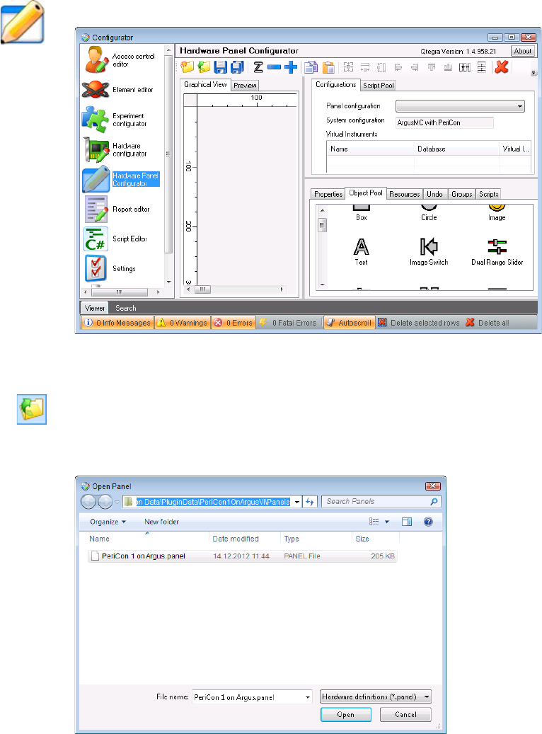
Configuration Tool
Hardware Database Editor
Thermo Scientific Qtegra Scripting Language Software Manual (P/N 1383460, Revision A) 3-23
2. Click Hardware Panel Configurator, see Figure 3-16.
3. On the toolbar, click to open the Open Panel dialog.
4. Browse to the folder C:\ProgramData\Thermo\Qtegra\_Application
Data\PluginData\<VIname>\Panels, see Figure 3-17.
NOTICE Replace the subfolder <VIname> by PeriCon1OnArgusVI,
PeriCon1OnHelixSFT or PeriCon1OnHelixMC.▲
Figure 3-16. Qtegra Hardware Panel Configurator
Figure 3-17. Open Panel dialog to select panel file
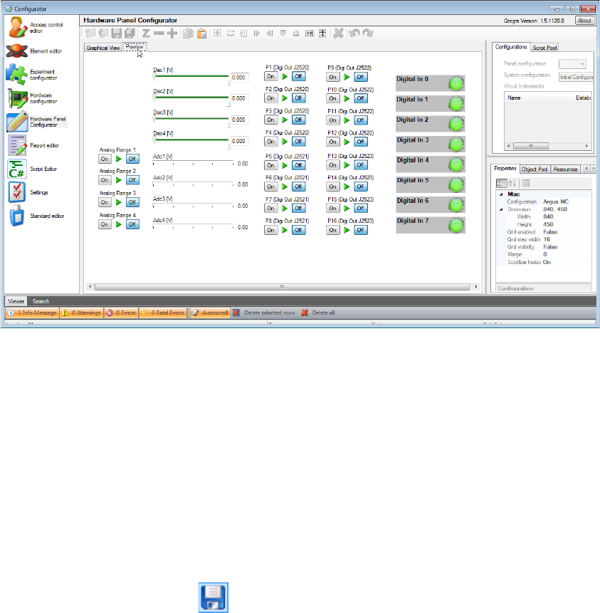
Configuration Tool
Hardware Database Editor
3-24 Qtegra Scripting Language Software Manual (P/N 1383460, Revision A) Thermo Scientific
5. Select the *.panel file for PeriCon and click Open.
The panel configuration is loaded to the Hardware Panel
Configurator, see Figure 3-18.
6. Select the Graphical View tab to edit the presentation.
Elements can be deleted or rearranged to match your system setup.
7. Add text, images or lines by dragging and dropping those elements
from the Object Pool (see Figure 3-16) on the right to the panel.
NOTICE New valves should only be added from specialists who know
what is necessary to program the linking functionality for Qtegra. ▲
8. On the toolbar, click Save Panel to save the panel under the same
name.
The pre-configured name for the PeriCon panel is directly linked to
the control of Qtegra. If the name is changed, Qtegra will not be
able to find this panel.
Creating a Graphical View
At least for training purposes, it might be helpful to create a graphical
view of your peripheral. Here, all graphical objects and their use will be
described.
Figure 3-18. PeriCon panel in Preview tab of Hardware Panel Configurator
Configuration Tool
Hardware Database Editor
Thermo Scientific Qtegra Scripting Language Software Manual (P/N 1383460, Revision A) 3-25
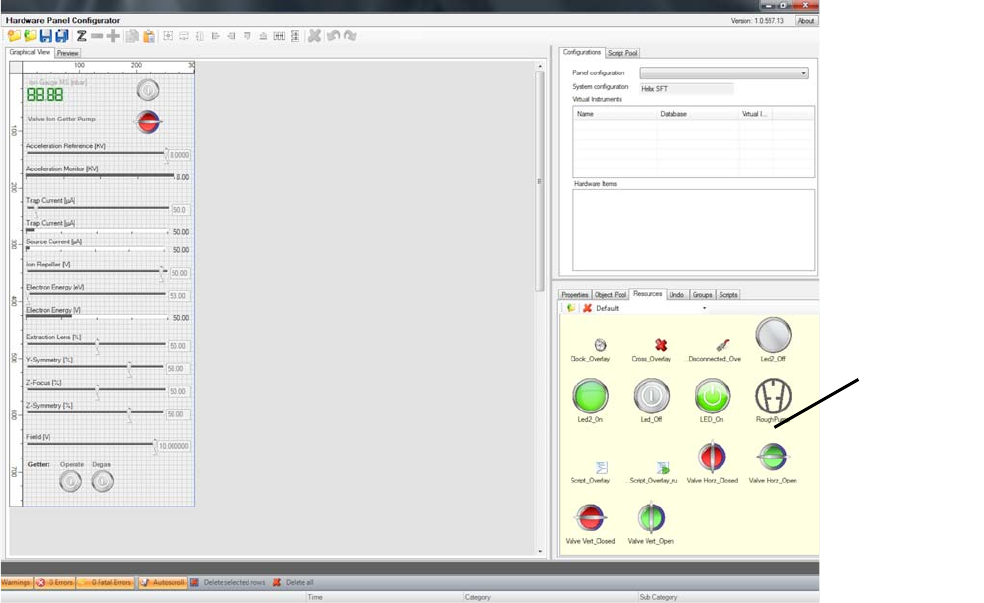
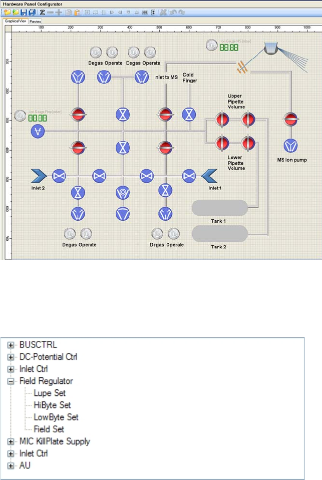
Figure 3-19 shows an example of a hardware panel created in the
Hardware Panel Configurator.
It contains not only the mass spectrometer controls (both source and
magnet) but also the inlet system with its valves, gauges and control
switches.
Hardware panels consist of functional objects that are linked to physical
hardware and graphical representations as well as simple bitmaps that
just represent an item without being associated to a physical effect
(“resources pool”).
See “Optional System Components” on page 6-5 for optional system
components as examples for hardware peripherals.
❖To create a new graphical view
1. In the Hardware Panel Configurator application, select the
Graphical View tab to get a blank grid where you can place the
objects that represent parts of your peripheral.
Figure 3-19. Example for a hardware panel
resources pool
Configuration Tool
Hardware Database Editor
3-26 Qtegra Scripting Language Software Manual (P/N 1383460, Revision A) Thermo Scientific
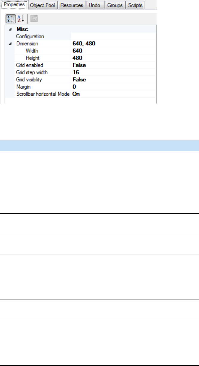
2. To change the initial dimensions of the grid, select the Properties
tab, see Figure 3-24.
Figure 3-20. Properties of the grid
Table 3-14. Grid properties
Property Description
Dimension
- Width
- Height
Width (default: 640) and Height (default:
480) of the grid. The unit is pixel. Click into
the Dimension row and change the values
accordingly
-or-
Click into the separate rows of Width and
Height to change their values.
Grid enabled Boolean to use (True) or ignore (False) the
grid within the Graphical View.
Grid step width Value (pixel) giving the distance of grid lines.
Default is 16 as divisor of 640 and 480.
Grid visibility Boolean to show (True) or hide (False) the
visibility of the grid. Note that your objects
are placed by control of the grid if Grid
enabled is True. The visibility is only used to
support dragging the objects.
Margin The margin value (pixel) is used to add
additional space around your graphical view.
Scrollbar horizontal
Mode
Three modes are supported:
Auto: Scrollbar is in a floating parent enabled
and in a docked parent enabled.
On: Scrollbar is enabled.
Off: Scrollbar is disabled.
Configuration Tool
Hardware Database Editor
Thermo Scientific Qtegra Scripting Language Software Manual (P/N 1383460, Revision A) 3-27
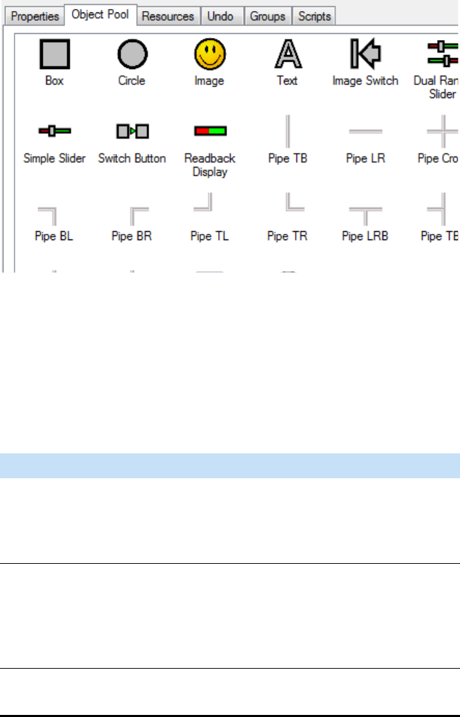
3. From the Object Pool tab, drag an object and drop it into your grid.
The objects represent physical parts of your peripheral. The Object
Pool provides a huge range of such parts.
The list of objects available for the design of the panel user interface
is shown in the Object Pool tab, see Figure 3-21. Note that some of
the objects require additional graphical “resources” as well as a link
to the hardware.
All the Pipes, the Box and Circle, Image and Text objects are just
decoration of the panel itself while the ImageSwitch, DualRangeSlider,
Simple Slider, Switch Button, ReadBack Display, and PushButton
objects will connect to hardware items and therefore act as controls on
the panel later on.
Figure 3-21. Object Pool tab
Table 3-15. Objects
Object Description
Box Shows a rectangular object that needs to be
specified by additional objects.
Initial values (96 × 96 pixel) are shown in the
Properties tab.
Circle Shows a round object that needs to be
specified by additional objects. When
selected, the circle object is shown with a
rectangular surrounding including 8 resize
pointers.
Image Shows an image object that needs a resource.
See ### for details in adding resources.

Configuration Tool
Hardware Database Editor
3-28 Qtegra Scripting Language Software Manual (P/N 1383460, Revision A) Thermo Scientific
NOTICE To place an object exactly, leave the Disable Grid boolean as
False. Dragging the object via mouse will force keeping the grid. Press
<Ctrl> + <Arrow keys> to drag the object with micro-steps. ▲
Text As many other objects, the property of a text
object shows the current behavior. Change the
Text property to display another text than the
default „Hallo World“. The object is shown as
an rectangle, which size may be modified by
its resize pointers like other objects, too.
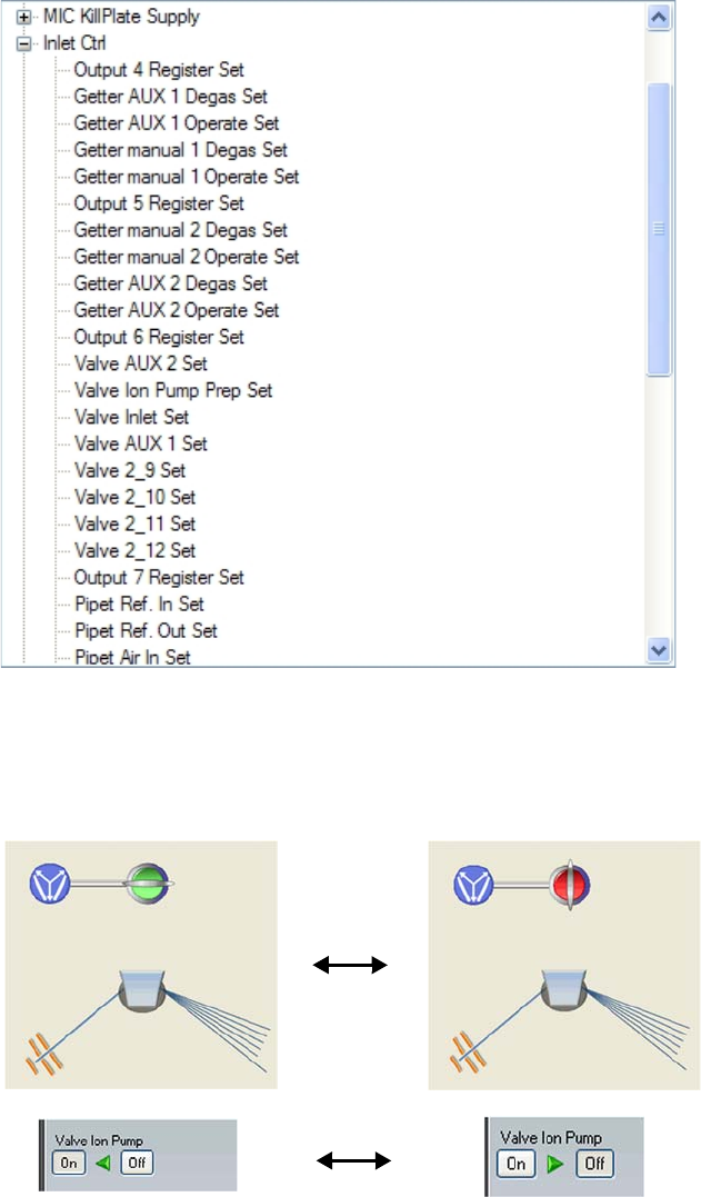
Image Switch This object shows already an image that
stands for a switch you can toggle between
„on“ and „off“ state. Check the items in the
Property tab for details. for example, the
Overlay Image that is shown when the switch
is changed from one status to the other. The
image is Cross_Overlay, by default. But you
can also select other images from the
Resources tab.
Dual Range Slider Shows a red filled rectangle with „Dual Range
Slider“ as Display Name.
Simple Slider Shows a red filled rectangle with „Simple
Slider“ as Display Name.
Switch Button Shown as a complex image with „Dual State
Switch“ as Display Name.
Readback Display Shows a red filled rectangle with „Readback
Display“ as Display Name. Liek all objects
listed above, the objects uses 96 × 96 pixel by
default. In the Properties tab, define if the
readback value is shown on a digital display.
Pipe (different
geometries)
To give you the opportunity to construct the
pipe lines as realistic as possible, the Object
Pool offers 11 different pipe geometries. Drag
the pipe object, which uses 64 × 64 pixel by
default.
Item Shows an LED_On image of 128 × 128 pixel
with the Script_Overlay resource.
Push Button Shows a green round image of 128 × 128 pixel
to simulate a push button. Its state is shown
by the Off Image (Led2_On) and the On
Image (Led2_Off).
Table 3-15. Objects, continued
Object Description
Configuration Tool
Hardware Database Editor
Thermo Scientific Qtegra Scripting Language Software Manual (P/N 1383460, Revision A) 3-29
4. To rebuild your real existing peripheral, drag the object to the grid
and place it using your mouse pointer (press the mouse button). If
another object like a pipe needs to be placed independent from the
grid, press <Ctrl> on your keyboard and move the object with the
<Arrow keys> to the desired position.
5. If a combination of, for example, a valve object with pipes is used
several time, just group them to become selected with one click.
a. Select the Groups tab.
b. On the toolbar, click Add new group to type the name of the
new group.
The name of your new group is shown in the list having 0
members.
c. In the Graphical View, select your object that shall become a
member of this group. From the shortcut menu, select Assign
group membership to open a list of all currently group names.
d. Click the desired group name to add the selected object to this
group.
The list window is closed. In the Groups tab, the amount of
Members is increased.
e. Repeat step c and step d for all objects to become a group
member.
6. To select a group, click one of its members. As shown in the shortcut
menu, the whole group is automatically selected. Click Copy and
Paste to duplicate the group.
7. When you select Clone Objects from the shortcut menu of a group,
all particular members of the group are copied to a place next to the
original. You can then modify the objects according your needs. The
cloned objects are no more part of a group and will therefore be
modified separately.
8. To assign an object with an image, select an image from the
Resources tab and drag this item onto your object in the grid.
Figure 3-22. Group having 0 group members
Configuration Tool
Hardware Database Editor
3-30 Qtegra Scripting Language Software Manual (P/N 1383460, Revision A) Thermo Scientific
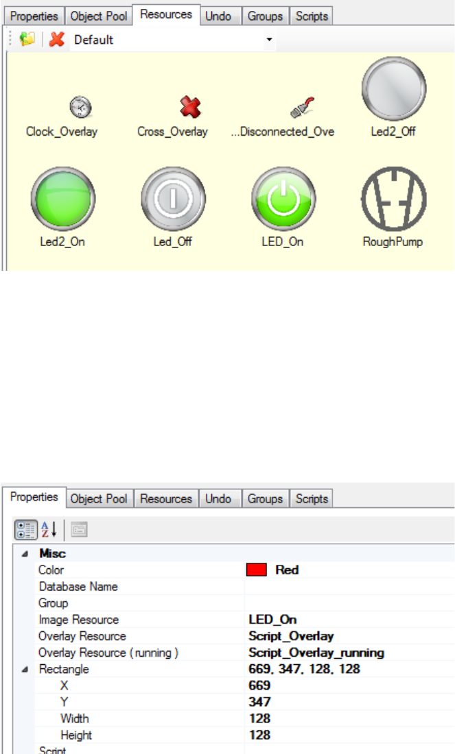
Figure 3-23 and the lower right part of Figure 3-19 show the
Resources pool where you find a selection of images representing a
range of hardware items. The Resources pool includes, for example,
gauges, valves, buttons, switches, digital readouts and hardware
symbols.
9. To add your own images, save them in the .png file format in the
C:\ProgramData\Thermo\Qtegra\_Application Data\Hardware Panel
Configurator\Standard Images folder. Note that your image is
resized and saved with 128 × 128 pixel to fit into the current grid.
The Properties tab of the currently selected object (an “item”)
shows the information about the graphical container as well as the
hardware references and resource usage, see Figure 3-24.
Figure 3-23. Resources pool of hardware items
Figure 3-24. Properties of selected object
Configuration Tool
Hardware Database Editor
Thermo Scientific Qtegra Scripting Language Software Manual (P/N 1383460, Revision A) 3-31
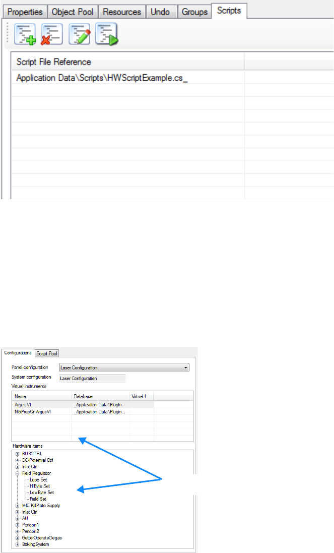
Your creation steps of the Hardware Panel Configurator are stacked and
allow to undo the step. See Figure 3-25 for an example of the Undo
Stack.
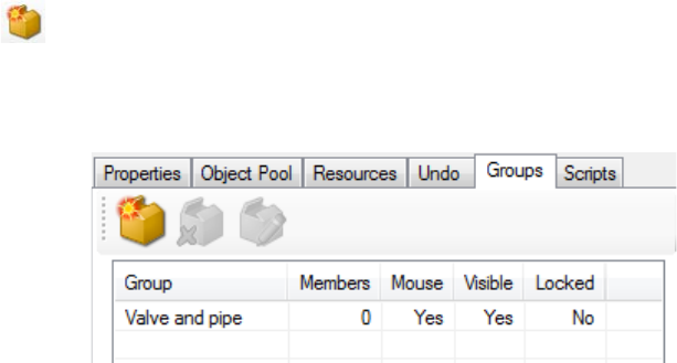
The Groups tab lists all hardware items that are grouped and therefore
be taken as one item. Double-click a group to select this group in the
Graphical View. Double-click the mouse, visible or locked entry to
toggle its state. See Figure 3-26.
Figure 3-25. Undo stack of creation steps
Figure 3-26. Groups tab to control grouped items
Configuration Tool
Hardware Database Editor
3-32 Qtegra Scripting Language Software Manual (P/N 1383460, Revision A) Thermo Scientific
To control the action of the hardware items, the Scripts tab shows a
Script File Reference. Select the script and click the desired icon from
the toolbar to edit the script. See Figure 3-27.
To set up the necessary hardware links you have to make sure that the
correct experiment configuration is selected. The available hardware
databases will then automatically load. To assign a hardware link to a
display object, simply drag the hardware item into the panel object and
drop it. To control the success of this operation, compare the properties
of the object before and after the operation. The parameters are outlined
in Figure 3-28.
Figure 3-27. Scripts tab to control referenced scripts
Figure 3-28. Parameters of a defined resource
parameters of the
defined resource
Configuration Tool
Hardware Database Editor
Thermo Scientific Qtegra Scripting Language Software Manual (P/N 1383460, Revision A) 3-33
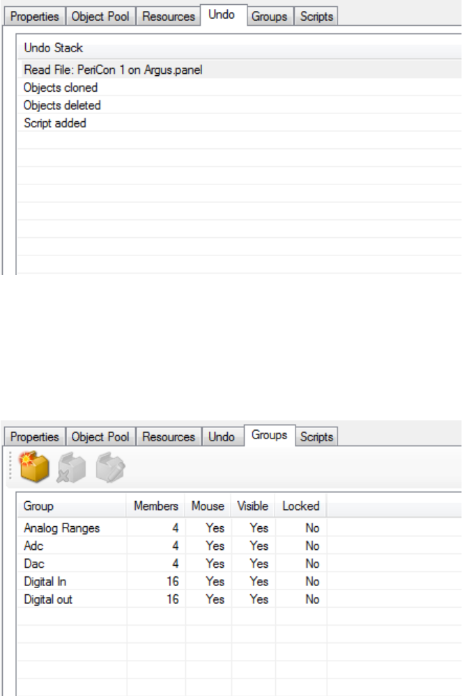
Check the Properties tab to compare the properties of the hardware
item without hardware assignment and with hardware assignment. See
Figure 3-29.
As well as resources from the pool, you can also add images to the panel.
❖To create a new panel for a temperature control object
1. Open the Configurator tool of Qtegra.
2. Click Hardware Panel Configurator, see Figure 3-16.
3. From the Object Pool tab (see Figure 3-21), drag the object into the
Graphical View pane. In this example, drag Simple Slider as object to
Figure 3-29. Properties of a hardware item without and with hardware assignment
Configuration Tool
Hardware Database Editor
3-34 Qtegra Scripting Language Software Manual (P/N 1383460, Revision A) Thermo Scientific
set the temperature and Readback Display as a thermometer object.
The object are shown as red colored squares, see Figure 3-30.
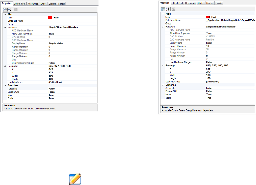
4. To check the properties of the default object, select the Properties
tab (see Figure 3-24) and recognize the missing Database Name that
controls the hardware assignment.
5. To assign a database, select a Panel configuration from the upper
right area.
The list of Hardware Items below is filled.
6. Expand the PeriCon1 entry and select the desired items. In this
example, drag Adc2 (your analog device) to the Readback Display
and Dac4 to the Simple Slider object.
The red colored squares change to symbols, see Figure 3-30.
Figure 3-30. New objects dragged into the Graphical View
Figure 3-31. New objects assigned with hardware database information
Configuration Tool
Hardware Database Editor
Thermo Scientific Qtegra Scripting Language Software Manual (P/N 1383460, Revision A) 3-35
The Properties tab shows new data, for example, Database Name,
DisplayName, Unit, and other Hardware items. There is no need to
add items.
7. Check the modified entries for all objects. Change the values for the
Range Maximum and Range Minimum if desired.
8. To adapt the objects exactly according your peripheral hardware,
select the Hardware Configurator section on the left panel.
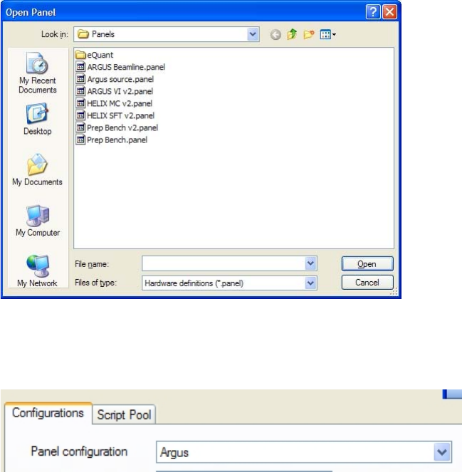
9. On the toolbar, click Open to load the hardware definition. Browse
to C:\ProgramData\Thermo\Qtegra\_Application Data\PluginData\
and open the folder representing your hardware, for example,
HelixSFT. Double-click the desired *.imhwd file to load the
hardware definition file.
The Hardware Entries are listed.
10. Expand PeriCon1 (or the hardware, where your object belongs to)
and select your object, for example, Adc2.
The right pane shows the current settings. Expand all entries.
11. Change the Unit from V to °C.
12. Change the Minimum and Maximum to desired values, for
example, 0 as minimum and 2000 as maximum.
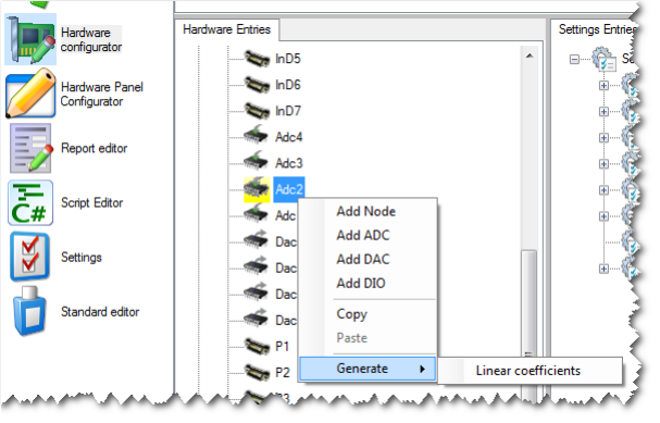
13. Right-click your hardware entry to show the shortcut menu. Select
Generate > Linear coefficients to set the right conversion
parameters, see Figure 3-32.
The Conversion Parameters change accordingly.
14. Set the parameters for the other objects the same way. In this
example, set the maximum to 2000 to get the same scale on the
thermometer (Dac4).
Figure 3-32. Shortcut menu of hardware entry
Configuration Tool
Hardware Database Editor
3-36 Qtegra Scripting Language Software Manual (P/N 1383460, Revision A) Thermo Scientific
15. On the toolbar, click Save to save your configuration. Select and
replace the hardware definition (*.imhwd) you opened in step 9.
16. To use the new hardware settings, reload the hardware settings
(*.imhwd), that means, click New on the toolbar and then load your
definition once again.
17. Select the Hardware Panel Configurator and check the settings.
❖To add images to the panel
1. To do this, start the Configurator and open the Hardware Panel
Configurator.
2. In order to get the configurator into the state as in Figure 3-35, open
the existing NGPrepBench panel.
3. From the Panel configuration dropdown list, select the entry Argus.
Figure 3-33. Open Panel dialog
Figure 3-34. Selecting a Panel configuration
Configuration Tool
Hardware Database Editor
Thermo Scientific Qtegra Scripting Language Software Manual (P/N 1383460, Revision A) 3-37
4. After loading the configuration, the Hardware Panel Configurator
shows a Graphical View, see Figure 3-35.
5. After this process is completed, you see a list of predefined hardware
items in the Hardware Items panel, see Figure 3-36.
NOTICE The entry for the Inlet Ctrl (the inlet controller) appears twice.
The reason is that the entries in the hardware database are split into
those that are inside the MS itself (first occurrence) and those that are
used in the Prep Bench (second occurrence). ▲
Figure 3-35. Example for a Graphical View of a configuration
Figure 3-36. MS Inlet Control
Configuration Tool
Hardware Database Editor
3-38 Qtegra Scripting Language Software Manual (P/N 1383460, Revision A) Thermo Scientific
6. In order to view the available entries for the Prep Bench, expand the
second Inlet Ctrl, see Figure 3-37.
As an example, Figure 3-38 illustrates how to switch a valve in the
Hardware Panel Configurator.
Figure 3-37. Prep Bench Inlet Control
Figure 3-38. Switching a valve in Hardware Panel Configurator
Configuration Tool
Hardware Database Editor
Thermo Scientific Qtegra Scripting Language Software Manual (P/N 1383460, Revision A) 3-39
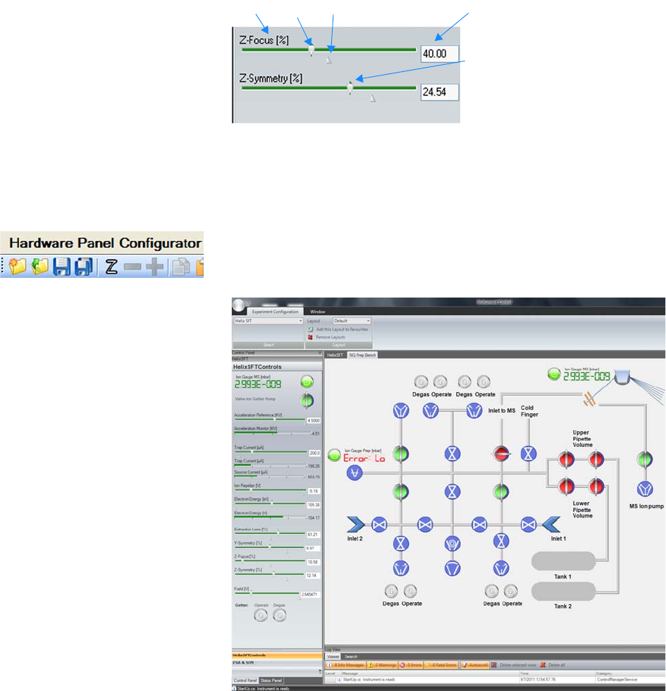
As an example, Figure 3-39 illustrates how to change a voltage in the
Hardware Panel Configurator.
Once the hardware panel has been created, it can be saved using the
Save command of the toolbar. Then it can be used in Instrument
Control. See Figure 3-40.
Labeled Components: 1=name of control, 2=set value slider, 3=saved value,
4=set value (displayed), 5=readback value (green marker in background)
Figure 3-39. Changing a voltage in Hardware Panel Configurator
1 2 3
5
4
Figure 3-40. Hardware panel used in Instrument Control
Configuration Tool
Scripting Engine
3-40 Qtegra Scripting Language Software Manual (P/N 1383460, Revision A) Thermo Scientific
Scripting Engine
One basic concept of our software is to control additional hardware by
scripts.
To be flexible in the use of various scripts a complex timing scheme has
been implemented. For details see “The Phase Model” on page 4-3.
In its simplest form, for every sample line of a workbook, 3 scripts will
be executed, Prepare, Acquire, and PostAcquisition. Experience shows,
that even with this simple approach most of the typical analysis
sequences can be set up. See “Script Editor” on page 3-43 for an
overview of the script sequence available in your current environment.
In the bottom line it remains in the hands of the user to separate a
complex acquisition task into a sequence of scripts that properly interact
with the measurements of the mass spectrometer itself. The examples
given below (see “Examples” on page 5-1) show some possibilities.
One complex approach in general is to separate preparation and
finalization steps with respect to a single measurement.
This process is a general problem that requires a high degree of
abstraction.
What is Scripting?
Scripting is the process of writing instructions to the computer that
result in physical actions like valve operations or positioning of devices.
It is also possible to perform mathematical operations or to access the
computers hardware.
For this purpose, Qtegra ISDS has implemented a mechanism that will
interpret C# code at runtime. See Figure 3-41.
Figure 3-41. Code example (C#) to open a message box
Configuration Tool
Scripting Engine
Thermo Scientific Qtegra Scripting Language Software Manual (P/N 1383460, Revision A) 3-41
Introduction into C#
Scripting uses native C# code based on the .NET environment and is
thus extremely powerful. This Software Manual will not explain how to
use C#. Please refer to the documentation, which is available at the
Microsoft developers pages (www.msdn.com, search for “overview of the
.NET framework” that will open
http://msdn.microsoft.com/en-us/library/zw4w595w%28v=vs.110%29.aspx).
Unfortunately, scripting is also very dangerous when inattentively
modified.
Furthermore, scripting can easily be very complex and difficult to read.
Command Overview
Most of the structure of the above example (see Figure 3-41) is given by
the general structure of the C# programming language. This includes
the if...else structure, the block structure using the {} brackets and the
syntax of the logical arguments for the if clauses. The indentation is
based on a common agreement to enhance the readability of the code.
Explaining this structure is not the scope of this manual. For a better
understanding we have to refer to the numerous literature on the C#
programming language.
The MessageBox function and its syntax are part of the .NET
environment and as such declared and explained in the vast .NET
database that is available via the Microsoft Developers Network
(www.msdn.com). For a detailed explanation on how to use this
programming language extension, refer to the Microsoft web pages.
Qtegra language elements commonly used in scripting.
•naming conventions
•name spaces
•instrument related commands
•objects and structures related to instrument functionality
-TuneSettingsManager
-Logger
-Scan
-Sweep
The following instrument related commands are frequently used when
you directly access the instruments hardware.
Configuration Tool
Scripting Engine
3-42 Qtegra Scripting Language Software Manual (P/N 1383460, Revision A) Thermo Scientific
The functions SetParameter, GetParameter, SetCalc and GetCalc access
items from the hardware database directly. They consist of 2 parameters,
a string that contains a link to the hardware item in the form
“GenericInstrument.ItemName” and a value in the form of an object
that is adopted to the type of data that the hardware item expects or
delivers.
Value can range from a boolean for a simple switch (true, false for on,
off) to a double for the calculated result of an analog to digital
conversion.
•ArgusMC.SetParameter(“some hardware item”, value)
•ArgusMC.GetParameter(“some hardware item”, out value)
•Logger.Log(loglevel.info, “some text”)
•ArgusMC.SetTimeZero()
•SampleLineInfo.TryGetValue(“NGPrepOnArgusVI.SampleInlet”,
out SmpTypeKey)
•JumpToNewMass(200.0, 1000, true)
•SEM protection
•SetCalc
•GetCalc
Concept and Structure of Script Files
Let us take the SampleFunction as an example to understand the file
name and structure. The example assigns the ArgusMC instrument and
may be changed to HelixSFT or HelixMC according your needs.
The SampleFunctionScript.cs file (found on
C:\ProgramData\Thermo\Qtegra\_Application Data\Scripts\Noble Gas Examples)
contains the main code to include the libraries and to insert additional
scripts.
NOTICE Command lines like “//InsertScript: <Path and Name of .cs
file>” are used by the Preparser. Do not interpret as comment. ▲
The SampleFunctionIncludeScript.cs file contains code snippets to
activate Tune settings, to modify the MonitorScan parameters, to read a
single array of collector data, to retrieve data from a scan of the magnetic
field or the electric field. It also contains sample code to change the
current CupConfiguration.
Configuration Tool
Scripting Engine
Thermo Scientific Qtegra Scripting Language Software Manual (P/N 1383460, Revision A) 3-43
The SampleFunctionScript.cs.ext file is created by the Preparser. This file
includes the original script and the included script files. This file is not
delivered by Thermo Scientific, but is build during the runtime.
Script Editor
The script controlling your peripheral or your PeriCon system must be
adjusted according to your system setup. The Script Editor of the
Qtegra ISDS Configurator interprets C# code at runtime. Generally,
you can use scripts including the words Prepare, Acquire and
PostAcquisition that are executed at a predefined time.
NOTICE Only users experienced with C# scripting should edit the
scripts. ▲
Qtegra Scripts
The concept of Qtegra ISDS is based on three different kinds to use
scripts.
•Scripts consisting of the Main method only. These scripts are started
from the Qtegra ISDS Status window, see “Example 1 - minimum
implementation” on page 3-43.
•Scripts that are binding HW items, for example, GetParameter and
SetParameter, see “Example 2 - controlling hardware items” on
page 3-46.
•Scripts that are binding VIs (Generic Instruments). These scripts are
started from the Configurator/Script Editor, see “Example 3 -
automated scripts controlling generic instruments” on page 3-47.
Example 1 - minimum implementation
Qtegra offers C# scripts that may consist of optional and mandatory
methods. At least the Main method is mandatory and will be executed
when the script is started.
❖To edit a script in the Instrument Control tool
1. Open the Instrument Control tool of Qtegra.
2. Select your Experiment Configuration.
A tab is opened next to the Experiment Configuration tab showing
your instrument.
3. The left window tile shows the Control Panel. Select the Status
Panel tab to display a list of all available scripts.
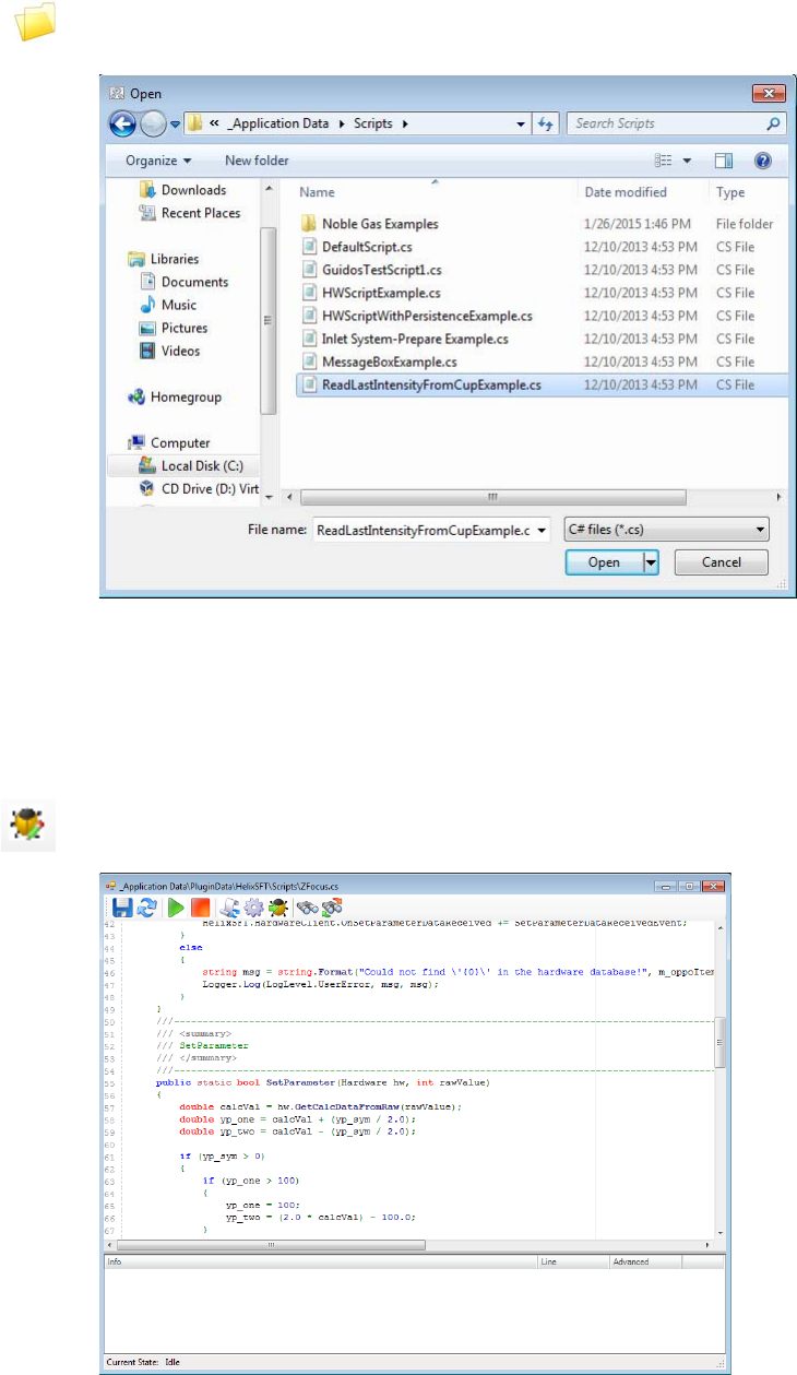
Configuration Tool
Scripting Engine
3-44 Qtegra Scripting Language Software Manual (P/N 1383460, Revision A) Thermo Scientific
4. Click Open Script to select a Qtegra script from the installation
folders, see Figure 3-42.
The script is loaded into the Script List.
- or -
5. Click Open In Editor to open the C# code of the script in the
Editor window.
6. Edit the script according to your needs.
Figure 3-42. Opening a script from Instrument Control
Figure 3-43. Script Editor in Instrument Control

Configuration Tool
Scripting Engine
Thermo Scientific Qtegra Scripting Language Software Manual (P/N 1383460, Revision A) 3-45
7. On the toolbar, click Debug to test the script according the C#
syntax.
NOTICE Correct C# syntax does not automatically confirm correct
hardware commands. That means, execution of your script may
nevertheless set unwanted values. ▲
8. When the script does not contain syntax errors click Save on the
toolbar to save the script.
See
C:\ProgramData\Thermo\Qtegra\_Application\Scripts\ReadLastIntensit
yFromCupExamples.cs as an example for this kind of scripts.
Here, the script consists of the three methods Initialize (optional), Main
(mandatory), and Dispose (optional). A script must at least consist of the
Main method, which may run without further parameters.
The Initialize method is called once before the Main method is called.
In the example shown above, the Initialize method is empty. The final
Dispose method is also empty. That means that the
ReadLastIntensityFromCup script executes only the Main method.
public class ReadLastIntensityFromCup
{
public static void Initialize()
{
}
public static void Main()
{
double cupIntensity;
string cupReadbackName = "Intensity Cup 2 Readback";
while (true)
{
if (ArgusMC.GetParameter(cupReadbackName, out value))
{
Logger.Log(LogLevel.Debug, string.Format("{0} = {1} fA.",
cupReadbackName, cupIntensity));
}
Thread.Sleep(500);
}
}
public static void Dispose()
{
}
}
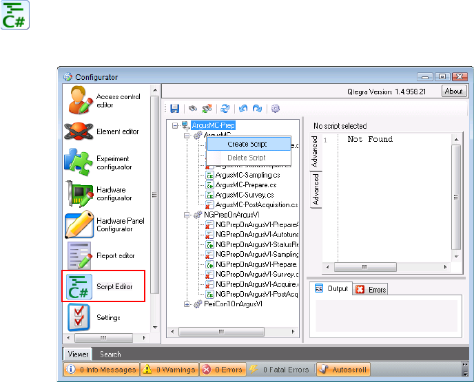
Configuration Tool
Scripting Engine
3-46 Qtegra Scripting Language Software Manual (P/N 1383460, Revision A) Thermo Scientific
Use the toolbar on top of the Script Editor window (see Figure 3-43) to
run, reset, debug and save the script.
Example 2 - controlling hardware items
Scripts opened here are automatically stored in the Qtegra folder for
that hardware item.
❖To edit a script for Qtegra Scripting Language to control hardware
items
1. Open the Configurator tool of Qtegra.
2. Click Script Editor.
The Script Editor opens and shows a list of the predefined script
names for the Configuration currently loaded, see Figure 3-44.
3. Right-click the script name indicated by an “x” you wish to edit and
select Create Script from the shortcut menu.
- or -
Click the script item.
Always edit NGPrep scripts to include Qtegra Scripting Language.
Figure 3-44. Script Editor in Configurator with shortcut menu
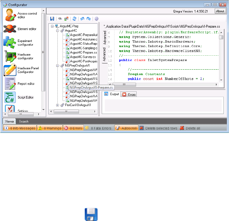
Configuration Tool
Scripting Engine
Thermo Scientific Qtegra Scripting Language Software Manual (P/N 1383460, Revision A) 3-47
In the Advanced tab of the Editor pane, the script is displayed, see
Figure 3-45.
NOTICE The path displayed above the script on the right is predefined
for each instrument and cannot be changed. ▲
4. Edit the script according to your system setup.
5. Click Save to save the script with the same name.
The preconfigured name for the Qtegra Scripting Language script is
directly linked to the control of Qtegra. If the name is changed,
Qtegra will not be able to find and execute this script.
These scripts typically have a GetParameter and SetParameter command
in their methods. See “Hardware Script Example” on page 5-5 for
details on the hardware script structure.
Example 3 - automated scripts controlling generic instruments
Automated scripts controlling VIs (Generic Instruments, see “Generic
Instruments” on page 3-49) are created in the Configurator.
❖To edit a script for Qtegra Scripting Language to control hardware
items
1. Open the Configurator tool of Qtegra.
Figure 3-45. Script Editor in Configurator showing Qtegra Scripting Language script
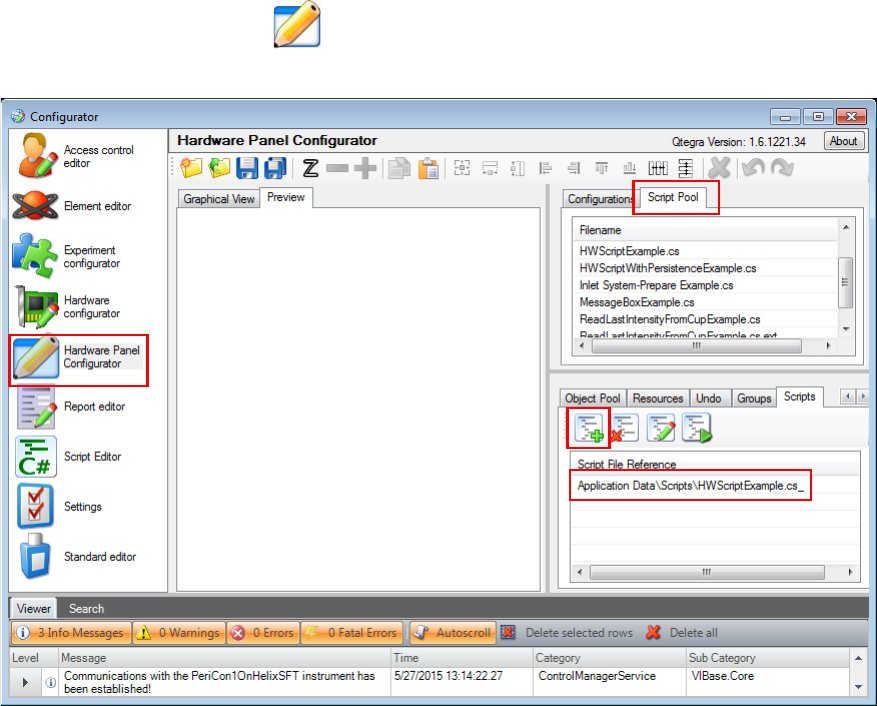
Configuration Tool
Scripting Engine
3-48 Qtegra Scripting Language Software Manual (P/N 1383460, Revision A) Thermo Scientific
2. Click Hardware Panel Configurator.
The Hardware Panel Configurator opens and shows a Script Pool in
the upper right area, see Figure 3-46.
3. The lower right area shows six tabs. The right most Script tab
provides buttons to load, edit, delete and execute the Script File
Reference.
NOTICE Scripts opened here are automatically stored in the Qtegra
folder for that hardware item. ▲
4. To change the code, select the script in the Script File Reference
window and click the Edit button. Your preferred text editor opens.
Figure 3-46. Opening a script from the Hardware Panel Configurator

Configuration Tool
Generic Instruments
Thermo Scientific Qtegra Scripting Language Software Manual (P/N 1383460, Revision A) 3-49
Generic Instruments
Generic instruments can easily be added to your configuration. The
instruments shown in the list of Available Items are shipped with Qtegra
ISDS and therefore ready for use. Nevertheless, the properties may be
modified according your needs.
❖To add a generic instrument
1. In the Configurator tool, select the Experiment Configurator
application.
2. On the right Available Items window pane, select the Instruments
tab.
3. From the shortcut menu of the items, select Add Generic
Instrument.
A new line GenericInstrument is appended to the list.
4. Type a name for the new instrument and close the edit mode with
<Enter>.
The new generic instrument is appended to the list.
❖To assign an image to the new generic instrument
1. From the Instruments tab of the list of Available Items, select the
new generic instrument.
2. From the shortcut menu, select Instrument Properties... to open
the Instrument Properties dialog. See Figure 3-47.
Figure 3-47. Properties of a generic instrument
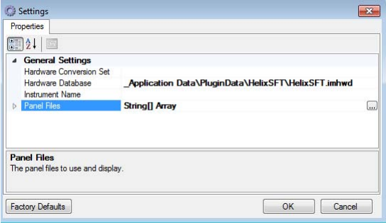
Configuration Tool
Generic Instruments
3-50 Qtegra Scripting Language Software Manual (P/N 1383460, Revision A) Thermo Scientific
3. If desired, change here the Displayname and the Description.
Click into the text boxes and change accordingly.
4. For the presentation of a small image, click the browse button next
to Image Small and select a suitable image from your network
environment.
The Select Picture dialog opens and is awaiting a *.png or *.jpg file.
5. For the presentation of a large image, click the browse button next
to Image Large and select a suitable image from your network
environment.
The Select Picture dialog opens and is awaiting a *.png or *.jpg file.
NOTICE If the selected picture is too large only the upper left 48 × 48
pixels for small images and 256 × 256 pixels for large images are used. ▲
6. Click OK to close the Instrument Properties dialog and to adapt the
information.
The thumbnail next to the new generic instrument changes
accordingly.
❖To change the settings
1. From the Instruments tab of the list of Available Items, select the
new generic instrument.
2. From the shortcut menu, select Default Settings... to open the
Settings dialog. See Figure 3-48.
NOTICE Changes in the properties do effect the functionality. Make
sure to create and modify only generic instruments that are based on the
standard. If an instrument is created by a supplier, for example, ESI do
never change the properties. ▲
Figure 3-48. Settings of a generic instrument
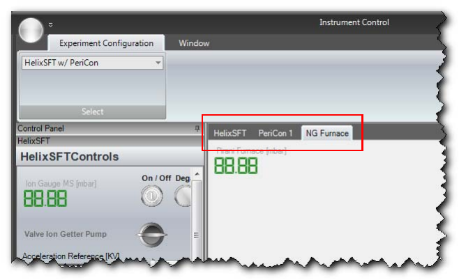
Configuration Tool
Generic Instruments
Thermo Scientific Qtegra Scripting Language Software Manual (P/N 1383460, Revision A) 3-51
3. In the Settings dialog, select the Hardware Database that applies
your laboratory environment. This database belongs to the original
hardware or is modified by the customer or is created by the
customer. (see “Manipulating the Hardware Database” on page 3-3).
4. Enter the Hardware Conversion Set and the Instrument Name
according your settings.
5. Click the browse button next to Panel Files to select a panel where
the generic instrument is placed.
When the panel is loaded, expand the Panel Files node to see the
item.
6. Click OK to close the Settings dialog.
To see the generic instrument, open the Instrument Control tool,
load the configuration and check the tabs of the main window,
which represent the panels, see Figure 3-49.
Implication for the Scripting Sequence
The 3 steps approach of the acquisition phase model shows how a
generic instrument (VI equals Virtual Instrument) is appended to the
sample list, see “The Phase Model” on page 4-3. Every generic
instrument populates its own line.
Customizing Sample Lists
Edit Sample List Entries according the following name convention:
_application\plugins\<VIname1>\
Figure 3-49. Tabs representing the panels of a generic instrument

Configuration Tool
Generic Instruments
3-52 Qtegra Scripting Language Software Manual (P/N 1383460, Revision A) Thermo Scientific
for example
C:\ProgramData\Thermo\Qtegra\_Application Data\PluginData\NGPrepOnArgusVI.
The following code example shows how the column called “Label” is
added to the Sample List. The code (see Table 3-16) is saved in the
plugin folder of the virtual instrument, for example,
C:\ProgramData\Thermo\Qtegra\_Application Data\PluginData\NGPrepOnArgusVI.
The code lines are explained as follows, see Table 3-17.
1VIname is a placeholder for the virtual instrument, for example, ArgusVI or HelixSFT.
Table 3-16. Code example with line numbers: NGPrepOnArgusVI.xml
1<?xml version="1.0" encoding="ISO-8859-1"?>
2<SampleList>
3 <SampleListColumn Shared="true">
4 <Id>NGPrepOnArgusVI</Id>
5 <Name>Identifier</Name>
6 <Caption>Label</Caption>
7 <Type>string</Type>
8 <Default><Identifier></Default>
9 </SampleListColumn>
10 <SampleListColumn>
11 <Id>NGPrepOnArgusVI</Id>
12 <Name>SampleInlet</Name>
13 <Caption>Sample Inlet</Caption>
14 <Type>string</Type>
15 <Default>Blank</Default>
16 <AllowedValues>
17 <Value>Blank</Value>
18 <Value>Upper Pipette</Value>
19 <Value>Lower Pipette</Value>
20 </AllowedValues>
21 </SampleListColumn>
22</SampleList>
Table 3-17. Code line explanation
Line Definition
1 Header of .xml code. Refers to xml version and character
coding.
2 Defines the Qtegra object that is modified by the code.
3 Initiates the element of the object.
4 Defines the VI, the name must be the same as the folder
name.
5
6
7
8
9 End tag for line 3.

Configuration Tool
Generic Instruments
Thermo Scientific Qtegra Scripting Language Software Manual (P/N 1383460, Revision A) 3-53
10 Defines the element of the object.
11 Defines the VI, the name must be the same as the folder
name.
12
13 String that is shown in the header of the new column.
14 Defines the type of variable that is shown in the new column.
15 Default value; in case of strings “Blank” is often used. In case
of int (integers) a defined value is used instead.
16 Optional tag to specify a list box with values to be selected.
17 Optional first item of the list box entries.
18 Optional second item of the list box entries.
19 Optional third item of the list box entries.
20 End tag for line 16.
21 End tag for line 10.
22 End tag for line 2.
Table 3-17. Code line explanation, continued
Line Definition
Configuration Tool
Generic Instruments
3-54 Qtegra Scripting Language Software Manual (P/N 1383460, Revision A) Thermo Scientific
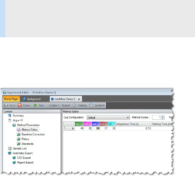
Thermo Scientific Qtegra Scripting Language Software Manual (P/N 1383460, Revision A) 4-1
Chapter 4 Acquisition System
General Remarks
When editing a method in a LabBook, one basically builds a timing
scheme where integration cycles follow settling times.
The complete process of the physical measurement of the mass
spectrometer is called Acquire or acquisition task. The task assumes gas
in the source and produces numbers and calculation results.
All the parameters used for this task are stored in the sample definition.
This includes the source settings via the so called CupConfiguration and
timing considerations that are stored in the method editor. In the
method editor, a sequence of mass jumps, integration cycles and settling
times can be configured to make up a single method cycle. See
Figure 4-51.
Contents
•General Remarks
•The Phase Model
Figure 4-50. Editing a method in a LabBook
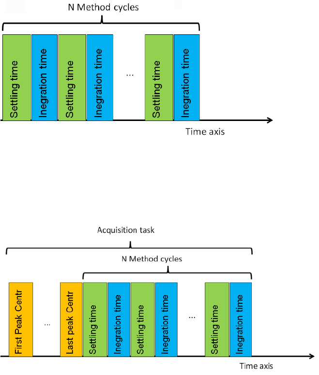
Acquisition System
General Remarks
4-2 Qtegra Scripting Language Software Manual (P/N 1383460, Revision A) Thermo Scientific
Additionally the individual method cycles can be repeated to allow for
extrapolation measurements. Repetitions of the method are essential to
allow for extrapolation calculation.
Together with possible peak center actions, the whole sequence makes
up the acquisition task of the mass spectrometer for a single sample line.
This acquisition task is part of the scripting sequence (see “The Phase
Model” on page 4-3) of the mass spectrometer.
Consequently, we have to put all the required instructions for the gas
preparation in the Prepare script. See Figure 4-53.
In order to be ready for the next sample, we have to place all the
instructions to remove the gas from the source and preparation device in
the PostAcquisition script. See Figure 4-53.
Figure 4-51. N Method Cycles
Figure 4-52. Acquisition Task
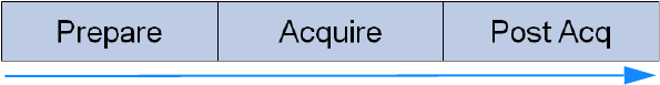
Acquisition System
The Phase Model
Thermo Scientific Qtegra Scripting Language Software Manual (P/N 1383460, Revision A) 4-3
The Phase Model
Qtegra utilizes a scheduling scheme called the Phase Model that is
centered around the mass spectrometers acquisition task. The phase
model enables you to deal with complex measurement tasks including
sample preparation, measurement and instrument cleanup. The phase
model supports an instrument environment made up from several
dependent devices like auto samplers, preparation devices or additional
detectors.
To keep the events always under control make sure that all events that
belong to the same phase are finished before the next phase is started. A
phase in this context is the time period needed for a defined procedure,
like Prepare, Acquire or PostAcq. In the following (see “The Three Steps
Approach” on page 4-3) a phase is also called step.
Furthermore, all events belonging to the same phase start at the same
instance in time (multi-threading is implemented). For every sample in
the sample list of the LabBook, the complete phase model is executed, so
that virtually any thinkable preparation/acquisition/data-processing
cycle can be modeled.
The phase model contains currently 9 major steps but is extend-able.
However, for the scripts implemented around the mass spectrometers a
simplified scheme proved sufficient so far.
The Three Steps Approach
The default phase model describes three phases. Currently a three steps
approach is used in the scripts that control the preparation device and
that can be used as scripting examples to develop your own scripts.
❖The three steps approach
1. Initially, the Prepare script (preparation) is executed.
2. After the Prepare script is terminated, the Acquire script
(measurement) is executed.
3. After the Acquire script is terminated, the Post Acq script
“PostAcquisition” (cleanup) is executed.
This example (see Figure 4-53) shows a simple sequence as the sample of
your LabBook uses one virtual instrument.
Figure 4-53. Three steps approach
time
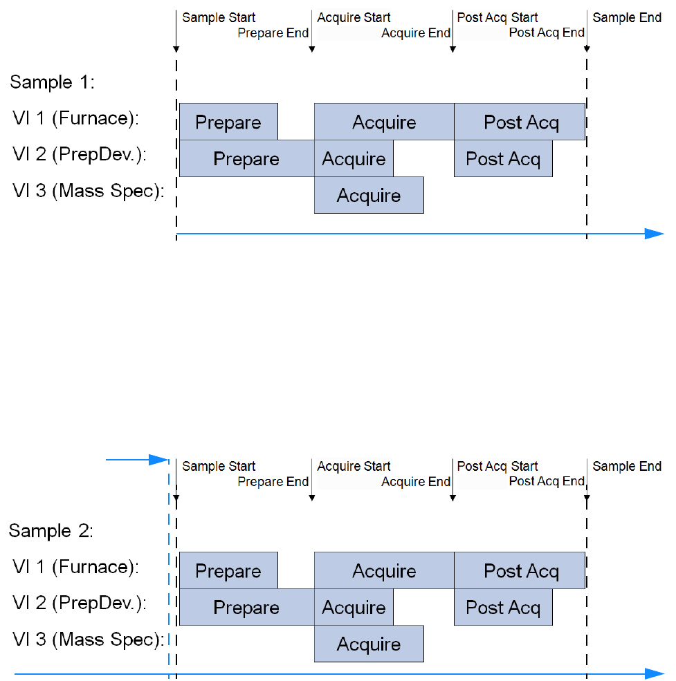
Acquisition System
The Phase Model
4-4 Qtegra Scripting Language Software Manual (P/N 1383460, Revision A) Thermo Scientific
In the Example 1 (see Figure 4-54) it is shown that 3 virtual instruments
(Furnace, PrepDev., Mass Spec) run their Prepare - Acquire - Post Acq
sequence by synchronizing the start of each phase.
NOTICE All three virtual instruments belong to one sample of your
LabBook. ▲
The next line of your LabBook stands for sample 2, which is started
after sample 1 is finished. Sample 2 also includes the execution of three
virtual instruments, see Figure 4-55.
For the use with a standard NGPrep unit scripts for preparation and
PostAcquisition are provided in the following folders:
C:\ProgramData\Qtegra\_Application Data\PluginData\<VIName>\Scripts
The scripts are named according this scheme:
<VIName>-Prepare.cs, <VIName>-PostAcquisition.cs
Figure 4-54. Example 1: Three VIs executed for sample 1.
time
Figure 4-55. Sample 2: Three VIs executed for sample 2
End of Sample 1
time

Acquisition System
The Phase Model
Thermo Scientific Qtegra Scripting Language Software Manual (P/N 1383460, Revision A) 4-5
Structure of Prepare Script for Prep Unit
Figure 4-56. Prep Unit
Acquisition System
The Phase Model
4-6 Qtegra Scripting Language Software Manual (P/N 1383460, Revision A) Thermo Scientific

Thermo Scientific Qtegra Scripting Language Software Manual (P/N 1383460, Revision A) 5-1
Chapter 5 Examples
The following examples are based on real installations at Thermo Fisher
Scientific customers who use scripts to control hardware attached to the
mass spectrometer.
Contents
•A Simple Approach
•Hardware Script Example
•Hardware Control via Ethernet
•Example for RS232 Communication
•Furnace Control via PeriCon
•Control via IEEE-488 Interface
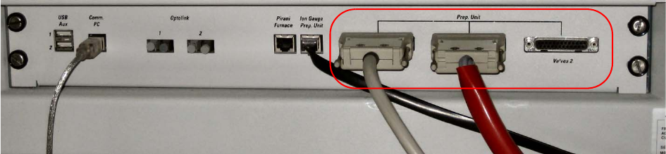
Examples
A Simple Approach
5-2 Qtegra Scripting Language Software Manual (P/N 1383460, Revision A) Thermo Scientific
A Simple Approach
A simple approach is to use the existing outputs designated for the use
with an NG Prep Bench for the purpose of controlling the valves that
the customer provides. It is assumed that the valves are controlled by
electro-pneumatic valves that in turn are controlled by switching on and
off a 24 Volt supply.
The implementation shows a simple approach.
The NG Prep Bench is connected to the mass spectrometer via three
sub-D connectors (one male, 2 female) that are located on the rear panel
of the mass spectrometer, see Figure 5-57.
On these 3 connectors, various signals are available that are intended to
directly control valve drivers (24 Volt, 500 mA single line, total 2 Amps
per base address). The connectors are labeled Getter (J9010), Valves 1
(J9020) and Valves 2 (J9030) and each of them is able to control 12
valves (1.5 base address blocks) each. The pins 1 to 12 are open collector
outputs that can be switched to drive a resistive load versus the 24 Volt
supply that is also present on the same plug (pins 14 to 25). The active
output pins are labeled Valve 1.1 to Valve 1.12 (for J9020) and Valve 2.1
to Valve 2.12 (for J9030) respectively. For the pins on J9010, please see
Figure 5-59. The mass spectrometer has a number of predefined
outputs. These are dedicated for the use with valves.
You can start with the existing panel that is found in
C:\ProgramData\Thermo\Qtegra\_Application
Data\PluginData\NGPrepOnArgusVI\Panels.
Figure 5-57. Usage of existing outputs
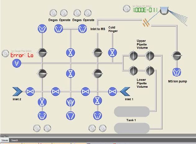
Examples
A Simple Approach
Thermo Scientific Qtegra Scripting Language Software Manual (P/N 1383460, Revision A) 5-3
Modify it according your needs. See Figure 5-58.
Use a dictionary (list of hardware addresses) for communication
between the programmer and the electronics engineer. Each output
signal has a logical representation in the databases of Qtegra ISDS.
The database file can be found in
C:\ProgramData\Thermo\Qtegra\_Application
Data\PluginData\<instrument name> and is usually called <instrument
name>.imhwd
Figure 5-58. Preparation phase
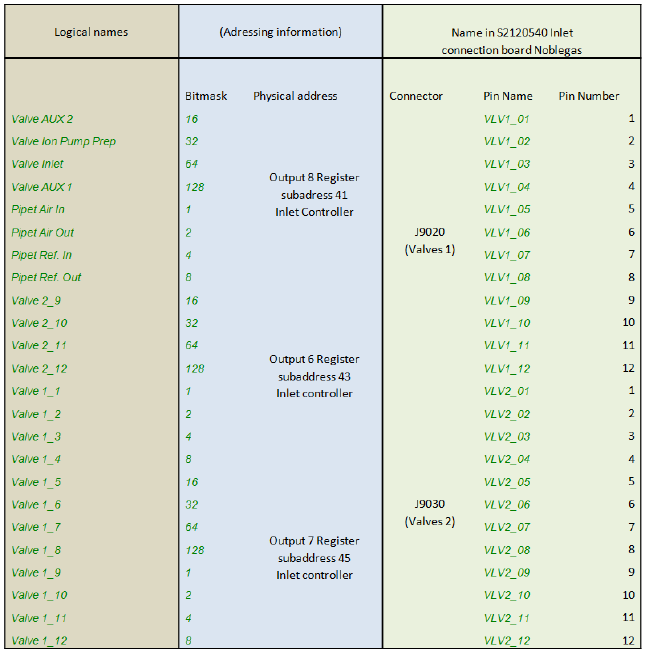
Examples
A Simple Approach
5-4 Qtegra Scripting Language Software Manual (P/N 1383460, Revision A) Thermo Scientific
Figure 5-59 lists the signals and their logical representation.
Advantages
•It is not necessary to understand the mechanisms of hardware
database.
•Only some graphical design operations yield a usable device control.
Disadvantages
•Custom hardware not separated from mass spectrometer – high
potential of damaging the mass spectrometer itself.
•Limited functionality – only valves and inputs.
Figure 5-59. List of hardware addresses
Examples
Hardware Script Example
Thermo Scientific Qtegra Scripting Language Software Manual (P/N 1383460, Revision A) 5-5
Hardware Script Example
This section shows an example of a hardware script with comments
included to the command lines. For assigning the script to your
configuration, see “The Hardware Script” on page 3-19.
The first 3 lines are commands to the script interpreter to include
certain programming resources (.dll):
The next 3 lines are required to be able to access the namespaces for the
commands used later on: Logger.Log, <InstrumentCoreName> and so
on:
<InstrumentCoreName> needs to be replaced by ArgusMC, HelixSFT,
or HelixMC (according the folder names of
C:\ProgramData\Thermo\Qtegra\_Application Data\PluginData)
The public class statement starts the actual implementation of the
hardware script. The class name should match the name of the script
itself for optimized transparency:
The Initialize method is required and must not be omitted, it should be
used to set initial values and, more important, connect to the internal
event system of Qtegra:
// RegisterAssembly: BasicHardware.dll
// RegisterAssembly: HardwareClient.dll
// RegisterAssembly: plugin\HardwareScript.if.dll
using Thermo.Imhotep.BasicHardware;
using Thermo.Imhotep.HardwareClientNS;
using Thermo.Imhotep.HardwareScript;
//--------------------------------------------------------------------------------------------------
// Replace the <InstrumentCoreName> placeholder with your real instrument core name.
//--------------------------------------------------------------------------------------------------
public class SomeHWScript
{
///-------------------------------------------------------------------------------------------------
/// <summary>
/// Initialize the script item and / or connect events.
/// </summary>
///-------------------------------------------------------------------------------------------------
public static void Initialize()
{
Logger.Log(LogLevel.Debug, String.Format("Initialize \'{0}\' script.", <InstrumentCoreName>.Name));
// Default value for cached raw value.
m_rawValue = 0;
// Example for connecting an event.
<InstrumentCoreName>.HardwareClient.OnSetParameterDataReceived += SetParameterDataReceivedEvent;
}
Examples
Hardware Script Example
5-6 Qtegra Scripting Language Software Manual (P/N 1383460, Revision A) Thermo Scientific
The SetParameter method is called whenever a value should be set from
the outside of the script – that is when the hardware item is called from
another instance. Here you need to place the code to be executed when
the value of this hardware item is to be changed:
Every hardware item should provide some return parameters, for
instance to denote the success of an operation or to provide a readback
value. Place your code in the following section called GetParameter:
A script also contains a section to handle Events:
///-------------------------------------------------------------------------------------------------
/// <summary>
/// This handles the setting of a value on this hardware item.
/// </summary>
///-------------------------------------------------------------------------------------------------
public static bool SetParameter(Hardware hw, int rawValue)
{
m_rawValue = rawValue;
return true;
}
///-------------------------------------------------------------------------------------------------
/// <summary>
/// This handles the getting of a value from this hardware item.
/// </summary>
///-------------------------------------------------------------------------------------------------
public static bool GetParameter(Hardware hw, out int rawValue)
{
if (<InstrumentCoreName>.InstrumentCommunications != InstrumentCommunications.Connected)
{
rawValue = 0;
return false;
}
rawValue = m_rawValue.Value;
return true;
}
///-------------------------------------------------------------------------------------------------
/// <summary>
/// Example event handler when other hardware items are set.
/// </summary>
///-------------------------------------------------------------------------------------------------
public static void SetParameterDataReceivedEvent(object sender, SetParameterDataEventArgs args)
{
}
Examples
Hardware Script Example
Thermo Scientific Qtegra Scripting Language Software Manual (P/N 1383460, Revision A) 5-7
Finally, the Dispose method removes all code from memory when the
script object is no longer used. At least the Event handler needs to be
disconnected from the event handler chain:
The last section of the script file contains definitions for internal
parameters, here by default, an integer called m_rawValue is defined to
represent a digital representation for the physical value to be set (DAC)
or read (ADC):
The last bracket specifies the definition of the class end:
///-------------------------------------------------------------------------------------------------
/// <summary>
/// When the hardware script is stopped, this implements all necessary cleanup.
/// </summary>
///-------------------------------------------------------------------------------------------------
public static void Dispose()
{
// Sample for disconnecting an event.
<InstrumentCoreName>.HardwareClient.OnSetParameterDataReceived -= SetParameterDataReceivedEvent;
}
//--------------------------------------------------------------------------------------------------
// Internal members.
//--------------------------------------------------------------------------------------------------
private static int? m_rawValue;
}

Examples
Hardware Control via Ethernet
5-8 Qtegra Scripting Language Software Manual (P/N 1383460, Revision A) Thermo Scientific
Hardware Control via Ethernet
This section describes additional approaches to control external
hardware.
❖To control the hardware via the Ethernet
1. You need a script that opens the necessary TCP/IP socket. In this
example, this has been done for the ARGUS VI with SN01004A.
2. Modify this script according your needs.
Make sure that the correct TCP/IP address and an available port is
used. See the line of the scripts that equals
public TCPClientConnection(string hostName, int port).
3. The script allows to send simple text messages via the Ethernet. The
TCPIPDIO.cs1 script (see Table 5-20 on page 5-14) sends two
different strings depending on the state requested. In the example
the strings are DIO is On and DIO is Off.
1TCPIPDIO: Digital Input Output commands sent via Ethernet
Table 5-18. Code Example: TCPClientConnection.cs
// -------------------------------------------------------------------
// © Copyright 2014 Thermo Fisher Scientific Inc. All rights reserved.
// -------------------------------------------------------------------
// This example is meant to be used in a Windows Forms application.
using System;
using System.Collections.Generic;
using System.Linq;
using System.Text;
using System.Threading;
using System.Net.Sockets;
namespace WindowsFormsApplication2
{
class TCPClientConnection
{
// This is the constructor. One must pass the host name and port number where to connect to.
public TCPClientConnection(string hostName, int port)
{
HostName = hostName;
Port = port;
m_running = true;
RetryDelayMS = 2000;
m_connectionThread = new Thread(new ThreadStart(ConnectionThread));
m_connectionThread.IsBackground = true;
m_connectionThread.Start();
}
Examples
Hardware Control via Ethernet
Thermo Scientific Qtegra Scripting Language Software Manual (P/N 1383460, Revision A) 5-9
// This is a readonly property which returns the host name specified at construction.
public string HostName { get; protected set; }
// This is a readonly property which returns the port number specified at construction.
public int Port { get; protected set; }
// This property is used to specify how often a connection attempt should be executed whilst no
connection is established.
public int RetryDelayMS { get; set; }
// This method can be used to write data onto the network stream.
public bool WriteData(byte[] buffer, int offset, int size)
{
try
{
m_tcpClient.GetStream().Write(buffer, offset, size);
return true;
}
catch
{
}
return false;
}
// This method is used to get a network stream over which one can communicate.
public bool GetStream(out NetworkStream stream)
{
if ((m_tcpClient != null) && (m_tcpClient.Client.Connected))
{
stream = m_tcpClient.GetStream();
m_stream = stream;
return true;
}
stream = null;
return false;
}
// This method must be called to close the connection and also stop the connection thread.
public void Destroy()
{
m_running = false;
if (m_stream != null)
{
m_stream.Close();
m_stream = null;
}
if (m_tcpClient != null)
{
m_tcpClient.Close();
m_tcpClient = null;
}
}
Table 5-18. Code Example: TCPClientConnection.cs, continued
Examples
Hardware Control via Ethernet
5-10 Qtegra Scripting Language Software Manual (P/N 1383460, Revision A) Thermo Scientific
// The connection thread, that monitors whether a connection is active and when not, attempt to
make a connection.
private void ConnectionThread()
{
m_tcpClient = new TcpClient();
bool connected = false;
while (m_running)
{
if (!m_tcpClient.Client.Connected)
{
try
{
m_tcpClient.Connect(HostName, Port);
connected = true;
}
catch
{
if (connected)
{
m_tcpClient.Close();
m_tcpClient = new TcpClient();
}
connected = false;
}
}
if (m_running)
{
Thread.Sleep(RetryDelayMS);
}
}
}
// The private members.
private Thread m_connectionThread;
private TcpClient m_tcpClient;
private NetworkStream m_stream;
private object m_lock = new object();
private bool m_running;
}
}
Table 5-18. Code Example: TCPClientConnection.cs, continued
Examples
Hardware Control via Ethernet
Thermo Scientific Qtegra Scripting Language Software Manual (P/N 1383460, Revision A) 5-11
Table 5-19. TCPServerConnection.cs
// -------------------------------------------------------------------
// © Copyright 2014 Thermo Fisher Scientific Inc. All rights reserved.
// -------------------------------------------------------------------
// This example is meant to be used in a Windows Forms application.
using System;
using System.Collections.Generic;
using System.Linq;
using System.Text;
using System.Threading;
using System.Net.Sockets;
using System.Net;
namespace WindowsFormsApplication1
{
class TCPServerConnection
{
// This is the constructor. One must pass the port number and buffer size. The server is always
running on the localhost.
public TCPServerConnection(int port, int bufferSize)
{
Port = port;
BufferSize = bufferSize;
m_running = true;
m_connectionThread = new Thread(new ThreadStart(ConnectionThread));
m_connectionThread.IsBackground = true;
m_connectionThread.Start();
}
Examples
Hardware Control via Ethernet
5-12 Qtegra Scripting Language Software Manual (P/N 1383460, Revision A) Thermo Scientific
// This is the data received event. Attach to this event to be informed when data was received.
Remember that on a network stream, data could be fragmented.
public event EventHandler<TCPData> DataReceived;
// This is a read only property which returns the port number specified at construction.
public int Port { get; protected set; }
// This is a read only property which returns the buffer size which was specified at
construction.
public int BufferSize { get; protected set; }
// This method closes all connections and stops the server. This must be called to release the
used port.
public void Destroy()
{
m_running = false;
if (m_tcpListener != null)
{
m_tcpListener.Stop();
m_tcpListener = null;
}
m_connectionThread = null;
}
// This is the internal connection thread which listens for incoming connections.
private void ConnectionThread()
{
IPAddress[] addr = Dns.GetHostAddresses("localhost");
m_tcpListener = new TcpListener(addr[1], Port);
m_tcpListener.Start();
while (m_running)
{
try
{
TcpClient client = m_tcpListener.AcceptTcpClient();
ThreadPool.QueueUserWorkItem(new WaitCallback(MessageReceiver), client);
}
catch
{
}
}
if (m_tcpListener != null)
{
m_tcpListener.Stop();
}
}
Table 5-19. TCPServerConnection.cs, continued
Examples
Hardware Control via Ethernet
Thermo Scientific Qtegra Scripting Language Software Manual (P/N 1383460, Revision A) 5-13
// This is the internal message receiver which receives the connection messages and fires the
DataReceived event.
private void MessageReceiver(object tcpClient)
{
System.Diagnostics.Trace.WriteLine("TCP Client Connected");
TcpClient client = (TcpClient)tcpClient;
TCPData tcpData = new TCPData();
byte[] data = new byte[BufferSize];
NetworkStream stream = client.GetStream();
try
{
int bytes;
while ((bytes = stream.Read(data, 0, BufferSize)) > 0)
{
lock (m_lock)
{
if (DataReceived != null)
{
System.Diagnostics.Trace.WriteLine("TCP Client Received Data");
tcpData.Client = client;
tcpData.Data = data;
tcpData.DataCount = bytes;
DataReceived(client, tcpData);
}
}
}
}
catch
{
}
client.Close();
System.Diagnostics.Trace.WriteLine("TCP Client Disconnected");
}
// The private members.
private Thread m_connectionThread;
private TcpListener m_tcpListener;
private object m_lock = new object();
private bool m_running;
}
Table 5-19. TCPServerConnection.cs, continued
Examples
Hardware Control via Ethernet
5-14 Qtegra Scripting Language Software Manual (P/N 1383460, Revision A) Thermo Scientific
// This data class holds the data when data was received from a connection.
public class TCPData : EventArgs
{
// The default constructor.
public TCPData()
{
}
// The data constructor.
public TCPData(TcpClient client, byte[] data, int dataCount)
{
Client = client;
Data = data;
DataCount = dataCount;
}
// The Client who sent the data.
public TcpClient Client { get; set; }
// The data which was received. Remember that the data might be fragmented.
public byte[] Data { get; set; }
// The number of bytes received.
public int DataCount { get; set; }
}
}
Table 5-19. TCPServerConnection.cs, continued
Table 5-20. Code Example: TCPDIO.cs
// RegisterAssembly: BasicHardware.dll
// RegisterAssembly: plugin\HardwareScript.if.dll
// RegisterSystemAssembly: System.dll
using System.Net;
using System.Net.Sockets;
using System.Text;
using Thermo.Imhotep.BasicHardware;
using Thermo.Imhotep.HardwareScript;
// -------------------------------------------------------------------
// © Copyright 2014 Thermo Fisher Scientific Inc. All rights reserved.
// -------------------------------------------------------------------
NOTICE Here, insert the TCPClientConnection that is described in Table 5-18.▲
Examples
Hardware Control via Ethernet
Thermo Scientific Qtegra Scripting Language Software Manual (P/N 1383460, Revision A) 5-15
public class TCPDIO
{
// This is called when a new value was set on the hardware item.
public static bool SetParameter(Hardware hw, int rawValue)
{
m_lastSetValue = rawValue;
if (m_connection != null)
{
Logger.Log(LogLevel.Info, string.Format("The Core ID is: {0}", ArgusMC.Id));
byte[] data = m_encoder.GetBytes(string.Format("Dio is {0}", (rawValue == 0) ? "Off" : "On
"));
return m_connection.WriteData(data, 0, data.Length);
}
return false;
}
// This is called to get the last set value for this item. This method is called periodically.
public static bool GetParameter(Hardware hw, out int rawValue)
{
lock (m_lock)
{
if (!m_initialized)
{
// Create a client connection, specifying the host name and port number.
m_connection = new TCPClientConnection("localhost", 11223);
m_initialized = true;
}
}
rawValue = m_lastSetValue;
return true;
}
// This is used to clean up and stop the script.
private static void Dispose()
{
if (m_connection != null)
{
m_connection.Destroy();
m_connection = null;
}
}
// The private members.
private static TCPClientConnection m_connection;
private static bool m_initialized;
private static ASCIIEncoding m_encoder = new ASCIIEncoding();
private static object m_lock = new object();
private static int m_lastSetValue;
}
Table 5-20. Code Example: TCPDIO.cs, continued
Examples
Hardware Control via Ethernet
5-16 Qtegra Scripting Language Software Manual (P/N 1383460, Revision A) Thermo Scientific
Table 5-21. Code Example: TCPDAC.cs
// RegisterAssembly: BasicHardware.dll
// RegisterAssembly: plugin\HardwareScript.if.dll
// RegisterSystemAssembly: System.dll
using System.Net;
using System.Net.Sockets;
using System.Text;
using Thermo.Imhotep.BasicHardware;
using Thermo.Imhotep.HardwareScript;
NOTICE Here, insert the TCPClientConnection that is described in Table 5-18.▲
public class TCPDAC
{
// This is called when a new value was set on the hardware item.
public static bool SetParameter(Hardware hw, int rawValue)
{
m_lastSetValue = rawValue;
if (m_connection != null)
{
double value = hw.GetCalcDataFromRaw(rawValue);
byte[] data = m_encoder.GetBytes(string.Format("Slider value = {0}", value));
return m_connection.WriteData(data, 0, data.Length);
}
return false;
}
// This is called to get the last set value for this item. This method is called periodically.
public static bool GetParameter(Hardware hw, out int rawValue)
{
lock (m_lock)
{
if (!m_initialized)
{
// Create a client connection, specifying the host name and port number.
m_connection = new TCPClientConnection("localhost", 11223);
m_initialized = true;
}
}
rawValue = m_lastSetValue;
return true;
}
// This is used to clean up and stop the script.
private static void Dispose()
{
if (m_connection != null)
{
m_connection.Destroy();
m_connection = null;
}
}
// The private members.
private static TCPClientConnection m_connection;
private static ASCIIEncoding m_encoder = new ASCIIEncoding();
private static bool m_initialized;
private static object m_lock = new object();
private static int m_lastSetValue;
}
Examples
Hardware Control via Ethernet
Thermo Scientific Qtegra Scripting Language Software Manual (P/N 1383460, Revision A) 5-17
Table 5-22. TCPIP Control: Manual Valve.cs (from customer)
// RegisterAssembly: BasicHardware.dll
// RegisterAssembly: plugin\HardwareScript.if.dll
// RegisterSystemAssembly: System.dll
using System.Text;
using System.Collections.Generic;
using Thermo.Imhotep.BasicHardware;
using Thermo.Imhotep.HardwareScript;
// -------------------------------------------------------------------
// © Copyright 2014 Thermo Fisher Scientific Inc. All rights reserved.
// -------------------------------------------------------------------
public class ManualValve
{
// This is called when a new value was set on the hardware item.
public static bool SetParameter(Hardware hw, int rawValue)
{
m_lastSetValue = rawValue;
Logger.Log(LogLevel.Info, string.Format("The Core ID is: {0}", ArgusMC.Id));
//Console.WriteLine("This is to certify that the valve is set to {0}", m_lastSetValue);
MessageBox.Show(string.Format("Please make sure that the valve is {0}",m_lastSetValue),
"Manual Valve switch !", "OK", "Information");
return true;
}
// This is called to get the last set value for this item. This method is called periodically.
public static bool GetParameter(Hardware hw, out int rawValue)
{
rawValue = m_lastSetValue;
//Logger.Log(LogLevel.Info, string.Format("Get returns the following value {0}", rawValue));
return true;
}
// This is used to clean up and stop the script.
private static void Dispose()
{
}
// The private members.
private static bool m_initialized;
private static int m_lastSetValue;
}
Examples
Hardware Control via Ethernet
5-18 Qtegra Scripting Language Software Manual (P/N 1383460, Revision A) Thermo Scientific
Table 5-23. TCPIP Control: Valve C.cs (from customer)
// RegisterAssembly: BasicHardware.dll
// RegisterAssembly: plugin\HardwareScript.if.dll
// RegisterSystemAssembly: System.dll
using System.Net;
using System.Net.Sockets;
using System.Text;
using System.IO;
using Thermo.Imhotep.BasicHardware;
using Thermo.Imhotep.HardwareScript;
using Thermo.Imhotep.Util;
// -------------------------------------------------------------------
// © Copyright 2014 Thermo Fisher Scientific Inc. All rights reserved.
// -------------------------------------------------------------------
public class InstantTCPConnection
{
// This method creates a connection and returns the network stream needed for communications.
public bool GetTCPStream(string hostName, int port, out NetworkStream networkStream)
{
if (m_tcpClient != null)
{
try
{
networkStream = m_tcpClient.GetStream();
if (networkStream.CanWrite)
{
return true;
}
}
catch
{
}
m_tcpClient.Close();
m_tcpClient = null;
}
try
{
m_tcpClient = new TcpClient();
m_tcpClient.Connect(hostName, port);
networkStream = m_tcpClient.GetStream();
if (networkStream.CanWrite)
{
return true;
}
m_tcpClient.Close();
m_tcpClient = null;
}
Examples
Hardware Control via Ethernet
Thermo Scientific Qtegra Scripting Language Software Manual (P/N 1383460, Revision A) 5-19
catch (Exception e)
{
string error = string.Format("Error opening the TCP connection: {0}", e.ToString());
Logger.Log(LogLevel.UserError, error, error);
}
networkStream = null;
return false;
}
// This method is used to read a string from the network stream. String.Empty is returned on error.
public string ReadString(NetworkStream stream)
{
int BufferSize = 1024;
byte[] data = new byte[BufferSize];
try
{
StringBuilder myCompleteMessage = new StringBuilder();
int numberOfBytesRead = 0;
// Incoming message may be larger than the buffer size.
do
{
numberOfBytesRead = stream.Read(data, 0, data.Length);
myCompleteMessage.AppendFormat("{0}", Encoding.ASCII.GetString(data, 0,
numberOfBytesRead));
}
while (stream.DataAvailable);
string info = string.Format("Read Data: {0} the received text is '{1}'", numberOfBytesRead,
myCompleteMessage);
Logger.Log(LogLevel.UserInfo, info, info);
return myCompleteMessage.ToString();
}
catch (Exception e)
{
string error = string.Format("Could not read from the NetworkStream. {0}", e.ToString());
Logger.Log(LogLevel.UserError, error, error);
}
return string.Empty;
}
// This method is used to write a string onto the network stream.
public bool WriteString(NetworkStream stream, string message)
{
try
{
byte[] data = m_encoder.GetBytes(message);
stream.Write(data, 0, data.Length);
string info = string.Format("Data sent: {0}", message);
Logger.Log(LogLevel.UserInfo, info, info);
return true;
}
Table 5-23. TCPIP Control: Valve C.cs (from customer), continued
Examples
Hardware Control via Ethernet
5-20 Qtegra Scripting Language Software Manual (P/N 1383460, Revision A) Thermo Scientific
catch (Exception e)
{
string error = string.Format("Error writing to the TCP connection: {0}", e.ToString());
Logger.Log(LogLevel.Error, error);
}
return false;
}
// This is used to close the current tcp stream and connection.
public void CloseTCPStream(NetworkStream stream)
{
if (stream != null)
{
stream.Close();
}
if (m_tcpClient != null)
{
m_tcpClient.Close();
m_tcpClient = null;
}
}
// This method is used to destroy this instance of the class. After calling this method, the
instance cannot be used any more.
public void Destroy()
{
if (m_tcpClient != null)
{
m_tcpClient.Close();
m_tcpClient = null;
}
m_encoder = null;
}
// The Members.
private ASCIIEncoding m_encoder = new ASCIIEncoding();
private TcpClient m_tcpClient;
}
Table 5-23. TCPIP Control: Valve C.cs (from customer), continued
Examples
Hardware Control via Ethernet
Thermo Scientific Qtegra Scripting Language Software Manual (P/N 1383460, Revision A) 5-21
public class TCPDIO
{
// This is called when a new value was set on the hardware item.
public static bool SetParameter(Hardware hw, int rawValue)
{
LocalizationHelper.SetThreadCulture();
bool result = false;
NetworkStream stream;
if (m_connection.GetTCPStream("129.138.12.157", 1059, out stream))
{
string message = string.Format("{0}:C", (rawValue == 0) ? "CLOSE" : "OPEN");
if (m_connection.WriteString(stream, message))
{
string response = m_connection.ReadString(stream);
if (response == "OK")
{
m_lastSetValue = rawValue;
result = true;
}
}
m_connection.CloseTCPStream(stream);
}
return result;
}
Table 5-23. TCPIP Control: Valve C.cs (from customer), continued
Examples
Hardware Control via Ethernet
5-22 Qtegra Scripting Language Software Manual (P/N 1383460, Revision A) Thermo Scientific
// This is called to get the last set value for this item. This method is called periodically.
public static bool GetParameter(Hardware hw, out int rawValue)
{
lock (m_lock)
{
if (!m_initialized)
{
LocalizationHelper.SetThreadCulture();
NetworkStream stream;
if (m_connection.GetTCPStream("129.138.12.157", 1059, out stream))
{
string message = "GET:C";
if (m_connection.WriteString(stream, message))
{
string response = m_connection.ReadString(stream);
if (response == "0")
{
m_lastSetValue = 0;
m_initialized = true;
}
else if (response == "1")
{
m_lastSetValue = 1;
m_initialized = true;
}
}
m_connection.CloseTCPStream(stream);
}
}
}
rawValue = m_lastSetValue;
return true;
}
// This is used to clean up and stop the script.
public static void Dispose()
{
if (m_connection != null)
{
m_connection.Destroy();
m_connection = null;
}
m_lock = null;
}
// The private members.
private static bool m_initialized;
private static object m_lock = new object();
private static int m_lastSetValue;
private static InstantTCPConnection m_connection = new InstantTCPConnection();
}
Table 5-23. TCPIP Control: Valve C.cs (from customer), continued
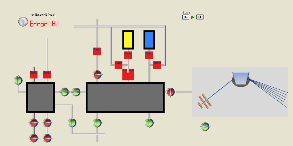
Examples
Hardware Control via Ethernet
Thermo Scientific Qtegra Scripting Language Software Manual (P/N 1383460, Revision A) 5-23
4. Define a new hardware item in the Configurator. See “Hardware
Configurator” on page 3-2 and “Hardware Panel Configurator” on
page 3-22.
The final implementation may look as the example shown in
Figure 5-60.
Figure 5-60. Implementation scheme used at customer, NMIT
Examples
Example for RS232 Communication
5-24 Qtegra Scripting Language Software Manual (P/N 1383460, Revision A) Thermo Scientific
Example for RS232 Communication
•ComPort socket to send and receive commands via RS 232
interface.
•This enables you to use ComPorts or USB ports to establish a
communication with external devices like gauge controllers.
Table 5-24. Code Example: COMPort Device.cs
// RegisterSystemAssembly: System.dll
// RegisterAssembly: BasicHardware.dll
// RegisterAssembly: HardwareClient.dll
using Thermo.Imhotep.BasicHardware;
using Thermo.Imhotep.HardwareClientNS;
using Thermo.Imhotep.Util;
using System.IO.Ports;
using System.Globalization;
// -------------------------------------------------------------------
// © Copyright 2014 Thermo Fisher Scientific Inc. All rights reserved.
// -------------------------------------------------------------------
/*
* This example shows how to read values from a Fluke189 multimeter, connected via a COM port.
* It shows that one could use the .Net SerialPort class if needed.
*
* Alternatively one could also use the Qtegra COMPortManager class which resides in COMPort.dll. This
dll can be loaded
* by adding the following line at the top of the script: "// RegisterAssembly: COMPort.dll"
*
* To reference any other .Net assemblies, one should use the "// RegisterSystemAssembly: ..."
keyword.
*
* Please note that hardware scripts, i.e. scripts which is attached to a hardware item in the
Hardware Configurator under
* the Configurator tool, must have a specific convention. The convention is as such that the last
class in the file must implement
* the GetParamter and SetParmeter methods. In this example it is the 'Fluke189Hardware' class.
*
* Please also refer to the general hardware script example: _Application
Data\Scripts\HWScriptExample.cs which is found under
* Qtegra's Program Data folder. When Windows 7 is used, this is found under 'C:\ProgramData'.
*/
Examples
Example for RS232 Communication
Thermo Scientific Qtegra Scripting Language Software Manual (P/N 1383460, Revision A) 5-25
public class Fluke189 : Singleton<Fluke189>
// The Singleton class is defined in the pre-included Qtegra library: 'Util.dll'
{
private Fluke189()
{
// Must be declared as private.
}
protected override void Initialize()
{
// Add here any relevant initialization code.
base.Initialize();
}
public void Connect()
{
lock (m_lock)
{
if (m_port == null)
{
try
{
m_port = new SerialPort("COM2", 9600, Parity.None, 8, StopBits.One);
m_port.RtsEnable = true;
m_port.WriteTimeout = 100;
m_port.ReadTimeout = 1000;
m_port.NewLine = "\r";
m_port.Open();
m_thread = new Thread(new ThreadStart(QueryThread));
m_thread.IsBackground = true;
m_thread.Start();
}
catch
{
m_port = null;
}
}
}
}
public double QueryMeasurement()
{
return m_measurementData;
}
public void Disconnect()
{
lock (m_lock)
{
if (m_port != null)
{
m_port.Close();
m_port = null;
}
}
}
Table 5-24. Code Example: COMPort Device.cs, continued
Examples
Example for RS232 Communication
5-26 Qtegra Scripting Language Software Manual (P/N 1383460, Revision A) Thermo Scientific
private void QueryThread()
{
while (m_port != null)
{
lock (m_lock)
{
if (m_port != null)
{
try
{
m_port.DiscardInBuffer();
m_port.DiscardOutBuffer();
m_port.WriteLine("QM");
string dataString = m_port.ReadLine();
if (dataString == "0")
{
dataString = (m_port.ReadLine()).Substring(3, 7);
if(!double.TryParse(dataString, NumberStyles.Number,
CultureInfo.InvariantCulture, out m_measurementData))
{
m_measurementData = 0.0;
}
}
}
catch
{
m_measurementData = 0.0;
}
}
}
// Note that here is no delay since the communication is so slow that it does not
actually cause any CPU load,
// if this would not be the case, some delay would be needed.
}
}
protected override void KillInstance()
{
// This method is also called by the singleton class, when Qtegra services shuts down.
lock (m_lock)
{
Disconnect();
m_thread = null;
m_lock = null;
}
base.KillInstance();
}
object m_lock = new object();
double m_measurementData;
SerialPort m_port;
Thread m_thread;
}
Table 5-24. Code Example: COMPort Device.cs, continued
Examples
Example for RS232 Communication
Thermo Scientific Qtegra Scripting Language Software Manual (P/N 1383460, Revision A) 5-27
class Fluke189Hardware
{
/// <summary>
/// This method is called each time a value is set on this hardware item.
/// </summary>
/// <param name="hw">The hardware item instance, holding all parameters like conversion
parameters, units etc.</param>
/// <param name="rawValue">The raw value to be set, which is mapped on the defined hardware mask.
</param>
/// <returns><c>true</c>, when the item was successfully set; otherwise, <c>false</c>.</returns>
public static bool SetParameter(Hardware hw, int rawValue)
{
return true;
}
/// <summary>
/// This method is called every time a value needs to be read out by Qtegra. When an item is placed
on some hardware panel,
/// this method is automatically called at least once per second. It depends on the monitored
interval set for the panel.
/// </summary>
/// <param name="hw">The hardware item instance, holding all parameters like conversion
parameters, units etc.</param>
/// <param name="rawValue">The raw value which was read out, which must be mapped on the defined
hardware mask. </param>
/// <returns><c>true</c>, when the item was successfully read; otherwise, <c>false</c>.</returns>
public static bool GetParameter(Hardware hw, out int rawValue)
{
if (!m_initialized)
{
Fluke189.Instance.Connect();
m_initialized = true;
}
// Here the hardware item is used to convert between calculated, i.e. real world values,
to raw values, i.e. values
// which are mapped to the defined bit mask, by using the defined conversion formula and
conversion parameters.
rawValue = (int)hw.GetRawDataFromCalc(Fluke189.Instance.QueryMeasurement());
return true;
}
/// <summary>
/// This is called when a hardware script is terminated.
/// </summary>
public static void Dispose()
{
if (m_initialized)
{
Fluke189.Instance.Disconnect();
m_initialized = false;
}
}
public static bool m_initialized = false;
}
Table 5-24. Code Example: COMPort Device.cs, continued

Examples
Furnace Control via PeriCon
5-28 Qtegra Scripting Language Software Manual (P/N 1383460, Revision A) Thermo Scientific
Furnace Control via PeriCon
Design Goal
This section describes a customer implementation via the universal
interface PeriCon.
The Jumo dTron Controller
The latest version of the NG Furnace contains a Jumo dTron controller
that is equipped with an analog input module. This module accepts an
external voltage to control the set point, which is used to set the
temperature.
The Jumo dTron controller is also equipped with an output module.
This module provides a readout of the actual temperature.
These additional modules are configured as follows (refer to Jumo dTron
304/308/316 Operating Manual B 70.3041.0, Section 8.1), see
Table 5-25.
The Out 6 corresponds to the Analog Out 1 module (refer to Jumo
dTron 304/308/316 Operating Manual B 70.3041.0, Section 8.5). The
configuration is shown in Table 5-26.
Table 5-25. Analog In 2 setting parameters
Item Value Remarks
Sens 9 Input range 0 to 10 Volts
Lin 0 Linear operation
OFFS 0 No offset; may be used later to
correct a possible offset
SCL 0 Not used
SCH 0 Not used
dF 9 Filter time 9 sec to dampen
sudden changes in input
Heat 0 No function
Table 5-26. Analog Out 6 setting parameters
Item Value Remarks
Funct 3 Output represents the process
value; true temperature of the
Furnace
SiGn 0 Output range 0 to 10 Volts
rOut 0 Not used

Examples
Furnace Control via PeriCon
Thermo Scientific Qtegra Scripting Language Software Manual (P/N 1383460, Revision A) 5-29
The required electrical connections are fed to a DB9 plug located in the
rear of the NG Furnace with the assignments as shown in Table 5-27.
Based on this setup, it is easy to use a PeriCon.
❖To perform control and readback of the oven parameters from Qtegra
1. Connect a pair of cables from an analog output of the PeriCon to
the Analog Inputs of the NG Furnace.
2. Connect a pair of cables from an analog output of the NG Furnace
to the Analog Inputs of the PeriCon.
3. On the hardware, make sure that the Analog Input is configured
with a range of 0 to 10 Volts input to match the output
specifications of the NG Furnace controller.
NOTICE For reference with the code examples assume that the PeriCon
Dac4 is used as the channel for the temperature set value while the
readback will happen via Adc2. ▲
Customizing Sample Lists
Preparation Flowchart
This section describes how to translate actions to code.
0Pnt 0 0 °C in the Furnace will be
translated into 0 Volts at the
output
End 2000 2000 °C in the Furnace will be
translated into 10 Volts at the
output
Table 5-27. DB9 Connector functions
DB9 Connector Function On PeriCon Function
Pin 1 Analog In 2 (-) Adc2 (-)
Pin 2 Analog In 2 (+) Adc2 (+)
Pin 4 Analog Out (+) Dac4 (+)
Pin 5 Analog Out (-) Dac4 (-)
Table 5-26. Analog Out 6 setting parameters, continued
Item Value Remarks
Examples
Furnace Control via PeriCon
5-30 Qtegra Scripting Language Software Manual (P/N 1383460, Revision A) Thermo Scientific
Begin with the creation of an empty panel as described in “Creating
Hardware Panel for PeriCon” on page 3-22. Add a readback display and
in the properties, assign Adc2 of the PeriCon as data source. Add a
simple slider and in the properties, assign Dac4 of the PeriCon as
hardware item.
In the Hardware Panel Configurator (see “Hardware Panel
Configurator” on page 3-22), edit the Unit parameter of the object, that
means, change from the default voltage calibration V into a temperature
calibration °C. Edit the Properties, that means, set the Maximum and
Minimum values to resemble the following ranges:
•minimum 0 V equals 0 °C
•maximum 10 V equals 2000 °C
Select Generate > Linear coefficients from the shortcut menu to
complete the assignments as described in “To create a new panel for a
temperature control object” on page 3-33. Save the new settings in the
hardware database to make them available.
To complete the software integration, add a column to the sample list of
the workbook (see “To use this workflow in a LabBook” on page 2-5)
that allows to set the temperature for the Furnace in the laboratory
environment. The code example (see Table 5-28) shows how to modify
the sample list descriptive file for the NGFurnaceOnHelixSFT.
The modification creates a new column FurnaceTemp with a default
value of 18 in the LabBook. See “To use this workflow in a LabBook” on
page 2-5 for details on how to create a LabBook with your workflow.
Table 5-28. Code example: NGFurnaceOnHelixSFT.xml
<?xml version="1.0" encoding="ISO-8859-1"?>
<SampleList>
<SampleListColumn Shared="true">
<Id>NGFurnaceOnHelixSFT</Id>
<Name>Identifier</Name>
<Caption>Label</Caption>
<Type>string</Type>
<Default><Identifier></Default>
</SampleListColumn>
<SampleListColumn>
<Id>NGFurnaceOnHelixSFT</Id>
<Name>FurnaceTemp</Name>
<Caption>Temp</Caption>
<Type>int</Type>
<Default>18</Default>
</SampleListColumn>
</SampleList>
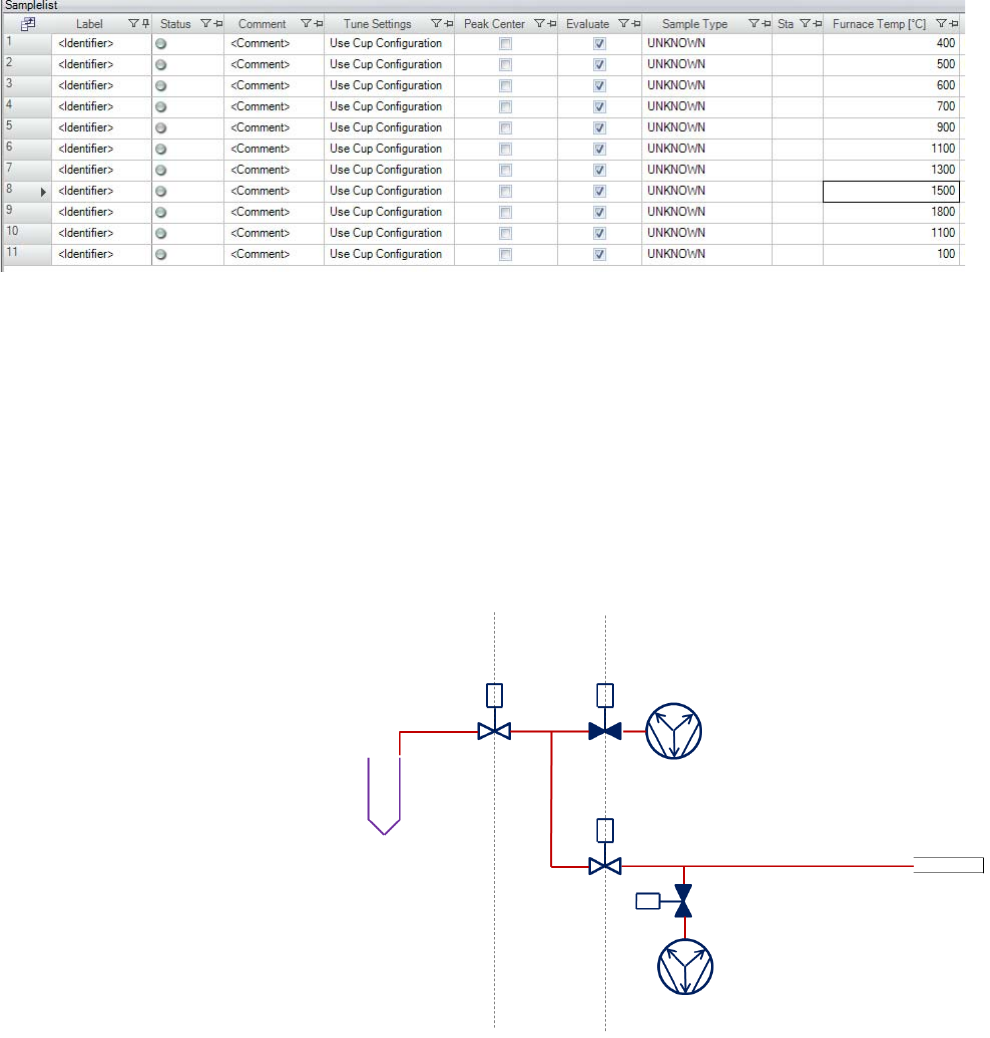
Examples
Furnace Control via PeriCon
Thermo Scientific Qtegra Scripting Language Software Manual (P/N 1383460, Revision A) 5-31
After creation of this column the contents is read from inside the script
to establish an automated control of the FurnaceTemp dependent from
user requests. In the LabBook’s Samplelist, set up subsequent lines to
create an automated heating sequence where the individual temperature
steps are entered (see Figure 5-61).
The Prepare script for the Furnace needs to contain a section to readout
the Sample line entry (similar to the code in NGPrep Prepare) and code
lines to set the Furnace temperature.
Furnace sample preparation
The following graphical views show the steps for a furnace sample
preparation.
The sample is located on the left side of the graphical view. The pumps
of the mass spectrometer are open. The valve between sample and
“Prep” is closed.
Figure 5-61. Samplelist with individual temperature steps in the FurnaceTemp column
Figure 5-62. Initial valve positions
Furnace Prep Mass Spectrometer
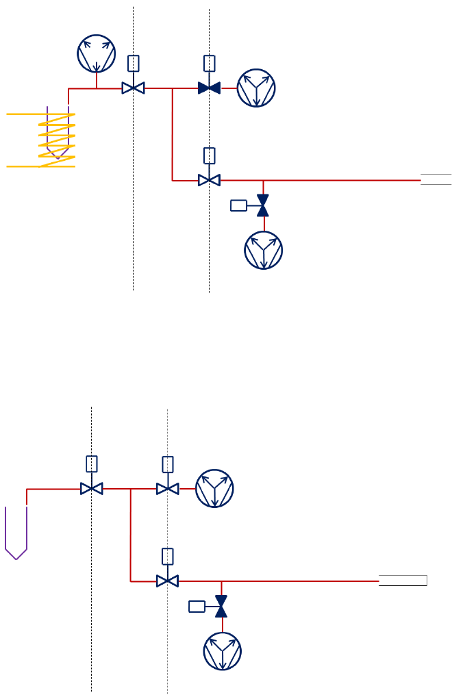
Examples
Furnace Control via PeriCon
5-32 Qtegra Scripting Language Software Manual (P/N 1383460, Revision A) Thermo Scientific
The furnace is switched on. The sample expands into the Furnace
manifold. All valves remain in the initial state.
The Prep pump valve is closed. The other valves remain in their initial
state. The furnace is switched off.
Figure 5-63. Release gas from sample
Figure 5-64. Close Prep pump valve
Furnace Prep Mass Spectrometer
Furnace Prep Mass Spectrometer

Examples
Furnace Control via PeriCon
Thermo Scientific Qtegra Scripting Language Software Manual (P/N 1383460, Revision A) 5-33
The sample valve is opened. The other valves remain in their initial
state. The sample expands into the Prep manifold.
Check amount of gas and decide on expansion.
The ms pump valve is closed.
Figure 5-65. Expand sample into manifold
Figure 5-66. Close mass spectrometer pump valve
Furnace Prep Mass Spectrometer
Furnace Prep Mass Spectrometer
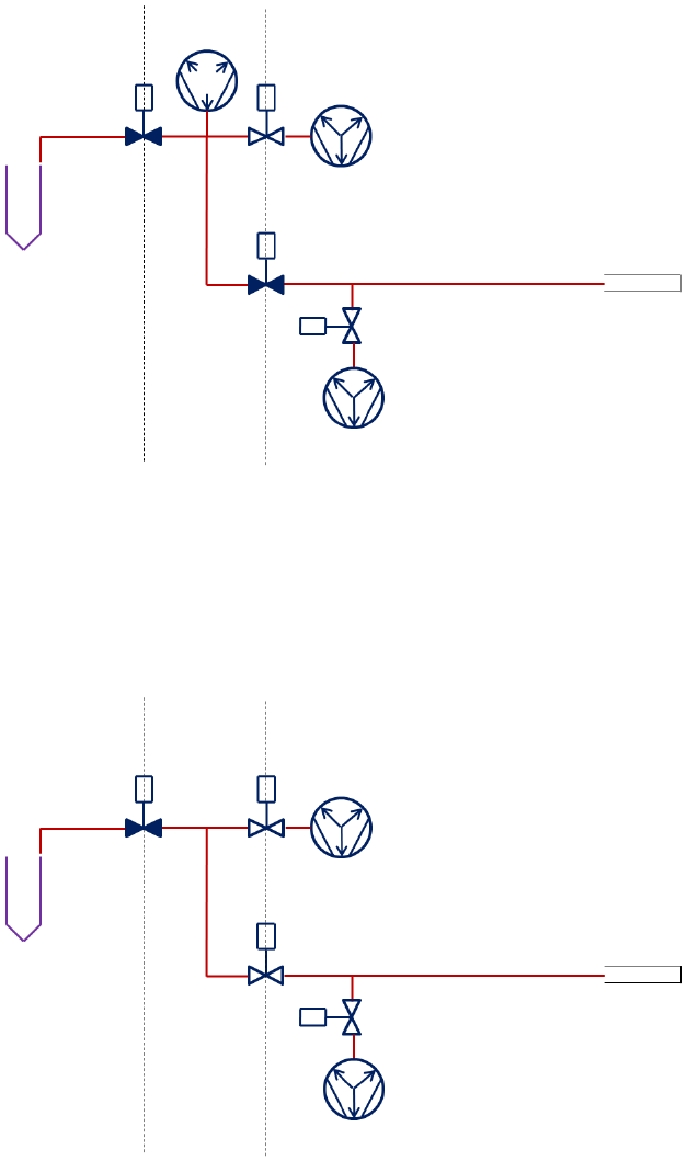
Examples
Furnace Control via PeriCon
5-34 Qtegra Scripting Language Software Manual (P/N 1383460, Revision A) Thermo Scientific
The ms valve is opened to admit the sample to the mass spectrometer.
TimeZero starts here. Need to wait until the sample spreads through the
complete system and equilibrates.
The Mass Spectrometer valve is closed. The acquisition may be stopped.
Figure 5-67. Admit sample to mass spectrometer
Figure 5-68. Close valve between Prep and mass spectrometer
Furnace Prep Mass Spectrometer
Furnace Prep Mass Spectrometer

Examples
Furnace Control via PeriCon
Thermo Scientific Qtegra Scripting Language Software Manual (P/N 1383460, Revision A) 5-35
The Prep valve is opened to remove extra gas from the Prep.
Figure 5-69. Remove the extra gas in the Prep
Furnace Prep Mass Spectrometer
Examples
Control via IEEE-488 Interface
5-36 Qtegra Scripting Language Software Manual (P/N 1383460, Revision A) Thermo Scientific
Control via IEEE-488 Interface
Goal
Instruments having an IEEE-488 interface are common in the field and
will therefore be discussed in this Software Manual.
Examples
You can incorporate IEEE-488 measurement devices, for example an
Agilent (HP) 34401A DMM, into your data acquisition and control
system. Commonly a National Instruments USB or internal IEEE-488
controller will be needed.
❖To create a panel to acquire data
1. Follow the instructions shown in “Hardware Panel Configurator” on
page 3-22.
2. The panel could look as shown in Figure 5-70.
Execution of the script will perform the following steps:
•Set the integration time
•Set the delay time between readings
•Start the acquisition
Figure 5-70. Panel for using HP 34401A DMMs
Examples
Control via IEEE-488 Interface
Thermo Scientific Qtegra Scripting Language Software Manual (P/N 1383460, Revision A) 5-37
•Stop the acquisition
•Display the output in a control, for example the panel shown above.
NOTICE USGS is happy to provide already developed code that does all
of this if helpful. ▲
The USGS example is based on the highest level API available. Consider
an IVI instrument driver with a .NET API, or an IVI-COM driver,
which is easily accessible from .NET. For example, the 34401A has an
IVI-COM driver:
http://www.keysight.com/main/software.jspx?ckey=1494698&lc=eng&
cc=US&nid=-536902435.536880933&id=1494698.
For additional information on controlling instruments from C# and
VB.NET using IVI Drivers see
http://ivifoundation.org/downloads/IVI%20GSG%202011/IVI%20G
SG%20C%20and%20VB%202011.pdf.
NOTICE USGS can loan an Agilent (HP) 34401A DMM for this
development if helpful. ▲
Examples
Control via IEEE-488 Interface
5-38 Qtegra Scripting Language Software Manual (P/N 1383460, Revision A) Thermo Scientific

Thermo Scientific Qtegra Scripting Language Software Manual (P/N 1383460, Revision A) 6-1
Chapter 6 Appendix
This appendix gives some basic information about analog and digital
instruments and a collection of third party hardware items such as
temperature controller, pressure transducer, etc.
Analog and Digital World
In order to understand the power of the approach you need to
understand that - for an electronics engineer - the real world consists of
two types of interfaces: analog and digital values.
A typical analog value is the speed of a car or the time itself (although
this can be disputed on a physical time scale). Analog control means that
the state of a device can have a continuous reading (for example 0 to
1000 mbar for a vacuum reading) while digital control is limited to 2
distinct stages (like ON and OFF for a valve). In general measurement
applications it is an agreement to use only certain windows in the
continuum to control electronic devices (0 to 10 Volt or 4 to 24 mA).
Contents
•Analog and Digital World
•Optional System Components
Appendix
Analog and Digital World
6-2 Qtegra Scripting Language Software Manual (P/N 1383460, Revision A) Thermo Scientific
The same is true for digital representations, where 0 and 24 Volt are
used to control valves (light or no light for data transmission over light
pipes and so on). The PeriCon uses these levels to control a good
selection of commercially available electronic and electro-pneumatic
devices.
The most favorable approach is to use the PeriCon interface to connect
all types of electronic controls to the mass spectrometer. The effort to
control a digital device like a pneumatic valve is usually neglected as it is
just a matter of translation to voltages or voltages to pressures or the like.
Figure 6-71. The world for an electronics engineer
analog digital
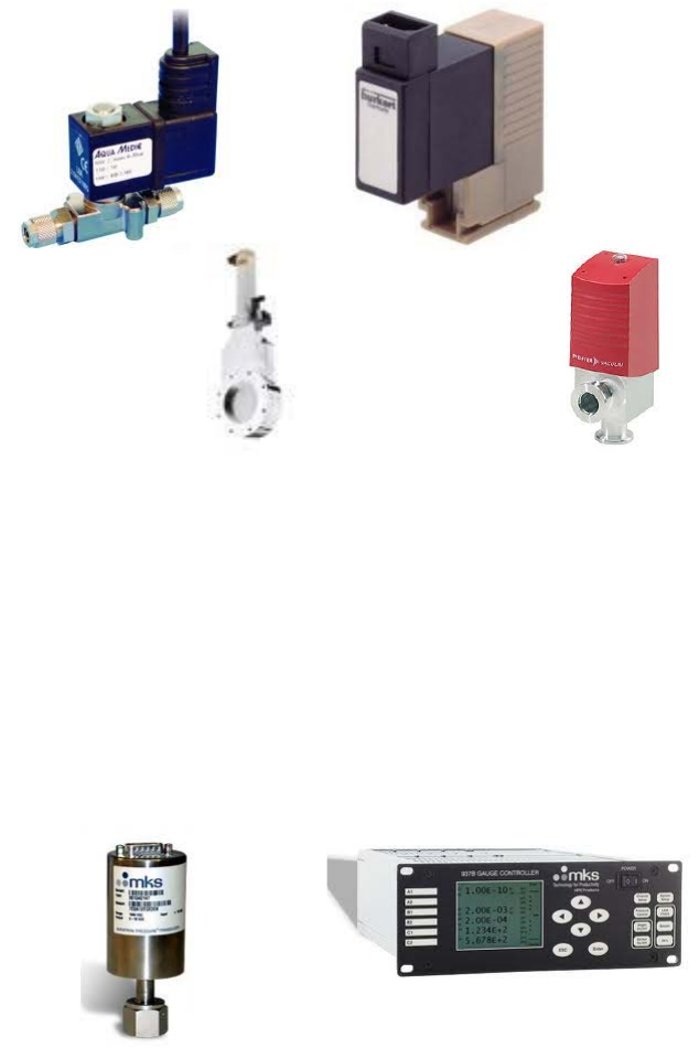
Appendix
Analog and Digital World
Thermo Scientific Qtegra Scripting Language Software Manual (P/N 1383460, Revision A) 6-3
Digital devices
Typical digital devices require just a change in a voltage. Many valves are
available that can be controlled by means of a 24 V direct current. The
presence or absence of this voltage will then open or close the valve -
sometimes amplified by pressurized air - depending on the make and
brand of the valve.
Analog devices
Typical analog devices include gauges provided we can read them via
electric signals, but reading a controller via a serial port would also result
in representing it with an analog device. The devices provide a range of
values that require translation into the computer world: called
digitizing. The device to digitize an analog value is called an Analog to
Digital Converter or ADC. Every ADC has a certain resolution
associated with it. The resolution controls the increment between two
analog values to create adjacent digital values. This resolution is usually
given as the total number of different digital values that the ADC can
possibly produce. A typical number for this resolution is 1024 or 65535.
Figure 6-72. Digital devices
Figure 6-73. Analog devices
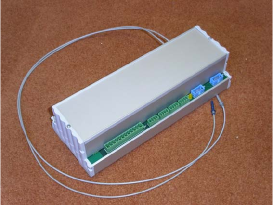
Appendix
Analog and Digital World
6-4 Qtegra Scripting Language Software Manual (P/N 1383460, Revision A) Thermo Scientific
To make all this more complicated and as all possible numbers are
multiples of 2 only the power to the base of 2 of the resolution is
specified. So a 12 bit ADC can produce 4096 (212-1) different digital
values.
The solution: PeriCon
In order to satisfy the various needs to control external devices it is
sufficient to have a number of analog and digital controls available. For
this purpose, Thermo Fisher Scientific offers the Unit PeriCon
(P/N 2075350).
PeriCon is a tool for specialized and advanced users. The PeriCon
applications complement the product portfolio of Thermo Fisher
Scientific to build and control home-made customized peripheral
devices. PeriCon serves as a link between the Thermo Scientific mass
spectrometer electronics and the user-made customized devices.
With PeriCon, a specialized application such as a valve, an analog input
or output or a trigger input can easily be added in a standardized way to
the peripherals of Thermo Fisher Scientific.
NOTICE It is possible to operate more than one PeriCon at any given
mass spectrometer. Ex-factory the addresses on the control module will
then be set for the second or third instrument (or more) according to
your order specification. ▲
PeriCon is designed to be mounted into a DIN-standard switch cabinet
and is supplied with this PeriCon, a power supply, plugs and cables.
Figure 6-74. PeriCon
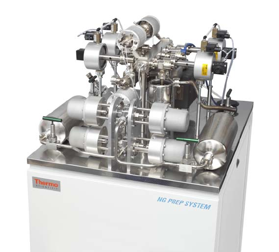
Appendix
Optional System Components
Thermo Scientific Qtegra Scripting Language Software Manual (P/N 1383460, Revision A) 6-5
Optional System Components
The following optional system components can also be controlled via
scripts.
NG PREP SYSTEM
The NG PREP SYSTEM is a sample purification system used for all
sample and reference gases before entering a mass spectrometer. It
contains all the valves and pumps needed to prepare and store noble gas
samples from air and to introduce these samples in precisely controlled
quantities into the mass spectrometer. See Figure 6-75 and refer to the
NG PREP SYSTEM Operating Manual.
Alternatively you can use your own sample introduction system, for
example together with a PeriCon.
Figure 6-75. NG PREP SYSTEM
Appendix
Optional System Components
6-6 Qtegra Scripting Language Software Manual (P/N 1383460, Revision A) Thermo Scientific
NG FURNACE
The high temperature resistance furnance NG FURNACE is used to
extract noble gases from solid samples. See Figure 6-76 and refer to the
NG FURNACE Operating Manual.
Figure 6-76. NG FURNACE
Thermo Scientific Qtegra Scripting Language Software Manual (P/N 1383460, Revision A) I-1
A
Access Control editor 3-1
acquire
definition 4-1
acquisition
definition 4-1
ADC 1-1, 3-34, 6-3
Agilent 34401A DMM 5-36
analog to digital converter 6-3
B
basic I/O settings 3-3
Bootloader
firmware updater 1-3
C
clone object 3-29
commands
of Workflow Editor 2-8
Configurator 1-2, 3-2
converter
analog to digital 1-1, 6-3
digital to analog 1-1
CupConfiguration 4-1
D
DAC 1-1, 3-34
debug 3-45
digtial input output 1-1
digtial to analog converter 1-1
DIO 1-1
E
Element Editor 3-1
Experiment Configurator 3-1
Experiment Editor 1-2
F
firmware
update 1-3
G
group
objects 3-29
H
Hardware Configurator 3-2
Hardware Database editor 3-1
hardware entries 2-1–2-2, 2-4–2-5, 2-7, 2-9–2-10, 3-2–3-3
hardware panel 3-22, 3-25, 3-39
Hardware Panel Configurator 3-22
Hardware Panel editor 3-1
I
IEEE-488 interface 5-36
inlet system 3-25
Instrument Control 1-2, 3-39
interface
IEEE-488 5-36
L
LabBook
definition 1-2
Logger
Windows service 1-3
M
method cycle 4-1
method editor 4-1
N
NG FURNACE 6-6
NG PREP SYSTEM 6-5
O
object
clone 3-29
object pool 3-27
objects
group 3-29
Index
I-2 Qtegra Scripting Language Software Manual (P/N 1383460, Revision A) Thermo Scientific
Index: P–W
P
PeriCon 3-20, 6-4
phase
of phase model 4-3
phase model 4-3
Q
Qtegra
Experiment Editor 1-2
Qtegra ISDS 1-1
R
resources pool 3-25
of hardware items 3-30
resources pool of hardware items 3-30
S
sample
definition 1-2
purification 6-5
script editor 3-1
Configurator 3-46–3-47
Instrument Control 3-43
settings entries 3-2
T
template
definition 1-2
W
workflow
definition 1-2
Workflow Editor 2-1