Eventide Atlas Series Recorders User Manual, Version 1.8 VR778 141078 Manual 180
User Manual: VR778
Open the PDF directly: View PDF ![]() .
.
Page Count: 266 [warning: Documents this large are best viewed by clicking the View PDF Link!]

Atlas Series Server 1.8 User Manual 1
ATLAS Series Audio Logging and Archiving System
Models VR778, VR725, and VR615
VERSION 1.8.0
141078 v1.8.0 April 15, 2008

Atlas Series Server 1.8 User Manual 2
© 2004 - 2008 Eventide, Inc. All rights reserved.
Every effort has been made to make this guide as complete and accurate as possible, but we
DISCLAIM ANY WARRANTY OF MERCHANTIBILITY OR FITNESS FOR A PARTICULAR PURPOSE. The
information provided is on an “as-is” basis and is subject to change without notice or obligation.
Eventide Inc. has neither liability nor responsibility to any person or entity with respect to loss or
damages arising from the information contained in this guide.
Warning: This computer program and its documentation are protected by copyright law and
international treaties. Any unauthorized copying or distribution of this program, its documentation,
or any portion thereof may result in severe civil and criminal penalties.
The software installed in accordance with this documentation is copyrighted and licensed by
Eventide Inc. under separate license agreement. The software may only be used pursuant to the
terms and conditions of such license agreement. Any other use may be a violation of law.
Caution: To reduce the risk of fire, use only 26 AWG or larger telecommunication line cord.
Trademarks
Eventide is a registered trademark of Eventide Inc.
Linux is a registered trademark of Linus Torvalds
Microsoft and Windows are registered trademarks of Microsoft Corporation
Other trademarks are the property of their respective owners. All terms known to be trademarks
are appropriately capitalized. If we missed yours, please let us know.

Atlas Series Server 1.8 User Manual 3
T
T
Ta
a
ab
b
bl
l
le
e
e
o
o
of
f
f
C
C
Co
o
on
n
nt
t
te
e
en
n
nt
t
ts
s
s
TABLE OF CONTENTS ...........................................................................................3
INTRODUCTION .................................................................................................12
Welcome....................................................................................................................................12
About this Manual......................................................................................................................13
RECORDER SETUP & OPERATION.......................................................................14
Unpacking the Recorder..........................................................................................................14
General Specifications .............................................................................................................15
VR615 and VR778 .......................................................................................................................15
Front Panel Details – VR615 and VR778...................................................................................16
Rear Panel Details ......................................................................................................................19
VR725 & Blank Panel Units.........................................................................................................20
Front Panel Details – VR725 with Touch screen......................................................................22
Rear Panel Details ......................................................................................................................24
Bench Test..................................................................................................................................25
Installation..................................................................................................................................27
General........................................................................................................................................27
Operating Limits..........................................................................................................................27
Location Considerations ...........................................................................................................28
Mounting Options.......................................................................................................................29
Other Considerations.................................................................................................................30
Connecting AC Power and UPS (Uninterruptible Power Supply) .......................................30
Before You Connect Audio Signals to the Recorder............................................................32
Connecting Telephone, Radio, and Other Analog Audio Signals to the Recorder........32

Atlas Series Server 1.8 User Manual 4
The Optional Quick Install Kit ....................................................................................................33
Connecting Digital Telephone Lines .......................................................................................35
Connecting to an Ethernet Network.......................................................................................35
Connecting a Keyboard...........................................................................................................35
Connecting Headphones.........................................................................................................36
Connecting Line-Level Equipment..........................................................................................36
Connecting a Label Printer.......................................................................................................36
Overview of the Front Panel User Interface.............................................................................36
Setup Screen...............................................................................................................................37
INFO Screen.................................................................................................................................38
RECALL Screen............................................................................................................................40
Playing Audio Records...............................................................................................................40
Using Filters...................................................................................................................................41
Displaying Columns....................................................................................................................47
Creating Playlists from the RECALL Screen.............................................................................48
RECORDER SETUP & ADMINISTRATION.............................................................52
Organization..............................................................................................................................53
Contents.....................................................................................................................................53
SETUP: SYSTEM INFO..........................................................................................55
Setup: System Info/Configuration Info ....................................................................................55
Setup: System Info: RAID Status................................................................................................58
Setup: System Info: Serial Number ...........................................................................................60
Setup: System Info: License Key ...............................................................................................61
Setup: System Info: Add On License Key................................................................................62
Setup: System Info: View alarm log .........................................................................................63
Setup: System Info: Enable/Disable Verbose Logging .........................................................63
SETUP: ARCHIVE.................................................................................................65
Setup: Archive : Archiving type................................................................................................65
Setup: Archive: Archive protection period ............................................................................66
Setup: Archive: Auto-eject........................................................................................................67

Atlas Series Server 1.8 User Manual 5
Setup: Archive: Enable/disable Label printing ......................................................................67
Setup: Archive: Resume archiving on startup........................................................................68
Setup: Archive: Set current archive time................................................................................68
Setup: Archive: Archive failsafe server....................................................................................70
Setup: Archive: Enable/disable archive failsafe ...................................................................71
Setup:Archive:Archive failsafe behavior................................................................................71
SETUP: NETWORK ARCHIVE...............................................................................72
Setup:Network Archive:Enable/Disable Network Archive ...................................................72
Setup:Network Archive:Hostname...........................................................................................73
Setup:Network Archive:Share Name ......................................................................................73
Setup:Network Archive:Workgroup.........................................................................................74
Setup:Network Archive:Username...........................................................................................75
Setup:Network Archive:Password............................................................................................75
Setup:Network Archive:Set Current Network Archive Time.................................................76
SETUP: RECORDING...........................................................................................77
Setup: Recording: Board configuration..................................................................................78
The Board Configuration Screen..............................................................................................78
Choosing an Encoding Algorithm............................................................................................80
Setup:Recording:Channel Configuration...............................................................................81
The Channel Configuration Screen.........................................................................................81
Steps for Setting Levels, Thresholds, and Hold Times.............................................................89
Setup: Recording: Delete calls after N days..........................................................................90
Setup: Recording: Max # of calls in DB...................................................................................91
Setup: Recording: Audio segment length..............................................................................92
SETUP: SECURITY ................................................................................................93
Setup:Security:Logins Required................................................................................................93
Setup: Security: Auto-logout timeout......................................................................................94
Setup: Security: User administration.........................................................................................95
About Security Groups...............................................................................................................95
Managing Users ..........................................................................................................................96

Atlas Series Server 1.8 User Manual 6
SETUP: EMAIL......................................................................................................99
Setup:Email:Enable/Disable Emails........................................................................................100
Setup:Email:SMTP Server..........................................................................................................100
Setup:Email:SMTP Port..............................................................................................................101
Setup:Email:Local Hostname..................................................................................................101
Setup:Email:SMTP Username...................................................................................................102
Setup:Email:SMTP Password....................................................................................................102
Setup:Email:SMTP From Address.............................................................................................103
Setup:Email:SMTP Reply-To Address.......................................................................................103
Setup:Email:SMTP Errors-To Address .......................................................................................104
Setup:Email:Force TLS Encryption...........................................................................................104
Setup:Email:Send test email....................................................................................................105
SETUP: NETWORK SETTINGS.............................................................................106
Setup:Network Settings:Enable/Disable DHCP....................................................................107
Setup:Network Settings:IP Address, Gateway, Net mask, Network..................................108
Setup:Network Settings:DNS Servers......................................................................................109
Setup:Network Settings:Broadcast ........................................................................................109
SETUP: CLOCK..................................................................................................110
Setup:Clock:Date/Time ...........................................................................................................111
Setup:Clock:Time zone............................................................................................................111
Setup:Clock:NTP Server............................................................................................................112
Setup: Clock:I RIG-B settings...................................................................................................113
IRIG-B...........................................................................................................................................113
Setup: Clock: RS232 Time settings..........................................................................................114
Time Code Synchronization Over RS-232..............................................................................114
Setup RS-232 Time Settings......................................................................................................115
Setup:Clock:Time sync status..................................................................................................116
SETUP:UTILITIES .................................................................................................117
Setup:Utilities:Write logs to removable media .....................................................................117
Setup:Utilities:Write configuration to archive .......................................................................118
Setup:Utilities:Read configuration from archive..................................................................120

Atlas Series Server 1.8 User Manual 7
Setup:Utilities:Archive restore..................................................................................................121
Setup:Utilities:Archive restore: Period Transfer......................................................................122
Setup:Utilities:Write metadata to archive.............................................................................123
Setup:Utilities:Read metadata from archive........................................................................124
Touch screen calibration (coarse and fine).........................................................................125
SETUP: SYSTEM SHUTDOWN.............................................................................126
Controlled Shutdown...............................................................................................................126
Forced Shutdown.....................................................................................................................127
Recorder Operation................................................................................................................128
Starting and Shutting Down....................................................................................................128
Recording..................................................................................................................................129
General ......................................................................................................................................129
RAID ............................................................................................................................................129
Searching, Sorting, and Playing Calls....................................................................................130
General ......................................................................................................................................130
Considerations ..........................................................................................................................130
Viewing Calls .............................................................................................................................130
Filtering and Searching............................................................................................................131
Columns .....................................................................................................................................133
Playing Back Calls.....................................................................................................................134
Looping ......................................................................................................................................134
Archiving....................................................................................................................................135
General ......................................................................................................................................135
Media Selection........................................................................................................................137
Sequential and Parallel Modes ..............................................................................................138
DVD-RAM Drive Operation......................................................................................................139
Selecting and Deselecting an Archive Drive.......................................................................141
Opening/Closing the DVD-RAM Drive...................................................................................141
Formatting Archive Media ......................................................................................................141
Start Archiving...........................................................................................................................142
Stop Archiving...........................................................................................................................142
Resume Archiving.....................................................................................................................142
Viewing Media Info ..................................................................................................................143

Atlas Series Server 1.8 User Manual 8
Printing a Label..........................................................................................................................143
Selecting The Archive Period..................................................................................................144
Browse Archive Media.............................................................................................................145
Archive Protection....................................................................................................................145
Auto-Eject ..................................................................................................................................146
Resuming Archiving on Start-Up.............................................................................................146
Setting Current Archive Time ..................................................................................................146
Designating and Activating an Archive Failsafe Server.....................................................148
Writing Call “Metadata” to an archive.................................................................................148
Live Monitoring..........................................................................................................................150
THE ATLAS ADMINISTRATIVE CLIENT...............................................................151
What is remote client software? ............................................................................................151
Do you need to install the client software at all?................................................................151
The Recorder Configuration Program...................................................................................152
Differences between the Client functions and Front Panel SETUP ...................................152
Installation................................................................................................................................153
Starting the Client.....................................................................................................................155
Server Login...............................................................................................................................156
Server settings............................................................................................................................157
Miscellaneous..........................................................................................................................159
Call Suppression......................................................................................................................161
User Accounts..........................................................................................................................163
Boards and Channels..............................................................................................................166
Channels....................................................................................................................................166
Boards.........................................................................................................................................167
Analog Telephony Board Configuration...............................................................................167
M-Audio HiFi Audio Recording Board Configuration..........................................................170
AI Logix NGX Configuration ....................................................................................................171
AI Logix E1/T1 Configuration ...................................................................................................173
VoIP Gateway Configuration.................................................................................................174

Atlas Series Server 1.8 User Manual 9
Channel Groups......................................................................................................................175
Channel Names........................................................................................................................175
Logs and Alerts........................................................................................................................176
Alerts...........................................................................................................................................176
Alerts History...............................................................................................................................177
Statistics......................................................................................................................................177
Email Server ...............................................................................................................................180
Configuration Files...................................................................................................................181
Custom Fields...........................................................................................................................184
Adding, Modifying, and Deleting Fields................................................................................184
Scheduled Recording.............................................................................................................187
Adding, Modifying, and Deleting Files ..................................................................................187
Scheduled Recording Parameters ........................................................................................189
Archiving: Archive Drives .......................................................................................................192
Centralized Archiving (CA) Configuration............................................................................194
Configuring Additional NET Drives .........................................................................................196
Centralized Archive Failsafe Configuration..........................................................................196
Archiving a Channel Group...................................................................................................197
Period Archiving With Recorder Configuration.....................................................................197
Call Source Tracking (CST).....................................................................................................197
Workstation Setup....................................................................................................................198
Creating A New Workstation..................................................................................................199
Editing An Existing Workstation...............................................................................................201
Deleting An Existing Workstation............................................................................................202
Final Workstation Configuration (Metadata Tagging) .......................................................202
Client Activity...........................................................................................................................204

Atlas Series Server 1.8 User Manual 10
Administration Client Menu Options......................................................................................205
File Menu....................................................................................................................................205
View Menu.................................................................................................................................206
Help Menu .................................................................................................................................206
APPENDIX 1 .....................................................................................................207
Server Software Installation and Upgrade.............................................................................207
Why Re-installation May be Necessary.................................................................................207
Why Upgrades May be Necessary or Desirable..................................................................207
The Software Upgrade/Installation Process..........................................................................208
Some Details, Especially About Installation..........................................................................208
Restoring Archives when Installing New Software...............................................................209
Potential Problems....................................................................................................................210
APPENDIX 2 .....................................................................................................211
PBX and Digital Telephony Hardware Information...............................................................211
APPENDIX 3 .....................................................................................................213
Connection Information for the HiFi Recording Board.........................................................213
APPENDIX 4 .....................................................................................................215
Optional General Purpose Input/Output (GPIO) Boards .....................................................215
National Instruments PCI-6503 Board (24-Channel)............................................................215
National Instruments PCI-6527 Board (48-Channel)............................................................216
APPENDIX 5 .....................................................................................................219
NIST Time Servers.....................................................................................................................219
APPENDIX 6 .....................................................................................................221
Eventide VR778 or VR725 with DDS-4 Tape Drives................................................................221

Atlas Series Server 1.8 User Manual 11
Overview....................................................................................................................................221
Loading a Tape and Preparing for Archiving......................................................................221
Ejecting a Tape.........................................................................................................................221
Playing Calls from a Tape........................................................................................................222
APPENDIX 7 .....................................................................................................225
Eventide Tape Archive Transfer Utility (Tatu).........................................................................225
APPENDIX 8 .....................................................................................................227
The Channel Wiring for Eventide Analog Telephony Boards...............................................227
APPENDIX 9 .....................................................................................................229
Alert Configuration..................................................................................................................229
APPENDIX 10 ...................................................................................................243
Eventide Voice Over Internet Protocol (VoIP) Implementation..........................................243
What is VoIP?.............................................................................................................................243
The Advantages VoIP Provides ..............................................................................................243
Technical Considerations........................................................................................................244
Prerequisites for VoIP Installation............................................................................................246
Network Requirements ............................................................................................................246
Gateway Configuration..........................................................................................................250
Archiving....................................................................................................................................253
VoIP Software Upgrade...........................................................................................................253
LIMITED WARRANTY.........................................................................................256
Index ........................................................................................................................................260

Atlas Series Server 1.8 User Manual 12
I
I
In
n
nt
t
tr
r
ro
o
od
d
du
u
uc
c
ct
t
ti
i
io
o
on
n
n
1
1
1
Welcome
Welcome and congratulations on your purchase of an ATLAS™ recorder! The
ATLAS™ (Advanced Technology Logging and Archiving System) series of recorders
is the latest offering from Eventide, the company that invented digital recorders in
1989.
This system manual will help you maximize the use of your purchase. It includes:
• A quick-start bench test, for those who want to quickly familiarize
themselves with some basic operations;
• Guidance on installing your recorder;
• Descriptions of all of the controls and menu items on the front panel user
interface;
• Step-by-step instructions on how to set up and operate your recorder.
Eventide is committed to your satisfaction. If, after using this manual, you still
have questions about the operation of your recorder, contact Technical Support at
support@eventide.com or call (201) 641-1200.
The Eventide web site has additional information that may be helpful. Go to
http://www.eventide.com.
One last thing: to help us reach you with information on updates and upcoming
new features, please send us your warranty card. We do not provide your
information to marketers or any other outside organizations.

Atlas Series Server 1.8 User Manual 13
ABOUT THIS MANUAL
This manual applies to software release 1.8 for the VR615, VR725, and VR778
recorders, as well as for the Recorder Configuration utility.
To identify the recorder software release number, do the following while the
recorder is running:
• Press Setup.
• Scroll to “Configuration Info” and select it.
• Check the “Release” item. That is the software version.
To identify the Recorder Configuration utility version number, select Help > About
from within the utility.
This manual contains the following information:
Chapter 1, “Introduction”: Provides an introduction to the Atlas recorder and
describes this manual.
Chapter 2, “Recorder Setup and Operation”: Provides information on the
following:
• Unpacking
• Performing a Bench Test
• Installing
• Adjusting Settings
• Operating using only the front panel, or with an attached mouse and
monitor
Chapter 3, “Recorder Setup and Administration: Provides information on using
the Setup menu and on administrative tasks.
Chapter 4, “The Atlas Administrative Client”: Provides information about
client software used for recorder administration, and detailed instructions on
using the Recorder Configuration utility.
Appendices: Provide information on types of available input interface boards with
which your recorder may be equipped.

Atlas Series Server 1.8 User Manual 14
R
R
Re
e
ec
c
co
o
or
r
rd
d
de
e
er
r
r
S
S
Se
e
et
t
tu
u
up
p
p
&
&
&
O
O
Op
p
pe
e
er
r
ra
a
at
t
ti
i
io
o
on
n
n
2
2
2
Unpacking the Recorder
CAUTION! Use care and assistance when lifting and handling the recorder. The VR615 weighs about 30
pounds (14 kg) and the VR725 about 50 pounds (23 kg). The VR778 can weigh as much as 95 pounds
(43 kg)!
Check the box for damage. A crushed box, holes, or water damage, for example,
could indicate that the recorder has been damaged. Open the box and inspect the
recorder and associated accessories. If the equipment appears damaged contact
Eventide right away and save the damaged box and packaging!
Check that the unit is delivered with the expected configuration and accessories.
The packing slip states the contents. In addition, the box will include:
• A configuration sheet indicating installed audio input boards and other
I/O boards;
• A warranty registration card;
• One archive medium per archive drive;
• One power line cord per power supply;
• Two server software disks, one labeled "install" and one labeled "update";
and
• This system manual.
• Two keys (We strongly recommend that you keep one of the keys as a
spare and put it in a safe place.)
Other accessories may be included, depending on your order. For example, you
may receive client disks. Sections 2 and 3 provide instructions for the client
software.
Atlas Series Server 1.8 User Manual 15
General Specifications
VR615 AND VR778
The Eventide ATLAS™ series of digital recorders is based on very similar server
(recorder) software and identical client (PC user) software. The primary differences
among different units in the product line are physical, e.g., size, power, storage
configuration, etc. The following table highlights the differences among the
products. This is a summary only, and does not replace the individual unit
specifications.
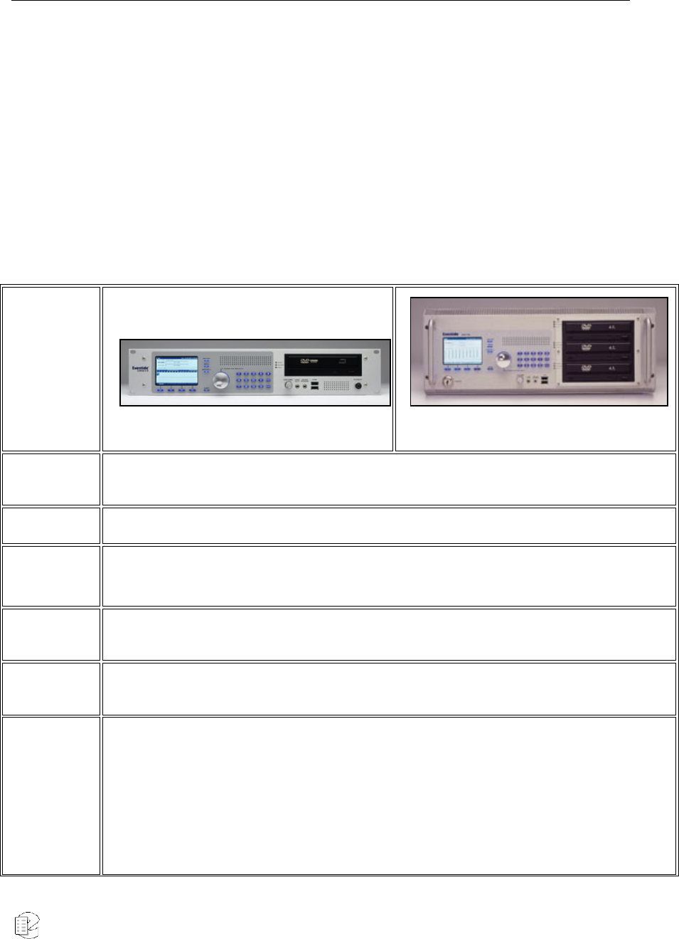
Table 1–Specification Summary for VR615 and VR778
Product view
Atlas VR615
Atlas VR778
Front Panel GUI 320x240 color TFT LCD display, soft keys, fixed keys, scroll wheel, keypad, volume control,
speaker
Front Panel I/O USB, 1/8" line level output, 1/8" headphone output
Remote
software
Windows-based remote call browser
Windows-based remote administration client
Operating
System Linux
Call Record
Database Internal relational database with programmable retention
Channel Inputs
Compression Rates (kbits/s): 13.3, 16, 32, 64 Mu-law
Frequency Response: 200 to 3400 Hz
Signal to Noise: -50dB
Crosstalk: -60dB
AGC: 24dB Boost
Impedance: >10Kohm
Atlas Series Server 1.8 User Manual 16
Network Ethernet 100Mb/Sec
Height 3-1/2" (2 rack units) 7" (4 rack units)
Depth 19" 26"
Power 150 watts nominal 200-300 watts
Power supplies Single Dual hot-swap
Weight 30 pounds nominal 55-95 pounds
Analog
channels 8-48 16-160
Digital
channels 16-48 16-96
Maximum hard
disk capacity 2 drives, RAID 1 2-6 drives, RAID 1 or RAID 5
Standard
archive drives 1 9.4GB DVD COMBO (DVD-RAM/R) 2 9.4GB DVD COMBO + 1 CD-RW
Standard hard
disk storage 2 X 120GB 2 X 120GB
Optional
storage — 2 X DDS-4, Removable hard drives
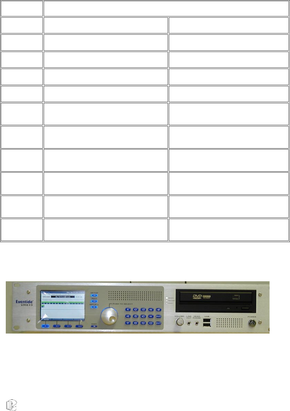
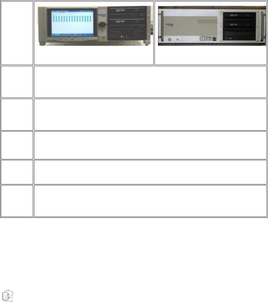
FRONT PANEL DETAILS – VR615 AND VR778
Atlas VR615
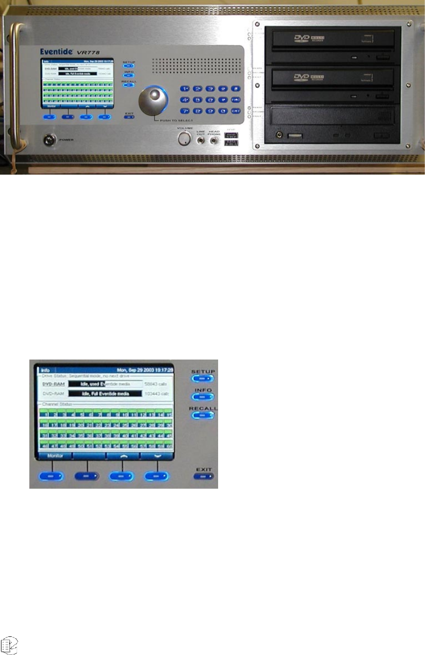
Atlas Series Server 1.8 User Manual 17
Atlas VR778
Above are the full front panels for the VR615 and the VR778. The VR778 in its
standard configuration has two DVD Combo drives and a CD-RW drive. The
VR615 has a single DVD Combo drive. Available optional drives include:
• Iomega REV® drives;
• DDS-4 tape drives;
• Removable hard drives; and
• Solid-state drives for special applications.
The display presents
information on the
operation of the recorder.
The bottom row of keys is
referred to as the "soft
keys" and their function is
defined by the bottom line
of the display, which
changes depending on
context.
The side keys have fixed
functions and are referred
to as mode keys.
Atlas Series Server 1.8 User Manual 18
The Knob and keypad are
used for data selection and
entry. Frequently an item
is "scrolled to" by turning
the Knob and then
selected by pressing it.
T
he
keypad enters numeric
and other data.
There are three LEDs to the left of each
archive drive.
READY indicates that there is a medium in
the drive
RECORD indicates that the drive is archiving
FAULT indicates that there is a problem with
the drive or medium
The power switch is operated with a key -
two of which are supplied. Note: You should
avoid using this switch to power down the
unit. Use it to power up only.
The audio section provides a headphone jack
and volume control for it. There is also a
constant level Line Out jack. The USB
connectors are for alphanumeric keyboard
connection or modem connection (used for
remote diagnostics).
Atlas Series Server 1.8 User Manual 19
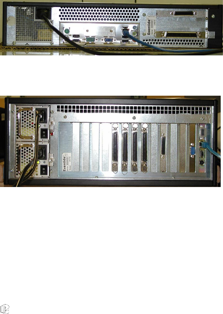
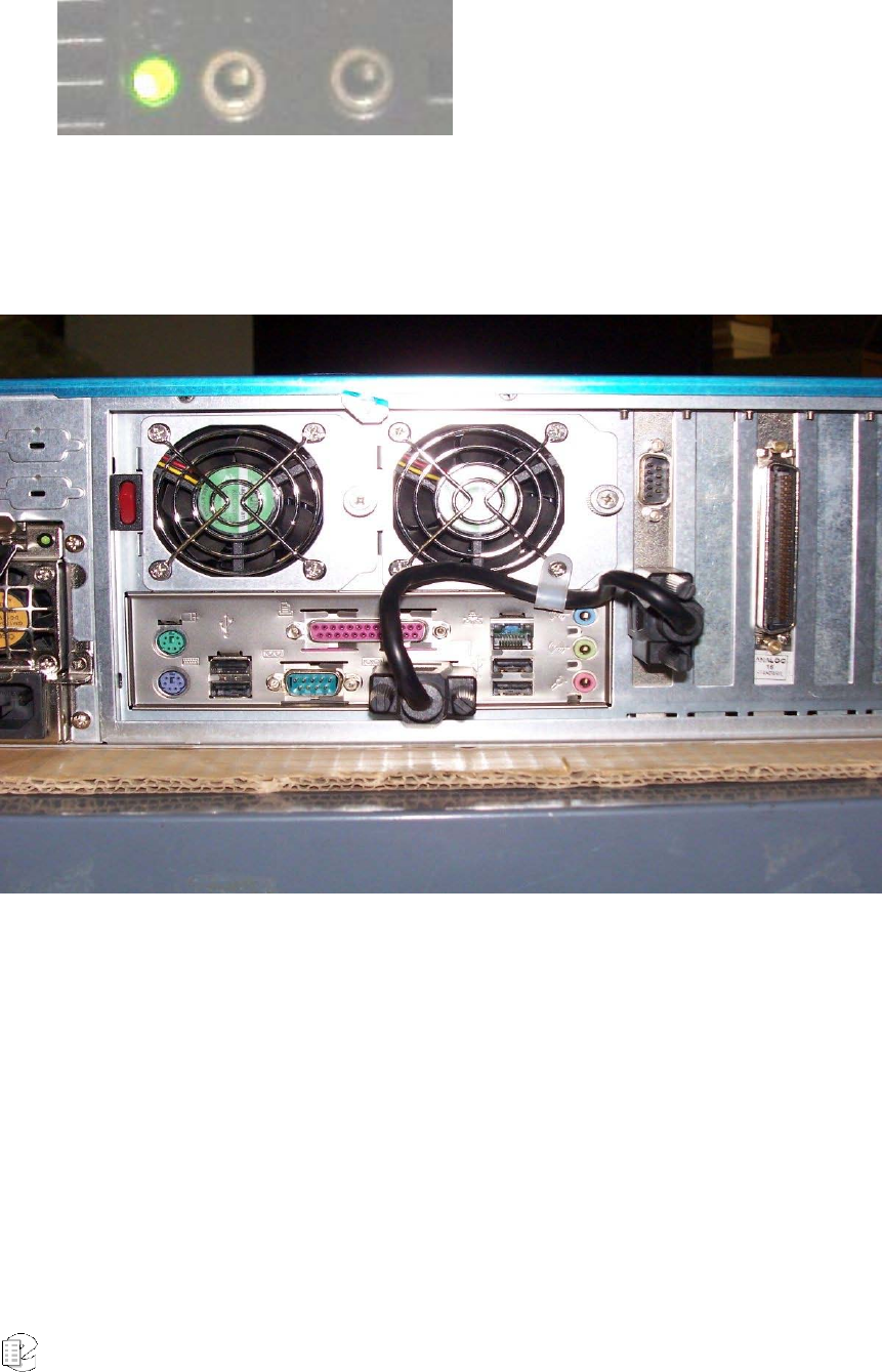
REAR PANEL DETAILS
Typical VR615 Rear Panel
Shown connected are the AC power and Ethernet port. The connector on the lower right
is for the single 16-channel analog telephony board.
Power Supply 8 7 6 5 4 3 2 1 f e d c b a
Typical VR778 Rear Panel with Slot Labeling
This VR778 shows connections to the dual-redundant power supplies and the Ethernet
port. The four large connectors in the center are for the four 16-channel telephony
boards in this unit. The small D connector on the second panel from the right is an RS-
232 connector for the optional label printer. Slots 1 through 8 can contain telephony
boards. Slot 1 holds the lowest-numbered channels.
Atlas Series Server 1.8 User Manual 20
VR725 & BLANK PANEL UNITS
These members of the Atlas series use either a touch screen display, which acts
both as a monitor and a mouse, or an external standard computer monitor and
mouse. All operations performed by the front panel controls on the VR615 and
VR778 can be performed by the touch screen. The Atlas blank panel models are
lower-cost alternatives for those who intend almost all operation to be remotely
controlled over the network. Installation can be accomplished with a “borrowed”
monitor, mouse and keyboard
Product
view
VR725 VR778-Blank Panel
Front
Panel
GUI
640 x 480 Touch screen Display or external monitor and standard
computer mouse
Front
Panel
I/O USB, 1/8" line level output, 1/8" headphone output
Remote
software
Windows-based remote call browser
Windows-based remote administration client
Operating
System Linux
Call
Record
Database Internal relational database with programmable retention

Atlas Series Server 1.8 User Manual 21
Channel
Inputs
Compression Rates (kbits/s): 13.3, 16, 32, 64 Mu-law
Frequency Response: 200 to 3400 Hz
Signal to Noise: -50dB
Crosstalk: -60dB
AGC: 24dB Boost
Impedance: >10Kohm
Network Ethernet 100Mb/Sec
Height 5-1/4" (3 rack units) 7" (4 rack units)
Depth 21" w/o cables, Display protrudes 2” 26"
Power 200 watts nominal 200-300 watts
Power
supplies Dual hot-swap Dual hot-swap
Weight 50 pounds nominal 55-95 pounds
Analog
channels 8-96 16-160
Digital
channels 16-96 16-120
Maximum
hard disk
capacity 4 drives, RAID 5 2-6 drives, RAID 1 or RAID 5
Standard
archive
drives 2 X 9.4GB DVD COMBO (DVD-RAM/R) 2 X 9.4GB DVD COMBO + 1 CD-RW
Standard
hard disk
storage 2 X 250GB 2 X 120GB
Optional
storage 2 X DDS4 (SCSI), 1TB Hot-swap RAID 2 X DDS-4, Removable hard drives,
3rd DVD
Atlas Series Server 1.8 User Manual 22
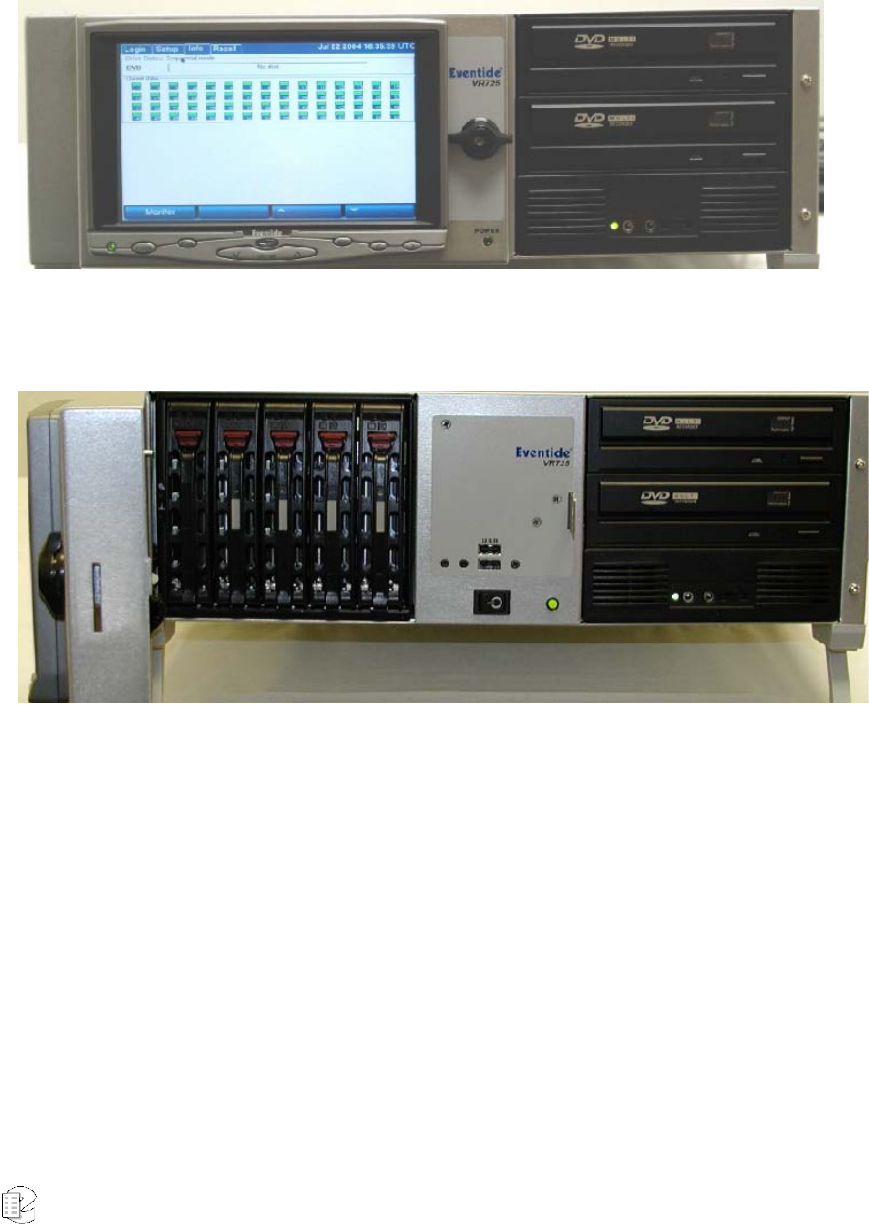
FRONT PANEL DETAILS – VR725 WITH TOUCH SCREEN
The touch screen display is on a locking door that protects the power switch and optional hot-swap
RAID array.
Door open to show RAID hard drives
The VR725 employs a touch screen display for control, instead of dedicated
buttons and keypad. All functions, including SETUP, can be accessed from this
panel. When necessary an alphanumeric keyboard appears on the screen so that
non-numeric data such as channel names can be entered. The RAID disk array
(up to 1 TB of storage) can be accessed and disks can be exchanged while the
recorder is operating by opening the monitor door. Two DVD Multi-drives are
standard for archiving on DVD-RAM.
Audio monitoring/playback is accomplished with an integral amplifier/speaker
unit (bottom right) with headphone jack, line-level output, and volume control.
Atlas Series Server 1.8 User Manual 23
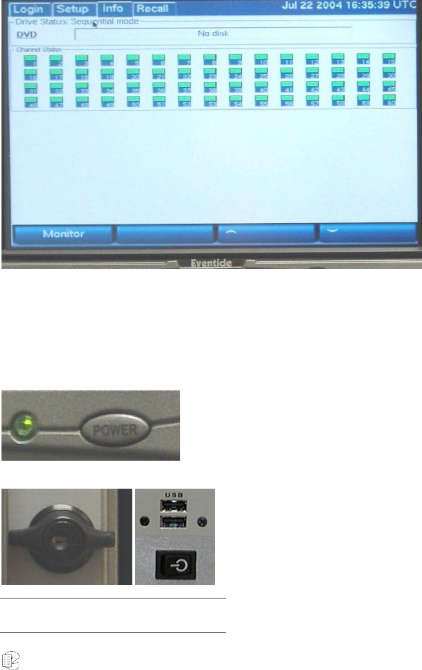
The touch screen display of the VR725 performs all the functions of the display
AND the keypad / soft keys present on the VR615 and VR778. When necessary, a
vertical scroll bar allows additional channel or data selection, and an
alphanumeric keyboard allows data entry of channel names and other required
SETUP information.
This power button, immediately below the
screen, controls the screen backlight
ONLY. Turning it off does not affect
recorder operation in any way. It can be
used as a “screen saver” if desired.
Note: You should avoid using this switch to power down
the unit. Use it to power up only.
The door lock (left) can be opened to
access critical recorder controls and the
hot-swap RAID disk array.
The recorder power switch (bottom right)
is behind the locked door, as are the USB
connectors for the optional keyboard.
T
wo
keys are supplied.
Atlas Series Server 1.8 User Manual 24
The audio section provides a ¼”
headphone jack and a constant level Line
Out jack for convenient re-recording. A
volume control (not shown) controls
speaker and headphone volume.
REAR PANEL DETAILS
Typical VR725 Rear Panel
Left to right: Dual Hot-Swap power supplies, connector panel for Ethernet, USB,
Keyboard, Mouse, Label Printer connector (COM1), and splitter cable. To the right of
the upper cable connector is the Time Source input (COM2) and four telephone board
connectors, 1 (left) through 4 (right).
Atlas Series Server 1.8 User Manual 25
Bench Test
Before installing the unit, you may want to run a brief bench test, especially if you
are unfamiliar with Eventide ATLAS™ series recorders. The following steps are just
one suggested bench test, which you can modify as you wish. If you change
settings, note the defaults first and set them back to the defaults after you
complete the test.
Plug in the provided line cord(s) to the appropriate line voltage.
Turn and hold the key for 1 second and release it. (VR725: unlock the door and
hold the switch for 1 second.) The boot process will start and diagnostic messages
will scroll by on the front panel screen or monitor.
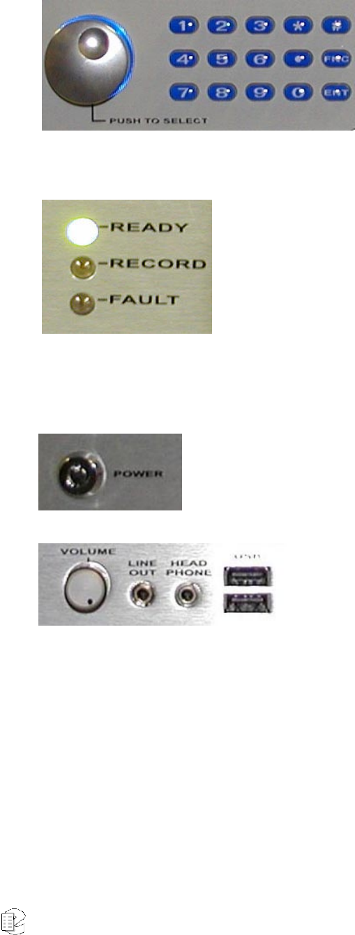
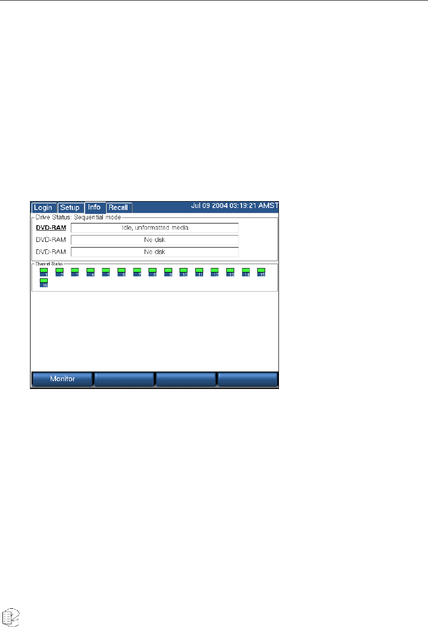
After several minutes, the screen will show the INFO display, one of three top-level
displays. The others are SETUP and RECALL, accessed by the mode keys.
Place a new archive medium in the archive drive. The associated Drive Status
indicator will change from "No disk" to "Unformatted media."
We do not recommend formatting it for now. Wait until you are actually ready to
start archiving. You will learn more about archiving later in the manual. Eject the
disk by selecting its drive and pressing the Eject soft key.
Atlas Series Server 1.8 User Manual 26
The Channel Status section tells you which channels the recorder recognizes as
ready for recording. If you ordered a 16-channel unit, whether analog-only,
digital-only, or a combination, you should see 16 green steady indicators.
Likewise for 24 channels, 32 channels, and so on. This is a good time to make
sure you see the expected number of channels.
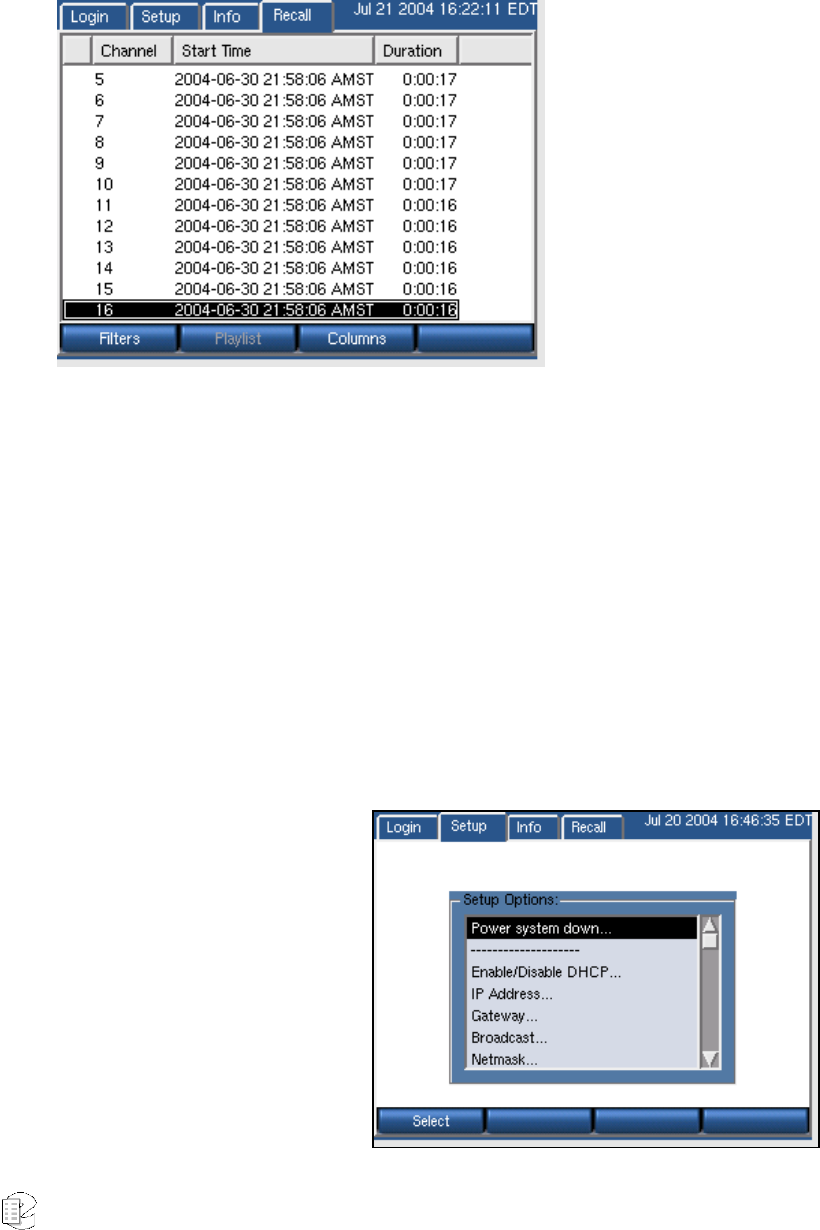
Press the RECALL button. No calls are listed at this point. When calls are
recorded they will be listed, as seen in the figure to the right, and may be played
back.
• Select the SETUP mode and scroll through the items. Try these exercises.
If you need a hint, scroll to the item in parenthesis.
• Read the default IP address and net mask of the recorder. (IP Address)
• Change the IP address. (IP Address)
• What time zone is the recorder set to? Change it to your local time zone
(you can change it back later if you want to). (Time Zone)
• What is the recorder's
internal date and
time? Change them.
(Date/Time)
• Read what types of
boards are installed in
the recorder. (Board
Configuration)
• Change the DETECT
setting of Channel 5.
Put it back to the
Atlas Series Server 1.8 User Manual 27
original setting. (Channel Configuration)
• Toggle AGC for Channel 6. (Channel Configuration)
• Read the serial number of the unit from the front panel. (Serial Number)
• Shut down the unit as follows: Go to SETUP. Choose the item to perform a
System Shutdown. Answer "yes" to the prompt. After the recorder
completes its controlled shutdown procedures, the unit will shut down.
Caution: Do not force a shutdown by pulling the power plug or using the power switch. A forced
shutdown can result in corrupted files and loss of data.
Installation
Caution: Some ATLAS™ recorder models are heavy! Do not attempt to lift or install these units without
assistance. Do not attempt to rack mount any model without either shelf or rack-slide support. Rack
slides are available as an option from Eventide. Do not support these units using only the mounting ears.
GENERAL
The ATLAS™ series recorders are best perceived as computer equipment. They
have essentially the same requirements, both physical and electrical, as standard
PCs, and similar attention should be paid to their environment to assure long life
and reliable operation. Site preparation, especially for larger installations, may
include providing rack cabinets and concentrating communication wiring – phone
lines, radio, etc. – nearby.
OPERATING LIMITS
The installation should allow the units to operate within their electrical and
physical operational limits.
Parameter Range or Limits
Voltage 100 - 250VAC
Frequency 47 - 63 Hz
Power VR615 - 150W/300W, VR725-200W/400W, VR778 - 200W/600W
Atlas Series Server 1.8 User Manual 28
(typ/max)
Temperature Operating +5C (41F) to 40C (104F)
Humidity 10% - 80% relative, non-condensing
Altitude -2,000 to +10,000 feet operating, 22,000 feet non-operating. If operated
at high altitudes, take special care that airflow is unrestricted by dust or
obstacles.
Shock and
Vibration
These units contain hard drive storage units and mechanical
components that are sensitive to mechanical vibration. They are
intended for operation in fixed locations. Vibration-isolation mountings
are required for use in mobile operation.
Shock Operating 1G, 11ms half-sine
Non-
operating 40G, 11ms half-sine
Vibration
Operating .2G, 5-300Hz
Non-
operating 1G, 5-300 Hz
Orientation The archive drives are sensitive to orientation. The recorder should not
be mounted more than 15 degrees off the horizontal plane.
LOCATION CONSIDERATIONS
When choosing a location, consider the following:
• Operating Limits. The location must respect the unit's operating limits,
as listed in the Operating Limits section of this manual.
• Convenience. If the unit will be operated from its front panel, then it
should be comfortably accessible to the operator. Service personnel should
have access to the unit.
• If the unit is to be installed in a rack, special rack units that provide a
horizontal writing surface are available.
• Security. If the unit must be physically secure, then it can be placed in a
locked equipment room with limited access. This will also help ensure data
security.

Atlas Series Server 1.8 User Manual 29
• Consider that a user with access to the unit can remove power, disconnect
the input cables, play back recordings, monitor calls, remove archive
media, and do other things to compromise your data. Logins are no
protection against a determined attacker.
• In short, if you are concerned about malicious users making a purposeful
effort to gain unauthorized access to your data, then the only real
protection is to place the unit in a secure location.
• Cable lengths. For analog signals, such as POTS lines and radio receiver
outputs, cable lengths are not likely to be an issue. An adequate level can
be obtained thousands of feet from the signal source. The unit has
programmable adjustments for low or high signal levels.
• That being said, shorter cable lengths will create less signal attenuation
and noise than longer cable lengths.
• For digital inputs, see the Appendices for more information.
• Particulates. The archive drives and, to a lesser extent, the fans and hard
drives, can be damaged by smoke and dust. If you find dust build up on
the surfaces or the fans being clogged, consider changing the location.
• Power dropouts or surges. The unit should be protected from power
dropouts and surges. The chosen location should have line power available
that is not on the same circuit as equipment that draws a large current on
start-up, such as electric motors or compressors or banks of fluorescent
lights. Line voltage fluctuations, brown-outs, and power outages can result
in loss of data and damage to the unit.
• An Uninterruptible Power Supply is required to mitigate these problems.
See the section entitled Connecting AC Power and UPS for a list of
approved UPS units.
• Spilled liquids. Liquids spilled on the unit can damage it. The location
should not encourage people to place coffee cups on the unit, for
instance.
• Shock. Shocking the unit while the hard drives are operating could
damage the hard drives. The location should not be subject to vibration or
jolting while the unit is operating.
MOUNTING OPTIONS
As normally provided, the unit can be mounted on any surface that can bear its
weight and that does not tilt more than 15°. It can be rack mounted if the rack
has a shelf to support it, and the front panel attached to the rack with the screws

Atlas Series Server 1.8 User Manual 30
provided to prevent casual removal. It must not be mounted solely with the
mounting ears and rack screws!
If no rack shelf is available, a rack-slide rail install kit, which includes slide rails,
rear slide supports, brackets, and mounting hardware, can be ordered:
¾ Rack-Slide Rail Kit for the VR778: Eventide Part# 324343
¾ Rack-Slide Rail Kit for the VR725: Eventide Part# 324430
¾ Rack-Slide Rail Kit for the VR615: Eventide Part# 324355
Alternatively, a center rack mounting option is also available for each Atlas
recorder as well:
¾ Center Rack Mount Kit for the VR778: Eventide Part# 108110
¾ Center Rack Mount Kit for the VR725: Eventide Part# 108109
¾ Center Rack Mount Kit for the VR615: Eventide Part# 108108
OTHER CONSIDERATIONS
The recorder is shipped with two keys. One key should be kept in a safe place as a
backup spare. You should consider preventing casual access to the other key as
well. The key should not be used to power down the recorder unless necessary. It
should be shut off using the SETUP/Power down option. Otherwise, data
corruption could occur. If it is necessary to use the key to shut down the recorder,
turn the key and hold it for one second and release the key. Do not continue
holding it until the recorder shuts down.
CONNECTING AC POWER AND UPS (UNINTERRUPTIBLE POWER SUPPLY)
The recorders use a "universal" power supplies. This means you can plug it into
any line (mains) voltage from 100 volts to 240 volts nominal. However, to prevent
unplanned shutdowns caused by power glitches or interruptions, the recorder
requires a UPS unit that meets certain minimum characteristics:
The UPS must provide power for a long enough period to allow orderly shutdown
of the recorder in case of power failure.
Atlas Series Server 1.8 User Manual 31
If your facility has a backup generator, the UPS should provide power long
enough to operate the recorder until the generator becomes operational after a
power failure (typically a minute or less) PLUS a period long enough to allow
orderly shutdown of the recorder in case of generator failure.
The UPS should be an approved model, i.e., one that can communicate its status
to the recorder. This isn't strictly necessary if your facility is manned and
personnel are trained to shut down the recorder using the appropriate procedure
in case of power failure. However, an approved UPS will keep the recorder running
and perform a safe shutdown when its battery power gets low.
Eventide offers commercial-grade, heavy-duty rack-mount UPS units. We have
tested the following units and confirm they work with the recorders.
Manufacturer Rating Eventide Part # Rack Height
APC / Tripp-Lite 1500VA, 940W, 120V 427213-001 2U (3-1/2")
APC / Tripp-Lite 1500VA, 940W, 240V 427213-002 2U
APC / Tripp-Lite 750VA, 120V 427214-001 2U
APC / Tripp-Lite 750VA, 240V 427214-002 2U
APC / Tripp-Lite 3000VA, 2700W, 120V 427215-001 2U
APC / Tripp-Lite 3000VA, 2700W, 240V 427215-002 2U
In addition, consumer-grade UPS units may be available locally and are suitable
for more casual installations. We have tested the following units and confirm they
work with the recorders.
Manufacturer Model Recommended for
APC Back-UPS ES 500 VR615
APC Back-UPS ES 725 VR778, VR725, VR615
To connect your recorder to a UPS, simply plug the UPS into an AC socket, and
plug the recorder into the UPS using the power cord provided. If you use an
approved UPS, also connect the UPS to one of the recorder's USB connectors on
the rear panel using the cable provided with the UPS. This communication link

Atlas Series Server 1.8 User Manual 32
will perform a safe shutdown when necessary, and also allow the recorder to
notify you (by display and optionally by email) if there is a power problem. Some
recorders are available with dual redundant power supplies. To preserve
redundancy, it is acceptable to use a separate UPS with each line cord.
BEFORE YOU CONNECT AUDIO SIGNALS TO THE RECORDER...
Before you connect the telephone lines, radio outputs, or other signals to be
tapped and recorded, set the recorder's internal clock, date, time zone, and
channel names. If you are installing new software on a currently operating
recorder, disconnect the audio inputs until you have restored the configuration of
the recorder, including channel selection and time zone. The reason for this is
that the recorder will begin recording as soon as it detects an input signal. Calls
with the wrong time, date, and time zone may get recorded and will likely remain
on the recorder for a long time. This might be confusing later when you search,
filter, and archive calls. Refer to the section entitled "Setting the Date, Time, and
Time Zone."
CONNECTING TELEPHONE, RADIO, AND OTHER ANALOG AUDIO SIGNALS TO THE RECORDER
This section applies to units equipped with the Analog Input Board. If you are not
sure if you have this board installed, follow the steps in the section entitled
"Bench Test," specifically step 8e, earlier in this manual. You can also check the
printed back-panel diagram that was packed with your recorder.
The Analog Input Board handles interfacing to analog audio signals. The number
of channels per board will vary depending on which is ordered, with 8, 16, and 24
channels being standard configurations. Each board presents a 25-pair "blue
ribbon" connector at a slot in the rear panel. When viewing the VR615 recorder
from the rear, the Analog Input Board is in the bottom horizontal slot. For the
VR778, the lowest-numbered channel board is in Slot 1, as shown in the figure in
the section entitled "Rear Panel Details." Slot 8 is nearest the power supply. Slot 1
is eight slots over from the power supply. The VR725 telephone boards are
numbered left to right when viewed from the rear.
A mating connector is provided for each board unless a Quick Install kit has been
ordered (next section). The connector has two rows of contacts. One row is
numbered 1 through 25, and the other row is numbered 26 through 50.

Atlas Series Server 1.8 User Manual 33
Numbering is such that pin 1 is opposite 26, and 25 is opposite 50. Each audio
input requires two wires, in what is known as a "balanced" configuration. There is
no "ground" connection. The channel and connector pin correspondence is
detailed in Appendix 8.
Eventide offers a Quick Install kit that, besides pulling together the parts you will
need for a convenient installation, brings Channel 1 to the white-blue pair. It is
described in the next section.
To connect a telephone line to a given channel, simply connect the two wires to
the two pins for that channel. It is not necessary to check or observe polarity.
To connect an audio source such as the line output or recording output of a radio,
connect the "hot" lead to one pin and the ground or shield lead to the other.
Again, there is no distinction between input pins - either can be connected to the
"hot" lead.
Any audio source may be connected, provided that the audio voltage is nominally
in the .1 - 1 Volt range and remains fairly constant. Differing voltage levels are
compensated for when setting up the card parameters from the recorder front
panel. Not recommended are sources with greatly varying levels, such as
"speaker" outputs. Also unusable are "microphone" signals, whose levels are too
low by far to be usable without preamplification.
Please refer to the Appendices for connection information for the optional “HiFi”
audio board.
THE OPTIONAL QUICK INSTALL KIT
For each telephone recording board in the recorder, you will have received either a
mating blue-ribbon connector or, if ordered as an option, a Quick Install kit. The
connections for the mating blue-ribbon connector are detailed in the appendix,
and the pins are numbered on the connector itself for reference.
The Quick Install kit, Eventide part #109033-003 (3 meter cable) and #109033-
007 (7 meter cable), include the following components:
Atlas Series Server 1.8 User Manual 34
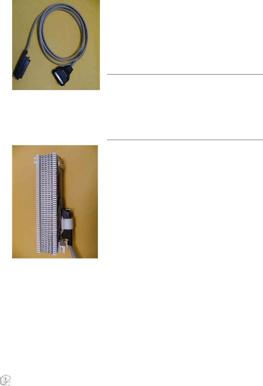
Cable
Connects the recorder telephony board to the punch
block. The rear-entry connector (right in photo) goes
to the recorder and is fastened to the telephony board
rear panel with small wire bails on each side. The
end-entry (left in photo) connector goes to the punch
block and is held in place with a Velcro strip.
Note: This cable may have special wiring! Before substituting a
standard 50-pair extender cable for this cable, confirm that the
telephony board(s) in your recorder do not have special
connections. Please refer to the telephony board appendix. If you
need a greater length, you may use an extender cable in series with
the cable provided as part of the kit whether or not it is one with
special wiring.
Punch block
This is a convenient (and standard) appliance used to
connect twisted pair telephone wiring to the recorder.
Using a "punch down tool" (not provided), the
telephone wires are forced into a slit cut in the
contacts in the block, which makes a firm electrical
and physical connection. The blocks are usually
mounted in the orientation shown.
Each block has 50 rows and four columns. The
contacts in each column are paired: Each outside
contact is connected to the one next to it. There is no
contact between the pairs.
By declaring the left side of the punch block (opposite
the connector) as the connection point for the
telephone (or other audio) lines, you have a common
location to connect your physical wiring.

Atlas Series Server 1.8 User Manual 35
Bridging Clips
The right side (nearest the connector) has each
column connected to an associated connector pin-pair
so that the top row is connected to pin 1, the next row
to pin 26, the third to pin 2, etc. Thus, adjacent
vertical rows form one signal pair.
When you connect the first telephone line, you just
start at the top and connect the wire pair to the first
two rows on the left. The next wire pair would go to
the next two rows down, on the left.
Finally, to connect the telephone line to its associated
recorder input, slip two bridging clips over the two
center contacts in each row.
The purpose of the punch block system is to centralize your connections, as well
as to provide a clean way to isolate the telephone or radio system from the
recorder, should it become necessary. The components can be isolated by
removing clips, rather than removing wires.
CONNECTING DIGITAL TELEPHONE LINES
Refer to the Appendices.
CONNECTING TO AN ETHERNET NETWORK
Connect to an Ethernet network by attaching a network cable between the RJ45
jack on the back of the recorder and your hub or router. The cable should be
CAT5 or equivalent with a male RJ45 plug for the recorder end. Do not use a
crossover cable. On the VR778, use the RJ45 jack on top. See the section entitled
"Network Settings" for information on administering the network settings for the
recorder.
CONNECTING A KEYBOARD
If you are using the remote administration client, Eventide's Recorder Config
product, then a keyboard is not required to operate the recorder. One can be used

Atlas Series Server 1.8 User Manual 36
to perform system administration tasks from the front panel and for diagnostic
work. Connect a PS2 keyboard to the PS2 connector on the back panel (purple on
the VR615 & VR725). Connect a USB keyboard to any USB connector. No
keyboard is necessary with the touch screen display, but one may be used if
desired. Connecting a USB keyboard to an operating recorder does not require
rebooting the system, but connecting a PS2 keyboard sometimes does.
CONNECTING HEADPHONES
Connect headphones to the 1/8" jack labeled "Headphone" on the front panel.
Suitable headphones are available from Eventide (part# 324200). Most
headphones with an appropriate plug can be used and adjusted to a comfortable
level with the front panel volume control.
CONNECTING LINE-LEVEL EQUIPMENT
A line-level audio output is available at the 1/8" jack labeled "Line Out" on the
front panel, if you wish to connect an external recorder such as a Philips Cassette
recorder to the recorder for excerpting calls to cassette. A high-quality rack-mount
recorder can be obtained from Eventide on special order under part number
324375. In addition, most standard cassette units with record capability can
derive an appropriate signal level from this jack.
CONNECTING A LABEL PRINTER
An optional Label Printer can be connected to the rear COM1 RS-232 connector to
make labels for archive media as they are recorded. (The COM2 connector, if
present, is reserved for an external time source.) The Seiko SLP-100 label printer
can be ordered from Eventide as part number 324254, and a two-roll pack of
labels (Seiko SLP-2RL) as 324171
Overview of the Front Panel User Interface
There are three main screens: SETUP, INFO, and RECALL. Depending on the
recorder model, you select the desired mode with a dedicated button, or with the
Atlas Series Server 1.8 User Manual 37
touch screen or mouse. Depending on how user permissions are set up, you may
not have access to all of these screens.
At the bottom of the display are four soft key labels, whose functions are selected
either by pressing a dedicated button or by the mouse or touch screen. Their
labels and functions will change with context.
The encoder wheel can be turned or pressed. Usually, turning it will let you scroll
through a list of items. Pressing it will let you select an item. On the VR725 and
blank panel models with external monitor, a scrollbar and mouse or touch screen
click perform the same function.
A numeric keypad (hardware or displayed) allows you to enter numbers, IP
addresses, and numeric data.
The volume control adjusts the speaker and headphone volume.
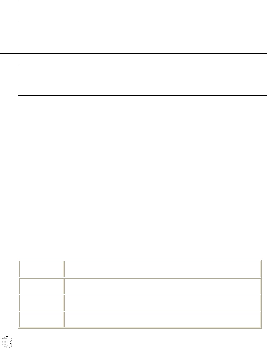
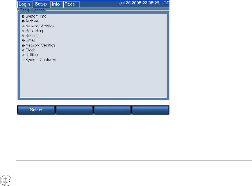
SETUP SCREEN
The SETUP screen allows you to view and set various recorder parameters, such
as IP address, time and date, network parameters, and user accounts.
See Table 3–SETUP Screen for brief description of the settings on this screen.
Note: If you are in the process of setting up a recorder, the very first thing you should do is set the Time
Zone of the recorder, found in the Clock subsection.
Atlas Series Server 1.8 User Manual 38
In keeping with the hierarchical menu structure used for Setup and the large
number of functions, we use a heading for each function showing the full
hierarchy, MODE: TOP LEVEL: SUB FUNCTION. E.g., the section describing how
to set the time zone is headed: Setup: Clock: Time Zone
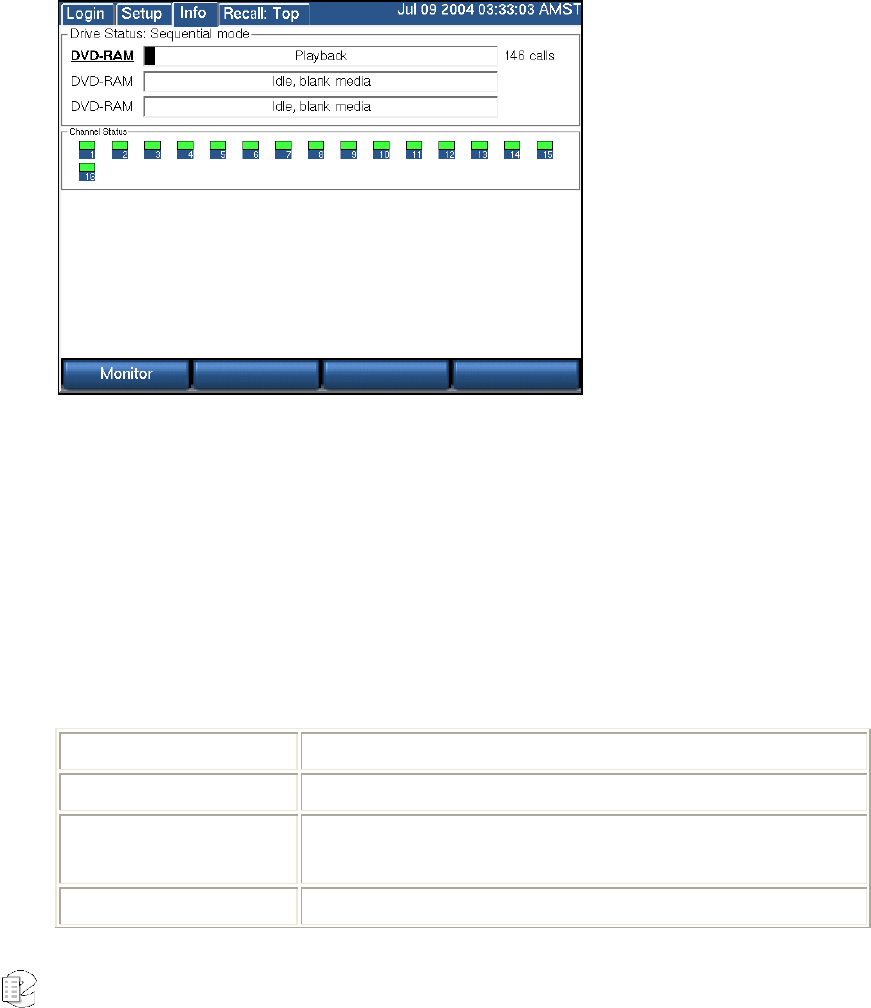
INFO SCREEN
The INFO screen allows you to view and set parameters for your archiving tasks,
check individual channel status, and enable live monitoring.
The top half shows the current status of your archiving drive or drives. The "Drive
Status" will say either "Sequential mode" or "Parallel mode," depending on how it
was set inside the SETUP screen. Each archive drive will have an individual
status indicator that looks like a wide, horizontal rectangle. To the left of the
rectangle is the type of archive drive (DVD-RAM or DDS-4). To the right of the
rectangle is the number of calls on the disk. Inside the rectangle are status
messages and a progress bar.
Table 2–INFO Screen Messages
DISPLAY DESCRIPTION
No Disk The drive is empty.
Loading A medium has been loaded and the recorder is scanning it to
learn its status.
Unloading A medium is being ejected.

Atlas Series Server 1.8 User Manual 39
DISPLAY DESCRIPTION
Idle, Unformatted
Media An unformatted medium is inserted.
Idle, Blank Media A formatted, blank medium is inserted.
Idle, Used Eventide
Media A medium with one or more recorded calls is inserted.
Idle, Full Eventide
Media A full medium is inserted.
Eventide
Configuration
Media
A medium containing recorder configuration information is
inserted.
Eventide Call Metadata
A medium containing call metadata is inserted.
Preparing for Playback
The medium is preparing for browsing. "Browsing" means the
viewing, searching, and playing back of calls. While
preparing, the recorder is loading the calls from the archive
into an internal database.
Playback The medium is ready for browsing.
<A black bar progress
indicator>
The progress indicator provides a graphic view of the
remaining capacity of the archive medium.
<The start time of the
call currently being
archived>
As each call is archived, the start time and date of the call are
displayed.
The bottom half of the INFO screen displays information about live incoming calls.
Each small block represents a channel. Each channel displays its number and a
color:
• Green – The channel is ready for recording.
• Red – Audio is being recorded.
• Blue – Audio is being monitored.
• Gray - The channel is not ready for recording. The audio interface board
may be missing or has not been recognized by the recorder.
• Yellow – The channel has been disabled by the “Record on Demand”
feature
Lastly, a Monitor soft key brings up a list of channels that can be selected for live
monitoring.
Atlas Series Server 1.8 User Manual 40
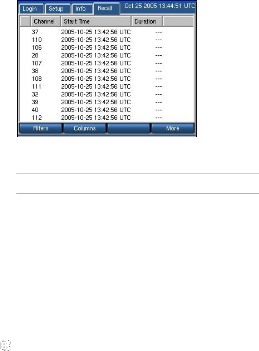
RECALL SCREEN
The RECALL screen is where you view, search, and play back calls. Calls are
displayed as rows, one row per call. You can specify which columns to display.
The default view is Channel Number, Start Time, and Duration. Searches are
accomplished by applying filters to the main call list. Calls can be filtered on date
and time, channel number, and dialed DTMF digits, among other parameters.
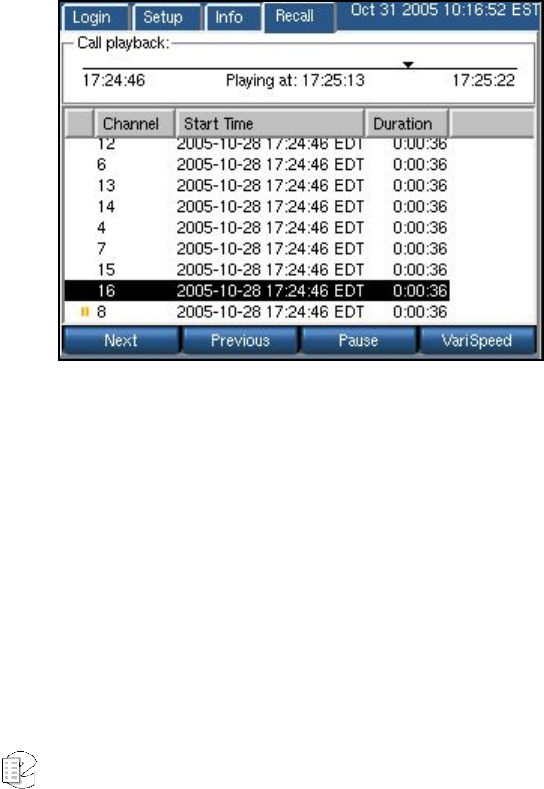
Playing Audio Records
To play back a record,
• From the main RECALL screen, highlight any record, and press the
recorder control knob. The audio record will play, and a timeline will
display at the top of the screen showing the record’s playback status and
general attributes.
• Press Next to play the next audio record, in descending sequence. Press
Previous to play the previous record. Press Pause to pause playback for
the current record.
• Press Varispeed to play the selected record at faster or slower playback
speeds. Moving the control clockwise to the left speeds playback for the
record; moving it counterclockwise slows it down.
Atlas Series Server 1.8 User Manual 41
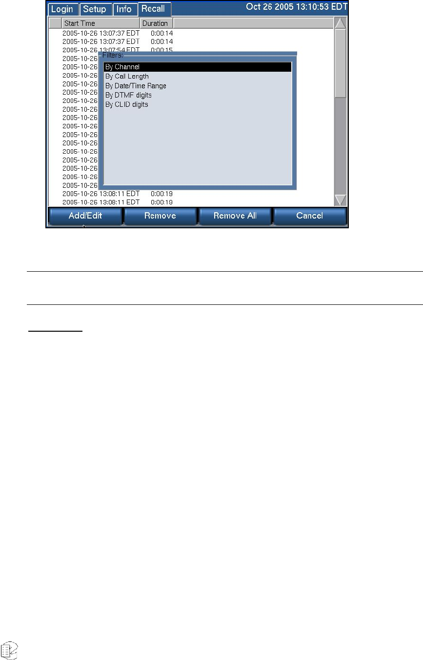
Using Filters
Pressing the RECALL soft key automatically retrieves all audio records resident on
the recorder (below). Use a combination of all available filters to refine your search
to find exactly the set of records you’re looking for.
Click the Filters soft key on the bottom left of the recorder console; the filters
popup screen now displays:
Note: The recorder screen synchronizes all soft keys with its active function; whichever buttons display
onscreen are the current functions for that soft key.
Atlas Series Server 1.8 User Manual 42
Descriptions follow for using each type of filter.
Note: Be sure to adjust your column displays to show the criteria by which you’re filtering. See the
Displaying Columns on page 44 to do this.
By Channel
The By Channel filter allows you to select audio records by individual channels.
• After clicking Filters from the main RECALL screen, highlight By Channel
in the Filters window. Now press the Add/Edit soft key at the bottom left
of the RECALL screen.
• The screen refreshes to display new options:
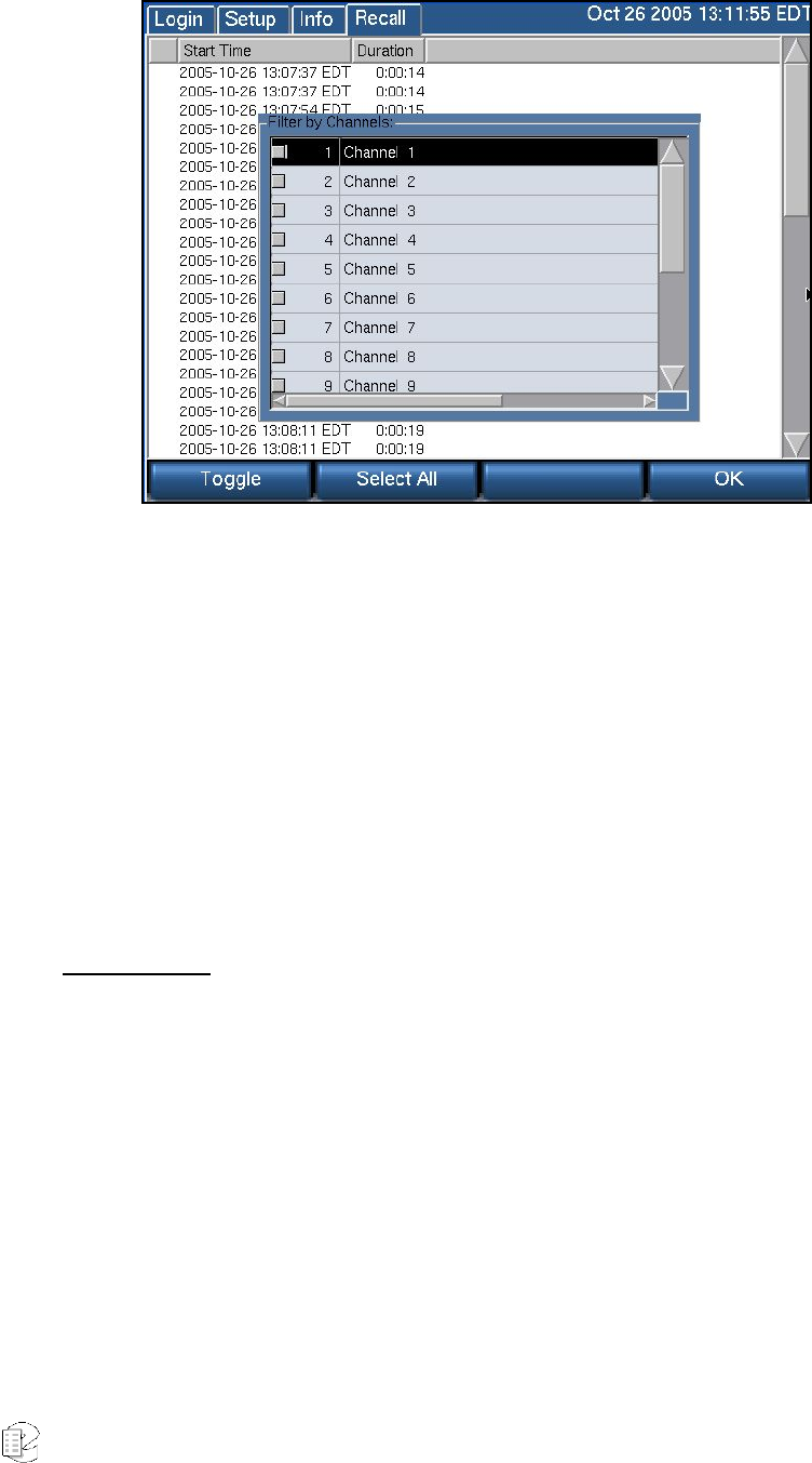
Atlas Series Server 1.8 User Manual 43
• To select individual channels, highlight the channel and press the Toggle
soft key. (A check mark with display in that channel’s checkbox to its left
to designate that it has been selected.)
• To deselect a channel, highlight one that has been selected, and press the
Toggle soft key. The check mark will be subsequently removed from its
checkbox.
• To select all channels, press Select All. (When all channels are selected,
this soft key switches to Unselect All.)
• When all channels you want to include in the search are selected, press
OK. The search will now be performed and display all records meeting
your channel criteria.
By Call Length
The By Call Length filter allows you to select audio records by their duration.
• Press the Filters soft key from the RECALL screen’s main display; when
the Filter window displays, highlight By Call Length.
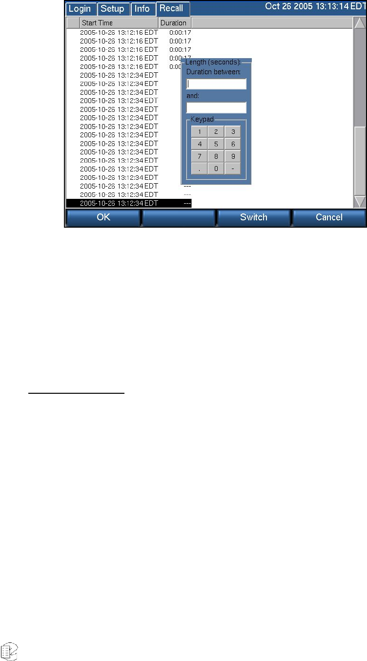
Atlas Series Server 1.8 User Manual 44
• The cursor displays in the top text box. Enter in here the beginning (most
brief) duration period in the time span. Enter all values in seconds.
• Next, press the Switch soft key, and the cursor moves to the second text
box. Enter here the maximum length of duration for the time span you’re
defining. (Switch toggles between the entry fields, so use it to return to the
first field to change the beginning value, if need be.)
• When finished, press OK to retrieve all records that meet this time frame
criterion. To cancel the action, press Cancel.
By Date/Time Range
The Date/Time Range filter allows you to select audio records by specific time
frame.
• Press the Filters soft key from the RECALL screen’s main display; when
the Filter window displays, highlight Date/Time Range. The Date/Time
Range window now displays:
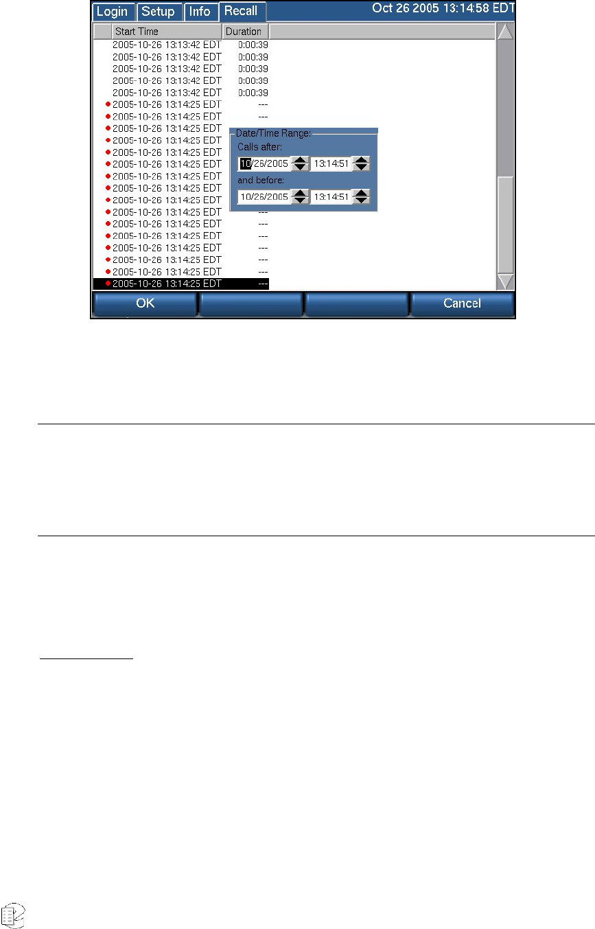
Atlas Series Server 1.8 User Manual 45
• The cursor displays initially in the Calls after date range entry field.
Depending on your interface*, use the forward or back soft keys or the up
and down arrow keys to move the date ahead or back.
*Note: The mechanics of the Date/Time Range filter vary depending on your display system. For users of
the VR725, which employs a touch screen and mouse support, the dates and times can be changed by
using the up and down arrow keys next to each field. Move to another entry field by clicking on it or
touching it. For all other Atlas models, soft keys are provided for back and forward navigation, and a
Switch soft key is provided for toggling between entry fields.
• Move to the Calls before and enter these date and time parameters. When
finished, click OK, and the search will return all audio records between
the dates and times you selected.
By DTMF Digits
Use the DTMF (Dual Tone Multi Frequency) Digits to filter all calls by this audio
record value.
• Press the Filters soft key; when the Filter window displays, highlight
DTMF Digits. The DTMF Digits selection window now displays:
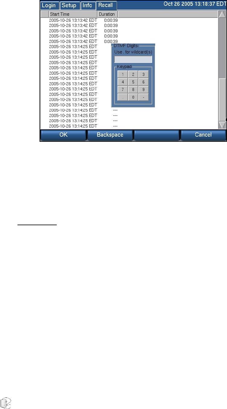
Atlas Series Server 1.8 User Manual 46
• Enter a series of DTMF numbers in the entry box provided, using the
keypad (for touch-screen users), a keyboard, or the recorder number keys.
Enter a period (“.”) to select a wildcard search. Use the backspace soft key
to move the cursor to another point in the number sequence.
• Press OK, and the search will retrieve all records that match these DTMF
criteria.
By CLID Digits
Use the CLID (Caller ID) Digits to filter all calls by this record attribute.
Press the Filters soft key; when the Filter window displays, highlight CLID Digits.
The CLID Digits selection window now displays:
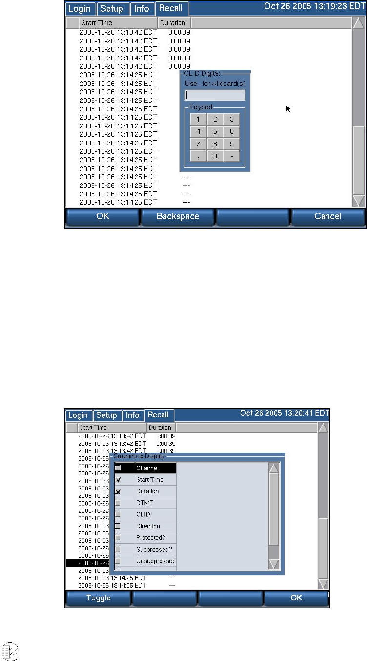
Atlas Series Server 1.8 User Manual 47
• The procedure for filtering CLID digits is identical as that for DTMF digits
described above.
• When finished, click OK to perform the search by the selected CLID digits.
Displaying Columns
The main screen’s soft key Columns is used to configure which column
information displays on your screen.
• Click Columns, and the Column Selection window displays:
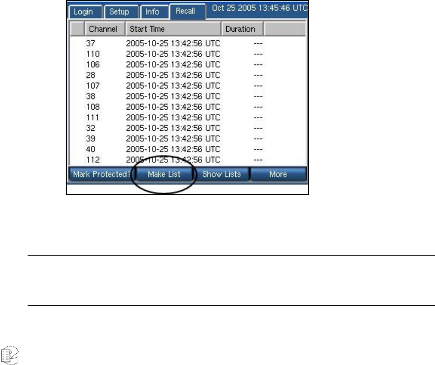
Atlas Series Server 1.8 User Manual 48
• Select a column type to display by highlighting it and clicking Toggle. To
deselect a column, do the same thing, except with a column heading
already selected.
• When finished, click OK, and the records in the database will display with
these selected columns and their associated information.
Creating Playlists from the RECALL Screen
Playlist is a term used to describe grouping calls that share similar characteristics
or attributes. Grouping them allows you to quickly retrieve them as a custom
group. You can easily group several or hundreds of calls from the RECALL screen
by following these procedures
• When you access the RECALL screen, all calls resident on your recorder
display. (Calls that are in progress display with a red circle to the left of
the channel number). To begin creating a playlist, press the More soft key.
The soft key options listed at the bottom of the screen change to Mark
Protected?, Make List, Show Lists, and More. Select the Make List soft key
(below):
• The screen now refreshes in an aqua green background, indicating that
you can make selections for a new playlist.
Note: The Mark Protected? Option is used to give an audio record a status wherein it cannot be deleted
from the recorder’ s hard drive. You may see if a selection has this status by selecting the Mark
Protected option in the Columns selection process (see Displaying Columns).
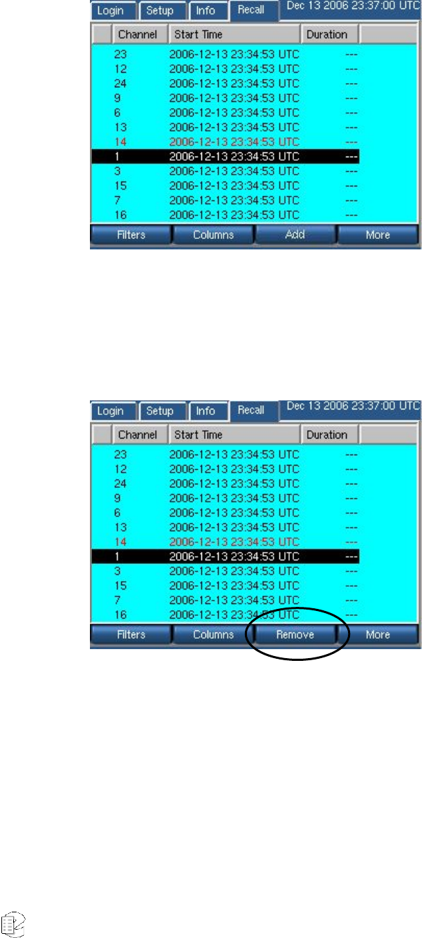
Atlas Series Server 1.8 User Manual 49
• Highlight a selection, and click Add. The entry will now display in red
lettering.
• When a selected entry is highlighted, the Add soft key changes to
Remove, which permits you to deselect it quickly from the playlist.;
• After you select all the entries you wish to include on the new playlist,
press More to proceed.
• The soft keys refresh to reflect your progress in this process; from the ones
displayed, click the List Done soft key.
• The screen refreshes with a listing of each audio record selected.
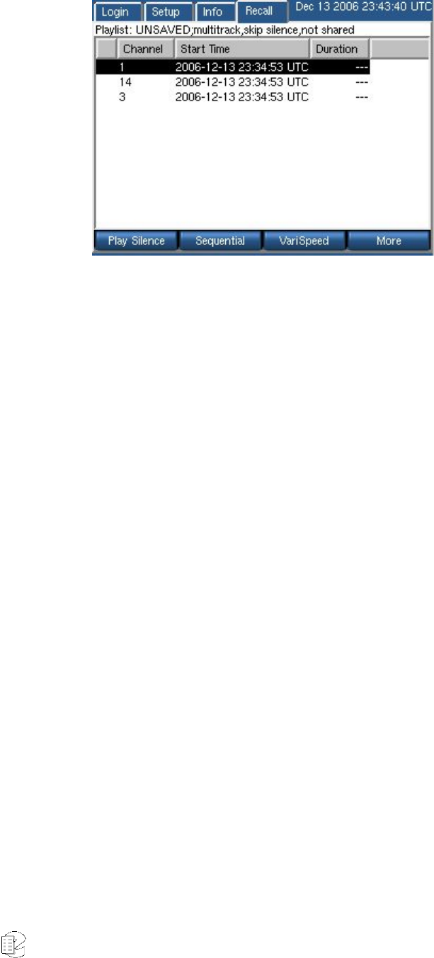
Atlas Series Server 1.8 User Manual 50
• Now the soft keys function as toggle buttons to define attributes to the
custom playlist you’re creating. From left to right, the soft keys are
o Play Silence/Skip Silence. Use this soft key to determine if this
playlist will play or skip silent passages between audio records.
o Sequential/Multitrack. This toggle determines whether records
are played in sequence by time recorded, or if records in the
playlist are played progressively by time. Calls that occur
simultaneously or with any time overlap play back concurrently.
o VariSpeed/Scrub. This option allows you to play back a selected
record from the playlist at different speeds. Rotate the control knob
to the left to slow down playback; rotate it to the right to speed it
up. Note that playback speed is not an attribute that is saved with
the playlist.
When all attributes for the playlist are defined, press the More soft key to
proceed.
• A new set of Soft key values now display. Click Save to save this custom
playlist.
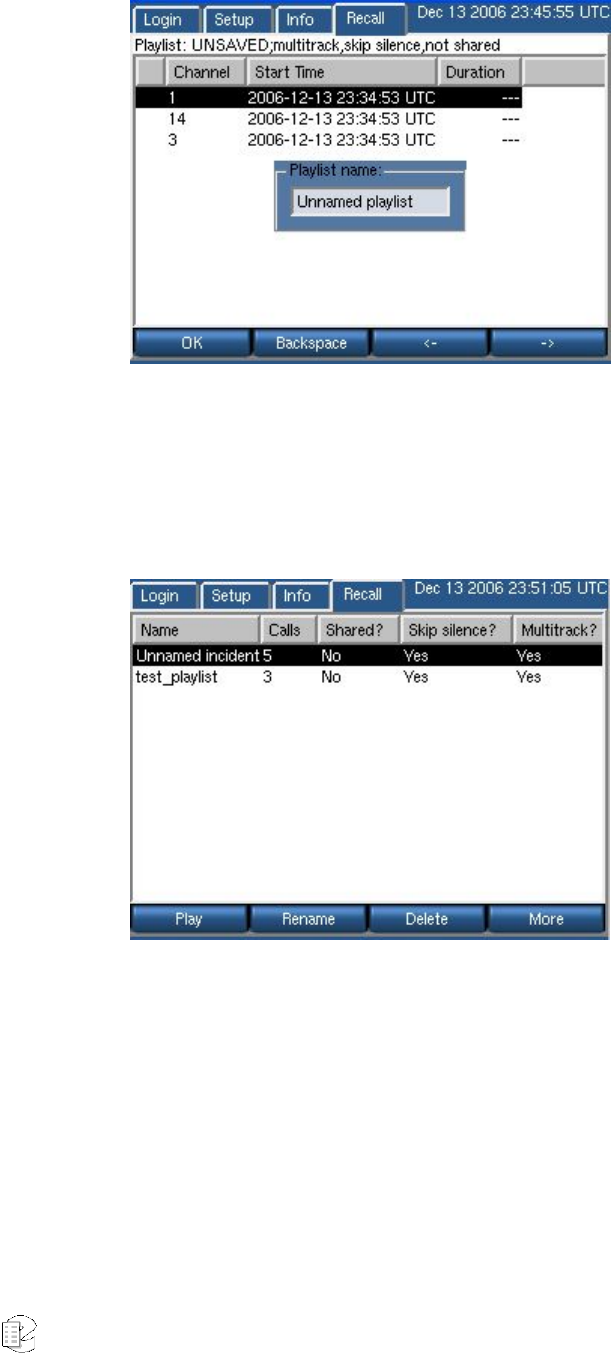
Atlas Series Server 1.8 User Manual 51
• From this screen, use the Backspace soft key to delete the default playlist
title (“Unnamed Playlist”) and enter your own. Use the forward and
backward arrow soft keys to position the cursor to insert a character.
• When finished, click Done; your playlist is now displayed with all others
when you click the Show Lists soft key from the opening RECALL screen.
• Press the respective soft key to play the playlist, rename a selected
playlist, or delete a selected playlist altogether.
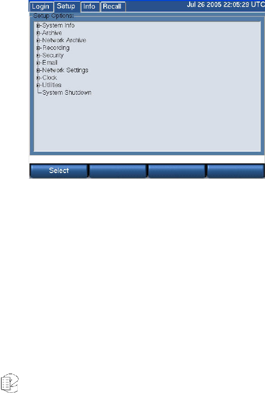
Atlas Series Server 1.8 User Manual 52
R
R
Re
e
ec
c
co
o
or
r
rd
d
de
e
er
r
r
S
S
Se
e
et
t
tu
u
up
p
p
&
&
&
A
A
Ad
d
dm
m
mi
i
in
n
ni
i
is
s
st
t
tr
r
ra
a
at
t
ti
i
io
o
on
n
n
3
3
3
This section discusses setup and administration of the recorder from the front
panel. On entering Setup mode, the following screen appears. This screen is a
hierarchical menu of available functions. Double clicking on any topic (except
System Shutdown) reveals a submenu. A top level item can also be expanded to
its submenu by clicking the small box to the left of the item. A second click of the
box or double click of the heading collapses the menu.
Any number of top level items can be expanded at once. If the listed items exceed
the available screen area, a scroll bar appears to the right of the screen to allow
access to them.
The Setup menu is
hierarchical. This means
that instead of one long list
of functions, they are
collected in groups, and
each group can be
"expanded" by clicking on
its name or on the small
box to its left. Likewise, the
group can be "collapsed" by
clicking on the box or on
the name of an expanded
group.
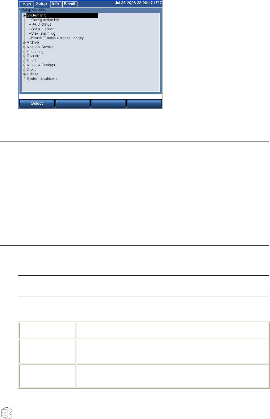
Atlas Series Server 1.8 User Manual 53
In this example, System
Info has been expanded
into its submenu, which
shows Configuration info,
RAID status, and other
items.
Organization
This Setup section is organized in a manner identical to the Setup menu itself.
Each expandable menu group has an associated subsection, and each subsection
explains the individual menu items in the group. The individual menu items have
headings that allows them to be identified with their location, e.g., the heading
"Setup: System info: Serial number" identifies the serial number explanation as
belonging to the Setup mode, and being in the System info group.
Contents
Table 3 describes the Setup Menu.
Note: If you are in the process of setting up a recorder, the very first thing you should do is set the Time
Zone of the recorder, found in the Clock subsection.
Table 3–SETUP Screen
Menu Section Abbreviated Description
System Info Provides information on hardware and software configuration of your
recorder, and status of the RAID disk system.
Archive Allows configuration of the archive drives and selects archiving
methods and backup.

Atlas Series Server 1.8 User Manual 54
Network Archive Configures unit to allow archiving on an external network.
Recording Configures the hardware recording boards and channels, and selects
how many and how long calls are retained.
Security Determines user privileges and whether logins are required.
Email Configures the parameters necessary for the recorder to send email
to selected users for exceptional conditions.
Network Settings Configures the recorder to work with your network.
Clock Allows recorder time to be set, and synchronization source to be
selected.
Utilities Provides methods for saving recorder configuration and "metadata"
info and migration aids.
System Shutdown Provides a controlled, or safe and orderly, shutdown of the recorder.
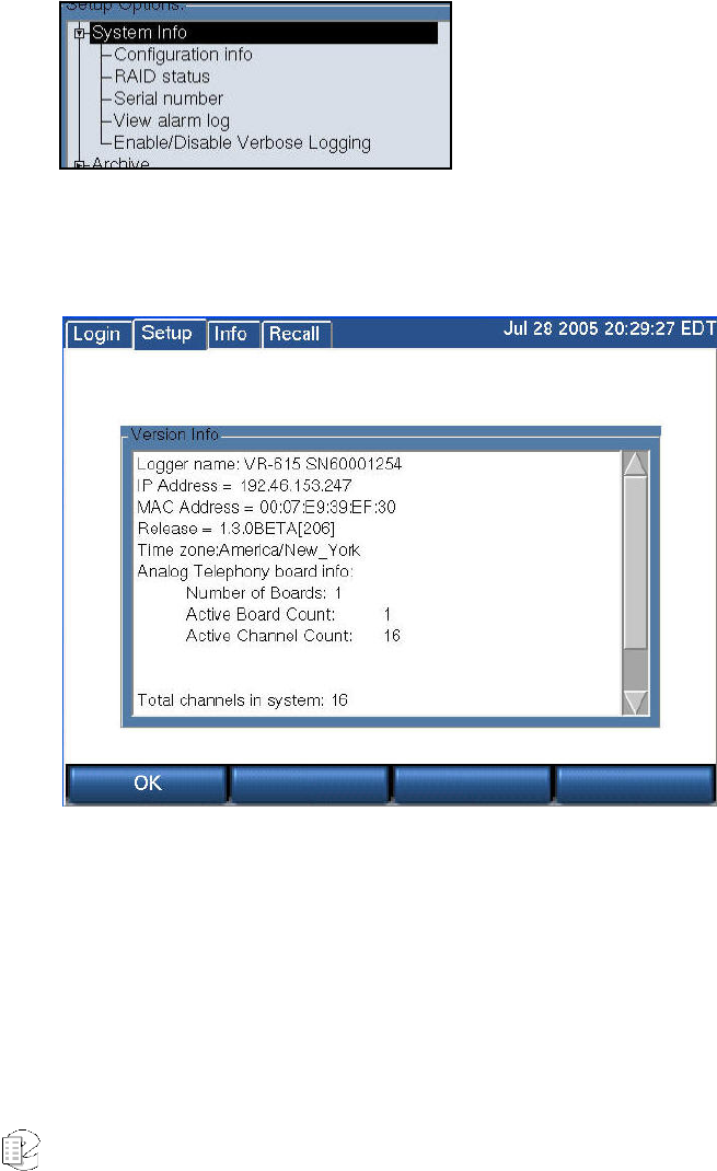
Atlas Series Server 1.8 User Manual 55
S
S
SE
E
ET
T
TU
U
UP
P
P:
:
:
S
S
Sy
y
ys
s
st
t
te
e
em
m
m
I
I
In
n
nf
f
fo
o
o
System Info provides data about your recorder. This information is especially
valuable if you encounter problems or unexpected operation. If you ever require
technical assistance with your recorder, this is the first place we (and you) should
look for the information needed to help.
SETUP: SYSTEM INFO/CONFIGURATION INFO
This Version Info screen displays the following settings.
Recorder Name: model and serial numbers concatenated. This name also will be
displayed by the optional Eventide remote client software.
IP Address: a 4 octet address for network connections.
MAC Address: the fixed hardware-level address of the recorder.
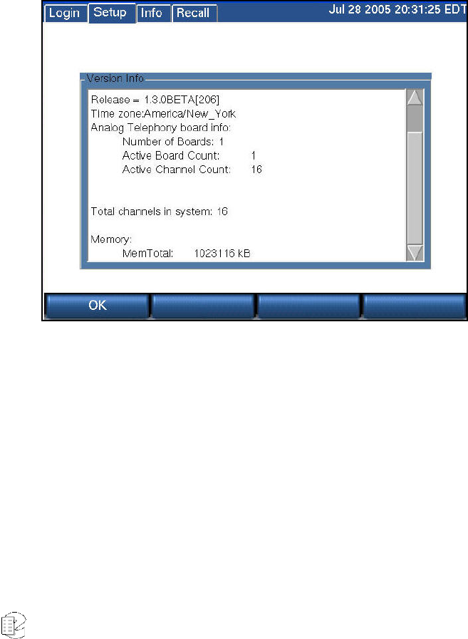
Atlas Series Server 1.8 User Manual 56
Release: the software version number.
Time Zone: the recorder’s internal time zone settings displayed as the selected
locale in the main screen. Note that the upper right corner of the display shows
time zone as a three-letter code.
Number of input interface boards.
Total channels of recording capability in the system.
Memory: MemTotal: the total RAM, in kilobytes. (See below: the right-hand scroll
bar accesses this information.
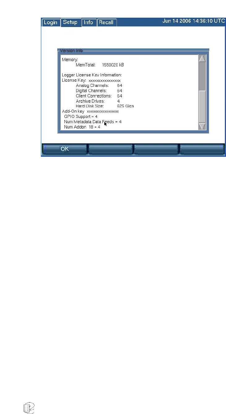
Atlas Series Server 1.8 User Manual 57
Recorder License Key Information
License Key: The recorder license key displays here, along with a list of licensed
features and the number or capacity of licensed components. Licensed features
for this key include analog and digital channels, MediaWorks and MediaAgent
connections, archive drives, and hard disks.
If you exceed licensed features by adding unlicensed components to the recorder,
such as hard drives or boards, the license key will become invalid. You can obtain
a license for these components or remove the components to restore full recorder
operation.
If the recorder does not have a valid license key, it will display alert message #52
or #53, depending upon how long it has operated without a license key. Alert #52
displays if you are within the 7-day grace period, and alert #53 displays if the
grace period has expired.
If the grace period expires, the recorder will continue to record and store
normally, but the following functions will be disabled:
• Recall
• Live Monitor
• Archive: including centralized archive, centralized archiving failsafe, network
attached storage, and DVD, USB, and FireWire (IEEE 1394) drives.
New for
Release
1.5
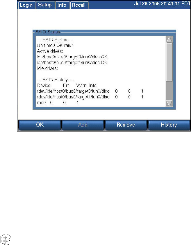
Atlas Series Server 1.8 User Manual 58
• MediaWorks connection
• MediaAgent connection
Add-On Key: This displays any add-on software license keys, which are used to
enable optional features on the recorder. The configuration information shows the
feature names and number or capacity of components licensed for it. Optional
features include MediaCoach connections, GPIO board support, metadata feeds,
centralized archiving, centralized archive failsafe, MDC-1200 decoding, and
support for more than one network archive (NAS device). The configuration
information does not include licensing for custom scripts that contain an
embedded software license key. The licensing for Custom Script Source Files is
embedded at the top of the file and can be viewed under Configuration Files.
SETUP: SYSTEM INFO: RAID STATUS
The RAID Status screen has three sections:
RAID Status enumerates the active and idle drives present in the system, and the
overall health of the storage system.
RAID History shows the number of errors and warnings, if any, which have
occurred since the system was installed.
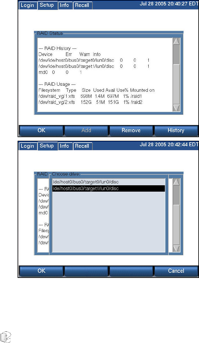
Atlas Series Server 1.8 User Manual 59
RAID Usage (below) shows how full the disks are. In this example, only a tiny
portion of the drives are full. (Calls are stored on the largest “partition” in the
array.) In a lightly-used recorder, it may take months or years to fill the disks. A
recorder with many channels and a high recording duty cycle will show “almost
full” fairly soon after installation, and will remain thus indefinitely, since newer
calls will replace older ones.
Pressing either the Remove or History soft key brings up a screen (above) that
allows you to select a drive. When you do so and select OK, either the history of
the drive will be displayed, or you will have an opportunity to delete the selected
drive. Doing so will degrade the RAID array, and a warning message is displayed.
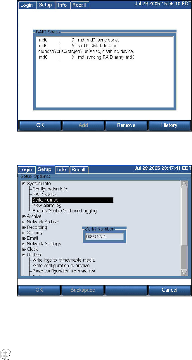
Atlas Series Server 1.8 User Manual 60
The screen below displays the result of removing and then adding a RAID drive.
Note that the Status now shows "syncing RAID array md0" since the removed disk
must be resynchronized.
SETUP: SYSTEM INFO: SERIAL NUMBER
This is a display-only function and it displays the recorder serial number. (The
grayed-out soft keys are functional only when the unit has no Serial Number,
which only occurs with a new unit.)
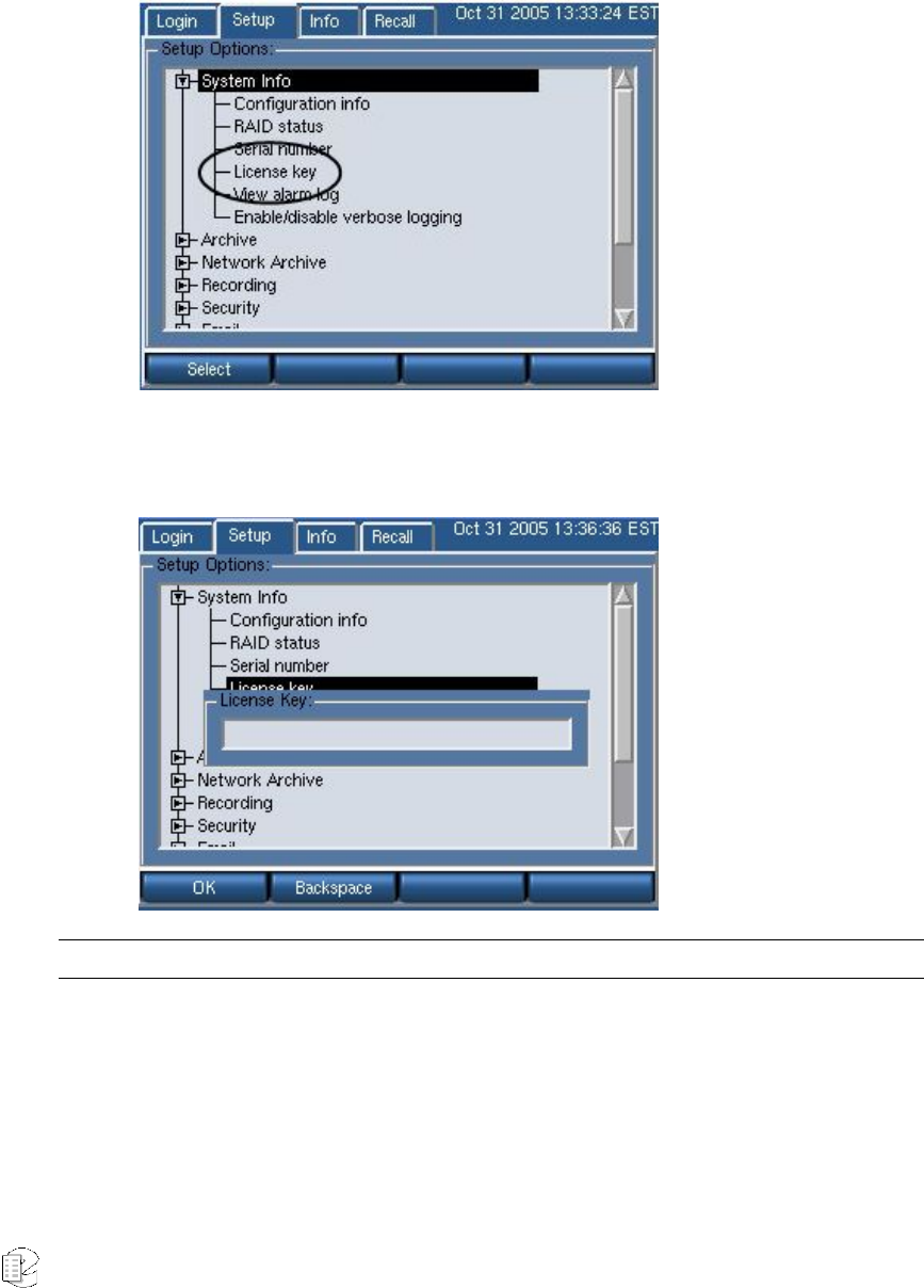
Atlas Series Server 1.8 User Manual 61
SETUP: SYSTEM INFO: LICENSE KEY
Select the License Key option to view your registration information for your
recorder:
• Highlight the License key option from the System Info directory, and press
Select. The screen refreshes with your assigned licensed key listed:
Note: In the illustration above the license key was removed for security reasons.
For all recorders shipping with version 1.4.0 and above installed, a sticker with
your license key will be affixed on the equipment. Users with existing recorders
upgrading to version 1.4 must contact Eventide to get this information.
A recorder without a valid license key will provide you full functionality for the
first seven days, after which it will be diminished until a valid key is entered.
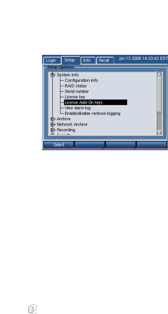
Atlas Series Server 1.8 User Manual 62
Your license key information also displays on the Config Info screen.
SETUP: SYSTEM INFO: ADD ON LICENSE KEY
This specifies any add-on software license keys, which are used to enable optional
features on the recorder, such as MediaCoach connections, GPIO board support,
metadata feeds, centralized archiving, centralized archive failsafe, MDC-1200
decoding, and support for more than one network archive (NAS device).
Select it, and enter the value provided to you by Eventide to enable these features.
From the entry screen, you can add, edit, or remove an existing license key.
If the features that require an add-on license key are not installed on your unit,
the License Add-On Keys entry is disabled.
New for
Release
1.5
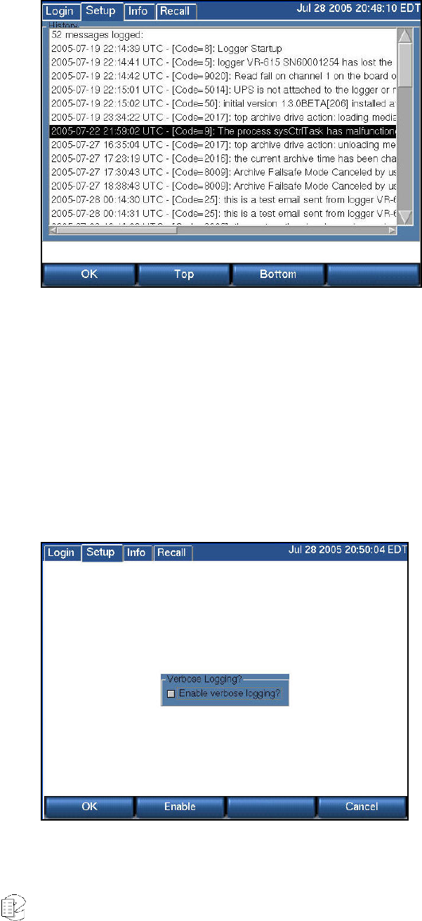
Atlas Series Server 1.8 User Manual 63
SETUP: SYSTEM INFO: VIEW ALARM LOG
The Alarm Log History screen displays important and potentially critical events in
the operational history of the recorder. This is valuable both for diagnostic
purposes and to determine if settings have been changed. These messages can
also be selectively emailed to users.
This log can become voluminous, and the Top and Bottom soft keys along with
the scrollbar speed navigation through the entries.
SETUP: SYSTEM INFO: ENABLE/DISABLE VERBOSE LOGGING

Atlas Series Server 1.8 User Manual 64
This function, when enabled, places additional information in the system logs.
The Enable key toggles the function, and switches the soft key between "Enable"
and "Disable." OK accepts the final decision.
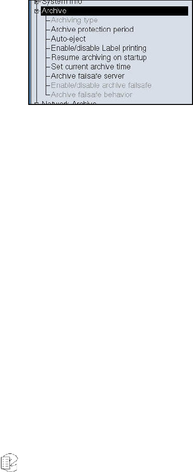
Atlas Series Server 1.8 User Manual 65
S
S
SE
E
ET
T
TU
U
UP
P
P:
:
:
A
A
Ar
r
rc
c
ch
h
hi
i
iv
v
ve
e
e
This section discusses only a portion of the very important subject of archiving. In
particular, it covers the mechanics of setting up the recorder to archive in the
manner and according to the philosophy decided for your site. Additional details
are found in the discussions of actually selecting, using, and recycling archive
media.
SETUP: ARCHIVE : ARCHIVING TYPE
This function selects sequential or parallel archiving on recorders with two or
more archive drives. Parallel archiving produces multiple disks with the same call
data. Sequential archiving begins the subsequent disk(s) where the previous one
finished.
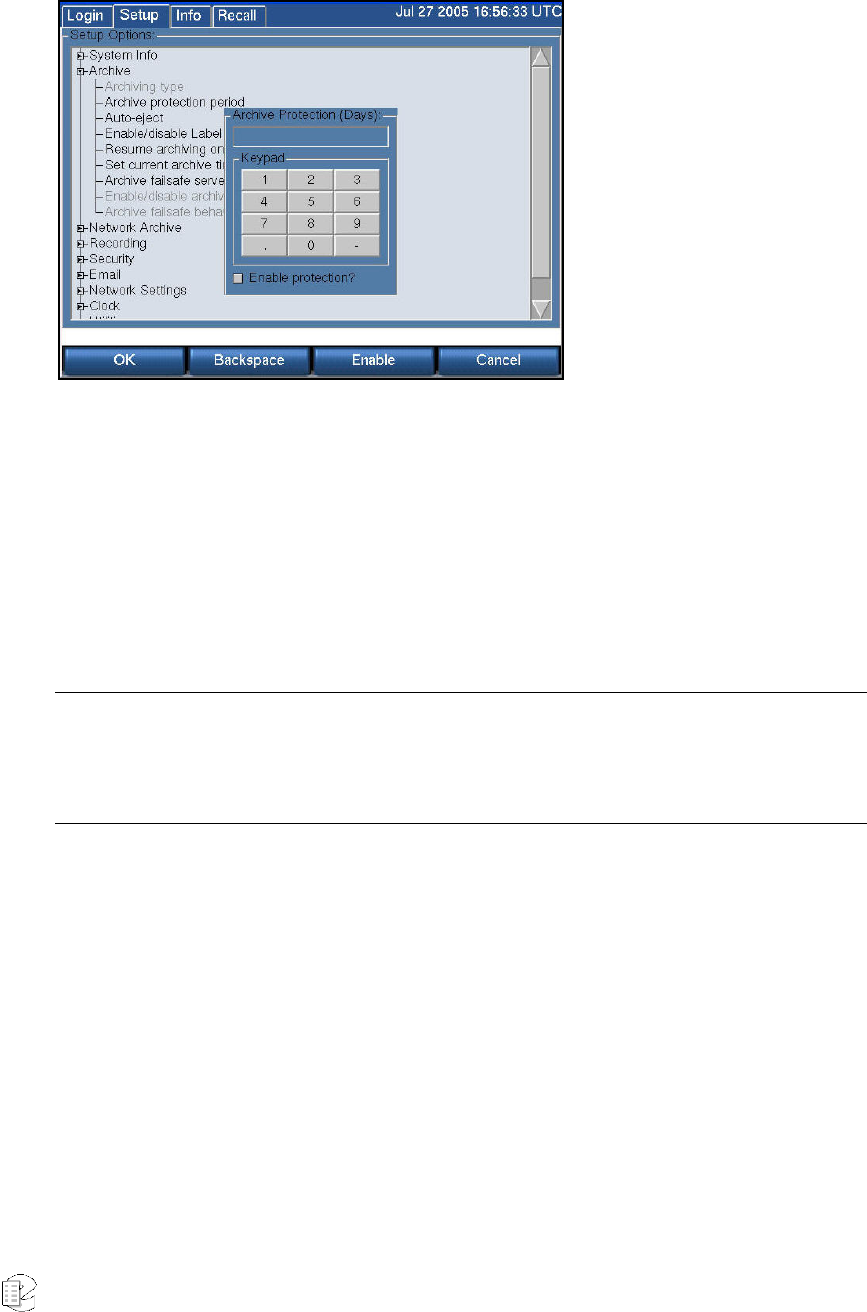
Atlas Series Server 1.8 User Manual 66
SETUP: ARCHIVE: ARCHIVE PROTECTION PERIOD
Entering a number and checking the "Enable protection?" box activates a feature
that allows you to attach a set number of days to a disk during which the disk
cannot be formatted in the recorder. It is intended to guard against unintentional
formatting. When a protected disk is inserted into the recorder, the date of the
latest call on the disk is compared with the current date, as displayed on the
recorder. If the difference between the two dates is less than the number of days
that was set as the protection period, then the recorder will not permit the disk to
be formatted.
Important: The Archive Protection feature must be enabled before a recording on that medium begins.
You cannot add the feature to a disk that already contains recorded calls. Also note that this is a
recorder function only. If you put the medium in a PC drive there is no protection. We recommend using
the "Write Protect" tab on DVD-RAM media for protection of critical archive media.
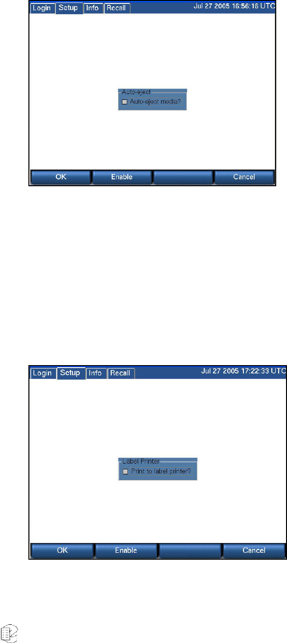
Atlas Series Server 1.8 User Manual 67
SETUP: ARCHIVE: AUTO-EJECT
Checking "Auto-eject media?" causes archive media to be automatically ejected
when the medium is recorded. This is especially valuable if you are using DVD-
RAMs with the optional label printer, since you can simply grab the label and
stick it on the cassette. If you are not using the label printer, it may be more
convenient to refrain from ejecting the media, since that way you can use the
Media Info function of the archiving system to give you the start and stop time of
the archive, which may then be manually written on the disk.
SETUP: ARCHIVE: ENABLE/DISABLE LABEL PRINTING
Checking the "Print to label printer?" box causes a label to be printed each time
an archive medium is completed. If enabled, the optional label printer must be
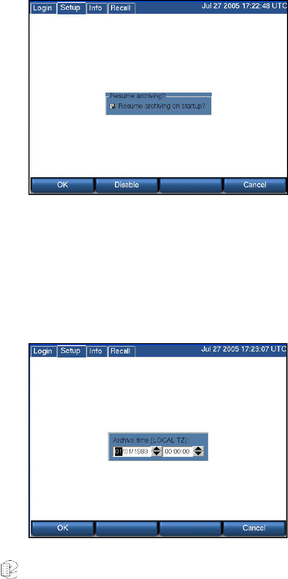
Atlas Series Server 1.8 User Manual 68
connected and powered up, or error messages will appear warning you that the
operation has failed.
SETUP: ARCHIVE: RESUME ARCHIVING ON STARTUP
If "Resume archiving?" is enabled, then a recorder that is turned off while an
archive medium is being recorded will automatically continue recording that
archive from where it left off when the recorder is restarted. If it isn't enabled,
then any archive media in the recorder when power is applied will appear as they
would if they were simply inserted in the drive.
SETUP: ARCHIVE: SET CURRENT ARCHIVE TIME

Atlas Series Server 1.8 User Manual 69
When you start archiving, the first call to be archived is determined by an internal
“archive pointer”. This pointer tracks where you left off archiving with the
previous disk, so that the next disk will begin where the previous one left off. Also,
if you are in the middle of a disk and you stop archiving, for whatever reason,
such as the need to browse calls on the disk, you can resume archiving at the
point where you left off. The goal is to ensure that only consecutive calls are
recorded on each disk, making labeling and searching easier. This pointer is
maintained automatically.
However, there are times when you may want to manually set the current pointer
location. For example, you may have misplaced an archive disk and you want to
re-archive calls. Of course, to do so the calls must still be present on the RAID.
To manually set the current archive time, use the arrow soft keys and the scroll
wheel to adjust the setting. On a touch screen display, select the field and entry
by clicking on the field or the up/down arrows. Press OK when you are content
with your selection. The next time you start archiving, the calls on your RAID
closest to the new archive time setting will be archived first.
When you have completed recording a medium whose starting time you have
selected with the Set Archive Time feature, the time pointer is set to the time of
the end of the medium just recorded. It is NOT set to the end of other data that
may have been archived. Sometimes this is desired behavior, such as when you
want to record more data than will fit on a single medium from the starting time
you set. Sometimes it may not be, such as when you want to continue archiving
from the end of the last medium you recorded in the normal sequence. If the
second is your requirement, you can note the desired time and reset the archive
pointer to this time. If you failed to make a note, you can take the most recent
archive medium, read the “Media info” for that disk, and set the pointer to that
time.
Important: As noted in the display, the Archive time is set in LOCAL time. If you are setting the archive
time to start at the end of a previously recorded archive medium, you will probably use the “Media
Info” feature to check on the end time of that medium. The recorder displays “Media Info” in UTC since
the archives are portable and must be compatible over time zones and different playback hardware.
To dovetail the recorded and new archive times, you must convert your local time to UTC for this setting.
For example, if “Media Info” shows an archive completed at 14:02:00 UTC and you are in the EST time
zone, you would want to set Archive time to 09:02:00.
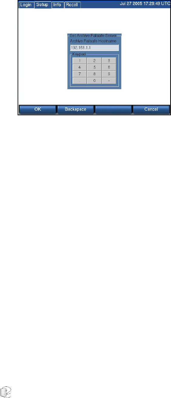
Atlas Series Server 1.8 User Manual 70
SETUP: ARCHIVE: ARCHIVE FAILSAFE SERVER
Failure of an archive medium or drive isn’t normally a grave concern since the
data remains on the hard drive and can be copied to another medium or on
another drive. However, some installations employ redundant recorders to assure
that failure of one unit will not cause any loss of recorded data. In such
installations, it is normally not desired to make two sets of archives, but the
availability of a duplicate recorder makes another option convenient: If the
primary recorder stops archiving for any reason, the redundant recorder can take
over this function. To implement this, you must:
Confirm both recorders are connected to the same signal sources and have
identical settings.
Designate one of the recorders as the secondary server: Select “Archive failsafe
server” and enter the address of the PRIMARY server in the normal fashion. This
is accomplished in the screen above by entering and accepting (with the OK soft
key) the IP address of the server.
Enable the secondary server to periodically check the primary: using the screen
“Enable/disable archive failsafe,” toggle the Enable box so that is checked, and
press the OK soft key. (See screen immediately below.)
Determine the behavior of the failover mechanism: Select desired “Archive failsafe
behavior” and toggle Archive failsafe error on “out of media.” Checking this box in
effect allows the secondary recorder to act as an extension of the primary recorder
for archiving. Not checking it causes the secondary to take over only in the case of
an archiving failure in the primary. (See the second screen, below.)
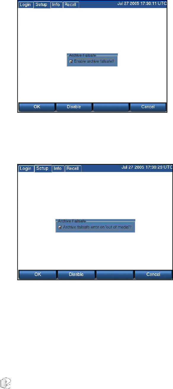
Atlas Series Server 1.8 User Manual 71
SETUP: ARCHIVE: ENABLE/DISABLE ARCHIVE FAILSAFE
See Setup: Archive: Archive failsafe server, above.
SETUP:ARCHIVE:ARCHIVE FAILSAFE BEHAVIOR
See Setup:Archive:Archive failsafe server above.
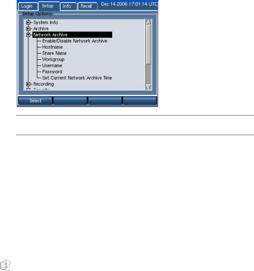
Atlas Series Server 1.8 User Manual 72
S
S
SE
E
ET
T
TU
U
UP
P
P:
:
:
N
N
Ne
e
et
t
tw
w
wo
o
or
r
rk
k
k
A
A
Ar
r
rc
c
ch
h
hi
i
iv
v
ve
e
e
The recorder is able to archive not only to its own internal drives and removable
media, it can also use network attached storage (NAS) on a typical Microsoft
Windows network for archiving.
Note: It is required that Hostname and Share Name be configured in order for network archiving to be
enabled.
Setup:Network Archive:Enable/Disable Network Archive
Check to enable or uncheck to disable the Network Archive feature.
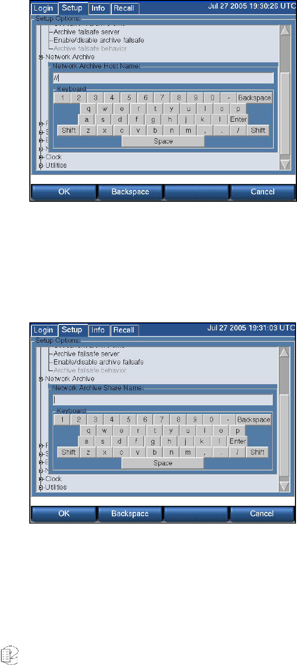
Atlas Series Server 1.8 User Manual 73
SETUP:NETWORK ARCHIVE:HOSTNAME
Hostname - the NETBIOS or DNS name of the server where the archives will be
stored. This server must be a Microsoft Windows server or other system that
emulates Microsoft Windows file sharing.
SETUP:NETWORK ARCHIVE:SHARE NAME
Share Name - the name of the share on the server where the archives will be
stored. Microsoft Windows syntax for specifying a network location is
\\Hostname\Sharename
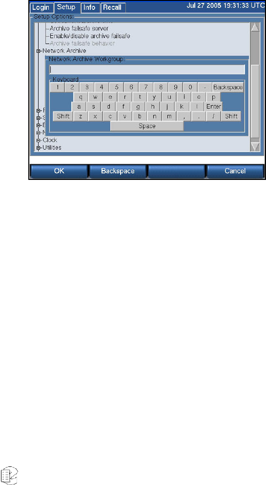
Atlas Series Server 1.8 User Manual 74
For example, if your network administrator has specified that your Atlas Archives
can be stored at
\\BigServer\AtlasArchives
the NAS Hostname should be configured as BigServer, and the Share Name
should be configured as AtlasArchives.
SETUP:NETWORK ARCHIVE:WORKGROUP
Workgroup - The Workgroup or Domain of the server where archives will be
stored.
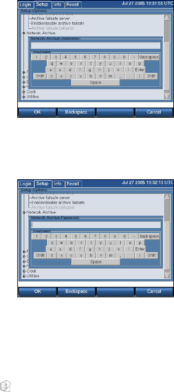
Atlas Series Server 1.8 User Manual 75
SETUP:NETWORK ARCHIVE:USERNAME
Username - a valid username that has been granted read/write access to the
hostname and share name where the archives will be stored.
SETUP:NETWORK ARCHIVE:PASSWORD
Password - the Password associated with the Username on the Microsoft Windows
server.
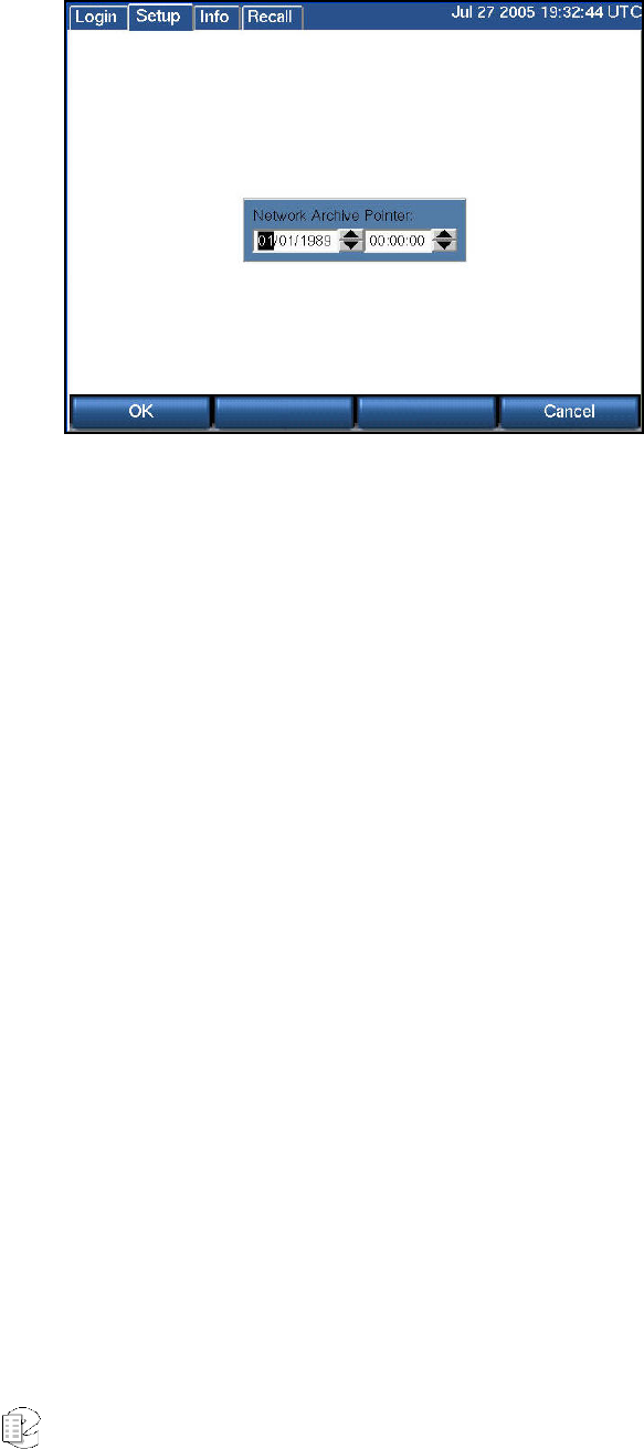
Atlas Series Server 1.8 User Manual 76
SETUP:NETWORK ARCHIVE:SET CURRENT NETWORK ARCHIVE TIME
Set Current Network Archive Time works identically to Setup:Archive:.Set
current archive time. There is no requirement that the local media and the
network archive times be the same. They can be set and reset independently.
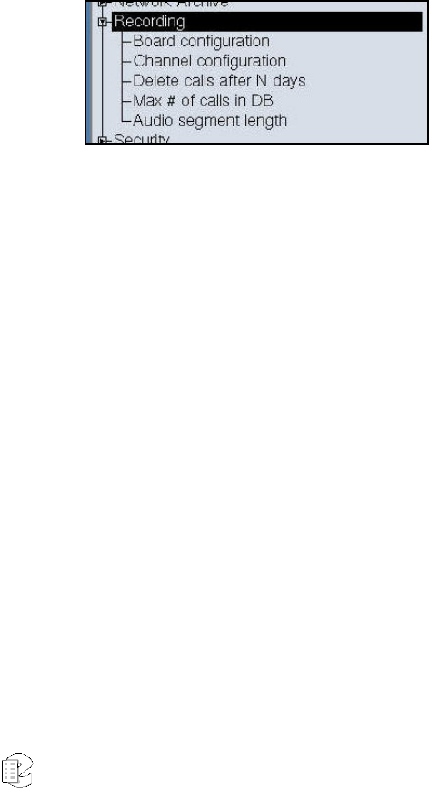
Atlas Series Server 1.8 User Manual 77
S
S
SE
E
ET
T
TU
U
UP
P
P:
:
:
R
R
Re
e
ec
c
co
o
or
r
rd
d
di
i
in
n
ng
g
g
This section discusses how to view and adjust settings on the Eventide Analog
Input Board and the individual channels. The Analog Input Board provides an
interface to analog signals, and is optimized for voice recording of telephone lines.
Eventide offers interfaces to other types of signals, such as digital PBX stations
and high-quality broadcast radio. Contact Eventide for more information, and
check the Appendices to the manual.
Board configuration is used primarily to select the recording algorithm that
digitally encodes the audio inputs. Channel configuration adapts each input to
the characteristics of its signal.
Once you have set the recorder's internal clock, configured the input board or
boards, and configured the channels, the recorder begins recording. There is no
record Start/Stop control; recording begins when the input lines are connected
and the appropriate signal triggers recording. Therefore, the recorder’s internal
clock settings and any board or channel configuration changes should be set prior
to connecting incoming signals to the audio input boards.
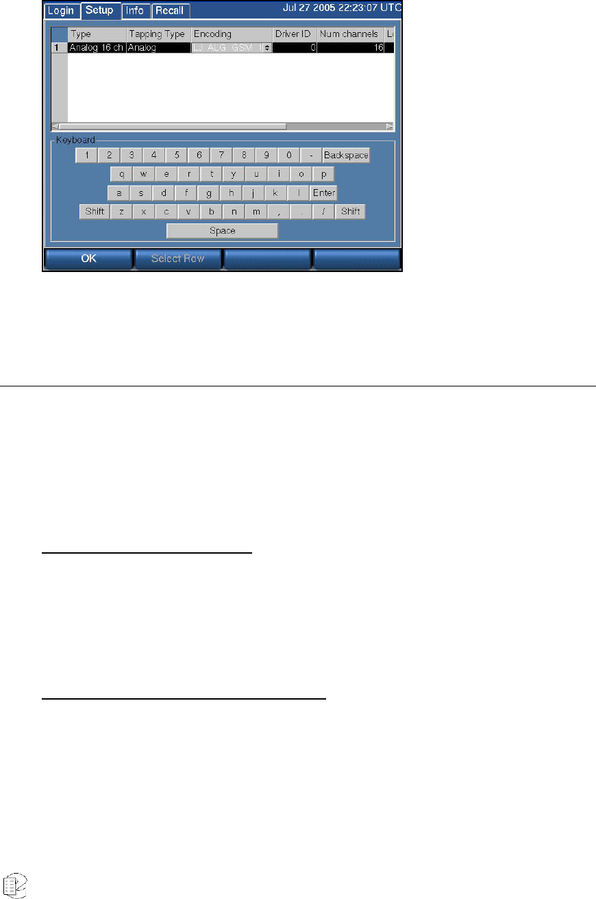
Atlas Series Server 1.8 User Manual 78
SETUP: RECORDING: BOARD CONFIGURATION
Board-level settings apply to all channels on the board.
The Board Configuration Screen
To get to the board configuration screen:
SETUP → Board Configuration
The figure to the right shows a system with a single Analog Input Board.
Navigating with the scroll wheel
To scroll vertically turn the scroll wheel (if there is only one board, this will not
apply); to scroll horizontally, press the scroll wheel to select a board and turn the
scroll wheel; after scrolling horizontally, press the "Select Row" soft key to go back
to scrolling vertically.
Navigating with the touch screen or mouse
To select a board, click the board number. To select a cell, click on the cell. Use
the horizontal scrollbar to bring the cell onto the screen if necessary.
The available settings to view or adjust are
• Type — The field is not editable; it displays the type of board installed.

Atlas Series Server 1.8 User Manual 79
• Tapping Type — The field is not editable; it displays the type of signal
that can be tapped with the board.
• Encoding — The field is editable and sets the encoding algorithm for all of
the channels on the board. See the next section for more information. To
set the encoding algorithm:
o Select the board you want to adjust.
o Select the "Encoding" entry you want to adjust by turning the scroll
wheel.
o Press the scroll wheel or click on the up/down arrows to change
the setting.
o To move horizontally to view other cells in the row, turn the scroll
wheel.
o To move vertically to select another row, press Select Row.
o To exit the screen, press OK.
• Driver ID — A unique identifier for the board for internal use. Not
editable.
• Num Channels — The number of recording channels available on the
board. Not editable.
• Recorder Ch Start — The first channel number that is assigned to the
board. Editable. By default the board installed in the lowest numbered slot
will be assigned channels starting at Channel 1. The next board will be
assigned channels consecutively starting from where the previous board
left off. For example, the first 16-channel board will be assigned Channels
1-16; the second board will be assigned Channels 17-32. If you want to
reverse the order, you can set the second board to start at 1, and the first
board to start at 17.
Changing the default assigned channels can bring up some issues. Avoid
changing the Recorder Ch Start setting if the new setting will point to the
first channel of a different type of board. If you do that, then you also
might have to change the parameters of each channel. During the factory
install, the individual channel settings are set to reasonable values for the
board. Those settings may not work for a different type of board.
To set the first channel assigned to the board:
o Select to the board you want to edit.
o Select the "Recorder Ch Start" entry you want to edit and click on it
or press the scroll wheel.
o Key in the desired channel number and press "Enter."

Atlas Series Server 1.8 User Manual 80
o System Ch Start — The first channel number that is assigned to
the board as part of a system of two or more recorders. Editable.
This number defaults to the same number as Recorder Ch Start.
This setting is for future use when multiple recorders can be
integrated to appear as a single recorder to administration clients
and remote call browsing software.
CHOOSING AN ENCODING ALGORITHM
The following encoding algorithms are available:
• 13 kbit/s GSM (factory default)
• 16 kbit/s G726
• 32 kbit/s G726
• 64 kbit/s Mu Law
The data rate indicates the amount of storage used per second of recording. The
default will give you the most channel-hours. Encoding algorithms always
represent a compromise between storage space and perceived quality. All the
algorithms listed are general-purpose, and are not restricted to voice. You might
want to select either the 32 or 64kbit/s algorithm if your recordings are going to
be used by other decoding equipment, such as with fax recording. Fax in
particular is very sensitive to the compromises made in reduced-bit-rate encoding.
The human ear is much less so.
The encoding algorithm is set on a per-board basis. All channels on a given board
must use the same algorithm. For this reason, you should plan to group all fax or
other special lines on the inputs of as few boards as possible. That way, only
those boards will need to record at a high bit rate, and storage space will be
conserved.
You can experiment with these algorithms to get the best balance between sound
quality and storage space. Be aware that if you change the setting while
recording, a few seconds of audio glitches will occur on the audio currently being
recorded.
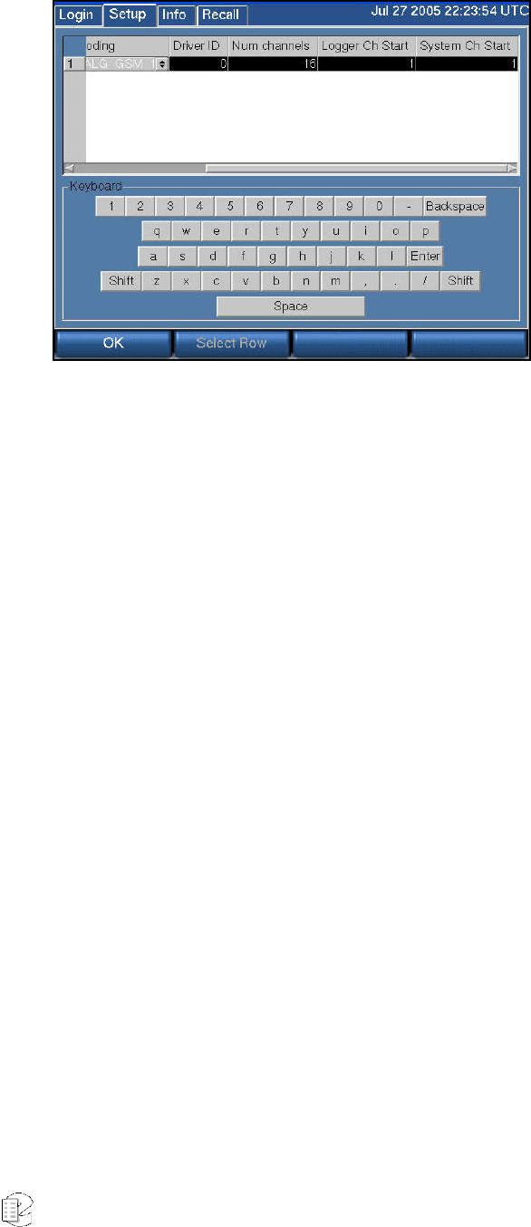
Atlas Series Server 1.8 User Manual 81
SETUP:RECORDING:CHANNEL CONFIGURATION
This section discusses how to view and edit settings for individual recording
channels on the Analog Input Board. Eventide offers other interface boards.
Contact Eventide for more information, and check the Appendices to the manual.
If the recorder is networked and you have the Recorder Config administration
client, we recommend you use it to change channel names. In fact, we
recommend it for all configuration tasks. You will find it to be quicker and more
convenient. In any case, if you are not networked and you are going to change
channel names, connect a PS2 or USB keyboard to the recorder. This will allow
entry of alphabetic characters. Other settings can be set with the numeric keypad
on the front panel. You can also use the touch screen or monitor and mouse on
units so equipped.
The Channel Configuration Screen
The figure below shows a 16-channel Analog Input Board with the factory default
settings.
To navigate inside this screen and view or adjust settings, follow these steps:
1) Scroll vertically and select the desired row.
2) Turn the scroll wheel or use the scroll bar to move horizontally; highlight the
desired cell to be edited.

Atlas Series Server 1.8 User Manual 82
3) Press the scroll wheel or click on the cell to select the desired cell.
4) If the cell has a "spinwheel" symbol, then adjust the value by turning the scroll
wheel and press the scroll wheel when done. Turn the wheel to continue moving
horizontally. With a touch screen, click on the arrows to raise or lower the setting,
and click Enter or select another cell for the value to take.
5) If the cell is a check box, press the scroll wheel or click on the box to check or
uncheck it. Turn the wheel or click on another cell to continue moving
horizontally.
6) If the cell is a numerical value with no spin wheel, then enter the desired value
using the numeric keypad and press "Enter" twice.
7) When done editing a row, press "Select Row" to scroll to a different row, or
press "OK" to exit the screen.
Important: Before you change channel names...
When you change the channel name and you browse calls on the server, all calls on the channel will
display the new channel name, including calls that existed before the change. Calls browsed from an
archive behave in the opposite way. The channel name in existence when the archive was first created
will be displayed for all calls on the archive, even calls that were recorded to the server with a newer
channel name. Therefore, if you wish to associate the old channel name with the calls that were
recorded when the old channel name was in use, and only with those calls, then archive the calls on a
blank disk before you change the channel name and do not append more calls to this disk later on,
after the change. When you browse the archive you will see the old channel names associated with the
appropriate calls.
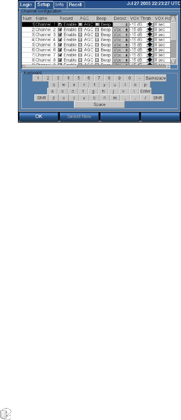
Atlas Series Server 1.8 User Manual 83
Num: Not editable. The channels are numbered consecutively, starting from the
first physical channel of the input board in the lowest numbered slot. So Row
Number 1 of the screen is always associated with that physical input channel.
Name: Editable with an attached or on-screen keyboard.
The Channel Configuration screen is the only place where the channel name is
visible on the front panel. When you browse calls, you will only see the channel
number (1, 2...). The channel names are visible when you browse calls with the
Eventide Remote Call Browser client.
The channel name can be up to 32 characters. It can identify the signal source for
each input channel. Telephone number, radio station call letters, ATC frequency
and function, or any other free-form data may be entered here. While up to 32
characters of data may be entered and saved, display constraints suggest that you
choose the first few characters most carefully. For example, in the Live Monitor
client application, the "Detail View" display only shows the first few characters in
the limited space available, so "Radio Station WABC 770KHz" would be less
useful than "WABC 770 NYC Radio station." There is no requirement to modify
these identifiers. The factory default "Channel 01" ... "Channel nn" may be
serviceable.
Record: This is the Record enable checkbox. This setting is accessed by a client
software feature that permits you to remotely disabled recording temporarily on a
selected channel. This box must be checked in order to enable recording. When
recording is disabled on a channel, it displays yellow on the INFO screen.

Atlas Series Server 1.8 User Manual 84
AGC: Activates or deactivates Automatic Gain Control. Automatic Gain Control
assures that recordings take advantage of the full dynamic range of the recording
process. If you record at too high a level, the signal will "clip" and sound very
distorted. If you record at too low a level, the signal will sound very soft and have
a poor signal-to-noise ratio. Enabling AGC gives extra margin when recording
telephone calls where the local party may be much louder than the distant one-it
will boost the gain by up to 24dB when the distant party is speaking. AGC should
be enabled in most cases. It can be disabled in installations where audio levels
are well-controlled (e.g., broadcast radio stations).
BEEP: Enables a “Beep tone” to signify to callers that the call is being recorded.
Activating the beep places a short, distinctive tone on the respective channel of
the input connector. This tone is approximately 65 milliseconds in duration at a
frequency of 1455Hz. It serves to indicate that the call is being recorded, and is
required by some state laws. Of course, the beep will only be audible to the callers
if the recorder is connected directly to the telephone line in question; if an
amplifier or other device is interposed it will serve no purpose. Beep tones are
only generated on Analog Input Boards, not on Digital PBX or T1/E1 interface
boards.
DETECT: This setting determines when an input channel is active and should be
recorded. There following options are available for this parameter:
• VOX: Starts recording if the audio input signal is above the Vox threshold.
• TRV: Starts recording if the DC input voltage is lower than the TRV (Tip-
Ring Voltage) threshold, indicating an "off-hook" condition.
• GPIO: Uses an input signal from an optional General Purpose
Input/Output (GPIO) board to trigger recording start and stop. The pin
pair that carries the input signal is specified in GPIO Pin column.
Recording starts on a high signal and stops on a low signal. This allows a
variety of external devices to trigger recording.
• Scheduled: Uses the Scheduled Recording facility to designate start and
stop recording settings.
• Always: Forces the channel to record regardless of input signal or voltage
conditions. Useful if there are periods of silence that need to be
documented, such as dead air on a broadcast station or long periods of
dead silence in a courtroom.
• Disable: Disables recording for the channel.
The factory default is VOX.
New for
Release
1.5
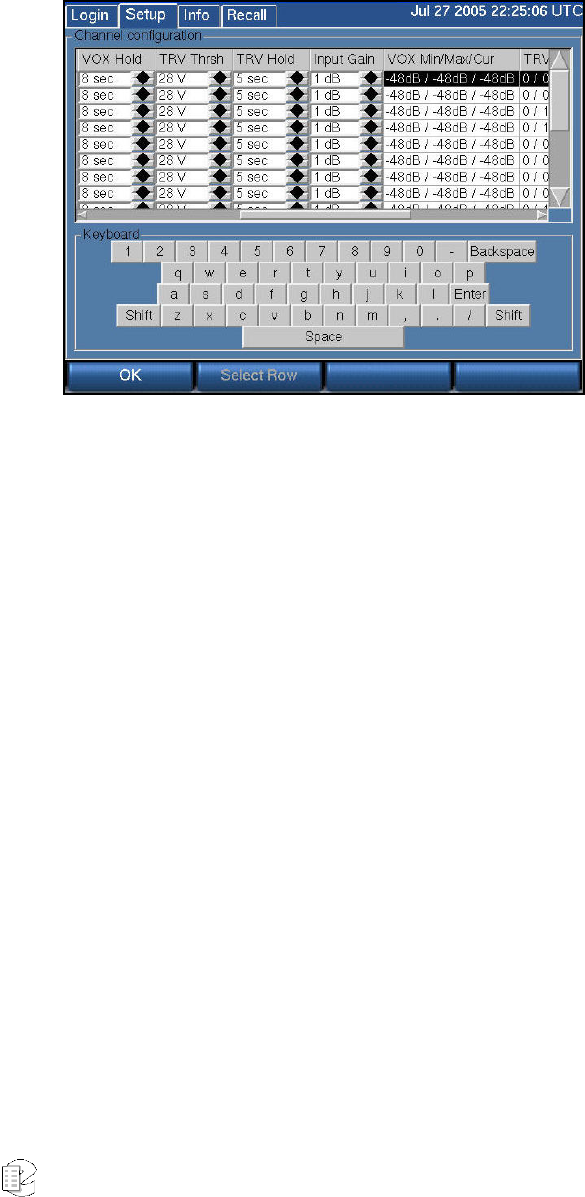
Atlas Series Server 1.8 User Manual 85
VOX Thrsh: If Record Enable Mode is VOX, this sets the trigger level for
recording. Recorders with version 1.1.5 or above software will see a value between
-48dB and 0dB. Units running earlier software versions will see an integer
between 0 and 32767. The factory default is -16dB or 5000.
VOX Hold: If Detect is set to VOX, this sets the number of seconds the channel
will continue recording after the signal drops and remains below the threshold.
The factory default is 8 seconds.
Setting this for too long a value will record long periods of silence at the end of
transmissions; too short a value may break a single call into apparent multiple
calls.
TRV Thrsh: This sets the DC voltage at which a phone line is assumed to be in
the off-hook state and eligible for recording. On a normal, clean telephone line,
this does not have to be set too finely. On-hook voltages are typically 40-55 volts,
off-hook under 10 volts. The factory default of 28 volts will probably be suitable.
Noisy telephone lines, lines at a great distance from the central office, and lines
that are recorded at one location but answered at another can have unusual
voltage profiles and may require adjustment.
TRV Hold: If Detect is set to TRV, this sets the number of seconds the call will
continue to be recorded after the telephone goes on-hook. The factory default is 5
seconds. The on-hook state is then considered to define the end of the
conversation.
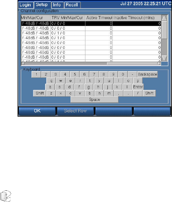
Atlas Series Server 1.8 User Manual 86
With a line that has normal ringing voltage on it (±105V at 20-30 Hz), TRV will
also respond to the ringing voltage. This means that, with a default of less than
four seconds, each ring will appear to be a separate call. By setting TRV hold to
five seconds or more, with a normal ringing cadence only one call will be logged
from the beginning of the ring to completion of the conversation.
If you have set a channel to TRV, a special (non-programmable) feature will detect
and flag a disconnected line if the tip/ring voltage stays below 3 volts for 10
minutes. If this happens, it generates a severity 2 (warning) alert indicating signal
loss (Alert #9016), and recording is stopped on that channel as long as the voltage
remains below 3 volts. When the voltage equals or exceeds 3 volts, it generates the
corresponding “Resolved” alert for Alert #9016 to indicate the signal is restored,
and normal TRV detection and recording will resume.
Input Gain: Gain (or attenuation) in dB of the input channel - used to set
recording level.
VOX Min/Max/Cur: Real-time display of signal input level - useful for setting
channel gain. This is not an editable item. This cell is an excellent tool for
diagnosing recording problems, such as one call being broken up into multiple
calls.
TRV Min/Max/Cur: This non-editable item shows you the real-time minimum,
maximum, and current value of the DC voltage at the channel input. The current
value will indicate if the phone is on- or off-hook; the Min and Max will show the
highest (on-hook) and lowest (off-hook) voltages seen by the channel input. If the
current value fluctuates over a wide range when you are not using the telephone,

Atlas Series Server 1.8 User Manual 87
it probably means that the line is very noisy. This tool can help you set the TRV
Thrsh value or diagnose problems such as spurious calls.
Activity Timeout: Timeout value in seconds. When set, alert #3001 (“Channel
was active for more than X seconds”) is issued if a channel is continuously active
for longer than the timeout value. The factory default is 0, which disables the
function. The timeout will occur for both VOX and TRV Detect settings.
The alert consists of a red window that pops up on the front panel of the recorder,
with a message that the activity timeout alert has triggered. This setting does not
affect the actual recording of the call. It simply issues an alert.
Activity Timeout is useful for calling attention to open or defective telephone
circuits. When a channel is set for TRV detection, a LOW voltage activates it. If the
circuit is open due to a broken wire, the voltage will always be LOW, and the
recorder will issue an alert if this condition persists. If you are going to use this
feature, then you should set this value to one that is longer than any reasonably
expected call or message to avoid nuisance alerts.
Inactivity Timeout: Timeout value in seconds. When set, alert #3002 (“Channel
was inactive for more than X seconds”) is issued if there is no activity on the
channel for longer than the timeout value. The factory default is 0, which disables
the function.
The alert consists of a red window that pops up on the front panel of the recorder,
with a message that the inactivity timeout alert has triggered. This setting does
not affect the actual recording of the call. It simply issues an alert.
Inactivity Timeout is useful for alerting you to circuits that should have signals
but do not. If you are monitoring a radio channel and the radio is turned off, the
inactivity timeout will eventually call this to your attention. Likewise, an unused
(but active and paid-for) telephone line can be identified with this feature. Of
course, legitimate inactivity can span weekends and holiday periods. Setting
periods too short can result in nuisance alerts.
GPIO Pin: Specifies a value indicating the input pin pair on the GPIO board that
is used for triggering recording to start or stop. (This field is used with the detect
GPIO setting.)
For the NI PCI-6503 24-channel GPIO board, values are as follows:
0: specifies pin pairs 47+48 (PA0)
New for
Release
1.5

Atlas Series Server 1.8 User Manual 88
1: specifies pin pairs 45+46 (PA1)
2: specifies pin pairs 43+44 (PA2)
3: specifies pin pairs 41+42 (PA3)
4: specifies pin pairs 39+40 (PA4)
5: specifies pin pairs 37+38 (PA5)
6: specifies pin pairs 35+36 (PA6)
7: specifies pin pairs 33+34 (PA7)
8: specifies pin pairs 7+8 (PC4)
9: specifies pin pairs 5+6 (PC5)
10: specifies pin pairs 3+4 (PC6)
11: specifies pin pairs 1+2 (PC7)
For the NI PCI-6527 48-channel GPIO board, values are as follows:
0: specifies pin pairs 47+48 (DIG+/-0.0)
1: specifies pin pairs 45+46 (DIG+/-0.1)
2: specifies pin pairs 43+44 (DIG+/-0.2)
3: specifies pin pairs 41+42 (DIG+/-0.3)
4: specifies pin pairs 39+40 (DIG+/-0.4)
5: specifies pin pairs 37+38 (DIG+/-0.5)
6: specifies pin pairs 35+36 (DIG+/-0.6)
7: specifies pin pairs 33+34 (DIG+/-0.7)
8: specifies pin pairs 31+32 (DIG+/-1.0)
9: specifies pin pairs 29+30 (DIG+/-1.1)
10: specifies pin pairs 27+28 (DIG+/-1.2)
11: specifies pin pairs 25+26 (DIG+/-1.3)
12: specifies pin pairs 23+24 (DIG+/-1.4)
13: specifies pin pairs 21+22 (DIG+/-1.5)
14: specifies pin pairs 19+20 (DIG+/-1.6)
15: specifies pin pairs 17+18 (DIG+/-1.7)
16: specifies pin pairs 15+16 (DIG+/-2.0)
17: specifies pin pairs 13+14 (DIG+/-2.1)
18: specifies pin pairs 11+12 (DIG+/-2.2)
19: specifies pin pairs 9+10 (DIG+/-2.3)
20: specifies pin pairs 7+8 (DIG+/-2.4)
21: specifies pin pairs 5+6 (DIG+/-2.5)
22: specifies pin pairs 3+4 (DIG+/-2.6)
23: specifies pin pairs 1+2 (DIG+/-2.7)
PBX NT/TE [Sync, Pbx, Phone]: This column is only important for NGX boards;
it is a tool for installation and troubleshooting. The data will look like this: 1.1 /

Atlas Series Server 1.8 User Manual 89
0.66 [2,1,0]. The first two numbers are signal levels in volts. The first of the pair is
the level of the signal coming from the PBX, and the second is the signal level
coming from the phone set.
The three numbers inside the brackets are the total error counts for the channel
since the last reconfiguration or reboot:
1. Sync errors are more general errors on the channel as a whole.
2. PBX errors are errors in the signal from the PBX.
3. Phone errors are in the signal from the phone.
These errors can signify problems and can affect recording: if the errors are
increasing at a steady rate, it indicates that there is a problem. However, if the
error counts aren't all zero, it might not be an indication of a serious issue: for
example, someone may have unplugged and then plugged back in a phone.
Problems can be caused by:
1. Line issues (bad taps, line lengths, tap lengths etc).
2. Unsupported phone set or line card.
3. The wrong PBX is set in the board configuration.
Steps for Setting Levels, Thresholds, and Hold Times
It is undesirable for single conversations to be broken up into multiple calls.
There is a lag between each stop and start, so some of the conversation will be
lost. Setting levels and thresholds properly will help you avoid this condition. This
applies to channels set for VOX detect.
If you are seeing this condition, or if you simply want to check how well the
default parameters match your facility, try this procedure:
1) Disable AGC.
2) Set the Input Gain. It should be set with signals that best match what will be
seen during normal operation. Watch the VOX Min/Max/Cur values and adjust
the gain so that the current value ranges between -6dB and -1dB while a signal is
present.
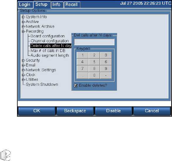
Atlas Series Server 1.8 User Manual 90
3) Enable AGC (if desired). Not recommended for broadcast recording,
recommended for communications or telephone channels.
4) Using the VOX Min/Max/Cur cell, note the VOX Cur value with no signal
present, but with the cabling still connected to account for line noise. Then note
the VOX Cur value with the lowest-level input signal that you are likely to see
during use.
5) Set the VOX Threshold using the values from the previous step. The threshold
should be higher than noise but lower than your lowest signal.
Another possible cause for conversations recorded on multiple separate calls is
Hold time. This would apply to both VOX Detect and TRV Detect. Conversations
with pauses longer than the Hold setting will generate a stop-recording signal.
When the conversation resumes, a start-recording signal will create a second call.
To determine if this is happening, listen to the last several seconds of a call. If you
hear a pause in the conversation longer than the Hold time, followed by a second
separate call of the same conversation, then the length of the pause caused the
stop-recording signal. If you wish, you can increase the Hold time. The downside
is that longer periods of silence will be recorded at the end of EVERY call on that
particular channel. For example, a 15-second Hold time on Channel 3 will cause a
15-second period of silence to be recorded on every call on Channel 3.
SETUP: RECORDING: DELETE CALLS AFTER N DAYS
You can set the database to begin deleting calls after a certain number of days. If
you set this feature to 60, calls over 60 days old will be deleted. The deletion does
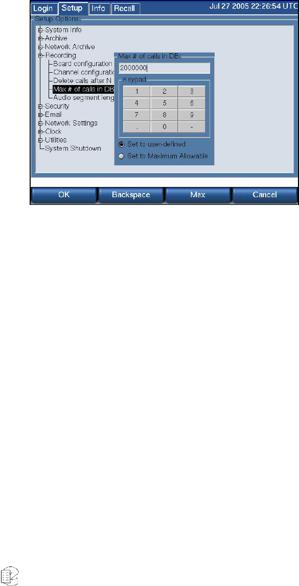
Atlas Series Server 1.8 User Manual 91
not occur immediately; calls start being deleted at the start of the next day (after
midnight). Enter the number of days maximum, or uncheck the "Enable deletes?"
box if you want to keep calls for as long as there remains space on the disk.
SETUP: RECORDING: MAX # OF CALLS IN DB
If the RAID becomes full, calls will be deleted starting with the oldest calls. In this
case the number of stored calls is self-limiting.
You can manually set a limit to the total number of calls that the internal
database will store. After the set number is reached, the oldest calls will begin
getting deleted. Deletion will not occur immediately; calls start being deleted at
the start of the next day (after midnight) as a safety measure. This feature is
enabled by default with a value of 200,000.
To Disable, i.e., to allow as many calls as possible to be stored, select the “Set to
Maximum Allowable” with the mouse or Max soft key.
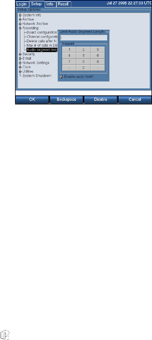
Atlas Series Server 1.8 User Manual 92
SETUP: RECORDING: AUDIO SEGMENT LENGTH
When audio is received continuously, such as with a radio broadcast, it is
possible to have "calls" as long as the maximum, which is 12 hours. This can be
very inconvenient, and this facility allows you to set the maximum length of any
continuous recording. The minimum length is 1 minute and the maximum is 12
hours, with the entry in minutes. If you don't want to limit segment length,
uncheck the "Enable audio limit?" box.
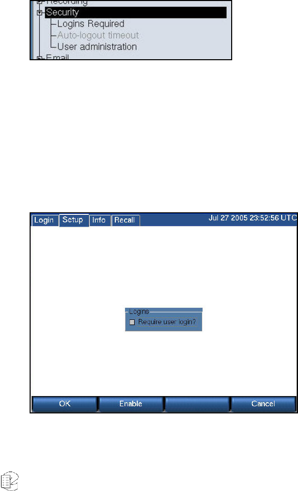
Atlas Series Server 1.8 User Manual 93
S
S
SE
E
ET
T
TU
U
UP
P
P:
:
:
S
S
Se
e
ec
c
cu
u
ur
r
ri
i
it
t
ty
y
y
At a site where a recorder may have multiple operators and different people are
authorized to perform different functions, both Login and user-privilege security
options are provided.
It is important to remember, however, that complete security is difficult to
achieve, and if the recorder is physically accessible, then the security provided by
keys and passwords may well be illusory!
For best security, keep your recorder in a physically protected area!
SETUP:SECURITY:LOGINS REQUIRED
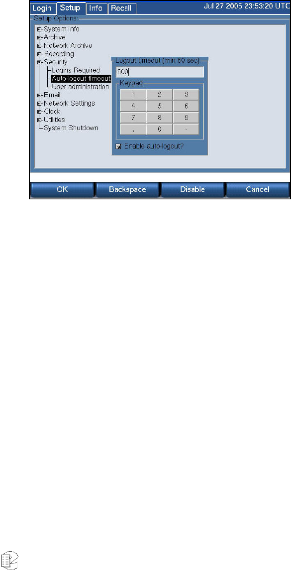
Atlas Series Server 1.8 User Manual 94
Turning on the login feature presents users with a Login button on the front
panel. Users will have to log in to reach other screens. To enable the user login
feature check the box with Enable or the mouse and select OK.
SETUP: SECURITY: AUTO-LOGOUT TIMEOUT
The auto logout feature automatically logs out the current user after a preset
time. To enable auto logout, enter the number of seconds you would like to have
the panel accessible. The minimum is 60 seconds, but this gives you little time to
do anything. In fact, you may find it difficult to disable auto logout. We
recommend 600 seconds (10 minutes), and this is the factory default.
To disable auto logout, log in if necessary and uncheck the "Enable auto-logout?"
box.
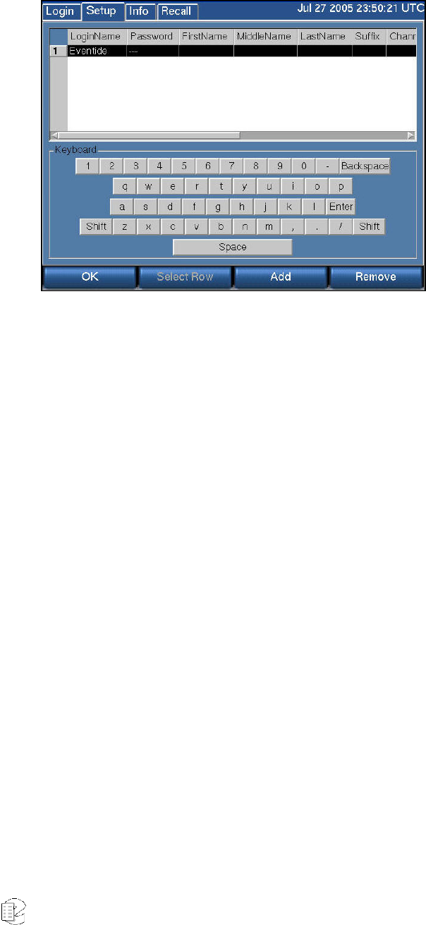
Atlas Series Server 1.8 User Manual 95
SETUP: SECURITY: USER ADMINISTRATION
For many installations, security is an important issue. Who should have access to
the front panel of the machine and what screens and functions should be
available to that user? This section will help you set up users and privileges.
These privileges will apply to the remote clients—that is, the clients will not
bypass the privileges that you set from the front panel.
About Security Groups
Users can be administered by name and password and assigned to one of a list of
built-in "groups." Privileges are associated with each group, and group members
gain those privileges. The privileges associated with each group are set up at the
factory and cannot be modified. There are no user-definable groups.
• Security Group
• Privileges
• Admin
• All available privileges, including the ability to create new users.
• Research
• Browse and play back recorded calls (RECALL screen only).
• Archiver
• Ability to archive calls (INFO screen only).
• Maintenance
• Ability to change system settings (SETUP screen only).
• Monitor
• Ability to monitor live calls (INFO screen only).

Atlas Series Server 1.8 User Manual 96
Managing Users
To add users, plug a keyboard into the USB connector on the front or back of the
recorder. If you don’t have a USB keyboard, you can plug a PS2 keyboard into its
round 6-pin connector on the rear panel, but it may be necessary to reboot the
recorder for it to be recognized. The keyboard is necessary for inputting
alphabetic characters. With a touch screen recorder, you can also use the
keyboard that appears on the screen, but a keyboard may be more convenient.
For a non-touch screen recorder, follow these steps.

Atlas Series Server 1.8 User Manual 97
Security Group Privileges
Admin All available privileges, including the ability to create
new users.
Research Browse and play back recorded calls (RECALL screen
only).
Archiver Ability to archive calls (INFO screen only).
Maintenance Ability to change system settings (SETUP screen only).
Monitor Ability to monitor live calls (INFO screen only).
1) Press SETUP, scroll to User Administration and select it.
2) Press "Add."
3) Type in a login name for the user and hit the ENT button on the front panel
twice. Use the scroll wheel or the keyboard arrow keys to scroll to the Password
cell, and press the encoder wheel to edit the cell.
4) Type in a password using the keyboard or the front panel numeric keypad. The
password consists of a string of from three to 10 digits. Of course, longer
passwords are more secure.
Important: It is easy to place spaces at the beginning or end of the password accidentally. Please
make sure there are no spaces in the password field.
After typing in the password, press "ENT" twice.
5) Repeat steps 3 and 4 to enter data for the FirstName, MiddleName, LastName,
and Suffix cells, if desired. These cells are descriptive and can be left blank.
6) (Scrollwheel models): For the Channels cell, pressing the scroll wheel to edit
the cell will bring you to a list of channels. Scroll to each channel and check the
box if you want the user's privileges to apply to that channel. Rather than using
the scroll wheel, you may find it easier to use the arrow keys and the F8 key of
the keyboard. F8 will place a check mark in the box. Press OK when done. (Touch
screen/keyboard models): Select the cell and type the channel range(s) as a
comma-separated list with a start and stop channel or a single channel. E.g., “1-
3, 7, 9-10” type in the cell would allow access to channels 1,2,3,7,9, and 10. Press
Enter twice to complete each user entry.
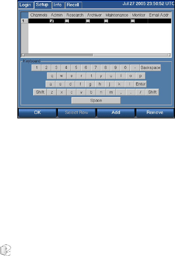
Atlas Series Server 1.8 User Manual 98
7) For the group cells (Admin, Research, etc...), choose the group that the user
will belong to and check the box using F8 or the encoder wheel.
8) For the Email Addr cell, type in the user's email address, if desired. This email
address will be used in conjunction with the Email Alert feature (discussed in the
Recorder Settings section). When certain alerts are generated by the recorder, the
user will receive an email message through this address.
Press the OK soft key to save the settings and add the user to the recorder
account.
For a touch screen recorder, or for one with a monitor and mouse, steps 3
through 8 require clicking the individual cells to get the information to “take.” The
horizontal scrollbar is used to bring cells onto the screen as necessary.
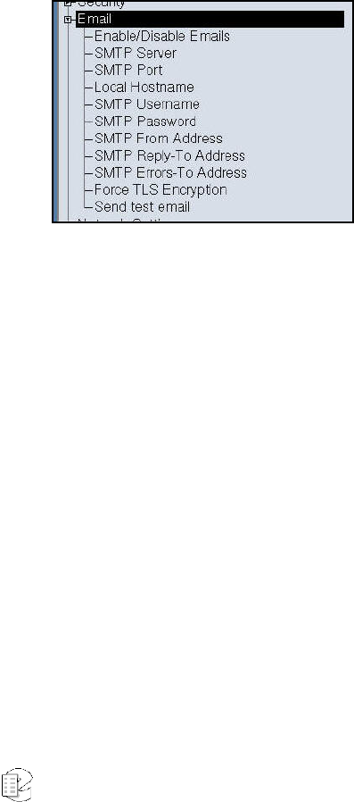
Atlas Series Server 1.8 User Manual 99
S
S
SE
E
ET
T
TU
U
UP
P
P:
:
:
E
E
Em
m
ma
a
ai
i
il
l
l
Setting these parameters is very similar to the normal email setup procedure on a
PC, e.g., the accounts settings in Microsoft Outlook or Outlook Express. You will
need the same information for these settings as you would for normal email, and
can obtain them from your network administrator (or possibly by looking at your
PC email settings).
All entries requiring IP addresses can use "fully qualified domain names" or
numerical addresses. FQDN (e.g., <host.domain.com>) is recommended since IP
addresses frequently change. The recorder does not have to be rebooted for the
email settings to take effect.
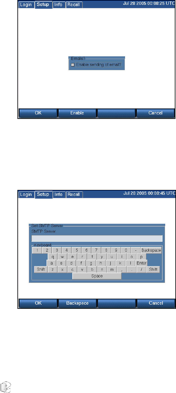
Atlas Series Server 1.8 User Manual 100
SETUP:EMAIL:ENABLE/DISABLE EMAILS
Enable/Disable Email globally permits emails to be sent when enabled. Email still
requires further configuration in the Security section to determine to whom it will
be sent.
SETUP:EMAIL:SMTP SERVER
SMTP Server. Be sure you are authorized to use the SMTP server in question.
Many are set to disallow “relaying” to prevent “spam.” This is likely to be a
problem if the recorder isn’t on the same network, and may be a problem even on
the same network if the recorder doesn’t have an “account.”
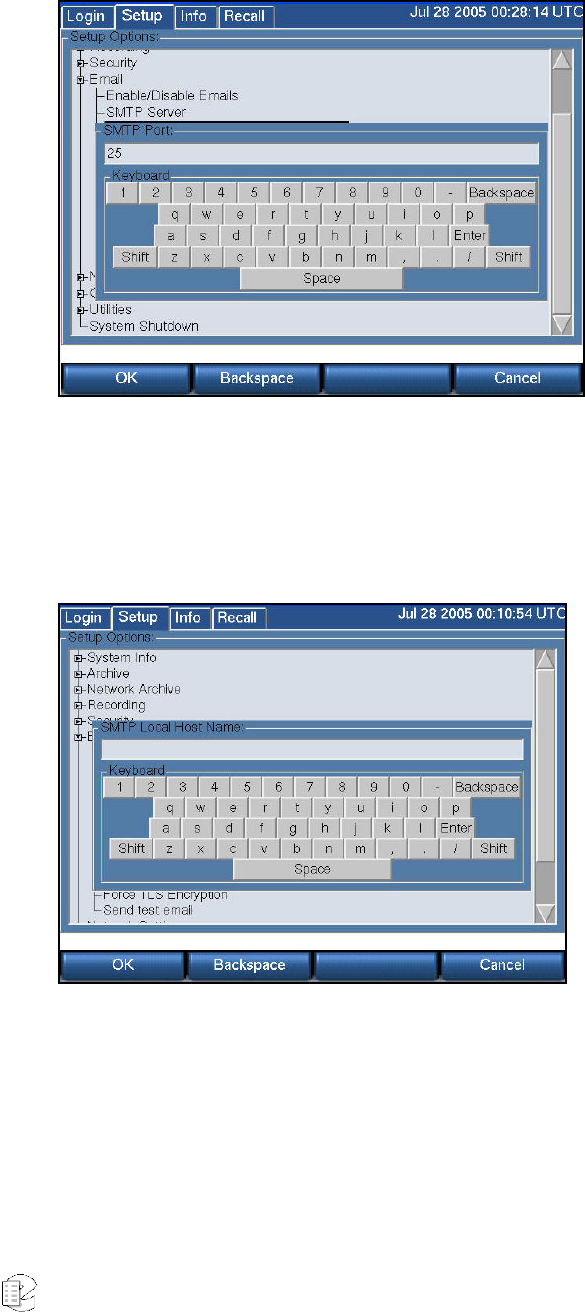
Atlas Series Server 1.8 User Manual 101
SETUP:EMAIL:SMTP PORT
Port 25 is the default used by SMTP servers. If a different port is to be used, it
may be entered here.
SETUP:EMAIL:LOCAL HOSTNAME
This is the hostname of the recorder if one has been assigned by the network
administrator. Example: recorder.yourdomain.com.
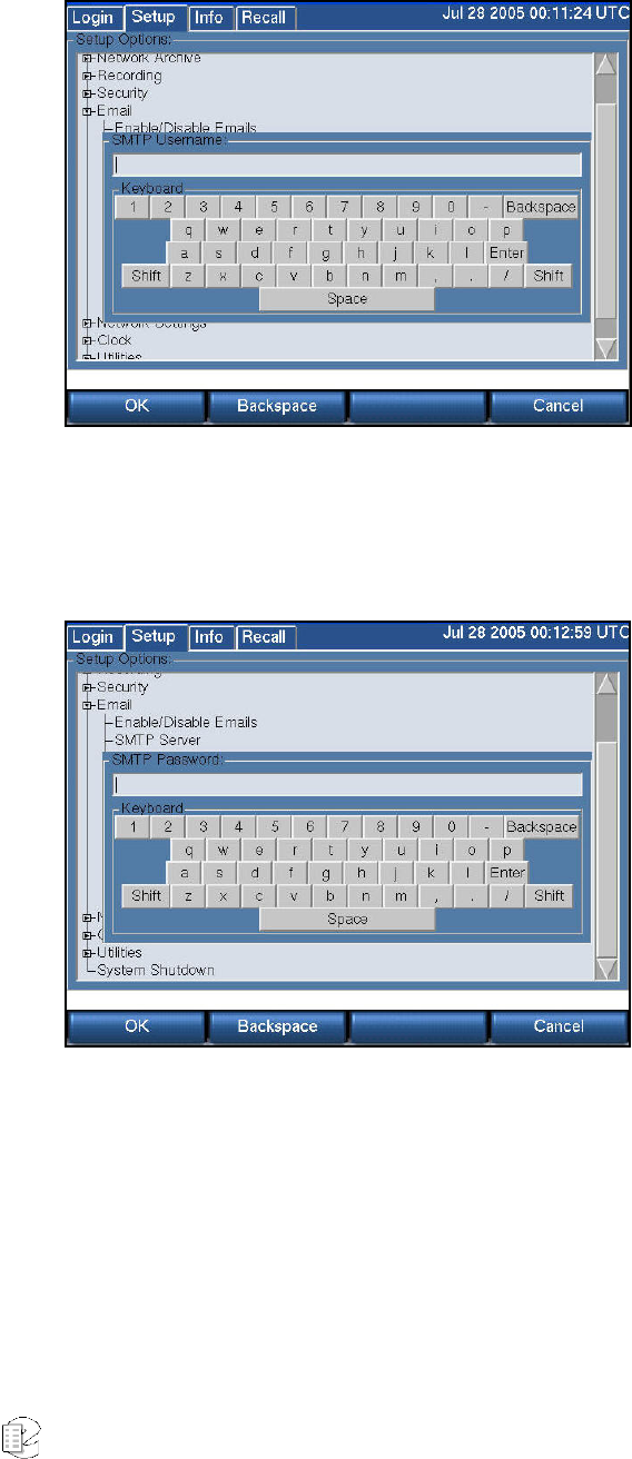
Atlas Series Server 1.8 User Manual 102
SETUP:EMAIL:SMTP USERNAME
SMTP Username (may be required by the SMTP server-see your administrator).
SETUP:EMAIL:SMTP PASSWORD
SMTP Password (may be required by the SMTP server-see your administrator).
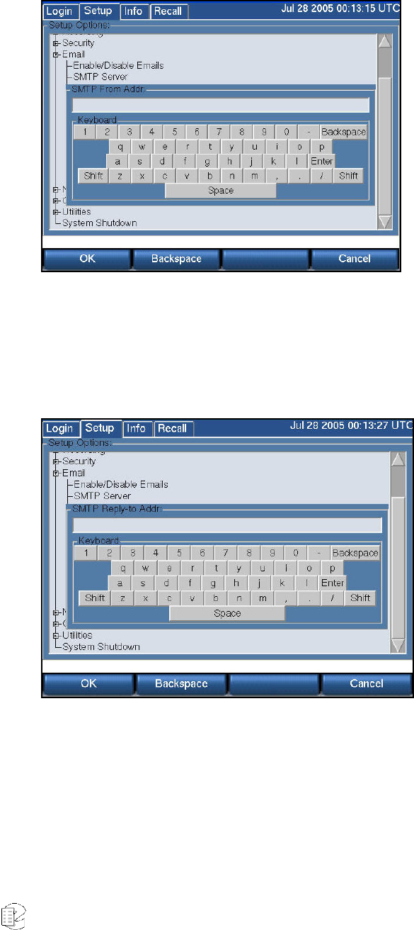
Atlas Series Server 1.8 User Manual 103
SETUP:EMAIL:SMTP FROM ADDRESS
SMTP From Address (The address you want to appear as the sender when the
user receives an email, e.g., “Eventide Recorder 2”).
SETUP:EMAIL:SMTP REPLY-TO ADDRESS
SMTP Reply-To Address (not required: the recorder does not accept or respond to
incoming email).
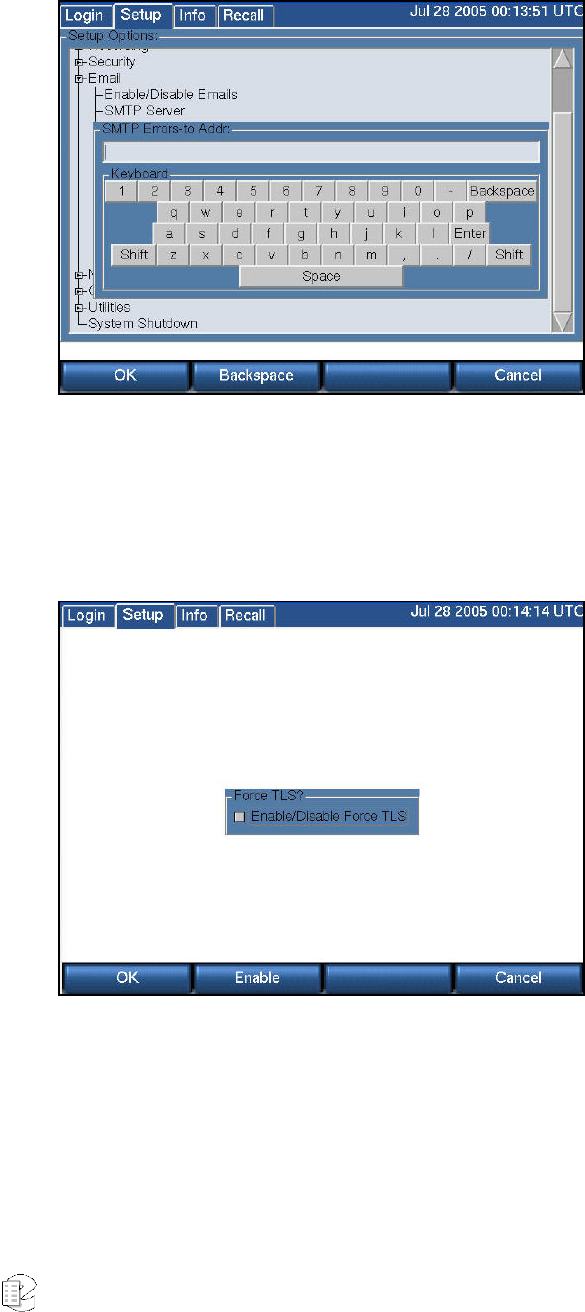
Atlas Series Server 1.8 User Manual 104
SETUP:EMAIL:SMTP ERRORS-TO ADDRESS
SMTP Errors-To Address (not required: an address that can receive "bounce"
messages if the recipient's mail can't be delivered).
SETUP:EMAIL:FORCE TLS ENCRYPTION
Enabling this function forces the recorder to use an authentication algorithm for
outgoing email. Disabling permits the email client to send unauthenticated email
if the SMTP server doesn't provide for authentication.
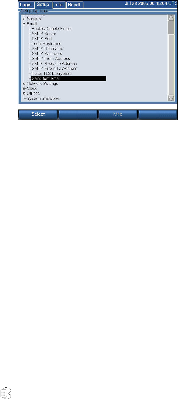
Atlas Series Server 1.8 User Manual 105
SETUP:EMAIL:SEND TEST EMAIL
"Send Test Email" will send a test email to all of the users with administered email
addresses. We recommend you use this feature to check your settings and
connectivity. Once the test email has been sent, you can confirm that it has gone
out by checking the recorder Alarm Log for a list of recipients, and, of course, by
checking with the recipients as to whether they received it.
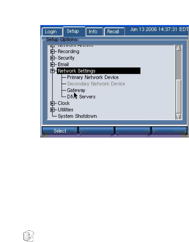
Atlas Series Server 1.8 User Manual 106
S
S
SE
E
ET
T
TU
U
UP
P
P:
:
:
N
N
Ne
e
et
t
tw
w
wo
o
or
r
rk
k
k
S
S
Se
e
et
t
tt
t
ti
i
in
n
ng
g
gs
s
s
If desired, the ATLAS recorder can connect to a TCP/IP-based Ethernet network.
The recorder includes a 10/100 Mbit/s twisted pair network interface. It is not
strictly necessary to connect the recorder to a data network. However, a
networked recorder provides advantages. For instance, you will be able to use
Eventide's optional remote clients for administration, viewing and playing
recorded calls, monitoring, and other functions. You can set up the recorder to
send email alerts for certain conditions. And you can synchronize to an NTP
server.
The Atlas recorders support two network interface cards (NICs), which provide
greater flexibility in your installation.
Primary and Secondary network devices are configured separately, but employ the
same gateway. (The gateway will automatically detect the IP address of any
computer residing on either network.)
The recorder is shipped with the following default network settings:
New for
Release
1.5
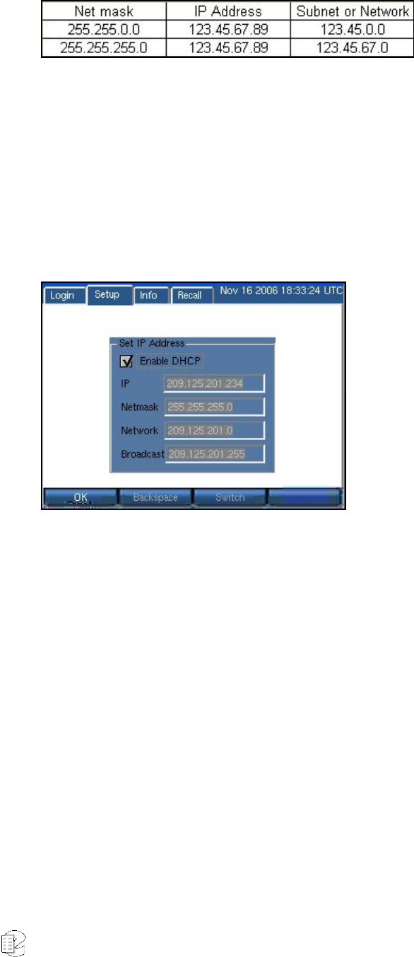
Atlas Series Server 1.8 User Manual 107
Select either network device entry to view or modify these settings.
The appropriate settings can be obtained from your network administrator, or
automatically with DHCP.
SETUP:NETWORK SETTINGS:ENABLE/DISABLE DHCP
If your network administrator tells you to use DHCP (Dynamic Host Configuration
Protocol), then enable DHCP as follows by checking the box and selecting OK.
With DHCP enabled, the other network settings are set automatically by the
DHCP server and cannot be changed manually. The settings remain readable
since the information, the IP address in particular, may be needed for client
setting.
If you are using the remote administration and call browsing software provided by
Eventide, then you should ask your network administrator to provide a “static IP
address” to the recorder. The client software will be unable to use services
provided by the recorder if the recorder's address changes, as it sometimes does
with DHCP.
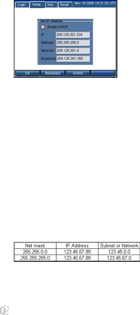
Atlas Series Server 1.8 User Manual 108
SETUP:NETWORK SETTINGS:IP ADDRESS, GATEWAY, NET MASK, NETWORK
If you are not using DHCP, then you must set the network parameters manually
from the front panel. There are some considerations in setting these parameters.
The IP address must not be in use by another device. If it is, then the address
may not "take” and even if it is accepted operation will be unreliable.
If you need the recorder to communicate with other devices on the network, such
as an administration client, an NTP server, or the internet, then the devices must
either be on the same subnet, or on a different subnet that can be reached over a
gateway. In the latter case, the address of the gateway must be added to the
recorder.
Speaking of subnets, the subnet is determined by the NETMASK setting. Your
subnet is the result of an AND operation between the 4-octet net mask and the 4-
octet IP address. Below are two common examples of net masks.
Your facility's network administrator will be able to help you in assigning the
proper IP address, net mask, broadcast address and, if necessary, gateway
address for the recorder. If the recorder will be sending email, one or more DNS
servers must be entered. To set the addresses, simply enter them in the blanks,
using Switch or the mouse to change fields.
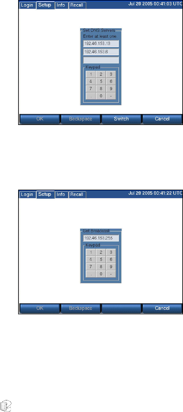
Atlas Series Server 1.8 User Manual 109
SETUP:NETWORK SETTINGS:DNS SERVERS
Set from one to three DNS server(s) by entering the correct address and using
Switch to traverse the fields.
SETUP:NETWORK SETTINGS:BROADCAST
Set the broadcast address.
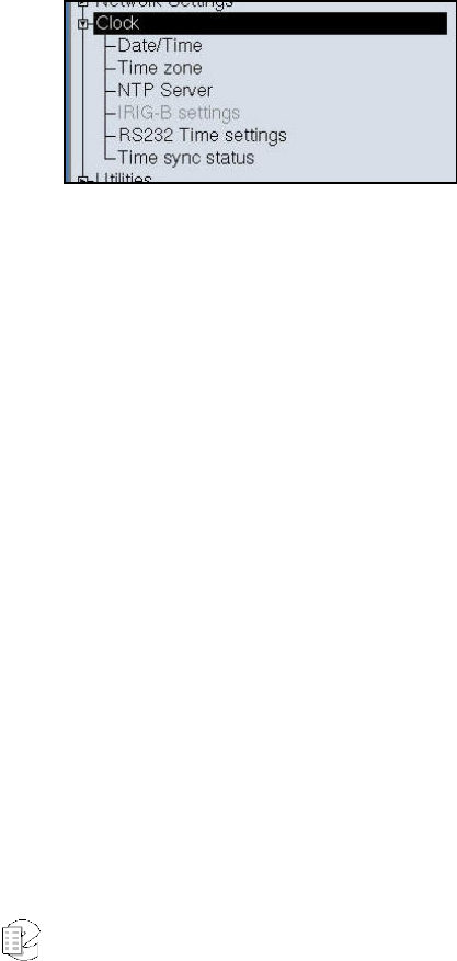
Atlas Series Server 1.8 User Manual 110
S
S
SE
E
ET
T
TU
U
UP
P
P:
:
:
C
C
Cl
l
lo
o
oc
c
ck
k
k
This section discusses setting the recorder date, time, and time zone, and
synchronizing it with an external time source. This must be accomplished
before you connect your incoming audio lines. If you are installing new software
on a currently operating recorder, you should disconnect your audio inputs until
you have set the time zone or restored the recorder configuration.
The current setting of the internal clock is observed in the display in the upper
right corner of the screen. The time zone is a three-letter code that is factory-set
to UTC (Universal Time).
When using the internal clock or NTP, Daylight Savings Time adjustments are
handled automatically.
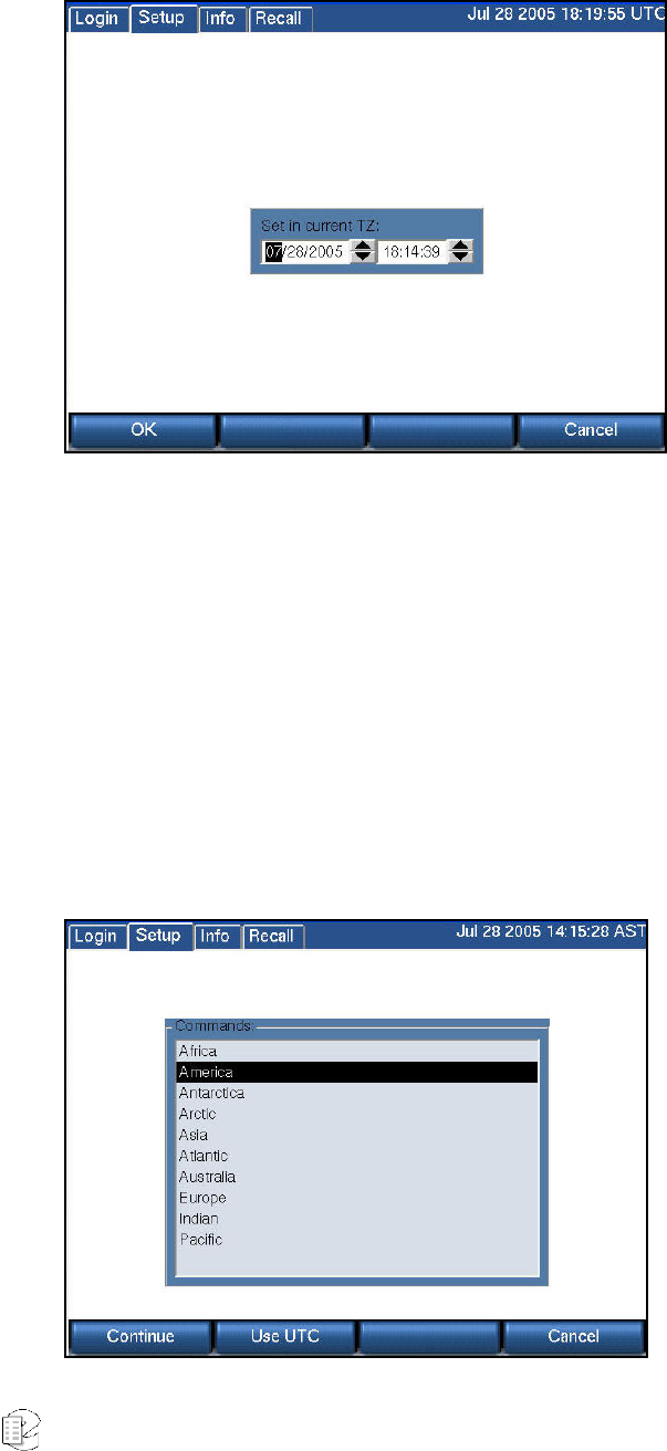
Atlas Series Server 1.8 User Manual 111
SETUP:CLOCK:DATE/TIME
The internal clock is accurate to a nominal one second per day.
To initially set the internal clock, first set the time zone to UTC (see below), then
set the time and date to the current UTC time using the knob or arrows and
accept it with OK. If you will be using NTP or an external time source, an
approximate clock setting is all that is necessary.
This site provides the current UTC time:
http://www.time.gov/timezone.cgi?UTC/s/0/java
SETUP:CLOCK:TIME ZONE
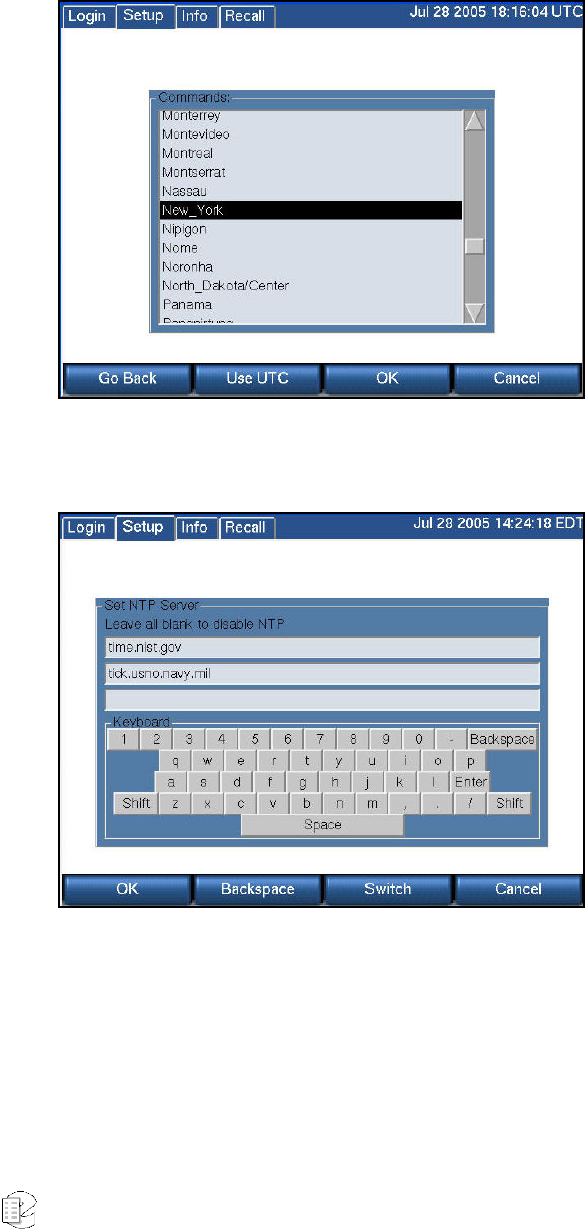
Atlas Series Server 1.8 User Manual 112
To set the recorder time zone, first select your continent (above screen), select
Continue, and then select your city or a city in your time zone (below screen).
Finally select OK. (If you prefer to use UTC, simply select Use UTC.)
SETUP:CLOCK:NTP SERVER
You can connect to up to three NTP (Network Time Protocol) servers. First you will
have to set up the recorder on your network. See the "Network Settings" section.
Of course, if you are using an NTP server over the internet, you will need a
reliable internet connection.
Eventide does not provide a default for the NTP server address because it is best
to select one near to you so as to minimize delays and outages caused by distance

Atlas Series Server 1.8 User Manual 113
and multiple network hops. Because the NTP server synchronizes the internal
recorder clock, a continuous connection is not required, but periodic connection
is. Historically, a list of National Institute of Standards and Technology (NIST)
internet time servers can be found on the web at:
http://www.boulder.nist.gov/timefreq/service/time-servers.html
For example, either time-a.nist.gov (129.6.15.28) or time-b.nist.gov (129.6.15.29)
has been known to work well on the east coast of the United States.
Note: Once you have selected NTP servers the Date/Time menu choice will be grayed out.
After you have activated NTP, wait a few minutes and then view Time sync status
(below) to confirm that the recorder is following the NTP-supplied time.
To disable NTP time synchronization, select NTP Server and delete all NTP server
names. After pressing OK, the Date/Time menu choice will no longer be grayed
out.
SETUP: CLOCK:I RIG-B SETTINGS
IRIG-B
If you have ordered optional IRIG-B support, then the recorder will be equipped
with an IRIG-B time code reader. An IRIG-B time code generator can be connected
to the BNC connector on the back of the recorder.
Note: The date is not affected by the IRIG generator. Set the date using the "Date/Time" menu.
• Set the time zone to the desired time zone for normal operation as
described above.
• Set the internal clock of the recorder to the wrong time so that time
synchronization will be obvious.
• Scroll to "IRIG-B Settings" and select it.
• Verify that the checkbox is checked, indicating that the setting is enabled.
• Use the encoder wheel or pick a value with the touch screen to set the
offset between the time zone to which the generator is set and UTC. For
example, if the generator is set to output EST time, set the recorder for -5.
If outputting EDT, set to -4. If outputting UTC, set to 0. The purpose of
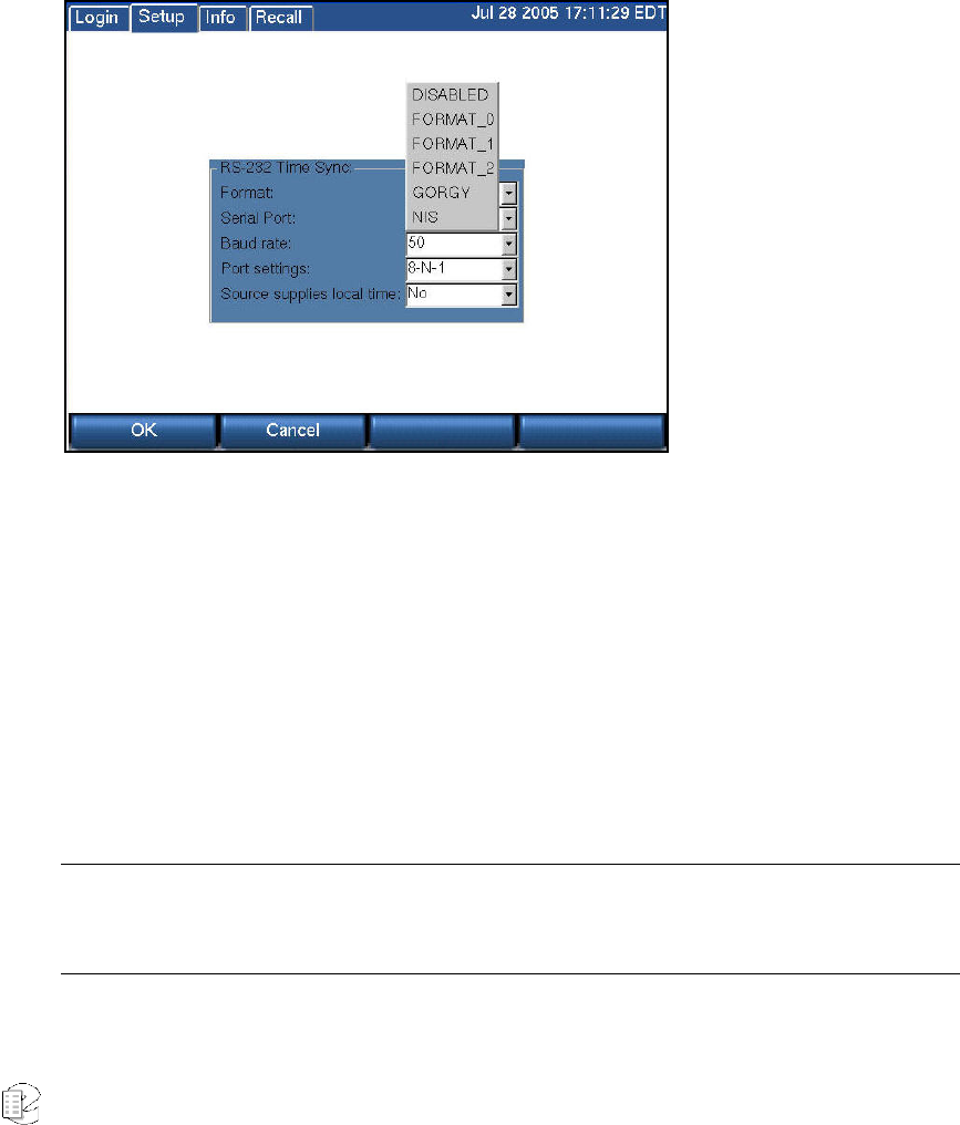
Atlas Series Server 1.8 User Manual 114
this setting is to convert the output of the generator to UTC, which the
recorder requires for its internal calculations.
• Press OK to save the settings.
• Connect the IRIG-B time code generator to the BNC connector on the back
of the recorder labeled "Time Code Input."
• Observe the time display at the upper right section of the front panel
display. Verify that it synchronizes shortly after you have activated it.
SETUP: CLOCK: RS232 TIME SETTINGS
Time Code Synchronization Over RS-232
A NENA-compliant time code generator (available from Spectracom, ESE, and
other companies) can be connected to the system's serial port. The VR615 has one
serial port. Either the time code generator or a label printer can be connected. The
VR725 and VR778 have two serial ports. The time code generator and a label
printer can be used simultaneously.
The date is not affected by the time code generator. Set the date using the
"Date/Time" menu item as described above.
Important:: Disconnect the RS-232 cable from the recorder when making setting changes. Otherwise
the recorder front panel controls may become unresponsive. Reconnect the cable AFTER all settings
are made and saved.

Atlas Series Server 1.8 User Manual 115
• Set the internal clock using the steps in the section entitled “Internal
Clock” above.
• Set the internal clock of the recorder to the wrong time so that time
synchronization will be obvious.
• Set the recorder to match the time code source.
SETUP RS-232 TIME SETTINGS
• Select the "Format" to match the generator's time format. Format 0,
Format 1, Format 2, GORGY, and NIS are available. DISABLE, of course,
will prevent the RS-232 source from being used.
• Select the COM port to which the generator is connected.. If the display
uses the notation "/dev/ttySn," then use S0 for COM1, and S1 for COM2.
For the VR615, there is no setting selection. If the VR615 is using a label
printer, the printer uses COM1 and RS-232 time sync cannot be used. For
the VR725 and VR778 with a label printer, the printer must use COM1,
and you should set the recorder to use COM2 for the sync signal. If there
is no label printer you can select either port for the RS-232 time sync.
• Match the Baud entry to that of the generator.
• Select the Port settings to set the communications parameters for data
bits, stop bits, and parity.
• Select Yes for "Source supplies local time" if your generator is on local
time; select No if it supplies UTC.
• Press the encoder wheel or OK to save the settings.
• Connect the time code generator to the RS-232 connector on the back of
the recorder. For the VR778 with a label printer, leave the printer on
COM1 and use COM2 for the generator.
• Observe the time display at the upper right section of the front panel
display. Verify that it synchronizes to the external source shortly after you
have activated it.
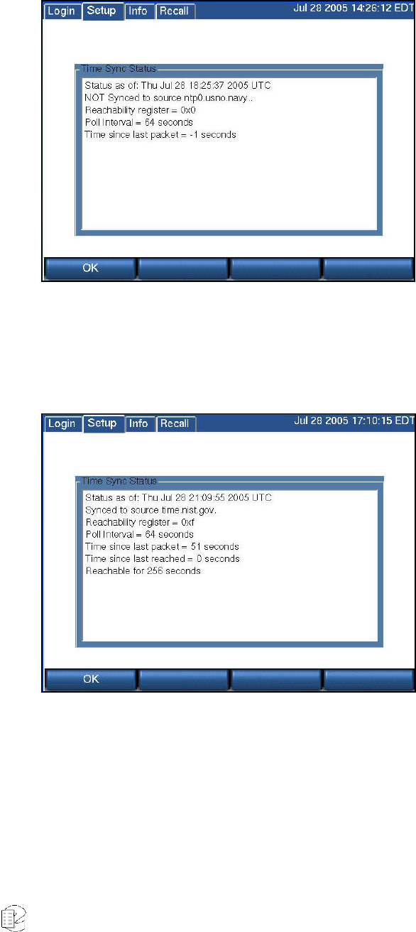
Atlas Series Server 1.8 User Manual 116
SETUP:CLOCK:TIME SYNC STATUS
The Time Sync Status screen shows whether the recorder is correctly
synchronized to an external source. The top screen shows that it is not receiving
NTP synchronization. The bottom screen shows the recorder operating in
synchrony with NTP source time.nist.gov.
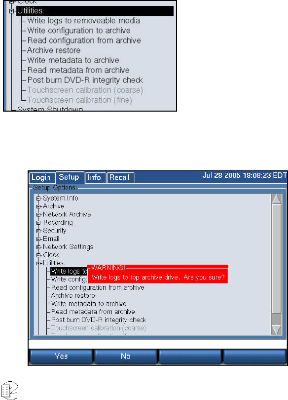
Atlas Series Server 1.8 User Manual 117
S
S
SE
E
ET
T
TU
U
UP
P
P:
:
:U
U
Ut
t
ti
i
il
l
li
i
it
t
ti
i
ie
e
es
s
s
These "utilities" are especially helpful for maintaining, backing up, and migrating your
recorder settings.
When you create a disk with recorder information and settings, we strongly recommend
that you immediately label it both with a description of the contents, the date, and the
recorder serial number.
Only DVD-RAM, USB, and REV media can be used for these utility functions.
SETUP:UTILITIES:WRITE LOGS TO REMOVABLE MEDIA
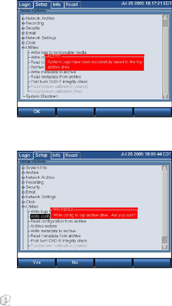
Atlas Series Server 1.8 User Manual 118
The system logs contain many clues and information that can help diagnose
problems with the recorder. Especially if your recorder isn't connected to the
internet, it may be necessary to send this log information to Eventide to assist in
finding a problem.
The procedure for using this function is to simply insert a blank formatted archive
medium in the recorder, select Write logs to removable media, and select "Yes"
when asked to confirm your wish. You must use a separate disk for each different
utility item to be saved.
SETUP:UTILITIES:WRITE CONFIGURATION TO ARCHIVE
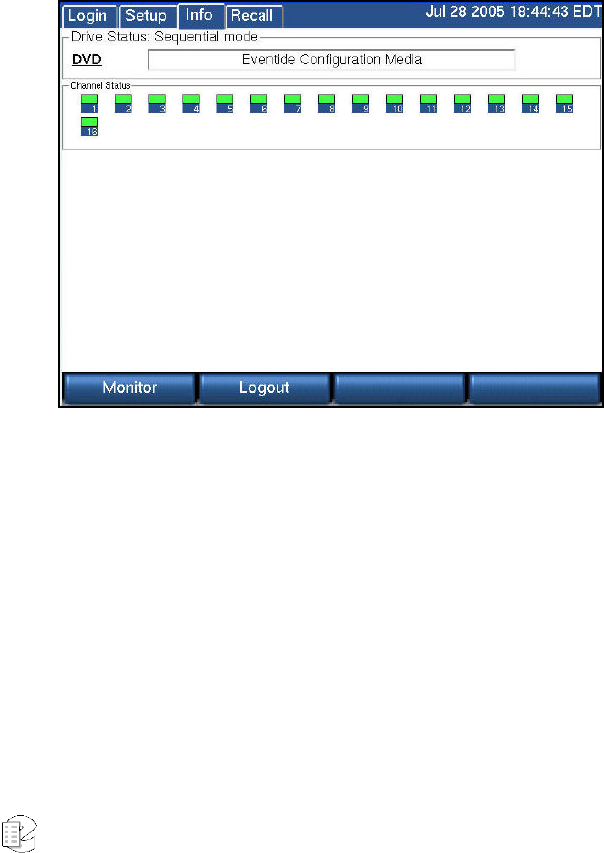
Atlas Series Server 1.8 User Manual 119
You can save your settings to an archive disk. If the settings are lost, you can
read them back into the recorder. Settings include your channel names, user
accounts, network settings, and clock synchronization settings). Insert a blank,
formatted archive medium and select "Write configuration to archive." Note the
warning and select "Yes" to continue.
If you have multiple recorders, mark the disk with the recorder's serial number.
You should not read back settings from a disk that has settings from a different
recorder. The recorders may be configured differently and the settings may not be
interchangeable.
Having a backup of your configuration is very valuable, and you should make one
even if you have decided that you do not wish to archive any recorder
recordings. We recommend creating one and putting it in a safe place along with
the spare key.
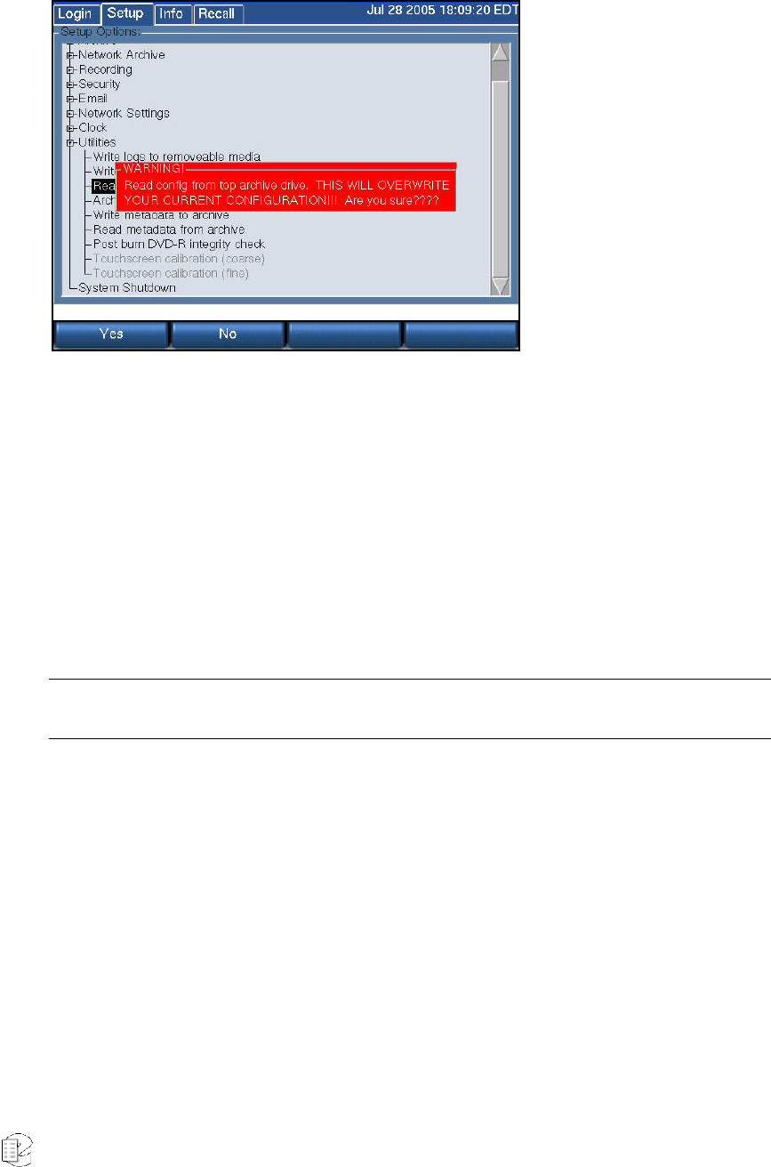
Atlas Series Server 1.8 User Manual 120
SETUP:UTILITIES:READ CONFIGURATION FROM ARCHIVE
Before reading back (restoring) the settings, make sure the settings on the disk
are appropriate to your recorder. As mentioned in the previous section, you
should not read back settings if the settings are from a different recorder, or if you
have added input boards to the recorder or made other configuration changes
that render the old settings inappropriate.
To read back the settings, insert the DVD-RAM with the settings, and select "Read
configuration from archive." Note any warnings and select "Yes" to continue.
Important: Reboot the recorder. Because some settings take effect on rebooting and some do not, if
you do not reboot, your settings may be inconsistent and may cause the recorder to fail.
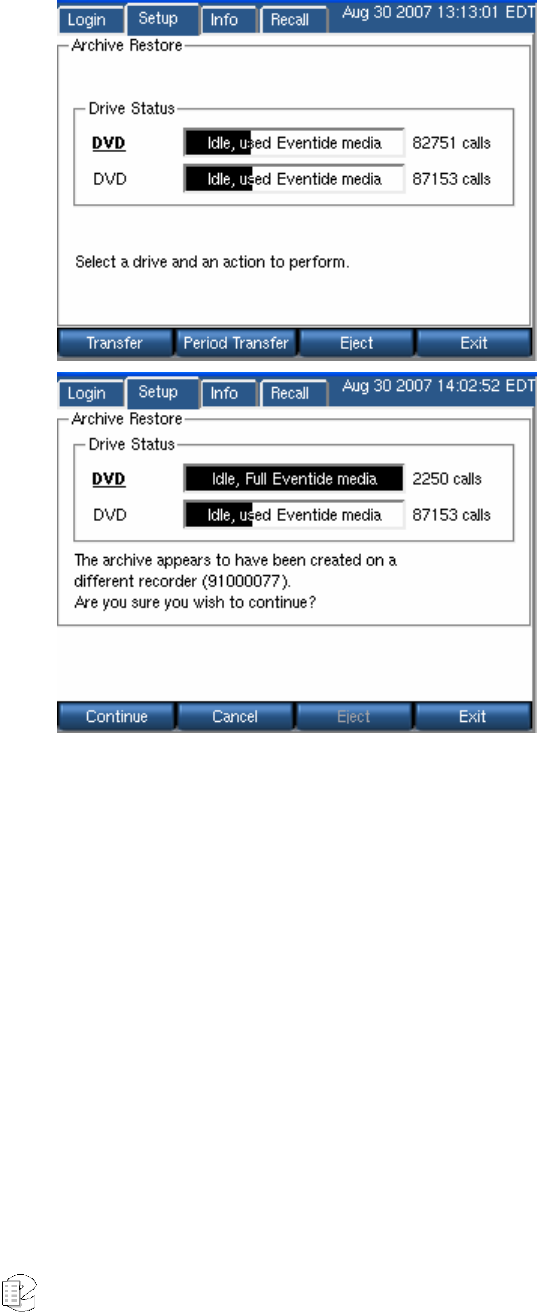
Atlas Series Server 1.8 User Manual 121
SETUP:UTILITIES:ARCHIVE RESTORE
In the Archiving section of the SETUP mode there is a menu item “Archive
restore.” If you insert previously–recorded archive media into one or more drives,
it will allow you to select that drive with the knob and perform a restore operation,
i.e., copy the calls from that medium back to RAID. Several checks are performed
before the medium is transferred:
• Does the serial number of the recorder that recorded the archive medium
agree with that of the destination recorder?
• Are the channel names of the recorder the same as the destination?
• Does the format of the data on the archive conform to that of the
destination?
• Is there any problem with or damage to the archive medium to be
transferred?
• Are all (or some) of these calls duplicates of calls already on the recorder?
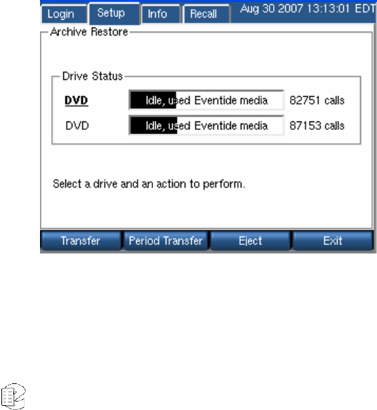
Atlas Series Server 1.8 User Manual 122
• And the perennially popular “Are you sure” you want to go ahead with the
transfer?
If none of these are appropriate for the medium, or if you indicated that you wish
to proceed, the archive transfer will commence. All drives operate independently.
You can restore archive media in all available drives, or you can even record
archives on one medium while restoring from another.
A couple of important points:
• The restoration process cannot continue once the RAID is full, so unless
you have a special reason for doing otherwise, always restore from the
most recent archive backwards.
• If you are restoring archives after a new installation, use the Set current
archive time facility to make sure that new archives are only recorded from
the present forward. If you don’t set this and begin new archiving after you
have restored your archives from a previous installation, you might find
yourself “re-archiving” the restored archives.
When you are done restoring your archives, be sure to restore the “metadata”
archive disk as well.
SETUP:UTILITIES:ARCHIVE RESTORE: PERIOD TRANSFER
New for
Release
1.7
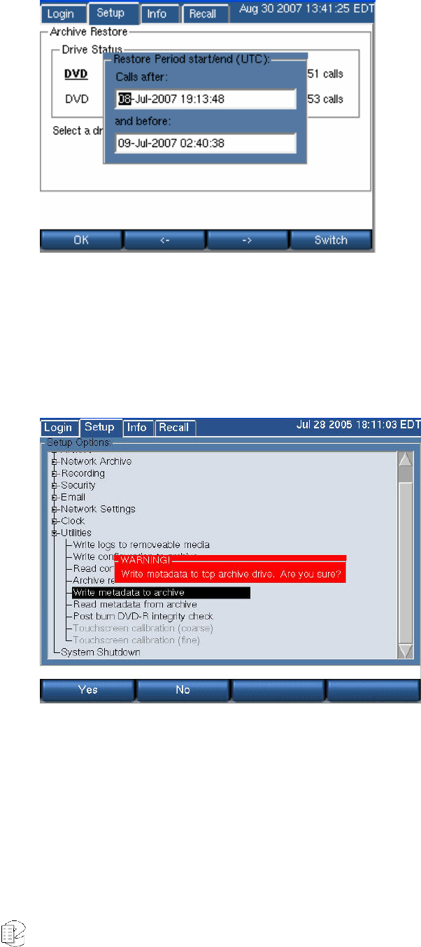
Atlas Series Server 1.8 User Manual 123
To restore a subset of calls from an archive, use Period Transfer, also found at the
Archive Restore screen. Set the time period and hit OK, and then proceed as you
would with a full disc Archive Restore.
SETUP:UTILITIES:WRITE METADATA TO ARCHIVE
“Metadata” means data about data, and is just a fancy way of saying that there is
(potentially) some data about calls associated with the calls. For example, when
you use the Browser Client to “protect” a call from being erased, or when you add
“incident” data to a specific call, this is considered metadata. This metadata is not
(and typically cannot) be stored with the call archives themselves. Why? Because
in most instances, archiving takes place contemporaneously with recording, or
shortly thereafter. However, the decision to protect a call, or to add or change
information about a call or incident can occur much later. Therefore, this
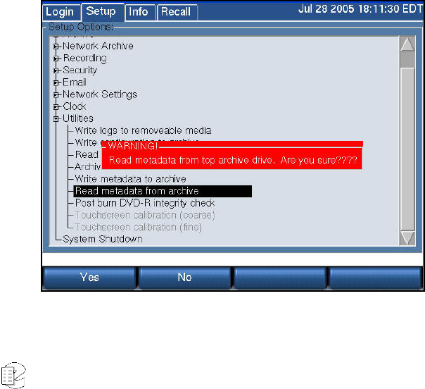
Atlas Series Server 1.8 User Manual 124
information may not be present when the archive is recorded and so obviously
cannot be recorded along with the archive.
The “Write metadata to archive” menu item allows you to gather all this later-
entered data on one medium, and to restore it to the recorder if necessary. (It will
not normally be necessary, but the purpose of saving it is the same as the
purpose of archiving – backup and safety.)
To create a metadata archive, insert a DVD-RAM medium in an available drive
and format it if necessary. Select “Write metadata to archive” and confirm you
want to do so by pressing the YES soft key. Remove the disk and store it with
your archives.
To restore the metadata to the recorder, insert the metadata archive and
select “Read metadata from archive” and confirm the operation.
Unlike the calls themselves, metadata takes a very small amount of space on a
disk, and the entire recorder can be backed up on a single metadata disk.
Metadata is stored in most cases the equivalent of “forever” and so the most
recent metadata backup will suffice to restore this data to all archives. Therefore,
you should determine a reasonable schedule for making these backups – once a
week, perhaps – and keep only a couple of disks in rotation for this purpose.
SETUP:UTILITIES:READ METADATA FROM ARCHIVE

Atlas Series Server 1.8 User Manual 125
Read metadata from archive restores the metadata saved in the above procedure.
After receiving the usual warning, "Yes" deposits the information back on the
RAID and associates it with the appropriate calls.
TOUCH SCREEN CALIBRATION (COARSE AND FINE)
This item only applies to the VR725, or to blank-panel units that may have the
Eventide Touch screen Monitor attached. When shipped with or as part of a
recorder, the touch screen is pre-calibrated. You may need to perform this
function if the adjustment drifts over time, or if you have to replace the monitor.
There are two selections – Coarse and Fine calibration. Coarse allows you to
coordinate the display with the touch screen at four points; fine provides a 25-
point calibration. When performing this calibration, use the pointer provided or
an object with a reasonably sharp point, as you want to get it as nearly precise as
possible. Select the calibration desired and touch the points as instructed by the
program. Note that you must touch AND HOLD the pointer on the screen until the
program goes to the next calibration point. This is different from normal operation
in which you can just poke an item and have it register.
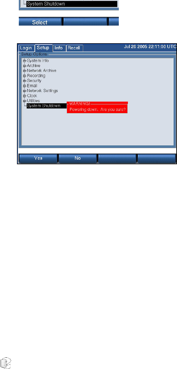
Atlas Series Server 1.8 User Manual 126
S
S
SE
E
ET
T
TU
U
UP
P
P:
:
:
S
S
Sy
y
ys
s
st
t
te
e
em
m
m
S
S
Sh
h
hu
u
ut
t
td
d
do
o
ow
w
wn
n
n
Always use System Shutdown to turn off the
recorder safely! Do not force a shutdown with
the power switch or by unplugging the
recorder, which can result in lost or corrupted
data.
This section describes how to shut down the recorder. For information on starting
the recorder, see “Starting and Shutting Down.”
To shut down the recorder, you can perform a controlled shutdown or a forced
shutdown. In most circumstances, you should only perform a controlled
shutdown. This allows the recorder to close all open files and complete current
database operations before shutdown. A forced shutdown can result in corrupted
files and loss of data. It can also damage any archive media in the process of
being written, and possibly leave either gaps or duplications in your archives. (In
addition, Eventide strongly recommends using the recorder with a UPS to allow a
controlled shutdown in the event of a power failure.)
CONTROLLED SHUTDOWN
To perform a controlled shutdown of the recorder:
1. Press SETUP.

Atlas Series Server 1.8 User Manual 127
2. Select System Shutdown.
3. You are prompted to confirm the shutdown. Press the "Yes" soft key, and the
recorder starts to shut down. Please be patient as this can take minutes,
especially if an archive medium is being written.
If for some reason, it is not possible to use this standard method to perform a
shutdown, a controlled shutdown can still be accomplished using the following,
somewhat riskier, alternative.
Use the front panel key switch (VR615 and VR778) or front panel power switch
(VR725) to initiate a controlled shutdown by pulsing the switch for up to one
second, as follows:
• Turn the VR615 and VR778 front panel key clockwise for up to one second, or
push the VR725 front panel power switch for up to one second.
• Do not pulse the switch for more than one second or else a forced shutdown
occurs that can result in lost and corrupted data.
FORCED SHUTDOWN
A forced shutdown should only be performed when a controlled shutdown is
impossible.
Caution: A forced shutdown can result in corrupted files and loss of data.
To perform a forced shutdown of the recorder:
• For recorders with a front panel power switch (VR725), push and hold the
power switch until the recorder shuts down. For recorders with a front panel
key switch (VR615 and VR778), turn the front panel key switch clockwise, and
hold the key in that position until the recorder shuts down.
• An alternative way to perform a forced shutdown is to turn off the power
supplies from the back panel, or unplug the power supplies.

Atlas Series Server 1.8 User Manual 128
Recorder Operation
STARTING AND SHUTTING DOWN
To start the recorder, use the front panel key switch or front panel power switch,
depending upon the unit. For recorders with a front panel key switch (VR615 and
VR778), insert the key provided, turn it clockwise, hold it for up to one second,
and release it. Do not hold the key in the turned position for more than one
second or it will force a shutdown before the unit completes the startup. For
recorders with a front panel power switch (VR725), the switch is behind the
locked door on which the display is mounted. The switch serves the same
function as the key switch on other models, and the same one-second rule
applies.
To shut down the recorder, you can perform a controlled shutdown or a forced
shutdown. In most circumstances, you should only perform a controlled
shutdown. This allows the recorder to close all open files and complete current
database operations before shutdown. A forced shutdown can result in corrupted
files and loss of data. It can also damage any archive media in the process of
being written, and possibly leave either gaps or duplications in your archives. (In
addition, Eventide strongly recommends using the recorder with a UPS to allow a
controlled shutdown in the event of a power failure.)
Caution: A forced shutdown can result in corrupted files and loss of data.
To perform a controlled shutdown of the recorder:
1. Press SETUP.
2. Select System Shutdown.
3. You are prompted to confirm the shutdown. Press the “Yes” soft key, and the
recorder starts to shut down. Please be patient as this can take minutes,
especially if an archive medium is being written.
If for some reason, it is not possible to use this standard method to perform a
shutdown, a controlled shutdown can still be accomplished using the following,
somewhat riskier, alternative.

Atlas Series Server 1.8 User Manual 129
Use the front panel key switch (VR615 and VR778) or front panel power switch
(VR725) to initiate a controlled shutdown by pulsing the switch for up to one
second, as follows:
• Turn the VR615 and VR778 front panel key clockwise for up to one second, or
push the VR725 front panel power switch for up to one second.
• Do not pulse the switch for more than one second or else a forced shutdown
occurs that can result in lost and corrupted data.
Eventide does not recommend forcing a shutdown, but if it becomes necessary,
see “Forced Shutdown” on page 127 for more information.
RECORDING
General
Once you have set the recorder's internal clock, configured the input board or
boards, and configured the channels, you are ready to begin recording. There is
no record Start/Stop control. Recording begins when the input lines are
connected and an appropriate signal triggers recording.
When a channel is recording, the channel indicator on the INFO screen will show
flashing red.
RAID
Calls are recorded to a RAID system, which is an abbreviation for “Redundant
Array of Independent (or Inexpensive) Disks.”
The RAID status menu item just below Configuration Info gives information on the
logical RAID type, the partitions, and the physical drives, and additional
information as described earlier. Information included on this screen includes
array status, capacity including percentage filled, and “history.” The Status item
is of particular interest, in that it shows at a glance whether the array is operating
normally, is “Rebuilding” as it will do when a new installation is made or a drive
has been replaced, or operating with reduced redundancy if a drive is defective.
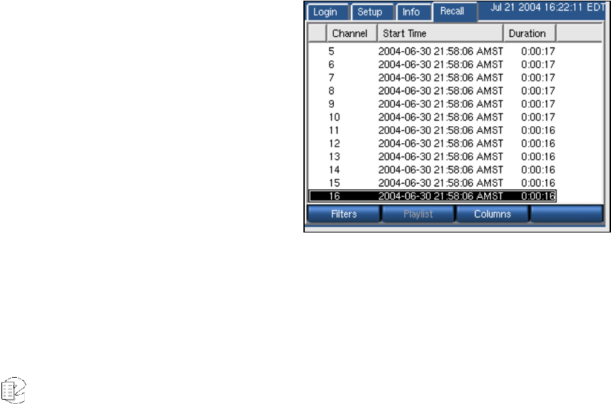
Atlas Series Server 1.8 User Manual 130
Some models of the recorder are available with drive “hot swap” capability. That
will also be shown in this display. Complete details on the RAID status display is
found at Setup: System Info: RAID Status.
SEARCHING, SORTING, AND PLAYING CALLS
General
You can view a list of calls on the RAID or on an individual archive. You can add
filters to help you search for a call or group of calls. And you can play back
individual calls through the recorder's front speaker or headphone jack.
Considerations
You may find it more convenient to use the MediaWorks or MediaAgent remote
clients for viewing and playing back calls. The front panel has limited display
space, so, even with filtering, you may have to do a lot of scrolling to find your
calls. Horizontal space is very limited, so you will not be able to display more than
a few columns at a time. And it may take more time for the calls to be retrieved
and displayed from the front panel than from the remote clients. Lastly, the
remote clients have functionality not available from the front panel, for example,
the ability to play back multiple calls with a single command.
Viewing Calls
To view a list of calls, first choose
whether you want to view calls
from the RAID (hard drive) or calls
from an archive. To choose the
RAID, press INFO and make sure
that none of the archives are
displaying the message "Playback."
If an archive is displaying
"Playback," then select it with the
scroll wheel or touch
screen/mouse, and press "Stop Browsing." Then press RECALL.
To choose an archive, press INFO and select the archive drive with the scroll
wheel or click the bar with touch screen or mouse. Press Browse Archives and
wait for the display to indicate "Playback." Then press RECALL.
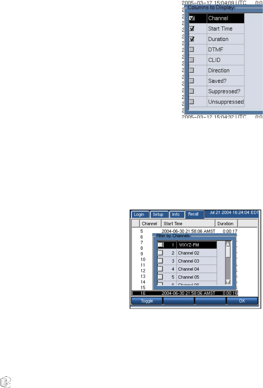
Atlas Series Server 1.8 User Manual 131
A list of all calls stored on the chosen medium will be displayed in tabular format.
Filtering and Searching
Using the front panel to scroll through hundreds
or thousands of calls is not practical. To search for
particular calls or groups of calls, you can place
filters on the list of calls. Pressing the Filters soft
key from the RECALL screen brings up a list of
parameters that can be filtered:
• Channel Number
• Call Length
• Date and Time
• Outgoing Dialed DTMF digits
• Incoming CLID (Calling Line Identification)
• Call Direction
• If the call is saved, suppressed, or unsuppressed
Filters are additive. If you filter on “Channel 10” and “duration of 5-10 minutes,"
you will only see calls that exist on Channel 10 and have a duration of 5-10
minutes. As you add filters, the list of calls will shorten accordingly. The default
setting is all filters removed.
To filter on Channel Number:
Filters → By Channel → <check off
the desired channels to view from
the list> → OK
In the special case of NO boxes
checked, the filter is disabled and
ALL channels will be displayed.
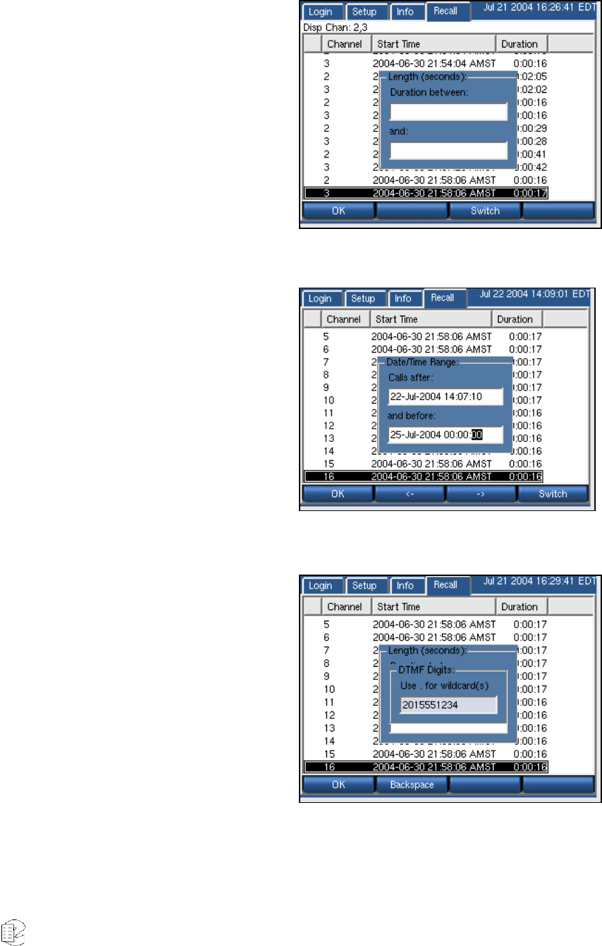
Atlas Series Server 1.8 User Manual 132
To filter on Call Length:
Filters → By Call Length → <enter
minimum duration> → Switch →
<enter maximum duration> → OK
The calls displayed will fall between
the two parameters, but will not
include the parameters. In other
words, a range of 51 to 53 seconds
will only display calls with a
duration of 52 seconds, but not 51 or 53. A range of 51 to 52 will display no calls.
To filter on Date/Time Range:
Filters → By Date/Time Range →
<enter the start date and time
using the left and right arrows and
the scroll wheel> → Switch →
<enter the end date and time using
the left and right arrows and the
scroll wheel> → OK
Touch screen or Mouse: Click on
field desired and click on up/down arrows to select date/time
To filter on dialed DTMF digits:
Filters → By DTMF digits → <enter
the string of digits> → OK
Calls with the string of digits
anywhere in the captured digits will
be displayed.
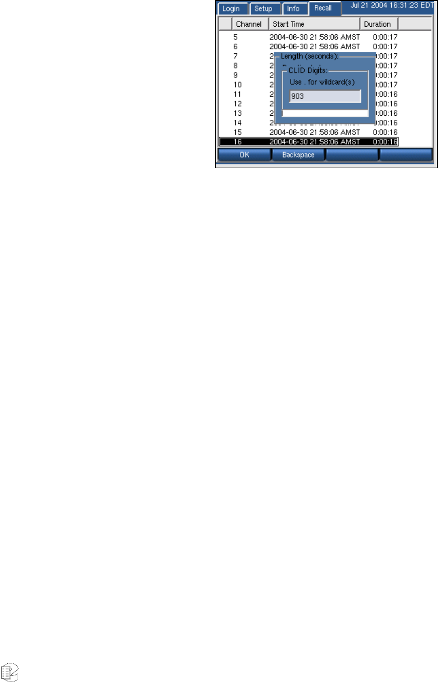
Atlas Series Server 1.8 User Manual 133
To filter on CLID:
Filters → By CLID → <enter the
string of digits> → OK
Calls with the string of digits
anywhere in the CLID will be
displayed.
Columns
The calls are displayed as a list, with multiple attributes per call. By default, only
the Channel Number, Start Time, and Duration are listed. There are, however,
eight total attributes, any of which can be displayed. These attributes are:
• Channel – Channel number the call was recorded on.
• Start time – The time at which the call was initiated.
• Duration – The call duration.
• DTMF - Dialed DTMF digits.
• CLID - Calling Line Identifier, the telephone number of the incoming
caller, if this data is available from your central office.
• Direction - Not used at this time. It will always say "Unknown."
• Saved? - Calls can be tagged so that they will not be erased when the hard
disk fills up. If the call is tagged to be saved, this field will say "Y."
• Suppressed? - If checked the call has been suppressed.
• Unsuppressed? - If checked, the call has been unsuppressed.
To change the displayed columns:
RECALL → Columns → <select or deselect the desired columns by toggling the
associated checkbox> → OK
Depending on the width of the column data, you may have to remove columns
before adding new ones.
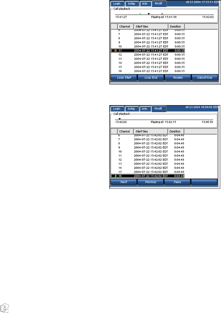
Atlas Series Server 1.8 User Manual 134
Playing Back Calls
Playing back calls from the front
panel is simply a matter of scrolling
to and selecting the desired call by
either pressing the scroll wheel or
clicking on the call. The call will play
through the front panel speaker or
through the headphones. A progress
counter and location indicator will be
displayed as the call plays.
To fast-forward or fast-reverse
through the call, turn the scroll
wheel. (There is no touch screen or mouse equivalent of this function.)
To stop playing the call, press the
scroll wheel or click on it again.
Press Next to stop playing the call
and begin playing the next call in the
list.
Press Previous to stop playing the
call and begin playing the previous
call in the list.
Press Pause to pause playback.
Pressing Pause brings up some new buttons.
Press Resume to resume playback.
Looping
You can set up a looped playback by designating a start point and end point
inside a call. Play the call and pause at the desired start point. Press Loop Start
and a green tic mark will appear on the progress line. Resume and pause again at
the desired stop point. Press Loop End and a red tic mark will appear. Resume
and the call will play back between your two designated loop points. Here is the
sequence:

Atlas Series Server 1.8 User Manual 135
Pause → Loop Start → Resume → Pause → Loop End → Resume
If you chose an end point earlier than the start point, the tic marks will change
color. The earlier point will always be the start point.
To cancel the loop, press Pause and then press Cancel Loop. The tic marks will
disappear. Then press Resume or press the scroll wheel to stop playback.
ARCHIVING
This section consolidates and duplicates (in part) information in the archiving
sections of the Setup menus. Here you will find a discussion of the various
aspects of archiving. The Setup section of this manual is a reference and shows
the menu location of all of the functions.
General
The recorder allows archiving recorded messages on removable media, such as
DVD-RAM or DDS-4 tape. The VR615 has one archive drive, the VR725 two, and
the VR778 will have from one to three drives.
Normally archive period selection is automatic: The recorder maintains an
internal pointer to the end of archived data and will automatically start recording
the next inserted medium from where the previous medium left off. This pointer
may be overridden. See the section entitled “Setting Current Archive Time” below
for instructions.
In recorders with two (or more) archive drives there are two modes of archiving:
sequential and parallel. Sequential archiving simply means that when a medium
is full, the recorder will check the next drive and, if it has a formatted and blank
medium installed, it will start recording on that medium. With the parallel
archiving mode selected, if a recorder has blank, formatted media in both drives
and archiving is begun, the same data will be recorded on both media. In
recorders with a single archive drive the setting has no effect.
In cases where immediate archiving is critical, there is a feature called “Failsafe
archiving.” This provides for transferring archive recording to a second, redundant
recorder, in case there’s a problem with an archive medium or drive in the
primary recorder.

Atlas Series Server 1.8 User Manual 136
Under some circumstances, such as replacing a recorder or installing new
software, you might want to restore previously recorded archives to the recorder
hard drive. The Archive restore feature provides for this.
Before selecting the archiving mode, the user should determine whether to record
archives at all. The storage capacity of the recorder is so great that it may well
exceed the normal retention time of the data. There is little point (beyond
redundancy) of recording archives if they will be erased and reused while the data
remains on the recorder! If it is decided to record archives, there are various
strategies. They depend primarily on the staffing of the facility in which the
recorder is installed and the rate at which information is being stored on the
recorder. Some considerations:
If your recorder is recording a hundred or more channels on a fairly steady basis,
you will find that enough data to fill one side of a DVD-RAM will be acquired every
six or so hours. Since it requires about an hour to transfer this much data to the
medium, in any 24-hour period at least two media will have to be exchanged (or
turned over). In this situation, if you do not have someone available to do this for
at least one shift, five days per week, you might eventually get behind and lose
data. (Note that this is an unusual situation - recorders are rarely this busy, and
if they are, it is typically only during business hours.)
If your recorder is recording a handful of channels sporadically, you might literally
get a year or more of data on the hard drive. If you decide to archive calls as they
come in, the archive medium will easily keep up with the incoming recordings,
and will only get filled in a week or maybe even a month. An alternative strategy
might be to record a new medium every week (or month) on a fixed schedule, and
let the data accumulate on the hard drive in the interim. This has the benefit of
making the archives fit a defined period, which might be more convenient for
subsequent research, and is easily scheduled.
Most applications will fall between these extremes; the recorder makes it easy to
adjust your strategy so that archive media exchange won't be demanding or
burdensome, and can be done on a convenient schedule.
Caution! Your archive medium may be your only copy of vital data. We recommend that any time you
insert an archive in a drive capable of writing to it for purposes of viewing or reading the data, you
activate the "Write Protect" tab.

Atlas Series Server 1.8 User Manual 137
Media Selection
This section assumes you are using DVD-RAM disks for archiving. DDS tapes can
also be used, with some limitations, on special order (contact Eventide). Eventide
recommends any of the following configurations of media for DVD-RAM archiving:
¾ 5.2GB DVD-RAM, single-sided, inside a Type 2 or Type 4 cassette.
¾ 9.4GB DVD-RAM, double-sided, inside a Type 2 or Type 4 cassette.
Some considerations on media selection:
• Double-sided disks will have to be manually flipped over to record both
sides.
• Type 2 and Type 4 cassettes are recommended because they can be
opened and the disk removed. This is useful if you want to use a computer
to play back the disks, since most computers will not accept the cassette.
It is also useful if you want to purchase a spindle of single-sided disks and
place them inside the cassette.
• In a facility with high call volume, you can save money and storage space
by purchasing spindles of single-sided bare disk media and only a few
cassettes. You would place the media in the cassettes to record them, and
back on the spindle when recording is complete. Besides expense, another
advantage is that the bare medium can’t be written in a DVD-RAM drive
on a computer, so there is less chance of data being unintentionally
overwritten. Some disadvantages are 1) the bare disks are not as
physically well protected when they are removed from the cassette, 2) the
bare disk is harder to label.
• A low call-volume facility may also wish to use single-sided disks. If the
facility wants to change the archive disks on a set schedule (say, once a
month), it might make sense to use single-sided disks that end up being
1/2 or 3/4 full, rather than double-sided disks that end up being mostly
empty.
One last note on data protection: Although the recorder incorporates an archive
protection mechanism, this is only effective when playing the archive in the
recorder itself. When playing the archive in an ordinary PC that accepts the
cassette, it is not protected from being overwritten unless the write protection tab
on the cassette is set.
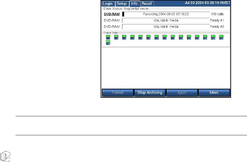
Atlas Series Server 1.8 User Manual 138
CD-R Media: CD-R media are not supported for archiving. This is mentioned
here because it is sometimes difficult to distinguish a blank, generic CD-R from a
DVD-R. If you try to archive onto a CD-R, it won’t work, and it may not be
immediately clear why, so be sure to confirm that you are using the proper (DVD)
archive medium.
Sequential and Parallel Modes
These modes apply only to recorders with more than one archive drive. Otherwise,
the setting has no effect.
Sequential mode means that archiving will continue automatically to the next
available medium. In the figure below the top disk is writing calls. When the disk
fills up, archiving will continue on the middle drive, and then on the bottom drive.
The middle and bottom drives must contain formatted, blank media. After the
disks are full, they can be flipped if they are double-sided, and the process will
continue. For example, when the top disk, Side A, fills up, the middle disk, Side A,
will begin recording. Meanwhile you can flip the top disk to Side B and recording
will continue there AFTER the middle drive, Side A, and the bottom drive, Side A,
are full.
Parallel mode means that archiving will not continue automatically to the next
available drive. Instead, you can begin recording on the top drive and begin
recording on the middle drive simultaneously (and the bottom drive if you wish)
and all drives will record
the same data. This mode
uses more disks but
provides redundancy.
To set the mode:
• Press SETUP.
• Scroll to and select
"Archiving Type,"
and select the
desired mode.
• Press OK.
Special Note: Optional software is available for recorders with two archive drives that allows different
user accounts access to specific drives. This software only functions for the parallel archiving mode.
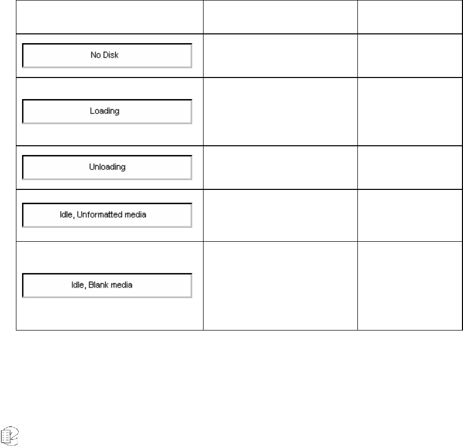
Atlas Series Server 1.8 User Manual 139
DVD-RAM Drive Operation
The INFO screen is the primary user interface for archiving.
The top half shows the current status of your archiving drive or drives. The "Drive
Status" will say either "Sequential mode" or "Parallel mode." Each archive drive
will have an individual status indicator that looks like a wide, horizontal
rectangle. To the left of the rectangle is the type of archive drive (DVD-RAM, R-
HD, REV, or DDS-4). To the right of the rectangle is the number of calls on the
disk, or a "Ready" message during sequential archiving. Inside the rectangle itself
is one of a number of possible messages and indications. At the bottom of the
screen are soft keys that change depending on context. The following table
provides more information.
Table 4–INFO Screen Archive Drive Messages and Soft Keys
Display Description Available Soft
keys
The drive is empty. Eject
A medium has been loaded
and the recorder is scanning it
to learn its status.
—-
A medium is being ejected. —-
An unformatted medium is
inserted. Format, Eject
A formatted, blank medium is
inserted.
Format, Start
Archiving, Eject,
More, Archive
Period, Media Info,
Print Label, Back
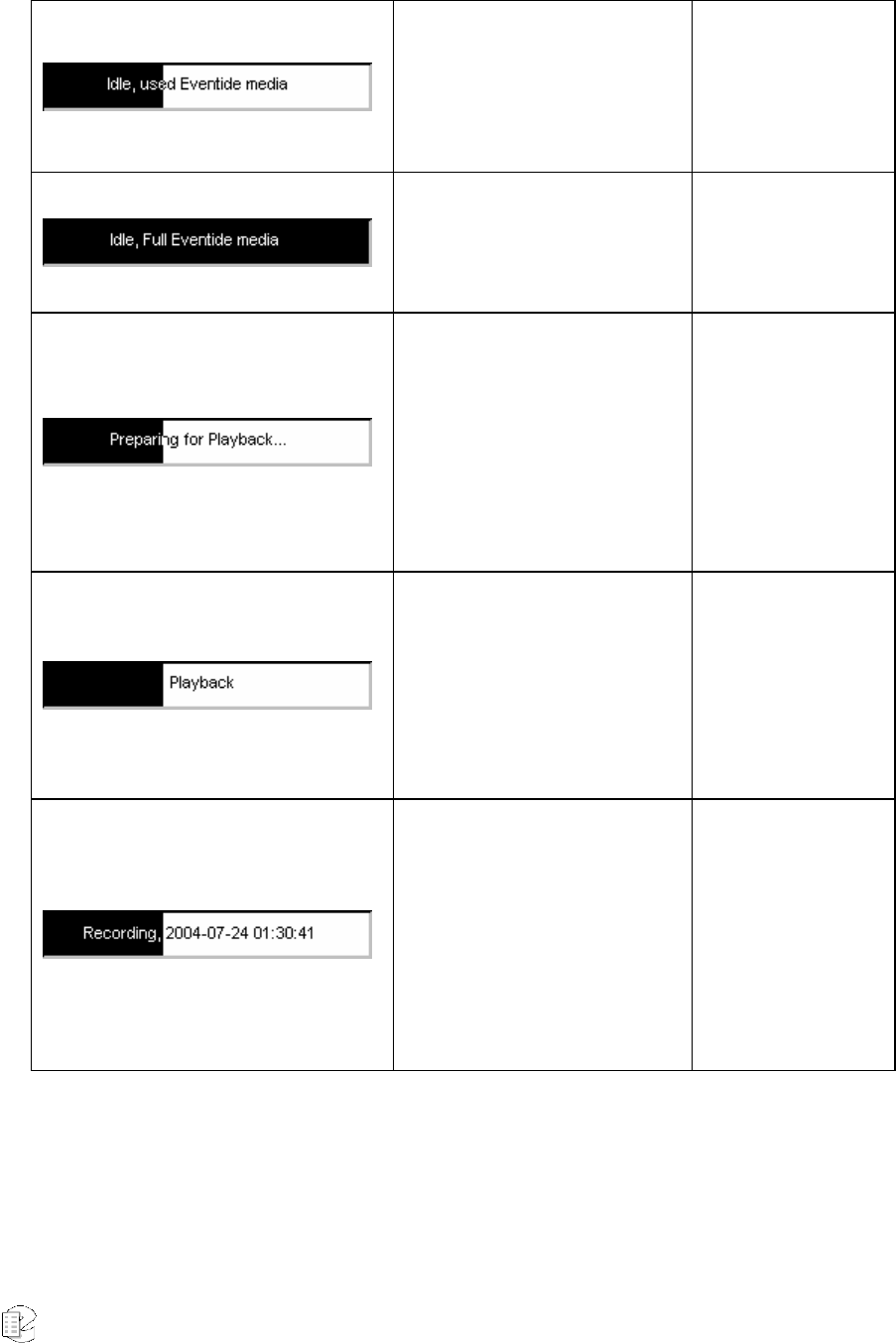
Atlas Series Server 1.8 User Manual 140
A medium with one or more
recorded calls is inserted
Format, Resume
Archiving, Eject,
More, Media Info,
Print Label, Browse
Archive
A full medium is inserted
Format, Eject,
More, Media Info,
Print Label, Browse
Archive, Back
The medium is preparing for
browsing. "Browsing" means the
viewing, searching, and playing
back of calls. While preparing,
the recorder is loading the calls
from the archive into an
internal database.
—-
The medium is ready for
browsing. Only one drive at a
time can be ready for
playback, the Recall screen
identifies that drive and shows
its calls.
More, Media Info,
Print Label, Stop
Browsing, Back
The progress indicator provides
a graphic view of the
remaining capacity of the
archive medium.
As each call is archived, the
start time and date of the call
are displayed.
—-
Other messages can appear in the rectangle, such as those that identify media
that contain Eventide configuration or metadata.

Atlas Series Server 1.8 User Manual 141
Selecting and Deselecting an Archive Drive
Scroll wheel: Turning the wheel will “bold” the designator of each drive
successively. When the desired drive is selected, press the wheel.
Touch screen: Simply click on the horizontal bar of the desired drive.
Once a drive has been selected, the Archiving soft keys will appear on the screen.
For the steps below, press the More soft key as necessary until the listed soft key
appears. To deselect Archiving mode, click the More soft key as often as necessary
until the Exit soft key appears, then click Exit.
Opening/Closing the DVD-RAM Drive
The drive can be opened by pressing the eject button on the drive itself only if the
drive is empty. For security reasons (both to protect operations in progress and to
protect the archive media), media cannot be ejected from the open/close button
on the drive panel itself. To eject these disks:
• Press the “Eject” soft key.
• To close the drive, simply push it back in, or press the open/close button
on the drive panel.
Formatting Archive Media
All archive media used with the Eventide recorder must be formatted. To format a
disk:
• Place the medium into any of the recorder's drives.
• Select that drive by turning and pressing the scroll wheel or by clicking its
bar.
• Press the “Format” soft key.
• Press “Yes” at the prompt.
When format is complete, the display will say "Idle, Blank Media" with no calls
recorded.

Atlas Series Server 1.8 User Manual 142
Start Archiving
Once the medium is formatted, archiving can begin. Select the drive and Press the
“Start Archiving” soft key. The display will say "Recording" with the start date and
time of each call as it is being archived. The calls counter will increment.
Stop Archiving
The correct method of halting the archiving process is through the Stop Archiving
soft key. This will ensure that the process completes cleanly so that the archived
data does not become corrupted. To halt archiving:
Select the drive and press the “Stop Archiving” soft key. The display will say "Idle,
Used Media."
Resume Archiving
After halting the archiving process using the Stop Archiving soft key, you can
resume archiving where you left off by using the Resume soft key. To resume
archiving:
Select the drive and press the “Resume” button. The calls should continue being
archived at the point they left off.
The resume function will not be available on the disk if you have archived to a
second disk in between the time you have stopped and attempted to resume on
the first disk. In other words, if you stop archiving and the disk is only partially
full, use the same disk when you resume. If you use another disk, you will no
longer be able to append files to the first disk. (Of course, you can format the first
disk to reuse it but you will lose the existing files.)
This is a consequence of a feature that ensures that archives contain consecutive
calls, so that archives can be cataloged more easily. While archiving, the recorder
maintains an internal pointer to the current file being archived. If archiving is
stopped and resumed, the recorder compares the pointer to the most recent call
on the disk. If it matches, then the Resume soft key will be displayed and calls
will be archived consecutively. Otherwise, the Resume soft key will not be
displayed and a blank archive medium must be inserted.
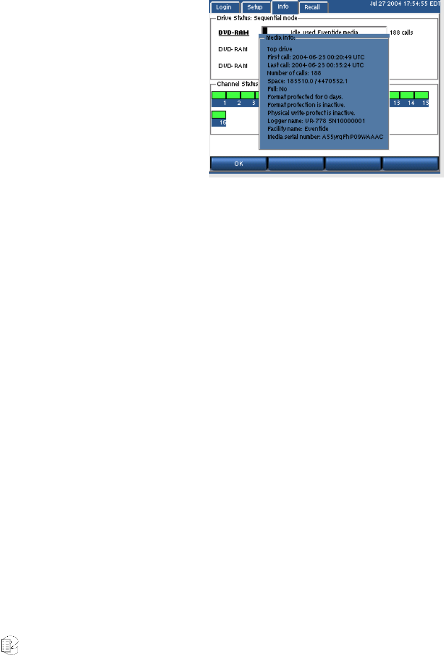
Atlas Series Server 1.8 User Manual 143
Viewing Media Info
You can view information about
your archive media.
• Insert the disk in a drive.
• Select the drive by turning
and pressing the scroll
wheel or by clicking its
bar.
• Press the “More” soft key.
• Press the “Media info” soft
key. A window pops up
with information about the
archive medium.
• Press “OK” or Exit to quit.
The following information is available for viewing:
• The start time of the earliest call on the archive
• The start time of the latest call on the archive
• The number of calls
• Used disk space in kilobytes
• Full? (Yes/No)
• Number of days for which format protection is enabled
• Format protection active/inactive
• Physical write protect active/inactive
• The recorder's model and serial number
Printing a Label
Eventide offers an optional label printer. If the printer is installed, the recorder
can print a label showing the dates of the first and last calls, along with some
other useful information. To print a label for an archive medium:
• Insert the disk in a drive.
• Select the drive by turning and pressing the scroll wheel or by clicking its
bar.
• Press the “More” soft key.
• Press the “Print Label” soft key.
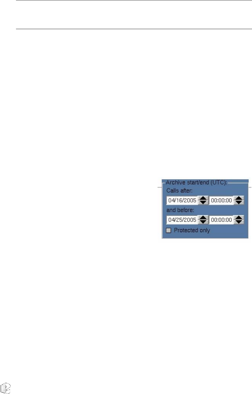
Atlas Series Server 1.8 User Manual 144
Note: If you do this without a printer attached you will see an error message stating that a printer was
not found and that the recorder will try again in 30 seconds. This message will appear three times and
then the attempt to print will abort.
You can also set the recorder to print a label automatically when the medium is
full. To do this:
• Press SETUP.
• Scroll to and select “Enable/Disable Label Printing.”
• Check the “Enable” box and press “OK."
• Some considerations:
Only apply the label to the indented portion of the cassette shell intended for this
purpose. The label is printed with the drive identification on the far right, so you
will know the medium to which it should be affixed. This information is irrelevant
after label application, and must be manually cut off so that the label will fit in
the indented area.
Selecting The Archive Period
You can create an archive medium that covers
only a particular period, such as the duration
of an incident, or a particular period such as a
day or a week. To further refine the selection of
calls on the archive medium, you can copy only
“protected calls,” i.e., those which you have
selected to be preserved. By selecting a period
and the calls within that period, you can make a disk that archives only a specific
incident despite the presence of many unrelated calls during the same period.
Creating this archive does not affect the archive “pointer” which determines at
what time the next archive will start. It is a completely different process.
To create a “selected period” archive:
• Insert a blank medium in the archive drive and format as described above.
• Reselect the archive drive with the Idle, Blank media legend.
• Press “More” twice and select the “Archive period” soft key
• Select the start date/time and end date/time of the desired archive period.
• Toggle “Protected only” to the desired state.

Atlas Series Server 1.8 User Manual 145
• Confirm that this is the desired period and press OK. Note that archives
are created in UTC, so you may have to make a mental correction for your
local time zone.
The archive will now be written to the medium.
Browse Archive Media
You browse calls on an archive just as you browse calls on the RAID. Browsing
means you can view attributes of calls, such as date and time, search calls, and
play them back. To browse an archive:
• Insert the disk in a drive.
• Select the drive by turning and pressing the scroll wheel or by clicking its
bar.
• Press the “More” soft key.
• Press the “Browse Archive” soft key. The display will indicate “Playback”
when the archive is ready.
• Press RECALL to view, search, and play back the calls.
To stop browsing an archive:
• Return to INFO screen.
• Select the drive that indicates “Playback."
• Press “More.”
• Press “Stop Browsing” soft key.
Archive Protection
Archive protection is a feature that allows you to attach a set number of days to a
disk during which the disk cannot be formatted in the recorder. It is intended to
guard against unintentional formatting. When a protected disk is inserted into the
recorder, the date of the latest call on the disk is compared with the current date,
as displayed on the recorder. If the difference between the two dates is less than
the number of days that was set as the protection period, then the recorder will
not permit the disk to be formatted.
Important: The Archive Protection feature must be enabled before recording begins. You cannot add
the feature to a disk that already contains recorded calls.
To enable archive protection:

Atlas Series Server 1.8 User Manual 146
• Press SETUP.
• Scroll to and select "Archive Protection Period.”
• Press the "Enable" soft key.
• Punch in the number of days that you want for the protection period.
• Press "ENT" or "OK."
Insert a blank, formatted disk in the recorder and start archiving. The disk will be
protected.
Auto-Eject
The auto-eject feature, when enabled, will cause the archive disk to eject
automatically when full. This provides the operator with an obvious indication
that the disk must be flipped over or replaced.
To set the auto-eject feature:
• Press SETUP.
• Scroll to and select "Auto-Eject.”
• Press the "Enable" soft key to enable it or "Disable" to disable it.
• Press "ENT" or "OK."
Resuming Archiving on Start-Up
If the recorder is recording to an archive and is shut down normally, this feature,
when enabled, will cause archiving to resume when the recorder is rebooted.
The feature is enabled by default. To set the feature:
• Press SETUP.
• Scroll to and select "Resume Archiving on Start-up.”
• Press the "Enable" soft key to enable it or "Disable" to disable it.
• Press "ENT" or "OK."
Setting Current Archive Time
When you start archiving, the first call to be archived is determined by an internal
“archive pointer”. This pointer tracks where you left off archiving with the
previous disk, so that the next disk will begin where the previous one left off. Also,
if you are in the middle of a disk and you stop archiving, for whatever reason,
such as the need to browse calls on the disk, you can resume archiving at the

Atlas Series Server 1.8 User Manual 147
point where you left off. The goal is to ensure that only consecutive calls are
recorded on each disk, making labeling and searching easier. The pointer is
maintained automatically.
However, there are times when you may want to manually set the current pointer
location. For example, you may have misplaced an archive disk and you want to
re-archive calls. Of course, the calls must
still be present on the RAID.
To manually set the current archive time:
• Press SETUP.
• Scroll to and select "Set Current Archive Time.” (If desired, make a note of
the time shown in the window before changing it.)
• Use the arrow soft keys and the scroll wheel to adjust the setting. On a
touch screen display, select the field and entry by clicking on the field or
the up/down arrows.
• Press “OK”.
The next time you start archiving, the calls on your RAID closest to the new
archive time setting will be archived first.
Important: After manually setting the current archive time, you will not be able to use the Resume
Archiving function on a used disk. You must use a blank archive medium..
When you have completed recording a medium whose starting time you have
selected with the Set Archive Time feature, the time pointer is set to the time of
the end of the medium just recorded. It is NOT set to the end of other data that
may have been archived. Sometimes this is desired behavior, such as when you
want to record more data than will fit on a single medium from the starting time
you set. Sometimes it may not be, such as when you want to continue archiving
from the end of the last medium you recorded in the normal sequence. If the
second is your requirement, you can reset the archive pointer to where it was as
noted above (step 2). If you failed to make a note, you can take the most recent
archive medium, read the “Media info” for that disk, and set the pointer to that
time.

Atlas Series Server 1.8 User Manual 148
Important: As noted in the display, the Archive time is set in LOCAL time. If you are setting the archive
time to start at the end of a previously recorded archive medium, you will probably use the “Media
Info” feature to check on the end time of that medium. The recorder displays “Media Info” in UTC since
the archives are portable and must be compatible over time zones and different playback hardware.
To dovetail the recorded and new archive times, you must convert your local time to UTC for this setting.
For example, if “Media Info” shows an archive completed at 14:02:00 UTC and you are in the EDT time
zone, you would want to set Archive time to 09:02:00.
Designating and Activating an Archive Failsafe Server
Failure of an archive medium or drive isn’t normally a grave concern since the
data remains on the hard drive and can be copied to another medium or on
another drive. However, some installations employ redundant recorders to assure
that failure of one unit will not cause any loss of recorded data. In such
installations, it is normally not desired to make two sets of archives, but the
availability of a duplicate recorder makes another option convenient: If the
primary recorder stops archiving for any reason, the redundant recorder can take
over this function. To implement this, you must:
• Confirm both recorders are connected to the same signal sources and have
identical settings.
• Designate one of the recorders as the secondary server: Select “Archive
failsafe server” and enter the address of the PRIMARY server in the normal
fashion.
• Enable the secondary server to periodically check the primary: Select
“Enable/disable archive failsafe,” toggle the Enable box so that is checked,
and press the OK soft key.
• Determine the behavior of the failover mechanism: Select desired “Archive
failsafe behavior” and toggle Archive failsafe error on “out of media.”
Checking this box in effect allows the secondary recorder to act as an
extension of the primary recorder for archiving. Not checking it causes the
secondary to take over only in the case of an archiving failure in the
primary.
Writing Call “Metadata” to an archive
“Metadata” means data about data, and is just a fancy way of saying that there is
(potentially) some data about calls associated with the calls. For example, when
you use the Browser Client to “protect” a call from being erased, or when you add
“incident” data to a specific call, this is considered metadata. This metadata is not

Atlas Series Server 1.8 User Manual 149
(and typically cannot) be stored with the call archives themselves. Why? Because,
in most instances, archiving takes place contemporaneously with recording, or
shortly thereafter. However, the decision to protect a call, or to add or change
information about a call or incident can occur much later. Therefore, this
information may not be present when the archive is recorded and so obviously
cannot be recorded along with the archive.
The “Write metadata to archive” menu item (as part of SETUP) allows you to
gather all this later-entered data on one medium, and to restore it to the recorder
if necessary. (It will not normally be necessary, but the purpose of saving it is the
same as the purpose of archiving – backup and safety.)
To create a metadata archive, insert a DVD-RAM medium in an available drive
and format it if necessary. Select “Write metadata to archive” and confirm you
want to do so by pressing the YES soft key. Remove the disk and store it with
your archives.
To restore the metadata to the recorder, insert the metadata archive and
select “Read metadata from archive” and confirm the operation.
Unlike the calls themselves, metadata takes a very small amount of space on a
disk, and the entire recorder can be backed up on a single metadata disk.
Metadata is stored in most cases the equivalent of “forever” and so the most
recent metadata backup will suffice to restore this data to all archives. Therefore,
you should determine a reasonable schedule for making these backups – once a
week, perhaps – and keep only a couple of disks in rotation for this purpose.
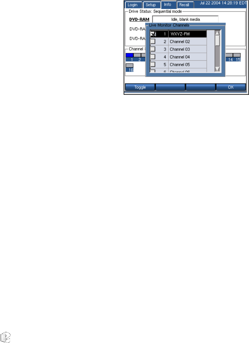
Atlas Series Server 1.8 User Manual 150
LIVE MONITORING
A maximum of eight channels can be monitored in real time from the front panel.
You can monitor a single channel
or multiple channels.
• To monitor calls:
• Navigate to the INFO screen.
• Press the “Monitor” soft key.
A list of channels will
appear.
• Scroll to and select the
desired channels, and use
the Toggle soft key.
• Press “OK."
The selected channel status indicators will turn blue. The audio will be heard
through the front panel speaker, or through headphones connected to the jack
labeled "Headphones."
Channels are deselected using the same method.

Atlas Series Server 1.8 User Manual 151
T
T
Th
h
he
e
e
A
A
At
t
tl
l
la
a
as
s
s
A
A
Ad
d
dm
m
mi
i
in
n
ni
i
is
s
st
t
tr
r
ra
a
at
t
ti
i
iv
v
ve
e
e
C
C
Cl
l
li
i
ie
e
en
n
nt
t
t
4
4
4
WHAT IS REMOTE CLIENT SOFTWARE?
Eventide offers optional client software that works in conjunction with a Windows
PC and the VR615, VR725, and VR778 recorders. The clients include an
administration client that allow you to administer the recorder, and user clients
that allow you to play back calls, monitor calls, and perform other tasks remotely
via a PC connected to the recorder through a network.
DO YOU NEED TO INSTALL THE CLIENT SOFTWARE AT ALL?
The Eventide ATLAS™ recorders are designed as standalone products and it is not
necessary to install the clients to use the product. A non-networked recorder
controlled only by the front panel controls may be adequate for your organization.
The advantages and extra functionality that come with the clients may or may not
be important to your needs.
The advantages to using the clients are these:
• Perform tasks at your desk, rather than at the recorder.
• Perform tasks more easily, with a full-sized computer monitor and a
keyboard and mouse. This is especially true for certain tasks:
o Changing the Channel Name parameter;
o Adding users when login is enabled;
o Administering the recorder as an email client to send email alerts;

Atlas Series Server 1.8 User Manual 152
o Changing Channel Configuration parameters.
• Multiple users can log in and use the recorder simultaneously.
• Get extra functionality:
o View long lists of calls in a tree format;
o Save calls as WAV files;
o Burn CDs;
o View and print reports;
o Play back calls on archives on a PC, without the recorder;
o Setting "facility name";
o Call suppression configuration;
o Tag calls for protection from being deleted;
o Compare user accounts on multiple servers;
o View call and archiving statistics.
Eventide offers two user clients, MediaWorks and MediaAgent. These completely
redesigned clients are designed for Server versions 1.4.3 and above. Each has
their own separate manual, which is provided to you with the software purchase.
(Note that Call Record Browser, Timeline Editor, and Live Monitor are no longer
supported.)
The Recorder Configuration Program
The PC-based administrative client Recorder Configuration application provides
you a seamless interface to virtually all of the functions available in the "SETUP"
menu of the hardware server (recorder) unit. In fact, this program and SETUP
interact so intimately that only one may control the recorder at a time. The client
is particularly valuable when you are working with a multi-recorder system, since
you can control them all from a single location and use the features of the
program to make sure the user and other setups are coordinated.
Differences between the Client functions and Front Panel SETUP
This section describes the server hardware — installation, connection, setup, etc.
Because the Administrative Client software performs almost all of the same
functions as the front panel SETUP, this section of the manual covers only
aspects necessary for operating the software. Practical details of SETUP — e.g.,
how to set VOX levels and off-hook detection, are discussed in the Setup Guide
and Reference section.

Atlas Series Server 1.8 User Manual 153
These functions can only be performed from the front panel (and why):
• Power system down (no way to restart)
• Adjust network parameters (e.g., IP address) or activate DHCP (can't
access unit over network until this is done or if changed)
• Select NTP address or configure external time source or set time (requires
viewing display, possibly configuring external hardware)
• Configure front-panel login requirements or auto-logout timeout (only
applies to front panel)
• Configure archiving and label printing (requires physical access to drives
and printer)
• Write and read machine configuration to archive (requires physical access
to drives)
These functions are only available in the Administrative Client software:
• Setting "facility name"
• Call suppression configuration
• Compare user accounts on multiple servers
• View call and archiving statistics logs
• Editing configuration text files
• Editing user-defined metadata custom fields
• Setup scheduled recording
The PC-based Administrative Client is very similar to the SETUP function on the
server. Which one you use in a given instance is largely a matter of preference.
Installation
The user installing the program must have Administrator permissions for the
workstation on which the installation is being performed.
• Insert the CD and click on the vrSeriesClients icon. Click NO when you are
asked about limited user accounts.
• Read and agree to the License Agreement.
New for
Release
1.5

Atlas Series Server 1.8 User Manual 154
• Select which programs to install. Eventide recommends installing the
Administration Client only on computers where people are authorized to
perform administration of the server functions.
• Click NEXT, and accept the default directory for installation unless there
is a very good reason for doing otherwise.
• Click Install.
• A window will appear showing progress. During the installation, a window
asking about "permissions" will appear. Click "No."
• Click "Close."
If you are installing the Eventide client software from a Windows Administrator
account but want it to be used by people with limited user accounts, the
procedure is as follows:
• Insert the CD and click on the vrSeriesClients icon. After reading the
instructions in the window, Click Yes when you are asked about limited
user accounts.
• Follow the instructions in the window for creating the user group and
adding users to it, and restart the installation. This time click "No" since
you have already created the group.
• Read and agree to the License Agreement
• Select which programs to install or upgrade. If the program(s) are already
installed on the computer, select Upgrade. We recommend installing the
Administration Client only on the computers of people authorized to
perform administration of the server functions.
• Click NEXT, and accept the default directory for installation unless there
is a very good reason for doing otherwise.
• Click Install.
• A window will appear showing progress. During the installation, a window
asking about "permissions" will appear. Click "Yes."
• Click "Close."
When the installation is complete, there will be a new program group "Eventide
VR Series" in the program menu. If the computer user will be using one or more of
the client programs frequently, it would be a time-saving gesture to copy and add
the appropriate icon(s) to the computer's "desktop."
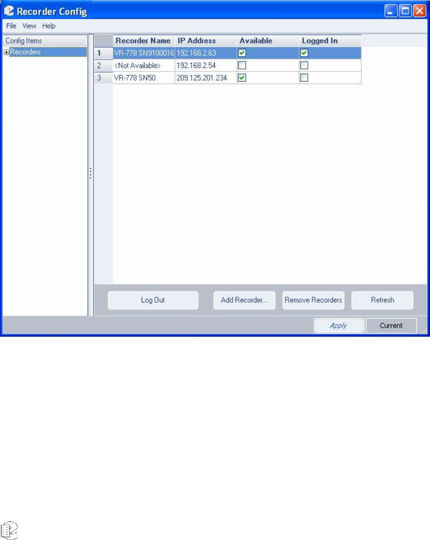
Atlas Series Server 1.8 User Manual 155
STARTING THE CLIENT
Launch the program by selecting Recorder Configuration from your Eventide VR
Series directory.
The following startup screen now displays:
Figure 1–Administrative Client Startup screen
The first time you run the client software, you must specify the recorders to which
you want to connect.
To do so, click Add Recorder and enter the IP address of the recorder you wish to
add in the New Recorder window. You’ll find the IP Address on the recorder front
panel display by selecting the Configuration Info display. After entering the IP
address using standard notation (e.g., 192.168.1.101), the selected recorder will
be added to the main window and will be identified by its name and IP address.

Atlas Series Server 1.8 User Manual 156
Two additional columns, Available and Logged In will display the current status of
the recorder.
• If you enter an invalid IP address, you will be asked to re-enter it.
• If you enter a valid IP address but no recorder can be found, it will be listed
as <Not Available>
• If you enter a valid IP address, the available column will be checked, but
you will be not shown as "Logged In."
• In a multiple recorder system, click Add Recorder and fill in IP addresses
until the list is complete.
SERVER LOGIN
Select a recorder by clicking its number to the left of its name. If you wish to log
into multiple units (and they all have the same administrative password), then
click on multiple blocks by holding down the <ctrl> key while clicking, or select a
group with the mouse and <shift> key. Then click Log In to Selected Recorders.
Enter the user Name and Password in the window and click OK. (If you want to
log in as "read only," deselect the Read/Write box that appears checked as a
default.) The selected recorder(s ) now will display with its respective "Available"
and "Logged In" boxes checked.
• If you enter an invalid password or invalid user name (or both), you will get
a message saying the user name and/or password are invalid. (For security
reasons, it does not say which is invalid.)
• If you log in to a recorder that was connected but is now off line, you will
receive a Login Failed message.
• If you log in to a recorder that has been connected to in read/write mode
by another program, or is in the SETUP mode at the front panel, a message
displays indicating that you are restricted to read-only mode.
The following screens illustrate the login process and some typical messages
associated with login and logout.
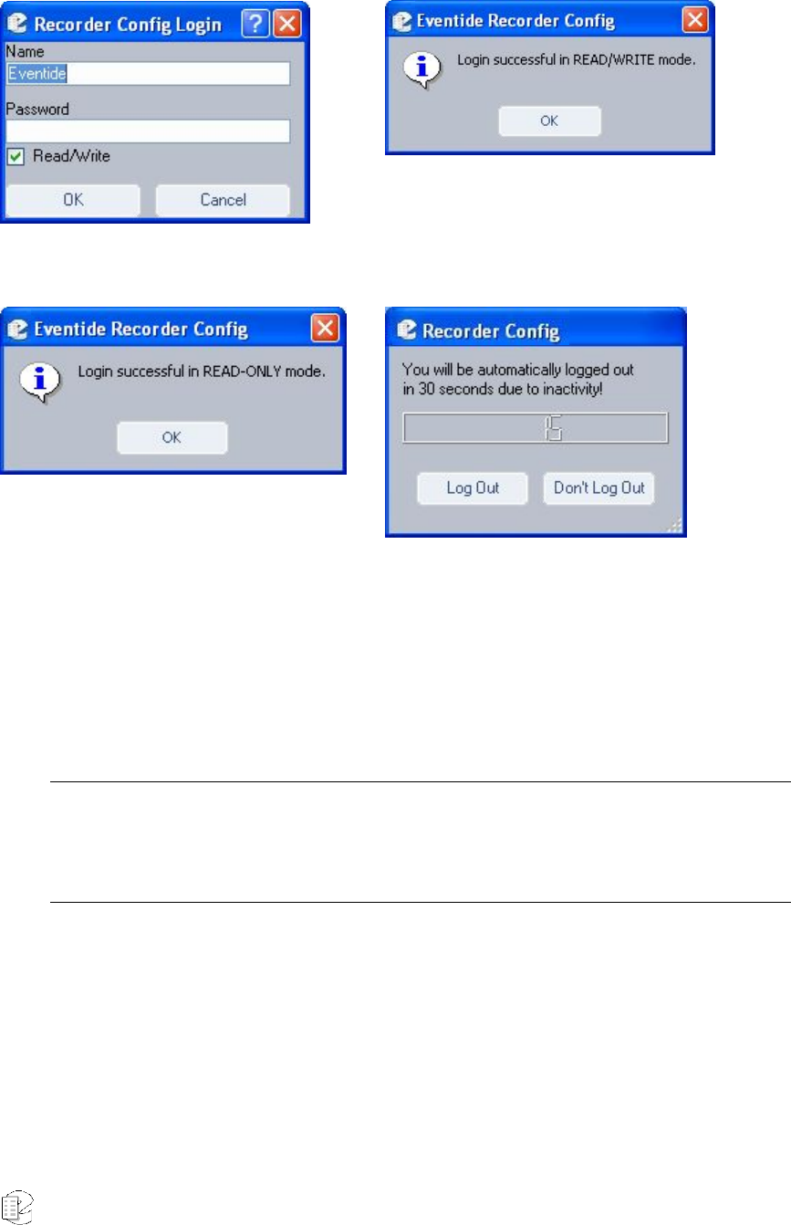
Atlas Series Server 1.8 User Manual 157
Figure 2–Server login window
Figure 3–Successful login message
Figure 4–Read-only access message
Figure 5–Automatic logout message
To prevent one administrator from locking out others, the administrative client
automatically logs the user out if there has been no activity for more than ten
minutes.
Note: If someone attempts to use the recorder front panel’s SETUP mode they will receive a "Locked”
notification." However, it is possible to break the lock from the front panel since it may be necessary to
do so to shut down power or perform other important operations. In this case, the Configuration Client
user is warned that any unapplied changes have been lost.
Once you have successfully logged in with read/write privileges on all selected
units, you can now modify the settings of the server.
SERVER SETTINGS
The Config Items menu is the key to selecting the server features and functions
to be displayed or modified.
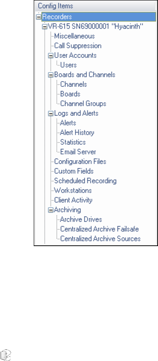
Atlas Series Server 1.8 User Manual 158
The program organizes the modification settings in a hierarchical directory tree.
Here the menu is fully expanded for the VR778 but remains collapsed for the
VR615. Clicking on any of the menu items launches that respective
administrative process.
Figure 6–Config Items administrative options
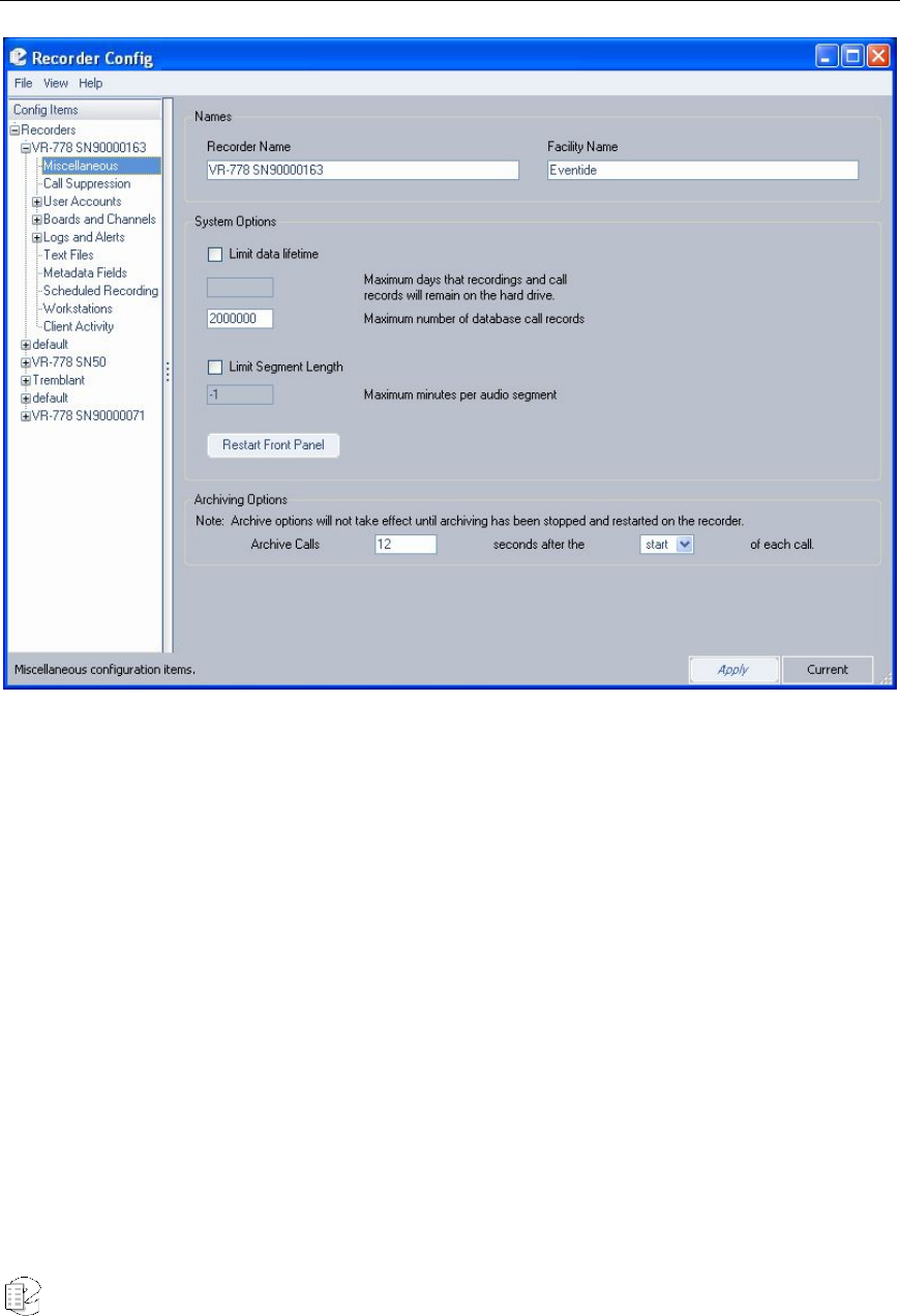
Atlas Series Server 1.8 User Manual 159
Miscellaneous
Figure 7–Miscellaneous Configuration screen
The Miscellaneous Configuration screen allows you to modify the call recorder
naming conventions and other associated general options. The Recorder Name
and Facility Name respectively default to the recorder model number and serial
number, and the designated owner. For either, you can change the settings by
simply typing in replacement information and clicking Apply. (The significance of
the System Options is discussed in the SETUP section.) The Recorder Name and
Facility Name are simply for your convenience in identifying units, and have no
operational significance. For example, you can change the displayed default
(model, serial number,) to something that better identifies it in your facility. This
has no effect on the actual serial number.
In the Limit Data Lifetime area of the screen, you can denote the number of
days data is retained on the server’s hard drive. Default is 30 days. Additionally,

Atlas Series Server 1.8 User Manual 160
you may designate the number of call records retained in the database. Default is
-1.
Under Limit Segment Length, you can set an absolute maximum time limit for
each call record. Default is 10 minutes.
Beneath Archiving Options, you can designate the delay parameters for
archiving a call.
In the text box following “Archive Calls,” select the number of seconds you wish to
wait before beginning an archive. Default value is 12 seconds. Next, in the drop-
down list following the text “seconds after the,” select either Start or End of the
call. After you modify archiving values, you must re-start your recorder for the
new settings to take effect.
Any of the values described can be changed by simply overwriting them with new
values, and clicking Apply.
New for
Release 1.6
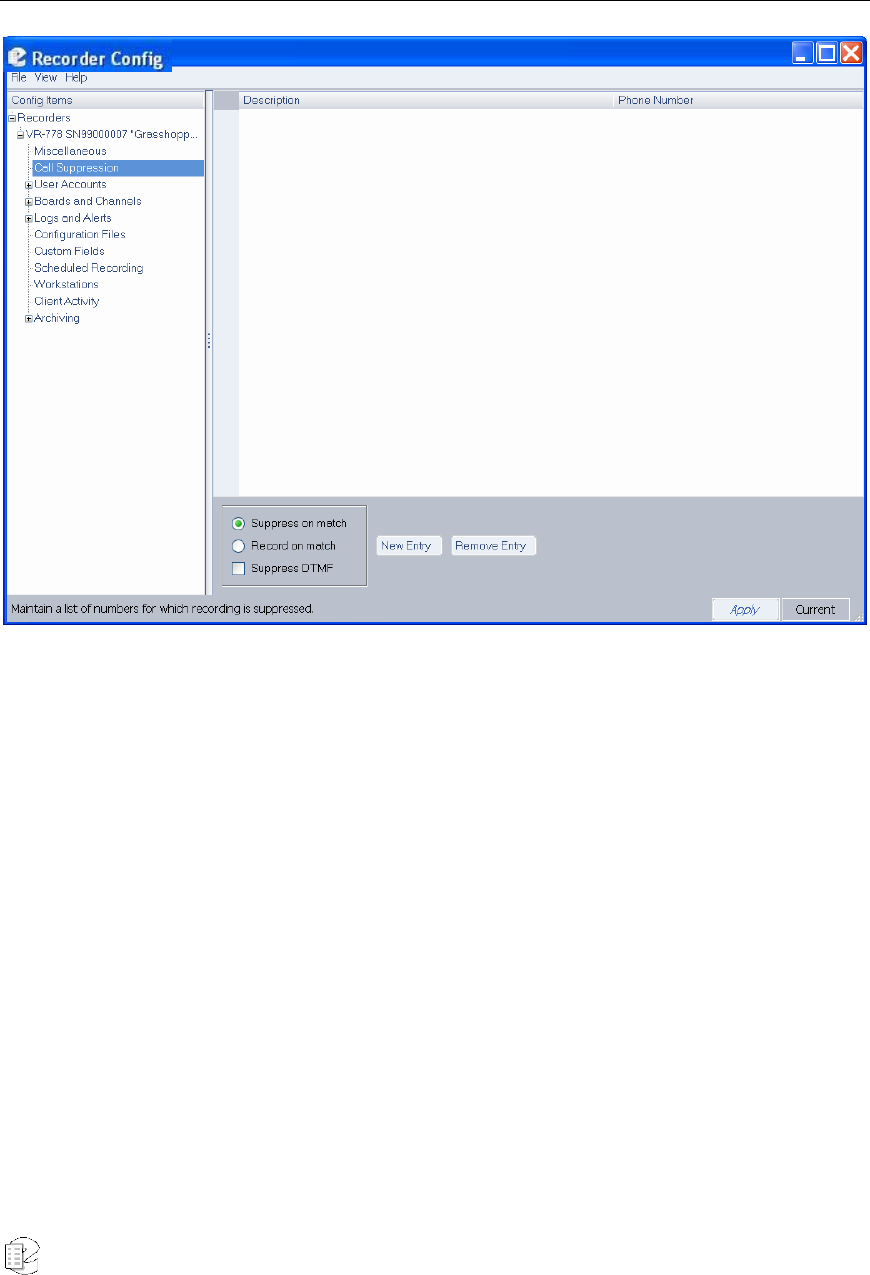
Atlas Series Server 1.8 User Manual 161
Call Suppression
Figure 8–Call Suppression screen
The Call Suppression screen provides the means to suppress, or prevent, calls
from recording (audio data will not recorded, but the recorder retains non-audio
data about the calls). This feature is accessible only from the Recorder
Configuration utility and not from the recorder front panel. This feature can be
used for a variety of purposes, including implementing a legally mandated
attorney-client privilege, or assuring privacy for undercover officers or high-
ranking officials.
Two mutually-exclusive suppression methods are provided:
• Suppress on match: Suppresses recording for all calls that match a telephone
number in the list. The recorder discontinues recording a call as soon as the
telephone number is recognized.
• Record on match: Suppresses recording for all calls except for those that
match a telephone number in the list.
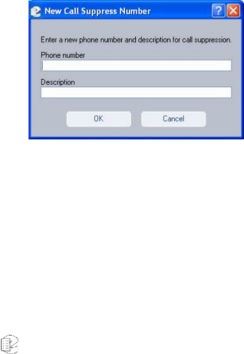
Atlas Series Server 1.8 User Manual 162
The suppression method applies to the entire list of telephone numbers rather
than to individual telephone number entries. To select a suppression method,
click on the radio button next to it.
The Suppress DTMF feature applies to all call suppression. When recording is
suppressed for a call and this feature is enabled, the recorder will not store a
record of the telephone keypad dialing tones (Touch-Tones*) that occur during the
call. This can be useful to prevent the storage of sensitive data transmitted by
DTMF during a call, such as social security numbers, passwords, and personal
identification numbers. Click the checkbox to enable this feature.
To suppress recording, you must select a suppression method, and create a list of
telephone numbers. Then you must enable record suppression on a channel-by-
channel basis by marking the Enable Record Suppress checkbox in “The Channel
Configuration Screen.” The following instructions describe how to create and
manage a list of telephone numbers.
To add a new entry to the list of numbers, click New Entry. This displays a text
entry box, similar to the following:
Enter a full or partial telephone number. A call containing this numeric sequence
within its telephone number will cause a match. For example, if you enter 800-
555-1234, any calls from this number will cause a match, but if you enter only
555, any calls with this sequence within the number will cause a match.
A partial number allows you to specify all calls from an area code or exchange.
Whereas the Suppress on match method is typically used for very specific
telephone numbers, the Record on match method is often used with a partial
number sequence. For example, if you want to match on an area code and
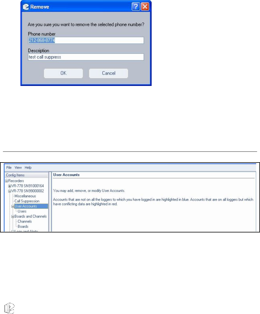
Atlas Series Server 1.8 User Manual 163
exchange, you can enter 800-555. (Note that a call from 900-880-0555 will also
match this number.)
Enter a description and click OK. The new entry displays in the list on the right
side of the screen.
To remove an existing entry, select it in the list, and click Remove. The system
displays a message asking for confirmation.
Click OK to proceed or Cancel to stop the action.
User Accounts
Figure 9–User Accounts screen
Note the text in the User Accounts window. The highlighting feature is reserved
for the administrative client, as described below.
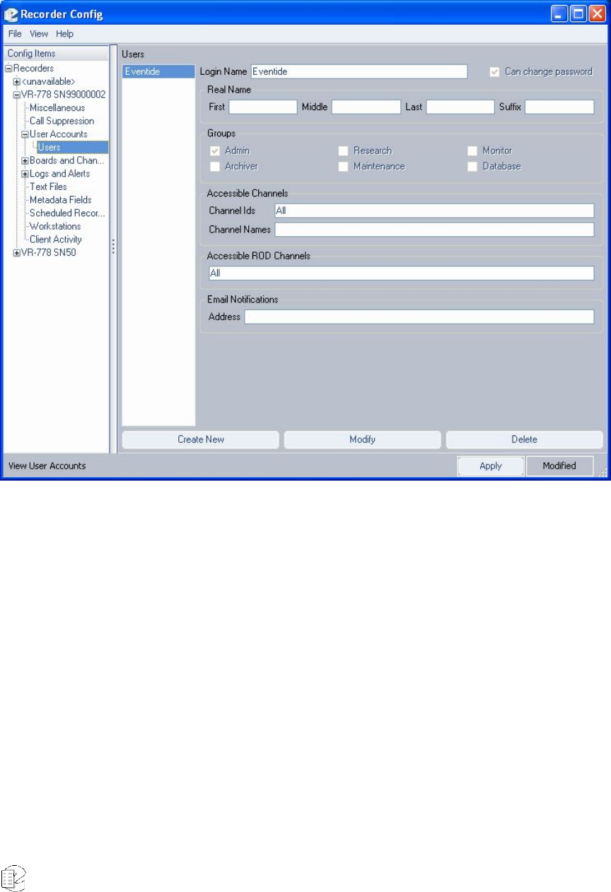
Atlas Series Server 1.8 User Manual 164
Click Users beneath User Accounts in the directory tree to access the User
Information screen:
Figure 10–User Administration screen
This window serves the same purpose as the User Administration function on the
server (see the SETUP section.) It also has the added capability to compare user
listings on multiple recorders, and highlight in blue or red users for which
information differs between recorders. You must have active connections for all
recorders you wish to compare.
The illustration shows the View User Accounts window, which is accessible
exclusively in read-only mode. It shows the users only on the selected recorder. If
there are users on other recorders that match or partially match each other but
have no counterpart on the selected recorder, they do not display.
To delete a user, select the user with the mouse, click Delete and choose
whether that user should be deleted from the selected recorder or from all.
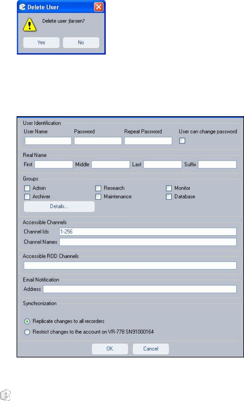
Atlas Series Server 1.8 User Manual 165
Figure 11–Delete User message
To add or modify user information, click Modify button or double-click on a
user’s name. Clicking Create New launches a blank screen, onto which you enter
new user information.
Figure 12–User information screen (Modify mode)
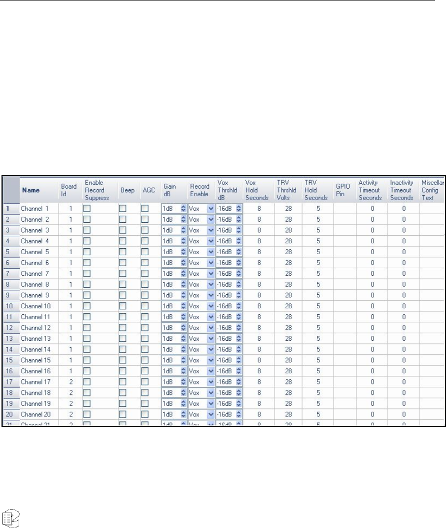
Atlas Series Server 1.8 User Manual 166
In any case, you can make new or changed user profiles effective for the single
recorder selected (default) or replicate the changes/additions for that user to all
recorders to which you are logged in. You must have write permission to a
recorder in order to make modifications. If you do not have write permission, the
Modify button is inaccessible. In this, case you will have to log out and then log
back in to only units to which you can gain access.
Boards and Channels
The Boards and Channels item allows you to configure telephony and audio
boards installed in the recorder as well as specific channels provided by the
boards.
CHANNELS
Selecting the Channels item displays the Channels Configuration screen, similar
to the following:
The Channel Configuration screen displays identical information to the server’s
front panel. The signal parameters are usually more conveniently set from the
server, since this is typically where the actual audio lines are located and it is

Atlas Series Server 1.8 User Manual 167
often necessary to make adjustments and connections external to the hardware in
the process of setup. (Descriptions for each adjustment are discussed in the
Setup section.) In order to make adjustments from this window, either enter an
appropriate number, or increment, decrement, or select the value as appropriate.
When all modifications are finished, click Apply.
BOARDS
Selecting the Boards item displays the Boards Configuration screen, which allows
you to select an installed telephony or audio board for configuration.
While the optional digital PBX boards can be configured for a large number of
different PBXs, the boards require customized setup at the factory, and in most
cases their configurations should not be changed.
This section covers the following boards:
• Analog Telephony Board Configuration
• M-Audio HiFi Audio Recording Board Configuration
• AI Logix NGX
• AI Logix E1/T1
• VoIP Gateway Configuration
Analog Telephony Board Configuration
If you select an analog board and click on the Edit Selection button, it displays
the Analog Board Configuration window, similar to the following:
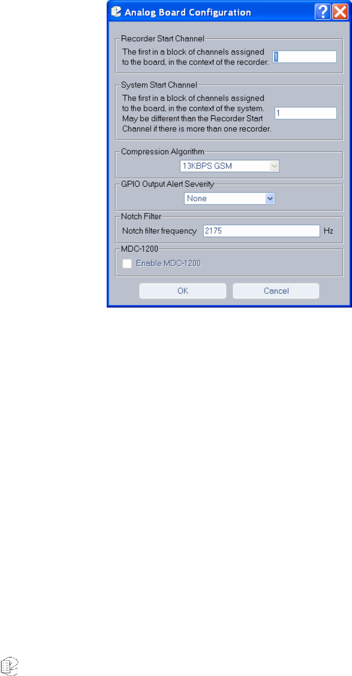
Atlas Series Server 1.8 User Manual 168
Figure 13–Analog Board Configuration window
• Recorder Start Channel – Displays the first channel number for the block of
channels that are assigned to this board at the factory. Do not change.
• System Start Channel – Displays the first channel number for the block of
channels that are assigned to this board at the factory when the recorder is
used in a multi-recorder setup.
• Compression Algorithm – Assigns a compression algorithm for use with the
board. Options include 13 KBPS GSM, 16 KBPS G.726 ADPCM, 32 KBPS G.726
ADPCM, and 64 KBPS mu-law.
• GPIO Output Alert Severity – Sets the alert level for triggering a GPIO signal.
This feature only applies to Eventide 8- or 16-channel analog telephony
boards.
For the 8- and 16-channel analog boards, the signal is output via tip/ring
pins 24 and 49 (“Relay: general alarm”), unless the board has reversed
connections (where pin 1 is at the bottom of the connector), in which case,
pins 27 and 2 are used.
New for
Release 1.7

Atlas Series Server 1.8 User Manual 169
Values:
– None: No GPIO alarm signal is generated.
– Alert Level 1: “Info” alerts or higher; ignores acknowledgement.
– Alert Level 2: “Warning” alerts or higher; ignores acknowledgement.
– Alert Level 3: “Error” alerts or higher; ignores acknowledgement.
– Alert Level 4: “Severe Error” alerts or higher; ignores acknowledgement.
– Alert Level 1 (Unack): “Info” alerts or higher.
– Alert Level 2 (Unack): “Warning” alerts or higher.
– Alert Level 3 (Unack): “Error” alerts or higher.
– Alert Level 4 (Unack): “Severe Error” alerts or higher.
Default: Alert Level 3 (Unack).
Severity settings implicitly include higher levels; for example, if you set the
severity to Level 1, any alert of severity 1 through 4 will trigger the signal,
whereas for Level 4, only the most severe alerts will trigger the GPIO signal. To
identify the severity level of an alert, see Table 8–Alert Messages, or view the
configuration for a specific alert using the Recorder Configuration utility (Logs
and Alerts > Alerts > Edit/View Selection).
The “Unack” settings specify that the GPIO signal will be turned off when the
alert is acknowledged in MediaWorks or MediaAgent, whereas the standard
settings allow the GPIO signal to continue when the alert is acknowledged in
MediaWorks or MediaAgent.
Example: At Alert Level 3 (Unack), a GPIO signal is triggered on Alert #1008
(severity 3): “The system is experiencing a high load. This may indicate a
problem.” If this alert is acknowledged in MediaWorks or MediaAgent, the
signal is turned off.
Note: The GPIO alert output feature also works with an optional GPIO board,
but only at the default alert severity setting, Alert Level 3 (Unack), and only if
the recorder does not contain any Eventide 8- or 16-channel analog telephony
boards. In this case, the signal is output on the first pair of output pins on the
GPIO board (pins 51+52 on 48-channel GPIO board or pins 31+32 on the 24-
channel GPIO board). The GPIO board requires an add-on license key.
• Notch Filter Frequency – Specifies a frequency to be filtered. The notch filter
detects and filters out a single frequency pilot tone, line-proving tone or guard
tone from a two-way radio signal, so that the voice data can be more clearly
understood. You can specify any frequency in the range 200 – 3200 Hz. Some
commonly used tones include the following (in Hz.): 1950, 2100, 2175, 2300,
New for
Release 1.8

Atlas Series Server 1.8 User Manual 170
2323, 2600, 2800, 2970. The filter operates with a minimum notch depth of
55 dB and bandwidth of +/–3% maximum at –3 dB. This feature is supported
on Eventide analog telephony boards only.
• Enable MDC-1200 – Enables MDC-1200 decoding, which will decode leading
or trailing audio frequency-shift keying (AFSK) data in two-way radio signals
and provide the four-digit unit ID of the transmitting radio unit. Other MDC-
1200 data, such as emergency alarm, pre-defined status message, selective
call, call alert, and radio check, can be obtained using custom scripts.
MDC-1200 decoding is supported for analog telephony boards only and
requires an add-on software license key.
To obtain the radio ID for transmissions/calls, create a custom field named
RADIO_ID of type string. Radio IDs can then be accessed in call records
through MediaWorks. Note that a new call record is triggered when a
transmission contains a radio ID different from the current call.
M-Audio HiFi Audio Recording Board Configuration
The M-Audio Board (below) uses the Ogg Vorbis compression scheme (similar to
MP3) for better audio quality at high compression rates with extended frequency
response.
New for
Release 1.8
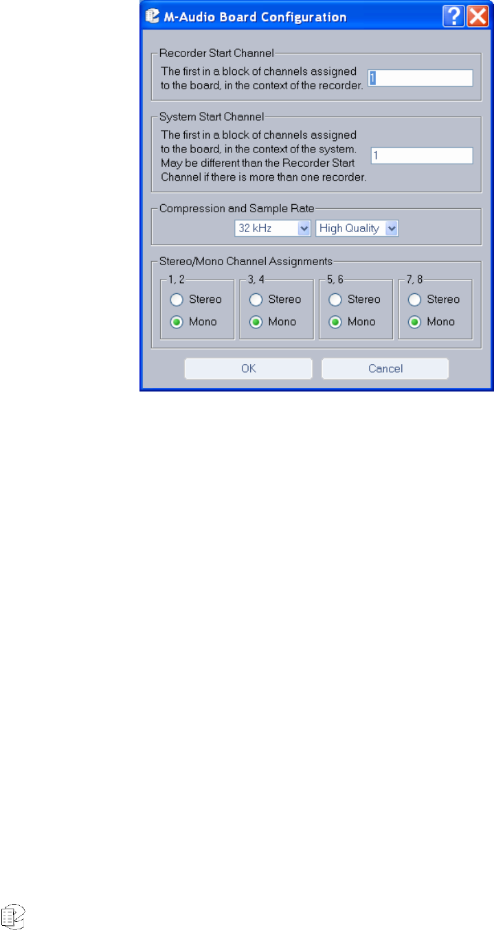
Atlas Series Server 1.8 User Manual 171
Figure 14–M-Audio Board Configuration window
• Recorder Start Channel – Displays the first channel number for the block of
channels that are assigned to this board at the factory. Do not change.
• System Start Channel – Displays the first channel number for the block of
channels that are assigned to this board at the factory when the recorder is
used in a multi-recorder setup.
• Compression and Sample Rate – M-Audio supports the following sampling
rates: 8 KHz, 12 KHz, 16 KHz, 22.050 KHz, 24 KHz, 32KHz, 44.1KHz,and
48KHz. Additionally, you can select one of two compression algorithms, Low
Quality or High Quality. The former reduces file size; the latter provides better
audio quality.
• Stereo/Mono Channel Assignments – Select here whether channels will
deliver stereo or mono output. Each 8-channel board appears as only four
channels on the display, as the channels are configured in pairs (stereo).
AI Logix NGX Configuration
The Administrative Client also supports operation with the AI Logix NGX digital
PBX board.
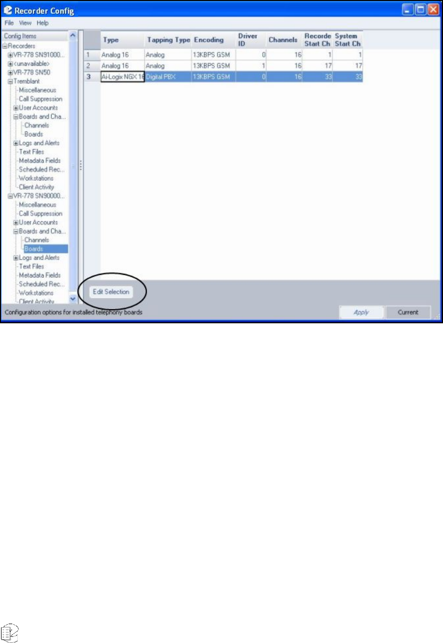
Atlas Series Server 1.8 User Manual 172
To view its settings and attributes, from the Boards Configuration screen
highlight the board in the right display area and click Edit Selection:
Figure 15–Board Configuration Screen
The following screen now displays:
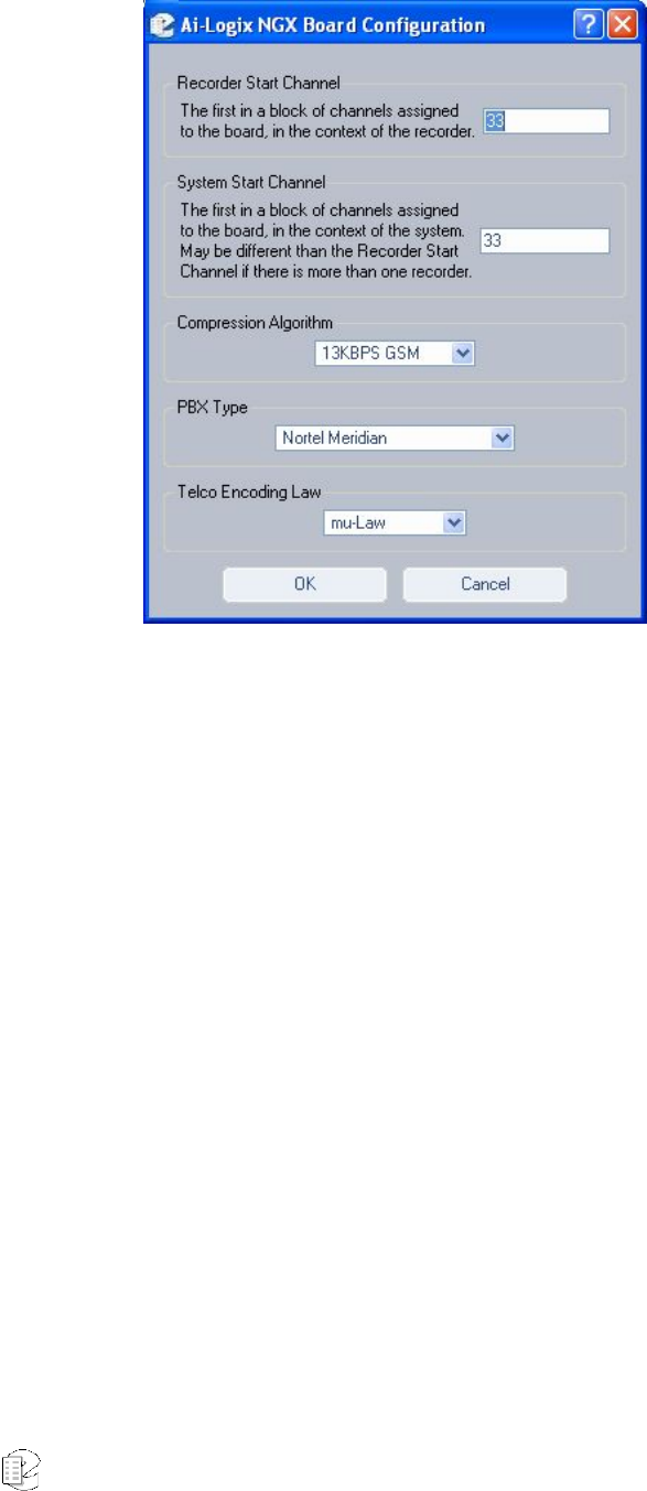
Atlas Series Server 1.8 User Manual 173
Figure 16–Ai-Logix NGX Board Configuration screen
Descriptions follow for each area of the screen.
• Recorder Start Channel – Displays the first channel number for the block of
channels that are assigned to this board at the factory. Do not change.
• System Start Channel – Displays the first channel number for the block of
channels that are assigned to this board at the factory when the recorder is
used in a multi-recorder setup.
• Compression Algorithm – Assigns a compression algorithm for use with the
board. Options include 13 KBPS GSM, 16 KBPS ADPCM, 32 KBPS ADPCM, and
64 KBPS mu-law.
• PBX Type – Lists all supported PBX types.
• Telco Encoding Law – Supported encoding types are A-law and mu-law.
AI Logix E1/T1 Configuration
The Administrative Client also supports operation with AI Logix E1/T1 boards.
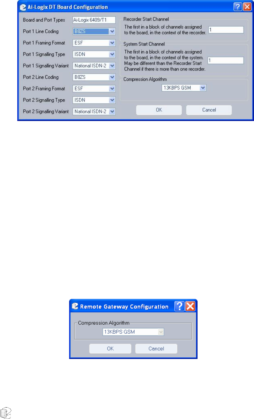
Atlas Series Server 1.8 User Manual 174
Figure 17–E1/T1 Board Configuration screen
The installation and configuration of an E1 or T1 board is done entirely at the
factory, and it is typically not required that any of the configuration parameters
be changed. Suffice to say that depending on the board installed, the successive
list of options change, as do the recorder start channels. Contact an Eventide
representative before you change the settings on this screen.
The Administrative Client also supports operation with AI Logix E1/T1 boards.
VoIP Gateway Configuration
To change the configuration, select the VoIP proxy board and click Edit:
Select the Compression Algorithm from the drop-down list. Options include 13
KBPS GSM, 16 KBPS ADPCM, 32 KBPS ADPCM, and 64 KBPS mu-law. When
finished, click OK.
New for
Release
1.6

Atlas Series Server 1.8 User Manual 175
For more information on Remote Gateway Configuration, see the section on
“Eventide Voice Over Internet Protocol (VoIP) Implementation.”
Channel Groups
To set up channel groups, do the following:
1. Log into the recorder you wish to configure.
2. Go to Boards and Channels: Channel Groups
3. If there are currently no channel groups, click Add Group, enter a
name and click OK. It will automatically be selected.
4. Select channel names that you want to add to this group. (Ctrl+click to
select or deselect multiple non-consecutive channel names, shift+click
to select consecutive channel names.)
5. Click the right arrow to add the selected channels to the group.
6. To delete channels, select them from the right hand column and click
the left arrow.
CHANNEL NAMES
With the addition of Channel Groups, Centralized Archiving, and Archive Failsafe,
the naming of channels on each recorder in your installation has taken on new
importance. If you are not using these features, you do not need to change
anything, but if you are, there are some points to consider for ease of use,
archiving and improved search results:
1. Channel names on Centralized Archiving sources should be unique
among all systems connected to the same destination.
2. Channel names on Centralized Archive Failsafe pairs should be
identical.
Changing channel names that were already in a channel group will remove the
channel from the group unless you add the new name to the list of channels
names in that channel group. This can be useful if you want to prevent new calls
on a channel from being archived as part of a channel group without removing
the earlier recorded calls.
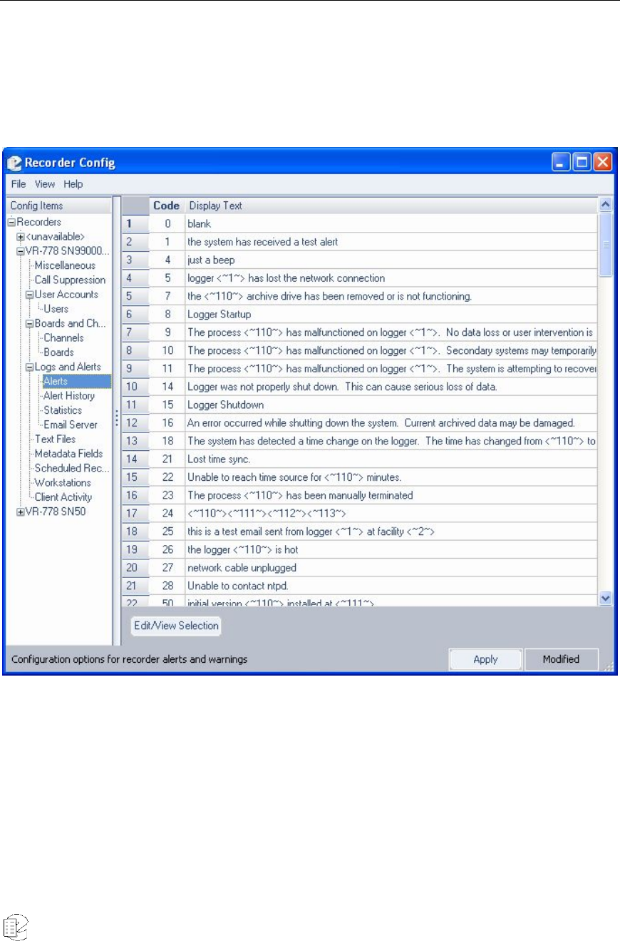
Atlas Series Server 1.8 User Manual 176
Logs and Alerts
The Atlas server not only logs data, it also generates system alerts and maintains
statistics on many critical areas of operation.
ALERTS
Figure 18–Alerts Screen
The Alerts screen provides the text content for all alert messages in the system. To
edit an alert, highlight it and click Edit/View Selection. Perform any edits, and
click Apply.
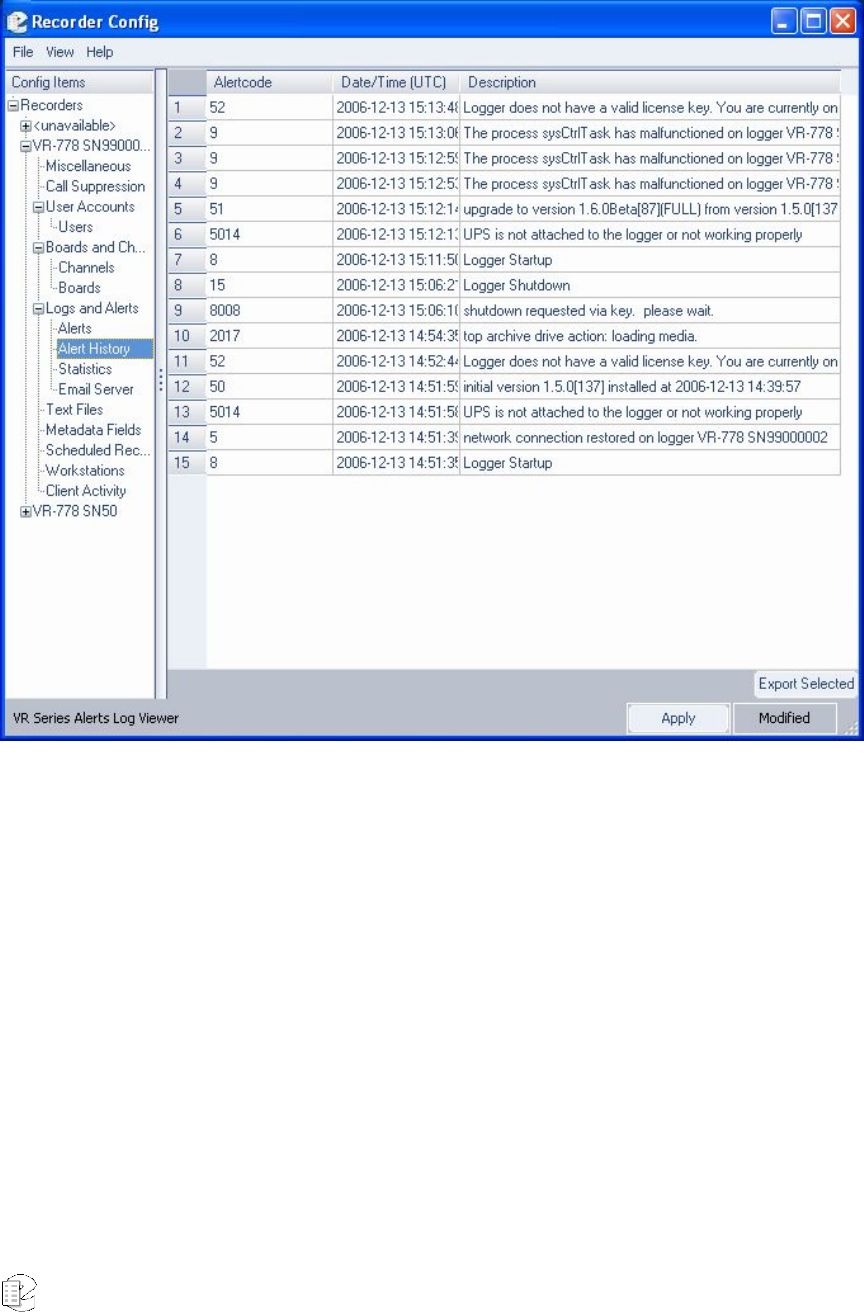
Atlas Series Server 1.8 User Manual 177
ALERTS HISTORY
Figure 19–Alerts History screen
This screen lists an ongoing history of what alerts were invoked, and what system
incident occurred to invoke them. To save a listing as an ASCII text file, highlight
the entries you’d like to save, click Export Selected, select a name for the file,
and click Save.
STATISTICS
The Recorder Daily Statistics screen provides you comprehensive numerical data
on call volume, call data statistics, and detailed archive information. It also
implicitly alerts you to impending or actual loss of data due to insufficient
storage.
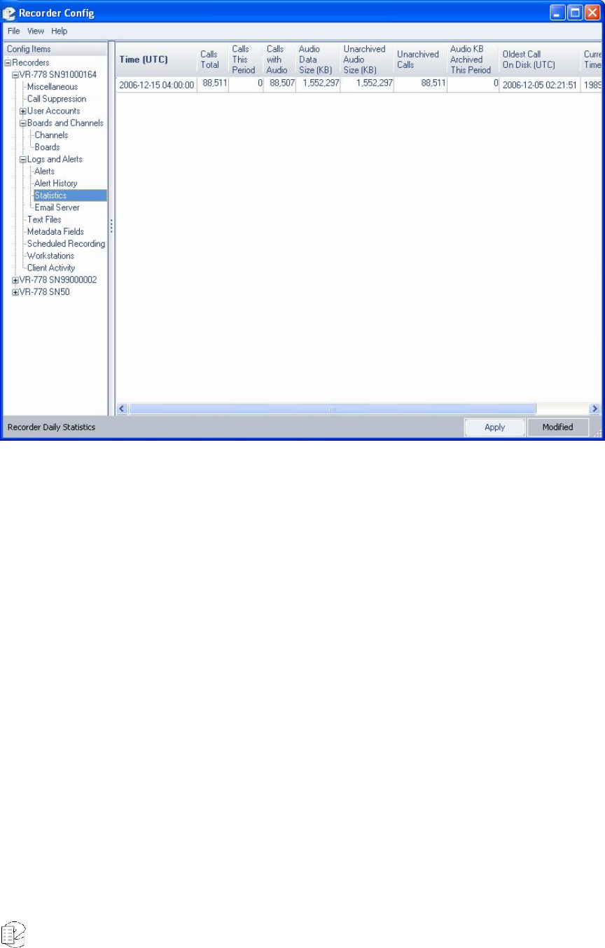
Atlas Series Server 1.8 User Manual 178
Figure 20–Statistics screen
Descriptions follow for each statistical area displayed.
• Time: Date and time statistics were compiled.
• Calls Total: How many calls are recorded on this unit.
• Calls This Period: How many calls were recorded in the one-day period
between Time entries.
• Calls with Audio: When a call is suppressed, there is still a call record
created that includes its start time, duration, caller ID, and DTMF info. The
audio for the suppressed call is not recorded, however, and they are
subtracted from the total number of calls.
• Audio Data Size(KB): How many KB (1024 Bytes) of audio are available for
playback.
• Unarchived Audio Size (KB): How many KB (1024 Bytes) of audio remain
to be archived before the archiving catches up with the present time. If this
New for
Release
1.7

Atlas Series Server 1.8 User Manual 179
number gets larger each day, then it means you're not keeping up and may
eventually lose data.
• Unarchived Calls: Similar to above, but number of calls instead of raw
data size.
• Audio KB Archived This Period: In this case, how much audio was
archived in the preceding day. Indicates whether disks are being changed
appropriately, etc.
• Oldest Call On Disk: This is perhaps the most critical of all statistics
logged. As a hard drive is filled, older calls begin being overwritten.
Ultimately, this should directly determine your archiving strategy for
moving older calls to other media.
• Current Archive Time: As archive media are written, this time is
incremented. All calls after this time and date have not been archived. (All
calls before may have been archived, assuming the archive was recorded
before they were erased due to lack of storage.)
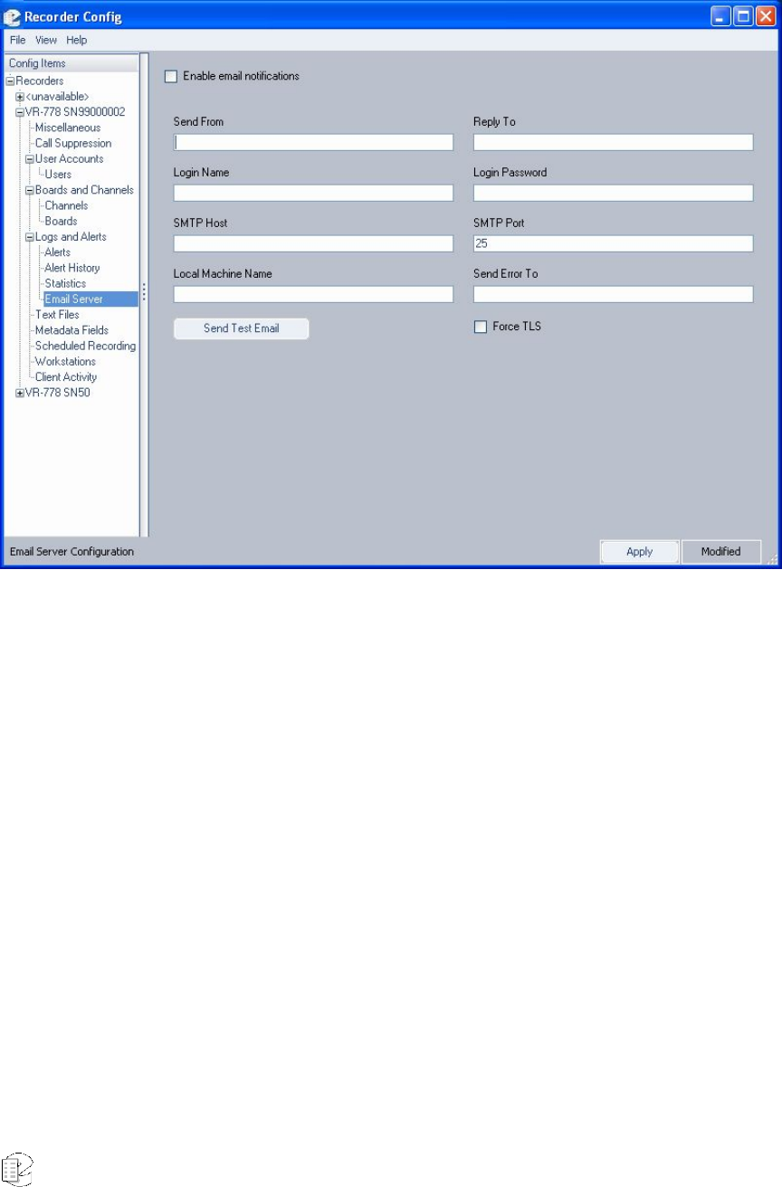
Atlas Series Server 1.8 User Manual 180
EMAIL SERVER
Figure 21–Email Notification screen
You can have the recorder send emails to designated recipients by filling in the
Email Server Configuration page and checking the Enable email notifications
checkbox. . The information needed here is discussed in the SETUP section. You
designate individual users to receive notifications under user administration.
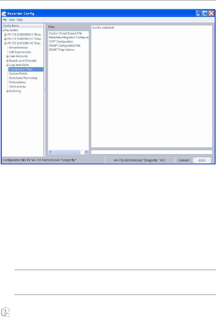
Atlas Series Server 1.8 User Manual 181
Configuration Files
Figure 22–Configuration Files screen
The Configuration Files screen is used to view and edit configuration text files
contained on the selected recorder. Some of the features supported through the
configuration files require additional software license keys.
To access a configuration file, select a file listed in the Files column and the
contents will be displayed in the column on the right.
To edit a configuration file, move the cursor to the point at which you’d like to
modify or append the file, and perform all necessary changes. You must have
read/write access to modify a configuration file.
Caution: Changing a configuration file could interfere with the operation of the recorder. Do not modify
custom script source files. Any change to a custom script will invalidate its license and prevent the script
from functioning, thereby interfering with the intended operation of the recorder system.
New for
Release
1.5

Atlas Series Server 1.8 User Manual 182
When you’re finished, click Apply, and all changes will be saved to the file.
The following types of configuration text files are supported:
• Custom Script Source File: This type of file contains purpose-built code that
has been designed to meet customer or site-specific requirements. Eventide
professional services offers this customized add-on code via scripting in the
file. The scripting capability is extremely powerful and flexible and can serve
many purposes. It can provide additional functionality through integration
with an external database, CTI server, or Computer Aided Dispatch system.
Use of this feature requires an additional software license key, which is
embedded at the top of the file. When the file contains customized code, it
must not be modified in any way; otherwise, it invalidates the license and
prevents the script from functioning. By default all installations will contain a
minimal script as a place-holder, which does not contain an embedded license
key. But to avoid unnecessary script alerts, do not modify this default script
either.
• Metadata Integration Configuration File: This file is used to configure the
recorder to recognize user-defined metadata feeds that arrive via a network
connection or serial port. Use of this feature requires an additional software
license key and custom scripting placed in the file to identify the format and
parsing of the metadata.
• SNMP Configuration File: This file is used to configure the recorder for
network management using the Simple Network Management Protocol
(SNMP). SNMP is used to manage network devices.
The SNMP configuration file describes the identity of the Eventide recorder so
that an SNMP client can query the recorder for information. The configuration
file allows you to set the following SNMPv2-MIB values for the recorder:
– rocommunity: Specifies the community name used to authenticate
messages. Public is the default read-only community. Set this to match the
desired read-only community name for your system.
– syslocation: Specifies the location of the recorder (character string).
– syscontact: Specifies contact information such as name, email address,
and phone number of a person to contact about the recorder (character
string).
– sysname: Specifies a name for the recorder (character string).
– sysdescription: Specifies a description for the recorder (character string).
The Eventide recorder provides read-only monitoring for supported SNMP
Management Information Bases (MIBs). The following MIBs are supported:
New for
Release 1.8
New for
Release 1.8

Atlas Series Server 1.8 User Manual 183
– RFC1213-MIB (MIB-II): IETF standard MIB that provides the core set of
managed objects for monitoring statistics (e.g, device status and number
and status of device interfaces) and for management control of devices on a
managed TCP/IP network; raw MIB data requires interpretation by a
management application.
– SNMPv2-MIB (RFC3418): Provides standard SNMPv2 information,
including system name, location, description, contact, and uptime.
– IP-MIB (RFC4293): Provides information for monitoring and management of
Internet Protocol version 4 within the managed entity.
– TCP-MIB (RFC4022): Provides information for monitoring and management
of the Transmission Control Protocol within the managed entity.
– UDP-MIB (RFC4113): Provides information for monitoring and management
of the User Datagram Protocol within the managed entity.
– HOST-RESOURCES-MIB (RFC2790): Provides information for monitoring
and management of the host recorder.
– IF-MIB (RFC2863): Provides information for monitoring and management of
network interfaces within the managed entity.
– RDBMS-MIB (RFC1697): Provides information for monitoring and
management of relational database implementations.
– DISMAN-EVENT-MIB (RFC2981): Defines event triggers and actions for
network management.
– NOTIFICATION-LOG-MIB (RFC3413): Provides a common local logging
infrastructure for other MIBs; intended primarily for senders of notifications
but can be used by receivers.
• SNMP Trap Actions: This file defines what happens when SNMP traps (alerts)
are received by the recorder. For example, the recorder can perform a
controlled shutdown when it receives an Object ID (OID) indicating that the
Uninterruptible Power Supply (UPS) battery is low.
• VOIP Configuration: This file is used to configure the network proxies for
Voice over Internet Protocol.
New for
Release 1.7
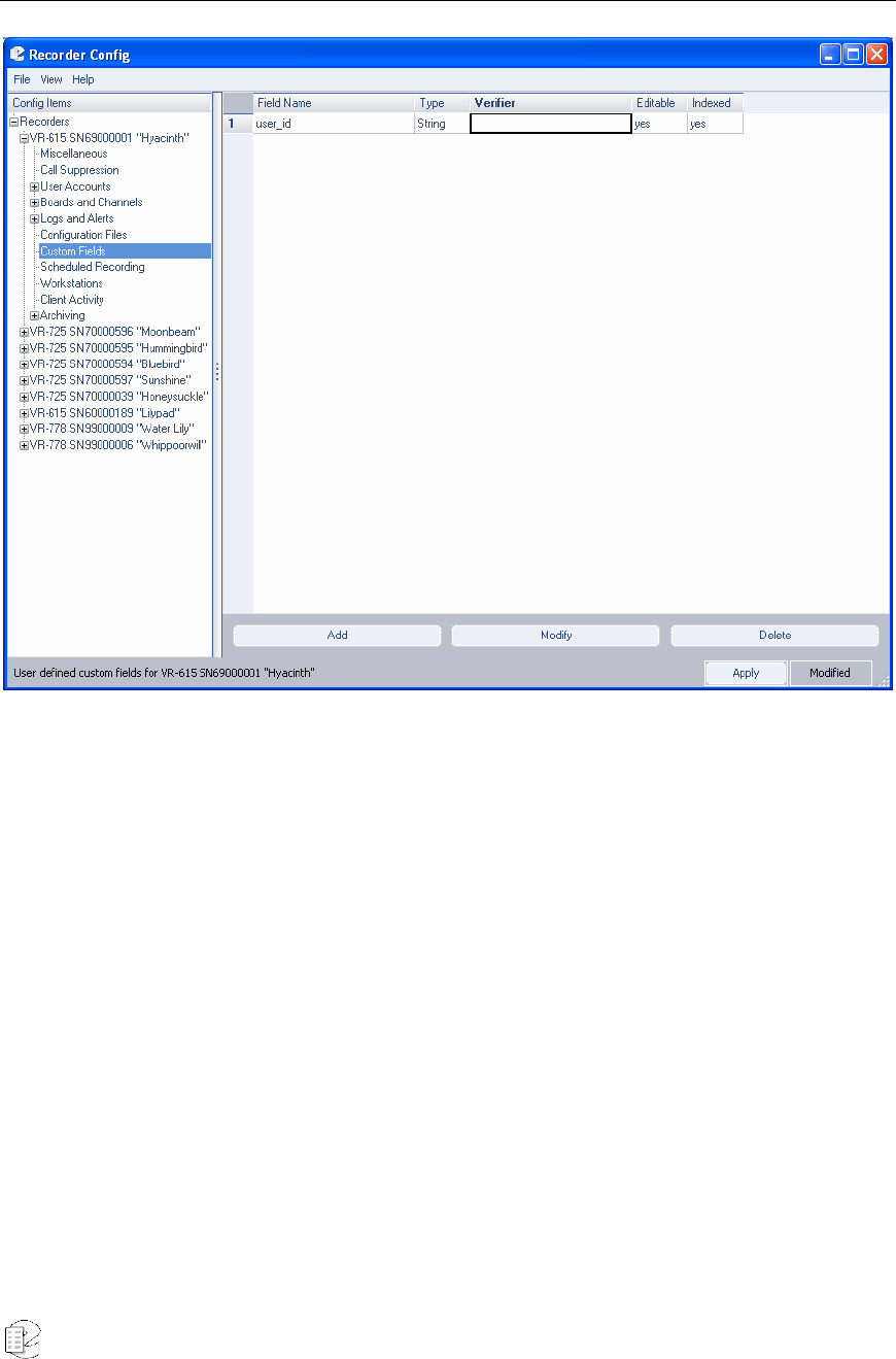
Atlas Series Server 1.8 User Manual 184
Custom Fields
Figure 23–Custom Fields screen
The Custom Fields screen allows you to designate new database fields for
inclusion in detail information for call records displayed in MediaWorks or
MediaAgent. As a matter of course, data must exist for the fields in order for its
information to be displayed accurately.
Like the Text Field screen, you must have Read/Write access to the selected
recorder to perform any additions, changes, or deletions. The activity buttons at
the bottom of the screen (Add, Modify, Delete) will display grayed out if you do not
have this permission.
Adding, Modifying, and Deleting Fields
To add a new entry, click Add; the following entry screen displays:
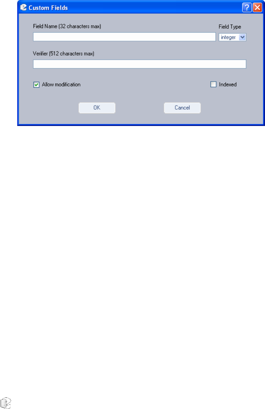
Atlas Series Server 1.8 User Manual 185
Figure 24–Add Field window
• In the Field Name field, enter a name for the new field.
• From the Field Type drop-down list, designate the type for this field.
Options are Integer, Date, or String.
• In the Verifier field, optionally enter a regular expression that will validate
the information in this field.
• Allow Modification designates whether this field will be editable after it is
created. By default, this option is selected. If you deselect this checkbox,
you will be unable to make changes to the field hereafter.
• Indexed will make this field an indexed field in the database, thereby
improving its retrieval time. Default is deselected.
When all information is complete, click OK.
To modify an existing field, highlight its respective number to the left of its
name, and click Modify. If the field has been designated as editable, you will
access the same screen described above, with that field’s information displaying.
If the field is not editable, you will receive the following message:
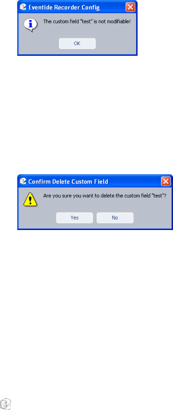
Atlas Series Server 1.8 User Manual 186
Figure 25–Custom Field Not Editable message
After you access the Edit screen, you are permitted only to modify two aspects of
the field: Verifier and Allow Modification.
If you need to change the name of a field, or any other characteristic not
supported by the Edit mode, you must delete the field and re-enter it with the new
attributes.
To delete an existing field, highlight its number, and click Delete. The
following confirmation window then displays:
Figure 26–Custom Field Delete Confirmation message
Click Yes to proceed, click No to cancel the action.
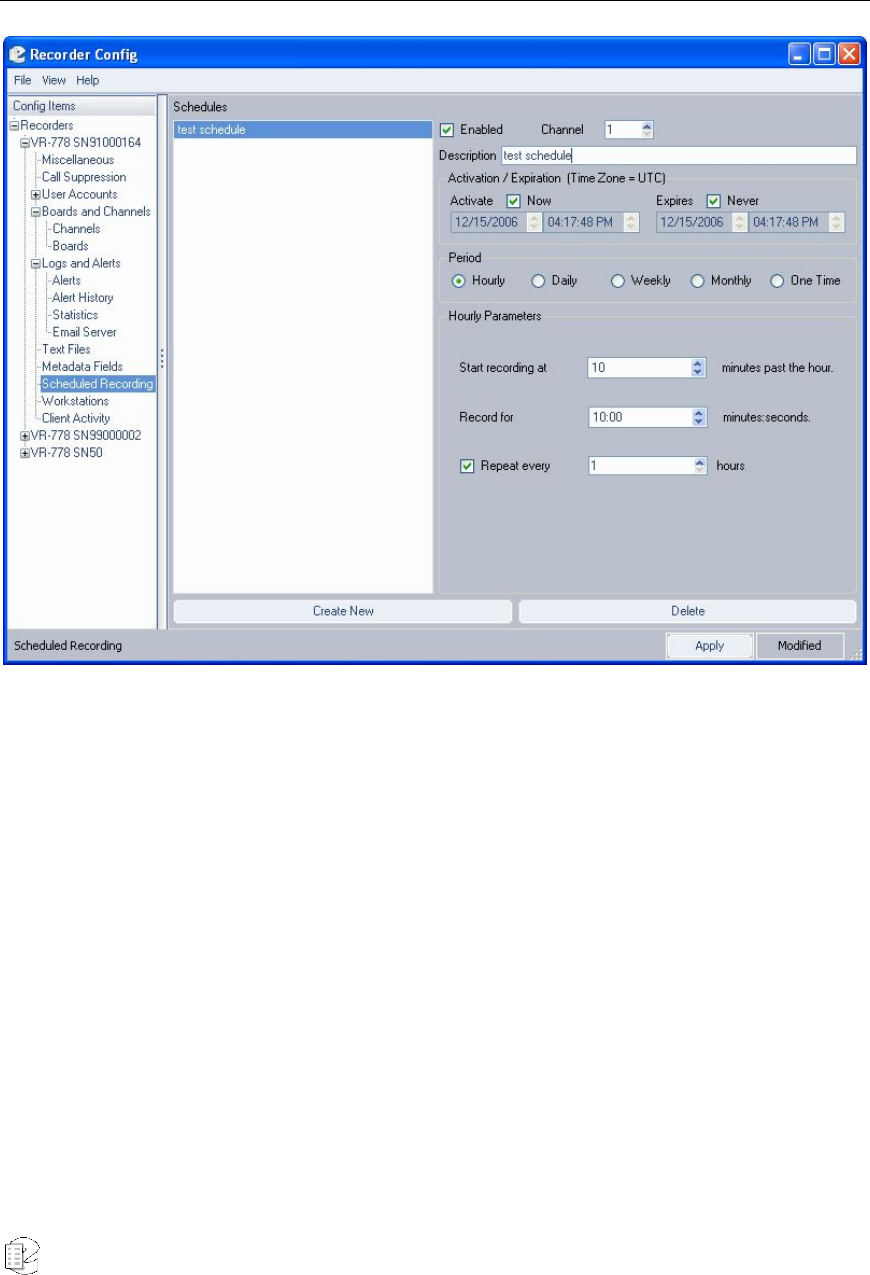
Atlas Series Server 1.8 User Manual 187
Scheduled Recording
Figure 27–Scheduled Recording screen
The Scheduled Recording configuration allows you to set specific timeframes for
recording. To add, modify, or delete schedules on this screen, you must have
Read/Write permissions for the system. The activity buttons at the bottom of the
screen (Create New, Delete) display as grayed out if you do not have Read/Write
access.
Adding, Modifying, and Deleting Files
To add a new schedule, click Create New; the following screen displays:
New for
Release
1.5
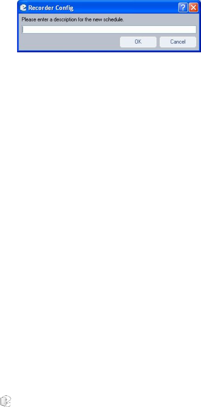
Atlas Series Server 1.8 User Manual 188
Figure 28–Scheduled Recording Description entry
Enter a name for the new schedule here, and click OK. The schedule listing at the
left side of the screen subsequently refreshes with this one listed at the bottom.
Descriptions follow for each of the fields included in a scheduled recording:
• Enabled – Select this checkbox to enable this schedule. Default is
deselected.
• Description – The name of the schedule.
• Activate – The date and time the schedule activates.
• Expires – The date and time the schedule ends.
• Period – Select Hourly, Daily, Weekly, Monthly, or One Time to denote the
frequency of the schedule.
• <Period> Parameters – The parameters displayed depend upon the
selected Period. See the next section, Scheduled Recording Parameters, for
information on these parameters.
• Once you’ve completed all the fields, click Apply to save the schedule.
To modify an existing schedule, select a schedule in the Schedules column,
and the right side of the screen displays the schedule. Providing you have
Read/Write access for the selected recorder, you can now modify any settings.
When finished, click Apply to save the schedule.
To delete an existing schedule, select the schedule in the Schedules column,
and click Delete. You are asked to confirm the deletion. Click Yes to proceed,
click No to cancel.
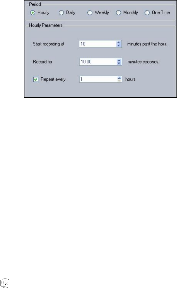
Atlas Series Server 1.8 User Manual 189
SCHEDULED RECORDING PARAMETERS
The information in the Parameters area of the screen depends upon which period
you select. Descriptions follow for each period.
• Hourly: The entry screen’s Parameters area displays with the following
fields:
Figure 29–Scheduled Recording (Hourly) Parameters
Start recording at XX minutes past the hour – Enter the number of
minutes past the top of each hour.
Record for XX minutes: seconds – Enter the length of time to record.
Repeat every XX hours – Select the checkbox to enable a repeat, and
enter the number of hours after which this scheduled recording will
repeat.
• Daily: The entry screen’s Parameters area displays with the following
fields:
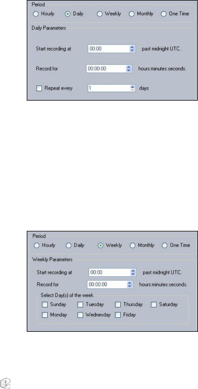
Atlas Series Server 1.8 User Manual 190
Figure 30–Scheduled Recording (Daily) Parameters
Start recording at XX minutes past midnight – Enter the number of
hours and minutes into the designated day to initiate recording.
Record for XX hours: minutes: seconds – Enter the length of time to
record.
Repeat every XX days – Select the checkbox to enable a repeat, and
enter the number of days after which this scheduled recording will repeat.
• Weekly: The entry screen’s Parameters area displays with the following
fields:
Figure 31–Scheduled Recording (Weekly) Parameters
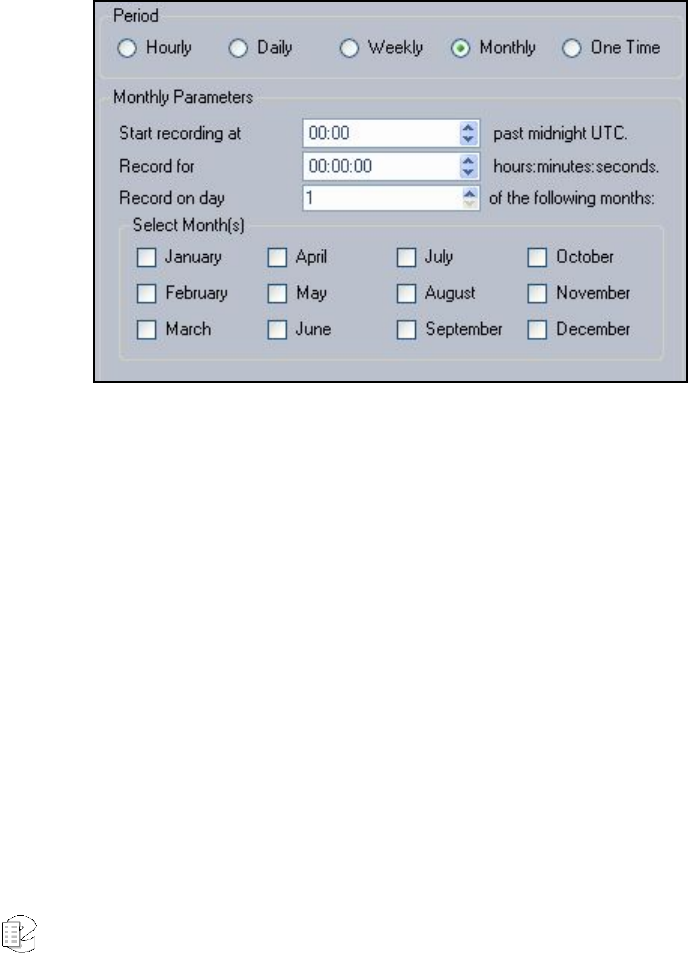
Atlas Series Server 1.8 User Manual 191
Start recording at XX minutes past midnight – Enter the number of
hours and minutes into the designated day to initiate recording.
Record for XX hours: minutes: seconds – Enter the length of time to
record.
Select Day(s) of the week – Check all days in for the selected weekly
during which you’d like recording to occur. At least one day must be
selected; as many as seven may be selected.
• Monthly: The entry screen’s Parameters area displays with the following
fields:
Figure 32–Scheduled Recording (Monthly) Parameters
Start recording at XX minutes past midnight – Enter the number of
hours and minutes into the designated day to initiate recording.
Record for XX hours: minutes: seconds – Enter the length of time to
record.
Record on day XX of the following months – The day of the designated
month on which you would like to record.
Select Month(s) – Check all months you want to apply this scheduled
recording. At least one month must be selected; as many as twelve may be
selected.
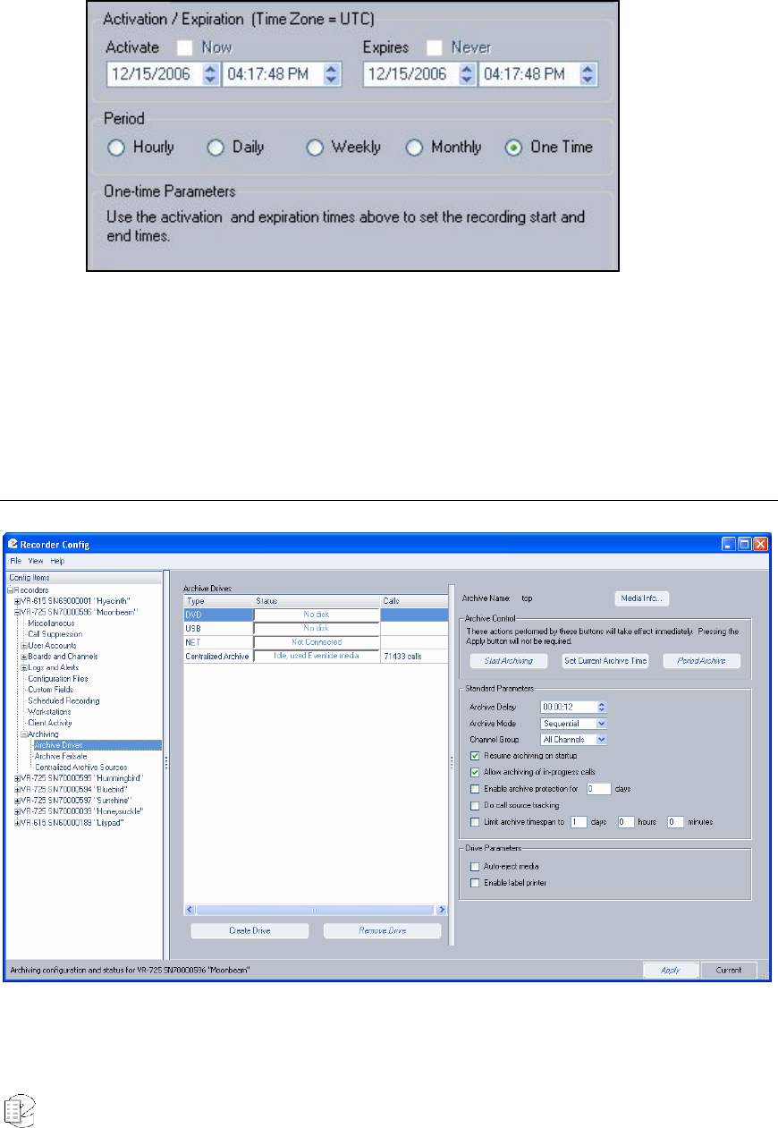
Atlas Series Server 1.8 User Manual 192
• One Time: The entry screen’s Parameters area displays with the following
fields:
Figure 33–Scheduled Recording (One Time) Parameters
One-time only recordings use the general parameters described above
section, and do not require any time-specific designations.
Archiving: Archive Drives
The DVD-RAM view.

Atlas Series Server 1.8 User Manual 193
There is an Archive Control section common to all drive types:
1. The left-most button changes based on context. It can be Start
Archiving, Resume Archiving, Begin Standby, or Cancel Standby.
2. Set Current Archive Time. This opens a dialog box that allows you to
set the current archive time on the selected drive.
3. Period Archive.
There is also a set of Standard Parameters common to all drive types:
1. Archive Delay (time in hours:minutes:seconds)
2. Archive Mode (Sequential / Parallel for systems with two DVD-RAM, R-
HD or REV drives; Standalone for other drive types)
3. Channel Group (defaults to “All Channels” and lists any custom groups
on the system)
4. (Yes/No) Resume archiving on startup
5. (Yes/No) Allow archiving of in-progress calls
6. (Yes/No) Enable archive protection for (number) days
7. (Yes/No) Do call source tracking
8. (Yes/No) Limit archive timespan to (number) days (number) hours
(number) minutes
There is a Drive Parameters section specifically for DVD-RAM:
1. Auto-eject media
2. Enable label printer
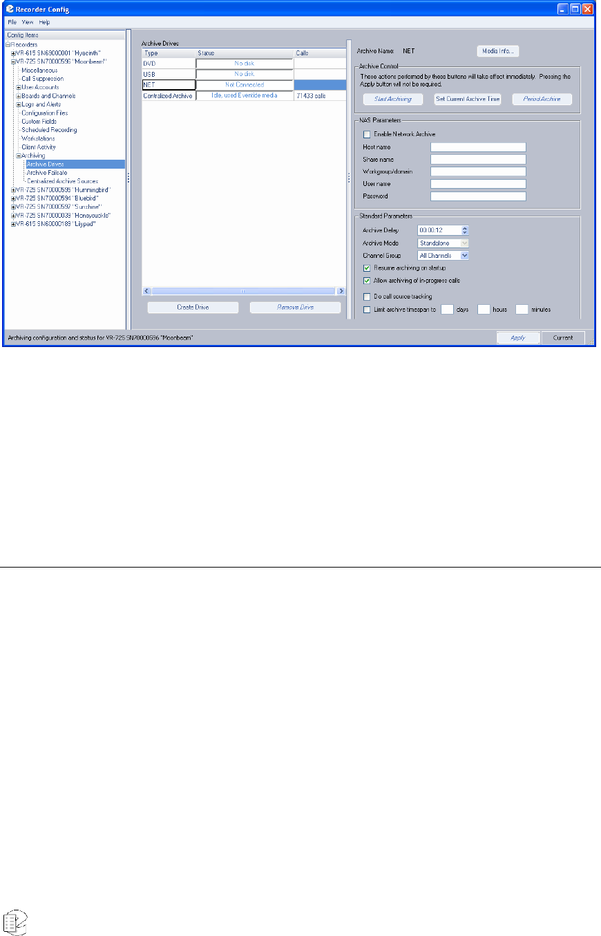
Atlas Series Server 1.8 User Manual 194
The NET Drive View
NET Parameters are the same configuration options as offered on the recorder’s
Setup screen. To successfully enable a network archive drive, you must provide at
least a hostname and sharename, and the rest of the parameters may be required
as well (check with your network administrator.)
Centralized Archiving (CA) Configuration
Note: Use of the optional Centralized Archiving feature requires an add-on
software license key.
Using Recorder Configuration, log into all machines involved in the desired
Centralized Archiving configuration at the same time. If you are adding a new
machine to an already existing configuration, you only need to log into the new
source and the destination machine.
For each source machine:
1. Make sure that all channels are named appropriately, as discussed in
the Channel Names section.
2. Go to Archiving: Archive Drives.
3. Click the Create Drive key.
New for
Release
1.7

Atlas Series Server 1.8 User Manual 195
4. Select Centralized Archive and click OK.
5. Enter the IP address of the destination machine.
6. Enter the name by which you want to identify the centralized archiving
drive. Note that the name should be distinct for each drive unless it is
intended to be part of an Archive Failsafe pair, in which case the drives
in the pair must have identical names.
7. Click OK and the drive will be created immediately, visible at the front
panel and in the Archiving: Archive Drives pane. The status will say
“Check Configuration” but it is not necessary to check anything yet.
Then Go to the destination recorder’s Archiving: Centralized Archive Sources
pane. For each source listed, select the source, click Approve and then click
Apply.
At this point the status message for the drives at each source will display either
“idle, blank media” or “Check Configuration.” There are three triggers for the
Check Configuration status message:
1. The destination has not approved the source.
2. The source has exceeded its number of licensed CA drives.
3. The custom fields on the source are missing on the destination.
Solutions:
1. Approve the source at the destination.
2. Either delete unused catapult drives or buy additional licenses.
3. Add all of the source’s custom fields to the destination recorder.
In practice, archiving to a Centralized Archiving drive is done identically to how
one archives to a DVD-RAM drive. From the source recorder’s front panel Info
screen or from Recorder Configuration’s Archiving: Archive Drives pane, select the
drive you wish to archive to and start archiving. The calls archived in this way are
stored on the destination Atlas recorder just like any other call, and are subject to
the same limits on number of calls and data retention as calls recorded locally; for
long term archiving, these calls should be further archived to DVD-RAM or NET
drives.

Atlas Series Server 1.8 User Manual 196
Configuring Additional NET Drives
More NET drives can now be configured via Recorder Configuration. Configuring
additional NET drives will require an additional license. To configure an
additional NET drive:
1. Go to Archiving: Archive Drives.
2. Click the Create Drive key.
3. Select Network Attached Storage and click OK.
4. Enter the host name and share name of the network archive (and any
other necessary parameters.)
Centralized Archive Failsafe Configuration
Note: Use of the optional Centralized Archive Failsafe feature requires an add-on
software license key.
1. The Centralized Archive Failsafe pair must be connected to identical
call inputs.
2. Set up a Centralized Archiving drive on each recorder in the pair.
These should point at the same destination recorder and must be given
exactly the same name, but this name must also be unique to this pair
and not given to any additional Centralized Archiving drives that
connect to the failsafe controller.
3. Approve both recorders at the destination recorder’s Archiving:
Centralized Archiving Sources pane.
4. Check the “Enable Centralized Archive Failsafe” checkbox on both
recorders in the archive failsafe pair. Apply this change.
At this point, Archive Failsafe is ready to be armed. If you start archiving on one
recorder, the other will display “ready standby” where it would normally display
“start archiving.” Additionally, you can log into the controller recorder and arm,
disarm and set the archive time on both recorders in the failsafe pair
simultaneously.
New for
Release
1.7
New for
Release
1.7

Atlas Series Server 1.8 User Manual 197
Archiving a Channel Group
1. Log into the recorder you wish to archive a channel group from.
2. Go to Archiving: Archive Drives.
3. Select the drive you wish to archive to.
4. From the Channel Groups pull down menu, select the channel group
you wish to archive to this drive.
5. Click Apply to apply the change.
At this point, any archiving done to this drive will archive calls only from the
channels in the channel group selected.
Period Archiving With Recorder Configuration
1. Load Eventide formatted media on the Atlas recorder.
2. Log into the recorder with the Recorder Configuration utility.
3. Go to Archiving: Archive Drives pane.
4. Select the drive that you want to archive to.
5. Click the Period Archive button.
6. Enter the start and stop times that you want to archive.
7. Click the OK button; the recorder will begin archiving this period to the
drive.
To combine this feature with Channel Groups, be sure to set and apply the
channel group you wish to archive from before starting the period archive.
Call Source Tracking (CST)
Call Source Tracking is an option that prevents calls from being left out of
archives. Because of the inherent nature of the technology involved, Atlas systems
do not always receive calls from VoIP and Centralized Archiving sources in real-
time; they can, under certain conditions, end up receiving calls hours or even
days after they were originally recorded. This has a significant impact on
archiving; for example, on a busy Atlas system with both local input board
sources and VoIP channels, if:
1. The archive pointer on a DVD-RAM drive is set to current time.
New for
Release
1.7
New for
Release
1.7
New for
Release
1.7

Atlas Series Server 1.8 User Manual 198
2. Calls are currently coming in on the local input channels.
3. Due to temporary but severe network congestion, the VoIP gateway has
buffered an hour's worth of calls which are just now transferring to the
Atlas recorder.
Starting to archive calls to this DVD-RAM drive would leave the hour of VoIP calls
unarchived. Because of this, archive drives can optionally be set to use Call
Source Tracking, which will prevent any archive from writing past the current
archive time of any source that is not currently up-to-date.
In the same scenario as the above, but with CST turned on, the result would be
the DVD-RAM drive would pause in archiving mode, idle, until the VoIP system
caught up to the archive time that had been initially set, at which point the DVD-
RAM would begin to fill with all of the calls, leaving nothing unarchived.
This feature is optional only because a Call Source may be temporarily off-line
and one needs to archive calls anyway. In that case, turn off CST, create the
archive you need, then turn CST back on and reset the archive time.
This section discusses setup and administration of the recorder from the front
panel. On entering Setup mode, the following screen appears. This screen is a
hierarchical menu of available functions. Double clicking on any topic (except
System Shutdown) reveals a submenu. A top level item can also be expanded to
its submenu by clicking the small box to the left of the item. A second click of the
box or double click of the heading collapses the menu.
Workstation Setup
The Workstations Setup area is used to assign specific channels to a workstation
location and a user. When a user is logged in at a designated workstation
location, metadata information is generated on the server tagged with that user’s
name for all calls received.
Click the Workstations option under Logs and Alerts, and the Workstations main
screen displays:
New for
Release
1.6
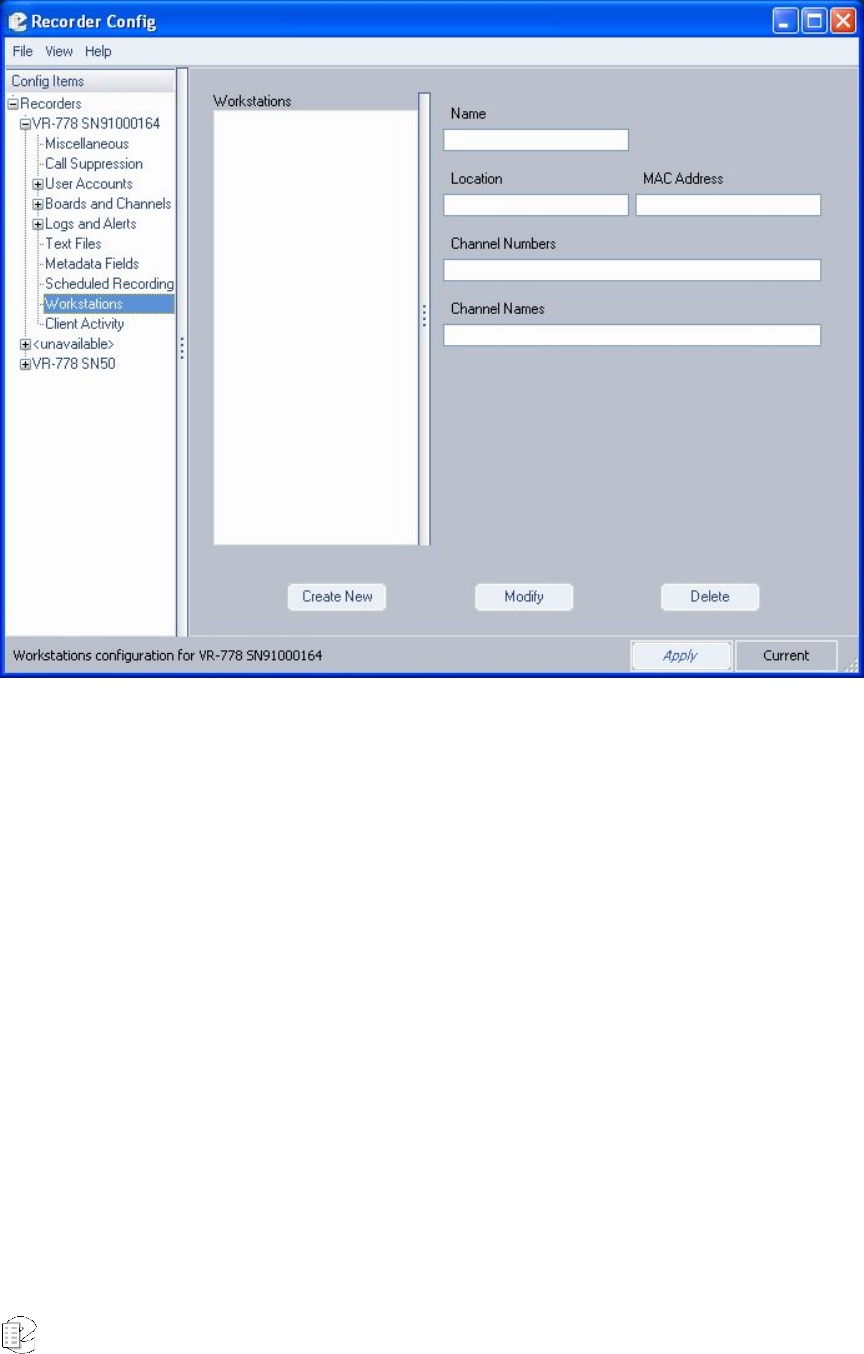
Atlas Series Server 1.8 User Manual 199
All existing workstation locations are listed in the Workstations area of the screen.
Click on an entry to display the attributes associated with the location on the
right side of the screen. All fields displayed here are read-only, and can be edited
only from the Edit Workstation window.
CREATING A NEW WORKSTATION
From the Workstation main screen, click Create New; the New Workstation
window now displays:
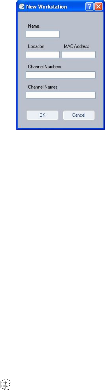
Atlas Series Server 1.8 User Manual 200
Enter the workstation name, location identifier, the channel numbers associated
with this workstation, channel names, and the MAC address of the workstation in
the fields provided.
Note that each workstation must have a unique MAC address, which is a unique
hardware identifier for the workstation’s Ethernet adapter.
To find out what MAC address is assigned to your Windows-based PCs,
• From Windows’ programs, select Accessories, then Command Prompt.
• When the Command Prompt screen displays, type ipconfig /all and press
Enter.
• The following information now displays (below):
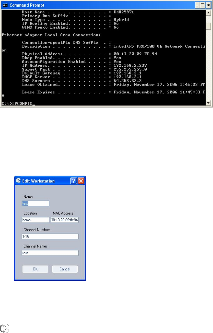
Atlas Series Server 1.8 User Manual 201
Your MAC address is the Physical Address, in this example 00-13-20-FB-94.
EDITING AN EXISTING WORKSTATION
From the Workstation main screen, highlight a workstation in the Workstation
column and click Modify. The Edit Workstation window now displays:
All fields listed can be modified. However, the MAC address, if entered correctly
the first time, should not be change.
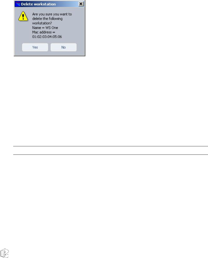
Atlas Series Server 1.8 User Manual 202
When all changes are complete, click Ok to save; click Cancel to abort the
process and leave the values unchanged.
DELETING AN EXISTING WORKSTATION
From the Workstation main screen, highlight a workstation location you would
like to remove and click Delete. The following confirmation screen now displays::
Click Yes to permanently delete the selected workstation; click No to cancel the
action.
FINAL WORKSTATION CONFIGURATION (METADATA TAGGING)
Finally, to complete workstation setup, you must create a new metadata field
called user_id. This field is automatically populated by the caller ID value
associated with an incoming call to a workstation, and is stored in the system’s
metadata tables.
Note: You must have read/write authority in order to complete this process.
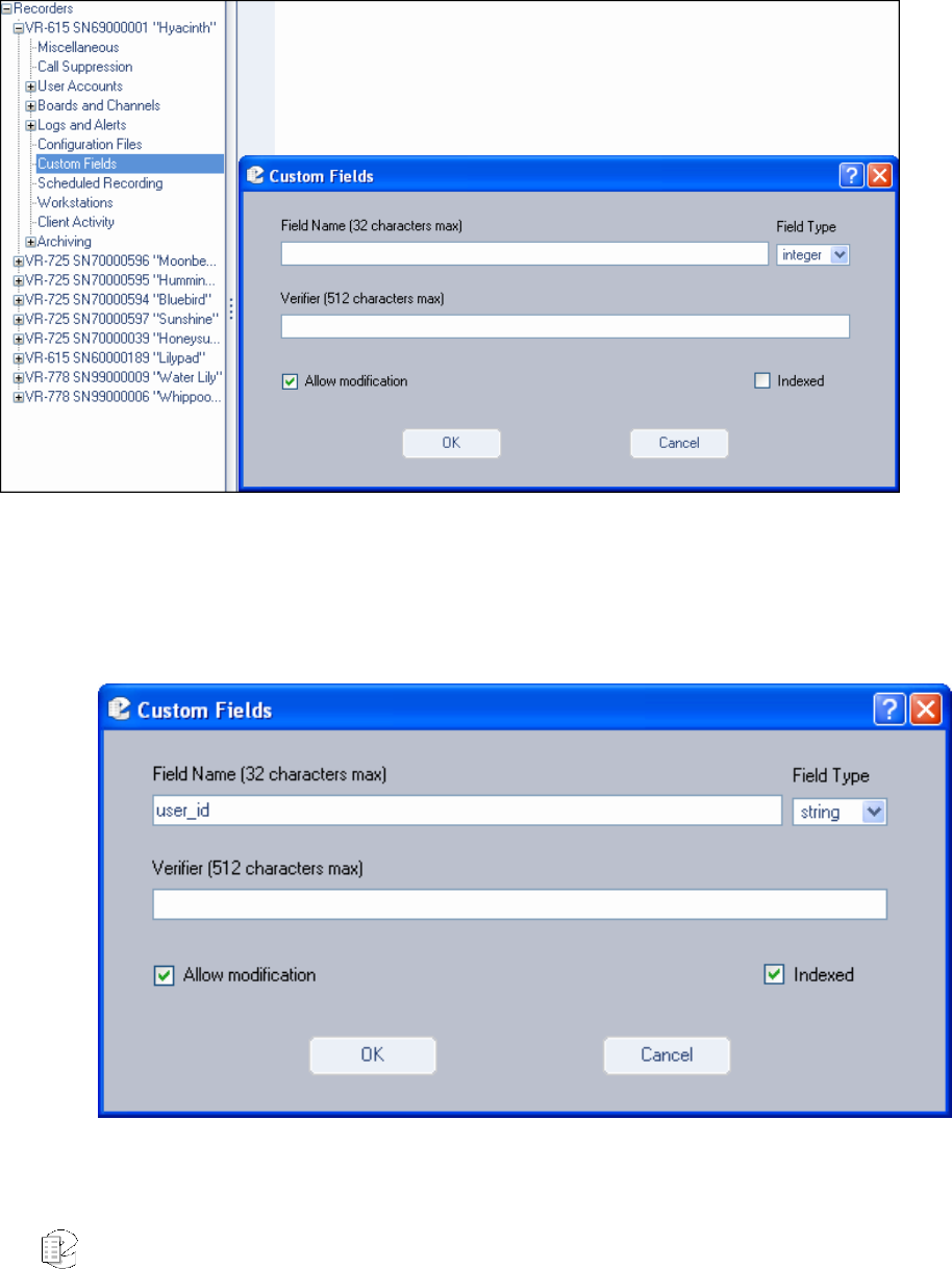
Atlas Series Server 1.8 User Manual 203
To perform this action,
• Go to the Metadata Fields option beneath the Logs and Events directory tree,
and click Add to launch the User-Defined Metadata window (below):
• In Field Name, enter user_id (this name is not case-sensitive) and in the Field
Type select string. If you wish to be able to perform searches by this value,
check the Indexed checkbox. When finished, your screen should look like
this:
• Click OK, and your workstation setup is now complete and ready to go.
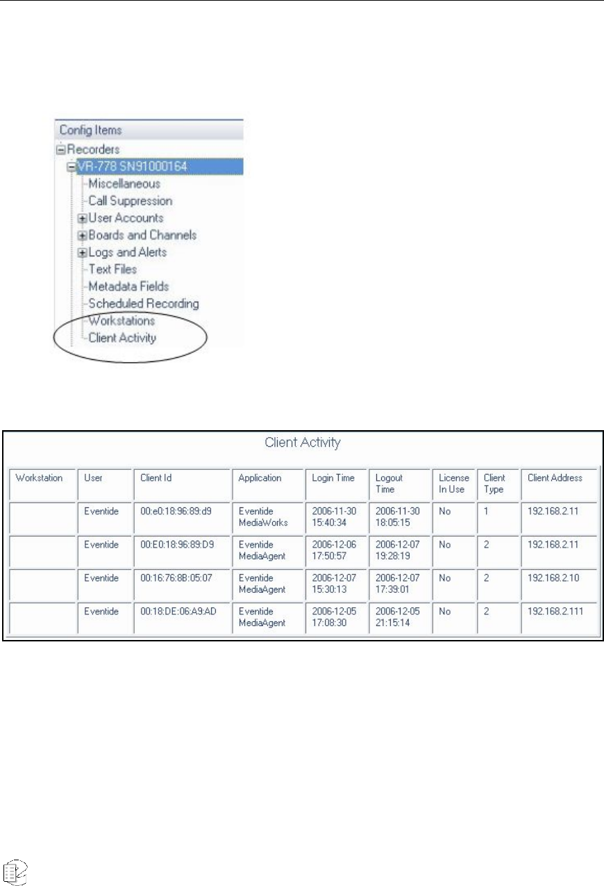
Atlas Series Server 1.8 User Manual 204
Client Activity
The Client Activity option allows you to view specific, detailed information about
all configured clients. It is a read-only resource that is accessed by clicking the
Client Activity menu option:
The screen refreshes to display client information across multiple criteria:
If a workstation has been set up for a user, details of its configuration will display
in the first column (see previous section for information on Workstation Setup).
New for
Release
1.6
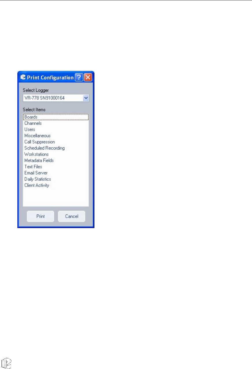
Atlas Series Server 1.8 User Manual 205
Administration Client Menu Options
FILE MENU
Apply – Saves and applies the current values.
Print – Prints activity reports for multiple system criteria:
.
In addition to those listed in the illustration, reports are may be generated for the
following criteria: Archiving, Network Archiving, Security, Email, Network
Settings, and Clock.
To generate a report, highlight a listed criteria, and click Print.
Exit – Closes all active sessions and exits the program.
New for
Release
1.6
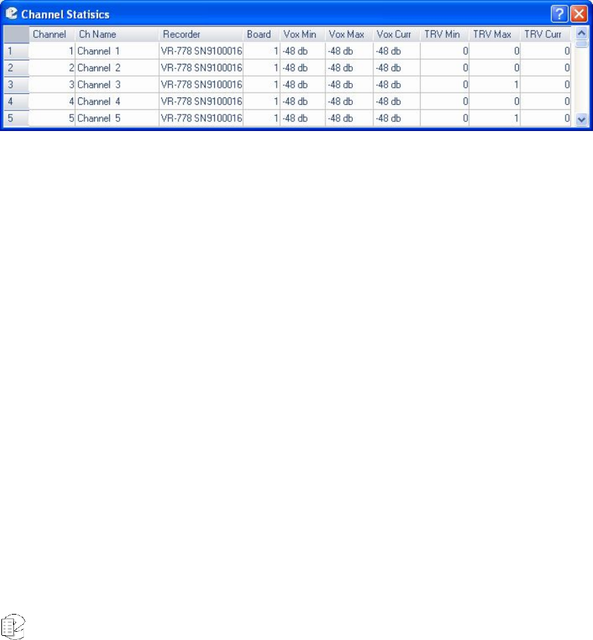
Atlas Series Server 1.8 User Manual 206
VIEW MENU
Channel Stats – (below) displays the audio and voltage levels of the signals being
applied to the hardware recording board(s). This information is useful for verifying
normal operation of the recorder and confirming that all channels are receiving
signals. (Typically this is accessed from the front panel while making
adjustments, and the meaning and adjustment of the numbers is discussed in the
SETUP section.) This display is for the analog telephony boards. Other input
options will show differing data. If you are logged into multiple recorders, their
data will also be shown here.
Figure 34–Channel Statistics menu option
Show Alerts – which is activated and deactivated by clicking, generates onscreen,
real-time alerts from the recorder. For example, if you are changing parameters
and someone uses the front panel to break the "lock" your program has, you will
be notified. A red check mark in front of the menu item indicates it is enabled.
HELP MENU
About – Lists release information specific to this version of the Administrative
Client.

Atlas Series Server 1.8 User Manual 207
A
A
Ap
p
pp
p
pe
e
en
n
nd
d
di
i
ix
x
x
1
1
1
Server Software Installation and Upgrade
Just as with any computer, the ATLAS series recorders require a software
"Operating System" and a number of "application programs" to be functional and
to perform useful work. The "OS" in this case is Linux, and the application
programs are a combination of standard programs and programs written and
maintained by Eventide to work with its custom hardware environment.
As part of the manufacturing process, we install the recorder software. Because
software is an ever-extending morass of features, bugs, and changes, we
occasionally create "upgrade" software to bring older recorders up to the current
software "version." It is sometimes desirable or even necessary to apply these
upgrades to customer's units, and the purpose of this Appendix is to discuss and
explain the process so that customers can confidently perform upgrades (and
even installations) without factory intervention.
Why Re-installation May be Necessary
The recorders use redundant disks, so a single drive failure should not cause loss
of data or software. However, if multiple disks in an array fail due to a common
cause (e.g., lightning or other power surge), you will have to re-install the software
when they are replaced. It is also possible that certain hardware additions and
software upgrades will require re-installation. Specifically, upgrading from
version 1.1.x to version 1.2.x or higher requires re-installation.
Why Upgrades May be Necessary or Desirable
There are several reasons why you may need to do an upgrade:
• Problems (bugs) are found in the version currently running;
• Hardware upgrades or changes require new software;
• Valuable features are available in the new release;
• Factory support requires a more recent software version.
• If your system is operating satisfactorily, you might prefer to leave things
alone. If you're a feature-hungry IT guy, well, upgrade away!

Atlas Series Server 1.8 User Manual 208
The Software Upgrade/Installation Process
The actual process of upgrading (or re-installing) your software is simple and is
almost completely automated. It goes like this:
• Archive your call data!
• Archive your recorder configuration!
• Remove all archive media.
• Insert the update or installation CD ROM in the top DVD drive. (If archive
drives are not DVD, insert the update medium in the CD ROM drive.
• Power down the recorder.
• Restore power.
• Exhibit patience while the software loads. When finished, the CD ROM will
eject automatically. Remove it from its tray.
• Power down the recorder.
• Restore power.
• Exhibit even more patience while the new software gets comfortable.
If this is a new installation rather than an upgrade, restore your configuration .
If this is a new installation rather than an upgrade, restore your archives, most
recent first, along with your “metadata.”
Some Details, Especially About Installation
The above list is really it. The hardest part is the "Exhibit patience" part since the
second time you are asked to do so, you may need to exhibit it for an hour or
more. The software does a lot of checking to make sure everything is OK. Here are
some further thoughts.
If you do a new installation, all your calls will be erased. If you have archived your
calls, you can restore them as described below. An upgrade will theoretically leave
your calls in the same state as they were earlier, and, in fact, it almost always
does. But: why take chances? You are probably archiving anyway, so can it hurt
to be up to date?
If you do a new installation, you will have to reconfigure the recorder in
accordance with the Setup instructions. This is greatly simplified by the
Read/Write Configuration to Archive feature. Please read the information in
SETUP carefully before you start the installation! After an installation, check the

Atlas Series Server 1.8 User Manual 209
Serial Number displayed in the SETUP mode display. If it is zero or not set,
change it to match the serial number on the label on the rear panel.
If you upgrade the recorder, be sure to read the "release notes" or other
information to see if there are any new SETUP items that must be configured.
Restoring Archives when Installing New Software
In the Archiving section of the SETUP mode there is a menu item “Archive
restore.” If you insert previously–recorded archive media into one or more drives,
it will allow you to select that drive with the knob and perform a restore operation,
i.e., copy the calls from that medium back to RAID. Several checks are performed
before the medium is transferred:
Does the serial number of the recorder that recorded the archive medium agree
with that of the destination recorder?
Are the channel names of the recorder the same as the destination?
Does the format of the data on the archive conform to that of the destination?
Is there any problem with or damage to the archive medium to be transferred?
Are all (or some) of these calls duplicates of calls already on the recorder?
And the perennially popular “Are you sure” you want to go ahead with the
transfer?
If none of these are appropriate for the medium, or if you indicated that you wish
to proceed, the archive transfer will commence. All drives operate independently.
You can restore archive media in all available drives, or you can even record
archives on one medium while restoring from another.
A couple of important points:
The restoration process cannot continue once the RAID is full, so unless you have
a special reason for doing otherwise, always restore from the most recent archive
backwards.
If you are restoring archives after a new installation, use the Set current archive
time facility to make sure that new archives are only recorded from the present
forward. If you don’t set this and begin new archiving after you have restored your

Atlas Series Server 1.8 User Manual 210
archives from a previous installation, you might find yourself “re-archiving” the
restored archives.
When you are finished restoring your archives, be sure to restore the “metadata”
archive disk as well.
Potential Problems
As we have said, the process is automated. At least for an upgrade, beyond
inserting/removing the disk, removing/applying power, and exhibiting patience,
there is little for you to do.
The most common problem we have observed has been failure of the upgrade
drive (the one in which you place the CD ROM) to recognize the medium. If this
happens, the recorder just powers up normally and the CD never ejects. In such a
case, manually eject the CD, and again shut down the unit. Next, visually inspect
the medium, confirm it has no scratches, it's clean, it's right-side-up, and it's
carefully centered in the drive tray. Then try again. If the drive persistently
refuses to recognize the CD, yet works correctly when archiving, you probably
have a defective upgrade CD, or one that differs enough from the drive's
calibration to make reading the CD problematic. You can try copying the CD ROM
to another blank, burning a new one, requesting a replacement, etc.
Much less common: The CD can't be read completely, and the upgrade/install
process hangs up and the CD does not eject. In either case, try the procedure
again from the beginning. For an installation, no damage will be done as long as
the install eventually completes correctly. For an upgrade, there is a possibility
that configuration information will have been lost, in which case it can be restored
manually or from the configuration archive that you made before starting the
upgrade. Do NOT, however, try to resume normal recorder operation until the
upgrade has completed normally.
PLEASE Read the Release Notes
Software upgrades will normally come with printed information, and possibly with a
"README" file on the disk. If anything in the release notes contradicts something you read
here, go with the release notes!
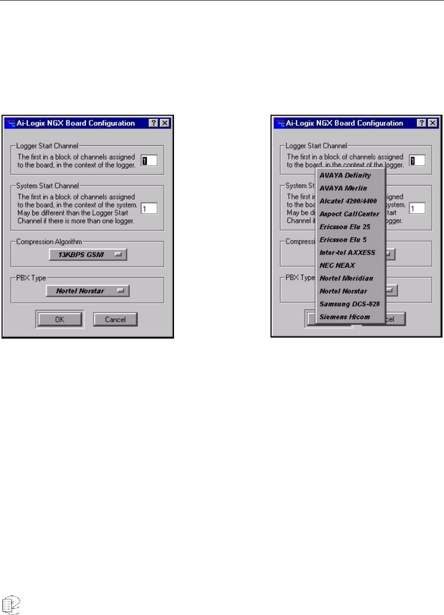
Atlas Series Server 1.8 User Manual 211
A
A
Ap
p
pp
p
pe
e
en
n
nd
d
di
i
ix
x
x
2
2
2
PBX and Digital Telephony Hardware Information
In addition to analog recording, the recorders can record digital telephony signals, both
from different vendors’ digital PBX and from T1/E1 lines. We suggest that Eventide
perform this configuration. If you need to install a digital telephony interface in an
installed recorder, please contact us.
This
configuration
page will only
be available in
the
Administrative
Client
program if you
have one or
more NGX
boards
installed in
your recorder.
The list to the
right shows
some of the
systems with
which the
recorder is
compatible.
Please contact
Eventide for
an up-to-date
list.

Atlas Series Server 1.8 User Manual 213
A
A
Ap
p
pp
p
pe
e
en
n
nd
d
di
i
ix
x
x
3
3
3
Connection Information for the HiFi Recording Board
Below is a rear-panel drawing and pinout diagram of the HiFi recording card
furnished when that option is ordered. This card has both audio inputs and
outputs, but only the inputs are used in this application. Recordings made with
this card use the Ogg Vorbis algorithm to reduce storage requirements while still
providing excellent audio quality and frequency response.
In the abbreviations below, "A" simply stands for "Audio."
AIN = Audio Input pin (channel number).
AOUT = Audio output pin (number).
AGND = Audio ground.
All grounds are equivalent. For an unbalanced audio input, connect the hot input
to AIN (channel) and the ground input to any AGND pin. If the source is balanced
using a transformer, connect the + signal to AIN (channel) and connect both the –
signal and the ground lead to any AGND pin. If the source is “balanced” using op-
amps, connect the + signal to AIN (channel) and connect the ground lead to any
AGND pin. Do not connect the – signal to the recorder.
The mating connector kit for M-Audio Hi-Fi card is Eventide p/n 105200. It
includes one DB44 male connector (solder type) and one DB44 hood. Each Hi-Fi
card is supplied with one kit.
Configuration of the HiFi recording board has fewer steps than the telephony
board: You can select the sampling rate, and whether a given channel is to record
or not. Unlike the telephony board, non-recording channels cannot be “live
monitored,” either from the front panel or from the Live Monitor client program.
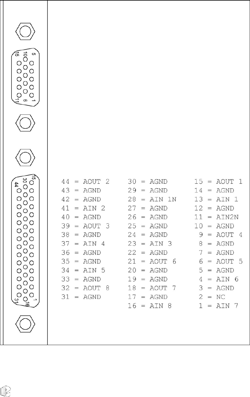
Atlas Series Server 1.8 User Manual 214
M-Audio 1010LT HiFi board connection diagram

Atlas Series Server 1.8 User Manual 215
A
A
Ap
p
pp
p
pe
e
en
n
nd
d
di
i
ix
x
x
4
4
4
Optional General Purpose Input/Output (GPIO) Boards
Note: The optional GPIO board feature requires an add-on license key from
Eventide.
The following uses can be made of a GPIO board:
• The start and stop of recording on a channel can be triggered by a GPIO
board input signal. (See “The Channel Configuration Screen” for more
information.) The logic of GPIO-triggered recording can be customized
using the custom script feature (see Custom Script Source File under
“Configuration Files”).
• A recorder alert can trigger a GPIO output signal. (See GPIO Alert Output
Severity under “Analog Telephony Board Configuration” for more
information.)
Eventide supports the following optional GPIO boards for use with recorders:
• National Instruments PCI-6503 Board (24-Channel)
• National Instruments PCI-6527 Board (48-Channel)
Caution: The National Instruments specifications for these GPIO boards describe the maximum ratings
for their input or output signals. Connections that exceed these maximum ratings can damage the
board and the recorder. Neither Eventide nor National Instruments are liable for any damages resulting
from signal connections that exceeed these maximum ratings.
NATIONAL INSTRUMENTS PCI-6503 BOARD (24-CHANNEL)
This board provides a 24-bit parallel, digital I/O interface with:
• 24 static digital I/O lines (non-isolated 5 V TTL/CMOS) in 8-bit ports, 2.4
mA
• 50-pin male D-type I/O connector
• No switches or jumpers
New for
Release 1.8
New for
Release 1.8
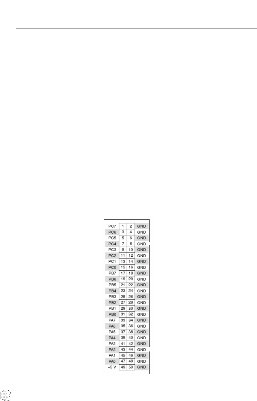
Atlas Series Server 1.8 User Manual 216
Note: The I/O ports are not optically isolated.
Note: Eventide has adopted static port assignments on the PCI-6503 (see page 217).
See Figure 35–GPIO Board Pin Assignments (NI PCI-6503) for the connector pin
assignments. For detailed specifications, refer to PCI-6503 on the National
Instruments web site (www.ni.com).
NATIONAL INSTRUMENTS PCI-6527 BOARD (48-CHANNEL)
This board provides a 48-bit, parallel, isolated digital I/O interface with:
• 24 optically-isolated digital inputs (5 V TTL/CMOS)
• 24 digital switch outputs (5 V TTL/CMOS)
• 100-pin female 0.050 D-type I/O connector
• No switches or jumpers
See Figure 36–GPIO Board Pin Assignments (NI PCI-6527) for the connector pin
assignments. For detailed specifications, refer to PCI-6527 on the National
Instruments web site (www.ni.com).
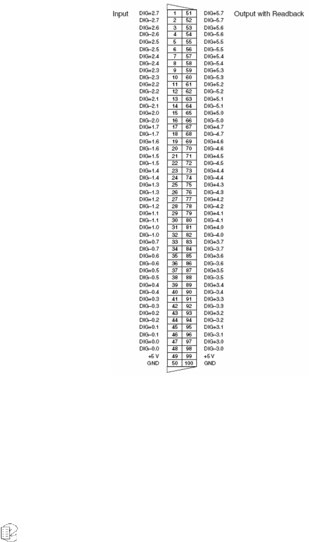
Atlas Series Server 1.8 User Manual 217
Figure 35–GPIO Board Pin Assignments (NI PCI-6503))
Eventide has adopted static port assignments on the PCI-6503, as follows:
Input channels 0 – 7: Port A (PA0–PA7); pin pairs 47+48 to 33+34
Input channels 8 – 11: Port C upper nibble (PC4–PC7); pin pairs 7+8 to 1+2
Output channels 0 – 7: Port B (PB0–PB7); pin pairs 31+32 to 17+18
Output channels 8 – 11: Port C lower nibble (PC0–PC3); pin pairs 7+8 to 1+2
Figure 36–GPIO Board Pin Assignments (NI PCI-6527))

Atlas Series Server 1.8 User Manual 219
A
A
Ap
p
pp
p
pe
e
en
n
nd
d
di
i
ix
x
x
5
5
5
NIST Time Servers
You can search the web for NIST Time Servers. Historically, a list of National
Institute of Standards and Technology (NIST) internet time servers can be found
on the web at:
http://www.boulder.nist.gov/timefreq/service/time-servers.html
This list provides each server's name, IP address, and location. It is probably best
to select one near to your location. If you have difficulty with using a server name,
you can access the server using the IP address instead.

Atlas Series Server 1.8 User Manual 221
A
A
Ap
p
pp
p
pe
e
en
n
nd
d
di
i
ix
x
x
6
6
6
Eventide VR778 or VR725 with DDS-4 Tape Drives
Overview
With DDS-4 tape drives installed in the VR778 or VR725, archiving is different
than with other types of removable media such as DVD-RAM. This addendum
discusses considerations when using tape for archiving. The Operator’s Manual
describes all aspects of these recorders in detail. Plead read the Operator’s
Manual before reading this document so that you will understand the differences
between a recorder with DVD media and a recorder with DDS-4 tape.
LOADING A TAPE AND PREPARING FOR ARCHIVING
To prepare the VR778 or VR725 to archive to tape:
• Make sure the tape is not write-protected (the protect tab should be
closed).
• Insert a tape in a tape drive.
• When you are asked what you want to do with the archive:
If you loaded a new tape or one that has never been used in a recorder, select
Format. After formatting is complete, press the knob and select Start Archiving. If
the tape has calls on it but you want to erase those calls, select Format. After
formatting is complete, press the knob and select Start Archiving. If the tape has
calls on it and you want to keep those calls, select Resume Archiving.
Ejecting a Tape
If a tape is full, the recorder will automatically stop archiving on the tape. If a tape
is currently archiving and you want to eject it, press the knob and select Stop
Archiving. When the tape returns to Idle status, press the knob and select Eject.
Wait for a message saying that it is safe to remove the tape, then press the Eject
button on the tape drive itself.

Atlas Series Server 1.8 User Manual 222
Playing Calls from a Tape
With DVD-RAM, the recorder saves calls as individual files. With tape, the
recorder stores large groups of calls in single files called tape archives. Each tape
archive can be as large as 4.7GB (the same size as one side of a 9.4GB DVD-
RAM). As many as four tape archives can fit on one DDS-4 tape. Before any calls
can be played from a tape, a tape archive must be selected, and all calls in the
archive must be transferred to hard disk. Once the calls are on hard disk they can
be played in much the same manner as calls on a DVD-RAM or on the recorder’s
internal RAID.
There are two ways to play and archive tape. One is to load it into a PC that has a
DDS-4 tape drive and use Eventide’s Remote Client software. The second is to
play it in the recorder in which it was recorded.
Playing a tape in the recorder is very similar to playing a DVD archive, except that
there is a preparatory step involved. When you press the Browse Archive soft key,
you must select the desired tape archive, of which there may be several on a tape.
The selected tape archive will then be copied to the recorder’s internal hard disk.
When the transfer is complete, Recall mode will work the same as it does with
DVD-RAM.
Note: This transfer may take 30 minutes or more! Please be patient!
To set up a PC for playing tapes from a recorder you will need:
• Multimedia PC
o Minimum requirements:
o 2GHz Intel Pentium 4
o 512MB DRAM
o 50GB free space on hard disk
o Sound card and speakers
o Keyboard, mouse, monitor
o Microsoft Windows XP
• Eventide Clients, Version 1.1, dated 21 Jan 2004 or later
• DDS-4 Tape drive
• Hewlett-Packard P/N C5686A (HP Surestore DAT 40i - 40GB internal
DDS-4 drive)
• SCSI Controller
• Adaptec Model 29160LP

Atlas Series Server 1.8 User Manual 223
Following the manufacturers’ instructions, install the SCSI controller and tape
drive in the PC. Then, turn on the PC and install the Eventide Client software.
Once the PC is set up, you are ready to play calls from a tape:
• Load a tape in the tape drive and wait several seconds for the tape to load.
• Run the Tatu utility (Tape Archive Transfer Utility). This is located in the
directory selected while installing the Eventide Client software. From the
Start button in Windows, select Programs, then Eventide VR Series, then
Tatu. Instructions for using Tatu are included in this document.
• Once Tatu has started, select a tape archive from the right panel and click
on the arrow. When the transfer has finished, the progress bar will be full
and the arrow will go dim. The transfer can take as long as an hour,
depending on the size of the tape archive.
• When the transfer is complete, exit Tatu and start the Call Record
Browser/MediaWorks.
• In the Recorders and Archives panel you should see the archive you just
transferred, listed as Archive: followed by a date. Click on the archive,
then click OK to enter the Call Record Browser.
From this point, you can select calls and play them as described in the Operator’s
Manual.
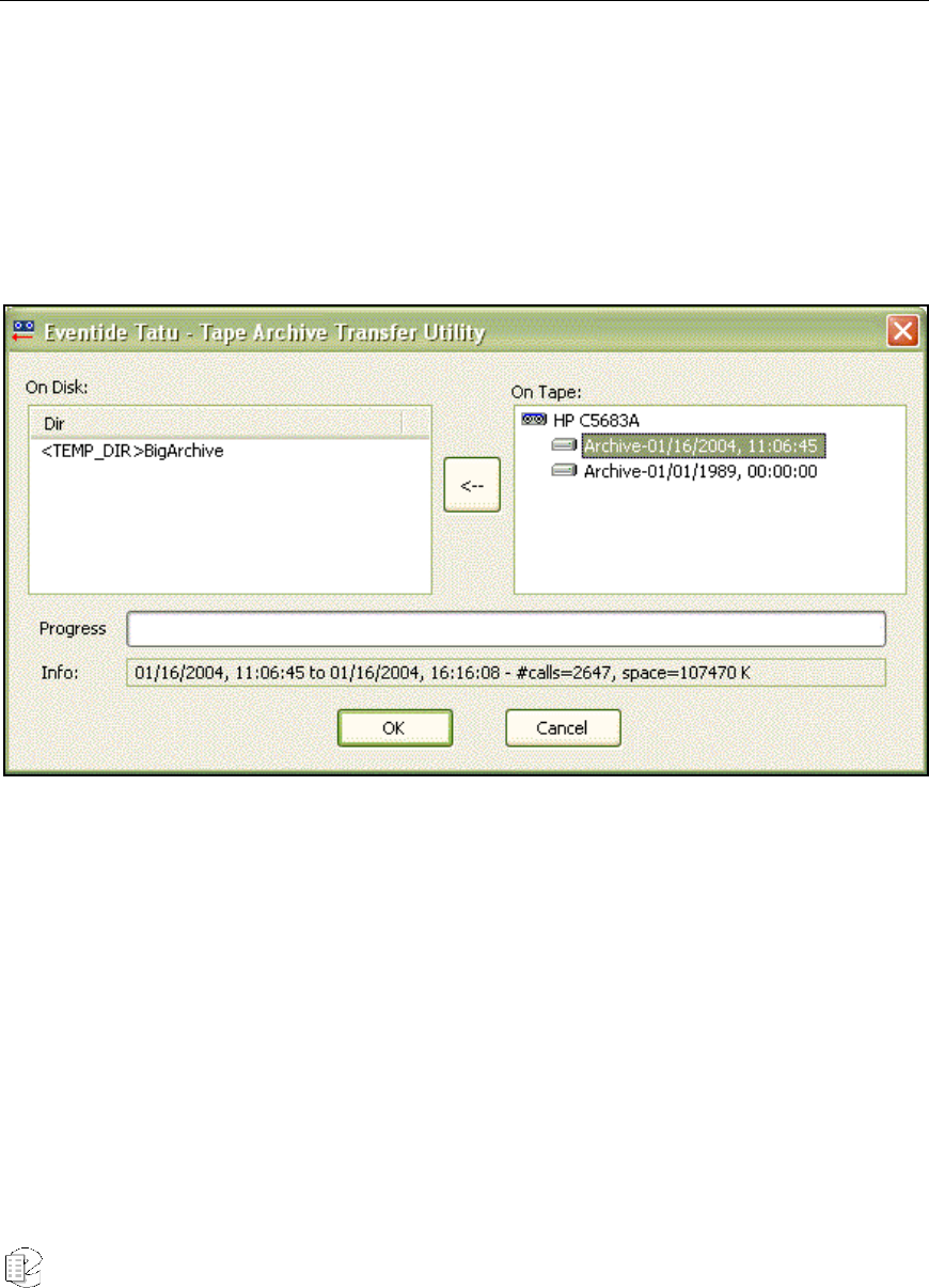
Atlas Series Server 1.8 User Manual 225
A
A
Ap
p
pp
p
pe
e
en
n
nd
d
di
i
ix
x
x
7
7
7
Eventide Tape Archive Transfer Utility (Tatu)
The Eventide Tape Archive Transfer Utility or Tatu,” is a standalone application
that enables users of the VR Series recorders that archive to DDS tapes to
transfer the archives from the tapes to the hard drive of their PCs. After affecting
this transfer, the Eventide Call Record Browser will automatically display these
archives for searching and playback.
The user interface to Tatu is quite intuitive:
When you launch Tatu from the Startup Menu, it brings up a splash screen that
notifies you that it is searching for tape drives and indexing the archives in them.
This may take several minutes as the tape drive spins up. When Tatu has finished
performing the index, the splash screen goes away and the main dialog comes up.
On the right, in a tree control, are listed the tape drives and the archives
contained on the tapes in the drives. On the left, in a list, are the archives already
present on the hard drive. When you select and archive in the tree, information is
displayed in the “Info” bar. The information consists of:
• Date and time the archive began.
• Date and time the archive ended.

Atlas Series Server 1.8 User Manual 226
• Number of calls in the archive.
• Total space taken up by the archive (in kilobytes).
If a tape archive is selected and you click on the “transfer arrow,” the archive will
begin transferring to the temporary directory on the hard drive. The temporary
directory is specified from the preferences on the Call Record Browser. The
transfer arrow will gray out during the transfer. When the transfer is finished, the
arrow will become active again.
Selecting a hard drive archive from the left list will enable the “Delete Archive”
button and you may click this button to delete the hard drive archive to free some
space.
This is not implemented in 1.1. You must go the temporary directory and delete it
manually.
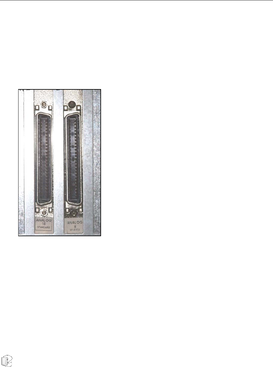
Atlas Series Server 1.8 User Manual 227
A
A
Ap
p
pp
p
pe
e
en
n
nd
d
di
i
ix
x
x
8
8
8
The Channel Wiring for Eventide Analog Telephony Boards
All Atlas series recorders that are equipped to record analog telephone calls
(“POTS”) are furnished with one or more Eventide analog telephony boards.
Eventide provides 8-, 16-, and 24-channel analog telephony boards. The 8- and
16-channel boards may contain either standard or reverse pin-outs on the Telco
connector, whereas the 24-channel boards all contain standard pin-outs.
All boards are labeled with the number of channels
and pin-out type (either standard or reverse), except
for very early versions of the 16-channel board. If you
have one of these unlabeled Eventide analog boards
in your recorder, it is a 16-channel board with
reverse pin-outs.
For standard and reverse pin-out assignments, see
Table 5–Eventide Analog Board Standard Pin-Outs
(8-, 16-, and 24-Channel Boards) and Table 6–
Eventide Analog Board Reverse Pin-Outs.
The Eventide Quick Install kits available for these
boards come with cables that compensate (if
necessary) for the pin ordering so that when wiring
the punch down blocks, the lines are in order according to normal telephone
company practice. Contact your Eventide representative to purchase your Quick
Install kit.

Atlas Series Server 1.8 User Manual 228
Table 5–Eventide Analog Board Standard Pin-Outs (8-, 16-, and 24-Channel Boards)
Chan Pins Chan Pins Chan
Pins Chan Pins Chan
Pins Chan Pins
1 1 + 26 5 5 + 30 9 9 + 34 13 13 + 38 17 17 + 42 21 21 + 46
2 2 + 27 6 6 + 31 10 10 + 35 14 14 + 39 18 18 + 43 22 22 + 47
3 3+ 28 7 7 + 32 11 11 + 36 15 15 + 40 19 19 + 44 23 23 + 48
4 4 + 29 8 8 + 33 12 12 + 37 16 16 + 41 20 20 + 45 24 24 + 49
Table 6–Eventide Analog Board Reverse Pin-Outs (8- and 16-Channel Boards)
Channel Pins Channel Pins Channel Pins Channel Pins
1 50 + 25 5 46 + 21 9 42 + 17 13 38 + 13
2 49 + 24 6 45 + 20 10 41 + 16 14 37 + 12
3 48 + 23 7 44 + 19 11 40 + 15 15 36 + 11
4 47 + 22 8 43 + 18 12 39 + 14 16 35 + 10
Important: The wiring is reversed, in the sense that Channel 1 would be connected to the
violet-slate pair, not the white-blue pair, if you are using standard telephone cables. On a
25-pair block terminated in standard telephone color code order, Channel 1 would be at
the bottom of the block.

Atlas Series Server 1.8 User Manual 229
A
A
Ap
p
pp
p
pe
e
en
n
nd
d
di
i
ix
x
x
9
9
9
Alert Configuration
In the course of operation, the recorder may generate a variety of alerts, which are
messages about aspects of the system operation. These messages have different
severity levels that range from informational messages to severe errors. You can
configure how alert notification is handled, as well as other alert features.
This section describes how to configure alert notification, including where to
display and email the alerts. It also provides the following information about alert
messages:
• Table 8–Alert Messages: A list of alert messages, including the alert code,
severity level, message text, and suggested actions.
• Table 7–Alert Severity Levels: A list of alert severity levels and descriptions.
Use the following procedures to configure alert notification.
First, enable email notification for the desired user accounts. This can be done only
from the Recorder Config administration client, not from the front panel. Users
who are enabled to receive email notification will receive ALL of the emailed alerts.
• Run Recorder Config and log into the recorder.
• In the left pane, choose Users.
• After a list of users appears, choose a user and select Modify. A window
should pop up allowing you to edit the user settings.
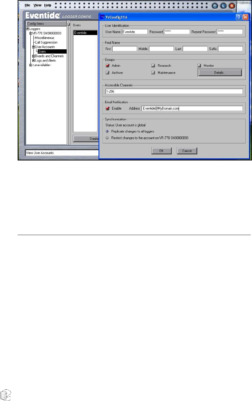
Atlas Series Server 1.8 User Manual 230
• In the Email Notification section, check the box labeled Enable and type in
the user’s email address.
• Hit OK to close the Modify window.
• Repeat for other users that should receive email notifications.
• Hit Apply button.
Second, configure the display and email settings for each of the available alerts.
• In the Recorder Config left pane, select Logs and Alerts, then select Alerts.
A list of available alerts will appear in the right pane.
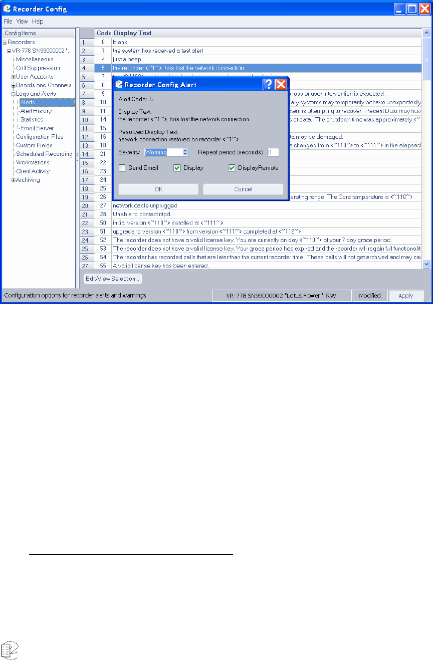
Atlas Series Server 1.8 User Manual 231
• In the list of alerts in the right pane, select an alert by clicking on the row
number in the leftmost column (to the left of the Code column).
• Click the Edit/View Selection button. This displays the alert message
configuration dialog , which allows you to adjust settings for the alert.
• Click the Display checkbox if you want the alert message to be displayed in
a red popup on the recorder front panel.
• Click the DisplayRemote checkbox if you want the alert message to be
displayed in a popup on the PC running the Recorder Config remote client.
• Click the Send Email checkbox if you want a notification to be mailed to
the list of enabled recipients.
• Click the OK button.
• When you have finished changing the alerts, make sure to click the Apply
button on the Alert Configuration window so that the changes are saved.
Lastly, enable the recorder to send emails.
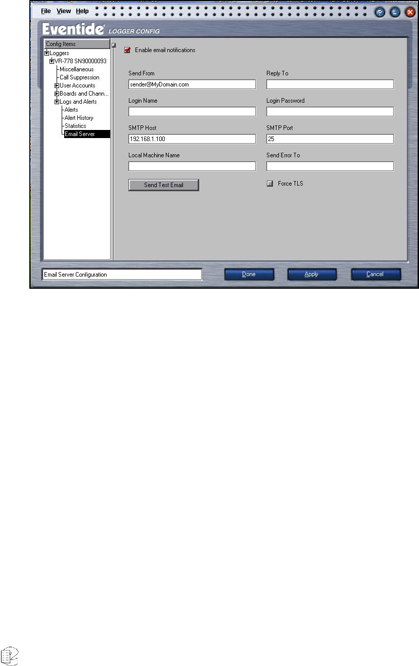
Atlas Series Server 1.8 User Manual 232
• In the left pane, choose Logs and Alerts, when the Logs and Alerts tree
expands, choose Email Server.
• In the right pane, check the Enable Email Notifications checkbox.
• Add the necessary information for your SMTP server.
• At a minimum, enter the IP Address of the SMTP server under SMTP Host.
• Usually the Send From field will require an email address of an account on
the SMTP server, in the form of name@domain.com.
Some servers require sender authentication, so the Login Name and Login Password
fields may need valid entries.
• SMTP Port is usually 25. Make sure your SMTP server is bound to a
different port before changing.
• Some SMTP Servers will require a Local Machine Name. The recorder’s
name is Eventide. Enter something that looks like
Eventide.yourdomainhere.com. But leave it blank unless it is required. Do
not put an “@” symbol in this box—this will cause an error.
• The Force TLS checkbox is usually left unchecked; if your SMTP server
requires an encrypted TLS connection, check this box.
• The Reply To and Send Error To fields are usually not required, but can be
filled out if desired, in the form name@domain.com.

Atlas Series Server 1.8 User Manual 233
• Hit Apply button.
• Test your settings with the Send Test Email button. If it works, the users
who have been enabled to receive notifications will receive a test message.

Atlas Series Server 1.8 User Manual 234
Table 7–Alert Severity Levels
Severity
Level (S) Name Description
1 Info An informational message or notice that does not require
acknowledgement. Example: Alert #8, “Recorder Startup.”
2 Warning Indicates trouble. Example: Alert #6004, “Primary Raid mount failed,
and the recorder recovered when secondary mount suceeded.
3 Error Indicates an error that could result in possible loss of data. Example:
Alert #5010, “The UPS on recorder <name> was found but is not
functioning properly.”
4 Severe Error Indicates a serious problem. Example: Alert #9024, “Analog Telephony
Board <name> has malfunctioned and has been disabled.”
Table 8–Alert Messages
Code S Text Description
1 1 The system has received a test alert No action required.
The “send test email” button has been
pushed, either on the front panel or in the
Recorder Config client.
5 2 Recorder <~1~> has lost the network
connection The recorder’s Ethernet connection has
been lost. The recorder may be in the
process of shutting down, or the cable
may be unplugged.
7 3 The <~110~> archive drive has been
removed or is not functioning. Check that the archive drive is present
and functioning.
8 1 Recorder Startup No action required.
The recorder has been started.
9 1 The process <~110~> has malfunctioned
on recorder <~1~>. No data loss or user
intervention is expected.
No Action Required if the alert only
happens occasionally.
10 3 The process <~110~> has malfunctioned
on recorder <~1~>. Secondary systems
may temporarily behave unexpectedly.
No data loss or user intervention is
expected
No Action Required if the alert only
happens occasionally.

Atlas Series Server 1.8 User Manual 235
Code S Text Description
11 3 The process <~110~> has malfunctioned
on recorder <~1~>. The system is
attempting to recover. Possible loss of
recent data has occurred
Verify that the expected number of calls
for the past few days is recorded on the
RAID. Do the same for the current archive
medium.
14 1 Recorder was not properly shut down. This
can cause serious loss of data. This alert displays when the system comes
back online from a hard power off. In most
cases no action is required.
15 1 Recorder Shutdown No action required. The recorder has been
shut down normally. This message does
not appear after a forced shutdown.
16 2 An error occurred while shutting down the
system. Current archived data may be
damaged.
Verify that the current archive medium
can be browsed and played.
18 1 The system has detected a time change
on the recorder. The time has changed
from <~110~> to <~111~> in the elapsed
time of <~112~> seconds. This may be
normal.
No action required.
21 1 External time source not present Recorder expects an external time source
and is not finding one. Verify that the time
source is connected.
22 1 External time source of type <~110~> was
detected in the system at time <~111~> No action required.
23 1 The process <~110~> has been manually
terminated No action required.
24 1 <~110~><~111~><~112~><~113~> No action required.
25 1 This is a test email sent from recorder
<~1~> at facility <~2~> No action required.
26 3 The recorder <~110~> is hot Verify that fans are operational. Verify that
RAID is ok (SETUP->Raid Status.)
27 1 Network cable unplugged Check network cable connection.
28 1 Unable to contact the NTP(Network Time
Protocol) server.
Check network connections and make
sure that the address of the NTP server is
correct.
50 1 Initial version <~110~> installed at <~111~>
A history of installed versions.
51 1 Upgrade to version <~110~> from version
<~111~> completed at <~112~>| A history of system upgrades.

Atlas Series Server 1.8 User Manual 236
Code S Text Description
52 2 Recorder does not have a valid license
key.
You are currently on day <~110~> of your
7 day grace period. Please contact
Eventide for a valid license key.
53 3 Recorder does not have a valid license
key. Your grace period has expired and the
recorder will regain full functionality when
a valid license key is entered.
Some functionality of the Recorder has
been suspended until a valid license key is
entered. Please contact Eventide for a
valid license key.
54 1 The recorder has recorded calls that are
later than the current recorder time. These
calls will not get archived and may cause
problems when you attempt to display
them.
Check the system clock and time zone.
Contact Eventide for further information.
1002 2 A call failed to be recorded on the
recorder. the call start time was <~110~> Verify if a call record exists. If it does,
attempt playback. If no audio, contact
Eventide.
1003 1 Calls are being removed from the hard
disc without ever having being archived.
the calls currently being deleted started
on <~110~>
Start archiving immediately.
1004 1 The hard disc is full. normal operations are
continuing and the oldest call on the
recorder will now be deleted to make
room for new calls. the first call deleted on
this recorder started at <~110~>
No action required. However, be aware
that calls cannot be recovered once they
are deleted. Make sure your archives are
up to date.
1005 2 A small amount of data may have been
lost from channel <~110~> on the call that
at <~111~>. This data loss my not be
noticeable.
Play back the call in question. If this
message occurs frequently, or if the data
loss is noticeable, contact Eventide.
1006 2 Calls are not being recorded due to a
recording problem. Error:<~110~> Check general operation of the recorder.
If INFO screen channel indicators are gray,
contact Eventide.
2001 1 The media in the <~111~> archive drive is
almost full No action required.
2002 1 The media with id <~110~> in the <~111~>
archive drive of recorder <~1~> is full Change medium.
2004 1 Warning: the operation of <~110~> was
performed when the drive was in a bad
state. Please retry the operation

Atlas Series Server 1.8 User Manual 237
Code S Text Description
2005 1 System configuration saved to the
<~110~> archive drive No action required.
2006 2 System configuration was NOT saved to
the <~110~> archive drive because of the
error: <~111~>
Try a different medium or take action
based on the error.
2008 2 System Logs were NOT saved to the
<~110~> archive drive: <~111~> Ensure that the archive medium is blank
and in the correct drive.
2009 1 System configuration was loaded from the
<~110~> archive drive. Please shutdown
and reboot your system
Reboot.
2010 2 System configuration was NOT loaded
from the <~110~> archive drive because
of the error: <~111~>
Take action based on the error.
2014 1 Writing archive to the <~110~> archive
drive failed. Please insert new media into
the <~110~> archive drive and hit the
'resume' soft key to retry.
Try a different medium.
2016 1 The current archive time has been
changed on the recorder from <~110~> to
<~111~>.
No action required.
2017 1 <~110~> archive drive action: <~111~>.
2019 1 Call Meta Information saved to the
<~110~> archive drive <~111~>.
2020 2 Call Meta Information was NOT saved to
the <~110~> archive drive <~111~>. Ensure that the archive medium is blank
and in the correct drive
2021 1 Call Meta Information was loaded from
the <~110~> archive drive.
2022 2 Call Meta Information was NOT loaded
from the <~110~> archive | <~111~>.drive
because of an error.
Refer to the error for possible action.
2024 3 The <~110~> archive drive medium was
improperly removed and may be
damaged. The recorder will attempt to
recover but some data loss is possible. In
the future please use the Eject soft key
and wait for the drive status to read "Safe
To Remove Media".
2025 1 The recorder <~1~> is currently not
archiving to any drive. No action required.

Atlas Series Server 1.8 User Manual 238
Code S Text Description
2026 2 The recorder <~1~> does not appear to
be archiving properly. the Recorder is
recording calls, but they do not appear to
be archived. this may be because of a
time change on the system or other
normal activity. If you believe this is a
problem please stop archiving and restart
it.
Check archiving operation.
2027 1 All media on the recorder <~1~> is either
full or in the wrong state to continue
archiving.
Archiving will not continue until blank
archive media is inserted and manually re-
started.
2030 1 The media loaded in the <~110~> archive
drive is damaged.
Error: <~111~> The media is damaged and
some data loss is possible. If possible,
archive the information on the media
again. Contact Eventide for further
assistance if data is missing.
2031 2 The media in the <~110~> archive drive
with start time <~111~> and end time
<~112~> has encountered problems
saving data.
The archive media may be faulty or
damaged. Please insert new Media and
archive again. The system archive time
has not been changed.
2032 1 Archive media format failed on the
<~110~> archive drive Please check that the media is not write-
protected or damaged. Error: <~111~>.
2033 1 A media error was encountered while
loading the <~110~> archive drive to
browse mode.
The archive media may be damaged and
have missing or incomplete calls. This error
could be caused by defective media or
an improper system shutdown. The archive
has the start time <~111~> and end time
<~112~>.
2200 2 The recorder <~1~> is not in standby
mode.
No action required.
2202 2 Archive Failsafe has been triggered on the
recorder <~1~>: <~110~>. No action required.
2203 1 The recorder <~1~> has been placed in
standby mode for the recorder <~110~>.
2204 1 Archive Restore complete on the <~110~>
drive of recorder <~1~>. No action required.
2300 1 Network Archive connected to address
<~110~>, share <~111~>. No action required.
2301 2 Network Archive to address <~110~>,
share <~111~> is NOT active.

Atlas Series Server 1.8 User Manual 239
Code S Text Description
2302 2 Network Archiving share is not connected.
Check network connection and ensure
that network share is active..
3001 1 Channel <~110~> was active for more
than <~111~> seconds. Generated as a result of your channel
settings for “Active Timeout.” Verify that
the channel is recording correctly.
3002 1 Channel <~110~> was inactive for more
than <~111~> seconds. Generated as a result of your channel
settings for “Inactive Timeout.” Verify that
the channel is recording correctly.
4001 1 A label has been printed for the archive
media on the <~110~> drive. No action required.
4002 2 Label printing failed on the <~110~> drive.
Error: <~111~> Take action based on error. Check printer
connection; cycle power on the printer;
form feed one label and attempt to print
again.
5000 2 Communications with the UPS backup
power supply has been lost on the
recorder <~1~> in facility <~2~>. Please
ensure that the UPS is properly connected
to the recorder
Check UPS connection.
5002 2 Power has been lost on the recorder
<~1~> in the facility <~2~>. The UPS is
currently providing power
No action required.
5005 2 Power has not been restored on the
recorder <~1~> in the facility <~2~> and
will be shut down shortly
Restore power to the recorder.
5008 2 The battery on recorder <~1~> has been
exhausted and is being shut down. Restore power to the recorder.
5010 3 The UPS on recorder <~1~> was found but
is not functioning properly Check UPS. Brand and model should be
supported by Eventide.
5013 1 UPS is attached and functioning normally No action required.
5014 1 UPS is not attached to the recorder or not
working properly Check UPS. Brand and model should be
supported by Eventide.
6000 4 A hard disc has failed on the recorder
<~1~>. please fix it Contact Eventide.
6001 4 RAID on recorder <~1~> now degraded.
Please fix it . Contact Eventide.

Atlas Series Server 1.8 User Manual 240
Code S Text Description
6002 1 The RAID has been changed: <~110~> No action required if the change is
expected..
7000 1 Email failure. Error: <~110~> Take action based on error. Send a test
email message to check email function.
7001 1 An unknown error code of <~110~> was
received
7002 1 An email has been sent to
<~110~><~111~> with the subject
"<~112~>"
No action required.
7003 1 The alert <~110~> has been
acknowledged by user <~111~> No action required.
8001 1 The user <~110~> has requested a system
shutdown No action required.
8002 1 The user <~110~> has been automatically
logged out No action required.
8003 1 Client login with username <~110~>,
version <~111~>, client string <~112~> No action required.
8004 1 Client has logged out with username
<~110~> No action required.
8005 1 Client login has failed with username
<~110~> No action required.
8006 1 The system time has been changed on
recorder <~1~> by user <~110~>. the old
time was <~111~>. the new time is
<~112~>
No Action Required if the time change is
expected.
8007 1 Configuration change by user <~110~>:
<~111~> No action required if the change is
expected.
8008 1 Shutdown requested via key. please wait. No action required.
8009 1 Archive Failsafe Mode Canceled by user
<~110~>.
9000 4 The board of type <~110~> has failed on
recorder <~1~>. the failed board is board
number <~111~>. it has failed <~112~>
times
Replace board.
9001 4 The board of type <~110~> in position
<~111~> could not be found A board may have been removed from
the recorder.

Atlas Series Server 1.8 User Manual 241
Code S Text Description
9002 4 Failed to open the board of type <~110~>
in position <~111~>. Error: <~112~> Take action based on error. Possibly
requires board replacement if alert
persists.
9003 4 Failed to configure the board of type
<~110~> in position <~111~>. Error <~112~> Take action based on error.
9004 2 DSP sync Error on the board of type
<~110~> in position <~111~>. sync error
count is <~112~>. Over run count is
<~113~>
Possible connection error to input board.
Board will recover automatically. If alert
persists contact Eventide.
9005 4 Failed to configure port <~112~> on the
board of type <~110~> in position
<~111~>. Error <~113~>
Take action based on error.
9006 3 Signal lost on port <~112~> on the board
of type <~110~> in position <~111~> Input signal has been lost. Check
connections to input board.
9007 3 Frames lost on port <~112~> on the board
of type <~110~> in position <~111~> Contact Eventide.
9008 2 AIS alarm on port <~112~> on the board of
type <~110~> in position <~111~> Contact Eventide.
9009 2 Yellow alarm on port <~112~> on the
board of type <~110~> in position <~111~> Contact Eventide.
9010 2 LOSMF alarm on port <~112~> on the
board of type <~110~> in position <~111~> Contact Eventide.
9011 2 LOCRC4MF alarm on port <~112~> on the
board of type <~110~> in position <~111~> Contact Eventide.
9012 2 TS16RAI alarm on port <~112~> on the
board of type <~110~> in position <~111~> Contact Eventide.
9013 2 Failed to open channel <~111~> on the
board of type <~110~>. Error: <~112~> Take action based on error.
9014 2 Failed to configure channel <~111~> on
the board of type <~110~>. Error: <~112~> Take action based on error.
9016 2 No signal present on channel <~111~> on
the board of type <~110~>. Input signal has been lost. Check
connections to input board.
9017 2 Recording could not be started on
channel <~111~> on the board of type
<~110~>.
Contact Eventide.

Atlas Series Server 1.8 User Manual 242
Code S Text Description
9018 2 Recording could not be stopped on
channel <~111~> on the board of type
<~110~>.
Contact Eventide.
9019 3 Read timeout on channel <~111~> on the
board of type <~110~>. Contact Eventide.
9020 3 Read fail on channel <~111~> on the
board of type <~110~>. Contact Eventide.
9021 3 Analog continuity check error on channel
<~110~>. No action required.
9022 4 Analog continuity number not being
updated channel <~110~>. Contact Eventide.
9023 4 <~110~>(<~111~>) has not been heard
from in <~112~> seconds. The recorder
may not be recording.
Contact Eventide.
9024 4 Analog Telephony Board <~110~> has
malfunctioned and has been disabled. Contact Eventide.

Atlas Series Server 1.8 User Manual 243
A
A
Ap
p
pp
p
pe
e
en
n
nd
d
di
i
ix
x
x
1
1
10
0
0
Eventide Voice Over Internet Protocol (VoIP) Implementation
WHAT IS VOIP?
VoIP is a technology that allows telephone calls to be made over local area
networks or the Internet. VoIP systems convert analog voice signals into digital
data packets and supports real-time, two-way transmission of conversations
using the Internet Protocol (IP).
VoIP calls can be made on the Internet using a VoIP service provider and standard
computer audio systems. Alternatively, some service providers support VoIP
through ordinary telephones that use special adapters to connect to a home
computer network.
VoIP services convert your voice into a digital signal that travels over the Internet.
If you are calling a regular phone number, the signal is converted to a regular
telephone signal before it reaches the destination. VoIP can allow you to make a
call directly from a computer, a special VoIP phone, or a traditional phone
connected to a special adapter.
THE ADVANTAGES VOIP PROVIDES
Each analog call is set up and delivered from a pair of dedicated copper wires
from the caller to the called party. This creates a dedicated physical connection
for a single call with extremely good quality. The technology is sufficient to carry
one call at a time over the pair of dedicated copper wires.
VoIP encapsulates the audio data into data packets. These packets are then sent
to the network. The same copper wire is now capable of carrying significantly
more than one conversation. The same device used to send voice is also capable of
sending other packetized information simultaneously like data, video and instant
messages. So at the very least VoIP is a much more efficient medium to transport
voice, and at the very best, will produce a much richer experience for the user
when one considers the enhanced features of video and instant messaging.
New for
Release 1.
6

Atlas Series Server 1.8 User Manual 244
Moreover, VoIP can be deployed with little or no cost, or can be an elaborate
application designed with your specific needs in mind. You either are looking for a
new telecommunications system or you want to enhance the one you have.
Additionally, VoIP can coexist with a PBX installation and provide an industry-
standard means for transporting audio.
VoIP systems typically operate on a LAN, which permits you to utilize your
existing network infrastructure for telephony. It does differ from legacy PBX
systems, which usually work when power goes out because they are simple to
back up and all of the telephones get their power from the PBX. In a VoIP system,
to get that type of redundancy, you need back up power for all of your LAN
equipment, plus consider how you will power the IP telephones during a power
outage.
TECHNICAL CONSIDERATIONS
VoIP’s handling of audio data differs significantly from how it is done on a
conventional, circuit-based network. On the latter, once a connection is
established, it is defined between two fixed points, and both the upstream and
downstream data are handled by the same pair of wires. VoIP’s digital
architecture uses different wires for upstream and downstream data, and the data
path is undefined. Audio is carried through RTP (Real Time Protocol) packets,
which can be routed through different paths. As a result, data packets of audio
data can become unsynchronized and be delivered out of their original sequence.
To address this, VoIP uses a buffering system that synchronizes delayed packets.
The inherent delay caused by packet buffering should never exceed 500 ms.
Networks are by no means limited to carrying only voice data. As such, a packet
filtering mechanism is used to detect and isolate RTP audio data packets from
other data types carried across the network.
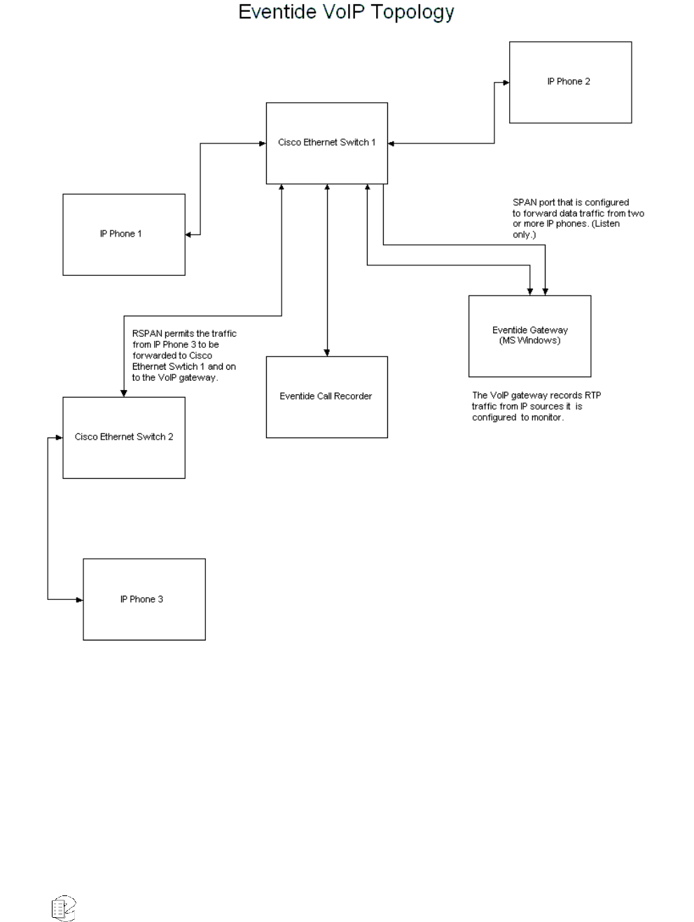
Atlas Series Server 1.8 User Manual 245

Atlas Series Server 1.8 User Manual 246
PREREQUISITES FOR VOIP INSTALLATION
Note:To upgrade a VoIP gateway, see “VoIP Software Upgrade” on page 253.
First, your call recorder must have firmware version 1.6 or higher installed to
support the recording of VoIP transmissions.
In order to successfully implement voice over IP, each call recorder must have
installed an Eventide VoIP gateway on the network. The gateway is a separate,
rack-mounted installation that passively captures data from the VoIP phone set
and interfaces with the call recorder via the LAN. As such, it acts essentially as an
intermediary between the two. Eventide call recorders can support more than one
gateway, in the event your call recorder installation requires more than the 96
channels supported by a single gateway, or if you wish to ‘tap’ the VoIP system
from different locations. (Tapping is the term used for creating permanent access
ports for network monitoring.)
Finally, the topology of your network must be configured to allow all call data to
be visible to a single Ethernet port, which is attached to the gateway.
NETWORK REQUIREMENTS
Your VoIP installation differs from a PBX phone system in that there exists no
centralized point from which to access the system. As such, it is imperative that
you configure your network topology to route all calls to your gateway from a
single Ethernet connection. This is most effectively accomplished using a Cisco
Systems Ethernet switch that supports Switched Port Analyzer (SPAN) technology
or Remote Switched Port Analyzer (RSPAN) technology. These components create
copies of the audio packets being sent across the network and send them to
another designated port for network analysis. In RSPAN’s case, it places audio
traffic on a SPAN port from different network switches.
For detailed information on SPAN and RSPAN, go to the following page on the
Cisco Systems web site:
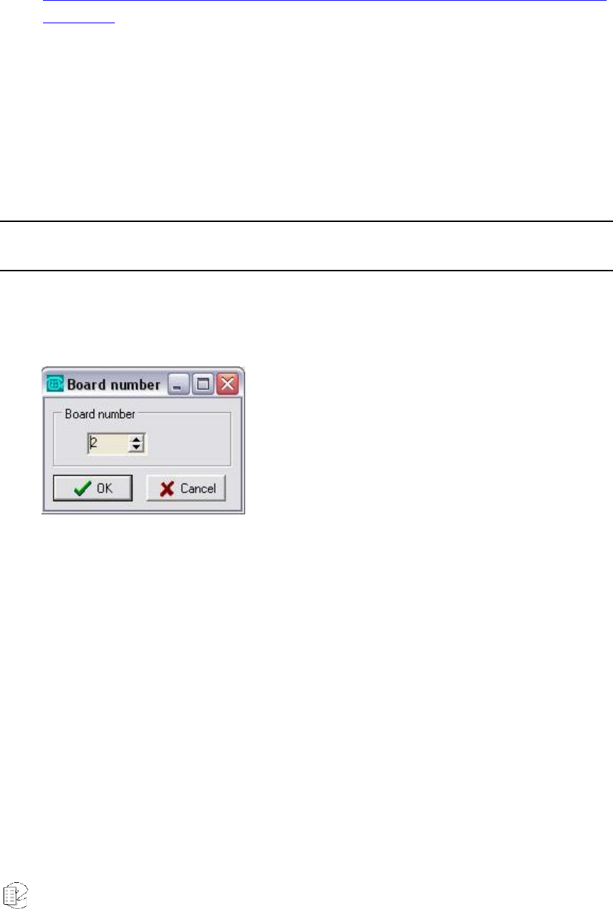
Atlas Series Server 1.8 User Manual 247
http://www.cisco.com/univercd/cc/td/doc/product/lan/c3550/12113ea1/3550scg/s
wspan.htm
One way to ensure that all audio data for recording is being received by the
gateway is by using The Parrot DSC Maintenance Tool, a utility that tracks
network traffic and lists the IPs and MAC addresses of all connected phone sets
and computers. The Maintenance Tool comes preinstalled on the VoIP gateway
system, and is located in the following directory:
C:\program files\cybertech\parrot dsc\maintenancetool.exe
Note: Your gateway must be successfully configured prior to using this utility. See the Gateway Configuration
section for a description of this task.
Launch the program, and the following window displays:
• Select Board Number 2, and click OK.
• A blank screen with a command prompt now displays: enter the following
command to generate a listing of all traffic currently active in the system:
ip_list ? ?
• Press Enter, and a listing now displays:
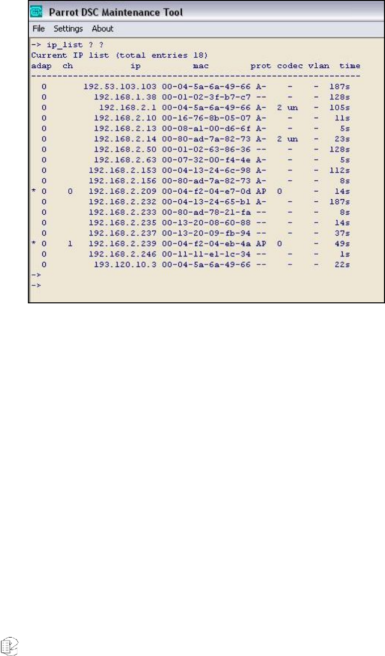
Atlas Series Server 1.8 User Manual 248
Each line in this report describes one detected system on the network.
Descriptions follow for each column displayed:
adap: The number of the Ethernet adapter on which this device was seen. This
numbers reflect the values you enter in the Selected Adapters section of the
configuration file for the gateway in Recorder Configuration.
ch: The channel number, if any, you have assigned to this IP or MAC address.
ip: The IP address of the device.
mac: The MAC address of the device.
prot: An A displays in this column if this device is sending or receiving data on
a port you designated as an audio port. A P displays if the port is designated a
signaling port.
codec: Not applicable for this purpose.

Atlas Series Server 1.8 User Manual 249
vlan: The designated virtual local area network (VLAN), if any, to which this
device is assigned.
time: The number of seconds passed since activity occurred to or from this
device.
To refresh the listing on the screen, simply reenter the command ip_list ? ?
If you require more extensive network analysis resources, use a network protocol
analyzer like Ethereal, a freeware program available at http://www.ethereal.com or
Wireshark at http://www.wireshark.org
Bandwidth is a critical issue for VoIP installations. If insufficient bandwidth is
available for the gateway to receive the audio, compress it, and send it to the
server, a delay occurs that can impact audio synchronization. For a VoIP
configuration on a local area network using a T1 connection, bandwidth does not
typically pose a problem.
In order to assure sufficient bandwidth, Eventide suggests implementing VoIP on
a virtual local area network (VLAN). A VLAN is a logical group on the network that
effectively prioritizes network traffic to ensure enough bandwidth. VLANs also
greatly ease the configuration issues surrounding SPAN and RSPAN ports.
The MAC or IP addresses of all active phone sets must be designated. This
information is entered in the Text Files area of the Atlas Series Administration
tool, VR Config, version 1.6. Additionally, port ranges for both the signaling ports
(the call’s attributes) and audio ports (the actual audio data packets) must be
designated. Only calls that occur on ports in these designated ranges are
recorded; all others are ignored.
The call recording server and the gateway must be configured in a way that
allows them to recognize each other’s presence. The call recorder knows of the
gateway from its IP address, so Eventide strongly suggests that the gateway be
configured with a static IP address. This is also helpful for Eventide technical
support, in the event system maintenance needs to be performed using either a
modem or virtual private network (VPN).

Atlas Series Server 1.8 User Manual 250
If for whatever reason the call recorder disconnects, the gateway will begin
caching all audio received. As soon as the connection is restored, all buffered
audio is forwarded to the server. No audio will be lost if the disconnect is a
relatively short one, but if the server is down for an extended period, some audio
will be lost due to limits of its caching facility. Note that during a time of
disconnect, Live Monitor will not function, and all channels display as grayed out.
It is imperative for the call recorder and the gateway to have the same time
source, in order for audio data to be correctly sequenced and archived. This is
most easily achieved by synchronizing them to a single NTP (Network Time
Protocol) server, or any other reliable time source.
GATEWAY CONFIGURATION
• Use Recorder Configuration 1.6 or greater to log in to the server.
• Go to the Configuration Files area for the selected call recorder. This is where
configuration is performed that allows the call recorder to communicate with
the VoIP gateway.
• From the Files column, highlight the VoIP Configuration file:
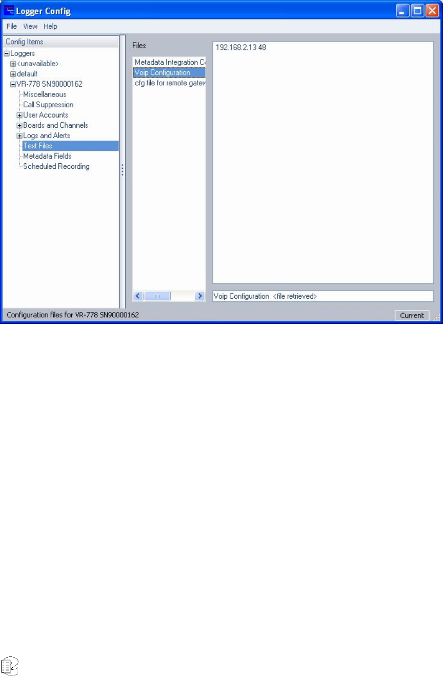
Atlas Series Server 1.8 User Manual 251
• This file contains information that defines all gateways that the call recorder
should look for and communicate with. Each line of the file contains the IP
address of the VoIP gateway, followed by a space, followed by the number of
channels configured for that gateway. In the illustration above, the gateway at
this IP address (192.168.2.13) is configured for 48 channels.
• If your gateway is not yet configured, add it here in this format. If the call
recorder came preconfigured from the factory to operate with a VoIP gateway,
this entry already displays. You will, however, be required to change the IP
address to whichever IP you have assigned the gateway on your network.
• When all changes are made to the file, go to the File menu, and click Apply.
You must now reboot the call recorder in order for them to take effect.
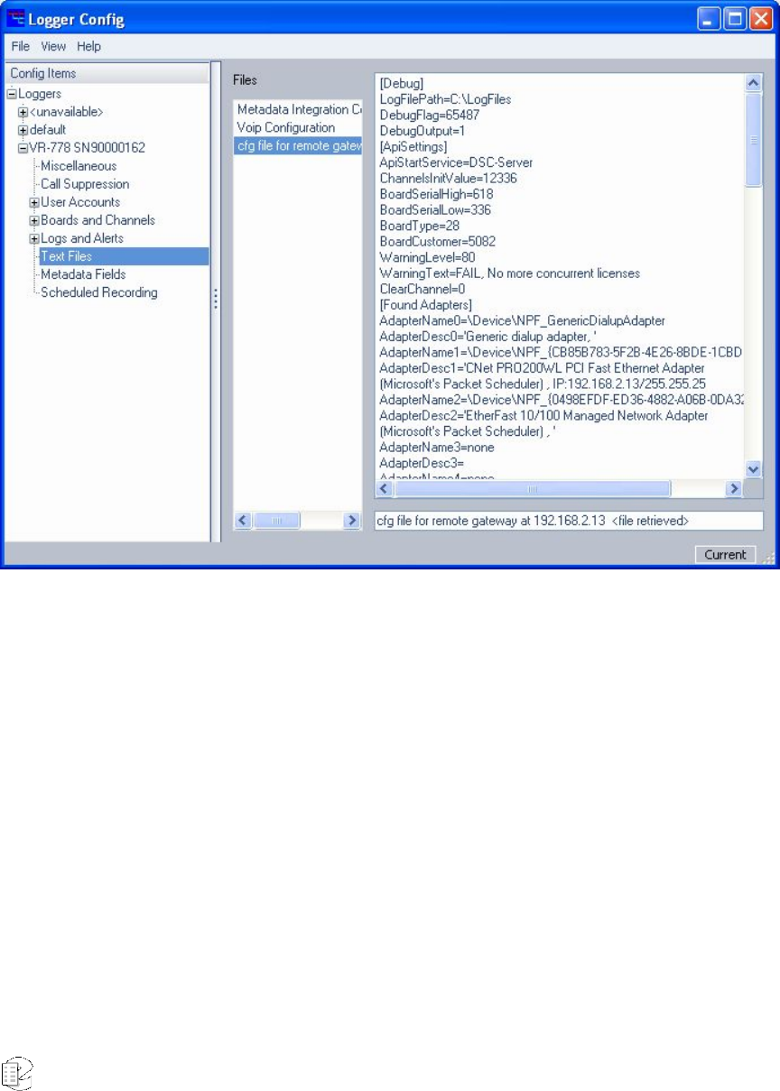
Atlas Series Server 1.8 User Manual 252
After rebooting, launch Recorder Configuration again to edit the configuration file
for that specific gateway:
This file (cfg file for remote gateway) is downloaded to the call recorder from the
VoIP gateway. As such, it will not display until the presence of the gateway has
been detected on the network by the call recorder. A majority of lines in this file
remain unchanged; the following, however, must be modified to suit your
configuration:
• Selected Adapters: from the Found Adapters section of the file, copy the
name of any network adapters (Ethernet cards) that you wish to use to
capture VoIP traffic.
• Under Protocol Ports, select the port range for VoIP signaling between the
phones and PBX system.
• Under Audio Ports, select the port range for VoIP audio packets.
• Under IpToChannel or MacToChannel, define the specific IP or MAC address
for each phone set on the network:

Atlas Series Server 1.8 User Manual 253
• The number of channels enabled for recording on this gateway is limited by
the number of channel licenses purchased from Eventide. You must either use
IP addresses or MAC addresses, not a combination of the two. Consequently,
the address format not employed should be entered all as zeros.
• When finished, go to the File menu, and click Apply. For your changes to
take effect, you must now reboot the gateway.
ARCHIVING
The archiving facility of the Atlas series is wholly dependent upon time stamps to
generate accurate and sequential archives. An audio record is eligible for
archiving 15 seconds after it concludes recording. If a disconnect between the
gateway and the recorder occurs, this impacts how the archive pointer caches the
calls, and the sequence in which calls will be received and ultimately archived. If
the delay is significant, an alert displays that details the conditions of the
disconnect, and some calls will not be archived. In such a case, Eventide suggests
doing a period archive.
VOIP SOFTWARE UPGRADE
This section describes how to upgrade the VoIP software on the Eventide VoIP
gateway.
The gateway and the recorder must use compatible versions of Eventide software;
that is, they must both be updated with software from the same release level.
Eventide recommends upgrading the gateway first.
Note: After the upgrade, the gateway must be restarted.
Before beginning the upgrade, make sure that the system is not in use and all
archiving is up to date.
New for
Release 1.8
Atlas Series Server 1.8 User Manual 254
Upgrade the VoIP gateway as follows:
1. Load the CD-ROM containing the software upgrade.
2. Click on Start>Run. The Run dialog displays, allowing you to enter the name
of a program to open.
3. Type d:\upgrade.bat and press Enter. The upgrade program displays
messages in a command window as it upgrades the software. Then a prompt
similar to the following is displayed:
Enter PBX Type: ALCATEL AVAYA CISCO ERICSSON H323 MITEL NEC
NORTEL SIEMENS SELTA SIP or VOX
4. Type the name of the PBX manufacturer as displayed in the list and press
Enter. After a brief wait, the Firmware Update window displays, similar to the
following:
5. Use the information in this window to determine whether the VoIP gateway
firmware needs to be upgraded (as follows). For the board listed as Type PCI
Mod Short VoIP (and only this board), the Current Configuration column
must show voip_lic_mod_pci_03, which is the latest version of firmware.
A. If this board shows the latest version of firmware, you do not need to
update the firmware. Close the window using the “X” in the upper right
corner to cancel. After all the windows close, you must complete the
gateway upgrade by rebooting the gateway. (Don’t forget to upgrade the
recorder software and test the recorder to verify that recording works
normally.)
B. If this board does not show the latest version of firmware, you must
update the firmware for this board using the following steps.

Atlas Series Server 1.8 User Manual 255
6. To mark this board for a firmware update, click on the red “X” in the Do
Update column, and it will change to a green checkmark. (Do not update the
firmware for other boards listed.)
7. To select the firmware file, click on the browse button (“…”) to the right of the
Configuration File field. Then select the voip_lic_mod_pci_03.zmx file located
in D:\ (the CD-ROM drive root folder) and click Open. The Firmware Update
window is displayed with the name of the firmware file shown in the
Configuration Files field.
8. To begin the firmware update, click on the “Start updating board
configurations” button. After the update completes successfully, the Status
column for this board should show “Programming successful” and a message
is displayed saying, “To re-activate (updated) boards, the system must be
rebooted!!!”
9. Click the OK button, and after all the windows close, you must complete the
gateway upgrade by rebooting the gateway.
Don’t forget to upgrade the recorder software and test the recorder to verify that
recording works normally.

Atlas Series Server 1.8 User Manual 256
L
L
Li
i
im
m
mi
i
it
t
te
e
ed
d
d
W
W
Wa
a
ar
r
rr
r
ra
a
an
n
nt
t
ty
y
y
The Eventide ATLAS series recorders are built to exacting quality standards and
should give years of trouble-free service. If you are experiencing problems, your
recourse is this warranty.
Eventide Inc. warrants the products unit to be free from defects in workmanship
and material under normal operation and service for a period of one year from the
date of purchase, as detailed below. At our discretion within the warranty period,
we may elect to repair or replace the defective unit. This means that if the unit
fails under normal operation because of such defect, we will repair the defective
unit at no charge for parts or labor. We also assume a limited responsibility for
shipping charges, as detailed below.
The warranty does not extend beyond repair or replacement as stated herein and
in no event will we be responsible for consequential or incidental damages caused
by any defect, and such damages are specifically excluded from this warranty.
Our sole obligation is to repair or replace the defective unit as described herein.
The warranty DOES NOT COVER any damage to the unit regardless of the cause
of that damage. The unit is a complex piece of equipment that does not react well
to being dropped, bounced, crushed, soaked or exposed to excessively high
temperatures, voltages, electrostatic or electromagnetic fields. If the unit is
damaged for these or similar causes, and the unit is deemed to be economically
repairable, we will repair it and charge our normal rates.
The warranty DOES NOT COVER shipping damage, either to or from Eventide. If
you receive a new unit from us in damaged condition, notify us and the carrier;
we will arrange to file an insurance claim and either repair or exchange the unit.
If you receive a new unit from a dealer in damaged condition, notify the dealer
and the carrier.
If we receive the unit from you with apparent shipping damage, we will notify you
and the carrier. In this case, you must arrange to collect on any insurance held
by you or your carrier. We will await your instructions as to how to proceed with
the unit, but we will charge you for all repairs on damaged units.

Atlas Series Server 1.8 User Manual 257
Who is covered under the warranty
The warranty applies to the original purchaser of a new unit from Eventide or an
Authorized Eventide Dealer. Demo units are also covered by this warranty under
slightly different circumstances (see below). Units that are used, or have been
used as part of a rental program, are not covered under any circumstances.
It is your responsibility to prove or to be able to prove that you have purchased
the unit under circumstances which affect the warranty. A copy of your purchase
invoice is normally necessary and sufficient for this.
If you have any questions about who is an Authorized Eventide Dealer, call us.
Units with the serial number plate defaced or removed will not be serviced or
covered by this warranty.
When the warranty becomes effective
The one-year warranty period begins on the day the unit is purchased from an
Authorized Eventide Dealer or, if the unit is drop-shipped from Eventide, on the
day shipped, plus a reasonable allowance for shipping delays. This applies
whether or not you return your warranty registration form.
When we receive a unit, this is how we determine whether it is under warranty:
If the unit was shipped from our factory within the past calendar year, we assume
that it is under warranty unless there is evidence to the contrary, such as its
having been sold as used or rented, etc..
If the unit was shipped from our factory more than a calendar year ago, we
assume it is not under warranty unless there is a warranty registration form on
file showing that it has been purchased within the past year under appropriate
conditions or if you send a copy of your purchase invoice indicating warranty
status along with the unit.
If the unit was used as a demo, the warranty runs from the date that it was
received by the dealer. The original purchaser gets the unexpired portion of that
warranty.

Atlas Series Server 1.8 User Manual 258
When you send a unit for repair, you should indicate whether or not you believe it
to be under warranty. If you do not say the unit is under warranty, we will charge
you for the repair and we will not refund unless the charge was caused by an
error on our part. If you believe the unit to be under warranty and you do say it is
but we disagree, you will not incur any charges until the dispute is resolved.
Reading the above, you can see that it is to your advantage to send in the
warranty registration form when you purchase the unit. If we know who you are,
we can send you updates and notifications, and advise you of our new products.
It will also enable you to receive pre-shipment of certain parts.
Who performs warranty work
The only company authorized to perform work under this warranty is Eventide
Inc., Little Ferry, New Jersey. While you are free to give personal authorization to
anyone else (or to work on it yourself), we will not honor claims for payment for
parts or labor from you or from third parties.
However, we and our dealers do try to be helpful in various ways. Our dealers will
assist, usually without charge during the warranty period, in determining whether
there is a problem requiring return to the factory, and alleviating user error or
interconnection problems that may be preventing the unit from operating to its
full capability.
We are available for consultation if the dealer is unable to assist.
If a part is found to be defective during the warranty period and you wish to
replace it yourself, we will normally ship the part immediately at no charge,
provided your warranty registration form is on file. We reserve the right to request
that the defective part be returned to us.
Shipping within the 50 United States
You are responsible for getting the unit to our door at no cost to us. We cannot
accept collect or COD shipments.
We will return the unit to you prepaid, at our expense, using an expeditious
shipping method, normally United Parcel Service. If you are in a hurry and want
us to use a premium shipping method (such as air express, next day air, etc.), be
sure you tell us and agree to pay shipping charges collect. If you specify a method

Atlas Series Server 1.8 User Manual 259
that does not permit collect or COD charges, remit sufficient funds to prepay
shipping.
Shipping outside the 50 United States
If you purchased the unit from a dealer in your country, consult with the dealer
before returning the unit.
If you wish to return the unit to us, please note the following:
1. The unit must be prepaid to our door. This means that you are responsible for
all shipping charges, including customs brokerage and duties. When a unit is
shipped to us it must be cleared through United States Customs by an authorized
broker. You must make arrangements for this to be done. Normally, your freight
forwarder has a branch in the United States that can handle this transaction. If
you want our assistance in clearing incoming packages, you must notify us before
shipping the unit for repair, giving full details of the shipment, and including a
minimum of $250.00 in US funds to cover the administrative and brokerage
expenses. Any balance will be applied to the repair charges or refunded. If a
balance is due to us, we will request a further prepayment.
2. All shipments will be returned to you collect. If this is impossible because of
shipping regulations or money is due us, we will request prepayment from you for
the appropriate amount.
3. All funds must be in $US. Payment may be made by check drawn on any bank
in the US, or by telegraphic funds transfer to our bank. If you send US currency,
be sure that it is sent by a method you can trace, such as registered mail. If you
wish to pay by Letter of Credit, be sure that it affords sufficient time for work to
be performed and the L/C negotiated, and that it is free from restrictive
conditions and documentation requirements.
4. We reserve the right to substitute freight carriers. Although we will attempt to
honor your request for a specific carrier, it is frequently necessary to select a
substitute because of difficulties in communication or scheduling.
This warranty gives you specific legal rights and you may also have other rights
which vary from location to location.

Atlas Series Server 1.8 User Manual 260
Index
Active Timeout, 239
Activity Timeout, 87
Add-On Key, 58
Add-on license key
centralized archive failsafe, 196
Centralized archiving, 194
Configuration file, 181
GPIO board, 215
MDC-1200, 170
Metadata integration, 182
Administration Client Menu Options, 205
Administrative Client, 151, 152, 153, 155,
171, 173, 174, 206, 211
AGC, 84
AGND, 213
AI Logix E1/T1, 173
AI Logix NGX, 171
AIN, 213
Alarm relay
general, 168
Alert
codes, 234
severity, 234
Alerts
alerts screen, 176
configuration, 229
GPIO, 168
history screen, 177
Messages, 234
severity levels, 234
severity levels (GPIO), 169
Analog Board Configuration dialog, 168
Analog Input Board, 32, 77, 78, 81
Analog Telephony Board, 167
AOUT, 213
Archive, 53, 54, 65, 144, 145, 179, 208,
209, 222, 223, 238
Archive Drives, 192
Archive failsafe behavior, 70, 148
Archive failsafe server, 70, 71, 148
Archive Protection, 66, 145, 146
Archive restore, 136
Archiving, 135
Audio Board, 170
Auto-Eject, 146
Before you change channel names..., 82
Bench testing, 25
Board Configuration, 167
Board Configuration Screen, 78, 172
Browse Archive, 145
Browse Archive Media, 145
Call Suppression screen, 161
Centralized Archive Failsafe, 196
Centralized Archiving, 194
Channel Configuration, 166
Channel Configuration Screen, 81, 166
Channel Groups, 175, 197
Channel Names, 175, 194

Atlas Series Server 1.8 User Manual 261
Choosing an Encoding Algorithm, 80
Client Activity, 204
Client installation, 153
Clock, 54
Columns, 133
Config Items menu, 157
Configuration Files, 181
Connecting a Label Printer, 36
Connecting AC Power and UPS, 30
Connecting Line-Level Equipment, 36
Connecting Telephone, Radio, and
Other Analog Audio Signals, 32
Connection Information for the HiFi
Recording Board, 213
Controlled shutdown, 126
Creating Playlists from the RECALL
Screen, 48
Custom Fields, 184
Custom Fields screen, 184
Custom script
GPIO, 215
MDC-1200, 170
Custom Script, 182
Delete Archive, 226
Delete User, 165
Designating and Activating an Archive
Failsafe Server, 148
DETECT, 26, 84
Detect GPIO, 84
Displaying Columns, 47
DVD-RAM, 16, 21, 22, 38, 66, 117, 120,
124, 135, 136, 137, 139, 149, 221, 222
DVD-RAM Drive Operation, 139
Email, 54
Email Notification screen, 180
Embedded license key (custom script),
182
Enable/disable archive failsafe, 148
Ethernet, 16, 19, 21, 24, 35, 106, 234
Ethernet port, 19
Eventide Tape Archive Transfer Utility
(Tatu), 225
Eventide VR778 or VR725 with DDS-4
Tape Drives, 221
Fault LED, 18
Filter, notch, 169
Filtering and Searching, 131
Forced shutdown, 127
Formatting Archive Media, 141
Front Panel Details
VR615 and VR778, 16
VR725 with Touch screen, 22
Gateway Configuration, 250
General alarm relay, 168
General Specifications – VR615 and
VR778, 15
General Specifications – VR725 & Blank
Panel Units, 20
GPIO
board, 215
detect, 84
NI PCI-6503 board, 87, 215
NI PCI-6527 board, 88, 216
output alert severity, 168
pin setting, 87
pinouts (NI PCI-6503), 217
pinouts (NI PCI-6527), 217
Guard tone filter, 169
Inactive Timeout, 239
Inactivity Timeout, 87
INFO, 25, 36, 39, 95, 97, 129, 130, 139, 145,
150, 236
INFO Screen, 38
Installation, 27

Atlas Series Server 1.8 User Manual 262
Knob, 18
License key
centralized archive failsafe, 196
centralized archiving, 194
Configuration file, 181
Custom script, 182
GPIO board, 215
MDC-1200, 170
Metadata integration, 182
License Key Information, 57
Line-proving tone filter, 169
Live Monitoring, 150
Location considerations, 28
Logs, Alerts and Statistics, 176
Looping, 134
Managing Users, 96
Mark Protected option, 48
M-Audio Board, 170
M-Audio Board Configuration window,
171
MDC-1200, 170
Media Selection, 137
Metadata integration, 182
Miscellaneous Configuration screen, 159
Mounting options, 29
National Instruments GPIO boards, 215
Network Settings, 54
NIST Time Servers, 219
Notch filter, 169
Opening/Closing the DVD-RAM Drive,
141
Operational limits, 27
Optional drives, 17
PBX, 77, 84, 167, 171, 173, 211
PBX and Digital Telephony Hardware
Information, 211
Period Archiving, 197
Pilot tone filter, 169
Pinouts (GPIO NI PCI-6503), 217
Pinouts (GPIO NI PCI-6527), 217
Play Silence/Skip Silence, 50
Playing Audio Records, 40
Playing Back Calls, 134
Printing a Label, 143
Quick Install Kit, 33, 227
RAID, 16, 21, 22, 23, 53, 58, 59, 69, 91, 121,
122, 125, 129, 130, 145, 147, 209, 222,
235
RAID disk array, 23
Ready LED, 18
Rear Panel Details, 19, 24
Recall
By Call Length filter, 43
By Channel filter, 42
By CLID Digits filter, 46
By Date/Time filter, 44
By DTMF Digits filter, 45
RECALL, 25, 26, 36, 41, 42, 43, 44, 51, 95,
97, 130, 131, 133, 145
RECALL Screen, 40
Record, 83
Record LED, 18
Recorder contents and accessories, 14
Recording, 129
Relay
general alarm, 168
Release number, 13
Remote client software, 151
Restoring Archives when Installing New
Software, 209
Resume Archiving, 142

Atlas Series Server 1.8 User Manual 263
Scheduled Recording, 84, 187, 189, 190,
191, 192
Scheduled Recording Parameters, 189
Scheduled Recording screen, 187
Scripts
custom, 182
custom (MDC-1200), 170
GPIO, 215
Searching, Sorting, and Playing Calls, 130
Security, 54
Security Groups, 95
Selecting and Deselecting an Archive
Drive, 141
Selecting The Archive Period, 144
Sequential and Parallel Modes, 138
Sequential/Multitrack, 50
Server Login, 156
Server Software Installation and
Upgrade, 207
Set Archive Time, 69, 147
Set Current Archive Time, 147
Setting Current Archive Time, 146
Setting Levels, Thresholds, and Hold
Times, 89
Setup RS-232 Time Settings, 115
Setup Screen, 37
Setup: Archive : Archiving type, 65
Setup: Archive: Archive failsafe server, 70
Setup: Archive: Archive protection
period, 66
Setup: Archive: Auto-eject, 67
Setup: Archive: Enable/disable archive
failsafe, 71
Setup: Archive: Enable/disable Label
printing, 67
Setup: Archive: Resume archiving on
startup, 68
Setup: Archive: Set current archive time,
68
SETUP: Clock, 110
Setup: Clock: RS232 Time settings, 114
Setup: Clock:I RIG-B settings, 113
SETUP: Email, 99
SETUP: Network Archive, 72
SETUP: Network Settings, 106
Setup: Recording: Audio segment
length, 92
Setup: Recording: Board configuration,
78
Setup: Recording: Delete calls after N
days, 90
Setup: Recording: Max # of calls in DB,
91
SETUP: Security, 93
Setup: Security: Auto-logout timeout, 94
Setup: Security: User administration, 95
Setup: System Info/Configuration Info, 55
Setup: System Info: Add On License Key,
62
Setup: System Info: Enable/Disable
Verbose Logging, 63
Setup: System Info: License Key, 61
Setup: System Info: RAID Status, 58
Setup: System Info: Serial Number, 60
Setup: System Info: View alarm log, 63
SETUP: System Shutdown, 126
Setup:Archive:Archive failsafe behavior,
71
Setup:Clock:Date/Time, 111
Setup:Clock:NTP Server, 112
Setup:Clock:Time sync status, 116
Setup:Clock:Time zone, 111
Setup:Email:Enable/Disable Emails, 100
Setup:Email:Force TLS Encryption, 104

Atlas Series Server 1.8 User Manual 264
Setup:Email:Local Hostname, 101
Setup:Email:Send test email, 105
Setup:Email:SMTP Errors-To Address, 104
Setup:Email:SMTP From Address, 103
Setup:Email:SMTP Password, 102
Setup:Email:SMTP Port, 101
Setup:Email:SMTP Reply-To Address, 103
Setup:Email:SMTP Server, 100
Setup:Email:SMTP Username, 102
Setup:Network Archive:Enable/Disable
Network Archive, 72
Setup:Network Archive:Hostname, 73
Setup:Network Archive:Password, 75
Setup:Network Archive:Set Current
Network Archive Time, 76
Setup:Network Archive:Share Name, 73
Setup:Network Archive:Username, 75
Setup:Network Archive:Workgroup, 74
Setup:Network Settings:Broadcast, 109
Setup:Network Settings:DNS Servers, 109
Setup:Network Settings:Enable/Disable
DHCP, 107
Setup:Network Settings:IP Address,
Gateway, Net mask, Network, 108
Setup:Recording:Channel Configuration,
81
Setup:Security:Logins Required, 93
SETUP:Utilities, 117
Setup:Utilities:Archive restore, 121, 122
Setup:Utilities:Read configuration from
archive, 120
Setup:Utilities:Read metadata from
archive, 124
Setup:Utilities:Write configuration to
archive, 118
Setup:Utilities:Write logs to removable
media, 117
Setup:Utilities:Write metadata to archive,
123
Severity level for alerts, 234
Shutdown
controlled, 126
forced, 127
SNMP configuration file, 182
SNMP monitoring, 182
SNMP trap actions, 183
Software Upgrade/Installation Process,
208
Software version, 13
Start Archiving, 142
Starting and Shutting Down, 128
Statistics screen, 178
Stop Archiving, 142
System Info, 53, 55, 61
System Info: RAID Status, 130
System Shutdown, 54
Tested UPS units, 31
Text Files screen, 181
The Channel Wiring for Eventide Analog
Telephony Boards, 227
Time Code Synchronization Over RS-232,
114
Toggle soft key., 43, 150
Tone
guard, pilot, line-proving, 169
Touch screen calibration (coarse and
fine), 125
TRV, 84, 86, 87
TRV Hold, 85
TRV Min/Max/Cur, 86
TRV Thrsh, 85
Unpacking the Recorder, 14
USB connectors, 18, 23, 31

Atlas Series Server 1.8 User Manual 265
User Accounts, 163
User information screen (Modify mode),
165
Using Filters, 41
Utilities, 54
Varispeed, 40
VariSpeed/Scrub, 50
Version, 13
Viewing Calls, 130
Viewing Media Info, 143
VoIP, 243
VOIP configuration file, 183
VoIP gateway
software upgrade, 253
VoIP Gateway Configuration, 174
VoIP Installation, 246
VoIP Network Requirements, 246
VOX, 84, 87, 89, 152
VOX Hold, 85
VOX Min/Max/Cur, 86
VOX Thrsh, 85
Workstation Setup, 198
Writing metadata to an archive, 148

Atlas Series Server 1.8 User Manual 266
