Raspberry Pi Hacks 1449362346 %7B2FBCBBD1%7D %5BSuehle %26 Callaway 2014 01 05%5D {2FBCBBD1} [Suehle & 05]
User Manual: 1449362346 %7B2FBCBBD1%7D Raspberry Pi Hacks %5BSuehle %26 Callaway 2014-01-05%5D
Open the PDF directly: View PDF ![]() .
.
Page Count: 392 [warning: Documents this large are best viewed by clicking the View PDF Link!]
- Copyright
- Table of Contents
- Foreword
- Preface
- Chapter 1. Configuration Hacks
- Hack 01 Choose and Format the Right SD Card
- Hack 02 Mount the SD Card
- Hack 03 Decode the LEDs
- Hack 04 Update the Firmware
- Hack 05 Monitor the Raspberry Pi Hardware
- Hack 06 Overclock Your Pi
- Hack 07 Overvolt for Higher Performance
- Hack 08 Get More USB Ports
- Hack 09 Troubleshoot Power Problems
- Hack 10 Unbreak Your Raspberry Pi
- Hack 11 Go Headless
- Hack 12 Connect with SSH
- Hack 13 Give Your Pi a Static IP Address
- Hack 14 Learn to Speak GPIO
- Hack 15 Connect GPIO Pins to a Breadboard
- Hack 16 Add a USB Serial Console
- Hack 17 Add a Reset Button
- Hack 18 Get Power to the Pi on the Move
- Hack 19 Test Your Might (in Volts)
- Hack 20 Add Additional Memory with Swap
- Chapter 2. Hacking Linux for the Raspberry Pi
- Hack 21 Build a Cross-Compiler Toolchain
- Hack 22 Build a Custom Kernel
- Hack 23 Update to the Latest Prebuilt Kernel
- Hack 24 Split Memory Between the GPU and Linux Userspace
- Hack 25 Update the Firmware and Prebuilt Binary Kernel the Easy Way
- Hack 26 Emulate the Pi
- Hack 27 Try Occidentalis: The Raspberry Pi Distro for (Advanced) Education
- Hack 28 Monitor the Pi’s IP Address
- Hack 29 Run Android on the Raspberry Pi
- Chapter 3. Raspberry Pi Around the House
- Chapter 4. Hacking the Outdoors
- Hack 37 Tell the Temperature Outside (Without Going Out There)
- Hack 38 Check on Your Plants
- Hack 39 Make Your Pi Water-Resistant (with a Case)
- Hack 40 Make Your Pi Water-Resistant (Without a Case)
- Hack 41 Find Geocaches from Your Car
- Hack 42 See the Light
- Hack 43 Listen to Aircraft Transponders
- Hack 44 Control Aerial Photography
- Hack 45 Have the Best Holiday Lights Display
- Chapter 5. Multimedia Hacks
- Hack 46 Play Video Files
- Hack 47 Enable Additional Video Codecs
- Hack 48 Build a Pi MusicBox
- Hack 49 Turn Your Pi into a Radio
- Hack 50 Control the Pi via Touchscreen
- Hack 51 Emulate Classic Video Game Consoles
- Hack 52 Connect a DSLR
- Hack 53 Set Up a Photobooth
- Hack 54 Turn Your Pi into a Tiny Media Center
- Hack 55 Watch Movies in the Backseat of Your Car
- Chapter 6. Extend Your Pi
- Hack 56 Control GPIO from a Web Browser
- Hack 57 Add a Tiny Screen
- Hack 58 Connect Arduino Shields to Your Raspberry Pi
- Hack 59 Control a 3D Printer
- Hack 60 Add a Numeric Keypad
- Hack 61 Add a Heat Sink
- Hack 62 Enable the Raspberry Pi Camera on Pidora
- Hack 63 Build a Solar-Powered Lab
- Hack 64 Build a MIDI Controller (on the Cheap!)
- Hack 65 Build a Raspberry Pi Supercomputer
- Index
- About the Authors


Ruth Suehle and Tom Callaway
Raspberry Pi Hacks
Raspberry Pi Hacks
by Ruth Suehle and Tom Callaway
Copyright © 2014 Ruth Suehle and Tom Callaway. All rights reserved.
Printed in the United States of America.
Published by O’Reilly Media, Inc., 1005 Gravenstein Highway North, Sebastopol, CA 95472.
O’Reilly books may be purchased for educational, business, or sales promotional use. Online
editions are also available for most titles (http://my.safaribooksonline.com). For more informa-
tion, contact our corporate/institutional sales department: 800-998-9938 or
corporate@oreilly.com.
Editors: Brian Sawyer and Rachel
Roumeliotis
Production Editor: Christopher Hearse
Copyeditor: Amanda Kersey
Proofreader: Jasmine Kwityn
Indexer: Ellen Troutman
Cover Designer: Mark Paglietti
Interior Designer: David Futato
Illustrator: Rebecca Demarest
December 2013: First Edition
Revision History for the First Edition:
2014-12-06: First release
See http://oreilly.com/catalog/errata.csp?isbn=9781449362348 for release details.
Nutshell Handbook, the Nutshell Handbook logo, and the O’Reilly logo are registered trademarks
of O’Reilly Media, Inc. Raspberry Pi Hacks and related trade dress are trademarks of O’Reilly
Media, Inc.
Many of the designations used by manufacturers and sellers to distinguish their products are
claimed as trademarks. Where those designations appear in this book, and O’Reilly Media, Inc.,
was aware of a trademark claim, the designations have been printed in caps or initial caps.
While every precaution has been taken in the preparation of this book, the publisher and authors
assume no responsibility for errors or omissions, or for damages resulting from the use of the
information contained herein.
ISBN: 978-1-449-36234-8
[V]
This book is dedicated to Seth Vidal. Seth didn’t live long enough to see
this book finished, but within it, a little piece of his hacker spirit will live
on forever.
Table of Contents
Foreword . . . . . . . . . . . . . . . . . . . . . . . . . . . . . . . . . . . . . . . . . . . ix
Preface . . . . . . . . . . . . . . . . . . . . . . . . . . . . . . . . . . . . . . . . . . . . xi
1. Configuration Hacks . . . . . . . . . . . . . . . . . . . . . . . . . . . . . . . . . 1
Hack 01. Choose and Format the Right SD Card 1
Hack 02. Mount the SD Card 3
Hack 03. Decode the LEDs 7
Hack 04. Update the Firmware 8
Hack 05. Monitor the Raspberry Pi Hardware 13
Hack 06. Overclock Your Pi 17
Hack 07. Overvolt for Higher Performance 20
Hack 08. Get More USB Ports 22
Hack 09. Troubleshoot Power Problems 24
Hack 10. Unbreak Your Raspberry Pi 29
Hack 11. Go Headless 31
Hack 12. Connect with SSH 32
Hack 13. Give Your Pi a Static IP Address 34
Hack 14. Learn to Speak GPIO 36
Hack 15. Connect GPIO Pins to a Breadboard 39
Hack 16. Add a USB Serial Console 47
Hack 17. Add a Reset Button 54
Hack 18. Get Power to the Pi on the Move 56
Hack 19. Test Your Might (in Volts) 57
Hack 20. Add Additional Memory with Swap 61
2. Hacking Linux for the Raspberry Pi . . . . . . . . . . . . . . . . . . . . . . . 63
Hack 21. Build a Cross-Compiler Toolchain 63
Hack 22. Build a Custom Kernel 76
Hack 23. Update to the Latest Prebuilt Kernel 87
Hack 24. Split Memory Between the GPU and Linux Userspace 91
v
Hack 25. Update the Firmware and Prebuilt Binary Kernel the Easy Way 96
Hack 26. Emulate the Pi 97
Hack 27. Try Occidentalis: The Raspberry Pi Distro for (Advanced)
Education 99
Hack 28. Monitor the Pi’s IP Address 102
Hack 29. Run Android on the Raspberry Pi 107
3. Raspberry Pi Around the House . . . . . . . . . . . . . . . . . . . . . . . . 111
Hack 30. Share Files with Samba 111
Hack 31. Use Your Raspberry Pi as a Remote Print Server 117
Hack 32. Make Calls with a Raspberry Pi Asterisk Telephone System 121
Hack 33. Build Your Own Web Server 127
Hack 34. Control a LEGO Robot 134
Hack 35. (Appear to) Survive a Gaping Chest Wound 150
Hack 36. Look for Aliens 157
4. Hacking the Outdoors . . . . . . . . . . . . . . . . . . . . . . . . . . . . . . . 165
Hack 37. Tell the Temperature Outside (Without Going Out There) 165
Hack 38. Check on Your Plants 172
Hack 39. Make Your Pi Water-Resistant (with a Case) 176
Hack 40. Make Your Pi Water-Resistant (Without a Case) 178
Hack 41. Find Geocaches from Your Car 182
Hack 42. See the Light 188
Hack 43. Listen to Aircraft Transponders 198
Hack 44. Control Aerial Photography 204
Hack 45. Have the Best Holiday Lights Display 219
5. Multimedia Hacks . . . . . . . . . . . . . . . . . . . . . . . . . . . . . . . . . 227
Hack 46. Play Video Files 227
Hack 47. Enable Additional Video Codecs 231
Hack 48. Build a Pi MusicBox 232
Hack 49. Turn Your Pi into a Radio 244
Hack 50. Control the Pi via Touchscreen 247
Hack 51. Emulate Classic Video Game Consoles 255
Hack 52. Connect a DSLR 258
Hack 53. Set Up a Photobooth 262
Hack 54. Turn Your Pi into a Tiny Media Center 269
Hack 55. Watch Movies in the Backseat of Your Car 277
6. Extend Your Pi . . . . . . . . . . . . . . . . . . . . . . . . . . . . . . . . . . . . 287
Hack 56. Control GPIO from a Web Browser 287
Hack 57. Add a Tiny Screen 290
Hack 58. Connect Arduino Shields to Your Raspberry Pi 292
Hack 59. Control a 3D Printer 312
Hack 60. Add a Numeric Keypad 316
vi TABLE OF CONTENTS
Hack 61. Add a Heat Sink 322
Hack 62. Enable the Raspberry Pi Camera on Pidora 324
Hack 63. Build a Solar-Powered Lab 326
Hack 64. Build a MIDI Controller (on the Cheap!) 329
Hack 65. Build a Raspberry Pi Supercomputer 337
Index . . . . . . . . . . . . . . . . . . . . . . . . . . . . . . . . . . . . . . . . . . . . . 345
vii
TABLE OF CONTENTS

Foreword
In April 2011 I was coming to the end of an executive MBA program at Cambridge and
looking forward to spending some quality time with my wife, Liz. The old joke is that
MBA stands for married but absent, and after two years of barely seeing each other,
the last thing on our minds was jumping straight into another startup.
But after our accidental announcement of the Raspberry Pi educational computer
project the following month (see “Funny Story...” sidebar), we had little choice but to
knuckle down and make it happen. Liz, a freelance journalist by background, dropped
everything to run our nascent community at www.raspberrypi.org. I, along with my
colleagues at Broadcom and my fellow Raspberry Pi Foundation trustee Pete Lomas,
started to figure out how to actually deliver the $25 ARM/Linux box that we’d so rashly
promised to build.
Funny Story…
We went to see Rory Cellan-Jones at the BBC, in the hope that we might be
able to use the dormant “BBC Micro” brand. He put a video of our prototype
on his blog and got 600,000 YouTube views in two days. There’s nothing
quite like accidentally promising over half a million people that you’ll make
them a $25 computer to focus the mind.
Nine months later, we launched the Model B Raspberry Pi, taking 100,000 orders on
the first day and knocking out both our distributors’ websites for a period of several
hours. In the 18 months since then, we’ve sold nearly two million Raspberry Pis in over
80 countries.
So, how did our little educational computer, conceived as a way of getting a few hun-
dred more applicants to the Computer Science Tripos at Cambridge, get so out of
control? Without a doubt, the explosive growth of the Pi community has been thanks
ix
to the creativity and enthusiasm of hobbyists, who see the Pi as an easy way to connect
sensors, actuators, displays, and the network to build cool new things. Where for the
first year of the project Liz’s blog posts described work that was being done by us as
we struggled first to design the Pi and then to build enough of them to keep up with
demand, today the vast majority of her posts are about what you have been doing with
the Pi.
It’s hard to pick favorites from the vast number of projects that we’ve seen and fea-
tured on the website. As an unreformed space cadet, the ones that stand out most in
my mind are Dave Akerman’s high-altitude ballooning and Cristos Vasilas’s astropho-
tography experiments. Dave’s work in particular promises to put a space program
within the budgetary reach of every primary school in the developed world and is part
of a broader trend toward using the Pi to teach young people not just about computer
programming, but about the whole range of STEM (science, technology, engineering,
and mathematics) subjects. Another great development in this area was Mojang’s
decision at the end of 2012 to port Minecraft to the Pi, creating the scriptable Minecraft
Pi Edition and spawning a large range of educational software projects.
As we head into 2014 and toward the second anniversary of the launch, we’re looking
forward to seeing what you all get up to with the Pi. One thing is certain: it won’t be
anything I can imagine today.
—Eben Upton
Founder and Trustee, Raspberry Pi Foundation
xFOREWORD

Preface
The inspiration for the Raspberry Pi was born when Eben Upton was working with
computer science students at Cambridge University (see the Foreword for his own
account). He saw a need for incoming students to have greater opportunities to obtain
programming experience before they got to the university level. The first concept de-
signs for what would become the Pi we know now were born in 2006. Alpha boards
were demonstrated in late 2011, and the first 10 boards were auctioned off at the
beginning of 2012, raising £16,000.
The first batch of 10,000 Raspberry Pis went on sale February 29, 2012. Toward the
end of 2011, the SD card image for it had already been downloaded more than 50,000
times, hinting at its impending popularity. The two UK sellers at the time, Premier
Farnell and RS Components, sold out within minutes, with the latter reporting more
than 100,000 orders that day. Upton designed them for education—specifically
Python, hence the “Pi” part of the name. But the tiny board caught the eye of already-
experienced programmers and electronics hackers. As of this writing, a year and a
half after that first day of sale, more than two million have been sold.
And then roughly 1.95 million of them got stuck in an office drawer while their owners
gathered with hackerspace friends over beer and collectively lamented, “Yeah, I
bought a Pi, but I haven’t figured out what to do with it yet. I was thinking I might use
it to build a time machine and try to study the K-Pg event in person, but I’ll probably
just put XBMC on it.”
We wrote this book for you, the ones who haven’t decided what to do with your lan-
guishing Pis yet. Of course, if you do just want to install XBMC, you can refer to Hack
#54 and then read the rest of the book to see the fun you’re missing. Alas, we haven’t
perfected the time machine hack yet, but follow @suehle and @spotrh on Twitter, and
we’ll let you know if we find a good source for flux capacitors.
We’re in what we hope is still the early stages of a return to a DIY culture. Those of you
deeply embroiled in it already, who have been to every Maker Faire and joined your
xi

local hackerspace the day it opened, might insist that, on the contrary, we are deep
in the midst of said return. But it hasn’t gone far enough yet. Beyond our little maker/
hacker/builder/doer niche is still a wide world of disposable goods and electronics
consumption and dump-tion. Our devices are increasingly designed to do what the
designer intended without the flexibility to do what the owner intends, needs, or wants.
Further, they often are sealed up boxes, keeping prying fingers from ripping them apart
and rebuilding them to suit new visions.
The acceptance of closed, unhackable, unfixable goods is relatively new in the course
of human culture. It’s not so long ago—perhaps even your own childhood if you’re over
30 or so—in which we were happily building our computers from kits and taking the
TV to the repair shop instead of buying a new one. Devices like the Raspberry Pi help
bring us back to that better time when we knew (or could find out) what was happening
inside the things that we owned, when we could change them for the better and give
them new life when they broke down.
The first chapter of this book is for everyone with a Raspberry Pi; it gives you a basis
on which to build all of the hacks. From there, we move on to the larger projects that
implement all of those smaller hack needs. And in the spirit of the Pi’s original purpose,
we hope you learn a lot.
Who This Book Is For
Despite the potentially intimdating word “hacks” in the title, we don’t expect you to
be a Linux kernel developer or electrical engineer to be able to use this book. Hacks
and hacking—not in the sense you hear those words used on the six o’clock news—
are how many of us learn best. Hands on, trying something new, possibly frying elec-
tronics in the process.
We’ve tried to write these hacks so that even the novice can follow along and become
a Raspberry Pi hacker. It will help greatly if you have at least a rudimentary under-
standing of how to use the Linux command line. For the most part, we walk you through
those steps, too, but in places where we haven’t, a quick look to Google or to the man
pages of a command should catch you up.
As to the electronics half of the hacking, we’ve tried to spell as much out in detail as
possible. For those who already have a workroom filled with jumper wires and strange
parts you picked up out of the electronics store clearance bin “because they might be
handy someday,” this level of detail might feel belabored. Just skip ahead to the parts
that are useful to you and be thankful that your less-knowledgeable friends will be
getting help from the book instead of calling you to ask if “GND” is really that impor-
tant, based on the assumption that it’s an amusing nod to their childhood and stands
for “Goonies Never (say) Die.”
xii PREFACE

How to Use This Book
Although you can read this book cover to cover, each hack should stand alone, so feel
free to browse and jump to the different sections that interest you most. If there’s a
prerequisite you need to know about, a cross-reference will guide you to the right hack.
The hacks in the book are organized into the following chapters:
Chapter 1, Configuration Hacks
The first chapter introduces you to the common needs of Raspberry Pi users, like
making sure you have the right SD card for the project. It deals with the assorted
parts and issues you’re likely to encounter with any Raspberry Pi project, such as
power problems and getting aquainted with the GPIO pins. You’ll also find tips
and tricks for dealing with some of its more finicky aspects.
Chapter 2, Hacking Linux for the Raspberry Pi
The most basic description you can give of the Raspberry Pi is “small Linux com-
puter,” which means a lot of the things you’ll want to do will require some knowl-
edge of Linux, working from the command line, and getting into the system. Even
if you’re relatively new to Linux, we’ll help you walk through processes—like build-
ing a custom kernel and updating the firmware—that might sound challenging to
the novice but don’t have to be.
Chapter 3, Raspberry Pi Around the House
Now that you’ve gotten the hardware and operating system under control, you
can start looking for bigger projects. In this chapter, you’ll find some ways to use
it around the house, including in really useful projects that make your home com-
puting setup a little smoother.
Chapter 4, Hacking the Outdoors
Why should all the Pi fun be inside your house? You can use it to help out in the
garden, take it geocaching, or run an animated holiday lights display from it. And
that’s just the beginning. What if you could (nearly) waterproof it?
Chapter 5, Multimedia Hacks
Back inside (mostly), this chapter presents the many ways you can use your Pi
for entertainment. You can play music in a few ways, including by turning the Pi
itself into an FM radio or by using it to set up a home theater. Then you can take
it on the road and let the kids watch movies from the backseat by integrating a
touchscreen.
xiii
PREFACE

Chapter 6, Extend Your Pi
This final chapter addresses some larger projects (not that launching an aerial
photography rig isn’t big!). Use the hacks in this chapter to attach more things to
your Pi, get more control over the GPIO, and even build your own cluster of Rasp-
berry Pis with up to 64 nodes.
Hardware Requirements
Most of the hacks in this book use the Raspberry Pi Model B, version 2. Here is a little
information for you to consult and compare to the needs of your intended project
before deciding whether the board you have will serve your purpose.
Why “Model A” and “Model B”?
In keeping with the educational goals, these names are a nod to the inspiration for
the Raspberry Pi, the BBC Micro computer released with the same model names
in 1981.
The Broadcom BCM2835 chip, 700 MHz CPU, and GPU are the same across the
boards. All of them offer HDMI, composite RAC (PAL and NTSC), and a 3.5 mm audio
jack. They all also have the same SD card slot. The Model A sells for $25, while the
Model B sells for $35. See Table P-1 for a description of notable differences.
Table P-1. Differences between Model A and Model B
FEATURE MODEL A MODEL B
Memory 256 MB SDRAM 512 MB SDRAM
USB ports 1 2
Ethernet none 10/100 Ehternet RJ45
There are also two revisions of the Model B board, as shown in Figure P-1.
xiv PREFACE
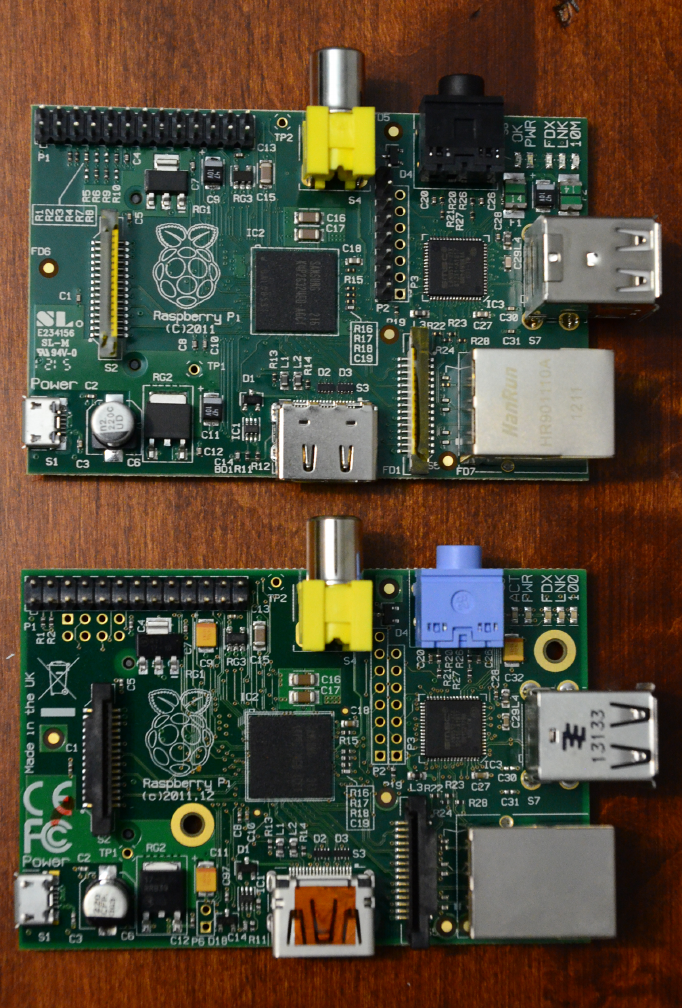
Figure P-1.
For visual comparison, the two Model B boards: revision 1 (top) and revision 2 (bottom)
xv
PREFACE

Changes made for rev 2 include:
• 2 2.5 mm nonplated mounting holes added
•LED labeling: D9 (yellow) corrects 10 label to 100, and D5 (green) says ACT for
“Activity” instead of OK.
• Reset circuit added (see Hack #17 for how to use it)
•USB fuses removed (this helps with USB hubs that backfeed power, as long it’s
no more than 2.5A under fault conditions)
• GPIO pin changes:
—CAM_GPIO: GPIO27 now GPIO21 routed to S5 pin 11 (S5 is the camera inter-
face)
—GPIO_GEN2: GPIO21 now GPIO27 routed to P1 pin 13 (P1 is the main, long strip
of GPIO pins)
— Additional GPIO added on P5 (see Figure P-2), which maps as follows:
— P1 - 5V0
— P2 - 3.3V
— P3 - GPIO28
— P4 - GPIO29
— P5 - GPIO30
— P6 - GPIO31
— P7 - GND
— P8 - GND
•Primary and secondary I2C channels switched (see Table P-2)
Figure P-2.
P5 pin order (Note that “P5” label is on bottom of the board)
xvi PREFACE

Table P-2. I2C channels in Rev 1 and Rev 2
REV 1 REV 2
SCL0 (GPIO 1) routed to P1 pin 5 routed to S5 pin 13
SDA0 (GPIO 0) routed to P1 pin 3 routed to S5 pin 14
SCL1 (GPIO 3) routed to S5 pin 13 routed to P1 pin 5
This information is applicable for most of the hacks in the book. But, of course, just
because they were tested (and possibly designed for) the Model B, it doesn’t mean
that the hacks won’t work with a different model or revision (unless otherwise speci-
fied). Feel free to use what you have, but know you might need to refer to additional
information online about older boards.
Conventions Used in This Book
The following typographical conventions are used in this book:
Italic
Indicates new terms, URLs, and email addresses.
Constant width
Used for program listings, as well as within paragraphs to refer to program ele-
ments such as variable or function names, databases, data types, environment
variables, statements, filenames, file extensions, and keywords.
Constant width bold
Shows commands or other text that should be typed literally by the user.
Constant width italic
Shows text that should be replaced with user-supplied values or by values deter-
mined by context.
This element signifies a tip, suggestion, warning, caution or general note.
Using Code Examples
All code listings are also available at the book’s GitHub repository.
This book is here to help you get your job done. In general, if example code is offered
with this book, you may use it in your programs and documentation. You do not need
to contact us for permission unless you’re reproducing a significant portion of the
code. For example, writing a program that uses several chunks of code from this book
xvii
PREFACE

does not require permission. Selling or distributing a CD-ROM of examples from
O’Reilly books does require permission. Answering a question by citing this book and
quoting example code does not require permission. Incorporating a significant
amount of example code from this book into your product’s documentation does re-
quire permission.
We appreciate, but do not require, attribution. An attribution usually includes the title,
author, publisher, and ISBN. For example: For example: "Raspberry Pi Hacks by Ruth
Suehle and Tom Callaway (O’Reilly). Copyright 2014 Ruth Suehle and Tom Callaway,
978-1-449-36234-8.”
If you feel your use of code examples falls outside fair use or the permission given
above, feel free to contact us at permissions@oreilly.com.
Safari® Books Online
Safari Books Online is an on-demand digital library that delivers
expert content in both book and video form from the world’s lead-
ing authors in technology and business.
Technology professionals, software developers, web designers, and business and cre-
ative professionals use Safari Books Online as their primary resource for research,
problem solving, learning, and certification training.
Safari Books Online offers a range of product mixes and pricing programs for organi-
zations, government agencies, and individuals. Subscribers have access to thousands
of books, training videos, and prepublication manuscripts in one fully searchable da-
tabase from publishers like O’Reilly Media, Prentice Hall Professional, Addison-Wesley
Professional, Microsoft Press, Sams, Que, Peachpit Press, Focal Press, Cisco Press,
John Wiley & Sons, Syngress, Morgan Kaufmann, IBM Redbooks, Packt, Adobe Press,
FT Press, Apress, Manning, New Riders, McGraw-Hill, Jones & Bartlett, Course Tech-
nology, and dozens more. For more information about Safari Books Online, please visit
us online.
xviii PREFACE

How to Contact Us
Please address comments and questions concerning this book to the publisher:
O’Reilly Media, Inc.
1005 Gravenstein Highway North
Sebastopol, CA 95472
800-998-9938 (in the United States or Canada)
707-829-0515 (international or local)
707-829-0104 (fax)
We have a web page for this book, where we list errata, examples, and any additional
information. You can access this page at http://oreil.ly/Raspberry-Pi-Hacks.
To comment or ask technical questions about this book, send email to bookques
tions@oreilly.com.
For more information about our books, courses, conferences, and news, see our web-
site at http://www.oreilly.com.
Find us on Facebook: http://facebook.com/oreilly
Follow us on Twitter: http://twitter.com/oreillymedia
Watch us on YouTube: http://www.youtube.com/oreillymedia
Acknowledgments
Ruth and Tom would like to thank the following people for their inspiration, ideas, help,
and support:
•Le Dernier Bar Avant Le Fin Du Monde, which we affectionately refer to as “the
greatest bar in the world,” where this book’s initial hack list was born with the help
of Josh Boyer, Dennis Gilmore, a few pitchers of French beer, and a Pan Galactic
Gargle Blaster
•Every Fedora contributor, as one of the four foundations is friends and so many
of you friends have helped us along the way
•Rodney Radford, both contributor and new friend, for tirelessly answering what
he no doubt thought were absurd questions, driving many miles to tinker in per-
son, and for trying to help moderately dangerous X-Men costume ideas come
true without harm to the wearer or to the book’s deadline
Ruth thanks Scott, for being the kind of husband who understands when she runs off
to places with nicknames like “the greatest bar in the world” and events like Maker
Faire while he stays home with two awesome kids, who, while awesome, neither serve
xix
PREFACE

Pan Galactic Gargle Blasters nor build massive fire-based art installations (yet). Those
awesome kids are the ones this is really for—the next generation of hackers and mak-
ers—so even greater thanks to Hannah, who QAed the XBMC instructions in this book
(proving they’re easy enough for a seven-year-old) and Ian, who can always say he
learned to spell his first word during the writing of this book: a 12-character login
password.
Tom would like to thank his wife Pam for putting up with him. He was writing this book
in the midst of traveling the world, presenting at conferences, having a second child,
and moving across the United States. He’d also like to dedicate his parts of this book
to his sons, Jimmy (3) and Danny (0.5), who will hopefully read this book one day and
think, “Dad, this stuff is so old, it doesn’t even respond to my brain WiFi signals.”
Contributors
Emmanuel Ackerman is a retired computer programmer who now spends his time
doing Sufi meditation and exercises, making pottery, and doing volunteer work for
Powering Potential and related groups. Ackerman contributed Hack #63.
David Bordonada works for Libelium, which runs Cooking Hacks, a site full of both
tutorials and parts for your Raspberry Pi and other hardware projects. Bordonada
contributed Hack #58.
Simon Cox is professor of computational methods and head of the Computational
Engineering Design Research Group (CED) Group within the Faculty of Engineering
and the Environment (FEE) at the University of Southampton. He is also the associate
dean for enterprise in engineering and the environment. Cox contributed Hack #65.
Lori Easterly is currently an information security engineer with a background in Linux
and systems administration, currently residing in central Florida. Among numerous
hacky interests, she is a shortwave and radio-listening enthusiast with a passion for
technology, tinkering, and discovery. Easterly contributed Hack #43.
Oliver Mattos is a search engine mechanic at Google by day and a Pi hacker by night
who loves to make anything do something it wasn’t made for. Mattos contributed Hack
#49 with Oskar Weigl.
Joe Ottinger is a principal engineer on the Open Source and Standards team at Red
Hat. Ottinger contributed Hack #64.
Rodney Radford is an embedded software developer and collector of hobbies, bounc-
ing between hardware tinkering, nearspace telemetry, high altitude rocketry, geo-
caching, SCUBA diving, woodworking, time travel, and robotics as time (and time
travel) permits. Radford contributed Hack #44 and Hack #45.
xx PREFACE

Jared Smith is an open source enthusiast. He enjoys programming, systems admin-
istration, documentation, VoIP, and teaching others how to use open source software.
Smith contributed Hack #32.
Wouter van Wijk (www.woutervanwijk.nl) is the creator of Pi MusicBox. He combines
being a journalist for the second biggest newspaper in the Netherlands with being a
techie who is fascinated by the interaction of people and computers. He enjoys de-
signing user interfaces and experimenting, and likes to make computers and services
easier to use. van Wijk contributed Hack #48.
Oskar Weigl is a master’s student at Imperial College and ARM engineer whose
greatest passions are playing with hardware and software (and building robots)—a
true forward- and reverse-engineer. Weigl contributed Hack #49 with Oliver Mattos.
xxi
PREFACE

1
Configuration Hacks
They say the beginning is usually a good place to start anything, but this is a Hacks
book. You’re likely to skip around to things with interesting titles, or perhaps the one
that starts in Old English because you were flipping through the pages and it looked
like the book had some terrible printing errors.
That said, there are some things that it’s nice to keep in the back of your head before
you start building things, and the Raspberry Pi has a few unexpected quirks that it’s
good to be aware of. If you’re entirely new to Linux, electronics hacking, or both, it’s a
good idea to give this chapter a read-through before proceeding with any of the other
hacks. You just might learn something that will save your Pi (and the $35 of having to
replace it).
HACK 01 Choose and Format the Right SD Card
The Raspberry Pi does not have any built-in flash storage; it needs an SD
card to do anything. Picking the right one might seem simple, but we’re
here to help you make the right choice.
Your SD card choice is an important one. After all, when it comes to the Raspberry Pi,
it’s the equivalent of choosing a hard drive. Being able to change the entire system
quickly by inserting a new SD card is also one of the Pi’s most interesting strengths,
especially when it comes to education. A few factors should weigh into your card se-
lection, though, and even if you think you’ve chosen well, you might still need to trou-
bleshoot minor problems.
SD cards are sold with a class number (e.g., 4, 6, 10), in which a higher class number
equates to a faster card. Most high-quality, Class-4-or-greater SDHC cards (i.e., a
recognized name brand) should work for most purposes. Vendors that sell cards with
a Linux distribution meant for the Raspberry Pi largely use SanDisk or Kingston brand
SDHC Class 4 cards. You can find a thorough list of known, tested cards (as well as
cards that don’t work) at http://elinux.org/RPi_VerifiedPeripherals. That said, a faster
card can as much as double your transfer rate (in terms of MB/sec), so if speed is
critical to your use, you should go with a higher class card.
1

Class 10 Too Classy?
The early Raspberry Pi firmware and bootloader didn’t like Class 10 SD cards. This
problem is supposed to have been fixed, but you’ll still see people occasionally
running into problems with Class 10 cards, so just be aware that it’s a potential
issue. If you have your heart set on a Class 10 card and the first one doesn’t work,
try a different brand. In addition, overclocking has been found to cause errors with
Class 6 and Class 10 SD cards, regardless of size or brand, and the errors might
not appear for a few days or weeks. Keep this in mind if you plan to overclock your
Pi.
If decision making isn’t your strong suit, you can also keep multiple cards around, each
with a different purpose, for a single Raspberry Pi. If you’d like easy peace of mind,
several vendors sell SD cards preloaded with Linux distributions for the Raspberry Pi,
including a card containing NOOBS (New Out-Of-Box Software), which has several
distro options on it. RS Components and element14 offer a card preloaded with
NOOBS as an add-on when you purchase a Raspberry Pi.
NOOBS
NOOBS was designed to make setting up a Raspberry Pi super easy. It supports
multiple OS installations and re-installations, as well as config file editing and web
browsing (to research answers to boot problems) in a pre-boot environment. After
all, this thing was designed for education, and you’re not going to learn much if you
can’t even get started. It fits on a 4 GB card and gives you multiple choices about
which distro you’d like to set up. After you’ve chosen, you can always return to the
menu and make a different selection by holding down Shift during boot, either to
try something new or to get a mulligan on a corrupted card. If you don’t buy it on
a preloaded card, you can download it from http://www.raspberrypi.org/down
loads.
If you used one of the SD cards that’s known to work and you’re still having problems,
you should check a few other things. Be sure that you’ve updated the firmware on the
Pi (see Hack #04). If it was not a new SD card, be sure you fully formatted it first, and
make sure you do so for the whole card and not just a partition.
First, find the card’s device name:
$ su -c 'fdisk -ls'
or:
$ df -h
2RASPBERRY PI HACKS

You’re looking for something like /dev/sdd or /dev/mmcblk0 with the size of your SD
card. To format, run the mkdosfs command, replacing /dev/mmcblk0 with the location
of your card:
$ mkdosfs -I -F32 /dev/mmcblk0
This will make a single FAT formatted partition on the SD card. To be honest, it really
doesn’t matter very much how you format or partition the SD card in most cases,
because when installing any of the system images for Raspberry Pi OS distributions
that include partitions (such as Pidora or Raspbian), the partition table on the SD card
will be completely overwritten by the installed OS image. The exception to that is
NOOBS. By partitioning the disk with a single FAT partition, it is possible to install
NOOBS to the SD card by simply copying the NOOBS files directly onto the SD card.
If you find that you have, say, an 8 GB card, and your computer thinks it’s only 2 GB,
you need to “grow” it to match. Or you might have found that your card’s device name
ends in p1 (followed by p2 and so forth):
/dev/mmcblk0p2 1.6G 1.5G 54M 97% /run/media/wwatson/rootfs
/dev/mmcblk0p1 50M 18M 33M 35% /run/media/wwatson/boot
This means your card is partitioned, and you should get down to one partition before
formatting. Adjusting partitions and their sizes is most easily accomplished with a GUI
tool called Gparted, a visual version of the command-line parted.
HACK 02 Mount the SD Card
While you can certainly access the files on the Raspberry Pi directly from
within a running instance, mounting the SD card on a separate computer
with an SD card reader makes many tasks (such as adding or editing
files) easier.
The Raspberry Pi is a standalone Linux computer, but it really helps to have another
computer on hand. In some cases, it might even be necessary. Fortunately, many
computers now come with SD card readers built in, and if yours didn’t, they’re inex-
pensive and easy to come by. So, even if you buy your SD cards preloaded, you should
probably still have an SD card reader and a second computer for interacting with your
Raspberry Pi build.
Most Linux distributions for the Raspberry Pi create at least two partitions on the SD
card. The first partition is always /boot, because the Raspberry Pi GPU reads its firm-
ware from the beginning of the SD card. The second partition is usually / (also known
as the root partition).
3
CHAPTER 1: CONFIGURATION HACKS

Pidora labels the partitions on the SD card boot and root, but Raspbian does not
use disk labels, so it is especially important to note the device names for that dis-
tribution.
Modern Linux distributions (on your separate computer), such as Fedora or Ubuntu,
will auto-mount the partitions on the SD card when it is inserted and provide some
sort of notification of this event. However, if you’re not sure, running the mount com-
mand should list all mounted partitions on the system. You are looking for something
like /dev/mmcblk0p1, which means the first partition (p1) on the MMC block (mmcblk)
device:
[spot@wolverine ~]$ mount
proc on /proc type proc (rw,nosuid,nodev,noexec,relatime)
sysfs on /sys type sysfs (rw,nosuid,nodev,noexec,relatime)
...
/dev/sda3 on / type ext4 (rw,relatime,data=ordered)
/dev/sda1 on /boot type ext4 (rw,relatime,data=ordered)
/dev/mmcblk0p1 on /run/media/spot/boot type vfat (rw,nosuid,nodev,rela
time,uid=1000,gid=1000,fmask=0022,dmask=0077,codepage=437,iocharset=as
cii,shortname=mixed,showexec,utf8,flush,errors=remount-ro,uhelper=udisks2)
/dev/mmcblk0p2 on /run/media/spot/rootfs type ext4 (rw,nosuid,nodev,rela
time,data=ordered,uhelper=udisks2)
The last two lines in the output identify the MMC block device partitions mounted
in /run/media/spot/boot and /run/media/spot/rootfs, respectively.
Linux uses the term MMC to describe the driver for both MultiMediaCard and Se-
cure Digital (SD) formats.
If your SD card is not mounted automatically, make sure it’s inserted and look at the
output from the dmesg command. You do not need to pass any options to dmesg (al-
though piping it through less is always a good idea). When you run it, it will print out
quite a bit of stuff, but the output is in order from the last time you have booted your
Linux system.
You’ll want to look at the end of the output. Specifically, you look toward the end of
the output to figure out the name of the MMC block device. Figure 1-1 shows an ex-
ample of the sort of messages you are looking for.
4RASPBERRY PI HACKS
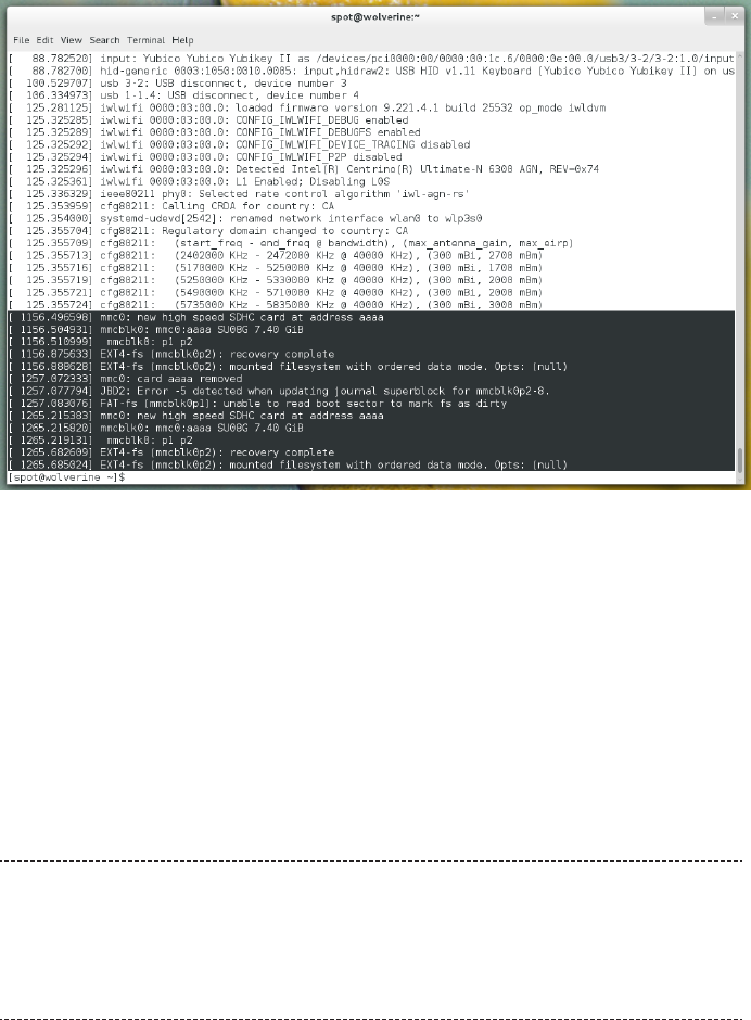
Figure 1-1.
Output from dmesg on Fedora 19, with the MMC block device messages highlighted
In Figure 1-1, the MMC block device name is mmcblk0, and it has two partitions, p0 and
p1. This gives you enough information to determine the Linux device names for these
partitions: /dev/mmcblk0p0 and /dev/mmcblk0p1. You can confirm these are the correct
device names by running:
brw-rw---- 1 root disk 179, 1 Aug 20 20:42 /dev/mmcblk0p1
brw-rw---- 1 root disk 179, 2 Aug 20 20:42 /dev/mmcblk0p2
If they exist, they’re probably the ones you want (unless you have multiple SD cards
inserted into your system somehow).
SD card readers connected via SPI interfaces are generally designated /dev/
mmc*, but SD card readers connected via USB are designated /dev/sd* (and some
laptops’ internal SD card readers are connected via USB). Be careful when ac-
cessing a /dev/sd* device, as it’s then much easier to accidentally specify a hard
disk drive instead.
Once you’ve identified the Linux device names for the MMC block device partitions
on your system, you should be able to manually mount them by creating two mount
point directories (as root):
5
CHAPTER 1: CONFIGURATION HACKS
$ su -c 'mkdir /mnt/raspi-boot'
$ su -c 'mkdir /mnt/raspi-root'
These directories will serve as anchors for mounting the partitions from the MMC
block device.
Then, use the mount command to mount the boot and root partitions:
$ su -c 'mount /dev/mmcblk0p1 /mnt/raspi-boot'
$ su -c 'mount /dev/mmcblk0p2 /mnt/raspi-root'
If these mount commands return without errors, it means they have mounted suc-
cessfully. You can confirm they have mounted by running mount again and piping the
output through a grep for the MMC block device name (mmcblk0):
$ mount | grep mmcblk0
/dev/mmcblk0p1 on /mnt/raspi-boot type vfat (rw,rela
time,fmask=0022,dmask=0022,codepage=437,iocharset=ascii,shortname=mixed,er
rors=remount-ro)
/dev/mmcblk0p2 on /mnt/raspi-root type ext4 (rw,relatime,data=ordered)
You should also now be able to see files in the /mnt/raspi-boot and /mnt/raspi-root
directories.
It is also possible to mount the /boot partition inside the mounted / partition, but we
recommend keeping them separate. That way, if you forget to mount the boot parti-
tion, it is more obvious, and you avoid the problem of accidentally copying files into
the /boot directory on the root partition. Remember, Linux mounts the boot partition
on top of that /boot directory, and any files that get copied into that directory when
the boot partition is not mounted are not visible!
Mounting the SD card is especially useful to make quick changes to the config.txt
file that lives in the Raspberry Pi Linux /boot partition. If you need to change the ouput
display settings for a new monitor (or an old HDMI TV with less than amusing quirks),
it’s a lot easier to do it from a mounted SD card than from a headless Raspberry Pi.
Just make sure the boot partition is mounted, and then change into that directory
(/mnt/raspi-boot) and directly edit config.txt (as root). Save your changes, and then
run sync to make sure the buffers get written back to the SD card.
When that finishes, change out of the directory (if you do not, Linux will not let you
cleanly unmount the partition) and unmount both of the partitions (as root) with the
umount command:
$ cd /mnt/raspi-boot/
$ su -c 'vi config.txt'
$ sync;sync;sync;
$ cd /mnt
6RASPBERRY PI HACKS
$ su -c 'umount /mnt/raspi-boot'
$ su -c 'umount /mnt/raspi-root'
If the umount commands both return without any errors, it is now safe to remove your
SD card. Just put it back in your Raspberry Pi, power it on, and hope for the best.
HACK 03 Decode the LEDs
Each Raspberry Pi has a set of LEDs in one corner that give you clues
about what’s happening (or not happening!) with the device. The Model
A had only two lights, but the Model B offers a lot more insight and val-
uable troubleshooting information.
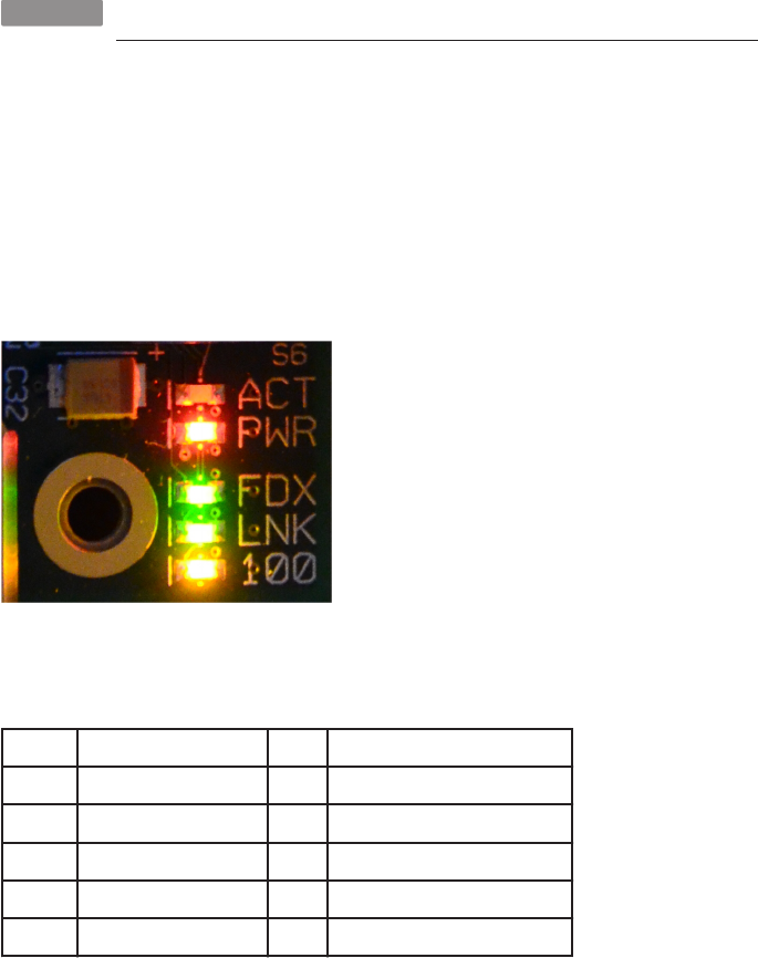
The Raspberry Pi Model B has five status LEDs (shown in Figure 1-2 and described in
Table 1-1) that will help you troubleshoot problems when it won’t boot or other prob-
lems arise. Since the Pi has no BIOS, the screen won’t show you anything at all until
the Pi successfully boots. That’s where these little lights come in handy.
Figure 1-2.
Model B LEDs
Table 1-1. Status LEDs on the Raspberry Pi Model B
NUMBER LABEL COLOR FUNCTION
D5 OK (Rev 1.0) ACT (Rev 2.0) Green SD card access, connected to GPIO 16
D6 PWR Red 3.3 V Power, connected to 3.3 V
D7 FDX Green Full Duplex LAN
D8 LNK Green Link/Activity LAN
D9 10M (Rev 1.0) 100 (Rev 2.0) Yellow 10/100Mbit LAN
The first two lights (D5 and D6) are the most important pair when you want to make
sure that your problem isn’t as simple as “it’s not plugged in.” Table 1-2 describes the
most common indicators you’ll see on these lights.
7
CHAPTER 1: CONFIGURATION HACKS

Table 1-2. Common LED Error Codes
LIGHT INDICATION MOST LIKELY PROBLEM
Red PWR light off No power
Red PWR light on, green OK light off The Pi can’t read the image on the card. The voltage is below 5V.
Green OK light blinks 3 times* start.elf was not found
Green OK light blinks 4 times* start.elf did not launch
Green OK light blinks 7 times* kernel.img was not found
Note that the flash patterns identified with an asterisk in Table 1-2 are accurate for
the firmware available since October 20, 2012. Earlier firmware used different pat-
terns, and later firmware may change these indicators as well.
The two files it’s looking for, start.elf and kernel.img, absolutely must be on the boot
partition. The first, start.elf, is the GPU binary firmware image, and kernel.img, as
its name implies, is the Linux kernel. If the red PWR light is on, you know have power;
then it’s up to the green light to tell you what’s gone wrong.
If the green light doesn’t flash at all, the first thing you shuld do is check your SD card
in another computer. Make sure that the image is written correctly. If all of the file-
names look like somebody leaned on the keyboard, it did not write correctly! Format
it and start again. If it does look OK, plug in nothing but the power and the SD card,
then each of your other peripherals one at a time to see which is causing the problem.
If the green light does blink, refer to Table 1-2 for information about what has gone
wrong. Note that once start.elf has loaded, you’ll see “the rainbow” (four large
squares of color bleeding together). It should quickly go away as your Linux distro
continues to boot, but if it doesn’t, your problem is in the kernel.img file.
Blink Your IP Address Through the LEDs
Pidora offers some features specifically for running in headless mode, including
the use of the LEDs to communicate your IP address. See Hack #11 to learn how.
HACK 04 Update the Firmware
The firmware your Raspberry Pi requires comes with any Linux distribu-
tion you choose, but it’s frequently updated upstream, and your project
might benefit from (or require) a more recent version.
8RASPBERRY PI HACKS

The Raspberry Pi is a little different from your laptop, and even different from a lot of
traditional embedded computers. The heart of the Raspberry Pi is the Broadcom
BCM2835 system-on-chip, which is the CPU, GPU, and memory all combined in a
single component. This detail is important, because the Raspberry Pi actually boots
from the BCM2835 GPU. When you provide power to the Raspberry Pi, the CPU in the
BCM2835 system-on-chip is actually disabled!
The Raspberry Pi boots like this:
1. First-stage bootloader: A bootloader programmed into the BCM2835 system-
on-chip hardware mounts the FAT32 boot partition from the Linux distribution on
the SD card. Note that this first-stage bootloader is programmed at manufacture
time and is not modifiable or replaceable. A small, dedicated RISC core on the
Raspberry Pi GPU starts this process.
2. Second-stage bootloader: Read off the boot partition on the SD card, this firm-
ware (bootcode.bin) accesses the additional GPU firmware files, programs those
firmware files into the Raspberry Pi GPU, and then starts it.
3. GPU firmware: This firmware (start.elf) allows the GPU to enable the CPU. An
additional file, fixup.dat, configures the SDRAM partition between the GPU and
the CPU. At this point, the CPU is released, and execution is transferred to it from
the GPU.
4. User code: The CPU boots any supported binary, but the Linux kernel is the de-
fault. It assumes the filename is kernel.img, but you can be override the default
in config.txt.
Versions of the Raspberry Pi firmware prior to October 19, 2012 contained an ad-
ditional third-stage bootloader (loader.bin), but this is no longer required or used.
Previous builds also had different versions of the GPU firmware that had to be
swapped in and out to enable different memory splits between the ARM CPU and
GPU, but this is now configured in config.txt.
Because of how the Raspberry Pi boots, you must use an SD card to boot the Rasp-
berry Pi; you cannot boot it from any other device (such as network or USB storage)
alone. But this is a good thing. It prevents you from rendering the device unusable,
because you cannot override the first-stage bootloader. If you end up with damaged,
broken, or incomplete firmware, you can simply start over with a clean SD card.
The Raspberry Pi Foundation provides the firmware files that the GPU loads, which
then enable the Raspberry Pi to boot a specially formatted Linux kernel image. All the
Linux distribution images intended for use on the Raspberry Pi come with a copy of
this firmware, but it is constantly updated upstream. To enable new functionality (or
9
CHAPTER 1: CONFIGURATION HACKS
boot newer Linux kernels), you will want to make sure you are running the latest revi-
sion of the firmware.
The upstream home for the Raspberry Pi firmware is https://github.com/raspberrypi/
firmware/. There is currently no source code available for these firmware files, so this
repository contains only binary versions. Because the Raspberry Pi is so slow (espe-
cially for Git operations), we strongly recommend that you check out these files to
your x86 laptop.
First, you need to make sure you have a Git client installed by running the following
command on Fedora:
$ yum install git
or this command on Debian/Ubuntu:
$ apt-get install git-core
Next, create a working directory for Raspberry Pi related files, such as ~/raspi:
$ mkdir ~/raspi
Go into the raspi directory:
$ cd ~/raspi
Use Git to get a local copy of the firmware files:
$ git clone https://github.com/raspberrypi/firmware.git
This will create a checkout in a new directory, named firmware. By default, this checks
out the master branch, which at the time of this writing was synced up to the version
of the firmware currently used by the Raspbian Linux kernel (3.2). If you are using a
3.2 kernel, this is the firmware you want to use. Another branch (named next) enables
the updated drivers in the 3.6 Linux kernel. If you want to use this branch, change into
the firmware directory and enter:
$ git checkout next
To switch back to the master branch, enter:
$ git checkout master
If you want to update your firmware again later, you don’t need to check out this tree
again. Simply go to the top-level checkout directory (~/raspi/firmware) and enter:
$ git pull
Remember, this will pull changes for the current branch only. If you want to pull
changes for the other branch, you will need to switch to the other branch with the Git
checkout command and run git pull there as well.
10 RASPBERRY PI HACKS

Now that you have checked out the repository and chosen your branch, your next step
is to copy the boot firmware onto the SD card that has the Raspberry Pi Linux distri-
bution image. To do this, you’ll need to make sure the partitions on that SD card are
properly mounted (covered in detail in Hack #02).
From here on, we will assume that the boot partition from your SD card with the Rasp-
berry Pi Linux distribution image is mounted at /mnt/raspbi-boot. Current versions of
Fedora (including Pidora) will automount it to /run/media/$USERNAME/boot, where
$USERNAME is your username, so if you have it mounted somewhere else, substitute that
mount point in the next set of instructions.
To update the firmware on the boot partition, all you need to do is copy the right files
from the firmware/boot directory into the mounted boot partition (as root).
You probably do not want to copy all of the files from this directory.
You’re looking for these critical firmware files in the firmware/boot directory:
•bootcode.bin
•fixup.dat
•start.elf
We strongly recommend that you back up the existing (and presumably) working
copies of these files at this point. You can accomplish this by renaming these files (as
root) in the mounted boot partition first:
$ su -c 'mv /mnt/raspi-boot/bootcode.bin /mnt/raspi-boot/bootcode.bin.back
up'
$ su -c 'mv /mnt/raspi-boot/fixup.dat /mnt/raspi-boot/fixup.dat.backup'
$ su -c 'mv /mnt/raspi-boot/start.elf /mnt/raspi-boot/start.elf.backup'
Copy each of these firmware files (as root) into the mounted boot partition:
$ cd ~/raspi/firmware/boot/
$ su -c 'cp -a bootcode.bin fixup.dat start.elf /mnt/raspi-boot/'
su versus sudo
The command example used here for copying firmware files (along with
most other command examples in this book) use su. The su command will
prompt you for the root password of your Linux laptop. If you have config-
ured sudo for use on your Linux laptop, you can replace the su -c command
with sudo and the command to copy the firmware files (as root) will look like
this instead:
11
CHAPTER 1: CONFIGURATION HACKS

$ sudo cp -a bootcode.bin fixup.dat start.elf /mnt/raspi-boot/
Whichever method you prefer is fine, as they are both valid methods for
Linux operations as the root user. We use the su -c syntax in most examples
throughout the book for all root operations because it will work in all cases,
whereas sudo works only if it is configured for your user on that Linux dis-
tribution. If you an encounter instructions prefaced with sudo, know that su
is an option when you don’t have sudo configured.
When the new Raspberry Pi firmware finishes copying onto the boot partition, run the
sync command to ensure the data has all arrived onto the SD card:
$ sync
Then it should be safe to unmount the SD card partition(s) and eject the SD card. You
can unmount these partitions from the GUI interface of your Linux laptop, or you can
manually unmount them from the terminal by changing into a directory that is not in
either of the mounted partitions and then enter:
$ cd ~
$ su -c 'umount /mnt/raspi-boot'
$ su -c 'umount /mnt/raspi-root'
At this point, the SD card will contain the new firmware. You’ll know that the update
worked if the Raspberry Pi still boots into the Linux image, but at a minimum, the
firmware will draw a multicolored “rainbow” box (see “Somewhere Over the Rain-
bow...” sidebar) to the configured output device (usually an HDMI connected one) as
its first step in the boot process (unless you have explicitly disabled this behavior in
config.txt). If that occurs, the firmware is properly installed onto the SD card.
Somewhere Over the Rainbow…
Hopefully, if everything goes well with your Raspberry Pi, you’ll never have
to see the “rainbow” screen (shown in Figure 1-3) for more than a fraction
of a second when it boots up. The screen is generated by the Raspberry Pi
firmware as it initializes the GPU component of the BCM2835 system-on-
chip.
To test that the output works successfully, the GPU draws four pixels on the
screen and then scales those pixels to be very large, resulting in the multi-
color screen. If your Raspberry Pi ever refuses to go over the rainbow and
into a proper Linux boot, it means that the configured Linux kernel image
(default: kernel.img) was not able to boot.
12 RASPBERRY PI HACKS

Figure 1-3.
The “rainbow” screen (uploaded to http://elinux.org/File:Debug-screen.jpg by user Popcorn-
mix and shared under the terms of the Creative Commons Attribution-ShareAlike 3.0 Unpor-
ted License)
Some optional versions exist for some of the Raspberry Pi firmware files. It is possible
to configure the Raspberry Pi to dedicate the minimum amount of memory to the GPU
(16 MB). When this is done, the Raspberry Pi Second Stage Bootloader looks for
start_cd.elf and fixup_cd.dat instead of start.elf and fixup.dat. Hack #24 provides
a longer discussion on GPU/CPU memory splitting.
HACK 05 Monitor the Raspberry Pi Hardware
Worried that your Pi is throwing wild parties while you’re out of the house?
Here’s how to point a webcam at it and stream the video to the Internet.
Just kidding! These tools can monitor the physical state of your tiny
hardware.
A “normal” Linux computer would likely include onboard health monitoring sensors.
Quite a few monitoring chips and components are used in various systems, but on the
Raspberry Pi, all of that hardware is entirely hidden inside the Broadcom system-on-
chip, so you can’t access it with those usual methods.
To reach those components to monitor your Pi’s health, you need to use the vcgencmd
utility. It should be preinstalled with any of the general-purpose Raspberry Pi Linux
distributions available, but if it’s not, you can get a copy from the firmware tree at
https://github.com/raspberrypi. If your distribution is compiled for ARM hardware
floating point, look in the hardfp/ subdirectory; otherwise, look in the opt/ subdirec-
tory.
Checking for Hard Float
At the time of this writing, most Linux distributions (including Pidora, Rasp-
bian, Occidentalis, OpenELEC, and RaspBMC) are built for the ARMv6 hard-
float architecture, because that gives the best possible performance on the
Raspberry Pi. However, some older releases of these targets (and other OS
platforms) were built with optimization for ARMv6 soft-float. These two op-
13
CHAPTER 1: CONFIGURATION HACKS

timization levels are not compatible with each other. On Linux, there is a
good way to check for support for ARMv6 hard-float, using the readelf
command:
$ readelf -a /usr/lib/libc.so.6 | grep FP
You can run this command directly on the Raspberry Pi Linux distribution
(you might need to install the elfutils package first), or you can copy a
binary or library from within the Raspberry Pi Linux distribution and onto
another system with readelf handy.
If the binary has support for ARMv6 hard-float optimization, you will get
output that looks like this:
Tag_FP_arch: VFPv2
Tag_ABI_FP_rounding: Needed
Tag_ABI_FP_denormal: Needed
Tag_ABI_FP_exceptions: Needed
Tag_ABI_FP_number_model: IEEE 754
Tag_ABI_HardFP_use: SP and DP
Tag_ABI_VFP_args: VFP registers
The important line is the last one, Tag_ABI_VFP_args: VFP registers. It will
show up only if the binary being checked is built with ARMv6 hard-float
optimization.
Once you’ve installed it (if necessary), look at the options that vcgencmd offers:
$ vcgencmd commands
This will output a list of all the commands that you can pass to the vcgencmd tool:
commands="vcos, ap_output_control, ap_output_post_processing,
vchi_test_init, vchi_test_exit, pm_set_policy, pm_get_status,
pm_show_stats, pm_start_logging, pm_stop_logging, version, commands,
set_vll_dir, led_control, set_backlight, set_logging, get_lcd_info,
set_bus_arbiter_mode, cache_flush, otp_dump, codec_enabled, get_camera,
get_mem, measure_clock, measure_volts, measure_temp, get_config,
hdmi_ntsc_freqs, hdmi_status_show, render_bar, disk_notify, inuse_notify,
sus_suspend, sus_status, sus_is_enabled, sus_stop_test_thread, egl_plat
form_switch, mem_validate, mem_oom, mem_reloc_stats, file, vctest_memmap,
vctest_start, vctest_stop, vctest_set, vctest_get"
Unfortunately, it doesn’t actually tell you anything about those commands or what
they do. Some of them seem obvious, but then when you run them, they return things
like this:
error=2 error_msg="Invalid arguments"
14 RASPBERRY PI HACKS

The tool is poorly documented, but the Raspberry Pi community has come together
and figured some of them out.
Measure Component Voltage
The vcgencmd measure_volts command shows the voltage for some of the key Rasp-
berry Pi components, specifically:
core
The GPU processor core
sdram_c
The SDRAM controller
sdram_i
The SDRAM input/output (I/O)
sdram_p
The SDRAM physical memory
Each of these components can be passed as an option to the vcgencmd meas
ure_volts command (if you don’t specify one, it will return the value for core).
You might be wondering why you’d care about measuring these voltages, and in most
cases, you probably don’t. They’ll sit happily as shown in Table 1-3.
Table 1-3. Components voltage
COMPONENT VOLTAGE
core 1.20
sdram_c 1.20
sdram_i 1.20
sdram_p 1.23
The only time you might care about the component voltages is if you decide you want
to overclock your Raspberry Pi. All of these voltages are configurable (as covered in
detail in Hack #06).
You might expect this command to return the system board voltage (which varies
between 4.75V and 5.25V under normal conditions), but it doesn’t. See Hack #09 for
how to do that manually.
15
CHAPTER 1: CONFIGURATION HACKS

Measure Temperature
The vcgencmd measure_temp command reports the core temperature of the BCM2835
system-on-chip on your Raspberry Pi (in Celsius):
temp=44.4'C
Alternatively, you can get the same temperature reading by reading this value directly
from /sys/class/thermal/thermal_zone0/temp:
$ cat /sys/class/thermal/thermal_zone0/temp
44388
Fun with Math and Science
To convert that value to the Celsius temperature, simply divide it by 1,000.
To get Fahrenheit, multiply the Celsius temperature by 1.8 and add 32. To
get Kelvin, add 273.15 to the Celsius temperature. Is it getting hot in here,
or is it just us?
From the perspective of monitoring the Raspberry Pi hardware, this reading is prob-
ably sufficient. Since there is really no separation of the CPU/GPU (at least not from
a physical or heating perspective), this gives you an idea of how hot the board is run-
ning. That said, if you want a more detailed (or just an additional) temperature reading,
you can wire in an additional temperature sensor, as described in Hack #37.
Monitor Memory Split
Whether hardcoded or dynamically allocated, the vcgencmd get_mem command returns
the value for either the ARM CPU or the video GPU.
To see the amount of memory currently split off for the ARM CPU, run:
$ su -c 'vcgencmd get_mem arm'
arm=448M
To see the amount of memory currently split to the video GPU, run:
$ su -c 'vcgencmd get_mem gpu'
gpu=64M
Check Custom Configuration Overrides
Have you forgotten what configuration changes you have made to your Raspberry Pi?
Specifically, the ones that change settings in the firmware? While you could look
in /boot/config.txt, the vcgencmd get_config command is here to help you.
16 RASPBERRY PI HACKS

To see all configurations with a number (integer) datatype, run:
$ su -c 'vcgencmd get_config int'
arm_freq=900
To see all configurations with a text (string) datatype, run:
$ su -c 'vcgencmd get_config str'
There are very, very few configuration options that store string values instead of
integers. Don’t be too surprised if the vcgencmd get_config str command doesn’t
return anything.
If you just want to check the value of a specific configuration, pass that config name
instead:
$ su -c 'vcgencmd get_config arm_freq'
arm_freq=900
The vcgencmd utility is not the most user-friendly tool, but it does have a deep con-
nection into the inner workings of the Raspberry Pi. Since this tool is open source (and
the source code is available in the aforementioned Raspberry Pi GitHub firmware
checkout), if you want to go very deep into the inner workings of the Raspberry Pi
hardware, looking at the vcgencmd source code is a good jumping-off point.
HACK 06 Overclock Your Pi
The Raspberry Pi is not a notably fast computer. For most projects, it is
more than capable of providing enough performance to get the job done,
but for other projects, you might want to overclock the hardware to get
a little bit more horsepower.
The Raspberry Pi hardware is preconfigured to what the manufacturer believes is the
best balance of reliability and performance. Now that we’ve stated that for the record,
it also comes with a lot of tuning knobs, and if you are feeling brave, you can turn them
up to get extra performance out of the hardware.
This is what the cool kids call overclocking. People have been overclocking their com-
puters since the beginning of the PC era, but it really became common when owners
realized that the only difference between the high-end and low-end model of the same
Intel CPU was whether it passed speed tests. The ones that passed got labeled at the
higher clock speed, while the rest got the lower clock speed. If you were lucky, you
could adjust settings to get a higher clock speed.
17
CHAPTER 1: CONFIGURATION HACKS

These days, overclocking refers to changing any sort of setting to get performance
above and beyond the default configuration of the hardware. As an example, some
people have resorted to any number of tricks and hacks to get a performance boost,
including immersing the entire system in liquid nitrogen cooled Flourinert. Some peo-
ple are crazy.
This is an excellent time to warn you: trying to overclock your Raspberry Pi will
almost certainly make the hardware burn out quicker, possibly immediately. It will
also probably not double your performance, and if by some miracle it did, you
probably wouldn’t be able to run anything reliably on the overclocked Raspberry
Pi.
Then again, this is a $35 PC. You live only once. (When you decide to really take
that advice to heart, try Hack #40.)
Remember that the heart of the Raspberry Pi is a Broadcom system-on-chip, with an
ARM CPU, a Videocore IV GPU, and 512 MB of RAM. Each of these parts have its own
clock frequencies, and the GPU has adjustable clock frequencies for its subcompo-
nents. Specifically, the GPU has a core frequency, an H264 frequency (the H264
hardware video decoder block), a 3D processor frequency, and an image sensor pro-
cessor frequency.
You can tweak all of these settings by changing options in /boot/config.txt. This file
may or may not exist; if it does not, just create a new empty file.
Increase ARM CPU Frequency
Let’s start with the most obvious overclock: the ARM CPU. The frequency of the ARM
CPU (arm_freq) defaults to 700 MHz. To speed it to 900 MHz, add this line to /boot/
config.txt:
arm_freq=900
Then, when you reboot, the hardware will try its best to honor your request. But re-
member, this isn’t magic. No matter how badly you want to put 30000000 as the fre-
quency, it isn’t going to work. People with a lot of experience overclocking hardware
have determined that the Raspberry Pi does not usually successfully overclock be-
yond 900 MHz, unless you use overvolting (see Hack #07).
Increase SDRAM Frequency
Another simple way to overclock is to increase the frequency of the SDRAM memo-
ry. The frequency of the SDRAM memory (sdram_freq) defaults to 400 MHz. You can
usually increase this value to 500 Mhz without issue by adding this line to /boot/
config.txt:
18 RASPBERRY PI HACKS

sdram_freq=500
Just like with arm_freq, you’ll need to reboot your Raspberry Pi for this to take effect.
Increase GPU Frequency
Your last major overclocking option is the GPU components, the frequencies of which
are all defined by gpu_freq and default to 250 MHz.
gpu_freq is a sort of super setting. Setting it assigns the same value to the core_freq
(GPU processor core frequency), h264_freq (hardware video block frequency),
isp_freq (image sensor pipeline block frequency), and v3d_freq (3D block frequen-
cy). If you have a GPU-intensive task, you might get some extra performance by in-
creasing the gpu_freq to 325. You can do this by adding this line to /boot/config.txt:
gpu_freq=325
That said, we don’t recommend changing the gpu_freq value, because it will take per-
formance away from the CPU. Instead, you might try just changing the core_freq value.
If you do this, it is important to keep all of the GPU frequencies (listed previously)
either the same or different by a factor of an integer multiplier. If you do not do this,
the GPU components will receive a mixture of incompatible pulses and things will stop
working very quickly.
However, because the core_freq value also includes the L2 cache and some of the
SDRAM memory clock cycles, increasing just that value could give the ARM CPU a
performance boost. Multiply the default value by 2 (the largest integer that will really
work) and set the value to 500 in /boot/config.txt like this:
core_freq=500
Note that this might not work. Some people report success, while others report
failure. If you try to mix this core_freq change in with the other overclocking fea-
tures, it might work only when they are set low (or left at the default).
We cannot emphasize this enough: sometimes, when overclocking fails, it does so
in less-than-obvious ways. Reliable programs become buggy, hardware devices
stop working at random, and the system might just reboot for no good reason.
When you do overclock, you’ll want to have a quantifiable test case that you can run
over and over again to see what gives you the best performance for the workload that
you care about on your specific Raspberry Pi. Do not simply download a canned
benchmark and trust it. A benchmark designed to show GPU performance will not
help you optimize your overclocked Raspberry Pi system for tasks that are CPU-
bound.
19
CHAPTER 1: CONFIGURATION HACKS

Pretested Overclock Presets
Newer versions of the Raspberry Pi firmware contain the option to choose between
five overclock (turbo) presets that try to get the most performance out of the SoC
without impairing the lifetime of the Pi. This is done by monitoring the core temper-
ature of the chip and the CPU load and dynamically adjusting clock speeds and the
core voltage.
So, when there is a low demand on the CPU, or it is getting too hot, the performance
is throttled down, but if the CPU has much to do, and the chip’s temperature allows
it, performance is temporarily increased, with clock speeds up to 1 GHz, depending
on the individual board and which of the turbo settings is used. Table 1-4 details the
current settings of the five overclock presets.
Table 1-4. Overclock presets
PRESET ARM CORE SDRAM OVERVOLT
None 700 250 400 0
Modest 800 250 400 0
Medium 900 250 450 2
High 950 250 450 6
Turbo 1000 500 600 6
If you are running a current version of Raspbian, you will notice that the raspi-
config tool has support for configuring your Pi into any of these five presets. For other
distributions, you will need to define the preset you want to use in /boot/config.txt
by passing the values for each option individually. For example, to set the Medium
preset, add these lines to your /boot/config.txt:
arm_freq=900
core_freq=250
sdram_freq=450
over_voltage=2
Also, just because the Turbo setting has been known to work with some Raspberry Pi
units, that doesn’t mean it will work with yours. Quite a few users have reported SD
card corruption when trying to run their Raspberry Pi at that overclock preset.
HACK 07 Overvolt for Higher Performance
Overvolting, also known as “dynamic voltage scaling to increase voltage,”
is a trick to get more performance out of an electrical component.
The circuits in your Raspberry Pi are made up of transistors that act as logic gates or
switches. The voltage at these nodes switches between a high voltage and a low volt-
20 RASPBERRY PI HACKS

age during normal operation. When the switch changes, the capacitance of the tran-
sistor and the voltage applied affect how quickly the switch output changes. Config-
uring a circuit to use higher voltage (“overvolting”) allows the circuit to react faster,
which permits you to overclock the hardware further than what would normally be
possible.
The Raspberry Pi firmware exposes some configurable voltages, which map up with
the following values in /boot/config.txt:
•over_voltage (core)
•over_voltage_sdram_c
•over_voltage_sdram_i
•over_voltage_sdram_p
If you do overvolt your Raspberry Pi by changing any of these settings, it might
permanently set a fuse in your BCM2805 system on chip. That means that the
vendor will know if you overvolt the hardware, it burns out, and you try to return it
as defective. We shouldn’t have to say that it’s not OK to return things as defective
when you were responsible, but you should be aware that this is warranty-voiding
behavior.
The biggest change comes from adjusting the over_voltage value, which is the core
voltage for the ARM CPU and GPU in the BCM2835. The possible values for over_volt
age run from -16 (0.8 V) to 8 (1.4 V), with default value at 0 (1.2 V). Each integer above
(or below) 0 steps the voltage by 0.025 V. You cannot go over 6 without also setting
force_turbo=1 (note that this will probably trip the “warranty voided fuse”).
The over_voltage configuration setting is a super-setting; changing it applies the value
to the over_voltage_sdram_c (SDRAM controller voltage), over_voltage_sdram_i
(SDRAM I/O voltage), and over_voltage_sdram_p (SDRAM physical voltage) settings.
It is possible to set those settings independently, but you are far more likely to get
them wrong (or mismatched) and end up with memory corruption, so we strongly
recommend that you use the over_voltate super-setting instead.
If you decide to overvolt, just set these configuration options in /boot/config.txt, and
then reboot.
When you’re overvolting (or overclocking as well), monitoring the voltage levels of the
components you’ve bumped up suddenly makes more sense. These methods can
nudge out a tiny bit more performance from the hardware, but you’re trading that
extra bit of performance for a reduction in hardware lifetime (and possibly stability as
well).
21
CHAPTER 1: CONFIGURATION HACKS

HACK 08 Get More USB Ports
The Raspberry Pi Model B has two dedicated USB connector ports, but
really, that just isn’t enough for an awful lot of use cases. Here’s how you
can hack in a few more.
Universal Standard Bus (USB) has become the de facto standard connector for com-
puting accessories. Keyboards, mice, hard drives, joysticks, flashlights, and even foam
missile launchers all connect via USB. The Raspberry Pi (Model B) comes with two
dedicated USB 2.0 ports to allow you access to this wide world of peripheral goodness,
but these ports get used up quickly. The normal use case of a keyboard and mouse
will use up both of these connectors, and you’re left with no place to put anything else!
This is not a new problem for computer users. Laptops usually come with one to three
USB connectors as well, even though a single USB host controller can support many
more devices running simultaneously on the same BUS (up to 127 devices, to be pre-
cise). The trick to getting more is to use a USB hub.
Once upon a time, USB hubs were expensive. That time is long past. In fact, they’re
regularly given away for free. But there is a catch with these USB hubs. They come in
two flavors:
Bus powered
This type of USB hub draws all its power from the host computer’s USB interface
and is the type you’re likely to acquire as a free giveaway or in the cheap-stuff bin
at the electronics store.
Externally powered
Also known as self-powered, this type of USB hub has an external power supply
and uses it to provide full power to each USB connector on the hub.
USB 2.0 current is allocated in units of 100 mA (called unit loads), up to a maximum
total of 500 mA per port. This means that if you are using a bus-powered hub, in the
best possible scenario (getting 500 mA from the host computer), it can power four
devices. That’s what the specification says, so it must be true, right? But in the real
world, this isn’t quite the case.
For starters, the USB hub needs some power to run, so it won’t be able to take the
500 mA from the host computer and give it all to the ports. Even if we assume it is an
extremely efficient device (they usually are not), that means it can provide one unit
load to four devices at once. But that’s not the whole story.
The USB specification is pretty loose as specifications go (partially as a result of its
ubiquity), and lots and lots of devices want more than 100 mA to work properly—most
notably, wireless networking USB devices and keyboards with fancy features (LCD
displays, integrated USB hubs, backlights, blenders, etc.). These devices are classified
22 RASPBERRY PI HACKS
as high-power USB devices and can use up to the maximum of five unit loads (500
mA) per port. They are rarely (if ever) labeled as such, and they look visually identical
to low-power (single-unit load) devices.
On top of all that, the dedicated USB connectors on the Raspberry Pi provide only one
unit load (100 mA) per port instead of the five unit loads that a “normal” computer
would. This amount isn’t nearly enough to power a bus-powered hub with anything
else connected to it, so that won’t work for you at all. The free (or extremely cheap)
USB 2.0 hubs? They are always bus powered. Sorry. You’re going to have to buy
something a little nicer.
This is why if you connect a high-power USB device directly to the Raspberry Pi, it will
either attempt to operate in low-power mode (sometimes these devices can do that),
or the Raspberry Pi will simply power off or refuse to see the device. The majority of
high-power devices will detect at low power, then try to pull additional power when
put into active use (this is particularly common with wireless devices), resulting in a
confusing scenario where the device appears to work, and the Linux kernel drivers
load, but it doesn’t actually work reliably or properly.
The solution to this problem space for the Raspberry Pi is to use an externally powered
USB hub. You will want to use a good one, though, because there are plenty of awful
choices here as well. It is common for the manufacturers of these USB hubs to cut
corners and design the hub to run off of a low-amperage power supply. They do this
because they assume that most of the devices you will connect to it are low powered
and that you will not have all of the ports used at once.
It is not uncommon for inexpensive, seven-port hubs to use a 1 A power supply. If each
of those seven ports is connected to a high-power (five unit loads, 500 mA) device,
they would need a 3.5 A power supply. More, really, because the hub needs power too!
To be safe, you should assume the opposite from what these cost-cutting manufac-
turers do. Just assume that any USB device you want to connect to your Raspberry
Pi is high powered and that each port in your USB hub will have a high-powered device
connected to it. Then it is a simple math problem to confirm if a USB hub will be a
good choice:
1. Take the number of ports on the USB hub, and add 1 (to account for the USB hub
itself).
2. Multiply that number by the size of a high-power load (.5).
The result will be the number of amps that the power supply for your USB hub should
be providing (at a minimum).
23
CHAPTER 1: CONFIGURATION HACKS

Even if you do use an externally powered USB hub, you might still run into issues using
it with the Raspberry Pi. Some hubs will send power across the USB interconnect cable
(the cable connecting the USB hub to the Raspberry Pi). This is called backpower.
The standard says that hubs aren’t supposed to do this, but plenty of them do. Back-
power can result in a situation where the connected USB hub has power before the
Raspberry Pi has power (across the standard micro-USB power connector), which
would cause the Raspberry Pi to be in a partially powered-on state. While partially
powered on, your Raspberry Pi might start to make unwanted writes to the SD card.
To avoid this, you can plug the USB hub’s power supply and the power supply for your
Raspberry Pi into the same power strip, then use the switch on the power strip to
power them on simultaneously.
The Pi Hut sells a seven-port USB hub designed specifically to be ideal for the Rasp-
berry Pi. It avoids the need for careful power-on ordering, because it will never feed
any power back over the interconnect cable. Sadly, however, it has only a 2 A power
supply, which means you can have high-power devices (using five unit loads) on only
three ports at once, with the leftover power going to the hub. Still, this unit is designed
not to backpower, so you’ll never have to worry about that.
There is also a four-port hub that is known to not have backpower issues. Even though
it also has a 2 A power supply, you’re arguably less likely to exceed that on a four-port
USB hub than you would be on a seven-port USB hub.
The best hub for the Raspberry Pi that we’ve seen so far is the PIHUB. It is a four-port
externally powered hub with a 3 A power supply, and it is in the shape of the Raspberry
Pi logo. They don’t have a U.S. version at the time of this writing, but they say it is
coming soon!
HACK 09 Troubleshoot Power Problems
The Pi doesn’t need a lot of power, but that also means that it needs what
it’s asking for, and you can run into trouble when it gets too much or too
little.
The Raspberry Pi runs off a 5 V (DC) power source, pulled either from a dedicated
Micro USB Type B port (labeled as Power on the board) or via the GPIO expansion
(labeled as P1 on the board) pins, specifically the 5 V pins at P1-02 and P1-04.
24 RASPBERRY PI HACKS

If you have a charger for most Android phones, you have the Pi’s power cable (sorry,
iPhone fans). It is possible (but not the best scenario and might not work at all) to plug
the other end into the USB port of your computer rather than the wall. And for other
projects, you’ll want to get power through the GPIO. That said…
Think Twice Before Using the GPIO to Power the Pi
Before you rush to input 5 V over the GPIO pin, remember that when you do this you’re
bypassing the hardware’s input fuse. That fuse is there to protect your hardware in
case of malice or stupidity.
For example, imagine that you think you’re passing 5 V, but you’re actually passing
more than that into the Raspberry Pi via the GPIO. That might be because you weren’t
entirely clear on what you were doing, or it could just be an accident. Either way, out
comes magic smoke! And by “magic,” we mean, “that project just disappeared like a
bunny in a hat!”
Plenty of power supplies aren’t perfectly “clean,” meaning it might say “5 V,” but what
it means is “more or less 5 Vish.” Even if it just spikes above 5 V, you’re bypassing
the transient-voltage-suppression (TVS) diode!
That diode is what would normally protect the Raspberry Pi from those unexpected
voltage spikes (by shunting away the excess current when it exceeds the avalanche
breakdown potential), but you’re just going right around it. And then out comes the
magic smoke.
Last, but not least, you have to put regulated 5 V into the GPIO, and most power
adapters do not output regulated voltage. This means you need to have a voltage
regulator circuit between the GPIO pin and the power adapter.
For all of these reasons, we highly recommend you just feed power into the Micro USB
Type B port, unless you have a truly excellent reason not to.
Do Not Backpower the Pi over USB
Hack #08 explains how some USB hubs will backpower over the interconnect cable,
which can actually partially power the Raspberry Pi. Do not do this.
USB hubs are not supposed to backpower. This is not regulated or reliable power in
any real sense. It can (and likely will) result in unpredictable behavior including (but
not limited to) unexpected program failures, kernel panics, and SD card corruption.
25
CHAPTER 1: CONFIGURATION HACKS

I Still Want to Backpower the Pi!
OK, fine. There is a reasonably reliable way to do this. Some industrious
hackers in Australia had a custom USB 3.0 hub produced with the explicit
purpose of providing backpower for a Raspberry Pi.
Specifically, the interconnect port on their hub will send over the 1000 mA
(1 A) that the Raspberry Pi needs for normal operation. This will power the
Pi entirely off the connection to the USB hub (no separate power source is
necessary). You can check it out here:
http://www.buyraspberrypi.com.au/shop/4-port-usb-3-0-powered-usb-
hub/
The only downside to using this hub is that it has only a 2 A power supply,
and 1 A is going to the Raspberry Pi, leaving a little less than 1 A (some of
that needs to go to the hub itself) for the connected devices. That doesn’t
leave a lot of room for too many high-power devices (.5 A at maximum five-
unit load).
Get Power Through GPIO Safely
Note that there is a big difference between using the Raspberry Pi GPIO pins to power
an attached device and pushing 5 V into the GPIO to power the Raspberry Pi. Lots of
the hacks in this book need to draw some current from the GPIO pins, and this is safe
to do.
There are 3.3 V pins (P1-01 and P1-17), in addition to the 5 V pins (P1-02 and P1-04).
Maximum permitted current draw from the 3.3 V pins is 50 mA. Maximum permitted
current draw from the 5 V pins varies between the Raspberry Pi Model A and Model
B hardware. The value for the maximum permitted current draw from the 5 V pins is
calculated by starting with the USB input current (nominally 1 A), then subtracting
the current draw from the rest of the board.
On the Model A, the board has a current draw of 500 mA, so the max current draw off
the 5 V pin is 500 mA. On the Model B, because it has a higher current draw on the
board of 700 mA, the max current draw off the 5 V pin is 300 mA.
Remember, be very, very careful with those 5 V pins! If you short 5 V to any of the other
GPIO P1 pins, you’re likely to fry the entire Raspberry Pi. While deep-fried raspberry
pie sounds like a delightful carnival snack, a fried Raspberry Pi circuit board is neither
tasty or desirable.
26 RASPBERRY PI HACKS
Solve Power Problems
Now that you’ve reviewed your power options, you have to figure out what to do when
things go awry.
When the power is too low (or the current is too low), the Raspberry Pi starts to act…
well, the technical term is “weird.” USB devices might not show up, or they might blink
in and out randomly. Software might not run reliably. Cats and dogs living together,
mass hysteria!
If things are just being “weird,” there’s a good chance insufficient power is to blame.
There are two main reasons why this can happen, even when you think you’ve done
everything right: a subpar power supply or a faulty Micro USB cable.
Get a better power supply
It’s the opposite of that power spiking problem mentioned in “Think Twice Before
Using the GPIO to Power the Pi” on page 25. It says “5 V,” but what it means is, “I might
consider delivering 5 V on my best day when all the stars are aligned and you perfectly
hum the Doctor Who theme song backward to appease my cranky nature.” But they
couldn’t fit all those words on the plug, so they just put “5 V.” (Or at least that’s our
theory.)
Sadly, this is a common scenario. A lot of cheap Micro USB cell phone chargers are
cheap for a good reason: they don’t work very well. (Did you buy it at a dollar store?
That could be a clue it’s a cheap one.)
When it’s for your phone, it’s no big deal. It just takes longer to charge your battery.
But the Raspberry Pi won’t take so kindly to the drop in desired power.
The best way to avoid this is to buy a proven reliable power supply. For example, Ada-
fruit sells an excellent 5 V 1A power supply that actually outputs 5.25, which makes up
for any voltage drop across the resistance of the USB cable between the power supply
and the Raspberry Pi.
Get a better micro USB cable
Your Micro USB cable is less likely to be subpar in quality than the power supply, but
it does happen. Cables have conductors in them that provide some resistance, but
that’s usually irrelevant.
For example, at 5 ohms and 50 mA of current, the voltage drop across the cable might
be about 250 mV. Most devices are OK with that, because the USB specifications
require that they be tolerant of voltage drops of that amount. However, some devices,
like the Raspberry Pi, want more power (especially if you have some hungry USB
devices plugged directly into the Raspberry Pi’s USB ports).
27
CHAPTER 1: CONFIGURATION HACKS

As mentioned previously in this hack, the Model B draws a peak current of 700 mA,
so if your USB cable has 5 ohms of resistance, it would result in a 3.5 V voltage drop.
As far as the Pi is concerned, that’s huge.
The good news is that most USB cables don’t have 5 ohms of resistance, and the really
good ones will be very close to 0. We haven’t really had problems with cables that
came with modern phones, which seems to be most people’s source of such cables.
If you need to purchase a USB Micro B cable, Mediabridge’s “USB charging cables”
test with a low resistance and are available on Amazon. Adafruit’s USB Micro B cables
also work fine in peak-current draw on the Model B.
Why Do USB Devices Cause My Pi to Reboot?
Hotplugging (plugging in a USB device when the Pi is already running) will
often cause the Pi to reboot. Plugging in the device causes a power spike,
which means a drop in power to the Pi, which leads to the reboot.
The Rev 1 board had two 140 mA polyfuses on the USB ports that prevented
this but caused other problems, so Rev 2 boards do not. If you do anticipate
the need to hotplug a device, do it through a powered USB hub.
Test Your Cable’s Resistance
If you have a cheap power supply, you can almost guarantee that’s your problem. But
if you think you have a problem with your cable and want to test its resistance, you
can either take the cable apart or you can use an accessible Micro USB Type B device
(something that has ground pins on it).
The USB Type A connector is big enough that you can get to the ground pin directly.
(It’s Pin 4, the first pin on the left if you’re looking down the cable with the hollow space
at the top of the connector.) Measure resistance with a calibrated multimeter set to
the lowest ohm setting from ground on the Micro USB-B connected device to ground
on the USB Type A connector to get a good idea of the cable’s resistance.
You can also get a little hardware tool to simplify this. Bitwizard B.V. makes a USB
prodder just for this purpose.
Some people have even made their own cables by soldering low-resistance wires to a
power supply and a Micro USB Type B connector. This is a neat hack if you just want
to try making cables, but it’s not really necessary.
28 RASPBERRY PI HACKS
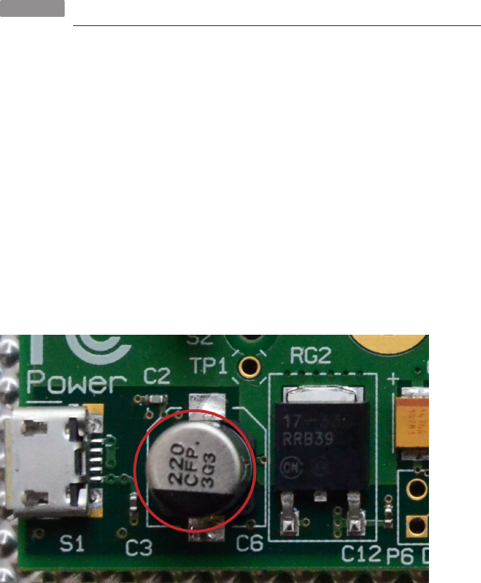
Most modern USB cables do not seem to have serious resistance issues. If it will
charge a Micro USB Type B cell phone quickly and reliably, it is probably good enough
for the Raspberry Pi. If it won’t, a new one is generally easy and cheap to come by.
HACK 10 Unbreak Your Raspberry Pi
The Raspberry Pi hardware is pretty rugged for its size, but it does have
one notable weak point that you might discover. Here’s how to find it and
how to hack it back to life if it breaks.
The Raspberry Pi comes with a built-in self-destruct button that many people have
accidentally triggered the first time they plugged it in. OK, that’s not precisely true.
But the placement of one of the Pi’s fragile components makes it really easy to destroy
your new toy before you’ve gotten to play with it. Here’s what to do in case you broke
it before you got around to reading this hack.
Just behind the power connection on the board is a small silver cylinder (see
Figure 1-4). It’s called capacitor C6, and it’s a 220 μF, 16-volt, surface-mount electro-
lytic capacitor that smooths out the voltage going to the Pi. It also seems like a really
good spot to grip when you’re plugging in or unplugging your micro USB cable. It’s
not. Don’t touch it. It’s not a critical component, and your Pi could still work without
it, but it also might not.
Figure 1-4.
C6 is the black and silver cylinder beside the power connector
29
CHAPTER 1: CONFIGURATION HACKS

If you’re looking for a replacement in online stores, try searching with the terms
“220 uF 16v electrolytic capacitor.”
The relative fragility of this piece’s connection is one of several good reasons to make
or buy a good case for your Raspberry Pi. Meanwhile, if you need to carry it around,
use the original static bag and box it came in.
Test Your Power Supply
If you do happen to break off the capacitor, and your Pi stops working, take consolation
in the knowledge that you’re not the only one, and though it’s not covered under war-
ranty, you have a few options. First, a new and better power supply might fix the prob-
lem. With a stable power supply, you shouldn’t have any problems.
If you don’t know whether your power supply is doing what it should (beyond the
obvious evidence of “it works” or “it doesn’t work”), you can test it. The first sign that
you’re not getting consistent or strong enough power is not an unworking Pi, but rather
an unreliable one.
When things start acting up mid-stream—all was fine at first, then maybe when you
get into the GUI, the peripherals stop working—that’s when it’s time to check your
voltage. The Pi has test points labeled TP1 and TP2 to help you. TP1 is just under the
Raspberry Pi logo, and TP2 is between the GPIO and the RCA out.
Set your multimeter to 20V in the DC range and touch the leads to TP1 and TP2. The
reading should be near 5 volts and certainly no more than 0.25 volts away in either
direction.
Replace the C6 Capacitor
If your Pi is still not working or if you just want the capacitor back on there, you can
solder a new one on.
Soldering on a new capacitor might make your Raspberry Pi as good as new. It
definitely will void your Raspberry Pi warranty.
When you solder it back on, note that the capacitor is polarized, and thus it is critical
to have the black stripe facing the edge of the board. For some basic soldering tips,
check out “Soldering Reminders” on page 42.
30 RASPBERRY PI HACKS

HACK 11 Go Headless
Even though the Raspberry Pi supports 1080p HDMI video out, there are
lots of projects where it is not cost effective or practical to connect it to
a video display. Here’s how to go without a monitor.
The Raspberry Pi is often touted as an inexpensive computer, but if you don’t have a
monitor and other assorted peripherals already available, the cost soars quickly. Also,
since one of the most appealing features of the Raspberry Pi for creative projects is
its diminutive size, you’re likely to discover that you need to run in “headless” mode:
no monitor, no keyboard, and no mouse. Just a Pi flying solo (perhaps literally if you’re
building Hack #44!). That’s when it’s time to run headless.
Change Your Root Password
Don’t forget to change your root password early on. It’s a good practice in general,
but it’s particularly important in headless mode. Most Raspberry Pi distros have
well-known default root passwords.
In general, your eventually headless Pi projects will begin life connected to a monitor
and input devices just to get everything ready. If nothing else, it seems like the easiest
way to get the IP address, which is the first step to being able to SSH to the Raspberry
Pi. However, if you use Pidora, you can go headless from the beginning, thanks to a
configuration option that bypasses the first boot process and is meant specifically for
going headless.
Once you’ve installed Pidora on your SD card (you can download the latest version
from http://www.pidora.ca), create a file called headless in the partition named boot.
For a static IP address, list it along with the netmask and gateway in the headless file:
IPADDR=192.168.1.123
NETMASK=255.255.255.0
GATEWAY=192.168.1.1
You can also use this file to initiate rootfs-resize by adding:
RESIZE
If you would like to set the swap amount, add it here as well:
SWAP=512
If your Pi should obtain its IP address dynamically (DHCP), headless should stay emp-
ty. But then how do you find out what the IP address is? This is where Pidora’s headless
mode comes through for you!
31
CHAPTER 1: CONFIGURATION HACKS

Once you boot the Raspberry Pi with this headless file, the IP address will first flash
through the speakers two minutes after powering on. Thirty seconds later, it will flash
the IP address through the green OK/ACT LED. These functions are provided through
ip-info, a package that contains the aptly named ip-read and ip-flash. The flashes
indicate numbers in the following way:
• Digits 1–9 are indicated with short flashes (e.g., three short flashes is a 3).
• 0 is indicated with 10 short flashes.
• Digits are separated by a pause.
•Dot (.) is indicated with a long flash.
You can read more about the ip-info package and download it at https://github.com/
ctyler/ip-info/.
As mentioned earlier, Pidora would usually run through the first boot process and have
you set up a root password and another user. But that script will run only if input
devices are found. Otherwise, the system configures the ethernet interface via IPv4
DHCP and assumes you’ll set up any other preferences you would have made at first
boot on your own.
HACK 12 Connect with SSH
For any headless project, as well as a matter of convenience when you’re
away from your project or just too lazy to walk across the room, you’ll
need to know how to SSH to your Raspberry Pi.
OpenSSH, the open source set of tools for secure communcation created by the
OpenBSD project, is likely available in any distro you choose.
If you’re going a little retro, note that “Squeeze,” the version of Raspbian before
“Wheezy,” didn’t have SSH running by default.
If you aren’t certain, all you have to do is attempt to SSH to your Pi, and you’ll find out
pretty quickly. Attach a monitor and keyboard, and then run:
$ service sshd status
'Redirecting to /bin/systemctl status sshd.service
sshd.service - OpenSSH server daemon
Loaded: loaded (/usr/lib/systemd/system/sshd.service; enabled)
Active: active (running) since Wed 2013-02-13 13:06:40 EST; 28min
ago
32 RASPBERRY PI HACKS

Process: 273 ExecStartPre=/usr/sbin/sshd-keygen (code=exited, sta
tus=0/SUCCESS)
Main PID: 280 (sshd)
CGroup: name=systemd:/system/sshd.service
└─280 /usr/sbin/sshd -D
If your output doesn’t look similar to that, it’s quick to install. Here’s the command on
Fedora:
$ su -c 'yum install openssh-server openssh-clients'
And here’s how to install it on Debian/Ubuntu:
$ su -c 'apt-get install ssh'
Once you’ve determined that it is installed, set it to start the daemon automatically
at each boot:
$ su -c 'chkconfig sshd on'
If you’re not going headless from square one with the Pi, you can connect it to a monitor
and run ifconfig. That’s the simple way, assuming you’ve got a monitor and keyboard
handy. Note that if you’re using a newer version of Fedora or Pidora, you’ll need to use
ip addr instead.
Or check your router’s default IP address, which is probably on a sticker somewhere
on it or on a website if you search for your router brand. (192.168.0.1 is a common
one.) You can also run route -n to find it. The numbers under Gateway on the line
flagged UG are the default IP. Go to that address in a web browser, and you’ll almost
certainly find some sort of router control panel where you can see connected devices,
including your Pi.
You could also use nmap, the network mapper tool. This is a fun way to learn a new tool
if you haven’t used it. That said, you should do your nmap learning only on your home
network and not at the office, in the coffee shop, or anywhere else you’re not in charge
of said network. When you run su -c nmap 192.168.1.1/24, replacing the IP address
with that of your network, you’ll see a list of everything connected to that network.
One of them will have a MAC address labeled Raspberry Pi Foundation, and it will list
your Pi’s IP address as well.
If you’re going to frequently connect via SSH, you’ll want to simplify things by giving
your Pi a static IP address (see Hack #13).
And now you’re ready to connect to your Pi by running ssh username@host, where
username is an account you’ve set up on the Raspberry Pi and host is the IP address
you found or configured. If you haven’t yet set up a user, you might need to refer to
33
CHAPTER 1: CONFIGURATION HACKS

the default login. On Pidora, it’s root/raspberrypi. On Raspbian-based systems, it’s
pi/raspberry.
The first time you connect to any machine, it will store a record of that machine in .ssh/
known_hosts. This list is checked on each connection. That means the first time you
connect, you’ll see a dialog that asks you:
The authenticity of host '192.168.1.174 (192.168.1.174)' can't be establish
ed.
RSA key fingerprint is 78:75:1d:1c:a1:79:11:18:15:e5:04:08:15:16:23:42.
Are you sure you want to continue connecting (yes/no)?
It sounds a little ominous, but “yes” is the right answer, despite the “warning” that
follows.
Now you’re ready to use the command line to transfer files to and from your Raspberry
Pi and to work on it almost as if you were working directly on it. If you’d like to be able
to launch GUI interfaces over SSH, use -X when you connect:
$ ssh -X ruth@192.168.1.118
Most (but not all) graphical applications will work with this method, known as “X for-
warding.”
HACK 13 Give Your Pi a Static IP Address
If you always want to be able to connect to your Pi through the same IP
address without looking it up, you’ll need to assign it a static IP address
(as opposed to a dynamically assigned one).
Many ISPs use dynamic IP addressing, which means that you get a different IP address
each time you connect to the Internet. If you’re connecting to the Pi over SSH regularly
(see Hack #12), using VoIP (see Hack #32), or have other reasons to always have the
same IP address, you’ll want to set up static IP addressing.
In Pidora, you can either follow the instructions in Hack #11 if you’re running headless,
or if you’re not, edit the files in /etc/sysconfig/network-scripts.
If you’re usually a Debian user, these files are analgous to /etc/network/inter
faces.
You’ll see the available network interfaces configurations listed as ifcfg-<interface-
name>. Choose the one you’ll be using for the connection and edit it in your favorite
text editor, for example:
34 RASPBERRY PI HACKS
$ vi ifcfg-eth0
You’ll see something like this:
DEVICE=eth0
BOOTPROTO=dhcp
ONBOOT=yes
NM_CONTROLLED=yes
You need to change the BOOTPROTO line from dhcp to static. Also make sure ONBOOT is
set to yes. Then add IPADDR, NETMASK, BROADCAST, and NETWORK information like you would
have in the headless file. Remember not to choose an IP address already in use else-
where in your network. NETMASK is always 255.255.255.0. GATEWAY is your router’s IP
address:
IPADDR=192.168.1.123
NETMASK=255.255.255.0
BROADCAST=192.168.1.255
GATEWAY=192.168.1.1
Finally, restart the network service to apply your new settings:
$ systemctl restart network.service
If you’re using a Raspbian-based distro, you’ll follow similar steps, just in a different
place. Rather than looking for separate files, open /etc/network/interfaces (as root):
$ su -c 'vi /etc/network/interfaces'
Then look for the line:
iface eth0 inet dhcp
Change dhcp to static, and add your static IP address, gateway, broadcast, and net-
mask:
iface eth0 inet static
address 192.168.1.123
gateway 192.168.1.1
broadcast 192.168.1.1
netmask 255.255.255.0
network 192.168.1.0
If you need a little help gathering these, you can find the current IP address, netmask,
and broadcast by running ifconfig and noting the inet addr, mask, and bcast, respec-
tively, while route -n will give you the gateway and network, which it calls Destina
tion. (Again, on newer Fedora and Pidora versions, use ip addr instead of ifconfig.)
35
CHAPTER 1: CONFIGURATION HACKS

Choosing a Unique Static IP Address
You should be sure to pick an IP address that is not already in use by any other
devices on your network. Otherwise, your network connection will not work prop-
erly. When DHCP is in use, duplication is prevented, but it is possible to accidentally
do it when setting the IP statically.
Additionally, you will need to manually specify a DNS server when setting a static IP
address. DHCP configurations usually configure the DNS server for you, but there is
no way for a static IP configuration to know what the DNS server is. To set the DNS
server, edit /etc/resolv.conf (as root), and add the following line:
nameserver 11.23.58.13
Replace 11.23.58.13 with the IP address of your DNS server. If you have multiple DNS
servers, you can have multiple nameserver $IP lines in this file.
After saving your changes, restart networking for the new settings to take effect:
$ su -c '/etc/init.d/networking restart'
You now have a static IP address that won’t change each time you access the Internet.
HACK 14 Learn to Speak GPIO
GPIO stands for General-Purpose Input/Output, and its presence on your
Raspberry Pi makes many hacks in this book possible. This hack helps
dymystify it.
The Raspberry Pi contains standard connectors that you are probably familiar with
(Ethernet, HDMI, audio, and USB), but it also includes 26 pins (in two rows of 13) that
are intended to connect directly to lower level devices. These pins are called the GPIO
(general-purpose input/output) pins, because they are programmable input/output
pins intended for a wide range of purposes.
Practically, this means we can use the GPIO pins to connect almost anything to a
Raspberry Pi. The header of these pins is labeled on the Raspberry Pi as P1, as shown
in Figure 1-5.
36 RASPBERRY PI HACKS
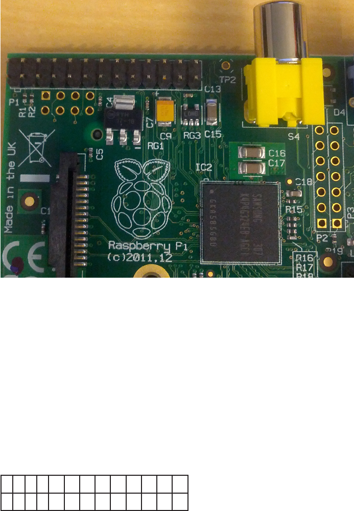
Figure 1-5.
Raspberry Pi Model B with the GPIO header in the upper-left corner
Simple enough, right? Well, here’s where it gets a little more confusing. There are two
ways of numbering the GPIO pins on the Raspberry Pi.
Pin-Number Labeling
The first way to label the GPIO pins is to refer to the pin numbers on the P1 header on
the Raspberry Pi board. If you look at the pins in Figure 1-5, Pin 1 is the first pin to the
left in the bottom row, Pin 2 is the first pin to the left in the bottom row, and they
continue to alternate in values to the right. In table form, the board pin numbers look
like Table 1-5.
Table 1-5. Board pin numbers
2 4 6 8 10 12 14 16 18 20 22 24 26
1 3 5 7 9 11 13 15 17 19 21 23 25
This method of labeling the Raspberry Pi GPIO pins by their board numbers is simple
to understand by looking at the hardware. If you use this numbering scheme, you
should prefix the pin numbers with the board label, “P1-”.
37
CHAPTER 1: CONFIGURATION HACKS

BCM Labeling
But another labeling system for the Raspberry Pi GPIO pins uses the channel numbers
on the Broadcom SOC. This system is referred to as the BCM system. It is the most
common system in use, especially because the GPIO pins are not completely inter-
changeable and they are wired differently between the various models and revisions
of the Raspberry Pi.
Table 1-6 shows the mappings of the BCM pin labels to the pins as shown in Figure 1-5
(for the Raspberry Pi Model B Revision 2, the current revision as of this writing).
Table 1-6. BCM pin labels (Raspberry Pi Model B revision 2)
5 V 5 V GND 14 (TXD) 15 (RXD) 18 GND 23 24 GND 25 8 7
3.3 V 2 (SDA) 3 (SCL) 4 GND 17 27 22 3.3V 10 (MOSI) 9 (MISO) 11 (SCKL) GND
Let’s dig a little deeper. As you can see from the labeling, some of the pins are pre-
configured for special purposes. The pins marked as 3.3 V and 5 V are power pins,
with the voltage as labeled. The GND pins provide ground for wiring up circuits. BCM
Pins 2 (P1-03) and 3 (P1-05) are pre-setup to provide I2C bus 1. BCM Pins 14 (P1-08)
and 15 (P1-10) are configured to provide a serial console. BCM pin 18 (P1-12) supports
Pulse-Width Modulation (PWM).
For these reasons (and also because it is the most common Raspberry Pi GPIO la-
beling scheme used on the Internet), this book uses the BCM pin labels.
We realize this might be confusing when you are wiring up devices to your Pi, but see
the next section for a clever way to help you remember what is what.
Label Your Own GPIO Pins
GPIO should be simple, but the common labeling scheme (BCM) is so confusing and
easy to forget. Here’s a simple hack to make sure you always remember which pin
goes where.
Dr. Simon Monk had a problem: he wanted to wire all sorts of temporary connections
to his Raspberry Pi GPIO pins, but every time he wanted to do so, he had to go online
and look up the BCM pin labels. Then there was the task of counting down the pins to
find the right one, and while this sounds easy, trust us, you’ll likely get this wrong just
as he did.
38 RASPBERRY PI HACKS
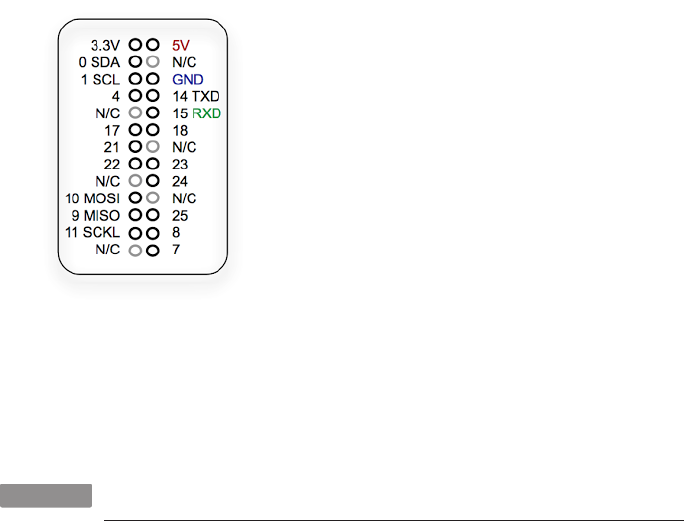
To solve this problem, he created something called the Raspberry Leaf (shown in
Figure 1-6). The Raspberry Leaf is a perfectly sized and scaled diagram of the Rasp-
berry Pi GPIO pins, with the BCM labels next to them.
Figure 1-6.
Raspberry Leaf, created by Simon Monk
You can photocopy and use this image for reference, but it’s probably easier to down-
load from this book’s Git repository or the original PDF from Dr. Monk’s website.
HACK 15 Connect GPIO Pins to a Breadboard
A solderless breadboard is a helpful friend when building electronics
hacks, especially when you are prototyping or just testing out a device.
Let’s hack a simple connector to our Raspberry Pi.
While you can simply connect your Raspberry Pi GPIO pins to devices via common
jumper wires, or solder wires directly between your add-on device and the GPIO pins,
it is almost always helpful to have a little more space to work. Enter our old reliable
friend, the solderless breadboard, shown in Figure 1-7. Even if you’ve never done an
electronics project before, you may have seen this fellow with rows and columns of
little holes in a rectangle of white plastic.
39
CHAPTER 1: CONFIGURATION HACKS
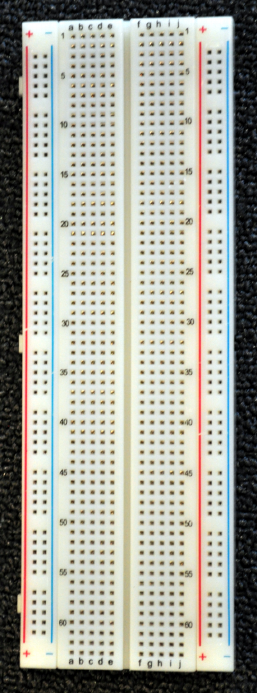
Figure 1-7.
A breadboard
A breadboard works by providing horizontal rows of connector holes (often separated
by a gap) that are wired together. When you want to connect two wires together, you
can simply insert them into holes along the same horizontal row. Need more holes?
Just jump a wire from one row to another.
Additionally, most breadboards have vertical “rails” down each side, marked with red
and black. These rails are intended to be used for power and ground connections, to
simplify wiring circuits.
Our friends at Adafruit built a handy kit called the Pi Cobbler, which allows you to
connect a standard 26 pin ribbon cable (just like you’d use on a PC motherboard) to
a labeled printed circuit board (PCB) with a cable connector and individual pin break-
outs. That PCB breakout board has pins that allow it to push right into your bread-
40 RASPBERRY PI HACKS

board. Then, connect the cable to the Raspberry Pi GPIO pins and to the Cobbler PCB
breakout board, and you can start connecting devices directly through your bread-
board.
The instructions in this hack are also inspired by Limor “Ladyada” Fried’s excellent
assembly tutorial.
Adafruit sells the Pi Cobbler in a couple variants:
Compact version
Comes preassembled, so you can use it as soon as it arrives in the mail. (They
used to sell this as an unassembled kit, but it doesn’t look like they do anymore.)
T-Cobbler version
Slightly larger, but covers less of the pins on the breadboard due to its “T” layout.
At the time of this writing, the T-Cobbler is sold only as part of a kit (not preas-
sembled).
If you end up with an unassembled kit for either of these versions, do not fret. It is easy
to assemble it yourself. Here’s everything you need:
• A soldering iron
• Some solder
• A breadboard
•Your Pi Cobbler kit, containing a blue PCB, a 26-pin ribbon cable, a black con-
nector, and some male header pins (this might be in a single stick or in two smaller
sticks)
If your male header pins (these are the metal pins with black plastic header in the
middle, splitting the pins into one short and one long end) are in a single long stick,
gently break off two pieces of 13 pins each. You can do this with your fingers or pliers.
These correspond to the two pairs of 13 holes on the long edges of the Pi Cobbler PCB.
Also, go ahead and plug in your soldering iron and set it on a stand (see “Soldering
Reminders” on page 42 if you need some help or if it’s been a while). Give it 5–10 minutes
to come up to full temperature. If you have a fancy soldering iron with a temperature
setting, Adafruit recommends you set it to 700 degrees Fahrenheit.
Place the Pi Cobbler PCB in front of you so that the pin labels (e.g., GND) are legible
and oriented normally. On the T-Cobbler kit, the board is aligned like a T. On the original
kit, the board’s longer sides should be parallel to you.
The PCB is labeled with a box, indicating where the black header connector should be
placed. Gently press the header into the box, making sure to align the notch in the
41
CHAPTER 1: CONFIGURATION HACKS

header with the notch indicated in the box. On the original Cobbler PCB, the notch
must be right next to the “21/27” label; on the T-Cobbler PCB, the notch must be
between the two large round holes at the T junction point. You need to get this right,
because if you get the notch backward, this will cause the pins to be reversed when
the cable is connected between the Cobbler and the GPIO pins, and the labels on the
Cobbler will all be wrong.
Soldering Reminders
Soldering might seem scary at first, but it really isn’t very difficult if you’re
careful and respectful of the iron. Keep a few things in mind:
•Solder, when heated, releases mildly toxic smoke. You should always
solder in a well-ventilated area.
•The soldering iron gets hot. Very hot. (The actual temperature varies
on the type, quality, and condition of your soldering iron.) It will burn
you if you touch the tip of the iron, so always hold it by the handle, and
don’t lean in too close.
• Always assume a plugged-in soldering iron is hot and treat it that way.
Heck, we usually assume unplugged soldering irons are hot, too.
•Every soldering iron should come with a stand. Use it. This keeps you
from accidentally burning holes in your workstation, project, hand, leg…
•Keep a small, moist sponge handy, and as needed, use it to wipe off
excess solder from the tip of the hot iron. If the tip of the iron becomes
coated in solder, it will no longer work effectively.
• You don’t need to put a giant blob of solder down to make a good con-
nection. When heated, solder quickly becomes a liquid and will flow into
heated connections. Just a tiny bit will do. Practice will help you realize
how much to apply.
Flip over the PCB, with header connector still in place, so that it is now sitting on the
header. You should see little bits of the 26 connector pins poking out from 26 metal
rings on the PCB. Press the tip of your soldering iron simultaneously against a pair of
the rings and pins. Hold it there for a few seconds to heat up the metal, and then touch
some solder against the tip of the iron. The solder will melt instantly, liquify, and flow
between the pin and the ring, making a complete connection.
42 RASPBERRY PI HACKS
You want to use enough solder so that you cannot see air between the pin and the ring,
but not so much that you make a connection between neighboring pins. Really, it
doesn’t take much, just a tiny bit. This solder will be completing the electrical con-
nection, but it will also be providing a mechanical bond that holds the device together.
Repeat this process for all 26 pins, until the header connector is neatly soldered to
the PCB, and then put your soldering iron back on its stand (you’ll use it again in a
moment).
Get your breadboard and place it in front of you. Place the two sets of male header
pins into the breadboard, with the long ends into the breadboard, until the middle
header plastic on each pin is resting against the breadboard.
You want to do this so that they are in the same spacing and alignment as they appear
on the PCB Cobbler. For the original Cobbler, this is about five breadboard rows apart;
for the T-Cobbler, this is only three rows apart.
Flip the PCB back over and set it into the short ends of the male header pins. The
breadboard is acting as a stand for us now. Push the PCB gently down until all of the
pins are poking through the labeled rings, and the PCB is resting up against the plastic
header middles. Pick your soldering iron up again, and solder each of these 26 rings
and pins.
When you’re finished, clean off the tip of your soldering iron with a moist sponge and
unplug it. Put it back on the stand to cool off. You can now connect the ribbon cable
between the completed Pi Cobbler and the Raspberry Pi GPIO pins. You’ll notice that
the cable will only go into the Pi Cobbler one way, because of the notch on the con-
nector. However, be careful, because the Raspberry Pi GPIO pins do not have any
connector, and the cable can connect two possible ways. The ribbon cable included
in your kit will have two indicators to help you align it properly:
•The ribbon cable has one wire of a different color. This uniquely colored wire
should be on the edge closest to the SD card slot on the Raspberry Pi.
•Both ends of the ribbon cable have a notched connector. The notch on the con-
nector going to the Pi should be pointed toward the Raspberry Pi logo on the
board, as shown in Figure 1-8, never away from it.
The finished and connected Pi Cobbler will look something like Figure 1-9 (this is an
original Pi Cobbler).
43
CHAPTER 1: CONFIGURATION HACKS
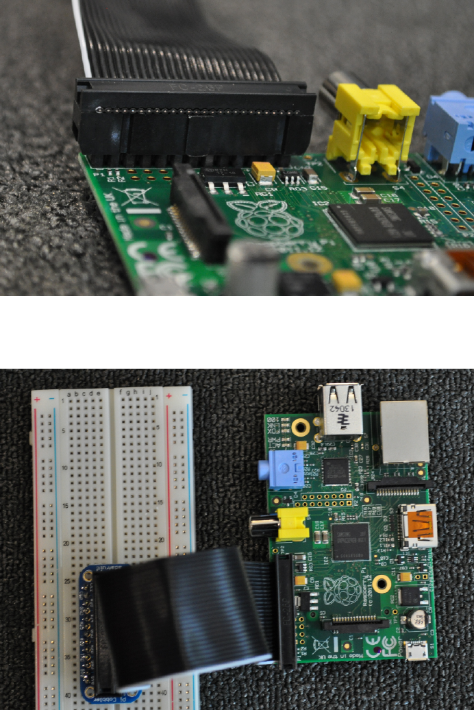
Figure 1-8.
Close-up of a properly connected Cobbler ribbon cable
Figure 1-9.
Completed and connected Pi Cobbler
44 RASPBERRY PI HACKS

It might not seem like much, but trust us, when you are wiring up multiple devices to
the Raspberry Pi GPIO pins, being able to easily use a breadboard (and see the GPIO
labels at a glance) will make you happy that you completed this hack.
GPIO Quick Reference
If you turn your Pi so that the GPIO pins are in the upper right, the pins are numbered
from top to bottom, with odd numbers on the left and even on the right (thus, the first
row is 1 and 2, second row is 3 and 4, etc.). Note that these do not correspond to GPIO
numbers; for example, GPIO 22 is on pin 15. Table 1-7 explains the purposes of the pins
of a Version 2 board.
Table 1-7. GPIO pin purposes for Version 2 board
PIN NUMBER PURPOSE
1 3.3 V power
2 5 V power
3 GPIO 2 (SDA)
4 5 V power
5 GPIO 3 (SCL)
6 Ground
7 GPIO 4 (GPCLK0)
8 GPIO 14 (TXD)
9 Ground
10 GPIO 15 (RXD)
11 GPIO 17
12 GPIO 18 (PCM_CLK)
13 GPIO 27
14 Ground
15 GPIO 22
16 GPIO 23
17 3.3 V power
18 GPIO 24
19 GPIO 10 (MOSI)
20 Ground
21 GPIO 9 (MISO)
22 GPIO 25
45
CHAPTER 1: CONFIGURATION HACKS

PIN NUMBER PURPOSE
23 GPIO 11 (SCLK)
24 GPIO 8 (CE0)
25 Ground
26 GPIO 7 (CE1)
The pins are meant for input no higher than 3.3 V, and there is no overvoltage
protection.
Inter-Integrated Circuit (I2C)
The I2C interface (SDA and SCL), which you can access through pins 3 and 5, is a
connection for low-speed peripherals or sensors. You can have multiple devices con-
nected through the same pins.
Pulse-Width Modulation (PWM)
Pin 12 offers control for motors similar to analog control through pulse-width modu-
lation (labeled PCM_CLK). For some purposes, you can achieve the same effect
through software, which may be useful since the Pi has only one PWM pin.
Universal Asynchronous Receiver/Transmitter (UART)
The UART pins (14/TXD and 15/RXD) are used for serial console access. If you don’t
need that, you can switch them to GPIO for an extra two GPIO pins. This is also true
of the I2C and SPI pins, but you’re least likely to want to use the UART pins.
Serial Peripheral Interface Bus (SPI)
The SPI pins are the pins you’ll use for some types of sensors or attaching other de-
vices. SPI operates in master/slave fashion:
• 19 - Master Out, Slave In (MOSI)
• 21 - Master In, Slave Out (MISO)
• 23 - Serial Clock (SCLK)
• 24 - CE0 (chip select)
• 26 - CE1 (chip select)
46 RASPBERRY PI HACKS

The two chip select pins mean you can control two SPI devices.
For those who would like to better understand GPIO and to effectively use this feature
of the Raspberry Pi, we recommend looking through this page, which provides an
access library for the Pi’s GPIO. It will be particularly useful if you are already familiar
with Arduino wiring.
HACK 16 Add a USB Serial Console
Arguably the most common way to access embedded devices like the
Raspberry Pi is via the built-in serial device. This easy hack gives you a
USB serial console from your Raspberry Pi.
Almost all of the common embedded computers and microcontrollers available today
have built-in Universally Asynchrononous Receiver/Transmitters (UARTs). The UART
provides a mechanism for receiving and transmitting serial data, one bit at a time.
This method of serial communication is sometimes referred to as transistor-transistor
logic (TTL) serial. The data rate varies by device, but it is measured in bits per second.
The Raspberry Pi has a built-in UART connected to BCM Pins 14 (TXD) and 15 (RXD),
with a data rate of 115200bps (or baud).
Hey, That’s Not Really Baud!
OK, from a semantic point of view, yes, baud is the unit of symbol rate, which
is not always identical to gross bit rate (bps). Wikipedia says that baud is
“the number of distinct symbol changes (signaling events) made to the
transmission medium per second in a digitally modulated signal or a line
code.” Then it goes on for several more pages of mathematical distinction
about baud, which may be fascinating to you or may put you to sleep.
The key takeaway is this: the computer and electronics industry has been
widely misusing the term baud for about 40 years now. As a result, lots of
software and hardware uses bps and baud interchangeably. In the specific
case of the USB serial console on the Raspberry Pi, the data rate in bps and
the baud rate are the same. The units here don’t matter to us as much as
making sure you have a functional serial console, and for that, you need to
know that the data rate is 115200. Bits, baud, giant hamsters of doom, pick
your units as you will, but 115200 is the magic number for the Raspberry Pi
UART serial device.
47
CHAPTER 1: CONFIGURATION HACKS

If you’ve been using computers for a few years, you probably remember when almost
every computer came with an RS-232 serial port, but in the last few years, these ports
have been disappearing, and most laptops no longer include them (or they only have
them on the optional laptop dock). Believe it or not, for connecting to the Raspberry
Pi UART serial port, this is actually a good thing. The Broadcom chip that the Rasp-
berry Pi depends on uses 0 and 3.3 V logic levels, not the +/- 3 to 15 V range used by
PC RS-232 serial ports. This means even if you have one of those RS-232 serial ports
on your computer, you’d need a board or adapter to convert the signal levels before it
would work.
RS-232 or Bust!
Here’s a pretty good tutorial on how to build a 3.3 V to RS-232 level converter.
The good news is that there is a better way to connect the Raspberry Pi UART serial
port to your computer: USB! Adafruit sells a wonderful USB-to-TTL Serial Cable, which
connects directly to the GPIO pins on the Raspberry Pi and provides a USB serial
device on the other end. This cable has four female jumper connectors on one end
(the end that doesn’t have a USB connector). These jumpers have color-coded wires:
red for 5 V power, black for ground (GND), green for receiving data into the Raspberry
Pi (RXD), and white for transmitting data from the Raspberry Pi (TXD). You might also
notice that the USB connector end is larger than normal, because it also has a USB-
to-Serial conversion chip inside it.
To make the physical connection, you simply need to connect three of the female
jumper connectors directly to the appropriate pins on the Raspberry Pi GPIO. The
white transmitting wire goes into the TXD port (BCM Pin 14 (P1-08)), and the green
receiving wire goes into the RXD port (BCM Pin 15 (P1-10)). The black ground wire can
go into any of the GND pins, but for simplicity, we recommend you put it in the GND
pin immediately to the left of the TXD port (P1-06). You can confirm your wiring by
comparing it to Figure 1-10.
A Hack for the Red Wire
You may note that we did not ask you to connect the red power wire. This
is because the USB serial device will power itself with 5 V at 500 mA directly
from the USB port. You may also note that we said that the Raspberry Pi
UART uses 3.3 V logic levels, not 5 V, and this is true, but the receiving and
transmitting wires are already converted to 3.3 V. It all works fine, stop not-
ing and move on.
There is, however, a cool mini hack you can do with that red power wire.
Because 5 V is going across that red wire, you can use it to power the Rasp-
berry Pi, instead of doing so via the normal mini-B USB connector. Just
48 RASPBERRY PI HACKS
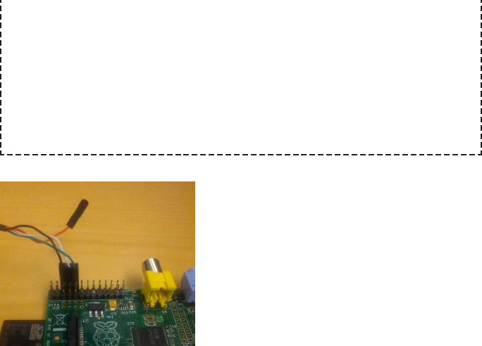
connect the red wire to the 5 V pin (P1-04), then without any other power
source connected, plug the USB-to-TTL Serial cable into your laptop. The
Raspberry Pi will boot up!
This is really just a parlor trick, because the power coming off that red wire
is not the ideal way to power the Raspberry Pi for a number of reasons, as
discussed in “Think Twice Before Using the GPIO to Power the Pi” on page
25.
Figure 1-10.
A properly wired USB to TTL serial cable
Now, go ahead and connect the USB connector to your computer.
To connect to the UART serial device, you first need to know its device name. The
kernel assigns it a device name when the USB serial driver successfully loads (which
it should have already done when you inserted the USB end of the cable), so you just
need to look through the output from dmesg.
Specifically, we know that the device name will be ttyUSB#, where # is a number. It’s
probably ttyUSB0, but let’s look to be sure. If you have multiple USB serial devices
present on your system (you naughty super hacker, you), you’re looking for the one
with the pl2303 converter type. If you have more than one pl2303 converter type USB
serial device present, pick one at a time and try until you find the right one. Anyway,
here’s how you can check:
$ dmesg | grep -B2 ttyUSB
[23882.896558] usbserial: USB Serial support registered for pl2303
[23882.896578] pl2303 1-1.5.1:1.0: pl2303 converter detected
[23882.898285] usb 1-1.5.1: pl2303 converter now attached to ttyUSB0
Sure enough, our device is ttyUSB0. This means that the full device node name is /dev/
ttyUSB0. Unprivileged users do not normally have access to /dev/ttyUSB# devices; you
need to be in a special group. If you look at the file permissions on the device node
49
CHAPTER 1: CONFIGURATION HACKS

name, you will see that it is owned by root and access is granted to users in the dialout
group:
$ ls -l /dev/ttyUSB0
crw-rw----T 1 root dialout 188, 0 Aug 22 19:11 /dev/ttyUSB0
You can either connect to the /dev/ttyUSB0 device using the root account (via su or
sudo), or you can add your normal user to the dialout group. To add your user to the
dialout group, run:
$ su -c 'usermod -a -G dialout $USER'
This will not take effect in your terminal sessions until they are restarted. Either log
out and log in again, or reboot your Linux system.
Not Using Linux to Connect to the Serial Port?
You can imagine the face the authors are making right now. It is a disap-
proving face. ಠ_ಠ However, we can give you a few tips anyway.
Windows and Mac OS X systems will need to install PL2303HXA drivers,
which you can download for Windows XP/Vista/7 and Mac OS X.
According to the vendor, Windows 8 is not supported for this device. Maybe
if you’re a Windows 8 user, this is a good time to consider dual booting to
Linux?
As far as terminal software goes, if you are using Windows XP or older, it
comes with a program called Hyperterminal that can connect to a serial
console. If you are using a newer version of Windows, you’ll need to down-
load a third-party terminal program. We recommend PuTTY. For Mac OS X,
you can either use screen in the same way that we’ve described for Linux,
or you can try ZOC.
Now it’s time to connect to the Raspberry Pi UART serial device. You’ll need to use a
client that supports a serial connection; there are lots and lots out there, but the two
common ones are minicom and screen.
Minicom
Minicom was written to look like Telix, a popular MS-DOS terminal program that was
probably written before you were born. We now feel old(er). It has that MS-DOS look
and feel to it—namely, it is old, crufty, and confusing—but it does work. To install it on
Fedora:
$ su -c 'yum install minicom -y'
50 RASPBERRY PI HACKS
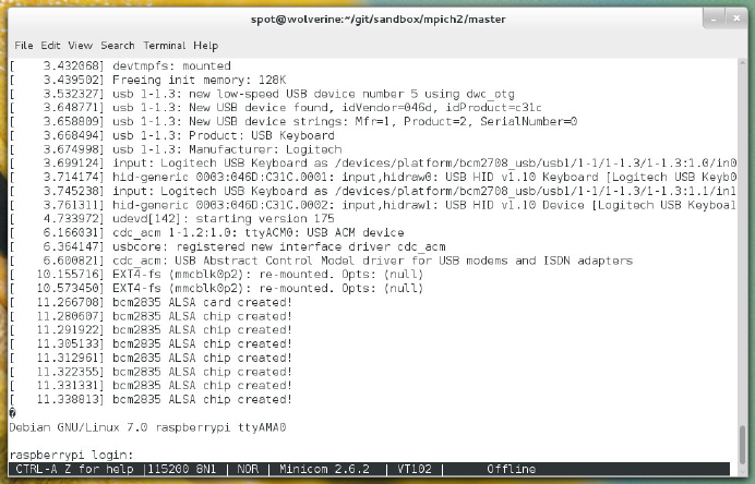
or on Debian/Ubuntu:
$ su -c 'apt-get install minicom'
Once installed, to use minicom to connect to the Raspberry Pi UART serial device, run:
$ minicom -b 115200 -o -D /dev/ttyUSB0
To test it, reboot the Raspberry Pi while it is connected; you should see Linux kernel
messages scroll down the screen, and it will look similar to Figure 1-11.
Figure 1-11.
minicom interfacing with the Raspberry Pi UART serial device
You can exit minicom with Control-A X, or get into its somewhat helpful help menu
with Control-A Z. If you end up manually configuring minicom, just leave the Parity/
Bits at 8N1, and disable the Software Flow Control. You don’t need to go in there
though. There are bats in there.
Screen
Screen is a powerful utility, normally used to multiplex multiple virtual consoles. If this
were Linux in a Nutshell, we’d have a whole chapter about using screen. Since this is
a different book, we’ll just focus on using it as a serial terminal client.
To install it on Fedora, run:
$ su -c 'yum install screen -y'
51
CHAPTER 1: CONFIGURATION HACKS

or on Debian/Ubuntu:
$ su -c 'apt-get install screen'
Once installed, to use screen to connect to the Raspberry Pi UART serial device, run:
$ screen /dev/ttyUSB0 115200
To exit the screen session, type Control-A K.
Using the Serial Device as a Login Console
Raspbian preconfigures the UART serial device as a login-capable console, but Pidora
does not. To enable the UART serial device as a login console session, run:
$ su -c 'systemctl start serial-getty@ttyAMA0.service'
This will turn it on immediately. If you have a serial cable connected, you should see
a login prompt appear. To make this login session permanent (and automatically
loaded on boot), simply run:
$ su -c 'ln -snf /usr/lib/systemd/system/serial-getty@.service \
/etc/systemd/system/getty.target.wants/serial-getty@ttyAMA0.service'
By making that symbolic link in the systemd directory tree, you are telling systemd to
start the ttyAMA0 device as a “getty” or login console.
Fun Serial Console Trivia
The name “getty” comes from the term “get teletype.” A teletype was originally a
device with a typewriter for input and a printer for output for use as telegraph
machines, but as computers evolved, these devices found a use as a method of
inputting data to a computer. The teletype was also widely used in a “receive only”
format in newsrooms in the 1940s and 1950s. The “clickety clack” sound effect of
news coming in “over the wire” is that of a teletype. Eventually, these devices be-
came proper serial consoles, and they are the reason why we call console devices
in Linux “TTYs”.
Both Pidora and Raspbian come with the UART serial device preconfigured as a con-
sole for kernel messages. You can see this in the /boot/cmdline.txt file:
dwc_otg.lpm_enable=0 console=ttyAMA0,115200 kgdboc=ttyAMA0,115200 con
sole=tty1 root=/dev/mmcblk0p2 ro rootfstype=ext4 rootwait quiet
The console value tells the Linux kernel where to output messages at boot time, and
the kgdboc value enables kernel debugging over that console.
52 RASPBERRY PI HACKS
If you are working on a project that wants dedicated access to the UART serial device,
you will probably want to remove the console=ttyAMA0,115200 and kgdboc=ttyA
MA0,115200 entries from /boot/cmdline.txt and reboot your Raspberry Pi. If you do
not, you will get unexpected line noise across the serial line from the Linux kernel that
your program/project is probably not ready to deal with.
If you have enabled the serial devices as a login console, you will also want to disable
that. To disable it on Raspbian, comment out the following lines in /etc/inittab (by
changing the line to start with a #):
T0:23:respawn:/sbin/getty -L ttyAMA0 115200 vt100
On Pidora, you simply need to remove the systemd getty service symlink for the
ttyAMA0 device, by running:
$ su -c 'rm -f /etc/systemd/system/getty.target.wants/serial-
getty@ttyAMA0.service'
On either Linux distribution, after making these changes, reboot for them to take ef-
fect.
Weird Noise (or Missing Signal) on the Serial Connection?
Both Ubuntu and Fedora include a piece of software called ModemManager, which han-
dles setting up all sorts of modem devices, from old dial-up modems to more modern
3G/4G devices. Unfortunately, quite a few current modems just have the same generic
converter chip that our USB serial connector cable uses (the pl2303) stuck in front
of the modem.
As a result, ModemManager will try to access it (and keep trying, and keep trying …),
because it has no way of knowing that the device behind /dev/ttyUSB0 is a modem, or
a Braille terminal, or in our case, a Raspberry Pi. This might prevent you from being
able to open /dev/ttyUSB0, or it might simply cause noise to appear across the console.
Since we know what that USB device is connecting to, we can tell ModemManager to leave
it alone and explicitly blacklist our connector device with udev rules.
53
CHAPTER 1: CONFIGURATION HACKS

As root, edit the /lib/udev/rules.d/77-mm-usb-device-blacklist.rules file, and add
these lines before the LABEL="mm_usb_device_blacklist_end" line at the bottom:
# Adafruit USB to TTL Serial Cable (PL2303HXA)
ATTRS{idVendor}=="067b", ATTRS{idProduct}=="2303", ENV{ID_MM_DEVICE_IG
NORE}="1"
If you use a different USB serial cable from the Adafruit cable, and you’re trying to fix
this problem, you should be able to run the lsusb application (from the usbutils pack-
age) to determine the idVendor and idProduct string (they will show up in the output
in the syntax XXXX:YYYY where XXXX is the idVendor and YYYY is the idProduct).
For example, the lsusb value for the Adafruit USB serial cable looks like this:
Bus 003 Device 002: ID 067b:2303 Prolific Technology, Inc. PL2303 Serial
Port
Udev automatically detects changes to rules files, so changes take effect immediately
without requiring udev to be restarted. That said, sometimes you need to reboot the
Linux system for udev to reread its rules. Either way, whenever udev reads in its new
rules, the USB serial converter device should now be blacklisted, and ModemManager
should ignore it from then on out.
HACK 17 Add a Reset Button
Perhaps you’ve noticed your Pi lacks something pretty common among
electronics: a power switch. The Model B revision 2 boards come with a
small fix.
It’s somewhere between vaguely uncomfortable and outright inconvenient to remove
the power supply from your computer as an on/off switch, but that’s what you do on
the Raspberry Pi. One easy fix, regardless of what board you have, is to plug it into a
power strip with an on/off switch and use that. But with the Model B revision 2 boards,
you have another option.
54 RASPBERRY PI HACKS
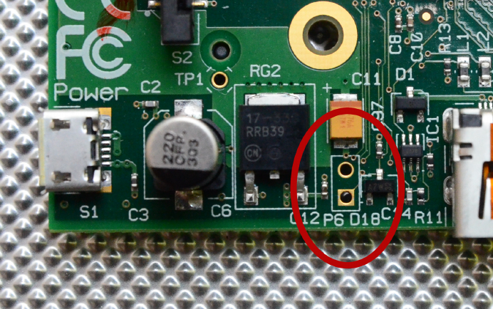
One of the added features on these boards is labeled P6. It’s easy to miss. P6 is just
two small holes on the opposite side of the board from the GPIO, near the HDMI port
(see Figure 1-12).
Figure 1-12.
P6 holes
If you solder a pair of header pins into these two holes (see “Soldering Reminders” on
page 42 if you’re new to soldering), you have a reset switch, as shown in Figure 1-13.
Just use a metal object to connect the two pins and short them.
55
CHAPTER 1: CONFIGURATION HACKS
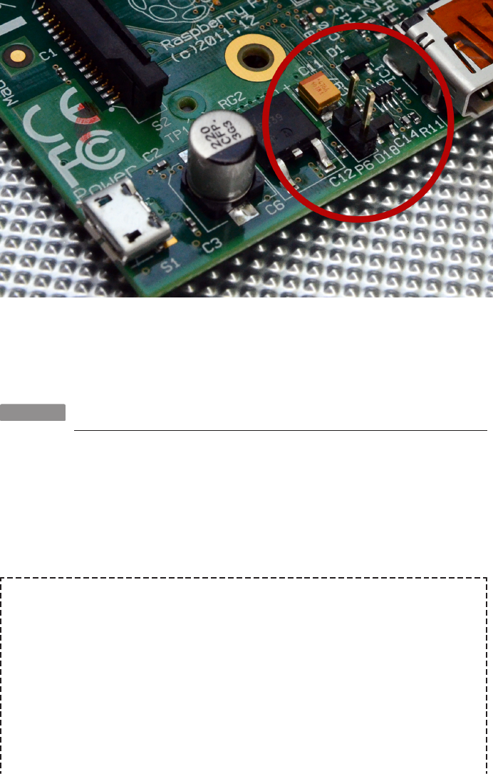
Figure 1-13.
Reset pins in place
This short will also reset the CPU from shutdown, causing the Pi to start.
HACK 18 Get Power to the Pi on the Move
Power doesn’t have to mean a plug in the wall. You have a few more op-
tions to increase portability.
To get power to your Pi, you need five stable volts at 700 mA through a Type B Micro
USB plug. As mentioned elsewhere, it’s not a bad idea to get a power adapter specif-
ically intended for the Raspberry Pi, though your phone charger or other similar
adapter will likely work.
Less-than-Recommended Power Options
Much like trying to substitute anything for eggs in a recipe, there are options
that aren’t particularly recommended but work out for some people. For
example, powering your Pi through your laptop’s USB port. It doesn’t offi-
cially work and isn’t recommended, but we’ve seen it work. Trying to push
power through the GPIO isn’t a great idea either. See “Get Power Through
GPIO Safely” on page 26 for more on power and the GPIO pins.
We’ve also heard of success with power over Ethernet and even intentionally
backpowering through USB to power the Pi. Again, not the recommended
56 RASPBERRY PI HACKS

method, but hacks are about trying something new. As long as you conduct
your electrical experimentation safely, the worst you’ll end up with is the
loss of a $35 board but the gain of a good story, possibly featuring smoke,
which enhances any story.
But if you want portability, what you need is a battery pack. You might think of these
devices as emergency power for your cell phone. They come in assorted strengths,
shapes, sizes, and colors, but in the end, they’re two things: power and a USB port,
which are the two things that you need to power the Pi.
Look for one that has 5V regulated output. We use the New Trent iCarrier (IMP120D),
a 12,000 mAh pattery pack with two USB ports and an on/off button. Depending on
activity on the Pi, that’s enough power to last 14– 16 hours or more.
This portable power is critical to some of the hacks in this book, most notably Hack
#44. It’s an enhancement for others. And worst case, it’s spare juice for your phone.
HACK 19 Test Your Might (in Volts)
If you aren’t already friends with a multimeter, you will be soon. Pi
projects all need power, and the Pi provides a way for you to check the
voltage of the board on the board.
Assuming you don’t have a few power supplies around to swap out, or if you’re deter-
mined to get a particular and unusual power source working, you’re going to want to
check the voltage on the Raspberry Pi.
There are two test points on your Raspberry Pi for just such a need, as shown in
Figure 1-14. TP1 is the 5 V point and TP2 is ground.
They’re in slightly different but nearby places on the Model A board, but they’re
still labeled TP1 and TP2 in that tiny white PCB label text.
57
CHAPTER 1: CONFIGURATION HACKS
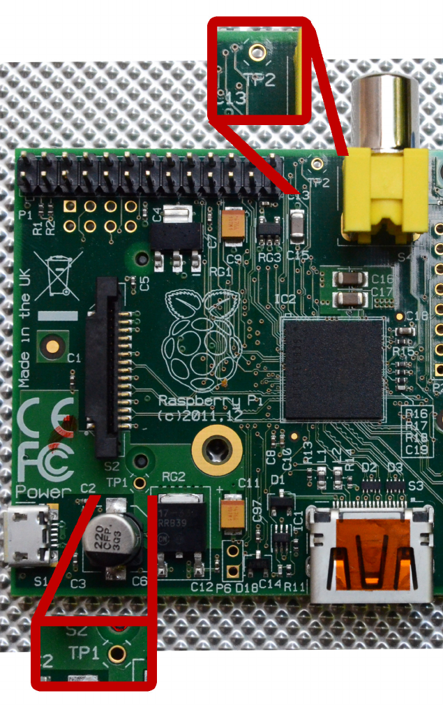
Figure 1-14.
Test point locations (a.k.a. “electronics vision test”)
58 RASPBERRY PI HACKS
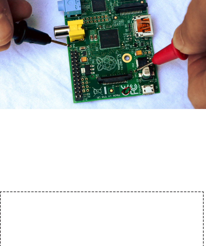
To test the voltage:
1. Plug in all the peripherals you expect to use, and power on the Pi (and the pe-
ripherals).
2. Set your multimeter range to 20 V.
3. Touch the red lead of your multimeter to TP1 and the black lead to TP2 (as shown
in Figure 1-15).
Figure 1-15.
Testing the voltage
The Pi needs a good 5 V supply but has a tolerance of +/-0.25 V or so. That means
that, at a minimum, you should be seeing 4.75 V, preferably more like 4.8 V or more.
Below that, and either your peripherals will start acting up or the Pi might not even
boot at all. It might also reboot spontaneously.
You can also try unplugging various peripherals, using different monitors, removing
Ethernet, etc. Test again to see how the result changes.
It’s Electric!
It’s entirely possible that the Raspberry Pi is the first place you’ve gotten
this close to the electricity part of your electronics. If that’s the case, it’s
worth some light reading about how all this power stuff works. But at the
most basic level, you’ll want to understand these three terms and the rela-
tionship among them:
59
CHAPTER 1: CONFIGURATION HACKS
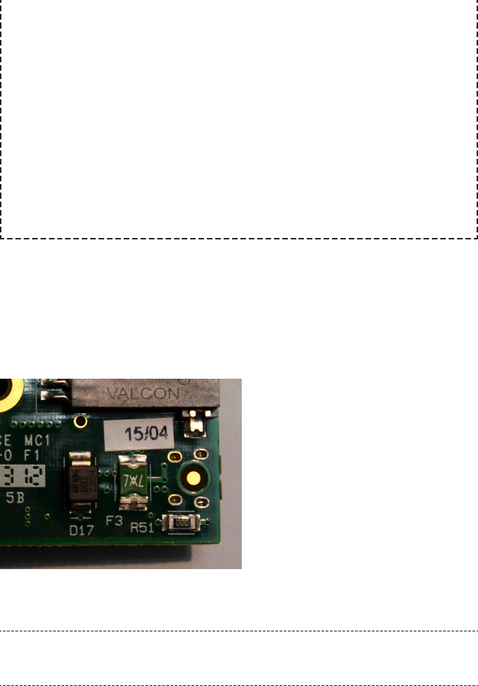
Voltage
The difference in charge between two points
Current
The rate at which charge is flowing
Resistance
A material’s tendency to resist the flow of charge (current)
If you know two of them, you can figure out the third, thanks to Ohm’s law,
which says that V=I*R, or the voltage (volts) is equal to the current (amps)
times the resistance (ohms). Those who are mathematically disinclined can
get an assist from the handy tool at the online Ohm’s Law Calculator.
Keep this in mind when things act funny and you’re not sure why: it might be worth a
quick power check.
You can also use the Pi’s test points to test its polyfuse. A polyfuse is a type of fuse
that can repair itself after it has been blown. The Raspberry Pi has at least one of these,
labeled F3 on the bottom of the board, as shown in Figure 1-16.
Figure 1-16.
F3 polyfuse beneath SD card slot
Earlier Pis also had two on the USB ports, which have since been replaced by 0
Ohm resistors. They were known as F1 and F2.
You’ll find F3 to the left of the SD card slot if you turn the Pi over and hold the SD slot
toward you.
60 RASPBERRY PI HACKS

How long it takes for it to “heal” is variable, as much as a few days, and they can be
permently damaged. They are replaceable, though. To test whether you’re having a
problem with the F3 polyfuse:
1. Remove the SD card and all of the peripherals, unlike testing the voltage, but leave
it plugged in.
2. Turn the board upside down.
3. With the same settings (range 20 V), touch one lead to the back side of TP2 (since
the board is upside down) and the other to the metallic part of F3 facing the SD
card slot. This will tell you the voltage coming from the fuse.
4. Next, touch one lead to the back side of TP2 and the other to the metallic part of
F3 facing the outside of the board. Check the voltage. This will tell you the voltage
coming in.
It’s normal for the reading on F3 to be 0.2 V lower than the power coming in, but any
more than that indicates a problem with the polyfuse.
HACK 20 Add Additional Memory with Swap
Need a little more memory on your Raspberry Pi? Swap will let you trade
disk space for memory.
Linux has long inclued the concept of swap, where the kernel is capable of moving
memory pages between RAM and disk. In practical application, this provides more
usable memory to the OS (at the cost of disk space). Because the Raspberry Pi Model
B only has 512 MB of memory, the idea of adding swap files (or partitions) to increase
the usable memory is compelling.
Swap Hazards
Before we begin, you should be aware of a downside to this approach. Swap
is only as fast as the speed of the storage device that it is written to. It also
is a highly write-intensive operation. From a practical perspective, this
means that if you add swap to your SD card in your Raspberry Pi, it will cause
the overall disk performance to drop significantly and notably shorten the
life of the SD card.
Because the entire OS on the Raspberry Pi runs off the SD card, we strongly
recommend that you not place swap files or partitions on the SD card. These
downsides also apply to a USB flash drive connected to the Raspberry Pi.
Because they are also flash-based storage devices, adding swap files from
USB flash drives will cause the same overall performance slowdowns and
61
CHAPTER 1: CONFIGURATION HACKS

shortening of life span. If you really want to add swap, the best possible case
is over an actual external hard drive connected via a SATA-to-USB converter.
Raspbian comes preconfigured with a 100 MB swap file enabled, via dphys-swapfile.
You can change the settings of this swapfile by editing /etc/dphys-swapfile. It has only
one option: CONF_SWAPSIZE. If you want to increase the size of the swapfile, change the
value from 100 to a larger value (depending on the free space on your SD card). Alter-
natively, you can disable this option by changingthe value to ++0.
Any changes to this value will not take effect until you run the following commands:
$ /etc/init.d/dphys-swapfile stop
$ /etc/init.d/dphys-swapfile start
Pidora configures 512 MB of swap by default at firstboot (unless the user specifies
otherwise). This is placed in the file /swap0 and configured in /etc/fstab by the rootfs-
resize service.
For other Linux distributions (or to place a swapfile on a different location), you will
need to manually create the swapfile:
$ sudo dd if=/dev/zero of=/path/to/swapfile bs=1M count=1024
$ sudo mkswap /path/to/swapfile
$ sudo swapon /path/to/swapfile
These commands will generate a 1 GB swap file (1024 x 1 M = 1 GB) at /path/to/
swapfile, which you should change to the location of your swapfile. To make the swap
file automatically enabled on boot, add a new line to your /etc/fstab file:
/path/to/swapfile none swap defaults 0 0
You will see the additional memory (as swap) in the output of the free command:
$ free
total used free shared buffers cached
Mem: 448688 436960 11728 0 6776 395392
-/+ buffers/cache: 34792 413896
Swap: 1048572 0 1048572
62 RASPBERRY PI HACKS

2
Hacking Linux for the
Raspberry Pi
While there are many available operating systems for the Raspberry Pi, the most sup-
ported one is Linux. The Raspberry Pi Foundation maintains a Linux kernel source tree
with support for the Raspberry Pi hardware.
Linux is famous for its flexibility and support for a large number of devices. Whether
you are just interested in learning Linux, or if you need to make some modifications
in order to enable an awesome hack, this chapter will help you through the process.
HACK 21 Build a Cross-Compiler Toolchain
The Raspberry Pi is well-suited for many things, but compile speed is not
one of them. To build anything of consequence from source in a reason-
able amount of time, you’ll need to to use a cross-compiler running on a
faster computer.
A cross-compiler is a compiler (and dependent libraries) built to run on one architec-
ture but that generates binaries for a different architecture, usually an incompatible
one. In this case, you need a cross-compiler that will allow you to build binaries opti-
mized for the Raspberry Pi Linux environment.
Like most tasks in Linux, you can generate a cross-compiler in a few ways, but to
ensure that you end up with a toolchain optimized for the best performance on the
Raspberry Pi, we suggest not installing prepackaged cross-compilers that come with
your Linux distribution. Instead, the following sections will walk you through the pro-
cess of using crosstool-ng to build it from scratch.
Install crosstool-ng
crosstool-ng is designed to assist you in the complicated task of generating a compiler
toolchain. It provides a powerful frontend and build scripts that let you choose what
you need your toolchain to do, then automate the build, while keeping you from need-
63

ing to understand exactly how the numerous pieces of the toolchain hook together.
Compared to building cross-compilers manually, this is a lifesaver.
crosstool-ng is built using the same configuration frontend technology as the
Linux kernel source, so the menu structure that it uses will likely be familiar to you.
Just like the Linux kernel, many options might not make sense to you or might
seem confusingly similar. Never fear, brave hackers! You’ll need to change only a
few of these options from their defaults.
You can put your Raspberry Pi aside; you won’t need it. Instead, start with an x86-
based system running your preferred Linux distribution. Any distribution you are
comfortable working with that includes a working compiler will be fine. As far as the
system goes, the bigger, the better. More CPU cores and more memory will result in
faster builds, and x86_64 is always preferred. Also, you’ll want to have a healthy
amount of available disk space (10 GB should be more than sufficient).
To build the cross-compiler toolchain, you first need to make sure you have some
development components. Specifically, you’ll need a native compiler (in this
case,GCC with support for C & C), libstdc (standard C++ libraries, both shared and
static), libtool and make (for the build infrastructure), GNU MP (for fast precision
mathematics), gperf (a perfect hash function generator), bison (a C grammar parser),
flex (a lexical pattern recognition engine), ncurses (a terminal graphics library), sed
(a stream editor), subversion (client tooling for accessing SVN code repositories),
and texinfo (a documentation generation and parsing tool).
Don’t worry too much about these pieces: you do not need to know how they work (or
even why you need them), just know that you do. Really, all you need to do is install
them, and you accomplish that by running the following commands.
On Fedora, enter:
$ su -c 'yum install gcc gcc-c++ bison make ncurses-devel texinfo flex
gperf \
libtool sed subversion gmp-devel libstdc++-devel libstdc++-static'
For Ubuntu, enter:
$ su -c 'apt-get install gcc g++ bison make ncurses-dev texinfo flex
gperf \
libtool sed subversion libgmp-dev libstdc++-dev'
Next, download a copy of the crosstool-ng source code. At the time of this writing, the
latest version is 1.18.0.
64 RASPBERRY PI HACKS

Unpack the crosstool-ng source tarball into your home directory:
$ tar xvfj crosstool-ng-1.18.0.tar.bz2
Fix for PPL Bug
The version of the Parma Polyhedra Library (PPL) that crosstool-ng uses
(0.11.2) has a bug in it. Specifically, it is not compatible with newer versions
of the GNU Multiple Precision Arithmetic Library (GMP). We have provided
a fix for this, to allow PPL to compile properly against more recent versions
of GMP. There is a patch file named 101-gmp-build-fix.patch in our GitHub
repository. First, clone a local copy of our GitHub tree into your home di-
rectory, then copy the patch file into the crosstool-ng source directory:
$ cd ~
$ git clone https://github.com/spotrh/rpihacks
Cloning into 'rpihacks'...
remote: Counting objects: 247, done.
remote: Compressing objects: 100% (190/190), done.
remote: Total 247 (delta 75), reused 206 (delta 37)
Receiving objects: 100% (247/247), 251.84 KiB | 0 bytes/s, done.
Resolving deltas: 100% (75/75), done.
$ cp -a rpihacks/101-gmp-build-fix.patch ~/crosstool-ng-1.18.0/patch
es/ppl/0.11.2/
By placing this patch file in the crosstool-ng-1.18.0/patches/ppl/
0.11.2/ directory, it allows crosstool-ng to apply this fix to PPL 0.11.2 before
it builds it.
On systems with older GMP versions, this patch may not be necessary, but
applying it will not cause any problems. We strongly recommend that you
copy this patch into the crosstool-ng patches tree before proceeding.
Configure crosstool-ng
Go into the crosstool-ng-1.18.0 source directory and run configure. The only option
you will need to pass to it is a prefix value for where you want to install crosstool-ng.
We strongly recommend that you use /opt/crosstool-ng-1.18.0, just to give it a space
that is guaranteed to be far, far away from the rest of your Linux system:
$ ./configure --prefix=/opt/crosstool-ng-1.18.0
65
CHAPTER 2: HACKING LINUX FOR THE RASPBERRY PI
This configure script, like virtually every configure script ever created, will check your
Linux system to ensure that all of crosstool-ng’s dependencies are present and ac-
counted for. If it fails, simply use your Linux distribution tools (yum or apt-get, as ap-
propriate) to install the missing packages. Once this completes successfully, it will
create a Makefile. To build the crosstool-ng code, run:
$ make
This should result in success, because crosstool-ng isn’t difficult to build. Once it
finishes, you just need to make install it into its new home (/opt/crosstool-
ng-1.18.0). Don’t forget to run this as root:
$ su -c 'make install'
Add crosstool-ng to Your PATH
Now that you have the crosstool-ng software installed and configured, add it to your
PATH. This will allow you to run commands specifically for crosstool-ng without need-
ing to type a long command string.
The easiest way to accomplish this varies by Linux distribution and shell choice. On
Fedora, using the default bash shell, you need to make a change to the ~/.bash_pro
file. On Ubuntu, edit ~/.profile. What you’re looking for is a configuration (or dot)
file that lives in your home directory and sets the PATH. Usually, this file will contain a
line that explicitly exports the PATH variable, like this:
export PATH
Just above that line, add this line:
PATH=$PATH:/opt/crosstool-ng-1.18.0/bin
This will append /opt/crosstool-ng-1.18.0/bin to the end of the existing value of PATH
($PATH). Save the file, and then you can either open a new shell instance or source the
modified file. Since we’re brave hackers, we’ll just source the new file like this:
$ source ~/.bash_profile
These directions will vary if you’re using a shell other than bash, but if you have made
that choice, most of the previous section is common sense to you, and you should be
able to add a directory to your PATH in the shell of your choice.
66 RASPBERRY PI HACKS

Configure the Cross-Compiler
Now it is time to actually build the Raspberry Pi cross-compiler. In the process of doing
so, crosstool-ng will download quite a lot of source files from the Internet. To keep
things clean, you should make a temporary home (a sandbox) and work in that direc-
tory:
$ mkdir ~/cross-sandbox
$ cd ~/cross-sandbox
Now you can safely launch the crosstool-ng configuration utility by running:
$ ct-ng menuconfig
crosstool-ng supports a wide variety of different toolchains and subvariants of tool-
chains. For the best optimization, we recommend using the Linaro variant of the GCC
compiler. Linaro is a nonprofit organization that specializes in optimizing and improv-
ing open source technologies for the ARM platform, and they tend to make the nicest
ARM Linux compilers.
On that recommendation, next you’re going to build a Linaro GCC cross-compiler
specifically optimized for the hardware inside the Raspberry Pi.
In GCC language, this is an arm-bcm2708hardfp-linux-gnueabi toolchain. The
bcm2708 describes the specific CPU type (Broadcom 2708), hardfp means that it
is using a hardware floating point unit (specifically, it means that values are being
passed to functions in the floating-point registers), linux is the OS, and gnueabi
means that it supports the GNU Embedded Application Binary Interface (EABI).
The EABI allows for different compilers to generate compatible code.
While most of the crosstool-ng settings are fine at their default values, you will need
to double-check some of them. When you launch ct-ng menuconfig, it will open a Text
User Interface (or TUI for short) in your terminal window. It will present you with a
series of menus that you can navigate using the arrow keys, the Enter key (to select
an item or menu), and the spacebar (to enable or disable specific items). Items which
are enabled have either an asterisk or a set value next to them.
The top menu looks like Figure 2-1.
67
CHAPTER 2: HACKING LINUX FOR THE RASPBERRY PI
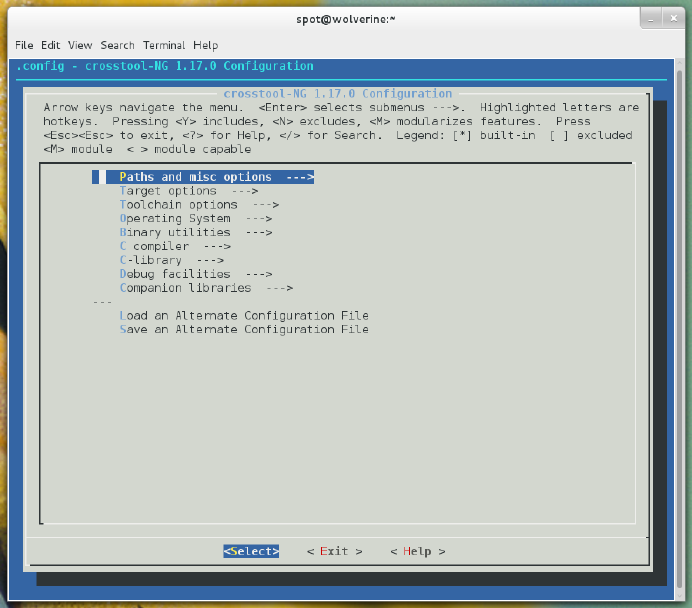
Figure 2-1.
Main configuration menu
The following sections describe the changes you’ll need to make, grouped by menu
sections from the top down.
Paths and Misc Options
In this section of the crosstool-ng menu (shown in Figure 2-2), make the following
changes:
• Enable “Try features marked as EXPERIMENTAL”.
•Set “Prefix directory” to the location where you want your cross-compiler tool-
chain to be installed. We suggest putting this either in its own subdirectory
in /opt or your home directory to ensure you don’t get your cross-compiler tool-
chain confused with your system native toolchain. We leave this at the default
value of ${HOME}/x-tools/${CT_TARGET}, which evaluates to ~/x-tools/arm-rpi-
linux-gnueabi/.
68 RASPBERRY PI HACKS
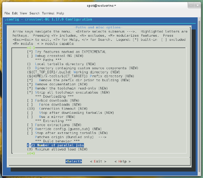
•Set “Number of parallel jobs”. This value will be passed to make to accelerate the
build time for the cross-compiler toolchain. Setting this value too low will make
the build take longer than it needs to, but setting it too high will result in the CPU
resources being spread too thin (and will also make the build take longer than it
needs to). The magic value seems to be the number of CPU cores in your system
multiplied by 1.5. On our 8 core laptop, this is 12. If you’re not sure how many CPU
cores your system has, run:
$ cat /proc/cpuinfo |grep processor
Count the number of lines, as each CPU core will appear to Linux as a unique pro-
cessor.
Figure 2-2.
Paths and misc options configuration submenu
Target Options
In this menu (shown in Figure 2-3), make sure the following settings are set:
69
CHAPTER 2: HACKING LINUX FOR THE RASPBERRY PI

• Set “Target architecture” to arm.
• Set “Endianness” to Little endian.
• Set “Bitness” to 32-bit.
Figure 2-3.
Target options configuration submenu
All of these should be the defaults, but the settings that follow are probably not. Making
the following changes will tune the cross-compiler toolchain to generate the best
possible binaries for the Raspberry Pi:
•Set “Architecture level” to armv6zk. This is the specific ARM architecture revision
of the Raspberry Pi ARM CPU.
•Set “Emit assembly for CPU” to arm1176jzf-s.
• Set “Tune for CPU” to arm1176jzf-s.
• Set “Use specific FPU” to vfp.
• Set “Floating point” to hardware (FPU).
70 RASPBERRY PI HACKS
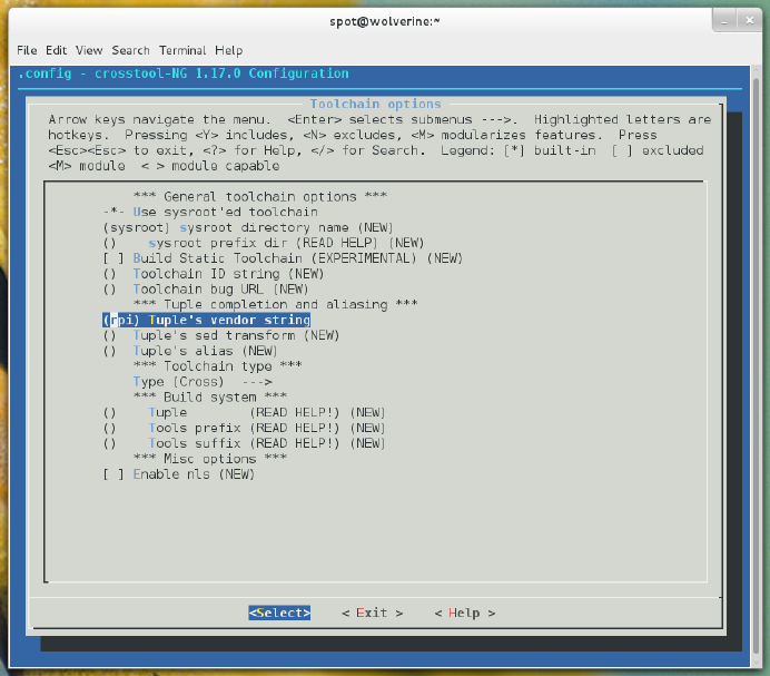
• Set “Default instruction set mode” to arm.
• Enable “Use EABI”.
Toolchain Options
Make the following change to the Toolchain options (shown in Figure 2-4):
•Set “Tuple’s vendor string” to rpi. Really, we could put anything we wanted in
here. We strongly recommend doing this to ensure that you know you’re using
the Raspberry Pi cross-compiler toolchain.
Figure 2-4.
Toolchain options configuration submenu
Operating System Options
Make the following changes to the Operating Systems Options (shown in Figure 2-5):
71
CHAPTER 2: HACKING LINUX FOR THE RASPBERRY PI
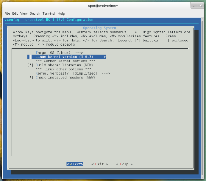
• Set “Target OS” to linux.
•Set “Linux kernel version” to 3.6.11. (Your Raspberry Pi might not be running the
3.6.11 kernel yet, but this is a safe value.)
Figure 2-5.
Operating system configuration submenu
Binary Utilities Options
Make the following changes to the Binary Utilities (shown in Figure 2-6):
•Set “Binary format” to ELF.
• Set “binutils version” to 2.22
72 RASPBERRY PI HACKS
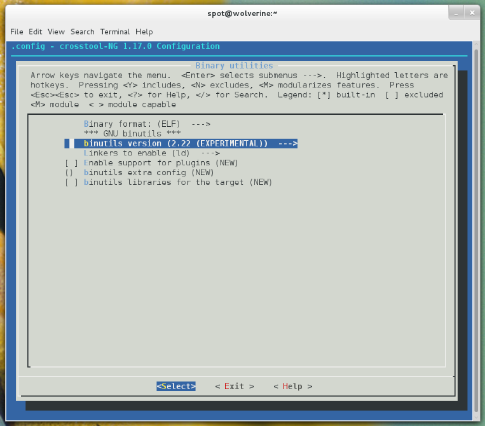
Figure 2-6.
Binary utilities configuration submenu
C Compiler Options
Make the following changes to the C Compiler options (shown in Figure 2-7):
• Enable “Show linaro versions”.
•Set “gcc version” to linaro-4.7-2013.01. (Feel free to try newer ones if they are
available when you are reading this.)
• Enable “C++”.
• Set “gcc extra config” to --with-float=hard.
• Enable “Link libstdc++ statically into gcc binary”.
73
CHAPTER 2: HACKING LINUX FOR THE RASPBERRY PI
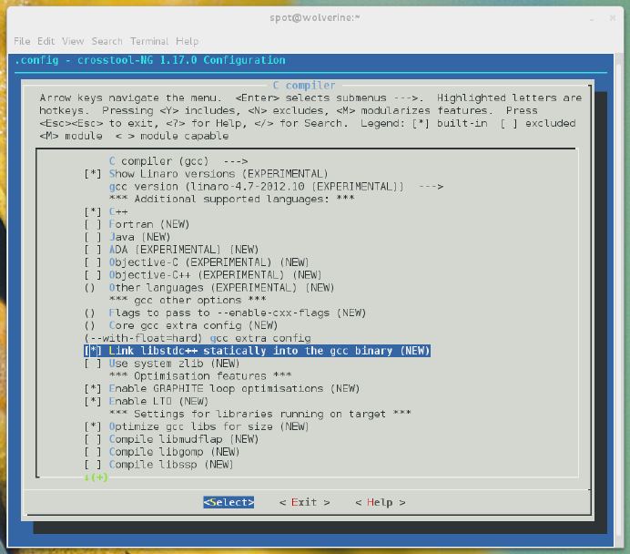
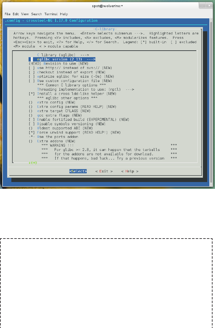
Figure 2-8.
C-library configuration submenu
That completes the configuration portion. Go to the main screen, exit, and save the
configuration file when prompted.
Disable CT_WANTS_STATIC_LINK
On some systems, crosstool-ng sets the CT_WANTS_STATIC_LINK value to Y,
even though you didn’t select that. This will cause it to fail early in the build
process, but you can use sed to ensure it is disabled. Run this command:
$ sed -i 's|CT_WANTS_STATIC_LINK=y|# CT_WANTS_STATIC_LINK is not set|
g' .config
This command might look complicated, but all it is doing is disabling the
CT_WANTS_STATIC_LINK feature in the crosstool-ng configuration file by
searching for the string that exactly matches the CT_WANTS_STATIC_LINK
75
CHAPTER 2: HACKING LINUX FOR THE RASPBERRY PI

option when it is enabled and, if found, replacing it with the string that dis-
ables it.
Begin the Build
Now you just need to kickoff the build process:
$ ct-ng build
It will then download everything it needs and build your Raspberry-Pi-optimized cross-
compiler toolchain. This is the longest part. The time will vary depending on your
system specifications and Internet speeds, but 45 minutes to an hour or more on a
powerful laptop is not unreasonable.
When this completes successfully, you will now have a cross-compiler toolchain in the
~/x-tools/arm-rpi-linux-gnueabi/bin directory. You will want to add this directory to
your PATH, in the same manner that you added the crosstool-ng directory previously.
Change the line you added from:
PATH=$PATH:/opt/crosstool-ng-1.18.0/bin
to:
PATH=$PATH:$HOME/x-tools/arm-rpi-linux-gnueabi/bin:/opt/crosstool-
ng-1.18.0/bin
Save the file, and then source it again to update the PATH value. Now you can test your
toolchain by running:
$ arm-rpi-linux-gnueabi-gcc -v
It will return a lot of information on how gcc is configured and optimized, along with
printing the compiler version. If you see that, your Raspberry Pi cross-compiler tool-
chain is ready to go.
HACK 22 Build a Custom Kernel
For many hacks, the standard prebuilt Linux kernel images are sufficient,
but some require options or drivers that are not enabled. This hack turns
on some additional options that will be useful for other hacks in this book.
The Linux kernel is a fantastic operating system core for a number of reasons, starting
with its versatility, its native support for a large number of architectures and devices,
and its open source code base. The Raspberry Pi Foundation provides prebuilt Linux
kernel images customized to support the Raspberry Pi hardware, as well as the cor-
responding source code tree, so that you can build a custom kernel image of your own
that will work on the Raspberry Pi. This is necessary, because not all of the code
76 RASPBERRY PI HACKS

needed for the Linux kernel to work on the Raspberry Pi is yet merged into the official
Linux kernel source tree.
The first step to building your own kernel is to decide whether you want to do so
natively from within the Linux instance running on the Raspberry Pi or to build it on
an x86 Linux system with a properly configured cross-compiler toolchain. We strongly
recommend the latter approach, because it will go much much faster (several hours
faster) and it is not that much more complicated.
We’ll assume that you’re building your new kernel with a cross-compiler toolchain—
specifically, the one described in Hack #21. You will also need to have the make and
ncurses-dev (or ncurses-devel) packages installed on your x86 Linux system.
If you really prefer to build the kernel natively on the Raspberry Pi, make sure that
you have the gcc, make, and libncurses-dev (or ncurses-devel) packages in-
stalled. Then, simply omit the ARCH=arm CROSS_COMPILE=arm-rpi-linux-
gnueabi- flags from each command-line invocation. You will also need to have a
copy of the Raspberry Pi Linux kernel source tree present in the running Linux
filesystem.
Download the Kernel Source Tree
First you’ll need to download a copy of the Raspberry Pi Linux kernel source tree. There
are currently several branches under development:
rpi-3.2.27
This was the original kernel source that the first Raspberry Pi Linux distributions
were using, but it is rather out of date at this point.
rpi-3.6.y
This is the active development kernel source tree, based on the kernel indicated
(3.6.11 as of this writing).
rpi-3.8.y, rpi-3.9.y, rpi-3.10.y, and rpi-3.11.y
These branches were created to track the various newer kernels. If you need
something specific with a newer branch, these might help you out.
The instructions in this hack will work for any kernel branch, but we strongly recom-
mend that you start with the rpi-3.6.y source tree, because it is still getting new
functionality and has the added advantage of several additional upstream releases’
worth of bug fixes and features.
Either way, you need to check out the Raspberry Pi Linux kernel source tree from Git.
We recommend you put this checkout in your ~/raspi working directory on your Linux
laptop (which you created in Hack #04), but if it doesn’t exist, just run mkdir ~/raspi):
77
CHAPTER 2: HACKING LINUX FOR THE RASPBERRY PI

$ cd ~/raspi
$ git clone git://github.com/raspberrypi/linux.git
This currently defaults to a 3.6.y checkout, but you can always confirm that by trying
to manually switch to the rpi-3.6.y branch:
$ cd ~/raspi/linux
$ git checkout rpi-3.6.y
If you want to use a different version of the source tree (e.g., 3.2.27-based), manually
switch to the rpi-$VERSION branch using the same method, but substitute rpi-
$VERSION for the Git checkout.
Alternatively, you can download a tarball from the GitHub website, which contains a
current copy of the code tree:
•rpi-3.2.27: https://github.com/raspberrypi/linux/archive/rpi-3.2.27.tar.gz
•rpi-3.6.y: https://github.com/raspberrypi/linux/archive/rpi-3.6.y.tar.gz
These links should never go stale, because GitHub generates these tarballs each time
you request them. This method has the advantage of being slightly faster, but we
usually prefer to checkout the full Git source tree, because we can then use the Git
tools to apply the latest changes from the upstream repository without needing to
download a new Linux kernel source tree again.
If you download these tarballs (into ~/raspi), simply unpack them using the following
tar command:
$ cd ~/raspi
$ tar xvfz rpi-3.6.y.tar.gz
This will create a linux-rpi-3.6.y/ (or linux-rpi-$VERSION) directory in ~/raspi (the
Git checkout will create a linux/ directory instead).
Next, you need to make sure you have a clean working kernel source tree. Change into
your Raspberry Pi Linux kernel source directory and run:
$ make mrproper
Linux Kernel Trivia
The Linux kernel contains a make clean target as well as the make mrprop
er target. The make mrproper target is a sort of “super clean,” as it does
everything that the clean target does, but a whole lot more (the clean target
leaves generated artifacts behind, while mrproper brings the kernel source
tree back to a pristine state).
78 RASPBERRY PI HACKS

But why is it called mrproper? It’s named after Mr. Proper, the internationally
used name of a well-recognized mascot for cleaning products. In the United
States, he is known as Mr. Clean.
Configure the Linux Kernel
Now you’re ready to start configuring the Linux kernel. This can be a daunting task if
you have never done it before, but that doesn’t mean you shouldn’t give it a shot!
(That’s the whole reason you bought a book called Hacks, right?)
The key to success is to start with a good default configuration that is known to work
properly on the Raspberry Pi. A base default configuration file is included in the Linux
kernel source checkout. This config file has the options enabled to support the hard-
ware embedded within the Raspberry Pi. Just copy it to the top-level Raspberry Pi
Linux kernel source directory (as .config):
$ cp arch/arm/configs/bcmrpi_defconfig .config
We recommend this approach, because it will minimize the number of questions that
you have to answer later.
Other Sources for Kernel Config Files
There are other places to get kernel config files. If you have an active Rasp-
berry Pi Linux instance that you just want to make minor kernel changes to,
you can get a copy of the configuration file that corresponds to that running
kernel image. To do this, type the following from within the Raspberry Pi
Linux instance:
$ zcat /proc/config.gz > ~/.config
Then, copy ~/.config from the Raspberry Pi Linux instance onto your Linux
laptop and place that copy in your Raspberry Pi Linux kernel source direc-
tory (as .config).
You should be aware that if you take this .config file from a kernel that is of
a different version than the source tree you are working on, this .config file
will not match up with the same configuration options that those kernels
have. It will still work, but you will end up having to answer a lot of questions
about these missing options in a later step.
We’ve also placed a copy of our Raspberry Pi kernel configuration file here
into the GitHub repository for this book. You should be able to use it as a
starting point if nothing else works. To download it, simply clone our repos-
itory:
79
CHAPTER 2: HACKING LINUX FOR THE RASPBERRY PI

$ git clone https://github.com/spotrh/rpihacks
In the new rpihacks directory, you will see a file named kernel-
book.config. Copy this file into your top-level Raspberry Pi Linux kernel
source directory (as .config).
From here onward, you will need to specify the ARCH=arm CROSS_COMPILE=arm-rpi-
linux-gnueabi- options to all of the make invocations. This tells the Linux kernel
code that you are building for a non-native architecture (ARM) and with a specific
cross-compiler toolchain. The “-” at the end of the arm-rpi-linux-gnueabi- string
is important, because the Makefiles will append the necessary binary commands
(e.g., gcc, ar, ld) to the end.
Now you need to make sure that this base configuration file is brought up to date:
$ make ARCH=arm CROSS_COMPILE=arm-rpi-linux-gnueabi- oldconfig
This command will ask you to provide answers to any values that are not defined in
the config file, and you’re likely to have more than a few blanks to fill in. For the vast
majority, you should simply hit Enter to accept the default, but there are a few that we
recommend you set if prompted:
Cross-compiler tool prefix (CROSS_COMPILE) [] (NEW)
Set this to arm-rpi-linux-gnueabi-. This is not entirely necessary, but it is better
to be safe than sorry here.
Local version - append to kernel release (LOCALVERSION) [] (NEW)
Set this to something unique. This will help you differentiate your custom kernel
from the prebuilt kernel images. We suggest using something that you will identify
easily as it relates to your project, or something containing the build date.
Those two settings will come early on (usually as the first two you see). After they’re
set, you just need to hit Enter several hundred times over the span of about 10 minutes.
Don’t worry too much about reading or changing these other options, as there is a
better way to find and make configuration changes in the next step. Just keep hitting
Enter until it says:
#
# configuration written to .config
#
80 RASPBERRY PI HACKS
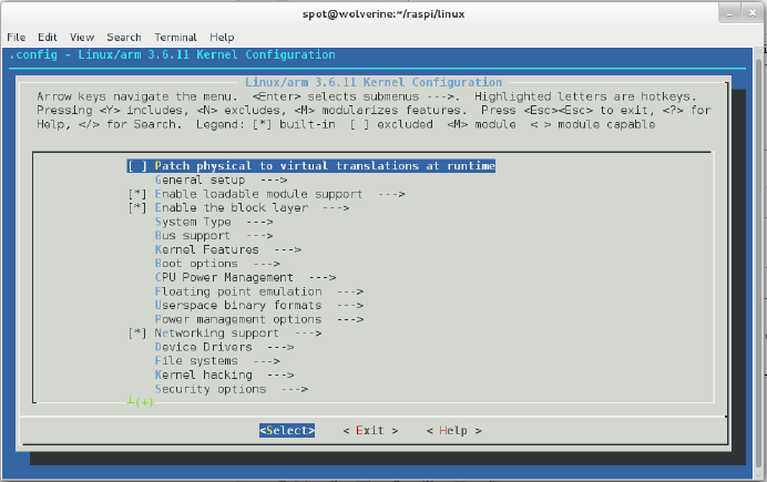
Once that has happened, you should be back at a shell prompt. Now you can use the
better, more intuitive menuconfig option to make specific configuration changes:
$ make ARCH=arm CROSS_COMPILE=arm-rpi-linux-gnueabi- menuconfig
This will present you with an ncurses-based Text User Interface (TUI) menu configu-
ration system, as shown in Figure 2-9.
Figure 2-9.
TUI menu configuration system
You can navigate through this system with the arrow keys and the Enter button.
Here you can make all sorts of configuration changes. Generally, if you’re doing this,
you’re enabling drivers or specific kernel features that you need for a hack. While we
can’t possibly list every option in the Linux kernel configuration universe (that would
be an entirely different book), we do point out options that need to be enabled in
several hacks in this book.
If you aren’t sure about an option, the TUI will let you see more information about any
specific configuration option by using the right arrow to move to Help (when an option
is highlighted) and then pressing Enter. The following screen presents a short sum-
mary of the option (usually in English, although sometimes in kernel-hacker dialect)
beneath the Kconfig syntax name for the option.
81
CHAPTER 2: HACKING LINUX FOR THE RASPBERRY PI

There are usually two ways to enable an option:
Compiled-in
If you opt to compile in a feature or driver, it will appear in the TUI with an asterisk.
You can select to compile in an item by hitting the spacebar when it is highlighted.
The upside to compiling things into the Linux kernel is that the feature/driver will
always be active. The downside is that the kernel becomes bigger and will use
more memory.
Modular
To enable a feature or driver as a module, just hit the M key when the item is
highlighted. Not everything can be built as a module, but most things can.
PinMux
One advantage to modularizing drivers is that it simplifies PinMux control on the
Raspberry Pi. PinMux is short for Pin-Multiplexing. The Broadcom BCM2835
system-on-chip used in the Raspberry Pi uses PinMux to select which signals will
be present on the pins of the chip. The multiplexing is necessary because the
number of available signals exceeds the number of available pins. Or, to put it
simply, some of the GPIO pins can be connected to different things within the
BCM2835 at different times. If your drivers which affect the GPIO pins or devices
are built as modules, you can switch the PinMux by simply loading/unloading the
module.
You should also be aware that some items, when enabled in the TUI, will expose ad-
ditional items (or even new submenus).
Quite a few of the hacks in our book connect to the Raspberry Pi across the I2C bus,
so you will definitely want to enable “I2C Support” (CONFIG_I2C). This option is under
the Device Drivers menu, and you will want to compile it into your kernel.
82 RASPBERRY PI HACKS
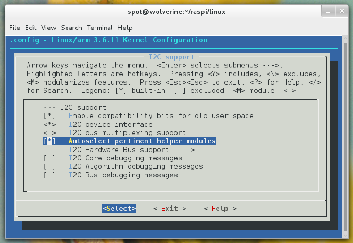
Additionally, you will need to go into the I2C Support submenu, and enable compiled-
in support for the “I2C device interface” (CONFIG_I2C_CHARDEV) and “Autoselect perti-
nent helper modules” (CONFIG_I2C_HELPER_AUTO). Figure 2-10 shows the menu with
these options properly enabled.
Figure 2-10.
I2C support options properly enabled
Then, in the “I2C Hardware Bus support” submenu, enable the BCM2708 BSC (CON
FIG_I2C_BCM2708) driver (again, as compiled-in, not as a module). This is the hardware
driver for the Raspberry Pi’s I2C bus controller. The BCM2708 I2C baud rate defaults
to 100000, and that is fine. It should look like Figure 2-11.
83
CHAPTER 2: HACKING LINUX FOR THE RASPBERRY PI
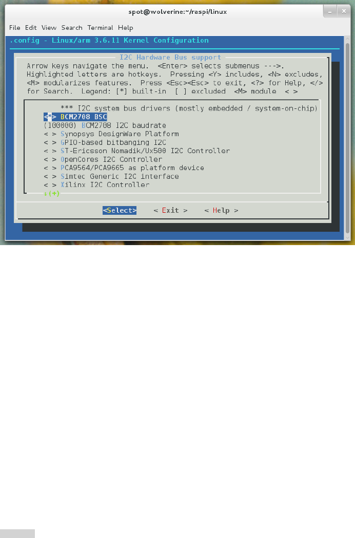
Figure 2-11.
BCM2708 BSC driver enabled to be compiled-in to the kernel
It is almost never risky to enable something as a module (“M”), unless it is marked as
EXPERIMENTAL or DANGEROUS. However, it is rather risky to disable something that
is enabled in the default configuration. Unless you know what you are doing, you are
probably better off leaving all of the default settings alone.
That said, do not be overwhelmed by the sheer volume of configuration choices. Feel
free to explore by navigating through menus and reading the help entries. You just
might find something interesting.
When you’re done configuring your kernel, return to the top-level menu and select
Exit. The TUI will prompt you to save your new configuration. It will exit and leave you
at a shell prompt, at which point you’re ready to build the kernel image.
Build the Kernel Image
To speed up the build, you can parallelize the compilation by passing the -j flag to
make. You’ll need to know how many CPU cores are present on your build system to
determine the ideal value.
Hack #21 provides a longer explanation of this concept, but the basic formula we rec-
ommend trying is the number of CPU cores you have multiplied by 1.5. For example,
84 RASPBERRY PI HACKS

on an eight-core laptop, it would be 12. Using that example with this flag, the command
to kickoff the build is:
$ make ARCH=arm CROSS_COMPILE=arm-rpi-linux-gnueabi- -j12
If you do not want to run a parallel compilation, simply omit the -j## flag from the
command (note, however, that this will cause the build to take significantly longer).
At this point, your laptop is cross-compiling the core Linux kernel image. Depending
on the options you have selected, this might take a while, but if all goes well, it will
finish compiling without errors. Next, you’ll need to build the matching kernel mod-
ules.
To keep the size of the core Linux kernel image small, many of the drivers for devices,
filesystems, and optional functionality are normally configured to be built as Linux
kernel modules. These make up a large tree of files, where each file is an individually
loadable device driver.
Most Linux distributions (including Pidora and Raspbian) contain support for auto-
loading appropriate kernel modules as they are needed, but you might find some sit-
uations in which you’ll want to load a kernel module manually. This model also helps
with memory management and boot object size. The default configuration we provide
with this book modularizes as much as possible.
To start the Linux kernel modules build, run:
$ make ARCH=arm CROSS_COMPILE=arm-rpi-linux-gnueabi- modules -j12
This will also take some time, but it should finish without errors. If a module fails to
build, you might need to disable it in the kernel configuration file and restart the whole
process, but this is unlikely. Now, you just need to install your new kernel.
Install a New Kernel
The core Linux kernel image for the Raspberry Pi is a specially formatted copy of the
zImage binary, compiled as an ARM boot executable. This image contains the primary
functions of the Linux kernel, and it contains all the necessary code for booting into
the Linux operating system.
This is the file that is booted by the Raspberry Pi GPU firmware. It is not usually a large
file (slightly less than 3 MB). If you’ve built a custom Linux kernel from source as
described in the previous sections, you can find a copy of the core Linux kernel image
at arch/arm/boot/Image within that kernel source tree.
To install a new kernel, you will need to copy files onto the SD card containing your
Raspberry Pi Linux distribution. If you have not already mounted your SD card on your
Linux laptop, go ahead and do so by following the directions in Hack #02. Make sure
85
CHAPTER 2: HACKING LINUX FOR THE RASPBERRY PI
that both the root and boot partitions are mounted, because you will need to copy
files to both partitions.
Go ahead and copy the new core Linux kernel image into the mounted boot partition
on the SD card:
$ su -c 'cp -a arch/arm/boot/Image /mnt/raspi-boot/new-kernel.img'
By default, the Raspberry Pi GPU firmware attempts to boot kernel.img from the boot
partition. Since you are installing a new kernel, you probably want to override this
behavior.
If you want it to boot a different filename, you can specify that by adding a line to
config.txt (also found on the boot partition). If for some reason config.txt is not
present on the boot partition (it is not necessary for the Raspberry Pi to boot Linux),
simply create a new file with that filename.
To boot a specific file, edit /mnt/raspi-boot/config.txt and add a line like this:
kernel=new-kernel.img
In this example, the Raspberry Pi GPU will now look for new-kernel.img on the boot
partition of the SD card and try to execute it at boot time. Conveniently, this is the
name we used when we copied over the new kernel image. We used a new name here
to avoid conflicts with the stock Linux kernel image file kernel.img that came with your
Raspberry Pi Linux distribution. From here on, we will assume that the Raspberry Pi
Linux distribution is configured to boot your new kernel image file (as specified by
kernel=).
The second set of files that you need to copy over are the prebuilt Linux kernel modules
that match the new kernel image file. If you built a new Linux kernel from source, you’ll
need to install your new modules into a temporary directory. To do this, simply run
these commands from the top level of your kernel source code tree:
$ mkdir ~/modules
$ make ARCH=arm CROSS_COMPILE=arm-rpi-linux-gnueabi- \
INSTALL_MOD_PATH=~/modules modules_install
Unlike the core Linux kernel image (which has to be on the boot partition), the kernel
modules live in the root partition—specifically, in the /lib/modules directory. All you
need to do to install them is to copy the whole versioned directory (or directories)
into /lib/modules on the mounted root SD card partition. For your custom-built kernel,
these commands will copy over the proper modules:
$ cd ~/modules
$ su -c 'cp -a lib/modules/* /mnt/raspi-root/lib/modules/'
86 RASPBERRY PI HACKS

Post-Installation Tasks
When the last of these modules finishes copying onto the root partition, make sure
you have config.txt on the mounted boot SD card partition configured to boot the
new kernel image (or unconfigured, so that kernel.img is booted). Then run the sync
command a few times to ensure the data has all arrived onto the SD card:
$ sync;sync;sync
Now it should be safe to unmount the SD card partition(s) and eject the SD card. You
can unmount these partitions either from the GUI interface of your Linux laptop, or
you can manually unmount them from the terminal by running these commands:
$ cd ~
$ su -c 'umount /mnt/raspi-boot'
$ su -c 'umount /mnt/raspi-root'
Make sure to change into a directory that is not in either of the mounted partitions
before attempting to run the umount command, or that command will not succeed.
Next, put your SD card into your Raspberry Pi and plug it in. You should see it boot
into the Linux kernel successfully. Once you’ve logged in, you can now run:
$ uname -a
Linux myrpi 3.6.11+ #24 PREEMPT Sun Aug 19 21:28:36 BST 2013 armv6l GNU/
Linux
This will print out a list of system information, but the most important one is the ver-
sion of the running Linux kernel. It should match the version of the modules directory
(or directories) that you just copied over. You can also confirm that the build date
printed out for the running kernel matches the date that you built your new kernel.
HACK 23 Update to the Latest Prebuilt Kernel
Want the latest Linux kernel features for your Raspberry Pi? Of course
you do, and there is a way to get them without having to build it from
source.
The nice folks at the Raspberry Pi Foundation are regularly hard at work adding new
features to their Linux kernel source tree. They also go one step beyond and regularly
update a copy of a prebuilt Linux kernel image. This kernel is configured with a set of
options and modules intended specifically for the Raspberry Pi. Using this kernel
means that you can be sure that all of the hardware built into the Raspberry Pi will be
properly enabled, along with any Raspberry-Pi-specific functionality.
87
CHAPTER 2: HACKING LINUX FOR THE RASPBERRY PI

Distribution specific features
Some Linux distributions may assume the presence of features which are not en-
abled or supported in the Raspberry Pi Foundation prebuilt kernel images. Exam-
ples include SELinux, some extended filesystem attributes, and some typos of
cryptography. This is one of the reasons we recommend that you keep a backup
copy of the distribution provided kernel image around, just in case.
The Raspberry Pi Foundation offers prebuilt binary kernel images in the same Git
repository that they use for firmware. To get a copy of this Git tree, see the instructions
in Hack #04.
Remember that this Git tree has two branches: master, which is targeted for the Rasp-
berry Pi Linux kernel 3.2-based source tree, and next, which is targeted for the Rasp-
berry Pi Linux kernel 3.6-based source tree. You need to make sure that your kernel
and firmware revision versions match; otherwise, your kernel might not boot (or fea-
tures might not work the way that you expect). The file locations for the prebuilt kernel
files are identical for both branches of the Git repository.
The Raspberry Pi Foundation’s prebuilt Linux kernel is handy, having been designed
for use with the Pi, and it contains a wide range of common device driver modules.
However, it is missing some modules that you might need when connecting periph-
erals. If this is the case, you will want to build a custom Linux kernel from source, as
covered in Hack #22.
Get the Prebuilt Linux Kernel
The prebuilt Linux kernel images come in two parts:
• The core Linux kernel image (firmware/boot/kernel.img)
•The prebuilt Linux kernel modules that correspond to that image (firmware/
modules)
You can view the history of builds for the core Linux kernel image via the GitHub web-
site. If you want to see the history for the next branch, just change the branch via the
drop-down on the website, or replace master with next in the URL.
Alternative Prebuilt Kernel Variants
The Raspberry Pi foundation also provides two alternative variants of this
prebuilt kernel:
88 RASPBERRY PI HACKS

kernel_cutdown.img
This is the smallest possible Linux kernel that can be booted on the
Raspberry Pi. It contains minimal peripheral support outside of what is
absolutely needed to use the embedded devices on the Raspberry Pi.
It comes with a much smaller set of kernel modules than the standard
kernel image.
kernel_emergency.img
This is a Linux kernel image that contains a wide range of support com-
piled directly into the Linux kernel. Because so much support is com-
piled directly into this kernel, it can be treated as a “safe mode” kernel,
and it should boot properly even if the Raspberry Pi Linux userspace
has problems. The downside to this kernel image is that it is large in
comparison (9.2 M) and thus will have a performance impact. Also, it
does not come with any kernel modules, as all of the device drivers are
compiled into the kernel image!
Both of these alternative kernel images are built from the same source tree
as the normal kernel image and are present in the Git checkout (firmware/
boot). You can copy these to the boot partition using the same methods
described for the usual image. Simply change directory into the mounted
boot partition, rename any existing copies of these files to serve as backups,
and then copy the new files from the Git checkout into the mounted boot
partition.
Remember, if you want to boot into one of these kernels (or one of your
backup kernel images), just add an appropriate kernel= line to config.txt.
You might want to add multiple lines to correspond to different kernel im-
ages, but be sure to comment out any entries that you are not using by
prepending a \# character to the beginning of the line.
Now you can safely copy the new core Linux kernel image from your Git checkout onto
the boot partition (as root). You’ll want to rename this file from kernel.img when you
do this (or rename the existing kernel.img in the SD card boot partition).
Install the Prebuilt Kernel Modules
Next, it is time to install the matching prebuilt kernel modules. You can find these
modules under the firmware/modules directory from your Git checkout. There will be
at least two directories here, and each will contain a version that corresponds to the
version of the Linux kernel used to build these images (and modules). At the time of
this writing, this version was 3.6.10, which shows as:
89
CHAPTER 2: HACKING LINUX FOR THE RASPBERRY PI

$ ls -l
total 8
drwxrwxr-x 3 spot spot 4096 Dec 12 21:57 3.6.10+
drwxrwxr-x 3 spot spot 4096 Dec 12 21:57 3.6.10-cutdown+
What’s Up with That +?
You might have noticed that the versioned directories here have a \+ ap-
pended to them. This is a custom identifier that the Raspberry Pi Founda-
tion uses for their kernel builds, mostly to prevent conflicts with custom
kernel builds (which by default, do not contain a custom identifier).
The prebuilt core Linux kernel images will be looking for their modules in
these exact directory names (including the +), so do not rename them. If
there is an existing directory with the same name, it is reasonably safe to
overwrite it (assuming that you have also copied the matching kernel image
file from the same firmware checkout), but you can always rename the di-
rectory to act as a backup.
Just be aware that even if you boot the older kernel image via kernel= in
config.txt, it will not know how to look in the renamed modules directory
and will try to load its modules from the original versioned directory.
The 3.6.10+ directory contains the modules that are built for kernel.img, while the
33.6.10-cutdown+ directory contains the modules that are built for kernel_cut
down.img. Makes sense, right? If you have copied kernel_cutdown.img into the boot
partition of your SD card, you will want the corresponding modules, but if you have
copied only kernel.img, you can leave them alone. It will not hurt anything to also copy
the cutdown kernel modules, but it will eat up about 15 MB more on your SD card.
For the prebuilt kernel, this will copy the proper modules:
$ cd ~/raspi/firmware/modules
$ su -c 'cp -a 3.6.10+ /mnt/raspi-root/lib/modules/'
From here on out, you will need to complete the same post-installation tasks that you
would do for a kernel installed from source, as described in “Post-Installation Tasks”
on page 87.
Merging Raspberry Pi Changes into Upstream
Linux Kernel Source
At some point, ideally, the Raspberry Pi Foundation will be able to merge all
of its Raspberry Pi (and BCM2835 system-on-chip) changes into the up-
stream Linux kernel source. This will mean that it is no longer necessary to
90 RASPBERRY PI HACKS

have a separate Raspberry-Pi-specific Linux kernel source tree, and it is
possible that the Raspberry Pi Foundation will stop providing new prebuilt
kernel images as a result.
This is just speculation, though, because while the Raspberry Pi Foundation
has indicated a desire for merging its patches into the upstream Linux ker-
nel tree, and there are various kernel hackers working toward this goal, it
has not yet happened. To date, the Foundation has not given any indication
that it will stop making prebuilt kernel images. This should not be too big of
a problem if it does happen, because the Linux distributions will easily be
able to produce prebuilt Raspberry-Pi-specific Linux kernel images that
they maintain from the upstream “Linus” source tree.
We point this out only so that if you are reading this book at a future time
when this has indeed occurred and you are not seeing recently updated
prebuilt kernel images in their GitHub firmware repository, you might have
an idea why.
HACK 24 Split Memory Between the GPU and
Linux Userspace
The performance that you get from your Raspberry Pi is tightly coupled
to the amount of memory that you allocate to its core components. Be-
cause this isn’t a system you can just drop more RAM into, you should
consider the needs of your project and the best way to split the available
memory.
In the embedded hardware universe, memory is almost always a precious and scant
commodity. The performance of the system is usually tightly coupled to the amount
of present (and accessible) memory. Additionally, most embedded systems do not
have any user-serviceable method to increase the amount of physical memory, and
the Raspberry Pi is no different.
When the Raspberry Pi Model B was first released, it came with 256 MiB of memory
(either Hynix MobileDDR2 or Samsung Mobile DRAM, depending on when it was pro-
duced). The memory rests physically on top of the Broadcom media processor in the
BCM2835 system-on-chip. This is known as package on package (PoP). PoP allows
for an embedded system to combine multiple ball grid array (BGA) packages in a
vertical stack.
The Raspberry Pi system-on-chip uses a mixed logic-memory stack, which is useful
to save space and allows the hardware vendor to choose from a wide range of com-
patible options (and helps them to keep costs down). This design decision allowed
91
CHAPTER 2: HACKING LINUX FOR THE RASPBERRY PI

them to easily upgrade the amount of on-board memory on the Model B from 256
MiB to 512 MiB (all Model B units sold after October 15, 2012 have the larger amount).
How to Tell Which Pi You Have
If you have a Pi that’s been sitting around for a while, and you’re not sure
which one it is, you can use cat /proc/cpuinfo to find out. The results look
like this:
Processor : ARMv6-compatible processor rev 7 (v6l)
BogoMIPS : 795.44
Features : swp half thumb fastmult vfp edsp java tls
CPU implementer : 0x41
CPU architecture: 7
CPU variant : 0x0
CPU part : 0xb76
CPU revision : 7
Hardware : BCM2708
Revision : 000e
Serial : 0000000011185abc
The part after Revision tells you which board you have. Refer to this table:
Revision code Model Rev number RAM (MB)
0002 B 1.0 256
0003 B 1 256
0004 B 2 256
0005 B 2 256
0006 B 2 256
0007 A 2 256
0008 A 2 256
0009 A 2 256
000d B 2 512
000e B 2 512
000f B 2 512
This significantly improved the performance of the Raspberry Pi. Unfortunately, mak-
ing a change to the amount of memory is a decision that can really be made only at
92 RASPBERRY PI HACKS

fabrication time, and it’s not one that a user can easily hack. Stacking these tiny BGA
units is best done by robots, not clumsy human hands.
Even with the newer 512 MiB of memory, it’s a precious resource. Because of how the
BCM2835 system-on-chip works, some of this memory must go to the GPU. You might
have seen this sort of behavior on lower-end GPU cards for x86 computers, which do
not include dedicated on-GPU memory and dedicate some system memory for GPU
usage. The Raspberry Pi firmware allows for you to customize the amount of memory
that is allocated to the GPU.
Before the 512 MiB Raspberry Pi Model B units existed, customizing memory alloca-
tion was accomplished by choosing a start.elf file corresponding to the splits shown
in Table 2-1.
Table 2-1. Memory allocation on 256 MiB Raspberry Pi Model B
ARM CPU VIDEOCORE GPU FILENAME
128 MiB 128 MiB arm128_start.elf
192 MiB 64 MiB arm192_start.elf
224 MiB 32 MiB arm224_start.elf
240 MiB 16 MiB arm240_start.elf
This worked well when the Raspberry Pi Model B firmware had only one possible
memory size (256 MiB) to support, but when they started producing the 512 MiB
Model B units, this approach no longer made sense. Among other reasons this didn’t
work, the most obvious is that twice as many splits are possible on the 512 MiB units
(even if some of them are pretty ludicrous). They also wanted the firmware to be able
to support both units, and the split-out start.elf model was very much hardcoded to
the 256 MiB size.
Allocate Memory with config.txt
The current firmware (necessary for the 512 MiB units) abandons the separate
start.elf file approach and adds support for start.elf to read in a variable (gpu_mem)
from config.txt that specifies exactly the amount the user wants to allocate to the
GPU in chunks of 16 MiB, with 16 MiB as the minimum and 448 MiB as the maximum.
To set this, open config.txt (on the boot partition of the SD card containing the Rasp-
berry Pi Linux image) in the editor of your choice and use the following syntax (where
value is an integer representing the total MiB to dedicate to the GPU, in chunks of 16
MiB, 16 to 128 MiB):
gpu_mem=(value)
93
CHAPTER 2: HACKING LINUX FOR THE RASPBERRY PI

The Raspberry Pi firmware sets gpu_mem=64 as the default. But just how much memory
should you allocate to the GPU? The answer depends on what your Raspberry Pi will
be used for.
If you’re using it in a headless mode (see Hack #11), you can set gpu_mem to the minimum
value of 16. If you do this, you will need to be sure that start_cd.elf and fix
up_cd.elf are present, because they will be used instead. Be careful with this, because
video will not work at all at this minimal setting, but on the upside, it will leave 496 MiB
for the ARM CPU (this gets used by Linux userspace).
For an only slightly video-friendly option, at gpu_mem=32, the Linux kernel can drive the
framebuffer at 1080p, but 3D and video processing will not work properly. At
gpu_mem=128, you will get excellent 3D and video decoding performance, but you will
leave the Linux userspace with only 384 MiB.
In the middle of the road with a 256 MiB/256 MiB split, you will give the GPU enough
memory to handle big textures, but the Linux userspace will really struggle. It is pos-
sible to increase this value up to 448 MiB, but we don’t recommend exceeding 128
MiB unless you have an exceptionally GPU-intensive use case.
While the core Linux kernel is capable of running in memory-starved environments,
most userspace applications (especially graphical ones) rely on the availability of tens
of MiB of memory to run properly. The Raspberry Pi contains less memory than most
popular smartphones (for example, the Galaxy Nexus and iPhone 5 have 1 GiB, and
the Nexus 4 has 2 GiB).
Also keep in mind that Linux aggressively pre-caches available memory that is not
currently being used by applications to improve system performance. This means that
the more memory you can allocate to the ARM CPU, the better performance you’ll get
from Linux.
Make a config.txt Compatible with 256 or 512 MiB
Models
It is possible to make a config.txt that works on both 256 MiB and 512 MiB
Raspberry Pi Model B units. To set the GPU memory to be compatible with
both units, you need to use the gpu_mem_256 and gpu_mem_512 parameters.
The gpu_mem_256 parameter is used on the 256 MiB Raspberry Pi Model B,
overrides any value set in gpu_mem=, and is ignored entirely on the 512 MiB
Raspberry Pi Model B.
The same is true of the gpu_mem_512 setting, except that it is used on the 512
MiB unit and ignored on the 256 MiB unit. gpu_mem_256 has a max value of
192, and gpu_mem_512 has a max value of 448.
94 RASPBERRY PI HACKS

On Raspbian, it is also possible to configure an explicit memory split by using the
raspi-config utility. Launch raspi-config as root, and select the Memory Split option.
For most of the hacks and projects in this book, gpu_mem=128 should be a good place
to start. It’s the setting that has given us the best possible overall performance in most
of our tinkering. Feel free to experiment, though, as the only real damage you can do
is to the Raspberry Pi’s performance, and you can always change it back.
Automatically Share Memory
While you might be able to guess how much memory you want to split between the
CPU (OS) and the GPU (graphics), there are a lot of situations where you probably will
not know for sure. In cases like this, you really want to be able to configure your Rasp-
berry Pi to split the memory on the fly, allocating it between the CPU and the GPU as
needed.
As of the post-November 2012 firmware and 3.6 Linux kernel updates, there is a better
way to manage the GPU/CPU memory split. Called the Contiguous Memory Allocator
(CMA), it enables a dynamically managed memory split between the GPU and the
ARM CPU by setting low- and high-water marks for the GPU.
The config.txt parameter for the GPU low-water mark is cma_lwm, and cma_hwm is the
parameter for the GPU high-water mark. In order to use these parameters, you also
must pass some options to the Linux kernel at boot time. You can do this by adding
these options to cmdline.txt (on the boot partition of the SD card):
coherent_pool=6M smsc95xx.turbo_mode=N
This change to cmdline.txt also has the side-effect of disabling the turbo mode
for the built-in ethernet controller on the Raspberry Pi, but you might not mind too
much unless you have a network-intensive use case. Disabling turbo mode also
sometimes improves wireless network performance (and eliminates a lot of DE-
BUG noise in the system logs in some cases).
In this configuration, you will also need to set the following values in config.txt:
gpu_mem_256=112
gpu_mem_512=368
cma_lwm=16
cma_hwm=32
cma_offline_start=16
Once you have rebooted the Raspberry Pi with these settings in place, it will result in
466 MiB memory free (212 MiB on the 256 MiB Model B unit) for the Linux userspace
by default, with more allocated to the GPU as needed (within the watermarks).
95
CHAPTER 2: HACKING LINUX FOR THE RASPBERRY PI

While this CMA support is comparatively new, we highly recommend trying it instead
of hardcoding the split for most common use cases. It will improve things like web
browser performance while still allowing for high GPU memory utilization cases on-
demand.
HACK 25 Update the Firmware and Prebuilt Binary
Kernel the Easy Way
Everything’s easier when there’s a tool for it, and fortunately, Liam
McLoughlin (a.k.a. “Hexxeh”) has created one for updating your Rasp-
berry Pi firmware and kernel.
rpi-update is a shell script that automates the process of updating the firmware, pre-
built binary kernel, and prebuilt VideoCore SDK files on an SD card containing a Rasp-
berry Pi Linux distribution image.
First, make sure that you have the readelf and git binaries installed in your chosen
Raspberry Pi Linux distribution. You will need these commands for successful use of
the rpi-update script. On most Linux distributions, readelf is in the binutils package
and git is in the git package.
To install it, run the following (as root) on Pidora:
$ su -c 'yum install binutils git'
or Raspbian:
$ su -c 'apt-get install binutils git-core'
To use this script, download it from within your running Raspberry Pi Linux Distribution
image with the following command:
$ wget https://raw.github.com/Hexxeh/rpi-update/master/rpi-update
You will need to put it in your $PATH and set it executable. The simplest way to do this
is to run the following commands (as root):
$ su -c 'cp rpi-update /usr/bin/'
$ su -c 'chmod +x /usr/bin/rpi-update'
Then, to update the firmware, prebuilt binary kernel, and VideoCore SDK libraries all
at once, simply run (as root):
$ su -c 'rpi-update'
There are, however, a few caveats to using this shortcut tool:
96 RASPBERRY PI HACKS

•It does require you to run the script from within the running Linux environment.
Make sure that the time is set properly within the environment, or you might get
script failures relating to clock drift.
•The script does not let you perform fine-grained update operations (e.g., just
update the firmware). It is an all-or-nothing experience.
•The script assumes that the VideoCore files are located under /opt/vc. Some
Raspberry Pi Linux distributions (such as Pidora) place the VideoCore files in a
different location or include them in the system library directories, so this script
will not work well for them.
The rpi-update script does not use the official GitHub repository for prebuilt files be-
cause of the size of that repository. Instead, Hexxeh keeps a copy of those files in a
separate GitHub repository with a different filesystem layout.
While this separate repository seems to be manually synced with the official reposi-
tory on a regular basis, keep in mind that it is possible that you will not be getting the
absolute latest available revisions of these files. Sometimes, that’s how it goes when
you try to take shortcuts.
HACK 26 Emulate the Pi
Whether you’re travelling without your Pi, need to test something in a
hurry, or your kids have taken over the Pi while you weren’t looking, it can
sometimes be convenient to emulate it on another machine. QEMU can
help.
QEMU (short for Quick EMUlator) is an open source, hosted hypervisor. That means
that you can use it to run a Linux distro that was made for your Raspberry Pi (which
uses ARM hardware) on your usual computer (an x86 laptop, for example).
It has two modes. The first is user-mode emulation, which lets you run single programs
that weren’t compiled for your machine. But this hack focuses on QEMU’s full-system
emulation, which lets you emulate an entire computer—in this case, a Raspberry Pi.
First install QEMU, by running this command on Fedora:
$ su -c 'yum install qemu'
Or, you can run this on Debian/Ubuntu:
$ su -c 'apt-get qemu-system-arm'
Download kernel-qemu from http://xecdesign.com/downloads/linux-qemu/kernel-
qemu. You can also compile your own kernel.
97
CHAPTER 2: HACKING LINUX FOR THE RASPBERRY PI

Why Is This Kernel Special?
You might have noticed that we have not pointed you to the hack in this book (Hack
#22) that covers building a custom kernel for booting on the Raspberry Pi. This is
intentional, because that kernel will not work on qemu_. Qemu emulates a wide range
of hardware environments, but the exact hardware found in the Raspberry Pi is not
yet one of them.
The kernel-qemu file uses the closest match available in qemu and provides the
same level of ARM optimization and runtime support. This allows you to use almost
everything in your Raspberry Pi Linux distribution userspace as is. The most no-
table exception is the videocore libraries (and any applications which use them).
Because qemu has no BCM2835 system-on-chip hardware emulation, these ap-
plications will fail to operate properly in qemu emulation.
Create a directory to work in, and put a copy of your distro’s image and kernel-qemu
in it. The rest of this example will use the Pidora 18 image (pidora-18-r1c.img) and
qemu as that directory, though you can replicate these instructions for other distros
and of course name your directories whatever you like.
Run file on the image:
$ file pidora-18-r1c.img
pidora-18-r1c.img: x86 boot sector; partition 1: ID=0xc, active, starthead
32, startsector 2048, 102400 sectors; partition 2: ID=0x83, starthead 32,
startsector 104448, 3389858 sectors, code offset 0xb8
Take the startsector number from partition 2 (bold in the previous output) and mul-
tiply it by 512 to use as the offset number when you mount the image:
$ sudo mount qemu/pidora-18-r1c.img -o offset=53477376 /mnt/pidora
Now open /mnt/pidora/etc/ld.so.preload in a text editor and comment out the one
line you find there by adding a # in front of it and saving the file. You can now unmount:
$ sudo umount /mnt/pidora
And you’re ready to start Pidora in QEMU:
$ qemu-system-arm -kernel kernel-qemu -cpu arm1176 -m 256 -M versatilepb -
serial stdio -append "root=/dev/sda2 panic=1" -hda pidora-18-r1c.img
These are the options you’re setting:
-kernel
You’re telling it to use the kernel-qemu kernel file you downloaded. If you created
your own, specify its name+/path+ here instead.
98 RASPBERRY PI HACKS

-cpu
The Raspberry Pi contains an ARM1176 core, which you specify here. To see the
complete list of options QEMU offers, use the command qemu-system-arm -cpu
help.
If you have an older QEMU installation or acquire it from a package that hasn’t been
updated, you might encounter a problem with the -cpu option, because older ver-
sions didn’t support ARM1176. You might be able to make this work by substituting
arm1136-r2, but it would be better to update your version of QEMU.
-m
This sets the virtual RAM in megabytes. It is unlikely to work with more than 256.
-M
This sets the emulated machine type. (We’re specifying the Versatile PB platform
here.)
-serial
This redirects the virtual serial port. The default is vc in graphical mode and stdio
in non-graphical mode.
-append
This option gives the kernel command-line arguments.
-hda
This is the location of the image of the distro you’re emulating.
You can read further documentation of QEMU’s options at http://qemu.org.
This will take you to the first boot screen, and you can go through that process just
like you would on an actual Pi. It will reboot at the end, but QEMU will close, and you’ll
have to start it again. Just press the up arrow once to get to the previous qemu-system-
arm command and run it again.
This time you’ll boot through to the login screen and can use it as if you were on an
actual Raspberry Pi.
HACK 27 Try Occidentalis: The Raspberry Pi Distro
for (Advanced) Education
If you’re interested in using the Pi for hardware-hacking education (or
learning!), Adafruit’s Raspberry Pi Educational Linux Distro (a.k.a. Occi-
dentalis), is a great place to start.
99
CHAPTER 2: HACKING LINUX FOR THE RASPBERRY PI

Raspbian was one of the first Linux distributions designed specifically for the Raspb-
ery Pi, and it was based on Debian 7.0, nicknamed “Wheezy.” Thus the Raspberry Pi
version was named with the portmanteau “Raspbian Wheezy.” But online electronics
shop Adafruit found that Raspbian Wheezy didn’t have some of the features it most
wanted for hacking through the Raspberry Pi’s breakout pins, so it decided to create
its own. It’s called Occidentalis and is based on Raspbian Wheezy with hardware SPI,
I2C, and WiFi support built in, among other things.
Occidentalis is recommended for those with Linux experience who are interested
in taking full advantage of the hardware. Despite the “for education” aspect, it’s
not meant for beginners. That doesn’t mean it’s useless for kids; rather, it means
that this is a do-it-together sort of project.
Occidentalis is worth mentioning in this book, because it is intended for use with elec-
tronics. This means that it comes preconfigured in kernel and userspace to access
and control some commonly available sensors and components. This is especially
true if they come from Adafruit. Using Occidentalis will save you some time if you’re
attempting Hack #37.
As of this writing, the current version of Occidentalis is v0.2, based on Raspbian
Wheezy from August 16, 2012. Version 0.1 includes:
•Firmware updating: Liam McLoughlin (“Hexxeh”) created a tool called rpi-
updater to update the Raspberry Pi’s firmware. We talk about it in more detail in
Hack #25.
•I2C and hardware SPI supported and initialized at boot.
•Ready-to-go sshd at first boot: At boot, the ssh keys are generated with a user-
name and password of pi/raspberry on raspberrypi.local.
•Support for WiFi through the Realtek RTL8188CUS USB module, a tiny 802.11b/
g/n WLAN controller, which you can purchase from Adafruit and other vendors
for about $12.
•One-wire support on GPIO 4. See this GitHub page.
Version 0.2 includes those features as well as:
•Removed persistent wlan0 entry
•RTC, lm-sensors
•Kernel modules DS1307, AD626 I2C digipots, HMC6352, BMP085, and ADS1015,
which support common sensors, like weather sensors
•Custom PWM/Servo kernel module
100 RASPBERRY PI HACKS

Occidentalis and Hynix
If your CPU says “Hynix” in a handwriting-style font on it, that indicates that you
have Hynix RAM. It will not work with Occidentalis as of version 0.2. The next ver-
sion is expected to be compatible.
Download the most recent version of Occidentalis at http://learn.adafruit.com/. It is
only a 99 MB download, which decompresses to a 2.6 GB image, so you only need a
4 GB card, unless you want extra room for storage. As of v0.2, you should see the
raspi-config tool at boot. If not, or if you’d like to return to it later, enter:
$ sudo raspi-config
What’s with the Crazy Name?
For starters, it’s a lot quicker to type “Occidentalis” than “Adafruit Raspberry Pi
Educational Linux Distro.” But if you go to http://learn.adafruit.com, you’ll notice
that the Occidentalis logo looks a lot like the Raspberry Pi logo, but a bit darker.
Rubus occidentalis is a particular species in the rose family more commonly known
as “black raspberry,” hence the name and the logo.
Your options in raspi-config should look familiar if you’ve used Raspbian, upon which
Occidentalis is based. Here are the ones you’ll most likely want to use or change up
front:
expand_rootfs
Clicking this will give you no further options; it will simply expand the root partition
to fill the available space on the SD card, which will be available after the next
reboot.
change_pass
Since the pi user’s password is publicly known, it’s a good idea to change it at first
boot.
boot_behaviour
Tell it whether you want to boot to the command line or to the GUI desktop.
update
Update to the latest packages.
Of course, for update, you’re going to need to be online, which is easy if you plugged
into a wired connection. But if you’re using a WiFi dongle, you’ll have to set up the
101
CHAPTER 2: HACKING LINUX FOR THE RASPBERRY PI

wireless connection first. Though Raspbian offers a GUI tool on the desktop to do so,
Occidentalis does not. Open the network interfaces file in a text editor:
$ sudo vi /etc/network/interfaces
Edit the last two lines for your network configuration:
auto lo
iface lo inet loopback
iface eth0 inet dhcp
allow-hotplug wlan0
auto wlan0
iface wlan0 inet dhcp
wpa-ssid "Change this to your network SSID"
wpa-psk "Change this to your network password"
Remember to leave the quotation marks intact. Reboot, and your wireless connection
should be working.
It’s also worth noting, particularly if you’re using the Raspberry Pi with your kids, that
Occidentalis (and generally anything on the Pi) is not going to be up to the speed they
expect. In fact, it’s almost certain that at some point you’re going to assume that
something’s not working when really it’s just taking much, much longer than you ex-
pect—even “simple” things, like opening a Midori browser window or going to a web
page. Patience is the key with the Pi.
HACK 28 Monitor the Pi’s IP Address
Sure, you can ifconfig every time you need to know your Pi’s IP address.
Or you could see it at a glance any time.
This hack is all about knowing the IP address on your Pi. Unless you keep your Pi
connected to a monitor and a keyboard all of the time, or have its IP statically assigned,
you might not be able to easily determine its IP address. With a little bit of hardware
and a little bit of software, you’ll be able to answer that question whenever you want
to, simply by taking a look at your Pi, as shown in Figure 2-12.
102 RASPBERRY PI HACKS
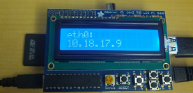
Figure 2-12.
Raspberry Pi showing the eth0 IP
How do we perform this magical feat? Well, the trick is in another Adafruit project kit:
the LCD Pi Plate. The lovely and talented folks over at Adafruit have designed a simple
way to stack an 16 x 2 LCD and a simple keypad right on top of a Raspberry Pi. It comes
as an unassembled kit, but putting it together is simple.
Build the LCD Pi Plate
To assemble the LCD Pi Plate, you will need:
• A soldering iron (and solder)
• A LCD Pi Plate Kit (it includes a 16x2 Blue LCD, but Adafruit sells other colors)
• Fine wire cutters
• A narrow-tipped Phillips screwdriver
• Tall stacking header (optional)
There are many different ways to connect an LCD to a Raspberry Pi, but the LCD Pi
Plate has some notable advantages for this hack. The LCDs that Adafruit uses require
a lot of digital pinouts (six to nine, depending on the functionality of the LCD device).
If you attached this device directly to your Raspberry Pi, you’d take up a lot of GPIO
pins simply to add an LCD.
But the LCD Pi Plate provides a stackable way to add an LCD (think Arduino shield)
that uses only two pins, the I2C pins. Also, because of how the I2C bus works, you can
attach additional devices to those pins and they will appear on the I2C bus (as long
as they do not have conflicting addresses). On top of that, you get five push buttons
that you can use to interact with the LCD.
Adafruit has a fantastic tutorial that walks you through the process of assembling the
LCD Pi plate. But if you’re unable to view it for some reason, the kit is very straight-
forward.
Basically, you solder in the two 220 ohm resistors (labeled Red, Red, Brown, Gold) in
the slots labeled RED and BLUE, and the 1 remaining resistor (330 ohm, labeled Or-
ange, Orange, Brown, Gold) goes in the slot labeled GREEN. Trim the excess leads
103
CHAPTER 2: HACKING LINUX FOR THE RASPBERRY PI
away after soldering. Then, insert all of the push buttons in the marked button slots
(all the way flush with the board) and solder them in.
Next, solder in the potentiometer (it has three “legs”) in the slot marked Contrast,
and the MCP23017 i2c port expander chip gets soldered into the slot marked
(MCP23017). Just make sure you align the notch in the chip with the notch in the
silkscreened outline, or it will not work.
At this point, we recommend deviating from the Adafruit kit a bit. It comes with a
normal height header connector (looks like a black plastic rectangle with holes and
pins on the other side), which will work fine, but if you want to be able to connect other
devices through the LCD Pi Plate (specifically, the Pi Cobbler), you should buy one of
the extra-tall stacking headers. Either way, put the header in the underside of the
board so that the pins stick up through the top. The header is where it will connect to
the Raspberry Pi GPIO pins. Solder it in (on the top).
Then, stick the rubber bumper to the underside of the board, right above where you
soldered in the buttons, sitting flat, as close as you can get it to the buttons and the
left edge without overlapping or going off the board.
Break off a 16 pin length of the header pins (or 18, if you bought a different LCD that
requires more), and insert it into the top of the LCD Pi Plate with the long pins sticking
up. Put the LCD into position, setting into to the long header pins. Solder each of the
header pins on the underside of the board and on the top of the LCD.
At this point, it should be completely assembled (and sturdy). You can push it onto
your Raspberry Pi, inserting the GPIO pins into the connector so that it lines up neatly
on top of the Raspberry Pi.
Again, if any of these steps are unclear, the Adafruit online tutorial is excellent, so you
should refer to it if you get confused along the way.
Install Software to Control the LCD Pi Plate
Adafruit is also worthy of respect because it writes open source software to drive the
hardware that it sells. The LCD Pi Plate has a Python library written for it that you can
use to access and program the LCD and buttons. You can get a copy from their GitHub
repository, but we have also included a copy in the GitHub repository for this book
(along with some additional code that we wrote to monitor the IP address on the Pi).
Go ahead and clone our GitHub repository on your Raspberry Pi (if you haven’t done
it already):
$ git clone https://github.com/spotrh/rpihacks
In order for any of this software to work, you need to enable the I2C support in the
Linux kernel. If you’re using a custom kernel (on any Linux flavor), configured as de-
104 RASPBERRY PI HACKS

scribed in Hack #22, you don’t need to do anything here. If you’re running Pidora or
Occidentalis without a custom kernel, you also have everything you need need pre-
configured.
But if you’re running a Raspbian instance running your kernel, you will need some
additional configuration to enable I2C support. Specifically, you need to run the fol-
lowing command:
$ su -c 'modprobe i2c-bcm2708'
To make that persistent, you will also want to edit /etc/modules and add these lines to
the end of the file:
i2c-bcm2708
i2c-dev
On any distro, you’ll need to install some software to add a Python module for System
Management Bus (SMBus) support (you can think of SMBus as a stricter version of
I2C), the python-rpi, the I2C utilities, and the python-netifaces module (this is how
you will get the IP address information).
Pidora doesn’t have a packaged version of python-smbus in release 18 (the current
release as of this writing), so we’ve included a RPM package for you in the book’s
GitHub repository.
On Pidora, run:
$ su -c 'yum install i2c-tools python-rpi.gpio python-netifaces -y'
$ su -c 'yum install rpihacks/i2c-tools-python-3.1.0-5.fc18.armv6hl.rpm --
nogpgcheck'
On Raspbian/Occidentalis, run:
$ su -c 'apt-get install python-dev python-rpi.gpio python-smbus i2c-tools
python-netifaces'
Run the Code
With this software installed, you can scan the I2C bus (bus 1) for the LCD Pi Plate:
$ su -c 'i2cdetect -y 1'
0 1 2 3 4 5 6 7 8 9 a b c d e f
00: -- -- -- -- -- -- -- -- -- -- -- -- --
10: -- -- -- -- -- -- -- -- -- -- -- -- -- -- -- --
20: 20 -- -- -- -- -- -- -- -- -- -- -- -- -- -- --
30: -- -- -- -- -- -- -- -- -- -- -- -- -- -- -- --
40: -- -- -- -- -- -- -- -- -- -- -- -- -- -- -- --
50: -- -- -- -- -- -- -- -- -- -- -- -- -- -- -- --
105
CHAPTER 2: HACKING LINUX FOR THE RASPBERRY PI
60: -- -- -- -- -- -- -- -- -- -- -- -- -- -- -- --
70: -- -- -- -- -- -- -- --
Sure enough, you can see the Adafruit LCD Pi Plate on the I2C bus, as device number
20.
Now, go ahead and change into the Adafruit_CharLCDPlate/ directory within your
checkout of our GitHub repository:
$ cd rpihacks/Adafruit_CharLCDPlate
In that directory, you will see a few Python files. Most of these provide the library of
functions necessary to access the LCD Pi Plate. If you just want to test proper oper-
ation of your wiring and soldering work, you can run the Adafruit test script:
$ su -c 'python ./LCDtest.py'
This will cycle through the background colors and print text strings to the LCD when
you press the buttons on the Pi Plate. If you are using the Blue 16x2 LCD that normally
comes with this kit, it does not support different background colors, so this program
will seem to dim the background depending on which button you press. Don’t get
scared if this happens.
If no visible text appears, but you can see the LCD blinking, you probably just need to
adjust the contrast. Use your fine-tipped Phillips screwdriver to turn the potentiom-
eter (it’s the round knob next to the buttons with a Phillips-shaped slot in it) until text
appears.
When you’re satisfied with the test script, it’s time to get to the good stuff. We’ve
written a different Python script that, when executed, will run a simple program that
displays the IP addresses for eth0 and wlan0. It also has a crude menu structure, so
that you can push the Up and Down button on the LCD Pi Plate to switch between
displaying the IP address for eth0 and wlan0, respectively. The other buttons will re-
turn you to the menu screen.
To run that program, simply run:
$ su -c 'python ./LCD-pi-plate-demo.py'
If you want that program to run in the background, just add a & after ./LCD-pi-plate-
demo.py (but within the '' marks for the su -c invocation).
You should see this on the LCD panel:
Pi IP Addrs
UP:eth0 DN:wlan0
If you press the Up button on the LCD Pi Plate, it will try to display the address for eth0
(if any).
106 RASPBERRY PI HACKS

If you press the Down button on the LCD Pi Plate, it will try to display the address for
wlan0 (if any).
While we know that the Raspberry Pi does not have built-in wireless networking sup-
port, it is common for people to add that support by connecting a USB wireless device.
While eth0 and wlan0 devices are hardcoded in our script, you can easily change them
if you’d prefer to display other networking devices. This code is simple: if you have a
basic understanding of Python, you should be able to figure out how it works. Feel free
to take what we’ve made and improve upon it!
HACK 29 Run Android on the Raspberry Pi
Read through this chapter and got tired of all the Linux? Or maybe you
just love Android. Either way, it’s not impossible to run Android rather
than a Linux distribution on your Raspberry Pi, but this is a project for
the dedicated hackers.
The good news is that there is a community based around running Android on the
Raspberry Pi, which means if you’ve decided to give it a shot, there are people to whom
you can turn. They gather information on a wiki at http://androidpi.wikia.com/wiki/
Android_Pi_Wiki. For a quick status check, log into their IRC channel, #razdroid, on
Freenode.
The bad news is that this isn’t one of the faster moving communities you’ll find. This
isn’t a reflection on the community at all. Rather, the Raspberry Pi was simply not
designed for Android. In July 2012, Eben Moglen posted on the Raspberry Pi blog
about the progress on a port of Android 4.0 (Ice Cream Sandwich) for the Pi. Unfortu-
nately, that was well over a year ago as of this writing, and it is also the last update on
the subject. The Razdroid wiki now states “Very doubtful that any Android that will be
usable will ever be released.”
But even a nonfunctional system is an opportunity for learning, and learning is what
the Raspberry Pi was designed for. So if Android and Raspberry Pi both interest you,
there’s no harm in giving it a shot. The worst outcome is that you say, “Well, that didn’t
work,” which you expected from the beginning anyway. The best outcome is that you
learn something about the Android, the Pi, or both in the process.
Since that official Android built by Broadcom hasn’t appeared yet, the working builds
are based on CyanogenMod, a popular replacement firmware for Android-based
107
CHAPTER 2: HACKING LINUX FOR THE RASPBERRY PI

phones and tablets. CyanogenMod isn’t the only such replacement, but it is one of
the most popular ones.
Another Odd Name
“Cyanogen” was the screen name of developer Steve Kondik, whose re-
placement firmware for the HTC Dream was built on one by a developer who
stopped work on his popular mod and directed its users to Cyanogen’s.
The short way to go about this is to download one of the images that others have built
and install it to your SD card. CyanogenMod 9 (based on Android 4.0)is so useless as
to be considered unusable. Thus the available images are built on CyanogenMod 7.2
(based on Android 2.3).
If you’re an Android phone or tablet user who enjoys CyanogenMod, you recognize
that the current version is well past either of these.
The wiki describes this version as “Boots, very slow, barely usable.” However, there
are more than a few blog posts from people who enjoy it for some purpose or another,
so don’t let that deter you.
The bottom of the main page of the Android Pi wiki includes several download links.
The first has notes that state it may or may not work only on Model A Raspberry Pis.
We used cm7_img_24-7-2012.tar.gz, the image for CyanogenMod 7.2.
Download the ZIP file and extract the image using dd, replacing /dev/mmcblk0 with the
location of your SD card and the img filename with the correct one if you’re using a
different image:
$ dd bs=4M if=cm7_img_24-7-2012.img of=/dev/mmcblk0
Then put your SD card in the Pi, power it on, and you’ve got Android on Pi, as shown
in Figure 2-13.
If you have never built Android (or Cyanogenmod, or perhaps anything else) before,
you will need to install quite a few packages. You should also follow the steps in Hack
#21 before proceeding.
108 RASPBERRY PI HACKS
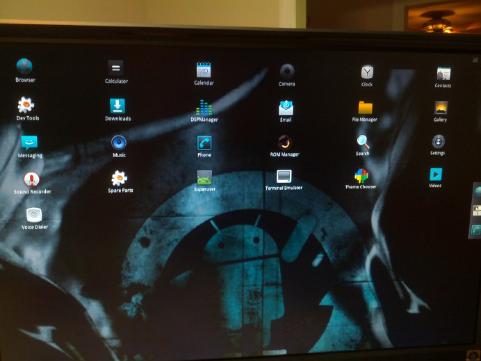
Figure 2-13.
Android running on the Raspberry Pi
The Android Pi wiki offers a set of instructions for compiling CyanogenMod to run on
your Raspberry Pi. We have run them several times on multiple systems with varied
results—mostly of the negative sort. It’s a learning exercise if this is unfamiliar territory
for you, and that is always a worthwhile venture. We offer this information largely as
fair warning to those who might get excited about the possibility but disappointed with
the result.
Note that if you do want to compile CyanogenMod yourself for the Raspberry Pi on
Fedora, you’ll need a slightly different set of packages installed from the instructions
on the wiki:
$ su -c 'yum install make curl gnupg git bison unzip zip flex gperf gcc-c++
libstdc++-devel glibc-devel.i686 zlib-devel.i686 ncurses-devel.i686 libX11-
devel.i686 mesa-libGL-devel.i686 readline-devel.i686'
Other than that, the build instructions are the same. Ideally you will end up with usable
files you can flash to your SD card. Don’t be too frustrated if it doesn’t successfully
finish—you’re certainly not alone, and this is a complicated problem. Take what you’ve
learned from the experience, and then if you still want to try Android on the Pi, simply
use the image offered on the wiki.
109
CHAPTER 2: HACKING LINUX FOR THE RASPBERRY PI

3
Raspberry Pi Around the
House
Your Raspberry Pi has one handy feature when it comes to household projects: its
size. You can easily hide it in a wall or behind a piece of furniture or put it inside larger
build projects like robots and costumes.
This chapter will give you ideas for using your Raspberry Pi for assorted projects
around the house, from the practical (like Hack #31, printing from all your computers
to one printer) to the simply fun (like Hack #35 , using your Pi in your next Halloween
costume).
HACK 30 Share Files with Samba
We accept that there’s a possibility not all of the computers in your house
run Linux. Some might even use Windows (like that one used for PlayOn
in Hack #54). In that case, this hack should help your systems communi-
cate.
Samba is an open source suite of tools for SMB/CIFS clients. In plainspeak, it lets a
Linux computer (like your Raspberry Pi) talk to a Windows machine as if it were a
Windows file or print server.
SMB (Server Message Block) is a protocol for sharing files, printers, and assorted
communications. CIFS (Common Internet File System) is the modern form of SMB.
SMB was designed to run on the NetBIOS API and runs by default on versions of
Windows since Windows 2000. Samba started as a project to reverse engineer SMB
to allow users on Microsoft systems to access files on Sun systems.
Samba works by creating a network share for directories and subdirectories you
choose on your Raspberry Pi. From your Windows machine, you can mount the share
with smbmount, and they will look like networked Windows folders. There is also an
smbclient utility that will feel like using an FTP program, if you’re more comfortable
with that method.
111

Samba requires two daemons, smbd for the sharing services and nmbd for the NetBIOS
name requests, which are controlled by the smb service. (You can use a third daemon,
winbindd, to help the Linux machine understand the Windows user and group infor-
mation on Windows NT 2000 and Windows Server 2003 systems.)
Let’s Samba!
Samba is also a Brazilian dance style popularized by Carmen Miranda, or
as you may know her, “the person who inspired the Bugs Bunny cartoons
in which he wears a hat made of fruit.” Despite thorough experimentation
on the authors’ part, there is no evidence that dancing the samba with your
Raspberry Pi will do anything but make you look silly.
The name was borrowed for the software we’re discussing here by grepping
a UNIX system’s dictionary for words that had the letters S, M, and B. You
can try this yourself by running grep -i ^s.*m.*b /usr/share/dict/words,
although as of a 1998 message about the history of Samba, creator Andrew
Trigdell notes, “Strangely enough, when I repeat that now I notice that Sam-
ba isn’t in /usr/dict/words on my system anymore!” We’re just glad he
didn’t go with “Sulphmethemoglobin.”
We’ll assume you’re using a USB external hard drive with your Raspberry Pi for this
project (and it’s likely you’ll want to if you’re bothering with Samba). If you’re starting
from scratch, consider formatting it as either FAT32 or NTFS (if you’re borrowing it
from a Windows machine, it probably already is). It’s not really necessary, but it will
be handy later if you decide to no longer use it with the Raspberry Pi and want to use
that drive with the Windows machine.
Locate said drive (or USB flash drive or just the SD card—whatever you’re intending
to share):
$ fdisk -l
The output will look something like this:
Disk /dev/mmcblk0: 7822 MB, 7822376960 bytes
4 heads, 16 sectors/track, 238720 cylinders, total 15278080 sectors
Units = sectors of 1 * 512 = 512 bytes
Sector size (logical/physical): 512 bytes / 512 bytes
I/O size (minimum/optimal): 512 bytes / 512 bytes
Disk identifier: 0x000d4f0f
Device Boot Start End Blocks Id System
/dev/mmcblk0p1 4096 147455 71680 c W95 FAT32 (LBA)
/dev/mmcblk0p2 151552 15278079 7563264 83 Linux
112 RASPBERRY PI HACKS
Disk /dev/sda: 1037 MB, 1037041664 bytes
2 heads, 63 sectors/track, 16075 cylinders, total 2025472 sectors
Units = sectors of 1 * 512 = 512 bytes
Sector size (logical/physical): 512 bytes / 512 bytes
I/O size (minimum/optimal): 512 bytes / 512 bytes
Disk identifier: 0x0101bc87
Device Boot Start End Blocks Id System
/dev/sda1 * 32 2025471 1012720 6 FAT16
The first disk, /dev/mmcblk0, is the SD card in the Raspberry Pi. The second, /dev/
sda/, is a USB flash drive we put in one of the Pi’s USB connections to use as the
example shared storage. Create a mount directory for the drive:
$ mkdir /mnt/PiShare
To see whether you were successful, run ls /mnt, and you should see PiSamba listed.
Open /etc/fstab in your favorite text editor, so you can tell it to connect to PiSamba
at boot:
$ sudo vi /etc/fstab
The contents of the file will look something like this:
#
# /etc/fstab
# Created by anaconda
#
# Accessible filesystems, by reference, are maintained under '/dev/disk'
# See man pages fstab(5), findfs(8), mount(8) and/or blkid(8) for more info
#
LABEL="rootfs" / ext4 defaults,noa
time 1 1
LABEL="boot" /boot vfat noauto,com
ment=systemd.automount 1 2
/swap0 swap swap
Add the following line at the bottom:
/dev/sda1 /mnt/PiShare vfat defaults 0 0
For the first part, use the device name you saw listed when you ran fdisk (in this
example, /dev/sda/). Be sure to change PiSamba if you used a different name for your
mount, and make ntfs-3g whatever type of hard drive format you used. Save the file,
exit, and mount the share:
$ mount -a
113
CHAPTER 3: RASPBERRY PI AROUND THE HOUSE

If you run ls /mnt/, you should see your files. If you don’t, check your disk type in the
line you added in /etc/fstab.
Samba is included with many Linux distributions and is set to start automatically. It
is not, however, necessarily included with your Raspberry Pi Linux distribution. But
that’s easy to fix.
To install Samba on Pidora, run the following command:
$ sudo yum install samba
For Raspbian, run this one:
$ sudo apt-get install samba samba-common-bin
Once it’s installed, the service will start automatically. The Samba configuration file
lives in /etc/samba/smb.conf. Open it in your editor to get it set up for your particular
needs.
If you’re nervous about editing config files, create a backup first by running
cp /etc/samba/smb.conf /etc/samba/smb.conf.backup.
It’s also a well-commented file, so feel free to read it all to get a better feel for what
you’re doing:
$ sudo vi /etc/samba/smb.conf
At the bottom of the first large chunk of comments, you’ll see this:
[global]
workgroup = WORKGROUP
#usershare allow guests = yes
#security=share
security=user
follow symlinks = yes
wide links = no
unix extensions = no
lock directory = /var/cache/samba
[pi]
browsable = yes
read only = no
#guest ok = yes
valid users = pi
path = /home/pi
#force user = pi (no longer needed)
114 RASPBERRY PI HACKS

[devices]
browsable = yes
read only = no
#guest ok = yes
valid users = pi
path = /media
force user = root
Add this to the bottom of the file:
[PiShare]
browsable = yes
read only = no
path = /mnt/PiShare
create mask = 0660
directory mask = 0771
Save the file, exit, and restart Samba. On Pidora, reboot the Samba service with:
$ su -c '/sbin/service smb restart'
On Raspbian, use:
$ su -c '/etc/init.d/samba restart'
Configure Samba Without the Command Line
If you’re using Pidora, a package available for the GUI Samba Server Configuration
Tool can modify the /etc/samba/ files for you. To install this tool, run:
$ su -c 'yum install system-config-samba'
You can start it from the command line by typing system-config-samba.
Now connect to your share from another machine. From Fedora, for example, use the
Connect to Server dialog (similar dialogs exist in any Linux distribution or on OS X or
Windows). The share address is smb:// followed by the IP address, a slash, and the
name of your share, as shown in Figure 3-1.
115
CHAPTER 3: RASPBERRY PI AROUND THE HOUSE
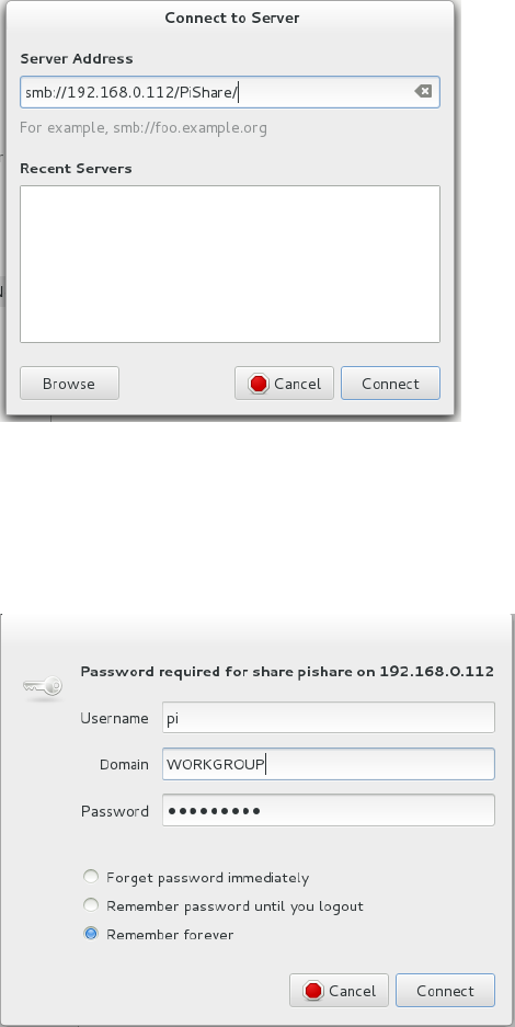

HACK 31 Use Your Raspberry Pi as a Remote Print
Server
You’re never on the computer with the bulky, unsightly printer when you
want to print something. The Raspberry Pi is small enough that you can
hide your printer just about anywhere and let the Pi do the work of being
a print server.
You might think it would be nice to hide the bulky printer out of sight, but you’ll need
to connect to it to actually print something. If you connect the printer to a discreet Pi
running as a print server, you can connect to it from your primary computer remotely.
You might even be able to find ways to mount the Pi on the back of the printer, or just
tuck it away nearby. Either way, physically connect the printer cable to your Raspberry
Pi, and let’s get started!
The easiest and most logical way to turn your Raspberry Pi into a print server is to set
up CUPS (the Common UNIX Printing System). It’s another one of those things that’s
often included in a Linux distribution, but probably not with your Raspberry Pi distri-
bution. That’s what packages are for.
Install it on Pidora with the following command:
$ su -c 'yum install cups'
Or install it on Raspbian:
$ su -c 'apt-get install cups'
When you install CUPS, it creates a group called lpadmin whose members CUPS will
authenticate:
$ su -c 'usermod -aG lpadmin user'
Replace user with the username that will be responsible for the printers. (Create one
first if you prefer.)
Then you need to make a few changes to the CUPS configuration file in /etc/cups/
cupsd.conf. It never hurts to make a backup before you go editing such things:
$ cp /etc/cups/cupsd.conf /etc/cups/cupsd.conf.backup
Open the configuration file in a text editor and comment out the line under “Only listen
for connections from the local machine” that says Listen localhost:631. Then add
the following line under it:
Listen 192.168.0.122:631
Change the first part to your Pi’s IP address with :631 appended. (631 is the port that
CUPS listens on.)
117
CHAPTER 3: RASPBERRY PI AROUND THE HOUSE

Under “Restrict access to the server…”, add the following lines in bold, replacing the
subnet with your own:
<Location />
Order allow,deny
Allow 192.168.0.
Allow Localhost
<Location>
Under “Restrict access to the admin pages…”, add the following lines in bold, replacing
the subnet with your own:
<Location /admin>
Order allow,deny
Allow 192.168.0.
Allow Localhost
<Location>
Under “Restrict access to configuration files…”, add the following lines in bold, replac-
ing the subnet with your own:
<Location /admin/conf>
AuthType Default
Require user @SYSTEM
Order allow,deny
Allow 192.168.0.
Allow Localhost
<Location>
Firewalling
Some Linux distributions come preconfigured with a iptables firewall for security.
They do not usually have the CUPS ports (631 for TCP and UDP) open in the default
configuration. Since you want to permit traffic to access the CUPS server through
the firewall, you’ll need to punch a hole. For Pidora and Raspbian, you can add these
lines into /etc/sysconfig/iptables:
-A INPUT -i eth0 -p tcp -m tcp --dport 631 -j ACCEPT
-A INPUT -i eth0 -p udp -m udp --dport 631 -j ACCEPT
You can also edit the configuration file from within a web interface (see Figure 3-3) by
opening a browser on the Pi (Midori is usually the included web browswer), going to
http://localhost:631/admin, and selecting “Edit Configuration File” in the right column
under Server.
118 RASPBERRY PI HACKS

Figure 3-3.
The CUPS administration web portal
Once you’ve made those edits, restart CUPS:
$ su -c 'service cups restart'
Then use a web browser to go to http://192.168.0.122:631, replacing the first part with
your Pi’s IP address. (This can be on the Pi, your laptop, or any machine within the
subnet.) Choose the Administration tab, and select Add Printer.
When you’re asked for a username and password, enter the information for the user
you added to the lpadmin group. On the Add Printer page (Figure 3-4), choose your
printer from the list under Local Printers.
Figure 3-4.
The Add Printer configuration page
In the list shown in Figure 3-4, you see three printers. The two HPLIP devices are
actually just printer drivers from the HP Linux Imaging and Printing project.
You’ll be asked to add or edit the name, description, and location of the printer. If you
would like to, enable Share This Printer.
119
CHAPTER 3: RASPBERRY PI AROUND THE HOUSE
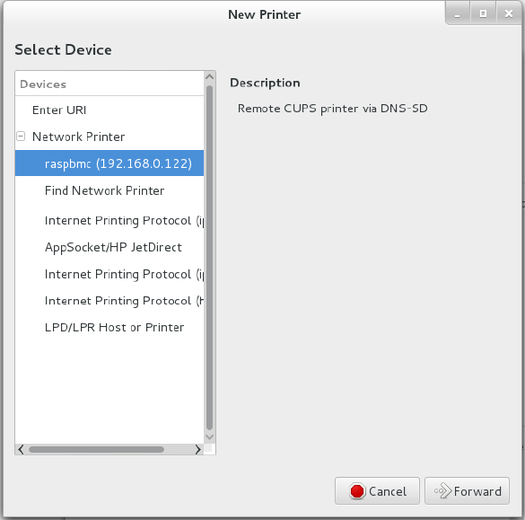
In the next step, you’ll be asked to choose the printer driver. You can scroll through
the list until you find your printer (several are likely marked as “recommended”), or
you can browse to a PPD file that you have from your printer’s manufacturer for the
driver.
Finally, you’re offered the chance to set some generic print settings, like page size and
source. When you’re finished setting your preferences, click Set Default Options, and
you’ll be back to the main administration page for that printer.
If you haven’t already, move to another machine on the network and get it ready to
print. Use that particular computer’s printer settings system (see Figure 3-5 for Fe-
dora) to add a printer and select the one that you’ve just set up.
Figure 3-5.
Fedora New Printer setup dialog
Print a test page, and you’re finished!
120 RASPBERRY PI HACKS

HACK 32 Make Calls with a Raspberry Pi Asterisk
Telephone System
Asterisk is a telephone system in software. It is typically used to bridge
callers together, or offer up features such as voicemail or call queues.
Because it’s built totally in software, you can run it on your Raspberry Pi.
Because the Raspberry Pi doesn’t have any sort of analog telephone connections,
setting up Asterisk means using a technology called voice over IP (VoIP) to commu-
nicate on the Raspberry Pi. You’ll use a computer program called a softphone, to-
gether with a microphone and speakers, to emulate a telephone. The softphone will
then communicate across the network to Asterisk running on the Raspberry Pi.
For more information on Asterisk, check out the Asterisk website or Asterisk: The
Definitive Guide from O’Reilly Media.
Installing Asterisk
Installing Asterisk is fairly simple, as most modern Linux distributions have packages
rebuilt for Asterisk. On Pidora, just run the following command:
$ su -c 'yum install asterisk asterisk-voicemail-plain asterisk-sounds-core-
en-gsm'
Here’s the command to run on Raspbian:
$ su -c 'aptitude install asterisk asterisk-config asterisk-core-sounds-en-
gsm'
This will install Asterisk with a basic configuration, common features such as voice-
mail, as well as some sound prompts. Feel free to search your distribution’s package
list for additional Asterisk modules.
This hack uses a VoIP protocol called SIP to communicate between one or more soft-
phones and Asterisk. Getting SIP working through a firewall (especially a NAT firewall)
is difficult and beyond the scope of this hack. In order for your connections to work,
you’ll need to turn off the firewall, so that it doesn’t block connection attempts.
Don’t leave your Raspberry Pi connected to the Internet with the firewall disabled,
because someone will likely attempt to try to break into your Raspberry Pi. This is
especially imporant if you haven’t changed the password on your Raspberry Pi
from the defaults. We suggest you turn off the firewall on your Raspberry Pi only
long enough to test out things, and then turn it back on.
121
CHAPTER 3: RASPBERRY PI AROUND THE HOUSE
Starting Asterisk
Once Asterisk has been installed, you’ll need to start the Asterisk process. You can
start it with the initscripts, or simply type (as root):
$ asterisk
This should start Asterisk running in the background. After Asterisk is running in the
background, you can connect to the running Asterisk system with the following com-
mand:
$ asterisk -r
If for some reason Asterisk isn’t starting on your system, you can start it in console
mode:
$ asterisk -c
Be aware that running it in console mode is recommended only for debugging pur-
poses, because as soon as you exit out of the console, Asterisk stops running.
You can also increase the verbosity level of the Asterisk command prompt by supply-
ing one or more -v arguments to Asterisk, like this:
$ asterisk -vvvr
This example sets the verbosity level to three, if it wasn’t already three or higher. At
verbosity level three, Asterisk tells you about every step it executes in its dialing plan,
so it’s a nice level to use when you’re learning Asterisk.
When you successfully connected to the Asterisk process, you should be greeted with
a prompt that looks something like this:
Asterisk 1.8.23.1, Copyright (C) 1999 - 2013 Digium, Inc. and others.
Created by Mark Spencer <markster@digium.com>
Asterisk comes with ABSOLUTELY NO WARRANTY; type 'core show warranty' for
details.
This is free software, with components licensed under the GNU General Public
License version 2 and other licenses; you are welcome to redistribute it un
der
certain conditions. Type 'core show license' for details.
=========================================================================
Connected to Asterisk 1.8.23.1 currently running on hockey (pid = 23801)
Verbosity was 0 and is now 3
hockey*CLI>
In this example, we’re running Asterisk version 1.8.23.1 on a computer named “hock-
ey.”
122 RASPBERRY PI HACKS
Did you notice the last line ends in *CLI>? This is the prompt for the Asterisk command-
line interface (CLI), and it is the primary tool for interacting with the Asterisk system
and debugging within Asterisk. Before going any futher, here are a few commands to
help you feel comfortable.
To see how long Asterisk has been running, type:
*CLI> core show uptime
hockey*CLI> core show uptime
System uptime: 55 seconds
Last reload: 55 seconds
Most commands in the Asterisk CLI follow the “subsection-verb-details” model,
where the first word of the command tells which part of the system you want to interact
with (core in this case, which is a verb to tell Asterisk what you’d like to do: show), and
then any other details the system needs to know in order to perform the action.
To stop Asterisk immediately, type:
*CLI> core stop now
You can also use core stop when convenient to have Asterisk stop the next time there
are no active calls on the system, or core stop gracefully to reject any new calls, and
then shut down the system when the call volume reaches zero. Don’t shut down As-
terisk just yet (unless you’d like to practice stopping it and starting it again just to get
a feel for it).
The Asterisk CLI also has built-in help (type help at the CLI) and tab-completion. For
an example, type help and then press the TAB key twice before --, and you’ll see that
the Asterisk CLI shows you all the possibile commands that begin with “help.”
Setting Up a Softphone
There are three steps to setting up a softphone with Asterisk. The first is to configure
an account within Asterisk for the phone to connect to. Second, you’ll need to con-
figure the softphone itself to connect to Asterisk. And finally, you’ll need to set up a
list of instructions (called a dialing plan or dialplan) that Asterisk should follow when
a particular extension is dialed.
Configure an SIP account
To set up an account for the softphone, you’ll first need to find the configuration file
for the type of connection you’ll be using. Asterisk speaks a number of different voice
over IP protocols, but the most popular one is SIP, so that’s what this example will use.
123
CHAPTER 3: RASPBERRY PI AROUND THE HOUSE
To add an account for your SIP softphone, add the following lines to the very bottom
of /etc/asterisk/sip.conf:
[one]
type=friend
host=dynamic
secret=cHaNgEmEpLeAsE!
context=raspi-demo
The first line (in square brackets) is the name of the account. The type line tells it what
kind of a device you’re talking to. This example uses the friend type, because that
means that the softphone can call Asterisk and that Asterisk can also call the soft-
phone.
The host line says that the IP address assigned to the softphone isn’t known (or might
change at any moment), so instead of hardcoding an IP address, the softphone will
periodically tell Asterisk where it is. This is called registration (covered in more detail
in the next section).
The secret setting is the password on this account. Pick a different password, and
make it long and difficult to guess. Last, the context setting tells the system which
part of the dialplan to execute when a call comes from the softphone.
Once you’ve added these lines to the sip.conf configuration file, you’ll need to tell
Asterisk to reload that configuration file. From the Asterisk CLI, type:
$*CLI> sip reload
You can then use the sip show peers command to see which SIP accounts you have
configured:
hockey*CLI> sip show peers
Name/username Host Dyn
Forcerport ACL Port Status
one (Unspecified) D
N 0 Unmonitored
1 sip peers [Monitored: 0 online, 0 offline Unmonitored: 0 online, 1 off
line]
Did you notice that the host says (Unspecified)? This means that the softphone hasn’t
registered with Asterisk yet, so we don’t know where to find the softphone to send
messages to it. We’ll rectify that shortly.
Register your SIP client
Next, you’ll need to use a SIP softphone to be able to connect to Asterisk for test-
ing. There are a number of free SIP softphones available. I prefer Blink for Mac and
Windows, Twinkle on Linux, and CSipSimple on Android.
124 RASPBERRY PI HACKS
While configuring each of these softphones is beyond the scope of this hack, the ba-
sics are the same. Simply configure the softphone with one as the username (and auth
username, if it’s required by your softphone), cHaNgEmEpLeAsE! as the password (or the
new password you entered in the secret setting in sip.conf), and the IP address of
your Raspberry Pi for the SIP server, registrar, domain, proxy, and/or outbound proxy
settings.
Once your softphone has registered, you should be able to run sip show peers from
the Asterisk CLI again and see that the Host field now shows an IP address, like this:
hockey*CLI> sip show peers
Name/username Host Dyn
Forcerport ACL Port Status
one/one 192.168.55.187 D
N 7060 Unmonitored
1 sip peers [Monitored: 0 online, 0 offline Unmonitored: 1 online, 0 off
line]
If you’re having problems getting your softphone to register, double-check that you’ve
(temporarily) disabled the firewall on the Raspberry Pi. For simplicity’s sake, you
should use a softphone within the same network as your Raspberry Pi, as the SIP
protocol is notoriously difficult to use when it has to pass through a firewall or router.
You can also watch the Asterisk CLI closely when the softphone attempts to register,
as it will often give you useful information (such as telling you that the password pro-
vided by the softphone doesn’t match the password in the sip.conf configuration file).
Set up an extension in the dialplan
The final step is to set up one or more extensions in the dialplan to execute when that
extension is dialed by the softphone. If you were to dial extension 100 on the softphone
at this point, you would likely get back a 404: Extension not found error. The Asterisk
CLI would report something like this:
NOTICE[24237]: chan_sip.c:23437 handle_request_invite: Call from 'one'
(192.168.55.187:7060) to extension '100' rejected because extension not
found in context 'raspi-demo'.
In order to make extension 100 do something a bit more useful, you need to add a new
section to the /etc/asterisk/extensions.conf configuration file. This section name
needs to match the context setting from our account in the sip.conf configuration
file. In this case, call it [raspi-demo].
Add the following lines to the end of /etc/asterisk/extensions.conf:
[raspi-demo]
exten => 100,1,Answer()
125
CHAPTER 3: RASPBERRY PI AROUND THE HOUSE

exten => 100,2,Playback(hello-world)
exten => 100,3,Playback(tt-weasels)
exten => 100,4,Hangup()
Let’s walk through each line quickly, and then try it out. The first line (in square brack-
ets) is the name of the context, which is an independent section of the dialplan. Ex-
tension 100 in the [raspi-demo] context is independent from extension 100 in another
context, such as [not-my-demo]. Contexts are often used to keep different clients iso-
lated from parts of the dialplan, or to provide different features to different clients.
The second line defines an extension (100, in this case) and a priority (or step number,
which is 1 in this case) and says that the first thing extension 100 should do is to call
the Answer() application. This application, as its name implies, answers the call.
Note that the priority numbers must be in numerical order, and should not skip
any numbers. For example, if Asterisk executes priority number three and can’t
find a priority number four, it will simply hang up the call for security reasons.
The next line (priority 2), calls the Playback() application, which plays a prerecorded
sound file in which you’ll hear a female voice say “Hello, World.” The next line (priority
3) also plays a sound file, which tells you that “Weasels have eaten our phone system.”
The last line calls the Hangup() application, which ends the call.
The parameter to the Playback() application is the name of the sound file to play,
without the extension. Asterisk is smart enough to choose the best sound prompt
format to play if there are multiple files with the same name but in different formats.
It chooses the format that requires the least amount of CPU power to transcode
(or convert) to the current audio format of the call.
Once you’ve added those five lines to the end of your extensions.conf configuration
file, you’ll need to tell Asterisk to reload the dialplan. To do this, go to the Asterisk CLI
and type dialplan reload.
To test that your new [raspi-demo] context has been successfully read and parsed,
type:
hockey*CLI> dialplan show raspi-demo
[ Context 'raspi-demo' created by 'pbx_config' ]
'100' => 1. Answer()
[pbx_config]
2. Playback(hello-world)
[pbx_config]
3. Playback(tt-weasels)
126 RASPBERRY PI HACKS

[pbx_config]
4. Hangup()
[pbx_config]
-= 1 extension (4 priorities) in 1 context. =-
Now’s the time for the big test! From your softphone, dial 100, and listen for Asterisk
to play the sound prompts.
We’re only scratching the surface with the most basic of applications here. For a
full list of the dialplan applications you can use in your dialplan, type core show
applications at the Asterisk CLI.
Of course, there’s much more that you can do with Asterisk on your Raspberry Pi,
including implementing call menus, voicemail, allowing clients to call each other, and
so forth. Now that you’ve learned the basics, you can dive into all the wonderful things
that Asterisk can do. And don’t forget to turn your firewall back on when you’re done!
—Jared Smith
HACK 33 Build Your Own Web Server
From kids with creative urges to grown-ups with pet projects, wanting
your own website is a common desire. Having a Raspberry Pi makes it
easy to set up your own web server, whether it’s for your blog or a web
interface for interacting with a larger Pi project.
There are as many reasons to want a web server as there are websites. We’ll cover two
options: first, how to set up your own blog on a Raspberry Pi; second, getting started
with a development environment called Coder that helps you learn the basic building
blocks of the web: HTML, JavaScript, Cascading Style Sheets (CSS), and Node.JS.
Set Up a Basic Blog Server
There are hundreds of millions of blogs out there. Why not let your Pi add a voice to
the chorus? The easiest way to get your Pi online and yourself blogging is by setting
up the LAMP stack: Linux, Apache (web server), MySQL (database), and PHP. To-
gether they give you a base on which you can run WordPress, one of the most popular
blogging platforms.
By setting up a distro on your Pi, you already have the L down, so let’s move to the A.
Here’s how to install Apache on Pidora:
$ su -c 'yum install httpd mod_ssl'
127
CHAPTER 3: RASPBERRY PI AROUND THE HOUSE

And here’s the command for Raspbian:
$ su -c 'apt-get install apache2'
The detail of possibilities for using and configuring Apache are well beyond the
scope of this book, but also well documented elsewhere. We recommend starting
with the online documentation. If you’re interested in a book, try Apache Cookbook
(O’Reilly), or for a broader introduction to web development, Beginning PHP5,
Apache, and MySQL Web Development (O’Reilly).
Next you’ll need to install MySQL, PHP, and the PHP gd module (required by Word-
Press). Here’s the command for Pidora:
$ su -c 'yum install mysql mysql-server'
$ su -c 'yum install php php-mysql php-gd'
And here’s the command for Raspbian:
$ su -c 'apt-get install mysql-server'
$ su -c 'apt-get install php php-mysql php-gd'
Start the MySQL daemon and Apache, on Pidora:
$ su -c 'systemctl start mysqld.service'
$ su -c 'systemctl start httpd'
or on Raspbian:
$ su -c 'service start mysqld'
Then ensure that they will both start on their own in the future, on Pidora:
$ su -c 'chkconfig mysqld on'
$ su -c 'chkconfig httpd on'
or on Raspbian:
$ su -c 'update-rc.d mysqld enable'
$ su -c 'update-rc.d httpd enable'
Then set up the installation:
$ su -c '/usr/bin/mysql_secure_installation'
You’ll be asked to set a root password and several other settings, which are well de-
scribed by the script along with recommended choices. If all goes well, at the end you’ll
see:
Cleaning up...
128 RASPBERRY PI HACKS
All done! If you’ve completed all of these steps, your MySQL installation should now
be secure:
Thanks for using MySQL!
For WordPress, you’ll need a database and a user. Log in to MySQL using the root
password you just set up:
$ mysql -u root -p
Then create your database and user. Replace piblogger with whatever you’d like your
database to be named and ian with the user who will be in charge of it (and it should
go without saying that mypassword is a terrible password choice that you should
change):
mysql> CREATE DATABASE piblogger;
Query OK, 1 row affected (0.00 sec)
mysql> CREATE USER 'ian'@'localhost' IDENTIFIED BY 'mypassword';
Query OK, 0 rows affected (0.00 sec)
mysql> GRANT ALL PRIVILEGES ON * . * to 'ian'@'localhost';
Query OK, 0 rows affected (0.00 sec)
mysql> FLUSH PRIVILEGES;
Query OK, 0 rows affected (0.00 sec)
mysql> EXIT
Download the latest WordPress tarball from https://wordpress.org/latest.tar.gz or:
$ wget https://wordpress.org/latest.tar.gz
Extract the tarball into the public HTML folder:
$ sudo tar -xvzf latest.tar.gz -C /var/www/html
This will create a directory called wordpress in /var/www/html. Next you need to set up
the config file:
$ vi /var/www/html/wordpress/wp-config-sample.php
The things you need to configure are at the top of the file, and the parts you need to
fill in are in all caps:
// ** MySQL settings - You can get this info from your web host ** //
/** The name of the database for WordPress */
define('DB_NAME', 'piblogger');
/** MySQL database username */
129
CHAPTER 3: RASPBERRY PI AROUND THE HOUSE

define('DB_USER', 'ian');
/** MySQL database password */
define('DB_PASSWORD', 'mypassword');
/** MySQL hostname */
define('DB_HOST', 'localhost');
/** Database Charset to use in creating database tables. */
define('DB_CHARSET', 'utf8');
/** The Database Collate type. Don't change this if in doubt. */
define('DB_COLLATE', '');
Finally, change the name of the sample config to config.php. We like to save a copy of
the sample until everything’s running properly, so for now:
$ cp /var/www/html/wordpress/wp-config-sample.php var/www/html/wordpress/wp-
config.php
When your site is running as you would like, delete wp-config-sample.php.
Now, when you go to the site in a browser (by default it’s at /wordpress after a domain
if you’ve registered one, or your IP address if you haven’t). It’s only a one-page setup
(see Figure 3-6), after which you can add one more voice to the blogosphere.
Figure 3-6.
The one-page WordPress web-based setup
130 RASPBERRY PI HACKS

You can now log into your WordPress dashboard and start configuring its themes and
posting. Learn more about how to use all of its features at http://codex.wordpress.org.
Use Coder for Your Website
Coder is a tool created by Jason Striegel in the Google Creative Lab as a way to teach
kids basic web programming using the Raspberry Pi. It doesn’t have that kid-program
feel, though, so if you’re an adult who’s never tried learning HTML, CSS, or JavaScript,
it’s handy for you as well.
On the Coder website, you’ll find a ZIP file with an installer for Mac users and instruc-
tions for using it with Windows. However, there are not any instructions for using it
with Linux. To do so, download the Coder ZIP file, which contains a folder (at the time
of this writing, coder_v0.4) within which you’ll find two files: CoderSetup.app and ras
pi.img. The latter is all you need. Extract it and then use a tool like Fedora-arm-installer
or dd from the command line to flash the image to your SD card:
$ sudo dd bs=4M if=raspi.img of=/dev/mmcblk0
Fedora ARM Installer
The Fedora ARM Installer is a convenient tool for flashing your SD card im-
ages if you’re less-than-comfortable with the command line. You don’t have
to use it for Fedora or Pidora images; it will work with any image you want
to flash to the Pi. If you’re on Fedora, you can install it with yum install
fedora-arm-installer. For other systems, you can download it at http://
fedoraproject.org/wiki/Fedora_ARM_Installer.
Boot the Pi with your newly flashed SD card, and you’ll see the Raspbian raspi-config
screen. You don’t need to change anything, although you probably want to resize the
partition (option 1, expand_rootfs). Then select Finish and reboot.
Now move back to your Linux machine and open Chrome or Chromium and go to
https://coder.local in the browser. You’ll be welcomed to Coder, and all you have to do
for setup is choose a password (Figure 3-7).
131
CHAPTER 3: RASPBERRY PI AROUND THE HOUSE
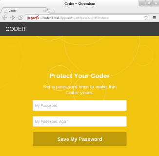
Figure 3-7.
Coder setup screen
One of the first blocks you see is “Hello Coder,” which helps you explore how Coder
works. The edit button is represented by the </> symbol at the upper right of the page.
If you click it in Hello Coder, you find pages that give you a brief introduction to HTML,
CSS, JavaScript, and Node.JS through tabs across the top of the screen.
Coder also offers two prebuilt apps, Space Rocks! and Eyeball, whose code you can
explore and edit to see how they were built (which is perhaps the best way to learn
how code works). You see their blocks on the home page when you start as well.
Once you enter one of these, you have two choices in the upper-right menu. You can
click HACK to quickly edit a few settings to see how they affect the app (see
Figure 3-8). You can also click the Coder edit button (</>) to edit all of the code behind
them. In either case, you see the code on the left and the results on the right each time
you click the Save button.
132 RASPBERRY PI HACKS
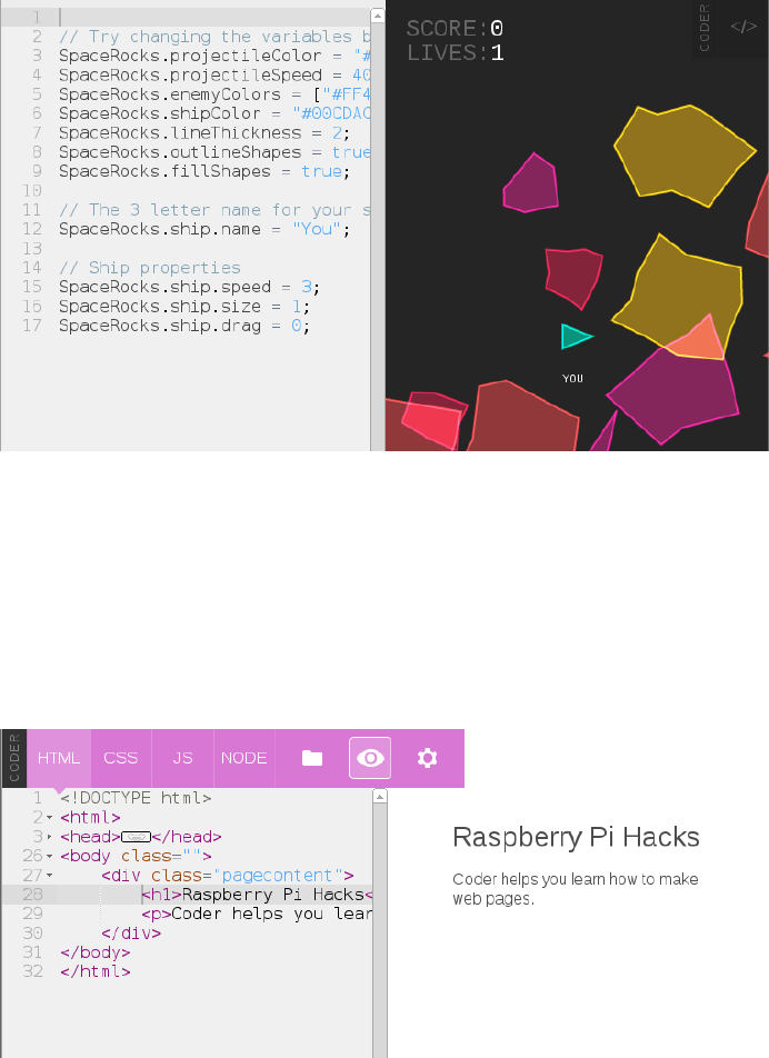
Figure 3-8.
The Space Rocks! HACK screen
Finally, when you’re ready to go on your own, you click the green rectangle on the
Coder homepage with a + sign in the middle and start creating your own app by naming
it and giving it a color for its block on your Coder homepage. Once you’ve created it,
at first all you’ll see is a basic web page. Click the Coder edit button (</>) in the upper
right to start creating from scratch (Figure 3-9).
Figure 3-9.
Creating your own web page and apps in Coder
You can click the small, vertical word CODER at the top of any screen to return to the
home page and edit or create more apps.
133
CHAPTER 3: RASPBERRY PI AROUND THE HOUSE

HACK 34 Control a LEGO Robot
What could be cooler than a functioning, programmable robot made
from LEGO bricks? A functioning, programmable LEGO robot connected
to and controlled by a Raspberry Pi.
We love LEGO. Possibly more than our kids do (or ever will). We’ve also been fans of
the LEGO Mindstorms kits for a long time. The LEGO Mindstorms kits are a combi-
nation of LEGO (and Technic-style) bricks and electronic components such as sen-
sors, motors, and a programmable brick.
The brick is especially notable because it is the “brain” of the Mindstorms set, and
you can program it directly to control the peripheral devices in the kit. The brick in the
most recent version of the LEGO Mindstorms (LEGO Mindstorms NXT 2.0, as of this
writing) is, unsurprisingly, called the NXT Intelligent Brick, and it’s pretty cool (see
Figure 3-10).
Figure 3-10.
NXT Intelligent Brick
At its core, the NXT Intelligent Brick is powered by a 32-bit Atmel AT91SAM7S256
microcontroller (with 256 KB flash memory and 64 KB RAM) and an 8-bit Atmel AT-
mega48 microcontroller running at 4 MHz. It has an embedded 100x64 pixel LCD
screen (controlled by push buttons below it) with support for four input devices (ports
1–4) and three output devices (ports A–C).
It also supports both Bluetooth and USB connections, which is important because,
while you can program the brick itself to operate the attached devices for the robot
(with simple programs), you can also control the brick directly via USB, and that is
exactly how you’ll do it in this hack.
134 RASPBERRY PI HACKS

The LEGO Mindstorms NXT 2.0 kit comes with a lot of Windows software to control
and program the brick, and there are some official (and unofficial) bindings for a wide
array of languages. The official Windows software will obviously not run on a Rasp-
berry Pi, but there is a software suite that does: ROS.
Installing ROS and Dependencies
ROS (short for robot operating system) is an open source suite of software that pro-
vides libraries and tools to help software developers create robot-related applications,
including hardware abstraction, device drivers, libraries, visualizers, message-
passing, and package management. It was originally developed by the Stanford Arti-
ficial Intelligence Laboratory, but that work has spun off into a company called Willow
Garage, a robotics research institute and incubator. The goal is to provide a level of
open source standardization on the application programming interface (API) for ro-
botics so that a consistent set of software can be used on any type of robotic com-
ponent with minimal new software necessary and the common functionality shared.
This is a thriving effort with an active community that regularly puts out major, named
releases. We’ll start by installing the current stable release, as of the time of this
writing: Groovy Galapagos (Groovy, for short).
NXT Intelligent Brick Firmware
The ROS nxt component software requires the NXT Intelligent Brick to be running
a recent version of the default LEGO firmware (v1.28 or newer). To do this, you’ll
need to have a Windows (or OS X) system with the LEGO Mindstorms software
installed and the NXT Intelligent Brick connected. Run the software, and go into
the Tools
→
Update NXT Firmware menu option. You might need to download the
NXT firmware files manually.
There is also a way to flash the NXT firmware from Linux. Download and install
libnxt and use the fwflash executable.
Start with a clean installation of Raspbian.
There are two ways to install ROS: from prebuilt binary packages or from source. While
it is certainly possible to install ROS from source on a Raspberry Pi, it takes far too
long. Instead, using a community repository of ROS packages optimized for the Rasp-
berry Pi will significantly speed up the time it takes to install ROS. To enable this APT
repository of packages (called ROSpbian), run:
$ sudo echo "deb http://64.91.227.57/repos/rospbian wheezy main" > /etc/apt/
sources.list.d/rospbian.list
Then add the package signing key (for package verification) and reload the apt pack-
age data:
135
CHAPTER 3: RASPBERRY PI AROUND THE HOUSE
$ wget http://64.91.227.57/repos/rospbian.key -O - | sudo apt-key add -
--2013-08-27 19:31:41-- http://64.91.227.57/repos/rospbian.key
Connecting to 64.91.227.57:80... connected.
HTTP request sent, awaiting response... 200 OK
Length: 1739 (1.7K) [application/pgp-keys]
Saving to: `STDOUT'
100%
[===========================================================================
=================================>] 1,739 --.-K/s in 0s
2013-08-27 19:31:41 (20.2 MB/s) - written to stdout [1739/1739]
OK
$ sudo apt-get update
Now you can install ROS packages from the ROSpbian repository. The ros_comm com-
ponents are a good starter package, because they will pull in all of the core ROS com-
ponents and tools as dependencies and install everything in one pass:
$ sudo apt-get install ros-groovy-ros-comm ros-groovy-rosbuild
It will take a little while to complete. When it finishes, you’ll need to configure your user
account to enable the ROS environment by default. ROS includes a bash script con-
taining a number of environment variables (and amendments to $PATH) so that you
can run ROS commands. Make sure your account sources this file (in bash, source is
roughly analogous to using #include in a C program).
To source the ROM environment every time you log in (or instantiate a bash shell), you
need to add it to the .bashrc file in that user’s home directory:
$ echo "source /opt/ros/groovy/setup.bash" >> ~/.bashrc
You also want root to be aware of the ROS environment, so do the same for the root
user. Use sudo and su - together to switch to a root user session, then run the com-
mand again to source /opt/ros/groovy/setup.bash during .bashrc:
$ sudo su -
$ echo "source /opt/ros/groovy/setup.bash" >> /root/.bashrc
$ exit
Now you’re ready to download and prepare the ROS components for the NXT Mind-
storms. As mentioned before, the ROS software provides a framework of standardized
components, but each specific robotic device needs a module (or modules) to support
its specific quirks. NXT Mindstorms requires the nxt family of modules. Max Sieber
forked off a copy of the nxt codebase to add support for the Groovy ROS and the
Raspberry Pi, but it needed some additional patches to build properly. We’ve forked
a copy of his work and added fixes. Clone a copy of our GitHub repository to work with:
136 RASPBERRY PI HACKS

$ sudo apt-get install git
$ git clone https://github.com/spotrh/nxt
ROS is very, very picky about where its files live on the filesystem, so you need to move
your nxt checkout to the proper location:
$ sudo mv nxt /opt/ros/groovy/share/
If you do not move the nxt “stack” into that ROS directory, none of the ROS tools will
find it.
You’ll need to set up Raspbian to give permission for the pi user to communicate with
the NXT Intelligent Brick as a normal user (rather than using root). To do this, start by
adding the lego group:
$ sudo groupadd lego
Then add yourself to that group:
$ sudo usermod -a -G lego <username>
The value for <username> is either the default pi username in Raspbian or a custom
user, if you have created one.
Next, set up udev rules to allow any users in the lego group to have read/write access
to the NXT Intelligent Brick. The nxt/70-lego.rules file contains prewritten rules, so
you just need to copy it into the udev rules directory:
$ sudo cp -a nxt/70-lego.rules /etc/udev/rules.d/70-lego.rules
Then restart udev to make the new rules take effect:
$ sudo service udev restart
Locale Handling in Raspbian
Raspbian defaults to a locale setting of en_GB.UTF-8. You might encounter
weird errors if you’re actually trying to communicate from en_US.UTF-8 (or
any other UTF-8 locale that isn’t en_GB). ROS does this sometimes. Specif-
ically, this sort of thing:
terminate called after throwing an instance of 'std::runtime_error'
what(): locale::facet::_S_create_c_locale name not valid
Aborted
This error is caused because the en_US.UTF-8 (or other requested) locale
does not exist. The easiest way to fix this is by running dpkg-reconfigure:
$ sudo dpkg-reconfigure locales
137
CHAPTER 3: RASPBERRY PI AROUND THE HOUSE

This loads a text interface to configure additional locales on Raspbian. Ei-
ther select “All locales” (this will eat up some disk space), or scroll down
with the arrow keys and select en_US.UTF-8 UTF-8 (or any other locales rel-
evant to you). On the next screen, set the proper default language/locale
for you. It will regenerate the locale files, reset the LC_* environment vari-
ables, and resolve this issue.
Normally, you’d build your ROS stack here, but it is worth noting that ROS is migrating
away from stacks. The ROS NXT code is still configured to use stacks, as opposed to
using catkin, which is the tool that most of the Groovy ROS prefers. As a result, you’ll
need to install some additional nxt dependencies manually (it doesn’t help that the
ROSpbian repository is missing a lot of catkinized components, too):
$ sudo apt-get install ros-groovy-geometry-msgs ros-groovy-nav-msgs ros-
groovy-sensor-msgs \
ros-groovy-visualization-msgs ros-groovy-tf ros-groovy-image-transport
ros-groovy-laser-geometry \
ros-groovy-python-qt-binding ros-groovy-urdfdom ros-groovy-rosconsole-
bridge ros-groovy-image-geometry \
libcurl4-openssl-dev libxml2-dev ros-groovy-geometric-shapes libassimp-
dev ros-groovy-orocos-kdl \
libogre-dev libyaml-cpp-dev python-wxgtk2.8 wx2.8-headers libwxgtk2.8-dev
ros-groovy-tf-conversions \
python-usb ros-groovy-python-orocos-kdl
This will take a few minutes to complete.
Next, you’ll need to build collada-dom from source. The COLLADA Document Object
Model (DOM) is an API that provides a C++ object representation of a COLLADA XML
instance document. The COLLADA format is used for interactive 3D applications, and
ROS uses it.
Download and unpack a copy of the collada-dom source tarball from SourceForge:
$ sudo mkdir /opt/ros/collada
$ cd /opt/ros/collada
$ sudo wget http://downloads.sourceforge.net/project/collada-dom/Collada
%20DOM/Collada%20DOM%202.4/collada-dom-2.4.0.tgz
$ sudo tar xf collada-dom-2.4.0.tgz
Make a build directory within the source directory and build and install the collada-
dom code:
$ cd collada-dom-2.4.0
$ sudo mkdir build
$ cd build
138 RASPBERRY PI HACKS

$ sudo cmake ..
$ sudo make
$ sudo make install
That will take several hours to build on the Raspberry Pi. Once it has finished, you need
to build a newer version of assimp.
Assimp is the library short name for the Open Asset Import Library, which provides
support for a variety of 3D file formats. You might have noticed that you installed
libassimp-dev as a dependency, but the version packaged in Raspbian does not work
properly with the collada code in ROS. Never fear, you just need to build a newer
version from source code to replace it (you still want to install the libassimp-dev
package, to keep all the dpkg dependencies are happy):
$ cd ~
$ git clone https://github.com/assimp/assimp
Cloning into 'assimp'...
remote: Counting objects: 17035, done.
remote: Compressing objects: 100% (4368/4368), done.
remote: Total 17035 (delta 12579), reused 16717 (delta 12293)
Receiving objects: 100% (17035/17035), 60.56 MiB | 594 KiB/s, done.
Resolving deltas: 100% (12579/12579), done.
Checking out files: 100% (1646/1646), done.
Once you have the assimp source code handy, you just need to build it and install it
(into the system paths, not /usr/local). You also need to explicitly delete the packaged
assimp libraries before installing the newer assimp version:
$ sudo rm -rf /usr/lib/libassimp*
$ mkdir build
$ cd build
$ cmake -DCMAKE_INSTALL_PREFIX:PATH=/usr ..
$ make
$ sudo make install
This will completely overwrite the assimp files from the Raspbian package with the
newer ones that work with the ROS collada code.
If Raspbian updates libassimp3 and does not have the fix for ROS collada, you
might undo this work by applying that update.
At this point, you should have collada-dom and a working assimp installed. Now, man-
ually build the catkinized ROS components that are not yet in ROSpbian. To build
catkinized ROS components, create a catkin workspace to use:
139
CHAPTER 3: RASPBERRY PI AROUND THE HOUSE
$ mkdir -p ~/catkin_ws/src
$ cd ~/catkin_ws/src
$ catkin_init_workspace
Download the urdf component source into the catkin workspace (it is part of the
robot_model component) with a git checkout into catkin_ws/src/:
$ git clone https://github.com/ros/robot_model.git
Cloning into 'robot_model'...
remote: Counting objects: 4176, done.
remote: Compressing objects: 100% (1715/1715), done.
remote: Total 4176 (delta 2257), reused 4141 (delta 2232)
Receiving objects: 100% (4176/4176), 2.16 MiB | 418 KiB/s, done.
Resolving deltas: 100% (2257/2257), done.
GitHub repositories for fast-moving projects like ROS often support multiple branches
at once, so it is important to make sure you have the correct branch for the version of
ROS you are using. In this case, you are using groovy, so you need to change your
robot_model checkout to reflect the groovy-devel code branch:
$ cd robot_model
$ git checkout groovy-devel
Branch groovy-devel set up to track remote branch groovy-devel from origin.
Switched to a new branch 'groovy-devel'
$ cd ..
Manually download the map_msgs component in the same method and directory (cat
kin_ws/src) as for urdf:
$ git clone https://github.com/ethz-asl/map_msgs
Cloning into 'map_msgs'...
remote: Counting objects: 43, done.
remote: Compressing objects: 100% (27/27), done.
remote: Total 43 (delta 12), reused 43 (delta 12)
Unpacking objects: 100% (43/43), done.
Download the next component (cmake_modules), needed to build ROS COLLADA sup-
port:
$ git clone https://github.com/ros/cmake_modules
Cloning into 'cmake_modules'...
remote: Counting objects: 125, done.
remote: Compressing objects: 100% (61/61), done.
remote: Total 125 (delta 60), reused 119 (delta 58)
Receiving objects: 100% (125/125), 17.46 KiB, done.
Resolving deltas: 100% (60/60), done.
Download the interactive_markers component:
140 RASPBERRY PI HACKS
$ git clone https://github.com/ros-visualization/interactive_markers
Cloning into 'interactive_markers'...
remote: Counting objects: 10659, done.
remote: Compressing objects: 100% (5209/5209), done.
remote: Total 10659 (delta 5297), reused 10484 (delta 5138)
Receiving objects: 100% (10659/10659), 7.90 MiB | 976 KiB/s, done.
Resolving deltas: 100% (5297/5297), done.
$ cd interactive_markers
$ git checkout groovy-devel
Branch groovy-devel set up to track remote branch groovy-devel from origin.
Switched to a new branch 'groovy-devel'
$ cd ..
While a package for this exists in ROSpbian, it is not current enough. Be sure to switch
this to the groovy-devel branch as well (it may or may not already be on this branch
when you check it out).
Last, but not least, download the source tree for the rviz component and switch the
code checkout to use the groovy-devel branch:
$ git clone https://github.com/ros-visualization/rviz
Cloning into 'rviz'...
remote: Counting objects: 14175, done.
remote: Compressing objects: 100% (6144/6144), done.
remote: Total 14175 (delta 8853), reused 13288 (delta 7980)
Receiving objects: 100% (14175/14175), 11.31 MiB | 820 KiB/s, done.
Resolving deltas: 100% (8853/8853), done.
$ cd rviz
$ git checkout groovy-devel
Branch groovy-devel set up to track remote branch groovy-devel from origin.
Switched to a new branch 'groovy-devel'
$ cd ..
Go back to the top-level directory of your catkin workspace and run catkin_make:
$ cd ~/catkin_ws
$ catkin_make -DCMAKE_INSTALL_PREFIX=/opt/ros/groovy
The catkin_make command is a sort of “super cmake“: it orders all of the components
in the catkin workspace, then iterates through them, configuring each of them in order
and then building them in order.
The -DCMAKE_INSTALL_PREFIX flag tells catkin_make that you want to install your files
into /opt/ros/groovy. You will start to see output from catkin_make immediately, but
it will take a long time to successfully complete. The output provides a percentage
progress indicator to let you know how far along the build process is:
141
CHAPTER 3: RASPBERRY PI AROUND THE HOUSE
[ 26%] Building CXX object rviz/src/rviz/CMakeFiles/rviz.dir/tool_manag
er.cpp.o
[ 26%] Building CXX object rviz/src/rviz/CMakeFiles/rviz.dir/
uniform_string_stream.cpp.o
[ 27%] Building CXX object rviz/src/rviz/CMakeFiles/rviz.dir/view_control
ler.cpp.o
This is going to take a few hours to complete (we just left it building overnight and
came back to it in the morning). When it finishes, it should look something like this
(ignore the warnings; like Earth, they’re mostly harmless):
{standard input}:10893: Warning: swp{b} use is deprecated for this architec
ture
[100%] Meta target for rviz_sip Python bindings...
[100%] Built target librviz_sip
You also need to use catkin_make to install these files into the /opt/ros/groovy ROS
structure, but because you need to run this as root, you have to take a few extra steps
(you can’t just use sudo). Just switch to a root session with sudo and su -, then change
back into your catkin workspace directory (/home/pi/catkin_ws). Once there, run cat
kin_make install, with the CMAKE_INSTALL_PREFIX definition set to /opt/ros/groovy:
$ sudo su -
$ cd /home/pi/catkin_ws
$ sudo catkin_make install -DCMAKE_INSTALL_PREFIX=/opt/ros/groovy
$ exit
That should not take long to complete, but now you have all of your catkinized ROS
components ready and installed. Now you build the legacy ROS stacks (including the
NXT stack that you need to use):
$ cd ~
$ rosmake -i nxt
The -i flag tells rosmake to mark components hatbuild successfully with the ROS_NO
BUILD flag, which keeps rosmake from building things over and over later without any
good reason.
The rosmake build process generates a lot of output, but most of it isn’t terribly useful.
It will attempt to build all the components in the nxt stack, along with the dependencies
you’ve downloaded. You can see that rosmake is iterating through all the catkinized
components and looking for its build files (and not finding them), which is where most
of the noisy output comes from. It should finish with output that looks something like
this:
[ rosmake ] Results:
[ rosmake ] Built 66 packages with 0 failures.
142 RASPBERRY PI HACKS

[ rosmake ] Summary output to directory
[ rosmake ] /home/pi/.ros/rosmake/rosmake_output-20130909-141408
At this point, you should have an installation on your Raspberry Pi that contains the
core ROS stack and the additional ROS components necessary to support the NXT
Mindstorms brick and sensors. If you’ve made it this far, you should be proud. While
ROS is an awesome toolkit, installing it for the Raspberry Pi is no easy task at the
moment.
Testing the ROS Connection to the NXT Brick
It’s time to make sure that ROS can see the NXT Intelligent Brick. Make sure your brick
has fresh batteries (or an AC adapter plugged in), and power it on (the orange button
in the center is the power button). Connect the USB cable from the NXT Brick to the
Raspberry Pi. (Feel free to put a powered USB hub in the middle.)
Get out one of the touch sensors from the NXT Mindstorms kit. This sensor is used
by the kit to indicate when your robot runs into something (and thus “touches” it). It
has an orange button on its tip that you can easily press in with your finger. Connect
the touch sensor to Port 1 (lower left of the NXT brick).
Then open two sessions to the Raspberry Pi (either terminals if you are running locally,
or SSH sessions if not—see Hack #12 for help). In the first session, you’re going to start
roscore, the heart of ROS. It provides support for the nodes that allow the ROS infra-
structure to function. You can start it manually to test your connection by running
roscore, which should result in output that looks like the following:
$ roscore
... logging to /home/pi/.ros/log/bffc809a-1957-11e3-b0b1-b827eb545e36/
roslaunch-raspberrypi-12155.log
Checking log directory for disk usage. This may take awhile.
Press Ctrl-C to interrupt
Done checking log file disk usage. Usage is <1GB.
started roslaunch server http://raspberrypi:44402/
ros_comm version 1.9.41
SUMMARY
========
PARAMETERS
* /rosdistro
* /rosversion
NODES
143
CHAPTER 3: RASPBERRY PI AROUND THE HOUSE

auto-starting new master
process[master]: started with pid [12174]
ROS_MASTER_URI=http://raspberrypi:11311/
setting /run_id to bffc809a-1957-11e3-b0b1-b827eb545e36
process[rosout-1]: started with pid [12187]
started core service [/rosout]
At this point, the session will stop (although roscore is still running), and ROS will be
ready to run tasks. Switch to your second session or terminal.
In this session, you need to be root to access the USB device, so go ahead and use
sudo and su - to switch to a root session. Then you can use the rosrun command to
run a ROS Python script to check the touch sensor. This script is simple; it polls the
sensor and prints True or False for the state of the touch sensor. “True” means it is
touching something; “False” means it is not.
It will time out after a few seconds, so have the sensor handy, and then run:
$ sudo su -
$ rosrun nxt_python touch_sensor_test.py
As you press the sensor, your screen should scroll messages indicating the sensor
state, like this:
TOUCH: False
TOUCH: True
For good measure, let’s test the color sensor as well (using color_sensor_test.py from
the nxt_python component). The color sensor can emit a range of colors from its LED
and can also detect the color and intensity of objects in front of it. Plug it into Port 1
(unplug the touch sensor) and run (as root):
$ rosrun nxt_python color_sensor_test.py
This will flash the LED on the front of the color sensor to red, blue, green, white, and
then off. Next, it will take intensity readings for the amount of “blue” light (try covering
the sensor completely to watch it drop to zero). Finally, it will detect the color in front
of the sensor and return a decimal value corresponding to the color codes in Table 3-1.
Table 3-1. NXT RGB color sensor detected values
NUMBER COLOR
1 Black
2 Blue
3 Green
144 RASPBERRY PI HACKS

NUMBER COLOR
4 Yellow
5 Red
6 White
Pretty nifty, huh? Go ahead and disconnect the color sensor, as it might be left on after
the test script completes, and you don’t want to burn it out.
Now that you know that the ROS environment is working with the NXT Intelligent Brick,
you can build a test robot model. There are a few different ways to do this, but the
simplest is to create a new ROS package and modify it.
First, use the roscmd tool to change into the nxt component directory, and then create
a new ROS package called my_nxt_robot with the aptly named roscreate-pkg com-
mand (you do not need to be root):
$ roscd nxt
$ roscreate-pkg my_nxt_robot rospy nxt_ros
Created package directory /opt/ros/groovy/share/nxt/my_nxt_robot
Created python source directory /opt/ros/groovy/share/nxt/my_nxt_robot/src
Created package file /opt/ros/groovy/share/nxt/my_nxt_robot/Makefile
Created package file /opt/ros/groovy/share/nxt/my_nxt_robot/manifest.xml
Created package file /opt/ros/groovy/share/nxt/my_nxt_robot/CMakeLists.txt
Created package file /opt/ros/groovy/share/nxt/my_nxt_robot/mainpage.dox
Please edit my_nxt_robot/manifest.xml and mainpage.dox to finish creating
your package
This command also tells roscreate_pkg that your new my_nxt_robot ROS package will
depend on rospy and nxt_ros.
Now, prepare the new my_nxt_robot ROS package with rosmake and change into the
directory:
$ rosmake
$ cd my_nxt_robot
You need to write out a configuration file, which will tell the NXT ROS bindings what
you have connected to the NXT Intelligent Brick. Open a file editor and save out the
following as robot.yaml:
nxt_robot:
- type: touch
frame_id: touch_frame
name: my_touch_sensor
145
CHAPTER 3: RASPBERRY PI AROUND THE HOUSE
port: PORT_1
desired_frequency: 20.0
This configuration says that you have a touch sensor connected on Port 1 (named
my_touch_sensor) that you wish to check the status of 20 times per second (or 20 Hz).
The NXT brick is not capable of handling high check frequencies, so you probably
don’t want to set this value any larger (smaller is fine, though). Go ahead and recon-
nect the touch sensor to Port 1 (and make sure your NXT brick is powered on).
Each device connected to the brick should be specified in this file, starting with a -
before the type definition. For this example, we’re keeping it simple, but when you want
to build a more complicated robot, you’ll need more than one item in this file.
To get ROS to run the robot, you need to create a ROS launch file named ro
bot.launch. Using a text editor, create a new file with that name and add the following
inside it:
<launch>
<node pkg="nxt_ros" type="nxt_ros.py" name="nxt_ros" output="screen" re
spawn="true">
<rosparam command="load" file="$(find my_nxt_robot)/robot.yaml" />
</node>
</launch>
Now you can test your simple, one-sensor robot. You must be root, so switch to a root
session first, change back into the my_nxt_robot package directory, and then use ro
slaunch to launch the ROS robot:
$ sudo su -
$ roscd my_nxt_robot
$ roslaunch robot.launch
... logging to /root/.ros/log/bffc809a-1957-11e3-b0b1-b827eb545e36/
roslaunch-raspberrypi-20985.log
Checking log directory for disk usage. This may take awhile.
Press Ctrl-C to interrupt
Done checking log file disk usage. Usage is <1GB.
started roslaunch server http://raspberrypi:43572/
SUMMARY
========
PARAMETERS
* /nxt_ros/nxt_robot
* /rosdistro
146 RASPBERRY PI HACKS
* /rosversion
NODES
/
nxt_ros (nxt_ros/nxt_ros.py)
ROS_MASTER_URI=http://localhost:11311
core service [/rosout] found
process[nxt_ros-1]: started with pid [21027]
[INFO] [WallTime: 1378757674.921416] Creating touch with name my_touch_sen
sor on PORT_1
You should see output similar to these messages, which indicate that ROS is running
your robot. It will not return you to a shell prompt and will run in that session until you
kill it (Ctrl+C will do the trick). Go ahead and open a second session to your Raspberry
Pi.
This robot configuration defines one sensor: my_touch_sensor. You can confirm that
this touch sensor is active by running the rostopic list command:
$ rostopic list
/my_touch_sensor
/rosout
/rosout_agg
You can see the raw output from the touch sensor by running rostopic echo
my_touch_sensor. This will stream a running status to your terminal as the headers
come in from the touch sensor. Press and hold the touch sensor and note that the
contact field changes from False to True:
header:
seq: 2088
stamp:
secs: 1378758120
nsecs: 589009046
frame_id: touch_frame
contact: True
If you want to add a servo motor (connected to output Port A), you could add a section
like this to your robot.yaml:
- type: motor
name: l_motor_joint
port: PORT_A
desired_frequency: 10.0
147
CHAPTER 3: RASPBERRY PI AROUND THE HOUSE
In this example, we’ve defined a motor as a “joint,” which makes sense in the context
of a LEGO Mindstorms robot. The motor turns, and it makes the robot flex at that
point. Because we’ve added a joint, we also need to tell ROS to aggregate the joint
states in our robot.launch file. Edit that file so that it now looks like this:
<launch>
<node pkg="nxt_ros" type="nxt_ros.py" name="nxt_ros" output="screen" re
spawn="true">
<rosparam command="load" file="$(find my_nxt_robot)/robot.yaml" />
</node>
<node pkg="nxt_ros" type="joint_states_aggregator.py"
name="joint_state_publisher" output="screen" />
</launch>
By adding sensors and output motors, you have the building blocks of an ROS robot.
The ROS framework is incredibly powerful, but also very complicated.
Unfortunately, going into details on building more complicated robots in ROS would
be a whole book unto itself! In fact, there has been at least one published so far. There
is a lot of documentation on how to use ROS, and the ROS community is generally very
helpful to newcomers, which will help you get to the next step of the robot of your
imagination.
Just Python, Please
ROS is very cool, but if you just want to build a simple Mindstorms robot, you can use
a set of NXT Python bindings without the complexity of ROS.
Raspbian has a python-nxt package that you can install via apt-get:
$ sudo apt-get install python-nxt
This code is similar to the ROS nxt_python component, but it is much newer and does
not depend on ROS. The python-nxt component includes a simple sensors test case.
Connect a touch sensor to Port 1, a sound sensor to Port 2, a light sensor to Port 3,
and an ultrasonic sensor to Port 4. Then run the test code (as root):
$ sudo python /usr/share/doc/python-nxt/examples/test_sensors.py
Touch: False
Sound: 0
Light: 0
Ultrasonic: 22
148 RASPBERRY PI HACKS
If ROS is still running, this might give you an error about not being able to access the
NXT Intelligent Brick (only one application at a time can talk to the NXT Brick). Kill any
running ROS processes and try again.
Obviously, your own readings will vary from these examples. Another example in /usr/
share/doc/python-nxt/examples/spin.py shows how you can trigger motors attached
to the NXT Intelligent Brick output ports. This code is short, so we will walk through it
here:
#!/usr/bin/env python
import nxt.locator
from nxt.motor import *
The first line tells the shell that this is a Python program and needs to be run through
the Python interpreter when executed directly. The next two lines import the specific
functions from the python-nxt library that the script is using, the nxt.locator function
that finds and connects to the NXT brick, and all of the nxt.motor functions.
This section defines the spin_around function:
def spin_around(b):
m_left = Motor(b, PORT_B)
m_left.turn(100, 360)
m_right = Motor(b, PORT_C)
m_right.turn(-100, 360)
It creates the m_left variable, which is mapped to the motor connected to the brick’s
output Port B, and the m_right variable, which is mapped to the motor connected to
output Port C. It then tells m_left to do a 360° turn with 100 power units (the possible
range is from -127 to 128, and the python-nxt code recommends that you have an
absolute value greater than 64). Next, it tells m_right to do a 360° turn at -100 power.
In other words, this function does exactly what it says: it uses the motors to spin the
robot around.
This last part of the code finds the NXT Intelligent Brick and assigns it to the b variable,
then tells that brick to spin_around:
b = nxt.locator.find_one_brick()
spin_around(b)
Try not to get too dizzy.
There are other good examples of using python-nxt in /usr/share/doc/python-nxt/
examples/, as well as on the python-nxt website.
149
CHAPTER 3: RASPBERRY PI AROUND THE HOUSE

HACK 35 (Appear to) Survive a Gaping Chest
Wound
The Raspberry Pi isn’t bulletproof. It won’t actually save you from looking
like an extra on a crime show. But you can take your video-game armor
costume to the next level with a Pi, its camera, and a small screen.
Cosplay (short for costume play), has boomed in the last few years. Even if you haven’t
considered costuming much since your mom dressed you as a pumpkin for the
second-grade Halloween play, you’ve probably seen some of these amazing works
online from events like the Comic Con and Dragon Con fan conventions or on shows
like SyFy’s Heroes of Cosplay.
Build the Costume
One area in particular that has taken off is armor building. It sounds like something
you’d need welding skills for, but you might be surprised what the best way to pull of
a realistic, inexpensive armor costume is: foam. Simple sheets of foam.
This could mean a couple of different things, starting with the thin craft foam you find
at your local craft supply store, usually in 12” x 18” sheets alongside buckets of ad-
hesive foam cutout shapes for kids to make cheesy craft projects at summer camp.
This type of foam is great for areas that need to look or be thin, like finger pieces, or
for detail work.
At the other end of the spectrum, you can purchase pieces of EVA foam up to an inch
thick or more. The easiest way to obtain this is to go to a hardware supply store (we
find it at Harbor Freight Tools, which has locations all over the United States) and look
for interlocking foam floor mats. The ones Harbor Freight sells come in a pack of four
(and are often on sale!) with a smooth side and a textured side that looks great for
certain types of armor.
Other Materials for Armor Building
Foam isn’t the only way to go. When you’re ready to graduate to the next level, it’s
time to learn how to build with fiberglass. Before fiberglass, there were thermo-
plastics. If you bought craft store plastic in the ’80s, heated it up in a pot of water,
and molded it into strange shapes and earrings, that’s what we’re talking about
(products like Friendly Plastic and Wonderflex). The currently popular version is
called Worbla. It’s easy to cut, takes paint well, and you can use all the scraps by
heating it up and balling it up like clay. Creative costumers have even used plastic
garbage cans. Or if you’re just not ready for the investment, there’s always the pile
of cardboard boxes in your garage. Don’t scoff. The Dragon Con 2013 Masquerade
winner was a pretty great cardboard RoboCop.
150 RASPBERRY PI HACKS

The fabric store doesn’t sell armor patterns alongside the sewing patterns, though,
so you’re going to have to look elsewhere. Pepakura to your rescue! Pepakura is the
Japanese word for “papercraft,” as well as the name of a piece of software for creating
3D paper models. If you expand one of those models to be human-sized, you have a
pattern for making your armor. Unfortunately, the software is Windows-only, but it’s
worth it to get your armor made.
You can create your own 3D models in software like Blender, but if you want to make
a costume of a fairly well-known character like Iron Man or Commander Shepard from
Mass Effect, you can find patterns freely available online from someone else who did
it first. Just search for “pepakura [costume name].” There is also a handy Instructables
tutorial to get you started.
Resources for Costume Building
If you’re interested in general costume building, the first place you should
go is the forums on The Replica Prop Forum. Other groups exist for specific
interest groups, such as the 405th Infantry Division for Halo and the 501st
Legion for people interested in joining others with Star Wars costumes for
the Imperial side. (Those on the “good guy” side should check out the Rebel
Legion.)
Once you get involved with all of this, you’ll find that unless you’ve done a particularly
spectacular job or something incredibly creative, your costume armor is just another
in a sea of the same character. For example, more than 60 people showed up to the
Mass Effect photo shoot at Dragon Con in 2013. That’s a lot of Sheps, and that’s just
the ones who showed up for the shoot!
Even if you create an original design, it’ll look like Just More Armor to all the people
who think it looks cool but would totally believe you if you told them Big Daddy was
this guy in the Brotherhood of Steel from Half-Life, which was this really dark spinoff
of Super Mario Brothers. (You should play it!) What you need is something just a little
bit different.
Add the Battle Wound
Enter your battle wound. The goal is to hide the tiny camera in one side of your armor
with the screen in the opposite side, flush with the armor. With an image of what’s
behind you showing in front on the screen, the effect is that someone can see through
you. You might remember some news stories from around the time the third Harry
Potter film was released about a “real invisibility cloak.” This is a far, far cruder version
of the camera-and-screen technique used to make that cloak.
151
CHAPTER 3: RASPBERRY PI AROUND THE HOUSE

Resolution, Parallax, Details, Details…
Understand that this is not a perfect effect. Though it’s going to look awesome in
a still photo in the right pose, someone standing close to you will clearly see that
this is a screen. A tiny TFT LCD has pretty good resolution, but few screens (es-
pecially any you can afford to embed in a costume) have lifelike resolution. On top
of that, there’s the matter of parallax. Imagine a hole in a wall. (OK, we often call
those “windows,” but we’re talking armor here, so imagine you just blasted a hole
in the wall with your massive fictional weapon that goes “pew pew pew.”) As you
walk past the window or stand and sit in front of it, what you see changes. What a
viewer sees through your chest screen will change only when you or the back-
ground move.
For this project, you’ll need a TFT like the one in Hack #57 (or other small screen), a
Raspberry Pi camera, and your armor-building (a.k.a. foam-destroying) tools. If you
get this far in the project, you’ll have discovered that it’s a lot easier to cut the foam,
particularly the thick kind, with a hot knife. You can get kits that include a hot blade,
such as a woodburning or leatherworking kit. Most appropriate to the projects in this
book is a soldering iron/hot knife combination (such as the X-Acto X73780), so if
you’re embarking on this project and don’t have a soldering iron yet, that’s the way to
go.
The first step is to choose a location for your faux wound. You don’t have to make this
look like a chest wound, despite the hack title. (Although if you’re going to be severely
injured and freakishly survive, why not?) Just choose the best location that suits your
character and story. The technological factor that may influence your choice is the
shape and size of your armor pieces and where you can (a) hide the Pi and camera
and (b) have cables long enough to reach both such that the camera is roughly op-
posite the screen.
When you’re handling the camera, be sure not to scratch the lens, crease the cable,
or bend the pins that connect the camera to the board.
Lay out your armor and estimate the locations of each component so that you can
figure out how long your cables will need to be. Consider various possibilities regarding
where you can hide the three pieces and their wiring. Remember, you’ll also need to
power the Pi with a portable battery pack (see Hack #18).
The Pi camera comes with a 150 mm (~6”) cable, which isn’t very long, and the cable
itself is a bit fragile. Likewise, the TFT screen comes with a short cable, and its ribbon
connection to its board is also fragile. When you finalize a place for all of these com-
ponents, be sure to secure them well and make sure they’re not going to snag on other
parts of your costume when you’re moving around or taking it on and off.
152 RASPBERRY PI HACKS
A longer cable to the camera is a possibility, although it will introduce more noise,
which is a problem since we’re hoping for a reasonably realistic look (at least from a
distance). Several vendors sell kits to extend (or 1:1 replace) the camera’s 15-core, 1
mm pitch ribbon cable:
•BitWizard B.V. says that it has successfully extended the cable to 4 meters (~13
feet) with an extension kit that contains both straight and right-angle connectors,
which also could be useful depending on the way you need to place parts in your
costume. The ribbon cable does not come with the kit, but the company sells it
separately for €0.15/10 cm.
•ModMyPi and Toby Electronics sell direct replacement mm cables (15-way flat flex
cables). The ModMyPi one is 150 mm; the Toby one (type number FFC1-15-
B-150-10-5-160MM) is 160 mm.
• The Pi Hut sells replacement ribbon cables from 50–300 mm, but only through
its eBay storefront (the_pi_hut), not through its usual website.
To replace the ribbon cable, pull the black connector out of the camera module by the
corners, but just a bit—not all the way off. Then you can slide the flat ribbon out.
A Simple Script
The software to power the camera is the raspivid utility, provided as part of Raspbian
(or downloaded and installed along with the latest firmware in the Raspberry Pi Foun-
dation firmware repository).
We recommend this specific invocation of raspivid:
raspivid -w 320 -h 240 -t 0 -b 5000000 -o -
This will run the camera in video mode, at a resolution of 320 x 240, with a bitrate of
5 MBits/s, forever. It won’t ever save the result to a file; if you want to change that,
replace the -o - syntax with -o /path/to/filename, but be careful, since you’ll over-
write that file every time this command is run. You should test this command with the
hardware connected to make sure that it works well for you (you might want to change
the resolution or bitrate, if you are using a different screen).
When you are happy with the raspivid command line, you’ll want to put it into a script.
This is a very simple script, so just open up your favorite text editor (as root) and write
out these lines:
#!/bin/bash
# script to run raspivid at 320x240, 5MB/s, forever
raspivid -w 320 -h 240 -t 0 -b 5000000 -o -
153
CHAPTER 3: RASPBERRY PI AROUND THE HOUSE
Write out the file to /usr/bin/camloop.sh. You’ll need to make it executable, too, which
can be accomplished by running:
$ sudo chmod +x /usr/bin/camloop.sh
You can execute this script and confirm that indeed, it displays the camera on the TFT
screen at the desired resolution and bitrate in a never-ending loop. To end it, just hit
Control-C and the script will die.
We recommend that you configure this script to run automatically on boot, since
you’re not likely to have a keyboard connected to your costume when you’re showing
this off. The procedure to do this varies by distribution.
For Raspbian, you simply need to invoke this script from /etc/rc.local. Open that file
with a text editor (as root), and add this line directly above the line that says exit 0:
/usr/bin/camloop.sh &
The use of the & command at the end of the line tells the Python script to run in the
background. This is important, because otherwise, rc.local would wait for it to finish
before proceeding. Since this script runs in an infinite video loop, it would never pro-
ceed, and your boot process would sit there waiting.
Pidora uses a different boot software (systemd), which does not use the rc.local
concept. As a result, you will need to create a new systemd service file for the Python
script. Copy this file (also in the book’s GitHub repository) to /usr/lib/systemd/
system/camloop.service (as root):
[Unit]
Description=Camera Loop
[Service]
Type=simple
ExecStart=/usr/bin/camloop.sh
[Install]
WantedBy=multi-user.target
Then, you can start it immediately by running:
$ su -c 'systemctl start camloop.service'
To make this service start on each boot, run:
$ su -c 'systemctl enable camloop.service'
154 RASPBERRY PI HACKS
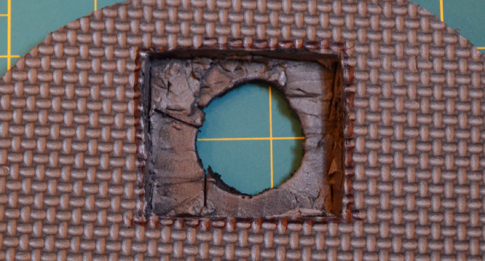
Finish the Costume
Once you’ve figured out part locations and cable lengths and tested your script, you’re
ready for the real work—carving up your hard work. Unless you’re already particularly
adept at foam cutting, we suggest doing this a few times with scraps before you go
slicing up your hard work on the real thing. You have a few aims in this shape that are
probably a bit different from the sculpting you did on the rest of your armor:
•You probably want to cut a round hole smaller than the square screen, since even
the worst shot from a Stormtrooper doesn’t blast a square hole.
•The visible side of the hole should be as flush with the screen as possible.
•The back side should then be sturdy enough to support the screen and its fragile
cable.
To accomplish this, lay the screen on the back side of the foam and outline it with a
marker. You want an accurate outline to ensure a snug fit.
First cut the round hole, cutting all the way through the foam. Then carefully make
cuts following the outline shape going nearly all the way through but not piercing the
front of the foam. (This is why you practice on scraps.)
Working from the hole out to those edges, slice parallel to the foam, cutting out a
rectangle for the screen to sit in, as shown in Figure 3-11. It doesn’t have to be perfectly
smooth. The goal is just to get it as close to the surface of the foam as possible.
Figure 3-11.
Hole to set screen into foam, viewed from back side
155
CHAPTER 3: RASPBERRY PI AROUND THE HOUSE
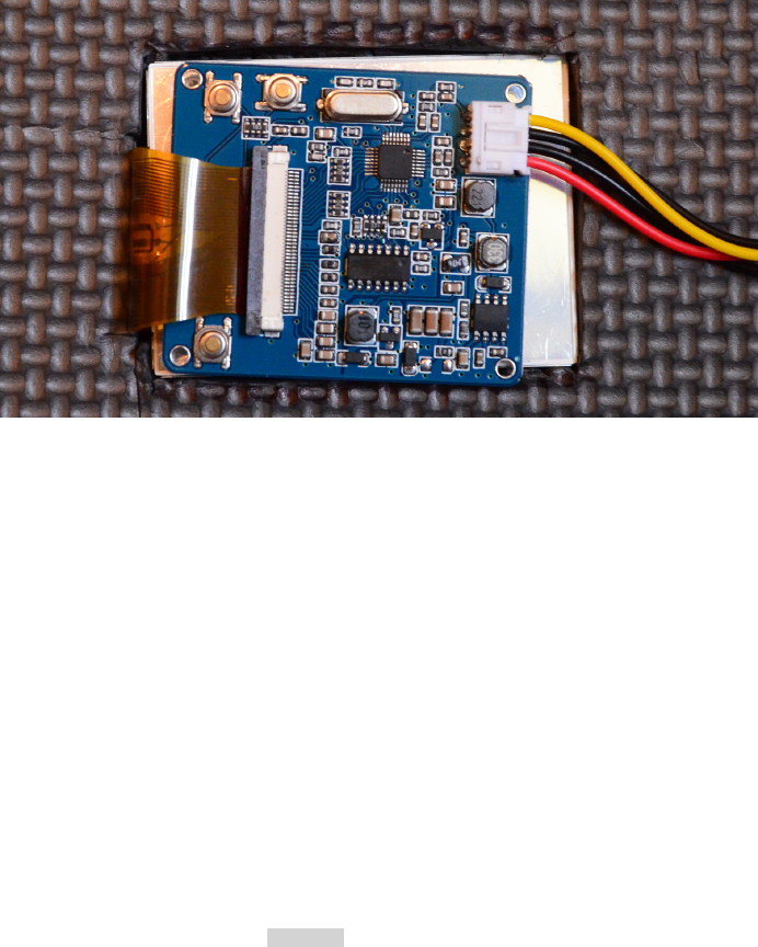
You might need to cut a notch on one side for the ribbon connector. Remember, that’s
a fragile connector, and if you tear it, about all you can do is wipe your tears and buy
a new screen set.
Once the hole is sized properly, you can set the screen into the hole, as shown in
Figure 3-12. Turn it over and admire your work!
Figure 3-12.
Screen set into finished hole, view from back side
Once you get all that taken care of, it’s time to add some realism. You’re going to want
the hole to look a bit burnt. Conveniently, you have a burning device in your hands—
your hot knife. Use the metal extension between the knife and the handle, which also
gets hot, to melt the edges of the hole. They’ll both get smoother and blackened.
You can also paint some scorch marks around the edges and in various other spots
for added realism. If you accidentally tapped some other part of your foam with the
hot knife while you were working, that’s a great place to create more “battle damage”
so it doesn’t look like your shiny, fresh armor got shot through the second you stepped
out of the pod/ship/space station.
Put It All Together
Finally, put it all together. Mount the screen in the hole and secure the Raspberry Pi,
power supply, and cables in the places you’ve found to hide them. If you’re using the
TFT display we use here (see Hack #57 for further instructions on connecting it), re-
member also that its ribbon connector is rather fragile and should be secure and
protected.
156 RASPBERRY PI HACKS

Turn everything on, run your script (or let it autostart), and you’re ready to be a walking
war wound, as shown in Figure 3-13. We recommend some nice zombie makeup to
complete the look.
Figure 3-13.
Screen running in hole window
You can take this hack in other directions as well. Embed a larger screen in the chest
of a robot to show its “controls,” or have music videos playing on a dancing robot.
Build a Fallout Pip-Boy. Put the camera and screen together in front and create a
steampunk “explorer” character whose rig displays a first-person account of what he
finds. Dream up all sorts of other possibilities and get to costuming!
HACK 36 Look for Aliens
Your Raspberry Pi can be a part of the world’s largest distributed com-
puting project. You might not actually find signs of alien life, but then,
wouldn’t it be fun if you did? And your Pi does all the work.
For more than a decade, the Search for Extraterrestrial Intelligence (SETI) project has
used distributed computing through SETI@Home to help with the massive task of
sifting through the data from radio telescopes for signs of intelligence beyond Earth.
These telescopes receive more noise than anything else, and every bit more data that
can be processed means a wider range of frequencies that can be examined. This was
originally done using supercomputers until David Gedye organized the SETI@Home
project to enable anyone, anywhere to help process all of the data they were acquiring.
You can conduct your own piece of the ET hunt with your Raspberry Pi (or several of
them!).
157
CHAPTER 3: RASPBERRY PI AROUND THE HOUSE

You may remember the SETI@Home Classic project as a screensaver that launched
in May 1999, which was used by millions. This version, known as SETI@Home Classic,
was retired in December 2005 when funding ran out. In those six years, 5,436,301
users from 226 countries provided the equivalent of 2,433,979.781 years of CPU time.
While the project didn’t find signs of extraterrestrial life, it did make its mark as the
largest computation in history. From then on through today, the project continued
through the Berkeley Open Infrastructure for Network Computing (BOINC) open
source platform for volunteer grid computing.
BOINC was originally created for SETI@Home in the Space Sciences Laboratory at
the University of California, Berkeley and now receives funding from the National Sci-
ence Foundation. In addition to SETI@Home, it now runs more than 40 other projects,
from Enigma@home, which is attempting to decode the remaining three unbroken
Enigma messages from World War II, to QMC@Home, which calculates molecular
geometry for the field of quantum chemistry.
If you’ve followed the work at CERN’s Large Hadron Collider (LHC), you can use your
BOINC installation to participate in the LHC@home project. Once you’ve installed it,
you can also connect to those other projects that process data for research in nearly
every area of math and science. Data processed by more than 8 million hosts using
BOINC, the world’s largest distributed computing project, has led to breakthroughs
in AIDS research, found new celestial objects, and even helped find a stolen laptop.
The most popular projects running on BOINC as of this writing are:
SETI@Home
The subject of this section
Einstein@Home
Searches for gravitational signals from pulsars and has discovered nearly 50 new
pulsars
World Community Grid
An IBM-sponsored humanitarian project that has partnered with hundreds of
other organizations on research from cancer to clean energy
BOINC can run continuously, taking advantage of unused processor time as it’s avail-
able. Some people wholly devote older equipment to personal “SETI farms.” Devoting
a Raspberry Pi to always looking for ET could be your way of contributing to the project.
You could even build a “Raspberry Pi farm,” though it would unfortunately not grow
pie. But maybe that credit-card-sized computer will be the one that finds definitive
signs of life beyond Earth.
Read more about the early history of SETI@Home at http://setia
thome.berkeley.edu/classic.php
158 RASPBERRY PI HACKS
Begin by installing the BOINC manager and client:
$ su -c 'yum install boinc-manager boinc-client'
or:
$ sudo apt-get install boinc-client boinc-manager
To ensure that the BOINC client starts every time you boot the system, enter:
$ sudo systemctl enable boinc-client.service
Then reboot. If you would prefer to start the BOINC client manually, you can do so any
time with the following command:
$ systemctl start boinc-client.service
If your alien-hunting Pi will be devoted to the cause and not needing a monitor, you
have the option of installing only the client and starting it at boot. In this case, enter
only:
$ su -c yum install boinc-client
or:
$ sudo apt-get install boinc-client
Setting Up BOINC
The following instructions assume that you are using the BOINC Manager, which you
can find under System in the Applications Menu if you’re using Fedora or start from
the command line by typing boincmgr. It might take a moment before anything appears
in the BOINC Manager window the first time. When it does start, you’ll see the error
“Unable to connect to the core client.”
Open a terminal and first check that the BOINC Client is running:
$ sudo systemctl status boinc-client.service
You should see something similar to the following:
boinc-client.service - Berkeley Open Infrastructure Network Computing Client
Loaded: loaded (/usr/lib/systemd/system/boinc-client.service; enabled)
Active: active (running) since Wed, 2013-04-17 14:37:22 EST; 1min ago
Process: 19413 ExecStartPre=/usr/bin/chown boinc:boinc /var/log/
boinc.log /var/log/boincerr.log (code=exited, status=0/SUCCESS)
Process: 19410 ExecStartPre=/usr/bin/touch /var/log/boinc.log /var/log/
boincerr.log (code=exited, status=0/SUCCESS)
Process: 19406 ExecStartPre=/bin/sleep 1 (code=exited, status=0/
SUCCESS)
Main PID: 19416 (boinc)
159
CHAPTER 3: RASPBERRY PI AROUND THE HOUSE
CGroup: name=systemd:/system/boinc-client.service
├ 19416 /bin/bash /usr/bin/boinc --dir /var/lib/boinc
├ 19417 /usr/bin/boinc_client --allow_multiple_clients --
dir /var/lib/boinc
├ 19422 ../../projects/setiathome.berkeley.edu/
setiathome_6.03_i686-pc-linux-gnu
├ 19423 ../../projects/setiathome.berkeley.edu/
setiathome-5.28.x86_64-pc-linux-gnu
├ 19424 ../../projects/setiathome.berkeley.edu/
setiathome-5.28.x86_64-pc-linux-gnu
└ 19425 ../../projects/setiathome.berkeley.edu/
setiathome-5.28.x86_64-pc-linux-gnu
Apr 17 14:37:21 localhost.localdomain systemd[1]: Starting Berkeley Open In
frastructure Network Computing Client...
Apr 17 14:37:22 localhost.localdomain systemd[1]: Started Berkeley Open In
frastructure Network Computing Client.
You can also see if the client is running by looking for it in the list of currently running
processes:
$ ps aux | grep boinc
You should see several boinc processes, including boinc_client in a list similar to the
following:
root 16818 0.0 0.0 196284 2656 pts/0 S Apr17 0:00 su boinc
boinc 16819 0.0 0.0 114084 1760 pts/0 S+ Apr17 0:00 bash
jnettles 18734 0.0 0.0 111848 1264 ? S 10:27 0:00 /bin/
bash /usr/bin/boincmgr
jnettles 18741 0.1 0.7 706868 28800 ? Sl 10:27 0:16 boinc_gui
boinc 20117 0.0 0.0 113948 1328 ? SNs 14:41 0:00 /bin/
bash /usr/bin/boinc --dir /var/lib/boinc
boinc 20118 0.1 0.1 306116 5716 ? SN 14:41 0:00 /usr/bin/
boinc_client --allow_multiple_clients --dir /var/lib/boinc
boinc 20123 93.4 0.9 36920 35768 ? RNl 14:41 0:58 ../../
projects/setiathome.berkeley.edu/setiathome_6.03_i686-pc-linux-gnu
boinc 20124 90.5 1.1 58124 45052 ? SNl 14:41 0:57 ../../
projects/setiathome.berkeley.edu/setiathome-5.28.x86_64-pc-linux-gnu
boinc 20125 91.7 1.1 57616 44536 ? SNl 14:41 0:57 ../../
projects/setiathome.berkeley.edu/setiathome-5.28.x86_64-pc-linux-gnu
boinc 20126 92.0 1.1 56964 43892 ? SNl 14:41 0:58 ../../
projects/setiathome.berkeley.edu/setiathome-5.28.x86_64-pc-linux-gnu
root 20144 0.0 0.0 109180 880 pts/1 S+ 14:42 0:00 grep --
color=auto boinc
160 RASPBERRY PI HACKS
If you do not, try starting the service by entering +systemctl start boinc-
client.service+.
Once you’ve confirmed that the client is running, it’s time to configure the BOINC
Manager:
$ sudo vi /var/lib/boinc/gui_rpc_auth.cfg
This file contains a long string of characters that is your BOINC password. Copy it
(Shift+Ctrl+V), then exit (:q!).
Flush the IP tables:
$ sudo iptables -F
Now go to the BOINC Manager window. Go to View → Advanced View (or use Shift+Ctrl
+A to switch). Under Advanced → Select Computer, enter 127.0.0.1 for the hostname
(using localhost may or may not work) and paste the password you copied from
gui_rpc_auth.cfg.
For security reasons, BOINC Manager requires this password each time you start it.
At this point, unless you intend to walk away from it and never use the manager again,
you should change some permissions to save yourself from having to copy and paste
the password each time.
As you saw when you listed the BOINC processes, installing it created a boinc user as
well. That user is currently the owner of everything under /var/lib/boinc/. By adding
yourself to the boinc group, you can create permissions that let your BOINC Manager
connect to the client without looking up that password each time:
$ su
[Enter password]
$ /usr/sbin/usermod -G boinc -a YOURNAME
$ chmod g+rw /var/lib/boinc
$ chmod g+rw /var/lib/boinc/*.*
$ ln -s /var/lib/boinc/gui_rpc_auth.cfg /home/YOURNAME/gui_rpc_auth.cfg
After you have logged out and back in, you will be added to the boinc group and should
no longer have to repeat the password steps when using the BOINC Manager.
BOINC Account Managers
There are several BOINC account managers (which in a sense means BOINC Manager
is really just middle management). They manage your BOINC accounts if you’re par-
ticipating in multiple projects or have BOINC running on multiple systems.
Even if you’re running it only on this one Raspberry Pi, using an account manager will
make things easier, and BOINC Manager will prompt you to set one up. The website
161
CHAPTER 3: RASPBERRY PI AROUND THE HOUSE
for BAM!, one of the account managers, explains some of the differences between
using an account manager and not using one.
BOINC Account Manager (BAM!)
Despite its name, BOINC Account Manager (BAM!) is not run by the same team as
BOINC. It was created by the group that runs BOINCstats, which, as the name implies,
provides statistics related to the various projects running on BOINC.
As you’re setting up the BOINC Manager for the first time, you’ll be asked to select an
account manager. If you choose BAM!, you will be directed to set up a BAM account
at http://bam.boincstats.com, where can create and access your accounts for
SETI@Home and other projects.
You can use the same account on multiple Raspberry Pis (or other computers), but
make sure that you consistently use the same email address when joining projects
and teams. If, after creating an account, you don’t get the BAM! verification email,
check your spam folder, or add boincstats.com to the accepted domains filter.
1. Sign in.
2. Select Tools → Add projects. You’ll notice the long list of other distributed com-
puting projects from a wide variety of math and science purposes that you can
contribute to using BOINC. You can choose multiple projects—that’s what the
BOINC Manager is for.
3. Select SETI@Home. You’ll be asked to either create a login or to give ones you
already use. If you create an account, you’ll then be directed to the SETI@Home
website, where you’ll finish the registration process.
4. Optionally, find a team to join or create one. If you search for “raspberry pi” in the
keywords section, you’ll find the Raspberry Pi Team, created specifically for peo-
ple using the Pi to run BOINC. Those who simply like the Raspberry Pi but are
running BOINC from another system are welcome, too, so don’t take the team’s
statistics as being purely from Pis. You can view this team’s statistics at http://
boincstats.com/en/stats/-1/team/detail/51ef74e7931bf4eaaf10fe521d6b9df0.
GridRepublic
GridRepublic is an account manager built on the BOINC manager code. It is created
by the GridRepublic nonprofit organization that was formed shortly after BOINC to
establish the manager concept—a place from which to the control the projects.
To use the GridRepublic manager, you must create an account with them, using the
same name as your World Community Grid account if you have one. You then “attach”
it to your BOINC installation. You can learn more on the Grid Republic site.
162 RASPBERRY PI HACKS
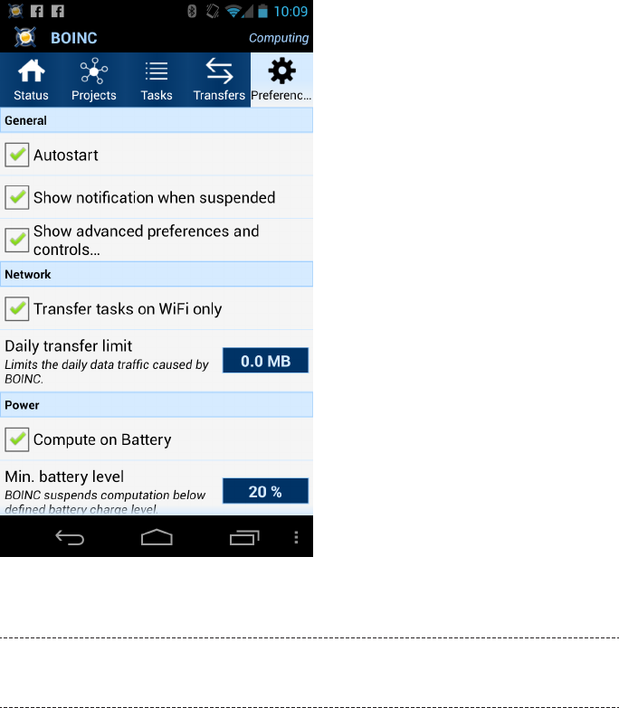
AndroBOINC
If you use an Android smartphone, you can remotely control your BOINC client(s) from
your phone. Search in Google Play for “boinc.” There are several unofficial apps, but
we recommend AndroBOINC (Figure 3-14). If you don’t have an unlimited data plan,
be careful how you set the autorefresh rate when not on WiFi, lest you be sad when
next month’s bill comes.
Figure 3-14.
AndroBOINC client
There is also an official BOINC Android app available for alpha testing. Read the
instructions there carefully if you’re interested in joining the testing.
AndroBOINC offers basic control and status of your BOINC client. Think of it as the
BOINC Manager, but on your phone. (You don’t want to run the client on your phone
unless you really hate having battery left to do anything else.)
163
CHAPTER 3: RASPBERRY PI AROUND THE HOUSE

4
Hacking the Outdoors
Electronics outside, you say? Isn’t that a bad idea? We do have a couple of water-
resistant suggestions (Hack #39 and Hack #40). But we also have ideas for how to put
your Pi to use on your outdoor projects, from monitoring your garden (Hack #38) to
controlling your holiday lights (Hack #45).
HACK 37 Tell the Temperature Outside (Without
Going Out There)
The outside temperature is not a constant value; it fluctuates, and we
know you like to know what it is. Whether you’re helping plants stay
healthy or just want to know how many layers of clothes to wear, this hack
can help!
Hack #05 shows that the Raspberry Pi measures the temperature of its BCM2835
system-on-chip, but this is different. In order to read the temperature near the Rasp-
berry Pi (or even nowhere near it), you’ll need to connect a temperature sensor. While
Linux supports some USB thermometers, it is just as simple (and arguably more fun),
to wire up a simple temperature sensor to the GPIO on the Raspberry Pi.
This hack uses the Texas Instruments TMP102 I2C temperature sensor for the fol-
lowing reasons:
• It is very small. Smaller than a quarter. See Figure 4-1 for proof.
•It is a digital sensor (this makes the wiring much easier and the results much more
accurate).
• Sparkfun sells it already connected to a breakout board.
•It is cheap (less than $6 USD at the time of this writing).
•It is accurate over a range of temperatures from -25°C and +85°C. (That’s -13° to
185°F.)
165

Figure 4-1.
TMP102 and a shiny quarter
Depending on which Linux distribution you are using, you might not have all the drivers
necessary to use the TMP102. Both Raspbian and Pidora are missing the driver for
the TMP102. You can enable the support for this driver if you build a custom kernel
from source, as covered in Hack #22. Be sure that you have enabled (compiled in)
CONFIG_I2C, CONFIG_I2C_CHARDEV, and CONFIG_I2C_BCM2708.
Because you will be using the lm_sensors userspace component to get readings from
the TMP102, you will need to be sure to enable “Hardware Monitoring support” (CON
FIG_HWMON) under Device Drivers. You also need to have CONFIG_SENSORS_TMP102 enabled
as a module. We will assume that the TMP102 support is present as a module going
forward. Figure 4-2 shows an example of what this option looks like.
Alternatively, Occidentalis supports the I2C and TMP102 sensor support out of the
box, so you could just use that (and avoid the need for a custom kernel for this
hack). For more information about Occidentalis, see Hack #27.
What is I2C?
I2C (Inter-Integrated Circuit) is a protocol for connecting low-speed devices with
two wires. It is common in embedded systems, especially for sensors. The Rasp-
berry Pi has two dedicated GPIO pins (2 and 3 on the current Raspberry Pi Model
B) preconfigured for I2C.
166 RASPBERRY PI HACKS
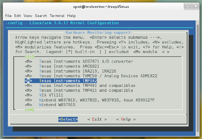
Figure 4-2.
Texas Instruments TMP102 sensor support enabled as a module
Sparkfun’s breakout board makes connecting it to the Raspberry Pi simple. There are
six pins (or leads) coming off of the breakout. These pins are labeled on the back of
the breakout board, and the ones you care about are on the left side.
The first pin is Ground (GND), the second pin is the Serial Clock (SCL), the third pin
is the Serial Data Line (SDA), and the fourth pin is 5 V (V+). The SCL and SDA pins are
how the sensor sends/receives data across the I2C bus.
You should not need to use the pins labeled ALT or ADD0 (they’re on the right side of
the breakout board), unless you already have a conflicting device on the same I2C bus
and need to change the device number. Because this is the only device on the Rasp-
berry Pi GPIO I2C bus for this hack, you can just leave those pins alone. You can see
these labels on the TMP102 device, as shown in Figure 4-3.
167
CHAPTER 4: HACKING THE OUTDOORS
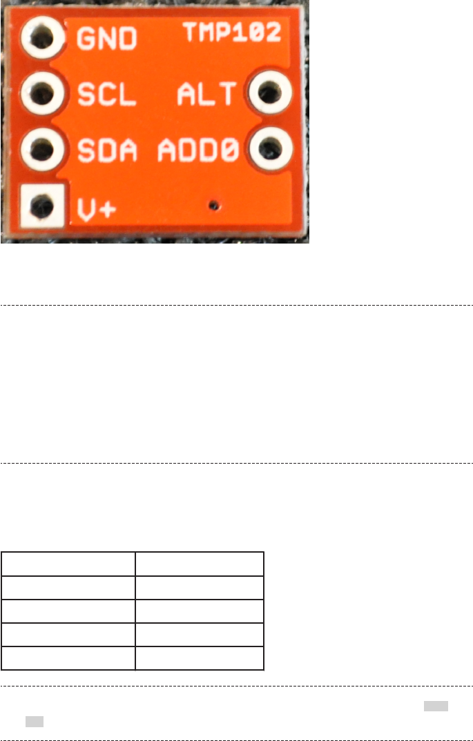
Figure 4-3.
TMP102 labels
But the Datasheet Says…
If you happen to look at the datasheet provided by Sparkfun, you might notice that
its numbering is different from what we’ve provided. It numbers the pins as they
come off the TMP102 sensor itself, not as they appear on the breakout board. The
TMP102 sensor is that tiny black chip in the middle of the breakout board. If you
look closely (possibly with a magnifying glass), you’ll see the leads coming off the
TMP102 to the breakout pins. The ordering is different, but the breakout board
labels make a lot more sense to use, so we use those instead.
The mapping of the TMP102 breakout pins to the Raspberry Pi GPIO is fairly obvious,
as shown in Table 4-1.
Table 4-1. TMP pin mapping
TMP102 BREAKOUT PIN LABEL RASPBERRY PI BCM GPIO PIN
GND GND
SCL 3 (SCL)
SDA 2 (SDA)
V+ 5 V
Remember, the mapping in Table 4-1 referes to the BCM GPIO pin labels. See Hack
#14 if this doesn’t make sense to you.
168 RASPBERRY PI HACKS

To connect this device to the Raspberry Pi, you’ll first need to solder wires to the
TMP102 breakout pins that you are using (GND, SCL, SDA, and V+).
See “Soldering Reminders” on page 42 for some basic soldering tips.
If you are lazy, you can use male jumper wires and bend them tightly to make the
connection, but this is really sloppy and hackish, even for a Hacks book. Either way,
once you have wires coming off the TMP102 breakout, you need to connect them to
the Raspberry Pi. You can either use jumper wires to connect directly to the appro-
priate GPIO pins, or you can use a Pi Cobbler and a breadboard for the simplest wiring
(see Hack #15 for more about the Pi Cobbler).
To use your TMP102 sensor (and make sure it is working on the Raspberry Pi I2C Bus),
you need to install some software. To install i2ctools and lm-sensors, run the follow-
ing command on Pidora:
$ su -c 'yum install i2c-tools lm_sensors -y'
On Raspbian, run:
$ su -c 'apt-get install i2c-tools lm-sensors'
Now, let’s try to find your device on the Raspberry Pi’s I2C Bus. To look for the device,
you need to run i2cdetect on bus 1. On the original Raspberry Pi Model B units, this
was bus 0, but with the current hardware, it is bus 1. Bus 0 actually exists on the current
Raspberry Pi Model B, but you have to connect to it via the camera connector. Here’s
the i2cdetect command line you want to run:
$ su -c 'i2cdetect -y 1'
You should see output like this:
0 1 2 3 4 5 6 7 8 9 a b c d e f
00: -- -- -- -- -- -- -- -- -- -- -- -- --
10: -- -- -- -- -- -- -- -- -- -- -- -- -- -- -- --
20: -- -- -- -- -- -- -- -- -- -- -- -- -- -- -- --
30: -- -- -- -- -- -- -- -- -- -- -- -- -- -- -- --
40: -- -- -- -- -- -- -- -- 48 -- -- -- -- -- -- --
50: -- -- -- -- -- -- -- -- -- -- -- -- -- -- -- --
60: -- -- -- -- -- -- -- -- -- -- -- -- -- -- -- --
70: -- -- -- -- -- -- -- --
169
CHAPTER 4: HACKING THE OUTDOORS

This is a graphical way of telling you that there is a device on I2C bus 1, with the numeric
identifier 48. This is your TMP102 sensor.
Hey, That Didn’t Work!
If you try the command to install i2ctools and lm-sensors on a default install
of Raspbian, it will look like this:
$ su -c 'i2cdetect -y 1'
Error: Could not open file `/dev/i2c-1' or `/dev/i2c/1': No such file
or directory
Why? Raspbian’s kernel has CONFIG_I2C_CHARDEV and CONFIG_I2C_BCM2708
enabled as modules, instead of built in to the kernel like Pidora does (and
like we recommend). If you got this error, it means you didn’t build a custom
kernel, as recommended in Hack #22. Go back and do that now. If you do not
and you just load these modules, you’ll run into trouble trying to access the
TMP102, because that driver isn’t built at all in Raspbian.
If you did build a custom kernel, but left CONFIG_I2C_BCM2708 as a module
for some reason, you can manually load the i2c-dev module with this com-
mand:
$ su -c 'modprobe i2c-bcm2708'
That will make /dev/i2c-1 appear, and your i2cdetect invocation will suc-
ceed.
You now know that our TMP102 device is device number 48 on I2C bus 1, but you need
to tell the Linux kernel that it exists:
$ su -c 'echo tmp102 0x48 > /sys/class/i2c-adapter/i2c-1/new_device'
At this point, you are ready to start reading temperature data from your TMP102 sen-
sor. The standard tool for doing this in Linux (lm_sensors) comes with a library (lib
sensors) that lots of tools support, but as a beginning point, you are going to use the
included sensors command:
$ sensors
bcm2835_thermal-virtual-0
Adapter: Virtual device
temp1: +42.8°C
tmp102-i2c-1-48
Adapter: bcm2708_i2c.1
temp1: +24.8°C (high = +160.0°C, hyst = +150.0°C)
170 RASPBERRY PI HACKS
In this output, you can see two readings:
bcm2835_thermal-virtual-0
This is the temperature sensor inside the Broadcom BCM2835 system on chip
at the heart of the Raspberry Pi. It is also the same reading you can get from
vcgencmd, as described in “Measure Temperature” on page 16.
tmp102-i2c-1-48
This is your TMP102 sensor, reporting for duty.
From this output, you can see that your TMP102 sensor is reporting a lovely temper-
ature of 24.8°C. The high value is the value at which the TMP102 shuts down due to
extreme overheating (160.0°C qualifies).
It also has a hyst value, which refers to “temperature hysteresis limit” (sadly, not Def
Leppard’s legendary 1987 album Hysteria). The hysteresis limit value is the value at
which the sensor reading no longer fluctuates, as it approaches the shutdown tem-
perature.
If you just want to see the TMP102 reading, you just need to pass the lm_sensors “chip
name” for that device as an option. As configured, the TMP102 is tmp102-i2c-1-48
($sensortype-$bustype-$busnumber-$devicenumber). If you want to see the values in
Fahrenheit, just pass -f:
$ sensors -f tmp102-i2c-1-48
tmp102-i2c-1-48
Adapter: bcm2708_i2c.1
temp1: +76.5°F (high = +320.0°F, hyst = +302.0°F)
If you want to parse the sensor values directly, you can either use the aforementioned
libsensors library, or you can access the values directly via /sys. /sys/class/i2c-dev/
i2c-1/device/1-0048/ is the device node where you can find the values stored in spe-
cial /sys files. These files represent the values reported from the device driver, and are
updated constantly. If you want to get an updated value, just reopen one of these files:
$ cd /sys/class/i2c-dev/i2c-1/device/1-0048/
$ ls
driver modalias power temp1_input temp1_max_hyst
hwmon name subsystem temp1_max uevent
$ cat temp1_input
23312
To convert that value to Celsius, just divide it by 1,000. If you need to convert it to other
temperature units, refer to “Fun with Math and Science” on page 16.
171
CHAPTER 4: HACKING THE OUTDOORS

HACK 38 Check on Your Plants
Plants are an important part of the ecosystem of life on our planet. Or
maybe you just want tasty toppings on your burger. Either way, you can
use your Raspberry Pi to help them grow big and healthy.
Gardening is tricky stuff. Plants can’t talk, so they can’t tell us what they need. Gar-
deners are like hackers in a lot of ways: they learn a lot by doing, getting experience
in how to grow plants, where to keep them, how much to feed them, and what songs
they like to listen to (hey, I heard they love music). At the heart of this, whether they
realize this or not, is data gathering. By adding a dedicated temperature and humidity
sensor to a Raspberry Pi, we can gather useful data about the state of the garden.
Most plants need a few things to grow properly:
Soil
This supports the plant and gives it an anchor for the roots to grow in. The roots
draw in the water and minerals that the plant needs. You want to use a healthy,
well-nourished soil with the right sort of minerals and ingredients for your plant.
Potting soil is usually a good start, but there are much larger books about getting
the perfect soil for your plant.
Sunlight
Plants perform photosynthesis, which is the process of converting sunlight into
the chemical fuels to “power” the plants biological processes. All green plants
need light, but the amount varies by plant. Some plants prefer a lot of of light, and
some plants prefer much less.
Air
Specifically, carbon dioxide. If the air near your plant is too polluted, your plant
will not grow well.
Water
Everything alive (that we know of) needs water. Plants are no different, but the
amount of water that a plant requires varies by the type of plant. If this is confusing
to you, think about a cactus in the desert and then compare it to a palm tree next
to an oasis. Both are plants, both need water, but the cactus needs far less to
survive (and wouldn’t really be able to use more than a little anyway).
Space
Plants need space to grow, usually up, but sometimes outward.
Optimum temperature
Again, this is specific to the type of plants, but all plants have a range of temper-
atures that they prefer. The U.S. Department of Agriculture calls this “plant har-
diness” and maps it out into zones across the United States. Each zone is indi-
172 RASPBERRY PI HACKS

cated by the range of temperatures it experiences, and each zone is given an
identifier code. For example, Tom’s plant hardiness zone is 5b, and Ruth’s is 7a.
See http://planthardiness.ars.usda.gov for a map of all the U.S. zones (and to
discover your zone). Also, some plants tolerate frost and freezing better than
others, so depending on your plants, temperatures dropping below 0°C could
result in plant death.
Measuring the space, soil, and air is not simple to do, but we can measure the amount
of water in the air and the temperature of the garden. You can also measure the in-
tensity of light near the plants using the light sensor in Hack #42, but this hack will
focus on monitoring temperature and water (humidity).
Serious Gardeners
If you’re a hardcore gardener, you might point out that while humidity is interesting,
it is less interesting than rainfall measurement (assuming your garden is not in a
water-controlled greenhouse). To get that, you need to wire up a rain gauge sensor.
There are several different rain gauge sensors on the market, but connecting them
to a Raspberry Pi and getting the data is a bit more complicated. There are some
1-Wire rain gauge units, but the Raspberry Pi does not have a 1-Wire connector. You
can get around that by building a circuit to connect it to GPIO (either via the w1-
gpio driver or the I2C bus), or you can buy a 1-Wire-to-USB converter (like the
Maxim Integrated DS9490R#).
From a software side, you can use OWFS to read the data from the 1-Wire device.
This can get complicated quickly, so we’ll leave this as an exercise for the motivated
and serious gardener. For the rest of us, we’ll start with humidity and work our way
up.
While it is technically true that your plants are growing in real time, they are doing it
so slowly that you have to watch them over long periods of time to see the growth.
(Search YouTube for “time lapse of plants”; it is rather freaky and cool.) As a result,
we do not need to have real-time measurements of temperature and humidity, so
using a sensor like a TMP102 (as in Hack #37) is overkill. Instead, we can use an “all-
in-one” temperature and humidity sensor. Adafruit has an excellent one from Adsong,
the AM2302.
Here are the main reasons the AM2302 sensor is a good one for this hack:
•It is sealed up in a plastic body, which will help it be resistant to Mother Nature’s
wrath. It also has a mounting hole, so you can attach it (either by hanging or
screwing) in a secure location in your garden.
•It is a digital sensor, so it is accurate and simple to wire.
•It reads in new data every two seconds, which is nowhere near real time, but is
more than sufficient for monitoring plants in a garden.
173
CHAPTER 4: HACKING THE OUTDOORS

•It uses three wires, and only one wire for communication! This means that only
three GPIO pins on your Raspberry Pi will be used (and only one general-purpose
pin needs to be reserved).
In fact, the only real downside to using the AM2302 is that it does not (as of the time
of this writing) have a native Linux kernel driver for it. This means that we cannot easily
plug it into the lm_sensors infrastructure, as described in Hack #37.
Adding the AM2302 to the Linux Kernel
The AM2302 has a DHT22 temperature-humidity sensor at its core. It should be
rather simple for someone with a basic understanding of C and the Linux kernel to
add a hwmon driver for the DHT22. If you’re looking for a good starter Linux kernel
development project, this might be it! We hope that one day this note will become
obsolete once someone writes this code, and then this hack becomes much sim-
pler for everyone!
Again, Adafruit comes to the rescue. They provide an open source C program for
reading the temperature and humidity values off the AD2302. We’ll get to that in a
moment, but first, you’ll want to wire it to your Raspberry Pi. The AD2302 has three
wires coming out of the plastic case:
Red
For 3.3 V power
Black
For Ground (GND)
Yellow
Where the data comes out
Technically, you can connect any of the generic I/O pins on the GPIO header and it will
work, but we know you’re going to ask us to tell you which pin to use … so just go ahead
and connect the yellow data wire to BCM Pin 4 (P1-07). Why? Well, it is the first generic
I/O pin underneath the 3.3 V (the two pins above it are I2C pins).
Connect the red wire to the 3.3V power pin (P1-01) and the black wire to a Ground
(GND) pin. If you aren’t sure what all of these GPIO terms mean, check out Hack #14.
The simplest way to wire these pins to the Raspberry Pi is with a solderless breadboard
and a Pi Cobbler (Hack #15). The wires coming from the AD2302 are a little too thin to
insert into the breadboard, so you’ll probably want to connect them directly to some
thicker wire first. There are a number of ways to do this:
• Solder the wire to a thicker wire.
174 RASPBERRY PI HACKS
•Twist the ends of the two wires together, then seal them with electrical tape (or
hot glue).
• Crimp the wires together using a crimping tool.
No matter which method you use, you’ll probably need to strip off some of the insu-
lated connector covering the wires. You really should use a wire stripper for this, and
not try to use a pair of scissors (or the cutting part of a pair of pliers), because you run
the risk of cutting off part of the wire itself.
Once you have these three wires connected and properly inserted into your bread-
board (with a Pi Cobbler connecting it to your Raspberry Pi GPIO ports), you can install
the software to test it out.
On your Raspberry Pi, clone a copy of the Adafruit Git Raspberry Pi repository:
$ git clone git://github.com/adafruit/Adafruit-Raspberry-Pi-Python-Code.git
$ cd Adafruit-Raspberry-Pi-Python-Code/Adafruit_DHT_Driver
Even though the name of this repository is Adafruit-Raspberry-Pi-Python-Code, you
will notice that the code in this directory is in C. Adafruit had to use C code to talk to
the AM2302 sensor since it requires extremely fast timing to read, and Python would
not be able to easily accomplish this task.
Adafruit includes a precompiled binary that should work on any distribution of Linux
for the Raspberry Pi, but if you do not trust their binary (or it doesn’t work for some
reason), you can rebuild it. Just have gcc and make installed, and run:
$ rm -f Adafruit_DHT
$ make Adafruit_DHT
Either way, you need to run the Adafruit_DHT binary. To talk to the AM2302 sensor on
BCM Pin 4, run:
$ su -c './Adafruit_DHT 2302 4'
Using pin #4
Data (40): 0x2 0x16 0x0 0xe6 0xfe
Temp = 23.0 *C, Hum = 53.4 %
The first option passed is the sensor type (this code also supports interfacing with a
raw DHT11 (11) and DHT22 (22) in addition to the AM2302 (2302)). The second option
is the GPIO pin that it is connected to. You can see that it is reporting a temperature
of 23.0°C and a humidity of 53.4%.
You now have a reliable way of measuring the data from the AM2302. Adafruit has
also included a Python script (Adafruit_DHT_googledocs.ex.py), which will run the
Adafruit_DHT binary every 30 seconds, and upload the humidity and temperature
readings into a Google Docs spreadsheet.
175
CHAPTER 4: HACKING THE OUTDOORS

To use it, you will need to configure the script with your own Google Docs account
details. Open Adafruit_DHT_googledocs.ex.py with your favorite text editor and then
look for this section of code:
# Account details for google docs
email = 'you@somewhere.com'
password = '$hhh!'
spreadsheet = 'SpreadsheetName'
Change the values for the email, password, and spreadsheet, making sure to keep the
actual values wrapped in single quotes, and save out the file. To run the script, simply
execute it from a terminal:
$ ./Adafruit_DHT_googledocs.ex.py
You might want to run this in a screen session, so that you do not need to keep that
terminal open. To do that, simply execute the screen command before running the
Adafruit_DHT_googledocs.ex.py script, and then press Control-A-D to disconnect from
the screen session. You can reconnect to that screen session later by running screen
-r.
You can now go to your Google Docs account in a web browser and watch the humidity
and temperature data for your plants get uploaded over time.
This is a simple monitoring setup, but it is possible to make more complicated setups
using this model:
•You could write a wrapper script to check for alert conditions (temperature ap-
proaching freezing) and have it send you notification emails (or tweets).
•You could use the AM2302 as a data source for automating your garden (think
automated watering).
•Or if you really don’t like plants, it could be part of a homemade weather station.
Monitoring home-brewed beer or your wine cellar?
Really, anything that doesn’t handle temperature or moisture well is ideal for this hack.
HACK 39 Make Your Pi Water-Resistant (with a
Case)
If you want to run your Raspberry Pi outdoors, you’re going to need to
put it in a water-resistant case. Here’s one way to do it.
If you are working on a project that involves readings from the great outdoors, the best
place for your Raspberry Pi is inside, but that isn’t always practical or possible. Wheth-
er you are trying to monitor plants in a garden, or automating your mailbox, you’ll need
to protect your Raspberry Pi from:
176 RASPBERRY PI HACKS
Water
This includes, but is not limited to, rain, snow, sleet, hail, dew, sprinkler, and animal
… fluids.
Nature
Dirt doesn’t hurt children, but it is no friend to electronics. Lots of animals like
warmth, and the Raspberry Pi is an oasis of heat in a cold night. Also, the com-
bination of nature and water means mold and mildew, neither of which is good
for your Pi. Oh, and insects, we can’t forget them.
Weather
We’re not too worried about a tornado or a hurricane here. If that happens, you’ve
got bigger problems than a broken or missing $35 Linux PC. That said, we don’t
want it to fly away or break in normal weather conditions.
Here’s how to build a water-resistant, outdoor-friendly case for your Raspberry Pi.
Start with a water-tight plastic container and lid (or, if you want to really up your game,
get an ammo box with a rubber O-ring seal from an Army-Navy surplus store instead).
We recommend getting a large one, as opposed to the smallest one the Raspberry Pi
will fit completely into.
The plastic container will serve as a general protection from most of the main concerns
highlighted earlier. Using a larger container will allow you to weight it down from the
inside as needed and also gives it a bit more of an air pocket for the heat generated
by the Raspberry Pi to dissipate outward.
You’ll probably want to connect cables to the Raspberry Pi, so you’ll need to make
some holes in the container. Try to make these as small and as few as possible, but
don’t just make one big hole and run all of your cables through it.
The trick is to make a hole, run a cable through it, and then use common silicon sealant
(available at any large hardware store) to permanently seal the cable into the hole and
restore the watertight seal for the plastic container. The trouble with this arrangement
with multiple cables in the same hole is that it can be tricky to completely seal the
gaps that occur between the cables. Also, if you opted for the metal ammunition box,
you’ll need to get specialized sealant for metal (and a pretty good drill setup to make
the holes).
Using a large container also gives you the opportunity to connect the USB power plug
directly to a weatherized extension cord inside the container. Then, you can seal the
extension cord through the hole, and the USB power plug is not exposed to the ele-
ments at all.
Since this arrangement is good, but not perfect (and it will condense some), go ahead
and toss in several silica gel packets. This can be purchased rather cheaply from a
177
CHAPTER 4: HACKING THE OUTDOORS

variety of sources (including Amazon). The silica will dry out the air inside the con-
tainer even further, and it is nontoxic.
Silica gel packets usually contain the warning not to eat them because of silica’s
extreme dessicant nature and the fact that it is commonly doped with other chem-
icals that allow it to visually alter its color as it takes on moisture. Those chemicals
are usually carcinogenic.
Also, depending on how waterproof (or animal-proof) you want the case to be, you
can take the extra step of sealing the container lid into place “permanently” when
you’ve finished.
We recommend that you consider wiring a temperature sensor (and possibly a hu-
midity sensor) inside of this container case in addition to any external sensors or
input/outputs (see Hacks Hack #37 and Hack #38 for details).
And as a bonus idea, you could also use this hack as the basis for a more elaborate
Raspberry Pi-powered interactive geocache (as described in Hack #41).
HACK 40 Make Your Pi Water-Resistant (Without a
Case)
Have you ever wanted to run your Raspberry Pi underwater without a
case? This hack can make that happen (at least for a while).
Normally, electronics of any sort coming into contact with water results in the release
of the magic smoke and one dead electronic component. Electronics used in the same
environment as water are carefully sealed in watertight components (think about un-
derwater cameras for example), but the Raspberry Pi is just a bare electronics board.
You could make it water resistant with a case (as described in Hack #39), but that can
get expensive, and at the time of this writing, there were not many water-resistant
cases for the Raspberry Pi out there. You could seal the entire Raspberry Pi in trans-
parent resin, but that isn’t something most people have immediately available.
Safety Warning and Disclaimer
This hack is not for the faint of heart. It could very well result in a dead Raspberry
Pi and some serious pain. It goes without saying that the Raspberry Pi is not de-
signed or intended for use in water. By mixing electricity and water, you expose
yourself to a very real risk of electrocution. Unless you are really prepared to un-
dertake this hack safely, you might consider skipping it and moving on to some-
thing else. We don’t want you to hurt yourself. No hack is worth injury.
178 RASPBERRY PI HACKS

Enter NeverWet. NeverWet is a spray-on paint-type product from Rustoleum that,
when applied to a surface, makes it extremely hydrophobic (as the name implies). The
NeverWet paint applies a coating that causes water to form nearly perfect spheres,
which roll off the surface, keeping items dry and clean. In the United States, you can
find it in home improvement stores for $20. It comes in a box with two spray cans. The
first is a primer, and the second applies the super-hydrophobic layer.
What Rustoleum Thinks About This Hack
We feel at this point we should tell you what Rustoleum thinks about using Never-
Wet on electronics. From their FAQ page:
Q: Can NeverWet be used on electronics? A: No, NeverWet should not be used on
electronics.
OK, you’ve read that, right? Rustoleum isn’t interested in hearing about how this
hack didn’t work for you or how you destroyed a $35 mini-computer. (For the re-
cord, we aren’t interested in hearing about it either.) All righty then, let us continue.
Regardless of what the FAQ says, we know this works (at least for a while). We’ve
done it.
There is an aesthetic downside to this hack. The NeverWet paint is not transparent,
not even a little bit. When it dries, it looks like someone has applied a chalky white film
over the surface of the Raspberry Pi. (Because you actually did by spraying it repeat-
edly with NeverWet paint.) It looks weird, to say the least.
Here’s what you’ll need for this hack:
•A Raspberry Pi that you have no sentimental attachment to. You’re never getting
that $35 back.
•An SD card that you never plan on using again. We recommend a full-sized SD
card, not a mini card in a converter, since that just adds another crevice for water
to try to get in.
•Cables that you never want to use again. We used a USB power cable and a USB
to TTL serial console cable, as the bare minimum to access the Pi, but you might
want to add an Ethernet and HDMI cable into the mix or a WiFi dongle.
• One package of NeverWet spray paint.
Go to a dry, cool, still, well-ventilated place with your supplies. (We went with “the
backyard on a nice fall day.”) You should already have your SD card configured with a
Linux image. If you’re using a console over the UART serial device, have that properly
configured as described in Hack #16.
179
CHAPTER 4: HACKING THE OUTDOORS
Firmly and completely insert your SD card and the cables you want to use. Make sure
the system works right now, then leave all the cables connected to the Raspberry Pi,
but disconnect the other ends from everything (like electricity!).
Now get out the NeverWet paint. The paint comes with instructions, but here’s the
basic workflow:
1. Prep your Raspberry Pi and cables for painting. We hung the Raspberry Pi in mid-
air using the attached cables, but you might want to set it down on a table. Gen-
erally, dangling electronics from their cables is a bad idea, but in the name of a
solid coat, we’ll let it slide this time.
2. Shake can #1 (the primer) for a few minutes.
3. Holding the can 6–12 inches away from the Raspberry Pi, apply a quick (but
complete) coat of the NeverWet primer to ALL exposed surfaces, including a few
inches on each cable, as shown in Figure 4-4. Spray inside every possible nook
and cranny you can, including connectors you are not using and all around each
connector you are using. Don’t forget to spray the edges and the GPIO pins.
4. Let the primer dry for 30–60 minutes.
5. Shake can #2 (super-hydrophic paint) for a few minutes.
6. Repeat the process you used with the printer for can #2. Be thorough, but don’t
waste paint. You want a solid coating on every possible surface that might contact
water, but you don’t want to end up with a drippy mess. You want to be making
smooth passes with the spray paint.
7. Let it dry for five minutes, and then apply another layer of the paint in can #2. You
want to repeat this cycle 3–4 times.
8. When you’ve put on all the layers, let the Raspberry Pi dry for 12–24 hours.
180 RASPBERRY PI HACKS
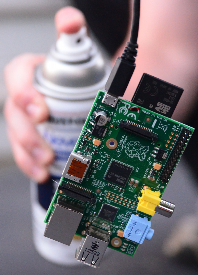
Figure 4-4.
Spraying the primer on the Raspberry Pi
181
CHAPTER 4: HACKING THE OUTDOORS

After the last drying period, your Raspberry Pi is ready to use again. Power it up to
make sure that the act of painting it with NeverWet didn’t kill it before it ever hits the
water.
If you are planning to to immerse your Raspberry Pi in water, you should not hold it
with your bare hands (for what we hope are obvious safety reasons). You should be
able to gently insert it by holding the cable and lower it into a small container of water
(either powered on or off). If you insert it into the water before powering it on, you
might want to be a good distance away before sending power over to the Raspberry
Pi. Having the Pi plugged in via a USB power cable run to a power strip (that is switched
off) might be a good idea, since you can turn on the power strip from a distance.
Additionally, whenever there is a risk of water, you should consider having a Ground
Fault Circuit Interruptor (GFCI) in use. You can get this built into your power strip, or
as an adaptor for the plug.
This is not a magic spell. It might not work at all. If you didn’t do a thorough paint job,
it might immediately go “zap” and die. Heck, it might do that even if you do the best
paint job known to mankind.
That said, even if you do manage to make a Raspberry Pi water-resistant using this
method, you shouldn’t assume you can put it in a fish tank on your desk and use it
forever. The coating isn’t permanent; it will fade with time and friction. Rustoleum
notes that NeverWet relies on a layer of air to form the super-hydrophobic coating on
the surface of the object. This means if you submerge a treated object over time, the
coating will dissipate.
If you are putting a Pi in a space where humidity is a real possibility, this might be a
good insurance against occasional humidity ending your project in heartbreak. How-
ever, we admit that in most cases, this is just a fun hack that allows you to say that
you’ve run Linux in a computer completely underwater with no case.
HACK 41 Find Geocaches from Your Car
Geocaching is a great way to be geeky and get outdoors. Why not convert
a Raspberry Pi into a Cacheberry Pi?
Geocaching taps into the thrill of finding something hidden, of going on a treasure
hunt. If you’ve never heard of geocaching before, the idea is simple. People hide a
storage container somewhere publicly accessible (although not necessarily easily
accessible) and upload the GPS positioning coordinates for that container to the In-
ternet.
The size of the container varies from the very small (just large enough to hold a min-
iature pencil with a tiny sheet of paper rolled around it), to small (35 mm film canister
or Altoids tin), all the way up to large containers such as metal ammunition boxes.
182 RASPBERRY PI HACKS
These are then hidden in plain sight, such as attached under park benches, hanging
from trees, or in the crevices between rocks. One particularly memorable geocache
is secured inside a large hollow tree by a tension pulley system. You reach inside the
tree, pull a ring, and the geocache would drop down. Pull the ring again, and the cache
goes back up inside the tree.
The ideas behind geocaching are not new by any means; people were doing real-world
treasure hunts in the form of letterboxing for years beforehand. But when GPS was
made available to the public in 1991, followed by the ubiquity of highly accurate GPS
systems and the explosion of the Internet, geocaching-type treasure hunting was able
to flourish.
At the time of this writing, http://geocaching.com (the primary website for logging and
adding geocaches) is tracking more than two million active geocaches and more than
six million registered geocachers. It is a game that can be played by people of all ages
and abilities, with nothing more than a smartphone and tenacity. The rules of the game
are simple: find as many as you can, be discreet when finding caches, leave the cache
better than you found it, and log your finds (or failure to finds) so that the cache’s
activity can be tracked.
There are other complexities:
Exchange items
Goodies, trinkets, toys, and “treasures” are left by geocachers in caches of sup-
portable sizes. The rule of thumb is that if you take one, you also leave one behind.
Travel bugs and geocoins
Tracked objects that move via geocachers from cache to cache.
Travel bug hotels
Geocaches specifically set up to facilitate the drop-off and retrieval of travel bugs.
These are usually found near transportation hubs, such as airports, so that geo-
cachers can help travel bugs move around the world.
Puzzle caches
Geocaches where the GPS coordinates must be decoded from a puzzle.
Multi-stage caches
Sequences of caches where only the first set of GPS coordinates are provided,
and each cache provides another set of GPS coordinates until they lead you to
the final cache (usually a much larger cache with tradable goodies).
While there are any number of smartphone applications (or add-ons for in-car GPS
systems) to help you find geocaches near you, Jeff Clement created the Cacheberry
Pi (Figure 4-5) to be embedded in a car. This Raspberry Pi-based project is primarily
intended to show you what the next nearby geocache is in a big, obvious way (as
183
CHAPTER 4: HACKING THE OUTDOORS
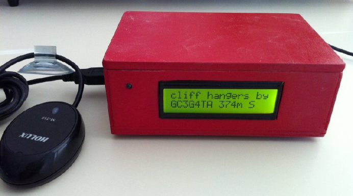
opposed to staring at little icons on a general-purpose GPS). It empowers you to not
have to do as much prep before setting out to go geocaching by letting you simply get
in your car, pick a direction, and drive.
Figure 4-5.
Cacheberry Pi (photo by Jeff Clement, http://cacheberrypi.jclement.ca)
This hack is also smart about how it presents geocaches to you. When still, it presents
the nearest cache in a 3 km radius. When the Cacheberry Pi detects that you are
traveling at highway speeds, it will instead focus its search in front of you and show
you only the nearest geocache in the direction that you are traveling. It has the ability
to maintain a database of 20,000+ geocaches and to track a log of which caches you
have visited (and allow you to transfer that log via USB storage device). It displays the
nearest geocache to you, the distance to that cache, and the compass bearing to the
geocache.
Gathering Hardware
To build the Cacheberry Pi, you will need some hardware in addition to the Raspberry
Pi unit.
GPS receiver
The Cacheberry Pi project assumes that you are using a USB-powered GPS receiver
(GPSr) and recommends the Holux M-215, but any other standards-compliant GPS
should work properly.
184 RASPBERRY PI HACKS

You can also use the Adafruit Ultimate GPS Module, but if you do that, you will need
to disable the serial console so that the GPS can use it (as covered in Hack #16). If you
choose this hardware, you will also need to reconfigure gpsd within the Cacheberry Pi
Linux OS to point to the serial GPSr by running:
$ sudo dpkg-reconfigure gpsd
This step is not necessary if you use a supported USB-powered GPSr.
LCD screen
The LCD screen is where the Cacheberry Pi will present geocache information to you
while you’re on the hunt. The Cacheberry Pi project recommends the IIC/I2C/TWI
SPI Serial LCD 1602 Module Electronic building block for Arduino.
You can also use the Sainsmart 1602 ICD LCD unit, but you will then have to modify
the driver in the Cacheberry Pi codebase. Steve Whitcher has documented how he
was able to get it working.
It might also be possible to use other 16 x 2 LCD units (such as the one on the Adafruit
LCD Pi Plate, covered in Hack #28), but we have not tested them.
Power cord
Because the Cacheberry Pi is designed to be used in an automobile, you can plug it
into an available 12 V power (cigarette lighter) receptacle. Hack #55 covers this sort of
power arrangement in detail.
Since the only device normally plugged into the Cacheberry Pi USB bus is the GPSr
(and a USB flash drive when updating the geocache database), you should not need
to use an externally powered USB hub.
Serial console
This is optional (and not available if you are using the Adafruit Ultimate GPS Module),
but the Cacheberry Pi is configured by default to support a serial console over the
Raspberry Pi GPIO pins.
If you want to add a serial console, just follow the instructions in Hack #16, and make
a hole in the project box for the wire to come out.
Indicator LED
You can optionally connect an indicator LED. It will flash when a geocache is nearby,
but you don’t really need this unless geocaches are few and far between in your part
of the world (or you only have a few in the Cacheberry Pi database).
185
CHAPTER 4: HACKING THE OUTDOORS

Project box
Admittedly, this is purely an aesthetic component, but you can get a standard plastic
project box, cut a hole for the LCD to mount, then place the Raspberry Pi inside of the
box as well. Holes for the power cable and both USB ports will finish off the box, then
you can attach your finished Cacheberry Pi (in a box) to the dash of your car.
Preparing the Software Image
The Cacheberry Pi project offers a prebuilt image (based on Raspbian). Put a fresh
SD card into your Linux computer, and then download and uncompress a copy of the
Cacheberry Pi image:
$ wget http://cdn.jclement.ca/cacheberrypi/cacheberrypi.img.20120921.bz2
$ tar xf cacheberrypi.img.20120921.bz2
By the time you read this, there might be a newer image than the 2012-09-21 image.
You can confirm on the Cacheberry Pi project website.
After it downloads sucessfully, use the dd command to write the Cacheberry Pi image
onto the SD card. Be extra careful that you know which device is your inserted SD card
(Hack #02 explains how to figure that out). In Fedora, this is almost always /dev/
mmcblk0, but on other distributions it is a /dev/sd* device. You do not want to use dd to
overwrite your laptop’s hard drive with the Cacheberry Pi image!
Once you’re sure you know the SD card device name, run the dd command as root,
changing the of= value as needed:
$ sudo dd bs=4M if=cacheberrypi.img.20120921 of=/dev/mmcblk0
When that finishes, run the sync command a few times to ensure the image was prop-
erly written onto the SD card (and not just into the memory buffers):
$ sync;sync;sync
Finally, remove the SD card from your laptop and insert it into your Raspberry Pi.
Wiring the Cacheberry Pi
This hack assumes you are using the components recommended by the Cacheberry
Pi project. If you differ from them, you will need to adjust accordingly.
Plug the USB GPSr directly into a USB port on the Raspberry Pi. The LCD screen has
four pins, labeled SCL, SDA, VCC, and GND. You will need to connect these pins to the
appropriate pins on the Raspberry Pi GPIO using female-to-female jumper wires.
Table 4-2 shows the pin mapping.
186 RASPBERRY PI HACKS

Table 4-2. Cacheberry LCD pin mapping
CACHEBERRY LCD PIN LABEL RASPBERRY PI BCM GPIO PIN
GND GND
SCL 3 (SCL)
SDA 2 (SDA)
VCC 5 V
If you want to connect an indicator LED, wire it into BCM Pin 25 (P1-22), with an ap-
propriate resistor between the BCM 25 pin and the positive leg of the LED. The type
of resistor will depend on the specifications of the LED being used. For example, if you
use a Red LED with a voltage of 2 V and a current of 15 mA, the 5 V circuit will require
a 220 ohm resistor. You can calculate the resistor value for your LED with this website:
http://led.linear1.org/1led.wiz The negative leg of the LED should wire to an available
GPIO ground (GND) pin.
Connect the Raspberry Pi to the mini-USB power cable (fed from the 12 V cigarette
lighter receptacle), and the OS image should boot up.
Loading Cache Data
Because the Cacheberry Pi is not networked, you need to load geocaches via a USB
flash drive. It is configured to always listen for a USB drive to be inserted, and when
one is inserted with the proper filesystem layout, it will automatically import the
geocache database off of the USB drive. It will also copy the track history from the
Cacheberry Pi to the USB flash drive.
To set up a USB flash drive, insert it into your Linux computer and make sure it is
mounted. Most Linux distributions will automount USB storage devices when they are
inserted. Check the output of the mount command for a /dev/sdb or /dev/sdc device
(/dev/sda is usually the laptop hard drive), and then change into the directory where
the USB drive is mounted.
Download and decompress the “sample” ZIP file for the Cacheberry USB filesystem
layout. Then copy the files into the mounted USB drive (in this example, we assume
it is mounted at /mnt/usbdrive):
$ cd ~
$ wget http://cdn.jclement.ca/cacheberrypi/cacheberrypi_usbstick_sample.zip
$ unzip cacheberrypi_usbstick_sample.zip
$ cp -a cacheberrypi_usbstick_sample/* /mnt/usbdrive
The USB drive is now prepared for use, but you’ll want to add some cache entries. The
Cacheberry Pi will look for a file named nav.csv in the cacheberrypi/ directory. This
187
CHAPTER 4: HACKING THE OUTDOORS
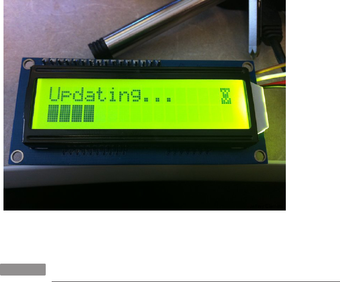
comma-separated values (CSV) file contains the list of geocaches in what is com-
monly referred to as “Microsoft Streets and Trips” format.
The simplest way to generate this CSV file is to run GSAK on Windows or Open Cache
Manager on Linux/OSX. You can also generate a CSV file directly on http://geocach
ing.com if you have a premium account and set up a “pocket query.”
Save the nav.csv file to the USB flash drive, unmount it, and insert it into the running
Cacheberry Pi. It should detect the USB flash drive, and the LCD screen will show a
progress indicator as it copies over the updated geocache database (Figure 4-6).
Figure 4-6.
Cacheberry Pi (photo by Jeff Clement, http://cacheberrypi.jclement.ca)
HACK 42 See the Light
Detecting the presence (and intensity) of light can help you to automate
all sorts of tasks, from the garden to home automation and beyond. Hack
your Raspberry Pi and it will see the light!
Few things are constant in our world, but the rising and setting of the sun is close
enough that you can count it as one, at least for the next five billion years or so. By
monitoring the presence and intensity of light, you can tell whether it is day or night,
whether it is sunny or cloudy, or if someone has turned on a lamp in a room. But to do
that, you need a luminosity sensor.
188 RASPBERRY PI HACKS

There are lots of different luminosity sensors out there, but because you want to wire
it to our trusty friend, the Raspberry Pi, you want to pick something that you can add
to that device easily. Because the Raspberry Pi does not support analog inputs
(without going through a converter first), you need a digital luminosity sensor, with
bonus points for one that the Linux kernel supports natively. Adafruit has just the
thing: the Taos TSL2561 digital luminosity/lux/light sensor.
What is Lux?
Lux (abbreviated lx), is the SI unit for measuring illuminance, described in
terms of one lumen per square meter. It can be measured with a device
logically called a “lux meter.” The full moon is about 1 lux, while direct sun-
light is measured in the range of tens of thousands to >100,000 lux.
Why is this sensor ideal? A few reasons:
•It is a digital sensor, so you can connect it directly to the Raspberry Pi GPIO pins
without any complicated wiring.
•It is precise and can be configured to detect light ranges from 0.1 to 40,000+ lux.
•It contains both infrared and full-spectrum diodes. Most luminosity sensors have
only one type of detection diode, but the TSL2561 can separately measure infra-
red, full-spectrum, or human-visible light.
•It supports I2C (for an explanation of I2C, see What is I2C?). This means you can
connect it to the Raspberry Pi GPIO with just four pins.
•It is a low-power component, about 0.5 mA when actively sensing and less than
15 uA when in powerdown mode.
• It is also small, about the size of a U.S. quarter (see Figure 4-7).
189
CHAPTER 4: HACKING THE OUTDOORS
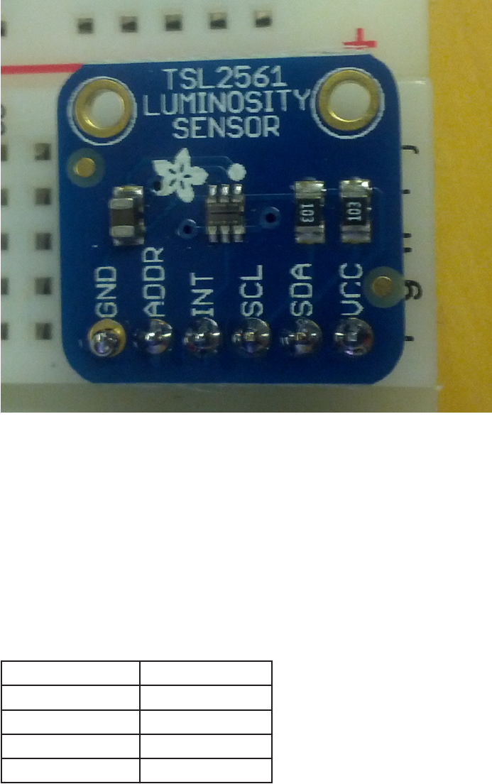
Figure 4-7.
The tiny TSL2561
When you purchase the TSL2561 sensor kit, it comes with the light sensor already
attached to a six-pin breakout board (and a six-pin header strip). Plug the header strip
into a breadboard, with the long end of the header pins down, and then place the light
sensor breakout board onto the header pins (the shorter ends). Solder the pins per-
manently to the breakout board (if you need a refresher on soldering, see “Soldering
Reminders” on page 42).
Then, you’ll need to connect four of the six pins on the TSL2561 breakout board to the
Raspberry Pi GPIO ports (see Table 4-3).
Table 4-3. TSL2561 Breakout Mapping Table
TSL2561 BREAKOUT PIN LABEL RASPBERRY PI BCM GPIO PIN
GND GND
SCL 3 (SCL)
SDA 2 (SDA)
VCC 3.3 V
190 RASPBERRY PI HACKS

The TS2561 is a 3.3 V-powered device, so be sure you do not accidentally connect it
to the 5 V power pin on the Raspberry Pi GPIO, or it will go off to electronics heaven.
The Pi Cobbler makes this wiring notably simpler (see Hack #15), but as long as you
have wires connecting the TSL2561 breakout to the right pins on the Raspberry Pi
GPIO, you will be fine.
As usual, the instructions in this hack refer to the BCM GPIO pin labels here (see
Hack #14 for details).
Once the TSL2561 breakout board is wired up to the Raspberry Pi, you can use the
I2C utilities within the Linux distribution environment to confirm it is properly con-
nected to the I2C bus on the GPIO, assuming your kernel has I2C support properly
configured. If you have built a custom kernel as described in Hack #22, you will have
I2C preconfigured properly. If not, you might need to load the following modules before
you can access I2C devices:
$ su -c 'modprobe i2c-bcm2708'
$ su -c 'modprobe i2c-dev'
Further, you will need to enable these additional options:
Industrial IO Support (CONFIG_IIO)
This option can also be found in the Device Drivers menu. The industrial I/O sub-
system provides a unified framework for drivers for many different types of em-
bedded sensors using a variety of different physical interfaces. You can also go
into that menu and build support for any of the devices that you find within it that
you might want to use in projects. Be sure that you compile in the top-level IIO
support, as shown in Figure 4-8 (you can modularize the sensors below it if you
wish). You will also want to be sure to enable (and compile in) the “Enable buffer
support within IIO” (CONFIG_IIO_BUFFER), “Industrial I/O buffering based on kfifo”
(CONFIG_IIO_KFIFO_BUF), and “Enable triggered sampling support” (CON
FIG_IIO_TRIGGER) options inside the Industrial IO Support menu.
191
CHAPTER 4: HACKING THE OUTDOORS
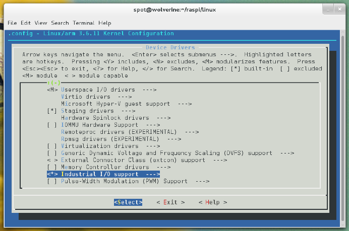
Figure 4-8.
Enabling Industrial IO Support (CONFIG_IIO)
TAOS light sensors (CONFIG_SENSORS_TSL2563)
This driver is currently in the staging level of the Linux kernel device drivers, which
is reserved for drivers that are new or less tested than other drivers. To enable it,
navigate into the Device Drivers menu and then the Staging drivers menu (you
will need to enable it first). From there, go into the IIO staging drivers submenu
and then into Light sensors. CONFIG_SENSORS_TSL2563 is labeled in that menu as
“TAOS TSL2560, TSL2561, TSL2562 and TSL2563 ambient light sensors.” Enable
it as a module, as shown in Figure 4-9. You will also need to enable “Hwmon driver
that uses channels specified via iio maps” (CONFIG_IIO_ST_HWMON) to allow IIO de-
vices to provide basic hwmon functionality. This entry is in the Device Drivers →
Staging drivers → IIO staging drivers menu. You should compile this driver into
the Linux kernel so that you automatically get this feature when you use IIO de-
vices.
192 RASPBERRY PI HACKS
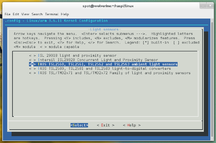
Figure 4-9.
TAOS TSL2561 light sensor support enabled as a module
To install the necessary userspace software (i2c-tools) on Pidora, run:
$ su -c 'yum install i2c-tools -y'
To install i2c-tools on Raspbian, run:
$ su -c 'apt-get install i2c-tools'
To look for the device, you need to run i2cdetect on bus 1 (as root). Here’s the i2cde
tect command line you want to run:
$ su -c 'i2cdetect -y 1'
If all of your wiring is correct, you will see output like this:
0 1 2 3 4 5 6 7 8 9 a b c d e f
00: -- -- -- -- -- -- -- -- -- -- -- -- --
10: -- -- -- -- -- -- -- -- -- -- -- -- -- -- -- --
20: -- -- -- -- -- -- -- -- -- -- -- -- -- -- -- --
30: -- -- -- -- -- -- -- -- -- 39 -- -- -- -- -- --
40: -- -- -- -- -- -- -- -- -- -- -- -- -- -- -- --
50: -- -- -- -- -- -- -- -- -- -- -- -- -- -- -- --
60: -- -- -- -- -- -- -- -- -- -- -- -- -- -- -- --
70: -- -- -- -- -- -- -- --
193
CHAPTER 4: HACKING THE OUTDOORS
The TSL2561 sensor reports as device address 0x39 on the I2C bus, and sure enough,
i2cdetect sees it. If you want to change the device address, you can connect a wire to
the ADDR pin on the TSL2561 breakout board. Connect it to a ground (GND) pin to set
the address to 0x29, or connect it to a 3.3 V power pin to set the address to 0x49.
Accessing the Sensor via Python
The easiest way to get readings from the TSL2561 sensor is to use the Adafruit I2C
Python module. The simplest value to understand from the TSL2561 is lux, but the
TSL2561 doesn’t read in those units directly; you have to write code to do the math-
ematical conversion.
As a further complication, you can adjust the gain on the TSL2561 sensor. If the gain
is set low (1), the sensor will calculate more accurate readings in bright light to avoid
sensor saturation. If the gain is set high (16), the sensor will calculate more accurate
readings in low light by boosting the sensitivity. You can also generate a reading with
“automatic” gain, which cycles between low and high gain.
You will need to install the python-smbus and Adafruit_I2C libraries. The python-smbus
library is included in the Pidora and Raspbian package repositories, so you can install
it normally. Here’s the command for Pidora:
$ su -c 'yum install python-smbus'
And here’s how to install it on Raspbian:
$ su -c 'apt-get install python-smbus'
The Adafruit_I2C code is in the Adafruit Raspberry Pi Python Code GitHub repository.
Check out a copy of it, and change into the Adafruit_I2C directory:
$ git clone https://github.com/adafruit/Adafruit-Raspberry-Pi-Python-Code
$ cd Adafruit-Raspberry-Pi-Python-Code/Adafruit_I2C
From this directory, you can run a Python script to calculate the lux value measured
by the TSL2561. This script was written by Ty Brown and is included here with his
permission:
#!/usr/bin/python
import sys
import smbus
import time
from Adafruit_I2C import Adafruit_I2C
### Written for Python 2 <-!!!
### Big thanks to bryand, who wrote the code that I borrowed heavily from/
was inspired by
194 RASPBERRY PI HACKS
### More thanks pandring who kind of kickstarted my work on the TSL2561 sen
sor
### A great big huge thanks to driverblock and the Adafruit team (Congrats
on your many succeses
### Ladyada). Without you folks I would just be a guy sitting somewhere
thinking about cool stuff
### Now I'm a guy building cool stuff.
### If any of this code proves useful, drop me a line at medicforlife.blog
spot.com
class Luxmeter:
i2c = None
def __init__(self, address=0x39, debug=0, pause=0.8):
self.i2c = Adafruit_I2C(address)
self.address = address
self.pause = pause
self.debug = debug
self.gain = 0 # no gain preselected
self.i2c.write8(0x80, 0x03) # enable the device
def setGain(self,gain=1):
""" Set the gain """
if (gain != self.gain):
if (gain==1):
self.i2c.write8(0x81, 0x02) # set gain = 1X and timing
= 402 mSec
if (self.debug):
print "Setting low gain"
else:
self.i2c.write8(0x81, 0x12) # set gain = 16X and timing
= 402 mSec
if (self.debug):
print "Setting high gain"
self.gain=gain; # safe gain for calculation
time.sleep(self.pause) # pause for integration
(self.pause must be bigger than integration time)
def readWord(self, reg):
"""Reads a word from the I2C device"""
try:
195
CHAPTER 4: HACKING THE OUTDOORS
wordval = self.i2c.readU16(reg)
newval = self.i2c.reverseByteOrder(wordval)
if (self.debug):
print("I2C: Device 0x%02X returned 0x%04X from reg 0x%02X"
% (self.address, wordval & 0xFFFF, reg))
return newval
except IOError:
print("Error accessing 0x%02X: Check your I2C address" %
self.address)
return -1
def readFull(self, reg=0x8C):
"""Reads visible+IR diode from the I2C device"""
return self.readWord(reg);
def readIR(self, reg=0x8E):
"""Reads IR only diode from the I2C device"""
return self.readWord(reg);
def getLux(self, gain = 0):
"""Grabs a lux reading either with autoranging (gain=0) or with a
specified gain (1, 16)"""
if (gain == 1 or gain == 16):
self.setGain(gain) # low/highGain
ambient = self.readFull()
IR = self.readIR()
elif (gain==0): # auto gain
self.setGain(16) # first try highGain
ambient = self.readFull()
if (ambient < 65535):
IR = self.readIR()
if (ambient >= 65535 or IR >= 65535): # value(s) exeed(s) data
range
self.setGain(1) # set lowGain
ambient = self.readFull()
IR = self.readIR()
if (self.gain==1):
ambient *= 16 # scale 1x to 16x
IR *= 16 # scale 1x to 16x
ratio = (IR / float(ambient)) # changed to make it run under python
2
196 RASPBERRY PI HACKS

if (self.debug):
print "IR Result", IR
print "Ambient Result", ambient
if ((ratio >= 0) & (ratio <= 0.52)):
lux = (0.0315 * ambient) - (0.0593 * ambient * (ratio**1.4))
elif (ratio <= 0.65):
lux = (0.0229 * ambient) - (0.0291 * IR)
elif (ratio <= 0.80):
lux = (0.0157 * ambient) - (0.018 * IR)
elif (ratio <= 1.3):
lux = (0.00338 * ambient) - (0.0026 * IR)
elif (ratio > 1.3):
lux = 0
return lux
oLuxmeter=Luxmeter()
print "LUX HIGH GAIN ", oLuxmeter.getLux(16)
print "LUX LOW GAIN ", oLuxmeter.getLux(1)
print "LUX AUTO GAIN ", oLuxmeter.getLux()
A copy of this script is also available in the GitHub repository for this book. Be sure you
put this file in the Adafruit_I2C directory. To read the lux values, run:
$ chmod +x tsl2561-lux.py
$ su -c './tsl2561-lux.py'
This script does all of the hard work for you. It reads in the values from the sensor at
the different gain settings and then does the math necessary to convert those values
into lux units.
Accessing the Sensor Directly from the Kernel
It is also possible to interface directly to the TSL2561 sensor via the I2C bus at the
kernel level, assuming you have enabled that support in a custom kernel (as described
in Hack #22). First, you need to tell the kernel (as root) to attach the TSL2561 driver to
the I2C device at 0x39 (or 0x29/0x49 if you changed the address with the ADDR pin):
$ su -
$ echo tsl2563 0x39 > /sys/class/i2c-adapter/i2c-1/new_device
When you do this, it will output a message like this to dmesg:
197
CHAPTER 4: HACKING THE OUTDOORS

[ 522.400407] tsl2563 1-0039: model 5, rev. 0
[ 522.402650] i2c i2c-1: new_device: Instantiated device tsl2563 at 0x39
There is a new device node (1-0039) in /sys/class/i2c-adapter/i2c-1/. Inside that
node is a iio:device0 mapping, and inside that mapping directory are several devices
that allow you to get readings:
$ ls -l /sys/class/i2c-adapter/i2c-1/1-0039/iio\:device0/
...
-rw-r--r-- 1 root root 4096 Sep 16 20:37 in_illuminance0_input
-rw-r--r-- 1 root root 4096 Sep 16 20:37 in_intensity_both_calibscale
-rw-r--r-- 1 root root 4096 Sep 16 20:37 in_intensity_both_raw
-rw-r--r-- 1 root root 4096 Sep 16 20:37 in_intensity_ir_calibscale
-rw-r--r-- 1 root root 4096 Sep 16 20:37 in_intensity_ir_raw
...
These files contain the current raw sensor values for the calibration scale and the
infrared and combined luminosity readings. To do anything with them, you’ll have to
convert them using the math in the TSL2561 datasheet.
HACK 43 Listen to Aircraft Transponders
Every day, thousands and thousands of airplanes are flying the friendly
skies. Some might be flying over you right now! With a USB TV tuner and
a Raspberry Pi, you can listen to the aircraft transponders and find out
which planes are up there.
An aircraft transponder is the device on board a plane that responds to radio fre-
quencies and helps identify the plane for various systems, including radar. They gen-
erally send a few pieces of information, including altitutde, location, and what’s called
a “squawk” code that further identifies the flights. If you want to listen to aircraft
transponders, it will help if you’re within five miles of a local airport, but the occasional
commercial plane passing by will be sufficient—you’ll just have more infrequent re-
sults.
Here’s what you’ll need:
• Raspbian
•NooElec R820T: these devices are easily found on eBay as well, but be sure you
have the E4000 chipset variant. Look for “E4000” in the description to make sure
your purchase will work with this project or refer to the list of supported hard-
ware. This device is also called an RTL-SDR, or RealTek Software Defined Radio,
because of the vendor of the analog-to-digital chip it uses. It looks like a flash drive
(see Figure 4-10), but it is so much more.
198 RASPBERRY PI HACKS
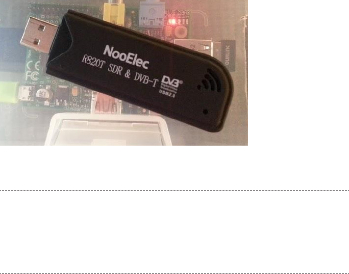
•Dump1090: open source code for tuning the RTL-SDR hardware and decoding
the data.
Figure 4-10.
NooElec R820T
Extend Your Antenna
The antenna supplied with the NooElec R820T devices is pretty short. You can run
a longer antenna over a window ledge, or to craft a more optimal antenna, see the
tutorial at http://www.balarad.net. For most purposes, however, the NooElec’s in-
cluded antenna will suffice.
Set Up the Code
To get started, update Raspbian and install the dependencies needed for building
Dump1090:
$ sudo apt-get update
$ sudo apt-get upgrade
$ sudo apt-get install git-core git make cmake libusb-1.0-0-dev build-
essential pkg-config
Once finished, check out a copy of the source code of the drivers for the RTL-SDR
device, and then build and install them on your Raspberry Pi:
cd /opt/
git clone git://git.osmocom.org/rtl-sdr.git
cd rtl-sdr
sudo mkdir build
cd build
sudo cmake ../ -DINSTALL_UDEV_RULES=ON
199
CHAPTER 4: HACKING THE OUTDOORS
sudo make
sudo make install
sudo ldconfig
Be aware that the build process that occurs during these steps will take several mi-
nutes on the Pi. The build script will update your status as it progresses.
When the install is complete, you need to copy a set of device rules for the RTL-SDR
into the udev configuration directory:
$ cd /opt/rtl-sdr/
$ sudo cp rtl-sdr.rules /etc/udev/rules.d/
These rules will ensure that your RTL-SDR device is properly configured when it is
inserted into your Raspberry Pi.
If you haven’t already done so, go ahead and plug in your RTL-SDR device. Then, reboot
the Raspberry Pi to ensure that the system cleanly and correctly loads the drivers on
startup:
$ sudo reboot
Now, you should run a test script to make sure Raspbian is using the driver and can
receive data from the RTL-SDR device:
$ rtl_test -t
If all is well, happy messages will appear and test the modes of the RTL-SDR device:
$ rtl_test -t
Found 1 device(s):
0: Generic RTL2832U (e.g. hama nano)
Using device 0: Generic RTL2832U (e.g. hama nano)
Found Elonics E4000 tuner
Supported gain values (18): -1.0 1.5 4.0 6.5 9.0 11.5 14.0 16.5 19.0 21.5
24.0 29.0 34.0 42.0 43.0 45.0 47.0 49.0
Benchmarking E4000 PLL...
[E4K] PLL not locked for 51000000 Hz!
[E4K] PLL not locked for 2204000000 Hz!
[E4K] PLL not locked for 1102000000 Hz!
[E4K] PLL not locked for 1241000000 Hz!
E4K range: 52 to 2203 MHz
E4K L-band gap: 1102 to 1241 MHz
200 RASPBERRY PI HACKS
Let this run and finish if you like, or stop the test program with Ctrl+C.
Move back to the /opt/ directory to prepare Dump1090, our signal decoding script:
$ cd /opt/
Then create the /dump1090 directory with Git:
$ git clone git://github.com/MalcolmRobb/dump1090.git
Cloning into 'dump1090'...
remote: Counting objects: 687, done.
remote: Compressing objects: 100% (420/420), done.
remote: Total 687 (delta 411), reused 521 (delta 259)
Receiving objects: 100% (687/687), 712.00 KiB | 72 KiB/s, done.
Resolving deltas: 100% (411/411), done.
Change directories into dump1090:
$ cd dump1090
Type make and press Enter. This too will take a little time as it compiles, so mark your
spot in this tutorial and take a short break if you like. (We always support eating pie
while building with the Pi.)
After make has finished, you’ll be just about ready to run the app. If you haven’t noted
the IP address of your Raspberry Pi yet, do so now with ifconfig, which results in
something like this:
eth0 Link encap:Ethernet HWaddr b8:27:eb:81:54:dc
inet addr:192.168.1.17 Bcast:192.168.1.255 Mask:255.255.255.0
UP BROADCAST MULTICAST MTU:1500 Metric:1
RX packets:0 errors:0 dropped:0 overruns:0 frame:0
TX packets:0 errors:0 dropped:0 overruns:0 carrier:0
collisions:0 txqueuelen:1000
RX bytes:0 (0.0 B) TX bytes:0 (0.0 B)
lo Link encap:Local Loopback
inet addr:127.0.0.1 Mask:255.0.0.0
UP LOOPBACK RUNNING MTU:16436 Metric:1
RX packets:17 errors:0 dropped:0 overruns:0 frame:0
TX packets:17 errors:0 dropped:0 overruns:0 carrier:0
collisions:0 txqueuelen:0
RX bytes:2042 (1.9 KiB) TX bytes:2042 (1.9 KiB)
The address after inet addr: will be the IP address you will use to view the plane traffic
in a web browser after starting the script, which you’re ready to do!
201
CHAPTER 4: HACKING THE OUTDOORS
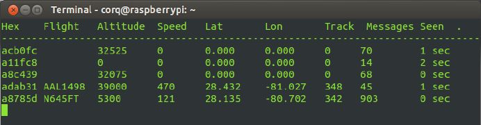
Run the Script
Before running the script, move to the dump1090 directory:
$ cd /opt/dump1090
Then, run the script:
$ ./dump1090 --net --net-http-port 8080
You won’t see much happen, but if you see no errors, the script is likely running, and
if commercial planes are nearby, you will see an occasional stream of strange hex code.
It might take a few minutes, but planes will transmit data from their beacon as they
pass overhead, and when they do, you’ll begin to see lines in the script populate, as
shown in Figure 4-11.
Figure 4-11.
Beacon data from passing planes
From another PC on your local network, open a web browser and enter the Pi’s IP
address with :8080 appended (for example, http://192.168.1.17:8080). The first time
you load this page, it will seem slow, because the Pi initializes the Google Maps API for
the first time.
After a moment, you will see a handy map centered somewhere in Europe that looks
a lot like Figure 4-12. Just drag it to focus on your own region or double-click on your
area of the map until you’ve zoomed into the area where you are.
202 RASPBERRY PI HACKS

Figure 4-12.
A plane flies over Florida
You can also define your actual latitude and longitude to get your map to center in
your region (instead of Europe, if that’s not where you are) at startup. Visit http://
itouchmap.com/latlong.html to pinpoint your location and note the coordinates. Use
them to update script.js in /opt/dump1090/public_html/ with your actual location:
# find these lines below, update coordinates with the coordinates you got
from the iTouch map page, making sure the lines end with the semicolon.
var Map = null;
var CenterLat = 28.08864;
var CenterLon = -80.609436;
Save the file and exit. The next time you run Dump1090, the web page will center on
your region of the map.
—Lori Easterly
203
CHAPTER 4: HACKING THE OUTDOORS

HACK 44 Control Aerial Photography
Aerial photography, particularly from nearspace altitudes, has gained
popularity in recent years. The Raspberry Pi makes it even easier to ach-
ieve a low-weight payload with plenty of storage for photo, video, and
data.
Aerial photography has been practiced since the mid-19th century when Gaspard-
Félix Tournachon photographed Paris from a balloon. For some, it’s an art form. For
others, there’s a distinct goal, such as when a group teamed with the Louisiana Bucket
Brigade to map and document the Deepwater Horizon oil spill in 2010.
The recommendations in this hack are based on the launches by the NC Near Space
Research group, which started as a group entering the Hackerspaces in Space contest,
created in 2010 by Chicago hackerspace Workshop 88. They’ve since gone on to
launch multiple balloons and found the Raspberry Pi to be a useful tool for such
projects.
The Raspberry Pi takes half an amp of currrent. Why would you want to put that in the
payload of a balloon where weight and size are critical? Because having it onboard will
give you just about everything you need and a little more:
•Small and lightweight storage in an SD card for not only the “hard drive” and
computing, but also for the storage of all the data and photography
•GPIO that can be used for a wide range of sensors, including an accelerometer,
magnetometer, gyroscope, and temperature sensors
•Video out, so you can drive a video transmitter directly and see the video live on
the ground, rather than waiting until after the payload is retrieved (that is, if the
payload is retrieved)
•The ability to send on-screen display of the project’s current data while in flight,
including its location and height
•An optional lightweight camera module designed specifically for the Raspberry
Pi
•The ability to connect to a USB WiFi adapter for WiFi from space!
While not used on this project, the Raspberry Pi can also serve as a tracking device
for finding the payload after it lands. The sound module on the Pi can generate a
modulated APRS (Amateur Position Reporting System) data stream that can be fed
into the transmitter and broadcast to ham radio operators, allowing you to track it live.
Thus a single, credit-card-sized device provides camera, data collection, tracking, and
storage all in one incredibly cost-effective piece. When you add the prices of these
components if built otherwise, the Raspberry Pi is both the cheapest and lightest way
to go, which is handy, given what else you’ll have to buy.
204 RASPBERRY PI HACKS

For a near-space balloon photography project launch, you need the following major
components in addition to the Raspberry Pi (which is a part of your payload):
• Balloon to lift the payload
• Parachute to bring it down safely
• The payload itself (contents described next)
• A tracking device to find it
Build the Payload
Your first step is to build your payload, because that’s the only way to find out how
heavy it is. Knowing that piece of information is critical to figuring out what size balloon
and parachute you’ll need and how much helium to lift it.
If you’re launching in the United States, you should keep your payload under four
pounds, which keeps you from having to do further weight/size ratio calculations for
the FAA (see note on FAA Regulations). You should also contact your local FAA office
(or the relevant airspace organization for your country) prior to planning a flight to
make sure you follow their recommendations for the design, launch, and retrieval of
the payload.
FAA Regulations
In the United States, the relevant section of the Code of Federal Regulations is Title
14: Aeronautics and Space, Part 101: Moored Balloons, Kites, Amateur Rockets
And Unmanned Free Balloons. Part 101.1(4), which describes the size limits of the
payload:
•More than four pounds with a weight/size ratio of more than three ounces
per square inch of any surface of the package (determined by dividing
the total weight in ounces of the payload package by the area in square
inches of its smallest surface)
• More than than six pounds (regardless of weight/size ratio)
• A payload of two or more packages that weighs more than 12 pounds
Before launching anything, you shuld read this section of the Federal Regulations
in its entirety to be sure you comply.
You should first decide what you will use for you payload container. Whatever you
choose, keep it light and waterproof. A styrofoam cooler is an easy and cheap solution,
because you can make modifications with nothing more than a knife. Lightweight
plastic containers are also useful.
205
CHAPTER 4: HACKING THE OUTDOORS
Whatever you choose needs to be large enough to house the Raspberry Pi, a battery
pack, your tracking device, and your camera(s), as well as any other parts you’ve
chosen to use as a part of the project. (You can see how space and weight can add
up!) The example payload in this hack includes the Raspberry Pi connected to:
•Video out to a 144 MHz Videolinx ham radio ATV (Amateur TV) transmitter and
small whip antenna Trackuino which contains a GPS, and a 300 milliwat HX-1
144.39 MHz APRS transmitter, and an Arduino for decoding and modulating the
GPS signal for the transmitter
• GY-80 I2C 9-Axis Magnetic Acceleration Gyroscope Module
•5000 mAh USB cell phone backup battery
• USB WiFi adapter
•USB Y power cable to allow powering the WiFi directly from the battery and not
through the Raspberry Pi’s weak USB power ports
• Raspberry Pi camera module
• Nikon Coolpix camera (controlled by gphoto)
The Trackuino is an Arduino-based APRS system that includes a high-altitude GPS
system and GPS antenna. The Arduino decodes the data from the GPS and then
modulates it to drive a 300 mW HX-1 transmitter, which then drives an 8 W Micro Amp
3 amplifier, which is then fed into a whip antenna. The amplifier isn’t necessary once
your payload gets up high enough above the terrain, but it is helpful in locating the
payload when it’s down on the ground and away from other ham radio APRS systems.
The Trackuino and Micro Amp3 are driven by eight AA lithium cell batteries (inde-
pendent of the 5000 mAh cell phone battery that powers the Raspberry Pi), which
will last 5+ hours. This separate power supply is helpful in the event that the Raspberry
Pi loses power before the payload is recovered.
The GPS signal of the Trackuino can also be routed to the Raspberry Pi so that it can
correlate the sensor data with the time stamp, altitude, and latitude and longitude
data from the GPS (you will need to disable the console port on the serial device before
doing this). The GY-80 module connects to the I2C pins and ground and 3.3 V power
signals from the Raspberry Pi.
For the Raspberry Pi battery, we suggest a 5,000 mAh cell phone backup battery. A
pack of this size can run the Pi, record sensor data, and power the camera for more
than five hours. They’re lighter weight than nickel-cadmium (NiCd) batteries and can
be purchased for as little as $15. Another advantage of this as a battery pack for the
Raspberry Pi is that it has two built-in USB power outputs (one for the Raspberry Pi
and one for the USB WiFi Y cable), and a built-in power switch (which the Pi itself lacks).
206 RASPBERRY PI HACKS
The Raspberry Pi camera is the main camera for the payload in this hack, although it
also holds a Nikon Coolpix attached through the Pi’s remaining USB port and con-
trolled by gphoto.
Gather Gas, Balloon, and Parachute
Once the payload is built, you can determine its weight, which lets you calculate the
amount of lifting gas it requires. You need one cubic foot of helium per ounce of pay-
load. Thus, for a four-pound payload, you will need about 64 cubic feet of helium.
However, that amount of helium is just enough for neutral buoyancy, so you will need
an additional 1–1.5 pounds of lift to actually lift the payload. This amount of lift will give
you an ascent rate of about 1,000 feet per minute. For a four-pound payload, that’s
5.5 pounds of lift needed, for a total of 88 cubic feet of helium.
Manufacturers specify balloon size based on the amount of lifting gas. For this exam-
ple of a four-pound payload and 88 cubic ft of helium, an 600-gram balloon will achieve
altitudes of 70,000 feet or above. Smaller balloons will pop at a lower altitude, and
larger balloons tend to pop at a higher altitude. However, if you choose a balloon that’s
too large, it might never pop, and you end up with a “drifter” that can hang around the
sky for days, so it’s better to choose a smaller balloon until you get experience with
more launches.
Now that you know the weight of the payload, you can also calculate the size of the
parachute, which you need for a slow and safe descent. Parachute companies de-
scribe parachute size based on a reasonable descent rate, typically 10–15 feet per
second. We recommend The Rocketman, Ky Michaelson, a former Hollywood stunt-
man and stunt equipment designer who now runs a business selling balloon and rock-
et parachutes and related materials. You can read more about recovery parachutes
on his website.
For this size payload, a three- to four-foot parachute is appropriate. Balloon and par-
achute should be attached with shroud lines that are 50 pounds tensile strength or
less (per FAA guidelines).
Install Software
You need to load a few things onto your Pi before you’re ready to launch:
• I2C libraries (for talking to the GY-80 sensor board)
• GPSd (daemon for decoding GPS data streams)
• GPIO libraries (for controlling status LEDs and sensing switch inputs)
•gphoto (for controlling the Nikon camera—see “Geting Started with gPhoto” on
page 258 for further help)
207
CHAPTER 4: HACKING THE OUTDOORS

• lighthttpd web server (for displaying the web pages over ATV and WiFi)
• sqllite data base (for storing all the sensor data)
• The Python scripts (main control program, sensor libraries, startup scripts)
• The web pages (displayed over ATV and WiFi)
The main script configures the sensors, then goes into a loop that continuously polls
the status of the sensors and GPS, taking photos, and storing the sensor data in a
SQLite database and storing the images in a image directory.
You can stitch the images together after the mission using FFmpeg software (available
as a packge ffmpeg in Fedora or Debian—see “How to Get ffmpeg in Fedora” sidebar)
to create a video stream. For a two-hour launch, you will end up with about 3,600
pictures, which form a several-minute-long video when combined together.
How to Get ffmpeg in Fedora
FFmpeg records, converts, and streams video and audio and contains more
than 100 codecs. It can encode in many formats, including MPEG4, avi,
mjpeg, and Flash. Because Fedora includes only completely free software
(see http://fedoraproject.org/wiki/Objectives), FFmpeg is not included.
The RPM Fusion project provides additional package repositories for soft-
ware that Fedora does not include. They offer one-click setup from a Firefox
browser, or you can do it from the command line:
$ su -c 'yum localinstall --nogpgcheck http://download1.rpmfusion.org/
free/fedora/rpmfusion-free-release-$(rpm -E %fedora).noarch.rpm
http://download1.rpmfusion.org/nonfree/fedora/rpmfusion-nonfree-
release-$(rpm -E %fedora).noarch.rpm'
Then you’re ready to run: su -c yum install ffmpeg.
Download the sensor libraries, main control loop, and web pages from this book’s
GitHub repo into a directory on your Raspberry Pi. This is the main loop of the sensor
program, 10DOFd.py:
#!/usr/bin/python
#
===========================================================================
# 10 degree of freedom daemon for nearspace balloon telemetry
#
# Rodney Radford (AK4CH) - www.blackskytelemetry.org
#
208 RASPBERRY PI HACKS
# Interfaces to the GY-80 10DOF board, and an external GPS to log
# the sensors into a sqllite data base
#
===========================================================================
#
# Standard system libraries needed
#
import os, subprocess, sys, sh, shutil, time
import RPi.GPIO as GPIO
import sqlite3 as db
#
# Custom sensor libraries created for this project
#
from GPS import GPS # GPS lat/long/altitude/time
from ADXL345 import ADXL345 # accelerometer
from BMP085 import BMP085 # pressure + temp
from HMC5883 import HMC5883 # magnetometer (compass) + temp
from L3G4200D import L3G4200D # gyroscope
#
# Camera constants
#
CAMERA_PERIOD = 15 # Number of seconds between each photo
#
# Constants that define the GPIO pins for the LEDs and the enable switch
#
SW_enable = 11 # if ON, take a photo and update dbase (else skip)
LED_status = 23 # RED (False/on, blinks at 0.5hz rate)
LED_gpsok = 24 # GREEN (False/on if GPS lock valid)
LED_camera = 25 # YELLOW (False if dbase write and camera capture enabled)
#
# Simple printable timestamp of the current time
#
def timestamp():
return time.strftime('%x %X %z')
#
# Poll each of the sensor libraries for data
#
def getSensorData():
209
CHAPTER 4: HACKING THE OUTDOORS
global GPSdata
global timeG
global lat
global lon
global altG
# Get the GPS sensor data
GPSdata = gps.current_value()
if (GPSdata == None):
print "NO FIX!!"
timeG = 0
lat = 0
lon = 0
altG = 0
else:
print "RETURNED: ", GPSdata
timeG = GPSdata.time
lat = GPSdata.lat
lon = GPSdata.lon
altG = GPSdata.alt
global XYZa
global roll
global pitch
# Get the accelerometer sensor data
XYZa = acc.readAccelerometer()
roll = acc.computeRoll(XYZa)
pitch = acc.computePitch(XYZa)
global XYZm
global XYZmh
# Get the compass sensor data
XYZm = compass.readCompass()
XYZmh = compass.heading(XYZm)
global XYZr
global tempG
# Get the gyroscope sensor data
XYZr = gyro.readGyro()
tempG = gyro.readTemperature()
210 RASPBERRY PI HACKS
global press
global altP
global tempP
# Get the pressure sensor data
press = pressure.readPressure()
altP = pressure.readAltitude()
tempP = pressure.readTemperature()
#
# Take a photo (and flash the photo status LED)
#
def takePhoto():
GPIO.output(LED_camera, False)
filename = time.strftime("%Y%m%d_%H%M%S.JPG")
sh.gphoto2("--capture-image-and-download", "--keep", "--force-overwrite",
"--filename", filename)
if (os.path.isfile(filename)):
sh.ln("-sf", filename, "latest.jpg")
else:
print "missing file:", filename
GPIO.output(LED_camera, True)
#
# Create a brand new sqllite dbase and populate it with a dummy record
#
def createDB():
global con
DB_FILENAME = "../data/10DOF_data.db"
con = db.connect(DB_FILENAME)
with con:
cur = con.cursor()
cur.execute("CREATE TABLE Sensors("
"Lat REAL, Long REAL, AltG REAL, TimeG TEXT, "
"XA REAL, YA REAL, ZA REAL, ROLL REAL, PITCH REAL, "
"XM REAL, YM REAL, ZM REAL, XMH REAL, YMH REAL, ZMH
REAL, "
"XR REAL, YR REAL, ZR REAL, TempG REAL, "
"Pressure REAL, AltP REAL, TempP REAL)")
211
CHAPTER 4: HACKING THE OUTDOORS
data = [ # "Lat REAL, Long REAL, AltG REAL, TimeG TEXT, "
35.68981, -78.405353333, 84.8,
'2013-05-02T01:53:41.001Z',
# XA REAL, YA REAL, ZA REAL, ROLL REAL, PITCH REAL, "
0.0, 0.0, 1.0, -1.0, 0.0,
# XM REAL, YM REAL, ZM REAL, XMH REAL, YMH REAL, ZMH
REAL, "
-28.0, -96.0, -216.0, -156.037511025422,
-172.613956848733, -163.739795291688,
# XR REAL, YR REAL, ZR REAL, TempG REAL, "
0.0, -1.0, -1.0, -7.0,
# Pressure REAL, AltP REAL, TempP REAL)")
101426.0, -7.49042223835529, 16.5]
cur.execute("INSERT INTO Sensors VALUES(?" + (",?"*21) + ")", data)
#
# Write out the current sensor data to the dbase
#
def updateDB():
with con:
cur = con.cursor()
data = [lat,lon,altG,timeG,
XYZa[0],XYZa[1],XYZa[2],roll,pitch,
XYZm[0],XYZm[1],XYZm[2],XYZmh[0],XYZmh[1],XYZmh[2],
XYZr[0],XYZr[1],XYZr[2],tempG,
press,altP,tempP]
cur.execute("INSERT INTO Sensors VALUES(?" + (",?"*21) + ")", data)
#
# Roll the dbase so we have the current and a series of older/backup dbases
# This allows each session to be distinct, yet protects against acciden
tal
# erasure of all data if the payload is turned off and then back on
#
def rollDB():
212 RASPBERRY PI HACKS
# Delete the oldest snapshot
shutil.rmtree("../data/snapshot_09", True)
# Rollover snapshots 01..08 into 02..09
for version in range(8,0,-1):
os.rename("snapshot_0" + str(version), "snapshot_0" + str(version+1))
# Make a new snapshot_01 directory
os.mkdir("snapshot_01")
# Move the existing data into the new snapshot_01
os.system("mv *.JPG *.db *.log snapshot_01 > /dev/null 2>&1")
# Now create the latest.jpg link in the current data set
sh.ln("-sf", "initial.jpg", "latest.jpg")
# --------------------------------------------------------------
# Main body of the program
# --------------------------------------------------------------
os.environ['TZ'] = "EST"
# Add this project's bin path so we can pick up gphoto2 and then
# change the current directory to the data directory so we
# can deposit all the photos/data there
os.environ['PATH'] = os.environ['PATH'] + ":../bin"
os.chdir("/home/pi/balloon/data")
# Initialize the GPIO LEDs/switch
GPIO.setwarnings(False)
GPIO.setmode(GPIO.BCM)
GPIO.setup(SW_enable, GPIO.IN)
GPIO.setup(LED_status, GPIO.OUT)
GPIO.setup(LED_gpsok, GPIO.OUT)
GPIO.setup(LED_camera, GPIO.OUT)
# Make sure the LEDs are off by default (will flash them later)
GPIO.output(LED_status, True)
GPIO.output(LED_gpsok, True)
GPIO.output(LED_camera, True)
# Initialize the sensor libraries
213
CHAPTER 4: HACKING THE OUTDOORS
gps = GPS()
acc = ADXL345()
pressure = BMP085()
compass = HMC5883()
gyro = L3G4200D()
# Start up the background GPS thread
gps.start()
# Roll the old dbase values and create a new one for this mission
rollDB()
createDB()
# Flash the LEDs for 2 seconds - this is a good visual indication that
# the program is up and the LEDs all work, as well as it works as a
# time delay to make sure the libraries are stable (background GPS task)
for loop in range(0,4):
blink_on = ((loop & 1) == 1)
GPIO.output(LED_status, blink_on)
GPIO.output(LED_gpsok, blink_on)
GPIO.output(LED_camera, blink_on)
time.sleep (0.5)
# Acivity boolean - toggles on each loop (controls activity LED)
activity = True
# Set up the next camera time so a photo will be taken as soon as the
# enable switch is turned on
next_camera_time = 0
# Run forever
while True:
# Read from each of the sensors
getSensorData()
# Toggle the activity LED
activity = not activity
GPIO.output(LED_status, activity)
# Indicate GPS status on the green LED
GPIO.output(LED_gpsok, (GPSdata == None))
# If the enable switch is on, then update the dbase and take a picture
214 RASPBERRY PI HACKS
if (GPIO.input(SW_enable)):
# Update the dbase with the latest sensor readings
updateDB()
# Is it also time for a new photo?
if (time.time() > next_camera_time):
takePhoto()
# Now calculate the time for the next photo
next_camera_time = next_camera_time + CAMERA_PERIOD
# Delay for 0.5 seconds (this controls the activity LED flash rate)
time.sleep(0.5)
This is the script that generates the main station ID web page, stationid.py:
#!/usr/bin/python
# -*- coding: utf-8 -*-
import sqlite3 as db
import sys
import time
import cgitb
cgitb.enable()
import cgi
def openDB():
global con
DB_FILENAME = "../data/10DOF_data.db"
con = db.connect(DB_FILENAME)
try:
openDB()
except db.Error, e:
print "<!DOCTYPE html><head><meta http-equiv='refresh' content='15'></
head>Error %s:</html>" % e.args[0]
sys.exit(1)
try:
cur = con.cursor()
cur.execute('select * from Sensors order by TimeG desc limit 1')
rows = cur.fetchall()
215
CHAPTER 4: HACKING THE OUTDOORS
except db.Error, e:
print "<!DOCTYPE html><head><meta http-equiv='refresh' content='15'></
head>Error %s:</html>" % e.args[0]
sys.exit(1)
finally:
if con:
con.close()
template = "<!DOCTYPE html>\n"
template += "<html><head><meta http-equiv='refresh' content='5'><ti
tle>First Library in Space</title>\n" # EDIT REFRESH TIME HERE
template += "<link href='styles.css' rel='stylesheet' type='text/css'>\n"
template += "</head><body>\n"
template += '<div id="content">\n'
# ENTER CALL SIGN HERE:
template += '<div id="page-header"><h2>First Library in Space/July 10,
2013</h2></div>'
template += '<img id="idimage" src="latest.jpg">'
template += '<div id="statbox">'
template += '<p>AK4CH</p>'
template += "<br>\n"
template += '<p>'
template += (rows[0][3])[11:19] # Chopping off date
template += "</p>\n"
template += '<p>N '
template += (str(rows[0][0]))[:7] # Truncating
template += "</p>\n"
template += '<p> W '
template += (str(abs(rows[0][1])))[:7] # Truncating
template += "</p>\n"
template += '<p>A: '
template += str(int(rows[0][2]))[:10]
template += "'</p>\n"
216 RASPBERRY PI HACKS
template += '<p>T: '
template += str(int((32 + (9*rows[0][21])/5) + 0.5))
template += "° F</p>\n"
template += "</div>"
template += '</div>\n'
template += "</body></html>\n"
print template
If you download the complete tarball from GitHub, you’ll see several directories. You
can use the bin/startup.sh program to start these scripts and programs automati-
cally. The files can live anywhere in your file structure.
Track the Payload
Some form of tracking for your payload is a must, and there are many ways to do so.
One option is a SPOT Satellite GPS Messenger device. The benefit is that you don’t
need any sort of ham radio license to use it, but it is one of the more expensive choices
since it requires a yearly license to use. It also does not provide altitude data and does
not report position data above about 30,000 feet.
Another option is a ham radio Automatic Packet Reporting System (APRS) beacon,
which is cheaper and requires no usage fees, but it does require a ham radio license.
As an additional benefit, if you use a high-altitude GPS, APRS has the advantage of
continuous telemetry data for the full flight of your payload.
Of course, an even better option is redundancy: fly both!
Prepare for Launch
Choose a launch field outside of a flight path of major airlines. You can find these maps
online and find a location not in line with the runways of any nearby airports. You should
also be at least 20 miles away from an airport, in an area that has good visibility in all
directions, and that has no power lines or tall tress or other obstructions. Once you
select a site, make sure to consult your local aviation authority to verify there are no
issues with the airspace above your field or the projected path of your payload.
Once you’ve chosen a location and a date, you can start running simulations at the
CUSF Landing Predictor for the anticipated date and time of the launch. The CUSF
pulls NOAA data from weather balloons launches twice a day at multiple sites around
the United States to measure and calculate the wind speed and direction for anything
free-floating.
217
CHAPTER 4: HACKING THE OUTDOORS
You can plot the projected course and length of time in air of your balloon. That will
let you determine whether you’d be flying into bad airspace or over large bodies of
water or other bad flight/recovery areas. If the prediction doesn’t look good, you have
the option of moving to a different field or even trying different launch times during
the day (sometimes varying launch time by just a few hours can change the predicted
path direction).
At the field, you will need your helium tank, cutoff valve, hose and fill system, as well
as a large tarp where you can lay out everything on the ground. Fill up the balloon, tie
it to the payload, turn on all your equipment, and you are ready to go.
Depending on what you are flying in your payload, you might also have to set up a
ground support system. If you are flying the WiFi USB adapter, you will need a good
WiFi antenna on the ground, such as a 2’ x 3’ parabolic WiFi dish antenna on a mount,
connected to a laptop.
For Amateur TV (ATV) reception, you will need a directional antenna (such as a Yagi)
to receive the video signal. You can attach a TV and VCR (you can even get 12-volt
versions meant for vehicles) for easy viewing and recording. Finally, if you’re tracking
with APRS, you’ll want a hand-held APRS-compatible ham radio systems for tracking
the signal in the field.
Mission Success
The balloon and payload described here were initially launched with the video trans-
mitter, WiFI USB, Trackuino APRS, and a SPOT system. The video link lasted until the
payload was 70,000 feet high and 20 miles down range. Unfortunately, the APRS and
SPOT system failed, and the payload was never recovered. However, a new payload
was put together and relaunched just a few weeks later, and more than 3,200 photos
were retrieved from the Raspberry Pi camera (over 8 GB of data!), and the payload
was recovered successfully. Figure 4-13 shows the type of photo results you can ach-
ieve from a successful launch.
Full details of the payload, construction techniques, as well as hints for launching and
recovery and future research projects are all documented on the Black Sky Telemetry
site.
218 RASPBERRY PI HACKS

Figure 4-13.
The edge of the earth, as captured from a Raspberry Pi-powered payload (courtesy of Rodney Rad-
ford)
With the Raspberry Pi as the control system for the balloon payload, there are many
potential areas of improvement, including adding more cameras, adding a servo-
controlled camera to control where it is pointed, improving data transmission, and
adding even more sensors.
—Rodney Radford
HACK 45 Have the Best Holiday Lights Display
You’ve probably seen a YouTube video of somebody with an animated
holiday light display, putting the rest of the neighborhood to shame (and
possibly torturing the people across the street). If your aspirations in life
include being Clark Griswold, then this hack is for you.
The Raspberry Pi’s GPIO makes controlling up to 17 changing sequences of lights easy.
Your neighbors’ sanity and your power bill are your only limits! Your setup consists of
a Raspberry Pi connected to a relay board via a level converter, as shown in Figure 4-14.
219
CHAPTER 4: HACKING THE OUTDOORS

Figure 4-14.
Raspberry Pi, converter board, and relay board (on left) connected to housing with electrical outlets
(on right)
The relay board connects to two pairs of power outlets just like the ones in your wall,
which you’ll use to plug in your light strands.
Connect the Hardware
While you could build your own separate relay controllers, plenty of vendors sell pre-
made relay control cards with one, two, four, or eight relays on one card for less than
it would cost to do it yourself. (That always hurts to say when you love to DIY, but
sometimes it really is easier to just buy built.)
Then you just have to control the relays from the Pi. You’ll find both 5 V and 12 V relays
for sale. Avoid the 12 V ones, which will require more level shifting as well as a second
power supply. With a 5 V relay, all you’ll need to add is a 3.3-to-5 volt converter for the
Raspberry Pi GPIO pins. Level converter boards are also readily available online from
vendors like Adafruit and DX.com.
A level converter actually has several converters in one board: 5 V power, 3.3 V power,
ground, and four signals going in and four signals going out. Converting the signal
from 3.3 V out of the pins into the 5 V that the relay requires provides the necessary
power to the relay while grounding the signal so it doesn’t fry the Raspberry Pi.
Do not use the 5 V power from the Raspberry Pi to power the relays. You could burn
out your Pi.
220 RASPBERRY PI HACKS

Connect four differently colored male/female jumper wires from the following GPIO
to the level converter board’s channels:
• Pin 23 to Channel 1
• Pin 22 to Channel 2
• Pin 27 to Channel 3
• Pin 17 to Channel 4
Next, connect the level converter to the relay board’s signal pins on VCC (5 V), each
of the four channels, and ground (GND). (It may also have markings for voltage (V)
and ground (G).
Opto-isolated relay boards might work without the level converter board.
Now, you’ll need to connect the relays to the outlets. Looking at the outlets, you will
see that the screws on one side are brass, and the screws on the other side are silver.
The brass side is the “hot” side that is controlled by the relay, while the silver side is
the return. Start by breaking the tabs that tie the top and bottom outlets together on
the brass side, so you can control the top and bottom outlets independently.
This is a potentially dangerous project! Keep the 120 V power at the relay far away
from all low-voltage wiring on the Raspberry Pi. You could be seriously electrocuted
by what otherwise seems like a simple short. Note that you might need to consult
local/regional building codes on construction and installation of your finished
project.
Next, connect a 16-gauge white copper wire to one of the silver screws (top or bottom,
it does not matter) on each of the two outlets, and connect these two white wires to
the white wire of a grounded power cord. You can purchase a three-wire grounded
power cord at your local home improvement store—we simply pilfered one from a
spare power strip.
Now it is time to run a wire to the relays. If you look carefully at the relays, you will see
either two connectors per relay or three connectors per relay, depending on your
specific version. If you have three wires, one is usually labeled NO (for Normally Open,
which means it is off when not energized), another is labeled NC (for Normally Closed,
which means it is on when not energized), and the third wire is the common.
You want to use the common wire and the Normally Open one. If you have only two
connectors for each relay, you don’t need to worry about this. As long as you use the
common side, it really doesn’t matter if you mix up the Normally Open and Normally
221
CHAPTER 4: HACKING THE OUTDOORS
Closed relay output as you can either change it later, or simply reverse the relay logic
by boolean inverting the GPIO.output second parameter.
Run a 16-gauge black copper wire to the common of each relay and tie them all to-
gether to the black wire of the power cord. Run another 16-gauge black copper wire
from the Normally Open (or only remaining connector if only two per relay) to each of
the brass screws on the outlets. You can use a metallic silver marker on the ends of
each of the black wires to indicate the channel number (1–4), so it will be easy to run
it to the correct outlet. Be sure to label the outlets so you later remember which one
is controlled by each channel.
Run a ground wire from the ground screw on each outlet (usually green) to the ground
wire of the power plug. Check your wiring to make sure it is correct with no loose or
frayed wires. Once you are sure everything looks good, screw the outlet into the box
and screw on the outlet box cover. If you are using this for control of outdoor lighting,
you should place the setup box in an area out of the elements, such as in a garage,
under a porch, or even inside the house, and then run the wires to each of the outlets.
Install the Software
First, install the GPIO control library and Python tools. Pidora includes python-
rpi.gpio by default, but you’ll need to install python-devel manually:
$ su -c 'yum install python-devel'
On Raspbian, you’ll need to install both python-rpi.gpio and python-devel:
$ sudo apt-get install python-dev
$ sudo apt-get install python-rpi.gpio
Then add the following code (which you can also download from this book’s GitHub
repository) to any directory:
#!/usr/bin/python
import RPi.GPIO as GPIO
import time
DELAY = 1
#
# GPIO signals for the 4 relays
#
# Note that there are enough GPIO signals to control multiple
# 4-channel boards from the same RPi
#
# Name the channels and note of the colors of your wires for reference
222 RASPBERRY PI HACKS
#
CH1 = 23 # Channel 1 - Brown
CH2 = 22 # Channel 2 - Orange
CH3 = 27 # Channel 3 - Green
CH4 = 17 # Channel 4 - Yellow
#
# Set up the four channels with GPIO signals as output
#
GPIO.setmode(GPIO.BCM)
GPIO.setup(CH1, GPIO.OUT)
GPIO.setup(CH2, GPIO.OUT)
GPIO.setup(CH3, GPIO.OUT)
GPIO.setup(CH4, GPIO.OUT)
#
# The sequence for the relay controller - bit mask of each
# of the 4 channels. This example first turns each of the
# channels off, then cycles through each one, one at a time,
# and then repeats the sequence again
#
# Sequence table describes the order you want the lights to come on.
#
sequence = [0b0000, # All off
0b0001, # Only channel 1 on
0b0010, # Only channel 2 on
0b0100, # Only channel 3 on
0b1000] # Only channel 4 on
#
# Start at the beginning of the sequence array
#
index = 0
#
# Run forever,,,
#
while True:
#
# Convert the integer sequence bitmask into the individual
# channel controls
GPIO.output(CH1, ((sequence[index] & 1) == 1))
GPIO.output(CH2, ((sequence[index] & 2) == 2))
223
CHAPTER 4: HACKING THE OUTDOORS
GPIO.output(CH3, ((sequence[index] & 4) == 4))
GPIO.output(CH4, ((sequence[index] & 8) == 8))
#
# Delay... make this as long a you want, or make it variable
#
time.sleep(DELAY)
#
# Advance to the next pattern in the sequence
#
index = index + 1
if (index >= len(sequence)):
index = 0
Move this file (as root) to /usr/bin/lightsequences.py. You can save yourself some
annoyance later by also setting it to be executable:
$ sudo chmod +x /usr/bin/lightsequences.py
You probably want to make this Python script run automatically when your Raspberry
Pi boots up. The way to do this is different between Pidora and Raspbian.
For Raspbian, you simply need to invoke this script from /etc/rc.local. Open that file
with a text editor (as root), and add this line directly above the line that says exit 0:
python /usr/bin/lightsequences.py &
The use of the & command at the end of the line tells the Python script to run in the
background. This is important, because otherwise, rc.local would wait for it to finish
before proceeding. Since this script runs in an infinite loop, it would never proceed,
and your boot process would sit there waiting.
Pidora uses a different boot software (systemd), which does not use the rc.local
concept. As a result, you will need to create a new systemd service file for the Python
script. Copy this file (also in the book’s GitHub repository) to /usr/lib/systemd/
system/lightsequences.service (as root):
[Unit]
Description=Christmas Light Sequence Loop
[Service]
Type=simple
ExecStart=/usr/bin/python /usr/bin/lightsequences.py
[Install]
WantedBy=multi-user.target
224 RASPBERRY PI HACKS

Then, you can start it immediately by running:
$ su -c 'systemctl start lightsequences.service'
To make this service start on each boot, run:
$ su -c 'systemctl enable lightsequences.service'
From here, you have many options to expand and customize your light display. Having
Ethernet included means you could add a web-based interface to start and stop the
lights or to control them. Thanks to the audio-out jack, you can even use it as the sound
source.
You could combine this hack with Hack #49 to send the sound through a radio broad-
cast. With serial input coming in, you could use a MIDI sequence to control both lights
and sound. With an attached camera, you could serve a picture of your changing dis-
play to the Web. And thanks to the Raspberry Pi, that’s all readily available in one
package. Happy holidays!
—Rodney Radford
225
CHAPTER 4: HACKING THE OUTDOORS

5
Multimedia Hacks
One of the first things many people do with their Raspberry Pis is to set up an XMBC
media center. If that’s where you’d like to start as well, we’ve got you covered (Hack
#54).
But there’s a lot more you can do in the multimedia realm with this fun little device.
Why limit it to being the media server when you can take it on the road and use it for
in-car entertainment (Hack #55)? You can also turn it into a radio (Hack #49), play your
favorite childhood video games (Hack #51), jazz up your next party with a photobooth
(Hack #53), and more.
HACK 46 Play Video Files
Want to watch a video on your Raspberry Pi? Using the right software will
help you get the best performance on playback, even from HD 1080p
files!
The Raspberry Pi is not quite the same as a normal computer, but one thing that it
can do very well is video decoding. On your Linux laptop, when you play a video file,
you are probably decoding that file entirely in software. This works fine, because your
laptop CPU is fast enough to do this work in real-time. The Raspberry Pi CPU is not
generally fast enough to do this, though, so to make up for it, the Broadcom 2835
system-on-chip graphics processing unit (GPU) includes dedicated hardware to de-
code (and encode) video files. You can access this hardware through the VideoCore
libraries, but most of the video player software commonly used on Linux does not yet
have support for those libraries.
Enter omxplayer, a video player specifically made to access the Raspberry PI’s GPU
via the VideoCore libraries. It was made by Edgar (gimli) Hucek, and while it is not
fancy (it has no GUI), it just works. The maintained source code for omxplayer lives at
https://github.com/popcornmix/omxplayer.
227

Omxplayer was designed for the Raspbian environment and is much more com-
plicated to build for other platforms. If you want to build for Pidora, you should try
the steps documented by Omarr Khattab.
To install omxplayer on Raspbian, you will need to have Git installed and then clone a
copy of the source tree into your home directory on the Raspberry Pi:
$ sudo apt-get install git
$ git clone https://github.com/popcornmix/omxplayer
Cloning into 'omxplayer'...
remote: Counting objects: 1065, done.
remote: Compressing objects: 100% (539/539), done.
remote: Total 1065 (delta 730), reused 823 (delta 523)
Receiving objects: 100% (1065/1065), 1.38 MiB | 598 KiB/s, done.
Resolving deltas: 100% (730/730), done.
Because you will need to build it from source, you’ll need to complete some additional
build dependencies and system preparations. To simplify the process on Raspbian,
just run the included script (./prepare-native-raspbian.sh), which will prepare the OS
for building omxplayer:
$ ./prepare-native-raspbian.sh
This will do a lot of things:
• Patch the makefiles for the Raspbian specific settings.
• Install dependent packages for building omxplayer.
• Install gcc 4.7, which is necessary to build omxplayer.
• Update the Raspberry Pi firmware.
• Install the latest prebuilt Linux kernel (and modules).
• Update to the latest videocore libraries and headers.
• Sync the changes to the SD card.
•Launch raspi-config to enable you to set the memory_split. If you have an older
Raspberry Pi Model B (with only 256 MB of memory), you will need to set the
memory_split value to 16; otherwise, the ffmpeg code in omxplayer will not com-
pile. If you have a current Raspberry Pi Model B, the default setting (64) is ac-
ceptable as is.
Even with this process, you still have a few things left to do to get it working.
There is (at least as of the time of this writing) one minor bug in Makefile.include that
will prevent it from building. To fix it, open Makefile.include with your favorite text
228 RASPBERRY PI HACKS
editor and add this string to the end of the INCLUDES line (should be the last line in the
file):
-I/opt/vc/include/interface/vmcs_host/linux/
Be sure there is a space between this string and any of the already present strings.
Additionally, you will need to configure gcc and g++ 4.7 to be your default compilers.
Raspbian uses the alternatives mechanism to allow for multiple versions of the gcc
compilers to be installed simultaneously. To switch to gcc 4.7, run:
$ sudo update-alternatives --install /usr/bin/gcc gcc /usr/bin/gcc-4.6 60 --
slave /usr/bin/g++ g++ /usr/bin/g++-4.6
$ sudo update-alternatives --install /usr/bin/gcc gcc /usr/bin/gcc-4.7 40 --
slave /usr/bin/g++ g++ /usr/bin/g++-4.7
$ sudo update-alternatives --config gcc
At the end of this, the update-alternatives command will prompt you to choose the
number for the gcc version that you wish to be the default. Enter the number that
corresponds to the entry for gcc 4.7.
Finally, you will need to install the dbus development headers:
$ sudo apt-get install libdbus-1-dev
When this finishes, you will need to add the dbus header include flags to Makefile.in
clude. You can quickly determine what those are by running:
$ pkg-config --cflags dbus-1
At the time of this writing, that command returns:
-I/usr/include/dbus-1.0 -I/usr/lib/arm-linux-gnueabihf/dbus-1.0/include
Add those additional include flags to the end of the INCLUDES line (should be the last
line in Makefile.include):
At this point, you will need to reboot the Pi and change back into the omxplayer source
directory. From there, you will need to build ffmpeg from source (there is a version of
ffmpeg in the Raspbian repositories, but it is too old):
$ cd ~/omxplayer
$ make ffmpeg
In case it was not clear from the earlier comment about allocating most of the Rasp-
berry Pi memory to the OS (and away from the GPU), compiling ffmpeg is a resource-
intensive process. It will take a while to complete, but when it does, you will be able to
build the rest of omxplayer:
229
CHAPTER 5: MULTIMEDIA HACKS

$ cd ~/omxplayer
$ make
$ make dist
To install omxplayer system-wide, go into the omxplayer-dist directory and copy the
file tree into the top-level usr/ directory as root:
$ cd omxplayer-dist
$ sudo cp -a usr/* /usr/
There is one last thing you will need to do to use omxplayer. Because omxplayer ac-
cesses the videocore directly on the Raspberry Pi, it uses /dev/vchiq. This device node
is not normally accessible by non-root users, so if you want to be able to run omxplayer
as another user, you’ll need to set up a udev rule to allow users in the video group to
access /dev/vchiq:
$ sudo su -
$ echo 'SUBSYSTEM=="vchiq",GROUP="video",MODE="0660"' > /etc/udev/rules.d/
10-vchiq-permissions.rules
$ usermod -aGvideo <USERNAME>
Substitute your username (the default user for Raspbian is pi) for <USERNAME> in the
usermod command. Then reboot the Raspberry Pi one last time.
You are ready to watch videos with omxplayer now. To watch a video, simply run:
$ omxplayer -o hdmi myvideo.mp4
The -o flag allows you to select the output device. You are probably connected to the
HDMI cable for audio and video. If so, you need to specify hdmi as the output device.
There’s no man page for omxplayer, but the options are somewhat documented in the
output of omxplayer --help.
To control the video during playback, use control keys. Table 5-1 shows the more com-
mon control keys for omxplayer.
Table 5-1. Common omxplayer control keys
KEY FUNCTION
< Rewind
> Fast Forward
s Toggle Subtitles
p / space Pause
q Quit
- Volume Down
230 RASPBERRY PI HACKS

KEY FUNCTION
+ / = Volume Up
For the full list of control keys, see the output of omxplayer -k.
HACK 47 Enable Additional Video Codecs
The Raspberry Pi hardware is capable of decoding audio and video for-
mats directly. It ships with support for the most common formats, but
you can unlock more.
One of the powerful features of the Raspberry Pi lies in the BCM2835 system-on-chip’s
ability to do fast hardware decoding (and encoding) of video formats. Without this,
the Raspberry Pi would have to process video files with software codecs for decoding/
encoding, and the Raspberry Pi is not a fast computer in this regard. As a general rule,
if you can do it natively with hardware, it will run faster than it would emulated in
software.
The BCM2835 system-on-chip is capable of natively decoding most video formats,
but it supports only H.264/MPEG-4 video in the stock Raspberry Pi. The reason for
this is simple: money. The Raspberry Pi Foundation needed to cut every possible cor-
ner to keep the per-unit costs for the Raspberry Pi as low as possible. In order to enable
the BCM2835 to support a particular hardware video codec, they would have to pay
a per-device license fee. As a result, they could afford only one video codec, so they
picked one that they felt would be the best (and most common) codec.
While H.264/MPEG-4 is pretty common, there are a lot of video files that are encoded
in MPEG-2. The Raspberry Pi Foundation looked into also enabling that codec by de-
fault, but it would have increased the cost of every Raspberry Pi by approximately
10%. They also couldn’t afford a blanket license for the MPEG-2 codec, so they worked
out a clever compromise. They set up a store to sell video codec license keys.
For a few dollars, you can purchase a license for either the MPEG-2 or Microsoft’s VC-1
codec. This license will be tied to your Raspberry Pi’s unique CPU serial number. Once
you purchase the license, the Raspberry Pi Foundation will send you back a numeric
string. To enable the hardware video codec, you need to edit /boot/config.txt and
pass that string as the value for the matching codec enablement option. To enable
the MPEG-2 hardware codec, add a line like this to /boot/config.txt:
decode_MPG2=0x18675309
To enable the VC-1 hardware codec, add a line like this:
decode_WVC1=0x11235813
231
CHAPTER 5: MULTIMEDIA HACKS

You can have multiple keys for multiple Raspberry Pi units (allowing you to swap out
an SD card). To add additional keys, simply append them in a comma-separated list,
like this:
decode_MPG2=0x18675309,0xdeadbeef,0x11001001
Feel free to try these example “license keys” out if you must, but they’re not real. Sorry.
You’ll need to pay the license fee to get working keys for your Raspberry Pi.
Videocore Accelerated Video Codecs
In January, the Raspberry Pi Foundation pushed out a firmware update to
add support for several free video codecs, specifically, VP6, VP8, MJPEG,
and Ogg Theora. This support differs from the other codecs, because they
are not handled completely in hardware, but instead, are accelerated with
the videocore libraries. This means they are not as fast as they would be if
the BCM2835 system-on-chip was doing all the work in hardware, but
they’re much much faster than they would be going through a pure software
video decoder. Practically, this means that you can get pretty seamless
playback for files in these formats via omxplayer (Hack #46) or XBMC (Hack
#54) without having to do anything special at all.
HACK 48 Build a Pi MusicBox
The Pi MusicBox turns your Raspberry Pi into a controllable music player
that supports Spotify, Apple Airplay, and Web Radio.
Say you have a huge library on Spotify (20+ million songs) just waiting for you to play
them on your computer. Spotify is great. But how to play these songs on your audio
setup? Using a headphones cable? That’s not great with your laptop. Bluetooth? Un-
reliable.
Enter Pi MusicBox. It turns your Pi into a music player (supporting Spotify, Apple Air-
play, and Web Radio), which you can operate from your desktop computer or from
your couch using a tablet, smartphone, or laptop. Connect your Raspberry Pi to an
audio setup, install the software, and welcome a new way of listening to music!
It can output the sound not only through the headphones jack of the Pi, but also
through HDMI and USB, and it supports playing music via WiFi, Last.fm, and from the
SD card. The software will detect as much of the configuration as possible at boot,
and configure the system automatically. But you have to supply the system with some
information.
232 RASPBERRY PI HACKS
For this hack, you’ll need a Spotify Premium account and an audio set, either head-
phones or a set of USB speakers. A monitor or television is not required, but might
come in handy.
Getting and Configuring the Software
Download the ready-to-go image from http://www.pimusicbox.com. For this guide, we
used Pi MusicBox version 0.4. Newer versions should generally work the same way,
though specific options could change.
After downloading the ZIP file, extract it:
$ unzip musicbox0.4.zip
Put the resulting image on your SD card (you’ll need to use at least 1 GB):
$ su -c 'dd bs=4M if=musicbox0.4.img of=/dev/mmcblk0'
$ su -c 'sync'
To make it as easy as possible to configure, you can edit the settings of Pi MusicBox
from any file manager, whether you’re using Linux, Mac, or Windows.
In MUSICBOX, you’ll see a folder called config containing a file called settings.ini, which
you should open in a text editor. The file is structured like other ini files. All lines starting
with a ## are comments, and some configuration lines are also commented out. If you
want to use them, remove the ## at the beginning of the line.
You can also edit this file when you boot your Pi and log in (see “Getting Your Hands
Dirty” on page 243). The file then is located in /boot/config/.
The most basic configuration file looks like this:
[MusicBox]
SPOTIFY_USERNAME = ‘spotifyusername’
SPOTIFY_PASSWORD = ‘spotifypassword’
These three settings should be enough to run Pi MusicBox:
[MusicBox]
The section name of the configuration file. It has to be there, but you can ignore
it.
spotifyusername
The username of your Spotify Premium account (or Facebook login if you use
Facebook to connect to Spotify).
spotifypassword
Your own password, of course.
233
CHAPTER 5: MULTIMEDIA HACKS
After you edit the basic settings, you can boot Pi MusicBox. You can edit many more
settings, but it’s good to try booting with the basic ones first, check to see that it’s all
working, then come back later to add the rest.
Note that the Pi MusicBox requires a network connection to operate. It will not start
without one. If you use a wired network, all you have to do is plug the network cable in
the Pi and it will be configured using DHCP. If you want to use a static address, you
need to get into the console and configure it yourself (see “Getting Your Hands
Dirty” on page 243).
Connecting through WiFi using a dongle is also supported. If you connect a supported
WiFi dongle to your Pi, the MusicBox software should be able to detect and use it
instead of a cable connection. Most dongles are supported, but not all. If you buy one,
make sure it’s supported by Raspbian, the Linux distribution on which MusicBox is
based.
To make WiFi work, you have to fill in the network name (SSID) and your password in
the config file. Add these lines to the basic configuration shown previously, or edit the
default file supplied with MusicBox:
WIFI_NETWORK = 'mywifinetwork'
WIFI_PASSWORD = 'mypassword'
Substitute mywifinetwork and mypassword with the correct values of your own network.
For now, the WiFi on Pi MusicBox supports only WPA(2) encrypted networks config-
ured via DHCP. As with a wired network, if you want to use a static address, WEP
encryption, or no encryption, you need to get into the console and configure it yourself
(see “Getting Your Hands Dirty” on page 243).
Playing Music
Once you’ve booted the Pi MusicBox, if you have a monitor attached, you will see a
message that says:
Now the output of Mopidy (the musicserver) appears. Nothing to worry about
(it's shown for if something's wrong), you can log in if you want (the out
put of Mopidy could continue).
Below that you’ll see some information about your MusicBox setup, such as the active
connections. You can start typing a login name (there’s no prompt), but you don’t
need to. Pi MusicBox is designed to be operated not from the Pi itself, but from another
computer, such as a laptop, desktop, tablet, or smartphone. You can use almost any
device with a modern web browser (Chrome 14+, Safari 6+, Firefox 11+, or Internet
Explorer 10+) to operate it.
Point your browser to the Pi at http://musicbox.local. Most OS X/iOS and Windows
devices will find it immediately. If it doesn’t work, you could try to install Apple Bonjour
234 RASPBERRY PI HACKS

or iTunes in Windows to make it work. Linux should also work if Avahi or Samba/
Winbind is installed. You have to add the http:// part of the address in some browsers,
because otherwise, it will try to search for musicbox.local in Google.
If it doesn’t work, or if you use Android (which does not support Bonjour/Avahi/
Samba), you have to access MusicBox using the IP address of your Pi. This address
is different on every network (e.g., http://192.168.1.5/ or http://10.1.100.2). You can
look it up using a network utility (see Hack #12 for more suggestions) or read it from
the screen when Pi MusicBox boots.
Now that you’re connected, it’s time to play some music. The process varies, de-
pending on your music source.
When you access the interface, most things are clear immediately. Your Spotify play-
lists will appear by default on the first tab. Select one of the playlists to show the tracks
it contains. Select the track you want to play, and choose one of the play options in
the pop-up menu that appears. Using this pop-up menu, you can either play the song,
add it to the queue, or find more tracks from the same album or the same artist. Just
play around—literally!
You can also start by searching. Use the third tab at the bottom of the screen to reach
the Search functions, where you can look for artists, albums, or songs, as shown in
Figure 5-1.
Figure 5-1.
The Pi MusicBox Search function
Once you’ve found a song that interests you, click it to play it or add it to your queue
with the pop-up menu shown in Figure 5-2.
235
CHAPTER 5: MULTIMEDIA HACKS
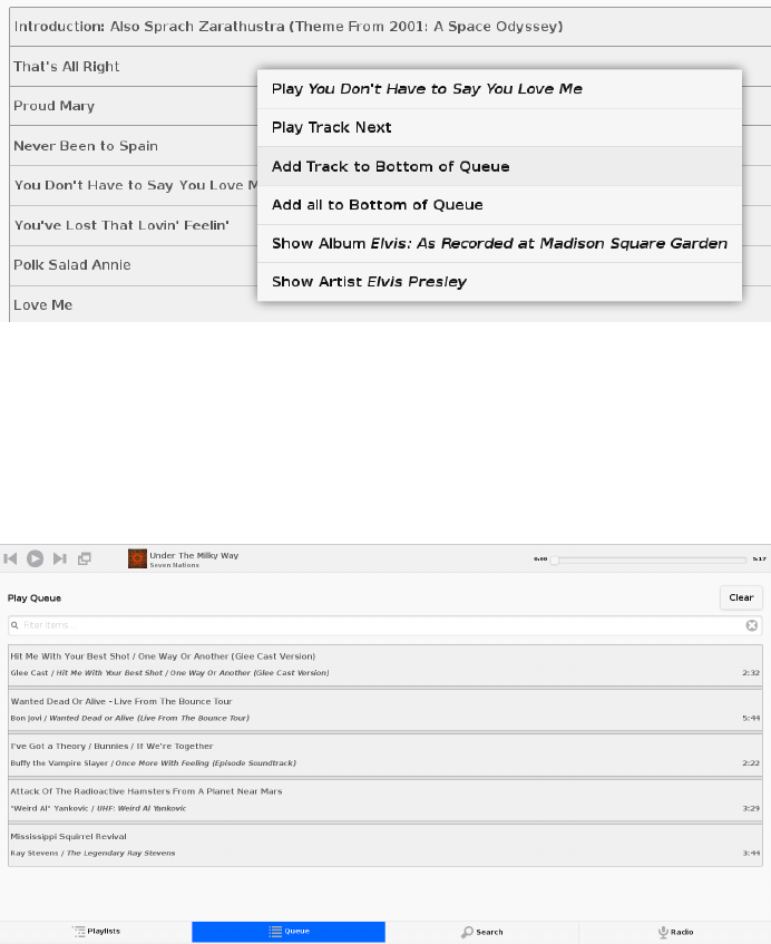
Figure 5-2.
Play a song immediately or add it to the queue
The second tab lists all the songs in your queue (see Figure 5-3). You can click them
to get a similar menu to the one in Figure 5-2, or you can use it to remove songs from
the queue.
Figure 5-3.
A Pi MusicBox queue of songs for the worst (and shortest) party playlist ever
If you would rather play streams from web radio stations, you have to use a stream
URL. You cannot use commonly available container files like M3U, XSPF, or PLS (yet).
You have to add the real stream. This stream URL is hidden inside the M3U or PLS
file. To find this URL, open the container file in a text editor. A PLS file looks like this:
[playlist]
numberofentries=1
236 RASPBERRY PI HACKS
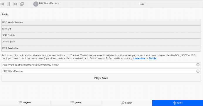
File1=http://vprbbc.streamguys.net:8000/vprbbc24.mp3
Title1=BBC World Service
Length1=-1
version=2
The stream URL in this example is http://vprbbc.streamguys.net:8000/
vprbbc24.mp3. M3U and XSPF files look different, but the stream URL is always clearly
visible.
As you can see in Figure 5-4, several streams are already set up when you first use Pi
MusicBox.
Figure 5-4.
Ready-to-go web radio stations in Pi MusicBox
You can find radio stations (PLS and M3U) using services like http://dir.xiph.org/, Lis-
tenlive.eu, or Dirble.com. Add the stream URL and the name of the station and press
the Play button. The last 25 stations are saved locally using a browser cookie (not on
the server yet, so you need to do it on every client you use).
Pi MusicBox also supports Last.fm, which collects the tracks you play so you can
discover new music. Go to http://www.last.fm to create an account if you don’t already
have one. To let Last.fm collect the tracks you play, fill in the credentials of this service:
LASTFM_USERNAME = 'lastfmuser'
LASTFM_PASSWORD = 'lastfmpassword'
Another service supported by Pi MusicBox is SoundCloud, the service that lets you
“hear the world’s sounds.” To configure it, you need a special ID, a token that you can
get from http://www.mopidy.com/authenticate. You have to log in with your Sound-
Cloud ID to get the token. This information is not shared with the mopidy.com site.
237
CHAPTER 5: MULTIMEDIA HACKS
When you log in, you’ll see a token appear on the page. Add this token to the set
tings.ini file, similar to this:
SOUNDCLOUD_TOKEN = '1-1111-111111'
SOUNDCLOUD_EXPLORE = 'electronic/Ambient, pop/New Wave, rock/Indie'
Replace the example 1-111-111111 with your token. Use the SOUNDCLOUD_EXPLORE
configuration to configure the playlists you want to see in the interface.
Multi-room audio
Pi MusicBox supports multi-room audio, meaning you can have multiple Raspberry
Pis on your network, even in different rooms. The devices need to have their own
names to be accessible. Use this option to give your MusicBox a different name:
NAME = 'Kitchen'
The name you choose should be no than nine alphanumeric characters (no spaces,
dots, etc.). After a new boot, the web interface for playing music will be accessible via
a new address. Where the default would be http://musicbox.local from devices that
support Bojour/Avahi, when you change the name, it becomes http://
newname.local. In the previous example, it would be http://kitchen.local/.
It’s not possible to play different music on multiple devices using the same Spotify
account at the same time, unless you have multiple accounts. This is a limitation of
Spotify.
Music Player Daemon (MPD)
Though the web-based interface is recommended, you can also use native software
that supports the Music Player Daemon (MPD) protocol to control Pi MusicBox. Apps
and applications are available for all sorts of devices and operating systems. Not all
of them work great with MusicBox, though.
For Android, MPDroid is recommended. On OS X, Theremin works (without search).
On Linux, you can use the excellent (and wonderfully named) console app ncmpcpp. On
a Linux desktop, GMPC and Sonata work well. On iOS, try mPod and mPad. For Win-
dows, clients either don’t work well or are untested.
The Pi can play the music from Spotify in different levels of quality. The better the
quality, the more data needs to be downloaded from Spotify (this is called bitrate).
Higher quality means a higher bitrate and a bit more use of your Internet connection.
Typical broadband connections should be able to support the highest bitrate easily.
If you have a good connection to the Internet, you can set the quality to high, but if
your connection is slow or unstable, or if you have usage limits on your connection,
238 RASPBERRY PI HACKS
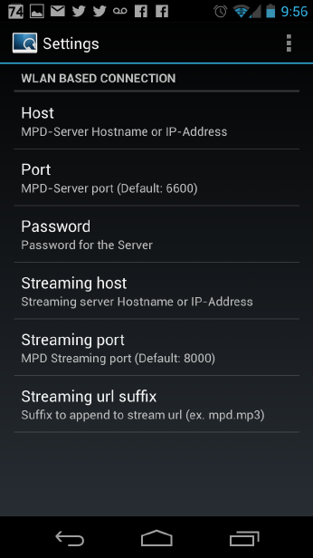
you can it lower and use less data. Possible rates are 96 (low, but acceptable quality,
FM-like), 160 (default), or 320 (highest quality, CD-like).
Set the bitrate to high like this in the configuration file:
SPOTIFY_BITRATE = 320
Or set the bitrate to low like this:
SPOTIFY_BITRATE = 96
You can install MPDroid from Google Play. (Or if you’d like to try others, consult the
MPD Wiki’s list of clients.) When you first start it, you’ll see the settings page. Choose
“Default connection settings,” which will take you to a list of options as seen in
Figure 5-5.
Figure 5-5.
MPDroid settings page
Select Host, and enter the IP address of your Pi MusicBox. Then return to the main
menu, and you should see your playlist start playing (Figure 5-6).
239
CHAPTER 5: MULTIMEDIA HACKS

Figure 5-6.
MPDroid playing music
Remember that unless you’ve opened your Pi to the external Internet, you’ll need to
connect your phone to WiFi on the same network, or MPDroid won’t work.
Networked music
If you would like to play your own music files, you can do so via a Windows network.
To do so, edit the configuration file, so that MusicBox knows where your files are. This
address could be a bit cryptic to a first-time user—for example:
NETWORK_MOUNT_ADDRESS = '//192.168.1.5/musicshare'
or:
240 RASPBERRY PI HACKS
NETWORK_MOUNT_ADDRESS = '//mynasserver/shared/music'
The first part (//) is the way shares in the Windows network are created. Just add it
and forget it. The next part (mynasserver or 192.168.1.5) is the name or IP address of
the server that hosts the file. The last part (/musicshare or /shared/music) tells
MusicBox which share to mount.
When your server is protected, you need to set the username and password for the
Network share using the following configuration lines:
NETWORK_MOUNT_USER = 'username'
NETWORK_MOUNT_PASSWORD = 'password'
MusicBox will not see the files immediately. The music files needs to be scanned at
boot, every time you add or remove files. This process can slow down the boot of the
MusicBox, so use it with care. MusicBox will scan the files using the following config-
uration lines:
SCAN_ONCE = 'true'
or:
SCAN_ALWAYS = 'true'
The names speak for themselves. Using SCAN_ONCE, the music files will be scanned only
once. Use this if you don’t change the music files often. Use SCAN_ALWAYS if you change
your music files a lot. This will enable you to change the files and reboot MusicBox. It
will recognize the new files after the boot. But, again, the scanning process can slow-
down the booting of MusicBox considerably.
Local music
Pi MusicBox also has an option to store music files on the SD card. This process is a
bit more complicated. Since MusicBox is created for a 1 GB or larger SD card, the
filesystem is also less than 1 GB. If you put MusicBox on a larger SD card, the rest of
the space on the card won’t be used unless you resize the filesystem.
You can do this manually using a partition manager (on Linux, try GParted), or you can
let MusicBox try to resize it automatically. If the process fails, you’ll have a nonfunc-
tional MusicBox, but since you should be doing this at the beginning, you can just start
over with the installation. If you’ve done a lot of customization, however, you should
back up the card first.
Using this line in the settings, Pi MusicBox will automatically resize the filesystem to
the maximum size of the SD card:
RESIZE_ONCE = 'true'
241
CHAPTER 5: MULTIMEDIA HACKS
Putting music files on the SD card is recommended only on cards larger than 1 GB.
MusicBox needs the 1 GB for caching and other storage. After resizing an SD card with
more storage, you can put your own music files on the Pi using either the Windows
network or by mounting the root filesystem of the card on a Linux computer and
copying the files. Leave at least 200 MB of free space on the device.
To use the Windows network, you have to have the workgroup name of the network
set to the default name, WORKGROUP. If you want another name, you have to change it
by hand in /etc/samba/smb.conf (see “Getting Your Hands Dirty” on page 243). Remem-
ber to let MusicBox scan the files at boot (see “Networked music” on page 240).
Sound Configuration
By default, Pi MusicBox will send the sound to the analog headphone output on the
Pi. This sound is good enough, but due to hardware constraints, not always great. If
you want to have better sound, use the HDMI to connect the Pi to an amplifier, or
connect a USB sound card (also called USB Digital Audio Converter/DAC), USB
speakers, or USB headphones. MusicBox supports almost all types of USB speakers,
headphones, and DACs, but if you buy one, make sure it’s Linux compatible. DACs with
digital outputs are also available in many web stores.
When booting, Pi MusicBox will autodetect what is connected to the device and con-
figure it accordingly. If you connect multiple devices, USB will be selected first as a
sound output, HDMI after that, and lastly the analog output of the Pi itself. You can
override this in the configuration file using the following line:
OUTPUT = 'analog'
If you include this, the default output will be the analog headphones jack of the Pi,
even if you connected using an USB device or an HDMI cable. The options are analog,
hdmi, usb.
Security
Pi MusicBox is not totally secure and is intended to run only in the cozy environment
of your local network, not outside a firewall. The heart of MusicBox is not protected
enough to do that. Also, your WiFi and Spotify passwords are stored in plain text on
the SD card. This might be fixed in the future.
For more security, change the default password by setting this line (where mypass is
your new password):
MUSICBOX_PASSWORD = 'mypass'
This will change the passwords of both the user musicbox and the user root. The pass-
word will be removed from the configuration file after it’s updated.
242 RASPBERRY PI HACKS

If you want, to change the root password to something else for more security, use this
line:
ROOT_PASSWORD = 'mypass'
Getting Your Hands Dirty
If you’d like to dig a bit, there are plenty more options to explore in Pi MusicBox. For
the following options, you have to log into the box on the console, or via SSH (see Hack
#12).
To log in remotely via SSH, you will need to enable the SSH service. Do that by adding
this line to your configuration file:
SSH_ENABLED = ‘true’
Reboot. After that, you can connect to MusicBox via SSH.
Mopidy
The main ingredient of MusicBox is Mopidy, an open source music server developed
by people from all over the world. By default, Pi MusicBox is set up using the best
working extensions, but you can extend it to play music from other sources, such as
SoundCloud, Google Music, and Beets Music.
Adding these extensions is beyond the scope of this hack, but you can find additional
resources and documentation at Mopidy’s website and reach the developers on the
Mopidy mailing list or via IRC on the #mopidy channel on Freenode.
rc.local
The /etc/rc.local file is another important piece of Pi MusicBox. It’s a shell script
where the sound hardware is set up and the configuration is done. For example, the
configuration file of Mopidy is created from rc.local. Edit this file is you want to add,
change, or remove features.
Working at Midnight
For Linux novices, a nice utility called Midnight Commander could be useful for brows-
ing the filesystem and editing files. It works like the age-old DOS-utility Norton
Commander and it’s included in MusicBox. Start it using the command mc.
243
CHAPTER 5: MULTIMEDIA HACKS

Static network
To use MusicBox in a network with static IP addresses, you have to edit /etc/network/
interfaces. The lines that configure the wired network look like this:
allow-hotplug eth0
iface eth0 inet dhcp
For a static wired network, you should change it to something like this:
iface eth0 inet static
address 192.168.1.5
netmask 255.255.255.0
gateway 192.168.1.1
Change the IP addresses as applicable for your network. For more about finding and
setting your IP address, see Hack #13.
Updating
When a new version of MusicBox is released, the only way to update it is to do a new
installation. Note that if you update the kernel or other packages on the system man-
ually without a new MusicBox installation, it could eventually break things, so a fresh
installation is preferred.
—Wouter van Wijk
HACK 49 Turn Your Pi into a Radio
Sure, it’s easy to play an entire library of music files from your Raspberry
Pi. But how about using the Pi itself (which doesn’t have any sort of built-
in radio transmitter) as a radio?
The PiFM project, created by Oliver Mattos and Oskar Weigl, was designed to turn your
Raspberry Pi into a radio. By switching a GPIO pin from on to off at a high frequency,
you’ll build yourself a makeshift Rapberry Pi FM transmitter.
To get started, download the PiFM files from http://www.icrobotics.co.uk/wiki/
images/c/c3/Pifm.tar.gz to your Raspberry Pi and extract the tarball in the Pi’s home
folder. You’ll have four files there:
•sound.wav
•PiFm.py
•pifm.c
•pifm
244 RASPBERRY PI HACKS

Tune a radio to 103.3 FM and put it near your Pi. Then open a terminal and enter:
$ sudo python
>> import PiFM
>> PiFm.play_sound("sound.wav")
If you want to play your own sound, convert it to WAV format (16 bit mono, 22 Khz is
best) and put it in your home directory.
This will work only with the radio next to the Raspberry Pi. To get a little more range,
you can connect any 50 cm wire to GPIO4 to act as an antenna. Pointing it straight up
works well and should get you around 50 m of range.
You might need a license to transmit radio in some countries, so if you’re unsure,
it is best to leave the antenna disconnected. It will still work, but with a very short
range.
Compile the code for pifm.c using the following command:
$ gcc -lm -std=c99 pifm.c -o mypifm
To broadcast your WAV file, just run:
$ ./mypifm myaudio.wav
How It Works
FM stands for frequency modulation, which is how it sends sounds over the air. Fre-
quency modulation works by having a signal (called a carrier signal) that regularly
changes from positive to negative and back again very quickly (in the case of the PiFM
radio, it changes and changes back again 103.3 million times every second!). When
you vary speed of this change to be just a bit faster or slower, the radio on the other
end can detect the changing speed and makes sound based on how it changes.
But how do you make the Raspberry Pi change something so quickly and accurately?
The Pi has an on-board clock manager that can accurately produce any clock fre-
quency you want by dividing the system processor clock (which is normally around
500 Mhz) down to any other rate you want. To tell it what to do, you set a register (a
special piece of memory) to a number saying what you want the system clock divided
by to make the FM radio clock. For example:
• System Clock = 500 Mhz
• Divider Register = 5.000
• FM radio clock frequency = 500/5 = 100 Mhz
245
CHAPTER 5: MULTIMEDIA HACKS
This divider can be a fractional number and adjusted up and down by tiny bits to make
your sound.
Alas, it turns out that to keep your sound playing smoothly, you need to regularly
adjust the rate, and the Raspberry Pi isn’t very good at that. The Pi can run more than
one program at a time, but it has only one processor. It does this by quickly switching
between running programs (multitasking). This normally works well, but in this case,
if another program is running when the clock rate needs adjusting, there will be a glitch
in the sound.
To combat this problem, you can use the Direct Memory Access (DMA) controller. You
can give the DMA controller a list of things to do (e.g., what rate to adjust the sound
to at each point in time), and then it does it in the background, even if the main pro-
cessor is busy running other programs. The PiFM program just makes a list of things
for the DMA controller to tell the clock generator to do and then gets it going.
Accessing Hardware
The Python library calls a C program (provided both precompiled and in source form).
The C program maps the peripheral bus (0x20000000) in physical memory into virtual
address space using /dev/mem and mmap. To do this, it needs root access, hence the sudo.
Next, it sets the clock generator module to enabled and sets it to output on GPIO4 (no
other accessible pins can be used). It also sets the frequency to 103.3 Mhz (provided
from PLLD@500Mhz, divided by 5), which provides a carrier. At this point, radios will
stop making a “fuzz” noise and become silent.
Modulation is done by adjusting the frequency using the fractional divider between
103.325 Mhz and 102.275 Mhz, which makes the audio signal. The fractional divider
doesn’t have enough resolution to produce more than ~6 bit audio, but since the Pi is
fast, you can do PWM to provide about 10 additional bits, giving a total resolution of
16 bits, matching the audio input.
Fun with FM
Here are some ideas of things you might be able to try with PiFm:
Make a repeated playlist (easy)
A simple loop in Python calling play_sound on different sound files should let you
play an entire list of files one at a time.
Make a “mystery sound” game (medium)
Play a sound, and the player must guess which household object makes the same
sound. They can take their radio round the house to try to find a matching sound.
246 RASPBERRY PI HACKS

Make a Morse code program (medium)
If you make a sound file for “dot,” another for “dash,” and a third as a “gap,” you
should be able to play them in the right order to send Morse code.
Make a wireless network (hard)
As an extension of the Morse code idea, see if you can send any information (for
example, an image file) via noises on the radio, and make a decoder program on
your computer that can recognize the noises through a microphone and convert
it to a file again. You now have a crude wireless network link and radio-modem
that you have made entirely yourself!
—Oliver Mattos and Oskar Weigl
HACK 50 Control the Pi via Touchscreen
While the Raspberry Pi has native hardware support for two types of vid-
eo output (HDMI and composite video), there are times where it would
be helpful to be able to use it with a touchscreen monitor, such as those
used for both display and input in tablet computers.
The Raspberry Pi Model B contains a Display Serial Interface (DSI) connector, which
is a 15-way, flat flex connector labeled S2 next to the Raspberry Pi logo on the board.
DSI is sometimes used to connect touchscreens in small-form-factor devices such as
smartphones. Sadly, adding a touchscreen to your Pi is not as simple as disassembling
an abandoned smartphone and reconnecting the screen to the DSI connector.
The GPU firmware that enables the native video output needs code to explicitly sup-
port any device connected to the DSI port. Since this firmware is not open source, it
is not currently possible to add support for any DSI-connected screens, nor are there
any known devices that the GPU firmware supports on the DSI connector. It is widely
expected that, at some point, the Raspberry Pi Foundation will release official periph-
erals that can connect to the DSI connector, which will make this a much simpler task
(assuming that one of those peripherals is a touchscreen). Until that point, however,
we’ll just have to hack around it.
Choosing a Touchscreen
The first step is to figure out which touchscreen to connect to the Raspberry Pi. There
are quite a few touchscreen devices on the market, but the majority of them are ex-
tremely expensive, and the Linux support for them is haphazard at best. We chose the
Mimo 720 touchscreen because it is small (7” x 5.25” x 1”), light (less than a pound),
USB-driven, mountable with a bracket, and relatively inexpensive (MSRP $199 USD,
but it is regularly on sale around $129).
247
CHAPTER 5: MULTIMEDIA HACKS

There is at least one drawback to this device. It uses DisplayLink, a technology that
allows for an additional monitor and graphics device to be connected via USB.
Unfortunately, this means that the Mimo 720 is not connected to or using the
Raspberry Pi GPU. The result is that it is not possible to use it as a VideoCore output
device, and it is not powerful enough to drive anything needing high-quality video
performance or acceleration on its own.
So, while it might seem perfect to use in a car seat-back multimedia player hack,
we would not recommend it for that use case. There are, however, plenty of other
cases where it’s still a handy solution!
The Mimo 720 is technically two devices in one unit: an 800 x 480 LCD DisplayLink
monitor and an e2i Technology, Inc. USB touchpanel. Linux detects these devices
separately, so it is important for your Raspberry Pi Linux kernel to support for both of
them.
Installing and Enabling Drivers
You can make the Mimo 720 available as a monitor to Linux via two kernel drivers,
either the USB Display Link Framebuffer Driver (CONFIG_FB_UDL in Kconfig-speak,
udlfb.ko as a module) or the USB Display Link Kernel Mode Setting (KMS) driver
(CONFIG_DRM_UDL in Kconfig-speak, udl.ko as a module). The UDL Kernel Mode Setting
driver does not work as well for this use as the UDL Framebuffer Driver. The KMS driver
is likely to eventually be the better choice, but in the interim, the Framebuffer Driver
works great for our hacking needs.
The e2i Technology touchpanel portion of the device is driven by the USB Touchscreen
Driver (CONFIG_TOUCHSCREEN_USB_COMPOSITE in Kconfig-speak, usbtouchscreen.ko as a
module).
Neither the USB Touchscreen Driver nor the UDL Framebuffer Driver is enabled by
default in the prebuilt kernels provided by the Raspberry Pi Foundation, and thus,
almost never present in Raspberry Pi Linux distribution images, but this is easily rem-
edied with a custom kernel, which you can build from source with the instructions in
“Install a New Kernel” on page 85.
When you build your custom kernel for this hack, you will need to be sure that you
configure it so that these additional drivers are also built. As a reminder, you can con-
figure which drivers and options to build using make menuconfig.
248 RASPBERRY PI HACKS
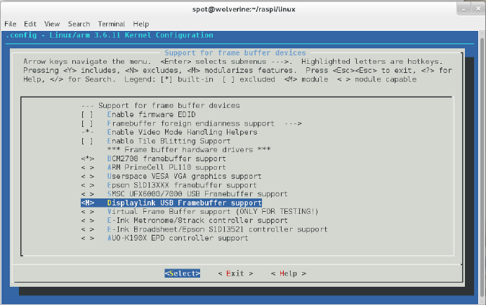
To enable the framebuffer driver, go into the Device Drivers menu and select “Graphics
support” → “Support for frame buffer devices.” At this screen, you need to enable
“Displaylink USB Framebuffer support.” Since you will want to use this driver as a
module, hit the M key when that item is highlighted in the TUI. When successful, your
screen should look something like Figure 5-7.
Figure 5-7.
Configuring Displaylink USB Framebuffer support as a module
Next, you need to enable USB touchscreen support. Exit to the Device Drivers menu
(right arrow to Exit, then Enter). From there, go into the “Input device support”
menu. You need to enable the “Touchscreens” option on this page (by hitting the
spacebar when “Touchscreens” is highlighted), then press Enter to go into the
Touchscreens menu.
In the Touchscreens menu, highlight the “USB Touchscreen Driver” option and press
M to enable it as a module. By default, this enables all of the supported USB
Touchscreens, but you should still scroll down and make sure that the “e2i
Touchscreen controller (e.g., From Mimo 740)” option is enabled. You can confirm that
is enabled by making sure that it has an asterisk beside it, as shown in Figure 5-8.
249
CHAPTER 5: MULTIMEDIA HACKS
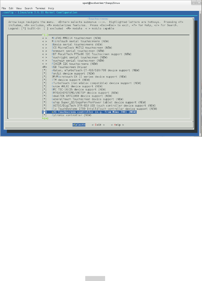
Figure 5-8.
e2i Touchscreen controller driver enabled
Once your kernel and modules are rebuilt, simply install them into the Raspberry Pi
Linux distribution image. Reboot your Raspberry Pi with the Mimo 720 connected.
On the Mimo 720, the screen will cycle through several colors and patterns as the
Raspberry Pi boots. This is the Mimo 720 initializing the frame buffer, and it means
that the Mimo 720 works properly. At this point, it will stop at a green screen, which
is fine, because you have not yet configured the Linux userspace to run the display.
Within the Raspberry Pi Linux instance, you should see kernel messages like this in
the output of dmesg:
udlfb: DisplayLink MIMO - serial #101234567
udlfb: DisplayLink USB device /dev/fb1 attached. 800x480 resolution. Using
1504K framebuffer memory
There are a couple ways you can get this information from your Raspberry Pi:
•SSH into the Raspberry Pi (see Hack #12).
•Connect a monitor to the HDMI or composite video.
Later, you’re going to reconfigure X to run the main display to the Mimo 720, but for
now, the graphical X11 display should still be running on the directly connected mon-
itor.
250 RASPBERRY PI HACKS

Linux Distributions Without Xorg/X11
OpenELEC makes a build of their XBMC-based Linux OS for the Raspberry Pi, but
it does not use Xorg. Because OpenELEC relies entirely on the VideoCore output
devices, this particular hack will not work on that distribution, unless you rebuild
it entirely from source and enable Xorg support. You’ll have the same problem if
you try to use RaspBMC with this hack.
In the dmesg output, you’re looking for the line that tells you which frame buffer device
the Linux kernel has assigned to the Mimo 720. In the current example, the device
is /dev/fb1. It is probably /dev/fb1 for you as well, unless you have other devices plug-
ged into the Raspberry Pi that show up to the Linux kernel as frame buffers. Just make
a note of this device name, as you will need it to write your Xorg configuration file later.
For the touch panel, look for messages like this in the output of dmesg:
input: e2i Technology, Inc. USB Touchpanel as /devices/platform/bcm2708_usb/
usb1/1-1/1-1.3/1-1.3.1/1-1.3.1.3/1-1. 3.1.3:1.0/input/input2
usbcore: registered new interface driver usbtouchscreen
These messages mean that the usbtouchscreen driver has been loaded and the e2i
Technology USB Touchpanel in the Mimo 720 has been detected.
Now, look in the /dev/input/by-id/ directory. You should see a filename that looks
something like:
/dev/input/by-id/usb-e2i_Technology__Inc._USB_Touchpanel_L000000000-event-
if00
Take a note of this filename, which you’ll use to identify your touch panel device in the
Xorg configuration file. You use this ID instead of using a /dev/input/event* device,
because the ordering of those devices can (and does) change when you add things
like USB mice and keyboards to the bus. Using the touchscreen’s unique device iden-
tifier ensures that you always end up with a working X session.
Xorg Configuration
At this point, it is time to start writing your Xorg configuration file. Modern Linux dis-
tributions usually autodetect a working Xorg configuration for the present hardware,
but in the case of the Raspberry Pi, it will result in a working X session for the GPU,
not the Mimo 720. By making your own Xorg configuration file, you’ll be overriding the
autodetection and telling the Raspberry Pi Linux distribution to use the Mimo 720 as
the primary graphical display and input device. You can still plug in a USB keyboard
and mouse, and those will be auto-detected and used in addition to the Mimo 720
touchscreen as input sources.
251
CHAPTER 5: MULTIMEDIA HACKS
Create a new file in your home directory called xorg.conf.mimo and open it in your
favorite text editor. (If you don’t care about the inner workings here, you can just
download our xorg.conf.mimo from the book’s GitHub repository.)
Your Xorg cofiguration file needs five sections: Device, Monitor, Screen, ServerLayout,
and InputDevice:
Section "Device"
Identifier "DisplayLinkDevice"
driver "fbdev"
Option "fbdev" "/dev/fb1"
Option "ShadowFB" "off"
EndSection
This defines a video device named DisplayLinkDevice that uses the fbdev driver across
the Mimo’s framebuffer device (/dev/fb1). If your framebuffer device is different, ad-
just it accordingly.
We also disable the ShadowFB feature. ShadowFB causes the fbdev driver to force the
CPU to do each drawing operation first into a shadow frame buffer in system virtual
memory and then copy the result into video memory. While this behavior is good for
most cases, for our DisplayLink device, you need the CPU to draw directly into video
memory:
Section "Monitor"
Identifier "monitor"
Option "DPMS"
EndSection
This section defines a Monitor device, which we have uncreatively named monitor. The
only other setting here is to enable Display Power Management Signaling (DPMS),
which allows power saving behaviour of the touchscreen when you are not using your
Raspberry Pi:
Section "Screen"
Identifier "screen"
Device "DisplayLinkDevice"
Monitor "monitor"
EndSection
The third section defines a Screen device that ties our DisplayLinkDevice video device
to our monitor device. This is how Xorg works; it draws to a screen device. Xorg sup-
ports multiple devices, including multiple screen devices, but for this hack, we’re
keeping it simple:
Section "ServerLayout"
Identifier "default"
Screen 0 "screen" 0 0
252 RASPBERRY PI HACKS
InputDevice "touchscreen" "CorePointer"
Option "BlankTime" "0"
Option "StandbyTime" "0"
Option "SuspendTime" "0"
Option "OffTime" "0"
EndSection
The ServerLayout section tells Xorg how to layout any screens that you wish to use.
This is simple, because you have only one screen device, so just put it in position 0,0
(the numbers correspond to a horizontal and vertical ordering, where 0 is the first
position).
You’ll also tell it that, for your ServerLayout, you want to use the touchscreen input
device as your mouse device. By passing it as CorePointer, it tells Xorg to use it as the
default mouse device. The other options are for the DPMS timeout settings:
BlankTime
The time in minutes to let the screensaver (if any) run before blanking the screen
StandbyTime and SuspendTime
Define the inactivity period (in minutes) before going into standby and suspend
mode, respectively
OffTime
Defines the inactivity period before turning the monitor device off entirely
In this example config, these options are all set to 0, which effectively disables power
saving on the device, but you should customize them for your needs.
When setting these, you should stagger them out, in the order presented, so that your
monitor device goes blank, then to standby, then to suspend, then turns off entirely.
If you do not want your monitor to go into one of those states (or it does not support
that state), you can always disable it by passing a 0 value to it:
Section "InputDevice"
Identifier "touchscreen"
Driver "evdev"
Option "Device" "/dev/input/by-id/usb-
e2i_Technology__Inc._USB_Touchpanel_L000000000-event-if00"
Option "DeviceName" "touchscreen"
Option "ReportingMode" "Raw"
Option "SendCoreEvents" "On"
Option "Calibration" "449 31910 31857 988"
EndSection
253
CHAPTER 5: MULTIMEDIA HACKS
The last section defines the input device for the touchscreen component of the
Mimo. The touchscreen device uses the evdev driver, pointing to the e2i input device
node identified earlier:
/dev/input/by-id/usb-e2i_Technology__Inc._USB_Touchpanel_L000000000-event-
if00
Continuing our less-than-creative naming scheme, it is named touchscreen. We need
to have the Mimo touchscreen in Raw reporting mode to work properly, and since we
are using it as the main input pointer, we want it to have the SendCoreEvents option
enabled.
The last option is a calibration option, which is how the Mimo touchscreen knows how
to properly report touch events. The calibration values should be correct for your
device, but if they are not, you may need to determine them for yourself. There are a
few ways to do this, but the tool that exists for most of the Linux distributions is called
evtest. To install it on Pidora, run:
$ su -c 'yum install evtest -y'
Or on Raspbian/Occidentalis:
$ sudo apt-get install evtest
evtest is intended as a debugging tool, to see all of the input that is being generated
from an evdev-compatible input device. For calibration purposes, we need to know
the minimum and maximum values being reported along the X and Y axes of the
touchscreen. Run evtest on the Mimo touchscreen device node:
$ sudo evtest /dev/input/by-id/usb-
e2i_Technology__Inc._USB_Touchpanel_L000000000-event-if00
Using the Touchscreen
Now, every time you touch the screen, evtest will output debugging information about
the event. For example, when you touch near the center of the screen, it generates an
event that looks like this:
Event: time 1378951053.759441, type 1 (EV_KEY), code 330 (BTN_TOUCH), value
1
Event: time 1378951053.759452, type 3 (EV_ABS), code 0 (ABS_X), value 17165
Event: time 1378951053.759456, type 3 (EV_ABS), code 1 (ABS_Y), value 17217
Event: time 1378951053.759460, -------------- SYN_REPORT ------------
Event: time 1378951053.766434, type 3 (EV_ABS), code 0 (ABS_X), value 17191
Event: time 1378951053.766442, type 3 (EV_ABS), code 1 (ABS_Y), value 17259
Event: time 1378951053.766446, -------------- SYN_REPORT ------------
Event: time 1378951053.773442, type 3 (EV_ABS), code 0 (ABS_X), value 17208
Event: time 1378951053.773452, type 3 (EV_ABS), code 1 (ABS_Y), value 17422
254 RASPBERRY PI HACKS

Event: time 1378951053.773456, -------------- SYN_REPORT ------------
Event: time 1378951053.826439, type 1 (EV_KEY), code 330 (BTN_TOUCH), value
0
Event: time 1378951053.826456, -------------- SYN_REPORT ------------
This is a single touch (BTN_TOUCH), but you can see it gets three distinct X (ABS_X) and
Y (ABS_Y) measurements. To determine the minimum and maximum X and Y calibra-
tion values, you will need to touch the upper-left, upper-right, lower-left, and lower-
right corners of the screen (as close to the edge as you can). Then, write down the
smallest and largest values for ABS_X and ABS_Y that appear in the evtest output. These
make up the values that go into your xorg config file, with this option syntax:
Option "Calibration" "<MIN_X> <MAX_X> <MIN_Y> <MAX_Y>"
Substitute in your discovered values for <MIN_X>, <MAX_X>, <MIN_Y>, and <MAX_Y>.
With your xorg.conf.mimo complete, you can now make the Mimo touchscreen into
your primary device by copying it to /etc/X11/xorg.conf as root:
$ sudo cp -a xorg.conf.mimo /etc/X11/xorg.conf
When you reboot (assuming that your Linux instance is configured to boot into a
graphical mode), you should see your desktop display out to your Mimo touchscreen.
Keep in mind that if you have something connected to the “normal” video output of
the Raspberry Pi (e.g., HDMI), you will still see the Linux kernel and boot messages go
to that device, because the DisplayLink device is not the main target for that output.
Also, because it is not using the VideoCore GPU at all, you will not be able to playback
videos using the hardware video codecs, and they will be slow.
HACK 51 Emulate Classic Video Game Consoles
Relive the golden era of home video gaming by letting your Raspberry Pi
pretend to be the gaming systems of yesteryear. Hey, you kids, get off
our lawn. We’re hacking here!
We both have fond memories of the original Nintendo Entertainment System (NES).
(For Tom, it was his first dedicated gaming console. Ruth was still playing with an Atari
2600 and stuck with whatever could be found on 5.25-inch floppies.) Now, although
we both have kids who think of video games as something much more complicated
than Duck Hunt could have dreamed to be, those old 8-bit (and later, 16-bit) games
still have a lot of play left in them.
It’s not surprising to see the retro trend in a lot of new independent video games, but
what about going straight to the source? Those old games from the 1980s and 1990s
were good enough for us then. We’re certainly not too good for them now. You could
spend a lot of money buying a working system and all of your old games on eBay, but
255
CHAPTER 5: MULTIMEDIA HACKS

let’s assume for a moment that you’re not independently wealthy. Your Raspberry Pi
can emulate most of these old gaming consoles for you!
The original video game consoles were good for their time, but by today’s standards,
they’re nothing but slow and weak. The NES had a 1.79 MHz CPU (that’s an M, not a
G), with 2 KiB of onboard memory. Today, most of these hardware consoles have been
fully reverse-engineered, and pure software implementations have been written that
can emulate them almost perfectly.
All that’s left to worry about is the games. Even if you still have the media lying around,
your Raspberry Pi didn’t arrive with any slots designed for those old game cartridges
and discs. Instead, those software emulators are written to read ROM files, which are
imaged copies of the games, taken from their original media and saved to a file.
Downloading the ROM files from the Internet for the games that you want to play is
the simplest way to get started; however, its legality is questionable in a lot of juris-
dictions. There are other alternatives, such as the Retrode gaming adapter, which is
a USB device that has native slots for Sega Genesis and Super Nintendo (SNES)
games, as well as native connectors for the controllers of both systems.
This hack assumes that you have ROM image files for your games. Depending on
where you are, ROMs may have some legal issues. For the purposes of this hack, we
will simply assume that you possess legal ROMs.
As for controllers, Linux supports almost any USB joystick that you can find. For the
full nostalgia experience, you can purchase original gaming controllers converted to
use USB connectors and USB connectors that will provide a native port for the original
controller.
Using an NES/SNES Controller Through the GPIO
It is possible to connect an NES or SNES controller directly through the Raspberry
Pi GPIO, but you’ll need to build and use a RetroPie GPIO Adapter. There is a com-
plete writeup (with hardware specifications, schematics, and software) here:
http://blog.petrockblock.com/2012/10/21/the-retropie-gpio-adapter/
First you need to turn your Raspberry Pi into a gaming supercomputer. Start with a
fresh Raspbian install, which works best for this purpose. Update all of the compo-
nents:
$ sudo apt-get update
$ sudo apt-get upgrade -y
256 RASPBERRY PI HACKS

While there are quite a few game console emulator software choices out there, be-
cause the Raspberry Pi is an ARM-based system (as opposed to x86-based), the best
option is called RetroArch. Although building RetroArch for the Raspberry Pi was ini-
tially complicated, Florian Müller has created a tool called RetroPie that automates
almost the entire process.
Florian also provides prebuilt images containing finished RetroPie setups.
RetroPie needs to have some additional software installed on top of the Raspbian
image to work properly, so you should start off by running:
$ sudo apt-get install -y git dialog
Then you can pull down a copy of the latest RetroPie setup software from GitHub:
$ git clone --depth=0 git://github.com/petrockblog/RetroPie-Setup.git
This will create a directory called RetroPie-Setup. Change into that directory, set the
main setup script to be executable, then run it as root:
$ cd RetroPie-Setup
$ chmod +x retropie_setup.sh
$ sudo ./retropie_setup.sh
This will load a clean text interface to set up the RetroPie suite. You can install either
from prebuilt binaries or from source. Installing from source (option 2) will give you
the absolute latest versions of all of the emulators and game runtimes, but it will take
quite a bit longer (and is a bit more complicated to do). Installing the binaries (option
1) is faster (though it still takes a while), so we recommend you go down that path. It
will go out and download all of the files it needs to setup the various supported emu-
lators and runtimes, and when it finishes, it will write out a debug log of everything it
did.
When this finishes successfully, you need to select the SETUP option from the main
menu (option 3). If you plan on using this as a dedicated video gaming station, you
should consider starting the Emulation Station on boot (option 4), as that will provide
a nice frontend to all of the gaming options. You can also enable a nice splash screen
to display on boot (option 6), but that is entirely eye candy.
Option 7 might be useful to you. You can configure the sound output from the emu-
lators to go over the HDMI connection, the analog audio connection, or automatically
detect what is in use.
257
CHAPTER 5: MULTIMEDIA HACKS

We have seen some scenarios where the “Auto” setting does not work properly.
If you enable the Emulation Station on boot, you can reboot, and the system will boot
directly into the Emulation Station GUI. You can also launch this GUI manually by
running:
$ emulationstation
On its first run, Emulation Station will prompt you to configure your joystick. It uses
the joystick to navigate through the GUI interface (though it does not pass those joy-
stick settings to every emulator). You can choose from the emulated systems using
the left and right buttons on your joystick controller.
If you do not have ROMs installed for an emulated system, Emulation Station will not
display that system as a choice. To install ROMs for a system, put the files
in /home/pi/RetroPie/roms/<systemname>/. If your ROM files are compressed, you
might need to uncompress them before Emulation Station will recognize them.
HACK 52 Connect a DSLR
The official Raspberry Pi camera is tiny and mighty, but there are times
you’ll want the control and interchangeable lenses of your DSLR. The Pi
can handle that, too.
Although the Raspberry Pi was designed for a camera (that didn’t even exist until more
than a year after the Pi itself launched!), that camera doesn’t have nearly the power
of your DSLR. We used one to create a portable photobooth (along with a Tux the
penguin mascot costume!) to take to open source conferences (see Hack #53).
Tethering a computer to your DSLR can offer you some big additional capabilities,
including in-the-moment settings adjustments for rapid subsequent exposures, near-
ly instant backups, and remote camera control from anywhere. The fact that the Pi is
so small makes the whole setup a lot more feasible.
Geting Started with gPhoto
The quickest way to get started on any of those projects or whatever else you can
imagine doing with a Pi-controlled camera is with gPhoto, which is a set of software
and libraries for doing just that. gPhoto supports more than 1,600 cameras, so there’s
a good chance that unless you have either an exceptionally old or exceptionally new
piece of equipment, it’s on the list. For example, if you own a Pi because you love tiny
things, that supported list even includes the absurdly small, 1.2-ounce, 2.36” x 1.52”
Che-ez SPYZ camera!
258 RASPBERRY PI HACKS

Camera Protocols
gPhoto is not intended for controlling webcams, but there is one other reason your
camera might not be on the supported list. Most cameras with USB ports use either
(or both) Picture Transfer Protocol (PTP) or USB Mass Storage protocols. USB
Mass Storage doesn’t allow remote control of a device and very much limits what
else you can do through the protocol and thus is fairly useless to us here. Many
modern cameras (post 2003) have used PTP as well. Nikon cameras often default
to USB Mass Storage, but you can switch them to PTP through the on-camera
settings menus.
In addition to your Raspberry Pi, your camera, and a USB cable to connect the two,
you’ll need libgphoto2, a libgphoto2 frontend (such as gphoto2,gtkam, kamera, or digi
kam) and libusb on your Pi. To get everything running on Pidora, run the following
command:
$ su -c 'yum install libgphoto2 gphoto2 libusb'
Here’s how to get what you need on Raspbian:
$ su -c 'apt-get install libgphoto2-2 gphoto2 libusb'
If you’d like to see whether your camera is supported before trying this out, run
gphoto2 --list-cameras, but the list is quite long, and unless you have an odd or
new camera, it’s almost certainly in there.
Now, let’s test them! Plug your camera into your laptop via USB cable and enter:
$ gphoto2 --capture-image-and-download
You might get the following error:
*** Error ***
Out of Focus
ERROR: Could not capture image.
ERROR: Could not capture.
Fortunately, the error generally tells you where you went wrong. But preferably, you’ll
capture a photo:
New file is in location /capt0000.jpg on the camera
Saving file as capt0000.jpg
Deleting file /capt0000.jpg on the camera
Deleting 'capt0000.jpg' from folder '/'...
You can even capture video this way by specifying the number of seconds you’d like
to record:
259
CHAPTER 5: MULTIMEDIA HACKS

$ gphoto2 --capture-movie=5
Capturing 5 preview frames as movie to 'movie.mjpg'.
Movie capture finished (6 frames)
That’s a “motion jpeg,” in case you were wondering what a .mjpg file is.
Basic Capture Commands and Variables
What you do with your new camera+Pi powers is up to you. These are the three main
capture commands:
--capture-image
Capture an image and keep it on the camera.
--capture-movie
Capture a movie file (depends on camera).
--capture-sound
Capture an audio clip.
You can also add -and-download to image capture, so --capture-image-and-download
will take a photo and immediately download it to the computer.
These few commands should be enough to get you started, but explore gphoto2
--help to learn even more.
You might also want to include some of the following variables:
--filename NAME
Specifies a filename, where NAME is the desired filename. You can create a default
value for this in ~/.gphoto/settings. It accepts additions, including %n: (for incre-
menting numbers), + (for date and time information), and +% (to keep the
filename in lowercase).
260 RASPBERRY PI HACKS
-F
The number of frames to capture in a row.
-I N
The time to wait between frames in seconds, specified by N.
--force-overwrite
Overwrite files without asking.
Finding More About Your Camera
To discover a stunningly large amount of information about your camera, from the
serial number to how charged the battery is to whether the flash is on, and probably
quite a few things that you aren’t even entirely sure what they mean, run the summary:
$ gphoto2 --summary
Some cameras will take photos at regular intervals for you. Some will only do it for a
few shots and then stop. You can use gphoto2 to do so at an interval you specify. This
is great for everything from science fair project displays to making composite photos
to time-lapse videos of all sorts of things. To take photos at continuous intervals:
$ gphoto2 --capture-image --I 30
The I stands for “interval,” and the number after it is the count in seconds between
photos. It will continue indefinitely (or until the battery dies). Put your camera on a
tripod and let it go. If you would rather it stop after a certain number of photos, add
--frames 5 and specify the number of shots you’d like it to take.
You can also adjust most of your camera’s settings from gPhoto. This is one way to
capture a long series of bracketed photos (for HDR photography, for example). Create
a file called bracket.sh with the following contents:
$ gphoto2 --set-config-value /main/capturesettings/shutterspeed=.1\
--capture-image\
--set-config-value /main/capturesettings/shutterspeed=.5\
--capture-image\
--set-config-value /main/capturesettings/shutterspeed=1\
--capture-image\
261
CHAPTER 5: MULTIMEDIA HACKS

Turn on your camera, connect it to the Pi, and enter ./bracket.sh to run the com-
mands. Your camera will take three photos with shutter speeds of .1, .5, and 1 second
and save them to the camera.
You can do the same thing with exposure compensation, for example:
$ gphoto2 --set-config-value /main/capturesettings/exposurecompensation=-3 \
--capture-image \
--set-config-value /main/capturesettings/exposurecompensation=0 \
--capture-image \
--set-config-value /main/capturesettings/exposurecompensation=3 \
--capture-image
Experiment with various settings and image capture options. Remember that your
camera will take all of these photos starting in the mode in which it is set. The best
approach is to set it to full manual, focus on your subject, and switch to manual focus
to lock it before running these scripts.
HACK 53 Set Up a Photobooth
Now that you know how to connect a camera (see Hack #52), you’re ready
to be the hit of your next party. Set up a fun backdrop, gather some props,
and set up your Raspberry Pi photobooth.
We first set up this photobooth at the SXSW Interactive festival for a Fedora booth in
the exhibit hall and then at several other conferences thereafter. It’s a fun way to get
people to come into the booth and hang out for a minute, even if you don’t have one
of us in a Tux costume there to amuse your visitors. It’s also a great setup for something
like a Halloween party (costumes!) or company event. All you have to do to is run one
command (press Up and Enter to repeatedly do so from the command line), and you
can keep the photo fun going all night.
You’ll need a camera on a tripod connected via USB cable to the Raspberry Pi, as well
as a monitor and peripherals. It’s handy to have a fairly lengthy USB cable, depending
on your setup and space, but particularly long USB cables can cause problems ranging
from slowness to just plain not working.
Figure 5-9 shows the photobooth we set up in the Fedora booth at OSCON. You can
see the backdrop and Tux on the left, with Ruth checking the Pi setup on the monitor
in the foreground.
262 RASPBERRY PI HACKS

Figure 5-9.
Oscon photobooth (photo by Sarah White)
We’ve tested this with several cameras, including a Nikon D90, Nikon D5100, and a
Canon EOS Rebel XSi (450D). However, any of the cameras listed as supported by
libgphoto2 should work.
Once you have the hardware set up, you need to install four packages on your Rasp-
berry Pi. On Pidora:
$ su -c 'yum install python-imaging qrencode gphoto2 surl'
On Raspbian, the first three packages have the same names:
$ su -c 'apt-get install python-imaging qrencode gphoto2'
The last one, surl, is a URL shortener. It is packaged for Fedora (and thus Pidora), but
it is not available via apt-get. If you’re using Raspbian or some other Debian-based
distribution, you’ll need to acquire it for yourself from https://launchpad.net/surl. It’s
a normal Python module, so all you have to do is download the latest source and
unpack it. Then, build it:
$ python setup.py build
263
CHAPTER 5: MULTIMEDIA HACKS
To install it, run the following command from within the source directory:
$ su -c 'python setup.py build install -O1 --skip-build'
Finally, save the following Python script as photobooth.py, and you’re ready to go
(we’ve broken it up to explain the various sections and how you can adapt it to your
purposes):
#!/usr/bin/python
# photobooth.py - version 0.3
#
# Copyright (C) 2011 Luke Macken <lmacken@redhat.com>
# This program is free software: you can redistribute it and/or modify
# it under the terms of the GNU General Public License as published by
# the Free Software Foundation, either version 3 of the License, or
# (at your option) any later version.
#
# This program is distributed in the hope that it will be useful,
# but WITHOUT ANY WARRANTY; without even the implied warranty of
# MERCHANTABILITY or FITNESS FOR A PARTICULAR PURPOSE. See the
# GNU General Public License for more details.
#
# You should have received a copy of the GNU General Public License
# along with this program. If not, see <http://www.gnu.org/licenses/>.
#
# Requires: python-imaging, qrencode, gphoto2, surl
import os
import surl
import Image
import subprocess
from uuid import uuid4
from os.path import join, basename, expanduser
The script goes through a series of steps:
1. Uses gphoto2 to detect the camera.
2. Asks you to press Enter, and when you do, it tells the camera to take a photo,
which it saves locally.
3. Applies a watermark to the lower-right corner of the photo.
4. Uploads the photo to the server you specify.
5. Generates a QR code that points to the image’s URL so that your subjects can
download their photos easily by scanning the QR code with their phones.
264 RASPBERRY PI HACKS
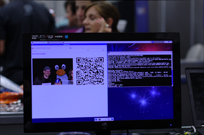
6. Generates a shortened URL for the image using the URL-shortening service you
specify.
7. Creates and displays on the monitor an HTML page that shows the photo, the QR
code, the shortened URL, and any other information you want it to show.
Figure 5-10 shows the output from the complete script: a web page with the photo
and QR code for visitors to download it.
Figure 5-10.
Output of photobooth.py
Choose a location to store the assorted data that goes along with your photo:
# Where to spit out our qrcode, watermarked image, and local html
out = expanduser('~/Desktop/photodata')
You can add a watermark to your images, such as a project name (you can also exclude
this line if you don’t want the photos watermarked):
# The watermark to apply to all images
watermark_img = expanduser('~/Desktop/fedora.png')
You’ll need to have a place you can upload the pictures to. You’ll also need a stable
Internet connection, which can be problematic if you’re setting up a photobooth at an
event like a conference. If that’s the case, be sure to get a wired connection and not
try to do this over WiFi:
265
CHAPTER 5: MULTIMEDIA HACKS
# This assumes ssh-agent is running so we can do password-less scp
ssh_image_repo = 'fedorapeople.org:~/public_html/photobooth/'
# The public HTTP repository for uploaded images
http_image_repo = 'http://lmacken.fedorapeople.org/photobooth/'
[source, python]
Define the size of the QR code you want to display:
# Size of the qrcode pixels
qrcode_size = 10
# Whether or not to delete the photo after uploading it to the remote server
delete_after_upload = True
[source, python]
People will scan the QR code to visit your web page and download their photos. Then
choose whether to save photos after they’ve been uploaded. If you’re doing this at a
conference, that directory can fill up quickly if you save them!
When you want to change picture quality and size or are having trouble with the photo,
you’ll want to consult the gphoto2 configuration options, which you can set here:
# The camera configuration
# Use gphoto2 --list-config and --get-config for more information
gphoto_config = {
'/main/imgsettings/imagesize': 3, # small
'/main/imgsettings/imagequality': 0, # normal
'/main/capturesettings/zoom': 70, # zoom factor
}
Choose which service to use to create your short URLs (options include a.gd, bit.ly,
burnurl.com, cli.gs, decenturl.com, digg.com, is.gd, kl.am, liip.to, metamark.net,
sn.im, snipr.com, snipurl.com, snurl.com, tinyurl.com, tr.im, turl.ca, ur.ly, and zz.gd):
# The URL shortener to use
shortener = 'tinyurl.com'
The Photobooth class includes most of the hard work for this setup:
class PhotoBooth(object):
def initialize(self):
""" Detect the camera and set the various settings """
cfg = ['--set-config=%s=%s' % (k, v) for k, v in gphoto_con
fig.items()]
subprocess.call('gphoto2 --auto-detect ' +
' '.join(cfg), shell=True)
266 RASPBERRY PI HACKS
def capture_photo(self):
""" Capture a photo and download it from the camera """
filename = join(out, '%s.jpg' % str(uuid4()))
cfg = ['--set-config=%s=%s' % (k, v) for k, v in gphoto_con
fig.items()]
subprocess.call('gphoto2 ' +
'--capture-image-and-download ' +
'--filename="%s" ' % filename,
shell=True)
return filename
def process_image(self, filename):
print "Processing %s..." % filename
print "Applying watermark..."
image = self.watermark(filename)
print "Uploading to remote server..."
url = self.upload(image)
print "Generating QRCode..."
qrcode = self.qrencode(url)
print "Shortening URL..."
tiny = self.shorten(url)
print "Generating HTML..."
html = self.html_output(url, qrcode, tiny)
subprocess.call('xdg-open "%s"' % html, shell=True)
print "Done!"
If you choose not to watermark, you’ll want to delete this section:
def watermark(self, image):
""" Apply a watermark to an image """
mark = Image.open(watermark_img)
im = Image.open(image)
if im.mode != 'RGBA':
im = im.convert('RGBA')
layer = Image.new('RGBA', im.size, (0,0,0,0))
position = (im.size[0] - mark.size[0], im.size[1] - mark.size[1])
layer.paste(mark, position)
outfile = join(out, basename(image))
Image.composite(layer, im, layer).save(outfile)
return outfile
The script continues by uploading the image, creating the QR code and the web page,
and offering a shortened URL:
267
CHAPTER 5: MULTIMEDIA HACKS
def upload(self, image):
""" Upload this image to a remote server """
subprocess.call('scp "%s" %s' % (image, ssh_image_repo), shell=True)
if delete_after_upload:
os.unlink(image)
return http_image_repo + basename(image)
def qrencode(self, url):
""" Generate a QRCode for a given URL """
qrcode = join(out, 'qrcode.png')
subprocess.call('qrencode -s %d -o "%s" %s' % (
qrcode_size, qrcode, url), shell=True)
return qrcode
def shorten(self, url):
""" Generate a shortened URL """
return surl.services.supportedServices()[shortener].get({}, url)
def html_output(self, image, qrcode, tinyurl):
""" Output HTML with the image, qrcode, and tinyurl """
html = """
<html>
<center>
<table>
<tr>
<td colspan="2">
<b><a href="%(tinyurl)s">%(tinyurl)s</a></b>
</td>
</tr>
<tr>
<td><img src="%(image)s" border="0"/></td>
<td><img src="%(qrcode)s" border="0"/></td>
</tr>
</table>
</center>
</html>
""" % {'image': image, 'qrcode': qrcode, 'tinyurl': tinyurl}
outfile = join(out, basename(image) + '.html')
output = file(outfile, 'w')
output.write(html)
output.close()
return outfile
if __name__ == "__main__":
268 RASPBERRY PI HACKS

photobooth = PhotoBooth()
try:
photobooth.initialize()
while True:
raw_input("Press enter to capture photo.")
filename = photobooth.capture_photo()
photobooth.process_image(filename)
except KeyboardInterrupt:
print "\nExiting..."
Change the various settings to meet your needs, and your photobooth party is all set
up. (Tux costume optional and not included with this book.)
HACK 54 Turn Your Pi into a Tiny Media Center
The first thing that many people want to do with their new $35 computer
is turn it into a tiny media center, so we’d be remiss in not helping you
out.
This hack is going to veer off a bit from what you’ve read so far, as far as distro. We’ve
been telling you how to do things in Pidora and Raspbian, two of the most common
Raspberry Pi Linux distributions. Since we both work on Fedora, you can imagine we
have an inclination toward Pidora. But you can also see that we’ve been giving you
instructions throughout this book for Raspbian as well, and occasionally only one or
the other. That’s because sometimes one distro simply is the right one for the job,
and in this case, it’s Raspbmc.
If you’re going to set up a media server, you want it to work as well as possible, becase
it’s standing between you and [insert your favorite show here]. That means you might
as well use XBMC (regardless of how you feel about the Xbox—see “XBMC” sidebar),
as it’s commonly used, which means it has a significant community waiting with an-
swers to any problems you encounter. And because it’s so popular, a distro has sprung
up specifically intended for it. That’s Raspbmc.
XBMC
XBMC was originally created for the Xbox and stood for Xbox Media Center.
It’s now available for Linux as well as Windows, OS X, and even Android and
iOS. Their release names are all allusions to popular media. Releases so far
have been Atlantis, Babylon, Camelot, Dharma, Eden, Frodo, and Gotham.
You can download the Raspbmc image and set up your SD card like you would with
any other distribution, but the Raspbmc folks have also made an interactive installer
269
CHAPTER 5: MULTIMEDIA HACKS
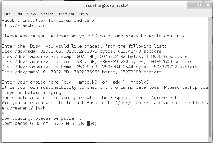
to make it easier for you. Note that if you use the installer, you will need a network
connection to the Pi at first boot for setup.
First, get the installer:
$ wget http://svn.stmlabs.com/svn/raspbmc/release/installers/python/
install.py
$ chmod +x install.py
$ sudo python install.py
[source, bash]
These three commands will then start the installer, as shown in Figure 5-11.
Figure 5-11.
Raspbmc installer
Once installation is complete, you will be asked:
Would you like to setup your post-installation settings [ADVANCED]? [y/N]
If you say yes, you will be asked two questions:
Would you like to install Raspbmc to a USB stick or an NFS share?
Note that this still requires an SD card for booting. [y/N]
Would you like to configure networking manually? This is useful if you are
configuring WiFi or a non-DHCP network [y/N]
270 RASPBERRY PI HACKS
Once you have answered them, you will be told:
Raspbmc is now ready to finish setup on your Pi, please insert the SD card
with an active internet connection
Connect your Ethernet, keyboard, and mouse to the Pi. Insert the SD card and plug it
in for first boot. If you don’t have a network connection, you’ll get an error on a blue
screen:
Sorry, I couldn't connect to the update server. Please verify you have a
wired network ocnnection or properly configured wireeless connection and dis
able any proxy servers on your network.
After you have done this, unplug your Raspberry Pi for 60 seconds before try
ing again.
Assuming it does find the network connection, you’ll get a message telling you that
this is going to take 15–20 minutes.
Once it’s finished, XBMC is ready to go. Restart the system, and you can start using
your new media center. Periodically, XBMC will offer helpful tips when you do some-
thing for the first time (it’s quite user-friendly). All that’s left is to decide what to en-
tertain yourself with!
XBMC supports just about any format you want to throw at it. You can watch DVDs
and unencrypted Blu-ray discs. You can play CDs. For files you have on a drive, you
can play, watch, or listen to more file types than you can name off the top of your head,
including all the standard video formats—even the open Ogg format.
If you doubt the thoroughness of the options, acceptable audio files include NSF (NES
Sound Format), SID (Commodore 64), and YM (Atari ST). The XBMC wiki has a com-
plete list of supported types for reference.
XBMC will communicate over all sorts of networking protocols, including AirPlay,
UPnP, SMB/SAMBA/CIFS, NFS, NTP, and WebDAV. (And that’s just a start.)
Decode MPEG-2 and VC-1
The Raspberry Pi doesn’t include a license to decode MPEG-2 or VC-1. That decision
was made to keep the price of the device as low as possible. Then everyone wanted
to use the Pi for a media center with their existing libraries that included MPEG-2
encoded files.
If that includes you, you can purchase an inexpensive MPEG-2 license from the Rasp-
berry Pi store. Microsoft’s VC-1 license is also available. Unfortunately, this isn’t instant
gratification, so plan ahead. The licenses are generated offline and sent to you within
72 hours of purchase.
271
CHAPTER 5: MULTIMEDIA HACKS

To purchase one, you’ll need your serial number, which you can find easily:
$ cat /proc/cpuinfo
Processor : ARMv6-compatible processor rev 7 (v6l)
BogoMIPS : 795.44
Features : swp half thumb fastmult vfp edsp java tls
CPU implementer : 0x41
CPU architecture: 7
CPU variant : 0x0
CPU part : 0xb76
CPU revision : 7
Hardware : BCM2708
Revision : 000e
Serial : 0000000011185abc
The last line, Serial, is the part you’ll need in order to purchase a license. When you
receive your license, it will be a text file with one line that says something like
decode_MPEG2=0x8675309. Edit the config file on your Raspberry Pi:
$ sudo vi /boot/config.txt
Add the license information as a new line at the bottom, save, and exit. Reboot your
Pi, and you’re ready to go. Because this is in the configuration file on the distribution,
if you change distributions or reinstall your card, you will need to add the license again.
Because the code is linked to the serial number of the Pi, however, you will need to
purchase a separate license for each physical Raspberry Pi you want to use it on.
Add a Remote Control
Once you’ve been using your new Pi media center and decided you like it, you might
feel it’s missing one familiar piece: a remote control. Flirc is a small USB dongle that
turns whatever remote control you have lying around the house into your new XBMC
remote control. You can buy it from Flirc directly or one of their distributors, including
The Pi Hut and ModMyPi.
Bonus: a portion of the profits go to the USC Cancer Research Facility.
You can set up Flirc on your PC (Windows, Mac, or Debian/Ubuntu) with a sim-
ple .exe, .dmg, or by adding Flirc to your apt-get sources list. Instructions and down-
loads for each are available at http://www.flirc.tv/downloads.
Once you install the software and start it, you’ll see the screen shown in Figure 5-12.
272 RASPBERRY PI HACKS
Figure 5-12.
Flirc setup screen
Plug in the Flirc dongle and let it run its automatic setup. Then you’re ready to connect
it to your remote control.
As each button on the on-screen Flirc remote flashes, press a button on your remote
control to associate with that button. A few presses later, your remote control is now
your XBMC remote control. You can unplug the Flirc dongle and plug it into your
Raspberry Pi.
At this point, it is safe to unplug the mouse and keyboard, since you’ll be using the
remote control you just set up. (And unless you have a hub handy, you’ll need one of
those USB ports for it!) Flirc does offer some options specifically for XBMC—click
Controllers, and choose XBMC from the drop-down.
If you’d like to explore other options for remote controls with XBMC, the XBMC wiki
offers several other options. This is particularly useful if you’d like to use a Media Center
Edition (MCE) remote, which is meant to work with Microsoft Windows and Windows
Media Center. These may not function well with Flirc.
273
CHAPTER 5: MULTIMEDIA HACKS

Shortcut for Cord Cutters
One of the downsides to cutting the cord and ridding yourself of a cable or satellite
service is that things don’t just come on. You have to turn on your TV and wait for your
Playstation 3 or Roku or whatever device you’re using (now a Raspberry Pi!) to start
as well. You can plug the Pi into a separate power outlet and leave it running all the
time so that when you turn on your TV, you don’t have to wait for it to boot. Or, if you’d
rather not consume power and keep the Pi running when you’re not watching TV,
there’s another option.
If your TV has a USB port, try connecting it to your Raspberry Pi for power. It might
not work, but sometimes it does. And if it does, your Pi will boot when you turn on the
TV, and you’re one step closer to your favorite shows. We still can’t make whatever
you were hoping to watch magically appear when you turn on your TV, but maybe this
will cut out one extra step. The downside to this approach is that most TVs cut the
power to the USB port when the TV is turned off. This leads to a regular pattern of
abrupt OS shutdown, which may shorten the life of your SD card in your Raspberry
Pi, or at the very least, require the filesystems on it to be repaired with fsck more often.
Add Some Content
Now that you have a media center, what are you going to watch? If you’re like us, you’d
like to be able to get your Hulu and Netflix subscriptions in there. The easiest way to
do so is with one more paid service: PlayOn.
PlayOn combines content from a wide source of online providers and makes it easy
for you to find and consume. We’ve been using it for some time now and can gen-
uinely recommend that it’s worth the cost. The price varies with changing sales,
but even a lifetime subscription is probably half or less of one of your monthly cable
bills.
PlayOn is a really handy server for a Windows machine (that’s the one downside: you
need an extra machine, and only Windows will do) that streams your video content to
just about any device. To get content to your TV, however, it needs a helper friend, like
your new Raspberry Pi with XBMC. You can use it to play your subscription services,
including Netflix, Hulu, and Amazon Instant Video. There are also plenty of free chan-
nels. If you want to be sure that the stuff you watch is available before you sign on, you
can use the PlayOn Show Finder.
Once you purchase your PlayOn subscription and install it on your Windows computer,
you’ll need to enter your registration license in the PlayOn Settings (Start → All Pro-
grams → PlayOn → PlayOn Settings) on the Registration tab, as shown in Figure 5-13.
274 RASPBERRY PI HACKS
Figure 5-13.
PlayOn registration dialog
Once you’ve done that, go to the Videos menu on your XBMC setup to tell it about the
PlayOn share.
Click the Files tab under Videos. From that screen, select Files → Add Videos. Click
Browse → UPnP Devices. In that list, you should see PlayOn. Click it, and click OK, and
XBMC will list it by it UPnP address (Figure 5-14).
Click OK to confirm, and you’ll see the list of available services and channels
(Figure 5-15).
275
CHAPTER 5: MULTIMEDIA HACKS
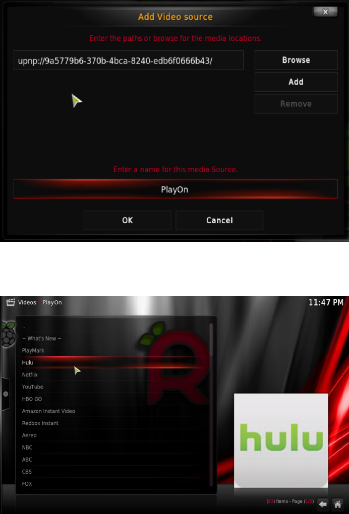
Figure 5-14.
PlayOn setup screen in XBMC
Figure 5-15.
PlayOn channel list in XBMC
276 RASPBERRY PI HACKS

Enjoy all of your favorite shows… right after you finish reading this book.
HACK 55 Watch Movies in the Backseat of Your
Car
If you’re a parent, you know that long trips in a car with children can be…
trying. Why not build a relatively inexpensive, in-car media player?
The idea of a TV screen in the car is not at all new. In fact, you can right now drop a
few thousand dollars and have one installed that plays DVDs from your dashboard.
Or, you can spend significantly less and build something yourself that plays practically
anything you can think of.
Our good friend, the Raspberry Pi, is small, efficient, and it plays movies very, very
well, thanks to its dedicated hardware support for video codecs. Here’s what you need
to hack it together for those long car trips that need a little entertainment.
Your Reliant (in Terms of Power) Automobile
Really, any make or model of car should work for this, with one caveat: power. A bit of
a history lesson is probably appropriate here.
Once upon a time, it was cool to smoke cigarettes, and car manufacturers felt like they
were doing their customers a major service by providing an on-demand heat source
that they could use to light their smokes. This device works by connecting a thin coil
of nichrome wire to a high current from the car’s electrical system. You’d push the
handle in, the current would heat up the coil, and in a few seconds, the lighter would
heat up (it would actually glow orange/red hot) and then the handle would pop out.
You could then press the tip to your cigarette and enjoy the act of giving yourself lung
cancer on the go.
Today, most people choose not to use those cancer sticks, but these “cigarette lighter”
receptacles remain. Why? Because these ports provide 12 volts of electricity, and we
have a lot of power-hungry gadgets that need juice. While some new vehicles provide
dedicated USB (or even pronged power outlets), most of them still provide these
standard, 12 V “cigarette lighter” plugs. In fact, a lot of cars that have them available
intend for them to power only compatible accessories and don’t actually include the
actual lighter (many even include an explicit message that states “this is not a ciga-
rette lighter”).
These 12 V receptacles will power the parts for this hack. You’ll need three of them to
do it the way described here. You might be able to get away with using only two, but
you’d have to power your Raspberry Pi from a powered USB hub that also powers
devices connected to the same Raspberry Pi, and that isn’t usually very reliable.
277
CHAPTER 5: MULTIMEDIA HACKS

If you need more receptacles than your car has available, there are a few ways to hack
around that. You can get a socket splitter, which will expand a single socket out to two.
Some socket splitters even add a USB port in addition to the two sockets. With that
setup, you could run everything that this hack needs off one 12 V receptacle. Other
ways to get the power to your devices involve more complicated hardware setups or
custom electrical wiring, so we’re not going to cover them here.
Your Car Is a Special Snowflake
Keep in mind that some cars might have these receptacles wired up differently. For
example, on the Dodge Caravan, some of the 12 V ports are wired to the ignition
and provide power only when the car is turned on. Other ports provide power di-
rectly from the battery and will have juice even when the engine isn’t running. Every
make, model, year, and variant of vehicle will have its own eccentricities in this
regard, so you should consult your owner’s manual to understand the ground rules.
Assuming you don’t have a USB power port available (either via a splitter or included
in your car), you’ll need to get a 12 V-to-USB converter. These are a lot more commonly
available (and a lot less expensive) than they used to be, but the fact is that you get
what you pay for with these converters. A good rule of thumb is that if they’re free,
they’re junk.
Let us elaborate on that a little bit before you go off to rage-trash your free converters
that you picked up as swag at your last tech conference. Most of these converters
assume that you are plugging in a phone or a tablet into them. In fact, they even as-
sume you’re plugging in an Apple phone or tablet. Apple devices charge over USB at
1 amp of current, so these cheap/free converters often don’t offer up more than 1 amp
of current, nor do they try very hard to make that current very clean or regular.
This results in a slow charge for most other devices. Although other devices (such as
your Android phone or tablet) will take 1 amp, they generally prefer 2.1 amps of current
or even more, depending on the device, and as a result, can charge faster. These cheap
converters also have a nasty tendency to be assembled poorly, resulting in a quick
converter death if it overheats (or just has pieces fall off).
As a result, we recommend that you connect your Raspberry Pi to a high-quality con-
verter that provides 2.1 amps of current. We’ve seen good results from the Media-
bridge High Output Dual USB Car Charger on the 2.1AMP port, but anything with a
dedicated 2.1AMP port (and a total rating of at least 3.1 amps) should do the trick.
We do not recommend that you use a 12 V converter cable designed for charging a
phone (especially not a third-party provided cable), because they often have the same
problems as the cheap converters do. Acceptably poor for a phone, but no good for
an “always-on” Raspberry Pi. As always, your mileage may vary (YMMV), so don’t rush
278 RASPBERRY PI HACKS
to post an angry but it works for me rebuttal online. Things that shouldn’t work some-
times do.
The touchscreen used in this hack (more about that in “Touchscreen” on page 280)
comes with a power cable to connect directly to a 12 V receptacle, so you won’t need
to worry about it. However, because you need a powered USB hub to prevent the
Raspberry Pi from using too much power (and simply turning off or behaving errati-
cally), you will need to get an inverter.
In this context, an inverter is a device that takes the 12 V DC power coming from the
“cigarette lighter” and changes it to an AC power outlet (the amount of wattage pro-
vided varies by the unit). These inverters vary in quality (and functionality), but be-
cause you need to plug only one thing into it, 200 watts should be enough.
We have successfully used a number of 300-watt inverters on the market. If you want
to spend the money, you can get a pure sine-wave inverter that provides an exact
replica of AC household power with two ground fault protected outlets and will likely
work for years reliably and silently. This comes with a cost, though, as they run about
$175.
Instead, you can get a modified sine-wave inverter for $20–30. These do not work as
reliably, but they should work to power a USB hub. They’re also a lot louder and hotter,
usually with fans running all the time.
Storage for Your Movies
The next thing you’re going to need is a place to put your digital video files. While you
could put a few of these onto the SD card running the Raspberry Pi, that space will fill
up quickly (and these files are usually quite large).
You’ll also need to factor in the fact that you’re installing this in a moving car. That
rules out a traditional portable hard drive, because it has moving parts and is not
usually very tolerant of a lot of bumps.
Instead, you’re going to use a solid state drive (SSD). The technologies behind SSDs
have been around since the 1950s, but since then, they’ve gotten much bigger (in
capacity), much smaller (in size), and much cheaper (in cost). SSDs are basically big
blocks of memory without any mechanical moving parts. This makes them very fast,
but more importantly for this hack, they work perfectly through every bump and
bounce of your car.
You can connect an SSD to the Raspberry Pi over USB. Purchase a drive that is de-
signed to be external, or buy an internal SSD and put it in an external USB chassis. At
this point, the majority of these USB chassis units are USB 3.0, due to the high speed
(up to 5 Gbit/s at half duplex, twice that at full duplex). This is fine, but the Raspberry
Pi can only communicate across its USB bus at USB 2.0 speeds (up to 480 Mbit/s),
279
CHAPTER 5: MULTIMEDIA HACKS

and USB 2.0 is limited to half-duplex rates. Because USB 3.0 is backward-compatible
to USB 2.0, this is not a problem, but you won’t get USB 3.0 speeds out of the drive.
Whether you buy a premade external drive or use a separate chassis, you want to
make sure it draws its power from the USB port, not from an external adapter. If it did
that, you’d have something else you needed to plug into the inverter, and that really
isn’t necessary.
You should also remember that you cannot boot your Raspberry Pi from this SSD.
You’ll just be mounting it as a storage partition where you will put your movies.
Touchscreen
You could use a TV or a monitor that connects to the Pi’s video outputs (either HDMI
or composite), but then you’d have to interface with the Raspberry Pi through a key-
board or a mouse, and that’s not ideal in a moving car (definitely not if you want your
kids to use this setup from the backseat).
Instead, this hack uses a touchscreen. If you’ve been looking through this book, you
may have noticed we have a separate hack (Hack #50) that covers how to add a
touchscreen to a Raspberry Pi, but that particular type of touchscreen is not a good
choice here. It is a DisplayLink device, which means it doesn’t use the HDMI or com-
posite outputs on the Raspberry Pi. Since the Raspberry Pi can decode hardware
video using only those output devices, you’ll need a touchscreen that is connected to
them (instead of just over USB).
The part we found for this came from a company called Chinavasion, with the highly
descriptive name of 7 Inch HD Touchscreen Car Monitor. This nifty little unit supports
HDMI input at 1720x1440 (not quite 1080p, but still, not shabby), but it also has an
integrated touchscreen with Linux support. It is not super cheap (about $150 at the
time of this writing), but it is designed for use in a car, so it comes with a native 12 V
power cable.
Powered USB Hub
You’ll need a powered USB hub. Hypothetically, you could try to get away with just
plugging your touchscreen and SSD into the Raspberry Pi directly, but practically,
we’re telling you not to try that. Your Pi is far more likely to simply turn off when you
try that, and you won’t be able to attach any other components, like a keyboard or
mouse (for debugging the setup) or a wireless network controller (for downloading
files or connecting to the Internet from a coffee shop on the road).
The brand or model doesn’t matter so much here. The most important detail is this:
it needs to be externally powered. You need to be able to plug it into the wall, or in this
case, into the inverter plugged into the 12 V receptacle. Many inexpensive USB hubs
280 RASPBERRY PI HACKS

are not externally powered and draw their power from the USB cable that it uses to
connect to your computer (in this case, the Raspberry Pi). Since you’re trying to work
around the power limitations of the Raspberry Pi, this really will not work. If you want
more of the gory details about why, see Hack #08.
You will be connecting two devices to the USB hub: your touchscreen and your
portable SSD, so make sure your hub has enough juice coming from its power adapter
to provide .5 A to two ports.
Software
Technically, you could use almost any Linux distribution here, but we strongly recom-
mend using RaspBMC for this purpose. This customized version of Debian with XBMC
preinstalled is ideal for the needs of this hack. XBMC is a robust and featureful suite
of software that provides a GUI interface for a media center. RaspBMC has been cus-
tomized specifically to support the hardware decoding and output features of the
Raspberry Pi.
Connect your Raspberry Pi to your touchscreen (video to the HDMI port) and your
external USB hub. Plug the touchscreen’s USB cable into the USB hub, along with a
normal keyboard and mouse. You’ll need these input devices at first, because the
touchscreen won’t work yet. Then insert a new SD card into your Linux laptop and
install RaspBMC onto it. We have a whole hack on how to install RaspBMC to the Pi,
so flip over to Hack #54 and follow those instructions. Come back when you’re done;
we’ll wait.
What About OpenELEC?
If you want to use something other than RaspBMC, OpenELEC will probably work,
but you’ll need to build a custom kernel for it that has support for touchscreens. If
you follow the instructions in Hack #22, it should work.
Welcome back! You should now have a shiny (and Raspberry-tinted) RaspBMC ses-
sion displaying on your touchscreen.
Enabling Touchscreen Support
If you touch the touchscreen now, you will probably notice that it does respond, but
not properly. The mouse cursor will jump around, seemingly at random. It isn’t really
random, though; it just isn’t properly calibrated yet. The good news is that it is already
detected, and the proper Linux kernel drivers are loaded (RaspBMC is very clever).
To calibrate the touchscreen, you will need to SSH into the RaspBMC session to enable
the touchscreen. To determine the IP address of your Raspberry Pi, navigate (with the
281
CHAPTER 5: MULTIMEDIA HACKS
mouse) over to to the System menu (it is the farthest item to the right), then to the
System info tab. It will print out a page of system information details, including a field
labeled “IP address.”
From your Linux laptop, SSH into that IP address as the pi user. We’ll assume the IP
address is 192.168.5.128 in these examples, but you should of course replace it with
your actual IP address:
$ ssh pi@192.168.5.128
The default password is raspberry. Once you successfully SSH in, RaspBMC will
prompt you to set your locale and keyboard settings. For Americans, it’s en_US.UTF-8
UTF-8. If you don’t know your locale setting, you can enable “All locales” at the top, but
it will eat up space on the SD card.
After this finishes, you can set the timezone, and finally, it will drop you to a shell
prompt, where you can get down to the business of calibrating the touchscreen. First,
go ahead and stop XBMC:
$ sudo stop xbmc
Download and install the touchscreen library and calibration script:
$ wget --no-check -O tslib_1-1_armhf.deb "https://docs.google.com/uc?
export=download&id=0B4lrG9aRe-8MUlRaRW5LcXNDaDA"
$ sudo dpkg -i tslib_1-1_armhf.deb
$ wget --no-check -O ts_calib.sh "https://docs.google.com/uc?
export=download&id=0B4lrG9aRe-8MOV94Nl90SExsVE0"
$ chmod +x ts_calib.sh
You’ll need to configure the ts_calib.sh calibration script before it will work properly.
Specifically, you need to know the device name for the touchscreen’s event device.
The easiest way to determine this is to run ls -l /dev/input/by-id:
$ ls -l /dev/input/by-id
total 0
lrwxrwxrwx 1 root root 9 Sep 12 21:19 usb-Logitech_USB_Keyboard-event-if01 -
> ../event3
lrwxrwxrwx 1 root root 9 Sep 12 21:19 usb-Logitech_USB_Keyboard-event-kbd -
> ../event2
lrwxrwxrwx 1 root root 9 Sep 12 22:23 usb-Logitech_USB_Optical_Mouse-event-
mouse -> ../event4
lrwxrwxrwx 1 root root 9 Sep 12 22:23 usb-Logitech_USB_Optical_Mouse-mouse -
> ../mouse2
lrwxrwxrwx 1 root root 9 Sep 12 21:19 usb-eGalax_Inc._Touch-event-mouse -
> ../event1
lrwxrwxrwx 1 root root 6 Sep 12 21:19 usb-eGalax_Inc._Touch-mouse -> ../js0
282 RASPBERRY PI HACKS
The touchscreen in this example is an “eGalax Inc.” touchscreen, so the event device
is event1. Edit ts_calib.sh with your favorite text editor, and change the TSLIB_TSDE
VICE line to reflect the proper event device. For the setup in this example, it should look
like this:
export TSLIB_TSDEVICE=/dev/input/event1
Save it to disk, and then run it (as root):
$ sudo sh ./ts_calib.sh
xres = 1280, yres = 720
The touchscreen display should flash, then display a calibration screen with a cross-
hair. Carefully tap the crosshair with the included stylus (or, if you’ve already lost the
stylus, the tip of a click pen with the ink tip not pushed out). It will move around the
screen to all four corners, then to the center. When you finish, it will print the calibration
values out to the terminal, and the calibration is done.
Now you need to use uinput-mapper to map the touchscreen input to an input device
that xbmc finds friendlier. To be specific, it lets you map specific touch behaviors to
various mouse click types. Download the software and the configuration, and install
it into the /scripts directory:
$ wget --no-check -O uimapper.tar.gz "https://docs.google.com/uc?
export=download&id=0B4lrG9aRe-8Malg2VkM0YW1CT28"
$ wget --no-check -O uimapper.conf "https://docs.google.com/uc?
export=download&id=0B4lrG9aRe-8MM2RIWFh1WjJWUW8"
$ sudo mkdir -p /scripts
$ sudo tar -xf uimapper.tar.gz -C /scripts
Edit uimapper.conf with your favorite text editor, and correct the UIMAPPER_DEV line to
reflect the event device you found earlier:
env UIMAPPER_DEV="/dev/input/event1"
Save out the file, and move it (as root) into position inside /etc/init. This will allow
uinput-mapper to start when the RaspBMC instance boots:
$ sudo mv uimapper.conf /etc/init
You need to tweak the internal uinput_mapper configuration a bit before it will work
properly. Open /scripts/uinput_mapper/configs/touchscreen.py in a text editor (as
root) and change this line:
sres = subprocess.check_output("tvservice -s", shell=True)
to look like this:
sres = subprocess.check_output("/opt/vc/bin/tvservice -s", shell=True)
283
CHAPTER 5: MULTIMEDIA HACKS
Without that change, the uinput_mapper upstart service will fail to find the tvservice
binary and silently fail.
Your touchscreen should be ready. Reboot your Raspberry Pi to test it:
$ sudo shutdown -r now
When it comes back up, try touching the screen. The cursor should move to where
you touched. If you want to “touch” a click, touch and hold for a half-second and then
release. It will take some getting used to. This setup should work simultaneously with
any other attached input devices (such as a keyboard and mouse), so if you want to
have an “override” console, you can add that easily.
If you need to debug the uinput_mapper service, first stop the xbmc service:
$ sudo stop xbmc
If you do not do this, XBMC will hold the uinput_mapper device, and you won’t be able
to access it with anything else for debugging. You can install the evtest utility from the
Raspbian repository and use it to debug the events that the touchscreen is registering:
$ sudo apt-get install evtest
$ evtest
No device specified, trying to scan all of /dev/input/event*
Not running as root, no devices may be available.
Available devices:
/dev/input/event0: eGalax Inc. Touch
/dev/input/event1: eGalax Inc. Touch
/dev/input/event2: Logitech USB Keyboard
/dev/input/event3: Logitech USB Keyboard
/dev/input/event4: Logitech USB Optical Mouse
/dev/input/event5: uimapper - touchscreen
Select the device event number [0-5]: 5
Input driver version is 1.0.1
Input device ID: bus 0x3 vendor 0x42 product 0xbebe version 0x1
Input device name: "uimapper - touchscreen"
Supported events:
Event type 0 (EV_SYN)
Event type 1 (EV_KEY)
Event code 106 (KEY_RIGHT)
Event code 273 (BTN_RIGHT)
Event code 320 (BTN_TOOL_PEN)
Event code 330 (BTN_TOUCH)
Event type 3 (EV_ABS)
Event code 0 (ABS_X)
Value 0
Min 0
284 RASPBERRY PI HACKS

Max 2047
Event code 1 (ABS_Y)
Value 0
Min 0
Max 2047
Event type 4 (EV_MSC)
Event code 4 (MSC_SCAN)
Properties:
Testing ... (interrupt to exit)
When evtest prompts you to select the device, choose the uimapper device and then
touch away (and hold touch and double-touch). You will see the different signals that
uinput_mapper is generating as a result of your touches. If you do not see a uimapper
device at this screen, it means that the uinput_mapper service is either stopped or not
running properly.
Adding Videos
If you have not already done so, put your videos on your SSD. The SSD can be for-
matted for any filesystem that RaspBMC understands (NTFS, FAT, ext2/3/4, etc.),
and your video files can be in any directory or folder hierarchy that you want. Just be
aware that XBMC will force you to navigate through those folders to play your videos,
so we recommend keeping it as shallow as possible. You can also add music or pictures
in this same way.
Supported Encodings
By default, the Raspberry Pi hardware supports hardware decoding of only H264/
MPEG-4 video encoding. RaspBMC will try to play files that are encoded with other
video codecs, but it might have to fall back to software decoding to do so, and the
performance of that will be poor. For more details on how to add additional hard-
ware video codecs, see Hack #47.
When you plug the SSD into the USB hub, if RaspBMC is running, it will automatically
detect the additional drive, and you will be able to select that source for your videos
(or music/pictures). You should test it out now to make sure you can successfully
playback videos. The touchscreen has small speakers that will play the HDMI audio
being output by the Raspberry Pi.
Putting It All Together
Now that everything works properly, you just need to put it in your car. Plugging in the
power should be straightforward: you plug the touchscreen into one 12 V receptacle,
your power inverter (to household AC power plug) into another, and then plug the
285
CHAPTER 5: MULTIMEDIA HACKS
Raspberry Pi into a third one (or a USB port if it is available). The SSD and the
touchscreen USB connectors should be plugged into the USB hub, and the USB hub
should have its interconnect hooked to the Raspberry Pi. The touchscreen HDMI con-
nector should be connected directly to the Raspberry Pi.
The touchscreen includes mounting plates, so you can mount it directly to the car
seat, but if you are crafty, you can make a container that will hang over the back of the
headrest of a front seat that encapsulates all of this loose hardware.
It is also possible for you to hide it all away in your car by hacking it into the empty
spaces (or carving out empty spaces). There is no one right way to do this, and it’s
dependent on your vehicle’s design, so we leave it up to you to figure out what works
best for your car.
286 RASPBERRY PI HACKS

6
Extend Your Pi
The real magic of the Raspberry Pi happens when you make it a part of something
else. Use the GPIO to connect it to new devices (Hack #56). Connect Arduino shields
(Hack #58). Add a tiny screen (Hack #57), numeric keypad (Hack #60 ), or heat sink (Hack
#61). Do all of them, and make something amazing. This chapter is to help get you
started taking the Pi beyond mere Linux computer into something more.
HACK 56 Control GPIO from a Web Browser
Your Raspberry Pi GPIO interface is a gateway to an entire Internet of
Things. Here is a simple way to access it from a web browser.
Every day, more and more devices become network-aware, either intentionally or as
a result of clever hacks. This phenomenon has many names, but the most common
seems to be “Internet of Things.” You can use your Raspberry Pi to help your dumb
devices get smart and join the Internet of Things.
The best way to connect your Pi to other devices is via the GPIO expansion ports. If
you’re not sure what that means, go take a quick read through Hack #14. These digital
pins will let you wire almost anything into your Raspberry Pi, but once the physical
connection is made, you’ll want a framework in place to actually do something.
Eric PTAK created a REST framework and web app to control the Raspberry Pi and its
GPIO through the Web. Called WebIOPi, this framework allows you to use and control
your Pi’s GPIO over the Internet (or through a number of language bindings and APIs).
287
To install it, start with a current image of Raspbian. Then, from the running instance
of Raspbian, download and install the WebIOPi code:
$ wget http://webiopi.googlecode.com/files/WebIOPi-0.6.0.tar.gz
$ tar xvzf WebIOPi-0.6.0.tar.gz
$ cd WebIOPi-0.6.0
$ sudo ./setup.sh
You might want to check the WebIOPi website to make sure that 0.6.0 is still the latest
version before proceeding. If it has been updated, adjust appropriately.
The setup script (setup.sh) will download and install the necessary WebIOPi depen-
dencies from the apt-get repositories in Raspbian, then build the code and install it
into the proper locations.
When this finishes, you’ll have a WebIOPi service that you can run and access via a
web browser. To turn it on, run:
$ sudo /etc/init.d/webiopi start
You can then connect to it from within the Raspbian session by opening a web browser
and navigating to http://localhost:8000/. If you want to connect to it from a remote
system, you can replace localhost with either the IP address or fully qualified host-
name of the Raspberry Pi. For login credentials, the user is webiopi and the password
is raspberry.
Once connected, you will be able to view a graphical representation of the Raspberry
Pi GPIO header (click on the “GPIO header” link), as shown in Figure 6-1. From this
page, you can swap the direction on the Input/Output pins (not on the power or
Ground pins, for what are hopefully obvious reasons).
288 RASPBERRY PI HACKS

Figure 6-1.
WebIOPi browser showing GPIO view
WebIOPi is capable of doing a lot more than this though. It provides a Python library
that contains support for all kinds of GPIO interactions, including explicit support for
digital-to-analog converters (DAC), analog-to-digital converters (ADC), common sen-
sors, I2C, serial, and SPI devices.
Additionally, the web application itself allows you to monitor and debug these same
devices and connections. It also includes Java and Javascript libraries that will enable
you to make custom web (and Android) clients to interface with and remotely control
devices that are connected through the Raspberry Pi GPIO.
Finally, because WebIOPi talks REST, you can interface to it through any other lan-
guage that you choose, but the native libraries are a bit more friendly.
289
CHAPTER 6: EXTEND YOUR PI

HACK 57 Add a Tiny Screen
Sometimes it’s just not convenient to carry around a full-sized monitor.
Maybe you want to build a tiny, portable computer. There are screens for
you!
When we decided to start working on portable Raspberry Pi projects, we chose Ada-
fruit’s 2.5” NTSC/PAL display, partly for the quality and partly because it was one of
the few options at the time. It has RCA connections, 32 levels of backlight brightness
you can adjust with buttons, and a switch that changes it from portrait to landscape
display.
The one downside for connecting this piece to your Raspberry Pi is that it has a female
RCA jack, just like your Pi. There are male-male RCA connector pieces, which is what
we’ve used here to connect them, but that adds about an inch and a half of inflexible
metal bulk to your project.
OK, we lied. There’s a second downside. The ribbon that connects the display to
the board in this little TFT setup is pretty fragile. Be extremely careful with it when
you’re getting your project together, and take this into account when you decide
how to build it a housing, especially if it’s a portable project.
Perhaps you’ve noticed that we like to tell you to do things that are generally consid-
ered a bad idea. (To some degree, that’s the nature of a hack, isn’t it?) Here’s another
one. Officially, you can’t power this TFT through the GPIO. It doesn’t even make a lot
of sense to try if you read the description for the board, which states:
• Power with 6-15VDC only into onboard buck converter
• 80 mA power draw at 12 V, 150 mA at 6 V
Conveniently, we’re not the kind of people who read instructions (or requirements, or
even good advice sometimes). And thus we didn’t notice that at all before connecting
it to the GPIO in a prototype miniature game center. (If you’d like to do so, combine
this hack with Hack #51.)
And it worked. We wired the red to pin 2 (5 v) and the black one to pin 4 (ground), as
shown in Figure 6-2.
290 RASPBERRY PI HACKS
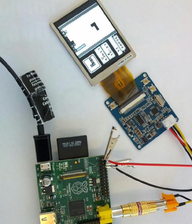
Figure 6-2.
Prototype handheld gaming system
The correct thing to tell you is that it’s probably not very stable or a good way to run
long-term. The truth is that we played Tetris this way for longer than we’d like to admit,
given the number of full-sized modern gaming devices at our disposal. If you don’t
want to build in a second power supply, this appears to work out just fine, at least for
an afternoon of Tetris.
A better way, however, is to purchase a female DC power adapter. Unscrew the side
marked +, insert the red wire, and screw it back down. Insert the black wire on the
other side, and you’re set to connect the screen to any power supply with a 2.1 mm
DC connection.
291
CHAPTER 6: EXTEND YOUR PI

HACK 58 Connect Arduino Shields to Your
Raspberry Pi
Because there are already many available shields for extending the func-
tionality of an Arduino, Raspberry Pi hackers have found ways to bring
those parts to Raspberry Pi.
The idea behind the Raspberry Pi to Arduino shields connection bridge is to allow the
Raspberry Pi to make use of any of the shields, boards, and modules designed for
Arduino. It also includes the possibility of connecting digital and analog sensors, using
the same pinout of Arduino but with the power and capabilities of the Raspberry Pi.
In order to make the compatibility complete, Cooking Hacks created the arduPi library,
which allows you to use the Raspberry Pi with the same code used with an Arduino.
To do so, they implemented conversion functions so that you can control all the I/O
interfaces (I2C, SPI, UART, analog, and digital) in the same way you would control
them with the Arduino. Options with this shield and the arduPi library include con-
necting:
•Any Arduino wireless module to the Raspberry Pi, such as the XBee 802.15.4/
XBee ZigBee, RFID, NFC, Bluetooth, Bluetooth Pro, WiFi, GPRS, or 3G
•Any sensor (analog 0-5 V, digital) to the Raspberry Pi with a precession of 16b
using the integrated ADC.
•Complex sensors through I2C and UART buses
•Arduino-specific shields, like the radiation sensor shield, CanBus, and relay shield
•Any electronic module or actuator that works over I2C, SPI, UART
The bridge board connects to the Raspberry Pi’s GPIO pins from below. As shown in
Figure 6-3, the top includes the following items:
•8 digital pins
•Socket for wireless modules
•RX/TX pins
•I2C pins (SDA, SCL)
•SPI pins (SCK, MISO, MOSI, CS), which can be used also as GPIO
•8-channel analog-to-digital converter
•Switch to enable external power supply
292 RASPBERRY PI HACKS
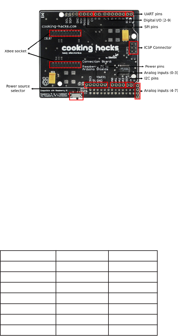
Figure 6-3.
Cooking Hacks’ Raspberry Pi to Arduino shields connection bridge
Cooking Hacks includes the schematic as a PDF download on its website.
Using the arduPi Library
arduPi is a C++ library that lets you write programs for Raspberry Pi as if you were
writing an Arduino program. All the functions that control serial port communications,
I2C, SPI, and GPIO pins are available using the Arduino syntax. The available library
functions are listed in Table 6-1.
To get started, first download the arduPi library. In the library folder you will find three
files: arduPi.cpp, arduPi.h, and arduPi_template.cpp. The arduPi_template.cpp file is
meant to be used as a starting point to create programs with the same behavior as
an Arduino program.
Table 6-1. ArduiPi library functions
SERIAL LIBRARY FUNCTIONS WIRE LIBRARY FUNCTIONS SPI LIBRARY FUNCTIONS
available() begin() begin()
begin() requestFrom() end()
end() beginTransmission() setBitOrder()
flush() endTransmission() setClockDivider()
peek() write() setDataMode()
print() read() transfer()
println()
293
CHAPTER 6: EXTEND YOUR PI

SERIAL LIBRARY FUNCTIONS WIRE LIBRARY FUNCTIONS SPI LIBRARY FUNCTIONS
read()
readBytes()
readBytesUntil()
find()
findUntil()
parseInt()
parseFloat()
setTimeout()
write()
The arduPi template looks like this:
//Include arduPi library
#include "arduPi.h"
/*********************************************************
* IF YOUR ARDUINO CODE HAS OTHER FUNCTIONS APART FROM *
* setup() AND loop() YOU MUST DECLARE THEM HERE *
* *******************************************************/
/**************************
* YOUR ARDUINO CODE HERE *
* ************************/
int main (){
setup();
while(1){
loop();
}
return (0);
}
As you can see in the main() function, the setup() function is called once, and then the
loop() function is called continuously until the program is forced to finish.
Whether you’re writing a new program or already have an Arduino program written
that uses the ported functions, you can use the template (ardupi_template.cpp) and
put your Arduino code where it says YOUR ARDUINO CODE HERE. Remember that the
program you are writing is a C++ program, so you can use all the C++ libraries. Here
are the available Arduino functions:
294 RASPBERRY PI HACKS
•delay()
•delayMicroseconds()
•millis()
•pinMode()
•digitalWrite()
•digitalRead()
•analogRead() (on pins from A0 to A7—for example, analogRead(5) will read from
A5)
•shiftIn()
•shiftOut()
•attachInterrupt()
•detachInterrupt()
You can detect RISING and FALLING interrupts. Any digital pin (from 2 to 13) can be used
in attachInterrupt(). For example, if you want to be aware of RISING events on pin 6,
you can use attachInterrupt(6,function_to_call,RISING).
Enable the UART port
On the Raspberry Pi, make a backup of /boot/cmdline.txt and open it for editing:
$ sudo cp /boot/cmdline.txt /boot/cmdline_backup.txt
$ sudo vi /boot/cmdline.txt
Here’s what this file contains:
dwc_otg.lpm_enable=0 console=ttyAMA0,115200 kgdboc=ttyAMA0,115200 con
sole=tty1 $
Remove the parameters that reference the UART serial port (ttyAMA0) so that it says
only this:
dwc_otg.lpm_enable=0 console=tty1 $
Open /etc/inittab and comment out the following line:
T0:23:respawn:/sbin/getty -L ttyAMA0 115200 vt100
Then reboot the Raspberry Pi.
295
CHAPTER 6: EXTEND YOUR PI

Compile the arduPi library and a program using it
As arduPi is a C++ library, we will use g++ to compile it. You can compile the arduPi
library to obtain an object file (.o) and use this file to link your program: g++ -c ardu
Pi.cpp -o arduPi.o.
Once you have already compiled the arduPi library, you can run:
$ g++ -lrt -lpthread my_program.cpp arduPi.o -o my_program
If the arduPi library is not yet compiled, you can compile both it and your program and
link them in a single step:
$ g++ -lrt -lpthread my_program.cpp arduPi.cpp -o my_program
The -lrt flag is necesary because the library uses the function clock_gettime
(time.h). The -lpthread option is needed because attachInterrupt() and detachIn
terrupt() functions use threads.
Run your program
Now, to run your program, you must have the right permissions in order to use GPIO
so that /dev/mem can be accessed on the Raspberry Pi. Then you simply run the fol-
lowing command:
sudo ./my_program
GPIO input
GPIO peripherals vary quite widely. In some cases, they are simple: a group of pins
that can be switched as a group to either input or output. The input and output voltages
are typically, though not universally, limited to the supply voltage of the device with
the GPIOs on and may be damaged by greater voltages.
Some GPIOs have 5 V tolerant inputs, and even on low-supply voltages the device can
accept 5 V without damage. For the Raspberry Pi, you must adapt the voltage level of
a 5 V sensor to prevent possible damage. If you don’t have an assortment of parts
readily available, you can reproduce these instructions with the contents of Cooking
Hacks’ Starter Kit for Raspberry Pi, A/V Edition.
GPIO voltage levels are 3.3 V and are not 5 V tolerant. There is no over-voltage
protection on the board. Digital inputs use a 3.3 V logic level and are not tolerant
of 5 V levels, such as you might find on a 5 V powered Arduino. Use extreme caution
when working with GPIO. You might damage your Raspberry Pi or your other
equipment and potentially shock yourself.
296 RASPBERRY PI HACKS
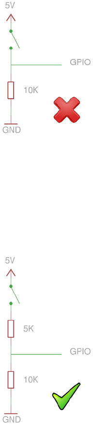
When a GPIO pin is set as an input, such as with a basic push-button example, you
can have these voltage incompatibility problems. The circuit in Figure 6-4 is wrong,
because when you press the button, the GPIO input is connected to 5 volts, which
might damage the device.
Figure 6-4.
Incorrect circuit
You can avoid damage by using a resistor in the push-button cable. The value of the
resistor is determined by the leakage current of the GPIO pin (the current used by the
circuit to read the pin) and the amount of voltage drop it creates as a result. With the
5K resistor, you obtain 3.3 V in the GPIO input because Vgpio = 5 V·(10K/(10K+5K))
= 3.3 V. Figure 6-5 shows a correct circuit.
Figure 6-5.
Correct circuit
297
CHAPTER 6: EXTEND YOUR PI
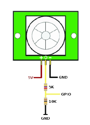
You will have the same problem if you use a sensor operating at 5 volts. Figure 6-6
shows an example using a PIR sensor, using the same resistive divider that we used
to adapt voltage level.
Figure 6-6.
Adapting voltage with resistors
Analog-to-Digital Conversion
The shield includes an Analog-to-Digital Converter (ADC) of 12 bits of resolution,
which allows you to connect any sensor to the Raspberry Pi with higher precision than
an Arduino does. The communication between the Raspberry Pi and the ADC of the
shield is made via I2C.
The information of each channel can be obtained reading two bytes from I2C, but first,
one byte (corresponding to the channel address) should be sent through I2C, de-
pending on the channel you want to select. Table 6-2 shows a list of the channel ad-
dresss.
298 RASPBERRY PI HACKS

Table 6-2. Channel addresses
CHANNEL ADDRESS
0 0xDC
1 0x9C
2 0xCC
3 0x8C
4 0xAC
5 0xEC
6 0xBC
7 0xFC
The following example program reads every channel continuously, waiting five sec-
onds between iterations. With a wire connecting the 5 V pin with some of the pins of
the ADC, it should read a value close to 5.000000:
//Include arduPi library
#include "arduPi.h"
unsigned char val_0 = 0;
unsigned char val_1 = 0;
byte address = 0x08;
int channel_0 = 0;
int channel_1 = 0;
int channel_2 = 0;
int channel_3 = 0;
int channel_4 = 0;
int channel_5 = 0;
int channel_6 = 0;
int channel_7 = 0;
float analog_0 = 0.0;
float analog_1 = 0.0;
float analog_2 = 0.0;
float analog_3 = 0.0;
float analog_4 = 0.0;
float analog_5 = 0.0;
float analog_6 = 0.0;
float analog_7 = 0.0;
void setup()
{
299
CHAPTER 6: EXTEND YOUR PI
Wire.begin(); // join I2C bus (address optional for master)
}
void loop()
{
// channel 0
Wire.beginTransmission(8);
Wire.write(byte(0xDC));
char val[2];
val_0 = Wire.read(); // receive high byte (overwrites previous reading)
val_1 = Wire.read();
channel_0 = int(val_0)*16 + int(val_1>>4);
analog_0 = channel_0 * 5.0 / 4095.0;
printf("Channel 0: digital value = %d", channel_0);
printf(" analog value = %f\n", analog_0);
// channel 1
Wire.beginTransmission(8);
Wire.write(byte(0x9C));
val_0 = Wire.read(); // receive high byte (overwrites previous reading)
val_1 = Wire.read();
channel_1 = int(val_0)*16 + int(val_1>>4);
analog_1 = channel_1 * 5.0 / 4095.0;
printf("Channel 1: digital value = %d", channel_1);
printf(" analog value = %f\n", analog_1);
// channel 2
Wire.beginTransmission(8);
Wire.write(byte(0xCC));
val_0 = Wire.read(); // receive high byte (overwrites previous reading)
val_1 = Wire.read();
channel_2 = int(val_0)*16 + int(val_1>>4);
analog_2 = channel_2 * 5.0 / 4095.0;
printf("Channel 2: digital value = %d", channel_2);
300 RASPBERRY PI HACKS
printf(" analog value = %f\n", analog_2);
// channel 3
Wire.beginTransmission(8);
Wire.write(byte(0x8C));
val_0 = Wire.read(); // receive high byte (overwrites previous reading)
val_1 = Wire.read();
channel_3 = int(val_0)*16 + int(val_1>>4);
analog_3 = channel_3 * 5.0 / 4095.0;
printf("Channel 3: digital value = %d", channel_3);
printf(" analog value = %f\n", analog_3);
// channel 4
Wire.beginTransmission(8);
Wire.write(byte(0xAC));
val_0 = Wire.read(); // receive high byte (overwrites previous reading)
val_1 = Wire.read();
channel_4 = int(val_0)*16 + int(val_1>>4);
analog_4 = channel_4 * 5.0 / 4095.0;
printf("Channel 4: digital value = %d", channel_4);
printf(" analog value = %f\n", analog_4);
// channel 5
Wire.beginTransmission(8);
Wire.write(byte(0xEC));
val_0 = Wire.read(); // receive high byte (overwrites previous reading)
val_1 = Wire.read();
channel_5 = int(val_0)*16 + int(val_1>>4);
analog_5 = channel_5 * 5.0 / 4095.0;
printf("Channel 5: digital value = %d", channel_5);
printf(" analog value = %f\n", analog_5);
// channel 6
Wire.beginTransmission(8);
Wire.write(byte(0xBC));
val_0 = Wire.read(); // receive high byte (overwrites previous reading)
val_1 = Wire.read();
301
CHAPTER 6: EXTEND YOUR PI
channel_6 = int(val_0)*16 + int(val_1>>4);
analog_6 = channel_6 * 5.0 / 4095.0;
printf("Channel 6: digital value = %d", channel_6);
printf(" analog value = %f\n", analog_6);
// channel 7
Wire.beginTransmission(8);
Wire.write(byte(0xFC));
val_0 = Wire.read(); // receive high byte (overwrites previous reading)
val_1 = Wire.read();
channel_7 = int(val_0)*16 + int(val_1>>4);
analog_7 = channel_7 * 5.0 / 4095.0;
printf("Channel 7: digital value = %d", channel_7);
printf(" analog value = %f\n", analog_7);
printf("\n");
delay(1000);
}
int main (){
setup();
while(1){
loop();
}
return (0);
}
Figure 6-7 shows the output of this program when connecting the 5 V pin of the Rasp-
berry Pi to the analog input 0.
302 RASPBERRY PI HACKS
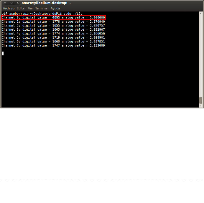
Figure 6-7.
Output of ADC program
UART
Accessing UART with the arduPi library is as simple as doing it with Arduino. You need
to include arduPi.h in your code and create an instance of the SerialPi class, naming
it Serial. Naming the instance as Serial allows you to use the Arduino syntax.
These steps are already done for you if you use the template to create your pro-
grams.
These are the available functions:
•Serial.available()
•Serial.begin()
•Serial.end()
•Serial.flush()
•Serial.peek()
•Serial.print()
•Serial.println()
•Serial.read()
•Serial.readBytes()
•Serial.readBytesUntil()
303
CHAPTER 6: EXTEND YOUR PI

•Serial.find()
•Serial.findUntil()
•Serial.parseInt()
•Serial.parseFloat()
•Serial.setTimeout()
•Serial.write()
All of these functions have the same functionality as their Arduino counterparts, which
you can read more about at http://arduino.cc/en/Reference/serial.
I2C
“Analog-to-Digital Conversion” on page 298 briefly discussed I2C. This example in this
section uses a BlinkM RGB I2C-controlled LED. BlinkM (Figure 6-8) has a high-quality,
high-power RGB LED and a small AVR microcontroller in one piece, allowing a user to
digitally control an RGB LED over a simple I2C interface. In this example, you’ll change
the LED color both directly and using fade transitions.
Figure 6-8.
blinkM module
More information about this part and the commands you can send to it can be
found in the BlinkM datasheet.
To set up Blink FM, make the following connections:
304 RASPBERRY PI HACKS
1. Connect the (-) pin of the LED with the GND pin of the shield.
2. Connect the (+) pin of the LED with the 5V pin of the shield.
3. Connect the d pin of the LED with the SDA pin of the shield.
4. Connect the c pin of the LED with the SCL pin of the shield.
Then create and execute a file with the following code, which will alternate the LED’s
color from red to blue five times and then make some smooth transitions resulting in
purples:
*
* Copyright (C) 2012 Libelium Comunicaciones Distribuidas S.L.
* http://www.libelium.com
*
* This program is free software: you can redistribute it and/or modify
* it under the terms of the GNU General Public License as published by
* the Free Software Foundation, either version 3 of the License, or
* (at your option) any later version.
*
* This program is distributed in the hope that it will be useful,
* but WITHOUT ANY WARRANTY; without even the implied warranty of
* MERCHANTABILITY or FITNESS FOR A PARTICULAR PURPOSE. See the
* GNU General Public License for more details.
*
* You should have received a copy of the GNU General Public License
* along with this program. If not, see .
*
* Version 0.1
* Author: Anartz Nuin Jiménez
*/
//Include arduPi library
#include "arduPi.h"
void setup(){
Wire.begin();
Wire.beginTransmission(9);
Wire.write('o'); //End the current Light script
Wire.endTransmission();
}
void loop(){
305
CHAPTER 6: EXTEND YOUR PI
for (int i=0;i < 5;i++){
Wire.beginTransmission(9);
Wire.write('n'); //Change to color
Wire.write(byte(0xff)); //Red component
Wire.write(byte(0x00)); //Green component
Wire.write(byte(0x00)); //Blue component
Wire.endTransmission();
delay(500);
Wire.beginTransmission(9);
Wire.write('n'); //Change to color
Wire.write(byte(0x00)); //Red component
Wire.write(byte(0x00)); //Green component
Wire.write(byte(0xff)); //Blue component
Wire.endTransmission();
delay(500);
}
for (int i=0;i < 10;i++){
Wire.beginTransmission(9);
Wire.write('c'); //Fade to color
Wire.write(byte(0xff)); //Red component
Wire.write(byte(0x00)); //Green component
Wire.write(byte(0x5a)); //Blue component
Wire.endTransmission();
delay(150);
Wire.beginTransmission(9);
Wire.write('c'); //Fade to color
Wire.write(byte(0x55)); //Red component
Wire.write(byte(0x20)); //Green component
Wire.write(byte(0x5a)); //Blue component
Wire.endTransmission();
delay(150);
}
}
int main (){
setup();
while(1){
306 RASPBERRY PI HACKS
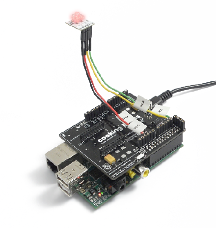
loop();
}
return (0);
}
SPI
It is possible to communicate with SPI devices using the functions provided by arduPi.
The following example uses the SPI functions to print messages on a ST7920
LCD12864 (SPI LCD).
First put the switch of the LCD in SPI mode. Then proceed with the connection be-
tween the LCD and the Raspberry Pi to Arduino shield. Use jumper wires to connect
the following, as shown in Figure 6-9:
• VCC of the LCD to 5 V of the shield
• GND of the LCD to GND of the shield
• SCK of the LCD to SCK of the shield
• SID of the LCD to MOSI of the shield
• CS of the LCD to 8 pin of the shield
Figure 6-9.
LCD shield
307
CHAPTER 6: EXTEND YOUR PI
For this project, we are using GPIO pin 8 on the Raspberry Pi shield as chip select. So,
when you need to select the LCD as the target device for the SPI communication, you
need to set pin 8 to HIGH.
Create and execute a file with the following code to show the messages “Cooking
Hacks” and “SPI LCD for Raspberry Pi” with a delay of two seconds in between:
/*
* Copyright (C) 2012 Libelium Comunicaciones Distribuidas S.L.
* http://www.libelium.com
*
* This program is free software: you can redistribute it and/or modify
* it under the terms of the GNU General Public License as published by
* the Free Software Foundation, either version 3 of the License, or
* (at your option) any later version.
*
* This program is distributed in the hope that it will be useful,
* but WITHOUT ANY WARRANTY; without even the implied warranty of
* MERCHANTABILITY or FITNESS FOR A PARTICULAR PURPOSE. See the
* GNU General Public License for more details.
*
* You should have received a copy of the GNU General Public License
* along with this program. If not, see .
*
* Version 0.1
* Author: Anartz Nuin Jiménez
*/
//Include arduPi library
#include "arduPi.h"
int latchPin = 8;
unsigned char char1[]=" Cooking Hacks ";
unsigned char char2[]=" SPI LCD for ";
unsigned char char3[]=" Raspberry Pi ";
void initialise();
void displayString(int X,int Y,unsigned char *ptr,int dat);
void writeCommand(int CMD);
void writeData(int CMD);
void writeByte(int dat);
void clear();
void setup(){
SPI.begin();
308 RASPBERRY PI HACKS
SPI.setBitOrder(MSBFIRST);
SPI.setDataMode(SPI_MODE0);
SPI.setClockDivider(SPI_CLOCK_DIV128);
initialise();
}
void loop(){
displayString(0,0,char1,16);
delay(2000);
clear();
displayString(1,0,char2,16);
displayString(2,0,char3,16);
delay(2000);
clear();
}
void initialise(){
pinMode(latchPin, OUTPUT);
digitalWrite(latchPin, LOW);
delayMicroseconds(80);
writeCommand(0x30);
writeCommand(0x0c);
writeCommand(0x01);
writeCommand(0x06);
}
void displayString(int X,int Y,unsigned char *ptr,int dat){
int i;
switch(X){
case 0: Y|=0x80;break;
case 1: Y|=0x90;break;
case 2: Y|=0x88;break;
case 3: Y|=0x98;break;
default: break;
}
309
CHAPTER 6: EXTEND YOUR PI
writeCommand(Y);
for(i=0;i < dat;i++){
writeData(ptr[i]);
}
}
void writeCommand(int CMD){
int H_data,L_data;
H_data = CMD;
H_data &= 0xf0;
L_data = CMD;
L_data &= 0x0f;
L_data <<= 4;
writeByte(0xf8);
writeByte(H_data);
writeByte(L_data);
}
void writeData(int CMD){
int H_data,L_data;
H_data = CMD;
H_data &= 0xf0;
L_data = CMD;
L_data &= 0x0f;
L_data <<= 4;
writeByte(0xfa);
writeByte(H_data);
writeByte(L_data);
}
void writeByte(int dat){
digitalWrite(latchPin, HIGH);
delayMicroseconds(80);
SPI.transfer(dat);
digitalWrite(latchPin, LOW);
}
void clear(){
writeCommand(0x30);
writeCommand(0x01);
}
310 RASPBERRY PI HACKS
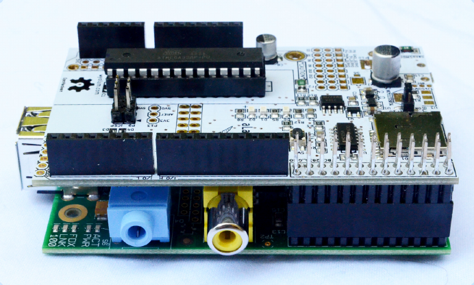
int main (){
setup();
while(1){
loop();
}
return (0);
}
You can find further support and forums and purchase shields and sensors that work
with these instructions.
If you’re interested in further pursuing Raspberry Pi projects that integrate Arduino
parts, you might also be interested in the Alamode (shown in Figure 6-10), a develop-
ment board that, like the Cooking Hacks board, makes your Raspberry Pi compatible
with Arduino shields. The Alamode is voltage-safe, it has a built-in, bi-directional
translator that makes the 3.3 V to 5 V conversion for you, and it also has a Micro-SD
slot for storage and an RTC chip.
Figure 6-10.
Alamode board sitting on Raspberry Pi, showing GPIO connection
Although the Cooking Hacks Raspberry Pi to Arduino board and the Alamode are not
identical, you might end up making a decision based partly on features and partly on
which you find easier and more convenient to obtain based on where in the world you
live. Cooking Hacks is based in Spain but has global distributors. In the United States,
311
CHAPTER 6: EXTEND YOUR PI

look to MicroController Pros for their products. You can buy the Alamode here, which
has an American warehouse and distributors around the world.
—David Bordonada
HACK 59 Control a 3D Printer
Home 3D printing is a relatively new possibility for most people, but as
prices for printers continue to drop, you might find yourself happily print-
ing plastic. Why not let your Raspberry Pi help?
A 3D printer is an amazing machine that lets you convert a 3D model that exists only
in bits and bytes into something tangible. Until recently, the cost for this hardware was
prohibitively high, both in price and space required to house it. In the last few years,
however, they’ve gone from tens (or hundreds) of thousands of dollars to as little as
a few hundred and from the size of a refrigerator to smaller than your toaster.
These increasingly common home 3D printers use an additive method, which means
plastic (or other malleable materials) are driven through a heated extruder. This ex-
truder is attached to a series of belts and motors, which allow it to move along the X,
Y, and Z axes. The plastic is then extruded in layers onto a plate of glass (which may
or may not be heated, depending on the plastic type in use), where it cools quickly.
The printer repeats this process, printing layer upon layer (upward) until the object is
completed.
There are many different types of these 3D printers, but the most common is known
as the RepRap family of printers. These printers feature open hardware and are rela-
tively easy to build from publicly available plans on the Internet, but they are also
available in prebuilt commercial offerings. One such vendor is Lulzbot, which produces
and sells high-quality (and high-resolution) RepRap style printers.
For the purposes of this hack, we’ll assume that you have a Lulzbot AO-101 (shown in
Figure 6-11), but these instructions apply generally to any printer in the RepRap family.
312 RASPBERRY PI HACKS
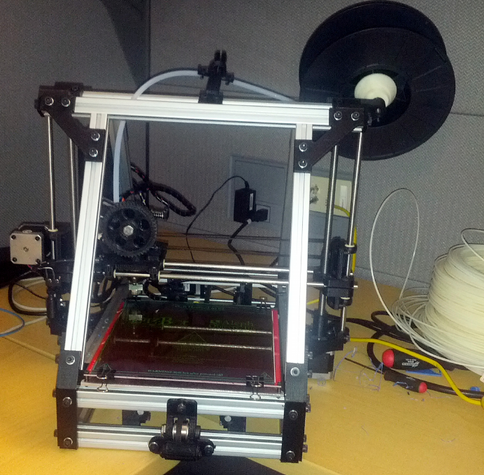
Figure 6-11.
Tom’s Lulzbot AO-101
The Lulzbot AO-101 is powered by a RAMBo electronics board (Figure 6-12), which
uses an Atmega processor, stepper motor drivers, and power management outputs
to control the movement and temperature of the extruder and the heated plate glass
bed. While this hardware does its job very well, it is not very smart. It knows only how
to process a series of instructions called G-code.
313
CHAPTER 6: EXTEND YOUR PI
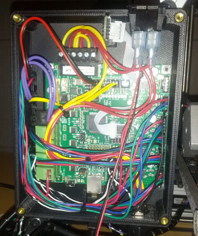
Figure 6-12.
RAMBo electronics in Lulzbot AO-101
G-code is a computer language that tells the 3D printer exactly what to do, through a
series of explicit instructions. It tells the printer where to move its extruder and bed,
at what speeds, and through what paths. It is roughly analogous to PostScript for
traditional 2D printers.
G-code has existed since the 1950s and is generally accepted as the standard lan-
guage for interfacing with computerized machine tools. However, because each 3D
314 RASPBERRY PI HACKS

printer is different, you cannot simply take a G-code file and send it to any printer. The
G-code has to be generated with the specifications of your printer taken into account.
Replace the RAMBo with a Raspberry Pi?
You might wonder why we don’t talk about replacing the RAMBo electronics with
the Raspberry Pi. While the Raspberry Pi is a lot smarter than the RAMBo board
and is capable of sending instructions to the 3D printer and manipulating and
“slicing” models into G-code, the RAMBo board is specialized for performing real-
time control of the stepper motors (and heating units) that make up the heart of
the 3D printer. The Raspberry Pi would be a poor substitute for this without ex-
tensive (and complicated) modifications. Even when hacking, we prefer to let the
Raspberry Pi and the RAMBo live in harmony, taking advantage of each other’s
strengths.
Using a 3D printer from Linux is a multiple-stage process. First, you need to have a 3D
model that you want to print. This could be something that you built yourself using
free software like Blender or OpenSCAD, or it could be something you downloaded off
the Internet. Thingiverse is dedicated to the sharing of user-designed files for 3D
models, and it’s a great starting point if you’re looking for something to print.
Once you’ve got a 3D model that you want to print, the next step is to convert that
model into the G-code for your printer. There are several available software packages
that do this, but our favorite is Slic3r.
On Pidora, slic3r is packaged up, so you can install it with yum:
$ sudo yum install slic3r
On other distributions, you’ll need to download and install slic3r from source:
$ git clone git://github.com/alexrj/Slic3r
$ cd Slic3r
$ sudo perl Build.PL
$ sudo perl Build.PL --gui
Once slic3r is installed, you can run it in GUI mode. It will prompt you to configure
your printer. The Lulzbot website includes slic3r configuration files for their printers.
Add your 3D model to slic3r (scaling and copying as desired), then click the Export
G-code button. This is a resource intensive process, so it will take quite a bit longer on
your Raspberry Pi than it would on your laptop, but it will eventually complete.
When you have your .gcode file, you’ll need to send it to the printer to print. The rec-
ommended printer control software for the Lulzbot AO-101 is called Printrun. Printrun
is a set of Python applications for sending G-code instructions to the printer, including
315
CHAPTER 6: EXTEND YOUR PI

the instructions to print your 3D model, but also for moving the printer around and
controlling the heated units.
On Pidora, Printrun is packaged up, so to install it, just run:
$ sudo yum install printrun
On other distributions, you’ll have to download the Printrun source code from GitHub:
$ git clone https://github.com/kliment/Printrun.git
The Printrun source is Python, so no compilation is needed. To run the GUI interface
for printrun (pronterface), simply run:
$ sudo ./pronterface.py
Pronterface Naming
Did we say pronterface? Yes, we did. It isn’t a typo. That’s just what printrun calls
their GUI application. The name is derived from their console utility, pronsole. The
name looks funny, but the GUI works well.
This will open a wxPython GUI interface. You will need to configure it to connect to the
3D printer (plugged into the Raspberry Pi via USB). The Lulzbot AO-101 looks like a
USB serial device, so you will tell Printrun to connect to the /dev/ttyACM0 port.
Make sure the port baud rate is set to 115200 in the pull-down menu to the right of
the port selection. Then hit the connect button, and the 3D printer (assuming it is
turned on) will connect and send a status message. You can then load up the .gcode
file for your 3D model.
You will need to turn on the heated nozzle and bed to the proper temperatures for the
type of plastic that is loaded into your printer (these buttons are in the lower left of
the UI interface). Once the printer is at the proper heat settings, you click the Print
button, and off it goes!
HACK 60 Add a Numeric Keypad
Thanks to the ubiquity of telephones and automatic teller machines,
most people alive today are intimately familiar with a numeric keypad.
Hacking one into your Raspberry Pi can open up a wide range of possible
projects.
A numeric keypad doesn’t seem like much—just a 3 x 4 grid of numbers and symbols
(occasionally a 4 x 4 grid), right? And everyone who has ever dialed (a humorous
leftover term, given that we’re talking about keypads rather than rotary dials) a phone
316 RASPBERRY PI HACKS
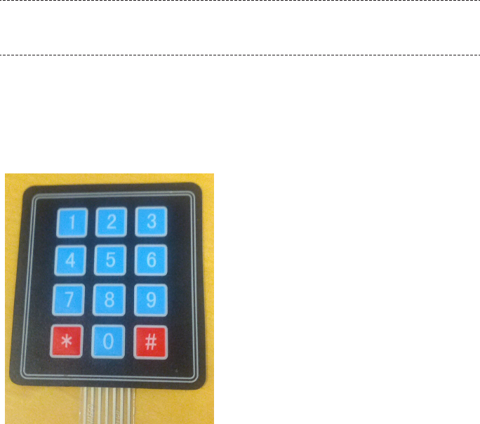
number or entered a PIN for an ATM withdrawal or debit purchase knows how to use
it. But added to a Raspberry Pi, you could use a keypad as part of a locking mechanism
or for any kind of numeric input. You could even use it to turn your Raspberry Pi into
a Voice over IP (VoIP) phone, but with that old push-button feel.
In addition to your Pi, you’ll need:
• Linux preinstalled with python2 (any distribution should work).
•A matrix input numeric keypad. We used the Membrane 3x4 Matrix Keypad avail-
able from Adafruit, but you can adjust our instructions to work with other key-
pads.
•A breadboard and male-to-female jumper wires. These are just for prototyping
the numeric keypad connection to the GPIO on the Raspberry Pi. For a more
permanent setup, you should solder things together.
These instructions assume you’re using a Raspberry Pi Model B, revision 2. If
you’re not, the GPIO pin numbers are different, and you’ll need to adjust.
How the Matrix Keypad Works
The Membrane 3x4 Matrix Numeric Keypad is simple. It has three columns with four
rows of buttons and one wire for each row and column, as shown in Figure 6-13.
Figure 6-13.
Membrane 3 x 4 Matrix Numeric Keypad
317
CHAPTER 6: EXTEND YOUR PI

The wires from the numeric keypad run to seven pins (pins 1 and 7 are labeled). Use
the jumper wires to connect these pins into your breadboard. By scanning the activity
of the rows and columns, you can detect which button is being pressed on the keypad
and translate it to the corresponding number.
The ordering of the pins might be logical from a layout perspective, but it took us a bit
of trial and error to determine which rows and columns matched up to the keypad
pins. See Table 6-3 for reference.
Table 6-3. Keypad pins and associated rows/columns
KEYPAD PIN NUMBER ROW/COLUMN
7 Row 1
6 Row 2
5 Row 3
4 Row 4
3 Column 1
2 Column 2
1 Column 3
Obviously, if you’re using a different numeric keypad, your pinouts may differ.
Connecting the Keypad to the Raspberry Pi
The simplest way to connect the numeric keypad to the Raspberry Pi is to connect
each of the keypad pins to a dedicated GPIO pin. The code in this hack assumes that
you have the pins connected as shown in Table 6-4.
Table 6-4. Keypad pins to GPIP pins
KEYPAD PIN NUMBER ROW/COLUMN GPIO PIN
7 Row 1 18
6 Row 2 23
5 Row 3 24
4 Row 4 25
3 Column 1 4
2 Column 2 17
1 Column 3 22
The simplest way to wire this is by connecting the female end of a jumper wire to a
GPIO pin, then connecting the male end of that wire into the appropriate location on
318 RASPBERRY PI HACKS

the breadboard. Remember, you want to have the GPIO-connected jumper wires lined
up with the corresponding horizontal row that contains the keypad pin.
How to Use Fewer Pins
This configuration is the easiest to wire, but it does have the disadvantage of using
up a lot of the GPIO pins on your Raspberry Pi. If you are feeling braver, you could
cut back on the number of GPIO pins used by wiring a demultiplexer (demux) to
the row pins, cutting them from four down to two.
You could also binary encode the column outputs with pull-down resistors on the
GPIO input pins and diodes to generate and mix the binary signal, resulting in two
column pins instead of three. If you do this, you’d need to write new code to handle
the more complicated inputs, which is left as an exercise to the power hacker.
(Credit goes to aTao on the Raspberry Pi forums for pointing this out.)
Installing the Software
To keep things simple here, we’ll take advantage of the Python Raspberry Pi GPIO
library. Pidora and Raspbian install this software by default, but if you do not have it
already available in your Linux distribution, you can download the source code. A copy
of this code is also included in the GitHub repository for this book.
Chris Crumpacker wrote a Python library called matrix_keypad to interface the Rasp-
berry Pi directly with the Adafruit Matrix numeric keypad, but unfortunately, it has
some bugs which prevent it from working as is. We’ve taken revision 1.0.4 of his li-
brary and cleaned up the bugs that were preventing it from working properly.
To install this library, first check out the fixed source code:
$ git clone https://github.com/spotrh/rpihacks
$ cd rpihacks/matrix_keypad-1.0.4-fixed
Next, build and install the fixed library:
$ python setup.py build
$ su -c 'python setup.py install --prefix=/usr'
Running the Program
Now you have a working copy of the matrix_keypad library installed on your Raspberry
Pi. We have also included a demonstration script (derived from Chris’s examples) so
that you can test your setup. There is a file in the matrix_keypad-1.0.4-fixed/ directory
called book-demo.py. Make sure your numeric keypad is wired in correctly, then run:
$ chmod +x book-demo.py
$ su -c './book-demo.py'
319
CHAPTER 6: EXTEND YOUR PI
This code will prompt you to enter your four-digit secret code into the numeric keypad.
The code in this example is 8675. As you enter the digits, it will print out debugging
details showing you the digit entered, the current stored value of your code to that
point, the number of digits in your code that you have entered, and finally, after four
digits have been entered, whether your code is correct.
Nifty, huh? But how does it work? book-demo.py uses the keypad function from the
matrix_keypad_RPi_GPIO module in the matrix_keypad library. The matrix_key
pad_MCP230xx module in the library it is only for when you have an I2C Port Expander
in use. The code also imports the sleep and exit functions from the standard Python
time and sys libraries so the code can sleep briefly if it’s entered incorrectly and so
that it can exit if it is entered properly:
from matrix_keypad.matrix_keypad_RPi_GPIO import keypad
from time import sleep
from sys import exit
Now, to silence the GPIO warnings. The Python Raspberry Pi GPIO library emits warn-
ings whenever you have any GPIO pins configured as anything other than input. Since
the matrix_keypad_RPi_GPIO library always configures the column pins as output (low),
you’ll get this warning every time you use it. You don’t want to see that, so silence it
by disabling the warnings:
import RPi.GPIO as GPIO
GPIO.setwarnings(False)
Now you need to initialize the keypad class from the matrix_keypad_RPi_GPIO module.
This will create a kp variable you can use to read the keys from the physical numeric
keypad. The matrix_keypad_Rpi_GPIO module supports both 3 x 4 and 4 x 4 numeric
keypad devices, but because our hardware is a 3 x 4, we’ll tell it that we have only three
columns. We also set up variables to store code attempts, the passcode we are check-
ing for, and a counter variable to track the progress of inputting the code:
kp = keypad(columnCount = 3)
# Setup variables
attempt = "0000"
passcode = "8675"
counter = 0
At this point, the program prints a friendly message to the user to tell her what to do
(input the four-digit secret code) and start a loop:
print 'Enter your four digit secret code into the numeric keypad!'
# Loop while waiting for a keypress
while True:
320 RASPBERRY PI HACKS
# Loop to get a pressed digit
digit = None
while digit == None:
digit = kp.getKey()
The loop uses the getKey() function from the keypad class to continuously poll the
numeric keypad device waiting for the user to press keys and input parts of her code.
Once a key is pressed, the value of digit changes from None to the value of the key
pressed, the value of the digit entered prints, the value for the code to that point (in
the attempt variable) updates, and the code entered so far prints:
# Print the result
print "Digit Entered: %s"%digit
attempt = (attempt[1:] + str(digit))
print "Attempt value: %s"%attempt
Now the program checks to see if the code as entered so far matches the value set in
passcode earlier. If it does, the program prints a happy message and exits:
# Check for passcode match
if (attempt == passcode):
print "Your code was correct, goodbye."
exit()
If it doesn’t match the passcode (either because it is incorrect or because not enough
digits have been entered), the program proceeds to the end of the loop, updating the
number of digits entered. If the number of digits in the entered code is more than four,
the program knows the user did not find the correct code in time it restarts the loop.
If it is fewer than four digits, it simply loops again and waits for more digits:
else:
counter += 1
print "Entered digit count: %s"%counter
if (counter >= 4):
print "Incorrect code!"
sleep(3)
print "Try Again"
sleep(1)
counter = 0
sleep(0.5)
This example program plays a simple guessing game, but it illustrates how you can
use the physical numeric keypad as an input device. You could easily modify this code
to unlock a door when the correct code is entered, incorporate it as part of an alarm
system, or use it to take numeric input for a Raspberry Pi-controlled thermostat.
321
CHAPTER 6: EXTEND YOUR PI

HACK 61 Add a Heat Sink
A heat sink for your Raspberry Pi? But it’s so little! Tiny, but mighty. You
may be surprised at just how warm it can get.
You’ve probably noticed that computers are hot. Not like “don’t touch the stove” hot
(most of the time), but “my smartphone is sometimes a hand warmer in the winter”
hot. It’s the integrated circuits (ICs) that make that toasty feeling (as well as make
your electronics work), and assorted bad things happen when they get too toasty,
ranging from warping the plastic case to (in extreme cases) burning laps of people
who take “laptop” literally. Sometimes you’ll learn your computer is too hot because
it knows it’s overheating and locks up or shuts down. It’s unlikely your Raspberry Pi
will overheat in average use, but it’s not impossible with more intense use.
A heat sink could seem like a bit much for such a little device, but depending on what
you’re using the Pi for (have you read Hack #06?), it could extend the computer’s life.
And frankly, heat sinks look neat. Of course, if your goal is “as small as possible,” this
isn’t the plan for you. If your goal is “naked electronics looking awesome,” you’re in
the right place.
Not Safe for Kids?
The Raspberry Pi was designed for education, and that includes with safety in
mind. It’s exceptionally unlikely that in any normal use, the Pi is going to get so hot
as to be unsafe to touch, so don’t worry about giving it to your kids.
The Raspberry Pi produces heat from three ICs: the CPU, the Ethernet controller, and
the power regulator. Geektopia used a thermal camera to study the Raspberry Pi’s
heat output (as shown in Figure 6-14. Simply plugged in and running, the three ICs
had measured temperatures of, 48.7º C (119.66º F), 53º C (127.4º F), and 49.9º C
(121.82º F), respectively.
322 RASPBERRY PI HACKS

Figure 6-14.
Thermal photo of Raspberry Pi running but at rest (courtesy of GeekTopia, http://www.geektopia.es)
The hottest test Geektopia ran was during video playback with Ethernet plugged in,
which drove the Ethernet controller to 65.1º C (149.18º F). (The full test results are
available in Spanish.) You can read one method of measuring your own CPU’s tem-
perature in “Measure Temperature” on page 16.
Which heat sink you buy depends not only on your performance needs, but potentially
on your aesthetic preferences and shipping location. Barch Designs sells a Raspberry
Pi case made from CNC-milled aircraft-grade aluminum that also acts as a heat sink.
The case gives you access to all the ports and has visibility to the LEDs with engraving
showing their purposes. As a bonus, you can have it etched with your words or design
—perhaps the name of your project?
The Barch Design case (shown in Figure 6-15) comes with a thermal paste. The interior
of the case has three raised pillars that contact the three IC chips on the Raspberry
Pi. Apply the paste to each of these pillars to activate the heat sink properties of the
case.
323
CHAPTER 6: EXTEND YOUR PI

Figure 6-15.
Heat sink case (photo by Benjamin Barch)
Because we’re based in the United States, we refer frequently in this book to parts
available from Adafruit, but if you’re not in North America, ModMyPi, a UK-based
company that sells Raspberry Pi accessories and parts, might be a better bet for a lot
of your needs. They deliver internationally with an expected wait of three to seven
days, which isn’t bad if they have something you can’t find anywhere else.
ModMyPi sells a more traditional-looking set of alumnium heat sinks with a small piece
for each of the three heat-producing areas. No glue required for this one—they attach
with provided thermal tape.
A heat sink alone won’t change everything, though. If you have it sealed up inside a
case (other than ones like that above designed to be or complement a heat sink),
you’re just sending the heat a few extra centimeters away—not that useful. Make sure
your chosen housing has appropriate air circulation.
HACK 62 Enable the Raspberry Pi Camera on
Pidora
As of this writing, the Raspbery Pi camera module does not yet officially
work with Pidora. That doesn’t mean we can’t make it happen anyway.
324 RASPBERRY PI HACKS
Using the Raspberry Pi camera module is well-documented online—if you’re using
Raspbian. To do so, you need to update the OS and use the built-in raspi-config tool
to enable it. There are a few more steps, but that’s the gist of it. Pidora doesn’t use
raspi-config, though, so it takes another step or two, but you can still use the camera
module with it.
Mount the SD card in your laptop or other computer that isn’t the Raspberry Pi. Mount
the two partitions, replacing /dev/mmcblk0 with the location of your own SD card, which
you can find with df -h:
$ sudo mnt /dev/mmcblk0p1 /mnt/raspi-boot/
$ sudo mnt /dev/mmcblk0p2 /mnt/raspi-root/
Then update all the boot firmware from the Pidora image to the latest version from
GitHub and copy the firmware onto the SD card:
$ git clone https://github.com/raspberrypi/firmware
$ cp -a firmware/boot/*.bin firmware/boot/*.dat firmware/boot/*.elf /mnt/
raspi-boot/
Update the videocore libraries and binaries. With the Pidora SD card mounted, run:
$ sudo cp -a firmware/hardfp/opt/vc/bin /mnt/raspi-root/usr/
$ sudo cp -a firmware/hardfp/opt/vc/include /mnt/raspi-root/usr/
$ sudo cp -a firmware/hardfp/opt/vc/lib /mnt/raspi-root/usr/
$ sudo cp -a firmware/hardfp/opt/vc/sbin /mnt/raspi-root/usr/
Finally, add these two lines to /boot/config.txt on the SD card:
gpu_mem=128
start_x=1
As mentioned previously, the camera needs 128 MB of memory dedicated to the GPU
to work correctly. The _x firmware variant is the one that the Pi needs to use the
camera.
Shut down and connect the camera to the Raspberry Pi. The blue tape side of the
ribbon cable should be facing toward the Ethernet jack, and the leads side should be
facing toward the HDMI connector. Make sure none of the lead pins are bent.
Start the Pi, and you’re ready to test the connection:
sudo raspistill -v -o temp.jpg
Of course, before performing that last step, you should be sure to slyly point it at family
members doing something hilarious. That camera’s so small, they’ll never notice.
325
CHAPTER 6: EXTEND YOUR PI

HACK 63 Build a Solar-Powered Lab
One of the benefits of the Pi is its low-power consumption, which makes
it well suited to being the centerpiece of a solar-powered education lab.
Several rural labs around the world have taken advantage of RACHEL. Short for remote
area community hotspots for education and learning, RACHEL deployments are low-
cost, scalable collections of open source software and educational content pulled
from Creative Commons licensed sources such as The Khan Academy, Wikipedia, and
CK-12.
RACHEL servers are specifically intended for remote locations with low-to-no Internet
connectivity. Powering Potential uses the RACHEL educational software on the server
that is then accessed through each student’s unit. RACHEL is free to download, install,
manage, and replicate and can be deployed in nearly any environment with minimal
hardware, such as a Raspberry Pi lab.
In fact, one of the configurations available from RACHEL is designed specifically for
the Raspberry Pi and called RACHEL-Pi. It’s been used by The Best of Both initiative
in Ghana and Powering Potential in Tanzania. Powering Potential also uses solar power
to run the labs. Thanks to a low-power monitor and the Pi, each workstation consumes
less than 10 watts over DC power.
Powering Potential’s flagship program, Educating-Through-Technology, partners
with government secondary schools in Tanzania to bring the Raspberry Pi and
basic technology instruction to students. In 2013, they began rolling the program
out to three schools in each of Tanzania’s 30 regions.
Unlike many of the hacks in this book, these workstations require a Model B, revision
2 with 512 MB of RAM. (And because it is for educational purposes, Powering Potential
houses the Pis in clear cases so that the students can see the components.) You’ll
also need a 4 GB or greater SD card, and they recommend a Class 10 or UHS-1 (Ultra
High Speed) card (see Class 10 Too Classy? for notes on this).
Gather Hardware
For each station, the Raspberry Pis in their cases are mounted on the back of each
monitor. Each workstation includes:
•Hanns-G Model Hl161Abb 15.6” LED monitor. This choice is part of a goal to obtain
low-wattage equipment that consumes only 10 watts of electricity between the
monitor and the computer (and running on DC instead of AC power).
• Pi View HDMI to VGA Adapter.
326 RASPBERRY PI HACKS

•Keyboard, mouse, router, printer, and modem (for their work, Powering Potential
sources these locally in Tanzania).
•Wi-Pi USB Wireless Adapter (originally used for communication between the stu-
dent client and the servers, but due to intermittent connection issues, Powering
Potential is exploring replacement solutions).
• Powered USB hub (optional).
•12-volt-to-5-volt stepdown converter 3 A female USB (Figure 6-16), which is used
to connect the Raspberry Pi to the 12 V solar power system, in addition to the
Micro USB cable to power to Raspberry Pi.
•Headsets for sound.
Figure 6-16.
12-volt-to-5-volt stepdown converter
For the solar power system for the lab, they use a vendor configuration from Ensol
Tanzania Limited, which includes:
•85 W solar module
• 108 Ah solar battery
• 45 A solar controller
327
CHAPTER 6: EXTEND YOUR PI
• Mounting frame
• Battery box
• 180 watt DC-to-AC inverter (for printer)
• Lightning arrestor and earthing system
The hardware required for the RACHEL server is identical to the client/student con-
figuration, except that it requires a larger SD card—32 GB for only RACHEL-Pi or 64
GB if KA-Lite is included. Because 64 GB cards are not well-suited to the purpose, only
cards rated UHS-1 will work for that scenario. In addition, a router facilitates commu-
nication between student clients and the servers. The UHS-1 class 64 GB cards that
have been tested and known to work with the Pi include:
• Kingston SD10G3/64GB UHS-I Elite
• Lexar Platinum II SDXC UHS-I Card
• SanDisk Ultra® SDXC™ UHS-I
Set Up the Raspberry Pi
Powering Potential uses Raspbian for the student Raspberry Pis. Emmanuel Acker-
man, technical adviser at Powering Potential, offers configuration tips on the World-
Possible forums under the handle mannyack.
Most importantly, he notes that the default sound configuration is “auto,” which
means that if you connect the monitor through the composite video port, the sound
will be directed through the audio jack, and if you connect the monitor through the
HDMI port, the audio will be directed to the HDMI audio. The monitor they use is an
HDMI monitor that doesn’t support audio. To tell Raspbian to use the headphones,
you should be able to run:
$ sudo amixer cset numid=3 1
Mannyack recommends doing this manually through /var/lib/alsa/asound.state in
a text editor instead, followed by pulling the power to force a shutdown.
The Raspberry Pi’s GPU can be used for video decoding, including high-definition
video. Raspbian includes a video player called omxplayer, which uses the GPU for
processing. Powering Potential has adapted the media-berry package that reroutes
HTML5 video playback in Midori (the default Raspberry Pi web browser) for omxplayer
to work with RACHEL videos.
The lab is powered by solar powers installed on the roof of the computer lab in a
conventional arrangement (panels and batteries). Power cabling brings the 12 V power
produced by the sun from the batteries to the computers. A 12-volt-to-5-volt stepdown
converter brings that down to usable power for the Raspberry Pis. The monitors,
328 RASPBERRY PI HACKS
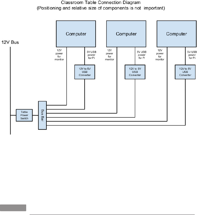
however, are connected directly to the 12 V circuit, rather than using the supplied
power cord (including brick/transformer) that come with the monitors.
In the lab, the tables each have three computers with two students per computer to
encourage synergy and collaboration between students, as shown in Figure 6-17.
Figure 6-17.
Classroom diagram
RACHEL completes the stetup. English and Spanish versions are available for down-
load at http://worldpossible.org/rachel/download. They also offer installation instruc-
tions, or you can order preinstalled units.
—Emmanuel Ackerman
HACK 64 Build a MIDI Controller (on the Cheap!)
This hack helps you build a homemade MIDI controller, using the Rasp-
berry Pi as a central controlling component, for a fraction of the cost of
commercial devices.
The Alcyone, a Raspberry-Pi-based MIDI controller, was inspired by the Moog Taurus
2, including its astronomical name. However, if you’re familiar with these machines,
the Roland PK-6 is more of a direct equivalent to the Alcyone. The goal was to create
a MIDI controller in the form of bass pedals. Building a foot pedal would be far less
329
CHAPTER 6: EXTEND YOUR PI

expensive than purchasing a Moog Taurus 3 (a full analog synthesizer in a foot pedal
form factor) or even a PK-6 (a simple foot pedal controller, at roughly $900 USD).
For those less familiar with music production, MIDI stands for musical instrument
digital interface, and it’s an industry-standard protocol for electronic instruments. It
is based on three types of events (note events, control events, and global events) and
uses a serial connection at 31250 baud.
Why “Alcyone”?
The Moog Taurus was originally designed as a part of a synthesizer ensem-
ble called the Constellation. The Taurus was the bass pedal of the ensemble;
the other parts were the Lyra and the Apollo. The Lyra was never built; the
Apollo’s design found its way into the PolyMoog. The Taurus, however, be-
came very popular, through its use in bands such as Rush, Genesis, ELP
(from whom the explanation of the Constellation comes), and others.
When naming this project, various star names were considered. Alcyone is
Taurus’s second-brightest star and one of the Pleiades. The project Alcyone
is pronounced “al-SEE-on-ee,” though the star is “al-SIGH-on-ee.” The war-
ped pronunciation came from “halcyon,” which is a variant of the mytho-
logical character Alcyone’s name. “Halcyon” uses the “ee” form of the “y.”
The Alcyone is “merely” a MIDI controller; it does not generate any sound in and of
itself. The actual processing power is provided through a Raspberry Pi, and the Rasp-
berry Pi’s audio output is only 11 bits, which is better than, say, a Nintendo DS or some
ancient digital synthesizers, but is far inferior to CD quality, and is nowhere near what
you’d want for actual audio creation.
Hardware
The Alcyone uses a simple internal electronic design (shown in Figure 6-18). The ped-
als themselves are a 13-note chord, salvaged from an old Lowrey organ, purchased
over eBay. They rely on a rocker switch that pulls a spring across a circuit to close it.
You could build your own (or perhaps 3D-print your own) if organ salvage proves chal-
lenging.
330 RASPBERRY PI HACKS
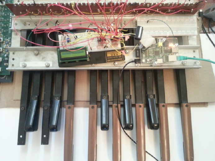
Figure 6-18.
The Alcyone
In the Lowrey design, the pedals convert the circuit to a CV/Gate signal, which was a
standard before MIDI was created. However, CV/Gate was never formally specified,
so different manufacturers use different implementations. CV/Gate normally con-
verts to a voltage: the first note might be +1 V, the second note +2 V, and so forth.
However, this is a convention and not a standard, and the Raspberry Pi has neither
analog inputs nor the capability to handle +13 V.
Thus it was simpler to use as little of the existing mechanism as possible, which meant
relying solely on the rocker switch and wiring custom digital I/O. As the Pi has only a
limited number of GPIO pins, the circuits for the rocker switches are wired to a set of
I2C chips. These use a serial protocol to map GPIO pins. The MCP23008 offers eight
individually addressible GPIO pins, and the MCP23017 offers 16.
The I2C chips can be wired such that seven of them are on a single serial connection.
Thus, if you use seven MCP23008 chips in a series, you have 56 uniquely addressable
pins. With the MCP23017, you could have 112. There are likely to be other I2C chips
available, and you don’t have to have a homogenous chain.
The physical electronic circuit is thus simple: three MCP23008s in series with two of
them dedicated to pedal input and one driving three LEDs for runtime status.
331
CHAPTER 6: EXTEND YOUR PI

The pedals are connected to power (+5 V) and wired to the MCP23008s. The digital
inputs are also connected to pull-down resistors to clear out digital noise.
The Raspberry Pi is connected to the I2C series and also to a Din5 connector (the
industry standard for MIDI connections). The Din5 is mounted on a Sparkfun MIDI
shield kit, mostly chosen for availability and ease of use.
A powered USB hub is also part of the hardware installation. The hub has one device
attached, a wireless networking dongle. The powered hub is necessary because the
Raspberry Pi does not carry enough current to reliably power most wireless dongles
(see Hack #08).
Why Wireless TCP/IP?
The wireless networking is part of a software choice made fairly early in the
implementation cycle. Initial external control relied on the Raspberry Pi’s
onboard Ethernet connection, which implies a requirement for networking
infrastructure. However, one facet of the Alcyone’s potential use is stage
work, and at many theaters, networking is spotty if existent at all.
The simplest solution involves the Alcyone serving as its own wireless ac-
cess point, meaning that it provides its own networking infrastructure.
An alternative would be to avoid TCP/IP altogether. Bluetooth is another
messaging protocol, one designed for device-to-device communications,
particularly for short messages. Bluetooth devices can also be designed for
low-power usage. However, this means writing a custom Bluetooth client
for every possible client platform.
The wireless on the Raspberry Pi is configured as an access point so the Alcyone can
serve as its own networking infrastructure. It has its own network SSID and security.
The external client has to use this access point in order to control the Alcyone.
Not only does this avoid reliance on what might be inconsistent or nonexistent net-
work services, it also limits the amount of traffic that competes for the client, and it
also allows us to use a consistent IP for the Alcyone (as opposed to guessing what
valid address the Alcyone happens to receive from the network infrastructure).
You need two packages to set this up: hostapd and udhcpd as described in eLinux.org‘s
RPI Wireless Hotspot page.
332 RASPBERRY PI HACKS
Software
The software for the Alcyone comes in two artifacts: the actual embedded code (the
code running on the Raspberry Pi) and an external client app (currently targeted for
Android).
The embedded platform runs a single application (called alcyone of all things), written
in C. C was chosen because the original test program was written on an Arduino Uno,
which tends to encourage the use of Arduino “sketches,” which are themselves a form
of C++ code (mostly with really odd library support).
C++ editing was largely done through Code::Blocks, easily installed for Fedora
through:
$ su -c 'yum install codeblocks'
Interaction with the physical hardware is provided by Gordon Prescott‘s wiringPi li-
brary, an excellent utility with various language implementations.
It uses three threads, provided via boost::thread, to execute. All three threads are
infinite loops. The Alcyone is a set of state machines, with the different machines able
to affect the others.
The simplest thread is a “flare” machine. It loops through the output LEDs. The loop
provides a timer value via an extern variable.
The second thread polls the digital inputs for changes in pedal state—in other words,
when the pedals are pressed down and lifted up. The routine keeps track of two states:
the “current state” based on a digital read, and the “previously read” state.
The current state is buffered to handle bounce.
Bounce is the natural tendency of an electrical current to fluctuate during changes.
When a circuit is closed (or opened), electrons flow across it occasionally until the
circuit settles in; the circuit appears to “bounce” open and closed for a short period
of time. This makes consistent reads very difficult, unless you “debounce” the circuit.
There are two ways to debounce circuits. One hardware approach uses something
called a Schmitt trigger buffer. Jack Ganssle has an excellent guide to debouncing that
describes a few different ways to handle bounce in hardware and software (including
code).
Alcyone uses a similar approach with a class that examines the input and counts the
“open” and “closed” states. It’s possible that the debouncing mechanism could be
fooled if the user plays quickly enough (pressing and releasing pedals much faster
than the human eye can blink), but the sample frequency is high enough that we ha-
ven’t seen any incorrect results yet.
333
CHAPTER 6: EXTEND YOUR PI
Through the process, on every loop, it reads the digital state of the pedals, and feeds
that into the debouncing mechanism, yielding a result (biased toward the actual
state).
If the current state is different from the “previously read” state, then we have a change;
if the “current state” is “down,” then the pedal was just pressed, and we need to send
a “note on” event; otherwise, a “note off” event should be sent.
Which note is sent is based on an offset. The MIDI mechanism contains a reference
to a “current octave” and a “current transposition” setting; the actual note used is
determined by multiplying the octave by 12, then adding the transposition value.
Therefore, if the current octave is three, and the transposition setting is one (meaning
that the farthest left pedal is now C# and not C, an offset of one half-step), and the
third pedal is depressed, the actual note is calculated through the use of the pedal,
plus the octave offset, plus the transposition. The pedals start at zero, so the pedal
number is two:
2 + 3*12 + 1 = 39
This actually yielded a bug in the initial demonstration of the Alcyone. If the transpo-
sition settings were changed while a note was being played, the “note off” event would
be for the wrong note! The reason should be fairly apparent.
Assume the “note on” event is for note 39 (as in the calculation above). Now let us set
the transposition to zero (i.e., reset it). Now, when the pedal is released, the “note off”
value is calculated… at 38, instead of 39.
The “note off” event thus doesn’t correspond to the “note on” event, and therefore a
receiver doesn’t actually get the correct signal to release the note.
This is corrected by the use of another data element, the “last note sent by this pedal.”
Thus, note off events take the note value from this dataset, rather than recalculating
the note value when the pedal is released.
Thus, the pedal press/release cycle follows this process:
1. Physically depress pedal (poor, sad pedal).
2. Calculate MIDI note by offset of pedal + 12*octave + transposition.
3. Store MIDI note in an internal array, index based on the offset of the pedal.
4. Send MIDI on.
5. Physically release the pedal.
6. Send MIDI off based on the note in the internal array.
334 RASPBERRY PI HACKS

MIDI actually required a number of changes to the Linux configuration for the Rasp-
berry Pi.
The Pi’s serial driver does not actually support 31250 baud, the baud rate required by
the MIDI specification. Therefore, you must overclock the serial chip, by modify-
ing /boot/config.txt:
init_uart_clock=2441406
init_uart_baud=38400
Next, you must disable the serial console, which uses the RX/TX pins needed for MIDI,
through modification of /boot/cmdline.txt:
dwc_otg.lpm_enable=0 console=tty1 console=tty1 root=/dev/mmcblk0p2 /
rootfstype=ext4 elevator=deadline rootwait bcm2708.uart_clock=3000000
Lastly, you must disable the TTY that would normally get assigned to the RX/TX pins,
as well, by modifying /etc/inittab:
#Spawn a getty on Raspberry Pi serial line
#T0:23:respawn:/sbin/getty -L ttyAMA0 115200 vt100
The last thread is a simple web server, based on CoralBits’ libonion, which uses the C
++ interface layer to map three request patterns (two with no-op responses for client
performance). The Alcyone uses a simple web app written with JQuery (and served
via lightttpd) to call this service with a single parameter: message. This app has a series
of buttons corresponding to control events: two kinds of channel changes, four kinds
of transposition events, and three different kind of system resets.
The message is actually an encoded byte, based on Table 6-5.
Table 6-5. Messages and encoded bytes
MESSAGE PAYLOAD NOTES
MSG_MIDI_RESET 0001 Turns off all MIDI notes on every channel
xxxx
MSG_MIDI_CHANNEL_CHANGE 0010
vvvv
MSG_MIDI_OCTAVE_CHANGE 0100
vvvv MSG_MIDI_TRANSPOSITION_CHANGE
1000
vvvv MSG_RESET 1111
Resets the Alcyone’s internal state to defaults xxxx
MSG_REQUEST_STATUS 0011 Responds with three bytes: octave, transposition, channel
335
CHAPTER 6: EXTEND YOUR PI
In Table 6-5, xxxx is an “ignored value” and vvvv is “down if zero.”
The web service mechanism is a simple loop. It processes a request, has an internal
switch/case that examines the upper nybble of the message value, and applies changes
as required.
No matter what the requested operation is, the Alcyone responds with three integers
in plain text, which correspond to the current octave, the current transposition setting,
and the current MIDI channel. The JQuery-based request reads these three integers
and populates the web page with the current instrument status.
Ergonomics
An implemented schematic and working software (both embedded and external) are
all well and good, but they all ignore the actual aspect of playing the Alcyone.
The Alcyone is designed to be played by standing guitarists. It is not likely to be played
delicately.
In order to be useful, it must be mounted in a case that offers the following qualities:
•Heavy enough to allow stability for the pedals. It would be unfortunate for the
musician if the pedals moved during performance (as many stage configurations
are laid out for the convenience of the performer, and often monitors are aimed
in specific ways). It would be even less fortunate for an audience member if the
Alcyone were to somehow be launched at him or her.
•Tough enough to handle being stepped on thousands of times, by a full-grown
adult.
•Pedals low enough so that the musician’s ankle is comfortable while playing the
instrument.
All of the “white keys” were replaced with wooden keys made from wood meant for a
picket fence cut down to size to match the existing pedals (roughly six inches long).
These are more likely to be immediately durable as compared to the original organ
pedals (which would be decades old).
As for the external container, the Alcyone has a wooden case built from 2 × 4 wood
and shellacked fencing, giving it a rustic look (which has its own appeal, for various
reasons) and is tough enough to handle rough treatment. With proper reinforcement,
the Alcyone is strong enough for an adult to stand on, although you probably shouldn’t
jump on it. It’s not a percussion instrument!
—Joe Ottinger
336 RASPBERRY PI HACKS

HACK 65 Build a Raspberry Pi Supercomputer
There seem to be two things people immediately want to do with their
Pis: make a media server (see Hack #54) or make a cluster of Raspberry
Pis. This hack is for those of you in the latter group.
Be þéos sceaft, sum clyster, nemnende for se eponymous ceorl fram… Just kidding.
We’re talking a Beowulf cluster, not the Old English stuff. And not Old English like the
wood cleaner, like the epic poem. Either way, it doesn’t matter. By the time we trans-
lated this whole hack into mediocre Old English, our grandchildren would be writing
about installing Fedora 140 on the Lingonberry Muffin (all the rage in 2073—keep an
eye out).
A Beowulf cluster is what happens when you connect some smaller computers (most
likely some cheap bits somebody stuck in a storage closet a while back, or as Wikipedia
more politely describes it, “commodity-grade”) together to build a supercomputer.
The term came from such a computer built at NASA in the mid ’90s, so named because
the eponymous character of Beowulf had “thirty men’s heft of grasp in the gripe of his
hand.”
The following instructions are adapted from those written by Simon Cox in the Com-
putational Engineering and Design Research Group at the University of Southampton
for a Raspberry Pi supercomputer with LEGO racking. It uses MPI (Message Passing
Interface) to communicate between nodes.
These instructions assume you are using Raspbian. When you first boot the image,
expand the image to fill the card. Don’t forget to change the default password and
refresh the list of packages in your cache (sudo apt-get update). Then you’re ready to
start supercomputing!
Background Reading
Parallel Processing on the Pi is an excellent post to read, if only for reassurance
that you are going to make it by the end, but don’t start following those instructions.
You’re going to build everything yourself in this hack.
You’ll also want to look at the MPICH Installer’s Guide to better understand some
of the steps in this hack.
Build MPI to Run Code on Multiple Nodes
To begin, get Fortran:
$ sudo apt-get install gfortran
After all, what is scientific programming without Fortran being a possibility?
337
CHAPTER 6: EXTEND YOUR PI

If you have Fortran, you are good to go without excluding anything. The packages
here are for armel, but you need armhf, so in this hack you’ll build MPI yourself.
Make a directory to put the MPI sources in:
$ mkdir /home/pi/mpich2
$ cd ~/mpich2
Next, get the MPI sources from Argonne National Laboratory. The MPI source con-
tinues to be updated, so you might need to visit http://www.mpich.org/downloads/
to find the latest stable release version for MPICH2:
$ wget http://www.mcs.anl.gov/research/projects/mpich2/downloads/tarballs/
1.4.1p1/mpich2-1.4.1p1.tar.gz
Once you have it, unpack the file:
$ tar xfz mpich2-1.4.1p1.tar.gz
You will need to update this as the version of MPICH2 increments. Next, make a place
to put the compiled stuff, which will also make it easier to figure out what you have
put in new on your system:
$ sudo mkdir /home/rpimpi/
$ sudo mkdir /home/rpimpi/mpich2-install
You might end up building this a few times. Make a build directory (so you keep the
source directory clean of build things) and then change into it:
$ sudo mkdir /home/pi/mpich_build
$ cd /home/pi/mpich_build
Now you’re ready to configure the build:
$ sudo /home/pi/mpich2/mpich2-1.4.1p1/configure -prefix=/home/rpimpi/mpich2-
install
Again, you will need to update this as the version of MPICH2 increments. Now is a
good time to go make a cup of tea. (We recommend Earl Grey, hot, but that part is up
to you.) It will be waiting when you come back.
Make the files, have another cup of tea, install them, and have a third cup of tea:
$ sudo make
$ sudo make install
Add the place that you put the install to your PATH:
$ export PATH=$PATH:/home/rpimpi/mpich2-install/bin
338 RASPBERRY PI HACKS
Note that to put this on the path permanently you will need to edit .profile and add
at the bottom these two lines:
# Add MPI to path
PATH="$PATH:/home/rpimpi/mpich2-install/bin"
Check whether things installed successfully:
$ which mpicc
$ which mpiexec
Now you’re ready to test whether MPI works for you on a single node. Change directory
back to home (cd ~), make a directory for testing (mkdir mpi_testing), and change
into your testing directory (cd mpi_testing). Get your IP address (ifconfig if neces-
sary) and put it into a single file called machinefile.
Then, test whether MPI works:
$ mpiexec -f machinefile -n <number> hostname
If you run:
$ mpiexec -f machinefile –n 1 hostname
The output should look like this:
raspberrypi
Now try a little C code. In the examples subdirectory of where you built MPI, you’ll find
the famous CPI example, which you will now use MPI on your Pi to calculate pi:
$ cd /home/pi/mpi_testing
$ mpiexec -f machinefile -n 2 ~/mpich_build/examples/cpi
Process 0 of 2 is on raspberrypi
Process 1 of 2 is on raspberrypi
pi is approximately 3.1415926544231318, Error is 0.0000000008333387
Take a break and celebrate getting this far! (Perhaps a fourth cup of tea is in order?)
Flash Me… Once
You now have a master copy of the main node of the machine with all of the installed
files for MPI in a single place. It’s time to clone the card. Shut down your Pi (sudo
poweroff). Remove the SD card and write the image from your SD card back to your
PC. In the following example, we’ll call that file wheezy-
raspbian_backup_mpi_master.img.
Eject the card and put a fresh card into your SD card reader. Write the wheezy-
raspbian_backup_mpi_master.img image you just created to the SD card. Put this sec-
339
CHAPTER 6: EXTEND YOUR PI
ond card into your second Raspberry Pi and boot it. You should now have two Rasp-
berry Pis on. Unless otherwise stated, all the commands that follow are typed from
the Master Pi that you built first.
Use SSH Instead of Password Login Between the Pis
Using RSA will give you a much quicker login. Working on the master Pi node:
$ cd ~
$ ssh-keygen -t rsa –C “raspberrypi@raspberrypi”
This sets a default location of /home/pi/.ssh/id_rsa to store the key. Enter a pass-
phrase (e.g., myfirstpicluster). If you leave this blank, you’ll have bad security, but
you won’t have to type passphrases any more.
Next, copy the keys to the Raspberry Pi:
$ cat ~/.ssh/id_rsa.pub | ssh pi@192.168.1.162 "mkdir .ssh;cat >> .ssh/
authorized_keys"
Log on to your second Pi and enter:
$ ls –al ~/.ssh
You should see a file called authorized_keys. This file is your ticket to No-Login Heaven
on the nodes. Now add the new Pi to machinefile. Log into it and get its IP address
(ifconfig). Working on the Master Raspberry Pi (the first one you built), machine
file should now have both of the IP addresses for your Raspberry Pis—for example:
192.168.1.161
192.168.1.162
Again it’s time to run a little C code. Like before, you’ll find the CPI example in the
examples subdirectory of where you built MPI. The first time, you will need to enter
the passphrase for the key you generated (unless you left it blank) and the password
for the second Pi:
$ cd /home/pi/mpi_testing
$ mpiexec -f machinefile -n 2 ~/mpich_build/examples/cpi
Process 0 of 2 is on raspberrypi
Process 1 of 2 is on raspberrypi
pi is approximately 3.1415926544231318, Error is 0.0000000008333387
If you repeat this a second time, you won’t need to type any passwords. Note that you
have not changed the hostnames yet (so yes, the previous code is running on the two
machines, but they both have the same hostname at the moment).
If you want to rename each machine, you can do it from the Master node:
340 RASPBERRY PI HACKS
$ ssh pi@192.168.1.162 'sudo echo "iridispi002" | sudo tee /etc/hostname'
$ ssh pi@192.168.1.163 'sudo echo "iridispi003" | sudo tee /etc/hostname'
$ ssh pi@192.168.1.164 'sudo echo "iridispi004" | sudo tee /etc/hostname'
You should then reboot each worker node.
If you put in the following command again:
$ mpiexec -f machinefile -n 2 ~/mpich_build/examples/cpi
Process 0 of 2 is on raspberrypi
Process 1 of 2 is on iridispi002
pi is approximately 3.1415926544231318, Error is 0.0000000008333387
This shows the master node still called raspberrypi and the first worker called iridis
pi002, and you see each process running on the separate nodes.
Congratulations! You’ve built a two-node supercomputer! Continue to build up to 64
(or more!) nodes.
Build More Nodes
You now have a copy of the worker nodes of the machine with all of the installed files
for MPI in a single place. You want to clone this card, because it has the SSH key on it
in the right place. Shut down your Pi (sudo poweroff) and eject the card. Put it into
your SD card reader and write the image from your SD Card back to your PC, naming
it wheezy-raspbian_backup_mpi_worker.img.
Eject the card and put a fresh card into the machine. Write the wheezy-
raspbian_backup_mpi_master.img image you created from the PC to your card. Repeat
for each additional node you would like to add.
Use Python Bindings for MPI
Now that your supercomputer is set up, you have options for various Python bindings
for MPI. These instructions will get one of them, mpi4py working (read more about it
at http://mpi4py.scipy.org).
Start by installing the package:
$ sudo apt-get install python-mpi4py
You also want to run the demo, so get the source, too:
$ cd ~
$ mkdir mpi4py
$ cd mpi4py
$ wget http://mpi4py.googlecode.com/files/mpi4py-1.3.tar.gz
341
CHAPTER 6: EXTEND YOUR PI

$ tar xfz mpi4py-1.3.tar.gz
$ cd mpi4py-1.3/demo
Now repeat these steps on each of your other nodes, as this hasn’t been baked into
the system image.
Run examples (on your master node):
$ mpirun.openmpi -np 2 -machinefile /home/pi/mpi_testing/machinefile python
helloworld.py
Hello, World! I am process 0 of 2 on raspberrypi.
Hello, World! I am process 1 of 2 on iridispi002.
Then:
$ mpiexec.openmpi -n 4 -machinefile /home/pi/mpi_testing/machinefile python
helloworld.py
Hello, World! I am process 2 of 4 on raspberrypi.
Hello, World! I am process 3 of 4 on iridispi002.
Hello, World! I am process 1 of 4 on iridispi002.
Hello, World! I am process 0 of 4 on raspberrypi.
Getting Pip for Raspberry Pi
Pip is a tool for installing and managing those Python packages, which will
give you an easy way to do so with your cluster. Read more about it at http://
www.pip-installer.org/en/latest/index.html.
Make a directory under your home called pip_testing and change into it. A
prerequisite for pip is distribute, so let’s get that first and then install pip:
$ curl http://python-distribute.org/distribute_setup.py | sudo python
$ curl https://raw.github.com/pypa/pip/master/contrib/get-pip.py | su
do python
Notes on Making MPI Shared Libraries for Raspberry Pi
MPI libraries can also be built “shared” so that they can be dynamically loaded. This
gives a library file that ends in .so. not .a, and you can do that by building those MPI
libraries again.
To do so, repeat the steps beginning with making a directory for your MPI sources, but
with a suffix of _shared on the directory names:
342 RASPBERRY PI HACKS

•/home/pi/mpich2_shared
•/home/rpimpi_shared/
•/home/rpimpi_shared/mpich2-install_shared
•/home/pi/mpich_build_shared
Configure the build:
$ sudo /home/pi/mpich2_shared/mpich2-1.4.1p1/configure -prefix=/home/rpim
pi_shared/mpich2-install_shared --enable-shared
Follow the steps to make and install the files. Then add the place that you put the install
to your PATH:
$ export PATH=$PATH:/home/rpimpi_shared/mpich2-install_shared/bin
Remember that to permanently put this on the path you will need to edit .profile and
add at the bottom these two lines:
# Add MPI Shared to path
PATH="$PATH:/home/rpimpi_shared/mpich2-install_shared/bin"
Actually Read Beowulf While You Wait for make
If you don’t like tea, you can spend those tea-drinking steps reading John Lesslie
Hall’s translation of Beowulf with notes and additional information at http://
www.gutenberg.org/ebooks/16328 or the 1337 version (straight-up translation-
only) by Francis Barton Gummere at http://www.gutenberg.org/ebooks/981
—Simon Cox
343
CHAPTER 6: EXTEND YOUR PI

We’d like to hear your suggestions for improving our indexes. Send email to index@oreilly.com.
Index
A
AC power, changeing DC to, 279
Adafruit
2.5 inch NTSC/PAL display, 290
I2C Python module, 194
LCD Pi Plate, 103
Pi Cobbler, 40
power supplies, 27
Python library for LCD Pi Plate, 104
Raspberry Pi Educational Linux Dis-
tro (Occidentalis), 99
Ultimate GPS Module, 185
USB Micro B cables, 28
USB-to-TTL Serial Cable, 48
Adafruit_DHT binary, 175
ADCs (Analog-to-Digital Converters),
298
aerial photography, controlling, 204–
219
advantages of Raspberry Pi for, 204
building the payload, 205
components needed in addition to Pi,
205
gathering gas, balloon, and para-
chute, 207
installing software in Pi, 207
preparing for launch, 217
results from successful mission, 218
tracking the payload, 217
aircraft transponders, listening to, 198–
203
getting a map that centers in your re-
gion, 202
materials for project, 198
running Dump1090, 202
Alamode board, 311
alcyone application, 333
Alcyone MIDI controller, 329, 330
aliens, looking for, 157–163
AM2302 sensor, 173
adding to Linux kernel, 174
C code to read data from, 175
wiring to Raspberry Pi, 174
Amateur Position Reporting System
(see APRS)
Amazon Instant Video, 274
analog output of Pi for sound output,
242
Android
accessing Pi MusicBox, 235
AndroBOINC, 163
CSipSimple softphone, 124
MPDroid, 238
installing and using, 239
running on Raspberry Pi, 107–109
Android_Pi_Wiki, 107
Answer( ) application, 126
antennas
for aerial photography hack, 218
included with NooElec R820T, 199
wire connected to GPIO4, 245
Apache web server
documentation and information re-
sources, 128
installing, 127
starting, 128
345

Apple Airplay, 232
Apple Bonjour, 235
Apple Macintosh (see Mac OS X)
APRS (Amateur Position Reporting Sys-
tem), 204
Trackuino, Arduino-based system,
206
APRS (Automatic Packet Reporting Sys-
tem), 217
hand-held system to track signal in
the field, 218
APT repository, ROSpbian, 135
Arduino
connecting Arduino shields to Pi,
292–312
analog-to-digital conversion, 298
compiling arduPi and a program
using it, 296
enabling the UART port, 295
GPIO input, 296
I2C, 304
options with shield and arduPi li-
brary, 292
SPI, 307
UART, 303
using arduPi library, 293
Trackuino APRS system, 206
arduPi library, 292
accessing UART, 303
compiling, and a program using it,
296
running your program, 296
using, 293
ARM architecture revision of Raspberry
Pi ARM, 70
ARM CPU (see CPU/GPU of Raspberry
Pi)
ARM Installer (Fedora), 131
ARM Linux compilers, 67
ARM1176 core, 99
armor building, 150
other materials for, 150
armor-building tools, 152
ARMv6 hard-float optimization, 13
ARMv6 soft-float optimization, 14
assimp (Open Asset Import Library),
139
Asterisk telephone system, 121–127
installing, 121
prompt for command line, 123
setting up a softphone, 123
configuring SIP account, 123
registering SIP client, 124
setting up extension in dialplan,
125
starting, 122
Atmel AT91SAM7S256 microcontroller,
134
Atmel ATmega48 microcontroller, 134
audio files accepted by XBMC, 271
audio set, 233
Automatic Packet Reporting System
(see APRS)
Avahi, 235
B
backpower, 24
avoiding when using USB hubs, 25
providing reliably for Raspberry Pi,
26
backups
critical firmware files in boot parti-
tion, 11
balloon photography project, 207
(see also aerial photography, control-
ling)
choosing the balloon, 207
reasons to use Raspberry Pi, 204
BAM (BOINC Account Manager), 162
(see also BOINC)
Barch Designs case, 323
batteries for aerial photography project,
206
battery packs, 57
baud, 47
baud rate for MIDI specification, 335
BCM labeling (GPIO pins), 38
Beowulf, 337
reading, 343
346 INDEX

Beowulf clusters, 337
Berkeley Open Infrastructure for Net-
work Computing (see BOINC)
Binary Utilities Options (crosstool-ng),
72
bison, 64
bit rate, 47
bitrate, 238
setting Spotify bitrate for Pi, 239
Bitwizard B.V., USB prodder , 28
Black Sky Telemetry site, 218
Blink softphone for Mac and Windows,
124
BlinkM RGB I2C-controlled LED, 304
blogging
setting up basic blog server, 127–131
Bluetooth, 332
BOINC, 158
account managers, 161
AndroBOINC, 163
BOINC Account Manager (BAM), 162
GridRepublic account manager, 162
installing manager and client, 159
setting up, 159
boot partition, SD card, 3
alternative prebuilt kernel variants,
89
copying new core Linux kernel image
into, 86
mounting manually, 6
updating firmware on, 11
boot process, Raspberry Pi, 9
/boot/config.txt file (see config.txt file)
bootcode.bin file, 11
bounce, 333
bps (see bit rate)
bracketed photos, 261
breadboards
connecting GPIO pins to, 39–47
bricks, programmable, 134, 134
(see also NXT Intelligent Brick)
broadcast, finding with ifconfig, 35
Broadcom BCM2835 chip, xiv
broken Raspberry PI, fixing, 29
Brown, Ty, 194
buffer support within IIO, 191
bus-powered USB hubs, 22
byte encoding, MIDI message based on,
335
C
C code for AM2302 sensor, 175
C Compiler Options (crosstool-ng), 73
C-library options (crosstool-ng), 74
C6 capacitor, 29
replacing, 30
Cacheberry Pi, 183–188
hardware needed for, 184
loading cache data, 187
project website, 186
software image for, 186
wiring, 186
calibration option, Mimo touchscreen,
254
determining max/min X and Y cali-
bration values, 255
calibration script for in-car touchscreen,
282
cameras, 258
(see also DSLR, connecting)
enabling Raspberry Pi camera on Pi-
dora, 324
finding out more about, 261
for aerial photography hack, 207
gphoto to control Nikon camera,
207
for cosplay project, 152
ribbon cable, 152
software and script to power it,
153
for photobooth, 263
getting configuration from gphoto2,
266
Pi Raspberry camera, 258
capacitor 06 (see C6 capacitor)
capture commands, 260
variables, 260
carrier signal, 245
case (water-resistant) for Pi, 177
347
INDEX

case for Pi used as heat sink, 323
catkin tool, 138
building catkinized ROS components,
139
running catkin-make, 141
running catkin_make to install files
into /opt/ros/groovy/ ROS struc-
ture, 142
Celsius/Fahrenheit/Kelvin temperature
conversions, 16
Class 10 SD cards, 2
clock frequency, FM radio, 245
clock generator module, 246
cmake_modules ROS component, 140
cmdline.txt file
options to use GPU low- and high-
water marks, 95
code examples from this book
config file for Reasperry Pi Linux ker-
nel, 79
Coder, using for your website, 131–133
COLLADA Document Object Model
(DOM), 138
color sensor
testing ROS sensor, 144
command-line interface (CLI), Asterisk,
123
Common UNIX Printing System (see
CUPS)
compiled-in options, 82
composite video output, 247
config file, Linux kernel, 79
config.txt file
booting file other than default ker-
nel.img, 86
memory allocation with, 93
GPU low- and high-water marks,
95
making file compatible with 256
or 512 MiB models, 94
quick changes on mounted SD card,
6
configuration
checking custom overrides, 16
checking value of specific, 17
configuration hacks, 1–62
adding a Reset button, 54
adding a USB serial console, 47–54
adding memory with swap, 61–62
choosing and formatting the SD card,
1–3
connecting GPIO pins to a bread-
board, 39–47
connecting with SSH, 32–34
decoding the LEDs, 7–8
getting more USB ports, 22–24
getting power to Pi on the move, 56
going headless, 31
learning GPIO, 36–39
monitoring Raspberry Pi hardware,
13–17
mounting the SD card, 3–7
overclocking, 17–20
overvolting, 20
static IP address for Pi, 34–36
troubleshooting power problems,
24–29
unbreaking your Raspberry Pi, 29
updating the firmware, 8–13
CONFIG_HWMON, 166
CONFIG_I2C_BCM2708, 166
enabled as module, 170
CONFIG_I2C_CHARDEV, 166
enabled as module, 170
CONFIG_IIO, 191
CONFIG_IIO_ST_HWMON, 192
CONFIG_SENSORS_TMP102 enabled as
module, 166
CONFIG_SENSORS_TSL2563, 192
connectors, 36
console mode, starting Asterisk in, 122
consoles
adding USB serial console, 47–54
hack for the red wire, 48
Contiguous Memory Allocator (CMA),
95
348 INDEX

controllers, 256
using NES/SNES controller through
GPIO, 256
converter board, 220
connecting, 221
converters, 278
Cooking Hacks, Raspberry Pi to Arduino
shields connection bridge, 292
core frequency, GPU processor, 19
problems with overclocking, 19
core Linux kernel image, 88
cosplay, surviving gaping chest wound,
150–157
adding the battle wound, 151
building the costume, 150
finishing the custume, 155
putting it all together, 156
costumes, building, 150
other materials for armor building,
150
resources for, 151
CPU cores, number of, 84
CPU/GPU of Raspberry Pi, 18
-cpu option in QEMU, 99
decoding/encoding video files by
GPU, 227
GPU and DisplayLink technology,
248
GPU firmware, no support for DSI-
connected devices, 247
increasing ARM CPU frequency, 18
increasing GPU frequency, 19
monitoring memory split, 16
overvolting, 21
sharing memory automatically, 95
cross-compiler, building, 63–76
adding crosstool-ng to PATH, 66
beginning the build, 76
configuring cross-compiler, 67–75
configuring crosstool-ng, 65
installing crosstool-ng, 63
installing development tools, 64
crosstool-ng
adding to your PATH, 66
configuration menu, 67
configuring, 65
configuring the cross-compiler, 67–
75
Binary Utilities Options, 72
C Compiler Options, 73
C-library options, 74
Operating System Options, 71
Paths and Misc. Options, 68
Target Options, 69
Toolchain Options, 71
disabling CT_WANTS_STATIC_LINK,
75
installing, 63
PPL bug fix, 65
CSV files for geocache data, 188
CT_WANTS_STATIC_LINK, disabling, 75
CUPS (Common UNIX Printing System),
117
Add Printer configuration page, 119
administration web portal, 118
editing configuration file, 117
setting up another network comput-
er to print, 120
current, defined, 60
CUSF Landing Predictor, 217
CV/Gate, 331
CyanogenMod, 107
compiling to run on Raspberry Pi,
109
CyanogenMod 7.2 (based on Android
2.3), 108
D
DACs (Digital Audio Converters), 242
DC power, changing to AC, 279
dd command, 186
debouncing circuits, 333
demultiplexer (demux), 319
device name
finding for SD cards, 2
for UART serial device, 49
Device section, Xorg configuration, 252
DHT22 temperature-humidity sensor,
174
349
INDEX

dialing plan (or dialplan), 123
getting complete list of applications,
127
setting up an extension, 125
Digital Audio Converters (DACs), 242
Display Power Management Signaling
(DPMS), 252
Display Serial Interface (DSI) connector,
247
DisplayLink, 248
DIY culture, xi
DMA (Direct Memory Access) controller,
246
dmesg command, 4
device name for UART serial device,
49
DNS server, sepcifying for static IP ad-
dress, 36
dphys-swapfile, 62
DPMS (Display Power Management Sig-
naling), 252
DSI (Display Serial Interface) connector,
247
DSLR, connecting, 258–262
basic capture commands and vari-
ables, 260
finding out more about your camera,
261
getting started with gPhoto, 258
Dump1090, 199
dependencies for building, installing,
199
getting map centered on your region,
202
preparing for use, 201
running the script, 202
dynamic IP addressing, 34
dynamic voltage scaling to increase volt-
age, 20
E
e2i Technology touchpanel, 248
e2i Touchscreen controller option, 249
Einstein@Home, 158
electricity
essential terms and relationships, 59
mixing with water, hazards of, 178
elfutils package, 14
emulating Raspberry Pi, 97–99
Emulation Station, 257
configuring your joystick, 258
enabling Raspberry Pi camera on Pi-
dora, 324
encryption (for wireless networks), 234
Enigma@home, 158
Enzol Tanzania Limited, 327
error codes, common LED codes, 7
evtest tool, 254, 284
output about touch events, 254
EXPERIMENTAL or DANGEROUS op-
tions, 84
extending your Pi, 287–343
adding a heat sink, 322–324
adding a numeric keypad, 316–321
connecting the keypad to Pi, 318
how the Matrix Keypad works, 317
installing the software, 319
running the program, 319
adding a tiny screen, 290
building a MIDI controller, 329–336
ergonomics, 336
hardware, 330
software, 333
building a solar-powered lab, 326
gathering hardware, 326
setting up Pi, 328
building a supercomputer, 337–343
building more nodes, 341
building MPI to run on multiple
nodes, 337
making MPI shared libraries for Pi,
342
using Python bindings for MPI,
341
using SSH for login between Pis,
340
350 INDEX

connecting Arduino shields to Pi,
292–312
analog-to-digital conversion, 298
compiling arduPi library and a pro-
gram using it, 296
enabling the UART port, 295
GPIO input, 296
I2C, 304
SPI, 307
UART, 303
using arduPi library, 293
controlling a 3D printer, 312–316
controlling GPIO from a web browser,
287–289
enabling camera on Pidora, 324
extensions, setting up in dialplan, 125
external hard drives, using for shared
file storage, 112
externally powered USB hubs, 22
possible issues using with Raspberry
Pi, 24
extraterrestrial intelligence, searching
for, 157–163
F
FAA regulations on balloon-launched
payload, 205
Fahrenheit/Celsius/Kelvin temperature
conversions, 16
FAT formatted partition on SD card, 3
Fedora ARM Installer, 131
ffmpeg, 208, 228
building from source, 229
filesystem, resizing, 241
filesystems, SSD formatting for, 285
firewalls
getting SIP traffic through, 121
permitting traffic to access CUPS
server, 118
firmware
home for Raspberry Pi firmware, 10
updates on the Pi, 2
updating for Raspberry Pi, 8–13
updating the easy way, 96
version currently used by Raspbian
Linux kernel, 10
fixup.dat file, 11
flex, 64
Flirc USB dongle, 272
FM (frequency modulation), 245
formatting SD cards, 2
Fortran, 337
four-port USB hub, 24
framebuffer driver support, enabling,
249
free command, 62
frequency modulation (FM), 245
G
G-code, 314
converting 3D model to, 315
sending instructions to the printer,
315
gateway, finding with ifconfig, 35
GCC compiler, 64, 175
configuring gcc and gcc4.7 as defualt
compilers, 229
Linaro version, 67
gd module (PHP), 128
General Purpose Input/Output (see
GPIO)
geocaching with Pi, 182–188
Cacheberry Pi, 183
gathering Cacheberry Pi hardware,
184
loading cache data into Cacheberry
Pi, 187
overview of geocaching, 183
preparing Cacheberry Pi software im-
age, 186
wiring Cacheberry Pi, 186
getty, 52
git
Adafruit-Raspberry-Pi-Python-Code,
175
checking out Raspberry Pi Linux ker-
nel source tree, 77
git binary in git package, 96
351
INDEX

prebuilt Linux kernel images for
Raspberry Pi, 88
using to update Raspberry Pi firm-
ware, 10
GitHub
nxt codebase and fixes, 136
Python library for LCD Pi Plate, 104
ROS repository, multiple branches,
140
tarball of Linux kernel source tree, 78
GMP (GNU Multiple Precision Arithmet-
ic Library, 65
GNU MP, 64
Google Docs, Adafruit_DHT, Python
script for, 176
Gparted tool, 3
gperf, 64
gPhoto, 207, 258
gphoto2, 259
installing on Raspberry Pi, 263
GPIO, 24, 36–39
BCM labeling for pins, 38
connecting numeric keypad, 318
connecting pins to a breadboard,
39–47
GPIO quick reference, 45
connecting wire to GPIO4 to act as
antenna, 245
controlling from a web browser, 287–
289
getting power through safely, 26
header of GPIO pins, 36
input, 296
labeling your own pins, 38
libraries for aerial photography hack,
207
mapping of TMP102 breakout pins to,
168
one-wire support on GPIO 4, 100
pin-number labeling, 37
problems in using to power Pi, 25
Python Raspberry Pi GPIO library,
320
using NES/SNES/controller through,
256
GPS, 183
GPS receiver for Cacheberry Pi, 184
plugging into Raspberry Pi, 186
GPSd daemon to decode GPS data
streams, 207
tracking aerial photography payload,
217
Trackuion APRS system, 206
graphics processing unit (GPU), 227
(see also CPU/GPU of Raspberry Pi)
GridRepublic, 162
Groovy ROS, 135
groovy-devel code branch (ROS reposi-
tory), 140
Ground Fault Circuit Interruptor (GFCI),
182
GSAK (on Windows), 188
GY-80 module, 206
H
H.264/MPEG-4 video, 231
Hackerspaces in Space contest, 204
ham radio Automatic Packet Reporting
System (APRS), 217
Hangup( ) application, 126
Hanns-G Model Hl161Abb LED monitor,
326
hard float, checking for, 13
Hardware Monitoring support, 166
hardware monitoring, by IIO devices,
192
hardware video block frequency, 19
HDMI, 247
connecting Pi MusicBox to amplifier,
242
headless mode, running Raspberry Pi in,
31
headphones, 233
analog headphones jack of Pi, 242
telling Raspbian to use, 328
heat sink, adding to Pi, 322–324
thermal photo of heat output from Pi,
322
352 INDEX

helium for aerial photography balloon,
207
high-power USB devices, 23
holiday lights display, 219–225
connecting the hardware, 220
installing the software, 222
setup, 219
Holux M-215 GPS receiver, 184
hotplugging, 28
household projects, 111–163
building a web server, 127–133
controlling a LEGO robot, 134–149
cosplay (costume play), 150–157
looking for aliens, 157–163
sharing files with Samba, 111–116
using Raspberry Pi as remote print
server, 117–120
using Raspberry Pi Aterisk telephone
system, 121–127
HPLIP (HP Linux Imaging and Printing
project), 119
Hulu, 274
humidity, 173
combined temperature and humidity
sensor (AM2302), 173
Hynix RAM, Occidentalis and, 101
hysteresis limit value, 171
I
I2C (Inter-Integrated Circuit), 46
Adafruit I2C Python module, 194
attempt to install i2ctools and lm-
sensors on default Raspbian, 170
BlinkM RGB I2C-controlled LED, 304
communication between Pi and ADC
of Arduino shield, 298
connection of TSL2561 to I2C bus on
GPIO, 191
defined, 166
kernel support for, 166
libraries for talking to GY-80 sensor
board, 207
TMP102 I2C sensor, 165
I2C support
enabling in Linux kernel, 104
in Occidentalis, 100
kernel option, 82
i2c-tools, installing, 169, 193
i2cdetect command, 193
i2cdetect command line, 169
ifconfig command, 33, 201
finding current IP address, netmask,
and broadcast, 35
IIC/I2C/TWI SPI Serial LCD 1602 Mod-
ule, 185
image sensor pipeline block frequency,
19
Industrial IO Support option, 191
input device for Mimo touchscreen, 254
Inter-Integrated Circuit (see I2C)
interactive_markers ROS component,
140
Internet of Things, 287
intervals for taking photos, specifying,
261
inverters, 279
iOS
accessing Pi MusicBox, 235
mPod and mPad for Pi MusicBox,
238
ip addr command, 33
IP address
accessing Pi MusicBox by, 235
blinking through LEDs, 8
getting for Raspberry Pi, 201
giving your Pi a static IP address, 34–
36
choosing unique address, 36
headless mode and, 31
monitoring for Raspberry Pi, 102–
107
building LCD Pi Plate, 103
installing software to control LCD
Pi Plate, 104
network with static address, using Pi
MusicBox in, 244
router’s default IP address, 33
ip-flash command, 32
ip-info package, 32
353
INDEX

ip-read command, 32
iptables, editing for CUPS traffic, 118
IRC channel, #razdroid, on Freenode,
107
iTunes, 235
J
JQuery, 335
K
Kelvin temperature, 16
kernel
building a custom kernel, 76–87
building kernel image, 84
configuring the kernel, 79
downloading kernal source tree,
77
installing new kernel, 85
natively, on Raspberry Pi, 77
post-installation tasks, 87
updating prebuilt kernel easy way, 96
updating to latest prebuilt kernal
installing prebuilt kernel modules,
89
updating to latest prebuilt kernel,
87–91
distribution-specific features, 88
getting prebuilt kernel, 88
kernel modules
building for custom kernel, 85
copying for new kernel image file, 86
enabling feature or driver as, 82
kernel-qemu file, downloading, 97
kernel.img file, 8
changing GPU firmware booting of,
86
kernel_cutdown.img, 89
kernel_emergency.img, 89
keypad class, 320
keypad for LCD Pi Plate, 103
Kondik, Steve, 108
L
LAMP, 127
Apache web server, installing, 127
MySQL, PHP, and PHP gd module, in-
stalling, 128
Last.fm, playing music via, 232, 237
LCD Pi Plate, 103–107
building, 103
displaying IP address for Pi, 106
installing software to control, 104
library of Python functions to access,
106
running LCD-pi-plate-demo.py script,
106
LCD screens
DisplayLink monitor in Mimo 720,
248
for Cacheberry Pi, 185
connecting to Raspberry Pi, 186
SPI LCD, printing messages on, using
arduPi, 307
LCDtest.py script, 106
LEDs
BlinkM RGB I2C-controlled LED, 304
decoding, 7–8
blinking your IP address, 8
common LED error codes, 7
flashing IP address, 32
Hanns-G Model Hl161Abb LED moni-
tor, 326
indicator LED for Cacheberry Pi, 185
connecting to Raspberry Pi, 187
LEGO Mindstorms kits, 134
LEGO robot (see robot (LEGO), control-
ling)
LHC@home, 158
libgphoto2, 259
cameras supported by, 263
libsensors library, 170
libusb, 259
license keys for video codecs, 232
light, monitoring, 188–198
accessing TSL2561 sensor directly
from Linux kernel, 197
accessing TSL2561 sensor via
Python, 194
lux, 189
354 INDEX

TSL2561 sensor, 189
lighthttpd web server, 207
lights display (see holiday lights display)
Linaro variant of GCC compiler, 67
Linux
configuration for Raspberry Pi,
changes required by MIDI, 335
distribution images for use with
Raspberry Pi, 9
distribution on SD card for Raspberry
Pi, 1
distributions for Raspberry Pi, 3, 269
hard float, 13
flashing NXT Intelligent Brick firm-
ware from, 135
GMPC and Sonata to control Pi Mu-
sicBox, 238
hacking for Raspberry Pi, 63–109
building a custom kernel, 76–87
building cross-compiler toolchain,
63–76
emulating Pi, 97–99
monitoring IP address for Pi, 102–
107
Occidentalis, 99–102
splitting memory between GPU
and Linux userspace, 91–96
updating firmware and kernel
easy way, 96
updating to latest prebuilt kernel,
87–91
installing OpenSSH, 33
making Pi MusicBox work on Linux
computers, 235
mounting SD card on Linux comput-
er, 4
mounting USB flash drive, 187
not using to connect to serial port,
50
swapfile, 62
video player software, 227
Linux, Apache, MySQL, and PHP (see
LAMP)
lm_sensors, 166
installing, 169
reading data from TMP102 sensor,
170
locale handling in Raspbian, 137
login console, using Raspberry Pi UART
serial device as, 52
Lowrey organ pedals, 330
lpadmin group, 117
lsusb application, 54
Lulzbot AO-101 printer, 312
luminosity sensors, 189
lux (lx), 189
Python script to calculate from
TSL2561 readings, 194
TSL2561 sensor readings and, 194
M
M3U files, 236
Mac OS X
terminal software, 50
Theremin, 238
using to connect to serial port, 50
make clean command, 78
make mrproper command, 78
make package, 77
make utility, 175
-j flag to speed up build, 84
ARCH=arm CROSS_COMPILE=arm-
rpi-linux-gnueabi- options, 80
compiling Dump1090, 201
making sure Linux kernel config file is
current, 80
menuconfig option, 81
starting Linux kernel modules build,
85
Makefile.include
adding dbus header include flags,
229
bug in, 228
male header pins, 41
map_msgs ROS component, 140
Matrix Numeric Keypad
connecting to Raspberry Pi, 318
how it works, 317
355
INDEX

matrix_keypad library, 319
program using, 319
matrix_keypad_RPi_GPIO module, 320
maximum permitted current draw from
5 V pins, 26
media center, turning Pi into, 269–277
adding a remote control, 272
adding content, 274
decoding MPEG-2 and VC-1, 271
shortcut for cord cutters, 274
XBMC, 269
media-berry package, 328
Mediabridge
High Output Dual USB Car Charger,
278
USB charging cables, 28
Membrane 3x4 Matrix Numeric Keypad,
317
memory split, 91–96
allocating memory with config.txt
file, 93
and optional versions of firmware
files, 13
automatically sharing memory, 95
monitoring, 16
setting up for ffmpeg code to com-
pile, 228
start.elf file corresponding to, 93
memory, adding with swap, 61–62
Message Passing Interface (see MPI)
MicroController Pros, 312
Microsoft
Streets and Trips format, 188
VC-1 license, 271
Windows (see Windows systems)
MIDI (musical instrument digital inter-
face), 330
MIDI controller, building cheaply, 329–
336
ergonomics, 336
hardware, 330
software, 333
Midnight Commander utility, 243
Miller, Florian, 257
Mimo 720 touchscreen, 247
e2i Technology USB Touchpanel de-
tected, 251
frame buffer devices assigned by ker-
nel to, 251
kernel drivers for, 248
rebooting Pi with it connected, 250
using, 254
Xorg configuration file for, 251
minicom, 50
MJPEG codec, 232
mkdosfs command, 3
MMC block device partitions, 4
confirming correct device names, 5
Model A and Model B, xiv
LEDs, 7
maximum permitted current draw
from 5 V pins, 26
memory on Model B, 91
peak current draw on Model B, 28
revisions of Model B board, xiv
USB ports on Model B, 22
ModemManager, 53
ModMyPi, 324
modular options, 82
modules, Linux kernel
building for custom kernel, 85
enabling feature or driver as, 82
installing prebuilt modules, 89
prebuilt Linux kernel modules, 88
monitoring Raspberry Pi hardware, 13–
17
checking custom configuration over-
rides, 16
checking for hard float, 13
measuring component voltage, 15
memory split, 16
monitors
connecting to HDMI or composite
video, 250
Hanns-G Model Hl161Abb LED moni-
tor, 326
Monitor section, Xorg configuration,
252
356 INDEX

operating Raspberry Pi without a
monitor, 31
Monk, Simon, 38
Moog Taurus, 329
Mopidity, 243
Morse code program, 247
mounting the SD card, 3–7
movies, watching in your car, 277–286
adding videos, 285
power source, 277
powered USB hub, 280
putting it all together, 285
software, 281
storage for movies, 279
touchscreen, 280
MPD (Music Player Daemon), 238
MPDroid, 238
installing and using, 239
MPEG-2 codec, 231
decoding, 271
enabling in config.txt, 231
MPI (Message Passing Interface), 337
building to run code on multiple no-
des, 337
making shared libraries for Pi, 342
using Python bindings for, 341
writing master image onto SD card,
339
MPICH Installer’s Guide, 337
multi-room audio, 238
multimedia hacks, 227–286
building Pi MusicBox, 232–244
connecting a DSLR, 258–262
controlling Pi via touchscreen, 247–
255
emulating classic video game con-
soles, 255–258
enabling additional video codecs,
231–232
playing video files, 227–231
setting up a photobooth, 262–269
turning Pi into a radio, 244–247
turning Pi into media center, 269–
277
watching movies in your car, 277–
286
multimeter
testing USB cable’s resistance, 28
testing voltage on Raspberry Pi, 59
testing your power supply, 30
music player, Pi MusicBox, 232–244
getting and configuring software, 233
editing Pi MusicBox settings, 233
network connections, 234
Midnight Commander utility, 243
Mopidity, 243
more options to explore, 243
MPD (Music Player Daemon), 238
multi-room audio, 238
networked music, 240
playing local music, 241
playing music, 234
search function, 235
selecting songs and adding to
queue, 235
streams from web radio stations,
236
rc.local file, 243
security, 242
sound configuration, 242
updating, 244
using in network with static IP ad-
dress, 244
musical instrument digital interface
(MIDI), 330
MySQL
creating database and user for Word-
Press, 129
in LAMP, 127
setting up installation, 128
starting, 128
mystery sound game, 246
N
native compiler, 64
nav.csv file, 188
NC (Normally Closed) wires, 221
NC Near Space Research Group, 204
ncurses, 64
357
INDEX

ncurses-dev package, 77
ncurses-devel package, 77
NES (Nintendo Entertainment System),
255
using NES/SNES controller through
GPIO, 256
Netflix, 274
netmask, finding with ifconfig, 35
network connections (Pi MusicBox),
234
network interfaces
configurations, 34
editing to use Pi MusicBox in static
network, 244
network interfaces file, wireless connec-
tion for Occidentalis, 102
networked music, playing on Pi Music-
Box, 240
networking protocols used with XBMC,
271
NeverWet coating, 179
painting Raspberry Pi and compo-
nents with, 180
Nikon Coolpix, 207
nmap tool, 33
nmbd, 112
NO (Normally Open) wires, 221
NOOBS (New Out-Of-Box Software)
installing/copying directly onto SD
card, 3
SD cards preloaded with, 2
NooElec R820T, 198
numeric keypad, adding to Pi, 316–321
connecting the keypad, 318
how the Matrix Keypad works, 317
installing the software, 319
other uses for keypad, 321
running the program, 319
nxt family of modules, 136
NXT Intelligent Brick, 134
firmware, 135
permission for Pi user to communi-
cate with, 137
testing ROS connection to, 143
udev rules for lego group users to ac-
cess, 137
using NXT Python bindings for sim-
ple robot, 148
O
Occidentalis, 99–102
download site for most recent ver-
sion, 101
features of Version 0.1 and 0.2, 100
I2C and TMP102 sensor support, 166
origin of the name, 101
raspi-config options, 101
wireless connection, setting up, 102
Ogg Theora codec, 232
Ohm’s law, 60
omxplayer, 227, 328
building on Raspbian, 228
control keys for video playback, 230
documentation, 230
installing on Raspbian, 228
installing system-wide, 230
running as user other than root, 230
watching videos with, 230
1-Wire sensors, 173
Open Asset Import Library (assimp),
139
Open Cache Manager (Linux/OSX), 188
OpenELEC, 251, 281
OpenSSH, 32
Operating System Options (crosstool-
ng), 71
OS distributions for Raspberry Pi, 3
outdoors, hacking, 165–225
checking on your plants, 172–176
controlling aerial photography, 204–
219
geocaching with Pi, 182–188
holiday lights display, 219–225
light-monitoring, 188–198
listening to aircraft transponders,
198–203
making Pi water-resistant, 176–182
358 INDEX

overclocking, 17–20
causing errors with Class 10 SD
cards, 2
increasing ADRAM frequency, 18
increasing ARM CPU frequency, 18
increasing GPU frequency, 19
pretested overclock presets, 20
warnings about, 18
overvolting, 20
P
package on package (PoP), 91
parachute for aerial photography, 207
parallax, 152
Parallel Processing on the Pi, 337
Parma Polyhedra Library (PPL), bug fix,
65
partitioning SD cards, 3
adjusting partitions and their sizes, 3
boot and root partitions, Linux distri-
butions, 3
resizing filesystem, Pi MusicBox, 241
Paths and Misc Options (crosstool-ng
menu), 68
payload for balloon photography, 205
components included in, 206
container for, 205
FAA regulations on, 205
tracking, 217
pedal press/release cycle, MIDI control-
ler, 334
Pepakura, 151
performance optimization, 17
(see also overclocking)
overvolting, 20
photobooth, setting up, 262–269
camera configuration, examining,
266
choosing URL shortener, 266
materials required for, 262
packages to install on Raspberry Pi,
263
Photobooth class, 266
photobooth.py script, 264
QR code, 266
stable Internet connection for up-
loading pictures, 265
watermark for images, 265
photography, aerial (see aerial photog-
raphy, controlling)
PHP
in LAMP, 127
installing PHP and gd module, 128
Pi Cobbler, 40, 169
versions, 41
Pi MusicBox (see music player, Pi Mu-
sicBox)
Picture Transfer Protocol (PTP), 259
Pidora
building omxplayer, 228
enabling Raspberry Pi camera on,
324
giving your Pi a static IP address, 34
headless configuration option, 31
pidora-18-r1c.img, 98
starting in QEMU, 98
swap configuration, default, 62
systemd service file for camera
script, 154
PiFM, 244–247
accessing hardware, 246
downloading and extracting files, 244
fun with, 246
how it works, 245
PIHUB, 24
pin-number labeling (GPIO), 37
PinMux control, 82
Pip, 342
PL2303HXA drivers, 50
plants (outdoor), checking on, 172–176
requirements for plants, 172
Playback( ) application, 126
playlist, creating, 246
PlayOn, 274
PLS files, 236
plus sign (+), appended to Raspberry Pi
kernel builds, 90
polyfuse, 60
testing for problems, 61
359
INDEX

PoP (package on package), 91
power
essential terms in electricity, 59
getting to Pi on the move, 56
in cars, 277
less-than-recommended power op-
tions, 56
power cord for Cacheberry Pi, 185
power problems, troubleshooting, 24–
29
avoiding backpowering Pi over USB,
25
considerations in using GPIO to pow-
er Pi, 25
getting a better Micro USB cable, 27
getting a better power supply, 27
getting power through GPIO safely,
26
symptoms of power problems, 27
testing USB cable’s resistance, 28
power source for Raspberry Pi, 24
power supplies
getting a better one, 27
irregularities in voltage supplied, 25
testing, 30
Powering Potential, 326
print server, remote, using Raspberry Pi
as, 117–120
printed circuit boards (PCBs), 40
Printrun, 315
project box for Cacheberry Pi, 186
pronterface, 316
PTP (Picture Transfer Protocol), 259
Pulse-Width Modulation (PWM), 46
PuTTY, 50
PWM (Pulse-Width Modulation), 46
Python
accessing TSL2561 sensor via, 194
bindings for MPI, 341
holiday lights project tools, 222
library for LCD Pi Plate, 104
matrix_keypad library, 319
NXT Python bindings for simple ro-
bot, 148
photobooth.py script, 264
python-imaging package, 263
python-smbus library, 194
Raspberry Pi GPIO library, 319
ROS script to test color sensor, 144
ROS script to test touch sensor, 144
script to run Adafruit_DHT binary,
175
scripts for aerial photography
project, 207
System Management Bus (SMBus)
support modlue, 105
Q
QEMU (Quick EMUlator), 97–99
documentation of other options, 99
installing, 97
starting Pidora in, 98
QR code, size of, 266
qrencode package, 263
R
RACHEL, 326
hardware required for server, 328
RACHEL-Pi, 326
radio
finding web radio stations, 237
license requirements in some coun-
tries, 245
playing streams from web radio sta-
tions on Pi MusicBox, 236
turning your Pi into (PiFM), 244–247
rain gauge sensors, 173
rainbow screen, 12
RAMBo electronics boards, 313
Raspberry Leaf, 39
Raspberry Pi
determining which version you have,
92
emulating, 97–99
Linux kernel source tree, 77
merging changes into upstream Li-
nux kernel source, 90
prebuilt Linux kernel, 88
alternative or variant versions, 88
360 INDEX

Raspberry Pi to Arduino shields connec-
tion bridge, 292
Raspbian
enabling I2C support in Linux kernel,
105
static IP address for Pi, 35
Raspbian Wheezy, 100
Raspbmc, 269
for in-car movie watching, 281
interactive installer for, 269
post-installation settings, 270
raspi-config file, options for Occidenta-
lis, 101
raspi-config tool, 20
raspivid utility, 153
script to run it, 153
rc.local file, 243
readelf
checking for ARMv6 hard-float sup-
port, 14
in binutils package, 96
Realtek RTL8188CUS USB module, 100
RealTek Software Defined Radio (see
RTL-SDR)
regulated voltage, 25
relay board, 220
connecting, 221
remote control, adding to Pi media cen-
ter, 272
rep-update script, warnings about use
of, 96
RepRap family of printers, 312
Reset button, adding, 54
resistance
defined, 60
testing for USB cables, 28
USB cables, 27
resistors, adapting voltage with, 297
resolution, parallax, and battle wound
effect, 152
REST, WebIOPi framework, 287
RetroArch tool, 257
Retrode gaming adapter, 256
RetroPie tool, 257
robot (LEGO), controlling, 134–149
installing ROS and dependencies,
135–143
testing ROS connection to NXT Brick,
143
using NXT Python bindings, 148
The Rocketman, 207
ROM files for video games, 256
Emulation Station and, 258
root partition, SD card, 3
Linux kernel modules on, 86
mounting manually, 6
root user
changing root password, 31
su versus sudo command, 11
rootfs-resize, 31
ROS (robot operating system), 135
information resources on robot build-
ing, 148
installing ROS and dependencies,
135–143
assimp library, 139
building catkinized ROS compo-
nents, 139
building legacy ROS stacks, 142
COLLADA DOM, 138
nxt codebase, 136
testing connection to NXT Brick, 143
roscore command, 143
roslaunch command, 146
ROSpbian repository, 135
rosrun command, 144
routers, default IP address, 33
rpi-3.6.y kernel source tree, 77
rpi-update script, 96
in Occidentalis, 100
putting on SPATH and making it exe-
cutable, 96
RPM Fusion project, 208
RS-232 serial ports, 48
RTL-SDR (RealTek Software Defined Ra-
dio), 198
drivers, building and installing, 199
plugging into Pi and rebooting, 200
361
INDEX

Rustoleum, NeverWet, 179
rviz ROS component, 141
S
Sainsmart 1602 ICD LCD unit, 185
Samba, 111–116
connecting to share from another
machine, 115
GUI configuration tool, 115
installing on Raspberry Pi, 114
Samba/Winbind for Pi MusicBox,
235
Samba Server Configuration Tool, 115
SCAN_ONCE and SCAN_ALWAYS set-
tings, 241
Schmitt trigger buffer, 333
screen, 50
installing and connecting to Raspber-
ry Pi UART serial device, 51
screens, 307
(see also LCD screens; monitors)
screen device, Xorg configuration,
252
tiny screen for Raspberry Pi, 290
SD cards
choosing and formatting, 1–3
copying files onto for new Linux ker-
nel, 85
flashing Coder image onto, 131
hazards of adding swap to, 61
image-flashing tool, 131
loading CyanogenMod 7.2, 108
mounting, 3–7
music files stored on, 241
playing music via, 232
putting musicbox0.4 image on, 233
writing Cacheberry Pi image onto,
186
SDHC Class 4 cards, 1
SDRAM
increasing frequency, 18
voltage settings, 21
Search for Extraterrestrial Intelligence
(see SETI project)
sed, 64
disabling CT_WANTS_STATIC_LINK,
75
Sega Genesis video games, 256
sensors
combined temperature and humidity
sensor (AM2302), 173
confirming active sensor with rostop-
ic list command, 147
for aerial photography hack, 208
downloading libraries, 208
main control loop of 10DOFd.py
program, 208
luminosity, 189
reading data from, 170
ROS script to test color sensor, 144
running ROS script to test touch sen-
sor, 144
support in Occidentalis, 100
temperature sensor, 165
touch sensor on test robot, 146
serial connections
clients supporting, 50
weird noise (or missing signal) on, 53
serial consoles
for Cacheberry Pi, 185
trivia, 52
Serial Peripheral Interface Bus (see SPI)
Server Message Block protocol (see
SMB)
ServerLayout section, Xorg configura-
tion, 253
servos, adding servo motor to robot, 147
SETI project, 157
SETI@Home, 158
7 Inch HD Touchscreen Car Monitor,
280
seven-port USB hub, 24
shares on Windows networks, 241
signal decoding script (see Dump1090)
silica gel packets, 177
sine-wave inverters, 279
362 INDEX

SIP, 121
configuring account for SIP soft-
phone, 123
registering your SIP client, 124
Slic3r, 315
SMB (Server Message Block), 111
smb.conf file, editing, 114
smbd, 112
SMBus, Python module for, 105
SNES (Super Nintendo) video games,
256
socket splitters, 278
softphone application, 121
setting up a softphone with Asterisk,
123
configuring SIP account, 123
registering your SIP client, 124
setting up extension in dialplan,
125
solar-powered lab, building, 326
gathering hardware, 326
setting up Raspberry Pi, 328
solar power system, 327
soldering
connecting Pi Cobbler PCB to GPIO
pins, 42
reminders about, 42
solid state drives (SSDs), 279
storing videos on, 285
sound configuration, Pi MusicBox, 242
sound module on Pi, 204
SoundCloud, 237
speakers (USB), 233
SPI (Serial Peripheral Interface Bus), 46
communicating with, using arduPi
functions, 307
support in Occidentalis, 100
SPOT Satellite GPS Messenger device,
217
Spotify, 232
account information, 233
levels of quality for music, 238
limitation on playing different music
on multiple devices, 238
playlists on Pi MusicBox, 235
sqllite database, 207
SSDs (solid state drives), 279
storing videos on, 285
SSH
connecting to Raspberry Pi, 32–34
launching GUI interfaces, 34
enabling for Pi MusicBox, 243
ready-to-go sshd in Occidentalis, 100
using instead of password login be-
tween Pis, 340
start.elf file, 8, 11
corresponding to memory splits, 93
static IP address (see IP address)
stationid.py script, 215
status LEDs on Model B, 7
stepdown converter, 327
stream URL for web radio, 236
su versus sudo command, 11
subscription services, 274
subversion, 64
super settings
gpu_freq, 19
over_voltage, 21
supercomputer, building, 337–343
building more nodes, 341
building MPI to run on multiple no-
des, 337
making MPI shared libraries for
Raspberry Pi, 342
using Python bindings for MPI, 341
using SSH for login between Pis, 340
surl package, 263
swap, 61–62
hazards of, 61
setting for headless mode, 31
sync command, 12
ensuring image is written onto SD
card, 186
running after installing new kernel, 87
system board voltage, 15
System Management Bus (SMBus) sup-
port, Python module for, 105
363
INDEX

T
TAOS light sensors device driver, 192
Taos TSL2561 luminosity sensor, 189
(see also TSL2561 luminosity sensor)
tar command, unpacking Linux kernel
tarballs, 78
Target Options (crosstool-ng menu), 69
telephone system (see Asterisk tele-
phone system)
teletype, 52
television
connecting to Raspberry Pi for pow-
er, 274
getting content to, 274
temperature
converting to different scales, 16
measuring for BCM2835 system-on-
chip, 16
monitoring without going outside,
165
plant hardiness zones, 172
temperature hysteresis limit, 171
temperature sensors, 169
(see also TMP102 sensor)
combined temperature and humidity
sensor (AM2302), 173
Texas Instruments TMP102 I2C sen-
sor, 165
test point locations, 57
Texas Instruments TMP102 I2C temper-
ature sensor, 165
texinfo, 64
Text User Interface (TUI) menu configu-
ration system, 81
TFT LCD screen, 152
mounting on costume and running it,
156
preparing for armor costume, 155
resolution, 152
Theremin, 238
Thingiverse, 315
3D block frequency, 19
3D file formats, support for (assimp),
139
3D models to print, 315
3D paper models, 151
3D printer, controlling, 312–316
TMP102 sensor, 165
connecting to Raspberry Pi, 169
finding on Pi I2C Bus, 169
labels, 167
mapping of breakout pins to GPIO,
168
reading data from, 170
Toolchain Options (crosstool-ng), 71
touch events, determining, 254
touch sensor
confirming active sensor with rostop-
ic list command, 147
ROS script to test, 144
test robot with, 146
touchscreen, controlling Pi via, 247–255
choosing a touchscreen, 247
installing and enabling drivers, 248
using the touchscreen, 254
Xorg configuration file, 251
touchscreens
enabling USB touchscreen support,
249
for use in cars, 279, 280
connecting Raspberry Pi to, 281
enabling support, 281
mounting, 286
Trackuino, 206
transient voltage suppression (TVS) di-
ode, 25
transistor-transistor logic (TTL) serial,
47
triggered sampling support in IIO, 191
TSL2561 luminosity sensor, 189
accessing directly from kernel, 197
accessing readings via Python mod-
ule, 194
connecting to Raspberry Pi GPIO,
190
ts_calib.sh script, 282
TUI (Text User Interface) menu configu-
ration system, 81
364 INDEX

turbo mode, disabled by changes to
comline.txt, 95
turbo presets, 20
Twinkle SIP softphone on Linux, 124
2.5 inch NTSC/PAL display, 290
U
UART (Universal Asynchronous Receiv-
er/Transmitter), 46
accessing with arduPi library, 303
connecting Raspberry Pi UART serial
port to computer USB, 48
enabling the UART port, 295
Raspberry Pi UART serial device
data rate, 47
using as login console, 52
serial communication over, 47
udev rules
access to NXT Intelligent Brick by le-
go group users, 137
blacklisting connector device, 53
for RTL-SDR device, 200
UDL Framebuffer driver, 248
UDL Kernel Mode Setting driver, 248
uimapper.conf file, 283
uinput_mapper, 283
unbreaking your Raspberry Pi, 29
replacing the C6 capacitor, 30
testing the power supply, 30
unit loads, 22
Universal Asynchronous Receiver/
Transmitter (see UART)
Universal Standard Bus (see USB)
unmounting boot and root SD parti-
tions, 6, 12
update-alternatives command, 229
urdf component source, 140
URL shortener (surl), 263
URLs (short), services that create, 266
USB
12 V-to-USB converters, 278
Display Link Framebuffer Driver, 248
Display Link Kernel Mode Setting
(KMS), 248
flash drive for geocache data, 187
flash drive for shared storage, 113
getting a better Micro USB cable, 27
getting more USB ports, 22–24
interconnect cable, hubs sending
power across, 24
serial console from Raspberry Pi, 47–
54
sound cards, speakers, or head-
phones for Pi MusicBox, 242
speakers, 233
SSD connected to Pi over, 279
testing cable’s resistance, 28
touchpanel in Mimo 720, 248
Touchscreen Driver, 248
USB devices causing Pi to reboot, 28
USB Mass Storage protocol, 259
USB Digital Audio Converter/DAC, 242
USB hubs, 22
4-port USB hub, 24
7-port hub for Raspberry Pi, 24
determining if a good choice, 23
PIHUB, 24
powered, for use in cars, 280
reliable backpower for Raspberry Pi,
26
USB-to-TTL Serial Cable, 48
female jumper connectors, hack for
red wire, 48
usbutils package, lsusb application, 54
V
VC-1 codec
decoding, 271
enabling, 231
license for, 231
vcgencmd tool, 14
get_config command, 16
get_mem command, 16
measure_temp command, 16
measure_volts command, 15
source code, 17
versions
prebuilt Linux kernel and modules,
matching, 89
365
INDEX

printing version of running Linux ker-
nel, 87
video
adding videos to in-car entertain-
ment, 285
capturing with gphoto, 259
DisplayLinkDevice in Xorg configura-
tion, 252
enabling additional video codecs,
231–232
videocore accelerated video co-
decs, 232
Pi native hardware support for HDMI
and composite video output, 247
playing video files on Raspberry Pi,
227–231
RACHEL videos, omxplayer working
with, 328
video codecs, supported encodings,
285
video codec license keys, store to sell,
231
video game consoles (classic), emulat-
ing, 255–258
using NES/SNES controller through
GPIO, 256
video stream, creating from aerial photo
hack, 208
videocore accelerated video codecs,
232
Videocore IV GPU (see CPU/GPU of
Raspberry Pi)
VideoCore libraries, 227
VideoCore SDK libraries, updating, 96
VoIP (voice over IP), 121
SIP protocol, 121
voltage
checking for Raspberry Pi, 57
defined, 60
measuring component voltage, 15
overvolting, 20
VP6, VP8, MJPEG, and Ogg Theora vid-
eo codecs, 232
W
water
humidity, 173
mixing with electricity, hazards of,
178
requirements for plants, 172
water-resistant Pi, 176–182
building water-resistant case for Pi,
177
without a case, 178
immersing Pi in water, 182
requirements for hack, 179
WAV file format, 245
web browsers
controlling GPIO from, 287–289
for Pi MusicBox, 234
web pages for aerial photography hack,
207
downloading, 208
script generating main station ID
page, 215
Web Radio, 232
web servers
building your own, 127–133
setting up basic blog server, 127–
131
lighthttpd web server, 207
WebIOPi, 287
Python library supporting GPIO inter-
actions, 289
websites, using Coder for, 131–133
WiFi
equipment for aerial photography
hack, 218
network connection for Pi MusicBox,
234
Occidentalis support for, 100
playing music via, 232
winbindd, 112
Windows systems
LEGO Mindstorms software, 135
making Pi MusicBox work, 235
Music Player Daemon (MPD) clients,
238
366 INDEX

networked music, playing on Pi Mu-
sicBox, 240
PlayOn, 274
putting music files on Pi using Win-
dows network, 242
terminal software, 50
using to connect to serial port, 50
wire strippers, 175
wireless networking
creating wireless network with PiFM,
247
setting up connection for Occidenta-
lis, 102
support added to Raspberry Pi, 107
TCP/IP wireless for MIDI controller,
332
wiring, holiday lights project, 221
wiringPi library, 333
WordPress, 127
configuring, 129
database and user for, 129
downloading and installing, 129
web-based setup, 130
World Community Grid, 158
WorldPossible forums, 328
X
X forwarding, 34
XBMC, xi, 269
networking protocols, 271
Raspbmc for in-car movies, 281
remote controls, 272
support for many formats, 271
uinput_mapper device, 284
Videos menu, PlayOn share, 275
XBMC-based Linux OS for Raspberry Pi,
251
Xbox, 269
Xorg configuration file for Mimo 720,
251
Xorg/Xll, Linux distributions without,
250
XSPF files, 236
Z
zImage binary file, 85
ZOC, 50
367
INDEX

About the Authors
Ruth Suehle manages the Community Leadership team in Red Hat’s Open Source
and Standards group, which supports upstream open source software communities.
She also leads the Fedora Project’s marketing team. Previously an editor for Red Hat
Magazine, she now leads discussions about open source principles as a moderator at
opensource.com. Ruth is also a senior editor at GeekMom.com, where she covers the
adventures of motherhood alongside technology and sci-fi.
Tom Callaway is the Fedora engineering manager at Red Hat, where he has worked
since 2001. He has been active with Fedora since its creation and currently serves as
the Fedora packaging committee chair, responsible for defining the standards that
Fedora uses to keep its package quality high. He also maintains 300+ packages in
Fedora, which may also mean he is legally insane. He enjoys pinball, gaming, sci-fi,
frogs, geocaching, traveling, and causing trouble with his wife, Pam, and son, Jimmy.
Colophon
The cover fonts are URW Typewriter and Guardian Sans. The text font is Benton Sans;
the heading font is Benton Sans; and the code font is Dalton Maag’s Ubuntu Mono.
