1484201825 %7B44BAC1FF%7D Mastering The Raspberry Pi %5BGay 2014 08 18%5D {44BAC1FF} [Gay 18]
User Manual: 1484201825 %7B44BAC1FF%7D Mastering the Raspberry Pi %5BGay 2014-08-18%5D
Open the PDF directly: View PDF ![]() .
.
Page Count: 482 [warning: Documents this large are best viewed by clicking the View PDF Link!]
- Contents at a Glance
- Contents
- About the Author
- About the Technical Reviewer
- Acknowledgments
- Chapter 1: Why This Book?
- Chapter 2: The Raspberry Pi
- Chapter 3: Preparation
- Chapter 4: Power
- Chapter 5: Header Strips, LEDs, and Reset
- Chapter 6: SDRAM
- /proc/meminfo
- MemTotal
- MemFree
- Buffers
- Cached
- SwapCached
- Active
- Inactive
- Active(anon)
- Inactive(anon)
- Active(file)
- Inactive(file)
- Unevictable
- Mlocked
- SwapTotal
- SwapFree
- Dirty
- Writeback
- AnonPages
- Mapped
- Shmem
- Slab
- SReclaimable
- SUnreclaim
- KernelStack
- PageTables
- NFS_Unstable
- Bounce
- WritebackTmp
- CommitLimit
- Committed_AS
- VmallocTotal
- VmallocUsed
- VmallocChunk
- Physical Memory
- Memory Mapping
- Virtual Memory
- Final Thoughts on SDRAM
- /proc/meminfo
- Chapter 7: CPU
- Chapter 8: USB
- Chapter 9: Ethernet
- Chapter 10: SD Card Storage
- Chapter 11: UART
- Chapter 12: GPIO
- Chapter 13: 1-Wire Driver
- Chapter 14: I2C Bus
- Chapter 15: SPI Bus
- Chapter 16: Boot
- Chapter 17: Initialization
- Chapter 18: vcgencmd
- Chapter 19: Linux Console
- Chapter 20: Cross-Compiling
- Chapter 21: Cross-Compiling the Kernel
- Chapter 22: DHT11 Sensor
- Chapter 23: MCP23017 GPIO Extender
- Chapter 24: Nunchuk-Mouse
- Chapter 25: Real-Time Clock
- Chapter 26: VS1838B IR Receiver
- Chapter 27: Stepper Motor
- Chapter 28: The H-Bridge Driver
- Chapter 29: Remote-Control Panel
- Chapter 30: Pulse-Width Modulation
- Chapter 31: Glossary
- Chapter 32: Power Standards
- Chapter 33: Electronics Reference
- Chapter 34: Raspbian apt Commands
- Chapter 35: ARM Compile Options
- Chapter 36: Mac OS X Tips
- Bibliography: Bibliography
- Index
TECHNOLOGY IN ACTION™
You already know that the Raspberry Pi is an excellent teaching tool.
If you want to teach Linux basics or Python programming, it’s a great
place to start. But what if you are an electronics engineer, a Linux systems
administrator, or an experienced maker? You want to know the inner workings
of the Raspberry Pi – how to design without wading through basics and
introductory material.
If you want to get right into the pro-level guts of the Raspberry Pi,
complete with schematics, detailed hardware explanations, reporting
voltages and temperatures, and recompiling the kernel, then Mastering the
Raspberry Pi is just the book you need. Along with thorough explanations
of hardware and operating system, you’ll also get a variety of project
examples that you can tune for your own project ideas.
In this book, you’ll learn:
• How to set up the Raspberry Pi for bare metal interfacing
• Detailed and clear explanations of the Pi’s hardware capabilities,
including GPIO
• Working with Raspbian Linux, including boot files, the Pi’s own
vcgencmd command, and cross-compiling software,
including the kernel
• How to build a GPIO extender
• How to interface a stepper motor with an H-bridge driver
• How to make a remote control panel
• How to generate Pulse Width Modulation from the Pi
You’ll find yourself turning to Mastering the Raspberry Pi over and over
again for both inspiration and reference. Whether you’re an electronics
profes sional, or just looking for more detailed information on the Raspberry
Pi, this is exactly the book for you.
Mastering the Raspberry Pi
www.apress.com
US $49.99
Shelve in Computer Hardware/General
User level: Intermediate–Advanced
SOURCE CODE ONLINE
Gay
Warren Gay
Also available:
Mastering the
Raspberry Pi
A complete reference guide
And project ideA generAtor
for the rAspberry pi
Mastering the Raspberry Pi
9781484 201824
54999
ISBN 978-1-4842-0182-4

For your convenience Apress has placed some of the front
matter material after the index. Please use the Bookmarks
and Contents at a Glance links to access them.

v
Contents at a Glance
About the Author ������������������������������������������������������������������������������������������������������������ xxvii
About the Technical Reviewer ����������������������������������������������������������������������������������������� xxix
Acknowledgments ����������������������������������������������������������������������������������������������������������� xxxi
Chapter 1: Why This Book? ■ ������������������������������������������������������������������������������������������������1
Chapter 2: The Raspberry Pi ■ ����������������������������������������������������������������������������������������������5
Chapter 3: Preparation ■ ������������������������������������������������������������������������������������������������������9
Chapter 4: Power ■ �������������������������������������������������������������������������������������������������������������17
Chapter 5: Header Strips, LEDs, and Reset ■ ����������������������������������������������������������������������29
Chapter 6: SDRAM ■ �����������������������������������������������������������������������������������������������������������37
Chapter 7: CPU ■ �����������������������������������������������������������������������������������������������������������������53
Chapter 8: USB ■ �����������������������������������������������������������������������������������������������������������������69
Chapter 9: Ethernet ■����������������������������������������������������������������������������������������������������������75
Chapter 10: SD Card Storage ■ �������������������������������������������������������������������������������������������83
Chapter 11: UART ■ �������������������������������������������������������������������������������������������������������������91
Chapter 12: GPIO ■ �����������������������������������������������������������������������������������������������������������117
Chapter 13: 1-Wire Driver ■ ����������������������������������������������������������������������������������������������157
Chapter 14: I2C Bus ■ �������������������������������������������������������������������������������������������������������167
Chapter 15: SPI Bus ■ �������������������������������������������������������������������������������������������������������177
Chapter 16: Boot ■ ������������������������������������������������������������������������������������������������������������191
Chapter 17: Initialization ■ �����������������������������������������������������������������������������������������������221
■ Contents at a GlanCe
vi
Chapter 18: vcgencmd ■���������������������������������������������������������������������������������������������������229
Chapter 19: Linux Console ■ ���������������������������������������������������������������������������������������������235
Chapter 20: Cross-Compiling ■ �����������������������������������������������������������������������������������������237
Chapter 21: Cross-Compiling the Kernel ■ �����������������������������������������������������������������������253
Chapter 22: DHT11 Sensor ■ ���������������������������������������������������������������������������������������������263
Chapter 23: MCP23017 GPIO Extender ■ ��������������������������������������������������������������������������275
Chapter 24: Nunchuk-Mouse ■ �����������������������������������������������������������������������������������������303
Chapter 25: Real-Time Clock ■ �����������������������������������������������������������������������������������������329
Chapter 26: VS1838B IR Receiver ■����������������������������������������������������������������������������������349
Chapter 27: Stepper Motor ■ ��������������������������������������������������������������������������������������������365
Chapter 28: The H-Bridge Driver ■ �����������������������������������������������������������������������������������383
Chapter 29: Remote-Control Panel ■ ��������������������������������������������������������������������������������401
Chapter 30: Pulse-Width Modulation ■ �����������������������������������������������������������������������������421
Appendix A: Glossary ■�����������������������������������������������������������������������������������������������������439
Appendix B: Power Standards ■ ���������������������������������������������������������������������������������������445
Appendix C: Electronics Reference ■ ��������������������������������������������������������������������������������447
Appendix D: Raspbian apt Commands ■ ���������������������������������������������������������������������������449
Appendix E: ARM Compile Options ■ ��������������������������������������������������������������������������������453
Appendix F: Mac OS X Tips ■ ��������������������������������������������������������������������������������������������455
Bibliography ■ ������������������������������������������������������������������������������������������������������������������457
Index ���������������������������������������������������������������������������������������������������������������������������������463

1
Chapter 1
Why This Book?
This book developed out of a need for an in-depth work about the Raspberry Pi that just didn’t seem to exist. If I had
found one, I would have gladly purchased it. A quick survey revealed a large number of “how to get started” books.
But I pined for something with the kind of meat that appeals to engineering types. Give me numbers, formulas, and
design procedures.
Almost all of that information is available out there on the Internet somewhere. But I discovered that some
questions take considerable time to research. If you know exactly where to look, the answer is right there. But if
you’re just starting out with the Raspberry Pi, you have several online Easter-egg hunts ahead of you. How much is
your time worth?
Here’s a short sample of some of the questions answered in this book:
How much current can a general purpose input/output (GPIO) port source or sink?•
What is the resistance of the GPIO internal pull-up/pull-down resistor?•
Which GPIO does the 1-Wire interface use?•
What is the GPIO voltage range for a 0 bit or 1 bit?•
How do you budget the GPIO power?•
Some of these questions have simple answers, while others require an “it depends” explanation. You might be
wondering why you need to know the internal GPIO pull-up resistance. Chapter 27 discusses this in connection
with motor driver interfaces and what happens at boot time. A number of questions arise when you start designing
interfaces to the outside world. While you may not aspire to be an electronics engineer, it helps to think like one.
Who Needs This Book?
This is an important question and the answer, of course, depends on what you are looking for. So let’s cut to the chase.
This book is
Not an easy “how to get started” book (These are plentiful.)•
Not a book about Scratch, Python, or Ruby programming•
Not a “download package X, configure it, and install it thusly” book•
Not a media server or retro games console handbook•
Not a book on how to use or administer Linux•
Chapter 1 ■ Why this Book?
2
This book is targeted to those who have the following:
A college/university level or hobbyist interest•
Some exposure to Linux (Raspbian Linux)•
Some exposure to the C programming language•
Some exposure to digital electronics•
This Book Is Primarily About
In very broad terms, this book can be described primarily as follows:
A Raspberry Pi hardware reference, with software exploration•
An electronics interfacing projects book, exploring the hardware and software to drive it•
In a nutshell, it is a reference and projects book for the Raspberry Pi. The reference coverage is extensive compared
to other offerings. A considerable section of the book is also dedicated to projects. I believe that this combination
makes it one of the best choices for a book investment.
An ever-increasing number of interface boards can be purchased for the Pi, and the choices increase with each
passing month. However, this book takes a “bare metal” approach and does not use any additional extender/adapter
board solutions. You can, of course, use them, but they are not required.
This text also uses a “poor student” approach, using cheap solutions that can be purchased as Buy It Now sales
on eBay. These then are directly interfaced to the GPIO pins, and I discuss the challenges and safety precautions as
required. This approach should also meet the needs of the hobbyist on a limited budget.
You should have a beginning understanding of the C programming language to get the most out of the software
presented. Since the projects involve electronic interfacing, a beginning understanding of digital electronics is also
assumed. The book isn’t designed to teach electronics, but some formulas and design procedures are presented.
Even those with no interest in programming or electronics will find the wealth of reference material in this book
worth owning. The back of the book contains a bibliography for those who want to research topics further.
Learning Approach
Many times a construction article in a magazine or a book will focus on providing the reader with a virtual kit. By
this, I mean that every tool, nut and bolt, component, and raw material is laid out, which if properly assembled, will
achieve the project’s end purpose. This is fine for those who have no subject area knowledge but want to achieve that
end result.
However, this book does not use that approach. The goal of this book is to help you learn how to design solutions
for your Rasbperry Pi. You cannot learn design if you’re not allowed to think for yourself! For this reason, I encourage
the substitution of parts and design changes. Considerable effort is expended in design procedure. This book avoids a
“here is exactly how you do it” approach that many online projects use.
I explain the challenges that must be reviewed, and how they are evaluated and overcome. One simple example
is the 2N2222A transistor driver (see Chapter 12), where the design procedure is provided. If you choose to use a
different junk box transistor, you can calculate the base resistor needed, knowing its HFE (or measured on a digital
multimeter). I provide a recipe of sorts, but you are not required to use the exact same ingredients.
In some cases, a project is presented using a purchased assembled PCB driver. One example (in Chapter 27) is
the ULN2003A stepper motor driver PCB that can be purchased from eBay for less than $5 (free shipping). The use of
the PCB is entirely optional, since this single-chip solution can be breadboarded. The PCB, however, offers a cheap,
ready-made solution with LED indicators that can be helpful in developing the solution. In many cases, the assembled
PCB can be purchased for about the same price as the components themselves. Yet these PCB solutions don’t rob you
of the interface design challenge that remains. They simply save you time.
Chapter 1 ■ Why this Book?
3
It is intended that you, the reader, not use the presented projects as exact recipes to be followed. Use them as
guidelines. Explore them as presented first if you like, but do not be afraid to substitute or alter them in some way. By
the time you read this book, some PCBs used here may no longer be available. Clever eBay searches for chip numbers
may turn up other manufactured PCB solutions. The text identifies the kind of things to watch out for, like unwanted
pull-up resistors and how to locate them.
By all means, change the presented software! It costs nothing to customize software. Experiment with it. The
programs are purposely provided in a “raw” form. They are not meant to be deployed as finished solutions. They are
boiled down as much as possible to be easily read and understood. In some cases, error checking was removed to
make the code more readable. All software provided in this book is placed in the public domain with no restrictions.
Mold it to your needs.
If you follow the projects presented—or better, try them all—you’ll be in a good position to develop new interface
projects of your own design. You’ll know what questions to ask and how to research solutions. You’ll know how to
interface 3-volt logic to 5-volt logic systems. You’ll know how to plan for the state of the GPIO outputs as the Raspberry
Pi boots up, when driving external circuits. Experience is the best teacher.
Organization of This Book
This book is organized into four major parts. The first part is an introduction, which does not present “how to get
started” material but does cover topics like static IP addressing, SSH, and VNC access. I’ll otherwise assume that you
already have all the “getting started” material that you need.
Part 2 is a large reference section dedicated to the Raspberry Pi hardware. It begins with power supply topics,
header strips (GPIO pins), LEDs, and how to wire a reset button. Additional chapters cover SDRAM, CPU, USB,
Ethernet (wired and wireless), SD cards, and UART (including RS-232 adapters). A large focus chapter on GPIO is
presented. Additional chapters cover Linux driver access to 1-Wire devices, the I2C bus, and the SPI bus. Each chapter
examines the hardware and then the software API for it.
In Part 3, important software aspects of the Raspberry Pi are examined. This part starts with a full exploration of
the boot process, initialization (from boot to command prompt), and vcgencmd and its options. The Linux console and
the serial console are documented. Finally, software development chapters on cross- compiling the kernel are covered
in detail.
Part 4 is the fun part of the book, where you apply what you learned to various projects. All of the projects are
inexpensive and easy to build. They include interfacing 1-Wire sensors, an I2C GPIO extender, a nunchuk as a mouse,
an infrared reader, unipolar and bipolar stepper motor drivers, switch debouncing, PWM, and a remote sensor/console.
There is also a real-time clock project for the Model A owner (which can be tried on the Model B). These cover the
majority of the interfacing use cases that you will encounter.
The meanings of acronyms used in this advanced level book will be taken for granted. As the reader, you are likely
familiar with the terms used. If however, you find yourself in need of clarification, Appendix A contains an extensive
glossary of terms.
Software in This Book
I generally dislike the “download this guy’s package X from here and install it thusly” approach. The problem is that
the magic remains buried inside package X, which may not always deliver in the ways that you need. Unless you
study their source code, you become what ham radio people call an appliance operator. You learn how to install and
configure things but you don’t learn how they work.
For this reason, a bare metal approach is used. The code presented is unobstructed by hidden software layers.
It is also independent of the changes that might occur to magic package X over time. Consequently, it is hoped that
the programs that compile today will continue to compile successfully in the years to come.
Python programmers need not despair. Knowing how things are done at the bare metal level can help your
understanding. Learning exactly what happens at the system level is an improvement over a vague idea of what a
Python package is doing for you. Those who write packages for Python can be inspired by this book.
Chapter 1 ■ Why this Book?
4
The software listings have been kept as short as possible. Books filled with pages of code listings tend to be
“fluffy.” To keep the listing content reduced, the unusual technique of #include-ing shared code is often used.
Normally, program units are compiled separately and linked together at the end. But that approach requires header
files, which would just fill more pages with listings.
The source code used in this book is available for download from this website:
git://github.com/ve3wwg/raspberry_pi.git
There you can also obtain the associated make files. The git clone command can be used on your Raspberry Pi
as follows:
$ git clone git://github.com/ve3wwg/raspberry_pi.git
To build a given project, simply change to the project subdirectory and type the following:
$ cd ./raspberry_pi
$ make
If you are making program changes and want to force a rebuild from scratch, simply use this:
$ make clobber all
Final Words
If you are still reading, you are considering purchasing or have purchased this book. That makes me truly excited
for you, because chapters of great Raspberry Pi fun are in your hands! Think of this book as a Raspberry Pi owners
manual with fun reference projects included. Some may view it as a cookbook, containing basic idea recipes that can
be tailored to personal needs. If you own a Raspberry Pi, you need this book!
A lot of effort went into including photos, figures, and tables. These make the book instantly more useful as a
reference and enjoyable to read. Additional effort went into making the cross-references to other areas of the book
instantly available.
Finally, this is the type of book that you can lie down on the couch with, read through once, while absorbing
things along the way. Afterward, you can review the chapters and projects that interest you most. Hopefully, you will
be inspired to try all of the projects presented!

5
Chapter 2
The Raspberry Pi
Before considering the details about each resource within the Raspberry Pi, it is useful to take a high-level inventory.
In this chapter, let’s just list what you get when you purchase a Pi.
In later chapters, you’ll be looking at each resource from two perspectives:
The hardware itself—what it is and how it works•
The driving software and API behind it•
In some cases, the hardware will have one or more kernel modules behind it, forming the device driver
layer. They expose a software API that interfaces between the application and the hardware device. For example,
applications communicate with the driver by using ioctl(2) calls, while the driver communicates with the I2C
devices on the bus. The /sys/class file system is another way that device drivers expose themselves to applications.
You’ll see this when you examine GPIO in Chapter 12.
There are some cases where drivers don’t currently exist in Raspbian Linux. An example is the Pi’s PWM
peripheral that you’ll look at in Chapter 30. Here we must map the device’s registers into the application memory
space and drive the peripheral directly from the application. Both direct access and driver access have their
advantages and disadvantages.
So while our summary inventory here simply lists the hardware devices, you’ll be examining each from a
hardware and software point of view in the chapters ahead.
Models
A hardware inventory is directly affected by the model of the unit being examined. The Raspberry Pi comes in two
models:
Model A (introduced later as a hardware-reduced model)•
Model B (introduced first and is the full hardware model)•
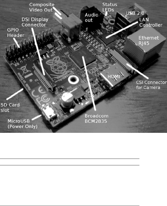
Figure 2-1 shows the Model B and its interfaces. Table 2-1 indicates the differences between the two models.
Chapter 2 ■ the raspberry pi
6
Figure 2-1. Model B interfaces
Table 2-1. Model Differences
Resource Model A Model B
RAM 256 MB 512 MB
USB ports 1 2
Ethernet port None 10/100 Ethernet (RJ45)
Power consumption10 300 mA (1.5 W) 700 mA (3.5 W)
Target price9$25.00 $35.00
As you can see, one of the first differences to note is the amount of RAM available. The revision 2.0 (Rev 2.0)
Model B has 512 MB of RAM instead of 256 MB. The GPU also shares use of the RAM. So keep that in mind when
budgeting RAM.
In addition, the Model A does not include an Ethernet port but can support networking through a USB network
adapter. Keep in mind that only one USB port exists on the Model A, requiring a hub if other USB devices are needed.
Finally, the power consumption differs considerably between the two models. The Model A is listed as requiring
300 mA vs. 700 mA for the Model B. Both of these figures should be considered low because consumption rises
considerably when the GPU is active (when using the desktop through the HDMI display port).
The maximum current flow that is permitted through the 5 V micro-USB connection is about 1.1 A because of the
fuse. However, when purchasing a power supply/adapter, it is recommended that you seek supplies that are rated higher
than 1.2 A because they often don’t live up to their specifications. Chapter 4 provides more details about power supplies.

Chapter 2 ■ the raspberry pi
7
Hardware in Common
The two Raspberry Pi models share some common features, which are summarized in Table 2-2.9 The Hardware
column lists the broad categories; the Features column provides additional specifics.
Table 2-2. Common Hardware Features
Hardware Features Comments
System on a chip Broadcom BCM2835 CPU, GPU, DSP, SDRAM, and USB port
CPU model
Clock rate
ARM1176JZF-S core With floating point
700 MHz Overclockable to 800 MHz
GPU Broadcom VideoCore IV
OpenGL ES 2.0 3D
OpenVG 3D
MPEG-2
VC-1 Microsoft, licensed
1080p30 H.264 Blu-ray Disc capable, 40 Mbit/s
MPEG-4 AVC high-profile decoder and encoder
1 Gpixel/s, 1.5 Gtexels/s 24 GFLOPS with DMA
Video output Composite RCA PAL and NTSC
HDMI Rev 1.3 and 1.4
Raw LCD panels Via DSI
Audio output 3.5 mm jack
HDMI
Storage SD/MMC/SDIO Card slot
Peripherals 8 × GPIO
UART
I2C bus 100 kHz
SPI bus Two chip selects, +3.3 V, +5 V, ground
Power source 5 V via micro-USB
Which Model?
One of the questions that naturally follows a model feature comparison is why the Model A? Why wouldn’t everyone
just buy Model B?
Power consumption is one deciding factor. If your application is battery powered, perhaps a data-gathering node
in a remote location, then power consumption becomes a critical factor. If the unit is supplemented by solar power,
the Model A’s power requirements are more easily satisfied.
Cost is another advantage. When an Arduino/AVR class of application is being considered, the added capability
of the Pi running Linux, complete with a file system on SD, makes it irresistible. Especially at the model A price of $25.
Chapter 2 ■ the raspberry pi
8
Unit cost may be critical to students in developing countries. Networking can be sacrificed, if it still permits
the student to learn on the cheaper Model A. If network capability is needed later, even temporarily, a USB network
adapter can be attached or borrowed.
The main advantage of the Model B is its networking capability. Networking today is so often taken for granted.
Yet it remains a powerful way to integrate a larger system of components. The project outlined in Chapter 29
demonstrates how powerful ØMQ (ZeroMQ) can be in bringing separate nodes together.

9
Chapter 3
Preparation
While it is assumed that you’ve already started with the Raspberry Pi, there may be a few things that you want to
do before working through the rest of this book. For example, if you normally use a laptop or desktop computer,
you may prefer to access your Pi from there. Consequently, some of the preparation in this chapter pertains to
network access.
If you plan to do most or all of the projects in this book, I highly recommend using something like the Adafruit Pi
Cobbler (covered later in this chapter). This hardware breaks out the GPIO lines in a way that you can access them on
a breadboard. If you’re industrious, you could build a prototyping station out of a block of wood. I took this approach
but would buy the Adafruit Pi Cobbler if I were to do it again (this was tedious work).
Static IP Address
The standard Raspbian SD card image provides a capable Linux system, which when plugged into a network, uses
DHCP to automatically assign an IP address to it. If you’d like to connect to it remotely from a desktop or laptop, then
the dynamic IP address that DHCP assigns is problematic.
There are downloadable Windows programs for scanning the network. If you are using a Linux or Mac host, you
can use Nmap to scan for it. The following is an example session from a MacBook Pro, using the MacPorts collection
nmap command. Here a range of IP addresses are scanned from 1–254:
$ sudo nmap −sP 192.168.0.1−254
Starting Nmap 6.25 (http://nmap.org) at 2013−04−14 19:12 EDT
. . .
Nmap scan report for mac (192.168.0.129)
Host is up.
Nmap scan report for rasp (192.168.0.132)
Host is up (0.00071s latency).
MAC Address : B8:27:EB:2B:69:E8 (Raspberry Pi Foundation)
Nmap done : 254 IP addresses (6 hosts up) scanned in 6.01 seconds
$
In this example, the Raspberry Pi is clearly identified on 192.168.0.132, complete with its MAC address. While this
discovery approach works, it takes time and is inconvenient.
If you’d prefer to change your Raspberry Pi to use a static IP address, see the “Wired Ethernet” section in Chapter 9
for instructions.
CHAPTER 3 ■ PREPARATION
10
Using SSH
If you know the IP address of your Raspberry Pi or have the name registered in your hosts file, you can log into it by
using SSH. In this example, we log in as user pi on a host named rasp (in this example, from a Mac):
$ ssh pi@rasp
pi@rasp’s password:
Linux raspberrypi 3.2.27+ #250 PREEMPT ... armv6l
...
Last login : Fri Jan 18 22:19:50 2013 from 192.168.0.179
$
Files can also be copied to and from the Raspberry Pi, using the scp command. Do a man scp on the Raspberry Pi
to find out more.
It is possible to display X Window System (X-Window) graphics on your laptop/desktop, if there is an X-Window
server running on it. (Windows users can use Cygwin for this, available from www.cygwin.com.) Using Apple's OS X as
an example, first configure the security of your X-Window server to allow requests. Here I’ll take the lazy approach of
allowing all hosts (performed on the Mac) by using the xhost command:
$ xhost +
access control disabled, clients can connect from any host
$
From the Raspberry Pi, connected through the SSH session, we can launch Xpdf, so that it opens a window on
the Mac:
$ export DISPLAY=192.168.0.179:0
$ xpdf &
Here, I’ve specified the Mac’s IP address (alternatively, an /etc/hosts name could be used) and pointed the
Raspberry Pi to use the Mac’s display number :0. Then we run the xpdf command in the background, so that we can
continue to issue commands in the current SSH session. In the meantime, the Xpdf window will open on the Mac,
while the Xpdf program runs on the Raspberry Pi.
This doesn’t give you graphical access to the Pi’s desktop, but for developers, SSH is often adequate. If you want
remote graphical access to the Raspberry’s desktop, see the next section, where VNC is introduced.
VNC
If you’re already using a laptop or your favorite desktop computer, you can conveniently access your Raspberry Pi’s
graphical desktop over the network. Once the Raspberry Pi’s VNC server is installed, all you need is a VNC client
on your accessing computer. Once this is available, you no longer need a keyboard, mouse, or HDMI display device
connected to the Raspberry Pi. Simply power up the Pi on your workbench, with a network cable plugged into it.
You can easily install the VNC server software on the Pi at the cost of about 10.4 MB in the root file system. The
command to initiate the download and installation is as follows:
$ sudo apt–get install tightvncserver
After the software is installed, the only remaining step is to configure your access to the desktop. The vncserver
command starts up a server, after which you can connect remotely to it.
CHAPTER 3 ■ PREPARATION
11
Using SSH to log in on the Raspberry Pi, type the following command:
$ vncserver :1 –geometry 1024x740 –depth 16 –pixelformat rgb565
You will require a password to access your desktop.
Password:
Verify:
Would you like to enter a view–only password (y/n ) ? n
New 'X' desktop is rasp:1
Creating default startup script/home/pi/.vnc/xstartup Starting applications specified
in/home/pi/.vnc/xstartup
Log file is/home/pi/.vnc/rasp:1.log
$
The password prompts are presented only the first time that you start the VNC server.
Display Number
In the vncserver command just shown, the first argument identifies the display number. Your normal Raspberry Pi
X-Window desktop is on display :0. So when you start up a VNC server, choose a new unique display number like :1.
It doesn’t have to be the number 1. To a limited degree, you can run multiple VNC servers if you find that useful. For
example, you might choose to start another VNC server on :2 with a different display resolution.
Geometry
The -geometry 1024x740 argument configures the VNC server’s resolution in pixels. This example’s resolution is
unusual in that normally 1024×768 would be used for a display resolution, a common geometry choice for monitors.
But this need not be tied to a physical monitor resolution. I chose the unusual height of ×740 to prevent the VNC client
program from using scrollbars (on a Mac). Some experimentation may be required to find the best geometry to use.
Depth
The -depth 16 argument is the pixel-depth specification. Higher depths are possible, but the resulting additional
network trafficc might curb your enthusiasm.
Pixel Format
The last command-line argument given is -pixelformat rgb565. This particular example specifies that each pixel is 5
bits, 6 bits, 5 bits—for red, green and blue, respectively.
Password Setup
To keep unauthorized people from accessing your VNC server, a password is accepted from you when you start the
server for the first time. The password chosen can be changed later with the vncpasswd command.
CHAPTER 3 ■ PREPARATION
12
Server Startup
If you often use VNC, you may want to define a personal script or alias to start it on demand. Alternatively, have it
started automatically by the Raspberry Pi as part of the Linux initialization. See Chapter 17 for more information
about initialization scripts.
VNC Viewers
To access your VNC server on the Raspberry Pi, you need a corresponding VNC viewer on the client side. On the Mac,
you can use the MacPorts collection to install a viewer:
$ sudo port install vnc
Once the viewer is installed, you can access your VNC server on the Raspberry Pi at 192.168.0.170, display :1,
with this:
$ vncviewer 192.168.0.170:1
If you have your Raspberry Pi in the hosts file under rasp, you can use the name instead:
$ vncviewer rasp:1
When the VNC viewer connects to the server, you will be prompted for a password. This obviously keeps others
out of your VNC server.
For Ubuntu Linux, you can install the xvnc4viewer package. For Windows, several choices are available, such as
RealVNC and TightVNC.
If you find that the screen resolution doesn’t work well with your client computer, experiment with different
VNC server resolutions (-geometry). I prefer to use a resolution that doesn’t result in scrollbars in the viewer.
Scrolling around your Raspberry Pi desktop is a nuisance. You can eliminate the need for scrolling by reducing the
geometry dimensions.
Stopping VNC Server
Normally, you don’t need to stop the VNC server if you are just going to reboot or shut down your Raspberry Pi. But
if you want to stop the VNC server without rebooting, this can be accomplished. Supply the display number that you
used in the VNC server startup (:1 in this example) using the -kill option:
$ vncserver –kill :1
This can be useful as a security measure, or to save CPU resources when the server isn’t being used. This can also
be useful if you suspect a VNC software problem and need to restart it.
Prototype Station
The danger of working with the tiny Raspberry Pi’s PCB is that it moves all over the surface as wires tug at it. Given its
low mass, it moves easily and can fall on the floor and short wires out in the process (especially around curious cats).
CHAPTER 3 ■ PREPARATION
13
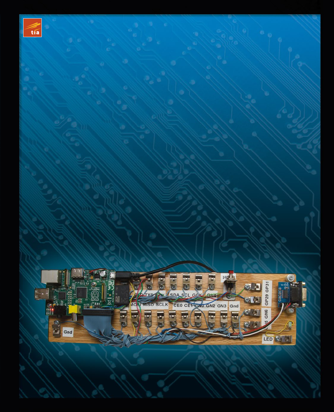
For this reason, I mounted my Raspberry Pi on a nice block of wood. A small plank can be purchased from the
lumberyard for a modest amount. I chose to use teak since it looks nice and doesn’t crack or warp. Even if you choose
to use something like the Adafruit Pi Cobbler, you may find it useful to anchor the Raspberry Pi PCB. Mount the PCB
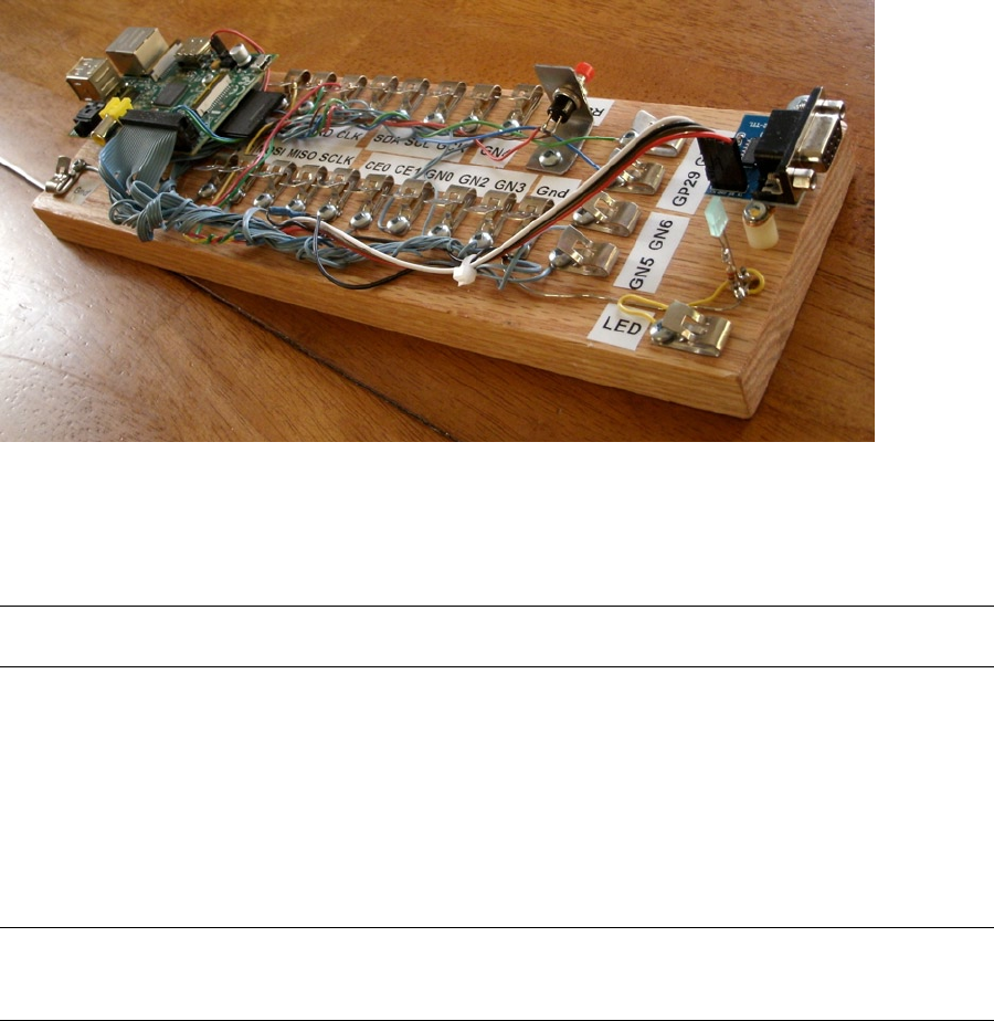
on the wood with spacers. Figure 3-1 shows my prototype station.
Figure 3-1. A simple prototype station
Retro Fahnestock clips were installed and carefully wired to a connector on header strip P1 (the wiring was the
most labor-intensive part of this project).
Tip ■ Fahnestock clips can be economically purchased at places like www.tubesandmore.com (part # S-H11-4043-6).
A small PCB for the RS-232 interface was acquired from eBay ($2.32 total) and mounted at the end of the station.
Wires from the RS-232 PCB were routed back to RX/TX and +3.3 V clips and simply clipped into place (this allows
you to disconnect them, if you wish to use those GPIO pins for some other purpose). The RS-232 PCB is permanently
grounded for convenience.
The RS-232 PCB is necessary only for those who wish to use a serial console or to interface with some other serial
device. The PCB acquired was advertised on eBay as “MAX232CSE Transfer Chip RS-232 To TTL Converter Module
COM Serial Board.” The converter (based on the MAX232CSE chip) will work with TTL or 3.3 V interfaces. Connecting
the RS-232 converter’s VCC connection to the Raspberry Pi +3.3 V supply makes it compatible with the Pi.
Caution ■ Do not connect the RS-232 converter to +5 V, or you will damage the Pi. For additional information about
this, see Chapter 11.
In Figure 3-1 you can see a simple bracket holding a small push button (top right). This has been wired up to P6
for a reset button. This is not strictly required if your power supply is working correctly (power-on reset works rather
well). Unlike an AVR setup, you are not likely to use reset very often. Chapter 5 has more details about this.
CHAPTER 3 ■ PREPARATION
14
The LED was added to the station last. It was soldered to a pair of half-inch finishing nails, nailed into the wood.
The LED’s cathode has a 220 W resister soldered in series with it to limit the current and wired to ground. The anode
is connected to the Fahnestock clip labeled LED. The LED can be tested by connecting an alligator lead from the LED
clip to the +3.3 V supply clip (this LED also tolerates +5 V). Be sure to choose a low- to medium-current LED that
requires about 10 mA or less (16 mA is the maximum source current from a GPIO pin).
To test your prototyping station, you may want to use the script listed in the “GPIO Tester” section in Chapter 12.
That script can be used to blink a given GPIO pin on and off in 1-second intervals.
Adafruit Pi Cobbler
A much easier approach to prototype connections for GPIO is to simply purchase the Adafruit Pi Cobbler kit, which is
available from the following site:
learn.adafruit.com/adafruit-pi-cobbler-kit/overview
This kit provides you with these features:
Header connector for the Pi’s P1•
Ribbon cable•
Small breakout PCB•
Breakout header pins•
After assembly, you plug the ribbon cable onto the header P1. At the other end of the ribbon cable is a small PCB
that provides 26 pins that plug into your prototype breadboard. A small amount of assembly is required.
Gertboard
Students might consider using a Gertboard, which is available from this site:
uk.farnell.com
The main reason behind this recommendation is that the Raspberry Pi’s connections to the outside world are
sensitive, 3.3 V, and vulnerable to static electricity. Students will want to connect all manner of buttons, switches,
motors, and relays. Many of these interfaces require additional buffers and drivers, which is what the Gertboard is
there for.
In addition to providing the usual access to the Pi’s GPIO pins, the Gertboard also provides these features:
Twelve • buffered I/O pins
Three push buttons•
Six open collector drivers (up to 50 V, 500 mA)•
A motor controller (18 V, 2 A)•
A two-channel 8/10/12 bit digital-to-analog converter•
A two-channel 10-bit analog-to-digital converter•
A 28-pin DIP ATmega microcontroller•
This provides a ready-made learning environment for the student, who is anxious to wire up something and just
“make it work.” Many of the 3-volt logic and buffering concerns are eliminated, allowing the student to focus on projects.
CHAPTER 3 ■ PREPARATION
15
Bare Metal
Despite the availability of nice adapters like the Gertboard, the focus of this text is on interfacing directly to the Pi’s 3 V
GPIO pins. Here are some of the reasons:
No specific adapter has to be purchased for the projects in this book.•
Any specified adapter can go out of production.•
You’ll not likely use an expensive adapter on each • deployed Pi.
Bare metal interfacing will exercise your design skills.•
If we were to do projects with only wiring involved, there wouldn’t be much learning involved. Facing the design
issues that arise from working with weak 3 V GPIOs driving the outside world will be much more educational.
The third bullet speaks to finished projects. If you’re building a robot, for example, you’re not going to buy
Gertboards everywhere you need to control a motor or read sensor data. You’re going to want to economize and build
that yourself. This book is designed to help you face those kinds of challenges.

17
Chapter 4
Power
One of the most frequently neglected parts of a system tends to be the power supply—at least when everything is
working. Only when things get weird does the power supply begin to get some scrutiny.
The Raspberry Pi owner needs to give the power supply extra respect. Unlike many AVR class boards, where the
raw input voltage is followed by an onboard 5 V regulator, the Pi expects its power to be regulated at the input. The Pi
does include onboard regulators, but these regulate to lower voltages (3.3 V and lower).
Figure 4-1 illustrates the rather fragile Micro-USB power input connector. There is a large round capacitor
directly behind the connector that people often grab for leverage. It is a mistake to grab it, however, as many have
reported “popping it off” by accident.
Figure 4-1. Micro-USB power input

CHAPTER 4 ■ POWER
18
Calculating Power
Sometimes power supplies are specified in terms of voltage, and power handling capability in watts. The Pi’s input
voltage of 5 V must support a minimum of 700 mA (Model B). Let’s compute a power supply figure in watts (this does
not include any added peripherals):
P=VI
=5 0.7
= 3.5 W
´
´
The 3.5 W represents a minimum requirement, so we should overprovision this by an additional 50%:
P
W
=´
=
35 150
525
..
.
The additional 50% yields a power requirement of 5.25 W.
Tip ■ Allow 50% extra capacity for your power supply. A power supply gone bad may cause damage or many other
problems. One common power-related problem for the Pi is loss of data on the SD card.
Current Requirement
Since the power supply being sought produces one output voltage (5 V), you’ll likely see adapters with advertised
current ratings instead of power. In this case, you can simply factor a 50% additional current instead:
II
A
plyPisup.
..
.
=´
=´
=
150
0 700 150
105
To double-check our work, let’s see whether this agrees with the power rating we computed earlier:
P=VI
=5 1.05
= 5.25 W
´
´
The result does agree. You can conclude this section knowing that you minimally need a 5 V supply that produces
one of the following:
5.25 W or more•
1.05 A or more (ignoring peripherals)•
Supplies that can meet either requirement, should be sufficient. However, you should be aware that not all
advertised ratings are what they seem. Cheap supplies often fail to meet their own claims, so an additional margin
must always be factored in.

CHAPTER 4 ■ POWER
19
Peripheral Power
Each additional circuit that draws power, especially USB peripherals, must be considered in a power budget. Depending
on its type, a given USB peripheral plugged into a USB 2 port can expect up to 500 mA of current, assuming it can obtain
it. (Pre Rev 2.0 USB ports were limited to 140 mA by polyfuses.)
Wireless adapters are known to be power hungry. Don’t forget about the keyboard and mouse when used, since
they also add to the power consumption. If you’ve attached an RS-232 level shifter circuit (perhaps using MAX232CPE),
you should budget for that small amount also in the 3 V supply budget. This will indirectly add to your +5 V budget,
since the 3 V regulator is powered from it. (The USB ports use the +5 V supply.) Anything that draws power from your
Raspberry Pi should be tallied.
Model B Input Power
The Raspberry Pi’s input voltage is fixed at exactly 5 V (±0.25 V). Looking at the schematic in Figure 4-2, you can see
how the power enters the micro-USB port on the pin marked VBUS. Notice that the power flows through fuse F3,
which is rated at 6 V, 1.1 A. If after an accidental short, you find that you can’t get the unit to power up, check that fuse
with an ohmmeter.
Figure 4-2. Model B Rev 2.0 input power

CHAPTER 4 ■ POWER
20
If you bring the input +5 V power into the Pi through header P1, P5, or TP1, for example, you will lose the safety
of the fuse F3. So if you bypass the micro-USB port to bring in power, you may want to include a safety fuse in the
supplying circuit.
Figure 4-3 shows the 3.3 V regulator for the Pi. Everything at the 3.3 V level is supplied by this regulator, and the
current is limited by it.
Figure 4-3. 3.3 V power
Model A Input Power
Like the Model B, the Model A receives its power from the micro-USB port. The Model A power requirement is 300
mA, which is easily supported by a powered USB hub or desktop USB 2 port. A USB 2 port is typically able to supply
a maximum of 500 mA unless the power is divided among neighboring ports. You may find in practice, however, that
not all USB ports will deliver 500 mA.
As with the Model B, factor the power required by your USB peripherals. If your total nears or exceeds 500 mA,
you may need to power your Model A from a separate power source. Don’t try to run a wireless USB adapter from the
Model A’s USB port if the Pi is powered by a USB port itself. The total current needed by the Pi and wireless adapter
will likely exceed 500 mA. Supply the wireless adapter power from a USB hub, or power the Pi from a 1.2 A or better
power source. Also be aware that not all USB hubs function correctly under Linux, so check compatibility if you’re
buying one for that purpose.
3.3 Volt Power
Since the 3.3 V supply appears at P1-01, P1-17, and P5-02, it is useful to examine Figure 4-3 (shown previously) to note
its source. This supply is indirectly derived from the input 5 V supply, passing through regulator RG2. The maximum
excess current that can be drawn from it is 50 mA; the Raspberry Pi uses up the remaining capacity of this regulator.
When planning a design, you need to budget this 3 V supply carefully. Each GPIO output pin draws from this
power source an additional 3 to 16 mA, depending on how it is used. For more information about this, see Chapter 12.
Powered USB Hubs
If your power budget is stretched by USB peripherals, you may want to consider the use of a powered USB hub. In this
way, the hub rather than your Raspberry Pi provides the necessary power to the downstream peripherals. The hub is
especially attractive for the Model A because it provides additional ports.

CHAPTER 4 ■ POWER
21
Again, take into account that not all USB hubs work with (Raspbian) Linux. The kernel needs to cooperate with
connected USB hubs, so software support is critical. The following web page lists known working USB hubs:
http://elinux.org/RPi_Powered_USB_Hubs
Power Adapters
This section pertains mostly to the Model B because the Model A is easily supported by a USB 2 port. We’ll first look at
an unsuitable source of power and consider the factors for finding suitable units.
An Unsuitable Supply
The example shown in Figure 4-4 was purchased on eBay for $1.18 with free shipping (see the upcoming warning
about fakes). For this reason, it was tempting to use it.
Figure 4-4. Model A1265 Apple adapter
This is an adapter/charger with the following ratings:
• Model: A1265
• Input: 100–240 VAC
• Output: 5 V, 1 A
When plugged in, the Raspberry Pi’s power LED immediately lights up, which is a good sign for an adapter
(vs. a charger). A fast rise time on the power leads to successful power-on resets. When the voltage was measured,
the reading was +4.88 V on the +5 V supply. While not ideal, it is within the range of acceptable voltages. (The voltage
must be between 4.75 and 5.25 V.)
The Apple unit seemed to work fairly well when HDMI graphics were not being utilized (using serial console,
SSH, or VNC). However, I found that when HDMI was used and the GPU had work to do (move a window across the
desktop, for example), the system would tend to seize up. This clearly indicates that the adapter does not fully deliver
or regulate well enough.

CHAPTER 4 ■ POWER
22
Caution ■ Be very careful of counterfeit Apple chargers/adapters. The Raspberry Pi Foundation has seen returned units
damaged by these. For a video and further information, see www.raspberrypi.org/archives/2151.
E-book Adapters
Some people have reported good success using e-book power adapters. I have also successfully used a 2 A Kobo charger.
Best Power Source
While it is possible to buy USB power adapters at low prices, it is wiser to spend more on a high-quality unit. It is not
worth trashing your Raspberry Pi or experiencing random failures for the sake of saving a few dollars.
If you lack an oscilloscope, you won’t be able to check how clean or dirty your supply current is. A better
power adapter is cheaper than an oscilloscope. A shaky/noisy power supply can lead to all kinds of obscure and
intermittent problems.
A good place to start is to simply Google “recommended power supply Raspberry Pi.” Do your research
and include your USB peripherals in the power budget. Remember that wireless USB adapters consume a lot of
current—up to 500 mA.
Note ■ A random Internet survey reveals a range of 330 mA to 480 mA for wireless USB adapter current consumption.
Voltage Test
If you have a DMM or other suitable voltmeter, it is worthwhile to perform a test after powering up the Pi. This is
probably the very first thing you should do, if you are experiencing problems.
Follow these steps to perform a voltage test:
1. Plug the Raspberry Pi’s micro-USB port into the power adapter’s USB port.
2. Plug in the power adapter.
3. Measure the voltage between P1-02 (+5 V) and P1-25 (Ground): expect +4.75 to +5.25 V.
4. Measure the voltage between P1-01 (+3.3 V) and P1-25 (Ground): expect +3.135 to +3.465 V.
Caution ■ Be very careful with your multimeter probes around the pins of P1. Be especially careful not to short the
+5 V to the +3.3 V pin, even for a fraction of a second. Doing so will zap your Pi! If you feel nervous or shaky about this,
leave it alone. You may end up doing more harm than good. As a precaution, put a piece of wire insulation (or spaghetti)
over the +3.3 V pin.
The left side of Figure 4-5 shows the DMM probes testing for +5 V on header strip P1. Again, be very careful not to
touch more than one pin at a time when performing these measurements. Be particularly careful not to short between
5 V and 3.3 V. To avoid a short-circuit, use a piece of wire insulation, heat shrink tubing, or even a spaghetti noodle
over the other pin.
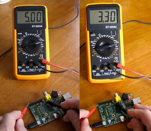
CHAPTER 4 ■ POWER
23
The right side of Figure 4-5 shows the positive DMM probe moved to P1-01 to measure the +3.3 V pin. Appendix
B lists the ATX power supply standard voltage levels, which include +5 ± 0.25 V and +3.3 ± 0.165 V.
Battery Power
Because of the small size of the Raspberry Pi, it may be desirable to run it from battery power. Doing so requires a
regulator and some careful planning. To meet the Raspberry Pi requirements, you must form a power budget. Once
you know your maximum current, you can flesh out the rest. The following example assumes that 1 A is required.
Requirements
For clarity, let’s list our battery power requirements:
Voltage 5 V, within ± 0.25 V•
Current 1 A•
Figure 4-5. Measuring voltages
CHAPTER 4 ■ POWER
24
Headroom
The simplest approach is to use the linear LM7805 as the 5 V regulator. But there are some disadvantages:
There must be some headroom above the input voltage (about 2 V).•
Allowing too much headroom increases the power dissipation in the regulator, resulting in •
wasted battery power.
A lower maximum output current can also result.•
Your batteries should provide a minimum input of 5+2 V (7 V). Any lower input voltage to the regulator will result
in the regulator “dropping out” and dipping below 5 V. Clearly, a 6 V battery input will not do.
LM7805 Regulation
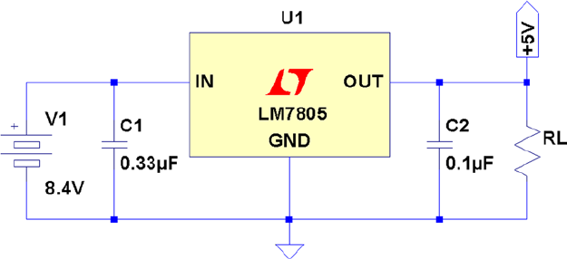
Figure 4-6 shows a very simple battery circuit using the LM7805 linear regulator. Resistor RL represents the load
(the Raspberry Pi).
Figure 4-6. Regulated battery supply
The 8.4 V battery is formed from seven NiCad cells in series, each producing 1.2 V. The 8.4 V input allows the
battery to drop to a low of 7 V before the minimum headroom of 2 V is violated.
Depending on the exact 7805 regulator part chosen, a typical heat-sinked parameter set might be as follows:
• Input voltage: 7–25 V
• Output voltage: 1.5 A (heat-sinked)
• Operating temperature: 125°C
Be sure to use a heat sink on the regulator so that it can dissipate heat energy to the surrounding air. Without one,
the regulator can enter a thermal shutdown state, reducing current flow to prevent its own destruction. When this
happens, the output voltage will drop below +5 V.
CHAPTER 4 ■ POWER
25
Keep in mind that the amount of power dissipated by the battery is more than that received by the load. If we
assume that the Raspberry Pi is consuming 700 mA, a minimum of 700 mA is also drawn from the battery through
the regulator (and it could be slightly higher). Realize that the regulator is dissipating additional energy because of its
higher input voltage. The total power dissipated by the regulator and the load is as follows:
PPP
VAVV A
WW
W
dLR
=
=5 0.7
=
= 5.88
´
´+ -´
+
(. ).
..
84 507
35 238
The regulator must dissipate the difference between the input and the output voltages (2.38 W). This additional
energy heats up the regulator with the energy being given away at the heat sink. Because of this, designers avoid using
a high input voltage on linear regulator circuits.
If the regulator is rated at a maximum of 1.5 A at 7 V (input), the power maximum for the regulator is about
10.5 W. If we apply an input voltage of 8.4 V instead of 7, we can derive what our 5 V maximum current will be:
IP
V
W
V
A
in
max
max
.
.
.
=
=
=
10 5
84
125
From this, we find that the 8.4 V battery regulator circuit can provide a maximum of 1.25 A at the output, without
exceeding the regulator’s power rating. Multiply 8.4 V by 1.25 A to convince yourself that this equals 10.5 W.
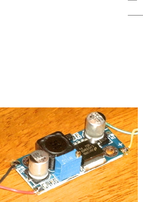
DC-DC Buck Converter
If the application is designed for data acquisition, for example, it is desirable to have it run as long as possible on a
given set of batteries or charge cycle. A switching regulator may be more suitable than the linear regulator.
Figure 4-7 shows a very small PCB that is about 1.5 SD cards in length. This unit was purchased from eBay for
$1.40, with free shipping. At these prices, why would you build one?
Figure 4-7. DC-DC buck converter

CHAPTER 4 ■ POWER
26
They are also simple to use. You have + and – input connections and + and – output connections. Feed power in
at one voltage and get power out at another voltage. This is so simple that you’ll forgive me if I omit the diagram for it.
But don’t immediately wire it up to your Raspberry Pi, until you have calibrated the output voltage. While it might
come precalibrated for 5 V, it is best not to count on it. If the unit produces a higher voltage, you might fry the Pi.
The regulated output voltage is easily adjusted by a multiturn trim pot on the PCB. Adjust the pot while you read
your DMM.
The specifications for the unit I purchased are provided in Table 4-1 for your general amusement. Notice the wide
range of input voltages and the fact that it operates at a temperature as low as –40ºC. The wide range of input voltages
and current up to 3 A clearly makes this a great device to attach to solar panels that might vary widely in voltage.
Table 4-1. DC-DC buck converter specifications
Parameter Min Max Units Parameter Min Max Units
Input voltage 4.00 35.0 Volts Output ripple 30.9 mA
Input current 3.0 Amps Load regulation ±0.5 %
Output voltage 1.23 30.0 Volts Voltage regulation ±2.5 %
Conversion efficiency 92 % Working temperature –40 +85 °C
Switching frequency 150 kHz PCB size 45×20×12 mm
Net weight 10 g
The specification claims up to a 92% conversion efficiency. Using 15 V on the input, I performed my own little
experiment with measurements. With the unit adjusted to produce 5.1 V at the output, the readings shown in
Table 4-2 were taken.
Table 4-2. Readings taken from experiment
Parameter Input Output Units
Voltage 15.13 5.10 Volts
Current 0.190 0.410 Amps
Power 2.87 2.09 Watts
From the table we expected to see more power used on the input side (2.87 W). The power used on the output
side was 2.09 W. The efficiency then becomes a matter of division:
209
2870 728
.
..=
From this we can conclude that the measured conversion efficiency was about 72.8%.
How well could we have done if we used the LM7805 regulator? The following is a best case estimate, since I don’t
have an actual current reading for that scenario. But we do know that at least as much current that flows out of the
regulator must flow into it (likely more). So what is the absolute best that the LM7805 regulator could theoretically do?
Let’s apply the same current draw of 410 mA for the Raspberry Pi at 5.10 V, as shown in Table 4-3. (This was operating
without HDMI output in use.)

CHAPTER 4 ■ POWER
27
The power efficiency for this best case scenario amounts to this:
209
2910 718
.
..=
The absolute best case efficiency for the LM7805 regulator is 71.8%. But this is achieved at its optimal input
voltage. Increasing the input voltage to 12 V causes the power dissipation to rise considerably, resulting in a 42.5%
efficiency (this calculation is left to the reader as an exercise). Attempting to operate the LM7805 regulator at 15.13 V,
as we did with the buck converter, would cause the efficiency to drop to less than 33.7%. Clearly, the buck converter is
much more efficient at converting power from a higher voltage source.
Signs of Insufficient Power
In the forums, it has been reported that ping sometimes doesn’t work from the desktop (with HDMI), yet works OK in
console mode.42 Additionally, I have seen that desktop windows can freeze if you move them (HDMI). As you start to
move the terminal window, for example, the motion would freeze part way through, as if the mouse stopped working.
These are signs of the Raspberry Pi being power starved. The GPU consumes more power when it is active,
performing accelerated graphics. Either the desktop freezes (GPU starvation) or the network interface fails (ping).
There may be other symptoms related to HDMI activity.
Another problem that has been reported is resetting of the Raspberry Pi shortly after starting to boot. The board
starts to consume more power as the kernel boots up, which can result in the Pi being starved.43
If you lose your Ethernet connection when you plug in a USB device, this too may be a sign of insufficient power.44
While it may seem that a 1 A power supply should be enough to supply a 700 mA Raspberry Pi, you will be better
off using a 2 A supply instead. Many power supplies simply don’t deliver their full advertised ratings.
The micro-USB cable is something else to suspect. Some are manufactured with thin conductors that can result
in a significant voltage drop. Measuring the voltage as shown previously in the “Voltage Test” section may help
diagnose that. Try a higher-quality cable to see whether there is an improvement.
No Power
If your Pi appears dead, even though power is present at the input, the input polyfuse could have blown. If this was a
recent event, allow the unit to cool down. The polymer in the fuse recrystallizes, but this can take several hours. If you
think the F3 poly fuse is permanently destroyed, see the Linux wiki page45 for how to test it.
Table 4-3. Hypothetical LM7805 power use
Parameter Input Output Units
Voltage 7.1 5.10 Volts
Current 0.410 0.410 Amps
Power 2.91 2.09 Watts

29
Chapter 5
Header Strips, LEDs, and Reset
In this chapter, an inventory of the Raspberry Pi header strips, LEDs, and reset button connections is covered.
These are important interfaces from the Pi to the outside world. You may want to use a bookmark for Table 5-3,
which outlines the general purpose input/output (GPIO) pins on header strip P1.
Status LEDs
The Model A Raspberry Pi has a subset of the Model B LED indicators because it lacks the Ethernet port. The Model B
has three additional LEDs, each showing the network status. Table 5-1 provides a list of LED statuses.
Table 5-1. Status LEDs
LED Color Model A Model B Comment
ACT Green OK ACT SD card access activity
PWR Red Yes Yes Power supply
FDX Green N/A Yes LAN: Full duplex
LNK Green N/A Yes LAN: Link
100 Yellow N/A 100 Labeled incorrectly on Rev 1.0 as 10M: 10/100 Mbit link
OK or ACT LED
This green LED indicates SD card I/O activity. This active low LED is internally driven by the kernel on
GPIO 16 (see the kernel source file bcm2708.c in arm/mach-bcm2708).
PWR LED
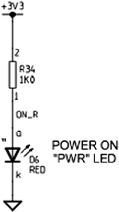
This red LED simply indicates that the Raspberry Pi has power. Figure 5-1 shows that the power LED is supplied from
the 3.3 V regulator.14 Consequently, the LED indicates only that power is arriving through the 3.3 V regulator.
CHAPTER 5 ■ HEADER STRIPS, LEDS, AND RESET
30
The power LED indicator is not necessarily an indication that the power is good. It simply indicates that power is
present. The LED can be lit and still not have sufficient voltage present for the CPU to operate correctly.
If there is any doubt about how good the power supply is, refer to the “Voltage Test” section in Chapter 4, which
has information about how to perform a voltage test.
FDX LED
This green LED indicates that the Ethernet port is operating in full-duplex mode.
LNK LED
This green LED indicates that the Ethernet port has an active link-level status.
10M or 10/100 LED
Model B Rev 1.0 had this LED incorrectly labelled as 10M. The correct label is 100, which is found on Rev 2.0 boards.
This yellow LED indicates that the 100 Mbit link is active (otherwise, it is a 10 Mbit link).
Figure 5-1. Power LED

CHAPTER 5 ■ HEADER STRIPS, LEDS, AND RESET
31
Header P1
The Raspberry Pi includes a 13x2 pin strip identified as P1, which exposes GPIO pins. This includes the I2C, SPI, and
UART peripherals as well as the +3.3 V, +5.0 V, and ground connections. Table 5-2 shows the pin assignments for the
Model B, Rev 1.0 PCB.
Table 5-2. Rev 1.0 GPIO Header Connector P1 (Top View)
Lower Left Upper Left
3.3 V power P1-01 P1-02 5 V power
GPIO 0 (I2C0_SDA)+R1=1.8k P1-03 P1-04 5 V power
GPIO 1 (I2C0_SCL)+R2=1.8k P1-05 P1-06 Ground
GPIO 4 (GPCLK 0/1-Wire) P1-07 P1-08 GPIO 14 (TXD)
Ground P1-09 P1-10 GPIO 15 (RXD)
GPIO 17 P1-11 P1-12 GPIO 18 (PCM_CLK)
GPIO 21 (PCM_DOUT) P1-13 P1-14 Ground
GPIO 22 P1-15 P1-16 GPIO 23
3.3 V power P1-17 P1-18 GPIO 24
GPIO 10 (MOSI) P1-19 P1-20 Ground
GPIO 9 (MISO) P1-21 P1-22 GPIO 25
GPIO 11 (SCKL) P1-23 P1-24 GPIO 8 (CE0)
Ground P1-25 P1-26 GPIO 7 (CE1)
Lower Right Upper Right
Caution ■ The Model A can supply a maximum of 500 mA from the +5 V pins of P1. The model B has a lower
maximum limit of 300 mA. These limits are due to the fusible link F3 on the PCB (shown previously in Figure 4-2 in
Chapter 4). Note also for both models, the +3.3 V pins of P1 and P5 are limited to a maximum of 50 mA. This is the
remaining capacity of the onboard voltage regulator. GPIO currents also draw from this resource. (See Figure 4-3.)
Table 5-3 shows the connections for the Model B revision 2.0. According to the Raspberry Pi website14, these pin
assignments are not expected to change beyond Rev 2.0 in future revisions. The additional Rev 2.0 header P5 is shown
in Table 5-4.

CHAPTER 5 ■ HEADER STRIPS, LEDS, AND RESET
32
Note ■ Chapter 7 provides more information on identifying your Raspberry Pi. If you have an early pre Rev 2.0 board,
be aware that the GPIO pins differ.
Safe Mode
If your Raspbian SD image supports it, a safe mode can be activated when needed. The New Out of Box Software (NOOBS)
image still appears to support this feature.
Pin P1-05, GPIO 3 is special to the boot sequence for Rev 2.0 models. (This is GPIO 1 on the pre Rev 2.0 Model B.)
Grounding this pin or jumpering this to P1-06 (ground) causes the boot sequence to use a safe mode boot procedure.
If the pin is used for some other purpose, you can prevent this with configuration parameter avoid_safe_mode=1.
Be very careful that you don’t accidentally ground a power pin (like P1-01 or P1-02) when you do use it.
Table 5-4. Rev 2.0 P5 Header (Top View)
Lower Left Upper Left
(Square) 5 V P5-01 P5-02 3.3 V, 50 mA
GPIO 28 P5-03 P5-04 GPIO 29
GPIO 30 P5-05 P5-06 GPIO 31
Ground P5-07 P5-08 Ground
Lower Right Upper Right
Table 5-3. Rev 2.0 GPIO Header Connector P1 (Top View)
Lower Left Upper Left
3.3 V power, 50 mA max P1-01 P1-02 5 V power
GPIO 2 (I2C1_SDA1)+R1=1.8k P1-03 P1-04 5 V power
GPIO 3 (I2C1_SCL1)+R2=1.8k P1-05 P1-06 Ground
GPIO 4 (GPCLK 0/1-Wire) P1-07 P1-08 GPIO 14 (TXD0)
Ground P1-09 P1-10 GPIO 15 (RXD0)
GPIO 17 (GEN0) P1-11 P1-12 GPIO 18 (PCM_CLK/GEN1)
GPIO 27 (GEN2) P1-13 P1-14 Ground
GPIO 22 (GEN3) P1-15 P1-16 GPIO 23 (GEN4)
3.3 V power, 50 mA max P1-17 P1-18 GPIO 24 (GEN5)
GPIO 10 (SPI_MOSI) P1-19 P1-20 Ground
GPIO 9 (SPI_MISO) P1-21 P1-22 GPIO 25 (GEN6))
GPIO 11 (SPI_SCKL) P1-23 P1-24 GPIO 8 (CE0_N)
Ground P1-25 P1-26 GPIO 7 (CE1_N)
Lower Right Upper Right

CHAPTER 5 ■ HEADER STRIPS, LEDS, AND RESET
33
If yours fails to respond to safe mode, it may be due to a manufacturing error. See this message:
www.raspberrypi.org/phpBB3/viewtopic.php?f=29&t=12007
In that thread, it is suggested that you check the following:
$ vcgencmd otp_dump | grep 30:
30:00000002
If you see the value 2, it means that the firmware thinks this is a Rev 1.0 board (even though it may be a Rev 2.0).
When that applies, it will not support the safe mode sequence. Newer Rev 2.0 Pis do not have this issue.
When safe mode is invoked by the jumper, the config.txt file is ignored except for the avoid_safe_mode
parameter. Additionally, this mode overrides the kernel command line, and kernel_emergency.img is loaded. If this
file is unavailable, kernel.img is used instead.
The intent of this feature is to permit the user to overcome configuration problems without having to edit the
SD card on another machine in order to make a correction. The booted emergency kernel is a BusyBox image with
/boot mounted so that adjustments can be made. Additionally, the /dev/mmcblk0p2 root file system partition can be
fixed up or mounted if necessary.
Logic Levels
The logic level used for GPIO pins is 3.3 V and is not tolerant of 5 V TTL logic. The Raspberry Pi PCB is designed to be
plugged into PCB extension cards or otherwise carefully interfaced to 3 V logic. Input voltage parameters VIL and VIH
are described in Chapter 12. This feature of the Pi makes it an interesting case study as we interface it to the
outside world.
GPIO Configuration at Reset
The Raspberry Pi GPIO pins can be configured by software control to be input or output, to have pull-up or pull-down
resistors, or to assume some specialized peripheral function. After reset, only GPIO 14 and 15 are assigned a special
function (UART). After boot up, however, software can even reconfigure the UART pins as required.
When a GPIO pin is configured for output, there is a limited amount of current that it can drive (source or sink).
By default, each P1 GPIO is configured to use an 8 mA driver, when the pin is configured as an output. Chapter 12 has
more information on the software control of this.
Note ■ Raspbian 1-Wire bus is GPIO 4 (GPCLK0) Pin P1-07.
1-Wire Driver
The default GPIO pin used for the 1-Wire driver is GPIO 4. This is hard-coded in the following kernel source file:
arch/arm/mach–bcm2708/bcm2708.c
If you need to change this default, alter the line in bcm2708.c that defines the macro W1_GPIO:
#define W1_GPIO 4
Then rebuild your kernel.
CHAPTER 5 ■ HEADER STRIPS, LEDS, AND RESET
34
Header P5
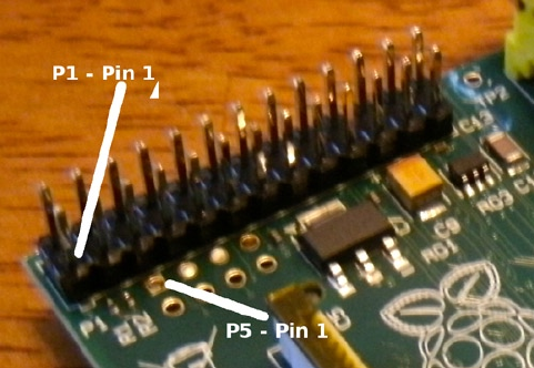
Be careful with the orientation of this Model B Rev 2.0 header strip. See Figure 5-2: while looking down at P1, with its
pin 1 at the lower left, the P5 strip has its pin 1 at the upper left (note the square pad on either side of the PCB).
Figure 5-2. P5’s pin 1 location on the Rev 2.0 Model B
As a practical matter, I found that the pins for P5 can be soldered into the PCB with some care (they are not
included). However, the proximity of P5 to P1 makes it impossible to plug in a header connector to P1 and P5 at
the same time. With the pins installed, it is possible to use individual wire plugs on the pins as needed. I ended up
plugging in a dual-wire plug on P5-04 and P5-06, which is one row away from P1. These wires were then brought out
to connectors on a wood strip for easier access.
By default, GPIO pins 28 through 31 are configured for driving 16 mA. (Chapter 12 has more information about this.)
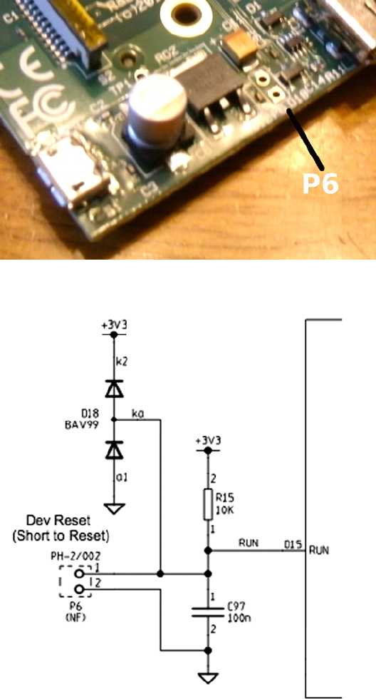
Reset
In the revision 2.0 Raspberry Pi, a reset circuit was implemented, as shown in Figure 5-4.11 To complete the reset
circuit, attach a push button to pins 1 and 2 of P6, as shown in Figure 5-3.14
CHAPTER 5 ■ HEADER STRIPS, LEDS, AND RESET
35
To actuate the reset, P6 pin 1 is short-circuited to P6 pin 2. This resets the BCM2835 SoC chip. This is something you
will want to avoid using while Raspbian Linux is up and running. Use reset as a last resort to avoid losing file content.
Figure 5-4. Reset circuit
Figure 5-3. Model B Rev 2.0 P6

37
Chapter 6
SDRAM
The Model B Rev 2.0 Raspberry Pi has 512 MB of SDRAM, while the older revisions and remaining models have
256 MB. Contrast this to the AVR class ATmega168p, which has 1 KB of static RAM. SDRAM is synchronous dynamic
random access memory, which synchronizes with the system bus for improved performance. It uses a form of
pipelining to gain this advantage.
There isn’t much about the memory hardware that concerns the average Pi developer. However, in this chapter,
you’ll examine some useful Raspbian Linux kernel interfaces that inform us how that memory is utilized. You’ll also
examine how to access the memory-mapped ARM peripherals directly from your Linux application.
/proc/meminfo
The pseudo file /proc/meminfo provides us with information about memory utilization. This information varies
somewhat by architecture and the compile options used for that kernel. Let’s study an example that is produced by
Raspbian Linux, on the Raspberry Pi:
$ cat /proc/meminfo
MemTotal: 448996 kB
MemFree: 340228 kB
Buffers: 14408 kB
Cached: 58532 kB
SwapCached: 0 kB
Active: 45948 kB
Inactive: 51564 kB
Active(anon): 24680 kB
Inactive(anon): 820 kB
Active(file): 21268 kB
Inactive(file): 50744 kB
Unevictable: 0 kB
Mlocked: 0 kB
SwapTotal: 102396 kB
SwapFree: 102396 kB
Dirty: 0 kB
Writeback: 0 kB
AnonPages: 24584 kB
Mapped: 20056 kB
Shmem: 932 kB
Slab: 6088 kB
SReclaimable: 2392 kB
Chapter 6 ■ SDraM
38
SUnreclaim: 3696 kB
KernelStack: 1216 kB
PageTables: 1344 kB
NFS_Unstable: 0 kB
Bounce: 0 kB
WritebackTmp: 0 kB
CommitLimit: 326892 kB
Committed_AS: 215104 kB
VmallocTotal: 188416 kB
VmallocUsed: 744 kB
VmallocChunk: 186852 kB
All of the memory values shown have the units KB to the right of them, indicating kilo (1,024) bytes.
This next example was taken from a Model A Raspberry Pi, with 256 MB:63
$cat/proc/meminfo
MemTotal: 190836 kB
MemFree: 151352 kB
Buffers: 7008 kB
Cached: 20640 kB
SwapCached: 0 kB
Active: 14336 kB
Inactive: 18648 kB
Active(anon): 5468 kB
Inactive(anon): 0 kB
Active(file): 8868 kB
Inactive(file): 18648 kB
Unevictable: 0 kB
Mlocked: 0 kB
SwapTotal: 0 kB
SwapFree: 0 kB
Dirty: 0 kB
Writeback: 0 kB
AnonPages: 5348 kB
Mapped: 6512 kB
Shmem: 136 kB
Slab: 3712 kB
SReclaimable: 1584 kB
SUnreclaim: 2128 kB
KernelStack: 944 kB
PageTables: 620 kB
NFS_Unstable: 0 kB
Bounce: 0 kB
WritebackTmp: 0 kB
CommitLimit: 95416 kB
Committed_AS: 57876 kB
VmallocTotal: 188416 kB
VmallocUsed: 704 kB
VmallocChunk: 186852 kB
Many of these values are noticeably smaller.

Chapter 6 ■ SDraM
39
In the sections that follow, a Model B to Model A comparison is provided. In some cases, the comparison isn’t
meaningful because the values represent activity that has or has not occurred. For example, the value for AnonPages is
going to depend on the mix of commands and applications that have run. But values from both models are provided
for completeness. Other values such as MemTotal can be meaningfully compared, however.
MemTotal
The MemTotal line indicates the total amount of memory available, minus a few reserved binary regions. Note that
memory allocated to the GPU is not factored into MemTotal. Some may choose to allocate the minimum of 16 MB to
the GPU to make more memory available.
Model B Model A
MemTotal 448,996 KB 190,836 KB
If we break this down a bit further, accounting for memory allocated to the GPU (see Chapter 16 for more details),
we find that there is about 9.5 MB (1.9%) of memory that is unaccounted for, as shown in Table 6-1.
Table 6-1. GPU and Main Memory Breakdown
Memory Model B Comments
MemTotal 448,996 KB /proc/meminfo
gpu_mem 65,536 KB /boot/config.txt
Total 514,532 KB 502.5 MB
Unaccounted for 9,756 KB 9.5 MB
MemFree
MemFree normally represents the sum of LowFree + HighFree memory in kilobytes on the Intel x86 platform. For ARM,
this simply represents the amount of memory available to user space programs.
Model B Model A
MemFree 340,228 KB 151,352 KB
The Model B has 332.25 MB for application programs, which amounts to about 64.9% (Rev 2.0). The Model A
values indicate about 57.7% of the memory is available.
Buffers
This value represents temporary buffers used within the kernel for raw disk blocks, and so forth. This value should not
get much larger than about 20 MB or so.27
Model B Model A
Buffers 14,408 KB 7,008 KB

Chapter 6 ■ SDraM
40
Cached
This value represents the read file content that has been cached (page cache). This does not include the content
reported for SwapCached.
Model B Model A
Cached 58,532 KB 20,640 KB
SwapCached
The value shown for SwapCached represents memory that was swapped out and is now swapped back in. For
efficiency, these memory pages are still represented by swap disk space, should they be needed again.
Model B Model A
SwapCached 0 KB 0 KB
The fact that the value is reported as zero is a happy sign that no swapping has occurred, or is no longer pertinent.
Active
The Active memory value represents recently used memory that is not reclaimed, unless absolutely necessary.
Model B Model A
Active 45,948 KB 14,336 KB
Inactive
This value represents memory that is not active and is likely to be reclaimed when memory is needed.
Model B Model A
Inactive 51,564 KB 18,648 KB
Active(anon)
This value represents memory that is not backed up by a file and is active. Active memory is not reclaimed unless
absolutely necessary.
Model B Model A
Active(anon) 24,680 KB 5,468 KB

Chapter 6 ■ SDraM
41
Inactive(anon)
This value represents memory that is not backed up by a file and is not active. Inactive memory is eligible to be
reclaimed if memory is required.
Model B Model A
Inactive(anon) 820 KB 0 KB
Active(file)
This value represents file-backed memory, which is active. Active memory is reclaimed only if absolutely required.
Model B Model A
Active(file) 21,268 KB 8,868 KB
Inactive(file)
This value represents inactive memory that is backed by a file. Inactive memory is eligible for reclamation, when
memory is required.
Model B Model A
Inactive(file) 50,744 KB 18,648 KB
Unevictable
This amount reflects the total amount of memory that cannot be reclaimed. Memory that is locked, for example,
cannot be reclaimed.
Model B Model A
Unevictable 0 KB 0 KB
Mlocked
This value reports the amount of locked memory.
Model B Model A
Mlocked 0 KB 0 KB

Chapter 6 ■ SDraM
42
SwapTotal
This value reports the total amount of swap space available in kilobytes.
Model B Model A
SwapTotal 102,396 KB 0 KB
SwapFree
This value reports the remaining amount of swap space available in kilobytes.
Model B Model A
SwapFree 102,396 KB 0 KB
Dirty
This value represents the kilobytes of memory that have been modified and are waiting to be written to disk.
Model B Model A
Dirty 0 KB 0 KB
Writeback
This value reports the amount of memory in kilobytes being written back to disk.
Model B Model A
Writeback 0 KB 0 KB
AnonPages
This represents the non-file-backed pages of memory mapped into user space.
Model B Model A
AnonPages 24,584 KB 5,348 KB
Mapped
This value reports the files that have been mapped into memory. This may include library code.
Model B Model A
Mapped 20,056 KB 6,512 KB

Chapter 6 ■ SDraM
43
Shmem
This parameter does not appear to be documented well. However, it represents the amount of shared memory in
kilobytes.
Model B Model A
Shmem 932 KB 136 KB
Slab
This parameter is described as “in-kernel data structures cache.”27
Model B Model A
Slab 6,088 KB 3,712 KB
SReclaimable
This parameter is described as “Part of Slab that might be reclaimed, such as caches.”27
Model B Model A
SReclaimable 2,392 KB 1,584 KB
SUnreclaim
This parameter is described as “Part of Slab that cannot be reclaimed [under] memory pressure.”27
Model B Model A
SUnreclaim 3,696 KB 2,128 KB
KernelStack
This value reports the memory used by the kernel stack(s).
Model B Model A
KernelStack 1,216 KB 944 KB
PageTables
This value reports the amount of memory required by the page tables used in the kernel. Clearly, with more memory
to manage, there is more memory dedicated to page tables.
Model B Model A
PageTables 1,344 KB 620 KB

Chapter 6 ■ SDraM
44
NFS_Unstable
This value represents “NFS pages sent to the server, but not yet committed to stable storage.”27 This example data
suggests that NFS is not being used.
Model B Model A
NFS_Unstable 0 KB 0 KB
Bounce
This reports the memory used for “block device bounce buffers.”27
Model B Model A
Bounce 0 KB 0 KB
WritebackTmp
This parameter reports the memory used by FUSE for “temporary writeback buffers.”27
Model B Model A
WritebackTmp 0 KB 0 KB
CommitLimit
The documentation states:
Based on the overcommit ratio (vm.overcommit_ratio), this is the total amount of memory currently
available to be allocated on the system. This limit is only adhered to if strict overcommit accounting is enabled
(mode 2 in vm.overcommit_memory). The CommitLimit is calculated with the following formula:27
CommitLimit = ( vm.overcommit_ratio × Physical RAM) + Swap
For example, a system with 1 GB of physical RAM and 7 GB of swap with a vm.overcommit_ratio of 30 would yield a
CommitLimit of 7.3 GB. For more details, see the memory overcommit documentation in vm/overcommitaccounting.
The formula can be written as follows:
C=(R r) +S´
The elements of this formula are described here:
• C is the overcommit limit.
• R is the physical RAM available (MemTotal).
• S is the swap space available (SwapTotal).
• r is the overcommit ratio percent (expressed as a fraction).

Chapter 6 ■ SDraM
45
The overcommit ratio, r, is not reported in the /proc/meminfo data. To obtain that ratio, we consult another
pseudo file. This example was taken from a Rev 2.0 Model B, but it appears to be a value common to all Pis:
$ cat /proc/sys/vm/overcommit_ratio
50
The value 50 is to be interpreted as r = 0.50 (50%).
Using the overcommit formula, the value for S can be computed for the swap space available:
S=C(Rr)
KB
-
=-
=-
=
´
´326892 448996 050
326892 262144
102394
(.)
This fits within 2 KB of the SwapTotal value of 102,396 KB reported by /proc/meminfo.
The overcommit ratio is configurable by the user, by writing a value into the pseudo file. This example changes
the ratio to 35%:
$ sudo -i
# echo 35 >/proc/sys/vm/overcommit_ratio
# cat /proc/sys/vm/overcommit_ratio
35
The CommitLimit values reported by our example Raspberry Pi sessions are shown in Table 6-2 for comparison
purposes. A Model B pre Rev 2.0 version is also included here for comparison.
Table 6-2. Example Model B to Model A Memory Comparisons
Model B Rev 2.0 Model B Pre 2.0 Model A
CommitLimit 326,892 KB 127,868 KB 95,416 KB
MemTotal 448,996 KB 124,672 KB 190,836 KB
SwapTotal 102,396 KB 65,532 KB 0 KB
Commit Ratio 50 50 50
With thanks to Dan Braun for providing the Model B Pre 2.0 data.
The value of the Model A commit ratio was calculated here since it wasn’t available from the website. But if you
calculate the swap space S for it, you arrive at the value of –2 KB, if you assume 50% for the commit ratio. This agrees
with the 2 KB difference you saw earlier.

Chapter 6 ■ SDraM
46
Committed_AS
This parameter is described as follows:
The amount of memory presently allocated on the system. The committed memory is a sum of all of
the memory which has been allocated by processes, even if it has not been “used” by them as of yet.
A process which malloc()’s 1 GB of memory, but only touches 300 MB of it will only show up as using
300 MB of memory even if it has the address space allocated for the entire 1 GB. This 1 GB is memory
which has been “committed” to by the VM and can be used at any time by the allocating application.
With strict overcommit enabled on the system (mode 2 in vm.overcommit_memory), allocations which
would exceed the CommitLimit(detailed above) will not be permitted. This is useful if one needs to
guarantee that processes will not fail due to lack of memory once that memory has been successfully
allocated.27
Model B Model A
Committed_AS 215,104 KB 57,876 KB
VmallocTotal
This represents the total amount of allocated virtual memory address space.
Model B Model A
VmallocTotal 188,416 KB 188,416 KB
VmallocUsed
This is the amount of virtual memory that is in use, reported in kilobytes.
Model B Model A
VmallocUsed 744 KB 704 KB
VmallocChunk
This value reports the largest size of a vmalloc area, in kilobytes.
Model B Model A
VmallocChunk 186,852 KB 186,852 KB

Chapter 6 ■ SDraM
47
Physical Memory
Let’s now turn our attention to the Raspberry Pi’s physical memory layout. Normally, physical memory isn’t a concern
to application programmers, because the operating system and its drivers provide an abstract and often portable way to
access them. However, when this support is absent, direct access to a peripheral like the PWM controller is necessary.
Figure 6-1 illustrates the physical addressing used on the Raspberry Pi. The SDRAM starts at physical address
zero and works up to the ARM/GPU split point (Chapter 16 defines the split point). The ARM peripherals are mapped
to physical memory starting at the address of 0x20000000. This starting address is of keen interest to Pi programmers.
Figure 6-1. Physical memory layout
Table 6-3. Peripheral Offsets for the Raspberry Pi
Peripheral Offset Address Description C Offset Macro
Base 0x00000000 0x20000000 Starting address BCM2708_PERI_BASE
PADS_GPIO 0x00100000 0x20100000 PADS base PADS_GPIO_BASE
GPIO 00..27 0x0010002C 0x2010002C GPIO 00..27 pads PADS_GPIO_00_27
GPIO 28..45 0x00100030 0x20100030 GPIO 28..45 pads PADS_GPIO_28_45
GPIO 46..53 0x00100034 0x20100034 GPIO 46..53 pads PADS_GPIO_46_53
Clock 0x00101000 0x20101000 Clock registers CLK_BASE
GPIO 0x00200000 0x20200000 GPIO registers GPIO_BASE
GPPUD 0x00200025 0x20200025 Pull-up enable
GPPUDCLK0 0x00200026 0x20200026 Pull-up clock 0
GPPUDCLK1 0x00200027 0x20200027 Pull-up clock 1
PWM 0x0020C000 0x2020C000 PWM registers PWM_BASE
In the region labeled Peripherals, the offsets and addresses indicated in Table 6-3 are of interest to us.
Chapter 6 ■ SDraM
48
Throughout this book, you’ll see the macros BCM2708_PERI_BASE and GPIO_BASE, for example, used in programs
that access the peripherals directly.
Memory Mapping
To gain access to physical memory under Linux, we make use of the /dev/mem character device and the mmap(2)
system call. The /dev/mem node is shown here:
$ ls −l /dev/mem
crw−r−−−−T 1 root kmem 1, 1 Dec 31 1969 /dev/mem
From the ownership information shown, it is immediately obvious that you’ll need root privileges to access
it. This is sensible given that a process can cause havoc with direct access to the physical memory. Clearly, the Pi
developer should exercise caution in what the applications do with it.
The mmap(2) system call API is shown here:
#include <sys/mman.h>
void ∗mmap(
void ∗addr, /∗Address to use ∗/
size_t length, /∗Number of bytes to access ∗/
int prot, /∗Memory protection ∗/
int flags, /∗Option flags ∗/
int fd, /∗Opened file descriptor ∗/
off_t offset /∗Starting off set ∗/
) ;
Rather than look at all the options and flags available to this somewhat complicated system call, let’s look at the
ones that we use in the following code:
static char ∗map = 0;
static void
gpio_init() {
int fd;
char ∗map;
fd = open("/dev/mem",O_RDWR|O_SYNC) ; /∗Needs root access ∗/
if ( fd < 0 ) {
perror("Opening /dev/mem") ;
exit(1) ;
}
map = (char ∗) mmap(
NULL, /∗Any address ∗/
BLOCK_SIZE, /∗ # of bytes ∗/
PROT_READ|PROT_WRITE,
MAP_SHARED, /∗Shared ∗/
fd, /∗ /dev/mem ∗/
GPIO_BASE /∗Offset to GPIO ∗/
) ;
Chapter 6 ■ SDraM
49
if ( (long)map == −1L ) {
perror("mmap(/dev/mem)");
exit(1) ;
}
close(fd);
ugpio = (volatile unsigned ∗)map;
}
The first thing performed in this code is to open the device driver node /dev/mem. It is opened for reading and
writing (O_RDWR), and the option flag O_SYNC requests that any write(2) call to this file descriptor result in blocking
the execution of the caller until it has completed.
Address
Next, the mmap(2) call is invoked. The address argument is provided with NULL (zero) so that the kernel can choose
where to map it into the caller’s address space. If the application were to specify a starting address to use and the
kernel was not able use it, the system call would fail. The starting address is returned and assigned to the character
pointer map in the preceding listing.
Length
Argument 2 is supplied with the macro BLOCK_SIZE in this example. This is the number of bytes you would like to map
into your address space. This was defined earlier in the program as 4 KB:
#define BLOCK_SIZE (4∗1024)
While the application may not need the full 4 KB of physical memory mapped, mmap(2) may insist on using a
multiple of the page size. This can be verified on the command line as follows:
$ getconf PAGE_SIZE
4096
A program could determine this as well, by using the sysconf(2) system call:
#include <unistd.h>
...
long sz = sysconf(_SC_PAGESIZE);
Protection
The third mmap(2) argument is supplied with the flags PROT_READ and PROT_WRITE. This indicates that the application
wants both read and write access to the memory-mapped region.
Flags
The flags argument is supplied with the value MAP_SHARED. This permits nonexclusive access to the
underlying mapping.
Chapter 6 ■ SDraM
50
File Descriptor
This argument supplies the underlying opened file to be mapped into memory. In this case, we map a region of
physical ARM memory into our application by using the opened device driver node /dev/mem.
Offset
This last argument specifies the location in physical memory where we want to start our access. For the GPIO
registers, it is the address 0x20200000.
Return Value
The return value, when successful, will be an application address that points to the physical memory region we asked
for. The application programmer need not be concerned with what this address is, except to save and use it for access.
The return value is also used for indicating failure, so this should be checked and handled:
if ( (long) map == –1L ) {
perror("mmap(/dev/mem)");
exit(1);
}
The returned address (pointer) map is cast to a long integer and compared to -1L. This is the magic value that
indicates that an error occurred. The error code is found in errno.
Volatile
The last section of this initialization code for GPIO assigns the address map to another variable, ugpio, as follows:
ugpio = (volatile unsigned ∗)map;
The value ugpio was defined earlier in the program:
static volatile unsigned ∗ugpio = 0;
There are two things noteworthy about this:
The data type is an unsigned • int (32 bits on the Pi).
The pointed-to data is marked as • volatile.
Since the Pis registers are 32 bits in size, it is often more convenient to access them as 32-bit words. The unsigned
data type is perfect for this. But be careful with offsets in conjunction with this pointer, since they will be word offsets
rather than byte offsets.
The volatile keyword tells the compiler not to optimize access to memory through the pointer variable. Imagine
code that reads a peripheral register and reads the same register again later, to see whether an event has occurred.
An optimizing compiler might say to itself, “I already have this value in CPU register R, so I’ll just use that since it is
faster.” But the effect of this code is that it will never see a bit change in the peripheral’s register because that data was
not fetched back into a CPU register. The volatile keyword forces the compiler to retrieve the value even though it
would be faster to use the value still found in a register.
Chapter 6 ■ SDraM
51
Virtual Memory
In the previous section, you looked at how to access physical memory in an application, provided that you had the
rights to do so (root or setuid). The Broadcom Corporation PDF manual “BCM2835 ARM Peripherals,” page 5, also
shows a virtual memory layout on the right. This should not be confused with the physical memory layout that you
examined earlier. Virtual memory can be accessed through /dev/kmem driver node using mmap(2), but we won’t be
needing that in this book.
Final Thoughts on SDRAM
Some parameters such as Buffers impact the performance of Raspbian Linux on the Pi. From our comparison, we saw
that the Model A seems to use about half of the buffering available to the Model B Rev 2.0 Pi. This is reasonable when
limited memory has to be divided between operating system and application use.
Another performance area related to memory is how much SDRAM is dedicated to GPU use. This parameter is
examined in Chapter 16.
Probably the most important aspect of memory allocation is how much memory is available to the developer’s
application programs. The value of MemFree is perhaps the most useful metric for this. When exceeding physical
memory limits, the swapping parameters then become measurements of interest.
Finally, we took a detailed look at how to access the Raspberry Pi peripherals directly using mmap(2).
Until Raspbian Linux gains device drivers for peripherals such as PWM, the direct access technique will be necessary.
Even with driver support, there are sometimes valid reasons to access the peripheral registers directly.

53
Chapter 7
CPU
The Raspberry Pi includes an ARM 700 MHz CPU. In this chapter, you’ll first look at the versions of the Pi that have
been released into the wild. Then after looking briefly at overclocking, you’ll examine how the CPU is exploited by the
Linux application.
Identification
Several revisions of the Pi have been released and sold. Table 7-1 lists the known revisions and some of the changes
related to them.
Table 7-1. Board Identification40, 41
Code Model Rev. RAM P1-03 P1-05 P1-13 P5 Manuf. Comments
0002 B 1.0 256 MB GPIO0 GPIO1 GPIO21 N Egoman?
0003 B 1.0+ 256 MB GPIO0 GPIO1 GPIO21 N Egoman? Fuse mod and
D14 removed
0004 B 2.0 256 MB GPIO1 GPIO2 GPIO27 Y Sony
0005 B 2.0 256 MB GPIO1 GPIO2 GPIO27 Y Qisda
0006 B 2.0 256 MB GPIO1 GPIO2 GPIO27 Y Egoman
0007 A 2.0 256 MB GPIO1 GPIO2 GPIO27 Y Egoman
0008 A 2.0 256 MB GPIO1 GPIO2 GPIO27 Y Sony
0009 A 2.0 256 MB GPIO1 GPIO2 GPIO27 Y Qisda
000d B 2.0 512 MB GPIO1 GPIO2 GPIO27 Y Egoman
000e B 2.0 512 MB GPIO1 GPIO2 GPIO27 Y Sony
000f B 2.0 512 MB GPIO1 GPIO2 GPIO27 Y Qisda

Chapter 7 ■ CpU
54
Once your Raspberry Pi has booted up in Raspbian Linux, you can check the board’s identification with the
following command:
$ cat /proc/cpuinfo
Processor : ARMv6–compatible processor rev 7 (v6l)
BogoMIPS : 697.95
Features : swp half thumb fastmult vfp edsp java tls
CPU implementer : 0x41
CPU architecture : 7
CPU variant : 0x0
CPU part : 0xb76
CPU revision : 7
Hardware : BCM2708
Revision : 000f
Serial : 00000000f52b69d9
The preceding example reports a revision of 000f, which is a Rev 2.0 Pi.
Overclocking
Raspbian Linux for the Raspberry Pi is conservatively configured for reliability by default. Those with the need for
speed can reconfigure it for increased performance but at the risk of less-reliable operation.
Raspbian Linux 3.6.11 provides a raspi-config menu of five CPU profiles. The profile None is the default:
Profile ARM CPU Core SDRAM Overvolt
None 700 MHz 250 MHz 400 MHz 0
Modest 800 MHz 250 MHz 400 MHz 0
Medium 900 MHz 250 MHz 450 MHz 2
High 950 MHz 250 MHz 450 MHz 6
Turbo 1 GHz 500 MHz 600 MHz 6
The raspi-config requires root privileges and is started as follows:
$ sudo raspi-config
The initial menu screen provides an overclock selection with the description Configure overclocking.
Choosing that menu item opens another menu, allowing you to choose a profile.
Choosing a profile from this menu changes the following parameters in /boot/config.txt:
Parameter None Modest Medium High Turbo
arm_freq= 700 800 900 950 1000
core_freq= 250 250 250 250 500
sdram_freq= 400 400 450 450 600
over_voltage= 0 0 2 6 6
When trading reliability for performance, these factors should be considered as it relates to your application:

Chapter 7 ■ CpU
55
How critical is the application for•
Correctness/accuracy•
Uptime•
How does increased performance relate to the results?•
Improved accuracy (Fourier transforms, real-time processing)•
Increased number of measurements/sampling points•
What is the impact of failure?•
Will the unit perform reliably in all required temperatures (in an enclosure, outdoors)?•
How do these performance profiles affect day-to-day performance? Developers are often concerned about
compile times, so I did a simple compile-time test.
The test procedure used is as follows:
1. With raspi-config, configure the desired overclocking profile.
2. Reboot.
3. Change to the book’s source code top-level directory.
4. Use the command make clobber.
5. Use the command time make.
Table 7-2 summarizes the results in seconds for compiling all projects for this book, using the different
overclocking profiles. The elapsed times did not always improve (Real), but they can vary widely because of how
I/O to the SD card occurs. The CPU time otherwise improved, with one small exception between Medium and High
“User” CPU time.
Table 7-2. Profile Compile Tests
Profile Real User System
None 56.641 23.730 3.520
Modest 37.475 22.330 3.510
Medium 40.127 20.830 3.360
High 49.318 20.980 3.240
Turbo 32.756 15.380 2.650
Everyone has a different appetite for speed. I usually favor reliability over speed, since failure and intermittent
problems can cause “wild goose chases” and otherwise waste valuable time. Yet in some situations performance can
be important enough to accept the risks. An application performing real-time Fourier transforms on audio might
justify Turbo mode, for example.
Chapter 7 ■ CpU
56
Execution
Connected with the idea of the CPU is program execution itself. Before you look at program execution, you need to
take high-level view of the execution context. Figure 7-1 shows the operating environment that an executing program
operates within.
At the lowest end of the address space is the “text” region containing the program code. This region of virtual
memory is read-only, containing read-only program constants in addition to executable code.
The next region (in increasing address) contains blocks of uninitialized arrays, buffers, static C variables, and
extern storage.
At the high end of memory are environment variables for the program, like PATH. You can easily check this
yourself by using getenv("PATH") and printing the returned address for it. Its address will likely be the highest address
in your Raspberry Pi application, except possibly for another environment variable.
Below that, your main program’s stack begins and grows downward. Each function call causes a new stack frame
to be created below the current one.
If you now add a thread to the program, a new stack has to be allocated for it. Experiments on the Pi show that the
first thread stack gets created approximately 123 MB below the main stack’s beginning. A second thread has its stack
allocated about 8 MB below the first. Each new thread’s stack (by default) is allocated 8 MB of stack space.
Dynamically allocated memory gets allocated from the heap, which sits between the static/extern region and
the bottom end of the stack.
Figure 7-1. Program execution context
Chapter 7 ■ CpU
57
Threads
Before threads were perfected under Linux, many application developers tended to avoid them. Now, however, there
is little reason to.
Every attempt was made to keep the project programs in this book simple. This usually meant also avoiding
threads. Yet, a few projects would have been more complicated without them. In the example using ØMQ, threads
would have been present behind the scenes, even if we didn’t see them in our application code.
With that introduction, let’s take a crash course on the pthread API as it applies to Raspbian Linux.
pthread Headers
All pthread functions require the following header file:
#include <pthread.h>
When linking programs compiled to use pthreads, add the linker option:
-lpthread: Link with the pthread library.
pthread Error Handling
The pthread routines return zero when they succeed and return an error code when they fail. The value errno is not
used for these calls.
The reason behind this is likely that it was thought that the traditional Unix errno approach would be phased out
in the near future (at the time POSIX threads were being standardized). The original use of errno was as follows:
extern int errno;
However, this approach didn’t work for threaded programs. Imagine two threads concurrently opening files with
open(2), which sets the errno value upon failure. Both threads cannot share the same int value for errno.
Rather than change a vast body of code already using errno in this manner, other approaches were implemented
to provide each thread with its own private copy of errno. This is one reason that programs today using errno must
include the header file errno.h. The header file takes care of defining the thread specific reference to errno.
Because the pthread standard was developing before the errno solution generally emerged, the pthread library
returns the error code directly when there is an error and returns zero when the call is a success. If Unix were to be
rewritten from scratch today, all system calls would probably work this way.
pthread_create(3)
The function pthread_create(3) is used to create a new thread of execution. The function call looks more daunting
than it really is:
int pthread_create(
pthread_t ∗thread,
const pthread_attr_t ∗attr,
void ∗(∗start_routine)(void ∗),
void ∗arg
);

Chapter 7 ■ CpU
58
The call to pthread_create(3) creates a new stack, sets up registers, and performs other housekeeping.
Let’s describe the arguments:
thread: This first argument is simply a pointer to a pthread_t variable to receive the
created thread’s ID value. The ID value allows you to query and control the created thread.
If the call succeeds, the thread ID is returned to the calling program.
attr: This is a pointer to a pthread_attr_t attribute object that supplies various options
and parameters. If you can accept the defaults, simply supply zero or NULL.
start_routine: As shown in the following code, this is simply the name of a start routine
that accepts a void pointer and returns a void pointer.
arg: This generic pointer is passed to start_routine. It may point to anything of interest to
the thread function (start_routine). Often this is a structure containing values, or in a
C++ program, it can be the pointer to an object. If you don’t need an argument value,
supply zero (or NULL).
returns: Zero is returned if the function is successful; otherwise, an error number is
returned (not in errno).
Error Description
EAGAIN Insufficient resources to create another thread, or a system-imposed limit on the number of threads
was encountered.
EINVAL Invalid settings in attr.
EPERM No permission to set the scheduling policy and parameters specified in attr.
The C language syntax of argument 3 is a bit nasty for beginning C programmers. Let’s just show what the function
for argument 3 looks like:
void ∗
start_routine(void ∗arg) {
...
return some_ptr;
}
The following is perhaps the simplest example of thread creation possible:
static void ∗
my_thread(void ∗arg) {
... // thread execution
return 0;
}
int
main(int argc, char ∗∗argv) {
pthread_t tid; // Thread ID
int rc;
rc = pthread_create(&tid,0,my_thread,0);
assert(!rc);

Chapter 7 ■ CpU
59
This example does not use thread attributes (argument 2 is zero). We also don’t care about the value passed
into my_thread(), so argument 4 is provided a zero. Argument 3 simply needs to tell the system call what function to
execute. The value of rc will be zero if the thread is successfully created (tested by the assert(3) macro).
At this point, the main thread and the function my_thread() execute in parallel. Since there is only one CPU
on the Raspberry Pi, only one executes at any instant of time. But they both execute concurrently, trading blocks of
execution time in a preemptive manner. Each, of course, runs using its own stack.
Thread my_thread() terminates gracefully, by returning.
pthread_attr_t
There are several thread attributes that can be fetched and set. You’ll look only at perhaps the most important
attribute (stack size) to keep this crash course brief. For the full list of attributes and functions, you can view
the man pages for it:
$ man pthread_attr_init
To initialize a new attribute, or to release a previously initialized pthread attribute, use this pair of routines:
int pthread_attr_init(pthread_attr_t ∗attr);
int pthread_attr_destroy(pthread_attr_t ∗attr);
attr: Address of the pthread_attr_t variable to initialize/destroy
returns: Zero upon success, or an error code when it fails (not in errno)
Error Description
ENOMEM Insufficient resources (memory)
The Linux implementation of pthread_attr_init(3) may never return the ENOMEM error, but other Unix
platforms might.
The following is a simple example of creating and destroying an attribute object:
pthread_attr_t attr;
pthread_attr_init(&attr); // Initialize attr
...
pthread_attr_destroy(&attr); // Destroy attr
Perhaps one of the most important attributes of a thread is the stack size attribute:
int pthread_attr_setstacksize(pthread_attr_t *attr, size_t stacksize);
int pthread_attr_getstacksize(pthread_attr_t *attr, size_t *stacksize);
attr: The pointer to the attribute to fetch a value from, or to establish an attribute in.
stacksize: This is a stack size value when setting the attribute, and a pointer to the
receiving size_t variable when fetching the stack size.
returns: Returns zero if the call is successful; otherwise, returns an error number
(not in errno).

Chapter 7 ■ CpU
60
The following error is possible for pthread_attr_setstacksize(3):
Error Description
EINVAL The stack size is less than PTHREAD_STACK_MIN (16,384) bytes.
The Linux man page further states:
On some systems, pthread_attr_setstacksize() can fail with the error EINVAL if stack size is not a
multiple of the system page size.
The following simple example obtains the system default stack size and increases it by 8 MB:
pthread_attr_t attr;
size_t stksiz;
pthread_attr_init(&attr); // Initialize attr
pthread_attr_getstacksize (&attr,&stksiz); // Get stack size
stksiz += 8 ∗ 1024 ∗ 1024; // Add 8 MB
pthread_attr_setstacksize(&attr,stksiz); // Set stack size
The system default is provided by the initialization of attr. Then it is a matter of “getting” a value out of the attr
object, and then putting in a new stack size in the call to pthread_attr_setstacksize().
Note that this set of operations has simply prepared the attributes object attr for use in a pthread_create() call.
The attribute takes effect in the new thread, when the thread is actually created:
pthread_attr_t attr;
...
rc = pthread_create(&tid,&attr,my_thread,0);
pthread_join(3)
In the earlier pthread_create() example, the main program creates my_thread() and starts it executing. At some
point, the main program is going to finish and want to exit (or return). If the main program exits before my_thread()
completes, the entire process and the threads in it are destroyed, even if they have not completed.
To cause the main program to wait until the thread completes, the function pthread_join(3) is used:
int pthread_join(pthread_t thread, void **retval);
thread: Thread ID of the thread to be joined with.
retval: Pointer to the void * variable to receive the returned value. If you are uninterested
in a return value, this argument can be supplied with zero (or NULL).
returns: The function returns zero when successful; otherwise, an error number is
returned (not in errno).

Chapter 7 ■ CpU
61
The following example has added pthread_join(3), so that the main program does not exit until my_thread() exits.
int
main(int argc,char ∗∗argv) {
pthread_t tid; // Thread ID
void ∗retval = 0; // Returned value pointer
int rc;
rc = pthread_create(&tid,0,my_thread,0);
assert(!rc);
rc = pthread_join(tid,&retval); // Wait for my_thread()
assert(!rc);
return 0;
}
pthread_detach(3)
The function pthread_join(3) causes the caller to wait until the indicated thread returns. Sometimes, however, a
thread is created and never checked again. When that thread exits, some of its resources are retained to allow for a
join operation on it. If there is never going to be a join, it is better for that thread to be forgotten when it exits and have
its resources immediately released.
The pthread_detach(3) function is used to indicate that no join will be performed on the named thread. This
way, the named thread becomes configured to release itself automatically, when it exits.
int pthread_detach(pthread_t thread);
The argument and return values are as follows:
thread: The thread ID of the thread to be altered, so that it will not wait for a join when
it completes. Its resources will be immediately released upon the named thread’s
termination.
returns: Zero if the call was successful; otherwise, an error code is returned (not in errno).
Error Description
EINVAL Thread is not a joinable thread.
ESRCH No thread with the ID thread could be found.
The pthread_detach function simply requires the thread ID value as its argument:
pthread_t tid; // Thread ID
int rc;
rc = pthread_create(&tid,0,my_thread,0);
assert(!rc);
pthread_detach(tid); // No joining with this thread

Chapter 7 ■ CpU
62
pthread_self(3)
Sometimes it is convenient in a piece of code to find out what the current thread ID is. The pthread_self(3) function
is the right tool for the job:
pthread_t pthread_self(void);
An example of its use is shown here:
pthread_t tid;
tid = pthread_self();
pthread_kill(3)
The pthread_kill(3) function allows the caller to send a signal to another thread. The handling of thread signals is
beyond the scope of this text. But there is one very useful application of this function, which you’ll examine shortly:
#include <signal.h>
int pthread_kill(pthread_t thread, int sig);
Notice that the header file for signal.h is needed for the function prototype and the signal definitions.
thread: This is the thread ID that you want to signal (or test).
sig: This is the signal that you wish to send. Alternatively, supply zero to test whether the
thread exists.
returns: Returns zero if the call is successful, or an error code (not in errno).
Error Description
EINVAL An invalid signal was specified.
ESRCH No thread with the ID thread could be found.
One useful application of the pthread_kill(3) function is to test whether another thread exists. If the sig
argument is supplied with zero, no actual signal is delivered, but the error checking is still performed. If the function
returns zero, you know that the thread still exists.
But what does it mean when the thread exists? Does it mean that it is still executing? Or does it mean that it has
not been reclaimed as part of a pthread_join(3), or as a consequence of pthread_detach(3) cleanup?
It turns out that when the thread exists, it means that it is still executing. In other words, it has not returned from
the thread function that was started. If the thread has returned, it is considered to be incapable of receiving a signal.
Based on this, you know that you will get a zero returned when the thread is still executing. When error code
ESRCH is returned instead, you know that the thread has completed.

Chapter 7 ■ CpU
63
Mutexes
While not strictly a CPU topic, mutexes cannot be separated from a discussion on threads. A mutex is a locking device
that allows the software designer to stop one or more threads while another is working with a shared resource. In
other words, one thread receives exclusive access. This is necessary to facilitate inter-thread communication. I’m
simply going to describe the mutex API here, rather than the theory behind the application of mutexes.
pthread_mutex_create(3)
A mutex is initialized with the system call to pthread_mutex_init(3):
int pthread_mutex_init(
pthread_mutex_t ∗mutex,
const pthread_mutexattr_t ∗attr
);
mutex: A pointer to a pthread_mutex_t object, to be initialized.
attr: A pointer to a pthread_mutexattr_t object, describing mutex options. Supply zero
(or NULL), if you can accept the defaults.
returns: Returns zero if the call is successful; otherwise, returns an error code (not in errno).
Error Description
EAGAIN The system lacks the necessary resources (other than memory)
to initialize another mutex.
ENOMEM Insufficient memory exists to initialize the mutex.
EPERM The caller does not have the privilege to perform the operation.
EBUSY The implementation has detected an attempt to reinitialize the
object referenced by mutex, a previously initialized, but not yet
destroyed, mutex.
EINVAL The value specified by attr is invalid.
An example of mutex initialization is provided here:
pthread_mutex_t mutex;
int rc;
rc = pthread_mutex_init(&mutex,0);
assert (!rc);

Chapter 7 ■ CpU
64
pthread_mutex_destroy(3)
When the application no longer needs a mutex, it should use pthread_mutex_destroy(3) to release its resources:
pthread_mutex_t mutex ;
int rc;
...
rc = pthread_mutex_destroy(&mutex);
assert(!rc);
mutex: The address of the mutex to release resources for
returns: Returns zero when successful, or an error code when it fails (not in errno)
Error Description
EBUSY Mutex is locked or in use in conjunction with a pthread_cond_wait(3) or pthread_cond_timedwait(3).
EINVAL The value specified by mutex is invalid.
pthread_mutex_lock(3)
When a thread needs exclusive access to a resource, it must lock the resource’s mutex. As long as the cooperating
threads follow the same procedure of locking first, they cannot both access the shared object at the same time.
int pthread_mutex_lock(pthread_mutex_t ∗mutex);
mutex: A pointer to the mutex to lock.
returns: Returns zero if the mutex was successfully locked; otherwise, an error code is
returned (not in errno).
Error Description
EINVAL The mutex was created with the protocol attribute having the value PTHREAD_PRIO_PROTECT, and
the calling thread’s priority is higher than the mutex’s current priority ceiling. Or the value specified
by the mutex does not refer to an initialized mutex object.
EAGAIN Maximum number of recursive locks for mutex has been exceeded.
EDEADLK The current thread already owns the mutex.
The following shows the function being called:
pthread_mutex_t mutex;
int rc;
...
rc = pthread_mutex_lock(&mutex);

Chapter 7 ■ CpU
65
pthread_mutex_unlock(3)
When exclusive access to a resource is no longer required, the mutex is unlocked:
int pthread_mutex_unlock(pthread_mutex_t ∗mutex);
mutex: A pointer to the mutex to be unlocked.
returns: Returns zero if the mutex was unlocked successfully; otherwise, an error code is
returned (not in errno).
Error Description
EINVAL The value specified by mutex does not refer to an initialized mutex object.
EPERM The current thread does not own the mutex.
A simple example of unlocking a mutex is provided here:
pthread_mutex_t mutex;
int rc;
...
rc = pthread_mutex_unlock(&mutex);
Condition Variables
Sometimes mutexes alone are not enough for efficient scheduling of CPU between different threads. Mutexes and
condition variables are often used together to facilitate inter-thread communication. Some beginners might struggle
with this concept, if they are seeing it for the first time.
Why do we need condition variables when we have mutexes?
Consider what is necessary in building a software queue that can hold a maximum of eight items. Before
we can queue something, we need to first see if the queue is full. But we cannot test that until we have the queue
locked—otherwise, another thread could be changing things under our own noses.
So we lock the queue but find that it is full. What do we do now? Do we simply unlock and try again? This
works but it wastes CPU resources. Wouldn’t it be better if we had some way of being alerted when the queue was
no longer full?
The condition variable works in concert with a mutex and a “signal” (of sorts). In pseudo code terms, a program
trying to queue an item on a queue would perform the following steps:
1. Lock the mutex. We cannot examine anything in the queue until we lock it.
2. Check the queue’s capacity. Can we place a new item in it? If so:
a. Place the new item in the queue.
b. Unlock and exit.
3. If the queue is full, the following steps are performed:
a. Using a condition variable, “wait” on it, with the associated mutex.
b. When control returns from the wait, return to step 2.

Chapter 7 ■ CpU
66
How does the condition variable help us? Consider the following steps:
1. The mutex is locked (1).
2. The wait is performed (3a). This causes the kernel to do the following:
a. Put the calling thread to sleep (put on a wait queue)
b. Unlock the mutex that was locked in step 1
Unlocking of the mutex in step 2b is necessary so that another thread can do something with the queue
(hopefully, take an entry from the queue so that it is no longer full). If the mutex remained locked, no thread would be
able to move.
At some future point in time, another thread will do the following:
1. Lock the mutex
2. Find entries in the queue (it was currently full), and pull one item out of it
3. Unlock the mutex
4. Signal the condition variable that the “waiter” is using, so that it can wake up
The waiting thread then awakens:
1. The kernel makes the “waiting” thread ready.
2. The mutex is successfully relocked.
Once that thread awakens with the mutex locked, it can recheck the queue to see whether there is room to queue
an item. Notice that the thread is awakened only when it has already reacquired the mutex lock. This is why condition
variables are paired with a mutex in their use.
pthread_cond_init(3)
Like any other object, a condition variable needs to be initialized:
int pthread_cond_init(
pthread_cond_t ∗cond,
const pthread_condattr_t ∗attr
);
cond: A pointer to the pthread_cond_t structure to be initialized.
attr: A pointer to a cond variable attribute if one is provided, or supply zero (or NULL).
returns: Zero is returned if the call is successful; otherwise, an error code is returned
(not in errno).
Error Description
EAGAIN The system lacked the necessary resources.
ENOMEM Insufficient memory exists to initialize the condition variable.
EBUSY The implementation has detected an attempt to reinitialize the object referenced by cond, a previously
initialized, but not yet destroyed, condition variable.
EINVAL The value specified by attr is invalid.

Chapter 7 ■ CpU
67
pthread_cond_destroy(3)
When a condition (cond) variable is no longer required, its resources should be released with the following call:
int pthread_cond_destroy(pthread_cond_t ∗cond);
cond: Condition variable to be released.
returns: Zero if the call was successful; otherwise, returns an error code (not in errno).
Error Description
EBUSY Detected an attempt to destroy the object referenced by cond while it is referenced by
pthread_cond_wait() or pthread_cond_timedwait() in another thread.
EINVAL The value specified by cond is invalid.
pthread_cond_wait(3)
This function is one-half of the queue solution. The pthread_cond_wait(3) function is called with the mutex already
locked. The kernel will then put the calling thread to sleep (on the wait queue) to release the CPU, while at the same
time unlocking the mutex. The calling thread remains blocked until the condition variable cond is signaled in some
way (more about that later).
When the thread is awakened by the kernel, the system call returns with the mutex locked. At this point, the
thread can check the application condition (like queue length) and then proceed if things are favorable, or call
pthread_cond_wait(3) again to wait further.
int pthread_cond_wait(pthread_cond_t *cond, pthread_mutex_t *mutex);
cond: Pointer to the condition variable to be used for the wake-up call.
mutex: Pointer to the mutex to be associated with the condition variable.
returns: Returns zero upon success; otherwise, an error code is returned (not in errno).
Error Description
EINVAL The value specified by cond, mutex is invalid. Or different mutexes were
supplied for concurrent pthread_cond_timedwait() or pthread_cond_
wait() operations on the same condition variable.
EPERM The mutex was not owned by the current thread at the time of the call.
The following code snippet shows how a queuing function would use this. (Initialization of mutex and cond is
assumed.)
pthread_mutex_t mutex;
pthread_cond_t cond;
...
pthread_mutex_lock(&mutex);

Chapter 7 ■ CpU
68
while ( queue.length >=max_length )
pthread_cond_wait(&cond,&mutex);
// queue the item
...
pthread_mutex_unlock(&mutex);
The while loop retries the test to see whether the queue is “not full.” The while loop is necessary when multiple
threads are inserting into the queue. Depending on timing, another thread could beat the current thread to queuing
an item, making the queue full again.
pthread_cond_signal(3)
When an item is taken off the queue, a mechanism needs to wake up the thread attempting to put one entry into the
full queue. One wake-up option is the pthread_cond_signal(3) system call:
int pthread_cond_signal(pthread_cond_t ∗cond);
cond: A pointer to the condition variable used to signal one thread.
returns: Returns zero if the function call was successful; otherwise, an error number is
returned (not in errno).
Error Description
EINVAL The value cond does not refer to an initialized condition variable.
It is not an error if no other thread is waiting. This function does, however, wake up one waiting thread, if one or
more are waiting on the specified condition variable.
This call is preferred for performance reasons if signaling one thread will “work.” When there are special
conditions whereby some threads may succeed and others would not, you need a broadcast call instead. When it can
be used, waking one thread saves CPU cycles.
pthread_cond_broadcast(3)
This is the broadcast variant of pthread_cond_signal(3). If multiple waiters have different tests, a broadcast should
be used to allow all waiters to wake up and consider the conditions found.
int pthread_cond_broadcast(pthread_cond_t ∗cond);
cond: A pointer to the condition variable to be signaled, waking all waiting threads.
returns: Zero is returned when the call is successful; otherwise, an error number is
returned (not in errno).
Error Description
EINVAL The value cond does not refer to an initialized condition variable.
It is not an error to broadcast when there are no waiters.
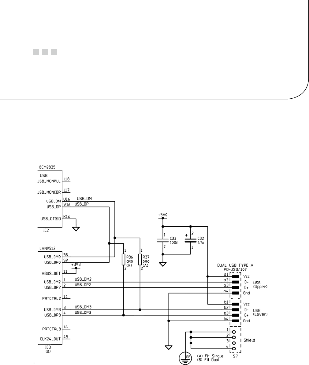
69
Chapter 8
USB
The USB port has become ubiquitous in the digital world, allowing the use of a large choice of peripherals. The Model
B Raspberry Pi supports two USB 2 ports, and the Model A just one.
This chapter briefly examines some power considerations associated with USB support and powered hubs.
The remainder of this chapter examines the device driver interface available to the Raspbian Linux developer.
Figure 8-1 serves as a chapter reference schematic of the Raspberry USB interface.
Figure 8-1. USB interface

CHAPTER 8 ■ USB
70
Power
Early models of the Raspberry Pi limited each USB port to 100 mA because of the polyfuses included. Revision 2.0
models did away with these, leaving you with more options.
Even with the polyfuses removed, the end user should remember that the USB ports are powered by the input
to the Raspberry Pi PCB. This is supplied through fuse F3 (see Figure 4-3, shown previously in Chapter 4). This limits
the maximum USB current to 500 mA for the Model A (which is the limit for one USB port anyway) and 300 mA for the
Model B. Exceeding these limits could cause fuse F3 to blow.
Note ■ Wireless USB adapters consume between 350 mA and 500 mA.
Powered Hubs
Whether you have a Model A or Model B Raspberry Pi, you’ll want to use a powered USB hub for high-current
peripherals. This is particularly true for wireless network adapters, since they often require up to 500 mA.
A USB hub requires coordination with the Linux kernel and thus requires Raspbian Linux driver support.
A number of hubs have been reported not to work. The following web page is a good resource listing hubs that are
known work with Raspbian Linux:
http://elinux.org/RPi_Powered_USB_Hubs
With the powered USB hub plugged in, you can list the USB devices that have registered with the kernel by using
the lsusb command:
# lsusb
Bus 001 Device 001: ID 1d6b:0002 Linux Foundation 2.0 root hub
Bus 001 Device 002: ID 0424:9512 Standard Microsystems Corp.
Bus 001 Device 003: ID 0424:ec00 Standard Microsystems Corp.
Bus 001 Device 004: ID 0451:2077 Texas Instruments, Inc. TUSB2077 Hub
The first three listed are the usual suspects from the Pi’s own hardware. The last line shows that a TUSB2077 Hub
has been registered. Figure 8-2 shows my Belkin USB hub on a busy workbench. If your hub fails to appear in this
report, it likely means that there is no driver support for it.
CHAPTER 8 ■ USB
71
USB API Support
USB devices are normally supported by device drivers and appear as generic peripherals like keyboards, mice, or
storage. The USB Boarduino is a little different, using the FTDI chipset, and supported by a driver.
Once the Boarduino is plugged in, the lsusb command lists it, thanks to the FTDI chipset driver:
$ lsusb
...
Bus 001 Device 008: ID 0403:6001 Future Technology Devices \
International, Ltd FT232 USB–Serial (UART) IC
The supporting driver makes the Boarduino available as a serial device:
$ ls –l /dev/ttyUSB0
Crw–rw——T 1 root dialout 188, 0 Dec 31 1969 /dev/ttyUSB0
The serial device support allows the AVR device to be programmed by avrdude. A Raspberry Pi application can
also communicate with the AVR device’s application. If you want to use network-like packets, the SLIP serial protocol,
for example, can be used to communicate over that link. The “Serial API” section of Chapter 11 covers the Linux API
for serial communications.
libusb
Although USB devices are supported by drivers and appear as generic devices, in some situations a user space
program needs to communicate with specialized hardware. While Raspbian Linux has libusb installed, the developer
will want to install the developer package for it:
# apt–get install libusb–dev
Figure 8-2. A powered USB hub
CHAPTER 8 ■ USB
72
The USB API is fairly large, complex and beyond the scope of this text. But the curious developer can read more
about the libusb API at the website:
http://libusb.sourceforge.net/doc/index.html
In this chapter, you’ll examine just the beginnings of a libusb program, so that you can get a flavor of how the
API works.
Include Files
The main include file for Raspbian libusb support is as follows:
#include <usb.h>
The next few pages show a simple USB program, which enumerates USB buses and devices. Once a device is
located, an attempt is made to “claim” it and then release it (it will print CLAIMED if successful). However, when all
of your USB devices are fully supported by drivers, none will be claimed. This list can be checked against the lsusb
command output.
The next example program was run on a Raspberry Pi with the following USB devices reported by lsusb:
$ lsusb
Bus 001 Device 002: ID 0424:9512 Standard Microsystems Corp.
Bus 001 Device 001: ID 1d6b:0002 Linux Foundation 2.0 root hub
Bus 001 Device 003: ID 0424:ec00 Standard Microsystems Corp.
Bus 001 Device 004: ID 05ac:1002 Apple, Inc. Extended Keyboard Hub [Mitsumi]
Bus 001 Device 005: ID 0451:2077 Texas Instruments, Inc. TUSB2077 Hub
Bus 001 Device 006: ID 05ac:0204 Apple, Inc.
Bus 001 Device 007: ID 045e:0040 Microsoft Corp. Wheel Mouse Optical
The example program was compiled by the provided make file in the libusb subdirectory and invoked as follows:
$ ./tusb
Device: 007 045e:0040 class 0.0 protocol 0 device 768, manuf 1, serial 0
0.0.0 class 3
Device: 006 05ac:0204 class 0.0 protocol 0 device 290, manuf 1, serial 0
0.0.0 class 3
0.1.0 class 3
Device: 005 0451:2077 class 9.0 protocol 0 device 256, manuf 0, serial 0
0.0.0 class 9
Device: 004 05ac:1002 class 9.0 protocol 0 device 290, manuf 1, serial 0
0.0.0 class 9
Device: 003 0424:ec00 class 255.0 protocol 1 device 512, manuf 0, serial 0
0.0.0 class 255
Device: 002 0424:9512 class 9.0 protocol 2 device 512, manuf 0, serial 0
0.0.0 class 9
0.0.1 class 9
Device: 001 1d6b:0002 class 9.0 protocol 1 device 774, manuf 3, serial 1
0.0.0 class 9
CHAPTER 8 ■ USB
73
These are easily compared by noting the device name, such as 007, which is reported by lsusb to be the
Microsoft mouse.
1 /∗∗∗∗∗∗∗∗∗∗∗∗∗∗∗∗∗∗∗∗∗∗∗∗∗∗∗∗∗∗∗∗∗∗∗∗∗∗∗∗∗∗∗∗∗∗∗∗∗∗∗∗∗∗∗∗∗∗∗∗∗∗∗
2 ∗ tusb.c – Scan list of USB devices and test claim/release.
3 ∗∗∗∗∗∗∗∗∗∗∗∗∗∗∗∗∗∗∗∗∗∗∗∗∗∗∗∗∗∗∗∗∗∗∗∗∗∗∗∗∗∗∗∗∗∗∗∗∗∗∗∗∗∗∗∗∗∗∗∗∗∗/
4
5 #include <stdio.h>
6 #include <stdlib.h>
7 #include <errno.h>
8 #include <usb.h>
9 #include <assert.h>
10
11 /∗∗∗∗∗∗∗∗∗∗∗∗∗∗∗∗∗∗∗∗∗∗∗∗∗∗∗∗∗∗∗∗∗∗∗∗∗∗∗∗∗∗∗∗∗∗∗∗∗∗∗∗∗∗∗∗∗∗∗∗∗∗∗
12 ∗ See http://libusb.sourceforge.net/doc/index.html for API
13 ∗∗∗∗∗∗∗∗∗∗∗∗∗∗∗∗∗∗∗∗∗∗∗∗∗∗∗∗∗∗∗∗∗∗∗∗∗∗∗∗∗∗∗∗∗∗∗∗∗∗∗∗∗∗∗∗∗∗∗∗∗∗/
14
15 int
16 main(int argc, char ∗∗argv) {
17 struct usb_bus ∗busses, ∗bus;
18 struct usb_device ∗dev;
19 struct usb_device_descriptor ∗desc;
20 usb_dev_handle ∗hdev;
21 int cx, ix, ax, rc;
22
23 usb_init();
24 usb_find_busses();
25 usb_find_devices();
26
27 busses = usb_get_busses();
28
29 for ( bus=busses; bus; bus = bus–>next ) {
30 for ( dev=bus–>devices; dev; dev = dev–>next ) {
31 desc = &dev–>descriptor;
32
33 printf("Device: %s %04x:%04x ",
34 dev–>filename,
35 desc–>idVendor,
36 desc–>idProduct);
37 printf(" class %u.%d protocol %u",
38 desc–>bDeviceClass,
39 desc–>bDeviceSubClass,
40 desc–>bDeviceProtocol);
41 printf(" device %u, manuf %u, serial %u\n",
42 desc–>bcdDevice,
43 desc–>iManufacturer,
44 desc–>iSerial Number);
45
46 hdev = usb_open(dev);
47 assert(hdev);
48
CHAPTER 8 ■ USB
74
49 rc = usb_claim_interface(hdev,0);
50 if ( !rc ) {
51 puts(" CLAIMED..");
52 rc = usb_release_interface(hdev, 0);
53 puts(" RELEASED..");
54 assert(!rc);
55 }
56 usb_close(hdev);
57
58 /∗Configurations ∗/
59 for ( cx=0; cx <dev–>descriptor.bNumConfigurations; ++cx ) {
60 /∗Interfaces ∗/
61 for ( ix=0; ix < dev–>config[cx].bNumInterfaces; ++ix ) {
62 /∗Alternates ∗/
63 for ( ax=0; ax < dev–>config[cx].interface[ix].num_altsetting; ++ax ) {
64 printf(" %d.%d.%d class %u\n",
65 cx,ix,ax,
66 dev–>config[cx].interface[ix].altsetting[ax].bInterfaceClass);
67 }
68 }
69 }
70 }
71 }
72
73 return 0;
74 }
75
76 /∗End tusb.c ∗/

75
Chapter 9
Ethernet
Networking has become an important part of everyday life, whether wireless or by wire. Having a network adapter on
your Raspberry Pi allows you to connect to it and do things on it from the comfort of your desktop or laptop computer.
It also allows your application on the Pi to reach out to the outside world. Even when the Raspberry Pi is deployed as
part of an embedded project, the network interface continues to be important. Remote logging and control are just
two examples.
Wired Ethernet
The standard Raspbian SD card image provides a wired network connection, using DHCP to automatically assign
an IP address to it. If you are using the HDMI output and keyboard devices to do work on the Pi, the dynamically
assigned IP address is not a bother. But if you would like to eliminate the attached display and keyboard, connecting
over the network is attractive. The only problem is the potentially changing IP address. (DHCP will not always
use a different IP address, since the address is leased for a time.) It is difficult to contact your Raspberry Pi from a
laptop until you know its IP address. As you saw in Chapter 3, you can use the nmap command to scan for it, but this
is inconvenient:
$ sudo nmap −sP 192.168.0.1−254
Starting Nmap 6.25 (http://nmap.org) at 2013−04−14 19:12 EDT
. . .
Nmap scan report for mac (192.168.0.129)
Host is up.
Nmap scan report for rasp (192.168.0.132)
Host is up (0.00071s latency).
MAC Address: B8:27:EB:2B:69:E8 ( Raspberry Pi Foundation )
Nmap done : 254 IP addresses (6 hosts up) scanned in 6.01 seconds
$
If you use your Pi at school or away from your own premises, using DHCP may still be the best option for you.
If you are plugging it into different networks as you travel, DHCP sets up your IP address properly and takes care of
the name server configuration. However, if you are using your unit at home, or your school can assign you a valid IP
address to use, a static IP address simplifies access.
Note ■ Be sure to get approval and an IP address assigned to prevent network conflicts.
CHAPTER 9 ■ ETHERNET
76
/etc/network/interfaces
As supplied by the standard Raspbian image, the /etc/network/interfaces file looks like this:
$ cat /etc/network/interfaces
auto lo
iface lo inet loopback
iface eth0 inet dhcp
allow−hotplug wlan0
iface wlan0 inet manual
wpa−roam/etc/wpa_supplicant/wpa_supplicant.conf
iface default inet dhcp
$
The wired Ethernet interface (Model B) is named eth0. The line starting with iface eth0 indicates that your
network interface eth0 is using DHCP. If this is what you want, leave it as is.
Changing to Static IP
If you haven’t booted up your Raspberry Pi with the network cable plugged in, now is a good time to do that. This may
save you time later, when we review the name server settings.
Next, before you start changing it, save a backup of the /etc/network/interfaces file in case you want to
change it back:
$ sudo −i
# cd /etc/network
# cp interfaces interfaces.bak
Next, edit the line in /etc/network/interfaces that begins with iface eth0 so that it reads like the following:
iface eth0 inet static
address 192.168.0.177
gateway 192.168.0.1
netmask 255.255.255.0
network 192.168.0.0
broadcast 192.168.0.255
In this example, we have established a fixed IP address of 192.168.0.177, along with the appropriate settings for
gateway, netmask, network, and broadcast address. If the network is not your own, get a network administrator to
help you with the correct values to use.
There is one other file that needs to be checked and potentially edited:
$ cat /etc/resolv.conf
domain myfastisp.net
search myfastisp.net
nameserver 192.168.0.1
If you’ve booted up your Raspberry Pi previously while it was using DHCP (with network cable plugged in),
these values may already be suitably configured. Otherwise, you’ll need to edit them to get the name service to work.
In this example, the Internet Service Provider is myfastisp.net, and name service requests are forwarded through
the firewall router at 192.168.0.1.
CHAPTER 9 ■ ETHERNET
77
Test Static IP Address
Once you have configured things, the simplest thing to do is to reboot your Raspberry Pi to make the new settings take
effect (use sudo /sbin/reboot or sudo /sbin/shutdown -r now).
Once you’ve rebooted and logged in, check your IP address:
$ ifconfig eth0
eth0 Link encap : Ethernet HWaddr b8:27:eb:2b:69:e9
inet addr:192.168.0.177 Bcast: 192.168.0.255 Mask: 255.255.255.0
UP BROADCAST RUNNING MULTICAST MTU: 1500 Metric: 1
RX packets: 1046 errors: 0 dropped : 3 overruns: 0 frame: 0
TX packets: 757 errors: 0 dropped: 0 over runs : 0 carrier: 0
collisions:0 txqueuelen :1000
RX bytes: 74312 (72.5 KiB) TX bytes: 86127 (84.1 KiB)
In the preceding example, the inet addr matches our configured static IP address. Let’s now check that the
names are resolving. Normally, I would recommend nslookup or dig for this, but neither comes preinstalled on
Raspbian. So let’s just use ping:
$ ping −c1 google.com
PING google.com (74.125.226.4) 56 (84) bytes of data.
64 bytes from yyz06s05−in−f4.1e100.net (74.125.226.4): . . .
−−− google.com ping statistics −−−
1 packets transmitted, 1 received, 0% packet loss, time 0ms
rtt min/avg/max/mdev = 11.933/11.933/11.933/0.000 ms
$
In this example, we see that google.com was looked up and translated to the IP address 74.125.226.4. From this,
we conclude that the name service is working. The -c1 option on the ping command line causes only one ping to be
performed. Otherwise, ping will keep trying, and you may need to ^C to interrupt its execution.
If the name google.com does not resolve, you’ll need to troubleshoot /etc/resolv.conf. As a last resort, you
might switch back to using DHCP (interfaces.bak) and reboot. If the /etc/resolv.conf file is updated with new
parameters, you might try again.
USB Adapters
If you have a USB Ethernet adapter (non-wireless), you can set up networking for that also. The following line added
to /etc/network/interfaces will cause it to use DHCP:
iface usb0 inet dhcp
For a fixed usb0 IP address, configure as we did earlier (for eth0). For example:
iface usb0 inet static
address 192.168.0.178
gateway 192.168.0.1
netmask 255.255.255.0
network 192.168.0.0
broadcast 192.168.0.255
This provides interface usb0 with a fixed address of 192.168.0.178.
CHAPTER 9 ■ ETHERNET
78
/etc/hosts File
If you have a static IP address for your Raspberry Pi, why not update your Linux, OS X, or Windows hosts file (typically,
C:\Windows\system32\drivers\etc\hosts) with a hostname for it? For example, your hosts file could have the
following line added:
$ cat /etc/hosts
. . .
192.168.0.177 rasp raspi rpi pi # My Raspberry Pi
Now you can use a hostname of rasp, raspi, rpi, or pi to access your Raspberry Pi on the network.
Wireless Ethernet
If you haven’t already done so, review the “Powered USB Hubs” section of Chapter 8. Wi-Fi adapters can require
350 mA to 500 mA of current draw.
The following web page lists good information about the various brands of Wi-Fi adapters available and their
level of support:
http://elinux.org/RPi_USB_Wi-Fi_Adapters
I have a NetGear WN111(v2) RangeMax Next Wireless adapter available. Apparently, this adapter uses one of the
following chips:
Atheros AR9170•
Atheros AR9101•
Since the AR9170 shows up in the supported list for the D-Link DWA-160, there is a reasonable chance of driver
support for it. After plugging it into the powered USB hub and rebooting, the console log shows that it is being “seen”:
$ dmesg
. . .
[3.867883] usb 1_1.3.2: New USB device found, idVendor=0846, idProduct=9001
[3.893138] usb 1_1.3.2: New USB device strings: Mfr=16, Product=32, SerialNumber=
[3.923115] usb 1_1.3.2: Product: USB2.0 WLAN
[3.930064] usb 1_1.3.2: Manufacturer : ATHER
[3.963095] usb 1_1.3.2: SerialNumber : 12345
[4.393875] cfg80211: Calling CRDA to update world regulatory domain
[4.663403] usb 1_1.3.2: reset full_speed USB device number 5 using dwc_otg
[4.953470] usbcore: registered new interface driver carl9170
[6.687035] usb 1_1.3.2: firmware not found.
[7.703098] usb 1_1.3.2: kill pending tx urbs.
But there is a troubling error message: “firmware not found.” Also visible in the log, we see that the driver is
named carl9170. Further research reveals that it also requires a firmware file named carl9170-1.fw. While this file is
available from other sources, the simplest way to install this file is to install it from Raspbian sources:
$ sudo apt–get install firmware–linux

CHAPTER 9 ■ ETHERNET
79
The firmware file being sought and installed is as follows:
$ ls –l /lib/firmware/carl9170−1.fw
−rw−r−−r−−1 root root 13388 Jan 14 17:04 /lib/firmware/carl9170−1.fw
Rebooting again, the missing firmware message is gone. The lsusb report also confirms the device is ready:
# lsusb
Bus 001 Device 001: ID 1d6b :0002 Linux Foundation 2.0 root hub
Bus 001 Device 002: ID 0424:9512 Standard Microsystems Corp.
Bus 001 Device 003: ID 0424: ec00 Standard Microsystems Corp.
Bus 001 Device 004: ID 0451:2077 Texas Instruments, Inc. TUSB2077 Hub
Bus 001 Device 005: ID 0846:9001 NetGear, Inc. WN111(v2) RangeMax Next Wireless \
[Atheros AR9170+AR9101]
#
The hardware driver support is now in place. The device now needs network configuration.
Configuration
You could edit the configuration files by hand if you knew all the possible keywords necessary for your particular
wireless authentication protocol. The following Linux raspberrypi 3.2.27+ files are involved:
Pathname Description
/etc/network/interfaces Main configuration file for networks
/etc/wpa_supplicant/wpa_supplicant.conf Authentication information
You’ll find a variety of advice on how to configure these on the Internet. But the quickest path to success is to
just use the wpa_gui dialog box from the Raspberry Pi desktop. Once you’ve done it this way, directly editing the
configuration files can be performed later if you need to tweak it further.
Figure 9-1 shows how to locate the wpa_gui dialog box from your Pi desktop. Once wpa_gui is started, click the
Manage Networks tab, shown in Figure 9-2. If you’ve made prior attempts at configuring wlan0, delete them all from
this menu. Then click the Scan button at the bottom right.
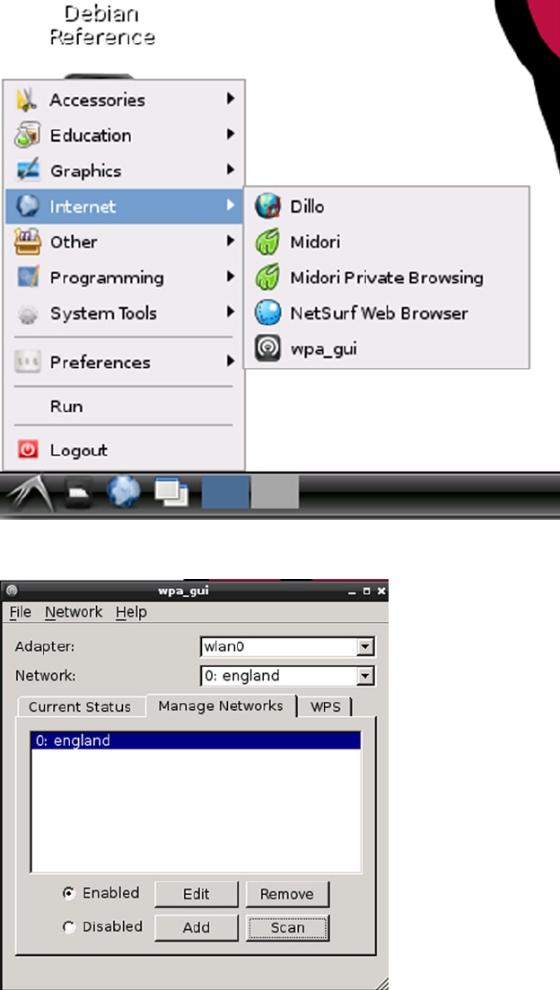
CHAPTER 9 ■ ETHERNET
80
Figure 9-1. wpa_gui dialog box
Figure 9-2. The Manage Networks tab
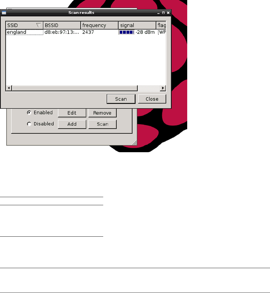
CHAPTER 9 ■ ETHERNET
81
After clicking Scan, your wireless network should eventually appear in the scan list, as shown in Figure 9-3.
Figure 9-3. Results of a wireless network scan
Double-click the line representing your network. This brings up a new dialog box that allows you to fill in the
remaining authentication parameters:
Parameter Example
Authentication WPA-Personal (PSK)
Encryption CCMP
PSK Pass phrase
Enter settings that apply to your network. After completing the data input, click the Add button. As you exit the
dialog box, be sure to select Save Configuration from the File menu.
Caution ■ Don’t forget to pull down Save Configuration from the File menu before you exit the setup application.
This is easily forgotten, and no reminder of unsaved changes is provided.
CHAPTER 9 ■ ETHERNET
82
After saving the new Wi-Fi configuration, reboot. After the Pi comes back up, log in and check the network
interfaces. Look for interface wlan0:
$ ifconfig
. . .
wlan0 Link encap: Ethernet HWaddr 00:22:3f:8d: 78: f9
inet addr:192.168.0.61 Bcast:192.168.0.255 Mask:255.255.255.0
UP BROADCAST RUNNING MULTICAST MTU: 1500 Metric: 1
RX packets: 10514 errors: 0 dropped: 0 overruns: 0 frame : 0
TX packets: 121 errors: 0 dropped : 0 over runs: 0 carrier: 0
collisions:0 txqueuelen:1000
RX bytes: 767287 (749.3 KiB) TX bytes: 9188 (8.9 KiB)
The preceding example shows that the wlan0 is available and has a DHCP-assigned IP address. You can now ping
or ssh to this access point.
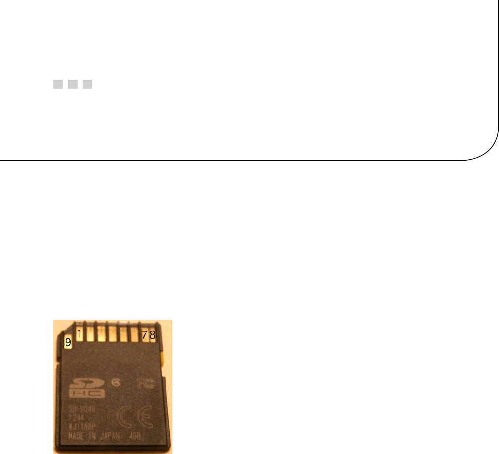
83
Chapter 10
SD Card Storage
The file system is central to the Unix system design, from which Linux borrows. The necessary mass storage
requirements have traditionally been fulfilled through hard disk subsystems. However, as Linux hosts become as small
as cell phones, flash memory technology has replaced the bulky mechanical drive.
SD Card Media
The standard SD card is 32 mm long, 24 mm wide, and 2.1 mm thick. Figure 10-1 illustrates the connections available
on the underside of the SD card. The schematic excerpt shown later will document how the connections are made to
this media.
Figure 10-1. SD card pinout
SD Card Interface
In the Raspberry Pi, the SD card is interfaced to the SoC through GPIO pins 46 through 53, seen in Figure 10-2. The
SoC senses the insertion of an SD card through the closing of a socket switch (pins 10 and 11 of the socket). Thus GPIO
47 is brought to ground potential when the socket is occupied.
Looking at the wiring in Figure 10-2, it might be assumed that all data transfers are 4 bits wide (GPIO 50 through
GPIO 53). However, as the following sections will describe, this depends on the SD card media used.
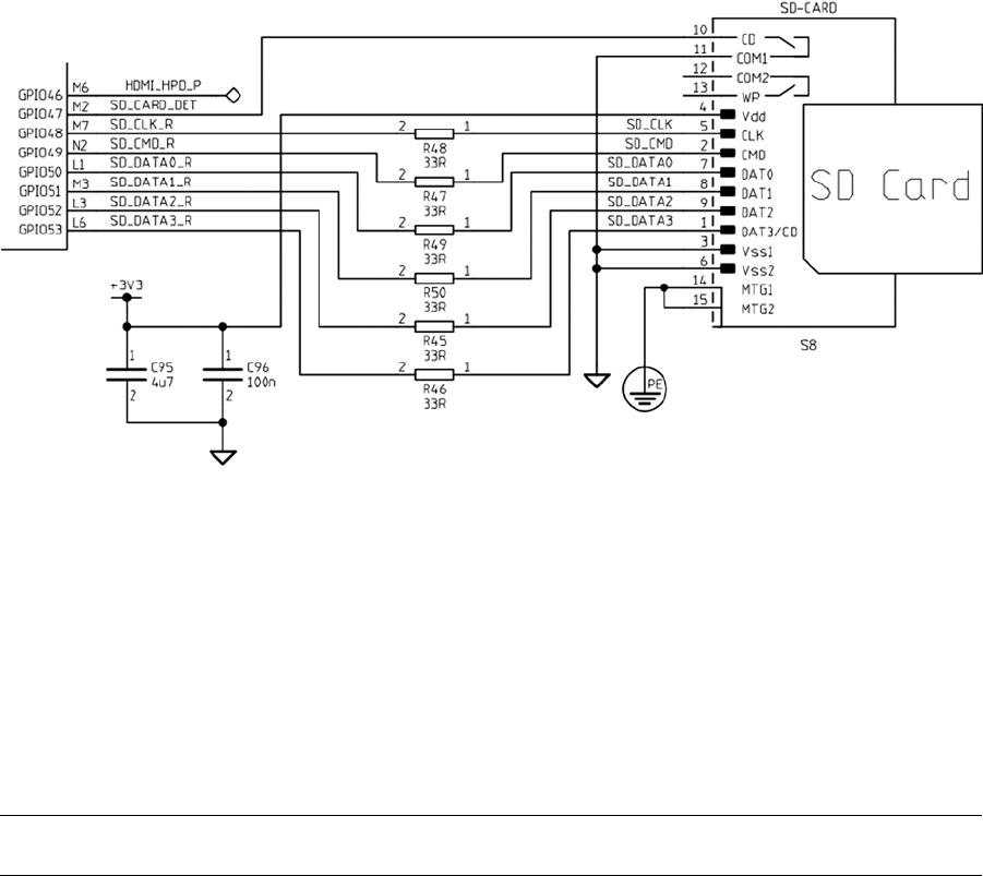
CHAPTER 10 ■ SD CARD STORAGE
84
SD Card Basics
The SD card includes an internal controller, also known as a Flash Storage Processor (FSP). In this configuration, the
Linux host merely provides a command and waits for the response. The FSP takes care of all erase, programming,
and read operations necessary to complete the command. In this way, Flash card designs are permitted to increase in
complexity as new performance and storage densities are implemented.
The SD card manages data with a sector size of 512 bytes. This was intentionally made the same as the IDE
magnetic disk drive for compatibility with existing operating systems. Commands issued by the host include a sector
address to allow read/writes of one or more sectors.
Note ■ Operating systems may use a multiple of the 512-byte sector.
Commands and data are protected by CRC codes in the FSP. The FSP also automatically performs a read after
write to verify that the data is written correctly.21 If the data write is found defective, the FSP automatically corrects it,
replacing the physical sector with another if necessary.
The SD card soft error rate is much lower than a magnetic disk drive. In the rare case when errors are discovered,
the last line of defense is a correcting ECC, which allows for data recovery. These errors are corrected in the media to
prevent future unrecoverable errors. All of this activity is transparent to the host.
Figure 10-2. SD card circuit

CHAPTER 10 ■ SD CARD STORAGE
85
Raspbian Block Size
The block size used by the operating system may be a multiple of the media’s sector size. To determine the physical
block size used under Raspbian, we first discover how the root file system is mounted (the following listing has been
trimmed with ellipses):
$ mount
/dev/root on/type ext4 (rw, noatime, . . . )
. . .
/dev/mmcblk0p1 on/boot type vfat (rw, relatime , . . . )
$
From this we deduce that the device used for the root file system is /dev/root. The pathname given is a symbolic
link, so we need to determine the real device pathname:
$ ls −dl /dev/root
lrwxrwxrwx 1 root root 9 Jan 12 19:33/dev/root −> mmcblk0p2
$
From this, we deduce that the actual device pathname is /dev/mmcblk0p2. The naming convention used tells us
the following:
Component Name Number Type
Prefix /dev/mmcblk MMC block
Device number 0 0
Partition number p2 2
From the earlier mount command output, notice that the /boot file system was mounted on /dev/mmcblk0p1.
(No symbolic link was used in this case.) From this we understand that the /boot file system is from partition 1 of the
same SD card device.
Using the root device information, we consult the /sys pseudo file system to find out the physical sector size.
Here we supply mmcblk0 as the third-level pathname qualifier to query the device:
$ cat /sys/block/mmcblk0/queue/physical_block_size
512
$ cat /sys/block/mmcblk0/queue/logical_block_size
512
$
The result shown informs us that the Raspbian Linux used in this example uses a block (sector) size of 512 bytes,
both physically and logically. This precisely matches the SD card’s sector size. Since the /boot file system uses the
same physical device as root, this also applies to that partition.
Disk Cache
While we’re examining mounted SD card file systems, let’s also check the type of device node used:
$ ls −l /dev/mmcblk0p?
brw−rw−−−T 1 root floppy 179, 1 Dec 31 1969 /dev/mmcblk0p1
brw−rw−−−T 1 root floppy 179, 2 Jan 12 19:33 /dev/mmcblk0p2
$

CHAPTER 10 ■ SD CARD STORAGE
86
The example output shows a b at the beginning of the brw-rw—T field. This tells us that the disk device is a
block device as opposed to a character device. (The associated character device would show a c instead.) Block
devices are important for file systems because they provide a disk cache capability to vastly improve the file
system performance. The output shows that both the root (partition 2) and the /boot (partition 1) file systems are
mounted using block devices.
Capacities and Performance
SD cards allow a configurable data bus width within limits of the media. All SD cards start with one data bit line until
the capabilities of the memory card are known:
The SD bus allows dynamic configuration of the number of data lines. After power-up, by default,
the SD card will use only DAT0 for data transfer. After initialization, the host can change the bus
width (number of active data lines). This feature allows [an] easy trade-off between hardware cost
and system performance.18
After the capabilities of the media are known, the data bus can be expanded under software control, as supported.
Given that SD cards with memory capacities up to 2 GB operate with a 1-bit data bus, it is highly desirable to use a 4
GB or larger card on the Raspberry Pi, even if the extra storage is not required. More-advanced cards also offer greater
transfer speeds by use of higher data clock rates.
Table 10-1 summarizes SD card capabilities.19
Table 10-1. SD Card Capabilities
Standard Description Greater Than Up To Data Bus
SDSC Standard capacity 0 2 GB 1-bit
SDHC High capacity 2 GB 32 GB 4-bit
SDXC Extended capacity 32 GB 2 TB 4-bit
Transfer Modes
There are three basic data transfer modes used by SD cards:18
SPI Bus mode•
1-bit SD mode•
4-bit SD mode•
SPI Bus Mode
The SPI Bus mode is used mainly by consumer electronics using small microcontrollers supporting the SPI bus.
Examining Table 10-2 reveals that data is transmitted 1 bit at a time in this mode (pin 2 or 7).

CHAPTER 10 ■ SD CARD STORAGE
87
The various SD card connections are used in different ways, as documented by the Table 10-2 mnemonics in the
columns I/O and Logic. Table 10-3 is a legend for these and also applies to later Tables 10-4 and 10-5.
Table 10-2. SPI Bus Mode
Pin Name I/O Logic Description SPI
1 nCS I PP Card select (negative true) CS
2 DI I PP Data in MOSI
3VSS S S Ground
4 VDD S S Power
5 CLK I PP Clock SCLK
6VSS S S Ground
7DO OPP Data out MISO
8 NC Memory cards
nIRQ O OD Interrupt on SDIO cards
9 NC Not connected
Table 10-3. Legend for I/O and Logic
Notation Meaning Notes
I Input
Relative to cardO Output
I/O Input or output
PP Push/pull logic
OD Open drain
S Power supply
NC Not connected Or logic high
1-bit SD Mode
Table 10-4 lists the pins and functions of the SD card when it is in 1-bit SD mode. The data traverses pin 7 (DAT0)
while the clock is supplied on pin 5. Pin 2 is used to send commands and receive responses. This mode uses a
proprietary transfer format.

CHAPTER 10 ■ SD CARD STORAGE
88
4-bit SD Mode
This is the mode used when the data bus width is more than a single bit and supported by SDHC and SDXC cards.
Higher data clock rates also improve transfer rates. Table 10-5 lists the pin assignments.
Table 10-4. 1-bit SD Mode
Pin Name I/O Logic Description
1 NC No connection
2 CMD I/O PP/OD Command/response
3VSS S S Ground
4 VDD S S Power
5 CLK I PP Clock
6VSS S S Ground
7 DAT0 I/O PP Data 0
8 NC NC Memory cards
nIRQ O OD SDIO cards
9 NC No connection
Table 10-5. 4-bit SD Mode
Pin Name I/O Logic Description
1 DAT3 I/O PP Data 3
2 CMD I/O PP/OD Command/response
3VSS S S Ground
4 VDD S S Power
5 CLK I PP Clock
6VSS S S Ground
7 DAT0 I/O PP Data 0
8 DAT1 I/O PP Data 1
nIRQ O OD SDIO cards share with interrupt
9 DAT2 I/O PP Data 2

CHAPTER 10 ■ SD CARD STORAGE
89
Wear Leveling
Unfortunately, Flash memory is subject to wear for each write operation performed (as each write requires erasing
and programming a block of data). The design of Flash memory requires that a large block of memory be erased and
rewritten, even if a single sector has changed value. For this reason, wear leveling is used as a technique to extend
the life of the media. Wear leveling extends life by moving data to different physical blocks while retaining the same
logical address.
Note ■ ScanDisk calls the block of Flash memory being erased and rewritten a zone.
Some cards use wear leveling.18 Indeed the SanDisk company indicates that their products do use wear leveling.20
However, the type of wear leveling supported by SanDisk is limited to zones within the media. Each SanDisk zone has
3% extra capacity, from which writes can be wear leveled within. If the zone size is 4 MB and is overprovisioned by
3%, this leaves about 245 spare sectors within each zone. Thus each 4 MB zone holds 8,192 active sectors at any given
instant, rotated among 245 spares.
Note ■ SanDisk indicates that the 4 MB zones may change with future memory capacities.
Other manufacturers may not implement wear leveling at all or use a lower level of overprovisioning. Wear
leveling is not specified in the SD card standard, so no manufacturer is compelled to follow SanDisk’s lead.
Note that wear leveling applies to read/write file systems. If the file system is mounted read-only, no erase and
program operations are occurring inside the card. So no “erase wear” is taking place. But do take into account all of
the mounted partitions on the same media.
If you are using your Raspberry Pi for educational purposes, you can probably ignore the issue. However, using
known brands like SanDisk can provide you with additional quality assurance. Consider also the advantage of
documented overprovisioning and wear leveling characteristics.
Caution ■ Some brands of SD cards have been reported not to work with the Raspberry Pi, so the brand/product issue
cannot be totally ignored.
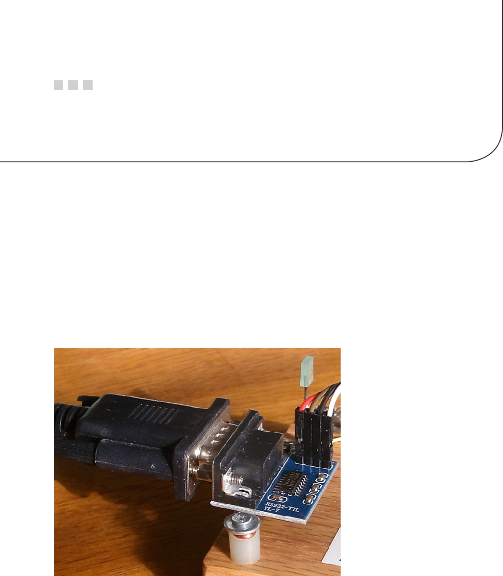
91
Chapter 11
UART
The Raspberry Pi has a UART interface to allow it to perform serial data communications. The data lines used are
3.3 V logic-level signals and should not be connected to TTL logic (+5 V) (they also are not RS-232 compatible). To
communicate with equipment using RS-232, you will need a converter module.
RS-232 Converter
While an industrious person could build their own RS-232 converter, there is little need to do so when cheap
converters are available.
Figure 11-1 shows a MAX232CSE chip interface that I use. (This unit supports only the RX and TX lines.) When
searching for a unit, be sure that you get one that works with 3 V logic levels. Some units work only with TTL (+5 V)
logic, which would be harmful to the Pi. The MAX232CSE chip will support 3 V operation when its VCC supply pin is
connected to +3 V.
Figure 11-1. MAX232CSE interface

CHAPTER 11 ■ UART
92
Note ■ Throughout this text, we’ll refer to 3 V, knowing that it is precisely 3.3 V.
Figure 11-2 is a schematic excerpt of the UART section of the Raspberry Pi. The UART connections are shown as
TXD0 and RXD0.
Figure 11-2. UART interface
Also when selecting a converter, consider whether you need only the data lines, or the data lines and the
hardware flow control signals. Some units support only the RX and TX lines. For hardware flow control, you’ll also
want the CTS and DTR signals. A full RS-232 converter would also include DTR, DSR, and CD signals.
DTE or DCE
When choosing your RS-232 converter, keep in mind that there are two types of serial connections:
DCE: Data communications equipment (female connector)
DTE: Data terminal equipment (male connector)
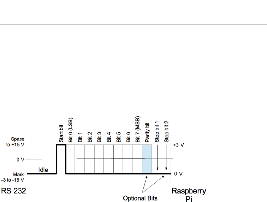
CHAPTER 11 ■ UART
93
A normal USB serial adapter (for a laptop, for example) will present a DTE (male) connector. The wiring of this
cable is such that it expects to plug into to a DCE (female) connection. When this holds true for your Raspberry Pi’s
adapter, the laptop’s serial adapter can plug straight into the DCE (female) connector, eliminating the need for a
crossover cable or null modem.
Consequently, for your Pi, choose a RS-232 converter that provides a female (DCE) connector. Likewise, make
sure that you acquire for the laptop/desktop a cable or USB device that presents a male (DTE) connection. Connecting
DTE to DTE or DCE to DCE requires a crossover cable, and depending on the cable, a “gender mender” as well. It is
best to get things “straight” right from the start.
Assuming that you used a DCE converter for the Pi, connect the RS-232 converter’s 3 V logic TX to the Pi’s TXD0
and the RX to the Pi’s RXD0 data lines.
All this business about DCE and DTR has always been rather confusing. If you also find this confusing, there
is another practical way to look at it. Start with the connectors and the cable(s) that you plan to use. Make sure they
mate at both ends and that the serial cable is known to be a straight cable (instead of a crossover). Once those physical
problems are taken care of, you can get the wiring correct. Connect the TX to RX, and RX to TX. In other words, you wire
the crossover in your own wiring between the RS-232 adapter and the Raspberry Pi. The important thing to remember
is that somewhere the transmitting side needs to send a signal into the RX (receiving) side, in both directions.
Note ■ A straight serial cable will connect pin 2 to pin 2, and pin 3 to pin 3 on a DB9 or DB25 cable. A crossover cable
will cross these two, among other signal wire changes.
RS-232
RS-232 is the traditional name for a series of standards related to serial communication. It was first introduced by the
Radio Sector of the EIA in 1962.46 The first data terminals were teletypewriters (DTE) communicating with modems
(DCE). Early serial communications were plagued by incompatibilities until later standards evolved.
A serial link includes two data lines, with data being transmitted from a terminal and received by the same
terminal. In addition to these data lines are several handshaking signals (such as RTS and CTS). By default, these are
not provided for by the Raspberry Pi.
Figure 11-3 shows a serial signal transmission, with time progressing from left to right. RS-232 equipment expects
a signal that varies between –15 V and +15 V.
Figure 11-3. Serial signal

CHAPTER 11 ■ UART
94
The standard states that the signal is considered to be in a mark state, when the voltage is between –3 and –15 V.
The signal is considered in a space state if the voltage is between +3 and +15 V. The RS-232 data line is in the mark state
when the line is idle.
Start Bit
When an asynchronous character of data is to be sent, the line first shifts to a space level for the duration of 1 bit. This
is known as the start bit (0). Data bits immediately follow.
Asynchronous lines do not use a clock signal like synchronous links. The asynchronous receiver must have a
clock matching the same baud rate as the transmitter. The receiver samples the line 16 times in the bit cell time to
determine its value. Sampling helps to avoid a noise pulse from triggering a false data read.
Data Bits
Data bits immediately follow the start bit, least significant bit first. A space is a 0 data bit, while mark represents a 1 bit.
Early teletype equipment used 5 data bits sending characters in the 5-bit Baudot code.47 For this reason, serial ports
can be configured for 5, 6, 7, or 8 data bits. Before the ASCII character set was extended to 8 bits, it was common to use
7-bit serial data.
Parity Bit
An optional parity bit can be generated when transmitting or can be detected on the receiving side. The parity can
be odd, even, or stick (mark or space). The most commonly used setting today is No Parity, which saves 1-bit time for
faster communication. Older equipment often used parity to guard against errors from noisy serial lines. Odd parity is
preferred over even because it forces at least one signal transition in the byte’s transmission. This helps with the data
reliability.
Mark or space parity is unusual and has limited usefulness. Mark parity could be used along with 2 stop bits
to effectively provide 3 stop bits for very slow teletypewriter equipment. Mark or space parity reduces the effective
throughput of data without providing any benefit, except possibly for diagnostic purposes. Table 11-1 summarizes the
various parity configurations.
Table 11-1. RS-232 Parity Settings
Parity X Notes
None N No parity bit
Even E 1 if even number of data 1-bits
Odd O 1 if odd number of data 1-bits
Mark M Always at mark level (1)
Space S Always at space level (0)
Stop Bit(s)
Asynchronous communication requires synchronizing the receiver with the transmitter. For this reason, 1 or more
stop bits exist so that the receiver can synchronize with the leading edge of the next start bit. In effect, each stop bit
followed by a start bit provides built-in synchronization.

CHAPTER 11 ■ UART
95
Many UARTs support 1, 1.5, or 2 stop bits. The Broadcom SoC supports 1 or 2 stop bits only. The use of 2 stop bits
was common for teletypewriter equipment and probably rarely used today. Using 1 stop bit increases the overall data
throughput. Table 11-2 summarizes the stop-bit configurations.
Table 11-2. Stop-Bit Configuration
Stop Bits Description
1 1 stop bit
1.5 1.5 stop bits (†)
2 2 stop bits
†Unsupported by the Raspberry Pi
Baud Rate
The baud rate is calculated from bits per second, which includes the start, data, parity, and stop bits. A link using
115200 baud, with no parity and 1 stop bit, provides the following data byte rate:
DB
sdpS
rate =+++
=+++
=
115200
1801
11 520,ecbytes/s
where
B is the baud rate.
s is the start bit (always 1).
d is the number of data bits (5, 6, 7, or 8).
p is the parity bit (0 or 1).
S is the stop bit (1, 1.5, or 2).
The 115200 baud link allows 11,250 bytes per second. If a parity bit is added, the throughput is reduced:
Drate =+++
=
115200
1811
10 472 7,.bytes/sec
The addition of a parity bit reduces the transmission rate to 10,472.7 bytes per second.
Table 11-3 lists the standard baud rates that a serial link can be configured for on the Raspberry Pi.

CHAPTER 11 ■ UART
96
Break
With asynchronous communication, it is also possible to send and receive a break signal. This is done by stretching
the start bit beyond the data bits and the stop bit(s), and eventually returning the line to the mark state. When the
receiver sees a space instead of a mark for the stop bit, it sees a framing error.
Some UARTs distinguish between a framing error and a break by noting how long the line remains in the space
state. A simple framing error can happen as part of noisy serial line communications (particularly when modems
were used) and normally attributed to a received character error. Without break detection, it is possible to assume
that a break has been received when several framing errors occur in a sequence. Short sequences of framing errors,
however, can also just indicate a mismatch in baud rates between the two end points.
Flow Control
Any link that transmits from one side to a receiver on the other side has the problem of flow control. Imagine a factory
assembly line where parts to be assembled arrive at the worker’s station faster than he can assemble them. At some
point, the conveyor belt must be temporarily stopped, or some parts will not get assembled. Alternatively, if the
conveyor belt is reduced in speed, the assembly worker will always be able to keep up, but perhaps at a slower than
optimal pace.
Unless the serial link receiver can process every character of data as fast as it arrives, it will need flow control.
The simplest approach is to simply reduce the baud rate, so that the receiver can always keep up. But this isn’t always
satisfactory and leads to a reduced overall throughput. A logging application might be able to write the information
quickly, except when writes occur to an SD card, for example.
A better approach is to signal to the transmitter to stop sending when the receiver is bogged down. Once the
receiver catches up, it can then tell the transmitter to resume transmission. Note that this problem exists for both sides
of a serial link:
Data transmitted to the terminal (DTE)•
Data transmitted to the data communications equipment (DCE)•
Table 11-3. Standard Baud Rates
Rate Notes
75 Teletypewriters
110 Teletypewriters
300 Low-speed (acoustic) modem
1200
2400
4800
9600
19200
38400
57600
115200 Raspberry Pi console

CHAPTER 11 ■ UART
97
Two forms of flow control are used:
Hardware flow control•
Software flow control•
Hardware Flow Control
Hardware flow control uses additional signal lines to regulate the flow of data. The RS-232 standards have quite an
elaborate set of signals defined, but the main signals needed for flow control are shown in Table 11-4. Unlike the data
line, these signals are inactive in the space state and active in the mark state.
Table 11-4. Hardware Flow Controls
DTE Direction DCE Description Active
RTS →RTS Request to send(†) Low
CTS ←CTS Clear to send(†)
DSR ←DSR Data set ready Low
DTR → DTR Data terminal ready
† Primary flow control signals
Table 11-5. Software Flow Control Characters
Code Meaning ASCII Hex Keyboard
XOFF Pause transmission DC3 13 Control-S
XON Resume transmission DC1 11 Control-Q
The most important signals are the ones marked with a dagger in Table 11-4. When CTS is active (mark), for
example, the DCE (Pi) is indicating that it is OK to send data. If the DCE gets overwhelmed by the volume of data, the
CTS signal will change to the inactive (space) state. Upon seeing this, the DTE (laptop) is required to stop sending
data. (Otherwise, loss of data may occur.)
Similarly, the laptop operating as the DTE is receiving data from the DCE (Pi). If the laptop gets overwhelmed
with the volume of incoming data, the RTS signal is changed to the inactive state (space). The remote end (DCE) is
then expected to cease transmitting. When the laptop has caught up, it will reassert RTS, giving the DCE permission
to resume.
The DTR and DSR signals are intended to convey the readiness of the equipment at each end. If the terminal was
deemed not ready (DTR), DSR is not made active by the DCE. Similarly, the terminal will not assert DTR unless it is ready.
In modern serial links, DTR and DSR are often assumed to be true, leaving only CTS and RTS to handle flow control.
Where flow control is required, hardware flow control is considered more reliable than software flow control.
Software Flow Control
To simplify the cabling and the supporting hardware for serial communications, the hardware flow controls can be
omitted/ignored. In its place, a data protocol is used instead.
Initially, each end of the link assumes readiness for reception of data. Data is sent until an XOFF character is
received, indicating that transmission should stop. The receiver sends the XON character when it is ready to resume
reception again. These software flow control characters are shown in Table 11-5.

CHAPTER 11 ■ UART
98
In a terminal session, the keyboard commands can be used to control the serial connection. For example, if
information is displaying too fast, the user can type Ctrl-S to cause the transmission to stop. Pressing Ctrl-Q allows it
to resume.
The disadvantages of software flow control include the following:
1. Line noise can prevent the receiver from seeing the XOFF character and can lead to loss of
data (causing data overrun).
2. Line noise can prevent the remote end from seeing the XON character and can fail to
resume transmission (causing a link “lockup”).
3. Line noise can cause a false XON/XOFF character to be received (data loss or link lockup).
4. The delay in the remote end seeing a transmitted XOFF character can cause loss of data if
the receiving buffer is full.
5. The XON and XOFF characters cannot be used for data in the transmission.
Problems 1 to 3 can cause link lockups or data loss to occur. Problem 4 is avoidable if the buffer notifies the other
end early enough to prevent a buffer overflow. Problem 5 is an issue for binary data transmission.
Raspberry Pi UARTs
The Raspberry Pi supports two UARTs:
UART Driver Node GPIO ALT
UART0 drivers/tty/serial/amba- pl011.c /dev/ttyAMA0 14 & 15 0
UART1 The mini has no driver. 14 & 15 5
Some websites have incorrectly stated that the mini UART is the one being used. But this does not jibe with the
Broadcom documentation, nor the Raspbian Linux device driver. The Broadcom BCM2835 ARM Peripherals manual
states that the mini UART is UART1. UART1 is available only as alternate function 5 for GPIO 14 and 15. Raspbian
Linux boots up using alternate function 0 for GPIO 14 and 15, providing the UART0 peripheral instead. Finally, the
source code for the device driver references PL011 in the naming throughout.
ARM PL011 UART
By default, UART0 is provided after reset and boot-up, on GPIO 14 (TX) and 15 (RX), configured as alternate function 0
(Table 11-6). UART0 is the full UART, referred to as the ARM PL011 UART. Broadcom refers the interested reader to the
ARM PrimeCell UART (PL011) Revision r1p5 Technical Reference Manual for more information.
Table 11-6. UART0 Pins
Function GPIO P1/P5 ALT Direction Description
TXD 14 P1-08 0 Out DTE transmitted data
RXD 15 P1-10 0 In DTE received data
RTS 17 P1-11 3 Out Request to send
CTS 30 P5-05 3 In Clear to send
CHAPTER 11 ■ UART
99
RTS/CTS Access
Hardware flow controls CTS and RTS are available on GPIO 30 and 17, respectively, when configured. By default these
are GPIO inputs, but this can be changed. To gain access to the UART’s CTS and RTS signals, configure GPIO 30 and 17
to alternate function 3. Table 11-6 summarizes the connections that are used by the UART.
The following short C program shows how to gain access to these signals. The listing for the included source file
gpio_io.c is given in the “Direct Register Access” section of Chapter 12.
1 /*********************************************************************
2 * rtscts.c Configure GPIO 17 & 30 for RTS & CTS
3 *********************************************************************/
4
5 #include <stdio.h>
6 #include <stdlib.h>
7 #include <fcntl.h>
8 #include <unistd.h>
9 #include <errno.h>
10 #include <setjmp.h>
11 #include <sys/mman.h>
12 #include <signal.h>
13
14 #include "gpio_io.c" /*GPIO routines */
15
16 static inline void
17 gpio_setalt(intgpio, unsigned alt) {
18 INP_GPIO(gpio);
19 SET_GPIO_ALT(gpio, alt);
20 }
21
22 int
23 main(int argc, char **argv) {
24
25 gpio_init(); /*Initialize GPIO access */
26 gpio_setalt(17, 3); /*GPIO 17 ALT = 3 */
27 gpio_setalt(30, 3); /*GPIO 3 0 ALT = 3 */
28 return 0;
29 }
30
31 /*End rtscts.c */
PL011 UART Features
The Broadcom BCM2835 ARM Peripherals manual states that the following features are unsupported:
• No Infrared Data Association (IrDA) support
• No Serial InfraRed (SIR) protocol encoder/decoder (endec)
• No direct memory access (DMA)
• No support for signals DCD, DSR, DTR, and RI
CHAPTER 11 ■ UART
100
The following features are supported, however:
Separate 16×8 transmit and 16×12 receive FIFO buffers•
Programmable baud rate generator•
False start-bit detection•
Line-break generation and detection•
Support of control functions CTS and RTS•
Programmable hardware flow control•
Fully programmable serial interface characteristics:•
Data can be 5, 6, 7, or 8 bits.•
Even, odd, mark, space, or no-parity bit generation and detection.•
1 or 2 stop-bit generation.•
Baud rate generation, DC up to UARTCLK/16.•
Broadcom also states that there are some differences between its implementation of the UART and the 16C650
UART. But these are mostly device driver details:
Receive FIFO trigger levels are 1/8, 1/4, 1/2, 3/4, and 7/8.•
Transmit FIFO trigger levels are 1/8, 1/4, 1/2, 3/4, and 7/8.•
The internal register map address space and the bit function of each register differ.•
1.5 stop bits is • not supported.
• No independent receive clock.
The only real concern to the application developer is that the 1.5 stop-bits configuration option is not available,
which is rarely used these days anyway.
If you need the RS-232 DCD, DSR, DTR, and RI signals, these can be implemented using GPIO input and output
pins (along with the appropriate RS-232 line-level shifters). These are relatively slow-changing signals, which can
easily be handled in user space. The one limitation of this approach, however, is that the hang-up TTY controls
provided by the device driver will be absent. To change that, the device driver source code could be modified to
support these signals using GPIO. The Raspbian Linux module of interest for this is as follows:
drivers/tty/serial/amba-pl011.c
Exclusive Serial Line Use
As outlined in Chapter 19’s “Available Consoles” section, the serial device /dev/ttyAMA0 is easily applied as a
serial console device. However, some Raspberry Pi application developers will want to use that serial interface for
application purposes, instead of a console. Without taking measures for exclusive access, the console will write to your
serial peripheral and respond to its input as well (as root console commands).
Even if you turned off the console, there can still be unwanted interaction from a login prompt.
CHAPTER 11 ■ UART
101
Procedure
Use the following steps to configure exclusive serial port access:
1. Eliminate console references to console=ttyAMA0,... in the files:
a. /boot/cmline.txt
b. /boot/config.txt (check option cmdline="...")
2. Eliminate the kernel debugging option kgdboc=ttyAMA0,... as outlined for the console in
step 1.
3. Eliminate the login prompt caused by the /etc/inittab entry. Look for ttyAMA0 and
comment the line out. The line will look something like T0:23:respawn:/sbin/getty -L
ttyAMA0 115200 vt100.
With these steps accomplished, reboot. The device /dev/ttyAMA0 should be available exclusively for your
application to use.
Verification
To check that /etc/inittab has not launched a getty process, use the following after rebooting:
$ ps aux | grep ttyAMA0
No entries should appear.
To check that you have eliminated all kernel console references to the device, you can use the following:
$ grep ttyAMA0 /proc/cmdline
Serial API
The Linux operating system provides access to serial port functions through a family of system and library calls. Most
of these require that you have an open file descriptor for the serial device driver being used. For the Raspberry Pi, this
will usually be the device /dev/ttyAMA0. Full information can be had from these man pages:
• tcgetattr(3)
• tty_ioctl(4)–ioctl(2) equivalents to tcgetattr(3)
The bulk of the developer work for serial ports is configuration of the serial driver:
Physical characteristics: baud rate, data bits, parity, and stop bits•
Driver processing characteristics: raw or cooked mode, for example•
Once the driver is configured, the software developer is able to use the usual read(2)/readv(2), write(2)/
writev(2), select(2), or poll(2) system calls.
For an example program using some of this API, see the “Software” section of Chapter 27.
CHAPTER 11 ■ UART
102
Header Files
Programs involved in altering TTY settings will want to include the following include files:
#include <termios.h>
#include <unistd.h>
open(2)
Most of the serial operations in this section require an open file descriptor to the TTY device being used. For the
Raspberry Pi UART, you’ll want to specify /dev/ttyAMA0.
int fd;
fd = open("/dev/ttyAMA0",O_RDWR); /* Open for reading and writing */
if ( fd < 0 ) {
perror("Opening/dev/ttyAMA0");
You may need to take special measures to gain access to the device, since by default it will be protected. Note the
permissions and user/group ownership:
$ ls –l /dev/ttyAMA0
crw–rw---1 root tty 204, 64 Feb 9 13:12 /dev/ttyAMA0
struct termios
Many of the serial port configuration options require the use of the structure termios:
struct termios {
tcflag_t c_iflag; /* input mode flags */
tcflag_t c_oflag; /* output mode flags */
tcflag_t c_cflag; /* control mode flags */
tcflag_t c_lflag; /* local mode flags */
cc_t c_line; /* line discipline */
cc_t c_cc[NCCS]; /* control characters */
speed_t c_ispeed; /* input speed */
speed_t c_ospeed; /* output speed */
};
The tables in the following sections describe the C language macros used for the members of the termios
structure:
Table • 11-7 lists the macros for member c_iflag.
Table • 11-8 lists the macros for member c_oflag.
Table • 11-9 lists the macros for member c_cflag.
Table • 11-10 lists the macros for member c_lflag.
Table • 11-11 lists the macros for member c_cc.

CHAPTER 11 ■ UART
103
Table 11-7. Input (c_iflag) Flags
Flag Set Description Flag Description
BRKINT T Break causes SIGINT else 0x00 ISTRIP Strip off eighth bit
F Break reads as 0x00 INLCR Translate NL to CR
IXANY Any character will resume IUTF8 Input is UTF8 charset
IXOFF Enable input XON/XOFF ICRNL Translate CR to NL
IXON Enable output XON/XOFF IGNBRK Ignore break
IGNPAR Ignore framing and parity errors IGNCR Ignore CR
IUCLC Translate uppercase to lowercase
INPCK Enable parity checking
PARMRK T Prefix framing/parity error with \377
F Don’t prefix with \377 (byte reads 0)
Table 11-8. Output (c_oflag) Flags
Flag Description Flag Description
CR0 CR delay mask 0 OFDEL Fill character is DEL else NUL
CR1 CR delay mask 1 OFILL Use fill characters instead of timed delay
CR2 CR delay mask 2 OLCUC Translate lowercase to uppercase
CR3 CR delay mask 3 ONLCR Translate NL to CR-NL
CRDLY CR delay: apply CR0-CR3 ONLRET Don’t output CR
FF0 FF delay mask 0 ONOCR Don’t output CR at column 0
FF1 FF delay mask 1 OPOST Enable output processing
FFDLY FF delay: apply FF0-FF1 TAB0 Tab delay mask 0
NL0 NL delay mask 0 TAB1 Tab delay mask 1
NL1 NL delay mask 1 TAB2 Tab delay mask 1
NLDLY NL delay: apply NL0-NL1 TAB3 Tab delay mask 2
OCRNL Translate CR to NL TABDLY Tab delay: apply TAB0-TAB3

CHAPTER 11 ■ UART
104
Table 11-9. Control (c_cflag) Flags
Flag Baud Flag Baud Flag Description
B0 Hang-up B115200 115,200 CLOCAL Ignore modem controls
B50 50 B230400 230,400 CMSPAR Stick parity
B75 75 B460800 460,800 CREAD Enable receiver
B110 110 B500000 500,000 CRTSCTS Enable RTS/CTS flow
B134 134 B576000 576,000 CS5 5 data bits
B150 150 B921600 921,600 CS6 6 data bits
B200 200 B1000000 1,000,000 CS7 7 data bits
B300 300 B1152000 1,152,000 CS8 8 data bits
B600 600 B1500000 1,500,000 CSIZE Data bits mask
B1200 1,200 B2000000 2,000,000 CSTOPB 2 stop bits (else 1)
B1800 1,800 B2500000 2,500,000 HUPCL Modem control hang-up
B2400 2,400 B3000000 3,000,000 PARENB Enable parity
B4800 4,800 B3500000 3,500,000 PARODD Odd or stick = 1 parity
B9600 9,600 B4000000 4,000,000 CBAUD Rate mask
B19200 19,200 CBAUDEX Extended mask
B38400 38,400 CIBAUD Input rate mask
B57600 57,600 EXTA External A
EXTB External B
Table 11-10. Local (c_lflag) Flags
Flag Description Flag Description
ECHOCTL Echo controls as ^X ECHO Echo input
IEXTEN Enable input processing ECHOE Erase previous char
PENDIN Reprint upon reading ECHOK Erase line on kill
ECHOKE Erase each char on kill ISIG Generate signals
ECHONL Echo NL even if !ECHO NOFLSH No flush on signal
ECHOPRT Print chars during erase TOSTOP Send SIGTTOU
ICANON Enable canonical mode XCASE Terminal is uppercase

CHAPTER 11 ■ UART
105
tcgetattr(3)
Before you make changes to the serial port settings, you will want to retrieve the current settings in case you later
need to restore them. This also greatly simplifies configuration, allowing you to change only the settings that need
changing.
Use the tcgetattr(3) function to fetch the current serial device settings:
int tcgetattr(int fd, struct termios *termios_p);
where
fd is the open TTY file descriptor.
termios_p is the struct to be filled with current setting information.
struct termios term;
int rc;
rc = tcgetattr(fd,&term);
if ( rc < 0 ) {
perror("tcgetattr(3)");
tcsetattr(3)
When the termios structure has been defined with the serial parameters you wish to use, the tcsetattr(3) call is
used to set them in the device driver:
int tcsetattr(
int fd,
int optional_actions,
const struct termios *termios_p
);
where
fd is the open TTY file descriptor to change.
optional_actions is one of three actions (listed in the following table).
termios_p is a pointer to the new settings to be applied.
Table 11-11. Special (c_cc) Characters
Macro Description Macro Description
VEOF End-file (^D) VQUIT Quit (^\)
VEOL End line (NUL) VREPRINT Reprint (^R)
VEOL2 End line 2 VSTART XON (^Q)
VERASE Erase (^H) VSTOP XOFF (^S)
VINTR Interrupt (^C) VSUSP Suspend (^Z)
VKILL Kill (^U) VTIME Time-out decsecs
VLNEXT Literal next (^V) VWERASE Word erase (^W)
VMIN Min chars to read

CHAPTER 11 ■ UART
106
The three choices for optional_actions are as follows:
optional_actions Meaning
TCSANOW The change occurs immediately.
TCSADRAIN Change occurs after all output has been sent.
TCSAFLUSH As TCSADRAIN, but pending input is discarded.
The following shows an example of use:
struct termios term;
int rc;
...
rc = tcsetattr(fd,TCSADRAIN,&term);
if ( rc < 0 ) {
perror("tcsetattr(3)");
tcsendbreak(3)
A break signal can be transmitted to the remote end by calling the tcsendbreak(3) function:
int tcsendbreak(int fd, int duration);
where
fd is the open TTY file descriptor.
duration is the amount of time to use to represent a break.
When the argument duration is zero, it sends a break signal lasting between 0.25 and 0.5 seconds. When the
argument is nonzero, the man page states that some implementation-defined amount of time is used instead.
int rc;
rc = tcsendbreak(fd,0);
if ( rc < 0 ) {
perror("tcsendbreak(3)");
tcdrain(3)
The function tcdrain(3) can be used to block the execution of the calling program until all of the output characters
have been transmitted out of the UART:
int tcdrain(int fd);
where
fd is the open TTY file descriptor. An example follows:
int rc;
rc = tcdrain(fd);
if ( rc < 0 ) {
perror("tcdrain(3)");

CHAPTER 11 ■ UART
107
tcflush(3)
The tcflush(3) call can be used to flush pending input or output data from the serial port buffers.
int tcflush(int fd, int queue_selector);
where
fd is the open TTY file descriptor.
queue_selector determines which queue(s) are to be flushed.
The following values are used for the queue_selector argument:
queue_selector Description
TCIFLUSH Flushes unread incoming data
TCOFLUSH Flushes untransmitted output data
TCIOFLUSH Flushes both unread and untransmitted data
The following example flushes pending input data:
int rc;
rc = tcflush(fd,TCIFLUSH);
tcflow(3)
Various flow control operations can be performed by calling the tcflow(3) function:
int tcflow(int fd, int action);
where
fd is the open TTY file descriptor.
action is the flow control action required (as shown in the following table).
The valid choices for action are as follows:
action Description
TCOOFF Suspends output (transmission stops)
TCOON Resumes output
TCIOFF Immediately sends a STOP character to stop the remote device
TCION Transmits a START character to resume the remote device
The following example shows the program immediately suspending output:
int rc;
rc = tcflow(fd,TCOOFF);
if ( rc < 0 ) {
perror("tcflow (3)");
CHAPTER 11 ■ UART
108
cfmakeraw(3)
The cfmakeraw(3) function is a convenience routine to establish raw mode, where no special data conversions or
mappings occur. The caller should first call upon tcgetattr(3) to define the initial termios structure settings. Then
cfmakeraw(3) can be used to adjust those settings for raw mode:
void cfmakeraw(struct termios *termios_p);
where
termios_p is a pointer to a struct populated with the serial device’s current settings, to be altered.
Note that no file descriptor is provided since this function doesn’t actually change anything beyond the data
structure that was passed to it. After calling cfmakeraw(3), the user will need to use cfsetattr(3) to inform the driver
of the changes.
struct termios term;
int rc;
rc = cfgetattr(fd,&term); /*Get settings */
cfmakeraw(&term); /* Alter settings for raw mode */
rc = tcsetattr(fd,TCSADRAIN,&term); /* Apply the settings */
Calling cfmakeraw(3) is equivalent to manually applying the following changes:
struct termios term;
...
term.c_iflag &= ~(IGNBRK | BRKINT | PARMRK | ISTRIP
| INLCR | IGNCR | ICRNL | IXON);
term.c_oflag &= ~OPOST;
term.c_lflag &= ~(ECHO | ECHONL | ICANON | ISIG | IEXTEN);
term.c_cflag &= ~(CSIZE | PARENB);
term.c_cflag |=CS8;
This is a good place to pause and discuss what raw mode is. There are two forms of serial I/O supported by Linux
(and Unix generally):
Cooked mode: The input, output, and echoing functions are modified/performed by the kernel.
Raw mode: The input/output data is sent to/from the application unchanged by the kernel.
The serial port developer, wishing to communicate with a serial device or AVR class microcontroller, will be very
interested in raw mode. Using raw mode, the data you transmit is sent unmodified to its destination. Likewise, the
data received is received as it was originally transmitted. Cooked mode, which is the norm, is a very different beast.
The original purpose of serial lines for Unix was the handling of user interaction using terminal I/O (this is still
true for the serial port console). Many terminal processing functions were considered common enough among
applications to centralize them in the kernel. This saved the application from having to deal with these physical
aspects and lead to consistency in their handling. This terminal handling is affectionately known as cooked mode.
The main areas of cooked mode processing are as follows:
Input processing: The type of kernel processing performed on serial input data (like backspace processing)
Output processing: The type of kernel processing performed on serial output data (like converting a sent line feed
into a carriage return and line-feed pair)
Local processing: Involving input and output, processing features such as echo
Control processing: Other serial controls

CHAPTER 11 ■ UART
109
We can get a sense of how raw mode differs from cooked mode by looking at what cfmakeraw(3) changes.
Looking at
term.c_iflag &= ~ (IGNBRK | BRKINT | PARMRK | ISTRIP
| INLCR | IGNCR | ICRNL | IXON);
we see that the following input processing features are disabled:
Flag Description Setting
IGNBRK Ignore break Disabled
BRKINT Break reads as 0x00 Disabled
PARMRK Don’t prefix with \377 (byte reads 0) Disabled
ISTRIP Strip off eighth bit Disabled
INLCR Translate NL to CR Disabled
IGNCR Ignore CR Disabled
ICRNL Translate CR to NL Disabled
IXON Enable output XON/XOFF Disabled
Disabling ISTRIP prevents the kernel from stripping the high-order bit in the byte. Disabling INLCR, ICRNL
prevents the substitution of NL or CR characters (for input). Disabling IGNCR prevents the kernel from deleting the CR
character from the input stream. Disabling IXON disables software flow control so that the characters XON and XOFF can
be read by the application program.
Looking at the output processing changes,
term.c_oflag &= ~OPOST;
we see that the following change applies:
Flag Description Setting
OPOST Enable output processing Disabled
This disables all output processing features with one flag.
Local processing includes both input and output. The following local processing flags are changed:
term.c_lflag &= ~(ECHO | ECHONL | ICANON | ISIG| IEXTEN);
From this, we see that these local processing features are disabled:
Flag Description Setting
ECHO Echo input Disabled
ECHONL Echo NL even if !ECHO Disabled
ICANON Enable canonical mode Disabled
ISIG Generate signals Disabled
IEXTEN Enable input processing Disabled

CHAPTER 11 ■ UART
110
Disabling ICANON means that all special nonsignal characters defined in c_cc are disregarded (like VERASE).
Disabling ISIG means that there will be no signals sent to your application for characters like VINTR. Disabling IEXTEN
disables other c_cc character processing like VEOL2, VLNEXT, VREPRINT, VWERASE, and the IUCLC flag. Disabling ECHO
and ECHONL disables two aspects of character echoing.
Finally, the following control aspects are changed:
term.c_cflag &= ~ (CSIZE | PARENB);
term.c_cflag |= CS8;
meaning that:
Flag Description Setting
CSIZE Data bits mask Masked-out data bits
PARENB Generate/detect parity Disabled
CS8 8 data bits Set to 8-bit data
The CSIZE masking is used to reset the data bits field to zeros. This allows the CS8 bit pattern to be or-ed in later,
setting the data bits value to 8 bits. Disabling the PARENB flag causes parity generation on output to be disabled, and
disables parity checking on input. If your raw link requires parity generation and checking, you’ll need to undo this
particular change in your own code.
You can see from this list that a plethora of special processing is altered to go from cooked mode to raw mode. It is
no wonder that this support routine was made available.
cfgetispeed(3)
The current input baud rate for the line can be queried by the cfgetispeed(3) function:
speed_t cfgetispeed(const struct termios *termios_p);
where
termios_p is the pointer to the structure containing the terminal configuration.
Because the termios structure has been extended and modified over the years, this function provides a more
portable way to extract the input baud rate, including the more recently added higher baud rates.
struct termios term;
speed_t baud_rate;
baud_rate = cfgetispeed(&term);
cfgetospeed(3)
The current output baud rate can be extracted from the termios structure with
speed_t cfgetospeed(const struct termios *termios_p);
where
termios_p is the pointer to the structure containing the terminal configuration.
Because the termios structure has been extended and modified over the years, this function provides a portable
way to extract the output baud rate, including the more recently added higher baud rates.
CHAPTER 11 ■ UART
111
cfsetispeed(3)
The cfsetispeed(3) function permits a portable way to establish an input baud rate in the termios structure:
int cfsetispeed(struct termios *termios_p, speed_t speed);
where
termios_p is the pointer to the TTY configuration structure to be modified.
speed is the input baud rate to apply.
Note that this function only updates the termios data structure and has no direct effect on the device being used.
struct termios term;
int rc;
rc = cfsetispeed(&term,115200);
if ( rc < 0 ) {
perror("cfsetispeed(3)");
cfsetospeed(3)
The cfsetospeed(3) function sets the output baud rate in the termios structure:
int cfsetospeed(struct termios *termios_p, speed_t speed);
where
termios_p is the pointer to the TTY configuration structure being modified.
speed is the output baud rate to apply.
Note that this function only updates the termios data structure with no direct effect on the device being used.
struct termios term;
int rc;
rc = cfsetospeed(&term,9600);
if ( rc < 0 ) {
perror(“cfsetospeed(3)");
cfsetspeed(3)
Most serial communication uses a common baud rate for transmitting and receiving. For this reason, this is the
preferred function to invoke for establishing both the input and output baud rates:
int cfsetspeed(struct termios *termios_p, speed_t speed);
where
termios_p is the pointer to the TTY configuration structure to be modified.
speed is the input and output baud rate to apply.
Note that this function only updates the termios data structure with no direct effect on the device being used.

CHAPTER 11 ■ UART
112
struct termios term;
int rc;
rc = cfsetspeed(&term,9600);
if ( rc < 0 ) {
perror("cfsetsspeed(3)");
read(2)
The read(2) system call can be used for reading from the serial port, in addition to normal Linux files and other
devices:
#include <unistd.h>
ssize_t read(int fd, void *buf, size_t count);
where
fd is the open file descriptor to read from.
buf is the buffer to read the data into.
count is the maximum number of bytes to read.
returns an int, where
-1 indicates an error, with the error code found in errno.
0 indicates that the serial port has been closed with the end-of-file character.
>0 indicates the number of bytes read.
The errors that pertain to blocking calls on a serial port include the following:
Error Description
EBADF fd is not a valid file descriptor.
EFAULT buf is outside your accessible address space.
EINTR The call was interrupted by a signal before any data was read.
More will be said about EINTR near the end of this chapter.
The following example reads up to 256 bytes into the array buf, from the serial port open on the file unit fd:
int fd; /*Opened serial port */
char buf[256];
int rc;
rc = read(fd,buf,sizeof buf);
if ( rc < 0 ) {
fprintf(stderr,"%s: reading serial port.\n",strerror(errno));
...
} else if ( !rc ) {
/*End file */
} else {
/*Process rc bytes in buf[] */
}

CHAPTER 11 ■ UART
113
write(2)
To transmit data on a serial link, you can use the write(2) system call:
#include <unistd.h>
ssize_t write(int fd, const void *buf, size_t count);
where
fd is the file unit of the opened serial port.
buf is the buffer containing the bytes to be transmitted.
count is the number of bytes to transmit.
returns an int, where
-1 indicates that an error has occurred, with the error found in errno.
0 indicates no bytes were transmitted (end-of-file, port was closed).
>0 indicates the number of bytes transmitted.
The possible errors related to blocking calls for serial port writes include the following:
Error Description
EBADF fd is not a valid file descriptor or is not open for writing.
EFAULT buf is outside your accessible address space.
EINTR The call was interrupted by a signal before any data was written.
Normally, only an error (-1) or a value of count is returned. If the serial port was opened for nonblocking I/O, the
returned count can be less than the requested count (this mode of operation is not discussed here). In blocking mode
(which we are assuming here), the call will return only when the full count requested has been written. Any failure
would otherwise result in an error being returned instead.
The following is an example of its use, as it pertains to a serial port:
int fd;
char buf[256];
int rc, n;
strcpy(buf,"Hello World!\n");
n = strlen(buf);
rc = write(fd,buf,n);
if ( rc < 0 ) {
fprintf(stderr,"%s: writing serial link.\n",strerror(errno));
...
}
assert(rc == n);
readv(2) and writev(2)
An often neglected option for reading and writing are the readv(2) and writev(2) system calls. These tend to
be more useful for programs that work with packets than for interactive terminal sessions. These are presented
because the serial port application developer may want to use a protocol that has more than one buffer containing
CHAPTER 11 ■ UART
114
headers, data, and trailer. Using the scatter-gather routines can enhance your code communicating with an AVR class
microcontroller. The use of an I/O vector here is similar in concept to the I/O vectors used by I2C I/O operations in
the ioctl(2,I2C_RDWR) system call (see Chapter 14).
#include <sys/uio.h>
ssize_t readv(int fd, const struct iovec *iov, int iovcnt);
ssize_t writev(int fd, const struct iovec *iov, int iovcnt);
where
fd is the open serial port file descriptor for reading/writing.
iov is the I/O vector directing the reading/writing.
iovcnt is the I/O vector count.
returns an int, where
-1 indicates an error, leaving the error code in errno, see read(2) or write(2).
0 indicates that an end-of-file condition occurred.
>n indicates the actual number of bytes read/written.
The I/O vector is shown here:
struct iovec {
void *iov _base; /*Starting address */
size_t iov_len; /*Number of bytes to transfer */
};
In the following example, a simple terminal writev(2) system call is used to piece together three pieces of
information, to be transmitted to the terminal:
The text • Hello
The person’s name provided in the argument • name
The text • !\n\r at the end
One of the advantages of the writev(2) call is its ability to take separate buffers of data and transmit them as a
whole in one I/O operation:
void
fun(int serport, const char *name) {
struct iovec iov[3];
int rc;
iov[0].iov_base = "Hello";
iov[0].iov_len = 6;
iov[1].iov_base = (void *)name;
iov[1].iov_len = strlen(name);
iov[2].iov_base = "!\n\r";
iov[2].iov_len = 3;
rc = writev(serport,iov,3);
if ( rc < 0 ) {
fprintf(stderr,"%s: writev(2)\n",strerror(errno));
abort();
}
}
CHAPTER 11 ■ UART
115
Each segment to be transmitted is described by one iov[x] member, each consisting of a buffer pointer and the
number of bytes. The writev(2) system call is told how many iov[] entries to use in its third calling argument.
Error EINTR
One error code that afflicts many device I/O system calls is the EINTR error, “Interrupted system call.” This error code
applies to read(2), readv(2), write(2), and writev(2) on devices that may “block” execution until the required
data has been fully read/written. (This also applies to ioctl(2) when I2C I/O is performed.) The EINTR error is
not returned for I/O to disk because these I/O calls don’t block for a long time (the I/O is to/from a file system disk
memory buffer). The application developer should otherwise plan on handling this error.
The EINTR error is the Unix way of working with signals. Consider what happens when your application is waiting
for a single keystroke from the user at a terminal (or reading a packet from an AVR class device):
rc = read(fd,buf,n); /*Block until n bytes read */
Until that read is satisfied (or the file descriptor is closed), execution will stop there. In the meantime, another
process or thread may signal your application to do something, perhaps to shut down and exit. A signal handler like
the following is invoked when the signal is handled:
static void
sigint_handler(int signo) {
is_signaled = 1; /*Please exit this program */
}
At this point, your application is in the middle of a system call, waiting to read from the serial port. The system
call’s registers are saved on the stack frame, and your application has entered into the kernel. The handling of the
signal means that the kernel calls your signal handler, placing another stack frame on your current stack.
Because a signal can arrive at any time, there are many things you can’t do from within a signal handler. For
example, you must not invoke malloc(3) or other non-reentrant functions. Otherwise, you risk doing another
malloc(3) inside an interrupted malloc(3), which leads to disaster. The important point here is that a very limited
number of safe things can be performed from inside a signal handler.
One thing that is safe to do in a signal handler is to set a global variable of some kind, like the is_signaled
variable in the example. One problem remains: how does the code blocked in the read(2) call respond to this
notification? When the signal handler returns, the application will continue to block trying to read from the serial port.
The Unix solution to this problem is to have the kernel return an error code EINTR after a signal handler receives
a signal. In this manner, the read(2) call returns an error, allowing the application program to test whether it received
a signal. The following code shows how the simple read(2) call is replaced with a loop that checks whether the signal
handler was called:
do {
rc = read(fd, buf, n); /*Block until n bytes read */
if ( is_signaled )
longjmp(shutdown,1); /*Shutdown this server */
} while ( rc == –1 && errno == EINTR );
if ( rc == –1 ) { /*Check for non EINTR errors */
fprintf(stderr,"%s: read(2)\n",strerror(errno));
abort();
}
CHAPTER 11 ■ UART
116
In this code snippet, we see that the read(2) call is performed as part of a loop. As long as an error is returned
and the errno value is EINTR, we check for any interesting events (like is_signaled) and repeat the call. If any other
type of error occurs or we succeed, we drop out of the loop.
This is the basic template that should be used for any call that might receive EINTR, even if you don’t plan to
handle signals in your application. Otherwise, you may find that your Pi application may run for weeks and then one
day when you least expect it, fail because of a received EINTR error.

117
Chapter 12
GPIO
General-purpose I/O is a topic near to the hearts of Raspberry Pi owners, because this is the interface to the outside
world. The BCM2835 is flexibly designed to allow I/O pins to be reconfigured under software control. GPIO 14 can be
an input, an output, or operate as a serial port TX data line, for example. This makes the Raspberry Pi very adaptable.
One of the challenges related to the Pi’s GPIO interface is that it uses a weak CMOS 3 V interface. The GPIO pins are
susceptible to static electricity damage, and the I/O pins are weak drivers (2 to 16 mA). Additionally, GPIO power must
be budgeted from the total spare current capacity of 50 mA. Using adapter boards overcomes these problems but adds
considerably to the cost. This then provides a fertile area for coming up with cheap and effective roll-your-own solutions.
Pins and Designations
Figures 12-1 and 12-2 show the schematic GPIO connections for the Raspberry Pi. You will notice that the GPIO pins
are also designated with the GENx designation. (Gen 7 to 10 was not available prior to version 2.) This may have been
an early attempt to follow the Arduino lead of naming their pins digital0 or analog4, for example, in a generic way.
It appears, however, that this naming convention has not really caught on among Pi users. Despite this, these names
are cross-referenced in Table 12-1. These are probably the preferred first choices when shopping for GPIO pins to use,
since they are less likely to be required for special (alternate) functions like UART or SPI.
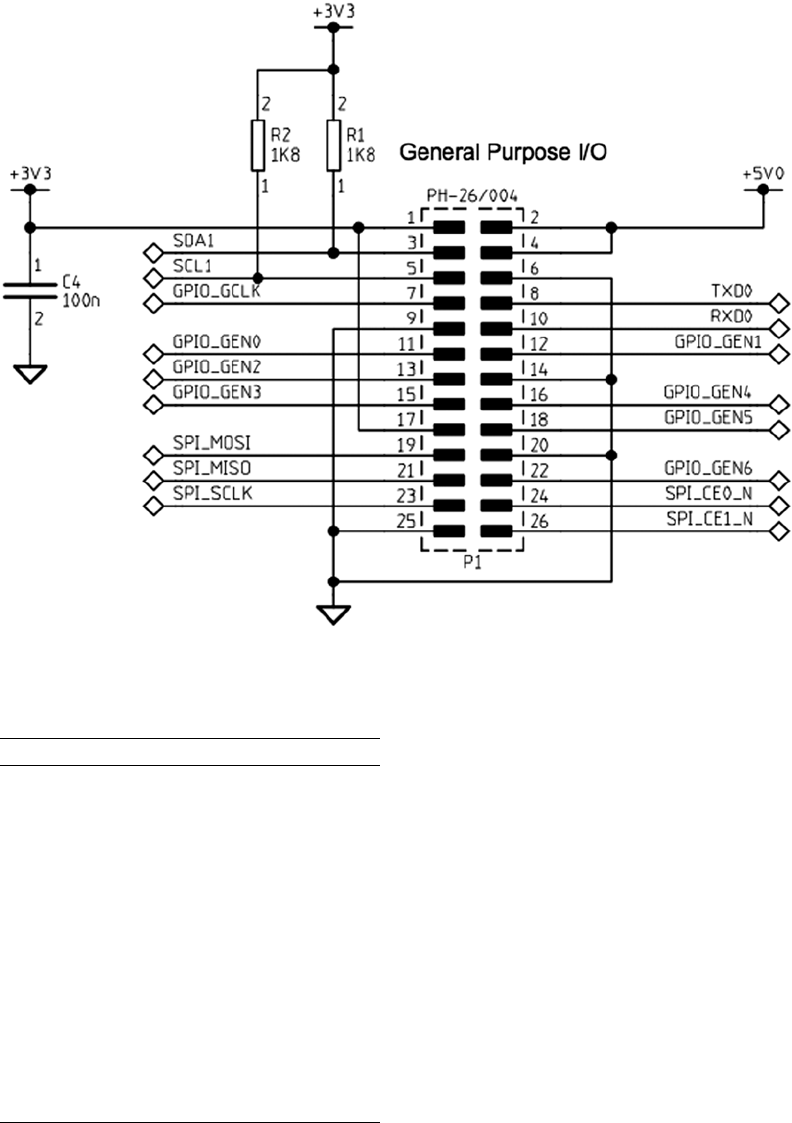
CHAPTER 12 ■ GPIO
118
Figure 12-1. GPIO P1 header
Table 12-1. Rev 2.0 GEN and GPIO Designations
GENxGPIOyHeader
GEN0 GPIO 17 P1-11
GEN1 GPIO 18 P1-12
GEN2 GPIO 27 P1-13
GEN3 GPIO 22 P1-15
GEN4 GPIO 23 P1-16
GEN5 GPIO 24 P1-18
GEN6 GPIO 25 P1-22
GEN7 GPIO 28 P5-03
GEN8 GPIO 29 P5-04
GEN9 GPIO 30 P5-05
GEN10 GPIO 31 P5-06

CHAPTER 12 ■ GPIO
119
A couple of GPIO pins have pull-up resistors. Figure 12-1 shows that GPIO pins 2 (SDA1) on P1-03, and GPIO 3 (SCL1)
on P1-05, have an 1.8 kΩ pull-up resistor. This should be taken into account if you use these for something other than I2C.
The layouts of headers P1 and P5, where the GPIO pins are made accessible, are documented in Chapter 5.
Note ■ P5 was not present prior to version 2, but both Models A and B now include it (without header pins).
Configuration After Reset
Upon reset, most GPIO pins are configured as general-purpose inputs with the exceptions noted in Table 12-2.
(Figure 12-2 applies to version 2, Models A and B.) The Pull-up column indicates how the internal pull-up resistor is
initially configured. The pull-up resistors apply when the GPIO is configured as an input pin.
Table 12-2. Rev 2.0 Configuration After Reset
GPIO Pull-up Config ALT
0 High Input
1 High Input
2 High SDA1 0
3 High SCL1 0
4 High Input
5 High GPCLK1 0
6 High Output
7 High Input
8 High Input
9Low Input
10 Low Input
11 Low Input
14 Low TXD0 0
15 Low RXD0 0
16 Low Output
17 Low Input
18 Low Input
21 Low Input
22 Low Input
23 Low Input
24 Low Input
(continued)
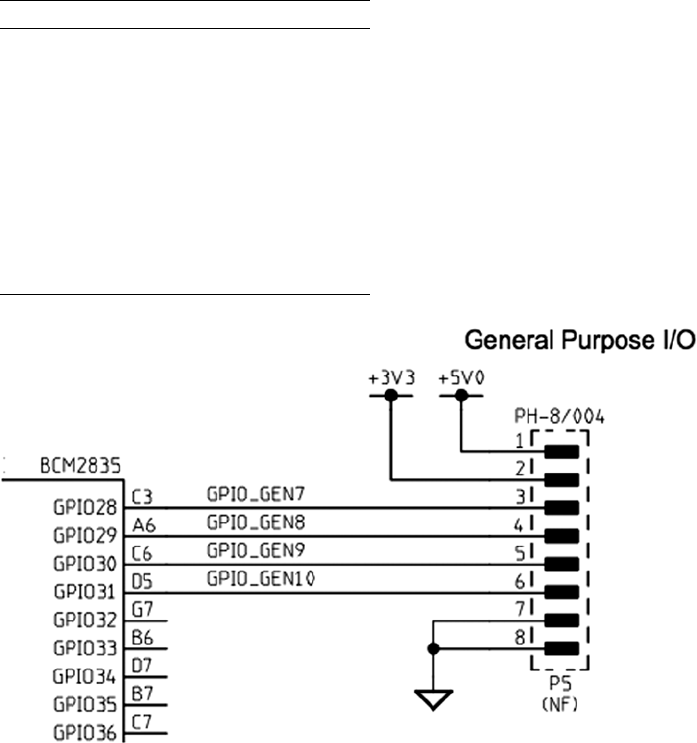
CHAPTER 12 ■ GPIO
120
Pull-up Resistors
As noted earlier, GPIO pins 2 and 3 have an external resistor tied to the +3.3 V rail. The remaining GPIO pins are pulled
high or low by an internal 50 kΩ resistor in the SoC.56, 48 The internal pull-up resistor is rather weak, and effective
at only giving an unconnected GPIO input a defined state. A CMOS input should not be allowed to float midway
between its logic, high or low. When pull-up resistance is needed for an external circuit, it is probably best to provide
an external pull-up resistor, rather than rely on the weak internal one.
Configuring Pull-up Resistors
The pull-up configuration of a GPIO pin can be configured using the SoC registers GPPUP and GPPUDCLK0/1.
(The “Physical Memory” section of Chapter 6 has the physical addresses for these registers.)
Figure 12-2. GPIO P5 header
GPIO Pull-up Config ALT
25 Low Input
27 Low Output
28 - Input
29 - Input
30 Low Input
31 Low Input
40 Low PWM0 0
45 - PWM1 0
Table 12-2. (continued)

CHAPTER 12 ■ GPIO
121
The GPPUP register is laid out as follows:
GPPUP Register
Bits Field Description Type Reset
31-2 - Unused
GPIO pin pull-up/down
R 0
1-0 PUD 00 Off—disable pull-up/down
01 Pull-down enable
10 Pull-up enable
11 Reserved
R/W 0
The GPPUDCLK0 register is laid out as follows:
GPPUDCLK0 Register
Bits Field Description Type Reset
31-0 PUDCLKn n = 0..31 R/W 0
0 No effect
1 Assert clock
Finally, the GPPUDCLK1 register is formatted this way:
GPPUDCLK1 Register
Bits Field Description Type Reset
31-22 - Reserved R 0
21-0 PUDCLKn n = 32..53 R/W 0
0 No effect
1 Assert clock
According to the Broadcom documentation, the general procedure for programming the pull-up resistor is this:
1. Write the pull-up configuration desired in the rightmost 2 bits of the 32-bit GPPUP register.
The configuration choices are as follows:
00: Disable pull-up control.
01: Enable pull-down control.
10: Enable pull-up control.
2. Wait 150 cycles to allow the preceding write to be registered.
3. Write a 1-bit to every GPIO position, in the group of 32 GPIO pins being configured.
GPIOs 0–31 are configured by register GPPUDCLK0.
4. Wait another 150 cycles to allow step 3 to register.
5. Write 00 to GPPUP to remove the control signal.
CHAPTER 12 ■ GPIO
122
6. Wait another 150 cycles to allow step 5 to register.
7. Finally, write to GPPUDCLK0/1 to remove the clock.
The Broadcom procedure may seem confusing because of the word clock. Writing to GPPUP and GPPUDCLK0/1
registers by using the preceding procedure is designed to provide a pulse to the internal pull-up resistor flip-flops
(their data clock input). First a state is established in step 1, and then the configured 1 bits are clocked high in step 3
(for selected GPIO pins). Step 5 establishes a zero state, which is then sent to the flip-flop clock inputs in step 7.
The documentation also states that the current settings for the pull-up drivers cannot be read. This makes sense
when you consider that the state is held by these internal flip-flops that were changed by the procedure. (There is no
register access available to read these flip-flops.) Fortunately, when configuring the state of a particular GPIO pin, you
change only the pins you select by the GPPUDCLK0/1 register. The others remain unchanged.
The program pullup.c, shown next, provides a simple utility to change the pull-up resistor settings. The program
listing for gpio_io.c is provided in the “Direct Register Access” section of Chapter 12. The source for timed_wait.c is
found in the “Source Code” section of Chapter 25.
After compiling, the following example changes the GPIO 7 pull-up to high and GPIO 8 to low:
$ ./pullup 7=low 8=high
1 /∗∗∗∗∗∗∗∗∗∗∗∗∗∗∗∗∗∗∗∗∗∗∗∗∗∗∗∗∗∗∗∗∗∗∗∗∗∗∗∗∗∗∗∗∗∗∗∗∗∗∗∗∗∗∗∗∗∗∗∗∗∗∗∗∗∗∗∗∗
2 ∗ pullup.c : Change the pull−up resistor setting for GPIO pin
3 ∗∗∗∗∗∗∗∗∗∗∗∗∗∗∗∗∗∗∗∗∗∗∗∗∗∗∗∗∗∗∗∗∗∗∗∗∗∗∗∗∗∗∗∗∗∗∗∗∗∗∗∗∗∗∗∗∗∗∗∗∗∗∗∗∗∗∗∗∗/
4
5 #include <stdio.h>
6 #include <stdlib.h>
7 #include <fcntl.h>
8 #include <unistd.h>
9 #include <errno.h>
10 #include <setjmp.h>
11 #include <sys/mman.h>
12 #include <signal.h>
13
14 #include "gpio_io.c" /∗GPIO routines ∗/
15 #include "timed_wait.c" /∗Delay ∗/
16
17 /∗∗∗∗∗∗∗∗∗∗∗∗∗∗∗∗∗∗∗∗∗∗∗∗∗∗∗∗∗∗∗∗∗∗∗∗∗∗∗∗∗∗∗∗∗∗∗∗∗∗∗∗∗∗∗∗∗∗∗∗∗∗∗∗∗∗∗∗∗
18 ∗ 0x7E200094 GPPUD GPIO Pin Pull−up/down Enable
19 ∗ 0x7E200098 GPPUDCLK0 GPIO Pin Pull−up/down Enable Clock 0
20 ∗∗∗∗∗∗∗∗∗∗∗∗∗∗∗∗∗∗∗∗∗∗∗∗∗∗∗∗∗∗∗∗∗∗∗∗∗∗∗∗∗∗∗∗∗∗∗∗∗∗∗∗∗∗∗∗∗∗∗∗∗∗∗∗∗∗∗∗∗/
21
22 #define GPIO_GPPUD ∗(ugpio+37)
23 #define GPIO_GPPUDCLK0 ∗(ugpio+38)
24
25 static inline void
26 gpio_setpullup(int gpio, int pull) {
27 unsigned mask = 1 << gpio; /∗GPIOs 0 to 31 only ∗/
28 unsigned pmask = pull >=0 ? ( 1 << !! pull) : 0;
29
30 GPIO_GPPUD = pmask ; /∗Select pull−up setting ∗/
31 timed_wait (0, 500, 0) ;
32 GPIO_GPPUDCLK0 = mask ; /∗Set the GPIO of interest ∗/
33 timed_wait (0, 500, 0) ;
34 GPIO_GPPUD = 0 ; /∗Reset pmask ∗/

CHAPTER 12 ■ GPIO
123
35 timed_wait (0, 500, 0);
36 GPIO_GPPUDCLK0 = 0 ; /∗Set the GPIO of interest ∗/
37 timed_wait (0, 500, 0);
38 }
39
40 /∗∗∗∗∗∗∗∗∗∗∗∗∗∗∗∗∗∗∗∗∗∗∗∗∗∗∗∗∗∗∗∗∗∗∗∗∗∗∗∗∗∗∗∗∗∗∗∗∗∗∗∗∗∗∗∗∗∗∗∗∗∗∗∗∗∗∗∗∗
41 ∗ Command line arguments are of the form <gpio>={low , high or none },
42 ∗ for example : ./pull−up 7=high 8=low
43 ∗
44 ∗ Only the first character of the argument after '=' is checked.
45 ∗∗∗∗∗∗∗∗∗∗∗∗∗∗∗∗∗∗∗∗∗∗∗∗∗∗∗∗∗∗∗∗∗∗∗∗∗∗∗∗∗∗∗∗∗∗∗∗∗∗∗∗∗∗∗∗∗∗∗∗∗∗∗∗∗∗∗∗∗/
46 int
47 main(int argc, char ∗∗argv) {
48 int x, gpio, p;
49 char arg [64];
50
51 gpio_init();
52
53 for ( x=1; x<argc; ++x ) {
54 if ( sscanf (argv [x] ,"%d=%s", &gpio, arg) != 2 )
55 goto errxit;
56 if ( ∗arg == 'n' )
57 p = −1;
58 else if ( ∗arg == ' l ' || ∗arg == 'h ' )
59 p = ∗arg == 'h ' ? 1 : 0;
60 else goto errxit;
61 if ( gpio < 0 || gpio > 31 ) {
62 fprintf (stderr,"%s : GPIO must be <= 31\n",
63 argv[x]) ;
64 return 1;
65 }
66 gpio_setpullup(gpio, p);
67 }
68 return 0;
69
70 errxit : fprintf (stderr,"Argument '%s ' must be in the form\n"
71 " <gpio>=<arg> where arg is h, l or n.\ n",
72 argv [ x ] ) ;
73 return 1;
74 }
75
76 /∗End pullup.c ∗/
The default drive strengths after booting are listed next, along with the GPIO addresses for the corresponding
GPIO pads:
Address GPIO Pads Reset Drive Strength
0x2010002C GPIO 0 to 27 8 mA
0x20100030 GPIO 28 to 45 16 mA
0x20100034 GPIO 46 to 53 8 mA

CHAPTER 12 ■ GPIO
124
Table 12-3 summarizes the GPIO Pads Control register. Note that to be successful setting values in this register,
the field labeled PASSWRD must receive the value 0x5A. This is a simple measure to avoid having the values trashed
by an accidental write to this location.
Table 12-3. GPIO Pads Control
Bits Field Description I/O Reset
31:24 PASSWRD 0x5A Must be 0x5A when writing W 0x00
23:05 Reserved 0x00 Write as zero, read as don’t care R/W
04:04 SLEW Slew rate
0 Slew rate limited R/W 1
1 Slew rate not limited
03:03 HYST Enable input hysterisis
0 Disabled R/W 1
1 Enabled
02:00 DRIVE Drive strength R/W 3
0 2 mA
1 4 mA
2 6 mA
3 8 mA (default except 28 to 45)
4 10 mA
5 12 mA
6 14 mA
7 16 mA (GPIO 28 to 45)
Testing Pull-up State
If you want to test the state of the pull-up resistors, the following procedure can be used:
1. Make sure no connection is attached so that the input can float.
2. Configure the GPIO pin as an input.
3. Configure the GPIO as active high (that is, not active low).
4. Read the input value.
a. A reading of 1 means that the input was pulled high.
b. A reading of 0 means that the input was pulled low.
Note that GPIO pins 2 and 3 are pulled up by external resistors, while others may be connected to other circuits
(GPIO 6). This will affect your readings for those pins. Note also that pins configured for alternate functions may be
outputs and will be driven.

CHAPTER 12 ■ GPIO
125
When the input GPIO is configured with no pull-up, you might see random values, but this is unreliable. An input
voltage can float above or below a threshold and remain there for a time.
The script presented in the “GPIO Input Test” section of Chapter 12 can be used to test a GPIO input
(^C to exit the script).
Logic Levels
GPIO pins use 3 V logic levels. The precise BCM2835 SoC logic-level specifications are as follows:
Parameter Volts Description
VIL £ 0.8 Voltage, input low
VIH ³ 1.3 Voltage, input high
As we work through several projects in this book, we’ll be making frequent references to these parameters. You
might want to commit these voltage levels to memory or mark the page with a tab. The voltage levels between VIL and
VIH are considered to be ambiguous or undefined, and must be avoided.
Drive Strength
How much drive can a GPIO pin provide in terms of current drive? The design of the SoC is such that each GPIO pin
can safely sink or source up to 16 mA without causing it harm.28 The drive strength is also software configurable from 2
mA up to 16 mA.29 The boot-up default is to use the drive strength of 8 mA.28 However, as our test program pads.c will
show, the GPIO outputs 28 to 45 were found configured for 16 mA (GPIO 28 to 31 are available on header P5).
Table 12-3 shows the SoC registers for reading and configuring the drive strength of the GPIO pins. There are
three registers, affecting GPIO pins in three groups of 28 (two groups affect user-accessible GPIOs). The slew rate,
hysteresis, and drive strength settings all apply at the group level. The drive strength is configured through a 3-bit
value from 2 mA to 16 mA, in increments of 2 mA. When writing to these registers, the field PASSWRD must contain
the hexadecimal value 0x5A, as a guard against accidental changes.
To visualize how the Raspberry Pi controls drive strength, examine Figure 12-3. The control lines Drive0 through
Drive2 are enabled by bits in the DRIVE register. With these three control lines disabled (zero), only the bottom 2 mA
amplifier is active (this amplifier is always enabled for outputs). This represents the weakest drive-strength setting.
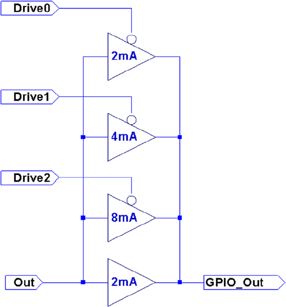
CHAPTER 12 ■ GPIO
126
With Drive0 set to a 1, the top amplifier is enabled, adding another 2 mA of drive, for a total of 4 mA. Enabling
Drive1 adds a further 4 mA of drive, totaling 8 mA. Enabling Drive2 brings the total drive capability to 16 mA.
It should be mentioned that these drive capabilities are not current limiters in any way. What they do is apply
more amplifier drive in order to meet the logic-level requirements (next section). If the GPIO output is wired up to
a light load like a CMOS chip or MOSFET transistor where little current is drawn, then the minimum drive of 2 mA
suffices. The single GPIO 2 mA buffer can effortlessly establish a logic high in its proper voltage range as well as bring
the voltage to a logic low when required.
When the GPIO output is loaded with a higher current load, the single 2 mA buffer may not be enough to keep
the logic level within spec. By applying more amplifier drive, the output voltage levels are coerced into the correct
operating range.
Input Pins
A GPIO input pin should experience voltages only between 0 and the 3.3 V maximum. Always exercise caution when
interfacing to other circuits that use higher voltages like TTL logic, where 5 V is used. The SoC is not tolerant of
overvoltages and can be damaged.
While there exist protection diodes for protecting against negative input swings, these are weak and intended
only to bleed away negative static charges. Be sure to design your input circuits so that the GPIO input never sees a
negative input potential.
Figure 12-3. Drive-strength control
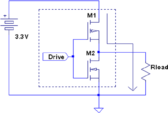
CHAPTER 12 ■ GPIO
127
Output Pins
As an output GPIO pin, the user bears full responsibility for current limiting. There is no current limiting provided.
When the output pin is in the high state, as a voltage source, it tries to supply 3.3 V (within the limits of the transistor).
If this output is shorted to ground (worst case), then as much current as can be supplied will flow. This will lead
to permanent damage.
The outputs also work to the specifications listed earlier, but the attached load can skew the operating voltage
range. An output pin can source or sink current. The amount of current required and the amount of output drive
configured alters the operating voltage profile. As long as you keep within the current limits for the configured drive
capability, the voltage specifications should be met.
Figure 12-4 illustrates how a GPIO port sources current into its load (Rload). Current flows from the +3.3 V supply,
through transistor M1, out the GPIO pin, and into Rload to ground. Because of this, it takes a high (logic 1) to send
current into the load. This makes the circuit an “active high” configuration.
Figure 12-4. GPIO output high
Figure 12-5 shows how the GPIO output sinks current instead. Because Rload is connected to the +3.3 V supply,
current flows through Rload, into the GPIO output pin, and through the bottom transistor M2 to ground. To send current
through the load, a low (logic 0) is written to the output port. This is the active low configuration.
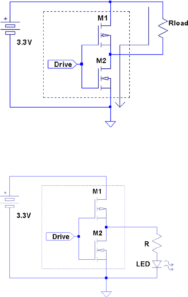
CHAPTER 12 ■ GPIO
128
Figure 12-6 shows the active high configuration’s Rload circuit element substituted with an LED and limiting
resistor R. Since there is no current limiting provided by the GPIO port, resistor R must be provided to do this.
Figure 12-5. GPIO output low
Figure 12-6. GPIO driving an LED

CHAPTER 12 ■ GPIO
129
Driving LEDs
When an LED is hooked up to the GPIO output port, Rload becomes the LED and the limiting resistor (in series).
The math is complicated slightly by the fact that the LED is a diode. As a diode, it has a voltage drop, which should be
subtracted from the supply voltage. For red LEDs, the voltage drop is usually between 1.63 and 2.03 V.30
Knowing the current draw you want for the LED, the resistor R can be calculated from the following:
R=VV
I
CC LED
LED
–
where
VCC is the supply voltage (+3.3 V).
VLED is the voltage drop for the LED.
ILED is the required current draw for the LED.
For VLED it is best to assume the worst case and assume the lower voltage drop of 1.63 V. Assuming we need 8 mA
to get reasonable brightness from the LED, we can calculate the resistance of the limiting resistor:
R=-
=
33 163
0 008
208 75
..
.
.W
Since resistors come in standard values, we round up to a standard 10% component of 220 Ω.
Note ■ Rounding resistance down would lead to higher current. It is better to err on the side of less current.
The LED and the 220 Ω limiting resistor can be wired according to Figure 12-4 (and shown in Figure 12-6). When
wired this way, a high is written to the GPIO output port to make current flow through the LED.
The sense of the GPIO port can be altered by the sysfs file active_low (see Table 12-5 later in this chapter).
Putting the GPIO pin 7 into active low mode reverses the logic sense, as follows:
# echo 1 >/sys/class/gpio/gpio7/active_low
With this mode in effect, writing a 1 to GPIO pin 7 causes the pin to go “low” on the output and causes the
LED to go off:
# echo 1 >/sys/class/gpio/gpio7/value
If the LED was wired according to Figure 12-5, it would turn on instead.
Driving Logic Interfaces
For LEDs, the requirements of the interface are rather simple. The interface is a success if the LED is lit when the
output port is in one state, and the LED is dark in the other. The precise voltage appearing at the GPIO output pin in
these two states is of little concern, as long as the maximum current limits are respected.
When interfacing to logic, the output voltage is critical. For the receiving logic, the output level must be at least
VIH to reliably register a 1 bit (for the BCM2835, this is 1.3 V). Likewise, the output should present less than VIL to
reliably register a 0 in the receiver (for the BCM2835, this is 0.8V). Any voltage level between these limits is ambiguous
and can cause the receiver to randomly see a 0 or a 1.
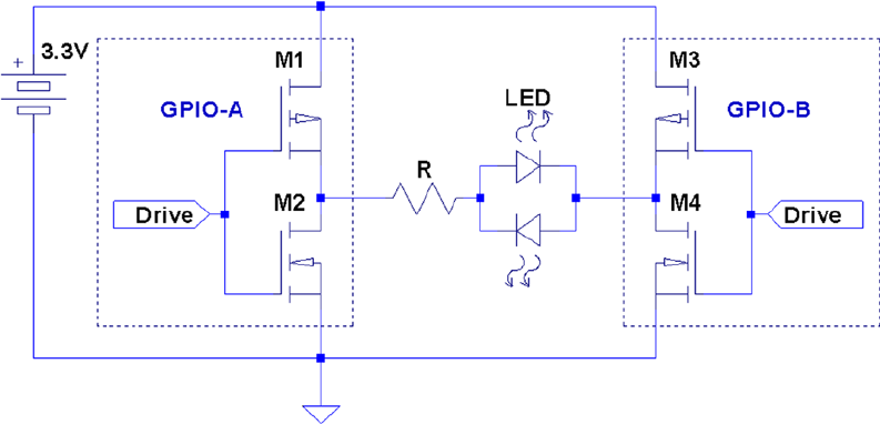
CHAPTER 12 ■ GPIO
130
There are a fairly large number of approaches to interfacing between different logic families. A good source of
information is provided by the document “Microchip 3V Tips ’n Tricks.”31
Another document titled “Interfacing 3V and 5V Applications, AN240” describes the issues and challenges of
interfacing between systems.32 It describes, for example, how a 5 V system can end up raising the 3 V supply voltage if
precautions are not taken.
Approaches to interfacing include direct connections (when safe), voltage-dividing resistors, diode resistor
networks, and the more-complex op-amp comparators.
When choosing an approach, remember to consider the necessary switching speed of the interface required.
Driving Bi-color LEDs
This is a good point to inject a note about driving bi-color LEDs. Some of these are configured so that one LED is
forward biased while the other is reversed biased. This has the advantage of needing only the usual two LED leads.
To change colors, you simply change the polarity of the power going into the pair.
To drive these and choose a color, you need a way to reverse the current. This is normally done using the
H-Bridge driver, which is explored in Chapter 28. There a bipolar stepper motor is driven by the H-Bridge driver.
The LED, however, requires considerably less current, and so this is an easy assignment. If you choose a bi-color LED
requiring 10 mA or less, you can drive it directly from a pair of GPIO outputs.
Figure 12-7 illustrates the bi-color LED driving arrangement. Compare this configuration with the H-Bridge in
Chapter 28’s Figure 28-1. Do you see the similarity?
Figure 12-7. Driving a bi-colored LED
The pair of GPIO outputs form an H-Bridge because each of the outputs themselves are a pair of CMOS driving
transistors—an upper and lower half. It is this pairing that makes them capable of both sourcing and sinking a current.
By using two GPIO outputs, you form an H-Bridge driver.
To light the bi-color LED in one color, make one GPIO high (source), while the other is made low (sink). Then the
current will flow through the LED from the first GPIO output into the second. To reverse the current and see the other
color, make the first GPIO low and the other high. Now the current flows from the second GPIO output into the first.
CHAPTER 12 ■ GPIO
131
Testing Drive Strength
There’s nothing like finding out for yourself the configured parameters of your Raspberry Pi. The program pads.c
(next) dumps out the GPIO Pads Control registers so that you can verify the actual parameters in effect.
Each GPIO pin defaults to setting 3 (for 8 mA).28 Running the pads.c program on my Rev 2.0 Raspberry Pi showed
that the GPIO group from 28 to 45 was configured for 16 mA. GPIO pins 28 to 31 are available on header P5.
The following example session shows the output for my Raspberry Pi:
$ sudo ./pads
07E1002C : 0000001B 1 1 3
07E10030 : 0000001F 1 1 7
07E10034 : 0000001B 1 1 3
The last four fields on each output line are as follows:
1. The word value in hexadecimal
2. The configured slew rate setting
3. The configured hysteresis setting
4. The drive-level code
What this suggests is that GPIO 28 through 31 could be used, if you have higher current driving requirements.
If you have a requirement to change these settings from within a C program, the program pads.c can be easily
modified. Use the macro GETPAD32 (line 16) for inspiration.
1 /∗∗∗∗∗∗∗∗∗∗∗∗∗∗∗∗∗∗∗∗∗∗∗∗∗∗∗∗∗∗∗∗∗∗∗∗∗∗∗∗∗∗∗∗∗∗∗∗∗∗∗∗∗∗∗∗∗∗∗∗∗∗∗∗∗∗∗∗∗
2 ∗ pads . c : Examine GPIO Pads Control
3 ∗∗∗∗∗∗∗∗∗∗∗∗∗∗∗∗∗∗∗∗∗∗∗∗∗∗∗∗∗∗∗∗∗∗∗∗∗∗∗∗∗∗∗∗∗∗∗∗∗∗∗∗∗∗∗∗∗∗∗∗∗∗∗∗∗∗∗∗∗/
4 #include <stdio.h>
5 #include <stdlib.h>
6 #include <fcntl.h>
7 #include <sys/mman.h>
8 #include <unistd.h>
9
10 #define BCM2708_PERI_BASE 0 x20000000
11 #define PADS_GPIO_BASE (BCM2708_PERI_BASE + 0 x100000 )
12 #define PADS_GPIO_00_27 0x002C
13 #define PADS_GPIO_28_45 0x0030
14 #define PADS_GPIO_46_53 0x0034
15
16 #define GETPAD32(offset) ( ∗(unsigned ∗) ((char ∗) (pads)+offset))
17
18 #define BLOCK_SIZE (4∗1024)
19
20 volatile unsigned ∗pads ;
21
22 void
23 initialize(void) {
24 int mem_fd = open("/dev/mem",O_RDWR|O_SYNC);
25 char ∗pads_map;
26
CHAPTER 12 ■ GPIO
132
27 if ( mem_fd <= 0 ) {
28 perror("Opening/dev/mem");
29 exit(1);
30 }
31
32 pads_map = (char ∗)mmap(
33 NULL, /∗Any address ∗/
34 BLOCK_SIZE, /∗Map length ∗/
35 PROT_READ|PROT_WRITE,
36 MAP_SHARED,
37 mem_fd, /∗File to map ∗/
38 PADS_GPIO_BASE /∗Offset to registers ∗/
39 );
40
41 if ( (long)pads_map == −1L ) {
42 perror("mmap failed.");
43 exit(1);
44 }
45
46 close(mem_fd);
47 pads = (volatile unsigned ∗)pads_map;
48 }
49
50 int
51 main(int argc,char ∗∗argv) {
52 int x;
53 union {
54 struct {
55 unsigned drive : 3;
56 unsigned hyst : 1;
57 unsigned slew : 1;
58 unsigned reserved : 13;
59 unsigned passwrd : 8;
60 } s;
61 unsigned w;
62 } word;
63
64 initialize();
65
66 for ( x=PADS_GPIO_00_27; x<=PADS_GPIO_46_53; x += 4 ) {
67 word.w = GETPAD32(x) ;
68 printf("%08X : %08X %x %x %x\n" ,
69 x+0x7E10000, word.w,
70 word.s.slew, word.s. hyst, word.s.drive) ;
71 }
72
73 return 0;
74 }
75
76 /∗End ∗/

CHAPTER 12 ■ GPIO
133
GPIO Current Budget
Gert van Loo states that “the Raspberry-Pi 3V3 supply was designed with a maximum current of ~3 mA per GPIO
pin.”29 He correctly concludes that if “you load each pin with 16 mA, the total current is 272 mA.”
From this, we can calculate the designed current budget for GPIO pins:
1. Gert is referring to 17 GPIO pins (
272
16 17
mA
mA =
)
2. The Pi is designed for 17 × 3 mA = 51mA
This is consistent with the 50 mA capacity figure we arrived at in Chapter 4. This is the remaining current capacity
available from pins P1-01, P1-17, and P5-02.
Consequently, when budgeting your 3.3 V supply current, factor in the following:
GPIO: Current used for each GPIO output pin assigned (2 mA to 16 mA)
+3.3 V: All current going to circuits powered from P1-01, P1-17, and P5-02.
MAX232CSE: If you attached a RS-232 adapter, allow for about 15 mA.
To save on your power budget, configure unused GPIO pins as inputs.
Configuration
Each GPIO pin is affected by several configuration choices:
General-purpose input, output, or alternate function•
Input event detection method•
Input pull-up/pull-down resistors•
Output drive level•
Alternate Function Select
When a GPIO pin is configured, you must choose whether it is an input, an output, or an alternate function
(like the UART). The complete list of choices is shown in Table 12-4. The exact nature of what alternate function x
means depends on the pin being configured.
Table 12-4. Alternate Function Selection
Code Function Selected ALT
000 GPIO pin is an input.
001 GPIO pin is an output.
100 GPIO pin is alternate function 0. 0
101 GPIO pin is alternate function 1. 1
110 GPIO pin is alternate function 2. 2
111 GPIO pin is alternate function 3. 3
011 GPIO pin is alternate function 4. 4
010 GPIO pin is alternate function 5. 5
CHAPTER 12 ■ GPIO
134
The values shown in the table’s Code column are used in the configuration register itself. The alternate function
numbers are listed in the ALT column. Keeping these two straight can be confusing when programming. Once the
function has been selected, the configuration is then fine-tuned according to its peripheral type.
Output Pins
When a pin is configured for output, the remaining elements of configuration consist of the following:
Logic sense•
Output state•
The output state of the GPIO pins can either be set by the kernel as a 32-bit word (affects 32 GPIOs at a time) or
individually set or cleared. Having individual set/clear operations allows the host to change individual bits without
disturbing the state of others (or having to know their state).
Input Pins
Input pins are more complex because of the additional hardware functionality offered. This requires that the input
GPIO pin be configured for the following:
Detect rising input signals (synchronous/asynchronous)•
Detect falling input signals (synchronous/asynchronous)•
Detect high-level signals•
Detect low-level signals•
Logic sense•
Interrupt handling (handled by driver)•
Choose no pull-up; use a pull-up or pull-down resistor•
Once these choices have been made, it is possible to receive data related to input signal changes, or simply query
the pin’s current state.
Alternate Function
When an alternate function such as the UART is chosen, many aspects of the pin’s configuration are predetermined.
Despite this, each pin used by the peripheral should be preconfigured for input or output according to its function.
These details are normally provided by the supporting driver.
Sysfs GPIO Access
In this section, we’re going to access the GPIO pins through the /sys pseudo file system. This is the GPIO driver
interface. Because it provides file system objects, it is possible to control GPIO pins from the command line (or shell).
The C/C++ programmer might be quick to dismiss this approach, because it might seem too slow. However,
for input pins, the driver provides the advantage of providing a reasonable edge-level detection that is not possible
when accessing the GPIO registers directly. The driver is able to receive interrupts when a GPIO state changes. This
information can in turn be passed onto the application program using poll(2) or select(2).

CHAPTER 12 ■ GPIO
135
Everything that you need for GPIO access is rooted in the top-level directory:
/sys/class/gpio
At this directory level, two main control pseudo files are maintained by the driver. These are write-only:
export: Requests the kernel to export control of the requested GPIO pin by writing its
number to the file
unexport: Relinquishes control of the GPIO pin by writing its number to the file
Note ■ Even root gets the permission denied if you try to read these files.
Normally, the kernel manages the GPIO pins, especially if they are used for resources that need them (like the
UART). In order for an application to manipulate a GPIO pin, it must first request that the kernel relinquish control of
the requested pin. From a userspace perspective, the operation is like opening a file. The script or program should be
prepared for failure in the event that a GPIO pin is busy.
COrreCt USe OF SUDO
It is tempting to perform some operations from a nonroot account, using sudo like this:
$ sudo echo 17 >/sys/class/gpio/export
-bash: /sys/class/gpio/export: Permission denied
This does not work because the I/O redirection is performed by the shell before the sudo command begins.
Change to interactive mode first and then the operation will succeed:
$ sudo -i
# echo 17 >/sys/class/gpio/export
export
The export pseudo file allows you to request a GPIO pin from the kernel. For example, if you want to manipulate
GPIO pin 17, you request it from the kernel by writing its pin number to the pseudo file:
$ sudo –i
# echo 17 >/sys/class/gpio/export
After a successful run, list the directory /sys/class/gpio:
# ls
export gpio17 gpiochip0 unexport
#
A new subdirectory (a symlink to a directory, actually) named gpio17 appears. This tells you that the kernel has
given up control of GPIO 17 and has provided you this file system object to manipulate. At this point, you can consider
the GPIO 17 as available.

CHAPTER 12 ■ GPIO
136
unexport
Some applications may require a GPIO pin for only a short time. When the application is finished with the pin, the
application can release the pin back to the kernel. This is done by writing to the unexport pseudo file:
$ sudo -i
# echo 17 >/sys/class/gpio/unexport
After this command completes, the pseudo object gpio17 disappears from the /sys/class/gpio directory.
This confirms that the GPIO is now being managed by the driver and makes it impossible for userspace programs to
mess with it (except for direct register access).
gpioX
Once you have a file system object like /sys/class/gpio/gpio17 to work with, you can configure it and perform I/O.
The main objects that you’ll see are outlined in Table 12-5. The ones normally used by shell programs are simply as follows:
direction: To set the I/O direction
value: To read or write the I/O bit
active_low: To alter the sense of logic
Table 12-5. /sys/class/gpio/gpioX Objects
Object Type R/W Values Description
direction File R/W in Input pin
out Output pin
high Output & high
low Output & low
value File R/W 0 or 1 Read or write
edge File R/W None No edge
Rising Rising edge
Falling Falling edge
Both Rising or falling
active_low File R/W 0 Normal sense
1 Active low
uevent File
subsystem Symlink Symlink to self
power Directory R

CHAPTER 12 ■ GPIO
137
The values used for direction are worth expanding on:
Value Description
in GPIO becomes an input port.
out GPIO becomes an output port (with some prior state).
high GPIO becomes output, but in a 1 state (high).
low GPIO becomes output, but in a 0 state (low).
The high and low options look like convenience frills, but they’re not. Consider configuring an output and
setting it to 1:
# echo out >/sys/class/gpio/gpio7/direction
# echo 1 >/sys/class/gpio/gpio7/value
Some time will pass before the execution of the second command takes place to establish the correct output
level. If the GPIO output state was previously left in a zero state, the GPIO 7 pin will reflect a 0 (low) until the second
command completes. For electronic devices operating in nanosecond time frames, this can be a problem.
To provide glitch-free configuration, the following can be done instead:
# echo high >/sys/class/gpio/gpio7/direction
This way, the driver takes the necessary steps to establish the correct output level prior to making the pin an output.
The settings of the file named edge affect how a C program (for example) would process poll(2) on the file
named value (reading). A poll(2) system call could block the execution of the program until the required event
occurred (like a rising edge).
Active Low
Sometimes it is desirable to have the logic inverted for the GPIO pin being used. For example, when driving an LED in
the circuit configuration of Figure 12-5, a logic low is required to light the LED.
Value Description
0 Noninverted logic
1 Inverted logic
Inverting the logic allows you to light the LED with a logic 1:
# echo 1 >/sys/class/gpio/gpio7/active_low
# echo 1 >/sys/class/gpio/gpio7/value
Conversely, if you don’t want inverted logic, you should be certain to establish that by writing a 0:
# echo 0 >/sys/class/gpio/gpio7/active_low
CHAPTER 12 ■ GPIO
138
Chip Level
You will also notice the presence of a subdirectory named gpiochipN in /sys/class/gpio, where N is a numeric digit.
The following main pseudo files exist within that directory:
base: The value read should be the same value N, which is the first GPIO managed
by this chip.
label: The label (for example, bcm2708_gpio) of the chip, which is not necessarily unique.
Used for diagnostic purposes.
ngpio: The value read indicates how many GPIOs this chip manages, starting with the
value read from base.
GPIO Tester
If you decided to build yourself a prototype board with the Raspberry Pi mounted on it, you may find this simple shell
script useful for checking the wiring of the GPIO breakout clips. Or perhaps you just want to verify that the connection
brought out to the breadboard is the correct one. Simply supply the GPIO pin number that you want to blink, on the
command line:
$ cat ./gp
#!/bin/bash
GPIO="$1"
SYS=/sys/class/gpio
DEV=/sys/class/gpio/gpio$GPIO
if [ ! −d $DEV ] ; then
# Make pin visible
echo $GPIO >$SYS/export
fi
# Set pin to output
echo out >$DEV/direction
function put() {
# Set value of pin (1 or 0)
echo $1 >$DEV/value
}
while true ; do
put 1
echo "GPIO $GPIO: on"
sleep 1
put 0
echo "GPIO $GPIO: off $(date)"
sleep 1
done
# End

CHAPTER 12 ■ GPIO
139
To exercise GPIO 25 (GEN6), use this command (project file scripts/gp):
# ./gp 25
When testing with an LED and alligator clip lead, ground yourself to the ground pin first (or better still, a good
ground like a water tap). Static electricity can be especially bad in the winter months. It not only can cause your Pi to
reset but also can inflict internal damage. After discharging yourself to the ground pin, apply the lead and allow time
enough for 1-second-on and 1-second-off events.
Note ■ Cats are especially bad for static electricity.
GPIO Input Test
To test out the GPIO input capability, a simple script is presented next (and is available in the scripts subdirectory as
a file named input). By default, it assumes 0 for the active low setting, meaning that normal logic applies to the input
values. If, on the other hand, a 1 is used, inverted logic will be applied. Using the script named input, apply one of the
following commands to start it (^C to end it):
# ./input 0 # Normal "active high" logic
. . .
# ./input 1 # Use active low logic
The script, of course, can be modified, but as listed, it reads an input on GPIO 25 (GEN6) and presents what it
has read to GPIO 24 (GEN5). It additionally reports what has been read to standard output. If the output (GPIO 24) is
wired to an LED, the input status will be visible in the LED (use Figure 12-6 as a guide for wiring).
The script has its limitations, one of which is that the sleep(1) command is used. This causes it to have a
somewhat sluggish response. If you don’t like that, you can comment out the else and sleep commands. As a
consequence, it will hog the CPU, however, but be more responsive.
#!/bin/bash
ALO="${1:−0}" # 1=active low, else 0
INP=25 # Read from GPIO 25 (GEN6)
OUT=24 # Write t o GPIO 24 (GEN5)
set −eu
trap "close_all" 0
function close_all() {
close $INP
close $OUT
}
function open() { # pin direction
dev=$SYS/gpio$1
if [ ! −d $dev ] ; then
echo $1 >$SYS/export
fi
CHAPTER 12 ■ GPIO
140
echo $2 >$dev/direction
echo none >$dev/edge
echo $ALO >$dev/active_low
}
function close() { # pin
echo $1 >$SYS/unexport
}
function put() { # pin value
echo $2 >$SYS/gpio$1/value
}
function get() { # pin
read BIT <$SYS/gpio$1/value
echo $BIT
}
count=0
SYS=/sys/class/gpio
open $INP in
open $OUT out
put $OUT 1
LBIT=2
while true ; do
RBIT=$(get $INP)
if [ $RBIT −ne $LBIT ] ; then
put $OUT $RBIT
printf "%04d Status : %d\n" $count $RBIT
LBIT=$RBIT
let count=count+1
else
sleep 1
fi
done
# End
The following is an example session:
# ./input
0000 Status : 0
0001 Status : 1
0002 Status : 0
0003 Status : 1
^C
#
When GPIO 25 is grounded, 0 should be read, as reported in line 0000 of the example. If you then apply a high
(for example, from the +3.3 V supply), a 1 should be reported.

CHAPTER 12 ■ GPIO
141
Floating Potentials
The beginning student may be puzzled about “glitches” seen by some GPIO inputs (28 or 29). When a GPIO input
without a pull-up resistor is unattached, the line can “float,” or change over time, due to static electrical buildup.
Unless a pull-up or pull-down resistor is attached (or configured), the pin can assume intermediate voltages. A voltage in
the range of VIL = 0.8 V to VIH = 1.3 V is ambiguous to the Pi. Input voltages in this range may read randomly as 1s or 0s.
Caution ■ If you are using a loose wire or alligator clip to apply high or low signals to an input GPIO pin, be very careful
to avoid static electricity, which can cause damage. Use a ground strap or hold onto the Pi’s ground to bleed any static
away, while changing connections. Static electricity may also cause your Raspberry Pi to reset. A real ground, like a water
tap, is best for bleeding off static.
When using a button or switch, for example, use a pull-up resistor to +3.3 V (or configure the SoC to use one).
In this manner, high is immediately seen by the input when the switch or button is temporarily unconnected.
Note ■ A switch is temporarily disconnected while changing its poles.
Reading Events
One of the shortcomings of the input script is that it must poll the input pin’s value continuously, to see if the value
has changed. In a multiprocessing environment like Linux, it is rude to burn the CPU like this (hence the compromise
with the sleep command). A better design would have the program wait for a change on the input pin, allowing other
processes to use the CPU while it waits.
The GPIO driver within the kernel is, in fact, able to do that, though not usable by shell commands. The C
program evinput.c is an example program that takes advantage of this capability and is presented next. It uses the
poll(2) system call to accomplish this. The basic procedure used is this:
1. The GPIO pin X is configured for input.
2. The value of /sys/class/gpio/gpioX/edge has been configured for the edge(s) to be
reported (see Table 12-5).
3. When querying the input pin, the open file descriptor for /sys/class/gpio/gpioX/value
is provided to the poll(2) call (line 111).
4. The time-out is specified as –1 in argument 3, so poll(2) will wait forever, if necessary.
5. When there is new data for the GPIO input, poll(2) returns and rc will be greater than
zero, breaking out of the loop.
6. The program must rewind to the beginning of the pseudo file with lseek(2) (line 118).
7. Finally, the text is read from the value file in line 119.
Step 6 can be omitted if you only need notification. However, to read the correct data, a rewind to the start of the
pseudo file is required.
The program shown also checks whether the signal handler was called. If it sees that variable is_signaled has
been set, the routine gpio_poll() returns –1 to indicate to the caller that a program exit is needed (lines 112 to 113).

CHAPTER 12 ■ GPIO
142
Test Run
A test was performed using a GPIO output pin (27) wired to the input pin (17). In one session, GPIO output pin 27 was
changed from 0 to 1 and back. The events were captured in the other session, running ./evinput.
Note ■ If the reader compiles the programs using the included makefile for each program, the programs are
automatically built to use setuid root. Doing this allows them to run with root privileges, without needing to use the
sudo command.
The following is a session output obtained from the ./evinput run. The output pauses after reporting the first
line (line 4). Following that, new lines appear whenever the input pins change state.
1 $ ./evinput 17
2 Monitoring for GPIO input changes:
3
4 GPIO 17 changed: 0
5 GPIO 17 changed: 1
6 GPIO 17 changed: 0
7 GPIO 17 changed: 1
8 ^C
9 $
Input GPIO pin 17 was changed from this separate session, using output GPIO 27 (recall that it is wired to
GPIO 17 for this test):
1 # cd /sys/class/gpio
2 # echo 27 >export
3 # ls
4 export gpio27 gpiochip0 unexport
5 # cd gpio27
6 # ls
7 active_low direction edge power subsystem uevent value
8 # echo out >direction
9 # echo 0 >value
10 # # s t a r t e d . / evinput 17 he r e . . .
11 # echo 1 >value
12 # echo 0 >value
13 # echo 1 >value
From the sessions shown, GPIO 17 was set low in the preceding line 9. After that, the ./evinput program was
started and the first line is reported (line 4 in the evinput session). As the input pin changed state in lines 11+ (in the
preceding code), the input events were being reported in lines 5+ (evinput session).
CHAPTER 12 ■ GPIO
143
Checking the system with the top command, you’ll see that ./evinput does not consume CPU. Yet the program
is indeed responsive to the input change events. This leaves the CPU for all of your other processes that you may
need to run.
1 / ∗∗∗∗∗∗∗∗∗∗∗∗∗∗∗∗∗∗∗∗∗∗∗∗∗∗∗∗∗∗∗∗∗∗∗∗∗∗∗∗∗∗∗∗∗∗∗∗∗∗∗∗∗∗∗∗∗∗∗∗∗∗∗∗∗∗∗∗∗
2 ∗ evinput.c : Event driven GPIO input
3 ∗
4 ∗ ./evinput gpio#
5 ∗∗∗∗∗∗∗∗∗∗∗∗∗∗∗∗∗∗∗∗∗∗∗∗∗∗∗∗∗∗∗∗∗∗∗∗∗∗∗∗∗∗∗∗∗∗∗∗∗∗∗∗∗∗∗∗∗∗∗∗∗∗∗∗∗∗∗∗∗/
6
7 #include <stdio.h>
8 #include <stdlib.h>
9 #include <fcntl.h>
10 #include <unistd.h>
11 #include <string.h>
12 #include <errno.h>
13 #include <signal.h>
14 #include <assert.h>
15 #include <sys/poll.h>
16
17 static int gpio_inpin = –1; / ∗ GPIO input pin ∗/
18 static int is_signaled = 0; / ∗ Exit program if signaled ∗/
19
20 typedef enum {
21 gp_export=0, / ∗ /sys/class/gpio/export ∗/
22 gp_unexport, / ∗ /sys/class/gpio/unexport ∗/
23 gp_direction, / ∗ /sys/class/gpio%d/direction ∗/
24 gp_edge, / ∗ /sys/class/gpio%d/edge ∗/
25 gp_value / ∗ /sys/class/gpio%d/value ∗/
26 } gpio_path_t;
27
28 /∗
29 ∗ Internal : Create a pathname for type in buf.
30 ∗ /
31 static const char ∗
32 gpio_setpath(int pin, gpio_path_t type, char ∗ buf, unsigned bufsiz) {
33 static const char ∗ paths[] = {
34 "export", "unexport", "gpio%d/direction",
35 "gpio%d/edge", "gpio%d/value"};
36 int slen;
37
38 strncpy (buf, "/sys/class/gpio/", bufsiz);
39 bufsiz –= (slen = strlen(buf));
40 snprintf(buf+slen, bufsiz, paths[type], pin);
41 return buf;
42 }
43
44 /∗
45 ∗ Open /sys/class/gpio%d/value for edge detection :
46 ∗/
47 static int
CHAPTER 12 ■ GPIO
144
48 gpio_open_edge(int pin, const char ∗ edge) {
49 char buf [128];
50 FILE ∗f;
51 int fd;
52
53 /∗Export pin : /sys/class/gpio/export ∗/
54 gpio_setpath(pin, gp_export, buf, size of buf);
55 f = fopen(buf, "w");
56 assert(f);
57 fprintf(f,"%d\n", pin);
58 fclose(f);
59
60 /∗Direction : /sys/class/gpio%d/direction ∗/
61 gpio_setpath(pin, gp_direction, buf, size of buf);
62 f = fopen(buf, "w");
63 assert(f);
64 fprintf(f,"in\n");
65 fclose(f);
66
67 /∗Edge : /sys/class/gpio%d/edge ∗/
68 gpio_setpath(pin, gp_edge, buf, size of buf);
69 f = fopen (buf, "w");
70 assert(f);
71 fprintf(f,"% s\n", edge);
72 fclose(f);
73
74 /∗Value : /sys/class/gpio%d/value ∗/
75 gpio_setpath(pin, gp_value, buf, size of buf);
76 fd = open(buf,O_RDWR);
77 return fd;
78 }
79
80 /∗
81 ∗ Close (unexport) GPIO pin :
82 ∗ /
83 static void
84 gpio_close(int pin) {
85 char buf[128];
86 FILE ∗f;
87
88 / ∗ Unexport : /sys/class/gpio/unexport ∗/
89 gpio_setpath(pin, gp_unexport, buf, size of buf);
90 f = fopen(buf, "w");
91 assert(f);
92 fprintf(f,"%d\n", pin);
93 fclose(f);
94 }
95
96 /∗
97 ∗ This routine will block until the open GPIO pin has changed
98 ∗ value. This pin should be connected to the MCP23017 /INTA
99 ∗ pin.
CHAPTER 12 ■ GPIO
145
100 ∗/
101 static int
102 gpio_poll(int fd) {
103 struct pollfd polls;
104 char buf [32];
105 int rc, n;
106
107 polls.fd = fd; /∗ /sys/class/gpio17/value ∗/
108 polls.events = POLLPRI; /∗Exceptions ∗ /
109
110 do {
111 rc = poll(&polls, 1, –1); /∗Block ∗/
112 if ( is_signaled )
113 return –1; /∗Exit if ^C received ∗/
114 } while ( rc < 0 && errno == EINTR );
115
116 assert (rc > 0);
117
118 lseek(fd, 0, SEEK_SET);
119 n = read(fd, buf, size of buf) ; /∗Read value ∗/
120 assert(n > 0);
121 buf[n] = 0;
122
123 rc = sscanf(buf,"% d",&n);
124 assert(rc==1);
125 return n; /∗Return value ∗/
126 }
127
128 /∗
129 ∗ Signal handler to quit the program :
130 ∗ /
131 static void
132 sigint_handler(int signo) {
133 is_signaled = 1; /∗Signal to exit program ∗/
134 }
135
136 /∗
137 ∗ Main program :
138 ∗/
139 int
140 main(int argc, char ∗∗ argv) {
141 int fd, v;
142
143 /∗
144 ∗ Get GPIO input pin to use :
145 ∗/
146 if (argc != 2) {
147 usage: fprintf(stderr, "Usage: %s <gpio_in_pin>\n", argv[0]);
148 return 1;
149 }
CHAPTER 12 ■ GPIO
146
150 if ( sscanf(argv[1], "%d",&gpio_inpin) != 1 )
151 goto usage;
152 if ( gpio_inpin < 0 || gpio_inpin >=32 )
153 goto usage;
154
155 signal (SIGINT, sigint_handler) ; /∗Trap on SIGINT ∗/
156 fd = gpio_open_edge(gpio_inpin, "both"); /∗GPIO input ∗/
157
158 puts("Monitoring for GPIO input changes: \n");
159
160 while ( (v = gpio_poll (fd)) >=0 ) { /∗Block until input changes ∗/
161 printf("GPIO %d changed: %d\n", gpio_inpin, v);
162 } while ( !is_signaled ); /∗Quit if ^C' d ∗/
163
164 putchar('\n');
165 close(fd); /∗Close gpio%d/value ∗/
166 gpio_close(gpio_inpin); /∗Unexport gpio ∗ /
167 return 0;
168 }
169
170 / ∗ End event.c ∗ /
Direct Register Access
It is possible to access the GPIO registers directly. The module gpio_io.c shows the code that can be used for this.
It requires the program to invoke gpio_init() upon startup, which then makes the registers available. The code
as presented is intended to be #included into the module using it. (Normally, it would be compiled as a separate
module.) The API made available is outlined in the following subsections.
These routines are used in several examples and projects within this book, including the following:
pullup: Change the pull-up register setting.
bipolar: Drive a bipolar stepper motor (Chapter 28).
rtscts: Change the ALT function (Chapter 11).
valt: View ALT function settings (subdir valt in source code).
unipolar: Drive a unipolar stepper motor (Chapter 27).
dht11: Humidity and temperature sensor (Chapter 22).
pwm: Pulse width modulation (Chapter 30).
gpio_init( )
This function call opens access to the GPIO registers. This will require root privileges, which is why many programs
in this book were compiled with setuid root. The operation of this routine is to gain access to the physical memory
space, so that the GPIO registers can be accessed. This procedure is covered in the “Memory Mapping” section of
Chapter 6.
void gpio_init(void);
CHAPTER 12 ■ GPIO
147
gpio_config( )
This function call allows the caller to configure a pin as input or output:
typedef enum {
Input = 0, /∗GPIO is an Input ∗/
Output /∗GPIO is an Output ∗/
} direction_t;
void gpio_config(int gpio,direction_t output);
The arguments are as follows:
gpio: The GPIO pin to be configured
output: The value Input or Output
gpio_write( )
This function permits the caller to set the output GPIO pin to a 1 or a 0.
void gpio_write(int gpio,int bit);
The arguments are as follows:
gpio: The GPIO pin to write to
bit: The value of the output bit (1 or 0)
Only the least significant bit of argument bit is used.
gpio_read( )
This function reads the requested GPIO pin and returns the bit (0 or 1).
int gpio_read(int gpio);
The single argument gpio is used to specify the GPIO pin to be read.
gpio_io.c
The following pages show the program listing for gpio_io.c:
1 /∗∗∗∗∗∗∗∗∗∗∗∗∗∗∗∗∗∗∗∗∗∗∗∗∗∗∗∗∗∗∗∗∗∗∗∗∗∗∗∗∗∗∗∗∗∗∗∗∗∗∗∗∗∗∗∗∗∗∗∗∗∗∗∗∗∗∗∗∗
2 ∗ gpio_io.c : GPIO Access Code
3 ∗∗∗∗∗∗∗∗∗∗∗∗∗∗∗∗∗∗∗∗∗∗∗∗∗∗∗∗∗∗∗∗∗∗∗∗∗∗∗∗∗∗∗∗∗∗∗∗∗∗∗∗∗∗∗∗∗∗∗∗∗∗∗∗∗∗∗∗∗/
4
5 #define BCM2708_PERI_BASE 0x20000000
6 #define GPIO_BASE (BCM2708_PERI_BASE + 0x200000)
7 #define BLOCK_SIZE (4∗1024)
8
CHAPTER 12 ■ GPIO
148
9 /∗GPIO setup macros. Always use INP_GPIO (x) before using OUT_GPIO(x)
10 or SET_GPIO_ALT(x, y ) ∗/
11 #define INP_GPIO (g) ∗(ugpio + ((g)/10)) &= ~(7 <<(((g) % 10)∗3))
12 #define OUT_GPIO(g) ∗(ugpio + ((g)/10)) |= (1 <<(((g) % 10)∗3))
13 #define SET_GPIO_ALT(g,a) \
14 ∗(ugpio + (((g)/10))) |= (((a) <=3?(a) + 4 : (a)==4?3:2)<<(((g)%10)∗3))
15
16 #define GPIO_SET ∗(ugpio+7) /∗ sets bits ∗/
17 #define GPIO_CLR ∗(ugpio+10) /∗ clears bits ∗/
18 #define GPIO_GET ∗(ugpio+13) /∗ gets all GPIO input levels ∗/
19
20 typedef enum {
21 Input = 0, /∗GPIO is an Input∗/
22 Output /∗GPIO is an Output∗/
23 } direction_t;
24
25 static volatile unsigned ∗ugpio;
26
27 /∗∗∗∗∗∗∗∗∗∗∗∗∗∗∗∗∗∗∗∗∗∗∗∗∗∗∗∗∗∗∗∗∗∗∗∗∗∗∗∗∗∗∗∗∗∗∗∗∗∗∗∗∗∗∗∗∗∗∗∗∗∗∗∗∗∗∗∗∗
28 ∗ Perform initialization to access GPIO registers:
29 ∗ Sets up pointer ugpio.
30 ∗∗∗∗∗∗∗∗∗∗∗∗∗∗∗∗∗∗∗∗∗∗∗∗∗∗∗∗∗∗∗∗∗∗∗∗∗∗∗∗∗∗∗∗∗∗∗∗∗∗∗∗∗∗∗∗∗∗∗∗∗∗∗∗∗∗∗∗∗/
31 static void
32 gpio_init() {
33 int fd;
34 char ∗map;
35
36 fd = open("/dev/mem",O_RDWR|O_SYNC); /∗Needs root access ∗/
37 if ( fd < 0 ) {
38 perror("Opening/dev/mem");
39 exit(1);
40 }
41
42 map = (char ∗ ) mmap(
43 NULL, /∗Any address ∗/
44 BLOCK_SIZE, /∗ # of bytes ∗/
45 PROT_READ| PROT_WRITE,
46 MAP_SHARED, /∗Shared ∗/
47 fd, /∗ /dev/mem ∗/
48 GPIO_BASE /∗Offset to GPIO ∗/
49 ) ;
50
51 if ( (long)map == 1L ) {
52 perror("mmap(/dev/mem)");
53 exit(1);
54 }
55
56 close(fd);
57 ugpio = (volatile unsigned ∗)map;
58 }
59
CHAPTER 12 ■ GPIO
149
60 /∗∗∗∗∗∗∗∗∗∗∗∗∗∗∗∗∗∗∗∗∗∗∗∗∗∗∗∗∗∗∗∗∗∗∗∗∗∗∗∗∗∗∗∗∗∗∗∗∗∗∗∗∗∗∗∗∗∗∗∗∗∗∗∗∗∗∗∗∗
61 ∗ Configure GPIO as Input or Output
62 ∗∗∗∗∗∗∗∗∗∗∗∗∗∗∗∗∗∗∗∗∗∗∗∗∗∗∗∗∗∗∗∗∗∗∗∗∗∗∗∗∗∗∗∗∗∗∗∗∗∗∗∗∗∗∗∗∗∗∗∗∗∗∗∗∗∗∗∗∗/
63 static inline void
64 gpio_config (int gpio, direction_t output) {
65 INP_GPIO (gpio);
66 if ( output ) {
67 OUT_GPIO(gpio);
68 }
69 }
70
71 /∗∗∗∗∗∗∗∗∗∗∗∗∗∗∗∗∗∗∗∗∗∗∗∗∗∗∗∗∗∗∗∗∗∗∗∗∗∗∗∗∗∗∗∗∗∗∗∗∗∗∗∗∗∗∗∗∗∗∗∗∗∗∗∗∗∗∗∗∗
72 ∗ Write a bit to the GPIO pin
73 ∗∗∗∗∗∗∗∗∗∗∗∗∗∗∗∗∗∗∗∗∗∗∗∗∗∗∗∗∗∗∗∗∗∗∗∗∗∗∗∗∗∗∗∗∗∗∗∗∗∗∗∗∗∗∗∗∗∗∗∗∗∗∗∗∗∗∗∗∗/
74 static inline void
75 gpio_write(int gpio, int bit) {
76 unsigned sel = 1 << gpio;
77
78 if ( bit ) {
79 GPIO_SET = sel;
80 } else {
81 GPIO_CLR = sel;
82 }
83 }
84
85 /∗∗∗∗∗∗∗∗∗∗∗∗∗∗∗∗∗∗∗∗∗∗∗∗∗∗∗∗∗∗∗∗∗∗∗∗∗∗∗∗∗∗∗∗∗∗∗∗∗∗∗∗∗∗∗∗∗∗∗∗∗∗∗∗∗∗∗∗∗
86 ∗ Read a bit from a GPIO pin
87 ∗∗∗∗∗∗∗∗∗∗∗∗∗∗∗∗∗∗∗∗∗∗∗∗∗∗∗∗∗∗∗∗∗∗∗∗∗∗∗∗∗∗∗∗∗∗∗∗∗∗∗∗∗∗∗∗∗∗∗∗∗∗∗∗∗∗∗∗∗/
88 static inline int
89 gpio_read(int gpio) {
90 unsigned sel = 1 << gpio;
91
92 return (GPIO_GET) & sel ? 1 : 0 ;
93 }
94
95 / ∗ End gpio_io.c ∗/
GPIO Transistor Driver
The GPIO pins on the Pi are often going to be pressed into driving something in the outside world. GPIO pins 28 to 31
can drive up to 16 mA, maximum. The remaining GPIO pins are configured to drive up to 8 mA. These are fairly weak
interfaces to the outside world.
Sometimes all that is needed is a simple one-transistor buffer. The 2N2222A transistor is cheap and drives a fair
amount of current. Figure 12-8 shows a simple driver circuit attached to a GPIO output pin.

CHAPTER 12 ■ GPIO
150
The GPIO output driver sees only a diode-like path to ground through the base of transistor Q1. Resistor R1 is chosen
to limit that current.
The resistor shown as Rc in the figure represents the load, like a high-current LED in series with a current-limiting
resistor. Alternatively, it may be a resistor chosen so that the Vout represents a stiffer output voltage.
In the diagram, the resistor Rc is connected to the +5 V power supply. This is safe because current cannot flow
from the collector into the base of Q1. This prevents 5 V from flowing into the GPIO pin (that junction is reversed
biased). Thus Q1 allows you to convert the 3.3 V GPIO output into a 5 V TTL signal, for example. The 2N2222A
transistor has an absolute maximum VCE of 30 V. This allows you to drive even higher voltage loads, provided that you
stay within the transistor’s current and power ratings.
Driver Design
The transistor driver circuit is limited by the power-handling capability of Q1 and the maximum collector current.
Looking at the datasheet, the maximum power listed for Q1 is 0.5 W at 25ºC. When the transistor is turned on
(saturated), the voltage across Q1 (VCE) is between 0.3 V and 1 V (see VCE(sat) in the datasheet). The remainder of the
voltage is developed across the load. If we assume the worst case of 1 V for VCE (leaving 4 V across the load), we can
compute the maximum current for IC:
I=
P
V
=
=A
C
Q
CE
1
1
0.3
3.3
Clearly, this calculated current exceeds the listed absolute maximum current IC of 600 mA. So we use the maximum
current for IC = 600 mA instead. For safety, we use the minimum of these maximum ratings. While this transistor is clearly
capable of driving up to 600 mA of current, let’s design our driver for a modest current flow of 100 mA.
Figure 12-8. 2N2222A driver

CHAPTER 12 ■ GPIO
151
The next thing to check is the HFE of the part. The parameter value required is the lowest HFE value for the amount
of collector current flowing (HFE drops with increasing IC current). A STMicroelectronics datasheet shows its 2N2222A
part as having an HFE = 40, IC = 500 mA, with VCE = 10 V . They also have a more favorable HFE value of 100, for 150 mA,
but it is best to err on the side of safety. We can probably assume a safe compromise of HFE = 50.
The HFE parameter is important because it affects how much current is required to drive Q1’s base. The input base
current is calculated as follows:
I=I
H
mA
mA
B
C
FE
=
=
100
50
2
This value tells us that the GPIO pin will need to supply up to 2 mA of drive into Q1’s base. With 2 mA of drive, Q1
will be able to conduct up to 100 mA in the collector circuit. A current of 2 mA is easily accommodated by any GPIO
pin. Note that if you were to design closer to the design limits of this transistor (500 mA in this example), you should
probably allow an additional 10% of base current “overdrive” to make certain that the transistor goes into saturation.
Current flow into the base of Q1 creates a voltage drop of VBE = 0.7 V, from the input base lead to ground. So to
calculate the resistor value R1 we take the VR1 divided by the current. The highest voltage coming from GPIO is going to
be slightly less than the 3.3 V power supply rail. It is safe to assume that GPIOHIGH = 3 V. The voltage appearing across
R1 is thus GPIOHIGH–VBE.
RGPIO V
I
HIGH BE
B
1
307
0 002
1 150
=-
=-
=
.
.
,W
The nearest 10% standard resistor value is R1 = 1.2 kΩ. Using this resistor value as a check, let’s compute
backward what our actual drive capability is from Q1. First we need to recompute IB now that we know R1 :
I=
GPIO V
R
mA
B
HIGH BE
1
-
=-
=
307
1200
19
.
.
This tells us that the GPIO output pin will not have to source more than 1.9 mA of current, using R1 = 1.2 kΩ.
Now let’s calculate the maximum drive we can reliably expect in the collector circuit of Q1:
I=IH
mA
CB FE
´
=´
=
0 0019 50
95
.
Note ■ This discussion glibly avoids the effects of components being within ±10% tolerance.
This computes that the designed 2N2222A driver circuit is capable of driving up to 95 mA.
CHAPTER 12 ■ GPIO
152
To obtain even more performance out of that driver (if you need it), you could choose a resistor closer to the
actual value desired (1150 Ω). It turns out that a 1% resistor can be had at exactly 1.15 kΩ:
I=IH
mA
CBFE
´
=´
=
0 002 50
100
.
Be careful that your design does not stress the transistor beyond its maximum ratings (power and current). You
might be willing to risk the cheap transistor, but keep in mind that the poor little thing might be holding back a higher
voltage (like a river dam). If the transistor is destroyed, the high voltage may come crashing into the base circuit and
cause damage to the Pi’s GPIO pin. So be nice to Q1!
Substitution
You don’t have to use my choice of the 2N2222A transistor for driving a load. Substitute what you have or what you
plan to order. Today’s DMMs can measure the transistor HFE, so that makes planning easier when using junk box parts.
Another critical factor in selecting a part is the power capability of the transistor. You should probably know
exactly what that limit is, unless you are driving an extremely light load. Finally, it is important to know what the
maximum voltage ratings are for the selected transistor, if you plan to drive voltages higher than 3 V. You need to be
able to count on it holding back those higher voltages in the collector circuit to prevent damage to the Pi.
Inductive Loads
Inductive loads like relays and motors present a special problem. They generate a high reverse voltage when current is
switched off or interrupted. When the relay coil is turned off, the magnetic field collapses around the coil of wire. This
induces a high voltage, which can damage the Pi (and can also provide a mild electric shock).
Electric motors exhibit a similar problem. As the DC current sparks and stutters at the commutator inside the
motor, high reverse voltage spikes are sent back into the driving circuit. This is due to the magnetic field collapsing
around the motor windings.
Consequently, inductive loads need a reverse-biased diode across the load to short out any induced currents.
The diode conducts only when the back electromotive force (EMF) is generated by the inductive load.
Figure 12-9 shows diode D1 reverse biased across the relay coil winding L1 (or motor). The diode bleeds away any
reverse current that might be generated. Use a diode with sufficient current-carrying capability (matching at least the
current in Q1).
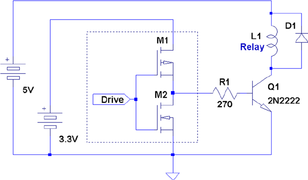
CHAPTER 12 ■ GPIO
153
Since there is no current-limiting resistor used in series with L1 , whether motor or relay, make sure that no more
current than ICmax will flow. For relays, you need a coil resistance greater than or equal to 50 Ω, when driven from
approximately 5 V. Otherwise, you risk burning out driver Q1 (assuming the 2N2222A with its power limit of 0.5 watts
at 5 V). You can drive lower resistance coils, if you designed your driver to handle the additional current. For example,
a 500 mA driver can handle coil resistances as low as 10 ohms (at 5 V).
The 2N2222A transistor is probably suitable for only the smallest of electric motors. Depending on how it is used,
a motor can stall and thus greatly increase its current demands. Motors also have high startup currents. If the motor is
started and stopped frequently, the driving transistor may be overworked.
Driver Summary
This section on the transistor driver should not be thought of as your only choice in driver solutions. It was presented
because it is simple and cheap and can fill the need for many small loads, like high-current LEDs or panel lightbulbs.
Simple and cheap may be essential for robot building when many drivers are required.
While students may use the Gertboard for labs, we still need to provide a substitute when the Raspberry Pi is
integrated into something that was built (like a robot). It might be wise to stock up on a few good transistor types for
this purpose.
Utility gpio
For this book, I have avoided using instances of “magic package X.” However, the wiringPi project is popular enough
that no chapter on GPIO would be complete without mentioning it. The wiringPi project provides a handy utility for
displaying and changing GPIO functionality. The package can be downloaded from here:
https://projects.drogon.net/raspberry-pi/wiringpi/download-and-install
Figure 12-9. Driver for inductive load
CHAPTER 12 ■ GPIO
154
This page lists instructions for obtaining, compiling, and installing the package. Once installed, the gpio
command is available:
$ gpio −h
gpio : Usage : gpio −v
gpio −h
gpio [−g ] <read/write /wb/pwm/ clock/mode> ...
gpio [−p ] <read/write /wb> ...
gpio readall
gpio unexportall/exports ...
gpio export/edge/unexport ...
gpio drive <group> <value>
gpio pwm−bal/pwm−ms
gpio pwmr <range>
gpio pwmc <divider>
gpio load spi / i2c
gpio gbr <channel>
gpio gbw <channel> <value>
There are many options and functions within this utility. I’ll just demonstrate some quick examples of the most
useful ones. Once installed, the full details of the utility can be found by this command:
$ man 1 gpio
Displaying GPIO Settings
The following command can be used to display your GPIO settings:
$ gpio readall
+----------+--------+---------+-------+-------+
| wiringPi | GPIO | Name | Mode | Value|
+----------+--------+---------+-------+-------+
| 0 | 17 | GPIO 0 | IN | High |
| 1 | 18 | GPIO 1 | IN | Low |
| 2 | 27 | GPIO 2 | OUT | Low |
| 3 | 22 | GPIO 3 | IN | Low |
| 4 | 23 | GPIO 4 | IN | Low |
| 5 | 24 | GPIO 5 | IN | Low |
| 6 | 25 | GPIO 6 | IN | Low |
| 7 | 4 | GPIO 7 | IN | Low |
| 8 | 2 | SDA | ALT0 | High |
| 9 | 3 | SCL | ALT0 | High |
| 10 | 8 | CE0 | IN | Low |
| 11 | 7 | CE1 | IN | Low |
| 12 | 10 | MOSI | IN | Low |
| 13 | 9 | MISO | IN | Low |
| 14 | 11 | SCLK | IN | Low |
| 15 | 14 | TxD | ALT0 | High |
| 16 | 15 | RxD | ALT0 | High |
CHAPTER 12 ■ GPIO
155
| 17 | 28 | GPIO8 | IN | Low |
| 18 | 29 | GPIO9 | IN | Low |
| 19 | 30 | GPIO10 | IN | Low |
| 20 | 31 | GPIO11 | IN | Low |
+----------+--------+---------+-------+-------+
Reading GPIO
As a convenience, the gpio command allows you to read values from the command line:
$ gpio export 27 in
$ gpio −g read 27
0
$ gpio unexportall
Use the -g option to specify that the pin number is a GPIO pin number. (I found the need for the -g option irksome.)
Writing GPIO
Like the read function, the gpio command can write values:
$ gpio export 27 out
$ gpio −g write 27 1
$ gpio −g read 27
1
$ gpio −g write 27 0
$ gpio −g read 27
0
$ gpio unexportall
Use the -g option to specify GPIO pin numbers for the read/write commands.
Modify Drive Levels
The gpio command also enables you to alter the drive levels of the three available pads. The following changes pad 1
to drive level 6 (from 7):
$ gpio drive 1 6
Use the pads program shown earlier in this chapter to verify the current settings:
$ gpio drive 1 6
$ ./pads
07E1002C : 0000001B 1 1 3
07E10030 : 0000001E 1 1 6
07E10034 : 0000001B 1 1 3
This kind of change should not be made lightly. If you don’t have a sound reason to change these drive levels, it is
recommended that you don’t.

157
Chapter 13
1-Wire Driver
The 1-Wire protocol was developed by Dallas Semiconductor Corp. initially for the iButton.37 This communication
protocol was attractive enough to be applied to other devices and soon adopted by other manufacturers. This chapter
provides an overview of the 1-Wire protocol and how it is supported in the Raspberry Pi.
1-Wire Line and Power
The 1-Wire protocol actually uses two wires:
• Data: The single wire used for data communication
• Ground: The ground or “return” wire
The 1-Wire protocol was designed for communication with low–data content devices like temperature sensors.
It provides for low-cost remote sensing by supplying power over the same wire used for data communications. Each
sensor can accept power from the data line while the data line is in the high state (which is also the line’s idle state).
The small amount of power that is siphoned off charges the chip’s internal capacitor (usually about 800 pF).37
When the data line is active (going low), the sensor chips continue to run off of their internal capacitors (in
parasitic mode). Data communications cause the data line to fluctuate between low and high. So whenever the line
level returns high again, even for an instant, the capacitor recharges.
The device also provides an optional VDD pin, allowing power to be supplied to it directly. This is sometimes used
when parasitic mode doesn’t work well enough. This, of course, requires an added wire, which adds to the cost of the
circuit. We’ll be focusing on the parasitic mode in this chapter. In parasitic mode, VDD is connected to the ground.
Line Driving
The data line is driven by open collector transistors in the master and slave devices. The line is held high by a pull-up
resistor when the driver transistors are all in the Off state. To initiate a signal, one transistor turns on and thus pulls the
line down to ground potential.
Figure 13-1 shows a simplified schematic of the master attached to the bus. Some voltage V (typically, +5 V) is
applied to the 1-Wire bus through the pull-up resistor Rpullup. When the transistor M2 is in the Off state, the voltage on
the bus remains high because of the pull-up resistor. However, when the master device activates transistor M2, current
is caused to flow from the bus to the ground, acting like a signal short-circuit. Slave devices attached to the bus will see
a voltage near zero.
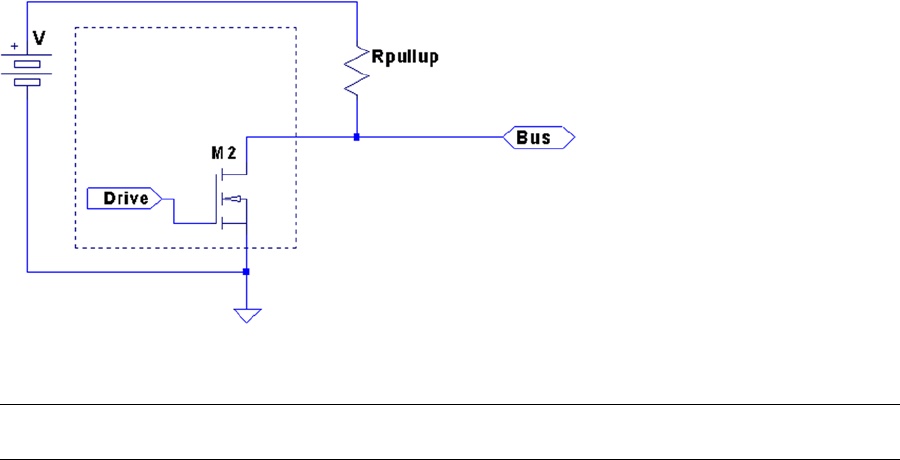
CHAPTER 13 ■ 1-WIRE DRIVER
158
Note ■ The Raspbian Linux 1-Wire bus uses GPIO 4 (GPCLK0) pin P1-07.
Likewise, when a slave is signaled to respond, the master listens to the bus while the slave activates its driving
transistor. Whenever all driving transistors are off, the bus returns to the high idle state.
The master can request that all slave devices reset. After the master has made this request known, it relinquishes
the bus and allows it to return to the high state. All slave devices that are connected to the bus respond by bringing
the line low after a short pause. Multiple slaves will bring the line low at the same time, but this is permitted. This
informs the master that at least one slave device is attached to the bus. Additionally, this procedure puts all slaves into
a known reset state.
Master and Slave
The master device is always in control of the 1-Wire bus. Slaves speak only to the master, and only when requested.
There is never slave-to-slave device communication.
If the master finds that communication becomes difficult for some reason, it may force a bus reset. This corrects
for an errant slave device that might be jabbering on the line.
Protocol
This section presents a simplistic introduction to the 1-Wire communication protocol. Knowing something about how
the signaling works is not only interesting, but may be helpful for troubleshooting. More information is available on
the Internet.38
Reset
Figure 13-2 provides a simplified timing diagram of the reset procedure for the 1-Wire protocol. When the master
driver begins, it must reset the 1-Wire bus to put all the slave devices into a known state.
Figure 13-1. 1-Wire driver circuit

CHAPTER 13 ■ 1-WIRE DRIVER
159
For reset, the bus is brought low and held there for approximately 480 msec. Then the bus is released, and the
pull-up resistor brings it high again. After a short time, slave devices connected to the bus start responding by bringing
the line low and holding it for a time. Several slaves can participate in this at the same time. The master samples the
bus at around 70 msec after it releases the bus. If it finds the line low, it knows that there is at least one slave connected
and responding.
Soon after the master sampling point, all slaves release the bus again and go into a listening state. They do
not respond again until the master specifically addresses a slave device. For simplicity, we’ll omit the discovery
protocol used.
Note ■ Each slave has a guaranteed unique address.
Data I/O
The data protocol is shown in Figure 13-3. Whether writing a 0 or 1 bit, the sending device brings the bus line low.
This announces the start of a data bit.
Figure 13-2. 1-Wire reset protocol
Figure 13-3. 1-Wire read/write of 1 data bit

CHAPTER 13 ■ 1-WIRE DRIVER
160
When a 0 is being transmitted, the line is held low for approximately 60 msec. Then the bus is released and
allowed to return high. When a 1 bit is being transmitted, the line is held low for only about 6 msec before releasing the
bus. Another data bit is not begun until 70 msec after the start of the previous bit. This leaves a guard time of 10 msec
between bits. The receiver then has ample time to process the bit and gains some signal noise immunity.
The receiver notices a data bit is coming when the line drops low. It then starts a timer and samples the bus at
approximately 15 msec. If the bus is still in the low state, a 0 data bit is registered. Otherwise, the data bit is interpreted
as a 1. Having registered a data bit, the receiver then waits further until the line returns high (in the case of a 0 bit).
The receiver remains idle until it notices the line going low again, announcing the start of the next bit.
The sender can be either the master or the slave, but the master always has control. Slaves do not write data to the
bus unless the master has specifically requested it.
Slave Support
Table 13-1 lists the slave devices that are supported by Raspbian Linux. The module names listed are found in the
kernel source directory arch/arm/machbcm2708/slave.
Table 13-1. 1-Wire Slave Driver Support
Device Module Description
DS18S20 w1_therm.c Precision digital thermometer
DS18B20 Programmable resolution thermometer
DS1822 Econo digital thermometer
DS28EA00 9- to 12-bit digital thermometer with PIO
bq27000 w1_bq27000.c Highly accurate battery monitor
DS2408 w1_ds2408.c Eight-channel addressable switch
DS2423 w1_ds2423.c 4 KB RAM with counter
DS2431 w1_ds2431.c 1 KB EEPROM
DS2433 w1_ds2433.c 4 KB EEPROM
DS2760 w1_ds2760.c Precision Li+ battery monitor
DS2780 w1_ds2780.c Stand-alone fuel gauge
Reading Temperature
The support for the usual temperature sensors is found in the kernel module w1_therm. When you first boot your
Raspbian Linux, that module may not be loaded. You can check for it with the lsmod command:
$ lsmod
Module Size Used by
snd_bcm2835 12808 1
snd_pcm 74834 1 snd_bcm2835
snd_seq 52536 0
snd_timer 19698 2 snd_seq, snd_pcm
snd_seq_device 6300 1 snd_seq
snd 52489 7 snd_seq_device, snd_timer,
snd_seq, snd_pcm, snd_bcm2835
snd_page_alloc 4951 1 snd_pcm
CHAPTER 13 ■ 1-WIRE DRIVER
161
The module w1_therm is not loaded according to the example. This module also depends on the driver module
wire. Another thing you can check is the pseudo file system:
$ ls –l /sys/bus/w1
ls: cannot access /sys/bus/w1 : No such file or directory
Having not found the pathname /sys/bus/w1, we have confirmation that the device driver is not loaded.
Loading module w1_therm will bring in most of its module dependents:
$ sudo modprobe w1_therm
$ lsmod
Module Size Used by
w1_therm 2705 0
wire 23530 1 w1_therm
cn 4649 1 wire
snd_bcm2835 12808 1
snd_pcm 74834 1 snd_bcm2835
...
After the wire module is loaded, you’ll see the /sys/bus/w1/devices directory. One more module is needed:
$ sudo modprobe w1_gpio
$ lsmod
Module Size Used by
w1_gpio 1283 0
w1_therm 2705 0
wire 23530 2 w1_therm,w1_gpio
cn 4649 1 wire
snd_bcm2835 12808 1
...
$ cd /sys/bus/w1/devices
$ ls
w1_bus_master1
Once module w1_gpio is loaded, there is a bus master driver for GPIO pin 4 (the default GPIO for the 1-Wire
bus) at the ready. The bus master makes its presence known by creating directory w1_bus_master1. Change to that
directory and list it to see the associated pseudo files within it. Table 13-2 lists the initial set of pseudo files and
symlinks found there.

CHAPTER 13 ■ 1-WIRE DRIVER
162
Bus Master
The bus master driver scans for new slave devices every 10 seconds (according to w1_master_timeout).
File w1_master_attempts indicates how many scans have been performed to date. File w1_master_slave_count shows
how many slaves have been detected out of a maximum of w1_master_max_slave_count. Reading w1_master_slaves
provides a list of slaves found or not found.
The following is an example output session produced while two DS18B20 temperature sensors were connected to
the bus:
$ cd /sys/bus/w1/devices/w1_bus_master1
$ cat w1_master_slaves
28−00000478d75e
28−0000047931b5
$
Slave Devices
Figure 13-4 shows the pinout of the Dallas DS18B20 slave device. This temperature sensor is typical of many 1-wire
slave devices.
Table 13-2. w1_bus_masterX Files
File Type Read Content
driver Symlink
power Directory
subsystem Symlink
uevent File DRIVER=w1_master_driver
w1_master_add File Write device ID xx-xxxxxxxxxxxx to add slave
w1_master_attempts File 88
w1_master_max_slave_count File 10
_master_name File w1_bus_master1
w1_master_pointer File 0xd7032148
w1_master_pullup File 1
w1_master_remove File Write device ID xx-xxxxxxxxxxxx to remove slave
w1_master_search File –1
w1_master_slave_count File 0
w1_master_slaves File Not found
w1_master_timeout File 10
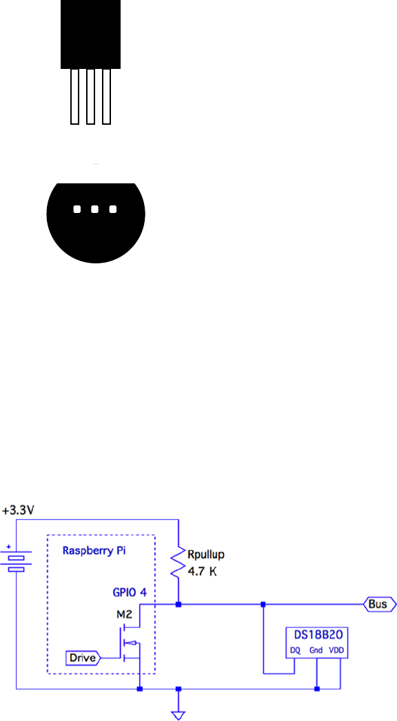
CHAPTER 13 ■ 1-WIRE DRIVER
163
Slave devices are identified by a pair of digits representing the product family, followed by a hyphen and serial
number in hexadecimal. The ID 28-00000478d75e is an example. You might also want to try different devices, like the
similar DS18S20. Figure 13-5 illustrates the DS18B20 attached to the Raspberry Pi.
12
GND
DQ
VDD
To-92
GND Ground
Data In/Out
Power Supply Voltage
PIN DESCRIPTION
DQ
VDD
BOTTOM VIEW
3
12
DS1820
DALLAS
3
-
-
-
Figure 13-4. DS18B20 pin-out
Figure 13-5. 1-Wire with DS18B20 slave circuit
CHAPTER 13 ■ 1-WIRE DRIVER
164
When things are working correctly, the bus master detects slave devices automatically as part of its periodic scan.
If the device you’ve attached is not showing up within 10 seconds or so, you may want to try forcing it. You can force
adding a slave device entry as follows:
# cd /sys/bus/w1/devices/w1_bus_master1
# echo 28−0000028f6667 >w1_master_add
Upon doing this, subdirectory 28-0000028f6667 will appear, at least until the driver gives up trying to
communicate with it (the following line with the ellipsis is abbreviated):
# ls –ltr ./28–0000028f6667
total 0
–rw–r––r–– 1 root root 4096 Jan 30 18:56 uevent
lrwxrwxrwx 1 root root 0 Jan 30 18:56 subsystem –> ../../../bus/w1
–r––r––r–– 1 root root 4096 Jan 30 18:56 w1_slave
Drwxr–xr–x 2 root root 0 Jan 30 18:56 powerr
–r––r––r–– 1 root root 4096 Jan 30 18:56 name
–r––r––r–– 1 root root 4096 Jan 30 18:56 id
lrwxrwxrwx 1 root root 0 Jan 30 18:56 driver –> .../w1_slave_driver
If you want to remove a slave device, you can use the w1_master_remove file. The device will reappear in 10 seconds
or so (due to a scanning period), if the device is still physically connected to the bus.
# echo 28–0000028f6667 >w1_master_remove
The following example shows how two DS18B20 temperature sensors show up on the 1-Wire bus:
$ cd /sys/bus/w1/devices
$ ls
28−00000478d75e 28−0000047931b5 w1_bus_master1
$
Reading the Temperature
The slave device’s temperature can be read by reading its w1_slave pseudo file. In this example, we read two DS18B20
temperature sensors that are supposed to be accurate to ±0.5 ºC. Reading these two sensors together should show
fairly good agreement (they were in close proximity of each other):
$ cat 28−00000478d75e/w1_slave 28−0000047931b5/w1_slave
14 01 4b 46 7f ff 0c 10 b4 : crc=b4 YES
14 01 4b 46 7f ff 0c 10 b4 t=17250
14 01 4b 46 7f ff 0c 10 b4 : crc=b4 YES
14 01 4b 46 7f ff 0c 10 b4 t=17250
$
Each sensor brings back two lines of data from the device driver. We see that both sensors agree exactly—that the
temperature is 17.250ºC. This speaks well for their accuracy. The DS18B20 device also supports a wide temperature
range (–55ºC to +125ºC), which make them good as outdoor sensors.
If the read hangs at this point, it may be that the sensor hasn’t fully registered yet. This can happen if you forced
adding it, but the driver was unable to communicate with it.
CHAPTER 13 ■ 1-WIRE DRIVER
165
1-Wire GPIO Pin
Raspbian Linux has its driver support for the 1-Wire bus on GPIO 4 (P1-07). This pin is hard-coded in the kernel
driver. If you want to change this, look for the definition of W1_GPIO in the source file:
arch/arm/mach-bcm2708/bcm2708.c
Change the definition of W1_GPIO to the pin you require (found near line 73):
// use GPIO 4 for the one–wire GPIO pin, if enabled
#define W1_GPIO 4
Then, of course, you’ll need to rebuild and install the new kernel.
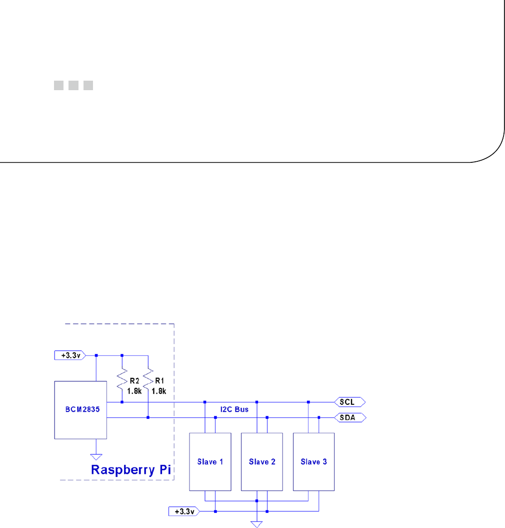
167
Chapter 14
I2C Bus
The I2C bus, also known as the two-wire interface (TWI), was developed by Philips circa 1982 to allow communication
with lower-speed peripherals.49 It was also economical because it required only two wires (excluding ground and
power connections). Since then, other standards have been devised, building upon this framework, such as the
SMBus. However, the original I2C bus remains popular as a simple, cost-effective way to connect peripherals.
I2C Overview
Figure 14-1 shows the I2C bus in the Raspberry Pi context. The Raspberry Pi provides the I2C bus using the BCM2835 as
the bus master. Notice that the Pi also provides the external pull-up resistors R1 and R2, shown inside the dotted lines.
Figure 14-1. The I2C bus

CHAPTER 14 ■ I2C BUS
168
The two I2C bus lines are provided on the header strip P1:
P1 Rev 1.0 Rev 2.0 +
GPIO I2C Bus GPIO I2C Bus
P1-03 0 SDA0 I2C-0 2 SDA1 I2C-1
P1-05 1 SCL0 3 SCL1
Note that the original Raspberry Pi provided I2C bus 0, but switched to using bus 1 with Rev 2.0 and later units.
The design of the I2C bus is such that multiple peripherals are attached to the SDA and the SCL lines. Each slave
(peripheral) has its own unique 7-bit address. For example, the MCP23017 GPIO extender peripheral might be configured
with the address of 0x20. Each peripheral is called upon by the master by using this address. All nonaddressed peripherals
are expected to remain quiet so that communication can proceed with the selected slave device.
SDA and SCL
The two bus lines used for I2C are as follows:
Line P1 Idle Description
SDA P1-03 High Serial data line
SCL P1-05 High Serial clock line
Both masters and slaves take turns at “grabbing the bus” at various times. Master and slave use open-drain
transistors to drive the bus. It is because all participants are using open-drain drivers that pull-up resistors must be
used (provided by the Pi). Otherwise, the data and clock lines would float between handoffs.
The open-drain driver design allows all participants to drive the bus lines—just not at the same time. Slaves, for
example, turn off their line drivers, allowing the master to drive the signal lines. The slaves just listen, until the master
calls them by address. When the slave is required to answer, the slave will then assert its driver, thus grabbing the line.
It is assumed by the slave that the master has already released the bus at this point. When the slave completes its own
transmission, it releases the bus, allowing the master to resume.
The idle state for both lines is high. The high state for the Raspberry Pi is +3.3 V. Other systems may use +5 V
signaling. When shopping for I2C peripherals, you’ll want to choose ones that will operate at the 3 V level. Otherwise,
5 V peripherals can sometimes be used with careful planning or with use of signal adapters. The DS1307 Real-Time
clock project is one such a case that is covered in Chapter 25.
Multimaster and Arbitration
The I2C protocol does support the idea of multiple masters. This complicates things, because two masters may grab
the bus and transmit at the same time. When this happens, a process of arbitration is used to resolve the clash.
Each transmitting master simultaneously monitors what it sees on the bus that it is driving. If a discrepancy is
seen between what it is transmitting and what it is sensing on the bus line, it knows that it must release the bus and
cease. The first node to notice conflict is required to release the bus. The other that has not noticed any discrepancy is
free to continue its transmission, since its message has not been affected. If it too sees a problem, it will also cease and
retry later.
Not all devices support this arbitration. Ones that do are usually advertised as having multimaster support.
Multimaster arbitration is not covered in this book, since this is an advanced I2C topic.
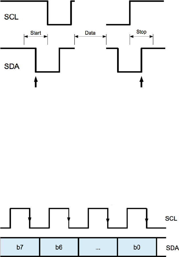
CHAPTER 14 ■ I2C BUS
169
Bus Signaling
The start and stop bits are special in the I2C protocol. The start bit is illustrated in Figure 14-2. Notice the SDA line
transition from high to low, while the clock remains in the high (idle) state. The clock will follow by going low after 1/2
bit time following the SDA transition. This special signal combination informs all connected devices to “listen up,”
since the next piece of information transmitted will be the device address.
Figure 14-2. I2C start/stop signaling
Figure 14-3. I2C Data bit transmission
The stop bit is also special in that it allows slave devices to know whether more information is coming. When the
SDA line transitions from low to high midway through a bit cell, it is interpreted as a stop bit. The stop bit signals the
end of the message.
There is also the concept of a repeated start, often labeled in diagrams as SR. This signal is electrically identical to
the start bit, except that it occurs within a message in place of a stop bit. This signals to the peripheral that more data
is being sent or required as part of another message.
Data Bits
Data bit timings are approximately as shown in Figure 14-3. The SDA line is expected to stabilize high or low
according to the data bit being sent, prior to the SCL line going high. The receiver clocks in the data on the falling edge
of SCL, and the process repeats for the next data bit. Note that most significant bits are transmitted first.
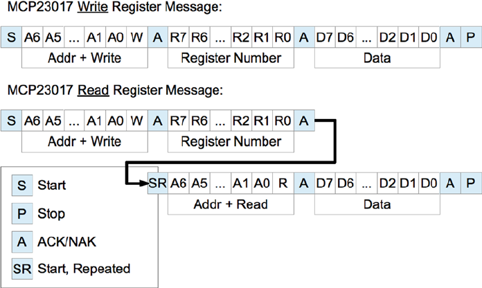
CHAPTER 14 ■ I2C BUS
170
Message Formats
Figure 14-4 displays two example I2C messages that can be used with the MCP23017 chip (Chapter 23). The simplest
message is the write register request.
Figure 14-4. Example I2C messages
The diagram shows each message starting with the S (start) bit and ending with a P (stop) bit. After the start bit,
each message begins with a byte containing the 7-bit peripheral address and a read/write bit. Every peripheral must
read this byte in order to determine whether the message is addressed to it.
The addressed peripheral is expected to return an ACK/NAK bit after the address is sent. If the peripheral fails to
respond for any reason, the line will go high due to the pull-up resistor, indicating a NAK. The master, upon seeing a
NAK, will send a stop bit and terminate the transmission.
When the peripheral ACKs the address byte, the master then continues to write when the request is a write. The
first example shows the MCP23017 8-bit register number being written next. This indicates which of the peripheral’s
registers is to be written to. The peripheral will then ACK the register number, allowing the master to follow with the
data byte to be written into the selected register. This too must be ACKed. If the master has no more data to send, the
P (stop) bit is sent to end the transmission. Otherwise, more data bytes could follow with the sequence ending with
the stop bit.
The second example in Figure 14-4 shows how a message may be composed of both write and read messages.
The initial sequence looks like the write, but this only writes a register number into the peripheral. Once the register
number is ACKed, the master then sends an SR (start, repeated) bit. This tells the peripheral that no more write data
is coming and to expect a peripheral address next. Since the address transmitted specifies the same peripheral, the
same peripheral responds with an ACK. This request is a read, so the peripheral continues to respond with 8 bits of
the requested read data, with the master ACKing the data received. The master terminates the message with a P (stop)
to indicate that no more data is to be read.
Many peripherals will support an auto-increment register mode. This is a feature of the peripheral, however, and
not all devices support this. Once a peripheral’s register has been established by a write, successive reads or writes
can occur in auto-increment mode, with the register being incremented with each byte transferred. This results in
more-efficient transfers.

CHAPTER 14 ■ I2C BUS
171
Which I2C Bus?
Before we look at the I2C software API provided by Raspbian Linux, you should first determine which I2C bus you’ll be
working with. Early Raspberry Pi revisions provided I2C bus 0 on header strip P1, while later units changed this to
bus 1. This will matter to both commands and programs communicating with I2C peripherals.
The “Identification” section of Chapter 7 discusses how to identify your Pi by displaying the firmware code from
/proc/cpuinfo. What is displayed as a Revision is actually more of a firmware code. The following is a quick check
example:
$ grep Revision /proc/cpuinfo
Revision : 000f
From this information, use the firmware code (revision) number to determine which I2C bus to use:
Revision I2C Bus SDA SCL
P1-03 P1-05
0002 0 GPIO-0 GPIO-1
0003 0
0004+ 1 GPIO-2 GPIO-3
I2C Bus Speed
Unlike the SPI bus, the I2C bus operates at a fixed speed within Raspbian Linux. The SoC document claims I2C
operation up to 400 kHz, but the reported clock rate during the Raspbian Linux boot is 100 kHz:
$ dmesg | grep –i i2c
[1005.08] i2c /dev entries driver
[1026.43] bcm2708_i2c bcm2708_i2c.0: BSC0 Controller at. . . (baudrate 100k)
[1026.43] bcm2708_i2c bcm2708_i2c.1: BSC1 Controller at . . .(baudrate 100k)
Don’t be alarmed if the preceding grep command doesn’t provide any output. Later versions of Raspbian didn’t
load bcm2708_i2c at boot time. You should see the same messages in the /var/log/syslog after you manually load
the module as shown here:
$ sudo modprobe i2c_bcm2708
$ tail /var/log/syslog
. . .
Mar 12 20:16:55 raspberrypi kernel: [168.845802] bcm2708_i2c bcm2708_i2c.0: \
BSC0 Controller at 0x20205000 (irq 79) (baudrate 100k)
Mar 12 20:16:55 raspberrypi kernel: [168.846423] bcm2708_i2c bcm2708_i2c.1: \
BSC1 Controller at 0 x20804000 (irq 79) (baudrate 100k)
CHAPTER 14 ■ I2C BUS
172
Tools
Working with I2C peripherals is made easier with the use of utilities. These I2C utilities are easily installed using the
following command:
$ sudo apt−get install i2c−tools
The i2c-tools package includes the following utilities:
i2cdetect: Detects peripherals on the I2C line
i2cdump: Dumps values from an I2C peripheral
i2cset: Sets I2C registers and values
i2cget: Gets I2C registers and values
Each of these utilities has a man page available for additional information. We’ll be using some of these
commands in this chapter and in later parts of this book.
I2C API
In this section, we’ll look at the bare-metal C language API for the I2C bus transactions. An application using this API
is provided in Chapter 23’s “MCP23017 GPIO Extender” section.
Kernel Module Support
Access to the I2C bus is provided through the use of kernel modules. If lsmod indicates that the drivers are not loaded,
you can load them at the command line:
$ sudo modprobe i2c–dev
$ sudo modprobe i2c–bcm2708
Once these modules are loaded, i2cdetect should be able to see bus-level support. On Revision 2.0 and later
Raspberry Pis, the i2c-0 bus is for internal use. The user bus is shown as i2c-1. On early Pis this is reversed.
$ i2cdetect –l
i2c–0 unknown bcm2708_i2c.0 N/A
i2c–1 unknown bcm2708_i2c.1 N/A
After the driver support is available, the device nodes should appear under /dev:
$ ls –l /dev/i2c*
crw−rw−−−T 1 root root 89, 0 Feb 18 23:53 /dev/i2c−0
crw−rw−−−T 1 root root 89, 1 Feb 18 23:53 /dev/i2c−1
Header Files
The following header files should be included in an I2C program:
#include <sys/ioctl.h>
#include <linux/i2c−dev.h>

CHAPTER 14 ■ I2C BUS
173
open(2)
Working with I2C devices is much like working with files. You’ll open a file descriptor, do some I/O operations with it,
and then close it. The one difference is that you’ll want to use ioctl(2) calls instead of the usual read(2)/write(2) calls.
#include <sys/types.h>
#include <sys/stat.h>
#include <fcntl.h>
int open(const char *pathname, int flags, mode_t mode);
where
pathname is the name of the file/directory/driver that you need to open/create.
flags is the list of optional flags (use O_RDWR for reading and writing).
mode is the permission bits to create a file (omit argument, or supply zero when not creating).
returns -1 (error code in errno) or open file descriptor >=0 .
Error Description
EACCES Access to the file is not allowed.
EFAULT The pathname points outside your accessible address space.
EMFILE The process already has the maximum number of files open.
ENFILE The system limit on the total number of open files has been reached.
ENOMEM Insufficient kernel memory was available.
To work with an I2C bus controller, your application must open the driver, made available at the device node:
int fd;
fd = open("/dev/i2c−1",O_RDWR);
if ( fd < 0 ) {
perror("Opening /dev/i2c−1");
Note that the device node (/dev/i2c-1) is owned by root, so you’ll need elevated privileges to open it or have
your program use setuid(2).
ioctl(2,I2C_FUNC)
In I2C code, a check is normally performed to make sure that the driver has the right support. The I2C_FUNC ioctl(2)
call allows the calling program to query the I2C capabilities. The capability flags returned are documented in Table 14-1.
long funcs;
int rc;
rc = ioctl(fd,I2C_FUNCS,&funcs);
if ( rc < 0 ) {
perror("ioctl(2,I2C_FUNCS)");
abort();
}
/* Check that we have plain I2C support */
assert(funcs & I2C_FUNC_I2C);

CHAPTER 14 ■ I2C BUS
174
The assert() macro used here checks that at least plain I2C support exists. Otherwise, the program aborts.
ioctl(2,I2C_RDWR)
While it is possible to use ioctl(2,I2C_SLAVE) and then use read(2) and write(2) calls, this tends not to be
practical. Consequently, the use of the ioctl(2,I2C_RDWR) system call will be promoted here instead. This system
call allows considerable flexibility in carrying out complex I2C I/O transactions.
The general API for any ioctl(2) call is as follows:
#include <sys/ioctl.h>
int ioctl(int fd, int request, argp);
where
fd is the open file descriptor.
request is the I/O command to perform.
argp is an argument related to the command (type varies according to request).
returns -1 (error code in errno), number of msgs completed (when request = I2C_RDWR).
Error Description
EBADF fd is not a valid descriptor.
EFAULT argp references an inaccessible memory area.
EINVAL request or argp is not valid.
When the request argument is provided as I2C_RDWR, the argp argument is a pointer to struct i2c_rdwr_ioctl_data.
This structure points to a list of messages and indicates how many of them are involved.
struct i2c_rdwr_ioctl_data {
struct i2c_msg *msgs; /* ptr to array of simple messages */
int nmsgs; /* number of messages to exchange */
};
Table 14-1. I2C_FUNC bits
Bit Mask Description
I2C_FUNC_I2C Plain I2C is supported (non SMBus)
I2C_FUNC_10BIT_ADDR Supports 10-bit addresses
I2C_FUNC_PROTOCOL_MANGLING Supports:
I2C_M_IGNORE_NAK
I2C_M_REV_DIR_ADDR
I2C_M_NOSTART
I2C_M_NO_RD_ACK

CHAPTER 14 ■ I2C BUS
175
The individual I/O messages referenced by the preceding structure are described by struct i2c_msg:
struct i2c_msg {
__u16 addr; /* 7/10 bit slave address */
__u16 flags; /* Read/Write & options */
__u16 len; /* No. of bytes in buf */
__u8 *buf; /* Data buffer */
};
The members of this structure are as follows:
addr: Normally this is the 7-bit slave address, unless flag I2C_M_TEN and function
I2C_FUNC_10BIT_ADDR are used. Must be provided for each message.
flags: Valid flags are listed in Table 14-2. Flag I2C_M_RD indicates the operation is a read.
Otherwise, a write operation is assumed when this flag is absent.
buf: The I/O buffer to use for reading/writing this message component.
len: The number of bytes to read/write in this message component.
Table 14-2. I2C Capability Flags
Flag Description
I2C_M_TEN 10-bit slave address used
I2C_M_RD Read into buffer
I2C_M_NOSTART Suppress (Re)Start bit
I2C_M_REV_DIR_ADDR Invert R/W bit
I2C_M_IGNORE_NAK Treat NAK as ACK
I2C_M_NO_RD_ACK Read will not have ACK
I2C_M_RECV_LEN Buffer can hold 32 additional bytes
An actual ioctl(2,I2C_RDWR) call would be coded something like the following. In this example, a MCP23017
register address of 0x15 is being written out to peripheral address 0x20, followed by a read of 1 byte:
int fd;
struct i2c_rdwr_ioctl_data msgset;
struct i2c_msg iomsgs[2];
static unsigned char reg_addr[] = {0x15};
unsigned char rbuf[1];
int rc;
iomsgs[0].addr = 0x20; /* MCP23017−A */
iomsgs[0].flags = 0; /* Write operation. */
iomsgs[0].buf = reg_addr;
iomsgs[0].len = 1;

CHAPTER 14 ■ I2C BUS
176
iomsgs[1].addr = iomsgs[0].addr; /* Same MCP23017-A */
iomsgs[1].flags = I2C_M_RD; /* Read operation */
iomsgs[1].buf = rbuf;
iomsgs[1].len = 1;
msgset.msgs = iomsgs;
msgset.nmsgs = 2;
rc = ioctl(fd,I2C_RDWR,&msgset);
if ( rc < 0 ) {
perror("ioctl (2, I2C_RDWR)");
The example shown defines iomsgs[0] as a write of 1 byte, containing a register number. The entry iomsgs[1]
describes a read of 1 byte from the peripheral. These two messages are performed in one ioctl(2) transaction. The
flags member of iomsgs[x] determines whether the operation is a read (I2C_M_RD) or a write (0).
Note ■ Don’t confuse the peripheral’s internal register with the peripheral’s I2C address.
Each of the iomsgs[x].addr members must contain a valid I2C peripheral address. Each message can potentially
address a different peripheral, though there are no examples of this in this book. The ioctl(2) will return an error
with the first message failure. For this reason, you may not always want to combine multiple messages in one
ioctl(2) call, especially when different devices are involved.
The returned value, when successful, is the number of struct i2c_msg messages successfully performed.
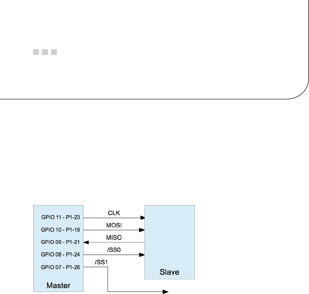
177
Chapter 15
SPI Bus
The Serial Peripheral Interface bus, known affectionately as spy, is a synchronous serial interface that was named
by Motorola.39 The SPI protocol operates in full-duplex mode, allowing it to send and receive data simultaneously.
Generally speaking, SPI has a speed advantage over the I2C protocol but requires more connections.
SPI Basics
Devices on the SPI bus communicate on a master/slave basis. Multiple slaves coexist on a given SPI bus, with each
slave being selected for communication by a slave select signal (also known as chip select). Figure 15-1 shows the
Raspberry Pi as the master communicating with a slave. Additional slaves would be connected as shown with the
exception that a different slave select signal would be used.
Figure 15-1. SPI interface
Data is transmitted from the master to the slave by using the MOSI line (master out, slave in). As each bit is being
sent out by the master, the slave sends data bits on the MISO line (master in, slave out). Bits are shifted out of the
master and into the slave. Simultaneously, bits are shifted out of the slave and into the master. Both transfers occur to
the beat of the system clock (CLK).
Many SPI devices support only 8-bit transfers, while others are more flexible. The SPI bus is a de facto standard,
meaning that there is no standard for data transfer width and SPI mode.39 The SPI controller can also be configured to
transmit the most significant or the least significant bit first. All of this flexibility can result in confusion.

CHAPTER 15 ■ SPI BUS
178
SPI Mode
SPI operates in one of four possible clock signaling modes, based on two parameters:
Parameter Description
CPOL Clock polarity
CPHA Clock phase
Each parameter has two possibilities, resulting in four possible SPI modes of operation. Table 15-1 lists all four
modes available. Note that a given mode is often referred to by using a pair of numbers like 1,0 or simply as mode 2
(for the same mode, as shown in the table). Both types of references are shown in the Mode column.
Table 15-1. SPI Modes
CPOL CPHA Mode Description
0 0 0,0 0 Noninverted clock, sampled on rising edge
0 1 0,1 1 Noninverted clock, sampled on falling edge
1 0 1,0 2 Inverted clock, sampled on rising edge
1 1 1,1 3 Inverted clock, sampled on falling edge
Clock Sense Description
Noninverted Signal is idle low, active high
Inverted Signal is idle high, active low
Peripheral manufacturers did not define a standard signaling convention in the beginning, so SPI controllers
allow configuration to accommodate any of the four modes. However, once a mode has been chosen, all slaves on the
same bus must agree.
Signaling
The clock polarity determines the idle clock level, while the phase determines whether the data line is sampled on
the rising or falling clock signal. Figure 15-2 shows mode 0,0, which is perhaps the preferred form of SPI signaling. In
Figure 15-2, the slave is selected first, by bringing the
SS
(slave select) active. Only one slave can be selected at a time,
since there must be only one slave driving the MISO line. Shortly after the slave is selected, the master drives the MOSI
line, and the slave simultaneously drives the MISO line with the first data bit. This can be the most or least significant
bit, depending on how the controller is configured. The diagram shows the least significant bit first.
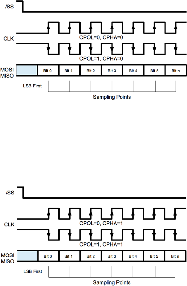
CHAPTER 15 ■ SPI BUS
179
In mode 0,0 the first bit is clocked into the master and slave when the clock line falls from high to low. This clock
transition is positioned midway in the data bit cell. The remaining bits are successively clocked into master and slave
simultaneously as the clock transitions from high to low. The transmission ends when the master deactivates the slave
select line. When the clock polarity is reversed (CPOL = 1, CPHA = 0), the clock signal shown in Figure 15-2 is simply
inverted. The data is clocked at the same time in the data cell, but on the rising edge of the clock instead.
Figure 15-3 shows the clock signals with the phase set to 1 (CPHA = 1). When the clock is noninverted (CPOL = 0),
the data is clocked on the rising edge. Note that the clock must transition to its nonidle state one-half clock cycle earlier
than when the phase is 0 (CPHA = 0). When the SPI mode is 1,1, the data is clocked in on the falling edge of the clock.
Figure 15-2. SPI signaling, modes 0 and 2
Figure 15-3. SPI signaling modes 1 and 3
While the four different modes can be confusing, it is important to realize that the data is sampled at the same
times within the data bit cells. The data bit is always sampled at the midpoint of the data cell. When the clock phase
is 0 (CPHA = 0), the data is sampled on the trailing edge of the clock, whether falling or rising according to CPOL.
When the clock phase is 1 (CPHA = 1), the data is sampled on the leading edge of the clock, whether rising or falling
according to CPOL.

CHAPTER 15 ■ SPI BUS
180
Slave Selection
While some protocols address their slaves by using transmitted data, the SPI bus simply uses a dedicated line for
each slave. The Raspberry Pi dedicates the GPIO pins listed in Table 15-2 as slave select lines (also known as chip
enable lines).
Table 15-2. Raspberry Pi Built-in Chip Enable Pins
GPIO Chip Enable P1
8
CE0
P1-24
7
CE1
P1-26
The Raspbian Linux kernel driver supports the use of only these two chip enable lines. However, the driver is
designed such that you don’t have to use them, or only these. It is possible, for example, to add a third GPIO pin as a
slave select. The application simply takes responsibility for activating the slave select GPIO line prior to the data I/O
and deactivates it after. When the driver is controlling the two slave selects, this is done automatically.
Driver Support
Raspbian Linux supports SPI through the spi_bcm2708 kernel module. As a loadable kernel module, it may not be
loaded by default. Check for it by using the lsmod command:
$ lsmod
Module Size Used by
spidev 5136 0
spi_bcm2708 4401 0
...
If you would like the module loaded by default after a reboot, edit the /etc/modprobe.d file raspi-blacklist.
conf. In the file, look for the line
blacklist spi-bcm2708
and change that to a comment line, by putting a # character in front, as follows:
# blacklist spi-bcm2708
With that module un-blacklisted, the module will automatically be loaded with each new reboot.
The kernel module can be manually loaded by using modprobe command:
$ sudo modprobe spi_bcm2708
This loads the module and its dependents. Once the kernel module support is present, the device driver nodes
should appear:
$ ls /dev/spi*
/dev/spidev0.0 /dev/spidev0.1
$

CHAPTER 15 ■ SPI BUS
181
These two device nodes are named according to which slave select should be activated, as shown in Table 15-3.
Table 15-3. SPI Device Nodes
Pathname Bus Device GPIO
SS
/dev/spidev0.0 0 0 8
CE0
/dev/spidev0.1 0 1 7
CE1
If you open either of these device nodes by applying the option SPI_NO_CS, the node chosen makes no difference.
Macro SPI_NO_CS indicates that slave select will be performed by the application instead of the driver, if any select is
used at all. (When only one slave device is attached, the peripheral can be permanently selected.)
SPI API
The bare-metal API for SPI involves calls to ioctl(2) to configure the interface and further calls to ioctl(2) for
simultaneous read and write. The usual read(2) and write(2) system calls can be used, when a one-sided transfer is
being performed.
Header Files
The header files needed for SPI programming are as follows:
#include <fcntl.h>
#include <unistd.h>
#include <stdint.h>
#include <sys/ioctl.h>
#include <linux/types.h>
#include <linux/spi/spidev.h>
The spidev.h include file defines several macros and the struct spi_ioc_transfer. Table 15-4 lists the main
macros that are declared. The macros SPI_CPOL and SPI_CPHA are used in the definitions of the values SPI_MODE_x.
If you prefer, it is possible to use SPI_CPOL and SPI_CPHA in place of the mode macros.

CHAPTER 15 ■ SPI BUS
182
Communicating with an SPI device consists of the following system calls:
open(2): Opens the SPI device driver node
read(2): Reads with 0 bytes being transmitted
write(2): Writes data while discarding received data
ioctl(2): For configuration and bidirectional I/O
close(2): Closes the SPI device driver node
In SPI communication, the use of read(2) and write(2) is unusual. Normally, ioctl(2) is used to facilitate
simultaneous read and write transfers.
Open Device
In order to perform SPI communication through the kernel driver, you need to open one of the device nodes by using
open(2). The general format of the device pathname is
/dev/spidev<bus>.<device>
as we saw earlier. The following is a code snippet opening bus 0, device 0.
int fd;
fd = open("/dev/spidev0.0",O_RDWR);
if ( fd < 0 ) {
perror("Unable to open SPI driver");
exit(1);
}
SPI communication involves both reading and writing, so the driver is opened for read and write (O_RDWR).
Table 15-4. SPI Macro Definitions
Macro Supported Description
SPI_CPOL Yes Clock polarity inverted (CPOL = 1)
SPI_CPHA Yes Clock phase is 1 (CPHA = 1)
SPI_MODE_0 Yes SPI Mode 0,0 (CPOL = 0, CPHA = 0)
SPI_MODE_1 Yes SPI Mode 0,1 (CPOL = 0, CPHA = 1)
SPI_MODE_2 Yes SPI Mode 1,0 (CPOL = 1, CPHA = 0)
SPI_MODE_3 Yes SPI Mode 1,1 (CPOL = 1, CPHA = 1)
SPI_CS_HIGH Yes Chip select is active high
SPI_LSB_FIRST No LSB is transmitted first
SPI_3WIRE No Use 3-Wire data I/O mode
SPI_LOOP No Loop the MOSI/MISO data line
SPI_NO_CS Yes Do not apply Chip Select
SPI_READY No Enable extra Ready signal

CHAPTER 15 ■ SPI BUS
183
SPI Mode Macros
Before SPI communications can be performed, the mode of communication needs to be configured. Table 15-5 lists
the C language macros that can be used to configure the SPI mode to be used.
Table 15-5. SPI Mode Macros
Macro Effect Comments
SPI_CPOL CPOL = 1 Or use SPI_MODE_x
SPI_CPHA CPHA = 1 Or use SPI_MODE_x
SPI_CS_HIGH SS is active high Unusual
SPI_NO_CS Don’t assert select Not used/application controlled
These bit values are simply or-ed together to specify the options that are required. The use of SPI_CPOL implies
CPOL = 1. Its absence implies CPOL = 0. Similarly, the use of SPI_CPHA implies CPHA = 1 (otherwise, CPHA = 0). The
options SPI_MODE_x use the SPI_CPOL and SPI_CPHA macros to define them. You don’t need to use them both in your
code. The mode definitions are shown here:
#define SPI_MODE_0 (0|0)
#define SPI_MODE_1 (0|SPI_CPHA)
#define SPI_MODE_2 (SPI_CPOL|0)
#define SPI_MODE_3 (SPI_CPOL|SPI_CPHA)
The unsupported options are not shown, though one or more of these could be supported in the future.
Note ■ The mode values SPI_LOOP, SPI_LSB_FIRST, SPI_3WIRE, and SPI_READY are not currently supported in the
wheezy release of Raspbian Linux.
The following is an example that defines SPI_MODE_0:
uint8_t mode = SPI_MODE_0;
int rc;
rc = ioctl(fd,SPI_IOC_WR_MODE,&mode);
if ( rc < 0 ) {
perror("Can't set SPI write mode.");
If you’d like to find out how the SPI driver is currently configured, you can read the SPI mode with ioctl(2)
as follows:
uint8_t mode;
int rc;
rc = ioctl(fd,SPI_IOC_RD_MODE,&mode);
if ( rc < 0 ) {
perror("Can't get SPI read mode.");

CHAPTER 15 ■ SPI BUS
184
Bits per Word
The SPI driver also needs to know how many bits per I/O word are to be transmitted. While the driver will likely
default to 8 bits, it is best not to depend on that. This can be configured with the following ioctl(2) call:
uint8_t bits = 8;
int rc;
rc = ioctl(fd, SPI_IOC_WR_BITS_PER_WORD,&bits);
if ( rc < 0 ) {
perror ("Can't set bits per SPI word.");
Note ■ The SPI driver in the Raspbian wheezy release supports only 8-bit transfers.
The currently configured value can be fetched with ioctl(2) as follows:
uint8_t bits;
int rc;
rc = ioctl(fd,SPI_IOC_RD_BITS_PER_WORD,&bits);
if ( rc == −1 ) {
perror("Can't get bits per SPI word.");
When the number of bits is not an even multiple of eight, the bits are assumed to be right-justified. For example,
if the word length is set to 4 bits, the least significant 4 bits are transmitted. The higher-order bits are ignored.
Likewise, when receiving data, the least significant bits contain the data. All of this is academic on the Pi,
however, since the driver supports only byte-wide transfers.
Clock Rate
To configure the data transmission rate, you can set the clock rate with ioctl(2) as follows:
uint32_t speed = 500000; /* Hz */
int rc;
rc = ioctl(fd,SPI_IOC_WR_MAX_SPEED_HZ,&speed);
if ( rc < 0 ) {
perror("Can't configure SPI clock rate.");
The current configured clock rate can be fetched by using the following ioctl(2) call:
uint32_t speed; /* Hz */
int rc;
rc = ioctl(fd,SPI_IOC_RD_MAX_SPEED_HZ,&speed);
if ( rc < 0 ) {
perror("Can't get SPI clock rate.");
CHAPTER 15 ■ SPI BUS
185
Data I/O
SPI communication involves transmitting data while simultaneously receiving data. For this reason, the read(2)
and write(2) system calls are usually inappropriate. The ioctl(2) call can, however, perform a simultaneous read
and write.
The SPI_IOC_MESSAGE(n) form of the ioctl(2) call uses the following structure as its argument:
struct spi_ioc_transfer {
__u64 tx_buf; /* Ptr to tx buffer */
__u64 rx_buf; /* Ptr to rx buffer */
__u32 len; /* # of bytes */
__u32 speed_hz; /* Clock rate in Hz */
__u16 delay_usecs; /* Delay in microseconds */
__u8 bits_per_word; /* Bits per "word" */
__u8 cs_change; /* Apply chip select */
__u32 pad; /* Reserved */
};
The tx_buf and rx_buf structure members are defined as a 64-bit unsigned integers (__u64). For this reason,
you must cast your buffer pointers when making assignments to them:
uint8_t tx[32], rx[32];
struct spi_ioc_transfer tr;
tr.tx_buf = (unsigned long) tx;
tr.rx_buf = (unsigned long ) rx;
On the Raspberry Pi, you will see example code that simply casts the pointers to unsigned long. The compiler
automatically promotes these 32-bit values to a 64-bit value. This is safe on the Pi because the pointer value
is a 32-bit value.
If you do not wish to receive data (maybe because it is “don’t care” data), you can null out the receive buffer:
uint8_t tx[32];
struct spi_ioc_transfer tr;
tr.tx_buf = (unsigned long) tx;
tr.rx_buf = 0; /* ignore received data */
Note that to receive data, the master must always transmit data to shift data out of the slave peripheral. If any
byte transmitted will do, you can omit the transmit buffer. Zero bytes will then be automatically transmitted by the
driver to shift the slave data out onto the MISO line.
It is also permissible to transmit from the buffer you’re receiving into:
uint8_t io[32];
struct spi_ioc_transfer tr;
tr.tx_buf = (unsigned long) io; /* Transmit buffer */
tr.rx_buf = (unsigned long) io; /* is also recv buffer */
The len structure member indicates the number of bytes for the I/O transfer. Receive and transmit buffers
(when both used) are expected to transfer the same number of bytes.

CHAPTER 15 ■ SPI BUS
186
The member speed_hz defines the clock rate that you wish to use for this I/O, in Hz. This overrides any value
configured in the mode setup, for the duration of the I/O. The value will be automatically rounded down to a
supported clock rate when necessary.
When the value speed_hz is 0, the previously configured clock rate is used (SPI_IOC_WR_MAX_SPEED_HZ).
When the delay_usecs member is nonzero, it specifies the number of microseconds to delay between transfers.
It is applied at the end of a transfer, rather than at the start. When there are multiple I/O transfers in a single ioctl(2)
request, this allows time in between so that the peripheral can process the data.
The bits_per_word member defines how many bits there are in a “word” unit. Often the unit is 1 byte (8 bits), but
it need not be (but note that the Raspbian Linux driver supports only 8 bits).
An application might use 9 bits to transmit the 8-bit byte and a parity bit, for example. The bits communicated
on the SPI bus are taken from the least significant bits of the buffer bytes. This is true even when transmitting the most
significant bit first.
When the bits_per_word value is 0, the previously configured value from SPI_IOC_WR_BITS_PER_WORD is used.
(See drivers/spi/spi-bcm2708.c in the function bcm2708_process_transfer()).
Note ■ The Raspbian wheezy driver requires that bits_per_word is the value 8 or 0.
The cs_change member is treated as a Boolean value. When 0, no chip select is performed by the driver.
The application is expected to do what is necessary to notify the peripheral that it is selected (usually a GPIO pin is
brought low). Once the I/O has completed, the application then must normally unselect the slave peripheral.
When the cs_change member is true (non-zero), the slave selected will depend on the device pathname that was
opened. The bus and the slave address are embedded in the device name:
/dev/spidev<bus>.<device>
When cs_change is true, the driver asserts
GPIO8
for spidev0.0 and asserts
GPIO7
for spidev0.1 prior to
I/O and then deactivates the same upon completion. Of course, using these two nodes requires two different
open(2) calls.
The SPI_IOC_MESSAGE(n) macro is used in the ioctl(2) call to perform one or more SPI I/O operations. The
macro is unusual because it requires an argument n. (Perhaps someone will take it upon themselves someday to clean
this interface up to work like I2C.) This specifies how many I/O transfers you would like to perform. An array of
spi_ioc_transfer structures is declared and configured for each transfer required, as shown in the next example:
struct spi_ioc_transfer io[3]; /* Define 3 transfers */
int rc;
io[0].tx_buf = . . . ; /* Configure I/O */
...
io[2].bits_per_word = 8;
rc = ioctl(fd,SPI_IOC_MESSAGE(3),& io[0]);
The preceding example will perform three I/O transfers. Since the application never gets to perform any GPIO
manipulation between these I/Os, this applies to communicating with one particular slave device.
CHAPTER 15 ■ SPI BUS
187
The following example code brings all of the concepts together, to demonstrate one I/O. The spi_ioc_transfer
structure is initialized so that 32 bytes are transmitted and simultaneously 32 are received.
uint8_t tx[32], rx[32];
struct spi_ioc_transfer tr;
int rc;
tr.tx_buf = (unsigned long) tx;
tr.rx_buf = (unsigned long) rx;
tr.len = 32;
tr.delay_usecs = delay;
tr.speed_hz = speed;
tr.bits_per_word = bits;
rc = ioctl(fd,SPI_IOC_MESSAGE(1),&tr);
if ( rc < 1 ) {
perror("Can't send spi message");
Here a single I/O transmission occurs, with data being sent from array tx and received into array rx.
The return value from the ioctl(2) call returns the number of bytes transferred (32 in the example). Otherwise,
-1 is returned to indicate that an error has occurred.
Close
Like all Unix I/O operations, the device is closed when the open file descriptor is no longer required:
close(fd);
Write
The write(2) system call can be used, if the received data is unimportant. Note, however, that no delay is applied
with this call.
Read
The read(2) system call is actually inappropriate for SPI since the master must transmit data on MOSI in order for
the slave to send bits back on the MISO line. However, when read(2) is used, the driver will automatically send out
0 bits as necessary to accomplish the read. (Be careful that your peripheral will accept 0 bytes without unintended
consequences.) Like the write(2) call, no delay is provided.
SPI Testing
When developing your SPI communication software, you can perform a simple loopback test to test your framework.
Once the framework checks out, you can then turn your attention to communicating with the actual device.
While the Raspbian Linux driver does not support the SPI_LOOP mode bit (in the wheezy release), you can
still physically loop your SPI bus by connecting a wire from the MOSI output back to the MISO input pin
(connect GPIO 10 to GPIO 9).
CHAPTER 15 ■ SPI BUS
188
A simple program, shown next, demonstrates this type of loopback test. It will write out 4 bytes (0x12, 0x23, 0x45,
and 0x67) to the SPI driver. Because you have wired the MOSI pin to the MISO input, anything transmitted will
also be received.
When the program executes, it will report the number of bytes received and four hexadecimal values:
$ sudo ./spiloop
rc=4 12 23 45 67
$
If you remove the wire between MOSI and MISO, and connect the MISO to a high (+3.3 V), you should be able to
read 0xFF for all of the received bytes. If you then connect MISO to ground, 0x00 will be received for each byte instead.
(Be certain to apply to the correct pin, since applying high or low to an output can damage it, and do not apply +5 V.)
1 /********************************************
2 * spiloop.c − Example loop test
3 * Connect MOSI (GPIO 10) to MISO (GPIO 9)
4 ********************************************/
5 #include <stdio.h>
6 #include <errno.h>
7 #include <stdlib.h>
8 #include <stdint.h>
9 #include <fcntl.h>
10 #include <unistd.h>
11 #include <sys/ioctl.h>
12 #include <linux/types.h>
13 #include <linux/spi/spidev.h>
14
15 static int fd = −1;
16
17 static void
18 errxit(const char *msg) {
19 perror(msg);
20 exit(1);
21 }
22
23 int
24 main(int argc, char ** argv) {
25 static uint8_t tx[] = {0x12, 0x23, 0x45, 0x67};
26 static uint8_t rx[] = {0xFF, 0xFF, 0xFF, 0xFF};
27 struct spi_ioc_transfer ioc = {
28 .tx_buf = (unsigned long) tx,
29 .rx_buf = (unsigned long) rx,
30 .len = 4,
31 .speed_hz = 100000,
32 .delay_usecs = 10,
33 .bits_per_word = 8,
34 .cs_change = 1
35 } ;
36 uint8_t mode = SPI_MODE_0;
37 int rc;
38
CHAPTER 15 ■ SPI BUS
189
39 fd = open("/dev/spidev0.0",O_RDWR);
40 if ( fd < 0 )
41 errxit("Opening SPI device.");
42
43 rc = ioctl(fd,SPI_IOC_WR_MODE,&mode);
44 if ( rc < 0 )
45 errxit("ioctl (2) setting SPI mode.");
46
47 rc = ioctl(fd,SPI_IOC_WR_BITS_PER_WORD,&ioc.bits_per_word);
48 if ( rc < 0 )
49 errxit("ioctl (2) setting SPI bits perword.");
50
51 rc = ioctl(fd,SPI_IOC_MESSAGE(1),&ioc);
52 if ( rc < 0 )
53 errxit("ioctl (2) for SPI I/O");
54 close(fd);
55
56 printf("rc=%d %02X %02X %02X %02X\n",
57 rc, rx[0], rx[1], rx[2], rx[3]);
58 return 0;
59 }

191
Chapter 16
Boot
When the power is first applied to the Raspberry Pi, or it has been reset (see the “Reset” section of Chapter 5), a boot
sequence is initiated. As you will see in this chapter, it is the GPU that actually brings up the ARM CPU.
The way that the Raspberry Pi is designed, it must be booted from firmware found on the SD card. It cannot boot
from any other source. RISC code for the GPU is provided by the Raspberry Pi Foundation in the file bootcode.bin.
After the second-stage boot loader has been executed, it is possible that other operating systems or ARM boot
loaders such as U-Boot can be initiated.
Booting ARM Linux
Generally speaking, Linux under the ARM architecture needs a small amount of assistance to get started.
The following are some of the minimal things that the boot loader needs to do:25
1. Initialize and configure memory (with MMU, cache, and DMA disabled)
2. Load the kernel image into memory
3. Optionally, load an initial RAM disk image
4. Initialize and provide boot parameters to the loaded kernel (ATAG list)
5. Obtain/determine the Linux machine type (MACH_TYPE)
6. Execute the kernel image with the correct starting register values (r1 = machine number,
r2 points to the ATAG list)
7. Additionally, the boot loader is expected to perform some initialization of a serial and/or
video console.
In the Raspberry Pi, this boot-loading assistance comes from the embedded GPU in the SoC. The GPU supports a
small RISC core that is able to run from initial code found in its ROM. From this small amount of code, the GPU is able
to initialize itself and the SD card hardware. From the media on the SD card, it is able to bootstrap itself the rest of the
way. For this reason, the Raspberry Pi must always bootstrap from an SD card.
Boot Sequence
This section looks at the startup sequence in greater detail. The participating hardware components, the files and data
elements are considered. The boot procedure consists of the following sequence of events:
1. At power-up (or reset), the ARM CPU is offline.23
2. A small RISC core in the GPU begins to execute SoC ROM code (first-stage boot loader).

CHAPTER 16 ■ BOOT
192
3. The GPU initializes the SD card hardware.
4. The GPU looks at the first FAT32 partition in the SD media. (There remains some question
about specific limitations as Broadcom has documented this—for example, can it boot
from a first FAT16 partition?)
5. The second-stage boot-loader firmware named bootcode.bin is loaded into the GPU.
6. The GPU control passes to the loaded bootcode.bin firmware (SDRAM is initially
disabled).
7. The file start.elf is loaded by the GPU into RAM from the SD card.
8. An additional file, fixup.dat, is used to configure the SDRAM partition between GPU and
ARM CPU.
9. The file config.txt is examined for configuration parameters that need to be processed.
10. Information found in cmdline.txt is presumably also passed to start.elf.
11. The GPU allows the ARM CPU to execute the program start.elf.
12. The module start.elf runs on the ARM CPU, with information about the kernel to be
loaded.
13. The kernel is loaded, and execution control passes to it.
Boot Files
The FAT32 partition containing the boot files is normally mounted as /boot, after Raspbian Linux has come up.
Table 16-1 lists the files that apply to the boot process. The text files can be edited to affect new configurations.
The binary files can also be replaced by new revisions of the same.
Table 16-1. /boot Files
File Name Purpose Format
bootcode.bin Second-stage boot loader Binary
fixup.dat Configure split of GPU/CPU SDRAM Binary
config.txt Configuration parameters Text
cmdline.txt Command-line parameters for kernel Text
start.elf ARM CPU code to be launched Binary
kernel.img Kernel to be loaded Binary
Name can be overridden with kernel= parameter in config.txt
config.txt
The config.txt file permits you to configure many aspects of the boot process. Some options affect physical devices,
and others affect the kernel being loaded.

CHAPTER 16 ■ BOOT
193
Composite Video Settings
The composite video output from the Raspberry Pi is primarily configured by three basic parameters:
• sdtv_mode
• sdtv_aspect
• sdtv_disable_colourburst
Standard Definition Video
The parameter sdtv_mode determines the video mode (TV standard) of the composite video output jack.
sdtv_mode Description
0 Normal NTSC (default)
1 Japanese NTSC (no pedestal)
2 Normal PAL
3 Brazilian PAL 525/60
Composite Aspect Ratio
The sdtv_aspect parameter configures the composite video aspect ratio.
sdtv_aspect Description
1 4:3 (default)
2 14:9
3 16:9
Color Burst
By default, color burst is enabled. This permits the generation of color out of the composite video jack. Setting the
video for monochrome may be desirable for a sharper display.
sdtv_disable_colourburst Description
0 Color burst enabled (default)
1 Color burst disabled (monochrome)

CHAPTER 16 ■ BOOT
194
High-Definition Video
This section covers config.txt settings that affect HDMI operation.
HDMI Safe Mode
The hdmi_safe parameter enables support of automatic HDMI configuration for optimal compatibility.
hdmi_safe Description
0 Disabled (default)
1 Enabled
When hdmi_safe=1 (enabled), the following settings are implied:
• hdmi_force_hotplug=1
• config_hdmi_boost=4
• hdmi_group=1
• hdmi_mode=1
• disable_overscan=0
HDMI Force Hot-Plug
This configuration setting allows you to force a hot-plug signal for the HDMI display, whether the display is connected
or not. The NOOBS distribution enables this setting by default.
hdmi_force_hotplug Description
0 Disabled (non-NOOBS default)
1 Use HDMI mode even when no HDMI monitor is detected (NOOBS default)
HDMI Ignore Hot-Plug
Enabling the hdmi_ignore_hotplug setting causes it to appear to the system that no HDMI display is attached, even
if there is. This can help force composite video output, while the HDMI display is plugged in.
hdmi_ignore_hotplug Description
0 Disabled (default)
1 Use composite video even if an HDMI display is detected

CHAPTER 16 ■ BOOT
195
HDMI Drive
This mode allows you to choose between DVI (no sound) and HDMI mode (with sound, when supported).
hdmi_drive Description
1 Normal DVI mode (no sound)
2 Normal HDMI mode (sound will be sent if supported and enabled)
HDMI Ignore EDID
Enabling this option causes the EDID information from the display to be ignored. Normally, this information is
helpful and is used.
hdmi_ignore_edid Description
Unspecified Read EDID information
0xa5000080 Ignore EDID information
HDMI EDID File
When hdmi_edid_file is enabled, the EDID information is taken from the file named edid.txt. Otherwise, it is taken
from the display, when available.
hdmi_edid_file Description
0 Read EDID data from device (default)
1 Read EDID data from edid.txt file
HDMI Force EDID Audio
Enabling this option forces the support of all audio formats even if the display does not support them. This permits
pass-through of DTS/AC3 when reported as unsupported.
hdmi_force_edid_audio Description
0 Use EDID-provided values (default)
1 Pretend all audio formats are supported

CHAPTER 16 ■ BOOT
196
Avoid EDID Fuzzy Match
Avoid fuzzy matching of modes described in the EDID.
avoid_edid_fuzzy_match Description
0 Use fuzzy matching (default)
1 Avoid fuzzy matching
HDMI Group
The hdmi_group option defines the HDMI type.
hdmi_group Description
0 Use the preferred group reported by the EDID (default)
1 CEA
2 DMT
HDMI Mode
This option defines the screen resolution to use in CEA or DMT format (see the parameter hdmi_group in the
preceding subsection “HDMI Group”). In Table 16-2, the modifiers shown have the following meanings:
H means 16:9 variant of a normally 4:3 mode.
2x means pixel doubled (higher clock rate).
4x means pixel quadrupled (higher clock rate).
R means reduced blanking (fewer bytes are used for blanking within the data stream,
resulting in lower clock rates).
Table 16-2. HDMI Mode Settings
Group CEA DMT
Mode Resolution Refresh Modifiers Resolution Refresh Notes
1 VGA 640×350 85 Hz
2 480 p 60 Hz 640×400 85 Hz
3 480 p 60 Hz H 720×400 85 Hz
4 720 p 60 Hz 640×480 60 Hz
5 1080 i 60 Hz 640×480 72 Hz
6 480 i 60 Hz 640×480 75 Hz
(continued)

CHAPTER 16 ■ BOOT
197
Group CEA DMT
Mode Resolution Refresh Modifiers Resolution Refresh Notes
7 480 i 60 Hz H 640×480 85 Hz
8 240 p 60 Hz 800×600 56 Hz
9 240 p 60 Hz H 800×600 60 Hz
10 480 i 60 Hz 4x 800×600 72 Hz
11 480 i 60 Hz 4x H 800×600 75 Hz
12 240 p 60 Hz 4x 800×600 85 Hz
13 240 p 60 Hz 4x H 800×600 120 Hz
14 480 p 60 Hz 2x 848×480 60 Hz
15 480 p 60 Hz 2x H 1024×768 43 Hz Don’t use
16 1080 p 60 Hz 1024×768 60 Hz
17 576 p 50 Hz 1024×768 70 Hz
18 576 p 50 Hz H 1024×768 75 Hz
19 720 p 50 Hz 1024×768 85 Hz
20 1080 i 50 Hz 1024×768 120 Hz
21 576 i 50 Hz 1152×864 75 Hz
22 576 i 50 Hz H 1280×768 R
23 288 p 50 Hz 1280×768 60 Hz
24 288 p 50 Hz H 1280×768 75 Hz
25 576 i 50 Hz 4x 1280×768 85 Hz
26 576 i 50 Hz 4x H 1280×768 120 Hz R
27 288 p 50 Hz 4x 1280×800 R
28 288 p 50 Hz 4x H 1280×800 60 Hz
29 576 p 50 Hz 2x 1280×800 75 Hz
30 576 p 50 Hz 2x H 1280×800 85 Hz
31 1080 p 50 Hz 1280×800 120 Hz R
32 1080 p 24 Hz 1280×960 60 Hz
33 1080 p 25 Hz 1280×960 85 Hz
34 1080 p 30 Hz 1280×960 120 Hz R
35 480 p 60 Hz 4x 1280×1024 60 Hz
36 480 p 60 Hz 4x H 1280×1024 75 Hz
37 576 p 50 Hz 4x 1280×1024 85 Hz
Table 16-2. (continued)
(continued)

CHAPTER 16 ■ BOOT
198
Group CEA DMT
Mode Resolution Refresh Modifiers Resolution Refresh Notes
38 576 p 50 Hz 4x H 1280×1024 120 Hz R
39 1080 i 50 Hz R 1360×768 60 Hz
40 1080 i 100 Hz 1360×768 120 Hz R
41 720 p 100 Hz 1400×1050 R
42 576 p 100 Hz 1400×1050 60 Hz
43 576 p 100 Hz H 1400×1050 75 Hz
44 576 i 100 Hz 1400×1050 85 Hz
45 576 i 100 Hz H 1400×1050 120 Hz R
46 1080 i 120 Hz 1440×900 R
47 720 p 120 Hz 1440×900 60 Hz
48 480 p 120 Hz 1440×900 75 Hz
49 480 p 120 Hz H 1440×900 85 Hz
50 480 i 120 Hz 1440×900 120 Hz R
51 480 i 120 Hz H 1600×1200 60 Hz
52 576 p 200 Hz 1600×1200 65 Hz
53 576 p 200 Hz H 1600×1200 70 Hz
54 576 i 200 Hz 1600×1200 75 Hz
55 576 i 200 Hz H 1600×1200 85 Hz
56 480 p 240 Hz 1600×1200 120 Hz R
57 480 p 240 Hz H 1680×1050 R
58 480 i 240 Hz 1680×1050 60 Hz
59 480 i 240 Hz H 1680×1050 75 Hz
60 1680×1050 85 Hz
61 1680×1050 120 Hz R
62 1792×1344 60 Hz
63 1792×1344 75 Hz
64 1792×1344 120 Hz R
65 1856×1392 60 Hz
66 1856×1392 75 Hz
67 1856×1392 120 Hz R
68 1920×1200 R
Table 16-2. (continued)
(continued)

CHAPTER 16 ■ BOOT
199
HDMI Boost
The config_hdmi_boost parameter allows you to tweak the HDMI signal strength.
config_hdmi_boost Description
0 Non-NOOBS default
1
2
3
4 Use if you have interference issues (NOOBS default setting)
5
6
7 Maximum strength
Group CEA DMT
Mode Resolution Refresh Modifiers Resolution Refresh Notes
69 1920×1200 60 Hz
70 1920×1200 75 Hz
71 1920×1200 85 Hz
72 1920×1200 120 Hz R
73 1920×1440 60 Hz
74 1920×1440 75 Hz
75 1920×1440 120 Hz R
76 2560×1600 R
77 2560×1600 60 Hz
78 2560×1600 75 Hz
79 2560×1600 85 Hz
80 2560×1600 120 Hz R
81 1366×768 60 Hz
82 1080 p 60 Hz
83 1600×900 R
84 2048×1152 R
85 720 p 60 Hz
86 1366×768 R
Table 16-2. (continued)

CHAPTER 16 ■ BOOT
200
HDMI Ignore CEC Init
When this option is enabled, the CEC initialization is not sent to the device. This avoids bringing the TV out of standby
and channel switch when rebooting.
hdmi_ignore_cec_init Description
0 Normal (default)
1 Don’t send initial active source message
HDMI Ignore CEC
When this option is enabled, the assumption made is that CEC is not supported at all by the HDMI device, even if the
device does have support. As a result, no CEC functions will be supported.
hdmi_ignore_cec Description
0 Normal (default)
1 Disable CEC support
Overscan Video
A few options control the overscan support of the composite video output. When overscan is enabled, a certain
number of pixels are skipped at the sides of the screen as configured.
Disable Overscan
The disable_overscan option can disable the overscan feature. It is enabled by default:
disable_overscan Description
0 Overscan enabled (default)
1 Overscan disabled
Overscan Left, Right, Top, and Bottom
These parameters control the number of pixels to skip at the left, right, top, and bottom of the screen.
Parameter Pixels to Skip
overscan_left=0 At left
overscan_right=0 At right
overscan_top=0 At top
overscan_bottom=0 At bottom

CHAPTER 16 ■ BOOT
201
Frame Buffer Settings
The Linux frame buffer support is configured by a few configuration options described in this section.
Frame Buffer Width
The default is to define the width of the frame buffer as the display’s width minus the overscan pixels.
framebuffer_width Description
default Display width overscan
framebuffer_width=n Set width to n pixels
Frame Buffer Height
The default is to define the height of the frame buffer as the display’s height minus the overscan pixels.
framebuffer_height Description
default Display height overscan
framebuffer_height=n Set height to n pixels
Frame Buffer Depth
This parameter defines the number of bits per pixel.
framebuffer_depth Description
8 Valid, but default RGB palette makes an unreadable screen
16 Default
24 Looks better but has corruption issues as of 6/15/2012
32 No corruption, but requires framebuffer_ignore_alpha=1,
and shows wrong colors as of 6/15/2012
Frame Buffer Ignore Alpha
The alpha channel can be disabled with this option. As of this writing, this option must be used when using a frame
buffer depth of 32 bits.
framebuffer_ignore_alpha Description
0 Alpha channel enabled (default)
1 Alpha channel disabled

CHAPTER 16 ■ BOOT
202
General Video Options
The display can be flipped or rotated in different ways, according to the display_rotate option. You should be able to
do both a flip and a rotate by adding the flip values to the rotate value.
Note ■ I was unable to get the flip options to work on Linux Raspberry Pi 3.2.27+ #250. It is possible that a newer
version of the boot-loader bootcode.bin may be needed. But as of 2014, this remains an issue.
The 90º and 270º rotations require additional memory on the GPU, so these options won’t work with a 16 MB
GPU split.
display_rotate Description
0 0º (default)
1 90º
2 180º
3 270º
0x1000 Horizontal flip
0x2000 Vertical flip
While the flip options are documented, I was unable to get them to work. The rotations, however, were confirmed
as working.
Licensed Codecs
The following options permit you to configure the purchased license key codes for the codecs they affect.
Option Notes
decode_MPG2=0x12345678 License key for hardware MPEG-2 decoding
decode_WVC1=0x12345678 License key for hardware VC-1 decoding
Testing
The following test option enables image/sound tests during boot. This is intended for manufacturer testing.
test_mode Description
0 Disable test mode (default)
1 Enable test mode

CHAPTER 16 ■ BOOT
203
Memory
This section summarizes configuration settings pertaining to memory.
Disable GPU L2 Cache
The disable_l2cache option allows the ARM CPU access to the GPU L2 cache to be disabled. This needs the
corresponding L2 disabled in the kernel.
disable_l2cache Description
0 Enable GPU L2 cache access (default)
1 Disable GPU L2 cache access
GPU Memory (All)
The gpu_mem option allows configuration of the GPU memory for all Raspberry Pi board revisions (unless gpu_mem_256
or gpu_mem_512 is supplied).
gpu_mem Description
gpu_mem=64 Default is 64 MB
gpu_mem=128 128 MB
GPU Memory (256)
The gpu_mem_256 option allows configuration of the GPU memory for the 256 MB Raspberry Pi boards.
When specified, it overrides the gpu_mem option setting.
gpu_mem_256 Description
unspecified Defined by gpu_mem option
gpu_mem_256=128 128 MB (example)
GPU Memory (512)
The gpu_mem_512 option configures the GPU memory allocated for the 512 MB Raspberry Pi boards. When specified,
it overrides the gpu_mem option setting.
gpu_mem_512 Description
unspecified Defined by gpu_mem option
gpu_mem_512=128 128 MB (example)

CHAPTER 16 ■ BOOT
204
Boot Options
Several options in this section affect the boot process. Many options pertain to the kernel being started, while others
affect file systems and devices.
Disable Command-Line Tags
The disable_commandline_tags option permits the user to prevent start.elf from filling in ATAGS memory before
launching the kernel. This prevents the cmdline.txt file from being supplied to the kernel at boot time.
disable_commandline_tags Description
0 Enable ATAGS (default)
1 Disable command line in ATAGS
Command Line
The cmdline option allows you to configure the kernel command-line parameters within the config.txt file, instead
of the cmdline.txt file.
cmdline Description
unspecified Command line is taken from cmdline.txt
cmdline=“command” Command line is taken from parameter
Kernel
By default, start.elf loads the kernel from the file named kernel.img. Specifying the kernel parameter allows the
user to change the file’s name.
kernel Description
unspecified kernel=“kernel.img” (default)
kernel=“plan9.img” kernel=“plan9.img”
Kernel Address
This parameter determines the memory address where the kernel image is loaded into.
kernel_address Description
0x00000000 Default

CHAPTER 16 ■ BOOT
205
RAM File System File
The ramfsfile parameter names the file for the RAM FS file, to be used with the kernel.
ramfsfile Description
unspecified No RAM FS file used
ramfsfile=“ramfs.file” File ramfs.file is used
RAM File System Address
The ramfsaddr parameter specifies where the RAM file system image is to be loaded into memory.
ramfsaddr Description
0x00000000 Default address
Init RAM File System
This option is a convenience option, which combines the options ramfsfile and ramfsaddr.
initramfs Arg 1 Arg 2 Description
initramfs initram.gz 0x00800000 Example
Device Tree Address
The device_tree_address option defines where the device tree address is loaded.
device_tree_address Description
0x00000000 Default
Init UART Baud
The init_uart_baud option allows the user to reconfigure the serial console to use a baud rate that is different from
the default.
init_uart_baud Description
115200 Default baud rate

CHAPTER 16 ■ BOOT
206
Init UART Clock
The init_uart_clock parameter permits the user to reconfigure the UART to use a different clock rate.
init_uart_clock Description
3000000 Default
Init EMMC Clock
The init_emmc_clock parameter allows the user to tweak the EMMC clock, which can improve the SD card
performance.
init_emmc_clock Description
100000000 Default
Boot Delay
The boot_delay and boot_delay_ms options allow the user to reconfigure the delay used by start.elf prior to
loading the kernel. The actual delay time used is computed from the following:
Dbm=´+1000
where
• D is the computed delay in milliseconds.
• b is the boot_delay value.
• m is the boot_delay_ms value.
boot_delay (b) Description
1 Default
The boot_delay_ms augments the boot_delay parameter.
boot_delay_ms (m) Description
0 Default
Avoid Safe Mode
A jumper or switch can be placed between pins P1-05 (GPIO 1) and P1-06 (ground) to cause start.elf to initiate a
safe mode boot. If GPIO 1 is being used for some other I/O function, the safe mode check should be disabled.
avoid_safe_mode Description
0 Default (check P1-05 for safe mode)
1 Disable safe mode check

CHAPTER 16 ■ BOOT
207
Overclocking
According to the Raspberry Pi Configuration Settings file, Revision 14 (http://elinux.org/RPi_config.txt) the
ARM CPU, SDRAM, and GPU have their own clock signals (from a PLL). The GPU core, H.264, V3D, and ISP all share
the same clock.
The following commands can be used to check your CPU, once you have a command-line prompt. The /proc/
cpuinfo pseudo file will give you a BogoMIPS figure:
$ cat /proc/cpuinfo
Processor : ARMv6−compatible processor rev 7 ( v6l )
BogoMIPS : 697.95
Features : swp half thumb fastmult vfp edsp java tls
CPU implementer : 0x41
CPU architecture : 7
CPU variant : 0x0
CPU part : 0xb76
CPU revision : 7
Hardware : BCM2708
Revision : 000f
Serial : 00000000 f52b69e9
$
The vcgencmd can be used to read the ARM CPU clock frequency:
$ vcgencmd measure_clock arm
frequency (45)=700074000
$
To configure for overclocking, you start with the phase-locked loop (PLL). The PLL frequency is computed as
follows:
pfloor cc=æ
è
çö
ø
÷
()
2400
22
where
• p is the computed PLL frequency.
• c is the core frequency.
From this, the GPU frequency multiple m is computed from a trial GPU frequency t as follows:
mp
t
=
The value m is then rounded to the nearest even integer value, and the final GPU frequency g is computed as
follows:
gp
m
=
If we take an example where the core frequency c is 500 MHz, then p is determined as follows:
Pfloor=´
æ
è
çö
ø
÷´´
()
=
2400
2 500 2 500
2000

CHAPTER 16 ■ BOOT
208
Further, if we are targeting a GPU frequency of 300 MHz, we compute m:
m==
2000
300 6 666.
The value m is rounded to the nearest even integer:
m=6
The final GPU frequency becomes
gp
m
== =
2000
6333 33.
The example GPU clock is 333.33 MHz.
Table 16-3 lists the standard clock profiles, as provided by the Raspberry Pi Foundation. Additionally, it is stated
that if the SoC reaches temp_limit, the overclock settings will be disabled. The value of temp_limit is configurable.
Table 16-3. Standard Clock Profiles
Profile ARM CPU Core SDRAM Over Voltage
None 700 MHz 250 MHz 400 MHz 0
Modest 800 MHz 300 MHz 400 MHz 0
Medium 900 MHz 333 MHz 450 MHz 2
High 950 MHz 450 MHz 450 MHz 6
Turbo 1000 MHz 500 MHz 500 MHz 6
Warranty and Overclocking
At one time, overclocking could void your warranty. Also note that Internet forum users have reported SD card
corruption when trying out overclocked configurations (though several improvements to SD card handling have
been made). Be sure to back up your SD card. The following combination of parameters may set a permanent bit in
your SoC chip and void your warranty. While the Raspberry Pi announcement (www.raspberrypi.org/introducing-
turbo-mode-up-to-50-more-performance-for-free/) speaks of overclocking without voiding the warranty, it is
subject to some conditions like using the cpufreq driver. The following conditions may put your warranty in jeopardy:
• ver_voltage > 0, and at least one of the following:
• force_turbo = 1
• current_limit_override = 0x5A000020
• temp_limit > 85

CHAPTER 16 ■ BOOT
209
Force Turbo Mode
The documentation indicates that force_turbo has no effect if other overclocking options are in effect.
By default, force_turbo is disabled. When disabled, it disables some other configuration options such as
h264_freq. However, enabling force_turbo also enables h264_freq, v3d_freq, and isp_freq.
force_turbo Description
0 (default) Enables dynamic clocks and voltage for the ARM core, GPU core, and SDRAM. In this mode, settings
for h264_freq, v3d_freq, and isp_freq are ignored.
1 Disables dynamic clocks and voltage for the ARM core, GPU core, and SDRAM. Configuration
option values h264_freq, v3d_freq, and isp_freq apply when specified.
Initial Turbo
The initial_turbo option is described in config.txt as “enables turbo mode from boot for the given value in
seconds (up to 60).” This is somewhat confusing.
What is meant is that turbo mode will be enabled after a delay of a configured number of seconds after boot. By
default, if turbo mode is enabled, it is enabled immediately (after examining config.txt).
The initial_turbo option allows the boot process to proceed at normal clock rates until the process has
progressed to a certain point. Some people on Internet forums that experience SD card corruption from overclocking
will suggest the initial_turbo option as a solution.
initial_turbo Description
0 No timed turbo mode (default)
60 Maximum number of seconds after boot before enabling turbo mode
Temperature Limit
The temp_limit configuration option allows the user to override the default safety limit. Increasing this value beyond
85ºC voids your warranty.
When the SoC temperature exceeds temp_limit, the clocks and voltages are set to default values for safer
operation.
temp_limit Description
85 Temperature limit in Celsius (default)
> 85 Voids your warranty

CHAPTER 16 ■ BOOT
210
ARM CPU Frequency
The parameter arm_freq sets the clock frequency of the ARM CPU in MHz. This option applies in non-turbo and
turbo modes.
arm_freq Description
700 Default ARM CPU frequency, in MHz
> 700 May void warranty—check related conditions
Minimum ARM CPU Frequency
This option can be used when using dynamic clocking of the ARM CPU. This sets the lowest clock speed for the ARM.
arm_freq_min Description
700 Default ARM CPU frequency in MHz
> 700 May void warranty—check related conditions
GPU Frequency
The gpu_freq option determines the following other values:
Parameter MHz
core_freq Core frequency
h264_freq H.264 frequency
isp_freq Image sensor pipeline frequency
v3d_freq 3D video block frequency
The gpu_freq parameter has the following default value:
gpu_freq Description
250 Default GPU frequency (MHz)
Core Frequency
The core_freq option allows the user to configure the GPU processor core clock. This parameter also affects the ARM
performance, since it drives the L2 cache.
core_freq Description
250 Default in MHz

CHAPTER 16 ■ BOOT
211
Minimum Core Frequency
When dynamic clocking is used, this sets the minimum GPU processor core clock rate. See also the core_freq option.
Like the core_freq option, this parameter affects the ARM performance, since it drives the L2 cache.
core_freq_min Description
250 Default in MHz
H.264 Frequency
This parameter configures the frequency of the video block hardware. This parameter applies when force_turbo
mode is enabled.
h264_freq Description
250 Default in MHz
ISP Frequency
This parameter configures the image sensor pipeline clock rate and applies when force_turbo mode is enabled.
isp_freq Description
250 Default in MHz
V3D Frequency
The v3d_freq configures the 3D block frequency in MHz. This parameter applies when force_turbo mode is enabled.
v3d_freq Description
250 Default in MHz
SDRAM Frequency
The sdram_freq parameter allows the user to configure frequency of the SDRAM.
sdram_freq Description
400 Default in MHz

CHAPTER 16 ■ BOOT
212
Minimum SDRAM Frequency
When dynamic clocks are used, the sdram_freq_min allows the user to configure a minimum clock rate in MHz.
sdram_freq_min Description
400 Default in MHz
Avoid PWM PLL
The avoid_pwm_pll configuration parameter allows the user to unlink the core_freq from the rest of the GPU.
A Pi configuration note states, “analog audio should still work, but from a fractional divider, so lower quality.”
avoid_pwm_pll Description
0 Linked core_freq (default)
1 Unlinked core_freq
Voltage Settings
The configuration parameters in this subsection configure voltages for various parts of the Raspberry Pi.
Current Limit Override
When supplied, the switched-mode power supply current limit protection is disabled. This can be helpful with
overclocking if you are encountering reboot failures.
current_limit_override Description
Unspecified Default (limit in effect)
0x5A000020 Disables SMPS current limit protection
Over Voltage
The ARM CPU and GPU core voltage can be adjusted through the over_voltage option. Use the values shown in
Table 16-4.
Over Voltage Minimum
The over_voltage_min option can be used when dynamic clocking is employed, to prevent the voltage dropping
below a specified minimum. Use the values from Table 16-4.

CHAPTER 16 ■ BOOT
213
Over Voltage SDRAM
The over_voltage_sdram configuration option is a convenient way to set three options at once:
• over_voltage_sdram_c: SDRAM controller voltage
• over_voltage_sdram_i: SDRAM I/O voltage adjust
• over_voltage_sdram_p: SDRAM physical voltage adjust
Raspberry Pi documentation says the over_voltage_sdram option “sets over_ voltage_sdram_c, over_voltage_
sdram_i, over_voltage_sdram_p together.” Use the values shown in Table 16-4.
Table 16-4. Voltage Parameter Values
Parameter Voltage Notes
-16 0.8 V
-15 0.825 V
-14 0.85 V
-13 0.875 V
-12 0.9 V
-11 0.925 V
-10 0.95 V
-9 0.975 V
-8 1.0 V
-7 1.025 V
-6 1.05 V
-5 1.075 V
-4 1.1 V
-3 1.125 V
-2 1.15 V
-1 1.175 V
0 1.2 V Default
1 1.225 V
2 1.25 V
3 1.275 V
4 1.3 V
5 1.325 V
6 1.35 V
7 1.375 V Requires force_turbo=1
8 1.4 V Requires force_turbo=1
CHAPTER 16 ■ BOOT
214
SDRAM Controller Voltage
Use the over_voltage_sdram_c option to set the voltage for the SDRAM controller. Use the values shown in
Table 16-4. See also the over_voltage_sdram option.
SDRAM I/O Voltage
Use the over_voltage_sdram_i option to set the voltage for the SDRAM I/O subsystem. Use the values shown in
Table 16-4. See also the over_voltage_sdram option.
SDRAM Physical Voltage
The over_voltage_sdram_p option adjusts the “physical voltage” for the SDRAM subsystem. Use the values shown in
Table 16-4. See also the over_voltage_sdram option.
cmdline.txt
The cmdline.txt file is used to supply command-line arguments to the kernel. The Raspbian values supplied in the
standard image are broken into multiple lines here for easier reading (note that the NOOBS distribution may show a
different device for the root file system):
$ cat /boot/cmdline.txt
dwc_otg.lpm_enable=0 \
console=ttyAMA0,115200 \
kgdboc=ttyAMA0,115200 \
console=tty1 \
root=/dev/mmcblk0p2 \
rootfstype=ext4 \
elevator=deadline \
rootwait
$
This file is provided as a convenience, since the parameters can be configured in the config.txt file, using the
cmdline="text" option. When the config.txt option is provided, it supersedes the cmdline.txt file.
Once the Raspbian Linux kernel comes up, you can review the command-line options used as follows
(edited for readability):
$ cat /proc/cmdline
dma.dmachans=0x7f35 \
bcm2708_fb.fbwidth=656 \
bcm2708_fb.fbheight=416 \
bcm2708.boardrev=0xf \
bcm2708.serial=0xf52b69e9 \
smsc95xx.macaddr=B8:27:EB:2B:69:E9 \
sdhci−bcm2708.emmc_clock_freq=100000000 \
vc_mem.mem_base=0x1c000000 \
vc_mem. mem_size=0x20000000 \
dwc_otg.lpm_enable=0 \
console=ttyAMA0,115200 \

CHAPTER 16 ■ BOOT
215
kgdboc=ttyAMA0,115200 \
console=tty1 \
root=/dev/mmcblk0p2 \
rootfstype=ext4 \
elevator=deadline \
rootwait
$
Additional options can be seen prepended to what was provided in the cmdline.txt file. Options of the format
name.option=values are specific to kernel-loadable modules. For example, the parameter bcm2708_fb.fbwidth=656
pertains to the module bcm2708_fb.
There are too many Linux kernel parameters to describe here (entire books have been written on this topic), but
some of the most commonly used ones are covered in the following subsections.
Serial console=
The Linux console parameter specifies to Linux what device to use for a console. For the Raspberry Pi, this is normally
specified as follows:
console=ttyAMA0,115200
This references the serial device that is made available after boot-up as /dev/ttyAMA0. The parameter following
the device name is the baud rate (115200).
The general form of the serial console option is as follows:
console=ttyDevice,bbbbpnf
The second parameter is the options field:
Zone Description Value Raspbian Notes
bbbb Baud rate 115200 Can be more than four digits
p Parity n No parity
o Odd parity
e Even parity
n Number of bits 7 7 data bits
8 8 data bits
f Flow control r RTS
omitted No RTS
Virtual console=
Linux supports a virtual console, which is also configurable from the console= parameter. Raspbian Linux specifies
the following:
console=tty1
CHAPTER 16 ■ BOOT
216
This device is available from /dev/tty1, after the kernel boots up. The tty parameters used for this virtual
console can be listed (edited here for readability):
$ sudo −i
# stty −a </dev/tty1
speed 38400 baud ; rows 26; columns 82; line = 0;
intr = ^C; quit = ^\; erase = ^?; kill = ^U; \
eof = ^D; eol = <undef>; eol2 = <undef>; swtch = <undef>;
start = ^Q; stop = ^S ; susp = ^Z; rprnt = ^R; werase = ^W; \
lnext = ^V; flush = ^O; min = 1; time = 0;
−parenb −parodd cs8 hupcl −cstopb cread −clocal −crtscts
−ignbrk brkint −ignpar −parmrk −inpck −istrip −inlcr \
−igncr icrnl ixon −ixoff −iuclc −ixany imaxbel iutf8
opost −o lcuc −ocrnl onlcr −onocr −onlret −ofill −ofdel \
nl0 cr0 tab0 bs0 vt0 ff0
isig icanon iexten echo echoe echok −echonl −noflsh \
−xcase −tostop −echoprt −echoctl echoke
#
kgdboc=
The kgdboc parameter was named after the idea “kgdb over console.” This allows you to use a serial console as your
primary console as well as use it for kernel debugging. The primary console, however, need not be a serial console for
kgdboc to be used.27
The Raspbian image supplies this:
kgdboc=ttyAMA0,115200
This allows kernel debugging to proceed through serial device /dev/ttyAMA0, which is the only serial device
supported on the Raspberry Pi.
root=
The Linux kernel needs to know what device holds the root file system. The standard Raspbian image supplies the
following:
root=/dev/mmcblk0p2
This points the kernel to the SD card (mmcblk0), partition 2 (non-NOOBS distribution). See also the rootfstype
parameter.
The general form of the root= parameter supports three forms:
• root=MMmm: Boot from major device MM, minor mm (hexadecimal).
• root=/dev/nfs: Boot a NFS disk specified by nfsroot (see also nfs-root= and ip=).
• root=/dev/name: Boot from a device named /dev/name.

CHAPTER 16 ■ BOOT
217
rootfstype=
In addition to specifying the device holding the root file system, the Linux kernel sometimes needs to know the
file system type. This is configured through the rootfstype parameter. The standard Raspbian image supplies the
following:
rootfstype=ext4
This example indicates that the root file system is the ext4 type.
The Linux kernel can examine the device given in the root parameter to determine the file system type. But there
are scenarios where the kernel cannot resolve the type or gets confused. Otherwise, you may want to force a certain
file system type. Another situation is when MTD is used for the root file system. For example, when using JFFS2, it
must specified.
elevator=
This option selects the I/O scheduler scheme to be used within the kernel. The standard Raspbian image specifies the
following:
elevator=deadline
To find out the I/O scheduler option being used and the other available choices (in your kernel), we can consult
the /sys pseudo file system:
$ cat /sys/block/mmcblk0/queue/scheduler
noop [deadline] cfq
$
The name mmcblk0 is the name of the device that your root file system is on. The output shows in square brackets
that the deadline I/O scheduler is being used. The other choices are noop and cfq. These I/O schedulers are as
follows:
Name Description Notes
noop No special ordering of requests
cfq Completely fair scheduler Older
deadline Cyclic scheduler, but requests have deadlines Newest
The deadline I/O scheduler is the newest implementation, designed for greater efficiency and fairness. The
deadline scheduler uses a cyclic elevator, except that it additionally logs a deadline for the request. A cyclic elevator
is one where the requests are ordered according to sector numbers and head movement (forward and backward). The
deadline scheduler will use the cyclic elevator behavior, but if it looks like the request is about to expire, it is given
immediate priority.
rootwait=
This option is used when the device used for the root file system is a device that is started asynchronously with other
kernel boot functions. This is usually needed for USB and MMC devices, which may take extra time to initialize. The
rootwait option forces the kernel to wait until the root device becomes ready.

CHAPTER 16 ■ BOOT
218
Given that the root file system is on the SD card (a MMC device), the Raspbian image uses the following:
rootwait
nfsroot=
The nfsroot option permits you to define a kernel that boots from an NFS mount (assuming that NFS support is
compiled into the kernel). The square brackets show placement of optional values:
nfsroot=[server−ip:]root−dir[,nfs−options]
Field Description
server-ip NFS server IP number (default uses ip=)
root-dir Root dir on NFS server. If there is a %s present, the IP address will be inserted there.
nfs-options NFS options like ro, separated by commas
When unspecified, the default of /tftpboot/client_ip_address will be used. This requires that root=/dev/nfs
be specified and optionally ip= may be added.
To test whether you have NFS support in your kernel, you can query the /proc file system when the system has
booted:
$ cat /proc/filesystems
nodev sysfs
nodev rootfs
nodev bdev
nodev proc
nodev cgroup
nodev tmpfs
nodev devtmpfs
nodev debugfs
nodev sockfs
nodev pipefs
nodev anon_inodefs
nodev rpc_pipefs
nodev configfs
nodev devpts
ext3
ext2
ext4
nodev ramfs
vfat
msdos
nodev nfs
nodev nfs4
nodev autofs
nodev mqueue
From this example, we see that both the older NFS (nfs) and the newer NFS4 file systems are supported.

CHAPTER 16 ■ BOOT
219
Table 16-5. ip= Kernel Parameter
Field Description Default
ip-client IP address of the client Autoconfigured
ip-server IP address of NFS server, required only for NFS root Autoconfigured
gw-ip IP address of server if on a separate subnet Autoconfigured
netmask Netmask for local IP address Autoconfigured
hostname Hostname to provide to DHCP Client IP address
device Name of interface to use When more than one is available, autoconf
autoconf Autoconfiguration method Any
ip=
This option permits the user to configure the IP address of a network device, or to specify how the IP number is
assigned. See also the root= and nfsroot= options.
ip=client−ip:server−ip:gw−ip:netmask:hostname:device:autoconf
Table 16-5 describes the fields within this option. The autoconf value can appear by itself, without
the intervening colons if required. When ip=off or ip=none is given, no autoconfiguration takes place.
The autoconfiguration protocols are listed in Table 16-6.
Table 16-6. Autoconfiguration Protocols
Protocol Description
off or none Don’t autoconfigure
on or any Use any protocol available (default)
dhcp Use DHCP
bootp Use BOOTP
rarp Use RARP
both Use BOOTP or RARP but not DHCP
Emergency Kernel
In the event that your Raspberry Pi does not boot up properly, an emergency kernel is provided in /boot as file
kernel_emergency.img. This kernel includes a BusyBox root file system to provide recovery tools. Through use of
e2fsck, you’ll be able to repair your normal Linux root file system. If necessary, you’ll be able to mount that file system
and make changes with the BusyBox tools.

CHAPTER 16 ■ BOOT
220
To activate the emergency kernel, mount your SD card in a Linux, Mac, or Windows computer. Your computer
should see the FAT32 partition, allowing you to rename files and edit configurations. Rename your current
kernel.img to something like kernel.bak (you likely want to restore this kernel image later). Then rename kernel_
emergency.img as kernel.img.
If you have used special configuration options in config.txt and cmdline.txt, you should copy these to
config.bak and cmdline.bak, respectively. Then remove any special options that might have caused trouble
(especially overclocking options). Alternatively, you can restore original copies of these two files, as provided by the
standard Raspbian image download.
Note ■ Your FAT32 partition (/boot) probably has about 40 MB of free disk space (for a standard Raspbian disk
image). Renaming large files, rather than copying them, saves disk space. Consequently, renaming kernel images is
preferred over copying. Small files like config.txt or cmdline.txt can be copied as required.
The entire procedure is summarized here:
1. Rename kernel.img to kernel.bak (retain the normal kernel).
2. Rename kernel_emergency.img to kernel.img.
3. Copy config.txt to config.bak.
4. Copy cmdline.txt to cmdline.bak.
5. Edit or restore config.txt and cmdline.txt to original or safe configurations.
Step 5 requires your own judgment. If you have customized hardware, there may be some nonstandard
configuration settings that you need to keep (see the previous “Avoid Safe Mode” section). The idea is to simply
give your emergency kernel as much chance for success as possible. Disabling all overclocking options is also
recommended.
Caution ■ After changes, make sure you properly unmount the SD card media (Linux/Mac) or “safely remove USB
device” in Windows. Pulling the SD card out before all of the disk data has been written will corrupt your FAT32 partition,
adding to your troubles. This may even cause loss of files.
With the kernel exchanged and the configuration restored to safe options, it should now be possible to boot the
emergency kernel. Log in and rescue.
To restore your system back to its normal state, you’ll need to follow these steps:
1. Rename kernel.img to kernel_emergency.img (for future rescues).
2. Rename kernel.bak to kernel.img (reinstate your normal kernel).
3. Restore/alter your config.txt configuration, if necessary.
4. Restore/alter your cmdline.txt configuration, if necessary.
At this point, you can reboot with your original kernel and configuration.

221
Chapter 17
Initialization
After the Linux kernel is booted, the first executing userland process ID number (PID) is 1. This process, known as
init, is initially responsible for spawning all other required processes required by the system. The init process
continues to execute after the system is up, running as a daemon (in the background). It should never be terminated
by the user (when attempted on Raspbian Linux, the kill request was ignored).
Run Levels
The init process maintains a concept of a run level for the system. The current run level can be checked at the
command line:
$ runlevel
N 2
$
The N shown here is the previous run level that was in effect. This N means that there was no prior run level. The 2
shown at the right is the current run-level number.
Raspbian Linux supports the run levels shown in Table 17-1. According to the action defined in Raspbian Linux’s
/etc/inittab file, it changes to run level 2 by default (see the /etc/inittab line with the initdefault action, which
is described later). If problems are encountered, such as a corrupted root file system, the run level is taken to single-
user mode (1). This allows the user at the console to repair the problem and resume the transition to a multiuser run
level (normally 2) afterward.
Table 17-1. Raspbian Run Levels
Run Level Meaning Notes
S or s Used at initial boot Reserved
0 Halt Reserved
1 Single-user mode Reserved
2 Multiuser mode Default
3 Multiuser mode
4 Multiuser mode
(continued)

CHAPTER 17 ■ INITIALIZATION
222
/etc/inittab
Once the init process has begun and performed its own initialization, it starts reading from configuration file /etc/
inittab. This small file has a simple format composed of four fields, separated by colons:
id:runlevels:action:process
Lines beginning with a # are ignored as comments. Table 17-2 describes the four fields.
Table 17-2. /etc/inittab Fields
Field Name Description
1 id A unique 1- to 4-character name for the entry
2 runlevel(s) Lists the run levels for which the specified action should be performed
3 action Describes the action required
4 process Command-line text for the process
Table 17-1. (continued)
Run Level Meaning Notes
5 Multiuser mode
6 Initiate reboot Reserved
7 Undocumented See man 8 init
8 Undocumented
9 Undocumented
inittab Action initdefault
The /etc/inittab file should have one (and only one) entry, with an action named initdefault. This identifies what
the initial run level should be after booting. The run level value is taken from the runlevels field of this entry. The
Raspbian Linux image uses the following:
# The default runlevel.
id:2:initdefault:
This specifies that run level 2 is entered after the Linux kernel has booted. The name in the id field is not
important here and simply must be unique within the file. The process field is also ignored for this entry. If the /etc/
inittab file lacks the initdefault entry, init will ask for a run level from the console.
Field 3 of the inittab line specifies an action. The possible action choices are described in Table 17-3.

CHAPTER 17 ■ INITIALIZATION
223
General Startup Sequence
Ignoring special events like power on demand and keyboard events, the general /etc/inittab processing follows this
sequence:
1. /etc/inittab is searched for the initdefault action.
2. The user is prompted at the console for a run level, if none is found in /etc/inittab or the
file is missing.
3. The init process sets the run level.
4. The sysinit entries are performed.
5. The boot and bootwait entries are performed.
6. All other entries that include the established run level are performed.
Table 17-3. init Actions
Action Description Notes
respawn Restart whenever process terminates.
wait The process is started once when the run level is
entered, and init will wait for its termination.
once Process is started when run level is entered.
boot Executed during system boot. Ignores run levels, after sysinit entries
bootwait Executed during system boot, but waits for the
process to complete.
Ignores run levels, after sysinit entries
off This does nothing (treat as a comment).
ondemand Execute upon demand: a, b, or c. No run-level change
initdefault Specifies the initial run level to use.
sysinit Execute during system boot. Prior to boot/bootwait
Ignores run levels
powerwait Execute process when power goes down. Waits for termination
powerfail Execute process when power goes down. Does not wait
powerokwait Execute process when power restored.
powerfailnow Execute process when UPS signals near exhaustion
of battery.
ctrlaltdel Execute process when init sees SIGINT. SIGINT triggered by Ctrl-Alt-Delete.
kbrequest Execute process after special key press.
CHAPTER 17 ■ INITIALIZATION
224
Step 4: sysinit
The standard Raspbian image uses the following for step 4:
# Boot−time system configuration/initialization script.
# This is run first except when booting in emergency (−b) mode.
si::sysinit:/etc/init.d/rcS
The preceding sysinit entry specifies that script /etc/init.d/rcS is to be run. This is a simple script that
redirects the execution to yet another script:
#!/bin/sh
#
# rcS
#
# Call all S??* scripts in /etc/rcS.d/ in numerical/alphabetical order
#
exec /etc/init.d/rc S
From this we see that execution continues with /etc/init.d/rc with argument 1 set to S. This script is
responsible for starting and stopping services on run-level changes. This particular inittab entry is used at initial
boot-up and is used to invoke all startup scripts in /etc/rcS.d/S*.
Each of the /etc/rcS.d/S* scripts get invoked with one argument, start. Normally, the script would invoke
/etc/rcS.d/K* scripts first (kill scripts that we will discuss later), but upon initial boot, there is no prior run level.
Step 5: boot/bootwait
Under Raspbian Linux, there are no boot or bootwait entries to perform.
Step 6: runlevel
The last step of the initialization involves changing from the non-run-level N to the run level 2, which was declared
by the initdefault entry. The Raspbian inittab declares that the /etc/init.d/rc script is run with a run-level
argument for each of these run-level changes:
l0:0:wait:/etc/init.d/rc 0
l1:1:wait:/etc/init.d/rc 1
l2:2:wait:/etc/init.d/rc 2
l3:3:wait:/etc/init.d/rc 3
l4:4:wait:/etc/init.d/rc 4
l5:5:wait:/etc/init.d/rc 5
l6:6:wait:/etc/init.d/rc 6
The first part of starting a new run level is to run the stop (kill) scripts at the new run level, provided that there
was a previous run level. At boot time, there is no current level (it is N). So at startup, these scripts are ignored.
CHAPTER 17 ■ INITIALIZATION
225
If, however, the system had been in single-user mode (for example) and the system was changed to run level 2,
these kill scripts would be invoked:
$ ls −lL /etc/rc2.d/K*
−rwxr−xr−x 1 root root 2610 Jul 25 2011 /etc/rc2.d/K01lightdm
−rwxr−xr−x 1 root root 6491 Jul 21 2012 /etc/rc2.d/K05nfs−common
−rwxr−xr−x 1 root root 2344 Jun 15 2012 /etc/rc2.d/K05rpcbind
The script /etc/init.d/rc first iterates through these kill scripts (in sort order). When the current level has a
stop (kill) script, the following logic applies:
1. If the previous run level did have a matching stop (kill) script, and
2. If the previous level didn’t have a start script,
3. Then there is no need to execute the stop (kill) script.
Otherwise, the corresponding kill script is necessary and is performed.
At startup, or after a run-level change, the startup scripts for the new run level (2 in this example) are performed.
When the current level has a start script, then the following logic applies:
1. If the previous run level also has a matching start script, and
2. The current level doesn’t have a stop (kill) script,
3. Then there is no need to stop and restart the script.
Otherwise, the start script is invoked.
For all run levels except 0 and 6, the action being performed by the /etc/init.d/rc script is to start services
(except where kill scripts apply). Entering run level 0 (halt) or 6 (reboot) is a bit different, since the script must be
stopping services.
The following is an example list of startup scripts used by the Raspberry Pi when entering run level 2
after booting:
$ ls −lL /etc/rc2.d/S*
−rwxr−xr−x 1 root root 1276 Aug 31 2012 /etc/rc2.d/S01bootlogs
−rwxr−xr−x 1 root root 4698 May 1 2012 /etc/rc2.d/S01ifplugd
−rwxr−xr−x 1 root root 995 Aug 31 2012 /etc/rc2.d/S01motd
−rwxr−xr−x 1 root root 3054 Sep 26 2012 /etc/rc2.d/S01rsyslog
−rwxr−xr−x 1 root root 714 Jun 28 2012 /etc/rc2.d/S01sudo
−rwxr−xr−x 1 root root 3169 May 10 2011 /etc/rc2.d/S01triggerhappy
−rwxr−xr−x 1 root root 3033 Jul 9 2012 /etc/rc2.d/S02cron
−rwxr−xr−x 1 root root 2832 Sep 29 2012 /etc/rc2.d/S02dbus
−rwxr−xr−x 1 root root 2148 Jun 9 2012 /etc/rc2.d/S02dphys−swapfile
−rwxr−xr−x 1 root root 1814 Dec 26 2009 /etc/rc2.d/S02ntp
−rwxr−xr−x 1 root root 4395 Dec 13 06:43 /etc/rc2.d/S02rsync
−rwxr−xr−x 1 root root 3881 Feb 24 2012 /etc/rc2.d/S02ssh
−rwxr−xr−x 1 root root 1313 Jun 30 2012 /etc/rc2.d/S04plymouth
−rwxr−xr−x 1 root root 782 Mar 16 2012 /etc/rc2.d/S04rc.local
−rwxr−xr−x 1 root root 1074 Mar 16 2012 /etc/rc2.d/S04rmnologin
Like many Linux distributions, Raspbian Linux places the actual script files in the directory /etc/init.d. The
names found in /etc/rc2.d, for example, are symlinks to the actual files.
It should also be noted that these scripts are run in the order determined by the pair of digits following the S or K
prefix. This is a natural consequence of the way the shell sorts file names when listing files.

CHAPTER 17 ■ INITIALIZATION
226
inittab Action wait
The wait init action is useful for entries that you want to run individually when the new run level is first entered.
The init process will not resume with further entries until the launched process has terminated (whether launched
successfully or not). Presumably, there is an implied order based on line sequence found in the file. An important
attribute of this type of entry is that it is performed only once upon starting the run level.
inittab Action once
The once action is very similar to the wait action, except that the init process will not wait for the started process to
terminate (perhaps it doesn’t). Entries marked once are started only once per entry of a given run level, but init then
proceeds with immediately processing other entries.
inittab Action respawn
The respawn option is often used for processes that manage terminal lines (gettys). The following example is taken
from the standard Raspbian /etc/inittab:
# Spawn a getty on Raspberry Pi serial line
T0:23:respawn:/sbin/getty −L ttyAMA0 115200 vt100
This entry is used whenever init enters run levels 2 or 3. It launches program /sbin/getty to prompt the user for
login on the serial console device (/dev/ttyAMA0 in this example). Other command-line parameters help the getty
program to configure the terminal and login environment. When the user logs out of his session, the getty process
terminates. When init notices that the process has terminated, it starts /sbin/getty again because of the respawn
action. In this way, the terminal line is readied for the next user login.
Caution ■ When using the respawn action for your own application, be careful that it doesn’t fail frequently. Otherwise,
init will churn by repeatedly restarting your process after it fails. You may eventually get a message on the console
with init temporarily suspending the entry. This reduces the hogging of system resources from frequent respawning.
But this suspension is temporary.
Changing Run Levels
The preceding sections outlined the startup procedure. Let’s now examine what happens when you change run levels.
telinit
The /sbin/telinit executable is linked to the init program file /sbin/init. This form of the command is used to
inform the executing init process to request a change of run levels:
# telinit x
where x is the new run level to enter. The run level may be specified only as one of the choices described in Table 17-4.

CHAPTER 17 ■ INITIALIZATION
227
Any unrecognized level is silently ignored.
Change of Run Level
Let’s use an example to keep the references concrete. If you were in run level 1 and directed the system to change to
run level 2 with
# telinit 2
the following happens:
1. /etc/init.d/rc executes all K* (kill) scripts for run level 2 (the level you are changing to),
with an argument of stop.
2. /etc/init.d/rc executes all S* (start) scripts for run level 2, with the argument start.
3. Except where previously noted (redundant stop and start script executions are omitted)
Another way to think about this is that all K* symlinks at a particular run level identify services that should not be
running at that level. Similarly, the S* symlinks identify services that should be running at that level.
Single-User Mode
Changing to single-user mode works the same as for any other level, except that most of the scripts are designed to be
kill scripts to stop services (/etc/rc1.d/K*), rather than to start them.
The concept of single-user mode is that only one user will be using the system, without unnecessary services
running in the background. This run level is normally used to repair the file systems or to reconfigure the system.
Halt and Reboot
Changing to level 0 (halt) or 6 (reboot) requires stopping all services. As a result, in this case only the kill scripts are
performed with the argument stop. In the file
/usr/share/doc/sysv-rc/README.runlevels
you will find this remark:
In the future, the /etc/rc6.d/SXXxxxx scripts MIGHT be moved to /etc/rc6.d/K1XXxxxx for clarity.
Table 17-4. telinit Run Levels
Level Description
0-6 Run level 0, 1, 2, 3, 4, 5, or 6
a, b, c Invoke inittab entries with a, b, or c
Q or q Tell init to reexamine /etc/inittab
S or s Change to single-user mode
U or u Tell init to reexecute itself
CHAPTER 17 ■ INITIALIZATION
228
Creating a New Service
If you had a dedicated application for your Raspberry Pi, you might want to assign it to a dedicated run level, perhaps 4.
In this manner, you could still perform maintenance and perhaps even development in run level 2. When it was time
to start the dedicated application, you’d use telinit to change to run level 4. You could even have /etc/inittab
cause a reboot directly into level 4, by the following entry:
id:4:initdefault:
Rebooting directly to your custom run level 4 would be useful for solar applications to handle restarts due to
power fluctuations.
To arrange the startup/kill scripts, you would need the following:
1. Kill scripts at the following locations (symlinks to /etc/init.d/service). These apply
when you change from level 4 to one of the other levels, where you don’t want the service
running.
a. /etc/rc2.d/KXXservice
b. /etc/rc3.d/KXXservice
c. /etc/rc5.d/KXXservice
d. Note that single-user mode by default will not have other services left running.
2. You will need a startup script for run level 4:
a. /etc/rc4.d/SXXservice
In the preceding script, XX is a sequence number (00 to 99) that positions where in the list of scripts it gets
executed.
Also note that the symlinks
• /etc/rc2.d/KXXservice
• /etc/rc2.d/SXXservice
point to the same file in /etc/init.d/service. The K* symlinks are invoked with the argument stop, while the S*
symlinks are invoked with start. This means that your single /etc/init.d/service script file should stop or start
based on this command-line argument.
The advantage of running your dedicated application from its own run level includes the following:
Less competition for CPU resources from unused daemons•
Increased security by not running services that permit external login attempts•
Restricted physical access—login only via the serial port console (when configured)•
Automatic restart of your application after a power failure•
With run levels 3, 4, and 5 to work with, you can configure a mix of different dedicated application profiles.

229
Chapter 18
vcgencmd
Apart from the usual Linux commands that display status, the Raspberry Pi includes a custom command named
vcgencmd, which can report voltages and temperatures. This chapter documents the known features of the command.
The executable file behind the command is /usr/bin/vcgencmd.
vcgencmd Commands
There is no man page for this command, but the list of all supported options can be displayed with the commands
option. The command output has been broken over several lines for readability:
$ vcgencmd commands
commands="vcos, ap_output_control, ap_output_post_processing, \
pm_set_policy, pm_get_status, pm_show_stats, pm_start_logging, \
pm_stop_logging, version, commands, set_vll_dir, \
led_control, set_backlight, set_logging, get_lcd_info, \
set_bus_arbiter_mode, cache_flush, otp_dump, codec_enabled, \
measure_clock, measure_volts, measure_temp, get_config, \
hdmi_ntsc_freqs, render_bar, disk_notify, inuse_notify, \
sus_suspend, sus_status, sus_is_enabled, \
sus_stop_test_thread, egl_platform_switch, mem_validate, \
mem_oom, mem_reloc_stats, file, vctest_memmap, vctest_start, \
vctest_stop, vctest_set, vctest_get"
At the time of this writing, some of these options remained undocumented. A summary list of options is itemized
in Table 18-1.
Table 18-1. Summary of vcgencmd Command-Line Options
Option Name Argument(s) Description
ap_output_control
ap_output_post_processing
cache_flush Flushes GPU’s L1 cache
codec_enabled codec Reports status of codec
commands Lists options
(continued)

Chapter 18 ■ vCgenCmd
230
Option measure_clock
This firmware access option provides the user with clock rate information, according to the argument appearing after
measure_clock. Valid values for <clock> are listed in Table 18-2.
vcgencmd measure_clock <clock>
Option Name Argument(s) Description
disk_notify
egl_platform_switch
file
get_config
get_lcd_info Returns height, width, and depth of the
display frame buffer
hdmi_ntsc_freqs
inuse_notify
led_control
measure_clock clock Reports frequency
measure_temp Reports SoC temperature
measure_volts device Reports voltage
mem_oom Reports Out of Memory events
mem_reloc_stats Reports relocatable memory stats
mem_validate
otp_dump
pm_get_status
pm_set_policy
pm_show_stats
pm_start_logging
pm_stop_logging
render_bar
set_backlight
set_bus_arbiter_mode
set_logging
Table 18-1. (continued)

Chapter 18 ■ vCgenCmd
231
The following shell script is often used to list all available clocks:
$ for src in arm core h264 isp v3d uart pwm emmc pixel vec hdmi dpi ; do
echo −e "$src : $(vcgencmd measure_clock $src)" ;
done
Here is the example output:
arm : frequency (45)=700074000
core : frequency (1)=250000000
h264 : frequency (28)=250000000
isp : frequency (42)=250000000
v3d : frequency (43)=250000000
uart : frequency (22)=3000000
pwm : frequency (25)=0
emmc : frequency (47)=100000000
pixel : frequency (29)=108000000
vec : frequency (10)=0
hdmi : frequency (9)=163683000
dpi : frequency (4)=0
Table 18-2. Valid Arguments for the measure_clock Option
Clock Description
arm ARM CPU
core Core
dpi Display Pixel Interface
emmc External MMC device
h264 h.264 encoder
hdmi HDMI clock
isp Image Sensor Pipeline
pixel Pixel clock
pwm Pulse Width Modulation
uart UART clock
v3d Video 3D
vec

Chapter 18 ■ vCgenCmd
232
Option measure_volts
The measure_volts option allows the various subsystem voltages to be reported:
$ for id in core sdram_c sdram_i sdram_p ; do
echo −e "$id: $(vcgencmd measure_volts $id)" ;
done
core: volt=1.20V
sdram_c: volt=1.20V
sdram_i: volt=1.20V
sdram_p: volt=1.23V
Table 18-3 provides a legend for the output report lines.
Table 18-3. Valid Device Names for measure_volts
Device Description
core Core
sdram_c SDRAM controller
sdram_i SDRAM I/O
sdram_p SDRAM physical
Option measure_temp
The measure_temp option allows the user to retrieve the SoC temperature, in degrees Celsius.
$ vcgencmd measure_temp
temp=36.3 °C
In this example, the relatively idle core was reported to be 36.3ºC.
Option codec_enabled
The codec_enabled option reports the operational status of the codecs supported by the Raspberry Pi. Valid codec
names are listed in Table 18-4. The codec support can be summarized with the following command:
$ for id in H264 MPG2WCV1 ; do
echo −e "$id: $(vcgencmd codec_enabled $id)";
done
H264: H264=enabled
MPG2: MPG2=disabled
WCV1: WCV1=disabled

Chapter 18 ■ vCgenCmd
233
Option version
The version option reports the GPU firmware version:
$ vcgencmd version
Oct 25 2012 16:37:21
Copyright (c) 2012 Broadcom
version 346337 (release)
Option get_lcd_info
While get_lcd_info was undocumented at the time of this writing, it appears to provide LCD/monitor width and
height, and pixel depth:
$ vcgencmd get_lcd_info
720 480 24
Option get_config
The get_config option is useful in scripts that need to query your Raspberry Pi’s configuration, as defined in
/boot/config.txt. See Chapter 16 for the options that can be queried. For example, a script can query whether
avoid_safe_mode is in effect:
$ vcgencmd get_config avoid_safe_mode
avoid_safe_mode=0
Table 18-4. vcgencmd CODEC Names
Name Description
H264 h.264 CODEC
MPG2 MPEG-2 CODEC
WVC1 VC1 CODEC

235
Chapter 19
Linux Console
The Raspbian Linux console is configured (or assumed) by the kernel command line. See the console option
described in Chapter 16.
Available Consoles
The list of consoles is available through the /proc/consoles pseudo file:
$ cat /proc/consoles
tty1 −WU (EC p ) 4:1
ttyAMA0 −W− (E p ) 204:64
The organization and flags displayed are described in Tables 19-1 and 19-2. The major and minor numbers are
confirmed in the following example session output:
$ ls −l /dev/tty1 /dev/ttyAMA0
crw−rw−−−− 1 root tty 4, 1 Jan 21 00:06 /dev/tty1
crw−rw−−−− 1 root tty 204, 64 Jan 21 00:06 /dev/ttyAMA0
Table 19-1. /proc/consoles Fields
Field Parameter Example Description
1 device tty1 /dev/tty1
2 operations -WU-
R = read
W = write
U = unblank
3 flags (EC p ) See flags in Table 19-2
4 major:minor 4:1 Device major/minor

Chapter 19 ■ Linux ConsoLe
236
Serial Console
If you wired up a serial console to your Raspberry Pi, you can use a utility such as PuTTY (http://www.chiark.
greenend.org.uk/~sgtatham/putty/download.html) on your laptop or desktop computer to connect to it. The serial
console sees the following first few lines at boot (long lines are edited):
Uncompressing Linux... done, booting the kernel.
[ 0.000000] Initializing cgroup subsys cpu
[ 0.000000] Linux version 3.2.27+ (dc4@dc4–arm–01) \
(gcc version 4.7.2 20120731 (prerelease) \
(crosstool –NG linaro –1.13.1+bzr2458 – Linaro GCC 2012.08 )) \
#250 PREEMPT Thu Oct 18 19:03:02 BST 2012
[ 0.000000] CPU: ARMv6–compatible processor [410fb767] \
revision 7 (ARMv7), cr=00c5387d
[ 0.000000] CPU : PIPT /VIPT nonaliasing data cache, \
VIPT nonaliasing instruction cache
[ 0.000000] Machine: BCM2708
Using the dmesg command, you can see almost the same thing:
$ dmesg | head −5
[ 0.000000] Initializing cgroup subsys cpu
[ 0.000000] Linux version 3.2.27+ (dc4@dc4−arm−01) \
(gcc version 4.7.2 20120731 (prerelease) \
(crosstool −NG linaro −1.13.1+bzr2458 − Linaro GCC 2012.08)) \
#250 PREEMPT Thu Oct 18 19:03:02 BST 2012
[ 0.000000] CPU: ARMv6−compatible processor [410fb767] \
revision 7 (ARMv7), cr=00c5387d
[ 0.000000] CPU:PIPT/VIPT nonaliasing data cache, \
VIPT nonaliasing instruction cache
[ 0.000000] Machine:BCM2708
The difference is that the initial Uncompressing Linux console output is missing. Additionally, any debug
messages that a new kernel might display can be capturable on a serial console.
Table 19-2. The Meaning of Flags Displayed in Parentheses
Flag Meaning
E The console is enabled.
C Is the preferred console.
B Primary boot console.
p Used for printk buffer.
b Not a TTY, but is a Braille device.
a Safe to use when CPU is offline.

237
Chapter 20
Cross-Compiling
Embedded computers often lack the necessary resources for developing and compiling software. The Raspberry Pi is
rather special in this regard since it already includes the gcc compiler and the needed linking tools (under Raspbian
Linux). But while the code can be developed and built on the Raspberry Pi, it may not always be the most suitable
place for software development. One reason is the lower performance of the SD card.
To compile native code for the Raspberry Pi, you need a compiler and linker that knows how to generate ARM
binary executables. Yet it must run on a host with a different architecture (for example, Mac OS X). Hence the reason
it is called a cross-compiler. The cross-compiler will take your source code on the local (build) platform and generate
ARM binary executables, to be installed on your target Pi.
There are prebuilt cross-compile tools available, including the Raspberry Pi Foundation’s own tools
(git://github.com/raspberrypi/tools.git), but these can be problematic for some versions of Linux. Running the
cross-compiler on a different Linux release than it was built for may cause the software to complain about missing or
incompatible shared libraries. But if you find that you can use a prebuilt release, it will save considerable time.
In this chapter, you’ll walk through how to build your own cross-compiler. This may permit you to get the job
done using your existing Linux release.
Terminology
Let’s first cover some terminology used in this chapter:
build: Also called the local platform, this is the platform that you perform the compiling on
(for example, Mac OS X).
target: The destination platform, which is the Raspberry Pi (ARM) in this chapter.
Let’s now consider some of the cross-compiling issues before you take the plunge. There are two main problem
areas in cross-compiling:
All C/C++ include files and libraries for the Raspberry Pi (ARM) must be available on your •
build platform.
The cross-compiler and related tools must generate code suitable for the target platform.•
So before you decide that you want to build a cross-compiler environment, are you prepared to
Provide all matching C/C++ header files from the ARM platform?•
Provide all ARM libraries needed, including libraries for third-party products like sqlite3 that •
you intend to link with?
Provide sufficient disk space for the cross-compiler and tools?•
Chapter 20 ■ Cross-Compiling
238
The crosstool-NG software will mitigate some of these issues. For example, the correct Linux headers are chosen
by the configuration step shown later in this chapter.
Disk space solves many issues by holding a copy of your Raspberry Pi’s root file system on your build platform.
Simple programs won’t require this (for example, a Hello World). But software linking to libraries may require this.
Even if you’re strapped for disk space, you may be able to mount the Raspbian SD card on the build platform, thus
gaining access to the Raspberry Pi’s root file system.
Operating System
The procedure used for building a cross-compiler environment is somewhat complex and fragile. Using the
crosstool-NG software simplifies things considerably. Despite this advantage, it is best to stick with proven cross-
compiler platforms and configurations.
You might be tempted to say, “The source code is open, and so it should work on just about any operating
system.” (You might even say, “I’ll fix the problems myself.”) The reality is not quite so simple. I use the Mac
Ports collection (www.macports.org) for a number of things and quickly discovered the limitations of building a
crosstool-NG on Mac OS X. For example, I found that objcopy was not supported when ./configure was run for
the cross-compiler. Unless you are willing to spend time on Internet forums and wait for answers, I suggest you take
a more pragmatic approach—build your cross-compiling environment on a recent and stable Ubuntu or Debian
environment.
This chapter uses Ubuntu 14.04 LTS hosted in VirtualBox 4.3.12 (www.virtualbox.org) on a Mac OS X Mavericks
MacBook Pro, running an Intel i7 processor. Current versions of Ubuntu are recommended. Ubuntu 12.10 was the
version tested and used by the process documented at this link:
www.kitware.com/blog/home/post/426
Host, Guest, Build, and Target
At this point, a short note is in order because these terms can get confusing, especially for those performing this for
the first time. Let’s list the environment terms, which will be referred to throughout the remainder of this chapter:
• Host environment
• Guest environment
• Build/local environment
• Target environment
So many environments! The terms host and guest environments enter the picture when you are using a virtual
machine like VirtualBox. VirtualBox is used to host another operating system on top of the one you are using. For
example, you might be running Mac OS X on your laptop. In this example, the OS X environment hosts Ubuntu Linux
within VirtualBox. The Ubuntu Linux operating system is thus referred to as the guest operating system.
The term build (or local) environment refers to the Linux environment that is executing the cross-compiler and
tools. These Linux tools produce or manipulate code for the target environment (your Raspberry Pi’s ARM CPU).
Platform Limitations
Many people today are using 64-bit platforms similar to my own MacBook Pro, with an Intel i7 processor. This may
present a problem if you want to build a cross-compiler for the Raspberry Pi, which is a 32-bit platform. Many people
building a cross-compiler on a 64-bit platform have encountered software problems building for a 32-bit platform.
Chapter 20 ■ Cross-Compiling
239
For this reason, if you are using a 64-bit platform, you’ll probably want to choose a VirtualBox solution. This will
allow you to run a 32-bit operating system to host the cross-compiler. On the other hand, if you are already running a
32-bit operating system, creating a native cross-compiler for the Pi is a real possibility.
Without VirtualBox (Native)
If you are already using a Linux development environment like Debian or Ubuntu, the term host is equivalent to
the build (or local) environment. The host and guest environments are likewise equivalent, though it is probably
more correct to say there is no guest operating system in this scenario. This simpler scenario leaves us with just two
environments:
Host/guest/build: Native environment running the cross-compiler tools
Target: The destination execution environment (Raspberry Pi)
Using VirtualBox (Ubuntu/Linux)
If you do not have a suitable Linux environment, one can be hosted on the platform you have. You can host Linux from
Windows, Mac OS X, Solaris, or another distribution of Linux. VirtualBox can be downloaded from the following:
www.virtualbox.org
When VirtualBox is used, the host environment is the environment that is running VirtualBox (for example, Mac
OS X). The guest operating system will be Ubuntu (recommended) or Debian. This leaves us with three environments
in total:
Host: Or native, running VirtualBox (for example, Windows)
Guest/build: Ubuntu/Debian development environment within VirtualBox
Target: The destination execution environment (your Raspberry Pi)
Planning Your Cross-Development Environment
The main consideration at this point is normally disk space. If you are using VirtualBox, limited memory can be
another factor. If you are using Linux or Mac OS X, check your mounted disks for available space (or Windows tools as
appropriate):
$ df −k
Filesystem 1024−blocks Used Available Capacity Mounted on
/dev/disk0s2 731734976 154168416 577310560 22% /
devfs 186 186 0 100% /dev
map −hosts 0 0 0 100% /net
map auto_home 0 0 0 100% /home
map −static 0 0 0 100% /Volumes/oth
$
In the preceding example output, we see that the root file system has plenty of space. But your file system may be
laid out differently. Symlinks can be used when necessary to graft a larger disk area onto your home directory.
Chapter 20 ■ Cross-Compiling
240
If you’re using VirtualBox, create virtual disks with enough space for the Linux operating system and your
cross-compiler environment. You may want to put your Linux software on one virtual disk with a minimum size of
about 8–10 GB (allow it to grow larger).
Allow a minimum of 10 GB for your cross-compiler environment (and allow it to grow). 9 GB is just barely large
enough to host the cross-compiler tools and allow you to compile a Hello World type of program. But you must also
factor in additional space for the Raspberry Linux kernel, its include files, and all other third-party libraries that you
might need to build with (better still, a copy of the Raspberry Pi’s root file system).
Within your development Ubuntu/Debian build environment, make sure your cross-compiler and build area are
using the disk area that has available space. It is easy to glibly create a directory someplace convenient and find out
later that the space that you thought you were going to use wasn’t available.
Building the Cross-Compiler
At this point, I’ll assume that you’ve set up and installed Ubuntu in VirtualBox, if necessary. Otherwise, you are
building your cross-compiler tools on an existing Ubuntu/Debian system, with disk space sufficient for the job.
We will be using the basic recipe outlined from this web resource:
“Cross-Compiling for Raspberry Pi,” www.kitware.com/blog/home/post/426
Download crosstool-NG
The released crosstool-NG downloads are found at this site:
http://crosstool-ng.org/download/crosstool-ng/
current release: crosstool-ng-1.19.0.tar.bz2
It is normal practice to download the newest stable version of software. I am using 1.19.0 in this text because it
was current at the time of writing.
Staging Directory
I’ll assume that you’ve symlinked to your disk area with sufficient available disk space. In other words, the symlink
named ~/devel points to the development area to be used. This can be just a subdirectory if you have sufficient disk
space there.
In directory ~/devel, create a subdirectory named staging (~/devel/staging) and change it to the following:
$ cd ~/devel # Dir is ~/devel
$ mkdir staging
$ cd ./staging # Dir is ~/devel/staging
$ pwd
/home/myuserid/devel/staging
$
Chapter 20 ■ Cross-Compiling
241
Unpack the Tarball
Assuming the tarball crosstool-ng-1.19.0.tar.bz2 was downloaded to your home directory, you would perform
the following (change the option j if the suffix is not .bz2):
$ tar xjvf ~/crosstool−ng−1.19.0.tar.bz2
. . .
$
After the unpacking completes, you should have a subdirectory named crosstoolng-1.19.0 in your staging
directory.
Create /opt/x-tools
You can choose a different location if you like, but I’m going to assume that the crosstool-NG software is going to
install into /opt/x-tools. We’ll also assume your user ID is fred (substitute your own).
$ sudo mkdir -p /opt/x−tools
$ sudo chown fred /opt/x−tools
Once your installation is complete later, you can change the ownership back to root for protection.
Install Package Dependencies
The crosstool-NG build depends on several packages provided by Ubuntu/Debian as optionally installed software:
bison: GNU yacc
flex: GNU lex
subversion: Subversion source control package
libtool: Library tool
texinfo: Install the texinfo package
gawk: GNU awk (gawk)
gperf: Perfect hash function generator
automake: Tool for generating GNU standards-compliant Makefiles
Save time by making sure these packages are installed before proceeding to the next step. Package dependencies often
change over time. Depending on your host system, you may find that additional packages (such as libncurses5-dev,
for example) are also needed. If more packages are needed, the configure step usually identifies them.
Configure crosstools-NG
With the package dependencies installed, you are now in a position to make the crosstool-NG software:
$ cd ~/devel/staging/crosstool−ng−1.19.0
$ ./configure −−prefix=/opt/x−tools
If this completes without errors, you are ready to build and install the crosstool-NG software. If it reports that you
are missing package dependencies, install them now and repeat.
Chapter 20 ■ Cross-Compiling
242
make crosstool-ng
At this point, you should have no trouble building crosstool-NG. Perform the following make command:
$ cd ~/devel/staging/crosstool−ng−1.19.0
$ make
This takes very little time and seems trouble free.
make install
Once the crosstool-NG package has been compiled, it is ready to be installed into /opt/x-tools. From the same
directory:
$ sudo make install
If you still own the directory /opt/x-tools from earlier (recall sudo chown fred /opt/x−tools), you won’t need
to use sudo in the preceding step. After make install is performed, you will have the crosstool-NG command ct-ng
installed in the directory /opt/x-tools/bin.
PATH
To use the newly installed ct-ng command, you will need to adjust your PATH environment variable:
$ PATH="/opt/x−tools/bin:$PATH"
The website also indicates that you might have to unset environment variable LD_LIBRARY_PATH, if your platform
has it defined. If so, then unset it as follows:
$ unset LD_LIBRARY_PATH
Now you should be able to run ct-ng to get version info (note that there are no hyphens in front of version in
the following command). Seeing the version output confirms that your ct-ng command has been installed and is
functional:
$ ct–ng version
This is crosstool-NG version 1.19.0
Copyright (C) 2008 Yann E. MORIN <yann.morin.1998@free.fr>
This is free software; see the source for copying conditions.
There is NO warranty; not even for MERCHANTABILITY or FITNESS FOR A PARTICULAR PURPOSE.
Cross-Compiler Configuration
The command ct-ng simplifies the work necessary to configure and build the cross-compiler tool chain. From here,
we are concerned with building the cross-compiler tools themselves. When that process is completed, you will have
populated the cross-compiler tools into the directory /opt/x-tools/arm-unknown-linux-gnueabi.

Chapter 20 ■ Cross-Compiling
243
Before ct-ng can build your cross-compiler, it must first be configured:
$ cd ~/devel/staging
$ ct−ng menuconfig
If you get a “command not found” error message, check that the PATH variable is set properly.
Paths and Misc Options
When the command starts up, the menu configuration screen is presented.
Press Enter, to open the Paths and Misc Options submenu.
Once in the Paths and Misc Options menu, as shown next, use the cursor key to move down to Try Features
Marked as Experimental. Once that line is highlighted, press the spacebar to put an asterisk inside the square
brackets, to select the option (pressing space again toggles the setting).
Chapter 20 ■ Cross-Compiling
244
After doing that, while in the same menu, move the cursor down to the middle entry labelled Prefix Directory and
press Enter to select it.
For the procedure used in this book, modify the path to the following:
/opt/x-tools/${CT_TARGET}
as illustrated here:
Once the pathname is established, press Enter on the OK button shown. This returns you to the Paths and Misc
Options menu.
Then select the Exit button shown at the bottom, and press Enter again.
Chapter 20 ■ Cross-Compiling
245
Target Options
From the main menu, select Target Options with the cursor and press Enter to open that menu. Then choose
Target Architecture and press Enter. In that menu, choose Arm and use the Select button at the bottom. This returns
you to the Target Options menu.
While in the Target Options menu (shown next), verify the Endianness setting by reviewing the status in brackets.
It should read Little Endian. If not, enter that menu and change it to Little endian. Below the Endianness menu item is
the Bitness option. It should already indicate 32-bit. If not, select it and change the setting to 32-bit.
Finally, exit this submenu with the Exit button.

Chapter 20 ■ Cross-Compiling
246
Operating System
At the main menu again, choose Operating System and then choose Linux Kernel Version.
It is best to choose the release that most closely matches the kernel that you are using (perhaps, for example,
3.10.2). Once you have chosen, exit back to the main menu.
Binary Utilities
At the main menu, open the Binary Utilities menu. Cursor down to Binutils Version and open that submenu:
In this menu, you are presented various versions of binutils that can be used. Choose the most current stable
(nonexperimental) version. Version 2.22 was chosen here. Select the version and exit back to the main menu.
Chapter 20 ■ Cross-Compiling
247
C Compiler
At the main menu, open the C Compiler submenu. Here it is recommended that you enable the Show Linaro
Versions option.
Once that is enabled, you can select the submenu Gcc Version:
The preceding figure shows linaro-4.8.2013.06-1 being chosen (which I had good results with). Newer versions
are always becoming available. Choose the compiler and then choose the Select button at the bottom.
Then choose Exit once again to return to the main menu.
Chapter 20 ■ Cross-Compiling
248
Save Configuration
Unless you have a reason to change anything else, exit the menu again to cause the Save prompt to appear:
Upon selecting Yes, the command exits with the following session output showing in the terminal window:
$ ct−ng menuconfig
IN config.gen/arch.in
IN config.gen/kernel.in
IN config.gen/cc.in
IN config.gen/libc.in
IN config/config.in
#
# configuration saved
#
At this point, it is worth mentioning that you may want to save your configuration somewhere outside the
current directory. The configuration is saved in a file named .config and can be copied elsewhere. The following is a
suggestion:
$ cp .config ~/ct-ng.config.bak
Saving the file outside the current directory will prevent accidental loss if ct-ng distclean is invoked.
Build Cross-Compiler
Check the ownership of /opt/x-tools. If you don’t own this directory, change the ownership now:
$ sudo chown −R fred /opt/x−tools
This will save you from having to execute the build process with root privileges. Now at long last, you can initiate
the building of the cross-compiler:
$ cd ~/devel/staging
$ ct−ng build
Allow a good block of time for this job. This is not something that can be pushed through in a hurry. Ideally,
you can just leave the command to run and check for successful completion in an hour or so. However, it is not
uncommon for different software problems to arise at this stage. I once spent an entire Saturday troubleshooting this
step. If you do encounter problems, read the next section for some troubleshooting tips.
Chapter 20 ■ Cross-Compiling
249
If all goes well, ct-ng compiles and installs tools into /opt/x-tools without any further interaction. In the
following session, Retrieving needed toolchain components is rather brief, because this was a session rerun with
the components cached somewhere. Your download times will be longer when doing this for the first time.
[INFO] Performing some trivial sanity checks
[INFO] Build started 20140103.102402
[INFO] Building environment variables
[INFO] =================================================================
[INFO] Retrieving needed toolchain components' tarballs
[INFO] Retrieving needed toolchain components' tarballs: done in 0.13s (at 00:04)
[INFO] =================================================================
[INFO] Extracting and patching toolchain components
[INFO] Extracting and patching toolchain components: done in 3.96s (at 00:08)
[INFO] =================================================================
[INFO] Installing GMP for host
[INFO] Installing GMP for host: done in 37.57s (at 00:46)
[INFO] =================================================================
[INFO] Installing MPFR for host
[INFO] Installing MPFR for host: done in 18.16s (at 01:04)
[INFO] =================================================================
[INFO] Installing PPL for host
[INFO] Installing PPL for host: done in 268.27s (at 05:32)
[INFO] =================================================================
[INFO] Installing CLooG/PPL for host
[INFO] Installing CLooG/PPL for host: done in 6.45s (at 05:39)
[INFO] =================================================================
[INFO] Installing MPC for host
[INFO] Installing MPC for host: done in 7.97s (at 05:47)
[INFO] =================================================================
[INFO] Installing binutils for host
[INFO] Installing binutils for host: done in 53.52s (at 06:40)
[INFO] =================================================================
[INFO] Installing pass -1 core C compiler
[INFO] Installing pass -1 core C compiler: done in 222.36s (at 10:23)
[INFO] =================================================================
[INFO] Installing kernel headers
[INFO] Installing kernel headers: done in 4.54s (at 10:27)
[INFO] =================================================================
[INFO] Installing C library headers & start files
[INFO] Installing C library headers & start files: done in 31.26s (at 10:58)
[INFO] =================================================================
[INFO] Installing pass -2 core C compiler
[INFO] Installing pass -2 core C compiler: done in 512.54s (at 19:31)
[INFO] =================================================================
[INFO] Installing C library
[INFO] Installing C library: done in 805.58s (at 32:57)
[INFO] =================================================================
[INFO] Installing final compiler
[INFO] Installing final compiler: done in 484.58s (at 41:01)
[INFO] =================================================================
[INFO] Cleaning -up the toolchain's directory
[INFO] Stripping all toolchain executables
Chapter 20 ■ Cross-Compiling
250
[INFO] Cleaning -up the toolchain's directory: done in 3.86s (at 41:05)
[INFO] Build completed at 20130103.110507
[INFO] (elapsed: 41:04.93)
[INFO] Finishing installation (may take a few seconds )...
[41:05] /
The overall time for my build was 41 minutes (reported to be 83 minutes on a Windows 8 Intel i5 using
VirtualBox). My build was performed in VirtualBox running on Mac OS X Mavericks, using the Intel i7 processor
(2.8 GHz). On the same Mac, I found that the times approximately doubled when the VirtualBox disk images were
located on a USB 2.0 disk drive. From these figures, you can estimate your build time.
Troubleshooting
The session output that you get from this build process is very terse. As such, you don’t always get a clear idea of what
the real failure was. For this reason, you’ll often need to check the build.log file:
$ less build.log
Using less, you can navigate to the end of the build.log file by typing a capital G.
One failure that frequently occurs in the beginning is a failed download. While the build process does retry
downloads and tries different download methods, it can still fail. All that you need to do is to start the build again. It
will download only the remaining files needed. Sometimes it will succeed on the second or third retry attempt.
Sometimes a component will fail in its configuration phase. Check the build.log file first to determine precisely
which component is involved. Next you will want to examine the config.log file for that particular component. For
example, let’s say the isl component failed. Dive down into the .build subdirectory until you find its config.log file:
$ cd .build/arm-unknown-linux-gnueabi/build/build-isl-host-i686-build_pc-linux-gnu
$ less config.log
Navigate to the end of config.log and work backward a few pages. Eventually, you will see text describing the
command that was tried and the error message produced. In one instance, I was able to determine that the custom
compiler option that I added (-fpermissive) was causing the failure. The solution then was to remove that option
and try again.
Some errors will occur only with certain version choices. At one time, I was receiving errors related to PPL and
needed a patch to correct it. Google is your friend (the following patch is an example):
http://patchwork.ozlabs.org/patch/330733/
I found that saving that patch to a file and applying it to the sources corrected the issue. Later, when I decided to
start over with a different choice of compiler, this patch became unnecessary (the software was downloaded
fresh again).
In getting through these issues, you can simply make corrections and then rerun the ct-ng build command. It is
recommended that you plan for a later rebuild of everything again (after a clean), once the problems are solved. This
will ensure that you have a good build without dependency issues.
If, after a correction, you run into the same problem, you may need to do a clean step first and start over.
Depending on how deep you think the problem may be, choose one of the following:
• ct-ng clean
• ct-ng distclean (Be careful; see the following text.)
Chapter 20 ■ Cross-Compiling
251
The ct-ng clean command will usually be enough, forcing the next build to start fresh. Any downloaded files
and configuration will remain and are reused.
The ct-ng distclean command is much more drastic, since it removes all of the downloaded content and your
configuration files. I copied the .config file to .config.bak and discovered to my horror that .config.bak had been
removed! So if you back up the .config file, copy it outside the current directory for safety.
Above all, keep your head. It’s difficult to troubleshoot these issues if you feel time pressure or get angry over
the time invested. When under time pressure, leave it for another day when you can deal with it leisurely and
thoughtfully. Each redo takes considerable time. Wherever possible, eliminate the guesswork.
With each problem, take a deep breath, patiently look for clues, and pay attention to the details in the error
messages. Remember that line in the movie Apollo 13 : “Work the problem, people!”

253
Chapter 21
Cross-Compiling the Kernel
While normally not possible on embedded platforms, it is possible to build kernels on your Raspberry Pi with its
luxurious root file system. Despite this, cross-compiling on desktop systems is preferred for faster compile times. This
chapter examines the procedure for building your Raspbian kernel.
It is assumed that you have the cross-compiler tools and environment ready. Either the tool set built in
Chapter 20 or an installed prebuilt tool chain will do. In this chapter, I assume that the cross-compiler prefix is as
follows (ending in a hyphen):
/opt/x−tools/arm–unknown−linux–gnueabi/bin/arm−unknown−linux−gnueabi−
Substitute as appropriate, if your tools are installed differently.
Image Tools
According to the “RPi Buying Guide” from eLinux.org, “The way the memory addresses are arranged in the Broadcom
SoC, you will need to prepare the compiled image for use.” Consequently, an image tool must be used so that the built
kernel image can be modified for booting by the Raspberry Pi.
Note ■ You can read more of the “RPi Buying Guide” at
http://s3.amazonaws.com/szmanuals/8d4eb934fa27c2cbecd2a7f3b6922848.
Let’s begin by creating and changing to a work directory:
$ mkdir ~/work
$ cd ~/work
The tools can be downloaded from here:
$ wget https://github.com/raspberrypi/tools/archive/master.tar.gz
They can also be fetched from the Git repository:
$ git clone --depth 1 git@github.com:raspberrypi/tools.git

CHAPTER 21 ■ CROSS-COMPILING THE KERNEL
254
Save time with the –depth 1 option to avoid downloading older versions that you are uninterested in. The git
command will produce a subdirectory named tools. After git has completed, the following additional git steps are
recommended:
$ rm -fr ./tools/.git # Delete unneeded .git subdirectory
$ mv tools tools-master # Rename for consistency in this chapter
$ tar czvf master.tar.gz # create master.tar.gz as if we downloaded it
Whether you simply downloaded master.tar.gz or created it in the preceding step (after using git), unpack the
tarball into /opt as follows:
$ cd /opt
$ sudo tar xzf ~/work/master.tar.gz
This creates the subdirectory /opt/tools-master.
Note ■ If you have trouble using git from VirtualBox, there may be networking issues involved (reconfiguration may
correct this). The simplest workaround is to simply use git outside VirtualBox and upload the master.tar.gz file
with scp.
If you need to save space and you don’t need to use the other tools included, remove them:
$ cd /opt/tools−master
$ ls
arm-bcm2708 configs mkimage pkg sysidk usbboot
If you are using the cross-compiler from Chapter 20, you won’t need the arm-bcm2708 subdirectory:
$ cd /opt/tools−master
$ sudo rm −fr arm-bcm2708
To use the image tool, you’ll need Python installed, so install it now, if needed.
Download Kernel
The first thing needed is the Raspbian kernel sources. If you want the “bleeding edge” in development, the git
command is the best way to acquire the source code.
While you could clone the entire Linux project, this will result in a long download. The following method is
suggested as a quick way to obtain the kernel release of interest from git (change 3.10.y to the release that you want
to fetch):
$ mkdir ~/work/linux
$ cd ~/work/linux
$ git init
$ git fetch –depth 1 git@github.com:raspberrypi/linux.git \
rpi-3.10.y:refs/remotes/origin/rpi-3.10.y
$ git checkout origin/rpi-3.10.y
CHAPTER 21 ■ CROSS-COMPILING THE KERNEL
255
The source tarball can be fetched more easily with the wget command. Here is an example download:
$ wget https://github.com/raspberrypi/linux/archive/rpi−3.10.y.tar.gz
If you get an error message about an untrusted certificate (ERROR: The certificate of 'github.com' is not
trusted), add the –no-check-certificate option:
$ wget −−no−check−certificate \
https://github.com/raspberrypi/linux/archive/rpi−3.10.y.tar.gz
In this chapter, I assume that you have downloaded the tarball. Once the download is complete, unpack the
sources somewhere convenient. I also assume that you’re going to use ~/work/rasp as your working directory:
$ mkdir −p ~/work/rasp
$ cd ~/work/rasp
$ tar xzf ~/rpi−3.10.y.tar.gz
This should leave you a subdirectory named rpi-3.10.y that you can change to the following:
$ cd ~/work/rasp/linux−rpi−3.10.y
Edit Makefile
It is possible to put the ARCH= and CROSS-COMPILE= definitions on the make command line like this:
$ make ARCH=arm CROSS−COMPILE=/opt/x−tools/arm−unknown−\
linux−gnueabi/bin/arm−unknown−linux−gnueabi−
However, this is tedious and error prone. You could use an alias or some other workaround, but the best
approach is probably just to edit these parameters in the top-level Makefile.
Using an editor of your choice, look for a line in the top-level Makefile that starts with ARCH=, as shown here:
ARCH ?= $ (SUBARCH)
CROSS_COMPILE ?= $ (CONFIG_CROSS_COMPILE:"%"=%)
The safest thing to do is to duplicate these pair of lines and comment out the first pair, keeping them around in
their original form. Then modify the second pair as shown:
#ARCH ?= $ (SUBARCH)
#CROSS_COMPILE ?= $ (CONFIG_CROSS_COMPILE:"%"=%)
ARCH ?= arm
CROSS_COMPILE ?= /opt/x−tools/arm−unknown−linux−gnueabi/bin/arm−unknown−linux−gnueabi−
The CROSS_COMPILE prefix should match everything up to but not including the command name gcc shown next
(edited to fit). If you’ve not already done so, edit the PATH variable so that the cross-compiler tools are searched first:
PATH="/opt/x-tools/arm-unknown-linux-gnueabi/bin:$PATH"

CHAPTER 21 ■ CROSS-COMPILING THE KERNEL
256
Now verify that your compiler is being located:
$ type arm−unknown−linux−gnueabi−gcc
arm−unknown−linux−gnueabi−gcc is hashed \
(/opt/x−tools/arm−unknown−linux−gnueabi/bin/arm−unknown−linux−gnueabi−gcc)
make mrproper
In theory, this step shouldn’t be necessary. But the kernel developers want you to do it anyway, in case something was
accidentally left out of place. Keep in mind that this step also removes the .config file. So if you need to keep it, make
a copy of it.
$ make mrproper
Caution ■ The command make mrproper cleans up everything, including your kernel .config file. You may want to
copy .config to .config.bak.
Kernel Config
Before building your kernel, you need a configuration. The downloaded kernel source does not include your Pi’s
kernel settings. If you want to build the kernel with the same configuration as the one you are using, grab your
configuration from your running Pi:
$ scp pi@rasp:/proc/config.gz.
Then uncompress the configuration and move it into place:
$ gunzip <config.gz >~/work/rasp/linux−rpi−3.10.y/.config
Alternatively, because there may be new options that were not used by your old kernel, you may want to start
with a fresh set of default options for your kernel. Copying these defaults will give you a good starting point from
which to proceed (assuming the directory ~/work/rasp/linux-rpi-3.10.y):
$ cp ./arch/arm/configs/bcmrpi_defconfig .config
At this point, you can modify the configuration, but for your first build, I suggest you leave it as is. Once you get
a successful build and run of the kernel, you can go back with confidence and make changes. Otherwise, if the new
kernel fails, you won’t know whether it was the kernel, your build procedure, or the configuration that you chose.
If you downloaded your kernel from the Git repository, there is a likelihood that the first build of the kernel will
fail if you copied the bcmrpi_defconfig configuration. The reason is that some of the configured modules may not be
fully developed (or undergoing changes), but are enabled in the configuration for testing. For example, if an IPTables
module fails to compile, you may need to disable it in the configuration. If the option is difficult to find in the menu
(see make menuconfig next), it is an accepted practice to just edit the .config file. Things are often easier to find with
the editor.

CHAPTER 21 ■ CROSS-COMPILING THE KERNEL
257
make menuconfig
The first time around, you should start make menuconfig and then just exit. When you decide later that you need to
make configuration changes, you can either use the menu-driven approach here or edit the .config file directly. The
menu-driven approach is usually best since it can guide you through the process:
$ make menuconfig
make
Now that the configuration has been established, start the build process. If you hadn’t planned on making
configuration changes, you might still be prompted with some configuration questions. To proceed without
configuration changes, simply press Enter to accept the existing value for the parameter.
$ make
The build process takes a fair bit of time. On a MacBook Pro using an Intel i7 processor, hosting Ubuntu in
VirtualBox, the process takes about 40 minutes to complete. You mileage will vary.
Next, build the modules for the kernel:
$ make modules
Now you are ready to install the new kernel and its modules.
Tip ■ If your /tmp file system is not large enough for the build, you can direct the temporary files to another directory.
For example, to use ./tmp in your work area:
$ mkdir ./tmp
$ export TMPDIR="$PWD/tmp"
Prepare Kernel Image
In the subdirectory arch/arm/boot/zImage is your built kernel image:
$ cd ~/work/rasp/linux−rpi−3.10.y/arch/arm/boot
$ ls −l zImage
−rwxr−xr−x 1 wwg wwg 3696136 2014−06−22 13:58 zImage
Now let’s prepare an image that can be booted by the Raspberry Pi.
The image tool seems to need to run from its own directory (otherwise, it is unable to locate the boot-
uncompressed.txt file). So change to the image tool’s directory and run it from there. It will create the file kernel.img
in that directory, so make sure you have permissions there:
$ cd /opt/tools−master/mkimage
$ python /opt/tools−master/mkimage/imagetool−uncompressed.py \
~/work/rasp/linux−rpi−3.10.y/arch/arm/boot/zImage
CHAPTER 21 ■ CROSS-COMPILING THE KERNEL
258
$ ls −l
total 3160
-rw-rw-r-- 1 root root 157 May 8 08:14 args-uncompressed.txt
-rw-rw-r-- 1 root root 201 May 8 08:14 boot-uncompressed.txt
-rw-rw-r-- 1 root root 32768 Jun 24 08:28 first32k.bin
-rwxrwxr-x 1 root root 822 May 8 08:14 imagetool-uncompressed.py
-rw-r--r-- 1 root root 3187280 Jun 24 08:28 kernel.img
From this, we see that it creates file kernel.img, which is 3, 187, 280 bytes in size.
Install Kernel Image
Here I assume that you have the SD card mounted on your desktop, rather than in VirtualBox. The SD card can be
mounted in VirtualBox, but this takes some special care and additional effort. See the “VirtualBox Mount of SD Card”
section at the end of the chapter (if this works for you, this will be more convenient).
With your SD card mounted, you can change out your kernel. It is recommended that you rename the original
kernel.img file in case you want to reinstate it later. On the Mac, the session might look something like this:
$ cd /Volumes/Untitled/ # Where the SD card is mounted
$ ls
bootcode.bin config.txt issue.txt kernel_emergency.img
cmdline.txt fixup.dat kernel.img start.elf
config.bak fixup_cd.dat kernel_cutdown.img start_cd.elf
$ mv kernel.img kernel.orig
Once the original kernel is safely renamed on the SD card, you can copy the new kernel onto it:
$ scp wwg@osx-rpi:/opt/tools−master/mkimage/kernel.img /Volumes/Untitled/.
wwg@osx-rpi's password:
kernel.img 100% 2665KB 2.6MB/s 00:00
$ sync
Here I transferred the prepared image using scp, from VirtualBox machine osx-rpi, installing the new kernel as
kernel.img. You may be able to boot the new kernel without updating the modules (obviously, the new modules
will not be available). Once you boot up your Pi with the new kernel, then using scp you should be able to copy your
new module’s tarball to it (see the “Modules” section later). Try booting the new kernel and log in to check it
(long lines edited):
$ ssh pi@rasp
...
$ dmesg | head
...
[ 0.000000] Linux version 3.10.38 (wwg@osx-xpi) \
(gcc version 4.8.2 20130603 (prerelease) \
(crosstool −NG 1.19.0)) \
#3 PREEMPT Mon Jun 23 22:26:50 EST 2014
...
CHAPTER 21 ■ CROSS-COMPILING THE KERNEL
259
Here we have confirmation that the kernel was built by wwg@osx-xpi (on VirtualBox), using the crosstool-NG
development tools and built on June 23. This is confirmation that the kernel is the new one that was installed. Next, of
course, the modules need to be installed.
Boot Failure
If you see the initial colored flash screen remain on the console, this indicates that the kernel.img file failed to
load/start.43
Modules
The modules need to be staged somewhere, so you can transfer them to the Pi’s root file system (on the SD card). Here
I’ll stage them in ~/work/modules. Specify the full pathname to the staging directory by using the INSTALL_MOD_PATH
variable:
$ mkdir −p ~/work/modules
$ make INSTALL_MOD_PATH=$HOME/work/modules modules_install
Note that $HOME is safer than the tilde (~) in the make command, since the shell may not substitute it properly. The
bash shell, version 4.3.8, does seem to handle the tilde, however.
After this install step completes, you will have a subtree of kernel modules deposited there. These files now need
to be installed in the Pi’s root file system. Either mount the Pi’s root file system under Linux, or use the existing kernel
on the Pi itself. The following shows how the modules are put into a tar file for transport to the Pi:
$ cd ~/work/modules
$ tar czf modules.tar.gz.
$ tar tzf modules.tar.gz | head −4
. /
. /modules.tar.gz
. /lib/
. /lib/modules/
$ scp modules.tar.gz pi@rasp:.
On the Raspberry Pi, you can install it:
$ tar tzf modules.tar.gz | head −7
. /
. /modules.tar.gz
. /lib/
. /lib/modules/
. /lib/modules/3.2.27/
. /lib/modules/3.2.27/modules.symbols.bin
. /lib/modules/3.2.27/modules.usbmap
$ cd /
$ sudo tar xzf ~/modules.tar.gz
CHAPTER 21 ■ CROSS-COMPILING THE KERNEL
260
With the new modules installed, reboot your new kernel. Once the Pi boots up, log in and check whether any
modules got loaded:
$ lsmod
Module Size Used by
snd_bcm2835 16292 0
...
Firmware
From time to time, you should check to see whether new firmware is available. This code is available in binary form
only. There are always two versions of the firmware available:35
Master: The current firmware used in Raspbian
Next: The firmware in development, which provides GPU updates
Depending on your needs, choose one of the following:
$ wget−−no−check−certificate\
https://github.com/raspberrypi/firmware/archive/master.tar.gz
$ wget−−no−check−certificate\
https://github.com/raspberrypi/firmware/archive/next.tar.gz
Of particular interest is the bootcode.bin firmware file. There are other files like the *.dat files. It is unclear when
these dat files should be replaced. These may depend on the release of the Raspbian Linux kernel.
$ cd ./firmware−master/boot
$ ls −l
total 37248
−rw−r−−r−− .. 18693 26 Jan 14:31 COPYING.linux
−rw−r−−r−− .. 1447 26 Jan 14:31 LICENCE.broadcom
−rw−r−−r−− .. 17764 26 Jan 14:31 bootcode.bin
−rw−r−−r−− .. 5735 26 Jan 14:31 fixup.dat
−rw−r−−r−− .. 2260 26 Jan 14:31 fixup_cd.dat
−rw−r−−r−− .. 8502 26 Jan 14:31 fixup_x.dat
−rw−r−−r−− .. 2800968 26 Jan 14:31 kernel.img
−rw−r−−r−− .. 9609864 26 Jan 14:31 kernel_emergency.img
−rw−r−−r−− .. 2539540 26 Jan 14:31 start.elf
−rw−r−−r−− .. 569016 26 Jan 14:31 start_cd.elf
−rw−r−−r−− .. 3472580 26 Jan 14:31 start_x.elf
If you think you need a firmware update, copy from this subdirectory to your Raspberry Pi’s /boot directory.
VirtualBox Mount of SD Card
All this shuffling images around remotely using scp is a nuisance, but it gets the job done. If you are running
VirtualBox, you may find that you can mount the SD card directly. This allows you to more easily update the SD card
file systems, including the modules and firmware. I’ll be showing the VirtualBox procedure for a Mac, but the process
is similar for Windows.
CHAPTER 21 ■ CROSS-COMPILING THE KERNEL
261
The first step on the Mac is to determine which disk device the SD card is assigned to:
$ diskutil list
In my case, the SD card showed up as /dev/disk2 (this is obvious because it wasn’t there prior to inserting
the SD card).
Next you need to make sure that any mounted file systems from that SD card are unmounted (the Mac likes to
automount everything it can). Using the diskutil command, unmount all file systems mounted from /dev/disk2:
$ diskutil unmountDisk /dev/disk2
Finally (for the Mac), you need to grant permissions to VirtualBox to use the raw device. Since VirtualBox likely
runs under your own login, you need to grant permissions to it. I’ll use the lazy approach here, to grant permissions to
everyone on the device (the device will go away as soon as it is removed anyway):
$ sudo chmod 0666 /dev/disk2
Note that once you remove the SD card, and later insert it, you will need to repeat this step.
Next, you will need to locate the VBoxManage command. On the Mac you will find it here (Windows users may
find it in C:\Program Files\Sun):
$ cd /Applications/VirtualBox.app/Contents/MacOS
You can either add that directory to your current PATH, or simply change to that directory. Then use the
VBoxManage command to create a control file (*.vmdk). This control file informs VirtualBox how to access that raw
device (place the *.vmdk wherever you find it convenient):
$ sudo VBoxManage internalcommands createrawvmdk \
-filename /Volumes/VirtualBox/sddisk.vmdk \
-rawdisk /dev/disk2
Now enter your VirtualBox console and open the storage settings. Click the Add Hard Disk icon and select the
control file you created (in the example, it was created on /Volumes/VirtualBox/sddisk.vmdk). Make sure you add
this device after your current boot device. Otherwise, VirtualBox will try to boot from your SD card instead.
After starting VirtualBox, you should see your new devices under Linux. In my case, the SD card devices showed
up as /dev/sdb (entire SD card), /dev/sdb1 (partition 1), and /dev/sdb2 (partition 2). With this success, it is now
possible to mount these partitions after creating mount points (I used ~/mnt1 and ~/mnt2):
$ sudo mount /dev/sdb1 ~/mnt1
$ sudo mount /dev/sdb2 ~/mnt2
Now you can list those mount points to see the Raspberry Pi file system content. This access makes it an easy
matter to install your kernel:
$ cd /opt/tools−master/mkimage
$ sudo mv ~/mnt1/kernel.img ~/mnt1/kernel.orig # Rename original kernel
$ sudo dd if=kernel.img ~/mnt1/kernel.img # Install new kernel image
Likewise, you can now update the kernel modules:
$ cd ~/mnt2 # Raspberry Pi' Root file system
$ tar xzvf ~/work/modules/modules.tar.gz # Unpack new modules into ~/mnt2/lib
CHAPTER 21 ■ CROSS-COMPILING THE KERNEL
262
With the modifications completed, change out of the file system (to unbusy them) and unmount them:
$ cd ~
$ sudo umount ~/mnt1
$ sudo umount ~/mnt2
If you are hosting VirtualBox on a Mac, the Mac will automount the first partition the moment that VirtualBox
closes the SD card device. So be sure to undo that before pulling the SD card out (to prevent any file system
corruption). You can use the Mac’s diskutil to do this for you:
$ diskutil unmountDisk /dev/disk2

263
Chapter 22
DHT11 Sensor
The DHT11 humidity and temperature sensor is an economical peripheral manufactured by D-Robotics UK
(www.droboticsonline.com). It is capable of measuring relative humidity between 20 and 90% RH within the
operating temperature range of 0 to 50°C, with an accuracy of ±5% RH. Additionally, temperature is measured in
the range of 0 to 50°C, with an accuracy of ±2°C. Both values are returned with 8-bit resolution.
Characteristics
The signaling used by the DHT sensor is similar to the 1-Wire protocol, but the response times differ. Additionally,
there is no device serial number support. These factors make the device incompatible with the 1-Wire drivers within
the Linux kernel. Figure 22-1 shows a DHT11 sensor.
Figure 22-1. DHT11 sensor
The DHT11 sensor also requires a power supply. In contrast, the signal line itself powers most 1-Wire peripherals.
The datasheet states that the DHT11 can be powered by a range of voltages, from 3 V to 5.5 V. Powering it from the
Raspberry Pi’s 3.3 V source keeps the sensor signal levels within a safe range for GPIO. The device draws between
0.5 mA and 2.5 mA. Its standby current is stated as 100 mA to 150 mA, for those concerned about battery consumption.
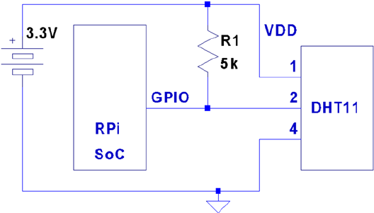
CHAPTER 22 ■ DHT11 SENSOR
264
Circuit
Figure 22-2 shows the general circuit connections between the Raspberry Pi and the DHT11 sensor. Pin 4 connects to
the common ground, while pin 1 goes to the 3.3 V supply. Pin 2 is the signal pin, which communicates with a chosen
GPIO pin. The program listing for dht11.c is configured to use GPIO 22. This is easily modified (look for gpio_dht11).
Figure 22-2. DHT11 circuit
When the Pi is listening on the GPIO pin and the DHT11 is not sending data, the line will float. For this reason,
R1 is required to pull the line up to a stable level of 3.3 V. The datasheet recommends a 5 kW resistor for the purpose
(a more common 4.7 kW resistor can be substituted safely). This presents less than 1 mA of load on either the GPIO
pin or the sensor when they are active. The datasheet also states that the 5 kW resistor should be suitable for cable
runs of up to 20 meters.
Protocol
The sensor speaks only when spoken to by the master (Raspberry Pi). The master must first make a request on the
bus and then wait for the sensor to respond. The DHT sensor responds with 40 bits of information, 8 of which are a
checksum.
Overall Protocol
The overall signal protocol works like this:
1. The line idles high because of the pull-up resistor.
2. The master pulls the line low for at least 18 ms to signal a read request and then releases
the bus, allowing the line to return to a high state.
3. After a pause of about 20 to 40 ms, the sensor responds by bringing the line low for 80 ms
and then allows the line to return high for a further 80 ms. This signals its intention to
return data.
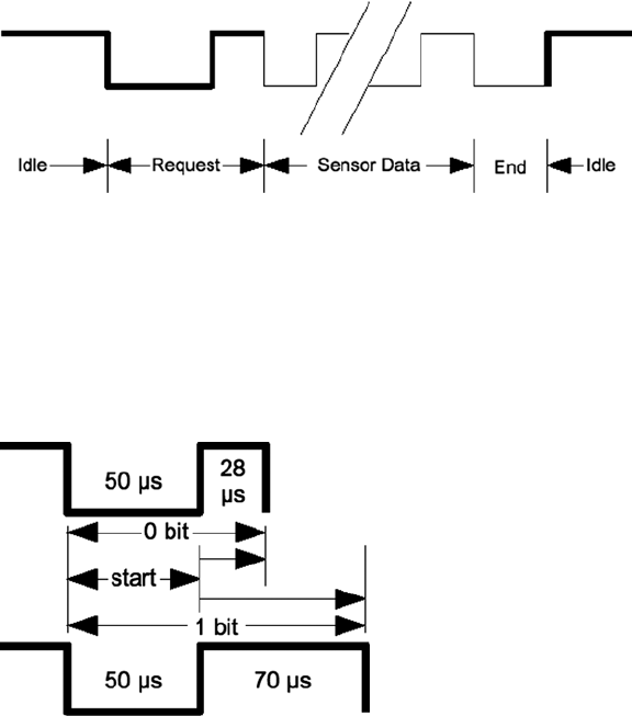
CHAPTER 22 ■ DHT11 SENSOR
265
4. Forty bits of information are then written out to the bus: each bit starting with a 50 ms low
followed by:
a. 26 to 28 ms of high to indicate a 0 bit
b. 70 ms of high to indicate a 1 bit
5. The transmission ends with the sensor bringing the line low one more time for 50 ms.
6. The sensor releases the bus, allowing the line to return to a high idle state.
Figure 22-3 shows the overall protocol of the sensor. Master control is shown in thick lines, while sensor control is
shown in thin lines. Initially, the bus sits idle until the master brings the line low and releases it (labeled Request). The
sensor grabs the bus and signals that it is responding (80 ms low, followed by 80 ms high). The sensor continues with
40 bits of sensor data, ending with one more transition to low (labeled End) to mark the end of the last bit.
Figure 22-3. General DHT11 protocol
Data Bits
Each sensor data bit begins with a transition to low, followed by the transition to high, as shown in Figure 22-4. The
end of the bit occurs when the line is brought low again as the start of the next bit. The last bit is marked off by one
final low-to-high transition.
Figure 22-4. DHT11 data bit
Each data bit starts with a transition to low, lasting for 50 ms. The final transition to low after the last bit also lasts
for 50 ms. After the bit’s low-to-high transition, the bit becomes a 0 if the high lasts only 26 to 28 microseconds. A 1 bit
stays high for 70 ms instead. Every data bit is completed when the transition from high to low occurs for the start of the
next bit (or final transition).
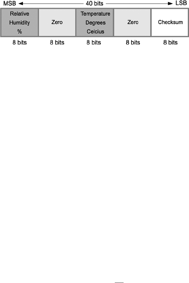
CHAPTER 22 ■ DHT11 SENSOR
266
Data Format
Figure 22-5 illustrates the 40-bit sensor response, transmitting the most significant bit first. The datasheet states
16 bits of relative humidity, 16 bits of temperature in Celsius, and an 8-bit checksum. However, the DHT11 always
sends 0s for the humidity and temperature fractional bytes. Thus the device really has only 8 bits of precision for each
measurement. Presumably, other models (or future ones) provide fractional values for greater precision.
Figure 22-5. DHT11 data format
The checksum is a simple sum of the first 4 bytes. Any carry overflow is simply discarded. This checksum gives
your application greater confidence that it has received correct values in the face of possible transmission errors.
Software
The user space software written to read the DHT11 sensor on the Raspberry Pi uses the direct register access of the
GPIO pin. The challenges presented by this approach include the following:
Short timings: 26 to 70 • ms
Preemptive scheduling delays within the Linux kernel•
One approach is to count how many times the program could read the high-level signal before the end of the
bit is reached (when the line goes low). Then decide on 0 bits for shorter times and 1s for longer times. After some
experimentation, a dividing line could be drawn, where shorter signals mean 0 while the others are 1s.
The difficulty with this approach is that it doesn’t adapt well if the Raspberry Pi is accelerated. When the CPU
clock is increased through overclocking, the program will tend to fail. There is also the potential for future Raspberry
Pis to include CPUs with higher clock rates.
The signal emitted by the sensor is almost a Manchester encoding. In Manchester encoding, one-half of the wave
form is shorter than the other. This allows counting up for the first half and counting down for the second. Based on
whether the counter underflows, a decision is made about the value of the bit seen.
The DHT11 signal uses a fixed first half of 50 ms The bit is decided based on how long the signal remains at a high
level after that. So a “bit bang” application could get a relative idea by counting the number of times it could read the
low-level signal. Based on that, it can get a relative idea of where the dividing line between a short and long high-level
signal is.
This is the approach that was adopted by the program dht11.c. It counts the number of times in a spin loop that
it can read the signal as low. On a 700 MHz nonturbo Raspberry Pi, I saw this count vary between 130 and 330 times,
with an average of 292. This time period is supposed to be exactly 50 ms, which illustrates the real-time scheduling
problem within a user space program. (The program did not use any real-time Linux priority scheduling.)
If the sensor waveform is true, a max count of 330 suggests that the Raspberry Pi can read the GPIO pin a
maximum of
330
50 66=./readss
m

CHAPTER 22 ■ DHT11 SENSOR
267
But the minimum of 130 GPIO reads shows a worst case performance of
130
50 26=.readss/
m
This variability in preemptive scheduling makes it difficult to do reliable timings.
I have seen the high-level bit counts vary between 26 and 378. (The interested reader can modify the code to
record the counts.) If the program is able to read 6.6 times per microsecond, a 1-bit time of 70 ms should yield a count
of 462. Yet the maximum seen was 378. Preemptive scheduling prevents the code from performing that many reads
without interruption.
The lower count of 26 represents the minimum count for 0 bits, where the line stays high for a shorter period of
time. This suggests that each GPIO read is about 1 ms or longer during the 0-bit highs.
The preceding information is just a crude sampling of the problem to illustrate the variability that must be
grappled with in a user space program, on a multitasking operating system.
Chosen Approach
The program shown in this chapter uses the following general approach:
1. Count the number of GPIO reads that report that the line is low (call it Clow).
2. Compute an adjustment bias B based on
BC
D
low
=
, where D is some fixed divisor.
3. Compute a new count K = B + Chigh, where Chigh is the number of times the line was read
as high.
4. If the count value K > Clow, the value is considered a 1-bit; otherwise, it’s considered a 0-bit.
The method is intended to at least partially compensate for the level of preemption being seen by the application
program. By measuring the low read counts, we get an idea of the number of times we can sample the line at the
moment. The approach is intended to adapt itself to a faster-running Raspberry Pi.
Table 22-1 shows some experimental results on an idle Raspberry Pi running at the standard 700 MHz. Different
divisors were tried and tested over 5-minute intervals. When the program runs, it attempts to read and report as
many sensor readings as it can, tracking good reports, time-out, and error counts. The program was terminated by
pressing ^C when an egg timer went off.
Table 22-1. Bias Test Results
Divisor Results Time-outs Errors
2 1 17 103
3 48 17 63
4 30 25 56
5 49 14 63
6 45 20 52
7 60 16 47
8 41 20 56
9 42 17 62
(continued)

CHAPTER 22 ■ DHT11 SENSOR
268
Using no bias at all, no successful reads result (which prompted the idea of applying a bias). Using a divisor of
2 applies too much adjustment, as can be seen by the low number of results (1). Increasing the divisor to the value 3 or
more produced a much higher success rate, near 48, which is almost 10 reports per minute. Setting the divisor to 3
seems to yield the most repeatable results overall.
It is uncertain from the datasheets how rapidly the sensor can be requeried. The program takes the conservative
approach of pausing 2 seconds between each sensor read attempt or waiting 5 seconds when a time-out has occurred.
The program reports an error when the checksum does not match. Time-outs occur if the code gets stuck waiting
for the signal to go low, for too long. This can happen if the program misses a critical event because of preemptive
scheduling. It sometimes happens that the high-to-low-to-high event can occur without the program ever seeing it.
If the going-low event takes too long, the program performs a longjmp into the main loop, to allow a retry.
The errors are reported to stderr, allowing them to be suppressed by redirecting unit 2 to /dev/null from the
command line.
The way that the Raspberry Pi relinquishes the sensor bus is by changing the GPIO pin from an output to an
input. When configured as an input, the pull-up resistor brings the bus line high when the bus is idle (the pull-up
applies when neither master or slave is driving the bus). When requested, the sensor grabs the bus and drives it high
or low. Finally, when the master speaks, we configure the pin as an output, causing the GPIO pin to drive the bus.
Example Run
When the program dht11 is run, you should see output similar to the following:
$ sudo ./dht11
RH 37% Temp 18 C Reading 1
(Error # 1)
(Timeout # 1)
RH 37% Temp 18 C Reading 2
(Timeout # 2)
RH 37% Temp 18 C Reading 3
RH 37% Temp 18 C Reading 4
RH 37% Temp 18 C Reading 5
Divisor Results Time-outs Errors
10 39 22 53
11 40 14 72
12 43 13 71
13 47 10 75
14 32 19 67
15 28 23 63
16 38 16 69
17 33 14 81
18 34 13 82
19 31 16 75
20 22 18 81
Table 22-1. (continued)

CHAPTER 22 ■ DHT11 SENSOR
269
(Error # 2)
(Timeout # 3)
(Error # 3)
(Error # 4)
(Error # 5)
RH 37% Temp 18 C Reading 6
(Error # 6)
RH 37% Temp 18 C Reading 7
(Error # 7)
(Error # 8)
(Error # 9)
RH 36% Temp 19 C Reading 8
RH 37% Temp 18 C Reading 9
(Timeout # 4)
RH 36% Temp 19 C Reading 10
^C
Program exited due to SIGINT:
Last Read: RH 36% Temp 19 C, 9 errors, 4 timeouts, 10 readings
Source Code
The next few pages list the source code for the program. This was assembled into one compile unit by using the
#include directive. This was done to save pages by eliminating additional header files and extern declarations.
Note ■ The source code for gpio_io.c is found in Chapter 12.
1 /*********************************************************************
2 * dht11.c: Direct GPIO access reading DHT11 humidity and temp sensor.
3 *********************************************************************/
4
5 #include <stdio.h>
6 #include <stdlib.h>
7 #include <fcntl.h>
8 #include <unistd.h>
9 #include <errno.h>
10 #include <setjmp.h>
11 #include <sys/mman.h>
12 #include <signal.h>
13
14 #include "gpio_io.c" /*GPIO routines */
15 #include "timed_wait.c" /*timed_wait() */
16
17 static const int gpio_dht11 = 22; /*GPIO pin */
18 static jmp_buf timeout_exit; /*longjmp on timeout */
19 static int is_signaled = 0; /*Exit program if signaled */
20
CHAPTER 22 ■ DHT11 SENSOR
270
21/*
22 * Signal handler to quit the program:
23 */
24 static void
25 sigint_handler(int signo) {
26 is_signaled = 1; /*Signal to exit program */
27 }
28
29 /*
30 * Read the GPIO line status:
31 */
32 static inline unsigned
33 gread(void) {
34 return gpio_read(gpio_dht11);
35 }
36
37 /*
38 * Wait until the GPIO line goes low:
39 */
40 static inline unsigned
41 wait_until_low(void) {
42 const unsigned maxcount = 12000;
43 unsigned count = 0;
44
45 while ( gread() )
46 if ( ++count >=maxcount || is_signaled )
47 longjmp(timeout_exit,1);
48 return count;
49 }
50
51 /*
52 * Wait until the GPIO line goes high:
53 */
54 static inline unsigned
55 wait_until_high(void) {
56 unsigned count = 0;
57
58 while ( !gread() )
59 ++count;
60 return count;
61 }
62
63 /*
64 * Read 1 bit from the DHT11 sensor:
65 */
66 static unsigned
67 rbit(void) {
68 unsigned bias;
69 unsigned lo_count, hi_count;
70
CHAPTER 22 ■ DHT11 SENSOR
271
71 wait_until_low();
72 lo_count = wait_until_high();
73 hi_count = wait_until_low();
74
75 bias = lo_count / 3;
76
77 return hi_count + bias > lo_count ? 1 : 0 ;
78 }
79
80 /*
81 * Read 1 byte from the DHT11 sensor :
82 */
83 static unsigned
84 rbyte(void) {
85 unsigned x, u = 0;
86
87 for ( x=0; x<8; ++x )
88 u = (u << 1) | rbit();
89 return u;
90 }
91
92 /*
93 * Read 32 bits of data + 8 bit checksum from the
94 * DHT sensor. Returns relative humidity and
95 * temperature in Celsius when successful. The
96 * function returns zero if there was a checksum
97 * error.
98 */
99 static int
100 rsensor(int *relhumidity, int *celsius) {
101 unsigned char u[5], cs = 0, x;
102 for ( x=0; x<5; ++x ) {
103 u[x] = rbyte();
104 if ( x < 4 ) /*Only checksum data..*/
105 cs += u[x]; /*Checksum */
106 }
107
108 if ( (cs & 0xFF) == u[4] ) {
109 *relhumidity = (int)u [0];
110 *celsius = (int)u [2];
111 return 1;
112 }
113 return 0;
114 }
115
116 /*
117 * Main program:
118 */
CHAPTER 22 ■ DHT11 SENSOR
272
119 int
120 main(int argc, char **argv) {
121 int relhumidity = 0, celsius = 0;
122 int errors = 0, timeouts = 0, readings = 0;
123 unsigned wait;
124
125 signal(SIGINT,sigint_handler); /*Trap on SIGINT */
126
127 gpio_init(); /*Initialize GPIO access */
128 gpio_config(gpio_dht11,Input); /*Set GPIO pin as Input */
129
130 for (;;) {
131 if ( setjmp(timeout_exit) ) { /*Timeouts go here */
132 if ( is_signaled ) /*SIGINT? */
133 break; /*Yes, then exit loop */
134 fprintf(stderr," (Timeout # %d)\n",++timeouts);
135 wait = 5;
136 } else wait = 2;
137
138 wait_until_high(); /*Wait GPIO line to go high */
139 timed_wait(wait,0,0); /*Pause for sensor ready */
140
141 gpio_config(gpio_dht11,Output); /*Output mode */
142 gpio_write(gpio_dht11,0); /*Bring line low */
143 timed_wait(0,30000,0); /*Hold low min of 18ms */
144 gpio_write(gpio_dht11,1); /*Bring line high */
145
146 gpio_config(gpio_dht11,Input); /*Input mode */
147 wait_until_low(); /*Wait for low signal */
148 wait_until_high(); /*Wait for return to high */
149
150 if ( rsensor(&relhumidity,& celsius) )
151 printf("RH %d%% Temp %d C Reading %d\n", relhumidity,
celsius,++readings);
152 else fprintf(stderr," (Error # %d)\n",++errors);
153 }
154
155 gpio_config(gpio_dht11,Input); /*Set pin to input mode */
156
157 puts("\ nProgram exited due to SIGINT: \n");
158 printf("Last Read: RH %d%% Temp %d C, %d errors, %d timeouts, %d readings \n",
159 relhumidity, celsius, errors, timeouts, readings);
160 return 0;
161 }
162
CHAPTER 22 ■ DHT11 SENSOR
273
163 /*End dht11.c */
1 /*********************************************************************
2 * Implement a precision "timed wait". The parameter early_usec
3 * allows an interrupted select(2) call to consider the wait as
4 * completed, when interrupted with only "early_usec" left remaining.
5 *********************************************************************/
6 static void
7 timed_wait(long sec,long usec,long early_usec) {
8 fd_set mt;
9 struct timeval timeout;
10 int rc;
11
12 FD_ZERO(&mt);
13 timeout.tv_sec = sec;
14 timeout.tv_usec = usec;
15 do {
16 rc = select (0,&mt,&mt,&mt,&timeout);
17 if ( ! timeout.tv_sec && timeout.tv_usec < early_usec )
18 return; /*Wait is good enough, exit */
19 } while ( rc < 0 && timeout.tv_sec && timeout.tv_usec );
20 }
21
22 /*End timed_wait.c */
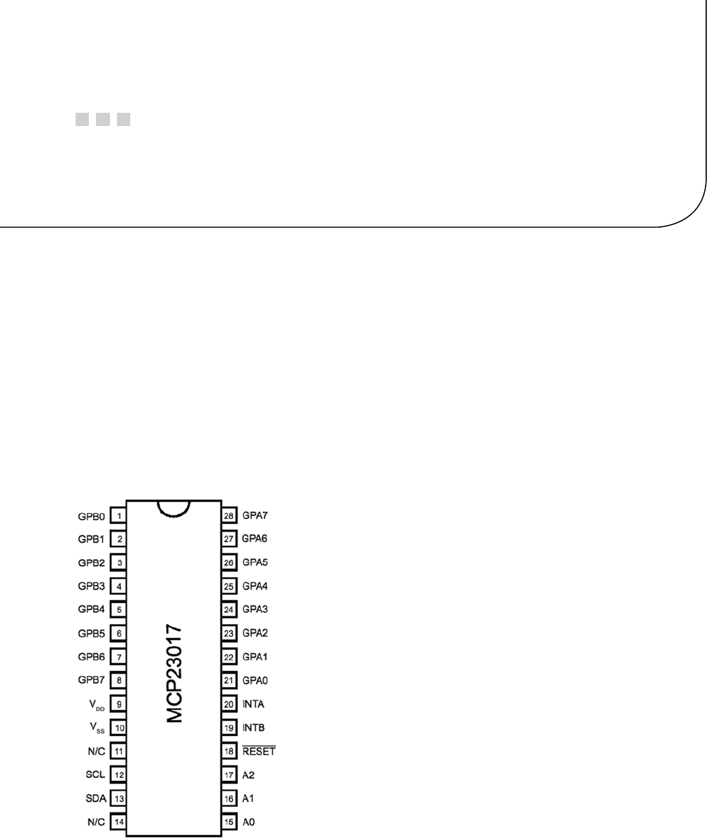
275
Chapter 23
MCP23017 GPIO Extender
Microchip’s MCP23017 provides 16 additional GPIO pins that can be purchased for as little as $1.99. The chip
communicates using the I2C bus. (The companion MCP23S17 is available for SPI bus.) The I2C bus allows the chip to
be remote from the Raspberry Pi, requiring only a four-wire ribbon cable (power, ground, and a pair of I2C bus lines).
This chapter explores the features and limits of this peripheral.
DC Characteristics
When shopping for chips or interface PCBs based on a particular chip, the first thing I look at is the operating supply
voltage. 5 V parts are inconvenient for the Pi because of its 3.3 V GPIO interface. Many newer devices operate over a
range of voltages, which include 3.3 V. The MCP23017 supply VDD operates from an extended range of +1.8 V to +5.5 V.
This clearly makes it compatible, if we power the chip from a +3.3 V source. Figure 23-1 shows the MCP23017chip
pinout diagram.
Figure 23-1. MCP23017 pinout

Chapter 23 ■ MCp23017 GpIO extender
276
GPIO Output Current
Another factor in choosing a peripheral chip is its output drive capability. How well can the GPIO pin source or
sink current? Chapter 12 notes that the Raspberry Pi’s own GPIO pins can source/sink up to 16 mA, depending on
configuration. The MCP23017 chip specifications indicate that it can source or sink up to 25 mA.
We still need to remember that if the MCP23017 is powered from the Raspberry Pi’s 3.3 V regulator on header P1,
the total current budget must not exceed 50 mA. This budget includes the Pi’s own GPIO pin current usage. If, on the
other hand, the MCP23017 is powered from a separate 3.3 V power supply, this limitation is eliminated.
There are still reasons to budget current, however. The chip must not consume more than 700 mW of power.
This implies a total current limit as follows:
IV
mA
V
DD
DD =
=
=
P
07
33
212
.
.
This power figure gives us an upper current limit. However, the datasheet of the MCP23017 also lists a maximum of
125 mA for supply pin VDD . If every GPIO output is sourcing power, this leaves us with the following average pin limit:
125
16 78
mA mA=.
So while the output GPIO pins can source up to 25 mA, we cannot have all of them doing so simultaneously.
Likewise, the datasheet lists VSS (ground) as limited to an absolute maximum of 150 mA. If every GPIO pin is an
output and sinking current, the average for each output pin cannot exceed the following:
150
16 94
mA mA=.
Once again, while each output pin can sink up to 25 mA, we see that they cannot all do so at the same time
without exceeding chip limits. This should not be discouraging, because in most applications, not all GPIO pins will
be outputs, and not all will all be driving heavy loads. The occasional pin that needs driving help can use a transistor
driver like the one discussed in Chapter 12.
Before we leave the topic of GPIO output driving, we can apply one more simple formula to help with interface
design. With the foregoing information, we can calculate the number of 25 mA outputs available:
125
25 5
mA
mA =
From this, it is known that four to five GPIO pins can operate near their maximum limits, as long as the remaining
GPIO pins are inputs or remain unconnected.
GPIO Inputs
In normal operation, the GPIO inputs should never see a voltage below the ground potential VSS. Nor should they ever
see a voltage above the supply voltage VDD. Yet, variations can sometimes happen when interfacing with the external
world, particularly with inductive components.
The datasheet indicates that clamping diodes provide some measure of protection against this. Should the
voltage on an input drop below 0, it is clamped by a diode so it will not go further negative and cause harm. The
Chapter 23 ■ MCp23017 GpIO extender
277
voltage limit is listed at –0.6 V, which is the voltage drop of the clamping diode. Likewise, if the voltage goes over VDD
(+3.3 V in our case), the clamping diode will limit the excursion to VDD + 0.6 V (+3.9 V).
This protection is limited by the current capability of the clamping diodes. The datasheet lists the maximum
clamping current as 20 mA. If pins are forced beyond their limits and the clamping current is exceeded, damage
will occur.
While we have focused on GPIO inputs in this section, the clamping diodes also apply to outputs. Outputs can be
forced beyond their limits by external circuits like pull-up resistors. Pull-up resistors should not be attached to +5 V,
for example, when the MCP23017 is operating from a +3.3 V supply.
Standby Current
If the MCP23017 device is not sourcing or sinking output currents, the standby current is stated as 3 mA (for 4.5 to 5.5 V
operation). This operating parameter is important to designers of battery-operated equipment.
Input Logic Levels
Since the device operates over a range of supply voltages, the datasheet defines the logic levels in terms of the supply
voltage. For example, the GPIO input low level is listed as
02.´VDD
. So if we operate with
VV
DD =+33.
, the input low
voltage is calculated as follows:
VV
V
IL DD
max=´
=´
=
02
02 33
066
.
..
.
Therefore, a voltage in the range of 0 to 0.66 V is guaranteed to read as a 0 bit.
Likewise, let’s calculate the input high voltage threshold, where the multiplier is given as 0.8:
VV
V
IH DD
min=´
=´
=
08
08 33
264
.
..
.
Thus any voltage greater than or equal to 2.64 V is read as a 1 bit, when powered from a +3.3 V supply. Any voltage
between VILmax and VIHmin is undefined and reads as a 1 or a 0, and perhaps randomly so.
Output Logic Levels
The output logic levels are stated differently. The datasheet simply states that the output low voltage should not
exceed a fixed limit. The high level is also stated as a minimum value relative to VDD. This pair of parameters is
listed here:
VV
VV V
V
DD
OLmax
OH min
=
=
=
=
06
07
33 07
27
.
.
..
.
-
-
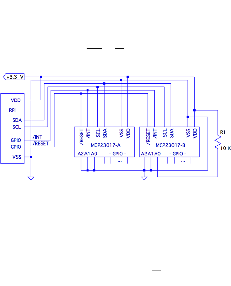
Chapter 23 ■ MCp23017 GpIO extender
278
Reset Timing
The only parameter of interest for timing apart from the I2C bus is the device reset time. In order for the device to see
a reset request, pin
RESET
must remain active (low) for a minimum of 1 ms. The device resets and places outputs into
the high-impedance mode within a maximum of 1 ms.
Circuit
Figure 23-2 shows a circuit with two remote MCP23017 GPIO extenders connected to one I2C bus. In the figure, the
power, ground, I2C data, and optional
RESET
and
INT
connections are shown connected through a six-conductor
ribbon cable. This allows the Raspberry Pi to communicate remotely to peripherals in a robot, for example.
Figure 23-2. MCP23017 circuit
The data communication occurs over the pair of signals SDA and SCL. These are connected to the Raspberry Pi’s
pins P1-03 and P1-05, respectively (GPIO 2 and 3 for Rev 2.0+). The other end of the I2C data bus is common to all
slave peripherals.
Each MCP23017 slave device is addressed by its individually configured A2, A1, and A0 pins. For device A, these
pins are shown grounded to define it as device number 0x20 (low bits are zeroed). A1 is tied high for device B so that
its peripheral address becomes 0x21. In this configuration, the Raspberry Pi will use addresses 0x20 and 0x21 to
communicate with these slave devices.
Lines labeled
RESET
and
INT
are optional connections. The
RESET
line can be eliminated if you never plan
to force a hardware reset of the slaves (tie to VDD through a 10 K resistor). Usually the power-on reset is sufficient.
The
INT
line is more desirable, since the MCP23017 can be programmed to indicate interrupts when a GPIO input
has changed in value (or does not match a comparison value). The
INT
line is an open collector pin so that many
can be tied together on the same line. However, the Pi will have to poll each peripheral to determine which device is
causing the interrupt. Alternatively, each slave could provide a separate
INT
signal, with a corresponding increase
in signal lines.

Chapter 23 ■ MCp23017 GpIO extender
279
Each MCP23017 chip has two interrupt lines, named
INT A
and
INT B
. There is the option of separate interrupt
notifications for the A group or the B group of GPIO pins. For remote operation, it is desirable to take advantage of
MCP23017’s ability to configure these to work in tandem, so that only one
INT
line is required.
On the Raspberry Pi end, the GPIO pin used for the
RESET
line would be configured as an output and held high,
until a reset is required. When activating a reset, the line must be held low for at least 1 microsecond, plus 1 more
microsecond to allow for the chip reset operation itself (and possibly longer, if non-MCP23017 slaves are connected to
the bus).
The
INT
line should be connected to a GPIO input on the Pi. This GPIO input either needs to be polled by the
application, or to have the GPIO configured to trigger on changes. Then the select(2) or poll(2) system calls can be
used to detect when an interrupt is raised by one or more peripherals.
The interrupt line, when used, should have a pull-up resistor configured (see Chapter 12 for information about
internal pull-up resistors). It may be best to use an external pull-up resistor, especially for longer cable runs. To keep
the sink current at 2 mA or less, the pull-up resistance used should be no lower than the following:
RV
mA
pullup=+
=
33
2
1650
.
W
A 2.2 kΩ 10% resistor will do nicely.
The +3.3 V line should be powered separately from the Raspberry Pi, unless the slaves expect to drive very low
currents. The main concern here is to not overload the remaining 50 mA capacity of the Pi’s +3.3 V regulated supply.
See Chapter 12 about budgeting +3.3 V power.
I2C Bus
Throughout this chapter, we are assuming a Rev 2.0 or later Raspberry Pi. This matters for the I2C bus because the
early versions wired I2C bus 0 to P1-03 and P1-05 (GPIO 0 and 1). Later this was changed to use bus 1. See Chapter
14 for more information about identifying your Pi and which I2C bus to use. If you are using an early Raspberry Pi
revision, you’ll need to substitute 0 for bus number 1, in commands and in the C source code that follows.
Wiring and Testing
The connections to the MCP23017 are simple enough that you can wire it up on a breadboard. The first step after
wiring is to determine that you can detect the peripheral on the I2C bus.
But even before that, check your kernel module support. If lsmod doesn’t show these modules loaded, you can
manually load them now:
$ sudo modprobe i2c−dev
$ sudo modprobe i2c−bcm2708
If you haven’t already done so, install i2c-tools:
$ sudo apt−get install i2c−tools
Chapter 23 ■ MCp23017 GpIO extender
280
If your I2C support is there, you should be able to list the available I2C buses:
$ i2cdetect −l
i2c −0 unknown bcm2708_i2c.0 N/A
i2c −1 unknown bcm2708_i2c.1 N/A
The I2C device nodes should also appear in /dev. These nodes give us access to the I2C drivers:
$ ls −l /dev/i2c*
crw−rw−−−T 1 root root 89, 0 Feb 18 23:53 /dev/i2c−0
crw−rw−−−T 1 root root 89, 1 Feb 18 23:53 /dev/i2c−1
The ultimate test is to see whether the MCP23017 chip is detected (change the 1 to 0 for older Pi revisions):
$ sudo i2cdetect −y 1
0 1 2 3 4 5 6 7 8 9 a b c d e f
00: −− −− −− −− −− −− −− −− −− −− −− −− −−
10: −− −− −− −− −− −− −− −− −− −− −− −− −− −− −− −−
20: 20 −− −− −− −− −− −− −− −− −− −− −− −− −− −− −−
30: −− −− −− −− −− −− −− −− −− −− −− −− −− −− −− −−
40: −− −− −− −− −− −− −− −− −− −− −− −− −− −− −− −−
50: −− −− −− −− −− −− −− −− −− −− −− −− −− −− −− −−
60: −− −− −− −− −− −− −− −− −− −− −− −− −− −− −− −−
70: −− −− −− −− −− −− −− −−
In this example, the A2, A1, and A0 pins of the MCP23017 were grounded. This gives the peripheral the I2C
address of 0x20. In the session output, we see that address 0x20 was detected successfully.
The i2cdump utility can be used to check the MCP23017 register:
$ sudo i2cdump –y –r 0x00–0x15 1 0x20 b
0 1 2 3 4 5 6 7 8 9 a b c d e f 0123456789abcdef
00: ff ff 00 00 00 00 00 00 00 00 00 00 00 00 00 00 ................
10: 00 00 00 00 00 00 ......
Here we have dumped out registers 0x00 to 0x15 on I2C bus 1, at peripheral address 0x20, in byte mode. This
was performed after a power-on reset, so we can check whether the register values match the datasheet values
documented. As expected, IODIRA (register 0x00) and IODIRB (register 0x01) have the default of all 1s (0xFF). This
also confirms that the registers are in BANK=0 mode (this is discussed in the following sections). All other MCP23017
registers default to 0 bits, which is also confirmed.
Software Configuration
The MCP23017 datasheet describes the full register complement and options available. In this chapter, we’ll concern
ourselves with a subset of its functionality, which is perhaps considered “normal use.” The extended functionality is
left as an exercise for you.
For this chapter’s project, we’re going to do the following:
Configure some GPIOs as inputs•
Configure some GPIOs as outputs•
Configure the group A and B inputs to signal an interrupt on any change•

Chapter 23 ■ MCp23017 GpIO extender
281
General Configuration
The MCP23017 peripheral has 10 registers for the GPIO-A pins, 10 registers for the GPIO-B pins, and one shared
register. In other words, there are 22 registers, with one pair of addresses referencing a common register. These
registers may be accessed in banks or interleaved. We’ll use interleaved mode in this chapter, to avoid having to reset
the device.
Interleaved register addresses are shown in Table 23-1. These are valid addresses when the IOCON register value
for BANK=0 (discussed later in this section).
Table 23-1. MCP23017 Register Addresses
Register A B Description
IODIRx 0x00 0x01 I/O direction
IPOLx 0x02 0x03 Input polarity
GPINTENx 0x04 0x05 Interrupt on change control
DEFVALx 0x06 0x07 Default comparison value
INTCONx 0x08 0x09 Interrupt control
IOCONx 0x0A 0x0B Configuration
GPPUx 0x0C 0x0D Pull-up configuration
INTFx 0x0E 0x0F Interrupt flags
INTCAPx 0x10 0x11 Interrupt captured value
GPIOx 0x12 0x13 General-purpose I/O
OLATx 0x14 0x15 Output latch
IOCON Register
This is the first register that must be configured, since it affects how registers are addressed. Additionally, other
settings are established that affect the entire peripheral.
Table 23-2 illustrates the layout of the IOCON register. Setting the BANK bit determines whether we use banked or
interleaved register addressing. The MCP23017 is in interleaved mode after a power-on reset. Once you set BANK=1,
the register addresses change. However, once this change is made, it is impossible to tell, after a program restart,
which register mode the peripheral is in. The only option is a hardware reset of the MCP23017 chip, to put it in a
known state. For this reason, we’ll keep the peripheral in its power-on reset state of BANK=0.

Chapter 23 ■ MCp23017 GpIO extender
282
In the tables that follow, a Y under the R (read) or W (write) column/row indicates that you can read or write the
respective value. The Reset column indicates the state of the bit after a device reset. An X indicates a “don’t care” or an
undefined value when read. An N indicates no access or no effect when written.
The bit MIRROR=1 is used to make
INT A
equivalent to
INT B
. In other words, GPIO A and B interrupts are
reported to both pins. This allows a single pin to be used for A and B groups.
Setting bit SEQOP=0 allows the peripheral to automatically increment the register address as each byte is read or
written. This eliminates the need to transmit a register address in many cases.
Bit DISSLW affects the physical handling of the SDA I2C bus line.
HAEN is applicable only to the MCP23S17 SPI device, since addresses are always enabled for I2C devices.
This project uses ODR=1 to configure the
INT A
pin as an open-drain pin. This allows multiple MCP23017 devices
to share the same interrupt line. Use a pull-up resistor on the
INT
line when this is in effect. Otherwise, you may
experience several sporadic interrupts.
Finally, INTPOL=0 is configured so that the interrupt is active low. This is required for an open-drain connected
line along with a pull-up resistor.
Table 23-2. IOCON Register
Bit Meaning R W Reset Description
7 BANK Y Y 0 Set to 0 for interleaved access
6 MIRROR Y Y 0 Set to 1 to join INTA & INTB
5 SEQOP Y Y 0 Set to 0 for auto-address increment
4 DISSLW Y Y 0 Set to 1 to disable slew rate control
3 HAEN Y Y 0 Ignored: I2C always uses address
2 ODR Y Y 0 Set to 1 for open-drain INT pins
1 INTPOL Y Y 0 Set to 0 for INT active low
0 N/A 0 X 0 Ignored: reads as zero
GPIO Address Note
These access a shared register
A 0x0A
B 0x0B

Chapter 23 ■ MCp23017 GpIO extender
283
OLATx Register
GPIO pins are all configured as inputs after a power-on reset (or use of
RESET
). Prior to configuring pins as outputs,
it is usually a good idea to set the required output values. This is accomplished by writing the OLAT register, for group A
or B. For this project, we’ll just write 0x00 to both OLATA and OLATB.
OLATx Register GPIO Address
Bit 7 6 5 4 3 2 1 0 A 0x14
R Y Y Y Y Y Y Y Y B 0x15
W Y Y Y Y Y Y Y Y
Reset 0 0 0 0 0 0 0 0
OLATx Bit Value
0 Output set to 0
1 Output set to 1
GPPUx Register
A given project should also define a known value for its input pull-up resistors. Setting a given bit to 1 enables a weak
100 KΩ internal pull-up resistor. This setting affects only the inputs. The pull-up resistors are configured off after a
reset. In our example code, we turn them on.
GPPUx Register GPIO Address
Bit 7 6 5 4 3 2 1 0 A 0x0C
R Y Y Y Y Y Y Y Y B 0x0D
W Y Y Y Y Y Y Y Y
Reset 0 0 0 0 0 0 0 0
GPPUx Bit Value
0 Pull-up resistor disabled
1 100 KW pull-up resistor enabled

Chapter 23 ■ MCp23017 GpIO extender
284
DEFVALx Register
This register is associated with interrupt processing. Interrupts are produced from conditions arising from input GPIO
pins only. An interrupt can be generated if the input differs from the DEFVALx register or if the input value has changed.
In the project presented, we simply zero this value because it is not used when detecting changed inputs.
DEFVALx Register GPIO Address
Bit 7 6 5 4 3 2 1 0 A 0x06
R Y Y Y Y Y Y Y Y B 0x07
W Y Y Y Y Y Y Y Y
Reset 0 0 0 0 0 0 0 0
DEFVALx Bit Value
0 Interrupt when input not 0
1 Interrupt when input not 1
INTCONx Register
This register specifies how input comparisons will be made. In our project, we set all these bits to 0 so that inputs
interrupt on change.
INTCONx Register GPIO Address
Bit 7 6 5 4 3 2 1 0 A 0x08
R Y Y Y Y Y Y Y Y B 0x09
W Y Y Y Y Y Y Y Y
Reset 0 0 0 0 0 0 0 0
INTCONx Bit Value
0 Input compared against its previous value
1 Input compared against DEFCONx bit value

Chapter 23 ■ MCp23017 GpIO extender
285
IPOLx Register
Bits set in this register will invert the logic sense of the corresponding GPIO inputs. In our project, we used no
inversion and set the bits to 0.
IPOLx Register GPIO Address
Bit 7 6 5 4 3 2 1 0 A 0x02
R Y Y Y Y Y Y Y Y B 0x03
W Y Y Y Y Y Y Y Y
Reset 0 0 0 0 0 0 0 0
IPOLx Bit Value
0 Read same logic as input pin
1 Read inverted logic of input pin
IODIRx Register
This register determines whether a given GPIO pin is an input or an output. Our project defines bits 4 through 7 as
inputs, with the remaining bits 0 through 3 of each 8-bit port as outputs.
IPOLx Register GPIO Address
Bit 7 6 5 4 3 2 1 0 A 0x00
R Y Y Y Y Y Y Y Y B 0x01
W Y Y Y Y Y Y Y Y
Reset 1 1 1 1 1 1 1 1
IPOLx Bit Value
0 Pin is configured as an output
1 Pin is configured as an input

Chapter 23 ■ MCp23017 GpIO extender
286
GPINTENx Register
This register enables interrupts on input pin events. Only inputs generate interrupts, so any enable bits for output pins
are ignored. How the interrupt is generated by the input is determined by registers DEFVALx and INTCONx.
GPINTENx Register GPIO Address
Bit 7 6 5 4 3 2 1 0 A 0x04
R Y Y Y Y Y Y Y Y B 0x05
W Y Y Y Y Y Y Y Y
Reset 0 0 0 0 0 0 0 0
GPINTENx Bit Value
0 Disable interrupts on this input
1 Enable interrupts for this input
For this project, we enabled interrupts on all inputs for ports A and B.
INTFx Register
This interrupt flags register contains the indicators for each input pin causing an interrupt. This register is unwritable.
Interrupt service routines start with this register to identify which inputs are the cause of the interrupt.
The DEFVALx and INTCONx registers configure how those interrupts are generated. The INTFx flags are cleared by
reading the corresponding INTCAPx or GPIOx register.
INTFx Register GPIO Address
Bit 7 6 5 4 3 2 1 0 A 0x0E
R Y Y Y Y Y Y Y Y B 0x0F
W N N N N N N N N
Reset 0 0 0 0 0 0 0 0
INTFx Bit Value
0 No interrupt for this input
1 Input has changed or does not compare

Chapter 23 ■ MCp23017 GpIO extender
287
INTCAPx Register
The interrupt capture register reports the status of the inputs as the interrupt is being raised. This register is
read-only. Reading this register clears the INTFx register, to allow new interrupts to be generated. When
INT A
is
linked to
INT B
, both INTCAPA and INTCAPB must be read to clear the interrupt (or read the GPIOx registers).
INTCAPx Register GPIO Address
Bit 7 6 5 4 3 2 1 0 A 0x10
R Y Y Y Y Y Y Y Y B 0x11
W N N N N N N N N
Reset 0 0 0 0 0 0 0 0
INTCAPx Bit Value
0 Input state was 0 at time of interrupt
1 Input state was 1 at time of interrupt
GPIOx Register
Reading this register provides the current input pin values, for pins configured as inputs. Reading the GPIOx register
also clears the interrupt flags in INTFx. When
INT A
is linked to
INT B
, both GPIOA and GPIOB must be read to clear
the interrupt (or read the INTCAPx registers).
Presumably, the OLATx register is read, for pins configured for output (the datasheet doesn’t say). Writing to the
GPIOx register alters the OLATx settings in addition to immediately affecting the outputs.
GPIOx Register GPIO Address
Bit 7 6 5 4 3 2 1 0 A 0x12
R Y Y Y Y Y Y Y Y B 0x13
W Y Y Y Y Y Y Y Y
Reset X X X X X X X X
Value R/W GPIOx Bit Value
0 R Current input pin state is low
W Write 0 to OLATx and output pin
1 R Current input pin state is high
W Write 1 to OLATx and output pin
Chapter 23 ■ MCp23017 GpIO extender
288
Main Program
Here are some change notes for the main program:
1. If you have a pre-revision 2.0 Raspberry Pi, change line 36 to use /dev/i2c-0.
2. Change line 55 if your MCP23017 chip is using a different I2C address
than 0x20 (A2, A1, and A0 grounded).
3. Change line 56 if you use a different Raspberry Pi GPIO for your interrupt sense pin.
The main program is fairly straightforward. Here are the basic overall steps:
1. A signal handler is registered in line 180, so ^C will cause the program to exit cleanly.
2. Routine i2c_init() is called to open the I2C driver and initialize.
3. Routine mcp23017_init() is called to initialize and configure the MCP23017 device on the
bus (only one is currently supported).
4. Routine gpio_open_edge() is called to open /sys/class/gpio17/value, so changes on
the interrupt line can be sensed. This is discussed in more detail later.
5. Finally, the main program enters a loop in lines 190 to 200, looping until ^C is entered.
Once inside the main loop, the following events occur:
1. Execution stalls when gpio_poll() is called. This blocks until the interrupt on GPIO 17
transitions from a high to a low.
2. The interrupt flags are read using routine mcp23017_interrupts(). They’re only reported
and otherwise not used.
3. Routine mcp23017_captured() is used to read the INTCAPA and INTCAPB registers in order
to clear the interrupt.
4. Finally, the routine post_outputs() reads the real-time input values and sends the bits to
the outputs.
Program mcp23017.c is shown here:
1 /*********************************************************************
2 * mcp23017.c : Interface with MCP23017 I/O Extender Chip
3 *
4 * This code assumes the following :
5 *
6 * 1. MCP23017 is configured for address 0x20
7 * 2. RPi’s GPIO 17 (GEN0) will be used for sensing interrupts
8 * 3. Assumed there is a pull up on GPIO 17.
9 * 4. MCP23017 GPA4-7 and GPB4–7 will be inputs, with pull-ups.
10 * 5. MCP23017 GPA0–3 and GPB0–3 will be ouputs.
11 * 6. MCP23017 signals interrupt active low.
12 * 7. MCP23017 operating in non–banked register mode.
13 *
14 * Inputs sensed will be copied to outputs :
15 * 1. GPA4–7 copied to GPA0–3
16 * 2. GPB4–7 copied to GPB0–3
17 *
Chapter 23 ■ MCp23017 GpIO extender
289
18 ********************************************************************/
19
20 #include <stdio.h>
21 #include <stdlib.h>
22 #include <fcntl.h>
23 #include <unistd.h>
24 #include <string.h>
25 #include <errno.h>
26 #include <signal.h>
27 #include <assert.h>
28 #include <sys/ioctl.h>
29 #include <sys/poll.h>
30 #include <linux/i2c.h>
31 #include <linux/i2c–dev.h>
32
33 #include "i2c_funcs.c" /* I2C routines */
34
35 /* Change to i2c 0 if using early Raspberry Pi */
36 static const char * node = "/dev/i2c–1";
37
38 #define GPIOA 0
39 #define GPIOB 1
40
41 #define IODIR 0
42 #define IPOL 1
43 #define GPINTEN 2
44 #define DEFVAL 3
45 #define INTCON 4
46 #define IOCON 5
47 #define GPPU 6
48 #define INTF 7
49 #define INTCAP 8
50 #define GPIO 9
51 #define OLAT 10
52
53 #define MCP_REGISTER(r,g) (((r) <<1)|(g)) cc/* For I2C routines */
54
55 static unsigned gpio_addr = 0x20; /* MCP23017 I2C Address */
56 static const int gpio_inta = 17 ; /* GPIO pin for INTA connection */
57 static int is_signaled = 0; /* Exit program if signaled * /
58
59 #include "sysgpio.c"
60
61 /*
62 * Signal handler to quit the program :
63 */
64 static void
65 sigint_handler(int signo) {
66 is_signaled = 1; /* Signal to exit program */
67 }
68
Chapter 23 ■ MCp23017 GpIO extender
290
69 /*
70 * Write to MCP23017 A or B register set:
71 */
72 static int
73 mcp23017_write(int reg,int AB,int value) {
74 unsigned reg_addr = MCP_REGISTER(reg,AB);
75 int rc;
76
77 rc = i2c_write8(gpio_addr,reg_addr,value);
78 return rc;
79 }
80
81 /*
82 * Write value to both MCP23017 register sets :
83 */
84 static void
85 mcp23017_write_both(int reg,int value) {
86 mcp23017_write(reg,GPIOA,value); /* Set A */
87 mcp23017_write(reg,GPIOB,value); /* Set B */
88 }
89
90 /*
91 * Read the MCP23017 input pins (excluding outputs,
92 * 16–bits) :
93 */
94 static unsigned
95 mcp23017_inputs(void) {
96 unsigned reg_addr = MCP_REGISTER(GPIO,GPIOA);
97
98
99 return i2c_read16(gpio_addr,reg_addr) & 0xF0F0;
100 }
101
102 /*
103 * Write 16 bits to outputs :
104 */
105 static void
106 mcp23017_outputs(int value) {
107 unsigned reg_addr = MCP_REGISTER(GPIO,GPIOA);
108
109 i2c_write16 (gpio_addr,reg_addr,value & 0x0F0F);
110 }
111
112 /*
113 * Read MCP23017 captured values (16–bits):
114 */
115 static unsigned
116 mcp23017_captured(void) {
117 unsigned reg_addr = MCP_REGISTER(INTCAP,GPIOA);
118
Chapter 23 ■ MCp23017 GpIO extender
291
119 return i2c_read16(gpio_addr,reg_addr) & 0xF0F0;
120 }
121
122 /*
123 * Read interrupting input flags (16–bits) :
124 */
125 static unsigned
126 mcp23017_interrupts(void) {
127 unsigned reg_addr = MCP_REGISTER(INTF,GPIOA);
128
129 return i2c_read16(gpio_addr,reg_addr) & 0xF0F0;
130 }
131
132 /*
133 * Configure the MCP23017 GPIO Extender :
134 */
135 static void
136 mcp23017_init(void) {
137 int v, int_flags;
138
139 mcp23017_write_both(IOCON,0b01000100); /* MIRROR=1,ODR=1 */
140 mcp23017_write_both(GPINTEN,0x00); /* No interrupts enabled */
141 mcp23017_write_both(DEFVAL,0x00); /* Clear default value */
142 mcp23017_write_both(OLAT,0x00); /* OLATx=0 */
143 mcp23017_write_both(GPPU,0b11110000); /* 4–7 are pull up */
144 mcp23017_write_both(IPOL,0b00000000); /* No inverted polarity */
145 mcp23017_write_both(IODIR,0b11110000); /* 4–7 are inputs, 0–3 outputs */
146 mcp23017_write_both(INTCON,0b00000000); /* Cmp inputs to previous */
147 mcp23017_write_both(GPINTEN,0b11110000); /* Interrupt on changes */
148
149 /*
150 * Loop until all interrupts are cleared:
151 */
152 do {
153 int_flags = mcp23017_interrupts();
154 if ( int_flags != 0 ) {
155 v = mcp23017_captured();
156 printf(" Got change %04X values %04X\n",int_flags,v);
157 }
158 } while ( int_flags != 0x0000 && !is_signaled );
159 }
160
161 /*
162 * Copy input bit settings to outputs :
163 */
164 static void
165 post_outputs(void) {
166 int inbits = mcp23017_inputs(); /* Read inputs */
167 int outbits = inbits >> 4; /* Shift to output bits */
168 mcp23017_outputs(outbits); /* Copy inputs to outputs */
Chapter 23 ■ MCp23017 GpIO extender
292
169 printf (" Outputs: %04X\n",outbits);
170 }
171
172 /*
173 *Main program :
174 */
175 int
176 main(int argc,char **argv) {
177 int int_flags, v;
178 int fd;
179
180 signal(SIGINT,sigint_handler); /* Trap on SIGINT */
181
182 i2c_init(node); /* Initialize for I2C */
183 mcp23017_init(); /* Configure MCP23017 @ 20 */
184
185 fd = gpio_open_edge(gpio_inta); /* Configure INTA pin */
186
187 puts("Monitoring for MCP23017 input changes :\n");
188 post_outputs(); /* Copy inputs to outputs */
189
190 do {
191 gpio_poll(fd) ; /* Pause until an interrupt */
192
193 int_flags = mcp23017_interrupts();
194 if ( int_flags ) {
195 v = mcp23017_captured();
196 printf(" Input change: flags %04X values %04X\n",
197 int_flags,v);
198 post_outputs();
199 }
200 } while ( !is_signaled ); /* Quit if ^C’ d */
201
202 fputc(’\n’, stdout);
203
204 i2c_close(); /* Close I2C driver */
205 close(fd); /* Close gpio17/value */
206 gpio_close(gpio_inta) ; /* Unex port gpio17 */
207 return 0;
208 }
209
210 /* End mcp23017.c */
Module i2c_funcs.c
To compile code when making use of I2C, you will need to install the libi2c development library:
$ sudo apt-get install libi2c-dev
Chapter 23 ■ MCp23017 GpIO extender
293
The i2c_funcs.c is a small module that wraps the ioctl(2) calls into neat little I/O functions:
i2c_write8(): Writes 8-bit value to MCP23017 register
i2c_write16(): Writes 16-bit value to MCP23017 register
i2c_read8(): Reads 8-bit value from MCP23017 register
i2c_read16(): Reads 16-bit value from MCP23017 register
Additionally, the open and close routines are provided:
i2c_init(): Opens the bus driver for /dev/i2c-x
i2c_close(): Closes the opened I2C driver
The C API for these I2C functions are described in Chapter 14.
1 /*************************************************************************
2 * i2c_funcs.c : I2C Access Functions
3 *************************************************************************/
4
5 static int i2c_fd = –1; /* Device node : /dev/i2c–1 */
6 static unsigned long i2c_funcs = 0; /* Support flags */
7
8 /*
9 * Write 8 bits to I2C bus peripheral:
10 */
11 int
12 i2c_write8(int addr,int reg,int byte) {
13 struct i2c_rdwr_ioctl_data msgset;
14 struct i2c_msg iomsgs[1];
15 unsigned char buf[2];
16 int rc;
17
18 buf[0] = (unsigned char)reg; /* MCP23017 register no. */
19 buf[1] = (unsigned char)byte; /* Byte to write to register */
20
21 iomsgs[0].addr = (unsigned)addr;
22 iomsgs[0].flags = 0; /* Write */
23 iomsgs[0].buf = buf;
24 iomsgs[0].len = 2;
25
26 msgset.msgs = iomsgs;
27 msgset.nmsgs = 1;
28
29 rc = ioctl(i2c_fd,I2C_RDWR,&msgset);
30 return rc < 0 ? –1 : 0;
31 }
32
33 /*
34 * Write 16 bits to Peripheral at address :
35 */
Chapter 23 ■ MCp23017 GpIO extender
294
36 int
37 i2c_write16(int addr, int reg, int value) {
38 struct i2c_rdwr_ioctl_data msgset;
39 struct i2c_msg iomsgs[1];
40 unsigned char buf[3];
41 int rc;
42
43 buf[0] = (unsigned char)reg;
44 buf[1] = (unsigned char)(( value >> 8 ) & 0xFF);
45 buf[2] = (unsigned char)(value & 0xFF);
46
47 iomsgs[0].addr = (unsigned)addr;
48 iomsgs[0].flags = 0; /* Write */
49 iomsgs[0].buf = buf;
50 iomsgs[0].len = 3;
51
52 msgset.msgs = iomsgs;
53 msgset.nmsgs = 1;
54
55 rc = ioctl(i2c_fd,I2C_RDWR,&msgset);
56 return rc < 0 ? –1 : 0;
57 }
58
59 /*
60 * Read 8–bit value from peripheral at addr :
61 */
62 int
63 i2c_read8(int addr,int reg) {
64 struct i2c_rdwr_ioctl_data msgset;
65 struct i2c_msg iomsgs[2];
66 unsigned char buf[1], rbuf[1];
67 int rc;
68
69 buf[0] = (unsigned char)reg;
70
71 iomsgs[0].addr = iomsgs[1].addr = (unsigned)addr;
72 iomsgs[0].flags = 0; /* Write */
73 iomsgs[0].buf = buf;
74 iomsgs[0].len = 1;
75
76 iomsgs[1].flags = I2C_M_RD; /* Read */
77 iomsgs[1].buf = rbuf;
78 iomsgs[1].len = 1;
79
80 msgset.msgs = iomsgs;
81 msgset.nmsgs = 2;
82
83 rc = ioctl(i2c_fd,I2C_RDWR,&msgset);
84 return rc < 0 ? –1 : ((int)(rbuf[0]) & 0x0FF);
85 }
86
Chapter 23 ■ MCp23017 GpIO extender
295
87 /*
88 * Read 16– bits of data from peripheral :
89 */
90 int
91 i2c_read16(int addr,int reg) {
92 struct i2c_rdwr_ioctl_data msgset;
93 struct i2c_msg iomsgs[2];
94 unsigned char buf[1], rbuf [2];
95 int rc;
96
97 buf[0] = (unsigned char)reg;
98
99 iomsgs[0].addr = iomsgs[1].addr = (unsigned)addr;
100 iomsgs[0].flags = 0; /* Write */
101 iomsgs[0].buf = buf;
102 iomsgs[0].len = 1;
103
104 iomsgs[1].flags = I2C_M_RD;
105 iomsgs[1].buf = rbuf ; /* Read */
106 iomsgs[1].len = 2;
107
108 msgset.msgs = iomsgs;
109 msgset.nmsgs = 2;
110
111 if ( (rc = ioctl(i2c_fd,I2C_RDWR,&msgset)) < 0 )
112 return –1;
113 return (rbuf[0] << 8) | rbuf[1];
114 }
115
116 /*
117 * Open I2C bus and check capabilities :
118 */
119 static void
120 i2c_init(const char * node) {
121 int rc;
122
123 i2c_fd = open(node,O_RDWR); /* Open driver /dev/i2s–1 */
124 if ( i2c_fd < 0 ) {
125 perror("Opening /dev/i2s–1");
126 puts("Check that the i2c dev & i2c–bcm2708 kernel modules "
127 "are loaded.");
128 abort();
129 }
130
131 /*
132 * Make sure the driver supports plain I2C I/O:
133 */
134 rc = ioctl(i2c_fd,I2C_FUNCS,&i2c_funcs);
135 assert(rc >= 0) ;
136 assert(i2c_funcs & I2C_FUNC_I2C);
137 }
138

Chapter 23 ■ MCp23017 GpIO extender
296
139 /*
140 * Close the I2C driver :
141 */
142 static void
143 i2c_close(void) {
144 close(i2c_fd);
145 i2c_fd = –1;
146 }
147
148 /* End i2c_funcs.c */
Module sysgpio.c
The sysgpio.c module performs some grunt work in making the /sys/class/gpio17/value node available and
configuring it. This node is opened for reading, so that poll(2) can be called upon it.
The interesting code in this module is found in lines 89 to 106, where gpio_poll() is defined. The file descriptor
passed to it as fd is the /sys/class/gpio17/value file that is
Configured as input•
Triggered on the falling edge (high-to-low transition)•
The poll(2) system call in line 99 blocks the execution of the program until the input (GPIO 17) changes from
a high state to a low state. This is connected to the MCP23017
INT A
pin, so it can tell us when its GPIO extender
input(s) have changed.
The poll(2) system call can return an error if the program has handled a signal. The error returned will be
EINTR when this happens (as discussed in Chapter 11, section “Error EINTR”). If the program detects that ^C has been
pressed (is_signaled is true), then it exits, returning -1, to allow the main program to exit.
A value of rc=1 is returned if /sys/class/gpio17/value has a changed value to be read. Before returning from
gpio_poll(), a read(2) of any unread data is performed. This is necessary so that the next call to poll(2) will block
until new data is available.
1 /*********************************************************************
2 * sysgpio.c : Open/configure /sys GPIO pin
3 *
4 * Here we must open the /sys/class/gpio/gpio17/value and do a
5 * poll(2) on it, so that we can sense the MCP23017 interrupts.
6 *********************************************************************/
7
8 typedef enum {
9 gp_export = 0, /* /sys/class/gpio/export */
10 gp_unexport, /* /sys/class/gpio/unexport */
11 gp_direction, /* /sys/class/gpo%d/direction */
12 gp_edge, /* /sys/class/gpio%d/edge */
13 gp_value /* /sys/class/gpio%d/value */
14 } gpio_path_t;
15
16 /*
17 * Internal : Create a pathname for type in buf.
18 */
Chapter 23 ■ MCp23017 GpIO extender
297
19 static const char *
20 gpio_setpath(int pin,gpio_path_t type,char *buf,unsigned bufsiz) {
21 static const char *paths[] = {
22 "export", "unexport", "gpio%d/direction",
23 "gpio%d/edge", "gpio%d/value" };
24 int slen;
25
26 strncpy(buf,"/sys/class/gpio/",bufsiz);
27 bufsiz –= (slen = strlen(buf));
28 snprintf(buf+slen,bufsiz,paths[type],pin);
29 return buf;
30 }
31
32 /*
33 * Open /sys/class/gpio%d/value for edge detection :
34 */
35 static int
36 gpio_open_edge(int pin) {
37 char buf[128];
38 FILE *f;
39 int fd;
40
41 /* Export pin: /sys/class/gpio/export */
42 gpio_setpath(pin,gp_export,buf,sizeof buf);
43 f = fopen(buf, "w");
44 assert(f);
45 fprintf(f,"%d\n",pin);
46 fclose(f);
47
48 /* Direction: /sys/class/gpio%d/direction */
49 gpio_setpath(pin,gp_direction,buf,sizeof buf);
50 f = fopen(buf,"w");
51 assert(f);
52 fprintf(f,"in\n");
53 fclose(f);
54
55 /* Edge: /sys/class/gpio%d/edge */
56 gpio_setpath(pin,gp_edge,buf,sizeof buf);
57 f = fopen(buf,"w");
58 assert(f);
59 fprintf(f,"falling\n");
60 fclose(f);
61
62 /* Value: /sys/class/gpio%d/value */
63 gpio_setpath(pin,gp_value,buf,sizeof buf);
64 fd = open(buf,O_RDWR);
65 return fd;
66 }
67
68 /*
69 * Close (unexport) GPIO pin :
70 */
Chapter 23 ■ MCp23017 GpIO extender
298
71 static void
72 gpio_close(int pin) {
73 char buf[128];
74 FILE *f ;
75
76 /* Unexport: /sys/class/gpio/unexport */
77 gpio_setpath(pin,gp_unexport,buf,size of buf);
78 f = fopen(buf,"w");
79 assert(f);
80 fprintf(f,"%d\n",pin);
81 fclose(f);
82 }
83
84 /*
85 * This routine will block until the open GPIO pin has changed
86 * value. This pin should be connected to the MCP23017 /INTA
87 * pin.
88 */
89 static int
90 gpio_poll(int fd) {
91 unsigned char buf[32];
92 struct pollfd polls;
93 int rc;
94
95 polls.fd = fd; /* /sys/class/gpio17/value */
96 polls.events = POLLPRI; /* Exceptions */
97
98 do {
99 rc = poll(&polls,1,–1); /* Block */
100 if ( is_signaled )
101 return –1; /* Exit if ^Creceived */
102 } while ( rc < 0 && errno == EINTR );
103
104 (void)read(fd,buf,sizeof buf); /* Clear interrupt */
105 return 0;
106 }
107
108 /* End sysgpio.c */
Example Run
The first time you run the program, you might encounter an error:
$ ./mcp23017
Opening /dev/i2s−1: No such file or directory
Check that the i2c−dev & i2c−bcm2708 kernel modules are loaded.
Aborted
$

Chapter 23 ■ MCp23017 GpIO extender
299
As the program states in the error message, it is unable to open the I2C driver, because the I2C kernel modules
have not been loaded. See Chapter 14 for modprobe information.
The following is a successful session. After the program is started, the program pauses after issuing the message
“Monitoring for MCP23017 input changes.” At this point, the program is in the poll(2) system call, waiting to be
notified of an interrupt from the MCP23017 peripheral. If you open another session, you can confirm that little or no
CPU resource is consumed by this.
$ sudo ./mcp23017
Monitoring for MCP23017 input changes :
Outputs : 0F0F
Input change : flags 8000 values 70F0
Outputs : 070F
Input change : flags 8000 values F0F0
Outputs : 070F
Input change : flags 8000 values F0F0
Outputs : 070F
Input change : flags 8000 values F0F0
Outputs : 070F
Input change : flags 8000 values F0F0
Outputs : 070F
Input change : flags 8000 values 70F0
Outputs : 0F0F
^C
$
While this was running, I carefully grounded pin 28 of the MCP28017 chip, which is input GPA7. This is reflected
immediately in the message:
Input change : flags 8000 values 70F0
The flags value reported as 8000 is decoded next, showing that GPA7 did indeed change in value:
INTFA INTFB
7654321076543210
1000000000000000
The value reported as 70F0 is from the INTCAPx register pair:
INTCAPA INTCAPB
7654321076543210
0111000011110000
This shows us that the GPA7 pin is found in the zero state at the time of the interrupt. All remaining inputs show
high (0s indicate output pins).

Chapter 23 ■ MCp23017 GpIO extender
300
While I grounded the GPA7 pin only once, you can see from the session output that several events occur. This is
due to the bounce of the wire as it contacts. You’ll also note that some events are lost during this bounce period.
Look at the input events:
1 Input change: flags 8000 values 70F0
2 Input change: flags 8000 values F0F0
3 Input change: flags 8000 values F0F0
4 Input change: flags 8000 values F0F0
5 Input change: flags 8000 values F0F0
6 Input change: flags 8000 values 70F0
Each interrupt correctly shows that pin GPA7 changed. But look closely at the captured values for the inputs:
1. The captured level of the input is 0 (line 1).
2. The captured level change of the input is now 1 (line 2).
3. The next input change shows a captured level of 1 (line 3).
How does the state of an input change from a 1 to a 1? Clearly what happens is that the input GPA7 changes to low
but returns to high by the time the interrupt is captured.
Push button, switch, and key bounces can occur often with a variety of pulse widths, in the range of
microseconds to milliseconds, until the contact stabilizes (off or on). The very action of pushing a button can initiate
a series of a thousand pulses. Some pulses will be too short for the software to notice, so it must be prepared to deal
with this. Sometimes electronics circuits are applied to eliminate “key debouncing” so that the software will see a
clean and singular event. This is what is accomplished in Chapter 29, where a flip-flop is used.
Response Times
You should be aware of the interrupt notification limitations provided by the poll(2) system call. The input lines
could easily change faster than the Raspberry Pi can respond. Consider the process involved:
1. An input GPIO extender pin changes in value.
2. The MCP23017 device activates
INT A
by bringing it from a high to a low
(a few cycles later).
3. The Raspberry Pi’s GPIO 17 pin sees a falling input level change.
4. The device driver responds to the GPIO pin change by servicing an interrupt and then
notifies the application waiting in poll(2).
5. The application sends some I2C traffic to query the INTFA and INTFB flag registers in the
MCP23017.
6. Registers GPIOA and GPIOB must also be read to clear the interrupt, involving more I/O on
the I2C bus.
Consequently, there is considerable delay in sensing a GPIO change and the clearing of the device interrupt.
An informal test using select(2) purely for delay purposes (no file descriptors) required a minimum of
approximately 150 ms on a 700 MHz Pi. The poll(2) call is likely to be nearly identical. Attempting to set smaller timed
delays bottomed out near 150 ms. This suggests that the quickest turnaround for reacting to an
INT
signal from the
MCP23017 will be 150 ms (excluding the time needed to actually service the registers in the peripheral). This means
that the absolute maximum number of interrupts per second that can be processed will be 6,600.
Chapter 23 ■ MCp23017 GpIO extender
301
To estimate the effects of the IC2 bus, let’s do some additional simplified calculations. The I2C bus operates at
100 kHz on the Raspberry Pi (Chapter 14). A single byte requires 8 data bits and an acknowledgment bit. This requires
about 90 ms per byte. To read one MCP23017 register requires the following:
1. The peripheral’s address byte to be sent (1 byte).
2. The MCP23017 register address to be sent (1 byte).
3. The MCP23017 responds back with 1 byte.
This requires 3 ´ 90 = 270 ms, just to read one register. Add to this the following:
1. Both interrupt flag registers INTFA and INTFB must be read.
2. Both GPIOA and GPIOB registers must be read, to clear the interrupt.
So, ignoring the start and stop bits, this requires 4 ´ 270 = 1.80 ms to respond to one input level change.
(This also ignores the effect of multiple peripherals on the bus.) This, added to the minimum of about 150 ms overhead
for poll(2), leads to the minimum response time of about 1.08 + 0.150 = 1.23 ms. This results in a practical limit of
about 800 signal changes per second.
Because of the response-time limitations, it is recommended that the INTCAPx register values be ignored. By
the time the application can respond to a signal change, it may have changed back again. This is why the program
presented uses the values read in GPIOA and GPIOB, rather than the captured values in the INTCAPx. But if your
application needs to know the state at the time of the event, the INTCAPx register values are available.
Some reduced I2C overhead can be attained by tuning the I/O operations. For example, with use of the
auto-increment address feature of the MCP23017, it is possible to read both INTFx flags and GPIOx registers in one
ioctl(2) call:
Tt tttttt
addr register INTFAINTFB register GPIOAGPIOB
=+ +++++
=´7990
0 630=.ms
That approach reduces the I2C time to approximately 7-byte times. The total turnaround time can then be
reduced to about 0.63 + 0.150 = 0.78 ms.

303
Chapter 24
Nunchuk-Mouse
This chapter’s project is about attaching the Nintendo Wii Nunchuk to the Raspberry Pi. The Nunchuk has two
buttons; an X-Y joystick; and an X, Y, and Z accelerometer. The sensor data is communicated through the I2C bus.
Let’s have some fun using a Nunchuk as a pointing device for the X Window System desktop.
Project Overview
The challenge before us breaks down into two overall categories:
The I2C data communication details of the Nunchuk device•
Inserting the sensed data into the X Window System desktop event queue•
Since you’ve mastered I2C communications in other parts of this book, we’ll focus more on the Nunchuk technical
details. The remainder of the chapter looks at the Linux uinput API that will be used for the X-Windows interface.
The final details cover a small but critical X-Windows configuration change, to bring about the Nunchuk-Mouse.
Nunchuk Features
The basic physical and data characteristics of the Nunchuk are listed in Table 24-1.
Table 24-1. Nunchuk Controls and Data Characteristics
User-Interface Features Bits Data Hardware/Chip
C Button 1 Boolean Membrane switch
Z button 1 Boolean Membrane switch
X-Y joystick 8x2 Integers 30 kW potentiometers
X, Y, and Z accelerometer 10x3 Integers ST LIS3L02 series
For application as a mouse, the C and Z buttons fill in for the left and right mouse buttons. The joystick is used to
position the mouse cursor.
While the Nunchuk normally operates at a clock rate of 400 kHz, it works just fine at the Raspberry Pi’s 100 kHz
I2C rate.

CHAPTER 24 ■ NUNCHUK-MOUSE
304
Note ■ I encourage you to experiment with the accelerometer.
Connector Pinout
There are four wires, two of which are power and ground (some units may have two additional wires, one
that connects to the shield and the other to the unused center pin). The remaining two wires are used for I2C
communication (SDA and SCL). The connections looking into the cable-end connector are shown in Table 24-2.
Table 24-2. Nuncheck Cable Connections
SCL Gnd
+3.3 V N/C SDA
Table 24-3. Nunchuk Connector Wiring
Pin Wii Wire CloneWire†Description P1
Gnd White White Ground P1-25
SDA Green Blue Data P1-03
+3.3 V Red Red Power P1-01
SCL Yellow Green Clock P1-05
†Clone wire colors vary!
The Nunchuk connector is annoyingly nonstandard. Some folks have rolled their own adapters using a double-sided
PCB to mate with the inner connections. Others have purchased adapters for around $6. Cheap Nunchuk clones may
be found on eBay for about half that price. With the growing number of clone adapters becoming available at more-
competitive prices, there is less reason to cut off the connector.
Tip ■ Beware of Nunchuk forgeries and nonfunctional units.
If you do cut off the connector, you will quickly discover that there is no standard wire color scheme. The only
thing you can count on is that the pins are laid out as in Table 24-2. If you have a genuine Wii Nunchuk, the listed wire
colors in Table 24-3 might be valid. The column labeled Clone Wire lists the wire colors of my own clone’s wires. Yours
will likely differ.
Before you cut that connector off your clone, consider that you’ll need to trace the connector to a wire color. Cut
the cable, leaving about 3 inches of wire for the connector. Then you can cut the insulation off and trace the pins to a
wire by using an ohmmeter (or by looking inside the cable-end connector).
Figure 24-1 shows the author’s clone Nunchuk with the connector cut off. In place of the connector, solid wire
ends were soldered on and a piece of heat shrink applied over the solder joint. The solid wire ends are perfect for
plugging into a prototyping breadboard.
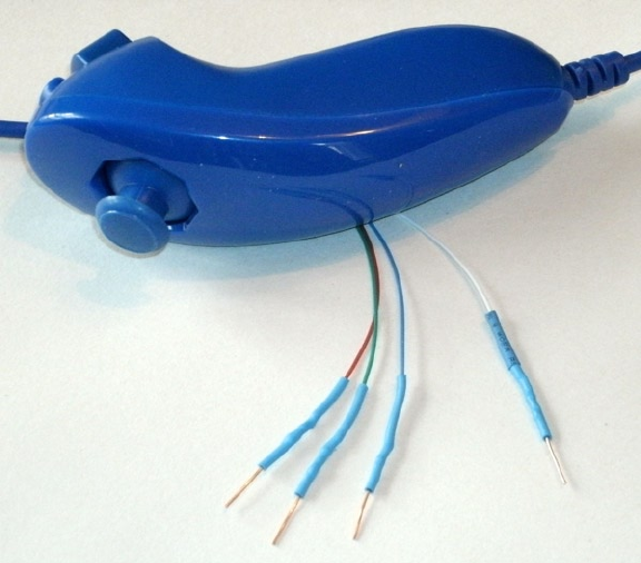
CHAPTER 24 ■ NUNCHUK-MOUSE
305
Testing the Connection
Once you’ve hooked up the Nunchuk to the Raspberry Pi, you’ll want to perform some simple tests to make sure it is
working. The first step is to make sure your I2C drivers are loaded:
$ lsmod | grep i2c
i2c_bcm2708 3759 0
i2c_dev 5620 0
If you see these modules loaded, you’re good to go. Otherwise, manually load them now:
$ sudo modprobe i2c−bcm2708
$ sudo modprobe i2c−dev
Assuming the Raspberry Pi rev 2.0+, you’ll use I2C bus 1 (see Chapter 14 if you’re not sure). Scan to see whether
your Nunchuk is detected:
$ sudo i2cdetect −y 1
0 1 2 3 4 5 6 7 8 9 a b c d e f
00: −− −− −− −− −− −− −− −− −− −− −− −− −−
10: −− −− −− −− −− −− −− −− −− −− −− −− −− −− −− −−
20: −− −− −− −− −− −− −− −− −− −− −− −− −− −− −− −−
30: −− −− −− −− −− −− −− −− −− −− −− −− −− −− −− −−
40: −− −− −− −− −− −− −− −− −− −− −− −− −− −− −− −−
Figure 24-1. Nunchuk with wire ends

CHAPTER 24 ■ NUNCHUK-MOUSE
306
50: −− −− 52 −− −− −− −− −− −− −− −− −− −− −− −− −−
60: −− −− −− −− −− −− −− −− −− −− −− −− −− −− −− −−
70: −− −− −− −− −− −− −− −−
If the Nunchuk is working, it will show up in this display at address 0x52. With the hardware verified, it is time to
move on to the software.
Nunchuk I2C Protocol
The Nunchuk contains a quirky little controller that communicates through the I2C bus. In order to know where to
store bytes written to it, the first byte must be an 8-bit register address. In other words, each write to the Nunchuk
requires the following:
One register address byte, followed by•
Zero or more data bytes to be written to sequential locations•
Thus for write operations, the first byte sent to the Nunchuk tells it where to start. Any following write bytes
received are written with the register address incremented.
Tip ■ Don’t confuse the register address with the Nunchuk’s I2C address of 0x52.
It is possible to write the register address and then read bytes instead. This procedure specifies the starting
location of data bytes to be read.
A quirky aspect of the Nunchuk controller is that there must be a short delay between writing the register address
and reading the data. Performing the write followed by an immediate read does not work. Writing data immediately
after the register address does succeed, however.
Note ■ The Nunchuk uses I2C address 0x52.
Encryption
The Nunchuk is designed to provide an encrypted link. However, that can be disabled by initializing it a certain way.
The defeat procedure is as follows:
1. Write 0x55 to Nunchuk location 0xF0.
2. Pause.
3. Write 0x00 to Nunchuk location 0xFB.
The following illustrates the message sequence involved. Notice that this is performed as two separate I2C
write operations:
Write Pause Write
F0 55 - FB 00
Once this is successfully performed, all future data is returned unencrypted.

CHAPTER 24 ■ NUNCHUK-MOUSE
307
Read Sensor Data
The whole point of the Nunchuk is to read its sensor data. When requested, it returns 6 bytes of data formatted as
shown in Table 24-4.
Table 24-4. Nunchuk Data
Byte Bits Description
1 Analog stick x axis value
2 Analog stick y axis value
3 X acceleration bits 9:2
4 Y acceleration bits 9:2
5 Z acceleration bits 9:2
6
0 Z button pressed (active low)
1 C button pressed (active low)
3:2 X acceleration bits 1:0
5:4 Y acceleration bits 1:0
7:6 Z acceleration bits 1:0
Some of the data is split over multiple bytes. For example, the X acceleration bits 9:2 are obtained from byte 3.
The lowest 2 bits are found in byte 6, in bits 3 and 2. These together form the 9-bit X acceleration value.
To retrieve this data, we are always required to tell the Nunchuk where to begin. So the sequence always begins
with a write of offset 0x00 followed by a pause:
Write Pause Read 6 bytes
00 - 01 02 03 04 05 06
The Nunchuk doesn’t allow us to do this in one ioctl(2) call, using two I/O messages. A write of 0 must be
followed by a pause. Then the 6 data bytes can be read as a separate I2C read operation. If the pause is too long,
however, the Nunchuk controller seems to time out, resulting in incorrect data being returned. So we must do things
the Nunchuk way.
Linux uinput Interface
While reading the Nunchuk is fun, we need to apply it to our desktop as a mouse. We need to insert mouse events
based on what we read from it.
The Linux uinput driver allows programmers to develop nonstandard input drivers so that events can be injected
into the input stream. This approach allows new input streams to be added without changing application code.
Certainly the Nunchuk qualifies as a nonstandard input device!
CHAPTER 24 ■ NUNCHUK-MOUSE
308
A problem with this uinput API is its general lack of documentation. The best information available on the
Internet seems to be from these three online sources:
“Getting started with uinput: the user level input subsystem” •
http://thiemonge.org/getting-started-with-uinput
”Using uinput driver in Linux- 2.6.x to send user input” •
http://www.einfochips.com/download/dash_jan_tip.pdf
“Types” •
http://www.kernel.org/doc/Documentation/input/event-codes.txt
The only other source of information seems to be the device driver source code itself:
drivers/input/misc/uinput.c
The example program provided in this chapter can help pull all the necessary details together for you.
Working with Header Files
The header files required for the uinput API include the following:
#include <sys/ioctl.h>
#include <linux/input.h>
#include <linux/uinput.h>
To compile code, making use of I2C, you also need to install the libi2c development library, if you have not done
that already:
$ sudo apt-get install libi2c-dev
Opening the Device Node
The connection to the uinput device driver is made by opening the device node:
/dev/uinput
The following is an example of the required open(2) call:
int fd;
fd = open("/dev/uinput",O_WRONLY|O_NONBLOCK);
if ( fd < 0 ) {
perror("Opening /dev/uinput");
...

CHAPTER 24 ■ NUNCHUK-MOUSE
309
Configuring Events
In order to inject events, the driver must be configured to accept them. Each call to ioctl(2) in the following code
enables one class of events based on the argument event. The following is a generalized example:
int rc;
unsigned long event = EV_KEY;
rc = ioctl(fd,UI_SET_EVBIT,event);
assert(!rc);
The list of UI_SET_EVBIT event types is provided in Table 24-5. The most commonly needed event types are
EV_SYN, EV_KEY, and EV_REL (or EV_ABS).
Table 24-5. List of uinput Event Types
From Header File input.h
Macro Description
EV_SYN Event synchronization/separation
EV_KEY Key/button state changes
EV_REL Relative axis mouse-like changes
EV_ABS Absolute axis mouse-like changes
EV_MSC Miscellaneous events
EV_SW Binary (switch) state changes
EV_LED LED on/off changes
EV_SND Output to sound devices
EV_REP For use with autorepeating devices
EV_FF Force feedback commands to input device
EV_PWR Power button/switch event
EV_FF_STATUS Receive force feedback device status
Caution ■ Do not or the event types together. The device driver expects each event type to be registered separately.
Configure EV_KEY
Once you have registered your intention to provide EV_KEY events, you need to register all key codes that might be
used. While this seems a nuisance, it does guard against garbage being injected by an errant program. The following
code registers its intention to inject an Escape key code:
int rc;
rc = ioctl(fd,UI_SET_KEYBIT,KEY_ESC);
assert(!rc);

CHAPTER 24 ■ NUNCHUK-MOUSE
310
To configure all possible keys, a loop can be used. But do not register key code 0 (KEY_RESERVED) nor 255; the
include file indicates that code 255 is reserved for the special needs of the AT keyboard driver.
int rc;
unsigned long key;
for ( key=1; key<255; ++key ) {
rc = ioctl(fd,UI_SET_KEYBIT,key);
assert(!rc);
}
Mouse Buttons
In addition to key codes, the same ioctl(2,UI_SET_KEYBIT) call is used to register mouse, joystick, and other kinds
of button events. This includes touch events from trackpads, tablets, and touchscreens. The long list of button codes is
defined in header file linux/input.h. The usual suspects are shown in Table 24-6.
Table 24-6. Key Event Macros
Macro Synonym Description
BTN_LEFT BTN_MOUSE Left mouse button
BTN_RIGHT Right mouse button
BTN_MIDDLE Middle mouse button
BTN_SIDE Side mouse button
The following example shows the application’s intention to inject left and right mouse button events:
int rc;
rc=ioctl(fd,UI_SET_KEYBIT,BTN_LEFT);
assert(!rc);
rc = ioctl(fd,UI_SET_KEYBIT,BTN_RIGHT);
assert(!rc);
Configure EV_REL
In order to inject EV_REL events, the types of relative movements must be registered in advance. The complete list of
valid argument codes is shown in Table 24-7. The following example indicates an intention to inject x and y relative
axis movements:
rc = ioctl(fd,UI_SET_RELBIT,REL_X);
assert(!rc);
rc = ioctl(fd,UI_SET_RELBIT,REL_Y);
assert(!rc);

CHAPTER 24 ■ NUNCHUK-MOUSE
311
Configure EV_ABS
While we don’t use the EV_ABS option in this project, it may be useful to introduce this feature at this point. This event
represents absolute cursor movements, and it too requires registration of intentions. The complete list of EV_ABS
codes is defined in linux/input.h. The usual suspects are defined in Table 24-8.
Table 24-7. UI_SET_RELBIT Options
Macro Intention
REL_X Send relative X changes
REL_Y Send relative Y changes
REL_Z Send relative Z changes
REL_RX x-axis tilt
REL_RY y- axis tilt
REL_RZ z- axis tilt
REL_HWHEEL Horizontal wheel change
REL_DIAL Dial-turn change
REL_WHEEL Wheel change
REL_MISC Miscellaneous
Table 24-8. Absolute Cursor Movement Event Macros
Macro Description
ABS_X Move X to this absolute X coordinate
ABS_Y Move Y to this absolute Y coordinate
The following is an example of registering intent for absolute x- and y-axis events:
int rc;
rc = ioctl(fd,UI_SET_ABSBIT,ABS_X);
assert(!rc);
rc = ioctl(fd,UI_SET_ABSBIT,ABS_X);
assert(!rc);
In addition to registering your intentions to inject these events, you need to define some coordinate parameters.
The following is an example:
struct uinput_user_dev uinp;
uinp.absmin[ABS_X] = 0;
uinp.absmax[ABS_X] = 1023;
CHAPTER 24 ■ NUNCHUK-MOUSE
312
uinp.absfuzz[ABS_X] = 0;
uinp.absflat[ABS_X] = 0;
uinp.absmin[ABS_Y] = 0;
uinp.absmax[ABS_Y] = 767;
uinp.absfuzz[ABS_Y] = 0;
uinp.absflat[ABS_Y] = 0;
These values must be established as part of your ioctl(2,UI_DEV_CREATE) operation, which is described next.
Creating the Node
After all registrations with the uinput device driver have been completed, the final step is to create the uinput node.
This will be used by the receiving application, in order to read injected events. This involves two programming steps:
1. Write the struct uinput_user_dev information to the file descriptor with write(2).
2. Perform an ioctl(2,UI_DEV_CREATE) to cause the uinput node to be created.
The first step involves populating the following structures:
struct input_id {
__u16 bustype;
__u16 vendor;
__u16 product;
__u16 version;
};
struct uinput_user_dev {
char name[UINPUT_MAX_NAME_SIZE];
struct input_id id;
int ff_effects_max;
int absmax[ABS_CNT];
int absmin[ABS_CNT];
int absfuzz[ABS_CNT];
int absflat[ABS_CNT];
};
An example populating these structures is provided next. If you plan to inject EV_ABS events, you must also
populate the abs members, mentioned in the “Configure EV_ABS” section.
struct uinput_user_dev uinp;
int rc;
memset(&uinp,0,sizeof uinp);
strncpy(uinp.name,"nunchuk",UINPUT_MAX_NAME_SIZE);
uinp.id.bustype = BUS_USB;
uinp.id.vendor = 0x1;
uinp.id.product = 0x1;
uinp.id.version = 1;
CHAPTER 24 ■ NUNCHUK-MOUSE
313
// uinp.absmax[ABS_X] = 1023; /∗EV_ABS only ∗/
// ...
rc = write(fd,&uinp,sizeof(uinp));
assert(rc == sizeof(uinp));
The call to write(2) passes all of this important information to the uinput driver. Now all that remains is to
request a device node to be created for application use:
int rc;
rc = ioctl(fd,UI_DEV_CREATE);
assert(!rc);
This step causes the uinput driver to make a device node appear in the pseudo directory /dev/input. An
example is shown here:
$ ls –l /dev/input
total 0
drwxr−xr−x 2 root root 120 Dec 31 1969 by−id
drwxr−xr−x 2 root root 120 Dec 31 1969 by−path
crw−rw−−−T 1 root input 13, 64 Dec 31 1969 event0
crw−rw−−−T 1 root input 13, 65 Dec 31 1969 event1
crw−rw−−−T 1 root input 13, 66 Dec 31 1969 event2
crw−rw−−−T 1 root input 13, 67 Feb 23 13:40 event3
crw−rw−−−T 1 root input 13, 63 Dec 31 1969 mice
crw−rw−−−T 1 root input 13, 32 Dec 31 1969 mouse0
crw−rw−−−T 1 root input 13, 33 Feb 23 13:40 mouse1
The device /dev/input/event3 was the Nunchuck’s created uinput node, when the program was run.
Posting EV_KEY Events
The following code snippet shows how to post a key down event, followed by a key up event:
1 static void
2 uinput_postkey(int fd,unsigned key) {
3 struct input_event ev;
4 int rc;
5
6 memset(&ev,0,sizeof(ev));
7 ev.type = EV_KEY;
8 ev.code = key;
9 ev.value = 1;
10
11 rc = write(fd,&ev,sizeof(ev));
12 assert(rc == sizeof(ev));
13
14 ev.value = 0;
15 rc = write(fd,&ev,sizeof(ev));
16 assert(rc == sizeof(ev));
17 }
CHAPTER 24 ■ NUNCHUK-MOUSE
314
From this example, you see that each event is posted by writing a suitably initialized input_event structure. The
example illustrates that the member named type was set to EV_KEY, code was set to the key code, and a keypress was
indicated by setting the member value to 1 (line 9).
To inject a key up event, value is reset to 0 (line 14) and the structure is written again.
Mouse button events work the same way, except that you supply mouse button codes for the code member.
For example:
memset(&ev,0,sizeof(ev));
ev.type = EV_KEY;
ev.code = BTN_RIGHT; /∗Right click ∗/
ev.value = 1;
Posting EV_REL Events
To post a relative mouse movement, we populate the input_event as a type EV_REL. The member code is set to the type
of event (REL_X or REL_Y in this example), with the value for the relative movement established in the member value:
static void
uinput_movement(int fd,int x,inty) {
struct input_event ev;
int rc;
memset(&ev,0,sizeof(ev));
ev.type = EV_REL;
ev.code = REL_X;
ev.value = x;
rc = write(fd,&ev,sizeof(ev));
assert(rc == sizeof(ev));
ev.code = REL_Y;
ev.value = y;
rc = write(fd,&ev,sizeof(ev));
assert (rc == sizeof(ev));
}
Notice that the REL_X and REL_Y events are created separately. What if you want the receiving application to avoid
acting on these separately? The EV_SYN event helps out in this regard (next).
Posting EV_SYN Events
The uinput driver postpones delivery of events until the EV_SYN event has been injected. The SYN_REPORT type of
EV_SYN event causes the queued events to be flushed out and reported to the interested application. The following is
an example:
static void
uinput_syn(int fd) {
struct input_event ev;
int rc;
CHAPTER 24 ■ NUNCHUK-MOUSE
315
memset(&ev,0,sizeof(ev));
ev.type = EV_SYN;
ev.code = SYN_REPORT;
ev.value = 0;
rc = write(fd,&ev,sizeof(ev));
assert(rc == sizeof(ev));
}
For a mouse relative movement event, for example, you can inject a REL_X and REL_Y, followed by a SYN_REPORT
event to have them seen by the application as a group.
Closing uinput
There are two steps involved:
1. Destruction of the /dev/input/event%d node
2. Closing of the file descriptor
The following example shows both:
int rc;
rc = ioctl(fd,UI_DEV_DESTROY);
assert(!rc);
close(fd);
Closing the file descriptor implies the ioctl(2,UI_DEV_DESTROY) operation. The application has the option of
destroying the device node while keeping the file descriptor open.
X-Window
The creation of our new uinput device node is useful only if our desktop system is listening to it. Raspbian Linux’s
X-Windows system needs a little configuration help to notice our Frankenstein creation. The following definition can
be added to the /usr/share/X11/xorg.config.d directory. Name the file 20-nunchuk.conf:
# Nunchuck event queue
Section "InputClass"
Identifier "Raspberry Pi Nunchuk"
Option "Mode" "Relative"
MatchDevicePath "/dev/input/event3"
Driver "evdev"
EndSection
# End 20−nunchuk.conf
This configuration change works only if your Nunchuk uinput device shows up as /dev/input/event3. If you
have other specialized input device creations on your Raspberry Pi, it could well be event4 or some other number. See
the upcoming section “Testing the Nunchuk” for troubleshooting information.
Restart your X-Windows server to have the configuration file noticed.

CHAPTER 24 ■ NUNCHUK-MOUSE
316
Tip ■ Normally, your Nunchuk program should be running already. But the X-Windows server will notice it when the
Nunchuk does start.
Input Utilities
When writing uinput event-based code, you will find the package input-utils to be extremely helpful. They can be
installed from the command line as follows:
$ sudo apt−get install input−utils
The following commands are installed:
lsinput(8): List uinput devices
input-events(8): Dump selected uinput events
input-kbd(8): Keyboard map display
This chapter uses the first two utilities: lsinput(8) and input-events(8).
Testing the Nunchuk
Now that the hardware, drivers, and software are ready, it is time to exercise the Nunchuk. Unfortunately, there is
no direct way for applications to identify your created uinput node. When the Nunchuk program runs, the node
may show up as /dev/input/event3 or some other numbered node if event3 already exists. If you wanted to start
a Nunchuk driver as part of the Linux boot process, you need to create a script to edit the file with the actual device
name. The affected X-Windows config file is as follows:
/usr/share/X11/xord.conf.d/20-nunchuk.conf
The script (shown next) determines which node the Nunchuk program created. The following is an example run,
while the Nunchuk program was running:
$ ./findchuk
/dev/input/event3
When the node is not found, the findchuk script exits with a nonzero code and prints a message to stderr:
$ ./findchuk
Nunchuk uinput device not found.
$ echo $?
1
CHAPTER 24 ■ NUNCHUK-MOUSE
317
The findchuk script is shown here:
#!/bin/bash
######################################################################
# Find the Nunchuck
######################################################################
#
# This script locates the Nunchuk uinput device by searching the
# /sys/devices/virtual/input pseudo directory for names of the form:
# input[0_9]∗. For all subdirectories found, check the ./name pseudo
# file, which will contain "nunchuk". Then we derive the /dev path
# from a sibling entry named event[0_9]∗. That will tell use the
# /dev/input/event%d pathname, for the Nunchuk.
DIR=/sys/devices/virtual/input # Top level directory
set_eu
cd "$DIR"
find . −type d −name 'input[0−9]∗' | (
set −eu
while read dirname ; do
cd "$DIR/$dirname"
if [−f "name"] ; then
set +e
name=$(cat name)
set −e
if [ $(cat name) = nunchuk ] ; then
event="/dev/input/$ (ls−devent[0−9]∗)"
echo $event
exit 0 # Found it
fi
fi
done
echo "Nunchuk uinput device not found." >&2
exit 1
)
# End findchuk
Testing ./nunchuk
When you want to see what Nunchuk data is being received, you can add the -d command-line option:
$ ./nunchuk −d
Raw nunchuk data: [83] [83] [5C] [89] [A2] [63]
.stick_x = 0083 (131)
.stick_y = 0083 (131)
.accel_x = 0170 (368)
.accel_y = 0226 (550)
.accel_z = 0289 (649)
.z_button= 0
.c_button= 0
CHAPTER 24 ■ NUNCHUK-MOUSE
318
The first line reports the raw bytes of data that were received. The remainder of the lines report the data in
its decoded form. While the raw data reports the button presses as active low, the Z and C buttons are reported as 1
in the decoded data. The value in the left column is in hexadecimal format, while the value in parenthesis is shown
in decimal.
Utility lsinputs
When the Nunchuk program is running, you should be able to see the Nunchuk uinput device in the list:
$ lsinput
...
/dev/input/event2
bustype : BUS_USB
vendor : 0x45e
product : 0x40
version : 272
name : "Microsoft Micro soft 3−Button Mou"
phys : "usb−bcm2708_usb−1.3.4/input0"
uniq : ""
bitsev : EV_SYN EV_KEY EV_REL EV_MSC
/dev/input/event3
bustype : BUS_USB
vendor : 0x1
product : 0x1
version : 1
name : "nunchuk"
bits ev : EV_SYN EV_KEY EV_REL
In this example, the Nunchuk shows up as event3.
Utility input-events
When developing uinput-related code, the input-events utility is a great help. Here we run it for event3 (the
argument 3 on the command line), where the Nunchuk mouse device is:
$ input−events 3
/dev/input/event3
bustype : BUS_USB
vendor : 0x1
product : 0x1
version : 1
name : "nunchuk"
bits ev : EV_SYN EV_KEY EV_REL
waiting for events
23:35:15.345105: EV_KEY BTN_LEFT (0x110) pressed
23:35:15.345190: EV_SYN code=0 value=0
23:35:15.517611: EV_KEY BTN_LEFT (0x110) released
23:35:15.517713: EV_SYN code=0 value=0
CHAPTER 24 ■ NUNCHUK-MOUSE
319
23:35:15.833640: EV_KEY BTN_RIGHT (0x111) pressed
23:35:15.833727: EV_SYN code=0 value=0
23:35:16.019363: EV_KEY BTN_RIGHT (0x111) released
23:35:16.019383: EV_SYN code=0 value=0
23:35:16.564129: EV_REL REL_X −1
23:35:16.564213: EV_REL REL_Y 1
23:35:16.564261: EV_SYN code=0 value=0
...
The Program
The code for nunchuk.c is presented on the following pages. The source code for timed_wait.c is shown in Chapter 22.
We’ve covered the I2C I/O in other chapters. The only thing left to note is the difficulty of providing a smooth interface
for events produced by the Nunchuk. Here are a few hints for the person who wants to experiment:
1. If the mouse moves too quickly, one major factor is the timed delay used. The
timed_wait() call in line 107 spaces out read events for the Nunchuk (currently 15 ms). This
also lightens the load on the CPU. Reducing this time-out increases the number of Nunchuk
reads and causes more uinput events to be injected. This speeds up the mouse pointer.
2. The function curve() in line 349 attempts to provide a somewhat exponential movement
response. Small joystick excursions should be slow and incremental. More-extreme
movements will result in faster mouse movements.
3. The Z button is interpreted as the left-click button, while the C button is the right-click button.
4. No keystrokes are injected by this program, but it can be modified to do so. The function
uinput_postkey() on line 244 can be used for that purpose.
1 /∗∗∗∗∗∗∗∗∗∗∗∗∗∗∗∗∗∗∗∗∗∗∗∗∗∗∗∗∗∗∗∗∗∗∗∗∗∗∗∗∗∗∗∗∗∗∗∗∗∗∗∗∗∗∗∗∗∗∗∗∗∗∗∗∗∗∗∗∗
2 ∗ nunchuk.c: Read events from nunchuck and stuff as mouse events
3 ∗∗∗∗∗∗∗∗∗∗∗∗∗∗∗∗∗∗∗∗∗∗∗∗∗∗∗∗∗∗∗∗∗∗∗∗∗∗∗∗∗∗∗∗∗∗∗∗∗∗∗∗∗∗∗∗∗∗∗∗∗∗∗∗∗∗∗∗∗/
4
5 #include <stdio.h>
6 #include <math.h>
7 #include <stdlib.h>
8 #include <fcntl.h>
9 #include <unistd.h>
10 #include <string.h>
11 #include <errno.h>
12 #include <signal.h>
13 #include <assert.h>
14 #include <sys/ioctl.h>
15 #include <linux/i2c−dev.h>
16 #include <linux/input.h>
17 #include <linux/uinput.h>
18
19 #include "timed_wait.c"
20
21 static int is_signaled = 0; /∗Exit program if signaled ∗/
22 static int i2c_fd = −1; /∗Open/dev/i2c−1 device ∗/
23 static int f_debug = 0; /∗True to print debug messages ∗/
CHAPTER 24 ■ NUNCHUK-MOUSE
320
24
25 typedef struct {
26 unsigned char stick_x; /∗Joystick X ∗/
27 unsigned char stick_y; /∗Joystick Y ∗/
28 unsigned accel_x; /∗Accel X ∗/
29 unsigned accel_y; /∗Accel Y ∗/
30 unsigned accel_z; /∗Accel Z ∗/
31 unsigned z_button: 1; /∗Z button ∗/
32 unsigned c_button: 1; /∗C button ∗/
33 unsigned char raw[6]; /∗Raw received data ∗/
34 } nunchuk_t;
35
36 / ∗
37 ∗ Open I2C bus and check capabilities:
38 ∗ /
39 static void
40 i2c_init(const char ∗node) {
41 unsigned long i2c_funcs = 0; /∗Support flags ∗/
42 int rc;
43
44 i2c_fd = open(node,O_RDWR); /∗Open driver/dev/i2s−1 ∗/
45 if ( i2c_fd < 0 ) {
46 perror("Opening/dev/i2s−1");
47 puts("Check that the i2c−dev & i2c−bcm2708 kernel modules"
48 "are loaded.");
49 abort();
50 }
51
52 /∗
53 ∗ Make sure the driver supports plain I2C I/O:
54 ∗/
55 rc = ioctl(i2c_fd,I2C_FUNCS,&i2c_funcs);
56 assert(rc >=0);
57 assert(i2c_funcs & I2C_FUNC_I2C);
58 }
59
60 /∗
61 ∗ Configure the nunchuk for no encryption:
62 ∗/
63 static void
64 nunchuk_init(void) {
65 static char init_msg1[] = {0xF0, 0x55};
66 static char init_msg2[] = {0xFB, 0x00};
67 struct i2c_rdwr_ioctl_data msgset;
68 struct i2c_msg iomsgs[1];
69 int rc;
70
71 iomsgs[0].addr = 0x52; /∗Address of Nunchuk ∗/
72 iomsgs[0].flags = 0; /∗Write ∗/
73 iomsgs[0].buf = init_msg1; /∗Nunchuk 2 byte sequence ∗/
74 iomsgs[0].len = 2; /∗2 bytes ∗/
75
CHAPTER 24 ■ NUNCHUK-MOUSE
321
76 msgset.msgs = iomsgs;
77 msgset.nmsgs = 1;
78
79 rc = ioctl(i2c_fd,I2C_RDWR,&msgset);
80 assert(rc == 1);
81
82 timed_wait(0,200,0); /∗Nunchuk needs time ∗/
83
84 iomsgs[0].addr = 0x52; /∗Address of Nunchuk ∗/
85 iomsgs[0].flags = 0; /∗Write ∗/
86 iomsgs[0].buf = init_msg2; /∗Nunchuk 2 byte sequence ∗/
87 iomsgs[0].len = 2; /∗2 bytes ∗/
88
89 msgset.msgs = iomsgs;
90 msgset.nmsgs = 1;
91
92 rc = ioctl(i2c_fd,I2C_RDWR,&msgset);
93 assert(rc == 1);
94 }
95
96 /∗
97 ∗ Read nunchuk data :
98 ∗/
99 static int
100 nunchuk_read(nunchuk_t ∗data) {
101 struct i2c_rdwr_ioctl_data msgset;
102 struct i2c_msg iomsgs[1];
103 char zero[1] = {0x00}; /∗Written byte ∗/
104 unsigned t;
105 int rc;
106
107 timed_wait(0,15000,0);
108
109 /∗
110 ∗ Write the nunchuk register address of 0x00:
111 ∗/
112 iomsgs[0].addr = 0x52; /∗Nunchuk address ∗/
113 iomsgs[0].flags = 0; /∗Write ∗/
114 iomsgs[0].buf = zero; /∗Sending buf ∗/
115 iomsgs[0].len = 1; /∗6 bytes ∗/
116
117 msgset.msgs = iomsgs;
118 msgset.nmsgs = 1;
119
120 rc = ioctl(i2c_fd,I2C_RDWR,&msgset);
121 if ( rc < 0 )
122 return −1; /∗I /O error ∗/
123
124 timed_wait(0,200,0); /∗Zzzz, nunchuk needs time ∗/
125
CHAPTER 24 ■ NUNCHUK-MOUSE
322
126 /∗
127 ∗ Read 6 bytes starting at 0x00:
128 ∗/
129 iomsgs[0].addr = 0x52; /∗Nunchuk address ∗/
130 iomsgs[0].flags = I2C_M_RD; /∗Read ∗/
131 iomsgs[0].buf = (char ∗)data−>raw; /∗Receive raw bytes here ∗/
132 iomsgs[0].len = 6; /∗6 bytes ∗/
133
134 msgset.msgs = iomsgs;
135 msgset.nmsgs = 1;
136
137 rc = ioctl(i2c_fd,I2C_RDWR,&msgset);
138 if ( rc < 0 )
139 return −1; /∗Failed ∗/
140
141 data−>stick_x = data−>raw[0];
142 data−>stick_y = data−>raw[1];
143 data−>accel_x = data−>raw[2] << 2;
144 data−>accel_y = data−>raw[3] << 2;
145 data−>accel_z = data−>raw[4] << 2;
146
147 t = data−>raw[5];
148 data−>z_button = t & 1 ? 0 : 1;
149 data−>c_button = t & 2 ? 0 : 1;
150 t >>=2;
151 data−>accel_x |= t & 3;
152 t >>=2;
153 data−>accel_y |= t & 3;
154 t >>=2;
155 data−>accel_z |= t & 3;
156 return 0;
157 }
158
159 /∗
160 ∗ Dump the nunchuk data:
161 ∗/
162 static void
163 dump_data(nunchuk_t ∗data) {
164 int x;
165
166 printf("Raw nunchuk data : ");
167 for ( x=0; x<6; ++x )
168 printf("[%02X]",data−>raw[x]);
169 putchar('\n');
170
171 printf(".stick_x = %04X (%4u)\n",data−>stick_x,data−>stick_x);
172 printf(".stick_y = %04X (%4u)\n",data−>stick_y,data−>stick_y);
173 printf(".accel_x = %04X (%4u)\n",data−>accel_x,data−>accel_x);
174 printf(".accel_y = %04X (%4u)\n",data−>accel_y,data−>accel_y);
175 printf(".accel_z = %04X (%4u)\n",data−>accel_z,data−>accel_z);
CHAPTER 24 ■ NUNCHUK-MOUSE
323
176 printf(".z_button= %d\n",data−>z_button);
177 printf(".c_button= %d\n\n",data−>c_button);
178 }
179
180 /∗
181 ∗ Close the I2C driver :
182 ∗/
183 static void
184 i2c_close(void) {
185 close(i2c_fd);
186 i2c_fd = −1;
187 }
188
189 /∗
190 ∗ Open a uinput node :
191 ∗/
192 static int
193 uinput_open(void) {
194 int fd;
195 struct uinput_user_dev uinp;
196 int rc;
197
198 fd = open("/dev/uinput",O_WRONLY|O_NONBLOCK);
199 if ( fd < 0 ) {
200 perror("Opening/dev/uinput");
201 exit(1);
202 }
203
204 rc = ioctl(fd,UI_SET_EVBIT,EV_KEY);
205 assert(!rc);
206 rc = ioctl(fd,UI_SET_EVBIT,EV_REL);
207 assert(!rc);
208
209 rc = ioctl(fd,UI_SET_RELBIT,REL_X);
210 assert(!rc);
211 rc = ioctl(fd,UI_SET_RELBIT,REL_Y);
212 assert(!rc);
213
214 rc = ioctl(fd,UI_SET_KEYBIT,KEY_ESC);
215 assert(!rc);
216
217 ioctl(fd,UI_SET_KEYBIT,BTN_MOUSE);
218 ioctl(fd,UI_SET_KEYBIT,BTN_TOUCH);
219 ioctl(fd,UI_SET_KEYBIT,BTN_MOUSE);
220 ioctl(fd,UI_SET_KEYBIT,BTN_LEFT);
221 ioctl(fd,UI_SET_KEYBIT,BTN_MIDDLE);
222 ioctl(fd,UI_SET_KEYBIT,BTN_RIGHT);
223
224 memset(&uinp,0,sizeof uinp);
225 strncpy(uinp.name,"nunchuk",UINPUT_MAX_NAME_SIZE);
226 uinp.id.bustype = BUS_USB;
227 uinp.id.vendor = 0x1;
CHAPTER 24 ■ NUNCHUK-MOUSE
324
228 uinp.id.product = 0x1;
229 uinp.id.version = 1;
230
231 rc = write(fd,&uinp,sizeof(uinp));
232 assert(rc == sizeof(uinp));
233
234 rc = ioctl(fd,UI_DEV_CREATE);
235 assert(!rc);
236 return fd;
237 }
238
239 /∗
240 ∗ Post keystroke down and keystroke up events:
241 ∗ (unused here but available for your own experiments)
242 ∗/
243 static void
244 uinput_postkey(int fd,unsigned key) {
245 struct input_event ev;
246 int rc;
247
248 memset(&ev,0,sizeof(ev));
249 ev.type = EV_KEY;
250 ev.code = key;
251 ev.value = 1; /∗Key down ∗/
252
253 rc = write(fd,&ev,sizeof(ev));
254 assert(rc == sizeof(ev));
255
256 ev.value = 0; /∗Key up ∗/
257 rc = write(fd,&ev,sizeof(ev));
258 assert(rc == sizeof(ev));
259 }
260
261 /∗
262 ∗ Post a synchronization point :
263 ∗/
264 static void
265 uinput_syn(int fd) {
266 struct input_event ev;
267 int rc;
268
269 memset(&ev,0,sizeof(ev));
270 ev.type = EV_SYN;
271 ev.code = SYN_REPORT;
272 ev.value = 0;
273 rc = write(fd,&ev,sizeof(ev));
274 assert(rc == sizeof(ev));
275 }
276
277 /∗
CHAPTER 24 ■ NUNCHUK-MOUSE
325
278 ∗ Synthesize a button click :
279 ∗ up_down 1=up, 0=down
280 ∗ buttons 1=Left, 2=Middle, 4=Right
281 ∗/
282 static void
283 uinput_click(int fd,int up_down,int buttons) {
284 static unsigned codes[] = {BTN_LEFT, BTN_MIDDLE, BTN_RIGHT};
285 struct input_event ev;
286 int x;
287
288 memset(&ev,0,sizeof(ev));
289
290 /∗
291 ∗ Button down or up events:
292 ∗/
293 for ( x=0; x < 3; ++x ) {
294 ev.type = EV_KEY;
295 ev.value = up_down; /∗Button Up or down ∗/
296 if ( buttons & (1 << x) ) { /∗Button 0, 1 or 2 ∗/
297 ev.code = codes[x];
298 write(fd,&ev,sizeof(ev));
299 }
300 }
301 }
302
303 /∗
304 ∗ Synthesize relative mouse movement:
305 ∗/
306 static void
307 uinput_movement(int fd,int x,int y) {
308 struct input_event ev;
309 int rc;
310
311 memset(&ev,0,sizeof(ev));
312 ev.type = EV_REL;
313 ev.code = REL_X;
314 ev.value = x;
315
316 rc = write(fd,&ev,sizeof(ev));
317 assert(rc == sizeof(ev));
318
319 ev.code = REL_Y;
320 ev.value = y;
321 rc = write(fd,&ev,sizeof(ev));
322 assert(rc == sizeof(ev));
323 }
324
325 /∗
326 ∗ Close uinput device :
CHAPTER 24 ■ NUNCHUK-MOUSE
326
327 ∗/
328 static void
329 uinput_close(int fd) {
330 int rc;
331
332 rc = ioctl(fd,UI_DEV_DESTROY);
333 assert(!rc);
334 close(fd);
335 }
336
337 /∗
338 ∗ Signal handler to quit the program:
339 ∗/
340 static void
341 sigint_handler(int signo) {
342 is_signaled = 1; /∗Signal to exit program ∗/
343 }
344
345 /∗
346 ∗ Curve the adjustment :
347 ∗/
348 static int
349 curve(int relxy) {
350 int ax = abs(relxy); /∗abs (re lxy) ∗/
351 int sgn = relxy < 0 ? −1 : 1; /∗sign (relxy) ∗/
352 int mv = 1; /∗Smallest step ∗/
353
354 if ( ax > 100 )
355 mv = 10; /∗Take large steps ∗/
356 else if ( ax > 65 )
357 mv = 7;
358 else if ( ax > 35 )
359 mv = 5;
360 else if ( ax > 15 )
361 mv = 2; /∗2nd smallest step ∗/
362 return mv ∗ sgn;
363 }
364
365 /∗
366 ∗ Main program:
367 ∗/
368 int
369 main(int argc,char ∗∗argv) {
370 int fd, need_sync, init = 3;
371 int rel_x=0, rel_y = 0;
372 nunchuk_t data0, data, last;
373
CHAPTER 24 ■ NUNCHUK-MOUSE
327
374 if ( argc > 1 && !strcmp(argv [1]," −d") )
375 f_debug = 1; /∗Enable debug messages ∗/
376
377 (void)uinput_postkey; /∗Suppress compiler warning about unused ∗/
378
379 i2c_init("/dev/i2c−1"); /∗Open I2C controller ∗/
380 nunchuk_init(); /∗Turn off encrypt ion ∗/
381
382 signal(SIGINT,sigint_handler); /∗Trap on SIGINT ∗/
383 fd = uinput_open(); /∗Open/dev/uinput ∗/
384
385 while ( !is_signaled ) {
386 if ( nunchuk_read(&data) < 0 )
387 continue;
388
389 if ( f_debug )
390 dump_data(&data); /∗Dump nunchuk data ∗/
391
392 if ( init > 0 && !data0.stick_x && !data0.stick_y ) {
393 data0 = data; /∗Save initial values ∗/
394 last = data;
395 −−init;
396 continue;
397 }
398
399 need_sync = 0;
400 if ( abs(data.stick_x − data0.stick_x) > 2
401 || abs(data.stick_y − data0.stick_y) > 2) {
402 rel_x = curve (data.stick_x − data0.stick_x);
403 rel_y = curve (data.stick_y − data0.stick_y);
404 if ( rel_x || rel_y ) {
405 uinput_movement(fd,rel_x,−rel_y);
406 need_sync = 1;
407 }
408 }
409
410 if ( last.z_button != data.z_button ) {
411 uinput_click(fd, data.z_button,1);
412 need_sync = 1;
413 }
414
415 if ( last.c_button != data.c_button ) {
416 uinput_click(fd,data.c_button,4);
417 need_sync = 1;
418 }
419
420 if ( need_sync )
421 uinput_syn(fd);
422 last = data;
423 }
CHAPTER 24 ■ NUNCHUK-MOUSE
328
424
425 putchar('\n');
426 uinput_close(fd);
427 i2c_close();
428 return 0;
429 }
430
431 /∗End nunchuk.c ∗/
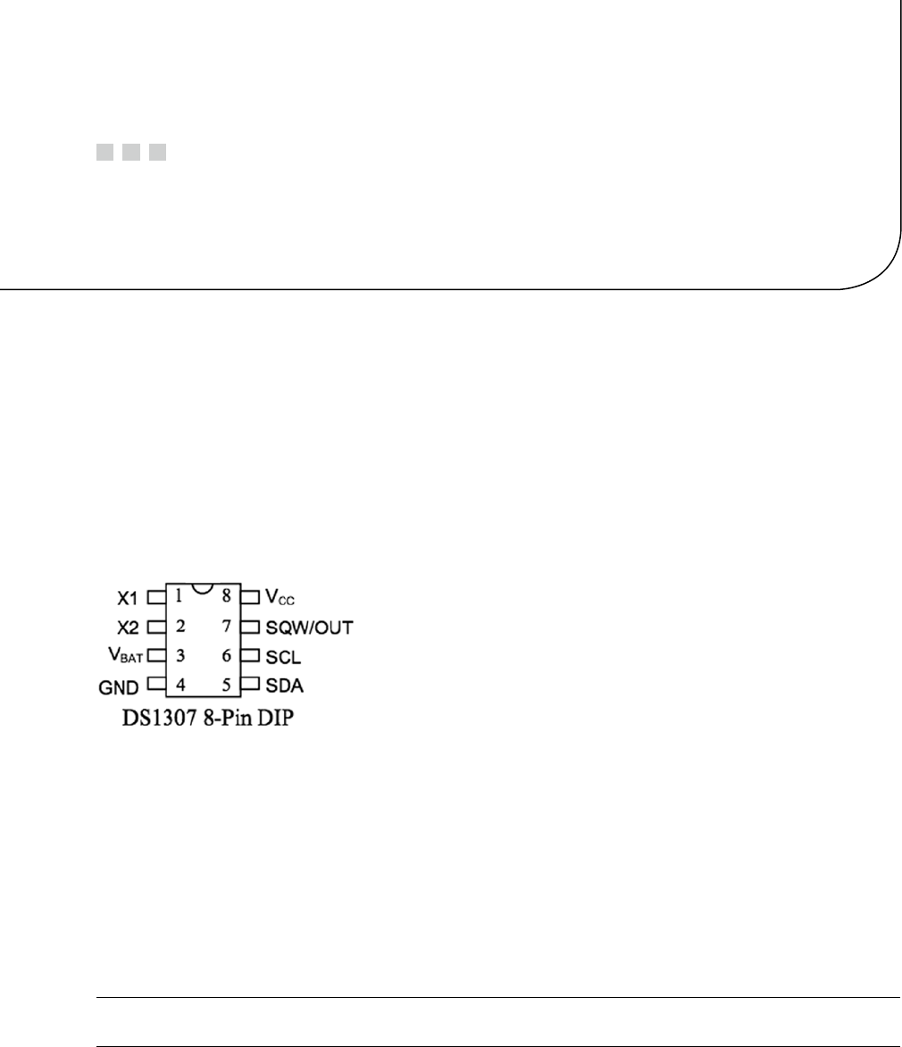
329
Chapter 25
Real-Time Clock
The Dallas Semiconductor DS1307 Real-Time Clock is the perfect project for the Raspberry Pi, Model A. Lacking a network
port, the Model A cannot determine the current date and time when it boots up. A 3 V battery attached to the DS1307
will keep its internal clock running for up to 10 years, even when the Pi is powered off. If you have a Model B, don’t feel left
out. There is no reason that you can’t try this project too; a Model B not connected to a network could use the DS1307.
DS1307 Overview
The pinout of the DS1307 chip is provided in Figure 25-1. The chip is available in PDIP-8 form or in SO format
(150 mils). Hobbyists who like to build their own will prefer the PDIP-8 form.
Figure 25-1. DS1307 pinout
A crystal is wired between pins 1 and 2 (X1 and X2). The battery powers the chip through pin 3 and flows to
ground (pin 4). This keeps the clock alive while the main power is absent. When there is power, it is supplied through
pin 8 (VCC). The I2C communication occurs via pins 5 and 6. Pin 7 provides an optional output clock signal or can
operate as an open collector output.
While you could build this circuit yourself, you can find fully assembled PCB modules using the DS1307 on eBay
for as little as $2.36 (with free shipping). These are available as Buy It Now offers, so you don’t have to waste your time
trying to win auctions. Just keep in mind that some are not shipped with a 3 V battery. (Check the product. The Tiny
RTC I used came with a 3.6 V battery.) It is claimed that there are mailing restrictions on batteries to certain countries.
So you may want to shop for suitable batteries while you wait for the mail.
Tip ■ Buying a fresh battery ahead of time is recommended, as batteries often arrive exhausted.
Figure 25-2 shows a PCB unit that I purchased through eBay. This unit came paired with the AT24C32 EEPROM
chip. The auction was labeled “Tiny RTC I2C Modules.” You don’t have to use this specific PCB, of course. The wiring
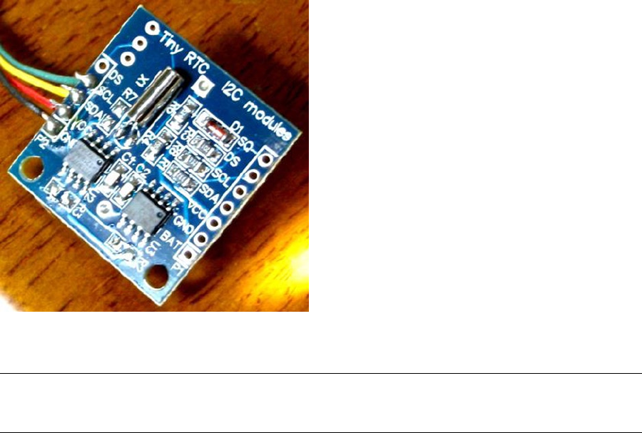
CHAPTER 25 ■ REAL-TIME CLOCK
330
Figure 25-2. An assembled DS1307 PCB purchased through eBay
for each chip is fairly basic and can be prototyped on a breadboard if you can’t find one. But if you do choose this PCB,
a modification is required before you attach it to the Raspberry Pi.
Caution ■ I2C pull-up resistors R2 and R3 must be removed before wiring the PCB to the Raspberry Pi. Also, if you plan
to attach the SQW/OUT output of this PCB to a GPIO input, be sure to track down and remove its pull-up resistor as well.
Pins X1 and X2
These pins are for connection to a 32.768 kHz crystal. The datasheet states that the “internal oscillator circuitry is
designed for operation with a crystal having a specified load capacitance (CL) of 12.5 pF.”
Pin SQW/OUT
This is an open-drain output from the DS1307 chip that you can choose to ignore if you like. It can be used as follows:
A GPIO-like output. If you plan on wiring this to a Pi GPIO pin, be sure to remove the pull-up •
resistor (on PCB) first. The +5 V from the pull-up will damage the Pi.
A square wave clock output, at one of the following programmable frequencies:•
1 Hz•
4.096 kHz•
8.192 kHz•
32.768 kHz•

CHAPTER 25 ■ REAL-TIME CLOCK
331
The datasheet lists a current rating for output when low:
Parameter Symbol Min Typ Max Units
Logic 0 Output (IOL = 5 mA)VOL 0.4 Volts
Without more-specific information, we arrive at the conclusion that a given logic pin is capable of sinking a
maximum of 5 mA (SDA). While doing so, the maximum voltage appearing at the pin is 0.4 V. This is well under the
0.8 V maximum, for the VIL voltage level of the Raspberry Pi.
The datasheet indicates that the SQW/OUT pin is an open-drain output. As such, you can use a pull-up to +3.3 V
or +5 V as your interface requires. It could be used to drive a small LED at 1 Hz, if the current is limited to less than
5 mA (although the datasheet doesn’t indicate the current capability of this open-drain transistor). Alternatively, it
can be used to drive other external logic with a pull-up resistor.
The datasheet indicates that the SQW/OUT pin can pulled as high as 5.5 V, even when VCC is lower in voltage
(such as +3.3 V.) This is safe, provided that these higher voltages never connect to the Pi’s GPIO pins.
Power
If you’ve looked at the datasheet for the DS1307 before, you might be wondering about the power supply voltage. The
datasheet lists it as a +5 V part, and by now you are well aware that the Pi’s GPIO pins operate at +3 V levels. The DC
operating conditions are summarized here:
Parameter Symbol Min Typ Max Units
Supply voltage VCC 4.5 5.0 5.5 Volts
Battery voltage VBAT 2.0 3.5 Volts
It is tempting to consider that the PCB might operate at +3.3 V, given that the battery in the unit is 3 V. However,
that will not work because the DS1307 chip considers a VCC lower than 1.25 × VBAT = 3.75 V to be a power-fail condition
(for a typical operation). When it senses a power fail, it relies on battery operation and will cease to communicate by
I2C, among other things. Power-fail conditions are summarized here:
Parameter Symbol Min Typ Max Units
Power-fail voltage VPF 1.26×VBAT 1.25×VBAT 1.284×VBAT Volts
The note in the datasheet indicates that the preceding figures were measured when VBAT = 3 V. So these figures
will likely deviate when the battery nears expiry. Given the power-fail conditions, we know that the device must be
powered from a +5 V power supply. But the only connections made to the Raspberry Pi are the SDA and SCL I2C lines.
So let’s take a little closer look at those and see if we can use them.
3-Volt Compatibility
The SCL line is always driven by the master, as far as the DS1307 is concerned. This means that SCL is always seen as
an input signal by the RTC clock chip. All we have to check here is whether the Raspberry Pi will meet the input-level
requirements. Likewise, the AT24C32 EEPROM’s SCL pin is also an input only.

CHAPTER 25 ■ REAL-TIME CLOCK
332
The SDA line is driven by both the master (Pi) and the DS1307 chip (slave). The SDA is driven from the Pi as a 3 V
signal, so again we need to make certain that the DS1307 will accept those levels. But what about the DS1307 driving
the SDA line? The Pi must not see +5 V signals.
The DS1307 datasheet clearly states that “the SDA pin is open drain, which requires an external pull-up resistor.”
The Raspberry Pi already supplies the pull-up resistor to +3.3 V. This means that the DS1307’s open drain will allow the
line to be pulled up to +3.3 V for the high logic level, when the output transistor is in the off state. When the transistor
is on, it simply pulls the SDA line down to ground potential. Thus with open-drain operation, we can interoperate
with the Raspberry Pi. A check of the AT24C32 EEPROM datasheets leads to the same conclusion.
Logic Levels
How do the I2C logic levels compare between the Raspberry Pi and the DS1307?
Signal Raspberry Pi DS1307
VIL £ 0.8 volts £ 0.8 volts
VIH ³ 1.3 volts ³ 2.2 volts
The VIL figure matches perfectly for both sides. As long as the Raspberry Pi provides a high level exceeding 2.2 V,
the DS1307 chip should read high levels just fine. Given that the Pi’s pull-up resistor is connected to +3.3 V, there is
very little reason to doubt problems meeting the DS1307 VIH requirement.
To summarize, we can safely power the DS1307 from +5 V, while communicating between it and the Raspberry Pi
at +3 V levels. The Pi already supplies pull-up resistors for the SCL and SDA lines, and these are attached to +3.3 V. If,
however, you choose to use other GPIO pins to bit-bang I2C (say), you’ll need to provide these pull-up resistors (they
must go to only +3.3 V).
Tiny RTC Modifications
In the preceding section, you saw that even though the DS1307 is a +5 V part, the SDA pin is driven by an open-drain
transistor. With the Raspberry Pi tying the SDA line to +3.3 V, the highest voltage seen will be exactly that. The open-
drain transistor can only pull it down to ground (this also applies to the AT24C32 EEPROM). Both chips have the SCL
pins as inputs (only), which are not pulled high by the chips themselves.
If you purchased a PCB like the one I used, however, be suspicious of pull-up resistors! I knew that the parts
would support +3.3 V I2C bus operation before the PCB arrived in the mail. However, I was suspicious of added
pull-up resistors. So when the PCB arrived, I quickly determined that the PCB did indeed include pull-up resistors
connected to the +5 V supply. The extra +5 V pull-up resistors must be tracked down and removed for use with the
Raspberry Pi.
Checking for Pull-up Resistors
There are two methods to test for pull-up resistors: a DMM resistance check and a voltage reading. I recommend that
you apply them both.
Since this modification is important to get correct, the following sections will walk you through the two different
procedures in detail.
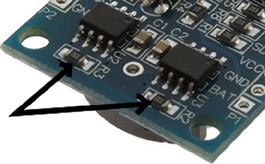
CHAPTER 25 ■ REAL-TIME CLOCK
333
Performing a DMM Resistance Check
Use these steps for the DMM resistance check:
1. Attach one probe of your DMM (reading kΩ) to the +5 V line of the PCB.
2. Attach the other probe to the SDA line and take the resistance reading.
3. Reverse the leads if you suspect diode action.
On my PCB, I read 3.3 kΩ. Reversing the DMM leads should read the same (proving only resistance). Performing
the same test with the SCL input, I also read 3.3 kΩ.
Performing a Voltage Reading
Do not skip this particular test. The result of this test will tell you whether your Raspberry Pi will be at risk.
1. Hook up your PCB to the +5 V supply it requires, but do not attach the SDA/SCL lines to
the Pi yet. Just leave them loose for measuring with your DMM.
2. With the DMM negative probe grounded, measure the voltage seen at the PCB’s SDA
and SCL inputs. If there is no pull-up resistor involved, you should see a low reading of
approximately 0.07 V. The reading will be very near ground potential.
On my unmodified PCB, these readings were +5 V because of the 3.3 kΩ pull-up resistors. If this also applies to
your PCB unit, a modification is required.
Performing a Tiny RTC Modification
If you have the exact same PCB that I used, you can simply remove resistors R2 and R3 (but I would double-check with
the preceding tests). These resistors are shown in Figure 25-3. Carefully apply a soldering iron to sweep them off the
PCB. Make sure no solder is left, shorting the remaining contacts. I highly recommend that you repeat the tests to
make sure you have corrected the pull-up problem and test for short circuits.
Figure 25-3. R
2 and R3 of the Tiny RTC I2C PCB

CHAPTER 25 ■ REAL-TIME CLOCK
334
Working with Other PCB Products
If you have a different PCB product, you may have optional resistors that you can leave uninstalled. Even though they
may be optional, someone might have done you the favor of soldering them in. So make sure you check for that (use
the earlier tests).
The Adafruit RTC module (http://www.adafruit.com/products/264) is reportedly sometimes shipped with the
2.2 kΩ resistors installed. For the Raspberry Pi, they must be removed.
Locating the Pull-up Resistors
Even if you don’t have a schematic for your PCB product, you will need to locate the pull-up resistors. Since there
aren’t many components on the PCB to begin with, they tend to be easy to locate:
1. Observe static electricity precautions.
2. Attach one DMM (kΩ) probe to the +5 V input to the PCB.
3. Look for potential resistors on the component side.
4. Locate all resistors that have one lead wired directly to the +5 V supply (resistance will read
0 Ω). These will be the prime suspects.
5. Now attach your DMM (range kΩ) to the SDA input. With the other DMM probe, check the
opposite ends of the resistors, looking for readings of 0 Ω. You should find one resistor end
(the other end of the resistor will have been previously identified as connected to the +5 V
supply).
6. Likewise, test the SCL line in the same manner as step 5.
7. Double-check: take a resistance reading between the SDA input and the +5 V supply.
You should measure a resistance of 2 to 10 kΩ, depending on the PCB manufacturer. You
should get the same reading directly across the resistor identified.
8. Repeat step 7 for the SCL line.
If you’ve done this correctly, you will have identified the two resistors that need to be removed. If you plan to
interface the SQW/OUT pin to a Pi GPIO, you’ll want to remove the pull-up used on that as well.
DS1307 Bus Speed
The DS1307 datasheet lists the maximum SCL clock speed at 100 kHz:
Parameter Symbol Min Typ Max Units
SCL clock frequency fSCL 0 100 kHz
The Raspberry Pi uses 100 kHz for its I2C clock frequency (see Chapter 14 for more information). The
specification also states that there is no minimum frequency. If you wanted to reserve the provided I2C bus for use
with other peripherals (perhaps at a higher frequency), you could bit-bang interactions with the DS1307 by using
another pair of GPIO pins. (Pull-up resistors to +3.3 V will be required; the internal pull-up resistors are not adequate.)
That is an exercise left for you.
Now that we have met power, signaling, and clock-rate requirements, “Let’s light this candle!”

CHAPTER 25 ■ REAL-TIME CLOCK
335
RTC and RAM Address Map
The DS1307 has 56 bytes of RAM in addition to the real-time clock registers. I/O with this chip includes an implied
address register, which ranges in value from 0x00 to 0x3F. The address register will wrap around to zero after reaching
the end (don’t confuse the register address with the I2C peripheral address).
Note ■ The DS1307 RTC uses I2C address 0x68.
The address map of the device is illustrated in Table 25-1. The date and time components are BCD encoded.
In the table, 10s represents the tens digit, while 1s represents the ones digit.
Table 25-1. DS1307 Register Map
Format
Address Register 7 6 5 4 3 2 1 0
0x00 Seconds CH 10s 1s
0x01 Minutes 0 10s 1s
0x02 Hours 0 24hr 10s 1s
12hr PM 10s 1s
0x03 Weekday 0 0 0 0 0 1s
0x04 Day 0 0 10s 1s
0x05 Month 0 0 0 10s 1s
0x06 Year 10s 1s
0x07 Control OUT 0 0 SQWE 0 0 RS1 RS2
0x08 RAM 00 byte
... ...
0x3F RAM 55 byte
The components of the register map are further described in Table 25-2. Bit CH allows the host to disable the
oscillator and thus stop the clock. This also disables the SQW/OUT waveform output (when SQWE=1). Bit 6 of the Hours
register determines whether 12- or 24-hour format is used. When in 12-hour format, bit 5 becomes an AM/PM indicator.
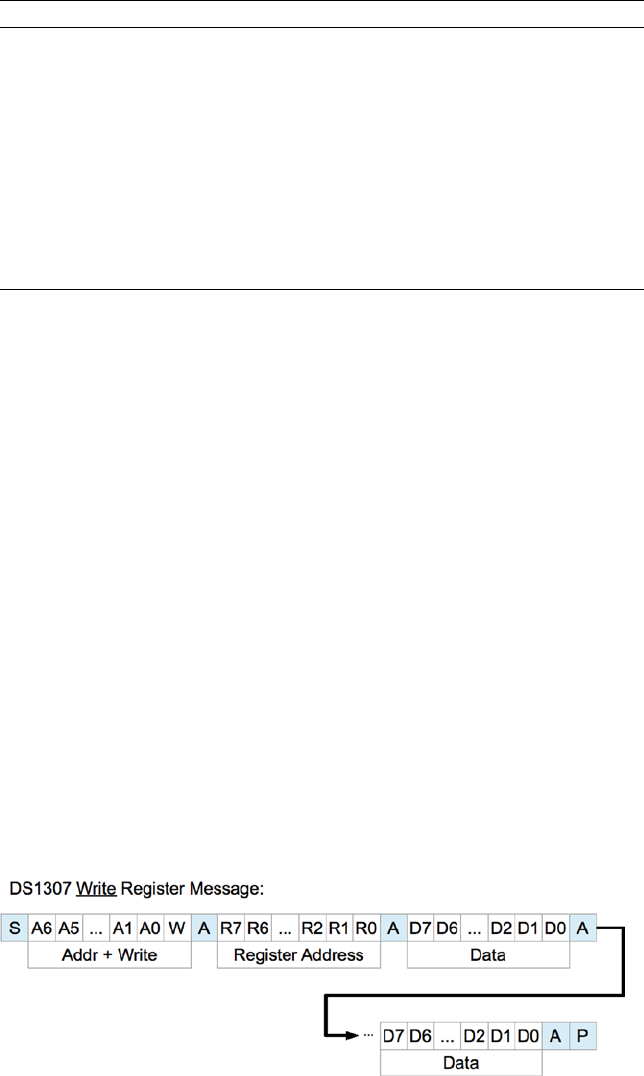
CHAPTER 25 ■ REAL-TIME CLOCK
336
Table 25-2. RTC Register Map Components
Bit Meaning
CH 0 Clock running
1 Clock (osc) halt
24hr 0 24-hour format
12hr 1 12-hour format RS1 RS0 Meaning
OUT 0 SQW/OUT = Low 0 0 1 Hz
1 SQW/OUT = High 0 1 4.096 kHz
SQWE 0 SQW/OUT is OUT 1 0 8.192 kHz
1 SQW/OUT is SQW 1 1 32.768 kHz
The Control register at address 0x07 determines how the SQW/OUT pin behaves. When SQWE=1, a square wave
signal is produced at the SQW/OUT pin. The frequency is selected by bits RS1 and RS0. In this mode, the OUT setting
is ignored.
When SQWE=0, the SQW/OUT pin is set according to the bit placed in OUT (bit 7 of the control register). In this mode,
the pin behaves as an open-drain GPIO output pin.
Reading Date and Time
When the DS1307 device is being read, a snapshot of the current date and time is made when the I2C start bit is seen.
This copy operation allows the clock to continue to run while returning a stable date/time value back to the master. If
this were not done, time components could change between reading bytes. The application should therefore always
read the full date/time set of registers as one I/O operation. The running clock does not affect reading the control
register or the RAM locations.
I2C Communication
The DS1307 registers and RAM can be written randomly, by specifying an initial starting register address, followed
by 1 or more bytes to be written. The register address is automatically incremented with each byte written and wraps
around to 0. The DS1307 slave device will ACK each byte as it is received, continuing until the master writes a stop
bit (P). The first byte sent is always the peripheral’s I2C address, which should not be confused with the selected
peripheral’s register address (that immediately follows). The DS1307 I2C address is always 0x68. The general form of
the write message is shown here:
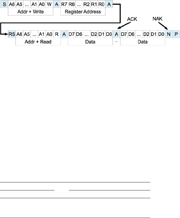
CHAPTER 25 ■ REAL-TIME CLOCK
337
The DS1307 supports multibyte reads. You can read multiple bytes from the DS1307 simply by starting with an
I2C start bit (S), and peripheral address sent as a read request. The slave will then serve up bytes one after another for
the master. Receiving terminates when the master sends a NAK.
If you want to be certain that the register address is established with a known value, you should always issue
a write request first. In the preceding diagram, the write request immediately follows the start bit (S). Only the
peripheral’s register address byte is written out prior to the repeating start bit (RS), which follows.
After the RS bit, the peripheral address is transmitted once more to re-engage the DS1307, but this time as a read
request. From that point on, the master reads bytes sequentially from the DS13017 until a NAK is sent. The final stop
bit (P) sent by the master ends the exchange. This peripheral provides us with a good example of a multimessage I/O.
This is demonstrated in lines 27 to 45 of the program ds1307get.c, in the upcoming pages. The entire I/O is
driven by the structures iomsgs[0] and iomsgs[1]. Structure iomsgs[0] directs the driver to write to peripheral
address 0x68 and writes 1 0x00 data byte out to it. This establishes the RTC’s internal register with a value of 0x00. The
read request is described in iomsgs[1], which is a read from the same peripheral 0x68, for 8 bytes. (Only 7 bytes are
strictly required for the date and time, but we read the additional control byte anyway.)
The data structure is laid out in C terms in the file ds1307.h. An optional exercise for you is to add a command-
line option to ds1307set to stop the clock and turn it on again using the ch bit (line 8 of ds1307.h).
Source module i2c_common.c has the usual I2C open/initialization and close routines in it.
Wiring
Like any I2C project for the Pi, you’ll wire the SDA and SCL lines as follows:
Pre Rev 2.0 Rev 2.0+
GPIO Line GPIO Line P1
0 SDA0 2 SDA1 P1-03
1 SCL0 3 SCL1 P1-05
The DS1307 PCB (or chip) is powered from the +5 V supply. Prior to attaching it to the Raspberry Pi, it is a good
idea to power the DS1307 and measure the voltage appearing on its SDA and SCL lines. Both should measure near
ground potential. If you see +5 V instead, stop and find out why.
Running the Examples
Since these programs use the I2C Linux drivers, make sure these kernel modules are either already loaded, or load
them manually now:
$ sudo modprobe i2c-bcm2708
$ sudo modprobe i2c-dev
CHAPTER 25 ■ REAL-TIME CLOCK
338
Program ds1307set.c (executable ds1307set) is used to reset the RTC to a new date/time value of your choice.
For example:
$ ./ds1307set 20130328215900
2013-03-28 21:59:00 (Thursday)
$
This sets the date according to the command-line value, which is in YYYYMMDDHHMMSS format.
Once the RTC date has been established, you can use the executable ds1307get to read back the date and time:
$ ./ds1307get
2013-03-28 22:00:37 (Thursday)
$
In this case, a little time had passed between setting the date and reading it. But we can see that the clock is
ticking away.
If you don’t like the date/time format used, you can either change the source code or set the environment
variable DS1307_FORMAT. For example:
$ export DS1307_FORMAT="%a %Y-%m-%d %H:%M:%S"
$ ./ds1307get
Thu 2013-03-28 22:03:38
$
For a description of the date/time format options available, use this:
$ man date
The setting of DS1307_FORMAT also affects the display format used by ds1307set.
The Ultimate Test
The ultimate test is to shut down the Raspberry Pi and turn off its power. Wait a minute or so to make sure that all of
the power has been drained out of every available capacitor. Then bring up the Pi again and check the date/time
with the program ds1307get. Did it lose any time?
The Startup Script
To put the RTC to good practical use, you’ll want to apply ds1307get at a suitable point in the Linux startup sequence.
You’ll need to wait until the appropriate I2C driver support is available (or can be arranged). You’ll need to develop a
short shell script, using the DS1307_FORMAT environment variable in order to produce a format suitable for the console
date command. To set the system date (as root), you would use this command:
# date [-u|--utc|--universal] [MMDDhhmm[[CC]YY][.ss]]
The startup script for doing all of this has not been provided here. I don’t want to spoil your fun when you can
develop this yourself. You learn best by doing. Review Chapter 17 if you need some help.
As a further hint, you’ll want to develop a script for the /etc/rc2.d directory, with a name starting with S and two
digits. The digits determine where the script runs in the startup sequence (you’ll want to make sure your script runs
after the system has come up far enough that I2C drivers are loaded).

CHAPTER 25 ■ REAL-TIME CLOCK
339
Once your startup script is developed, your Raspberry Pi can happily reboot after days, even years, of being
powered off, and still be able to come up with the correct date and time.
Note ■ If you’re running the older Model B, where the I2C bus 0 is used instead of 1, change line 21 in ds1307set.c
and line 21 in ds1307get.c. See Chapter 14 for more information.
1 /∗∗∗∗∗∗∗∗∗∗∗∗∗∗∗∗∗∗∗∗∗∗∗∗∗∗∗∗∗∗∗∗∗∗∗∗∗∗∗∗∗∗∗∗∗∗∗∗∗∗∗∗∗∗∗∗∗∗∗∗∗∗∗∗∗∗∗∗∗
2 ∗ ds1307.h: Common DS1307 types and macro definitions
3 ∗∗∗∗∗∗∗∗∗∗∗∗∗∗∗∗∗∗∗∗∗∗∗∗∗∗∗∗∗∗∗∗∗∗∗∗∗∗∗∗∗∗∗∗∗∗∗∗∗∗∗∗∗∗∗∗∗∗∗∗∗∗∗∗∗∗∗∗∗/
4
5 typedef struct {
6 /∗ Register Address 0x00 : Seconds ∗/
7 unsigned char secs_1s : 4; /∗Ones digit : seconds ∗/
8 unsigned char secs_10s : 3; /∗Tens digit : seconds ∗/
9 unsigned char ch : 1; /∗CH bit ∗/
10 /∗ Register Address 0x01 : Minutes ∗/
11 unsigned char mins_1s : 4; /∗Ones digit : minutes ∗/
12 unsigned char mins_10s : 3; /∗Tens digit : minutes ∗/
13 unsigned char mbz_1 : 1; /∗Zero bit ∗/
14 /∗ Register Address 0x02 : Hours ∗/
15 unsigned char hour_1s : 4; /∗Ones digit : hours ∗/
16 unsigned char hour_10s : 2; /∗Tens digit : hours (24 hr mode) ∗/
17 unsigned char mode_1224 : 1; /∗Mode bit : 12/24 hour format ∗/
18 /∗ Register Address 0x03 : Weekday ∗/
19 unsigned char wkday : 3; /∗Day of week (1−7) ∗/
20 unsigned char mbz_2 : 5; /∗Zero bits ∗/
21 /∗ Register Address 0x04 : Day of Month ∗/
22 unsigned char day_1s : 4; /∗Ones digit : day of month (1−31) ∗/
23 unsigned char day_10s : 2; /∗Tens digit : day of month ∗/
24 unsigned char mbz_3 : 2; /∗Zero bits ∗/
25 /∗ Register Address 0x05 : Month ∗/
26 unsigned char month_1s : 4; /∗Ones digit : month (1−12) ∗/
27 unsigned char month_10s : 1; /∗Tens digit : month ∗/
28 unsigned char mbz_4 : 3; /∗Zero ∗/
29 /∗ Register Address 0x06 : Year ∗/
30 unsigned char year_1s : 4; /∗Ones digit : year (00−99) ∗/
31 unsigned char year_10s : 4; /∗Tens digit : year ∗/
32 /∗ Register Address 0x07 : Control ∗/
33 unsigned char rs0 : 1; /∗RS0 ∗/
34 unsigned char rs1 : 1; /∗RS1 ∗/
35 unsigned char mbz_5 : 2; /∗Zeros ∗/
36 unsigned char sqwe : 1; /∗SQWE ∗/
37 unsigned char mbz_6 : 2;
38 unsigned char outbit : 1; /∗OUT ∗/
39 } ds1307_rtc_regs;
40
41 /∗ End ds1307 . h ∗/
CHAPTER 25 ■ REAL-TIME CLOCK
340
1 /∗∗∗∗∗∗∗∗∗∗∗∗∗∗∗∗∗∗∗∗∗∗∗∗∗∗∗∗∗∗∗∗∗∗∗∗∗∗∗∗∗∗∗∗∗∗∗∗∗∗∗∗∗∗∗∗∗∗∗∗∗∗∗∗∗∗∗∗∗
2 ∗ i2c_common.c : Common I2C Access Functions
3 ∗∗∗∗∗∗∗∗∗∗∗∗∗∗∗∗∗∗∗∗∗∗∗∗∗∗∗∗∗∗∗∗∗∗∗∗∗∗∗∗∗∗∗∗∗∗∗∗∗∗∗∗∗∗∗∗∗∗∗∗∗∗∗∗∗∗∗∗∗/
4
5 static int i2c_fd = −1; /∗Device node : /dev/ i2c−1 ∗/
6 static unsigned long i2c_funcs = 0; /∗Support flags ∗/
7
8 /∗
9 ∗ Open I2C bus and check cap abilities:
10 ∗/
11 static void
12 i2c_init(const char ∗node) {
13 int rc;
14
15 i2c_fd = open(node,O_RDWR); /∗Open driver /dev/i2s−1 ∗/
16 if ( i2c_fd < 0 ) {
17 perror("Opening /dev/ i 2 s −1");
18 puts("Check that the i2c−dev & i2c−bcm2708 kernelmodules "
19 " are loaded . " ) ;
20 abort();
21 }
22
23 /∗
24 ∗ Make sure the driver suppor tsplain I2C I /O:
25 ∗/
26 rc = ioctl(i2c_fd,I2C_FUNCS,&i2c_funcs);
27 assert(rc >=0);
28 assert(i2c_funcs & I2C_FUNC_I2C);
29 }
30
31 /∗
32 ∗ Close the I2C driver :
33 ∗/
34 static void
35 i2c_close(void) {
36 close(i2c_fd);
37 i2c_fd = −1;
38 }
39
40 /∗End i2c_common.c ∗/
1 /∗∗∗∗∗∗∗∗∗∗∗∗∗∗∗∗∗∗∗∗∗∗∗∗∗∗∗∗∗∗∗∗∗∗∗∗∗∗∗∗∗∗∗∗∗∗∗∗∗∗∗∗∗∗∗∗∗∗∗∗∗∗∗∗∗∗∗∗∗
2 ∗ ds1307set.c : Set real−time DS1307 clock on I2C bus
3 ∗∗∗∗∗∗∗∗∗∗∗∗∗∗∗∗∗∗∗∗∗∗∗∗∗∗∗∗∗∗∗∗∗∗∗∗∗∗∗∗∗∗∗∗∗∗∗∗∗∗∗∗∗∗∗∗∗∗∗∗∗∗∗∗∗∗∗∗∗/
4
5 #include <stdio.h>
6 #include <stdlib.h>
7 #include <ctype.h>
8 #include <time.h>
9 #include <fcntl.h>
10 #include <unistd . h>
11 #include <string . h>
CHAPTER 25 ■ REAL-TIME CLOCK
341
12 #include <errno . h>
13 #include <assert . h>
14 #include <sys / i octl . h>
15 #include <l inux / i2c−dev . h>
16
17 #include "i2c_common.c" /∗I2C routines ∗/
18 #include "ds1307.h" /∗DS1307 types ∗/
19
20 /∗Change to i2c−0 if using early Raspberry Pi ∗/
21 static const char ∗node = "/dev/i2c−1";
22
23 /∗
24 ∗ Write [ S ] 0xB0 <regaddr> <rtcbuf[0]> . . . <rtcbuf[n−1]> [P]
25 ∗/
26 static int
27 i2c_wr_rtc(ds1307_rtc_regs ∗rtc) {
28 struct i2c_rdwr_ioctl_data msgset;
29 struct i2c_msg iomsgs[1];
30 char buf[sizeof ∗rtc+1] ; /∗Work buffer ∗/
31
32 buf[0] = 0x00 ; /∗Register 0x00 ∗/
33 memcpy(buf+1,rtc,sizeof ∗rtc); /∗Copy RTC info ∗/
34
35 iomsgs[0].addr = 0x68; /∗DS1307 Address ∗/
36 iomsgs[0].flags = 0; /∗Write ∗/
37 iomsgs[0].buf = buf; /∗Register + data ∗/
38 iomsgs[0].len = sizeof ∗rtc + 1; /∗Total msg len ∗/
39
40 msgset.msgs = &iomsgs[0];
41 msgset.nmsgs = 1;
42
43 return ioctl(i2c_fd,I2C_RDWR,&msgset);
44 }
45
46 /∗∗∗∗∗∗∗∗∗∗∗∗∗∗∗∗∗∗∗∗∗∗∗∗∗∗∗∗∗∗∗∗∗∗∗∗∗∗∗∗∗∗∗∗∗∗∗∗∗∗∗∗∗∗∗∗∗∗∗∗∗∗∗∗∗∗∗∗∗
47 ∗ Set the DS1307 real−time clock on the I2C bus :
48 ∗
49 ∗ ./ds1307set YYYYMMDDHHMM[ss]
50 ∗∗∗∗∗∗∗∗∗∗∗∗∗∗∗∗∗∗∗∗∗∗∗∗∗∗∗∗∗∗∗∗∗∗∗∗∗∗∗∗∗∗∗∗∗∗∗∗∗∗∗∗∗∗∗∗∗∗∗∗∗∗∗∗∗∗∗∗∗/
51 int
52 main(int argc,char ∗∗argv) {
53 ds1307_rtc_regs rtc ; /∗8 DS1307 Register Values ∗/
54 char buf[32]; /∗Extraction buffe r ∗/
55 struct tm t0, t1; /∗Unix date / time values ∗/
56 int v, cx, slen;
57 char ∗date_format = getenv("DS1307_FORMAT");
58 char dtbuf[256]; /∗Formatted date/time ∗/
59 int rc; /∗Return code ∗/
60
CHAPTER 25 ■ REAL-TIME CLOCK
342
61 /∗
62 ∗ If no environment variable named DS1307_FORMAT, then
63 ∗ set a default date/time format.
64 ∗/
65 if ( !date_format )
66 date_format = "%Y−%m−%d %H:%M:%S (%A) " ;
67
68 /∗
69 ∗ Check command line usage :
70 ∗/
71 if ( argc != 2 | | (slen = strlen(argv[1])) < 12 || slen > 14 ) {
72 usage: fprintf(stderr,
73 "Usage : %s YYYYMMDDhhmm[ss]\n",
74 argv[0]);
75 exit(1);
76 }
77
78 /∗
79 ∗ Make sure every character is a digit in argument 1 .
80 ∗/
81 for ( cx=0; cx<slen; ++cx )
82 if ( !isdigit(argv[1][cx]) )
83 goto usage; /∗Not a numeric digit ∗/
84
85 /∗
86 ∗ Initialize I2C and clear rtc and t1 structures :
87 ∗/
88 i2c_init(node) ; /∗Initialize for I2C ∗/
89 memset(&rtc,0,sizeof rtc);
90 memset(&t1,0,sizeof t1);
91
92 /∗
93 ∗ Extract YYYYMMDDhhmm[ss] from argument 1:
94 ∗/
95 strncpy(buf,argv[1],4)[4] = 0; /∗buf[] = "YYYY" ∗/
96 if ( sscanf(buf,"%d",&v) != 1 || v < 2000 || v > 2099 )
97 goto usage;
98 t1.tm_year = v − 1900;
99
100 strncpy(buf,argv[1]+4,2)[2] = 0; /∗buf[] = "MM" ∗/
101 if ( sscanf(buf,"%d",&v) != 1 || v <= 0 || v > 12 )
102 goto usage;
103 t1.tm_mon = v−1; /∗0 − 11 ∗/
104
105 strncpy(buf,argv[1]+6,2)[2] = 0; /∗buf[] = "DD" ∗/
106 if ( sscanf(buf,"%d",&v) != 1 || v <= 0 || v > 31 )
107 goto usage ;
108 t1.tm_mday = v; /∗1 − 31 ∗/
109
CHAPTER 25 ■ REAL-TIME CLOCK
343
110 strncpy(buf,argv[1]+8,2)[2] = 0; /∗buf[] = "hh" ∗/
111 if ( sscanf(buf,"%d",&v) != 1 || v < 0 || v > 23 )
112 goto usage;
113 t1.tm_hour = v;
114
115 strncpy(buf,argv[1]+10,2)[2] = 0; /∗buf[] = "mm" ∗/
116 if ( sscanf(buf,"%d",&v) != 1 || v < 0 || v > 59 )
117 goto usage;
118 t1.tm_min = v;
119
120 if ( slen > 12 ) {
121 /∗ Optional ss was provided : ∗/
122 strncpy(buf,argv[1]+12,2)[2] = 0; /∗buf[] = "ss" ∗/
123 if ( sscanf(buf,"%d",&v) != 1 || v < 0 || v > 59 )
124 goto usage;
125 t1.tm_sec = v;
126 }
127
128 /∗
129 ∗ Check the validity of the date :
130 ∗/
131 t1.tm_isdst = −1; /∗Determine if daylight savings ∗/
132 t0 = t1; /∗Save initial values ∗/
133 if ( mktime(&t1) == 1L ) { /∗t1 is modified ∗/
134 bad_date : printf("Argument ’%s ’ is not avalid calendar date.\n",argv[1]) ;
135 exit(2);
136 }
137
138 /∗
139 ∗ If struct t1 was adjusted , then the original date/time
140 ∗ values were invalid :
141 ∗/
142 if ( t0.tm_year != t1.tm_year || t0.tm_mon != t1.tm_mon
143 || t0.tm_mday != t1.tm_mday || t0.tm_hour != t1.tm_hour
144 || t0.tm_min != t1.tm_min || t0.tm_sec != t1.tm_sec )
145 goto bad_date;
146
147 /∗
148 ∗ Populate DS1307 registers :
149 ∗/
150 rtc.secs_10s = t1.tm_sec / 10;
151 rtc.secs_1s = t1.tm_sec % 10;
152 rtc.mins_10s = t1.tm_min / 10;
153 rtc.mins_1s = t1.tm_min % 10;
154 rtc.hour_10s = t1.tm_hour / 10;
155 rtc.hour_1s = t1.tm_hour % 10;
156 rtc.month_10s = (t1.tm_mon + 1) / 10;
157 rtc.month_1s = (t1.tm_mon + 1) % 10;
158 rtc.day_10s = t1.tm_mday / 10;
159 rtc.day_1s = t1.tm_mday % 10;
CHAPTER 25 ■ REAL-TIME CLOCK
344
160 rtc.year_10s = (t1.tm_year + 1900 − 2000) / 10;
161 rtc.year_1s = (t1.tm_year + 1900 − 2000) % 10;
162
163 rtc.wkday = t1.tm_wday + 1; /∗Weekday 1−7 ∗/
164 rtc.mode_1224 = 0; /∗Use 24 hour format ∗/
165
166 #if 0 /∗Change to a 1 for debugging ∗/
167 printf("%d%d−%d%d−%d%d %d%d:%d%d:%d%d (wkday %d )\n",
168 rtc.year_10s,rtc.year_1s,
169 rtc.month_10s,rtc.month_1s,
170 rtc.day_10s,rtc.day_1s,
171 rtc.hour_10s,rtc.hour_1s,
172 rtc.mins_10s,rtc.mins_1s,
173 rtc.secs_10s,rtc.secs_1s,
174 rtc.wkday);
175 #end if
176 rc = i2c_wr_rtc(&rtc );
177
178 /∗
179 ∗ Display RTC values submitted :
180 ∗/
181 strftime(dtbuf,sizeof dtbuf,date_format,&t1);
182 puts(dtbuf);
183
184 if ( rc < 0 )
185 perror("Writing to DS1307 RTC");
186 else if ( rc != 1 )
187 printf(" Incomplete write : %d msgs of 2written \n",rc);
188
189 i2c_close();
190 return rc ==1? 0 : 4;
191 }
192
193 /∗ End ds1307set.c ∗/
1 /∗∗∗∗∗∗∗∗∗∗∗∗∗∗∗∗∗∗∗∗∗∗∗∗∗∗∗∗∗∗∗∗∗∗∗∗∗∗∗∗∗∗∗∗∗∗∗∗∗∗∗∗∗∗∗∗∗∗∗∗∗∗∗∗∗∗∗∗∗
2 ∗ ds1307get.c : Read real−time DS1307 clock on I2C bus
3 ∗∗∗∗∗∗∗∗∗∗∗∗∗∗∗∗∗∗∗∗∗∗∗∗∗∗∗∗∗∗∗∗∗∗∗∗∗∗∗∗∗∗∗∗∗∗∗∗∗∗∗∗∗∗∗∗∗∗∗∗∗∗∗∗∗∗∗∗∗/
4
5 #include <stdio.h>
6 #include <stdlib.h>
7 #include <ctype.h>
8 #include <time h>
9 #include <fcntl.h>
10 #include <unistd.h>
11 #include <string.h>
12 #include <errno.h>
13 #include <assert.h>
14 #include <sys/ioctl.h>
15 #include <linux/i2c−dev.h>
16
CHAPTER 25 ■ REAL-TIME CLOCK
345
17 #include "i2c_common.c" /∗I2C routines ∗/
18 #include "ds1307.h" /∗DS1307 types ∗/
19
20 /∗ Change to i2c−0 if using early Raspberry Pi ∗/
21 static const char ∗node = "/dev/i2c−1";
22
23 /∗
24 ∗ Read : [ S ] 0xB1 <regaddr> <rtcbuf[0]> . . . <rtcbuf[n−1]> [P]
25 ∗/
26 static int
27 i2c_rd_rtc(ds1307_rtc_regs ∗rtc) {
28 struct i2c_rdwr_ioctl_data msgset;
29 struct i2c_msg iomsgs[2];
30 char zero = 0x00; /∗Register 0x00 ∗/
31
32 iomsgs[0].addr = 0x68; /∗DS1307 ∗/
33 iomsgs[0].flags = 0; /∗Write ∗/
34 iomsgs[0].buf = &zero; /∗Register 0x00 ∗/
35 iomsgs[0].len = 1;
36
37 iomsgs[1].addr = 0x68; /∗DS1307 ∗/
38 iomsgs[1].flags = I2C_M_RD; /∗Read ∗/
39 iomsgs[1].buf = (char ∗)rtc;
40 iomsgs[1].len = size of ∗rtc;
41
42 msgset.msgs=iomsgs;
43 msgset.nmsgs=2;
44
45 return ioctl(i2c_fd,I2C_RDWR,&msgset);
46 }
47
48 /∗
49 ∗ Main program :
50 ∗/
51 int
52 main(int argc,char ∗∗argv) {
53 ds1307_rtc_regs rtc; /∗ 8 DS1307 Register Values ∗/
54 struct tm t0, t1; /∗Unix date / time values ∗/
55 char ∗date_format = getenv("DS1307_FORMAT");
56 char dtbuf[256]; /∗Formatted date/time ∗/
57 int rc; /∗Return code ∗/
58
59 /∗
60 ∗ If no environment variable named DS1307_FORMAT, then
61 ∗ set a default date/time format.
62 ∗/
63 if ( !date_format )
64 date_format = "%Y−%m−%d%H:%M:%S(%A)";
65
66 /∗
67 ∗ Initialize I2C and clear rtc and t1 structures:
68 ∗/
CHAPTER 25 ■ REAL-TIME CLOCK
346
69 i2c_init(node); /∗Initialize for I2C ∗/
70 memset(&rtc,0,sizeof rtc);
71 memset(&t1,0,sizeof t1);
72
73 rc = i2c_rd_rtc(&rtc);
74 if ( rc < 0 ) {
75 perror("Reading DS1307 RTC clock.");
76 exit(1);
77 } else if ( rc != 2 ) {
78 fprintf(stderr,"Read error: got %d of 2 msgs.\n",rc);
79 exit(1);
80 } else
81 rc = 0;
82
83 /∗
84 ∗ Check the date returned by the RTC:
85 ∗/
86 memset(&t1,0,sizeof t1);
87 t1.tm_year = (rtc.year_10s ∗ 10 + rtc.year_1s) + 2000 − 1900;
88 t1.tm_mon = rtc.month_10s ∗ 10 + rtc.month_1s − 1;
89 t1.tm_mday = rtc.day_10s ∗ 10 + rtc.day_1s;
90 t1.tm_hour = rtc.hour_10s ∗ 10 + rtc.hour_1s;
91 t1.tm_min = rtc.mins_10s ∗ 10 + rtc.mins_1s;
92 t1.tm_sec = rtc.secs_10s ∗ 10 + rtc.secs_1s;
93 t1.tm_isdst = −1; /∗Determine if daylight savings ∗/
94
95 t0 = t1;
96 if ( mktime(&t1) == 1L /∗t1 i s modi f ied ∗/
97 || t1.tm_year != t0.tm_year || t1.tm_mon != t0.tm_mon
98 || t1.tm_mday != t0.tm_mday || t1.tm_hour != t0.tm_hour
99 || t1.tm_min != t0.tm_min || t1.tm_sec != t0.tm_sec ) {
100 strftime(dtbuf,sizeof dtbuf,date_format,&t0);
101 fprintf(stderr,"Read RTC date is not valid: %s\n",dtbuf);
102 exit(2);
103 }
104
105 if ( t1.tm_wday != rtc.wkday−1 ) {
106 fprintf(stderr,
107 "Warning:RTC weekday is incorrect %d but should be %d\n",
108 rtc.wkday,t1.tm_wday);
109 }
110
111 #if 0 /∗Change to a 1 for debugging ∗/
112 printf("%d%d−%d%d−%d%d%d%d:%d%d:%d%d(wkday %d)\n",
113 rtc.year_10s,rtc.year_1s ,
114 rtc.month_10s,rtc.month_1s ,
115 rtc.day_10s, rtc.day_1s ,
116 rtc.hour_10s,rtc.hour_1s ,
117 rtc.mins_10s,rtc.mins_1s ,
CHAPTER 25 ■ REAL-TIME CLOCK
347
118 rtc.secs_10s,rtc.secs_1s ,
119 rtc.wkday);
120 #end if
121 strftime (dtbuf,size of dtbuf,date_format,&t1);
122 puts(dtbuf);
123
124 i2c_close();
125 return rc == 8 ? 0 : 4;
126 }
127
128 /∗ End ds1397get.c ∗/
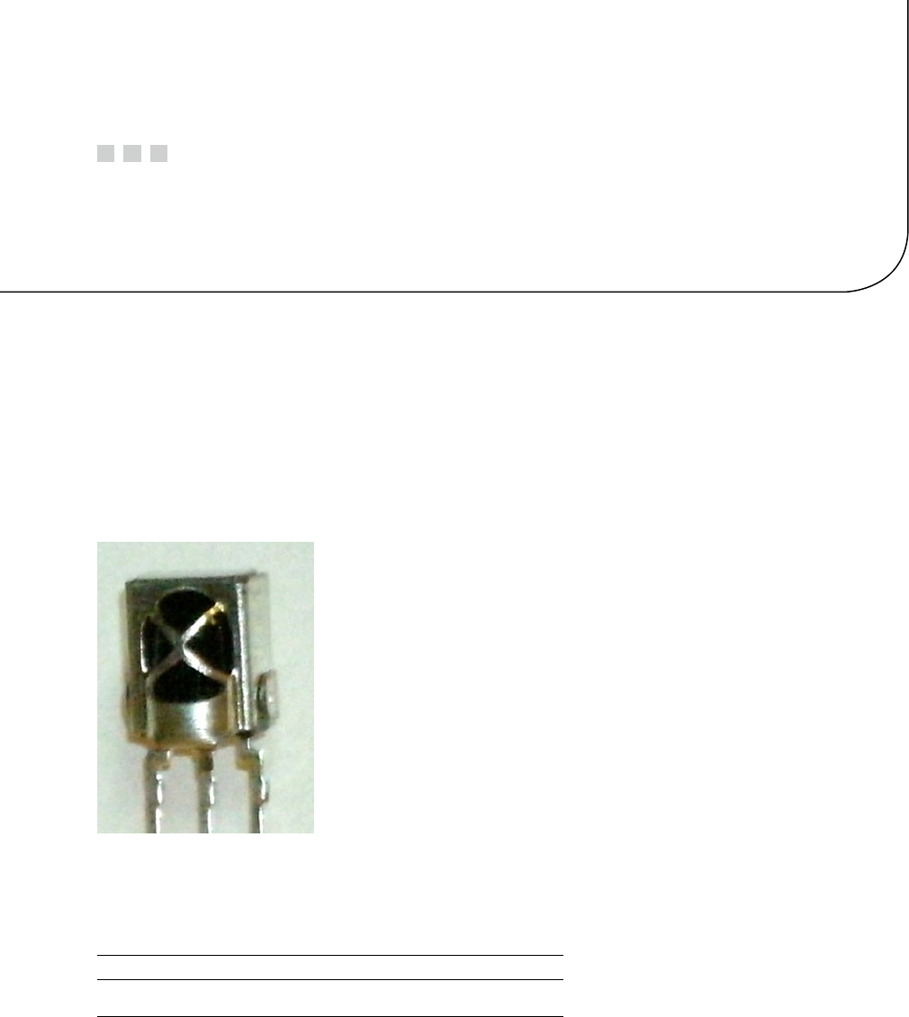
349
Chapter 26
VS1838B IR Receiver
The VS1838B is a PIN photodiode high-gain amplifier IC in an epoxy package with an outer shield. It consists of three
pins and is about the size of a signal transistor. This inexpensive part can be purchased for about $2 on eBay to give
your Raspberry Pi the ability to read many IR remote-control signals.
Operating Parameters
Figure 26-1 is a close-up photo of the VS1838B.
Figure 26-1. The VS1838B PIN photodiode
The datasheet provided for this part is mostly in Chinese. The most important parameter to decipher is the
supply voltage range, which is listed in English here:
Parameter Symbol Min Typ Max Units
Supply voltage VCC 2.7 5.5 Volts
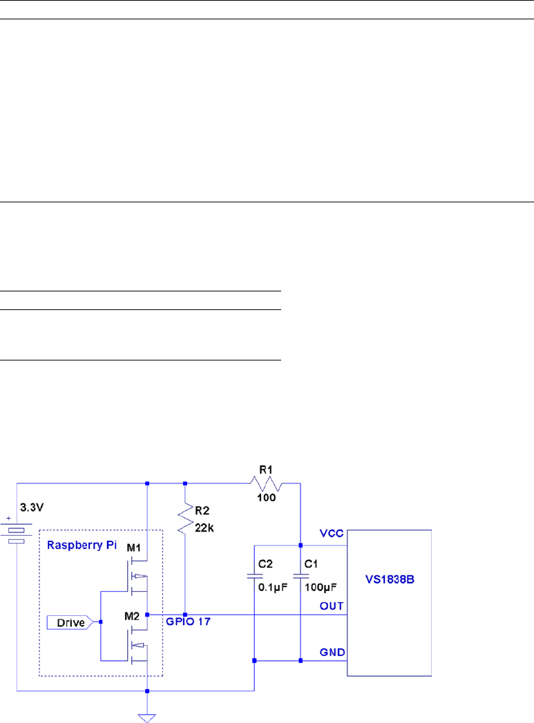
CHAPTER 26 ■ VS1838B IR RECEIVER
350
Given that 3.3 V is within the operating range for the device, we can use it for the Raspberry Pi. We simply power it
from the +3.3 V supply pin P1. The device requires only 1 mA of current, as seen in the other datasheet parameters here:
Parameter Symbol Test Conditions Min Typ Max Units
Supply current ICC VCC = 5.0 volts 0.6 0.8 1.0 mA
Receiving distance L11 13 m
Acceptance angle q ½ ±35 Deg
Carrier frequency f037.9 kHz
Bandwidth fBW 8 kHz
Voltage out low VOL Rpullup = 2.4 kW0.25 Volts
Voltage out high VOH VCC–0.3VCC Volts
Operating temp. Topr –30 +85 ºC
Pinout
With the lens of the part facing toward you, the pins are as follows, from left to right:
VS1838B
Front View
Out Gnd VCC
VS1838B Circuit
Figure 26-2 illustrates the VS1838B wired to the Raspberry Pi. Any GPIO pin can be used, but this text uses GPIO 17 for
ease of reference. If you choose to use a different GPIO, changes to the source code will be necessary.
Figure 26-2. VS1838B wired to the Raspberry Pi using GPIO 17

CHAPTER 26 ■ VS1838B IR RECEIVER
351
The circuit may appear somewhat daunting to students, compared to some of the other projects in this book. The
datasheet lists several components as being required: 100 W resistor R1, and capacitors C1 and C2. Finally, there is the
pull-up resistor R2, shown here as 22 kW.
Note ■ The datasheet simply shows the pull-up as being > 20 kW.
If you’re breadboarding this in a hurry, you can probably leave out R1, C1, and C2. I wired mine with R1 but forgot
about the capacitors. If you leave out the capacitors, R1 is not required either. R1 is not a current-limiting resistor here;
R1 and the capacitors are simply a low-pass filter designed to provide a quieter power supply to the part (which should
normally be used). But if you’re soldering this up, do include all of the recommended components for best results.
Don’t leave out the pull-up resistor. R2 is required.
The IR Receiver
Most IR remote controls today use the 38 kHz carrier frequency on an infrared beam of light. Even if you know that
your brand of remote uses a slightly different carrier frequency, the VS1838B may still work. The important point to
realize about this part is that it tries to detect the remote control while ignoring other light sources in the room. To
discriminate between fluorescent lighting and the remote control, it looks for this 38 kHz carrier signal. When it sees a
steady stream of pulses, it can ignore the interference.
The 22 kW pull-up resistor in the schematic diagram is necessary to pull the Out line up to VCC level, when no
38 kHz beam is seen. (The datasheet block diagram shows the output as a CMOS totem-pole output, but the pull-up
suggests open-drain configuration instead.) When the device sees a carrier for a minimum burst of 300 ms, it pulls the
Out line low. This line remains driven low as long as the carrier signal is detected. As soon as the carrier is removed for
300 ms or more, the line is pulled high again by the resistor.
Out Description
High No 38 kHz carrier seen
Low 38 kHz carrier is detected
Wired as shown, the Raspberry Pi will be able to see the effect of the carrier being turned on and off, many times
per second, as it receives remote-control bursts of IR light.
Software
This is where I apologize in advance. No matter which brand of TV or remote control is supported by the software in
this chapter, most people will own something different. However, if you own a relatively recently produced Samsung
TV, the software might just work for you out of the box. The software presented in this chapter was developed for the
remote control of a Samsung plasma HDTV (Model series 50A400).
If the software doesn’t work for you as is, then consider yourself blessed. When you dig into the program and
make it work for your remote, you’ll come away from the experience knowing much more than when you started.

CHAPTER 26 ■ VS1838B IR RECEIVER
352
Signal Components
Here’s where it gets fun. While most manufacturers have agreed on the 38 kHz carrier frequency, they haven’t agreed
on how the signaling works. Most protocols work on the principle of turning bursts of IR on and off, but how that
encodes a “key” differs widely.
An informative website (www.techdesign.be/projects/011/011_waves.htm) documents a few of the common
IR waveforms.54 The one we’re interested in is the Samsung entry, listed as protocol number 8.
Table 26-1 summarizes the technical aspects of the waveforms shown at the website. All times shown are in
milliseconds.
Table 26-1. IR Remote Waveform Times
Protocol Brand Component High Low High
ms
2 NEC Start bit 9 4.5 -
0 bit 0.56 0.56 -
1 bit 0.56 1.69 -
Stop bit 0.56 0.56 -
4 SIRCS Start bit 2.4 0.6 -
0 bit 0.6 0.6 -
1 bit 1.2 0.6 -
5 RC5 Start bit - 0.889 0.889
0 bit - 0.889 0.889
1 bit 0.889 0.889 -
7 Japan Start bit 3.38 1.69 -
0 bit 0.42 0.42 -
1 bit 0.42 1.69 -
8 Samsung Start bit 4.5 4.5 -
0 bit 0.56 0.56 -
1 bit 0.56 1.69 -
Stop bit 0.56 0.56 -
Table 26-2. Carrier Signals as Seen by the Raspberry Pi GPIO
Level GPIO Meaning
High (1) Low Carrier present
Low (0) High Carrier absent
The High/Low values shown in the table agree with the website. For our circuit, the signals are inverted because
of the way that the VS1838B brings the line low when a carrier is detected. The logic sense of these signals are
documented in Table 26-2 for clarity.

CHAPTER 26 ■ VS1838B IR RECEIVER
353
The waveform diagrams at the website are pleasant to look at, but the essential ingredients boil down to the
timings of three or four waveform components, which are listed in Table 26-3.
Table 26-3. Waveform Components
Component Description
Start bit Marks the start of a key-code
0 bit 0 bit for the code
1 bit 1 bit for the code
Stop bit Stop bit (end of code)
Table 26-1 shows that only the NEC and the Samsung signals use a stop bit. In both cases, each stop bit is simply
an extra 0 bit added onto the end of the stream.
All protocols use a special “start bit” to identify where the code transmission begins. RC5 just uses a 0-bit
waveform (in other words, the start and the 0 bits are identical).
A signal component always begins with a burst (seen as a GPIO low) followed by a time of no carrier (GPIO high).
The only thing that varies among manufacturers is the timings of these two signal components.
The RC5 protocol is unusual by allowing a start- or 0-bit transmission to begin with no carrier (GPIO high). Only
the 1 bit begins with an IR burst followed by no carrier. So if the remote is going from idle to transmission, the first half
of the bit cell for the start bit is unseen. But after the first transition, to mark the start, the receiver need only expect a
transition every 0.889 ms for 0 bits, and double that if the bits are changing state.
Looking at Table 26-1 again, notice that the shortest signal time occurs for type 7 (Japan) with a time of 0.42 ms.
The smallest detectable unit of time for the GPIO signal changes approaches 150 ms (0.15 ms) for the Raspberry Pi. But
if the Linux kernel is busy with other events, 420 ms events may not be reliably detected. Expect some trouble with that
particular protocol. Otherwise, the smallest unit of time shown is 560 ms for the other protocols.
Code Organization
If you experiment, you may find occurrences of other pulses within the IR data stream. For example, the Samsung
remote occasionally included a 46.5 ms pulse. Others may do something similar. I believe that these are key repeat
signals, which happen when you hold down a remote key.
In the Samsung bit stream, the bits gather into a 32-bit code. Your remote might use a different code length, but
32 bits is a convenient storage unit for a key code. For that reason, I expect that you’ll find that in other brands as well.
Command-Line Options
The irdecode utility program has been designed to take some options. These are listed when –h is used:
$ ./irdecode −h
Usage : ./irdecode [−d] [−g] [−n] [−p gpio]
where :
−d dumps event s
−g gnuplot waveforms
−n don’t invert GPIO input
−p gpio GPIO pin to use (17)
$

CHAPTER 26 ■ VS1838B IR RECEIVER
354
Without any options provided, the utility tries to decode Samsung remote-control codes (some of the output
is suppressed in this mode). The -p option can be provided to cause the command to use a different GPIO port. In
Samsung decode mode, stderr receives reports of the key codes. Redirect unit 2 to /dev/null if you don’t want them.
In this example, we capture the stderr output to file codes.out. The GPIO port is specified as 17 here, but this is
the command’s default:
$ ./irdecode −p17 2>codes.out
Monitoring GPIO 17 f or changes :
<POWER>
123
<RETURN>
73
<EXIT>
Exit .
$
While the program runs, it reports recognized key presses to stdout. Special keys are shown in angle brackets,
while the numeric digits just print as digits. In this mode, the program exits if it sees an <EXIT> key press on the
remote. You can also enter ^C in the terminal session to exit the program.
When the program exits, the codes.out file is displayed with the cat command:
$ cat codes.out
CODE E0E040BF
CODE E0E020DF
CODE E0E0A05F
CODE E0E0609F
CODE E0E0609F
CODE E0E01AE5
CODE E0E030CF
CODE E0E0609F
CODE E0E0B44B
$
Dump Mode
When the -d option is used, the program runs in dump mode. In this mode, the program will report level changes on
your selected GPIO pin:
$ ./irdecode −d
Monitoring GPIO 17 f or changes :
30524.573 1
4.628 0
4.322 1
0.696 0
1.555 1
Tip ■ By default, irdecode dumps out a 1 level when the carrier is present. To invert this to match the GPIO level,
use the -n option.
CHAPTER 26 ■ VS1838B IR RECEIVER
355
The left column of numbers is the time in milliseconds, prior to the level change. The number in the right column
shows you the level of the GPIO input after the change. In this example, the first event took a long time before it
changed (I was picking up the remote). The next change to low (0) occurs only 4.628 ms later, and so on.
This is a good format for getting a handle on the average pulse widths. From this output, you should see pulse
widths centered about certain ranges of numbers.
Each line reported is a signal change event. Either the GPIO pin changes to high, or it changes to a low level.
When reporting changes, therefore, you should never see two or more lines in a row change to a 0, for example.
The reported level should always alternate between 0 and 1.
If, however, you do see repeated highs or lows, this indicates that the program has missed events. Events spaced
closer together than about 150 ms are not likely to be seen on the Raspberry Pi. Noise and spikes can also cause these
kinds of problems.
Gnuplot Mode
Dump mode is great for analyzing pulse widths but it isn’t very helpful if you want to visualize the waveform. To
produce an output suitable for gnuplot, add the -g option:
$ ./irdecode −dg
Monitoring GPIO 17 f or changes :
31337.931 1
31342.528 1
31342.528 0 4.597
31342.528 0
31346.860 0
31346.860 1 4.332
31346.860 1
31347.594 1
31347.594 0 0.734
31347.594 0
31349.110 0
When the -g option is used, three lines are produced for each event:
Time of prior event, with previous state•
Time of current event, with previous state•
Time of current event, with current state, with time lapse in column 3•
If gnuplot is absent, you can install it on your Raspberry Pi as follows:
$ sudo apt–get install gnuplot–x11
These data plots can then be read into gnuplot to display a waveform. Create a file named gnuplot.cmd with
these commands in it:
set title "IR Remote Waveform"
set xlabel "Time (ms)"
set ylabel "Level"
set autoscale
set yrange [−.1:1.2]
plot "gnuplot.dat" using 1:2 with lines

CHAPTER 26 ■ VS1838B IR RECEIVER
356
Collect your output into a file named gnuplot.dat (or change the file gnuplot.cmd to use a different file name).
Then run gnuplot on the data:
$ gnuplot –p gnuplot.cmd
Figure 26-3 shows an example plot display. Note that you’ll normally have to edit out all but the most interesting
lines of data. Otherwise, your plot will be a rather crowded display of vertical lines.
Figure 26-3. gnuplot waveform of an IR signal
If running gnuplot doesn’t pop up a window, you may need to set the DISPLAY variable, or run xhost on the
X-Window server machine. If you are using the Raspberry Pi desktop, this should not be necessary.
The following xhost command enables anyone to create a window on your X-Window server:
# xhost +
The source code for the irdecode program is listed here:
1 /∗∗∗∗∗∗∗∗∗∗∗∗∗∗∗∗∗∗∗∗∗∗∗∗∗∗∗∗∗∗∗∗∗∗∗∗∗∗∗∗∗∗∗∗∗∗∗∗∗∗∗∗∗∗∗∗∗∗∗∗∗∗∗∗∗∗∗∗∗
2 ∗ irdecode.c : Read IR remote control on GPIO 17 (GEN0)
3 ∗∗∗∗∗∗∗∗∗∗∗∗∗∗∗∗∗∗∗∗∗∗∗∗∗∗∗∗∗∗∗∗∗∗∗∗∗∗∗∗∗∗∗∗∗∗∗∗∗∗∗∗∗∗∗∗∗∗∗∗∗∗∗∗∗∗∗∗∗/
4 #include <stdio.h>
5 #include <stdlib.h>
6 #include <fcntl.h>
7 #include <unistd.h>
8 #include <string.h>
CHAPTER 26 ■ VS1838B IR RECEIVER
357
9 #include <errno.h>
10 #include <signal.h>
11 #include <setjmp.h>
12 #include <assert.h>
13 #include <sys/time.h>
14 #include <sys/poll.h>
15 #include <getopt.h>
16
17 static int gpio_inpin = 17; /∗ GPIO input pin ∗/
18 static int is_signaled = 0; /∗ Exit program if signaled ∗/
19 static int gpio_fd = −1; /∗ Open file descriptor ∗/
20
21 static jmp_buf jmp_exit;
22
23 typedef enum {
24 gp_export=0, /∗ /sys/class/gpio/export ∗/
25 gp_unexport, /∗ /sys/class/gpio/unexport ∗/
26 gp_direction, /∗ /sys/class/gpio%d/direction ∗/
27 gp_edge, /∗ /sys/class/gpio%d/edge ∗/
28 gp_value /∗ /sys/class/gpio%d/value ∗/
29 } gpio_path_t ;
30
31 /∗
32 ∗Samsung Remote Codes :
33 ∗/
34 #define IR_POWER 0xE0E040BF
35 #define IR_0 0xE0E08877
36 #define IR_1 0xE0E020DF
37 #define IR_2 0xE0E0A05F
38 #define IR_3 0xE0E0609F
39 #define IR_4 0xE0E010EF
40 #define IR_5 0xE0E0906F
41 #define IR_6 0xE0E050AF
42 #define IR_7 0xE0E030CF
43 #define IR_8 0xE0E0B04F
44 #define IR_9 0xE0E0708F
45 #define IR_EXIT 0xE0E0B44B
46 #define IR_RETURN 0xE0E01AE5
47 #define IR_MUTE 0xE0E0F00F
48
49 static struct {
50 unsigned long ir_code; /∗ IR Code ∗/
51 const char ∗text; /∗ Display text ∗/
52 } ir_codes[] = {
53 { IR_POWER, "\n<POWER>\n" } ,
54 { IR_0, "0"},
55 { IR_1, "1" } ,
56 { IR_2, "2" } ,
57 { IR_3, "3" } ,
58 { IR_4, "4" } ,
59 { IR_5, "5" } ,
CHAPTER 26 ■ VS1838B IR RECEIVER
358
60 { IR_6, "6" } ,
61 { IR_7, "7" } ,
62 { IR_8, "8" } ,
63 { IR_9, "9" } ,
64 { IR_EXIT, "\n<EXIT>\n" } ,
65 { IR_RETURN, "\n<RETURN>\n" } ,
66 { IR_MUTE, "\n<MUTE>\n" } ,
67 { 0, 0 } /∗ End marker ∗/
68 } ;
69
70 /∗
71 ∗ Compute the time difference in milliseconds :
72 ∗/
73 static double
74 msdiff(struct timeval ∗t1,struct timeval ∗t0) {
75 unsigned long ut;
76 double ms;
77
78 ms = ( t1−>tv_sec − t0−>tv_sec ) ∗ 1000.0;
79 if ( t1−>tv_usec > t0−>tv_usec )
80 ms += ( t1−>tv_usec − t0−>tv_usec ) / 1000.0;
81 else {
82 ut = t1−>tv_usec + 1000000UL;
83 ut −= t0−>tv_usec;
84 ms += ut / 1000.0;
85 }
86 return ms;
87 }
88
89 /∗
90 ∗ Create a pathname fo r type in buf.
91 ∗/
92 static const char ∗
93 gpio_setpath(int pin,gpio_path_t type,char ∗buf,unsigned bufsiz) {
94 static const char ∗paths[] = {
95 "export", "unexport", "gpio%d/direction",
96 "gpio%d/edge", "gpio%d/value"};
97 int slen;
98
99 strncpy(buf,"/sys/class/gpio/",bufsiz);
100 bufsiz –= (slen = strlen(buf));
101 snprintf(buf+slen,bufsiz,paths[type],pin);
102 return buf;
103 }
104
105 /∗
106 ∗ Open /sys/class/gpio%d/value for edge detection :
107 ∗/
CHAPTER 26 ■ VS1838B IR RECEIVER
359
108 static int
109 gpio_open_edge(int pin,const char ∗edge) {
110 char buf[128];
111 FILE ∗f;
112 int fd;
113
114 /∗ Export pin: /sys/class/gpio/export ∗/
115 gpio_setpath(pin gp_export,buf,sizeof buf);
116 f = fopen(buf,"w");
117 assert(f);
118 fprintf(f,"%d\n",pin);
119 fclose(f);
120
121 /∗ Direction: /sys/class/gpio%d/direction ∗/
122 gpio_setpath(pin,gp_direction,buf,sizeof buf);
123 f = fopen(buf,"w");
124 assert(f);
125 fprintf(f,"in\n");
126 fclose(f);
127
128 /∗ Edge: /sys/class/gpio%d/edge ∗/
129 gpio_setpath(pin,gp_edge,buf,sizeof buf);
130 f = fopen(buf,"w");
131 assert(f);
132 fprintf(f,"%s\n",edge);
133 fclose(f);
134
135 /∗ Value: /sys/class/gpio%d/value ∗/
136 gpio_setpath(pin,gp_value,buf,sizeof buf);
137 fd = open(buf,O_RDWR);
138 return fd;
139 }
140
141 /∗
142 ∗ Close ( unexport ) GPIO pin :
143 ∗/
144 static void
145 gpio_close(int pin) {
146 char buf[128];
147 FILE ∗f;
148
149 /∗ Unexport: /sys/class/gpio/unexport ∗/
150 gpio_setpath(pin,gp_unexport,buf,sizeof buf);
151 f = fopen(buf,"w");
152 assert(f);
153 fprintf(f,"%d\n",pin);
154 fclose(f);
155 }
156
CHAPTER 26 ■ VS1838B IR RECEIVER
360
157 /∗
158 ∗ This routine will block until the open GPIO pin has changed
159 ∗ value .
160 ∗/
161 static int
162 gpio_poll(int fd,double ∗ms) {
163 static char needs_init = 1;
164 static struct timeval t0;
165 static struct timeval t1;
166 struct pollfd polls;
167 char buf[32];
168 int rc, n;
169
170 if ( needs_init ) {
171 rc = gettimeofday(&t0,0);
172 assert(!rc);
173 needs_init = 0;
174 }
175
176 polls.fd = fd; /∗ /sys/class/gpio17/value ∗/
177 polls.events = POLLPRI; /∗ Exceptions ∗/
178
179 do {
180 rc = poll(&polls,1,−1); /∗ Block ∗/
181 if ( is_signaled )
182 longjmp(jmp_exit,1);
183 } while ( rc < 0 && errno == EINTR );
184
185 assert(rc > 0);
186
187 rc = gettimeofday(&t1,0);
188 assert(!rc);
189
190 ∗ms = msdiff(&t1,&t0);
191
192 lseek(fd,0,SEEK_SET);
193 n = read(fd,buf,sizeof buf); /∗ Read value ∗/
194 assert(n>0);
195 buf[n] = 0;
196
197 rc = sscanf(buf,"%d",&n) ;
198 assert(rc==1);
199
200 t0 = t1; /∗ Save for next call ∗/
201 return n; /∗ Return value ∗/
202 }
203
204 /∗
205 ∗ Signal handler to quit the program :
206 ∗/
CHAPTER 26 ■ VS1838B IR RECEIVER
361
207 static void
208 sigint_handler(int signo) {
209 is_signaled = 1; /∗ Signal to exit program ∗/
210 }
211
212 /∗
213 ∗ Wait until the line changes :
214 ∗/
215 static inline int
216 wait_change(double ∗ms) {
217 /∗ Invert the logic of the input pin ∗/
218 return gpio_poll(gpio_fd,ms) ? 0 : 1;
219 }
220
221 /∗
222 ∗ Wait until line changes to "level" :
223 ∗/
224 static int
225 wait_level(int level) {
226 int v;
227 double ms;
228
229 while ( (v = wait_change(&ms)) != level )
230 ;
231 return v;
232 }
233
234 /∗
235 ∗ Get a 32 bit code from remote control :
236 ∗/
237 static unsigned long
238 getword(void) {
239 static struct timeval t0 = { 0, 0 };
240 static unsigned long last = 0;
241 struct timeval t1;
242 double ms;
243 int v, b, count;
244 unsigned long word = 0;
245
246 Start: word = 0;
247 count = 0;
248
249 /∗
250 ∗ Wait for a space of 46 ms :
251 ∗/
252 do {
253 v = wait_change(&ms);
254 } while ( ms < 46.5 );
255
256 /∗
257 ∗ Wait for start : 4.5ms high, then 4.5ms low :
258 ∗/
CHAPTER 26 ■ VS1838B IR RECEIVER
362
259 for ( v=1;; ) {
260 if ( v )
261 v = wait_level(0);
262 v = wait_level(1);
263 v = wait_change(&ms); /∗ High to Low ∗/
264 if ( !v && ms >=4.0 && ms <= 5.0 ) {
265 v = wait_change(&ms);
266 if ( v && ms >=4.0 && ms <= 5.0 )
267 break ;
268 }
269 }
270
271 /∗
272 ∗ Get 32 bi t code :
273 ∗/
274 do {
275 /∗ Wait for line to go low ∗/
276 v = wait_change(&ms);
277 if ( v || ms < 0.350 || ms > 0.8500 )
278 goto Start;
279
280 /∗ Wait for line to go high ∗/
281 v = wait_change(&ms);
282 if ( !v || ms < 0.350 || ms > 2.0 )
283 goto Start;
284
285 b = ms < 1.000 ? 0 : 1;
286 word = (word << 1) | b;
287 } while ( ++count < 32 );
288
289 /∗
290 ∗ Eliminate key stutter :
291 ∗/
292 gettimeofday(&t1,0);
293 if ( word == last && t0.tv_sec && msdiff (&t1,&t0) < 1100.0 )
294 goto Start; /∗ Too soon ∗/
295
296 t0 = t1;
297 fprintf(stderr,"CODE %08lX\n",word);
298 return word;
299 }
300
301 /∗
302 ∗ Get text form of remote key :
303 ∗/
304 static const char ∗
305 getircode(void) {
306 unsigned long code;
307 int kx;
308
CHAPTER 26 ■ VS1838B IR RECEIVER
363
309 for (;;) {
310 code = getword();
311 for ( kx=0; ir_codes[kx].text; ++kx )
312 if ( ir_codes[kx].ir_code == code )
313 return ir_codes[kx].text;
314 }
315 }
316
317 /∗
318 ∗ Main program :
319 ∗/
320 int
321 main(int argc,char ∗∗argv) {
322 const char ∗key;
323 int optch;
324 int f_dump = 0, f_gnuplot = 0, f_noinvert = 0;
325
326 while ( (optch = getopt(argc,argv,"dgnsp:h")) != EOF )
327 switch ( optch ) {
328 case 'd' :
329 f_dump = 1;
330 break;
331 case 'g' :
332 f_gnuplot = 1;
333 break;
334 case 'n':
335 f_noinvert = 1;
336 break;
337 case 'p' :
338 gpio_inpin = atoi(optarg);
339 break;
340 case 'h' :
341 /∗ Fall thru ∗/
342 default :
343 usage : fprintf (stderr,
344 "Usage: %s [−d ] [−g ] [−n ] [−p gpio]\n",argv[0]);
345 fputs("where: \n"
346 " −d\t\tdumps events\n"
347 " −g\t\tgnuplot waveforms\n"
348 " −n\ t \tdon’t invert GPIO input \n"
349 " −p gpio\tGPIO pin to use (17)\n",
350 stderr);
351 exit(1);
352 }
353
354 if ( gpio_inpin < 0 || gpio_inpin >=32 )
355 goto usage;
356
357 if ( setjmp(jmp_exit) )
358 goto xit;
359
CHAPTER 26 ■ VS1838B IR RECEIVER
364
360 signal(SIGINT,sigint_handler); /∗ Trap on SIGINT ∗/
361 gpio_fd = gpio_open_edge(gpio_inpin,"both"); /∗ GPIO input ∗/
362
363 printf("Monitoring GPIO %d for changes:\n",gpio_inpin);
364
365 if ( !f_dump ) {
366 /∗
367 ∗ Remote control read loop :
368 ∗/
369 for (;;) {
370 key = getircode();
371 fputs(key,stdout);
372 if ( !strcmp(key,"\n<EXIT>\n") )
373 break;
374 fflush(stdout);
375 }
376 } else {
377 /∗
378 ∗ Dump out IR level changes
379 ∗/
380 int v;
381 double ms, t =0.0;
382
383 wait_change(&ms); /∗ Wait for first change ∗/
384
385 for (;;) {
386 v = wait_change(&ms) ^ f_noinvert;
387 if ( !f_gnuplot )
388 printf("%12.3 f\t%d\n",ms,v);
389 else {
390 printf("%12.3 f\t%d\n",t,v^1);
391 t += ms;
392 printf("%12.3 f\t%d\n",t,v^1);
393 printf("%12.3 f\t%d\t%12.3 f\n",t,v,ms);
394 }
395 }
396 }
397
398 xit : fputs("\nExit.\n",stdout);
399 close(gpio_fd); /∗ Close gpio%d/value ∗/
400 gpio_close(gpio_inpin); /∗ Unexport gpio ∗/
401 return 0;
402 }
403 /∗ End irdecode.c ∗/
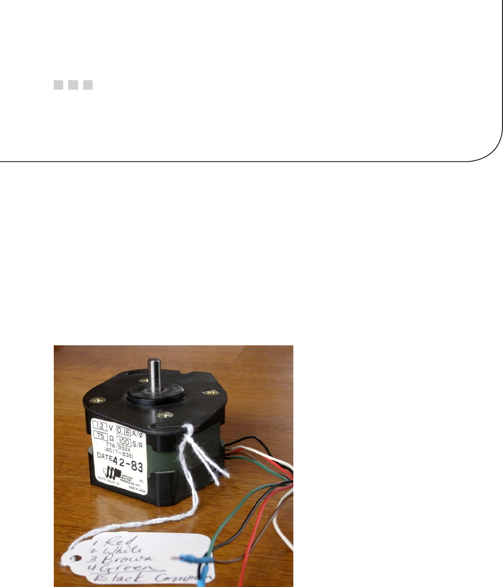
365
Chapter 27
Stepper Motor
A stepper motor is a brushless device with multiple windings, where one rotation is divided into several small steps.
Stepper motors are used when precise positioning is required. Unipolar stepper motors have multiple windings
connected to a common connection.
In this chapter, we’ll recycle an old floppy-disk stepper motor. Modern stepper motors are smaller and operate
at lower voltages. This particular stepper motor presents a good example of the challenges that exist when driving a
motor from a 12 V power supply.
Floppy-Disk Stepper Motor
Figure 27-1 shows an old 5.25-inch floppy-disk stepper motor that was sitting on a shelf in my furnace room.
Perhaps you have a gem like this in your own junk box.
Figure 27-1. A salvaged 5.25-inch floppy-disk motor
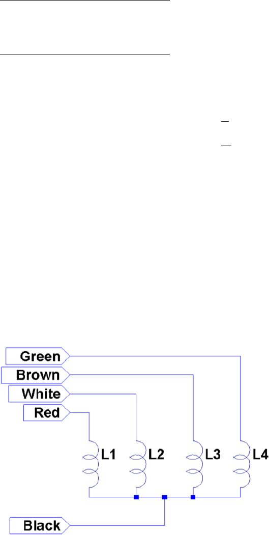
CHAPTER 27 ■ STEPPER MOTOR
366
This particular stepper motor has these markings on it:
12 V 0.16 A/Ø
75 W100 S/R
Date 42-83
This motor was clearly marked as a 12 V device. The 0.16 A/Ø marking tells us that each winding (phase Ø) is
rated for 160 mA. The following calculation confirms that the winding resistance is 75 W, which is consistent with the
printed current rating:
IV
R
mA
=
=
=
12
75
160
The 100 S/R marking tells us that this motor has 100 steps per revolution. It’s really nice when you get all the
information you need up front.
Your Junk-Box Motor?
Old 5.25-inch floppy-disk drives are getting scarcer these days. So what about other stepper motors that you might
have in your junk box? How can you determine whether you can use one?
The first thing you must check is the type of motor. This chapter focuses on unipolar motors that have three
or more step windings with a common connection. The floppy-disk stepper motor that I’m using in this chapter is
shown in Figure 27-2. Notice that this motor has four separate windings, labeled L1 through L4. These have a common
connection to a black wire coming out of the motor. To make this motor step, each winding must be activated in
sequence.
Figure 27-2. Floppy-disk stepper motor windings

CHAPTER 27 ■ STEPPER MOTOR
367
If you have a stepper motor on hand but don’t know much about it, you can test it with a DMM. Measure the DC
resistance of the windings between each pair of wires. You won’t need to measure every combination, but start a chart
something like the following I’ll use my motor as an example:
Wire 1 Wire 2 Reading
Black Red 84 W
Red White 168 W
White Brown 168 W
Brown Black 84 W
etc.
What does this tell you? The lowest readings show 84 W (the reading should be 75 W for this motor, but my DMM
doesn’t read low resistances accurately). The other readings are double that. This indicates that each winding should
read 84 W, and when it doesn’t, it means that we are measuring the resistance of two windings in series.
Looking again at the chart, we see that whenever we find an 84 W reading, the black wire is common to each.
Knowing that the black wire is common to the windings means that all of the other wires should read 84 W relative to it.
Now you know which wire is the common one.
Some motors you might encounter use two separate split windings. These won’t have a wire common to all
windings. You’ll find that some paired wires have infinite resistance (no connection). If this applies, you have a motor
that is applicable to the project in Chapter 28.
Another ingredient that you need to check is the DC resistance of each winding. Assuming you already measured
this while determining the common wire, perform this calculation:
IV
R
winding
winding
=
Let’s assume that you think your stepper motor is a 6 V part, or simply that you plan to operate it at 6 V. Assume
also that the measured DC resistance of the winding is 40 W. What will be the maximum current necessary to drive
this motor?
I
mA
winding=
=
6
40
150
This figure is important to the driving electronics. In this chapter, I am using an economical PCB purchased from
eBay that uses the ULN2003A driver chip. I’ll describe the chip and the PCB in more detail later. The ULN2003A chip
has a maximum drive rating of 500 mA. But this figure must be derated by the duty cycle used and the number of
simultaneous drivers. If you computed a figure of 300 mA or more, you may need to seek out a more powerful driver.
Note ■ In addition to stepper motors, the ULN2003A can drive lightbulbs and other loads.
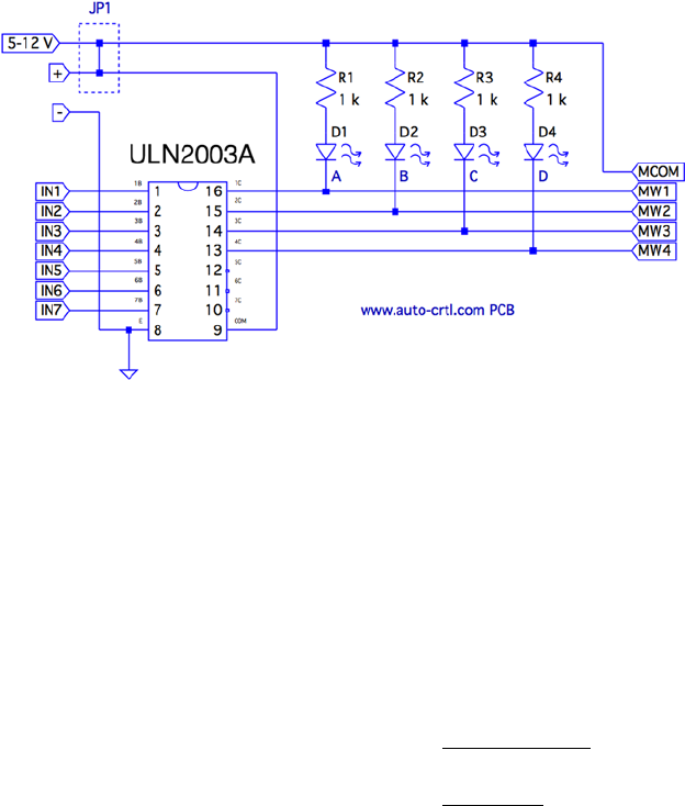
CHAPTER 27 ■ STEPPER MOTOR
368
Driver Circuit
Clearly, the GPIO outputs of the Raspberry Pi cannot drive a stepper motor directly. You could build your own
driver circuit (or breadboard one) using the ULN2003A chip. I chose instead to buy a PCB from eBay for $2
(with free shipping), which provided the advantage of four LEDs. These light when a winding is activated, which is
useful for testing. Figure 27-3 shows the schematic of the PCB that I used.
Figure 27-3. ULN2003A PCB schematic
The PCB includes two holes that power connections can be soldered into. There are also two pins marked
(+) and (-) for a push-on connector.
Beside the power connections is a small jumper with the text 5 – 12 V under it. This jumper is shown as JP1 in the
schematic. You’ll normally want to leave the jumper in.
The input connections are clearly labeled IN1 through IN7. However, only outputs 1C through 4C are used
(outputs for IN1 through IN4). The other ULN2003A outputs 5C through 7C are unconnected. Wires could be carefully
soldered to these pins, if you needed additional drivers for lamps, relays, or a second stepper motor.
The LEDs are connected from the (+) side, in series with a 1 kW current–limiting resistor. The voltage drop VCE(sat)
in the ULN2003A ranges from about 0.9 to 1.6 V (use the worst case of 0.9 V). Assuming that the voltage drop is 1.6 V
for red LEDs55 and the maximum of 12 V is applied, each LED conducts about this:
IVV V
R
mA
LED
CC CE satLED
LED
=--
=--
=
()
..
.
12 09 16
1000
95
The LEDs are the main reason the PCB lists a maximum voltage of 12 V. The ULN2003A chip has an absolute
maximum VCC voltage of 50 V. If, for example, you need to drive a 24 V stepper motor from an old 8-inch floppy drive,
you can remove jump JP1 to take the LEDs out of the circuit. Then you would supply the +24 V directly to the common
wire of the stepper motor itself. If you do this, you’ll also want to connect the PCB (+) to the motor’s supply. This
connects the motor to the COM pin of the ULN2003A, which provides reverse-biased diodes to drain away induced
voltages.
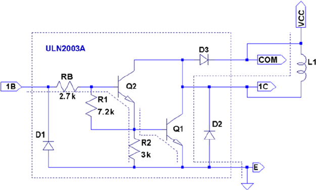
CHAPTER 27 ■ STEPPER MOTOR
369
When purchased, the PCB included a white socket for connection to the stepper motor. I removed that and
replaced it with a soldered-in ribbon cable. These wires connect the driver outputs 1C through 4C to the
stepper-motor windings.
The Raspberry Pi will drive pins IN1 through IN4 from the GPIO ports. When a given INx pin is driven high, the
Darlington pair of transistors will sink up to 500 mA of current from a positive (motor supply) source to ground.
Darlington Pair
It is tempting to look at the ULN2003A chip as a black box: a signal goes into it, and a bigger one comes out. But when
interfacing to voltages higher than the Raspberry Pi’s own +3.3 V system, extra caution is warranted. If any of this
higher voltage leaks back into the Pi, the GPIO pins will get “cooked” (if not the whole system).
Figure 27-4 shows input 1B being driven high by a GPIO line. This forward-biases Q2, which in turn biases Q1.
A small amount of current flows in dashed lines from 1B, into the base of Q2, and then from Q1 to ground. This small
amount of current flow allows a much greater current to flow from the collector of Q1 to ground. The dashed lines on
the right show the motor-winding current flowing from the motor power supply (12 V, for example), through Q1 to
ground through the E terminal.
Figure 27-4. ULN2003A driving a winding
When the GPIO ceases to drive input 1B as shown in Figure 27-5, the transistors Q2 and Q1 turn off. With no
more current flowing through L1, the magnetic field collapses, generating a reverse current. As the field collapses,
current flows into terminal 1C, through the diode D3 and back to the upper side of L1. In effect, diode D3 shorts out this
generated-back EMF. Diode D3 is necessary to prevent the rest of the electronics from seeing a high voltage, which can
cause damage and disruption.
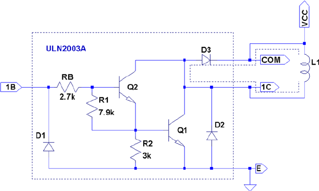
CHAPTER 27 ■ STEPPER MOTOR
370
One side effect of the reverse-biased diode is that it slows down the decay of the magnetic field. As current flows
in the reverse direction, the magnetic collapse is resisted. This results in magnetic forces inside the motor, which
affect its speed. (This same effect also slows the release of relay contacts.) When greater speed is required, a resistor is
sometimes used in series with the diode to limit its effect.
So what about voltage safety of our Raspberry Pi GPIO pins? Reexamine the Darlington pair Q2 and Q1. Pins COM and
1C can be as high as 50 V. But current cannot leak through D3 (from COM) because the diode junction is reverse-biased.
Current cannot leak from the collectors of Q2 and Q1 (from 1C) into the base circuits because those base-collector junctions
are behaving as reverse-biased diodes. The main point of caution is that Q2 and Q1 must remain intact.
If Q1 were allowed to overheat, for example, it might break down. If Q1 or Q2 breaks down, current will be allowed
to flow from its collector into the base circuit, which is connected to the GPIO. Therefore, the breakdown of the driver
transistors must be strictly prevented!
Driving the Driver
In this section, we look at the Raspberry Pi (GPIO) interface to the ULN2003A. There are two things we are most
interested in here:
The usual input logic-level interface•
Power-on reset and boot conditions•
Input Levels
The output current of the ULN2003A Darlington pair rises as the input voltage rises above the turn-on level. We
know from the Darlington configuration that there are two base-emitter junctions in the path from input to ground.
Therefore, the ULN2003A driver requires a 2 × VBE voltage to forward-bias the pair. If we assume VBE = 0.6 V, we can
compute a VIL for the driver as follows:
VV
V
IL BE
=´
=´
=
2
206
12
.
.
Figure 27-5. ULN2003A driver turning off

CHAPTER 27 ■ STEPPER MOTOR
371
Clearly, the Pi GPIO low (0.8 V) easily turns off the ULN2003A input with margin to spare. The datasheets
state that a maximum output drive of 300 mA can be achieved with a 3 V input drive signal. The ULN2003A drive
characteristics are shown here:
Signal Raspberry Pi ULN2003A
VIIC
VOL £ 0.8 V 1.2 V 500 mA
VOH ³1.3 V 2.4 V 100 mA
2.7 V 250 mA
3.0 V 300 mA
If we had a TTL signal driving the ULN2003A, we could get closer to the 500 mA maximum drive (interpolating
from the characteristics shown). However, for our purposes, we need only 160 mA, so a 3 V drive signal meets the
requirements well enough.
Note ■ TTL levels approach +5V.
Power-on Reset/Boot
The one serious matter that remains is what our circuit will be doing as the Raspberry Pi is reset and is spending
time booting up. The maximum ratings of the ULN2003A have to be derated when more than one Darlington pair is
operating simultaneously. This is because each driver that is on heats up the chip substrate. For this reason, it is highly
desirable for the ULN2003A to be “quiet” at reset time and subsequent boot-up. If a boot problem occurs, requiring a
lot of time to correct, the drivers could overheat.
This potentially requires that we use GPIO pins that
Are automatically configured as • inputs at reset
Are not configured with high pull-up resistors•
Input pins with high pull-up resistors are potentially bad news. A high level appearing on ULN2003A inputs might
activate drivers. In the worst-case scenario, all inputs become active.
Table 27-1 lists the acceptable GPIO pins as well as the reasons that others should be avoided.

CHAPTER 27 ■ STEPPER MOTOR
372
The pull-up resistance provided by the Broadcom SoC is weak (50 kW). Because of this, the worst-case input
drive, due to the pull-up resistance, is calculated as follows:
IV
R
V
k
A
I
CC
pullup
=
=
=
33
50
66
.
W
m
The ULN2003A datasheet states that it takes an input drive of 250 mA to produce an output current flow of
100 mA. Some GPIO pins are pulled up by external resistors (GPIO 2 and 3 for SDA and SCL). These GPIO pins should
not be used as motor drivers, for this reason.
The Darlington pair includes resistances that naturally pull down the input signal (review Figure 27-5).
Resistances RB, R1, and R2 are connected in series between the input and ground. This effectively provides a pull-down
resistance of approximately 13.6 kW. If the ULN2003A is attached to a floating input like GPIO 28 or 29, the input
voltage will automatically be pulled down as a result (this is desirable here).
Modes of Operation
A unipolar stepper motor may be operated in four modes. The first three of these modes use digital on/off signals to
drive each winding. The fourth micro-stepping mode requires driving each winding with varying analog signals. Since
we are driving with digital GPIO pins, we’ll examine only the first three modes.
Wave Drive (Mode 0)
Wave drive mode is the simplest of the modes, in which only one winding of the motor is activated at one time
(see Figure 27-6). Each winding is energized in sequence to cause the rotation to occur in full steps. The motor will
have significantly less torque than in full-step drive mode and is therefore rarely used.57
Table 27-1. GPIOs for Motor Control at Reset/Boot Time
GPIO
OK Bad Reason Bad Reason
09 23 00 Pull-up high 08 Pull-up high
10 24 01 Pull-up high 14 TXD0
11 25 02 Pull-up high 15 RXD0
12 28† 03 Pull-up high 16 Output
17 29† 04 Pull-up high 27 Output
18 30 05 Pull-up high
21 31 06 Output
22 07 Pull-up high
(†) No pull-up resistor
CHAPTER 27 ■ STEPPER MOTOR
373
Full-Step Drive (Mode 1)
Figure 27-7 shows how full-step drive mode operates. Each field is energized in turn like a wave drive, but the next
field is activated prior to turning off the prior field. In this way, an overlapping drive is affected in the direction of
travel. This is the usual drive method delivering full-rated torque.58
Half-Step Drive (Mode 2)
Figure 27-8 illustrates the drive waveforms for half-step drive mode. As in full-step mode, an overlapped drive is
applied to the field coils. Unlike full-step mode, the overlap occurs on the first third and the last third of a given coil’s
drive. For two-thirds of the waveform, there is overlapped drive. In the middle third, only one winding is active.
Figure 27-7. Full-step drive (mode 1)
Figure 27-6. Wave drive (mode 0)
CHAPTER 27 ■ STEPPER MOTOR
374
This mode provides increased angular resolution but suffers from having less torque (about 70% of full-rated torque).59
Software
To demonstrate stepper-motor driving without getting into a complex assignment, the program unipolar.c simply
positions the shaft of the motor to various hour positions of the clock, based on single-key commands.
With a pointer attached to the shaft of your motor, press 6, and the motor will point at 6 o’clock. Press 3, and the
motor figures out that it is quickest to step counterclockwise back to the 3 o’clock position. Press 7, and the motor
steps forward to 7 o’clock. All of this, of course, requires that you point the shaft at 12 o’clock before you begin
(the motor provides no information to the program about where it is currently pointing).
The program presented uses the GPIO pin assignments in Table 27-2 for driving the stepper motor (your wire
colors may differ):
Figure 27-8. Half-step drive
Table 27-2. GPIO Assignments Used by the Program unipolar.c
GPIO GENXP1 Mode Stepper Wire ULN2003A Description
17 GEN0 P1-11 Output Red 1B Field A
24 GEN5 P1-18 White 2B Field B
22 GEN3 P1-15 Brown 3B Field C
23 GEN4 P1-16 Green 4B Field D
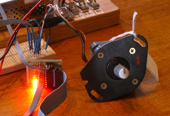
CHAPTER 27 ■ STEPPER MOTOR
375
At power-on reset and boot time, the selected GPIO lines are all input pins with pull-down resistors. After
boot-up, when the program starts and configures its GPIO pins, it will do the following:
1. Configure an output low value for each GPIO (while still an input)
2. Configure the GPIO pin as an output
Step 1 eliminates the possibility of a stepper winding being driven before the software is ready to drive it.
If this were not done, a driver could be activated when the GPIO is first configured as an output. Step 2, of course,
is necessary to drive the ULN2003A chip. But no glitch occurs in the output when step 1 is performed first.
After the main program has begun, it saves the current terminal settings in sv_ios and then sets up a raw mode,
permitting single-character I/O interaction (lines 167–173). See Chapter 11 for a review of the serial API.
Lines 175–178 initialize the GPIO lines to drive the stepper-motor field windings. The default stepper-motor
mode is configured on line 182, which may be overruled by a command-line argument. The program can also change
modes by using keystroke commands.
The remainder of the program is a while loop that extends from lines 185–241. It reads a single-character
command at line 187 and then dispatches to sections of code in the switch statement. The single-character
commands are summarized in Table 27-3.
Figure 27-9. Stepper motor with knob used as a pointer
Figure 27-9 shows how a pointer knob can be used for a pointer. Otherwise, this is your opportunity to get
creative.

CHAPTER 27 ■ STEPPER MOTOR
376
The < and > commands double or halve the step time interval. This slows and increases the rotational speed,
respectively. Stepper modes can be changed using the J, K, or L commands. These reposition the stepper to 12 o’clock
prior to changing modes. The digits 0 through 9 and letters A and B reposition the shaft to point to the hour of the clock.
You can test whether your rotation is properly working by using the + and - keystrokes to step one step clockwise
or counterclockwise. Pressing O (the letter O, not zero) toggles the drive power on or off for the motor. This is useful
for turning off the motor drive when you want to manually reposition the shaft.
The source code used in this program for gpio_io.c is provided in Chapter 12, and timed_wait.c in Chapter 22.
The main source module of interest is unipolar.c, which is presented at the end of this chapter.
Testing
Be careful setting up this project because of the voltages involved. One careless wiring error could bring higher voltage
into your GPIO pins and fry the Pi. In the following procedures, I refer to the driver PCB (as I used), but this procedure
applies equally to breadboarded circuits.
Here is the first part of the setup and checkout procedure:
1. Set up the power to the driver PCB without connecting it to the Raspberry Pi. Leave the
motor unconnected also.
2. Make sure that the driver inputs are not connected.
3. Apply the power to the PCB. No LEDs will light if everything is OK. No smoke? Good!
4. Apply +3.3 V one at a time to the driver inputs 1B through 4B (IN1 through IN4 on the PCB)
with a wire, which should cause the corresponding LED to light. (These driver inputs will
also accept +5 V for testing, if that is what you have available.) If you breadboarded the
circuit, consider adding LEDs to each driver output.
5. Measure the voltage at each unconnected driver input 1B through 4B (IN1 through IN4).
Each should measure 0 V (or very nearly). If you measure anything higher, you have either
a wiring error or a bad driver chip. Don’t use a defective driver.
Table 27-3. Single-Character Commands
Char Command Char Command
Q Quit 0 12 o’clock (noon)
< Slower steps 1 1 o’clock
> Faster steps 2
? Help ...
H 9 9 o’clock
J Stepper mode 0 A 10 o’clock
K Stepper mode 1 B 11 o’clock
L Stepper mode 2 +/= Step clockwise
P Show current position - Step counterclockwise
O Toggle drive on/off
CHAPTER 27 ■ STEPPER MOTOR
377
If this procedure tests out OK, the next step is to wire up the motor (with PCB still unconnected from the Pi):
1. Put some kind of pointer on the motor shaft (like a pointer knob) and wire up the motor to
the PCB driver outputs.
2. Make sure that the COM pin of the driver chip is connected to the + power connection
used for the motor (+12 V in my case). This is important for bleeding off the inductive kick
that occurs when the motor winding is turned off.
3. Apply power to the PCB and check for smoke. No smoke or crackling sounds means you
can proceed to the next step.
4. With the PCB power applied, you should be able to drive each motor winding with +3.3 V
applied to individual inputs, as before. If the motor is wired up correctly, it should twitch.
If the twitch is not visible, put your hand on the shaft. You should feel it when the winding
activates.
The next step is to make sure you wired the windings for the correct sequence. When applying step 4 of the
preceding procedure to each winding’s driver input, the motor should take one step clockwise. Watch for double
steps, or twitches in the reverse direction. As you strobe inputs 1B, 2B, 3B, and 4B (IN1 through IN4) in sequence, the
motor should step in an orderly clockwise direction. Reversing that activation sequence should cause the motor to
step counterclockwise. Keep your nose alert for smoke or funny smells. Then follow these steps:
1. Measure the inputs of the drivers 1B through 4B one last time, while the motor is
connected and all motor voltages are present. Each input should measure near 0 V
(due to its internal pull-down resistances).
2. Now power everything off.
3. Make sure there is a ground-wire connection between your Raspberry Pi’s ground and the
stepper-motor power supply’s ground. Don’t try operating without this critical link.
4. With everything still off, and observing care for static electricity, connect the GPIO pins to
each of the ULN2003A driver inputs 1B through 4B (IN1 through IN4).
Now turn everything on and keep alert, just in case. The Raspberry Pi should begin booting with no visible
activity on the stepper motor (or LEDs). If there is, you might have a GPIO wiring error. Turn off the stepper-motor
power supply if you can and bring the Pi down and recheck.
Assuming all went well, point your motor at 12 o’clock and start the program:
$ ./unipolar
If the motor struggles or moves erratically when you give it movement commands, you may need to correct the
motor wiring. Use the + and - commands to check whether the motor steps properly in one direction.
1 /***********************************************************
2 * unipolar.c : Drive unipolar stepper motor
3 **********************************************************/
4
5 #include <stdio.h>
6 #include <stdlib.h>
7 #include <fcntl.h>
8 #include <unistd.h>
9 #include <errno.h>
CHAPTER 27 ■ STEPPER MOTOR
378
10 #include <math.h>
11 #include <ctype.h>
12 #include <termio.h>
13 #include <sys/mman.h>
14 #include <signal.h>
15 #include <assert.h>
16
17 #include "gpio_io.c" /* GPIO routines */
18 #include "timed_wait.c" /* timed_wait () */
19
20 static const int steps_per_360 = 100; /* Full steps per rotation */
21
22 /* GPIO Pins : A B C D */
23 static const int gpios[] = { 17, 24, 22, 23 };
24
25 static float step_time = 0.1; /* Seconds */
26 static int drive_mode = 0; /* Drive mode 0, 1, or 2 */
27 static int step_no = 0; /* Step number */
28 static int steps_per_r = 100; /* Steps per rotation */
29 static int position = 0; /* Stepper position */
30 static int on_off = 0; /* Motor drive on/off */
31
32 static int quit = 0; /* Exit program if set */
33
34 /***********************************************************
35 * Await so many fractional seconds
36 **********************************************************/
37 static void
38 await(float seconds) {
39 long sec, usec;
40
41 sec = floor(seconds); /* Seconds to wait */
42 usec = floor((seconds_sec)*1000000); /* Microseconds */
43 timed_wait(sec,usec,0); /* Wait */
44 }
45
46 /***********************************************************
47 * Set motor drive mode
48 **********************************************************/
49 static void
50 set_mode(int mode) {
51 int micro_steps = mode < 2 ? 1 : 2;
52
53 step_no = 0;
54 drive_mode = mode;
55 steps_per_r = steps_per_360 * micro_steps;
56 printf("Drive mode %d\n",drive_mode);
57 }
58
CHAPTER 27 ■ STEPPER MOTOR
379
59 /***********************************************************
60 * Drive all fields according to bit pattern in pins
61 **********************************************************/
62 static void
63 drive(int pins) {
64 short x;
65 for ( x=0; x<4; ++x )
66 gpio_write(gpios [x],pins & (8>>x) ? 1 : 0);
67 }
68
69 /***********************************************************
70 * Advance motor:
71 * dir = -1 Step counter_clockwise
72 * dir = 0 Turn on exist ing fields
73 * dir = +1 Step clockwise
74 **********************************************************/
75 static void
76 advance(int dir) {
77 static int m0drv[] = {8, 4, 2, 1};
78 static int m1drv[] = {9, 12, 6, 3};
79 static int m2drv[] = {9, 8, 12, 4, 6, 2, 3, 1};
80
81 switch ( drive_mode ) {
82 case 0: /* Simple mode 0 */
83 step_no = (step_no + dir) & 3;
84 drive(m0drv[step_no]);
85 await(step_time/4.0);
86 break;
87 case 1: /* Mode 1 drive */
88 step_no = (step_no + dir) & 3;
89 drive(m1drv[step_no]);
90 await(step_time/6.0);
91 break;
92 case 2 : /* Mode 2 drive */
93 step_no = (step_no + dir) & 7;
94 drive(m2drv[step_no]);
95 await(step_time/1 2.0);
96 ;
97 }
98
99 on_off = 1; /* Mark as drive enabled */
100 }
101
102 /***********************************************************
103 * Move +/- n steps, keeping track of position
104 **********************************************************/
105 static void
106 move(int steps) {
107 int movement = steps;
108 int dir = steps >=0 ? 1 : -1;
109 int inc = steps >=0 ? -1 : 1;
110
CHAPTER 27 ■ STEPPER MOTOR
380
111 for ( ; steps != 0; steps += inc )
112 advance(dir);
113 position = (position + movement + steps_per_r) % steps_per_r;
114 }
115
116 /***********************************************************
117 * Move to an hour position
118 **********************************************************/
119 static void
120 move_oclock(int hour) {
121 int new_pos = floor((float)hour * steps_per_r/12.0);
122 int diff;
123
124 printf("Moving to %d o’clock.\n",hour);
125
126 if ( new_pos >=position ) {
127 diff = new_pos − position;
128 if ( diff <= steps_per_r/2 )
129 move(diff);
130 else move(−(position + steps_per_r − new_pos));
131 } else {
132 diff = position − new_pos;
133 if ( diff <= steps_per_r/2 )
134 move(-diff);
135 else move (new_pos + steps_per_r - position);
136 }
137 }
138
139 /***********************************************************
140 * Provide usage info :
141 **********************************************************/
142 static void
143 help(void) {
144 puts("Enter 0-9,A,B for 0_9,10,11 o’clock.\n"
145 " '<' to slow motor speed, \n"
146 " '>' to increase motor speed, \n"
147 " 'J ', 'K' or 'L' for modes 0−2,\n"
148 " '+'/ '−' to step 1 step,\n"
149 " 'O' to toggle drive on/off, \n"
150 " 'P' to show position, \n"
151 " 'Q' to quit.\n");
152 }
153
154 /***********************************************************
155 * Main program
156 **********************************************************/
157 int
158 main(int argc,char **argv) {
159 int tty = 0; /* Use stdin */
160 struct termios sv_ios, ios;
CHAPTER 27 ■ STEPPER MOTOR
381
161 int x, rc;
162 char ch;
163
164 if ( argc >=2 )
165 drive_mode = atoi(argv[1]); /* Drive mode 0_2 */
166
167 rc = tcgetattr(tty,&sv_ios); /* Save current settings */
168 assert(!rc);
169 ios = sv_ios;
170 cfmakeraw(&ios); /* Make into a raw config */
171 ios.c_oflag = OPOST | ONLCR; /* Keep output editing */
172 rc = tcsetattr(tty,TCSAFLUSH,& ios); /* Put terminal into raw mode */
173 assert(!rc);
174
175 gpio_init(); /* Initialize GPIO access */
176 drive(0); /* Turn off output */
177 for ( x=0; x<4; ++x )
178 gpio_config(gpios[x],Output); /* Set GPIO pin as Output */
179
180 help();
181
182 set_mode(drive_mode);
183 printf("Step time: %6.3f seconds\n",step_time);
184
185 while ( !quit ) {
186 write(1," : ",2);
187 rc = read(tty,&ch,1); /* Read char */
188 if ( rc != 1 )
189 break;
190 if ( islower(ch) )
191 ch = toupper(ch);
192
193 write(1,&ch,1);
194 write(1,"\n",1);
195
196 switch ( ch ) {
197 case 'Q': /* Quit */
198 quit = 1;
199 break;
200 case '<' : /* Go slower */
201 step_time *= 2.0;
202 printf ("Step time : %6.3 f seconds \n", step_time);
203 break;
204 case '>': /* Go faster */
205 step_time /=2.0;
206 printf ("Step time: %6.3 f seconds \n", step_time);
207 break;
208 case '?': /* Provide help */
209 case 'H':
210 help ();
211 break;
CHAPTER 27 ■ STEPPER MOTOR
382
212 case 'J': /* Mode 0 */
213 case 'K': /* Mode 1 */
214 case 'L': /* Mode 2 */
215 move_oclock(0);
216 set_mode((int) ch - (int) 'J');
217 break;
218 case 'A': /* 10 o’clock */
219 case 'B': /* 11 o’clock */
220 move_oclock ((int) ch - (int) 'A'+10);
221 break;
222 case 'O': /* Toggle on/ off drive */
223 on_off ^= 1;
224 if ( !on_off )
225 drive(0); /* Turn off motor drive */
226 else advance(0); /* Re_assert motor drive */
227 break;
228 case '+': /* Advance +1 */
229 case '=': /* Tread '=' as '+' for convenience */
230 case '-': /* Counter clock_wise 1 */
231 move(ch == '-' ? -1 : 1);
232 /* Fall thru */
233 case 'P': /* Display Position */
234 printf("Position: %d of %d\n",position,steps_per_r);
235 break;
236 default: /* 0 to 9’oclock */
237 if ( ch >= '0' && ch <= '9' )
238 move_oclock((int) ch - (int) '0');
239 else write (1,"???\n",4);
240 }
241 }
242
243 puts("\nExit.");
244
245 drive(0);
246 for ( x=0; x<4; ++x )
247 gpio_config(gpios[x],Input); /* Set GPIO pin as Input */
248
249 tcsetattr(tty,TCSAFLUSH,&sv_ios); /* Restore terminal mode */
250 return 0;
251 }
252
253 /* End unipolar.c */
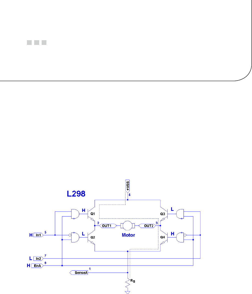
383
Chapter 28
The H-Bridge Driver
One of the challenges of driving DC electric motors is that they sometimes need the capability to operate in reverse.
To do this, the current flow must be reversed. Arranging for this requires additional hardware.
The H-Bridge driver can be used to drive a reversible DC motor or a bipolar stepper motor (also LEDs as in
chapter 12). Unlike the unipolar motor, the field windings of a bipolar stepper motor require reversible current flow to
operate. This chapter demonstrates the utility of the H-Bridge driver, using a bipolar stepper motor.
The L298 Driver
The L298 integrated circuit implements a convenient H-Bridge driver circuit. An H-Bridge can be built from discrete
components, but integrated circuits are more convenient for lower-current applications. Figure 28-1 shows the block
diagram for the L298 driver IC. You can see the H composed from the driver transistors Q1 through Q4, and the driven
motor in the center (in this case, a DC motor).
Figure 28-1. L298 full-bridge driver

CHAPTER 28 ■ THE H-BRIDGE DRIVER
384
The motor in the figure is driven when Q1 and Q4 are turned on. Q2 and Q3 are kept off when the other transistors
are on. If Q1 and Q2 were allowed to be on at the same time, a short circuit would exist from VSS to ground. The and
logic gates driving these transistors prevent this.
Returning to Figure 28-1, with Q1 and Q4 on, the current flows through the motor from left to right. Turning all
transistors off results in no current flow. Turning Q3 and Q2 on causes the current to flow from VSS to ground, passing
this time through the motor from right to left. By controlling pairs of transistors, current can be made to flow in one
direction or the other.
Sensing Resistor
When used, the sensing resistor RS is a low-resistance resistor for sensing how much current flows through the
motor (the datasheet suggests a non-wire-wound resistance of RS = 0.5 W). As current flow increases, the voltage VRS
across the resistor increases. When the motor stalls, for example, VRS will exceed a certain threshold voltage, allowing
protective circuitry to turn the drivers (and thus the motor) off. In this chapter, we will simply wire the sense pins to
ground and omit the protective circuitry for simplicity.
Enable A and B
The L298 is a dual-bridge driver, with units A and B. Figure 28-1 shows only unit A. The enable inputs EnA and EnB
enable or disable the drive to units A and B, respectively. Without a high signal on the enable input, no current will
flow through the bridge, no matter what the other input signals are. The enable input can be used by the protective
circuitry to disable the motor outputs, should the VRS voltage rise too high. Otherwise, the enable inputs can be tied to
the logic high or controlled by the microprocessor.
Inputs In1 and In2
Each half of the dual-bridge driver has a pair of logic inputs. They are In1 and In2 for bridge A, and In3 and In4 for
bridge B. We’ll focus on bridge A.
When the enable EnA pin is enabled, the In1 and In2 inputs have the following results for the motor drive:
In1 In2 Q1 Q2 Q3 Q4 Motor Current
0 0 On On No current flow
0 1 On On Right to left
1 0 On On Left to right
1 1 On On No current flow
A simple way to think about this is that one input must be high, while the other is low for the motor drive. The
direction is selected by the input that is high.
Protection Diodes
No inductive driver circuit is complete without protective diodes. When the applied voltage is suddenly removed from
the motor coil, the magnetic field collapses, producing an electric current. Recall in Chapter 27 that the reverse-biased
diode was used to bleed off the inductive kick in the unipolar motor drive.
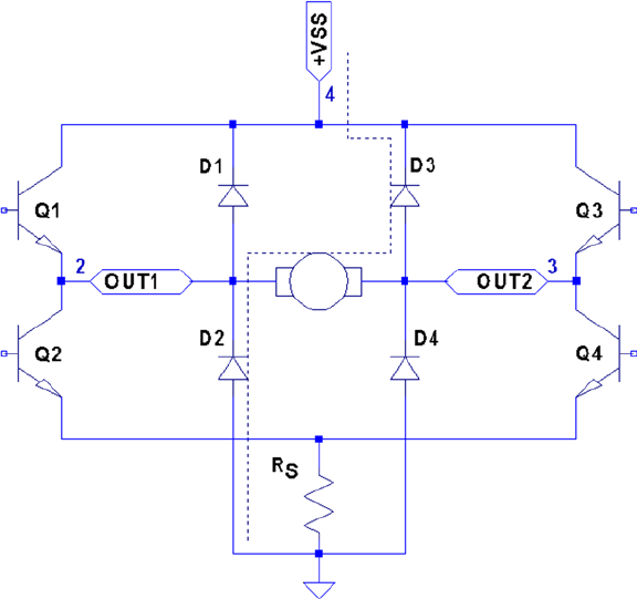
CHAPTER 28 ■ THE H-BRIDGE DRIVER
385
Figure 28-2 shows the L298 with the external protective diodes wired in (these are not included in the IC). If the
current flow was as shown in the earlier block diagram, the sudden off would cause the current to flow through
diodes D3 and D2. The SGS-Thomson Microelectronics datasheet specifies that these should be 1A fast-recovery
diodes (trr £ 200 ns). A slow-reacting diode can allow the voltage to spike into the surrounding circuit.
L298 PCB
You could build your own L298 driver circuit, but with the availability of PCBs around $4 on eBay, you’d have to have a
good reason to bother. Figure 28-3 shows the unit that I purchased and used for this project.
Figure 28-2. L298 with protective diodes

CHAPTER 28 ■ THE H-BRIDGE DRIVER
386
Note ■ I purchased this PCB as an eBay Buy It Now offer with free shipping.
The PCB has three power connections:
• VS, which is labeled as +12 V (yellow wire in the photo)
Gnd (black wire) •
• VSS, which is labeled as +5 V (red wire)
This particular PCB has a jumper (removed in Figure 28-3), with its two pins visible just above the
power-connection block and below the round capacitor. With the jumper installed, an onboard regulator supplies VSS
with +5 V from the VS (+12 V) input. The regulated +5 V is also available for external circuitry at the block connector
(where the red wire is shown).
When the motor (VS) voltage is higher than 12 V, it is best to remove the jumper and supply the +5 V into the block
instead. The reason for this is that the linear regulator must dissipate additional heat from the higher input voltage.
I am using a salvaged power supply with both a +5 V supply and a +16 V supply, so the jumper was removed.
To the right of the power-input block are header connection pins as follows:
+5V +5V
EnA In1 In2 In3 In4 EnB
The EnA and EnB connections have jumpers installed to enable both driver units (tying the enable A and B
inputs up to the +5 V supply). If you don’t need to control the enable inputs, leave the jumpers in. Otherwise, remove
them and then use the edge pins for inputs to enables A and B.
Figure 28-3. L298 driver PCB

CHAPTER 28 ■ THE H-BRIDGE DRIVER
387
The pins In1 through In4 are the inputs to the bridge drivers (see In1 and In2 in Figure 28-1).
The remaining connections are two blocks with paired connections:
OUT1 and OUT2, bridge connections for unit A•
OUT3 and OUT4, bridge connections for unit B•
You don’t have to install any protective diodes, since they are already included on the PCB. Price and
convenience were the reasons I chose to buy the PCB. If you breadboard the driver instead, be sure to wire in the
fast-acting protection diodes, since these are not included in the IC.
Driving from GPIO
Of course, before we attach the inputs of these drivers to the GPIO pins of the Raspberry Pi, we need to be certain that
the voltage levels are safe and that the interface logic levels work.
The L298 IC has the following power requirements:
Symbol Parameter Min Typ Max Unit
VSSupply voltage (pin 4) VIH + 2.5 46 Volts
VSS Logic supply voltage (pin 9) 4.5 5 7 Volts
From this, we see that the motor side (VS) can operate up to 46 V. The logic side, however, must have a minimum
of 4.5 V. In other words, the L298 driver operates at 5V TTL levels.
Note ■ Be sure to remove the regulator jumper when using high voltages.
But we’ve seen this kind of problem before, in Chapter 27. There we were still able to drive the ULN2003A safely
from the GPIO outputs at 3 V levels. So let’s check the signal requirements of GPIO outputs vs. L298 inputs:
GPIO L298
Signal Volts Volts Signal
VOL £ 0.8 V£ 1.5 V VIL
VOH ³ 1.3 V³ 2.3 V VIH
If you look carefully at the chart, there is a dodgy area where the GPIO output can be as low as VOH ³ 1.3 V and
still be in spec as far as the Raspberry Pi is concerned. We see that the L298 considers signals VIL £ 1.5V as a low. Worse,
only voltages ³ 2.3 V are considered high by the L298. The good news is that the L298 input current is very low:
L298
Symbol Parameter Test Conditions Typ Max Unit
IIH High-voltage input current VI = H £ VSS – 0.6 V30 100 mA
CHAPTER 28 ■ THE H-BRIDGE DRIVER
388
The input current necessary to drive the L298 input high is a maximum of 100 mA. The lowest configured output
drive capability of a GPIO pin is 2 mA. The L298 input current requirement is thus only 5% of the minimum current
drive available. If the GPIO pin had to drive a 2 mA signal, its output voltage might be as low as 1.3 V. But having to
supply only 100 mA of signal current means that the GPIO voltage should be almost as high as it can go.
For this reason, it is not that unreasonable to expect the GPIO output voltage to be near 3 V (allowing for a drop
from the +3.3 V supply). However, we must allow for variation in the +3.3 V power supply as well. If the supply is
within the standard range of +3.125 to +3.465 V, and we allow a GPIO output drop of, say, 0.3 V due to the output
transistor Ron , then the unloaded GPIO output voltage could be as low as 3.135 – 0.3 = 2.835 V. This is only 0.535 V
above the minimum VIH = 2.3 V that we need for the L298. This is cutting things rather close, but sufficient for hobby
and educational use (for products that are sold, you would want a greater margin for error). If this remains a concern
for a project build, external pull resistors to +3.3 V can be added.
The DMM Check
The final word is the voltage measurement of the L298 chip’s inputs. You must make certain there is no pull-up
resistor to +5 V on the PCB. The datasheet doesn’t indicate that any L298 chip internal pull-up resistors exist. But
seeing is believing, so don’t skip this check. A purchased PCB is more likely to contain pull-up resistors than not.
Without attaching it to the Pi, supply the circuit with +5 V for its logic (the motor supply need not be applied).
When using the onboard regulator, supply the +12 V to the +VS input instead. Then check the voltage appearing at
the EnA, EnB, In1, In2, In3, and In4 inputs. When measured, there should be nearly no voltage present (with respect
to ground). If you read +5 V instead, the PCB likely has provided a pull-up resistor somewhere. For the enable inputs,
jumpers may need to be removed. Do not wire these inputs to the Raspberry Pi until these inputs have passed this
check. Anything measured less than 0.6 V is probably OK. Measurements higher than this probably mean a defective
driver IC or a wiring error.
If you are supplying the L298 logic from a separate +5 V supply, it is a good idea to perform one more test with the
+12 V (or higher) motor supply applied. The measured voltage at each input pin should remain as before, near zero.
Anything else suggests a bad PCB or defective L298 chip leaking current into the inputs.
Bipolar Stepper Modes
Before we look at the schematic and software, let’s review how the bipolar stepper motor works. There are three basic
modes of operation for a bipolar stepper motor:
Wave drive, one-phase-on drive•
Wave drive, two-phase-on drive•
Half-step drive•
One-Phase-On Mode
Figure 28-4 shows the first two of four possible drive states for wave drive, one phase on. Each winding is energized
in turn for the first two steps. The final two steps energize the same two windings in sequence except that the current
polarity is reversed. In other words, the south pole of the rotor follows the positive input polarity (as wired in the
figure). In this mode, there are a total of four steps.
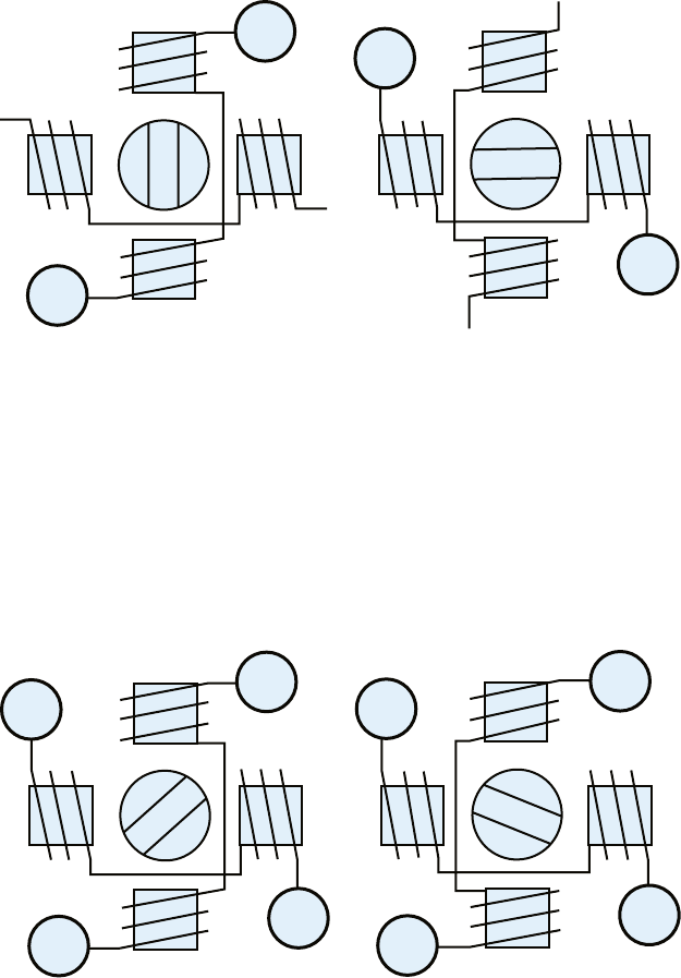
CHAPTER 28 ■ THE H-BRIDGE DRIVER
389
This simple mode of operation suffers from the loss of precision that the half-step drive has and lacks the torque
of two-phase-on mode.
Two-Phase-On Mode
Wave drive, two-phase-on mode energizes both windings for each step. This is where the extra torque comes from.
Figure 28-5 shows two of the four possible steps for this mode. Notice how the south pole centers itself between two
poles, as it follows the two positive polarities. Like the one-phase mode, there are only four possible steps.
N
S
N
S
+
+
-
-
Figure 28-4. Wave drive, one phase on
N
S
N
S
+
++
+-
---
Figure 28-5. Wave drive, two phase on
While this mode lacks the precision of half-step mode (next), it does enjoy the extra torque advantage over all
three modes.
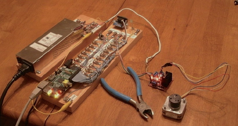
CHAPTER 28 ■ THE H-BRIDGE DRIVER
390
Half-Step Mode
In half-step mode, a combination of the two prior modes is used. First, only one winding is energized to point the
rotor at the winding’s pole (like one-phase mode). Then the next pole is energized while keeping the prior winding
energized. In this way, the rotor moves a half step between the two poles, as with two-phase mode. Finally, the
previous winding is turned off, producing another half step. The precision is increased to a total of eight steps in this
manner.
This is clearly the most precise of the three modes. While it lacks some of the torque of two-phase mode, it has on
average more torque than one-phase mode.
In all of these modes, it is necessary to first pass current through the windings in one direction, and then later in
the reverse direction. This allows the bipolar stepper motor to be built with less wire than the unipolar motor. In the
unipolar design, only one or two of the four center-tapped windings are used at one time. Consequently, the bipolar
motor is cheaper to manufacture and lighter in weight.
Figure 28-6 illustrates my test setup. At the left is a power supply that I rescued from a discarded piece of
equipment. To the right of the Raspberry Pi station, I have the L298 PCB wired up to the power and the Pi’s GPIO pins.
The remaining four wires go from the drive PCB to the bipolar stepper motor (I left some sort of shaft attachment to
the motor, to make the rotation more visible).
Figure 28-6. My bipolar stepper motor setup
Choosing Driving GPIOs
Recall from Chapter 27’s Table 27-1 that some GPIO pins are more suitable than others for motor controls. While the
Raspberry Pi is booting up, we don’t want driver circuits and motors running amok. It is best that the motor remains
disabled until the Pi boots up and the motor-controlling software takes proper control.
When using the L298, we can take one of two design approaches:
Tie enable inputs high, but choose • motor-safe GPIO pins for the driver inputs.
Drive the enable inputs from a • motor-safe GPIO and configure the other GPIO pins
after boot-up.
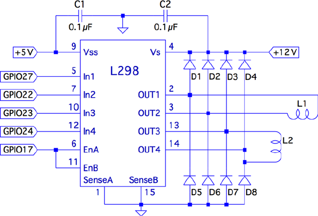
CHAPTER 28 ■ THE H-BRIDGE DRIVER
391
The first option does not use the enable inputs at all. For that, you must make sure that all In GPIO pins are safe
for motor control at boot time. The disadvantage is that all four input controls need to be taken from the safe GPIO
pool. If you need to drive more than one motor, your options start to become limited.
The second approach uses motor-safe GPIO pin(s) on the two enable inputs of the L298 driver. This way, the
enable inputs are pulled down during the boot-up process, disabling the motor controls, regardless of the state of the
In pins. This gives you flexibility to choose any other GPIO pins for use for the In signals. This is the approach adopted
for this chapter’s project. (Note that you can tie the enable pins together so that only one safe GPIO pin is required to
drive the enable input.) Because a bipolar stepper motor needs a bridge driver for each of its two windings, we’ll use
both bridge driver units provided by the L298 IC.
The enable inputs for the two windings can be ganged together and driven by one GPIO pin. This, of course, increases
the load on the GPIO output, but at a worst case of 200 mA, the driving voltage requirements will be easily met.
Project Schematic
Figure 28-7 shows the schematic for the bipolar motor driver. If you are using a purchased PCB, the only important
details are the connections to it. The schematic, however, helps us visualize all the separate components involved.
Figure 28-7. L298 schematic
In this circuit, the enable inputs A and B have been tied together so that only GPIO 17 needs to be allocated to
drive it.
Junk-Box Motors
If you’ve been an electronics hobbyist for a while, you likely have a bipolar motor in your junk box. If not, salvage one
from an old 3.5-inch floppy disk. Its seek motor will likely be a bipolar stepper. Another source of stepper motors is an
old flat-top scanner.

CHAPTER 28 ■ THE H-BRIDGE DRIVER
392
Bipolar motors are easier to figure out than unipolar motors. There are only four wires, and they operate in pairs.
To identify the pairs, simply take resistance readings. A low reading will identify one pair of wires. Once that pair is
identified, the remaining two wires should be the second pair and read similarly. Make sure there is no connection
between the windings. They should be electrically isolated from each other.
Program Operation
The program used in this chapter is named bipolar.c and is listed at the end of the chapter. The program is designed
similarly to the unipolar program in Chapter 27. The bipolar program, however, does not do clock positioning, but
instead operates in free-running mode when instructed to do so.
The program starts in one-phase mode, but the stepper-motor mode can be changed with any of the following
single-character commands:
Character Command
1 Wave mode, one phase
2 Wave mode, two phase
3 Half-step mode
Entering a mode command will automatically stop the motor if it is in free-running mode.
To test your motor connections, these single-step commands are available:
Character Command
+ Single step clockwise
- Single step counterclockwise
The + command steps the motor one step clockwise, while the – (minus) key steps the motor counterclockwise.
If your motor turns the wrong way, you can fix your wiring after testing it.
Similarly, use these single-step commands to make sure your motor is wired up correctly. In one-phase mode
(the default), the motor should step equally with each + or - step command. If not, one of the two pairs needs its
connections reversed.
The free-running commands (and Quit) are listed here:
Character Command
F Forward (free running)
R Reverse (free running)
S Stop
> Go faster (halve the step time)
< Go slower (double the step time)
Q Quit
CHAPTER 28 ■ THE H-BRIDGE DRIVER
393
Entering F starts the motor running, in the forward (clockwise) direction. To speed it up, press > while it is
running, or prior to starting it. Pressing the same direction command F toggles the motor off again. Alternatively, S
is available to stop the motor if that seems more intuitive. The R command starts the motor in the reverse direction.
Pressing R again stops it. Direction can be changed while the motor is running. This tests how well it recovers when
operated at higher speeds.
Program Internals
This program requires the use of a thread to run the motor in free-running mode. This design allows the main
program to continue to read user commands from the keyboard while supplying the motor with stepping commands.
The user can change the stepping speed, reverse the motor, or stop the motor.
The main user input dispatch loop is in the main program (lines 230 to 305). The threaded code resides in
lines 125 to 140. Unless the free-running F or R commands are in effect, the thread blocks in line 131, waiting for a
command. Once a command is received, the loop in lines 133 to 136 keeps the motor stepping, until the main loop
sets the stop flag.
The mutex and cond variables (lines 36 and 37) provide a simple arrangement to implement a queue from the
main thread to the free-running thread. The queue get function is implemented in lines 105 to 119. The code must first
successfully lock the mutex in line 109. Once that is accomplished, the while loop in lines 111 and 112 is executed. If the
cmd variable is still zero, this indicates that no command has been queued. When that happens, pthread_cond_wait()
in line 112 is executed. This unlocks the mutex and blocks the execution of the program. Control blocks until the cond
variable is signaled in line 158. When control returns from pthread_cond_wait(3), the kernel has relocked the mutex.
Queuing the command occurs in the routine queue_cmd() (lines 146 to 159). After locking the mutex (line 149),
the while loop checks whether the cmd variable is nonzero. If it is, this indicates that the motor thread has not received
the last command yet, and control blocks in the pthread_cond_wait() call (line 152). Again, when control blocks, the
kernel releases the mutex. The cond variable is signaled from line 117, when the command is taken off the
one-element queue.
The stepping functions are performed by the routine step() in lines 73 to 91. The motor drive is disabled in
line 86 so the GPIO signals can be changed (line 87). Once the new GPIO output settings are established, the drive to
the motor is enabled in line 88.
If you choose to use different GPIO pins for this project, change the constant declarations in lines 23 to 27.
1 /**********************************************
2 * bipolar.c : Drive a bipolar stepper motor
3 **********************************************/
4
5 #include <stdio.h>
6 #include <stdlib.h>
7 #include <fcntl.h>
8 #include <unistd.h>
9 #include <errno.h>
10 #include <math.h>
11 #include <ctype.h>
12 #include <termio.h>
13 #include <sys/mman.h>
14 #include <pthread.h>
15 #include <assert.h>
16
17 #include "gpio_io.c" /* GPIO routines */
18 #include "timed_wait.c" /* timed_wait() */
19
CHAPTER 28 ■ THE H-BRIDGE DRIVER
394
20 /*
21 * GPIO definitions :
22 */
23 static const int g_enable = 17; /* L298 EnA and EnB */
24 static const int g_in1 = 27; /* L298 In1 */
25 static const int g_in2 = 22; /* L298 In2 */
26 static const int g_in3 = 23; /* L298 In3 */
27 static const int g_in4 = 24; /* L298 In4 */
28
29 static volatile int stepper_mode = 0; /* Stepper mode − 1 */
30 static volatile float step_time = 0.1; /* Step time in seconds */
31
32 static volatile char cmd = 0; /* Thread command when nonzero */
33 static volatile char stop = 0; /* Stop thead when nonzero */
34 static volatile char stopped = 0; /* True when thread has stopped */
35
36 static pthread_mutex_t mutex; /* For inter−thread locks */
37 static pthread_cond_t cond; /* For inter−thread signaling */
38
39 /*
40 * Await so many fractional seconds
41 */
42 static void
43 await(float seconds) {
44 long sec, usec;
45
46 sec = floor(seconds); /* Seconds to wait */
47 usec = floor((seconds−sec)*1000000); /* Microseconds */
48 timed_wait(sec, usec, 0); /* Wait */
49 }
50
51 /*
52 * Enable/Disable drive to the motor
53 */
54 static inline void
55 enable(int enable) {
56 gpio_write(g_enable, enable);
57 }
58
59 /*
60 * Drive the appropriate GPIO outputs :
61 */
62 static void
63 drive(int L1L2) {
64 gpio_write(g_in1, L1L2&0x08);
65 gpio_write(g_in2, L1L2&0x04);
66 gpio_write(g_in3, L1L2&0x02);
67 gpio_write(g_in4, L1L2&0x01);
68 }
69
CHAPTER 28 ■ THE H-BRIDGE DRIVER
395
70 /*
71 * Take one step in a direction :
72 */
73 static void
74 step(int direction) {
75 static const int modes[3][8] = {
76 { 0b1000, 0b0010, 0b0100, 0b0001 }, /* Mode 1 */
77 { 0b1010, 0b0110, 0b0101, 0b1001 }, /* Mode 2 */
78 { 0b1000, 0b1010, 0b0010, 0b0110, 0b0100, 0b0101, 0b0001, 0b1001 }
79 } ;
80 static int stepno = 0; /* Last step no. */
81 int m = stepper_mode < 2 ? 4 : 8; /* Max steps for mode */
82
83 if ( direction < 0 )
84 direction = m − 1;
85
86 enable(0); /* Disable motor */
87 drive(modes[stepper_mode][stepno]); /* Change fields */
88 enable(1); /* Drive motor */
89
90 stepno = (stepno+direction) % m; /* Next step */
91 }
92
93 /*
94 * Set the stepper mode of operation :
95 */
96 static inline void
97 set_mode(int mode) {
98 enable(0);
99 stepper_mode = mode;
100 }
101
102 /*
103 * Take a command off the input queue
104 */
105 static char
106 get_cmd(void) {
107 char c;
108
109 pthread_mutex_lock(&mutex);
110
111 while ( !cmd )
112 pthread_cond_wait(&cond,&mutex);
113
114 c = cmd;
115 cmd = stop = 0;
116 pthread_mutex_unlock(&mutex);
117 pthread_cond_signal (&cond); /* Signal that cmd is taken */
118
119 return c;
120 }
121
CHAPTER 28 ■ THE H-BRIDGE DRIVER
396
122 /*
123 * Stepper controller thread :
124 */
125 static void *
126 controller(void * ignored) {
127 int command;
128 int direction;
129
130 for ( stopped = 1; ; ) {
131 command = get_cmd();
132 direction = command == 'F' ? 1 : −1;
133
134 for ( stopped = 0; !stop; ) {
135 step(direction);
136 await(step_time);
137 }
138 stopped = 1;
139 }
140 return 0;
141 }
142
143 /*
144 * Queue up a command for the controller thread :
145 */
146 static void
147 queue_cmd( char new_cmd) {
148
149 pthread_mutex_lock(&mutex); /* Gain exclusive access */
150
151 /* Wait until controller grabs and zeros cmd */
152 while ( cmd )
153 pthread_cond_wait(&cond ,&mutex);
154
155 cmd = new_cmd ; /* Deposit new command */
156
157 pthread_mutex_unlock(&mutex ); /* Unlock */
158 pthread_cond_signal(&cond); /* Signal that cmd is there */
159 }
160
161 /*
162 * Stop the current operation :
163 */
164 static void
165 stop_cmd(void) {
166 for ( stop = 1; !stopped; stop = 1 )
167 await(0.100);
168 }
169
170 /*
171 * Provide usage info :
172 */
CHAPTER 28 ■ THE H-BRIDGE DRIVER
397
173 static void
174 help(void) {
175 puts("Enter :\n"
176 " 1 − One phase mode\n"
177 " 2 − Two phase mode\n"
178 " 3 − Half step mode\n"
179 " R − Toggle Reverse (counter−clockwise)\n"
180 " F − Toggle Forward (clockwise)\n"
181 " S − Stop motor\n"
182 " + − Step forward\n"
183 " − − Step backwards\n"
184 " > − Faster step times \n"
185 " < − Slower step times \n"
186 " ? − Help\n"
187 " Q − Quit\n " ) ;
188 }
189
190 /*
191 * Main program
192 */
193 int
194 main(int argc,char **argv) {
195 pthread_t tid; /* Thread id */
196 int tty = 0; /* Use stdin */
197 struct termios sv_ios, ios;
198 int rc, quit;
199 char ch, lcmd = 0;
200
201 rc = tcgetattr (tty,&sv_ios); /* Save current settings */
202 assert(!rc);
203 ios = sv_ios;
204 cfmakeraw(&ios); /* Make into a raw config */
205 ios.c_oflag = OPOST | ONLCR; /* Keep output editing */
206 rc = tcsetattr(tty,TCSAFLUSH,&ios); /* Put terminal into raw mode */
207 assert(!rc);
208
209 /*
210 * Initialize and configure GPIO pins :
211 */
212 gpio_init();
213 gpio_config(g_enable,Output);
214 gpio_config(g_in1,Output);
215 gpio_config(g_in2,Output);
216 gpio_config(g_in3,Output);
217 gpio_config(g_in4, Output);
218
219 enable(0); /* Turn off output */
220 set_mode(0); /* Default is one phase mode */
221
222 help();
223
CHAPTER 28 ■ THE H-BRIDGE DRIVER
398
224 pthread_mutex_init(&mutex,0); /* Mutex for inter−thread locking */
225 pthread_cond_init(&cond,0); /* For inter−thread signaling */
226 pthread_create(&tid,0,controller,0); /* The thread itself */
227
228 /*
229 * Process single-character commands :
230 */
231 for ( quit=0; !quit; ) {
232 /*
233 * Prompt and read input char :
234 */
235 write(1,": ",2);
236 rc = read(tty,&ch,1);
237 if ( rc != 1 )
238 break;
239 if ( islower (ch) )
240 ch = toupper(ch);
241
242 write(1,&ch,1);
243 write(1,"\n",1);
244
245 /*
246 * Process command char :
247 */
248 switch ( ch ) {
249 case '1' : /* One phase mode */
250 stop_cmd();
251 set_mode(0);
252 break;
253 case '2' : /* Two phase mode */
254 stop_cmd();
255 set_mode(1);
256 break;
257 case '3' : /* Half step mode */
258 stop_cmd();
259 set_mode(2);
260 break;
261 case '<' : /* Make steps slower */
262 step_time *= 2.0;
263 printf("Step time is now %.3f ms\n",step_time *1000.0);
264 break;
265 case '>' : /* Make steps faster */
266 step_time /=2.0;
267 printf("Step time is now %.3f ms\n",step_time *1000.0);
268 break;
269 case 'F' : /* Forward : run motor */
270 if ( !stopped && lcmd != 'R' ) {
271 stop_cmd(); /* Stop due to toggle */
272 lcmd = 0;
CHAPTER 28 ■ THE H-BRIDGE DRIVER
399
273 } else {
274 stop_cmd(); /* Stop prior to change direction */
275 queue_cmd(lcmd='F');
276 }
277 break;
278 case 'R' : /* Reverse : run motor */
279 if ( !stopped && lcmd != ’F’ ) {
280 stop_cmd();
281 lcmd = 0;
282 } else {
283 stop_cmd();
284 queue_cmd(lcmd='R');
285 }
286 break ;
287 case 'S' : /* Just stop */
288 stop_cmd();
289 break;
290 case '+' : /* Step clockwise */
291 case '=' : /* So we don't have to shift for + */
292 stop_cmd();
293 step(1);
294 break;
295 case '−' : /* Step counterclockwise */
296 stop_cmd();
297 step(−1);
298 break;
299 case 'Q' : /* Quit */
300 quit = 1;
301 break;
302 default : /* Unsupported */
303 stop_cmd();
304 help();
305 }
306 }
307
308 stop_cmd();
309 enable(0);
310
311 puts("\nExit.");
312
313 tcsetattr(tty,TCSAFLUSH,&sv_ios); /* Restore terminal mode */
314 return 0;
315 }
316
317 /* End bipolar.c */

401
Chapter 29
Remote-Control Panel
Because of the Raspberry Pi’s small size and low cost, it is an attractive platform for remote-sensing applications.
A remote station might need to sense control panel switches or push button events. This electronic problem sounds
simple until you discover that switches and buttons suffer from contact bounce.
The remaining challenge resides on the software side. When your sensing stations are remote, some kind of local
software console needs to exist. In fact, your console may monitor several remote Raspberry Pis. Then add redundant
consoles, or consoles in multiple locations. Each of these has the ability to monitor and control the same remote
devices. It doesn’t take long before the problem becomes complex.
This chapter’s project aims to solve two problems:
Debouncing a switch or push button (hardware)•
Controlling remote consoles (software)•
Let’s first examine the contact bounce problem.
Switched Inputs
One of the aggravations of dealing with push buttons and switches in an electronic computing environment is
that contacts bounce. When you close a switch or push a button, the contacts can bounce a thousand times before
they settle and produce a stable contact. A modern computer might see thousands of on/off transitions before the
contacts stabilize.
This is not only a nuisance for software design, but also wasteful of the CPU. Each time the signal from the switch
changes state, the CPU must be interrupted to make note of this event and pass the information on to the interested
software (for example, GPIO change events). The software must then apply algorithms to smooth out these pulses and
arrive at a conclusion when the switch is fully on, or fully off. This is all very ugly and messy!
The same problem happens in reverse when contacts release. Thousands of pulses are delivered to the CPU as
the contacts slowly release and alternate between being in contact and being disconnected.
There are several ways to reduce or eliminate the problem. One approach is to apply a flip-flop ahead of the GPIO
pins, as shown in Figure 29-1. One end of a SPDT switch is wired to the flip-flop reset input, while the other is wired to
the set input. In this manner, a single pulse on either end changes the flip-flop state and keeps it stable.
CHAPTER 29 ■ REMOTE-CONTROL PANEL
402
When the switch is releasing one contact, there is no change in the flip-flop output. After the arm has flown
through its switching arc, the opposite contact eventually starts to bounce at the end of its swing. At this point, it takes
only a single pulse to change the output of the flip-flop to its new state. After that, it remains constant.
The pull-down resistors R1 and R2 are necessary because the CMOS inputs would otherwise float when the
switch arm disconnects from the switch’s contacts. While disconnected, the resistors pull the input voltage down to
ground potential.
The CD4013
The CD4013 is a CMOS part that is able to operate from +3 V and up. The pinout for the CD4013 is provided in
Figure 29-2. The supply voltage VDD is applied to pin 14, with pin 7 (VSS) performing as the ground return. From the
pinout diagram, you can see that this is a dual flip-flop IC, with pins labeled for units 1 and 2.
Figure 29-1. Using a flip-flop for debouncing
Figure 29-2. The CD4013 pinout
The datasheet for this part from various manufacturers shows the VIL and VIH levels when VDD = +5 V (and higher).
The values shown for VOH for each VDD are all listed at a value of VDD − 0.5 V. Extrapolating from that, I have assumed
VOH = 3.3 – 0.5 = 2.8 V in the following table. The VOL is listed as 0.05 V for all VDD values listed, so we’ll assume the
same for 3.3 V.

CHAPTER 29 ■ REMOTE-CONTROL PANEL
403
The following table compares the Raspberry Pi GPIO logic levels with those of the CD4013 chip operating at +3.3 V.
Raspberry Pi, GPIO CD4013, VDD = +3.3 V
Parameter Volts Volts Parameter
VIL £ 0.8 V£0.05 V VOL
VIH ³ 1.3 V³ 2.8 V † VOH
†Derived from a National Semiconductor datasheet
From Figure 29-1, recall that we are using the flip-flop output Q to drive a GPIO input. The flip-flop’s VOL is much
lower than the maximum value for VIL, so that works well. Additionally, from the table, notice that the VOH level of the
CD4013 output is well above the minimum required for VIH for the GPIO input as well. From this signal comparison,
we can conclude that the CD4013 part should play very nice with the Pi when powered from 3.3 V.
Caution ■ Unused CMOS inputs should not be left unconnected. If an unused input has no contribution to your design,
ground it. If you must have the input in a high state, wire it directly to the +3.3 V supply. No limiting resistor is required,
since a CMOS input draws no current. Likewise, do not omit R1 and R2, shown in Figure 29-1. Unused CMOS outputs,
however, can be left unconnected.
Unused CMOS inputs should not be left to float. In the presented flip-flop circuit, the following unused pins will
be grounded:
Pin Function Wired to Notes
3 Clock 1 Ground Not used
5 Data 1 Ground Not used
8 Set 2 Ground If FF2 not used
9 Data 2 Ground Not used
10 Reset 2 Ground If FF2 not used
11 Clock 2 Ground Not used
If the second flip-flop is used, simply ground unused pins 9 and 11. Otherwise, unused pins 8 and 10 should also
be grounded. With two flip-flops in the CD4013, you could debounce two switches/buttons.
Testing the Flip-Flop
After wiring up the CD4013 circuit, you can do a preliminary test before hooking it up to your Pi. Simply apply +3.3
V to the circuit and measure the voltage on pin 1 (Q1). When you throw the switch from one position to the next, the
output of Q1 should follow.
CHAPTER 29 ■ REMOTE-CONTROL PANEL
404
Hooked up to the Pi, you can test the circuit with the evinput program developed in Chapter 12. You can choose
any suitable GPIO input, or one that you configured for input. Consult Chapter 12 for a list of GPIOs that boot up in
input mode. I chose to use GPIO 22 (GEN3):
$ ./evinput 22
Monitoring for GPIO input changes :
GPIO 22 changed : 0
GPIO 22 changed : 1
GPIO 22 changed : 0
GPIO 22 changed : 1
GPIO 22 changed : 0
^C
$
Here the switch was initially off (Q1 reads low). Then I threw the switch on, and then off, on, and then off again.
Notice that there are no intervening glitches or other contact bounce events.
If you have a microswitch available with SPDT contacts, you can wire it as a push button. Push it on, release it,
push it on again, and release again. The Raspberry Pi will read nice clean events without any contact bounce. That’s
how we like it on the software side!
The LED
Figure 29-3 shows the wiring for the LED. The resistor R1 was chosen to provide a red LED, about 8 mA. If you’re using
a lower-powered LED, you can increase the resistance of R1. Students may want to review Chapter 12 for the procedure
on how to calculate the resistance for R1.
ØMQ
Some open source projects are just too good not to use. ØMQ is one of them. It exists to solve a difficult problem
close to our hearts. Using this library, we can have each Raspberry Pi act as a publisher of information for the multiple
software consoles acting as subscribers.
Figure 29-3. Sensor LED hookup

CHAPTER 29 ■ REMOTE-CONTROL PANEL
405
To allow multiple consoles to control each Pi sensing station, each sensing station also becomes a subscriber to
the console publishers. In effect, we have many-to-many communication in a tidy software API, thanks to ØMQ.
Note ■ For interesting reading, a nice overview of ØMQ is available here: http://zguide.zeromq.org/page:all.
Performing Installation
The download and installation of ØMQ is almost painless for the Raspberry Pi. Simply allow some time for the
compile, which might take a while (step 3):
1. wget http://download.zeromq.org/zeromq-3.2.2.tar.gz
2. ./configure –prefix=/usr/local
3. make
4. make check (optional)
5. make install
If you also want C++ support for ØMQ, you can perform the following additional steps (we’ll use only the C API
in this chapter):
1. git clone https://github.com/zeromq/cppzmq.git
2. cd cppzmq
3. sudo cp zmq.hpp /usr/local/include/
Compiling and Linking
When compiling source code using ØMQ, you need to specify only the directory where the include files were installed:
• -I /usr/local/include
For linking, you need the following linker options:
• -L/usr/local/lib -lzmq
• -Wl,-R/usr/local/lib
The last option tells the executable where to find the ØMQ shared libraries at runtime. Exclude that option when
linking on the Mac (or use the provided makefile target mac_console).
$ make
gcc –c –Wall –O0 –g –I/usr/local/include –Wall –O0 –g sensor.c –o sensor.o
gcc sensor.o –o sensor –L/usr/local/lib –lzmq –lncurses –Wl, –R/usr/local/lib
sudo chown root ./sensor
sudo chmod u+s ./sensor
gcc –c –Wall –O0 –g –I/usr/local/include –Wall –O0 –g console.c –o console.o
gcc –console.o –o console –L/usr/local/lib –lzmq –lncurses –Wl, –R/usr/local/lib
CHAPTER 29 ■ REMOTE-CONTROL PANEL
406
Sensing Station Design
Our Raspberry Pi sensing station will use the CD4013 flip-flop circuit to debounce one switch or SPDT push button.
The Pi station will also consist of one LED that will be controlled by the multiple software consoles.
If you need to imagine some kind of use case, imagine that the Raspberry Pi is controlling a jail cell door. The guard
who wants to open a door pushes a microswitch button to show SW1=On on the remote consoles (as a request indication).
After the monitoring agents check their video monitor, one of them agrees to honor the request by entering 1 on the
console (which lights the LED) to open the jail cell door. Pressing 0 closes the latch again (turns off the LED).
The great thing about using ØMQ for networking is that you can do the following:
Run • ./sensor with no consoles running
Run any number of • ./console (or ./mac_console) programs without the sensor running yet
Run as many consoles as you like•
Bring down consoles anytime you like•
With a little homework and extra effort, you could monitor multiple sensors as well. That was avoided here, to
keep the example as simple as possible.
Sensing Station Program
The sensing station (Raspberry Pi) is started as follows:
$ ./sensor
The station runs quietly until terminated (it can be shut down from a console).
While it runs, it periodically broadcasts (publishes) updates to the consoles with the current status of SW1 and
LED. This is necessary because a console may be offline when the last switch or LED change occurs.
Whenever SW1 changes, a broadcast is immediately sent with its new status sw1:%d, where %d is a 1 when the
switch is on, and otherwise, a 0.
The LED is changed only at the command of the console program. When the sensor program receives a console
message of the form led:%d (over the network), the LED is turned on or off, according to the value of %d (1 or 0).
Once the LED is changed, however, it is rebroadcasted to all consoles, so that the other consoles can see that this has
changed.
Finally, if the console sends stop: to the sensor, the sensor program shuts down and exits. Pressing ^C in its
terminal session will also terminate it.
Console Program
The console program should be compilable for any Linux or Mac OS X platform. If you use the downloaded makefile,
use the target mac_console when building it on Mac OS X:
$ make mac_console
For the Raspberry Pi or any other Linux distribution, you can build the program simply as follows:
$ make
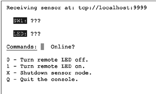
CHAPTER 29 ■ REMOTE-CONTROL PANEL
407
You’ll need the ncurses development library installed, in addition to ØMQ:
# apt–get install libncurses5–dev
To run the console program, simply launch it with the optional hostname as the first command-line argument
(the default is localhost):
$ ./console 192.145.200.14 # Raspberry Pi by IP no.
Mac users will use the following:
$ ./mac_console myrasp # Raspberry Pi by hostname
Figure 29-4 shows the appearance of the console when it first starts up. The ??? show that the console does not
yet know the status of the switch or LED. Beside the command-line input, it also shows Online?, indicating that it
does not yet know whether the sensor is online. As soon as one message is received, that changes to ONLINE.
Console Commands
The console commands are all single-character commands and are displayed on the screen. Typing 0 turns off the
LED on the sensor, and typing 1 turns it on. Typing q or Q quits the console.
Typing x or X terminates the sensor program. (It would not be good to have this option on a real jail cell control.)
Sensor Source Code
Every attempt was made to keep these listings short. But despite these attempts, the code is a bit “winded” for
this simple-minded task. The important thing here is the basic concept and how to leverage it in your own more
sophisticated designs.
Except for the use of pthreads and ØMQ, not much is new in the source code. Consequently, I’ll just provide
some highlights.
The sensor.c main program gets everything started, by opening the GPIO files (input and output), opening the ØMQ
sockets, and creating two threads. The main thread is contained within the main program, within the for loop starting at
line 298. The loop simply pulls console commands from the ØMQ socket console at line 299 and then acts upon them.
Figure 29-4. Console at startup
CHAPTER 29 ■ REMOTE-CONTROL PANEL
408
There are only two supported console commands:
led:%d: Change LED status
stop:: Shut down the ./sensor program
Line 286 of the main program creates the SW1_monitor_thread. This thread is located in lines 211 to 223. It uses
the poll(2) system call in the routine gpio_poll(), to determine when the switch setting changes. This GPIO input is
coming from Q1 of the flip-flop, which is connected to either a switch or a microswitch push-button.
Program execution blocks at line 216, until the switch changes state. Then the status of the switch is captured in
rc and relayed to all interested consoles by calling the routine publish_SW1().
The remaining thread is launched in the main program from line 289. It runs in lines 228 through 237. It is a very
small loop, which simply updates the consoles every 3 seconds, with the current status of the LED and SW1. This is
necessary so that consoles that are restarted can eventually know the current state of these items.
The mutex_lock() and mutex_unlock() routines are designed to guard against two threads using the same ØMQ
resources at the same time. Doing so would cause program aborts.
The ØMQ library supports a routine named zmq_poll(), which would have simplified things if it could have been
used. Unfortunately, it supports only ZMQ_POLLIN for input. Our switch change driver requires the use of poll(2)'s
POLLPRI event, so zmq_poll() will not support us there.
1 /************************************************************************
2 * sensor.c − Sense SW1, send to console (and take LED cmd from console)
3 ************************************************************************/
4
5 #include <stdio.h>
6 #include <stdlib.h>
7 #include <unistd.h>
8 #include <string.h>
9 #include <fcntl.h>
10 #include <assert.h>
11 #include <poll.h>
12 #include <pthread.h>
13
14 #include <zmq.h>
15
16 static const char *service_sensor_pub = "tcp ://*:9999";
17 static const char *service_sensor_pull = "tcp ://*:9998";
18
19 static void *context = 0; /* ZMQ context */
20 static void *publisher = 0; /* Publishing socket */
21 static void *console = 0; /* Pull socket */
22
23 static int SW1 = 0; /* Switchstatus */
24 static int LED = 0; /* LED status */
25 static int stop = 0; /* Nonzero when shutting down */
26
27 static int gp_SW1 = 22; /* GPIO 22 (input) */
28 static int gp_LED = 27; /* GPIO 22 (output) */
29 static int fd_SW1 = −1; /* Open fd for SW1 */
30
31 #include "mutex.c"
32
CHAPTER 29 ■ REMOTE-CONTROL PANEL
409
33 /*
34 * Publish the LED setting to the console(s)
35 */
36 static void
37 publish_LED(void) {
38 char buf [256];
39 size_tn;
40 int rc;
41
42 n = sprintf(buf,"led:%d",LED);
43 mutex_lock();
44 rc = zmq_send(publisher,buf,n,0);
45 assert(rc!=–1);
46 mutex_unlock();
47 }
48
49 /*
50 * Publish the switch setting to the console(s)
51 */
52 static void
53 publish_SW1(void) {
54 char buf[256];
55 size_t n;
56 int rc;
57
58 n = sprintf(buf,"sw1:%d",SW1);
59
60 mutex_lock();
61 rc = zmq_send(publisher,buf,n,0);
62 assert(rc!=–1);
63 mutex_unlock();
64 }
65
66 typedef enum {
67 gp_export = 0, /* /sys/class/gpio/export */
68 gp_unexport, /* /sys/class/gpio/unexport */
69 gp_direction, /* /sys/class/gpio%d/direction */
70 gp_edge, /* /sys/class/gpio%d/edge */
71 gp_value /* /sys/class/gpio%d/value */
72 } gpio_path_t;
73
74 /*
75 * Internal : Create a pathname for type in buf.
76 */
77 static const char *
78 gpio_setpath(int pin,gpio_path_t type,char *buf,unsigned bufsiz) {
79 static const char *paths [] = {
80 "export", "unexport", "gpio%d/ direction",
81 "gpio%d/edge", "gpio%d/value" };
82 intslen;
83
CHAPTER 29 ■ REMOTE-CONTROL PANEL
410
84 strncpy(buf,"/sys/class/gpio/",bufsiz);
85 bufsiz –= (slen == strlen(buf));
86 snprintf(buf+slen,bufsiz,paths[type],pin);
87 return buf;
88 }
89
90 /*
91 * Open/sys/class/gpio%d/value for edge detection :
92 */
93 static int
94 gpio_open_edge(int pin,const char *edge) {
95 char buf[128];
96 FILE *f;
97 int fd;
98
99 /* Export pin : /sys/class/gpio/export */
100 gpio_setpath(pin,gp_export,buf,sizeof buf);
101 f = fopen(buf,"w");
102 assert(f);
103 fprintf(f,"%d\n",pin);
104 fclose(f);
105
106 /* Direction : /sys/class/gpio%d/direction */
107 gpio_setpath(pin,gp_direction,buf,sizeof buf);
108 f = fopen(buf,"w");
109 assert(f);
110 fprintf(f,"in\n");
111 fclose(f);
112
113 /* Edge : /sys/class/gpio%d/edge */
114 gpio_setpath(pin, gp_edge,buf,sizeof buf);
115 f = fopen(buf,"w");
116 assert(f);
117 fprintf(f,"%s\n",edge);
118 fclose(f);
119
120 /* Value : /sys/class/gpio%d/value */
121 gpio_setpath(pin,gp_value,buf,sizeof buf);
122 fd = open(buf,O_RDWR);
123 return fd;
124 }
125
126 /*
127 * Open/sys/class/gpio%d/value for output :
128 */
129 static int
130 gpio_open_output(int pin) {
131 char buf[128];
132 FILE *f;
133 int fd;
134
CHAPTER 29 ■ REMOTE-CONTROL PANEL
411
135 /* Export pin : /sys/class/gpio/export */
136 gpio_setpath(pin,gp_export,buf,sizeof buf);
137 f = fopen(buf,"w");
138 assert(f);
139 fprintf(f,"%d\n",pin);
140 fclose(f);
141
142 /* Direction : /sys/class/gpio%d/direction */
143 gpio_setpath(pin,gp_direction,buf,sizeof buf);
144 f = fopen(buf,"w");
145 assert(f);
146 fprintf(f,"out\n");
147 fclose(f);
148
149 /* Value : /sys/class/gpio%d/value */
150 gpio_setpath(pin,gp_value,buf,sizeof buf);
151 fd = open(buf,O_WRONLY);
152 return fd;
153 }
154
155 /*
156 * Close (unexport) GPIO pin :
157 */
158 static void
159 gpio_close(int pin) {
160 char buf [128];
161 FILE *f ;
162
163 /* Unexport : /sys/class/gpio/unexport */
164 gpio_setpath(pin,gp_unexport,buf,sizeof buf);
165 f = fopen(buf,"w");
166 assert(f);
167 fprintf(f,"%d\n",pin);
168 fclose(f);
169 }
170
171 /*
172 * This routine will block until the open GPIO pin has changed
173 * value.
174 */
175 static int
176 gpio_poll(int fd) {
177 struct poll fd_polls;
178 char buf[32];
179 int rc, n;
180
181 polls.fd = fd; /* /sys/class/gpio17/value */
182 polls.events = POLLPRI; /* Exceptions */
183
CHAPTER 29 ■ REMOTE-CONTROL PANEL
412
184 do {
185 rc = poll (&polls,1, −1); /* Block */
186 } while ( rc < 0 && errno == EINTR );
187
188 assert(rc > 0);
189
190 lseek(fd,0,SEEK_SET);
191 n = read(fd,buf,sizeof buf); /* Read value */
192 assert(n>0);
193 buf[n] = 0;
194
195 rc = sscanf(buf,"%d",&n);
196 assert(rc==1);
197 return; /* Return value */
198 }
199
200 /*
201 * Write to the GPIO pin
202 */
203 static void
204 gpio_write(int fd,int dbit) {
205 write(fd,dbit ? "1\n" : "0\n",2);
206 }
207
208 /*
209 * Monitor switch changes on GPIO
210 */
211 static void *
212 SW1_monitor_thread(void *arg) {
213 int rc;
214
215 while ( !stop ) {
216 rc = gpio_poll(fd_SW1); /* Watch for SW1 changes */
217 if ( rc < 0 )
218 break;
219 SW1 = rc;
220 publish_SW1();
221 }
222 return 0;
223 }
224
225 /*
226 * Periodic broadcast to consoles thread
227 */
228 static void *
229 console_thread(void *arg) {
230
231 while ( !stop ) {
232 sleep(3);
233 publish_SW1();
CHAPTER 29 ■ REMOTE-CONTROL PANEL
413
234 publish_LED();
235 }
236 return 0;
237 }
238
239 /***************************************************************
240 * Main thread : read switch changes and publish to console (s)
241 **************************************************************/
242 int
243 main(int argc,char **argv) {
244 pthread_t tid;
245 int rc = 0;
246 char buf[256];
247 int fd_LED = −1; /* GPIO 27 */
248
249 mutex_init();
250
251 /* Open GPIO for LED */
252 fd_LED = gpio_open_output(gp_LED);
253 if ( fd_LED < 0 ) {
254 printf("%s : Opening GPIO %d for output.\n",
255 strerror (errno),gp_LED);
256 return 1;
257 }
258
259 /* Open GPIO for SW1 */
260 fd_SW1 = gpio_open_edge(22,"both"); /* GPIO input */
261 if ( fd_SW1 < 0 ) {
262 printf("%s: Opening GPIO %d for input.\n",
263 strerror(errno),gp_SW1);
264 return 1;
265 }
266
267 context = zmq_ctx_new();
268 assert(context);
269
270 /* Create a ZMQ publishing socket */
271 publisher = zmq_socket(context,ZMQ_PUB);
272 assert(publisher);
273 rc = zmq_bind(publisher,service_sensor_pub);
274 assert(!rc);
275
276 /* Create a console PULL socket */
277 console = zmq_socket(context, ZMQ_PULL);
278 assert(console);
279 rc = zmq_bind(console,service_sensor_pull);
280 assert(rc != −1);
281
282 SW1 = 0;
283 publish_SW1();
284 publish_LED();
285
CHAPTER 29 ■ REMOTE-CONTROL PANEL
414
286 rc = pthread_create(&tid,0,SW1_monitor_thread,0);
287 assert(!rc);
288
289 rc = pthread_create(&tid,0,console_thread,0);
290 assert(!rc);
291
292 /*
293 * In this thread, we "pull" console commands :
294 *
295 * led:n change state of LED
296 * stop: shutdown the sensor
297 */
298 for (;;) {
299 rc = zmq_recv(console,buf,sizeof buf −1,0);
300 if ( rc > 0 ) {
301 buf[rc] = 0;
302 if ( !strncmp(buf,"led:",4) ) {
303 /* LED command from console */
304 buf[rc] = 0;
305 sscanf(buf,"led:%d",&LED);
306 gpio_write(fd_LED,LED);
307 publish_LED();
308 }
309 if ( !strncmp(buf,"stop:",5) ) {
310 stop = 1;
311 break;
312 }
313 }
314 }
315
316 mutex_lock();
317 zmq_close(console);
318 console = 0;
319
320 rc = zmq_send(publisher,"off: " 4,0);
321 assert(rc !=−1);
322 sleep(3);
323 zmq_close(publisher);
324 publisher = 0;
325
326 gpio_close(gp_SW1);
327 gpio_close(gp_LED);
328 mutex_unlock();
329
330 return 0;
331 }
332
333 /* End sensor.c */
CHAPTER 29 ■ REMOTE-CONTROL PANEL
415
Console Source Code
The console program is an ncurses-based program. It provides the user with a full-screen display without the
complexity of programming a GUI program (an exercise left to the interested reader).
The main program initiates curses mode in lines 204 through 207. Prior to that, the ØMQ library is used to
subscribe to the sensor’s published data in lines 184 through 196. Notice that when subscribing, you must indicate
what subscriptions you want. Not setting any ZMQ_SUBSCRIBE options will result in no messages being received.
Lines 198 to 202 initiate a push connection to the sensor, so commands may be delivered from the console to the
sensor. Note that all running consoles will also establish this connection. Any console can control the sensor.
The main console loop from lines 226 through 243 receives the subscribed messages and displays them on the
console. That’s all it does.
The command_center thread is shown in lines 112 to 161. It simply reads a keystroke in line 125 and then
dispatches the command in line 132.
The ncurses library is not thread safe, so mutex locking is used to prevent more than one thread from attempting
to use that library simultaneously.
1 /*************************************************
2 * console.c − Raspberry Pi Sensor Console
3 ************************************************/
4
5 #include <stdio.h>
6 #include <stdlib.h>
7 #include <unistd.h>
8 #include <string.h>
9 #include <assert.h>
10 #include <pthread.h>
11 #include <curses.h>
12
13 #include <zmq.h>
14
15 #include "mutex.c"
16
17 static char*host_name = "local host"; /* Default host name */
18 static char service_sensor_pub[128]; /* Service name for sensor */
19 static char service_sensor_pull[128]; /* Service name for sensor's cmds */
20
21 static void *context = 0; /* ZMQ context object */
22 static void *subscriber = 0; /* Subscriber socket */
23 static void *console = 0; /* Push socket */
24
25 static int SW1 = −1; /* Known status of SW1 */
26 static int LED = −1; /* Known status of LED */
27
28 /*
29 * Post the status of SW1 to the console screen
30 */
CHAPTER 29 ■ REMOTE-CONTROL PANEL
416
31 static void
32 post_SW1(void) {
33
34 mutex_lock(); /* Lock for shared curses access */
35 attrset(A_REVERSE);
36 mvprintw(3,4,"SW1:");
37 attrset(A_NORMAL);
38 move (3,9);
39 if ( SW1 < 0 ) {
40 addstr("???");
41 } else {
42 if ( SW1 ) {
43 attrset(A_BOLD); /* Blink when switch on */
44 addstr("On ");
45 } else {
46 attrset(A_NORMAL);
47 addstr("Off"); /* SW1 is off */
48 }
49 }
50 attrset(A_NORMAL);
51 if ( SW1 >=0 || LED >=0 )
52 mvprintw(7,15,"ONLINE ");
53 move(7,12);
54 refresh();
55 mutex_unlock(); /* Done with curses */
56 }
57
58 /*
59 * Post LED status to console screen
60 */
61 static void
62 post_LED(void) {
63
64 mutex_lock(); /* Lock shared curses access */
65 attrset(A_REVERSE);
66 mvprintw(5,4,"LED:");
67 attrset(A_NORMAL);
68 move(5,9);
69
70 if ( LED < 0 ) {
71 addstr("???");
72 } else {
73 if ( LED ) {
74 attrset(A_BOLD);
75 addstr("On "); /* LED is now on */
76 } else {
77 attrset(A_NORMAL);
78 addstr("Off");/* LED is now off */
79 }
80 }
81
CHAPTER 29 ■ REMOTE-CONTROL PANEL
417
82 attrset(A_NORMAL);
83 if ( SW1 >=0 || LED >=0 )
84 mvprintw(7,15,"ONLINE ");
85 move(7, 12);
86 refresh();
87 mutex_unlock(); /* Release hold on cur ses */
88 }
89
90 /*
91 * Post online status to screen
92 */
93 static void
94 post_offline(void) {
95
96 SW1 = −1;
97 LED = −1;
98
99 mutex_lock(); /* Lock for shared curses access */
100 attrset(A_REVERSE|A_BLINK);
101 mvprintw(7,15,"OFFLINE");
102 refresh();
103 mutex_unlock(); /* Done with curses */
104
105 post_LED();
106 post_SW1();
107 }
108
109 /*
110 * Main console thread for command center
111 */
112 static void *
113 command_center(void *ignored) {
114 int rc;
115
116 post_LED(); /* Post unknown LED status */
117 post_SW1(); /* Post unknown SW1 status */
118
119 for (;;) {
120 mutex_lock(); /* Lock curses */
121 move (7,12); /* Move cursor to command point */
122 refresh();
123 mutex_unlock(); /* Release curses*/
124
125 rc = getch(); /* Wait for keystroke */
126
127 mutex_lock(); /* Lock curses */
128 mvaddch(7,12,rc); /* Echo character that was typed */
129 refresh();
130 mutex_unlock(); /* Release curses */
131
CHAPTER 29 ■ REMOTE-CONTROL PANEL
418
132 switch ( rc ) {
133 case '0' :
134 /* Tell sensor to turn off LED */
135 rc = zmq_send(console,"led : 0",5,0);
136 assert(rc !=−1);
137 break;
138 case '1' :
139 /* Tell sensor to turn on LED */
140 rc = zmq_send(console,"led: 1",5,0);
141 assert(rc!=−1);
142 break ;
143 case'x' :
144 case'X' :
145 rc = zmq_send(console,"stop :",5,0);
146 assert(rc!=−1);
147 break;
148 case 'q' :
149 case 'Q' :
150 /* Quit the command console */
151 sleep(1);
152 clear();
153 refresh();
154 endwin();
155 exit(0);
156 break;
157 default :
158 ;
159 }
160 }
161 }
162
163 /*
164 * Main thread : init/receive published SW1/LED status updates
165 *
166 * Specify the IP number or hostname of the sensor on the command
167 * line as argument one : $ ./console myrasp
168 */
169 int
170 main(int argc,char **argv) {
171 char buf[1024];
172 int rc;
173 pthread_t tid;
174
175 if ( argc > 1 )
176 host_name = argv[1];
177 sprintf(service_sensor_pub,"tcp://%s:9999",host_name);
178 sprintf(service_sensor_pull,"tcp://%s:9998",host_name);
179
180 mutex_init();
181 context = zmq_ctx_new();
182 assert(context);
183
CHAPTER 29 ■ REMOTE-CONTROL PANEL
419
184 subscriber = zmq_socket(context,ZMQ_SUB);
185 assert(subscriber);
186
187 rc = zmq_connect(subscriber,service_sensor_pub);
188 if (rc == −1) perror("zmq_connect\n");
189 assert(rc!=−1);
190
191 rc = zmq_setsockopt(subscriber,ZMQ_SUBSCRIBE,"sw1:", 4);
192 assert(rc!=−1);
193 rc = zmq_setsockopt(subscriber,ZMQ_SUBSCRIBE,"led:", 4);
194 assert(rc!=−1);
195 rc = zmq_setsockopt(subscriber,ZMQ_SUBSCRIBE, "off:",4);
196 assert(rc!=−1);
197
198 console = zmq_socket(context,ZMQ_PUSH);
199 assert(console);
200
201 rc = zmq_connect(console, service_sensor_pull);
202 assert(!rc);
203
204 initscr();
205 cbreak();
206 noecho();
207 nonl();
208
209 clear();
210 box(stdscr,0,0);
211 move(1,2);
212 printw("Receiving sensor at: %s",service_sensor_pub);
213
214 attrset(A_UNDERLINE);
215 mvaddstr(7,2,"Commands:");
216 attrset(A_NORMAL);
217 mvaddstr(9,2,"0 − Turn remote LED off.");
218 mvaddstr(10,2,"1 − Turn remote LED on.");
219 mvaddstr(11,2,"X − Shutdown sensor node.");
220 mvaddstr(12,2,"Q − Quit the console.");
221 mvprintw(7,15,"Online ?");
222
223 rc = pthread_create(&tid,0,command_center,0);
224 assert(!rc);
225
226 for(;;) {
227 rc = zmq_recv(subscriber,buf,sizeof buf − 1,0);
228 assert(rc >=0 && rc < sizeof buf −1);
229 buf[rc] = 0;
230
231 if ( !strncmp(buf,"off:",4) )
232 post_offline();
233
CHAPTER 29 ■ REMOTE-CONTROL PANEL
420
234 if ( !strncmp(buf,"sw1:",4) ) {
235 sscanf(buf,"sw1:%d",&SW1);
236 post_SW1();
237 }
238
239 if ( !strncmp(buf,"led:",4) ) {
240 sscanf(buf,"led:%d",&LED);
241 post_LED();
242 }
243 }
244
245 return 0;
246 }
247
248 /* console.c */
1 /*******************************************
2 * Mutex . c
3 ******************************************/
4
5 static pthread_mutex_t mutex;
6
7 static void
8 mutex_init(void) {
9 int rc = pthread_mutex_init(&mutex, 0);
10 assert(!rc);
11 }
12
13 static void
14 mutex_lock(void) {
15 intrc = pthread_mutex_lock(&mutex);
16 assert(!rc);
17 }
18
19 static void
20 mutex_unlock(void) {
21 int rc = pthread_mutex_unlock(&mutex);
22 assert(!rc);
23 }
24
25 /* End mutex.c */

421
Chapter 30
Pulse-Width Modulation
This chapter explores pulse-width modulation (PWM) using the Raspberry Pi. PWM is applied in motor control, light
dimming, and servo controls, to name a few examples. To keep the hardware simple and the software small enough to
read, we’re going to apply PWM to driving an analog meter in this chapter.
While the CPU percent-busy calculation used here is a bit cheesy, it is simple and effective for our demonstration.
The meter deflection will indicate how busy your Raspberry Pi’s CPU is. We’ll demonstrate this using a hardware and
software PWM solution.
Introduction to PWM
The GPIO output signal is a digital signal that may be only on or off. You can program it to deliver only 3 V or 0 V.
Consequently, there is no means for the software to ask the GPIO to deliver 1 or 2 V. Despite this limitation, an analog
meter can be driven from a digital output using PWM.
PWM is a technique that works on the principle of averaging the signal. If the signal is on for 10% of the total
cycle, then when the signal is averaged out, the result is an analog 10% of the two digital extremes. If the highest
voltage produced by the GPIO output is 3.3 V, a repeating digital signal that is only on for 75% of that cycle produces
an average voltage that’s determined as follows:
V
V
avg=´
=
33 075
2 475
..
.
If the GPIO output signal was high only 10% of the time, the averaged result is Vavg = 0.33 V. The on time as a
percentage of the total cycle time is known as the duty cycle.
Obviously, there is an averaging aspect to all of this. If you applied the 10% signal to the probes of an oscilloscope,
you’d see a choppy digital-looking signal. The duty cycle may be there, but the averaging effect is not.
The averaging effect is accomplished in several ways. In a lightbulb, the element is heated up by the on pulses but does
not cool immediately, so its brightness reflects the averaged current flow. A DC motor does not immediately stop when the
current is withdrawn, because the rotational inertia keeps the rotor spinning. A meter’s pointer does not immediately move
back to zero when the current is removed. All of these physical effects have an averaging effect that can be exploited.
PWM Parameters
PWM involves modulating the width of the pulse. But the pulse’s width is one aspect relative to a whole cycle.
Defining a PWM signal requires three parameters:
Frequency (or period) of the cycle•
The time period that the signal is on•
The time period that the signal is off•
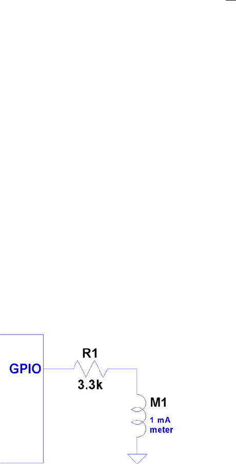
Chapter 30 ■ pulse-Width Modulation
422
It is tempting to think that the cycle time is unimportant. But consider a cycle lasting 10 seconds, where the signal
is on for 1 second and off for the remaining 9 (10%). Apply that signal to a meter, and the needle will show 100% for 1
second and zero for the remaining time. Clearly the cycle is too long for the meter’s movement to average out.
If you produce a software-derived PWM signal, a high-frequency rate will average well on the meter movement. But
the amount of CPU effort expended is also needlessly high, wasting computing power. Planning the operating frequency is
an important aspect of PWM. Hardware PWM peripherals also have design frequency limits that must be considered.
The remaining two parameters form the duty in duty cycle, and are often expressed as a fraction:
N
M
The denominator M = 100 when we talk of percentages. However, M may be any integer that divides the complete
cycle into equal units of time. The value N defines the number of units that the PWM device is to be on. The remaining
M – N step represents the off time.
PWM Hardware Peripheral
The Raspberry Pi makes one hardware PWM peripheral available to the user. It is available on GPIO 18 (GEN1),
but you must give up one of the audio channels to use it (or both, if you consider that the clock is also reconfigured
for PWM clock rates). If your application does not use audio, the peripheral makes a great resource for effortlessly
delivering fast and relatively clean pulse waveforms. And all this without having your software even “think” about it.
If you don’t need to change the duty cycle, you can set up the peripheral and let it run free on its own.
PWM Software
The servo folks would be wringing their hands at the thought of only one PWM signal. Fortunately, the Pi is quite
capable of generating more PWM signals if you can accept a little jitter in the signal output and a little CPU overhead
(about 6% of the CPU for each thread-driven PWM signal, in nonturbo mode). While separate processes could be
used to generate multiple PWM signals, this is best accomplished in one process using threads. The softpwm program
at the end of this chapter demonstrates this.
Meter Circuit
Figure 30-1 shows the circuit used for this chapter’s CPU percent meter. The resistor R1 = 3.3 kW when you use a 1 mA
meter movement.
Figure 30-1. PWM-driven meter

Chapter 30 ■ pulse-Width Modulation
423
If you know the current-handling capability for the meter you would like to use, you can calculate the resistance
needed as follows:
RV
Im
1=
where:
• V is the voltage (3.3 V) at the GPIO pin.
• Im is the current for your meter movement.
If your meter is known to use a 100 mA movement, for example, the series-dropping resistor would work out to be
the following:
R
k
1
33
0 0001
33
=
=
.
.W
For all projects in this book, I encourage you to substitute and try parts that you have on hand. You may have a
junk-box meter somewhere that you can use. Don’t use automotive ammeters, since they will usually have a shunt
installed. Almost any voltmeter or meter with a sufficiently sensitive movement can be used. The limit is imposed by
the GPIO output pin, which supports up to 8 mA (unless reconfigured).
If you don’t know its movement sensitivity, start with high resistances and work down (try lowest currents first).
With care, you can sort this out without wrapping the needle around the pin.
pwm Program
The program software pwm is listed at the end of this chapter. To facilitate discussion, I’ll show excerpts of it here.
The hardware example driven by pwm.c is the nastier of the two programs presented. This is due to the difficulty of
programming the PWM hardware registers and the clock-rate registers.
The main program invokes pwm_init(), which gains access to the Pi’s peripherals in much the same way that the
other examples did in gpio_init(). The same mmap() techniques are used for access to the PWM and CLK control
registers.
Whether operating pwm to just set the PWM peripheral or to use the CPU percent-busy function, the PWM
frequency must be set by the function pwm_frequency():
static int
pwm_frequency(float freq) {
...
This function stops the clock that is running and computes a new integer divisor. After disabling the clock, a little
sleep time is used to allow the clock peripheral to stop. The maximum clock rate appears to be 19.2 MHz. To compute
the divisor, the following calculation is used:
If
div =19200000
where:
• Idiv is the computed integer divisor.
• f is the desired PWM frequency.

Chapter 30 ■ pulse-Width Modulation
424
The range of the resulting Idiv is checked against the peripheral’s limits. The value of Idiv is then forced to remain in
range, but the return value is -1 or +1 depending on whether the frequency is under or over the limits.
idiv = (long)( clock_rate / (double) freq );
if ( idiv < 1 ) {
idiv = 1; /* Lowest divisor */
rc = -1;
} else if ( idiv >=0x1000 ) {
idiv = 0xFFF; /* Highest divisor */
rc = +1;
}
Once that is calculated, the value of Idiv is loaded:
ugclk[PWMCLK_DIV] = 0x5A000000 | ( idiv << 12 );
Finally, the clock source is set to use the oscillator, and the clock is enabled:
ugclk[PWMCLK_CNTL] = 0x5A000011;
After this, GPIO 18 is configured for ALT function 5, to gain access to the PWM peripheral:
INP_GPIO(18); /* Set ALT = 0 */
SET_GPIO_ALT(18,5); /* Or in '5' */
The way the SET_GPIO_ALT() macro is defined requires that the INP_GPIO() macro be used first. The INP_GPIO()
macro clears the ALT function bits so that SET_GPIO_ALT() can or in the new bits (the value 5, in this case).
The remaining steps ready the PWM peripheral:
pwm_ctl->MODE1 = 0; /* PWM mode */
pwm_ctl->RPTL1 = 0;
pwm_ctl->SBIT1 = 0;
pwm_ctl->POLA1 = 0;
pwm_ctl->USEF1 = 0;
pwm_ctl->MSEN1 = 0; /* PWM mode */
pwm_ctl->CLRF1 = 1;
Now, at this point, the PWM peripheral is almost ready to go. It needs the ratio
N
M
and then to be enabled.
This is done in the routine pwm_ratio():
static void
pwm_ratio(unsigned n,unsigned m) {
...
This function allows the
N
M
ratio be changed without having to fully reinitialize the other aspects, including the
clock. With our CPU percent-busy function, this ratio will be changing often.
pwm_ctl->PWEN1 = 0; /* Disable */
*pwm_rng1 = m;
*pwm_dat1 = n;
Chapter 30 ■ pulse-Width Modulation
425
After initialization, the PWM peripheral is already disabled. But the first step here disables it, because it may be
running when the ratio is being changed. The following pair of statements put the value of M into the PWM register
RNG1, while N goes into the DAT1 register.
A few more statements check for errors and reset if necessary (these may not be strictly necessary). Then the
following two statements provide a short pause and re-enable the PWM peripheral:
usleep(10); /* Pause */
pwm_ctl->PWEN1 = 1; /* Enable */
That covers the interesting aspects of the hardware PWM control.
Hardware PWM Set Command
When program pwm is provided with command-line arguments, it simply sets up and starts the PWM peripheral.
The command takes up to three arguments:
$ ./pwm N [M] [ F ]
where:
• N is the N in the PWM ratio.
• M is the M in the PWM ratio.
• F is the frequency required.
Once the command is started with these parameters, the PWM peripheral is started and the program exits:
$ . /pwm 40 100 1000
PWM set for 40/100, frequency 1000.0
$
If you have an oscilloscope available, you can attach probes to GPIO 18 and the ground to see a 40% PWM
signal. If you attach the meter circuit of Figure 30-1, it should read near 40% of the full deflection. Figure 30-2 shows
my milliampere meter showing nearly 40% (the deflection reading is nearly 0.4). The DMM in the background is
measuring the +3.3 V supply voltage, which is showing good voltage regulation.
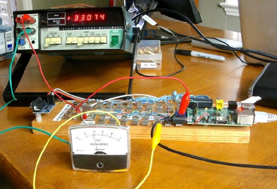
Chapter 30 ■ pulse-Width Modulation
426
To get a more accurate reading, you could put a potentiometer or Trimpot in series with a lower-valued resistor
and adjust for full deflection (with GPIO set to high).
Alternatively, you could take a voltage reading of the GPIO output when set to high and calculate the 1% resistor
value needed. At the time I took the photo for Figure 30-2, I measured 3.275 V when the GPIO was set high while
supplying current to the milliampere meter (through a 3.3 kW 10% resistor). Using that for the basis for calculations,
you could use a 3.24 kW 1% resistor.
Hardware Based CPU Percent-Busy Display
The same pwm command can be used as a CPU percent-busy command when started with no command-line arguments:
$ ./pwm
CPU Meter Mode:
1.4%
The percent of CPU that is busy will be repeatedly shown on the same console line. Simultaneously, the hardware
PWM ratio is being changed. This will cause the meter deflection to indicate the current CPU percent-busy reading.
The pwm command itself requires about 0.6% CPU, so you will never see the meter reach zero.
The CPU percent is determined in a cheesy manner, but it is simple and good enough for this demonstration.
for (;;) {
pipe = popen("ps -eo pcpu|sed 1d","r");
for ( total=0.0; fgets(buf,sizeof buf,pipe); ) {
sscanf(buf,"%f",&pct);
total += pct;
}
pclose(pipe);
printf("\r%.1f%% ",total);
fflush(stdout);
pwm_ratio(total,100);
usleep(300000);
}
Figure 30-2. A milliampere meter showing 40% deflection
Chapter 30 ■ pulse-Width Modulation
427
In this section of code, we open a piped command to ps, with options to report the percent of CPU used by each
process. The sed command deletes the header line from the ps command output.
The for loop reads each line, totaling the percent of CPU used. Occasionally, the total exceeds 100% because of
timing and other roughness in the calculations.
Once the CPU percent total is known, the function pwm_ratio() is called to alter the ratio, thus changing the
position of the meter’s indicator.
1 /***********************************************************
2 * pwm. c − PWM example program
3 **********************************************************/
4
5 #include <stdio.h>
6 #include <stdlib.h>
7 #include <unistd.h>
8 #include <fcntl.h>
9 #include <sys/mman.h>
10 #include <errno . h>
11 #include <string . h>
12
13 #define BCM2835_PWM_CONTROL 0
14 #define BCM2835_PWM_STATUS 1
15 #define BCM2835_PWM0_RANGE 4
16 #define BCM2835_PWM0_DATA 5
17
18 #define BCM2708_PERI_BASE 0x20000000
19 #define BLOCK_SIZE (4*1024)
20
21 #define GPIO_BASE (BCM2708_PERI_BASE + 0x200000)
22 #define PWM_BASE (BCM2708_PERI_BASE + 0x20C000)
23 #define CLK_BASE (BCM2708_PERI_BASE + 0x101000)
24
25 #define PWMCLK_CNTL 40
26 #define PWMCLK_DIV 41
27
28 static volatile unsigned *ugpio = 0;
29 static volatile unsigned *ugpwm = 0;
30 static volatile unsigned *ugclk = 0;
31
32 statics struct S_PWM_CTL {
33 unsigned PWEN1 : 1;
34 unsigned MODE1 : 1;
35 unsigned RPTL1 : 1;
36 unsigned SBIT1 : 1;
37 unsigned POLA1 : 1;
38 unsigned USEF1 : 1;
39 unsigned CLRF1 : 1;
40 unsigned MSEN1 : 1;
41 } volatile *pwm_ctl = 0;
42
Chapter 30 ■ pulse-Width Modulation
428
43 static struct S_PWM_STA {
44 unsigned FULL1 : 1;
45 unsigned EMPT1 : 1;
46 unsigned WERR1 : 1;
47 unsigned RERR1 : 1;
48 unsigned GAP01 : 1;
49 unsigned GAP02 : 1;
50 unsigned GAP03 : 1;
51 unsigned GAP04 : 1;
52 unsigned BERR : 1;
53 unsigned STA1 : 1;
54 } volatile *pwm_sta = 0;
55
56 static volatile unsigned *pwm_rng1 = 0;
57 static volatile unsigned *pwm_dat1 = 0;
58
59 #define INP_GPIO(g) *( ugpio+((g )/10)) &= ~(7<<(((g)%10)*3))
60 #define SET_GPIO_ALT(g,a) \
61 *(ugpio+(((g)/10))) |= (((a)<=3?(a)+4:((a)==4?3:2))<<(((g)%10)*3))
62
63 /*
64 * Establish the PWM frequency :
65 */
66 static int
67 pwm_frequency(float freq) {
68 const double clock_rate = 19200000.0;
69 long idiv;
70 int rc = 0;
71
72 /*
73 * Kill the clock :
74 */
75 ugclk[PWMCLK_CNTL] = 0x5A000020; /* Kill clock */
76 pwm_ctl−>PWEN1 = 0; /* Disable PWM */
77 usleep(10);
78
79 /*
80 * Compute and set the divisor:
81 */
82 idiv = (long)( clock_rate / (double)freq );
83 if ( idiv < 1 ) {
84 idiv = 1; /* Lowest divisor */
85 rc = −1;
86 } else if ( idiv >=0x1000 ) {
87 idiv = 0xFFF; /* Highest divisor */
88 rc = +1;
89 }
90
91 ugclk[PWMCLK_DIV] = 0x5A000000 | ( idiv << 12 );
92
Chapter 30 ■ pulse-Width Modulation
429
93 /*
94 * Set source to oscillator and enable clock :
95 */
96 ugclk[PWMCLK_CNTL] = 0x5A000011;
97
98 /*
99 * GPIO 18 is PWM, when set to Alt Func 5 :
100 */
101 INP_GPIO(18); /* Set ALT = 0 */
102 SET_GPIO_ALT(18,5); /* Or in '5 ' */
103
104 pwm_ctl−>MODE1 = 0; /* PWM mode */
105 pwm_ctl−>RPTL1 = 0;
106 pwm_ctl−>SBIT1 = 0;
107 pwm_ctl−>POLA1 = 0;
108 pwm_ctl−>USEF1 = 0;
109 pwm_ctl−>MSEN1 = 0; /* PWM mode */
110 pwm_ctl−>CLRF1 = 1;
111 return rc ;
112 }
113
114 /*
115 * Initialize GPIO/PWM/CLK Access
116 */
117 static void
118 pwm_init() {
119 int fd;
120 char *map;
121
122 fd = open("/dev/mem",O_RDWR|O_SYNC); /* Needs root access */
123 if ( fd < 0 ) {
124 perror("Opening /dev/mem");
125 exit(1);
126 }
127
128 map = (char *)mmap(
129 NULL, /* Any address */
130 BLOCK_SIZE, /* # of bytes */
131 PROT_READ|PROT_WRITE,
132 MAP_SHARED, /* Shared */
133 fd, /* /dev/mem */
134 PWM_BASE /* Offset to GPIO */
135 );
136
137 if ( (long)map == −1L ) {
138 perror("mmap(/dev/mem)");
139 exit(1);
140 }
141
142 /* Access to PWM */
143 ugpwm = (volatile unsigned *)map;
144 pwm_ctl = (struct S_PWM_CTL *) &ugpwm[BCM2835_PWM_CONTROL];
Chapter 30 ■ pulse-Width Modulation
430
145 pwm_sta = (struct S_PWM_STA *) &ugpwm[BCM2835_PWM_STATUS];
146 pwm_rng1 = &ugpwm[BCM2835_PWM0_RANGE];
147 pwm_dat1 = &ugpwm[BCM2835_PWM0_DATA];
148
149 map = (char *)mmap(
150 NULL, /* Any address */
151 BLOCK_SIZE, /* # of bytes */
152 PROT_READ|PROT_WRITE,
153 MAP_SHARED, /* Shared */
154 fd, /* /dev/mem */
155 CLK_BASE /* Offset to GPIO */
156 );
157
158 if ( (long )map == −1L ) {
159 perror("mmap(/dev/mem)");
160 exit(1);
161 }
162
163 /* Access to CLK */
164 ugclk = (volatile unsigned *)map;
165
166 map = (char *)mmap(
167 NULL, /* Any address */
168 BLOCK_SIZE, /* # of bytes */
169 PROT_READ|PROT_WRITE,
170 MAP_SHARED, /* Shared */
171 fd, /* /dev/mem */
172 GPIO_BASE /* Offset to GPIO */
173 );
174
175 if ( (long)map == −1L ) {
176 perror("mmap(/dev/mem)");
177 exit(1);
178 }
179
180 /* Access to GPIO */
181 ugpio = (volatile unsigned *)map;
182
183 close(fd);
184 }
185
186 /*
187 * Set PWM to ratio N/M, and enable it :
188 */
189 static void
190 pwm_ratio(unsigned n,unsigned m) {
191
192 pwm_ctl−>PWEN1 = 0; /* Disable */
193
194 *pwm_rng1 = m;
195 *pwm_dat1 = n;
196
Chapter 30 ■ pulse-Width Modulation
431
197 if ( !pwm_sta−>STA1 ) {
198 if ( pwm_sta−>RERR1 )
199 pwm_sta−>RERR1 = 1;
200 if ( pwm_sta−>WERR1 )
201 pwm_sta−>WERR1 = 1;
202 if ( pwm_sta−>BERR )
203 pwm_sta−>BERR = 1;
204 }
205
206 usleep(10); /* Pause */
207 pwm_ctl−>PWEN1 = 1; /* Enable */
208 }
209
210 /*
211 * Main program :
212 */
213 int
214 main(int argc,char **argv) {
215 FILE *pipe;
216 char buf[64];
217 float pct, total;
218 int n, m = 100;
219 float f = 1000.0;
220
221 if ( argc > 1 )
222 n = atoi(argv[1]);
223 if ( argc > 2 )
224 m = atoi(argv[2]);
225 if ( argc > 3 )
226 f = atof(argv[3]);
227 if ( argc > 1 ) {
228 if ( n > m || n < 1 || m < 1 || f < 586.0 || f > 19200000.0 ) {
229 fprintf(stderr,"Value error: N=%d , M=%d , F=%.1f \n",n,m,f);
230 return 1;
231 }
232 }
233
234 pwm_init();
235
236 if ( argc > 1 ) {
237 /* Start PWM */
238 pwm_frequency(f);
239 pwm_ratio(n,m);
240 printf("PWM set for %d/%d, frequency %.1f \n",n,m,f);
241 } else {
242 /* Run CPU Meter */
243 puts("CPU Meter Mode : ");
244 for (;;) {
245 pipe = popen("ps −eo pcpu | sed 1d","r");
Chapter 30 ■ pulse-Width Modulation
432
246 for ( total =0.0; fgets(buf,sizeof buf,pipe); ) {
247 sscanf(buf,"%f",&pct);
248 total += pct;
249 }
250 pclose(pipe);
251 printf("\r%.1f%%",total);
252 fflush(stdout);
253 pwm_ratio(total,100);
254 usleep(300000);
255 }
256 }
257
258 return 0 ;
259 }
260
261 /* End pwm.c */
Software PWM Program
The program softpwm works from the command line very similarly to the hardware PWM program pwm. One
difference, however, is that the software PWM requires that the program continue to run to maintain the signal.
The hardware program can exit and leave the PWM peripheral running.
The design of the program differs in that a thread is used for each PWM signal being maintained. With a little bit
of work, the softpwm.c module could be formed into a PWM software library. The data type PWM is created with the
same idea as the stdio FILE type:
typedef struct {
int gpio; /* GPIO output pin */
double freq; /* Operating frequency */
unsigned n; /* The N in N/M */
unsigned m; /* The M in N/M */
pthread _t thread; /* Controlling thread */
volatile char chgf; /* True when N/M changed */
volatile char stopf; /* True when thread to stop */
} PWM;
The comments identify the purpose of the structure object members. The last two members are flags that are
used to control the thread.
The function pwm_open(), establishes the GPIO line and the PWM frequency, and returns the PWM control block.
Note that no thread is started just yet:
PWM *
pwm_open(int gpio,double freq) {
PWM *pwm = malloc(sizeof *pwm);
pwm->gpio = gpio;
pwm->freq = freq;
pwm->thread = 0;
pwm->n = pwm->m = 0;
pwm->chgf = 0;
pwm->stopf = 0;

Chapter 30 ■ pulse-Width Modulation
433
INP_GPIO(pwm->gpio);
OUT_GPIO(pwm->gpio);
return pwm;
}
The reverse of open is the pwm_close() call. Here the thread is instructed to stop (stopf=1), and if there is a
thread running, a join with the thread is performed. The join causes the caller to block until the thread itself has
ended. Then the PWM structure is freed, completing the close operation.
void
pwm_close(PWM *pwm) {
pwm->stopf = 1;
if ( pwm->thread )
pthread_join(pwm->thread,0);
pwm->thread = 0;
free(pwm);
}
The software PWM signal starts when the ratio is established by a call to pwm_ratio():
void
pwm_ratio(PWM *pwm,unsigned n,unsigned m) {
pwm->n = n <= m ? n : m;
pwm->m = m;
if ( !pwm->thread )
pthread_create(&pwm->thread,0,soft_pwm,pwm);
else
pwm->chgf = 1;
}
This call establishes the values for N and M. Then if no thread is currently running, one is created with the
thread’s ID saved in the PWM structure. If the thread is already running, we simply point out to the thread that the
N
M
values have changed so that it can adapt to it at the cycle’s end.
The function soft_pwm() is the software PWM engine itself. The pthread_create() call passes the PWM structure
into the call as a void *arg, which is used by the function to access the PWM structure. The entire procedure is an outer
and inner loop. The outer loop runs as long as the stopf flag is zero. Then the floating-point period variables fperiod,
percent, and ontime are calculated.
From there, the inner loop continues until either the chgf or stopf flag variables become nonzero. If the stopf
becomes nonzero, both loops are exited. Once the thread function exits, the thread ends. The thread resources are
reclaimed in the pwm_close() call when it joins.
static void *
soft_pw(void *arg) {
PWM *pwm = (PWM *)arg;
double fperiod, percent, ontime;
while ( !pwm->stopf ) {
fperiod = 1.0 / pwm->freq;
percent = (double) pwm->n / (double)pwm->m;
ontime = fperiod * percent;
Chapter 30 ■ pulse-Width Modulation
434
for ( pwm->chgf=0; !pwm->chgf && !pwm->stopf; ) {
gpio_write(pwm->gpio,1);
float_wait(ontime);
gpio_write(pwm->gpio,0);
float_wait(fperiod-ontime);
}
}
return 0;
}
One final note about the PWM structure members concerns the use of the C keyword volatile. Both chgf and
stopf structure members are declared volatile so that the compiler will generate code that will access these values
every time they are required. Otherwise, compiler optimization may cause the generated code to reuse values held in
registers. This would cause the thread to not notice a change in these values, which are critical.
volatile char chgf; /* True when N/M changed */
volatile char stopf; /* True when thread to stop */
How Many PWMs?
The design of the preceding PWM software routines is such that you can open as many PWM instances as you require.
The limiting factors are as follows:
Number of free GPIO output lines•
CPU resource utilization•
On a nonturbo mode Raspberry Pi, the code shown seems to require approximately 6% CPU for each soft PWM
created. (The CPU utilization rises with frequency, however.) This leaves you with a certain latitude in the number of
PWM signals you generate.
Running the Software PWM Command
To generate a fixed software PWM signal on GPIO 22 (GEN3), run the command like this:
$ ./ softpwm 60 100 2000
PWM set for 60 / 100 , frequency 2000.0 (for 60 seconds )
Obviously, the PWM signal is present for only as long as the softpwm program continues to run.
Software Based CPU Percent-Busy Display
Without command-line arguments, the softpwm command defaults to being a CPU percent-busy driver. It drives pin
GPIO 22 (GEN3), which when attached to a meter as shown in Figure 30-1, will display CPU utilization.
$ ./softpwm
CPU Meter Mode :
6.5%
Chapter 30 ■ pulse-Width Modulation
435
Press ^C after the fascination of the CPU meter wears off.
1 /***********************************************************
2 * softpwm.c Software PWM example program
3 **********************************************************/
4
5 #include <stdio.h>
6 #include <stdlib.h>
7 #include <unistd.h>
8 #include <fcntl.h>
9 #include <sys/mman.h>
10 #include <errno.h>
11 #include <string.h>
12 #include <math.h>
13 #include <pthread.h>
14
15 #include "gpio_io.c"
16
17 typedef struct {
18 int gpio; /* GPIO out put pin */
19 double freq; /* Operating frequency */
20 unsigned n; /* The N in N/M */
21 unsigned m; /* The M in N/M */
22 pthread_t thread; /* Controlling thread */
23 volatile char chgf; /* True when N/M changed */
24 volatile char stopf; /* True when thread to stop */
25 } PWM;
26
27 /*
28 * Timed wait from a float
29 */
30 static void
31 float_wait(double seconds) {
32 fd_set mt ;
33 struct timeval time out;
34 int rc;
35
36 FD_ZERO(&mt);
37 timeout.tv_sec = floor(seconds);
38 timeout.tv_usec = floor((seconds - floor(seconds)) * 1000000);
39
40 do {
41 rc = select(0,&mt,&mt,&mt,&timeout);
42 } while ( rc < 0 && time out.tv_sec && timeout.tv_usec );
43 }
44
45 /*
46 * Thread performing the PWM function :
47 */
Chapter 30 ■ pulse-Width Modulation
436
48 static void *
49 soft_pwm(void *arg) {
50 PWM *pwm = (PWM *)arg;
51 double fperiod, percent, ontime;
52
53 while ( !pwm >stopf ) {
54 fperiod = 1.0 / pwm->freq;
55 percent = (double ) pwm->n / (double) pwm->m;
56 ontime = fperiod * percent ;
57 for ( pwm->chgf =0; !pwm->chgf && !pwm->stopf; ) {
58 gpio_write (pwm->gpio,1);
59 float_wait(ontime);
60
61 gpio_write(pwm->gpio,0);
62 float_wait(fperiod ontime);
63 }
64 }
65
66 return 0;
67 }
68
69 /*
70 * Open a soft PWM object:
71 */
72 PWM *
73 pwm_open(int gpio,double freq) {
74 PWM *pwm = malloc(sizeof **pwm);
75
76 pwm->gpio = gpio;
77 pwm->freq = freq;
78 pwm->thread = 0;
79 pwm->n = pwm->m = 0;
80 pwm->chgf = 0;
81 pwm->stopf = 0;
82
83 INP_GPIO(pwm->gpio);
84 OUT_GPIO(pwm->gpio);
85 return pwm;
86 }
87
88 /*
89 * Close the soft PWM object:
90 */
91 void
92 pwm_close(PWM *pwm) {
93 pwm->stopf = 1;
94 if ( pwm->thread )
95 pthread_join(pwm->thread,0);
96 pwm->thread = 0;
97 free(pwm);
98 }
99
Chapter 30 ■ pulse-Width Modulation
437
100 /*
101 * Set PWM Ratio:
102 */
103 void
104 pwm_ratio(PWM *pwm,unsigned n,unsigned m) {
105 pwm->n = n <= m ? n : m;
106 pwm->m = m;
107 if ( !pwm->thread )
108 pthread_create(&pwm->thread,0,soft_pwm,pwm);
109 else pwm->chgf = 1;
110 }
111
112 /*
113 * Main program:
114 */
115 int
116 main(int argc,char **argv) {
117 int n, m = 100;
118 float f = 1000.0;
119 PWM *pwm;
120 FILE *pipe;
121 char buf[64];
122 float pct, total;
123
124 if ( argc > 1 )
125 n = atoi(argv[1]);
126 if ( argc > 2 )
127 m = atoi(argv[2]);
128 if ( argc > 3 )
129 f = atof(argv[3]);
130 if ( argc > 1 ) {
131 if ( n > m || n < 1 || m < 1 || f < 586.0 || f > 19200000.0 ) {
132 fprintf(stderr,"Value error: N=%d, M=%d, F=%.1f \n",n,m,f);
133 return 1;
134 }
135 }
136
137 gpio_init();
138
139 if ( argc > 1 ) {
140 /* Run PWM mode */
141 pwm = pwm_open(22,1000.0); /* GPIO 22 (GEN3) */
142 pwm_ratio(pwm,n,m) ; /* n% , Start it */
143
144 printf ("PWM set for %d/%d, frequency %.1f (for 60 seconds)\n",n,m,f);
145
146 sleep(60);
147
148 printf("Closing PWM..\n");
149 pwm_close(pwm);
Chapter 30 ■ pulse-Width Modulation
438
150 } else {
151 /* Run CPU Meter */
152 puts("CPU Meter Mode: ");
153
154 pwm = pwm_open(22,500.0); /* GPIO 22 (GEN3) */
155 pwm_ratio(pwm,1,100); /* Start at 1% */
156
157 for (;;) {
158 pipe = popen("ps -eo pcpu | sed 1d","r");
159 for ( total = 0.0 ; fgets(buf,sizeof buf,pipe); ) {
160 sscanf(buf,"%f ",&pct);
161 total += pct;
162 }
163 pclose(pipe);
164
165 pwm_ratio(pwm,total,100);
166
167 printf("\r%.1f%% ",total);
168 fflush (stdout) ;
169
170 usleep(300000);
171 }
172 }
173
174 return 0;
175 }
176
177 /* End softpwm.c */

439
Appendix A
Glossary
AC
Alternating current
Amps
Amperes
ATAG
ARM tags, though now used by boot loaders for other architectures
AVC
Advanced Video Coding (MPEG-4)
AVR
Wikipedia states that “it is commonly accepted that AVR stands for Alf (Egil Bogen) and Vegard (Wollan)’s
RISC processor.”
BCD
Binary-coded decimal
Brick
To accidently render a device unusable by making changes to it
CEA
Consumer Electronics Association
cond
Condition variable
CPU
Central processing unit
CRC
Cyclic redundancy check, a type of hash for error detection
CVT
Coordinated Video Timings standard (replaces GTF)
daemon
A Unix process that services requests in the background
DC
Direct current
Appendix A ■ GlossAry
440
DCD
RS-232 data carrier detect
DCE
RS-232 data communications equipment
Distro
A specific distribution of Linux software
DLNA
Digital Living Network Alliance, whose purpose is to enable sharing of digital media between multimedia devices
DMM
Digital multimeter
DMT
Display Monitor Timing standard
DPI
Display Pixel Interface (a parallel display interface)
DPVL
Digital Packet Video Link
DSI
Display Serial Interface
DSR
RS-232 data set ready
DTE
RS-232 data terminal equipment
DTR
RS-232 data terminal ready
ECC
Error-correcting code
EDID
Extended display identification data
EEPROM
Electrically erasable programmable read-only memory
EMMC
External mass media controller
Flash
Similar to EEPROM, except that large blocks must be entirely rewritten in an update operation
FFS
Flash file system
FIFO
First in, first out
Appendix A ■ GlossAry
441
FSP
Flash storage processor
FTL
Flash translation layer
FUSE
Filesystem in Userspace (File system in USErspace)
GNU
GNU is not Unix
GPIO
General-purpose input/output
GPU
Graphics processing unit
GTF
Generalized Timing Formula
H.264
MPEG-4 Advanced Video Coding (AVC)
H-Bridge
An electronic circuit configuration that allows voltage to be reversed across the load
HDMI
High-Definition Multimedia Interface
HID
Human interface device
I2C
Two-wire interface invented by Philips
IC
Integrated circuit
IDE
Integrated development environment
IR
Infrared
ISP
Image Sensor Pipeline
JFFS2
Journalling Flash File System 2
LCD
Liquid-crystal display
LED
Light-emitting diode
Appendix A ■ GlossAry
442
mA
Milliamperes, a measure of current flow
MCU
Microcontroller unit
MMC
MultiMedia Card
MISO
Master in, slave out
MOSI
Master out, slave in
MTD
Memory technology device
mutex
Mutually exclusive
NTSC
National Television System Committee (analog TV signal standard)
PAL
Phase Alternating Line (analog TV signal standard)
PC
Personal computer
PCB
Printed circuit board
PLL
Phase-locked loop
PoE
Power over Ethernet (supplying power over an Ethernet cable)
POSIX
Portable Operating System Interface (for Unix)
pthreads
POSIX threads
PWM
Pulse-width modulation
Pxe
Preboot execution environment, usually referencing booting by network
RAM
Random-access memory
RI
RS-232 ring indicator
Appendix A ■ GlossAry
443
RISC
Reduced instruction set computer
RH
Relative humidity
ROM
Read-only memory
RPi
Raspberry Pi
RS-232
Recommended standard 232 (serial communications)
RTC
Real-time clock
SBC
Single-board computer
SD
Secure Digital Association memory card
SDIO
SD card input/output interface
SDRAM
Synchronous dynamic random-access memory
SoC
System on a chip
SMPS
Switched-mode power supply
SPI
Serial Peripheral Interface (bus)
Stick parity
Mark or space parity, where the bit is constant
TWI
Two-wire interface
UART
Universal asynchronous receiver/transmitter
USB
Universal Serial Bus
V3D
Video for 3D
VAC
Volts AC
Appendix A ■ GlossAry
444
VESA
Video Electronics Standards Association
VFS
Virtual file system
VNC
Virtual Network Computing
VSB
ATX standby voltage
YAFFS
Yet Another Flash File System

445
Appendix B
Power Standards
The following table references the standard ATX power supply voltages, regulation (tolerance), and voltage ranges.15
The values listed here for the +5 V and +3.3 V supplies were referenced in Chapter 4 as a basis for acceptable
power supply ranges. When the BroadCom power specifications become known, they should be used instead.
Supply (Volts) Tolerance Minimum Maximum Ripple
(Peak to Peak)
+5 V ±5% ± 0.25 V +4.75 V +5.25 V 50 mV
-5 V ±10% ±0.50 V –4.50 V –5.50 V 50 mV
+12 V ±5% ±0.60 V +11.40 V +12.60 V 120 mV
-12 V ±10% ±1.2 V –10.8 V –13.2 V 120 mV
+3.3 V ±5% ±0.165 V +3.135 V +3.465 V 50 mV
+5 VSB ±5% ±0.25 V +4.75 V +5.25 V 50 mV

447
Appendix C
Electronics Reference
The experienced electronic hobbyist or engineer will already know these formulas and units well. This reference
material is provided as a convenience for the student or beginning hobbiest.
Ohm’s Law
Using the following triangle, cover the unknown property to determine the formula needed. For example, if current (I)
is unknown, cover the I, and the formula
V
R
remains.
V
I
R
Power
Power can be computed from these formulas:
PIV
PIR
PV
R
=´
=´
=
2
2
Units
The following chart summarizes the main metric prefixes used in electronics.
Name Prefix Factor
Multiples mega M 106
kilo k 103
Fraction milli m 10–3
micro m10–6
nano n 10–9
pico p 10–12

449
Appendix d
Raspbian apt Commands
This appendix highlights the usage of commonly used package management commands under Raspbian Linux.
List Available Packages
$ apt–cache pkgnames
tesseract−ocr−epo
pipenightdreams
openoffice.org−l10n−mn
mumudvb
tbb−examples
libsvm−java
libsalck3−dev
libboost−timer1.50−dev
snort−rules−default
freediams−doc−fr
...
List Installed Packages
$ dpkg -l
Desired=Unknown/Install/Remove/Purge/Hold
| Status=Not/Inst/Conf-files/Unpacked/halF-conf/Half-inst/trig-aWait/Trig-pend
|/ Err?=(none)/Reinst-required (Status,Err: uppercase=bad)
||/ Name Version Architecture Description
+++ -============ -============== -============ -===============================
ii adduser 3.113+nmu3 all add and remove users and groups
ii alsa-base 1.0.25+2+nmu2 all ALSA driver configuration files
ii alsa–utils 1.0.25-3 armhf Utilities for configuring and \
using ALSA
ii apt 0.9.7.6+rpi1 armhf commandline package manager
ii apt–utils 0.9.7.6+rpi1 armhf package managment related \
utility programs
Appendix d ■ RAspbiAn Apt CommAnds
450
List Files for Package
$dpkg −L apt
/.
/etc
/etc/cron.daily
/etc/cron.daily/apt
/etc/logrotate.d
/etc/logrotate.d/apt
/etc/apt
/etc/apt/apt.conf.d
/etc/apt/apt.conf.d/01autoremove
/etc/apt/preferences.d
...
Perform Package Search
$ apt-cache search gnuplot
...
devscripts - scripts to make the life of a Debian Package maintainer easier
gnuplot - Command -line driven interactive plotting program
gnuplot-doc - Command -line driven interactive plotting program. Doc-package
gnuplot-mode - Yet another Gnuplot mode for Emacs
gnuplot-nox - Command-line driven interactive plotting program. No-X package
gnuplot-qt - Command-line driven interactive plotting program. QT-package
gnuplot-x11 - Command-line driven interactive plotting program. X-package
libchart-gnuplot -perl - module for generating two - and three-dimensional plots
libgnuplot-ocaml -dev - OCaml interface to the gnuplot utility
libgnuplot-ruby - Transitional package for ruby-gnuplot
libgnuplot-ruby1 .8 - Transitional package for ruby-gnuplot
libgraphics-gnuplotif-perl - dynamic Perl interface to gnuplot
libploticus0 - script driven business graphics library
libploticus0-dev - Development files for the ploticus library
...
Install a Package
$ sudo apt-get install gnuplot-x11
Reading package lists...
Building dependency tree...
Reading state information...
The following extra packages will be installed:
libglu1-mesa liblua5.1-0 libwxbase2.8-0 libwxgtk2.8-0
Suggested packages:
gnuplot-doc libgnomeprintui2.2-0
The following NEW packages will be installed:
gnuplot-x11 libglu1-mesa liblua5.1-0 libwxbase2.8-0 libwxgtk2.8-0
Appendix d ■ RAspbiAn Apt CommAnds
451
0 upgraded, 5 newly installed, 0 to remove and 107 not upgraded.
Need to get 4,967 kB of archives.
After this operation, 12.4 MB of additional disk space will be used.
Do you want to continue [Y/n]? y
Get:1 http :// mirrordirector.raspbian.org/raspbian/ wheezy/main libglu1-mesa armhf 8.0.5-3 [152 kB]
Get:2 http :// mirrordirector.raspbian.org/raspbian/ wheezy/main liblua5.1-0 armhf 5.1.5-4 [145 kB]
Get:3 http :// mirrordirector.raspbian.org/raspbian/ wheezy/main libwxbase2.8-0 armhf 2.8.12.1-12
[599 kB]
Get:4 http :// mirrordirector.raspbian.org/raspbian/ wheezy/main libwxgtk2.8-0 armhf 2.8.12.1-12
[3 ,011 kB]
Get:5 http :// mirrordirector.raspbian.org/raspbian/ wheezy/main gnuplot-x11 armhf 4.6.0-8 [1 ,059 kB]
Fetched 4,967 kB in 12s (408 kB/s)
Selecting previously unselected package libglu1-mesa:armhf.
(Reading database ... 60788 files and directories currently installed .)
Unpacking libglu1 -mesa:armhf (from .../libglu1-mesa_8.0.5-3 _armhf.deb) ...
Selecting previously unselected package liblua5.1-0: armhf.
Unpacking liblua5.1-0: armhf (from .../liblua5.1-0_5.1.5-4 _armhf.deb) ...
Selecting previously unselected package libwxbase2.8-0: armhf.
Unpacking libwxbase2.8-0: armhf (from .../libwxbase2.8-0_2.8.12.1-12_armhf.deb) ...
Selecting previously unselected package libwxgtk2.8-0: armhf.
Unpacking libwxgtk2.8-0: armhf (from .../libwxgtk2.8-0_2.8.12.1-12_armhf.deb) ...
Selecting previously unselected package gnuplot-x11.
Unpacking gnuplot-x11 (from .../gnuplot-x11_4.6.0-8_armhf.deb) ...
Processing triggers for menu ...
Processing triggers for man-db ...
Setting up libglu1-mesa:armhf (8.0.5-3) ...
Setting up liblua5.1-0:armhf (5.1.5-4) ...
Setting up libwxbase2.8-0:armhf (2.8.12.1-12) ...
Setting up libwxgtk2.8-0:armhf (2.8.12.1-12) ...
Setting up gnuplot-x11 (4.6.0-8) ...
Processing triggers for menu ...
$
Remove a Package
# apt−get remove pkg_name
# apt−get purge pkg_name
Install Updates
# apt−get update
Upgrade
# apt−get upgrade
Appendix d ■ RAspbiAn Apt CommAnds
452
Obtain Kernel Sources
$ wget −−no−check−certificate \
−O raspberrypi–linux−3.6.11.tar.gz \
http://github.com/raspberrypi/linux/tarball/rpi−3.6.y

453
Appendix e
ARM Compile Options
For ARM platform compiles, the following site makes compiler option recommendations:
http://elinux.org/RPi_Software.
The site states the following:
The • gcc compiler flags that produce the most optimal code for the Raspberry Pi are as follows:
-• Ofast -mfpu=vfp -mfloat -abi=hard -march=armv6zk -mtune=arm1176jzf-s
For some programs, -• Ofast may produce compile errors. In these cases, -O3 or -O2 should be
used instead.
• -mcpu=arm1176jzf-s can be used in place of -march=armv6zk -mtune=arm1176jzf-s.

455
Appendix F
Mac OS X Tips
This appendix offers a couple of tips pertaining to Raspberry Pi SD card operations under Mac OS X. Figure F-1
shows an SD card reader and a built-in card slot being used.
Figure F-1. USB card reader and MacBook Pro SD slot
The one problem that gets in the way of working with Raspberry Pi images on SD cards is the automounting of
partitions when the card is inserted. This, of course, can be disabled, but the desktop user will find this inconvenient.
So you need a way to turn it off, when needed.
Another problem that occurs is determining the OS X device name for the card. When copying disk images, you
need to be certain of the device name! Both of these problems are solved using the Mac diskutil command (found in
/usr/sbin/diskutil).
Caution ■ Copying to the wrong device on your Mac can destroy all of your files. Be afraid!
APPENDIX F ■ MAC OS X TIPS
456
Before inserting your SD cards, do the following:
$ diskutil list
/dev/disk0
#: TYPE NAME SIZE IDENTIFIER
0: GUID_partition_scheme 750.2 GB disk0
1: EFI 209.7 MB disk0s1
2: Apple_HFS Macintosh HD 749.3 GB disk0s2
3: Apple_Boot Recovery HD 650.0 MB disk0s3
Check the mounts:
$ mount
/dev/disk0s2 on / (hfs, NFS exported, local, journaled)
...
Insert the SD card:
$ diskutil list
/dev/disk0
#: TYPE NAME SIZE IDENTIFIER
0: GUID_partition_scheme 750.2 GB disk0
1: EFI 209.7 MB disk0s1
2: Apple_HFS Macintosh HD 749.3 GB disk0s2
3: Apple_Boot Recovery HD 650.0 MB disk0s3
/dev/disk1
#: TYPE NAME SIZE IDENTIFIER
0: FDisk_partition_scheme 3.9 GB disk1
1: Windows_FAT_32 58.7 MB disk1s1
2: Linux 3.8 GB disk1s2
Unmount any automounted partitions for disk1:
$ diskutil unmountDisk /dev/disk1
Unmount of all volumes on disk1 was successful
$
Likewise, insert the destination SD card and use diskutil to get its device name (mine was /dev/disk2).
Unmount all file systems that may have been automounted for it (diskutil unmountDisk).
At this point, you can perform a file system image copy:
$ dd if=/dev/disk1 of=/dev/disk2 bs=1024k
3724+0 records in 3724+0 records out
3904897024 bytes transferred in 2571.524357 secs (1518515 bytes/sec)
$

457
Bibliography
1. “Byte (magazine)”, From Wikipedia, the free encyclopedia.
< http://en.wikipedia.org/wiki/Byte_Magazine>
2. “Moore’s law”, From Wikipedia, the free encyclopedia.
<http://en.wikipedia.org/wiki/Moore%27s_law>
3. “EEPROM”, From Wikipedia, the free encyclopedia.
<http://en.wikipedia.org/wiki/EEPROM>
4. “Microcontroller”, From Wikipedia, the free encyclopedia.
<http://en.wikipedia.org/wiki/Micro-controller>
5. “Wiring”, From Wikipedia, the free encyclopedia.
<en.wikipedia.org/wiki/Wiring_(development_platform)>
6. “AVR Freaks Articles”, AVR Freaks.
<http://www.avrfreaks.net/index.php?module=FreaksArticles&func=viewArticles>
7. “Atmel AVR”, From Wikipedia, the free encyclopedia.
<http://en.wikipedia.org/wiki/Atmel_AVR>
8. “USB Boarduino (Arduino compatible) Kit w/ATmega328 - v2.0”, Adafruit Industries,
<www.adafruit.com/products/91>
9. “Raspberry Pi”, From Wikipedia, the free encyclopedia.
<http://en.wikipedia.org/wiki/Raspberry_Pi>
10. “Power supply confirmed as 5V micro-USB”, Raspberry Pi.
<http://www.raspberrypi.org/archives/260>
11. “Upcoming board revision”, Upcoming board revision.
<http://www.raspberrypi.org/archives/1929>
12. “Nine-Volt battery”, Wikipedia, the free encyclopedia.
<http://en.wikipedia.org/wiki/Nine-volt_battery>
■ BiBliography
458
13. “Introduction To The USB Power Form”, USB As A Power Source.
<http://www.girr.org/mac_stuff/usb_stuff.html>
14. “Model B revision 2.0 schematics”, Model B revision 2.0 schematics.
<http://www.raspberrypi.org/wp-content/uploads/2012/10/Raspberry-Pi-R2.0-
Schematics-Issue2.2_027.pdf>
15. ”Power Supply”, ATX.
<http://encyclopedia.thefreedictionary.com/ATX>
16. “Raspberry Pi”, Raspberry Pi - Revision 2.0,
<http://www.raspberrypi.org/wp-content/uploads/2012/10/Raspberry-Pi-R2.0-
Schematics-Issue2.2_027.pdf>
17. “Broadcom: BCM2835 ARM Peripherals”, www.farnell.com.
<http://www.farnell.com/datasheets/1521578.pdf>
18. “Secure Digital” From Wikipedia, the free encyclopedia.
<http://en.wikipedia.org/wiki/Secure_Digital>
19. “Chapter 3, SD Bus Topology”, SD Card Interface Description, SD Card Product Manual.
<http://media.digikey.com/pdf/Data%20Sheets/M-Systems%20Inc%20PDFs/SD%20
Card%20Prod%20Family%20OEM%20Manual.pdf>
20. “System Features”, SD Specifications Part 1 Physical Layer Simplified Specification Version
3.01 May 18, 2010.
<https://www.sdcard.org/downloads/pls/simplified_specs/archive/part1_301.pdf>
21. “Wear Leveling Methodology”, White Paper, SanDisk Flash Memory Cards Wear Leveling
<http://ugweb.cs.ualberta.ca/~c274/resources/hardware/SDcards/
WPaperWearLevelv1.0.pdf>
22. “Defect and Error Management”, SanDisk SD Card, Product Manual Version 2.2,
Document No. 80-13-00169, November 2004
<http://dlnmh9ip6v2uc.cloudfront.net/datasheets/Components/General/SDSpec.pdf>
23. “Overview”, RPi Software
<http://elinux.org/RPi_Software>
24. “See Also”, YAFFS, From Wikipedia, the free encyclopedia
<http://en.wikipedia.org/wiki/YAFFS>
25. Booting ARM Linux, Vincent Sanders
<http://www.simtec.co.uk/products/SWLINUX/files/booting_article.html>
26. “Apple iPhone charger teardown: quality in a tiny expensive package”, Ken Shirriff’s blog
<http://www.arcfn.com/2012/05/apple-iphone-charger-teardown-quality.html>
■ BiBliography
459
27. “meminfo:”, “The /proc Filesystem”
<http://www.kernel.org/doc/Documentation/filesystems/proc.txt>
28. “Programming GPIO output current”, Programming GPIO output current
<http://www.raspberrypi.org/phpBB3/viewtopic.php?f=44&t=9867>
29. “Errata”, GPIO Pads Control
<http://www.scribd.com/doc/101830961>
30. “Colors and Materials”, Light-emitting Diode
<http://en.wikipedia.org/wiki/Light-emitting_diode>
31. “Microchip 3V Tips ’n Tricks”
<http://www.newark.com/pdfs/techarticles/microchip/3_3vto5vAnalogTipsnTricks
Brchr.pdf>
32. “Interfacing 3V and 5V applications AN240”, Application Note, Phillips Semiconductors
<http://www.nxp.com/documents/application_note/AN240.pdf>
33. “GPIO Driving Example (C)”, RPi Low Level Peripherals
<http://elinux.org/RPi_Low-level_peripherals>
34. “Prepare the image file”, RPi Kernel Compilation
<http://elinux.org/RPi_Kernel_Compilation>
35. “Transfer the Firmware”, RPi Kernel Compilation
<http://elinux.org/RPi_Kernel_Compilation>
36. “1-Wire FAQ”, Design Guide v1.0
<http://www.1wire.org/Files/Articles/1-Wire-Design%20Guide%20v1.0.pdf>
37. “1-Wire”, From Wikipedia, the free encyclopedia
<http://en.wikipedia.org/wiki/1-Wire>
38. “1-Wire® (Protocol)”, Company: Dallas Semiconductor/Maxim, Linus Wong
<coecsl.ece.illinois.edu/ge423/sensorprojects/1-wire_full.doc>
39. “Serial Peripheral Interface Bus”, From Wikipedia, the free encyclopedia
<http://en.wikipedia.org/wiki/Serial_Peripheral_Interface_Bus>
40. “Raspberry Pi Revision identification”, Raspberry Pi
<http://www.raspberrypi.org/phpBB3/viewtopic.php?t=32733&p=281035>
41. “Automatic Raspberry Pi board revision detection: model A, B1 and B2”, RASPBERRY
ALPHA OMEGA, Raspberry Pi from start to finish
<http://raspberryalphaomega.org.uk/2013/02/06/automatic-raspberry-pi-board-
revision-detection-model-a-b1-and-b2/>
■ BiBliography
460
42. “Ping only works in console not from Desktop”, Raspberry PI Community Projects
<http://www.raspians.com/knowledgebase/errors/ping-only-works-in-console-
not-from-desktop>
43. “Coloured splash screen”, R-Pi Troubleshooting
<http://elinux.org/R-Pi_Troubleshooting#Coloured_splash_screen>
44. “Ethernet connection is lost when a USB device is plugged in”, R-Pi Troubleshooting
<http://elinux.org/R-Pi_Troubleshooting#Ethernet_connection_is_lost_when_a_
USB_device_is_plugged_in>
45. “GPIO”, R-Pi Troubleshooting
<http://elinux.org/R-Pi_Troubleshooting#GPIO>
46. “RS-232”, RS-232, From Wikipedia, the free encyclopedia
<http://en.wikipedia.org/wiki/RS-232>
47. “Baudot Code”, Baudo Code, From Wikipedia, the free encyclopedia
<http://en.wikipedia.org/wiki/Baudot_code>
48. “BCM2835 GPIO functions”, RPi BCM2835 GPIOs
<http://elinux.org/RPi_BCM2835_GPIOs>
49. “I2 C”, I2 C, From Wikipedia, the free encyclopedia
<http://en.wikipedia.org/wiki/I%C2%B2C>
50. “Hardware”, Wiimote/Extension Controllers/Nunchuck
<http://wiibrew.org/wiki/Wiimote/Extension_Controllers/Nunchuck>
51. “Getting started with uinput: the user level input subsystem”
<http://thiemonge.org/getting-started-with-uinput>
52. “Using uinput driver in Linux- 2.6.x to send user input”
<http://blog.csdn.net/outblue/article/details/5288760>
53. “Types”
<http://www.kernel.org/doc/Documentation/input/event-codes.txt>
54. “Waveforms”
<http://www.techdesign.be/projects/011/011_waves.htm>
55. “LED voltage drops”, LED Characteristics & Colours
<http://www.radio-electronics.com/info/data/semicond/leds-light-emitting-
diodes/characteristics.php>
56. “BCM3825 Pull-Up Resistor Value?”
<http://www.raspberrypi.org/phpBB3/viewtopic.php?f=44&t=35771&p=301563#p301563>
■ BiBliography
461
57. “Wave drive”, Stepper motor
<http://en.wikipedia.org/wiki/Stepper_motor>
58. “Full step drive (two phases on)”, Stepper motor
<http://en.wikipedia.org/wiki/Stepper_motor>
59. “Half Stepping”, Stepper motor
<http://en.wikipedia.org/wiki/Stepper_motor>
60. “The Old Way”, Wiimote/Extension Controllers
<http://wiibrew.org/wiki/Wiimote/Extension_Controllers>
61. “What does the current value mean?”, GPIO pads control,
<http://www.scribd.com/doc/101830961/GPIO-Pads-Control2>
62. “Brief history”, Atmel AVR
<http://en.wikipedia.org/wiki/Atmel_AVR>
63. “Meminfo”, Raspberry PI UART Debugger
<http://diy.powet.eu/2012/07/14/raspberry-pi-jtag-debugger>

A
A1265 Apple adapter, 21
Adafruit Pi Cobbler, 13–14
Adapters
e-book, 22
power source, 22
unsuitable supply, 21
voltage test, 22–23
wireless, 19
Application programming interface (API)
capability ags, 175
cfgetispeed(3), 110
cfgetospeed(3), 110
cfmakeraw(3), 108–110
cfsetispeed(3), 111
cfsetospeed(3), 111
cfsetspeed(3), 111
C language macros, 102–105
error EINTR, 115–116
FUNC bits, 173–174
header les, 102, 172
ioctl(2,I2C_RDWR) system, 174–176
kernel module support, 172
Linux operating system, 101
open(2), 102
open les, 173
read(2), 112
readv(2) and writev(2), 113–115
struct termios, 102
tcdrain(3), 106
tcow(3), 107
tcush(3), 107
tcgetattr(3), 105
tcsendbreak(3), 106
tcsetattr(3), 105
write(2), 113
ARM compile options, 453
B
“Bare metal” approach, 2, 15
Battery power
DC-DC buck converter, 25
headroom, 24
LM7805 regulation, 24–25
requirements, 23
BCM2835, 117
Bipolar stepper modes
half-step mode, 390
one-phase-on mode, 388
operations, 388
two-phase-on mode, 389
Book target, 1–2
Booting
alpha channel, 201
ARM linux, 191
autoconguration protocols, 219
boot_delay and boot_delay_ms options, 206
boot les, 192
CEC initialization, 200
cmdline option, 204
cmdline.txt le, 214
composite video settings, 193
device_tree_address option, 205
disable_buer support, 201
disable_commandline_tags option, 204
disable_overscan option, 200
elevator, 217
high-denition video, 194–197
init_emmc_clock parameter, 206
init_uart_baud option, 205
init_uart_clock parameter, 206
IP number, 219
kernel, 219
kernel_address, 205
kgdboc parameter, 216
Index
463
licensed codecs, 202
memory, 203
nfsroot option, 218
overclocking, 207–208
over SDRAM voltage, 213
over voltage minimum, 212
ramfsle parameter, 205
Raspberry Pi, 191
root le system, 216
rootfstype parameter, 217
rootwait, 218
safe mode boot, 206
SDRAM controller voltage, 214
SDRAM I/O voltage, 214
SDRAM physical voltage, 214
serial console (see Serial console)
start.elf, 204
switched-mode power, 212
virtual console, 215–216
voltage parameter values, 213
warranty and overclocking (see Warranty
and overclocking)
C
Central processing unit (CPU). See also reads,
CPU
board identication, 53
compile tests, 55
condition variables, 54, 65–68
Fourier transforms, 55
getenv(PATH), 56
mutexes, 63–65
overclocking, 54
program execution, 56
Raspberry Pi, 53
Raspbian Linux, 54
Changing run levels
halt and reboot, 227
single-user mode, 227
telinit, 226
CommitLimit, SDRAM
proc/meminfo, 45
vm.overcommit_memory, 44
Condition variables, CPU
inter-thread communication, 65
pthread_cond_broadcast(3), 68
pthread_cond_destroy(3), 67
pthread_cond_init(3), 66
pthread_cond_signal(3), 68
pthread_cond_wait(3), 67
queue, 66
Console commands, 407
Cross-compiling
64-bit platforms, 238
build/local environment, 238
conguration
Binary Utilities menu, 246
C compiler, 247
operating system, 246
paths and options, 243–244
save prompt, 248
Target Options, 245
crosstool-NG downloads, 240
crosstool-NG software, 241
embedded computers, 237
environment development, 239–240
guest environment, 238
host environment, 238
operating system, 238
/opt/x-tools, 241, 248, 250
PATH environment, 242
staging directory, 240
tarball, 241
target environment, 238
tools, 237
troubleshooting, 250
Ubuntu/Linux, 239
VirtualBox, 239
D
Data bit, 265
Data communications equipment (DCE), 92
Data terminal equipment (DTE), 92
DC-DC buck converter
input and output connections, 26
LM7805 power use, 27
measured conversion eciency, 26
output voltage, 26
solar panels, 26
specications, 26
DCE. See Data communications equipment (DCE)
DHT11 sensor
bias test results, 267–268
characteristics, 263
circuit connections, 264
data bit, 265
data format, 266
description, 263
run, 268
signal protocol, 264–265
software, 266–267
source code, 269–273
Digital multimeter (DMM), 388
■ index
464
Booting (cont.)
Direct register access
gpio_init(), 146
gpio_io.c, 147–148
gpio_read(), 147
gpio_write(), 147
DMM. See Digital multimeter (DMM)
Drive strength
GPIO input pin, 126
output pins, 127–128
reading and conguring, 125
DS1307 bus, 334
DS1307 chip
PCB, 329
pinout, 329
pin SQW/OUT, 330
pins X1 and X2, 330
DTE. See Data terminal equipment (DTE)
Dump mode, 354
E
Electronics reference
Ohm’s law, 447
power, 447
units, 447
Encryption, 306
Ethernet
description, 75
wired, 75–78
wireless, 78–79, 81–82
F
Fahnestock clips, 13
Flash storage processor (FSP), 84
Floppy-disk stepper motor, 365–367
Flow control
description, 96
hardware, 97
software, 97–98
G
General-purpose input/output (GPIO)
alternate function selection, 133
approaches, 390
BCM2835, 117
bi-color LEDs, 130
chip level, 138
current budget, 133
direct register access (see Direct register access)
DMM, 388
dodgy area, 387
drive levels, 155
driver, 141
drive strength (see Drive strength)
driving logic interfaces, 129–130
evinput program, 142, 144–146
evinput run, 142
oating potentials, 141
input, 276
input test, 139–140
LEDs, 129
L298 IC, 387
logic levels, 125
motor control, 372
options and functions, 154
output current, 276
P1 header, 118, 29, 32
P5 header, 120
pins, 119
pin source, 276
program pads.c, 131–132
program unipolar.c, 374
pull-up resistors (see Pull-up resistors)
Raspberry Pi, 117
reading and writing, 155
Rev 2.0 conguration, 119
settings, 154–155
sysfs (see Sysfs)
tester, 138
testing drive strength, 131
transistor driver (see Transistor driver)
transistors, 369
ULN2\:, 387
Gertboard, 14–15
Gnuplot mode, 355–361
GPIO. See General purpose input/output (GPIO)
H
H-Bridge driver
bipolar stepper modes, 388–390
GPIO (see GPIO)
junk-box motors, 391–392
L298 (see L298 driver)
program operations, 392–398
schematic, 391
Header
GPIO, 31–33
kernel.img, 33
logic levels, 33
macro W1_GPIO, 33
NOOBS, 32
Raspberry Pi, 31
Rev 2.0 model, 34
■ index
465
I
I2C bus
bus 1, 279
data bit transmission, 169
description, 167
design, 168
rmware code, 171
in Raspberry Pi context, 167
message formats, 170
multimaster and arbitration, 168
SDA and SCL, 168
speed, 171
start/stop signaling, 169
tools, 172
Initialization
boot/bootwait, 224
changing run levels (see Changing run levels)
/etc/inittab, 222
inittab Action initdefault, 222–223
inittab Action once, 226
inittab Action respawn, 226
inittab Action wait, 226
Raspbian Linux supports, 221
Raspbian run levels, 221–222
rebooting, 228
run level, 221, 224–225
startup/kill scripts arrangement, 228
sysinit, 224
J
Junk-box motors, 391–392
K
Kernel
boot failure, 259
conguration, 256
description, 253
downloading, 254–255
rmware, 260
image installation, 258
image preparation, 257
image tool, 253–254
Makele, 255
menucong, 257
modules, 259
mrproper, 256
SD card, 260, 262
L
L298 driver
components, 383
dual-bridge driver, 384
full-bridge driver, 383
inputs In1 and In2, 384
PCB, 385–387
protection diodes, 384–385
sensing resistor, 384
Learning approach, 2
LED. See Light-emitting diodes (LED)
Light emitting diodes (LED),
full-duplex mode, 30
GPIO, 29, 129
link-level, 30
PCB, 368
PWR, 29–30
Raspberry Pi, 29
Linux console
/proc/consoles, 235
serial console, 236
uncompressing linux, 236
Linux uinput interface
closing uinput, 315
conguring events, 309
description, 308
device node, 308
EV_ABS conguration, 311–312
EV_KEY conguration, 309
EV_KEY events, 313
EV_REL conguration, 310
EV_REL events, 314
EV_SYN events, 314–315
header les, 308
key event macros, 310
mouse buttons, 310
node creation, 312–313
Logic levels, 125
M
Mac OS X, tips, 455MacPorts collection
nmap command, 9
MCP23017
chip pinout, 275
description, 275
I2C bus (see I2C bus)
input logic levels, 277
main program, 288–292
module i2c_funcs.c, 292–295
output logic levels, 277
register addresses, 281
reset timing (see Reset timing)
response times, 300–301
run, 298–300
software conguration, 280
standby current, 277
sysgpio.c module, 296–298
wiring and testing, 279–280
■ index
466
Mutexes, CPU
API, 63
pthread_mutex_create(3), 63
pthread_mutex_destroy(3), 64
pthread_mutex_lock(3), 64
pthread_mutex_unlock(3), 65
N
New Out of Box Software (NOOBS), 32
NOOBS. See New Out of Box Software (NOOBS)
Nunchuk-mouse
cable connections, 304
code, 319, 321–324
connection testing, 305
connector, 304
controller, 306
controls and data characteristics, 303
description, 303
encryption, 306
ndchuk script, 317
input-events, 318–319
input utilities, 316
linux uinput interface (see Linux uinput interface)
lsinputs, 318
sensor data, 307
testing, 317–318
wire ends, 305
X-Windows, 315–316
O
Organization, in parts, 3
P, Q
Package dependencies, installation, 241
PCB. Printed circuit board (PCB)
P1 header, 118
P5 header, 120
Physical memory, SDRAM
ARM, 47
Raspberry Pi’s, 47
“Poor student” approach, 2
Power
3.3 volt power, 20
adapters (see Adapters)
battery (see Battery power)
calculation, 18
insucient, 27
micro-USB power input, 17
Model A input power, 20
Model B input power, 19–20
no power, 27
peripheral, 19
requirement, 18
USB hubs, 20
Powered USB hubs, 20
Power standards, 445
Printed circuit board (PCB), 386–387
Prototype station
LED, 14
retro Fahnestock clips, 13
RS-232 PCB, 13
testing, 14
pthread_create(3)
C language syntax, 58
my_thread(), 59
pthread_attr_t, 58
start_routine, 58
Pull-up resistors
broadcom procedure, 122
DMM resistance check, 333
GPIO input test, 125
GPIO pads control, 124
GPPUDCLK0 register, 121
GPPUP register, 121
PCB product, 334
pullup.c, 122–123
voltage reading, 333
Pulse-width modulation (PWM)
GPIO output signal, 421
hardware peripheral, 422
meter circuit, 422–423
parameters, 421
program
CPU percent-busy command, 426–430
GPIO 18, 424
hardware and clock-rate registers, 423
set command, 425
software (see Software PWM program)
software, 422
PWM. See Pulse-width modulation (PWM)
R
Raspberry Pi
Adafruit Pi Cobbler, 13–14
cost, 7
Gertboard, 14
hardware, 7
input voltage, 19
maximum current ow, 6
model A, 6, 8
model B, 6, 8
power consumption, 7
prototype station, 12–13
reference and projects book, 2
resetting, 27
scp command, 10
■ index
467
SSH session connected, 10
VNC (see VNC server)
Raspbian apt commands, 449
Real-time clock
3-volt compatibility, 331–332
and RAM address map, 335–336
description, 329
DS1307 bus speed, 334
DS1307 chip, 329
I2C communication, 336–337
power, 331
pull-up resistors (see Pull-up resistors)
Raspberry Pi, 338
reading date and time, 336
startup script, 339–343
wiring, 337
Register
DEFVALx, 284
GPINTENx, 286
GPIOx, 287
GPPUx, 283
INTCAPx, 287
INTCONx, 284
INTFx, 286
IOCON, 281–282
IODIRx, 285
IPOLx, 285
OLATx, 283
Remote-control panel
CD4013, 402–403
console program, 406–407
console source code, 415–419
ip-op testing, 403–404
LED, 404
ØMQ
compiling, 405
download and installation, 405
linking, 405
sensing station, 406
sensor source code, 407–413
switches and push buttons, 401
Reset circuit, 34–35
Reset timing
description, 278
interrupt lines, 279
MCP23017 circuit, 278
RS-232
baud rate, 95
break signal, 96
data bits, 94
description, 93
ow control (see Flow control)
parity bit, 94
serial signal, 93
start bit, 94
stop bit(s), 94–95
RS-232 converter
DTE/DCE, 92
MAX232CSE chip interface, 91
TXD0 and RXD0, 92
S
SD card storage
1-bit SD mode, 87
4-bit SD Mode, 88
block size, 85
capacities and performance, 86
character device, 86
circuit, 83
/dev/disk2, 261
device pathname, 85
FSP, 84
I/O and Logic, 87
media, 83
Raspbian Linux, 85
SPI bus mode, 86
storage requirements, 83
wear leveling, 89
SDRAM. See Synchronous dynamic random
access memory (SDRAM)
Serial peripheral interface (SPI) bus
bits per word, 184
bits_per_word member, 186
chip enable pins, 180
clock rate, 184
clock signals, 179
close, 187
communication, 185
cs_change member, 186
delay_usecs member, 186
description, 177
device nodes, 181
devices, 177
header les, 181
ioctl(2), 181
macro denitions, 182
mode macros, 183
open device, 182
Raspbian Linux kernel driver, 180
read(2) system, 187
signaling modes, 178
SPI_IOC_MESSAGE(n) macro, 186
test, 187, 189
write, 187
Serial port
procedure, 101
verication, 101
Software ow control
■ index
468
Raspberry Pi (cont.)
characters, 97
disadvantages, 98
Software PWM program
CPU percent-busy display, 434–435, 437–438
data type, 432
limiting factors, 434
pwm_close(), 433
pwm_open(), 432
run, command, 434
Software, stepper motor
conguration, 375
GPIO assignments, 374
pointer knob, 375
single-character commands, 376
testing, 376–382
SSH, 10–11
Static IP address, 9
Stepper motor
driver circuit
darlington pair, 369–370
LEDs, 368
ULN2\: PCB, 368
oppy-disk stepper motor, 365–367
full-step drive, 373
half-step drive, 373
input levels, 370
power-on reset/boot, 371–372
software (see Software, stepper motor)
wave drive, 372–373
Synchronous dynamic random access memory
(SDRAM)
active memory, 40
AnonPages, 42
block device bounce, 44
buers, 39
CommitLimit, 44–45
Committed_AS, 46
dirty and writeback, 42
le-backed memory, 41
KernelStack, 43
MemFree, 39
memory mapping
BLOCK_SIZE, 49
dev/mem, 48
MAP_SHARED, 49
mmap(2), 49
mmap(2) system, 48
oset, 50
PROT_READ, 49
return value, 50
volatile, 50
MemTotal, 39
Mlocked, 41
NFS_Unstable, 44
physical memory, 47–48
Pi developer, 37
proc/meminfo, 37
Raspbian Linux, 37
shmem, 43
slab, 43
SReclaimable, 43
SUnreclaim, 43
SwapCached, 40
SwapFree, 42
SwapTotal, 42
temporary writeback buers, 44
VmallocChunk, 46
VmallocTotal, 46
VmallocUsed, 46
Sysfs
C/C++ programmer, 134
export pseudo le, 135
glitch-free conguration, 137, 147
pseudo les, 135
unexport pseudo le, 136
T
reads, CPU
errno, 57
Linux, 57
pthread_attr_t, 59–60
pthread_create(3), 57–59
pthread_detach(3), 61
pthread Headers, 57
pthread_join(3), 60–61
pthread_kill(3), 62
pthread_self(3), 62
Transistor driver
2N2222A driver, 150
2N2222A transistor, 153
circuit, 150
H<Subscript>FE</Subscript> parameter, 151
inductive loads, 152–153
output driver, 150
substitution, 152
voltage, 151
U
Ubuntu Linux, 12
Universal asynchronous
receiver/transmitter (UART)
API (see Application programming
interface (API))
ARM PL011 UART, 98
CTS and RTS, 99
description, 91
PL011, 99–100
Raspberry Pi supports, 98
■ index
469
RS-232 (see RS-232)
RS-232 converter (see RS-232 converter)
serial port, 100
USB
adapters, 77
API support
include les, 72
libusb, 71
lsusb, 71–74
power, 70
powered hubs, 70
Raspberry USB interface, 69
V
vcgencmd
codec_enabled, 232
commands, 229
description, 229–230
get_cong option, 233
get_lcd_info, 233
measure_clock, 230–231
measure_temp, 232
measure_volts, 232
version option, 233
VNC server
depth, 11
display number, 11
geometry, 11
password setup, 11
pixel format, 11
server startup, 12
stopping, 12
viewers, 12
3.3 Volt power, 20
VS1838B IR receiver
circuit, 350–351
dump mode, 354
gnuplot mode, 355–358, 360
operating parameters, 349–350
software
code organization, 353
command-line options, 353–354
signal components, 352–353
W
Warranty and overclocking
ARM CPU frequency, 210
core frequency, 210
description, 208
force turbo mode, 209
GPU frequency, 210
H.264 frequency, 211
initial turbo, 209
ISP frequency, 211
minimum ARM CPU frequency, 210
minimum core frequency, 211
minimum SDRAM frequency, 212
PWM PLL, 212
SDRAM frequency, 211
temperature limit, 209
V3D frequency, 211
Wear leveling
ash memory, 89
SanDisk, 89
1-Wire driver
bus master driver, 161
communication protocol, 158
Dallas DS18B20 slave device, 162–163
data protocol, 159
description, 157
GPIO Pin, 165
line and power, 157
Loading module, 161
master device, 158
parasitic mode, 157
protocol, 157
reset protocol, 159
sensor, 164
slave device, 158
slave device’s temperature, 164
slave driver support, 160
temperature sensors, 160
wire driver circuit, 158
Wired ethernet
changing to static IP, 76
description, 75
DHCP, 75
/etc/hosts le, 78
/etc/network/interfaces, 76
nmap command, 75
test static IP address, 77
USB adapters, 77
Wireless adapters, 19
Wireless ethernet
adapter, 78
Atheros AR9101, 78
Atheros AR9170, 78
conguration, 79–82
console log, 78
rmware le, 78
rebooting, 79
X, Y, Z
X Window System, 10, 315
■ index
470
Universal asynchronous
receiver/transmitter (UART) (cont.)

Mastering the
Raspberry Pi
Warren W. Gay
Mastering the Raspberry Pi
Copyright © 2014 by Warren W. Gay
is work is subject to copyright. All rights are reserved by the Publisher, whether the whole or part of the material is
concerned, specically the rights of translation, reprinting, reuse of illustrations, recitation, broadcasting, reproduction
on microlms or in any other physical way, and transmission or information storage and retrieval, electronic adaptation,
computer software, or by similar or dissimilar methodology now known or hereafter developed. Exempted from this
legal reservation are brief excerpts in connection with reviews or scholarly analysis or material supplied specically
for the purpose of being entered and executed on a computer system, for exclusive use by the purchaser of the work.
Duplication of this publication or parts thereof is permitted only under the provisions of the Copyright Law of the
Publisher’s location, in its current version, and permission for use must always be obtained from Springer. Permissions
for use may be obtained through RightsLink at the Copyright Clearance Center. Violations are liable to prosecution
under the respective Copyright Law.
ISBN-13 (pbk): 978-1-4842-0182-4
ISBN-13 (electronic): 978-1-4842-0181-7
Trademarked names, logos, and images may appear in this book. Rather than use a trademark symbol with every
occurrence of a trademarked name, logo, or image we use the names, logos, and images only in an editorial fashion and
to the benet of the trademark owner, with no intention of infringement of the trademark.
e use in this publication of trade names, trademarks, service marks, and similar terms, even if they are not identied as
such, is not to be taken as an expression of opinion as to whether or not they are subject to proprietary rights.
While the advice and information in this book are believed to be true and accurate at the date of publication, neither
the authors nor the editors nor the publisher can accept any legal responsibility for any errors or omissions that may be
made. e publisher makes no warranty, express or implied, with respect to the material contained herein.
Publisher: Heinz Weinheimer
Lead Editor: Michelle Lowman
Development Editor: Douglas Pundick
Technical Reviewer: Stewart Watkiss
Editorial Board: Steve Anglin, Mark Beckner, Ewan Buckingham, Gary Cornell, Louise Corrigan, Jim DeWolf,
Jonathan Gennick, Jonathan Hassell, Robert Hutchinson, Michelle Lowman, James Markham,
Matthew Moodie, Je Olson, Jerey Pepper, Douglas Pundick, Ben Renow-Clarke, Dominic Shakeshaft, Gwenan
Spearing, Matt Wade, Steve Weiss
Coordinating Editor: Kevin Walter
Copy Editor: Sharon Wilkey
Compositor: SPi Global
Indexer: SPi Global
Artist: SPi Global
Cover Designer: Anna Ishchenko
Distributed to the book trade worldwide by Springer Science+Business Media New York, 233 Spring Street, 6th Floor,
New York, NY 10013. Phone 1-800-SPRINGER, fax (201) 348-4505, e-mail orders-ny@springer-sbm.com, or visit
www.springeronline.com. Apress Media, LLC is a California LLC and the sole member (owner) is Springer Science +
Business Media Finance Inc (SSBM Finance Inc). SSBM Finance Inc is a Delaware corporation.
For information on translations, please e-mail rights@apress.com, or visit www.apress.com.
Apress and friends of ED books may be purchased in bulk for academic, corporate, or promotional use. eBook versions
and licenses are also available for most titles. For more information, reference our Special Bulk Sales–eBook Licensing
web page at www.apress.com/bulk-sales.
Any source code or other supplementary material referenced by the author in this text is available to readers at
www.apress.com. For detailed information about how to locate your book’s source code, go to
www.apress.com/source-code/.
Raspberry Pi Foundation schematics used with permission.
I dedicate this book to the memory of my father, Charles Wallace Gay, who passed away this year.
He didn’t remember it when we discussed it last, but he was responsible for sparking my interest in
electronics at an early age. He had brought home from his used-car business two D cells,
a piece of blue automotive wire, and a ashlight bulb. After showing me how to hold them together
to complete the circuit and light the bulb, I was hooked for life.
I am also indebted to my family for their patience. Particularly my wife, Jacqueline, who tries
to understand why I need to do the things I do with wires, solder, and parts arriving in the mail.
I am glad for even grudging acceptance, because I’m not sure that I could give up the thrill of
moving electrons in some new way. Sometimes hobby electronics projects have no real justication
beyond “because we can!”

vii
Contents
About the Author ������������������������������������������������������������������������������������������������������������ xxvii
About the Technical Reviewer ����������������������������������������������������������������������������������������� xxix
Acknowledgments ����������������������������������������������������������������������������������������������������������� xxxi
Chapter 1: Why This Book? ■ ������������������������������������������������������������������������������������������������1
Who Needs This Book? ������������������������������������������������������������������������������������������������������������������1
This Book Is Primarily About����������������������������������������������������������������������������������������������������������2
Learning Approach ������������������������������������������������������������������������������������������������������������������������2
Organization of This Book ��������������������������������������������������������������������������������������������������������������3
Software in This Book �������������������������������������������������������������������������������������������������������������������3
Final Words ������������������������������������������������������������������������������������������������������������������������������������4
Chapter 2: The Raspberry Pi ■ ����������������������������������������������������������������������������������������������5
Models �������������������������������������������������������������������������������������������������������������������������������������������5
Hardware in Common ��������������������������������������������������������������������������������������������������������������������7
Which Model? ��������������������������������������������������������������������������������������������������������������������������������7
Chapter 3: Preparation ■ ������������������������������������������������������������������������������������������������������9
Static IP Address ���������������������������������������������������������������������������������������������������������������������������9
Using SSH ������������������������������������������������������������������������������������������������������������������������������������10
VNC ����������������������������������������������������������������������������������������������������������������������������������������������10
Display Number ��������������������������������������������������������������������������������������������������������������������������������������������������� 11
Geometry ������������������������������������������������������������������������������������������������������������������������������������������������������������� 11
Depth �������������������������������������������������������������������������������������������������������������������������������������������������������������������11
Pixel Format��������������������������������������������������������������������������������������������������������������������������������������������������������� 11
■ Contents
viii
Password Setup ��������������������������������������������������������������������������������������������������������������������������������������������������� 11
Server Startup ����������������������������������������������������������������������������������������������������������������������������������������������������� 12
VNC Viewers ��������������������������������������������������������������������������������������������������������������������������������������������������������12
Stopping VNC Server �������������������������������������������������������������������������������������������������������������������������������������������12
Prototype Station �������������������������������������������������������������������������������������������������������������������������12
Adafruit Pi Cobbler ����������������������������������������������������������������������������������������������������������������������14
Gertboard ������������������������������������������������������������������������������������������������������������������������������������14
Bare Metal �����������������������������������������������������������������������������������������������������������������������������������15
Chapter 4: Power ■ �������������������������������������������������������������������������������������������������������������17
Calculating Power �����������������������������������������������������������������������������������������������������������������������18
Current Requirement �������������������������������������������������������������������������������������������������������������������18
Peripheral Power �������������������������������������������������������������������������������������������������������������������������19
Model B Input Power �������������������������������������������������������������������������������������������������������������������19
Model A Input Power �������������������������������������������������������������������������������������������������������������������20
3�3 Volt Power �����������������������������������������������������������������������������������������������������������������������������20
Powered USB Hubs����������������������������������������������������������������������������������������������������������������������20
Power Adapters ���������������������������������������������������������������������������������������������������������������������������21
An Unsuitable Supply ������������������������������������������������������������������������������������������������������������������������������������������� 21
E-book Adapters �������������������������������������������������������������������������������������������������������������������������������������������������� 22
Best Power Source ����������������������������������������������������������������������������������������������������������������������������������������������22
Voltage Test ���������������������������������������������������������������������������������������������������������������������������������������������������������22
Battery Power ������������������������������������������������������������������������������������������������������������������������������23
Requirements ������������������������������������������������������������������������������������������������������������������������������������������������������ 23
Headroom ������������������������������������������������������������������������������������������������������������������������������������������������������������ 24
LM7805 Regulation ���������������������������������������������������������������������������������������������������������������������������������������������24
DC-DC Buck Converter ����������������������������������������������������������������������������������������������������������������������������������������� 25
Signs of Insufficient Power ���������������������������������������������������������������������������������������������������������27
No Power �������������������������������������������������������������������������������������������������������������������������������������27
■ Contents
ix
Chapter 5: Header Strips, LEDs, and Reset ■ ����������������������������������������������������������������������29
Status LEDs ���������������������������������������������������������������������������������������������������������������������������������29
OK or ACT LED ������������������������������������������������������������������������������������������������������������������������������������������������������ 29
PWR LED ��������������������������������������������������������������������������������������������������������������������������������������������������������������29
FDX LED ��������������������������������������������������������������������������������������������������������������������������������������������������������������� 30
LNK LED ���������������������������������������������������������������������������������������������������������������������������������������������������������������30
10M or 10/100 LED ���������������������������������������������������������������������������������������������������������������������������������������������� 30
Header P1 ������������������������������������������������������������������������������������������������������������������������������������31
Safe Mode �����������������������������������������������������������������������������������������������������������������������������������������������������������32
Logic Levels ���������������������������������������������������������������������������������������������������������������������������������������������������������33
GPIO Configuration at Reset ��������������������������������������������������������������������������������������������������������������������������������33
1-Wire Driver ������������������������������������������������������������������������������������������������������������������������������������������������������� 33
Header P5 ������������������������������������������������������������������������������������������������������������������������������������34
Reset �������������������������������������������������������������������������������������������������������������������������������������������34
Chapter 6: SDRAM ■ �����������������������������������������������������������������������������������������������������������37
/proc/meminfo �����������������������������������������������������������������������������������������������������������������������������37
MemTotal ������������������������������������������������������������������������������������������������������������������������������������������������������������� 39
MemFree ������������������������������������������������������������������������������������������������������������������������������������������������������������� 39
Buffers �����������������������������������������������������������������������������������������������������������������������������������������������������������������39
Cached ����������������������������������������������������������������������������������������������������������������������������������������������������������������� 40
SwapCached �������������������������������������������������������������������������������������������������������������������������������������������������������� 40
Active ������������������������������������������������������������������������������������������������������������������������������������������������������������������� 40
Inactive ���������������������������������������������������������������������������������������������������������������������������������������������������������������� 40
Active(anon) ��������������������������������������������������������������������������������������������������������������������������������������������������������� 40
Inactive(anon) ������������������������������������������������������������������������������������������������������������������������������������������������������ 41
Active(file) ������������������������������������������������������������������������������������������������������������������������������������������������������������41
Inactive(file) ���������������������������������������������������������������������������������������������������������������������������������������������������������41
Unevictable ���������������������������������������������������������������������������������������������������������������������������������������������������������� 41
Mlocked ���������������������������������������������������������������������������������������������������������������������������������������������������������������41
SwapTotal ������������������������������������������������������������������������������������������������������������������������������������������������������������ 42
SwapFree �������������������������������������������������������������������������������������������������������������������������������������������������������������42
■ Contents
x
Dirty ��������������������������������������������������������������������������������������������������������������������������������������������������������������������� 42
Writeback ������������������������������������������������������������������������������������������������������������������������������������������������������������42
AnonPages ����������������������������������������������������������������������������������������������������������������������������������������������������������� 42
Mapped ���������������������������������������������������������������������������������������������������������������������������������������������������������������� 42
Shmem ���������������������������������������������������������������������������������������������������������������������������������������������������������������43
Slab���������������������������������������������������������������������������������������������������������������������������������������������������������������������43
SReclaimable ������������������������������������������������������������������������������������������������������������������������������������������������������� 43
SUnreclaim ���������������������������������������������������������������������������������������������������������������������������������������������������������� 43
KernelStack ��������������������������������������������������������������������������������������������������������������������������������������������������������� 43
PageTables ����������������������������������������������������������������������������������������������������������������������������������������������������������43
NFS_Unstable ������������������������������������������������������������������������������������������������������������������������������������������������������ 44
Bounce ����������������������������������������������������������������������������������������������������������������������������������������������������������������� 44
WritebackTmp ����������������������������������������������������������������������������������������������������������������������������������������������������� 44
CommitLimit �������������������������������������������������������������������������������������������������������������������������������������������������������� 44
Committed_AS ����������������������������������������������������������������������������������������������������������������������������������������������������� 46
VmallocTotal �������������������������������������������������������������������������������������������������������������������������������������������������������� 46
VmallocUsed ��������������������������������������������������������������������������������������������������������������������������������������������������������46
VmallocChunk ������������������������������������������������������������������������������������������������������������������������������������������������������46
Physical Memory �������������������������������������������������������������������������������������������������������������������������47
Memory Mapping ������������������������������������������������������������������������������������������������������������������������48
Address ���������������������������������������������������������������������������������������������������������������������������������������������������������������� 49
Length ������������������������������������������������������������������������������������������������������������������������������������������������������������������ 49
Protection ������������������������������������������������������������������������������������������������������������������������������������������������������������ 49
Flags ��������������������������������������������������������������������������������������������������������������������������������������������������������������������49
File Descriptor ����������������������������������������������������������������������������������������������������������������������������������������������������� 50
Offset ������������������������������������������������������������������������������������������������������������������������������������������������������������������� 50
Return Value �������������������������������������������������������������������������������������������������������������������������������������������������������� 50
Volatile ����������������������������������������������������������������������������������������������������������������������������������������������������������������� 50
Virtual Memory ����������������������������������������������������������������������������������������������������������������������������51
Final Thoughts on SDRAM �����������������������������������������������������������������������������������������������������������51
■ Contents
xi
Chapter 7: CPU ■ �����������������������������������������������������������������������������������������������������������������53
Identification �������������������������������������������������������������������������������������������������������������������������������53
Overclocking ��������������������������������������������������������������������������������������������������������������������������������54
Execution �������������������������������������������������������������������������������������������������������������������������������������56
Threads ���������������������������������������������������������������������������������������������������������������������������������������57
pthread Headers ��������������������������������������������������������������������������������������������������������������������������������������������������57
pthread Error Handling ���������������������������������������������������������������������������������������������������������������������������������������� 57
pthread_create(3) ������������������������������������������������������������������������������������������������������������������������������������������������ 57
pthread_attr_t ����������������������������������������������������������������������������������������������������������������������������������������������������� 59
pthread_join(3) ���������������������������������������������������������������������������������������������������������������������������������������������������� 60
pthread_detach(3) ����������������������������������������������������������������������������������������������������������������������������������������������� 61
pthread_self(3) ���������������������������������������������������������������������������������������������������������������������������������������������������� 62
pthread_kill(3) ����������������������������������������������������������������������������������������������������������������������������������������������������� 62
Mutexes ���������������������������������������������������������������������������������������������������������������������������������������63
pthread_mutex_create(3) ������������������������������������������������������������������������������������������������������������������������������������ 63
pthread_mutex_destroy(3) ���������������������������������������������������������������������������������������������������������������������������������� 64
pthread_mutex_lock(3) ���������������������������������������������������������������������������������������������������������������������������������������64
pthread_mutex_unlock(3) �����������������������������������������������������������������������������������������������������������������������������������65
Condition Variables ����������������������������������������������������������������������������������������������������������������������65
pthread_cond_init(3) ������������������������������������������������������������������������������������������������������������������������������������������� 66
pthread_cond_destroy(3) ������������������������������������������������������������������������������������������������������������������������������������ 67
pthread_cond_wait(3) ����������������������������������������������������������������������������������������������������������������������������������������� 67
pthread_cond_signal(3) ���������������������������������������������������������������������������������������������������������������������������������������68
pthread_cond_broadcast(3) �������������������������������������������������������������������������������������������������������������������������������� 68
Chapter 8: USB ■ �����������������������������������������������������������������������������������������������������������������69
Power ������������������������������������������������������������������������������������������������������������������������������������������70
Powered Hubs �����������������������������������������������������������������������������������������������������������������������������70
USB API Support ��������������������������������������������������������������������������������������������������������������������������71
libusb ������������������������������������������������������������������������������������������������������������������������������������������������������������������� 71
Include Files ��������������������������������������������������������������������������������������������������������������������������������������������������������72
■ Contents
xii
Chapter 9: Ethernet ■����������������������������������������������������������������������������������������������������������75
Wired Ethernet ����������������������������������������������������������������������������������������������������������������������������75
/etc/network/interfaces ��������������������������������������������������������������������������������������������������������������������������������������� 76
Changing to Static IP ������������������������������������������������������������������������������������������������������������������������������������������� 76
Test Static IP Address ������������������������������������������������������������������������������������������������������������������������������������������ 77
USB Adapters ������������������������������������������������������������������������������������������������������������������������������������������������������� 77
/etc/hosts File ������������������������������������������������������������������������������������������������������������������������������������������������������78
Wireless Ethernet ������������������������������������������������������������������������������������������������������������������������78
Configuration ������������������������������������������������������������������������������������������������������������������������������������������������������� 79
Chapter 10: SD Card Storage ■ �������������������������������������������������������������������������������������������83
SD Card Media �����������������������������������������������������������������������������������������������������������������������������83
SD Card Interface ������������������������������������������������������������������������������������������������������������������������83
SD Card Basics ����������������������������������������������������������������������������������������������������������������������������84
Raspbian Block Size ��������������������������������������������������������������������������������������������������������������������85
Disk Cache ����������������������������������������������������������������������������������������������������������������������������������������������������������� 85
Capacities and Performance �������������������������������������������������������������������������������������������������������86
Transfer Modes ����������������������������������������������������������������������������������������������������������������������������86
SPI Bus Mode ������������������������������������������������������������������������������������������������������������������������������������������������������86
1-bit SD Mode �����������������������������������������������������������������������������������������������������������������������������������������������������87
4-bit SD Mode �����������������������������������������������������������������������������������������������������������������������������������������������������88
Wear Leveling ������������������������������������������������������������������������������������������������������������������������������89
Chapter 11: UART ■ �������������������������������������������������������������������������������������������������������������91
RS-232 Converter ������������������������������������������������������������������������������������������������������������������������91
DTE or DCE ����������������������������������������������������������������������������������������������������������������������������������������������������������� 92
RS-232 ����������������������������������������������������������������������������������������������������������������������������������������93
Start Bit ��������������������������������������������������������������������������������������������������������������������������������������������������������������94
Data Bits �������������������������������������������������������������������������������������������������������������������������������������������������������������� 94
Parity Bit �������������������������������������������������������������������������������������������������������������������������������������������������������������� 94
Stop Bit(s) ������������������������������������������������������������������������������������������������������������������������������������������������������������ 94
■ Contents
xiii
Baud Rate ������������������������������������������������������������������������������������������������������������������������������������������������������������ 95
Break ������������������������������������������������������������������������������������������������������������������������������������������������������������������ 96
Flow Control���������������������������������������������������������������������������������������������������������������������������������������������������������96
Raspberry Pi UARTs ���������������������������������������������������������������������������������������������������������������������98
ARM PL011 UART ������������������������������������������������������������������������������������������������������������������������98
RTS/CTS Access ��������������������������������������������������������������������������������������������������������������������������������������������������� 99
PL011 UART Features ������������������������������������������������������������������������������������������������������������������������������������������ 99
Exclusive Serial Line Use ����������������������������������������������������������������������������������������������������������100
Procedure ���������������������������������������������������������������������������������������������������������������������������������������������������������� 101
Verification ���������������������������������������������������������������������������������������������������������������������������������������������������������101
Serial API �����������������������������������������������������������������������������������������������������������������������������������101
Header Files �������������������������������������������������������������������������������������������������������������������������������������������������������102
open(2)��������������������������������������������������������������������������������������������������������������������������������������������������������������� 102
struct termios ���������������������������������������������������������������������������������������������������������������������������������������������������� 102
tcgetattr(3) �������������������������������������������������������������������������������������������������������������������������������������������������������� 105
tcsetattr(3) ���������������������������������������������������������������������������������������������������������������������������������������������������������105
tcsendbreak(3) ��������������������������������������������������������������������������������������������������������������������������������������������������� 106
tcdrain(3) ����������������������������������������������������������������������������������������������������������������������������������������������������������� 106
tcflush(3)������������������������������������������������������������������������������������������������������������������������������������������������������������ 107
tcflow(3)������������������������������������������������������������������������������������������������������������������������������������������������������������� 107
cfmakeraw(3) ���������������������������������������������������������������������������������������������������������������������������������������������������� 108
cfgetispeed(3) ���������������������������������������������������������������������������������������������������������������������������������������������������� 110
cfgetospeed(3) ��������������������������������������������������������������������������������������������������������������������������������������������������� 110
cfsetispeed(3) ����������������������������������������������������������������������������������������������������������������������������������������������������111
cfsetospeed(3) ���������������������������������������������������������������������������������������������������������������������������������������������������111
cfsetspeed(3) ����������������������������������������������������������������������������������������������������������������������������������������������������� 111
read(2) ��������������������������������������������������������������������������������������������������������������������������������������������������������������� 112
write(2) �������������������������������������������������������������������������������������������������������������������������������������������������������������� 113
readv(2) and writev(2) ��������������������������������������������������������������������������������������������������������������������������������������� 113
Error EINTR �������������������������������������������������������������������������������������������������������������������������������������������������������� 115
■ Contents
xiv
Chapter 12: GPIO ■ �����������������������������������������������������������������������������������������������������������117
Pins and Designations ���������������������������������������������������������������������������������������������������������������117
Configuration After Reset ����������������������������������������������������������������������������������������������������������119
Pull-up Resistors �����������������������������������������������������������������������������������������������������������������������120
Configuring Pull-up Resistors ���������������������������������������������������������������������������������������������������������������������������� 120
Testing Pull-up State �����������������������������������������������������������������������������������������������������������������������������������������124
Logic Levels ������������������������������������������������������������������������������������������������������������������������������125
Drive Strength ���������������������������������������������������������������������������������������������������������������������������125
Input Pins �����������������������������������������������������������������������������������������������������������������������������������������������������������126
Output Pins �������������������������������������������������������������������������������������������������������������������������������������������������������� 127
Driving Bi-color LEDs ����������������������������������������������������������������������������������������������������������������������������������������� 130
Testing Drive Strength ��������������������������������������������������������������������������������������������������������������������������������������� 131
GPIO Current Budget �����������������������������������������������������������������������������������������������������������������133
Configuration �����������������������������������������������������������������������������������������������������������������������������133
Alternate Function Select ����������������������������������������������������������������������������������������������������������������������������������133
Output Pins �������������������������������������������������������������������������������������������������������������������������������������������������������� 134
Input Pins �����������������������������������������������������������������������������������������������������������������������������������������������������������134
Alternate Function ��������������������������������������������������������������������������������������������������������������������������������������������� 134
Sysfs GPIO Access ���������������������������������������������������������������������������������������������������������������������134
export ���������������������������������������������������������������������������������������������������������������������������������������������������������������� 135
unexport ������������������������������������������������������������������������������������������������������������������������������������������������������������ 136
gpioX ������������������������������������������������������������������������������������������������������������������������������������������������������������������ 136
Chip Level ���������������������������������������������������������������������������������������������������������������������������������������������������������� 138
GPIO Tester ��������������������������������������������������������������������������������������������������������������������������������138
GPIO Input Test ��������������������������������������������������������������������������������������������������������������������������139
Floating Potentials ���������������������������������������������������������������������������������������������������������������������141
Reading Events ��������������������������������������������������������������������������������������������������������������������������141
Test Run ������������������������������������������������������������������������������������������������������������������������������������������������������������� 142
■ Contents
xv
Direct Register Access ��������������������������������������������������������������������������������������������������������������146
gpio_init( ) ��������������������������������������������������������������������������������������������������������������������������������������������������������� 146
gpio_config( ) ����������������������������������������������������������������������������������������������������������������������������������������������������� 147
gpio_write( ) ������������������������������������������������������������������������������������������������������������������������������������������������������ 147
gpio_read( ) ������������������������������������������������������������������������������������������������������������������������������������������������������� 147
gpio_io�c ������������������������������������������������������������������������������������������������������������������������������������������������������������ 147
GPIO Transistor Driver ����������������������������������������������������������������������������������������������������������������149
Driver Design ����������������������������������������������������������������������������������������������������������������������������������������������������� 150
Substitution ������������������������������������������������������������������������������������������������������������������������������������������������������� 152
Inductive Loads �������������������������������������������������������������������������������������������������������������������������������������������������152
Driver Summary ������������������������������������������������������������������������������������������������������������������������������������������������� 153
Utility gpio ���������������������������������������������������������������������������������������������������������������������������������153
Displaying GPIO Settings �����������������������������������������������������������������������������������������������������������������������������������154
Reading GPIO �����������������������������������������������������������������������������������������������������������������������������������������������������155
Writing GPIO ������������������������������������������������������������������������������������������������������������������������������������������������������� 155
Modify Drive Levels ������������������������������������������������������������������������������������������������������������������������������������������� 155
Chapter 13: 1-Wire Driver ■ ����������������������������������������������������������������������������������������������157
1-Wire Line and Power ��������������������������������������������������������������������������������������������������������������157
Line Driving �������������������������������������������������������������������������������������������������������������������������������157
Master and Slave ����������������������������������������������������������������������������������������������������������������������158
Protocol �������������������������������������������������������������������������������������������������������������������������������������158
Reset������������������������������������������������������������������������������������������������������������������������������������������������������������������ 158
Data I/O �������������������������������������������������������������������������������������������������������������������������������������������������������������� 159
Slave Support ����������������������������������������������������������������������������������������������������������������������������160
Reading Temperature ����������������������������������������������������������������������������������������������������������������160
Bus Master ��������������������������������������������������������������������������������������������������������������������������������������������������������162
Slave Devices ���������������������������������������������������������������������������������������������������������������������������������������������������� 162
Reading the Temperature ���������������������������������������������������������������������������������������������������������������������������������� 164
1-Wire GPIO Pin �������������������������������������������������������������������������������������������������������������������������165
■ Contents
xvi
Chapter 14: I2C Bus ■ �������������������������������������������������������������������������������������������������������167
I2C Overview �����������������������������������������������������������������������������������������������������������������������������167
SDA and SCL �����������������������������������������������������������������������������������������������������������������������������168
Multimaster and Arbitration ������������������������������������������������������������������������������������������������������168
Bus Signaling ����������������������������������������������������������������������������������������������������������������������������169
Data Bits ������������������������������������������������������������������������������������������������������������������������������������169
Message Formats ����������������������������������������������������������������������������������������������������������������������170
Which I2C Bus? �������������������������������������������������������������������������������������������������������������������������171
I2C Bus Speed ���������������������������������������������������������������������������������������������������������������������������171
Tools ������������������������������������������������������������������������������������������������������������������������������������������172
I2C API ���������������������������������������������������������������������������������������������������������������������������������������172
Kernel Module Support ������������������������������������������������������������������������������������������������������������������������������������� 172
Header Files �������������������������������������������������������������������������������������������������������������������������������������������������������172
open(2) ��������������������������������������������������������������������������������������������������������������������������������������������������������������173
ioctl(2,I2C_FUNC) ����������������������������������������������������������������������������������������������������������������������������������������������� 173
ioctl(2,I2C_RDWR) ��������������������������������������������������������������������������������������������������������������������������������������������� 174
Chapter 15: SPI Bus ■ �������������������������������������������������������������������������������������������������������177
SPI Basics ����������������������������������������������������������������������������������������������������������������������������������177
SPI Mode �����������������������������������������������������������������������������������������������������������������������������������178
Signaling �����������������������������������������������������������������������������������������������������������������������������������178
Slave Selection ��������������������������������������������������������������������������������������������������������������������������180
Driver Support ���������������������������������������������������������������������������������������������������������������������������180
SPI API ���������������������������������������������������������������������������������������������������������������������������������������181
Header Files �������������������������������������������������������������������������������������������������������������������������������������������������������181
Open Device ������������������������������������������������������������������������������������������������������������������������������������������������������� 182
SPI Mode Macros ����������������������������������������������������������������������������������������������������������������������������������������������� 183
Bits per Word ����������������������������������������������������������������������������������������������������������������������������������������������������� 184
Clock Rate ���������������������������������������������������������������������������������������������������������������������������������������������������������184
Data I/O �������������������������������������������������������������������������������������������������������������������������������������������������������������� 185
■ Contents
xvii
Close ������������������������������������������������������������������������������������������������������������������������������������������������������������������ 187
Write ������������������������������������������������������������������������������������������������������������������������������������������������������������������187
Read ������������������������������������������������������������������������������������������������������������������������������������������������������������������187
SPI Testing ���������������������������������������������������������������������������������������������������������������������������������187
Chapter 16: Boot ■ ������������������������������������������������������������������������������������������������������������191
Booting ARM Linux ��������������������������������������������������������������������������������������������������������������������191
Boot Sequence ��������������������������������������������������������������������������������������������������������������������������191
Boot Files ����������������������������������������������������������������������������������������������������������������������������������192
config�txt �����������������������������������������������������������������������������������������������������������������������������������192
Composite Video Settings ����������������������������������������������������������������������������������������������������������������������������������193
High-Definition Video �����������������������������������������������������������������������������������������������������������������������������������������194
Overscan Video �������������������������������������������������������������������������������������������������������������������������������������������������� 200
Frame Buffer Settings ���������������������������������������������������������������������������������������������������������������������������������������201
General Video Options ���������������������������������������������������������������������������������������������������������������������������������������� 202
Licensed Codecs ������������������������������������������������������������������������������������������������������������������������������������������������ 202
Testing ��������������������������������������������������������������������������������������������������������������������������������������������������������������� 202
Memory �������������������������������������������������������������������������������������������������������������������������������������������������������������203
Boot Options ������������������������������������������������������������������������������������������������������������������������������������������������������ 204
Overclocking ������������������������������������������������������������������������������������������������������������������������������������������������������207
Warranty and Overclocking �������������������������������������������������������������������������������������������������������������������������������208
Voltage Settings ������������������������������������������������������������������������������������������������������������������������������������������������� 212
cmdline�txt ���������������������������������������������������������������������������������������������������������������������������������214
Serial console=��������������������������������������������������������������������������������������������������������������������������������������������������215
Virtual console= ������������������������������������������������������������������������������������������������������������������������������������������������215
kgdboc= ������������������������������������������������������������������������������������������������������������������������������������������������������������ 216
root= ������������������������������������������������������������������������������������������������������������������������������������������������������������������ 216
rootfstype= ��������������������������������������������������������������������������������������������������������������������������������������������������������217
elevator= ����������������������������������������������������������������������������������������������������������������������������������������������������������� 217
rootwait= ����������������������������������������������������������������������������������������������������������������������������������������������������������� 217
■ Contents
xviii
nfsroot= �������������������������������������������������������������������������������������������������������������������������������������������������������������218
ip= ��������������������������������������������������������������������������������������������������������������������������������������������������������������������� 219
Emergency Kernel ���������������������������������������������������������������������������������������������������������������������219
Chapter 17: Initialization ■ �����������������������������������������������������������������������������������������������221
Run Levels ���������������������������������������������������������������������������������������������������������������������������������221
/etc/inittab ���������������������������������������������������������������������������������������������������������������������������������222
inittab Action initdefault ������������������������������������������������������������������������������������������������������������������������������������222
General Startup Sequence ��������������������������������������������������������������������������������������������������������������������������������� 223
inittab Action wait ����������������������������������������������������������������������������������������������������������������������������������������������226
inittab Action once ���������������������������������������������������������������������������������������������������������������������������������������������226
inittab Action respawn ��������������������������������������������������������������������������������������������������������������������������������������� 226
Changing Run Levels �����������������������������������������������������������������������������������������������������������������226
telinit������������������������������������������������������������������������������������������������������������������������������������������������������������������ 226
Change of Run Level ������������������������������������������������������������������������������������������������������������������������������������������ 227
Single-User Mode ����������������������������������������������������������������������������������������������������������������������������������������������227
Halt and Reboot ������������������������������������������������������������������������������������������������������������������������������������������������� 227
Creating a New Service �������������������������������������������������������������������������������������������������������������228
Chapter 18: vcgencmd ■���������������������������������������������������������������������������������������������������229
vcgencmd Commands ���������������������������������������������������������������������������������������������������������������229
Option measure_clock ��������������������������������������������������������������������������������������������������������������230
Option measure_volts ���������������������������������������������������������������������������������������������������������������232
Option measure_temp ���������������������������������������������������������������������������������������������������������������232
Option codec_enabled���������������������������������������������������������������������������������������������������������������232
Option version ���������������������������������������������������������������������������������������������������������������������������233
Option get_lcd_info �������������������������������������������������������������������������������������������������������������������233
Option get_config ����������������������������������������������������������������������������������������������������������������������233
■ Contents
xix
Chapter 19: Linux Console ■ ���������������������������������������������������������������������������������������������235
Available Consoles ��������������������������������������������������������������������������������������������������������������������235
Serial Console ���������������������������������������������������������������������������������������������������������������������������236
Chapter 20: Cross-Compiling ■ �����������������������������������������������������������������������������������������237
Terminology �������������������������������������������������������������������������������������������������������������������������������237
Operating System ����������������������������������������������������������������������������������������������������������������������238
Host, Guest, Build, and Target ����������������������������������������������������������������������������������������������������238
Platform Limitations ������������������������������������������������������������������������������������������������������������������������������������������ 238
Without VirtualBox (Native) �������������������������������������������������������������������������������������������������������������������������������� 239
Using VirtualBox (Ubuntu/Linux) ������������������������������������������������������������������������������������������������������������������������239
Planning Your Cross-Development Environment �����������������������������������������������������������������������239
Building the Cross-Compiler �����������������������������������������������������������������������������������������������������240
Download crosstool-NG ������������������������������������������������������������������������������������������������������������������������������������240
Staging Directory ���������������������������������������������������������������������������������������������������������������������������������������������� 240
Unpack the Tarball �������������������������������������������������������������������������������������������������������������������������������������������� 241
Create /opt/x-tools ��������������������������������������������������������������������������������������������������������������������������������������������� 241
Install Package Dependencies ���������������������������������������������������������������������������������������������������������������������������241
Configure crosstools-NG �����������������������������������������������������������������������������������������������������������������������������������241
make crosstool-ng ��������������������������������������������������������������������������������������������������������������������242
make install �������������������������������������������������������������������������������������������������������������������������������242
PATH ������������������������������������������������������������������������������������������������������������������������������������������242
Cross-Compiler Configuration ���������������������������������������������������������������������������������������������������242
Paths and Misc Options ������������������������������������������������������������������������������������������������������������������������������������243
Target Options �������������������������������������������������������������������������������������������������������������������������������������������������� 245
Operating System ���������������������������������������������������������������������������������������������������������������������������������������������� 246
Binary Utilities �������������������������������������������������������������������������������������������������������������������������������������������������� 246
C Compiler �������������������������������������������������������������������������������������������������������������������������������������������������������� 247
Save Configuration ������������������������������������������������������������������������������������������������������������������������������������������� 248
Build Cross-Compiler ����������������������������������������������������������������������������������������������������������������248
Troubleshooting ������������������������������������������������������������������������������������������������������������������������������������������������� 250
■ Contents
xx
Chapter 21: Cross-Compiling the Kernel ■ �����������������������������������������������������������������������253
Image Tools �������������������������������������������������������������������������������������������������������������������������������253
Download Kernel �����������������������������������������������������������������������������������������������������������������������254
Edit Makefile �����������������������������������������������������������������������������������������������������������������������������255
make mrproper��������������������������������������������������������������������������������������������������������������������������256
Kernel Config �����������������������������������������������������������������������������������������������������������������������������256
make menuconfig ���������������������������������������������������������������������������������������������������������������������257
make �����������������������������������������������������������������������������������������������������������������������������������������257
Prepare Kernel Image ����������������������������������������������������������������������������������������������������������������257
Install Kernel Image ������������������������������������������������������������������������������������������������������������������258
Boot Failure ������������������������������������������������������������������������������������������������������������������������������������������������������� 259
Modules �������������������������������������������������������������������������������������������������������������������������������������259
Firmware �����������������������������������������������������������������������������������������������������������������������������������260
VirtualBox Mount of SD Card �����������������������������������������������������������������������������������������������������260
Chapter 22: DHT11 Sensor ■ ���������������������������������������������������������������������������������������������263
Characteristics ��������������������������������������������������������������������������������������������������������������������������263
Circuit ����������������������������������������������������������������������������������������������������������������������������������������264
Protocol �������������������������������������������������������������������������������������������������������������������������������������264
Overall Protocol ������������������������������������������������������������������������������������������������������������������������������������������������� 264
Data Bits ����������������������������������������������������������������������������������������������������������������������������������������������������������� 265
Data Format ������������������������������������������������������������������������������������������������������������������������������������������������������� 266
Software ������������������������������������������������������������������������������������������������������������������������������������������������������������ 266
Chosen Approach ����������������������������������������������������������������������������������������������������������������������������������������������267
Example Run �����������������������������������������������������������������������������������������������������������������������������268
Source Code ������������������������������������������������������������������������������������������������������������������������������269
Chapter 23: MCP23017 GPIO Extender ■ ��������������������������������������������������������������������������275
DC Characteristics ���������������������������������������������������������������������������������������������������������������������275
GPIO Output Current ������������������������������������������������������������������������������������������������������������������������������������������276
GPIO Inputs �������������������������������������������������������������������������������������������������������������������������������������������������������� 276
■ Contents
xxi
Standby Current ������������������������������������������������������������������������������������������������������������������������������������������������� 277
Input Logic Levels ���������������������������������������������������������������������������������������������������������������������������������������������� 277
Output Logic Levels ������������������������������������������������������������������������������������������������������������������������������������������� 277
Reset Timing ������������������������������������������������������������������������������������������������������������������������������278
Circuit ����������������������������������������������������������������������������������������������������������������������������������������278
I2C Bus ��������������������������������������������������������������������������������������������������������������������������������������279
Wiring and Testing ���������������������������������������������������������������������������������������������������������������������279
Software Configuration �������������������������������������������������������������������������������������������������������������280
General Configuration ���������������������������������������������������������������������������������������������������������������������������������������� 281
Main Program ����������������������������������������������������������������������������������������������������������������������������288
Module i2c_funcs�c �������������������������������������������������������������������������������������������������������������������292
Module sysgpio�c ����������������������������������������������������������������������������������������������������������������������296
Example Run �����������������������������������������������������������������������������������������������������������������������������298
Response Times ������������������������������������������������������������������������������������������������������������������������300
Chapter 24: Nunchuk-Mouse ■ �����������������������������������������������������������������������������������������303
Project Overview �����������������������������������������������������������������������������������������������������������������������303
Nunchuk Features ���������������������������������������������������������������������������������������������������������������������303
Connector Pinout �����������������������������������������������������������������������������������������������������������������������304
Testing the Connection ��������������������������������������������������������������������������������������������������������������305
Nunchuk I2C Protocol ����������������������������������������������������������������������������������������������������������������306
Encryption ��������������������������������������������������������������������������������������������������������������������������������������������������������� 306
Read Sensor Data ����������������������������������������������������������������������������������������������������������������������������������������������307
Linux uinput Interface ���������������������������������������������������������������������������������������������������������������307
Working with Header Files ���������������������������������������������������������������������������������������������������������������������������������308
Opening the Device Node ���������������������������������������������������������������������������������������������������������������������������������308
Configuring Events ��������������������������������������������������������������������������������������������������������������������������������������������309
Creating the Node ���������������������������������������������������������������������������������������������������������������������������������������������� 312
Posting EV_KEY Events �������������������������������������������������������������������������������������������������������������������������������������� 313
Posting EV_REL Events ������������������������������������������������������������������������������������������������������������������������������������� 314
■ Contents
xxii
Posting EV_SYN Events ������������������������������������������������������������������������������������������������������������������������������������� 314
Closing uinput ���������������������������������������������������������������������������������������������������������������������������������������������������� 315
X-Window ����������������������������������������������������������������������������������������������������������������������������������315
Input Utilities �����������������������������������������������������������������������������������������������������������������������������316
Testing the Nunchuk ������������������������������������������������������������������������������������������������������������������316
Testing �/nunchuk ���������������������������������������������������������������������������������������������������������������������������������������������� 317
Utility lsinputs ���������������������������������������������������������������������������������������������������������������������������������������������������� 318
Utility input-events �������������������������������������������������������������������������������������������������������������������������������������������� 318
The Program ������������������������������������������������������������������������������������������������������������������������������319
Chapter 25: Real-Time Clock ■ �����������������������������������������������������������������������������������������329
DS1307 Overview ����������������������������������������������������������������������������������������������������������������������329
Pins X1 and X2 ���������������������������������������������������������������������������������������������������������������������������������������������������330
Pin SQW/OUT ����������������������������������������������������������������������������������������������������������������������������������������������������� 330
Power ����������������������������������������������������������������������������������������������������������������������������������������331
3-Volt Compatibility �������������������������������������������������������������������������������������������������������������������331
Logic Levels �������������������������������������������������������������������������������������������������������������������������������������������������������332
Tiny RTC Modifications ��������������������������������������������������������������������������������������������������������������332
Checking for Pull-up Resistors �������������������������������������������������������������������������������������������������������������������������� 332
DS1307 Bus Speed ��������������������������������������������������������������������������������������������������������������������334
RTC and RAM Address Map �������������������������������������������������������������������������������������������������������335
Reading Date and Time �������������������������������������������������������������������������������������������������������������336
I2C Communication �������������������������������������������������������������������������������������������������������������������336
Wiring ����������������������������������������������������������������������������������������������������������������������������������������337
Running the Examples ���������������������������������������������������������������������������������������������������������������337
The Ultimate Test �����������������������������������������������������������������������������������������������������������������������338
The Startup Script ���������������������������������������������������������������������������������������������������������������������338
■ Contents
xxiii
Chapter 26: VS1838B IR Receiver ■����������������������������������������������������������������������������������349
Operating Parameters ���������������������������������������������������������������������������������������������������������������349
Pinout ����������������������������������������������������������������������������������������������������������������������������������������������������������������350
VS1838B Circuit�������������������������������������������������������������������������������������������������������������������������350
The IR Receiver �������������������������������������������������������������������������������������������������������������������������������������������������� 351
Software ������������������������������������������������������������������������������������������������������������������������������������351
Signal Components �������������������������������������������������������������������������������������������������������������������������������������������� 352
Code Organization ��������������������������������������������������������������������������������������������������������������������������������������������� 353
Command-Line Options ������������������������������������������������������������������������������������������������������������������������������������� 353
Chapter 27: Stepper Motor ■ ��������������������������������������������������������������������������������������������365
Floppy-Disk Stepper Motor �������������������������������������������������������������������������������������������������������365
Your Junk-Box Motor? ��������������������������������������������������������������������������������������������������������������������������������������� 366
Driver Circuit �����������������������������������������������������������������������������������������������������������������������������368
Darlington Pair ��������������������������������������������������������������������������������������������������������������������������������������������������369
Driving the Driver ����������������������������������������������������������������������������������������������������������������������370
Input Levels ������������������������������������������������������������������������������������������������������������������������������������������������������ 370
Power-on Reset/Boot ���������������������������������������������������������������������������������������������������������������������������������������� 371
Modes of Operation �������������������������������������������������������������������������������������������������������������������372
Wave Drive (Mode 0) ������������������������������������������������������������������������������������������������������������������������������������������ 372
Full-Step Drive (Mode 1) ����������������������������������������������������������������������������������������������������������������������������������� 373
Half-Step Drive (Mode 2) ���������������������������������������������������������������������������������������������������������������������������������� 373
Software ������������������������������������������������������������������������������������������������������������������������������������374
Testing �������������������������������������������������������������������������������������������������������������������������������������������������������������� 376
Chapter 28: The H-Bridge Driver ■ �����������������������������������������������������������������������������������383
The L298 Driver �������������������������������������������������������������������������������������������������������������������������383
Sensing Resistor ������������������������������������������������������������������������������������������������������������������������������������������������ 384
Enable A and B ���������������������������������������������������������������������������������������������������������������������������������������������������384
Inputs In1 and In2 ���������������������������������������������������������������������������������������������������������������������������������������������� 384
Protection Diodes ���������������������������������������������������������������������������������������������������������������������������������������������� 384
■ Contents
xxiv
L298 PCB �����������������������������������������������������������������������������������������������������������������������������������385
Driving from GPIO ����������������������������������������������������������������������������������������������������������������������387
The DMM Check ������������������������������������������������������������������������������������������������������������������������������������������������388
Bipolar Stepper Modes ��������������������������������������������������������������������������������������������������������������388
One-Phase-On Mode �����������������������������������������������������������������������������������������������������������������������������������������388
Two-Phase-On Mode ����������������������������������������������������������������������������������������������������������������������������������������� 389
Half-Step Mode �������������������������������������������������������������������������������������������������������������������������������������������������� 390
Choosing Driving GPIOs �������������������������������������������������������������������������������������������������������������390
Project Schematic ���������������������������������������������������������������������������������������������������������������������391
Junk-Box Motors ����������������������������������������������������������������������������������������������������������������������������������������������� 391
Program Operation ��������������������������������������������������������������������������������������������������������������������392
Program Internals ����������������������������������������������������������������������������������������������������������������������������������������������393
Chapter 29: Remote-Control Panel ■ ��������������������������������������������������������������������������������401
Switched Inputs�������������������������������������������������������������������������������������������������������������������������401
The CD4013 �������������������������������������������������������������������������������������������������������������������������������402
Testing the Flip-Flop ������������������������������������������������������������������������������������������������������������������403
The LED �������������������������������������������������������������������������������������������������������������������������������������404
ØMQ �������������������������������������������������������������������������������������������������������������������������������������������404
Performing Installation �������������������������������������������������������������������������������������������������������������������������������������� 405
Compiling and Linking ���������������������������������������������������������������������������������������������������������������������������������������405
Sensing Station Design �������������������������������������������������������������������������������������������������������������406
Sensing Station Program�����������������������������������������������������������������������������������������������������������406
Console Program �����������������������������������������������������������������������������������������������������������������������406
Console Commands �������������������������������������������������������������������������������������������������������������������������������������������407
Sensor Source Code ������������������������������������������������������������������������������������������������������������������407
Console Source Code ����������������������������������������������������������������������������������������������������������������415
■ Contents
xxv
Chapter 30: Pulse-Width Modulation ■ �����������������������������������������������������������������������������421
Introduction to PWM ������������������������������������������������������������������������������������������������������������������421
PWM Parameters �����������������������������������������������������������������������������������������������������������������������421
PWM Hardware Peripheral ��������������������������������������������������������������������������������������������������������422
PWM Software ���������������������������������������������������������������������������������������������������������������������������422
Meter Circuit ������������������������������������������������������������������������������������������������������������������������������422
pwm Program ����������������������������������������������������������������������������������������������������������������������������423
Hardware PWM Set Command �������������������������������������������������������������������������������������������������������������������������� 425
Hardware Based CPU Percent-Busy Display ������������������������������������������������������������������������������������������������������ 426
Software PWM Program ������������������������������������������������������������������������������������������������������������������������������������432
How Many PWMs? ��������������������������������������������������������������������������������������������������������������������������������������������� 434
Running the Software PWM Command��������������������������������������������������������������������������������������������������������������434
Software Based CPU Percent-Busy Display ������������������������������������������������������������������������������������������������������� 434
Appendix A: Glossary ■�����������������������������������������������������������������������������������������������������439
Appendix B: Power Standards ■ ���������������������������������������������������������������������������������������445
Appendix C: Electronics Reference ■ ��������������������������������������������������������������������������������447
Ohm’s Law ���������������������������������������������������������������������������������������������������������������������������������447
Power ����������������������������������������������������������������������������������������������������������������������������������������447
Units ������������������������������������������������������������������������������������������������������������������������������������������447
Appendix D: Raspbian apt Commands ■ ���������������������������������������������������������������������������449
List Available Packages �������������������������������������������������������������������������������������������������������������449
List Installed Packages ��������������������������������������������������������������������������������������������������������������449
List Files for Package ����������������������������������������������������������������������������������������������������������������450
Perform Package Search �����������������������������������������������������������������������������������������������������������450
Install a Package �����������������������������������������������������������������������������������������������������������������������450
Remove a Package ��������������������������������������������������������������������������������������������������������������������451
Install Updates ���������������������������������������������������������������������������������������������������������������������������451
Upgrade �������������������������������������������������������������������������������������������������������������������������������������451
Obtain Kernel Sources ���������������������������������������������������������������������������������������������������������������452
■ Contents
xxvi
Appendix E: ARM Compile Options ■ ��������������������������������������������������������������������������������453
Appendix F: Mac OS X Tips ■ ��������������������������������������������������������������������������������������������455
Bibliography ■ ������������������������������������������������������������������������������������������������������������������457
Index ���������������������������������������������������������������������������������������������������������������������������������463

xxvii
About the Author
Warren W. Gay started out in electronics at an early age, dragging discarded TVs
and radios home from public school. In high school he developed a fascination
for programming the IBM 1130 computer, which resulted in a career plan change
to software development. After attending Ryerson Polytechnical Institute, he has
enjoyed a software developer career for over 30 years, programming mainly in
C/C++. Warren has been programming Linux since 1994 as an open source
contributor and professionally on various Unix platforms since 1987.
Before attending Ryerson, Warren built an Intel 8008 system from scratch
before there were CP/M systems and before computers got personal. In later years,
Warren earned an advanced amateur radio license (call sign VE3WWG) and worked
the amateur radio satellites. A high point of his ham radio hobby was making digital
contact with the Mir space station (U2MIR) in 1991.
Warren works at Datablocks.net, an enterprise-class ad serving software services
company. ere he programs C++ server solutions on Linux back-end systems.

xxix
About the Technical Reviewer
Stewart Watkiss graduated from the University of Hull, United Kingdom, with a
masters degree in electronic engineering. He has been a fan of Linux since rst
installing it on a home computer during the late 1990s. While working as a Linux
system administrator, he was awarded Advanced Linux Certication (LPIC 2) in
2006, and created the Penguin Tutor website to help others learning Linux and
working toward Linux certication (www.penguintutor.com).
Stewart is a big fan of the Raspberry Pi. He owns several Raspberry Pi
computers that he uses to help to protect his home (Internet lter), provide
entertainment (XBMC), and teach programming to his two children. He also
volunteers as a STEM ambassador, going into local schools to help support teachers
and teach programming to teachers and children.

xxxi
Acknowledgments
In the making of a book, there are so many people involved. I rst want to thank Michelle Lowman, acquisitions
editor, for her enthusiasm for the initial manuscript and pulling this project together. Enthusiasm goes a long way in
an undertaking like this.
I’d also like to thank Kevin Walter, coordinating editor, for handling all my email questions and correspondence,
and coordinating things. I greatly appreciated the technical review performed by Stewart Watkiss, checking the facts
presented, the formulas, the circuits, and the software. Independent review produces a much better end product.
anks also to Sharon Wilkey for patiently wading through the copy edit for me. Judging from the amount of
editing, I left her plenty to do. anks to Douglas Pundick, development editor, for his oversight and believing in
this book. Finally, my thanks to all the other unseen people at Apress who worked behind the scenes to bring this
text to print.
I would be remiss if I didn’t thank my friends for helping me with the initial manuscript. My guitar teacher,
Mark Steiger, and my brother-in-law’s brother, Erwin Bendicks, both volunteered their time to help me with the
rst manuscript. Mark has no programming or electronics background and probably deserves an award for reading
through “all that stu.” I am indebted also to my daughter Laura and her ancé Michael Burton, for taking the time to
take my photograph and the Raspberry Pi cover image, while they plan their wedding.
ere are so many others I could list who helped me personally to reach a point in my life where I could write a
book like this. To all of you, please accept my humble thanks, and may God bless.
