148420770X %7B14D24D2A%7D Experimenting With Raspberry Pi %5BGay 2014 11 18%5D {14D24D2A} [Gay 18]
User Manual: 148420770X %7B14D24D2A%7D Experimenting with Raspberry Pi %5BGay 2014-11-18%5D
Open the PDF directly: View PDF ![]() .
.
Page Count: 231 [warning: Documents this large are best viewed by clicking the View PDF Link!]
- Contents at a Glance
- Contents
- About the Author
- About the Technical Reviewer
- Acknowledgments
- Introduction
- Chapter 1: DHT11 Sensor
- Chapter 2: MCP23017 GPIO Extender
- Chapter 3: Nunchuk-Mouse
- Chapter 4: Real-Time Clock
- Chapter 5: VS1838B IR Receiver
- Chapter 6: Stepper Motor
- Chapter 7: 76 The H-Bridge Driver
- Chapter 8: Remote-Control Panel
- Chapter 9: Pulse-Width Modulation
- Chapter 10: Glossary
- Chapter 11: Power Standards
- Chapter 12: Electronics Reference
- Chapter 14: ARM Compile Options
- Appendix E: Mac OS X Tips
- Index

TECHNOLOGY IN ACTION™
Warren Gay
Experimenting
with Raspberry Pi
LOW-COST PROJECTS TO HELP YOU
GENERATE IDEAS, FROM MASTERING
THE RASPBERRY PI
Gay
Experimenting with Raspberry Pi
Need some inspiration for your Raspberry Pi projects?
Wondering how to work with Wii nunchucks, stepper motors,
how to create a remote control panel? If you need guidance,
Experimenting with Raspberry Pi, from Mastering the Raspberry
Pi, is your own personal idea generator. Experimenting with
Raspberry Pi covers how to work with various components and
hardware like humidity and temperature sensors, Wii nunchucks,
GPIO extenders, and IR receivers so you can add these to your
own projects.
Written with budgets in mind, author Warren Gay encourages
you to build, experiment, and swap out various parts to learn
more about the Pi and come up with the best ideas and
instructions for your own amazing Raspberry Pi project ideas.
In this book, you’ll learn:
• How to make a GPIO extender
• How to work with a stepper motor and the Pi,
including building an H-bridge driver
• How to make a remote control panel with the Pi
• How to use Pulse Width Modulation with the Pi
This book is for Raspberry Pi tinkerers and electronics
hobbyists who want to try out the Pi with different sensors and
components while learning more about how the Pi works.
Experimenting with Raspberry Pi
www.apress.com
Shelve in Computer Hardware/General
User level: Intermediate–Advanced
SOURCE CODE ONLINE
Also available:
9781484 207703
52499
ISBN 978-1-4842-0770-3

For your convenience Apress has placed some of the front
matter material after the index. Please use the Bookmarks
and Contents at a Glance links to access them.

v
Contents at a Glance
About the Author ���������������������������������������������������������������������������� xiii
About the Technical Reviewer ��������������������������������������������������������� xv
Acknowledgments ������������������������������������������������������������������������� xvii
Introduction ������������������������������������������������������������������������������������ xix
Chapter 1: DHT11 Sensor ■ ���������������������������������������������������������������� 1
Chapter 2: MCP23017 GPIO Extender ■ ������������������������������������������� 15
Chapter 3: Nunchuk-Mouse ■ ���������������������������������������������������������� 47
Chapter 4: Real-Time Clock ■ ���������������������������������������������������������� 77
Chapter 5: VS1838B IR Receiver ■��������������������������������������������������� 99
Chapter 6: Stepper Motor ■ ����������������������������������������������������������� 119
Chapter 7: 76 The H-Bridge Driver ■ ��������������������������������������������� 139
Chapter 8: Remote-Control Panel ■ ����������������������������������������������� 159
Chapter 9: Pulse-Width Modulation ■ �������������������������������������������� 183
Appendix A: Glossary ■������������������������������������������������������������������ 205
Appendix B: Power Standards ■ ���������������������������������������������������� 211
Appendix C: Electronics Reference ■ ��������������������������������������������� 213
Appendix D: ARM Compile Options ■ ��������������������������������������������� 215
Appendix E: Mac OS X Tips ■ ��������������������������������������������������������� 217
Index ���������������������������������������������������������������������������������������������� 219

xix
Introduction
ese are exciting times for the computing enthusiast. AVR and PIC microcontrollers
make low-level digital computing readily accessible. At the high-level there exist System
on a Chip (SoC) platforms, such as the Raspberry Pi. ese are capable of supporting
complex applications at aordable prices.
New challengers to the Raspberry Pi regularly appear now, yet the Pi remains
popular. is is because of the Raspberry Pi Foundation’s excellent support and the unit’s
continuing dominance in price. Both are critical to success. Foundation support provides
continued Raspbian Linux development, making it easier for people to get started and
use the platform. e foundation also continues to provide documentation and to
develop Pi specic peripherals such as the camera. Finally, low cost allows more people
to participate and at lower risk, should an experiment go bad.
Content of This Book
is book was formed from a category of chapters in the full volume Mastering the
Raspberry Pi. e focus in this particular book is experiments in Raspberry Pi interfacing
to the outside world. Every chapter involves some aspect of interfacing GPIO, PWM, I2C
bus, or SPI bus to some external electronics.
More than the electronic interface design is covered, however, since every interface
requires software to drive it. In some cases, applications will utilize Raspbian Linux
drivers to control the peripheral (such as the I2C bus). In other experiments, the
application software must control the GPIO pins directly. In every case, simplied
C programming is used as a place to start. e reader is encouraged therefore to apply
these programs as “idea generators.” Jump in and modify the programs to adapt to your
own ideas. Software is innitely malleable.
Approach Used
e focus of this text is on learning. You would not be well served if you were presented
some kind of “end product” to be plugged in and simply used. Instead, you are
encouraged to learn to design interfaces to the Pi for yourself—to build from scratch or to
modify existing designs. is book will give you some practical examples to work through.
Experience is the best teacher.
■ IntroduCtIon
xx
While this is not an electronics engineering text, a light engineering approach is
applied. For example, the dierence between the signal levels of the Pi versus the levels
required by an interfaced IC is scrutinized for some experiments. ese parameters are
taken from the IC’s datasheet. is design work is to counter the glib “seems to work”
approach often given in web blogs. It is better to know that it will work and that it will
always work. Getting it right is not dicult when a little care and understanding goes into
the process.
Assumptions About the Reader
Since the experiments in this book involve attaching things to the Raspberry Pi’s GPIO
pins, some digital electronics knowledge is assumed. e reader should have a good grasp
of DC voltage, current, and resistance at a minimum. Students who know Ohm’s law
will fare best in these experiments. For students who have not yet committed Ohm’s law to
memory, Appendix C serves a quick reference.
e Raspberry Pi uses 3.3 V digital logic. is creates a special problem when
interfacing to older TTL logic, which operates at the 5 V level. e experiment in Chapter 4
Real Time Clock, for example, demonstrates how to interface safely to a 5 V device, after
making some modications to a purchased pcb. ese experiments require extra care to
avoid damaging the Pi.
Experiments involving the I2C bus require the reader to be familiar with the concept
of open collector drivers. Without this understanding, the student will not appreciate why
a 3.3 V Pi can interface to a 5 V real-time clock chip, using the I2C bus. is concept is also
critical to understanding why several peripherals can share that same bus.
Hardware for the experiments assumes a student budget. e parts and assembled
pcbs used in this book were purchased from eBay, usually as buy-it-now auctions
(with free shipping). For this reason, the student need not have deep pockets to acquire
the parts used in these experiments.
Since hardware needs software to direct it, C programs are used and provided.
Consequently, it is best that you have at least a vague idea about the C programming
language to get the most out of the experiments. e example programs are simplied as
much as they could be without sacricing function. is keeps the software accessible to
the reader and eases the learning process.
Pi Hardware Assumed
All of the experiments in this book interface directly to the Raspberry Pi. No special
Gertboard or other special product is used. For this “bare-metal approach,” all you need
is a Raspberry Pi and the involved experiment’s hardware.
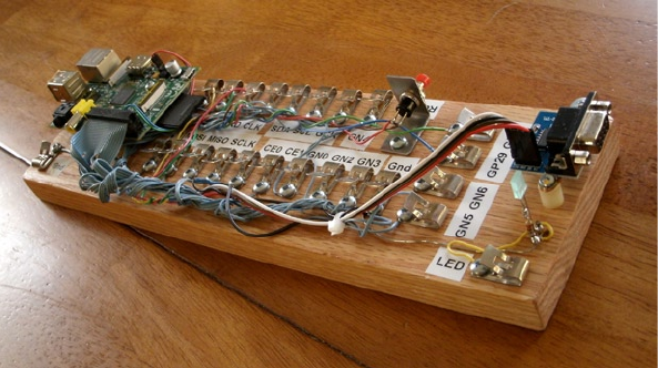
For my own experiments, I constructed a home-brewed setup where I placed the Pi
on a block of wood and ran wires out to some retro Fahnestock clips. While this worked
quite well, building this setup required considerable eort. I would recommend that
students get something easier like the Adafruit Pi Cobbler.
■ IntroduCtIon
xxi
For the reader, the advantage of this “bare-metal” approach is threefold:
ere is no dependence on product availability.•
ere is no built-in buering between the Pi and your peripheral.•
It costs less.•
Products come and go, so why build on that foundation? Add-on products also often
provide buering between the Pi and the outside world. But this feature would eliminate
the need to design this yourself.
Finally, in a large project like a robot, where several motor and sensor interfaces
exist, the need to economize becomes essential. is is where learning to design your
own interfaces pays o.
Test Equipment
e experiments in this book require access to a digital multimeter (DMM). is is critical
for testing voltages for the Raspberry Pi’s own safety. e Pi will not tolerate inputs above
+3.3 V without possible damage. Consequently, voltage readings are recommended
as part of several experiments to make sure that no damage to the Pi occurs whenever
voltages exceeding 3.3 V are involved.
Many experiments can be laid out on breadboards without the need for soldering.
A huge time saver is the use of ready-made breadboard jumper wires. ese can be
purchased from eBay for about $1.50 for about 50 to 65 wires. ey come in dierent
colors, t the breadboard well, and don’t require you strip the ends. Students have better
things to do with their time.
Final Words
By now, you are probably itching to get started. ere is no better time than the present!
A simple homemade Raspberry Pi workstation

1
Chapter 1
DHT11 Sensor
The DHT11 humidity and temperature sensor is an economical peripheral manufactured
by D-Robotics UK (www.droboticsonline.com). It is capable of measuring relative
humidity between 20 and 90% RH within the operating temperature range of 0 to 50°C,
with an accuracy of ±5% RH. Additionally, temperature is measured in the range of
0 to 50°C, with an accuracy of ±2°C. Both values are returned with 8-bit resolution.
Characteristics
The signaling used by the DHT sensor is similar to the 1-Wire protocol, but the response
times differ. Additionally, there is no device serial number support. These factors make
the device incompatible with the 1-Wire drivers within the Linux kernel. Figure 1-1 shows
a DHT11 sensor.
Figure 1-1. DHT11 sensor
CHAPTER 1 ■ DHT11 SENSOR
2
The DHT11 sensor also requires a power supply. In contrast, the signal line itself
powers most 1-Wire peripherals. The datasheet states that the DHT11 can be powered
by a range of voltages, from 3 V to 5.5 V. Powering it from the Raspberry Pi’s 3.3 V source
keeps the sensor signal levels within a safe range for GPIO. The device draws between
0.5 mA and 2.5 mA. Its standby current is stated as 100 mA to 150 mA, for those concerned
about battery consumption.
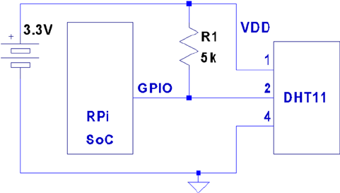
Circuit
Figure 1-2 shows the general circuit connections between the Raspberry Pi and the
DHT11 sensor. Pin 4 connects to the common ground, while pin 1 goes to the 3.3 V
supply. Pin 2 is the signal pin, which communicates with a chosen GPIO pin.
The program listing for dht11.c is configured to use GPIO 22. This is easily modified
(look for gpio_dht11).
Figure 1-2. DHT11 circuit
When the Pi is listening on the GPIO pin and the DHT11 is not sending data, the line
will float. For this reason, R1 is required to pull the line up to a stable level of 3.3 V. The
datasheet recommends a 5 kW resistor for the purpose (a more common 4.7 kW resistor
can be substituted safely). This presents less than 1 mA of load on either the GPIO pin or
the sensor when they are active. The datasheet also states that the 5 kW resistor should be
suitable for cable runs of up to 20 meters.
Protocol
The sensor speaks only when spoken to by the master (Raspberry Pi). The master must
first make a request on the bus and then wait for the sensor to respond. The DHT sensor
responds with 40 bits of information, 8 of which are a checksum.

CHAPTER 1 ■ DHT11 SENSOR
3
Overall Protocol
The overall signal protocol works like this:
1. The line idles high because of the pull-up resistor.
2. The master pulls the line low for at least 18 ms to signal a read
request and then releases the bus, allowing the line to return
to a high state.
3. After a pause of about 20 to 40 ms, the sensor responds by
bringing the line low for 80 ms and then allows the line to
return high for a further 80 ms. This signals its intention to
return data.
4. Forty bits of information are then written out to the bus: each
bit starting with a 50 ms low followed by:
a. 26 to 28 ms of high to indicate a 0 bit
b. 70 ms of high to indicate a 1 bit
5. The transmission ends with the sensor bringing the line low
one more time for 50 ms.
6. The sensor releases the bus, allowing the line to return to a
high idle state.
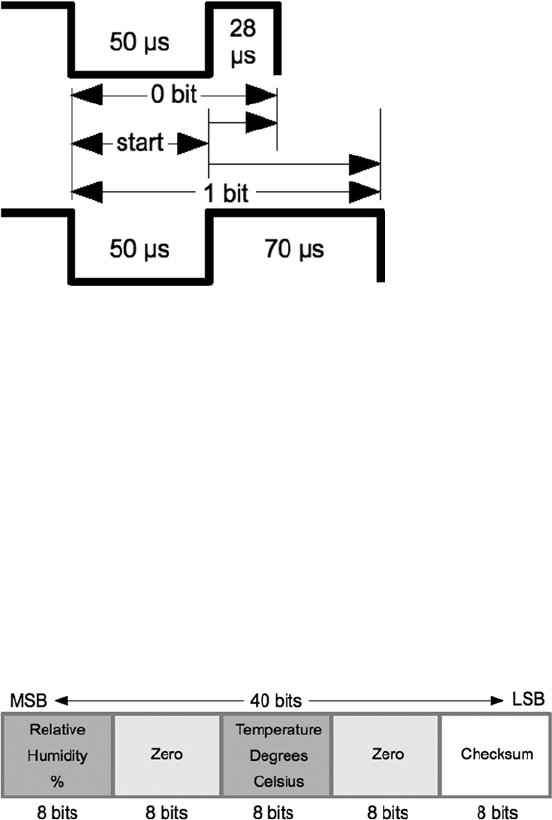
Figure 1-3 shows the overall protocol of the sensor. Master control is shown in thick
lines, while sensor control is shown in thin lines. Initially, the bus sits idle until the master
brings the line low and releases it (labeled Request). The sensor grabs the bus and signals
that it is responding (80 ms low, followed by 80 ms high). The sensor continues with 40 bits
of sensor data, ending with one more transition to low (labeled End) to mark the end of
the last bit.
Figure 1-3. General DHT11 protocol
CHAPTER 1 ■ DHT11 SENSOR
4
Data Bits
Each sensor data bit begins with a transition to low, followed by the transition to high, as
shown in Figure 1-4. The end of the bit occurs when the line is brought low again as the
start of the next bit. The last bit is marked off by one final low-to-high transition.
Figure 1-4. DHT11 data bit
Figure 1-5. DHT11 data format
Each data bit starts with a transition to low, lasting for 50 ms. The final transition
to low after the last bit also lasts for 50 ms. After the bit’s low-to-high transition, the bit
becomes a 0 if the high lasts only 26 to 28 microseconds. A 1 bit stays high for 70 ms
instead. Every data bit is completed when the transition from high to low occurs for the
start of the next bit (or final transition).
Data Format
Figure 1-5 illustrates the 40-bit sensor response, transmitting the most significant bit first.
The datasheet states 16 bits of relative humidity, 16 bits of temperature in Celsius, and an
8-bit checksum. However, the DHT11 always sends 0s for the humidity and temperature
fractional bytes. Thus the device really has only 8 bits of precision for each measurement.
Presumably, other models (or future ones) provide fractional values for greater precision.

CHAPTER 1 ■ DHT11 SENSOR
5
The checksum is a simple sum of the first 4 bytes. Any carry overflow is simply
discarded. This checksum gives your application greater confidence that it has received
correct values in the face of possible transmission errors.
Software
The user space software written to read the DHT11 sensor on the Raspberry Pi uses the
direct register access of the GPIO pin. The challenges presented by this approach include
the following:
Short timings: 26 to 70 • ms
Preemptive scheduling delays within the Linux kernel•
One approach is to count how many times the program could read the high-level
signal before the end of the bit is reached (when the line goes low). Then decide on 0 bits
for shorter times and 1s for longer times. After some experimentation, a dividing line
could be drawn, where shorter signals mean 0 while the others are 1s.
The difficulty with this approach is that it doesn’t adapt well if the Raspberry Pi is
accelerated. When the CPU clock is increased through overclocking, the program will
tend to fail. There is also the potential for future Raspberry Pis to include CPUs with
higher clock rates.
The signal emitted by the sensor is almost a Manchester encoding. In Manchester
encoding, one-half of the wave form is shorter than the other. This allows counting
up for the first half and counting down for the second. Based on whether the counter
underflows, a decision is made about the value of the bit seen.
The DHT11 signal uses a fixed first half of 50 ms The bit is decided based on how long
the signal remains at a high level after that. So a “bit bang” application could get a relative
idea by counting the number of times it could read the low-level signal. Based on that,
it can get a relative idea of where the dividing line between a short and long high-level
signal is.
This is the approach that was adopted by the program dht11.c. It counts the
number of times in a spin loop that it can read the signal as low. On a 700 MHz nonturbo
Raspberry Pi, I saw this count vary between 130 and 330 times, with an average of
292. This time period is supposed to be exactly 50 ms, which illustrates the real-time
scheduling problem within a user space program. (The program did not use any real-time
Linux priority scheduling.)
If the sensor waveform is true, a max count of 330 suggests that the Raspberry Pi can
read the GPIO pin a maximum of
330
50 66=./readss
m
But the minimum of 130 GPIO reads shows a worst case performance of
130
50 26=./readss
m

CHAPTER 1 ■ DHT11 SENSOR
6
This variability in preemptive scheduling makes it difficult to do reliable timings.
I have seen the high-level bit counts vary between 26 and 378. (The interested reader
can modify the code to record the counts.) If the program is able to read 6.6 times per
microsecond, a 1-bit time of 70 ms should yield a count of 462. Yet the maximum seen was
378. Preemptive scheduling prevents the code from performing that many reads without
interruption.
The lower count of 26 represents the minimum count for 0 bits, where the line stays
high for a shorter period of time. This suggests that each GPIO read is about 1 ms or longer
during the 0-bit highs.
The preceding information is just a crude sampling of the problem to illustrate
the variability that must be grappled with in a user space program, on a multitasking
operating system.
Chosen Approach
The program shown in this chapter uses the following general approach:
1. Count the number of GPIO reads that report that the line is
low (call it Clow).
2. Compute an adjustment bias B based on
BC
D
low
=
, where D is
some fixed divisor.
3. Compute a new count K = B + Chigh, where Chigh is the number
of times the line was read as high.
4. If the count value K > Clow, the value is considered a 1-bit;
otherwise, it’s considered a 0-bit.
The method is intended to at least partially compensate for the level of preemption
being seen by the application program. By measuring the low read counts, we get an idea
of the number of times we can sample the line at the moment. The approach is intended
to adapt itself to a faster-running Raspberry Pi.
Table 1-1 shows some experimental results on an idle Raspberry Pi running at the
standard 700 MHz. Different divisors were tried and tested over 5-minute intervals.
When the program runs, it attempts to read and report as many sensor readings as it
can, tracking good reports, time-out, and error counts. The program was terminated by
pressing ^C when an egg timer went off.

CHAPTER 1 ■ DHT11 SENSOR
7
Using no bias at all, no successful reads result (which prompted the idea of applying
a bias). Using a divisor of 2 applies too much adjustment, as can be seen by the low
number of results (1). Increasing the divisor to the value 3 or more produced a much
higher success rate, near 48, which is almost 10 reports per minute. Setting the divisor to 3
seems to yield the most repeatable results overall.
It is uncertain from the datasheets how rapidly the sensor can be requeried. The
program takes the conservative approach of pausing 2 seconds between each sensor read
attempt or waiting 5 seconds when a time-out has occurred.
The program reports an error when the checksum does not match. Time-outs occur
if the code gets stuck waiting for the signal to go low, for too long. This can happen if the
program misses a critical event because of preemptive scheduling. It sometimes happens
that the high-to-low-to-high event can occur without the program ever seeing it. If the
going-low event takes too long, the program performs a longjmp into the main loop, to
allow a retry.
Table 1-1. Bias Test Results
Divisor Results Time-outs Errors
2 1 17 103
3 48 17 63
4 30 25 56
5 49 14 63
6 45 20 52
7 60 16 47
8 41 20 56
9 42 17 62
10 39 22 53
11 40 14 72
12 43 13 71
13 47 10 75
14 32 19 67
15 28 23 63
16 38 16 69
17 33 14 81
18 34 13 82
19 31 16 75
20 22 18 81
CHAPTER 1 ■ DHT11 SENSOR
8
The errors are reported to stderr, allowing them to be suppressed by redirecting
unit 2 to /dev/null from the command line.
The way that the Raspberry Pi relinquishes the sensor bus is by changing the GPIO
pin from an output to an input. When configured as an input, the pull-up resistor brings
the bus line high when the bus is idle (the pull-up applies when neither master or slave
is driving the bus). When requested, the sensor grabs the bus and drives it high or low.
Finally, when the master speaks, we configure the pin as an output, causing the GPIO pin
to drive the bus.
Example Run
When the program dht11 is run, you should see output similar to the following:
$ sudo ./dht11
RH 37% Temp 18 C Reading 1
(Error # 1)
(Timeout # 1)
RH 37% Temp 18 C Reading 2
(Timeout # 2)
RH 37% Temp 18 C Reading 3
RH 37% Temp 18 C Reading 4
RH 37% Temp 18 C Reading 5
(Error # 2)
(Timeout # 3)
(Error # 3)
(Error # 4)
(Error # 5)
RH 37% Temp 18 C Reading 6
(Error # 6)
RH 37% Temp 18 C Reading 7
(Error # 7)
(Error # 8)
(Error # 9)
RH 36% Temp 19 C Reading 8
RH 37% Temp 18 C Reading 9
(Timeout # 4)
RH 36% Temp 19 C Reading 10
^C
Program exited due to SIGINT:
Last Read: RH 36% Temp 19 C, 9 errors, 4 timeouts, 10 readings

CHAPTER 1 ■ DHT11 SENSOR
9
Source Code
The next few pages list the source code for the program. This was assembled into one
compile unit by using the #include directive. This was done to save pages by eliminating
additional header files and extern declarations.
Note ■ The source code for gpio_io.c is found in Chapter 10 of Raspberry Pi Hardware
Reference (Apress, 2014).
1 /∗∗∗∗∗∗∗∗∗∗∗∗∗∗∗∗∗∗∗∗∗∗∗∗∗∗∗∗∗∗∗∗∗∗∗∗∗∗∗∗∗∗∗∗∗∗∗∗∗∗∗∗∗∗∗∗∗∗∗∗∗∗∗∗∗∗∗∗∗
2 ∗ dht11.c: Direct GPIO access reading DHT11 humidity and temp sensor.
3 ∗∗∗∗∗∗∗∗∗∗∗∗∗∗∗∗∗∗∗∗∗∗∗∗∗∗∗∗∗∗∗∗∗∗∗∗∗∗∗∗∗∗∗∗∗∗∗∗∗∗∗∗∗∗∗∗∗∗∗∗∗∗∗∗∗∗∗∗∗/
4
5 #include <stdio.h>
6 #include <stdlib.h>
7 #include <fcntl.h>
8 #include <unistd.h>
9 #include <errno.h>
10 #include <setjmp.h>
11 #include <sys/mman.h>
12 #include <signal.h>
13
14 #include "gpio_io.c" /∗ GPIO routines ∗/
15 #include "timed_wait.c" /∗ timed_wait() ∗/
16
17 static const int gpio_dht11 = 22; /∗ GPIO pin ∗/
18 static jmp_buf timeout_exit; /∗ longjmp on timeout ∗/
19 static int is_signaled = 0; /∗ Exit program if signaled ∗/
20
21/∗
22 ∗ Signal handler to quit the program:
23 ∗/
24 static void
25 sigint_handler(int signo) {
26 is_signaled = 1; /∗ Signal to exit program ∗/
27 }
28
29 /∗
30 ∗ Read the GPIO line status:
31 ∗/
32 static inline unsigned
33 gread(void) {
34 return gpio_read(gpio_dht11);
35 }
36
CHAPTER 1 ■ DHT11 SENSOR
10
37 /∗
38 ∗ Wait until the GPIO line goes low:
39 ∗/
40 static inline unsigned
41 wait_until_low(void) {
42 const unsigned maxcount = 12000;
43 unsigned count = 0;
44
45 while ( gread() )
46 if ( ++count >= maxcount || is_signaled )
47 longjmp(timeout_exit,1);
48 return count;
49 }
50
51 /∗
52 ∗ Wait until the GPIO line goes high:
53 ∗/
54 static inline unsigned
55 wait_until_high(void) {
56 unsigned count = 0;
57
58 while ( !gread() )
59 ++count;
60 return count;
61 }
62
63 /∗
64 ∗ Read 1 bit from the DHT11 sensor:
65 ∗/
66 static unsigned
67 rbit(void) {
68 unsigned bias;
69 unsigned lo_count, hi_count;
70
71 wait_until_low();
72 lo_count = wait_until_high();
73 hi_count = wait_until_low();
74
75 bias = lo_count / 3;
76
77 return hi_count + bias > lo_count ? 1 : 0 ;
78 }
79
80 /∗
81 ∗ Read 1 byte from the DHT11 sensor :
82 ∗/
CHAPTER 1 ■ DHT11 SENSOR
11
83 static unsigned
84 rbyte(void) {
85 unsigned x, u = 0;
86
87 for ( x=0; x<8; ++x )
88 u = (u << 1) | rbit();
89 return u;
90 }
91
92 /∗
93 ∗ Read 32 bits of data + 8 bit checksum from the
94 ∗ DHT sensor. Returns relative humidity and
95 ∗ temperature in Celsius when successful. The
96 ∗ function returns zero if there was a checksum
97 ∗ error.
98 ∗/
99 static int
100 rsensor(int ∗relhumidity, int ∗celsius) {
101 unsigned char u[5], cs = 0, x;
102 for ( x=0; x<5; ++x ) {
103 u[x] = rbyte();
104 if ( x < 4 ) /∗ Only checksum data..∗/
105 cs += u[x]; /∗ Checksum ∗/
106 }
107
108 if ( (cs & 0xFF) == u[4] ) {
109 ∗relhumidity = (int)u [0];
110 ∗celsius = (int)u [2];
111 return 1;
112 }
113 return 0;
114 }
115
116 /∗
117 ∗ Main program:
118 ∗/
119 int
120 main(int argc, char ∗∗argv) {
121 int relhumidity = 0, celsius = 0;
122 int errors = 0, timeouts = 0, readings = 0;
123 unsigned wait;
124
125 signal(SIGINT,sigint_handler); /∗ Trap on SIGINT ∗/
126
127 gpio_init(); /∗ Initialize GPIO access ∗/
128 gpio_config(gpio_dht11,Input); /∗ Set GPIO pin as Input ∗/
129
CHAPTER 1 ■ DHT11 SENSOR
12
130 for (;;) {
131 if ( setjmp(timeout_exit) ) { /∗ Timeouts go here ∗/
132 if ( is_signaled ) /∗ SIGINT? ∗/
133 break; /∗ Yes, then exit loop ∗/
134 fprintf(stderr," (Timeout # %d)\
n",++timeouts);
135 wait = 5;
136 } else wait = 2;
137
138 wait_until_high(); /∗ Wait GPIO line to go high ∗/
139 timed_wait(wait,0,0); /∗ Pause for sensor ready ∗/
140
141 gpio_config(gpio_dht11,Output); /∗ Output mode ∗/
142 gpio_write(gpio_dht11,0); /∗ Bring line low ∗/
143 timed_wait(0,30000,0); /∗ Hold low min of 18ms ∗/
144 gpio_write(gpio_dht11,1); /∗ Bring line high ∗/
145
146 gpio_config(gpio_dht11,Input); /∗ Input mode ∗/
147 wait_until_low() /∗ Wait for low signal ∗/
148 wait_until_high(); /∗ Wait for return to high ∗/
149
150 if ( rsensor(&relhumidity,& celsius) )
151 printf("RH %d%% Temp %d C Reading %d\n",
relhumidity, celsius,++readings);
152 else fprintf(stderr," (Error # %d)\n",++errors);
153 }
154
155 gpio_config(gpio_dht11,Input); /∗ Set pin to input mode ∗/
156
157 puts("\ nProgram exited due to SIGINT: \n");
158 printf("Last Read: RH %d%% Temp %d C, %d errors, "
"%d timeouts, %d readings \n",
159 relhumidity, celsius, errors, timeouts, readings);
160 return 0;
161 }
162
163 /∗ End dht11.c ∗/
CHAPTER 1 ■ DHT11 SENSOR
13
1 /∗∗∗∗∗∗∗∗∗∗∗∗∗∗∗∗∗∗∗∗∗∗∗∗∗∗∗∗∗∗∗∗∗∗∗∗∗∗∗∗∗∗∗∗∗∗∗∗∗∗∗∗∗∗∗∗∗∗∗∗∗∗∗∗∗∗∗∗∗
2 ∗ Implement a precision "timed wait". The parameter early_usec
3 ∗ allows an interrupted select(2) call to consider the wait as
4 ∗ completed, when interrupted with only "early_usec" left remaining.
5 ∗∗∗∗∗∗∗∗∗∗∗∗∗∗∗∗∗∗∗∗∗∗∗∗∗∗∗∗∗∗∗∗∗∗∗∗∗∗∗∗∗∗∗∗∗∗∗∗∗∗∗∗∗∗∗∗∗∗∗∗∗∗∗∗∗∗∗∗∗/
6 static void
7 timed_wait(long sec,long usec,long early_usec) {
8 fd_set mt;
9 struct timeval timeout;
10 int rc;
11
12 FD_ZERO(&mt);
13 timeout.tv_sec = sec;
14 timeout.tv_usec = usec;
15 do {
16 rc = select (0,&mt,&mt,&mt,&timeout);
17 if ( ! timeout.tv_sec && timeout.tv_usec < early_usec )
18 return; /∗ Wait is good enough, exit ∗/
19 } while ( rc < 0 && timeout.tv_sec && timeout.tv_usec );
20 }
21
22 /∗ End timed_wait.c ∗/

15
Chapter 2
MCP23017 GPIO Extender
Microchip’s MCP23017 provides 16 additional GPIO pins that can be purchased for as
little as $1.99. The chip communicates using the I2C bus. (The companion MCP23S17 is
available for SPI bus.) The I2C bus allows the chip to be remote from the Raspberry Pi,
requiring only a four-wire ribbon cable (power, ground, and a pair of I2C bus lines). This
chapter explores the features and limits of this peripheral.
DC Characteristics
When shopping for chips or interface PCBs based on a particular chip, the first thing I
look at is the operating supply voltage. 5 V parts are inconvenient for the Pi because of its
3.3 V GPIO interface. Many newer devices operate over a range of voltages, which include
3.3 V. The MCP23017 supply VDD operates from an extended range of +1.8 V to +5.5 V. This
clearly makes it compatible, if we power the chip from a +3.3 V source. Figure 2-1 shows
the MCP23017 chip pinout diagram.

Chapter 2 ■ MCp23017 GpIO extender
16
GPIO Output Current
Another factor in choosing a peripheral chip is its output drive capability. How well can
the GPIO pin source or sink current? As covered in Chapter 10 of Raspberry Pi Hardware
Reference (Apress, 2014), the Raspberry Pi’s own GPIO pins can source/sink up to
16 mA, depending on configuration. The MCP23017 chip specifications indicate that it
can source or sink up to 25 mA.
We still need to remember that if the MCP23017 is powered from the Raspberry
Pi’s 3.3 V regulator on header P1, the total current budget must not exceed 50 mA.
This budget includes the Pi’s own GPIO pin current usage. If, on the other hand, the
MCP23017 is powered from a separate 3.3 V power supply, this limitation is eliminated.
There are still reasons to budget current, however. The chip must not consume more
than 700 mW of power. This implies a total current limit as follows:
IP
V
mA
VDD
DD
=
=
=
07
33
212
.
.
Figure 2-1. MCP23017 pinout

Chapter 2 ■ MCp23017 GpIO extender
17
This power figure gives us an upper current limit. However, the datasheet of the
MCP23017 also lists a maximum of 125 mA for supply pin VDD. If every GPIO output is
sourcing power, this leaves us with the following average pin limit:
125
16 78
mA mA=.
So while the output GPIO pins can source up to 25 mA, we cannot have all of them
doing so simultaneously.
Likewise, the datasheet lists VSS (ground) as limited to an absolute maximum of
150 mA. If every GPIO pin is an output and sinking current, the average for each output
pin cannot exceed the following:
150
16 94
mA mA=.
Once again, while each output pin can sink up to 25 mA, we see that they cannot all
do so at the same time without exceeding chip limits. This should not be discouraging,
because in most applications, not all GPIO pins will be outputs, and not all will all be
driving heavy loads. The occasional pin that needs driving help can use a transistor driver
like the one discussed in Chapter 10 of Raspberry Pi Hardware Reference (Apress, 2014).
Before we leave the topic of GPIO output driving, we can apply one more simple
formula to help with interface design. With the foregoing information, we can calculate
the number of 25 mA outputs available:
125
25 5
mA
mA =
From this, it is known that four to five GPIO pins can operate near their maximum
limits, as long as the remaining GPIO pins are inputs or remain unconnected.
GPIO Inputs
In normal operation, the GPIO inputs should never see a voltage below the ground
potential VSS. Nor should they ever see a voltage above the supply voltage VDD. Yet,
variations can sometimes happen when interfacing with the external world, particularly
with inductive components.
The datasheet indicates that clamping diodes provide some measure of protection
against this. Should the voltage on an input drop below 0, it is clamped by a diode so it
will not go further negative and cause harm. The voltage limit is listed at –0.6 V, which is
the voltage drop of the clamping diode. Likewise, if the voltage goes over VDD (+3.3 V in
our case), the clamping diode will limit the excursion to VDD + 0.6 V (+3.9 V).
This protection is limited by the current capability of the clamping diodes. The
datasheet lists the maximum clamping current as 20 mA. If pins are forced beyond their
limits and the clamping current is exceeded, damage will occur.
Chapter 2 ■ MCp23017 GpIO extender
18
While we have focused on GPIO inputs in this section, the clamping diodes also
apply to outputs. Outputs can be forced beyond their limits by external circuits like
pull-up resistors. Pull-up resistors should not be attached to +5 V, for example, when the
MCP23017 is operating from a +3.3 V supply.
Standby Current
If the MCP23017 device is not sourcing or sinking output currents, the standby current
is stated as 3 μ A (for 4.5 to 5.5 V operation). This operating parameter is important to
designers of battery-operated equipment.
Input Logic Levels
Since the device operates over a range of supply voltages, the datasheet defines the logic
levels in terms of the supply voltage. For example, the GPIO input low level is listed as
0.2 × VDD. So if we operate with VDD= +3.3 V, the input low voltage is calculated as follows:
VV
V
IL DD
max.
..
.
=´
=´
=
02
02 33
066
Therefore, a voltage in the range of 0 to 0.66 V is guaranteed to read as a 0 bit.
Likewise, let’s calculate the input high voltage threshold, where the multiplier is
given as 0.8:
VV
V
IH DD
min.
..
.
=´
=´
=
08
08 33
264
Thus any voltage greater than or equal to 2.64 V is read as a 1 bit, when powered from
a +3.3 V supply. Any voltage between VILmax and VIHmin is undefined and reads as a 1 or a 0,
and perhaps randomly so.
Output Logic Levels
The output logic levels are stated differently. The datasheet simply states that the output
low voltage should not exceed a fixed limit. The high level is also stated as a minimum
value relative to VDD. This pair of parameters is listed here:
VV
VV V
V
OLma
OH mi DD
x
n
.
.
..
.
=
=
=
=
06
07
33 07
27
-
-
Chapter 2 ■ MCp23017 GpIO extender
19
Reset Timing
The only parameter of interest for timing apart from the I2C bus is the device reset time.
In order for the device to see a reset request, pin
RESET
must remain active (low) for a
minimum of 1 μs. The device resets and places outputs into the high-impedance mode
within a maximum of 1 μs.
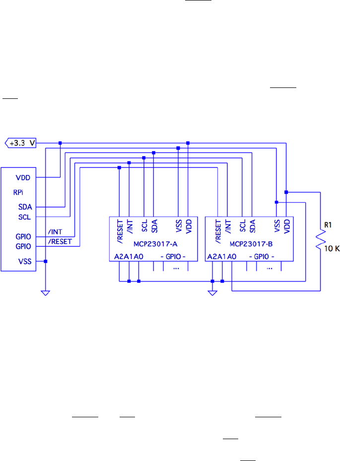
Circuit
Figure 2-2 shows a circuit with two remote MCP23017 GPIO extenders connected
to one I2C bus. In the figure, the power, ground, I2C data, and optional
RESET
and
INT
connections are shown connected through a six-conductor ribbon cable. This
allows the Raspberry Pi to communicate remotely to peripherals in a robot, for example.
Figure 2-2. MCP23017 circuit
The data communication occurs over the pair of signals SDA and SCL. These are
connected to the Raspberry Pi’s pins P1-03 and P1-05, respectively (GPIO 2 and 3 for Rev
2.0+). The other end of the I2C data bus is common to all slave peripherals.
Each MCP23017 slave device is addressed by its individually configured A2, A1,
and A0 pins. For device A, these pins are shown grounded to define it as device number
0x20 (low bits are zeroed). A1 is tied high for device B so that its peripheral address
becomes 0x21. In this configuration, the Raspberry Pi will use addresses 0x20 and 0x21 to
communicate with these slave devices.
Lines labeled
RESET
and
INT
are optional connections. The
RESET
line can be
eliminated if you never plan to force a hardware reset of the slaves (tie to VDD through a
10 K resistor). Usually the power-on reset is sufficient. The
INT
line is more desirable,
since the MCP23017 can be programmed to indicate interrupts when a GPIO input has
changed in value (or does not match a comparison value). The
INT
line is an open
collector pin so that many can be tied together on the same line. However, the Pi will have

Chapter 2 ■ MCp23017 GpIO extender
20
to poll each peripheral to determine which device is causing the interrupt. Alternatively,
each slave could provide a separate
INT
signal, with a corresponding increase in
signal lines.
Each MCP23017 chip has two interrupt lines, named
INT A
and
INT B
. There is
the option of separate interrupt notifications for the A group or the B group of GPIO pins.
For remote operation, it is desirable to take advantage of MCP23017’s ability to configure
these to work in tandem, so that only one
INT
line is required.
On the Raspberry Pi end, the GPIO pin used for the
RESET
line would be configured
as an output and held high, until a reset is required. When activating a reset, the line must
be held low for at least 1 microsecond, plus 1 more microsecond to allow for the chip reset
operation itself (and possibly longer, if non-MCP23017 slaves are connected to the bus).
The
INT
line should be connected to a GPIO input on the Pi. This GPIO input
either needs to be polled by the application, or to have the GPIO configured to trigger
on changes. Then the select(2) or poll(2) system calls can be used to detect when an
interrupt is raised by one or more peripherals.
The interrupt line, when used, should have a pull-up resistor configured (see
Chapter 10 of Raspberry Pi Hardware Reference [Apress, 2014] for information about
internal pull-up resistors). It may be best to use an external pull-up resistor, especially for
longer cable runs. To keep the sink current at 2 mA or less, the pull-up resistance used
should be no lower than the following:
RV
mA
pullup=+
=
33
2
1650
.
W
A 2.2 kΩ 10% resistor will do nicely.
The +3.3 V line should be powered separately from the Raspberry Pi, unless the
slaves expect to drive very low currents. The main concern here is to not overload the
remaining 50 mA capacity of the Pi’s +3.3 V regulated supply. See Chapter 10 of Raspberry
Pi Hardware Reference (Apress, 2014) about budgeting +3.3 V power.
I2C Bus
Throughout this chapter, we are assuming a Rev 2.0 or later Raspberry Pi. This matters for
the I2C bus because the early versions wired I2C bus 0 to P1-03 and P1-05 (GPIO 0 and 1).
Later this was changed to use bus 1. See Chapter 12 of Raspberry Pi Hardware Reference
(Apress, 2014) for more information about identifying your Pi and which I2C bus to use.
If you are using an early Raspberry Pi revision, you’ll need to substitute 0 for bus number
1, in commands and in the C source code that follows.
Chapter 2 ■ MCp23017 GpIO extender
21
Wiring and Testing
The connections to the MCP23017 are simple enough that you can wire it up on a
breadboard. The first step after wiring is to determine that you can detect the peripheral
on the I2C bus.
But even before that, check your kernel module support. If lsmod doesn’t show these
modules loaded, you can manually load them now:
$ sudo modprobe i2c−dev
$ sudo modprobe i2c−bcm2708
If you haven’t already done so, install i2c-tools:
$ sudo apt−get install i2c−tools
If your I2C support is there, you should be able to list the available I2C buses:
$ i2cdetect −l
i2c −0 unknown bcm2708_i2c.0 N/A
i2c −1 unknown bcm2708_i2c.1 N/A
The I2C device nodes should also appear in /dev. These nodes give us access to the
I2C drivers:
$ ls −l /dev/i2c∗
crw−rw−−−T 1 root root 89, 0 Feb 18 23:53 /dev/i2c−0
crw−rw−−−T 1 root root 89, 1 Feb 18 23:53 /dev/i2c−1
The ultimate test is to see whether the MCP23017 chip is detected (change the 1 to 0
for older Pi revisions):
$ sudo i2cdetect −y 1
0 1 2 3 4 5 6 7 8 9 a b c d e f
00: −− −− −− −− −− −− −− −− −− −− −− −− −−
10: −− −− −− −− −− −− −− −− −− −− −− −− −− −− −− −−
20: 20 −− −− −− −− −− −− −− −− −− −− −− −− −− −− −−
30: −− −− −− −− −− −− −− −− −− −− −− −− −− −− −− −−
40: −− −− −− −− −− −− −− −− −− −− −− −− −− −− −− −−
50: −− −− −− −− −− −− −− −− −− −− −− −− −− −− −− −−
60: −− −− −− −− −− −− −− −− −− −− −− −− −− −− −− −−
70: −− −− −− −− −− −− −− −−
In this example, the A2, A1, and A0 pins of the MCP23017 were grounded. This gives
the peripheral the I2C address of 0x20. In the session output, we see that address 0x20
was detected successfully.
Chapter 2 ■ MCp23017 GpIO extender
22
The i2cdump utility can be used to check the MCP23017 register:
$ sudo i2cdump –y –r 0x00–0x15 1 0x20 b
0 1 2 3 4 5 6 7 8 9 a b c d e f 0123456789abcdef
00: ff ff 00 00 00 00 00 00 00 00 00 00 00 00 00 00 ................
10: 00 00 00 00 00 00 ......
Here we have dumped out registers 0x00 to 0x15 on I2C bus 1, at peripheral address
0x20, in byte mode. This was performed after a power-on reset, so we can check whether
the register values match the datasheet values documented. As expected, IODIRA (register
0x00) and IODIRB (register 0x01) have the default of all 1s (0xFF). This also confirms that
the registers are in BANK=0 mode (this is discussed in the following sections). All other
MCP23017 registers default to 0 bits, which is also confirmed.
Software Configuration
The MCP23017 datasheet describes the full register complement and options available.
In this chapter, we’ll concern ourselves with a subset of its functionality, which is perhaps
considered “normal use.” The extended functionality is left as an exercise for you.
For this chapter’s project, we’re going to do the following:
Configure some GPIOs as inputs•
Configure some GPIOs as outputs•
Configure the group A and B inputs to signal an interrupt on any •
change
General Configuration
The MCP23017 peripheral has 10 registers for the GPIO-A pins, 10 registers for the
GPIO-B pins, and one shared register. In other words, there are 22 registers, with one pair
of addresses referencing a common register. These registers may be accessed in banks or
interleaved. We’ll use interleaved mode in this chapter, to avoid having to reset the device.
Interleaved register addresses are shown in Table 2-1. These are valid addresses
when the IOCON register value for BANK=0 (discussed later in this section).

Chapter 2 ■ MCp23017 GpIO extender
23
IOCON Register
This is the first register that must be configured, since it affects how registers are
addressed. Additionally, other settings are established that affect the entire peripheral.
Table 2-2 illustrates the layout of the IOCON register. Setting the BANK bit determines
whether we use banked or interleaved register addressing. The MCP23017 is in
interleaved mode after a power-on reset. Once you set BANK=1, the register addresses
change. However, once this change is made, it is impossible to tell, after a program restart,
which register mode the peripheral is in. The only option is a hardware reset of the
MCP23017 chip, to put it in a known state. For this reason, we’ll keep the peripheral in its
power-on reset state of BANK=0.
Table 2-1. MCP23017 Register Addresses
Register A B Description
IODIRx 0x00 0x01 I/O direction
IPOLx 0x02 0x03 Input polarity
GPINTENx 0x04 0x05 Interrupt on change control
DEFVALx 0x06 0x07 Default comparison value
INTCONx 0x08 0x09 Interrupt control
IOCONx 0x0A 0x0B Configuration
GPPUx 0x0C 0x0D Pull-up configuration
INTFx 0x0E 0x0F Interrupt flags
INTCAPx 0x10 0x11 Interrupt captured value
GPIOx 0x12 0x13 General-purpose I/O
OLATx 0x14 0x15 Output latch

Chapter 2 ■ MCp23017 GpIO extender
24
In the tables that follow, a Y under the R (read) or W (write) column/row indicates
that you can read or write the respective value. The Reset column indicates the state of
the bit after a device reset. An X indicates a “don’t care” or an undefined value when read.
An N indicates no access or no effect when written.
The bit MIRROR=1 is used to make
INT A
equivalent to
INT B
. In other words, GPIO
A and B interrupts are reported to both pins. This allows a single pin to be used for A and
B groups.
Setting bit SEQOP=0 allows the peripheral to automatically increment the register
address as each byte is read or written. This eliminates the need to transmit a register
address in many cases.
Bit DISSLW affects the physical handling of the SDA I2C bus line.
HAEN is applicable only to the MCP23S17 SPI device, since addresses are always
enabled for I2C devices.
This project uses ODR=1 to configure the
INT A
pin as an open-drain pin. This
allows multiple MCP23017 devices to share the same interrupt line. Use a pull-up resistor
on the
INT
line when this is in effect. Otherwise, you may experience several sporadic
interrupts.
Finally, INTPOL=0 is configured so that the interrupt is active low. This is required for
an open-drain connected line along with a pull-up resistor.
Table 2-2. IOCON Register
Bit Meaning R W Reset Description
7 BANK Y Y 0 Set to 0 for interleaved access
6 MIRROR Y Y 0 Set to 1 to join INTA & INTB
5 SEQOP Y Y 0 Set to 0 for auto-address increment
4 DISSLW Y Y 0 Set to 1 to disable slew rate control
3 HAEN Y Y 0 Ignored: I2C always uses address
2 ODR Y Y 0 Set to 1 for open-drain INT pins
1 INTPOL Y Y 0 Set to 0 for INT active low
0 N/A 0 X 0 Ignored: reads as zero
GPIO Address Note
These access a shared register
A 0x0A
B 0x0B

Chapter 2 ■ MCp23017 GpIO extender
25
OLATx Register
GPIO pins are all configured as inputs after a power-on reset (or use of
RESET
). Prior
to configuring pins as outputs, it is usually a good idea to set the required output values.
This is accomplished by writing the OLAT register, for group A or B. For this project, we’ll
just write 0x00 to both OLATA and OLATB.
OLATx Register GPIO Address
Bit 7 6 5 4 3 2 1 0 A 0x14
R Y Y Y Y Y Y Y Y B 0x15
W Y Y Y Y Y Y Y Y
Reset 0 0 0 0 0 0 0 0
OLATx Bit Value
0 Output set to 0
1 Output set to 1
GPPUx Register
A given project should also define a known value for its input pull-up resistors. Setting a
given bit to 1 enables a weak 100 KΩ internal pull-up resistor. This setting affects only the
inputs. The pull-up resistors are configured off after a reset. In our example code, we turn
them on.
GPPUx Register GPIO Address
Bit 7 6 5 4 3 2 1 0 A 0x0C
R Y Y Y Y Y Y Y Y B 0x0D
W Y Y Y Y Y Y Y Y
Reset 0 0 0 0 0 0 0 0
GPPUx Bit Value
0 Pull-up resistor disabled
1 100 KW pull-up resistor enabled

Chapter 2 ■ MCp23017 GpIO extender
26
DEFVALx Register
This register is associated with interrupt processing. Interrupts are produced from
conditions arising from input GPIO pins only. An interrupt can be generated if the
input differs from the DEFVALx register or if the input value has changed. In the project
presented, we simply zero this value because it is not used when detecting changed
inputs.
DEFVALx Register GPIO Address
Bit 7 6 5 4 3 2 1 0 A 0x06
R Y Y Y Y Y Y Y Y B 0x07
W Y Y Y Y Y Y Y Y
Reset 0 0 0 0 0 0 0 0
DEFVALx Bit Value
0 Interrupt when input not 0
1 Interrupt when input not 1
INTCONx Register
This register specifies how input comparisons will be made. In our project, we set all
these bits to 0 so that inputs interrupt on change.
INTCONx Register GPIO Address
Bit 7 6 5 4 3 2 1 0 A 0x08
R Y Y Y Y Y Y Y Y B 0x09
W Y Y Y Y Y Y Y Y
Reset 0 0 0 0 0 0 0 0
INTCONx Bit Value
0 Input compared against its previous value
1 Input compared against DEFCONx bit value

Chapter 2 ■ MCp23017 GpIO extender
27
IPOLx Register
Bits set in this register will invert the logic sense of the corresponding GPIO inputs. In our
project, we used no inversion and set the bits to 0.
IPOLx Register GPIO Address
Bit 7 6 5 4 3 2 1 0 A 0x02
R Y Y Y Y Y Y Y Y B 0x03
W Y Y Y Y Y Y Y Y
Reset 0 0 0 0 0 0 0 0
IPOLx Bit Value
0 Read same logic as input pin
1 Read inverted logic of input pin
IODIRx Register
This register determines whether a given GPIO pin is an input or an output. Our project
defines bits 4 through 7 as inputs, with the remaining bits 0 through 3 of each 8-bit port as
outputs.
IODIRx Register GPIO Address
Bit 7 6 5 4 3 2 1 0 A 0x00
R Y Y Y Y Y Y Y Y B 0x01
W Y Y Y Y Y Y Y Y
Reset 1 1 1 1 1 1 1 1
IODIRx Bit Value
0 Pin is configured as an output
1 Pin is configured as an input

Chapter 2 ■ MCp23017 GpIO extender
28
GPINTENx Register
This register enables interrupts on input pin events. Only inputs generate interrupts, so
any enable bits for output pins are ignored. How the interrupt is generated by the input is
determined by registers DEFVALx and INTCONx.
GPINTENx Register GPIO Address
Bit 7 6 5 4 3 2 1 0 A 0x04
R Y Y Y Y Y Y Y Y B 0x05
W Y Y Y Y Y Y Y Y
Reset 0 0 0 0 0 0 0 0
GPINTENx Bit Value
0 Disable interrupts on this input
1 Enable interrupts for this input
For this project, we enabled interrupts on all inputs for ports A and B.
INTFx Register
This interrupt flags register contains the indicators for each input pin causing an
interrupt. This register is unwritable.
Interrupt service routines start with this register to identify which inputs are the
cause of the interrupt. The DEFVALx and INTCONx registers configure how those interrupts
are generated. The INTFx flags are cleared by reading the corresponding INTCAPx or
GPIOx register.
INTFx Register GPIO Address
Bit 7 6 5 4 3 2 1 0 A 0x0E
R Y Y Y Y Y Y Y Y B 0x0F
W N N N N N N N N
Reset 0 0 0 0 0 0 0 0
INTFx Bit Value
0 No interrupt for this input
1 Input has changed or does not compare

Chapter 2 ■ MCp23017 GpIO extender
29
INTCAPx Register
The interrupt capture register reports the status of the inputs as the interrupt is being
raised. This register is read-only. Reading this register clears the INTFx register, to allow
new interrupts to be generated. When
INT A
is linked to
INT B
, both INTCAPA and
INTCAPB must be read to clear the interrupt (or read the GPIOx registers).
INTCAPx Register GPIO Address
Bit 7 6 5 4 3 2 1 0 A 0x10
R Y Y Y Y Y Y Y Y B 0x11
W N N N N N N N N
Reset 0 0 0 0 0 0 0 0
INTCAPx Bit Value
0 Input state was 0 at time of interrupt
1 Input state was 1 at time of interrupt
GPIOx Register
Reading this register provides the current input pin values, for pins configured as
inputs. Reading the GPIOx register also clears the interrupt flags in INTFx. When
INT A
is linked to
INT B
, both GPIOA and GPIOB must be read to clear the interrupt (or read the
INTCAPx registers).
Presumably, the OLATx register is read, for pins configured for output (the datasheet
doesn’t say). Writing to the GPIOx register alters the OLATx settings in addition to
immediately affecting the outputs.
GPIOx Register GPIO Address
Bit 7 6 5 4 3 2 1 0 A 0x12
R Y Y Y Y Y Y Y Y B 0x13
W Y Y Y Y Y Y Y Y
Reset X X X X X X X X

Chapter 2 ■ MCp23017 GpIO extender
30
Value R/W GPIOx Bit Value
0 R Current input pin state is low
W Write 0 to OLATx and output pin
1 R Current input pin state is high
W Write 1 to OLATx and output pin
Main Program
Here are some change notes for the main program:
1. If you have a pre-revision 2.0 Raspberry Pi, change line 36 to
use /dev/i2c-0.
2. Change line 55 if your MCP23017 chip is using a different I2C
address than 0x20 (A2, A1, and A0 grounded).
3. Change line 56 if you use a different Raspberry Pi GPIO for
your interrupt sense pin.
The main program is fairly straightforward. Here are the basic overall steps:
1. A signal handler is registered in line 180, so ^C will cause the
program to exit cleanly.
2. Routine i2c_init() is called to open the I2C driver and
initialize.
3. Routine mcp23017_init() is called to initialize and configure
the MCP23017 device on the bus (only one is currently
supported).
4. Routine gpio_open_edge() is called to open /sys/class/
gpio17/value, so changes on the interrupt line can be sensed.
This is discussed in more detail later.
5. Finally, the main program enters a loop in lines 190 to 200,
looping until ^C is entered.
Once inside the main loop, the following events occur:
1. Execution stalls when gpio_poll() is called. This blocks until
the interrupt on GPIO 17 transitions from a high to a low.
2. The interrupt flags are read using routine mcp23017_
interrupts(). They’re only reported and otherwise not used.
3. Routine mcp23017_captured() is used to read the INTCAPA
and INTCAPB registers in order to clear the interrupt.
4. Finally, the routine post_outputs() reads the real-time input
values and sends the bits to the outputs.
Chapter 2 ■ MCp23017 GpIO extender
31
Program mcp23017.c is shown here:
1 /∗∗∗∗∗∗∗∗∗∗∗∗∗∗∗∗∗∗∗∗∗∗∗∗∗∗∗∗∗∗∗∗∗∗∗∗∗∗∗∗∗∗∗∗∗∗∗∗∗∗∗∗∗∗∗∗∗∗∗∗∗∗∗∗∗∗∗∗∗
2 ∗ mcp23017.c : Interface with MCP23017 I/O Extender Chip
3 ∗
4 ∗ This code assumes the following :
5 ∗
6 ∗ 1. MCP23017 is configured for address 0x20
7 ∗ 2. RPi's GPIO 17 (GEN0) will be used for sensing interrupts
8 ∗ 3. Assumed there is a pull up on GPIO 17.
9 ∗ 4. MCP23017 GPA4-7 and GPB4–7 will be inputs, with pull-ups.
10 ∗ 5. MCP23017 GPA0–3 and GPB0–3 will be ouputs.
11 ∗ 6. MCP23017 signals interrupt active low.
12 ∗ 7. MCP23017 operating in non–banked register mode.
13 ∗
14 ∗ Inputs sensed will be copied to outputs :
15 ∗ 1. GPA4–7 copied to GPA0–3
16 ∗ 2. GPB4–7 copied to GPB0–3
17 ∗
18 ∗∗∗∗∗∗∗∗∗∗∗∗∗∗∗∗∗∗∗∗∗∗∗∗∗∗∗∗∗∗∗∗∗∗∗∗∗∗∗∗∗∗∗∗∗∗∗∗∗∗∗∗∗∗∗∗∗∗∗∗∗∗∗∗∗∗∗∗/
19
20 #include <stdio.h>
21 #include <stdlib.h>
22 #include <fcntl.h>
23 #include <unistd.h>
24 #include <string.h>
25 #include <errno.h>
26 #include <signal.h>
27 #include <assert.h>
28 #include <sys/ioctl.h>
29 #include <sys/poll.h>
30 #include <linux/i2c.h>
31 #include <linux/i2c–dev.h>
32
33 #include "i2c_funcs.c" /∗ I2C routines ∗/
34
35 /∗ Change to i2c 0 if using early Raspberry Pi ∗/
36 static const char ∗ node = "/dev/i2c–1";
37
38 #define GPIOA 0
39 #define GPIOB 1
40
41 #define IODIR 0
42 #define IPOL 1
43 #define GPINTEN 2
44 #define DEFVAL 3
45 #define INTCON 4
46 #define IOCON 5
Chapter 2 ■ MCp23017 GpIO extender
32
47 #define GPPU 6
48 #define INTF 7
49 #define INTCAP 8
50 #define GPIO 9
51 #define OLAT 10
52
53 #define MCP_REGISTER(r,g) (((r) <<1)|(g)) /∗ For I2C routines ∗/
54
55 static unsigned gpio_addr = 0x20; /∗ MCP23017 I2C Address ∗/
56 static const int gpio_inta = 17; /∗ GPIO pin for INTA connection ∗/
57 static int is_signaled = 0; /∗ Exit program if signaled ∗/
58
59 #include "sysgpio.c"
60
61 /∗
62 ∗ Signal handler to quit the program :
63 ∗/
64 static void
65 sigint_handler(int signo) {
66 is_signaled = 1; /∗ Signal to exit program ∗/
67 }
68
69 /∗
70 ∗ Write to MCP23017 A or B register set:
71 ∗/
72 static int
73 mcp23017_write(int reg,int AB,int value) {
74 unsigned reg_addr = MCP_REGISTER(reg,AB);
75 int rc;
76
77 rc = i2c_write8(gpio_addr,reg_addr,value);
78 return rc;
79 }
80
81 /∗
82 ∗ Write value to both MCP23017 register sets :
83 ∗/
84 static void
85 mcp23017_write_both(int reg,int value) {
86 mcp23017_write(reg,GPIOA,value); /∗ Set A ∗/
87 mcp23017_write(reg,GPIOB,value); /∗ Set B ∗/
88 }
89
90 /∗
91 ∗ Read the MCP23017 input pins (excluding outputs,
92 ∗ 16–bits) :
93 ∗/
Chapter 2 ■ MCp23017 GpIO extender
33
94 static unsigned
95 mcp23017_inputs(void) {
96 unsigned reg_addr = MCP_REGISTER(GPIO,GPIOA);
97
98
99 return i2c_read16(gpio_addr,reg_addr) & 0xF0F0;
100 }
101
102 /∗
103 ∗ Write 16 bits to outputs :
104 ∗/
105 static void
106 mcp23017_outputs(int value) {
107 unsigned reg_addr = MCP_REGISTER(GPIO,GPIOA);
108
109 i2c_write16 (gpio_addr,reg_addr,value & 0x0F0F);
110 }
111
112 /∗
113 ∗ Read MCP23017 captured values (16–bits):
114 ∗/
115 static unsigned
116 mcp23017_captured(void) {
117 unsigned reg_addr = MCP_REGISTER(INTCAP,GPIOA);
118
119 return i2c_read16(gpio_addr,reg_addr) & 0xF0F0;
120 }
121
122 /∗
123 ∗ Read interrupting input flags (16–bits) :
124 ∗/
125 static unsigned
126 mcp23017_interrupts(void) {
127 unsigned reg_addr = MCP_REGISTER(INTF,GPIOA);
128
129 return i2c_read16(gpio_addr,reg_addr) & 0xF0F0;
130 }
131
132 /∗
133 ∗ Configure the MCP23017 GPIO Extender :
134 ∗/
135 static void
136 mcp23017_init(void) {
137 int v, int_flags;
138
139 mcp23017_write_both(IOCON,0b01000100); /∗ MIRROR=1,ODR=1 ∗/
140 mcp23017_write_both(GPINTEN,0x00); /∗ No interrupts enabled ∗/
Chapter 2 ■ MCp23017 GpIO extender
34
141 mcp23017_write_both(DEFVAL,0x00); /∗ Clear default value ∗/
142 mcp23017_write_both(OLAT,0x00); /∗ OLATx=0 ∗/
143 mcp23017_write_both(GPPU,0b11110000); /∗ 4–7 are pull up ∗/
144 mcp23017_write_both(IPOL,0b00000000); /∗ No inverted polarity ∗/
/∗ 4–7 inputs, 0–3 outputs ∗/
145 mcp23017_write_both(IODIR,0b11110000);
146 mcp23017_write_both(INTCON,0b00000000); /∗ Cmp to previous ∗/
147 mcp23017_write_both(GPINTEN,0b11110000); /∗ Int on changes ∗/
148
149 /∗
150 ∗ Loop until all interrupts are cleared:
151 ∗/
152 do {
153 int_flags = mcp23017_interrupts();
154 if ( int_flags != 0 ) {
155 v = mcp23017_captured();
156 printf(" Got change %04X values %04X\n",int_
flags,v);
157 }
158 } while ( int_flags != 0x0000 && !is_signaled );
159 }
160
161 /∗
162 ∗ Copy input bit settings to outputs :
163 ∗/
164 static void
165 post_outputs(void) {
166 int inbits = mcp23017_inputs(); /∗ Read inputs ∗/
167 int outbits = inbits >> 4; /∗ Shift to output bits ∗/
168 mcp23017_outputs(outbits); /∗ Copy inputs to outputs ∗/
169 printf (" Outputs: %04X\n",outbits);
170 }
171
172 /∗
173 ∗Main program :
174 ∗/
175 int
176 main(int argc,char ∗∗argv) {
177 int int_flags, v;
178 int fd;
179
180 signal(SIGINT,sigint_handler); /∗ Trap on SIGINT ∗/
181
182 i2c_init(node); /∗ Initialize for I2C ∗/
183 mcp23017_init(); /∗ Configure MCP23017 @ 20 ∗/
184
185 fd = gpio_open_edge(gpio_inta); /∗ Configure INTA pin ∗/
186
Chapter 2 ■ MCp23017 GpIO extender
35
187 puts("Monitoring for MCP23017 input changes :\n");
188 post_outputs(); /∗ Copy inputs to outputs ∗/
189
190 do {
191 gpio_poll(fd); /∗ Pause until an interrupt ∗/
192
193 int_flags = mcp23017_interrupts();
194 if ( int_flags ) {
195 v = mcp23017_captured();
196 printf(" Input change: flags %04X values
%04X\n",
197 int_flags,v);
198 post_outputs();
199 }
200 } while ( !is_signaled ); /∗ Quit if ^C' d ∗/
201
202 fputc('\n', stdout);
203
204 i2c_close(); /∗ Close I2C driver ∗/
205 close(fd); /∗ Close gpio17/value ∗/
206 gpio_close(gpio_inta); /∗ Unexport gpio17 ∗/
207 return 0;
208 }
209
210 /∗ End mcp23017.c ∗/
Module i2c_funcs.c
To compile code when making use of I2C, you will need to install the libi2c
development library:
$ sudo apt-get install libi2c-dev
The i2c_funcs.c is a small module that wraps the ioctl(2) calls into neat little I/O
functions:
i2c_write8(): Writes 8-bit value to MCP23017 register
i2c_write16(): Writes 16-bit value to MCP23017 register
i2c_read8(): Reads 8-bit value from MCP23017 register
i2c_read16(): Reads 16-bit value from MCP23017 register
Additionally, the open and close routines are provided:
i2c_init(): Opens the bus driver for /dev/i2c-x
i2c_close(): Closes the opened I2C driver
Chapter 2 ■ MCp23017 GpIO extender
36
The C API for these I2C functions are described in Chapter 12 of Raspberry Pi
Hardware Reference (Apress, 2014).
1 /∗∗∗∗∗∗∗∗∗∗∗∗∗∗∗∗∗∗∗∗∗∗∗∗∗∗∗∗∗∗∗∗∗∗∗∗∗∗∗∗∗∗∗∗∗∗∗∗∗∗∗∗∗∗∗∗∗∗∗∗∗∗∗∗∗∗∗∗∗∗∗∗
2 ∗ i2c_funcs.c : I2C Access Functions
3 ∗∗∗∗∗∗∗∗∗∗∗∗∗∗∗∗∗∗∗∗∗∗∗∗∗∗∗∗∗∗∗∗∗∗∗∗∗∗∗∗∗∗∗∗∗∗∗∗∗∗∗∗∗∗∗∗∗∗∗∗∗∗∗∗∗∗∗∗∗∗∗/
4
5 static int i2c_fd = –1; /∗ Device node : /dev/i2c–1 ∗/
6 static unsigned long i2c_funcs = 0; /∗ Support flags ∗/
7
8 /∗
9 ∗ Write 8 bits to I2C bus peripheral:
10 ∗/
11 int
12 i2c_write8(int addr,int reg,int byte) {
13 struct i2c_rdwr_ioctl_data msgset;
14 struct i2c_msg iomsgs[1];
15 unsigned char buf[2];
16 int rc;
17
18 buf[0] = (unsigned char)reg; /∗ MCP23017 register no. ∗/
19 buf[1] = (unsigned char)byte; /∗ Byte to write to register ∗/
20
21 iomsgs[0].addr = (unsigned)addr;
22 iomsgs[0].flags = 0; /∗ Write ∗/
23 iomsgs[0].buf = buf;
24 iomsgs[0].len = 2;
25
26 msgset.msgs = iomsgs;
27 msgset.nmsgs = 1;
28
29 rc = ioctl(i2c_fd,I2C_RDWR,&msgset);
30 return rc < 0 ? –1 : 0;
31 }
32
33 /∗
34 ∗ Write 16 bits to Peripheral at address :
35 ∗/
36 int
37 i2c_write16(int addr, int reg, int value) {
38 struct i2c_rdwr_ioctl_data msgset;
39 struct i2c_msg iomsgs[1];
40 unsigned char buf[3];
41 int rc;
42
Chapter 2 ■ MCp23017 GpIO extender
37
43 buf[0] = (unsigned char)reg;
44 buf[1] = (unsigned char)(( value >> 8 ) & 0xFF);
45 buf[2] = (unsigned char)(value & 0xFF);
46
47 iomsgs[0].addr = (unsigned)addr;
48 iomsgs[0].flags = 0; /∗ Write ∗/
49 iomsgs[0].buf = buf;
50 iomsgs[0].len = 3;
51
52 msgset.msgs = iomsgs;
53 msgset.nmsgs = 1;
54
55 rc = ioctl(i2c_fd,I2C_RDWR,&msgset);
56 return rc < 0 ? –1 : 0;
57 }
58
59 /∗
60 ∗ Read 8–bit value from peripheral at addr :
61 ∗/
62 int
63 i2c_read8(int addr,int reg) {
64 struct i2c_rdwr_ioctl_data msgset;
65 struct i2c_msg iomsgs[2];
66 unsigned char buf[1], rbuf[1];
67 int rc;
68
69 buf[0] = (unsigned char)reg;
70
71 iomsgs[0].addr = iomsgs[1].addr = (unsigned)addr;
72 iomsgs[0].flags = 0; /∗ Write ∗/
73 iomsgs[0].buf = buf;
74 iomsgs[0].len = 1;
75
76 iomsgs[1].flags = I2C_M_RD; /∗ Read ∗/
77 iomsgs[1].buf = rbuf;
78 iomsgs[1].len = 1;
79
80 msgset.msgs = iomsgs;
81 msgset.nmsgs = 2;
82
83 rc = ioctl(i2c_fd,I2C_RDWR,&msgset);
84 return rc < 0 ? –1 : ((int)(rbuf[0]) & 0x0FF);
85 }
86
Chapter 2 ■ MCp23017 GpIO extender
38
87 /∗
88 ∗ Read 16– bits of data from peripheral :
89 ∗/
90 int
91 i2c_read16(int addr,int reg) {
92 struct i2c_rdwr_ioctl_data msgset;
93 struct i2c_msg iomsgs[2];
94 unsigned char buf[1], rbuf [2];
95 int rc;
96
97 buf[0] = (unsigned char)reg;
98
99 iomsgs[0].addr = iomsgs[1].addr = (unsigned)addr;
100 iomsgs[0].flags = 0; /∗ Write ∗/
101 iomsgs[0].buf = buf;
102 iomsgs[0].len = 1;
103
104 iomsgs[1].flags = I2C_M_RD;
105 iomsgs[1].buf = rbuf; /∗ Read ∗/
106 iomsgs[1].len = 2;
107
108 msgset.msgs = iomsgs;
109 msgset.nmsgs = 2;
110
111 if ( (rc = ioctl(i2c_fd,I2C_RDWR,&msgset)) < 0 )
112 return –1;
113 return (rbuf[0] << 8) | rbuf[1];
114 }
115
116 /∗
117 ∗ Open I2C bus and check capabilities :
118 ∗/
119 static void
120 i2c_init(const char ∗ node) {
121 int rc;
122
123 i2c_fd = open(node,O_RDWR); /∗ Open driver /dev/i2s–1 ∗/
124 if ( i2c_fd < 0 ) {
125 perror("Opening /dev/i2s–1");
126 puts("Check that the i2c dev & i2c–bcm2708 kernel
modules "
127 "are loaded.");
128 abort();
129 }
130

Chapter 2 ■ MCp23017 GpIO extender
39
131 /∗
132 ∗ Make sure the driver supports plain I2C I/O:
133 ∗/
134 rc = ioctl(i2c_fd,I2C_FUNCS,&i2c_funcs);
135 assert(rc >= 0) ;
136 assert(i2c_funcs & I2C_FUNC_I2C);
137 }
138
139 /∗
140 ∗ Close the I2C driver :
141 ∗/
142 static void
143 i2c_close(void) {
144 close(i2c_fd);
145 i2c_fd = –1;
146 }
147
148 /∗ End i2c_funcs.c ∗/
Module sysgpio.c
The sysgpio.c module performs some grunt work in making the /sys/class/gpio17/
value node available and configuring it. This node is opened for reading, so that poll(2)
can be called upon it.
The interesting code in this module is found in lines 89 to 106, where gpio_poll() is
defined. The file descriptor passed to it as fd is the /sys/class/gpio17/value file that is
Configured as input•
Triggered on the falling edge (high-to-low transition)•
The poll(2) system call in line 99 blocks the execution of the program until the
input (GPIO 17) changes from a high state to a low state. This is connected to the
MCP23017
INT A
pin, so it can tell us when its GPIO extender input(s) have changed.
The poll(2) system call can return an error if the program has handled a signal. The
error returned will be EINTR when this happens (as discussed in Chapter 9 of Raspberry
Pi Hardware Reference [Apress, 2014], section “Error EINTR”). If the program detects that
^C has been pressed (is_signaled is true), then it exits, returning -1, to allow the main
program to exit.
A value of rc=1 is returned if /sys/class/gpio17/value has a changed value to be
read. Before returning from gpio_poll(), a read(2) of any unread data is performed.
This is necessary so that the next call to poll(2) will block until new data is available.
Chapter 2 ■ MCp23017 GpIO extender
40
1 /∗∗∗∗∗∗∗∗∗∗∗∗∗∗∗∗∗∗∗∗∗∗∗∗∗∗∗∗∗∗∗∗∗∗∗∗∗∗∗∗∗∗∗∗∗∗∗∗∗∗∗∗∗∗∗∗∗∗∗∗∗∗∗∗∗∗∗∗∗
2 ∗ sysgpio.c : Open/configure /sys GPIO pin
3 ∗
4 ∗ Here we must open the /sys/class/gpio/gpio17/value and do a
5 ∗ poll(2) on it, so that we can sense the MCP23017 interrupts.
6 ∗∗∗∗∗∗∗∗∗∗∗∗∗∗∗∗∗∗∗∗∗∗∗∗∗∗∗∗∗∗∗∗∗∗∗∗∗∗∗∗∗∗∗∗∗∗∗∗∗∗∗∗∗∗∗∗∗∗∗∗∗∗∗∗∗∗∗∗∗/
7
8 typedef enum {
9 gp_export = 0, /∗ /sys/class/gpio/export ∗/
10 gp_unexport, /∗ /sys/class/gpio/unexport ∗/
11 gp_direction, /∗ /sys/class/gpo%d/direction ∗/
12 gp_edge, /∗ /sys/class/gpio%d/edge ∗/
13 gp_value /∗ /sys/class/gpio%d/value ∗/
14 } gpio_path_t;
15
16 /∗
17 ∗ Internal : Create a pathname for type in buf.
18 ∗/
19 static const char ∗
20 gpio_setpath(int pin,gpio_path_t type,char ∗buf,unsigned bufsiz) {
21 static const char ∗paths[] = {
22 "export", "unexport", "gpio%d/direction",
23 "gpio%d/edge", "gpio%d/value" };
24 int slen;
25
26 strncpy(buf,"/sys/class/gpio/",bufsiz);
27 bufsiz –= (slen = strlen(buf));
28 snprintf(buf+slen,bufsiz,paths[type],pin);
29 return buf;
30 }
31
32 /∗
33 ∗ Open /sys/class/gpio%d/value for edge detection :
34 ∗/
35 static int
36 gpio_open_edge(int pin) {
37 char buf[128];
38 FILE ∗f;
39 int fd;
40
41 /∗ Export pin: /sys/class/gpio/export ∗/
42 gpio_setpath(pin,gp_export,buf,sizeof buf);
43 f = fopen(buf, "w");
44 assert(f);
45 fprintf(f,"%d\n",pin);
46 fclose(f);
47
Chapter 2 ■ MCp23017 GpIO extender
41
48 /∗ Direction: /sys/class/gpio%d/direction ∗/
49 gpio_setpath(pin,gp_direction,buf,sizeof buf);
50 f = fopen(buf,"w");
51 assert(f);
52 fprintf(f,"in\n");
53 fclose(f);
54
55 /∗ Edge: /sys/class/gpio%d/edge ∗/
56 gpio_setpath(pin,gp_edge,buf,sizeof buf);
57 f = fopen(buf,"w");
58 assert(f);
59 fprintf(f,"falling\n");
60 fclose(f);
61
62 /∗ Value: /sys/class/gpio%d/value ∗/
63 gpio_setpath(pin,gp_value,buf,sizeof buf);
64 fd = open(buf,O_RDWR);
65 return fd;
66 }
67
68 /∗
69 ∗ Close (unexport) GPIO pin :
70 ∗/
71 static void
72 gpio_close(int pin) {
73 char buf[128];
74 FILE ∗f ;
75
76 /∗ Unexport: /sys/class/gpio/unexport ∗/
77 gpio_setpath(pin,gp_unexport,buf,size of buf);
78 f = fopen(buf,"w");
79 assert(f);
80 fprintf(f,"%d\n",pin);
81 fclose(f);
82 }
83
84 /∗
85 ∗ This routine will block until the open GPIO pin has changed
86 ∗ value. This pin should be connected to the MCP23017 /INTA
87 ∗ pin.
88 ∗/
89 static int
90 gpio_poll(int fd) {
91 unsigned char buf[32];
92 struct pollfd polls;
93 int rc;
94
Chapter 2 ■ MCp23017 GpIO extender
42
95 polls.fd = fd; /∗ /sys/class/gpio17/value ∗/
96 polls.events = POLLPRI; /∗ Exceptions ∗/
97
98 do {
99 rc = poll(&polls,1,–1); /∗ Block ∗/
100 if ( is_signaled )
101 return –1; /∗ Exit if ^Creceived ∗/
102 } while ( rc < 0 && errno == EINTR );
103
104 (void)read(fd,buf,sizeof buf); /∗ Clear interrupt ∗/
105 return 0;
106 }
107
108 /∗ End sysgpio.c ∗/
Example Run
The first time you run the program, you might encounter an error:
$ ./mcp23017
Opening /dev/i2s−1: No such file or directory
Check that the i2c−dev & i2c−bcm2708 kernel modules are loaded.
Aborted
$
As the program states in the error message, it is unable to open the I2C driver,
because the I2C kernel modules have not been loaded. See Chapter 12 of Raspberry Pi
Hardware Reference (Apress, 2014) for modprobe information.
The following is a successful session. After the program is started, the program
pauses after issuing the message “Monitoring for MCP23017 input changes.” At this point,
the program is in the poll(2) system call, waiting to be notified of an interrupt from the
MCP23017 peripheral. If you open another session, you can confirm that little or no CPU
resource is consumed by this.
$ sudo ./mcp23017
Monitoring for MCP23017 input changes :
Outputs : 0F0F
Input change : flags 8000 values 70F0
Outputs : 070F
Input change : flags 8000 values F0F0
Outputs : 070F
Input change : flags 8000 values F0F0
Outputs : 070F
Input change : flags 8000 values F0F0
Outputs : 070F

Chapter 2 ■ MCp23017 GpIO extender
43
Input change : flags 8000 values F0F0
Outputs : 070F
Input change : flags 8000 values 70F0
Outputs : 0F0F
^C
$
While this was running, I carefully grounded pin 28 of the MCP28017 chip, which is
input GPA7. This is reflected immediately in the message:
Input change : flags 8000 values 70F0
The flags value reported as 8000 is decoded next, showing that GPA7 did indeed
change in value:
INTFA INTFB
7654321076543210
1000000000000000
The value reported as 70F0 is from the INTCAPx register pair:
INTCAPA INTCAPB
7654321076543210
0111000011110000
This shows us that the GPA7 pin is found in the zero state at the time of the interrupt.
All remaining inputs show high (0s indicate output pins).
While I grounded the GPA7 pin only once, you can see from the session output that
several events occur. This is due to the bounce of the wire as it contacts. You’ll also note
that some events are lost during this bounce period. Look at the input events:
1 Input change: flags 8000 values 70F0
2 Input change: flags 8000 values F0F0
3 Input change: flags 8000 values F0F0
4 Input change: flags 8000 values F0F0
5 Input change: flags 8000 values F0F0
6 Input change: flags 8000 values 70F0

Chapter 2 ■ MCp23017 GpIO extender
44
Each interrupt correctly shows that pin GPA7 changed. But look closely at the
captured values for the inputs:
1. The captured level of the input is 0 (line 1).
2. The captured level change of the input is now 1 (line 2).
3. The next input change shows a captured level of 1 (line 3).
How does the state of an input change from a 1 to a 1? Clearly what happens is that
the input GPA7 changes to low but returns to high by the time the interrupt is captured.
Push button, switch, and key bounces can occur often with a variety of pulse widths,
in the range of microseconds to milliseconds, until the contact stabilizes (off or on). The
very action of pushing a button can initiate a series of a thousand pulses. Some pulses
will be too short for the software to notice, so it must be prepared to deal with this.
Sometimes electronics circuits are applied to eliminate “key debouncing” so that the
software will see a clean and singular event. This is what is accomplished in Chapter 8,
where a flip-flop is used.
Response Times
You should be aware of the interrupt notification limitations provided by the poll(2)
system call. The input lines could easily change faster than the Raspberry Pi can respond.
Consider the process involved:
1. An input GPIO extender pin changes in value.
2. The MCP23017 device activates
INT A
by bringing it from a
high to a low (a few cycles later).
3. The Raspberry Pi’s GPIO 17 pin sees a falling input level
change.
4. The device driver responds to the GPIO pin change by
servicing an interrupt and then notifies the application
waiting in poll(2).
5. The application sends some I2C traffic to query the INTFA and
INTFB flag registers in the MCP23017.
6. Registers GPIOA and GPIOB must also be read to clear the
interrupt, involving more I/O on the I2C bus.
Consequently, there is considerable delay in sensing a GPIO change and the clearing
of the device interrupt.
An informal test using select(2) purely for delay purposes (no file descriptors)
required a minimum of approximately 150 μs on a 700 MHz Pi. The poll(2) call is likely
to be nearly identical. Attempting to set smaller timed delays bottomed out near
150 μs. This suggests that the quickest turnaround for reacting to an
INT
signal from the
MCP23017 will be 150 μs (excluding the time needed to actually service the registers in
Chapter 2 ■ MCp23017 GpIO extender
45
the peripheral). This means that the absolute maximum number of interrupts per second
that can be processed will be 6,600.
To estimate the effects of the IC2 bus, let’s do some additional simplified
calculations. The I2C bus operates at 100 kHz on the Raspberry Pi (for more information,
see Chapter 12 of Raspberry Pi Hardware Reference [Apress, 2014]). A single byte requires
8 data bits and an acknowledgment bit. This requires about 90 μs per byte. To read one
MCP23017 register requires the following:
1. The peripheral’s address byte to be sent (1 byte).
2. The MCP23017 register address to be sent (1 byte).
3. The MCP23017 responds back with 1 byte.
This requires 3 × 90 = 270 μs, just to read one register. Add to this the following:
1. Both interrupt flag registers INTFA and INTFB must be read.
2. Both GPIOA and GPIOB registers must be read, to clear the
interrupt.
So, ignoring the start and stop bits, this requires 4 × 270 = 1.08 ms to respond to one
input level change. (This also ignores the effect of multiple peripherals on the bus.) This,
added to the minimum of about 150 μs overhead for poll(2), leads to the minimum
response time of about 1.08 + 0.150 = 1.23 ms. This results in a practical limit of about 800
signal changes per second.
Because of the response-time limitations, it is recommended that the INTCAPx
register values be ignored. By the time the application can respond to a signal change, it
may have changed back again. This is why the program presented uses the values read in
GPIOA and GPIOB, rather than the captured values in the INTCAPx. But if your application
needs to know the state at the time of the event, the INTCAPx register values are available.
Some reduced I2C overhead can be attained by tuning the I/O operations. For
example, with use of the auto-increment address feature of the MCP23017, it is possible
to read both INTFx flags and GPIOx registers in one ioctl(2) call:
Tt tttt tt
addr register INTFAINTFB register GPIOAGPIOB
=+ +++ ++
=´7990
0 630=.ms
That approach reduces the I2C time to approximately 7-byte times. The total
turnaround time can then be reduced to about 0.63 + 0.150 = 0.78 ms.

47
Chapter 3
Nunchuk-Mouse
This chapter’s project is about attaching the Nintendo Wii Nunchuk to the Raspberry Pi.
The Nunchuk has two buttons; an X-Y joystick; and an X, Y, and Z accelerometer. The
sensor data is communicated through the I2C bus. Let’s have some fun using a Nunchuk
as a pointing device for the X Window System desktop.
Project Overview
The challenge before us breaks down into two overall categories:
The I2C data communication details of the Nunchuk device•
Inserting the sensed data into the X Window System desktop •
event queue
Since you’ve mastered I2C communications in other parts of this book, we’ll focus
more on the Nunchuk technical details. The remainder of the chapter looks at the Linux
uinput API that will be used for the X-Windows interface. The final details cover a small
but critical X-Windows configuration change, to bring about the Nunchuk-Mouse.
Nunchuk Features
The basic physical and data characteristics of the Nunchuk are listed in Table 3-1.50
Table 3-1. Nunchuk Controls and Data Characteristics
User-Interface Features Bits Data Hardware/Chip
C Button 1 Boolean Membrane switch
Z button 1 Boolean Membrane switch
X-Y joystick 8x2 Integers 30 kW potentiometers
X, Y, and Z accelerometer 10x3 Integers ST LIS3L02 series

CHAPTER 3 ■ NUNCHUK-MOUSE
48
For application as a mouse, the C and Z buttons fill in for the left and right mouse
buttons. The joystick is used to position the mouse cursor.
While the Nunchuk normally operates at a clock rate of 400 kHz, it works just fine at
the Raspberry Pi’s 100 kHz I2C rate.
Note ■ I encourage you to experiment with the accelerometer.
Connector Pinout
There are four wires, two of which are power and ground (some units may have two
additional wires, one that connects to the shield and the other to the unused center pin).
The remaining two wires are used for I2C communication (SDA and SCL). The connections
looking into the cable-end connector are shown in Table 3-2.
Table 3-2. Nuncheck Cable Connections
SCL GND
+3.3 V N/C SDA
The Nunchuk connector is annoyingly nonstandard. Some folks have rolled their
own adapters using a double-sided PCB to mate with the inner connections. Others have
purchased adapters for around $6. Cheap Nunchuk clones may be found on eBay for
about half that price. With the growing number of clone adapters becoming available at
more-competitive prices, there is less reason to cut off the connector.
Tip ■ Beware of Nunchuk forgeries and nonfunctional units.
If you do cut off the connector, you will quickly discover that there is no standard
wire color scheme. The only thing you can count on is that the pins are laid out as in
Table 3-2. If you have a genuine Wii Nunchuk, the listed wire colors in Table 3-3 might be
valid. The column labeled Clone Wire lists the wire colors of my own clone’s wires. Yours
will likely differ.
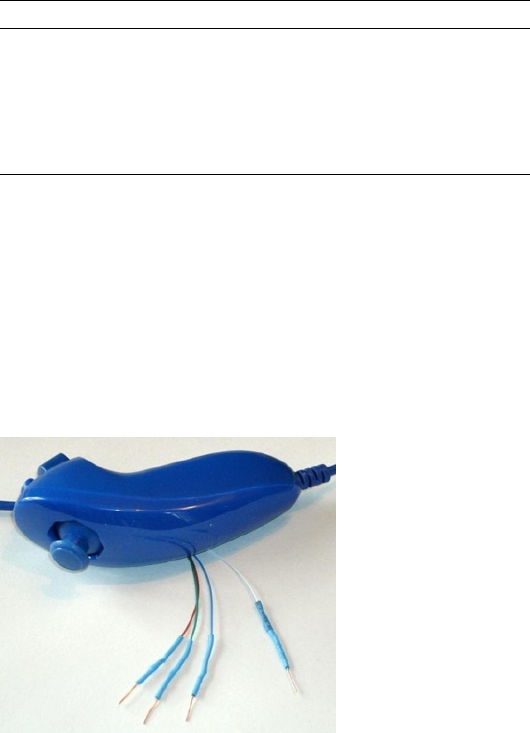
CHAPTER 3 ■ NUNCHUK-MOUSE
49
Before you cut that connector off your clone, consider that you’ll need to trace the
connector to a wire color. Cut the cable, leaving about 3 inches of wire for the connector.
Then you can cut the insulation off and trace the pins to a wire by using an ohmmeter
(or by looking inside the cable-end connector).
Figure 3-1 shows the author’s clone Nunchuk with the connector cut off. In place
of the connector, solid wire ends were soldered on and a piece of heat shrink applied
over the solder joint. The solid wire ends are perfect for plugging into a prototyping
breadboard.
Table 3-3. Nunchuk Connector Wiring
Pin Wii Wire CloneWire†Description P1
Gnd White White Ground P1-25
SDA Green Blue Data P1-03
+3.3 V Red Red Power P1-01
SCL Yellow Green Clock P1-05
†Clone wire colors vary!
Figure 3-1. Nunchuk with wire ends
Testing the Connection
Once you’ve hooked up the Nunchuk to the Raspberry Pi, you’ll want to perform some
simple tests to make sure it is working. The first step is to make sure your I2C drivers are
loaded:
$ lsmod | grep i2c
i2c_bcm2708 3759 0
i2c_dev 5620 0

CHAPTER 3 ■ NUNCHUK-MOUSE
50
If you see these modules loaded, you’re good to go. Otherwise, manually load them now:
$ sudo modprobe i2c−bcm2708
$ sudo modprobe i2c−dev
Assuming the Raspberry Pi rev 2.0+, you’ll use I2C bus 1 (see Chapter 12 of Raspberry
Pi Hardware Reference [Apress, 2014] if you’re not sure). Scan to see whether your
Nunchuk is detected:
$ sudo i2cdetect −y 1
0 1 2 3 4 5 6 7 8 9 a b c d e f
00: −− −− −− −− −− −− −− −− −− −− −− −− −−
10: −− −− −− −− −− −− −− −− −− −− −− −− −− −− −− −−
20: −− −− −− −− −− −− −− −− −− −− −− −− −− −− −− −−
30: −− −− −− −− −− −− −− −− −− −− −− −− −− −− −− −−
40: −− −− −− −− −− −− −− −− −− −− −− −− −− −− −− −−
50: −− −− 52 −− −− −− −− −− −− −− −− −− −− −− −− −−
60: −− −− −− −− −− −− −− −− −− −− −− −− −− −− −− −−
70: −− −− −− −− −− −− −− −−
If the Nunchuk is working, it will show up in this display at address 0x52. With the
hardware verified, it is time to move on to the software.
Nunchuk I2C Protocol
The Nunchuk contains a quirky little controller that communicates through the I2C bus.
In order to know where to store bytes written to it, the first byte must be an 8-bit register
address. In other words, each write to the Nunchuk requires the following:
One register address byte, followed by•
Zero or more data bytes to be written to sequential locations•
Thus for write operations, the first byte sent to the Nunchuk tells it where to start.
Any following write bytes received are written with the register address incremented.
Tip ■ Don’t confuse the register address with the Nunchuk’s I2C address of 0x52.
It is possible to write the register address and then read bytes instead. This procedure
specifies the starting location of data bytes to be read.
A quirky aspect of the Nunchuk controller is that there must be a short delay between
writing the register address and reading the data. Performing the write followed by an
immediate read does not work. Writing data immediately after the register address does
succeed, however.
Note ■ The Nunchuk uses I2C address 0x52.

CHAPTER 3 ■ NUNCHUK-MOUSE
51
Encryption
The Nunchuk is designed to provide an encrypted link. However, that can be disabled by
initializing it a certain way.60 The defeat procedure is as follows:
1. Write 0x55 to Nunchuk location 0xF0.
2. Pause.
3. Write 0x00 to Nunchuk location 0xFB.
The following illustrates the message sequence involved. Notice that this is
performed as two separate I2C write operations:
Write Pause Write
F0 55 - FB 00
Once this is successfully performed, all future data is returned unencrypted.
Read Sensor Data
The whole point of the Nunchuk is to read its sensor data. When requested, it returns 6
bytes of data formatted as shown in Table 3-4.
Table 3-4. Nunchuk Data
Byte Bits Description
1 Analog stick x axis value
2 Analog stick y axis value
3 X acceleration bits 9:2
4 Y acceleration bits 9:2
5 Z acceleration bits 9:2
6 0 Z button pressed (active low)
1 C button pressed (active low)
3:2 X acceleration bits 1:0
5:4 Y acceleration bits 1:0
7:6 Z acceleration bits 1:0

CHAPTER 3 ■ NUNCHUK-MOUSE
52
Some of the data is split over multiple bytes. For example, the X acceleration bits
9:2 are obtained from byte 3. The lowest 2 bits are found in byte 6, in bits 3 and 2. These
together form the 9-bit X acceleration value.
To retrieve this data, we are always required to tell the Nunchuk where to begin. So
the sequence always begins with a write of offset 0x00 followed by a pause:
Write Pause Read 6 bytes
00 - 01 02 03 04 05 06
The Nunchuk doesn’t allow us to do this in one ioctl(2) call, using two I/O
messages. A write of 0 must be followed by a pause. Then the 6 data bytes can be read as
a separate I2C read operation. If the pause is too long, however, the Nunchuk controller
seems to time out, resulting in incorrect data being returned. So we must do things the
Nunchuk way.
Linux uinput Interface
While reading the Nunchuk is fun, we need to apply it to our desktop as a mouse. We
need to insert mouse events based on what we read from it.
The Linux uinput driver allows programmers to develop nonstandard input drivers
so that events can be injected into the input stream. This approach allows new input
streams to be added without changing application code. Certainly the Nunchuk qualifies
as a nonstandard input device!
A problem with this uinput API is its general lack of documentation. The best
information available on the Internet seems to be from these three online sources:
“Getting started with uinput: the user level input subsystem” •
http://thiemonge.org/getting-started-with-uinput
“Using uinput driver in Linux- 2.6.x to send user input” •
http://www.einfochips.com/download/dash_jan_tip.pdf
“Types” • http://www.kernel.org/doc/Documentation/input/
event-codes.txt
The only other source of information seems to be the device driver source code itself:
drivers/input/misc/uinput.c
The example program provided in this chapter can help pull all the necessary details
together for you.
CHAPTER 3 ■ NUNCHUK-MOUSE
53
Working with Header Files
The header files required for the uinput API include the following:
#include <sys/ioctl.h>
#include <linux/input.h>
#include <linux/uinput.h>
To compile code, making use of I2C, you also need to install the libi2c development
library, if you have not done that already:
$ sudo apt-get install libi2c-dev
Opening the Device Node
The connection to the uinput device driver is made by opening the device node:
/dev/uinput
The following is an example of the required open(2) call:
int fd;
fd = open("/dev/uinput",O_WRONLY|O_NONBLOCK);
if ( fd < 0 ) {
perror("Opening /dev/uinput");
...
Configuring Events
In order to inject events, the driver must be configured to accept them. Each call to
ioctl(2) in the following code enables one class of events based on the argument event.
The following is a generalized example:
int rc;
unsigned long event = EV_KEY;
rc = ioctl(fd,UI_SET_EVBIT,event);
assert(!rc);
The list of UI_SET_EVBIT event types is provided in Table 3-5. The most commonly
needed event types are EV_SYN, EV_KEY, and EV_REL (or EV_ABS).

CHAPTER 3 ■ NUNCHUK-MOUSE
54
Caution ■ Do not or the event types together. The device driver expects each event type
to be registered separately.
Configure EV_KEY
Once you have registered your intention to provide EV_KEY events, you need to register all
key codes that might be used. While this seems a nuisance, it does guard against garbage
being injected by an errant program. The following code registers its intention to inject an
Escape key code:
int rc;
rc = ioctl(fd,UI_SET_KEYBIT,KEY_ESC);
assert(!rc);
To configure all possible keys, a loop can be used. But do not register key code 0
(KEY_RESERVED) nor 255; the include file indicates that code 255 is reserved for the special
needs of the AT keyboard driver.
Table 3-5. List of uinput Event Types
Macro From Header File input.h53]
Description
EV_SYN Event synchronization/separation
EV_KEY Key/button state changes
EV_REL Relative axis mouse-like changes
EV_ABS Absolute axis mouse-like changes
EV_MSC Miscellaneous events
EV_SW Binary (switch) state changes
EV_LED LED on/off changes
EV_SND Output to sound devices
EV_REP For use with autorepeating devices
EV_FF Force feedback commands to input device
EV_PWR Power button/switch event
EV_FF_STATUS Receive force feedback device status

CHAPTER 3 ■ NUNCHUK-MOUSE
55
int rc;
unsigned long key;
for ( key=1; key<255; ++key ) {
rc = ioctl(fd,UI_SET_KEYBIT,key);
assert(!rc);
}
Mouse Buttons
In addition to key codes, the same ioctl(2,UI_SET_KEYBIT) call is used to register
mouse, joystick, and other kinds of button events. This includes touch events from
trackpads, tablets, and touchscreens. The long list of button codes is defined in header file
linux/input.h. The usual suspects are shown in Table 3-6.
Table 3-6. Key Event Macros
Macro Synonym Description
BTN_LEFT BTN_MOUSE Left mouse button
BTN_RIGHT Right mouse button
BTN_MIDDLE Middle mouse button
BTN_SIDE Side mouse button
The following example shows the application’s intention to inject left and right
mouse button events:
int rc;
rc = ioctl(fd,UI_SET_KEYBIT,BTN_LEFT);
assert(!rc);
rc = ioctl(fd,UI_SET_KEYBIT,BTN_RIGHT);
assert(!rc);
Configure EV_REL
In order to inject EV_REL events, the types of relative movements must be registered in
advance. The complete list of valid argument codes is shown in Table 3-7. The following
example indicates an intention to inject x and y relative axis movements:
rc = ioctl(fd,UI_SET_RELBIT,REL_X);
assert(!rc);
rc = ioctl(fd,UI_SET_RELBIT,REL_Y);
assert(!rc);

CHAPTER 3 ■ NUNCHUK-MOUSE
56
Configure EV_ABS
While we don’t use the EV_ABS option in this project, it may be useful to introduce this
feature at this point. This event represents absolute cursor movements, and it too requires
registration of intentions. The complete list of EV_ABS codes is defined in linux/input.h.
The usual suspects are defined in Table 3-8.
Table 3-8. Absolute Cursor Movement Event Macros
Macro Description
ABS_X Move X to this absolute X coordinate
ABS_Y Move Y to this absolute Y coordinate
Table 3-7. UI_SET_RELBIT Options
Macro Intention
REL_X Send relative X changes
REL_Y Send relative Y changes
REL_Z Send relative Z changes
REL_RX x-axis tilt
REL_RY y- axis tilt
REL_RZ z- axis tilt
REL_HWHEEL Horizontal wheel change
REL_DIAL Dial-turn change
REL_WHEEL Wheel change
REL_MISC Miscellaneous
The following is an example of registering intent for absolute x- and y-axis events:
int rc;
rc = ioctl(fd,UI_SET_ABSBIT,ABS_X);
assert(!rc);
rc = ioctl(fd,UI_SET_ABSBIT,ABS_X);
assert(!rc);
CHAPTER 3 ■ NUNCHUK-MOUSE
57
In addition to registering your intentions to inject these events, you need to define
some coordinate parameters. The following is an example:
struct uinput_user_dev uinp;
uinp.absmin[ABS_X] = 0;
uinp.absmax[ABS_X] = 1023;
uinp.absfuzz[ABS_X] = 0;
uinp.absflat[ABS_X] = 0;
uinp.absmin[ABS_Y] = 0;
uinp.absmax[ABS_Y] = 767;
uinp.absfuzz[ABS_Y] = 0;
uinp.absflat[ABS_Y] = 0;
These values must be established as part of your ioctl(2,UI_DEV_CREATE)
operation, which is described next.
Creating the Node
After all registrations with the uinput device driver have been completed, the final step is
to create the uinput node. This will be used by the receiving application, in order to read
injected events. This involves two programming steps:
1. Write the struct uinput_user_dev information to the file
descriptor with write(2).
2. Perform an ioctl(2,UI_DEV_CREATE) to cause the uinput
node to be created.
The first step involves populating the following structures:
struct input_id {
__u16 bustype;
__u16 vendor;
__u16 product;
__u16 version;
};
struct uinput_user_dev {
char name[UINPUT_MAX_NAME_SIZE];
struct input_id id;
int ff_effects_max;
int absmax[ABS_CNT];
int absmin[ABS_CNT];
int absfuzz[ABS_CNT];
int absflat[ABS_CNT];
};
CHAPTER 3 ■ NUNCHUK-MOUSE
58
An example populating these structures is provided next. If you plan to inject
EV_ABS events, you must also populate the abs members, mentioned in the “Configure
EV_ABS” section.
struct uinput_user_dev uinp;
int rc;
memset(&uinp,0,sizeof uinp);
strncpy(uinp.name,"nunchuk",UINPUT_MAX_NAME_SIZE);
uinp.id.bustype = BUS_USB;
uinp.id.vendor = 0x1;
uinp.id.product = 0x1;
uinp.id.version = 1;
// uinp.absmax[ABS_X] = 1023; /∗ EV_ABS only ∗/
// ...
rc = write(fd,&uinp,sizeof(uinp));
assert(rc == sizeof(uinp));
The call to write(2) passes all of this important information to the uinput driver.
Now all that remains is to request a device node to be created for application use:
int rc;
rc = ioctl(fd,UI_DEV_CREATE);
assert(!rc);
This step causes the uinput driver to make a device node appear in the pseudo
directory /dev/input. An example is shown here:
$ ls –l /dev/input
total 0
drwxr−xr−x 2 root root 120 Dec 31 1969 by−id
drwxr−xr−x 2 root root 120 Dec 31 1969 by−path
crw−rw−−−T 1 root input 13, 64 Dec 31 1969 event0
crw−rw−−−T 1 root input 13, 65 Dec 31 1969 event1
crw−rw−−−T 1 root input 13, 66 Dec 31 1969 event2
crw−rw−−−T 1 root input 13, 67 Feb 23 13:40 event3
crw−rw−−−T 1 root input 13, 63 Dec 31 1969 mice
crw−rw−−−T 1 root input 13, 32 Dec 31 1969 mouse0
crw−rw−−−T 1 root input 13, 33 Feb 23 13:40 mouse1
The device /dev/input/event3 was the Nunchuck’s created uinput node, when the
program was run.
CHAPTER 3 ■ NUNCHUK-MOUSE
59
Posting EV_KEY Events
The following code snippet shows how to post a key down event, followed by a key up
event:
1 static void
2 uinput_postkey(int fd,unsigned key) {
3 struct input_event ev;
4 int rc;
5
6 memset(&ev,0,sizeof(ev));
7 ev.type = EV_KEY;
8 ev.code = key;
9 ev.value = 1;
10
11 rc = write(fd,&ev,sizeof(ev));
12 assert(rc == sizeof(ev));
13
14 ev.value = 0;
15 rc = write(fd,&ev,sizeof(ev));
16 assert(rc == sizeof(ev));
17 }
From this example, you see that each event is posted by writing a suitably initialized
input_event structure. The example illustrates that the member named type was set to
EV_KEY, code was set to the key code, and a keypress was indicated by setting the member
value to 1 (line 9).
To inject a key up event, value is reset to 0 (line 14) and the structure is written again.
Mouse button events work the same way, except that you supply mouse button codes
for the code member. For example:
memset(&ev,0,sizeof(ev));
ev.type = EV_KEY;
ev.code = BTN_RIGHT; /∗ Right click ∗/
ev.value = 1;
Posting EV_REL Events
To post a relative mouse movement, we populate the input_event as a type EV_REL. The
member code is set to the type of event (REL_X or REL_Y in this example), with the value
for the relative movement established in the member value:
static void
uinput_movement(int fd,int x,inty) {
struct input_event ev;
int rc;
CHAPTER 3 ■ NUNCHUK-MOUSE
60
memset(&ev,0,sizeof(ev));
ev.type = EV_REL;
ev.code = REL_X;
ev.value = x;
rc = write(fd,&ev,sizeof(ev));
assert(rc == sizeof(ev));
ev.code = REL_Y;
ev.value = y;
rc = write(fd,&ev,sizeof(ev));
assert (rc == sizeof(ev));
}
Notice that the REL_X and REL_Y events are created separately. What if you want the
receiving application to avoid acting on these separately? The EV_SYN event helps out in
this regard (next).
Posting EV_SYN Events
The uinput driver postpones delivery of events until the EV_SYN event has been injected.
The SYN_REPORT type of EV_SYN event causes the queued events to be flushed out and
reported to the interested application. The following is an example:
static void
uinput_syn(int fd) {
struct input_event ev;
int rc;
memset(&ev,0,sizeof(ev));
ev.type = EV_SYN;
ev.code = SYN_REPORT;
ev.value = 0;
rc = write(fd,&ev,sizeof(ev));
assert(rc == sizeof(ev));
}
For a mouse relative movement event, for example, you can inject a REL_X and REL_Y,
followed by a SYN_REPORT event to have them seen by the application as a group.
Closing uinput
There are two steps involved:
1. Destruction of the /dev/input/event%d node
2. Closing of the file descriptor

CHAPTER 3 ■ NUNCHUK-MOUSE
61
The following example shows both:
int rc;
rc = ioctl(fd,UI_DEV_DESTROY);
assert(!rc);
close(fd);
Closing the file descriptor implies the ioctl(2,UI_DEV_DESTROY) operation.
The application has the option of destroying the device node while keeping the file
descriptor open.
X-Window
The creation of our new uinput device node is useful only if our desktop system is
listening to it. Raspbian Linux’s X-Windows system needs a little configuration help to
notice our Frankenstein creation. The following definition can be added to the
/usr/share/X11/xorg.config.d directory. Name the file 20-nunchuk.conf:
# Nunchuck event queue
Section "InputClass"
Identifier "Raspberry Pi Nunchuk"
Option "Mode" "Relative"
MatchDevicePath "/dev/input/event3"
Driver "evdev"
EndSection
# End 20−nunchuk.conf
This configuration change works only if your Nunchuk uinput device shows up
as /dev/input/event3. If you have other specialized input device creations on your
Raspberry Pi, it could well be event4 or some other number. See the upcoming section
“Testing the Nunchuk” for troubleshooting information.
Restart your X-Windows server to have the configuration file noticed.
Tip ■ Normally, your Nunchuk program should be running already. But the X-Window
server will notice it when the Nunchuk does start.
CHAPTER 3 ■ NUNCHUK-MOUSE
62
Input Utilities
When writing uinput event-based code, you will find the package input-utils to be
extremely helpful. They can be installed from the command line as follows:
$ sudo apt−get install input−utils
The following commands are installed:
lsinput(8): List uinput devices
input-events(8): Dump selected uinput events
input-kbd(8): Keyboard map display
This chapter uses the first two utilities: lsinput(8) and input-events(8).
Testing the Nunchuk
Now that the hardware, drivers, and software are ready, it is time to exercise the Nunchuk.
Unfortunately, there is no direct way for applications to identify your created uinput
node. When the Nunchuk program runs, the node may show up as /dev/input/event3
or some other numbered node if event3 already exists. If you wanted to start a Nunchuk
driver as part of the Linux boot process, you need to create a script to edit the file with the
actual device name. The affected X-Windows config file is as follows:
/usr/share/X11/xord.conf.d/20-nunchuk.conf
The script (shown next) determines which node the Nunchuk program created. The
following is an example run, while the Nunchuk program was running:
$ ./findchuk
/dev/input/event3
When the node is not found, the findchuk script exits with a nonzero code and
prints a message to stderr:
$ ./findchuk
Nunchuk uinput device not found.
$ echo $?
1
CHAPTER 3 ■ NUNCHUK-MOUSE
63
The findchuk script is shown here:
#!/bin/bash
######################################################################
# Find the Nunchuck
######################################################################
#
# This script locates the Nunchuk uinput device by searching the
# /sys/devices/virtual/input pseudo directory for names of the form:
# input[0_9]∗. For all subdirectories found, check the ./name pseudo
# file, which will contain "nunchuk". Then we derive the /dev path
# from a sibling entry named event[0_9]∗. That will tell use the
# /dev/input/event%d pathname, for the Nunchuk.
DIR=/sys/devices/virtual/input # Top level directory
set_eu
cd "$DIR"
find . −type d −name 'input[0−9]∗' | (
set −eu
while read dirname ; do
cd "$DIR/$dirname"
if [−f "name"] ; then
set +e
name=$(cat name)
set −e
if [ $(cat name) = nunchuk ] ; then
event="/dev/input/$ (ls−devent[0−9]∗)"
echo $event
exit 0 # Found it
fi
fi
done
echo "Nunchuk uinput device not found." >&2
exit 1
)
# End findchuk
CHAPTER 3 ■ NUNCHUK-MOUSE
64
Testing ./nunchuk
When you want to see what Nunchuk data is being received, you can add the
-d command-line option:
$ ./nunchuk −d
Raw nunchuk data: [83] [83] [5C] [89] [A2] [63]
.stick_x = 0083 (131)
.stick_y = 0083 (131)
.accel_x = 0170 (368)
.accel_y = 0226 (550)
.accel_z = 0289 (649)
.z_button= 0
.c_button= 0
The first line reports the raw bytes of data that were received. The remainder of the
lines report the data in its decoded form. While the raw data reports the button presses as
active low, the Z and C buttons are reported as 1 in the decoded data. The value in the left
column is in hexadecimal format, while the value in parenthesis is shown in decimal.
Utility lsinputs
When the Nunchuk program is running, you should be able to see the Nunchuk uinput
device in the list:
$ lsinput
...
/dev/input/event2
bustype : BUS_USB
vendor : 0x45e
product : 0x40
version : 272
name : "Microsoft Micro soft 3−Button Mou"
phys : "usb−bcm2708_usb−1.3.4/input0"
uniq : ""
bitsev : EV_SYN EV_KEY EV_REL EV_MSC
/dev/input/event3
bustype : BUS_USB
vendor : 0x1
product : 0x1
version : 1
name : "nunchuk"
bits ev : EV_SYN EV_KEY EV_REL
In this example, the Nunchuk shows up as event3.
CHAPTER 3 ■ NUNCHUK-MOUSE
65
Utility input-events
When developing uinput-related code, the input-events utility is a great help. Here we run
it for event3 (the argument 3 on the command line), where the Nunchuk mouse device is:
$ input−events 3
/dev/input/event3
bustype : BUS_USB
vendor : 0x1
product : 0x1
version : 1
name : "nunchuk"
bits ev : EV_SYN EV_KEY EV_REL
waiting for events
23:35:15.345105: EV_KEY BTN_LEFT (0x110) pressed
23:35:15.345190: EV_SYN code=0 value=0
23:35:15.517611: EV_KEY BTN_LEFT (0x110) released
23:35:15.517713: EV_SYN code=0 value=0
23:35:15.833640: EV_KEY BTN_RIGHT (0x111) pressed
23:35:15.833727: EV_SYN code=0 value=0
23:35:16.019363: EV_KEY BTN_RIGHT (0x111) released
23:35:16.019383: EV_SYN code=0 value=0
23:35:16.564129: EV_REL REL_X −1
23:35:16.564213: EV_REL REL_Y 1
23:35:16.564261: EV_SYN code=0 value=0
...
The Program
The code for nunchuk.c is presented on the following pages. The source code for timed_
wait.c is shown in Chapter 1. We’ve covered the I2C I/O in other chapters. The only thing
left to note is the difficulty of providing a smooth interface for events produced by the
Nunchuk. Here are a few hints for the person who wants to experiment:
1. If the mouse moves too quickly, one major factor is the timed
delay used. The timed_wait() call in line 107 spaces out read
events for the Nunchuk (currently 15 ms). This also lightens
the load on the CPU. Reducing this time-out increases the
number of Nunchuk reads and causes more uinput events to
be injected. This speeds up the mouse pointer.
2. The function curve() in line 349 attempts to provide a
somewhat exponential movement response. Small joystick
excursions should be slow and incremental. More-extreme
movements will result in faster mouse movements.
CHAPTER 3 ■ NUNCHUK-MOUSE
66
3. The Z button is interpreted as the left-click button, while the
C button is the right-click button.
4. No keystrokes are injected by this program, but it can be
modified to do so. The function uinput_postkey() on line 244
can be used for that purpose.
1 /∗∗∗∗∗∗∗∗∗∗∗∗∗∗∗∗∗∗∗∗∗∗∗∗∗∗∗∗∗∗∗∗∗∗∗∗∗∗∗∗∗∗∗∗∗∗∗∗∗∗∗∗∗∗∗∗∗∗∗∗∗∗∗∗∗∗∗∗∗
2 ∗ nunchuk.c: Read events from nunchuck and stuff as mouse events
3 ∗∗∗∗∗∗∗∗∗∗∗∗∗∗∗∗∗∗∗∗∗∗∗∗∗∗∗∗∗∗∗∗∗∗∗∗∗∗∗∗∗∗∗∗∗∗∗∗∗∗∗∗∗∗∗∗∗∗∗∗∗∗∗∗∗∗∗∗∗/
4
5 #include <stdio.h>
6 #include <math.h>
7 #include <stdlib.h>
8 #include <fcntl.h>
9 #include <unistd.h>
10 #include <string.h>
11 #include <errno.h>
12 #include <signal.h>
13 #include <assert.h>
14 #include <sys/ioctl.h>
15 #include <linux/i2c−dev.h>
16 #include <linux/input.h>
17 #include <linux/uinput.h>
18
19 #include "timed_wait.c"
20
21 static int is_signaled = 0; /∗ Exit program if signaled ∗/
22 static int i2c_fd = −1; /∗ Open/dev/i2c−1 device ∗/
23 static int f_debug = 0; /∗ True to print debug messages ∗/
24
25 typedef struct {
26 unsigned char stick_x; /∗ Joystick X ∗/
27 unsigned char stick_y; /∗ Joystick Y ∗/
28 unsigned accel_x; /∗ Accel X ∗/
29 unsigned accel_y; /∗ Accel Y ∗/
30 unsigned accel_z; /∗ Accel Z ∗/
31 unsigned z_button:1; /∗ Z button ∗/
32 unsigned c_button:1; /∗ C button ∗/
33 unsigned char raw[6]; /∗ Raw received data ∗/
34 } nunchuk_t;
35
36 /∗
37 ∗ Open I2C bus and check capabilities:
38 ∗/
39 static void
40 i2c_init(const char ∗node) {
CHAPTER 3 ■ NUNCHUK-MOUSE
67
41 unsigned long i2c_funcs = 0; /∗ Support flags ∗/
42 int rc;
43
44 i2c_fd = open(node,O_RDWR); /∗ Open driver/dev/i2s−1 ∗/
45 if ( i2c_fd < 0 ) {
46 perror("Opening/dev/i2s−1");
47 puts("Check that the i2c−dev & i2c−bcm2708 kernel modules"
48 "are loaded.");
49 abort();
50 }
51
52 /∗
53 ∗ Make sure the driver supports plain I2C I/O:
54 ∗/
55 rc = ioctl(i2c_fd,I2C_FUNCS,&i2c_funcs);
56 assert(rc >= 0);
57 assert(i2c_funcs & I2C_FUNC_I2C);
58 }
59
60 /∗
61 ∗ Configure the nunchuk for no encryption:
62 ∗/
63 static void
64 nunchuk_init(void) {
65 static char init_msg1[] = {0xF0, 0x55};
66 static char init_msg2[] = {0xFB, 0x00};
67 struct i2c_rdwr_ioctl_data msgset;
68 struct i2c_msg iomsgs[1];
69 int rc;
70
71 iomsgs[0].addr = 0x52; /∗ Address of Nunchuk ∗/
72 iomsgs[0].flags = 0; /∗ Write ∗/
73 iomsgs[0].buf = init_msg1; /∗ Nunchuk 2 byte sequence ∗/
74 iomsgs[0].len = 2; /∗ 2 bytes ∗/
75
76 msgset.msgs = iomsgs;
77 msgset.nmsgs = 1;
78
79 rc = ioctl(i2c_fd,I2C_RDWR,&msgset);
80 assert(rc == 1);
81
82 timed_wait(0,200,0); /∗ Nunchuk needs time ∗/
83
84 iomsgs[0].addr = 0x52; /∗ Address of Nunchuk ∗/
85 iomsgs[0].flags = 0; /∗ Write ∗/
86 iomsgs[0].buf = init_msg2; /∗ Nunchuk 2 byte sequence ∗/
87 iomsgs[0].len = 2; /∗ 2 bytes ∗/
88
CHAPTER 3 ■ NUNCHUK-MOUSE
68
89 msgset.msgs = iomsgs;
90 msgset.nmsgs = 1;
91
92 rc = ioctl(i2c_fd,I2C_RDWR,&msgset);
93 assert(rc == 1);
94 }
95
96 /∗
97 ∗ Read nunchuk data :
98 ∗/
99 static int
100 nunchuk_read(nunchuk_t ∗data) {
101 struct i2c_rdwr_ioctl_data msgset;
102 struct i2c_msg iomsgs[1];
103 char zero[1] = {0x00}; /∗ Written byte ∗/
104 unsigned t;
105 int rc;
106
107 timed_wait(0,15000,0);
108
109 /∗
110 ∗ Write the nunchuk register address of 0x00:
111 ∗/
112 iomsgs[0].addr = 0x52; /∗ Nunchuk address ∗/
113 iomsgs[0].flags = 0; /∗ Write ∗/
114 iomsgs[0].buf = zero; /∗ Sending buf ∗/
115 iomsgs[0].len = 1; /∗ 1 byte ∗/
116
117 msgset.msgs = iomsgs;
118 msgset.nmsgs = 1;
119
120 rc = ioctl(i2c_fd,I2C_RDWR,&msgset);
121 if ( rc < 0 )
122 return −1; /∗ I /O error ∗/
123
124 timed_wait(0,200,0); /∗ Zzzz, nunchuk needs time ∗/
125
126 /∗
127 ∗ Read 6 bytes starting at 0x00:
128 ∗/
129 iomsgs[0].addr = 0x52; /∗ Nunchuk address ∗/
130 iomsgs[0].flags = I2C_M_RD; /∗ Read ∗/
131 iomsgs[0].buf = (char ∗)data−>raw; /∗ Receive raw bytes here ∗/
132 iomsgs[0].len = 6; /∗ 6 bytes ∗/
133
134 msgset.msgs = iomsgs;
135 msgset.nmsgs = 1;
136
CHAPTER 3 ■ NUNCHUK-MOUSE
69
137 rc = ioctl(i2c_fd,I2C_RDWR,&msgset);
138 if ( rc < 0 )
139 return −1; /∗ Failed ∗/
140
141 data−>stick_x = data−>raw[0];
142 data−>stick_y = data−>raw[1];
143 data−>accel_x = data−>raw[2] << 2;
144 data−>accel_y = data−>raw[3] << 2;
145 data−>accel_z = data−>raw[4] << 2;
146
147 t = data−>raw[5];
148 data−>z_button = t & 1 ? 0 : 1;
149 data−>c_button = t & 2 ? 0 : 1;
150 t >>= 2;
151 data−>accel_x |= t & 3;
152 t >>= 2;
153 data−>accel_y |= t & 3;
154 t >>= 2;
155 data−>accel_z |= t & 3;
156 return 0;
157 }
158
159 /∗
160 ∗ Dump the nunchuk data:
161 ∗/
162 static void
163 dump_data(nunchuk_t ∗data) {
164 int x;
165
166 printf("Raw nunchuk data : ");
167 for ( x=0; x<6; ++x )
168 printf("[%02X]",data−>raw[x]);
169 putchar('\n');
170
171 printf(".stick_x = %04X (%4u)\n",data−>stick_x,data−>stick_x);
172 printf(".stick_y = %04X (%4u)\n",data−>stick_y,data−>stick_y);
173 printf(".accel_x = %04X (%4u)\n",data−>accel_x,data−>accel_x);
174 printf(".accel_y = %04X (%4u)\n",data−>accel_y,data−>accel_y);
175 printf(".accel_z = %04X (%4u)\n",data−>accel_z,data−>accel_z);
176 printf(".z_button= %d\n",data−>z_button);
177 printf(".c_button= %d\n\n",data−>c_button);
178 }
179
180 /∗
181 ∗ Close the I2C driver :
182 ∗/
CHAPTER 3 ■ NUNCHUK-MOUSE
70
183 static void
184 i2c_close(void) {
185 close(i2c_fd);
186 i2c_fd = −1;
187 }
188
189 /∗
190 ∗ Open a uinput node :
191 ∗/
192 static int
193 uinput_open(void) {
194 int fd;
195 struct uinput_user_dev uinp;
196 int rc;
197
198 fd = open("/dev/uinput",O_WRONLY|O_NONBLOCK);
199 if ( fd < 0 ) {
200 perror("Opening/dev/uinput");
201 exit(1);
202 }
203
204 rc = ioctl(fd,UI_SET_EVBIT,EV_KEY);
205 assert(!rc);
206 rc = ioctl(fd,UI_SET_EVBIT,EV_REL);
207 assert(!rc);
208
209 rc = ioctl(fd,UI_SET_RELBIT,REL_X);
210 assert(!rc);
211 rc = ioctl(fd,UI_SET_RELBIT,REL_Y);
212 assert(!rc);
213
214 rc = ioctl(fd,UI_SET_KEYBIT,KEY_ESC);
215 assert(!rc);
216
217 ioctl(fd,UI_SET_KEYBIT,BTN_MOUSE);
218 ioctl(fd,UI_SET_KEYBIT,BTN_TOUCH);
219 ioctl(fd,UI_SET_KEYBIT,BTN_MOUSE);
220 ioctl(fd,UI_SET_KEYBIT,BTN_LEFT);
221 ioctl(fd,UI_SET_KEYBIT,BTN_MIDDLE);
222 ioctl(fd,UI_SET_KEYBIT,BTN_RIGHT);
223
224 memset(&uinp,0,sizeof uinp);
225 strncpy(uinp.name,"nunchuk",UINPUT_MAX_NAME_SIZE);
226 uinp.id.bustype = BUS_USB;
227 uinp.id.vendor = 0x1;
228 uinp.id.product = 0x1;
229 uinp.id.version = 1;
230
CHAPTER 3 ■ NUNCHUK-MOUSE
71
231 rc = write(fd,&uinp,sizeof(uinp));
232 assert(rc == sizeof(uinp));
233
234 rc = ioctl(fd,UI_DEV_CREATE);
235 assert(!rc);
236 return fd;
237 }
238
239 /∗
240 ∗ Post keystroke down and keystroke up events:
241 ∗ (unused here but available for your own experiments)
242 ∗/
243 static void
244 uinput_postkey(int fd,unsigned key) {
245 struct input_event ev;
246 int rc;
247
248 memset(&ev,0,sizeof(ev));
249 ev.type = EV_KEY;
250 ev.code = key;
251 ev.value = 1; /∗ Key down ∗/
252
253 rc = write(fd,&ev,sizeof(ev));
254 assert(rc == sizeof(ev));
255
256 ev.value = 0; /∗ Key up ∗/
257 rc = write(fd,&ev,sizeof(ev));
258 assert(rc == sizeof(ev));
259 }
260
261 /∗
262 ∗ Post a synchronization point :
263 ∗/
264 static void
265 uinput_syn(int fd) {
266 struct input_event ev;
267 int rc;
268
269 memset(&ev,0,sizeof(ev));
270 ev.type = EV_SYN;
271 ev.code = SYN_REPORT;
272 ev.value = 0;
273 rc = write(fd,&ev,sizeof(ev));
274 assert(rc == sizeof(ev));
275 }
276
CHAPTER 3 ■ NUNCHUK-MOUSE
72
277 /∗
278 ∗ Synthesize a button click :
279 ∗ up_down 1=up, 0=down
280 ∗ buttons 1=Left, 2=Middle, 4=Right
281 ∗/
282 static void
283 uinput_click(int fd,int up_down,int buttons) {
284 static unsigned codes[] = {BTN_LEFT, BTN_MIDDLE, BTN_RIGHT};
285 struct input_event ev;
286 int x;
287
288 memset(&ev,0,sizeof(ev));
289
290 /∗
291 ∗ Button down or up events:
292 ∗/
293 for ( x=0; x < 3; ++x ) {
294 ev.type = EV_KEY;
295 ev.value = up_down; /∗ Button Up or down ∗/
296 if ( buttons & (1 << x) ) { /∗ Button 0, 1 or 2 ∗/
297 ev.code = codes[x];
298 write(fd,&ev,sizeof(ev));
299 }
300 }
301 }
302
303 /∗
304 ∗ Synthesize relative mouse movement:
305 ∗/
306 static void
307 uinput_movement(int fd,int x,int y) {
308 struct input_event ev;
309 int rc;
310
311 memset(&ev,0,sizeof(ev));
312 ev.type = EV_REL;
313 ev.code = REL_X;
314 ev.value = x;
315
316 rc = write(fd,&ev,sizeof(ev));
317 assert(rc == sizeof(ev));
318
319 ev.code = REL_Y;
320 ev.value = y;
321 rc = write(fd,&ev,sizeof(ev));
322 assert(rc == sizeof(ev));
323 }
324
CHAPTER 3 ■ NUNCHUK-MOUSE
73
325 /∗
326 ∗ Close uinput device :
327 ∗/
328 static void
329 uinput_close(int fd) {
330 int rc;
331
332 rc = ioctl(fd,UI_DEV_DESTROY);
333 assert(!rc);
334 close(fd);
335 }
336
337 /∗
338 ∗ Signal handler to quit the program:
339 ∗/
340 static void
341 sigint_handler(int signo) {
342 is_signaled = 1; /∗ Signal to exit program ∗/
343 }
344
345 /∗
346 ∗ Curve the adjustment :
347 ∗/
348 static int
349 curve(int relxy) {
350 int ax = abs(relxy); /∗ abs (relxy) ∗/
351 int sgn = relxy < 0 ? −1 : 1; /∗ sign (relxy) ∗/
352 int mv = 1; /∗ Smallest step ∗/
353
354 if ( ax > 100 )
355 mv = 10; /∗ Take large steps ∗/
356 else if ( ax > 65 )
357 mv = 7;
358 else if ( ax > 35 )
359 mv = 5;
360 else if ( ax > 15 )
361 mv = 2; /∗ 2nd smallest step ∗/
362 return mv ∗ sgn;
363 }
364
365 /∗
366 ∗ Main program:
CHAPTER 3 ■ NUNCHUK-MOUSE
74
367 ∗/
368 int
369 main(int argc,char ∗∗argv) {
370 int fd, need_sync, init = 3;
371 int rel_x=0, rel_y = 0;
372 nunchuk_t data0, data, last;
373
374 if ( argc > 1 && !strcmp(argv [1]," −d") )
375 f_debug = 1; /∗ Enable debug messages ∗/
376
377 (void)uinput_postkey; /∗ Suppress compiler warning about unused ∗/
378
379 i2c_init("/dev/i2c−1"); /∗ Open I2C controller ∗/
380 nunchuk_init(); /∗ Turn off encrypt ion ∗/
381
382 signal(SIGINT,sigint_handler); /∗ Trap on SIGINT ∗/
383 fd = uinput_open(); /∗ Open/dev/uinput ∗/
384
385 while ( !is_signaled ) {
386 if ( nunchuk_read(&data) < 0 )
387 continue;
388
389 if ( f_debug )
390 dump_data(&data); /∗ Dump nunchuk data ∗/
391
392 if ( init > 0 && !data0.stick_x && !data0.stick_y ) {
393 data0 = data; /∗ Save initial values ∗/
394 last = data;
395 −−init;
396 continue;
397 }
398
399 need_sync = 0;
400 if ( abs(data.stick_x − data0.stick_x) > 2
401 || abs(data.stick_y − data0.stick_y) > 2) {
402 rel_x = curve (data.stick_x − data0.stick_x);
403 rel_y = curve (data.stick_y − data0.stick_y);
404 if ( rel_x || rel_y ) {
405 uinput_movement(fd,rel_x,−rel_y);
406 need_sync = 1;
407 }
408 }
409
410 if ( last.z_button != data.z_button ) {
411 uinput_click(fd, data.z_button,1);
412 need_sync = 1;
413 }
414
CHAPTER 3 ■ NUNCHUK-MOUSE
75
415 if ( last.c_button != data.c_button ) {
416 uinput_click(fd,data.c_button,4);
417 need_sync = 1;
418 }
419
420 if ( need_sync )
421 uinput_syn(fd);
422 last = data;
423 }
424
425 putchar('\n');
426 uinput_close(fd);
427 i2c_close();
428 return 0;
429 }
430
431 /∗ End nunchuk.c ∗/
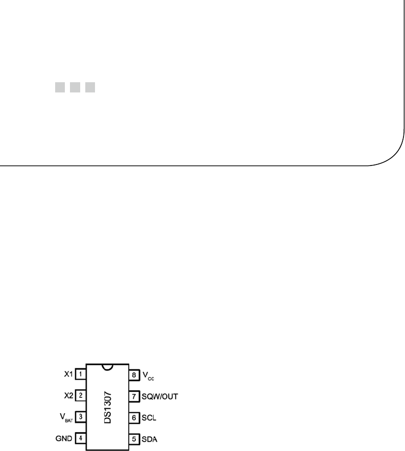
77
Chapter 4
Real-Time Clock
The Dallas Semiconductor DS1307 Real-Time Clock is the perfect project for the
Raspberry Pi, Model A. Lacking a network port, the Model A cannot determine the
current date and time when it boots up. A 3 V battery attached to the DS1307 will keep its
internal clock running for up to 10 years, even when the Pi is powered off. If you have a
Model B, don’t feel left out. There is no reason that you can’t try this project too; a Model
B not connected to a network could use the DS1307.
DS1307 Overview
The pinout of the DS1307 chip is provided in Figure 4-1. The chip is available in PDIP-8
form or in SO format (150 mils). Hobbyists who like to build their own will prefer the
PDIP-8 form.
Figure 4-1. DS1307 pinout
A crystal is wired between pins 1 and 2 (X1 and X2). The battery powers the chip
through pin 3 and flows to ground (pin 4). This keeps the clock alive while the main
power is absent. When there is power, it is supplied through pin 8 (VCC). The I2C
communication occurs via pins 5 and 6. Pin 7 provides an optional output clock signal or
can operate as an open collector output.
While you could build this circuit yourself, you can find fully assembled PCB
modules using the DS1307 on eBay for as little as $2.36 (with free shipping). These are
available as Buy It Now offers, so you don’t have to waste your time trying to win auctions.
Just keep in mind that some are not shipped with a 3 V battery. (Check the product.
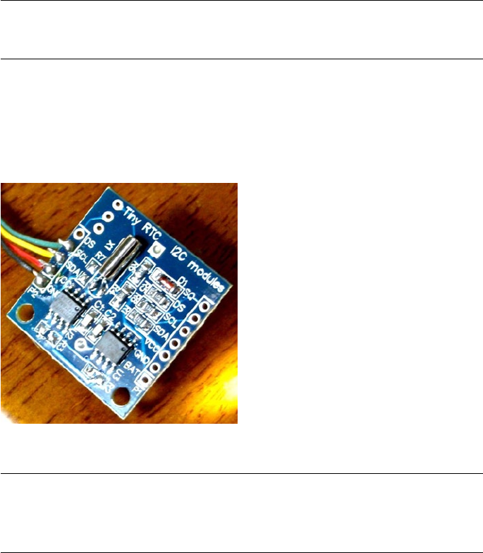
CHAPTER 4 ■ REAL-TIME CLOCK
78
The Tiny RTC I used came with a 3.6 V battery.) It is claimed that there are mailing
restrictions on batteries to certain countries. So you may want to shop for suitable
batteries while you wait for the mail.
Tip ■ Buying a fresh battery ahead of time is recommended, as batteries often arrive
exhausted.
Figure 4-2 shows a PCB unit that I purchased through eBay. This unit came paired
with the AT24C32 EEPROM chip. The auction was labeled “Tiny RTC I2C Modules.” You
don’t have to use this specific PCB, of course. The wiring for each chip is fairly basic and
can be prototyped on a breadboard if you can’t find one. But if you do choose this PCB, a
modification is required before you attach it to the Raspberry Pi.
Figure 4-2. An assembled DS1307 PCB purchased through eBay
Caution ■ I2C pull-up resistors R2 and R3 must be removed before wiring the PCB to the
Raspberry Pi. Also, if you plan to attach the SQW/OUT output of this PCB to a GPIO input, be
sure to track down and remove its pull-up resistor as well.

CHAPTER 4 ■ REAL-TIME CLOCK
79
Pins X1 and X2
These pins are for connection to a 32.768 kHz crystal. The datasheet states that the
“internal oscillator circuitry is designed for operation with a crystal having a specified
load capacitance (CL) of 12.5 pF.”
Pin SQW/OUT
This is an open-drain output from the DS1307 chip that you can choose to ignore if you
like. It can be used as follows:
A GPIO-like output. If you plan on wiring this to a Pi GPIO pin, be •
sure to remove the pull-up resistor (on PCB) first. The +5 V from
the pull-up will damage the Pi.
A square wave clock output, at one of the following programmable •
frequencies:
1 Hz ·
4.096 kHz ·
8.192 kHz ·
32.768 kHz ·
The datasheet lists a current rating for output when low:
Parameter Symbol Min Typ Max Units
Logic 0 Output (IOL = 5 mA)VOL 0.4 Volts
Without more-specific information, we arrive at the conclusion that a given logic pin
is capable of sinking a maximum of 5 mA (SDA). While doing so, the maximum voltage
appearing at the pin is 0.4 V. This is well under the 0.8 V maximum, for the VIL voltage
level of the Raspberry Pi.
The datasheet indicates that the SQW/OUT pin is an open-drain output. As such,
you can use a pull-up to +3.3 V or +5 V as your interface requires. It could be used to drive
a small LED at 1 Hz, if the current is limited to less than 5 mA (although the datasheet
doesn’t indicate the current capability of this open-drain transistor). Alternatively, it can
be used to drive other external logic with a pull-up resistor.
The datasheet indicates that the SQW/OUT pin can pulled as high as 5.5 V, even
when VCC is lower in voltage (such as +3.3 V.) This is safe, provided that these higher
voltages never connect to the Pi’s GPIO pins.

CHAPTER 4 ■ REAL-TIME CLOCK
80
Power
If you’ve looked at the datasheet for the DS1307 before, you might be wondering about
the power supply voltage. The datasheet lists it as a +5 V part, and by now you are well
aware that the Pi’s GPIO pins operate at +3 V levels. The DC operating conditions are
summarized here:
Parameter Symbol Min Typ Max Units
Supply voltage VCC 4.5 5.0 5.5 Volts
Battery voltage VBAT 2.0 3.5 Volts
It is tempting to consider that the PCB might operate at +3.3 V, given that the battery
in the unit is 3 V. However, that will not work because the DS1307 chip considers a VCC
lower than 1.25 × VBAT = 3.75 V to be a power-fail condition (for a typical operation). When
it senses a power fail, it relies on battery operation and will cease to communicate by I2C,
among other things. Power-fail conditions are summarized here:
Parameter Symbol Min Typ Max Units
Power-fail voltage VPF 1.26×VBAT 1.25×VBAT 1.284×VBAT Volts
The note in the datasheet indicates that the preceding figures were measured when
VBAT = 3 V. So these figures will likely deviate when the battery nears expiry. Given the
power-fail conditions, we know that the device must be powered from a +5 V power
supply. But the only connections made to the Raspberry Pi are the SDA and SCL I2C lines.
So let’s take a little closer look at those and see if we can use them.
3-Volt Compatibility
The SCL line is always driven by the master, as far as the DS1307 is concerned. This
means that SCL is always seen as an input signal by the RTC clock chip. All we have to
check here is whether the Raspberry Pi will meet the input-level requirements. Likewise,
the AT24C32 EEPROM’s SCL pin is also an input only.
The SDA line is driven by both the master (Pi) and the DS1307 chip (slave). The SDA
is driven from the Pi as a 3 V signal, so again we need to make certain that the DS1307 will
accept those levels. But what about the DS1307 driving the SDA line? The Pi must not
see +5 V signals.
The DS1307 datasheet clearly states that “the SDA pin is open drain, which requires an
external pull-up resistor.” The Raspberry Pi already supplies the pull-up resistor to +3.3 V.
This means that the DS1307’s open drain will allow the line to be pulled up to +3.3 V for
the high logic level, when the output transistor is in the off state. When the transistor is
on, it simply pulls the SDA line down to ground potential. Thus with
open-drain operation, we can interoperate with the Raspberry Pi. A check of the AT24C32
EEPROM datasheets leads to the same conclusion.

CHAPTER 4 ■ REAL-TIME CLOCK
81
Logic Levels
How do the I2C logic levels compare between the Raspberry Pi and the DS1307?
Signal Raspberry Pi DS1307
VIL £ 0.8 volts £ 0.8 volts
VIH ³ 1.3 volts ³ 2.2 volts
The VIL figure matches perfectly for both sides. As long as the Raspberry Pi provides
a high level exceeding 2.2 V, the DS1307 chip should read high levels just fine. Given
that the Pi’s pull-up resistor is connected to +3.3 V, there is very little reason to doubt
problems meeting the DS1307 VIH requirement.
To summarize, we can safely power the DS1307 from +5 V, while communicating
between it and the Raspberry Pi at +3 V levels. The Pi already supplies pull-up resistors
for the SCL and SDA lines, and these are attached to +3.3 V. If, however, you choose to use
other GPIO pins to bit-bang I2C (say), you’ll need to provide these pull-up resistors (they
must go to only +3.3 V).
Tiny RTC Modifications
In the preceding section, you saw that even though the DS1307 is a +5 V part, the SDA
pin is driven by an open-drain transistor. With the Raspberry Pi tying the SDA line to +3.3
V, the highest voltage seen will be exactly that. The open-drain transistor can only pull
it down to ground (this also applies to the AT24C32 EEPROM). Both chips have the SCL
pins as inputs (only), which are not pulled high by the chips themselves.
If you purchased a PCB like the one I used, however, be suspicious of pull-up
resistors! I knew that the parts would support +3.3 V I2C bus operation before the PCB
arrived in the mail. However, I was suspicious of added pull-up resistors. So when the
PCB arrived, I quickly determined that the PCB did indeed include pull-up resistors
connected to the +5 V supply. The extra +5 V pull-up resistors must be tracked down and
removed for use with the Raspberry Pi.
Checking for Pull-up Resistors
There are two methods to test for pull-up resistors: a DMM resistance check and a voltage
reading. I recommend that you apply them both.
Since this modification is important to get correct, the following sections will walk
you through the two different procedures in detail.
CHAPTER 4 ■ REAL-TIME CLOCK
82
Performing a DMM Resistance Check
Use these steps for the DMM resistance check:
1. Attach one probe of your DMM (reading kΩ) to the +5 V line
of the PCB.
2. Attach the other probe to the SDA line and take the resistance
reading.
3. Reverse the leads if you suspect diode action.
On my PCB, I read 3.3 kΩ. Reversing the DMM leads should read the same (proving
only resistance). Performing the same test with the SCL input, I also read 3.3 kΩ.
Performing a Voltage Reading
Do not skip this particular test. The result of this test will tell you whether your Raspberry
Pi will be at risk.
1. Hook up your PCB to the +5 V supply it requires, but do not
attach the SDA/SCL lines to the Pi yet. Just leave them loose
for measuring with your DMM.
2. With the DMM negative probe grounded, measure the
voltage seen at the PCB’s SDA and SCL inputs. If there is no
pull-up resistor involved, you should see a low reading of
approximately 0.07 V. The reading will be very near ground
potential.
On my unmodified PCB, these readings were +5 V because of the 3.3 kΩ pull-up
resistors. If this also applies to your PCB unit, a modification is required.
Performing a Tiny RTC Modification
If you have the exact same PCB that I used, you can simply remove resistors R2 and R3 (but
I would double-check with the preceding tests). These resistors are shown in Figure 4-3.
Carefully apply a soldering iron to sweep them off the PCB. Make sure no solder is left,
shorting the remaining contacts. I highly recommend that you repeat the tests to make
sure you have corrected the pull-up problem and test for short circuits.
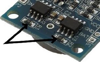
CHAPTER 4 ■ REAL-TIME CLOCK
83
Working with Other PCB Products
If you have a different PCB product, you may have optional resistors that you can
leave uninstalled. Even though they may be optional, someone might have done you the
favor of soldering them in. So make sure you check for that (use the earlier tests).
The Adafruit RTC module (http://www.adafruit.com/products/264) is reportedly
sometimes shipped with the 2.2 kΩ resistors installed. For the Raspberry Pi, they must be
removed.
Locating the Pull-up Resistors
Even if you don’t have a schematic for your PCB product, you will need to locate the pull-
up resistors. Since there aren’t many components on the PCB to begin with, they tend to
be easy to locate:
1. Observe static electricity precautions.
2. Attach one DMM (kΩ) probe to the +5 V input to the PCB.
3. Look for potential resistors on the component side.
4. Locate all resistors that have one lead wired directly to the
+5 V supply (resistance will read 0 Ω). These will be the prime
suspects.
5. Now attach your DMM (range kΩ) to the SDA input. With the
other DMM probe, check the opposite ends of the resistors,
looking for readings of 0 Ω. You should find one resistor
end (the other end of the resistor will have been previously
identified as connected to the +5 V supply).
6. Likewise, test the SCL line in the same manner as step 5.
7. Double-check: take a resistance reading between the SDA
input and the +5 V supply. You should measure a resistance of
2 to 10 kΩ, depending on the PCB manufacturer. You should
get the same reading directly across the resistor identified.
8. Repeat step 7 for the SCL line.
Figure 4-3. R
2 and R3 of the Tiny RTC I2C PCB

CHAPTER 4 ■ REAL-TIME CLOCK
84
If you’ve done this correctly, you will have identified the two resistors that need to be
removed. If you plan to interface the SQW/OUT pin to a Pi GPIO, you’ll want to remove
the pull-up used on that as well.
DS1307 Bus Speed
The DS1307 datasheet lists the maximum SCL clock speed at 100 kHz:
Parameter Symbol Min Typ Max Units
SCL clock frequency fSCL 0 100 kHz
The Raspberry Pi uses 100 kHz for its I2C clock frequency (see Chapter 12 of
Raspberry Pi Hardware Reference [Apress, 2014] for more information). The specification
also states that there is no minimum frequency. If you wanted to reserve the provided I2C
bus for use with other peripherals (perhaps at a higher frequency), you could bit-bang
interactions with the DS1307 by using another pair of GPIO pins. (Pull-up resistors to
+3.3 V will be required; the internal pull-up resistors are not adequate.) That is an exercise
left for you.
Now that we have met power, signaling, and clock-rate requirements, “Let’s light this
candle!”
RTC and RAM Address Map
The DS1307 has 56 bytes of RAM in addition to the real-time clock registers. I/O with
this chip includes an implied address register, which ranges in value from 0x00 to 0x3F.
The address register will wrap around to zero after reaching the end (don’t confuse the
register address with the I2C peripheral address).
Note ■ The DS1307 RTC uses I2C address 0x68.
The address map of the device is illustrated in Table 4-1. The date and time
components are BCD encoded. In the table, 10s represents the tens digit, while
1s represents the ones digit.

CHAPTER 4 ■ REAL-TIME CLOCK
85
The components of the register map are further described in Table 4-2. Bit CH allows
the host to disable the oscillator and thus stop the clock. This also disables the SQW/OUT
waveform output (when SQWE=1). Bit 6 of the Hours register determines whether 12- or
24-hour format is used. When in 12-hour format, bit 5 becomes an AM/PM indicator.
Table 4-1. DS1307 Register Map
Format
Address Register 7 6 5 4 3 2 1 0
0x00 Seconds CH 10s 1s
0x01 Minutes 0 10s 1s
0x02 Hours 0 24hr 10s 1s
12hr PM 10s 1s
0x03 Weekday 0 0 0 0 0 1s
0x04 Day 0 0 10s 1s
0x05 Month 0 0 0 10s 1s
0x06 Year 10s 1s
0x07 Control OUT 0 0 SQWE 0 0 RS1 RS2
0x08 RAM 00 byte
… …
0x3F RAM 55 byte
Table 4-2. RTC Register Map Components
Bit Meaning
CH 0 Clock running
1 Clock (osc) halt
24hr 0 24-hour format
12hr 1 12-hour format RS1 RS0 Meaning
OUT 0 SQW/OUT = Low 0 0 1 Hz
1 SQW/OUT = High 0 1 4.096 kHz
SQWE 0 SQW/OUT is OUT 1 0 8.192 kHz
1 SQW/OUT is SQW 1 1 32.768 kHz
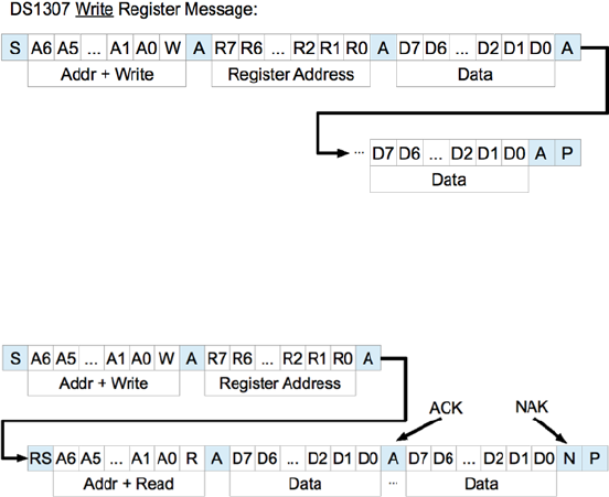
CHAPTER 4 ■ REAL-TIME CLOCK
86
The Control register at address 0x07 determines how the SQW/OUT pin behaves.
When SQWE=1, a square wave signal is produced at the SQW/OUT pin. The frequency is
selected by bits RS1 and RS0. In this mode, the OUT setting is ignored.
When SQWE=0, the SQW/OUT pin is set according to the bit placed in OUT (bit 7 of the
control register). In this mode, the pin behaves as an open-drain GPIO output pin.
Reading Date and Time
When the DS1307 device is being read, a snapshot of the current date and time is made
when the I2C start bit is seen. This copy operation allows the clock to continue to run
while returning a stable date/time value back to the master. If this were not done, time
components could change between reading bytes. The application should therefore
always read the full date/time set of registers as one I/O operation. The running clock
does not affect reading the control register or the RAM locations.
I2C Communication
The DS1307 registers and RAM can be written randomly, by specifying an initial starting
register address, followed by 1 or more bytes to be written. The register address is
automatically incremented with each byte written and wraps around to 0. The DS1307
slave device will ACK each byte as it is received, continuing until the master writes a stop
bit (P). The first byte sent is always the peripheral’s I2C address, which should not be
confused with the selected peripheral’s register address (that immediately follows). The
DS1307 I2C address is always 0x68. The general form of the write message is shown here:
The DS1307 supports multibyte reads. You can read multiple bytes from the DS1307
simply by starting with an I2C start bit (S), and peripheral address sent as a read request.
The slave will then serve up bytes one after another for the master. Receiving terminates
when the master sends a NAK.

CHAPTER 4 ■ REAL-TIME CLOCK
87
If you want to be certain that the register address is established with a known value,
you should always issue a write request first. In the preceding diagram, the write request
immediately follows the start bit (S). Only the peripheral’s register address byte is written
out prior to the repeating start bit (RS), which follows.
After the RS bit, the peripheral address is transmitted once more to re-engage
the DS1307, but this time as a read request. From that point on, the master reads
bytes sequentially from the DS13017 until a NAK is sent. The final stop bit (P) sent by
the master ends the exchange. This peripheral provides us with a good example of a
multimessage I/O.
This is demonstrated in lines 27 to 45 of the program ds1307get.c, in the upcoming
pages. The entire I/O is driven by the structures iomsgs[0] and iomsgs[1]. Structure
iomsgs[0] directs the driver to write to peripheral address 0x68 and writes 1 0x00 data
byte out to it. This establishes the RTC’s internal register with a value of 0x00. The read
request is described in iomsgs[1], which is a read from the same peripheral 0x68, for
8 bytes. (Only 7 bytes are strictly required for the date and time, but we read the
additional control byte anyway.)
The data structure is laid out in C terms in the file ds1307.h. An optional exercise for
you is to add a command-line option to ds1307set to stop the clock and turn it on again
using the ch bit (line 8 of ds1307.h).
Source module i2c_common.c has the usual I2C open/initialization and close
routines in it.
Wiring
Like any I2C project for the Pi, you’ll wire the SDA and SCL lines as follows:
Pre Rev 2.0 Rev 2.0+
P1GPIO Line GPIO Line
0 SDA0 2 SDA1 P1-03
1 SCL0 3 SCL1 P1-05
The DS1307 PCB (or chip) is powered from the +5 V supply. Prior to attaching
it to the Raspberry Pi, it is a good idea to power the DS1307 and measure the voltage
appearing on its SDA and SCL lines. Both should measure near ground potential. If you
see +5 V instead, stop and find out why.
Running the Examples
Since these programs use the I2C Linux drivers, make sure these kernel modules are
either already loaded, or load them manually now:
$ sudo modprobe i2c-bcm2708
$ sudo modprobe i2c-dev
CHAPTER 4 ■ REAL-TIME CLOCK
88
Program ds1307set.c (executable ds1307set) is used to reset the RTC to a new date/
time value of your choice. For example:
$ ./ds1307set 20130328215900
2013-03-28 21:59:00 (Thursday)
$
This sets the date according to the command-line value, which is in
YYYYMMDDHHMMSS format.
Once the RTC date has been established, you can use the executable ds1307get to
read back the date and time:
$ ./ds1307get
2013-03-28 22:00:37 (Thursday)
$
In this case, a little time had passed between setting the date and reading it. But we
can see that the clock is ticking away.
If you don’t like the date/time format used, you can either change the source code or
set the environment variable DS1307_FORMAT. For example:
$ export DS1307_FORMAT="%a %Y-%m-%d %H:%M:%S"
$ ./ds1307get
Thu 2013-03-28 22:03:38
$
For a description of the date/time format options available, use this:
$ man date
The setting of DS1307_FORMAT also affects the display format used by ds1307set.
The Ultimate Test
The ultimate test is to shut down the Raspberry Pi and turn off its power. Wait a minute
or so to make sure that all of the power has been drained out of every available capacitor.
Then bring up the Pi again and check the date/time with the program ds1307get. Did it
lose any time?
The Startup Script
To put the RTC to good practical use, you’ll want to apply ds1307get at a suitable point in
the Linux startup sequence. You’ll need to wait until the appropriate I2C driver support
is available (or can be arranged). You’ll need to develop a short shell script, using the

CHAPTER 4 ■ REAL-TIME CLOCK
89
DS1307_FORMAT environment variable in order to produce a format suitable for the
console date command. To set the system date (as root), you would use this command:
# date [-u|--utc|--universal] [MMDDhhmm[[CC]YY][.ss]]
The startup script for doing all of this has not been provided here. I don’t want to
spoil your fun when you can develop this yourself. You learn best by doing. Refer to
Chapter 3 of Raspberry Pi System Software Reference (Apress, 2014) if you need some help.
As a further hint, you’ll want to develop a script for the /etc/rc2.d directory, with
a name starting with S and two digits. The digits determine where the script runs in the
startup sequence (you’ll want to make sure your script runs after the system has come up
far enough that I2C drivers are loaded).
Once your startup script is developed, your Raspberry Pi can happily reboot after
days, even years, of being powered off, and still be able to come up with the correct date
and time.
Note ■ If you’re running the older Model B, where the I2C bus 0 is used instead of 1,
change line 21 in ds1307set.c and line 21 in ds1307get.c. See Chapter 12 of
Raspberry Pi Hardware Reference (Apress, 2014) for more information.
1 /∗∗∗∗∗∗∗∗∗∗∗∗∗∗∗∗∗∗∗∗∗∗∗∗∗∗∗∗∗∗∗∗∗∗∗∗∗∗∗∗∗∗∗∗∗∗∗∗∗∗∗∗∗∗∗∗∗∗∗∗∗∗∗∗∗∗∗∗∗
2 ∗ ds1307.h: Common DS1307 types and macro definitions
3 ∗∗∗∗∗∗∗∗∗∗∗∗∗∗∗∗∗∗∗∗∗∗∗∗∗∗∗∗∗∗∗∗∗∗∗∗∗∗∗∗∗∗∗∗∗∗∗∗∗∗∗∗∗∗∗∗∗∗∗∗∗∗∗∗∗∗∗∗∗/
4
5 typedef struct {
6 /∗ Register Address 0x00 : Seconds ∗/
7 unsigned char secs_1s : 4; /∗ Ones digit : seconds ∗/
8 unsigned char secs_10s : 3; /∗ Tens digit : seconds ∗/
9 unsigned char ch : 1; /∗ CH bit ∗/
10 /∗ Register Address 0x01 : Minutes ∗/
11 unsigned char mins_1s : 4; /∗ Ones digit : minutes ∗/
12 unsigned char mins_10s : 3; /∗ Tens digit : minutes ∗/
13 unsigned char mbz_1 : 1; /∗ Zero bit ∗/
14 /∗ Register Address 0x02 : Hours ∗/
15 unsigned char hour_1s : 4; /∗ Ones digit : hours ∗/
16 unsigned char hour_10s : 2; /∗ Tens digit : hours
(24 hr mode) ∗/
17 unsigned char mode_1224 : 1; /∗ Mode bit : 12/24 hour
format ∗/
18 /∗ Register Address 0x03 : Weekday ∗/
19 unsigned char wkday : 3; /∗ Day of week (1−7) ∗/
20 unsigned char mbz_2 : 5; /∗ Zero bits ∗/
21 /∗ Register Address 0x04 : Day of Month ∗/
22 unsigned char day_1s : 4; /∗ Ones digit : day of month
(1−31) ∗/
CHAPTER 4 ■ REAL-TIME CLOCK
90
23 unsigned char day_10s : 2; /∗ Tens digit : day of
month ∗/
24 unsigned char mbz_3 : 2; /∗ Zero bits ∗/
25 /∗ Register Address 0x05 : Month ∗/
26 unsigned char month_1s : 4; /∗ Ones digit : month (1−12)
∗/
27 unsigned char month_10s : 1; /∗ Tens digit : month ∗/
28 unsigned char mbz_4 : 3; /∗ Zero ∗/
29 /∗ Register Address 0x06 : Year ∗/
30 unsigned char year_1s : 4 /∗ Ones digit : year (00−99)
∗/
31 unsigned char year_10s : 4; /∗ Tens digit : year ∗/
32 /∗ Register Address 0x07 : Control ∗/
33 unsigned char rs0 : 1; /∗ RS0 ∗/
34 unsigned char rs1 : 1; /∗ RS1 ∗/
35 unsigned char mbz_5 : 2; /∗ Zeros ∗/
36 unsigned char sqwe : 1; /∗ SQWE ∗/
37 unsigned char mbz_6 : 2;
38 unsigned char outbit : 1; /∗ OUT ∗/
39 } ds1307_rtc_regs;
40
41 /∗ End ds1307 . h ∗/
1 /∗∗∗∗∗∗∗∗∗∗∗∗∗∗∗∗∗∗∗∗∗∗∗∗∗∗∗∗∗∗∗∗∗∗∗∗∗∗∗∗∗∗∗∗∗∗∗∗∗∗∗∗∗∗∗∗∗∗∗∗∗∗∗∗∗∗∗∗∗
2 ∗ i2c_common.c : Common I2C Access Functions
3 ∗∗∗∗∗∗∗∗∗∗∗∗∗∗∗∗∗∗∗∗∗∗∗∗∗∗∗∗∗∗∗∗∗∗∗∗∗∗∗∗∗∗∗∗∗∗∗∗∗∗∗∗∗∗∗∗∗∗∗∗∗∗∗∗∗∗∗∗∗/
4
5 static int i2c_fd = −1; /∗ Device node: /dev/i2c−1 ∗/
6 static unsigned long i2c_funcs = 0; /∗ Support flags ∗/
7
8 /∗
9 ∗ Open I2C bus and check cap abilities:
10 ∗/
11 static void
12 i2c_init(const char ∗node) {
13 int rc;
14
15 i2c_fd = open(node,O_RDWR); /∗ Open driver /dev/i2s−1 ∗/
16 if ( i2c_fd < 0 ) {
17 perror("Opening /dev/ i 2 s −1");
18 puts("Check that the i2c−dev & i2c−bcm2708 kernelmodules "
19 " are loaded . " ) ;
20 abort();
21 }
22
23 /∗
24 ∗ Make sure the driver suppor tsplain I2C I /O:
CHAPTER 4 ■ REAL-TIME CLOCK
91
25 ∗/
26 rc = ioctl(i2c_fd,I2C_FUNCS,&i2c_funcs);
27 assert(rc >= 0);
28 assert(i2c_funcs & I2C_FUNC_I2C);
29 }
30
31 /∗
32 ∗ Close the I2C driver :
33 ∗/
34 static void
35 i2c_close(void) {
36 close(i2c_fd);
37 i2c_fd = −1;
38 }
39
40 /∗ End i2c_common.c ∗/
1 /∗∗∗∗∗∗∗∗∗∗∗∗∗∗∗∗∗∗∗∗∗∗∗∗∗∗∗∗∗∗∗∗∗∗∗∗∗∗∗∗∗∗∗∗∗∗∗∗∗∗∗∗∗∗∗∗∗∗∗∗∗∗∗∗∗∗∗∗∗
2 ∗ ds1307set.c : Set real−time DS1307 clock on I2C bus
3 ∗∗∗∗∗∗∗∗∗∗∗∗∗∗∗∗∗∗∗∗∗∗∗∗∗∗∗∗∗∗∗∗∗∗∗∗∗∗∗∗∗∗∗∗∗∗∗∗∗∗∗∗∗∗∗∗∗∗∗∗∗∗∗∗∗∗∗∗∗/
4
5 #include <stdio.h>
6 #include <stdlib.h>
7 #include <ctype.h>
8 #include <time.h>
9 #include <fcntl.h>
10 #include <unistd . h>
11 #include <string . h>
12 #include <errno . h>
13 #include <assert . h>
14 #include <sys / i octl . h>
15 #include <l inux / i2c−dev . h>
16
17 #include "i2c_common.c" /∗ I2C routines ∗/
18 #include "ds1307.h" /∗ DS1307 types ∗/
19
20 /∗ Change to i2c−0 if using early Raspberry Pi ∗/
21 static const char ∗node = "/dev/i2c−1";
22
23 /∗
24 ∗ Write [ S ] 0xB0 <regaddr> <rtcbuf[0]> . . . <rtcbuf[n−1]> [P]
25 ∗/
26 static int
27 i2c_wr_rtc(ds1307_rtc_regs ∗rtc) {
28 struct i2c_rdwr_ioctl_data msgset;
29 struct i2c_msg iomsgs[1];
30 char buf[sizeof ∗rtc+1]; /∗ Work buffer ∗/
31
CHAPTER 4 ■ REAL-TIME CLOCK
92
32 buf[0] = 0x00; /∗ Register 0x00 ∗/
33 memcpy(buf+1,rtc,sizeof ∗rtc); /∗ Copy RTC info ∗/
34
35 iomsgs[0].addr = 0x68; /∗ DS1307 Address ∗/
36 iomsgs[0].flags = 0; /∗ Write ∗/
37 iomsgs[0].buf = buf; /∗ Register + data ∗/
38 iomsgs[0].len = sizeof ∗rtc + 1; /∗ Total msg len ∗/
39
40 msgset.msgs = &iomsgs[0];
41 msgset.nmsgs = 1;
42
43 return ioctl(i2c_fd,I2C_RDWR,&msgset);
44 }
45
46 /∗∗∗∗∗∗∗∗∗∗∗∗∗∗∗∗∗∗∗∗∗∗∗∗∗∗∗∗∗∗∗∗∗∗∗∗∗∗∗∗∗∗∗∗∗∗∗∗∗∗∗∗∗∗∗∗∗∗∗∗∗∗∗∗∗∗∗∗∗
47 ∗ Set the DS1307 real−time clock on the I2C bus :
48 ∗
49 ∗ ./ds1307set YYYYMMDDHHMM[ss]
50 ∗∗∗∗∗∗∗∗∗∗∗∗∗∗∗∗∗∗∗∗∗∗∗∗∗∗∗∗∗∗∗∗∗∗∗∗∗∗∗∗∗∗∗∗∗∗∗∗∗∗∗∗∗∗∗∗∗∗∗∗∗∗∗∗∗∗∗∗∗/
51 int
52 main(int argc,char ∗∗argv) {
53 ds1307_rtc_regs rtc; /∗ 8 DS1307 Register Values ∗/
54 char buf[32]; /∗ Extraction buffe r ∗/
55 struct tm t0, t1; /∗ Unix date / time values ∗/
56 int v, cx, slen;
57 char ∗date_format = getenv("DS1307_FORMAT");
58 char dtbuf[256]; /∗ Formatted date/time ∗/
59 int rc; /∗ Return code ∗/
60
61 /∗
62 ∗ If no environment variable named DS1307_FORMAT, then
63 ∗ set a default date/time format.
64 ∗/
65 if ( !date_format )
66 date_format = "%Y−%m−%d %H:%M:%S (%A) " ;
67
68 /∗
69 ∗ Check command line usage :
70 ∗/
71 if ( argc != 2 | | (slen = strlen(argv[1])) < 12 || slen > 14 ) {
72 usage: fprintf(stderr,
73 "Usage : %s YYYYMMDDhhmm[ss]\n",
74 argv[0]);
75 exit(1);
76 }
77
CHAPTER 4 ■ REAL-TIME CLOCK
93
78 /∗
79 ∗ Make sure every character is a digit in argument 1 .
80 ∗/
81 for ( cx=0; cx<slen; ++cx )
82 if ( !isdigit(argv[1][cx]) )
83 goto usage; /∗ Not a numeric digit ∗/
84
85 /∗
86 ∗ Initialize I2C and clear rtc and t1 structures :
87 ∗/
88 i2c_init(node) ; /∗ Initialize for I2C ∗/
89 memset(&rtc,0,sizeof rtc);
90 memset(&t1,0,sizeof t1);
91
92 /∗
93 ∗ Extract YYYYMMDDhhmm[ss] from argument 1:
94 ∗/
95 strncpy(buf,argv[1],4)[4] = 0; /∗ buf[] = "YYYY" ∗/
96 if ( sscanf(buf,"%d",&v) != 1 || v < 2000 || v > 2099 )
97 goto usage;
98 t1.tm_year = v − 1900;
99
100 strncpy(buf,argv[1]+4,2)[2] = 0; /∗ buf[] = "MM" ∗/
101 if ( sscanf(buf,"%d",&v) != 1 || v <= 0 || v > 12 )
102 goto usage;
103 t1.tm_mon = v−1; /∗ 0 − 11 ∗/
104
105 strncpy(buf,argv[1]+6,2)[2] = 0; /∗ buf[] = "DD" ∗/
106 if ( sscanf(buf,"%d",&v) != 1 || v <= 0 || v > 31 )
107 goto usage ;
108 t1.tm_mday = v; /∗ 1 − 31 ∗/
109
110 strncpy(buf,argv[1]+8,2)[2] = 0; /∗ buf[] = "hh" ∗/
111 if ( sscanf(buf,"%d",&v) != 1 || v < 0 || v > 23 )
112 goto usage;
113 t1.tm_hour = v;
114
115 strncpy(buf,argv[1]+10,2)[2] = 0; /∗ buf[] = "mm" ∗/
116 if ( sscanf(buf,"%d",&v) != 1 || v < 0 || v > 59 )
117 goto usage;
118 t1.tm_min = v;
119
120 if ( slen > 12 ) {
121 /∗ Optional ss was provided : ∗/
122 strncpy(buf,argv[1]+12,2)[2] = 0; /∗ buf[] = "ss" ∗/
123 if ( sscanf(buf,"%d",&v) != 1 || v < 0 || v > 59 )
124 goto usage;
CHAPTER 4 ■ REAL-TIME CLOCK
94
125 t1.tm_sec = v;
126 }
127
128 /∗
129 ∗ Check the validity of the date :
130 ∗/
131 t1.tm_isdst = −1; /∗ Determine if daylight savings ∗/
132 t0 = t1; /∗ Save initial values ∗/
133 if ( mktime(&t1) == 1L ) { /∗ t1 is modified ∗/
134 bad_date : printf("Argument '%s ' is not avalid calendar date.\
n",argv[1]) ;
135 exit(2);
136 }
137
138 /∗
139 ∗ If struct t1 was adjusted , then the original date/time
140 ∗ values were invalid :
141 ∗/
142 if ( t0.tm_year != t1.tm_year || t0.tm_mon != t1.tm_mon
143 || t0.tm_mday != t1.tm_mday || t0.tm_hour != t1.tm_hour
144 || t0.tm_min != t1.tm_min || t0.tm_sec != t1.tm_sec )
145 goto bad_date;
146
147 /∗
148 ∗ Populate DS1307 registers :
149 ∗/
150 rtc.secs_10s = t1.tm_sec / 10;
151 rtc.secs_1s = t1.tm_sec % 10;
152 rtc.mins_10s = t1.tm_min / 10;
153 rtc.mins_1s = t1.tm_min % 10;
154 rtc.hour_10s = t1.tm_hour / 10;
155 rtc.hour_1s = t1.tm_hour % 10;
156 rtc.month_10s = (t1.tm_mon + 1) / 10;
157 rtc.month_1s = (t1.tm_mon + 1) % 10;
158 rtc.day_10s = t1.tm_mday / 10;
159 rtc.day_1s = t1.tm_mday % 10;
160 rtc.year_10s = (t1.tm_year + 1900 − 2000) / 10;
161 rtc.year_1s = (t1.tm_year + 1900 − 2000) % 10;
162
163 rtc.wkday = t1.tm_wday + 1; /∗ Weekday 1−7 ∗/
164 rtc.mode_1224 = 0; /∗ Use 24 hour format ∗/
165
166 #if 0 /∗ Change to a 1 for debugging ∗/
167 printf("%d%d−%d%d−%d%d %d%d:%d%d:%d%d (wkday %d )\n",
168 rtc.year_10s,rtc.year_1s,
169 rtc.month_10s,rtc.month_1s,
170 rtc.day_10s,rtc.day_1s,
CHAPTER 4 ■ REAL-TIME CLOCK
95
171 rtc.hour_10s,rtc.hour_1s,
172 rtc.mins_10s,rtc.mins_1s,
173 rtc.secs_10s,rtc.secs_1s,
174 rtc.wkday);
175 #end if
176 rc = i2c_wr_rtc(&rtc );
177
178 /∗
179 ∗ Display RTC values submitted :
180 ∗/
181 strftime(dtbuf,sizeof dtbuf,date_format,&t1);
182 puts(dtbuf);
183
184 if ( rc < 0 )
185 perror("Writing to DS1307 RTC");
186 else if ( rc != 1 )
187 printf(" Incomplete write : %d msgs of 2written \n",rc);
188
189 i2c_close();
190 return rc ==1? 0 : 4;
191 }
192
1 /∗∗∗∗∗∗∗∗∗∗∗∗∗∗∗∗∗∗∗∗∗∗∗∗∗∗∗∗∗∗∗∗∗∗∗∗∗∗∗∗∗∗∗∗∗∗∗∗∗∗∗∗∗∗∗∗∗∗∗∗∗∗∗∗∗∗∗∗∗
2 ∗ ds1307get.c : Read real−time DS1307 clock on I2C bus
3 ∗∗∗∗∗∗∗∗∗∗∗∗∗∗∗∗∗∗∗∗∗∗∗∗∗∗∗∗∗∗∗∗∗∗∗∗∗∗∗∗∗∗∗∗∗∗∗∗∗∗∗∗∗∗∗∗∗∗∗∗∗∗∗∗∗∗∗∗∗/
4
5 #include <stdio.h>
6 #include <stdlib.h>
7 #include <ctype.h>
8 #include <time h>
9 #include <fcntl.h>
10 #include <unistd.h>
11 #include <string.h>
12 #include <errno.h>
13 #include <assert.h>
14 #include <sys/ioctl.h>
15 #include <linux/i2c−dev.h>
16
17 #include "i2c_common.c" /∗ I2C routines ∗/
18 #include "ds1307.h" /∗ DS1307 types ∗/
19
20 /∗ Change to i2c−0 if using early Raspberry Pi ∗/
21 static const char ∗node = "/dev/i2c−1";
22
CHAPTER 4 ■ REAL-TIME CLOCK
96
23 /∗
24 ∗ Read : [ S ] 0xB1 <regaddr> <rtcbuf[0]> . . . <rtcbuf[n−1]> [P]
25 ∗/
26 static int
27 i2c_rd_rtc(ds1307_rtc_regs ∗rtc) {
28 struct i2c_rdwr_ioctl_data msgset;
29 struct i2c_msg iomsgs[2];
30 char zero = 0x00; /∗ Register 0x00 ∗/
31
32 iomsgs[0].addr = 0x68; /∗ DS1307 ∗/
33 iomsgs[0].flags = 0; /∗ Write ∗/
34 iomsgs[0].buf = &zero; /∗ Register 0x00 ∗/
35 iomsgs[0].len = 1;
36
37 iomsgs[1].addr = 0x68; /∗ DS1307 ∗/
38 iomsgs[1].flags = I2C_M_RD; /∗ Read ∗/
39 iomsgs[1].buf = (char ∗)rtc;
40 iomsgs[1].len = size of ∗rtc;
41
42 msgset.msgs=iomsgs;
43 msgset.nmsgs=2;
44
45 return ioctl(i2c_fd,I2C_RDWR,&msgset);
46 }
47
48 /∗
49 ∗ Main program :
50 ∗/
51 int
52 main(int argc,char ∗∗argv) {
53 ds1307_rtc_regs rtc; /∗ 8 DS1307 Register Values ∗/
54 struct tm t0, t1; /∗ Unix date / time values ∗/
55 char ∗date_format = getenv("DS1307_FORMAT");
56 char dtbuf[256]; /∗ Formatted date/time ∗/
57 int rc; /∗ Return code ∗/
58
59 /∗
60 ∗ If no environment variable named DS1307_FORMAT, then
61 ∗ set a default date/time format.
62 ∗/
63 if ( !date_format )
64 date_format = "%Y−%m−%d%H:%M:%S(%A)";
65
66 /∗
67 ∗ Initialize I2C and clear rtc and t1 structures:
68 ∗/
69 i2c_init(node); /∗ Initialize for I2C ∗/
CHAPTER 4 ■ REAL-TIME CLOCK
97
70 memset(&rtc,0,sizeof rtc);
71 memset(&t1,0,sizeof t1);
72
73 rc = i2c_rd_rtc(&rtc);
74 if ( rc < 0 ) {
75 perror("Reading DS1307 RTC clock.");
76 exit(1);
77 } else if ( rc != 2 ) {
78 fprintf(stderr,"Read error: got %d of 2 msgs.\n",rc);
79 exit(1);
80 } else
81 rc = 0;
82
83 /∗
84 ∗ Check the date returned by the RTC:
85 ∗/
86 memset(&t1,0,sizeof t1);
87 t1.tm_year = (rtc.year_10s ∗ 10 + rtc.year_1s) + 2000 − 1900;
88 t1.tm_mon = rtc.month_10s ∗ 10 + rtc.month_1s − 1;
89 t1.tm_mday = rtc.day_10s ∗ 10 + rtc.day_1s;
90 t1.tm_hour = rtc.hour_10s ∗ 10 + rtc.hour_1s;
91 t1.tm_min = rtc.mins_10s ∗ 10 + rtc.mins_1s;
92 t1.tm_sec = rtc.secs_10s ∗ 10 + rtc.secs_1s;
93 t1.tm_isdst = −1; /∗ Determine if daylight savings ∗/
94
95 t0 = t1;
96 if ( mktime(&t1) == 1L /∗ t1 is modified ∗/
97 || t1.tm_year != t0.tm_year || t1.tm_mon != t0.tm_mon
98 || t1.tm_mday != t0.tm_mday || t1.tm_hour != t0.tm_hour
99 || t1.tm_min != t0.tm_min || t1.tm_sec != t0.tm_sec ) {
100 strftime(dtbuf,sizeof dtbuf,date_format,&t0);
101 fprintf(stderr,"Read RTC date is not valid: %s\n",dtbuf);
102 exit(2);
103 }
104
105 if ( t1.tm_wday != rtc.wkday−1 ) {
106 fprintf(stderr,
107 "Warning:RTC weekday is incorrect %d but should be %d\n",
108 rtc.wkday,t1.tm_wday);
109 }
110
111 #if 0 /∗ Change to a 1 for debugging ∗/
112 printf("%d%d−%d%d−%d%d%d%d:%d%d:%d%d(wkday %d)\n",
113 rtc.year_10s,rtc.year_1s ,
114 rtc.month_10s,rtc.month_1s ,
115 rtc.day_10s, rtc.day_1s ,
116 rtc.hour_10s,rtc.hour_1s ,
CHAPTER 4 ■ REAL-TIME CLOCK
98
117 rtc.mins_10s,rtc.mins_1s ,
118 rtc.secs_10s,rtc.secs_1s ,
119 rtc.wkday);
120 #end if
121 strftime (dtbuf,size of dtbuf,date_format,&t1);
122 puts(dtbuf);
123
124 i2c_close();
125 return rc == 8 ? 0 : 4;
126 }
127
128 /∗ End ds1397get.c ∗/

99
Chapter 5
VS1838B IR Receiver
The VS1838B is a PIN photodiode high-gain amplifier IC in an epoxy package with an
outer shield. It consists of three pins and is about the size of a signal transistor. This
inexpensive part can be purchased for about $2 on eBay to give your Raspberry Pi the
ability to read many IR remote-control signals.
Operating Parameters
Figure 5-1 is a close-up photo of the VS1838B.
Figure 5-1. The VS1838B PIN photodiode
The datasheet provided for this part is mostly in Chinese. The most important
parameter to decipher is the supply voltage range, which is listed in English here:
Parameter Symbol Min Typ Max Units
Supply voltage VCC 2.7 5.5 Volts

CHAPTER 5 ■ VS1838B IR RECEIVER
100
Given that 3.3 V is within the operating range for the device, we can use it for the
Raspberry Pi. We simply power it from the +3.3 V supply pin P1. The device requires only
1 mA of current, as seen in the other datasheet parameters here:
Parameter Symbol Test Conditions Min Typ Max Units
Supply current ICC VCC = 5.0 volts 0.6 0.8 1.0 mA
Receiving distance L11 13 m
Acceptance angle q ½ ±35 Deg
Carrier frequency f037.9 kHz
Bandwidth fBW 8 kHz
Voltage out low VOL Rpullup = 2.4 kW0.25 Volts
Voltage out high VOH VCC–0.3VCC Volts
Operating temp. Topr –30 +85 °C
Pinout
With the lens of the part facing toward you, the pins are as follows, from left to right:
VS1838B
Front View
Out Gnd VCC
VS1838B Circuit
Figure 5-2 illustrates the VS1838B wired to the Raspberry Pi. Any GPIO pin can be used,
but this text uses GPIO 17 for ease of reference. If you choose to use a different GPIO,
changes to the source code will be necessary.
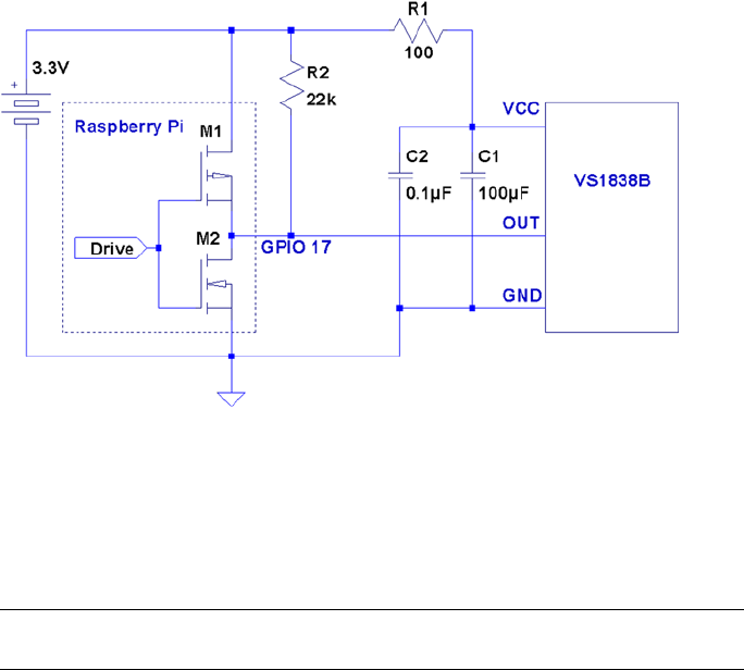
CHAPTER 5 ■ VS1838B IR RECEIVER
101
The circuit may appear somewhat daunting to students, compared to some of the
other projects in this book. The datasheet lists several components as being required:
100 W resistor R1, and capacitors C1 and C2. Finally, there is the pull-up resistor R2, shown
here as 22 kW.
Note ■ The datasheet simply shows the pull-up as being > 20 kW.
If you’re breadboarding this in a hurry, you can probably leave out R1, C1, and C2.
I wired mine with R1 but forgot about the capacitors. If you leave out the capacitors, R1
is not required either. R1 is not a current-limiting resistor here; R1 and the capacitors
are simply a low-pass filter designed to provide a quieter power supply to the part
(which should normally be used). But if you’re soldering this up, do include all of the
recommended components for best results. Don’t leave out the pull-up resistor. R2 is
required.
The IR Receiver
Most IR remote controls today use the 38 kHz carrier frequency on an infrared beam
of light. Even if you know that your brand of remote uses a slightly different carrier
frequency, the VS1838B may still work. The important point to realize about this part is
that it tries to detect the remote control while ignoring other light sources in the room.
To discriminate between fluorescent lighting and the remote control, it looks for this
38 kHz carrier signal. When it sees a steady stream of pulses, it can ignore the
interference.
Figure 5-2. VS1838B wired to the Raspberry Pi using GPIO 17

CHAPTER 5 ■ VS1838B IR RECEIVER
102
The 22 kW pull-up resistor in the schematic diagram is necessary to pull the Out line
up to VCC level, when no 38 kHz beam is seen. (The datasheet block diagram shows the
output as a CMOS totem-pole output, but the pull-up suggests open-drain configuration
instead.) When the device sees a carrier for a minimum burst of 300 μs, it pulls the Out
line low. This line remains driven low as long as the carrier signal is detected. As soon as
the carrier is removed for 300 μs or more, the line is pulled high again by the resistor.
Out Description
High No 38 kHz carrier seen
Low 38 kHz carrier is detected
Wired as shown, the Raspberry Pi will be able to see the effect of the carrier being
turned on and off, many times per second, as it receives remote-control bursts of IR light.
Software
This is where I apologize in advance. No matter which brand of TV or remote control
is supported by the software in this chapter, most people will own something different.
However, if you own a relatively recently produced Samsung TV, the software might just
work for you out of the box. The software presented in this chapter was developed for the
remote control of a Samsung plasma HDTV (Model series 50A400).
If the software doesn’t work for you as is, then consider yourself blessed. When
you dig into the program and make it work for your remote, you’ll come away from the
experience knowing much more than when you started.
Signal Components
Here’s where it gets fun. While most manufacturers have agreed on the 38 kHz carrier
frequency, they haven’t agreed on how the signaling works. Most protocols work on the
principle of turning bursts of IR on and off, but how that encodes a “key” differs widely.
An informative website (www.techdesign.be/projects/011/011_waves.htm)
documents a few of the common IR waveforms.54 The one we’re interested in is the
Samsung entry, listed as protocol number 8.
Table 5-1 summarizes the technical aspects of the waveforms shown at the website.
All times shown are in milliseconds.

CHAPTER 5 ■ VS1838B IR RECEIVER
103
The High/Low values shown in the table agree with the website. For our circuit, the
signals are inverted because of the way that the VS1838B brings the line low when a carrier
is detected. The logic sense of these signals are documented in Table 5-2 for clarity.
Table 5-1. IR Remote Waveform Times
Protocol Brand Component High Low High
ms
2 NEC Start bit 9 4.5 -
0 bit 0.56 0.56 -
1 bit 0.56 1.69 -
Stop bit 0.56 0.56 -
4 SIRCS Start bit 2.4 0.6 -
0 bit 0.6 0.6 -
1 bit 1.2 0.6 -
5 RC5 Start bit - 0.889 0.889
0 bit - 0.889 0.889
1 bit 0.889 0.889 -
7 Japan Start bit 3.38 1.69 -
0 bit 0.42 0.42 -
1 bit 0.42 1.69 -
8 Samsung Start bit 4.5 4.5 -
0 bit 0.56 0.56 -
1 bit 0.56 1.69 -
Stop bit 0.56 0.56 -
Table 5-2. Carrier Signals as Seen by the Raspberry Pi GPIO
Level GPIO Meaning
High (1) Low Carrier present
Low (0) High Carrier absent

CHAPTER 5 ■ VS1838B IR RECEIVER
104
The waveform diagrams at the website are pleasant to look at, but the essential
ingredients boil down to the timings of three or four waveform components, which are
listed in Table 5-3.
Table 5-3. Waveform Components
Component Description
Start bit Marks the start of a key-code
0 bit 0 bit for the code
1 bit 1 bit for the code
Stop bit Stop bit (end of code)
Table 5-1 shows that only the NEC and the Samsung signals use a stop bit. In both
cases, each stop bit is simply an extra 0 bit added onto the end of the stream.
All protocols use a special “start bit” to identify where the code transmission begins.
RC5 just uses a 0-bit waveform (in other words, the start and the 0 bits are identical).
A signal component always begins with a burst (seen as a GPIO low) followed by a
time of no carrier (GPIO high). The only thing that varies among manufacturers is the
timings of these two signal components.
The RC5 protocol is unusual by allowing a start- or 0-bit transmission to begin with
no carrier (GPIO high). Only the 1 bit begins with an IR burst followed by no carrier. So
if the remote is going from idle to transmission, the first half of the bit cell for the start bit
is unseen. But after the first transition, to mark the start, the receiver need only expect a
transition every 0.889 ms for 0 bits, and double that if the bits are changing state.
Looking at Table 5-1 again, notice that the shortest signal time occurs for type 7 (Japan)
with a time of 0.42 ms. The smallest detectable unit of time for the GPIO signal changes
approaches 150 μs (0.15 ms) for the Raspberry Pi. But if the Linux kernel is busy with
other events, 420 μs events may not be reliably detected. Expect some trouble with that
particular protocol. Otherwise, the smallest unit of time shown is 560 μs for the other
protocols.
Code Organization
If you experiment, you may find occurrences of other pulses within the IR data stream.
For example, the Samsung remote occasionally included a 46.5 ms pulse. Others may do
something similar. I believe that these are key repeat signals, which happen when you
hold down a remote key.
In the Samsung bit stream, the bits gather into a 32-bit code. Your remote might use
a different code length, but 32 bits is a convenient storage unit for a key code. For that
reason, I expect that you’ll find that in other brands as well.
CHAPTER 5 ■ VS1838B IR RECEIVER
105
Command-Line Options
The irdecode utility program has been designed to take some options. These are listed
when –h is used:
$ ./irdecode −h
Usage : ./irdecode [−d] [−g] [−n] [−p gpio]
where :
−d dumps event s
−g gnuplot waveforms
−n don't invert GPIO input
−p gpio GPIO pin to use (17)
$
Without any options provided, the utility tries to decode Samsung remote-control
codes (some of the output is suppressed in this mode). The -p option can be provided
to cause the command to use a different GPIO port. In Samsung decode mode, stderr
receives reports of the key codes. Redirect unit 2 to /dev/null if you don’t want them.
In this example, we capture the stderr output to file codes.out. The GPIO port is
specified as 17 here, but this is the command’s default:
$ ./irdecode −p17 2>codes.out
Monitoring GPIO 17 f or changes :
<POWER>
123
<RETURN>
73
<EXIT>
Exit .
$
While the program runs, it reports recognized key presses to stdout. Special keys are
shown in angle brackets, while the numeric digits just print as digits. In this mode, the
program exits if it sees an <EXIT> key press on the remote. You can also enter ^C in the
terminal session to exit the program.
When the program exits, the codes.out file is displayed with the cat command:
$ cat codes.out
CODE E0E040BF
CODE E0E020DF
CODE E0E0A05F
CODE E0E0609F
CODE E0E0609F
CODE E0E01AE5
CODE E0E030CF
CODE E0E0609F
CODE E0E0B44B
$

CHAPTER 5 ■ VS1838B IR RECEIVER
106
Dump Mode
When the -d option is used, the program runs in dump mode. In this mode, the program
will report level changes on your selected GPIO pin:
$ ./irdecode −d
Monitoring GPIO 17 f or changes :
30524.573 1
4.628 0
4.322 1
0.696 0
1.555 1
Tip ■ By default, irdecode dumps out a 1 level when the carrier is present. To invert this
to match the GPIO level, use the -n option.
The left column of numbers is the time in milliseconds, prior to the level change.
The number in the right column shows you the level of the GPIO input after the change.
In this example, the first event took a long time before it changed (I was picking up the
remote). The next change to low (0) occurs only 4.628 ms later, and so on.
This is a good format for getting a handle on the average pulse widths. From this
output, you should see pulse widths centered about certain ranges of numbers.
Each line reported is a signal change event. Either the GPIO pin changes to high, or
it changes to a low level. When reporting changes, therefore, you should never see two or
more lines in a row change to a 0, for example. The reported level should always alternate
between 0 and 1.
If, however, you do see repeated highs or lows, this indicates that the program has
missed events. Events spaced closer together than about 150 μs are not likely to be seen on
the Raspberry Pi. Noise and spikes can also cause these kinds of problems.
Gnuplot Mode
Dump mode is great for analyzing pulse widths but it isn’t very helpful if you want to
visualize the waveform. To produce an output suitable for gnuplot, add the -g option:
$ ./irdecode −dg
Monitoring GPIO 17 f or changes :
31337.931 1
31342.528 1
31342.528 0 4.597
31342.528 0
31346.860 0
31346.860 1 4.332
31346.860 1
CHAPTER 5 ■ VS1838B IR RECEIVER
107
31347.594 1
31347.594 0 0.734
31347.594 0
31349.110 0
When the -g option is used, three lines are produced for each event:
Time of prior event, with previous state•
Time of current event, with previous state•
Time of current event, with current state, with time lapse in •
column 3
If gnuplot is absent, you can install it on your Raspberry Pi as follows:
$ sudo apt–get install gnuplot–x11
These data plots can then be read into gnuplot to display a waveform. Create a file
named gnuplot.cmd with these commands in it:
set title "IR Remote Waveform"
set xlabel "Time (ms)"
set ylabel "Level"
set autoscale
set yrange [−.1:1.2]
plot "gnuplot.dat" using 1:2 with lines
Collect your output into a file named gnuplot.dat (or change the file gnuplot.cmd to
use a different file name). Then run gnuplot on the data:
$ gnuplot –p gnuplot.cmd
Figure 5-3 shows an example plot display. Note that you’ll normally have to edit out
all but the most interesting lines of data. Otherwise, your plot will be a rather crowded
display of vertical lines.
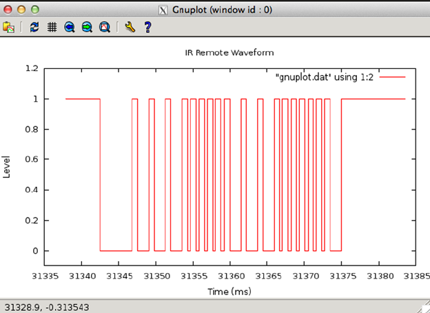
CHAPTER 5 ■ VS1838B IR RECEIVER
108
If running gnuplot doesn’t pop up a window, you may need to set the DISPLAY
variable, or run xhost on the X-Window server machine. If you are using the Raspberry Pi
desktop, this should not be necessary.
The following xhost command enables anyone to create a window on your
X-Window server:
# xhost +
The source code for the irdecode program is listed here:
1 /∗∗∗∗∗∗∗∗∗∗∗∗∗∗∗∗∗∗∗∗∗∗∗∗∗∗∗∗∗∗∗∗∗∗∗∗∗∗∗∗∗∗∗∗∗∗∗∗∗∗∗∗∗∗∗∗∗∗∗∗∗∗∗∗∗∗∗∗∗
2 ∗ irdecode.c : Read IR remote control on GPIO 17 (GEN0)
3 ∗∗∗∗∗∗∗∗∗∗∗∗∗∗∗∗∗∗∗∗∗∗∗∗∗∗∗∗∗∗∗∗∗∗∗∗∗∗∗∗∗∗∗∗∗∗∗∗∗∗∗∗∗∗∗∗∗∗∗∗∗∗∗∗∗∗∗∗∗/
4 #include <stdio.h>
5 #include <stdlib.h>
6 #include <fcntl.h>
7 #include <unistd.h>
8 #include <string.h>
9 #include <errno.h>
10 #include <signal.h>
11 #include <setjmp.h>
12 #include <assert.h>
13 #include <sys/time.h>
Figure 5-3. gnuplot waveform of an IR signal
CHAPTER 5 ■ VS1838B IR RECEIVER
109
14 #include <sys/poll.h>
15 #include <getopt.h>
16
17 static int gpio_inpin = 17; /∗ GPIO input pin ∗/
18 static int is_signaled = 0; /∗ Exit program if signaled ∗/
19 static int gpio_fd = −1; /∗ Open file descriptor ∗/
20
21 static jmp_buf jmp_exit;
22
23 typedef enum {
24 gp_export=0, /∗ /sys/class/gpio/export ∗/
25 gp_unexport, /∗ /sys/class/gpio/unexport ∗/
26 gp_direction, /∗ /sys/class/gpio%d/direction ∗/
27 gp_edge, /∗ /sys/class/gpio%d/edge ∗/
28 gp_value /∗ /sys/class/gpio%d/value ∗/
29 } gpio_path_t ;
30
31 /∗
32 ∗Samsung Remote Codes :
33 ∗/
34 #define IR_POWER 0xE0E040BF
35 #define IR_0 0xE0E08877
36 #define IR_1 0xE0E020DF
37 #define IR_2 0xE0E0A05F
38 #define IR_3 0xE0E0609F
39 #define IR_4 0xE0E010EF
40 #define IR_5 0xE0E0906F
41 #define IR_6 0xE0E050AF
42 #define IR_7 0xE0E030CF
43 #define IR_8 0xE0E0B04F
44 #define IR_9 0xE0E0708F
45 #define IR_EXIT 0xE0E0B44B
46 #define IR_RETURN 0xE0E01AE5
47 #define IR_MUTE 0xE0E0F00F
48
49 static struct {
50 unsigned long ir_code; /∗ IR Code ∗/
51 const char ∗text; /∗ Display text ∗/
52 } ir_codes[] = {
53 { IR_POWER, "\n<POWER>\n" } ,
54 { IR_0, "0" } ,
55 { IR_1, "1" } ,
56 { IR_2, "2" } ,
57 { IR_3, "3" } ,
58 { IR_4, "4" } ,
59 { IR_5, "5" } ,
60 { IR_6, "6" } ,
61 { IR_7, "7" } ,
CHAPTER 5 ■ VS1838B IR RECEIVER
110
62 { IR_8, "8" } ,
63 { IR_9, "9" } ,
64 { IR_EXIT, "\n<EXIT>\n" } ,
65 { IR_RETURN, "\n<RETURN>\n" } ,
66 { IR_MUTE, "\n<MUTE>\n" } ,
67 { 0, 0 } /∗ End marker ∗/
68 } ;
69
70 /∗
71 ∗ Compute the time difference in milliseconds :
72 ∗/
73 static double
74 msdiff(struct timeval ∗t1,struct timeval ∗t0) {
75 unsigned long ut;
76 double ms;
77
78 ms = ( t1−>tv_sec − t0−>tv_sec ) ∗ 1000.0;
79 if ( t1−>tv_usec > t0−>tv_usec )
80 ms += ( t1−>tv_usec − t0−>tv_usec ) / 1000.0;
81 else {
82 ut = t1−>tv_usec + 1000000UL;
83 ut −= t0−>tv_usec;
84 ms += ut / 1000.0;
85 }
86 return ms;
87 }
88
89 /∗
90 ∗ Create a pathname fo r type in buf.
91 ∗/
92 static const char ∗
93 gpio_setpath(int pin,gpio_path_t type,char ∗buf,unsigned bufsiz) {
94 static const char ∗paths[] = {
95 "export", "unexport", "gpio%d/direction",
96 "gpio%d/edge", "gpio%d/value"};
97 int slen;
98
99 strncpy(buf,"/sys/class/gpio/",bufsiz);
100 bufsiz –= (slen = strlen(buf));
101 snprintf(buf+slen,bufsiz,paths[type],pin);
102 return buf;
103 }
104
105 /∗
106 ∗ Open /sys/class/gpio%d/value for edge detection :
107 ∗/
CHAPTER 5 ■ VS1838B IR RECEIVER
111
108 static int
109 gpio_open_edge(int pin,const char ∗edge) {
110 char buf[128];
111 FILE ∗f;
112 int fd;
113
114 /∗ Export pin: /sys/class/gpio/export ∗/
115 gpio_setpath(pin gp_export,buf,sizeof buf);
116 f = fopen(buf,"w");
117 assert(f);
118 fprintf(f,"%d\n",pin);
119 fclose(f);
120
121 /∗ Direction: /sys/class/gpio%d/direction ∗/
122 gpio_setpath(pin,gp_direction,buf,sizeof buf);
123 f = fopen(buf,"w");
124 assert(f);
125 fprintf(f,"in\n");
126 fclose(f);
127
128 /∗ Edge: /sys/class/gpio%d/edge ∗/
129 gpio_setpath(pin,gp_edge,buf,sizeof buf);
130 f = fopen(buf,"w");
131 assert(f);
132 fprintf(f,"%s\n",edge);
133 fclose(f);
134
135 /∗ Value: /sys/class/gpio%d/value ∗/
136 gpio_setpath(pin,gp_value,buf,sizeof buf);
137 fd = open(buf,O_RDWR);
138 return fd;
139 }
140
141 /∗
142 ∗ Close ( unexport ) GPIO pin :
143 ∗/
144 static void
145 gpio_close(int pin) {
146 char buf[128];
147 FILE ∗f;
148
149 /∗ Unexport: /sys/class/gpio/unexport ∗/
150 gpio_setpath(pin,gp_unexport,buf,sizeof buf);
151 f = fopen(buf,"w");
CHAPTER 5 ■ VS1838B IR RECEIVER
112
152 assert(f);
153 fprintf(f,"%d\n",pin);
154 fclose(f);
155 }
156
157 /∗
158 ∗ This routine will block until the open GPIO pin has changed
159 ∗ value .
160 ∗/
161 static int
162 gpio_poll(int fd,double ∗ms) {
163 static char needs_init = 1;
164 static struct timeval t0;
165 static struct timeval t1;
166 struct pollfd polls;
167 char buf[32];
168 int rc, n;
169
170 if ( needs_init ) {
171 rc = gettimeofday(&t0,0);
172 assert(!rc);
173 needs_init = 0;
174 }
175
176 polls.fd = fd; /∗ /sys/class/gpio17/value ∗/
177 polls.events = POLLPRI; /∗ Exceptions ∗/
178
179 do {
180 rc = poll(&polls,1,−1); /∗ Block ∗/
181 if ( is_signaled )
182 longjmp(jmp_exit,1);
183 } while ( rc < 0 && errno == EINTR );
184
185 assert(rc > 0);
186
187 rc = gettimeofday(&t1,0);
188 assert(!rc);
189
190 ∗ms = msdiff(&t1,&t0);
191
192 lseek(fd,0,SEEK_SET);
193 n = read(fd,buf,sizeof buf); /∗ Read value ∗/
194 assert(n>0);
195 buf[n] = 0;
196
197 rc = sscanf(buf,"%d",&n) ;
198 assert(rc==1);
199
CHAPTER 5 ■ VS1838B IR RECEIVER
113
200 t0 = t1; /∗ Save for next call ∗/
201 return n; /∗ Return value ∗/
202 }
203
204 /∗
205 ∗ Signal handler to quit the program :
206 ∗/
207 static void
208 sigint_handler(int signo) {
209 is_signaled = 1; /∗ Signal to exit program ∗/
210 }
211
212 /∗
213 ∗ Wait until the line changes :
214 ∗/
215 static inline int
216 wait_change(double ∗ms) {
217 /∗ Invert the logic of the input pin ∗/
218 return gpio_poll(gpio_fd,ms) ? 0 : 1;
219 }
220
221 /∗
222 ∗ Wait until line changes to "level" :
223 ∗/
224 static int
225 wait_level(int level) {
226 int v;
227 double ms;
228
229 while ( (v = wait_change(&ms)) != level )
230 ;
231 return v;
232 }
233
234 /∗
235 ∗ Get a 32 bit code from remote control :
236 ∗/
237 static unsigned long
238 getword(void) {
239 static struct timeval t0 = { 0, 0 };
240 static unsigned long last = 0;
241 struct timeval t1;
242 double ms;
243 int v, b, count;
244 unsigned long word = 0;
245
CHAPTER 5 ■ VS1838B IR RECEIVER
114
246 Start: word = 0;
247 count = 0;
248
249 /∗
250 ∗ Wait for a space of 46 ms :
251 ∗/
252 do {
253 v = wait_change(&ms);
254 } while ( ms < 46.5 );
255
256 /∗
257 ∗ Wait for start : 4.5ms high, then 4.5ms low :
258 ∗/
259 for ( v=1;; ) {
260 if ( v )
261 v = wait_level(0);
262 v = wait_level(1);
263 v = wait_change(&ms); /∗ High to Low ∗/
264 if ( !v && ms >= 4.0 && ms <= 5.0 ) {
265 v = wait_change(&ms);
266 if ( v && ms >= 4.0 && ms <= 5.0 )
267 break ;
268 }
269 }
270
271 /∗
272 ∗ Get 32 bi t code :
273 ∗/
274 do {
275 /∗ Wait for line to go low ∗/
276 v = wait_change(&ms);
277 if ( v || ms < 0.350 || ms > 0.8500 )
278 goto Start;
279
280 /∗ Wait for line to go high ∗/
281 v = wait_change(&ms);
282 if ( !v || ms < 0.350 || ms > 2.0 )
283 goto Start;
284
285 b = ms < 1.000 ? 0 : 1;
286 word = (word << 1) | b;
287 } while ( ++count < 32 );
288
289 /∗
290 ∗ Eliminate key stutter :
291 ∗/
CHAPTER 5 ■ VS1838B IR RECEIVER
115
292 gettimeofday(&t1,0);
293 if ( word == last && t0.tv_sec && msdiff (&t1,&t0) < 1100.0 )
294 goto Start; /∗ Too soon ∗/
295
296 t0 = t1;
297 fprintf(stderr,"CODE %08lX\n",word);
298 return word;
299 }
300
301 /∗
302 ∗ Get text form of remote key :
303 ∗/
304 static const char ∗
305 getircode(void) {
306 unsigned long code;
307 int kx;
308
309 for (;;) {
310 code = getword();
311 for ( kx=0; ir_codes[kx].text; ++kx )
312 if ( ir_codes[kx].ir_code == code )
313 return ir_codes[kx].text;
314 }
315 }
316
317 /∗
318 ∗ Main program :
319 ∗/
320 int
321 main(int argc,char ∗∗argv) {
322 const char ∗key;
323 int optch;
324 int f_dump = 0, f_gnuplot = 0, f_noinvert = 0;
325
326 while ( (optch = getopt(argc,argv,"dgnsp:h")) != EOF )
327 switch ( optch ) {
328 case 'd' :
329 f_dump = 1;
330 break;
331 case 'g' :
332 f_gnuplot = 1;
333 break;
334 case 'n':
335 f_noinvert = 1;
336 break;
337 case 'p' :
338 gpio_inpin = atoi(optarg);
CHAPTER 5 ■ VS1838B IR RECEIVER
116
339 break;
340 case 'h' :
341 /∗ Fall thru ∗/
342 default :
343 usage : fprintf (stderr,
344 "Usage: %s [−d ] [−g ] [−n ] [−p
gpio]\n",argv[0]);
345 fputs("where: \n"
346 " −d\t\tdumps events\n"
347 " −g\t\tgnuplot waveforms\n"
348 " −n\ t \tdon't invert GPIO input \n"
349 " −p gpio\tGPIO pin to use (17)\n",
350 stderr);
351 exit(1);
352 }
353
354 if ( gpio_inpin < 0 || gpio_inpin >= 32 )
355 goto usage;
356
357 if ( setjmp(jmp_exit) )
358 goto xit;
359
360 signal(SIGINT,sigint_handler); /∗ Trap on SIGINT ∗/
361 gpio_fd = gpio_open_edge(gpio_inpin,"both"); /∗ GPIO input ∗/
362
363 printf("Monitoring GPIO %d for changes:\n",gpio_inpin);
364
365 if ( !f_dump ) {
366 /∗
367 ∗ Remote control read loop :
368 ∗/
369 for (;;) {
370 key = getircode();
371 fputs(key,stdout);
372 if ( !strcmp(key,"\n<EXIT>\n") )
373 break;
374 fflush(stdout);
375 }
376 } else {
377 /∗
378 ∗ Dump out IR level changes
379 ∗/
CHAPTER 5 ■ VS1838B IR RECEIVER
117
380 int v;
381 double ms, t =0.0;
382
383 wait_change(&ms); /∗ Wait for first change ∗/
384
385 for (;;) {
386 v = wait_change(&ms) ^ f_noinvert;
387 if ( !f_gnuplot )
388 printf("%12.3 f\t%d\n",ms,v);
389 else {
390 printf("%12.3 f\t%d\n",t,v^1);
391 t += ms;
392 printf("%12.3 f\t%d\n",t,v^1);
393 printf("%12.3 f\t%d\t%12.3 f\n",t,v,ms);
394 }
395 }
396 }
397
398 xit : fputs("\nExit.\n",stdout);
399 close(gpio_fd); /∗ Close gpio%d/value ∗/
400 gpio_close(gpio_inpin); /∗ Unexport gpio ∗/
401 return 0;
402 }
403 /∗ End irdecode.c ∗/
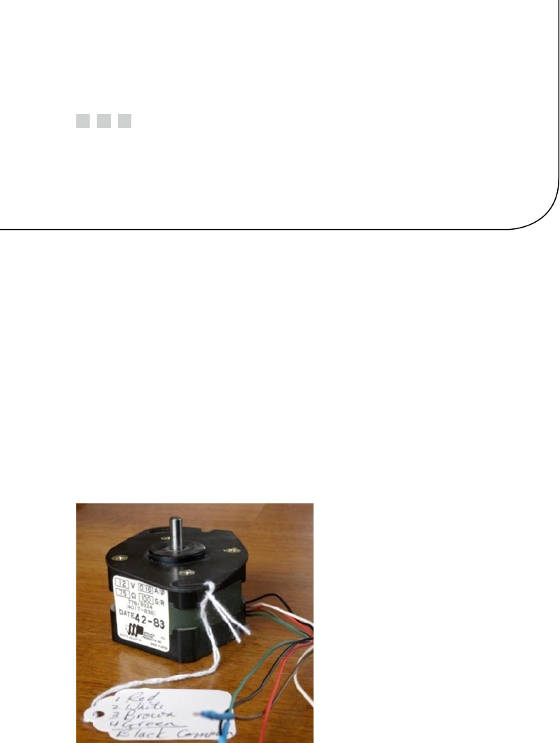
119
Chapter 6
Stepper Motor
A stepper motor is a brushless device with multiple windings, where one rotation is
divided into several small steps. Stepper motors are used when precise positioning is
required. Unipolar stepper motors have multiple windings connected to a common
connection.
In this chapter, we’ll recycle an old floppy-disk stepper motor. Modern stepper
motors are smaller and operate at lower voltages. This particular stepper motor presents a
good example of the challenges that exist when driving a motor from a 12 V power supply.
Floppy-Disk Stepper Motor
Figure 6-1 shows an old 5.25-inch floppy-disk stepper motor that was sitting on a shelf in
my furnace room. Perhaps you have a gem like this in your own junk box.
Figure 6-1. A salvaged 5.25-inch floppy-disk motor
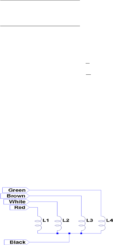
CHAPTER 6 ■ STEPPER MOTOR
120
This particular stepper motor has these markings on it:
12 V 0.16 A/Ø
75 W100 S/R
Date 42-83
This motor was clearly marked as a 12 V device. The 0.16 A/Ø marking tells us that
each winding (phase Ø) is rated for 160 mA. The following calculation confirms that the
winding resistance is 75 W, which is consistent with the printed current rating:
IV
R
mA
=
=
=
12
75
160
The 100 S/R marking tells us that this motor has 100 steps per revolution. It’s really
nice when you get all the information you need up front.
Your Junk-Box Motor?
Old 5.25-inch floppy-disk drives are getting scarcer these days. So what about other
stepper motors that you might have in your junk box? How can you determine whether
you can use one?
The first thing you must check is the type of motor. This chapter focuses on unipolar
motors that have three or more step windings with a common connection. The floppy-disk
stepper motor that I’m using in this chapter is shown in Figure 6-2. Notice that this motor
has four separate windings, labeled L1 through L4. These have a common connection to
a black wire coming out of the motor. To make this motor step, each winding must be
activated in sequence.
Figure 6-2. Floppy-disk stepper motor windings

CHAPTER 6 ■ STEPPER MOTOR
121
If you have a stepper motor on hand but don’t know much about it, you can test it
with a DMM. Measure the DC resistance of the windings between each pair of wires. You
won’t need to measure every combination, but start a chart something like the following
I’ll use my motor as an example:
Wire 1 Wire 2 Reading
Black Red 84 W
Red White 168 W
White Brown 168 W
Brown Black 84 W
etc.
What does this tell you? The lowest readings show 84 W (the reading should be 75 W
for this motor, but my DMM doesn’t read low resistances accurately). The other readings
are double that. This indicates that each winding should read 84 W, and when it doesn’t, it
means that we are measuring the resistance of two windings in series.
Looking again at the chart, we see that whenever we find an 84 W reading, the black
wire is common to each. Knowing that the black wire is common to the windings means
that all of the other wires should read 84 W relative to it. Now you know which wire is the
common one.
Some motors you might encounter use two separate split windings. These won’t
have a wire common to all windings. You’ll find that some paired wires have infinite
resistance (no connection). If this applies, you have a motor that is applicable to the
project in Chapter 7.
Another ingredient that you need to check is the DC resistance of each winding.
Assuming you already measured this while determining the common wire, perform this
calculation:
IV
R
Winding
winding
=
Let’s assume that you think your stepper motor is a 6 V part, or simply that you plan
to operate it at 6 V. Assume also that the measured DC resistance of the winding is 40 W.
What will be the maximum current necessary to drive this motor?
I
mA
Winding=
=
6
40
150
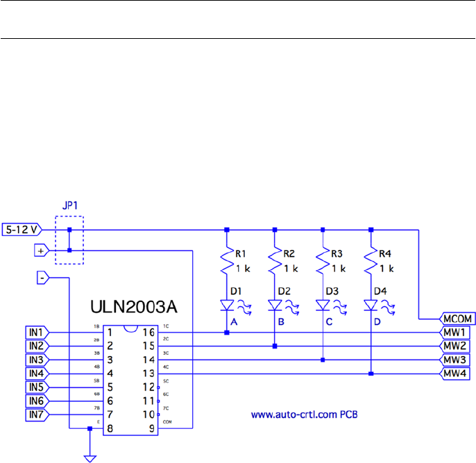
CHAPTER 6 ■ STEPPER MOTOR
122
This figure is important to the driving electronics. In this chapter, I am using an
economical PCB purchased from eBay that uses the ULN2003A driver chip. I’ll describe
the chip and the PCB in more detail later. The ULN2003A chip has a maximum drive
rating of 500 mA. But this figure must be derated by the duty cycle used and the number
of simultaneous drivers. If you computed a figure of 300 mA or more, you may need to
seek out a more powerful driver.
Note ■ In addition to stepper motors, the ULN2003A can drive lightbulbs and other loads.
Driver Circuit
Clearly, the GPIO outputs of the Raspberry Pi cannot drive a stepper motor directly.
You could build your own driver circuit (or breadboard one) using the ULN2003A chip.
I chose instead to buy a PCB from eBay for $2 (with free shipping), which provided the
advantage of four LEDs. These light when a winding is activated, which is useful for
testing. Figure 6-3 shows the schematic of the PCB that I used.
Figure 6-3. ULN2003A PCB schematic
The PCB includes two holes that power connections can be soldered into. There are
also two pins marked (+) and (-) for a push-on connector.
Beside the power connections is a small jumper with the text 5 – 12 V under it. This
jumper is shown as JP1 in the schematic. You’ll normally want to leave the jumper in.

CHAPTER 6 ■ STEPPER MOTOR
123
The input connections are clearly labeled IN1 through IN7. However, only outputs
1C through 4C are used (outputs for IN1 through IN4). The other ULN2003A outputs
5C through 7C are unconnected. Wires could be carefully soldered to these pins, if you
needed additional drivers for lamps, relays, or a second stepper motor.
The LEDs are connected from the (+) side, in series with a 1 kW current–limiting
resistor. The voltage drop VCE(sat) in the ULN2003A ranges from about 0.9 to 1.6 V (use
the worst case of 0.9 V). Assuming that the voltage drop is 1.6 V for red LEDs55 and the
maximum of 12 V is applied, each LED conducts about this:
IVV V
R
mA
LED
CC CE satLED
LED
=--
=--
=
()
..
.
12 09 16
1000
95
The LEDs are the main reason the PCB lists a maximum voltage of 12 V. The
ULN2003A chip has an absolute maximum VCC voltage of 50 V. If, for example, you need
to drive a 24 V stepper motor from an old 8-inch floppy drive, you can remove jump JP1 to
take the LEDs out of the circuit. Then you would supply the +24 V directly to the common
wire of the stepper motor itself. If you do this, you’ll also want to connect the PCB (+) to
the motor’s supply. This connects the motor to the COM pin of the ULN2003A, which
provides reverse-biased diodes to drain away induced voltages.
When purchased, the PCB included a white socket for connection to the stepper
motor. I removed that and replaced it with a soldered-in ribbon cable. These wires
connect the driver outputs 1C through 4C to the stepper-motor windings.
The Raspberry Pi will drive pins IN1 through IN4 from the GPIO ports. When a given
INx pin is driven high, the Darlington pair of transistors will sink up to 500 mA of current
from a positive (motor supply) source to ground.
Darlington Pair
It is tempting to look at the ULN2003A chip as a black box: a signal goes into it, and a
bigger one comes out. But when interfacing to voltages higher than the Raspberry Pi’s
own +3.3 V system, extra caution is warranted. If any of this higher voltage leaks back into
the Pi, the GPIO pins will get “cooked” (if not the whole system).
Figure 6-4 shows input 1B being driven high by a GPIO line. This forward-biases Q2,
which in turn biases Q1. A small amount of current flows in dashed lines from 1B, into
the base of Q2, and then from Q1 to ground. This small amount of current flow allows a
much greater current to flow from the collector of Q1 to ground. The dashed lines on the
right show the motor-winding current flowing from the motor power supply (12 V, for
example), through Q1 to ground through the E terminal.

CHAPTER 6 ■ STEPPER MOTOR
124
When the GPIO ceases to drive input 1B as shown in Figure 6-5, the transistors Q2
and Q1 turn off. With no more current flowing through L1, the magnetic field collapses,
generating a reverse current. As the field collapses, current flows into terminal 1C,
through the diode D3 and back to the upper side of L1. In effect, diode D3 shorts out this
generated-back EMF. Diode D3 is necessary to prevent the rest of the electronics from
seeing a high voltage, which can cause damage and disruption.
Figure 6-4. ULN2003A driving a winding
Figure 6-5. ULN2003A driver turning off
CHAPTER 6 ■ STEPPER MOTOR
125
One side effect of the reverse-biased diode is that it slows down the decay of the
magnetic field. As current flows in the reverse direction, the magnetic collapse is resisted.
This results in magnetic forces inside the motor, which affect its speed. (This same effect
also slows the release of relay contacts.) When greater speed is required, a resistor is
sometimes used in series with the diode to limit its effect.
So what about voltage safety of our Raspberry Pi GPIO pins? Reexamine the
Darlington pair Q2 and Q1. Pins COM and 1C can be as high as 50 V. But current cannot
leak through D3 (from COM) because the diode junction is reverse-biased. Current
cannot leak from the collectors of Q2 and Q1 (from 1C) into the base circuits because
those base-collector junctions are behaving as reverse-biased diodes. The main point of
caution is that Q2 and Q1 must remain intact.
If Q1 were allowed to overheat, for example, it might break down. If Q1 or Q2 breaks
down, current will be allowed to flow from its collector into the base circuit, which is
connected to the GPIO. Therefore, the breakdown of the driver transistors must be strictly
prevented!
Driving the Driver
In this section, we look at the Raspberry Pi (GPIO) interface to the ULN2003A. There are
two things we are most interested in here:
The usual input logic-level interface•
Power-on reset and boot conditions•
Input Levels
The output current of the ULN2003A Darlington pair rises as the input voltage rises
above the turn-on level. We know from the Darlington configuration that there are two
base-emitter junctions in the path from input to ground. Therefore, the ULN2003A
driver requires a 2 × VBE voltage to forward-bias the pair. If we assume VBE = 0.6 V, we can
compute a VIL for the driver as follows:
VV
V
IL BE
=´
=´
=
2
206
12
.
.

CHAPTER 6 ■ STEPPER MOTOR
126
Clearly, the Pi GPIO low (0.8 V) easily turns off the ULN2003A input with margin to
spare. The datasheets state that a maximum output drive of 300 mA can be achieved with
a 3 V input drive signal. The ULN2003A drive characteristics are shown here:
Signal Raspberry Pi
ULN2003A
VIIC
VOL £ 0.8 V 1.2 V 500 mA
VOH ³1.3 V
2.4 V 100 mA
2.7 V 250 mA
3.0 V 300 mA
If we had a TTL signal driving the ULN2003A, we could get closer to the 500 mA
maximum drive (interpolating from the characteristics shown). However, for our
purposes, we need only 160 mA, so a 3 V drive signal meets the requirements well
enough.
Note ■ TTL levels approach +5V.
Power-on Reset/Boot
The one serious matter that remains is what our circuit will be doing as the Raspberry Pi
is reset and is spending time booting up. The maximum ratings of the ULN2003A have
to be derated when more than one Darlington pair is operating simultaneously. This is
because each driver that is on heats up the chip substrate. For this reason, it is highly
desirable for the ULN2003A to be “quiet” at reset time and subsequent boot-up. If a boot
problem occurs, requiring a lot of time to correct, the drivers could overheat.
This potentially requires that we use GPIO pins that
Are automatically configured as • inputs at reset
Are not configured with high pull-up resistors•
Input pins with high pull-up resistors are potentially bad news. A high level
appearing on ULN2003A inputs might activate drivers. In the worst-case scenario, all
inputs become active.
Table 6-1 lists the acceptable GPIO pins as well as the reasons that others should be
avoided.

CHAPTER 6 ■ STEPPER MOTOR
127
The pull-up resistance provided by the Broadcom SoC is weak (50 kW). Because of
this, the worst-case input drive, due to the pull-up resistance, is calculated as follows:
IV
R
V
K
A
I
CC
pullup
=
=
=
33
50
66
.
W
m
The ULN2003A datasheet states that it takes an input drive of 250 mA to produce an
output current flow of 100 mA. Some GPIO pins are pulled up by external resistors (GPIO
2 and 3 for SDA and SCL). These GPIO pins should not be used as motor drivers, for this
reason.
The Darlington pair includes resistances that naturally pull down the input signal
(review Figure 6-5). Resistances RB, R1, and R2 are connected in series between the input
and ground. This effectively provides a pull-down resistance of approximately 13.6 kW.
If the ULN2003A is attached to a floating input like GPIO 28 or 29, the input voltage will
automatically be pulled down as a result (this is desirable here).
Modes of Operation
A unipolar stepper motor may be operated in four modes. The first three of these modes
use digital on/off signals to drive each winding. The fourth micro-stepping mode requires
driving each winding with varying analog signals. Since we are driving with digital GPIO
pins, we’ll examine only the first three modes.
Table 6-1. GPIOs for Motor Control at Reset/Boot Time
GPIO
OK Bad Reason Bad Reason
09 23 00 Pull-up high 08 Pull-up high
10 24 01 Pull-up high 14 TXD0
11 25 02 Pull-up high 15 RXD0
12 28† 03 Pull-up high 16 Output
17 29† 04 Pull-up high 27 Output
18 30 05 Pull-up high
21 31 06 Output
22 07 Pull-up high
(†) No pull-up resistor
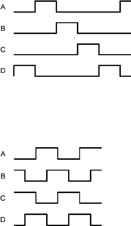
CHAPTER 6 ■ STEPPER MOTOR
128
Wave Drive (Mode 0)
Wave drive mode is the simplest of the modes, in which only one winding of the motor is
activated at one time (see Figure 6-6). Each winding is energized in sequence to cause the
rotation to occur in full steps. The motor will have significantly less torque than in full-step
drive mode and is therefore rarely used.57
Figure 6-7. Full-step drive (mode 1)
Figure 6-6. Wave drive (mode 0)
Full-Step Drive (Mode 1)
Figure 6-7 shows how full-step drive mode operates. Each field is energized in turn like
a wave drive, but the next field is activated prior to turning off the prior field. In this way,
an overlapping drive is affected in the direction of travel. This is the usual drive method
delivering full-rated torque.58
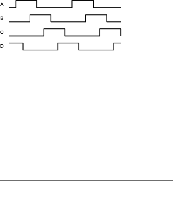
CHAPTER 6 ■ STEPPER MOTOR
129
Half-Step Drive (Mode 2)
Figure 6-8 illustrates the drive waveforms for half-step drive mode. As in full-step mode,
an overlapped drive is applied to the field coils. Unlike full-step mode, the overlap occurs
on the first third and the last third of a given coil’s drive. For two-thirds of the waveform,
there is overlapped drive. In the middle third, only one winding is active.
Figure 6-8. Half-step drive
This mode provides increased angular resolution but suffers from having less torque
(about 70% of full-rated torque).59
Software
To demonstrate stepper-motor driving without getting into a complex assignment, the
program unipolar.c simply positions the shaft of the motor to various hour positions of
the clock, based on single-key commands.
With a pointer attached to the shaft of your motor, press 6, and the motor will point
at 6 o’clock. Press 3, and the motor figures out that it is quickest to step counterclockwise
back to the 3 o’clock position. Press 7, and the motor steps forward to 7 o’clock. All of
this, of course, requires that you point the shaft at 12 o’clock before you begin (the motor
provides no information to the program about where it is currently pointing).
The program presented uses the GPIO pin assignments in Table 6-2 for driving the
stepper motor (your wire colors may differ):
Table 6-2. GPIO Assignments Used by the Program unipolar.c
GPIO GENX P1 Mode Stepper Wire ULN2003A Description
17 GEN0 P1-11 Output Red 1B Field A
24 GEN5 P1-18 White 2B Field B
22 GEN3 P1-15 Brown 3B Field C
23 GEN4 P1-16 Green 4B Field D
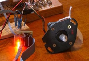
CHAPTER 6 ■ STEPPER MOTOR
130
Figure 6-9 shows how a pointer knob can be used for a pointer. Otherwise, this is
your opportunity to get creative.
Figure 6-9. Stepper motor with knob used as a pointer
At power-on reset and boot time, the selected GPIO lines are all input pins with pull-
down resistors. After boot-up, when the program starts and configures its GPIO pins, it
will do the following:
1. Configure an output low value for each GPIO (while still an input)
2. Configure the GPIO pin as an output
Step 1 eliminates the possibility of a stepper winding being driven before the
software is ready to drive it. If this were not done, a driver could be activated when
the GPIO is first configured as an output. Step 2, of course, is necessary to drive the
ULN2003A chip. But no glitch occurs in the output when step 1 is performed first.
After the main program has begun, it saves the current terminal settings in sv_ios
and then sets up a raw mode, permitting single-character I/O interaction (lines 167–173).
See Chapter 9 of Raspberry Pi Hardware Reference (Apress, 2014) for more information
about the serial API.
Lines 175–178 initialize the GPIO lines to drive the stepper-motor field windings.
The default stepper-motor mode is configured on line 182, which may be overruled by
a command-line argument. The program can also change modes by using keystroke
commands.
The remainder of the program is a while loop that extends from lines 185–241. It
reads a single-character command at line 187 and then dispatches to sections of code in
the switch statement. The single-character commands are summarized in Table 6-3.

CHAPTER 6 ■ STEPPER MOTOR
131
The < and > commands double or halve the step time interval. This slows and
increases the rotational speed, respectively. Stepper modes can be changed using the J, K,
or L commands. These reposition the stepper to 12 o’clock prior to changing modes. The
digits 0 through 9 and letters A and B reposition the shaft to point to the hour of the clock.
You can test whether your rotation is properly working by using the + and -
keystrokes to step one step clockwise or counterclockwise. Pressing O (the letter O, not
zero) toggles the drive power on or off for the motor. This is useful for turning off the
motor drive when you want to manually reposition the shaft.
The source code used in this program for gpio_io.c is provided in Chapter 10
of Raspberry Pi Hardware Reference (Apress, 2014), and timed_wait.c is provided in
Chapter 1. The main source module of interest is unipolar.c, which is presented at the
end of this chapter.
Testing
Be careful setting up this project because of the voltages involved. One careless wiring
error could bring higher voltage into your GPIO pins and fry the Pi. In the following
procedures, I refer to the driver PCB (as I used), but this procedure applies equally to
breadboarded circuits.
Here is the first part of the setup and checkout procedure:
1. Set up the power to the driver PCB without connecting it to
the Raspberry Pi. Leave the motor unconnected also.
2. Make sure that the driver inputs are not connected.
3. Apply the power to the PCB. No LEDs will light if everything is
OK. No smoke? Good!
Table 6-3. Single-Character Commands
Char Command Char Command
Q Quit 0 12 o’clock (noon)
< Slower steps 1 1 o’clock
> Faster steps 2
? Help …
H 9 9 o’clock
J Stepper mode 0 A 10 o’clock
K Stepper mode 1 B 11 o’clock
L Stepper mode 2 +/= Step clockwise
P Show current position - Step counterclockwise
O Toggle drive on/off
CHAPTER 6 ■ STEPPER MOTOR
132
4. Apply +3.3 V one at a time to the driver inputs 1B through 4B
(IN1 through IN4 on the PCB) with a wire, which should cause
the corresponding LED to light. (These driver inputs will also
accept +5 V for testing, if that is what you have available.) If
you breadboarded the circuit, consider adding LEDs to each
driver output.
5. Measure the voltage at each unconnected driver input 1B
through 4B (IN1 through IN4). Each should measure 0 V (or
very nearly). If you measure anything higher, you have either a
wiring error or a bad driver chip. Don’t use a defective driver.
If this procedure tests out OK, the next step is to wire up the motor (with PCB still
unconnected from the Pi):
1. Put some kind of pointer on the motor shaft (like a pointer
knob) and wire up the motor to the PCB driver outputs.
2. Make sure that the COM pin of the driver chip is connected
to the + power connection used for the motor (+12 V in my
case). This is important for bleeding off the inductive kick that
occurs when the motor winding is turned off.
3. Apply power to the PCB and check for smoke. No smoke or
crackling sounds means you can proceed to the next step.
4. With the PCB power applied, you should be able to drive
each motor winding with +3.3 V applied to individual inputs,
as before. If the motor is wired up correctly, it should twitch.
If the twitch is not visible, put your hand on the shaft. You
should feel it when the winding activates.
The next step is to make sure you wired the windings for the correct sequence.
When applying step 4 of the preceding procedure to each winding’s driver input, the
motor should take one step clockwise. Watch for double steps, or twitches in the reverse
direction. As you strobe inputs 1B, 2B, 3B, and 4B (IN1 through IN4) in sequence, the
motor should step in an orderly clockwise direction. Reversing that activation sequence
should cause the motor to step counterclockwise. Keep your nose alert for smoke or
funny smells. Then follow these steps:
1. Measure the inputs of the drivers 1B through 4B one last
time, while the motor is connected and all motor voltages
are present. Each input should measure near 0 V (due to its
internal pull-down resistances).
2. Now power everything off.
CHAPTER 6 ■ STEPPER MOTOR
133
3. Make sure there is a ground-wire connection between your
Raspberry Pi’s ground and the stepper-motor power supply’s
ground. Don’t try operating without this critical link.
4. With everything still off, and observing care for static
electricity, connect the GPIO pins to each of the ULN2003A
driver inputs 1B through 4B (IN1 through IN4).
Now turn everything on and keep alert, just in case. The Raspberry Pi should begin
booting with no visible activity on the stepper motor (or LEDs). If there is, you might have
a GPIO wiring error. Turn off the stepper-motor power supply if you can and bring the Pi
down and recheck.
Assuming all went well, point your motor at 12 o’clock and start the program:
$ ./unipolar
If the motor struggles or moves erratically when you give it movement commands,
you may need to correct the motor wiring. Use the + and - commands to check whether
the motor steps properly in one direction.
1 /∗∗∗∗∗∗∗∗∗∗∗∗∗∗∗∗∗∗∗∗∗∗∗∗∗∗∗∗∗∗∗∗∗∗∗∗∗∗∗∗∗∗∗∗∗∗∗∗∗∗∗∗∗∗∗∗∗∗∗∗∗∗∗∗∗∗∗∗∗
2 ∗ unipolar.c : Drive unipolar stepper motor
3 ∗∗∗∗∗∗∗∗∗∗∗∗∗∗∗∗∗∗∗∗∗∗∗∗∗∗∗∗∗∗∗∗∗∗∗∗∗∗∗∗∗∗∗∗∗∗∗∗∗∗∗∗∗∗∗∗∗∗∗∗∗∗∗∗∗∗∗∗∗/
4
5 #include <stdio.h>
6 #include <stdlib.h>
7 #include <fcntl.h>
8 #include <unistd.h>
9 #include <errno.h>
10 #include <math.h>
11 #include <ctype.h>
12 #include <termio.h>
13 #include <sys/mman.h>
14 #include <signal.h>
15 #include <assert.h>
16
17 #include "gpio_io.c" /∗ GPIO routines ∗/
18 #include "timed_wait.c" /∗ timed_wait () ∗/
19
20 static const int steps_per_360 = 100; /∗ Full steps per rotation ∗/
21
22 /∗ GPIO Pins : A B C D ∗/
23 static const int gpios[] = { 17, 24, 22, 23 };
24
25 static float step_time = 0.1; /∗ Seconds ∗/
26 static int drive_mode = 0; /∗ Drive mode 0, 1, or 2 ∗/
27 static int step_no = 0; /∗ Step number ∗/
28 static int steps_per_r = 100; /∗ Steps per rotation ∗/
CHAPTER 6 ■ STEPPER MOTOR
134
29 static int position = 0; /∗ Stepper position ∗/
30 static int on_off = 0; /∗ Motor drive on/off ∗/
31
32 static int quit = 0; /∗ Exit program if set ∗/
33
34 /∗∗∗∗∗∗∗∗∗∗∗∗∗∗∗∗∗∗∗∗∗∗∗∗∗∗∗∗∗∗∗∗∗∗∗∗∗∗∗∗∗∗∗∗∗∗∗∗∗∗∗∗∗∗∗∗∗∗∗∗∗∗∗∗∗∗∗∗∗
35 ∗ Await so many fractional seconds
36 ∗∗∗∗∗∗∗∗∗∗∗∗∗∗∗∗∗∗∗∗∗∗∗∗∗∗∗∗∗∗∗∗∗∗∗∗∗∗∗∗∗∗∗∗∗∗∗∗∗∗∗∗∗∗∗∗∗∗∗∗∗∗∗∗∗∗∗∗∗/
37 static void
38 await(float seconds) {
39 long sec, usec;
40
41 sec = floor(seconds); /∗ Seconds to wait ∗/
42 usec = floor((seconds_sec)∗1000000); /∗ Microseconds ∗/
43 timed_wait(sec,usec,0); /∗ Wait ∗/
44 }
45
46 /∗∗∗∗∗∗∗∗∗∗∗∗∗∗∗∗∗∗∗∗∗∗∗∗∗∗∗∗∗∗∗∗∗∗∗∗∗∗∗∗∗∗∗∗∗∗∗∗∗∗∗∗∗∗∗∗∗∗∗∗∗∗∗∗∗∗∗∗∗
47 ∗ Set motor drive mode
48 ∗∗∗∗∗∗∗∗∗∗∗∗∗∗∗∗∗∗∗∗∗∗∗∗∗∗∗∗∗∗∗∗∗∗∗∗∗∗∗∗∗∗∗∗∗∗∗∗∗∗∗∗∗∗∗∗∗∗∗∗∗∗∗∗∗∗∗∗∗/
49 static void
50 set_mode(int mode) {
51 int micro_steps = mode < 2 ? 1 : 2;
52
53 step_no = 0;
54 drive_mode = mode;
55 steps_per_r = steps_per_360 ∗ micro_steps;
56 printf("Drive mode %d\n",drive_mode);
57 }
58
59 /∗∗∗∗∗∗∗∗∗∗∗∗∗∗∗∗∗∗∗∗∗∗∗∗∗∗∗∗∗∗∗∗∗∗∗∗∗∗∗∗∗∗∗∗∗∗∗∗∗∗∗∗∗∗∗∗∗∗∗∗∗∗∗∗∗∗∗∗∗
60 ∗ Drive all fields according to bit pattern in pins
61 ∗∗∗∗∗∗∗∗∗∗∗∗∗∗∗∗∗∗∗∗∗∗∗∗∗∗∗∗∗∗∗∗∗∗∗∗∗∗∗∗∗∗∗∗∗∗∗∗∗∗∗∗∗∗∗∗∗∗∗∗∗∗∗∗∗∗∗∗∗/
62 static void
63 drive(int pins) {
64 short x;
65 for ( x=0; x<4; ++x )
66 gpio_write(gpios [x],pins & (8>>x) ? 1 : 0);
67 }
68
69 /∗∗∗∗∗∗∗∗∗∗∗∗∗∗∗∗∗∗∗∗∗∗∗∗∗∗∗∗∗∗∗∗∗∗∗∗∗∗∗∗∗∗∗∗∗∗∗∗∗∗∗∗∗∗∗∗∗∗∗∗∗∗∗∗∗∗∗∗∗
70 ∗ Advance motor:
71 ∗ dir = -1 Step counter_clockwise
72 ∗ dir = 0 Turn on existing fields
73 ∗ dir = +1 Step clockwise
74 ∗∗∗∗∗∗∗∗∗∗∗∗∗∗∗∗∗∗∗∗∗∗∗∗∗∗∗∗∗∗∗∗∗∗∗∗∗∗∗∗∗∗∗∗∗∗∗∗∗∗∗∗∗∗∗∗∗∗∗∗∗∗∗∗∗∗∗∗∗/
CHAPTER 6 ■ STEPPER MOTOR
135
75 static void
76 advance(int dir) {
77 static int m0drv[] = {8, 4, 2, 1};
78 static int m1drv[] = {9, 12, 6, 3};
79 static int m2drv[] = {9, 8, 12, 4, 6, 2, 3, 1};
80
81 switch ( drive_mode ) {
82 case 0: /∗ Simple mode 0 ∗/
83 step_no = (step_no + dir) & 3;
84 drive(m0drv[step_no]);
85 await(step_time/4.0);
86 break;
87 case 1: /∗ Mode 1 drive ∗/
88 step_no = (step_no + dir) & 3;
89 drive(m1drv[step_no]);
90 await(step_time/6.0);
91 break;
92 case 2: /∗ Mode 2 drive ∗/
93 step_no = (step_no + dir) & 7;
94 drive(m2drv[step_no]);
95 await(step_time/1 2.0);
96 ;
97 }
98
99 on_off = 1; /∗ Mark as drive enabled ∗/
100 }
101
102 /∗∗∗∗∗∗∗∗∗∗∗∗∗∗∗∗∗∗∗∗∗∗∗∗∗∗∗∗∗∗∗∗∗∗∗∗∗∗∗∗∗∗∗∗∗∗∗∗∗∗∗∗∗∗∗∗∗∗∗∗∗∗∗∗∗∗∗∗∗
103 ∗ Move +/- n steps, keeping track of position
104 ∗∗∗∗∗∗∗∗∗∗∗∗∗∗∗∗∗∗∗∗∗∗∗∗∗∗∗∗∗∗∗∗∗∗∗∗∗∗∗∗∗∗∗∗∗∗∗∗∗∗∗∗∗∗∗∗∗∗∗∗∗∗∗∗∗∗∗∗∗/
105 static void
106 move(int steps) {
107 int movement = steps;
108 int dir = steps >= 0 ? 1 : -1;
109 int inc = steps >= 0 ? -1 : 1;
110
111 for ( ; steps != 0; steps += inc )
112 advance(dir);
113 position = (position + movement + steps_per_r) % steps_per_r;
114 }
115
116 /∗∗∗∗∗∗∗∗∗∗∗∗∗∗∗∗∗∗∗∗∗∗∗∗∗∗∗∗∗∗∗∗∗∗∗∗∗∗∗∗∗∗∗∗∗∗∗∗∗∗∗∗∗∗∗∗∗∗∗∗∗∗∗∗∗∗∗∗∗
117 ∗ Move to an hour position
118 ∗∗∗∗∗∗∗∗∗∗∗∗∗∗∗∗∗∗∗∗∗∗∗∗∗∗∗∗∗∗∗∗∗∗∗∗∗∗∗∗∗∗∗∗∗∗∗∗∗∗∗∗∗∗∗∗∗∗∗∗∗∗∗∗∗∗∗∗∗/
CHAPTER 6 ■ STEPPER MOTOR
136
119 static void
120 move_oclock(int hour) {
121 int new_pos = floor((float)hour ∗ steps_per_r/12.0);
122 int diff;
123
124 printf("Moving to %d o’clock.\n",hour);
125
126 if ( new_pos >= position ) {
127 diff = new_pos − position;
128 if ( diff <= steps_per_r/2 )
129 move(diff);
130 else move(−(position + steps_per_r − new_pos));
131 } else {
132 diff = position − new_pos;
133 if ( diff <= steps_per_r/2 )
134 move(-diff);
135 else move (new_pos + steps_per_r - position);
136 }
137 }
138
139 /∗∗∗∗∗∗∗∗∗∗∗∗∗∗∗∗∗∗∗∗∗∗∗∗∗∗∗∗∗∗∗∗∗∗∗∗∗∗∗∗∗∗∗∗∗∗∗∗∗∗∗∗∗∗∗∗∗∗∗∗∗∗∗∗∗∗∗∗∗
140 ∗ Provide usage info :
141 ∗∗∗∗∗∗∗∗∗∗∗∗∗∗∗∗∗∗∗∗∗∗∗∗∗∗∗∗∗∗∗∗∗∗∗∗∗∗∗∗∗∗∗∗∗∗∗∗∗∗∗∗∗∗∗∗∗∗∗∗∗∗∗∗∗∗∗∗∗/
142 static void
143 help(void) {
144 puts("Enter 0-9,A,B for 0_9,10,11 o’clock.\n"
145 " '<' to slow motor speed, \n"
146 " '>' to increase motor speed, \n"
147 " 'J ', 'K' or 'L' for modes 0−2,\n"
148 " '+'/ '−' to step 1 step,\n"
149 " 'O' to toggle drive on/off, \n"
150 " 'P' to show position, \n"
151 " 'Q' to quit.\n");
152 }
153
154 /∗∗∗∗∗∗∗∗∗∗∗∗∗∗∗∗∗∗∗∗∗∗∗∗∗∗∗∗∗∗∗∗∗∗∗∗∗∗∗∗∗∗∗∗∗∗∗∗∗∗∗∗∗∗∗∗∗∗∗∗∗∗∗∗∗∗∗∗∗
155 ∗ Main program
156 ∗∗∗∗∗∗∗∗∗∗∗∗∗∗∗∗∗∗∗∗∗∗∗∗∗∗∗∗∗∗∗∗∗∗∗∗∗∗∗∗∗∗∗∗∗∗∗∗∗∗∗∗∗∗∗∗∗∗∗∗∗∗∗∗∗∗∗∗∗/
157 int
158 main(int argc,char ∗∗argv) {
159 int tty = 0; /∗ Use stdin ∗/
160 struct termios sv_ios, ios;
161 int x, rc;
162 char ch;
163
164 if ( argc >= 2 )
165 drive_mode = atoi(argv[1]); /∗ Drive mode 0_2 ∗/
166
CHAPTER 6 ■ STEPPER MOTOR
137
167 rc = tcgetattr(tty,&sv_ios); /∗ Save current settings ∗/
168 assert(!rc);
169 ios = sv_ios;
170 cfmakeraw(&ios); /∗ Make into a raw config ∗/
171 ios.c_oflag = OPOST | ONLCR; /∗ Keep output editing ∗/
172 rc = tcsetattr(tty,TCSAFLUSH,& ios); /∗ Put terminal into
raw mode ∗/
173 assert(!rc);
174
175 gpio_init(); /∗ Initialize GPIO access ∗/
176 drive(0); /∗ Turn off output ∗/
177 for ( x=0; x<4; ++x )
178 gpio_config(gpios[x],Output); /∗ Set GPIO pin as Output ∗/
179
180 help();
181
182 set_mode(drive_mode);
183 printf("Step time: %6.3f seconds\n",step_time);
184
185 while ( !quit ) {
186 write(1," : ",2);
187 rc = read(tty,&ch,1); /∗ Read char ∗/
188 if ( rc != 1 )
189 break;
190 if ( islower(ch) )
191 ch = toupper(ch);
192
193 write(1,&ch,1);
194 write(1,"\n",1);
195
196 switch ( ch ) {
197 case 'Q': /∗ Quit ∗/
198 quit = 1;
199 break;
200 case '<' : /∗ Go slower ∗/
201 step_time ∗= 2.0;
202 printf ("Step time : %6.3 f seconds \n",
step_time);
203 break;
204 case '>': /∗ Go faster ∗/
205 step_time /= 2.0;
206 printf ("Step time: %6.3 f seconds \n",
step_time);
207 break;
208 case '?': /∗ Provide help ∗/
209 case 'H':
210 help ();
CHAPTER 6 ■ STEPPER MOTOR
138
211 break;
212 case 'J': /∗ Mode 0 ∗/
213 case 'K': /∗ Mode 1 ∗/
214 case 'L': /∗ Mode 2 ∗/
215 move_oclock(0);
216 set_mode((int) ch - (int) 'J');
217 break;
218 case 'A': /∗ 10 o'clock ∗/
219 case 'B': /∗ 11 o'clock ∗/
220 move_oclock ((int) ch - (int) 'A'+10);
221 break;
222 case 'O': /∗ Toggle on/ off drive ∗/
223 on_off ^= 1;
224 if ( !on_off )
225 drive(0); /∗ Turn off motor drive ∗/
226 else advance(0); /∗ Re_assert motor drive ∗/
227 break;
228 case '+': /∗ Advance +1 ∗/
229 case '=': /∗ Tread '=' as '+' for convenience ∗/
230 case '-': /∗ Counter clock_wise 1 ∗/
231 move(ch == '-' ? -1 : 1);
232 /∗ Fall thru ∗/
233 case 'P': /∗ Display Position ∗/
234 printf("Position: %d of %d\n",position,
steps_per_r);
235 break;
236 default: /∗ 0 to 9’oclock ∗/
237 if ( ch >= '0' && ch <= '9' )
238 move_oclock((int) ch - (int) '0');
239 else write (1,"???\n",4);
240 }
241 }
242
243 puts("\nExit.");
244
245 drive(0);
246 for ( x=0; x<4; ++x )
247 gpio_config(gpios[x],Input); /∗ Set GPIO pin as Input ∗/
248
249 tcsetattr(tty,TCSAFLUSH,&sv_ios); /∗ Restore terminal mode ∗/
250 return 0;
251 }
252
253 /∗ End unipolar.c ∗/27.5. SOFTWARE

139
Chapter 7
76 The H-Bridge Driver
One of the challenges of driving DC electric motors is that they sometimes need the
capability to operate in reverse. To do this, the current flow must be reversed. Arranging
for this requires additional hardware.
The H-Bridge driver can be used to drive a reversible DC motor or a bipolar stepper
motor (also LEDs, as covered in Chapter 10 of Raspberry Pi Hardware Reference
[Apress, 2014]). Unlike the unipolar motor, the field windings of a bipolar stepper motor
require reversible current flow to operate. This chapter demonstrates the utility of the
H-Bridge driver, using a bipolar stepper motor.
The L298 Driver
The L298 integrated circuit implements a convenient H-Bridge driver circuit. An H-Bridge
can be built from discrete components, but integrated circuits are more convenient for
lower-current applications. Figure 7-1 shows the block diagram for the L298 driver IC.
You can see the H composed from the driver transistors Q1 through Q4, and the driven
motor in the center (in this case, a DC motor).
Figure 7-1. L298 full-bridge driver

CHAPTER 7 ■ 76 THE H-BRIDGE DRIVER
140
The motor in the figure is driven when Q1 and Q4 are turned on. Q2 and Q3 are kept off
when the other transistors are on. If Q1 and Q2 were allowed to be on at the same time, a
short circuit would exist from VSS to ground. The and logic gates driving these transistors
prevent this.
Returning to Figure 7-1, with Q1 and Q4 on, the current flows through the motor
from left to right. Turning all transistors off results in no current flow. Turning Q3 and Q2
on causes the current to flow from VSS to ground, passing this time through the motor
from right to left. By controlling pairs of transistors, current can be made to flow in one
direction or the other.
Sensing Resistor
When used, the sensing resistor RS is a low-resistance resistor for sensing how much
current flows through the motor (the datasheet suggests a non-wire-wound resistance
of RS = 0.5 W). As current flow increases, the voltage VRS across the resistor increases.
When the motor stalls, for example, VRS will exceed a certain threshold voltage, allowing
protective circuitry to turn the drivers (and thus the motor) off. In this chapter, we will
simply wire the sense pins to ground and omit the protective circuitry for simplicity.
Enable A and B
The L298 is a dual-bridge driver, with units A and B. Figure 7-1 shows only unit A. The
enable inputs EnA and EnB enable or disable the drive to units A and B, respectively.
Without a high signal on the enable input, no current will flow through the bridge, no
matter what the other input signals are. The enable input can be used by the protective
circuitry to disable the motor outputs, should the VRS voltage rise too high. Otherwise, the
enable inputs can be tied to the logic high or controlled by the microprocessor.
Inputs In1 and In2
Each half of the dual-bridge driver has a pair of logic inputs. They are In1 and In2 for
bridge A, and In3 and In4 for bridge B. We’ll focus on bridge A.
When the enable EnA pin is enabled, the In1 and In2 inputs have the following
results for the motor drive:
In1 In2 Q1 Q2 Q3 Q4 Motor Current
0 0 On On No current flow
0 1 On On Right to left
1 0 On On Left to right
1 1 On On No current flow
A simple way to think about this is that one input must be high, while the other is low
for the motor drive. The direction is selected by the input that is high.
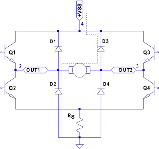
CHAPTER 7 ■ 76 THE H-BRIDGE DRIVER
141
Protection Diodes
No inductive driver circuit is complete without protective diodes. When the applied
voltage is suddenly removed from the motor coil, the magnetic field collapses, producing
an electric current. Recall in Chapter 6 that the reverse-biased diode was used to bleed off
the inductive kick in the unipolar motor drive.
Figure 7-2 shows the L298 with the external protective diodes wired in (these are
not included in the IC). If the current flow was as shown in the earlier block diagram, the
sudden off would cause the current to flow through diodes D3 and D2. The SGS-Thomson
Microelectronics datasheet specifies that these should be 1A fast-recovery diodes (trr £
200 ns). A slow-reacting diode can allow the voltage to spike into the surrounding circuit.
Figure 7-2. L298 with protective diodes
L298 PCB
You could build your own L298 driver circuit, but with the availability of PCBs around $4
on eBay, you’d have to have a good reason to bother. Figure 7-3 shows the unit that
I purchased and used for this project.
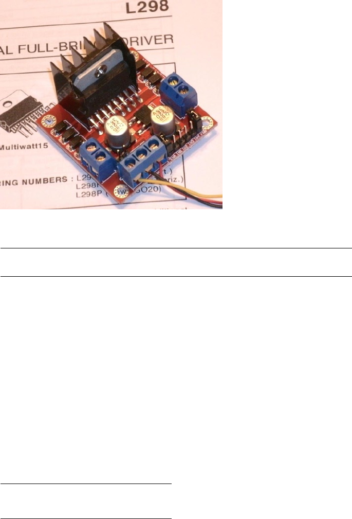
CHAPTER 7 ■ 76 THE H-BRIDGE DRIVER
142
Note ■ I purchased this PCB as an eBay Buy It Now offer with free shipping.
The PCB has three power connections:
• VS, which is labeled as +12 V (yellow wire in the photo)
Gnd (black wire)•
• VSS, which is labeled as +5 V (red wire)
This particular PCB has a jumper (removed in Figure 7-3), with its two pins visible
just above the power-connection block and below the round capacitor. With the jumper
installed, an onboard regulator supplies VSS with +5 V from the VS (+12 V) input. The
regulated +5 V is also available for external circuitry at the block connector (where the red
wire is shown).
When the motor (VS) voltage is higher than 12 V, it is best to remove the jumper and
supply the +5 V into the block instead. The reason for this is that the linear regulator must
dissipate additional heat from the higher input voltage. I am using a salvaged power
supply with both a +5 V supply and a +16 V supply, so the jumper was removed.
To the right of the power-input block are header connection pins as follows:
+5V +5V
EnA In1 In2 In3 In4 EnB
Figure 7-3. L298 driver PCB

CHAPTER 7 ■ 76 THE H-BRIDGE DRIVER
143
The EnA and EnB connections have jumpers installed to enable both driver units
(tying the enable A and B inputs up to the +5 V supply). If you don’t need to control the
enable inputs, leave the jumpers in. Otherwise, remove them and then use the edge pins
for inputs to enables A and B.
The pins In1 through In4 are the inputs to the bridge drivers (see In1 and In2 in
Figure 7-1).
The remaining connections are two blocks with paired connections:
OUT1 and OUT2, bridge connections for unit A•
OUT3 and OUT4, bridge connections for unit B•
You don’t have to install any protective diodes, since they are already included on the
PCB. Price and convenience were the reasons I chose to buy the PCB. If you breadboard
the driver instead, be sure to wire in the fast-acting protection diodes, since these are not
included in the IC.
Driving from GPIO
Of course, before we attach the inputs of these drivers to the GPIO pins of the Raspberry
Pi, we need to be certain that the voltage levels are safe and that the interface logic
levels work.
The L298 IC has the following power requirements:
Symbol Parameter Min Typ Max Unit
VSSupply voltage (pin 4) VIH + 2.5 46 Volts
VSS Logic supply voltage (pin 9) 4.5 5 7 Volts
From this, we see that the motor side (VS) can operate up to 46 V. The logic side,
however, must have a minimum of 4.5 V. In other words, the L298 driver operates at
5V TTL levels.
Note ■ Be sure to remove the regulator jumper when using high voltages.
But we’ve seen this kind of problem before, in Chapter 6. There we were still able to
drive the ULN2003A safely from the GPIO outputs at 3 V levels. So let’s check the signal
requirements of GPIO outputs vs. L298 inputs:
GPIO L298
Signal Volts Volts Signal
VOL £ 0.8 V£ 1.5 V VIL
VOH ³ 1.3 V³ 2.3 V VIH

CHAPTER 7 ■ 76 THE H-BRIDGE DRIVER
144
If you look carefully at the chart, there is a dodgy area where the GPIO output can be
as low as VOH ³ 1.3 V and still be in spec as far as the Raspberry Pi is concerned. We see that
the L298 considers signals VIL £ 1.5V as a low. Worse, only voltages ³ 2.3 V are considered
high by the L298. The good news is that the L298 input current is very low:
L298
Symbol Parameter Test Conditions Typ Max Unit
IIH High-voltage input current VI = H £ VSS – 0.6 V30 100 mA
The input current necessary to drive the L298 input high is a maximum of 100 μA.
The lowest configured output drive capability of a GPIO pin is 2 mA. The L298 input
current requirement is thus only 5% of the minimum current drive available. If the GPIO
pin had to drive a 2 mA signal, its output voltage might be as low as 1.3 V. But having to
supply only 100 μA of signal current means that the GPIO voltage should be almost as
high as it can go.
For this reason, it is not that unreasonable to expect the GPIO output voltage to
be near 3 V (allowing for a drop from the +3.3 V supply). However, we must allow for
variation in the +3.3 V power supply as well. If the supply is within the standard range
of +3.125 to +3.465 V, and we allow a GPIO output drop of, say, 0.3 V due to the output
transistor Ron, then the unloaded GPIO output voltage could be as low as 3.135 – 0.3 =
2.835 V. This is only 0.535 V above the minimum VIH = 2.3 V that we need for the L298.
This is cutting things rather close, but sufficient for hobby and educational use (for
products that are sold, you would want a greater margin for error). If this remains a
concern for a project build, external pull resistors to +3.3 V can be added.
The DMM Check
The final word is the voltage measurement of the L298 chip’s inputs. You must make
certain there is no pull-up resistor to +5 V on the PCB. The datasheet doesn’t indicate that
any L298 chip internal pull-up resistors exist. But seeing is believing, so don’t skip this
check. A purchased PCB is more likely to contain pull-up resistors than not.
Without attaching it to the Pi, supply the circuit with +5 V for its logic (the motor
supply need not be applied). When using the onboard regulator, supply the +12 V to the
+VS input instead. Then check the voltage appearing at the EnA, EnB, In1, In2, In3, and
In4 inputs. When measured, there should be nearly no voltage present (with respect
to ground). If you read +5 V instead, the PCB likely has provided a pull-up resistor
somewhere. For the enable inputs, jumpers may need to be removed. Do not wire these
inputs to the Raspberry Pi until these inputs have passed this check. Anything measured
less than 0.6 V is probably OK. Measurements higher than this probably mean a defective
driver IC or a wiring error.
If you are supplying the L298 logic from a separate +5 V supply, it is a good idea to
perform one more test with the +12 V (or higher) motor supply applied. The measured
voltage at each input pin should remain as before, near zero. Anything else suggests a bad
PCB or defective L298 chip leaking current into the inputs.
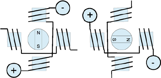
CHAPTER 7 ■ 76 THE H-BRIDGE DRIVER
145
Bipolar Stepper Modes
Before we look at the schematic and software, let’s review how the bipolar stepper motor
works. There are three basic modes of operation for a bipolar stepper motor:
Wave drive, one-phase-on drive•
Wave drive, two-phase-on drive•
Half-step drive•
One-Phase-On Mode
Figure 7-4 shows the first two of four possible drive states for wave drive, one phase on.
Each winding is energized in turn for the first two steps. The final two steps energize
the same two windings in sequence except that the current polarity is reversed. In other
words, the south pole of the rotor follows the positive input polarity (as wired in the
figure). In this mode, there are a total of four steps.
Figure 7-4. Wave drive, one phase on
This simple mode of operation suffers from the loss of precision that the half-step
drive has and lacks the torque of two-phase-on mode.
Two-Phase-On Mode
Wave drive, two-phase-on mode energizes both windings for each step. This is where the
extra torque comes from. Figure 7-5 shows two of the four possible steps for this mode.
Notice how the south pole centers itself between two poles, as it follows the two positive
polarities. Like the one-phase mode, there are only four possible steps.
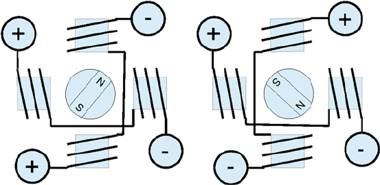
CHAPTER 7 ■ 76 THE H-BRIDGE DRIVER
146
While this mode lacks the precision of half-step mode (next), it does enjoy the extra
torque advantage over all three modes.
Half-Step Mode
In half-step mode, a combination of the two prior modes is used. First, only one winding
is energized to point the rotor at the winding’s pole (like one-phase mode). Then the next
pole is energized while keeping the prior winding energized. In this way, the rotor moves
a half step between the two poles, as with two-phase mode. Finally, the previous winding
is turned off, producing another half step. The precision is increased to a total of eight
steps in this manner.
This is clearly the most precise of the three modes. While it lacks some of the torque
of two-phase mode, it has on average more torque than one-phase mode.
In all of these modes, it is necessary to first pass current through the windings in one
direction, and then later in the reverse direction. This allows the bipolar stepper motor to
be built with less wire than the unipolar motor. In the unipolar design, only one or two of
the four center-tapped windings are used at one time. Consequently, the bipolar motor is
cheaper to manufacture and lighter in weight.
Figure 7-6 illustrates my test setup. At the left is a power supply that I rescued from
a discarded piece of equipment. To the right of the Raspberry Pi station, I have the L298
PCB wired up to the power and the Pi’s GPIO pins. The remaining four wires go from the
drive PCB to the bipolar stepper motor (I left some sort of shaft attachment to the motor,
to make the rotation more visible).
Figure 7-5. Wave drive, two phase on
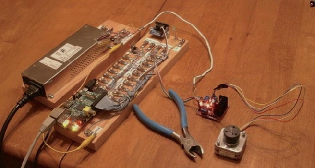
CHAPTER 7 ■ 76 THE H-BRIDGE DRIVER
147
Choosing Driving GPIOs
Recall from Chapter 6’s Table 6-1 that some GPIO pins are more suitable than others for
motor controls. While the Raspberry Pi is booting up, we don’t want driver circuits and
motors running amok. It is best that the motor remains disabled until the Pi boots up and
the motor-controlling software takes proper control.
When using the L298, we can take one of two design approaches:
Tie enable inputs high, but choose • motor-safe GPIO pins for the
driver inputs.
Drive the enable inputs from a • motor-safe GPIO and configure the
other GPIO pins after boot-up.
The first option does not use the enable inputs at all. For that, you must make sure
that all In GPIO pins are safe for motor control at boot time. The disadvantage is that all
four input controls need to be taken from the safe GPIO pool. If you need to drive more
than one motor, your options start to become limited.
The second approach uses motor-safe GPIO pin(s) on the two enable inputs of the
L298 driver. This way, the enable inputs are pulled down during the boot-up process,
disabling the motor controls, regardless of the state of the In pins. This gives you flexibility
to choose any other GPIO pins for use for the In signals. This is the approach adopted for
this chapter’s project. (Note that you can tie the enable pins together so that only one safe
GPIO pin is required to drive the enable input.) Because a bipolar stepper motor needs a
bridge driver for each of its two windings, we’ll use both bridge driver units provided by
the L298 IC.
The enable inputs for the two windings can be ganged together and driven by one
GPIO pin. This, of course, increases the load on the GPIO output, but at a worst case of
200 mA, the driving voltage requirements will be easily met.
Figure 7-6. My bipolar stepper motor setup
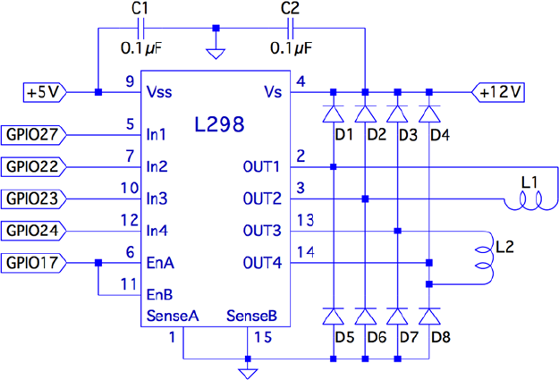
CHAPTER 7 ■ 76 THE H-BRIDGE DRIVER
148
Project Schematic
Figure 7-7 shows the schematic for the bipolar motor driver. If you are using a purchased
PCB, the only important details are the connections to it. The schematic, however, helps
us visualize all the separate components involved.
Figure 7-7. L298 schematic
In this circuit, the enable inputs A and B have been tied together so that only GPIO
17 needs to be allocated to drive it.
Junk-Box Motors
If you’ve been an electronics hobbyist for a while, you likely have a bipolar motor in your
junk box. If not, salvage one from an old 3.5-inch floppy disk. Its seek motor will likely be
a bipolar stepper. Another source of stepper motors is an old flat-top scanner.
Bipolar motors are easier to figure out than unipolar motors. There are only four
wires, and they operate in pairs. To identify the pairs, simply take resistance readings.
A low reading will identify one pair of wires. Once that pair is identified, the remaining
two wires should be the second pair and read similarly. Make sure there is no connection
between the windings. They should be electrically isolated from each other.

CHAPTER 7 ■ 76 THE H-BRIDGE DRIVER
149
Program Operation
The program used in this chapter is named bipolar.c and is listed at the end of the
chapter. The program is designed similarly to the unipolar program in Chapter 6. The
bipolar program, however, does not do clock positioning, but instead operates in free-
running mode when instructed to do so.
The program starts in one-phase mode, but the stepper-motor mode can be changed
with any of the following single-character commands:
Character Command
1 Wave mode, one phase
2 Wave mode, two phase
3 Half-step mode
Entering a mode command will automatically stop the motor if it is in
free-running mode.
To test your motor connections, these single-step commands are available:
Character Command
+ Single step clockwise
- Single step counterclockwise
The + command steps the motor one step clockwise, while the – (minus) key steps
the motor counterclockwise. If your motor turns the wrong way, you can fix your wiring
after testing it.
Similarly, use these single-step commands to make sure your motor is wired up
correctly. In one-phase mode (the default), the motor should step equally with
each + or - step command. If not, one of the two pairs needs its connections reversed.
The free-running commands (and Quit) are listed here:
Character Command
F Forward (free running)
R Reverse (free running)
S Stop
> Go faster (halve the step time)
< Go slower (double the step time)
Q Quit
CHAPTER 7 ■ 76 THE H-BRIDGE DRIVER
150
Entering F starts the motor running, in the forward (clockwise) direction. To speed
it up, press > while it is running, or prior to starting it. Pressing the same direction
command F toggles the motor off again. Alternatively, S is available to stop the motor
if that seems more intuitive. The R command starts the motor in the reverse direction.
Pressing R again stops it. Direction can be changed while the motor is running. This tests
how well it recovers when operated at higher speeds.
Program Internals
This program requires the use of a thread to run the motor in free-running mode. This
design allows the main program to continue to read user commands from the keyboard
while supplying the motor with stepping commands. The user can change the stepping
speed, reverse the motor, or stop the motor.
The main user input dispatch loop is in the main program (lines 230 to 305). The
threaded code resides in lines 125 to 140. Unless the free-running F or R commands are in
effect, the thread blocks in line 131, waiting for a command. Once a command is received,
the loop in lines 133 to 136 keeps the motor stepping, until the main loop sets the stop flag.
The mutex and cond variables (lines 36 and 37) provide a simple arrangement
to implement a queue from the main thread to the free-running thread. The queue
get function is implemented in lines 105 to 119. The code must first successfully lock
the mutex in line 109. Once that is accomplished, the while loop in lines 111 and 112
is executed. If the cmd variable is still zero, this indicates that no command has been
queued. When that happens, pthread_cond_wait() in line 112 is executed. This unlocks
the mutex and blocks the execution of the program. Control blocks until the cond variable
is signaled in line 158. When control returns from pthread_cond_wait(3), the kernel has
relocked the mutex.
Queuing the command occurs in the routine queue_cmd() (lines 146 to 159). After
locking the mutex (line 149), the while loop checks whether the cmd variable is nonzero.
If it is, this indicates that the motor thread has not received the last command yet, and
control blocks in the pthread_cond_wait() call (line 152). Again, when control blocks,
the kernel releases the mutex. The cond variable is signaled from line 117, when the
command is taken off the one-element queue.
The stepping functions are performed by the routine step() in lines 73 to 91. The
motor drive is disabled in line 86 so the GPIO signals can be changed (line 87). Once the
new GPIO output settings are established, the drive to the motor is enabled in line 88.
If you choose to use different GPIO pins for this project, change the constant
declarations in lines 23 to 27.
1 /*********************************************************************
2 * bipolar.c : Drive a bipolar stepper motor
3 *********************************************************************/
4
5 #include <stdio.h>
6 #include <stdlib.h>
7 #include <fcntl.h>
8 #include <unistd.h>
9 #include <errno.h>
CHAPTER 7 ■ 76 THE H-BRIDGE DRIVER
151
10 #include <math.h>
11 #include <ctype.h>
12 #include <termio.h>
13 #include <sys/mman.h>
14 #include <pthread.h>
15 #include <assert.h>
16
17 #include "gpio_io.c" /* GPIO routines */
18 #include "timed_wait.c" /* timed_wait() */
19
20 /*
21 * GPIO definitions :
22 */
23 static const int g_enable = 17; /* L298 EnA and EnB */
24 static const int g_in1 = 27; /* L298 In1 */
25 static const int g_in2 = 22; /* L298 In2 */
26 static const int g_in3 = 23; /* L298 In3 */
27 static const int g_in4 = 24; /* L298 In4 */
28
29 static volatile int stepper_mode = 0; /* Stepper mode − 1 */
30 static volatile float step_time = 0.1; /* Step time in seconds */
31
32 static volatile char cmd = 0; /* Thread command when nonzero */
33 static volatile char stop = 0; /* Stop thead when nonzero */
34 static volatile char stopped = 0; /* True when thread has stopped */
35
36 static pthread_mutex_t mutex; /* For inter−thread locks */
37 static pthread_cond_t cond; /* For inter−thread signaling */
38
39 /*
40 * Await so many fractional seconds
41 */
42 static void
43 await(float seconds) {
44 long sec, usec;
45
46 sec = floor(seconds); /* Seconds to wait */
47 usec = floor((seconds−sec)*1000000); /* Microseconds */
48 timed_wait(sec,usec,0); /* Wait */
49 }
50
51 /*
52 * Enable/Disable drive to the motor
53 */
54 static inline void
CHAPTER 7 ■ 76 THE H-BRIDGE DRIVER
152
55 enable(int enable) {
56 gpio_write(g_enable, enable);
57 }
58
59 /*
60 * Drive the appropriate GPIO outputs :
61 */
62 static void
63 drive(int L1L2) {
64 gpio_write(g_in1, L1L2&0x08);
65 gpio_write(g_in2, L1L2&0x04);
66 gpio_write(g_in3, L1L2&0x02);
67 gpio_write(g_in4, L1L2&0x01);
68 }
69
70 /*
71 * Take one step in a direction :
72 */
73 static void
74 step(int direction) {
75 static const int modes[3][8] = {
76 { 0b1000, 0b0010, 0b0100, 0b0001 }, /* Mode 1 */
77 { 0b1010, 0b0110, 0b0101, 0b1001 }, /* Mode 2 */
78 { 0b1000, 0b1010, 0b0010, 0b0110, 0b0100, 0b0101,
0b0001, 0b1001 }
79 } ;
80 static int stepno = 0; /* Last step no.*/
81 int m = stepper_mode < 2 ? 4 : 8; /* Max steps for mode */
82
83 if ( direction < 0 )
84 direction = m − 1;
85
86 enable(0); /* Disable motor */
87 drive(modes[stepper_mode][stepno]); /* Change fields */
88 enable(1); /* Drive motor */
89
90 stepno = (stepno+direction) % m; /* Next step */
91 }
92
93 /*
94 * Set the stepper mode of operation :
95 */
96 static inline void
CHAPTER 7 ■ 76 THE H-BRIDGE DRIVER
153
97 set_mode(int mode) {
98 enable(0);
99 stepper_mode = mode;
100 }
101
102 /*
103 * Take a command off the input queue
104 */
105 static char
106 get_cmd(void) {
107 char c;
108
109 pthread_mutex_lock(&mutex);
110
111 while ( !cmd )
112 pthread_cond_wait(&cond,&mutex);
113
114 c = cmd;
115 cmd = stop = 0;
116 pthread_mutex_unlock(&mutex);
117 pthread_cond_signal (&cond); /* Signal that cmd is taken */
118
119 return c;
120 }
121
122 /*
123 * Stepper controller thread :
124 */
125 static void *
126 controller(void * ignored) {
127 int command;
128 int direction;
129
130 for ( stopped = 1; ; ) {
131 command = get_cmd();
132 direction = command == 'F' ? 1 : −1;
133
134 for ( stopped = 0; !stop; ) {
135 step(direction);
136 await(step_time);
137 }
138 stopped = 1;
139 }
140 return 0;
141 }
142
143 /*
CHAPTER 7 ■ 76 THE H-BRIDGE DRIVER
154
144 * Queue up a command for the controller thread :
145 */
146 static void
147 queue_cmd( char new_cmd) {
148
149 pthread_mutex_lock(&mutex); /* Gain exclusive access */
150
151 /* Wait until controller grabs and zeros cmd */
152 while ( cmd )
153 pthread_cond_wait(&cond ,&mutex);
154
155 cmd = new_cmd; /* Deposit new command */
156
157 pthread_mutex_unlock(&mutex); /* Unlock */
158 pthread_cond_signal(&cond); /* Signal that cmd is there */
159 }
160
161 /*
162 * Stop the current operation :
163 */
164 static void
165 stop_cmd(void) {
166 for ( stop = 1; !stopped; stop = 1 )
167 await(0.100);
168 }
169
170 /*
171 * Provide usage info :
172 */
173 static void
174 help(void) {
175 puts("Enter :\n"
176 " 1 − One phase mode\n"
177 " 2 − Two phase mode\n"
178 " 3 − Half step mode\n"
179 " R − Toggle Reverse (counter−clockwise)\n"
180 " F − Toggle Forward (clockwise)\n"
181 " S − Stop motor\n"
182 " + − Step forward\n"
183 " − − Step backwards\n"
184 " > − Faster step times \n"
185 " < − Slower step times \n"
186 " ? − Help\n"
187 " Q − Quit\n " ) ;
188 }
189
190 /*
CHAPTER 7 ■ 76 THE H-BRIDGE DRIVER
155
191 * Main program
192 */
193 int
194 main(int argc,char **argv) {
195 pthread_t tid; /* Thread id */
196 int tty = 0; /* Use stdin */
197 struct termios sv_ios, ios;
198 int rc, quit;
199 char ch, lcmd = 0;
200
201 rc = tcgetattr (tty,&sv_ios); /* Save current settings */
202 assert(!rc);
203 ios = sv_ios;
204 cfmakeraw(&ios); /* Make into a raw config */
205 ios.c_oflag = OPOST | ONLCR; /* Keep output editing */
206 rc = tcsetattr(tty,TCSAFLUSH,&ios); /* Put into raw mode */
207 assert(!rc);
208
209 /*
210 * Initialize and configure GPIO pins :
211 */
212 gpio_init();
213 gpio_config(g_enable,Output);
214 gpio_config(g_in1,Output);
215 gpio_config(g_in2,Output);
216 gpio_config(g_in3,Output);
217 gpio_config(g_in4, Output);
218
219 enable(0); /* Turn off output */
220 set_mode(0); /* Default is one phase mode */
221
222 help();
223
224 pthread_mutex_init(&mutex,0); /* Mutex for inter−thread
locking */
225 pthread_cond_init(&cond,0); /* For inter−thread signaling */
226 pthread_create(&tid,0,controller,0); /* The thread itself */
227
228 /*
229 * Process single-character commands :
230 */
231 for ( quit=0; !quit; ) {
232 /*
233 * Prompt and read input char :
234 */
235 write(1,": ",2);
CHAPTER 7 ■ 76 THE H-BRIDGE DRIVER
156
236 rc = read(tty,&ch,1);
237 if ( rc != 1 )
238 break;
239 if ( islower (ch) )
240 ch = toupper(ch);
241
242 write(1,&ch,1);
243 write(1,"\n",1);
244
245 /*
246 * Process command char :
247 */
248 switch ( ch ) {
249 case '1' : /* One phase mode */
250 stop_cmd();
251 set_mode(0);
252 break;
253 case '2' : /* Two phase mode */
254 stop_cmd();
255 set_mode(1);
256 break;
257 case '3' : /* Half step mode */
258 stop_cmd();
259 set_mode(2);
260 break;
261 case '<' : /* Make steps slower */
262 step_time *= 2.0;
263 printf("Step time is now %.3f ms\n",step_
time*1000.0);
264 break;
265 case '>' : /* Make steps faster */
266 step_time /= 2.0;
267 printf("Step time is now %.3f ms\n",step_
time*1000.0);
268 break;
269 case 'F' : /* Forward : run motor */
270 if ( !stopped && lcmd != 'R' ) {
271 stop_cmd(); /* Stop due to toggle */
272 lcmd = 0;
273 } else {
274 op_cmd(); /* Stop prior to change direction */
275 queue_cmd(lcmd='F');
276 }
277 break;
278 case 'R' : /* Reverse : run motor */
CHAPTER 7 ■ 76 THE H-BRIDGE DRIVER
157
279 if ( !stopped && lcmd != ’F’ ) {
280 stop_cmd();
281 lcmd = 0;
282 } else {
283 stop_cmd();
284 queue_cmd(lcmd=’R’);
285 }
286 break ;
287 case 'S' : /* Just stop */
288 stop_cmd();
289 break;
290 case '+' : /* Step clockwise */
291 case '=' : /* So we don’t have to shift for + */
292 stop_cmd();
293 step(1);
294 break;
295 case '−' : /* Step counterclockwise */
296 stop_cmd();
297 step(−1);
298 break;
299 case 'Q' : /* Quit */
300 quit = 1;
301 break;
302 default : /* Unsupported */
303 stop_cmd();
304 help();
305 }
306 }
307
308 stop_cmd();
309 enable(0);
310
311 puts("\nExit.");
312
313 tcsetattr(tty,TCSAFLUSH,&sv_ios); /* Restore terminal mode */
314 return 0;
315 }
316
317 /* End bipolar.c */

159
Chapter 8
Remote-Control Panel
Because of the Raspberry Pi’s small size and low cost, it is an attractive platform for
remote-sensing applications. A remote station might need to sense control panel switches
or push button events. This electronic problem sounds simple until you discover that
switches and buttons suffer from contact bounce.
The remaining challenge resides on the software side. When your sensing stations
are remote, some kind of local software console needs to exist. In fact, your console may
monitor several remote Raspberry Pis. Then add redundant consoles, or consoles in
multiple locations. Each of these has the ability to monitor and control the same remote
devices. It doesn’t take long before the problem becomes complex.
This chapter’s project aims to solve two problems:
Debouncing a switch or push button (hardware)•
Controlling remote consoles (software)•
Let’s first examine the contact bounce problem.
Switched Inputs
One of the aggravations of dealing with push buttons and switches in an electronic
computing environment is that contacts bounce. When you close a switch or push a
button, the contacts can bounce a thousand times before they settle and produce a
stable contact. A modern computer might see thousands of on/off transitions before the
contacts stabilize.
This is not only a nuisance for software design, but also wasteful of the CPU. Each time
the signal from the switch changes state, the CPU must be interrupted to make note of this
event and pass the information on to the interested software (for example, GPIO change
events). The software must then apply algorithms to smooth out these pulses and arrive at a
conclusion when the switch is fully on, or fully off. This is all very ugly and messy!
The same problem happens in reverse when contacts release. Thousands of pulses
are delivered to the CPU as the contacts slowly release and alternate between being in
contact and being disconnected.
There are several ways to reduce or eliminate the problem. One approach is to apply
a flip-flop ahead of the GPIO pins, as shown in Figure 8-1. One end of a SPDT switch is
wired to the flip-flop reset input, while the other is wired to the set input. In this manner,
a single pulse on either end changes the flip-flop state and keeps it stable.
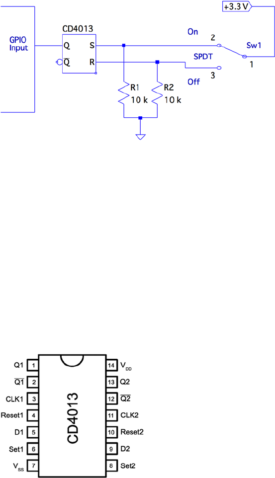
CHAPTER 8 ■ REMOTE-CONTROL PANEL
160
When the switch is releasing one contact, there is no change in the flip-flop output.
After the arm has flown through its switching arc, the opposite contact eventually starts
to bounce at the end of its swing. At this point, it takes only a single pulse to change the
output of the flip-flop to its new state. After that, it remains constant.
The pull-down resistors R1 and R2 are necessary because the CMOS inputs would
otherwise float when the switch arm disconnects from the switch’s contacts. While
disconnected, the resistors pull the input voltage down to ground potential.
The CD4013
The CD4013 is a CMOS part that is able to operate from +3 V and up. The pinout for the
CD4013 is provided in Figure 8-2. The supply voltage VDD is applied to pin 14, with pin 7
(VSS) performing as the ground return. From the pinout diagram, you can see that this is a
dual flip-flop IC, with pins labeled for units 1 and 2.
Figure 8-1. Using a flip-flop for debouncing
Figure 8-2. The CD4013 pinout

CHAPTER 8 ■ REMOTE-CONTROL PANEL
161
The datasheet for this part from various manufacturers shows the VIL and VIH levels
when VDD = +5 V (and higher). The values shown for VOH for each VDD are all listed at a
value of VDD − 0.5 V. Extrapolating from that, I have assumed VOH = 3.3 – 0.5 = 2.8 V in the
following table. The VOL is listed as 0.05 V for all VDD values listed, so we’ll assume the
same for 3.3 V.
The following table compares the Raspberry Pi GPIO logic levels with those of the
CD4013 chip operating at +3.3 V.
Raspberry Pi, GPIO CD4013, VDD = +3.3 V
Parameter Volts Volts Parameter
VIL £ 0.8 V£0.05 V VOL
VIH ³ 1.3 V³ 2.8 V † VOH
†Derived from a National Semiconductor datasheet
From Figure 8-1, recall that we are using the flip-flop output Q to drive a GPIO input.
The flip-flop’s VOL is much lower than the maximum value for VIL, so that works well.
Additionally, from the table, notice that the VOH level of the CD4013 output is well above
the minimum required for VIH for the GPIO input as well. From this signal comparison,
we can conclude that the CD4013 part should play very nice with the Pi when powered
from 3.3 V.
Caution ■ Unused CMOS inputs should not be left unconnected. If an unused input has
no contribution to your design, ground it. If you must have the input in a high state, wire
it directly to the +3.3 V supply. No limiting resistor is required, since a CMOS input draws
no current. Likewise, do not omit R1 and R2, shown in Figure 8-1. Unused CMOS outputs,
however, can be left unconnected.
Unused CMOS inputs should not be left to float. In the presented flip-flop circuit, the
following unused pins will be grounded:
Pin Function Wired to Notes
3 Clock 1 Ground Not used
5 Data 1 Ground Not used
8 Set 2 Ground If FF2 not used
9 Data 2 Ground Not used
10 Reset 2 Ground If FF2 not used
11 Clock 2 Ground Not used
CHAPTER 8 ■ REMOTE-CONTROL PANEL
162
If the second flip-flop is used, simply ground unused pins 9 and 11. Otherwise,
unused pins 8 and 10 should also be grounded. With two flip-flops in the CD4013, you
could debounce two switches/buttons.
Testing the Flip-Flop
After wiring up the CD4013 circuit, you can do a preliminary test before hooking it up to
your Pi. Simply apply +3.3 V to the circuit and measure the voltage on pin 1 (Q1). When
you throw the switch from one position to the next, the output of Q1 should follow.
Hooked up to the Pi, you can test the circuit with the evinput program that is
developed in Chapter 10 of Raspberry Pi Hardware Reference (Apress, 2014). You can
choose any suitable GPIO input, or one that you configured for input. Consult that book
also for a list of GPIOs that boot up in input mode. I chose to use GPIO 22 (GEN3):
$ ./evinput 22
Monitoring for GPIO input changes :
GPIO 22 changed : 0
GPIO 22 changed : 1
GPIO 22 changed : 0
GPIO 22 changed : 1
GPIO 22 changed : 0
^C
$
Here the switch was initially off (Q1 reads low). Then I threw the switch on, and then
off, on, and then off again. Notice that there are no intervening glitches or other contact
bounce events.
If you have a microswitch available with SPDT contacts, you can wire it as a push
button. Push it on, release it, push it on again, and release again. The Raspberry Pi
will read nice clean events without any contact bounce. That’s how we like it on the
software side!
The LED
Figure 8-3 shows the wiring for the LED. The resistor R1 was chosen to provide a red LED,
about 8 mA. If you’re using a lower-powered LED, you can increase the resistance of R1.
Students may want to refer to Chapter 10 of Raspberry Pi Hardware Reference (Apress, 2014)
for the procedure on how to calculate the resistance for R1.
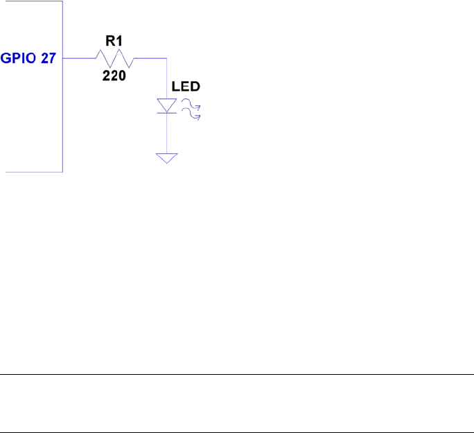
CHAPTER 8 ■ REMOTE-CONTROL PANEL
163
ØMQ
Some open source projects are just too good not to use. ØMQ is one of them. It exists to
solve a difficult problem close to our hearts. Using this library, we can have each Raspberry
Pi act as a publisher of information for the multiple software consoles acting as subscribers.
To allow multiple consoles to control each Pi sensing station, each sensing station
also becomes a subscriber to the console publishers. In effect, we have many-to-many
communication in a tidy software API, thanks to ØMQ.
Note ■ For interesting reading, a nice overview of ØMQ is available here:
http://zguide.zeromq.org/page:all.
Performing Installation
The download and installation of ØMQ is almost painless for the Raspberry Pi. Simply
allow some time for the compile, which might take a while (step 3):
1. wget http://download.zeromq.org/zeromq-3.2.2.tar.gz
2. ./configure –prefix=/usr/local
3. make
4. make check (optional)
5. make install
Figure 8-3. Sensor LED hookup
CHAPTER 8 ■ REMOTE-CONTROL PANEL
164
If you also want C++ support for ØMQ, you can perform the following additional
steps (we’ll use only the C API in this chapter):
1. git clone https://github.com/zeromq/cppzmq.git
2. cd cppzmq
3. sudo cp zmq.hpp /usr/local/include/
Compiling and Linking
When compiling source code using ØMQ, you need to specify only the directory where
the include files were installed:
• -I /usr/local/include
For linking, you need the following linker options:
• -L/usr/local/lib -lzmq
• -Wl,-R/usr/local/lib
The last option tells the executable where to find the ØMQ shared libraries at
runtime. Exclude that option when linking on the Mac (or use the provided makefile
target mac_console).
$ make
gcc –c –Wall –O0 –g –I/usr/local/include –Wall –O0 –g sensor.c –o sensor.o
gcc sensor.o –o sensor –L/usr/local/lib –lzmq –lncurses –Wl, –R/usr/local/lib
sudo chown root ./sensor
sudo chmod u+s ./sensor
gcc –c –Wall –O0 –g –I/usr/local/include –Wall –O0 –g console.c –o console.o
gcc –console.o –o console –L/usr/local/lib –lzmq –lncurses –Wl,
–R/usr/local/lib
Sensing Station Design
Our Raspberry Pi sensing station will use the CD4013 flip-flop circuit to debounce one
switch or SPDT push button. The Pi station will also consist of one LED that will be
controlled by the multiple software consoles.
If you need to imagine some kind of use case, imagine that the Raspberry Pi is
controlling a jail cell door. The guard who wants to open a door pushes a microswitch
button to show SW1=On on the remote consoles (as a request indication). After the
monitoring agents check their video monitor, one of them agrees to honor the request
by entering 1 on the console (which lights the LED) to open the jail cell door. Pressing 0
closes the latch again (turns off the LED).
CHAPTER 8 ■ REMOTE-CONTROL PANEL
165
The great thing about using ØMQ for networking is that you can do the following:
Run • ./sensor with no consoles running
Run any number of • ./console (or ./mac_console) programs
without the sensor running yet
Run as many consoles as you like•
Bring down consoles anytime you like•
With a little homework and extra effort, you could monitor multiple sensors as well.
That was avoided here, to keep the example as simple as possible.
Sensing Station Program
The sensing station (Raspberry Pi) is started as follows:
$ ./sensor
The station runs quietly until terminated (it can be shut down from a console).
While it runs, it periodically broadcasts (publishes) updates to the consoles with the
current status of SW1 and LED. This is necessary because a console may be offline when
the last switch or LED change occurs.
Whenever SW1 changes, a broadcast is immediately sent with its new status sw1:%d,
where %d is a 1 when the switch is on, and otherwise, a 0.
The LED is changed only at the command of the console program. When the sensor
program receives a console message of the form led:%d (over the network), the LED is
turned on or off, according to the value of %d (1 or 0). Once the LED is changed, however, it
is rebroadcasted to all consoles, so that the other consoles can see that this has changed.
Finally, if the console sends stop: to the sensor, the sensor program shuts down and
exits. Pressing ^C in its terminal session will also terminate it.
Console Program
The console program should be compilable for any Linux or Mac OS X platform. If you
use the downloaded makefile, use the target mac_console when building it on Mac OS X:
$ make mac_console
For the Raspberry Pi or any other Linux distribution, you can build the program
simply as follows:
$ make
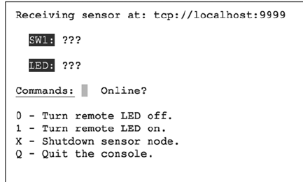
CHAPTER 8 ■ REMOTE-CONTROL PANEL
166
You’ll need the ncurses development library installed, in addition to ØMQ:
# apt–get install libncurses5–dev
To run the console program, simply launch it with the optional hostname as the first
command-line argument (the default is localhost):
$ ./console 192.145.200.14 # Raspberry Pi by IP no.
Mac users will use the following:
$ ./mac_console myrasp # Raspberry Pi by hostname
Figure 8-4 shows the appearance of the console when it first starts up. The ???
show that the console does not yet know the status of the switch or LED. Beside the
command-line input, it also shows Online?, indicating that it does not yet know whether
the sensor is online. As soon as one message is received, that changes to ONLINE.
Figure 8-4. Console at startup
Console Commands
The console commands are all single-character commands and are displayed on the
screen. Typing 0 turns off the LED on the sensor, and typing 1 turns it on. Typing q or Q
quits the console.
Typing x or X terminates the sensor program. (It would not be good to have this
option on a real jail cell control).
Sensor Source Code
Every attempt was made to keep these listings short. But despite these attempts, the
code is a bit “winded” for this simple-minded task. The important thing here is the basic
concept and how to leverage it in your own more sophisticated designs.
CHAPTER 8 ■ REMOTE-CONTROL PANEL
167
Except for the use of pthreads and ØMQ, not much is new in the source code.
Consequently, I’ll just provide some highlights.
The sensor.c main program gets everything started, by opening the GPIO files (input
and output), opening the ØMQ sockets, and creating two threads. The main thread is
contained within the main program, within the for loop starting at line 298. The loop simply
pulls console commands from the ØMQ socket console at line 299 and then acts upon them.
There are only two supported console commands:
led:%d: Change LED status
stop:: Shut down the ./sensor program
Line 286 of the main program creates the SW1_monitor_thread. This thread is
located in lines 211 to 223. It uses the poll(2) system call in the routine gpio_poll(),
to determine when the switch setting changes. This GPIO input is coming from Q1 of the
flip-flop, which is connected to either a switch or a microswitch push-button.
Program execution blocks at line 216, until the switch changes state. Then the status
of the switch is captured in rc and relayed to all interested consoles by calling the routine
publish_SW1().
The remaining thread is launched in the main program from line 289. It runs in
lines 228 through 237. It is a very small loop, which simply updates the consoles every 3
seconds, with the current status of the LED and SW1. This is necessary so that consoles
that are restarted can eventually know the current state of these items.
The mutex_lock() and mutex_unlock() routines are designed to guard against
two threads using the same ØMQ resources at the same time. Doing so would cause
program aborts.
The ØMQ library supports a routine named zmq_poll(), which would have
simplified things if it could have been used. Unfortunately, it supports only ZMQ_POLLIN
for input. Our switch change driver requires the use of poll(2)'s POLLPRI event, so
zmq_poll() will not support us there.
1 /∗∗∗∗∗∗∗∗∗∗∗∗∗∗∗∗∗∗∗∗∗∗∗∗∗∗∗∗∗∗∗∗∗∗∗∗∗∗∗∗∗∗∗∗∗∗∗∗∗∗∗∗∗∗∗∗∗∗∗∗∗∗∗∗∗∗∗∗∗
2 ∗ sensor.c − Sense SW1, send to console (and take LED cmd from console)
3 ∗∗∗∗∗∗∗∗∗∗∗∗∗∗∗∗∗∗∗∗∗∗∗∗∗∗∗∗∗∗∗∗∗∗∗∗∗∗∗∗∗∗∗∗∗∗∗∗∗∗∗∗∗∗∗∗∗∗∗∗∗∗∗∗∗∗∗∗∗/
4
5 #include <stdio.h>
6 #include <stdlib.h>
7 #include <unistd.h>
8 #include <string.h>
9 #include <fcntl.h>
10 #include <assert.h>
11 #include <poll.h>
12 #include <pthread.h>
13
14 #include <zmq.h>
15
16 static const char ∗service_sensor_pub = "tcp ://∗:9999";
17 static const char ∗service_sensor_pull = "tcp ://∗:9998";
18
CHAPTER 8 ■ REMOTE-CONTROL PANEL
168
19 static void ∗context = 0; /∗ ZMQ context ∗/
20 static void ∗publisher = 0; /∗ Publishing socket ∗/
21 static void ∗console = 0; /∗ Pull socket ∗/
22
23 static int SW1 = 0; /∗ Switchstatus ∗/
24 static int LED = 0; /∗ LED status ∗/
25 static int stop = 0; /∗ Nonzero when shutting down ∗/
26
27 static int gp_SW1 = 22; /∗ GPIO 22 (input) ∗/
28 static int gp_LED = 27; /∗ GPIO 22 (output) ∗/
29 static int fd_SW1 = −1; /∗ Open fd for SW1 ∗/
30
31 #include "mutex.c"
32
33 /∗
34 ∗ Publish the LED setting to the console(s)
35 ∗/
36 static void
37 publish_LED(void) {
38 char buf [256];
39 size_tn;
40 int rc;
41
42 n = sprintf(buf,"led:%d",LED);
43 mutex_lock();
44 rc = zmq_send(publisher,buf,n,0);
45 assert(rc!=–1);
46 mutex_unlock();
47 }
48
49 /∗
50 ∗ Publish the switch setting to the console(s)
51 ∗/
52 static void
53 publish_SW1(void) {
54 char buf[256];
55 size_t n;
56 int rc;
57
58 n = sprintf(buf,"sw1:%d",SW1);
59
60 mutex_lock();
61 rc = zmq_send(publisher,buf,n,0);
62 assert(rc!=–1);
63 mutex_unlock();
64 }
65
CHAPTER 8 ■ REMOTE-CONTROL PANEL
169
66 typedef enum {
67 gp_export = 0, /∗ /sys/class/gpio/export ∗/
68 gp_unexport, /∗ /sys/class/gpio/unexport ∗/
69 gp_direction, /∗ /sys/class/gpio%d/direction ∗/
70 gp_edge, /∗ /sys/class/gpio%d/edge ∗/
71 gp_value /∗ /sys/class/gpio%d/value ∗/
72 } gpio_path_t;
73
74 /∗
75 ∗ Internal : Create a pathname for type in buf.
76 ∗/
77 static const char ∗
78 gpio_setpath(int pin,gpio_path_t type,char ∗buf,unsigned bufsiz) {
79 static const char ∗paths [] = {
80 "export", "unexport", "gpio%d/ direction",
81 "gpio%d/edge", "gpio%d/value" };
82 intslen;
83
84 strncpy(buf,"/sys/class/gpio/",bufsiz);
85 bufsiz –= (slen == strlen(buf));
86 snprintf(buf+slen,bufsiz,paths[type],pin);
87 return buf;
88 }
89
90 /∗
91 ∗ Open/sys/class/gpio%d/value for edge detection :
92 ∗/
93 static int
94 gpio_open_edge(int pin,const char ∗edge) {
95 char buf[128];
96 FILE ∗f;
97 int fd;
98
99 /∗ Export pin : /sys/class/gpio/export ∗/
100 gpio_setpath(pin,gp_export,buf,sizeof buf);
101 f = fopen(buf,"w");
102 assert(f);
103 fprintf(f,"%d\n",pin);
104 fclose(f);
105
106 /∗ Direction : /sys/class/gpio%d/direction ∗/
107 gpio_setpath(pin,gp_direction,buf,sizeof buf);
108 f = fopen(buf,"w");
109 assert(f);
110 fprintf(f,"in\n");
111 fclose(f);
112
CHAPTER 8 ■ REMOTE-CONTROL PANEL
170
113 /∗ Edge : /sys/class/gpio%d/edge ∗/
114 gpio_setpath(pin, gp_edge,buf,sizeof buf);
115 f = fopen(buf,"w");
116 assert(f);
117 fprintf(f,"%s\n",edge);
118 fclose(f);
119
120 /∗ Value : /sys/class/gpio%d/value ∗/
121 gpio_setpath(pin,gp_value,buf,sizeof buf);
122 fd = open(buf,O_RDWR);
123 return fd;
124 }
125
126 /∗
127 ∗ Open/sys/class/gpio%d/value for output :
128 ∗/
129 static int
130 gpio_open_output(int pin) {
131 char buf[128];
132 FILE ∗f;
133 int fd;
134
135 /∗ Export pin : /sys/class/gpio/export ∗/
136 gpio_setpath(pin,gp_export,buf,sizeof buf);
137 f = fopen(buf,"w");
138 assert(f);
139 fprintf(f,"%d\n",pin);
140 fclose(f);
141
142 /∗ Direction : /sys/class/gpio%d/direction ∗/
143 gpio_setpath(pin,gp_direction,buf,sizeof buf);
144 f = fopen(buf,"w");
145 assert(f);
146 fprintf(f,"out\n");
147 fclose(f);
148
149 /∗ Value : /sys/class/gpio%d/value ∗/
150 gpio_setpath(pin,gp_value,buf,sizeof buf);
151 fd = open(buf,O_WRONLY);
152 return fd;
153 }
154
155 /∗
156 ∗ Close (unexport) GPIO pin :
157 ∗/
CHAPTER 8 ■ REMOTE-CONTROL PANEL
171
158 static void
159 gpio_close(int pin) {
160 char buf [128];
161 FILE ∗f ;
162
163 /∗ Unexport : /sys/class/gpio/unexport ∗/
164 gpio_setpath(pin,gp_unexport,buf,sizeof buf);
165 f = fopen(buf,"w");
166 assert(f);
167 fprintf(f,"%d\n",pin);
168 fclose(f);
169 }
170
171 /∗
172 ∗ This routine will block until the open GPIO pin has changed
173 ∗ value.
174 ∗/
175 static int
176 gpio_poll(int fd) {
177 struct poll fd_polls;
178 char buf[32];
179 int rc, n;
180
181 polls.fd = fd; /∗ /sys/class/gpio17/value ∗/
182 polls.events = POLLPRI; /∗ Exceptions ∗/
183
184 do {
185 rc = poll (&polls,1, −1); /∗ Block ∗/
186 } while ( rc < 0 && errno == EINTR );
187
188 assert(rc > 0);
189
190 lseek(fd,0,SEEK_SET);
191 n = read(fd,buf,sizeof buf); /∗ Read value ∗/
192 assert(n>0);
193 buf[n] = 0;
194
195 rc = sscanf(buf,"%d",&n);
196 assert(rc==1);
197 return; /∗ Return value ∗/
198 }
199
200 /∗
201 ∗ Write to the GPIO pin
202 ∗/
CHAPTER 8 ■ REMOTE-CONTROL PANEL
172
203 static void
204 gpio_write(int fd,int dbit) {
205 write(fd,dbit ? "1\n" : "0\n",2);
206 }
207
208 /∗
209 ∗ Monitor switch changes on GPIO
210 ∗/
211 static void ∗
212 SW1_monitor_thread(void ∗arg) {
213 int rc;
214
215 while ( !stop ) {
216 rc = gpio_poll(fd_SW1); /∗ Watch for SW1 changes ∗/
217 if ( rc < 0 )
218 break;
219 SW1 = rc;
220 publish_SW1();
221 }
222 return 0;
223 }
224
225 /∗
226 ∗ Periodic broadcast to consoles thread
227 ∗/
228 static void ∗
229 console_thread(void ∗arg) {
230
231 while ( !stop ) {
232 sleep(3);
233 publish_SW1();
234 publish_LED();
235 }
236 return 0;
237 }
238
239 /∗∗∗∗∗∗∗∗∗∗∗∗∗∗∗∗∗∗∗∗∗∗∗∗∗∗∗∗∗∗∗∗∗∗∗∗∗∗∗∗∗∗∗∗∗∗∗∗∗∗∗∗∗∗∗∗∗∗∗∗∗∗∗∗∗∗∗∗∗
240 ∗ Main thread : read switch changes and publish to console (s)
241 ∗∗∗∗∗∗∗∗∗∗∗∗∗∗∗∗∗∗∗∗∗∗∗∗∗∗∗∗∗∗∗∗∗∗∗∗∗∗∗∗∗∗∗∗∗∗∗∗∗∗∗∗∗∗∗∗∗∗∗∗∗∗∗∗∗∗∗∗∗/
242 int
243 main(int argc,char ∗∗argv) {
244 pthread_t tid;
245 int rc = 0;
246 char buf[256];
247 int fd_LED = −1; /∗ GPIO 27 ∗/
248
CHAPTER 8 ■ REMOTE-CONTROL PANEL
173
249 mutex_init();
250
251 /∗ Open GPIO for LED ∗/
252 fd_LED = gpio_open_output(gp_LED);
253 if ( fd_LED < 0 ) {
254 printf("%s : Opening GPIO %d for output.\n",
255 strerror (errno),gp_LED);
256 return 1;
257 }
258
259 /∗ Open GPIO for SW1 ∗/
260 fd_SW1 = gpio_open_edge(22,"both"); /∗ GPIO input ∗/
261 if ( fd_SW1 < 0 ) {
262 printf("%s: Opening GPIO %d for input.\n",
263 strerror(errno),gp_SW1);
264 return 1;
265 }
266
267 context = zmq_ctx_new();
268 assert(context);
269
270 /∗ Create a ZMQ publishing socket ∗/
271 publisher = zmq_socket(context,ZMQ_PUB);
272 assert(publisher);
273 rc = zmq_bind(publisher,service_sensor_pub);
274 assert(!rc);
275
276 /∗ Create a console PULL socket ∗/
277 console = zmq_socket(context, ZMQ_PULL);
278 assert(console);
279 rc = zmq_bind(console,service_sensor_pull);
280 assert(rc != −1);
281
282 SW1 = 0;
283 publish_SW1();
284 publish_LED();
285
286 rc = pthread_create(&tid,0,SW1_monitor_thread,0);
287 assert(!rc);
288
289 rc = pthread_create(&tid,0,console_thread,0);
290 assert(!rc);
291
292 /∗
293 ∗ In this thread, we "pull" console commands :
294 ∗
CHAPTER 8 ■ REMOTE-CONTROL PANEL
174
295 ∗ led:n change state of LED
296 ∗ stop: shutdown the sensor
297 ∗/
298 for (;;) {
299 rc = zmq_recv(console,buf,sizeof buf −1,0);
300 if ( rc > 0 ) {
301 buf[rc] = 0;
302 if ( !strncmp(buf,"led:",4) ) {
303 /∗ LED command from console ∗/
304 buf[rc] = 0;
305 sscanf(buf,"led:%d",&LED);
306 gpio_write(fd_LED,LED);
307 publish_LED();
308 }
309 if ( !strncmp(buf,"stop:",5) ) {
310 stop = 1;
311 break;
312 }
313 }
314 }
315
316 mutex_lock();
317 zmq_close(console);
318 console = 0;
319
320 rc = zmq_send(publisher,"off: " 4,0);
321 assert(rc !=−1);
322 sleep(3);
323 zmq_close(publisher);
324 publisher = 0;
325
326 gpio_close(gp_SW1);
327 gpio_close(gp_LED);
328 mutex_unlock();
329
330 return 0;
331 }
332
333 /∗ End sensor.c ∗/
Console Source Code
The console program is an ncurses-based program. It provides the user with a full-screen
display without the complexity of programming a GUI program (an exercise left to the
interested reader).
CHAPTER 8 ■ REMOTE-CONTROL PANEL
175
The main program initiates curses mode in lines 204 through 207. Prior to that, the
ØMQ library is used to subscribe to the sensor’s published data in lines 184 through 196.
Notice that when subscribing, you must indicate what subscriptions you want. Not setting
any ZMQ_SUBSCRIBE options will result in no messages being received.
Lines 198 to 202 initiate a push connection to the sensor, so commands may be
delivered from the console to the sensor. Note that all running consoles will also establish
this connection. Any console can control the sensor.
The main console loop from lines 226 through 243 receives the subscribed messages
and displays them on the console. That’s all it does.
The command_center thread is shown in lines 112 to 161. It simply reads a keystroke
in line 125 and then dispatches the command in line 132.
The ncurses library is not thread safe, so mutex locking is used to prevent more than
one thread from attempting to use that library simultaneously.
1 /∗∗∗∗∗∗∗∗∗∗∗∗∗∗∗∗∗∗∗∗∗∗∗∗∗∗∗∗∗∗∗∗∗∗∗∗∗∗∗∗∗∗∗∗∗∗∗∗∗∗∗∗∗∗∗∗∗∗∗∗∗∗∗∗∗∗∗∗∗
2 ∗ console.c − Raspberry Pi Sensor Console
3 ∗∗∗∗∗∗∗∗∗∗∗∗∗∗∗∗∗∗∗∗∗∗∗∗∗∗∗∗∗∗∗∗∗∗∗∗∗∗∗∗∗∗∗∗∗∗∗∗∗∗∗∗∗∗∗∗∗∗∗∗∗∗∗∗∗∗∗∗∗/
4
5 #include <stdio.h>
6 #include <stdlib.h>
7 #include <unistd.h>
8 #include <string.h>
9 #include <assert.h>
10 #include <pthread.h>
11 #include <curses.h>
12
13 #include <zmq.h>
14
15 #include "mutex.c"
16
17 static char∗host_name = "local host"; /∗ Default host name ∗/
18 static char service_sensor_pub[128]; /∗ Service name for sensor ∗/
19 static char service_sensor_pull[128]; /∗ Service name for sensor's cmds
∗/
20
21 static void ∗context = 0; /∗ ZMQ context object ∗/
22 static void ∗subscriber = 0; /∗ Subscriber socket ∗/
23 static void ∗console = 0; /∗ Push socket ∗/
24
25 static int SW1 = −1; /∗ Known status of SW1 ∗/
26 static int LED = −1; /∗ Known status of LED ∗/
27
28 /∗
29 ∗ Post the status of SW1 to the console screen
30 ∗/
CHAPTER 8 ■ REMOTE-CONTROL PANEL
176
31 static void
32 post_SW1(void) {
33
34 mutex_lock(); /∗ Lock for shared curses access ∗/
35 attrset(A_REVERSE);
36 mvprintw(3,4,"SW1:");
37 attrset(A_NORMAL);
38 move (3,9);
39 if ( SW1 < 0 ) {
40 addstr("???");
41 } else {
42 if ( SW1 ) {
43 attrset(A_BOLD); /∗ Blink when switch on ∗/
44 addstr("On ");
45 } else {
46 attrset(A_NORMAL);
47 addstr("Off"); /∗ SW1 is off ∗/
48 }
49 }
50 attrset(A_NORMAL);
51 if ( SW1 >= 0 || LED >= 0 )
52 mvprintw(7,15,"ONLINE ");
53 move(7,12);
54 refresh();
55 mutex_unlock(); /∗ Done with curses ∗/
56 }
57
58 /∗
59 ∗ Post LED status to console screen
60 ∗/
61 static void
62 post_LED(void) {
63
64 mutex_lock(); /∗ Lock shared curses access ∗/
65 attrset(A_REVERSE);
66 mvprintw(5,4,"LED:");
67 attrset(A_NORMAL);
68 move(5,9);
69
70 if ( LED < 0 ) {
71 addstr("???");
72 } else {
73 if ( LED ) {
74 attrset(A_BOLD);
75 addstr("On ") /∗ LED is now on ∗/
76 } else {
CHAPTER 8 ■ REMOTE-CONTROL PANEL
177
77 attrset(A_NORMAL);
78 addstr("Off"); /∗ LED is now off ∗/
79 }
80 }
81
82 attrset(A_NORMAL);
83 if ( SW1 >= 0 || LED >= 0 )
84 mvprintw(7,15,"ONLINE ");
85 move(7, 12);
86 refresh();
87 mutex_unlock(); /∗ Release hold on curses ∗/
88 }
89
90 /∗
91 ∗ Post online status to screen
92 ∗/
93 static void
94 post_offline(void) {
95
96 SW1 = −1;
97 LED = −1;
98
99 mutex_lock(); /∗ Lock for shared curses access ∗/
100 attrset(A_REVERSE|A_BLINK);
101 mvprintw(7,15,"OFFLINE");
102 refresh();
103 mutex_unlock(); /∗ Done with curses ∗/
104
105 post_LED();
106 post_SW1();
107 }
108
109 /∗
110 ∗ Main console thread for command center
111 ∗/
112 static void ∗
113 command_center(void ∗ignored) {
114 int rc;
115
116 post_LED(); /∗ Post unknown LED status ∗/
117 post_SW1(); /∗ Post unknown SW1 status ∗/
118
119 for (;;) {
120 mutex_lock(); /∗ Lock curses ∗/
121 move (7,12); /∗ Move cursor to command point ∗/
122 refresh();
123 mutex_unlock(); /∗ Release curses∗/
124
CHAPTER 8 ■ REMOTE-CONTROL PANEL
178
125 rc = getch(); /∗ Wait for keystroke ∗/
126
127 mutex_lock(); /∗ Lock curses ∗/
128 mvaddch(7,12,rc); /∗ Echo character that was typed ∗/
129 refresh();
130 mutex_unlock(); /∗ Release curses ∗/
131
132 switch ( rc ) {
133 case ’0’ :
134 /∗ Tell sensor to turn off LED ∗/
135 rc = zmq_send(console,"led : 0",5,0);
136 assert(rc !=−1);
137 break;
138 case ’1’ :
139 /∗ Tell sensor to turn on LED ∗/
140 rc = zmq_send(console,"led: 1",5,0);
141 assert(rc!=−1);
142 break ;
143 case’x’ :
144 case’X’ :
145 rc = zmq_send(console,"stop :",5,0);
146 assert(rc!=−1);
147 break;
148 case ’q’ :
149 case ’Q’ :
150 /∗ Quit the command console ∗/
151 sleep(1);
152 clear();
153 refresh();
154 endwin();
155 exit(0);
156 break;
157 default :
158 ;
159 }
160 }
161 }
162
163 /∗
164 ∗ Main thread : init/receive published SW1/LED status updates
165 ∗
166 ∗ Specify the IP number or hostname of the sensor on the command
167 ∗ line as argument one : $ ./console myrasp
168 ∗/
169 int
CHAPTER 8 ■ REMOTE-CONTROL PANEL
179
170 main(int argc,char ∗∗argv) {
171 char buf[1024];
172 int rc;
173 pthread_t tid;
174
175 if ( argc > 1 )
176 host_name = argv[1];
177 sprintf(service_sensor_pub,"tcp://%s:9999",host_name);
178 sprintf(service_sensor_pull,"tcp://%s:9998",host_name);
179
180 mutex_init();
181 context = zmq_ctx_new();
182 assert(context);
183
184 subscriber = zmq_socket(context,ZMQ_SUB);
185 assert(subscriber);
186
187 rc = zmq_connect(subscriber,service_sensor_pub);
188 if (rc == −1) perror("zmq_connect\n");
189 assert(rc!=−1);
190
191 rc = zmq_setsockopt(subscriber,ZMQ_SUBSCRIBE,"sw1:", 4);
192 assert(rc!=−1);
193 rc = zmq_setsockopt(subscriber,ZMQ_SUBSCRIBE,"led:", 4);
194 assert(rc!=−1);
195 rc = zmq_setsockopt(subscriber,ZMQ_SUBSCRIBE, "off:",4);
196 assert(rc!=−1);
197
198 console = zmq_socket(context,ZMQ_PUSH);
199 assert(console);
200
201 rc = zmq_connect(console, service_sensor_pull);
202 assert(!rc);
203
204 initscr();
205 cbreak();
206 noecho();
207 nonl();
208
209 clear();
210 box(stdscr,0,0);
211 move(1,2);
212 printw("Receiving sensor at: %s",service_sensor_pub);
213
214 attrset(A_UNDERLINE);
215 mvaddstr(7,2,"Commands:");
216 attrset(A_NORMAL);
CHAPTER 8 ■ REMOTE-CONTROL PANEL
180
217 mvaddstr(9,2,"0 − Turn remote LED off.");
218 mvaddstr(10,2,"1 − Turn remote LED on.");
219 mvaddstr(11,2,"X − Shutdown sensor node.");
220 mvaddstr(12,2,"Q − Quit the console.");
221 mvprintw(7,15,"Online ?");
222
223 rc = pthread_create(&tid,0,command_center,0);
224 assert(!rc);
225
226 for(;;) {
227 rc = zmq_recv(subscriber,buf,sizeof buf − 1,0);
228 assert(rc >= 0 && rc < sizeof buf −1);
229 buf[rc] = 0;
230
231 if ( !strncmp(buf,"off:",4) )
232 post_offline();
233
234 if ( !strncmp(buf,"sw1:",4) ) {
235 sscanf(buf,"sw1:%d",&SW1);
236 post_SW1();
237 }
238
239 if ( !strncmp(buf,"led:",4) ) {
240 sscanf(buf,"led:%d",&LED);
241 post_LED();
242 }
243 }
244
245 return 0;
246 }
247
248 /∗ console.c ∗/
1 /∗∗∗∗∗∗∗∗∗∗∗∗∗∗∗∗∗∗∗∗∗∗∗∗∗∗∗∗∗∗∗∗∗∗∗∗∗∗∗∗∗∗∗∗∗∗∗∗∗∗∗∗∗∗∗∗∗∗∗∗∗∗∗∗∗∗∗∗∗
2 ∗ Mutex . c
3 ∗∗∗∗∗∗∗∗∗∗∗∗∗∗∗∗∗∗∗∗∗∗∗∗∗∗∗∗∗∗∗∗∗∗∗∗∗∗∗∗∗∗∗∗∗∗∗∗∗∗∗∗∗∗∗∗∗∗∗∗∗∗∗∗∗∗∗∗∗/
4
5 static pthread_mutex_t mutex;
6
7 static void
8 mutex_init(void) {
9 int rc = pthread_mutex_init(&mutex, 0);
10 assert(!rc);
11 }
12
CHAPTER 8 ■ REMOTE-CONTROL PANEL
181
13 static void
14 mutex_lock(void) {
15 intrc = pthread_mutex_lock(&mutex);
16 assert(!rc);
17 }
18
19 static void
20 mutex_unlock(void) {
21 int rc = pthread_mutex_unlock(&mutex);
22 assert(!rc);
23 }
24
25 /∗ End mutex.c ∗/

183
Chapter 9
Pulse-Width Modulation
This chapter explores pulse-width modulation (PWM) using the Raspberry Pi. PWM is
applied in motor control, light dimming, and servo controls, to name a few examples.
To keep the hardware simple and the software small enough to read, we’re going to apply
PWM to driving an analog meter in this chapter.
While the CPU percent-busy calculation used here is a bit cheesy, it is simple
and effective for our demonstration. The meter deflection will indicate how busy your
Raspberry Pi’s CPU is. We’ll demonstrate this using a hardware and software PWM
solution.
Introduction to PWM
The GPIO output signal is a digital signal that may be only on or off. You can program it to
deliver only 3 V or 0 V. Consequently, there is no means for the software to ask the GPIO
to deliver 1 or 2 V. Despite this limitation, an analog meter can be driven from a digital
output using PWM.
PWM is a technique that works on the principle of averaging the signal. If the
signal is on for 10% of the total cycle, then when the signal is averaged out, the result is
an analog 10% of the two digital extremes. If the highest voltage produced by the GPIO
output is 3.3 V, a repeating digital signal that is only on for 75% of that cycle produces an
average voltage that’s determined as follows:
V
V
avg=´
=
33 075
2 475
..
.
If the GPIO output signal was high only 10% of the time, the averaged result is
Vavg = 0.33 V. The on time as a percentage of the total cycle time is known as the duty cycle.
Obviously, there is an averaging aspect to all of this. If you applied the 10% signal to
the probes of an oscilloscope, you’d see a choppy digital-looking signal. The duty cycle
may be there, but the averaging effect is not.
The averaging effect is accomplished in several ways. In a lightbulb, the element
is heated up by the on pulses but does not cool immediately, so its brightness reflects
the averaged current flow. A DC motor does not immediately stop when the current is
withdrawn, because the rotational inertia keeps the rotor spinning. A meter’s pointer
does not immediately move back to zero when the current is removed. All of these
physical effects have an averaging effect that can be exploited.

Chapter 9 ■ pulse-Width Modulation
184
PWM Parameters
PWM involves modulating the width of the pulse. But the pulse’s width is one aspect
relative to a whole cycle. Defining a PWM signal requires three parameters:
Frequency (or period) of the cycle•
The time period that the signal is on•
The time period that the signal is off•
It is tempting to think that the cycle time is unimportant. But consider a cycle
lasting 10 seconds, where the signal is on for 1 second and off for the remaining 9 (10%).
Apply that signal to a meter, and the needle will show 100% for 1 second and zero for the
remaining time. Clearly the cycle is too long for the meter’s movement to average out.
If you produce a software-derived PWM signal, a high-frequency rate will average well
on the meter movement. But the amount of CPU effort expended is also needlessly high,
wasting computing power. Planning the operating frequency is an important aspect of PWM.
Hardware PWM peripherals also have design frequency limits that must be considered.
The remaining two parameters form the duty in duty cycle, and are often expressed
as a fraction:
N
M
The denominator M = 100 when we talk of percentages. However, M may be any
integer that divides the complete cycle into equal units of time. The value N defines the
number of units that the PWM device is to be on. The remaining M – N step represents
the off time.
PWM Hardware Peripheral
The Raspberry Pi makes one hardware PWM peripheral available to the user. It is
available on GPIO 18 (GEN1), but you must give up one of the audio channels to use it
(or both, if you consider that the clock is also reconfigured for PWM clock rates). If your
application does not use audio, the peripheral makes a great resource for effortlessly
delivering fast and relatively clean pulse waveforms. And all this without having your
software even “think” about it. If you don’t need to change the duty cycle, you can set up
the peripheral and let it run free on its own.
PWM Software
The servo folks would be wringing their hands at the thought of only one PWM signal.
Fortunately, the Pi is quite capable of generating more PWM signals if you can accept a
little jitter in the signal output and a little CPU overhead (about 6% of the CPU for each
thread-driven PWM signal, in nonturbo mode). While separate processes could be used
to generate multiple PWM signals, this is best accomplished in one process using threads.
The softpwm program at the end of this chapter demonstrates this.
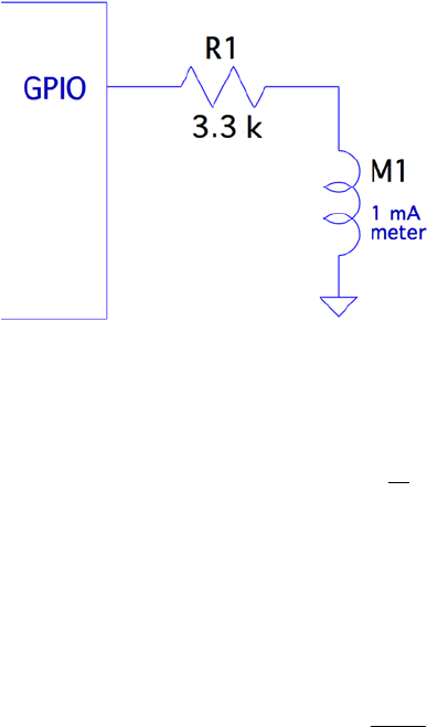
Chapter 9 ■ pulse-Width Modulation
185
Meter Circuit
Figure 9-1 shows the circuit used for this chapter’s CPU percent meter. The resistor
R1 = 3.3 kW when you use a 1 mA meter movement.
Figure 9-1. PWM-driven meter
If you know the current-handling capability for the meter you would like to use, you
can calculate the resistance needed as follows:
RV
1=Im
where:
• V is the voltage (3.3 V) at the GPIO pin.
• Im is the current for your meter movement.
If your meter is known to use a 100 mA movement, for example, the series-dropping
resistor would work out to be the following:
R
K
1
33
0 0001
33
=
=
.
.
W
For all projects in this book, I encourage you to substitute and try parts that you
have on hand. You may have a junk-box meter somewhere that you can use. Don’t
use automotive ammeters, since they will usually have a shunt installed. Almost any
voltmeter or meter with a sufficiently sensitive movement can be used. The limit is
imposed by the GPIO output pin, which supports up to 8 mA (unless reconfigured).
If you don’t know its movement sensitivity, start with high resistances and work
down (try lowest currents first). With care, you can sort this out without wrapping the
needle around the pin.

Chapter 9 ■ pulse-Width Modulation
186
pwm Program
The program software pwm is listed at the end of this chapter. To facilitate discussion,
I’ll show excerpts of it here. The hardware example driven by pwm.c is the nastier of the
two programs presented. This is due to the difficulty of programming the PWM hardware
registers and the clock-rate registers.
The main program invokes pwm_init(), which gains access to the Pi’s peripherals
in much the same way that the other examples did in gpio_init(). The same mmap()
techniques are used for access to the PWM and CLK control registers.
Whether operating pwm to just set the PWM peripheral or to use the CPU percent-busy
function, the PWM frequency must be set by the function pwm_frequency():
static int
pwm_frequency(float freq) {
...
This function stops the clock that is running and computes a new integer divisor.
After disabling the clock, a little sleep time is used to allow the clock peripheral to stop.
The maximum clock rate appears to be 19.2 MHz. To compute the divisor, the following
calculation is used:
If
div =19200000
where:
• Idiv is the computed integer divisor.
• f is the desired PWM frequency.
The range of the resulting Idiv is checked against the peripheral’s limits. The value
of Idiv is then forced to remain in range, but the return value is -1 or +1 depending on
whether the frequency is under or over the limits.
idiv = (long)( clock_rate / (double) freq );
if ( idiv < 1 ) {
idiv = 1; /* Lowest divisor */
rc = -1;
} else if ( idiv >= 0x1000 ) {
idiv = 0xFFF; /* Highest divisor */
rc = +1;
}
Once that is calculated, the value of Idiv is loaded:
ugclk[PWMCLK_DIV] = 0x5A000000 | ( idiv << 12 );

Chapter 9 ■ pulse-Width Modulation
187
Finally, the clock source is set to use the oscillator, and the clock is enabled:
ugclk[PWMCLK_CNTL] = 0x5A000011;
After this, GPIO 18 is configured for ALT function 5, to gain access to the PWM
peripheral:
INP_GPIO(18); /* Set ALT = 0 */
SET_GPIO_ALT(18,5); /* Or in '5' */
The way the SET_GPIO_ALT() macro is defined requires that the INP_GPIO() macro
be used first. The INP_GPIO() macro clears the ALT function bits so that SET_GPIO_ALT()
can or in the new bits (the value 5, in this case).
The remaining steps ready the PWM peripheral:
pwm_ctl->MODE1 = 0; /* PWM mode */
pwm_ctl->RPTL1 = 0;
pwm_ctl->SBIT1 = 0;
pwm_ctl->POLA1 = 0;
pwm_ctl->USEF1 = 0;
pwm_ctl->MSEN1 = 0; /* PWM mode */
pwm_ctl->CLRF1 = 1;
Now, at this point, the PWM peripheral is almost ready to go. It needs the ratio
N
M
and then to be enabled. This is done in the routine pwm_ratio():
static void
pwm_ratio(unsigned n,unsigned m) {
...
This function allows the
N
M
ratio be changed without having to fully reinitialize the
other aspects, including the clock. With our CPU percent-busy function, this ratio will
be changing often.
pwm_ctl->PWEN1 = 0; /* Disable */
*pwm_rng1 = m;
*pwm_dat1 = n;
After initialization, the PWM peripheral is already disabled. But the first step here
disables it, because it may be running when the ratio is being changed. The following pair
of statements put the value of M into the PWM register RNG1, while N goes into the DAT1
register.
Chapter 9 ■ pulse-Width Modulation
188
A few more statements check for errors and reset if necessary (these may not be
strictly necessary). Then the following two statements provide a short pause and re-enable
the PWM peripheral:
usleep(10); /* Pause */
pwm_ctl->PWEN1 = 1; /* Enable */
That covers the interesting aspects of the hardware PWM control.
Hardware PWM Set Command
When program pwm is provided with command-line arguments, it simply sets up and
starts the PWM peripheral. The command takes up to three arguments:
$ ./pwm N [M] [ F ]
where:
• N is the N in the PWM ratio.
• M is the M in the PWM ratio.
• F is the frequency required.
Once the command is started with these parameters, the PWM peripheral is started
and the program exits:
$ . /pwm 40 100 1000
PWM set for 40/100, frequency 1000.0
$
If you have an oscilloscope available, you can attach probes to GPIO 18 and the
ground to see a 40% PWM signal. If you attach the meter circuit of Figure 9-1, it should
read near 40% of the full deflection. Figure 9-2 shows my milliampere meter showing
nearly 40% (the deflection reading is nearly 0.4). The DMM in the background is
measuring the +3.3 V supply voltage, which is showing good voltage regulation.

Chapter 9 ■ pulse-Width Modulation
189
To get a more accurate reading, you could put a potentiometer or Trimpot in series
with a lower-valued resistor and adjust for full deflection (with GPIO set to high).
Alternatively, you could take a voltage reading of the GPIO output when set to high
and calculate the 1% resistor value needed. At the time I took the photo for Figure 9-2,
I measured 3.275 V when the GPIO was set high while supplying current to the
milliampere meter (through a 3.3 kW 10% resistor). Using that for the basis for
calculations, you could use a 3.24 kW 1% resistor.
Hardware Based CPU Percent-Busy Display
The same pwm command can be used as a CPU percent-busy command when started with
no command-line arguments:
$ ./pwm
CPU Meter Mode:
1.4%
The percent of CPU that is busy will be repeatedly shown on the same console line.
Simultaneously, the hardware PWM ratio is being changed. This will cause the meter
deflection to indicate the current CPU percent-busy reading. The pwm command itself
requires about 0.6% CPU, so you will never see the meter reach zero.
The CPU percent is determined in a cheesy manner, but it is simple and good
enough for this demonstration.
Figure 9-2. A milliampere meter showing 40% deflection
Chapter 9 ■ pulse-Width Modulation
190
for (;;) {
pipe = popen("ps -eo pcpu|sed 1d","r");
for ( total=0.0; fgets(buf,sizeof buf,pipe); ) {
sscanf(buf,"%f",&pct);
total += pct;
}
pclose(pipe);
printf("\r%.1f%% ",total);
fflush(stdout);
pwm_ratio(total,100);
usleep(300000);
}
In this section of code, we open a piped command to ps, with options to report the
percent of CPU used by each process. The sed command deletes the header line from the
ps command output.
The for loop reads each line, totaling the percent of CPU used. Occasionally, the
total exceeds 100% because of timing and other roughness in the calculations.
Once the CPU percent total is known, the function pwm_ratio() is called to alter the
ratio, thus changing the position of the meter’s indicator.
1 /*********************************************************************
2 * pwm. c − PWM example program
3 *********************************************************************/
4
5 #include <stdio.h>
6 #include <stdlib.h>
7 #include <unistd.h>
8 #include <fcntl.h>
9 #include <sys/mman.h>
10 #include <errno . h>
11 #include <string . h>
12
13 #define BCM2835_PWM_CONTROL 0
14 #define BCM2835_PWM_STATUS 1
15 #define BCM2835_PWM0_RANGE 4
16 #define BCM2835_PWM0_DATA 5
17
18 #define BCM2708_PERI_BASE 0x20000000
19 #define BLOCK_SIZE (4*1024)
20
21 #define GPIO_BASE (BCM2708_PERI_BASE + 0x200000)
22 #define PWM_BASE (BCM2708_PERI_BASE + 0x20C000)
23 #define CLK_BASE (BCM2708_PERI_BASE + 0x101000)
24
Chapter 9 ■ pulse-Width Modulation
191
25 #define PWMCLK_CNTL 40
26 #define PWMCLK_DIV 41
27
28 static volatile unsigned *ugpio = 0;
29 static volatile unsigned *ugpwm = 0;
30 static volatile unsigned *ugclk = 0;
31
32 statics struct S_PWM_CTL {
33 unsigned PWEN1 : 1;
34 unsigned MODE1 : 1;
35 unsigned RPTL1 : 1;
36 unsigned SBIT1 : 1;
37 unsigned POLA1 : 1;
38 unsigned USEF1 : 1;
39 unsigned CLRF1 : 1;
40 unsigned MSEN1 : 1;
41 } volatile *pwm_ctl = 0;
42
43 static struct S_PWM_STA {
44 unsigned FULL1 : 1;
45 unsigned EMPT1 : 1;
46 unsigned WERR1 : 1;
47 unsigned RERR1 : 1;
48 unsigned GAP01 : 1;
49 unsigned GAP02 : 1;
50 unsigned GAP03 : 1;
51 unsigned GAP04 : 1;
52 unsigned BERR : 1;
53 unsigned STA1 : 1;
54 } volatile *pwm_sta = 0;
55
56 static volatile unsigned *pwm_rng1 = 0;
57 static volatile unsigned *pwm_dat1 = 0;
58
59 #define INP_GPIO(g) *( ugpio+((g )/10)) &= ~(7<<(((g)%10)*3))
60 #define SET_GPIO_ALT(g,a) \
61 *(ugpio+(((g)/10))) |= (((a)<=3?(a)+4:((a)==4?3:2))<<(((g)%10)*3))
62
63 /*
64 * Establish the PWM frequency :
65 */
66 static int
67 pwm_frequency(float freq) {
68 const double clock_rate = 19200000.0;
69 long idiv;
70 int rc = 0;
71
Chapter 9 ■ pulse-Width Modulation
192
72 /*
73 * Kill the clock :
74 */
75 ugclk[PWMCLK_CNTL] = 0x5A000020; /* Kill clock */
76 pwm_ctl−>PWEN1 = 0; /* Disable PWM */
77 usleep(10);
78
79 /*
80 * Compute and set the divisor:
81 */
82 idiv = (long)( clock_rate / (double)freq );
83 if ( idiv < 1 ) {
84 idiv = 1; /* Lowest divisor */
85 rc = −1;
86 } else if ( idiv >= 0x1000 ) {
87 idiv = 0xFFF; /* Highest divisor */
88 rc = +1;
89 }
90
91 ugclk[PWMCLK_DIV] = 0x5A000000 | ( idiv << 12 );
92
93 /*
94 * Set source to oscillator and enable clock :
95 */
96 ugclk[PWMCLK_CNTL] = 0x5A000011;
97
98 /*
99 * GPIO 18 is PWM, when set to Alt Func 5 :
100 */
101 INP_GPIO(18); /* Set ALT = 0 */
102 SET_GPIO_ALT(18,5); /* Or in ’5 ’ */
103
104 pwm_ctl−>MODE1 = 0; /* PWM mode */
105 pwm_ctl−>RPTL1 = 0;
106 pwm_ctl−>SBIT1 = 0;
107 pwm_ctl−>POLA1 = 0;
108 pwm_ctl−>USEF1 = 0;
109 pwm_ctl−>MSEN1 = 0; /* PWM mode */
110 pwm_ctl−>CLRF1 = 1;
111 return rc ;
112 }
113
114 /*
115 * Initialize GPIO/PWM/CLK Access
116 */
Chapter 9 ■ pulse-Width Modulation
193
117 static void
118 pwm_init() {
119 int fd;
120 char *map;
121
122 fd = open("/dev/mem",O_RDWR|O_SYNC); /* Needs root access */
123 if ( fd < 0 ) {
124 perror("Opening /dev/mem");
125 exit(1);
126 }
127
128 map = (char *)mmap(
129 NULL, /* Any address */
130 BLOCK_SIZE, /* # of bytes */
131 PROT_READ|PROT_WRITE,
132 MAP_SHARED, /* Shared */
133 fd, /* /dev/mem */
134 PWM_BASE /* Offset to GPIO */
135 );
136
137 if ( (long)map == −1L ) {
138 perror("mmap(/dev/mem)");
139 exit(1);
140 }
141
142 /* Access to PWM */
143 ugpwm = (volatile unsigned *)map;
144 pwm_ctl = (struct S_PWM_CTL *) &ugpwm[BCM2835_PWM_CONTROL];
145 pwm_sta = (struct S_PWM_STA *) &ugpwm[BCM2835_PWM_STATUS];
146 pwm_rng1 = &ugpwm[BCM2835_PWM0_RANGE];
147 pwm_dat1 = &ugpwm[BCM2835_PWM0_DATA];
148
149 map = (char *)mmap(
150 NULL, /* Any address */
151 BLOCK_SIZE, /* # of bytes */
152 PROT_READ|PROT_WRITE,
153 MAP_SHARED, /* Shared */
154 fd, /* /dev/mem */
155 CLK_BASE /* Offset to GPIO */
156 );
157
158 if ( (long )map == −1L ) {
159 perror("mmap(/dev/mem)");
160 exit(1);
161 }
162
Chapter 9 ■ pulse-Width Modulation
194
163 /* Access to CLK */
164 ugclk = (volatile unsigned *)map;
165
166 map = (char *)mmap(
167 NULL, /* Any address */
168 BLOCK_SIZE, /* # of bytes */
169 PROT_READ|PROT_WRITE,
170 MAP_SHARED, /* Shared */
171 fd, /* /dev/mem */
172 GPIO_BASE /* Offset to GPIO */
173 );
174
175 if ( (long)map == −1L ) {
176 perror("mmap(/dev/mem)");
177 exit(1);
178 }
179
180 /* Access to GPIO */
181 ugpio = (volatile unsigned *)map;
182
183 close(fd);
184 }
185
186 /*
187 * Set PWM to ratio N/M, and enable it :
188 */
189 static void
190 pwm_ratio(unsigned n,unsigned m) {
191
192 pwm_ctl−>PWEN1 = 0; /* Disable */
193
194 *pwm_rng1 = m;
195 *pwm_dat1 = n;
196
197 if ( !pwm_sta−>STA1 ) {
198 if ( pwm_sta−>RERR1 )
199 pwm_sta−>RERR1 = 1;
200 if ( pwm_sta−>WERR1 )
201 pwm_sta−>WERR1 = 1;
202 if ( pwm_sta−>BERR )
203 pwm_sta−>BERR = 1;
204 }
205
206 usleep(10); /* Pause */
207 pwm_ctl−>PWEN1 = 1; /* Enable */
208 }
209
Chapter 9 ■ pulse-Width Modulation
195
210 /*
211 * Main program :
212 */
213 int
214 main(int argc,char **argv) {
215 FILE *pipe;
216 char buf[64];
217 float pct, total;
218 int n, m = 100;
219 float f = 1000.0;
220
221 if ( argc > 1 )
222 n = atoi(argv[1]);
223 if ( argc > 2 )
224 m = atoi(argv[2]);
225 if ( argc > 3 )
226 f = atof(argv[3]);
227 if ( argc > 1 ) {
228 if ( n > m || n < 1 || m < 1 || f < 586.0 || f > 19200000.0 ) {
229 fprintf(stderr,"Value error: N=%d , M=%d , F=%.1f \n",n,m,f);
230 return 1;
231 }
232 }
233
234 pwm_init();
235
236 if ( argc > 1 ) {
237 /* Start PWM */
238 pwm_frequency(f);
239 pwm_ratio(n,m);
240 printf("PWM set for %d/%d, frequency %.1f \n",n,m,f);
241 } else {
242 /* Run CPU Meter */
243 puts("CPU Meter Mode : ");
244 for (;;) {
245 pipe = popen("ps −eo pcpu | sed 1d","r");
246 for ( total =0.0; fgets(buf,sizeof buf,pipe); ) {
247 sscanf(buf,"%f",&pct);
248 total += pct;
249 }
250 pclose(pipe);
251 printf("\r%.1f%%",total);
252 fflush(stdout);
253 pwm_ratio(total,100);
254 usleep(300000);
255 }
256 }
257
Chapter 9 ■ pulse-Width Modulation
196
258 return 0 ;
259 }
260
261 /* End pwm.c */
Software PWM Program
The program softpwm works from the command line very similarly to the hardware
PWM program pwm. One difference, however, is that the software PWM requires that the
program continue to run to maintain the signal. The hardware program can exit and leave
the PWM peripheral running.
The design of the program differs in that a thread is used for each PWM signal being
maintained. With a little bit of work, the softpwm.c module could be formed into a PWM
software library. The data type PWM is created with the same idea as the stdio FILE type:
typedef struct {
int gpio; /* GPIO output pin */
double freq; /* Operating frequency */
unsigned n; /* The N in N/M */
unsigned m; /* The M in N/M */
pthread_t thread; /* Controlling thread */
volatile char chgf; /* True when N/M changed */
volatile char stopf; /* True when thread to stop */
} PWM;
The comments identify the purpose of the structure object members. The last two
members are flags that are used to control the thread.
The function pwm_open(), establishes the GPIO line and the PWM frequency, and
returns the PWM control block. Note that no thread is started just yet:
PWM *
pwm_open(int gpio,double freq) {
PWM *pwm = malloc(sizeof *pwm);
pwm->gpio = gpio;
pwm->freq = freq;
pwm->thread = 0;
pwm->n = pwm->m = 0;
pwm->chgf = 0;
pwm->stopf = 0;
INP_GPIO(pwm->gpio);
OUT_GPIO(pwm->gpio);
return pwm;
}

Chapter 9 ■ pulse-Width Modulation
197
The reverse of open is the pwm_close() call. Here the thread is instructed to stop
(stopf=1), and if there is a thread running, a join with the thread is performed. The join
causes the caller to block until the thread itself has ended. Then the PWM structure is freed,
completing the close operation.
void
pwm_close(PWM *pwm) {
pwm->stopf = 1;
if ( pwm->thread )
pthread_join(pwm->thread,0);
pwm->thread = 0;
free(pwm);
}
The software PWM signal starts when the ratio is established by a call to pwm_ratio():
void
pwm_ratio(PWM *pwm,unsigned n,unsigned m) {
pwm->n = n <= m ? n : m;
pwm->m = m;
if ( !pwm->thread )
pthread_create(&pwm->thread,0,soft_pwm,pwm);
else
pwm->chgf = 1;
}
This call establishes the values for N and M. Then if no thread is currently running,
one is created with the thread’s ID saved in the PWM structure. If the thread is already
running, we simply point out to the thread that the
N
M
values have changed so that it can
adapt to it at the cycle’s end.
The function soft_pwm() is the software PWM engine itself. The pthread_create()
call passes the PWM structure into the call as a void *arg, which is used by the function to
access the PWM structure. The entire procedure is an outer and inner loop. The outer loop
runs as long as the stopf flag is zero. Then the floating-point period variables fperiod,
percent, and ontime are calculated.
From there, the inner loop continues until either the chgf or stopf flag variables
become nonzero. If the stopf becomes nonzero, both loops are exited. Once the thread
function exits, the thread ends. The thread resources are reclaimed in the pwm_close()
call when it joins.
static void *
soft_pw(void *arg) {
PWM *pwm = (PWM *)arg;
double fperiod, percent, ontime;
Chapter 9 ■ pulse-Width Modulation
198
while ( !pwm->stopf ) {
fperiod = 1.0 / pwm->freq;
percent = (double) pwm->n / (double)pwm->m;
ontime = fperiod * percent;
for ( pwm->chgf=0; !pwm->chgf && !pwm->stopf; ) {
gpio_write(pwm->gpio,1);
float_wait(ontime);
gpio_write(pwm->gpio,0);
float_wait(fperiod-ontime);
}
}
return 0;
}
One final note about the PWM structure members concerns the use of the C
keyword volatile. Both chgf and stopf structure members are declared volatile so
that the compiler will generate code that will access these values every time they are
required. Otherwise, compiler optimization may cause the generated code to reuse
values held in registers. This would cause the thread to not notice a change in these
values, which are critical.
volatile char chgf; /* True when N/M changed */
volatile char stopf; /* True when thread to stop */
How Many PWMs?
The design of the preceding PWM software routines is such that you can open as many
PWM instances as you require. The limiting factors are as follows:
Number of free GPIO output lines•
CPU resource utilization•
On a nonturbo mode Raspberry Pi, the code shown seems to require approximately
6% CPU for each soft PWM created. (The CPU utilization rises with frequency, however.)
This leaves you with a certain latitude in the number of PWM signals you generate.
Running the Software PWM Command
To generate a fixed software PWM signal on GPIO 22 (GEN3), run the command like this:
$ ./ softpwm 60 100 2000
PWM set for 60 / 100 , frequency 2000.0 (for 60 seconds )
Obviously, the PWM signal is present for only as long as the softpwm program
continues to run.
Chapter 9 ■ pulse-Width Modulation
199
Software Based CPU Percent-Busy Display
Without command-line arguments, the softpwm command defaults to being a CPU
percent-busy driver. It drives pin GPIO 22 (GEN3), which when attached to a meter as
shown in Figure 9-1, will display CPU utilization.
$ ./softpwm
CPU Meter Mode :
6.5%
Press ^C after the fascination of the CPU meter wears off.
1 /*********************************************************************
2 * softpwm.c Software PWM example program
3 *********************************************************************/
4
5 #include <stdio.h>
6 #include <stdlib.h>
7 #include <unistd.h>
8 #include <fcntl.h>
9 #include <sys/mman.h>
10 #include <errno.h>
11 #include <string.h>
12 #include <math.h>
13 #include <pthread.h>
14
15 #include "gpio_io.c"
16
17 typedef struct {
18 int gpio; /* GPIO out put pin */
19 double freq; /* Operating frequency */
20 unsigned n; /* The N in N/M */
21 unsigned m; /* The M in N/M */
22 pthread_t thread; /* Controlling thread */
23 volatile char chgf; /* True when N/M changed */
24 volatile char stopf; /* True when thread to stop */
25 } PWM;
26
27 /*
28 * Timed wait from a float
29 */
30 static void
31 float_wait(double seconds) {
32 fd_set mt ;
33 struct timeval time out;
34 int rc;
35
Chapter 9 ■ pulse-Width Modulation
200
36 FD_ZERO(&mt);
37 timeout.tv_sec = floor(seconds);
38 timeout.tv_usec = floor((seconds - floor(seconds)) * 1000000);
39
40 do {
41 rc = select(0,&mt,&mt,&mt,&timeout);
42 } while ( rc < 0 && time out.tv_sec && timeout.tv_usec );
43 }
44
45 /*
46 * Thread performing the PWM function :
47 */
48 static void *
49 soft_pwm(void *arg) {
50 PWM *pwm = (PWM *)arg;
51 double fperiod, percent, ontime;
52
53 while ( !pwm >stopf ) {
54 fperiod = 1.0 / pwm->freq;
55 percent = (double ) pwm->n / (double) pwm->m;
56 ontime = fperiod * percent ;
57 for ( pwm->chgf =0; !pwm->chgf && !pwm->stopf; ) {
58 gpio_write (pwm->gpio,1);
59 float_wait(ontime);
60
61 gpio_write(pwm->gpio,0);
62 float_wait(fperiod ontime);
63 }
64 }
65
66 return 0;
67 }
68
69 /*
70 * Open a soft PWM object:
71 */
72 PWM *
73 pwm_open(int gpio,double freq) {
74 PWM *pwm = malloc(sizeof *pwm);
75
76 pwm->gpio = gpio;
77 pwm->freq = freq;
78 pwm->thread = 0;
79 pwm->n = pwm->m = 0;
80 pwm->chgf = 0;
81 pwm->stopf = 0;
82
Chapter 9 ■ pulse-Width Modulation
201
83 INP_GPIO(pwm->gpio);
84 OUT_GPIO(pwm->gpio);
85 return pwm;
86 }
87
88 /*
89 * Close the soft PWM object:
90 */
91 void
92 pwm_close(PWM *pwm) {
93 pwm->stopf = 1;
94 if ( pwm->thread )
95 pthread_join(pwm->thread,0);
96 pwm->thread = 0;
97 free(pwm);
98 }
99
100 /*
101 * Set PWM Ratio:
102 */
103 void
104 pwm_ratio(PWM *pwm,unsigned n,unsigned m) {
105 pwm->n = n <= m ? n : m;
106 pwm->m = m;
107 if ( !pwm->thread )
108 pthread_create(&pwm->thread,0,soft_pwm,pwm);
109 else pwm->chgf = 1;
110 }
111
112 /*
113 * Main program:
114 */
115 int
116 main(int argc,char **argv) {
117 int n, m = 100;
118 float f = 1000.0;
119 PWM *pwm;
120 FILE *pipe;
121 char buf[64];
122 float pct, total;
123
124 if ( argc > 1 )
125 n = atoi(argv[1]);
126 if ( argc > 2 )
127 m = atoi(argv[2]);
Chapter 9 ■ pulse-Width Modulation
202
128 if ( argc > 3 )
129 f = atof(argv[3]);
130 if ( argc > 1 ) {
131 if ( n > m || n < 1 || m < 1 || f < 586.0 || f > 19200000.0 ) {
132 fprintf(stderr,"Value error: N=%d, M=%d, F=%.1f \n",n,m,f);
133 return 1;
134 }
135 }
136
137 gpio_init();
138
139 if ( argc > 1 ) {
140 /* Run PWM mode */
141 pwm = pwm_open(22,1000.0); /* GPIO 22 (GEN3) */
142 pwm_ratio(pwm,n,m) ; / * n% , Start it */
143
144 printf("PWM set for %d/%d, frequency %.1f "
"(for 60 seconds)\n",n,m,f);
145
146 sleep(60);
147
148 printf("Closing PWM..\n");
149 pwm_close(pwm);
150 } else {
151 /* Run CPU Meter */
152 puts("CPU Meter Mode: ");
153
154 pwm = pwm_open(22,500.0); /* GPIO 22 (GEN3) */
155 pwm_ratio(pwm,1,100); / * Start at 1% */
156
157 for (;;) {
158 pipe = popen("ps -eo pcpu | sed 1d","r");
159 for ( total = 0.0 ; fgets(buf,sizeof buf,pipe); ) {
160 sscanf(buf,"%f ",&pct);
161 total += pct;
162 }
163 pclose(pipe);
164
165 pwm_ratio(pwm,total,100);
166
167 printf("\r%.1f%% ",total);
168 fflush (stdout) ;
169
Chapter 9 ■ pulse-Width Modulation
203
170 usleep(300000);
171 }
172 }
173
174 return 0;
175 }
176
177 / * End softpwm.c */

205
Appendix A
Glossary
AC
Alternating current
Amps
Amperes
ATAG
ARM tags, though now used by boot loaders for other architectures
AVC
Advanced Video Coding (MPEG-4)
AVR
Wikipedia states that “it is commonly accepted that AVR stands for Alf (Egil Bogen)
and Vegard (Wollan)’s RISC processor.”
BCD
Binary-coded decimal
Brick
To accidently render a device unusable by making changes to it
CEA
Consumer Electronics Association
cond
Condition variable
CPU
Central processing unit
CRC
Cyclic redundancy check, a type of hash for error detection
CVT
Coordinated Video Timings standard (replaces GTF)
daemon
A Unix process that services requests in the background
DC
Direct current
Appendix A ■ GlossAry
206
DCD
RS-232 data carrier detect
DCE
RS-232 data communications equipment
Distro
A specific distribution of Linux software
DLNA
Digital Living Network Alliance, whose purpose is to enable sharing of digital media
between multimedia devices
DMM
Digital multimeter
DMT
Display Monitor Timing standard
DPI
Display Pixel Interface (a parallel display interface)
DPVL
Digital Packet Video Link
DSI
Display Serial Interface
DSR
RS-232 data set ready
DTE
RS-232 data terminal equipment
DTR
RS-232 data terminal ready
ECC
Error-correcting code
EDID
Extended display identification data
EEPROM
Electrically erasable programmable read-only memory
EMMC
External mass media controller
Flash
Similar to EEPROM, except that large blocks must be entirely rewritten in an update
operation
FFS
Flash file system
Appendix A ■ GlossAry
207
FIFO
First in, first out
FSP
Flash storage processor
FTL
Flash translation layer
FUSE
Filesystem in Userspace (File system in USErspace)
GNU
GNU is not Unix
GPIO
General-purpose input/output
GPU
Graphics processing unit
GTF
Generalized Timing Formula
H.264
MPEG-4 Advanced Video Coding (AVC)
H-Bridge
An electronic circuit configuration that allows voltage to be reversed across the load
HDMI
High-Definition Multimedia Interface
HID
Human interface device
I2C
Two-wire interface invented by Philips
IC
Integrated circuit
IDE
Integrated development environment
IR
Infrared
ISP
Image Sensor Pipeline
JFFS2
Journalling Flash File System 2
LCD
Liquid-crystal display
Appendix A ■ GlossAry
208
LED
Light-emitting diode
mA
Milliamperes, a measure of current flow
MCU
Microcontroller unit
MMC
MultiMedia Card
MISO
Master in, slave out
MOSI
Master out, slave in
MTD
Memory technology device
mutex
Mutually exclusive
NTSC
National Television System Committee (analog TV signal standard)
PAL
Phase Alternating Line (analog TV signal standard)
PC
Personal computer
PCB
Printed circuit board
PLL
Phase-locked loop
PoE
Power over Ethernet (supplying power over an Ethernet cable)
POSIX
Portable Operating System Interface (for Unix)
pthreads
POSIX threads
PWM
Pulse-width modulation
Pxe
Preboot execution environment, usually referencing booting by network
RAM
Random-access memory
Appendix A ■ GlossAry
209
RI
RS-232 ring indicator
RISC
Reduced instruction set computer
RH
Relative humidity
ROM
Read-only memory
RPi
Raspberry Pi
RS-232
Recommended standard 232 (serial communications)
RTC
Real-time clock
SBC
Single-board computer
SD
Secure Digital Association memory card
SDIO
SD card input/output interface
SDRAM
Synchronous dynamic random-access memory
SoC
System on a chip
SMPS
Switched-mode power supply
SPI
Serial Peripheral Interface (bus)
Stick parity
Mark or space parity, where the bit is constant
TWI
Two-wire interface
UART
Universal asynchronous receiver/transmitter
USB
Universal Serial Bus
V3D
Video for 3D
Appendix A ■ GlossAry
210
VAC
Volts AC
VESA
Video Electronics Standards Association
VFS
Virtual file system
VNC
Virtual Network Computing
VSB
ATX standby voltage
YAFFS
Yet Another Flash File System

211
Appendix B
Power Standards
The following table references the standard ATX power supply voltages, regulation
(tolerance), and voltage ranges.15
The values listed here for the +5 V and +3.3 V supplies are referenced in Chapter 2
of Raspberry Pi Hardware Reference (Apress, 2014) as a basis for acceptable power supply
ranges. When the BroadCom power specifications become known, they should be
used instead.
Supply (Volts) Tolerance Minimum Maximum Ripple
(Peak to Peak)
+5 V ±5% ± 0.25 V +4.75 V +5.25 V 50 mV
-5 V ±10% ±0.50 V –4.50 V –5.50 V 50 mV
+12 V ±5% ±0.60 V +11.40 V +12.60 V 120 mV
-12 V ±10% ±1.2 V –10.8 V –13.2 V 120 mV
+3.3 V ±5% ±0.165 V +3.135 V +3.465 V 50 mV
+5 VSB ±5% ±0.25 V +4.75 V +5.25 V 50 mV

213
Appendix C
Electronics Reference
The experienced electronic hobbyist or engineer will already know these formulas
and units well. This reference material is provided as a convenience for the student or
beginning hobbiest.
Ohm’s Law
Using the following triangle, cover the unknown property to determine the formula
needed. For example, if current (I) is unknown, cover the I, and the formula
V
R
remains.
V
I R
Power
Power can be computed from these formulas:
PIV
PI R
PV
R
=´
=´
=
2
2

Appendix C ■ eleCtroniCs referenCe
214
Units
The following chart summarizes the main metric prefixes used in electronics.
Name Prefix Factor
Multiples mega M 106
kilo k 103
Fraction
milli m 10-3
micro m10-6
nano n 10-9
pico p 10-12

215
Appendix d
ARM Compile Options
For ARM platform compiles, the following site makes compiler option recommendations:
http://elinux.org/RPi_Software.
The site states the following:
The • gcc compiler flags that produce the most optimal code for the
Raspberry Pi are as follows:
-• Ofast -mfpu=vfp -mfloat -abi=hard -march=armv6zk
-mtune=arm1176jzf-s
For some programs, -• Ofast may produce compile errors. In these
cases, -O3 or -O2 should be used instead.
• -mcpu=arm1176jzf-s can be used in place of -march=armv6zk
-mtune=arm1176jzf-s.

217
Appendix e
Mac OS X Tips
This appendix offers a couple of tips pertaining to Raspberry Pi SD card operations under
Mac OS X. Figure E-1 shows an SD card reader and a built-in card slot being used.
Figure E-1. USB card reader and MacBook Pro SD slot
The one problem that gets in the way of working with Raspberry Pi images on SD
cards is the automounting of partitions when the card is inserted. This, of course, can be
disabled, but the desktop user will find this inconvenient. So you need a way to turn it off,
when needed.
Another problem that occurs is determining the OS X device name for the card.
When copying disk images, you need to be certain of the device name! Both of these
problems are solved using the Mac diskutil command (found in /usr/sbin/diskutil).
Caution ■ Copying to the wrong device on your Mac can destroy all of your files.
Be afraid!
APPENDIX E ■ MAC OS X TIPS
218
Before inserting your SD cards, do the following:
$ diskutil list
/dev/disk0
#: TYPE NAME SIZE IDENTIFIER
0: GUID_partition_scheme ∗750.2 GB disk0
1: EFI 209.7 MB disk0s1
2: Apple_HFS Macintosh HD 749.3 GB disk0s2
3: Apple_Boot Recovery HD 650.0 MB disk0s3
Check the mounts:
$ mount
/dev/disk0s2 on / (hfs, NFS exported, local, journaled)
...
Insert the SD card:
$ diskutil list
/dev/disk0
#: TYPE NAME SIZE IDENTIFIER
0: GUID_partition_scheme ∗750.2 GB disk0
1: EFI 209.7 MB disk0s1
2: Apple_HFS Macintosh HD 749.3 GB disk0s2
3: Apple_Boot Recovery HD 650.0 MB disk0s3
/dev/disk1
#: TYPE NAME SIZE IDENTIFIER
0: FDisk_partition_scheme ∗3.9 GB disk1
1: Windows_FAT_32 58.7 MB disk1s1
2: Linux 3.8 GB disk1s2
Unmount any automounted partitions for disk1:
$ diskutil unmountDisk /dev/disk1
Unmount of all volumes on disk1 was successful
$
Likewise, insert the destination SD card and use diskutil to get its device name
(mine was /dev/disk2). Unmount all file systems that may have been automounted for it
(diskutil unmountDisk).
At this point, you can perform a file system image copy:
$ dd if=/dev/disk1 of=/dev/disk2 bs=1024k
3724+0 records in 3724+0 records out
3904897024 bytes transferred in 2571.524357 secs (1518515 bytes/sec)
$

A
ARM compile options, 215
Average voltage, 183
Averaging eect, 183
B
Bipolar stepper modes
half-step mode, 146–147
one-phase-on mode, 145
operation, 145
two-phase-on mode, 145–146
BroadCom power specications, 211
C
CD4013
CMOS inputs, 161
description, 160–161
ip-op circuit, 161
Raspberry Pi GPIO logic levels, 161
Choppy digital-looking signal, 183
Connector pinout
breadboard, 49
cable-end connector, 48
I2C communication, 48
Raspberry Pi, 49
wiring, 49
Console commands, 166
CPU percent-busy command, 189–194
D
DC resistance, 121
DHT11 sensor
humidity and temperature, 1
power supply, 2
protocol (see Protocol, DHT11 sensor)
Raspberry Pi, 2
source code, 9
DMM, 121, 144
DS1307
bus speed, 84
I2C communication, 77
EEPROM, 78
PCB, 77
pin SQW/OUT, 79
pins X1 and X2, 79
Duty cycle, 183
E
Electronics reference
Ohm’s law, 213
power, 213
units, 214
F
Floppy-disk stepper motor
driver circuit
Darlington pair, 123–125
JP1, 122
LEDs, 123
ULN2\: PCB, 122
5.25-inch, 119
junk-box motor, 120–121
winding resistance, 120
windings, 120–121
G
Gnuplot mode
gnuplot.cmd, 107
IR signal, 108
waveform, 106
xhost command, 108
Index
219
GPIOs
design approaches, 147
DMM, 144
dodgy area, 144
L298 IC, 143
motor control, 126
program unipolar.c, 129
ULN2003A, 143
transistors, 124–125
GPIO 18 (GEN1), 184
GPIO output signal, 183
H
H-Bridge driver
bipolar stepper modes, 145–147
GPIO (see GPIOs)
junk-box motors, 148
L298 (see L298 driver)
L298 PCB, 141–143
program operation, 149–155
schematic, 148
I
I2C protocol
register address, 50
sensor data, 51–52
J, K
Junk-box meter, 185
Junk-box motors, 148
L
L298 driver
components, 139
dual-bridge driver, 140
full-bridge driver, 139–140
inputs in1 and in 2, 140
PCB, 141–143
protection diodes, 141
sensing resistor, 140
LED, 162
Light-emitting diodes (LEDs), 123
Linux uinput interface
device node, 53
EV_ABS, 56–57
EV_KEY, 54–55
EV_REL, 55
EV_SYN, 60
header les, 53
ioctl(2), 53
mouse buttons, 55
posting EV_KEY, 59
programmers, 52
uinput_user_dev information, 57
UI_SET_EVBIT event, 53
M
MCP23017 GPIO
breadboard, 21
byte mode, 22
gpio_open_edge(), 30
I2C bus, 15, 20
i2cdump utility, 22
inputs, 17
INTCAPx, 45
INT line, 19
ioctl(2) call, 45
key debouncing, 44
logic levels, 18
modprobe information, 42
module i2c_funcs.c, 35–36, 38–39
output current, 16–17
PCBs, 15
pinout, 16
poll(2) system, 44
post_outputs(), 30
pull-up resistors, 20
Raspberry Pi, 15, 19
reset timing, 19
ribbon cable, 19
Routine i2c_init(), 30
software conguration
(see Software conguration)
standby current, 18
sysgpio.c, 39, 41–42
Mutex and cond variables, 150
N
Nunchuk-mouse
connector pinout, 48–50
I2C communications, 47
I2C protocol, 50, 52
input utilities, 62, 65
linux uinput interface
(see Linux uinput interface)
timed_wait() call, 65
X-Windows, 47, 61
■ index
220
O
Ohm’s law, 213
ØMQ
compiling, 164
description, 163
download and installation, 163
linking, 164
P, Q
PCBs, 141–143
Power, 213
Power standards, 211
Protocol, DHT11 sensor
bias test results, 7
data bits, 4
GPIO, 8
humidity and temperature, 4
longjmp, 7
master control, 3
pull-up resistor, 3
sensor bus, 8
signal protocol, 3
software, 5–6
stderr, 8
Pulse-width modulation (PWM)
average voltage, 183
averaging eect, 183
duty cycle, 183
GPIO output signal, 183
hardware peripheral, 184
hardware PWM peripheral, 184
meter circuit, 185
parameters, 184
principle of averaging the signal, 183
program
CPU percent-busy command,
189–190, 192–194
GPIO 18, 187
hardware and clock-rate registers,
186
milliampere meter, 40%
deection, 189
mmap() techniques, 186
pwm_frequency(), 186
pwm_init(), 186
pwm_ratio(), 187
set command, 188
software (see Software PWM program)
Raspberry Pi, 183
software, 184
PWM. See Pulse-width
modulation (PWM)
R
Real-time clock
3-volt compatibility, 80–81
capacitor, 88
Dallas Semiconductor, 77
DMM resistance, 82
DS1307, 77–79
I2C communication, 86–87
kernel modules, 87
PCB, 82
power, 80
pull-up resistors, 81, 83
RAM address, 84, 86
wiring, 87
Remote-control panel
CD4013, 160–162
console program, 165–166
console source code, 174–180
ip-op, debouncing, 160
ip-op testing, 162
LED, 162
ØMQ, 163–164
sensing station design, 164
sensing station program, 165
sensor source code, 166–172
switches and push buttons, 159
S, T
Series-dropping resistor, 185
Software
cat command, 105
code organization, 104
dump mode, 106
gnuplot mode (see Gnuplot mode)
irdecode utility program, 105
Raspberry Pi GPIO, 103
RC5 protocol, 104
remote control, 102
signaling works, 102
stderr output, 105
waveforms, 102
■ index
221
Software conguration
DEFVALx, 26
GPINTENx, 28
GPIOx, 29
GPPUx, 25
INTCAPx, 29
INTCONx, 26
INTFx, 28
IOCON register, 23–24
IODIRx, 27
IPOLx, 27
OLATx, 25
register addresses, 22
Software PWM program
chgf and stopf structure members, 198
CPU percent-busy display, 199–202
data type, 196
limiting factors, 198
pwm_close(), 197
pwm_open(), 196
pwm_ratio(), 197
run, command, 198
Software, stepper motor
conguration, 130
GPIO assignments, 129
pointer knob, 130
single-character commands, 130–131
testing, 131–138
Stepper motor
oppy-disk (see Floppy-disk
stepper motor)
full-step drive mode, 128
half-step drive mode, 129
input levels, 125
power-on reset/boot, 126–127
software (see Software,
stepper motor)
wave drive mode, 128
U
ULN2003A driver chip, 122
Units, 214
V, W, X, Y, Z
VS1838B IR receiver
breadboard, 101
decipher, 99
GPIO, 100
photodiode, 99
Raspberry Pi, 100–101
remote controls, 99, 101
resistor, 102
signal transistor, 99
software (see Software)
■ index
222

Experimenting with
Raspberry Pi
Warren W. Gay
Experimenting with Raspberry Pi
Copyright © 2014 by Warren W. Gay
is work is subject to copyright. All rights are reserved by the Publisher, whether the whole or part
of the material is concerned, specically the rights of translation, reprinting, reuse of illustrations,
recitation, broadcasting, reproduction on microlms or in any other physical way, and transmission
or information storage and retrieval, electronic adaptation, computer software, or by similar or
dissimilar methodology now known or hereafter developed. Exempted from this legal reservation are
brief excerpts in connection with reviews or scholarly analysis or material supplied specically for the
purpose of being entered and executed on a computer system, for exclusive use by the purchaser of
the work. Duplication of this publication or parts thereof is permitted only under the provisions of the
Copyright Law of the Publisher’s location, in its current version, and permission for use must always
be obtained from Springer. Permissions for use may be obtained through RightsLink at the Copyright
Clearance Center. Violations are liable to prosecution under the respective Copyright Law.
ISBN-13 (pbk): 978-1-4842-0770-3
ISBN-13 (electronic): 978-1-4842-0769-7
Trademarked names, logos, and images may appear in this book. Rather than use a trademark
symbol with every occurrence of a trademarked name, logo, or image we use the names, logos, and
images only in an editorial fashion and to the benet of the trademark owner, with no intention of
infringement of the trademark.
e use in this publication of trade names, trademarks, service marks, and similar terms, even if they
are not identied as such, is not to be taken as an expression of opinion as to whether or not they are
subject to proprietary rights.
While the advice and information in this book are believed to be true and accurate at the date of
publication, neither the authors nor the editors nor the publisher can accept any legal responsibility
for any errors or omissions that may be made. e publisher makes no warranty, express or implied,
with respect to the material contained herein.
Managing Director: Welmoed Spahr
Lead Editor: Michelle Lowman
Development Editor: Douglas Pundick
Technical Reviewer: Stewart Watkiss
Editorial Board: Steve Anglin, Mark Beckner, Ewan Buckingham, Gary Cornell, Louise Corrigan,
Jim DeWolf, Jonathan Gennick, Robert Hutchinson, Michelle Lowman, James Markham,
Matthew Moodie, Je Olson, Jerey Pepper, Douglas Pundick, Ben Renow-Clarke,
Dominic Shakeshaft, Gwenan Spearing, Matt Wade, Steve Weiss
Coordinating Editor: Kevin Walter
Copy Editors: Sharon Wilkey and Kim Wimpsett
Compositor: SPi Global
Indexer: SPi Global
Artist: SPi Global
Cover Designer: Anna Ishchenko
Distributed to the book trade worldwide by Springer Science+Business Media New York,
233 Spring Street, 6th Floor, New York, NY 10013. Phone 1-800-SPRINGER, fax (201) 348-4505,
e-mail orders-ny@springer-sbm.com, or visit www.springeronline.com. Apress Media, LLC is a
California LLC and the sole member (owner) is Springer Science + Business Media Finance Inc
(SSBM Finance Inc). SSBM Finance Inc is a Delaware corporation.
For information on translations, please e-mail rights@apress.com, or visit www.apress.com.
Apress and friends of ED books may be purchased in bulk for academic, corporate, or promotional
use. eBook versions and licenses are also available for most titles. For more information, reference
our Special Bulk Sales–eBook Licensing web page at www.apress.com/bulk-sales.
Any source code or other supplementary material referenced by the author in this text is available to
readers at www.apress.com. For detailed information about how to locate your book’s source code,
go to www.apress.com/source-code/.
is book is dedicated to the memory of my father, Charles Wallace Gay, who
passed away this year. He didn’t remember it when we discussed it last, but he was
responsible for sparking my interest in electronics at an early age. He had brought
home from his used-car business two D cells, a piece of blue automotive wire, and
a ashlight bulb. After showing me how to hold them together to complete the
circuit and light the bulb, I was hooked for life.
I am also indebted to my family for their patience. Particularly my wife Jacqueline,
who tries to understand why I need to do the things I do with wires, solder, and
parts arriving in the mail. I am glad for even grudging acceptance because I’m
not sure that I could give up the thrill of moving electrons in some new way.
Sometimes hobby electronics projects have no real justication beyond
“because we can!”

vii
Contents
About the Author ���������������������������������������������������������������������������� xiii
About the Technical Reviewer ��������������������������������������������������������� xv
Acknowledgments ������������������������������������������������������������������������� xvii
Introduction ������������������������������������������������������������������������������������ xix
Chapter 1: DHT11 Sensor ■ ���������������������������������������������������������������� 1
Characteristics ���������������������������������������������������������������������������������������� 1
Circuit ������������������������������������������������������������������������������������������������������ 2
Protocol ��������������������������������������������������������������������������������������������������� 2
Overall Protocol ��������������������������������������������������������������������������������������������������������3
Data Bits ������������������������������������������������������������������������������������������������������������������ 4
Data Format �������������������������������������������������������������������������������������������������������������� 4
Software ������������������������������������������������������������������������������������������������������������������� 5
Chosen Approach ����������������������������������������������������������������������������������������������������� 6
Example Run ������������������������������������������������������������������������������������������� 8
Source Code �������������������������������������������������������������������������������������������� 9
Chapter 2: MCP23017 GPIO Extender ■ ������������������������������������������� 15
DC Characteristics ��������������������������������������������������������������������������������� 15
GPIO Output Current �����������������������������������������������������������������������������������������������16
GPIO Inputs ������������������������������������������������������������������������������������������������������������� 17
Standby Current ������������������������������������������������������������������������������������������������������ 18
Input Logic Levels ��������������������������������������������������������������������������������������������������� 18
Output Logic Levels ������������������������������������������������������������������������������������������������18
■ Contents
viii
Reset Timing ������������������������������������������������������������������������������������������ 19
Circuit ���������������������������������������������������������������������������������������������������� 19
I2C Bus �������������������������������������������������������������������������������������������������� 20
Wiring and Testing ��������������������������������������������������������������������������������� 21
Software Configuration ������������������������������������������������������������������������� 22
General Configuration ��������������������������������������������������������������������������������������������� 22
Main Program ���������������������������������������������������������������������������������������� 30
Module i2c_funcs�c ������������������������������������������������������������������������������� 35
Module sysgpio�c ���������������������������������������������������������������������������������� 39
Example Run ����������������������������������������������������������������������������������������� 42
Response Times ������������������������������������������������������������������������������������ 44
Chapter 3: Nunchuk-Mouse ■ ���������������������������������������������������������� 47
Project Overview ����������������������������������������������������������������������������������� 47
Nunchuk Features ��������������������������������������������������������������������������������� 47
Connector Pinout ����������������������������������������������������������������������������������� 48
Testing the Connection �������������������������������������������������������������������������� 49
Nunchuk I2C Protocol ���������������������������������������������������������������������������� 50
Encryption �������������������������������������������������������������������������������������������������������������� 51
Read Sensor Data ��������������������������������������������������������������������������������������������������� 51
Linux uinput Interface ��������������������������������������������������������������������������� 52
Working with Header Files ��������������������������������������������������������������������������������������53
Opening the Device Node �������������������������������������������������������������������������������������� 53
Configuring Events �������������������������������������������������������������������������������������������������53
Creating the Node ��������������������������������������������������������������������������������������������������� 57
Posting EV_KEY Events ������������������������������������������������������������������������������������������� 59
Posting EV_REL Events ������������������������������������������������������������������������������������������ 59
■ Contents
ix
Posting EV_SYN Events ������������������������������������������������������������������������������������������60
Closing uinput ��������������������������������������������������������������������������������������������������������� 60
X-Window ���������������������������������������������������������������������������������������������� 61
Input Utilities ����������������������������������������������������������������������������������������� 62
Testing the Nunchuk ������������������������������������������������������������������������������ 62
Testing �/nunchuk ���������������������������������������������������������������������������������������������������64
Utility lsinputs ��������������������������������������������������������������������������������������������������������� 64
Utility input-events �������������������������������������������������������������������������������������������������65
The Program ������������������������������������������������������������������������������������������ 65
Chapter 4: Real-Time Clock ■ ���������������������������������������������������������� 77
DS1307 Overview ���������������������������������������������������������������������������������� 77
Pins X1 and X2 ��������������������������������������������������������������������������������������������������������79
Pin SQW/OUT ���������������������������������������������������������������������������������������������������������� 79
Power ���������������������������������������������������������������������������������������������������� 80
3-Volt Compatibility ������������������������������������������������������������������������������� 80
Logic Levels ������������������������������������������������������������������������������������������������������������81
Tiny RTC Modifications �������������������������������������������������������������������������� 81
Checking for Pull-up Resistors ������������������������������������������������������������������������������� 81
DS1307 Bus Speed �������������������������������������������������������������������������������� 84
RTC and RAM Address Map ������������������������������������������������������������������� 84
Reading Date and Time ������������������������������������������������������������������������� 86
I2C Communication ������������������������������������������������������������������������������� 86
Wiring ���������������������������������������������������������������������������������������������������� 87
Running the Examples ��������������������������������������������������������������������������� 87
The Ultimate Test ����������������������������������������������������������������������������������� 88
The Startup Script ��������������������������������������������������������������������������������� 88
■ Contents
x
Chapter 5: VS1838B IR Receiver ■��������������������������������������������������� 99
Operating Parameters ��������������������������������������������������������������������������� 99
Pinout �������������������������������������������������������������������������������������������������������������������100
VS1838B Circuit����������������������������������������������������������������������������������� 100
The IR Receiver ����������������������������������������������������������������������������������������������������� 101
Software ���������������������������������������������������������������������������������������������� 102
Signal Components ����������������������������������������������������������������������������������������������� 102
Code Organization ������������������������������������������������������������������������������������������������ 104
Command-Line Options ���������������������������������������������������������������������������������������� 105
Chapter 6: Stepper Motor ■ ����������������������������������������������������������� 119
Floppy-Disk Stepper Motor ����������������������������������������������������������������� 119
Your Junk-Box Motor? ������������������������������������������������������������������������������������������ 120
Driver Circuit ��������������������������������������������������������������������������������������� 122
Darlington Pair ������������������������������������������������������������������������������������������������������123
Driving the Driver �������������������������������������������������������������������������������� 125
Input Levels ���������������������������������������������������������������������������������������������������������� 125
Power-on Reset/Boot �������������������������������������������������������������������������������������������� 126
Modes of Operation ����������������������������������������������������������������������������� 127
Wave Drive (Mode 0) ��������������������������������������������������������������������������������������������� 128
Full-Step Drive (Mode 1) ��������������������������������������������������������������������������������������� 128
Half-Step Drive (Mode 2) �������������������������������������������������������������������������������������� 129
Software ���������������������������������������������������������������������������������������������� 129
Testing ������������������������������������������������������������������������������������������������������������������131
Chapter 7: 76 The H-Bridge Driver ■ ��������������������������������������������� 139
The L298 Driver ����������������������������������������������������������������������������������� 139
Sensing Resistor ��������������������������������������������������������������������������������������������������� 140
Enable A and B ������������������������������������������������������������������������������������������������������ 140
■ Contents
xi
Inputs In1 and In2 ������������������������������������������������������������������������������������������������� 140
Protection Diodes �������������������������������������������������������������������������������������������������141
L298 PCB ��������������������������������������������������������������������������������������������� 141
Driving from GPIO �������������������������������������������������������������������������������� 143
The DMM Check ���������������������������������������������������������������������������������������������������144
Bipolar Stepper Modes ������������������������������������������������������������������������ 145
One-Phase-On Mode ��������������������������������������������������������������������������������������������145
Two-Phase-On Mode ��������������������������������������������������������������������������������������������145
Half-Step Mode ����������������������������������������������������������������������������������������������������� 146
Choosing Driving GPIOs ����������������������������������������������������������������������� 147
Project Schematic ������������������������������������������������������������������������������� 148
Junk-Box Motors �������������������������������������������������������������������������������������������������� 148
Program Operation ������������������������������������������������������������������������������ 149
Program Internals ������������������������������������������������������������������������������������������������� 150
Chapter 8: Remote-Control Panel ■ ����������������������������������������������� 159
Switched Inputs����������������������������������������������������������������������������������� 159
The CD4013 ����������������������������������������������������������������������������������������� 160
Testing the Flip-Flop ���������������������������������������������������������������������������� 162
The LED ����������������������������������������������������������������������������������������������� 162
ØMQ ����������������������������������������������������������������������������������������������������� 163
Performing Installation ����������������������������������������������������������������������������������������� 163
Compiling and Linking ������������������������������������������������������������������������������������������ 164
Sensing Station Design ����������������������������������������������������������������������� 164
Sensing Station Program��������������������������������������������������������������������� 165
Console Program ��������������������������������������������������������������������������������� 165
Console Commands ���������������������������������������������������������������������������������������������� 166
Sensor Source Code ���������������������������������������������������������������������������� 166
Console Source Code �������������������������������������������������������������������������� 174
■ Contents
xii
Chapter 9: Pulse-Width Modulation ■ �������������������������������������������� 183
Introduction to PWM ���������������������������������������������������������������������������� 183
PWM Parameters ��������������������������������������������������������������������������������� 184
PWM Hardware Peripheral ������������������������������������������������������������������ 184
PWM Software ������������������������������������������������������������������������������������� 184
Meter Circuit ���������������������������������������������������������������������������������������� 185
pwm Program �������������������������������������������������������������������������������������� 186
Hardware PWM Set Command �����������������������������������������������������������������������������188
Hardware Based CPU Percent-Busy Display ��������������������������������������������������������� 189
Software PWM Program ��������������������������������������������������������������������������������������� 196
How Many PWMs? ������������������������������������������������������������������������������������������������ 198
Running the Software PWM Command�����������������������������������������������������������������198
Software Based CPU Percent-Busy Display ���������������������������������������������������������� 199
Appendix A: Glossary ■������������������������������������������������������������������ 205
Appendix B: Power Standards ■ ���������������������������������������������������� 211
Appendix C: Electronics Reference ■ ��������������������������������������������� 213
Ohm’s Law ������������������������������������������������������������������������������������������� 213
Power �������������������������������������������������������������������������������������������������� 213
Units ���������������������������������������������������������������������������������������������������� 214
Appendix D: ARM Compile Options ■ ��������������������������������������������� 215
Appendix E: Mac OS X Tips ■ ��������������������������������������������������������� 217
Index ���������������������������������������������������������������������������������������������� 219

xiii
About the Author
Warren W. Gay started out in electronics at an
early age, dragging discarded TVs and radios home
from public school. In high school he developed a
fascination for programming the IBM 1130 computer,
which resulted in a career plan change to software
development. After attending Ryerson Polytechnical
Institute, he has enjoyed a software developer career
for more than 30 years, programming mainly in C/C++.
Warren has been programming Linux since 1994 as an
open source contributor and professionally on various
Unix platforms since 1987.
Before attending Ryerson, Warren built an Intel 8008
system from scratch before there were CP/M systems and
before computers got personal. In later years, Warren
earned an advanced amateur radio license (call sign
VE3WWG) and worked the amateur radio satellites.
A high point of his ham radio hobby was making digital
contact with the Mir space station (U2MIR) in 1991.
Warren works at Datablocks.net, an enterprise-class ad-serving software services
company. ere he programs C++ server solutions on Linux back-end systems.

xv
About the Technical
Reviewer
Stewart Watkiss graduated from the University of Hull,
United Kingdom, with a master’s degree in electronic
engineering. He has been a fan of Linux since rst
installing it on a home computer during the late 1990s.
While working as a Linux system administrator, he was
awarded Advanced Linux Certication (LPIC 2) in 2006
and created the Penguin Tutor web site to help others
learning Linux and working toward Linux certication
(www.penguintutor.com).
Stewart is a big fan of the Raspberry Pi. He owns
several Raspberry Pi computers that he uses to help to
protect his home (Internet lter), provide entertainment
(XBMC), and teach programming to his two children.
He also volunteers as a STEM ambassador, going
into local schools to help support teachers and teach
programming to teachers and children

xvii
Acknowledgments
In the making of a book, there are so many people involved. I rst want to thank Michelle
Lowman, acquisitions editor, for her enthusiasm for the initial manuscript and pulling
this project together. Enthusiasm goes a long way in an undertaking like this.
I’d also like to thank Kevin Walter, coordinating editor, for handling all my e-mail
questions and correspondence and coordinating things. I greatly appreciated the
technical review performed by Stewart Watkiss, checking the facts presented, the
formulas, the circuits, and the software. Independent review produces a much better end
product.
anks also to Sharon Wilkey for patiently wading through the copy edit for me.
Judging from the amount of editing, I left her plenty to do. anks to Douglas Pundick,
development editor, for his oversight and believing in this book. Finally, my thanks to all
the other unseen people at Apress who worked behind the scenes to bring this text
to print.
I would be remiss if I didn’t thank my friends for helping me with the initial
manuscript. My guitar teacher, Mark Steiger, and my brother-in-law’s brother, Erwin
Bendiks, both volunteered their time to help me with the rst manuscript. Mark has no
programming or electronics background and probably deserves an award for reading
through “all that stu.” I am indebted also to my daughter Laura and her husband Michael
Burton, for taking the time to take my photograph while planning their wedding at
that time.
ere are so many others I could list who helped me along the way. To all of you,
please accept my humble thanks, and may God bless.
