Evaluation Of Fillet Weld Requirements (1501 S) Making Welds 1501 S
User Manual: Making Fillet Welds
Open the PDF directly: View PDF ![]() .
.
Page Count: 4
Project Summary Report 1501-S – 1 –
The University of Texas at Austin
Center for
Transportation Research
PROJECT SUMMARY REPORT
CENTER FOR TRANSPORTATION RESEARCH
THE UNIVERSITY OF TEXAS AT AUSTIN
Project Summary Report 1501-S
Fillet Welding Procedure Qualification Research
Authors: Heather E. Gilmer and Karl H. Frank
Center for Transportation Research, The University of Texas at Austin
December 2001
Evaluation of Fillet Weld Requirements
The motivation for this
research was the desire to
develop improved procedures for
qualifying fillet welds on bridge
structures. The current procedure
qualification tests prevent the use
of active fluxes and other
consumables or procedures which
may be more applicable to fillet
welding. Active fluxes are
formulated for limited-pass
welding. They contain active
deoxidizers, such as manganese,
silicon, or both, to improve the
resistance to porosity and weld
cracking caused by contaminants
on or in the base metal. Most
fillet welds are single-pass welds
applied to unprepared surfaces.
The enhanced ability of active
fluxes to deoxidize the weld
metal is particularly important for
fillet welds. The amount of
manganese and silicon in the
weld metal varies with the arc
voltage, and so the arc voltage
must be carefully controlled
when making multipass welds
with active fluxes. The change in
the amount of silicon and
manganese when the arc voltage
is changed is used as an index to
differentiate between active and
inactive or neutral fluxes. More
active fluxes will show a larger
change in deposited weld metal
chemistry for an incremental
change in voltage.
The fillet weld qualification
requirements in the current bridge
welding code, ANSI/AASHTO/
AWS D1.5-96, henceforth “AWS
D1.5,” specify that fillet welding
procedures be qualified using a
groove weld specimen (AWS
D1.5, Section 5.10). A large
groove weld is used to produce
the test specimens. The weld is
designed to provide as near as
possible a weld that is undiluted
by the base metal. Fillet welds
are often single pass welds that
contain a considerable amount of
base metal in the cast welds. A
typical small fillet weld will have
more dilution of weld metal with
base metal than the material at
the center of the large groove
weld used in the standard test. In
addition to the difference in the
amount of dilution, the groove
weld microstructure will be
refined in subsequent passes;
single-pass fillet welds undergo
no refinement. In practice,
welding procedures that give
good test results for a groove
weld may not necessarily produce
the best fillet welds. In particu-
lar, fabricators have reported that
the heat input required to produce
a groove weld specimen that will
pass the specified tests is too high
for many fillet welds. This
requirement is particularly
problematic with T-joints welded
simultaneously on both sides,
where the total heat input to the
welded area is greatly increased.
There are anecdotal reports that
fillet welds made with procedures
that pass the qualification tests
have failed in the field.
The research investigated the
behavior of fillet welds to
determine what requirements if
any should be imposed upon the
fabricator to ensure the satisfac-
tory performance of fillet welds
used in bridges. The research was
restricted to welds made using the
submerged-arc process.
What We Did...
The research examined the
performance of fillet welds made
with a matrix of consumables and
heat inputs. Different fabricators
made the weld specimens using
consumables they normally use in
their shop. All of the consum-
ables were from the Lincoln
Electric Company. The weld
matrix is shown in Table 1. The
fabricator that provided the
weathering specimens uses this
set of consumables for all his
submerged-arc welds. This set of
consumables was included since
the fabricator does the majority
of the steel bridges in Texas. The
two heat input ranges used for
each set of consumables bound
the values that would be used in
normal fabrication. The high heat
input values used for the active
flux were much higher than the
fabricator would use in normal
practice. Two-sided as well as
single-sided welds were included
in the fabrication of the T-bend
and the fillet weld shear speci-
mens. These welds simulate the
welding of a stiffener to web. The
3/8 and 1/2 in. thick plates
Project Summary Report 1501-S – 2 –
forming the stem of the T, the
simulated stiffener, were used to
determine the influence on the
additional heat input from the weld on
the opposite side upon the weld
properties.
Each fabricator produced three
specialized fillet weld test specimens.
A transverse shear specimen similar to
the specimen in AWS B4.0-92 was
used to measure the shear strength of
the weld. A T-bend specimen, which
has been used by the Georgia and
California departments of transporta-
tion and also used to evaluate fillets
welds used on the new high perfor-
mance 70 grade bridge steel, was used
to measure the ductility of the welds.
A weld root Charpy V-notch,
WRCVN, specimen was utilized to
measure the notch toughness of a
simulated fillet weld. In addition, a
standard AWS groove weld qualifica-
tion specimen was made using
weathering consumables at the high
and low heat input in order to com-
pare the results of the specialized
fillet weld tests with the standard
AWS specimen. Three replicate
specimens were tested for each
condition. The factorial experimental
results were analyzed using analysis
of variance method.
What We Found...
The results of the tests indicated
that the strength and ductility mea-
sured in the shear and T-bend speci-
mens were similar. The T-bend
specimen did not provide meaningful
test results. However, it did provide a
means of assessing the depth of
penetration of the weld procedure.
High heat input double-sided dart
welds with an active flux produced
complete penetration with a 3/8 in.
web. Cracking across the weld
occurred in these specimens. How-
ever, the ductility of the single-sided
high heat input weld was the least
cracked. The hardness of the higher
heat input welds was less than the
lower heat input and the double-sided
welds produced the lowest hardness.
The variation of hardness with heat
input was largest in the welds using
an active flux. The double-sided high
heat input fillet weld on a 3/8 in. stem
produced the lowest weld hardness
with active and neutral fluxes. The
specimens using the weathering flux
showed smaller variation in weld
hardness with changes in heat input.
The estimated tensile strength for the
weld with lowest hardness is 84 ksi,
far above the required strength of 70
ksi.
The results of the weld shear
strength tests showed for all consum-
ables that the low-heat welds are
stronger and harder than high-heat
welds and single-sided welds are
stronger and harder than dart welds.
Both the calculated shear strength and
the tensile strength corresponding to
the hardness are well above the
nominal tensile strength of 70 ksi for
all speci-mens tested. The measured
shear strengths were as large as two to
four times the nominal value of 0.6 x
70 = 42 ksi.
For all three sets of consumables,
no effect of heat input was found
within the dart-welded specimens.
This finding may have to do with the
effect of dart welding on actual heat
input. It is possible that although
raising the heat input may change
weld strength, once a “saturation”
heat input is reached there will be no
more effect from further heat input
increases. If this is so, then dart
welding will have no additional effect
on a weld whose heat input is already
high.
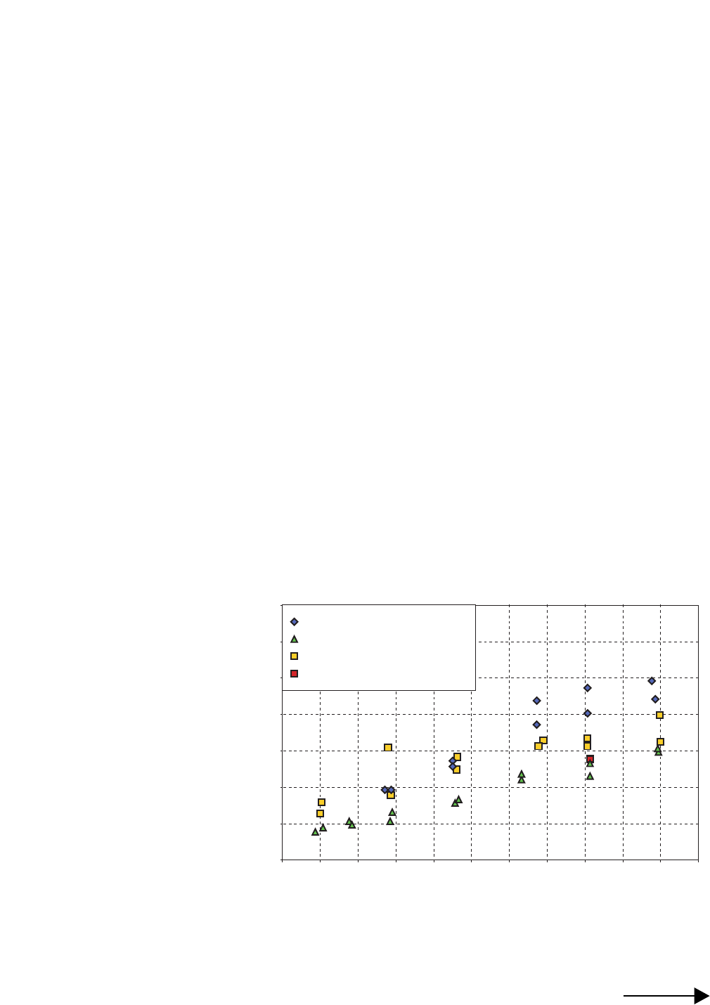
The active flux specimens gave
the lowest absorbed energy in the
WRCVN tests. A comparison of the
low heat input results is shown in
Figure 1.
The WRCVN, PQR, and certifi-
cate Charpy that the consumable
manufacturer reported results are
essentially the same for the active and
neutral fluxes. Only the weathering
consumables show a significant
difference between the WRCVN
specimens and the groove weld test
plate specimens performed for PQR
and certification testing. The heat
input had little effect on the results
from either the WRCVN or the
normal CVN test specimens.
The weathering consumable
WRCVN specimens had different
properties from standard AWS CVN
specimens. The pattern of results
from WRCVN tests was shifted
approximately 20C to 40C (35F to
70F) higher then the standard AWS
CVN specimens. The WRCVN
specimens should reflect fillet weld
properties more accurately because
they are taken from the root of what is
in essence a multiple-pass fillet weld.
If the pattern seen among the weather-
ing specimens can be extrapolated to
other consumables, then the standard
test overestimates weld toughness.
Medlock (1998) demonstrates that
standard AWS CVN test results are
not representative of production
groove welds, and typically have
higher toughness values than produc-
tion welds. Fillet welds differ even
more from the standard test weld, and
so are even less likely to be ad-
equately represented by the standard
test.
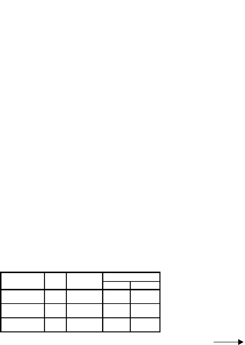
Table 1: Welding parameters
Consumable
Designation Flux Electrode Heat Inputs(kJ/in)
Low High
Neutral Flux 960 L-613/32"
wire 35.7 50.4
Active Flux 780 L-615/64"
wire 32.9 48.7
Weathering 860 LA-753/32"
wire 34.6 48.0
Project Summary Report 1501-S – 3 –
.
The Researchers
Recommend...
The results of this research
indicate that the tensile strength
requirements of the weld certification
tests are adequate to ensure the
strength of fillet welds. Based upon
these results, the weld qualification
tests presently required in AWS D1.5
are not necessary to ensure the
strength of a fillet weld. The T-bend
specimen did not provide a useful
measure of the strength or ductility of
a fillet weld. The T-weldment does
provide a simple means to evaluate
the influence of double-sided weld
upon the geometry of the weld and
melt-through of the stem. The
WRCVN specimen provides a
convenient method of characterizing
the toughness of the fillet weld root
material. The WRCVN toughness
may be comparable to or less than the
toughness measured in the standard
all-weld metal tests. The WRCVN
test is recommended as a simple
means to ensure that the fillet weld
toughness is adequate. Toughness
comparable to the base metal should
be sufficient for the root of the fillet.
The base metal is directly adjacent to
the weld metal at the root of the weld.
Consequently, a fracture will propa-
gate in either the weld or base metal,
whichever has the lowest toughness.
There is no benefit to having the weld
metal toughness significantly tougher
than the base metal. A weld root
toughness corresponding to the non-
fracture-critical base metal require-
ment for 4-inch plates in Temperature
Zone III should be adequate for all
bridges. For example, the required
toughness for Gr. 50 steel would be
20 ft-lbs at 10o F, per ASTM A 709
Table S1.2.
Based upon the results of this
study, the following recommended
changes to the specifications are
proposed:
1. The consumable supplier shall
perform the following tests
annually:
a. Two weld certification tests,
one at the highest and the other
at the lowest weld heat input
recommended by the manufac-
turer. If the fabricator stays
within these heat inputs, no
groove weld qualification
testing is required by the
fabricator. The essential
variables are those defined in
AWS D1.5-96 Section 5.12.2,
“Maximum-Minimum Heat
Input.”
b. A WRCVN test plate shall be
welded using the maximum and
minimum heat input recom-
mended. The average of three
specimens from each test weld
should be equal to or greater
than the non-fracture-critical
base metal requirement for
4-inch plates in Temperature
Zone III. For 36-ksi material,
the requirement for 50-ksi
material should be used.
2. The fabricator shall perform the
T-weldment test described below
every 5 years or whenever the
essential variables are changed.
The fillet weld T-weldment is
similar to the fillet weld soundness
test required in AWS D1.5-96
Section 5.10, with the following
exceptions.
a. The plate thickness shown in
AWS D1.5-96 Figure 5.8 shall
be the maximum rather than the
minimum plate thickness.
b. The welds shall be made at the
highest heat input in the WPS.
c. If two-sided dart welding will
be used in the production weld,
the same method should be used
for fabricating the T-weldment.
d. The spacing of the electrodes in
a two-sided weld shall be the
minimum specified in the WPS.
e. A T-weld test is required for
each weld size, or for the
minimum and maximum weld
sizes.
f. The welds are to be sectioned in
accordance with AWS D1.5-96
Section 5.10.3 and tested in
accordance with Section 5.19.3.
In addition, the maximum
penetration of each weld shall
not exceed 1/3 of the thickness
of the T-stem (dimension T2 in
AWS D1.5-96 Figure 5.8).
140
120
100
80
60
40
20
0
-60 -40 -20 0 20 40 60 80 100 120 140 160
Temperature (F)
Weathering, 34.6 jK/in heat input
Active Flux, 34.0 jK/in heat input
Neutral Flux, 35.6 jK/in heat input
Unusual Break
Toughness (ft-lb)
Figure 1: WRCVN Test Results

Project Summary Report 1501-S – 4 –
The University of Texas at Austin
Center for Transportion Research
3208 Red River, Suite #200
Austin, TX 78705-2650
Disclaimer
Research Supervisor: Karl H. Frank, P.E., (512) 471-4590
email: kfrank@uts.cc.utexas.edu
TxDOT Project Director: Ronnie Medlock, P.E., (512) 416-2456
email: rmedloc@dot.state.tx.us
The research is documented in the following report:
1501-1 Evaluation of Fillet Weld Qualification Requirements, October 1999.
To obtain copies of a report: CTR Library, Center for Transportation Research,
(512) 232-3138, email: ctrlib@uts.cc.utexas.edu
The results from this research will be formally presented to the AASHTO/AWS committee that writes the
AASHTO/AWS D1.5 Bridge Welding Code. This Code governs bridge welding in the US and includes require-
ments for qualification of fillet welding procedures. Dr. Karl Frank has already made a preliminary presentation to
the committee, and the committee has been provided with copies of the research results. It is expected that the
results from this research effort will be adopted to facilitate improvement of the way fillet welding procedures are
covered under this Code.
For more information please contact Tom Yarbrough, P.E., RTI Research Engineer, at (512) 465-7685 or email at
tyarbro@dot.state.tx.us.
This research was performed in cooperation with the Texas Department of Transportation and the U. S.
Department of Transportation, Federal Highway Administration. The content of this report reflects the views of
the authors, who are responsible for the facts and accuracy of the data presented herein. The contents do not
necessarily reflect the official view or policies of the FHWA or TxDOT. This report does not constitute a
standard, specification, or regulation, nor is it intended for construction, bidding, or permit purposes. Trade
names were used solely for information and not for product endorsement. The engineer in charge was Karl H.
Frank, P.E. (Texas No. 48953).
Your Involvement Is Welcome!
For More Details...
TxDOT Implementation Status
January 2002
The University of Texas at Austin
Center for
Transportation Research
