Dell PowerVault MD Series VCenter Plug In For VMware VSphere Installation And Configuration Guide (Web Client) 1507993835powervault Md3200 User's Guide11 En Us
User Manual: DELL POWERVAULT MD3860F pdf | FreeUserManuals.com
Open the PDF directly: View PDF ![]() .
.
Page Count: 83
- Dell PowerVault MD Series vCenter Plug-in for VMware vSphere Installation and Configuration Guide (Web Client)
- Overview of the Modular Disk Storage Manager Plug-in for VMware vCenter Web Client
- Installing the MD vCenter Plug-in for VMware vCenter web client
- Configuring the application server and plug‑in
- Configuring VMware ESXi hosts
- MD vCenter Plug-in manager
- Storage Arrays Objects view
- Selected Storage Array Summary tab
- Selected storage array Manage tab
- MD storage Manager Datastore Summary information
- Best practices
- Appendices

Dell PowerVault MD Series vCenter Plug-in
for VMware vSphere Installation and
Configuration Guide (Web Client)

Notes, cautions, and warnings
NOTE: A NOTE indicates important information that helps you make better use of your computer.
CAUTION: A CAUTION indicates either potential damage to hardware or loss of data and tells you
how to avoid the problem.
WARNING: A WARNING indicates a potential for property damage, personal injury, or death.
Copyright © 2015 Dell Inc. All rights reserved. This product is protected by U.S. and international copyright and
intellectual property laws. Dell™ and the Dell logo are trademarks of Dell Inc. in the United States and/or other
jurisdictions. All other marks and names mentioned herein may be trademarks of their respective companies.
2015 - 09
Rev. A01
Contents
1 Overview of the Modular Disk Storage Manager Plug-in for VMware
vCenter Web Client..................................................................................................7
MD vCenter Plug-in features................................................................................................................ 8
Installation prerequisites....................................................................................................................... 8
2 Installing the MD vCenter Plug-in for VMware vCenter web client............9
Downloading the MD vCenter Plug-in for VMware vCenter.............................................................. 9
Installing the application server............................................................................................................ 9
Upgrading from previous versions........................................................................................................9
Installing the MD vCenter Plug-in...................................................................................................... 10
3 Configuring the application server and plug‑in ...........................................12
Configuring application server memory.............................................................................................12
Configuring storage administrator roles.............................................................................................13
Creating a role............................................................................................................................... 13
Adding a user ID to a role..............................................................................................................15
No access.......................................................................................................................................16
MD vCenter Plug-in security...............................................................................................................16
Mozilla firefox.................................................................................................................................17
Google Chrome............................................................................................................................. 17
Microsoft Internet Explorer........................................................................................................... 18
Application server certificate management....................................................................................... 19
Import signed application server certificate.................................................................................19
Register vCenter server to application server..............................................................................20
Import - export configuration file...................................................................................................... 20
Export............................................................................................................................................. 21
Import.............................................................................................................................................21
Application server user management.................................................................................................21
4 Configuring VMware ESXi hosts...................................................................... 23
Configuring ALUA SUPPORT.............................................................................................................. 23
Adding ALUA SATP claim rule....................................................................................................... 23
Configuring iSCSI storage...................................................................................................................24
Additional information.................................................................................................................. 25
Configuring SAS support on ESXi hosts............................................................................................. 25
Upgrading the SAS SMI-S provider............................................................................................... 25
Enabling root login from a console login on ESXi hosts............................................................. 26
Creating a new user login.............................................................................................................26
3
Installing the SAS provider upgrade of ESXi ................................................................................ 26
Configuring ESXi hosts to Storage Arrays.......................................................................................... 26
Configure ESXi Host to Storage Array wizard...............................................................................27
5 MD vCenter Plug-in manager...........................................................................31
MD vCenter Plug-in features.............................................................................................................. 31
6 Storage Arrays Objects view.............................................................................33
Storage Arrays Objects view............................................................................................................... 33
Add Storage Array............................................................................................................................... 34
Discover Storage Arrays......................................................................................................................34
Collect Support Bundle.......................................................................................................................35
Edit Storage Array................................................................................................................................36
Remove Storage Arrays.......................................................................................................................36
Saving the storage array configuration.............................................................................................. 37
Enabling automatic save configuration backups.........................................................................38
Manually Save Configuration........................................................................................................38
View Event Log....................................................................................................................................39
7 Selected Storage Array Summary tab............................................................. 40
Summary view general information...................................................................................................40
Recovery Guru information................................................................................................................ 41
8 Selected storage array Manage tab.................................................................43
Virtual Disks view features ................................................................................................................. 43
Create Disk Group.........................................................................................................................44
Create Disk Pool............................................................................................................................45
Create Virtual Disks....................................................................................................................... 45
Legacy Snapshots..........................................................................................................................47
Redistribute Virtual Disk................................................................................................................48
Rename..........................................................................................................................................49
Disable Data Assurance.................................................................................................................49
Delete............................................................................................................................................ 49
Delete Multiple Virtual Disks......................................................................................................... 49
Mappings view features...................................................................................................................... 50
Add Mapping..................................................................................................................................51
Rescan Storage Adapters.............................................................................................................. 52
Add Host........................................................................................................................................ 53
Add Host Group.............................................................................................................................54
Rename..........................................................................................................................................55
Remove..........................................................................................................................................55
Virtual Disk Copy view features.......................................................................................................... 55
4
Create Virtual Disk Copy...............................................................................................................56
Stop Virtual Disk Copy.................................................................................................................. 58
Recopy...........................................................................................................................................58
Change Settings............................................................................................................................ 58
Remove Copy Pair.........................................................................................................................59
Snapshots view features..................................................................................................................... 59
Create Snapshot Group................................................................................................................ 60
Create Snapshot Image.................................................................................................................61
Create Snapshot Virtual Disk........................................................................................................ 62
Delete.............................................................................................................................................63
Remote Replication view features......................................................................................................64
Asynchronous remote replication (legacy) details.......................................................................65
Create Replication Group............................................................................................................. 66
Create Asynchronous Remote Replication Pair...........................................................................66
Suspend Replication......................................................................................................................67
Resume Replication...................................................................................................................... 68
Manual resync .............................................................................................................................. 68
Test Replication Communication.................................................................................................68
Change Roles................................................................................................................................ 69
Delete Replication Group............................................................................................................. 70
Remote Replication Group........................................................................................................... 70
Remote Replication (Legacy) view features.......................................................................................70
Create Remote Replication (legacy)..............................................................................................71
Suspend remote replication (legacy)............................................................................................72
Resume remote replication (legacy).............................................................................................72
Change Replication Settings.........................................................................................................73
Change Replicated Roles.............................................................................................................. 73
Test Replicated Communication.................................................................................................. 73
Remove Replicated Pairs...............................................................................................................74
9 MD storage Manager Datastore Summary information.............................. 75
10 Best practices.................................................................................................... 77
Defining virtual disks for vsphere........................................................................................................77
Virtual disk decision-making schemes............................................................................................... 77
Using the predictive scheme to make virtual disk decisions....................................................... 77
Using the adaptive scheme to make virtual disk decisions......................................................... 78
VMware ESXi host fibre channel configuration..................................................................................78
11 Appendices.........................................................................................................82
Current restrictions............................................................................................................................. 82
ID: 200627833 – multiple item delete restricted to less than 80 objects..................................82
5
ID: 200702748 – ESXi host to storage array wizard usability issues...........................................82
ID: 200716368 – vSphere 6.0 SAS datastore view...................................................................... 82
Configuration worksheet....................................................................................................................82
6

1
Overview of the Modular Disk Storage
Manager Plug-in for VMware vCenter
Web Client
The Dell PowerVault Modular Disk Storage Array vCenter Plug-in (MD vCenter Plug-in) is a VMware
vCenter Server Plug-in that provides integrated management of Dell MD Storage Arrays from in a VMware
Web Client session. The Web Client is a single management interface that you can use to manage the
VMware infrastructure and all of your day-to-day storage requirements. Instead of learning another
management application, you can focus on the entire virtual infrastructure.
Unless otherwise noted, later references to "MD Storage Array vCenter Plug-in" or "MD vCenter Plug-in"
in this document are used interchangeably to represent the MD VMware vCenter Plug-in.
NOTE: The MD vCenter Plug-in is not a direct replacement for the MD Storage Manager software,
which is still required for performing certain storage administration tasks.
The MD vCenter Plug-in enables you to perform the following tasks:
• Configure ESXi hosts to MD storage arrays.
• Create and delete virtual disks.
• Map virtual disks from the MD storage arrays to the ESXi host.
• View the vCenter Datastores available to MD Storage Arrays virtual disks.
You can create hardware snapshots, virtual disk copies, synchronous, and remote replication when these
premium features are enabled on the storage array. The MD vCenter Plug-in uses an application server to
facilitate the interface between the Web Client and the MD Storage arrays are based on the authenticated
logged-in user and the privileges assigned to that user's role.
The MD vCenter Plug-in requires that a VMware vCenter server is installed in the environment. The MD
vCenter Plug-in does not function in a configuration with only a Web Client and an ESXi host
configuration.
7
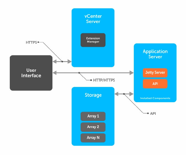
Figure 1. Communication details
MD vCenter Plug-in features
The following MD vCenter Plug-in features enable the integrated management of MD storage arrays:
• Storage array information
• Storage array organization
• Automatic and manual storage array configuration backup
• Storage provisioning and virtual disk mapping
• Copy services management
• Remote Replication (Legacy)
• Asynchronous Remove Replication
• Datastores to virtual disk details
• ESXi host configuration
Installation prerequisites
To install and use the MD vCenter Plug-in, see the latest Support Matrix available at Dell.com/support for
information about the prerequisites.
8

2
Installing the MD vCenter Plug-in for
VMware vCenter web client
Downloading the MD vCenter Plug-in for VMware
vCenter
Download the latest version of the MD vCenter Plug-in from the Dell website. See the support matrix
available at the Dell website for the most current web client versions. Copy the file to the host that you
are going to use as an application server.
NOTE: After downloading the Linux binary, add the execute attribute to the binary file to enable
execution of the installer (chmod +x vCenterInstaller-xx.xx.xxxx.xxxx.bin).
Installing the application server
Install the application server on a different Windows server than the VMware vCenter Server is installed
on.
NOTE: When adequate resources are available on the VMware vCenter Server system, you can
install the application server on the same host that the VMware vCenter Server is installed on, but
this is not recommended.
After you have downloaded the MD vCenter Plug-in software, copy the file to the system that is the
application server. Run the MD vCenter Plug-in installer to open the installation wizard. The installation
wizard installs an application server and the associated .jar files. After the installation is complete, the
installation wizard registers the MD vCenter Plug-in with the VMware vCenter Server.
Upgrading from previous versions
If upgrading from a previous version of the MD vCenter Plug-in and you want to use the same host for
the application server, copy the new installation file to the existing application server, and then run the
installer executable. This process automatically upgrades the previous MD vCenter Plug-in version to this
release.
NOTE: This version of the MD vCenter Plug-in supports only the VMware Web Client and does not
function with the VMware vSphere Client. If you still use the vSphere Client, you must use the
previous version of the MD vCenter Plug-in, release 2.7, to manage MD Storage Arrays in the
vSphere Client.
During the installation process, you must provide information about the system components, such as the
storage array names, the IP addresses, and the DNS names that are used during the installation. Table 1
9

shows the information required for each component. See Configuration worksheet for a printable
worksheet.
Table 1. Configuration worksheet example
Example Information Required Information Example Information
vCenter Server Name: VC-01 DNS name:IP Address: vc-01.domain.com192.1
68.51.217
vCenter Administrator
Name:
administrator Password: Password
Application Server
Name:
APP-01 DNS name:IP Address: app-01.domain.com192.
168.51.225
Storage Array 1 Name: E5400 IP Addresses: Password: 192.168.51.89/90None
Storage Array 2 Name: E2600 IP Addresses: Password: 192.168.51.91/92None
Storage Array 3 Name: IP Addresses: Password:
Storage Administrator
User ID:
User1 The user’s level of
storage administrator
rights (See figure for
examples)
Read-Only
Storage Administrator
User ID:
User2 The user’s level of
storage administrator
rights (See figure for
examples)
Read-Write
Installing the MD vCenter Plug-in
Open the MD Storage Manager MD vCenter Plug-in for VMware vCenter installer binary file on the target
host system that will be used as the application server.
1. Read the introduction screen, and then click Next.
2. Read the license agreement, accept the terms, and then click Next.
3. Select the local installation directory for the MD vCenter Plug-in manager or click Next for the
default.
4. Review the installation details and then click Install if the details are correct.
5. Change the port number of the application server or accept the default number of either 8084 or
8081, and then click Next.
NOTE: If the MD vCenter Plug-in is installed on the same system as an active vCenter Server,
and VMware Update Manager is also installed, the default port number 8084 for the plug-in
must be changed to an unused port number.
6. Change the IP address of the application server when necessary. The IP address that is displayed by
default is the IP address of the system the installer is running on. Click Next.
7. When you are asked to enter the IP address of the vCenter server on which you want to install MD
vCenter Plug-in, type the IP address of the vCetner server, and then click Next.
8. Enter the administrator's email address for alerts, and then click Next.
9. Enter the vCenter administrator's user ID, and then click Next.
10

NOTE: If the Plug-in will be installed into a vSphere 5.5 or 6.0 environment with Single Sign-on
(SSO), you must change the default user ID have to match the vSphere 5.5 or 6.0 or later
domain configuration (For example, administrator@ vsphere.local).
10. Enter the vCenter administrator's password, and then click Next.
11. The installation is now completed. Click Done to close the installation wizard.
12. Windows: To ensure that the application server was installed successfully, run the services.msc
command, and verify that the Application Server service was installed and the service started.
13. Linux: To ensure that the application server is started, run service Application-Server-vCP status.
root@ictm-linux-01:/# service Application-Server-vCP status Application-
Server-vCP process is running *root@ictm-linux-01:/#
11
3
Configuring the application server and
plug‑in
After the application server and the MD vCenter Plug-in are installed, verify that the MD vCenter Plug-in
was successfully registered with the vCenter server.
1. Open the vSphere Client to the vCenter Server.
2. On the menu, select Plug-ins → Manage Plug-ins.
The MD vCenter Plug-in for VMware vCenter is displayed as Enabled.
If the MD vCenter Plug-in is listed as disabled with an error message stating that it cannot communicate
with the application server, ensure that the port number defined for the application server is enabled to
pass through any firewalls that might be in use. The default application server Transmission Control
Protocol (TCP) port numbers are 8084 and 8081.
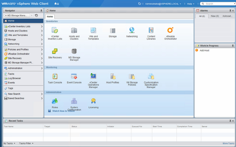
After the application server and VMware vCenter Server are configured, the MD vCenter Plug-in icon
appears in the Solution and Application section of the vSphere Web Client home page.
Configuring application server memory
If more than 250 storage arrays are managed from the MD vCenter Plug-in, you must modify the
application server configuration file. By default, the application server is configured for 1024 MB of RAM
usage. To adjust the settings to support more than 250 arrays, modify the appserver64.ini file located
on the application server in the C:\Program Files\Dell\MD Storage Manager Plug-in for
VMware vCenter\jetty directory.
1. Open the appserver64.ini file in a text editor.
12
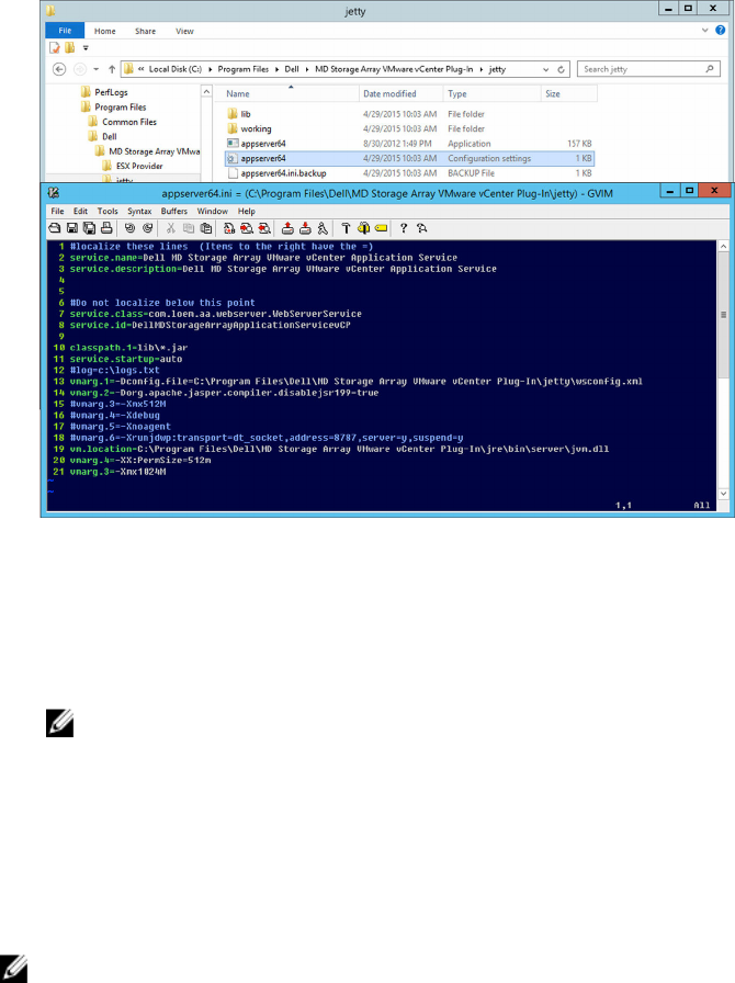
Figure 2. Application server memory settings
2. Locate the vmarg.3=-Xmx1024M line.
3. Change 1024 to the number associated with the number of storage arrays.
4. Save the configuration file.
5. Restart the Application Server (vCP) service.
NOTE: If the application server is reinstalled, this setting is reverted to the original setting of
1024 MB. You must edit it again to adjust the application server memory for your environment.
Configuring storage administrator roles
By default, all defined VMware vCenter user IDs have no user rights to MD storage arrays. When a user
requires either read permissions or read-write permissions to access the MD vCenter Plug-in, you must
modify the user’s role to give user rights access to the MD vCenter Plug-in.
NOTE: If attempting to access the client and you encounter a Not Authorized message, you must
restart the vSphere Client after defining the new Storage Administrator role before access is
provided. Only privileges are granted.
Creating a role
1. In the Administration area on the vSphere Client Home page, click the Roles icon.
The list of roles and usages is displayed.
13
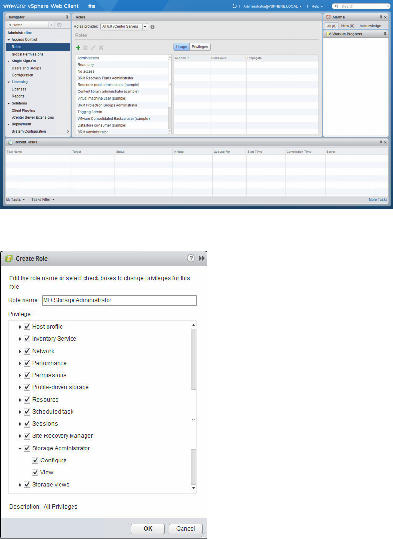
Figure 3. vCenter server roles list
2. Click the green-color plus icon (+) to add a new role.
Figure 4. Create role window
3. In the Role box, type the name of the new role.
4. In the Privileges list, select the access permissions to assign to this role.
14
NOTE: The administrator role is not editable; therefore, if the administrator user is to manage
storage, you must create a new role that has all of the privileges added to it. You must add the
administrator to this role by using the following procedure.
5. To allow Read-Only (View) or Read-Write (Configure) access permissions to the storage arrays,
select the appropriate permission from the Storage Administrator group.
6. Click OK.
NOTE: You can modify existing roles to include the storage administrator privileges, except for
the Administrator role, which you cannot modify.
Adding a user ID to a role
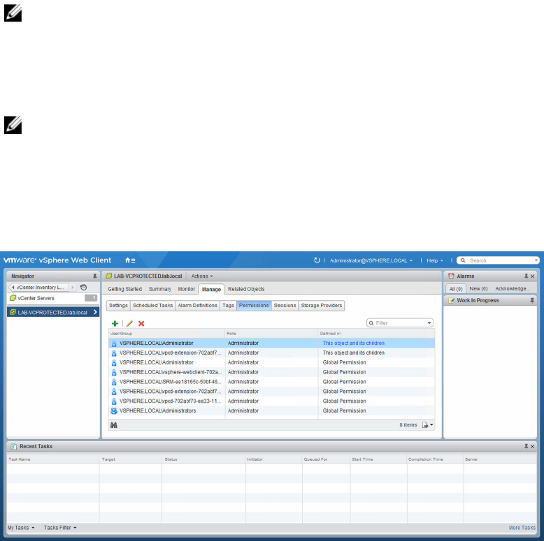
1. Click the VMware Home icon, select vCenter Inventory List, and then click vCenter Servers under
Resources Lists.
2. Select the vCenter server element to manage, and then select the Manage tab.
Figure 5. Add permission
3. Click the green plus icon to define the users who are members of the Role.
15
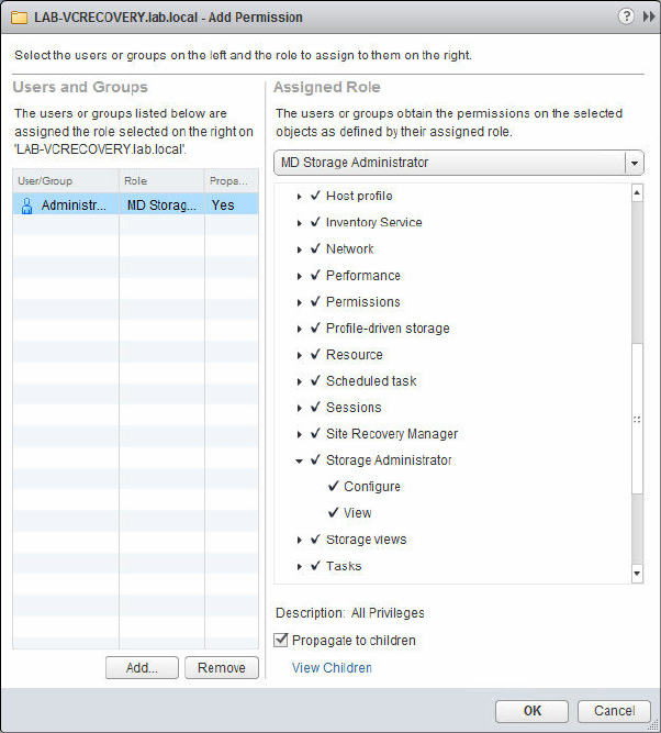
Figure 6. Add permission wizard
4. In the wizard, click Add, and select the User IDs that requires access to the storage arrays.
5. Select the assigned role from the drop-down menu, and then click OK to apply changes.
6. Click OK to apply permissions to the role.
No access
If you are not member of a role that has either the View or Configure MD Storage Administrator
permission, you cannot view any statistics from the MD vCenter Plug-in. If you attempt to access a MD
vCenter Plug-in feature, you receive the User is not authorized to use this plug-in message.
MD vCenter Plug-in security
The MD vCenter Plug-in uses TLS 1.2 for secure HTTPS communication between the Web Client and MD
Storage Manager application server, which necessitates the need for SSL certificate management to
establish communication between the client and the application server. The client browser used to
communicate with the Web Client dictates the needed procedures to establish communication with the
application server. If your environment uses trusted CA-signed SSL certificates, after the application
server certificate is signed and reimported, the following procedures are not needed.
16
Mozilla firefox
For Mozilla Firefox, you can currently accept the self-signed SSL certificate by using the Getting Started
pages and permanently store the certificate in Firefox’s truststore, which is remembered for future
connections between the Web Client and the application server.
Google Chrome
For Google Chrome,
1. Enter the URL for the vCenter Server to connect, and then select the Advanced option.
2. Click Proceed to advance to the VMware vCenter Server link, and then proceed to log in to the
vCenter Server as normal.
3. Click the MD vCenter Plug-in icon from the home page, and then select the How to configure
browser security link in the Getting Started tab.
4. Follow the procedures documented on the SSL Certificate Setup page to establish communication
to the application server. After communication has been established, the MD vCenter Plug-in should
function as normal.
17
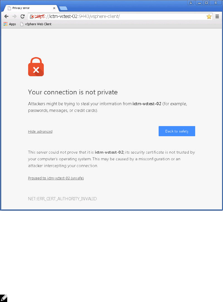
Figure 7. Chrome security page
Microsoft Internet Explorer
For Internet Explorer,
1. Enter the URL for the vCenter Server to connect to, and then click the Continue to this website (not
recommended) link. You may also have to install the vCenter Server SSL certificate to establish
connection.
2. After connected to the vCenter Server, click the MD vCenter Plug-in icon from the home page, and
then click the How to configure browser security link and follow the procedures on the SSL
Certificate Setup page.
NOTE: After communication has been established with the application server, it may take a couple
of minutes for the Summary tab information to display.
18
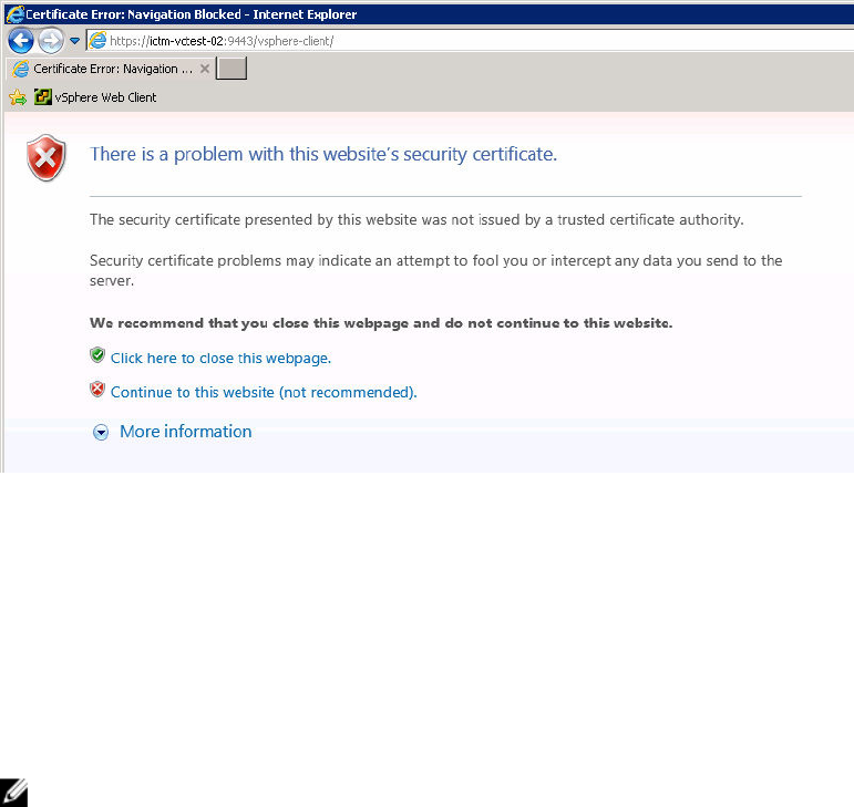
Figure 8. Internet Explorer certificate error page
Application server certificate management
To resolve the self-signed certificate errors with latest browsers, you must have the application server
certificate signed by a trusted Certification Authority (CA). During the installation of the MD vCenter Plug-
in, an SSL certificate was generated for the application server along with a certificate signing request
(CSR) that is specific to that application server. A trusted CA must sign the CSR and then reimported into
the Java keystore to implement a fully trusted certificate chain. The following steps describe the process
of importing the application server certificate after it is signed by a trusted CA.
NOTE: The CSR is typically located on the application server host directory C:\Program Files\MD
Storage Manager\ MD Storage Manager Plug-in for VMware vCenter\jetty
\working. The file is named <host_name>.csr. After the CSR has been signed by a trusted CA, copy
the signed certificate and the CA certificate to the same directory.
Import signed application server certificate
On the application server host system, start a command line interface (CLI) or terminal.
1. Change directory to C:\Program Files\Dell\MD Storage Manager Plug-in for VMware
vCenter\jetty\working directory
It is assumed that both the signed certificate and the CA certificate are copied to the working
directory.
2. Import the CA certificate into the Java keystore (if not already in trustedcacerts keystore) by running
the following at the command line interface (CLI): ..\..\jre\bin\keytool -import -
trustcacerts -alias root -file <ca_cert> -keystore keystore -storepass
changeit
3. Import the signed application server certificate into the Java keystore with the following at the
CLI: ..\..\jre\bin\keytool -import -trustcacerts -alias jetty -file
<signed_cert> -keystore keystore -storepass changeit
4. Restart the MD Storage Manager Application Server (vCP) service and allow a minute or two for the
service to initialize.
19
5. Ensure that the certificate is working by accessing the following URL (Assumed default port number
for https connection.): https://<application_server_address>:8084/vcenter2/
About.html
NOTE: Mozilla Firefox users also need to ensure the CA certificate has been imported into the
browser’s authorities’ truststore (Options → Advanced → Certificates → View
CertificatesAuthorities).
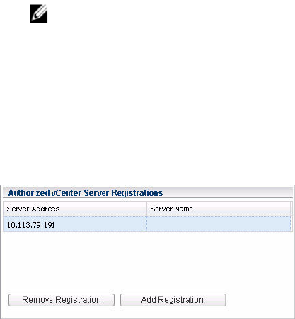
Register vCenter server to application server
If the jetty SSL certificate is recreated, you must register the vCenter Server with the application server to
detect the new certificate ID. To reregister the vCenter Server, navigate to the MD vCenter Plug-in
Getting Started page, click the Manage vCenter Server Access link, and log in to the Manage vCenter
Server Access page.
Figure 9. Authorized vCenter server registrations dialog box
1. Select the vCenter Server IP address of the vCenter Server to reconfigure.
2. Click the Remove Registration button to remove the old registration.
3. Click the Add Registration button and enter the vCenter Server Address, DNS Name, User ID, and
Password.
4. Click the Add button.
Import - export configuration file
The MD vCenter Plug-in supports the ability to import or export the storage array manager configuration
file that maintains the list of configured storage arrays and metadata information. This feature is useful for
backing up array configurations or deployment of new application server by using an existing
configuration file. To access this functionality, navigate to the MD vCenter Plug-in Getting Started page
and click the Manage Arraydata.xml Data link. Follow the procedures documented on the Manage
Arraydata.xml File page to log in to the application server.
After you log in to the application server, the Import or Export a Configuration File page is displayed.
20
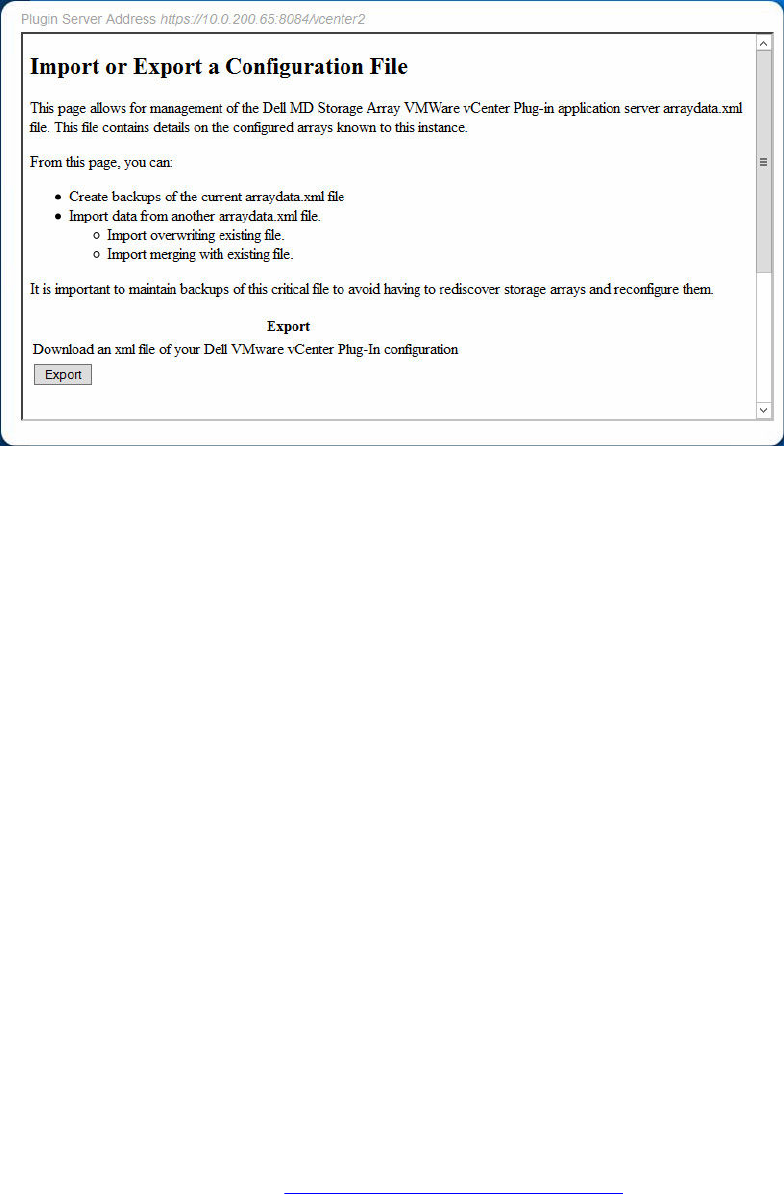
Figure 10. Import or export a configuration file page
Export
To export the current configuration file, click the Export button and select the location to which to save
the file.
Import
To import a previously saved configuration file, perform the following task:
1. Click the Browse button.
2. Navigate to the configuration file to import and click Open.
3. Select the import option button to use (Merge or Overwrite).
4. Click the Import button.
Application server user management
The application server user management is controlled using the users.properties file located in C:
\Program Files\MD Storage Manager\MD Storage Manager Plug-in for VMware vCenter
\jetty\working\config directory.
The format of the users.properties file is ID name, MD5 password hash, user ID.
# #Thu Apr 11 18:02:33 PDT 2013 admin=MD5\:
21232f297a57a5a743894a0e4a801fc3,admin ro=MD5\:
3605c251087b88216c9bca890e07ad9c,storage.ro #rw=MD5\:
038c0dc8a958ffea17af047244fb6960,storage.rw vcenter=MD5\:
736849783cb137f97c4e535c246afd4b,storage.rw
Dell does not recommend that you store your passwords in clear text. A MD5 password hash may be
generated from the following site: http://md5hashgenerator.com/index.php. Enter the password to be
21

hashed in the String box, and then click Generate MD5 Hash. Copy the hashed results to the
users.properties file in place of the existing user password hash (#).
Alternatively, you may use md5sum on a UNIX system to generate the MD5 has by using the following
(substitute your password for YOUR_PASSWORD_HERE):
$ echo -n "YOUR_PASSWORD_HERE" | md5sum | awk '{print $1}'
635893277b6b217e327565d3427ee5e8
Copy and replace the MD5 hash, in the users.properties file for the specific user, with the output of
the above command.
NOTE: You must specify the ‘-n’ option to avoid passing carriage return from echo to md5sum
utility.
22
4
Configuring VMware ESXi hosts
Configuring ALUA SUPPORT
Firmware versions 7.84 and later allows for support of an Asymmetric Logical Unit Access (ALUA)
configuration when the Target Port Group Support (TPGS) flag is set to ‘on’ (default for 7.84). This support
allows for active-active I/O throughput between all paths to the current owning RAID controller module
and LUN transfer to the alternate RAID controller module in failure scenarios. On the basis of your
environment, you may be able to achieve higher performance by switching the default multipath policy
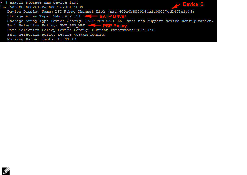
from MRU to Round Robin (RR). This performance is accomplished by performing the following task:
1. Identify current SATP claim rule in use for your storage.
Figure 11. esxcli storage nmp device list
2. Identify default PSP rule for SATP in use.
(Optional) Change default PSP rule to VMware RR.
Adding ALUA SATP claim rule
1. To create a new claim rule, enter the following at the CLI:
#esxcli storage nmp satp rule add -s VMW_SATP_ALUA -V LSI -M INF-01-00 -c
tpgs_on -P VMW_PSP_RR -e “LSI ALUA Claim Rule”
This command creates a new claim rule for the VMW_SATP_ALUA satp rule to claim any LUNs
matching the following:
Vendor ID = LSI
Model ID = INF-01-00
TPGS Flag = on
2. Assign the default path selection policy to round robin (VMW_PSP_RR).
NOTE: There are different methods to manage SATP claim rules; and your environment may
require different parameters to enable ALUA support. Consult the VMware Knowledge Base for
additional information.
23
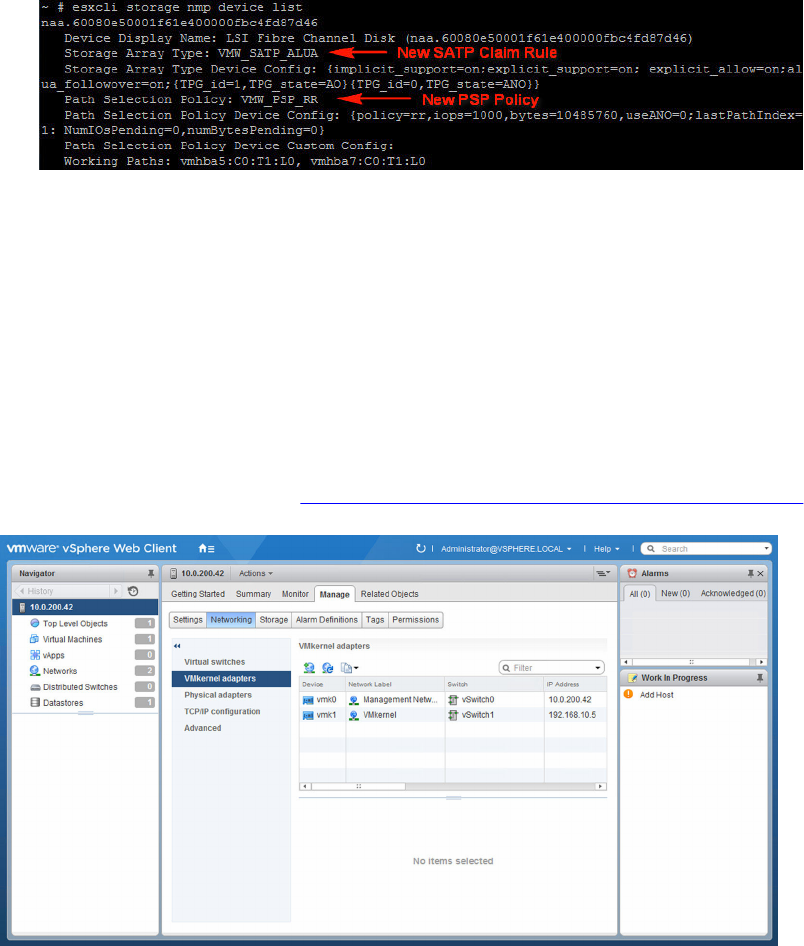
Figure 12. ALUA configured storage
Configuring iSCSI storage
To configure the network for software iSCSI storage, create an iSCSI VM kernel port, and map it to a
physical network interface card (NIC) that handles iSCSI traffic. On the basis of number of physical NICs
that you use for iSCSI network traffic, the networking setup can be different.
To configure iSCSI adapters with this wizard, iSCSI HBAs must already be defined in vSphere. This task is
accomplished by configuring an iSCSI network and adding iSCSI software initiator under storage
adapters.
To configure iSCSI storage, read the VMware Best Practices for Running VMware vSphere on iSCSI or
search for videos on implementing iSCSI with vSphere.
Figure 13. Networking configuration view
1. Add a VMkernel network for iSCSI communication.
2. Select NICs to use for iSCSI and configure.
3. In the Storage Adapters view, click Add, and then select Add Software iSCSI Adapter.
24
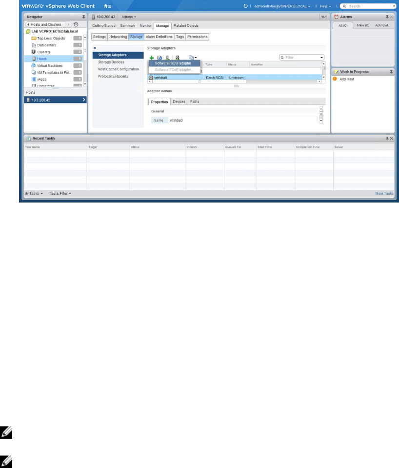
Figure 14. Add software iSCSI adapter
Additional information
For more information about network configuration for software iSCSI storage, refer to the following
sections in the iSCSI SAN Configuration Guide in the VMware vSphere Online Library:
• Configuring iSCSI Initiators and Storage
• Setting Up Software iSCSI Initiators
• Networking Configuration for Software iSCSI Storage
Configuring SAS support on ESXi hosts
For the MD vCenter Plug-in to configure ESXi hosts to the MD storage arrays, with SAS connections, an
updated version of the LSI SAS SMI-S provider must be installed on the ESXi hosts.
Upgrading the SAS SMI-S provider
NOTE: SAS support is available only for ESXi version 5.1 and later host versions. Previous versions of
ESX and ESXi are not supported.
NOTE: This upgrade is required only to allow the Host to Storage Configuration option to configure
SAS connected storage arrays. When the storage arrays are already configured, or the storage arrays
are not SAS-connected, you do not need to upgrade the in-box provider.
To use the SAS provider, you must first deploy it on the ESXi servers to be configured. This deployment
requires that either Secure File Transfer Protocol (SFTP) or Secure Copy (SCP) is enabled on the ESXi host.
To install the SAS SMI-S Provider upgrade package, you must have root access. To install the package by
remote login, either create a new user with host login privileges, or enable remote logins for the root
user.
25

Enabling root login from a console login on ESXi hosts
1. Press F2 to switch to the diagnostic console.
2. Select Troubleshooting Options.
3. Select Enable Remote Tech Support.
4. Select Restart Management Agents.
5. Press Esc to close the Configuration menu.
Creating a new user login
1. Connect the Web Client directly to the ESXi host to be configured.
2. Select the User & Groups tab in the Home → Inventory → Inventory window.
3. Right-click, and then click Add.
4. Type or select the relevant information for the new user, and ensure to select Grant shell access to
this user.
5. Click OK to save changes.
6. After logging in as this new user, use the su command to assume the ‘super user’ role.
Installing the SAS provider upgrade of ESXi
1. Use scp (or a utility like FileZilla) to copy the vmware-esx-provider-lsiprovider.vib file to the
target ESXi host.
2. Log in to the ESXi server as root.
NOTE: If root is not enabled, enable it temporarily for this install.
3. Run esxcli software vib install -v /tmp/vmware-esx-provider-lsiprovider.vib all on
same line (This step assumes the .vib file is located in the /tmp directory.
The following message appears:
~ # esxcli software vib install -v /tmp/vmware-esx-provider-lsiprovider.vib
Installation Result Message: The update completed successfully, but the
system needs to be rebooted for the changes to be effective. Reboot
Required: true VIBs Installed: LSI_bootbank_lsiprovider_500.04.V0.54-0004
VIBs Removed: VIBs Skipped:Reboot the host after stopping any running VMs.
4. After the host reboots, run esxcli software vib list |grep LSI to ensure that the update was applied.
~ # esxcli software vib list |grep LSI lsiprovider 500.04.V0.54-0004 LSI
VMwareAccepted 2015-02-05
Configuring ESXi hosts to Storage Arrays
NOTE: Before configuring ESXi hosts to storage arrays, you must already have added or discovered
storage arrays in your environment. For more information, see Add Storage Array and Discover
Storage Arrays.
To use the Automatic Host Configuration utility, go to Hosts in the Web Client, and select the ESXi host
that you want to configure. Right-click the ESXi host, and select Configure ESXi host to Storage Array
from the drop-down menu under All MD vCenter Plug-in.
26
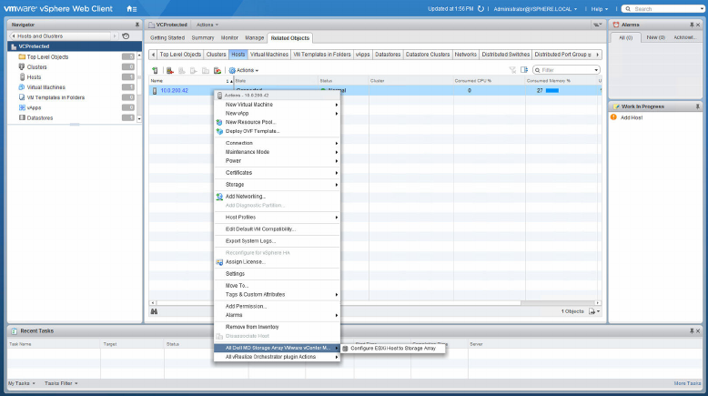
Figure 15. Configure ESXi host to storage array configuration wizard menu
The Configure ESXi host to Storage Array wizard is displayed. From this wizard, you can see how the
current ESXi host is configured to the storage array (if it is already configured). You can also add a host or
host group, rename a host or host group, remove a host or host group, and automatically configure the
ESXi host to another storage array.
Configure ESXi Host to Storage Array wizard
The wizard guides you through the process of configuring the HBAs on the selected ESXi host to the
storage arrays configured in the Array Manager. The wizard also provides information required to detect
and configure SAS HBAs in the ESXi hosts.
27
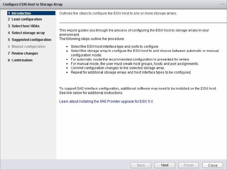
Figure 16. Configure ESXi Host to Storage Array wizard
1. Click Next after reading through the Introduction page.
The Inspect Configuration page is then initiated which verifies user privileges, gathers information
about the selected ESXi host, and gathers information on the configured storage arrays. This process
may take a few minutes depending on the number of HBAs, and storage arrays configured in the
system.
2. Click Next after all three discovery processess complete and three green check marks are displayed.
The Select Host HBAs page allows for selection of the HBAs that you want to configure from the
ESXi host. Select the option button next to the interface type to be configured. Select all of the HBA
ports that will be configured for the target storage array.
3. Click Next after selecting the HBA you want to configure.
The Select Storage Array page is displayed.
4. Select the storage array that will be used by the ESXi host being configured. Click Next after
selection.
The Suggested Configuration page is displayed showing the recommended HBA port configuration,
host configuration, and host group configuration. The suggested changes are displayed in blue italics
font.
5. To accept the suggest configuration, click Next; or, to manually configure the ESXi host, select the
Use manual configuration option, and then click Next.
a. If the manual configuration option is selected, the Manual Configuration page is displayed.
b. If the ESXi host will be participating in a cluster configuration with other ESXi hosts, and no
existing host group exists for the cluster configuration, select the storage array name and click
the Add Host Group button. Enter the name for the new host group, and then click OK.
28
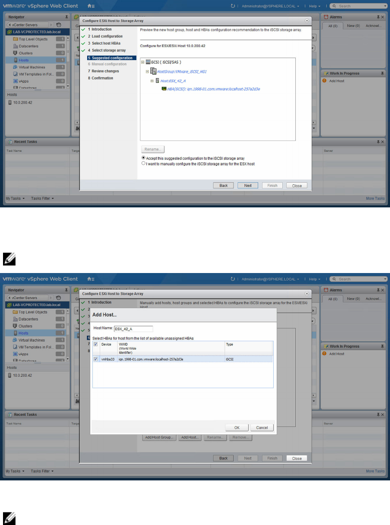
c. If the host group for the cluster already exists, select the host group name to add this host to.
Click Add Host button and enter the name for this ESXi host and select the check boxes next to
the HBAs to be used for the host definition.
Figure 17. Suggested ESXi host configuration
6. Select Next after completing manual configuration.
NOTE: Additional host configurations in a different host group from the previously defined host.
Figure 18. Manual add host dialog box
NOTE: The Configure ESXi Host to Storage Array wizard does not detect how the switch fabric
is zoned and suggested configurations are based on how the HBA ports are detected. The
suggested configuration may require the FC fabric to be rezoned based on the environment’s
cabling.
29
You cannot rename or remove existing configured hosts or host groups. Existing host and host
group configuration changes must be performed from the MD storage management software. Click
Next after all host groups and hosts have been defined.
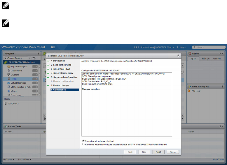
7. The Review Changes page is then displayed showing the changes that are applied to the storage
array. If you accept the changes, click the Next button.
8. A real-time summary page is then displayed showing the status of the changes being applied to the
selected storage array. After the changes have been applied, click the Re run button to repeat the
configuration process on another storage array or click Close to close the configuration wizard. You
must manually close the progress window after the changes are complete.
NOTE: To use multiple host groups as described, the storage array must have the Storage
Partitioning premium feature enabled.
NOTE: By default, the wizard displays only hosts that are prefixed with ‘ESX_’ and host groups
prefixed with ‘VMware_’. Other hosts or host groups configured on the storage array are not
displayed in the wizard unless the Show all host groups check box is selected.
Figure 19. Apply changes message box
30
5
MD vCenter Plug-in manager
MD vCenter Plug-in features
To use the MD vCenter Plug-in to manage MD storage arrays, click the MD vCenter Plug-in icon on the
Web Client home page in the Inventories section.
Figure 20. MD vCenter Plug-in for VMware vCenter icon
The Storage Arrays container displays in the upper-left corner and the Getting Started page in the main
window. The Storage Arrays container provides direct access to management of the configured storage
arrays in the plug-in. The Getting Started pages provide help tips to set up and configure the MD vCenter
Plug-in. The Summary tab displays summary information for all storage arrays known to the plug-in.
31
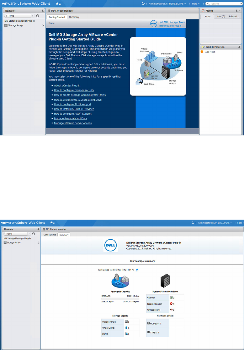
Figure 21. Getting started page
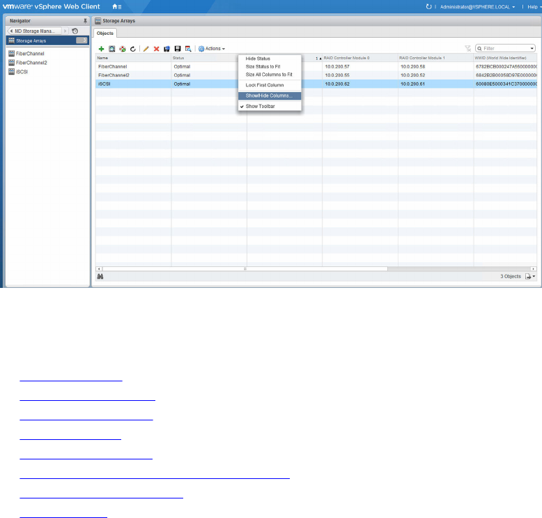
The MD vCenter Plug-in Summary tab provides summary information about all of the storage arrays
configured in the plug-in including:
• Plug-in version and copyright
• Aggregate storage capacity
• Storage array status breakdown
• Storage array objects
• Storage array hardware details
Figure 22. Storage array summary
32
6
Storage Arrays Objects view
Storage Arrays Objects view
The Storage Arrays Objects view displays all of the known storage arrays in a list view that you can
customize by clicking the arrow symbol in the column header and selecting which columns to display.
You can also sort the columns.
Figure 23. All Storage Arrays Table view
The Storage Arrays container view shows a list of known storage arrays and allows you add or remove
storage arrays. The following options are available from the storage array manager view:
•Add Storage Array
•Discover Storage Arrays
•Collect Support Bundle
•Edit Storage Array
•Remove Storage Arrays
•Enabling automatic save configuration backups
•Manually Save Configuration
•View Event Log
33
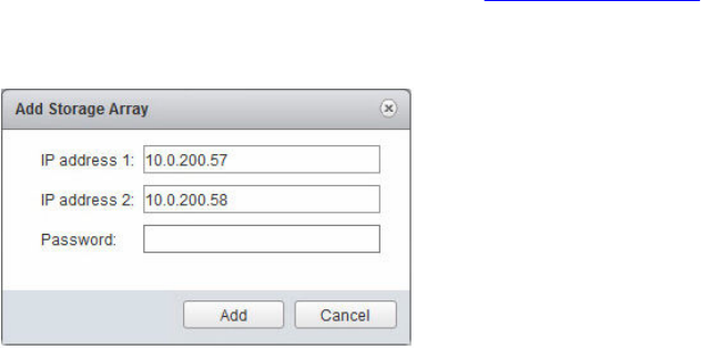
Add Storage Array
The Add Storage Array enables you to add a single storage array to the array manager view and type
storage array password, if necessary. The Add Array also provides the ability to assign asset tags to the
new storage array. If you need to add multiple arrays, see Discover Storage Arrays.
1. In the Commands area of the MD vCenter Plug-in Array Manager view, click Add Storage Array.
The Add Storage Array dialog box is displayed.
Figure 24. Add Storage Array window
2. In the RAID Controller Module 0 box, type the IP address or DNS name of the storage array’s RAID
controller module 0.
3. In the RAID Controller Module 1 box, type the IP address or DNS name of the storage array’s RAID
controller module 1.
4. In the Password box, type the password for the storage array that you are adding to the MD vCenter
Plug-in.
5. Click Add.
The storage array is added.
Discover Storage Arrays
The MD vCenter Plug-in enables you to auto discover storage arrays in a subnet to add to the Storage
Arrays container. To perform an auto discovery, perform the following task:
1. In the Commands area, click Discover Storage Arrays.
The Discover Storage Arrays dialog box is displayed. (Figure 25 with IP Start and IP End along with
the global array Password settings box.)
34
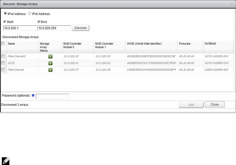
Figure 25. Discover Storage Arrays window
2. Enter the starting TCP/IP address of the IP range to discover storage arrays on.
3. Enter the ending TCP/IP address of the IP range to discover storage arrays on.
4. Click the Discover button to start the scan.
NOTE: This process may take several minutes depending on the scope of discovery.
5. (Optional) If the same array password is used for all the arrays to be added, you can specify it now in
the Password box.
6. Click Add to add all selected storage arrays to the MD vCenter Plug-in Array Manager.
7. Click the Close button to close the Discover Storage Arrays window when finished adding arrays.
Collect Support Bundle
The collect support bundle option performs an automatic collection of logs and configuration
information on your environment to be used by technical support to assist in problem resolution. To
generate a support bundle, perform the following task:
1. Select the target storage array in the right pane (table list).
2. Click the Collect Support Bundle icon. (This step may take some time.)
3. Your default browser should open a file save dialog.
4. Accept and complete the file download on the basis of your browser’s settings.
5. Click Close to finish the operation.
35
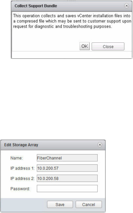
Figure 26. Collect Support Bundle dialog box
After the file vcpsupport_<date>.zip is downloaded to your system, you may then send it to Dell
technical support upon request.
Edit Storage Array
The Edit Storage Array option provides the ability to modify the selected storage array. Select the storage
array to modify, and then click the Edit Storage Array icon. You have the option to modify the settings for
the selected array.
Figure 27. Edit Storage Array dialog box
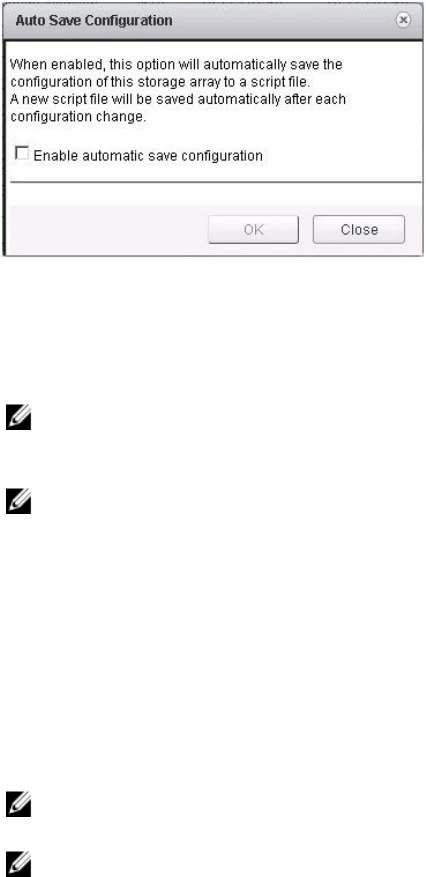
Remove Storage Arrays
You can remove storage arrays by either selecting an individual storage array in the Objects view or by
selecting multiple storage arrays.
1. On the Web Client Storage Arrays Objects tab, select the Storage Arrays you want to remove.
2. Click the Remove Storage Arrays icon.
36
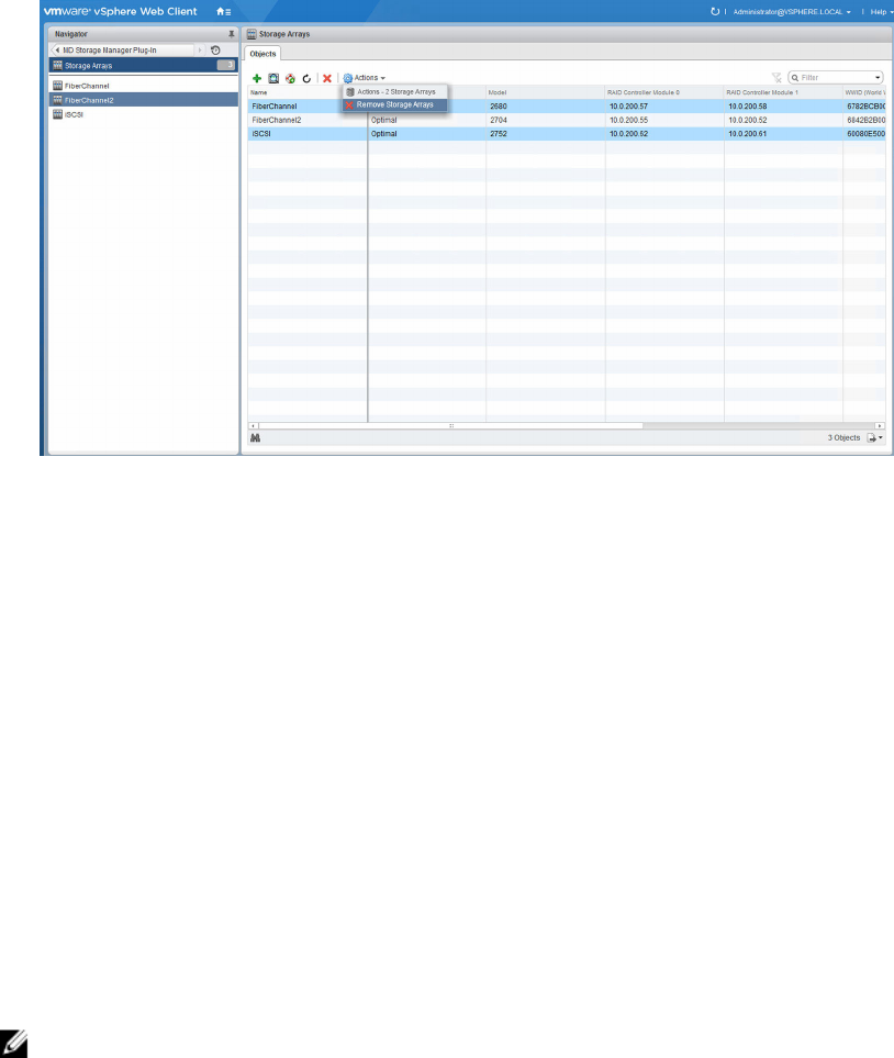
Figure 28. Remove Multiple Storage Arrays window
A message is displayed asking whether or not you want to remove storage arrays.
3. Click Yes.
Saving the storage array configuration
The MD vCenter Plug-in supports storage array configuration backups to script files that can be applied
to a storage array from the MD Storage Manager software. These script files facilitate the restoration of
the storage array configuration, such as storage array name, disk group configurations, virtual disk names,
and virtual disk capacities.
The MD vCenter Plug-in does not back up data that is stored on the storage array. You must use a
standard backup strategy to recover user data that is saved on the virtual disks.
The MD vCenter Plug-in Automatic Save Configuration feature performs a save configuration of the
storage array after a configuration event has occurred on the storage array, either from the MD vCenter
Plug-in or from the MD storage management software application.
Only the configuration information for the storage array is saved during a save configuration operation.
Data stored on the virtual disks is not saved.
NOTE: Only the base storage array configuration information is saved. Objects such as snapshots,
virtual disk copies, and remote replications are not saved to the script file.
A storage array modification event starts a four-minute timer, on the application server, at the time of the
event on the storage array. If in that four-minute time frame, no other configuration events have
occurred on the storage array, a save configuration occurs. If another modification event occurs in the
four-minute time window, the timer is reset to four minutes. When no modification events are detected
on the storage array in the four-minute time window, a save configuration is performed. Automatic Save
Configuration maintains the last 15 save-configuration script files.
37
Enabling automatic save configuration backups
You can set these backups to automatic or manually initiated. To enable automatic backups of the
storage array base configuration, perform the following task:
1. Select the target storage array from the list of managed storage arrays.
2. Click the Auto Save Configuration icon.
Figure 29. Auto Save Configuration dialog box
3. Select the Enable automatic save configuration check box.
4. Click OK.
5. Click Close.
NOTE: After automatic configuration backups are enabled, they are persisted between restarts
of the MD Storage Manager application server and vCenter Server. To disable automatic save
configuration, clear the check box in the Automatically Save Configuration dialog box.
NOTE: The automatic backup script files are located in the following directory: C:\Program
Files\Dell\ MD Storage Manager Plug-in for VMware vCenter\jetty\working
\savecfg. The files are named <storage_array_name>_<date_time_stamp>.cfg.
Manually Save Configuration
To manually save a configuration, perform the following task from the Storage Arrays Objects tab:
1. In the right pane, click the name of the storage array.
2. Click the Manually Save Configuration icon.
The Manual Save Configuration dialog box is displayed.
3. Click OK.
NOTE: You may receive a security alert informing you are about to leave a secure Internet
connection. Select Yes.
NOTE: If you see an error message stating your current security settings, do not download this
file. you must add the secured HTTP address for your application server to the trusted sites list
inside of Internet Explorer.
The File Download dialog box is displayed.
4. Click Save.
5. Click Close.
38
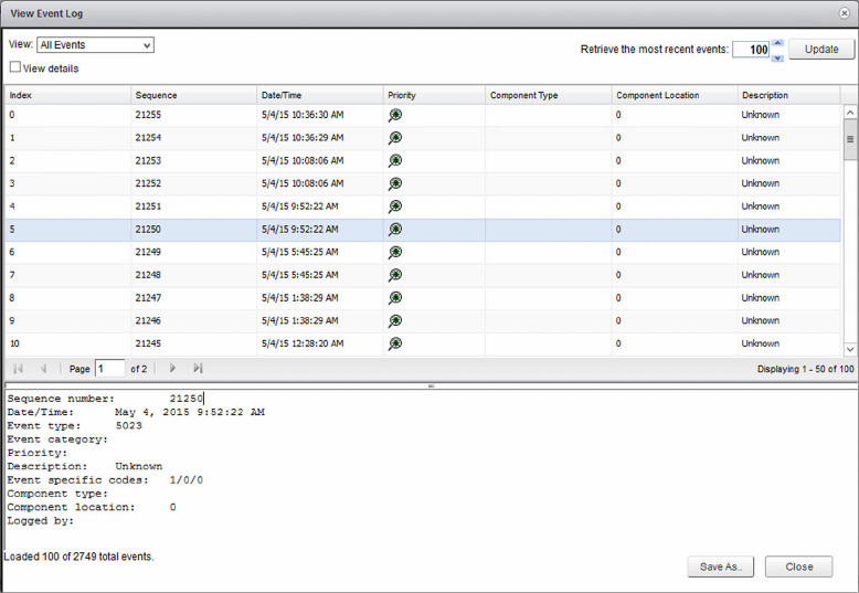
View Event Log
The View Event Log utility provides access to the selected storage array’s major event log. To access a
storage array’s major event log, perform the following task:
1. Select a storage array from the list of managed arrays.
2. Click the View Event Log icon or the View Event Log option, from the Actions drop-down menu.
Figure 30. View Event Log display
39
7
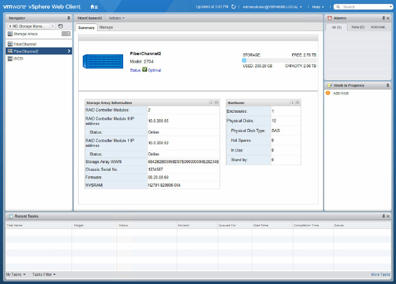
Selected Storage Array Summary tab
When you click a storage array from the Storage Arrays list, a summary of the selected storage array is
displayed on the page. This summary includes information about the status of the storage array, the
number of RAID controller module, their status, their IP addresses, the storage array WWN, the chassis
serial number, firmware and NVSRAM versions, and physical disk information. The storage array Summary
tab also provides access to the Recovery Guru information. If the storage array is non-optimal, the Needs
Attention link is activated describing the issues with the current storage array.
Figure 31. Storage Array Summary tab
Summary view general information
The Summary view tab provides general information about the select storage array in the Storage Array
Information portlet. The details displayed in this area include:
• Number of RAID controller modules
• RAID controller module IP addresses
• RAID controller module status
40

• Storage array WWN
• Storage array chassis serial number
• Storage array firmware version
• Storage array NVSRAM version
The Summary view tab also provides general information on the selected storage array’s physical disk
configuration under the Hardware portlet, which include:
• Number of expansion enclosures
• Number of physical disks
• Type of physical disks used
• Number of hot-spares defined
• Number of hot spares in-use
• Number of hot spares in stand-by
Recovery Guru information
The Recovery Guru information displays information about issues that are currently affecting the selected
storage array. This information includes the following:
• Summary of issues
• Detail of issues
• Recovery Procedures
NOTE: The recovery procedures are written to be applied from in MD Storage Manager and may not
be available in the MD vCenter Plug-in. You can resolve some issues from in the plug-in, but most
you have to apply from the MD Storage Manager.
41
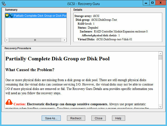
Figure 32. Recovery Guru information window
42
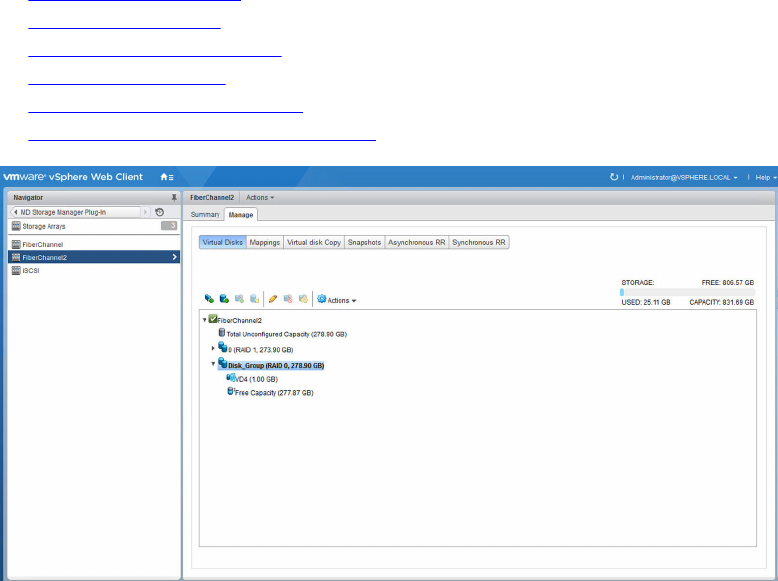
8
Selected storage array Manage tab
The Manage tab provides for management of the selected storage array. In this tab, you can select one of
the following views:
•Virtual Disks view features
•Mappings view features
•Virtual Disk Copy view features
•Snapshots view features
•Remote Replication view features
•Remote Replication (Legacy) view features
Figure 33. Manage view tab
Virtual Disks view features
When you click the Virtual Disks button, a page displays logical view of the storage array showing how
storage capacity is allocated. This view allows you to create dynamic disk pools, legacy disk groups, and
virtual disks. This view also provides the ability to manage existing disk pools, disk groups, and virtual disks
along with creating legacy snapshots of virtual disks. You can create new virtual disk on either a dynamic
disk pool or on a disk group.
43
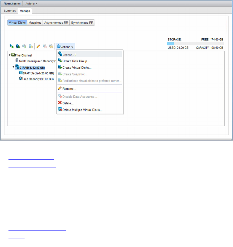
Figure 34. Storage array virtual disks view
•Create Disk Group
•Create Virtual Disks
•Create Snapshot
•Redistribute Virtual Disk
•Rename
•Disable Snapshot
•Recreate Snapshot
Additional options available from the Actions drop-down menu include:
•Disable Data Assurance
•Delete
•Delete Multiple Virtual Disks
Create Disk Group
The Create Disk Group command opens a wizard to help you in creating a new disk group. During this
process, you must select the available free physical disks, the physical disks that make up the new disk
group, and the RAID level.
The disk group wizard has five filtering options to help guide the creation of a new disk group. The first
filter allows filtering physical disks by capacity. This drop-down menu displays a list of all physical disk
capacities in the storage array. Select the size of the physical disk by which to filter. The second filter
option is to filter by physical disk speed (RPM). This drop-down menu displays a list of all physical disk
speeds detected in the storage array. Select the physical disk speed of the new disk group to apply filter.
The other three filter options allow for enforcement of tray loss protection (TLP), drawer loss protection
(DLP), and Data Assurance (DA). By selecting these options, the list of available physical disks is reduced
to allow for TLP, DLP, or DA during the disk group creation process. TLP and DLP allow for a complete
44
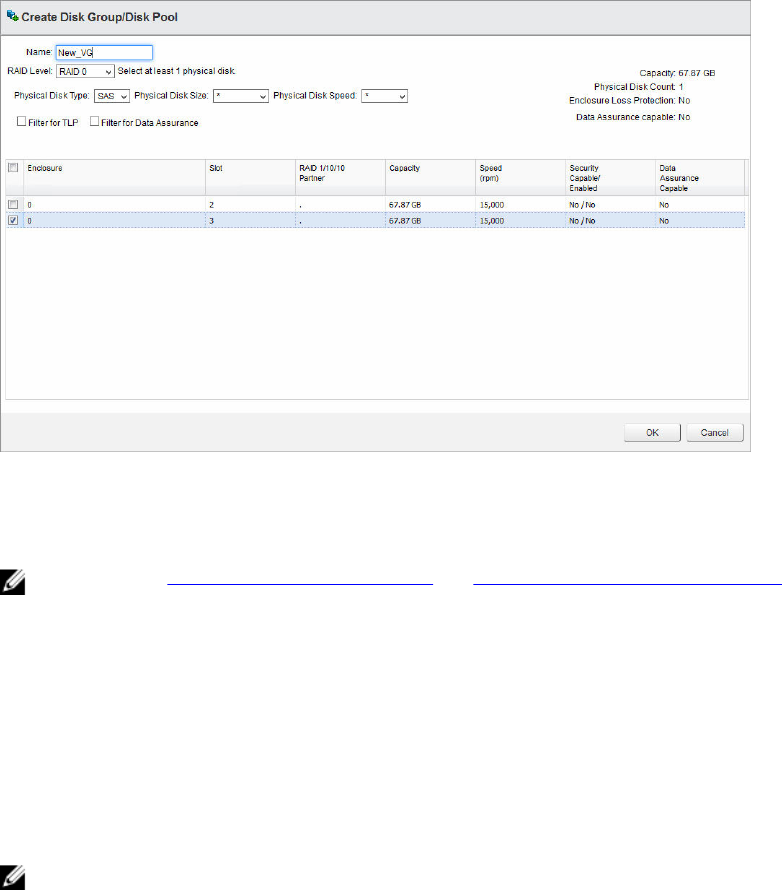
physical disk enclosure or complete drawer failure without failing the virtual disk(s) in the disk group. DA
provides data integrity checking between the RAID controller module to the physical disk, ensuring data
is written to disk correctly.
Figure 35. Create Disk Group dialog box
Selecting physical disk in the table view updates the Capacity information in the upper right corner of the
page showing the final capacity for the new disk group or disk pool.
NOTE: Review Defining virtual disks for vsphere and Virtual disk decision-making schemes to best
configure the MD Storage Manager for VMware vSphere environments.
Create Disk Pool
Dynamic Disk Pools (DDPs) are a feature of firmware versions 7.83 and later that provide for highly
redundant and scalable RAID architecture, also known as Controlled, Scalable, Decentralized Placement
of Replicated Data (CRUSH). This technology is used in place of traditional disk groups. Release 3.0
supports creation, management, and deletion of DDPs on the MD Storage Manager storage arrays.
To create a new DDP, click the Create Disk Group icon and select Disk Pool from the RAID level drop-
down menu. Select the physical disks to include in the disk pool.
NOTE: You must select a minimum of 11 physical disks to create a Dynamic Disk Pool.
Create Virtual Disks
Before creating a virtual disks that can be used by vSphere, you must select an existing disk pool with free
disk space, select an existing disk group with free disk space, create a new disk group from unconfigured
disk space, or create a new disk pool from unconfigured disk space.
To create a new virtual disk or virtual disks, click the Create Virtual Disk icon and perform the following
task:
45
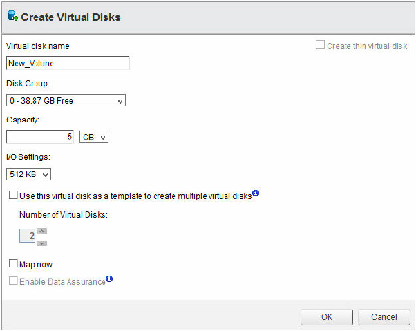
New virtual disk on a disk group
1. Click the Create Virtual Disk icon.
The Create Virtual Disks wizard is displayed.
Figure 36. Create Virtual Disk dialog box
2. In the Name box, type the disk name.
3. From the disk space drop-down menu, select a disk group to use for the new virtual disk.
4. In the Capacity box, type the disk space of the new disk, and select the modifier from the drop-
down menu.
5. In the I/O Settings area, select the segment size for the new disk.
6. (Optional) Select the check box if multiple disks are required, and then select the number of disks to
create.
7. (Optional) Select the Map now check box if the new virtual disks must be mapped immediately to a
host or host group.
8. (Optional) Select the Enable Data Assurance check box to enable DA for the new virtual disks.
9. Click OK.
New virtual disk on a disk pool
Creating virtual disks on a disk pool is similar to creating on a legacy disk group, except I/O settings are
dictated by the DDP. Also, creation of thin provisioned virtual disks is allowed on DDPs. To create a fat
provisioned virtual disk, repeat steps for New Virtual Disk on a Disk Group, skipping I/O settings. To create
a thin provisioned virtual disk, perform the following task:
1. Click the Create Virtual Disk icon.
2. In the Name box, type the virtual disk name.
3. From the Disk Group or Disk Pool drop-down menu, select a disk pool to use for the new virtual
disk.
46
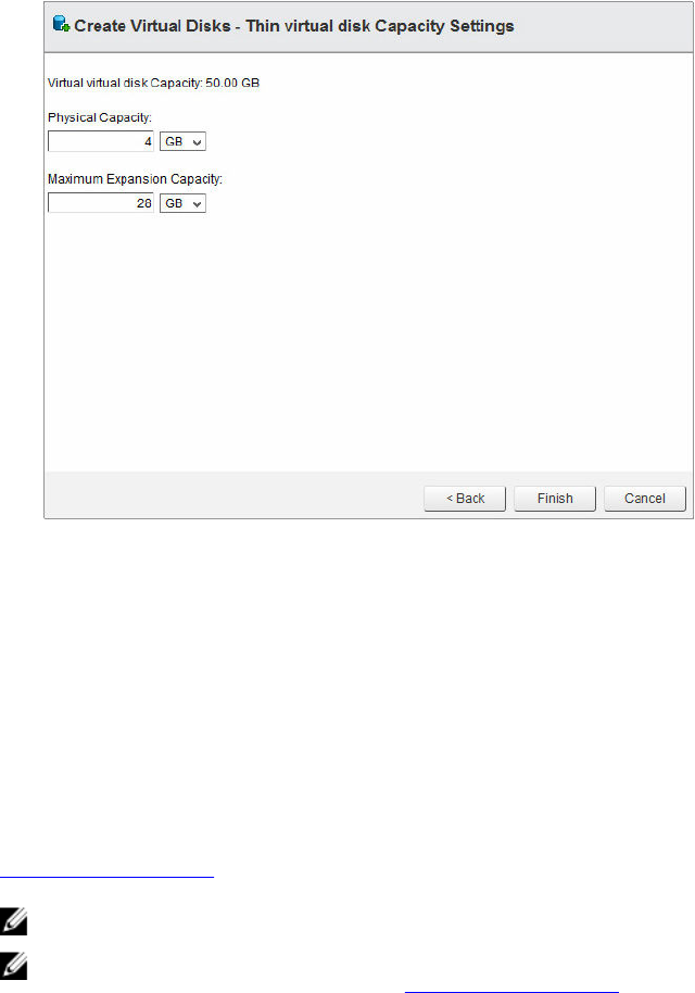
4. In the Size box, type the size of the new virtual disk, and select the rate from the drop-down menu.
5. Select the Create thin virtual disk check box.
6. (Optional) Select the Map now check box if the new virtual disks must be mapped immediately to a
host or host group.
7. (Optional) Select the Enable Data Assurance check box to enable DA for the new virtual disks.
8. Click Next.
Figure 37. Create Virtual Disk - Thin virtual disk Capacity Settings
9. In the Physical Capacity box, type the initial disk space for the thin provisioned virtual disks (multiple
of 4 GB).
10. In the Maximum Expansion Capacity box, type the maximum disk space required for the thin
provisioned virtual disks.
11. Click Finish, or Next if Map now option was selected.
Legacy Snapshots
When the Snapshot premium feature is enabled on the storage array and a valid base virtual disk is
selected, the Create Snapshot option is enabled. This feature allows you to create a legacy snapshot of
the base virtual disk that is selected. To create a new version snapshot by using point-in-time copy, see
Snapshots view features.
NOTE: Legacy snapshots are not allowed on thin provisioned virtual disks.
NOTE: Legacy snapshots are not supported on virtual disks residing on a DDP. To create a point-in-
time snapshot of these virtual disks, see Snapshots view features.
Create Snapshot
The Snapshot commands in the Virtual Disks view allow for management of the legacy snapshot feature.
To create a legacy snapshot, perform the following task:
1. Highlight the base virtual disk and click Create Snapshot.
47
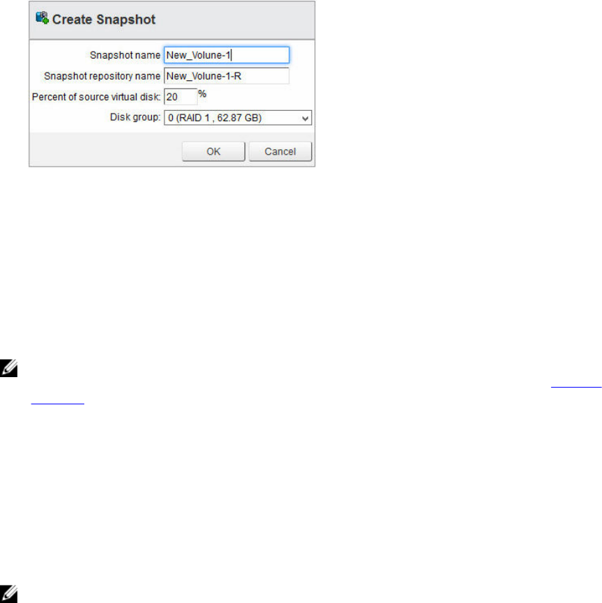
The Create Snapshot wizard is displayed.
Figure 38. Create a snapshot dialog box
•Snapshot name: the name of the new snapshot virtual disk.
•Snapshot repository name: the name of the new repository virtual disk.
•Percent of base virtual disk: the percentage of the base virtual disk to use for the repository.
•Disk group: the name of the disk group in which to place the repository virtual disk.
2. Enter the parameters to be used for the snapshot in the Create a snapshot wizard.
3. Select the disk group that you want to use for the snapshot repository from the drop-down menu.
4. Click OK.
NOTE: When the size of the snapshot exceeds the percentage of the base virtual disk, the snapshot
fails. The snapshot is no longer available for use until it is reestablished by recreating it (see Recreate
Snapshot).
Disable Snapshot
To temporarily deactivate a snapshot so that you can use it again later, highlight the snapshot virtual disk
in the virtual disks tree, and click the Disable Snapshot icon. The snapshot process stops, but the
relationship remains between the snapshot, the base virtual disks, and the repository virtual disks.
Recreate Snapshot
To reestablish a deactivated snapshot or refresh an existing snapshot, click Recreate Snapshot, and then
click the OK button to confirm the operation. A new snapshot of the base virtual disk is created.
NOTE: Recreating a snapshot disables the original snapshot before the new snapshot is created.
Redistribute Virtual Disk
The MD vCenter Plug-in supports redistribution of storage array virtual disks based on their preferred
RAID controller module ownership. Typically during ESXi rescan operations, virtual disk ownership is
transferred to the non-preferred RAID controller module causing the storage array to become non-
optimal. By redistributing the virtual disks to their preferred RAID controller module owner, resolves the
non-optimal condition and balance the I/O loads across the storage array RAID controller module. If all
the storage array virtual disks are already located on their preferred RAID controller module, the
Redistribute Virtual Disk icon is unavailable.
48

Rename
The Rename feature allows for renaming the selected object from the VirtualDisk tree view.
1. Select the object to be renamed, and then click the Rename icon.
2. Type new name for the object.
3. Click OK to apply the change.
Disable Data Assurance
The Disable Data Assurance allows for disabling data assurance (T10 PI) on the selected virtual disk. You
can only disable Data Assurance (DA) on virtual disks residing in a virtual disk group and not on virtual
disks residing in a disk pool. Select the virtual disk to deactivate DA on, and then click the Disable Data
Assurance icon from the Actions drop-down menu. No confirmation window is displayed during this
operation.
NOTE: After DA has been deactivated on a virtual disk, it cannot be reenabled. The virtual disks must
be recreated to enable DA.
NOTE: You can only disable DA on a virtual disk without dependencies such as legacy snapshots or
remote replication relationships.
Delete
The Delete command provides the ability to delete the selected object (virtual disk, disk group, disk pool,
or snapshot). You can only delete objects that are not participating in remote replication groups,
snapshot groups, or remote replications.
1. Select the object that you want to delete, and then click the Delete command from the Actions
drop-down menu.
2. Click OK to confirm deletion of the object (click Cancel to cancel deletion of object).
NOTE: You cannot delete some objects until all child objects are deleted first; such as DDPs or
virtual disks in a replicated relationship. Delete or remove member objects before deleting base
virtual disk, disk group, or disk pool.
Delete Multiple Virtual Disks
The Delete Multiple Virtual Disks command allows for deleting multiple virtual disks at one time. To use
this feature, perform the following task:
1. Select the storage array object from the virtual disks tree view.
2. Select the Delete Multiple Virtual Disks command from the Actions drop-down menu.
The Delete Multiple Virtual Disks wizard is displayed.
49
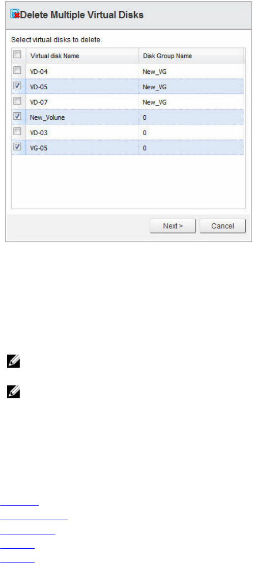
Figure 39. Delete Multiple Virtual Disks wizard
3. Select the virtual disks that you want to delete by selecting the check box next to the virtual disk
name.
4. Click Next after all virtual disks are selected.
A confirmation message dialog box is displayed.
5. If the information about the virtual disks you want to delete is correct, click Finish to delete the
selected virtual disks.
NOTE: Because of SDK limitation, you can delete a maximum of 80 virtual disks at a time by
using this command.
NOTE: You must remove virtual disks participating in a remote replication relationship from the
Remote Replication Group (RRG) before you can delete them.
Mappings view features
The Mappings view enables you to manage how storage array virtual disks are presented to the ESXi
hosts. This view also provides the ability to manage hosts and host groups on the selected storage array.
The following commands are available from this view:
•Add Host
•Add Host Group
•Add Mapping
•Rename
•Remove (Only available from the Actions drop-down menu.)
50
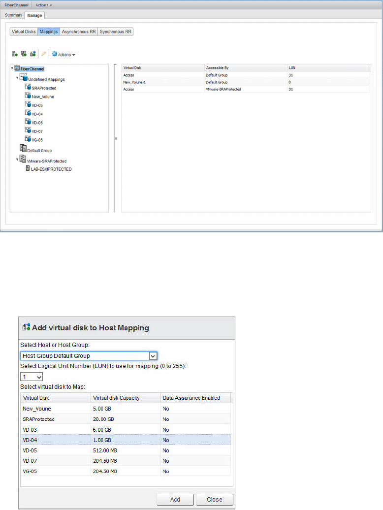
Figure 40. Storage array mappings view
Add Mapping
To present a virtual disks to an ESXi host or host group, perform the following task:
1. Click the Add Mapping icon.
Figure 41. Add virtual disk to Host Mapping
2. Select host or host group. The virtual disk is displayed from the drop-down menu.
3. Accept the default logical unit number (LUN) or change to required LUN number for the new
mapping.
4. Select the virtual disk to be mapped.
5. Click Add.
51
6. Repeat steps 3–5 for additional virtual disks to present or click Close.
NOTE: When your storage array uses multiple groups of HBAs per ESXi host, balance the new
virtual disks across all hosts or host groups. Do not add all the virtual disks to a single host or
host group because I/O balancing cannot occur if you do.
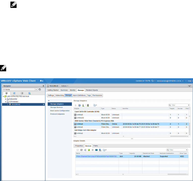
Rescan Storage Adapters
After you map the virtual disks to the ESXi hosts, you must rescan the storage adapters on the ESXi host
to detect the new storage virtual disks. This action is accomplished under the Manage tab in the Hosts
and Clusters view. Select Storage for the ESXi host that you want to configure, and then click the Rescan
all Storage Adapters icon.
NOTE: You may need to run the Rescan, from vCenter, twice to detect all of the new storage virtual
disks that have been mapped to the ESXi host.
Figure 42. Storage Storage Adapters
1. From this view, you can also verify that the correct number of paths have been configured by
clicking one of the devices listed under the storage adapter.
2. Select the Paths tab to view the details of the selected device. For round robin PSP, you must see
four active connections with two denoting I/O. For most recently used PSP, you must see either four
active connections with one channel showing I/O or two active connections and two standby
connections and one of the active channels showing I/O.
3. To change the PSP method for a device, select the Properties tab under Device Details pane, scroll
down to the Edit Multipathing button. Click the button and select path selection policy to apply to
the device from the drop-down menu. Click OK.
52
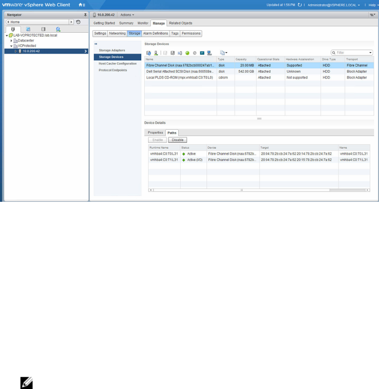
Figure 43. Storage Details path view
Add Host
The Add Host command enables you to define hosts that are used to present virtual disks. To add a new
host, perform the following task:
1. Select a host group to add a new host to and click the Add Host icon.
2. Enter the name for the new host.
3. Select the host type (VmwTPGSALUA for ESXi host) from the drop-down menu.
4. Select the interface type, and then click Next.
5. Select the available host port adapters’ identifiers for the new host that you want to add.
6. Click the down arrow to move the host port identifier to the lower window. (Repeat for dual port
configuration).
NOTE: Only unconfigured host port identifiers are displayed in the upper pane of the Add Host
wizard.
53
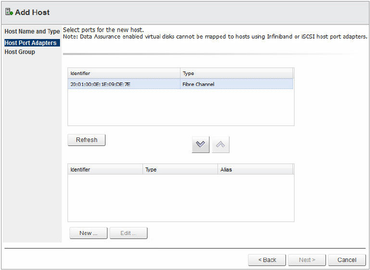
Figure 44. Host Port Adapters wizard
7. Click Next.
8. Select the option button to indicate if this host will be added to a host group (shared virtual disk
mappings).
9. If the host will be added to a host group, indicate the option button for either a new host group or
existing host group.
10. Enter a new host group name or select an existing host group from the drop-down menu.
11. Click Finish.
Add Host Group
To create a new host group and to share LUN mappings between hosts, perform the following task:
1. Click Add Host Group.
54
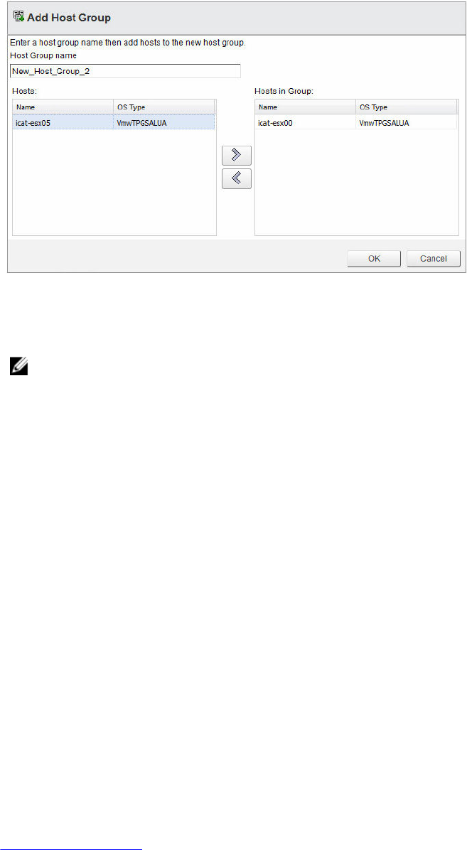
Figure 45. Add Host Group wizard
2. Type the name for the new host group.
3. Select the names of the hosts that you want to add to the new host group.
NOTE: Only hosts that are currently in the default host group are listed in the available hosts
list.
4. Click the right arrow to add the hosts to the new host group.
5. (Optional) Repeat steps 3 and 4 for adding more hosts.
6. Click OK after you add all hosts to the new host group.
Rename
The Rename command allows you to rename a host or host group. Select the host or host group that
you want to rename, and then click the Rename icon. Type the new name for the object, and then click
OK.
Remove
The Remove command allows you to remove the selected object (host or host group) from the storage
array. Select the host or host group that you want to remove, and then click the Remove icon from the
Actions drop-down menu.
Virtual Disk Copy view features
The Virtual Disk Copy view enables you to manage virtual disk copies on the selected storage array. This
tab also displays existing virtual disk copy pairs along with their current status. Virtual disk copy provides a
method to copy all existing data from a source virtual disk to a target virtual disk. Unlike snapshot, the
target virtual disk, after completion, does not rely on data from the source virtual disk; it contains all data
from the original virtual disk and may be mapped to alternate host(s) for data mining or recovery
purposes without affecting the source virtual disk data. The following commands are available from this
view:
•Create Virtual Disk Copy
55
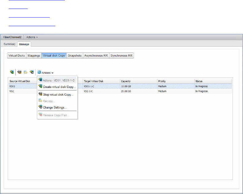

Figure 47. Select source Virtual Disk
NOTE: While the virtual disk copy is being established, a snapshot of the source virtual disk is
created which is used to create the virtual disk copy from. This ensures that the data is
consistent at the time the virtual disk copy was initiated and continued read-write access to the
source virtual disk during the copy operation.
NOTE: Snapshots for virtual disks residing on a disk pool are not supported in this release. Any
virtual disk copy using virtual disks on a disk pool is read-only to the host until the ‘copy’
process is completed.
2. Select the source virtual disk and click Next.
3. Click either Use existing virtual disk or Create a new virtual disk.
57
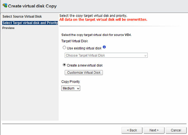
Figure 48. Select target virtual disk and priority
4. Select the copy priority to use while establishing the new virtual disk copy.
5. Click Next.
6. Review and verify the virtual disk copy settings and click Finish to start the virtual disk copy.
Stop Virtual Disk Copy
The Stop Virtual Disk Copy command stops the current virtual disk copy operation for the selected copy
pair. Select a copy pair that is in progress, and then click the Stop Virtual Disk Copy icon. A confirmation
message is displayed. Click OK.
Recopy
The Recopy command recopies all data from the source virtual disk to the target virtual disk, overwriting
any existing data on the target virtual disk, for the selected virtual disk copy pair.
All data available on the target virtual disk is overwritten with this option.
1. Select the virtual disk copy pair to use for the recopy.
2. Click Recopy.
3. Verify the information in the Recopy dialog box, and then click OK.
Change Settings
To change the target virtual disk to read-write or change the modification priority, perform the following
task:
1. Select an existing virtual disk copy pair from the list.
2. Click the Change Settings icon.
58
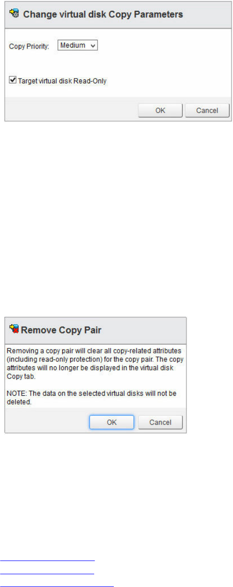
Figure 49. Change virtual disk Copy Parameters
3. From the Copy Priority drop-down menu, select the new priority for the virtual disk copy.
4. Clear the Target virtual disk Read-Only check box to allow for read-write of the target virtual disk
copy.
5. Click OK.
Remove Copy Pair
The Remove Copy Pair command removes the relationship of the source and target of a virtual disk copy
pair. This command does not remove the target virtual disk or the data residing on the target virtual disk.
To remove a virtual disk copy pair relationship, perform the following task:
1. Select the virtual disk copy pair to be removed.
2. Click Remove Copy Pair icon from the Actions drop-down menu.
3. Click OK to remove the virtual disk copy pair or Cancel.
Figure 50. Remove Copy Pair
Snapshots view features
MD storage arrays with controller firmware 7.84 and later support Point-in-Time (PiT) based snapshots.
These snapshots provide a PiT image of the base virtual disk that may be used to revert to, or presented
to an alternate host as read-only or read-write virtual disk. The following commands are available from
this view:
•Create Snapshot Group
•Create Snapshot Image
•Create Snapshot Virtual Disk
59
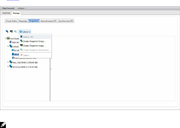
•Delete
Figure 51. Snapshot view
NOTE: To rollback a snapshot image to the base virtual disk, you must use MD Storage Manager.
Image rollback is not currently supported in the MD vCenter Plug-in. You can also use MD Storage
Manager to set up scheduled snapshot images automatically.
Create Snapshot Group
A snapshot group is used to hold snapshot images of a storage array virtual disk. To create a new
snapshot group, perform the following task:
1. Select the base virtual disk from the Virtual Disk tree.
2. Click Create Snapshot Group.
60
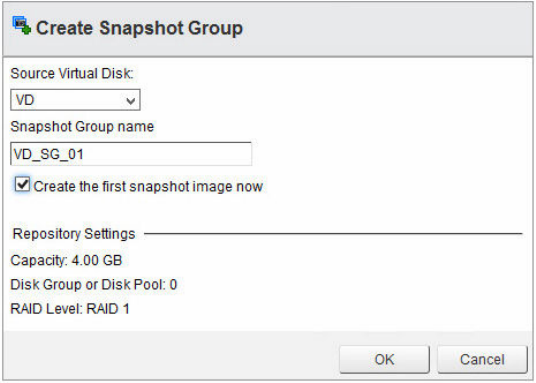
Figure 52. Create snapshot group dialog box
3. Modify the displayed parameters as necessary.
4. Click OK.
Create Snapshot Image
A snapshot image is a point-in-time copy of the base virtual disk. After an image is created, you can use it
to roll back the base virtual disk to, or you can use it to create a virtual disk from. To create an image,
perform the following task:
1. Select the base virtual disk from the virtual disk tree window.
2. Click Create Snapshot Image.
61
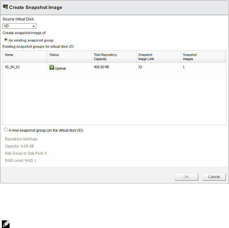
Figure 53. Create Snapshot Image dialog box
3. From the Base virtual disk drop-down menu, select the base virtual disk of the snapshot image.
4. Select an existing snapshot group to use for the new image.
NOTE: If this is the first snapshot image for the base virtual disk, a new snapshot group is
created if not already manually created.
5. Click OK.
Create Snapshot Virtual Disk
A snapshot virtual disk allows for a snapshot image to be mapped to a host or host group for data access.
To create a snapshot virtual disk, perform the following task:
1. Select a base virtual disk in the virtual disk tree window that has an existing snapshot group.
2. Click Create Snapshot Virtual Disk.
62
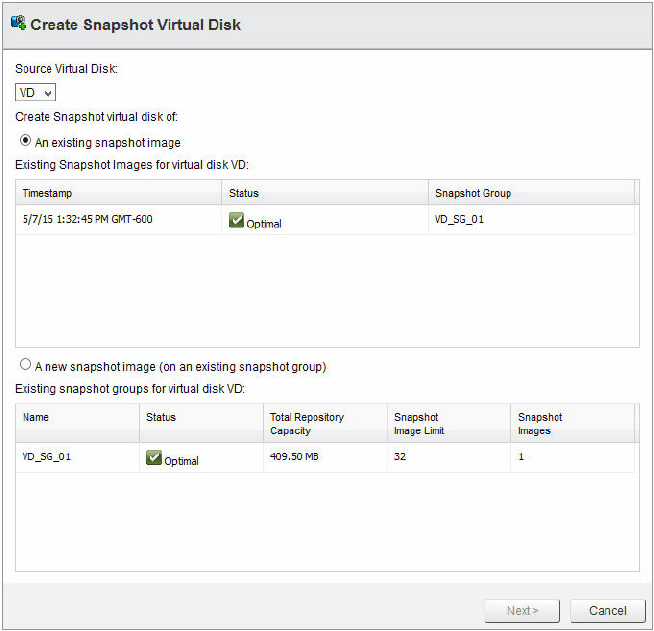
Figure 54. Create Snapshot Virtual Disk dialog box
3. Select a snapshot image from the available list of images or select the A new snapshot image option,
and then click Next.
4. In the Snapshot virtual disk name box, enter a name for the new snapshot virtual disk.
5. Select the access mode for the snapshot virtual disk.
6. Click Finish.
Delete
The Delete command allows for removal of snapshot virtual disks, snapshot images, or snapshot groups
depending on the object select. The delete option opens a dialog box of the selected object displaying
the leafs of that object. To delete a snapshot object, perform the following task:
1. Expand the base virtual disk from the virtual disks tree window.
2. Select the Snapshot Groups, Snapshot Images, or Snapshot Virtual Disks object.
3. Click Delete.
63
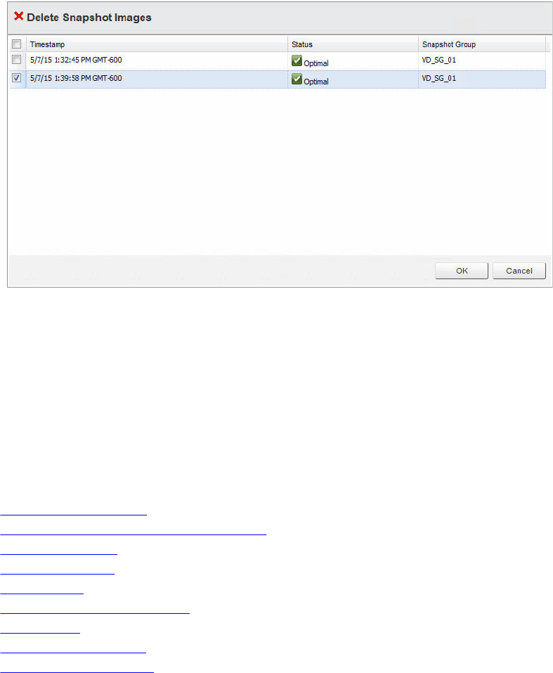
Figure 55. Delete snapshot images
4. Select the check box next to the leaf objects to be deleted.
5. Click OK.
6. In the message displayed, click OK to delete the object, or click Cancel to cancel the operation.
Remote Replication view features
The Remote Replication view feature allows for management of Asynchronous Remote Replication (aRR).
aRRs are available on MD storage arrays with controller firmware 7.84 and later. The following commands
are available in the Remote Replication view tab:
•Create Replication Group
•Create Asynchronous Remote Replication Pair
•Suspend Replication
•Resume Replication
•Manual resync
•Test Replication Communication
•Change Roles
•Delete Replication Group
•Remote Replication Group
64
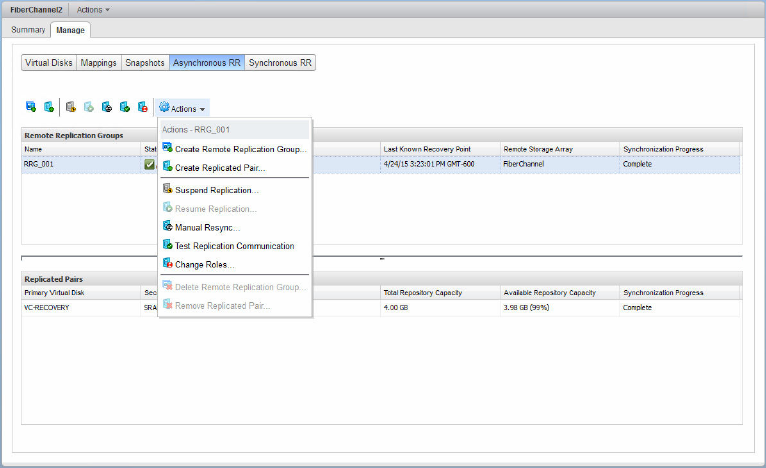
Figure 56. Asynchronous Remote Replication
Asynchronous remote replication (legacy) details
The aRR feature is similar to Remote Replication (RR) by allowing source virtual disks from a primary
storage array to be replicated to a target virtual disk on a remote storage array. However, aRR supports
both iSCSI and fibre channel connections between the storage arrays and uses point-in-time replication
strategy. aRR enables you to manage the synchronization process of creating a consistent data set on a
remote storage array.
A remote replication group may contain several replicated pairs that you can manage as one entity. A
replicated pair consists of a primary virtual disk and a secondary virtual disk. Both virtual disks contain
identical copies of the same data. Write operations are performed to the primary virtual disk and then
replicated to the secondary virtual disk based on the RRG synchronization settings.
An RRG defines the synchronization settings for all replicated pairs in the group. Each replicated pair in an
RRG shares the same synchronization settings, primary and secondary role, and write mode. You can
synchronize all replicated pairs in the RRG at the same time.
A remote replication group is associated with the local storage array and remote storage array in the
replicated pair.
• The local storage array performs the primary role in the remote replication group. All virtual disks
added to the remote replication group on the local storage array perform the primary role in the
replication relationship.
• The remote storage array performs the secondary role in the remote replication group. All virtual disks
added to the remote replication group on the remote storage array perform the secondary role in the
replication relationship.
65
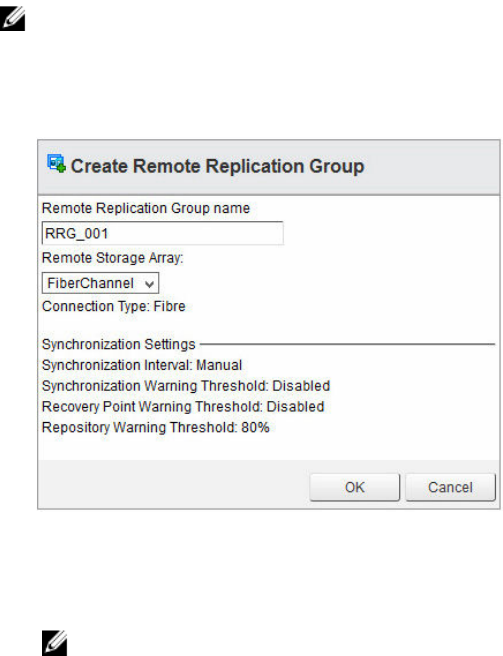
Create Replication Group
An RRG is used to group replicated pairs as a single entity and control replication settings for all members
of the RRG. A replicated pair may only reside in a single RRG. There is a limit of 4 RRGs per storage array.
To create a new RRG, perform the following task:
NOTE: To configure remote replication in the MD vCenter Plug-in, both arrays (local array and
remote array) must be added to the MD Storage Manager Plug-in Array Manager. If either array is
removed from the Array Manager, any RRGs configured between the two arrays are displayed in the
plug-in.
1. Click Create Replication Group.
Figure 57. Create Remote Replication Group dialog box
2. In the Remote Replication Group Name box, type a unique name of the RRG.
3. Select the remote storage array for the RRG from the Remote Storage Array drop-down menu.
NOTE: The Remote Storage Array drop-down menu lists only the storage arrays that support
selection as the remote storage array.
4. Click OK.
Create Asynchronous Remote Replication Pair
The Create Asynchronous Replication Pair feature allows for creating an asynchronous replicated pair
relationship between a primary virtual disk on the primary array and a secondary virtual disk on the
secondary array. To create a new asynchronous replicated pair, perform the following task:
1. In the Remote Replication group table, select an RRG (with primary role) in which to create a
replicated pair.
2. Click Create Asynchronous Replicated Pair.
The Create Asynchronous Remote Replicated Pair dialog box is displayed.
66
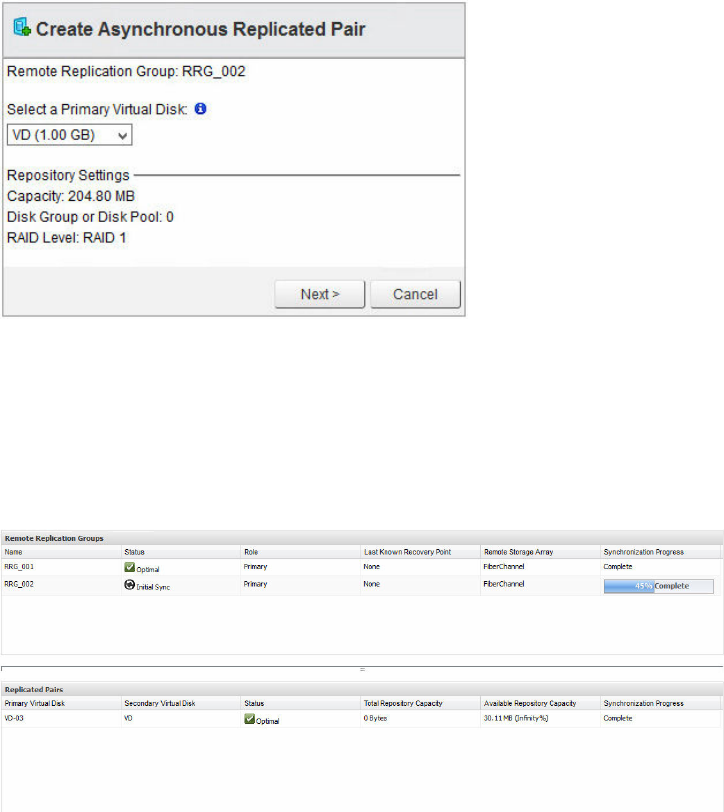
Figure 58. Create Asynchronous Replicated Pair dialog box
3. From the Select a Primary Virtual Disk drop-down menu, select the primary virtual disk for the
replicated pair.
4. Click Next.
5. From the Select a Secondary Virtual Disk drop-down menu, select the secondary virtual disk for the
replicated pair.
6. Click Finish.
Figure 59. Initial sync status remote replication groups table and replicated pairs table
Suspend Replication
When replication is suspended, the virtual disks in the replicated pairs cannot synchronize data. The
suspend-replication operation must be performed by the storage array in the primary role for the RRG.
To suspend replication, perform the following task:
1. Select the RRG in the Remote Replication Groups window.
2. Click Suspend Replication.
3. Select Yes, I wish to perform the operation.
4. Click OK.
67

Resume Replication
You can resume the replication only when all members of the remote replication group are in the
Optimal status. You can perform the resume operation only by the storage array that has the primary role
for the RRG. To resume replication, perform the following task:
1. Select the suspend RRG in the Remote Replication Group window.
2. Click Resume Replication.
3. Select Yes, I wish to perform the operation.
4. Click OK.
Manual resync
The Manual resync command forces the immediate resynchronization of the data on all replicated pairs
in the RRG. A manual resynchronization must be performed by the storage array that has the primary role
for the RRG.
NOTE: You cannot perform a manual resynchronization until the minimum wait time (10 minutes)
between synchronizations has elapsed.
To manually synchronize an RRG, perform the following task:
1. Select an RRG in the Remote Replication Group window.
2. Click Manual resync.
3. Select Yes, I wish to perform the operation.
4. Click OK.
Test Replication Communication
The Test Replication Communication feature displays statistics between the two storage arrays
configured for the RRG. Select the RRG to obtain information, and then click the Test Replication
Communication icon. The Test Communication Link results are displayed.
68
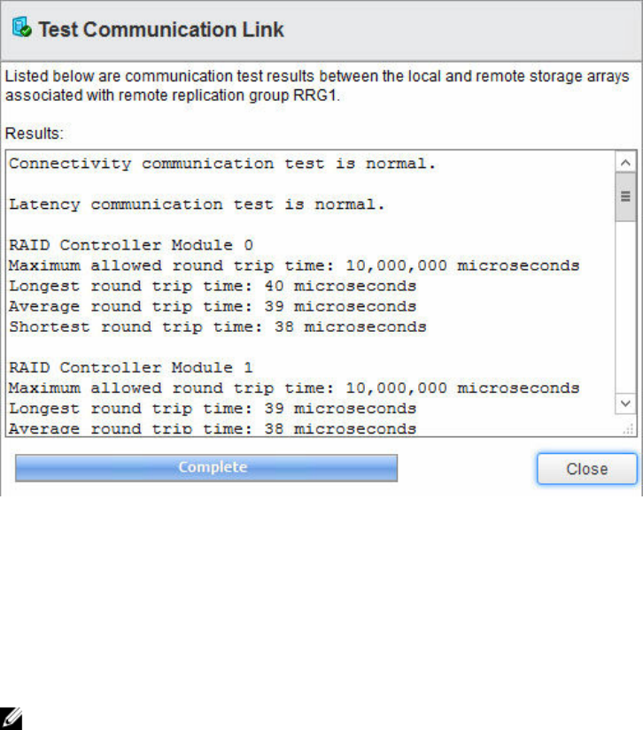
Figure 60. Test Replication Communication results
Change Roles
A Change Roles feature promotes the current secondary replication group to the primary role and
demotes the current primary replication group to the secondary role. After roles are changed, hosts
mapped to the former primary virtual disks in the RRG no longer have write access to the replicated
virtual disks. Hosts in the RRG that was promoted to the primary role now have write access to the
replicated virtual disks.
NOTE: If the RRG is not resynchronized, data written to primary virtual disks after the last
synchronization is lost and cannot be recovered.
To change roles, perform the following task:
1. Select the RRG in the Remote Replication Group window.
2. Click Change Roles.
The Confirm Change dialog box is displayed. The Resynchronize replication group now check box
is selected by default. To prevent the resynchronization, clear the check box.
3. Select Yes, I wish to perform this operation. Click OK.
The Remote Replication Group window shows the role change for the RRG. In the Remote
Replicated Pairs window, the primary and secondary virtual disks in the RRG have switched roles.
69
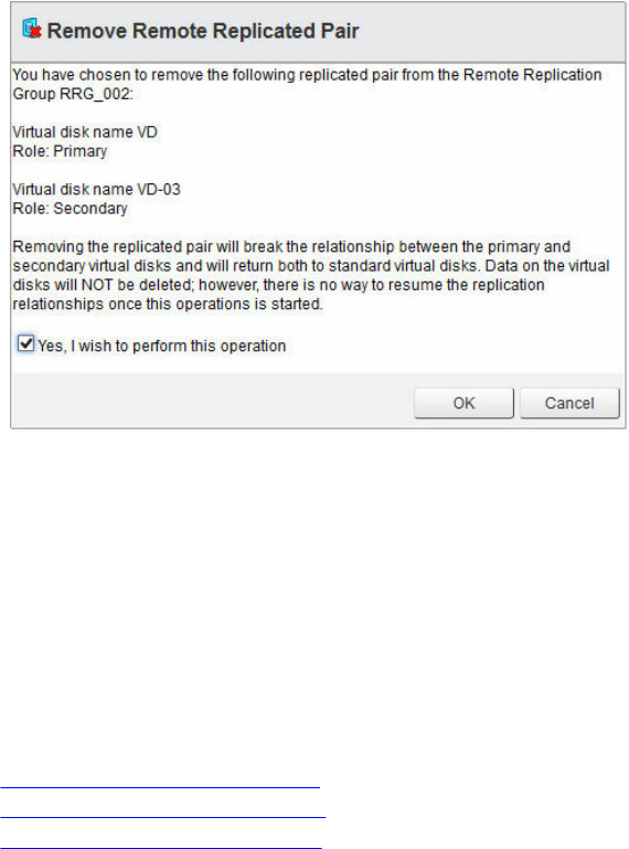
Delete Replication Group
You can also delete Remote Replication Groups after all replicated pairs have been removed from the
RRG. After you remove all of the replicated pairs, select the Delete Replication Group option from the
Actions drop-down menu.
Remote Replication Group
Removing a replicated pair breaks the relationship between the primary virtual disk and the secondary
virtual disk. Both virtual disks are return to standard virtual disk status. No data is deleted from either the
source virtual disk or the target virtual disk. To remove a replicated pair, perform the following task:
1. In the Remote Replication Group table, select the remote replication group from which to remove
the replicated pair.
2. Select the replicated pair to be removed from the Replicated Pairs table.
3. Select Remove Replicated Pair command from the Actions drop-down menu.
The Remove Remote Replicated Pair dialog box is displayed.
Figure 61. Remote Replication Group pair dialog box
4. Select Yes, I wish to perform the operation.
5. Click OK.
The replicated pair is removed from the Replicated Pairs table.
Remote Replication (Legacy) view features
When the Remote Replication (Legacy) premium feature is enabled on the storage array, the Remote
Replication (Legacy) tab appears in the MD vCenter Plug-in. From this tab, existing remote replication
(Legacy) pairs are displayed along with the Commands area, which allows the following commands:
•Create Remote Replication (legacy)
•Suspend remote replication (legacy)
•Resume remote replication (legacy)
70
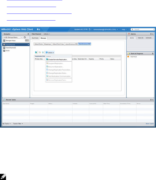
•Change Replication Settings
•Change Replicated Roles
•Test Replication Communication
•Remove Replicated Pairs
Figure 62. Remote Replication (Legacy) view
Create Remote Replication (legacy)
The Remote Replication (Legacy) command is used to establish a remote replication (legacy) between
two storage arrays connected using fibre channel. To establish a new remote replication, perform the
following task:
NOTE: To create a remote replication (legacy), both the local and the remote storage arrays must
be added to the Array Manager view.
1. Select the Create Remote Replication (Legacy) command.
2. Review the Introduction wizard instructions, and then click Next.
3. Select the primary virtual disk for the replication relationship, and then click Next.
4. From the drop-down menu, select the remote storage array for the replication.
5. From the drop-down menu, select the secondary virtual disk to be the target of the primary virtual
disk.
6. Select the write mode for the remote replication, and then click Next.
7. Select resynchronization method to use.
8. From the drop-down menu, select the synchronization priority for the replication, and then click
Next.
9. Review the Confirmation page, and then click Finish to establish the replicated relationship.
71
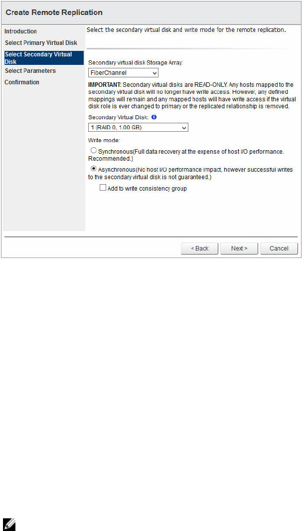
Figure 63. Create Remote Replication (Legacy) dialog box
Suspend remote replication (legacy)
To suspend remote replication (legacy) of a replicated pair, perform the following task:
1. Select the replicated pair in the Replicated Pairs window.
2. Click Suspend Replicating.
3. Click OK to suspend the selected replicated pair or Cancel to cancel the operation.
The I/O between the replicated pairs is suspended, but the replicated association is maintained.
Resume remote replication (legacy)
To resume remote replication (legacy) of a suspended replicated pair, perform the following task:
1. Select the suspended replicated pair in the Replicated Pairs window.
2. Click Resume Replication (Legacy).
3. Click OK to resume replication (legacy) of the selected replicated pair or Cancel to cancel the
operation.
The I/O between the replicated pairs resumes, and out-of-sync data is resynchronized.
NOTE: This option is available only for replicated pairs that have been suspended.
72
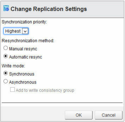
Change Replication Settings
To modify the parameters of a replicated pair, such as the synchronization priority, the resynchronization
method, or the write mode, perform the following task:
1. Select the replicated pair to modify.
2. Select Change Replication (Legacy) Settings command from the Actions drop-down menu.
Figure 64. Change virtual disk copy parameters
3. Modify the displayed parameters as needed.
4. Click OK.
Change Replicated Roles
Changing replication roles makes the following role changes in the replicated pair:
• Promotes the secondary virtual disk to the primary virtual disk and allows read-write access to the
virtual disk from the remote location.
• Demotes the primary virtual disk to the secondary virtual disk and disables writes to the virtual disk
from the primary site.
To change replication roles, perform the following task:
1. Select the replicated pair in the Replicated Pairs window.
2. Select Change Replicated Roles from the Actions drop-down menu.
3. Click OK to change the replication roles or click Cancel to cancel the operation.
Test Replicated Communication
Testing replicated communication displays the round-trip times between the virtual disks in the
replicated pair. The times are displayed as average round-trip times, shortest round-trip times, and
longest round-trip times.
To test replicated communication, perform the following task:
73
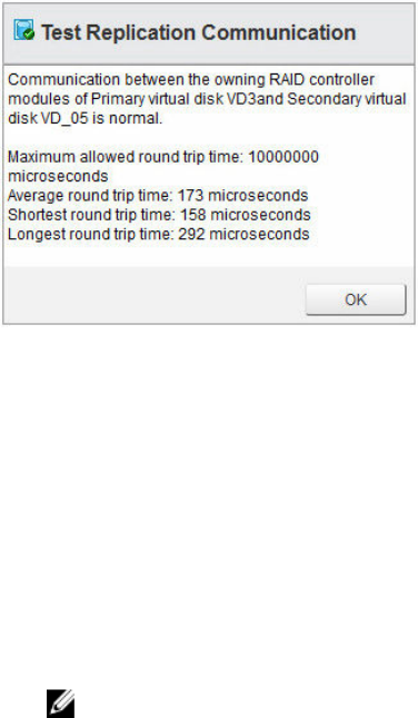
1. Select Test Replicated Communication from the Actions drop-down menu.
2. Click OK to close the dialog box after reviewing the information display.
Figure 65. Test Replicated Communication results
Remove Replicated Pairs
Removing a replicated pair breaks the replication association between the virtual disk at the primary site
and the virtual disk at the secondary site. After the operation completes, the replication status between
the virtual disks is lost. For replication to be re-established between the virtual disks, a full
resynchronization must occur. To remove a replicated pair relationship, perform the following task:
1. Select an existing replicated pair in the Replicated Pairs window.
2. Select Remove Replicated Pairs command from the Actions drop-down menu.
3. Click OK to remove the replicated pair or Cancel to cancel the process in the Remove Replicated
Pairs dialog box.
NOTE: The remove action will not remove the secondary virtual disk from the remote array or
remove the existing data on the secondary virtual disk.
74
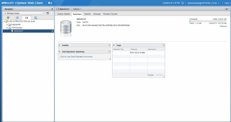
9
MD storage Manager Datastore Summary
information
Datastore summary information may also be displayed by performing the following task:
1. Go to the Storage view from the home button.
2. Select the Datastore to view from the Navigator list.
3. Click the MD Storage Manager Datastore Summary link.
Figure 66. VMware vCenter storage Summary view
75
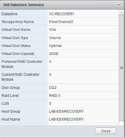
The summary information for the selected datastore is displayed. This information includes storage
array specific information on the underlying virtual disks servicing the selected datastore.
Figure 67. Dell Datastore Summary
76

10
Best practices
This section provides best practices for using MD storage arrays in VMware vSphere environments.
Defining virtual disks for vsphere
Before you provision virtual disks for VMFS datastores, you must plan how to set up storage for the ESXi
systems, including deciding on the number of virtual disks to use and the size of the virtual disks.
NOTE: For more information about making virtual disk decisions, including predictive schemes,
adaptive schemes, and disk shares, refer to the following sections of iSCSI SAN Configuration Guide:
• Using ESXi with an iSCSI Storage Area Network
• Making LUN Decisions in the VMware vSphere Online Library
When you are deciding how to format the virtual disks, keep in mind the following considerations:
• Ensure that each virtual disk has the correct RAID level and storage characteristics for applications in
the virtual machines (VMs) that use that virtual disk. Ensure that each virtual disk contains only one
VMFS datastore.
• When multiple VMs access the same VMFS datastore, use disk shares to prioritize virtual machines.
Fewer, larger virtual disks are appropriate for the following reasons:
• More flexibility to create VMs without asking the storage administrator for more space. More flexibility
for resizing virtual disks, doing snapshots, and so on. Fewer VMFS datastores to manage.
• More, smaller virtual disks are appropriate for the following reasons: Less wasted storage space.
Different applications might need different RAID characteristics.
• More flexibility, as the multipathing policy and disk shares are set per virtual disk.
• Use of Microsoft Cluster Service requires that each cluster disk resource is in its own virtual disk.
• Better performance because there is less contention for a single virtual disk.
Virtual disk decision-making schemes
When the storage characterization for a VM is not available, you can use either the predictive scheme or
the adaptive scheme to decide on the virtual disk size and number of virtual disks to use.
Using the predictive scheme to make virtual disk decisions
1. Create several virtual disks with different storage characteristics.
2. Build a VMFS Datastore on each virtual disk. Label each datastore according to its characteristics.
3. Allocate virtual disks to contain the data for VM applications in the VMFS datastores built on virtual
disks with the appropriate RAID level for the applications' requirements.
77
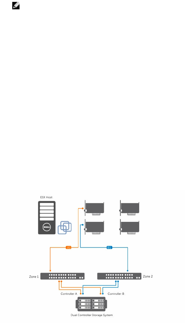
4. Use disk shares to distinguish high-priority VMs from low-priority VMs.
NOTE: Disk shares are relevant only in a given host. The shares assigned to VMs on one host
have no effect on VMs on other hosts.
5. Run the applications to determine whether or not VM performance is acceptable.
Using the adaptive scheme to make virtual disk decisions
1. Create a large virtual disk, such as RAID 1+0 or RAID 5, and enable write caching.
2. Build a VMFS datastore on that virtual disk.
3. Place four or five virtual disks on the VMFS datastore.
4. Run the applications to determine whether disk performance is acceptable.
If performance is acceptable, you can place additional virtual disks on the VMFS datastore. If
performance is not acceptable, create a new, larger virtual disk, and repeat the process. You can use
a different RAID level. Use migration so that you do not lose VMs when you recreate the virtual disk.
VMware ESXi host fibre channel configuration
The MD vCenter Plug-in allows an ESXi host to be automatically configured to use a MD storage array by
detecting the installed host bus adapters (HBAs) in the ESXi host and configuring new hosts on the
storage array with the World Wide Names (WWNs) of the HBAs from the ESXi host. The default ESXi
multipathing mode for MD Fibre Channel storage arrays is Most Recently Used (MRU). To ensure
optimum performance for the ESXi host with more than two HBAs, you must configure ESXi host to use
the storage array in pairs of HBAs. This method allows for the maximum I/O throughput from the ESXi
host to the storage array. Using this method requires proper SAN configuration and balancing of LUNs
between hosts/host groups. Figure 70 shows a properly configured two-HBA port, ESXi host, SAN
configuration utilizing two fabric switches and a dual-controller storage array.
Figure 68. Dual port HBA configuration
78
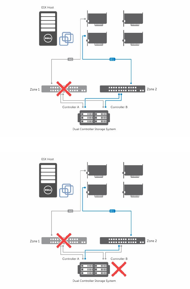
This example shows a fully redundant fabric configuration. If a Fibre Channel (FC) switch or HBA fails, the
alternate switch still connects to both storage RAID Controller Modules in the storage array. If a storage
RAID Controller Module also fails, the ESXi host can still access the remaining RAID Controller Module,
and all virtual disks fail over to that RAID Controller Module. A complete loss of access to storage occurs
if any other element fails.
Figure 69. Single failure
Figure 70. Double failure
This method works well to maintain access to the data in case of a hardware failure; however, MRU only
maintains one active path for each HBA group. Therefore, if you have an ESXi host with four HBAs, only
79
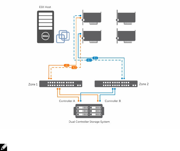
one HBA is active at a time. To achieve higher I/O throughput from the ESXi host to the storage array,
group the HBAs in pairs, and create virtual hosts for each pair of HBAs. This allows for a fully redundant
configuration, but also allows for two of the HBAs to be active at the same time versus a single HBA.
From the storage array, the second pair of HBAs is defined as a separate host, and then you can map
virtual disks directly to the new host or host group. You can use this same methodology to group
additional HBAs in the same manner. This method does require additional management to balance the
LUNs between the hosts/host groups to fully use the FC bandwidth between all HBA groups. When this
method is used in the array, the Automatic ESXi Host Configuration utility cannot determine which HBAs
are configured to each zone in the fabric, and the user must verify that a single HBA is connected to both
fabric zones for each HBA pair group.
Figure 71. Quad port configuration
NOTE: The intent of this configuration is to pair the HBAs so that no group of HBA ports are
contained on a single HBA card (if you are using dual port cards).
80
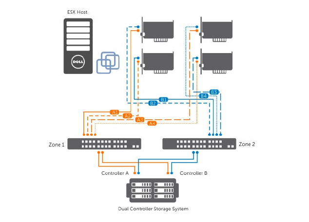
Figure 72. Eight HBA port configuration
81

11
Appendices
Current restrictions
This section describes known issues and available workarounds with MD vCenter Plug-in.
ID: 200627833 – multiple item delete restricted to less than 80 objects
Issue: When using multiple array delete or multiple virtual disk delete, you must limit the number of
selected objects to less than 80 per invocation of the command. This is due to the addressing space
allowed by the SDK.
Work Around: Run the multiple delete action repeatedly selecting less than 80 objects per invocation.
NOTE: Microsoft Internet Explorer browsers are limited to less than 40 objects per invocation.
ID: 200702748 – ESXi host to storage array wizard usability issues
Issue:
1. The Add Host Group button should be greyed-out on the initial loading of the manual configuration
page.
2. After creating an object under the parent item in the tree of the manual configuration page, the
visual representation of being selected (blue background on the label) on the parent is not displayed.
The font of the label stays bold.
3. The Rename dialogs for the Host Group and Host do not have titles.
4. After staging the objects to be created and you are on the Review Changes page, if you click on the
back button your items that were staged are no longer displayed.
Work Around: There is no real workaround for these issues.
ID: 200716368 – vSphere 6.0 SAS datastore view
Issue: When using vSphere 6.0, SAS Datastore virtual disks are not displayed in the Plug-in Datastores
view portlet.
Work Around: There is no workaround for this issue at this time.
Configuration worksheet
vCenter server Name: ______________________________________________________
82
DNS Name: ___________________________________________________________
IP Address: _________________________________________________________
vCenter server Administrator Name: ________________________________________
Password: ___________________________________________________________
Application Server Name: __________________________________________________
DNS Name: ___________________________________________________________
IP Address: _________________________________________________________
Storage Administrator User ID: ____________________________________________
Security Level: Read-Only ____________ or read-Write ________________
Storage Administrator User ID: ____________________________________________
Security Level: Read-Only ____________ or Read-Write ________________
Storage Array 1 Name: _____________________________________________________
IP Address(es): __________________________/__________________________
Password: ___________________________________________________________
Storage Array 2 Name: _____________________________________________________
IP Address(es): __________________________/__________________________
Password: ___________________________________________________________
Storage Array 3 Name: _____________________________________________________
IP Address(es): __________________________/__________________________
Password: ___________________________________________________________
Storage Array 4 Name: _____________________________________________________
IP Address(es): __________________________/__________________________
Password: ___________________________________________________________
83
