Bosch_Climate_5000_VRF_Catalogue_English_EN_ES 1508175161Bosch Climate 5000 VRF En
1508174394Bosch_Climate_5000_VRF_en BOSCH CLIMATE 5000 AAS-009-1CS pdf | FreeUserManuals.com
1508173792Bosch_Climate_5000_VRF_en BOSCH CLIMATE 5000 AA SERIES pdf | FreeUserManuals.com
1508174190Bosch_Climate_5000_VRF_en BOSCH CLIMATE 5000 AAS-009-0CS pdf | FreeUserManuals.com
1508174916Bosch_Climate_5000_VRF_en BOSCH CLIMATE 5000 AAS-012-1CS pdf | FreeUserManuals.com
1508174733Bosch_Climate_5000_VRF_en BOSCH CLIMATE 5000 AAS-012-0CS pdf | FreeUserManuals.com
User Manual: BOSCH CLIMATE 5000 AAS-024-1CS pdf | FreeUserManuals.com
Open the PDF directly: View PDF ![]() .
.
Page Count: 112 [warning: Documents this large are best viewed by clicking the View PDF Link!]

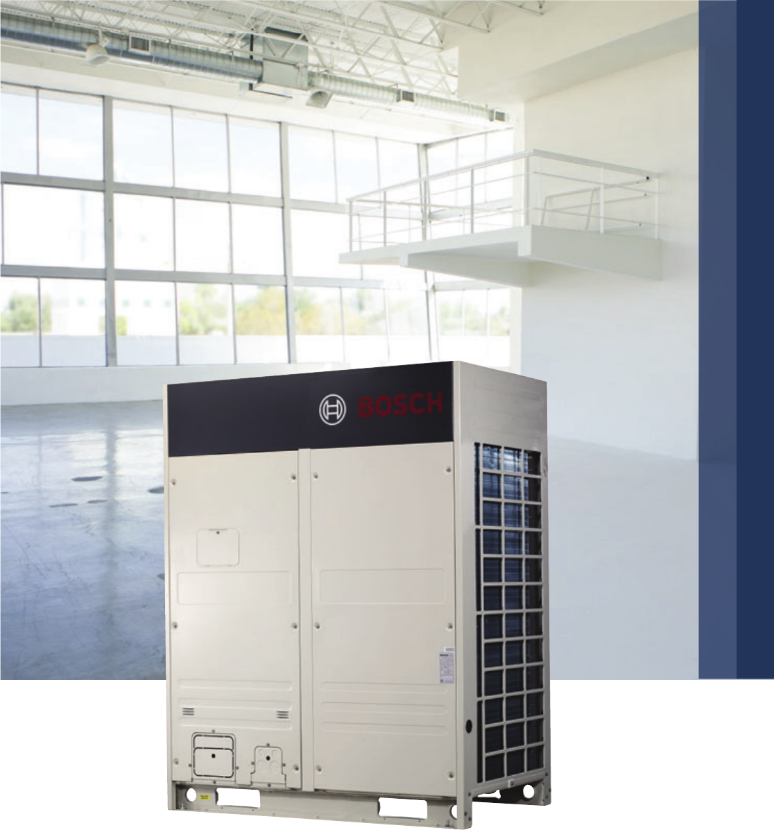
Bosch Climate 5000 VRF
Air Conditioning General Catalogue
Heat Pump & Heat Recovery
VRF Systems

Also a powerful
partner in the world
of air conditioning:
Bosch.
Discover new opportunities: Bosch is now
offering not only heating, hot water and
ventilation solutions, but also VRF (Variable
Refrigerant Flow) systems for efficient air
conditioning in commercial buildings. This
opens up attractive prospects for you and
even greater benefits from the expertise
of Bosch.
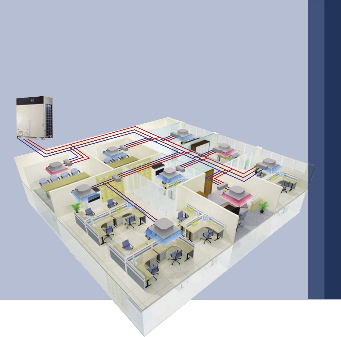
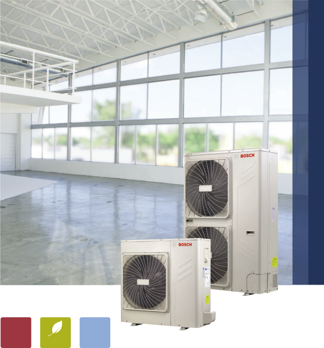
Ideal room climate at the touch of a button
Thanks to variable refrigerant flow technology,
the new Bosch VRF air conditioning systems are
convenient and save valuable energy at the same
time. They adapt their performance to current
demand and therefore also work with outstanding
efficiency under partial load. The systems consist
of outdoor units and several inside units and can
be utilised for both cooling and heating. These new
solutions from Bosch therefore play a decisive role
in ensuring that people in all areas of large buildings
enjoy a comfortable climate, independent of the
seasons of the year.
Efficiency from a single provider
If you are looking for an industrial boiler, a combined
heat and power system or high-efficiency VRF air
conditioning, Bosch has a multitude of solutions to
meet your precise needs. But that’s not all: Bosch also
realises customised package solutions with perfectly
harmonised components and technology from one single
provider. This means that you can comprehensively
exploit all existing efficiency potentials. The result:
your energy costs are permanently kept at a low level
and you make a sustainable contribution to protecting
the environment.
2 | Commercial Air Conditioners
The future: made by Bosch
Bosch enjoys a worldwide reputation for
highest-quality products and services. Global
organisation and production standards guarantee
uncontested approval and problem-free operation
of your largescale systems from Bosch. Thanks to
the enormous importance and long tradition of
innovation, you benefit from the unique, pioneering
spirit of Bosch engineering and technology. Advanced
technology and the high quality of your new VRF system
from Bosch thus ensure long-term fulfilment of its users’
expectations.

Commercial Air Conditioners | 3
Bosch Climate 5000 VRF
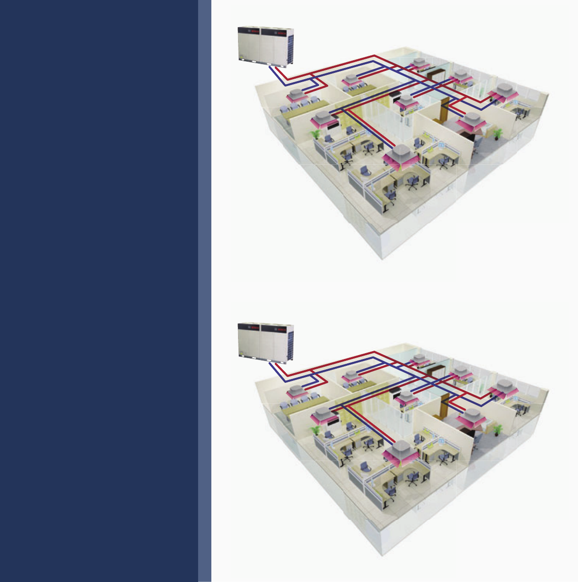
4 | Bosch Climate 5000 VRF
DCI Series –
DC Inverter Heat Pump
▶ Heat Pump (Cooling + Heating)
VRF air conditioning system
▶ Up to 64 indoor units can be
operated in one system
▶ Extensive capacity range from
8 HP to 72 HP in 2 HP increase-
ments, meets all customer
requirements concerning small
to large buildings
SDCI Series –
All DC Inverter Heat Pump
▶ Heat Pump (Cooling + Heating)
VRF air conditioning system
▶ All DC inverter technology with
all DC inverter compressors and
all DC fan motors makes high
energy efficiency
▶ Up to 64 indoor units can be
operated in one system
▶ Extensive capacity range from
8 HP to 72 HP in 2 HP increase-
ments, meets all customer needs
Bosch Climate 5000 VRF | 5
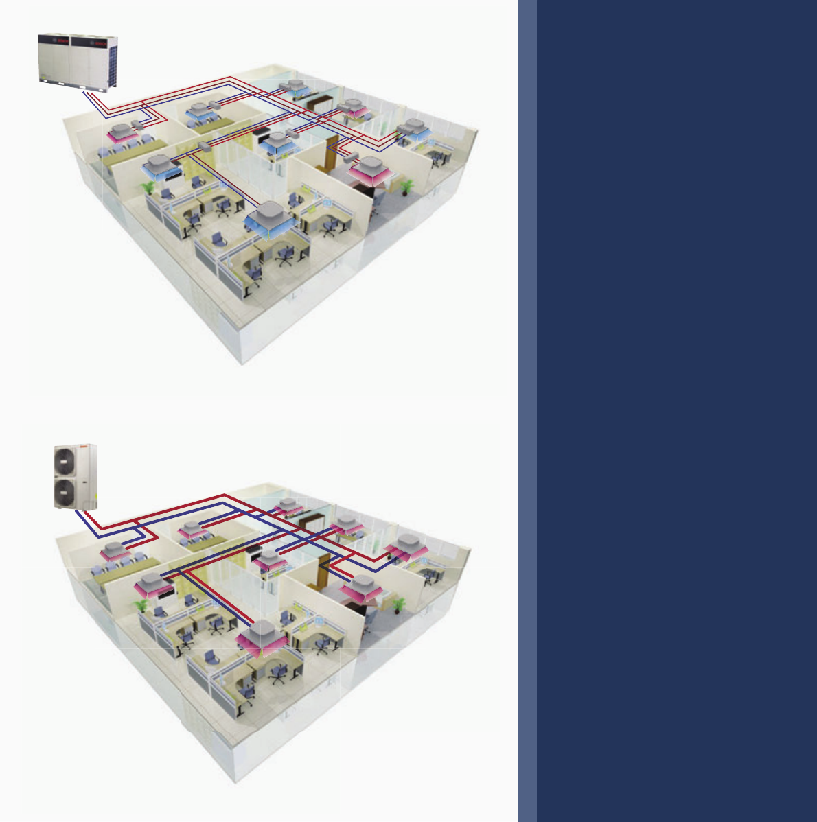
RDCI Series – All DC
Inverter Heat Recovery
▶ Simultaneous cooling and
heating operation in one system
▶ Up to 64 indoor units can be
operated in one system
▶ Extensive capacity range from
8 HP to 64 HP in 2 HP increase-
ments, meets all customer
requirement concerning small
to large buildings
▶ Heat recovery is achieved by
transfeering extract heat from
indoor units in cooling mode to
areas requiring heating
▶ The SBOX equipment switches
the system between cooling and
heating modes
MDCI Series –
Mini VRF Heat Pump
▶ Heat Pump (Cooling + Heating)
VRF air conditioning system
▶ All DC inverter technology
with all DC inverter compressors
and all DC fan motors makes
high energy efficiency
▶ Maximum 12 indoor units can
be operated in one system
▶ Extensive capacity range from
8 kW to 26 kW, suitable for
small offices, villas, shops, etc.
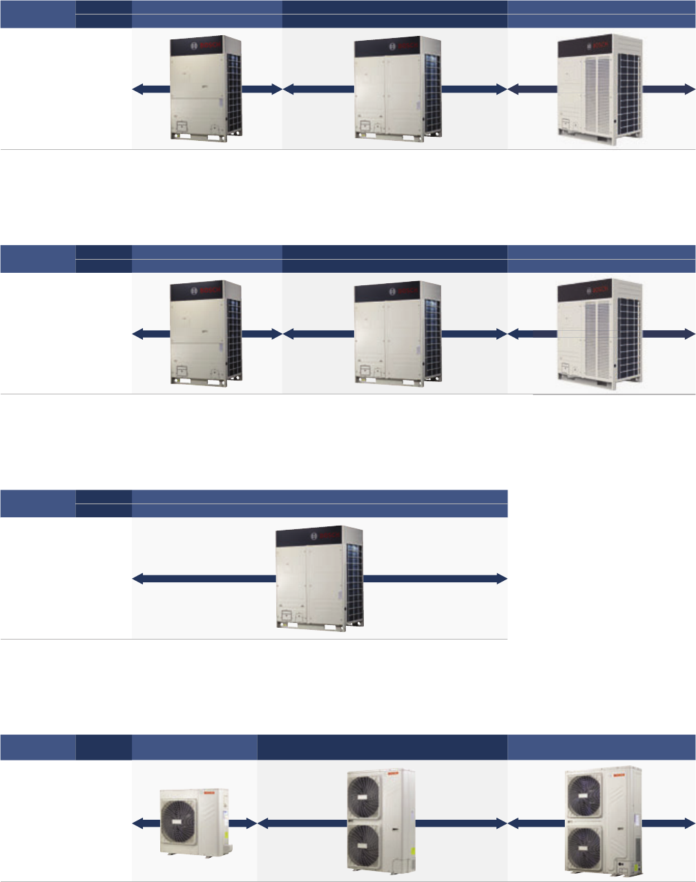
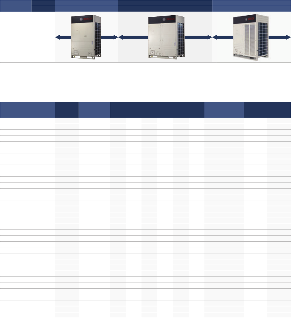
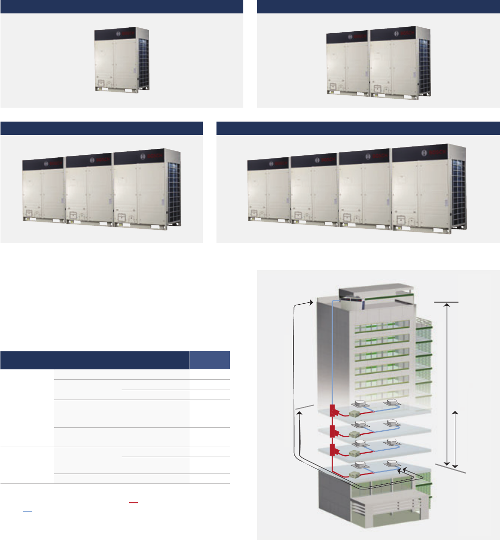
Product Lineup
DCI Series – DC Inverter Heat Pump VRF
SDCI Series – All DC Inverter Heat Pump VRF
RDCI Series – All DC Inverter Heat Recovery VRF
MDCI Series – Mini VRF Heat Pump
Capacity
Range
HP 8 10121416 18
kW 25.2 28.0 33.5 40.0 45.0 50.0
Appearance
Capacity
Range
HP 8 10 12 14 16 18
kW 25.2 28.0 33.5 40.0 45.0 50.0
Appearance
Capacity
Range
HP 8 10 12 14 16
kW 25.2 28.0 33.5 40.0 45.0
Appearance
Capacity
Range kW 8 10.5 12 14 16 18 20 22 26
Appearance
6 | Product Lineup

Contents | 7
Contents
8 Overview
13 DCI Series – DC Inverter Heat Pump VRF
27 SDCI Series – All DC Inverter Heat Pump VRF
37 RDCI Series – All DC Inverter Heat Recovery VRF
47 MDCI Series – Mini VRF Heat Pump
58 Indoor Units Lineup
78 Control Systems
90 Central Control Software
100 System Selection & Design
101 Heat Recovery Ventilation Units (HRV)
106 Joints
8 | Overview
Overview
Bosch Climate 5000 VRF has many key technologies which results in high improved performance.
You will find main technologies in the further pages which gives excellent cooling/heating performance,
comfort, reliability and easy installation.
Overview | 9
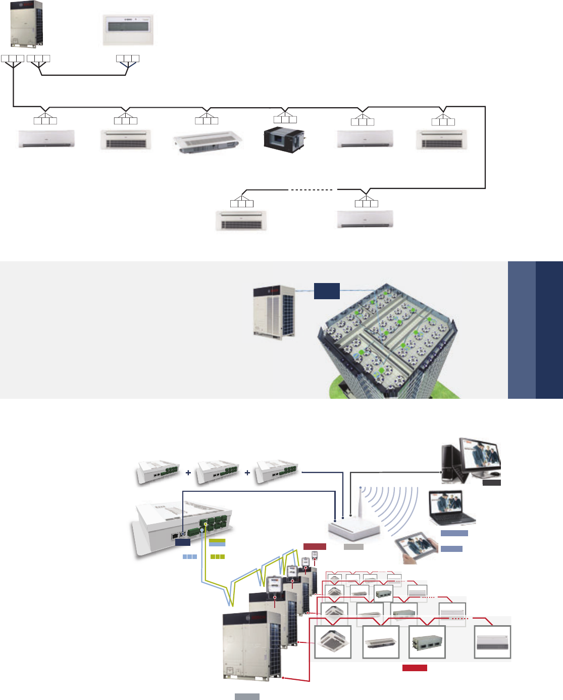
Bosch Climate 5000 VRF air conditioning system offers high class energy efficiency for cooling and heating by
utilizing brushless DC compressor control, innovative designed heat exchanger and several high performance
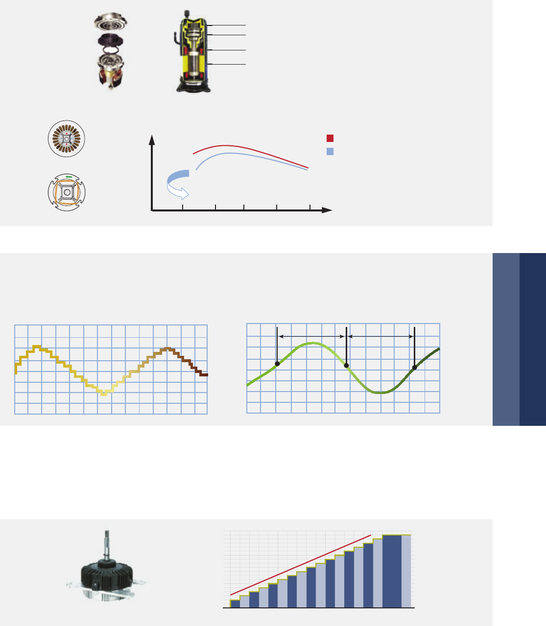
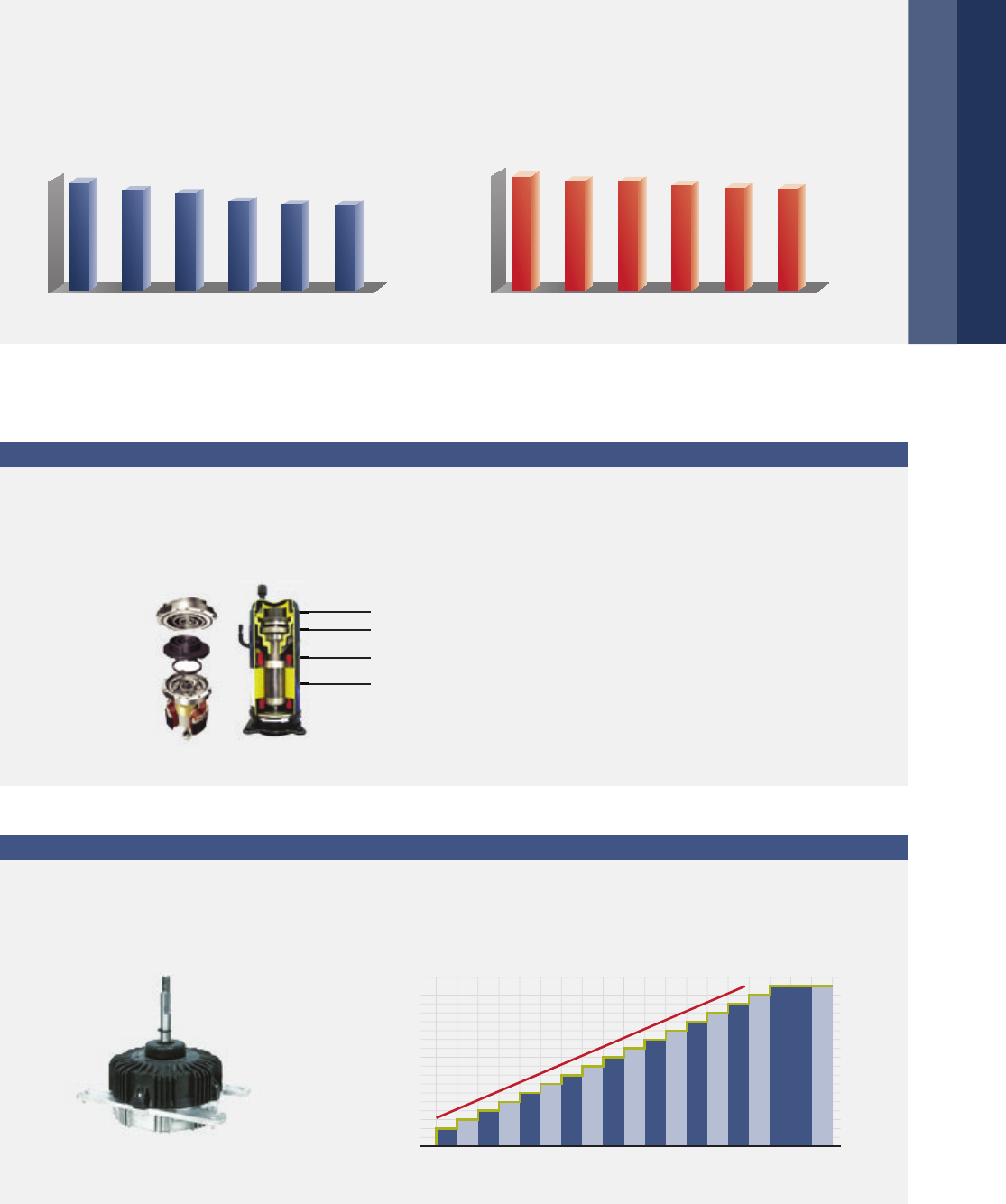
other parts. High efficiency DC inverter scroll compressor reduces power consumption by 25 %.
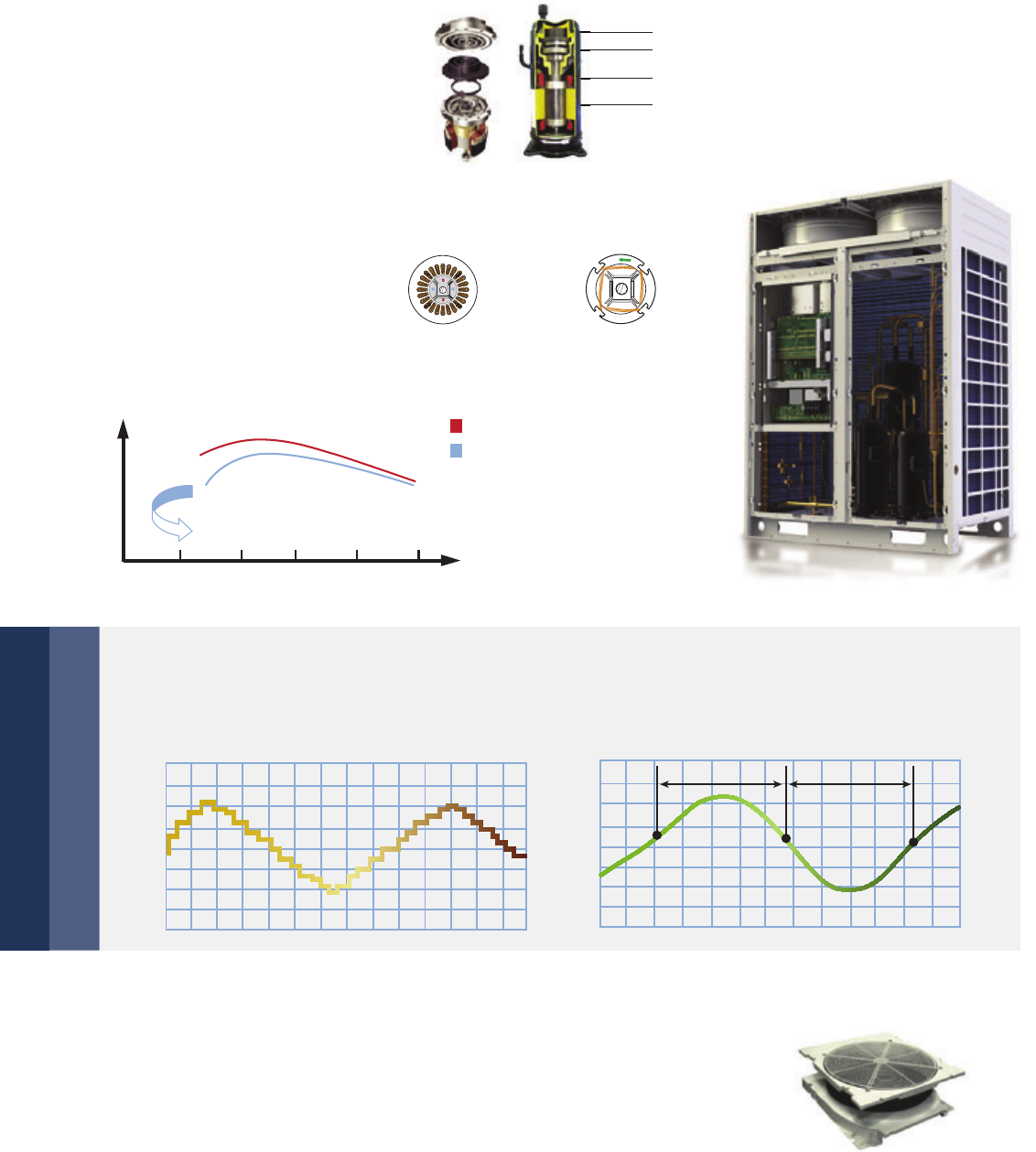
Powerful magnets provide high torque and efficiency and achieve 70 % reduction in volume.
High efficiency DC inverter compressor
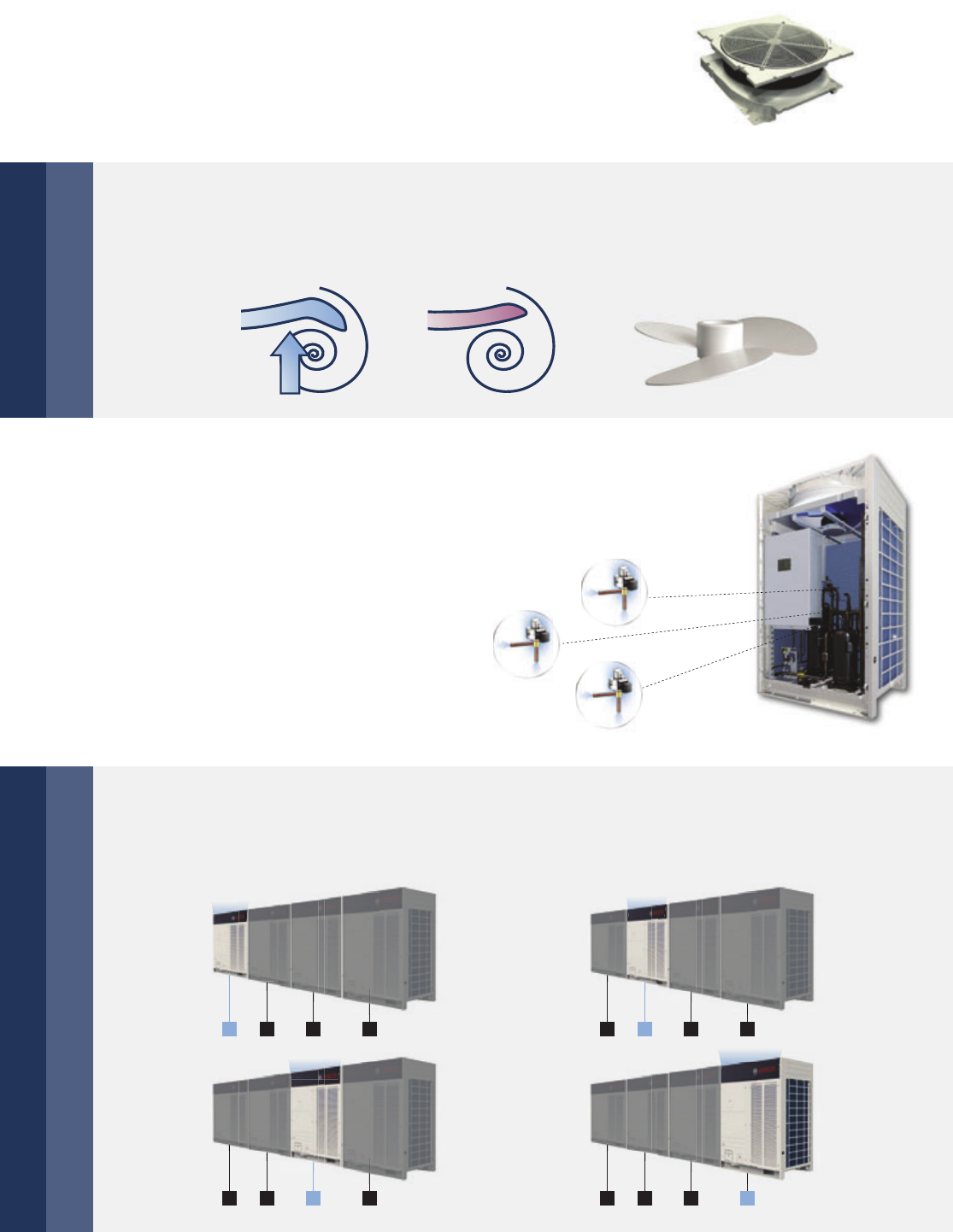
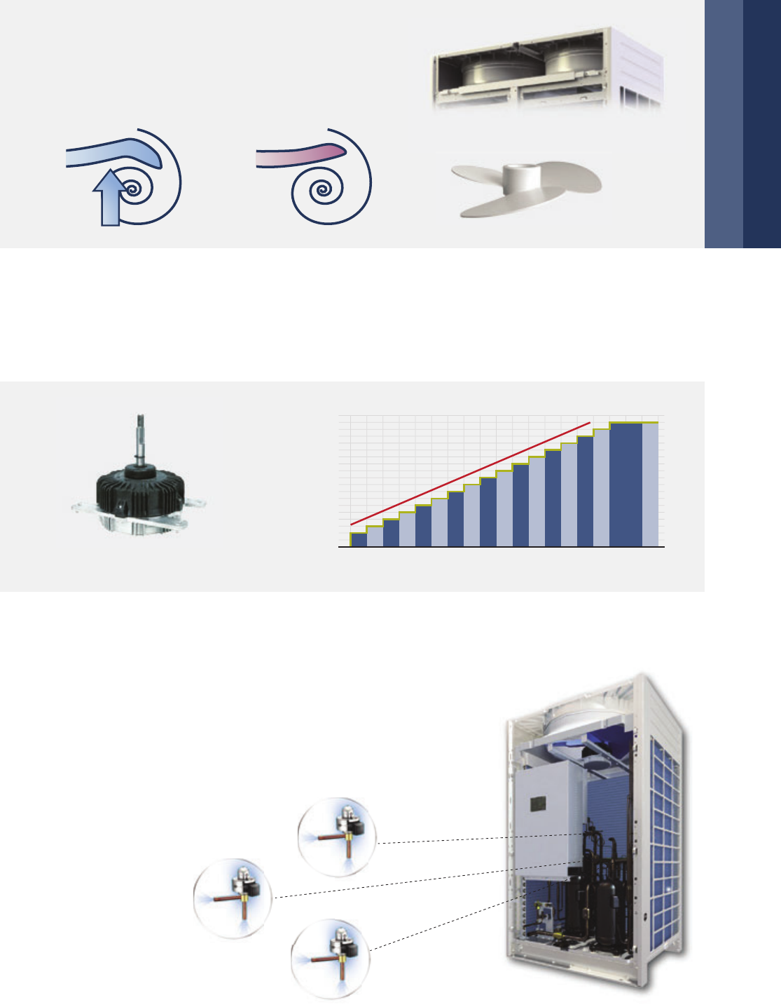
Adopting the 180° Sine Wave Inverter to smooth motor rotation greatly improves operating efficiency
compared with traditional sawtooth wave.
Smooth 180° sine wave DC inverter
According to the running load and system pressure, the system controls the speed of DC fan to achieve the
minimum energy consumption and best performance.
High efficiency DC fan motor
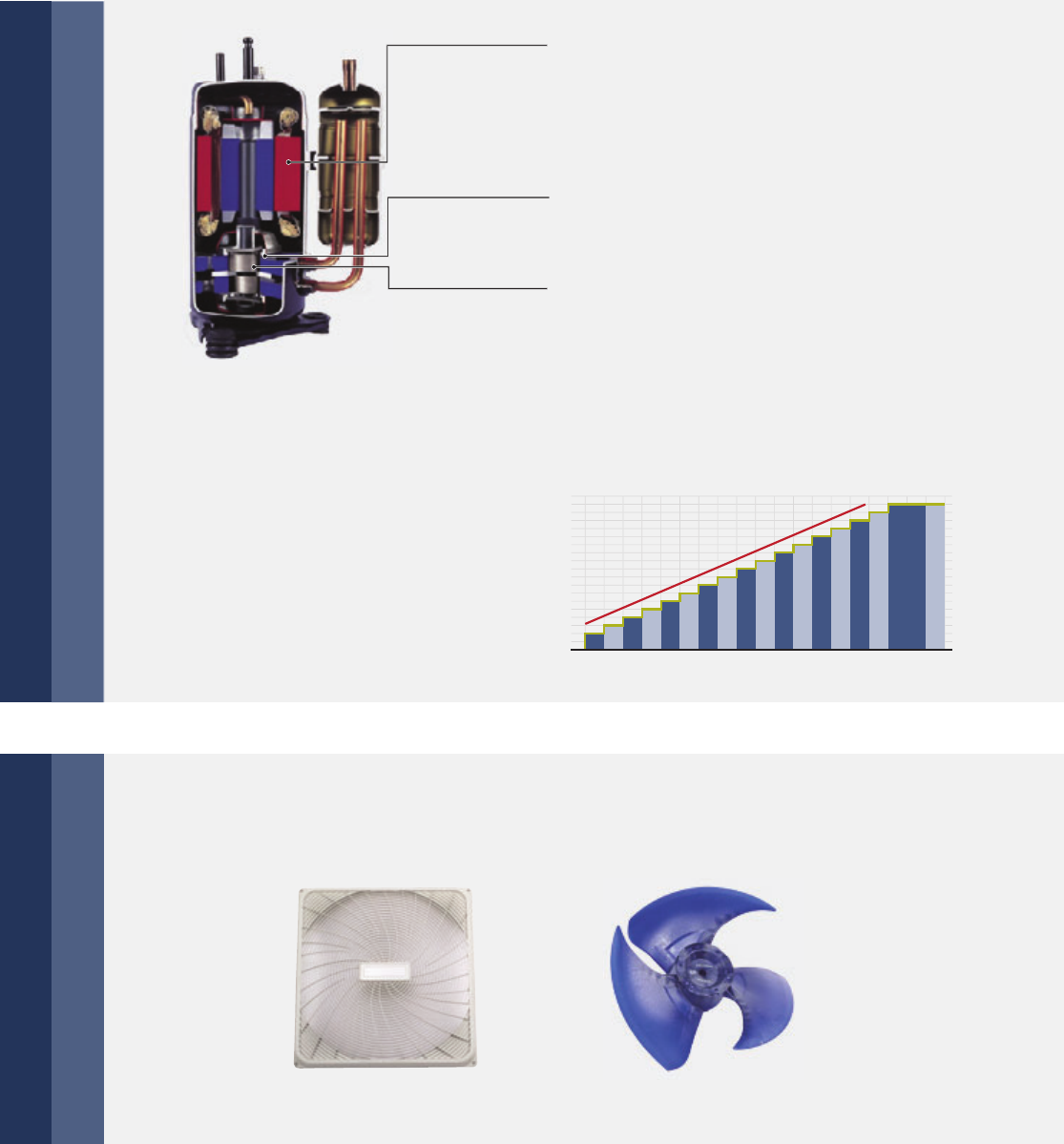
New structure enhances mid-frequency performance
Specially designed scroll profile for R-410A
More compact, weight reduced by 50%
Advanced permanent magnet DC motor improves
low-frequency band performance
Centralizing winding
Distributing winding
Compressor efficiency
Efficiency-Rotor Speed Curve
New DC motor-centralized winding
Common DC motor-distributing winding
20 40 60 80 100
Rotor speed(s-1)
180° 180°
DC motor
1000
System Pressure
200
-+
400
600
800
Motor Speed (RPM)
DC inverter
stepless
adjustment
AC inverter
multistep
adjustment
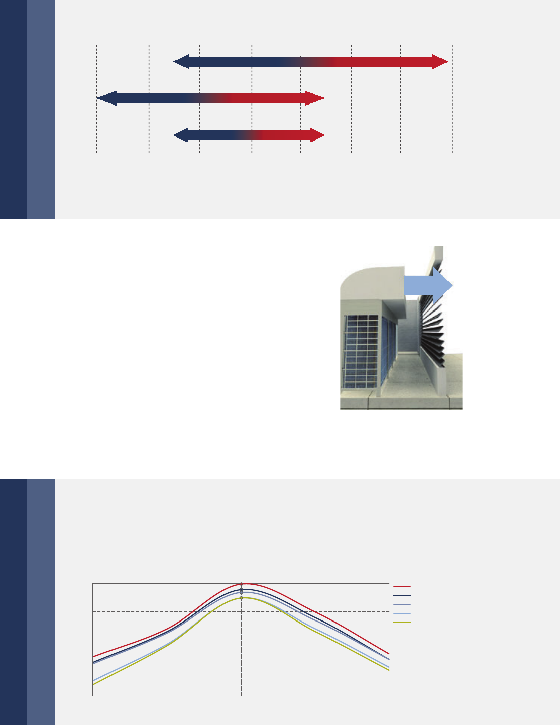
10 | Overview
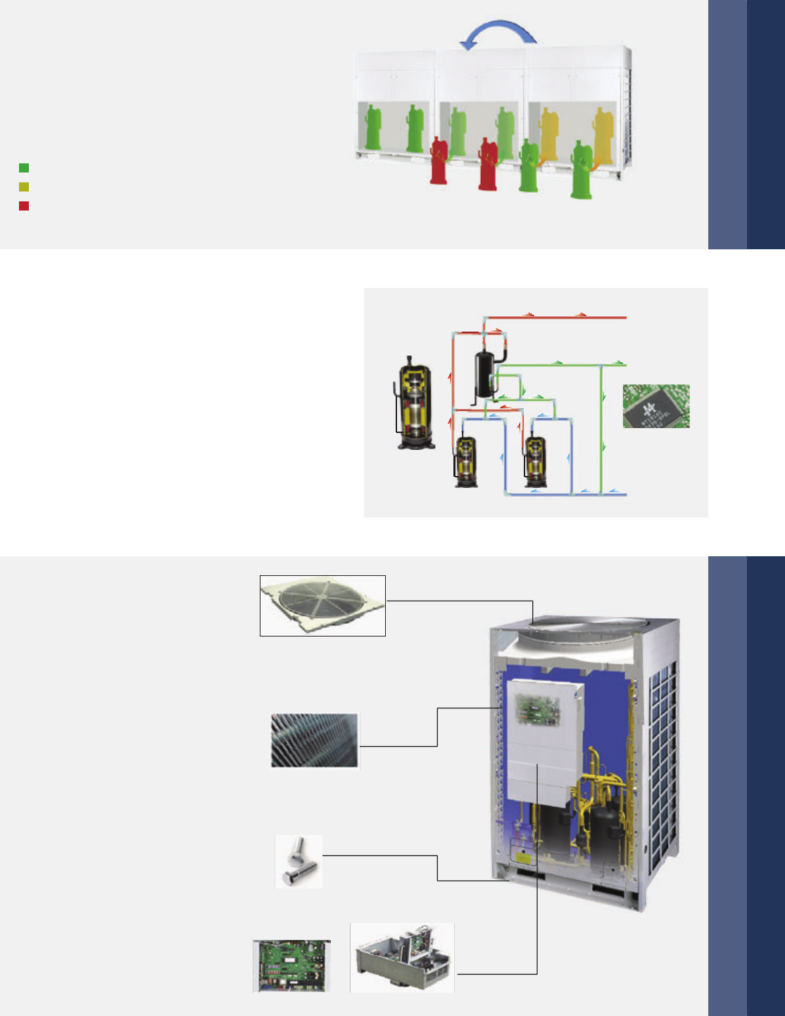
Optimized fan grille
Optimized fan blade shape with new air outlet grille enhanced air flow
volume which greatly improves fan performance and decreases noise.
Also, a higher external static pressure has been achieved up to 60 Pa.
A new blade with sharp edges and a slight curve increases the airflow rate and lowers vibration and
airflow resistance.
New profile fan blade
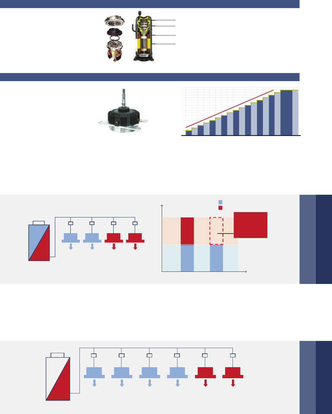
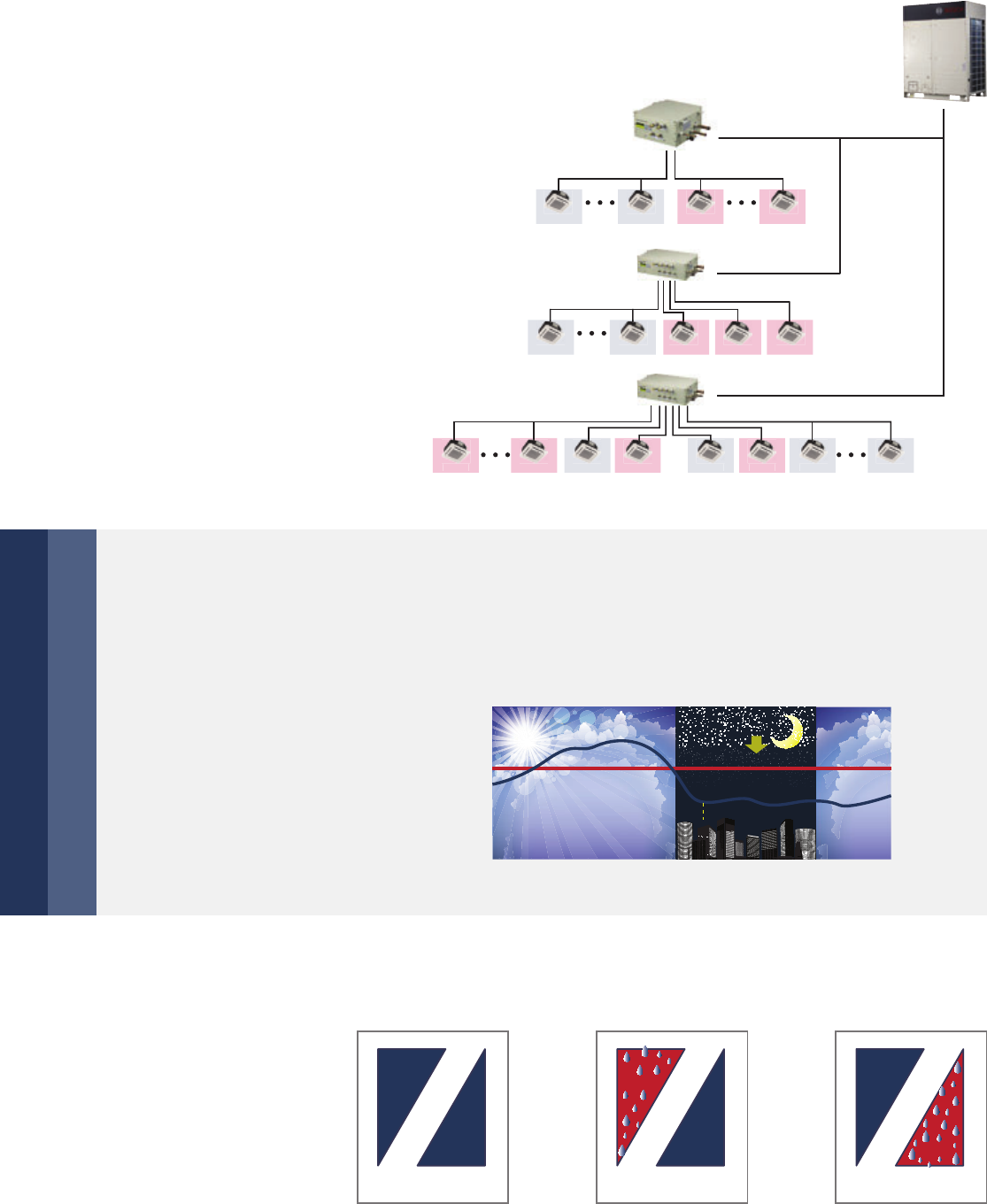
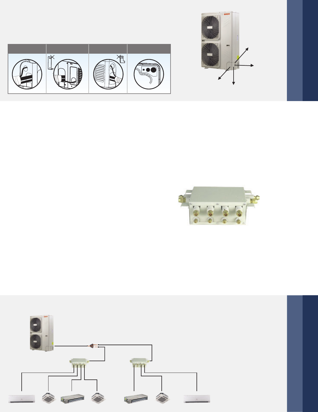
Multi solenoid valves control technology
Multi solenoid valves control technology in one
system. All the solenoid valves equipped in
the unit ensure temperature-control precisely,
system running steadily and economic to provide
a comfortable environment.
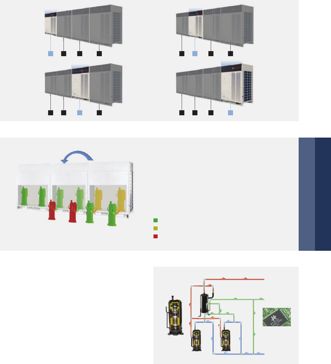
In one combination, any of the outdoor units can run as the master unit and master unit can cycle in a period,
to realize the equal lifespan among the outdoor units. As a result the system lifespan extends significantly.
Cycle duty operation
Priority
Priority
Priority
Priority
1 2 3 4
3 4 1 2
4 1 2 3
2 3 4 1
Overview | 11
Backup operation
In a multiple system, if one module is failed,
other modules can be backup instead of the
failed one for continuing operation.
Start backup operation
Running state
Stand by state
Fault or stop state
Precise oil control technology
5 stage oil control technology ensures every outdoor
unit & compressor’s oil always keep in the safe level,
completely solve the compressor oil lack problem.
1st stage: compressor internal oil separate
2nd stage: high efficiency oil separator
(separation efficiency up to 99%)
3rd stage: oil balance technology between compressors
4th stage: oil balance technology between modules
5th stage: intelligent system oil return program
1st stage
2nd stage
3rd stage
4th stage
5th stage
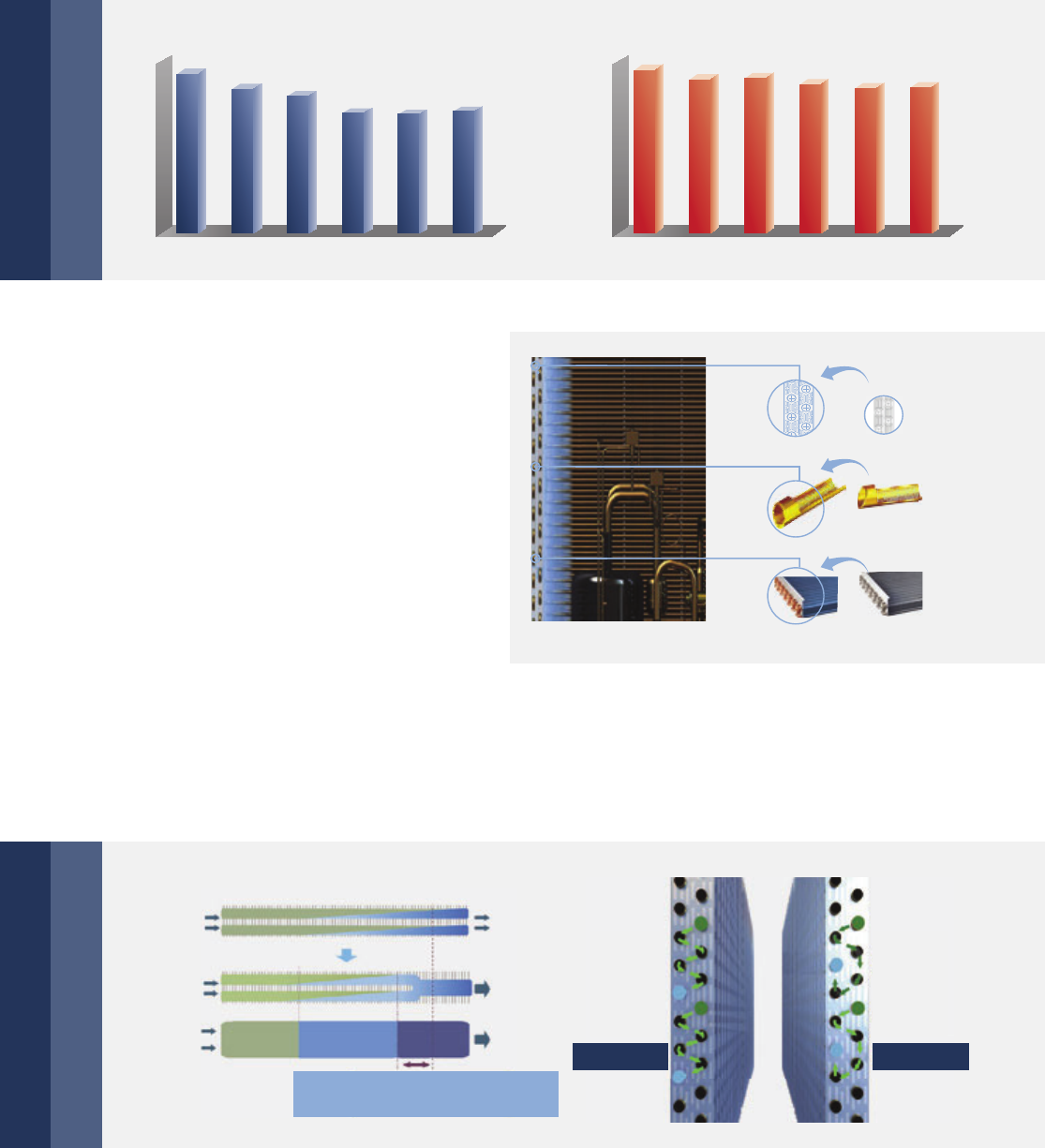
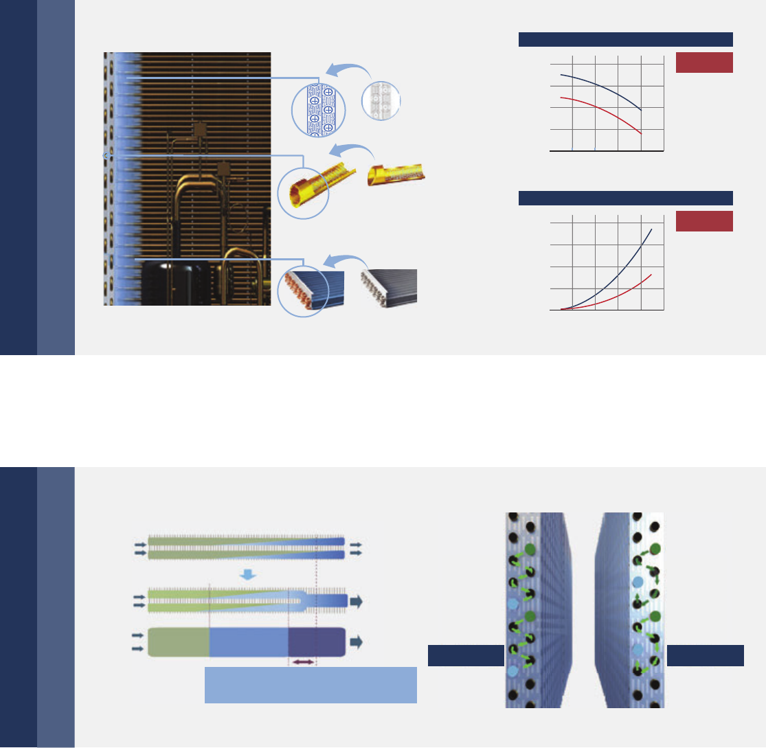
Anti corrosion treatment
Special anti corrosion
treatment of the heat
exchanger provides 5 to
6 times greater resistance
against acid rain and salt
corrosion.
The plastic grille protects against salt.
All panel parts are corrosion resistant
to protect against extreme ambient
conditions.
Corrosion resistant heat-exchanger fins.
All PCB parts in the unit are coated
with double-sided moisture proof
paint. The outer side of the control
box metal cover is spray-painted.
All screws are anti-rust.
12 | Overview
Double EXV control technology
Double EXV Control Technology in one system, each
EXV part achieves 480 pulse to adjust flow precisely.
Ensure the temperature-control precisely and steadily
to provide a comfortable envrionment.
DC inverter compressor soft start function reduces
strike to the electric network. This kind of high-
performance and low sound scroll compressor
operates at a faster rate when starting, reducing
start-up time. It also helps the unit to quickly adjust
the room temperature to the set level.
Intelligent soft start technology
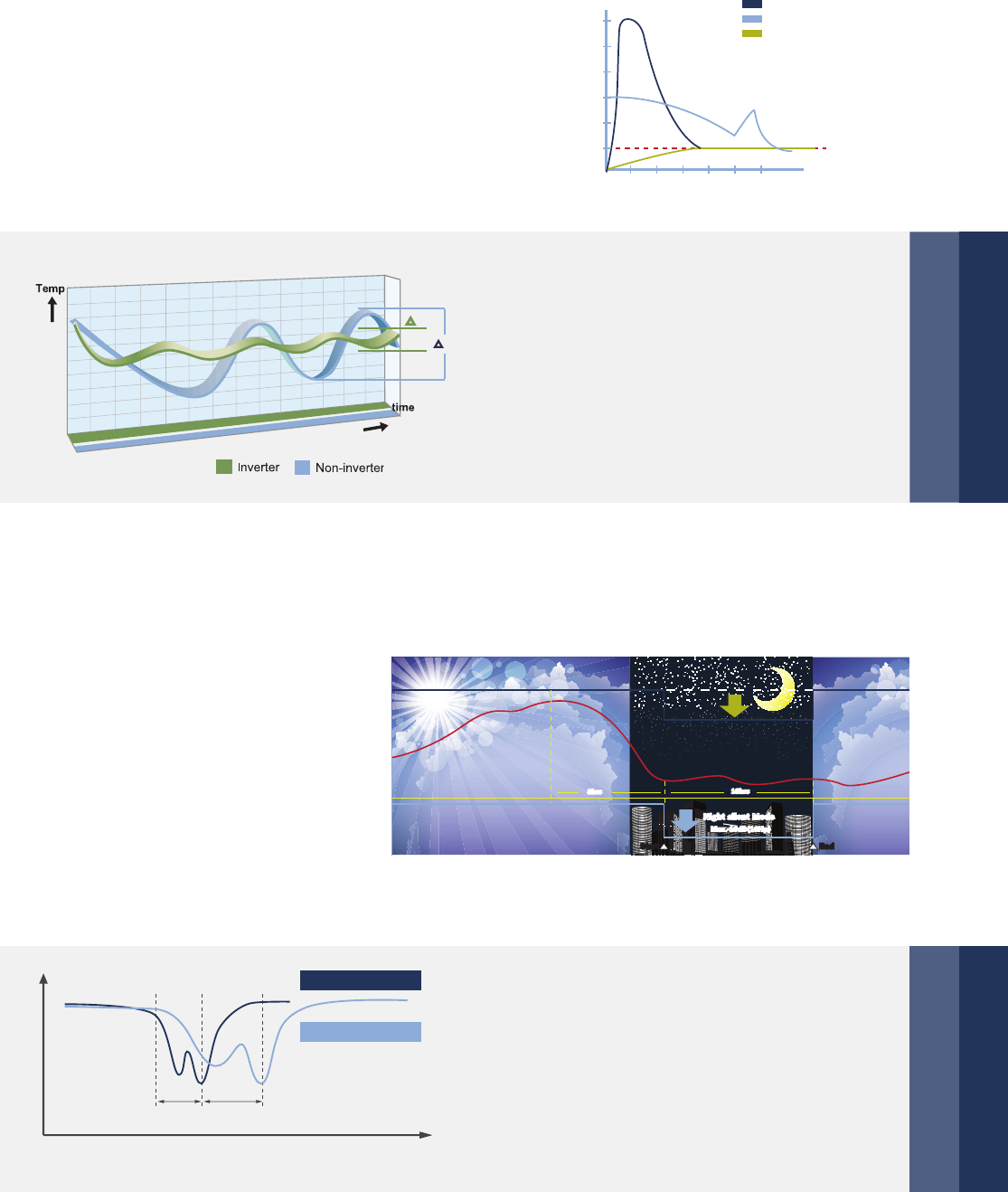
Quick warm-up & cool-down design
By utilizing the benefits of the inverter compressor,
the system can reach full load quickly and shorten
the warm-up and cool-down times to provide an
immediate and comfortable air solution.
Less temperature fluctuation will create a better
living environment.
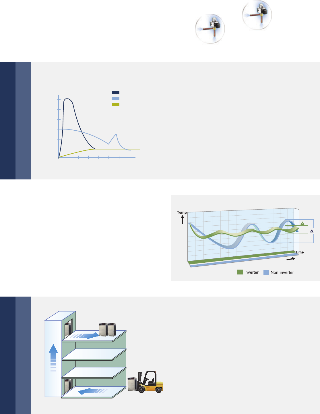
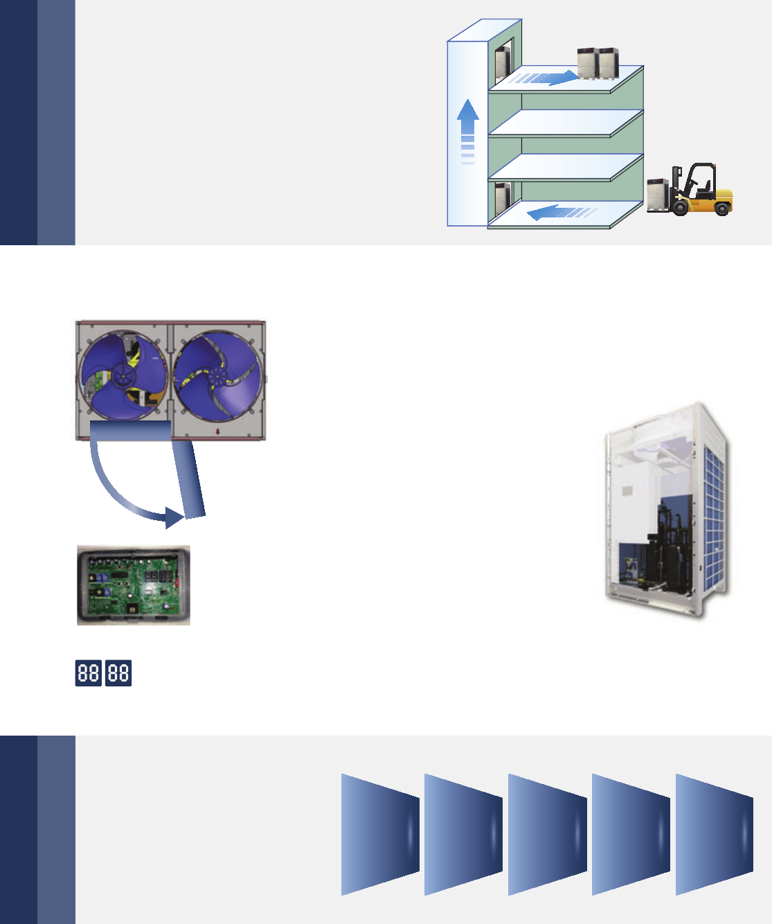
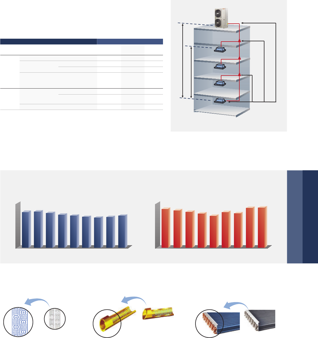
Compact size and light weight design minimizes the
installation footprint, reduces the installation floor load,
and is easier for transportation. For some projects the
units can even be transported through the elevator or
forklift, reduce access problem at the jobsite.
Compact design for effective use of space
123456
600
500
400
300
200
100
Comparison of start by inverter and by
traditional methods
Direct start
Y-△ start
Start by inverter
Starting current
(%)
(Sec)
△2
Fluctuation of room temperature
Cooling operation
1
Easy to transport
DCI Series | 13
DCI Series
Bosch DCI Series VRF offers flexible system design for all building types and high rise buildings.
System offers capacity up to 72 HP by combining maximum 4 outdoor units, with 2 HP as an
increasement.
14 | DCI Series
Lineup
Model
Capacity
Range
HP 8 10121416 18
kW 25.2 28.0 33.5 40.0 45.0 50.0
Appearance
Combination Table
Model No. of
Outdoor
Units
No. of
Compressors
Outdoor Unit Combination Maximum No.
of Connectable
Indoor Units
Capacity
8 HP 10 HP 12 HP 14 HP 16 HP 18 HP Cooling Heating
8 HP 1 1 1 13 25.2 27
10 HP 1 1 1 16 28 31.5
12 HP 1 2 1 20 33.5 37.5
14 HP 12 1 23 4045
16 HP 12 1 26 4550
18 HP 12 129 5056
20 HP 22 2 33 5663
22 HP 2 3 1 1 36 61.5 69
24 HP 2 3 1 1 39 68 76.5
26 HP 2 3 1 1 43 73 81.5
28 HP 2 3 1 1 46 78 87.5
30 HP 2 4 1 1 50 85 95
32 HP 2 4 1 1 53 90 101
34 HP 2 4 1 1 56 95 106
36 HP 2 4 2 59 100 112
38 HP 3 4 2 1 63 106 119
40 HP 3 5 1 1 1 64 113 126.5
42 HP 3 5 1 2 64 118 131.5
44 HP 3 5 1 1 1 64 123 137.5
46 HP 3 5 1 2 64 128 143.5
48 HP 3 6 1 1 1 64 135 151
50 HP 3 6 1 2 64 140 157
52 HP 3 6 1 2 64 145 162
54 HP 3 6 3 64 150 168
56 HP 4 6 2 2 64 156 175
58 HP 4 7 1 1 1 1 64 163 182.5
60 HP 4 7 1 1 2 64 168 188.5
62 HP 4 7 1 1 2 64 173 193.5
64 HP 4 7 1 3 64 178 199.5
66 HP 4 8 1 1 2 64 185 207
68 HP 4 8 1 3 64 190 213
70 HP 4 8 1 3 64 195 218
72 HP 4 8 4 64 200 224
Notes:
Capacities are based on the following conditions:
Cooling: Indoor temperature 27° C DB/19° C WB; Outdoor temperature 35°C DB/24° C WB
Heating: Indoor temperature 20° C DB/15° C WB; Outdoor temperature 7°C DB/6° C WB
Piping length: Piping length 7.5 m, level difference of zero.
The above models combination are factory-recommended models.
Features
DCI Series | 15
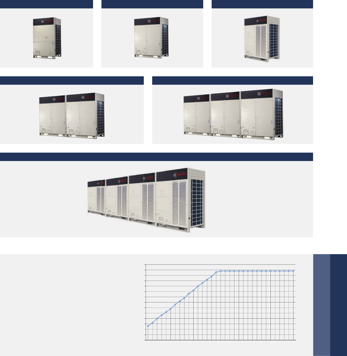
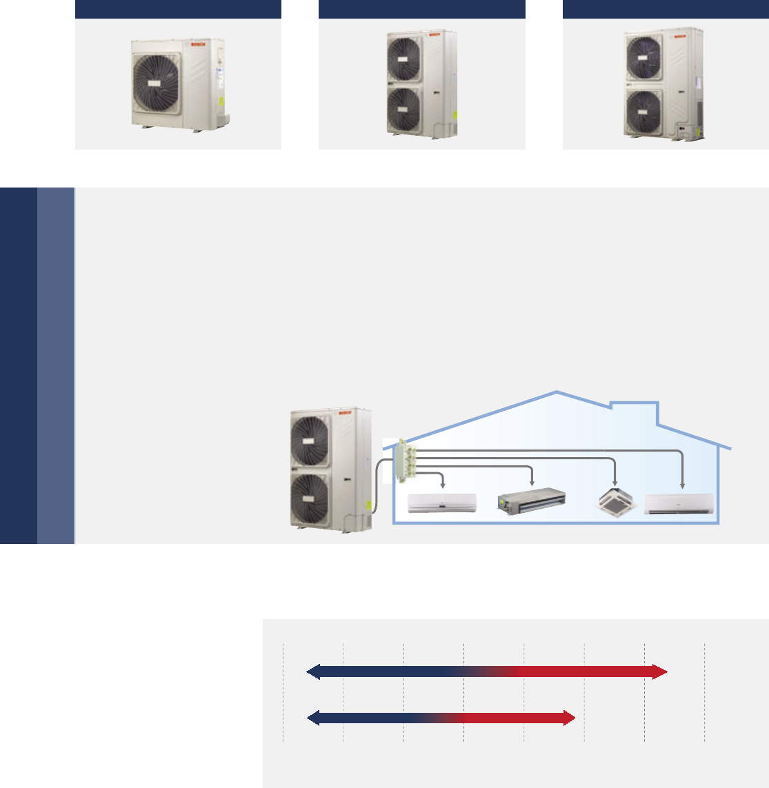
Wide Application Range
The outdoor units capacity range from 8 HP up to 72 HP in 2 HP increasement. Maximum 64 indoor units with
capacity up to 130% of total outdoor units can be connected as one refrigeration system.
8, 10 HP 12, 14, 16 HP 18 HP
20, 22, 24, 26, 28, 30, 32, 34, 36 HP 38, 40, 42, 44, 46, 48, 50, 52, 54 HP
56, 58, 60, 62, 64, 66, 68, 70, 72 HP
Number of connectable indoor unit
0
5
10
15
20
25
30
35
40
45
50
55
60
65
70
8HP
10HP
12HP
14HP
16HP
18HP
20HP
22HP
24HP
26HP
28HP
30HP
32HP
34HP
36HP
38HP
40HP
42HP
44HP
46HP
48HP
50HP
52HP
54HP
56HP
58HP
60HP
62HP
64HP
66HP
68HP
70HP
72HP
13
20
26
33
39
46
53
59
64
Large capacity for big sized building
More connectable indoor units
The high number of connectable units is
suitable for large buildings and projects.
16 | DCI Series
90 m
Maximum piping actual length 175 m
Level difference between
IDU~IDU 30 m
Level difference between IDU~ODU 70/110 m
The first indoor unit branch
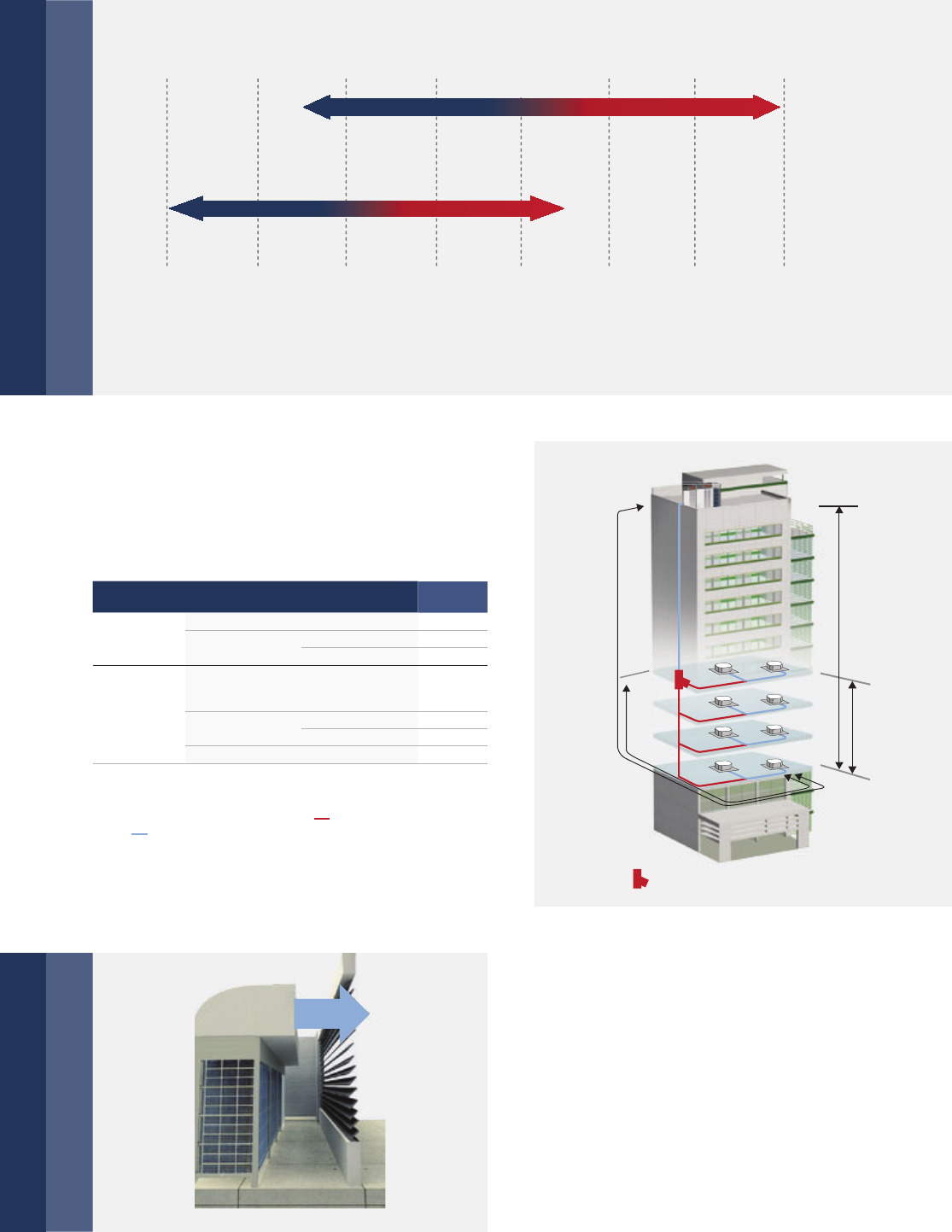
DCI Series system operates stable at extreme temperatures ranging from -20° C to 48°C.
The solution supports an incredible piping length
of 1,000 m and level difference of 110 m, making it
perfect for large projects.
The high static pressure propeller and optimized fan
guard can adapt to various installation environments.
60 Pa is available for the 12 HP model, 40 Pa is available
for other models. As a standard 0–20 Pa is set by default.
Wide operation range
Long piping length
Extra high static pressure – Max. 60 Pa and
air volume increased by 10 %
010203040
5
0-10-20
COOLING MODE
HEATING MODE
Outdoor temp. °C(D.B.)
48°C
24°C
-20°C
-5°C
Outdoor Temperature
Outdoor Temperature
* Total pipe length is equal to two times pipe length
plus pipe length.
* When the farthest pipe length is more than 40 m, it needs to meet the
specific condition according to the installation part of the technical
manual.
IDU = Indoor unit
ODU = Outdoor unit
Item Permitted
value (m)
Piping length
Total pipe length* (Actual) 1000
Maximum
piping (L)
Actual length 175
Equivalent length 200
Level
difference
Equivalent piping length from
the farthest IDU to the first indoor
branch joint
40/90*
Level difference
between IDU~ODU
Outdoor unit up 70
Outdoor unit down 110
Level difference between IDU~IDU 30
60 Pa
DCI Series | 17
In one combination, any outdoor unit can run as the master outdoor unit to equalize the life span of all units.
Higher Reliability
Cycle duty operation
High efficiency oil balance and oil
return technology
Backup operation
5 stage oil control technology ensures every outdoor
unit & compressor’s oil always keep in the safe level,
completely solve the compressor oil lack problem.
1st stage: compressor internal oil separate
2nd stage: high efficiency oil separator
(separation efficiency up to 99%)
3rd stage: oil balance technology between compressors
4th stage: oil balance technology between modules
5th stage: intelligent system oil return program
In a multiple system, when the master unit
failed, any single unit can be set as the master
unit, then the remaining units can keep on
working.
Running state
Stand by state
Fault or stop stateStart backup operation
1st stage
2nd stage
3rd stage
4th stage
5th stage
Priority
Priority
Priority
Priority
1 2 3 4
1 2 3 4
1 2 3 4
1 2 3 4
18 | DCI Series
The new designed window fins enlarge the
heat-exchanging area, decrease the air resist-
ance, save more power and enhance heat
exchange performance.
Hydrophilic fins and inner-threaded copper
pipes optimize heat exchange efficiency.
High Efficiency
12° C sub cooling
EER
4.29
3.89 3.7
3.25 3.21 3.29
8 HP 10 HP 12 HP 14 HP 16 HP 18 HP
4.39 4.14 4.17 4.02 3.91 3.93
8 HP 10 HP 12 HP 14 HP 16 HP 18 HP
COP
High performance heat exchanger
DCI Series with high efficiency DC compressors, all DC motors and high efficient heat exchanger.
The cooling EER up to 4.29 and the heating COP up to 4.39 in the 8 HP category
New design Original design
High efficiency inner-thread pipe,
enhance heat transfer.
Hydrophilic fins Normal fins
Innovative designed outdoor unit high efficiency heat ex-
changer, one time can reach up to 12° C subcooling degree,
reduces the system resistance and improves reliability.
When the outdoor temperature is 35° C, the refrigerant
can be cooled to 37.1° C, thus achieving high efficiency
heat exchange with only 2.1° C temperature difference.
Gas
Gas
Gas
Liquid
Liquid
Liquid
Gas LiquidGas-Liquid
Increase the hot liquid rate in the condenser
Improve the heat-exchange efficiency
Original design
New design
Common
Design
Sub-cooling
Technology
43°C
75°C
37.1°C
75°C
DCI Series | 19
DC inverter compressor soft start function reduces strike to
the electric network. This kind of high-performance and low
sound scroll compressor operates at a faster rate when start-
ing, reducing start-up time. It also helps the unit to quickly
adjust the room temperature to the set level.
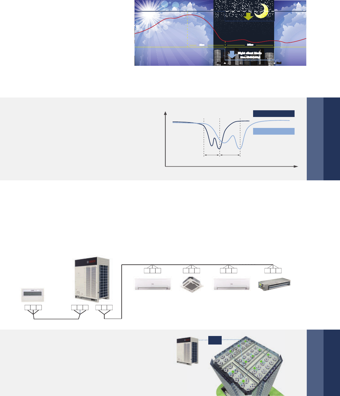
This feature which is easily set on
the PCB board allows the unit to be
set to different time options during
Non Peak and Peak operation time
optimizing the units noise output.
Extra silent operation mode can
reduce sound level further, minimum
46.8 dB(A). Night silent operation
will be activated X hours after the
peak temperature during daytime,
and it will go back to normal opera-
tion after Y hours.
High Comfort
Intelligent soft start technology
Night silent operation mode
123456
600
500
400
300
200
100
Comparison of start by inverter and by
traditional methods
Direct start
Y-△ start
Start by inverter
Starting current
(%)
(Sec)
Quick warm-up & cool-down design
Intelligent defrosting raises heat capacity
Utilizing the scroll compressor benefits,
DCI Series system can reach full load
quickly and shorten warm-up or cool-
down time for an immediately.
Intelligent defrosting program to judge the defrosting
time according to the systems' real requirement,
reduce the heating loss by unnecessary defrosting
and make the indoor side more comfortable. Every
time defrosting last only 4 min. due to the use of
specialized defrosting valve.
△2
Fluctuation of room temperature
Cooling operation
1
▶ Model 1→X: 6 hours, Y: 10 hours ▶ Model 2→X: 8 hours, Y: 10 hours
▶ Model 3→X: 6 hours, Y: 12 hours ▶ Model 4→X: 8 hours, Y: 8 hours
noisc
Notes:
This function can be activated by setting at site. Temperature(load) curve shown in the graph is just an example.
08:00
100
50
14:00 22:00 08:00
Peak value of ambient temp.
Noise dB Load % Capacity %
8hrs 10hrs
Night silent Mode
Max.-10dB(10Hp)
8hrs 10hrs
Night silent Mode
Max.-10dB(10Hp)
EndStart EndStart
Heating capacity
Usual defrosting
Δt
Time
t min
Intelligent defrosting
20 | DCI Series
Compact size and light weight design minimizes
the installation footprint, reduces the installation
floor load, and is easier for transportation. For
some projects the units can even be transported
through the elevator or forklift.
In VIP priority or vote priority mode,
the address of the VIP unit should be
set as 63. If there is no named 63
unit, it will respond to vote priority.
Easy Installation and Service
Easy Maintenance
Easier Installation and Service
Various locking modes
Newly designed rotating control box is so
excellent that it can rotate in a wide angle.
It is convenient for inspection and maintenance
of the pipeline system and greatly reduces the
time of dismount the electric control box.
Self-diagnosis function helps service
engineers locate faults quickly and easily.
Compressor is located near the access panel,
which simplifies checks and enables valve
or compressors parts to be replaced easily.
* Rotating Control box is available for 18 HP model which
with G-shape Condenser.
Easy to transport
W
i
d
e
R
o
t
a
t
i
n
g
A
n
g
l
e
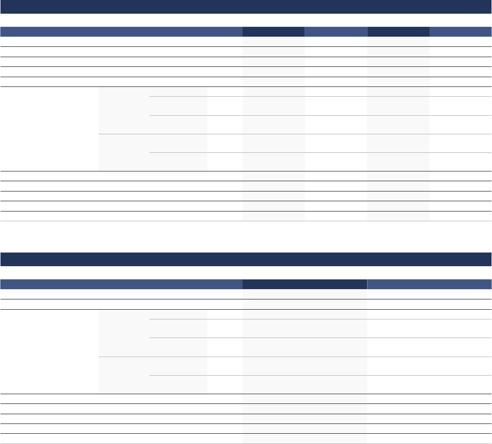
Reserved checking window on
electric control box for convenient
spot checking and status enquiry.
Heating
priority mode
(default)
Cooling
priority
mode
Priority mode
(VIP priority
or Vote
priority)
Only respond
to Heating
mode
Only respond
to Cooling
mode
Max. 1000 m
Outdoor
Indoor
Ammeter Switch
Laptop
Tablet
PC
LAN
K1K2EE
XY
M-Net
DCI Series | 21
Intelligent Manager of
Bosch, designed specifically
to control VRF systems, is
based around a centralized
format and dedicated to the
complete control and moni-
toring of all the system’s
functions. It can be used as
a flexible multi-purpose
system and applied to a
variety of needs, according
to the scale, purpose and
control method of each
building.
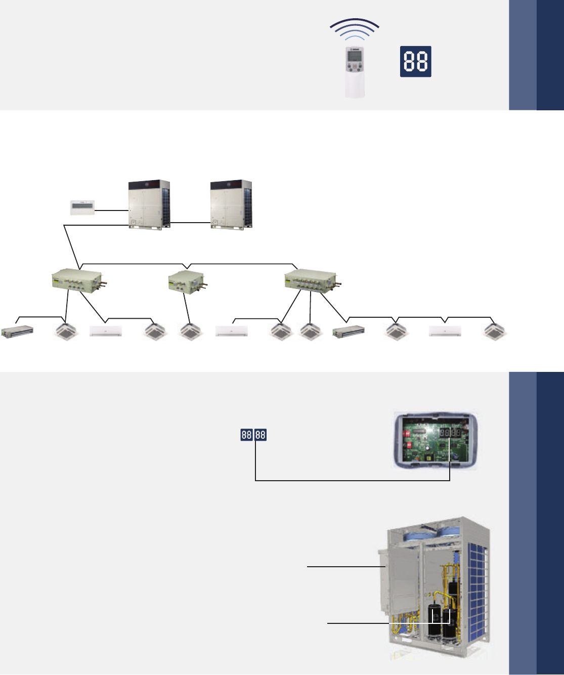
Simple signal line connection
Integrated solution for control and management
Auto addressing
Outdoor unit can distribute address for
each indoor unit automatically.
Wireless and wired controllers can enquire
and modify each indoor unit’s address.
PQE
PQE PQE PQE
XYE XYE
PQE PQE
PQEPQE
PQE
Centralized controllers can be connected from indoor side
or outdoor side (XYE terminals) at will. Only one group of
communication wire of PQE, achieved both of communication
for indoor & outdoor unit. It’s more convenient for communica-
tion wiring.
ON
Compressor efficiency
Efficiency-Rotor Speed Curve
New DC motor-centralized winding
Common DC motor-distributing winding
20 40 60 80 100
Rotor speed(s-1)
22 | DCI Series
DCI Series achieves the industry’s
top class energy efficiency of cooling
and heating by utilizing the brushless
reluctance DC compressor control,
DC fan motor, and improved perfor-
mance heat exchanger. High efficiency
DC inverter compressor reduces
power consumption by 25 %.
Technologies
High efficiency DC inverter compressor
Powerful magnets provide high
torque and efficiency and achieve
70 % reduction in volume.
Smooth the rotation of the compressor motor, improve the compressor operation efficiency sharply.
Effectively control the harmonic current and electromagnetic noise, and fully pass the international EMC test.
Smooth 180° sine wave DC inverter
New structure enhances mid-frequency performance
Specially designed scroll profile for R-410A
More compact, weight reduced by 50%
Advanced permanent magnet DC motor improves
low-frequency band performance
Centralizing winding Distributing winding
180° 180°
Fan grille
Optimized fan blade shape with new air outlet grille enhanced air flow volume
which greatly improves fan performance and decreases noise. Also, a higher
external static pressure has been achieved optionally from 20 Pa to 40 Pa.
(60 Pa is available for 12 HP)
Common Sawtooth
Wave
180° Sine Wave DC
Inverter
DCI Series | 23
A new blade with sharp edges and a slight curve increases
the airflow rate and lowers vibration and airflow resistance.
Multi-EXV Control Technology in one system, each EXV part achieves
480 pulse to adjust flow precisely. Ensure the temperature-controlling
precisely and steadily to give a comfortable envrionment.
New profile fan blade
Multi-EXV control technology
All DC fan motors
According to the running load and system pressure, the system controls the speed of DC fan to achieve the
minimum energy consumption and best performance.
DC motor
1000
System Pressure
200
-+
400
600
800
Motor Speed (RPM)
DC inverter
stepless
adjustment
AC inverter
multistep
adjustment
24 | DCI Series
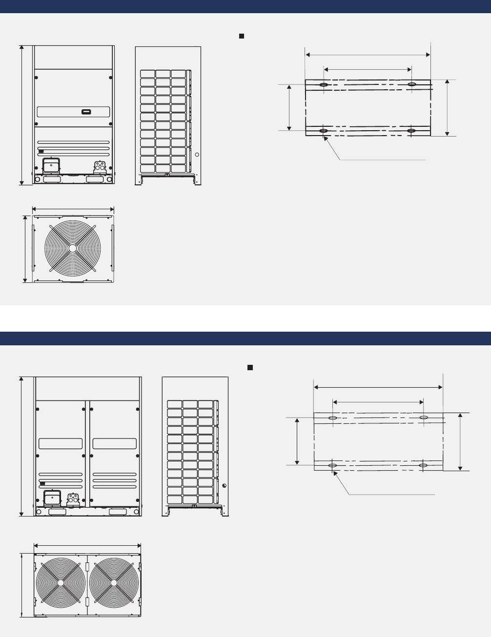
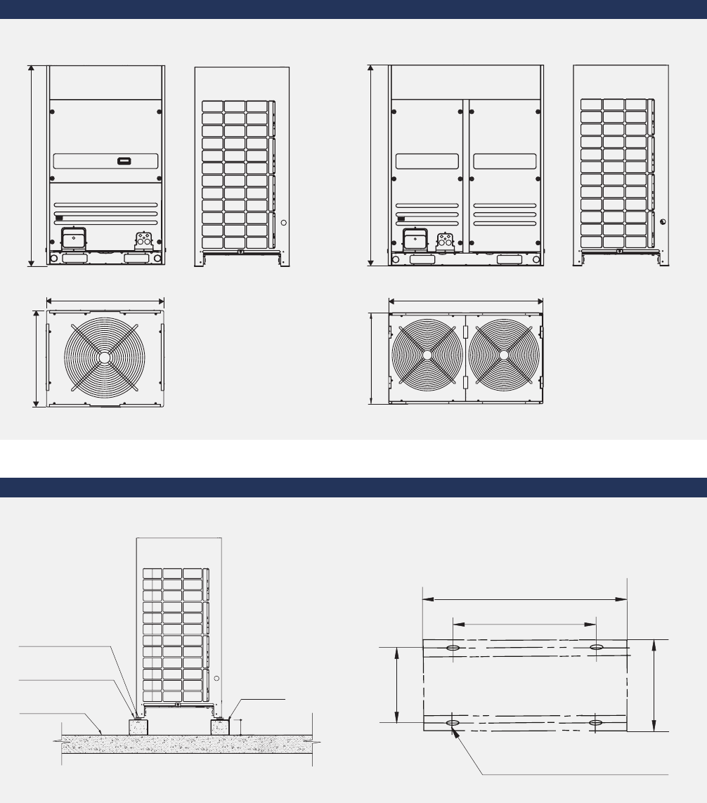
Dimensions
8, 10 HP Unit: mm
1615
765
960
Position illustration of screw bolts (Unit: mm)
15×23 long u-shape hole
960
830
736
765
12, 14, 16, 18 HP
1615
Unit: mm
765
1250
Position illustration of screw bolts (Unit: mm)
15×23 long u-shape hole
1250
1120
736 765
8, 10 HP
12, 14, 16, 18 HP
DCI Series | 25
DCI Series
DCI 8/25-3, DCI 10/28-3, DCI 12/33-3
Outdoor Unit
Specifications
Model DCI 8/25-3 DCI 10/28-3 DCI 12/33-3
Power supply V/Ph/Hz 380-415/3/50
Cooling
Capacity kW 25.2 28.0 33.5
Power input kW 5.88 7.20 9.05
EER kW/kW 4.29 3.89 3.70
Heating
Capacity kW 27.0 31.5 37.5
Power input kW 6.15 7.61 8.99
COP kW/kW 4.39 4.14 4.17
Connectable indoor unit Total capacity % 50 – 130 50 – 130 50 – 130
Max. quantity 13 16 20
Sound pressure level dB(A) 57 57 59
Pipe connections
Liquid pipe mm Ф9.53 Ф9.53 Ф12.7
Gas pipe mm Ф22.2 Ф22.2 Ф25.4
Oil balance pipe mm Ф6 Ф6 Ф6
Fan motor
Type DC DC DC+DC
Quantity 1 1 1+1
Air flow rate m³/h 11,500 11,500 15,100
Motor output W 420 420 420
ESP Pa 0 – 20 (default) 0 – 20 (default) 0 – 20 (default)
Pa 20 – 40 (customized) 20 – 40 (customized) 20 – 60 (customized)
DC inverter compressor
Quantity 1 1 1
Capacity kW 31.59 31.59 11.8
Crankcase heater W 27.6×2 27.6×2 27.6×2
Oil type FVC68D FVC68D FVC68D
Oil charge ml 500 500 500
Fixed scroll compressor
Quantity – – 1
Capacity kW – – 17.1
Crankcase heater W – – 27.6
Oil type – – FVC68D
Oil charge ml – – 500
Refrigerant Type R-410A R-410A R-410A
Factory charging kg 9 9 11
Design pressure (High/Low) MPa 4.4/2.6 4.4/2.6 4.4/2.6
Net dimension (W×H×D) mm 960×1615×765 960×1615×765 1250×1615×765
Packing size (W×H×D) mm 1025×1790×830 1025×1790×830 1305×1790×820
Net weight kg 200 200 268
Gross weight kg 215 215 288
Operating temperature range Cooling °C -5-48 -5-48 -5-48
Heating °C -20-24 -20-24 -20-24
Notes:
Capacities are based on the following conditions:
Cooling: Indoor temperature 27° C DB/19° C WB; Outdoor temperature 35°C DB/24° C WB.
Heating: Indoor temperature 20° C DB/15° C WB; Outdoor temperature 7°C DB/6° C WB.
Piping length: Piping length is 7.5 m, level difference is zero.
Connection piping diameter is based on the condition that the total equivalent liquid length is less than 90 m.
When the total equivalent liquid length is more than 90 m, please refer to technical manual to choose the connection piping diameter.
Sound values are measured in a semi-anechoic room, at a position 1 m in front of the unit and 1.3 m above the floor.
26 | DCI Series
DCI Series
DCI 14/40-3, DCI 16/45-3, DCI 18/50-3
Outdoor Unit
Specifications
Model DCI 14/40-3 DCI 16/45-3 DCI 18/50-3
Power supply V/Ph/Hz 380-415/3/50
Cooling
Capacity kW 40.0 45.0 50.0
Power input kW 12.31 14.02 15.20
EER kW/kW 3.25 3.21 3.29
Heating
Capacity kW 45.0 50.0 56.0
Power input kW 11.19 12.79 14.25
COP kW/kW 4.02 3.91 3.93
Connectable indoor unit Total capacity % 50 – 130 50 – 130 50 – 130
Max. quantity 23 26 29
Sound pressure level dB(A) 60 60 61
Pipe connections
Liquid pipe mm Ф12.7 Ф12.7 Ф15.9
Gas pipe mm Ф25.4 Ф28.6 Ф28.6
Oil balance pipe mm Ф6 Ф6 Ф6
Fan motor
Type DC+DC DC+DC DC+DC
Quantity 1+1 1+1 1+1
Air flow rate m³/h 15,100 15,100 15,250
Motor output W 900 900 940
ESP Pa 0 – 20 (default) 0 – 20 (default) 0 – 20 (default)
Pa 20 – 40 (customized) 20 – 40 (customized) 20 – 40 (customized)
DC inverter compressor
Quantity 1 1 1
Capacity kW 31.59 31.59 11.8
Crankcase heater W 27.6×2 27.6×2 27.6×2
Oil type FVC68D FVC68D FVC68D
Oil charge ml 500 500 500
Fixed scroll compressor
Quantity 1 1 1
Capacity kW 13.39 13.39 20.9
Crankcase heater W 27.6 27.6 27.6
Oil type FVC68D FVC68D FVC68D
Oil charge ml 500 500 500
Refrigerant Type R-410A R-410A R-410A
Factory charging kg 13 13 16
Design pressure (High/Low) MPa 4.4/2.6 4.4/2.6 4.4/2.6
Net dimension (W×H×D) mm 1250×1615×765 1250×1615×765 1250×1615×765
Packing size (W×H×D) mm 1305×1790×820 1305×1790×820 1305×1790×820
Net weight kg 280 280 300
Gross weight kg 300 300 320
Operating temperature range Cooling °C -5-48 -5-48 -5-48
Heating °C -20-24 -20-24 -20-24
Notes:
Capacities are based on the following conditions:
Cooling: Indoor temperature 27° C DB/19° C WB; Outdoor temperature 35°C DB/24° C WB.
Heating: Indoor temperature 20° C DB/15° C WB; Outdoor temperature 7°C DB/6° C WB.
Piping length: Piping length is 7.5 m, level difference is zero.
Connection piping diameter is based on the condition that the total equivalent liquid length is less than 90 m.
When the total equivalent liquid length is more than 90 m, please refer to technical manual to choose the connection piping diameter.
Sound values are measured in a semi-anechoic room, at a position 1 m in front of the unit and 1.3 m above the floor.
SDCI Series | 27
SDCI Series
SDCI outdoor units achieve world’s largest capacity of 72 HP with the industry’s top class energy
efficiency of cooling and heating. It supports an incredible piping length of 1,000 m and a longer level
difference of 110 m, making it perfect for big-sized and high-rise buildings for wide application.

28 | SDCI Series
Recommended Combination Table
Model No. of
Outdoor
Units
No. of
Compressors
Outdoor Unit Combination Maximum No.
of Connectable
Indoor Units
Capacity (kW)
8 HP 10 HP 12 HP 14 HP 16 HP 18 HP Cooling Heating
8 HP 1 1 1 13 25.2 27
10 HP 1 1 1 16 28 31.5
12 HP 1 2 1 20 33.5 37.5
14 HP 12 1 23 4045
16 HP 12 1 26 4550
18 HP 12 129 5056
20 HP 22 2 33 5663
22 HP 2 3 1 1 36 61.5 69
24 HP 2 3 1 1 39 68 76.5
26 HP 2 3 1 1 43 73 81.5
28 HP 2 3 1 1 46 78 87.5
30 HP 2 4 1 1 50 85 95
32 HP 2 4 1 1 53 90 101
34 HP 2 4 1 1 56 95 106
36 HP 2 4 2 59 100 112
38 HP 3 4 2 1 63 106 119
40 HP 3 5 1 1 1 64 113 126.5
42 HP 3 5 3 64 120 135
44 HP 3 5 1 1 1 64 123 137.5
46 HP 3 5 1 2 64 128 143.5
48 HP 3 6 1 1 1 64 135 151
50 HP 3 6 1 2 64 140 157
52 HP 3 6 1 2 64 145 162
54 HP 3 6 3 64 150 168
56 HP 4 6 2 2 64 156 175
58 HP 4 7 1 1 1 1 64 163 182.5
60 HP 4 7 1 1 2 64 168 188.5
62 HP 4 7 1 1 2 64 173 193.5
64 HP 4 7 1 3 64 178 199.5
66 HP 4 8 1 1 2 64 185 207
68 HP 4 8 1 3 64 190 213
70 HP 4 8 1 3 64 195 218
72 HP 4 8 4 64 200 224
Notes:
Capacities are based on the following conditions:
Cooling: Indoor temperature 27° C DB/19° C WB; Outdoor temperature 35°C DB/24° C WB.
Heating: Indoor temperature 20° C DB/15° C WB; Outdoor temperature 7°C DB/6° C WB.
Piping length: Piping length is 7.5 m, level difference is zero.
The above combination models are factory-recommended models.

Features
SDCI Series | 29
Wide Application Range
The outdoor units capacity range from 8 HP up to 72 HP in 2 HP increasement. Maximum 64 indoor units with
capacity up to 130% of total outdoor units can be connected in one refrigeration system.
Wide range of outdoor units
Large connectable
indoor units quantity
The large quantity of connectable
units is suitable for large buildings
and projects.
8, 10 HP 12, 14, 16 HP 18 HP
20, 22, 24, 26, 28, 30, 32, 34, 36 HP 38, 40, 42, 44, 46, 48, 50, 52, 54 HP
56, 58, 60, 62, 64, 66, 68, 70, 72 HP
Number of connectable indoor unit
0
5
10
15
20
25
30
35
40
45
50
55
60
65
70
8HP
10HP
12HP
14HP
16HP
18HP
20HP
22HP
24HP
26HP
28HP
30HP
32HP
34HP
36HP
38HP
40HP
42HP
44HP
46HP
48HP
50HP
52HP
54HP
56HP
58HP
60HP
62HP
64HP
66HP
68HP
70HP
72HP
13
20
26
33
39
46
53
59
64
30 | SDCI Series
Level difference
between IDU~IDU 30 m
90 m
Longest actual piping length 175 m
Level difference between IDU~ODU 110 m
SDCI series system operates stably at extreme temperatures ranging from -20° C to 48° C.
Maximum 60 Pa external static pressure can be
customized for the outdoor unit, flexible to build-in
installation. A standard 0 – 20 Pa external static
pressure is equipped by default for all outdoor units.
Outdoor units ESP can be customized at site (12 HP
is 60 HP, other models 40 HP).
Wide operation range
Long piping length
High external static pressure
010203040
5
0-10-20
COOLING MODE
HEATING MODE
Outdoor temp. °C(D.B.)
48°C
24°C
-20°C
-5°C
Outdoor Temperature
Outdoor Temperature
* Total pipe length is equal to two times pipe length
plus pipe length.
** When the piping length from the farthest IDU to the first indoor branch
joint is more than 40 m, it needs to meet specific conditions according
to the installation part of the technical manual to achieve 90 m.
Item Permitted
value (m)
Piping length
Total pipe length*(Actual) 1000*
Maximum
piping (L)
Actual length 175
Equivalent length 200
Equivalent piping length from
the farthest IDU to the first indoor
branch joint
40/90**
Level
difference
Level difference
between IDU~ODU
Outdoor unit up 70
Outdoor unit down 110
Level difference between IDU~IDU 30
60 Pa
IDU = Indoor unit
ODU = Outdoor unit
SDCI Series | 31
High Efficiency
The cooling EER up to 4.29 and the heating COP up to 4.39 in the 8 HP category.
High COP/EER values
EER COP
4.29 3.97 3.81 3.54 3.4 3.38
8 HP 10 HP 12 HP 14 HP 16 HP 18 HP
4.39 4.17 4.17 4.02 3.91 3.89
8 HP 10 HP 12 HP 14 HP 16 HP 18 HP
New structure enhances mid-frequency performance
Specially designed scroll profile for R-410A
More compact, weight reduced by 50 %
Advanced permanent magnet DC motor improves
low-frequency band performance
All DC inverter technology
All DC inverter compressors make the capacity output better distributed, and always work at 60 – 140 Hz
which is the most efficient range. It makes the efficiency more than 30 % higher than the normal.
All DC inverter compressors
All DC fan motors
DC motor
1000
System Pressure
200
-+
400
600
800
Motor Speed (RPM)
DC inverter
stepless
adjustment
AC inverter
multistep
adjustment
According to the running load and system pressure, the system controls the speed of DC fan to achieve the
minimum energy consumption and best performance.
32 | SDCI Series
▶ The new designed window fins enlarge the heat-exchanging area, decrease the air resistance,
save more power and enhance heat exchange performance.
▶ Hydrophilic film fins and inner-threaded copper pipes optimize heat exchange efficiency.
▶ Innovative designed high efficiency heat exchanger, which can reach up to 12° C subcooling
degree, reduces the system resistance and improves reliability.
▶ When the outdoor temperature is 35° C, the refrigerant can be cooled down to 37.1° C,
thus achieving high heat-exchanging efficiency with only 2.1° C temperature difference.
High performance heat exchanger
New design Original design
High efficiency inner-threaded pipe,
enhance heat transfer.
Hydrophilic fins + inner-threaded pipes
Relative frosting rate
0
0
200 400 600 800 1000
0.2
0.4
0.6
0.8
New design
Original design
Relative windage resistance
Windage & air flow
Reduce 28%
Relative windage resistance
Relative frosting rate
0
0
200 400 600 800 1000
0.2
0.4
0.6
0.8
New design
Original design
Frost contrast
Reduce 30%
Gas
Gas
Gas
Liquid
Liquid
Liquid
Gas LiquidGas-Liquid
Increase the hot liquid rate in the condenser
Improve the heat-exchange efficiency
Original design
New design
Common
Design
Sub-cooling
Technology
43°C
75°C
37.1°C
75°C
SDCI Series | 33
High comfort outdoor unit’s multi-
choice of silent mode during the
night. Super silent operation mode
can reduce sound level further,
minimum 45 dB(A).
Night silent operation will be activated
X hours after the peak temperature
during daytime, and it will go back to
normal operation after Y hours.
High Comfort
Easy Installation and Service
Night silent operation mode
Simple signal line connection
▶ Model 1→X: 6 hours, Y: 10 hours ▶ Model 2→X: 8 hours, Y: 10 hours
▶ Model 3→X: 6 hours, Y: 12 hours ▶ Model 4→X: 8 hours, Y: 8 hours
noisc
Notes:
This function can be activated by setting at site. Temperature(load) curve shown in the graph is just an example.
08:00
100
50
14:00 22:00 08:00
Peak value of ambient temp.
Noise dB Load % Capacity %
8hrs 10hrs
Night silent Mode
Max.-10dB(10Hp)
8hrs 10hrs
Night silent Mode
Max.-10dB(10Hp)
EndStart EndStart
Intelligent defrosting technology
Intelligent defrosting program will judge the defrosting
time according to the system real requirement,
reduce the heating loss by unnecessary defrosting
and make the indoor side more comfortable.
Defrosting time can be shortened to 4 min. due to
the specialized defrosting valve.
Heating capacity
Usual defrosting
Δt
Time
t min
Intelligent defrosting
PQE
XYE XYE
PQE PQE PQEPQE
Centralised controllers can be connected from indoor side or outdoor side (XYE terminals) at will. Only one group
of communication wire of PQE, achieved both of communication for indoor & outdoor unit. It’s more convenient for
communication wiring.
Auto addressing
Outdoor unit can distribute address for each indoor
unit automatically. Wireless and wired controllers can
enquire and modify each indoor unit’s address.
ON

34 | SDCI Series
Outdoor Unit
SDCI Series
Model SDCI 8/25-3 SDCI 10/28-3 SDCI 12/33-3
Power supply V/Ph/Hz 380-415/3/50
Cooling
Capacity kW 25.2 28.0 33.5
Power input kW 5.88 7.05 8.79
EER kW/kW 4.29 3.89 3.81
Heating
Capacity kW 27 31.5 37.5
Power input kW 6.15 7.55 8.99
COP kW/kW 4.39 4.17 4.17
Connectable indoor unit Total capacity % 50 – 130 50 – 130 50 – 130
Max. quantity 13 16 20
Sound pressure level dB(A) 57 57 59
Pipe connections
Liquid pipe mm Ф9.53 Ф9.53 Ф12.7
Gas pipe mm Ф22.2 Ф22.2 Ф25.4
Oil balance pipe mm Ф6 Ф6 Ф6
Fan motor
Type DC DC DC
Quantity 1 1 2
Air flow rate m³/h 11,242 11,242 13,000
Motor output W 750 750 560+380
ESP Pa 0 – 20 (default) 0 – 20 (default) 0 – 20 (default)
Pa 20 – 40 (customized) 20 – 40 (customized) 20 – 60 (customized)
DC inverter compressor
Quantity 1 1 2
Capacity kW 31.59 31.59 31.59+11.80
Crankcase heater W 27.6×2 27.6×2 27.6×4
Oil type FVC68D FVC68D FVC68D
Oil charge ml 500 500 500+500
Refrigerant Type R-410A R-410A R-410A
Factory charging kg 10 10 12
Design pressure (High/Low) MPa 4.4/2.6 4.4/2.6 4.4/2.6
Net dimension (W×H×D) mm 960×1,615×765 960×1,615×765 1,250×1,615×765
Packing size (W×H×D) mm 1,025×1,790×830 1,025×1,790×830 1,305×1,790×820
Net weight kg 212 212 288
Gross weight kg 227 227 308
Operating temperature range Cooling °C -5-48 -5-48 -5-48
Heating °C -20-24 -20-24 -20-24
Notes:
Capacities are based on the following conditions:
Cooling: Indoor temperature 27° C DB/19° C WB; Outdoor temperature 35°C DB/24° C WB.
Heating: Indoor temperature 20° C DB/15° C WB; Outdoor temperature 7°C DB/6° C WB.
Piping length: Piping length is 7.5 m, level difference is zero.
Connection piping diameter is based on the condition that the total equivalent liquid length is less than 90 m.
When the total equivalent liquid length is more than 90 m, please refer to technical manual to choose the connection piping diameter.
Sound values are measured in a semi-anechoic room, at a position 1 m in front of the unit and 1.3 m above the floor.
Specifications

SDCI Series | 35
Outdoor Unit
SDCI Series
Model SDCI 14/40-3 SDCI 16/45-3 SDCI 18/50-3
Power supply V/Ph/Hz 380-415/3/50
Cooling
Capacity kW 40.0 45.0 50.0
Power input kW 11.30 13.25 14.79
EER kW/kW 3.54 3.40 3.38
Heating
Capacity kW 45.0 50.0 56.0
Power input kW 11.19 12.79 14.40
COP kW/kW 4.02 3.91 3.89
Connectable indoor unit Total capacity % 50 – 130 50 – 130 50 – 130
Max. quantity 23 26 29
Sound pressure level dB(A) 61 62 62
Pipe connections
Liquid pipe mm Ф12.7 Ф12.7 Ф15.9
Gas pipe mm Ф25.4 Ф28.6 Ф28.6
Oil balance pipe mm Ф6 Ф6 Ф6
Fan motor
Type DC DC DC
Quantity 2 2 2
Air flow rate m³/h 15,620 15,620 15,620
Motor output W 560+380 560+380 560+380
ESP Pa 0 – 20 (default) 0 – 20 (default) 0 – 20 (default)
Pa 20 – 40 (customized) 20 – 40 (customized) 20 – 40 (customized)
DC inverter compressor
Quantity 2 2 2
Capacity kW 31.59+11.80 31.59+11.80 31.59+11.80
Crankcase heater W 27.6×4 27.6×4 27.6×4
Oil type FVC68D FVC68D FVC68D
Oil charge ml 500+500 500+500 500+500
Refrigerant Type R-410A R-410A R-410A
Factory charging kg 15 15 17
Design pressure (High/Low) MPa 4.4/2.6 4.4/2.6 4.4/2.6
Net dimension (W×H×D) mm 1,250×1,615×765 1,250×1,615×765 1,250×1,615×765
Packing size (W×H×D) mm 1,305×1,790×820 1,305×1,790×820 1,305×1,790×820
Net weight kg 288 288 310
Gross weight kg 308 308 330
Operating temperature range Cooling °C -5-48 -5-48 -5-48
Heating °C -20-24 -20-24 -20-24
Notes:
Capacities are based on the following conditions:
Cooling: Indoor temperature 27° C DB/19° C WB; Outdoor temperature 35°C DB/24° C WB.
Heating: Indoor temperature 20° C DB/15° C WB; Outdoor temperature 7°C DB/6° C WB.
Piping length: Piping length is 7.5 m, level difference is zero.
Connection piping diameter is based on the condition that the total equivalent liquid length is less than 90 m.
When the total equivalent liquid length is more than 90 m, please refer to technical manual to choose the connection piping diameter.
Sound values are measured in a semi-anechoic room, at a position 1 m in front of the unit and 1.3 m above the floor.
Specifications
36 | SDCI Series
Dimensions
Body dimension
Installation dimension
8, 10 HP Unit: mm
1615
765
960
12, 14, 16, 18 HP
1615
Unit: mm
765
1250
Unit: mm
Screw bolt position
15×23long U-shape hole
1120
1250
736
765
Concrete
basement
h=200
Φ10 Expansion bolt
Rubber shocking
proof mat
Solid ground
or roofing
200
RDCI Series | 37
RDCI Series
The all DC inverter heat recovery series, which offers simultaneous cooling and heating operation
in one system. The energy by-product from cooling or heating is transferred to where it is required
by using the balanced heat exchanger function, which saves up to 50 % in costs compared with a
conventional heat pump system.
Offers simultaneous cooling and
heating operation in one system

38 | RDCI Series
Recommended Combination Table
Model No. of
Outdoor
Units
No. of
Compressors
Outdoor Unit Combination Maximum No.
of Connectable
Indoor Units
Capacity (kW)
8 HP 10 HP 12 HP 14 HP 16 HP Cooling Heating
8 HP 1 1 1 13 25.2 27
10 HP 1 1 1 16 28 31.5
12 HP 1 1 1 20 33.5 37.5
14 HP 12 1 23 40 45
16 HP 12 126 45 50
18 HP 2 2 1 1 29 53.2 58.5
20 HP 22 2 33 56 63
22 HP 2 2 1 1 36 61.5 69
24 HP 2 3 1 1 39 68 76.5
26 HP 2 3 1 1 43 73 81.5
28 HP 24 2 46 80 90
30 HP 2 4 1 1 50 85 95
32 HP 2 4 2 53 90 100
34 HP 3 4 2 1 56 96 108
36 HP 3 4 2 1 59 101 113
38 HP 3 4 1 1 1 63 106.5 119
40 HP 3 5 1 1 1 64 113 126.5
42 HP 3 6 3 64 120 135
44 HP 3 6 2 1 64 125 140
46 HP 3 6 1 2 64 130 145
48 HP 3 6 3 64 135 150
50 HP 4 6 1 1 2 64 143.2 158.5
52 HP 4 6 2 2 64 146 163
54 HP 4 6 1 1 2 64 151.5 169
56 HP 4 7 1 1 2 64 158 176.5
58 HP 4 8 3 1 64 165 185
60 HP 4 8 2 2 64 170 190
62 HP 4 8 1 3 64 175 195
64 HP 4 8 4 64 180 200
Notes:
Capacities are based on the following conditions:
Cooling: Indoor temperature 27° C DB/19° C WB; Outdoor temperature 35°C DB/24° C WB.
Heating: Indoor temperature 20° C DB/15° C WB; Outdoor temperature 7°C DB/6° C WB.
Piping length: Piping length is 7.5 m, level difference is zero.
The above combination models are factory-recommended models.
RDCI Series | 39
Features
Wide Application Range
The outdoor units’ capacity range from 8 HP up to 64 HP in 2 HP increasement. Maximum 64 indoor units with
capacity up to 130% of total outdoor units can be connected as one refrigeration system.
8, 10, 12, 14, 16 HP 18 – 32 HP
34 – 48 HP 50 – 64 HP
Wide range of outdoor units
L
evel di
ff
eren
c
e
bet
w
ee
n ID
U
~ID
U
30
m
90
m
actual piping length 175Longest
m
ence between IDU~ODU 110
L
evel di
ff
er
m
The solution supports an incredible piping length
of 1,000 m and level difference of 110 m, making
it perfect for large projects.
Long piping length
* Total pipe length is equal to two times pipe length
plus pipe length.
** When the piping length from the farthest IDU to the first indoor branch
joint is more than 40 m, it needs to meet specific conditions according
to the installation part of the technical manual to achieve 90 m.
IDU = Indoor unit
ODU = Outdoor unit
Item Permitted
value (m)
Piping length
Actual total piping length 1000*
Longest piping Actual length 175
Equivalent length 200
Equivalent piping length from
the farthest IDU to the first indoor
branch joint
40/90**
Equivalent piping length from SBOX
to its downstream indoor unit 40
Level
difference
Level difference
between indoor
and outdoor units
Outdoor unit up 70
Outdoor unit down 110
Level difference between indoor units 30
40 | RDCI Series
RDCI series system operates stable at extreme temperatures ranging from -20° C to 48°C.
Heat recovery is achieved by diverting exhaust heat from indoor units in cooling mode to areas requiring
heating, maximising energy efficiency, reducing electricity costs and leading to high partload efficiencies
(up to 7.0 in the 8 HP category).
EER in simultaneous cooling and
heating mode are based on the
following condition:
Outdoor temperature 7° C DB/6° C WB,
indoor temperature 27° C DB/19° C WB
for cooling, indoor temperature 20° C
DB for heating.
Wide operation temperature range
High EER
Maximum 60 Pa external static pressure can be
customized for the outdoor unit, flexible to build-in
installation. A standard 0 – 20 Pa external static pressure
is equipped by default for all outdoor units. 20 – 40 Pa
external static pressure can be customized for 14, 16 HP
outdoor units, and 20 – 60 Pa can be customized for 8, 10,
12 HP outdoor unit.
High external static pressure
60 Pa
High Efficiency
Cooling Mode
Heating Mode
Simultaneous Cooling and Heating Mode
48°C
24°C
24°C-5°C
-20°C
-5°C
01020304050-10-20
Outdoor temperature (°C DB)
100 % cooling 75 % cooling
25 % heating
50 % cooling
50 % heating
25 % cooling
75 % heating 100 % heating
3.0
4.0
5.0
6.0
7.0
EER
EER 7.0
8 HP, up to 7.0
10 HP, up to 6.8
12 HP, up to 6.7
14 HP, up to 6.5
16 HP, up to 6.5
RDCI Series | 41
New structure enhances mid-frequency performance
Specially designed scroll profile for R-410A
More compact, weight reduced by 50 %
Advanced permanent magnet DC motor improves the
low frequency band performance
All DC inverter technology
All DC inverter compressors make
the capacity output better distri-
buted, and always work at 60 – 140 Hz
which is the most efficient range. It
makes the efficiency more than 30 %
higher than the normal.
According to the running load
and system pressure, the
system controls the speed of
DC fan to achieve the minimum
energy consumption and best
performance.
1000
S
y
stem Pressure
200
-+
400
600
800
Motor Speed (RPM)
DC inverter
stepless
adjustment
AC inverter
multistep
adjustment
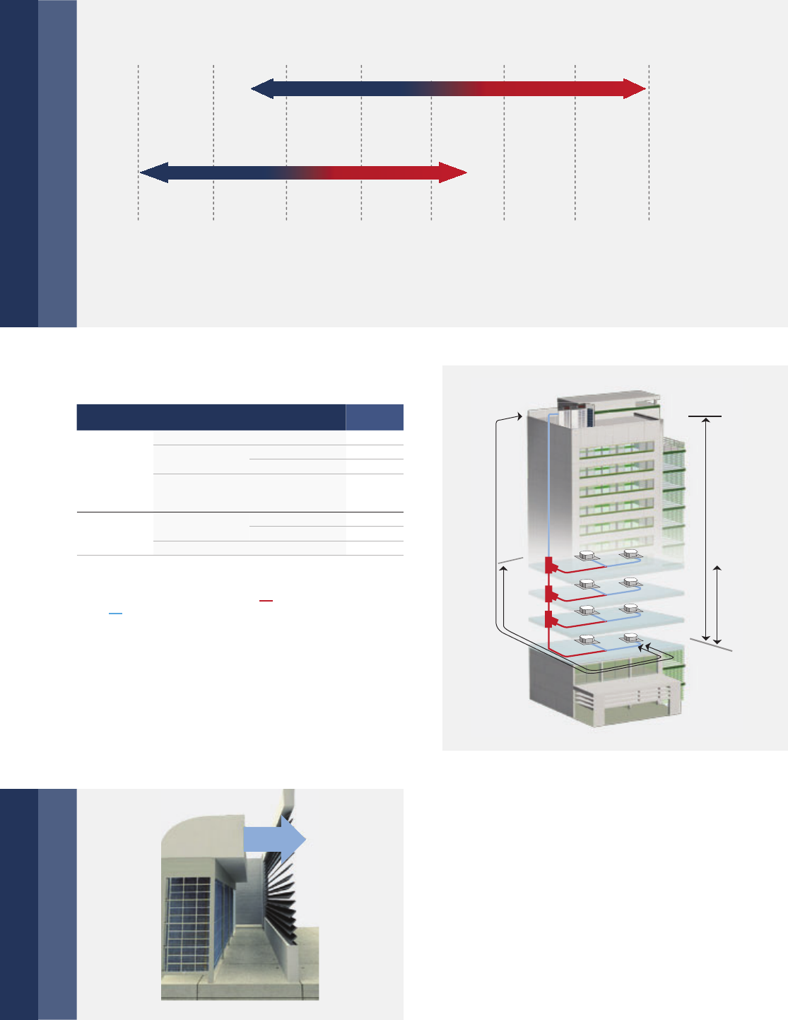
Heat recovery, more efficiency
Heating capacity automatic adjustment
Simultaneous heating and cooling in different zones, more energy saving by heat recovery from one
space to another which saves up to 50 % in costs compared with a conventional heat pump system.
Two parts condenser individual design, the unit can distribute a part of evaporator to be as condensing
area according to the heating load requirement to improve the utilization rate of the condenser.
2-pipe system 3-pipe system
Simultaneous Cooling and Heating Operation
Power
consumption
Cooling
Heating
No power
consumption
for heat
recovery
Cooling
14 kW 14 kW 14 kW 14 kW 14 kW 14 kW
Cooling Cooling Cooling Heating Heating
Partial Using
DC motor
All DC inverter compressors
All DC fan motors
42 | RDCI Series
Each heat exchanger is
defrosted by using heat
transferred from one heat
exchanger to the other in
the outdoor unit. Defrost
has no impact on the indoor
unit on heating mode.
High Comfort
Cooling and heating simultaneously
Continuous heating during defrost operation
The outdoor unit controls the operation
mode of each group indoor unit to achieve
simultaneous heating and cooling in one
system under the SBOX equipment which
adopts solenoid valve to precise control
refrigerant flow rate.
The indoor units connect to the same SBOX
can realize simultaneous cooling and heat-
ing operation.
In this mode, the indoor unit can
change the operation mode, to
control the indoor side temperature
at a constant temperature demanded.
Unit change to cooling mode at
daytime, when indoor temperature is
higher than setting temperature, and
change to heating mode at nighttime,
when indoor temperature is lower
than setting temp.
Auto mode control
Temperature
Setting temperature Ts Indoor temperature Ti
Ti>Ts
Cooling mode
Ti<Ts
Heating mode
Mode change automatically
Heat Exchanger 1
Heat Exchanger 2
Defrosting heat exchanger 1
Heat
Outdoor Unit
Heat Exchanger 1
Heat Exchanger 2
Defrosting heat exchanger 2
Heat
Outdoor Unit
Heat Exchanger 1
Heat Exchanger 2
Heating
Outdoor Unit
Simultaneous cooling and heating achieved by new designed SBOX equipment.
heating
h
eatin
g
heating
h
eatin
g
heating
h
eatin
g
heating
h
eatin
g
cooling cooling coolingcooling
Max- 4 Indoor Units Max- 4 Indoor Units
Max- 4 Indoor Units
cooling cooling
Max- 4 Indoor Units
heatingheatin
g
heating
Max- 4 Indoor UnitsMax- 4 Indoor Units
cooling cooling heatingheatin
g
heatingheating
RDCI Series | 43
Addressing indoor units are able to be done just by pressing
the button of the controller. No need to set the address by
the DIP switch one by one. Wired controller and wireless
controller can enquire and modify every indoor units address.
The check window reserved on electric
control box provides a convenient spot
checking and status enquiry. With the
4 bits digital tube LED display, it is very
convenient to show the data of the system,
such as pressure, compressor frequency,
error code, discharge temperature etc.,
which can make the maintenance, installa-
tion and commissioning easier.
Compressor is near the outside, and there
is simple pipe system for convenient main-
tenance. The newly designed rotating con-
trol box is so excellent that it can rotate in
a wide angle. It is convenient for the ins-
pection and maintenance of the pipeline
system and greatly reduced the time of
dismount the electric control box.
Centralised controller can connect from indoor
side or outdoor side (XYE terminals) at will.
Only one group of communication wire of PQE,
achieved both of communication for indoor &
outdoor unit and network. It’s more convenient
for communication wiring.
Easy Installation and Service
Remote addressing
Professional structure design for easy maintainence
Simple communication wiring
Remote addressing
Rotating electric
control box
Outer layout compressor
and simple pipe system
Remote addressing
P, Q, E P, Q, E P, Q, E
H1, H2, E
X, Y, E
P, Q, E P, Q, E
P, Q, E P, Q, E
P, Q, E P, Q, E P, Q, E
P, Q, E

44 | RDCI Series
Outdoor Unit
RDCI Series
Model RDCI 8/25-3 RDCI 10/28-3 RDCI 12/33-3 RDCI 14/40-3 RDCI 16/45-3
Power supply V/Ph/Hz 380-415/3/50
Cooling
Capacity kW 25.2 28.0 33.5 40.0 45.0
Power input kW 5.73 6.67 8.07 11.30 13.24
EER kW/kW 4.40 4.20 4.15 3.54 3.40
Heating
Capacity kW 27.0 31.5 37.5 45.0 50.0
Power input kW 6.00 7.33 8.72 11.19 12.79
COP kW/kW 4.50 4.30 4.30 4.02 3.91
Connectable indoor unit Total capacity % 50 – 130 50 – 130 50 – 130 50 – 130 50 – 130
Max. quantity 13 16 20 23 26
Sound pressure level dB(A) 57 57 58 60 60
Pipe connections
Liquid pipe mm Ф9.53 Ф12.7 Ф12.7 Ф15.9 Ф15.9
Low pressure
gas pipe mm Ф22.2 Ф22.2 Ф25.4 Ф28.6 Ф28.6
High pressure
gas pipe mm Ф19.1 Ф19.1 Ф19.1 Ф22.2 Ф22.2
High pressure
gas balance pipe mm Ф19.1 Ф19.1 Ф19.1 Ф19.1 Ф19.1
Oil balance pipe mm Ф6 Ф6 Ф6 Ф6 Ф6
Fan motor
Type DC DC DC DC DC
Quantity 22222
Air flow rate m³/h 12,000 12,000 13,000 15,000 15,000
Motor output W 420 420 420 750 750
ESP
Pa 0 – 20 (default) 0 – 20 (default) 0 – 20 (default) 0 – 20 (default) 0 – 20 (default)
Pa 20 – 60
(customized)
20 – 60
(customized)
20 – 60
(customized)
20 – 40
(customized)
20 – 40
(customized)
DC inverter compressor
Quantity 11122
Capacity kW 31.59 31.59 31.59 31.59+11.80 31.59+11.80
Crankcase heater W 30×2 30×2 30×2 30×4 30×4
Oil type FVC68D FVC68D FVC68D FVC68D FVC68D
Oil charge ml 500 500 500 500+500 500+500
Refrigerant Type R-410A R-410A R-410A R-410A R-410A
Factory charging kg 10 10 10 13 13
Design pressure (High/Low) MPa 4.4/2.6 4.4/2.6 4.4/2.6 4.4/2.6 4.4/2.6
Net dimension (W×H×D) mm 1,250×1,615
×765
1,250×1,615
×765
1,250×1,615
×765
1,250×1,615
×765
1,250×1,615
×765
Packing size (W×H×D) mm 1,305×1,790
×820
1,305×1,790
×820
1,305×1,790
×820
1,305×1,790
×820
1,305×1,790
×820
Net weight kg 255 255 255 303 303
Gross weight kg 273 273 273 322 322
Operating temperature range
Cooling °C -5-48 -5-48 -5-48 -5-48 -5-48
Heating °C -20-24 -20-24 -20-24 -20-24 -20-24
Simultaneous
cooling and
heating
°C -5~24 -5~24 -5~24 -5~24 -5~24
Notes:
Capacities are based on the following conditions:
Cooling: Indoor temperature 27° C DB/19° C WB; Outdoor temperature 35°C DB/24° C WB.
Heating: Indoor temperature 20° C DB/15° C WB; Outdoor temperature 7°C DB/6° C WB.
Piping length: Piping length is 7.5 m, level difference is zero.
Connection piping diameter is based on the condition that the total equivalent liquid length is less than 90 m.
When the total equivalent liquid length is more than 90 m, please refer to technical manual to choose the connection piping diameter.
Sound values are measured in a semi-anechoic room, at a position 1 m in front of the unit and 1.3 m above the floor.
Specifications
RDCI Series | 45
SBOX
SBOX Unit which can be connected multiple indoor units
SBOX Unit which can be connected only one indoor unit
Model SBOX01-1 SBOX02-1 SBOX04-1 SBOX06-1
Max. indoor unit groups 1246
Max. number of each group indoor units 4444
Max. number of all downstream indoor units 4×1=4 4×2=8 4×4=16 4×6=24
Max. capacity of each group indoor units kW 16 16 16 16
Total capacity of all downstream indoor units kW ≤16 ≤28 ≤45 ≤45
Piping
connections
Connect to
outdoor unit
Liquid pipe mm Ф9.53 Ф12.7 Ф15.9 Ф15.9
High pressure
gas pipe mm Ф15.9 Ф19.1 Ф22.2 Ф22.2
Low pressure
gas pipe mm Ф19.1 Ф25.4 Ф31.8 Ф31.8
Connect to
indoor unit
Liquid pipe mm Ф9.53 Ф9.53 Ф9.53 Ф9.53
Gas pipe mm Ф15.9 Ф15.9 Ф15.9 Ф15.9
Sound pressure level dB(A) 33 33 33 40
Net dimension (W×H×D) mm 630×225×600 630×225×600 960×225×600 960×225×600
Packing size (W×H×D) mm 725×325×685 725×325×685 1055×325×685 1055×325×685
Net weight kg 18 19.5 31 35
Gross weight kg 25 27 40 44.5
Model SBOX02E-1 SBOX04E-1
Max. number of all downstream indoor units 11
Capacity of downstream indoor unit kW 20 ~ 28 40 ~ 56
Piping
connections
Connect to
outdoor unit
Liquid pipe mm Ф12.7 Ф15.9
High pressure
gas pipe mm Ф19.1 Ф22.2
Low pressure
gas pipe mm Ф25.4 Ф31.8
Connect to
indoor unit
Liquid pipe mm Ф9.53 Ф9.53
Gas pipe mm Ф15.9 Ф15.9
Sound pressure level dB(A) 33 33
Net dimension (W×H×D) mm 630×225×600 960×225×600
Packing size (W×H×D) mm 725×325×685 1055×325×685
Net weight kg 19.5 31
Gross weight kg 27 40
Notes:
Sound values are measured in a semi-anechoic room, at a position 1 m below the SBOX in mode switch condition.
It is not recommended to install in the place where high noise performance is required.
Specifications
46 | RDCI Series
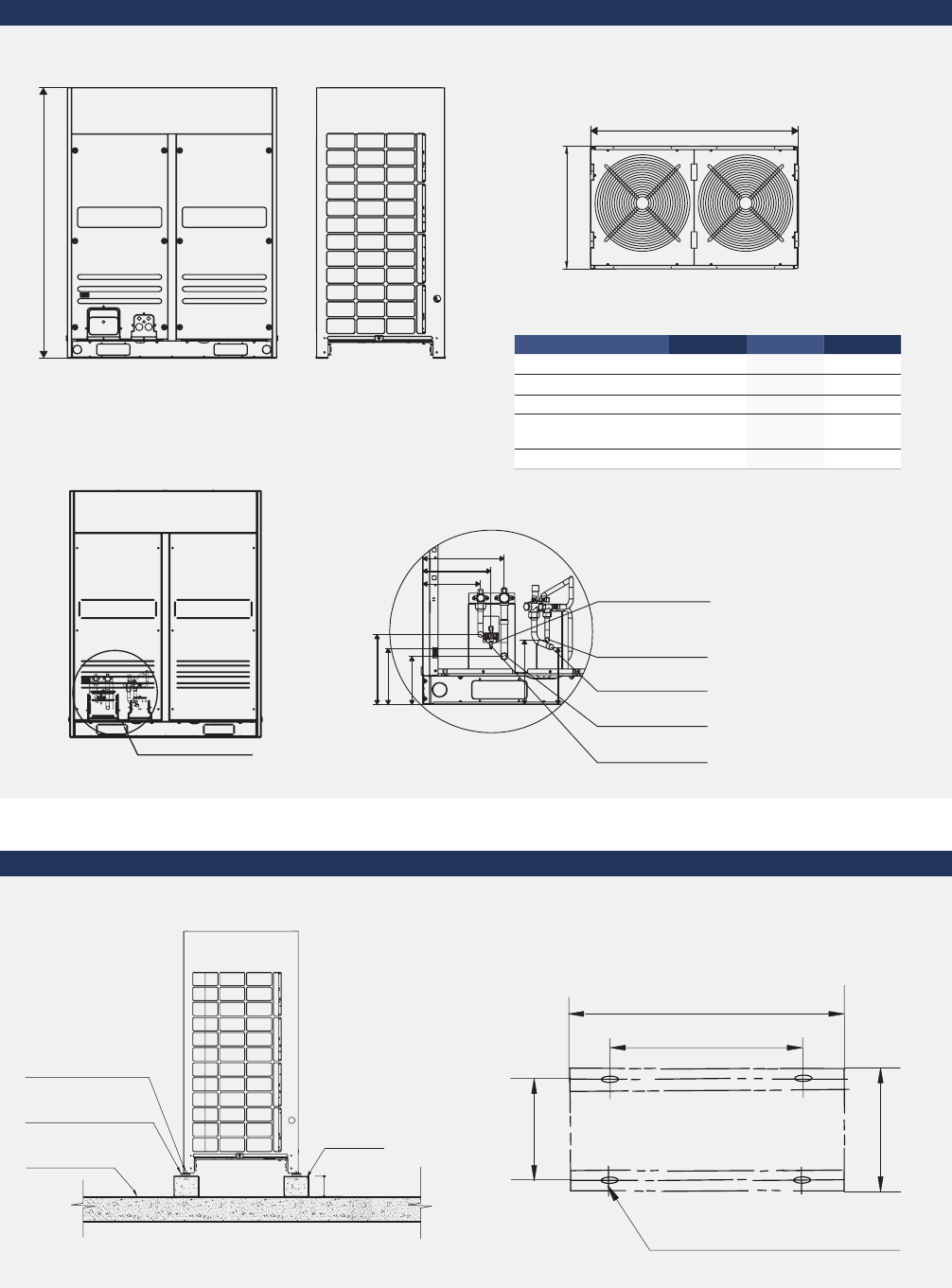
Dimensions
Body dimension
Installation dimension
1615
765
1250
Unit: mm
Screw bolt position
15×23long U-shape hole
1120
1250
736
765
Concrete
basement
h=200
Φ10 Expansion bolt
Rubber shocking
proof mat
Solid ground
or roofing
200
Unit: mm
Unit: mm
Piping HP 8/10 HP 12 HP 14/16
Liquid pipe Ф12.7 Ф12.7 Ф15.9
Low pressure gas pipe Ф22.2 Ф25.4 Ф28.6
High pressure gas pipe Ф19.1 Ф19.1 Ф22.2
High pressure gas
balance pipe Ф19.1 Ф19.1 Ф19.1
Oil balance pipe Ф6 Ф6 Ф6
R: Pipe connection
250
205
245
290
230
205
200
170
R section view
Oil balance pipe
Liquid pipe
High pressure
gas pipe
Low pressure
gas pipe
High pressure
gas balance pipe
MDCI Series | 47
MDCI Series
Full DC Inverter Mini VRF with DC inverter compressor and DC fan motor delivers a highly efficient
solution for small commercial buildings. Four to twelve rooms require only one outdoor unit,
and individual control is enabled in each room.
NEW
Fashion
Design R-410A Inverter
DC
48 | MDCI Series
Features
Wide Application Range
The outdoor units capacity range from 8 kW to 26 kW which is ideal for small offices, villas, apartments and shops,
making it perfect for commercial and residential application.
Mini VRF system operates
stable at extreme tempera-
ture range from -15°C to
43° C.
Wide range of outdoor units
Wide operation temperature range
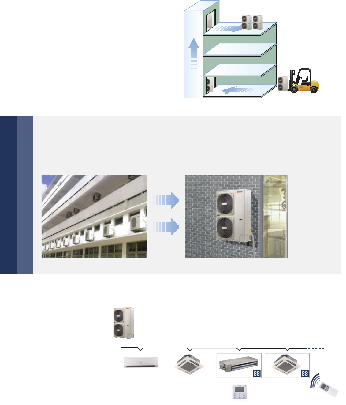
Flexible indoor units connection
Mini VRF with intelligent control gives you independent zoning control with maximum flexibility. A single
outdoor unit supports up to twelve indoor units, freeing up considerable space outside. Use your backyard
more wisely with much more space available created by less number of outdoor units.
8/10 kW 12/14/16/18 kW
▶ Max. 12 indoor units for a 26 kW outdoor unit installation
▶ Max. 11 indoor units for a 22 kW outdoor unit installation
▶ Max. 10 indoor units for a 20 kW outdoor unit installation
▶ Max. 9 indoor units for a 18 kW outdoor unit installation
▶ Max. 7 indoor units for a 16 kW outdoor unit installation
▶ Max. 6 indoor units for a 14 kW outdoor unit installation
▶ Max. 6 indoor units for a 12 kW outdoor unit installation
▶ Max. 5 indoor units for a 10 kW outdoor unit installation
▶ Max. 4 indoor units for a 8 kW outdoor unit installation
COOLING MODE
HEATING MODE
Outdoor temp.
43°C
27°C
-15°C
-15°C
0 1020304050
-10
-20 °C(D.B.)
20/22/26 kW
MDCI Series | 49
The Mini VRF provides a total piping length possibility of
100 m, a maximum height difference between outdoor and
indoor units of 30 m. The height difference between indoors
unit can be up to 8 m.
▶ The new designed window fins enlarge the heat-exchanging area, decrease the air resistance, save more power
and enhance heat exchange performance.
▶ Hydrophilic film fins and inner-threaded copper pipes optimize heat exchange efficiency.
▶ The specially coated blue fins enhance durability and protect against corrosion from air, water and other corrosive
agents, assures a longer coil service life.
Flexible piping design
High performance heat exchanger
Permitted value (m)
8/10 kW 12/14/
16/18 kW
20/22/
26 kW
Piping
length
Actual total piping length*1 100 100 120
Longest piping Actual length 45 60 60
Equivalent length 50 70 70
Equivalent piping length from
the farthest IDU to the first indoor
branch joint
20 20 20
Level
differ-
ence
Level difference
between indoor
and outdoor units
Outdoor unit up 30 30 30
Outdoor unit down 20 20 20
Level difference between indoor units 8 8 8
*1 Total pipe length is equal to all the liquid pipe or all the gas pipe length.
The lon
g
est pipin
g
len
g
th is 70 m
The first branch joint to the
farthest IDU is 20 m
The IDU to the nearest
branch joint is 15 m
Level difference between IDU and ODU is 30 m
Level difference between IDUs is 8 m
High Efficiency
High COP and EER values
EER COP
3.9 3.92 3.78 3.54 3.43 3.3 3.28 3.42
3.29
8 kW 10 kW 12 kW 14 kW 16 kW 18 kW 20 kW 24 kW22 kW
4.02 3.97 3.8 3.7 3.56 3.8 3.61
4.19
4.15
8 kW 10 kW 12 kW 14 kW 16 kW 18 kW 20 kW 26 kW22 kW
IDU = Indoor Unit
ODU = Outdoor Unit
New design Original design High efficiency inner-threaded pipe,
enhance heat transfer.
Reduce air resistance
Hydrophilic fins + inner-threaded pipes
50 | MDCI Series
Easy Installation and Service
Easy to transport
Easy installation
Auto addressing
Space saving design
Easy installation: No special area is required for
outdoor units. Easy transportaion: All outdoor
units can be transported by elevator, which
greatly simplifies installation and reduces time
and labor. The Mini VRF indoor and outdoor
units are almost as easy to install as residential
air conditioning systems, making them ideal for
small offices and shops.
Addresses of indoor units
can be set automatically
by outdoor units.
Wireless controller can
inquire and modify every
indoor units address.
The Mini VRF units are slimmer and more compact, resulting in significant savings in installation space.
In some large residential and light commercial areas, such as villas, restaurants, usually it needs more
than one indoor unit, which in turn requires multiple outdoor units.
Shield signal wire
Outdoor unit can
distribute address
for indoor unit.
MDCI Series | 51
More convenience in installation
New piping connection design
More convenient piping connector – branch box (MBB04)
A four-direction space is available for connecting
pipes and wiring in various installation sites.
Easier and safer installation thanks to a branch box that simplifies piping work and the adoption
of screw connection. Both left and right pipe flare connecting from outdoor unit to branch box is reserved,
which greatly simplifies field installation. Two sets of pipe size converter are packed with branch box to
transfer the pipe size from Φ6.35 mm to Φ9.53 mm and from Φ12.7 mm to Φ15.9 mm.
Low noise
The branch box linear design regulates the flow of refrigerant and
reduces the noise. By locating the branch box in the ceiling or out-
side, noise generated by the branch box can be kept clear of living
spaces, thus makes noise level to a minimum.
Brazing-free quick installation
All the piping leading to and from the branch box is connected
using screw joints, which can be installed quickly and easily.
Indoor installation
The branch box can be installed in the ceiling rather than outside. Removing the side and bottom covers
provides easy access for maintaining inner components such as circuit boards.
Front side Back side
Right side Bottom side
Front side
Bottom side
Back side
Right side
52 | MDCI Series
Advanced Technologies
Full DC inverter technology
At the heart of our system is a highly intelligent inverter driven compressor. This advanced technology enables
the output of the outdoor unit to be modulated by the cooling or heating demands of the zone that it controls.
This advanced system ensures precise temperature regulation and highly efficient energy usage.
High efficiency DC fan motor saved power up to 50 %.
Highly Efficient DC Motor:
▶ Creative motor core design
▶ High density neodymium magnet
▶ Concentrated type stator
▶ Wider operating frequency range
Better Balance and Extremely Low Vibration:
▶ Twin eccentric cams
▶ 2 balance weights
Highly Stable Moving Parts:
▶ Optimal material matching rollers and vanes
▶ Optimize compressor drive technology
▶ Highly robust bearings
▶ Compact structure
Compressor
(Twin Rotary) structure
1000
System Pressure
200
-+
400
600
800
Motor Speed (RPM)
DC inverter
stepless
adjustment
AC inverter
multistep
adjustment
Noise reducing design
Optimally designed fan shape and air discharge grille increases air volume and reduces running noise.
Newly Designed Fan Guard Powerful Large Propeller

MDCI Series | 53
Outdoor Unit
MDCI Series – Mini VRF Heat Pump
Model MDCI8-1 MDCI10-1 MDCI12-1/
MDCI12-3
MDCI14-1/
MDCI14-3
MDCI16-1/
MDCI16-3
MDCI18-3
Power supply V/Ph/Hz 220-240/1/50 220-240/1/50 220-240/1/50
380-415/3/50
220-240/1/50
380-415/3/50
220-240/1/50
380-415/3/50
220-240/1/50
380-415/3/50
Cooling
Capacity kW 8 10.5 12.3 14 15.5 17.5
Input kW 2.05 2.68 3.25 3.95 4.52 5.30
EER kW/kW 3.90 3.92 3.78 3.54 3.43 3.30
Heating
Capacity kW 9 11.5 13.2 15.4 17.0 19.0
Input kW 2.24 2.90 3.47 4.16 4.77 5.00
COP kW/kW 4.02 3.97 3.80 3.70 3.56 3.80
Connectable indoor unit Total capacity % 45 – 130 45 – 130 45 – 130 45 – 130 45 – 130 45 – 130
Max. quantity 456679
Sound pressure level dB(A) 56 57 57 57 57 59
Pipe connections Liquid pipe mm Ф9.53 Ф9.53 Ф9.53 Ф9.53 Ф9.53 Ф9.53
Gas pipe mm Ф15.9 Ф15.9 Ф15.9 Ф15.9 Ф19.1 Ф19.1
Fan motor
Type DC DC DC DC DC DC
Quantity 112222
Air flow rate m³/h 5,500 5,500 6,000 6,000 6,000 6,800
Motor output W 170 170 85x2 85x2 85x2 85x2
Compressor
Quantity 111111
Capacity kW 7 7 10 10 14 14
Crankcase
heater W 252525252525
Oil type FV50S FV50S FV50S FV50S FV50S FV50S
Oil charge ml 670+200 670+200 870+630 870+630 1400+250 1400+250
Refrigerant
Type R-410A R-410A R-410A R-410A R-410A R-410A
Factory
charging kg 2.8 2.95 3.3 3.9 3.9 4.5
Design pressure
(High/Low) MPa 4.4/2.6 4.4/2.6 4.4/2.6 4.4/2.6 4.4/2.6 4.4/2.6
Net dimension
(W×H×D) mm 1,075×966
×396
1,075×966
×396
900×1,327
×400
900×1,327
×400
900×1,327
×400
900×1,327
×400
Packing size
(W×H×D) mm 1,120×1,100
×435
1,120×1,100
×435
1,030×1,456
×435
1,030×1,456
×435
1,030×1,456
×435
1,030×1,456
×435
Net weight kg 75.5 75.5 95 95 100/102 107
Gross weight kg 85.5 85.5 106 106 111/113 118
Operating
temperature range
Cooling °C -15~43 -15~43 -15~43 -15~43 -15~43 -15~43
Heating °C -15~27 -15~27 -15~27 -15~27 -15~27 -15~27
Notes:
Capacities are based on the following conditions:
Cooling: Indoor temperature 27° C DB/19° C WB; Outdoor temperature 35°C DB/24° C WB.
Heating: Indoor temperature 20° C DB/15° C WB; Outdoor temperature 7°C DB/6° C WB.
Piping length: Piping length is 5 m, level difference is zero.
Sound values are measured in a semi-anechoic room, at a position 1 m in front of the unit and 1 m above the floor.
Specifications

54 | MDCI Series
Outdoor Unit
MDCI Series – Mini VRF Heat Pump
Model MDCI20-3 MDCI22-3 MDCI26-3
Power supply V/Ph/Hz 380-415/3/50 380-415/3/50 380-415/3/50
Cooling
Capacity kW 20 22.4 26
Input kW 6.1 6.8 7.6
EER kW/kW 3.28 3.29 3.42
Heating
Capacity kW 22 24.5 28.5
Input kW 6.1 5.9 6.8
COP kW/kW 3.61 4.15 4.19
Connectable indoor unit Total capacity % 50 – 130 50 – 130 50 – 130
Max. quantity 10 11 12
Sound pressure level dB(A) 59 59 60
Pipe connections Liquid pipe mm Ф9.53 Ф9.53 Ф9.53
Gas pipe mm Ф19.1 Ф19.1 Ф22.2
Fan motor
Type DC DC DC
Quantity 2 2 2
Air flow rate m³/h 10,999 10,494 10,494
Motor output W 210 (up)/160 (down) 200 (up)/150 (down) 200 (up)/150 (down)
Compressor
Quantity 1 1 1
Capacity kW 13.98 16.86 16.86
Crankcase
heater W252525
Oil type FV50S FV50S FV50S
Oil charge ml 1400+1300 1700+1500 1700+1500
Refrigerant
Type R-410A R-410A R-410A
Factory
charging kg 4.8 6.2 6.2
Design pressure
(High/Low) MPa 4.4/2.6 4.4/2.6 4.4/2.6
Net dimension
(W×H×D) mm 1,120×1,558×528 1,120×1,558×528 1,120×1,558×528
Packing size
(W×H×D) mm 1,270×1,720×565 1,270×1,720×565 1,270×1,720×565
Net weight mm 137 146.5 147
Gross weight mm 153 162.5 163
Operating
temperature range
Cooling °C -15~46 -15~46 -15~46
Heating °C -15~24 -15~24 -15~24
Notes:
Capacities are based on the following conditions:
Cooling: Indoor temperature 27° C DB/19° C WB; Outdoor temperature 35°C DB/24° C WB.
Heating: Indoor temperature 20° C DB/15° C WB; Outdoor temperature 7°C DB/6° C WB.
Piping length: Piping length is 5 m, level difference is zero.
Sound values are measured in a semi-anechoic room, at a position 1 m in front of the unit and 1 m above the floor.
Specifications
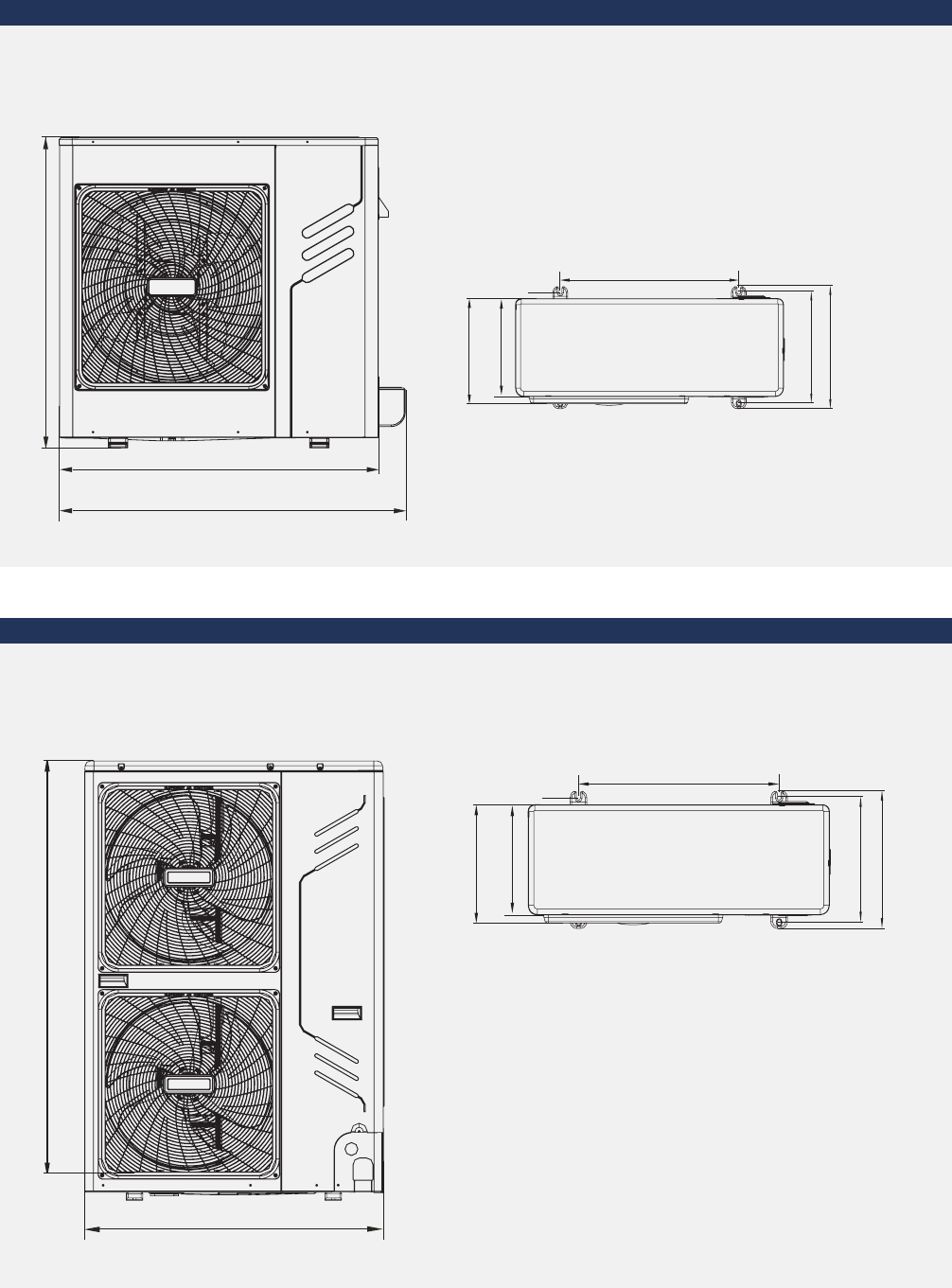
MDCI Series | 55
Dimensions
8/10 kW
Unit: mm
624
354
336
396
366
966
1075
8/10.5kW
990
12/14/16/18 kW
Unit: mm
12/14/16/18kW
600
348
320
400
360
1327
900
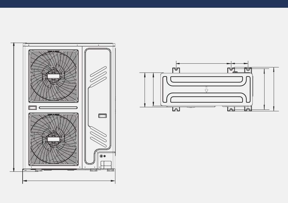
56 | MDCI Series
Dimensions
20/22.4/26 kW
Unit: mm
20/22.4/26kW
668 205.8
414
400
528
494
1558
1120

MDCI Series | 57
Notes

Indoor Units Lineup

Indoor Units Lineup | 59
Indoor Units
Lineup
62 1 Way Cassette
64 2 Way Cassette
66 Compact 4 Way Cassette
68 4 Way Cassette
70 Low & Medium Static Pressure Duct
72 High Static Pressure Duct
74 Ceiling & Floor
76 Wall Mounted
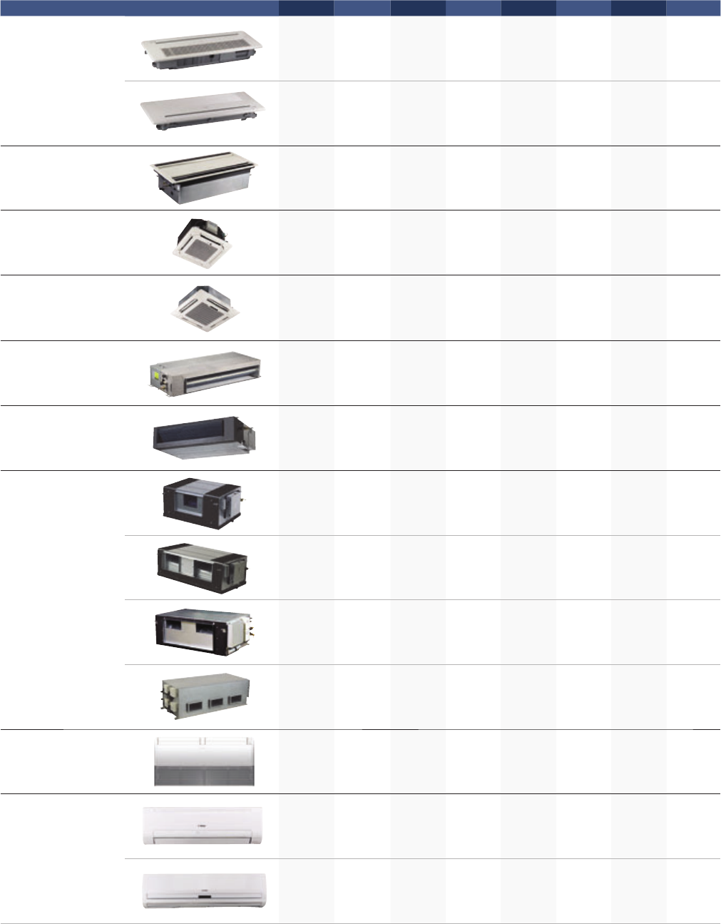
60 | Indoor Units Lineup
Type 1.5 kW 1.8 kW 2.2 kW 2.8 kW 3.6 kW 4.5 kW 5.6 kW 7.1 kW
1 Way Cassette
2 Way Cassette
Compact 4 Way
Cassette
4 Way Cassette
Low Static
Pressure Duct
Medium Static
Pressure Duct
High Static
Pressure Duct
Ceiling & Floor
Wall Mounted
More than 70 models are available to meet varied customer requirements, 1.5 kW model is only available for SDCI and MDCI series.

Indoor Units Lineup | 61
8.0 kW 9.0 kW 10.0 kW 11.2 kW 12.5 kW 14.0 kW 16.0 kW 20.0 kW 25.0 kW 28.0 kW 40.0 kW 45.0 kW 56.0 kW
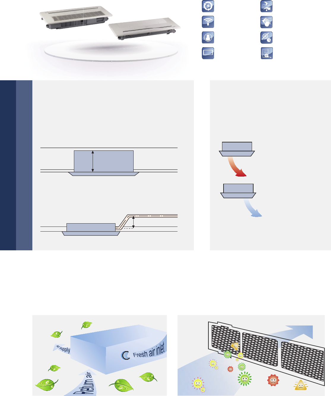
LED
DISPLAY
Auto Restart
Auto Addressing
Follow Me
LED Display
Fresh Air
Cleanable Panel
Anti-Cold Air Function
Built-in Drain Pump
62 | Indoor Units Lineup
1 Way Cassette
Only 153 mm thickness
Fresh air, improved air quality
Auto swing
Compact design, ultra slim body with a minimum
thickness of 153 mm for model 18–36, especially
suitable for narrow ceiling, such as in lobbies and
small meeting rooms.
Reserved fresh air intake port for high quality air
creates a comfortable and healthy environment.
Special enzyme sterilization and filtering technologies
filter bacteria, smog and pollen. Provide a clean, healthy
and natural air supply.
Auto swing mechanism guarantees
even airflow distribution and a better
room temperature balance.
Standard built-in drain pump with 750 mm
pump head.
153 mm
UItra Thin
750 mm
Single-flow design suits
corner installation
Heating
Cooling
Acetic acid Formol
Acetaldehyde
NH3

Indoor Units Lineup | 63
Model C1W18-1 C1W22-1 C1W28-1 C1W36-1 C1W45-1 C1W56-1 C1W71-1
Power supply V/Ph/Hz 220-240/1/50
Cooling capacity
kW 1.8 2.2 2.8 3.6 4.5 5.6 7,1
kcal/h 1,500 1,900 2,400 3,100 3,900 4,800 6,100
Btu/h 6,100 7,500 9,600 12,300 15,400 19,100 24.200
Heating capacity
kW 2.2 2.6 3.2 4 5 6.3 8
kcal/h 1,900 2,200 2,800 3,400 4,300 5,400 7,000
Btu/h 7,500 8,900 10,900 13,600 17,100 21,500 27,000
Rated input Cooling W 41 41 41 41 48 48 60
Heating W 41 41 41 41 43 44 55
Rated current Cooling A 0.24 0.24 0.25 0.25 0.37 0.39 0.30
Heating A 0.24 0.24 0.25 0.25 0.37 0.39 0.30
Airflow rate (H/M/L) m³/h 523/404/275 523/404/275 573/456/315 573/456/315 704/630/503 860/810/702 933/749/592
Sound pressure level (H/M/L) dB(A) 37/34/30 38/34/30 39/37/34 40/38/34 41/39/35 42/40/36 43/41/37
Refrigerant
Type R-410A R-410A R-410A R-410A R-410A R-410A R-410A
Control
method EXV EXV EXV EXV EXV EXV EXV
Indoor Unit
Net dim.
(W×H×D) mm 1,054×153
×425
1,054×153
×425
1,054×153
×425
1,054×153
×425
1,204×189
×443
1,204×189
×443
1,204×189
×443
Gross dim.
(W×H×D) mm 1,155×245
×490
1,155×245
×490
1,155×245
×490
1,155×245
×490
1,370×295
×505
1,370×295
×505
1,370×295
×505
Net/Gross kg 12.5/16 12.5/16 13/16.5 13/16.5 31.5/37.2 31.5/37.2 24.2/19.5
Panel
Net dim.
(W×H×D) mm 1,180×36.5
×465
1,180×36.5
×465
1,180×36.5
×465
1,180×36.5
×465
1,350×25
×505
1,350×25
×505
1,350×25
×505
Gross dim.
(W×H×D) mm 1,232×107
×517
1,232×107
×517
1,232×107
×517
1,232×107
×517
1,410×95
×560
1,410×95
×560
1,410×95
×560
Net/Gross kg 3.5/5.2 3.5/5.2 3.5/5.2 3.5/5.2 9/12 9/12 9/12
Piping
connections
L (flare) mm Φ6.35 Φ6.35 Φ6.35 Φ6.35 Φ6.35 Φ9.53 Φ12.7
G (flare) mm Φ12.7 Φ12.7 Φ12.7 Φ12.7 Φ12.7 Φ15.9 Φ15.9
Drain piping mm OD Ф25 OD Ф25 OD Ф25 OD Ф25 OD Ф25 OD Ф25 OD Ф25
Standard Controller Infrared Remote Controller (IRC)
Notes:
1. Nominal cooling capacities are based on the following conditions: return air temperature.: 27° C DB, 19°C WB, outdoor temperature.: 35° C DB, equivalent ref.
Piping: 8 m (horizontal)
2. Nominal heating capacities are based on the following conditions: return air temperature.: 20° C DB, outdoor temperature.: 7° C DB, 6°C WB, equivalent ref.
Piping: 8 m (horizontal)
3. Sound level is measured at 1.4 m below the unit.
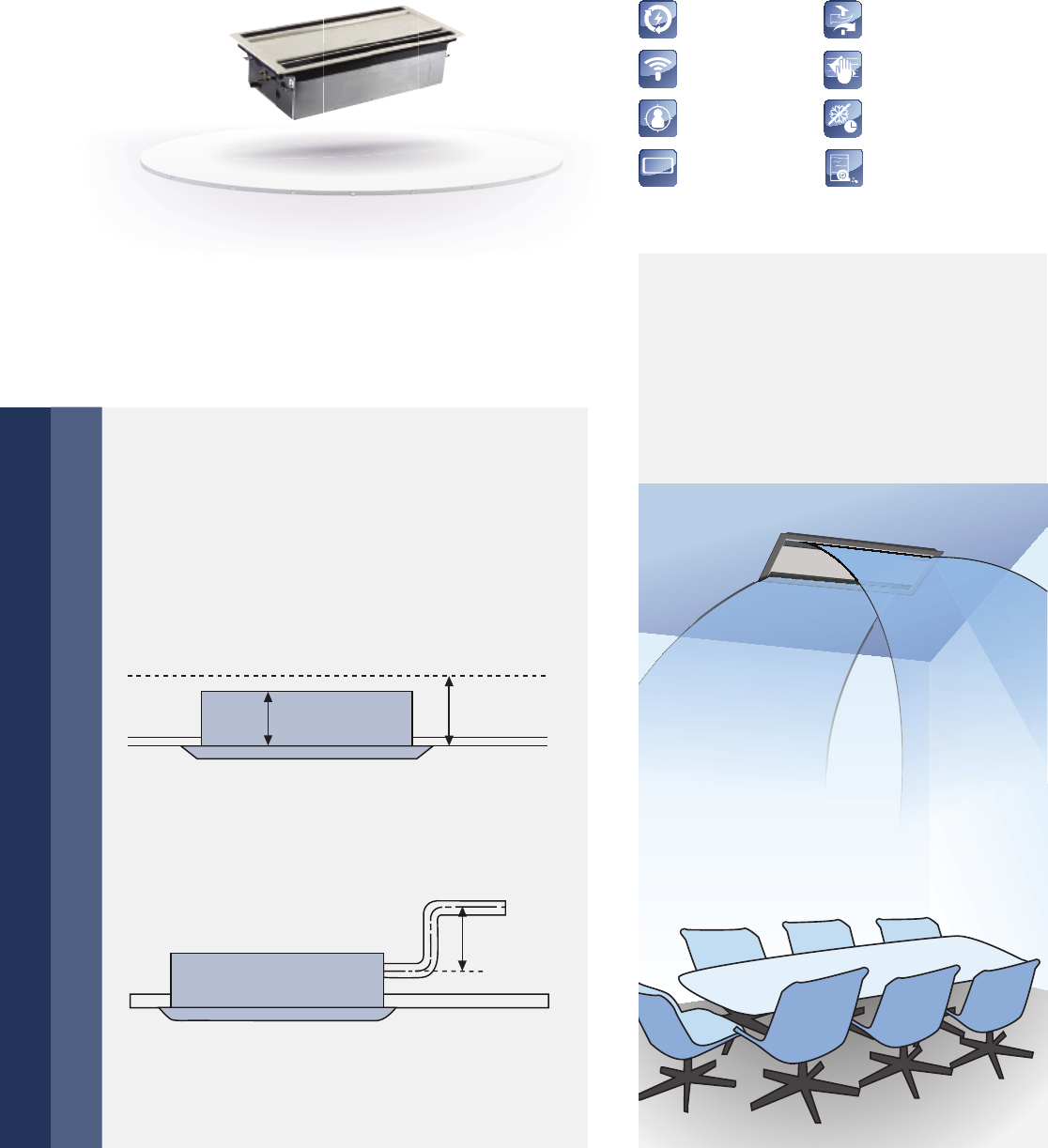
LED
DISPLAY
Auto Restart
Auto Addressing
Follow Me
LED Display
Fresh Air
Cleanable Panel
Anti-Cold Air Function
Built-in Drain Pump
64 | Indoor Units Lineup
2 Way Cassette
Quiet operation
Stylish design and slim body
High airflow
Optimized airflow duct with low resistance greatly
reduces noise, minimum down to 24 dB(A).
Standard built-in drain pump with 750 mm pump
head.
Flat-type suction grille design greatly simplifies
maintenance work.
Thanks to the stylish appearance and slim body,
the unit suits any room’s decor and ambience.
At only 300 mm high, the unit requires only
a small suspended ceiling space. Installation has
no height limitations, which makes overall design
features much more flexible.
High airflow for high ceiling appli cation
guarantees comfort in large space.
It makes every person in the room get
even distribution of airflow and tempera-
ture.
300 mm 305 mm
750 mm

Indoor Units Lineup | 65
Model C2W22-1 C2W28-1 C2W36-1 C2W45-1 C2W56-1 C2W71-1
Power supply V/Ph/Hz 220-240/1/50
Cooling capacity
kW 2.2 2.8 3.6 4.5 5.6 7.1
kcal/h 1,900 2,400 3,100 3,900 4,800 6,100
Btu/h 7,500 9,600 12,300 15,400 19,100 24,200
Heating capacity
kW 2.6 3.2 4.0 5.0 6.3 8.0
kcal/h 2,200 2,800 3,400 4,300 5,400 6,900
Btu/h 8,900 10,900 13,600 17,100 21,500 27,300
Power input Cooling W 57 57 60 92 108 154
Heating W 57 57 60 92 108 154
Rated current Cooling A 0.35 0.45 0.45 0.55 0.55 0.75
Heating A 0.35 0.45 0.45 0.55 0.55 0.75
Airflow rate (H/M/L) m³/h 654/530/410 654/530/410 725/591/458 850/670/550 980/800/670 1,200/1,000/
770
Sound pressure level (H/M/L) dB(A) 33/29/24 36/32/29 36/32/29 39/35/30 39/35/30 44/40/34
Refrigerant
Type R-410A R-410A R-410A R-410A R-410A R-410A
Control
method EXV EXV EXV EXV EXV EXV
Body
Net dim.
(W×H×D) mm 1,172×299×591 1,172×299×591 1,172×299×591 1,172×299×591 1,172×299×591 1,172×299×591
Gross dim.
(W×H×D) mm 1,355×400×675 1,355×400×675 1,355×400×675 1,355×400×675 1,355×400×675 1,355×400×675
Net/Gross kg 34/42.5 34/42.5 34/42.5 36/44.5 36/44.5 36/44.5
Panel
Net dim.
(W×H×D) mm 1,430×53×680 1,430×53×680 1,430×53×680 1,430×53×680 1,430×53×680 1,430×53×680
Gross dim.
(W×H×D) mm 1,525×130×765 1,525×130×765 1,525×130×765 1,525×130×765 1,525×130×765 1,525×130×765
Net/Gross kg 10.5/15 10.5/15 10.5/15 10.5/15 10.5/15 10.5/15
Piping connections
L (flare) mm Φ6.35 Φ6.35 Φ6.35 Φ6.35 Φ9.53 Φ9.53
G (flare) mm Φ12.7 Φ12.7 Φ12.7 Φ12.7 Φ15.9 Φ15.9
Drain piping mm OD Ф32 OD Ф32 OD Ф32 OD Ф32 OD Ф32 OD Ф32
Standard Controller Infrared Remote Controller (IRC)
Notes:
1. Nominal cooling capacities are based on the following conditions: return air temperature.: 27° C DB, 19°C WB, outdoor temperature.: 35° C DB, equivalent ref.
Piping: 8 m (horizontal)
2. Nominal heating capacities are based on the following conditions: return air temperature.: 20° C DB, outdoor temperature.: 7° C DB, 6°C WB, equivalent ref.
Piping: 8 m (horizontal)
3. Sound level is measured at 1.4 m below the unit.
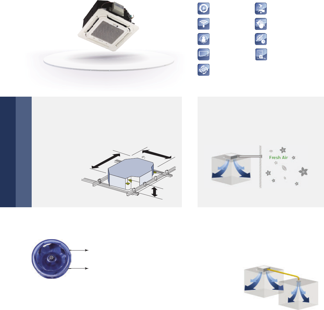
Auto Restart
Auto Addressing
Follow Me
LED Display
Fresh Air
Cleanable Panel
Anti-Cold Air Function
Built-in Drain Pump
LED
DISPLAY
Super High Air Flow
66 | Indoor Units Lineup
Compact 4 Way Cassette
Compact design, easy installation
Quiet operation, gentle air supply
Fresh air intake
Sub duct
Extremely compact casing suits any room’s decor
and requires little space for installation on a low
ceiling. Due to the compact body
and light weight,
all models can
be installed
without a hoist.
Streamline plate ensures quiet operation.
Advanced 3-D spiral fan design reduces air
resistance and operation noise.
Fresh air can enter through the cassette
unit so you can enjoy even fresher air in
your room.
Sub duct enables you to use the same air
conditioner unit to cool an additional smaller
space nearby.
570 mm
570 mm
Diffuser
3-D spiral fan blade
Indoor Units Lineup | 67
360° Airflow outlet High-lift drain pump
360° air outlet provides
strong air flow circulation
to cool or heat every cor-
ner of a room and evenly
distribute temperature.
Drain pump with a 500 mm pump head
is fitted as standard.
Model MC4W15-1 MC4W22-1 MC4W28-1 MC4W36-1 MC4W45-1
Power supply V/Ph/Hz 220-240/1/5
Cooling capacity
kW 1.5 2.2 2.8 3.6 4.5
kcal/h 1,300 1,900 2,400 3,100 3,900
Btu/h 5,100 7,500 9,600 12,300 15,400
Heating capacity
kW 1.7 2.4 3.2 4.0 5.0
kcal/h 1,500 2,100 2,700 3,400 4,300
Btu/h 5,800 8,200 10,900 13,600 17,100
Rated input Cooling W 36 50 50 56 56
Heating W 36 50 50 56 56
Rated current Cooling A 0.22 0.22 0.22 0.25 0.25
Heating A 0.22 0.22 0.22 0.25 0.25
Airflow rate (H/M/L) m³/h 501/435/283/208 522/414/313/238 522/414/313/238 610/521/409/314 610/521/409/314
Sound pressure level (H/M/L) dB(A) 34.9/32.5/22.5 35.8/33.4/23.4 35.8/33.4/23.4 41.5/35.6/28.8 41.5/35.6/28.8
Refrigerant
Type R-410A R-410A R-410A R-410A R-410A
Control
method EXV EXV EXV EXV EXV
Indoor Unit
Net dim.
(W×H×D) mm 570×260×570 570×260×570 570×260×570 570×260×570 570×260×570
Gross dim.
(W×H×D) mm 675×285×675 675×285×675 675×285×675 675×285×675 675×285×675
Net/Gross kg 16/19.5 16/20 16/20 18/22 18/22
Panel
Net dim.
(W×H×D) mm 647×50×647 647×50×647 647×50×647 647×50×647 647×50×647
Gross dim.
(W×H×D) mm 715×123×715 715×123×715 715×123×715 715×123×715 715×123×715
Net/Gross kg 2.4/4.5 2.4/4.5 2.4/4.5 2.4/4.5 2.4/4.5
Piping connections
L (flare) mm Φ6.35 Φ6.35 Φ6.35 Φ6.35 Φ6.35
G (flare) mm Φ12.7 Φ12.7 Φ12.7 Φ12.7 Φ12.7
Drain piping mm OD Ф25 OD Ф25 OD Ф25 OD Ф25 OD Ф25
Standard Controller Infrared Remote Controller (IRC)
Notes:
1. Nominal cooling capacities are based on the following conditions: return air temperature.: 27° C DB, 19°C WB, outdoor temperature.: 35° C DB, equivalent ref.
Piping: 8 m (horizontal)
2. Nominal heating capacities are based on the following conditions: return air temperature.: 20° C DB, outdoor temperature.: 7° C DB, 6°C WB, equivalent ref.
Piping: 8 m (horizontal)
3. Sound level is measured at 1.4 m below the unit.
500 mm
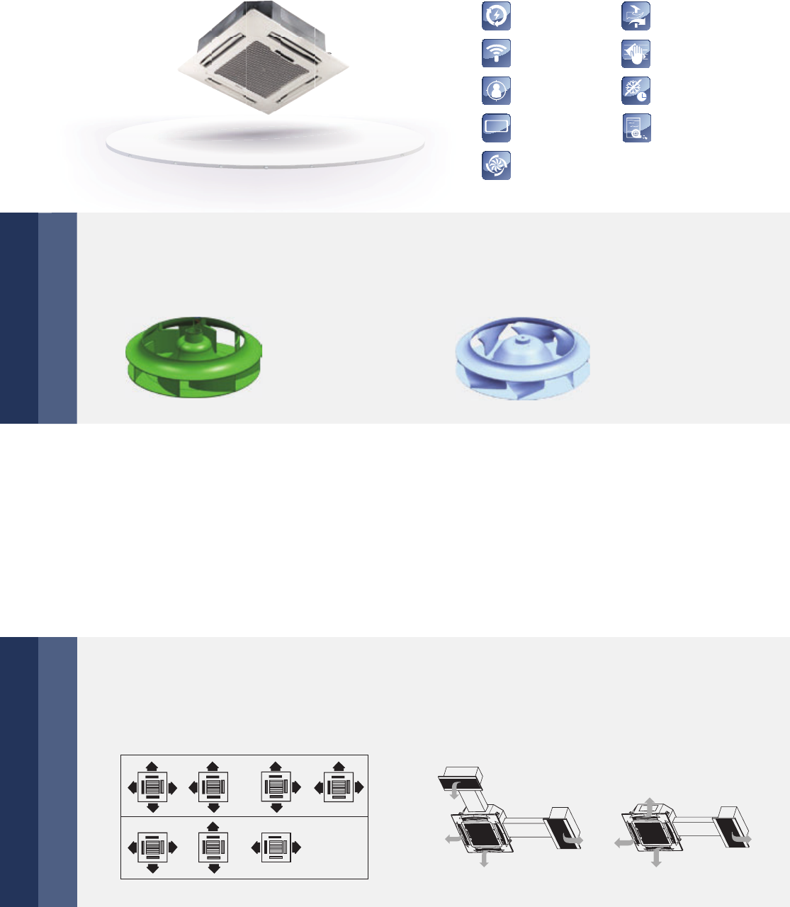
Auto Restart
Auto Addressing
Follow Me
LED Display
Fresh Air
Cleanable Panel
Anti-Cold Air Function
Built-in Drain Pump
LED
DISPLAY
Super High Air Flow
68 | Indoor Units Lineup
4 Way Cassette
Lower operating sound
More reliable
Flexible air distribution type
The new designed fan blade, air deflector and the built-in throttling part make the noise reduced greatly.
The former fan blade Optimized fan blade
▶ The connection of drainage pan adopts foaming technology which can further improve
the connection tightness.
▶ Capacitor is isolated by a sheet metal box making it safer and even more reliable.
▶ The high voltage and low voltage electricity wires are separated in an electronic control box
making the interference decreased greatly.
▶ 7 discharge patterns in 2 to 4 directions can be selected to suit
the requirements of installation site or the shape of the room.
▶ Duct connection is possible.

Indoor Units Lineup | 69
Model C4W28-1 C4W36-1 C4W45-1 C4W56-1 C4W71-1
Power supply V/Ph/Hz 220-240/1/50
Cooling capacity
kW 2.8 3.6 4.5 5.6 7.1
kcal/h 2,400 3,100 3,900 4,800 6,100
Btu/h 9,600 12,300 15,400 19,100 24,200
Heating capacity
kW 3.2 4.0 5.0 6.3 8.0
kcal/h 2,800 3,400 4,300 5,400 6,900
Btu/h 10,900 13,600 17,100 21,500 27,300
Power input Cooling W 80 80 88 88 88
Heating W 80 80 88 88 88
Rated current Cooling A 0.31 0.31 0.41 0.41 0.41
Heating A 0.31 0.31 0.41 0.41 0.41
Airflow rate (SH/H/M/L) m³/h 920/764/638/554 920/764/638/554
1,090/905/740/651 1,090/905/740/651 1,140/950/767/663
Sound pressure level (H/M/L) dB(A) 32/31/30 32/31/30 36/34/33 36/34/33 38/36/35
Refrigerant Type R-410A R-410A R-410A R-410A R-410A
Control met. EXV EXV EXV EXV EXV
Body
Net dim.
(W×H×D) mm 840×230×840 840×230×840 840×230×840 840×230×840 840×230×840
Gross dim.
(W×H×D) mm 955×260×955 955×260×955 955×260×955 955×260×955 955×260×955
Net/Gross kg 21.5/26.7 21.5/26.7 23.7/28.9 23.7/28.9 23.7/28.9
Panel
Net dim.
(W×H×D) mm 950×54.5×950 950×54.5×950 950×54.5×950 950×54.5×950 950×54.5×950
Gross dim.
(W×H×D) mm 1,035×90×1,035 1,035×90×1,035 1,035×90×1,035 1,035×90×1,035 1,035×90×1,035
Net/Gross kg 6/9 6/9 6/9 6/9 6/9
Piping connections
L (flare) mm Φ6.35 Φ6.35 Φ6.35 Φ9.53 Φ9.53
G (flare) mm Φ12.7 Φ12.7 Φ12.7 Φ15.9 Φ15.9
Drain piping mm Ф32 Ф32 Ф32 Ф32 Ф32
Standard Controller Infrared Remote Controller (IRC)
Model C4W80-1 C4W90-1 C4W100-1 C4W112-1 C4W140-1
Power supply V/Ph/Hz 220-240/1/50
Cooling capacity
kW 8.0 9.0 10.0 11.2 14.0
kcal/h 6,900 7,700 8,600 9,600 12,000
Btu/h 27,300 30,700 34,100 38,200 47,800
Heating capacity
kW 9.0 10.0 11.1 12.5 16.0
kcal/h 7,700 8,600 9,500 10,800 13,800
Btu/h 30,700 34,100 37,900 42,700 54,600
Power input Cooling W 110 140 165 165 176
Heating W 110 140 165 165 176
Rated current Cooling A 0.48 0.67 0.72 0.72 0.75
Heating A 0.48 0.67 0.72 0.72 0.75
Airflow rate (SH/H/M/L) m³/h 1,380/1,200/
1,021/789
1,598/1,332/
1,129/908
1,750/1,651/
1,304/1,127
1,750/1,651/
1,304/1,127
1,774/1,658/
1,335/1,130
Sound pressure level (H/M/L) dB(A) 42/39/37 42/39/37 45/42/40 45/42/40 46/41/39
Refrigerant Type R-410A R-410A R-410A R-410A R-410A
Control met. EXV EXV EXV EXV EXV
Body
Net dim.
(W×H×D) mm 840×230×840 840×300×840 840×300×840 840×300×840 840×300×840
Gross dim.
(W×H×D) mm 955×260×955 955×330×955 955×330×955 955×330×955 955×330×955
Net/Gross kg 23.7/28.9 28.7/34.1 28.7/34.1 28.7/34.1 30.9/36.3
Panel
Net dim.
(W×H×D) mm 950×54.5×950 950×54.5×950 950×54.5×950 950×54.5×950 950×54.5×950
Gross dim.
(W×H×D) mm 1,035×90×1,035 1,035×90×1,035 1,035×90×1,035 1,035×90×1,035 1,035×90×1,035
Net/Gross kg 6/9 6/9 6/9 6/9 6/9
Piping connections
L (flare) mm Φ9.53 Φ9.53 Φ9.53 Φ9.53 Φ9.53
G (flare) mm Φ15.9 Φ15.9 Φ15.9 Φ15.9 Φ15.9
Drain piping mm Ф32 Ф32 Ф32 Ф32 Ф32
Standard Controller Infrared Remote Controller (IRC)
Notes:
1. Nominal cooling capacities are based on the following conditions: return air temperature.: 27° C DB, 19°C WB, outdoor temperature.: 35° C DB, equivalent ref.
Piping: 8 m (horizontal)
2. Nominal heating capacities are based on the following conditions: return air temperature.: 20° C DB, outdoor temperature.: 7° C DB, 6°C WB, equivalent ref.
Piping: 8 m (horizontal)
3. Sound level is measured at 1.4 m below the unit.
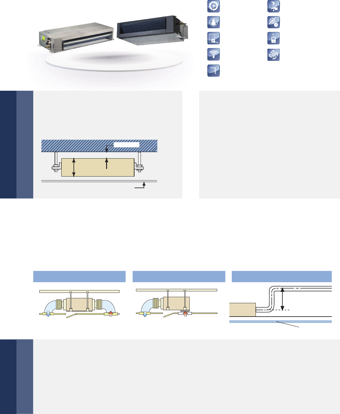
Auto Addressing
Auto Restart Fresh Air
Anti-Cold Air Function
Follow Me
Built-in Drain Pump
Connectable To Duct
Wired Controller
Super High Air Flow
70 | Indoor Units Lineup
Duct Type (Low&Medium Static Pressure)
Compact size
Flexible control and easy maintenance
External static pressure
Convenient installation
Only 210 mm (15~71 models) or 270 mm (80 to
112 models) or 300 mm (140 model) in height.
The EXV is fixed inside of the indoor unit. Standard filter is housed in an aluminum frame, which is removable
from the bottom in the downward direction. Suction chamber is included as standard equipment. Fresh air hole,
air inlet/outlet flange are standard for easy duct connection. A rear air inlet is standard and an inlet at the bottom
is optional. Both use the same connectable duct.
Standard wired remote controller WRC-HP. Standard functional ports are included
such as Remote On/Off Dry contact switch and Alarm signal output (220 V).
Four speed fan motor (Super high speed is
optional).
Change the wiring connection from ‘SH’ to ‘H’
to change the ESP.
210 mm
or 270 mm
or 300 mm
ceiling
min.5 mm
air intake from below
air intake from back drain pump as standard
ceiling
750 mm

Indoor Units Lineup | 71
Model SLPD15-1 SLPD22-1 SLPD28-1 SLPD36-1 SLPD45-1 SLPD56-1
Power supply V/Ph/Hz 220-240/1/50
Cooling capacity
kW 1.5 2.2 2.8 3.6 4.5 5.6
kcal/h 1,290 1,900 2,400 3,100 3,900 4,800
Btu/h 5,100 7,500 9,600 12,300 15,400 19,100
Heating capacity
kW 1.7 2.6 3.2 4.0 5.0 6.3
kcal/h 1,500 2,200 2,800 3,400 4,300 5,400
Btu/h 5,800 8,900 10,900 13,600 17,100 21,500
Rated input Cooling W 56 57 57 61 98 103
Heating W 56 57 57 61 98 103
Rated current Cooling A 0.31 0.31 0.31 0.33 0.36 0.36
Heating A 0.31 0.31 0.31 0.33 0.36 0.36
Airflow rate
(SH/M/L) m³/h 588 (30 pa)/
538/456/375
588 (30 pa)/
538/456/375
588 (30 pa)/
538/456/375
614 (30 pa)/
597/514/429
763 (30 pa)/
811/684/575
763 (30 pa)/
811/684/575
ESP (external static pressure) Pa 10 (10-30) 10 (10-30) 10 (10-30) 10 (10-30) 10 (10-30) 10 (10-30)
Sound pressure level (H/M/L) dB(A) 35.8/34.6/31.4 36/35/32 37/35/32 38.6/37.5/33.8 39/37.9/34 39/37.9/34
Refrigerant
Type R-410A R-410A R-410A R-410A R-410A R-410A
Control
method EXV EXV EXV EXV EXV EXV
Indoor Unit
Net dim.
(W×H×D) mm 740×210×500 740×210×500 740×210×500 740×210×500 960×210×500 960×210×500
Gross dim.
(W×H×D) mm 870×285×525 870×285×525 870×285×525 870×285×525 1,115×285×525 1,115×285×525
Net/Gross kg 17.5/20.5 17.5/20.5 17.5/20.5 17.5/20.5 22.5/26 22.5/26
Piping connections
L (flare) mm Φ6.35 Φ6.35 Φ6.35 Φ6.35 Φ6.35 Φ9.53
G (flare) mm Φ12.7 Φ12.7 Φ12.7 Φ12.7 Φ12.7 Φ15.9
Drain piping mm OD Ф25 OD Ф25 OD Ф25 OD Ф25 OD Ф25 OD Ф25
Standard Controller Wired Remote Controller WRC-HP (6 meters connection wire)
Model SLPD71-1 MPD80-1 MPD90-1 MPD112-1 MPD140-1
Power supply V/Ph/Hz 220-240/1/50
Capacity
kW 7.1 8.0 9.0 11.2 14.0
Cooling kcal/h 6,100 6,900 7,700 9,600 12,000
Btu/h 24,200 27,300 30,700 38,200 47,800
kW 8.0 9.0 10.0 12.5 15.5
Heating kcal/h 6,900 7,700 8,600 10,800 13,300
Btu/h 27,300 30,700 34,100 42,700 52,900
Power (Cooling) Input W 105 198 200 313 274
Rated Current
A 0.47 1.0 1.0 1.8 1.55
Power (Heating) Input W 105 198 200 313 274
Rated Current
A 0.47 1.0 1.0 1.8 1.55
Indoor air flow
(SH/H/M/L) m³/h 1,127 (30 pa)/
1,029/934/781
1,388 (50 pa)/
1,345/1,165/1,013
1,388 (50 pa)/
1,345/1,165/1,013
1,851 (80 pa)/
1,800/1,556/1,400
1,745 (100 pa)/
1,905/1,636/1,400
ESP (external static pressure) Pa 10 (10-30) 20 (10~50) 20 (10~50) 40 (10~80) 40 (10~100)
Sound pressure level (H/M/L) dB(A) 41.4/39/35 45.4/39.8/37 45.4/39.8/37 48.0 /41.9/38 47.7/43.2/39.0
Refrigerant
Type R-410A R-410A R-410A R-410A R-410A
Control
method EXV EXV EXV EXV EXV
Indoor Unit
Net dim.
(W×H×D) mm 1,180×210×500 1,180×270×775 1,230×270×775 1,230×270×775 1,290×300×865
Gross dim.
(W×H×D) mm 1,335×285×525 1,355×350×795 1,355×350×795 1,355×350×795 1,400×375×925
Net/Gross kg 28/31.5 38/46.5 40/48 40/48 49/58
Piping connections
L (flare) mm Φ9.53 Φ9.53 Φ9.53 Φ9.53 Φ9.53
G (flare) mm Φ15.9 Φ15.9 Φ15.9 Φ15.9 Φ15.9
Drain piping mm OD Ф25 OD Ф25 OD Ф25 OD Ф25 OD Ф25
Standard Controller Wired Remote Controller WRC-HP (6 meters connection wire)
Notes:
1. Nominal cooling capacities are based on the following conditions: return air temperature.: 27° C DB, 19°C WB, outdoor temperature.: 35° C DB, equivalent ref.
Piping: 8 m (horizontal)
2. Nominal heating capacities are based on the following conditions: return air temperature.: 20° C DB, outdoor temperature.: 7° C DB, 6°C WB, equivalent ref.
Piping: 8 m (horizontal)
3. Sound level is measured at 1.4 m below the air outlet.
External static pressure is based on high speed indoor air flow.
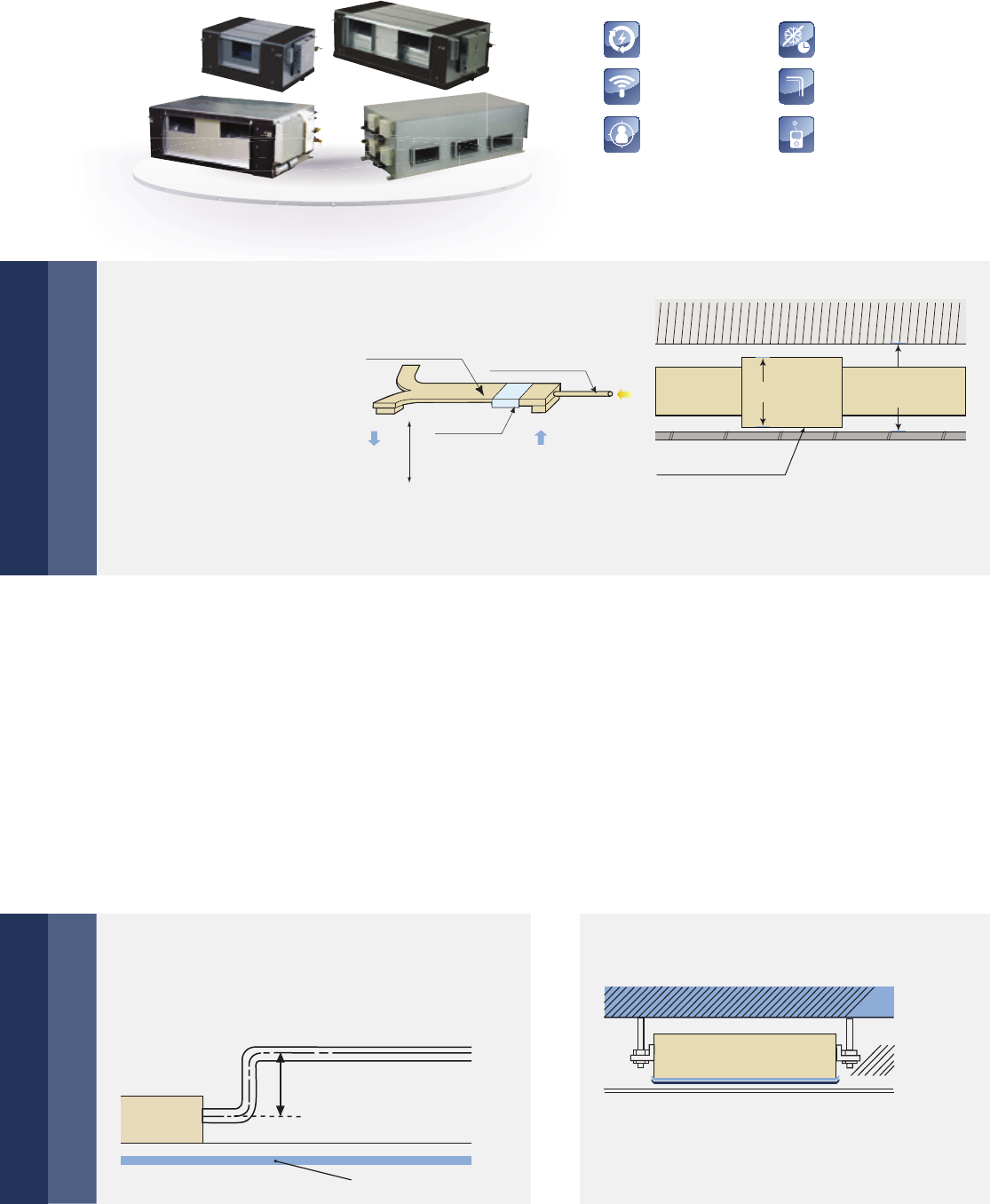
Auto Addressing
Auto Restart
Follow Me
Anti-Cold Air Function
Connectable To Duct
Wired Controller
72 | Indoor Units Lineup
High Static Pressure Duct
Flexible duct design
Option Double-skin drainage pan
Convenient installation
Flexible control and convenient for maintenance
External static pressure
can be up to 196 Pa
(models 71 to 160) or
280 Pa (models 200 to
560).
The maximum distance for air supply is about 14 m at height of 6.5 m.
With a 420 mm (models 71 to 160) thick body, the minimum distance required above the ceiling is 450 mm.
The EXV is fixed inside the indoor unit (models 70 to 160), requires no extra connection. Standard filter is
housed in an aluminum frame, which is removable from the bottom in the downward direction. Flange for air
in/outlet duct connection is standard.
Wired remote controller WRC-HP is as standard, and wireless remote controller IRC is as an option.
The display board is connected to the E-box in factory, easier troubleshooting by LED display. Easy access filters
both at the rear & bottom. Standard functional port such as remote on/off dry contact.
Drain pump with 750 mm pump head is optional
(models 71 to 160)
Double-skin drainage pan provide double
protection for ceilings (models 71 to 160
and models 400 to 560)
420 mm 450 mm
min.
INDOOR UNIT
The longest distance
of air supply is 14 m
The height of air
supply is 6.5 m
INDOOR UNIT
Fresh air in take
Air supply Air return
ceiling
750 mm

Indoor Units Lineup | 73
Model HPD71-1 HPD80-1 HPD90-1 HPD112-1 HPD140-1 HPD160-1
Power supply V/Ph/Hz 220-240/1/50
Capacity
kW 7.1 8.0 9.0 11.2 14.0 16.0
Cooling kcal/h 6,100 6,900 7,700 9,600 12,000 13,800
Btu/h 24,200 27,300 30,700 38,200 47,800 54,600
kW 8.0 9.0 10.0 12.5 16.0 17.0
Heating kcal/h 6,900 7,700 8,600 10,800 13,300 14,600
Btu/h 27,300 30,700 34,100 42,700 54,600 58,000
Power (Cooling) Input W 263 263 423 524 724 940
Rated Current
A 1.23 1.23 1.87 2.3 2.85 4.77
Power (Heating) Input W 263 263 423 524 724 940
Rated Current
A 1.23 1.23 1.87 2.3 2.85 4.77
Indoor air flow
(H/M/L) m³/h 1,443/
1,361/1,218
1,416/
1,338/1,220
1,951/
1,741/1,518
2,116/
1,936/1,520
3,000/
2,618/2,226
3,620/
3,044/2,744
ESP (external static pressure) Pa 25 (25~196) 37 (37~196) 37 (37~196) 50 (50~196) 50 (50~196) 50 (50~196)
Sound pressure level (H/M/L) dB(A) 48/46/44 48/46/44.5 52/49/47 52/49/47 53/50/48 54/52/50
Refrigerant
Type R-410A R-410A R-410A R-410A R-410A R-410A
Control
method EXV EXV EXV EXV EXV EXV
Indoor Unit
Net dim.
(W×H×D) mm 952×420×690 952×420×690 952×420×690 952×420×690 1,300×420×691 1,300×420×691
Gross dim.
(W×H×D) mm 1,090×440×768 1,090×440×768 1,090×440×768 1,090×440×768 1,436×450×768 1,436×450×768
Net/Gross kg 45/50 45/50 46.5/52.4 50.6/56 68/70 70/77.5
Piping connections
L (flare) mm Φ9.53 Φ9.53 Φ9.53 Φ9.53 Φ9.53 Φ9.53
G (flare) mm Φ15.9 Φ15.9 Φ15.9 Φ15.9 Φ15.9 Φ15.9
Drain piping mm OD Ф32 OD Ф32 OD Ф32 OD Ф32 OD Ф32 OD Ф32
Standard Controller Wired Remote Controller WRC-HP (6 meters connection wire)
Model HPD200-1 HPD250-1 HPD280-1 HPD400-1 HPD450-1 HPD560-1
Power supply V/Ph/Hz 220-240/1/50
Capacity
kW 20 25 28 40 45 56
Cooling kcal/h 17,200 21,500 24,100 34,400 38,700 48,200
Btu/h 68,200 85,300 95,500 136,500 153,500 191,100
kW 22.5 26 31.5 45 50 63
Heating kcal/h 19,400 22,400 27,100 38,700 43,000 54,200
Btu/h 76,800 88,700 107,500 153,500 170,600 214,960
Power (Cooling) Input W 1516 1516 1516 2700 2700 3400
Rated Current
A 8.6 8.6 8.6 12.5 12.5 15.5
Power (Heating) Input W 1516 1516 1516 3700 2700 3400
Rated Current
A 8.6 8.6 8.6 12.5 12.5 15.5
Indoor air flow
(H/M/L) m³/h 4,700/
4,100/3,599
4,700/
4,100/3,599
4,700/
4,100/3,599
7,472/
6,072/4,995
7,472/
6,072/4,995
9,550/
7,950/6,600
ESP (external static pressure) Pa 200 (50~280) 200 (50~280) 200 (50~280) 200 (50~280) 200 (50~280) 200 (50~280)
Sound pressure level (H/M/L) dB(A) 59/55/52 59/55/52 59/55/52 61/59/56 61/59/56 63/60/57
Refrigerant
Type R-410A R-410A R-410A R-410A R-410A R-410A
Control
method EXV EXV EXV EXV EXV EXV
Indoor Unit
Net dim.
(W×H×D) mm 1,443×470×810 1,443×470×810 1,443×470×810 1,970×
668×902.5
1,970×
668×902.5
1,970×
668×902.5
Gross dim.
(W×H×D) mm 1,509×550×990 1,509×550×990 1,509×550×990 2,095×800×964 2,095×800×964 2,095×800×964
Net/Gross kg 115/129 115/129 115/129 232/245 232/245 235/250
Piping connections
L (flare) mm Φ9.53x2 Φ9.53x2 Φ9.53x2 Φ9.53x2 Φ9.53x2 Φ9.53x2
G (flare) mm Φ15.9x2 Φ15.9x2 Φ15.9x2 Φ22.2x2 Φ22.2x2 Φ22.2x2
Drain piping mm OD Ф32 OD Ф32 OD Ф32 OD Ф32 OD Ф32 OD Ф32
Standard Controller Wired Remote Controller WRC-HP (6 meters connection wire)
Notes:
1. Nominal cooling capacities are based on the following conditions: return air temperature.: 27° C DB, 19°C WB, outdoor temperature.: 35° C DB, equivalent ref.
Piping: 8 m (horizontal)
2. Nominal heating capacities are based on the following conditions: return air temperature.: 20° C DB, outdoor temperature.: 7° C DB, 6°C WB, equivalent ref.
Piping: 8 m (horizontal)
3. Sound level is measured at 1.4 m below the air outlet.
External static pressure is based on high speed indoor air flow.
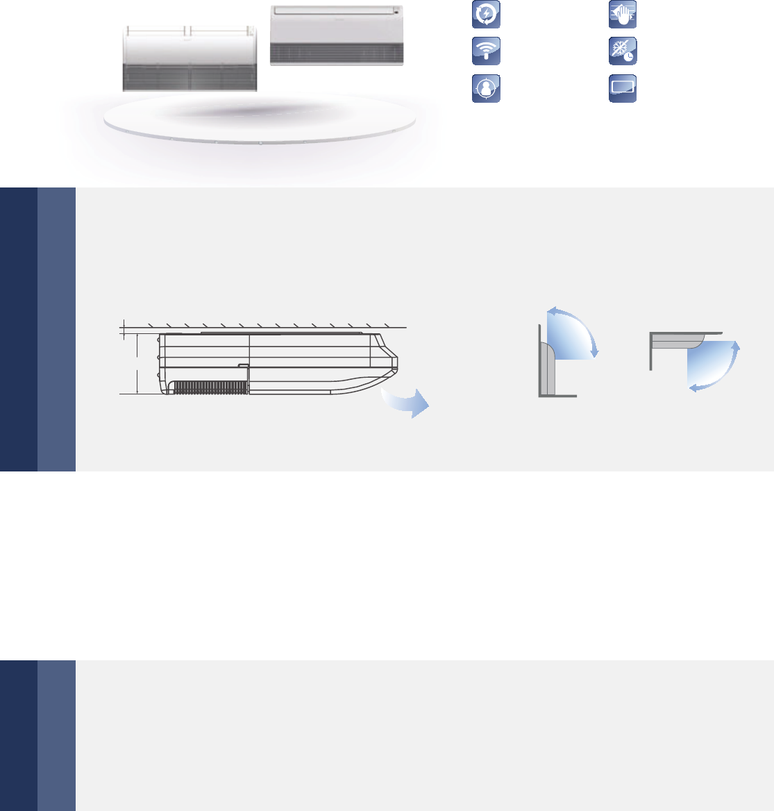
Auto Addressing
Auto Restart
Follow Me
Anti-Cold Air Function
Cleanable Panel
LED Display
LED
DISPLAY
74 | Indoor Units Lineup
Ceiling & Floor
Convenient installation
More comfortable
Auto swing and wide angle air flow
▶ The slim and sleek structure design ensures easy installation.
▶ It can be installed into a corner of the ceiling even if the ceiling is very narrow.
▶ Two direction auto swing – vertical and horizontal.
▶ The range of horizontal air discharge is widened which secures wider air flow distribution
to provide more comfortable air circulation no matter where the units is set up.
▶ Three air flow speeds: low, medium and high; double air guides.
▶ Adopt electrical expansion valve, ensuring precise flow control, lower modulation noise
when EXV operating.
▶ Low noise operations; minimum 36 dB(A).
▶ Smoother airflow and less turbulence due to the multi-blade fan and the air guide design.
>20
198 mm
Drop ceiling
Air Outlet The unit can be installed either horizontally on
the ceiling or vertically against the wall.

Indoor Units Lineup | 75
Model CF36-1 CF45-1 CF56-1 CF71-1
Power supply V/Ph/Hz 220-240/1/50
Cooling capacity
kW 3.6 4.5 5.6 7.1
kcal/h 3,100 3,900 4,800 6,100
Btu/h 12,300 15,400 19,100 24,200
Heating capacity
kW 4.0 5.0 6.3 8.0
kcal/h 3,400 4,300 5,400 6,800
Btu/h 13,600 17,100 21,500 27,300
Power input Cooling W 49 120 122 125
Heating
W 49 120 122 125
Rated current Cooling A 0.23 0.67 0.67 0.67
Heating
A 0.23 0.67 0.67 0.67
Airflow rate (H/M/L) m³/h 650/570/500 800/600/500 800/600/500 800/600/500
Sound pressure level (H/M/L) dB(A) 40/38/36 43/41/38 43/41/38 43/41/38
Refrigerant
Type R-410A R-410A R-410A R-410A
Control
method EXV EXV EXV EXV
Net dimension (W×H×D) mm 990×203×660 990×203×660 990×203×660 990×203×660
Packing dimension (W×H×D) mm 1,089×296×744 1,089×296×744 1,089×296×744 1,089×296×744
Net weight kg 26 28 28 28
Gross weight kg 32 34 34 34
Piping connections
L (flare) mm Φ6.35 Φ6.35 Φ9.53 Φ9.53
G (flare) mm Φ12.7 Φ12.7 Φ15.9 Φ15.9
Drain piping mm OD Ф25 OD Ф25 OD Ф25 OD Ф25
Standard Controller Infrared Remote Controller (IRC)
Model CF80-1 CF90-1 CF112-1 CF140-1
Power supply V/Ph/Hz 220-240/1/50
Cooling capacity
kW 8.0 9.0 11.2 14.0
kcal/h 6,900 7,700 9,600 13,300
Btu/h 27,300 30,700 38,200 47,800
Heating capacity
kW 9.0 10.0 12.5 15.0
kcal/h 7,700 8,600 10,800 12,900
Btu/h 30,700 34,100 42,700 51,200
Power input Cooling W 130 130 182 182
Heating
W 130 130 182 182
Rated current Cooling A 0.83 0.83 1.11 1.11
Heating
A 0.83 0.83 1.11 1.11
Airflow rate (H/M/L) m³/h 1,200/900/700 1,200/900/700 1,980/1,860/1,730 1,980/1,860/1,730
Sound pressure level (H/M/L) dB(A) 45/43/40 45/43/40 47/45/42 47/45/42
Refrigerant
Type R-410A R-410A R-410A R-410A
Control
method EXV EXV EXV EXV
Net dimension (W×H×D) mm 1,280×203×660 1,280×203×660 1,670×244×680 1,670×244×680
Packing dimension (W×H×D) mm 1,379×296×744 1,379×296×744 1,764×329×760 1,764×329×760
Net weight kg 34.5 34.5 54 54
Gross weight kg 41 41 59 59
Piping connections
L (flare) mm Φ9.53 Φ9.53 Φ9.53 Φ9.53
G (flare) mm Φ15.9 Φ15.9 Φ15.9 Φ15.9
Drain piping mm OD Ф25 OD Ф25 OD Ф25 OD Ф25
Standard Controller Infrared Remote Controller (IRC)
Notes:
1. Nominal cooling capacities are based on the following conditions: return air temperature.: 27° C DB, 19°C WB, outdoor temperature.: 35° C DB, equivalent ref.
Piping: 8 m (horizontal)
2. Nominal heating capacities are based on the following conditions: return air temperature.: 20° C DB, outdoor temperature.: 7° C DB, 6°C WB, equivalent ref.
Piping: 8 m (horizontal)
3. Floor standing: Sound level is measured 1 m from air-outlet in horizontal distance, 1 m above the floor in vertical distance.
Ceiling mounted: Sound level is measured 1 m from air-outlet in horizontal distance, 1 m from air-outlet in vertical distance.
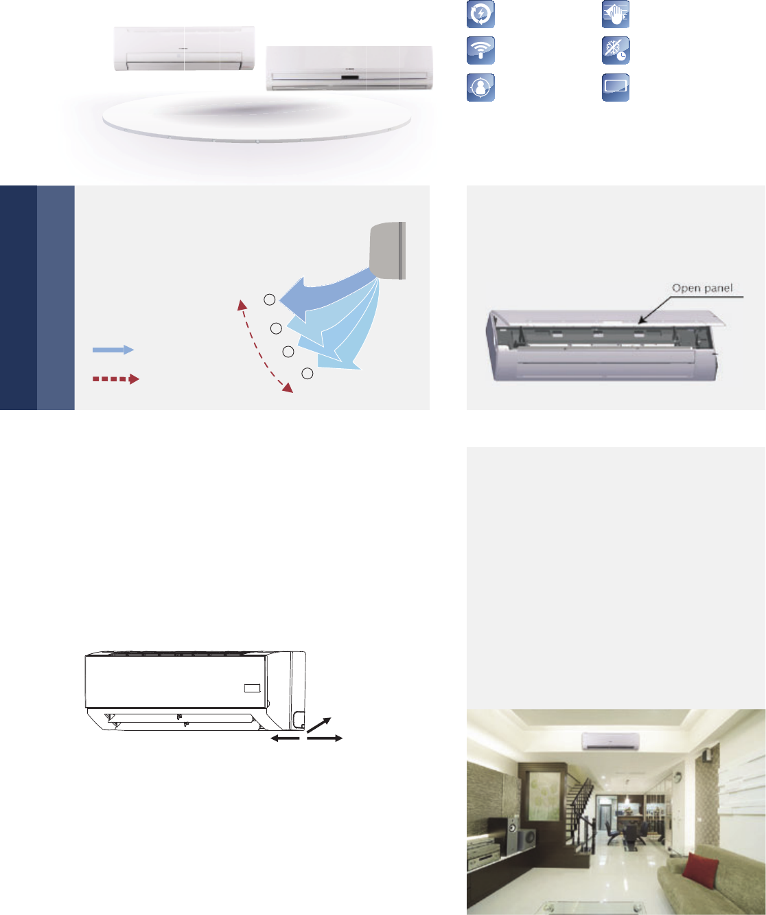
Auto Addressing
Auto Restart
Follow Me
Anti-Cold Air Function
Cleanable Panel
LED Display
LED
DISPLAY
76 | Indoor Units Lineup
Wall Mounted
Auto Swing Louver Easy maintenance
Convenient installation
Optimal comfort through better
flow control and quiet operations
▶ Multi-refrigerant outlet pipe method: left\right\rear,
more flexible for installation.
▶ The EXV is built-in the indoor unit, compact size, longer
the connection pipe; gas pipe: 468 mm; liquid pipe:
550 mm, more flexible for installation.
▶ Adopts new type fixing plate, is easy to install and stable.
The mechanical expansion valve offers
2,000-stage element positions to ensure
precise flow control and less modulation
noise when the EXV is operating for aquiet
and comfortable environment. Three air
flow speeds: low, medium and high; double
air guides. Smoother airflow and less turbu-
lence is ensured by the multi-blade fan and
the air guide design.
The Auto Swing Louver function
ensures that the air direction
corresponds to the
mode selected.
The front panel can be removed for easy
maintenance access.
Rear
Left Right
Step
Swing
1
2
3
4

Indoor Units Lineup | 77
Model HW15-1 HW22-1 HW28-1 HW36-1 HW45-1 HW56-1
Power supply V/Ph/Hz 220-240/1/50
Capacity
kW 1.5 2.2 2.8 3.6 4.5 5.6
Cooling kcal/h 1,300 1,900 2,400 3,100 3,900 4,800
Btu/h 5,100 7,500 9,600 12,300 15,400 19,100
kW 1.7 2.4 3.2 4.0 5.0 6.3
Heating kcal/h 1,500 2,100 2,800 3,400 4,300 5,400
Btu/h 5,800 8,200 10,900 13,600 17,100 21,500
Power input Cooling W 28 28 28 28 45 45
Heating
W 282828284545
Rated current Cooling A 0.12 0.14 0.14 0.14 0.2 0.2
Heating
A 0.12 0.14 0.14 0.14 0.2 0.2
Indoor air flow (H/M/L) m³/h 427/389/336 525/480/430 525/480/430 590/520/480 860/755/630 925/860/755
Sound pressure level (H/M/L) dB(A) 33/31/28 35/32/29 35/32/29 35/32/29 40/38/34 40/38/34
Refrigerant
Type R-410A R-410A R-410A R-410A R-410A R-410A
Control
method EXV EXV EXV EXV EXV EXV
Net dimension (W×H×D) mm 915×290×230 915×290×230 915×290×230 915×290×230 1,072×315×230 1,072×315×230
Packing size (W×H×D) mm 1,020×390×315 1,020×390×315 1,020×390×315 1,020×390×315 1,180×415×315 1,180×415×315
Net weight kg 12.4 13 13 13 15.1 15.1
Gross weight kg 15.9 16.8 16.8 16.8 19.5 19.5
Piping
connection
L (flare) mm Φ6.35 Φ6.35 Φ6.35 Φ6.35 Φ6.35 Φ9.53
G (flare) mm Φ12.7 Φ12.7 Φ12.7 Φ12.7 Φ12.7 Φ15.9
Drain piping mm OD Ф16.5 OD Ф16.5 OD Ф16.5 OD Ф16.5 OD Ф16.5 OD Ф16.5
Standard Controller Infrared Remote Controller (IRC)
Model HW71-1 HW80-1 HW90-1
Power supply V/Ph/Hz 220-240/1/50
Capacity
kW 7.1 8.0 9.0
Cooling kcal/h 6,100 6,900 7,700
Btu/h 24,200 27,300 30,700
kW 8.0 9.0 10
Heating kcal/h 6,900 7,700 8,600
Btu/h 27,300 30,700 34,100
Power input Cooling W 75 86 86
Heating W 75 86 86
Rated current Cooling A 0.33 0.39 0.39
Heating A 0.33 0.39 0.39
Indoor air flow (H/M/L) m³/h 1190/780/580 1,320/840/640 1,320/840/640
Sound pressure level (H/M/L) dB(A) 47/43/42 48/43/38 49/43/38
Refrigerant
Type R-410A R-410A R-410A
Control
method EXV EXV EXV
Net dimension (W×H×D) mm 1,250×325×245 1,250×325×245 1,250×325×245
Packing size (W×H×D) mm 1,345×430×335 1,345×430×335 1,345×430×335
Net weight kg 19.9 19.9 19.9
Gross weight kg 25 25 25
Piping connections
L (flare) mm Φ9.53 Φ9.53 Φ9.53
G (flare) mm Φ15.9 Φ15.9 Φ15.9
Drain piping mm OD Ф16.5 OD Ф16.5 OD Ф16.5
Standard Controller Infrared Remote Controller (IRC)
Notes:
1. Nominal cooling capacities are based on the following conditions: return air temperature.: 27° C DB, 19°C WB, outdoor temperature.: 35° C DB, equivalent ref.
Piping: 8 m (horizontal)
2. Nominal heating capacities are based on the following conditions: return air temperature.: 20° C DB, outdoor temperature.: 7° C DB, 6°C WB, equivalent ref.
Piping: 8 m (horizontal)
3. Sound level is measured 1 m below the air outlet horizontally and vertically.
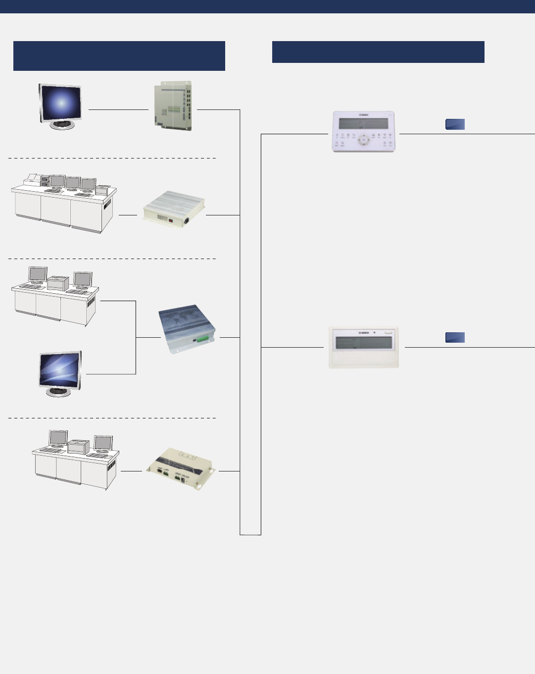
78 | Control Systems
Control Systems
Network Control
Note: The wires in the diagram show the signal flows only,
while not represent the actual connecting ways.
Centralised Control
Centralised Controller
Touch style
Indoor Centralised
Controller
X,Y,E
X,Y,E
CC-WT
CC-TS
BMS-BAC
BMS-MOD
Modbus Gateway Card
Connectable To
Various Sized Gateway
Bacnet Gateway
Web Monitoring System
Modbus Gateway
Interface Gateway
Lonworks Gateway Card
BVIM Software
BMS-LON
Bacnet Gateway Card
Lonworks Gateway
B
B
B
B
B
B
BV
VI
VI
VI
VI
VI
M
M
M
M
M
M
M
M
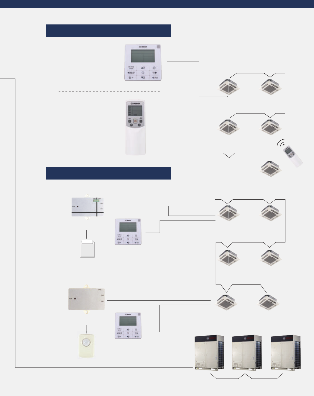
Control Systems | 79
Individual Control
Accessories
WRC-HP
HWRC
WRC-HR
IRC
Card-key Interface HK-IM
Remote Controller
Wired Controller
Outdoor Units
Card-key
Wired Controller
Wired Controller
Infrared Sensor IFS
Infrared Control Box
HK-IM
Infrared Sensor Module
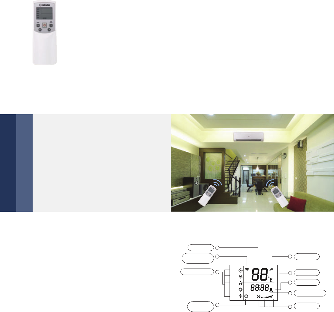
80 | Control Systems
Simplified user interface
Portable device
Users can synchronize the air conditioners’
parameters with the display panel on the
wireless remote controller to precisely control
a room’s environment.
The wireless remote controller is a port-
able control device that enables users to
control the A/C anywhere within a dis-
tance of 11 m.
Wireless Remote Controller
Functions
IRC
1
2
4
7
8
3
6
9
5
ON OFF
Temp
ON/OFF
Lock
Fan speed
Transmitting
display
Time ON/OFF
Running mode
Economic
operation
Time
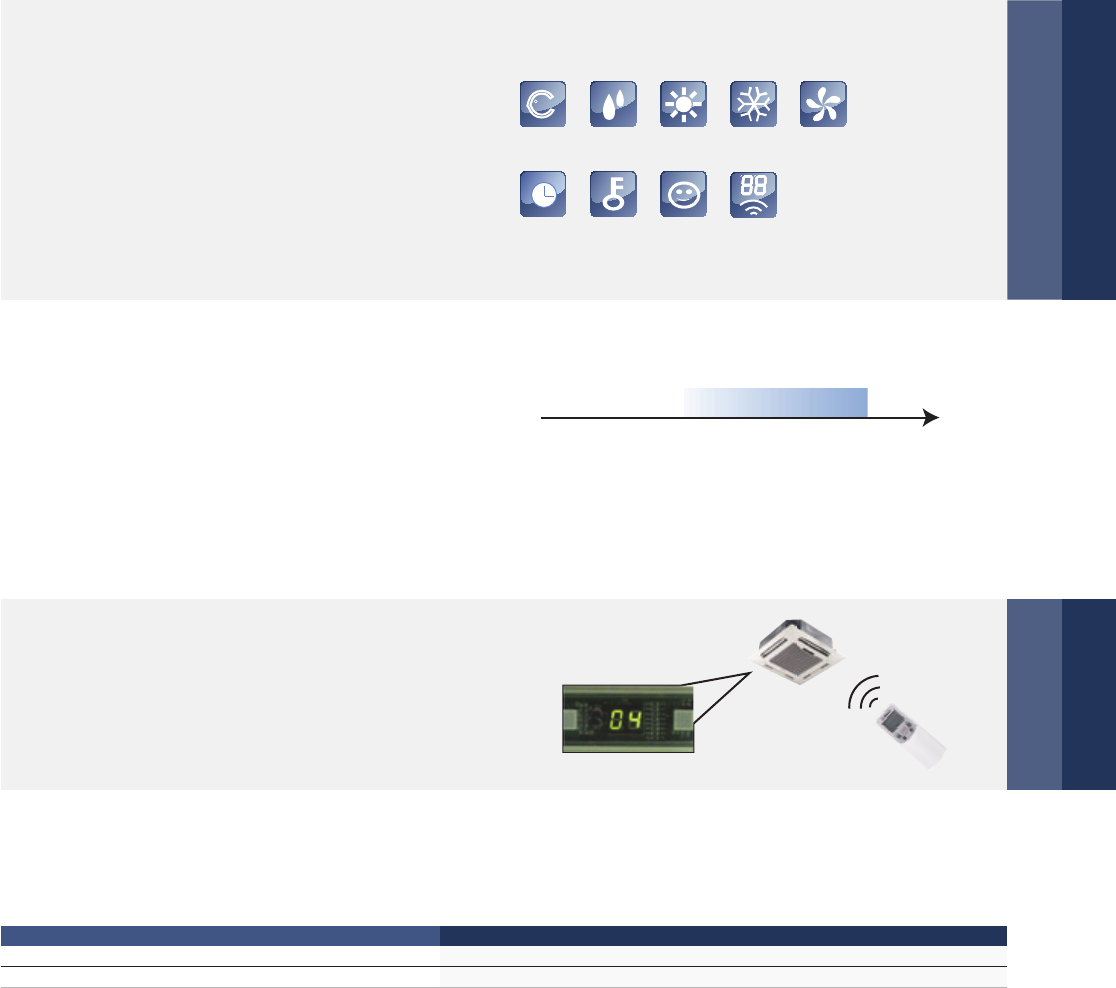
Control Systems | 81
Background light
Built-in timer
Setting addresses
The background light allows users to operate
the device in a dark room. The device lights
up when a button is pressed, and turns off
when a given operation is completed.
The built-in daily timer offers the convenience of auto-
matically starting and stopping the system at set times.
Besides the machine’s auto addressing function,
users can set the indoor unit’s address on the
wireless remote controller IRC.
AUTO
Auto mode COOL modeDRY mode HEAT mode FAN mode
Eco modeLock Address
setting
Timer
0 3 6 9 12151821
24°C
Time
ON OFF
The indoor unit is set to work in automode from 8:00 to 20:00.
Specifications
Model IRC
Dimensions (H×W×D) (mm) 150×65×20
Power (V) 1.5 V (LR03/AAA) ×2
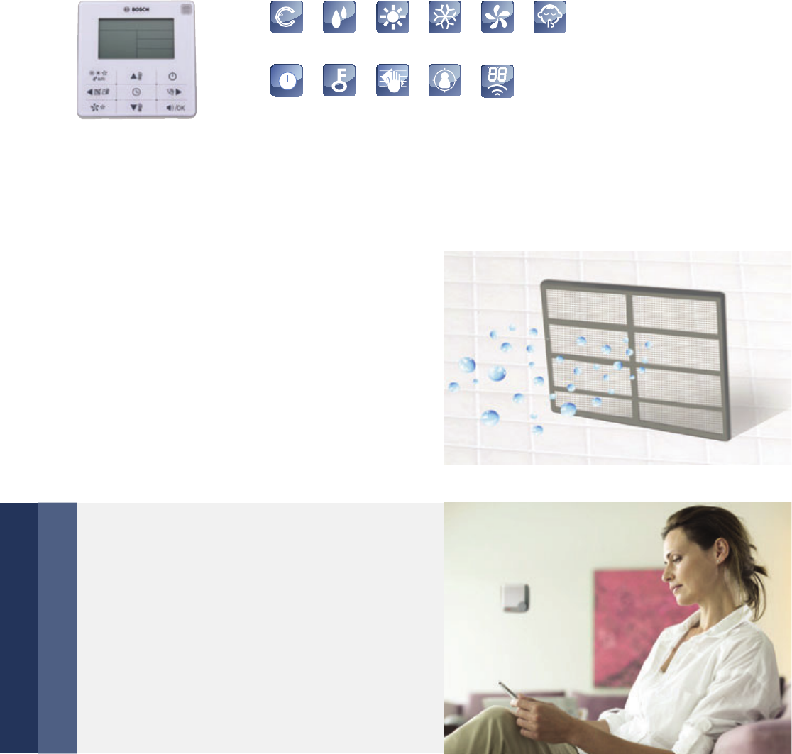
82 | Control Systems
Wired Remote Controller
Functions
Air filter cleaning reminding
Silent mode
The wired controller records the total running time of
the indoor unit. When the accumulated running time
reaches the preset value, it will remind users need to
clean the air filter of the indoor unit.
Cleaning the filter regularly can keep indoor air fresh
and clean, good for your health.
WRC-HP
Under the cooling, heating and auto mode, when
operating the silent mode, it can reduce the run-
ning noise through setting the fan speed to low.
This will help you bring a quieter environment.
AUTO
Auto mode COOL modeDRY mode HEAT mode FAN mode Silent mode
Lock Address
setting
Follow MeFilter cleaning
remind
Timer
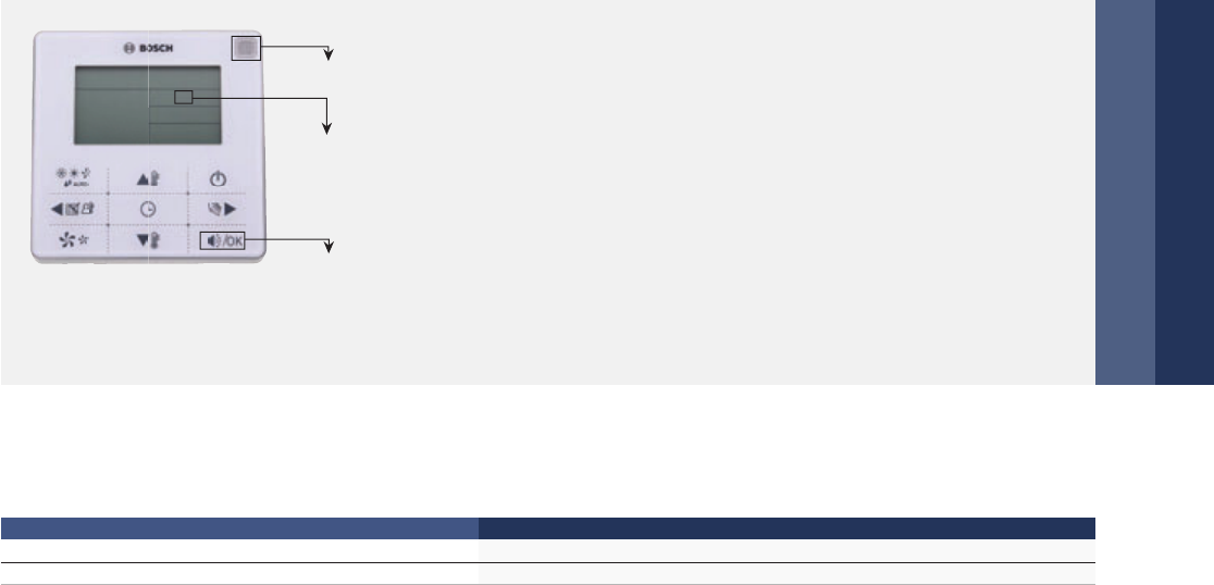
Control Systems | 83
Remote signal receiving function
Locking wired controller
WRC-HP provide a signal receiver for remote controller.
Signal from remote controller can be received by a wired
controller, then sent to the indoor unit and it conveni-
ences to control.
The locking function can be used to prevent other people
from using the controller.
Specifications
Model WRC-HP
Dimensions (H×W×D) (mm) 120×120×20
Power (V) DC 5V
Air filter cleaning
reminding icon
Remote signal
receiver
Silent Key
WRC-HP
(Touch key)
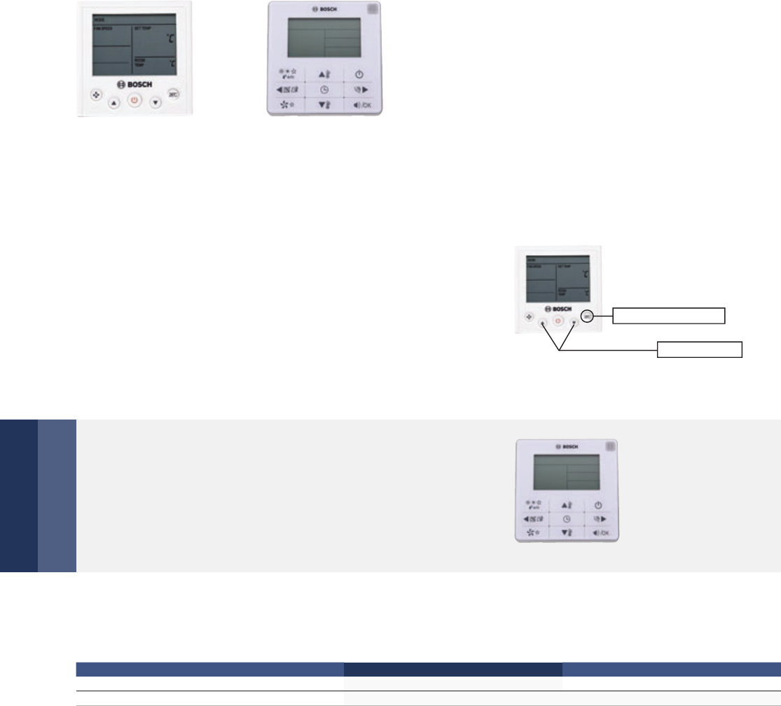
84 | Control Systems
Wired Remote Controllers
Functions
Wired Controller For RDCI Series – Auto Mode
Wired Controller For Hotel Room – Mode Setting
Under the auto mode of RDCI system, it can automatically
switch to COOL or HEAT mode according to the temperature
difference value between Tf (indoor temperature) and Ts
(setting temperature)
Mode-button hidden controller: Press the temperature
buttons "▲" and "▼" simultaneously for 3 seconds to
select the opera tion mode: COOL and HEAT. The design
is suitable for hotels, hospitals, schools and other similar
types of buildings.
HWRC WRC-HR
WRC-HR
Specifications
Model HWRC WRC-HR
Dimensions (H×W×D) (mm) 86×86×18 120×120×20
Power (V) DC 5V
Combination key Selecting Mode
26°C Shortcut Setting
HWRC
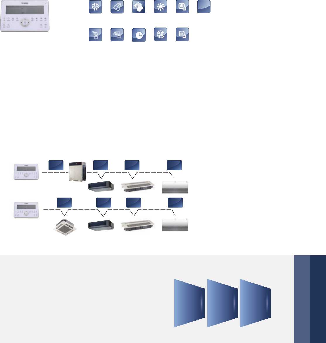
Control Systems | 85
Centralized Controller
Functions
Centralized control
Three lock modes
The centralized controller is a multifunctional device that can control up to 64 indoor units within a maximum
connection length of 1,200 m. The device connects to the master outdoor units of Bosch’s newly designed
products to simplify and centralize the wiring configuration. The 2 ways of connecting are as follows:
Centralized controller provides a superior way to man-
age the indoor units. Users are able to make their own
choice from locking the wireless controller, locking the
running mode or locking the centralized controller’s
keyboard as they wish.
* If it connects to XYE ports of master ODU,
ODU must be set to auto addressing mode.
CC-TS
HEAT
mode
Keyboard
lock
Remote
controller lock
COOL mode Swing Filter cleaning
remind
Timer Fan mode
Cooling
lock
Heating lock
Net
connection
Net
X,Y,E
X,Y,E X,Y,E X,Y,E X,Y,E
P,Q,E P,Q,E P,Q,E
Locking
Running
Mode
Locking
Remote
Controller
Locking
Keyboard
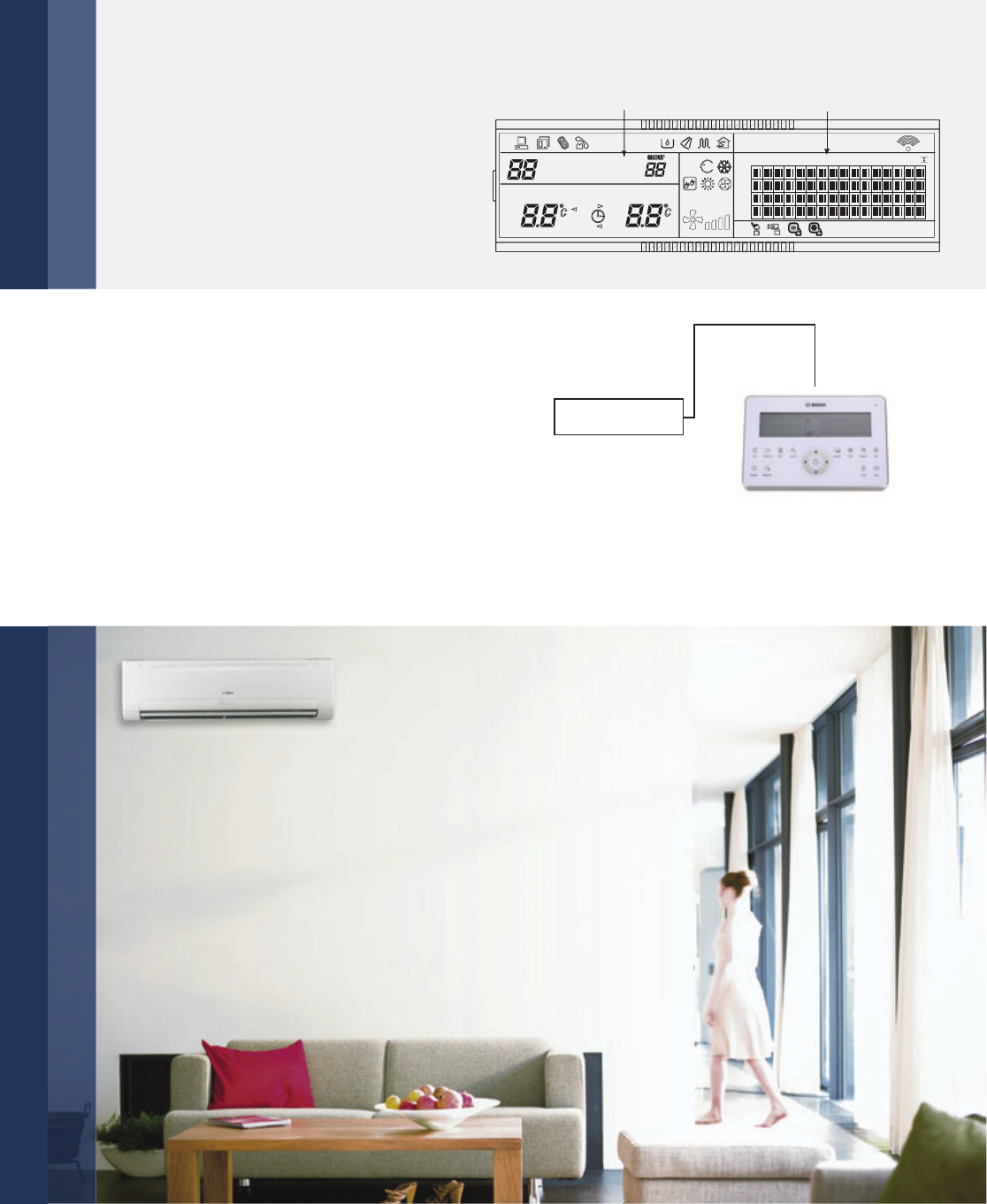
86 | Control Systems
Functions
Stylish design
Stylish design suits high-end environments. The keyboard lock function is used to prevent operational mistakes.
Air filter cleaning reminding function
The air filter cleaning reminding function is only
available on the touch-key central controller CC-TS.
The "FL" icon indicates that the air filter in a given
indoor unit needs cleaning.
Air filter cleaning
reminding icon
CC-TS
Indoor unit working status display
The centralized controller displays in-
door units’ working status and error
codes so users can easily identify faults
via checking the error codes table in
the userʼs manual before contacting
aservice engineer.
(1.6)
Error code or
protection code
Connecting
status matrix
GROUP QUERY RUN SET
SET.TEMP
ROOM.TEMP
#GROUPALL
INLINE ON OFF
Hr Hr
ON
T3 OFF
T2A
T2B
ERROR
PROTECT
MODE
FAN
AUTO
OPR.UNSUCCESS
00+
01 02 03 04 05 06 07 08 09 10 11 12 13 14 15 16
16+
32+
48+
#
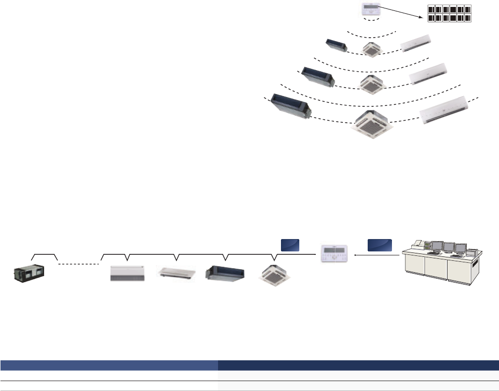
Control Systems | 87
Access to network monitoring
Single/unified control
The centralized controller is able to bridge up to 64 indoor units
on the network monitoring and building management systems.
The control object can be either a single unit or all
units, which vastly simplifies the control process.
Operation signal feedback ensures that all units
are working in the correct mode.
Specifications
Model CC-TS
Dimensions (H×W×D) (mm) 180×122×78
Power (V) 198 – 242 V (50 Hz)
OPR.UNSUCCESS
Indoor CC-TS
MAX. 64
X,Y,E F1,F2,E
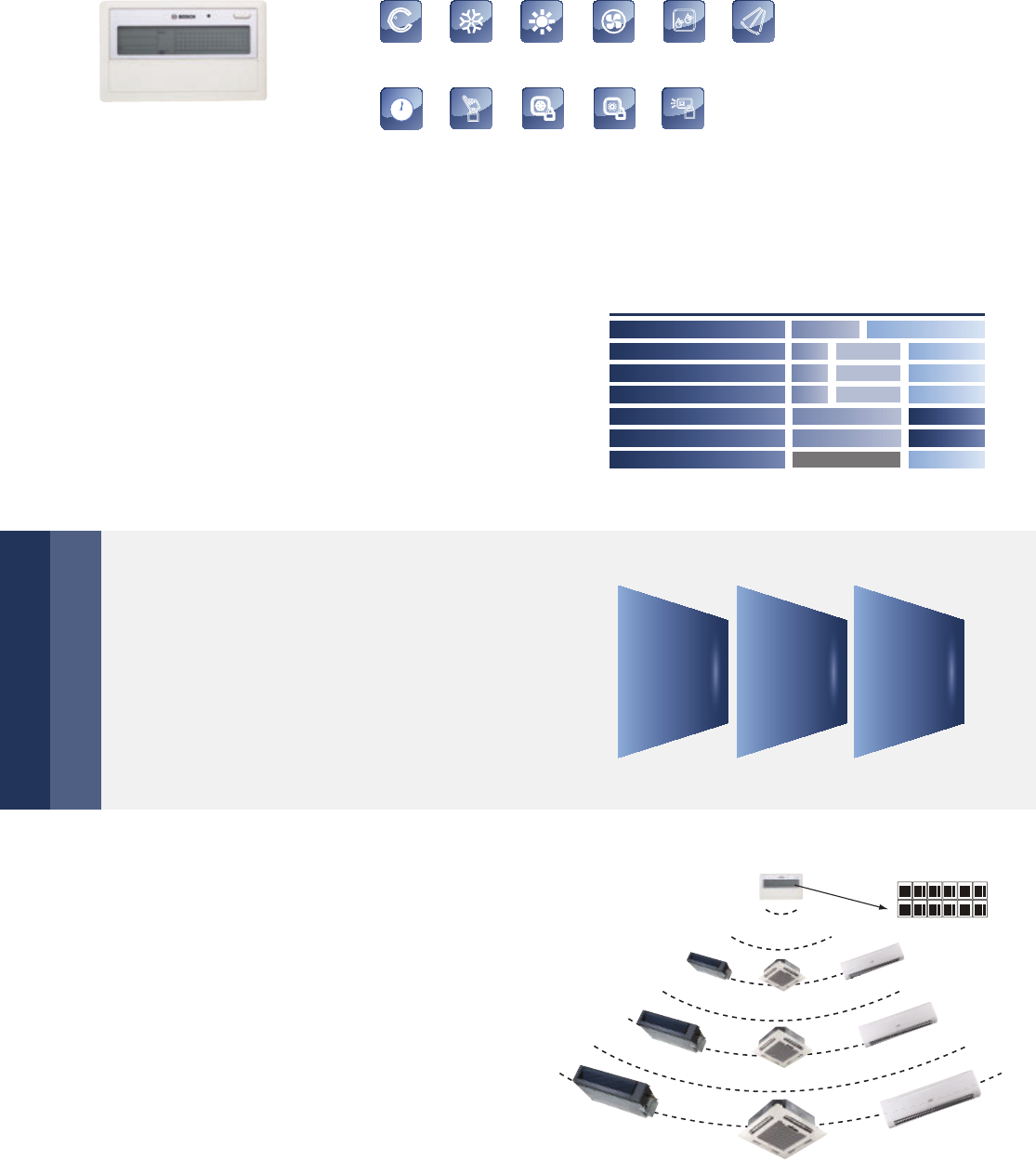
88 | Control Systems
OPR.UNSUCCESS
Single/unified control mode
The control object can be either a single unit or all
units, which vastly simplifies the control process.
Operation signal feedback ensures that all units are
working in the correct mode.
Centralized Controller – Weekly Schedule
Functions
Weekly schedule
CC-WT can include up to 64 indoor units in the
weekly schedule. Users can set up to 4 periods
per day, and select the desired running mode and
room temperature. The operating object can be a
single indoor unit or all the indoor units.
CC-WT
AUTO
Auto mode COOL mode HEAT mode Fan mode
Remote
controller lock
Heating
lock
Swing
Keyboard
lock
Cooling
lock
DRY mode
Weekly
schedule
Sun
Mon
Tue
Wed
Thu
Fri
Sat
8:00 16:00 23:59
28°C
26°C 22°C 17°C 23°C
26°C 22°C 17°C 23°C
26°C 22°C 17°C 23°C
22°C26°C 26°C
22°C26°C 26°C
off
28°C 24°C
22°C 24°C
Three lock modes
Centralized controller CC-WT provides a superior
way to manage the indoor units. Users are able to
make their own choice from locking the wireless
controller, locking the running mode or lock the
CC-WT’s keyboard as they wish.
Locking
Running
Mode
Locking
Remote
Controller
Locking
Keyboard
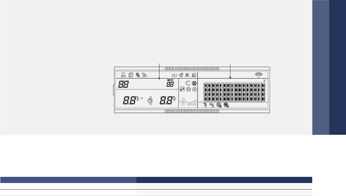
Control Systems | 89
Indoor unit working status display
CC-WT displays indoor units’ working status and error codes so users can easily identify
faults via checking the error codes table in the user’s manual before contacting a service engineer.
* If it connects to XYE ports of master
ODU, ODU must be set to auto
addressing mode.
(1.6)
Error code or
protection code
Connecting
status matrix
GROUP QUERY RUN SET
SET.TEMP
ROOM.TEMP
#GROUPALL
INLINE ON OFF
Hr Hr
ON
T3 OFF
T2A
T2B
ERROR
PROTECT
MODE
FAN
AUTO
OPR.UNSUCCESS
00+
01 02 03 04 05 06 07 08 09 10 11 12 13 14 15 16
16+
32+
48+
#
Specifications
Model CC-WT
Dimensions (H×W×D) (mm) 179×119×74
Power (V) 198 – 242 V (50 Hz)
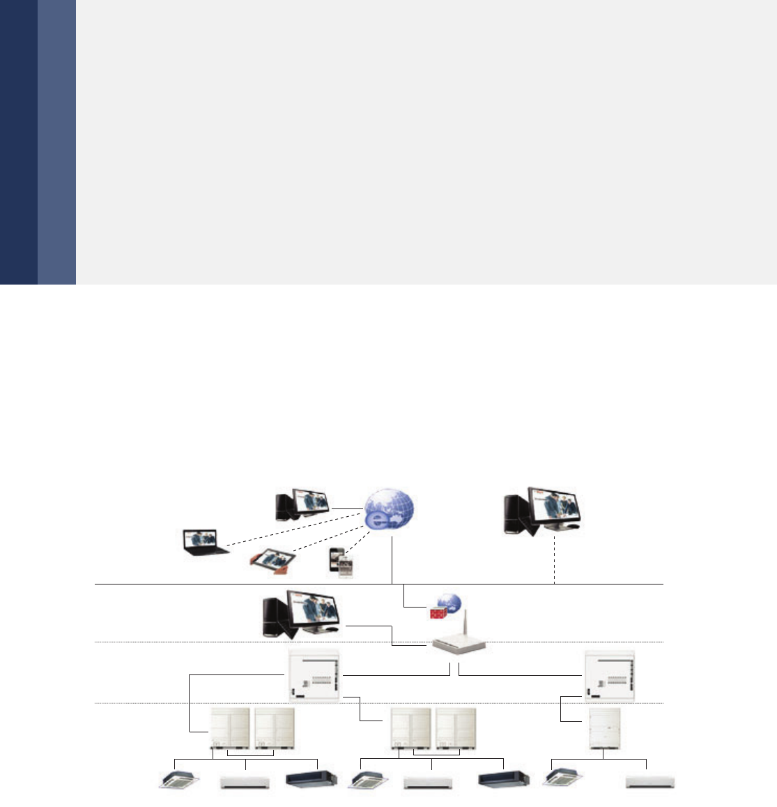
90 | Central Control Software
Network Control Application
Central Control Software
BVIM (Intelligent Manager of Bosch)
Functions
4th Generation Network Control System
Intelligent Manager of Bosch, designed specifically to control VRF systems, is based on a centralized
format and dedicated to the complete control and monitoring of all the system’s functions. It can be used
as a flexible multi-purpose system and applied to a variety of needs, according to the scale, purpose and
control method of each building.
▶ Up to 4 interfaces, 64 refrigerant systems,
1,024 indoor units, and 256 outdoor units
can be controlled by one PC.
▶ Web access
▶ User friendly operation
▶ Central building monitoring and control
▶ Energy saving management
▶ SMS modem (optional)
▶ Can run on Windows 7_32/64 bit, Windows XP_32 bit and Windows 8.
▶ Can monitor and control A/C anytime, anywhere by PC, iPhone, iPad and notebook computer.
▶ Supports WEB access: IE, Firefox, Safari and Chrome.
▶ Enables remote access through DSL, VPNs and so on.
▶ Electricity charge distribution
▶ Schedule management
▶ Low-load operation indicator
▶ Generation of operational history reports
(daily, weekly, monthly)
▶ Fault display & Warning message
▶ Air filter cleaning reminding function
▶ Emergency stop and Alarm signal output
Network monitoring
Internet
Firewall
Router
IP/Ethernet
Local PC (IMM)
A/C Units
Long distance PC (IMM)
Through VPN
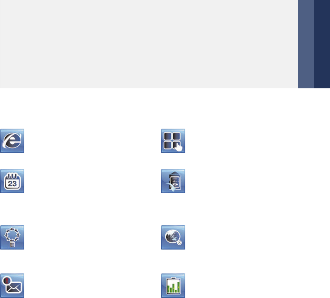
Central Control Software | 91
Various Managements
Highlights
Click & Operate, a user-friendly interface allows
even non-experts to perform the building manage-
ment system easily.
With the web access function, a PC, laptop com-
puter or a smartphone can be used as a remote
controller.
Based on a predetermined schedule, the Intelligent
Manager executes capacity control and intermittent
operations on all air conditioning units to maintain
a high comfort index.
The system can receive error messages from air
conditioning units in more than one buildings or
structures via public phone lines.
*Requires the Bosch "SMS Modem" to send automatic
warning messages to designated phone numbers.
Clicking the jump button will display a list of all
available screens. Clicking the back button will
return to the previous screen.
The interface will automatically back up data
on the installed SD card (2 GB) in case system
failure occurs, such as: power failure or system
dam. BVIM software also stores the previous
3 months’ operational data on the HDD.
Provides seven language settings:
English, Russian, French, German, Italian,
Spanish, Simple Chinese
Electricity charges can be easily divided when
billing users for air conditioning power charges;
for example, for tenants in a commercial
building, offices in a rented building, or rooms
in a hotel.
Operational information of individual indoor units
are monitored, allowing for distribution of power
consumption at outdoor units. Stores operation
data on multiple systems and displays it in graphical
format for visual management. Uses BVIM software
to generate tenant reports and help building owners
bill for energy use.
Provides information on proportional electrical power distribution to optimize electricity consumption
management. Uses software to calculate electric power proportional distribution, output and save elec-
tricity consumption data for each indoor unit (or group) which is connected to the intelligent manager.
Applies the patented Bosch Calculation Method to calculate consumption rates according to capacity
demand which is based on various parameters: setting temperature, room temperature, running mode,
rated HP, public areas, unused rooms, and nighttime use; outputs this information on a charge calculation
sheet to evenly divide power consumption charges among tenants.
Simple Operation and Management
Web Access function
Energy Saving Management
Warning Message
Visual Navigation
Data Backup
Multiple Languages
Electricity Charge Distribution
Data Management
Electricity Charge Distribution (Patented)
Automatically performs facility start/stop control,
switches the operating mode, sets temperatures
and enables/disables the remote control according
to the present time schedule. 4 sections and 20
actions per day for each single unit or group.
Schedule Control
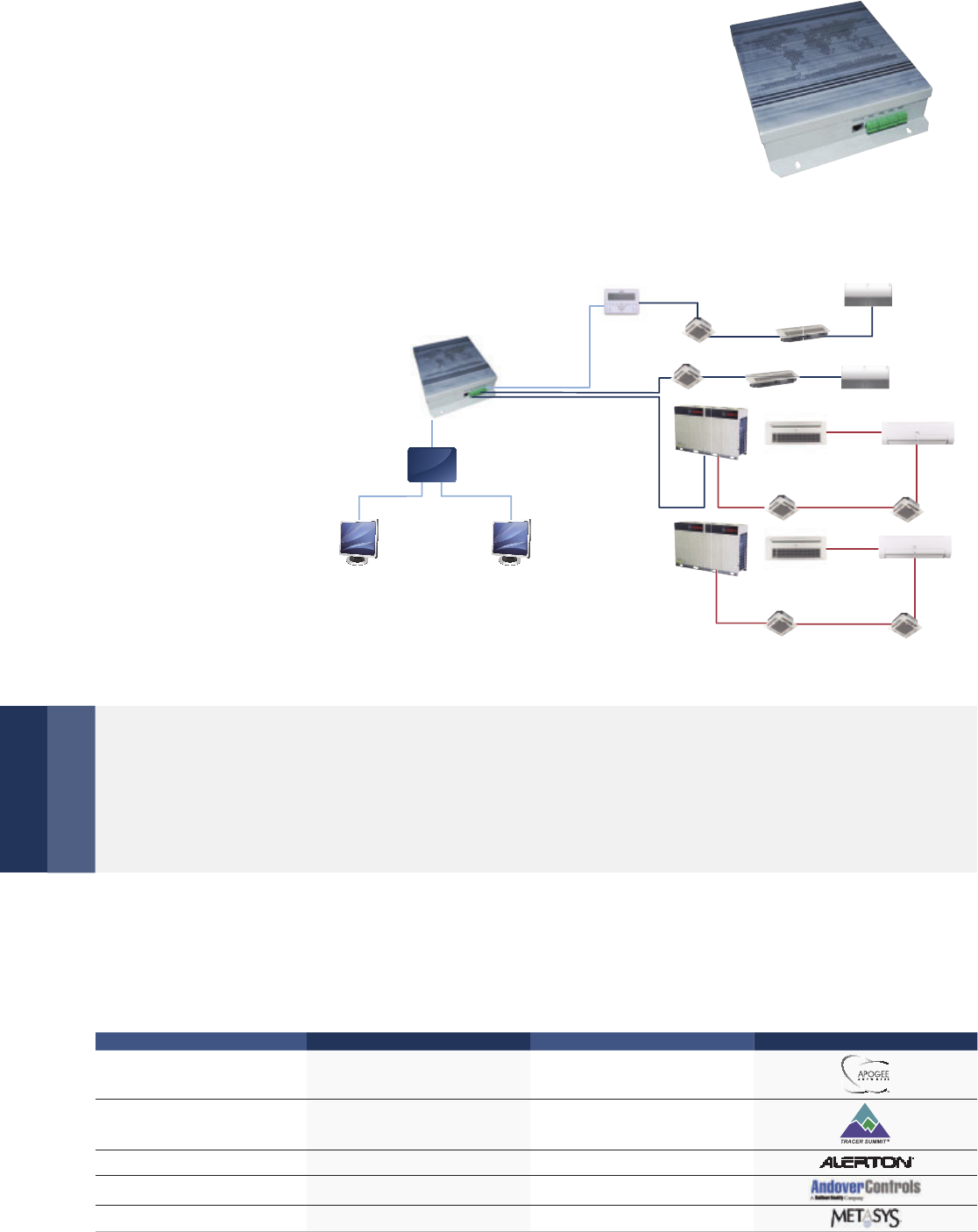
92 | Central Control Software
Monitoring units online
Wide compatibility
Accessories
Bacnet Gateway Card
Network example
BMS-BAC
Contains 4 groups of RS485 communication ports and be able to connect up to
256 indoor units or 128 outdoor units to the BMS. Built-in WEB function.
Each port can connect to XYE
ports of IDU/ODU or the K1K2E
ports of the outdoor units.
Each port can also connect
to one centralized controller
F1F2E ports.
BMS-BAC allows users to track units’ operational status and change their
running parameters on Internet Explorer for maximum control convenience.
BMS-BAC has a wonderful adaptability to the BMS
*If it connects to XYE ports of master ODU, ODU must be set to auto addressing mode.
Company BMS software Brand
1SIMENS APOGEE
2TRANE Tracer Summit
3Honeywell Alerton
4Schneider Andover
5Johnson METASYS
BMS
CC-TS
BMS-BAC
TCP/IP
Web monitoring
system
HUB Outdoor units Indoor units
P Q E
X Y E
F1 F2 E X Y E
Indoor units
Outdoor units Indoor units
P Q E
X Y E
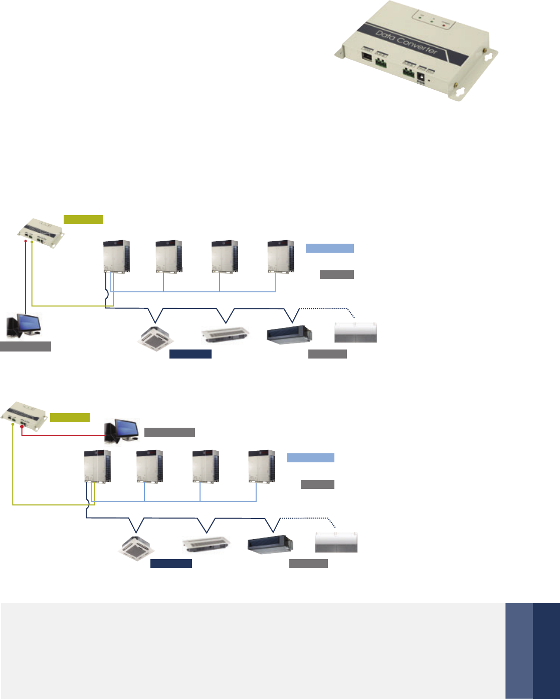
Central Control Software | 93
Accessories
Modbus Gateway Card
Network example
Config A/C System via Web
BMS-MOD
Supports Modbus protocol networks.
Bridges the Bosch VRF system to BMS.
Connect up to 64 indoor units or 16 indoor units and 4 outdoor units.*
Built-in Web server function.
* 4 outdoor units must be in the same system
When the Modbus network is set, users can conveniently configure their A/C network system
over the Internet using different TCP/IP browsers.
1) TCP connection method
2) RTU connection method
* 1. If it connects to XYE ports of
master ODU, ODU must be set
to auto addressing mode.
2. XYE and K1K2E must be
connected hand by hand.
K1 K2 E
Outdoor units
Max. 4
P Q E
Indoor units Max. 64
Modbus system
Modbus TCP/IP
K1K2E/
XYE bus
BMS-MOD
K1 K2 E
Outdoor units
Max. 4
P Q E
Indoor units Max. 64
Modbus system
K1K2E/
XYE bus
BMS-MOD
Modbus RTU
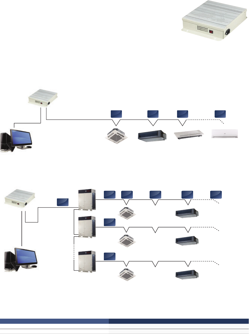
94 | Central Control Software
Accessories
Lonworks Gateway Card
Network example
BMS-LON
Comply with LonMark protocol, realizes the management and control
of VRF system. Can connect up to 64 indoor units to the BMS. Realizes non-
polarity communication, and also the application can be downloaded online.
Connection method 1: Suitable for all of air conditioner systems and connects maximum 64 indoor units.
Connection method 2: Only suitable for SDCI series and connects maximum 64 indoor units.
RS485
BMS-LON
BMS system
X,Y,E X,Y,E X,Y,E X,Y,E
BMS-LON
BMS system
X,Y,E
X,Y,E X,Y,E X,Y,E X,Y,E
P,Q,E
P,Q,E
P,Q,E
RS485
System 1
System 2
System N
Specifications
Model BMS-LON
Dimensions (H×W×D) (mm) 319×251×61
Power (V) 177~265V AC (50 Hz)
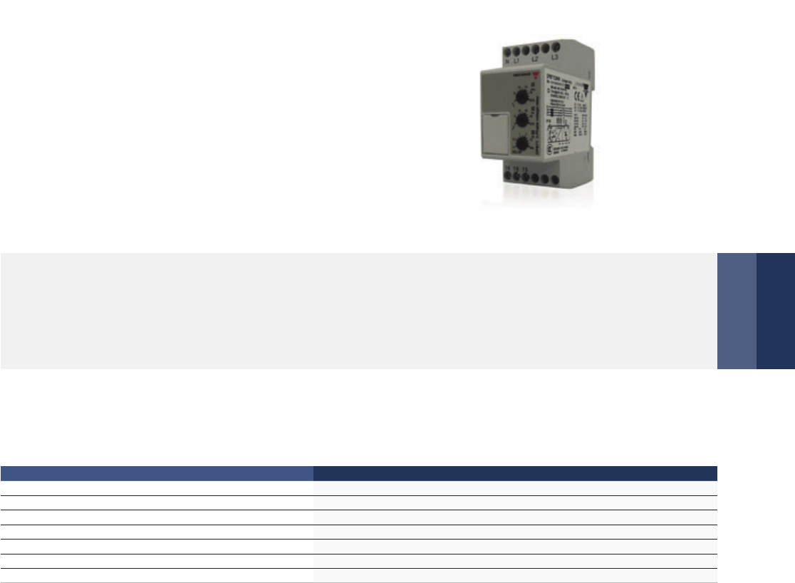
Central Control Software | 95
Accessories
Three Phase Connector
Excellent reliability
TPP
Detects the power condition and makes the corresponding
protecting action. Protects the compressor from being
damaged. Automatically distinguishes the abnormal power
supply conditions and automatically recovers.
The protector protects the entire system from power supply problems, and auto restarts after recovery.
Specifications
Model TPP
Power supply (V-N-Hz) 380~480V-3N 50/60 Hz
Temp. range (C) -20° C~50° C
Rated operational power (VA) 13 VA
Over voltage 18 %
Under voltage -12 %
Phase imbalance 8%
Dimensions (W×H×D) (mm) 81×67×35
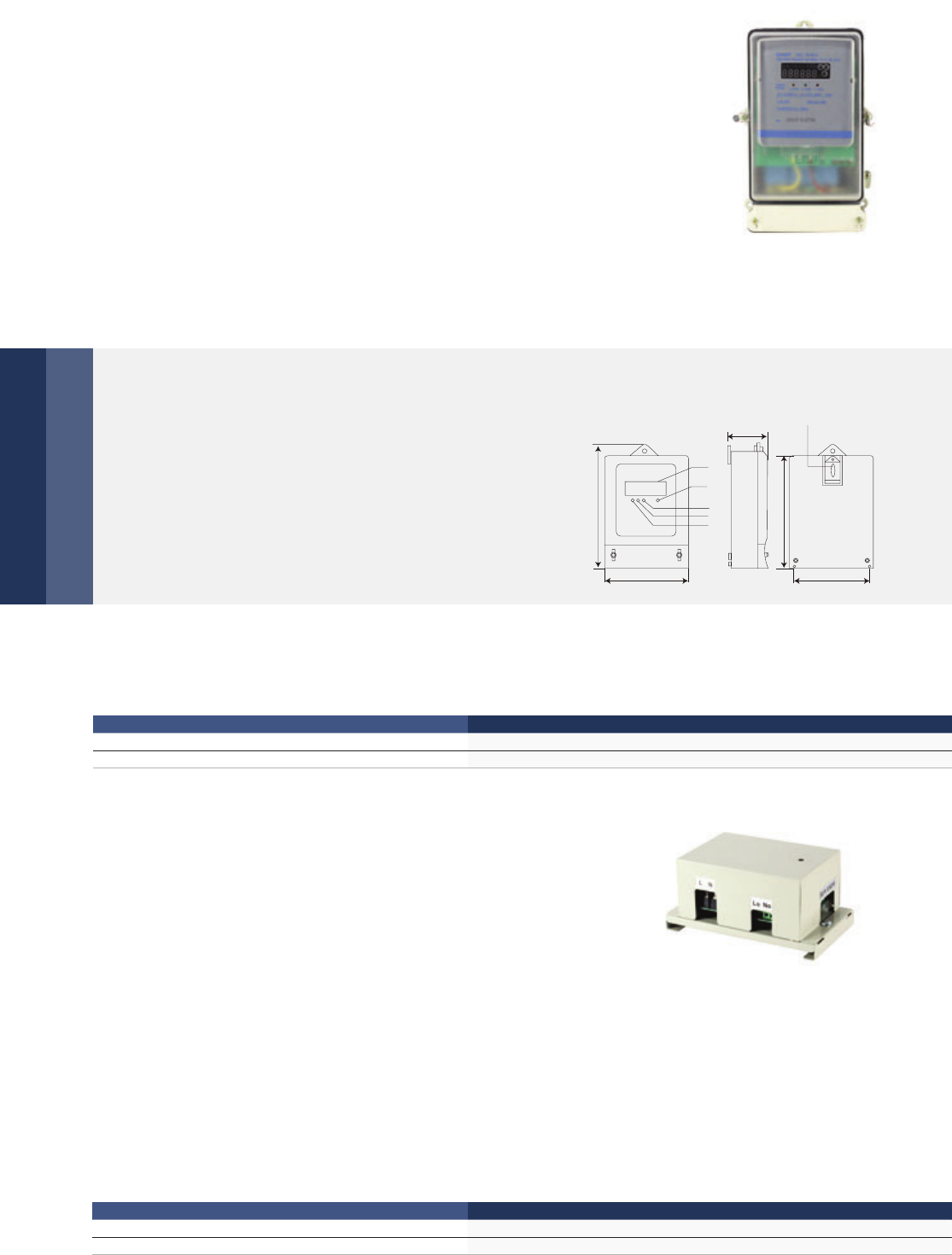
96 | Central Control Software
Digital Power Ammeter
Outdoor Unit Failure Alarm
Indications and installation
Low power consumption
Functions
DPA-3
ODU-FA
Calculates power consumption. Does not need adjusting after long-term use.
Corresponds one outdoor unit to one digital power meter.
The digital power meter is tested after manufacture
so it can be immediately deployed and used on-site.
The LED indicators and installation schematic are
shown in the figure on the left.
The digital power meter consumes minimal energy. Voltage circuit: less than 2W/10 VA. Current circuit: less than 2.5 VA
15mm long crack
201
230
131
145
A phase
B phase
C phase
LCD
72
Impulse
Specifications
Specifications
Model DPA-3
Dimensions (H×W×D) (mm) 230×145×72
Power (V) 200 – 500 V (50/60 Hz)
Model ODU-FA
Dimensions (H×W×D) (mm) 150×85×70
Power (V) 198 – 242 V (50/60 Hz)
ODU-FA is specially designed for engineering applications. It does not display the outdoor units working
parameters, but it can be connected to the alarm device. When outdoor unit is working abnormally, the RUN
light will flash.
Simple design
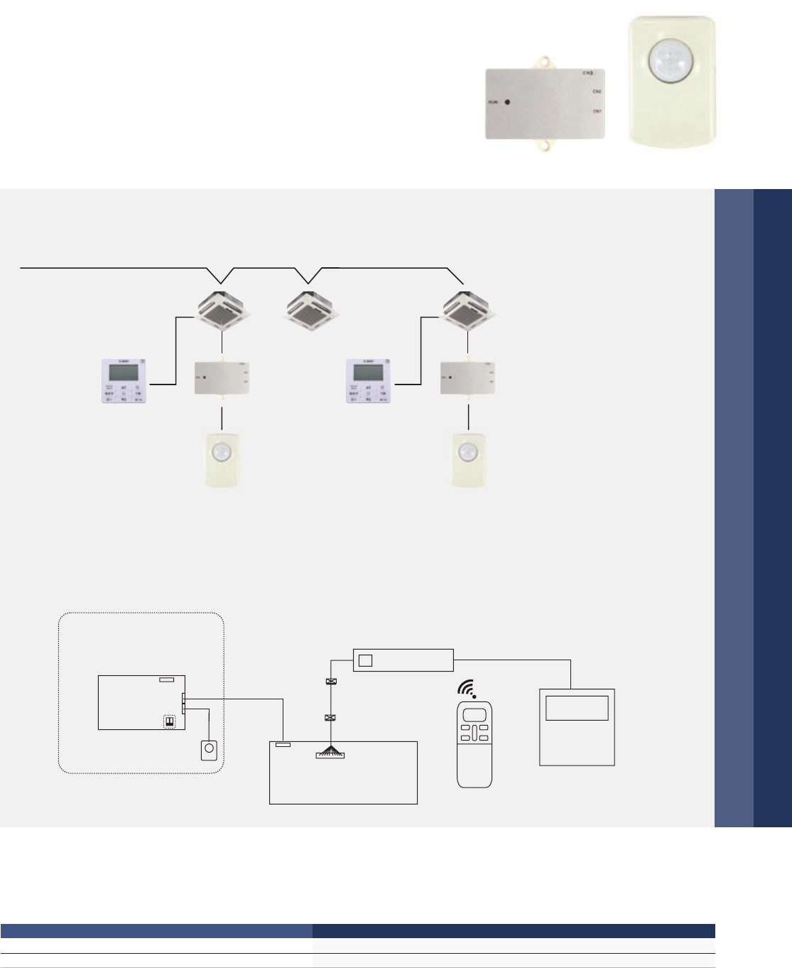
Central Control Software | 97
Infrared Sensing Controller
Accessories
Installation example
Electrical wiring
IFS
Automatically adjusts the room conditions.
Automatically extends the shutting down time, avoiding frequent ON/OFF.
Stylish appearance accommodates itself to different buildings.
Remote controller or
wired controller can
control indoor unit.
Specifications
Model IFS
Dimensions (H×W×D) (mm) Sensor part: 46×30×25.6, Control box: 86×72.8×15.5
Power (V) DC 5V
Wired controller
S1
Infrared Sensing Controller
Infrared
sensor
Infrared inductive
control box
Indoor main board
Display panel
CN3
CN2
CN1
IFS
Network
module
port
Display
panel port
Remote controller
Wired controller Wired controller
IFS IFS
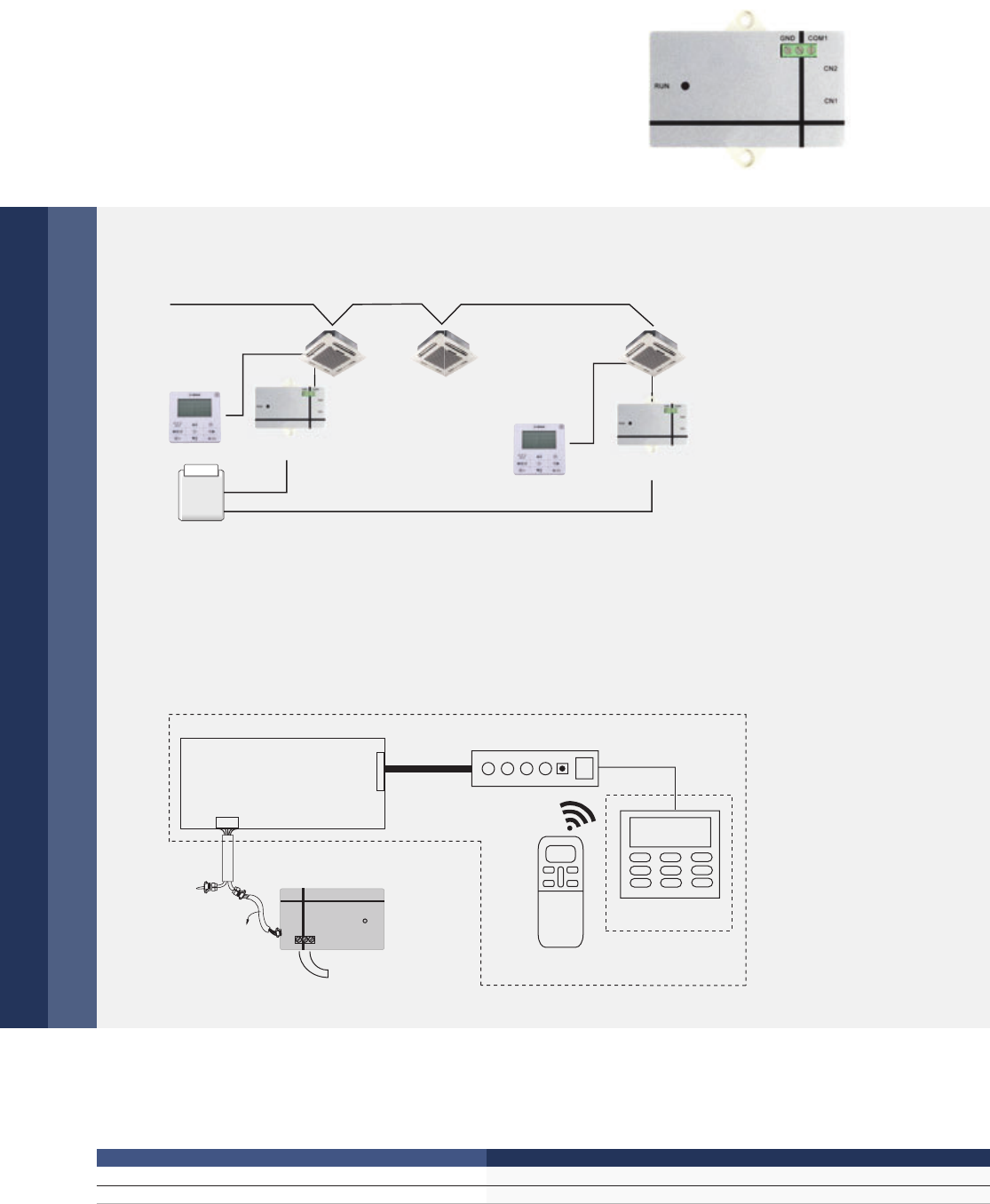
98 | Central Control Software
Hotel Card Key Interface Module
Installation example
Electrical wiring
HK-IM
Cooperates with the wired controller to automate control.
Eliminates the need for high voltage power, making the
device safe and steady.
Includes a build-in auto-restart function.
Remote controller or wired controller can control indoor unit.
Hotel card key interface module
Specifications
Model HK-IM
Dimensions (H×W×D) (mm) 86×72.8×15.5
Power (V) DC 5V
Display
panel port
Check
Wired controller
Remote controller
Display panel
Network module port
HK-IM
RUN
COM1 GND
CN1
CN2
5 meters
To hotel
control system
Hotel Card-inserter
Indoor main board
Card key
HK-IM
HK-IM
Wired controller
Wired controller
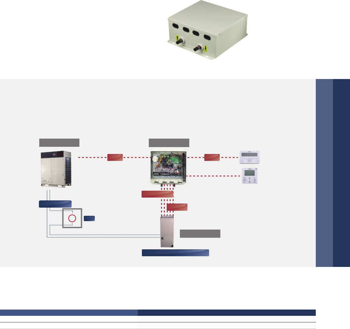
Central Control Software | 99
DX-AHU KIT
Accessories
Introduction
AHU KIT01-1/AHU KIT02-1/AHU KIT03-1
Can be used to connect VRF outdoor units with
DX AHU or other brand indoor units.
AHU KIT01-1/AHU KIT02-1/AHU KIT03-1 is an independent control box that can connect an AHU to
SDCI series system to realize centralized control with SDCI system. Control box wiring is as follows:
Specifications
Model AHU KIT01-1/AHU KIT02-1/AHU KIT03-1
Dimensions (H×W×D) (mm) 335×375×150
Power (V) 220 – 240V ~ 50 Hz
T1/T2/T2B/T2C
Fan/pump
Centralized Controller
Wired Controller
P/Q/E X/Y/E
Gas/Liquid pipe
Power supply Power supply
Power supply
DX AHU or other brand indoor units
x
EXV
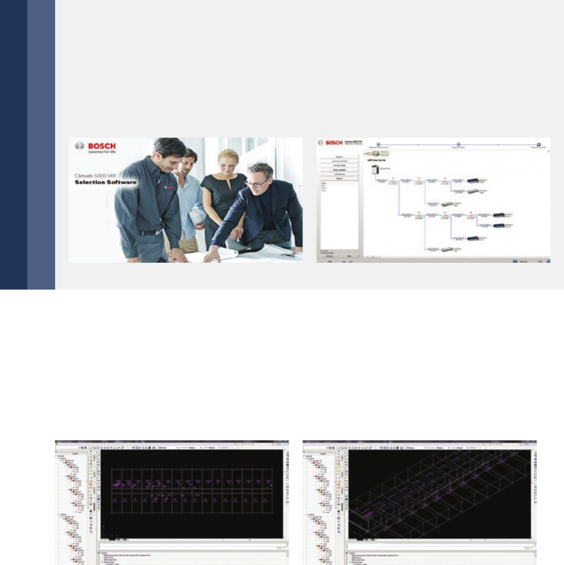
100 | System Selection & Design
Selection software
Windows Version
CAD Version
Load calculation: Provides two calculation methods (detailed room load calculation and rough load
calculation). Indoor & outdoor units selection: There are versatile indoor units and different outdoor
units for choosing. Piping drawing: Displays the detailed layout of an A/C system and the parameters
for piping and branch distributors. Controller selection: Provides a selection of controllers for indoor
units and outdoor units, including wireless and remote controllers for indoor units.
Report output: Outputs a comprehensive selection report as a Word or Excel document.
AutoCAD add-on software
Automatic Calculation: Refrigerant & drain pipe size
Automatic Selection: Distributor kit & branch joint
System Check: Installation regulation & refrigerant addition
Automatic Report: Piping installation diagram, equipment list & quotation
To meet desginers, consultants and installers requirements, Bosch has developed an advanced design automation
tool that can be used in AutoCAD-based CAD version or Windows-based version. The software provides quick and
convenient selectable options for users, supports multiple languages, and greatly improves the selection process.
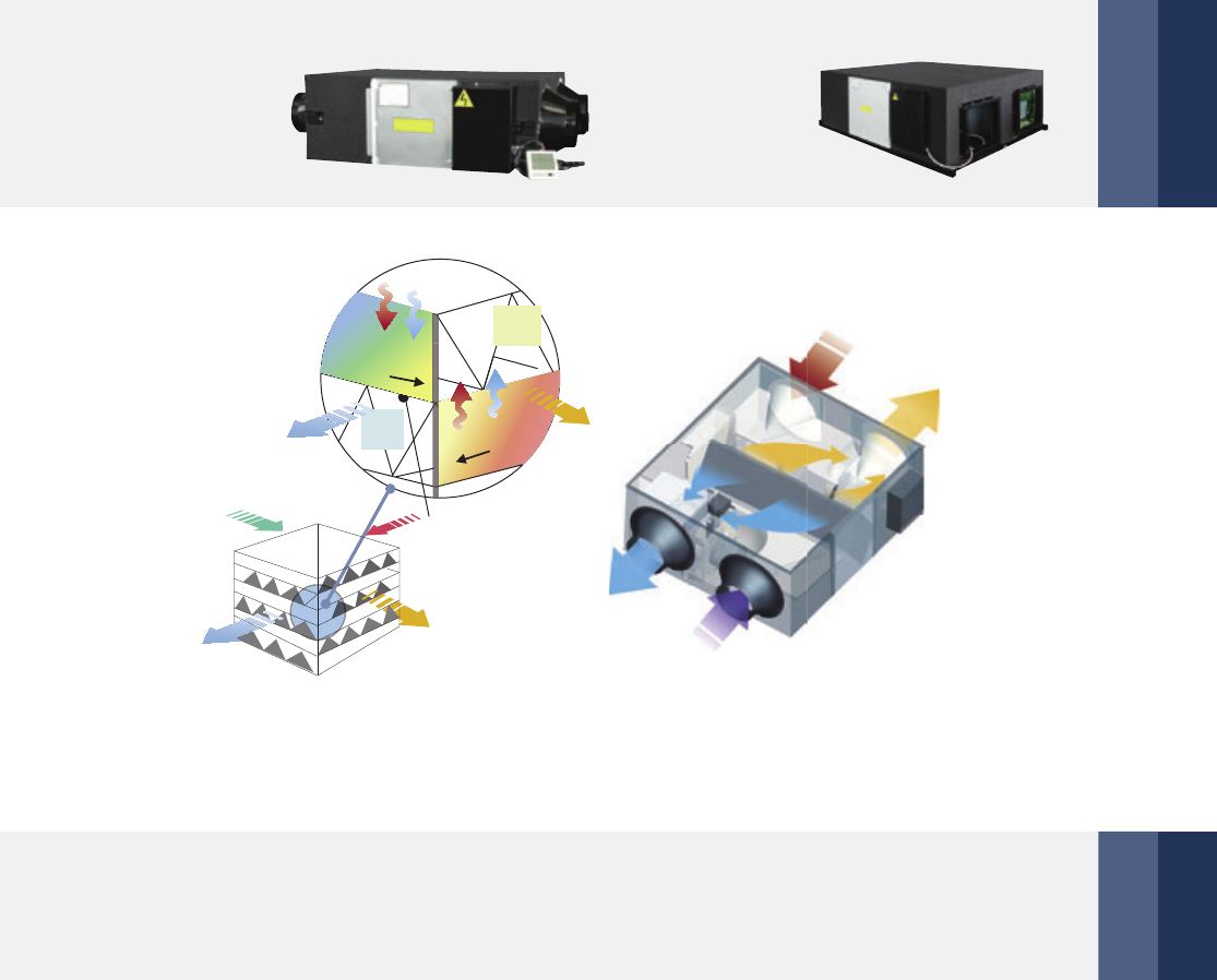
HRV | 101
Heat Recovery Ventilation Units (HRV)
Model Names
Low noise
Compact design, flexible installation and easy maintenance
HRV200-1
HRV300-1
HRV400-1
HRV500-1
HRV800-1
HRV1000-1
HRV1500-3
HRV2000-3
Sound proof material is used to guarantee quiet operation.
With a minimum height of only 264 mm and 23 kg weight, the unit
provides best convenience and possibility for installation in limited
spaces (HRV200-1 model).
Larger air supply rate enhanced heat exchange efficiency enhanced energy saving
The heat recovery ventilation unit (HRV) can regain heat energy lost through ventilation and reduce the room
temperature fluctuation caused by ventilation process. By utilizing the most advanced technology and technics,
Bosch HRV has extremely good performance. The heat exchanger core is made of special paper processed with
chemical treatment, which could realize better temperature and humidity control of the room environment.
Temperature exchange efficiency is above 65% and enthalpy exchange efficiency between 50 – 65 %.
SA
14
。
C
6。
C
0
。
C
EA
Heat exchange plate
20°C
Warm air
Heat
0°C
Cold air
Heat
Moisture
u
Moisture
(Exhaust air
to outdoors)
(Fresh air from
outdoors)
(Returm air
from room)
(Supply air
to room)
EA
OA
RA
SA
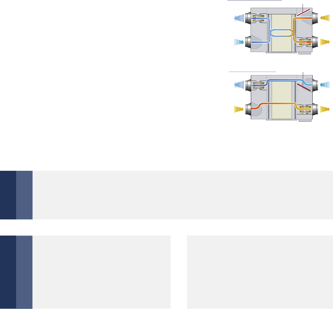
102 | HRV
Multi-modes for different Situations
Heat exchange mode
Bypass mode
Air supply mode
Exhaust air mode Auto mode
When air flow formed by the fans goes through the
heat exchanged core in cross way, due to temperature
difference between two channels of the core, thermal
transmission happens naturally. In summer days,
high temperature outdoor air gets cooled by indoor
exhaust air; in winter, low temperature outdoor air gets
heated by indoor exhaust air. So the energy contained
in exhaust air can be reclaimed and energy efficiency
gets improved.
In mild climate areas or seasons, when temperature and
humidity level difference between indoor and outdoor
is small, the unit works as a conventional ventilation fan.
Both supply fan and exhaust fan work at the same speed
(Hi/mid/low/auto).
It is one kind of bypass mode with air supply fan speed higher than exhaust fan speed.
It can be used in mild climate areas where a large amount of fresh air is needed.
It is also one kind of bypass mode with
exhaust fan speed higher than air supply fan
speed. It can be used in mild climate areas
where a large amounf ot exhaust air needs to
be expelled.
The controller chooses heat exchange mode
or bypass mode according to the temperature
difference between outdoor and indoor tem-
perature. Both the two fans work at low speed.
EA
OA
R
S
Element
Damper
Element
EA
OA
R
S
Damper
Heat exchange mode
Bypass mode
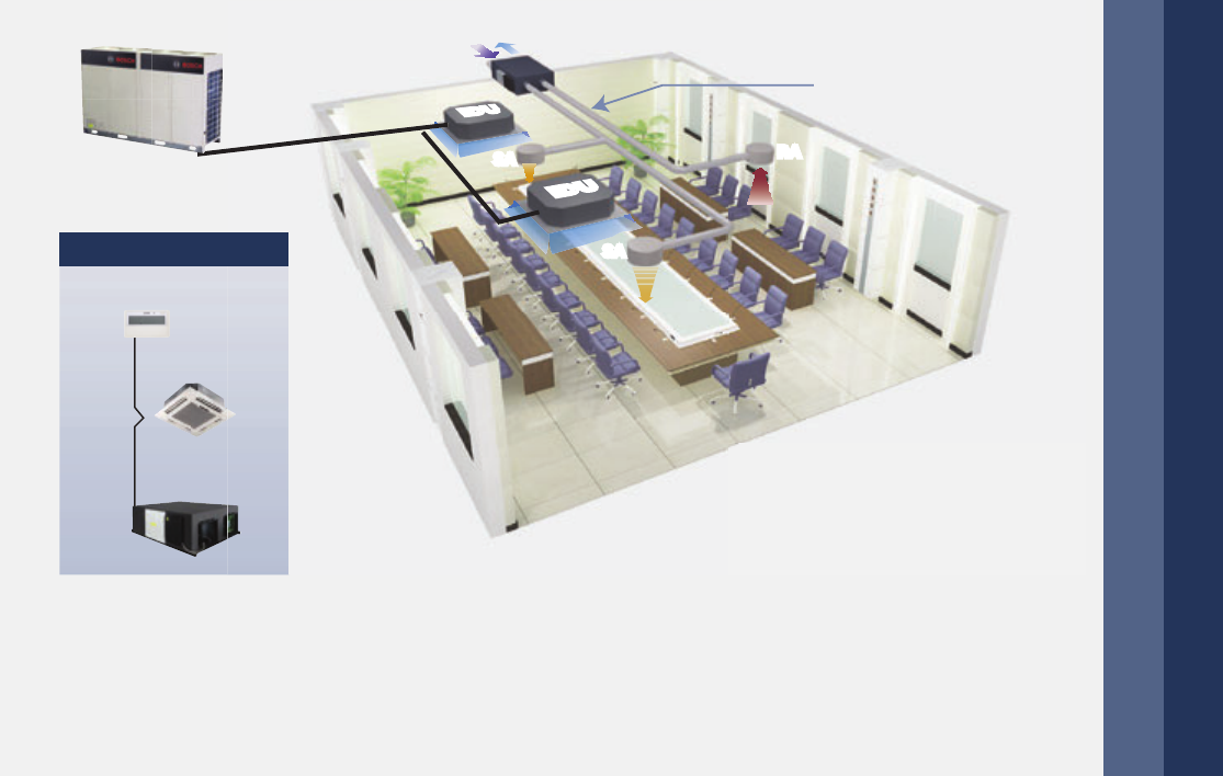
HRV | 103
Flexible Control
Interlocking control with other indoor units by controller is possible.
Duct
SA
SA
SA
SA
RA
RA
OA
IDUIDU
IDUIDU
EAEA
Centralized control
CC-WT
IDU = VRF Indoor Unit
SA = Supply Air
RA = Return Air
OA = Outdoor Air (Fresh Air)
EA = Exhaust Air

104 | HRV
Specifications
Model HRV200-1 HRV300-1 HRV400-1 HRV500-1
Power supply V/Ph/Hz 220-240/1/50 220-240/1/50 220-240/1/50 220-240/1/50
Cooling
Temperature
exchange
efficiency
High % 55 55 55 55
Medium % 55 55 55 55
Low % 60 60 60 60
Enthalpy
exchange
efficiency
High % 50 50 50 50
Medium % 50 50 50 50
Low % 55 55 55 55
Heating
Temperature
exchange
efficiency
High % 60 60 60 65
Medium % 60 60 60 65
Low % 65 65 65 70
Enthalpy
exchange
efficiency
High % 55 55 60 60
Medium % 55 55 60 60
Low % 60 60 65 65
Sound
pressure
level
Heat
exchange
mode
High dB(A) 27 30 32 35
Medium dB(A) 26 29 31 34
Low dB(A) 20 23 25 28
Bypass
mode
High dB(A) 28 31 33 36
Medium dB(A) 27 30 32 35
Low dB(A) 22 25 27 30
Net dimension (W×D×H) mm 866×655×264 944×722×270 944×927×270 1038×1026×270
Packing size (W×D×H) mm 930×730×445 1010×800×450 1010×1010×450 1120×1120×452
Net/gross weight kg 23/40 26/44 31/52 41/64
Casing Galvanized steel plate
Heat exchange system Air to air cross flow total heat (sensible heat + latent heat) exchange
Heat exchange element material Specially processed nonflammable paper
Fan
Type Centrifugal fan
Airflow rate
High m3/h 200 300 400 500
Medium m3/h 200 300 400 500
Low m3/h 150 225 300 375
ESP
High Pa 75 75 80 80
Medium Pa 58 60 65 68
LowPa35404345
Motor output W 20 40 80 120
Duct diameter mm Ф144 Ф144 Ф144 Ф194
Operating temperature range °C -7~43 DB, 80 % RH or less
Notes:
1. For the units model of HRV (200 – 1000), there are 3-speed adjustable air volume (Hi, Med, Low),
but for the units model of HRV (1500 – 2000), there are only 1-speed which cannot be adjusted.
2. Sound level is measured at 1.4m below the center of the body in an anechoic chamber.
3. Efficiency is measured under the following conditions:
* Cooling Condition: Air Exhaust Temp. 27°C DB, 19.5°C WB., Fresh Air Temp. 35°C DB, 28°C WB.
* Heating Condition: Air Exhaust Temp. 21°C DB, 13°C WB., Fresh Air Temp. 5°C DB, 2°C WB.

HRV | 105
Model HRV800-1 HRV1000-1 HRV1500-3 HRV2000-3
Power supply V/Ph/Hz 220-240/1/50 220-240/1/50 380-415/3/50 380-415/3/50
Cooling
Temperature
exchange
efficiency
High % 55 55 55 55
Medium % 55 55 – –
Low % 60 60 – –
Enthalpy
exchange
efficiency
High % 50 50 50 50
Medium % 50 50 – –
Low % 55 55 – –
Heating
Temperature
exchange
efficiency
High % 65 65 65 65
Medium % 65 65 – –
Low % 70 70 – –
Enthalpy
exchange
efficiency
High % 60 60 60 60
Medium % 60 60 – –
Low % 65 65 – –
Sound
pressure
level
Heat
exchange
mode
High dB(A) 39 40 51 53
Medium dB(A) 38 39 – –
Low dB(A) 32 33 – –
Bypass
mode
High dB(A) 40 41 52 54
Medium dB(A) 39 40 – –
Low dB(A) 34 35 – –
Net dimension (W×D×H) mm 1286×1006×388 1286×1256×388 1600×1270×540 1650×1470×540
Packing size (W×D×H) mm 1380×1100×573 1390×1350×580 1680×1350×720 1760×1580×720
Net/gross weight kg 62/88 79/110 163/224 182/247
Casing Galvanized steel plate
Heat exchange system Air to air cross flow total heat (sensible heat + latent heat) exchange
Heat exchange element material Specially processed nonflammable paper
Fan
Type Centrifugal fan
Airflow rate
High m3/h 800 1000 1500 2000
Medium m3/h 800 1000 – –
Low m3/h 600 750 – –
ESP
High Pa 100 100 160 170
Medium Pa 82 85 – –
Low Pa 54 58 – –
Motor output W 360 360 450 450
Duct diameter mm Ф242 Ф242 346×326 346×326
Operating temperature range °C -7~43 DB, 80 % RH or less
Notes:
1. For the units model of HRV (200 – 1000), there are 3-speed adjustable air volume (Hi, Med, Low),
but for the units model of HRV (1500 – 2000), there are only 1-speed which cannot be adjusted.
2. Sound level is measured at 1.4m below the center of the body in an anechoic chamber.
3. Efficiency is measured under the following conditions:
* Cooling Condition: Air Exhaust Temp. 27°C DB, 19.5°C WB., Fresh Air Temp. 35°C DB, 28°C WB.
* Heating Condition: Air Exhaust Temp. 21°C DB, 13°C WB., Fresh Air Temp. 5°C DB, 2°C WB.

Joints

Joints | 107
Joints
Dimensions
108 Joints
110 Dimensions
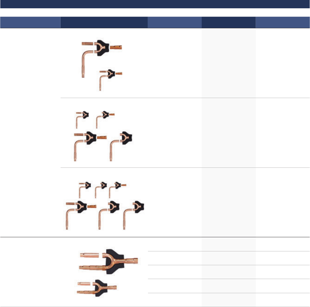
108 | Joints
Joints
Branch joints of two-pipe system (Heat Pump VRF)
Model Appearance Model name Packing Size (mm)/
Gross Weight (kg)
Description
Branch joint for
outdoor unit
ODU-BJ02 255×150×185/1.5 For two outdoor
units connection
ODU-BJ03 345×160×285/3.4 For three outdoor
units connection
ODU-BJ04 475×165×300/4.8 For four outdoor
units connection
Branch joint for
indoor unit
IDU-BJ01 290×105×100/0.4 X <16.6 kW
IDU-BJ02 290×105×100/0.6 16.6 ≤ X <33 kW
IDU-BJ03 310×130×125/0.9 33 kW ≤ X <66 kW
IDU-BJ04 350×180×170/1.5 66 kW ≤ X <92 kW
IDU-BJ05 365×195×215/1.9 92 kW ≤ X
X: The total capacity of indoor units which is connected to this branch joint
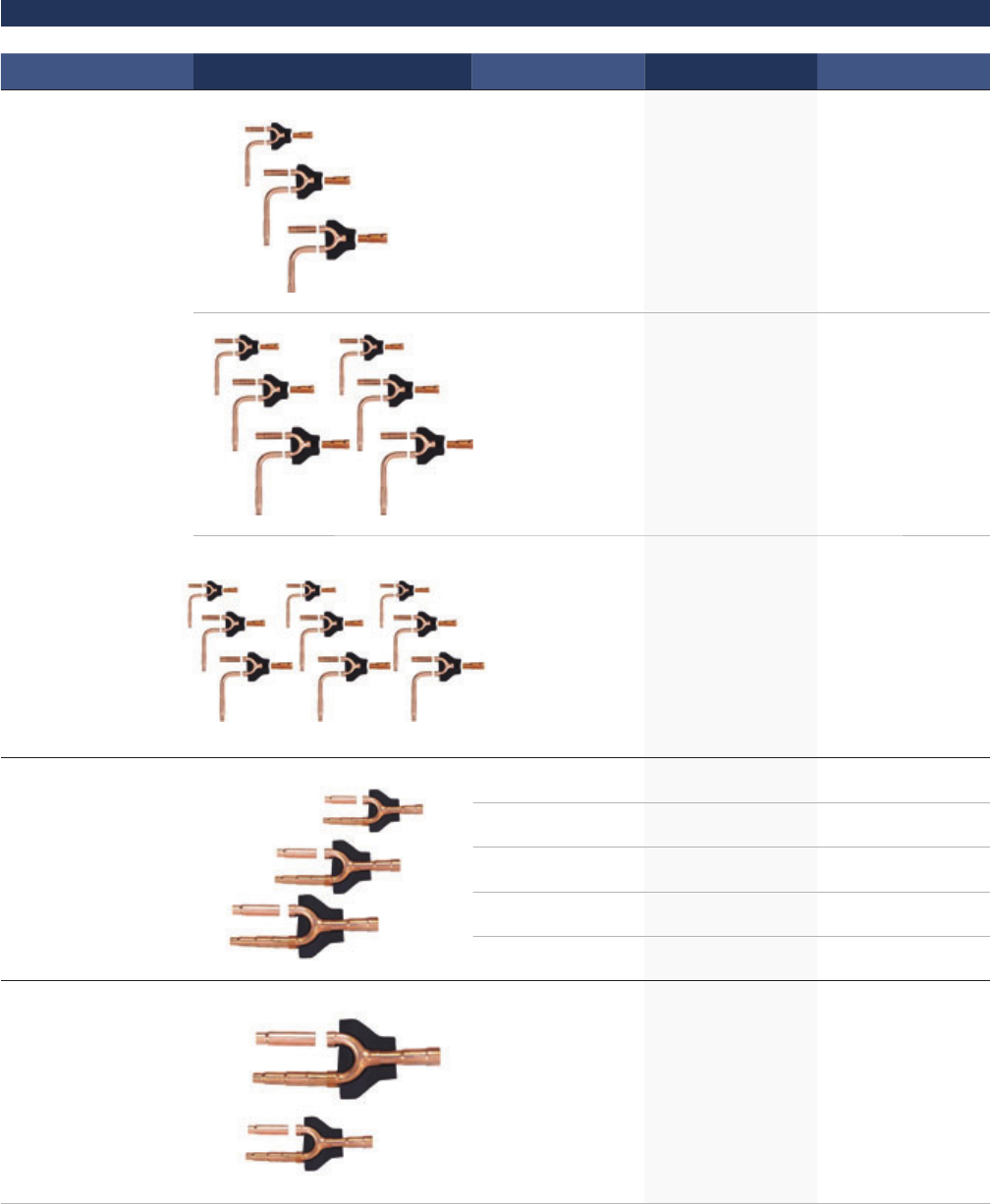
Joints | 109
Branch joints of three-pipe system (Heat Recovery VRF)
Model Appearance Model name Packing Size (mm)/
Gross Weight (kg)
Description
Branch joint
between outdoor unit
ODU-BJR02 272×167×232/2.2 For two outdoor
units connection
ODU-BJR03 472×157×312/5.0 For three outdoor
units connection
ODU-BJR04 745×160×335/7.5 For four outdoor
units connection
Branch joint
between SBOX
and outdoor unit
IDU-BJR01 257×127×107/0.8 X <16.6 kW
IDU-BJR02 287×137×107/0.9 16.6 ≤ X <33 kW
IDU-BJR03 297×167×177/1.4 33 kW ≤ X <66 kW
IDU-BJR04 372×197×187/2.3 66 kW ≤ X <92 kW
IDU-BJR05 432×222×227/3.3 92 kW ≤ X
Branch joint
between SBOX
and indoor unit
IDU-BJ01 290×105×100/0.4 X <16.6 kW
X: The total capacity of indoor units which is connected to this branch joint
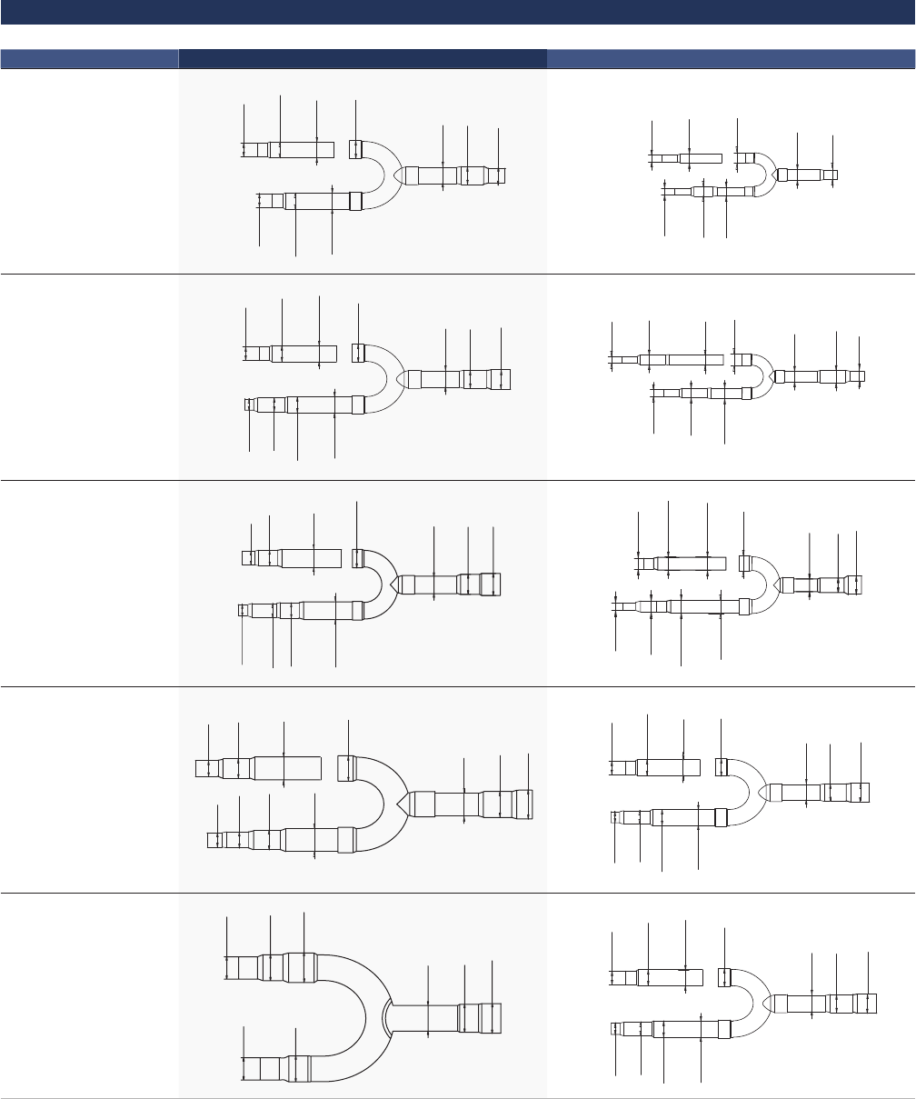
110 | Joints
Dimensions
Indoor branch joints
Branch model Gas side joints Liquid side joints
IDU-BJ01
ID:12.7
(ID:15.9)
OD:19.1
ID:19.1
OD:19.1
ID:19.1
ID:15.9
ID:12.7
(ID:15.9)
OD:19.1
OD:12.7
ID:9.5
ID:9.5
ID:6.4
OD:9.5
ID:6.4
OD:9.5
ID:9.5
IDU-BJ02
ID:15.9
(ID:19.1)
OD:22.2
ID:22.2
OD:22.2
ID:22.2
ID:25.4
ID:15.9
(ID:19.1)
OD:22.2
ID:12.7
OD:12.7
ID:6.4
ID:9.5
OD:12.7
OD:12.7
ID:12.7
ID:9.5
ID:12.7
ID:6.4
ID:9.5
IDU-BJ03
ID:28.6
ID:31.8
OD:28.6
ID:28.6
ID:19.1
ID:22.2
OD:28.6
ID:19.1
ID:22.2
OD:28.6
ID:15.9
ID:15.9
OD:15.9
ID:19.1
(ID:12.7)
OD:15.9
ID:9.5
ID:15.9
(ID:12.7)
OD:15.9
ID:9.5
ID:6.4
IDU-BJ04
ID:19.1
ID:22.2
ID:28.6
OD:34.9
ID:34.9
OD:34.9
ID:38.1
ID:22.2
ID:28.6
OD:34.9
ID:34.9
ID:12.7
(ID:15.9)
OD:19.1
ID:19.1
OD:19.1
ID:19.1
ID:22.2
ID:12.7
(ID:15.9)
OD:19.1
ID:9.5
IDU-BJ05
ID:34.9
ID:41.3
ID:34.9
ID:41.3
ID:41.3
ID:44.5
ID:44.5
OD:41.3
ID:15.9
(
ID:19.1)
OD:22.2
ID:22.2
OD:22.2
ID:22.2
ID:25.4
ID:15.9
(ID:19.1)
OD:22.2
ID:12.7
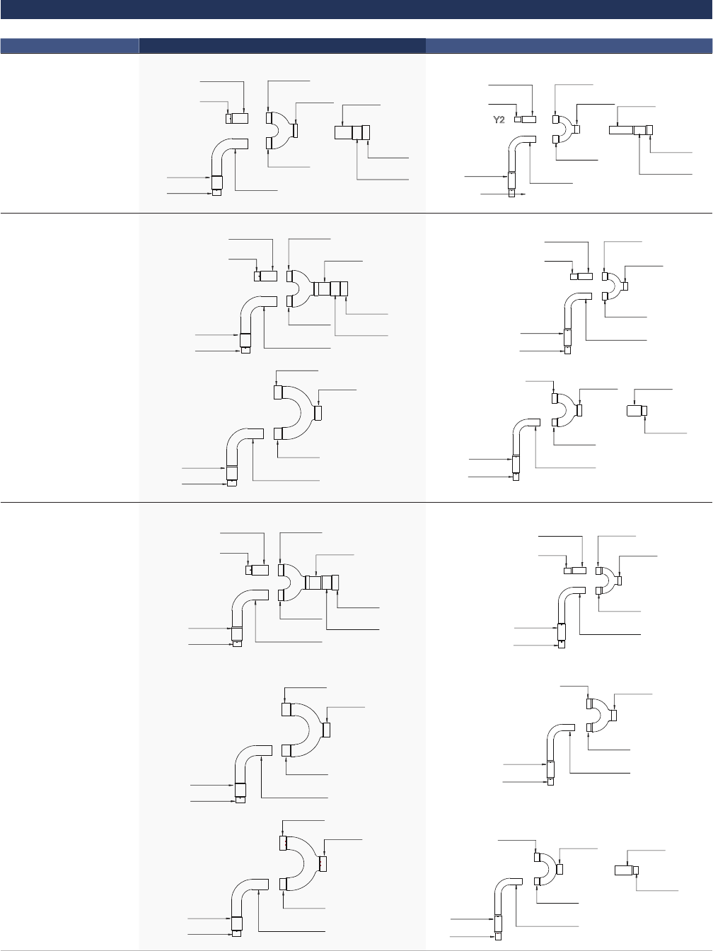
Joints | 111
Outdoor branch joints
Branch model Gas side joints Liquid side joints
ODU-BJ02
0D:31.8
ID:25.4
0D:31.8
ID:31.8
ID:25.4
Q1
Q2
ID:34.9
ID:31.8
ID:31.8
Q4
0D:34.9
ID:38.1
ID:34.9
Q3
ID:19.1
ID:15.9
ID:15.9
Y6
ID:15.9 0D:15.9
ID:12.7
ID:12.7
0D:15.9
Y1
Y2
0D:19.1
ID:22.2
ID:19.1
Y3
ODU-BJ03
ID:31.8
0D:34.9
ID:31.8
ID:38.1
ID:34.9
0D:31.8
ID:25.4
0D:31.8
ID:31.8
ID:25.4
Q1
Q2
Q7
ID:38.1
ID:41.3
ID:31.8
0D:31.8
ID:31.8
ID:25.4
Q1
Q5
ID:15.9
ID:15.9
ID:19.1
ID:15.9
0D:15.9
ID:12.7
ID:12.7
0D:15.9
Y1
Y6
Y2
ID:19.1 ID:22.2
ID:15.9
0D:15.9
ID:15.9
ID:12.7
Y1
Y7
0D:22.2
ID:19.1
Y4
ODU-BJ04
ID:31.8
0D:34.9
ID:31.8
ID:38.1
ID:34.9
0D:31.8
ID:25.4
0D:31.8
ID:31.8
ID:25.4
Q1
Q2
Q7
ID:38.1
ID:41.3
ID:31.8
0D:31.8
ID:31.8
ID:25.4
Q1
Q5
ID:41.3
ID:44.5
ID:31.8
0D:31.8
ID:31.8
ID:25.4
Q1
Q6
Description
ID:15.9
ID:19.1
ID:15.9
ID:15.9
0D:15.9
ID:12.7
ID:12.7
0D:15.9
Y1
Y6
Y2
ID:19.1 ID:22.2
ID:15.9
0D:15.9
ID:15.9
ID:12.7
Y1
Y7
ID:25.4
ID:22.2
ID:15.9
0D:15.9
ID:15.9
ID:12.7
Y1
Y8
0D:25.4
ID:22.2
Y5

Bosch Thermotechnik GmbH
Junkersstraße 20-24
73249 Wernau/Germany
