Cisco ASR 5x00 Mobility Management Entity Administration Guide MME 100 15 0 Admin
User Manual: MME-100
Open the PDF directly: View PDF ![]() .
.
Page Count: 266 [warning: Documents this large are best viewed by clicking the View PDF Link!]
- Front Cover
- Contents
- About this Guide
- Chapter 1 Mobility Management Entity Overview
- Product Description
- Network Deployment and Interfaces
- Features and Functionality - Base Software
- 3GPP R8 Identity Support
- ANSI T1.276 Compliance
- APN Restriction Support
- Authentication and Key Agreement (AKA)
- Bulk Statistics Support
- Closed Subscriber Groups
- Congestion Control
- Emergency Session Support
- EPS Bearer Context Support
- EPS GTPv2 Support on S11 Interface
- HSS Support Over S6a Interface
- Inter-MME Handover Support
- Interworking Support
- IPv6 Support
- Load Balancing
- Management System Overview
- MME Pooling
- MME Selection
- Mobile Equipment Identity Check
- Mobility Restriction
- Multiple PDN Support
- NAS Protocol Support
- NAS Signalling Security
- Network Sharing
- Operator Policy Support
- Overload Control
- PDN Type Control
- Packet Data Network Gateway (P-GW) Selection
- Radio Resource Management Functions
- RAN Information Management
- Reachability Management
- SCTP Multi-homing Support
- Serving Gateway Pooling Support
- Serving Gateway Selection
- Session and Quality of Service Management
- Subscriber Level Session Trace
- Threshold Crossing Alerts (TCA) Support
- Tracking Area List Management
- UMTS to LTE ID Mapping
- Features and Functionality - External Application Support
- Features and Functionality - Licensed Enhanced Feature Software
- Attach Rate Throttling
- Circuit Switched Fall Back (CSFB) and SMS over SGs Interface
- Enhanced Congestion Control and Overload Control
- Idle-mode Signaling Reduction
- IP Security (IPSec)
- Lawful Intercept
- Location Services
- Optimized Paging Support
- Overcharging Protection
- Session Recovery Support
- Single Radio Voice Call Continuity Support
- User Location Information Reporting
- VLR Management
- How the MME Works
- Supported Standards
- Chapter 2 Mobility Management Entity Configuration
- Configuring the System as a Standalone MME (base configuration)
- Configuring Optional Features on the MME
- Configuring Circuit Switched Fallback
- Configuring Dual Address Bearers
- Configuring Dynamic Peer Selection
- Configuring Emergency Session Support
- Configuring Gn/Gp Handover Capability
- Configuring Inter-MME Handover Support
- Configuring X.509 Certificate-based Peer Authentication
- Configuring Dynamic Node-to-Node IP Security on the S1-MME Interface
- Configuring ACL-based Node-to-Node IP Security on the S1-MME Interface
- Configuring Load Balancing on the MME
- Configuring Mobility Restriction Support
- Configuring S4-SGSN Handover Capability
- Configuring SCTP Multi-homing Support
- Configuring Static S-GW Pools
- Configuring UMTS to LTE ID Mapping
- Configuring User Location Information Reporting Support
- Chapter 3 Operator Policy
- What Operator Policy Can Do
- The Operator Policy Feature in Detail
- How It Works
- Operator Policy Configuration
- Verifying the Feature Configuration
- Chapter 4 APN Override
- Chapter 5 Closed Subscriber Groups
- Chapter 6 Enhanced Congestion Control and Overload Control
- Feature Description
- Configuring Enhanced Congestion Control
- Configuring Enhanced Congestion Control
- Verifying the Congestion Control Configuration
- Verifying Congestion Action Profiles
- Monitoring and Troubleshooting
- Chapter 7 Foreign PLMN GUTI Management
- Chapter 8 Heuristic and Intelligent Paging
- Chapter 9 Idle-mode Signaling Reduction
- Chapter 10 Load Balancing and Rebalancing
- Chapter 11 Location Services
- Location Services - Feature Description
- How Location Services Works
- Architecture
- Supported Functionality
- Flows
- Standards Compliance
- Configuring Location Services (LCS)
- Creating and Configuring a Location Service
- Associate the MME Service with the Location Service
- Associate the LTE Emergency Profile with the Location Service
- Verifying the LCS Configuration
- Show Command(s) and/or Outputs
- Chapter 12 Overcharging Protection
- Chapter 13 Single Radio Voice Call Continuity
- Chapter 14 UE Relocation
- Chapter 15 VLR Management
- Chapter 16 Monitoring the MME Service
- Chapter 17 Configuring Subscriber Session Tracing
- Chapter 18 Troubleshooting the MME Service
- Appendix A Engineering Rules

THE SPECIFICATIONS AND INFORMATION REGARDING THE PRODUCTS IN THIS MANUAL ARE SUBJECT TO CHANGE WITHOUT NOTICE. ALL
STATEMENTS, INFORMATION, AND RECOMMENDATIONS IN THIS MANUAL ARE BELIEVED TO BE ACCURATE BUT ARE PRESENTED WITHOUT WARRANTY
OF ANY KIND, EXPRESS OR IMPLIED. USERS MUST TAKE FULL RESPONSIBILITY FOR THEIR APPLICATION OF ANY PRODUCTS.
THE SOFTWARE LICENSE AND LIMITED WARRANTY FOR THE ACCOMPANYING PRODUCT ARE SET FORTH IN THE INFORMATION PACKET THAT SHIPPED
WITH THE PRODUCT AND ARE INCORPORATED HEREIN BY THIS REFERENCE. IF YOU ARE UNABLE TO LOCATE THE SOFTWARE LICENSE OR LIMITED
WARRANTY, CONTACT YOUR CISCO REPRESENTATIVE FOR A COPY.
The Cisco implementation of TCP header compression is an adaptation of a program developed by the University of California, Berkeley (UCB) as part of UCB’s public domain
version of the UNIX operating system. All rights reserved. Copyright © 1981, Regents of the University of California.
NOTWITHSTANDING ANY OTHER WARRANTY HEREIN, ALL DOCUMENT FILES AND SOFTWARE OF THESE SUPPLIERS ARE PROVIDED “AS IS” WITH ALL
FAULTS. CISCO AND THE ABOVE-NAMED SUPPLIERS DISCLAIM ALL WARRANTIES, EXPRESSED OR IMPLIED, INCLUDING, WITHOUT LIMITATION, THOSE
OF MERCHANTABILITY, FITNESS FOR A PARTICULAR PURPOSE AND NONINFRINGEMENT OR ARISING FROM A COURSE OF DEALING, USAGE, OR TRADE
PRACTICE.
IN NO EVENT SHALL CISCO OR ITS SUPPLIERS BE LIABLE FOR ANY INDIRECT, SPECIAL, CONSEQUENTIAL, OR INCIDENTAL DAMAGES, INCLUDING,
WITHOUT LIMITATION, LOST PROFITS OR LOSS OR DAMAGE TO DATA ARISING OUT OF THE USE OR INABILITY TO USE THIS MANUAL, EVEN IF CISCO OR
ITS SUPPLIERS HAVE BEEN ADVISED OF THE POSSIBILITY OF SUCH DAMAGES.
Cisco and the Cisco Logo are trademarks of Cisco Systems, Inc. and/or its affiliates in the U.S. and other countries. A listing of Cisco's trademarks can be found at
www.cisco.com/go/trademarks. Third party trademarks mentioned are the property of their respective owners. The use of the word partner does not imply a partnership relationship
between Cisco and any other company.
Any Internet Protocol (IP) addresses and phone numbers used in this document are not intended to be actual addresses and phon e numbers. Any examples, command display
output, network topology diagrams, and other figures included in the document are shown fo r illustrative purposes only. Any use of actual IP addresses or phone numbers in
illustrative content is unintentional and coincidental.
Cisco ASR 5x00 Mobility Management Entity Administration Guide
© 2014 Cisco Systems, Inc. All rights reserved.

Cisco ASR 5x00 Mobility Management Entity Administration Guide ▄
iii
CONTENTS
About this Guide ................................................................................................ xi
Conventions Used ................................................................................................................................... xii
Supported Documents and Resources .................................................................................................. xiii
Related Common Documentation ...................................................................................................... xiii
Related Product Documentation .................................................................................................... xiii
Obtaining Documentation .............................................................................................................. xiii
Contacting Customer Support ................................................................................................................ xiv
Mobility Management Entity Overview ........................................................... 15
Product Description ................................................................................................................................ 16
Qualified Platforms ............................................................................................................................. 18
Licenses ............................................................................................................................................. 18
Network Deployment and Interfaces ...................................................................................................... 19
MME in the E-UTRAN/EPC Network ................................................................................................. 19
Supported Logical Network Interfaces (Reference Points) ............................................................ 21
Features and Functionality - Base Software .......................................................................................... 27
3GPP R8 Identity Support .................................................................................................................. 28
ANSI T1.276 Compliance ................................................................................................................... 29
APN Restriction Support .................................................................................................................... 29
Authentication and Key Agreement (AKA) ......................................................................................... 29
Bulk Statistics Support ....................................................................................................................... 30
Closed Subscriber Groups ................................................................................................................. 30
Congestion Control ............................................................................................................................. 30
Emergency Session Support .............................................................................................................. 31
EPS Bearer Context Support ............................................................................................................. 32
EPS GTPv2 Support on S11 Interface ............................................................................................... 32
HSS Support Over S6a Interface ....................................................................................................... 33
Inter-MME Handover Support ............................................................................................................ 34
Interworking Support .......................................................................................................................... 34
Interworking with SGSNs ............................................................................................................... 34
Handover Support for S4-SGSNs .................................................................................................. 35
IPv6 Support ....................................................................................................................................... 35
MME Interfaces Supporting IPv6 Transport................................................................................... 36
Load Balancing ................................................................................................................................... 36
Load Re-balancing ......................................................................................................................... 36
Management System Overview ......................................................................................................... 37
MME Pooling ...................................................................................................................................... 38
MME Selection ................................................................................................................................... 39
Mobile Equipment Identity Check ....................................................................................................... 39
Mobility Restriction ............................................................................................................................. 39
Handover Restriction ..................................................................................................................... 39
Regional Zone Code Restriction .................................................................................................... 39
Multiple PDN Support ......................................................................................................................... 40
NAS Protocol Support ........................................................................................................................ 40
EPS Mobility Management (EMM) ................................................................................................. 40
EPS Session Management (ESM) ................................................................................................. 41
NAS Signalling Security ..................................................................................................................... 41

▀ Contents
▄ Cisco ASR 5x00 Mobility Management Entity Administration Guide
iv
Network Sharing ................................................................................................................................. 41
Operator Policy Support ..................................................................................................................... 41
Overload Control ................................................................................................................................ 42
PDN Type Control .............................................................................................................................. 42
Packet Data Network Gateway (P-GW) Selection ............................................................................. 43
Radio Resource Management Functions ........................................................................................... 43
RAN Information Management ........................................................................................................... 43
Reachability Management .................................................................................................................. 43
SCTP Multi-homing Support ............................................................................................................... 44
SCTP Multi-homing for S6a ........................................................................................................... 44
SCTP Multi-homing for S1-MME .................................................................................................... 44
SCTP Multi-homing for SGs ........................................................................................................... 44
Serving Gateway Pooling Support ..................................................................................................... 44
Serving Gateway Selection ................................................................................................................ 44
Session and Quality of Service Management .................................................................................... 45
Subscriber Level Session Trace ......................................................................................................... 45
Threshold Crossing Alerts (TCA) Support .......................................................................................... 46
Tracking Area List Management ........................................................................................................ 47
UMTS to LTE ID Mapping .................................................................................................................. 47
Features and Functionality - External Application Support .................................................................... 49
Web Element Management System ................................................................................................... 49
Features and Functionality - Licensed Enhanced Feature Software...................................................... 50
Attach Rate Throttling ......................................................................................................................... 50
Circuit Switched Fall Back (CSFB) and SMS over SGs Interface ...................................................... 50
Enhanced Congestion Control and Overload Control ........................................................................ 53
Idle-mode Signaling Reduction .......................................................................................................... 54
IP Security (IPSec) ............................................................................................................................. 54
Lawful Intercept .................................................................................................................................. 55
Location Services ............................................................................................................................... 55
Optimized Paging Support ................................................................................................................. 56
Overcharging Protection ..................................................................................................................... 56
Session Recovery Support ................................................................................................................. 56
Single Radio Voice Call Continuity Support ....................................................................................... 57
User Location Information Reporting .................................................................................................. 57
VLR Management ............................................................................................................................... 59
How the MME Works .............................................................................................................................. 60
EPS Bearer Context Processing ........................................................................................................ 60
Purge Procedure ................................................................................................................................ 60
Paging Procedure ............................................................................................................................... 60
Subscriber-initiated Initial Attach Procedure ...................................................................................... 61
Subscriber-initiated Detach Procedure............................................................................................... 64
Service Request Procedures .............................................................................................................. 65
UE-initiated Service Request Procedure ....................................................................................... 65
Network-initiated Service Request Procedure ............................................................................... 66
Supported Standards .............................................................................................................................. 69
3GPP References ............................................................................................................................... 69
Release 10 Supported Standards .................................................................................................. 69
Release 9 Supported Standards .................................................................................................... 69
IETF References ................................................................................................................................ 70
Object Management Group (OMG) Standards .................................................................................. 73
Mobility Management Entity Configuration ................................................... 75
Configuring the System as a Standalone MME (base configuration) ..................................................... 76
Information Required .......................................................................................................................... 76
Required MME Context Configuration Information ........................................................................ 76

Contents ▀
Cisco ASR 5x00 Mobility Management Entity Administration Guide ▄
v
Required MME Policy Configuration Information ........................................................................... 79
How This Configuration Works ........................................................................................................... 79
MME Configuration ............................................................................................................................. 81
Creating and Configuring the MME Context and Service .............................................................. 81
Creating and Configuring the eGTP Service and Interface Association ........................................ 83
Creating and Configuring the HSS Peer Service and Interface Associations ............................... 84
Configuring Dynamic Destination Realm Construction for Foreign Subscribers ........................... 85
Configuring Optional Features on the MME ........................................................................................... 87
Configuring Circuit Switched Fallback ................................................................................................ 87
Configuring Dual Address Bearers ..................................................................................................... 89
Configuring Dynamic Peer Selection ................................................................................................. 89
Configuring Emergency Session Support .......................................................................................... 90
Configuring Gn/Gp Handover Capability ............................................................................................ 91
Configuring Inter-MME Handover Support ......................................................................................... 92
Configuring X.509 Certificate-based Peer Authentication .................................................................. 93
Configuring Dynamic Node-to-Node IP Security on the S1-MME Interface ...................................... 94
Creating and Configuring an IPSec Transform Set ....................................................................... 94
Creating and Configuring an IKEv2 Transform Set ....................................................................... 95
Creating and Configuring a Crypto Template ................................................................................ 96
Binding the S1-MME IP Address to the Crypto Template ............................................................. 96
Configuring ACL-based Node-to-Node IP Security on the S1-MME Interface .................................. 97
Creating and Configuring a Crypto Access Control List ................................................................ 97
Creating and Configuring an IPSec Transform Set ....................................................................... 97
Creating and Configuring an IKEv2 Transform Set ....................................................................... 98
Creating and Configuring a Crypto Map ........................................................................................ 99
Configuring Load Balancing on the MME ........................................................................................ 100
Configuring Mobility Restriction Support .......................................................................................... 100
Configuring Inter-RAT Handover Restrictions on the MME ......................................................... 101
Configuring Location Area Handover Restrictions on the MME .................................................. 101
Configuring Tracking Area Handover Restrictions on the MME .................................................. 101
Configuring S4-SGSN Handover Capability .................................................................................... 102
Configuring SCTP Multi-homing Support ......................................................................................... 103
Configuring SCTP Multi-homing on the S1-MME Interface ......................................................... 103
Configuring SCTP Multi-homing on the S6a Interface ................................................................. 104
Configuring S6a SCTP and Application Timers for Multi-homing ................................................ 105
Configuring SCTP Multi-homing on the SGs Interface ................................................................ 106
Configuring Static S-GW Pools ........................................................................................................ 106
Creating and Configuring a TAI Management Database and Object .......................................... 106
Associating a TAI Management Database with an MME Service ............................................... 107
Associating a TAI Management Database with a Call Control Profile ......................................... 108
Configuring UMTS to LTE ID Mapping ............................................................................................. 108
Configuring User Location Information Reporting Support .............................................................. 109
Operator Policy ............................................................................................... 111
What Operator Policy Can Do .............................................................................................................. 112
A Look at Operator Policy on an SGSN ........................................................................................... 112
A Look at Operator Policy on an S-GW ........................................................................................... 112
The Operator Policy Feature in Detail .................................................................................................. 113
Call Control Profile ........................................................................................................................... 113
APN Profile ....................................................................................................................................... 114
IMEI-Profile (SGSN only) ................................................................................................................. 115
APN Remap Table ........................................................................................................................... 115
Operator Policies .............................................................................................................................. 116
IMSI Ranges ..................................................................................................................................... 116
How It Works ........................................................................................................................................ 118

▀ Contents
▄ Cisco ASR 5x00 Mobility Management Entity Administration Guide
vi
Operator Policy Configuration .............................................................................................................. 119
Call Control Profile Configuration ..................................................................................................... 120
Configuring the Call Control Profile for an SGSN ........................................................................ 120
Configuring the Call Control Profile for an MME or S-GW ........................................................... 120
APN Profile Configuration ................................................................................................................ 121
IMEI Profile Configuration - SGSN only ........................................................................................... 121
APN Remap Table Configuration ..................................................................................................... 122
Operator Policy Configuration .......................................................................................................... 122
IMSI Range Configuration ................................................................................................................ 123
Configuring IMSI Ranges on the MME or S-GW ......................................................................... 123
Configuring IMSI Ranges on the SGSN ....................................................................................... 123
Associating Operator Policy Components on the MME ................................................................... 124
Configuring Accounting Mode for S-GW .......................................................................................... 125
Verifying the Feature Configuration ...................................................................................................... 126
APN Override ................................................................................................... 127
Feature Description .............................................................................................................................. 128
How it Works ......................................................................................................................................... 129
Network Identifier (NI) Overriding ..................................................................................................... 129
Operator Identifier (OI) Overriding .................................................................................................... 129
Charging Characteristics Overriding ................................................................................................ 129
Configuring APN Override .................................................................................................................... 130
Before You Begin ............................................................................................................................. 130
Configuring Network Identifier Override ........................................................................................... 131
Configuring Operator Identifier Override .......................................................................................... 131
Configuring Charging Characteristics Override ................................................................................ 131
Verifying the APN Override Configuration ........................................................................................ 132
Closed Subscriber Groups ............................................................................ 133
Feature Description .............................................................................................................................. 134
How it Works ......................................................................................................................................... 135
Access Control ................................................................................................................................. 135
S1AP Messaging .......................................................................................................................... 135
S6a Messaging ............................................................................................................................ 136
CSG Notification to S-GW/P-GW ..................................................................................................... 136
CSG Status Communication to Peer MME/SGSN ........................................................................... 137
Message Flows ................................................................................................................................. 138
Configuring Closed Subscriber Groups ................................................................................................ 140
Verifying the Closed Subscriber Groups Configuration .................................................................... 140
Monitoring and Troubleshooting Closed Subscriber Groups ................................................................ 141
Enhanced Congestion Control and Overload Control ................................ 143
Feature Description .............................................................................................................................. 144
Enhanced Congestion Control and Overload Control ...................................................................... 144
Relationships to Other Features ....................................................................................................... 144
Limitations ........................................................................................................................................ 145
Configuring Enhanced Congestion Control .......................................................................................... 146
Configuring Enhanced Congestion Control ...................................................................................... 146
Configuring Thresholds and Tolerances ...................................................................................... 146
Configuring a Congestion Action Profile ...................................................................................... 149
Associating a Congestion Action Profile with Congestion Control Policies ................................. 149
Configuring Overload Control....................................................................................................... 150
Configuring Enhanced Congestion SNMP Traps ........................................................................ 150
Verifying the Congestion Control Configuration ............................................................................... 151
Verifying Congestion Action Profiles ................................................................................................ 153

Contents ▀
Cisco ASR 5x00 Mobility Management Entity Administration Guide ▄
vii
Monitoring and Troubleshooting ........................................................................................................... 154
Congestion Control Show Command(s) and/or Outputs .................................................................. 154
show congestion-control statistics mme ...................................................................................... 154
show congestion-control statistics mme ...................................................................................... 155
Foreign PLMN GUTI Management ................................................................. 157
Feature Description .............................................................................................................................. 158
How it Works ........................................................................................................................................ 159
Configuring Foreign PLMN GUTI Management ................................................................................... 160
Creating a Foreign PLMN GUTI Management Database ................................................................ 160
Configuring Foreign PLMN GUTI Management Database Entries .................................................. 160
Associating an MME Service with a Foreign PLMN GUTI Management Database ........................ 161
Verifying the Configuration ............................................................................................................... 161
Monitoring Foreign PLMN GUTI Management ..................................................................................... 163
Show Command(s) and/or Outputs .................................................................................................. 163
show session disconnect-reasons ............................................................................................... 163
Bulk Statistics ................................................................................................................................... 163
Heuristic and Intelligent Paging .................................................................... 165
Feature Description .............................................................................................................................. 166
How it Works ........................................................................................................................................ 167
Heuristic Paging ............................................................................................................................... 167
Intelligent Paging .............................................................................................................................. 167
Configuring MME Paging Features ...................................................................................................... 169
Configuring Heuristic Paging ............................................................................................................ 169
Configuring Intelligent Paging .......................................................................................................... 169
Creating and Configuring the Paging-Profile ............................................................................... 169
Creating and Configuring the Paging-Map .................................................................................. 170
Enable Heuristic Paging with Paging-Map (Intelligent Paging) ................................................... 170
Verifying the Paging Configuration ................................................................................................... 170
Monitoring and Troubleshooting the MME Paging Features ................................................................ 172
Paging Bulk Statistics ....................................................................................................................... 172
Paging Show Command(s) and/or Outputs ..................................................................................... 172
Idle-mode Signaling Reduction ..................................................................... 175
Feature Description .............................................................................................................................. 176
How it Works ........................................................................................................................................ 177
ISR Activation ................................................................................................................................... 177
ISR Deactivation ............................................................................................................................... 178
ISR Behavior with Circuit Switched Fallback ................................................................................... 179
Standards Compliance ..................................................................................................................... 179
Configuring ISR .................................................................................................................................... 180
Configuring ISR ................................................................................................................................ 180
Verifying ISR Configuration .............................................................................................................. 180
Monitoring and Troubleshooting ISR .................................................................................................... 181
ISR Bulk Statistics ............................................................................................................................ 181
ISR Show Command(s) and/or Outputs........................................................................................... 182
Load Balancing and Rebalancing ................................................................. 185
Feature Description .............................................................................................................................. 186
Load Balancing ................................................................................................................................. 186
Load Rebalancing ............................................................................................................................ 186
Relationships to Other Features ...................................................................................................... 186
How it Works ........................................................................................................................................ 187
Load Balancing ................................................................................................................................. 187
Load Rebalancing ............................................................................................................................ 187

▀ Contents
▄ Cisco ASR 5x00 Mobility Management Entity Administration Guide
viii
Configuring Load Balancing and Rebalancing ..................................................................................... 188
Configuring Load Balancing ............................................................................................................. 188
Verifying Load Balancing .................................................................................................................. 188
Performing Load Rebalancing (UE Offloading) ................................................................................ 188
Verifying Load Rebalancing (UE Offloading).................................................................................... 189
Monitoring Load Rebalancing ............................................................................................................... 190
Load Rebalancing Show Command(s) and/or Outputs .................................................................... 190
Location Services ........................................................................................... 193
Location Services - Feature Description ............................................................................................... 194
How Location Services Works .............................................................................................................. 195
Architecture ........................................................................................................................................... 196
Supported Functionality ........................................................................................................................ 197
Limitations ........................................................................................................................................ 197
Flows ..................................................................................................................................................... 198
Standards Compliance ......................................................................................................................... 201
Configuring Location Services (LCS) ................................................................................................... 202
Creating and Configuring a Location Service ....................................................................................... 203
Associate the MME Service with the Location Service ........................................................................ 204
Associate the LTE Emergency Profile with the Location Service ......................................................... 205
Verifying the LCS Configuration ........................................................................................................... 206
Show Command(s) and/or Outputs ...................................................................................................... 207
Overcharging Protection ................................................................................ 209
Feature Description .............................................................................................................................. 210
Relationships to Other Features ....................................................................................................... 210
How it Works ......................................................................................................................................... 211
Call Flows ......................................................................................................................................... 211
Configuring Overcharge Protection ...................................................................................................... 213
Enabling Overcharging Protection .................................................................................................... 213
Configuring S1AP Cause Code Group and Cause Code ................................................................. 213
Verifying the Overcharge Protection Configuration .......................................................................... 213
Single Radio Voice Call Continuity ............................................................... 215
Feature Description .............................................................................................................................. 216
Relationships to Other Features ....................................................................................................... 217
How it Works ......................................................................................................................................... 218
Flows ................................................................................................................................................ 218
Standards Compliance ..................................................................................................................... 218
Configuring Single Radio Voice Call Continuity.................................................................................... 219
Configuring SRVCC .......................................................................................................................... 219
Configuring an MSC Pool Area ........................................................................................................ 220
IMSI Hash MSC Pool ................................................................................................................... 220
Round-Robin MSC Pool ............................................................................................................... 221
MSC Offload ..................................................................................................................................... 222
Verifying the SRVCC Configuration ................................................................................................. 222
Monitoring and Troubleshooting SRVCC ............................................................................................. 223
SRVCC Show Command(s) and/or Outputs .................................................................................... 223
show mme-service statistics ........................................................................................................ 223
show egtpc statistics .................................................................................................................... 223
SRVCC Bulk Statistics...................................................................................................................... 225
eGTP-C Schema .......................................................................................................................... 225
MME Schema ............................................................................................................................... 225
UE Relocation .................................................................................................. 227
Feature Description .............................................................................................................................. 228

Contents ▀
Cisco ASR 5x00 Mobility Management Entity Administration Guide ▄
ix
How it Works ........................................................................................................................................ 229
UE Relocation .................................................................................................................................. 229
Relocating UE to Specific MME............................................................................................................ 230
Issuing the mme relocate-ue Command .......................................................................................... 230
Monitoring UE Relocation ..................................................................................................................... 231
UE Relocation Bulk Statistics ........................................................................................................... 231
UE Relocation Show Command(s) and/or Outputs ......................................................................... 231
VLR Management ............................................................................................ 233
Feature Description .............................................................................................................................. 234
Passive VLR Offloading ................................................................................................................... 234
Active VLR Offloading ...................................................................................................................... 234
UE Detach on VLR Recovery ........................................................................................................... 234
UE Detach on VLR Failure ............................................................................................................... 234
Enabling Active and Passive VLR Offloading....................................................................................... 235
Passive VLR Offloading ................................................................................................................... 235
Active VLR Offloading ...................................................................................................................... 235
Verifying VLR Offload Status and Configuration .............................................................................. 235
Enabling UE Detach on VLR Failure or VLR Recover ......................................................................... 238
UE Detach on VLR Recovery ........................................................................................................... 238
UE Detach on VLR Failure ............................................................................................................... 238
Manually Enabling UE Detach on VLR Failure ............................................................................ 238
Verifying UE Detach on VLR Failure/Recovery Status and Configuration ....................................... 239
Monitoring and Troubleshooting VLR Offload ...................................................................................... 240
SNMP Traps ..................................................................................................................................... 240
Bulk Statistics ................................................................................................................................... 240
Show Command(s) and/or Outputs .................................................................................................. 240
Active and Passive VLR Offload .................................................................................................. 240
UE Detach on VLR Recovery and VLR Failure ........................................................................... 240
Monitoring the MME Service .......................................................................... 243
Monitoring System Status and Performance ........................................................................................ 244
Clearing Statistics and Counters .......................................................................................................... 246
Configuring Subscriber Session Tracing ..................................................... 247
Introduction ........................................................................................................................................... 248
Supported Functions ........................................................................................................................ 249
Supported Standards ............................................................................................................................ 251
Subscriber Session Trace Functional Description ............................................................................... 252
Operation .......................................................................................................................................... 252
Trace Session .............................................................................................................................. 252
Trace Recording Session............................................................................................................. 252
Network Element (NE)...................................................................................................................... 252
Activation .......................................................................................................................................... 252
Management Activation ............................................................................................................... 253
Signaling Activation ...................................................................................................................... 253
Start Trigger ..................................................................................................................................... 253
Deactivation ...................................................................................................................................... 253
Stop Trigger ...................................................................................................................................... 253
Data Collection and Reporting ......................................................................................................... 253
Trace Depth ................................................................................................................................. 253
Trace Scope ................................................................................................................................. 254
Network Element Details .................................................................................................................. 254
MME ............................................................................................................................................. 254
S-GW ........................................................................................................................................... 254

▀ Contents
▄ Cisco ASR 5x00 Mobility Management Entity Administration Guide
x
P-GW ............................................................................................................................................ 255
Subscriber Session Trace Configuration .............................................................................................. 256
Enabling Subscriber Session Trace on EPC Network Element ....................................................... 256
Trace File Collection Configuration .................................................................................................. 257
Verifying Your Configuration ................................................................................................................. 258
Troubleshooting the MME Service ................................................................ 261
Test Commands ................................................................................................................................... 262
Using the eGTPC Test Echo Command .......................................................................................... 262
Engineering Rules........................................................................................... 263
APN Engineering Rules ........................................................................................................................ 264
Service Engineering Rules ................................................................................................................... 265
Node Engineering Rules ....................................................................................................................... 266

Cisco ASR 5x00 Mobility Management Entity Administration Guide ▄
xi
About this Guide
This preface describes the Cisco ASR 5x00 Mobility Management Entity Administration Guide, how it is organized and
its document conventions.
About this Guide
▀ Conventions Used
▄ Cisco ASR 5x00 Mobility Management Entity Administration Guide
xii
Conventions Used
The following tables describe the conventions used throughout this documentation.
Icon
Notice Type
Description
Information Note
Provides information about important features or instructions.
Caution
Alerts you of potential damage to a program, device, or system.
Warning
Alerts you of potential personal injury or fatality. May also alert you of potential electrical hazards.
Typeface Conventions
Description
Text represented as a screen
display
This typeface represents displays that appear on your terminal screen, for example:
Login:
Text represented as commands
This typeface represents commands that you enter, for example:
show ip access-list
This document always gives the full form of a command in lowercase letters. Commands
are not case sensitive.
Text represented as a command
variable
This typeface represents a variable that is part of a command, for example:
show card slot_number
slot_number is a variable representing the desired chassis slot number.
Text represented as menu or sub-
menu names
This typeface represents menus and sub-menus that you access within a software
application, for example:
Click the File menu, then click New

About this Guide
Supported Documents and Resources ▀
Cisco ASR 5x00 Mobility Management Entity Administration Guide ▄
xiii
Supported Documents and Resources
Related Common Documentation
The most up-to-date information for this product is available in the product Release Notes provided with each product
release.
The following common documents are available:
Hardware Installation Guide (hardware dependent)
System Administration Guide (hardware dependent)
Cisco ASR 5x00 Command Line Interface Reference
Cisco ASR 5x00 Statistics and Counters Reference
Cisco ASR 5x00 Release Change Reference
Cisco ASR 5x00 Thresholding Configuration Guide
Cisco ASR 5x00 SNMP MIB Reference
Web Element Manager Installation and Administration Guide
Cisco ASR 5x00 AAA Interface Administration and Reference
Cisco ASR 5x00 GTPP Interface Administration and Reference
Cisco StarOS IP Security (IPSec) Reference
Related Product Documentation
The following product documents are also available and work in conjunction with the MME:
Cisco ASR 5x00 Packet Data Network Gateway Administration Guide
Cisco ASR 5x00 Serving Gateway Administration Guide
Cisco ASR 5x00 System Architecture Evolution Gateway Administration Guide
Cisco ASR 5x00 Serving GPRS Support Node Administration Guide
Cisco ASR 5000 Session Control Manager Administration Guide
Cisco ASR 5x00 Gateway GPRS Support Node Administration Guide
Cisco ASR 5x00 HRPD Serving Gateway Administration Guide
Cisco ASR 5x00 System Architecture Evolution Gateway Administration Guide
Obtaining Documentation
The most current Cisco documentation is available on the following website:
http://www.cisco.com/cisco/web/psa/default.html
Use the following path selections to access the MME documentation:
Products > Wireless > Mobile Internet> Network Functions > Cisco MME Mobility Management Entity

About this Guide
▀ Contacting Customer Support
▄ Cisco ASR 5x00 Mobility Management Entity Administration Guide
xiv
Contacting Customer Support
Use the information in this section to contact customer support.
Refer to the support area of http://www.cisco.com for up-to-date product documentation or to submit a service request.
A valid username and password are required to access this site. Please contact your Cisco sales or service representative
for additional information.

Cisco ASR 5x00 Mobility Management Entity Administration Guide ▄
15
Chapter 1
Mobility Management Entity Overview
Cisco Mobility Management Entity (MME) is critical to the network function of the 4G mobile core network, known as
the evolved packet core (EPC). The MME resides in the EPC control plane and manages session states, authentication,
paging, mobility with 3GPP, 2G and 3G nodes, roaming, and other bearer management functions.
This overview provides general information about the MME including:
Product Description
Network Deployment and Interfaces
Features and Functionality - Base Software
Features and Functionality - External Application Support
Features and Functionality - Licensed Enhanced Feature Software
How the MME Works
Supported Standards

Mobility Management Entity Overview
▀ Product Description
▄ Cisco ASR 5x00 Mobility Management Entity Administration Guide
16
Product Description
This section describes the MME network function and its position in the LTE network.
The MME is the key control-node for the LTE access network. It works in conjunction with the evolved NodeB
(eNodeB), Serving Gateway (S-GW) within the Evolved Packet Core (EPC), or LTE/SAE core network to perform the
following functions:
Involved in the bearer activation/deactivation process and is also responsible for choosing the S-GW and for a
UE at the initial attach and at the time of intra-LTE handover involving Core Network (CN) node relocation.
Provides P-GW selection for subscriber to connect to PDN.
Provides idle mode UE tracking and paging procedure, including retransmissions.
Chooses the appropriate S-GW for a UE.
Responsible for authenticating the user (by interacting with the HSS).
Works as termination point for Non-Access Stratum (NAS) signaling.
Responsible for generation and allocation of temporary identities to UEs.
Checks the authorization of the UE to camp on the service provider’s Public Land Mobile Network (PLMN) and
enforces UE roaming restrictions.
The MME is the termination point in the network for ciphering/integrity protection for NAS signaling and
handles the security key management.
Communicates with MMEs in same PLMN or on different PLMNs. The S10 interface is used for MME
relocation and MME-to-MME information transfer or handoff.
Besides the above mentioned functions, the lawful interception of signaling is also supported by the MME.
The MME also provides the control plane function for mobility between LTE and 2G/3G access networks with the S3
interface terminating at the MME from the SGSN. In addition, the MME interfaces with SGSN for interconnecting to
the legacy network.
The MME also terminates the S6a interface towards the home HSS for roaming UEs.
Mobility Management Entity Overview
Product Description ▀
Cisco ASR 5x00 Mobility Management Entity Administration Guide ▄
17
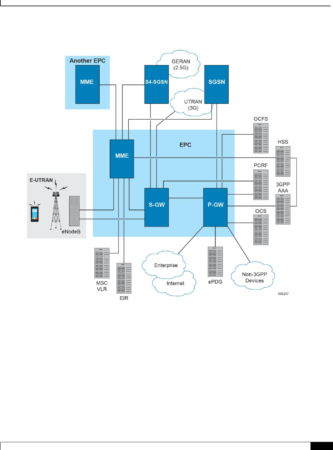
Figure 1. MME in the E-UTRAN/EPC Network Topology
In accordance with 3GPP standard, the MME provides following functions and procedures in the LTE/SAE network:
Non Access Stratum (NAS) signalling
NAS signalling security
Inter CN node signalling for mobility between 3GPP access networks (terminating S3)
UE Reachability in ECM-IDLE state (including control and execution of paging retransmission)
Tracking Area list management
PDN GW and Serving GW selection
MME selection for handover with MME change
SGSN selection for handover to 2G or 3G 3GPP access networks
Roaming (S6a towards home HSS)
Authentication

Mobility Management Entity Overview
▀ Product Description
▄ Cisco ASR 5x00 Mobility Management Entity Administration Guide
18
Bearer management functions including dedicated bearer establishment
Lawful Interception of signalling traffic
UE Reachability procedures
Interfaces with MSC for Voice paging
Interfaces with SGSN for interconnecting to legacy network
Qualified Platforms
MME is a StarOS application that runs on Cisco ASR 5x00 platforms. For additional platform information, refer to the
appropriate System Administration Guide and/or contact your Cisco account representative.
Licenses
The MME is a licensed Cisco product. Separate session and feature licenses may be required. Contact your Cisco
account representative for detailed information on specific licensing requirements. For information on installing and
verifying licenses, refer to the Managing License Keys section of the Software Management Operations chapter in the
System Administration Guide.

Mobility Management Entity Overview
Network Deployment and Interfaces ▀
Cisco ASR 5x00 Mobility Management Entity Administration Guide ▄
19
Network Deployment and Interfaces
This section describes the supported interfaces and deployment scenario of MME in LTE/SAE network.
The following information is provided in this section:
MME in the E-UTRAN/EPC Network
Supported Logical Network Interfaces (Reference Points)
MME in the E-UTRAN/EPC Network
The following figure displays the specific network interfaces supported by the MME. Refer to Supported Logical
Network Interfaces (Reference Points) for detailed information about each interface.
Mobility Management Entity Overview
▀ Network Deployment and Interfaces
▄ Cisco ASR 5x00 Mobility Management Entity Administration Guide
20
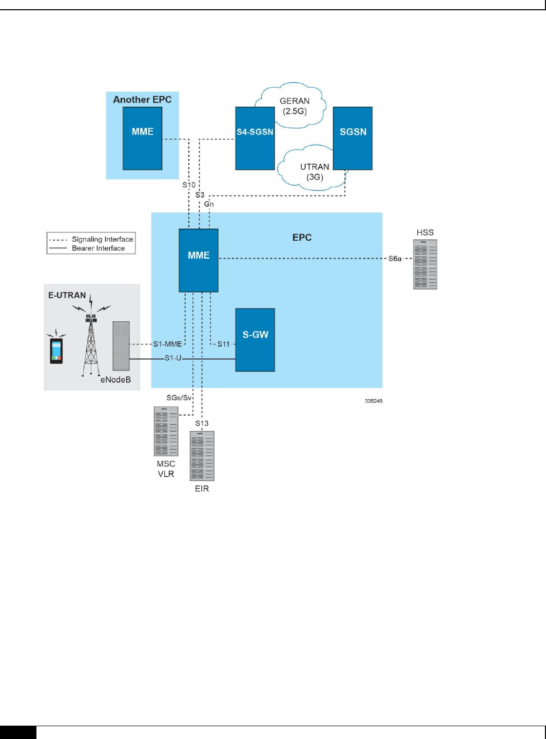
Figure 2. Supported MME Interfaces in the E-UTRAN/EPC Network
The following figure displays a sample network deployment of an MME, including all of the interface connections with
other 3GPP Evolved-UTRAN/Evolved Packet Core network devices.
Mobility Management Entity Overview
Network Deployment and Interfaces ▀
Cisco ASR 5x00 Mobility Management Entity Administration Guide ▄
21
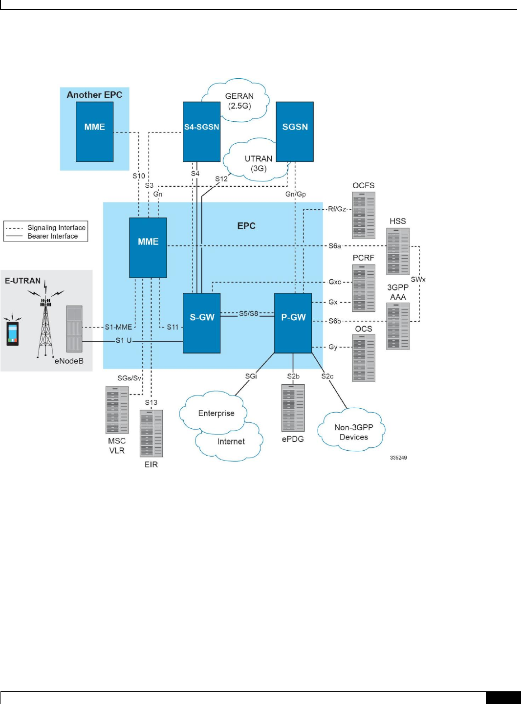
Figure 3. E-UTRAN/EPC Network Scenario
Supported Logical Network Interfaces (Reference Points)
The MME supports the following logical network interfaces/reference points:
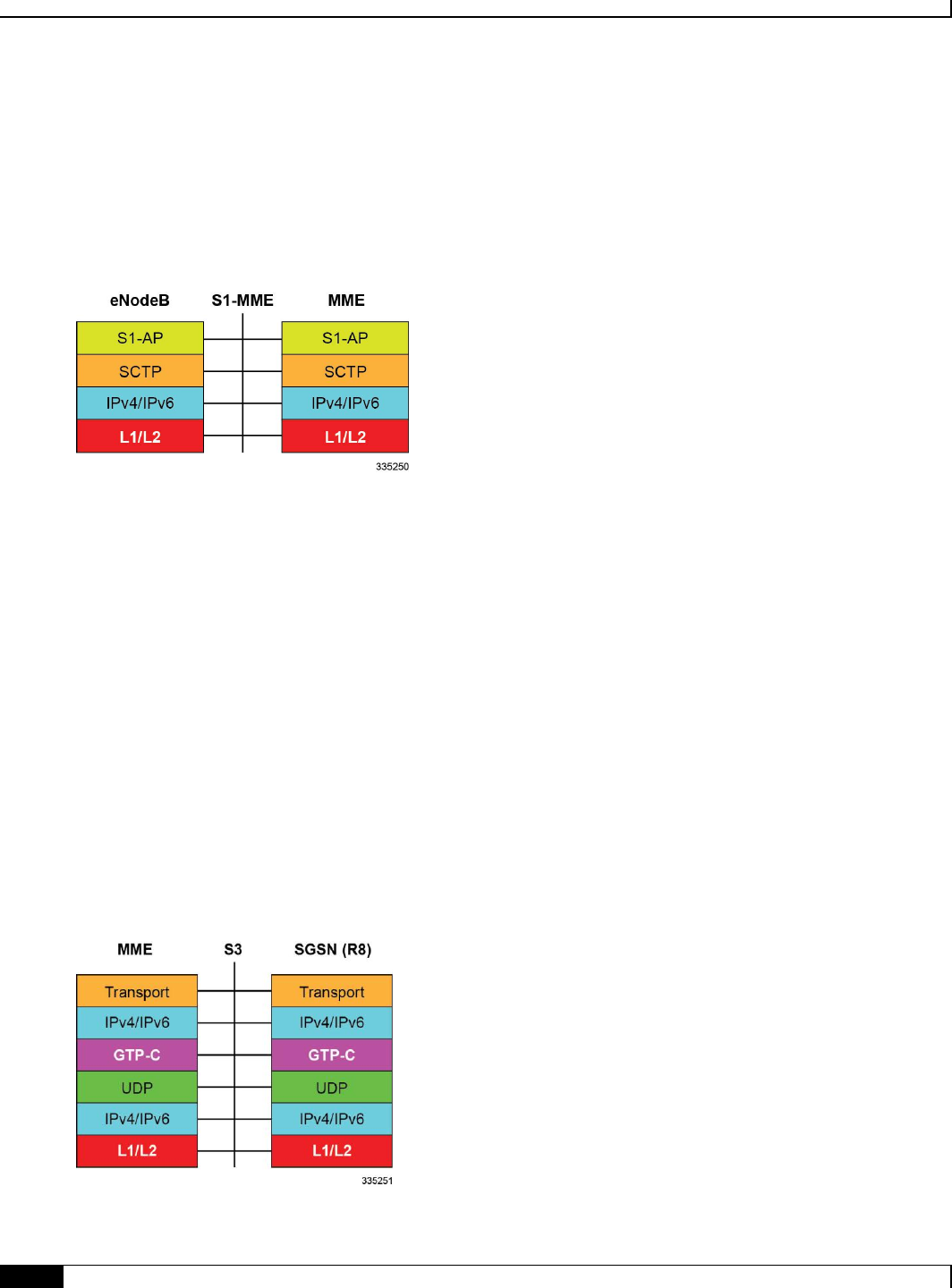
S1-MME Interface
This interface is the reference point for the control plane protocol between eNodeB and MME. S1-MME uses the S1
Application Protocol (S1-AP) over the Stream Control Transmission Protocol (SCTP) as the transport layer protocol for
guaranteed delivery of signaling messages between MME and eNodeB (S1).
This is the interface used by the MME to communicate with eNodeBs on the same LTE Public Land Mobile Network
(PLMN). This interface serves as path for establishing and maintaining subscriber UE contexts.
The S1-MME interface supports IPv4, IPv6, IPSec, and multi-homing.
One or more S1-MME interfaces can be configured per system context.
Mobility Management Entity Overview
▀ Network Deployment and Interfaces
▄ Cisco ASR 5x00 Mobility Management Entity Administration Guide
22
Supported protocols:
Application Layer: S1 Application Protocol (S1-AP)
Transport Layer: SCTP
Network Layer: IPv4, IPv6
Data Link Layer: ARP
Physical Layer: Ethernet
S3 Interface
This is the interface used by the MME to communicate with S4-SGSNs on the same Public PLMN for interworking
between GPRS/UMTS and LTE network access technologies. This interface serves as the signalling path for
establishing and maintaining subscriber UE contexts.
The MME communicates with SGSNs on the PLMN using the GPRS Tunnelling Protocol (GTP). The signalling or
control aspect of this protocol is referred to as the GTP Control Plane (GTPC) while the encapsulated user data traffic is
referred to as the GTP User Plane (GTPU).
One or more S3 interfaces can be configured per system context.
Supported protocols:
Transport Layer: UDP, TCP
Tunneling: IPv4 or IPv6 GTPv2-C (signaling channel)
Signalling Layer: UDP
Network Layer: IPv4, IPv6
Data Link Layer: ARP
Physical Layer: Ethernet
Mobility Management Entity Overview
Network Deployment and Interfaces ▀
Cisco ASR 5x00 Mobility Management Entity Administration Guide ▄
23
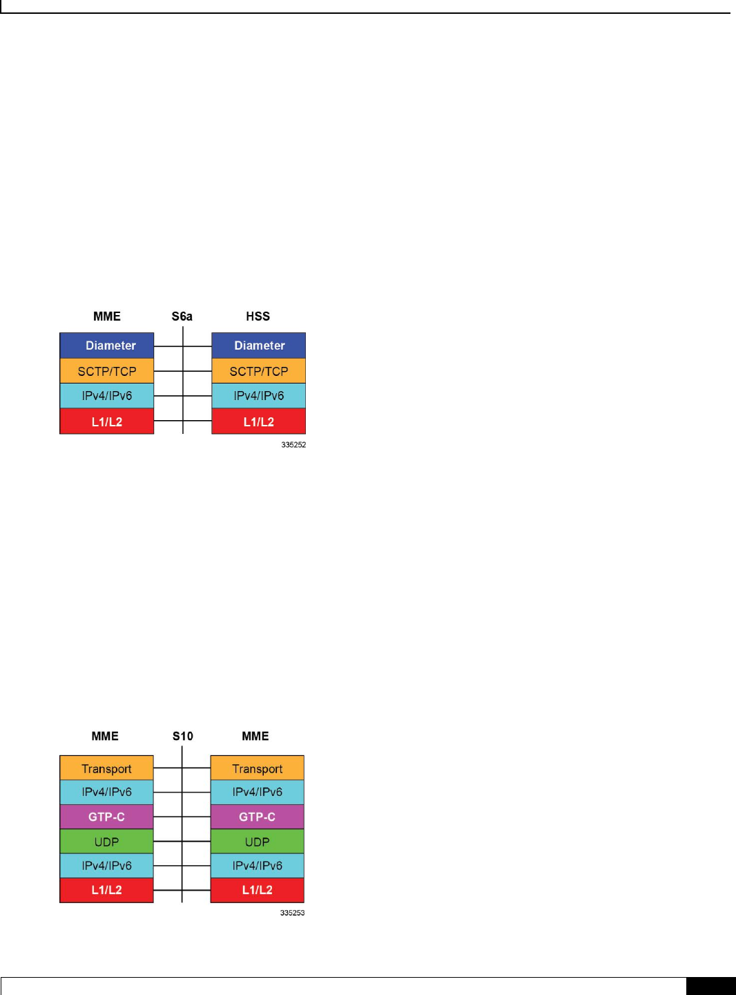
S6a Interface
This is the interface used by the MME to communicate with the Home Subscriber Server (HSS). The HSS is responsible
for transfer of subscription and authentication data for authenticating/authorizing user access and UE context
authentication. The MME communicates with the HSSs on the PLMN using Diameter protocol.
One or more S6a interfaces can be configured per system context.
Supported protocols:
Transport Layer: SCTP or TCP
Network Layer: IPv4, IPv6
Data Link Layer: ARP
Physical Layer: Ethernet
S10 Interface
This is the interface used by the MME to communicate with an MME in the same PLMN or on different PLMNs. This
interface is also used for MME relocation and MME-to-MME information transfer or handoff. This interface uses the
GTPv2 protocol.
One or more S10 interfaces can be configured per system context.
Supported protocols:
Transport Layer: UDP, TCP
Tunneling: IPv4 or IPv6 GTPv2-C (signaling channel)
Network Layer: IPv4, IPv6
Data Link Layer: ARP
Physical Layer: Ethernet
Mobility Management Entity Overview
▀ Network Deployment and Interfaces
▄ Cisco ASR 5x00 Mobility Management Entity Administration Guide
24
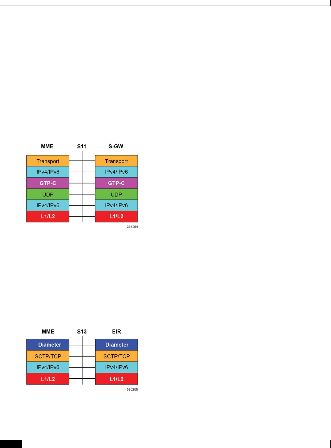
S11 Interface
This interface provides communication between the MME and Serving Gateways (S-GW) for information transfer. This
interface uses the GTPv2 protocol.
One or more S11 interfaces can be configured per system context.
Supported protocols:
Transport Layer: UDP, TCP
Tunneling: IPv4 or IPv6 GTPv2-C (signaling channel)
Network Layer: IPv4, IPv6
Data Link Layer: ARP
Physical Layer: Ethernet
S13 Interface
This interface provides communication between MME and Equipment Identity Register (EIR).
One or more S13 interfaces can be configured per system context.
Supported protocols:
Transport Layer: SCTP or TCP
Network Layer: IPv4, IPv6
Data Link Layer: ARP
Physical Layer: Ethernet
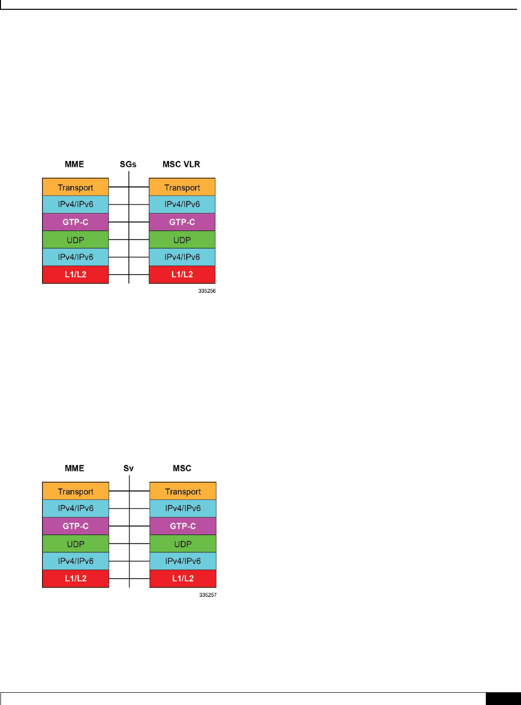
SGs Interface
The SGs interface connects the databases in the VLR and the MME to support circuit switch fallback scenarios.
Mobility Management Entity Overview
Network Deployment and Interfaces ▀
Cisco ASR 5x00 Mobility Management Entity Administration Guide ▄
25
Supported protocols:
Transport Layer: UDP, TCP
Tunneling: IPv4 or IPv6 GTP-C (signaling channel)
Network Layer: IPv4, IPv6
Data Link Layer: ARP
Physical Layer: Ethernet
Sv Interface
This interface connects the MME to a Mobile Switching Center to support the exchange of messages during a handover
procedure for the Single Radio Voice Call Continuity (SRVCC) feature.
Supported protocols:
Transport Layer: UDP, TCP
Tunneling: IPv4 or IPv6 GTP-C (signaling channel)
Network Layer: IPv4, IPv6
Data Link Layer: ARP
Physical Layer: Ethernet
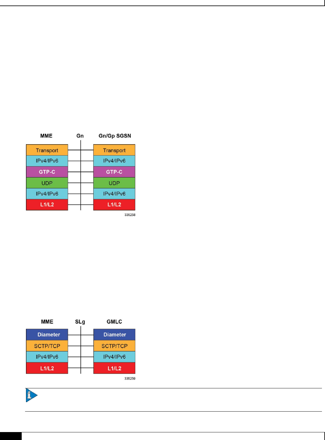
Gn Interface
Gn interfaces facilitate user mobility between 2G/3G 3GPP networks. The Gn interface is used for intra-PLMN
handovers. The MME supports pre-Release-8 Gn interfaces to allow inter-operation between EPS networks and 2G/3G
3GPP networks.
Mobility Management Entity Overview
▀ Network Deployment and Interfaces
▄ Cisco ASR 5x00 Mobility Management Entity Administration Guide
26
Roaming and inter access mobility between 2G and/or 3G SGSNs and an MME/S-GW are enabled by:
Gn functionality, as specified between two SGSNs, which is provided by the MME, and
Gp functionality, as specified between SGSN and GGSN, that is provided by the P-GW.
Supported protocols:
Transport Layer: UDP, TCP
Tunneling: IPv4 or IPv6 GTP-C (signaling channel)
Network Layer: IPv4, IPv6
Data Link Layer: ARP
Physical Layer: Ethernet
SLg Interface
This interface is used by the MME to communicate with the Gateway Mobile Location Center (GMLC). This diameter-
based interface is used for LoCation Services (LCS), which enables the system to determine and report location
(geographical position) information for connected UEs in support of a variety of location services.
Supported protocols:
Transport Layer: SCTP or TCP
Network Layer: IPv4, IPv6
Data Link Layer: ARP
Physical Layer: Ethernet
Important: MME Software also supports additional interfaces. For more information on additional interfaces,
refer to the Features and Functionality - Licensed Enhanced Feature Software section.

Mobility Management Entity Overview
Features and Functionality - Base Software ▀
Cisco ASR 5x00 Mobility Management Entity Administration Guide ▄
27
Features and Functionality - Base Software
This section describes the features and functions supported by default in the base software on the MME service and do
not require any additional licenses.
Important: To configure the basic service and functionality on the system for MME service, refer configuration
examples provide in MME Administration Guide.
This section describes following features:
3GPP R8 Identity Support
ANSI T1.276 Compliance
APN Restriction Support
Authentication and Key Agreement (AKA)
Bulk Statistics Support
Closed Subscriber Groups
Congestion Control
Emergency Session Support
EPS Bearer Context Support
EPS GTPv2 Support on S11 Interface
HSS Support Over S6a Interface
Inter-MME Handover Support
Interworking Support
IPv6 Support
Load Balancing
Management System Overview
MME Pooling
MME Selection
Mobile Equipment Identity Check
Mobility Restriction
Multiple PDN Support
NAS Protocol Support
NAS Signalling Security
Network Sharing
Operator Policy Support
Overload Control

Mobility Management Entity Overview
▀ Features and Functionality - Base Software
▄ Cisco ASR 5x00 Mobility Management Entity Administration Guide
28
Packet Data Network Gateway (P-GW) Selection
Radio Resource Management Functions
RAN Information Management
Reachability Management
SCTP Multi-homing Support
Serving Gateway Pooling Support
Serving Gateway Selection
Subscriber Level Session Trace
Threshold Crossing Alerts (TCA) Support
Tracking Area List Management
UMTS to LTE ID Mapping
3GPP R8 Identity Support
Provides the identity allocation of following type:
EPS Bearer Identity
Globally Unique Temporary UE Identity (GUTI)
Tracking Area Identity (TAI)
MME S1-AP UE Identity (MME S1-AP UE ID)
EPS Bearer Identity: An EPS bearer identity uniquely identifies EPS bearers within a user session for
attachment to the E-UTRAN access and EPC core networks. The EPS Bearer Identity is allocated by the MME.
There is a one to one mapping between EPS Radio Bearers via the E-UTRAN radio access network and EPS
Bearers via the S1-MME interface between the eNodeB and MME. There is also a one-to-one mapping
between EPS Radio Bearer Identity via the S1 and X2 interfaces and the EPS Bearer Identity assigned by the
MME.
Globally Unique Temporary UE Identity (GUTI): The MME allocates a Globally Unique Temporary Identity
(GUTI) to the UE. A GUTI has; 1) unique identity for MME which allocated the GUTI; and 2) the unique
identity of the UE within the MME that allocated the GUTI.
Within the MME, the mobile is identified by the M-TMSI.
The Globally Unique MME Identifier (GUMMEI) is constructed from MCC, MNC and MME Identifier (MMEI). In
turn the MMEI is constructed from an MME Group ID (MMEGI) and an MME Code (MMEC).
The GUTI is constructed from the GUMMEI and the M-TMSI.
For paging, the mobile is paged with the S-TMSI. The S-TMSI is constructed from the MMEC and the M-TMSI.
The operator needs to ensure that the MMEC is unique within the MME pool area and, if overlapping pool areas are in
use, unique within the area of overlapping MME pools.
The GUTI is used to support subscriber identity confidentiality, and, in the shortened S-TMSI form, to enable more
efficient radio signaling procedures (e.g. paging and Service Request).
Tracking Area Identity (TAI): Provides the function to assign the TAI list to the mobile access device to limit
the frequency of Tracking Area Updates in the network. The TAI is the identity used to identify the tracking
area or group of cells in which the idle mode access terminal will be paged when a remote host attempts to

Mobility Management Entity Overview
Features and Functionality - Base Software ▀
Cisco ASR 5x00 Mobility Management Entity Administration Guide ▄
29
reach that user. The TAI consists of the Mobile Country Code (MCC), Mobile Network Code (MNC) and
Tracking Area Code (TAC).
MME S1-AP UE Identity (MME S1-AP UE ID): This is the temporary identity used to identify a UE on the
S1-MME reference point within the MME. It is unique within the MME per S1-MME reference point instance.
ANSI T1.276 Compliance
ANSI T1.276 specifies security measures for Network Elements (NE). In particular it specifies guidelines for password
strength, storage, and maintenance security measures.
ANSI T1.276 specifies several measures for password security. These measures include:
Password strength guidelines
Password storage guidelines for network elements
Password maintenance, e.g. periodic forced password changes
These measures are applicable to the system and the Web Element Manager since both require password authentication.
A subset of these guidelines where applicable to each platform will be implemented. A known subset of guidelines, such
as certificate authentication, are not applicable to either product. Furthermore, the platforms support a variety of
authentication methods such as RADIUS and SSH which are dependent on external elements. ANSI T1.276 compliance
in such cases will be the domain of the external element. ANSI T1.276 guidelines will only be implemented for locally
configured operators.
APN Restriction Support
The APN-Restriction value may be configured for each APN in the P-GW and transferred to the MME. It is used to
determine, on a per-MS basis, whether it is allowed to establish EPS bearers to other APNs.
The APN-Restriction value is defined in clause 15.4 of 3GPP TS 23.060. APN-Restriction affects multiple procedures,
such as Initial Attach, TAU, PDN connectivity, and inter-MME handovers. The MME saves the APN-Restriction value
received in create session response for an APN and uses the maximum of the values from the currently active PDNs in
the next create session request. If a PDN is disconnected, then the maximum APN-Restriction is adjusted accordingly.
Authentication and Key Agreement (AKA)
The MME provides EPS Authentication and Key Agreement mechanism for user authentication procedure over the E-
UTRAN. The Authentication and Key Agreement (AKA) mechanism performs authentication and session key
distribution in networks. AKA is a challenge- response based mechanism that uses symmetric cryptography. AKA is
typically run in a Services Identity Module.
AKA is the procedure that take between the user and network to authenticate themselves towards each other and to
provide other security features such as integrity and confidentiality protection.
In a logical order this follows the following procedure:
1. Authentication: Performs authentication by identifying the user to the network and identifying the network to the
user.
2. Key agreement: Performs key agreement by generating the cipher key and generating the integrity key.
3. Protection: When the AKA procedure is performed, it protects the integrity of messages, the confidentiality of
the signalling data, and the confidentiality of the user data.

Mobility Management Entity Overview
▀ Features and Functionality - Base Software
▄ Cisco ASR 5x00 Mobility Management Entity Administration Guide
30
Bulk Statistics Support
The system's support for bulk statistics allows operators to choose to view not only statistics that are of importance to
them, but also to configure the format in which it is presented. This simplifies the post-processing of statistical data
since it can be formatted to be parsed by external, back-end processors.
When used in conjunction with the Web Element Manager, the data can be parsed, archived, and graphed.
The system can be configured to collect bulk statistics (performance data) and send them to a collection server (called a
receiver). Bulk statistics are statistics that are collected in a group. The individual statistics are grouped by schema.
Following is a partial list of supported schemas:
System: Provides system-level statistics
Card: Provides card-level statistics
Port: Provides port-level statistics
MME: Provides MME service statistics
GTPC: Provides GPRS Tunneling Protocol - Control message statistics
The system supports the configuration of up to 4 sets (primary/secondary) of receivers. Each set can be configured with
to collect specific sets of statistics from the various schemas. Statistics can be pulled manually from the chassis or sent
at configured intervals. The bulk statistics are stored on the receiver(s) in files.
The format of the bulk statistic data files can be configured by the user. Users can specify the format of the file name,
file headers, and/or footers to include information such as the date, chassis host name, chassis uptime, the IP address of
the system generating the statistics (available for only for headers and footers), and/or the time that the file was
generated.
When the Web Element Manager is used as the receiver, it is capable of further processing the statistics data through
XML parsing, archiving, and graphing.
The Bulk Statistics Server component of the Web Element Manager parses collected statistics and stores the information
in the PostgreSQL database. If XML file generation and transfer is required, this element generates the XML output and
can send it to a Northbound NMS or an alternate bulk statistics server for further processing.
Additionally, if archiving of the collected statistics is desired, the Bulk Statistics server writes the files to an alternative
directory on the server. A specific directory can be configured by the administrative user or the default directory can be
used. Regardless, the directory can be on a local file system or on an NFS-mounted file system on the Web Element
Manager server.
Closed Subscriber Groups
Closed Subscriber Group identifies a group of subscribers who are permitted to access one or more CSG cells of the
PLMN as a member of the CSG for a Home eNodeB.
Refer to the Closed Subscriber Groups chapter in the MME Administration Guide for more information.
Congestion Control
The congestion control feature allows you to set policies and thresholds and specify how the system reacts when faced
with a heavy load condition.
Congestion control monitors the system for conditions that could potentially degrade performance when the system is
under heavy load. Typically, these conditions are temporary (for example, high CPU or memory utilization) and are

Mobility Management Entity Overview
Features and Functionality - Base Software ▀
Cisco ASR 5x00 Mobility Management Entity Administration Guide ▄
31
quickly resolved. However, continuous or large numbers of these conditions within a specific time interval may have an
impact the system’s ability to service subscriber sessions. Congestion control helps identify such conditions and invokes
policies for addressing the situation.
Congestion control operation is based on configuring the following:
Congestion Condition Thresholds: Thresholds dictate the conditions for which congestion control is enabled
and establishes limits for defining the state of the system (congested or clear). These thresholds function in a
way similar to operation thresholds that are configured for the system as described in the Thresholding
Configuration Guide. The primary difference is that when congestion thresholds are reached, a service
congestion policy and an SNMP trap, starCongestion, are generated.
A threshold tolerance dictates the percentage under the configured threshold that must be reached in order for
the condition to be cleared. An SNMP trap, starCongestionClear, is then triggered.
The following system resources can be monitored:
System CPU usage
System service CPU usage (Demux-Card CPU usage)
System Memory usage
License usage
Maximum Session per service
Service Congestion Policies: Congestion policies are configurable for each service. These policies dictate how
services respond when the system detects that a congestion condition threshold has been crossed.
Congestion control can be used in conjunction with the load balancing feature provided on the MME. For more
information on MME load balancing, refer to the Load Balancing section in this chapter.
For more information or to configure Overload Control using the basic Congestion Control functionality, refer to the
Congestion Control chapter in the Cisco ASR 5x00 Series System Administration Guide.
For more information about the Enhanced Congestion Control functionality (a licensed feature), refer to the Enhanced
Congestion Control and Overload Control chapter in this guide.
Emergency Session Support
The MME supports the creation of emergency bearer services which, in turn, support IMS emergency sessions.
Emergency bearer services are provided to normally attached UEs and to UEs that are in a limited service state
(depending on local service regulations, policies, and restrictions).
The standard (refer to 3GPP TS 23.401) has identified four behaviors that are supported:
Valid UEs only
Authenticated UEs only
IMSI required, authentication optional
All UEs
To request emergency services, the UE has the following two options:
UEs that are in a limited service state (due to attach reject from the network, or since no SIM is present), initiate
an ATTACH indicating that the ATTACH is for receiving emergency bearer services. After a successful
attach, the services that the network provides the UE is solely in the context of Emergency Bearer Services.

Mobility Management Entity Overview
▀ Features and Functionality - Base Software
▄ Cisco ASR 5x00 Mobility Management Entity Administration Guide
32
UEs that camp normally on a cell initiates a normal ATTACH if it requires emergency services. Normal attached
UEs initiated a UE Requested PDN Connectivity procedure to request Emergency Bearer Services.
EPS Bearer Context Support
Provides support for subscriber default and dedicated Evolved Packet System (EPS) bearer contexts in accordance with
the following standards:
3GPP TS 36.412 V8.6.0 (2009-12): 3rd Generation Partnership Project; Technical Specification Group Radio
Access Network; Evolved Universal Terrestrial Access Network (E-UTRAN); S1 signaling transport (Release
8)
3GPP TS 36.413 V8.8.0 (2009-12): 3rd Generation Partnership Project; Technical Specification Group Radio
Access Network; Evolved Universal Terrestrial Radio Access Network (E-UTRAN); S1 Application Protocol
(S1AP) (Release 8)
IETF RFC 4960, Stream Control Transmission Protocol, December 2007
EPS bearer context processing is based on the APN that the subscriber is attempting to access. Templates for all of the
possible APNs that subscribers will be accessing must be configured within the system. Up to 1024 APNs can be
configured on the system.
Each APN template consists of parameters pertaining to how UE contexts are processed such as the following:
PDN Type: IPv4, IPv6, or IPv4v6
EPS Bearer Context timers
Quality of Service
A total of 11 EPS bearer per subscriber are supported. These could be all dedicated, or 1 default and 10 dedicated or any
combination of default and dedicated context. Note that there must be at least one default EPS Bearer context in order
for dedicated context to come up.
EPS GTPv2 Support on S11 Interface
Support for the EPS GTPv2 on S11 interface in accordance with the following standards:
3GPP TS 29.274 V8.4.0 (2009-12): 3rd Generation Partnership Project; Technical Specification Group Core
Network and Terminals; 3GPP Evolved Packet System (EPS); Evolved General Packet Radio Service (GPRS)
Tunnelling Protocol for Control plane (GTPv2-C); Stage 3 (Release 8)
The system supports the use of GTPv2 for EPS signalling context processing.
When the GTPv2 protocol is used, accounting messages are sent to the charging gateways (CGs) over the Ga interface.
The Ga interface and GTPv2 functionality are typically configured within the system's source context. As specified by
the standards, a CDR is not generated when a session starts. CDRs are generated according to the interim triggers
configured using the charging characteristics configured for the MME, and a CDR is generated when the session ends.
For interim accounting, STOP/START pairs are sent based on configured triggers.
GTP version 2 is always used. However, if version 2 is not supported by the CGF, the system reverts to using GTP
version 1. All subsequent CDRs are always fully-qualified partial CDRs. All CDR fields are R4.
Whether or not the MME accepts charging characteristics from the SGSN can be configured on a per-APN basis based
on whether the subscriber is visiting, roaming or, home.

Mobility Management Entity Overview
Features and Functionality - Base Software ▀
Cisco ASR 5x00 Mobility Management Entity Administration Guide ▄
33
By default, the MME always accepts the charging characteristics from the SGSN. They must always be provided by the
SGSN for GTPv1 requests for primary EPS Bearer contexts. If they are not provided for secondary EPS Bearer
contexts, the MME re-uses those from the primary.
If the system is configured to reject the charging characteristics from the SGSN, the MME can be configured with its
own that can be applied based on the subscriber type (visiting, roaming, or home) at the APN level. MME charging
characteristics consist of a profile index and behavior settings. The profile indexes specify the criteria for closing
accounting records based specific criteria.
Important: For more information on GTPv2 configuration, refer to the Creating and Configuring the eGTP
Service and Interface Association section in the Mobility Management Entity Configuration chapter of the MME Service
Administration Guide.
HSS Support Over S6a Interface
Provides a mechanism for performing Diameter-based authorization, authentication, and accounting (AAA) for
subscriber bearer contexts based on the following standards:
3GPP TS 23.401 V8.1.0 (2008-03): 3rd Generation Partnership Project; Technical Specification Group Services
and System Aspects; General Packet Radio Service (GPRS) enhancements for Evolved Universal Terrestrial
Radio Access Network (E-UTRAN) access (Release 8)
3GPP TS 29.272 V8.1.1 (2009-01): 3rd Generation Partnership Project; Technical Specification Group Core
Network and Terminals; Evolved Packet System (EPS); Mobility Management Entity (MME) and Serving
GPRS Support Node (SGSN) related interfaces based on Diameter protocol (Release 8)
3GPP TS 33.401 V8.2.1 (2008-12): 3rd Generation Partnership Project; Technical Specification Group Services
and System Aspects; 3GPP System Architecture Evolution (SAE): Security Architecture; (Release 8)
RFC 3588, Diameter Base Protocol, December 2003
The S6a protocol is used to provide AAA functionality for subscriber EPS Bearer contexts through Home Subscriber
Server (HSS).
During the initial attachment procedures the MME sends to the USIM on AT via the HSS the random challenge
(RAND) and an authentication token AUTN for network authentication from the selected authentication vector. At
receipt of this message, the USIM verifies that the authentication token can be accepted and if so, produces a response.
The AT and HSS in turn compute the Cipher Key (CK) and Integrity Key (IK) that are bound to Serving Network ID.
During the attachment procedure the MME requests a permanent user identity via the S1-MME NAS signaling interface
to eNodeB and inserts the IMSI, Serving Network ID (MCC, MNC) and Serving Network ID it receives in an
Authentication Data Request to the HSS. The HSS returns the Authentication Response with authentication vectors to
MME. The MME uses the authentication vectors to compute the cipher keys for securing the NAS signaling traffic.
At EAP success, the MME also retrieves the subscription profile from the HSS which includes QoS information and
other attributes such as default APN name and S-GW/P-GW fully qualified domain names.
Among the AAA parameters that can be configured are:
Authentication of the subscriber with HSS
Subscriber location update/location cancel
Update subscriber profile from the HSS
Priority to dictate the order in which the servers are used allowing for multiple servers to be configured in a
single context

Mobility Management Entity Overview
▀ Features and Functionality - Base Software
▄ Cisco ASR 5x00 Mobility Management Entity Administration Guide
34
Routing Algorithm to dictate the method for selecting among configured servers. The specified algorithm
dictates how the system distributes AAA messages across the configured HSS servers for new sessions. Once a
session is established and an HSS server has been selected, all subsequent AAA messages for the session will
be delivered to the same server.
Inter-MME Handover Support
The S10 interface facilitates user mobility between two MMEs providing for the transfer of the UE context from one to
the other. It is a GTPv2 control plane interface that supports the following handover types and features:
E-UTRAN-to-UTRAN (MME-to-MME) handover through:
Tracking Area Update based inter-MME relocation
Attach at an eNodeB connected to a different MME
S1 handover based inter-MME relocation
The MME supports handing over multiple bearers and multiple PDNs over to another MME
Trace functionality, monitor protocol, and monitor subscriber
DNS client configuration
IPv4 and IPv6: for peer MME selection, the preference is given to IPv6 addresses. IPv4 addresses are ignored if
IPv6 addresses are present.
Interworking Support
This section describes various interworking and handover scenarios supported by the MME. The following interworking
types are provided:
Interworking with SGSNs
Handover Support for S4 SGSNs
Interworking with SGSNs
This feature enables an integrated EPC core network to anchor calls from multi-mode access terminals and supports
seamless mobility on call hand-offs between an LTE or GERAN/UTRAN access network. This provides a valuable
function to enable LTE operators to generate incremental revenue from inbound roaming agreements with 2G/3G
roaming partners.
In order to support inter-RAT hand-offs for dual-mode access terminals between LTE and 2G/3G networks with 3GPP
Pre-Release 8 SGSN's, the MME will support combined hard handover and SRNS relocation procedures via the GTPv1
Gn/Gp reference interface. In preparation for the handover, the MME sends a Forward Relocation Request to the SGSN
and includes subscriber identity and context information including IMSI, Mobility Management context and PDP
context. The PDP context includes the GGSN address for the user plane and the uplink Tunnel Endpoint ID. These
addresses are equivalent to the PDN GW address. The MME maps the EPS bearer parameters to the PDP contexts.
After sending the forward relocation signaling to the target SGSN, the MME deletes the EPS bearer resources by
sending a Delete Bearer Request to the S-GW with a Cause code that instructs the S-GW not to initiate delete
procedures toward the P-GW.
When a mobile subscriber roams from an EUTRAN to GERAN/UTRAN access network it must also send a Routing
Area Update (RAU) to register its location with the target network. The target SGSN sends a Context Request to the

Mobility Management Entity Overview
Features and Functionality - Base Software ▀
Cisco ASR 5x00 Mobility Management Entity Administration Guide ▄
35
MME with P-TMSI to get the Mobility Management contexts and PDP contexts for the subscriber session. The SGSN
uses the Globally Unique Temporary ID (GUTI) from the MME to identify the P-TMSI/RAI.
Handover Support for S4-SGSNs
The S3 interface facilitates user mobility between an MME and an S4-SGSN providing for the transfer of the UE
context between the two. It is a GTPv2 control plane interface that supports the following handover types:
E-UTRAN-to-UTRAN and E-UTRAN-to-GERAN (MME-to-R8 SGSN) handover through:
Routing Area Update (RAU) based MME-R8 SGSN relocation where the RAU could be a result of UE
movement.
Attach at an RNC connected to a R8 SGSN
S1 handover/SRNS relocation based MME-R8 SGSN relocation
UTRAN-to-E-UTRAN and GERAN-to-E-UTRAN (R8 SGSN-to-MME) handover through:
Tracking Area Update (TAU) based R8 SGSN-MME relocation where the TAU could be a result of UE
movement.
Attach at an eNodeB connected to an MME.
SRNS relocation/S1 handover based R8 SGSN-MME relocation.
All handover types support handing over multiple bearers and multiple PDNs from the MME to a R8 SGSN and vice
versa.
The S3 interface also supports the following features:
Monitor Protocol and Monitor Subscriber
Subscriber Session Trace
IPv4 and IPv6: for peer SGSN selection, the preference is given to IPv6 addresses. IPv4 addresses are ignored if
IPv6 addresses are present.
Operator Policy for SGSN selection
Session Recovery: all MME sessions established using the S3 interface are capable of being recovered in case of
a session manager task failure.
IPv6 Support
This feature allows IPv6 subscribers to connect via the LTE/SAE infrastructure in accordance with the following
standards:
RFC 2460: Internet Protocol, Version 6 (IPv6) Specification
RFC 2461: Neighbor Discovery for IPv6
RFC 2462: IPv6 Stateless Address Autoconfiguration
RFC 3314: Recommendations for IPv6 in 3GPP Standards
RFC 3316: Internet Protocol Version 6 (IPv6) for Some Second and Third Generation Cellular Hosts
RFC 3056: Connection of IPv6 domains via IPv4 clouds
3GPP TS 27.060: Mobile Station Supporting Packet Switched Services

Mobility Management Entity Overview
▀ Features and Functionality - Base Software
▄ Cisco ASR 5x00 Mobility Management Entity Administration Guide
36
3GPP TS 29.061: Interworking between the Public Land Mobile Network (PLMN) supporting Packet Based
Services and Packet Data Networks (PDN)
The MME allows an APN to be configured for IPv6 EPS Bearer contexts. Also, an APN may be configured to
simultaneously allow IPv4 EPS Bearer contexts.
The MME supports IPv6 stateless dynamic auto-configuration. The mobile station may select any value for the interface
identifier portion of the address. The link-local address is assigned by the MME to avoid any conflict between the
mobile station link-local address and the MME address. The mobile station uses the interface identifier assigned by the
MME during the stateless address auto-configuration procedure. Once this has completed, the mobile can select any
interface identifier for further communication as long as it does not conflict with the MME's interface identifier that the
mobile learned through router advertisement messages from the MME.
Control and configuration of the above is specified as part of the APN configuration on the MME, e.g., IPv6 address
prefix and parameters for the IPv6 router advertisements. RADIUS VSAs may be used to override the APN
configuration.
Following IPv6 EPS Bearer context establishment, the MME can perform either manual or automatic 6to4 tunneling,
according to RFC 3056, Connection of IPv6 Domains Via IPv4 Clouds.
MME Interfaces Supporting IPv6 Transport
The following MME interfaces support IPv6 transport:
S1-MME: runs S1-AP/SCTP over IPv6 and supports IPv6 addresses for S1-U endpoints.
S3
S6a
S10
S11
S13
SGs
Sv
Load Balancing
Load balancing functionality permits UEs that are entering into an MME pool area to be directed to an appropriate
MME in a more efficient manner, spreading the load across a number of MMEs.
Load balancing is achieved by setting a weight factor for each MME so that the probability of the eNodeB selecting an
MME is proportional to its weight factor. The weight factor is typically set according to the capacity of an MME node
relative to other MME nodes. The weight factor is sent from the MME to the eNodeB via S1-AP messages.
Refer to the Load Balancing and Rebalancing chapter for more information about this feature.
MME load balancing can be used in conjunction with congestion control. For more information on congestion control,
refer to the Congestion Control section in this chapter.
Load Re-balancing
The MME load re-balancing functionality permits UEs that are registered on an MME (within an MME pool area) to be
moved to another MME.

Mobility Management Entity Overview
Features and Functionality - Base Software ▀
Cisco ASR 5x00 Mobility Management Entity Administration Guide ▄
37
The rebalancing is triggered using an exec command on the mme-service from which UEs should be offloaded.
When initiated, the MME begins to offload a cross-section of its subscribers with minimal impact on the network and
users. The MME avoids offloading only low activity users, and it offloads the UEs gradually (configurable from 1-1000
minutes). The load rebalancing can off-load part of or all the subscribers.
Refer to the Load Balancing and Rebalancing chapter in the MME Administration Guide for more information about
this feature.
Management System Overview
The system's management capabilities are designed around the Telecommunications Management Network (TMN)
model for management - focusing on providing superior quality network element (NE) and element management system
(Web Element Manager) functions. The system provides element management applications that can easily be integrated,
using standards-based protocols (CORBA and SNMPv1, v2), into higher-level management systems - giving wireless
operators the ability to integrate the system into their overall network, service, and business management systems. In
addition, all management is performed out-of-band for security and to maintain system performance.
The Operation and Maintenance module of the system offers comprehensive management capabilities to the operators
and enables them to operate the system more efficiently. There are multiple ways to manage the system either locally or
remotely using its out-of-band management interfaces.
These include:
Using the command line interface (CLI)
Remote login using Telnet, and Secure Shell (SSH) access to CLI through SPIO card's Ethernet management
interfaces
Local login through the Console port on SPIO card using an RS-232 serial connection
Using the Web Element Manager application
Supports communications through 10 Base-T, 100 Base-TX, 1000 Base-TX, or 1000
Base-SX (optical gigabit Ethernet) Ethernet management interfaces on the SPIO
Client-Server model supports any browser (i.e. Microsoft Internet Explorer v5.0 and above or Netscape v4.7 or
above, and others)
Supports Common Object Request Broker Architecture (CORBA) protocol and Simple Network Management
Protocol version 1 (SNMPv1) for fault management
Provides complete Fault, Configuration, Accounting, Performance, and Security (FCAPS) capabilities
Can be easily integrated with higher-level network, service, and business layer applications using the Object
Management Group's (OMG’s) Interface Definition Language (IDL)
The following figure demonstrates these various element management options and how they can be utilized within the
wireless carrier network.
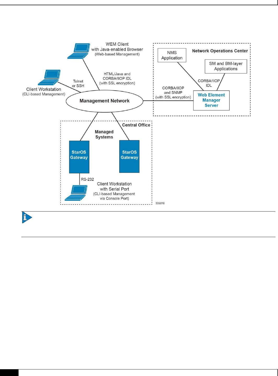
Mobility Management Entity Overview
▀ Features and Functionality - Base Software
▄ Cisco ASR 5x00 Mobility Management Entity Administration Guide
38
Figure 4. Element Management Methods
Important: MME management functionality is enabled by default for console-based access. For GUI-based
management support, refer Web Element Management System. For more information on command line interface based
management, refer to the Command Line Interface Reference.
MME Pooling
Provides support to configure MME pool area consisting multiple MMEs within which a UE may be served without any
need to change the serving MME.
The benefits of MME pooling are:
Enables Geographical Redundancy, as a pool can be distributed across sites.
Increases overall capacity, as load sharing across the MMEs in a pool is possible (see the Load Balancing feature
in this chapter).
Converts inter-MME Tracking Area Updates (TAUs) to intra-MME TAUs for moves between the MMEs of the
same pool. This substantially reduces signaling load as well as data transfer delays.
Eases introduction of new nodes and replacement of old nodes as subscribers can be moved is a planned manner
to the new node.
Eliminates single point of failure between an eNodeB and MME.

Mobility Management Entity Overview
Features and Functionality - Base Software ▀
Cisco ASR 5x00 Mobility Management Entity Administration Guide ▄
39
Enables service downtime free maintenance scheduling.
An MME Pool Area is defined as an area within which a UE may be served without need to change the serving MME.
An MME Pool Area is served by one or more MMEs in parallel. MME Pool Areas are a collection of complete
Tracking Areas. MME Pool Areas may overlap each other.
The Cisco MME supports MME Pooling functionality as defined in 3GPP TS 23.401. MME pooling allows carriers to
load balance sessions among pooled MMEs.
The Cisco MME supports configuration of up to a pool size of 32 nodes.
MME Selection
The MME selection function selects an available MME for serving a UE. This feature is needed for MME selection for
handover with minimal MME changes.
MME selection chooses an available MME for serving a UE. Selection is based on network topology, i.e. the selected
MME serves the UE’s location and in case of overlapping MME service areas, the selection function may prefer MME’s
with service areas that reduce the probability of changing the MME.
Mobile Equipment Identity Check
The Mobile Equipment Identity Check Procedure permits the operator(s) of the MME and/or the HSS and/or the PDN-
GW to check the Mobile Equipment's identity with EIR.
The mobile equipment (ME) identity is checked through the MME by passing it to an Equipment Identity Register
(EIR) over the S13 interface and then the MME analyzes the response from the EIR in order to determine its subsequent
actions; like rejecting or attaching a UE.
Mobility Restriction
The following types of mobility restriction are supported on the MME:
Handover Restriction
Regional Zone Code Restriction
Handover Restriction
Mobility Restriction comprises the functions for restrictions to mobility handling of a UE in E-UTRAN access. In
ECM-CONNECTED state, the core network provides the radio network with a Handover Restriction List.
The MME performs mobility or handover restrictions through the use of handover restriction lists. Handover restriction
lists are used by the MME operator policy to specify roaming, service area, and access restrictions. Mobility restrictions
at the MME are defined in 3GPP TS 23.401.
Regional Zone Code Restriction
Regional Zone Code Restriction allows an operator to control the areas in which a UE can roam in to receive service.
The code representing the zone in which a UE is to be offered service by the network can be configured in the HSS or
using local provisioning in the MME.

Mobility Management Entity Overview
▀ Features and Functionality - Base Software
▄ Cisco ASR 5x00 Mobility Management Entity Administration Guide
40
Once provisioned, the following restriction types are supported on the MME:
HSS subscription based zone code restriction - if the subscription data in the HSS contains zone codes, the UE is
allowed to camp only on those zones.
Support for Regional Zone Code restriction based on HSS subscription data allows operators to offer zone
based EPC subscriptions to home subscribers.
Local policy based zone code restrictions - using the operator policy on the MME, certain ranges of IMSI or
specific PLMN(s) could be restricted from or allowed to camp on, zones within the MME service area. This
policy could apply to any PLMN.
Local policy based zone code restriction allows operators to control access of EPC by roaming subscribers on a
zone basis.
Multiple PDN Support
This feature provides multiple PDN connectivity support for UE initiated service requests.
The MME supports an UE-initiated connectivity establishment to separate P-GWs or a single P-GW in order to allow
parallel access to multiple PDNs. Up to 11 PDNs are supported per subscriber.
Refer to PDN Type Control in this chapter for information about the ability to control the PDN type (IPv4, IPv6) to
which a given UE can be connected.
NAS Protocol Support
MME provides this protocol support between the UE and the MME. The NAS protocol includes following elementary
procedures for EPS Mobility Management (EMM) and EPS Session Management (ESM):
EPS Mobility Management (EMM)
This feature used to support the mobility of user equipment, such as informing the network of its present location and
providing user identity confidentiality. It also provides connection management services to the session management
(SM) sublayer.
An EMM context is established in the MME when an attach procedure is successfully completed. The EMM procedures
are classified as follows:
EMM Common Procedures: An EMM common procedure can always be initiated when a NAS signalling
connection exists.
Following are the common EMM procedure types:
Globally Unique Temporary Identity (GUTI) reallocation
Authentication and security mode
Identification
EMM information
EMM Specific Procedures: This procedure provides Subscriber Detach or de-registration procedure.
EMM Connection Management Procedures: This procedure provides connection management related
function like Paging procedure.

Mobility Management Entity Overview
Features and Functionality - Base Software ▀
Cisco ASR 5x00 Mobility Management Entity Administration Guide ▄
41
EPS Session Management (ESM)
This feature is used to provide the subscriber session management for bearer context activation, deactivation,
modification, and update procedures.
NAS Signalling Security
It provides integrity protection and encryption of NAS signalling. The NAS security association is between the UE and
the MME.
The MME uses the NAS security mode command procedure to establish a NAS security association between the UE
and MME, in order to protect the further NAS signalling messages.
The MME implements AES algorithm (128-EEA1 and 128-EEA2) for NAS signalling ciphering and SNOW 3G
algorithm (128-EIA1 and 128-EIA2) for NAS signalling integrity protection.
128-EIA1= SNOW 3G
128-EIA2= AES
Network Sharing
The LTE architecture enables service providers to reduce the cost of owning and operating the network by allowing the
service providers to have separate Core Network (CN) elements (MME, SGW, PDN GW) while the E-UTRAN (eNBs)
is jointly shared by them. This is enabled by the S1-flex mechanism by enabling each eNodeB to be connected to
multiple CN entities. When a UE attaches to the network, it is connected to the appropriate CN entities based on the
identity of the service provider sent by the UE.
In such a network sharing configuration, complete radio (access) network and partial core network is shared among
different operators. Each operator has its own network node for S-GW/P-GW, etc., while sharing a MME and the rest of
the radio network.
To support this network sharing configuration, the MME service can be configured with multiple local PLMNs per
service. This means that each mme-service will handle multiple PLMNs and will indicate this to the eNodeb during S1
SETUP procedure (as well using the S1 MME CONFIGURATION UPDATE message).
The configuration of these additional PLMNs is implemented using the network-sharing command within the mme-
service config mode. Refer to the Command Line Reference for detailed information on using this command.
When a UE attaches to the MME, the GUTI assignment will use the mme id corresponding to the PLMN configuration.
The plmn-id filter in the operator policy selection criteria allows PLMN-specific configurations in an operator policy.
Operator Policy Support
The operator policy provides mechanisms to fine tune the behavior of subsets of subscribers above and beyond the
behaviors described in the user profile. It also can be used to control the behavior of visiting subscribers in roaming
scenarios, enforcing roaming agreements and providing a measure of local protection against foreign subscribers.
An operator policy associates APNs, APN profiles, an APN remap table, and a call-control profile to ranges of IMSIs.
These profiles and tables are created and defined within their own configuration modes to generate sets of rules and
instructions that can be reused and assigned to multiple policies. In this manner, an operator policy manages the
application of rules governing the services, facilities, and privileges available to subscribers. These policies can override

Mobility Management Entity Overview
▀ Features and Functionality - Base Software
▄ Cisco ASR 5x00 Mobility Management Entity Administration Guide
42
standard behaviors and provide mechanisms for an operator to get around the limitations of other infrastructure
elements, such as DNS servers and HSSs.
The operator policy configuration to be applied to a subscriber is selected on the basis of the selection criteria in the
subscriber mapping at attach time. A maximum of 1,024 operator policies can be configured. If a UE was associated
with a specific operator policy and that policy is deleted, the next time the UE attempts to access the policy, it will
attempt to find another policy with which to be associated.
A default operator policy can be configured and applied to all subscribers that do not match any of the per-PLMN or
IMSI range policies.
Changes to the operator policy take effect when the subscriber re-attaches and subsequent EPS Bearer activations.
Refer to the Operator Policy chapter in this guide for more information.
Overload Control
Using the Congestion Control functionality or the Enhanced Congestion Control functionality, the MME can signal to
the eNodeBs to which it is connected to redirect traffic to other MMEs in the MME pool. This is accomplished using the
S1 interface Overload Procedure (3GPP TS 36.300 and 3GPP TS 36.413).
When overload control is configured and a congestion threshold is reached, the MME can be configured to send an
S1AP Overload Start message to a percentage of the eNodeBs to which the MME is connected. To reflect the amount of
load that the MME wishes to reduce, this percentage configurable. In the Overload Response IE sent to the eNodeBs,
the MME can request the eNodeB to reject or permit specific types of sessions, including:
reject non-emergency sessions
reject new sessions
permit emergency sessions
permit high-priority sessions and mobile-terminated services
reject delay-tolerant access.
For more information or to configure Overload Control using the basic Congestion Control functionality, refer to the
Congestion Control chapter in the System Administration Guide.
For more information or to configure Overload Control using the Enhanced Congestion Control functionality, refer to
the Enhanced Congestion Control and Overload Control chapter in this guide.
PDN Type Control
PDN Type Control enables the MME to override the requested Packet Data Network (PDN) type based on the inbound
roamer PLMN, and assign the UE to an IPv4 only or IPv6 only PDN.
If a UE requests an IPv4v6 PDN, it can be downgraded to an IPv4- or IPv6-only address. The MME signals the
appropriate cause to the UE to account for the PDN type change.
This functionality enables operators to control resource usage for roaming and home subscribers differently, and
ensures that IP network continuity works for inbound roamers.
PDN Type Control is configured in a call control profile that is applied via an operator policy. Refer to the Call Control
Profile Configuration Mode chapter of the Command Line Reference for more information.

Mobility Management Entity Overview
Features and Functionality - Base Software ▀
Cisco ASR 5x00 Mobility Management Entity Administration Guide ▄
43
Packet Data Network Gateway (P-GW) Selection
Provides a straightforward method based on a default APN provided during user attachment and authentication to assign
the P-GW address in the VPLMN or HPLMN. The MME also has the capacity to use a DNS transaction to resolve an
APN name provided by a UE to retrieve the PDN GW address.
P-GW selection allocates a P-GW that provides the PDN connectivity for the 3GPP access. The function uses subscriber
information provided by the HSS and possibly additional criteria. For each of the subscribed PDNs, the HSS provides:
an IP address of a P-GW and an APN, or
an APN and an indication for this APN whether the allocation of a P-GW from the visited PLMN is allowed or
whether a P-GW from the home PLMN shall be allocated.
The HSS also indicates the default APN for the UE. To establish connectivity with a PDN when the UE is already
connected to one or more PDNs, the UE provides the requested APN for the PDN GW selection function.
If the HSS provides an APN of a PDN and the subscription allows for allocation of a PDN GW from the visited PLMN
for this APN, the PDN GW selection function derives a PDN GW address from the visited PLMN. If a visited PDN GW
address cannot be derived, or if the subscription does not allow for allocation of a PDN GW from the visited PLMN,
then the APN is used to derive a PDN GW address from the HPLMN.
Radio Resource Management Functions
Radio resource management functions are concerned with the allocation and maintenance of radio communication
paths, and are performed by the radio access network.
To support radio resource management in E-UTRAN, the MME provides the RAT/Frequency Selection Priority (RFSP)
parameter to an eNodeB across S1. The RFSP is a “per UE” parameter that is used by the E-UTRAN to derive UE
specific cell reselection priorities to control idle mode camping. The RFSP can also be used by the E-UTRAN to decide
on redirecting active mode UEs to different frequency layers or RATs.
The MME receives the RFSP from the HSS during the attach procedure. For non-roaming subscribers, the MME
transparently forwards the RFSP to the eNodeB across S1. For roaming subscribers, the MME may alternatively send an
RFSP value to the eNodeB across S1 that is based on the visited network policy, such as an RFSP pre-configured per
Home-PLMN or a single RFSP’s values to be used for all roamers independent of the Home-PLMN.
RAN Information Management
The MME supports RAN Information Management (RIM) procedures as defined in 3GPP TS 23.401 on the S1-MME,
S3, Gn, and S10 interfaces.
RIM procedures allow the MME to exchange information between applications belonging to the RAN nodes. The MME
provides addressing, routing and relaying support for the RAN information exchange.
Reachability Management
It provides a mechanism to track a UE which is in idle state for EPS connection management.
To reach a UE in idle state the MME initiates paging to all eNodeBs in all tracking areas in the TA list assigned to the
UE. The EPS session manager have knowledge about all the eNodeB associations to the MME and generates a list of
eNodeBs that needs to be paged to reach a particular UE.

Mobility Management Entity Overview
▀ Features and Functionality - Base Software
▄ Cisco ASR 5x00 Mobility Management Entity Administration Guide
44
The location of a UE in ECM-IDLE state is known by the network on a Tracking Area List granularity. A UE in ECM-
IDLE state is paged in all cells of the Tracking Areas in which it is currently registered. The UE may be registered in
multiple Tracking Areas. A UE performs periodic Tracking Area Updates to ensure its reachability from the network.
SCTP Multi-homing Support
This sections describes multi-homing support for specific interfaces on the MME.
SCTP Multi-homing for S6a
The Cisco MME service supports up to four SCTP bind end point IPv4 or IPv6 addresses for the S6a interface.
SCTP Multi-homing for S1-MME
The Cisco MME service supports up to two SCTP bind end point IPv4 or IPv6 addresses for the S1-MME interface.
SCTP Multi-homing for SGs
The Cisco MME service supports up to two SCTP bind end point IPv4 or IPv6 addresses for the SGs interface.
Serving Gateway Pooling Support
The S-GW supports independent service areas from MME pooling areas. Each cell is associated to a pool of MMEs and
a pool of Serving Gateways. Once a cell selects an MME, that MME is able to select an S-GW which is in an S-GW
pool supported by the cell.
Static S-GW pools can be configurable on the MME. Each pool is organized as a set of S-GWs and the Tracking Area
Identities (TAIs) supported by them, known as a service area (SA). The incoming TAI is used to select an SA. Then,
based on protocol and statistical weight factors, an S-GW is selected from the pool serving that SA. The same list of S-
GWs may serve multiple TAIs. Static S-GW pools are used if there is no DNS configured or as a fallback if DNS
discovery fails.
For additional Information on TAI lists, refer to the Tracking Area List Management section in this overview.
Serving Gateway Selection
The Serving Gateway (S-GW) selection function selects an available S-GW to serve a UE. This feature reduces the
probability of changing the S-GW and a load balancing between S-GWs. The MME uses DNS procedures for S-GW
selection.
The selection is based on network topology; the selected S-GW serves the UE’s location, and in the case of overlapping
S-GW service areas, the selection may prefer S-GWs with service areas that reduce the probability of changing the S-
GW. If a subscriber of a GTP-only network roams into a PMIP network, the PDN GWs (P-GWs) selected for local
breakout supports the PMIP protocol, while P-GWs for home routed traffic use GTP. This means the S-GW selected for
such subscribers may need to support both GTP and PMIP, so that it is possible to set up both local breakout and home
routed sessions for these subscribers.

Mobility Management Entity Overview
Features and Functionality - Base Software ▀
Cisco ASR 5x00 Mobility Management Entity Administration Guide ▄
45
Session and Quality of Service Management
This support provides a foundation for contributing towards improved Quality of User Experience (QoE) by enabling
deterministic end-to-end forwarding and scheduling treatments for different services or classes of applications pursuant
to their requirements for committed bandwidth resources, jitter and delay. In this way, each application receives the
service treatment that users expect.
The MME Operator Policy configuration allows the specification of QoS for each traffic class that can either be used as
a default or as an over ride to the HSS settings.
In LTE-EPC 4G architectures, QoS management is network controlled via dynamic policy interactions between the
PCRF and PDN GW. EPS bearer management is used to establish, modify or remove dedicated EPC bearers in order to
provide service treatments tied to the needs of specific applications/service data flows. The service priority is
provisioned based on QoS Class Identifiers (QCI) in the Gx policy signaling. PCRF signaling interaction may also be
used to establish or modify the APN-AMBR attribute assigned to the default EPS bearer.
When it is necessary to set-up a dedicated bearer, the PDN GW initiates the Create Dedicated Bearer Request which
includes the IMSI (permanent identity of mobile access terminal), Traffic Flow Template (TFT - 5-tuple packet filters)
and S5 Tunnel Endpoint ID (TEID) information that is propagated downstream via the S-GW over the S11 interface to
the MME. The Dedicated Bearer signaling includes requested QoS information such as QCI, Allocation and Retention
Priority (ARP), Guaranteed Bit Rate (GBR - guaranteed minimum sending rate) and Maximum Bit Rate (MBR-
maximum burst size).
The MME allocates a unique EPS bearer identity for every dedicated bearer and encodes this information in a Session
Management Request that includes Protocol Transaction ID (PTI), TFT’s and EPS bearer QoS parameters. The MME
signals the Bearer Setup Request in the S1-MME message toward the neighboring eNodeB.
Subscriber Level Session Trace
The Subscriber Level Trace provides a 3GPP standards-based session-level trace function for call debugging and testing
new functions and access terminals in an LTE environment.
In general, the Session Trace capability records and forwards all control activity for the monitored subscriber on the
monitored interfaces. This is typically all the signaling and authentication/subscriber services messages that flow when a
UE connects to the access network.
As a complement to Cisco's protocol monitoring function, the MME supports 3GPP standards based session level trace
capabilities to monitor all call control events on the respective monitored interfaces including S6a, S1-MME and S11.
The trace can be initiated using multiple methods:
Management initiation via direct CLI configuration
Management initiation at HSS with trace activation via authentication response messages over S6a reference
interface
Signaling based activation through signaling from subscriber access terminal
The session level trace function consists of trace activation followed by triggers. The EPC network element buffers the
trace activation instructions for the provisioned subscriber in memory using camp-on monitoring. Trace files for active
calls are buffered as XML files using non-volatile memory on the local dual redundant hard drives. The Trace Depth
defines the granularity of data to be traced. Six levels are defined including Maximum, Minimum and Medium with
ability to configure additional levels based on vendor extensions.
All call control activity for active and recorded sessions is sent to an off-line Trace Collection Entity (TCE) using a
standards-based XML format over a FTP or secure FTP (SFTP) connection.
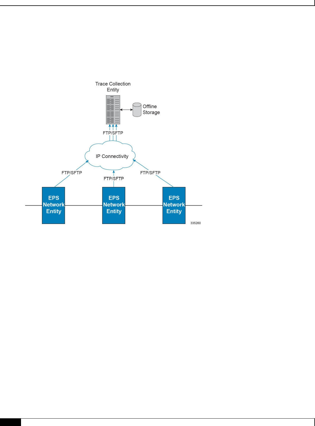
Mobility Management Entity Overview
▀ Features and Functionality - Base Software
▄ Cisco ASR 5x00 Mobility Management Entity Administration Guide
46
Note: In the current release the IPv4 interfaces are used to provide connectivity to the TCE. Trace activation is based on
IMSI or IMEI and only Maximum Trace Depth is supported in this release.
The following figure shows a high-level overview of the session-trace functionality and deployment scenario:
Figure 5. Session Trace Function and Interfaces
For more information on this feature, refer to the Configuring Subscriber Session Tracing chapter in the MME Service
Administration Guide.
Threshold Crossing Alerts (TCA) Support
Thresholding on the system is used to monitor the system for conditions that could potentially cause errors or outage.
Typically, these conditions are temporary (i.e high CPU utilization, or packet collisions on a network) and are quickly
resolved. However, continuous or large numbers of these error conditions within a specific time interval may be
indicative of larger, more severe issues. The purpose of thresholding is to help identify potentially severe conditions so
that immediate action can be taken to minimize and/or avoid system downtime.
The system supports Threshold Crossing Alerts for certain key resources such as CPU, memory, number of sessions etc.
With this capability, the operator can configure threshold on these resources whereby, should the resource depletion
cross the configured threshold, a SNMP Trap would be sent.
The following thresholding models are supported by the system:
Alert: A value is monitored and an alert condition occurs when the value reaches or exceeds the configured high
threshold within the specified polling interval. The alert is generated then generated and/or sent at the end of
the polling interval.
Alarm: Both high and low threshold are defined for a value. An alarm condition occurs when the value reaches
or exceeds the configured high threshold within the specified polling interval. The alert is generated then
generated and/or sent at the end of the polling interval.
Mobility Management Entity Overview
Features and Functionality - Base Software ▀
Cisco ASR 5x00 Mobility Management Entity Administration Guide ▄
47
Thresholding reports conditions using one of the following mechanisms:
SNMP traps: SNMP traps have been created that indicate the condition (high threshold crossing and/or clear) of
each of the monitored values.
Generation of specific traps can be enabled or disabled on the chassis. Ensuring that only important faults get displayed.
SNMP traps are supported in both Alert and Alarm modes.
Logs: The system provides a facility called threshold for which active and event logs can be generated. As with
other system facilities, logs are generated Log messages pertaining to the condition of a monitored value are
generated with a severity level of WARNING.
Logs are supported in both the Alert and the Alarm models.
Alarm System: High threshold alarms generated within the specified polling interval are considered
“outstanding” until a the condition no longer exists or a condition clear alarm is generated. “Outstanding”
alarms are reported to the system's alarm subsystem and are viewable through the Alarm Management menu in
the Web Element Manager.
The Alarm System is used only in conjunction with the Alarm model.
Important: For more information on threshold crossing alert configuration, refer to the Thresholding
Configuration Guide.
Tracking Area List Management
Provides the functions to allocate and reallocate a Tracking Area Identity (TAI) list to the UE to minimize Tracking
Area Updates (TAUs).
The MME assigns the TAI list to a UE so as to minimize the TAUs that are sent by the UE. The TAI list should be kept
to a minimum in order to maintain a lower paging load.
The MME allows up to 16 tracking areas configured locally to be included and sent to the mobile station in Tracking
Area List IE as part of Attach/TAU Accept message.
UMTS to LTE ID Mapping
The MME allows seamless inter-RAT interworking when the operator’s networks are configured with LACs allocated
from the reserved space of 32K to 64K. 3GPP Specifications have reserved this space for LTE MME Group IDs. The
MME and SGSN can distinguish between UMTS IDs (P-TMSI/RAI) and LTE IDs (GUTI) by configuring an MME
group ID to PLMN ID mapping.
Use Case 1: When a UE moves from 3G to LTE, the UE maps the P-TMSI and RAI to GUTI and uses this mapped
GUTI in the TAU Attach Request that it sends to the MME. At the MME, this mapped GUTI gets reverse mapped to P-
TMSI and RAI, which are used to fetch the UE’s Context from the old SGSN.
Use Case 1: When a UE moves from LTE to 3G, theUE maps the GUTI to P-TMSI and RAI, and performs a RAU
Attach to the SGSN. A Pre-Rel8 SGSN would attempt to fetch the UE’s context over the Gn/Gp interface using the
mapped P-TMSI and RAI. At the MME, the P-TMSI and RAI are reverse mapped to GUTI to fetch the locally stored
UE’s context. An S3-SGSN also behaves similar to Pre-Rel8 SGSN except for the way it discovers the source MME.
S3-SGSN identifies the P-TMSI & RAI received in RAU Request as a mapped one and performs LTE specific DNS
query using MME ID, to discover the source MME.
For the two use cases above, the MME/S3-SGSN would need to identify whether a given UMTS or LTE ID is a native
one or a mapped one. MME GroupID or LAC is used to make this distinction. If the Most Significant Bit(MSB) in LAC

Mobility Management Entity Overview
▀ Features and Functionality - Base Software
▄ Cisco ASR 5x00 Mobility Management Entity Administration Guide
48
is set then the UMTS ID is mapped from LTE. Similarly, if the MSB of MME Group ID is zero then the LTE ID is
mapped from UMTS. If the standard defined ranges are not complied, the target MME/S3-SGSN may incorrectly
conclude the source node as S3-SGSN/MME. This misinterpretation would lead to unsuccessful attempt to resolve the
source node since the DNS query is formulated with the assumption that the source node is either MME or S3-SGSN.
In order to address networks where the 1/0 MSB logic does not apply, the MME and SGSN can rely on a global
database of MME Group IDs (configured via CLI) instead of the standards specified MSB, to distinguish between
mapped and native UMTS and LTE IDs.
The MME consults this database of MME Group IDs when the below two conditions apply:
1. The MME is not aware of the received GUTI Type, such as when either the UE or the network are not Release 10
compliant.
2. MME-Service is associated with the MME Group ID database.
Refer to Configuring UMTS to LTE ID Mapping in Chapter 2 of this document for steps to create and configure this
database and to associate the MME service to this database.
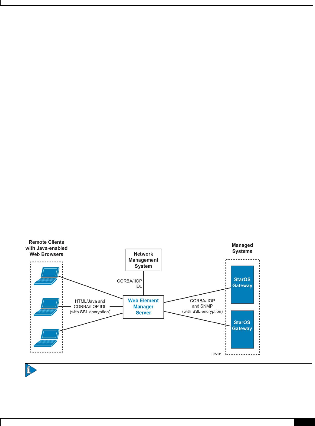
Mobility Management Entity Overview
Features and Functionality - External Application Support ▀
Cisco ASR 5x00 Mobility Management Entity Administration Guide ▄
49
Features and Functionality - External Application Support
This section describes the features and functions of external applications supported on the MME. These services require
additional licenses to implement the functionality.
This section describes following external applications:
Web Element Management System
Web Element Management System
Provides a graphical user interface (GUI) for performing fault, configuration, accounting, performance, and security
(FCAPS) management.
The Web Element Manager is a Common Object Request Broker Architecture (CORBA)-based application that
provides complete fault, configuration, accounting, performance, and security (FCAPS) management capability for the
system.
For maximum flexibility and scalability, the Web Element Manager application implements a client-server architecture.
This architecture allows remote clients with Java-enabled web browsers to manage one or more systems via the server
component which implements the CORBA interfaces. The server component is fully compatible with the fault-tolerant
Sun® Solaris® operating system.
The following figure demonstrates various interfaces between the Cisco Web Element Manager and other network
components.
Figure 6. Web Element Manager Network Interfaces
Important: MME management functionality is enabled by default for console-based access. For GUI-based
management support, refer Web Element Management System.

Mobility Management Entity Overview
▀ Features and Functionality - Licensed Enhanced Feature Software
▄ Cisco ASR 5x00 Mobility Management Entity Administration Guide
50
Features and Functionality - Licensed Enhanced Feature
Software
This section describes the optional enhanced features and functions for MME service.
Important: The following features require the purchase of an additional feature license to implement the
functionality with the MME service.
This section describes following enhanced features:
Attach Rate Throttling
Circuit Switched Fall Back (CSFB) and SMS over SGs Interface
Enhanced Congestion Control and Overload Control
Idle-mode Signaling Reduction
IP Security (IPSec)
Lawful Intercept
Location Services
Optimized Paging Support
Overcharging Protection
Session Recovery Support
Single Radio Voice Call Continuity Support
User Location Information Reporting
VLR Management
Attach Rate Throttling
This feature requires that a valid license key be installed. Contact your Cisco Account or Support representative for
information on how to obtain a license.
This feature enables operators to limit the rate at which the MME processes new connections (attaches, TAU requests,
and forward relocation requests) which in turn reduces the signaling on the external nodes.
See the network-overload-protection mme-new-connections-per-second command in the Global
Configuration Mode Commands chapter of the Command Line Reference for more information.
Circuit Switched Fall Back (CSFB) and SMS over SGs Interface
This feature requires that a valid license key be installed. Contact your Cisco Account or Support representative for
information on how to obtain a license.
Circuit Switched Fall Back (CSFB) enables the UE to camp on an EUTRAN cell and originate or terminate voice calls
through a forced switchover to the circuit switched (CS) domain or other CS-domain services (e.g., Location Services

Mobility Management Entity Overview
Features and Functionality - Licensed Enhanced Feature Software ▀
Cisco ASR 5x00 Mobility Management Entity Administration Guide ▄
51
(LCS) or supplementary services). Additionally, SMS delivery via the CS core network is realized without CSFB. Since
LTE EPC networks were not meant to directly anchor CS connections, when any CS voice services are initiated, any PS
based data activities on the EUTRAN network will be temporarily suspended (either the data transfer is suspended or
the packet switched connection is handed over to the 2G/3G network).
Important: CSFB to CDMA 1x networks is not supported in this release.
CSFB provides an interim solution for enabling telephony and SMS services for LTE operators that do not plan to
deploy IMS packet switched services at initial service launch.
CSFB function is realized by reusing Gs interface mechanisms, as defined in 3GPP TS 29.018, on the interface between
the MME in the EPS and the VLR. This interface is called the SGs interface. The SGs interface connects the databases
in the VLR and the MME.
EPC core networks are designed for all IP services and as such lack intrinsic support for circuit switched voice and
telephony applications. This presents challenges for those operators that do not plan to launch packet switched IMS core
networks at initial service deployment. CSFB represents an interim solution to address this problem by enabling dual
radio mobile devices (LTE/GSM/UMTS or CDMA1xRTT) to fall back to GSM/UMTS or CDMA1x access networks to
receive incoming or place outgoing voice calls. Highlights of the CSFB procedure are as follows:
Preparation Phase:
When the GSM/UMTS/LTE access terminal attaches to the EUTRAN access network, it uses combined
attachment procedures to request assistance from the MME to register its presence in the 2G/3G
network.
The MME uses SGs signaling to the MSC/VLR to register on behalf of the AT to the 2G/3G network.
The MME represents itself as an SGSN to the MSC and the MSC performs a location update to the
SGSN in the target 2G/3G network.
The MME uses the Tracking Area Identity provided by UE to compute the Location Area Identity it
provides to the MSC.
Execution Phase: Mobile Terminated Call:
When a call comes in at the MSC for the user, the MSC signals the incoming call via the SGs interface
to MME.
If the AT is an active state, the MME forwards the request directly to the mobile. If the user wishes to
receive the call the UE instructs the MME to hand over the call to the 2G/3G network. The MME then
informs the eNodeB to initiate the handoff.
If the AT is in dormant state, the MME attempts to page it at every eNodeB within the Tracking Area
list to reestablish the radio connection. As no data transfer is in progress, there are no IP data sessions
to handover and the mobile switches to its 2G/3G radio to establish the connection with the target
access network.
If the mobile is active and an IP data transfer is in progress at the time of the handover, the data transfer
can either be suspended or the packet switched connection can be handed over if the target network
supports Dual Transfer Mode. Note that this is typically only supported on UMTS networks.
Once the access terminal attaches to the 2G/3G cell, it answers the initial paging via the target cell.
Execution Phase: Mobile Originated Calls
This is very similar to the procedure for Mobile Terminated Calls, except there is no requirement for
idle mode paging for incoming calls and the AT has no need to send a paging response to the MSC
after it attaches to the target 2G/3G network.
The following CSFB features are supported:

Mobility Management Entity Overview
▀ Features and Functionality - Licensed Enhanced Feature Software
▄ Cisco ASR 5x00 Mobility Management Entity Administration Guide
52
Release 8 and Release 9 Specification Support
SGs-AP Encode/Decode of all messages
SGs-AP Procedure Support
Paging
Location Update
Non-EPS Alert
Explicit IMSI Detach
Implicit IMSI Detach
VLR Failure
HSS Failure
MM Information
NAS Message Tunneling
Service Request
MME Failure
SMS
Mobile Originating Voice Call
Mobile Terminating Voice Call
Gn/Gp Handover
S3 Handover
Basic and Enhanced TAI to LAI Mapping
Basic LAI to VLR Mapping
VLR association distribution among multiple MMEMGRs
IMSI Paging Procedure
SCTP Multi-homing for SGs interface
IPv6 Transport for SGs interface
SNMP Trap Support (Service/VLR association)
Operator Policy Support
SMS-only
Disallow CSFB
Reject EPS if IMSI attach fails
Reject EPS if VoIMS and no CSFB
CSFB Not Preferred
Configurable RFSP based on UE Usage and and Voice Domain Preference
PS Suspend/Resume over S11 (Release 8)
PS Suspend/Resume over S3/S11 (Release 9)
Support for SGs AP Timers: TS6-1, ts8, ts9, ts10, ts12-1, ts12-2, ts-13

Mobility Management Entity Overview
Features and Functionality - Licensed Enhanced Feature Software ▀
Cisco ASR 5x00 Mobility Management Entity Administration Guide ▄
53
Idle mode Signaling Reduction (ISR)
Multiple Association Support
SNMP Trap Support
VLRAssocDown - sent when an SCTP association to a VLR is down.
VLRDown - sent when all SCTP associations to a VLR are down.
VlrAllAssocDown - sent when all associations to all VLRs are down.
Support for Passive VLR Offload: See VLR Management .
Support for Active VLR Offload: See VLR Management .
UE Detach on VLR Failure: See VLR Management .
UE Detach on VLR Recovery: See VLR Management .
Enhanced Congestion Control and Overload Control
This feature requires that a valid license key be installed. Contact your Cisco Account or Support representative for
information on how to obtain a license.
This feature builds on the functionality provided by Congestion Control and Overload Control .
To allow greater control during overload conditions, the MME supports the configuration of three separate levels
(critical, major, minor) of congestion thresholds for the following system resources:
System CPU usage
System service CPU usage (Demux-Card CPU usage)
System Memory usage
License usage
Maximum Session per service
The MME can, in turn, be configured to take specific actions when any of these thresholds are crossed, such as:
Drop or reject the following S1-AP/NAS messages: S1 Setup, Handover events, TAU request, Service request,
PS-Attach request, Combined-attach request, Additional PDN request, or UE initiated bearer resource
allocation.
Allow voice or emergency calls/events.
Initiate S1AP overload start to a percentage of eNodeBs with options to signal any of the following in the
Overload Response IE:
reject non-emergency sessions
reject new sessions
permit emergency sessions
permit high-priority sessions and mobile-terminated services
reject delay-tolerant access.
For more information on configuring this functionality, refer to Enhanced Congestion Control and Overload Control
chapter of the MME Administration Guide.
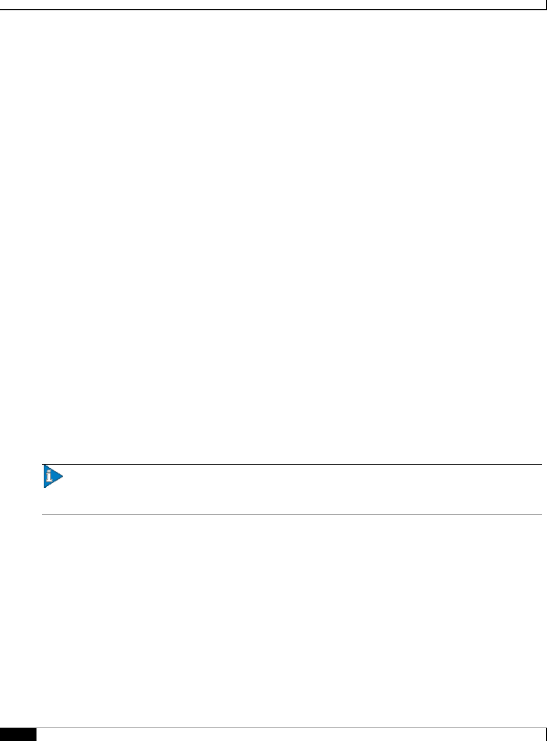
Mobility Management Entity Overview
▀ Features and Functionality - Licensed Enhanced Feature Software
▄ Cisco ASR 5x00 Mobility Management Entity Administration Guide
54
Idle-mode Signaling Reduction
This feature requires that a valid license key be installed. Contact your Cisco Account or Support representative for
information on how to obtain a license.
Idle-mode Signaling Reduction (ISR) allows a UE to be registered on (and roam between) E-UTRAN and
UTRAN/GERAN networks while reducing the frequency of TAU and RAU procedures and overall signaling.
Refer to the Idle-mode Signaling Reduction chapter in the MME Administration Guide for more information.
IP Security (IPSec)
This feature requires that a valid license key be installed. Contact your Cisco Account or Support representative for
information on how to obtain a license.
IP Security provides a mechanism for establishing secure tunnels from mobile subscribers to pre-defined endpoints (i.e.
enterprise or home networks) in accordance with the following standards:
RFC 2401, Security Architecture for the Internet Protocol
RFC 2402, IP Authentication Header (AH)
RFC 2406, IP Encapsulating Security Payload (ESP)
RFC 2409, The Internet Key Exchange (IKE)
RFC-3193, Securing L2TP using IPSEC, November 2001
IP Security (IPSec) is a suite of protocols that interact with one another to provide secure private communications across
IP networks. These protocols allow the system to establish and maintain secure tunnels with peer security gateways.
IPSec can be implemented on the system for the following applications:
PDN Access: Subscriber IP traffic is routed over an IPSec tunnel from the system to a secure gateway on the
packet data network (PDN) as determined by access control list (ACL) criteria.
Mobile IP: Mobile IP control signals and subscriber data is encapsulated in IPSec tunnels that are established
between foreign agents (FAs) and home agents (HAs) over the Pi interfaces.
Important: Once an IPSec tunnel is established between an FA and HA for a particular subscriber, all new
Mobile IP sessions using the same FA and HA are passed over the tunnel regardless of whether or not IPSec is
supported for the new subscriber sessions. Data for existing Mobile IP sessions is unaffected.
L2TP: L2TP-encapsulated packets are routed from the system to an LNS/secure gateway over an IPSec tunnel.
The following figure shows IPSec configurations.
Mobility Management Entity Overview
Features and Functionality - Licensed Enhanced Feature Software ▀
Cisco ASR 5x00 Mobility Management Entity Administration Guide ▄
55
Figure 7. IPSec Applications
Important: For more information on IPSec support, refer to the Cisco StarOS IP Security (IPSec) Reference.
Lawful Intercept
The feature use license for Lawful Intercept on the MME is included in the MME session use license.
The Cisco Lawful Intercept feature is supported on the MME. Lawful Intercept is a license-enabled, standards-based
feature that provides telecommunications service providers with a mechanism to assist law enforcement agencies in
monitoring suspicious individuals for potential illegal activity. For additional information and documentation on the
Lawful Intercept feature, contact your Cisco account representative.
Location Services
This feature requires that a valid license key be installed. Contact your Cisco Account or Support representative for
information on how to obtain a license.
LoCation Services (LCS) on the MME and SGSN is a 3GPP standards-compliant feature that enables the system (MME
or SGSN) to collect and use or share location (geographical position) information for connected UEs in support of a
variety of location services.
Refer to the Location Services chapter in the MME Administration Guide for more information.

Mobility Management Entity Overview
▀ Features and Functionality - Licensed Enhanced Feature Software
▄ Cisco ASR 5x00 Mobility Management Entity Administration Guide
56
Optimized Paging Support
This feature requires that a valid license key be installed. Contact your Cisco Account or Support representative for
information on how to obtain a license.
Also known as heuristic or idle-mode paging, this feature reduces network operations cost through more efficient
utilization of paging resources and reduced paging load in the EUTRAN access network.
Idle mode paging over EUTRAN access networks is an expensive operation that causes volumes of signaling traffic
between the S-GW and MME/SGSN. This problem is acute in the radio access network, where paging is a shared
resource with finite capacity. When a request for an idle mode access terminal is received by the S-GW, the MME
floods the paging notification message to all eNodeBs in the Tracking Area List (TAI). To appreciate the magnitude of
the problem, consider a network with three million subscribers and a total of 800 eNodeBs in the TAI. If each subscriber
was to receive one page during the busy hour, the total number of paging messages would exceed one million messages
per second.
To limit the volume of unnecessary paging related signaling, the Cisco MME provides intelligent paging heuristics.
Each MME maintains a list of “n” last heard from eNodeBs inside the TAI for the UE. The intent is to keep track of the
eNodeBs that the AT commonly attaches to such as the cells located near a person's residence and place of work. During
the average day, the typical worker spends the most time attaching to one of these two locations. When an incoming
page arrives for the idle mode user, the MME attempts to page the user at the last heard from eNodeB. The MME uses
Tracking Area Updates to build this local table. If no response is received within a configurable period, the MME
attempts to page the user at the last “n” heard from eNodeBs. If the MME has still not received acknowledgement from
the idle mode UE, only then does it flood the paging messages to all eNodeBs in the TAI.
In the majority of instances with this procedure, the UE will be paged in a small set of eNodeBs where it is most likely
to be attached.
Overcharging Protection
This feature requires that a valid license key be installed. Contact your Cisco Account or Support representative for
information on how to obtain a license.
Overcharging Protection helps in avoiding charging subscribers for dropped downlink packets while the UE is in idle
mode. This feature helps ensure subscribers are not overcharged while the subscriber is in idle mode.
Refer to the Overcharging Protection chapter in the MME Administration Guide for more information.
Session Recovery Support
The feature use license for Session Recovery on the MME is included in the MME session use license.
The Session Recovery feature provides seamless failover and reconstruction of subscriber session information in the
event of a hardware or software fault within the system preventing a fully connected user session from being
disconnected.
This feature is also useful for Software Patch Upgrade activities. If session recovery feature is enabled during the
software patch upgrading, it helps to permit preservation of existing sessions on the active PSC during the upgrade
process.
Session recovery is performed by mirroring key software processes (e.g. session manager and AAA manager) within the
system. These mirrored processes remain in an idle state (in standby-mode), wherein they perform no processing, until
they may be needed in the case of a software failure (e.g. a session manager task aborts). The system spawns new
instances of “standby mode” session and AAA managers for each active control processor (CP) being used.
Mobility Management Entity Overview
Features and Functionality - Licensed Enhanced Feature Software ▀
Cisco ASR 5x00 Mobility Management Entity Administration Guide ▄
57
Additionally, other key system-level software tasks, such as VPN manager, are performed on a physically separate
packet processing card to ensure that a double software fault (e.g. session manager and VPN manager fails at same time
on same card) cannot occur. The packet processing card used to host the VPN manager process is in active mode and is
reserved by the operating system for this sole use when session recovery is enabled.
The additional hardware resources required for session recovery include a standby system processor card (SPC) and a
standby packet processing card.
There are two modes for Session Recovery.
Task recovery mode: Wherein one or more session manager failures occur and are recovered without the need
to use resources on a standby packet processing card. In this mode, recovery is performed by using the
mirrored “standby-mode” session manager task(s) running on active packet processing cards. The “standby-
mode” task is renamed, made active, and is then populated using information from other tasks such as AAA
manager.
Full packet processing card recovery mode: Used when a PSC or PSC2 hardware failure occurs, or when a
packet processing card migration failure happens. In this mode, the standby packet processing card is made
active and the “standby-mode” session manager and AAA manager tasks on the newly activated packet
processing card perform session recovery.
Session/Call state information is saved in the peer AAA manager task because each AAA manager and session manager
task is paired together. These pairs are started on physically different packet processing cards to ensure task recovery.
Important: For more information on session recovery support, refer to the Session Recovery chapter in the
System Administration Guide.
Single Radio Voice Call Continuity Support
This feature requires that a valid license key be installed. Contact your Cisco Account or Support representative for
information on how to obtain a license.
Voice over IP (VoIP) subscribers anchored in the IP Multimedia Subsystem (IMS) network can move out of an LTE
coverage area and continue the call over the circuit-switched (CS) network through the use of the Single Radio Voice
Call Continuity (SRVCC) feature. The smooth handover of the VoIP call does not require dual-mode radio.
For more information about SRVCC, refer to the Single Radio Voice Call Continuity chapter in this document.
User Location Information Reporting
This feature requires that a valid license key be installed. Contact your Cisco Account or Support representative for
information on how to obtain a license.
User Location Information (ULI) Reporting allows the eNodeB to report the location of a UE to the MME, when
requested by a P-GW.
The following procedures are used over the S1-MME interface to initiate and stop location reporting between the MME
and eNodeB:
Location Reporting Control: The purpose of Location Reporting Control procedure is to allow the MME to
request that the eNodeB report where the UE is currently located. This procedure uses UE-associated signaling.
Location Report Failure Indication: The Location Report Failure Indication procedure is initiated by an
eNodeB in order to inform the MME that a Location Reporting Control procedure has failed. This procedure
uses UE-associated signalling.

Mobility Management Entity Overview
▀ Features and Functionality - Licensed Enhanced Feature Software
▄ Cisco ASR 5x00 Mobility Management Entity Administration Guide
58
Location Report: The purpose of Location Report procedure is to provide the UE's current location to the
MME. This procedure uses UE-associated signalling.
The start/stop trigger for location reporting for a UE is reported to the MME by the S-GW over the S11 interface. The
Change Reporting Action (CRA) Information Element (IE) is used for this purpose. The MME updates the location to
the S-GW using the User Location Information (ULI) IE.
The following S11 messages are used to transfer CRA and ULI information between the MME and S-GW:
Create Session Request: The ULI IE is included for E-UTRAN Initial Attach and UE-requested PDN
Connectivity procedures. It includes ECGI and TAI. The MME includes the ULI IE for TAU/ X2-Handover
procedure if the P-GW has requested location information change reporting and the MME support location
information change reporting. The S-GW includes the ULI IE on S5/S8 exchanges if it receives the ULI from
the MME. If the MME supports change reporting, it sets the corresponding indication flag in the Create
Session Request message.
Create Session Response: The CRA IE in the Create Session Response message can be populated by the S-GW
to indicate the type of reporting required.
Create Bearer Request: The CRA IE is included with the appropriate Action field if the Location Change
Reporting mechanism is to be started or stopped for the subscriber in the MME.
Modify Bearer Request: The MME includes the ULI IE for TAU/Handover procedures and UE-initiated
Service Request procedures if the P-GW has requested location information change reporting and the MME
supports location information change reporting. The S-GW includes this IE on S5/S8 exchanges if it receives
the ULI from the MME.
Modify Bearer Response: The CRA IE is included with the appropriate Action field if the Location Change
Reporting mechanism is to be started or stopped for the subscriber in the MME.
Delete Session Request: The MME includes the ULI IE for the Detach procedure if the P-GW has requested
location information change reporting and MME supports location information change reporting. The S-GW
includes this IE on S5/S8 exchanges if it receives the ULI from the MME.
Update Bearer Request: The CRA IE is included with the appropriate Action field if the Location Change
Reporting mechanism is to be started or stopped for the subscriber in the MME.
Change Notification Request: If no existing procedure is running for a UE, a Change Notification Request is
sent upon receipt of an S1-AP location report message. If an existing procedure is running, one of the
following messages reports the ULI:
Create Session Request
Create Bearer Response
Modify Bearer Request
Update Bearer Response
Delete Bearer Response
Delete Session Request
If an existing Change Notification Request is pending, it is aborted and a new one is sent.
Important: Information on configuring User Location Information Reporting support is located in the
Configuring Optional Features on the MME section of the Mobility Management Entity Configuration chapter in this
guide.

Mobility Management Entity Overview
Features and Functionality - Licensed Enhanced Feature Software ▀
Cisco ASR 5x00 Mobility Management Entity Administration Guide ▄
59
VLR Management
These features require that a valid license key be installed. Contact your Cisco Account or Support representative for
information on how to obtain a license.
The following features provide for additional resiliency of the Circuit Switched Fallback (CSFB) service.
Passive VLR Offloading and Active VLR Offloading: The MME supports the capability to passively offload
UEs for a specific VLR. This capability enables operators to preemptively move subscribers away from an SGs
interface associated with a VLR which is planned for maintenance mode.
Active VLR Offloading provides all of the functionality of Passive VLR Offloading, but also actively detaches
UEs associated with the VLR during an operator-specified time period. This expedites the process of
offloading UEs prior to a planned VLR maintenance event.
Both passive and active offload functionality is available only for VLRs within a LAC pool area.
UE Detach on VLR Failure: The MME supports the ability to perform a controlled release of UEs when a VLR
connection becomes unavailable.
UE Detach on VLR Recovery: The MME also has the ability to perform a controlled release of CSFB (SMS-
only) UEs when a failed VLR becomes responsive again (thereby returning the UE to a combined attached
state on a different VLR).
Refer to the VLR Management chapter in the MME Administration Guide for more information about these features.

Mobility Management Entity Overview
▀ How the MME Works
▄ Cisco ASR 5x00 Mobility Management Entity Administration Guide
60
How the MME Works
This section provides information on the function and procedures of the MME in an EPC network and presents message
flows for different stages of session setup.
The following procedures are supported in this release:
EPS Bearer Context Processing
Purge Procedure
Paging Procedure
Subscriber-initiated Initial Attach Procedure
Subscriber-initiated Detach Procedure
Service Request Procedures
UE-initiated Service Request Procedure
Network-initiated Service Request Procedure
EPS Bearer Context Processing
EPS Bearer context processing is based on the APN that the subscriber is attempting to access. Templates for all of the
possible APNs that subscribers will be accessing must be configured within the P-GW system.
Each APN template consists of parameters pertaining to how EPS Bearer contexts are processed such as the following:
PDN Type: The system supports IPv4, IPv6, or IPv4v6.
Timeout: Absolute and idle session timeout values specify the amount of time that an MS can remain connected.
Quality of Service: Parameters pertaining to QoS feature support such as for Traffic Policing and traffic class.
A total of 11 EPS bearer contexts are supported per subscriber. These could be all dedicated, or 1 default and 10
dedicated or any combination of default and dedicated context. Note that there must be at least one default EPS bearer
context in order for dedicated context to come up.
Purge Procedure
The purge procedure is employed by the Cisco MME to inform the concerned node that the MME has removed the EPS
bearer contexts of a detached UE. This is usually invoked when the number of records exceeds the maximum capacity
of the system.
Paging Procedure
Paging is initiated when there is data to be sent to an idle UE to trigger a service request from the UE. Once the UE
reaches connected state, the data is forwarded to it.
Paging retransmission can be controlled by configuring a paging-timer and retransmission attempts on system.
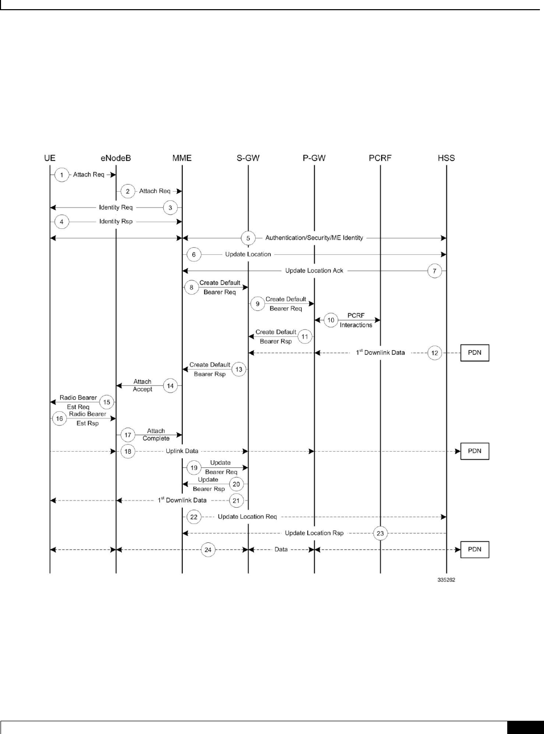
Mobility Management Entity Overview
How the MME Works ▀
Cisco ASR 5x00 Mobility Management Entity Administration Guide ▄
61
Subscriber-initiated Initial Attach Procedure
The following figure and the text that follows describe the message flow for a successful user-initiated subscriber attach
procedure.
Figure 8. Subscriber-initiated Attach (initial) Call Flow

Mobility Management Entity Overview
▀ How the MME Works
▄ Cisco ASR 5x00 Mobility Management Entity Administration Guide
62
Table 1. Subscriber-initiated Attach (initial) Call Flow Description
Step
Description
1
The UE initiates the Attach procedure by the transmission of an Attach Request (IMSI or old GUTI, last visited TAI (if
available), UE Network Capability, PDN Address Allocation, Protocol Configuration Options, Attach Type) message
together with an indication of the Selected Network to the eNodeB. IMSI is included if the UE does not have a valid GUTI
available. If the UE has a valid GUTI, it is included.
2
The eNodeB derives the MME from the GUTI and from the indicated Selected Network. If that MME is not associated
with the eNodeB, the eNodeB selects an MME using an “MME selection function”. The eNodeB forwards the Attach
Request message to the new MME contained in a S1-MME control message (Initial UE message) together with the
Selected Network and an indication of the E-UTRAN Area identity, a globally unique E-UTRAN ID of the cell from where
it received the message to the new MME.
3
If the UE is unknown in the MME, the MME sends an Identity Request to the UE to request the IMSI.
4
The UE responds with Identity Response (IMSI).
5
If no UE context for the UE exists anywhere in the network, authentication is mandatory. Otherwise this step is optional.
However, at least integrity checking is started and the ME Identity is retrieved from the UE at Initial Attach. The
authentication functions, if performed this step, involves AKA authentication and establishment of a NAS level security
association with the UE in order to protect further NAS protocol messages.
6
The MME sends an Update Location Request (MME Identity, IMSI, ME Identity) to the HSS.
7
The HSS acknowledges the Update Location message by sending an Update Location Ack to the MME. This message also
contains the Insert Subscriber Data (IMSI, Subscription Data) Request. The Subscription Data contains the list of all APNs
that the UE is permitted to access, an indication about which of those APNs is the Default APN, and the 'EPS subscribed
QoS profile' for each permitted APN. If the Update Location is rejected by the HSS, the MME rejects the Attach Request
from the UE with an appropriate cause.
8
The MME selects an S-GW using “Serving GW selection function” and allocates an EPS Bearer Identity for the Default
Bearer associated with the UE. If the PDN subscription context contains no P-GW address the MME selects a P-GW as
described in clause “PDN GW selection function”. Then it sends a Create Default Bearer Request (IMSI, MME Context ID,
APN, RAT type, Default Bearer QoS, PDN Address Allocation, AMBR, EPS Bearer Identity, Protocol Configuration
Options, ME Identity, User Location Information) message to the selected S-GW.
9
The S-GW creates a new entry in its EPS Bearer table and sends a Create Default Bearer Request (IMSI, APN, S-GW
Address for the user plane, S-GW TEID of the user plane, S-GW TEID of the control plane, RAT type, Default Bearer
QoS, PDN Address Allocation, AMBR, EPS Bearer Identity, Protocol Configuration Options, ME Identity, User Location
Information) message to the P-GW.
10
If dynamic PCC is deployed, the P-GW interacts with the PCRF to get the default PCC rules for the UE. The IMSI, UE IP
address, User Location Information, RAT type, AMBR are provided to the PCRF by the P-GW if received by the previous
message.
11
The P-GW returns a Create Default Bearer Response (P-GW Address for the user plane, P-GW TEID of the user plane, P-
GW TEID of the control plane, PDN Address Information, EPS Bearer Identity, Protocol Configuration Options) message
to the S-GW. PDN Address Information is included if the P-GW allocated a PDN address Based on PDN Address
Allocation received in the Create Default Bearer Request. PDN Address Information contains an IPv4 address for IPv4
and/or an IPv6 prefix and an Interface Identifier for IPv6. The P-GW takes into account the UE IP version capability
indicated in the PDN Address Allocation and the policies of operator when the P-GW allocates the PDN Address
Information. Whether the IP address is negotiated by the UE after completion of the Attach procedure, this is indicated in
the Create Default Bearer Response.
12
The Downlink (DL) Data can start flowing towards S-GW. The S-GW buffers the data.

Mobility Management Entity Overview
How the MME Works ▀
Cisco ASR 5x00 Mobility Management Entity Administration Guide ▄
63
Step
Description
13
The S-GW returns a Create Default Bearer Response (PDN Address Information, S-GW address for User Plane, S-GW
TEID for User Plane, S-GW Context ID, EPS Bearer Identity, Protocol Configuration Options) message to the new MME.
PDN Address Information is included if it was provided by the P-GW.
14
The new MME sends an Attach Accept (APN, GUTI, PDN Address Information, TAI List, EPS Bearer Identity, Session
Management Configuration IE, Protocol Configuration Options) message to the eNodeB.
15
The eNodeB sends Radio Bearer Establishment Request including the EPS Radio Bearer Identity to the UE. The Attach
Accept message is also sent along to the UE.
16
The UE sends the Radio Bearer Establishment Response to the eNodeB. In this message, the Attach Complete message
(EPS Bearer Identity) is included.
17
The eNodeB forwards the Attach Complete (EPS Bearer Identity) message to the MME.
18
The Attach is complete and UE sends data over the default bearer. At this time the UE can send uplink packets towards the
eNodeB which are then tunnelled to the S-GW and P-GW.
19
The MME sends an Update Bearer Request (eNodeB address, eNodeB TEID) message to the S-GW.
20
The S-GW acknowledges by sending Update Bearer Response (EPS Bearer Identity) message to the MME.
21
The S-GW sends its buffered downlink packets.
22
After the MME receives Update Bearer Response (EPS Bearer Identity) message, if an EPS bearer was established and the
subscription data indicates that the user is allowed to perform handover to non-3GPP accesses, and if the MME selected a
P-GW that is different from the P-GW address which was indicated by the HSS in the PDN subscription context, the MME
sends an Update Location Request including the APN and P-GW address to the HSS for mobility with non-3GPP accesses.
23
The HSS stores the APN and P-GW address pair and sends an Update Location Response to the MME.
24
Bidirectional data is passed between the UE and PDN.
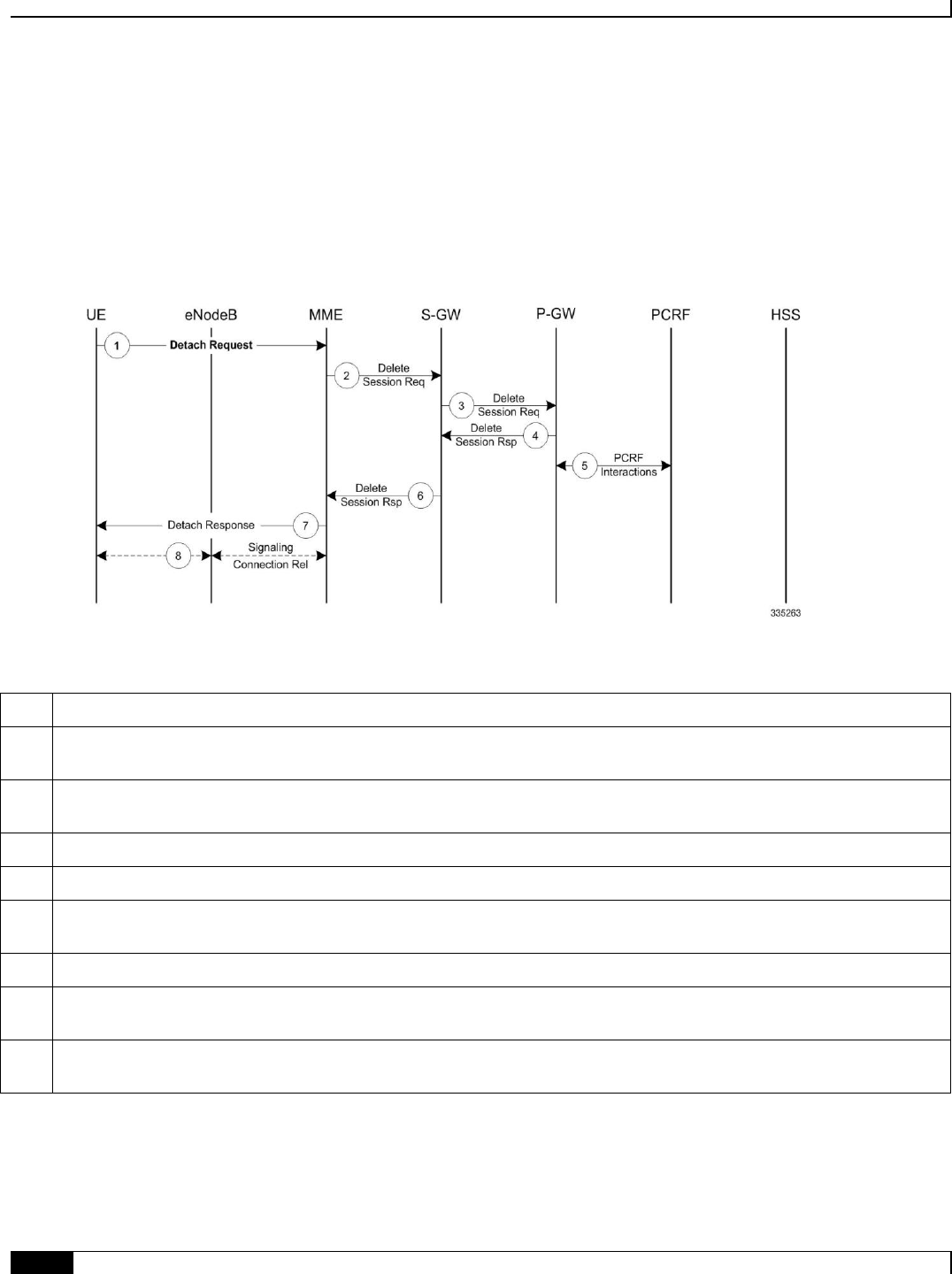
Mobility Management Entity Overview
▀ How the MME Works
▄ Cisco ASR 5x00 Mobility Management Entity Administration Guide
64
Subscriber-initiated Detach Procedure
The following figure and the text that follows describe the message flow for a user-initiated subscriber de-registration
procedure.
Figure 9. Subscriber-initiated Detach Call Flow
Table 2. Subscriber-initiated Detach Call Flow Description
Step
Description
1
The UE sends NAS message Detach Request (GUTI, Switch Off) to the MME. Switch Off indicates whether detach is due
to a switch off situation or not.
2
The active EPS Bearers in the S-GW regarding this particular UE are deactivated by the MME sending a Delete Bearer
Request (TEID) message to the S-GW.
3
The S-GW sends a Delete Bearer Request (TEID) message to the P-GW.
4
The P-GW acknowledges with a Delete Bearer Response (TEID) message.
5
The P-GW may interact with the PCRF to indicate to the PCRF that EPS Bearer is released if PCRF is applied in the
network.
6
The S-GW acknowledges with a Delete Bearer Response (TEID) message.
7
If Switch Off indicates that the detach is not due to a switch off situation, the MME sends a Detach Accept message to the
UE.
8
The MME releases the S1-MME signalling connection for the UE by sending an S1 Release command to the eNodeB with
Cause = Detach.
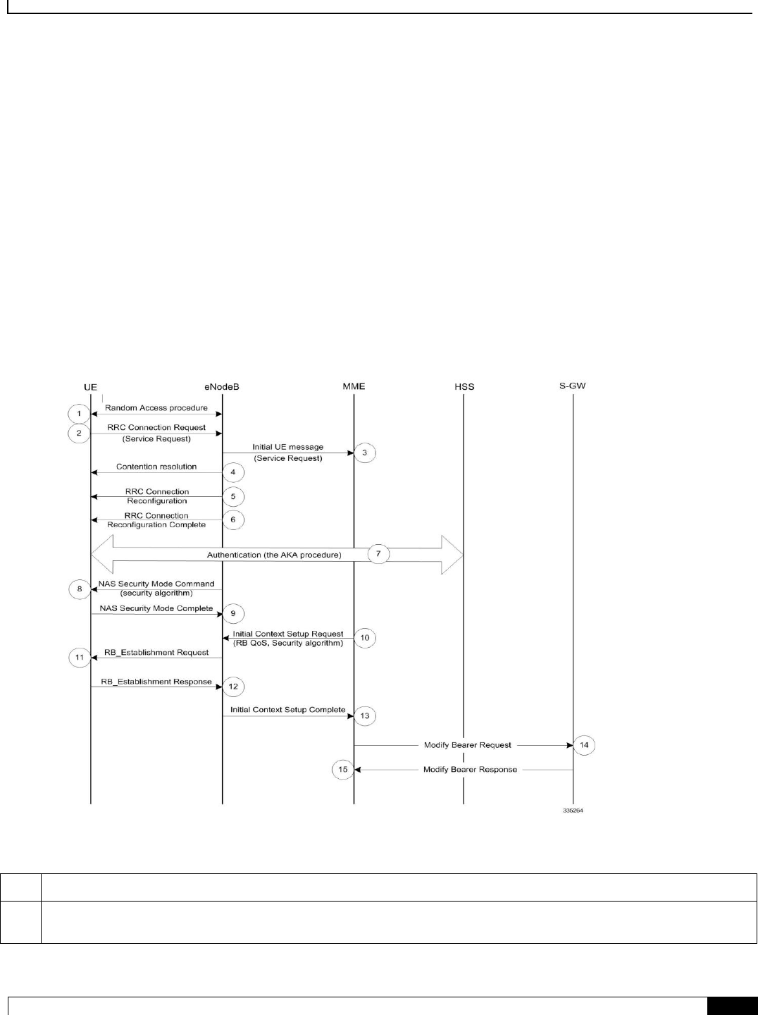
Mobility Management Entity Overview
How the MME Works ▀
Cisco ASR 5x00 Mobility Management Entity Administration Guide ▄
65
Service Request Procedures
Service Request procedures are used to establish a secure connection to the MME as well as request resource
reservation for active contexts. The MME allows configuration of the following service request procedures:
UE-initiated Service Request Procedure
Network-initiated Service Request Procedure
UE-initiated Service Request Procedure
The call flow in this section describes the process for re-connecting an idle UE.
The following figure and the text that follows describe the message flow for a successful UE-initiated service request
procedure.
Figure 10. UE-initiated Service Request Message Flow
Table 3. UE-initiated Service Request Message Flow Description
Step
Description
1
(NAS) The UE sends a Network Access Signaling (NAS) message Service Request (S-TMSI) towards the MME
encapsulated in an RRC message to the eNodeB.

Mobility Management Entity Overview
▀ How the MME Works
▄ Cisco ASR 5x00 Mobility Management Entity Administration Guide
66
Step
Description
2
The eNodeB forwards NAS message to the MME. The NAS message is encapsulated in an S1-AP: Initial UE message
(NAS message, TAI+ECGI of the serving cell).
3
NAS authentication procedures may be performed.
4
The MME sends an S1-AP Initial Context Setup Request (S-GW address, S1-TEID(s) (UL), EPS Bearer QoS(s), Security
Context, MME Signalling Connection Id, Handover Restriction List) message to the eNodeB. This step activates the radio
and S1 bearers for all the active EPS Bearers. The eNodeB stores the Security Context, MME Signalling Connection Id,
EPS Bearer QoS(s) and S1-TEID(s) in the UE RAN context.
5
The eNodeB performs the radio bearer establishment procedure.
6
The uplink data from the UE can now be forwarded by eNodeB to the S-GW. The eNodeB sends the uplink data to the S-
GW address and TEID provided in step 4.
7
The eNodeB sends an S1-AP message Initial Context Setup Complete message (eNodeB address, List of accepted EPS
bearers, List of rejected EPS bearers, S1 TEID(s) (DL)) to the MME.
8
The MME sends a Modify Bearer Request message (eNodeB address, S1 TEID(s) (DL) for the accepted EPS bearers, RAT
Type) to the S-GW. The S-GW is now able to transmit downlink data towards the UE.
9
The S-GW sends a Modify Bearer Response message to the MME.
Network-initiated Service Request Procedure
The call flow in this section describes the process for re-connecting an idle UE when a downlink data packet is received
from the PDN.
The following figure and the text that follows describe the message flow for a successful network-initiated service
request procedure:
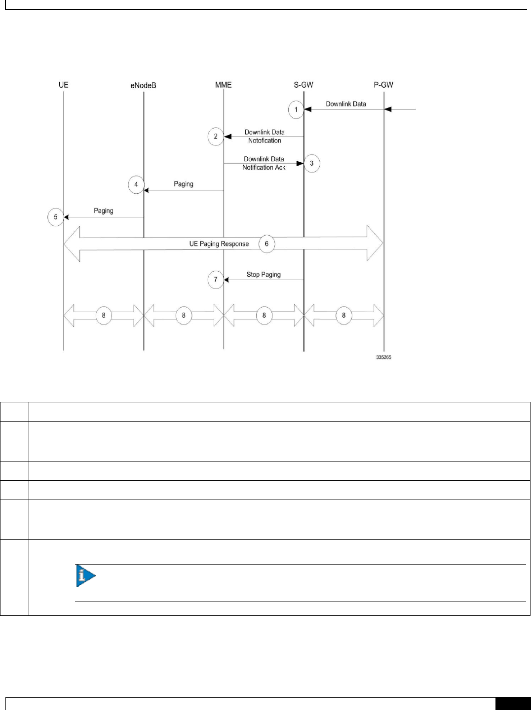
Mobility Management Entity Overview
How the MME Works ▀
Cisco ASR 5x00 Mobility Management Entity Administration Guide ▄
67
Figure 11. Network-initiated Service Request Message Flow
Table 4. Network-initiated Service Request Message Flow Description
Step
Description
1
A downlink data packet is received on the S-GW from PDN for the targeted UE. The S-GW checks to see if the UE is user-
plane connected (the S-GW context data indicates that there is no downlink user plane (TEID)). The downlink data is
buffered and the S-GW identifies which MME is serving the intended UE.
2
The S-GW sends a Downlink Data Notification message to the MME for the targeted UE.
3
The MME responds with a Downlink Data Notification Acknowledgement message to the S-GW.
4
The MME send a Paging Request to the eNodeB for the targeted UE. The Paging Request contains the NAS ID for paging,
TAI(s), the UE identity based DRX index, and the Paging DRX length. The Paging Request is sent to each eNodeB
belonging to the tracking area(s) where the UE is registered.
5
The eNodeB broadcasts the Paging Request in its coverage area for the UE.
Important: Steps 4 and 5 are skipped if the MME has a signalling connection over the S1-MME towards
the UE.

Mobility Management Entity Overview
▀ How the MME Works
▄ Cisco ASR 5x00 Mobility Management Entity Administration Guide
68
Step
Description
6
Upon receipt of the Paging indication in the E-UTRAN access network, the UE initiates the UE-triggered Service Request
procedure and the eNodeB starts messaging through the UE Paging Response.
The MME supervises the paging procedure with a timer. If the MME receives no Paging Response from the UE, it
retransmits the Paging Request. If the MME receives no response from the UE after the retransmission, it uses the
Downlink Data Notification Reject message to notify the S-GW about the paging failure.
7
The S-GW sends a Stop Paging message to MME.
8
The buffered downlink data is sent to the identified UE.

Mobility Management Entity Overview
Supported Standards ▀
Cisco ASR 5x00 Mobility Management Entity Administration Guide ▄
69
Supported Standards
The MME complies with the following standards for 3GPP LTE/EPS wireless networks.
3GPP References
IETF References
Object Management Group (OMG) Standards
3GPP References
Release 10 Supported Standards
3GPP TS 23.216 V10.5.0 (2012-12): 3rd Generation Partnership Project; Technical Specification Group Services
and System Aspects; Single Radio Voice Call Continuity (SRVCC); Stage 2 (Release 10)
3GPP TS 23.272 V10.9.0 (2012-12): 3rd Generation Partnership Project; Technical Specification Group Services
and System Aspects; Circuit Switched (CS) fallback in Evolved Packet System (EPS); Stage 2 (Release 10)
3GPP TS 24.301 V10.9.0 (2012-12): 3rd Generation Partnership Project; Technical Specification Group Core
Network and Terminals; Non-Access-Stratum (NAS) protocol for Evolved Packet System (EPS); Stage 3
(Release 10)
3GPP TS 29.118 V10.9.0 (2012-09): 3rd Generation Partnership Project; Technical Specification Group Core
Network and Terminals; Mobility Management Entity (MME) - Visitor Location Register (VLR) SGs interface
specification (Release 10)
3GPP TS 29.172 V10.1.0 (2011-09): 3rd Generation Partnership Project; Technical Specification Group Core
Network and Terminals; Location Services (LCS); Evolved Packet Core (EPC) LCS Protocol (ELP) between
the Gateway Mobile Location Centre (GMLC) and the Mobile Management Entity (MME); SLg interface
(Release 10)
3GPP TS 29.272 V10.5.0 (2011-12): 3rd Generation Partnership Project; Technical Specification Group Core
Network and Terminals; 3GPP Evolved Packet System (EPS); Mobility Management Entity (MME) and
Serving GPRS Support Node (SGSN) related interfaces based on Diameter protocol (Release 10)
3GPP TS 29.274 V10.5.0 (2011-12): 3rd Generation Partnership Project; Technical Specification Group Core
Network and Terminals; 3GPP Evolved Packet System (EPS); Evolved General Packet Radio Service (GPRS)
Tunnelling Protocol for Control plane (GTPv2-C); Stage 3 (Release 10)
3GPP TS 29.280 V10.4.0 (2012-06): 3rd Generation Partnership Project; Technical Specification Group Core
Network and Terminals; 3GPP Evolved Packet System (EPS); 3GPP Sv interface (MME to MSC, and SGSN
to MSC) for SRVCC (Release 10)
3GPP TS 36.413 V10.5.0 (2012-03): 3rd Generation Partnership Project; Technical Specification Group Radio
Access Network; Evolved Universal Terrestrial Radio Access Network (E-UTRAN); S1 Application Protocol
(S1AP) (Release 10)
Release 9 Supported Standards
3GPP TS 23.216 V9.6.0 (2010-12): 3rd Generation Partnership Project; Technical Specification Group Services
and System Aspects; Single Radio Voice Call Continuity (SRVCC); Stage 2 (Release 9)

Mobility Management Entity Overview
▀ Supported Standards
▄ Cisco ASR 5x00 Mobility Management Entity Administration Guide
70
3GPP TS 23.272 V9.6.0 (2010-12): 3rd Generation Partnership Project; Technical Specification Group Services
and System Aspects; Circuit Switched (CS) fallback in Evolved Packet System (EPS); Stage 2 (Release 9)
3GPP TS 23.401 V9.6.0 (2010-09): 3rd Generation Partnership Project; Technical Specification Group Services
and System Aspects; General Packet Radio Service (GPRS) enhancements for Evolved Universal Terrestrial
Radio Access Network (E-UTRAN) access (Release 9)
3GPP TS 24.301 V9.5.0 (2010-12): 3rd Generation Partnership Project; Technical Specification Group Core
Network and Terminals; Non-Access-Stratum (NAS) protocol for Evolved Packet System (EPS); Stage 3
(Release 9)
3GPP TS 29.118 V9.4.0 (2010-12): 3rd Generation Partnership Project; Technical Specification Group Core
Network and Terminals; Mobility Management Entity (MME) - Visitor Location Register (VLR) SGs interface
specification (Release 9)
3GPP TS 29.272 V9.5.0 (2010-12): 3rd Generation Partnership Project; Technical Specification Group Core
Network and Terminals; 3GPP Evolved Packet System (EPS); Mobility Management Entity (MME) and
Serving GPRS Support Node (SGSN) related interfaces based on Diameter protocol (Release 9)
3GPP TS 29.274 V 9.4.0 (2010-09): 3rd Generation Partnership Project; Technical Specification Group Core
Network and Terminals; 3GPP Evolved Packet System (EPS); Evolved General Packet Radio Service (GPRS)
Tunnelling Protocol for Control plane (GTPv2-C); Stage 3 (Release 9)
3GPP TS 29.280 V 9.5.0 (2010-12): 3rd Generation Partnership Project; Technical Specification Group Core
Network and Terminals; 3GPP Evolved Packet System (EPS); 3GPP Sv interface (MME to MSC, and SGSN
to MSC) for SRVCC (Release 9)
3GPP TS 33.401 V9.5.0 (2010-10): 3rd Generation Partnership Project; Technical Specification Group Services
and System Aspects; 3GPP System Architecture Evolution (SAE): Security Architecture; (Release 9)
3GPP TS 36.410 V9.2.0 (2010-06): 3rd Generation Partnership Project; Technical Specification Group Radio
Access Network; Evolved Universal Terrestrial Access Network (E-UTRAN); S1 General aspects and
principles (Release 9)
3GPP TS 36.411 V9.0.0 (2009-12): 3rd Generation Partnership Project; Technical Specification Group Radio
Access Network; Evolved Universal Terrestrial Access Network (E-UTRAN); S1 layer 1 (Release 9)
3GPP TS 36.413 V9.5.0 (2010-12): 3rd Generation Partnership Project; Technical Specification Group Radio
Access Network; Evolved Universal Terrestrial Radio Access Network (E-UTRAN); S1 Application Protocol
(S1AP) (Release 9)
IETF References
RFC-768, User Datagram Protocol (UPD), August 1980
RFC-791, Internet Protocol (IP), September 1982
RFC-793, Transmission Control Protocol (TCP), September 1981
RFC-894, A Standard for the Transmission of IP Datagrams over Ethernet Networks, April 1984
RFC-1089, SNMP over Ethernet, February 1989
RFC-1144, Compressing TCP/IP headers for low-speed serial links, February 1990
RFC-1155, Structure & identification of management information for TCP/IP-based internets, May 1990
RFC-1157, Simple Network Management Protocol (SNMP) Version 1, May 1990
RFC-1212, Concise MIB Definitions, March 1991

Mobility Management Entity Overview
Supported Standards ▀
Cisco ASR 5x00 Mobility Management Entity Administration Guide ▄
71
RFC-1213, Management Information Base for Network Management of TCP/IP-based Internets: MIB-II, March
1991
RFC-1215, A Convention for Defining Traps for use with the SNMP, March 1991
RFC-1224, Techniques for managing asynchronously generated alerts, May 1991
RFC-1256, ICMP Router Discovery Messages, September 1991
RFC-1305, Network Time Protocol (Version 3) Specification, Implementation and Analysis, March 1992
RFC-1332, The PPP Internet Protocol Control Protocol (IPCP), May 1992
RFC-1398, Definitions of Managed Objects for the Ethernet-Like Interface Types, January 1993
RFC-1418, SNMP over OSI, March 1993
RFC-1570, PPP LCP Extensions, January 1994
RFC-1643, Definitions of Managed Objects for the Ethernet-like Interface Types, July 1994
RFC-1701, Generic Routing Encapsulation (GRE), October 1994
RFC-1850, OSPF Version 2 Management Information Base, November 1995
RFC-1901, Introduction to Community-based SNMPv2, January 1996
RFC-1902, Structure of Management Information for Version 2 of the Simple Network Management Protocol
(SNMPv2), January 1996
RFC-1903, Textual Conventions for Version 2 of the Simple Network Management Protocol (SNMPv2),
January 1996
RFC-1904, Conformance Statements for Version 2 of the Simple Network Management Protocol (SNMPv2),
January 1996
RFC-1905, Protocol Operations for Version 2 of the Simple Network Management Protocol (SNMPv2), January
1996
RFC-1906, Transport Mappings for Version 2 of the Simple Network Management Protocol (SNMPv2), January
1996
RFC-1907, Management Information Base for Version 2 of the Simple Network Management Protocol
(SNMPv2), January 1996
RFC-1908, Coexistence between Version 1 and Version 2 of the Internet-standard Network Management
Framework, January 1996
RFC-1918, Address Allocation for Private Internets, February 1996
RFC-1919, Classical versus Transparent IP Proxies, March 1996
RFC-2002, IP Mobility Support, May 1995
RFC-2003, IP Encapsulation within IP, October 1996
RFC-2004, Minimal Encapsulation within IP, October 1996
RFC-2005, Applicability Statement for IP Mobility Support, October 1996
RFC-2118, Microsoft Point-to-Point Compression (MPPC) Protocol, March 1997
RFC 2131, Dynamic Host Configuration Protocol
RFC-2136, Dynamic Updates in the Domain Name System (DNS UPDATE)
RFC-2211, Specification of the Controlled-Load Network Element Service
RFC-2246, The Transport Layer Security (TLS) Protocol Version 1.0, January 1999

Mobility Management Entity Overview
▀ Supported Standards
▄ Cisco ASR 5x00 Mobility Management Entity Administration Guide
72
RFC-2328, OSPF Version 2, April 1998
RFC-2344, Reverse Tunneling for Mobile IP, May 1998
RFC-2394, IP Payload Compression Using DEFLATE, December 1998
RFC 2401, Security Architecture for the Internet Protocol
RFC 2402, IP Authentication Header (AH)
RFC 2406, IP Encapsulating Security Payload (ESP)
RFC 2409, The Internet Key Exchange (IKE)
RFC-2460, Internet Protocol Version 6 (IPv6)
RFC-2461, Neighbor Discovery for IPv6
RFC-2462, IPv6 Stateless Address Autoconfiguration
RFC-2486, The Network Access Identifier (NAI), January 1999
RFC-2571, An Architecture for Describing SNMP Management Frameworks, April 1999
RFC-2572, Message Processing and Dispatching for the Simple Network Management Protocol (SNMP), April
1999
RFC-2573, SNMP Applications, April 1999
RFC-2574, User-based Security Model (USM) for version 3 of the Simple Network Management Protocol
(SNMPv3), April 1999
RFC-2597, Assured Forwarding PHB Group, June 1999
RFC-2598, Expedited Forwarding PHB, June 1999
RFC-2618, RADIUS Authentication Client MIB, June 1999
RFC-2620, RADIUS Accounting Client MIB, June 1999
RFC-2661, Layer Two Tunneling Protocol “L2TP”, August 1999
RFC-2697, A Single Rate Three Color Marker, September 1999
RFC-2698, A Two Rate Three Color Marker, September 1999
RFC-2784, Generic Routing Encapsulation (GRE) - March 2000, IETF
RFC-2794, Mobile IP Network Access Identifier Extension for IPv4, March 2000
RFC-2809, Implementation of L2TP Compulsory Tunneling via RADIUS, April 2000
RFC-2845, Secret Key Transaction Authentication for DNS (TSIG), May 2000
RFC-2865, Remote Authentication Dial In User Service (RADIUS), June 2000
RFC-2866, RADIUS Accounting, June 2000
RFC-2867, RADIUS Accounting Modifications for Tunnel Protocol Support, June 2000
RFC-2868, RADIUS Attributes for Tunnel Protocol Support, June 2000
RFC-2869, RADIUS Extensions, June 2000
RFC-3007, Secure Domain Name System (DNS) Dynamic Update, November 2000
RFC-3012, Mobile IPv4 Challenge/Response Extensions, November 2000
RFC-3056, Connection of IPv6 Domains via IPv4 Clouds, February 2001
RFC-3101 OSPF-NSSA Option, January 2003

Mobility Management Entity Overview
Supported Standards ▀
Cisco ASR 5x00 Mobility Management Entity Administration Guide ▄
73
RFC-3143, Known HTTP Proxy/Caching Problems, June 2001
RFC-3193, Securing L2TP using IPSEC, November 2001
RFC-3314, Recommendations for IPv6 in Third Generation Partnership Project (3GPP) Standards, September
2002
RFC-3316, Internet Protocol Version 6 (IPv6) for Some Second and Third Generation Cellular Hosts, April 2003
RFC-3706, A Traffic-Based Method of Detecting Dead Internet Key Exchange (IKE) Peers, February 2004
RFC-3543, Registration Revocation in Mobile IPv4, August 2003
RFC 3588, Diameter Base Protocol, September 2003
RFC 4006, Diameter Credit-Control Application, August 2005
Draft, Route Optimization in Mobile IP
Draft, Generalized Key Distribution Extensions for Mobile IP
Draft, AAA Keys for Mobile IP
Object Management Group (OMG) Standards
CORBA 2.6 Specification 01-09-35, Object Management Group
Cisco ASR 5x00 Mobility Management Entity Administration Guide ▄
75
Chapter 2
Mobility Management Entity Configuration
This chapter provides configuration information for the Mobility Management Entity (MME).
Because each wireless network is unique, the system is designed with a variety of parameters allowing it to perform in
various wireless network environments. In this chapter, only the minimum set of parameters are provided to make the
system operational. Optional configuration commands specific to the MME product are located in the Command Line
Interface Reference.
The following procedures are located in this chapter:
Configuring the System as a Standalone MME (base configuration)
Configuring Optional Features on the MME
Important: At least one Packet Services Card (PSC/PSC2) must be made active prior to service configuration.
Information and instructions for configuring PSCs/PSC2s to be active can be found in the System Settings chapter of the
System Administration Guide.
Caution: While configuring any base-service or enhanced feature, it is highly recommended to avoid
conflicting or blocked IP addresses and port numbers when binding or assigning these to your configuration. In
association with some service steering or access control features, the use of inappropriate port numbers may result in
communication loss. Refer to the respective feature configuration document carefully before assigning any port number
or IP address for communication with internal or external networks.
Important: Information about all commands in this chapter can be found in the Command Line Interface
Reference.

Mobility Management Entity Configuration
▀ Configuring the System as a Standalone MME (base configuration)
▄ Cisco ASR 5x00 Mobility Management Entity Administration Guide
76
Configuring the System as a Standalone MME (base
configuration)
This section provides a high-level series of steps and associated configuration file examples for configuring the system
to perform as an MME in a test environment.
The configuration in this section assumes the following:
A single context for all interfaces and services (excepting the Local context)
static S-GW/P-GW selection (MME Policy configuration)
Information provided in this section includes the following:
Information Required
MME Configuration
Information Required
The following sections describe the minimum amount of information required to configure and make the MME
operational on the network. To make the process more efficient, it is recommended that this information be available
prior to configuring the system.
There are additional configuration parameters that are not described in this section. These parameters deal mostly with
fine-tuning the operation of the S-GW in the network. Information on these parameters can be found in the appropriate
sections of the Command Line Interface Reference.
Required MME Context Configuration Information
The following table lists the information that is required to configure the MME context.
Table 5. Required Information for MME Context Configuration
Required
Information
Description
MME context name
An identification string from 1 to 79 characters (alpha and/or numeric) by which the MME context is
recognized by the system.
S1-MME Interface Configuration (To/from eNodeB)
Interface name
An identification string between 1 and 79 characters (alpha and/or numeric) by which the interface is
recognized by the system.
Multiple names are needed if multiple interfaces will be configured.
IP address and
subnet
IPv4 or IPv6 address assigned to the S1-MME interface. This address will be used for binding the SCTP
(local bind address(es)) to communicate with the eNodeBs using S1-AP.
Multiple addresses and subnets are needed if multiple interfaces will be configured.

Mobility Management Entity Configuration
Configuring the System as a Standalone MME (base configuration) ▀
Cisco ASR 5x00 Mobility Management Entity Administration Guide ▄
77
Required
Information
Description
Physical port
number
The physical port to which the interface will be bound. Ports are identified by the chassis slot number where
the line card resides followed by the number of the physical connector on the card. For example, port 17/1
identifies connector number 1 on the card in slot 17.
A single physical port can facilitate multiple interfaces.
S11 Interface Configuration (To/from S-GW)
Interface name
An identification string between 1 and 79 characters (alpha and/or numeric) by which the interface is
recognized by the system.
Multiple names are needed if multiple interfaces will be configured.
IP address and
subnet
IPv4 address assigned to the S11 interface.
Multiple addresses and subnets are needed if multiple interfaces will be configured.
Physical port
number
The physical port to which the interface will be bound. Ports are identified by the chassis slot number where
the line card resides followed by the number of the physical connector on the card. For example, port 17/1
identifies connector number 1 on the card in slot 17.
A single physical port can facilitate multiple interfaces.
S6a Interface Configuration (To/from HSS)
Interface name
An identification string between 1 and 79 characters (alpha and/or numeric) by which the interface is
recognized by the system.
Multiple names are needed if multiple interfaces will be configured.
IP address and
subnet
IPv4 or IPv6 addresses assigned to the S6a interface.
Multiple addresses and subnets are needed if multiple interfaces will be configured.
Physical port
number
The physical port to which the interface will be bound. Ports are identified by the chassis slot number where
the line card resides followed by the number of the physical connector on the card. For example, port 17/1
identifies connector number 1 on the card in slot 17.
A single physical port can facilitate multiple interfaces.
S6a Diameter Endpoint Configuration
End point name
An identification string from 1 to 63 characters (alpha and/or numeric) by which the S6a Diameter endpoint
configuration is recognized by the system.
Origin realm name
An identification string between 1 through 127 characters.
The realm is the Diameter identity. The originator’s realm is present in all Diameter messages and is
typically the company or service name.
Origin host name
An identification string from 1 to 255 characters (alpha and/or numeric) by which the S6a origin host is
recognized by the system.
Origin host address
The IP address of the S6a interface.
Peer name
The S6a endpoint name described above.
Peer realm name
The S6a origin realm name described above.
Peer address and
port number
The IP address and port number of the HSS.
Route-entry peer
The S6a endpoint name described above.
S13 Interface Configuration (To/from EIR)

Mobility Management Entity Configuration
▀ Configuring the System as a Standalone MME (base configuration)
▄ Cisco ASR 5x00 Mobility Management Entity Administration Guide
78
Required
Information
Description
Interface name
An identification string between 1 and 79 characters (alpha and/or numeric) by which the interface is
recognized by the system.
Multiple names are needed if multiple interfaces will be configured.
IP address and
subnet
IPv4 or IPv6 addresses assigned to the S13 interface.
Multiple addresses and subnets are needed if multiple interfaces will be configured.
Physical port
number
The physical port to which the interface will be bound. Ports are identified by the chassis slot number where
the line card resides followed by the number of the physical connector on the card. For example, port 17/1
identifies connector number 1 on the card in slot 17.
A single physical port can facilitate multiple interfaces.
S13 Diameter Endpoint Configuration
End point name
An identification string from 1 to 63 characters (alpha and/or numeric) by which the S13 Diameter endpoint
configuration is recognized by the system.
Origin realm name
An identification string between 1 through 127 characters.
The realm is the Diameter identity. The originator’s realm is present in all Diameter messages and is
typically the company or service name.
Origin host name
An identification string from 1 to 255 characters (alpha and/or numeric) by which the S13 origin host is
recognized by the system.
Origin host address
The IP address of the S13 interface.
Peer name
The S13 endpoint name described above.
Peer realm name
The S13 origin realm name described above.
Peer address and
port number
The IP address and port number of the EIR.
Route-entry peer
The S13 endpoint name described above.
MME Service Configuration
MME service name
An identification string from 1 to 63 characters (alpha and/or numeric) by which the MME service can be
identified on the system. It is configured in the Context configuration mode.
Multiple names are needed if multiple MME services will be configured.
PLMN identifier
The identifier of Public Land Mobile Network (PLMN) of which MME belongs to. PLMN identifier is
consisting of MCC and MNC.
MME identifier
The identifier of MME node. The MME Id is consisting of MME group and MME code.
TAI management
database name
An identification string from 1 to 64 characters (alpha and/or numeric) by which the TAI management
database service can be associated with the MME service.
This is required for static S-GW selection. Refer to the Required MME Policy Configuration Information
section below.
P-GW IP address
IPv4 or IPv6 address of a PDN Gateway (P-GW). This is required for static S-GW/P-GW selection.
eGTP Service Configuration
eGTP service name
An identification string from 1 to 63 characters (alpha and/or numeric) by which the eGTP service can be
associated with MME system.
Multiple names are needed if multiple eGTP services will be used.

Mobility Management Entity Configuration
Configuring the System as a Standalone MME (base configuration) ▀
Cisco ASR 5x00 Mobility Management Entity Administration Guide ▄
79
Required
Information
Description
Interface type
Identifies the type of interface to which the eGTP service is bound. This interface type is “interface-mme”.
GTP-C binding IP
address
The IPv4 address of the S11 interface.
HSS Peer Service Configuration
HSS peer service
name
An identification string from 1 to 63 characters (alpha and/or numeric) by which the HSS peer service is
recognized by the system.
Multiple names are needed if multiple HSS peer services will be used.
Diameter HSS peer
The name for a pre-configured Diameter endpoint, configured on system to associate with this MME
service to access an HSS and an EIR. This is the S6a Diameter endpoint name.
Required MME Policy Configuration Information
The following table lists the information that is required to configure the MME Policy on an MME.
Table 6. Required Information for MME Policy Configuration
Required Information
Description
Tracking Area Identifier (TAI)
management database name
An identification string from 1 to 64 characters (alpha and/or numeric) by which the
TAI management database is recognized by the system.
Tracking Area Identifier (TAI)
management object name
An identification string from 1 to 64 characters (alpha and/or numeric) by which the
TAI management object is recognized by the system.
MCC, MNC, and TAC
The Mobile Country Code, Mobile Network Code, and Tracking Area Code for the S-
GW this management object represents.
S-GW IP address
The IPv4 or IPv6 address of the S-GW this management object represents.
How This Configuration Works
The following figure and supporting text describe how this configuration with a single context is used by the system to
process a subscriber call originating from the GTP LTE network.
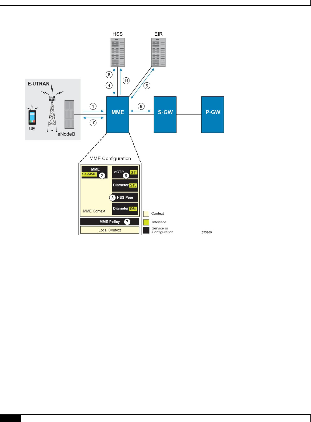
Mobility Management Entity Configuration
▀ Configuring the System as a Standalone MME (base configuration)
▄ Cisco ASR 5x00 Mobility Management Entity Administration Guide
80
1. The eNodeB forwards an Attach Request message from the UE to the MME containing the IMSI, last visited TAI (if
available), the UE’s core network capability, the PDN Type, and the Attach Type.
2. The MME service receives the Attach Request message and references the HSS peer service for authentication and
location resolution.
3. The HSS peer service configuration specifies the Diameter configuration and S6a interface to use to communicate with
the HSS and the Diameter configuration and S13 interface to use to communicate with the Equipment Identity Register
(EIR).
4. Assuming that the MME has no previous security context, it sends an S6a Authentication Request to the HSS and uses the
authentication vectors received in the response to complete the authentication procedure with UE.
5. After authentication, the MME proceeds to do a security setup with the UE. During this procedure, the ME identity is
transferred to the MME which then queries the EIR.
6. The MME then sends an Update Location Request to the HSS and obtains relevant subscription data for the IMSI in the
response.
7. The MME policy is accessed to determine the S-GW and P-GW to which the UE should be attached.
8. The MME uses the S11 interface bound to the eGTP service to communicate with the S-GW specified by the MME
policy configuration.
9. The MME then sends a Create Session Request to S-GW which is also forwarded to the specified P-GW (assuming GTP-
S5/S8) P-GW establishes the S5/S8 GTPU bearers and then responds with a Create-Session-response which is forwarded
to the MME by the S-GW. The S-GW includes the relevant S1-U bearer information.
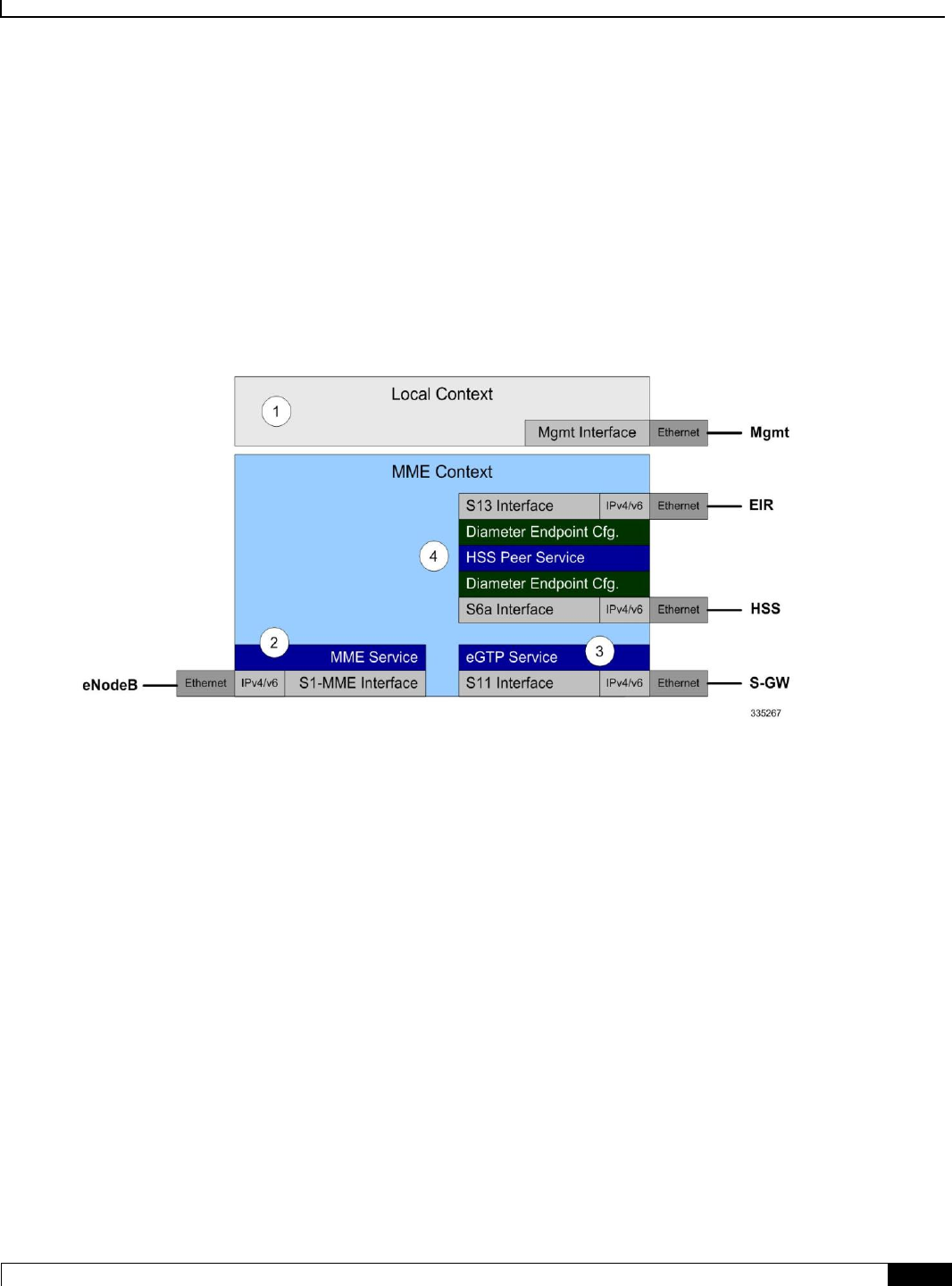
Mobility Management Entity Configuration
Configuring the System as a Standalone MME (base configuration) ▀
Cisco ASR 5x00 Mobility Management Entity Administration Guide ▄
81
10. The MME then sends a NAS Attach Accept embedded in the S1 Init Ctxt Setup request to the eNodeB. The Attach
Accept contains the IP address allocated to the PDN and the temporary identifier (GUTI) assigned to the UE. The MME
waits for positive acknowledgement from both the eNodeB (Init Ctxt Setup response) and UE (Attach Complete). The Init
Ctxt Setup Response contains the S1-U bearer endpoint information. The MME then uses the S11 Modify Bearer Request
to update the eNodeB endpoints with the S-GW. The receipt of the S11 Modify Bearer Response completes the end-to-
end bearer setup.
11. The MME then uses the S6a Notify Request to update the HSS with the APN and P-GW identity.
MME Configuration
To configure the system to perform as a standalone eGTP S-GW, review the following graphic and subsequent steps.
Step 1 Set system configuration parameters such as activating PSCs by applying the example configurations found in the
System Administration Guide.
Step 2 Create the MME context, service, and all interfaces, and bind the S1-MME interface to an IP address by applying the
example configuration in the Creating and Configuring the MME Context and Service section.
Step 3 Create the eGTP service and associate it with the S11 interface by applying the example configuration in the Creating
and Configuring the eGTP Service and Interface Association section.
Step 4 Create the HSS peer service and associate it with the S6a interface and S13 interface by applying the example
configuration in the Creating and Configuring the HSS Peer Service and Interface Associations section.
Step 5 Save your configuration to flash memory, an external memory device, and/or a network location using the Exec mode
command save configuration. For additional information on how to verify and save configuration files, refer to the
System Administration Guide and the Command Line Interface Reference.
Creating and Configuring the MME Context and Service
Use the following example to configure the MME context and all supported interfaces:
configure

Mobility Management Entity Configuration
▀ Configuring the System as a Standalone MME (base configuration)
▄ Cisco ASR 5x00 Mobility Management Entity Administration Guide
82
context <mme_context_name> -noconfirm
interface <s1-mme_intf_name>
ip address <ipv4_address>
exit
interface <s11_intf_name>
ip address <ipv4_address>
exit
interface <s6a_intf_name>
ip address <ipv4_address>
exit
interface <s13_intf_name>
ip address <ipv4_address>
exit
mme-service <mme_svc_name> -noconfirm
mme-id group-id <grp_id> mme-code <mme_code>
plmn-id mcc <mcc_value> mnc <mnc_value>
network-sharing plmnid mcc <mcc_value> mnc <mnc_value> mme-id group-id <id> mme-
code <code>
associate egtp-service <egtp-service_name> context <mme_context_name>
associate hss-peer-service <hss_peer_service_name> context <mme_context_name>
policy attach imei-query-type imei-sv verify-equipment-identity
pgw-address <pgw_ip_address>
bind s1-mme ipv4-address <ip_address>
exit
exit
port ethernet <slot_number/port_number>
no shutdown
bind interface <s1-mme_intf_name> <mme_context_name>
end

Mobility Management Entity Configuration
Configuring the System as a Standalone MME (base configuration) ▀
Cisco ASR 5x00 Mobility Management Entity Administration Guide ▄
83
Notes:
All interfaces in this configuration can also be specified as IPv6 addresses using the ipv6 address command.
Multi-homing is supported on the S1-MME and S6a interfaces. Refer to the Configuring SCTP Multi-homing
Support section in this chapter for more information on configuring multi-homing for the S1-MME and/or S6a
interface(s).
A maximum of 256 services (regardless of type) can be configured per system.
The bind s1-mme command can also be specified as an IPv6 address using the ipv6-address keyword.
The network-sharing command is used to configure an additional PLMN ID for this MME service.
The eGTP service is configured in the following section.
The HSS peer service is configured in the Creating and Configuring the HSS Peer Service and Interface
Associations section.
In the above example, the mobile equipment identity (IMEI) is checked during the attach procedure. This is
configured in the policy attach command. Another option is to check IMEI during the tracking area update
(TAU). This can be accomplished instead of, or, in addition to, the EIR query during the attach procedure. To
check during the TAU, use the policy tau command.
The pgw-address command is used to statically configure P-GW discovery.
Creating and Configuring the eGTP Service and Interface Association
Use the following example to create an eGTP service and associate it with the S11 interface.
configure
context <mme_context_name>
egtp-service <egtp_service_name>
interface-type interface-mme
gtpc bind ipv4-address <s11_infc_ip_address>
exit
exit
port ethernet <slot_number/port_number>
no shutdown
bind interface <s11_interface_name> <mme_context_name>
end
Notes:
The gtpc bind command can be specified as an IPv6 address using the ipv6-address keyword. The
interface specified for S11 communication must also be the same IPv6 address.

Mobility Management Entity Configuration
▀ Configuring the System as a Standalone MME (base configuration)
▄ Cisco ASR 5x00 Mobility Management Entity Administration Guide
84
Creating and Configuring the HSS Peer Service and Interface Associations
Use the following example to create and configure the HSS peer service:
configure
context <mme_context_name>
hss-peer-service hss_peer_service_name
diameter hss-endpoint <hss_endpoint_name> eir-endpoint <eir-endpoint_name>
exit
exit
diameter endpoint <hss-endpoint_name>
origin realm <realm_name>
origin host <name> address <S6a_interface_address>
peer <peer_name> realm <realm_name> address <hss_ip_address>
route-entry realm <realm_name> peer <peer_name>
exit
diameter endpoint <eir-endpoint_name>
origin realm <realm_name>
origin host <name> address <S13_interface_address>
peer <peer_name> realm <realm_name> address <eir_ip_address>
route-entry realm <realm_name> peer <peer_name>
exit
port ethernet <slot_number/port_number>
no shutdown
bind interface <s6a_interface_name> <mme_context_name>
exit
port ethernet <slot_number/port_number>
no shutdown
bind interface <s13_interface_name> <mme_context_name>
end

Mobility Management Entity Configuration
Configuring the System as a Standalone MME (base configuration) ▀
Cisco ASR 5x00 Mobility Management Entity Administration Guide ▄
85
Notes:
The origin host and peer commands can accept multiple IP addresses supporting multi-homing on each
endpoint. Refer to the Configuring SCTP Multi-homing Support section for information on configuring SCTP
multi-homing for the S6a interface.
Configuring Dynamic Destination Realm Construction for Foreign Subscribers
For a foreign subscriber, the MME does not know the HSS nodes in all the foreign PLMNs. In this case the MME routes
S6a/S6d requests directed to foreign PLMNs via a Diameter Routing Agent (DRA) using only the destination realm.
The DRA in turn routes the request to the correct HSS based on the destination realm. In order to accomplish this, the
MME needs to dynamically construct requests to the DRA/HSS with a Destination Realm representing the foreign
PLMN of the UE.
The MME can be configured to derive the EPC Home Network Realm/Domain based on the user's IMSI (MNC and
MCC values) and use it as the Destination Realm in all diameter messages.
For home subscribers, the MME will always use the configured peer realm as destination-realm, regardless if dynamic-
destination-realm is enabled.
Because MNCs can be 2 or 3 digits long, to provide the ability for an operator to configure the MCC and MNC of
foreign PLMNs, the operator policy of the subscriber map is used to determine the MNC value and the length of the
MNC. The following steps outline how this configuration can be implemented.
First, enable the dynamic destination realm functionality for the HSS Peer Service:
configure
context ctxt_name
hss-peer-service HSS1
dynamic-destination-realm
Then configure the foreign PLMNs in the LTE subscriber map. For example:
configure
lte-policy
subscriber map SM1
precedence 10 match-criteria imsi mcc 232 mnc 11 operator-policy-name OP.HOME
precedence 20 match-criteria imsi mcc 374 mnc 130 msin first 700000000 last
800000000 operator-policy-name OP.ROAMING
Then associate the subscriber map to the MME Service. For example:
configure
context ingress
mme-service mmesvc
associate subscriber-map SM1

Mobility Management Entity Configuration
▀ Configuring the System as a Standalone MME (base configuration)
▄ Cisco ASR 5x00 Mobility Management Entity Administration Guide
86
A static route entry must also be added in the diameter endpoint configuration for each foreign realm. For example:
configure
context ingress
diameter endpoint s6a1
peer HSS1 realm HSS-Realm1 address <ip-address> sctp
route-entry realm epc.mnc045.mcc123.3gppnetwork.org peer HSS1
With this sample configuration, an MNC of length 2 and value of 11 is matched with first operator policy (OP.HOME),
and an MNC length of 3 and value of 130 is matched with the second operator policy (OP.ROAMING). With this
configuration, the MME will find the MNC based on the operator policy for the foreign subscriber.
If there is no matching entry present in the operator policy, the MME will use the global static table to decide the MNC
length and pass that information to Diameter layer to construct the dynamic realm. The following list of MCCs are all
considered as 3 digit MNCs. All other MCCs are considered 2 digit MNCs.
302
334
354
405
310
338
356
708
311
342
358
722
312
344
360
732
316
346
365
348
376
The show hss-peer-service service name command displays this configuration in the Destination Realm field,
either Configured Peer Realm (default), or Dynamic Realm.
Request Auth-vectors : 1
Notify Request Message : Enable
Destination Realm : Dynamic Realm
Mobility Management Entity Configuration
Configuring Optional Features on the MME ▀
Cisco ASR 5x00 Mobility Management Entity Administration Guide ▄
87
Configuring Optional Features on the MME
The configuration examples in this section are optional and provided to cover the most common uses of the MME in a
live network. The intent of these examples is to provide a base configuration for testing.
The following optional configurations are provided in this section:
Configuring Circuit Switched Falllback
Configuring Dual Address Bearers
Configuring Dynamic Peer Selection
Configuring Emergency Session Support
Configuring Gn/Gp Handover Capability
Configuring Inter-MME Handover Support
Configuring X.509 Certificate-based Peer Authentication
Configuring Dynamic Node-to-Node IP Security on the S1-MME Interface
Configuring ACL-based Node-to-Node IP Security on the S1-MME Interface
Configuring Load Balancing on the MME
Configuring Mobility Restriction Support
Configuring S4-SGSN Handover Capability
Configuring SCTP Multi-homing Support
Configuring Static S-GW Pools
Configuring UMTS to LTE ID Mapping
Configuring User Location Information Reporting Support
Configuring Circuit Switched Fallback
The configuration example in this section creates an SGs interface and an SGs service for communicating with a Mobile
Switching Center/Visitor Location Register (MSC/VLR) for Circuit Switched Fallback capability.
Important: Circuit Switched Fallback is a licensed feature and requires the purchase of the Circuit Switched
Fallback feature license to enable it.
Use the following configuration example to enable Circuit Switched Fallback capability on the MME:
configure
lte-policy
tai-mgnt-db <db_name>
tai-mgmt-obj <object_name>

Mobility Management Entity Configuration
▀ Configuring Optional Features on the MME
▄ Cisco ASR 5x00 Mobility Management Entity Administration Guide
88
lai mcc <number> mnc <number> lac <area_code>
tai mcc <number> mnc <number> tac <area_code>
exit
exit
exit
context <mme_context_name> -noconfirm
interface <sgs_intf_name>
ip address <ipv4_address>
exit
sgs-service <name> -noconfirm
sctp port <port_number>
tac-to-lac-mapping tac <value> map-to lac <value> +
vlr <vlr_name> ipv4-address <ip_address> port <port_number>
pool-area <pool_name>
lac <area_code> +
hash-value non-configured-value use-vlr <vlr_name>
hash-value range <value> to <value> use-vlr <vlr_name>
exit
bind ipv4-address <sgs-intf_ipv4_address>
exit
mme-service <service_name>
associate tai-mgmt-db <db_name>
associate sgs-service <sgs_svc_name>
end
Notes:
The MME will attempt to map a TAI to LAI in the following order:
If a TAI Management Database is configured, the MME will first use any TAI to LAI mapping defined
within the database.
If no TAI Management Database is configured or if no suitable mapping is found within the TAI
Management Database, the MME will next attempt to map a specific TAC to a specific LAC as
defined in the SGs service according to the tac-to-lac-mapping command.

Mobility Management Entity Configuration
Configuring Optional Features on the MME ▀
Cisco ASR 5x00 Mobility Management Entity Administration Guide ▄
89
Lastly, the MME will attempt to use the default LAC value. This is defined using the tac-to-lac-
mapping command with the any-tac keyword option.
For the SGs interface, the tac-to-lac-mapping command supports the configuration of multiple TAC-to
LAC values in the same configuration line.
The SGs IP address can also be specified as an IPv6 address. To support this, the ip address command can be
changed to the ipv6 address command and the bind ipv4-address command can be changed to bind
ipv6-address command.
This command also allows for the configuration of a secondary IP address in support of SCTP multi-homing.
The VLR interface (vlr command) also supports IPv6 addressing and SCTP multi-homing.
Configuring Dual Address Bearers
This example configures support for IPv4/v6 PDNs.
Use the following configuration example to enable support on the MME for dual-address bearers:
configure
context <mme_context_name> -noconfirm
mme-service <mme_svc_name>
policy network dual-addressing-support
end
Configuring Dynamic Peer Selection
The configuration in this section replaces static configurations on the MME for the following peer components: MME,
P-GW, S-GW, SGSN.
Use the following example to configure dynamic P-GW, S-GW, and peer MME selection through a DNS interface:
configure
context <mme_context_name> -noconfirm
interface <dns_intf_name>
ip address <ipv4_address>
exit
ip domain-lookup
ip name-servers <dns_ip_address>
dns-client <name>
bind address <dns_intf_ip_address>

Mobility Management Entity Configuration
▀ Configuring Optional Features on the MME
▄ Cisco ASR 5x00 Mobility Management Entity Administration Guide
90
exit
mme-service <mme_svc_name>
dns pgw
dns sgw
dns peer-mme
dns peer-sgsn
end
Notes:
For the dns pgw, dns sgw, dns peer-mme, and dns peer-sgsn commands, the DNS client service must
exist in the same context as the MME service. If the DNS client resides in a different context, the contex
<ctx_name> command/variable must be added to the command(s).
If you have associated a tai-mgmt-db with a call-control-profile, and DNS is to be used for S-GW lookups, the
DNS configuration must be configured within the same call-control-profile using the dns-sgw command
present within the call-control-profile configuration mode.
Configuring Emergency Session Support
The configuration example in this section enables emergency bearer session support on the MME.
Use the following configuration example to enable emergency bearer services on the MME:
configure
lte-policy
lte-emergency-profile <profile_name>
ambr max-ul <bitrate> max-dl <bitrate>
apn <apn_name> pdn-type <type>
pgw ip-address <address> protocol <type> weight <value>
qos qci <qci> arp <arp_value> preemption-capability <capability> vulnerability
<type>
ue-validation-level <type>
exit
mme-service <mme_svc_name>
associate lte-emergency-profile <profile_name>
end
Notes:

Mobility Management Entity Configuration
Configuring Optional Features on the MME ▀
Cisco ASR 5x00 Mobility Management Entity Administration Guide ▄
91
A maximum of four LTE emergency profiles can be configured on the system.
In the apn command, the valid PDN types are: ipv4, ipv4v6, and ipv6.
In the pgw command, the valid protocol types are: both, gtp, and pmip. A maximum of four P-GW IP
addresses can be configured per profile. An FQDN can also be configured in place of the IP addresses but only
one P-GW FQDN can be configured per profile.
In the qos command, the valid preemption capabilities are: may and shall not. The valid vulnerability types
are: not-preemptable and preemptable.
The ue-validation-level types are: auth-only, full, imsi, and none.
To configure the MME to ignore the IMEI validation of the equipment during the attach procedure in emergency
cases, use the following command in the mme-service configuration mode:
policy attach imei-query-type <imei | imei-sv | none> verify-equipment-
identity verify-emergency
To configure the MME to ignore the IMEI validation of the equipment during TAU procecures in emergency
cases, use the following command in the mme-service configuration mode:
policy tau imei-query-type <imei | imei-sv | none> verify-equipment-
identity verify-emergency
Configuring Gn/Gp Handover Capability
The example configuration in this section provides 3G to 4G handover capabilities between the MME and a Gn/Gp
SGSN. The configuration creates the Gn interface used for control signalling during the handover.
Use the following configuration example to create a Gn interface and configure the control interface on the MME for
Gn/Gp handovers:
configure
context <mme_context_name> -noconfirm
interface <Gn_intf_name>
ip address <ipv4_address>
exit
sgtp-service <sgtp_svc_name>
gtpc bind address <Gn_intf_ip_address>
exit
mme-service <mme_svc_name>
associate sgtpc-service <sgtp_svc_name>
peer-sgsn rai mcc <mcc_value> mnc <mnc_value> rac <value> lac <value> address
<ip_address> capability gn
nri length <length> plmn-id mcc <mcc_value> mnc <mnc_value>

Mobility Management Entity Configuration
▀ Configuring Optional Features on the MME
▄ Cisco ASR 5x00 Mobility Management Entity Administration Guide
92
end
Notes:
The peer-sgsn command is used to statically configure a peer SGSN. SGSN selection can also be performed
dynamically through the DNS client. For more information about dynamic peer selection, refer to the
Configuring Dynamic Peer Selection section in this chapter.
If dynamic peer-SGSN selection is configured, an additional gtpc command must be added to the SGTP service:
gtpc dns-sgsn contex <cntxt_name>
In the absence of an NRI length configuration, the MME treats the NRI as invalid. The MME will use a plain
RAI-based FQDN (and not an NRI-based FQDN) for DNS queries made to resolve the source SGSN.
Configuring Inter-MME Handover Support
Use the following example to configure inter-MME handover support:
configure
context <mme_context_name> -noconfirm
interface <s10_intf_name>
ip address <ipv4_address>
exit
egtp-service <egtp_service_name>
interface-type interface-mme
gtpc bind ipv4-address <s10_infc_ip_address>
exit
exit
mme-service <mme_svc_name>
peer-mme gummei mcc <number> mnc <number> group-id <id> mme-code <code> address
<ipv4_address>
exit
exit
port ethernet <slot_number/port_number>
no shutdown
bind interface <s10_interface_name> <mme_context_name>
end

Mobility Management Entity Configuration
Configuring Optional Features on the MME ▀
Cisco ASR 5x00 Mobility Management Entity Administration Guide ▄
93
Notes:
The S10 IP address can also be specified as an IPv6 address. To support this, the ip address command can be
changed to the ipv6 address command.
The peer-mme command can also be configured to acquire a peer MME through the use of a TAI match as
shown in this command example:
peer-mme tai-match priority <value> mcc <number> mnc <number> tac any
address <ipv4_address>
The peer-mme command is used to statically configure a peer MME. MME selection can also be performed
dynamically through the DNS client. For more information about dynamic peer selection, refer to the
Configuring Dynamic Peer Selection section in this chapter.
The peer MME IP address can also be specified as an IPv6 address.
Configuring X.509 Certificate-based Peer Authentication
The configuration example in this section enables X.509 certificate-based peer authentication, which can be used as the
authentication method for IP Security on the MME.
Important: Use of the IP Security feature requires that a valid license key be installed. Contact your local Sales
or Support representative for information on how to obtain a license.
The following configuration example enables X.509 certificate-based peer authentication on the MME.
In Global Configuration Mode, specify the name of the X.509 certificate and CA certificate, as follows:
configure
certificate name <cert_name> pem url <cert_pem_url> private-key pem url
<private_key_url>
ca-certificate name <ca_cert_name> pem url <ca_cert_url>
end
Notes:
The certificate name and ca-certificate list ca-cert-name commands specify the X.509
certificate and CA certificate to be used.
The PEM-formatted data for the certificate and CA certificate can be specified, or the information can be read
from a file via a specified URL as shown in this example.
When creating the crypto template for IPSec in the Context Configuration Mode, bind the X.509 certificate and CA
certificate to the crypto template and enable X.509 certificate-based peer authentication for the local and remote nodes,
as follows:
configure
context <mme_context_name>
crypto template <crypto_template_name> ikev2-dynamic
Mobility Management Entity Configuration
▀ Configuring Optional Features on the MME
▄ Cisco ASR 5x00 Mobility Management Entity Administration Guide
94
certificate name <cert_name>
ca-certificate list ca-cert-name <ca_cert_name>
authentication local certificate
authentication remote certificate
end
Notes:
A maximum of sixteen certificates and sixteen CA certificates are supported per system. One certificate is
supported per service, and a maximum of four CA certificates can be bound to one crypto template.
The certificate name and ca-certificate list ca-cert-name commands bind the certificate and CA
certificate to the crypto template.
The authentication local certificate and authentication remote certificate commands
enable X.509 certificate-based peer authentication for the local and remote nodes.
Configuring Dynamic Node-to-Node IP Security on the S1-MME Interface
The configuration example in this section creates an IKEv2/IPSec dynamic node-to-node tunnel endpoint on the S1-
MME interface.
Important: Use of the IP Security feature requires that a valid license key be installed. Contact your local Sales
or Support representative for information on how to obtain a license.
The following configuration examples are included in this section:
Creating and Configuring an IPSec Transform Set
Creating and Configuring an IKEv2 Transform Set
Creating and Configuring a Crypto Template
Binding the S1-MME IP Address to the Crypto Template
Creating and Configuring an IPSec Transform Set
The following example configures an IPSec transform set which is used to define the security association that
determines the protocols used to protect the data on the interface:
configure
context <mme_context_name>
ipsec transform-set <ipsec_transform-set_name>
encryption aes-cbc-128
group none

Mobility Management Entity Configuration
Configuring Optional Features on the MME ▀
Cisco ASR 5x00 Mobility Management Entity Administration Guide ▄
95
hmac sha1-96
mode tunnel
end
Notes:
The encryption algorithm, aes-cbc-128, or Advanced Encryption Standard Cipher Block Chaining, is the
default algorithm for IPSec transform sets configured on the system.
The group none command specifies that no crypto strength is included and that Perfect Forward Secrecy is
disabled. This is the default setting for IPSec transform sets configured on the system.
The hmac command configures the Encapsulating Security Payload (ESP) integrity algorithm. The sha1-96
keyword uses a 160-bit secret key to produce a 160-bit authenticator value. This is the default setting for IPSec
transform sets configured on the system.
The mode tunnel command specifies that the entire packet is to be encapsulated by the IPSec header including
the IP header. This is the default setting for IPSec transform sets configured on the system.
Creating and Configuring an IKEv2 Transform Set
The following example configures an IKEv2 transform set:
configure
context <mme_context_name>
ikev2-ikesa transform-set <ikev2_transform-set_name>
encryption aes-cbc-128
group 2
hmac sha1-96
lifetime <sec>
prf sha1
end
Notes:
The encryption algorithm, aes-cbc-128, or Advanced Encryption Standard Cipher Block Chaining, is the
default algorithm for IKEv2 transform sets configured on the system.
The group 2 command specifies the Diffie-Hellman algorithm as Group 2, indicating medium security. The
Diffie-Hellman algorithm controls the strength of the crypto exponentials. This is the default setting for IKEv2
transform sets configured on the system.
The hmac command configures the Encapsulating Security Payload (ESP) integrity algorithm. The sha1-96
keyword uses a 160-bit secret key to produce a 160-bit authenticator value. This is the default setting for
IKEv2 transform sets configured on the system.
The lifetime command configures the time the security key is allowed to exist, in seconds.

Mobility Management Entity Configuration
▀ Configuring Optional Features on the MME
▄ Cisco ASR 5x00 Mobility Management Entity Administration Guide
96
The prf command configures the IKE Pseudo-random Function, which produces a string of bits that cannot be
distinguished from a random bit string without knowledge of the secret key. The sha1 keyword uses a 160-bit
secret key to produce a 160-bit authenticator value. This is the default setting for IKEv2 transform sets
configured on the system.
Creating and Configuring a Crypto Template
The following example configures an IKEv2 crypto template:
configure
context <mme_context_name>
crypto template <crypto_template_name> ikev2-dynamic
authentication local pre-shared-key key <text>
authentication remote pre-shared-key key <text>
ikev2-ikesa transform-set list <name1> . . . <name6>
ikevs-ikesa rekey
payload <name> match childsa match ipv4
ipsec transform-set list <name1> . . . <name4>
rekey
end
Notes:
The ikev2-ikesa transform-set list command specifies up to six IKEv2 transform sets.
The ipsec transform-set list command specifies up to four IPSec transform sets.
Binding the S1-MME IP Address to the Crypto Template
The following example configures the binding of the S1-MME interface to the crypto template:
configure
context <mme_context_name>
mme-service <mme_svc_name>
bind s1-mme ipv4-address <address> ipv4-address <address> crypto-template
<enodeb_crypto_template>
end
Mobility Management Entity Configuration
Configuring Optional Features on the MME ▀
Cisco ASR 5x00 Mobility Management Entity Administration Guide ▄
97
Notes:
The bind command in the MME service configuration can also be specified as an IPv6 address using the ipv6-
address command.
This example shows the bind command using multi-homed addresses. The multi-homing feature also supports
the use of IPv6 addresses.
Configuring ACL-based Node-to-Node IP Security on the S1-MME Interface
The configuration example in this section creates an IKEv2/IPSec ACL-based node-to-node tunnel endpoint on the S1-
MME interface.
Important: Use of the IP Security feature requires that a valid license key be installed. Contact your local Sales
or Support representative for information on how to obtain a license.
The following configuration examples are included in this section:
Creating and Configuring a Crypto Access Control List
Creating and Configuring an IPSec Transform Set
Creating and Configuring an IKEv2 Transform Set
Creating and Configuring a Crypto Map
Creating and Configuring a Crypto Access Control List
The following example configures a crypto ACL (Access Control List), which defines the matching criteria used for
routing subscriber data packets over an IPSec tunnel:
configure
context <mme_context_name>
ip access-list <acl_name>
permit tcp host <source_host_address> host <dest_host_address>
end
Notes:
The permit command in this example routes IPv4 traffic from the server with the specified source host IPv4
address to the server with the specified destination host IPv4 address.
Creating and Configuring an IPSec Transform Set
The following example configures an IPSec transform set which is used to define the security association that
determines the protocols used to protect the data on the interface:

Mobility Management Entity Configuration
▀ Configuring Optional Features on the MME
▄ Cisco ASR 5x00 Mobility Management Entity Administration Guide
98
configure
context <mme_context_name>
ipsec transform-set <ipsec_transform-set_name>
encryption aes-cbc-128
group none
hmac sha1-96
mode tunnel
end
Notes:
The encryption algorithm, aes-cbc-128, or Advanced Encryption Standard Cipher Block Chaining, is the
default algorithm for IPSec transform sets configured on the system.
The group none command specifies that no crypto strength is included and that Perfect Forward Secrecy is
disabled. This is the default setting for IPSec transform sets configured on the system.
The hmac command configures the Encapsulating Security Payload (ESP) integrity algorithm. The sha1-96
keyword uses a 160-bit secret key to produce a 160-bit authenticator value. This is the default setting for IPSec
transform sets configured on the system.
The mode tunnel command specifies that the entire packet is to be encapsulated by the IPSec header including
the IP header. This is the default setting for IPSec transform sets configured on the system.
Creating and Configuring an IKEv2 Transform Set
The following example configures an IKEv2 transform set:
configure
context <mme_context_name>
ikev2-ikesa transform-set <ikev2_transform-set_name>
encryption aes-cbc-128
group 2
hmac sha1-96
lifetime <sec>
prf sha1
end
Notes:

Mobility Management Entity Configuration
Configuring Optional Features on the MME ▀
Cisco ASR 5x00 Mobility Management Entity Administration Guide ▄
99
The encryption algorithm, aes-cbc-128, or Advanced Encryption Standard Cipher Block Chaining, is the
default algorithm for IKEv2 transform sets configured on the system.
The group 2 command specifies the Diffie-Hellman algorithm as Group 2, indicating medium security. The
Diffie-Hellman algorithm controls the strength of the crypto exponentials. This is the default setting for IKEv2
transform sets configured on the system.
The hmac command configures the Encapsulating Security Payload (ESP) integrity algorithm. The sha1-96
keyword uses a 160-bit secret key to produce a 160-bit authenticator value. This is the default setting for
IKEv2 transform sets configured on the system.
The lifetime command configures the time the security key is allowed to exist, in seconds.
The prf command configures the IKE Pseudo-random Function which produces a string of bits that cannot be
distinguished from a random bit string without knowledge of the secret key. The sha1 keyword uses a 160-bit
secret key to produce a 160-bit authenticator value. This is the default setting for IKEv2 transform sets
configured on the system.
Creating and Configuring a Crypto Map
The following example configures an IKEv2 crypto map:
configure
context <mme_context_name>
crypto map <crypto_map_name> ikev2-ipv4
match address <acl_name>
peer <ipv4_address>
authentication local pre-shared-key key <text>
authentication remote pre-shared-key key <text>
ikev2-ikesa transform-set list <name1> . . . <name6>
payload <name> match ipv4
lifetime <seconds>
ipsec transform-set list <name1> . . . <name4>
exit
exit
interface <s1-mme_intf_name>
ip address <ipv4_address>
crypto-map <crypto_map_name>
exit

Mobility Management Entity Configuration
▀ Configuring Optional Features on the MME
▄ Cisco ASR 5x00 Mobility Management Entity Administration Guide
100
exit
port ethernet <slot_number/port_number>
no shutdown
bind interface <s1-mme_intf_name> <mme_context_name>
end
Notes:
The type of crypto map used in this example is IKEv2-IPv4 for IPv4 addressing. An IKEv2-IPv6 crypto map can
also be used for IPv6 addressing.
The ipsec transform-set list command specifies up to four IPSec transform sets.
Configuring Load Balancing on the MME
In networks that contain multiple MMEs configured as a pool, load balancing is a necessary feature allowing UE
attachments to be spread accross the pool instead of a small number of MMEs.
The following example configures load balancing on an MME:
configure
context <mme_context_name>
mme-service <mme_svc_name>
relative-capacity <number>
end
Notes:
The relative-capacity command specifies a weight factor, such that the probability of the eNodeB selecting
this MME is proportional to this value in relation to other MMEs in a pool.
The relative capacity is defined as an integer from 0 through 255. The default value is 255.
The weight factor of the MME is sent from the MME to the eNodeB via S1-AP messages using the Relative
MME Capacity S1AP IE in the S1AP S1 Setup Response. If the relative MME capacity is changed after the S1
interface is already initialized, then the MME Configuration Update message is used to update this information
to the eNodeB.
Configuring Mobility Restriction Support
Mobility or handover restriction is performed by handover restriction lists configured on the MME. These lists restrict
inter-RAT, 3G location area, and/or 4G tracking area handovers based on the configuration in the Handover Restriction
List Configuration Mode.
Important: Mobility restriction support is only available through the operator policy configuration. For more
information on operator policy, refer to the Operator Policy chapter in this guide.

Mobility Management Entity Configuration
Configuring Optional Features on the MME ▀
Cisco ASR 5x00 Mobility Management Entity Administration Guide ▄
101
Configuring Inter-RAT Handover Restrictions on the MME
Inter-RAT handover restriction configurations on the MME restrict subscribers from participating in handovers to
defined radio access network types.
Use the following example to configure this feature:
configure
lte-policy
ho-restrict-list <name>
forbidden inter-rat cdma2000
end
Notes:
Other forbidden inter-RAT choices are: all, GERAN, and UNTRAN.
This configuration will only become operational when it is associated with a call control profile. Only one
handover restriction list can be associated with a call control profile.
Configuring Location Area Handover Restrictions on the MME
Location area handover restriction lists on the MME restrict subscribers from participating in handovers to specific 3G
location area codes.
Use the following example to configure this feature:
configure
lte-policy
ho-restrict-list <name>
forbidden location-area plmnid <id>
lac <area_code> <area_code> <area_code> +
end
Notes:
Up to 16 forbidden location areas can be configured per handover restriction list.
Up to 128 location area codes can be entered in a single lac command line.
This configuration will only become operational when it is associated with a call control profile. Only one
handover restriction list can be associated with a call control profile.
Configuring Tracking Area Handover Restrictions on the MME
Tracking area handover restriction lists on the MME restrict subscribers from participating in handovers to specific 4G
tracking area codes.
Use the following example to configure this feature:

Mobility Management Entity Configuration
▀ Configuring Optional Features on the MME
▄ Cisco ASR 5x00 Mobility Management Entity Administration Guide
102
configure
lte-policy
ho-restrict-list <name>
forbidden tracking-area plmnid <id>
tac <area_code> <area_code> <area_code> +
end
Notes:
Up to 16 forbidden tracking areas can be configured per handover restriction list.
Up to 128 tracking area codes can be entered in a single tac command line.
This configuration will only become operational when it is associated with a call control profile. Only one
handover restriction list can be associated with a call control profile.
Configuring S4-SGSN Handover Capability
This configuration example configures an S3 interface supporting inter-RAT handovers between the MME and an S4-
SGSN.
Use the following example to configure this feature:
configure
context <mme_context_name> -noconfirm
interface <s3_interface_name>
ip address <ipv4_address>
exit
mme-service <mme_svc_name>
peer-sgsn rai mcc <mcc_value> mnc <mnc_value> rac <value> lac <value> address
<ip_address> capability s3
nri length <length> plmn-id mcc <mcc_value> mnc <mnc_value>
exit
exit
port ethernet <slot_number/port_number>
no shutdown
bind interface <s3_interface_name> <mme_context_name>
end

Mobility Management Entity Configuration
Configuring Optional Features on the MME ▀
Cisco ASR 5x00 Mobility Management Entity Administration Guide ▄
103
Notes:
The S3 IP address can also be specified as an IPv6 address. To support this, the ip address command can be
changed to the ipv6 address command.
The peer-sgsn command is used to statically configure a peer SGSN. SGSN selection can also be performed
dynamically through the DNS client. For more information about dynamic peer selection, refer to the
Configuring Dynamic Peer Selection section in this chapter.
In the absence of an NRI length configuration, the MME treats the NRI as invalid. The MME will use a plain
RAI-based FQDN (and not an NRI-based FQDN) for DNS queries made to resolve the source SGSN.
Configuring SCTP Multi-homing Support
SCTP multi-homing can be configured on the S1-MME interface (to/from eNodeB), the S6a interface (to/from
HLR/HSS), and the SGs interface (to/from the MSC/VLR).
Configuring SCTP Multi-homing on the S1-MME Interface
Up to two IPv4 or IPv6 addresses for the S1-MME interface can be entered to allow for SCTP multi-homing.
The configuration example in this section is intended as a replacement for the S1-MME interface configuration located
in the Creating and Configuring the MME Context and Service section. Use the following example to configure S1-
MME multi-homing between the MME and the eNodeB:
configure
context <mme_context_name> -noconfirm
interface <s1-mme_intf_name>
ip address <ipv4_address>
ip address <secondary_ipv4_address>
exit
mme-service <mme_svc_name>
bind s1-mme ipv4-address <ipv4_address> ipv4-address <secondary_ipv4_address>
exit
exit
port ethernet <slot_number/port_number>
no shutdown
bind interface <s1-mme_intf_name> <mme_context_name>
end
Notes:

Mobility Management Entity Configuration
▀ Configuring Optional Features on the MME
▄ Cisco ASR 5x00 Mobility Management Entity Administration Guide
104
The S1-MME IP addresses can also be specified as IPv6 addresses using the ipv6 address keyword.
The IP addresses in the bind s1-mme ipv4-address command can also be specified as IPv6 addresses using
the ipv6-address keyword.
Configuring SCTP Multi-homing on the S6a Interface
Up to four IPv4 or IPv6 addresses for the S6a interface can be configured to allow for SCTP multi-homing.
The configuration example in this section is intended as a replacement for the S6a interface configuration located in the
Creating and Configuring the MME Context and Service section and the Diameter configuration for the S6a interface
located in the Creating and Configuring the HSS Peer Service and Interface Associations section. Use the following
example to configure S6a multi-homing between the MME and theHLR/HSS:
configure
context <mme_context_name>
interface <s6a_intf_name>
ip address <s6a_intf_primary_ip_addr> <ip_mask>
ip address <s6a_intf_secondary_ip_addr2> <ip_mask> secondary
ip address <s6a_intf_secondary_ip_addr3> <ip_mask> secondary
exit
exit
diameter endpoint <hss-endpoint_name>
origin realm <realm_name>
origin host <name> address <s6a_intf_primary_ip_addr> port <number> address
<s6a_intf_secondary_ip_addr2> port <number> address <s6a_intf_secondary_ip_addr3> port
<number>
peer <peer_name> realm <realm_name> address <hss_ip_addr1> port <number> address
<hss_ip_addr2> port <number> sctp
route-entry realm <realm_name> peer <peer_name>
exit
port ethernet <slot_number/port_number>
no shutdown
bind interface <s6a_intf_name> <mme_context_name>
exit
Notes:
The S6a IP addresses can also be specified as IPv6 addresses using the ipv6 address keyword.

Mobility Management Entity Configuration
Configuring Optional Features on the MME ▀
Cisco ASR 5x00 Mobility Management Entity Administration Guide ▄
105
Configuring S6a SCTP and Application Timers for Multi-homing
In the event of a path failure, the SCTP multi-homing feature requires time to activate the alternate path. Timers
associated with the SCTP heartbeat and the application; in this instance, a Diameter watchdog request, must be tuned
properly to ensure that the application does not timeout before the redundant SCTP path can be activated. The required
calculation is based on the two paths configured between the MME and the HSS, the maximum retransmission
configuration for the SCTP paths, and the SCTP heartbeat timeout configuration. The configuration of the timers must
be identical on both peers.
The recommended SCTP timer values are provided below in the first row for the Diameter application default values
that follow the typical case of two paths between the MME and HSS SCTP peers. SCTP HB interval can be in the range
of 1 to 10 seconds, since (10 sec x 1 retx x 2 paths = 20 seconds) < (30 sec watchdog timeout x 1 retry).
The second row displays the recommended configuration using the same Diameter defaults but providing a SCTP
heartbeat timer that reduces heartbeat traffic.
Table 7. SCTP/Application Timer Configuration Values
SCTP Heartbeat
Timeout
SCTP Path Max
Retransmissions
Diameter Device Watchdog
Timeout
Diameter Watchdog Request Max
Retries
1-10 range
1
30 (default)
1 (default)
5
1
30 (default)
1 (default)
The following example configures the SCTP and application timers for the S6a SCTP interface supporting multi-
homing:
configure
sctp-param-template <name>
sctp-max-path-retx <value>
timeout sctp-heart-beat <value>
exit
context <name>
diameter endpoint <endpoint_name>
associate sctp-parameter-template <template_name>
device-watchdog-request max-retries <retry_count>
watchdog-timeout <timeout>
end
Notes:
When no SCTP parameter template is associated with the Diameter endpoint, the following default values are
used:
sctp-max-path-retx 10 (default in the parameter template is 5)

Mobility Management Entity Configuration
▀ Configuring Optional Features on the MME
▄ Cisco ASR 5x00 Mobility Management Entity Administration Guide
106
timeout sctp-heart-beat 30 (default for the parameter template as well)
Configuring SCTP Multi-homing on the SGs Interface
Up to two IPv4 or IPv6 addresses for the SGs interface can be entered to allow for SCTP multi-homing.
The configuration example in this section is intended as a replacement for the SGs interface configuration located in the
Configuring Circuit Switched Falllback section. Use the following example to configure SGs multi-homing between
the MME and the MSC/VLR:
configure
context <mme_context_name> -noconfirm
interface <s1-mme_intf_name>
ip address <ipv4_address>
ip address <secondary_ipv4_address>
exit
sgs-service <mme_svc_name>
bind ipv4-address <ipv4_address> ipv4-address <secondary_ipv4_address>
exit
exit
port ethernet <slot_number/port_number>
no shutdown
bind interface <sgs_intf_name> <mme_context_name>
end
Notes:
The SGs IP addresses can also be specified as IPv6 addresses using the ipv6 address keyword.
The IP addresses in the bind ipv4-address command can also be specified as IPv6 addresses using the
ipv6-address keyword.
Configuring Static S-GW Pools
The MME supports static TAI list configuration which allows for the mapping of TAIs, TACs, and S-GWs to facilitate
S-GW pooling for UEs moving between TAIs in their TAI lists.
Creating and Configuring a TAI Management Database and Object
This section provides configuration examples for creating and configuring the TAI/S-GW associations for S-GW
pooling.

Mobility Management Entity Configuration
Configuring Optional Features on the MME ▀
Cisco ASR 5x00 Mobility Management Entity Administration Guide ▄
107
Use the following example to configure this feature on the MME:
configure
lte-policy
tai-mgmt-db <db_name>
tai-mgmt-obj <object_name>
tai mcc <number> mnc <number> tac <value>
sgw-address <ipv4_address> s5-s8-protocol gtp weight <number>
end
Notes:
Up to four databases can be configured on the system.
Up to 500 management objects can be configured per database.
Up to 16 TAIs can be configured per management object.
Up to 16 TACs can be configured per TAI.
The sgw-address variable can also be specified as an IPv6 address.
Up to 32 S-GW IP addresses can be configured per management object.
Weights for IPv4 addresses are ignored if IPv6 addresses are present meaning only IPv6 addresses are load-
balanced if present.
The s5-s8-protocol can also be specified as pmip or both (GTP and PMIP).
Associating a TAI Management Database with an MME Service
In order for an MME service to use a statically configured S-GW pool, it must be associated with the TAI Management
Database.
Use the following example to configure the TAI Management Database-to-MME service association:
configure
context <mme_context_name>
mme-service <mme_svc_name>
associate tai-mgmt-db <database_name>
end
Notes:
Only one TAI Management Database can be configured per MME service.
This association can also be performed in the Call Control Profile Configuration Mode supporting Operator
Policy. If both associations are configured, the Operator Policy association is preferred by the system.

Mobility Management Entity Configuration
▀ Configuring Optional Features on the MME
▄ Cisco ASR 5x00 Mobility Management Entity Administration Guide
108
Associating a TAI Management Database with a Call Control Profile
MME service can access a statically configured S-GW pool through an Operator Policy instance, specifically through
the Call Control Profile.
Use the following example to configure the TAI Management Database-to-MME service association:
configure
call-control-profile <name>
associate tai-mgmt-db <database_name>
end
Notes:
Only one TAI Management Database can be configured per Call Control Profile.
This association can also be performed in the MME Service Configuration Mode. If both associations are
configured, the Operator Policy association is preferred by the system.
If the tai-mgmt-db is associated with a call-control-profile, and DNS is to be used for S-GW lookups, the DNS
configuration must be configured within the same call-control-profile using the dns-sgw command within the
call-control-profile configuration mode.
Configuring UMTS to LTE ID Mapping
UMTS networks are configured with LACs allocated from the reserved space of 32K to 64K. In LTE networks, this
space is typically reserved for MME group IDs. To overcome this issue during inter-RAT handovers, the MME can be
configured with mappings between LACs and MME group IDs.
Use the following configuration example to map PLMN IDs to MME group IDs:
configure
lte-policy
network-global-mme-id-mgmt-db
plmn mcc <mcc_value> mnc <mnc_value> mme-group-id-range first <id> last <id>
exit
exit
context <mme_service_context>
mme-service <service_name>
associate network-global-mme-id-mgmt-db
end
Notes:
Up to 32 mappings can be configured on the system.

Mobility Management Entity Configuration
Configuring Optional Features on the MME ▀
Cisco ASR 5x00 Mobility Management Entity Administration Guide ▄
109
Overlapping ranges can be identified in the output of the show configuration errors command.
Configuring User Location Information Reporting Support
This feature allows the MME to query and receive UE location reports from an eNodeB.
Important: User Location Information Reporting is a licensed feature and requires the purchase of the ULI
Reporting feature license to enable it.
Use the following example to configure User Location Information (ULI) reporting support on the MME:
configure
context <mme_context_name>
mme-service <mme_svc_name>
location-reporting
end

Cisco ASR 5x00 Mobility Management Entity Administration Guide ▄
111
Chapter 3
Operator Policy
The proprietary concept of an operator policy, originally architected for the exclusive use of an SGSN, is non-standard
and currently unique to the ASR 5x00. This optional feature empowers the carrier with flexible control to manage
functions that are not typically used in all applications and to determine the granularity of the implementation of any
operator policy: to groups of incoming calls or to simply one single incoming call.
The following products support the use of the operator policy feature:
MME (Mobility Management Entity - LTE)
SGSN (Serving GPRS Support Node - 2G/3G/LTE)
S-GW (Serving Gateway - LTE)
This document includes the following information:
What Operator Policy Can Do
The Operator Policy Feature in Detail
Call Control Profile
APN Profile
IMEI-Profile (SGSN only)
APN Remap Table
Operator Policies
IMSI Ranges
How It Works
Operator Policy Configuration
Verifying the Feature Configuration

Operator Policy
▀ What Operator Policy Can Do
▄ Cisco ASR 5x00 Mobility Management Entity Administration Guide
112
What Operator Policy Can Do
Operator policy enables the operator to specify a policy with rules governing the services, facilities and privileges
available to subscribers.
A Look at Operator Policy on an SGSN
The following is only a sampling of what working operator policies can control on an SGSN:
APN information included in call activation messages are sometimes damaged, misspelled, missing. In such
cases, the calls are rejected. The operator can ensure calls aren't rejected and configure a range of methods for
handling APNs, including converting incoming APNs to preferred APNs and this control can be used in a
focused fashion or defined to cover ranges of subscribers.
In another example, it is not unusual for a blanket configuration to be implemented for all subscriber profiles
stored in the HLR. This results in a waste of resources, such as the allocation of the default highest QoS setting
for all subscribers. An operator policy provides the opportunity to address such issues by allowing fine-tuning
of certain aspects of profiles fetched from HLRs and, if desired, overwrite QoS settings received from HLR.
A Look at Operator Policy on an S-GW
The S-GW operator policy provides mechanisms to fine tune the behavior for subsets of subscribers. It also can be used
to control the behavior of visiting subscribers in roaming scenarios by enforcing roaming agreements and providing a
measure of local protection against foreign subscribers.
The S-GW uses operator policy in the SGW service configuration to control the accounting mode. The default
accounting mode is GTTP, but RADIUS/Diameter and none are options. The accounting mode value from the call
control profile overrides the value configured in SGW service. If the accounting context is not configured in the call
control profile, it is taken from SGW service. If the SGW service does not have the relevant configuration, the current
context or default GTPP group is assumed.

Operator Policy
The Operator Policy Feature in Detail ▀
Cisco ASR 5x00 Mobility Management Entity Administration Guide ▄
113
The Operator Policy Feature in Detail
This flexible feature provides the operator with a range of control to manage the services, facilities and privileges
available to subscribers.
Operator policy definitions can depend on factors such as (but not limited to):
roaming agreements between operators,
subscription restrictions for visiting or roaming subscribers,
provisioning of defaults to override standard behavior.
These policies can override standard behaviors and provide mechanisms for an operator to circumvent the limitations of
other infrastructure elements such as DNS servers and HLRs in 2G/3G networks.
By configuring the various components of an operator policy, the operator fine-tunes any desired restrictions or
limitations needed to control call handling and this can be done for a group of callers within a defined IMSI range or per
subscriber.
Re-Usable Components - Besides enhancing operator control via configuration, the operator policy feature minimizes
configuration by drastically reducing the number of configuration lines needed. Operator policy maximizes
configurations by breaking them into the following reusable components that can be shared across IMSI ranges or
subscribers:
call control profiles
IMEI profiles (SGSN only)
APN profiles
APN remap tables
operator policies
IMSI ranges
Each of these components is configured via a separate configuration mode accessed through the Global Configuration
mode.
Call Control Profile
A call control profile can be used by the operator to fine-tune desired functions, restrictions, requirements, and/or
limitations needed for call management on a per-subscriber basis or for groups of callers across IMSI ranges. For
example:
setting access restriction cause codes for rejection messages
enabling/disabling authentication for various functions such as attach and service requests
enabling/disabling ciphering, encryption, and/or integrity algorithms
enabling/disabling of packet temporary mobile subscriber identity (P-TMSI) signature allocation (SGSN only)
enabling/disabling of zone code checking
allocation/retention priority override behavior (SGSN only)

Operator Policy
▀ The Operator Policy Feature in Detail
▄ Cisco ASR 5x00 Mobility Management Entity Administration Guide
114
enabling/disabling inter-RAT, 3G location area, and 4G tracking area handover restriction lists (MME and S-
GW only)
setting maximum bearers and PDNs per subscriber (MME and S-GW only)
Call control profiles are configured with commands in the Call Control Profile configuration mode. A single call control
profile can be associated with multiple operator policies
For planning purposes, based on the system configuration, type of packet services cards, type of network (2G, 3G, 4G,
LTE), and/or application configuration (single, combo, dual access), the following call control profile configuration
rules should be considered:
1 (only one) - call control profile can be associated with an operator policy
1000 - maximum number of call control profiles per system (e.g., an SGSN).
15 - maximum number of equivalent PLMNs for 2G and 3G per call control profile
15 - maximum number of equivalent PLMNs for 2G per ccprofile.
15 - maximum number of supported equivalent PLMNs for 3G per ccprofile.
256 - maximum number of static SGSN addresses supported per PLMN
5 - maximum number of location area code lists supported per call control profile.
100 - maximum number of LACs per location area code list supported per call control profile.
unlimited number of zone code lists can be configured per call control profile.
100 - maximum number of LACs allowed per zone code list per call control profile.
2 - maximum number of integrity algorithms for 3G per call control profile.
3 - maximum number of encryption algorithms for 3G per call control profile.
APN Profile
An APN profile groups a set of access point name (APN)-specific parameters that may be applicable to one or more
APNs. When a subscriber requests an APN that has been identified in a selected operator policy, the parameter values
configured in the associated APN profile will be applied.
For example:
enable/disable a direct tunnel (DT) per APN. (SGSN)
define charging characters for calls associated with a specific APN.
identify a specific GGSN to be used for calls associated with a specific APN (SGSN).
define various quality of service (QoS) parameters to be applied to calls associated with a specific APN.
restrict or allow PDP context activation on the basis of access type for calls associated with a specific APN.
APN profiles are configured with commands in the APN Profile configuration mode. A single APN profile can be
associated with multiple operator policies.
For planning purposes, based on the system configuration, type of packet processing cards and 2G, 3G, 4G, and/or dual
access, the following APN profile configuration rules should be considered:
50 - maximum number of APN profiles that can be associated with an operator policy.
1000 - maximum number of APN profiles per system (e.g., an SGSN).

Operator Policy
The Operator Policy Feature in Detail ▀
Cisco ASR 5x00 Mobility Management Entity Administration Guide ▄
115
116 - maximum gateway addresses (GGSN addresses) that can be defined in a single APN profile.
IMEI-Profile (SGSN only)
The IMEI is a unique international mobile equipment identity number assigned by the manufacturer that is used by the
network to identify valid devices. The IMEI has no relationship to the subscriber.
An IMEI profile group is a set of device-specific parameters that control SGSN behavior when one of various types of
Requests is received from a UE within a specified IMEI range. These parameters control:
Blacklisting devices
Identifying a particular GGSN to be used for connections for specified devices
Enabling/disabling direct tunnels to be used by devices
IMEI profiles are configured with commands in the IMEI Profile configuration mode. A single IMEI profile can be
associated with multiple operator policies.
For planning purposes, based on the system configuration, type of packet processing cards, type of network (2G, 3G,
4G, LTE), and/or application configuration (single, combo, dual access), the following IMEI profile configuration rules
should be considered:
10 - maximum number of IMEI ranges that can be associated with an operator policy.
1000 - maximum number of IMEI profiles per system (such as an SGSN).
APN Remap Table
APN remap tables allow an operator to override an APN specified by a user, or the APN selected during the normal
APN selection procedure, as specified by 3GPP TS 23.060. This atypical level of control enables operators to deal with
situations such as:
An APN is provided in the Activation Request that does not match with any of the subscribed APNs; either a
different APN was entered or the APN could have been misspelled. In such situations, the SGSN would reject
the Activation Request. It is possible to correct the APN, creating a valid name so that the Activation Request
is not rejected.
In some cases, an operator might want to force certain devices/users to use a specific APN. For example, all
iPhone4 users may need to be directed to a specific APN. In such situations, the operator needs to be able to
override the selected APN.
An APN remap table group is a set of APN-handling configurations that may be applicable to one or more subscribers.
When a subscriber requests an APN that has been identified in a selected operator policy, the parameter values
configured in the associated APN remap table will be applied. For example, an APN remap table allows configuration
of the following:
APN aliasing - maps incoming APN to a different APN based on partial string match (MME and SGSN) or
matching charging characteristic (MME and SGSN).
Wildcard APN - allows APN to be provided by the SGSN when wildcard subscription is present and the user has
not requested an APN.
Default APN - allows a configured default APN to be used when the requested APN cannot be used – for
example, the APN is not part of the HLR subscription.

Operator Policy
▀ The Operator Policy Feature in Detail
▄ Cisco ASR 5x00 Mobility Management Entity Administration Guide
116
APN remap tables are configured with commands in the APN Remap Table configuration mode. A single APN remap
table can be associated with multiple operator policies, but an operator policy can only be associated with a single APN
remap table.
For planning purposes, based on the system configuration, type of packet processing cards, type of network (2G, 3G,
4G, LTE), and/or application configuration (single, combo, dual access), the following APN remap table configuration
rules should be considered:
1 – maximum number of APN remap tables that can be associated with an operator policy.
1000 – maximum number of APN remap tables per system (such as an SGSN).
100 – maximum remap entries per APN remap table.
Operator Policies
The profiles and tables are created and defined within their own configuration modes to generate sets of rules and
instructions that can be reused and assigned to multiple policies. An operator policy binds the various configuration
components together. It associates APNs, with APN profiles, with an APN remap table, with a call control profile,
and/or an IMEI profile (SGSN only) and associates all the components with filtering ranges of IMSIs.
In this manner, an operator policy manages the application of rules governing the services, facilities, and privileges
available to subscribers.
Operator policies are configured and the associations are defined via the commands in the Operator Policy configuration
mode.
The IMSI ranges are configured with the command in the SGSN-Global configuration mode.
For planning purposes, based on the system configuration, type of packet processing cards, type of network (2G, 3G,
4G, LTE), and/or application configuration (single, combo, dual access), the following operator policy configuration
rules should be considered:
1 – maximum number of call control profiles associated with a single operator policy.
1 – maximum number of APN remap tables associated with a single operator policy.
10 – maximum number of IMEI profiles associated with a single operator policy (SGSN only)
50 – maximum number of APN profiles associated with a single operator policy.
1000 – maximum number of operator policies per system (e.g., an SGSN); this number includes the single
default operator policy.
1000 – maximum number of IMSI ranges defined per system (e.g., an SGSN).
Important: SGSN operator policy configurations created with software releases prior to Release 11.0 are not
forward compatible. Such configurations can be converted to enable them to work with an SGSN running Release 11.0
or higher. Your Cisco Account Representative can accomplish this conversion for you.
IMSI Ranges
Ranges of international mobile subscriber identity (IMSI) numbers, the unique number identifying a subscriber, are
associated with the operator policies and used as the initial filter to determine whether or not any operator policy would
be applied to a call. The range configurations are defined by the MNC, MCC, a range of MSINs, and optionally the
PLMN ID. The IMSI ranges must be associated with a specific operator policy.

Operator Policy
The Operator Policy Feature in Detail ▀
Cisco ASR 5x00 Mobility Management Entity Administration Guide ▄
117
IMSI ranges are defined differently for each product supporting the operator policy feature.
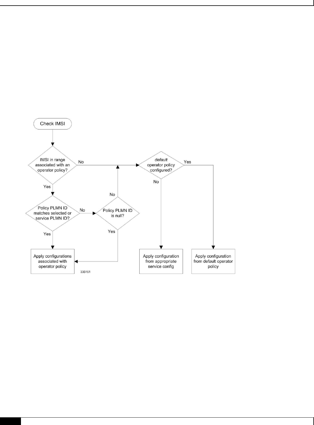
Operator Policy
▀ How It Works
▄ Cisco ASR 5x00 Mobility Management Entity Administration Guide
118
How It Works
The specific operator policy is selected on the basis of the subscriber’s IMSI at attach time, and optionally the PLMN ID
selected by the subscriber or the RAN node's PLMN ID. Unique, non-overlapping, IMSI + PLMN-ID ranges create call
filters that distinguish among the configured operator policies.
The following flowchart maps out the logic applied for the selection of an operator policy:
Figure 12. Operator Policy Selection Logic
Operator Policy
Operator Policy Configuration ▀
Cisco ASR 5x00 Mobility Management Entity Administration Guide ▄
119
Operator Policy Configuration
This section provides a high-level series of steps and the associated configuration examples to configure an operator
policy. By configuring an operator policy, the operator fine-tunes any desired restrictions or limitations needed to
control call handling per subscriber or for a group of callers within a defined IMSI range.
Most of the operator policy configuration components are common across the range of products supporting operator
policy. Differences will be noted as they are encountered below.
Important: This section provides a minimum instruction set to implement operator policy. For this feature to be
operational, you must first have completed the system-level configuration as described in the System Administration
Guide and the service configuration described in your product’s administration guide.
The components can be configured in any order. This example begins with the call control profile:
Step 1 Create and configure a call control profile, by applying the example configuration presented in the Call Control Profile
Configuration section.
Step 2 Create and configure an APN profile, by applying the example configuration presented in the APN Profile
Configuration section.
Important: It is not necessary to configure both an APN profile and an IMEI profile. You can
associate either type of profile with a policy. It is also possible to associate one or more APN profiles with an
IMEI profile for an operator policy (SGSN only).
Step 3 Create and configure an IMEI profile by applying the example configuration presented in the IMEI Profile
Configuration section (SGSN only).
Step 4 Create and configure an APN remap table by applying the example configuration presented in the APN Remap Table
Configuration section.
Step 5 Create and configure an operator policy by applying the example configuration presented in the Operator Policy
Configuration section.
Step 6 Configure an IMSI range by selecting and applying the appropriate product-specific example configuration presented in
the IMSI Range Configuration sections below.
Step 7 Associate the configured operator policy components with each other and a network service by applying the example
configuration in the Operator Policy Component Associations section.
Step 8 Save your configuration to flash memory, an external memory device, and/or a network location using the Exec mode
command save configuration. For additional information on how to verify and save configuration files, refer to the
System Administration Guide .
Step 9 Verify the configuration for each component separately by following the instructions provided in the Verifying the
Feature Configuration section of this chapter.

Operator Policy
▀ Operator Policy Configuration
▄ Cisco ASR 5x00 Mobility Management Entity Administration Guide
120
Call Control Profile Configuration
This section provides the configuration example to create a call control profile and enter the configuration mode.
Use the call control profile commands to define call handling rules that will be applied via an operator policy. Only one
call control profile can be associated with an operator policy, so it is necessary to use (and repeat as necessary) the range
of commands in this mode to ensure call-handling is sufficiently managed.
Configuring the Call Control Profile for an SGSN
The example below includes some of the more commonly configured call control profile parameters with sample
variables that you will replace with your own values.
configure
call-control-profile <profile_name>>
attach allow access-type umts location-area-list instance <list_id>
authenticate attach
location-area-list instance <instance> area-code <area_code>
sgsn-number <E164_number>
end
Note:
Refer to the Call Control Profile Configuration Mode chapter in the Command Line Interface Reference for
command details and variable options.
This profile will only become valid when it is associated with an operator policy.
Configuring the Call Control Profile for an MME or S-GW
The example below includes some of the more commonly configured call control profile parameters with sample
variables that you will replace with your own values.
configure
call-control-profile <profile_name>>
associate hss-peer-service <service_name> s6a-interface
attach imei-query-type imei verify-equipment-identity
authenticate attach
dns-pgw context <mme_context_name>
dns-sgw context <mme_context_name>
end

Operator Policy
Operator Policy Configuration ▀
Cisco ASR 5x00 Mobility Management Entity Administration Guide ▄
121
Note:
Refer to the Call Control Profile Configuration Mode chapter in the Command Line Interface Reference for
command details and variable options.
This profile will only become valid when it is associated with an operator policy.
APN Profile Configuration
This section provides the configuration example to create an APN profile and enter the apn-profile configuration mode.
Use the apn-profile commands to define how calls are to be handled when the requests include an APN. More than
one APN profile can be associated with an operator policy.
The example below includes some of the more commonly configured profile parameters with sample variables that you
will replace with your own values.
configure
apn-profile <profile_name>
gateway-address 123.123.123.1 priority <1>(SGSN only)
direct-tunnel not-permitted-by-ggsn (SGSN only)
idle-mode-acl ipv4 access-group station7 (S-GW only)
end
Note:
All of the parameter defining commands in this mode are product-specific. Refer to the APN Profile
Configuration Mode chapter in the Command Line Interface Reference for command details and variable
options.
This profile will only become valid when it is associated with an operator policy.
IMEI Profile Configuration - SGSN only
This section provides the configuration example to create an IMEI profile and enter the imei-profile configuration mode.
Use the imei-profile commands to define how calls are to be handled when the requests include an IMEI in the
defined IMEI range. More than one IMEI profile can be associated with an operator policy.
The example below includes some of the more commonly configured profile parameters with sample variables that you
will replace with your own values.
configure
imei-profile <profile_name>
ggsn-address 211.211.123.3
direct-tunnel not-permitted-by-ggsn (SGSN only)
associate apn-remap-table remap1

Operator Policy
▀ Operator Policy Configuration
▄ Cisco ASR 5x00 Mobility Management Entity Administration Guide
122
end
Note:
It is optional to configure an IMEI profile. An operator policy can include IMEI profiles and/or APN profiles.
This profile will only become valid when it is associated with an operator policy.
APN Remap Table Configuration
This section provides the configuration example to create an APN remap table and enter the apn-remap-table
configuration mode.
Use the apn-remap-table commands to define how APNs are to be handled when the requests either do or do not
include an APN.
The example below includes some of the more commonly configured profile parameters with sample variables that you
will replace with your own values.
configure
apn-remap-table <table_name>
apn-selection-default first-in-subscription
wildcard-apn pdp-type ipv4 network-identifier <apn_net_id>
blank-apn network-identifier <apn_net_id> (SGSN only)
end
Note:
The apn-selection-default first-in-subscription command is used for APN redirection to provide
“guaranteed connection” in instances where the UE-requested APN does not match the default APN or is
missing completely. In this example, the first APN matching the PDP type in the subscription is used. The first-
in-selection keyword is an MME feature only.
Some of the commands represented in the example above are common and some are product-specific. Refer to
the APN-Remap-Table Configuration Mode chapter in the Command Line Interface Reference for command
details and variable options.
This profile will only become valid when it is associated with an operator policy.
Operator Policy Configuration
This section provides the configuration example to create an operator policy and enter the operator policy configuration
mode.
Use the commands in this mode to associate profiles with the policy, to define and associate APNs with the policy, and
to define and associate IMEI ranges. Note: IMEI ranges are supported for SGSN only.
The example below includes sample variable that you will replace with your own values.
configure

Operator Policy
Operator Policy Configuration ▀
Cisco ASR 5x00 Mobility Management Entity Administration Guide ▄
123
operator-policy <policy_name>
associate call-control-profile <profile_name>
apn network-identifier <apn-net-id_1> apn-profile <apn_profile_name_1>
apn network-identifier <apn-net-id_2> apn-profile <apn_profile_name_1>
imei range <imei_number> to <imei_number> imei-profile name <profile_name>
associate apn-remap-table <table_name>
end
Note:
Refer to the Operator-Policy Configuration Mode chapter in the Command Line Interface Reference for
command details and variable options.
This policy will only become valid when it is associated with one or more IMSI ranges (SGSN) or subscriber
maps (MME and S-GW).
IMSI Range Configuration
This section provides IMSI range configuration examples for each of the products that support operator policy
functionality.
Configuring IMSI Ranges on the MME or S-GW
IMSI ranges on an MME or S-GW are configured in the Subscriber Map Configuration Mode. Use the following
example to configure IMSI ranges on an MME or S-GW:
configure
subscriber-map <name>
lte-policy
precedence <number> match-criteria imsi mcc <mcc_number> mnc <mnc_number> msin
first <start_range> last <end_range> operator-policy-name <policy_name>
end
Note:
The precedence number specifies the order in which the subscriber map is used. 1 has the highest precedence.
The operator policy name identifies the operator policy that will be used for subscribers that match the IMSI
criteria and fall into the MSIN range.
Configuring IMSI Ranges on the SGSN
The example below is specific to the SGSN and includes sample variables that you will replace with your own values.

Operator Policy
▀ Operator Policy Configuration
▄ Cisco ASR 5x00 Mobility Management Entity Administration Guide
124
configure
sgsn-global
imsi-range mcc 311 mnc 411 operator-policy oppolicy1
imsi-range mcc 312 mnc 412 operator-policy oppolicy2
imsi-range mcc 313 mnc 413 operator-policy oppolicy3
imsi-range mcc 314 mnc 414 operator-policy oppolicy4
imsi-range mcc 315 mnc 415 operator-policy oppolicy5
end
Note:
Operator policies are not valid until IMSI ranges are associated with them.
Associating Operator Policy Components on the MME
After configuring the various components of an operator policy, each component must be associated with the other
components and, ultimately, with a network service.
The MME service associates itself with a subscriber map. From the subscriber map, which also contains the IMSI
ranges, operator policies are accessed. From the operator policy, APN remap tables and call control profiles are
accessed.
Use the following example to configure operator policy component associations:
configure
operator-policy <name>
associate apn-remap-table <table_name>
associate call-control-profile <profile_name>
exit
lte-policy
subscriber-map <name>
precedence match-criteria all operator-policy-name <policy_name>
exit
exit
context <mme_context_name>
mme-service <mme_svc_name>
associate subscriber-map <name>

Operator Policy
Operator Policy Configuration ▀
Cisco ASR 5x00 Mobility Management Entity Administration Guide ▄
125
end
Notes:
The precedence command in the subscriber map mode has other match-criteria types. The all type is
used in this example.
Configuring Accounting Mode for S-GW
The accounting mode command configures the mode to be used for the S-GW service for accounting, either GTPP
(default), RADIUS/Diameter, or None.
Use the following example to change the S-GW accounting mode from GTPP (the default) to RADIUS/Diameter:
configure
context <sgw_context_name>
sgw-service <sgw_srv_name>
accounting mode radius-diameter
end
Notes:
An accounting mode configured for the call control profile will override this setting.

Operator Policy
▀ Verifying the Feature Configuration
▄ Cisco ASR 5x00 Mobility Management Entity Administration Guide
126
Verifying the Feature Configuration
This section explains how to display the configurations after saving them in a .cfg file as described in the System
Administration Guide .
Important: All commands listed here are under Exec mode. Not all commands are available on all platforms.
Step 1 Verify that the operator policy has been created and that required profiles have been associated and configured properly
by entering the following command in Exec Mode:
show operator-policy full name oppolicy1
The output of this command displays the entire configuration for the operator policy configuration.
[local]asr5x00# show operator-policy full name oppolicy1
Operator Policy Name = oppolicy1
Call Control Profile Name : ccprofile1
Validity : Valid
APN Remap Table Name : remap1
Validity : Valid
IMEI Range 711919739 to 711919777
IMEI Profile Name : imeiprof1
Include/Exclude : Include
Validity : Valid
APN NI homers1
APN Profile Name : apn-profile1
Validity : Valid
Note:
If the profile name is shown as “Valid”, the profile has actually been created and associated with the policy. If
the Profile name is shown as “Invalid”, the profile has not been created/configured.
If there is a valid call control profile, a valid APN profile and/or valid IMEI profile, and a valid APN remap
table, the operator policy is valid and complete if the IMSI range has been defined and associated.

Cisco ASR 5x00 Mobility Management Entity Administration Guide ▄
127
Chapter 4
APN Override
Access Point Name (APN) Override is a set of features which enable the operator to override the APN requested by the
UE. The functionality to provide configurable remapping provides the operator flexible options with APN handling
locally rather than requiring changes in the external systems.
Feature Description
How it Works
Configuring APN Override

APN Override
▀ Feature Description
▄ Cisco ASR 5x00 Mobility Management Entity Administration Guide
128
Feature Description
In many situations the APN provided in the Activation Request is unacceptable. Either it does not match any of the
subscribed APNs or could be misspelled, resulting in the SGSN rejecting the Activation Request. The APN Override
feature enables the operator to override an incoming APN specified by a subscriber or provided during the APN
selection procedure.
There are three methods of performing apn-overriding.
Network Identifier (NI) based overriding
Operator Identifier (OI) based overriding
Charging-characteristic based overriding
A valid license key is required to enable APN Override. Contact your Cisco Account or Support representative for
information on how to obtain a license.

APN Override
How it Works ▀
Cisco ASR 5x00 Mobility Management Entity Administration Guide ▄
129
How it Works
The following sections describe the three methods for overriding a UE requested APN. These options enable the
operator to overwrite incorrect APNs or apply an APN when not provisioned for the subscriber in the HLR.
Network Identifier (NI) Overriding
Network Identifier (NI) Overriding is done before validating the UE requested APN with HSS subscriber data.
Operator Identifier (OI) Overriding
Operator Identifier (OI) Overriding is done after Network Identifier is validated against HSS subscriber data. After the
FQDN is constructed for DNS query, OI overriding is applied on the constructed FQDN to form a new FQDN based on
OI remapping.
Charging Characteristics Overriding
Charging characteristics based overriding is performed if the apn-charging-characteristic/subscriber-charging-
characteristic from the HSS matches the configured APN and charging-characteristic in the remap entry.

APN Override
▀ Configuring APN Override
▄ Cisco ASR 5x00 Mobility Management Entity Administration Guide
130
Configuring APN Override
Configuration for all of the functions of the APN Override feature is accomplished in the APN Remap Table
configuration mode of the Operator Policy Feature. In order to enable apn-overriding, an apn-remap-table must be
configured and associated to the mme-service through the operator-policy.
Before You Begin
APN Override is configured with the commands in the APN Remap Table configuration mode. This mode generates a
table that is a key component of the Operator Policy feature and the table is not valid unless it is associated with an
operator policy.
Before entering the APN Remap Table configuration mode to configure specific APN override settings, you must first
create and associate the various related objects as follows:
Step 1 Create an APN Remap Table instance from the Global configuration mode.
Step 2 Associate the APN Remap Table with an operator policy in the Operator Policy configuration mode.
Step 3 Define which subscribers should have this operator policy applied.
Refer to the following example to complete these steps.
config
apn-remap-table table1 -noconfirm
exit
operator-policy name operator_policy -noconfirm
associate apn-remap-table table1
exit
lte-policy
subscriber-map subscriber1 -noconfirm
precedence 1 match-criteria all operator-policy-name operator_policy
exit
exit
context ingress -noconfirm
mme-service mmesvc -noconfirm
associate subscriber-map subscriber1
end

APN Override
Configuring APN Override ▀
Cisco ASR 5x00 Mobility Management Entity Administration Guide ▄
131
Configuring Network Identifier Override
Network Identifier (NI) Overriding is done before validating the UE requested APN with HSS subscriber data.
config
apn-remap-table table1
apn-remap network-identifier company.com new-ni internet1.com
exit
Notes:
The apn-remap command above remaps the UE requested APN “company.com” to “internet.com”.
Wildcards characters (*) can be used in the existing network identifier.
Configuring Operator Identifier Override
Operator Identifier (OI) Overriding is done after Network Identifier is validated against HSS subscriber data. After the
FQDN is constructed for the DNS query, Operator Identifier overriding is applied on the constructed FQDN to construct
the new FQDN based on OI remapping.
config
apn-remap-table table1
apn-remap operator-identifier mnc456.mcc123.gprs new-oi mnc987.mcc654.gprs
apn-remap operator-identifier mnc456.mcc123.gprs value-for-oi-mcc 543 value-for-oi-
mnc 234
exit
Notes:
The first apn-remap command above remaps “company.com.apn.epc.mnc456.mcc123.3gppnetwork.org” to
“starent.com.apn.epc.mnc987.mcc654.3gppnetwork.org”.
The second apn-remap command above remaps “starent.com.apn.epc.mnc456.mcc123.3gppnetwork.org” to
“starent.com.apn.epc.mnc234.mcc543.3gppnetwork.org”.
Wildcards characters (*) can be used in the existing operator identifier.
Configuring Charging Characteristics Override
If the UE-requested APN and apn-charging-characteristic /subscriber-charging-characteristic from HSS matches the
configured APN and charging-characteristic in the remap entry, then it is overridden with the target-ni configured.
config
apn-remap-table table1

APN Override
▀ Configuring APN Override
▄ Cisco ASR 5x00 Mobility Management Entity Administration Guide
132
cc behavior 0x785 profile 6 apn-remap network-identifier company.com new-ni
internet.com
exit
Notes:
The above command remaps “company.com” to “internet.com” if the configured charging-characteristic matches
the apn-charging-characteristic/subscriber-charging-characteristic in the HSS. Pdn-type also must match.
Verifying the APN Override Configuration
The following command shows the override settings configured for the specified apn-remap-table.
show apn-remap-table full name table1
[local]asr5x00# show apn-remap-table full name table1
Charging Characteristic APN Override Entry1
Match Charging Characteristics Behavior : 0x785
Match Charging Characteristics Profile-Index : 6
Match Requested APN : company.com
APN to use for Overriding : internet.com
APN remap Entry1 :
Match Input OI wildcard :mnc456.mcc123.gprs
Remap Input OI to :mnc987.mcc654.gprs
APN remap Entry2 :
Match Input NI wildcard :company.com
Remap Input NI to :internet1.com

Cisco ASR 5x00 Mobility Management Entity Administration Guide ▄
133
Chapter 5
Closed Subscriber Groups
This chapter describes the implementation of Closed Subscriber Groups (CSG) on the MME.
Feature Description
How it Works
Configuring Closed Subscriber Groups
Monitoring and Troubleshooting Closed Subscriber Groups

Closed Subscriber Groups
▀ Feature Description
▄ Cisco ASR 5x00 Mobility Management Entity Administration Guide
134
Feature Description
The MME provides support for Closed Subscriber Groups (CSG). This enables the MME to provide access control and
mobility management for subscribers who are permitted to access one or more CSG cells of the PLMN as a member of
the CSG for a Home eNodeB (HeNB).
A CSG ID is a unique identifier within the scope of the PLMN which identifies a Closed Subscriber Group in the
PLMN associated with a CSG cell or group of CSG cells.
The MME performs access control for CSG; a UE will not be permitted to access the network through a CSG cell unless
either the UE's subscription data includes the same CSG ID as the CSG cell, or if the CSG cell is operating in hybrid
mode.The MME also optionally reports the UE's CSG information to the S-GW/P-GW, based on the MME's CLI mme-
service configuration. The S-GW/P-GW, in turn, informs the MME when it should report user CSG information.

Closed Subscriber Groups
How it Works ▀
Cisco ASR 5x00 Mobility Management Entity Administration Guide ▄
135
How it Works
Closed Subscriber Group functionality on the MME is described in the following sections:
Access Control
CSG Notification to S-GW/P-GW
CSG Status Communication to Peer MME/SGSN
Refer to Message Flows for a simplified Closed Subscriber Groups message flow.
Access Control
The MME performs CSG-based access control by examining the CSG cell information provided by the eNodeB through
the S1AP interface for a UE connection or handover attempt, and comparing that to the CSG subscription data for that
UE provided by the HSS through the S6a interface. CSG-based access control affects the following S1AP and S6a
messages and messaging:
S1AP Messaging
S1 Setup Request – If the eNB sending the S1 Setup Request supports one or more CSG cells, the S1 Setup
Request will contain the CSG IDs of the supported CSGs. The MME will store the CSG IDs as part of the data
pertaining to the eNB.
eNB Configuration Update – If the eNB sending the eNB Configuration Update supports one or more CSG
cells, the eNB Configuration Update will contain the CSG IDs of the supported CSGs, which may or may not
have changed from those sent in the S1 Setup Request. The MME will overwrite the stored CSG IDs for that
eNB with the list contained in the eNB Configuration Update.
Initial UE Message – If the establishment of the UE-associated logical S1-connection is performed due to a
connection originating from a CSG cell, the CSG ID is included in the Initial UE Message. If the establishment
of the UE-associated logical S1-connection is performed due to a connection originating from a Hybrid cell,
the CSG ID and the Cell Access Mode IE are included in the Initial UE Message. The MME stores the CSG ID
and Cell Access Mode in the UE context. If the UE context already exists, the MME overwrites the existing
CSG ID and Cell Access Mode with the new data, or clears the CSG ID and Cell Access Mode if the CSG ID
is not present in the message. The CSG ID is checked against the subscription data from the HSS to determine
if the UE is a member of the CSG. If the UE is not a member, and the cell is not a hybrid cell, access is denied.
Initial Context Setup Request – If the cell is a hybrid cell, the Initial Context Setup Request from the MME
contains a CSG Membership Status IE indicating whether the UE is a member of the cell's CSG.
UE Context Modification Request – A UE Context Modification Request from the MME contains a CSG
Membership Status IE if the cell has a CSG ID (if the cell is either a CSG cell or a hybrid cell). The MME
sends a UE Context Modification Request indicating CSG Membership Status is Non-member if the HSS sends
a Delete Subscriber Data Request with DSR Flags indicating that CSG subscription data is being deleted. The
MME also sends a UE Context Modification Request indicating CSG Membership Status is Non-member if the
CSG subscription data for the CSG in question includes an Expiration Date AVP and the time indicated by the
AVP has been reached.
Paging – The Paging message may contain a list of one or more CSG IDs. If the MME includes this list, the
eNodeB avoids paging the UE at CSG cells whose CSG ID does not appear in the list. If the UE has CSG IDs

Closed Subscriber Groups
▀ How it Works
▄ Cisco ASR 5x00 Mobility Management Entity Administration Guide
136
in its subscription data, the MME includes the insersection of the eNodeB’s CSG ID list and the subscriber’s
CSG ID list in the Paging message whenever that UE is being paged.
Handover Required – The Handover Required message may contain a CSG ID; if it does, there may also be a
Cell Access Mode IE which indicates the target cell is a hybrid cell. When the MME receives a Handover
Required message with a CSG ID, it uses the UE's subscription data to determine if the UE is a member of the
CSG in question. If the UE is not a member and the cell is not a hybrid cell, the MME refuses the handover
attempt. Otherwise, the MME conveys the CSG information to the target system.
Handover Request – If the MME is sending a Handover Request message, a CSG ID is included in the message
if the target has been specified as either a CSG cell or hybrid cell with the CSG ID in question. If the cell has
been specified as a hybrid cell, the MME also includes a CSG Membership Status IE in the Handover Request
as well.
Handover Request Ack – If the Handover Request contains both a CSG ID and a CSG Membership Status IE,
but the target cell in question is a hybrid cell that broadcasts a different CSG ID, the actual CSG ID of the cell
shall be included in the Handover Request Ack. Upon receipt of such a message, the MME changes the CSG
ID of the UE, marks the target cell as being a hybrid cell, and considers the UE to be a non-member of the
CSG. Note that the MME may later discover via subscription data from the HSS that the UE is actually a
member of the CSG in question; if so, it sends a UE Context Modification Request indicating that the UE is a
member of the CSG. Note also that if the Handover Request contains a CSG ID and the target cell broadcasts a
different CSG ID and is not a hybrid cell, the eNB sends a Handover Failure message, not a Handover Request
Ack.
S6a Messaging
Update Location Ack – Messages from the HSS contain the UE's subscription data, which may include CSG
subscription data. CSG subscription data consists of one or more CSG IDs, each of which may also have an
associated expiration date. The CSG IDs are interpreted within the context of the PLMN ID sent to the HSS in
the Visited-PLMN-ID AVP in the Update Location Request message. The CSG subscription data is stored in
the UE's database entry along with the rest of the UE subscription data. The MME stores up to eight CSG IDs
per UE. The MME uses the CSG subscription data to determine membership in a given CSG by comparing the
CSG ID of the current cell against the CSG IDs in the subscription data.
Delete Subscriber Data Request – The HSS can indicate to the MME to delete the stored CSG subscription
data by sending a Delete Subscriber Data Request message with the CSG Deleted bit set in the DSR flags. If
this happens, and the UE is currently connected to a cell where it was a CSG member, the MME sends a UE
Context Modification Request indicating that the UE is no longer a CSG member. The MME is responsible for
enforcing the expiration date (if any) for a given CSG as indicated in the CSG subscription data. If the CSG
subscription expires, the MME must send a UE Context Modification Request indicating that the UE is no
longer a CSG member.
CSG Notification to S-GW/P-GW
The MME informs the P-GW whether it supports CSG change notification by setting the CSG Change Reporting
Support Indication (CCRSI) flag. MME support for CSG change notification can be enabled or disabled. If it is enabled,
the P-GW, based on input from the PCRF, determines if CSG change notification is required by sending the CSG
Information Reporting Action IE to the MME.
CSG notification to the S-GW/P-GW affects the following S11 messages and messaging:
Create Session Request – The Indication IE in the Create Session Request contains a CSG Change Reporting
Support Indication (CCRSI) flag, which is set when the MME is configured to support CSG information
change reporting to the S-GW/P-GW. If the UE is attached through a CSG or hybrid cell, the User CSG

Closed Subscriber Groups
How it Works ▀
Cisco ASR 5x00 Mobility Management Entity Administration Guide ▄
137
Information (UCI) IE is be included in the Create Session Request. The User CSG Information IE contains the
PLMN and CSG ID of the CSG or hybrid cell in question, the access mode (closed or hybrid), and if the access
mode is hybrid, the membership status of the UE in the CSG.
Create Session Response – The P-GW/S-GW will send the CSG Reporting Information IE in the Create
Session Response if CSG information reporting is to be started or stopped. This IE includes three bits that
indicate whether the MME should report when the UE enters or leaves a CSG (non-hybrid) cell, a subscribed
hybrid cell, or an unsubscribed hybrid cell. If all three bits are set to zero, all CSG information reporting to the
S-GW/P-GW is stopped. The MME stores the CSG reporting information as part of the PDN context, since the
reporting requirements may be different on different P-GWs.
Create Bearer Request – The Create Bearer Request message from the P-GW/S-GW may include a CSG
Reporting Information IE if CSG reporting from the MME is to change. The MME stores the CSG reporting
information as part of the PDN context in question.
Modify Bearer Request – The CCRSI flag in the Indication IE is set in a Modify Bearer Request when the
MME is configured to support CSG information change reporting to the S-GW/P-GW. If the P-GW/S-GW has
requested CSG information reporting and a TAU, Handover, or UE-initiated Service Request is taking place,
the MME includes the User CSG Information IE in the Modify Bearer Request message.
Update Bearer Request – The Update Bearer Request message from the P-GW/S-GW may include a CSG
Reporting Information IE if CSG reporting from the MME is to change. The MME stores the CSG reporting
information as part of the PDN context in question.
Change Notification Request – The MME sends a Change Notification Request to the S-GW/P-GW for each
PDN where it is requested, if a change to the CSG connection information changes without requiring either a
Create Bearer Request or Modify Bearer Request. The Change Notification Request contains a User CSG
Information IE. Since Location Reporting also uses the Change Notification Request message, the MME
minimizes the number of Change Notification Request messages sent by bundling the reporting of a location
change with a CSG change into the same message whenever possible.
Change Notification Response – The Change Notification Response message from the P-GW/S-GW may
include a CSG Reporting Information IE if CSG reporting from the MME is to change. The MME stores the
CSG reporting information as part of the PDN context in question.
CSG Status Communication to Peer MME/SGSN
The MME indicates its ability to report location information using the “CSG Change Reporting Support Indication”
which is a part of the indication flags parameter.
CSG status communication to a peer MME or SGSN affects the following S10 and S3 messages and messaging:
Forward Relocation Request – If the source MME or SGSN supports CSG information change reporting, the
CCRSI flag is set in the Indication IE in a Forward Relocation Request message from that MME or SGSN. If
the source eNB or RNC included a target CSG ID as part of the Handover Required message, the source MME
or SGSN include that CSG ID in a CSG ID IE in the Forward Relocation Request. If the source eNB or RNC
indicated that the target cell is a hybrid cell, the source MME or SGSN determine whether the UE is a member
of the CSG and include the CSG Membership Indication IE in the Forward Relocation Request. (A Forward
Relocation Request that contains a CSG ID IE but no CSG Membership Indication IE indicates that the target
cell is a closed CSG cell.) The PDN Connection IE(s) in the Forward Relocation Request will contain a CSG
Information Reporting Action IE if the P-GW/S-GW had previously sent it to the source MME or SGSN for
the PDN in question.
Context Response – If the old MME or SGSN in a Context Request/Response/Ack exchange supports CSG
information change reporting, the CCRSI flag is set in the Indication IE shall be set in the Context Response
from that MME or SGSN. The PDN Connection IE(s) in the Context Response contains a CSG Information
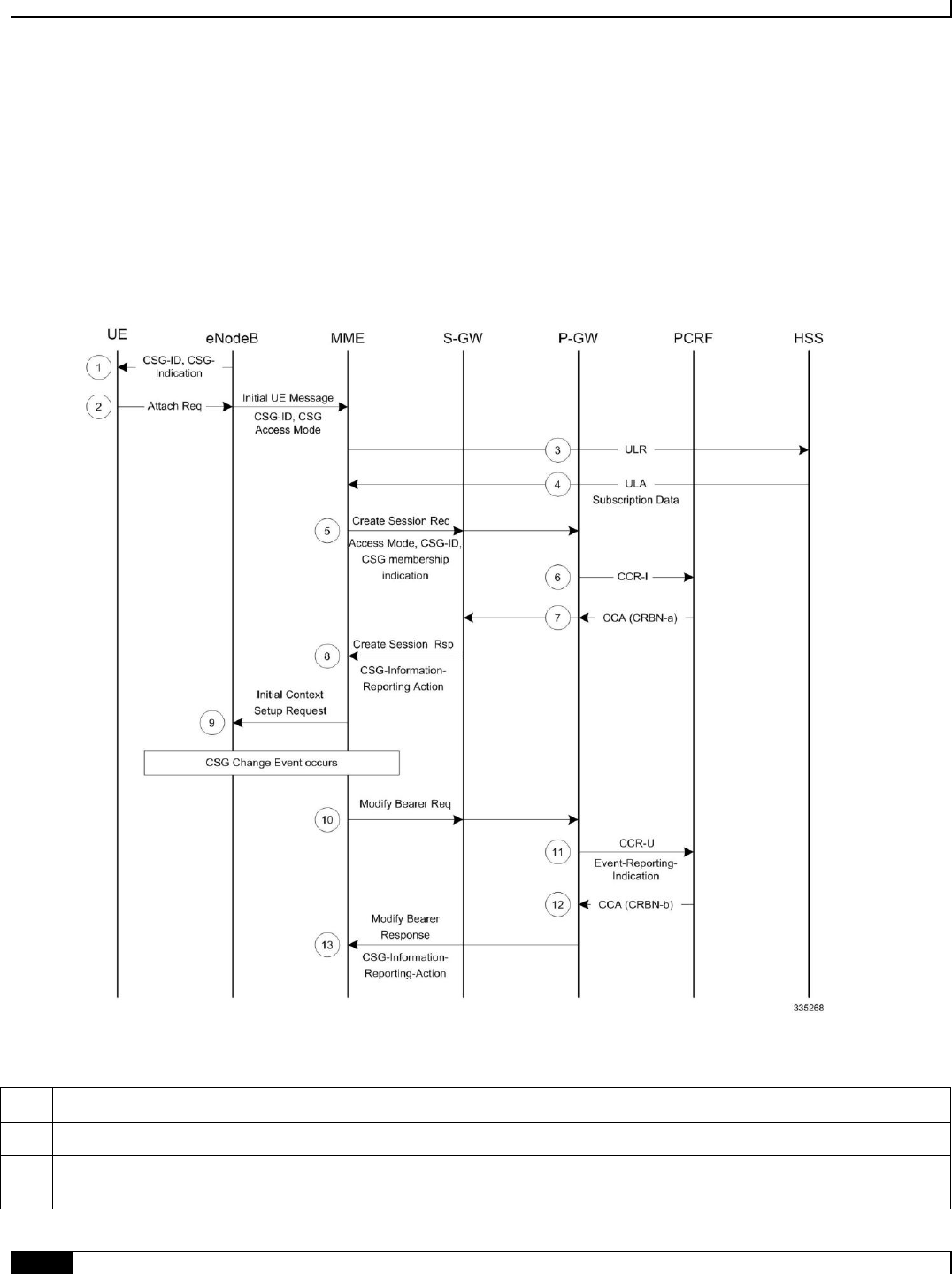
Closed Subscriber Groups
▀ How it Works
▄ Cisco ASR 5x00 Mobility Management Entity Administration Guide
138
Reporting Action IE if the P-GW/S-GW had previously sent it to the old MME or SGSN for the PDN in
question.
Message Flows
The following diagram shows the messaging between the EPC elements in a Closed Subscriber Group implementation.
Figure 13. Closed Subscriber Groups Message Flow
Table 8. Closed Subscriber Groups Message Flow
Step
Description
1
The eNodeB broadcasts the CSG Information to UEs.
2
When an Attach Request event happens, the eNodeB sends its own CSG-related Information in Initial UE message to the
MME.

Closed Subscriber Groups
How it Works ▀
Cisco ASR 5x00 Mobility Management Entity Administration Guide ▄
139
Step
Description
3
The MME sends an Update Location Request (ULR) to the HSS to get subscriber's profile.
4
The HSS responds with an Update Location Answer (ULA) including Subscription-Data which includes CSG-
Subscription-Data. If the ULA does not include a CSG_ID: 1) The Attach attempt will be rejected if the Access mode is set
to Closed; 2) The call will proceed on a non-CSG-member basis if the Access mode is set to Hybrid.
5
The MME proceeds with the call according to the user profile from the HSS. The MME sets the CSG membership
Indication and passes it to the S-GW including Access Mode and CSG-ID. The S-GW transparently passes the information
to the P-GW.
6
The P-GW requests policy and charging rule from the PCRF.
7
The PCRF sends Event-Trigger:=USER_CSG_INFO_CHG and USER-CSG-INFO AVP based on user subscription profile.
8
The P-GW sets CSG-Information-Reporting-Action in Create Session Response when the P-GW receives Event-
Trigger:=USER_CSG_INFO_CHG.
9
The MME sends CSG-Membership-Status to eNodeB. This is only occurs when the Access mode is set to Hybrid.
10
When a CSG change event happens, the eNodeB/MME reports the event. The MME updates CSG change event using a
Change Notification Request or Modify Bearer Request.
11
The P-GW reports CSG change event using Event-Reporting-Indication AVP to the PCRF.
12
The PCRF updates the policy and charging rule with Charging-Rule-Base-Name or install new Charging-Rule-Base-Name.
13
The P-GW sends a CSG Information Reporting Action IE as part of the Modify Bearer Response, a Change Notification
Response, or it can initiate a change through an Update Bearer Request.

Closed Subscriber Groups
▀ Configuring Closed Subscriber Groups
▄ Cisco ASR 5x00 Mobility Management Entity Administration Guide
140
Configuring Closed Subscriber Groups
CSG access control and status communication to peer MMEs/SGSNs is mandatory and enabled by default. CSG
notification to the S-GW/P-GW is optional and may be enabled using the csg-change-notification CLI command
within the scope of the mme-service configuration.
Use the following example to enable CSG change notification to the S-GW/P-GW.
configure
mme-service <mme_svc_name> -noconfirm
csg-change-notification
end
Notes:
By default csg-change-notification is disabled; the MME does not send CSG notification to the S-GW/P-
GW.
Verifying the Closed Subscriber Groups Configuration
Use either of the following Exec mode commands to verify if CSG notification to the S-GW/P-GW is enabled.
show mme-service all
show mme-service name <mme_svc_name>
The output of this command displays the entire configuration for the MME service specified.
[local]asr5x00# show mme-service name mmesvc1
CSG Change Notification : Enabled

Closed Subscriber Groups
Monitoring and Troubleshooting Closed Subscriber Groups ▀
Cisco ASR 5x00 Mobility Management Entity Administration Guide ▄
141
Monitoring and Troubleshooting Closed Subscriber Groups
CSG information and per-PDN CSG reporting information is included the following Exec mode command.
show mme-service session full all
The sample output below shows only the information relating to CSG.
[local]asr5x00# show mme-service session full all
CSG Cell Change Notification: Enabled
CSG Subscribed Hybrid Cell Change Notification: Enabled
CSG Unsubscribed Hybrid Cell Change Notification: Enabled
CSG Information:
CSG ID at last connection: 15625 (0x3d09)
CSG cell type: Hybrid
CSG membership status: Non-Member
If the CSG cell is not a hybrid cell, the CSG Information section will be displayed as follows:
CSG Information:
CSG ID at last connection: 15625 (0x3d09)
CSG cell type: Closed
CSG membership status: Member
If the last (or current) cell is not a CSG cell, the CSG Information section will be displayed as follows:
CSG Information:
CSG ID at last connection: None
CSG cell type: n/a
CSG membership status: n/a
The following command shows CSG IDs from the subscription data:
show mme-service db record imsi imsi_id
[local]asr5x00# show mme-service db record imsi 123456789012345
CSG IDs : 10
25
625

Closed Subscriber Groups
▀ Monitoring and Troubleshooting Closed Subscriber Groups
▄ Cisco ASR 5x00 Mobility Management Entity Administration Guide
142
If no CSG IDs are present in the subscription data, that state will be displayed as follows:
CSG IDs : None
The following command shows statistics for the number of times the MME sent a NAS message with the cause value
“Not authorized for this CSG”. These statistics are tracked for Attach Reject, Detach Request, Service Reject, and TAU
Reject.
The sample output that follows shows only the statistics relating to CSG.
show mme-service statistics
[local]asr5x00# show mme-service statistics
Attach Reject: 0 ... CSG Not Subscribed: 0
Detach Request: 0 ... CSG Not Subscribed: 0
Service Reject: 0 ... CSG Not Subscribed: 0
TAU Reject: 0 ... CSG Not Subscribed: 0

Cisco ASR 5x00 Mobility Management Entity Administration Guide ▄
143
Chapter 6
Enhanced Congestion Control and Overload Control
This chapter describes the license-enabled congestion control and overload control features on the MME.
Feature Description
Configuring Enhanced Congestion Control
Monitoring and Troubleshooting

Enhanced Congestion Control and Overload Control
▀ Feature Description
▄ Cisco ASR 5x00 Mobility Management Entity Administration Guide
144
Feature Description
Enhanced Congestion Control and Overload Control
This feature requires that a valid license key (MME Resiliency) be installed. Contact your Cisco Account or Support
representative for information on how to obtain a license.
This feature builds on the base congestion control functionality provided on the MME.
Refer to the Congestion Control and Overload Control sections in the MME Overview chapter for more information
about the basic functionality.
To allow greater control during overload conditions, the MME supports the configuration of three separate levels
(critical, major, minor) of congestion thresholds for the following system resources:
System CPU usage
System service CPU usage (Demux-Card CPU usage)
System Memory usage
License usage
Maximum Session per service
The MME can, in turn, be configured to take specific actions when any of these thresholds are crossed, such as:
Drop or reject the following S1-AP/NAS messages: S1 Setup, Handover events, TAU request, Service request,
PS-Attach request, Combined-attach request, Additional PDN request, or UE initiated bearer resource
allocation.
Allow voice or emergency calls/events.
Initiate S1AP overload start to a percentage of eNodeBs with options to signal any of the following in the
Overload Response IE:
reject non-emergency sessions
reject new sessions
permit emergency sessions
permit high-priority sessions and mobile-terminated services
reject delay-tolerant access.
Relationships to Other Features
This license-enabled feature builds on the base congestion control functionality provided on the MME.
Refer to the Congestion Control and Overload Control sections in the MME Overview chapter for more information
about the basic functionality.
Additional information is also provided in the Congestion Control chapter in the System Administration Guide.

Enhanced Congestion Control and Overload Control
Feature Description ▀
Cisco ASR 5x00 Mobility Management Entity Administration Guide ▄
145
Limitations
The base congestion control functionality also can monitor congestion of the following resources:
Port-specific RX and TX utilization
Port RX and TX utilization
Message queue utilization
Message queue wait time
The license-enabled Enhanced Congestion Control funtionality on the MME does not support the monitoring of these
resources using three different threshold levels (critical, major and minor). Only a single threshold level (critical) can be
monitored for these resources.

Enhanced Congestion Control and Overload Control
▀ Configuring Enhanced Congestion Control
▄ Cisco ASR 5x00 Mobility Management Entity Administration Guide
146
Configuring Enhanced Congestion Control
This feature requires that a valid license key be installed. Contact your Cisco Account or Support representative for
information on how to obtain a license.
Configuring Enhanced Congestion Control
Configuring Thresholds and Tolerances
License Utilization Thresholds
Maximum Session Per Service Thresholds
Service Control CPU Thresholds
System CPU Thresholds
System Memory Thresholds
Configuring a Congestion Action Profile
Associating a Congestion Action Profile with Congestion Control Policies
Configuring Overload Control
Configuring Congestion SNMP Traps
Configuring Thresholds and Tolerances
Congestion threshold values must be defined to establish when a congestion condition is reached. Congestion threshold
tolerances must also be configured to establish when a congestion condition is cleared. Individual thresholds values and
tolerances can be defined for critical, major and minor thresholds.
The default tolerance window for critical thresholds is 10%. The default for major and minor thresholds is 0%.
If the tolerance is configured greater than threshold, then the tolerance will be treated as zero.
When configuring thresholds and tolerances for critical, major and minor congestion levels, the threshold levels and
tolerances should never overlap. Consider the following example configuration, where the following threshold levels do
not overlap:
Critical congestion will trigger at 80% and will clear at 70%
Major congestion will trigger at 70% and will clear at 60%
Minor congestion will trigger at 60% and will clear at 50%.
configure
congestion-control threshold tolerance critical 10
congestion-control threshold max-sessions-per-service-utilization major 70
congestion-control threshold tolerance major 10
congestion-control threshold max-sessions-per-service-utilization minor 60

Enhanced Congestion Control and Overload Control
Configuring Enhanced Congestion Control ▀
Cisco ASR 5x00 Mobility Management Entity Administration Guide ▄
147
congestion-control threshold tolerance minor 10
congestion-control threshold max-sessions-per-service-utilization critical 80
end
For information about all of the congestion control commands available, refer to the Global Configuration Mode
Commands chapter of the ASR 5x00 Command Line Interface Reference.
License Utilization Thresholds
The license-utilization threshold is calculated based on the configured license values for the chassis.
In this example configuration, the minor threshold will be triggered at 4000 calls, major threshold will be triggered at
6000 calls, and critical threshold will be triggered at 8000 calls.
congestion-control threshold license-utilization critical 80
congestion-control threshold license-utilization major 60
congestion-control threshold license-utilization minor 40
Maximum Session Per Service Thresholds
This threshold is configured across all MME services.
config
congestion-control threshold max-sessions-per-service-utilization critical 80
When there are multiple MME services configured with different max-subscribers parameters, chassis congestion will
be calculated using the minimum of max-subscribers configured in each of the different MME services.
However, congestion actions will be applied to each individual service based on its corresponding max-session-per-
service parameters.
For example:
configure
context ingress
mme-service mmesvc1
bind s1-mme ipv4-address 10.10.10.2 max-subscribers 10000
exit
exit
mme-service mmesvc2
bind s1-mme ipv4-address 10.10.10.3 max-subscribers 1000
exit
exit

Enhanced Congestion Control and Overload Control
▀ Configuring Enhanced Congestion Control
▄ Cisco ASR 5x00 Mobility Management Entity Administration Guide
148
mme-service mmesvc3
bind s1-mme ipv4-address 192.80.80.3 max-subscribers 20000
end
In the above example, chassis level critical congestion will get triggered when the number of subscribers in mmesvc2 is
at 800. Corresponding SNMP traps will be generated. However, congestion policies will not be applied for mmesvc1
and mmesvc3. When the number of subscribers in mmesvc1 and mmesvc3 reaches 8000 and 16000 respectively, then
congestion policies will be applied for mmesvc1 and mmesvc3.
Chassis congestion will be cleared only when the congestion is cleared in all MME services.
Similarly, when minor, major and critical threshold are configured for max-session-per-service for many MME services,
the maximum value of the threshold will be considered for chassis level congestion .
For example, if mmesvc1 reaches the major threshold, mmesvc2 reaches the critical threshold and mmesvc3 reaches the
minor threshold, then chassis congestion state will be critical.
Service Control CPU Thresholds
This threshold is calculated from the system’s demux CPU. The threshold is calculated based on a five minute average
CPU usage.
The highest CPU usage value of two CPU cores of the demux CPU is considered. For example, if CPU core 0 has a five
miniute CPU usage of 40% and CPU core 1 has a five minute CPU usage of 80%, then CPU core 1 will be considered
for threshold calculation.
The following example configuration shows threshold levels of 80, 60, and 40% usage:
congestion-control threshold service-control-cpu-utilization critical 80
congestion-control threshold service-control-cpu-utilization major 60
congestion-control threshold service-control-cpu-utilization minor 40
System CPU Thresholds
This threshold is calculated using the five minute CPU usage average of all CPUs (except standby CPU and SMC CPU
).
The highest CPU usage value of two CPU core of all CPU will be considered.
The following example configuration shows threshold levels of 80, 60, and 40% usage:
congestion-control threshold system-cpu-utilization critical 80
congestion-control threshold system-cpu-utilization major 60
congestion-control threshold system-cpu-utilization minor 40
System Memory Thresholds
This threshold is calculated using the five minute memory usage average of all CPUs (except standby CPU and SMC
CPU ).
The following example configuration shows threshold levels of 80, 60, and 40% usage:

Enhanced Congestion Control and Overload Control
Configuring Enhanced Congestion Control ▀
Cisco ASR 5x00 Mobility Management Entity Administration Guide ▄
149
congestion-control threshold system-memory-utilization critical 80
congestion-control threshold system-memory-utilization major 60
congestion-control threshold system-memory-utilization minor 40
Configuring a Congestion Action Profile
Congestion Action Profiles define a set of actions which can be executed after the corresponding threshold is crossed.
Use the following example configuration which creates a congestion action profile named critical_action_profile and
defines several actions for this profile:
configure
lte-policy
congestion-action-profile critical_action_profile
reject s1-setups time-to-wait 60
drop handovers
reject combined-attaches
report-overload permit-emergency-sessions enodeb-percentage 50
end
See the Congestion Action Profile Configuration Commands chapter in the Command Line Reference for details about
all the congestion action profile commands available.
Refer to Configuring Overload Control in this chapter for more information about the report-overload keyword and
associated functionality.
Associating a Congestion Action Profile with Congestion Control Policies
Each congestion control policy (critical, major, minor) must be associated with a congestion control profile.
The following example configuration to associate the congestion action profile named critical_action_profile with the
critical congestion control policy:
configure
congestion-control policy critical mme-service action-profile critical_action_profile
Separate congestion action profiles can be associated with major and minor congestion control policies, for example:
congestion-control policy major mme-service action-profile major_action_profile
congestion-control policy minor mme-service action-profile minor_action_profile

Enhanced Congestion Control and Overload Control
▀ Configuring Enhanced Congestion Control
▄ Cisco ASR 5x00 Mobility Management Entity Administration Guide
150
Configuring Overload Control
When an overload condition is detected on an MME, the system can be configured to report the condition to a specified
percentage of eNodeBs and take the configured action on incoming sessions.
To create a congestion control policy with overload reporting, apply the following example configuration:
configure
lte-policy
congestion-action-profile <profile_name>
congestion-action-profile <profile_name>
end
configure
congestion-control policy critical mme-service action report-overload
reject-new-sessions enodeb-percentage <percentage>
end
Notes:
The following overload actions are also available (in addition to reject-new-sessions):
permit-emergency-sessions-and-mobile-terminated-services
permit-high-priority-sessions-and-mobile-terminated-services
reject-delay-tolerant-access
reject-non-emergency-sessions
See the Congestion Action Profile Configuration Mode Commands chapter in the Command Line Reference for details
about all the congestion action profile commands available.
Configuring Enhanced Congestion SNMP Traps
When an enhanced congestion condition is detected, an SNMP trap (notification) is automatically generated by the
system.
To disable (suppress) this trap:
configure
snmp trap suppress EnhancedCongestion
end
To re-enable generation of the EnhancedCongestion trap:
configure

Enhanced Congestion Control and Overload Control
Configuring Enhanced Congestion Control ▀
Cisco ASR 5x00 Mobility Management Entity Administration Guide ▄
151
snmp trap enable EnhancedCongestion target <target-name>
end
Verifying the Congestion Control Configuration
Use the following Exec mode command to display the configuration of the congestion control functionality.
show congestion-control configuration
The following output is a concise listing of all threshold and policy configurations showing multi-level Critical, Major
and Minor threshold parameters and congestion control policies:
Congestion-control: enabled
Congestion-control Critical threshold parameters
system cpu utilization: 80%
service control cpu utilization: 80%
system memory utilization: 80%
message queue utilization: 80%
message queue wait time: 10 seconds
port rx utilization: 80%
port tx utilization: 80%
license utilization: 100%
max-session-per-service utilization: 100%
tolerence limit: 10%
Congestion-control Critical threshold parameters
system cpu utilization: 80%
service control cpu utilization: 80%
system memory utilization: 80%
message queue utilization: 80%
message queue wait time: 10 seconds
port rx utilization: 80%
port tx utilization: 80%

Enhanced Congestion Control and Overload Control
▀ Configuring Enhanced Congestion Control
▄ Cisco ASR 5x00 Mobility Management Entity Administration Guide
152
license utilization: 100%
max-session-per-service utilization: 100%
tolerence limit: 10%
Congestion-control Major threshold parameters
system cpu utilization: 0%
service control cpu utilization: 0%
system memory utilization: 0%
message queue utilization: 0%
message queue wait time: 0 seconds
port rx utilization: 0%
port tx utilization: 0%
license utilization: 0%
max-session-per-service utilization: 0%
tolerence limit: 0%
Congestion-control Minor threshold parameters
system cpu utilization: 0%
service control cpu utilization: 0%
system memory utilization: 0%
message queue utilization: 0%
message queue wait time: 0 seconds
port rx utilization: 0%
port tx utilization: 0%
license utilization: 0%
max-session-per-service utilization: 0%
tolerence limit: 0%
Overload-disconnect: disabled
Overload-disconnect threshold parameters
license utilization: 80%
max-session-per-service utilization: 80%

Enhanced Congestion Control and Overload Control
Configuring Enhanced Congestion Control ▀
Cisco ASR 5x00 Mobility Management Entity Administration Guide ▄
153
tolerance: 10%
session disconnect percent: 5%
iterations-per-stage: 8
Congestion-control Policy
mme-service:
Critical Action-profile : ap3
Major Action-profile : ap2
Minor Action-profile : ap1
Verifying Congestion Action Profiles
To verify the configuration of a congestion action profile, use the following Exec mode command:
show lte-policy congestion-action-profile { name <profile_name> | summary }

Enhanced Congestion Control and Overload Control
▀ Monitoring and Troubleshooting
▄ Cisco ASR 5x00 Mobility Management Entity Administration Guide
154
Monitoring and Troubleshooting
This section provides information on how to monitor congestion control.
Congestion Control Show Command(s) and/or Outputs
This section provides information regarding show commands and/or their outputs in support of enhanced congestion
control.
show congestion-control statistics mme
The following command shows an overview of all congestion control statistics for the MME.
show congestion-control statistics mme [ full | critical | major | minor ]
The following output is a concise listing of congestion control statistics. In this example output, only the Critical
information is shown.
Critical Congestion Policy Action
Congestion Policy Applied : 0 times
PS attaches
Rejected : 0 times
Dropped : 0 times
PS attaches
Rejected : 0 times
Dropped : 0 times
Combined attaches
Rejected : 0 times
Dropped : 0 times
S1-Setup
Rejected : 0 times
Dropped : 0 times
Handover
Rejected : 0 times
Dropped : 0 times

Enhanced Congestion Control and Overload Control
Monitoring and Troubleshooting ▀
Cisco ASR 5x00 Mobility Management Entity Administration Guide ▄
155
Addn-pdn-connect
Rejected : 0 times
Dropped : 0 times
Addn-brr-connect
Rejected : 0 times
Dropped : 0 times
Service-Request
Rejected : 0 times
Dropped : 0 times
TAU-Request
Rejected : 0 times
Dropped : 0 times
S1AP Overload Start Sent : 2 times
S1AP Overload Stop Sent : 2 times
Excluded Emergency Events : 0 times
Excluded Voice Events : 0 times
show congestion-control statistics mme
The following command shows SNMP event statistics for the EnhancedCongestion trap and EnhancedCongestionClear
trap .
show snmp trap statistics verbose | grep EnhancedCongestion

Cisco ASR 5x00 Mobility Management Entity Administration Guide ▄
157
Chapter 7
Foreign PLMN GUTI Management
This feature allows operators to gain some savings on signaling by avoiding DNS request attempts to foreign PLMNs if
a foreign PLMN GUTI is not allowed.
Feature Description
How it Works
Configuring Foreign PLMN GUTI Management
Monitoring Foreign PLMN GUTI Management

Foreign PLMN GUTI Management
▀ Feature Description
▄ Cisco ASR 5x00 Mobility Management Entity Administration Guide
158
Feature Description
In releases prior to 15.0, all Attach and TAU Requests containing a foreign GUTI would result in a DNS lookup for the
peer MME or SGSN, followed by an S10, S3 or Gn/Gp Identification or Context Request. This could result in
significant delay when the GUTI is from a foreign PLMN, which the local MME cannot access.
In Release 15.0, a Foreign PLMN GUTI Management Database can now be configured to allow or immediately reject
Attach Requests or TAU Requests containing a GUTI from a foreign PLMN. This Foreign PLMN GUTI Management
Database contains as many as 16 entries, where each entry consists of a PLMN (MCC and MNC) and an action, which
can either be Allow or Reject. If the action is Reject, the MME will not perform any DNS requests to locate a peer
MME or SGSN to which any foreign GUTI from that foreign PLMN maps.

Foreign PLMN GUTI Management
How it Works ▀
Cisco ASR 5x00 Mobility Management Entity Administration Guide ▄
159
How it Works
When an Attach Request or TAU Request containing a foreign GUTI is received, the MME must first determine if the
GUTI's PLMN matches either the MME's own PLMN or one of the MME's shared PLMNs. If such a match is found,
the foreign GUTI belongs to a local PLMN, no foreign PLMN check is made, and a DNS request for a peer MME or
SGSN may be made as the request is processed normally. If the GUTI's PLMN does not match either the MME's own
PLMN or one of the MME's shared PLMNs, the foreign GUTI belongs to a foreign PLMN and the MME Service is
checked for an association to a Foreign PLMN GUTI Management Database. If there is no such association, all Attach
Requests and TAU Requests containing foreign GUTIs from foreign PLMNs are allowed to be processed, and a DNS
request for a peer MME or SGSN may be made.
If an association to a Foreign PLMN GUTI Management Database is present, the database is checked for a matching
foreign PLMN. If no match is found, the MME continues processing the Attach Request or TAU Request, and a DNS
request may be made. If a match is found, the action specified for the foreign PLMN (either Allow or Reject) is applied.
If the action is Reject, and the request is a TAU Request, a TAU Reject message is sent immediately with cause code 9
(UE Identity cannot be derived by the network), and no DNS lookup is performed to find a peer MME or SGSN. If the
action is Reject, and the request is an Attach Request, the MME sends a NAS Identity Request to the UE to determine
its IMSI, and no DNS lookup is performed to find a peer MME or SGSN. If the action is Allow, the MME continues
processing the Attach Request or TAU Request, and a DNS request may be made.
If a TAU Request containing a foreign GUTI is rejected due to its PLMN being present in the Foreign PLMN GUTI
Management Database, the mme-foreign-plmn-guti-rejected session disconnect reason will be incremented.
Similarly, the emmdisc-foreignplmnreject bulk statistic counter, which tracks the number of times this disconnect
reason, is incremented..

Foreign PLMN GUTI Management
▀ Configuring Foreign PLMN GUTI Management
▄ Cisco ASR 5x00 Mobility Management Entity Administration Guide
160
Configuring Foreign PLMN GUTI Management
Creating a Foreign PLMN GUTI Management Database
Configuring Foreign PLMN GUTI Management Database Entries
Associating an MME Service with a Foreign PLMN GUTI Management Database
Verifying the Configuration
Creating a Foreign PLMN GUTI Management Database
A Foreign PLMN GUTI Management Database is configured as part of the lte-policy configuration mode.
config
lte-policy
foreign-plmn-guti-mgmt-db fguti_db_name
end
Up to four Foreign PLMN GUTI Management Datbases may be configured.
To delete an existing database, use the no keyword followed by the database specifier and name in lte-policy
configuration mode.
no foreign-plmn-guti-mgmt-db fguti-db1
Configuring Foreign PLMN GUTI Management Database Entries
A Foreign PLMN GUTI Management Database entry consists of an MCC, an MNC, and an action (either Allow or
Reject). The following example creates two entries:
configure
lte-policy
foreign-plmn-guti-mgmt-dbdb_name
plmn mcc 123 mnc 456 allow
plmn mcc 321 mnc 654 reject
The any keyword may be used as a wildcard in place of both the MCC and MNC values, or in place of an MNC value
with a specific MCC value. In other words, the following commands are allowed:
plmn mcc any mnc any reject
plmn mcc 123 mnc any allow

Foreign PLMN GUTI Management
Configuring Foreign PLMN GUTI Management ▀
Cisco ASR 5x00 Mobility Management Entity Administration Guide ▄
161
However, a wildcard MCC is not allowed with a specific MNC value. For example, the following command is not
allowed:
plmn mcc any mnc 456 allow
It is strongly recommended that a Foreign PLMN GUTI Management Database contain an mcc any mnc any entry in
order to define the default behavior when a GUTI with an unknown MCC / MNC combination is received. If such an
entry is absent, the default behavior will be to allow Attach Requests and TAU Requests with unknown MCC/ MNC
combinations, which may result in DNS lookups for peer MMEs and SGSNs. This default behavior would be the same
as if there were no Foreign PLMN GUTI Management Database defined.
Up to 16 foreign PLMN entries may be added to a database.
The no keyword followed by a PLMN removes the specific entry from the database. Refer to the following example:
no plmn mcc 123 mnc 456
Associating an MME Service with a Foreign PLMN GUTI Management Database
An MME Service can be associated with a database using the associate foreign-plmn-guti-mgmt-db command
in MME Service Configuration mode.
configure
context ctxt_name
mme-service mme_svc
associate foreign-plmn-guti-mgmt-db db_name
end
Multiple MME Services may be associated with a single Foreign PLMN GUTI Management Database. Because of this,
it is not possible to cross-check the PLMNs in the database against an MME Service's own PLMN or its shared PLMNs.
However, the MME Service's own PLMN or shared PLMNs will never be checked against the Foreign PLMN GUTI
Management Database, regardless of whether those PLMNs are configured in the database or not. In other words, any
Attach Request or TAU Request containing a GUTI from the MME Service's own PLMN or one of its shared PLMNs
will always be processed, and may result in a DNS lookup for a peer MME or SGSN.
The association can be removed using the following command:
no associate foreign-plmn-guti-mgmt-db
Verifying the Configuration
Use the following command to display the list of Foreign PLMN GUTI Management databases configured on the
system:
show lte-policy foreign-plmn-guti-mgmt-db summary
Use the following command to display the entries configured within a specific Foreign PLMN GUTI Management
Database:

Foreign PLMN GUTI Management
▀ Configuring Foreign PLMN GUTI Management
▄ Cisco ASR 5x00 Mobility Management Entity Administration Guide
162
show lte-policy foreign-plmn-guti-mgmt-db name fguti-db1
Foreign PLMN GUTI Mgmt DB fguti-db1
PLMN mcc 123 mnc 456 allow
PLMN mcc 321 mnc 654 reject
PLMN mcc any mnc any reject
PLMN mcc 123 mnc any allow
Use the following command to display the Foreign PLMN GUTI Management database to which an MME Service has
been associated:
show mme-service name mme_svc_name
Refer to the Foreign-PLMN-GUTI-Mgmt-DB field in the output, as shown here:
Foreign-PLMN-GUTI-Mgmt-DB : fguti-db1

Foreign PLMN GUTI Management
Monitoring Foreign PLMN GUTI Management ▀
Cisco ASR 5x00 Mobility Management Entity Administration Guide ▄
163
Monitoring Foreign PLMN GUTI Management
This section provides information on how to monitor the Foreign PLMN GUTI Management feature.
Show Command(s) and/or Outputs
This section provides information regarding show commands and/or their outputs relating to this feature.
show session disconnect-reasons
If a TAU Request containing a foreign GUTI is rejected due to its PLMN being present in the Foreign PLMN GUTI
Management Database, the following session disconnect reason is incremented.
mme-foreign-plmn-guti-rejected(534)
Bulk Statistics
The following statistic is included in the MME Schema in support of the Foreign PLMN GUTI feature:
emmdisc-foreignplmnreject
This statistic increments when an Attach or TAU request containing a foreign GUTI is rejected due to restrictions set in
the Foreign PLMN GUTI Management Database.
The following statistic is also included in the System Schema in support of the Foreign PLMN GUTI feature:
disc-reason-534: mme-foreign-plmn-guti-rejected(534)
This statistic increments when a session is disconnected due to the restrictions set in the Foreign PLMN GUTI
Management Database.

Cisco ASR 5x00 Mobility Management Entity Administration Guide ▄
165
Chapter 8
Heuristic and Intelligent Paging
This chapter describes the advanced paging features of the MME.
Feature Description
How it Works
Configuring MME Paging Features
Monitoring and Troubleshooting the MME Paging Features

Heuristic and Intelligent Paging
▀ Feature Description
▄ Cisco ASR 5x00 Mobility Management Entity Administration Guide
166
Feature Description
A valid license key is required to enable heuristic and intelligent paging. Contact your Cisco Account or Support
representative for information on how to obtain a license.
The MME supports two levels of paging optimization to minimize the paging load in the EUTRAN access network:
Heuristic Paging
Also known as idle-mode paging, this feature reduces network operations cost through more efficient
utilization of paging resources and reduced paging load in the EUTRAN access network. This problem is acute
in the radio access network, where paging is a shared resource with finite capacity. When a request for an idle
mode access terminal is received by the S-GW, the MME floods the paging notification message to all
eNodeBs in the Tracking Area List (TAI). To appreciate the magnitude of the problem, consider a network
with three million subscribers and a total of 800 eNodeBs in the TAI. If each subscriber was to receive one
page during the busy hour, the total number of paging messages would exceed one million messages per
second.
Intelligent Paging
Intelligent Paging further optimizes heuristic paging to allow operators to specify different paging profiles for
different streams of traffic (CS or PS traffic types). Each paging profile provides the flexibility to control the
pace, volume and type of paging requests sent to eNBs.

Heuristic and Intelligent Paging
How it Works ▀
Cisco ASR 5x00 Mobility Management Entity Administration Guide ▄
167
How it Works
Heuristic Paging
Each MME maintains a list of “n” last heard from eNodeBs for the UE. The intent is to keep track of the eNodeBs that
the AT commonly attaches to such as the cells located near a person's residence and place of work. During the average
day, the typical worker spends the most time attaching to one of these two locations.
Using Heuristic Paging, the MME attempts to page the user in stages as described in the “Heuristic Paging Behavior”
section that follows.
Default (Non-Heuristic) Paging Behavior
If no license is in place, or if the heuristic paging is not turned on, the MME by default pages all eNodeBs in all TAIs
present in the TAI list assigned to the UE.
The number of paging retries attempted for Packet Switch (PS) calls is dictated by the max-paging-attempts
command under the mme-service configuration. If no configuration exists then by default 3 retries are attempted.
The timeout duration for each retry is dictated by the t3413-timeout command under mme-service configuration. If
no configuration exists, the default value of 6 seconds is used.
For Circuit Switch (CS) calls, the MME sends only one paging attempt, regardless of the configuration of the max-
paging-attempts command.
Heuristics Paging Behavior
If heuristics paging is turned on for the mme-service the following heuristics paging behavior is used:
1. Page the last eNodeB from which the UE contacted the MME in the last TAI from which the UE contacted the
MME.
2. Page all eNodeBs in the last TAI from which the UE contacted the MME.
3. Page all eNodeBs in all TAIs present in the TAI list assigned to the UE.
When heuristic paging is enabled, the MME tracks the last TAI from which the UE contacted the MME and the last
eNodeB from which the UE contacted the MME.
Paging to the last eNodeB (1) and the TAI from which UE was last heard (2) is done only once. max-paging-
attempts configured in the mme-service is used only to control the number paging attempts to all eNodeBs in all TAIs
(3).
Important: For paging requests for Circuit Switch (CS) calls, the MME does not follow this staged paging
behavior. Instead, it follows the standards-defined paging mechanism of paging all eNodeBs in all TAIs present in the
TAI list assigned to the UE (all-enb-all-tai). Only one attempt is made with no retries.
Intelligent Paging
With Intelligent Paging, the MME can be configured with paging profiles which define different stages of paging
(paging maps). These controls determine whether the MME sends a paging-request to either the last TAI or all TAIs. In
addition, these controls determine whether the MME sends the paging request to just one eNodeB, a specific number of
eNodeBs, or to all eNBs. This enables the MME to control the span and reach of each paging request.
Two new modules, configurable under the lte-policy configuration mode, are introduced to support intelligent paging:

Heuristic and Intelligent Paging
▀ How it Works
▄ Cisco ASR 5x00 Mobility Management Entity Administration Guide
168
Paging-profile – This module allows operator to configure different stages of paging in the order of desired
execution with parameters that control the pace, volume and behavior of a given paging stage.
Paging-map – This module allows operator to apply different 'paging-profiles' to different traffic types. When
MME service is associated with an instance of this module, MME checks this map object to figure the type of
paging-profile to adopt for a given paging trigger.
Important: If the MME is associated with a paging-map object that either does not exist or does not have an
entry matching the paging-trigger, the MME performs paging as described in Default Heuristics Paging Behavior.

Heuristic and Intelligent Paging
Configuring MME Paging Features ▀
Cisco ASR 5x00 Mobility Management Entity Administration Guide ▄
169
Configuring MME Paging Features
Important: Use of these Paging features require that a valid license key be installed. Contact your local Sales or
Support representative for information on how to obtain a license.
Configuring Heuristic Paging
The example configuration in this section allows the MME to perform heuristic (optimized), idle-mode paging, reducing
the number of messages carried over the E-UTRAN access network.
The following configuration example enables heuristic (optimized) paging on the MME:
configure
context <mme_context_name>
mme-service <mme_svc_name>
heuristic-paging
end
Configuring Intelligent Paging
The following sections provide configuration examples to enable intelligent paging on the MME:
Step 1 Create and configure a paging-profile. Refer to Creating and Configuring the Paging-Profile .
Step 2 Create and configure a paging-map. Refer to Creating and Configuring the Paging-Map .
Step 3 Enable heuristic paging and assign a paging-map to a specific mme-service. Refer to Enable Heuristic Paging with
Paging-Map (Intelligent Paging) .
Creating and Configuring the Paging-Profile
A paging-profile enables operators to configure different stages of paging in the order of desired execution with
parameters that control the pace, volume and behavior of a given paging stage.
The following configuration example creates two paging-profiles in the lte-policy configuration mode:
configure
lte-policy
paging-profile <paging_profile_name1 > -noconfirm
paging-stage 1 match-criteria all action all-enb-all-tai t3413-timeout 5 max-
paging-attempts 4

Heuristic and Intelligent Paging
▀ Configuring MME Paging Features
▄ Cisco ASR 5x00 Mobility Management Entity Administration Guide
170
paging-profile <paging_profile_name2 > -noconfirm
paging-stage 1 match-criteria all action last-n-enb-last-tai max-n-enb 1 t3413-
timeout 5 max-paging-attempts 1
paging-stage 2 match-criteria all action all-enb-last-tai t3413-timeout 5 max-
paging-attempts 1
end
Creating and Configuring the Paging-Map
A paging-map enables operators to apply different paging-profiles to different traffic types. When an MME service is
associated with an instance of this module, the MME checks this map object to figure the type of paging-profile to adopt
for a given paging trigger.
The following configuration example creates a paging-profile in the lte-policy configuration mode:
configure
lte-policy
paging-map <paging_map_name > -noconfirm
precedence 1 traffic-type { cs | ps } paging-profile paging_profile_name1
end
Enable Heuristic Paging with Paging-Map (Intelligent Paging)
The following example enables heuristic-paging and associates a paging-map to the specified mme-service.
configure
context <mme_context_name > -noconfirm
mme-service <mme_svc_name > -noconfirm
heuristic-paging paging-map paging_map_name
end
Verifying the Paging Configuration
The following command displays the paging configuration on the mme-service.
show mme-service all
The output of this command displays the entire configuration for the MME service specified.
[local]asr5x00# show mme-service name mmesvc1
Heuristic Paging : Enabled

Heuristic and Intelligent Paging
Configuring MME Paging Features ▀
Cisco ASR 5x00 Mobility Management Entity Administration Guide ▄
171
Heuristic Paging Map : pgmap1

Heuristic and Intelligent Paging
▀ Monitoring and Troubleshooting the MME Paging Features
▄ Cisco ASR 5x00 Mobility Management Entity Administration Guide
172
Monitoring and Troubleshooting the MME Paging Features
For more information regarding bulk statistics and output fields and counters in this section, refer to the Statistics and
Counters Reference.
Paging Bulk Statistics
The following bulk statistics are included in the MME Schema to track paging events. Note that these bulk statistics
have been replaced by the bulk statistics above.
ps-paging-init-events-attempted
ps-paging-init-events-success
ps-paging-init-events-failures
ps-paging-last-enb-success
ps-paging-last-tai-success
ps-paging-tai-list-success
Paging Show Command(s) and/or Outputs
This section provides information regarding show commands and/or their outputs in support of the MME Paging
features.
Only those counters which relate to paging are shown.
The following command shows a list of all paging-profiles in order of paging-stage.
show lte-policy paging-profile summary
The following command shows information for the specified paging-profile.
show lte-policy paging-profile name <name >
[local]asr5x00# show lte-policy paging-profile name pg-aggressive
Paging Profile : pg-aggressive
Paging Stage 1 :
Paging Action - Page all TAIs in all ENBs.
Match Criteria - No conditions. Always apply this stage.
T3414-Timeout - 5 sec
Max Paging Retries - 4
The following command shows a list of all paging-maps configured.

Heuristic and Intelligent Paging
Monitoring and Troubleshooting the MME Paging Features ▀
Cisco ASR 5x00 Mobility Management Entity Administration Guide ▄
173
show lte-policy paging-map summary
The following command shows information for the specified paging-map.
show lte-policy paging-map name < name >
[local]asr5x00# show lte-policy paging-map name pg-map2
Paging Map : pg-map2
Precedence 1 : Circuit-Switched (CS); Paging is performed as per paging-profile pg2
Precedence 2 : Packet-Switched (PS); Paging is performed as per paging-profile pg4
The following command shows the UE Tracking Information for the Last Reported 5 eNodeBs and Last Reported 7
ECGIs for the specified IMSI.
show mme-service db record imsi < imsi >
The following groups of Signaling event counters track individual Detach and LCS (Location Services) paging events.

Cisco ASR 5x00 Mobility Management Entity Administration Guide ▄
175
Chapter 9
Idle-mode Signaling Reduction
Idle-mode Signaling Reduction (ISR) allows a UE to be registered on (and roam between) E-UTRAN and
UTRAN/GERAN networks while reducing the frequency of TAU and RAU procedures and overall signaling.
Feature Description
How it Works
Configuring ISR
Monitoring and Troubleshooting ISR

Idle-mode Signaling Reduction
▀ Feature Description
▄ Cisco ASR 5x00 Mobility Management Entity Administration Guide
176
Feature Description
Idle mode Signaling Reduction (ISR) allows the UE to be registered in UTRAN/GERAN at the same time it is
registered in E-UTRAN. ISR requires functionality in both the UE and the network (i.e. in the SGSN, MME, S-GW and
HSS) to activate ISR for a UE. The network can decide for ISR activation individually for each UE.
ISR allows the UE to roam between LTE & 2G/3G while reducing the frequency of TAU and RAU procedures caused
by UEs reselecting between E-UTRAN and GERAN/UTRAN, when operated together. It not only reduces the signaling
between UE and network, but also reduces the signaling between E-UTRAN & UTRAN/GERAN.
When ISR is activated, the UE is registered with both the MME and S4 SGSN. Both the S4 SGSN and the MME have a
control connection with the S-GW. The MME and S4 SGSN are both registered at the HSS. The UE stores MM
parameters from S4 SGSN (e.g. P-TMSI and RA) and from MME (e.g. GUTI and TA(s)) and the UE stores session
management (bearer) contexts that are common for E-UTRAN and GERAN/UTRAN accesses. In an idle state the UE
can reselect between E-UTRAN and GERAN/UTRAN (within the registered RA and TAs) without any need to perform
TAU or RAU procedures with the network. SGSN and MME store each other's address when ISR is activated.
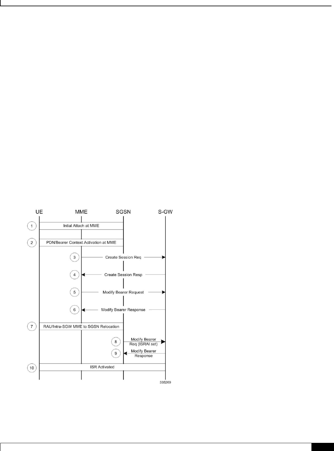
Idle-mode Signaling Reduction
How it Works ▀
Cisco ASR 5x00 Mobility Management Entity Administration Guide ▄
177
How it Works
ISR Activation
ISR does not entail any changes to the initial attach procedure at the MME or S4 SGSN. ISR is only activated when the
UE is registered with both the MME and S4 SGSN. This happens for the first time when the UE has a previous state at
either the MME or S4 SGSN and relocates to the other node. This is achieved via TAU/RAU procedures or via inter-
RAT procedures. Both the S4 SGSN and the MME then have a control connection with the Serving GW. The MME and
S4 SGSN are both registered at the HSS.
The UE stores Mobility Management (MM) parameters from the SGSN (P-TMSI and RA) and from MME (GUTI and
TA(s)) and the UE stores session management (bearer) contexts that are common for E-UTRAN and GERAN/UTRAN
accesses. In the idle state, the UE can reselect between E-UTRAN and GERAN/UTRAN (within the registered RA and
TAs) without any need to perform TAU or RAU procedures with the network. The SGSN and MME store each other's
address when ISR is activated.
Figure 14. ISR Activation During MME to SGSN Relocation
Notes:
S3 Fwd relocation request/context response would indicate ISR support at MME via indication flag (ISRSI).
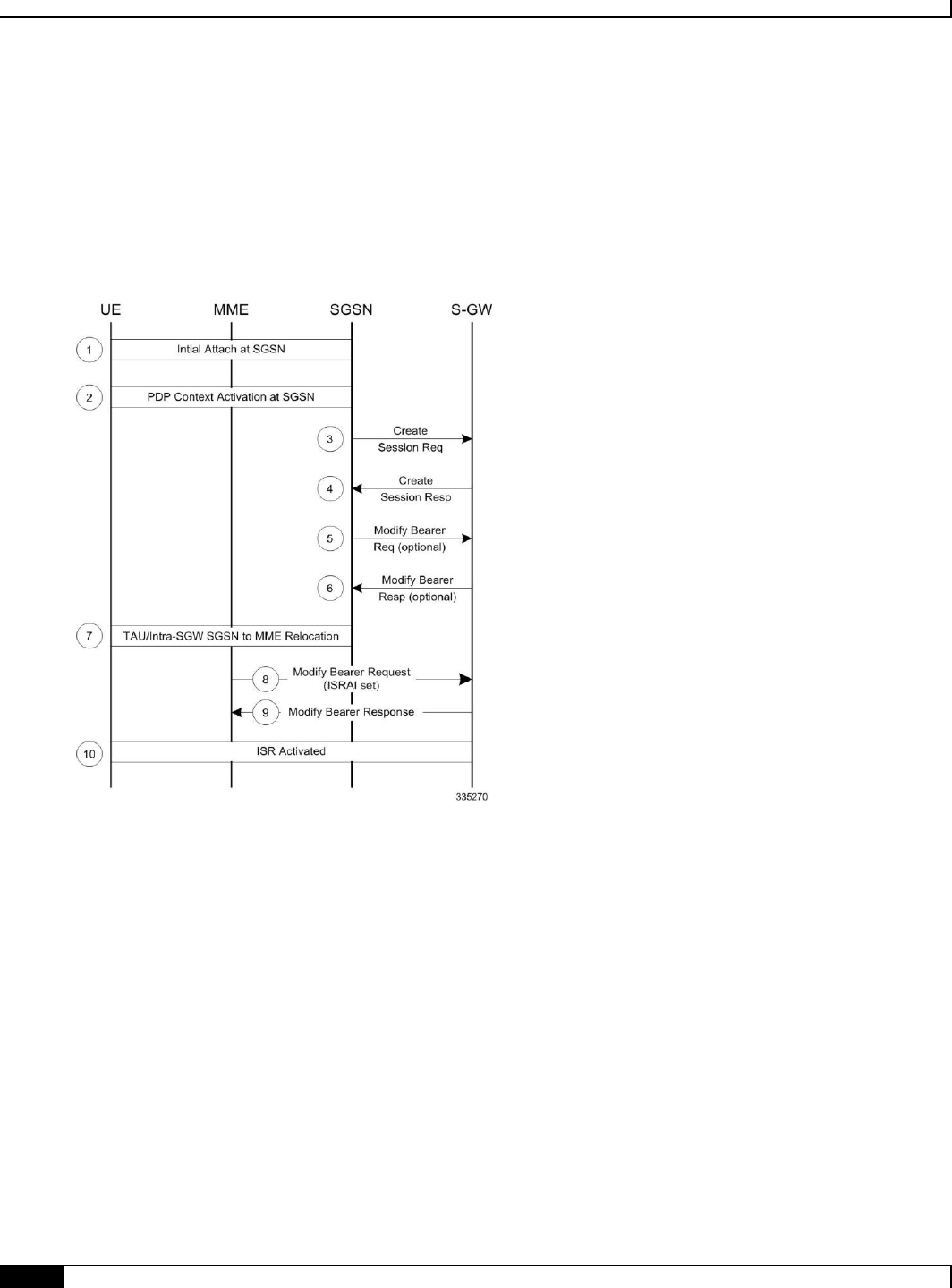
Idle-mode Signaling Reduction
▀ How it Works
▄ Cisco ASR 5x00 Mobility Management Entity Administration Guide
178
If the SGSN also supports ISR, it activates and indicates so using ISRAI flag to the S-GW in an S4 modify
bearer request message.
The SGSN uses Context Ack/Fwd Relocation Complete response to indicate to MME that ISR has been
activated. This ensures that the MME does not delete UE context.
The MME also expects the HSS to not send a Cancel-Location-request to the MME.
Figure 15. ISR Activation During SGSN to MME Relocation
Notes:
S3 Fwd relocation request/context response indicates ISR support at SGSN via indication flag (ISRSI).
If the MME also supports ISR, it activates and indicates so using ISRAI flag to the S-GW in a S11 Modify
Bearer Request message.
The MME uses the Context Ack/Fwd Relocation Complete notification to indicate to the SGSN that ISR has
been activated. This ensures that the SGSN does not delete the UE context.
The MME sends a t3423 timer and sends the appropriate EPS Update result IE to UE in a TAU accept.
ISR Deactivation
The UE and the network run independent periodic update timers for GERAN/UTRAN and for E-UTRAN. When the
MME or SGSN do not receive periodic updates, the MME and SGSN may decide independently for implicit detach,
which removes session management (bearer) contexts from the CN node performing the implicit detach and it also
removes the related control connection from the S-GW. Implicit detach by one CN node (either SGSN or MME)
deactivates ISR in the network. It is deactivated in the UE when the UE cannot perform periodic updates in time. When

Idle-mode Signaling Reduction
How it Works ▀
Cisco ASR 5x00 Mobility Management Entity Administration Guide ▄
179
ISR is activated and a periodic updating timer expires, the UE starts a Deactivate ISR timer. When this timer expires
and the UE was not able to perform the required update procedure, the UE deactivates ISR.
All special situations that cause context in the UE, MME and SGSN to become asynchronous are handled by ISR
deactivation. The normal RAU/TAU procedures synchronize contexts in MME and SGSN and activate ISR again when
wanted by the network.
ISR Behavior with Circuit Switched Fallback
ISR capability impacts some MME messaging when Circuit Switched Fallback (CSFB) is also implemented.
When receiving a Paging Request from the MSC/VLR, the MME must initiate paging in both the E-UTRAN and
the UTRAN/GERAN domains (as a UE in idle mode may be in either cell coverage).
When the MSC/VLR initiates a Non-EPS Alert Procedure, the MME must inform the peer SGSN of the request.
If there is signaling activity in the UTRAN/GERAN domain, the SGSN can inform the MME (via the S3
interface) to allow the MME to indicate activity to the MSC/VLR.
IMSI-detach is allowed from the SGSN.
Standards Compliance
The ISR capability complies with the following standards for 3GPP LTE/EPS wireless networks:
3GPP TS 23401-970
3GPP TS 29274-940
3GPP TS 23272-990
3GPP TS 24301-950

Idle-mode Signaling Reduction
▀ Configuring ISR
▄ Cisco ASR 5x00 Mobility Management Entity Administration Guide
180
Configuring ISR
Configuring ISR
This feature requires that a valid license key be installed. Contact your Cisco Account or Support representative for
information on how to obtain a license.
Use the following example to enable the ISR feature on the specified MME service
config
mme-service <mme_svc_name> -noconfirm
isr-capability
exit
Verifying ISR Configuration
Use either of the following commands to verify if ISR is enabled.
show mme-service all
show mme-service name <mme_svc_name>
The output of this command displays the entire configuration for the MME service specified.
[local]asr5x00# show mme-service name mmesvc1
ISR Capability : Enabled

Idle-mode Signaling Reduction
Monitoring and Troubleshooting ISR ▀
Cisco ASR 5x00 Mobility Management Entity Administration Guide ▄
181
Monitoring and Troubleshooting ISR
ISR Bulk Statistics
The following MME Schema bulk statistics have been introduced for the Idle-mode Signaling Reduction feature:
isr-activated
The following eGTP-C Schema bulk statistics have been introduced for the Idle-mode Signaling Reduction feature:
mobility-sent-cspagingind
mobility-recv-cspagingind
mobility-sent-alertmmenotf
mobility-sent-retransalertmmenotf
mobility-recv-alertmmenotf
mobility-recv-retransalertmmenotf
mobility-sent-alertmmeack
mobility-sent-retransalertmmeack
mobility-recv-alertmmeack
mobility-recv-retransalertmmeack
mobility-sent-alertmmeackaccept
mobility-sent-alertmmeackdenied
mobility-recv-alertmmeackaccept
mobility-recv-alertmmeackdenied
mobility-sent-ueactivitynotf
mobility-sent-ueactivitynotf
mobility-sent-retransueactivitynotf
mobility-recv-ueactivitynotf
mobility-recv-retransueactivitynotf
mobility-sent-ueactivityack
mobility-sent-retransueactivityack
mobility-recv-ueactivityack
mobility-recv-retransueactivityack
mobility-sent-ueactivityackaccept
mobility-sent-ueactivityackdenied
mobility-recv-ueactivityackaccept
mobility-recv-ueactivityackdenied

Idle-mode Signaling Reduction
▀ Monitoring and Troubleshooting ISR
▄ Cisco ASR 5x00 Mobility Management Entity Administration Guide
182
mobility-sent-detachnotf
mobility-sent-retransdetachnotf
mobility-recv-detachnotf
mobility-recv-retransdetachnotf
mobility-sent-detachack
mobility-recv-detachack
mobility-sent-detachackaccept
mobility-sent-detachackdenied
mobility-recv-detachackaccept
mobility-recv-detachackdenied
ISR Show Command(s) and/or Outputs
This section provides information regarding show commands and/or their outputs in support of ISR.
Only those counters which relate to ISR are shown.
show mme-service statistics
Table 9. ISR Deactivation Statistics
Field
Description
ISR Deactivation Statistics
S3 path failure
The total number of Idle mode Signaling Reduction (ISR) deactivations due to failure in the S3 interface.
SGSN local detach
The total number of Idle mode Signaling Reduction (ISR) deactivations due to SGSN detach notification.
SGW relocation
The total number of Idle mode Signaling Reduction (ISR) deactivations due to S-GW relocation of the
session to an MME/SGSN which does not support ISR.
CN Node
relocation
The total number of Idle mode Signaling Reduction (ISR) deactivations due to CN Node relocation of the
session to an MME/SGSN which does not support ISR.
Implicit detach
The total number of Idle mode Signaling Reduction (ISR) deactivations due to an idle timeout (implicit
detach) initiated by either the MME or Peer SGSN.
Other detach
procedures
The total number of Idle mode Signaling Reduction (ISR) deactivations due to an idle timeout (implicit
detach) initiated by either the MME or Peer SGSN.
Other reasons
The total number of Idle mode Signaling Reduction (ISR) deactivations due to a reason not otherwise
classified by one of the other ISR Deactivation Statistics categories.
show mme-service session full

Idle-mode Signaling Reduction
Monitoring and Troubleshooting ISR ▀
Cisco ASR 5x00 Mobility Management Entity Administration Guide ▄
183
Table 10. ISR Session Information
Field
Description
ISR
Status
Displays if the session is using Idle mode Signaling Reduction (ISR). Possible configurations are Activated or
Deactivated.
Peer
SGSN
Displays the IP address of the SGSN which has a context for this UE in support of Idle mode Signaling Reduction
(ISR). A Peer SGSN address is only shown when ISR is activated for this session.
show mme-service session summary
Table 11. ISR Session Summary
Field
Description
Total ISR-activated sessions
The current total number of MME sessions which are activated for ISR.
show egtpc sessions
Typically this command shows only one EGTP session (S11) per UE. When an ISR-activated UE is present, this
command displays 2 EGTP sessions per UE.

Cisco ASR 5x00 Mobility Management Entity Administration Guide ▄
185
Chapter 10
Load Balancing and Rebalancing
The following sections describe the load balancing features available on the MME.
Feature Description
How it Works
Configuring Load Balancing and Rebalancing
Monitoring Load Rebalancing

Load Balancing and Rebalancing
▀ Feature Description
▄ Cisco ASR 5x00 Mobility Management Entity Administration Guide
186
Feature Description
The following sections describe the load balancing and rebalancing functionality available on the MME.
Load Balancing
Load balancing on the MME permits UEs that are entering into an MME pool area to be directed to an appropriate
MME in a more efficient manner, spreading the load across a number of MMEs.
Load Rebalancing
The MME load rebalancing functionality permits UEs that are registered on an MME (within an MME pool area) to be
moved to another MME in the pool. The rebalancing is triggered using an exec command on the mme-service from
which UEs should be offloaded.
When initiated, the MME begins to offload a cross-section of its subscribers with minimal impact on the network and
users. The MME avoids offloading only low activity users, and it offloads the UEs gradually (configurable from 1-1000
minutes). The load rebalancing can off-load part of or all the subscribers.
The eNodeBs may have their load balancing parameters adjusted beforehand (e.g., the weight factor is set to zero if all
subscribers are to be removed from the MME, which will route new entrants to the pool area into other MMEs).
Relationships to Other Features
MME load balancing can be used in conjunction with congestion control. For more information on congestion control,
refer to the Congestion Control section in Chapter 1 of the MME Administration Guide.

Load Balancing and Rebalancing
How it Works ▀
Cisco ASR 5x00 Mobility Management Entity Administration Guide ▄
187
How it Works
Load Balancing
Load balancing is achieved by setting a weight factor for each MME so that the probability of the eNodeB selecting an
MME is proportional to its weight factor. The weight factor is set by the operator according to the capacity of an MME
node relative to other MME nodes. The relative-capacity mme-service level command is used to specify this
relative weighting factor.
Once set, the Relative MME Capacity IE is included in the S1AP S1 SETUP RESPONSE message from MME to relay
this weight factor. If the relative MME capacity is changed after the S1 interface is already initialized, then the MME
CONFIGURATION UPDATE message is used to update this information to the eNodeB.
Load Rebalancing
The MME uses the mme offload mme-service exec level command to enable the operator to offload UEs for a
particular mme-service for load rebalancing among MMEs in a MME pool area. The command enables the operator to
specify a percentage of UEs to offload, and the desired time duration in which to complete the offload.
The operator can also include the keyword option disable-implicit-detach. By default, if the UE context is not
transferred to another MME within 5 minutes, the UE will be implicitly detached. This option disables this implicit
detach timer.
To offload ECM-CONNECTED mode UEs, the MME initiates the S1 Release procedure with release cause “load
balancing TAU required”.
To offload UEs which perform TA Updates or Attaches initiated in ECM-IDLE mode, the MME completes that
procedure and the procedure ends with the MME releasing S1 with release cause “load balancing TAU required”.
To offload UEs in ECM-IDLE state without waiting for the UE to perform a TAU or perform Service request and
become ECM CONNECTED, the MME first pages the UE to bring it to ECM-CONNECTED state.
Call Handling and Other Messaging Considerations
New calls are processed normally (as per the new call policy configuration). The offloading process does not reject INIT
UE messages for new subscribers. To prevent new calls from entering this MME, set the relative-capacity on this
mme-service to 0.
When Init UE messages are received for an existing offloaded subscriber, the ue-offloading state is set as MARKED
and the offload procedure continues until the UE is offloaded.
Once a UE is offloaded, messages such as EGTP events, Create bearer, Update bearer, Idle mode exit, and Paging
trigger are be rejected. HSS initiated events also will be rejected for offloaded UEs.
Detach events are processed as usual.
Important: Emergency attached UEs in Connected or Idle mode are not considered for offloading.

Load Balancing and Rebalancing
▀ Configuring Load Balancing and Rebalancing
▄ Cisco ASR 5x00 Mobility Management Entity Administration Guide
188
Configuring Load Balancing and Rebalancing
Configuring Load Balancing
Set the relative capacity of an mme-service to enable load balancing across a group of mme-services within an MME
pool.
Use the following example to set the relative capacity of this mme-service. The higher the value, the more likely the
corresponding MME is to be selected.
config
mme-service mme_svc -noconfirm
relative-capacity <0-255>
exit
Notes:
The default relative capacity for an mme-service is 255.
Verifying Load Balancing
show mme-service all
[local]asr5000# show mme-service all
Relative Capacity:
50
Performing Load Rebalancing (UE Offloading)
The following example command rebalances (offloads) 30 percent of all UEs from the specified mme-service (to other
mme-services in the MME pool) over the course of 10 minutes.
mme offload mme-service mme_svc time-duration 10 offload-percentage 30 -noconfirm
This command can also be entered with the disable-implicit-detach option. By default, if the UE context is not
transferred to another MME within 5 minutes, the UE will be implicitly detached. This option disables this implicit
detach timer.
mme offload mme-service mme_svc time-duration 10 offload-percentage 30 disable-implicit-
detach -noconfirm
To stop the offloading process, issue the command with the stop keyword option.
mme offload mme-service mme_svc stop -noconfirm

Load Balancing and Rebalancing
Configuring Load Balancing and Rebalancing ▀
Cisco ASR 5x00 Mobility Management Entity Administration Guide ▄
189
Verifying Load Rebalancing (UE Offloading)
The following command shows the offload configuration as well as the status of the rebalancing.
show mme-service name svc_name offload statistics
[local]asr5000# show mme-service name mme1 offload statistics
Current Offload Status: In Progress
Implicit Detach Status: Enabled
Time Duration Requested: 600 secs
Percentage of Subscribers Requested: 30
Total Number of Subscribers: 0
Total Number of Subscribers to be Offloaded: 0
Total Number of Subscribers Offloaded: 0
Total Number of Subscribers Received Context Transfer: 0
Remaining Time: 0 secs
Where the Current Offload Status field will report one of the following:
None – No UEs marked for offloading and no UEs currently being offloaded.
Marked – MME has marked UEs for offloading, but is waiting for offload trigger on timer expiry.
In Progress – MME is currently offloading marked UEs.
Done – Offload procedure is completed or has been terminated by operator using stop keyword.
These counters are reset each time an offload procedure is initiated, or when the following command is entered:
clear mme-service statistics offload

Load Balancing and Rebalancing
▀ Monitoring Load Rebalancing
▄ Cisco ASR 5x00 Mobility Management Entity Administration Guide
190
Monitoring Load Rebalancing
The following sections describe commands available to monitor load rebalancing on the MME.
Load Rebalancing Show Command(s) and/or Outputs
This section provides information regarding show commands and their outputs in support of load rebalancing (UE
offload).
The following show command displays current statistics for the Load Rebalancing feature.
show mme-service name mme_svc offload statistics
Table 12. show mme-service name <mme_svc_name> offload statistics
Field
Description
Current Offload Status
Current offload status of the specified mme-service. Possible values are Not Started, In
Progress and Completed.
Implicit Detach Status
The Implicit Detach Status specified in the mme offload command. When enabled, if the UE
context is not transferred to another MME within 5 minutes then it will be implicitly detached.
Time Duration Requested
The time-duration value specified in the mme offload command (in seconds). This is the
maximum allowed time for the offload procedure to complete.
Percentage of Subscribers
Requested
The offload-percentage specified in the mme offload command (specified as a percentage of
all UEs on this mme-service).
Total Number of Subscribers
The total number of UEs on the specified mme-service.
Total Number of Subscribers to
be Offloaded
Total number of UEs on the specified mme-service selected for offloading.
Total Number of Subscribers
Offloaded
The total number of UEs which have been successfully offloaded from this mme-service (UE
offloading State/Event = Done).
Total Number of Subscribers
Received Context Transfer
Total number of UEs which has been successfully context transferred to another MME.
Remaining Time
The number of seconds remaining to complete the offload procedure.
The following command also provides information relating to load balancing:
show mme-service session full all
Only the output field which relate to load rebalancing is shown.
Table 13. show mme-service session full all
Field
Description

Load Balancing and Rebalancing
Monitoring Load Rebalancing ▀
Cisco ASR 5x00 Mobility Management Entity Administration Guide ▄
191
Field
Description
UE Offloading
Displays the UE offload state. Possible values are None, Marked, In-Progress and Done.

Cisco ASR 5x00 Mobility Management Entity Administration Guide ▄
193
Chapter 11
Location Services
LoCation Services (LCS) on the MME and SGSN is a 3GPP standards-compliant feature that enables the system (MME
or SGSN) to collect and use or share location (geographical position) information for connected UEs in support of a
variety of location services.

Location Services
▀ Location Services - Feature Description
▄ Cisco ASR 5x00 Mobility Management Entity Administration Guide
194
Location Services - Feature Description
The Location Services (LCS) feature enables the EPC MME and the GPRS/UMTS SGSN to use the SLg (MME) or Lg
(SGSN) interface which provides the mechanisms to support specialized mobile location services for operators,
subscribers, and third party service providers. Use of this feature and the SLg/Lg interface is license controlled.
The location information is reported in standard geographical co-ordinates (longitude and latitude) together with the
time-of-day and the estimated errors (uncertainty) of the location of the UE. For external use, the location information
may be requested by and reported to a client application associated with the UE, or a client within or attached to the core
network. For internal use, the location information can be utilized by the SGSN for functions such as location assisted
handover or to support other features.
Location information is intended to be used for
location-based charging (e.g., home-location billing, roaming-location billing),
location-based services (e.g., lawful interception, emergency calls),
positioning services offered to the subscribers (e.g., mobile yellow pages, navigation applications on mobiles),
and
by the operator for service provider services such as network planning and enhanced call routing.

Location Services
How Location Services Works ▀
Cisco ASR 5x00 Mobility Management Entity Administration Guide ▄
195
How Location Services Works
The MME LCS responsibilities center around UE subscription authorization and managing LCS positioning requests.
The LCS functions of the MME are related to LCS co-ordination, location request, authorization and operation of the
LCS services.
The operation begins with a LCS Client requesting location information for a UE from the LCS server. The LCS server
will pass the request to the MME in the core network. The MME in the core network then:
1. verifies that the LCS Client is authorized to request the location of the UE or subscriber;
2. verifies that location services are supported by the UE;
3. establishes whether it (the MME) is allowed to locate the UE or subscriber, for privacy or other reasons;
4. requests the access network (via S1 interface) to provide location information for an identified UE, with
indicated QoS;
5. receives information about the location of the UE from the Access Network and forward it to the Client;
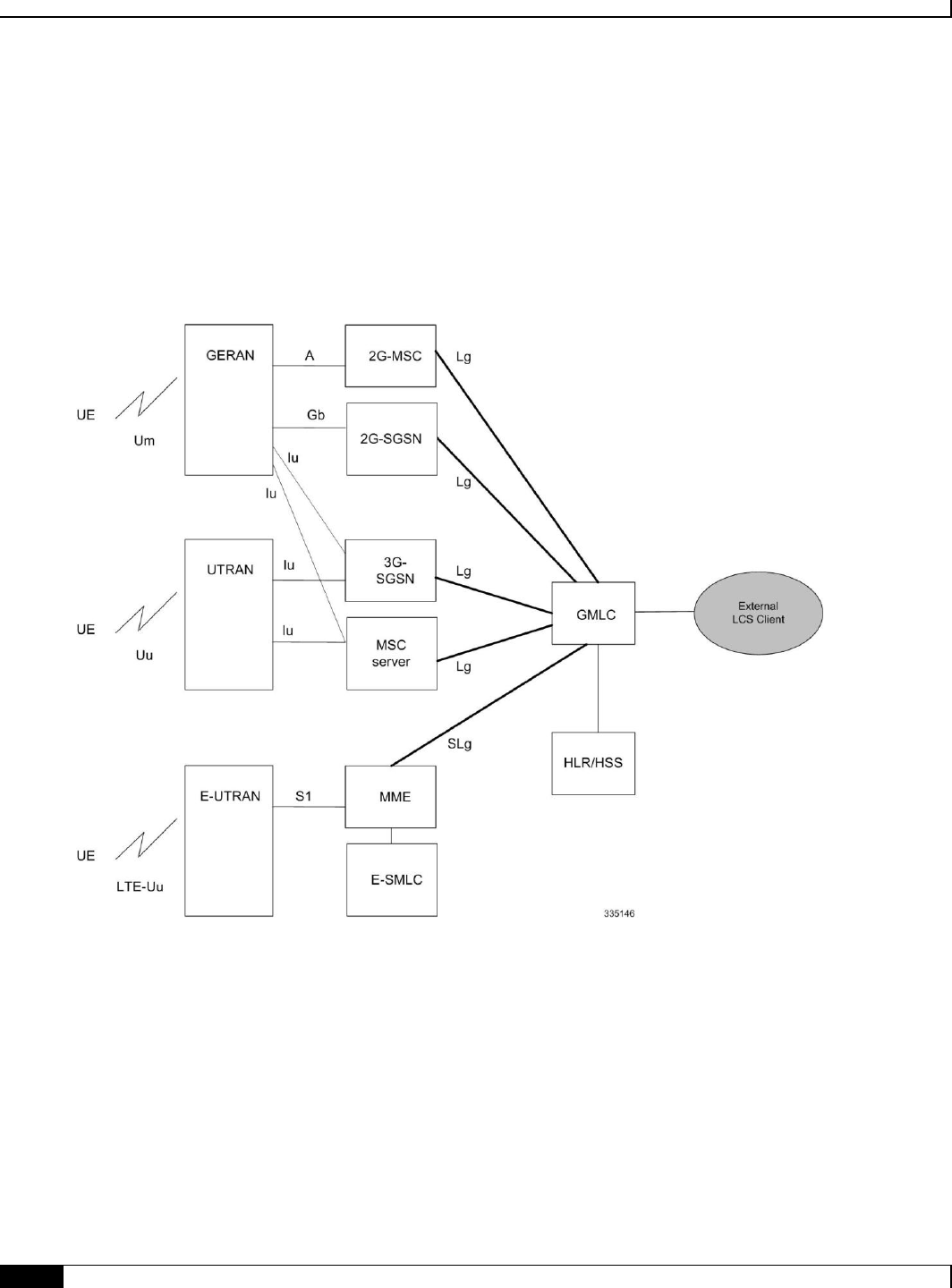
Location Services
▀ Architecture
▄ Cisco ASR 5x00 Mobility Management Entity Administration Guide
196
Architecture
The MME is accessible to the Gateway Mobile Location Center (GMLC) via the SLg interface.
The SGSN is accessible to the GMLC via the Lg interface.
Figure 16. LCS Architecture
The MME informs the HLR/HSS about a UE's location services capabilities for an EPC network.

Location Services
Supported Functionality ▀
Cisco ASR 5x00 Mobility Management Entity Administration Guide ▄
197
Supported Functionality
The MME supports the following LCS functions:
Immediate Mobile-Terminating Location Requests (MT-LI) [TS 3GPP 23.271].
MT-LR procedures from the GMLC with client type of Lawful Intercept and Emergency services.
Network Induced (NI-LR) procedures for Emergency PDN Connect and Emergency Attach, and Inbound
relocation with emergency PDN (through TAU or SRNS).
Circuit Switch Fallback (CSFB): When a UE is combined attached to the MME, and the CSFB registration is not
for SMS-only services, the MME shall page UE on receipt of an SGs page with LCS Client identity.
Limitations
Currently, MME support is limited to:
A single location request at a time for the target UE. Concurrent location requests are not supported.
Location reporting granularity is at the E-UTRAN Cell Global Identifier (EGCI) level only.
Only Provide Subscriber Location messages with the id as IMSI are supported.
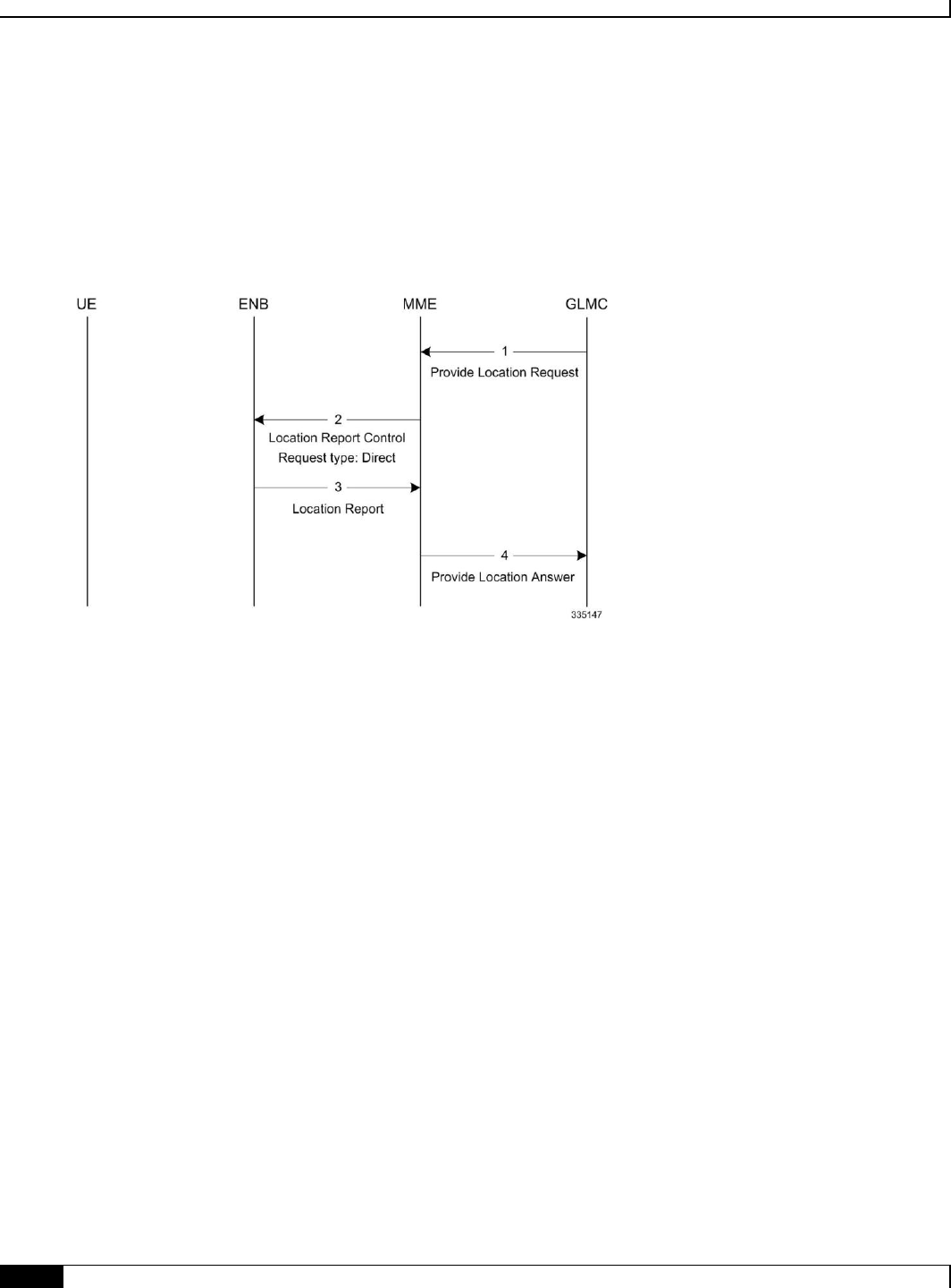
Location Services
▀ Flows
▄ Cisco ASR 5x00 Mobility Management Entity Administration Guide
198
Flows
Mobile Terminated Location Requests
Figure 17. 4G LCS - MT-LR Call Flow - Connected Mode
1. The MME receives a Provide Location Request from the GMLC. The UE is in Connected mode.
2. The MME sends Location Report Control message with request-type as 'Direct'.
3. The eNodeB (ENB) sends the current location of the UE (ECGI) in the Location report message.
4. The MME sends Provide Location Answer to GMLC with ECGI received in the location Report Message
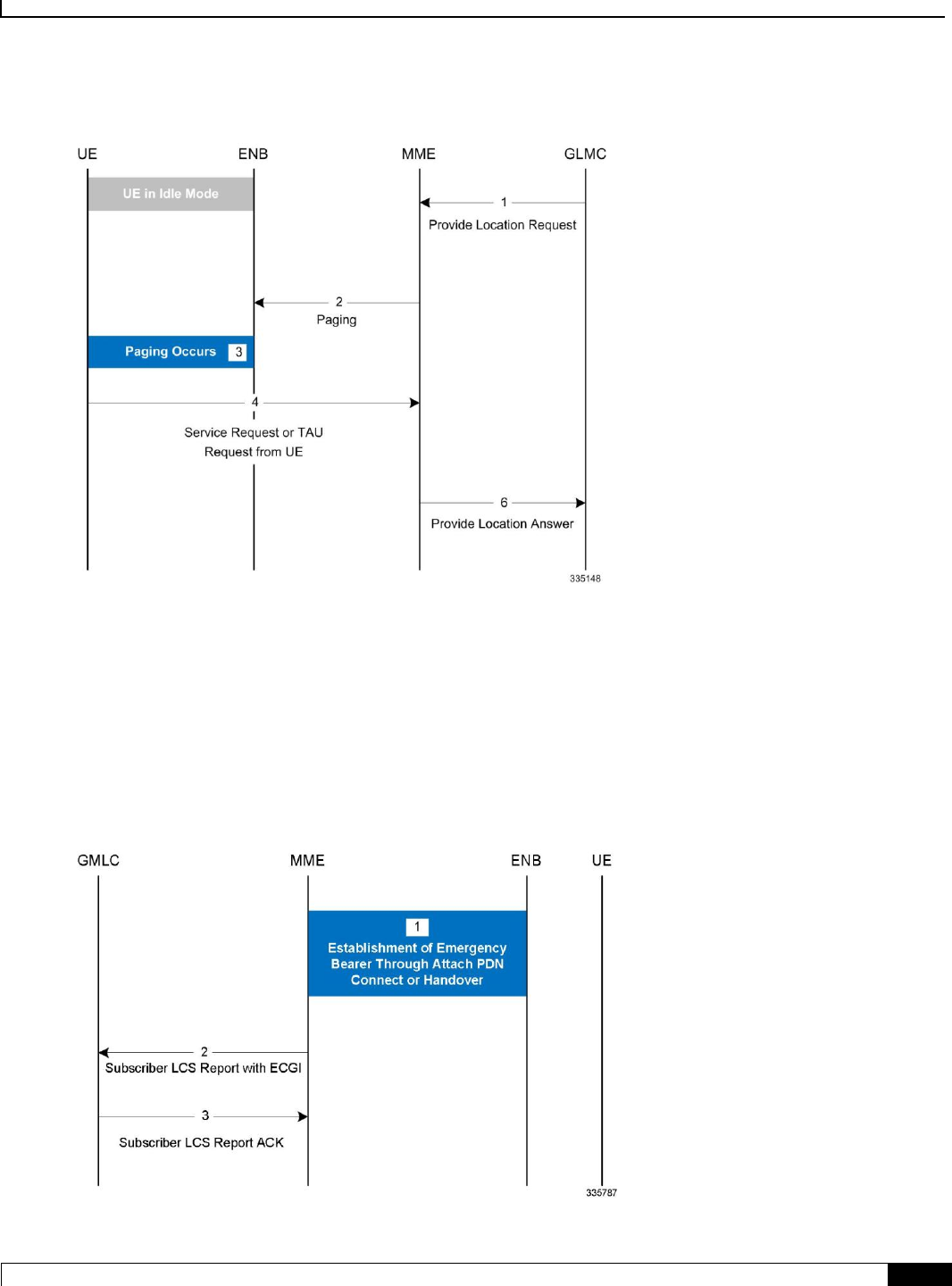
Location Services
Flows ▀
Cisco ASR 5x00 Mobility Management Entity Administration Guide ▄
199
Figure 18. 4G LCS - MT-LR Call Flow - Idle Mode
1. The MME receives a Provide Location Request from the GMLC. The UE is in idle mode.
2. The MME pages the UE.
3. If the UE does not respond to the page, the MME responds with the last known location and sets the age of location report
accordingly if the Location Type requested by the GMLC was “current or last known location”.
4. If paging is successful, the UE responds with Service request/TAU request.
5. The MME uses the ECGI in the S1 message and sends Provide Location Answer message to the GMLC.
Network Induced Location Requests
Figure 19. 4G LCS - NI-LR Call Flow

Location Services
▀ Flows
▄ Cisco ASR 5x00 Mobility Management Entity Administration Guide
200
1. The UE establishes Emergency bearers with MME. This could be a Emergency Attach or establishement of an
Emergency PDN. Handover of an Emergency call from one MME to the other is also possible.
2. If the MME is configured to support Location service for emergency calls, the latest ECGI is sent in the
Subscriber Location Report message to the configured GMLC.
3. The GMLC, on processing the Subscriber location report, sends the Subscriber location ACK. Note: A Negative
ACK will not have any effect.

Location Services
Standards Compliance ▀
Cisco ASR 5x00 Mobility Management Entity Administration Guide ▄
201
Standards Compliance
The Location Services feature complies with the following standards:
TS 3GPP 23.271, v9.6.0
TS 3GPP 24.080, v9.2.0
TS 3GPP 24.171, v9.0.0
TS 3GPP 29.172, v9.4.0
Location Services
▀ Configuring Location Services (LCS)
▄ Cisco ASR 5x00 Mobility Management Entity Administration Guide
202
Configuring Location Services (LCS)
This section provides a high-level series of steps and the associated configuration examples to configure Location
Services on the MME.
The commands could be issued in a different order, but we recommend that you follow the outlined order for an initial
LCS configuration. All listed configuration steps are mandatory unless otherwise indicated.
Important: For all the required configuration commands to be available and to implement the configuration, the
MME must have loaded the license for the Lg interface.
Step 1 Create a location service configuration on the MME.
Step 2 Associate the location service with the appropriate Diameter endpoint.
Step 3 Associate the MME service with this location service.
Step 4 Associate the LTE Emergency Policy with this location service.
Step 5 Save your configuration to flash memory, an external memory device, and/or a network location using the Exec mode
command save configuration. For additional information on how to verify and save configuration files, refer to the
System Administration Guide.
Step 6 Verify the configuration for each component by following the instructions provided in the Verifying the Feature
Configuration section.

Location Services
Creating and Configuring a Location Service ▀
Cisco ASR 5x00 Mobility Management Entity Administration Guide ▄
203
Creating and Configuring a Location Service
A location service must be created within a context. Up to 16 separate location services can be created.
Important: The Origin host configured in the endpoint for SLg interface must match the origin host
configured in the endpoint for S6a interface.
config
context <context_name> -noconfirm
location-service <location_svc_name> -noconfirm
associate diameter endpoint <endpoint>
end
Notes:
This series of commands creates a Location service and associates the service with a diameter endpoint.

Location Services
▀ Associate the MME Service with the Location Service
▄ Cisco ASR 5x00 Mobility Management Entity Administration Guide
204
Associate the MME Service with the Location Service
Once the location service is created and configured, the MME service must be associated with it. The steps below
assume the MME service has already been created.
config
context <context_name> -noconfirm
mme-service <mme_svc_name>
associate location-service <location_svc_name>
end
Notes:
This series of commands associates an MME service with the new location service.

Location Services
Associate the LTE Emergency Profile with the Location Service ▀
Cisco ASR 5x00 Mobility Management Entity Administration Guide ▄
205
Associate the LTE Emergency Profile with the Location Service
Once the location service is created and configured, the LTE Emergency Profile must be associated with it. The steps
below assume the LTE Emergency Profile has already been created.
This procedure enables the MME to provide location information of an emergency call to the GMLC.
config
lte-policy
lte-emergency-profile <profile_name>
associate location-service <location_svc_name>
end
Notes:
This series of commands associates the LTE Emergency Profile with the new location service.

Location Services
▀ Verifying the LCS Configuration
▄ Cisco ASR 5x00 Mobility Management Entity Administration Guide
206
Verifying the LCS Configuration
The following command displays configuration information for all Location services configured on the MME.
show location-service service all
The following command displays the location service to which each MME service is associated.
show mme-service all
The following command displays the location service to which the specified LTE Emergency Profile is associated.
show lte-policy lte-emergency-profile profile_name
The following command displays a list of all services configured on the system, including location services (listed as
Type: lcs).
show services all

Location Services
Show Command(s) and/or Outputs ▀
Cisco ASR 5x00 Mobility Management Entity Administration Guide ▄
207
Show Command(s) and/or Outputs
The following command displays statistics for all LCS activity on the MME.
show location-service statistics all
Use the following command to clear the LCS statistics for a specific Location service.
clear location-service statistics service location_svc_name
The following command displays LCS statistics for a specific MME service.
show mme-service statistics service mme-service mme_svc_name
Use the following command to clear MME service statistics for a specific MME service.
clear mme-service statistics mme-service mme_svc_name

Cisco ASR 5x00 Mobility Management Entity Administration Guide ▄
209
Chapter 12
Overcharging Protection
Overcharging Protection helps in avoiding charging subscribers for dropped downlink packets while the UE is in idle
mode. This feature helps ensure subscriber are not overcharged while the subscriber is in idle mode.
Feature Description
How it Works
Configuring Overcharge Protection

Overcharging Protection
▀ Feature Description
▄ Cisco ASR 5x00 Mobility Management Entity Administration Guide
210
Feature Description
Important: A valid license key is required to enable Overcharge Protection on the MME. Contact your Cisco
Account or Support representative for information on how to obtain a license.
For Non-GBR (Guaranteed Bit Rate) 4G bearers, the P-GW is not aware when the UE loses radio coverage, and will
continue to forward and charge downlink packets, which can result in overcharging of subscribers. 3GPP does not
specify a standard solution to deal with such scenarios.
A typical example is when a subscriber drives into a tunnel while having an active download session. Downlink packets
will be counted in P-GW before discarded later in S-GW due to the UE not responding to paging.
The subscriber may lose coverage while connected to a particular MME/S-GW and later regain coverage in the same or
diiferent MME/S-GW.
The subscriber may lose coverage in 4G and regain coverage in 2G/3G, or vice versa.
Gn and S3/S4 based network architecture may be used in the case of Loss of Radio Coverage.
Relationships to Other Features
Overcharging protection on the MME requires separate overcharging protection licenses on the S-GW and P-GW.
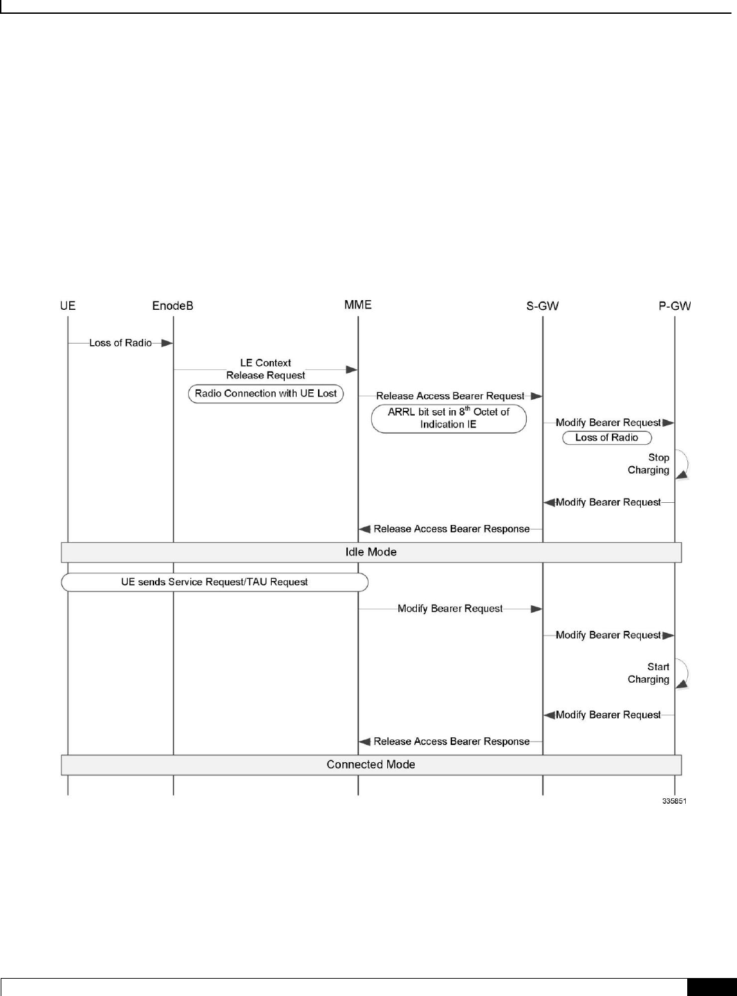
Overcharging Protection
How it Works ▀
Cisco ASR 5x00 Mobility Management Entity Administration Guide ▄
211
How it Works
Call Flows
The following diagram depicts the call flow when a UE loses radio access, and then later regains access, as it relates to
overcharging protection.
Figure 20. Overcharging Protection Call Flow
Overcharging protection in MME is triggered by a UE Context Release Request from the eNodeB. This request can
come to MME when UE is in EMM connected/connecting mode.
On receiving the UE Context Release Request, the MME checks the radio cause in the received message against the
configured overcharging protection cause code.

Overcharging Protection
▀ How it Works
▄ Cisco ASR 5x00 Mobility Management Entity Administration Guide
212
If the configured cause code matches the received cause code, the MME sends Loss of Radio Contact using ARRL
(Abnormal Release of Radio Link) bit in the Release Access Bearer Request (GTPv2 message) to the S-GW. The ARRL
(Abnormal Release of Radio Link) is bit 7 in the 8th Octet of Indication IE of Release Access Bearer Req message.
On Receiving ARRL indication in Release Acccess Bearer Request , the S-GW will inform the P-GW to stop charging.
When the radio contact is resumed in the 4G network, the Modify Bearer Req will enable the P-GW to start charging
again.
The ARRL bit is supported only in Release Access Bearer Request message by MME.

Overcharging Protection
Configuring Overcharge Protection ▀
Cisco ASR 5x00 Mobility Management Entity Administration Guide ▄
213
Configuring Overcharge Protection
Enabling Overcharging Protection
To enable overcharging protection for a specific MME service, issue the following commands:
configure
context <context_name>
mme-service <svc_name>
policy overcharge-protection s1ap-cause-code-group <group_name>
end
To disable overcharging protection:
no policy overcharge-protection
Configuring S1AP Cause Code Group and Cause Code
To configure the S1AP Cause Code Group and S1AP cause code “Radio Connection With UE Lost (21)”:
configure
lte-policy
cause-code-group <group_name> protocol s1ap
class radio cause <radio_cause_code>
end
Notes:
For example, to define a cause code group for the code “Radio Connection With UE Lost”, enter: class radio
cause 21
Verifying the Overcharge Protection Configuration
The Overcharge Protection field has been added to the output of show mme-service name service_name to
display the configuration of this feature, either “Not configured” or showing the configured S1-AP cause code group
name:
Policy Inter-RAT Indirect Fwd Tunnels : Never
Policy Inter-RAT Ignore SGSN ContextID : Disabled

Overcharging Protection
▀ Configuring Overcharge Protection
▄ Cisco ASR 5x00 Mobility Management Entity Administration Guide
214
Policy S1-Reset : Idle-Mode-Entry
Overcharge Protection : Cause Code Group grp1

Cisco ASR 5x00 Mobility Management Entity Administration Guide ▄
215
Chapter 13
Single Radio Voice Call Continuity
Voice over IP (VoIP) subscribers anchored in the IP Multimedia Subsystem (IMS) network can move out of an LTE
coverage area and continue the voice call over the circuit-switched (CS) network through the use of the Single Radio
Voice Call Continuity (SRVCC) feature. Unlike other methods like CSFB, it does not require a dual-mode radio.
Feature Description
How it Works
Configuring Single Radio Voice Call Continuity
Monitoring and Troubleshooting SRVCC
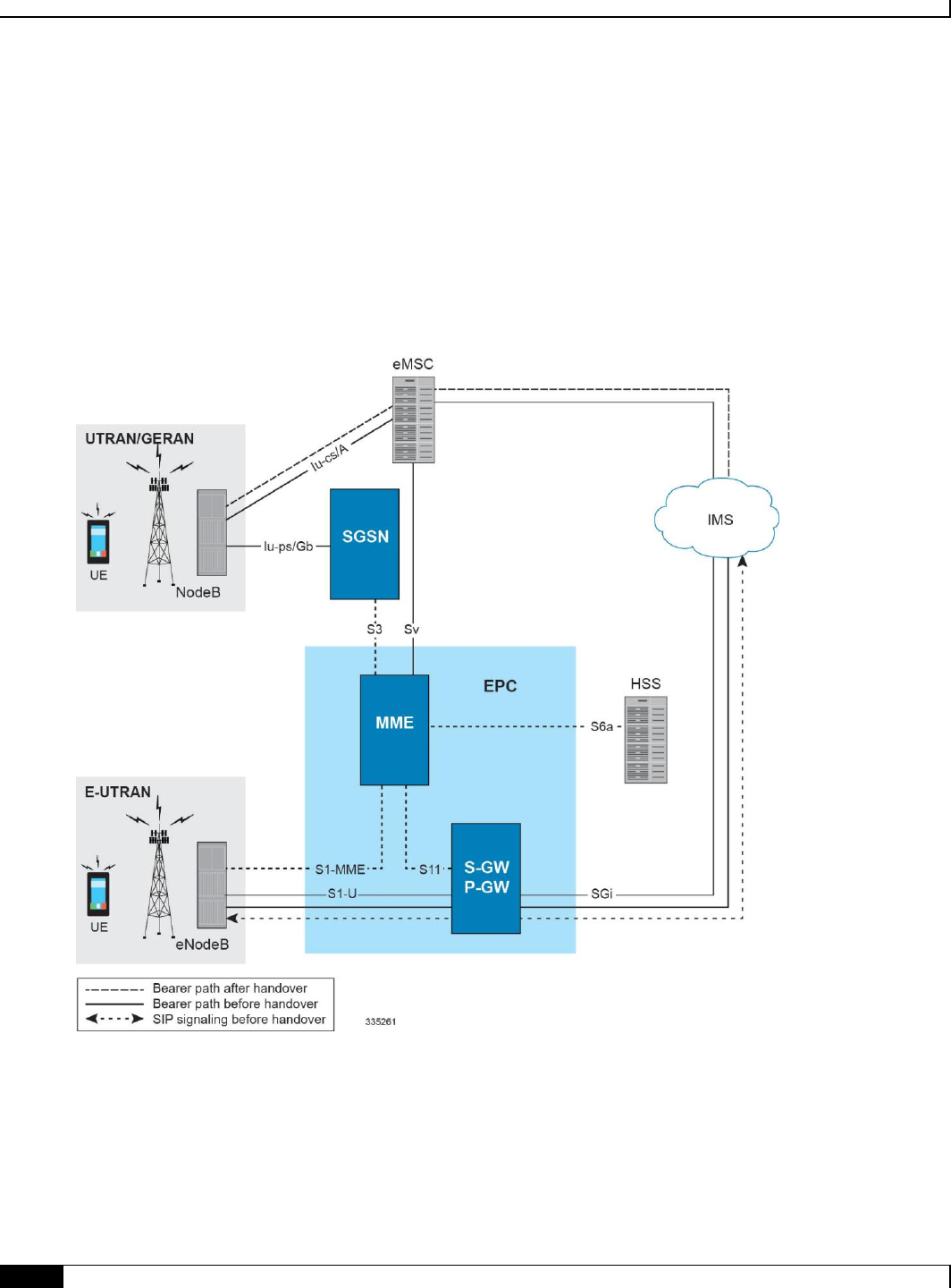
Single Radio Voice Call Continuity
▀ Feature Description
▄ Cisco ASR 5x00 Mobility Management Entity Administration Guide
216
Feature Description
SRVCC requires that a valid license key be installed. Contact your Cisco Account or Support representative for
information on how to obtain a license.
To support SRVCC functionality on the MME, an Sv interface is created to the Mobile Switching Center (MSC) server
responsible for communicating with the MME during the handover process.
Figure 21. SRVCC Architecture
The MME supports the following SRVCC features:
MSC Pool Areas: MSC pool areas can be configured for load balancing and intelligent selection of MSC servers based
on PLMN and/or IMSI hash values. Up to 24 MSC servers can be defined per MME service. Each pool-area can
optionally be associated with a PLMN, which is the target PLMN as specified in the SRVCC Handover request.
The MME attempts to select an MSC using the following selection order: 1) Pool-area that matches the PLMN and of
type hash 2) Pool-area that matches the PLMN and of type round-robin 3) Pool-area that does not have PLMN and of
type hash 4) Pool-area that does not have PLMN and of type round-robin.

Single Radio Voice Call Continuity
Feature Description ▀
Cisco ASR 5x00 Mobility Management Entity Administration Guide ▄
217
MSC Offload: The MME allows an administrator to place one or more MSC server in maintenance mode. This action
removes the MSC server as a possible selection target.
The MME implementation of SRVCC also supports:
IMS Centralized Service call handling as specified in 3GPP TS 29.280, enabling call flow handling for advanced
scenarios.
Emergency Calls as defined in 3GPP TS 29.280.
GTP echo path management messages as defined in 3GPP TS 29.280.
GTP-C DSCP marking.
Relationships to Other Features
If the UE supports circuit-switch fallback (CSFB) and/or IMS voice, or both, the UE shall include the information
element "Voice domain preference and UE's usage setting" in Attach Request and Tracking Area Update Request
messages. The UE's usage setting indicates whether the UE behaves in a voice centric or data centric way. The voice
domain preference for E-UTRAN indicates whether the UE is configured as CS Voice only, CS Voice preferred and
IMS PS Voice as secondary, IMS PS Voice preferred and CS Voice as secondary, or IMS PS Voice only. The purpose
of this information element is to signal to the network the UE's usage setting and voice domain preference for E-
UTRAN.
The UE also includes the SRVCC capability indication as part of the "MS Network Capability" in the Attach Request
message and in Tracking Area Updates. This capability needs to be accessed and stored on the MME.
If the UE reflects SRVCC along with IMS voice in the "Voice domain preference" in a Combined Attach, the MME will
treat it as a EPS Attach with SRVCC capability.

Single Radio Voice Call Continuity
▀ How it Works
▄ Cisco ASR 5x00 Mobility Management Entity Administration Guide
218
How it Works
The existing eGTP-C service is enhanced to support the Sv reference point. A new instance of the eGTP-C service must
be configured for Sv messages.
SRVCC requires the following elements:
SRVCC requires the STN-SR to be sent to the MSC for all non-emergency calls. If the STN-SR is not present in
the HSS during the Attach procedure, SRVCC handover will not be allowed for non-emergency calls. In case
of situations like STN-SR not being configured for non-emergency calls, the MME will send a HANDOVER
PREPARATION FAILURE message back with the cause code set to Handover Failure in Target System.
MSC Server that has been enhanced for SRVCC.
UE that has ICS (IMS Service Continuity) capabilities with single radio access. The UE includes the ICS
Capability indication as part of the UE network capability in the Attach Request message. The MME stores this
information for SRVCC operation.
IMS network and SCC-AS in which the call is anchored. The MME signals to the UE the presence of VoIMS in
the Attach Response
SRVCC is agnostic as to the whether S3 or GnGP is used for the SGSN interface.
Flows
The following SRVCC call flows are supported:
SRVCC from E-UTRAN to GERAN without DTM support (TS 23.216 V10.5.0; Section 6.2.2.1).
SRVCC from E-UTRAN to GERAN with DTM but without DTM HO support and from E-UTRAN to UTRAN
without PS HO (TS 23.216 V9.6.0; Section 6.2.2.1A).
SRVCC from E-UTRAN to UTRAN with PS HO or GERAN with DTM HO support (TS 23.216 V9.6.0;
Section 6.2.2.1A).
Emergency calls for all of the above three SRVCC scenarios
Standards Compliance
The MME implementation of SRVCC complies with the following standards:
3GPP TS 23.216 Single Radio Voice Call Continuity (SRVCC) V10.5.0
3GPP TS 29.280 Sv Interface (MME to MSC and SGSN to MSC) for SRVCC V10.4.0
3GPP TS 36.413 S1 Application Protocol (S1AP) V10.5.0
3GPP TS 29.303 Domain Name System Procedures; Stage 3 V10.4.0

Single Radio Voice Call Continuity
Configuring Single Radio Voice Call Continuity ▀
Cisco ASR 5x00 Mobility Management Entity Administration Guide ▄
219
Configuring Single Radio Voice Call Continuity
Configuring SRVCC
Configuring an MSC Pool Area
MSC Offload
Verifying the SRVCC Configuration
Configuring SRVCC
Use the following example to configure basic SRVCC support on the MME, including:
Creating the eGTP-C Sv service and binding it to an IPv4/v6 address.
Assocating the eGTP-C service to the MME service.
Configuring one or more MSC servers within the MME service.
configure
context <mme_context_name>
interface <sv_intf_name>
ip address <ipv4_address>
exit
egtp-service <egtpc_sv_service_name>
interface-type interface-mme
gtpc bind ipv4-address <sv_infc_ip_address>
exit
mme-service <mme_service_name>
associate egtpc-sv-service <egtpc_sv_service_name>
msc name <msc_name> ip-address <ip_address>
exit
exit
port ethernet <slot_number/port_number>
no shutdown
bind interface <sv_intf_name> <mme_context_name>

Single Radio Voice Call Continuity
▀ Configuring Single Radio Voice Call Continuity
▄ Cisco ASR 5x00 Mobility Management Entity Administration Guide
220
end
Notes:
The gtpc bind command can be specified as an IPv6 address using the ipv6-address keyword. The
interface specified for Sv communication must also be the same IP address type.
Configuring an MSC Pool Area
In order to support pooling, multiple MSC servers and pool-areas for Sv interface are allowed to be configured within
the MME service. A maximum of 24 MSC servers can be configured for a given MME Service. Each MME Service can
also have be a maximum of 24 pool areas. Each pool-area can have a maximum of 24 MSC's.
The pool can be either based on IMSI hash or a round-robin scheme. In the IMSI hash scheme, an MSC is chosen based
on the result of the IMSI [(IMSI div 10) modulo 1000]. In case of round-robin, the MME selects the next MSC based on
the round-robin scheme.
Each pool-area is associated with a unique name. Within a pool-area of type hash, up to 24 hash-values can be defined.
Pool-area of type round-robin can have up to 24 entries.
Each pool-area can be associated with a PLMN which is the target PLMN as specified in the SRVCC Handover request.
MME attempts to select a MSC using the following selection order:1) Pool-area that matches the PLMN and of type
hash2) Pool-area that matches the PLMN and of type round-robin3) Pool-area that does not have PLMN and of type
hash4) Pool-area that does not have PLMN and of type round-robin
IMSI Hash MSC Pool
Use the following example to configure an MSC server pool with a selection scheme based on the IMSI hash value.
configure
context <ctxt_name>
mme-service <service_name>
pool-area <pool_area_name> type hash-value
hash-value { <hash_value> | range <start_value> to <end_value> } use-msc
msc_id
plmn-id mcc <code> mnc <code>
exit
Notes:
The pool-area command creates a Mobile Switching Center (MSC) server pool area and defines that the MSC
servers be selected from within the pool using the result of the IMSI (using the hash-value keyword).
The optional plmn-id command associates a Public Land Mobile Network (PLMN) identifier with this Mobile
Switching Center (MSC) pool area. This is used to select an MSC based on the target PLMN as specified in the
SRVCC handover request. If a pool does not have any PLMN id associated with it, the pool area is assumed to
be able to serve any PLMN.

Single Radio Voice Call Continuity
Configuring Single Radio Voice Call Continuity ▀
Cisco ASR 5x00 Mobility Management Entity Administration Guide ▄
221
If this command is used, the PLMN id values specified must be unique within a given MSC pool area type. For
example, multiple pool areas of type hash cannot use the same PLMN. However, you can configure one pool
area of type hash and another of type round-robin and have both use the same PLMN id.
The hash-value command configures the selection of a Mobile Switching Center (MSC) server in a MSC pool
area based on the hash value derived from the IMSI [(IMSI div 10) modulo 1000].
The use-msc keyword associates an MSC to use for this hash value, where msc_name is the name of the MSC
as previously configured in the MME service using the msc command. A maximum of 24 MSCs can be
defined per pool area.
See the MME MSC Server Pool Area Configuration Mode chapter of the Command Line Interface Reference for
more information.
Round-Robin MSC Pool
Use the following example to configure an MSC server pool with a round-robin selection scheme.
configure
context <ctxt_name>
mme-service <service_name>
pool-area <pool-area-name> type round-robin
plmn-id mcc <code> mnc <code>
use-msc msc_id
exit
Notes:
The pool-area command creates a Mobile Switching Center (MSC) server pool area and defines that the MSC
servers be selected from within the pool using a round-robin scheme (using the round-robin keyword).
The optional plmn-id command associates a Public Land Mobile Network (PLMN) identifier with this Mobile
Switching Center (MSC) pool area. This is used to select an MSC based on the target PLMN as specified in the
SRVCC handover request. If a pool does not have any PLMN id associated with it, the pool area is assumed to
be able to serve any PLMN.
If this command is used, the PLMN id values specified must be unique within a given MSC pool area type. For
example, multiple pool areas of type hash cannot use the same PLMN. However, you can configure one pool
area of type hash and another of type round-robin and have both use the same PLMN id.
The use-msc command associates an MSC with this pool area, where msc_name is the name of the MSC as
previously configured in the MME service using the msc command. A maximum of 24 MSCs can be defined
per pool area.
See the MME MSC Server Pool Area Configuration Mode chapter of the Command Line Interface Reference for
more information.

Single Radio Voice Call Continuity
▀ Configuring Single Radio Voice Call Continuity
▄ Cisco ASR 5x00 Mobility Management Entity Administration Guide
222
MSC Offload
The MME allows an administrator to place one or more MSC server in maintenance mode. This action removes the
MSC server as a possible selection target.
To offload and MSC, use the offline keyword at the end of the msc configuration command .
When the configuration is changed back to online, the MSC will be added back as a selection target and normal
operation is returned.
configure
context <ctxt_name>
mme-service <service_name>
msc <name> [ ip-address <address> ] [ offline | online ]
exit
Notes:
No actual GTPv2 messages are generated when the configuration is changed to offline. The MSC is only
removed as a selection target for future load sharing.
Verifying the SRVCC Configuration
The following command displays the MSC servers configured in the specified MME service:
show mme-service name service_name
In the following example output:
msc1, msc2, and msc3 are configured with an IPv4 address.
msc3 is currently configured for MSC offload (offline).
SCTP Alternate Accept Flag : Enabled
MSC : msc1 10.10.1.1
MSC : msc2 10.10.1.2
MSC : msc3 10.10.1.3 Offline

Single Radio Voice Call Continuity
Monitoring and Troubleshooting SRVCC ▀
Cisco ASR 5x00 Mobility Management Entity Administration Guide ▄
223
Monitoring and Troubleshooting SRVCC
SRVCC Show Command(s) and/or Outputs
This section provides information regarding show commands and/or their outputs in support of SRVCC.
show mme-service statistics
This command displays SRVCC statistics for CS handovers with no Dual Transfer Mode (DTM), CS-only transfers, and
CS and PS transfers.
EUTRAN-> UTRAN/GERAN using Sv Interface:
CS only handover with no DTM support:
Attempted: 0 Success: 0
Failures: 0
CS only handover:
Attempted: 0 Success: 0
Failures: 0
CS and PS handover:
Attempted: 0 Success: 0
Failures: 0
show egtpc statistics
This command displays EGTPC Sv interface statistics statistics for CS handovers with no Dual Transfer Mode (DTM),
CS-only transfers, and CS and PS transfers.
SRVCC Messages:
PS to CS Request:
Total TX: 0
Initial TX: 0
Retrans TX: 0
Discarded: 0
No Rsp Rcvd: 0
PS to CS Response:

Single Radio Voice Call Continuity
▀ Monitoring and Troubleshooting SRVCC
▄ Cisco ASR 5x00 Mobility Management Entity Administration Guide
224
Total RX: 0
Initial RX: 0
Accepted: 0
Denied: 0
Discarded: 0
PS to CS Complete Notification:
Total RX: 0
Initial RX: 0
Retrans RX: 0
Discarded: 0
PS to CS Complete Acknowledge:
Total TX: 0
Initial TX: 0
Accepted: 0
Denied: 0
Retrans TX: 0
Discarded: 0
PS to CS Cancel Notification:
Total TX: 0
Initial TX: 0
Retrans TX: 0
Discarded: 0
No Rsp Rcvd: 0
PS to CS Cancel Acknowledge:
Total RX: 0
Initial RX: 0
Accepted: 0
Denied: 0
Discarded: 0

Single Radio Voice Call Continuity
Monitoring and Troubleshooting SRVCC ▀
Cisco ASR 5x00 Mobility Management Entity Administration Guide ▄
225
SRVCC Bulk Statistics
eGTP-C Schema
The following statistics are included in the eGTP-C Schema in support of SRVCC:
For descriptions of these variables, see “eGTP-C Schema Statistics“ in the Statistics and Counters Reference.
srvcc-sent-pstocsreq
srvcc-sent-retranspstocsreq
srvcc-recv-pstocsrsp
srvcc-recv-pstocsrspDiscard
srvcc-recv-pstocsrspaccept
srvcc-recv-pstocsrspdenied
srvcc-recv-pstocscmpnotf
srvcc-recv-pstocscmpnotfDiscard
srvcc-recv-retranspstocscmpnotf
srvcc-sent-pstocscmpack
srvcc-sent-retranspstocscmpack
srvcc-sent-pstocscmpackaccept
srvcc-sent-pstocscmpackdenied
srvcc-sent-pstocscancelnotf
srvcc-sent-retranspstocscancelnotf
srvcc-recv-pstocscancelack
srvcc-recv-pstocscancelackDiscard
srvcc-recv-pstocscanelackaccept
srvcc-recv-pstocscancelackdenied
MME Schema
The following statistics are included in the MME Schema in support of SRVCC:
For descriptions of these variables, see “MME Schema Statistics“ in the Statistics and Counters Reference.
s1-ho-4gto3g-cs-nodtm-sv-attempted
s1-ho-4gto3g-cs-nodtm-sv-success
s1-ho-4gto3g-cs-nodtm-sv-failures
s1-ho-4gto3g-cs-sv-attempted
s1-ho-4gto3g-cs-sv-success
s1-ho-4gto3g-cs-sv-failures

Single Radio Voice Call Continuity
▀ Monitoring and Troubleshooting SRVCC
▄ Cisco ASR 5x00 Mobility Management Entity Administration Guide
226
s1-ho-4gto3g-csps-sv-attempted
s1-ho-4gto3g-csps-sv-success
s1-ho-4gto3g-csps-sv-failures


UE Relocation
▀ Feature Description
▄ Cisco ASR 5x00 Mobility Management Entity Administration Guide
228
Feature Description
This feature enables operators to move a UE between different MME nodes within a MME pool area. This functionality
can be useful for maintenance of equipment, to allow testing on all components, verifying functionality on new nodes
that are not in service yet (when expanding the pool), and for establishing a particular call scenario for troubleshooting.

UE Relocation
How it Works ▀
Cisco ASR 5x00 Mobility Management Entity Administration Guide ▄
229
How it Works
UE Relocation
Using this command, the MME can release a UE (based on the UE’s IMSI), and cause it to attach to another particular
MME within an MME Pool Area.
The UE must be in the EMM-REGISTERED or ECM-CONNECTED state in order to be relocated. If the UE is not in
either of these states, the command will be rejected.
If the UE is in ECM-CONNECTED state, the MME uses the GUTI relocation command with a GUTI constructed from
the parameters of the mme relocate-ue command. Once confirmation is received from the UE, the UE is detached
with detach type “re-attach required”. If the GUTI relocation procedure fails, the UE is still detached from the network.

UE Relocation
▀ Relocating UE to Specific MME
▄ Cisco ASR 5x00 Mobility Management Entity Administration Guide
230
Relocating UE to Specific MME
Issuing the mme relocate-ue Command
Use this exec mode command to trigger the specified UE (IMSI) to detach from the current MME and to reattach to the
target MME.
You must know the mme-group-id and mme-code of the target MME. You must also know the IMSI of the UE to be
relocated and provide a new GUTI MME-TMSI for this UE.
This is a one-time executable command. The MME does not retain a record of UEs which have been targeted for
relocation. There is no restriction on the number of UEs that can be relocated.
mme relocate-ue imsi <imsi> new-guti mme-group-id <32768-65535> mme-code <0-255> m-tmsi
<0-4294967295>
Notes:
If the UE is not in EMM-REGISTERED or ECM-CONNECTED mode, the command is rejected.
If the mme-group-id and mme-code corresponds to the MME where the UE is currently registered, the command
is rejected.

UE Relocation
Monitoring UE Relocation ▀
Cisco ASR 5x00 Mobility Management Entity Administration Guide ▄
231
Monitoring UE Relocation
This section lists the bulk statistics and show commands that display UE relocation statistics for a given MME.
UE Relocation Bulk Statistics
The following statistics are included in the MME Schema to track UE Relocations:
emm-msgtx-guti-reloc
The total number of EMM control messages sent - GUTI relocations.
Type: Counter
Int32
emm-msgtx-guti-reloc-retx
The total number of EMM control messages sent - retransmitted GUTI relocations.
Type: Counter
Int32
emm-msgrx-guti-reloc-complete
The total number of EMM control messages received - GUTI relocation complete.
Type: Counter
Int32
UE Relocation Show Command(s) and/or Outputs
This section provides information regarding show commands and/or their outputs in support of the <Feature Name>.
The following counters are included in the show mme-service statistics output in support of the UE Relocation
feature:
Total EMM Control Messages
GUTI Relocation
The total number of EMM GUTI Relocation messages sent for a specific ECM event associated with all
MME services on the system.
Retransmissions
The total number of retransmitted EMM GUTI Relocation messages sent for a specific ECM event
associated with all MME services on the system.
GUTI Reloc
Complete
The total number of EMM GUTI Reloc Complete messages received for a specific ECM event associated
with all MME services on the system.
EMM (Evolved Mobility Management) Statistics
GUTI Relocation
This sub-group displays all GUTI relocation event attempts/successes/failures associated with all MME
services on the system.

Cisco ASR 5x00 Mobility Management Entity Administration Guide ▄
233
Chapter 15
VLR Management
This chapter describes various MME features that provide additional resiliency of the Circuit Switched Fallback (CSFB)
service, relating to the management of Visitor Location Registers (VLRs).
Feature Description
Enabling Active and Passive VLR Offloading
Enabling UE Detach on VLR Failure or VLR Recover
Monitoring and Troubleshooting VLR Offload

VLR Management
▀ Feature Description
▄ Cisco ASR 5x00 Mobility Management Entity Administration Guide
234
Feature Description
These features require a valid license key to be installed. Contact your Cisco Account or Support Representative for
information on how to obtain a license.
Passive VLR Offloading
The MME provides the ability for an operator to enable or disable 'offload' mode for a specified VLR. This capability
enables operators to preemptively move subscribers away from an SGs interface associated with a VLR which is
planned for maintenance mode. When this offload command is set on the MME, all sessions matching this VLR are
marked with a ‘VLR offload’ flag. During the next UE activity, the MME requires each UE to perform a combined
TAU/LAU. This feature is available to all VLRs, both non-pooled VLRs as well as those configured within an MME
LAC pool area.
The VLR offload functionality and MME offload functionality cannot be performed at the same time; activation of one
prevents activation of the other (and vice versa).
Active VLR Offloading
Active VLR Offloading provides all of the functionality of Passive VLR Offloading, but also actively detaches UEs
associated with the VLR during an operator-specified time period. This expedites the process of offloading UEs prior to
a planned VLR maintenance event. This feature is available to all VLRs, both non-pooled VLRs as well as those
configured within an MME LAC pool area.
The VLR offload functionality and MME offload functionality cannot be performed at the same time; activation of one
prevents activation of the other (and vice versa).
UE Detach on VLR Recovery
The MME supports the ability to perform a controlled release of UEs when a failed VLR becomes active again. This
feature is available to all VLRs, both non-pooled VLRs as well as those configured within an MME LAC pool area.
This applies to SMS-only capable UEs (UEs that are capable of SMS, but not Circuit Switched Fall Back voice calls)
that are currently registered as EPS-Only. This enables the UE to return to a combined attached state to restore SMS
services.
UE Detach on VLR Failure
The MME supports the ability to perform a controlled release of UEs when an active VLR connection fails. This applies
to CSFB UEs that are currently registered to the VLR that failed. This feature is available to all VLRs, both non-pooled
VLRs as well as those configured within an MME LAC pool area.
This enables the UE to return to a combined attached state on a different VLR.

VLR Management
Enabling Active and Passive VLR Offloading ▀
Cisco ASR 5x00 Mobility Management Entity Administration Guide ▄
235
Enabling Active and Passive VLR Offloading
Passive VLR Offloading
The following Exec mode command instructs the MME to mark UEs associated with the specified VLR with a “VLR
offload” flag. This enables the MME to preemptively move subscribers away from an VLR which is scheduled to be put
in maintenance mode.
sgs offload sgs-service service-name vlr vlr-name start time-duration 0 [ -noconfirm ]
The following command stops the marking of subscribers associated with the specified VLR to an offload state.
sgs offload sgs-service service-name vlr vlr-name stop [ -noconfirm ]
Notes:
A time-duration value of 0 enables Passive VLR Offloading only.
More than one VLR may be offloaded at the same time.
VLR Offloading and MME offloading cannot be performed at the same time.
Active VLR Offloading
The following Exec mode command instructs the MME to mark UEs associated with the specified VLR with a “VLR
offload” flag, and begin detaching these UEs according to the time-duration specified in the command. Affected UEs
are detached and required to reattach to another VLR.
sgs offload sgs-service service-name vlr vlr-name start time-duration <1-3000
minutes> [ -noconfirm ]
The following command stops active VLR offloading for UEs associated with the specified VLR.
sgs offload sgs-service service-name vlr vlr-name stop [ -noconfirm ]
Notes:
A time-duration value of 1-3000 enables Active VLR Offloading and Passive VLR Offloading. The MME
splits this time duration into n intervals, 5 seconds apart. A maximum of 50 subscribers will be actively
detached per interval. For example, a setting of 120 minutes with 60000 subscribers would process all
subscribers in 100 minutes. Any subscribers remaining at the expiry of the time-duration will not be detached,
but will be marked with the “VLR offload” flag.
VLR Offloading and MME offloading cannot be performed at the same time.
Verifying VLR Offload Status and Configuration
The following command displays VLR offload statistics for the specified SGs service.
show sgs-service offload-status service-name <sgs_svc_name>

VLR Management
▀ Enabling Active and Passive VLR Offloading
▄ Cisco ASR 5x00 Mobility Management Entity Administration Guide
236
The following sample output shows VLR Offload related statistics.
[local]asr5x00# show sgs-service offload-status service-name sgssvc
VLR Name : vlr1
VLR Offload : Yes
Offloaded Count : 31678
Total Count : 43051
VLR Name : vlr2
VLR Offload : No
Offloaded Count : 0
Total Count : 45789
To clear the counters displayed by the previous command, issue the following command.
clear sgs-service offload-status service-name sgs_svc_name
When Passive or Active VLR Offload is enabled, the following command displays the “VLR Offload” flag for the
specified VLR.
show mme-service session vlr-name <vlr_name>
The following output shows the VLR Offload flag enabled.
[local]asr5x00# show mme-service session vlr-name vlr1
CSFB Information:
SGS Assoc State: SGs-ASSOCIATED
SGS Service: sgssvc
VLR: vlr1
LAI: 123:456:200
Pool Area: pool1
Non-Pool Area: N/A
P-TMSI: 0x1
Flags:
VLR Reliable Indicator
VLR Offload
The following command shows the offload state of all VLRs on the system.

VLR Management
Enabling Active and Passive VLR Offloading ▀
Cisco ASR 5x00 Mobility Management Entity Administration Guide ▄
237
show sgs-service vlr-status full
[local]asr5x00# show sgs-service vlr-status full
MMEMGR : Instance 6
MME Reset : Yes
Service ID : 2
Peer ID : 100794369
VLR Name : vlr1
SGS Service Name : test
SGS Service Address : 192.60.60.25
SGS Service Port : 29118
VLR IP Address : 192.60.60.6
VLR Psgsort : 29118
Assoc State : DOWN
Assoc State Up Count : 2
VLR Offload : No
To clear the counters displayed by the previous command, issue either of the following commands. The first command
clears statistics for all VLRs, while the second command clears statistics for the specified VLR only.
clear sgs-service vlr-status service-name sgs_svc_nameclear sgs-service vlr-status vlr-
name vlr_name

VLR Management
▀ Enabling UE Detach on VLR Failure or VLR Recover
▄ Cisco ASR 5x00 Mobility Management Entity Administration Guide
238
Enabling UE Detach on VLR Failure or VLR Recover
UE Detach on VLR Recovery
The following Exec mode command intructs the MME to automatically perform active recovery of SMS-only capable
UEs (UEs that are capable of SMS, but not Circuit Switched Fall Back voice calls) when a failed VLR becomes
responsive again.
sgs vlr-recover sgs-service sgs_svc_name duration <1-3000 minutes> backoff-timer <1-
3000 seconds> [ -noconfirm ]
The following command disables the sgs vlr-recover functionality.
no sgs vlr-recover sgs-service sgs_svc_name [ -noconfirm ]
Notes:
When this command is issued, the MME monitors the availability of all VLRs. If a failed VLRs become
available again, the MME attempts to recover (SMS-Only) UEs that failed while the VLR was unavailable with
an EPS Detach.
When a VLR is down, and a UE needs to associate with the VLR that went down, the UE will be downgraded to
EPS-Only-Attach when initially attaching. This command should be issued after the VLR recovers. This
command detaches UEs that are SMS-Only so that they can reattach and avail of the SMS functionality.
UEs which required CSFB (voice) and were downgraded as a result of the VLR being down will not be affected
by this command. This command is for UEs which have a SMS-Only requirement. This command remains
active until it is disabled with the no sgs vlr-recover command.
duration – Specifies the amount of time in minutes over which all qualifying UEs will be recovered.
The MME splits this duration into n intervals, 5 seconds apart. A maximum of 50 subscribers are processed per
interval. For example, a setting of 2 minutes with 100 subscribers would result in the MME processing all
subscribers in the first 2 intervals (10) seconds. Any subscribers remaining at the expiry of the duration will not
be processed.
backoff-timer – Specifies the period of time the MME will wait following the detection of a recovered VLR
before starting the VLR recovery actions.
Refer to the sgs vlr-recover command in the Exec Mode chapter of the Command Line Interface Reference
for more information.
UE Detach on VLR Failure
Manually Enabling UE Detach on VLR Failure
The following Exec mode command instructs the MME to perform controlled release of CSFB UEs connected to a VLR
when a VLR becomes unavailable.
sgs vlr-failure sgs-service sgs_svc_name duration <1-3000 minutes> backoff-timer <1-
3000 seconds> [ -noconfirm ]

VLR Management
Enabling UE Detach on VLR Failure or VLR Recover ▀
Cisco ASR 5x00 Mobility Management Entity Administration Guide ▄
239
This command remains active until it is disabled with the following command:
no sgs vlr-failure sgs-service sgs_svc_name [ -noconfirm ]
Refer to the sgs vlr-failure command in the Exec Mode (D-S) chapter of the Command Line Interface Reference
for more information.
Notes:
When enabled, the MME monitors the availability of all VLRs. If one or more VLRs become unavailable, the
MME performs a controlled release (EPS IMSI detach) for all UEs associated with that VLR. If another VLR
is available, the MME sends a combined TA/LA Update with IMSI attach.
duration – Specifies the amount of time in minutes during which all qualifying UEs will be detached.
The MME splits this duration into n intervals, 5 seconds apart. A maximum of 50 subscribers are processed per
interval. For example, a setting of 2 minutes with 100 subscribers would result in the MME processing all
subscribers in the first 2 intervals (10) seconds. Any subscribers remaining at the expiry of the duration will not
be processed.
backoff-timer – Specifies the period of time in seconds the MME will wait following the detection of a VLR
condition before starting the controlled release of affected UEs.
Verifying UE Detach on VLR Failure/Recovery Status and Configuration
Use the following command to display the offload status of all VLRs on the system.
show sgs-service vlr-status full
This sample output shows the fields relating to UE Detach on VLR Failure and UE Detach on VLR Recover. Not all
fields shown below may be displayed, based on your configuration:
[local]asr5x00# show sgs-service vlr-status full
VLR Failure Detach : No Detached Count : 0 Total : 0
VLR Recover Detach : Yes Detached Count : 11 Total : 102
To clear the counters displayed by the previous command, issue either of the following commands. The first command
clears statistics for all VLRs for the specified SG, while the second command clears statistics for the specified VLR
only.
clear sgs-service vlr-status service-name sgs_svc_nameclear sgs-service vlr-status vlr-
name vlr_name

VLR Management
▀ Monitoring and Troubleshooting VLR Offload
▄ Cisco ASR 5x00 Mobility Management Entity Administration Guide
240
Monitoring and Troubleshooting VLR Offload
SNMP Traps
The following traps are generated to track conditions relating to VLR associations:
The VLR down trap is raised only after the VLR goes to the DOWN state after being UP. When all VLR’s are down
after at least one has been UP, the all VLR’s DOWN trap is raised.
starVLRAssocDown / starVLRAssocUp - indicates a condition when an association of a VLR is down
(VLRAssocDown), and when a down association comes back up (VLRAssocUp).
starVLRDown / starVLRUp - indicates a condition where all SCTP associations to a specific VLR are down
(VLRDown), and when a down VLR comes back up (VLRUp).
starVLRAllAssocDown / starVLRAllAssocDownClear - indicates a condition when all SCTP associations of
all VLRs are down (VLRAllAssocDown), and when a down association comes back up
(VLRAllAssocDownClear).
Bulk Statistics
This SGs schema provides operational statistics that can be used for monitoring and troubleshooting the SGs
connections on a per-VLR basis.
Refer to the SGs Schema Statistics chapter of the Statistics and Counters Reference for detailed explanations of all bulk
statistics provided in this schema.
Show Command(s) and/or Outputs
This section provides information regarding show commands and/or their outputs.
Active and Passive VLR Offload
The following command shows the status of the VLR offload process for the specified SGs service.
show sgs-service offload-status service-name sgs_svc_name
The following command shows the status and configuration information of all VLRs on the system.
show sgs-service vlr-status full
UE Detach on VLR Recovery and VLR Failure
The following command shows the statistics for the sgs vlr-recover and sgs vlr-failure commands.
show sgs-service vlr-status full
Refer to the show sgs-service chapter of the Statistics and Counters Reference for detailed explanations of all
information displayed by this command.

VLR Management
Monitoring and Troubleshooting VLR Offload ▀
Cisco ASR 5x00 Mobility Management Entity Administration Guide ▄
241

Cisco ASR 5x00 Mobility Management Entity Administration Guide ▄
243
Chapter 16
Monitoring the MME Service
This chapter provides information for monitoring service status and performance using the show commands found in
the Command Line Interface (CLI). These command have many related keywords that allow them to provide useful
information on all aspects of the system ranging from current software configuration through call activity and status.
The selection of keywords described in this chapter is intended to provided the most useful and in-depth information for
monitoring the system. For additional information on these and other show command keywords, refer to the Command
Line Interface Reference.
In addition to the CLI, the system supports the sending of Simple Network Management Protocol (SNMP) traps that
indicate status and alarm conditions. Refer to the SNMP MIB Reference Guide for a detailed listing of these traps.

Monitoring the MME Service
▀ Monitoring System Status and Performance
▄ Cisco ASR 5x00 Mobility Management Entity Administration Guide
244
Monitoring System Status and Performance
This section contains commands used to monitor the status of tasks, managers, applications and other software
components in the system. Output descriptions for most of the commands are located in the Counters and Statistics
Reference.
Table 14. System Status and Performance Monitoring Commands
To do this:
Enter this command:
View Session Statistics and Information
Display Session Resource Status
View session resource status
show resources session
Display Historical Session Counter Information
View all historical information for all sample intervals
show session counters historical
Display Session Duration Statistics
View session duration statistics
show session duration
Display Session State Statistics
View session state statistics
show session progress
Display Session Subsystem and Task Statistics
Refer to the System Software Tasks appendix of the System Administration Guide for additional information on the Session
subsystem and its various manager tasks.
View AAA Manager statistics
show session subsystem facility aaamgr all
View MME Manager statistics
show session subsystem facility mmemgr all
View Session Manager statistics
show session subsystem facility sessmgr all
View MME Application statistics
show logs facility mme-app
View MME HSS Service facility statistics
show logs facility mme-hss
View MME miscellaneous logging facility statistics
show logs facility mme-misc
View MME Demux Manager logging facility statistics
show logs facility mmedemux
Display Session Disconnect Reasons
View session disconnect reasons with verbose output
show session disconnect-reasons
View MME Service Statistics
Display MME Service Session Statistics
View MME service session state
show mme-service session full
View MME service session statistics
show mme-service counters
View MME database statistics for all instances of DB
show mme-service db statistics

Monitoring the MME Service
Monitoring System Status and Performance ▀
Cisco ASR 5x00 Mobility Management Entity Administration Guide ▄
245
To do this:
Enter this command:
View individual MME service statistics in concise mode
show mme-service statistics mme-service
mme_svc_name
View HSS Statistics
View HSS session summary
show hss-peer-service session summary all
View HSS session statistics
show hss-peer-service statistics all
View eGTPC Statistics
View eGTPC peer information
show egtpc peers interface sgw-egress address
ip_address
View eGTPC session information
show egtpc sessions
View eGTPC session statistics
show egtpc statistics
View Subscriber Session Trace Statistics
View session trace statistics for subscriber with specific
trace reference id on an MME
show session trace subscriber reference-id
trace_ref_id network-element mme
View Trace Collection Entity connections and statistics for
all network elements
show session trace tce-summary

Monitoring the MME Service
▀ Clearing Statistics and Counters
▄ Cisco ASR 5x00 Mobility Management Entity Administration Guide
246
Clearing Statistics and Counters
It may be necessary to periodically clear statistics and counters in order to gather new information. The system provides
the ability to clear statistics and counters based on their grouping (MME, MME-HSS, MME DB, etc.).
Statistics and counters can be cleared using the CLI clear command. Refer to the Command Line Reference for
detailed information on using this command.

Cisco ASR 5x00 Mobility Management Entity Administration Guide ▄
247
Chapter 17
Configuring Subscriber Session Tracing
This chapter provides information on subscriber session trace functionality to allow an operator to trace subscriber
activity at various points in the network and at various level of details in EPS network. The product Administration
Guides provide examples and procedures for configuration of basic services on the system. It is recommended that you
select the configuration example that best meets your service model, and configure the required elements for that model,
as described in the respective product Administration Guide, before using the procedures in this chapter.
This chapter discusses following topics for feature support of Subscriber Session Tracing in LTE service:
Introduction
Supported Standards
Subscriber Session Tracing Functional Description
Subscriber Session Trace Configuration
Verifying Your Configuration
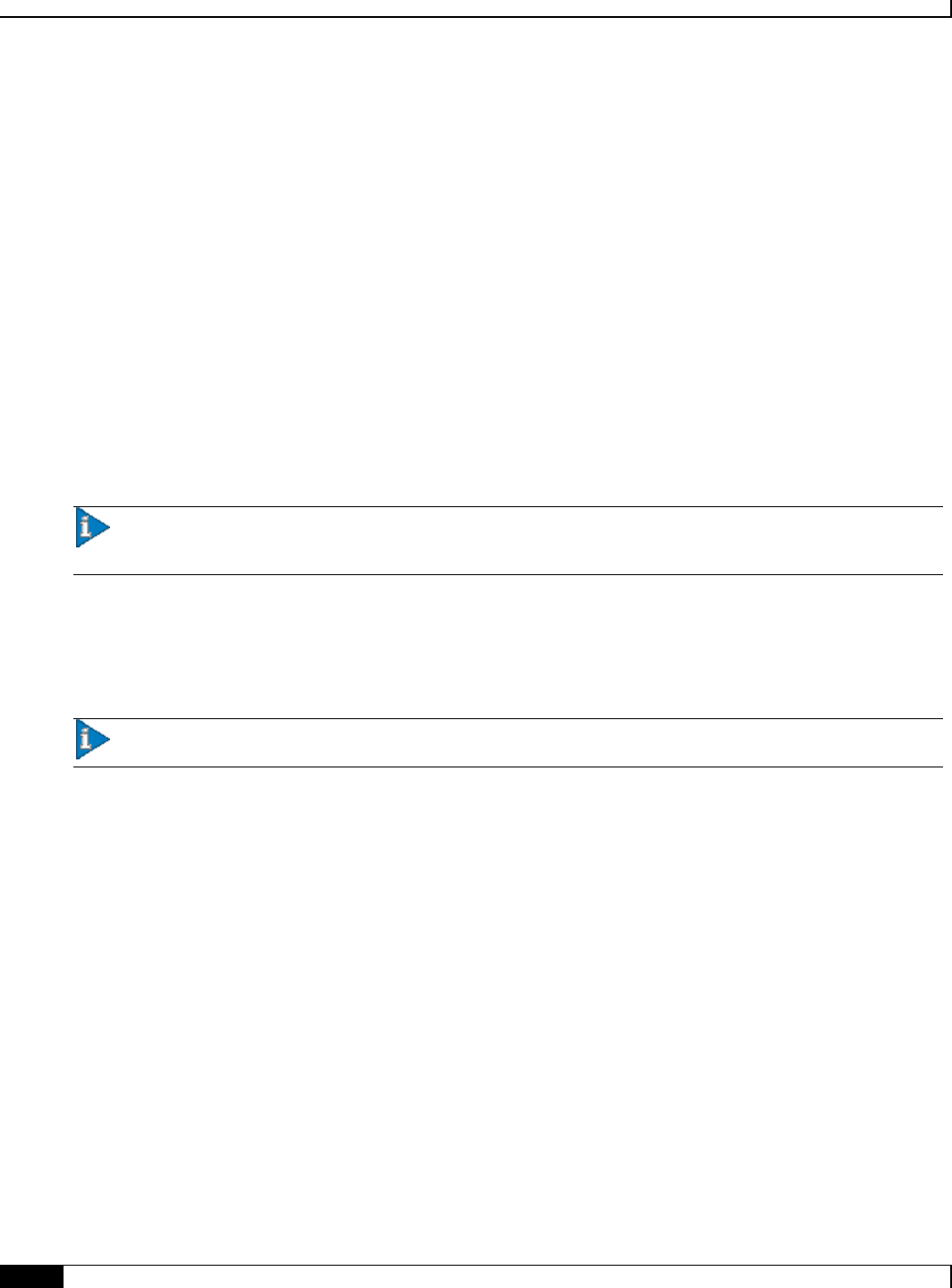
Configuring Subscriber Session Tracing
▀ Introduction
▄ Cisco ASR 5x00 Mobility Management Entity Administration Guide
248
Introduction
The Subscriber Level Trace provides a 3GPP standards-based session-level trace function for call debugging and testing
new functions and access terminals in an LTE environment.
In general, the Session Trace capability records and forwards all control activity for the monitored subscriber on the
monitored interfaces. This is typically all the signaling and authentication/subscriber services messages that flow when a
UE connects to the access network.
The EPC network entities like MME, S-GW, P-GW support 3GPP standards based session level trace capabilities to
monitor all call control events on the respective monitored interfaces including S6a, S1-MME and S11 on MME, S5,
S8, S11 at S-GW and S5 and S8 on P-GW. The trace can be initiated using multiple methods:
Management initiation via direct CLI configuration
Management initiation at HSS with trace activation via authentication response messages over S6a reference
interface
Signaling based activation through signaling from subscriber access terminal
Important: Once the trace is provisioned it can be provisioned through the access cloud via various signaling
interfaces.
The session level trace function consists of trace activation followed by triggers. The time between the two events is
where the EPC network element buffers the trace activation instructions for the provisioned subscriber in memory using
camp-on monitoring. Trace files for active calls are buffered as XML files using non-volatile memory on the local dual
redundant hard drives on the chassis. The Trace Depth defines the granularity of data to be traced. Six levels are defined
including Maximum, Minimum and Medium with ability to configure additional levels based on vendor extensions.
Important: Only Maximum Trace Depth is supported in the current release.
The following figure shows a high-level overview of the session-trace functionality and deployment scenario:
Configuring Subscriber Session Tracing
Introduction ▀
Cisco ASR 5x00 Mobility Management Entity Administration Guide ▄
249
Figure 22. Session Trace Function and Interfaces
All call control activity for active and recorded sessions is sent to an off-line Trace Collection Entity (TCE) using a
standards-based XML format over a FTP or secure FTP (SFTP) connection.
Note: In the current release the IPv4 interfaces are used to provide connectivity to the TCE. Trace activation is based on
IMSI or IMEI.
Supported Functions
This section provides the list of supported functionality of this feature support:
Support to trace the control flow through the access network.
Trace of specific subscriber identified by IMSI
Trace of UE identified by IMEI(SV)
Ability to specify specific functional entities and interfaces where tracing should occur.
Scalability and capacity

Configuring Subscriber Session Tracing
▀ Introduction
▄ Cisco ASR 5x00 Mobility Management Entity Administration Guide
250
Support up to 32 simultaneous session traces per NE
Capacity to activate/deactivate TBD trace sessions per second
Each NE can buffer TBD bytes of trace data locally
Statistics and State Support
Session Trace Details
Management and Signaling-based activation models
Trace Parameter Propagation
Trace Scope (EPS Only)
MME: S1, S3, S6a, S10, S11
S-GW: S4, S5, S8, S11, Gxc
PDN-GW: S2a, S2b, S2c, S5, S6b, Gx, S8, SGi
Trace Depth: Maximum, Minimum, Medium (with or without vendor extension)
XML Encoding of Data as per 3GPP standard 3GPP TS 32.422 V8.6.0 (2009-09)
Trace Collection Entity (TCE) Support
Active pushing of files to the TCE
Passive pulling of files by the TCE
1 TCE support per context
Trace Session Recovery after Failure of Session Manager

Configuring Subscriber Session Tracing
Supported Standards ▀
Cisco ASR 5x00 Mobility Management Entity Administration Guide ▄
251
Supported Standards
Support for the following standards and requests for comments (RFCs) have been added with this interface support:
3GPP TS 32.421 V8.5.0 (2009-06): 3rd Generation Partnership Project; Technical Specification Group Services
and System Aspects; Telecommunication management; Subscriber and equipment trace: Trace concepts and
requirements (Release 8)
3GPP TS 32.422 V8.6.0 (2009-09): 3rd Generation Partnership Project; Technical Specification Group Services
and System Aspects; Telecommunication management; Subscriber and equipment trace; Trace control and
configuration management (Release 8)
3GPP TS 32.423 V8.2.0 (2009-09): 3rd Generation Partnership Project; Technical Specification Group Services
and System Aspects; Telecommunication management; Subscriber and equipment trace: Trace data definition
and management (Release 8)

Configuring Subscriber Session Tracing
▀ Subscriber Session Trace Functional Description
▄ Cisco ASR 5x00 Mobility Management Entity Administration Guide
252
Subscriber Session Trace Functional Description
This section describes the various functionality involved in tracing of subscriber session on EPC nodes:
Operation
The session trace functionality is separated into two steps - activation and trigger.
Before tracing can begin, it must be activated. Activation is done either via management request or when a UE initiates
a signaled connection. After activation, tracing actually begins when it is triggered (defined by a set of trigger events).
Trace Session
A trace session is the time between trace activation and trace de-activation. It defines the state of a trace session,
including all user profile configuration, monitoring points, and start/stop triggers. It is uniquely identified by a Trace
Reference.
The Trace Reference id is composed of the MCC (3 digits) + the MNC (3 digits) + the trace Id (3 byte octet string).
Trace Recording Session
A trace recording session is a time period in which activity is actually being recorded and traceable data is being
forwarded to the TCE. A trace recording session is initiated when a start trigger event occurs and continues until the
stop trigger event occurs and is uniquely identified by a Trace Recording Session Reference.
Network Element (NE)
Network elements are the functional component to facilitate subscriber session trace in mobile network.
The term network element refers to a functional component that has standard interfaces in and out of it. It is typically
shown as a stand-alone AGW. Examples of NEs are the MME, S-GW, and P-GW.
Currently, subscriber session trace is not supported for co-located network elements in the EPC network.
Activation
Activation of a trace is similar whether it be via the management interface or via a signaling interface. In both cases, a
trace session state block is allocated which stores all configuration and state information for the trace session. In
addition, a (S)FTP connection to the TCE is established if one does not already exist (if this is the first trace session
established, odds are there will not be a (S)FTP connection already established to the TCE).
If the session to be traced is already active, tracing may begin immediately. Otherwise, tracing activity concludes until
the start trigger occurs (typically when the subscriber or UE under trace initiates a connection). A failure to activate a
trace (due to max exceeded or some other failure reason) results in a notification being sent to the TCE indicating the
failure.

Configuring Subscriber Session Tracing
Subscriber Session Trace Functional Description ▀
Cisco ASR 5x00 Mobility Management Entity Administration Guide ▄
253
Management Activation
With a management-initiated activation, the WEM sends an activation request directly to the NE where the trace is to be
initiated. The NE establishes the trace session and waits for a triggering event to start actively tracing. Depending upon
the configuration of the trace session, the trace activation may be propagated to other NEs.
Signaling Activation
With a signaling based activation, the trace session is indicated to the NE across a signaling interface via a trace
invocation message. This message can either be piggybacked with an existing bearer setup message (in order to trace all
control messages) or by sending a separate trace invocation message (if the user is already active).
Start Trigger
A trace recording session starts upon reception of one of the configured start triggers. Once the start trigger is received,
the NE generates a Trace Recording Session Reference (unique to the NE) and begins to collect and forward trace
information on the session to the TCE.
List of trigger events are listed in 3GPP standard 3GPP TS 32.422 V8.6.0 (2009-09).
Deactivation
Deactivation of a Trace Session is similar whether it was management or signaling activated. In either case, a
deactivation request is received by the NE that contains a valid trace reference results in the de-allocation of the trace
session state block and a flushing of any pending trace data. In addition, if this is the last trace session to a particular
TCE, the (S)FTP connection to the TCE is released after the last trace file is successfully transferred to the TCE.
Stop Trigger
A trace recording session ends upon the reception of one of the configured stop triggers. Once the stop trigger is
received, the NE will terminate the active recording session and attempt to send any pending trace data to the TCE. The
list of triggering events can be found in 3GPP standard 3GPP TS 32.422 V8.6.0 (2009-09).
Data Collection and Reporting
Subscriber session trace functionality supprots data collection and reporting system to provide historical usage adn event
analysis.
All data collected by the NE is formatted into standard XML file format and forwarded to the TCE via (S)FTP. The
specific format of the data is defined in 3GPP standard 3GPP TS 32.423 V8.2.0 (2009-09)
Trace Depth
The Trace Depth defines what data is to be traced. There are six depths defined: Maximum, Minimum, and Medium all
having with and without vendor extension flavors. The maximum level of detail results in the entire control message
getting traced and forwarded to the TCE. The medium and minimum define varying subsets of the control messages
Configuring Subscriber Session Tracing
▀ Subscriber Session Trace Functional Description
▄ Cisco ASR 5x00 Mobility Management Entity Administration Guide
254
(specific decoded IEs) to be traced and forwarded. The contents and definition of the medium and minimum trace can
be found in 3GPP standard 3GPP TS 32.423 V8.2.0 (2009-09).
Important: Only Maximum Trace Depth is supported in the current release.
Trace Scope
The Trace Scope defines what NEs and what interfaces have the tracing capabilities enabled on them. This is actually a
specific list of NE types and interfaces provided in the trace session configuration by the operator (either directly via a
management interface or indirectly via a signaling interface).
Network Element Details
Trace functionality for each of the specific network elements supported by this functionality are described in this
section.
This section includes the trace monitoring points applicable to them as well as the interfaces over which they can send
and/or receive trace configuration.
MME
The MME support tracing of the following interfaces with the following trace capabilities:
Interface Name
Remote Device
Trace Signaling (De)Activation RX
Trace Signaling (De)Activation TX
S1a
eNodeB
N
Y
S3
SGSN
Y
Y
S6a
HSS
Y
N
S10
MME
Y
Y
S11
S-GW
N
Y
S-GW
The S-GW support tracing of the following interfaces with the following trace capabilities:
Interface Name
Remote Device
Trace Signaling (De)Activation RX
Trace Signaling (De)Activation TX
S1-U
eNodeB
Y
N
S4
SGSN
N
N
S5
P-GW (Intra-PLMN)
Y
N
S8
P-GW (Inter-PLMN)
N
N
S11
MME
Y
N
S12
RNC
Y
N

Configuring Subscriber Session Tracing
Subscriber Session Trace Functional Description ▀
Cisco ASR 5x00 Mobility Management Entity Administration Guide ▄
255
Interface Name
Remote Device
Trace Signaling (De)Activation RX
Trace Signaling (De)Activation TX
Gxc
Policy Server
Y
N
P-GW
The P-GW support tracing of the following interfaces with the following trace capabilities:
Interface Name
Remote Device
Trace Signaling (De)Activation RX
Trace Signaling (De)Activation TX
S2abc
Various NEs
N
N
S5
S-GW (Intra-PLMN)
Y
N
S6b
AAA Server/Proxy
Y
N
S8
S-GW (Inter-PLMN)
N
N
Gx
Policy Server
Y
N
SGi
IMS
Y
N

Configuring Subscriber Session Tracing
▀ Subscriber Session Trace Configuration
▄ Cisco ASR 5x00 Mobility Management Entity Administration Guide
256
Subscriber Session Trace Configuration
This section provides a high-level series of steps and the associated configuration examples for configuring the system
to enable the Subscriber Session Trace collection and monitoring function on network elements s in LTE/EPC networks.
Important: This section provides the minimum instruction set to enable the Subscriber Session Trace
functionality to collect session traces on network elements on EPC networks. Commands that configure additional
function for this feature are provided in the Command Line Interface Reference.
These instructions assume that you have already configured the system level configuration as described in the System
Administration Guide and specific product Administration Guide.
To configure the system to support subscriber session trace collection and trace file transport on a system:
Step 1 Enable the subscriber session trace functionality with NE interface and TCE address at the Exec Mode level on an EPC
network element by applying the example configurations presented in the Enabling Subscriber Session Trace on EPC
Network Element section.
Step 2 Configure the network and trace file transportation parameters by applying the example configurations presented in the
Trace File Collection Configuration section.
Step 3 Save your configuration to flash memory, an external memory device, and/or a network location using the Exec mode
command save configuration. For additional information on how to verify and save configuration files, refer to the
System Administration Guide and the Command Line Interface Reference.
Step 4 Verify the configuration of Subscriber Session Trace related parameters by applying the commands provided in the
Verifying Your Configuration section of this chapter.
Enabling Subscriber Session Trace on EPC Network Element
This section provides the configuration example to enable the subscriber session trace on a system at the Exec mode:
session trace subscriber network-element { ggsn | mme | pgw | sgw } { imei
<imei_id> } { imsi <imsi_id> } { interface { all | <interface> } } trace-ref
<trace_ref_id> collection-entity <ip_address>
Notes:
<interface> is the name of the interfaces applicable for specific NE on which subscriber session traces have
to be collected. For more information, refer to the session trace subscriber command in the Command
Line Interface Reference.
<trace_ref_id> is the configured Trace Id to be used for this trace collection instance. It is composed of
MCC (3 digit)+MNC (3 digit)+Trace Id (3 byte octet string).
<ip_address> is the IP address of Trace collection Entity in IPv4 notation.

Configuring Subscriber Session Tracing
Subscriber Session Trace Configuration ▀
Cisco ASR 5x00 Mobility Management Entity Administration Guide ▄
257
Trace File Collection Configuration
This section provides the configuration example to configure the trace fil e collection parameters and protocols to be
used to store trace files on TCE through FTP/S-FTP:
configure
session trace subscriber network-element { all | ggsn | mme | pgw | sgw } [
collection-timer <dur> ] [ tce-mode { none | push transport { ftp | sftp } path
<string> username <name> { encrypted password <enc_pw> ] | password <password> }
} ]
end
Notes:
<string> is the location/path on the trace collection entity (TCE) where trace files will be stored on TCE. For
more information, refer to the session trace command in the Command Line Interface Reference.

Configuring Subscriber Session Tracing
▀ Verifying Your Configuration
▄ Cisco ASR 5x00 Mobility Management Entity Administration Guide
258
Verifying Your Configuration
This section explains how to display and review the configurations after saving them in a .cfg file as described in the
System Administration Guide and also to retrieve errors and warnings within an active configuration for a service.
Important: All commands listed here are under Exec mode. Not all commands are available on all platforms.
These instructions are used to verify the Subscriber Session Trace configuration.
Step 1 Verify that your subscriber session support is configured properly by entering the following command in Exec Mode:
show session trace statistics
The output of this command displays the statistics of the session trace instance.
Num current trace sessions: 5
Total trace sessions activated: 15
Total Number of trace session activation failures: 2
Total Number of trace recording sessions triggered: 15
Total Number of messages traced: 123
Number of current TCE connections: 2
Total number of TCE connections: 3
Total number of files uploaded to all TCEs: 34
Step 2 View the session trace references active for various network elements in an EPC network by entering the following
command in Exec Mode:
show session trace trace-summary
The output of this command displays the summary of trace references for all network elements:
MME
Trace Reference: 310012012345
Trace Reference: 310012012346
SGW
Trace Reference: 310012012345
Trace Reference: 310012012346
PGW

Configuring Subscriber Session Tracing
Verifying Your Configuration ▀
Cisco ASR 5x00 Mobility Management Entity Administration Guide ▄
259
Trace Reference: 310012012347

Cisco ASR 5x00 Mobility Management Entity Administration Guide ▄
261
Chapter 18
Troubleshooting the MME Service
This chapter provides information and instructions for using the system command line interface (CLI) for
troubleshooting issues that may arise during service operation.
Troubleshooting the MME Service
▀ Test Commands
▄ Cisco ASR 5x00 Mobility Management Entity Administration Guide
262
Test Commands
In the event that an issue was discovered with an installed application or line card, depending on the severity, it may be
necessary to take corrective action.
The system provides several redundancy and fail-over mechanisms to address issues with application and line cards in
order to minimize system downtime and data loss. These mechanisms are described in the sections that follow.
Using the eGTPC Test Echo Command
This command tests the eGTP service’s ability to exchange eGTPC packets with the specified peer which can be useful
for troubleshooting and/or monitoring.
The test is performed by the system sending eGTP-C echo request messages to the specified peer(s) and waiting for a
response.
Important: This command must be executed from within the context in which at least one eGTP service is
configured.
The command has the following syntax:
egtpc test echo peer-address peer_ip_address src-address egtp_svc_ip_address
Keyword/Variable
Description
peer-address
peer_ip_address
Specifies that eGTP-C echo requests will be sent to a specific peer (HSS).ip_address is
the address of the HSS receiving the requests.
src-address
egtp_svc_ip_address
Specifies the IP address of a S6a interface configured on the system in eGTP service.
NOTE: The IP address of the system’s S6a interface must be bound to a configured eGTP
service prior to executing this command.
The following example displays a sample of this command’s output showing a successful eGTPC echo-test from an
eGTP service bound to address 192.168.157.32 to an HSS with an address of 192.168.157.2.
EGTPC test echo
--------------
Peer: 172.10.10.2 Tx/Rx: 1/1 RTT(ms): 2 (COMPLETE) Recovery: 10 (0x0A)

Cisco ASR 5x00 Mobility Management Entity Administration Guide ▄
263
Appendix A
Engineering Rules
This section provides engineering rules or guidelines that must be considered prior to configuring the system for your
network deployment.
This appendix describes following engineering rules for MME services:
APN Engineering Rules
Service Engineering Rules
Node Engineering Rules

Engineering Rules
▀ APN Engineering Rules
▄ Cisco ASR 5x00 Mobility Management Entity Administration Guide
264
APN Engineering Rules
The following engineering rules apply to APNs:
APNs must be configured within the context used for authentication.
A maximum of 1,024 APNs per system can be configured.

Engineering Rules
Service Engineering Rules ▀
Cisco ASR 5x00 Mobility Management Entity Administration Guide ▄
265
Service Engineering Rules
The following engineering rules apply regarding the services configured within the system:
A maximum of 256 services (regardless of type) can be configured per system.
Caution: Large numbers of services greatly increase the complexity of management and may impact
overall system performance (i.e. resulting from such things as system handoffs). Therefore, it is recommended
that a large number of services only be configured if your application absolutely requires it. Please contact your
local service representative for more information.
The total number of entries per table and per chassis is limited to 256.
Even though service names can be identical to those configured in different contexts on the same system, this is not a
good practice. Having services with the same name can lead to confusion, difficulty troubleshooting problems, and make
it difficulty understanding outputs of show commands.

Engineering Rules
▀ Node Engineering Rules
▄ Cisco ASR 5x00 Mobility Management Entity Administration Guide
266
Node Engineering Rules
The following engineering rules apply regarding the number of nodes supported on the system:
eNodeBs: The MME supports a maximum of 32,000 eNodeB connections per MME service.
