D Link ™ DGS 3200 Switch 1514798657DGS 10 UI REFERENCE GUIDE 2.00 EN
User Manual: DLINK XSTACK DGS-3200-10 pdf | FreeUserManuals.com
Open the PDF directly: View PDF ![]() .
.
Page Count: 321 [warning: Documents this large are best viewed by clicking the View PDF Link!]
- Table of Contents
- Intended Readers
- Secion 1 Web-based Switch Configuration
- Section 2 Configuration
- Device Information
- System Information
- Serial Port Settings
- IP Address
- Port Configuration
- Static ARP Settings
- Gratuitous ARP
- User Accounts
- Command Logging Settings
- System Log Configuration
- System Severity Settings
- MAC Address Aging Time
- Web Settings
- Telnet Settings
- Password Encryption
- CLI Paging Settings
- Firmware Information
- Dual Configuration Settings
- Power Saving
- MAC Notification Settings
- SNMP Settings
- CPU Filter L3 Control Packet Settings
- Single IP Management
- SD Card FS Settings (DGS-3200-24 Only)
- SD Card Management (DGS-3200-24 Only)
- Section 3 L2 Features
- VLAN
- Layer 2 Protocol Tunneling Settings
- Egress Filter Settings
- L2 Multicast Control
- Multicast Filtering
- Port Mirroring
- Spanning Tree
- Link Aggregation
- Forwarding & Filtering
- LLDP
- NLB FDB Settings
- Section 4 L3 Features
- Section 5 QoS
- Section 6 Security
- RADIUS
- IP-MAC-Port Binding (IMPB)
- Port Security
- DHCP Server Screening
- 802.1X (Port-based and Host-based Access Control)
- Authentication Server
- Authenticator
- Client
- Authentication Process
- Understanding 802.1X Port-based and Host-based Network Access Control
- 802.1X Global Settings
- 802.1X Port Settings
- 802.1X User Settings
- Guest VLAN Settings
- Authenticator State
- Authenticator Statistics
- Authenticator Session Statistics
- Authenticator Diagnostics
- Initialize Port-based Port(s)
- Initialize Host-based Port(s)
- Reauthenticate Port-based Port(s)
- Reauthenticate Host-based Port(s)
- SSL
- SSH
- Access Authentication Control
- MAC-based Access Control (MAC)
- Web-based Access Control (WAC)
- Japanese Web-based Access Control (JWAC)
- Compound Authentication
- IGMP Access Control Settings
- ARP Spoofing Prevention Settings
- BPDU Attack Protection
- Loopback Detection Settings
- Traffic Segmentation
- Safeguard Engine Settings
- Trusted Host Settings
- Section 7 ACL
- Section 8 Network Application
- Section 9 OAM
- Section 10 Monitoring
- Section 11 Save and Tools
- Save Configuration
- Save Log
- Save All
- Download Configuration File/Download Configuration File to NV-RAM
- Download Configuration File to SD Card
- Download Firmware/Download Firmware to NV-RAM
- Download Firmware to SD Card
- Upload Configuration File/Upload Configuration File to TFTP
- Upload Log File/Upload Log File to TFTP
- Reset
- Reboot System
- Appendix A – Mitigating ARP Spoofing Attacks Using Packet Content ACL
- Appendix B – Password Recovery Procedure
- Appendix C – System Log Entries
- Appendix D – Trap Logs

_____________________________________________
Information in this document is subject to change without notice.
© 2011 D-Link Corporation. All rights reserved.
Reproduction in any manner whatsoever without the written permission of D-Link Corporation is strictly forbidden.
Trademarks used in this text: D-Link and the D-LINK logo are trademarks of D-Link Corporation; Microsoft and Windows are registered
trademarks of Microsoft Corporation.
Other trademarks and trade names may be used in this document to refer to either the entities claiming the marks and names or their products. D-
Link Corporation disclaims any proprietary interest in trademarks and trade names other than its own.
June 2011 P/N 651GS3200045G

xStack® DGS-3200 Series Layer 2 Managed Gigabit Ethernet Switch Web UI Reference Guide
iii
Table of Contents
Intended Readers ........................................................................................................................................................................... xi
Typographical Conventions ........................................................................................................................................................................... xi
Notes, Notices, and Cautions ......................................................................................................................................................................... xi
Safety Cautions .............................................................................................................................................................................................xii
General Precautions for Rack-Mountable Products .................................................................................................................................... xiii
Lithium Battery Precaution ..................................................................................................................................................................... xiv
Protecting Against Electrostatic Discharge .................................................................................................................................................. xiv
Web-based Switch Configuration ................................................................................................................... 1
Introduction .................................................................................................................................................................................... 1
Logging onto the Web Manager ...................................................................................................................................................................... 1
Web-based User Interface ............................................................................................................................................................................... 2
Areas of the User Interface ........................................................................................................................................................................ 2
Web Pages ....................................................................................................................................................................................................... 3
Configuration ................................................................................................................................................... 4
Device Information ........................................................................................................................................................................ 5
System Information ........................................................................................................................................................................ 5
Serial Port Settings ......................................................................................................................................................................... 6
IP Address ...................................................................................................................................................................................... 6
Setting the Switch’s IP Address using the Console Interface .................................................................................................................... 7
Port Configuration .......................................................................................................................................................................... 8
Port Auto Negotiation Information ................................................................................................................................................................. 8
Port Detail Information ................................................................................................................................................................................... 8
Port Settings .................................................................................................................................................................................................... 9
Port Description Settings............................................................................................................................................................................... 11
Port Error Disabled ....................................................................................................................................................................................... 12
Jumbo Frame Settings ................................................................................................................................................................................... 12
Static ARP Settings ...................................................................................................................................................................... 12
Gratuitous ARP ............................................................................................................................................................................ 13
Gratuitous ARP Global Settings ................................................................................................................................................................... 13
Gratuitous ARP Settings ............................................................................................................................................................................... 13
User Accounts .............................................................................................................................................................................. 14
Admin and User Privileges ...................................................................................................................................................................... 15
Command Logging Settings ......................................................................................................................................................... 15
System Log Configuration ........................................................................................................................................................... 16
System Log Settings...................................................................................................................................................................................... 16
System Log Host ........................................................................................................................................................................................... 16
System Severity Settings .............................................................................................................................................................. 17
MAC Address Aging Time .......................................................................................................................................................... 18
Web Settings ................................................................................................................................................................................ 18
Telnet Settings .............................................................................................................................................................................. 19
Password Encryption .................................................................................................................................................................... 19

xStack® DGS-3200 Series Layer 2 Managed Gigabit Ethernet Switch Web UI Reference Guide
iv
CLI Paging Settings ..................................................................................................................................................................... 19
Firmware Information .................................................................................................................................................................. 20
Dual Configuration Settings ......................................................................................................................................................... 21
Power Saving ............................................................................................................................................................................... 23
LED State Settings ........................................................................................................................................................................................ 23
Power Saving Settings .................................................................................................................................................................................. 24
Power Saving LED Settings .......................................................................................................................................................................... 25
Power Saving Port Settings ........................................................................................................................................................................... 25
MAC Notification Settings .......................................................................................................................................................... 26
MAC Notification Global Settings ................................................................................................................................................................ 26
MAC Notification Port Settings .................................................................................................................................................................... 26
SNMP Settings ............................................................................................................................................................................. 27
SNMP Global State Settings ......................................................................................................................................................................... 28
SNMP Linkchange Traps Settings ................................................................................................................................................................ 28
SNMP View Table ........................................................................................................................................................................................ 29
SNMP Group Table ...................................................................................................................................................................................... 30
SNMP User Table ......................................................................................................................................................................................... 31
SNMP Community Table .............................................................................................................................................................................. 32
SNMP Host Table ......................................................................................................................................................................................... 33
SNMP v6Host Table ..................................................................................................................................................................................... 34
SNMP Engine ID .......................................................................................................................................................................................... 34
SNMP Trap Configuration ............................................................................................................................................................................ 35
RMON .......................................................................................................................................................................................................... 35
CPU Filter L3 Control Packet Settings ........................................................................................................................................ 36
Single IP Management ................................................................................................................................................................. 36
Single IP Settings .......................................................................................................................................................................................... 38
Topology ....................................................................................................................................................................................................... 39
Firmware Upgrade ........................................................................................................................................................................................ 46
Configuration File Backup/Restore ............................................................................................................................................................... 46
Upload Log File ............................................................................................................................................................................................ 46
SD Card FS Settings (DGS-3200-24 Only) ................................................................................................................................. 47
SD Card Management (DGS-3200-24 Only) ............................................................................................................................... 48
SD Card Backup Settings .............................................................................................................................................................................. 48
SD Card Execute Settings ............................................................................................................................................................................. 48
L2 Features ..................................................................................................................................................... 50
VLAN .......................................................................................................................................................................................... 50
802.1Q VLAN............................................................................................................................................................................................... 50
802.1v Protocol VLAN ................................................................................................................................................................................. 58
802.1v Protocol Group Settings ............................................................................................................................................................... 58
802.1v Protocol VLAN Settings .............................................................................................................................................................. 59
GVRP Settings .............................................................................................................................................................................................. 60
MAC-based VLAN Settings ......................................................................................................................................................................... 61
Private VLAN Settings ................................................................................................................................................................................. 61
PVID Auto Assign Settings .......................................................................................................................................................................... 64
Voice VLAN ................................................................................................................................................................................................. 64

xStack® DGS-3200 Series Layer 2 Managed Gigabit Ethernet Switch Web UI Reference Guide
v
Voice VLAN Global Settings .................................................................................................................................................................. 64
Voice VLAN Port Settings ...................................................................................................................................................................... 65
Voice VLAN OUI Settings ...................................................................................................................................................................... 66
Voice VLAN Device ............................................................................................................................................................................... 66
Voice VLAN LLDP-MED Voice Device ................................................................................................................................................ 67
VLAN Trunk Settings ................................................................................................................................................................................... 67
Browse VLAN .............................................................................................................................................................................................. 68
Layer 2 Protocol Tunneling Settings ............................................................................................................................................ 68
Egress Filter Settings.................................................................................................................................................................... 69
L2 Multicast Control .................................................................................................................................................................... 69
IGMP Snooping ............................................................................................................................................................................................ 70
IGMP Snooping Settings ......................................................................................................................................................................... 70
IGMP Snooping Rate Limit Settings ....................................................................................................................................................... 72
IGMP Snooping Static Group Settings .................................................................................................................................................... 73
IGMP Router Port .................................................................................................................................................................................... 74
IGMP Snooping Group ............................................................................................................................................................................ 74
IGMP Snooping Forwarding Table .......................................................................................................................................................... 75
IGMP Snooping Counter ......................................................................................................................................................................... 75
IGMP Host Table ..................................................................................................................................................................................... 76
MLD Snooping ............................................................................................................................................................................................. 77
MLD Snooping Settings .......................................................................................................................................................................... 77
MLD Snooping Rate Limit Settings ........................................................................................................................................................ 80
MLD Snooping Static Group Settings ..................................................................................................................................................... 80
MLD Router Port ..................................................................................................................................................................................... 81
MLD Snooping Group ............................................................................................................................................................................. 82
MLD Snooping Forwarding Table ........................................................................................................................................................... 82
MLD Snooping Counter .......................................................................................................................................................................... 83
MLD Host Table ...................................................................................................................................................................................... 84
Multicast VLAN ........................................................................................................................................................................................... 84
IGMP Multicast Group Profile Settings ................................................................................................................................................... 84
IGMP Snooping Multicast VLAN Settings ............................................................................................................................................. 85
Multicast Filtering ........................................................................................................................................................................ 87
IPv4 Multicast Filtering ................................................................................................................................................................................ 87
IPv4 Multicast Profile Settings ................................................................................................................................................................ 87
IPv4 Limited Multicast Range Settings ................................................................................................................................................... 88
IPv4 Max Multicast Group Settings ......................................................................................................................................................... 89
Multicast Filtering Mode............................................................................................................................................................................... 89
Port Mirroring .............................................................................................................................................................................. 90
Spanning Tree .............................................................................................................................................................................. 91
STP Bridge Global Settings .......................................................................................................................................................................... 93
STP Port Settings .......................................................................................................................................................................................... 94
MST Configuration Identification ................................................................................................................................................................. 96
STP Instance Settings .................................................................................................................................................................................... 97
MSTP Port Information ................................................................................................................................................................................ 97
Link Aggregation ......................................................................................................................................................................... 98

xStack® DGS-3200 Series Layer 2 Managed Gigabit Ethernet Switch Web UI Reference Guide
vi
Port Trunking ................................................................................................................................................................................................ 98
LACP Port Settings ..................................................................................................................................................................................... 101
Forwarding & Filtering .............................................................................................................................................................. 101
Unicast Forwarding ..................................................................................................................................................................................... 101
Multicast Forwarding .................................................................................................................................................................................. 102
LLDP .......................................................................................................................................................................................... 103
LLDP .......................................................................................................................................................................................................... 103
LLDP Global Settings ............................................................................................................................................................................ 103
LLDP Port Settings ................................................................................................................................................................................ 104
LLDP Management Address List .......................................................................................................................................................... 105
LLDP Basic TLVs Settings ................................................................................................................................................................... 105
LLDP Dot1 TLVs Settings .................................................................................................................................................................... 106
LLDP Dot3 TLVs Settings .................................................................................................................................................................... 107
LLDP Statistics System ......................................................................................................................................................................... 108
LLDP Local Port Information ................................................................................................................................................................ 109
LLDP Remote Port Information ............................................................................................................................................................ 110
LLDP-MED ................................................................................................................................................................................................ 111
LLDP-MED System Settings ................................................................................................................................................................. 111
LLDP-MED Port Settings ...................................................................................................................................................................... 111
LLDP-MED Local Port Information ...................................................................................................................................................... 112
LLDP-MED Remote Port Information .................................................................................................................................................. 113
NLB FDB Settings ..................................................................................................................................................................... 113
L3 Features ................................................................................................................................................... 115
IPv4 Static/Default Route Settings ............................................................................................................................................. 115
IPv4 Route Table ....................................................................................................................................................................... 115
IPv6 Interface Settings ............................................................................................................................................................... 116
IPv6 Route Settings .................................................................................................................................................................... 117
IPv6 Neighbor Settings .............................................................................................................................................................. 117
QoS ................................................................................................................................................................ 119
Bandwidth Control ..................................................................................................................................................................... 121
Queue Bandwidth Control Settings ............................................................................................................................................ 122
Traffic Control ........................................................................................................................................................................... 122
802.1p Default Priority ............................................................................................................................................................... 125
802.1p User Priority ................................................................................................................................................................... 125
QoS Scheduling Mechanism ...................................................................................................................................................... 126
Security ......................................................................................................................................................... 127
RADIUS ..................................................................................................................................................................................... 127
Authentication RADIUS Server Settings .................................................................................................................................................... 127
RADIUS Accounting Settings .................................................................................................................................................................... 128
RADIUS Authentication ............................................................................................................................................................................. 129
RADIUS Account Client............................................................................................................................................................................. 130
IP-MAC-Port Binding (IMPB)................................................................................................................................................... 131
IMPB Global Settings ................................................................................................................................................................................. 133
IMPB Port Settings ..................................................................................................................................................................................... 134

xStack® DGS-3200 Series Layer 2 Managed Gigabit Ethernet Switch Web UI Reference Guide
vii
IMPB Entry Settings ................................................................................................................................................................................... 135
MAC Block List .......................................................................................................................................................................................... 136
DHCP Snooping .......................................................................................................................................................................................... 137
DHCP Snooping Maximum Entry Settings ........................................................................................................................................... 137
DHCP Snooping Entry........................................................................................................................................................................... 137
ND Snoop ................................................................................................................................................................................................... 138
ND Snoop Maximum Entry Settings ..................................................................................................................................................... 138
ND Snoop Entry .................................................................................................................................................................................... 139
Port Security ............................................................................................................................................................................... 139
Port Security Settings .................................................................................................................................................................................. 139
Port Lock Entries ........................................................................................................................................................................................ 140
DHCP Server Screening ............................................................................................................................................................. 141
DHCP Screening Port Settings .................................................................................................................................................................... 141
DHCP Offer Filtering .................................................................................................................................................................................. 142
802.1X (Port-based and Host-based Access Control) ................................................................................................................ 143
Authentication Server ............................................................................................................................................................................ 144
Authenticator ......................................................................................................................................................................................... 144
Client ..................................................................................................................................................................................................... 145
Authentication Process .......................................................................................................................................................................... 145
Understanding 802.1X Port-based and Host-based Network Access Control ........................................................................................ 146
802.1X Global Settings ............................................................................................................................................................................... 148
802.1X Port Settings ................................................................................................................................................................................... 149
802.1X User Settings .................................................................................................................................................................................. 151
Guest VLAN Settings ................................................................................................................................................................................. 151
Authenticator State ...................................................................................................................................................................................... 152
Authenticator Statistics ............................................................................................................................................................................... 152
Authenticator Session Statistics .................................................................................................................................................................. 153
Authenticator Diagnostics ........................................................................................................................................................................... 154
Initialize Port-based Port(s) ......................................................................................................................................................................... 155
Initialize Host-based Port(s) ........................................................................................................................................................................ 156
Reauthenticate Port-based Port(s) ............................................................................................................................................................... 156
Reauthenticate Host-based Port(s) .............................................................................................................................................................. 156
SSL ............................................................................................................................................................................................. 157
SSL Settings ................................................................................................................................................................................................ 157
SSL Certification Settings ........................................................................................................................................................................... 159
SSH ............................................................................................................................................................................................ 159
SSH Settings ............................................................................................................................................................................................... 160
SSH Authentication Method and Algorithm Settings ................................................................................................................................. 161
SSH User Authentication List ..................................................................................................................................................................... 162
Access Authentication Control ................................................................................................................................................... 163
Enable Admin ............................................................................................................................................................................................. 164
Authentication Policy Settings .................................................................................................................................................................... 164
Application Authentication Settings ........................................................................................................................................................... 165
Authentication Server Group ...................................................................................................................................................................... 165
Authentication Server Settings .................................................................................................................................................................... 167

xStack® DGS-3200 Series Layer 2 Managed Gigabit Ethernet Switch Web UI Reference Guide
viii
Login Method Lists Settings ....................................................................................................................................................................... 168
Enable Method Lists Settings ...................................................................................................................................................................... 169
Local Enable Password Settings ................................................................................................................................................................. 170
MAC-based Access Control (MAC) .......................................................................................................................................... 170
MAC-based Access Control Settings .......................................................................................................................................................... 171
MAC-based Access Control Local Settings ................................................................................................................................................ 173
MAC-based Access Control Authentication State ...................................................................................................................................... 173
Web-based Access Control (WAC) ........................................................................................................................................... 174
WAC Global Settings .................................................................................................................................................................................. 176
WAC User Settings ..................................................................................................................................................................................... 177
WAC Port Settings ...................................................................................................................................................................................... 178
WAC Authenticating State .......................................................................................................................................................................... 179
WAC Customize Page ................................................................................................................................................................................ 179
Japanese Web-based Access Control (JWAC) ........................................................................................................................... 180
JWAC Global Settings ................................................................................................................................................................................ 180
JWAC Port Settings .................................................................................................................................................................................... 182
JWAC User Settings ................................................................................................................................................................................... 183
JWAC Authentication State ........................................................................................................................................................................ 184
JWAC Customize Page Language .............................................................................................................................................................. 185
JWAC Customize Page ............................................................................................................................................................................... 185
Compound Authentication ......................................................................................................................................................... 186
Compound Authentication Settings ............................................................................................................................................................ 189
Compound Authentication Guest VLAN Settings ...................................................................................................................................... 191
Compound Authentication MAC Format Settings ...................................................................................................................................... 191
IGMP Access Control Settings .................................................................................................................................................. 192
ARP Spoofing Prevention Settings ............................................................................................................................................ 193
BPDU Attack Protection ............................................................................................................................................................ 194
Loopback Detection Settings ..................................................................................................................................................... 195
Traffic Segmentation .................................................................................................................................................................. 196
Safeguard Engine Settings ......................................................................................................................................................... 197
Trusted Host Settings ................................................................................................................................................................. 198
ACL ............................................................................................................................................................... 200
ACL Configuration Wizard ........................................................................................................................................................ 200
Access Profile List ..................................................................................................................................................................... 201
CPU Access Profile List ............................................................................................................................................................. 215
Time Range Settings .................................................................................................................................................................. 228
Network Application .................................................................................................................................... 230
DHCP/BOOTP Relay................................................................................................................................................................. 230
DHCP/BOOTP Relay Global Settings ........................................................................................................................................................ 230
DHCP/BOOTP Relay Interface Settings ..................................................................................................................................................... 233
DHCPv6 Relay ........................................................................................................................................................................... 233
DHCPv6 Relay Global Settings .................................................................................................................................................................. 233
DHCPv6 Relay Settings .............................................................................................................................................................................. 234
DHCP Server.............................................................................................................................................................................. 234

xStack® DGS-3200 Series Layer 2 Managed Gigabit Ethernet Switch Web UI Reference Guide
ix
DHCP Server Global Settings ..................................................................................................................................................................... 235
DHCP Server Exclude Address Settings ..................................................................................................................................................... 235
DHCP Server Pool Settings ........................................................................................................................................................................ 236
DHCP Server Manual Binding .................................................................................................................................................................... 237
DHCP Server Dynamic Binding ................................................................................................................................................................. 238
DHCP Conflict IP ....................................................................................................................................................................................... 238
DHCP Local Relay Settings ....................................................................................................................................................... 238
DHCP Auto Configuration Settings ........................................................................................................................................... 239
DHCP Option 12 Settings .......................................................................................................................................................... 240
DNS Resolver ............................................................................................................................................................................ 240
DNS Resolver Global Settings .................................................................................................................................................................... 240
DNS Resolver Static Name Server Settings ................................................................................................................................................ 241
DNS Resolver Dynamic Name Server Table .............................................................................................................................................. 241
DNS Resolver Static Host Name Settings ................................................................................................................................................... 241
DNS Resolver Dynamic Host Name Table ................................................................................................................................................. 242
PPPoE Circuit ID Insertions Settings ......................................................................................................................................... 242
SMTP Settings ........................................................................................................................................................................... 243
SNTP Settings ............................................................................................................................................................................ 244
Time Settings .............................................................................................................................................................................................. 244
Time Zone Settings ..................................................................................................................................................................................... 244
Ping Test .................................................................................................................................................................................... 246
OAM .............................................................................................................................................................. 248
Ethernet OAM ............................................................................................................................................................................ 248
Ethernet OAM Settings ............................................................................................................................................................................... 248
Ethernet OAM Configuration Settings ........................................................................................................................................................ 249
Ethernet OAM Event Log ........................................................................................................................................................................... 250
Ethernet OAM Statistics ............................................................................................................................................................................. 250
DULD Settings ........................................................................................................................................................................... 251
Cable Diagnostics ...................................................................................................................................................................... 252
Monitoring .................................................................................................................................................... 254
Device Environment................................................................................................................................................................... 254
CPU Utilization .......................................................................................................................................................................... 254
DRAM & Flash Utilization ........................................................................................................................................................ 255
Port Utilization ........................................................................................................................................................................... 256
Packet Size ................................................................................................................................................................................. 256
Packets ....................................................................................................................................................................................... 258
Received (RX) ............................................................................................................................................................................................ 258
UMB_Cast (RX) ......................................................................................................................................................................................... 260
Transmitted (TX) ........................................................................................................................................................................................ 261
Errors .......................................................................................................................................................................................... 263
Received (RX) ............................................................................................................................................................................................ 263
Transmitted (TX) ........................................................................................................................................................................................ 265
Browse ARP Table ..................................................................................................................................................................... 266
Browse Router Port .................................................................................................................................................................... 266

xStack® DGS-3200 Series Layer 2 Managed Gigabit Ethernet Switch Web UI Reference Guide
x
Browse MLD Router Port .......................................................................................................................................................... 267
Browse Session Table ................................................................................................................................................................ 267
IGMP Snooping Group .............................................................................................................................................................. 268
MLD Snooping Group ............................................................................................................................................................... 268
MAC Address Table .................................................................................................................................................................. 269
System Log ................................................................................................................................................................................ 270
Save and Tools .............................................................................................................................................. 271
Save Configuration..................................................................................................................................................................... 272
Save Log .................................................................................................................................................................................... 272
Save All ...................................................................................................................................................................................... 273
Download Configuration File/Download Configuration File to NV-RAM ............................................................................... 273
Download Configuration File to SD Card .................................................................................................................................. 274
Download Firmware/Download Firmware to NV-RAM ........................................................................................................... 274
Download Firmware to SD Card ................................................................................................................................................ 274
Upload Configuration File/Upload Configuration File to TFTP ................................................................................................ 275
Upload Log File/Upload Log File to TFTP ................................................................................................................................ 275
Reset ........................................................................................................................................................................................... 276
Reboot System ........................................................................................................................................................................... 276
Appendix A – Mitigating ARP Spoofing Attacks Using Packet Content ACL ...................................... 277
Appendix B – Password Recovery Procedure ........................................................................................... 284
Appendix C – System Log Entries .............................................................................................................. 285
Appendix D – Trap Logs ............................................................................................................................. 304

xStack® DGS-3200 Series Layer 2 Managed Gigabit Ethernet Switch Web UI Reference Guide
xi
Intended Readers
The DGS-3200 Series Web UI Reference Guide contains information for setup and management of the Switch. This manual is
intended for network managers familiar with network management concepts and terminology.
Typographical Conventions
Convention Description
[ ] In a command line, square brackets indicate an optional entry. For example: [copy
filename] means that optionally you can type copy followed by the name of the file. Do
not type the brackets.
Bold font Indicates a button, a toolbar icon, menu, or menu item. For example: Open the File
menu and choose Cancel. Used for emphasis. May also indicate system messages or
prompts appearing on screen. For example: You have mail. Bold font is also used to
represent filenames, program names and commands. For example: use the copy
command.
Boldface Typewriter
Font Indicates commands and responses to prompts that must be typed exactly as printed in
the manual.
Initial capital letter Indicates a window name. Names of keys on the keyboard have initial capitals. For
example: Click Enter.
Italics Indicates a window name or a field. Also can indicate a variables or parameter that is
replaced with an appropriate word or string. For example: type filename means that the
actual filename should be typed instead of the word shown in italic.
Menu Name > Menu
Option Menu Name > Menu Option Indicates the menu structure. Device > Port > Port
Properties means the Port Properties menu option under the Port menu option that is
located under the Device menu.
Notes, Notices, and Cautions
A NOTE indicates important information that helps make better use of the
device.
A NOTICE indicates either potential damage to hardware or loss of data
and tells how to avoid the problem.
A CAUTION indicates a potential for property damage, personal injury, or
death.

xStack® DGS-3200 Series Layer 2 Managed Gigabit Ethernet Switch Web UI Reference Guide
xii
Safety Cautions
Use the following safety guidelines to ensure your own personal safety and to help protect your system from potential damage.
Throughout this safety section, the caution icon ( ) is used to indicate cautions and precautions that need to be reviewed and
followed.
To reduce the risk of bodily injury, electrical shock, fire, and damage to the equipment observe the following precautions.
• Observe and follow service markings.
• Do not service any product except as explained in the system documentation.
• Opening or removing covers that are marked with the triangular symbol with a lightning bolt may expose the user to
electrical shock.
• Only a trained service technician should service components inside these compartments.
• If any of the following conditions occur, unplug the product from the electrical outlet and replace the part or contact your
trained service provider:
• Damage to the power cable, extension cable, or plug.
• An object has fallen into the product.
• The product has been exposed to water.
• The product has been dropped or damaged.
• The product does not operate correctly when the operating instructions are correctly followed.
• Keep your system away from radiators and heat sources. Also, do not block cooling vents.
• Do not spill food or liquids on system components, and never operate the product in a wet environment. If the system gets
wet, see the appropriate section in the troubleshooting guide or contact your trained service provider.
• Do not push any objects into the openings of the system. Doing so can cause fire or electric shock by shorting out interior
components.
• Use the product only with approved equipment.
• Allow the product to cool before removing covers or touching internal components.
• Operate the product only from the type of external power source indicated on the electrical ratings label. If unsure of the type
of power source required, consult your service provider or local power company.
• To help avoid damaging the system, be sure the voltage selection switch (if provided) on the power supply is set to match the
power available at the Switch’s location:
• 115 volts (V)/60 hertz (Hz) in most of North and South America and some Far Eastern countries such as South Korea
and Taiwan
• 100 V/50 Hz in eastern Japan and 100 V/60 Hz in western Japan
• 230 V/50 Hz in most of Europe, the Middle East, and the Far East
• Also, be sure that attached devices are electrically rated to operate with the power available in your location.
• Use only approved power cable(s). If you have not been provided with a power cable for your system or for any AC-
powered option intended for your system, purchase a power cable that is approved for use in your country. The power cable
must be rated for the product and for the voltage and current marked on the product's electrical ratings label. The voltage and
current rating of the cable should be greater than the ratings marked on the product.
• To help prevent electric shock, plug the system and peripheral power cables into properly grounded electrical outlets. These
cables are equipped with three-prong plugs to help ensure proper grounding. Do not use adapter plugs or remove the
grounding prong from a cable. If using an extension cable is necessary, use a 3-wire cable with properly grounded plugs.
• Observe extension cable and power strip ratings. Make sure that the total ampere rating of all products plugged into the
extension cable or power strip does not exceed 80 percent of the ampere ratings limit for the extension cable or power strip.
• To help protect the system from sudden, transient increases and decreases in electrical power, use a surge suppressor, line
conditioner, or uninterruptible power supply (UPS).
• Position system cables and power cables carefully; route cables so that they cannot be stepped on or tripped over. Be sure
that nothing rests on any cables.
xStack® DGS-3200 Series Layer 2 Managed Gigabit Ethernet Switch Web UI Reference Guide
xiii
• Do not modify power cables or plugs. Consult a licensed electrician or your power company for site modifications. Always
follow your local/national wiring rules.
• When connecting or disconnecting power to hot-pluggable power supplies, if offered with your system, observe the
following guidelines:
• Install the power supply before connecting the power cable to the power supply.
• Unplug the power cable before removing the power supply.
• If the system has multiple sources of power, disconnect power from the system by unplugging all power cables from
the power supplies.
• Move products with care; ensure that all casters and/or stabilizers are firmly connected to the system. Avoid sudden stops
and uneven surfaces.
General Precautions for Rack-Mountable Products
Observe the following precautions for rack stability and safety. Also, refer to the rack installation documentation accompanying
the system and the rack for specific caution statements and procedures.
• Systems are considered to be components in a rack. Thus, "component" refers to any system as well as to various peripherals
or supporting hardware.
CAUTION: Installing systems in a rack without the front and side stabilizers installed could
cause the rack to tip over, potentially resulting in bodily injury under certain circumstances.
Therefore, always install the stabilizers before installing components in the rack. After
installing system/components in a rack, never pull more than one component out of the
rack on its slide assemblies at one time. The weig
ht of more than one extended
component could cause the rack to tip over and may result in serious injury.
• Before working on the rack, make sure that the stabilizers are secured to the rack, extended to the floor, and that the full
weight of the rack rests on the floor. Install front and side stabilizers on a single rack or front stabilizers for joined multiple
racks before working on the rack.
• Always load the rack from the bottom up, and load the heaviest item in the rack first.
• Make sure that the rack is level and stable before extending a component from the rack.
• Use caution when pressing the component rail release latches and sliding a component into or out of a rack; the slide rails
can pinch your fingers.
• After a component is inserted into the rack, carefully extend the rail into a locking position, and then slide the component
into the rack.
• Do not overload the AC supply branch circuit that provides power to the rack. The total rack load should not exceed 80
percent of the branch circuit rating.
• Ensure that proper airflow is provided to components in the rack.
• Do not step on or stand on any component when servicing other components in a rack.
NOTE: A qualified electrician must perform all connections to DC power and to safety
grounds. All electrical wiring must comply with applicable local or national codes and
practices.
CAUTION: Never defeat the ground conductor or operate the equipment in the absence
of a suitably installed ground conductor. Contact the appropriate electrical inspection
authority or an electrician if uncertain that suitable grounding is available.

xStack® DGS-3200 Series Layer 2 Managed Gigabit Ethernet Switch Web UI Reference Guide
xiv
CAUTION: The system chassis must be positively grounded to the rack cabinet frame.
Do not attempt to connect power to the system until grounding cables are connected.
Completed power and safety ground wiring must be inspected by a qualified electrical
inspector. An energy hazard will exist if the safety ground cable is omitted or
disconnected.
CAUTION: When mounting the Switch on a cement wall, a proper concrete sleeve
anchor should be used, such as the one that is included in the optional D-Link Wall Mount
kit (DRE-KIT018).
Lithium Battery Precaution
CAUTION: Incorrectly replacing the lithium battery of the Switch may cause the battery to
explode. Replace this battery only with the same or equivalent type recommended by the
manufacturer. Discard used batteries according to the manufacturer’s instructions.
Protecting Against Electrostatic Discharge
Static electricity can harm delicate components inside the system. To prevent static damage, discharge static electricity from your
body before touching any of the electronic components, such as the microprocessor. This can be done by periodically touching an
unpainted metal surface on the chassis.
The following steps can also be taken prevent damage from electrostatic discharge (ESD):
1. When unpacking a static-sensitive component from its shipping carton, do not remove the component from the antistatic
packing material until ready to install the component in the system. Just before unwrapping the antistatic packaging, be
sure to discharge static electricity from your body.
2. When transporting a sensitive component, first place it in an antistatic container or packaging.
3. Handle all sensitive components in a static-safe area. If possible, use antistatic floor pads, workbench pads and an
antistatic grounding strap.
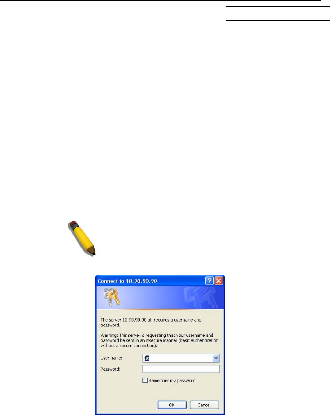
xStack® DGS-3200 Series Layer 2 Managed Gigabit Ethernet Switch Web UI Reference Guide
1
Section 1
Web-based Switch Configuration
Introduction
Logging onto the Web Manager
Web-Based User Interface
Introduction
All software functions of the Switch can be managed, configured, and monitored via the embedded web-based (HTML) interface.
Manage the Switch from remote stations anywhere on the network through a standard browser, such as Internet Explorer 5.5 or
later, Netscape 8.0 or later, Firefox 2.0 or later, or Apple Safari 3.0. The browser acts as a universal access tool and can
communicate directly with the Switch using the HTTP protocol.
The Web-based management module and the Console program (and Telnet) are different ways to access the same internal
switching software and configure it. Thus, all settings encountered in web-based management are the same as those found in the
console program.
Logging onto the Web Manager
To begin managing the Switch, simply run the browser installed on your computer and point it to the IP address you have defined
for the device. The URL in the address bar should read something like: http://123.123.123.123, where the numbers 123 represent
the IP address of the Switch.
NOTE: The factory default IP address is 10.90.90.90.
This opens the management module's user authentication window, as seen below.
Figure 1 - 1. Enter Network Password window
Leave both the User Name field and the Password field blank and click OK. This will open the Web-based user interface. The
Switch management features available in the web-based manager are explained below.
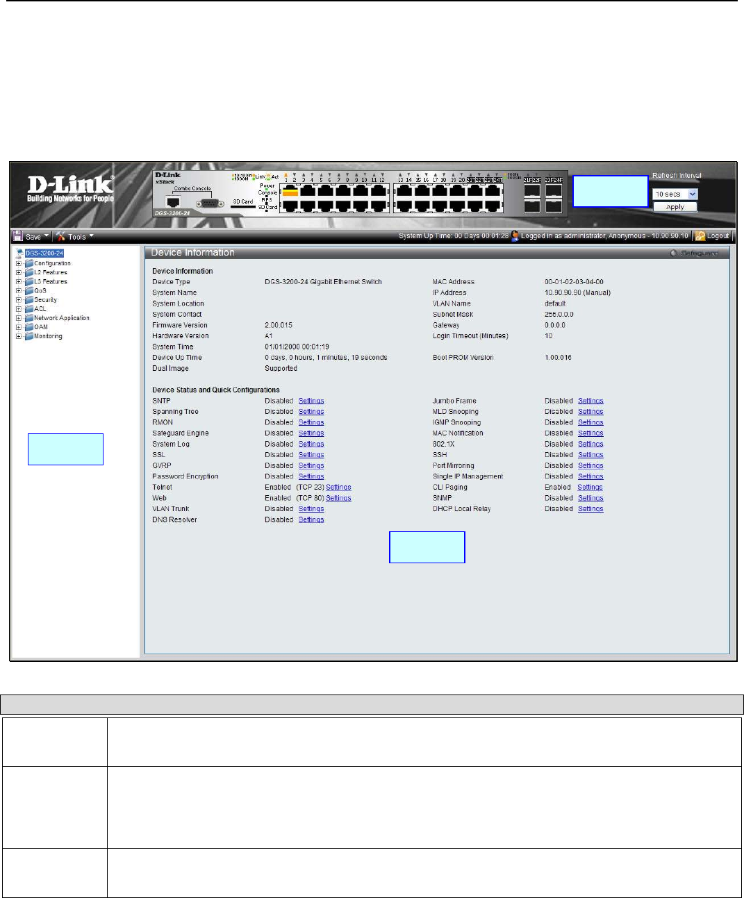
xStack® DGS-3200 Series Layer 2 Managed Gigabit Ethernet Switch Web UI Reference Guide
2
Web-based User Interface
The user interface provides access to various Switch configuration and management windows, allows the user to view
performance statistics, and permits graphical monitoring of the system status.
Areas of the User Interface
The figure below shows the user interface. Three distinct areas divide the user interface, as described in the table.
Figure 1 - 2. Main Web-Manager window
Area Function
Area 1 Select the folder or window to display. Open folders and click the hyperlinked window buttons and
subfolders contained within them to display windows.
Area 2 Presents a graphical near real-time image of the front panel of the Switch. This area displays the
Switch's ports and expansion modules and shows port activity, depending on the specified mode.
Some management functions, including port monitoring are accessible here. Click the D-Link logo to
go to the D-Link website.
Area 3 Presents Switch status based on user selection and the entry of configuration data. In addition,
hyperlinks are offered for many Switch features to enable quick configuration.
Area 2
Area 1
Area 3

xStack® DGS-3200 Series Layer 2 Managed Gigabit Ethernet Switch Web UI Reference Guide
3
Web Pages
When connecting to the management mode of the Switch with a web browser, a login screen is displayed. Enter a user name and
password to access the Switch's management mode.
Below is a list of the main folders available in the Web interface:
Configuration - In this section the user will be able to configure features regarding the Switch’s configuration.
L2 Features - In this section the user will be able to configure features regarding the Layer 2 functionality of the Switch.
L3 Features - In this section the user will be able to configure features regarding the Layer 3 functionality of the Switch.
QoS - In this section the user will be able to configure features regarding the Quality of Service functionality of the Switch.
Security - In this section the user will be able to configure features regarding the Switch’s security.
ACL - In this section the user will be able to configure features regarding the Access Control List functionality of the Switch.
Network Application - In this section the user will be able to configure features regarding network applications handled by the
Switch.
OAM - In this section the user will be able to configure features regarding the Switch’s operations, administration and
maintenance (OAM).
Monitoring - In this section the user will be able to monitor the Switch’s configuration and statistics.
NOTE: Be sure to configure the user name and password in the User
Accounts window before connecting the Switch to the greater network.

xStack® DGS-3200 Series Layer 2 Managed Gigabit Ethernet Switch Web UI Reference Guide
4
Section 2
Configuration
Device Information
System Information
Serial Port Settings
IP Address
Port Configuration
Static ARP Settings
Gratuitous ARP
User Accounts
System Log Configuration
System Severity Settings
MAC Address Aging Time
Web Settings
Telnet Settings
Password Encryption
CLI Paging Settings
Firmware Information
Power Saving
MAC Notification Settings
SNMP Settings
CPU Filter L3 Control Packet Settings
Single IP Management
SD Card FS Settings (DGS-3200-24 only)
SD Card Management (DGS-3200-24 only)

xStack® DGS-3200 Series Layer 2 Managed Gigabit Ethernet Switch Web UI Reference Guide
5
Device Information
This window contains the main settings for all major functions for the Switch. It appears automatically when you log on to the
Switch. To return to the Device Information window after viewing other windows, click the DGS-3200-10/DGS-3200-16/
DGS-3200-24 folder. The Device Information window shows the Switch’s MAC Address (assigned by the factory and
unchangeable), the Boot PROM Version, Firmware Version, Hardware Version, and many other important types of information.
This is helpful to keep track of PROM and firmware updates and to obtain the Switch’s MAC address for entry into another
network device’s address table, if necessary. In addition, this window displays the status of functions on the Switch to quickly
assess their current global status. Many functions are hyper-linked for easy access to enable quick configuration from this
window.
Figure 2 - 1. Device Information window
System Information
The user can enter a System Name, System Location, and System Contact to aid in defining the Switch.
To view the following window, click Configuration > System Information:
Figure 2 - 2. System Information window
The fields that can be configured are described below:
Parameter Description
System Name Enter a system name for the Switch, if desired. This name will identify it in the Switch network.
System Location Enter the location of the Switch, if so desired.
System Contact Enter a contact name for the Switch, if so desired.

xStack® DGS-3200 Series Layer 2 Managed Gigabit Ethernet Switch Web UI Reference Guide
6
Click Apply to implement changes made.
Serial Port Settings
The user can adjust the Baud Rate and the Auto Logout values.
To view the following window, click Configuration > Serial Port Settings:
Figure 2 - 3. Serial Port Settings window
The fields that can be configured are described below:
Parameter Description
Baud Rate This field specifies the baud rate for the serial port on the Switch. There are four possible
baud rates to choose from, 9600, 19200, 38400 and 115200. For a connection to the Switch
using the CLI interface, the baud rate must be set to 115200, which is the default setting.
Auto Logout Select the logout time used for the console interface. This automatically logs the user out after
an idle period of time, as defined. Choose from the following options: 2 mins, 5 mins, 10 mins,
15 mins or Never. The default setting is 10 mins.
Click Apply to implement changes made.
IP Address
The IP address may initially be set using the console interface prior to connecting to it through the Ethernet. If the Switch IP
address has not yet been changed, read the introduction of the DGS-3200 Series CLI Manual for more information. The Web
manager will display the Switch’s current IP settings.
To view the following window, click Configuration > IP Address:
Figure 2 - 4. IP Address window
To manually assign the Switch’s IP address, subnet mask, and default gateway address:
1. Click the Manual radio button at the top of the window.
2. Enter the appropriate IP Address and Subnet Mask.
3. If accessing the Switch from a different subnet from the one it is installed on, enter the IP address of the default Gateway.
If managing the Switch from the subnet on which it is installed, the user may leave the default address (0.0.0.0) in this
field.

xStack® DGS-3200 Series Layer 2 Managed Gigabit Ethernet Switch Web UI Reference Guide
7
4. If the Switch has no previously configured VLANs, the user can use the Management VLAN Name entitled “default”.
This default Management VLAN contains all of the Switch ports as members. If the Switch has previously configured
VLANs, the user will need to enter the VLAN ID of the VLAN that contains the port connected to the management
station that will access the Switch. The Switch will allow management access from stations with the same VID listed
here.
NOTE: The Switch’s factory default IP address is 10.90.90.90 with a subnet
mask of 255.0.0.0 and a default gateway of 0.0.0.0.
To use the DHCP or BOOTP protocols to assign the Switch an IP address, subnet mask, and default gateway address:
Use the radio button at the top of the window to choose either DHCP or BOOTP. This selects the method the Switch assigns an IP
address on the next reboot.
The following parameters may be configured or viewed:
Parameter Description
Manual Allows the entry of an IP address, subnet mask, and a default gateway for the Switch. These fields
should be of the form xxx.xxx.xxx.xxx, where each xxx is a number (represented in decimal form)
between 0 and 255. This address should be a unique address on the network assigned for use by
the network administrator.
DHCP The Switch will send out a DHCP broadcast request when it is powered up. The DHCP protocol
allows IP addresses, network masks, and default gateways to be assigned by a DHCP server. If
this option is set, the Switch will first look for a DHCP server to provide it with this information
before using the default or previously entered settings.
BOOTP The Switch will send out a BOOTP broadcast request when it is powered up. The BOOTP protocol
allows IP addresses, network masks, and default gateways to be assigned by a central BOOTP
server. If this option is set, the Switch will first look for a BOOTP server to provide it with this
information before using the default or previously entered settings.
Subnet Mask A Bitmask that determines the extent of the subnet that the Switch is on. Should be of the form
xxx.xxx.xxx.xxx, where each xxx is a number (represented in decimal) between 0 and 255. The
value should be 255.0.0.0 for a Class A network, 255.255.0.0 for a Class B network, and
255.255.255.0 for a Class C network, but custom subnet masks are allowed.
Gateway IP address that determines where packets with a destination address outside the current subnet
should be sent. This is usually the address of a router or a host acting as an IP gateway. If your
network is not part of an intranet, or you do not want the Switch to be accessible outside your local
network, you can leave this field unchanged.
Management
VLAN Name This allows the entry of a VLAN name from which a management station will be allowed to manage
the Switch using TCP/IP (in-band via Web manager or Telnet). Management stations that are on
VLANs other than the one entered here will not be able to manage the Switch in-band unless their
IP addresses are entered in the Trusted Host window (Security > Trusted Host). If VLANs have
not yet been configured for the Switch, the default VLAN contains all of the Switch’s ports. There
are no entries in the Trusted Host table, by default, so any management station that can connect to
the Switch can access the Switch until a management VLAN is specified or Management Station IP
addresses are assigned.
Click Apply to implement changes made.
Setting the Switch’s IP Address using the Console Interface
Each Switch must be assigned its own IP Address, which is used for communication with an SNMP network manager or other
TCP/IP application (for example BOOTP, TFTP). The Switch’s default IP address is 10.90.90.90. The default Switch IP address
can be changed to meet the specification of your networking address scheme.
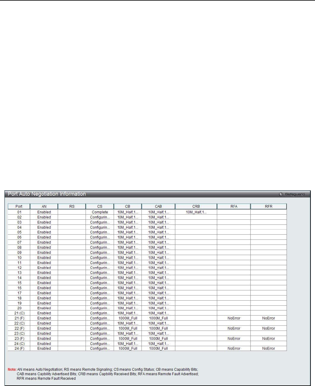
xStack® DGS-3200 Series Layer 2 Managed Gigabit Ethernet Switch Web UI Reference Guide
8
The IP address for the Switch must be set before the Web-based manager can manage the switch. The Switch IP address can be
automatically set using BOOTP or DHCP protocols, in which case the actual address assigned to the Switch must be known. The
IP address may be set using the Command Line Interface (CLI) over the console serial port as follows:
• Starting at the command line prompt, enter the commands config ipif System ipaddress xxx.xxx.xxx.xxx/
yyy.yyy.yyy.yyy. Where the x’s represent the IP address to be assigned to the IP interface named System and the y’s
represent the corresponding subnet mask.
• Alternatively, the user can enter config ipif System ipaddress xxx.xxx.xxx.xxx/z. Where the x’s represent the IP
address to be assigned to the IP interface named System and the z represents the corresponding number of subnets in
CIDR notation.
The IP interface named System on the Switch can be assigned an IP address and subnet mask, which can then be used to connect a
management station to the Switch’s Telnet or Web-based management agent.
Successful entry of the command will produce a “Success” message, indicating that the command execution was correctly. The
user may now utilize this address to configure or manage the Switch through Telnet, the Command Line Interface (CLI) or the
Web-based management (GUI).
Port Configuration
Port Auto Negotiation Information
The following window displays the detailed auto negotiation information.
To view the following window, click Configuration > Port Configuration > Port Auto Negotiation Information:
Figure 2 - 5. Port Auto Negotiation Information window
Port Detail Information
This window displays the detail information of ports.
To view the following window, click Configuration > Port Configuration > Port Detail Information:

xStack® DGS-3200 Series Layer 2 Managed Gigabit Ethernet Switch Web UI Reference Guide
9
Figure 2 - 6. Port Detail Information window
Click the Refresh button to update the information.
Port Settings
This windows is used to configure and display the switch ports settings.
To view the following window, click Configuration > Port Configuration > Port Settings:
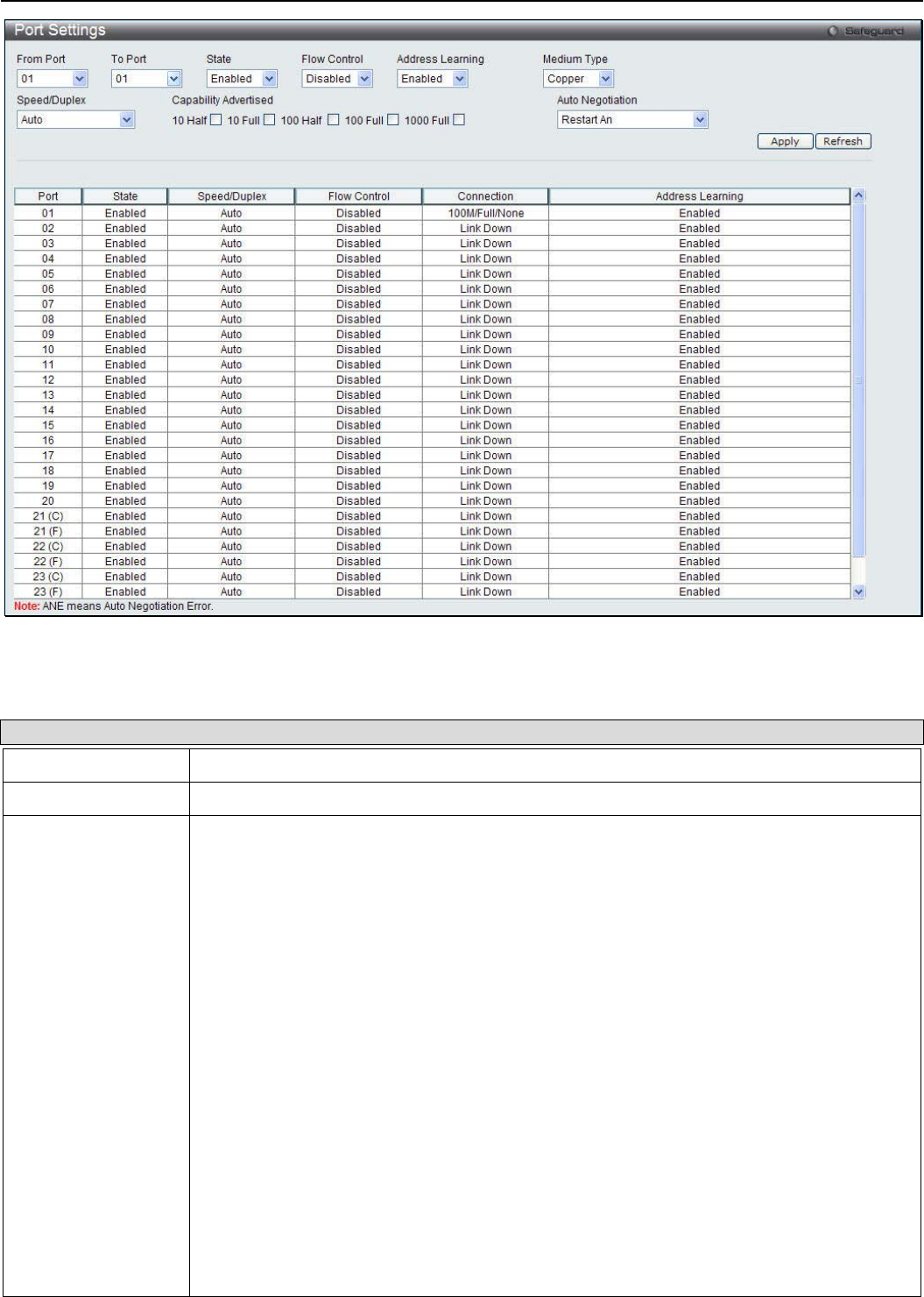
xStack® DGS-3200 Series Layer 2 Managed Gigabit Ethernet Switch Web UI Reference Guide
10
Figure 2 - 7. Port Settings window
The following parameters may be configured or viewed:
Parameter Description
From Port / To Port Use the drop-down menus to select the ports to be configured.
State Use the drop-down menu to enable or disable a given port or group of ports.
Speed/Duplex Toggle the Speed/Duplex field to either select the speed and duplex/half-duplex state of the
port. Auto denotes auto-negotiation between 10 and 100 Mbps devices, in full- or half-
duplex. The Auto setting allows the port to automatically determine the fastest settings the
device the port is connected to can handle, and then to use those settings. The other
options are 10M Half, 10M Full, 100M Half, 100M Full, 1000M Full_Master, 1000M
Full_Slave, and 1000M Full. There is no automatic adjustment of port settings with any
option other than Auto.
The Switch allows the user to configure three types of gigabit connections; 1000M
Full_Master, 1000M Full_Slave, and 1000M Full. Gigabit connections only support full
duplex connections and take on certain characteristics that are different from the other
choices listed.
The 1000M Full_Master and 1000M Full_Slave parameters refer to connections running a
1000BASE-T cable for connection between the Switch port and other device capable of a
gigabit connection. The master setting (1000M Full_Master) will allow the port to advertise
capabilities related to duplex, speed and physical layer type. The master setting will also
determine the master and slave relationship between the two connected physical layers.
This relationship is necessary for establishing the timing control between the two physical
layers. The timing control is set on a master physical layer by a local source. The slave
setting (1000M Full_Slave) uses loop timing, where the timing comes from a data stream
received from the master. If one connection is set for 1000M Full_Master, the other side of
the connection must be set for 1000M Full_Slave. Any other configuration will result in a link
down status for both ports.
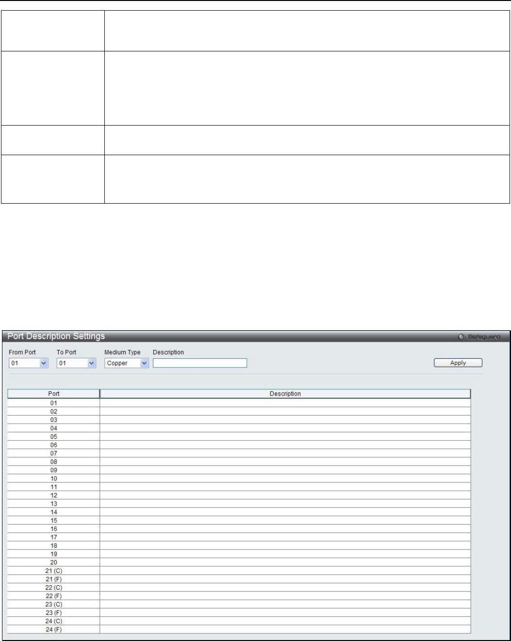
xStack® DGS-3200 Series Layer 2 Managed Gigabit Ethernet Switch Web UI Reference Guide
11
Flow Control Displays the flow control scheme used for the various port configurations. Ports configured
for full-duplex use 802.3x flow control, half-duplex ports use backpressure flow config, and
Auto ports use an automatic selection of the two. The default is Disabled.
Address Learning Enable or disable MAC address learning for the selected ports. When Enabled, destination
and source MAC addresses are automatically listed in the forwarding table. When address
learning is Disabled, MAC addresses must be manually entered into the forwarding table.
This is sometimes done for reasons of security or efficiency. See the section on
Forwarding/Filtering for information on entering MAC addresses into the forwarding table.
The default setting is Enabled.
Medium Type If configuring the Combo ports, this defines the type of transport medium to be used,
whether Copper or Fiber.
Auto Negotiation Use the drop-down menu to specify the auto-negotiation configuration.
Restart An – Select to restart the auto-negotiation process
Remote Fault Advertisedt - The remote fault advertisement option will be configured.
Click Apply to implement the new settings on the Switch.
Click the Refresh button to refresh the display section of this page.
Port Description Settings
The Switch supports a port description feature where the user may name various ports.
To view the following window, click Configuration > Port Configuration > Port Description:
Figure 2 - 8. Port Description window
Use the From Port and To Port drop-down menu to choose a port or range of ports to describe. Users may then enter a description
for the chosen port(s). If configuring the Combo ports, the Medium Type defines the type of transport medium to be used, whether
Copper or Fiber.
Click Apply to set the descriptions in the Port Description window.
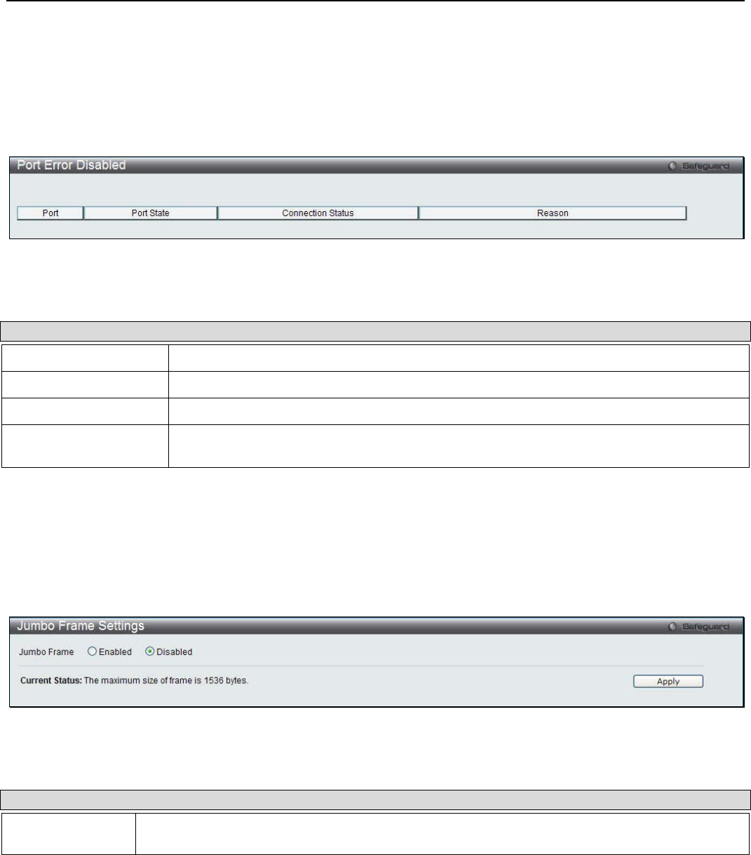
xStack® DGS-3200 Series Layer 2 Managed Gigabit Ethernet Switch Web UI Reference Guide
12
Port Error Disabled
The following window will display the information about ports that have had their connection status disabled, for reasons such as
storm control or link down status.
To view the following window, click Configuration > Port Configuration > Port Error Disabled:
Figure 2 - 9. Port Error Disabled window
The following parameters are displayed:
Parameter Description
Port Displays the port that has been error disabled.
Port State Describes the current running state of the port, whether enabled or disabled.
Connection Status This field will read the uplink status of the individual ports, whether enabled or disabled.
Reason Describes the reason why the port has been error-disabled, such as it has become a
shutdown port for storm control.
Jumbo Frame Settings
The Switch supports jumbo frames. Jumbo frames are Ethernet frames with more than 1,500 bytes of payload. The Switch
supports jumbo frames with a maximum frame size of 10240 bytes.
To view the following window, click Configuration > Port Configuration > Jumbo Frame Settings:
Figure 2 - 10. Jumbo Frame window
The following parameter can be configured:
Parameter Description
Jumbo Frame This field will enable or disable the Jumbo Frame function on the Switch. The default is
Disabled. The maximum frame size is 10240 bytes.
To enable or disable Jumbo Frame, use the radio button and click Apply.
Static ARP Settings
The Address Resolution Protocol is a TCP/IP protocol that converts IP addresses into physical addresses. This table allows
network managers to view, define, modify, and delete ARP information for specific devices.
Static entries can be defined in the ARP table. When static entries are defined, a permanent entry is entered and is used to translate
IP addresses to MAC addresses.
To view the following window, click Configuration > Static ARP Settings:
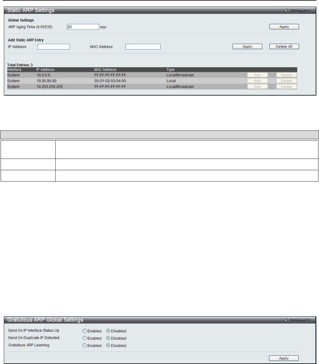
xStack® DGS-3200 Series Layer 2 Managed Gigabit Ethernet Switch Web UI Reference Guide
13
Figure 2 - 11. Static ARP Settings window
The following parameters may be configured or viewed:
Parameter Description
ARP Aging Time
(0-65535) The ARP entry age-out time, in seconds. The default is 20 minutes.
IP Address The IP address of the ARP entry.
MAC Address The MAC address of the ARP entry.
After entering a global ARP Aging Time in seconds, click Apply to allow it to take effect. The default value is 20 seconds.
After entering the IP Address and MAC Address of the Static ARP entry, click Apply to implement the new entry. To completely
clear the static ARP entries, click the Delete All button.
To modify a static ARP entry, click the Edit button located on the right side of the entry in the ARP table at the bottom of the
window.
To delete a static ARP entry, click the Delete button located on the right side of the entry in the static ARP table at the bottom of
the window.
Gratuitous ARP
Gratuitous ARP Global Settings
The window is used to enable or disable the gratuitous ARP global settings.
To view the following window, click Configuration > Gratuitous ARP > Gratuitous ARP Global Settings:
Figure 2 - 12. Gratuitous ARP Global Settings window
Click the Apply button to accept the changes made.
Gratuitous ARP Settings
The user can configure the IP interface’s gratuitous ARP parameter.
To view the following window, click Configuration > Gratuitous ARP > Gratuitous ARP Settings:

xStack® DGS-3200 Series Layer 2 Managed Gigabit Ethernet Switch Web UI Reference Guide
14
Figure 2 - 13. Gratuitous ARP Settings window
The fields that can be configured are described below:
Parameter Description
Trap Use the drop-down menu to enable or disable the trap option. By default the trap is disabled.
Log Use the drop-down menu to enable or disable the logging option. By default the event log is
enabled.
Interface Name Enter the interface name of the Layer 3 interface. Select All to enable or disable gratuitous ARP
trap or log on all interfaces.
Interval Time (0-
65535) Enter the periodically send gratuitous ARP interval time in seconds. 0 means that gratuitous ARP
request will not be sent periodically. By default the interval time is 0.
Click the Apply button to accept the changes made.
User Accounts
The Switch allows the control of user privileges.
To view the following window, click Configuration > User Accounts:
Figure 2 - 14. User Accounts window
To add a new user, type in a User Name and New Password and retype the same password in the Confirm New Password field.
Choose the level of privilege (Admin or User) from the Access Right drop-down menu.
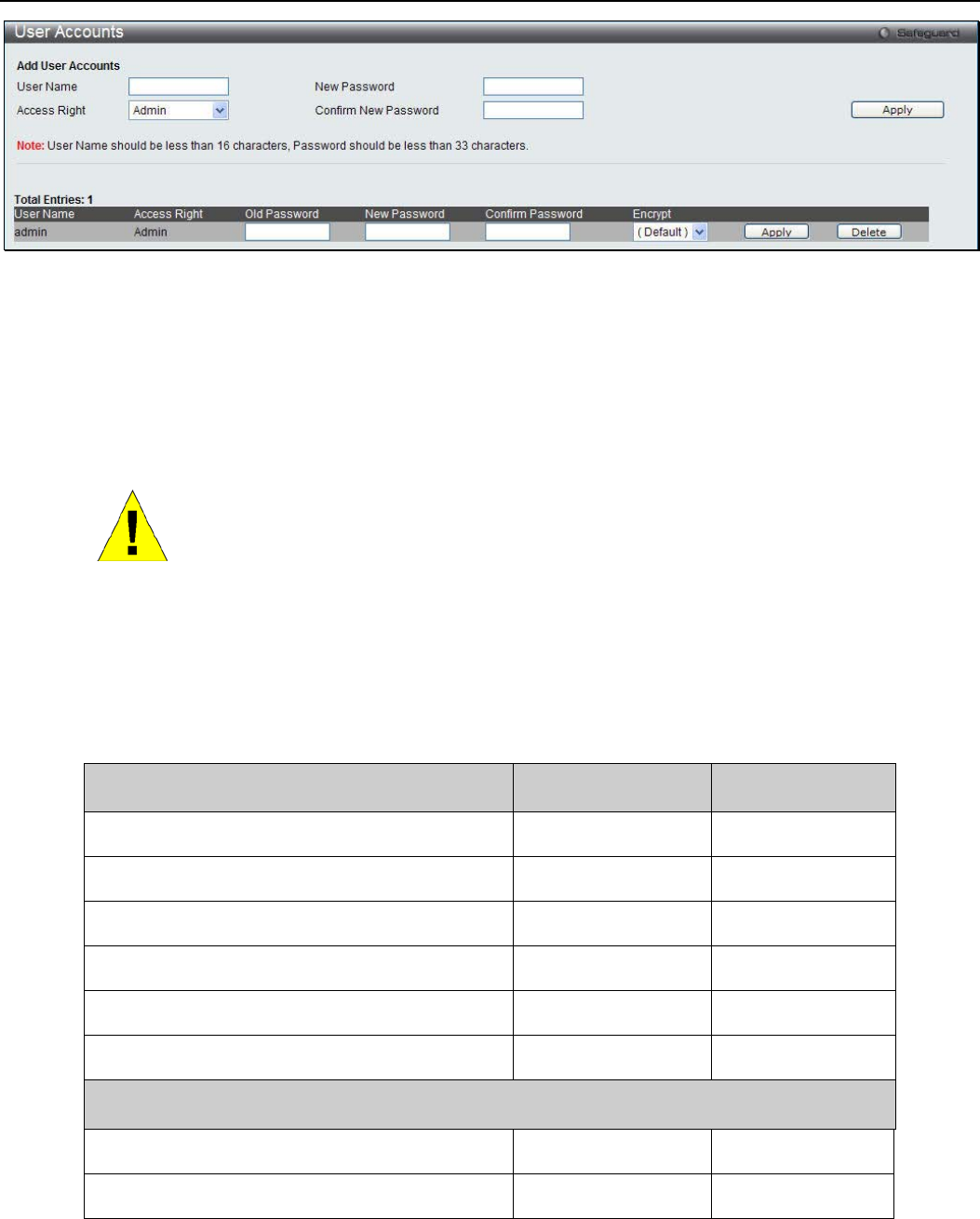
xStack® DGS-3200 Series Layer 2 Managed Gigabit Ethernet Switch Web UI Reference Guide
15
Figure 2 - 15. User Accounts window (Edit)
Modify or delete an existing user account in the table at the bottom of the window. To delete the user account, click the Delete
button. To change the password, click the Edit button next to the entry in the table at the bottom of the window. Enter an Old
Password, New Password, and retype the new password in the Confirm Password field offered, use the drop-down menu to select
the type of encryption desired (Plain Text or Sha 1), and then click Apply. The level of privilege (Admin or User) can be viewed
in the Access Right column in the table at the bottom of the window.
NOTICE: In case of lost passwords or password corruption, please refer to the
Appendix D, “Password Recovery Procedure,” which will guide you through the
steps necessary to resolve this issue.
Admin and User Privileges
There are two levels of user privileges, Admin and User. Some menu selections available to users with Admin privileges may not
be available to those with User privileges.
The following table summarizes the Admin and User privileges:
Management Admin User
Configuration Yes Read-only
Network Monitoring Yes Read-only
Community Strings and Trap Stations Yes Read-only
Update Firmware and Configuration Files Yes No
System Utilities Yes No
Factory Reset Yes No
User Account Management
Add/Update/Delete User Accounts Yes No
View User Accounts Yes No
Command Logging Settings
This window is used to enable or disable the command logging settings.
To view the following window, click Configuration > Command Logging Settings:
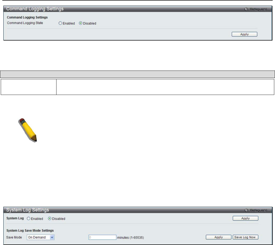
xStack® DGS-3200 Series Layer 2 Managed Gigabit Ethernet Switch Web UI Reference Guide
16
Figure 2 - 16. Command Logging Settings window
The following parameters may be configured or viewed:
Parameter Description
Command Logging
State Use the radio buttons to enable or disable the function.
Click the Apply button to accept the changes made.
NOTE: When the switch is under the booting or executing downloaded configuration
procedure, all configuration commands will not be logged. When the user uses AAA
authentication to logged in, the user name should not be changed if the user has used the
Enable Admin function to replace its privilege.
System Log Configuration
System Log Settings
The window is used to choose a method for which to save the Switch’s log to the flash memory of the Switch.
To view the following window, click Configuration > System Log Configuration > System Log Settings:
Figure 2 - 17. System Log Settings window
Use the drop-down menu to choose the method for saving the switch log to the flash memory. The user has three options:
• Time Interval – Users who choose this method can configure a time interval by which the Switch will save the log files,
in the box adjacent to this configuration field. The user may set a time between 1 and 65535 minutes.
• On Demand – Users who choose this method will only save log files when they manually tell the Switch to do so, either
using the Save Log link in the Save folder or clicking the Save Log Now button on this window.
• Log Trigger – Users who choose this method will have log files saved to the Switch every time a log event occurs on the
Switch.
The default setting is On Demand. Click Apply to save changes made. Click Save Log Now to immediately save log files
currently on the switch.
System Log Host
The Switch can send Syslog messages to up to four designated servers using the System Log Server.
To view the following window, click Configuration > System Log Configuration > System Log Host:

xStack® DGS-3200 Series Layer 2 Managed Gigabit Ethernet Switch Web UI Reference Guide
17
Figure 2 - 18. System Log Host window
The following parameters may be configured or viewed:
Parameter Description
Host ID Syslog server settings index (1 to 4).
Host IP Address The Ipv4 address of the Syslog server.
UDP Port (514 or
6000-65535) Type the UDP port number used for sending Syslog messages. The default is 514.
Severity This drop-down menu allows you to select the level of messages that will be sent. The
options are Warning, Informational, and All.
Facility Use the drop-down menu to select Local 0, Local 1, Local 2, Local 3, Local 4, Local 5, Local
6, or Local 7.
Status Choose Enabled or Disabled to activate or deactivate.
To set the System Log Server configuration, click Apply. Click the Edit button to configure the specific entry. To delete an entry
from the System Log Host List table, click the corresponding Delete button next to the entry.
System Severity Settings
The Switch can be configured to allow alerts be logged or sent as a trap to an SNMP agent or both. The level at which the alert
triggers either a log entry or a trap message can be set as well. Use the System Severity Settings window to set the criteria for
alerts. The current settings are displayed below the System Severity Table.
To view the following window, click Configuration > System Severity Settings:
Figure 2 - 19. System Severity Settings window
The following parameters may be configured or viewed:
Parameter Description
System Severity Choose how the alerts are used from the drop-down menu. Select Log to send the alert of the
Severity Type configured to the Switch’s log for analysis. Choose Trap to send it to an SNMP
agent for analysis, or select All to send the chosen alert type to an SNMP agent and the
Switch’s log for analysis.
Severity Level Choose what level of alert will trigger sending the log entry or trap message as defined by the
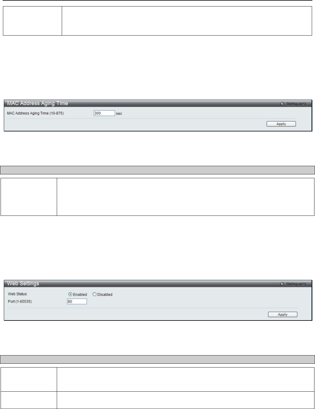
xStack® DGS-3200 Series Layer 2 Managed Gigabit Ethernet Switch Web UI Reference Guide
18
Severity Name. Select Critical to send only critical events to the Switch’s log or SNMP agent.
Choose Warning to send critical and warning events to the Switch’s log or SNMP agent.
Select Information to send informational, warning, and critical events to the Switch’s log or
SNMP agent.
Click Apply to implement the new System Severity Settings.
MAC Address Aging Time
Users can configure the MAC Address aging time on the Switch.
To view the following window, click Configuration > MAC Address Aging Time:
Figure 2 – 20. MAC Address Aging Time window
The following parameter may be configured or viewed:
Parameter Description
MAC Address
Aging Time (10-
875)
Specify the length of time a learned MAC Address will remain in the forwarding table without
being accessed (that is, how long a learned MAC Address is allowed to remain idle). To change
this, type in a different value to represent the MAC address age-out time in seconds. The MAC
Address Aging Time can be set to any value between 10 and 875 seconds. The default setting
is 300 seconds.
Click Apply to set the MAC Address Aging Time.
Web Settings
Users can configure the Web settings on the Switch.
To view the following window, click Configuration > Web Settings:
Figure 2 – 21. Web Settings window
The following parameters may be configured or viewed:
Parameter Description
Web Status Web-based management is Enabled by default. If you choose to disable this by clicking
Disabled, you will lose the ability to configure the system through the web interface as soon as
these settings are applied.
Port (1-65535) The TCP port number used for Web-based management of the Switch. The “well-known” TCP
port for the Web protocol is 80.
Click Apply to set the web settings.
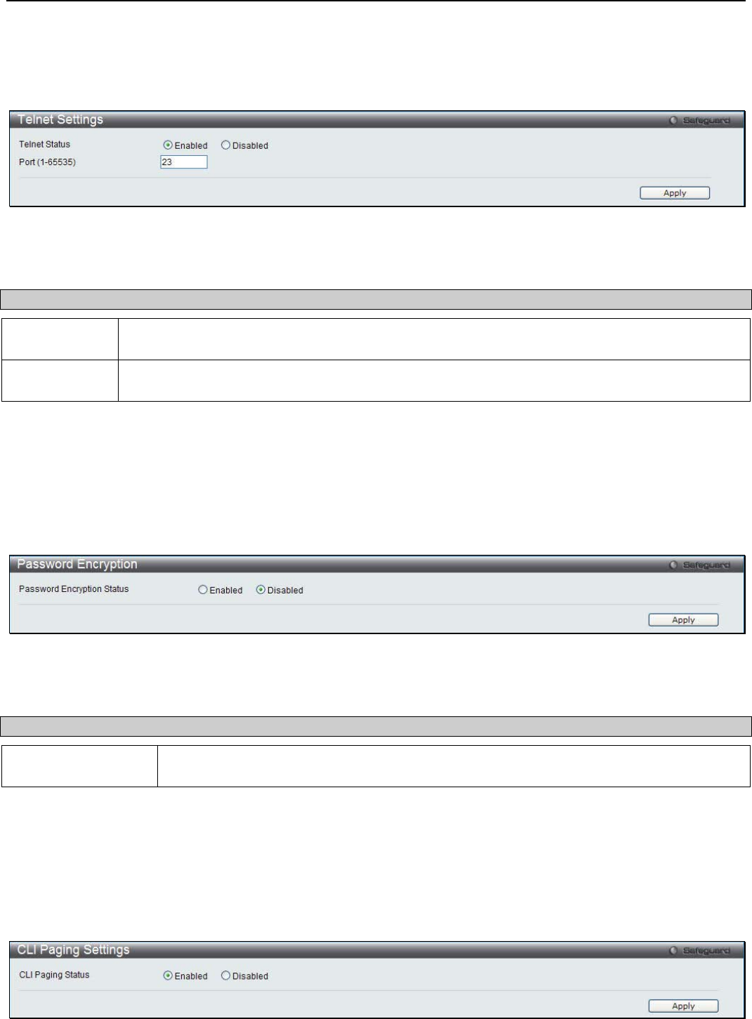
xStack® DGS-3200 Series Layer 2 Managed Gigabit Ethernet Switch Web UI Reference Guide
19
Telnet Settings
Users can configure Telnet Settings on the Switch.
To view the following window, click Configuration > Telnet Settings:
Figure 2 – 22. Telnet Settings window
The following parameters may be configured or viewed:
Parameter Description
Telnet Status Telnet configuration is Enabled by default. If you do not want to allow configuration of the system
through Telnet choose Disabled.
Port (1-65535) The TCP port number used for Telnet management of the Switch. The “well-known” TCP port for
the Telnet protocol is 23.
Click Apply to set the Telnet setting.
Password Encryption
Users can configure Password Encryption on the Switch.
To view the following window, click Configuration > Password Encryption:
Figure 2 – 23. Password Encryption window
The following parameter may be configured or viewed:
Parameter Description
Password
Encryption Status Password encryption is Disabled by default. To enable password encryption, click the
Enabled radio button.
Click Apply to set the password encryption.
CLI Paging Settings
Users can stop the scrolling of multiple pages beyond the limits of the console when using the Command Line Interface.
To view the following window, click Configuration > CLI Paging Settings:
Figure 2 – 24. CLI Paging Settings window
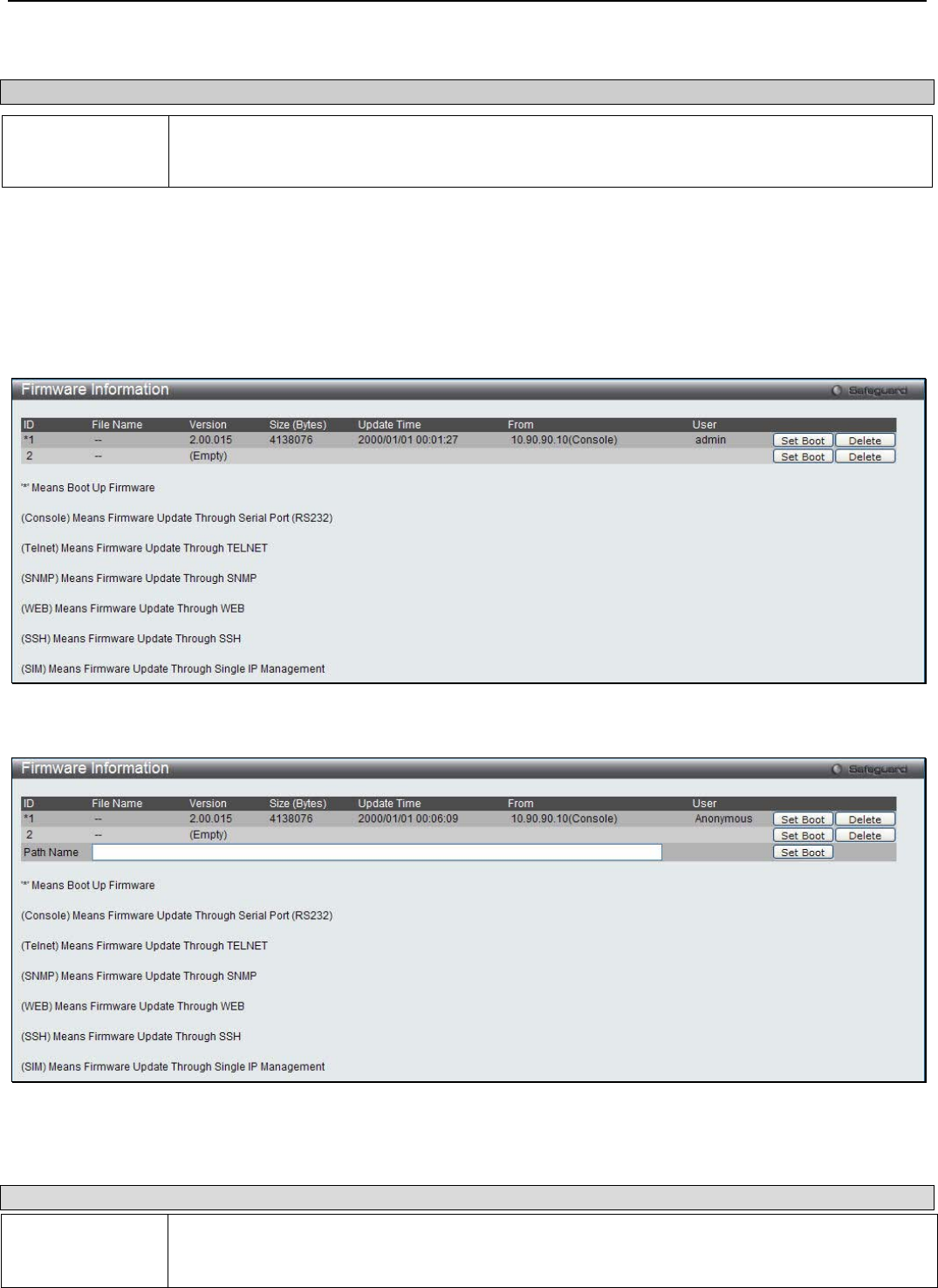
xStack® DGS-3200 Series Layer 2 Managed Gigabit Ethernet Switch Web UI Reference Guide
20
The following parameter may be configured or viewed:
Parameter Description
CLI Paging
Status Command Line Interface paging stops each page at the end of the console. This allows you to
stop the scrolling of multiple pages of text beyond the limits of the console. CLI Paging is
Enabled by default. To disable it, click the Disabled radio button.
Click Apply to set the CLI Paging setting.
Firmware Information
Users can view, set the next boot-up status, and delete current firmware images stored on the Switch.
To view the following window, click Configuration > Firmware Information:
Figure 2 – 25. Firmware Information window (DGS-3200-10 and DGS-3200-16 models)
Figure 2 – 26. Firmware Information window (DGS-3200-24 model)
The following parameters may be configured or viewed:
Parameter Description
ID States the image ID number of the firmware in the Switch’s memory. The Switch can store 2
firmware images for use. Image ID 1 will be the default boot-up firmware for the Switch unless
otherwise configured by the user.

xStack® DGS-3200 Series Layer 2 Managed Gigabit Ethernet Switch Web UI Reference Guide
21
Version States the firmware version.
Size States the size of the corresponding firmware, in bytes.
Update Time States the specific time the firmware version was downloaded to the Switch.
From States the IP address of the origin of the firmware. There are six ways firmware may be
downloaded to the Switch. Boot-up files are denoted by an asterisk (*) next to the file.
Console – If the IP address has the word Console next to it, it denotes a firmware upgrade
through the Console Serial Port (RS-232).
Telnet – If the IP address has the word Telnet next to it, it denotes a firmware upgrade through
Telnet.
SNMP – If the IP address has the word SNMP next to it, it denotes a firmware upgrade through
the Simple Network Management Protocol (SNMP).
WEB – If the IP address has the word WEB next to it, it denotes a firmware upgrade through the
web-based management interface.
SSH – If the IP address has the word SSH next to it, it denotes a firmware upgrade through the
Secure Shell (SSH).
SIM – If the IP address has the word SIM next to it, it denotes a firmware upgrade through the
Single IP Management feature.
User States the user who downloaded the firmware. This field may read “Anonymous” or “Unknown”
for users that are not identified.
Path Name
(DGS-3200-24
model only)
This parameter is used to boot the Switch up from a firmware image stored on an SD card.
To boot the Switch from a firmware image stored on an SD card carry out the following:
• Input the path of the firmware image on the SD-card (such as "c:\DGS3200.had").
• Click the adjacent Set Boot button to use the firmware image, stored on the SD-card, as
the bootup image.
To set firmware as the boot-up firmware the next time the Switch is restarted, click the Set Boot button. To remove the firmware
from this window, click the Delete button.
Dual Configuration Settings
Users can display dual configuration settings on the Switch. The Switch allows two configurations to be stored in its memory and
either can be configured as the boot-up configuration for the Switch (the DGS-3200-24 also allows configurations to be stored on
an SD-card). The user may select a boot-up configuration for the Switch by clicking the Boot button to select it. This will instruct
the Switch to use this newly selected configuration the next time the Switch is restarted. To delete a configuration, click the
adjacent Delete button. To set a configuration as the active configuration, click the adjacent Active button.
To view the following window, click Configuration > Dual Configuration Settings:
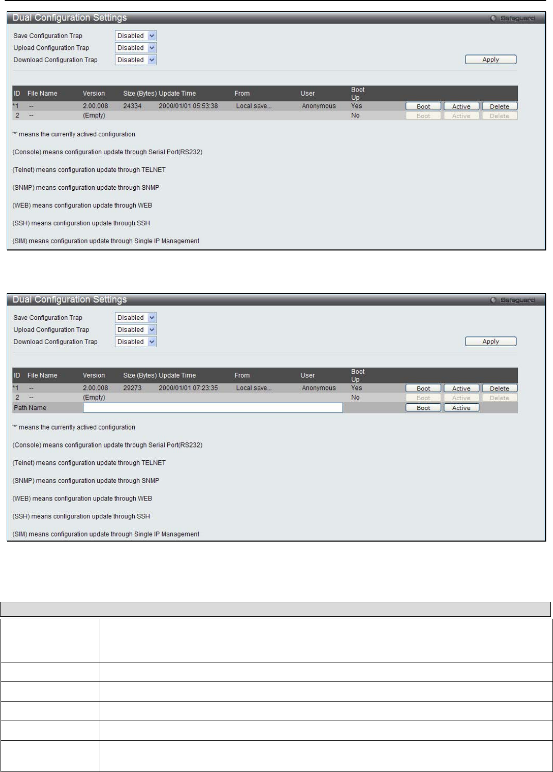
xStack® DGS-3200 Series Layer 2 Managed Gigabit Ethernet Switch Web UI Reference Guide
22
Figure 2 - 27. Dual Configuration Settings window (DGS-3200-10 and DGS-3200-16 models)
Figure 2 - 28. Dual Configuration Settings window (DGS-3200-24 model)
The following parameters may be configured or viewed:
Parameter Description
ID States the configuation ID number of the configuaration in the Switch’s memory. The Switch can
store 2 configurations for use. Configuration ID 1 will be the default boot-up configuration for the
Switch unless otherwise configured by the user.
File Name States the file name.
Version States the configuration version.
Size (Bytes) States the size of the corresponding configuration, in bytes.
Update Time States the specific time the configuration version was downloaded to the Switch.
From States the IP address of the origin of the configuration. There are five ways a configuration may
be downloaded to the Switch. Boot-up files are denoted by an asterisk (*) next to the file.

xStack® DGS-3200 Series Layer 2 Managed Gigabit Ethernet Switch Web UI Reference Guide
23
Console – If the IP address has the word Console next to it, it denotes a configuration upgrade
through the Console Serial Port (RS-232).
Telnet – If the IP address has the word Telnet next to it, it denotes a configuration upgrade
through Telnet.
SNMP – If the IP address has the word SNMP next to it, it denotes a configuration upgrade
through the Simple Network Management Protocol (SNMP).
WEB – If the IP address has the word WEB next to it, it denotes a configuration upgrade through
the web-based management interface.
SSH – If the IP address has the word SSH next to it, it denotes a configuration upgrade using
Secure Shell (SSH).
SIM – If the IP address has the word SIM next to it, it denotes a configuration upgrade through
the Single IP Management feature.
User States the user who downloaded the configuration. This field may read “Anonymous” or
“Unknown” for users that are not identified.
Boot Up States if the configuration will be used to boot up the Switch or not. Yes indicates that the
configuration will be used as the boot up configuration. No indicates that the configuration will not
be used as the boot up configuration.
Path Name
(DGS-3200-24
model only)
This parameter is used to boot the Switch up from a configuration stored on an SD card.
To boot the Switch from a configuration stored on an SD card carry out the following:
• Input the path of configuration on the SD-card (such as "c:\DGS3200.had").
• Click the adjacent Set Boot button to use the configuration, stored on the SD-card, as
the bootup configuration.
• Click the adjacent Active button to make the configuration, stored on the SD-card, the
active configuration.
Setting the Boot Up Configuration:
• Click the Boot button next to the configuration you want to use as the Boot Up configuration.
• A Success message appears to indicate that the configuration that will be used for booting up the Switch has changed.
• The Boot Up parameter next to the configuration that will be used to boot up the Switch will read Yes.
Setting the Active Configuration:
• Click the Active button next to the configuration you want to use as the Active configuration.
• A Success message appears to indicate that the configuration that will be used as the active configuration has changed.
• An asterisk will appear next to ID of the configuration that is being used as the active configuration.
Deleting a Configuration:
• Click the Delete button next to the configuration you want to delete.
• A Success message appears to indicate that the configuration has been deleted.
Power Saving
LED State Settings
This window is used to configure the port LED state.
To view the following window, click Configuration > Power Saving > LED State Settings:

xStack® DGS-3200 Series Layer 2 Managed Gigabit Ethernet Switch Web UI Reference Guide
24
Figure 2 – 29. Port LED State Settings window
The following parameter may be configured:
Parameter Description
Port LED State Click the radio buttons to enable or disable the port LED state.
Click Apply to save the settings.
Power Saving Settings
This window allows the user to implement the Switch’s built-in power saving features and set the schedule to enforce the settings.
When the Power Saving Mode Link Detection State is Enabled, a port which has a link down status will be turned off to save
power to the Switch. This will not affect the port’s capabilities when the port status is link up. When the Power Saving Mode
Length Detection State is Enabled, the Switch will automatically determine the length of the cable and adjust the power flow
accordingly. When Power Saving Mode LED State is Enabled, the LED’s state of ports will be turned off during the configured
time range. When Power Saving Mode Port State is Enabled, the ports will be shut down during the configured time range. When
Power Saving Mode Hibernation State is Enabled, the Switch will go into a low power state and be idle during the configured
time range. It will shut down all the ports, all network function (telnet, ping, etc.) will not work, and only the console connection
will work via the RS232 port. If the Switch is an endpoint type PSE (Power Sourcing Equipment), it will not provide power to the
port.
To view the following window, click Configuration > Power Saving > Power Saving Settings:
Figure 2 – 30. Power Saving Settings window
The following parameter may be configured or viewed:
Parameter Description
Power Saving Mode
Link Detection State Click the radio buttons to enable or disable the link detection state.
Power Saving Mode
Length Detection
State
Click the radio buttons to enable or disable length detection state.
Power Saving Mode
LED State Click the radio buttons to enable or disable LED state.
Power Saving Mode Click the radio buttons to enable or disable port state.
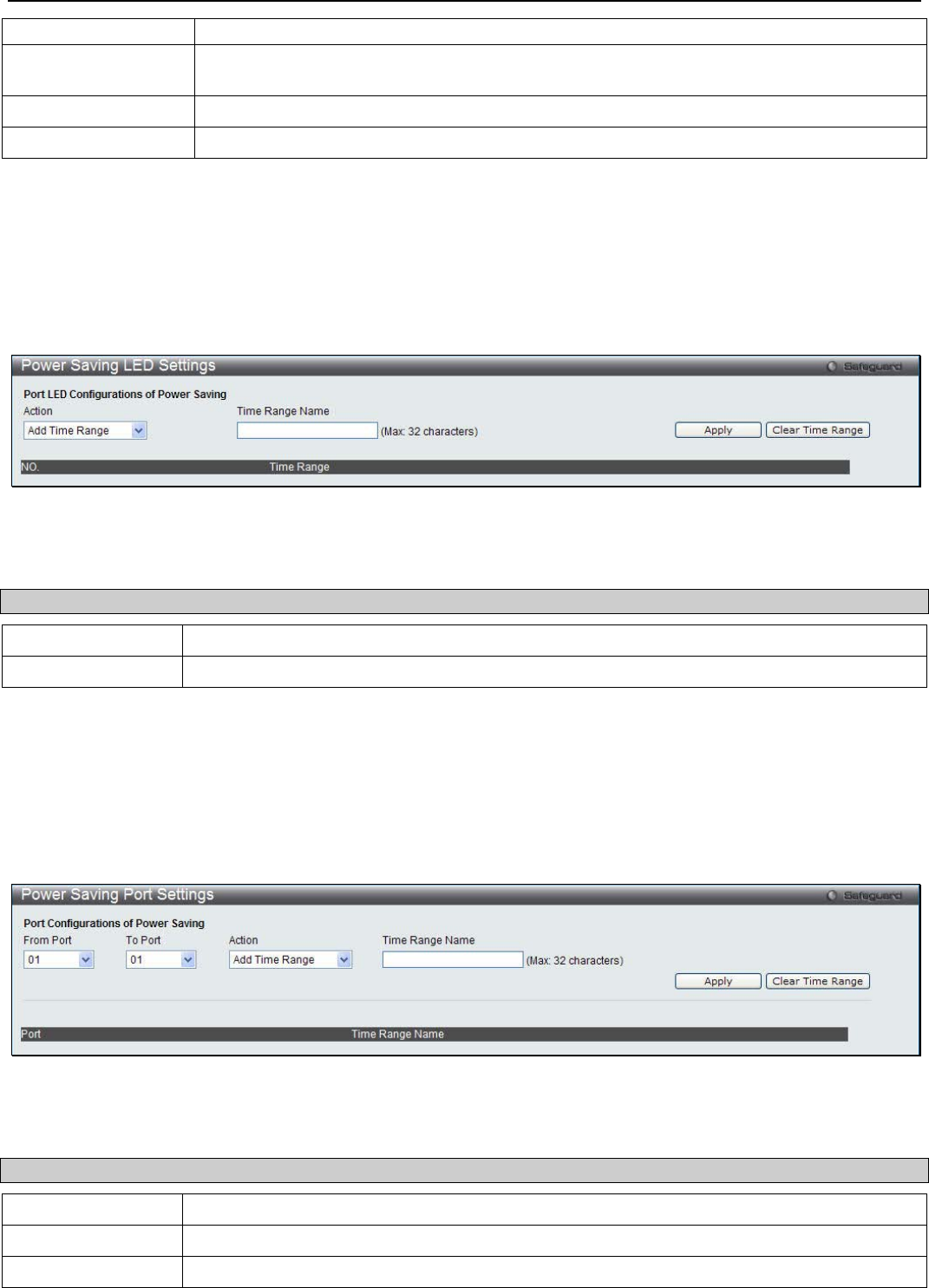
xStack® DGS-3200 Series Layer 2 Managed Gigabit Ethernet Switch Web UI Reference Guide
25
Port State
Power Saving Mode
Hibernation State Click the radio buttons to enable or disable hibernation state.
Action Use the drop down menu to add or delete the schedule.
Time Range Name Specify the name of the schedule.
Click Apply to set the password encryption. Click the Clear Time Range to remove all the entries.
Power Saving LED Settings
This window is used to add or delete the power saving schedule on the LED of all ports.
To view the following window, click Configuration > Power Saving > Power Saving LED Settings:
Figure 2 – 31. Power Saving LED Settings window
The following parameter may be configured:
Parameter Description
Action Use the drop down menu to add or delete the schedule.
Time Range Name Specify the name of the schedule.
Click the Apply button to save the settings. Click the Clear Time Range to remove all the entries.
Power Saving Port Settings
This window is used to set the power saving state.
To view the following window, click Configuration > Power Saving > Power Saving Port Settings:
Figure 2 – 32. Power Saving Port Settings window
The following parameter may be configured:
Parameter Description
From Port / To Port Use the drop-down menu to select the ports to be configured.
Action Use the drop down menu to add or delete the schedule.
Time Range Name Specify the name of the schedule.
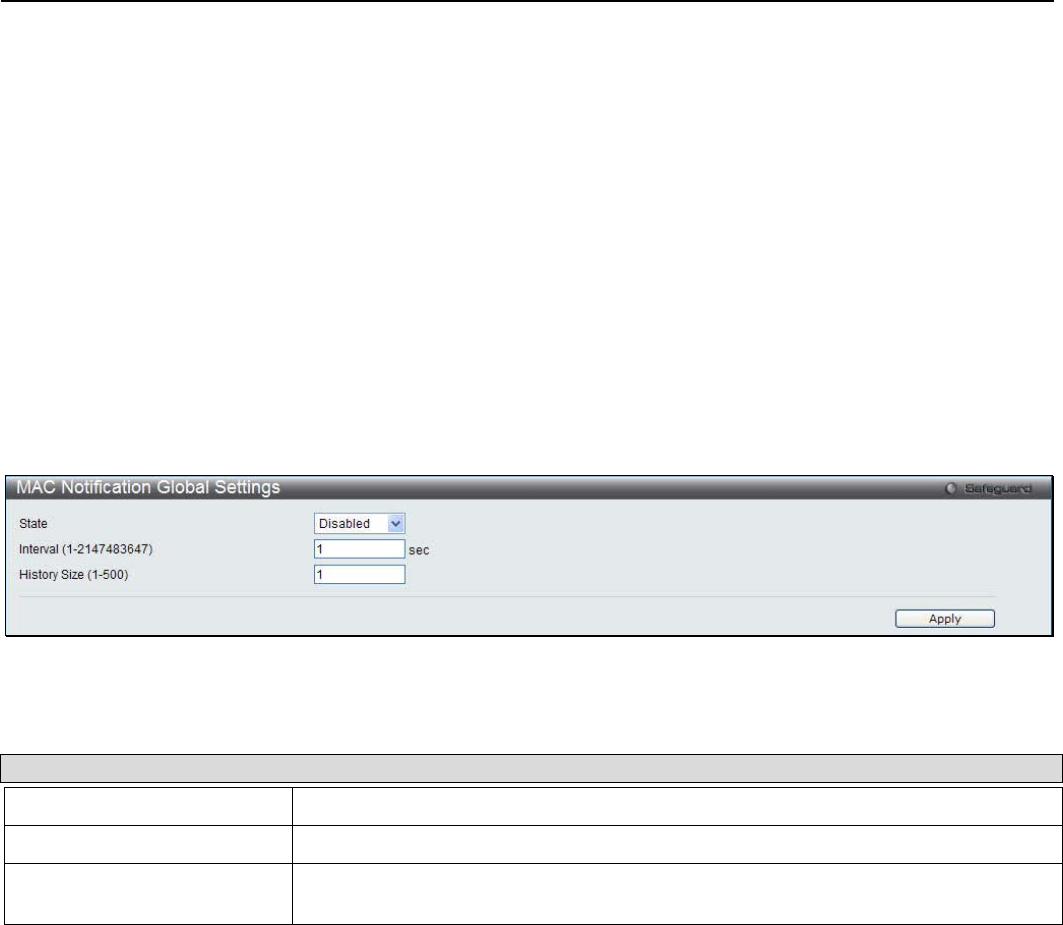
xStack® DGS-3200 Series Layer 2 Managed Gigabit Ethernet Switch Web UI Reference Guide
26
Click the Apply button to save the settings.
Click the Clear Time Range to remove all the entries.
MAC Notification Settings
MAC Notification is used to monitor MAC addresses learned and entered into the forwarding database.
MAC Notification Global Settings
This window allows you to globally set MAC notification on the Switch.
To view the following window, click Configuration > MAC Notification Settings > MAC Notification Global Settings:
Figure 2 - 33. MAC Notification Global Settings window
The following parameters may be viewed and modified:
Parameter Description
State Enable or disable MAC notification globally on the Switch
Interval (1-2147483647) The time in seconds between notifications.
History Size (1-500) The maximum number of entries listed in the history log used for notification. Up to
500 entries can be specified.
Click Apply to implement your changes.
MAC Notification Port Settings
Users can set MAC notification for individual ports on the Switch.
To view the following window, click Configuration > MAC Notification Settings > MAC Notification Port Settings:
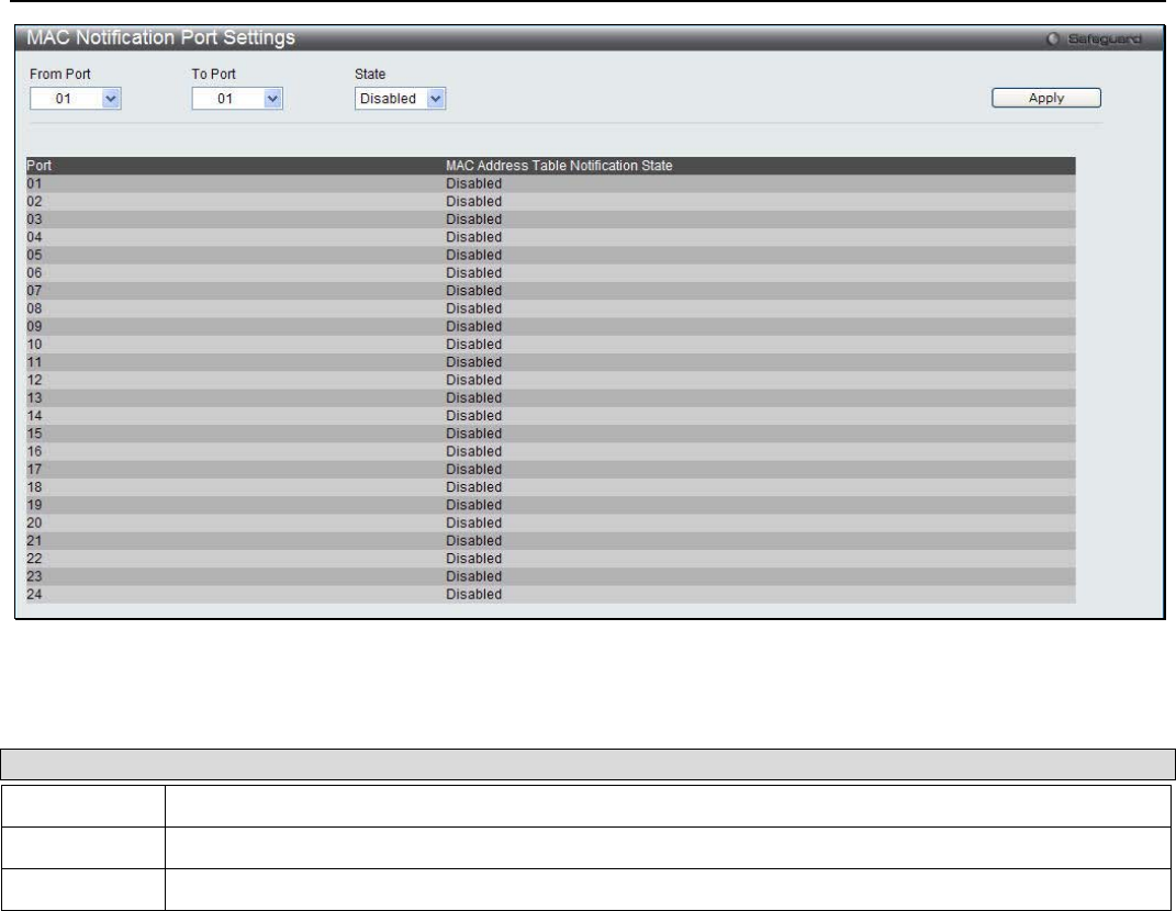
xStack® DGS-3200 Series Layer 2 Managed Gigabit Ethernet Switch Web UI Reference Guide
27
Figure 2 - 34. MAC Notification Port Settings window
To change MAC notification settings for a port or group of ports on the Switch, configure the following parameters:
Parameter Description
From Port Select a beginning port to enable for MAC notification using the drop-down menu.
To Port Select an ending port to enable for MAC notification using the drop-down menu.
State Enable MAC Notification for the ports selected using the drop-down menu.
Click Apply to implement changes made.
SNMP Settings
Simple Network Management Protocol (SNMP) is an OSI Layer 7 (Application Layer) designed specifically for managing and
monitoring network devices. SNMP enables network management stations to read and modify the settings of gateways, routers,
switches, and other network devices. Use SNMP to configure system features for proper operation, monitor performance and
detect potential problems in the Switch, switch group or network.
Managed devices that support SNMP include software (referred to as an agent), which runs locally on the device. A defined set of
variables (managed objects) is maintained by the SNMP agent and used to manage the device. These objects are defined in a
Management Information Base (MIB), which provides a standard presentation of the information controlled by the on-board
SNMP agent. SNMP defines both the format of the MIB specifications and the protocol used to access this information over the
network.
The Switch supports the SNMP versions 1, 2c, and 3. The three versions of SNMP vary in the level of security provided between
the management station and the network device.
In SNMP v.1 and v.2, user authentication is accomplished using ‘community strings’, which function like passwords. The remote
user SNMP application and the Switch SNMP must use the same community string. SNMP packets from any station that has not
been authenticated are ignored (dropped).
The default community strings for the Switch used for SNMP v.1 and v.2 management access are:
• public – Allows authorized management stations to retrieve MIB objects.
• private – Allows authorized management stations to retrieve and modify MIB objects.

xStack® DGS-3200 Series Layer 2 Managed Gigabit Ethernet Switch Web UI Reference Guide
28
SNMPv3 uses a more sophisticated authentication process that is separated into two parts. The first part is to maintain a list of
users and their attributes that are allowed to act as SNMP managers. The second part describes what each user on that list can do
as an SNMP manager.
The Switch allows groups of users to be listed and configured with a shared set of privileges. The SNMP version may also be set
for a listed group of SNMP managers. Thus, you may create a group of SNMP managers that are allowed to view read-only
information or receive traps using SNMPv1 while assigning a higher level of security to another group, granting read/write privi-
leges using SNMPv3.
Using SNMPv3 individual users or groups of SNMP managers can be allowed to perform or be restricted from performing
specific SNMP management functions. The functions allowed or restricted are defined using the Object Identifier (OID)
associated with a specific MIB. An additional layer of security is available for SNMPv3 in that SNMP messages may be
encrypted. To read more about how to configure SNMPv3 settings for the Switch read the next section.
Traps
Traps are messages that alert network personnel of events that occur on the Switch. The events can be as serious as a reboot
(someone accidentally turned OFF the Switch), or less serious like a port status change. The Switch generates traps and sends
them to the trap recipient (or network manager). Typical traps include trap messages for Authentication Failure, Topology Change
and Broadcast\Multicast Storm.
MIBs
The Switch in the Management Information Base (MIB) stores management and counter information. The Switch uses the
standard MIB-II Management Information Base module. Consequently, values for MIB objects can be retrieved from any SNMP-
based network management software. In addition to the standard MIB-II, the Switch also supports its own proprietary enterprise
MIB as an extended Management Information Base. Specifying the MIB Object Identifier may also retrieve the proprietary MIB.
MIB values can be either read-only or read-write.
The Switch incorporates a flexible SNMP management for the switching environment. SNMP management can be customized to
suit the needs of the networks and the preferences of the network administrator. Use the SNMP V3 menus to select the SNMP
version used for specific tasks.
The Switch supports the Simple Network Management Protocol (SNMP) versions 1, 2c, and 3. The administrator can specify the
SNMP version used to monitor and control the Switch. The three versions of SNMP vary in the level of security provided
between the management station and the network device.
SNMP settings are configured using the menus located on the SNMP Settings folder of the Web manager. Workstations on the
network that are allowed SNMP privileged access to the Switch can be restricted with the Management Station IP Address menu.
SNMP Global State Settings
SNMP global state settings can be enabled or disabled.
To view the following window, click Configuration > SNMP Settings > SNMP Global State Settings:
Figure 2 - 35. SNMP Global State Settings window
Click the Apply button to let your change take effect.
SNMP Linkchange Traps Settings
Users can set SNMP linkchange traps.
To view the following window, click Configuration > SNMP Settings > SNMP Linkchange Trap Settings:
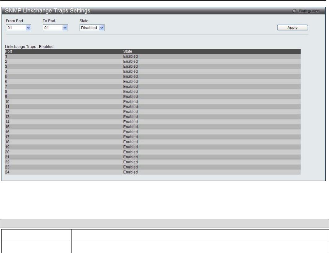
xStack® DGS-3200 Series Layer 2 Managed Gigabit Ethernet Switch Web UI Reference Guide
29
Figure 2 - 36. SNMP Linkchange Trap Settings window
The following parameters may be configured:
Parameter Description
From Port / To Port Use the drop-down menu to select the ports to be configured.
State Use the drop-down menu to enable or disable the SNMP linkchange traps.
Click Apply to implement the changes.
SNMP View Table
Users can assign views to community strings that define which MIB objects can be accessed by a remote SNMP manager. The
SNMP Group created with this table maps SNMP users (identified in the SNMP User Table) to the views created in the previous
window.
To view the following window, click Configuration > SNMP Settings > SNMP View Table:
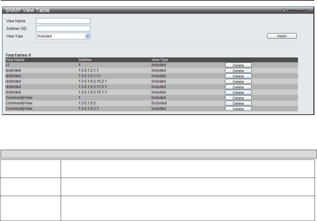
xStack® DGS-3200 Series Layer 2 Managed Gigabit Ethernet Switch Web UI Reference Guide
30
Figure 2 - 37. SNMP View Table window
The following parameters can be set:
Parameter Description
View Name Type an alphanumeric string of up to 32 characters. This is used to identify the new SNMP
view being created.
Subtree OID Type the Object Identifier (OID) Subtree for the view. The OID identifies an object tree (MIB
tree) that will be included or excluded from access by an SNMP manager.
View Type Select Included to include this object in the list of objects that an SNMP manager can access.
Select Excluded to exclude this object from the list of objects that an SNMP manager can
access.
To delete an existing SNMP View Table entry, click the Delete button corresponding to the entry to delete. To create a new entry,
enter the information above the table and then click the Apply button.
SNMP Group Table
An SNMP Group created with this table maps SNMP users (identified in the SNMP User Table) to the views created in the
previous window.
To view the following window, click Configuration > SNMP Settings > SNMP Group Table:
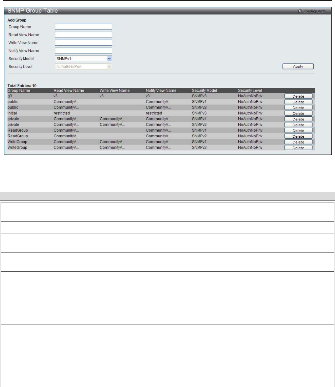
xStack® DGS-3200 Series Layer 2 Managed Gigabit Ethernet Switch Web UI Reference Guide
31
Figure 2 - 38. SNMP Group Table window
The following parameters can be set:
Parameter Description
Group Name Type an alphanumeric string of up to 32 characters. This is used to identify the new SNMP
group of SNMP users.
Read View Name This name is used to specify the SNMP group created can request SNMP messages.
Write View Name Specify an SNMP group name for users that are allowed SNMP write privileges to the Switch’s
SNMP agent.
Notify View Name Specify a SNMP group name for users that can receive SNMP trap messages generated by
the Switch’s SNMP agent.
Security Model SNMPv1 – Specifies that SNMP version 1 will be used.
SNMPv2 – Specifies that SNMP version 2c will be used. The SNMPv2 supports both
centralized and distributed network management strategies. It includes improvements in the
Structure of Management Information (SMI) and adds some security features.
SNMPv3 – Specifies that the SNMP version 3 will be used. SNMPv3 provides secure access
to devices through a combination of authentication and encrypting packets over the network.
Security Level The Security Level settings only apply to SNMPv3.
NoAuthNoPriv – Specifies that there will be no authorization and no encryption of packets sent
between the Switch and a remote SNMP manager.
AuthNoPriv – Specifies that authorization will be required, but there will be no encryption of
packets sent between the Switch and a remote SNMP manager.
AuthPriv – Specifies that authorization will be required, and that packets sent between the
Switch and a remote SNMP manger will be encrypted.
To delete an existing SNMP Group Table entry, click the Delete button next to the corresponding entry.
To add a new entry to the Switch’s SNMP Group Table, enter the information at the top of the window and then click Apply.
SNMP User Table
This window displays all of the SNMP User’s currently configured on the Switch.
To view the following window, click Configuration > SNMP Settings > SNMP User Table:

xStack® DGS-3200 Series Layer 2 Managed Gigabit Ethernet Switch Web UI Reference Guide
32
Figure 2 - 39. SNMP User Table window
The following parameters can be configured:
Parameter Description
User Name An alphanumeric string of up to 32 characters. This is used to identify the SNMP users.
Group Name This name is used to specify the SNMP group created can request SNMP messages.
SNMP Version V3 – Indicates that SNMP version 3 is in use.
SNMP V3
Encryption Use the drop-down menu to enable encryption for SNMP V3. This is only operable in SNMP V3
mode. The choices are None, Password, or Key.
Auth-Protocol MD5 – Specifies that the HMAC-MD5-96 authentication level will be used. This field is only
operable when V3 is selected in the SNMP Version field and the Encryption field has been
checked. This field will require the user to enter a password.
SHA – Specifies that the HMAC-SHA authentication protocol will be used. This field is only
operable when V3 is selected in the SNMP Version field and the Encryption field has been
checked. This field will require the user to enter a password.
Priv-Protocol None – Specifies that no authorization protocol is in use.
DES – Specifies that DES 56-bit encryption is in use, based on the CBC-DES (DES-56)
standard. This field is only operable when V3 is selected in the SNMP Version field and the
Encryption field has been checked. This field will require the user to enter a password between 8
and 16 alphanumeric characters.
To delete an existing SNMP User Table entry, click the Delete button corresponding to the entry to delete.
To implement changes made, click Apply.
SNMP Community Table
Users can create an SNMP community string to define the relationship between the SNMP manager and an agent. The community
string acts like a password to permit access to the agent on the Switch. One or more of the following characteristics can be
associated with the community string:
• An Access List of IP addresses of SNMP managers that are permitted to use the community string to gain access to the
Switch’s SNMP agent.
• Any MIB view that defines the subset of all MIB objects will be accessible to the SNMP community.
• Read/write or read-only level permission for the MIB objects accessible to the SNMP community.
To view the following window, click SNMP Settings > Configuration > SNMP Community Table:
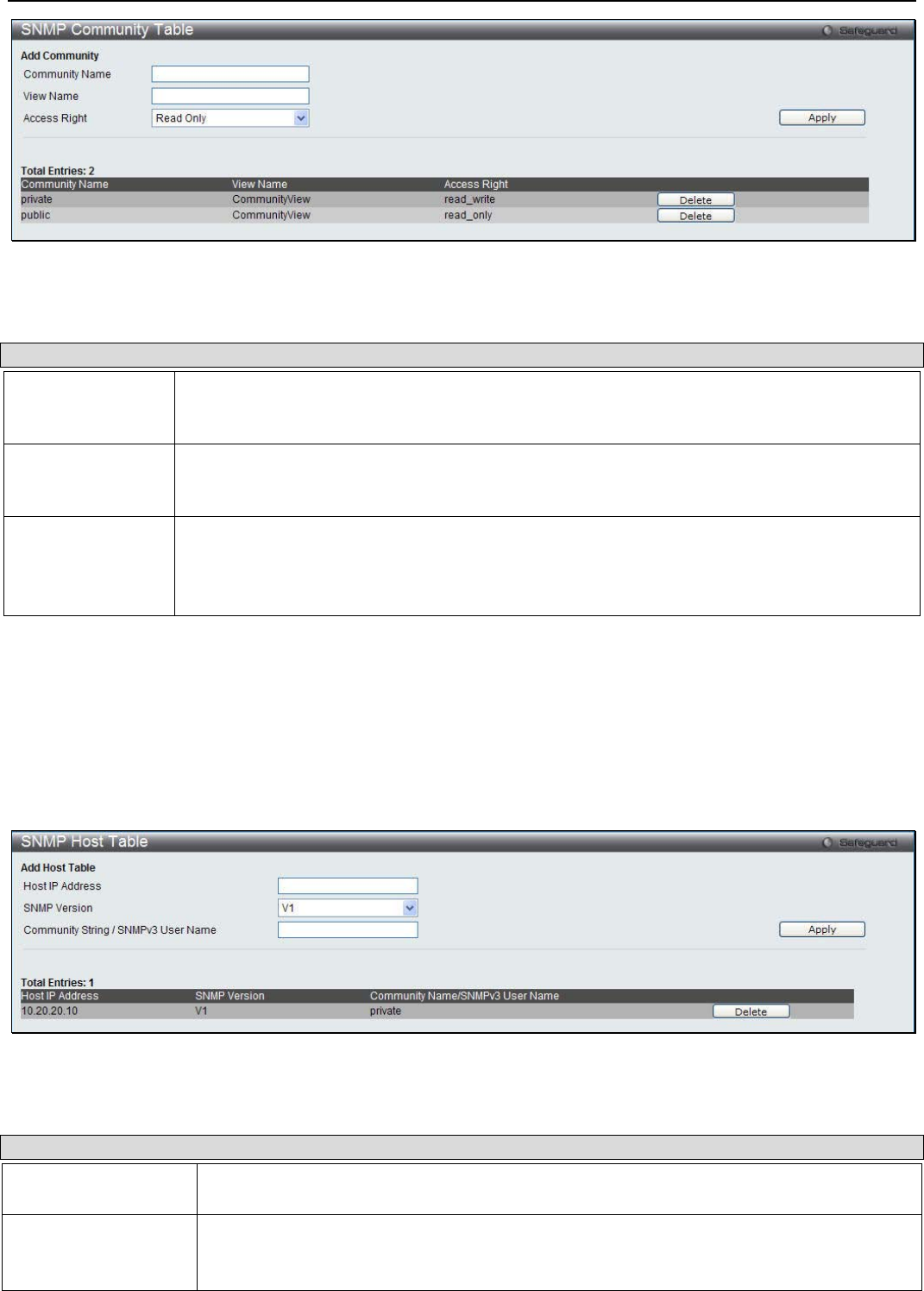
xStack® DGS-3200 Series Layer 2 Managed Gigabit Ethernet Switch Web UI Reference Guide
33
Figure 2 - 40. SNMP Community Table window
The following parameters can be set:
Parameter Description
Community Name Type an alphanumeric string of up to 32 characters that is used to identify members of an
SNMP community. This string is used like a password to give remote SNMP managers access
to MIB objects in the Switch’s SNMP agent.
View Name Type an alphanumeric string of up to 32 characters that is used to identify the group of MIB
objects that a remote SNMP manager is allowed to access on the Switch. The view name must
exist in the SNMP View Table.
Access Right Read Only – Specifies that SNMP community members using the community string created
can only read the contents of the MIBs on the Switch.
Read Write – Specifies that SNMP community members using the community string created
can read from, and write to the contents of the MIBs on the Switch.
To implement the new settings, click Apply. To delete an entry from the SNMP Community Table, click the Delete button
corresponding to the entry to delete.
SNMP Host Table
Users can set up SNMP trap recipients for IPv4.
To view the following window, click Configuration > SNMP Settings > SNMP Host Table:
Figure 2 - 41. SNMP Host Table window
The following parameters can set:
Parameter Description
Host IP Address Type the IP address of the remote management station that will serve as the SNMP host for
the Switch.
SNMP Version V1 – To specify that SNMP version 1 will be used.
V2c – To specify that SNMP version 2c will be used.
V3-NoAuthNoPriv – To specify that the SNMP version 3 will be used, with a NoAuth-NoPriv
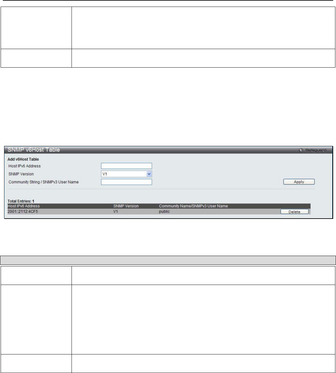
xStack® DGS-3200 Series Layer 2 Managed Gigabit Ethernet Switch Web UI Reference Guide
34
security level.
V3-AuthNoPriv – To specify that the SNMP version 3 will be used, with an Auth-NoPriv
security level.
V3-AuthPriv – To specify that the SNMP version 3 will be used, with an Auth-Priv security
level.
Community String /
SNMP V3 User Name Type in the community string or SNMP V3 user name as appropriate.
To add a new entry to the Switch’s SNMP Host Table, enter the information at the top of the window and then click the Apply
button. To delete an existing SNMP Host Table entry, click the Delete button corresponding to the entry to delete.
SNMP v6Host Table
Users can set up SNMP trap recipients for IPv6.
To view the following window, click Configuration > SNMP Settings > SNMP v6Host Table:
Figure 2 - 42. SNMP v6Host Table window
The following parameters can be configured:
Parameter Description
Host IPv6 Address Type the IP address of the remote management station that will serve as the SNMP host for
the Switch.
SNMP Version V1 – To specify that SNMP version 1 will be used.
V2c – To specify that SNMP version 2c will be used.
V3-NoAuthNoPriv – To specify that the SNMP version 3 will be used, with a NoAuth-NoPriv
security level.
V3-AuthNoPriv – To specify that the SNMP version 3 will be used, with an Auth-NoPriv
security level.
V3-AuthPriv – To specify that the SNMP version 3 will be used, with an Auth-Priv security
level.
Community String /
SNMPv3 User Name Type in the community string or SNMP V3 user name as appropriate.
To add a new entry to the Switch’s SNMP v6Host Table, enter the information at the top of the window and then click the Apply
button. To delete an existing SNMP v6Host Table entry, click the Delete button corresponding to the entry to delete.
SNMP Engine ID
The Engine ID is a unique identifier used for SNMP V3 implementations on the Switch.
To view the following window, click Configuration > SNMP Settings > SNMP Engine ID:

xStack® DGS-3200 Series Layer 2 Managed Gigabit Ethernet Switch Web UI Reference Guide
35
Figure 2 - 43. SNMP Engine ID window
The following parameter can be configured:
Parameter Description
Engine ID The SNMP engine ID displays the identification of the SNMP engine on the Switch. The
default value is suggested in RFC2271. The very first bit is 1, and the first four octets are set
to the binary equivalent of the agent’s SNMP management private enterprise number as
assigned by IANA (D-Link is 171). The fifth octet is 03 to indicate the rest is the MAC
address of this device. The sixth to eleventh octets is the MAC address.
Click Apply to implement the changes.
SNMP Trap Configuration
Users can enable and disable global SNMP trap support, SNMP authentication failure trap support, Linkchange Traps, Coldstart
Traps, and Warmstart Traps. To enable Linkchange Traps for a specific port or range of ports, go to the SNMP Linkchange Traps
Settings window.
To view the following window, click Configuration > SNMP Settings > SNMP Trap Configuration:
Figure 2 - 44. SNMP Trap Configuration window
To enable or disable the SNMP Traps, SNMP Authenticate Traps, Linkchange Traps, Coldstart Traps, and Warmstart Traps, use
the corresponding drop-down menu to change and click Apply.
RMON
Users can enable and disable remote monitoring (RMON) status for the SNMP function on the Switch. In addition, RMON Rising
and Falling Alarm Traps can be enabled and disabled.
To view the following window, click Configuration > SNMP Settings > RMON:
Figure 2 - 45. RMON window
To enable or disable RMON for SNMP, use the radio buttons. Click Apply when finished.
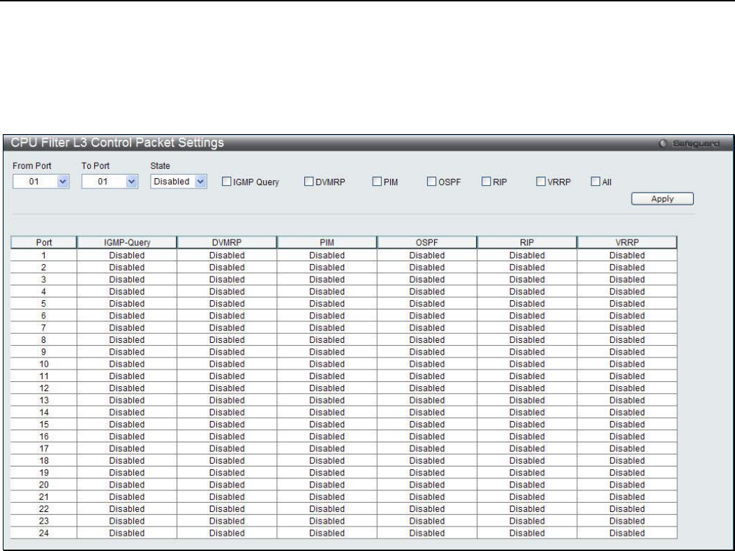
xStack® DGS-3200 Series Layer 2 Managed Gigabit Ethernet Switch Web UI Reference Guide
36
CPU Filter L3 Control Packet Settings
Users can discard and display Layer 3 control packets sent to the CPU from specific ports.
To view the following window, click Configuration > CPU Filter L3 Control Packet Settings:
Figure 2 - 46. CPU Filter L3 Control Packet Settings window
To set CPU filter Layer 3 control packet settings on the Switch, use the From Port and To Port drop-down menus to select the
desired port range, change the State to Enabled, and tick the desired Layer 3 categories (IGMP Query, DVMRP, PIM, OSPF, RIP,
VRRP, or All). Click Apply when finished.
Single IP Management
Simply put, D-Link Single IP Management is a concept that will stack switches together over Ethernet instead of using stacking
ports or modules. There are some advantages in implementing the “Single IP Management” feature:
1. SIM can simplify management of small workgroups or wiring closets while scaling the network to handle increased
bandwidth demand.
2. SIM can reduce the number of IP address needed in your network.
3. SIM can eliminate any specialized cables for stacking connectivity and remove the distance barriers that typically limit
your topology options when using other stacking technology.
Switches using D-Link Single IP Management (labeled here as SIM) must conform to the following rules:
• SIM is an optional feature on the Switch and can easily be enabled or disabled through the Command Line Interface or
Web Interface. SIM grouping has no effect on the normal operation of the Switch in the user’s network.
• There are three classifications for switches using SIM. The Commander Switch (CS), which is the master switch of the
group, Member Switch (MS), which is a switch that is recognized by the CS a member of a SIM group, and a
Candidate Switch (CaS), which is a Switch that has a physical link to the SIM group but has not been recognized by the
CS as a member of the SIM group.
• A SIM group can only have one Commander Switch (CS).

xStack® DGS-3200 Series Layer 2 Managed Gigabit Ethernet Switch Web UI Reference Guide
37
• All switches in a particular SIM group must be in the same IP subnet (broadcast domain). Members of a SIM group
cannot cross a router.
• A SIM group accepts up to 32 switches (numbered 1-32), not including the Commander Switch (numbered 0).
• There is no limit to the number of SIM groups in the same IP subnet (broadcast domain); however a single switch can
only belong to one group.
• If multiple VLANs are configured, the SIM group will only utilize the default VLAN on any switch.
• SIM allows intermediate devices that do not support SIM. This enables the user to manage switches that are more than
one hop away from the CS.
The SIM group is a group of switches that are managed as a single entity. The Switch may take on three different roles:
1. Commander Switch (CS) – This is a switch that has been manually configured as the controlling device for a group, and
takes on the following characteristics:
• It has an IP Address.
• It is not a command switch or member switch of another Single IP group.
• It is connected to the member switches through its management VLAN.
2. Member Switch (MS) – This is a switch that has joined a single IP group and is accessible from the CS, and it takes on
the following characteristics:
• It is not a CS or MS of another IP group.
• It is connected to the CS through the CS management VLAN.
3. Candidate Switch (CaS) – This is a switch that is ready to join a SIM group but is not yet a member of the SIM group.
The Candidate Switch may join the SIM group of the Switch by manually configuring it to be a MS of a SIM group. A
switch configured as a CaS is not a member of a SIM group and will take on the following characteristics:
• It is not a CS or MS of another Single IP group.
• It is connected to the CS through the CS management VLAN
The following rules also apply to the above roles:
• Each device begins in a Candidate state.
• CS's must change their role to CaS and then to MS, to become a MS of a SIM group. Thus, the CS cannot directly be
converted to a MS.
• The user can manually configure a CS to become a CaS.
• A MS can become a CaS by:
• Being configured as a CaS through the CS.
• If report packets from the CS to the MS time out.
• The user can manually configure a CaS to become a CS
• The CaS can be configured through the CS to become a MS.
After configuring one switch to operate as the CS of a SIM group, additional DGS-3200 Series switches may join the group by
manually configuring the Switch to be a MS. The CS will then serve as the in band entry point for access to the MS. The CS’s IP
address will become the path to all MS’s of the group and the CS’s Administrator’s password, and/or authentication will control
access to all MS’s of the SIM group.
With SIM enabled, the applications in the CS will redirect the packet instead of executing the packets. The applications will
decode the packet from the administrator, modify some data, and then send it to the MS. After execution, the CS may receive a
response packet from the MS, which it will encode and send it back to the administrator.
When a CaS becomes a MS, it automatically becomes a member of the first SNMP community (including read/write and read
only) to which the CS belongs. However, if a MS has its own IP address, it can belong to SNMP communities to which other
switches in the group, including the CS, do not belong.
Upgrade to v1.61
To better improve SIM management, the DGS-3200 Series switches have been upgraded to version 1.61 in this release. Many
improvements have been made, including:
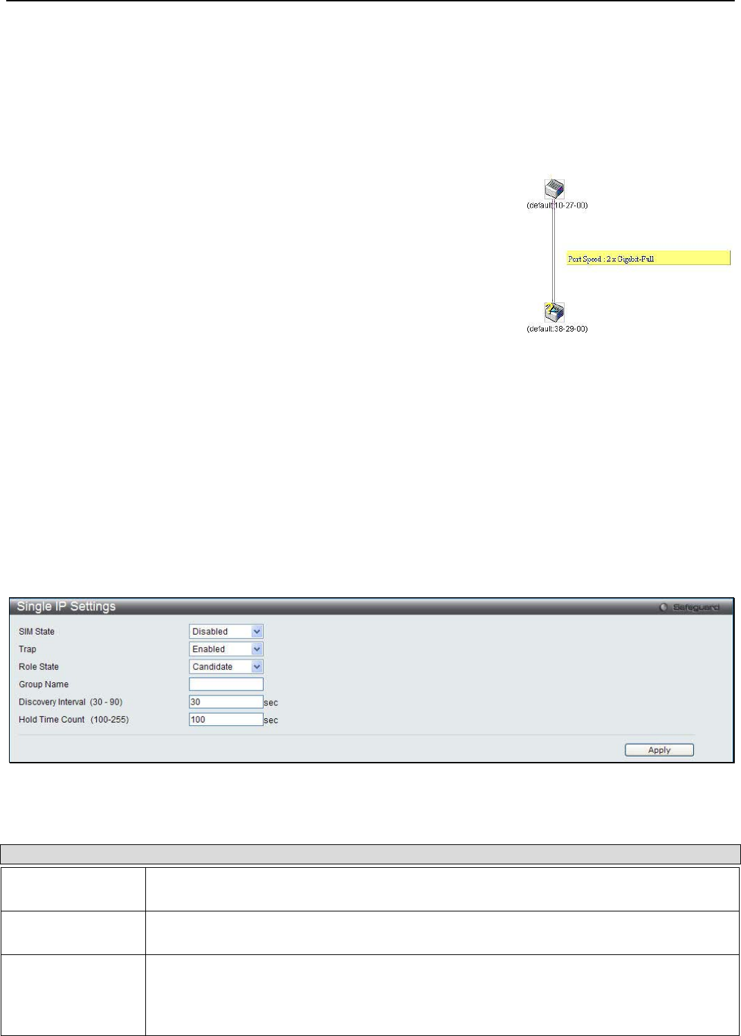
xStack® DGS-3200 Series Layer 2 Managed Gigabit Ethernet Switch Web UI Reference Guide
38
4. The Commander Switch (CS) now has the capability to automatically rediscover member switches that have left the SIM
group, either through a reboot or web malfunction. This feature is accomplished through the use of Discover packets and
Maintenance packets that previously set SIM members will emit after a reboot. Once a MS has had its MAC address and
password saved to the CS’s database, if a reboot occurs in the MS, the CS will keep this MS information in its database
and when a MS has been rediscovered, it will add the MS back into the SIM tree automatically. No configuration will be
necessary to rediscover these switches.
There are some instances where pre-saved MS switches cannot be rediscovered. For example, if the Switch is still powered down,
if it has become the member of another group, or if it has been configured to be a Commander Switch, the rediscovery process
cannot occur.
5. This version will support switch upload and downloads for firmware, configuration files and log files, as follows:
• Firmware – The switch now supports MS firmware downloads from a TFTP server.
• Configuration Files – This switch now supports downloading and uploading of configuration files both to (for
configuration restoration) and from (for configuration backup) MS’s, using a TFTP server.
• Log – The Switch now supports uploading MS log files to a TFTP server.
6. The user may zoom in and zoom out when utilizing the topology window to get a better, more defined view of the
configurations.
Single IP Settings
The Switch is set as a Candidate (CaS) as the factory default configuration and Single IP Management is disabled.
To enable SIM for the Switch using the Web interface, click Configuration > Single IP Management > Single IP Settings:
Figure 2 - 47. Single IP Settings window
The following parameters can be configured:
Parameter Description
SIM State Use the drop-down menu to either enable or disable the SIM state on the Switch. Disabled will
render all SIM functions on the Switch inoperable.
Trap Use the drop-down menu to either enable or disable a trap. This is designed to control the
sending of traps issued from a member switch.
Role State Use the drop-down menu to change the SIM role of the Switch. The two choices are:
Candidate – A Candidate Switch (CaS) is not the member of a SIM group but is connected to
a Commander Switch. This is the default setting for the SIM role of the Switch.
Commander – Choosing this parameter will make the Switch a Commander Switch (CS). The
2. The topology map now includes new features for connections that are a
member of a port trunking group. It will display the speed and number of Ethernet
connections creating this port trunk group, as shown in the adjacent picture.
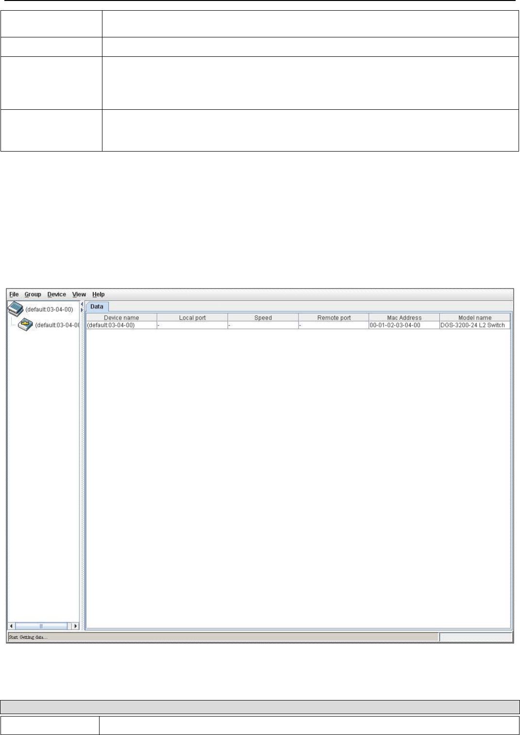
xStack® DGS-3200 Series Layer 2 Managed Gigabit Ethernet Switch Web UI Reference Guide
39
user may join other switches to this Switch, over Ethernet, to be part of its SIM group.
Choosing this option will also enable the Switch to be configured for SIM.
Group Name Enter a Group Name in this textbox. This is optional.
Discovery Interval
(30-90) The user may set the discovery protocol interval, in seconds that the Switch will send out
discovery packets. Returning information to a Commander Switch will include information
about other switches connected to it. (Ex. MS, CaS). The user may set the Discovery Interval
from 30 to 90 seconds. The default value is 30 seconds.
Hold Time Count
(100-255) This parameter may be set for the time, in seconds; the Switch will hold information sent to it
from other switches, utilizing the Discovery Interval. The user may set the hold time from 100
to 255 seconds. The default value is 100 seconds.
Click Apply to implement the changes. After enabling the Switch to be a Commander Switch (CS), the Single IP Management
folder will then contain four added links to aid the user in configuring SIM through the web, including Topology, Firmware
Upgrade, Configuration Backup/Restore and Upload Log.
Topology
This window will be used to configure and manage the Switch within the SIM group and requires Java script to function properly
on your computer.
The Java Runtime Environment on your server should initiate and lead you to the Topology window, as seen below.
Figure 2 - 48. Topology window
The Topology window holds the following information on the Data tab:
Parameter Description
Device Name This field will display the Device Name of the switches in the SIM group configured by the user.

xStack® DGS-3200 Series Layer 2 Managed Gigabit Ethernet Switch Web UI Reference Guide
40
If no device is configured by the name, it will be given the name default and tagged with the
last six digits of the MAC Address to identify it.
Local Port Displays the number of the physical port on the CS that the MS or CaS is connected to. The
CS will have no entry in this field.
Speed Displays the connection speed between the CS and the MS or CaS.
Remote Port Displays the number of the physical port on the MS or CaS to which the CS is connected. The
CS will have no entry in this field.
MAC Address Displays the MAC Address of the corresponding Switch.
Model Name Displays the full Model Name of the corresponding Switch.
To view the Topology View window, open the View drop-down menu in the toolbar and then click Topology, which will open
the following Topology Map. This window will refresh itself periodically (20 seconds by default).
Figure 2 - 49. Topology View window
This window will display how the devices within the Single IP Management Group connect to other groups and devices. Possible
icons on this window are as follows:
Icon Description
Group
Layer 2 commander switch
Layer 3 commander switch
Commander switch of other group
Layer 2 member switch.

xStack® DGS-3200 Series Layer 2 Managed Gigabit Ethernet Switch Web UI Reference Guide
41
Layer 3 member switch
Member switch of other group
Layer 2 candidate switch
Layer 3 candidate switch
Unknown device
Non-SIM devices
Tool Tips
In the Topology view window, the mouse plays an important role in configuration and in viewing device information. Setting the
mouse cursor over a specific device in the topology window (tool tip) will display the same information about a specific device as
the Tree view does. See the window below for an example.
Figure 2 - 50. Device Information Utilizing the Tool Tip
Setting the mouse cursor over a line between two devices will display the connection speed between the two devices, as shown
below.
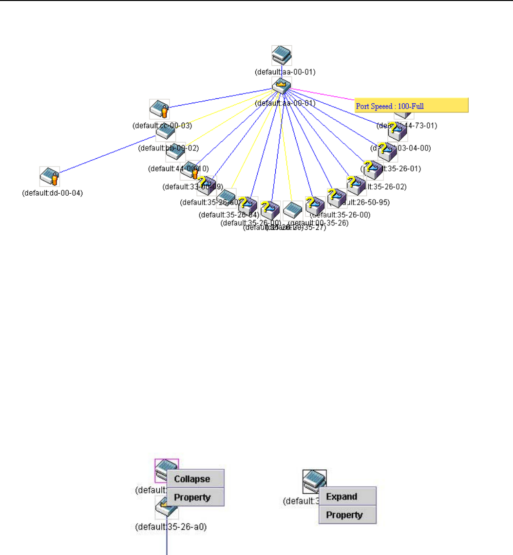
xStack® DGS-3200 Series Layer 2 Managed Gigabit Ethernet Switch Web UI Reference Guide
42
Figure 2 - 51. Port Speed Utilizing the Tool Tip
Right-Click
Right-clicking on a device will allow the user to perform various functions, depending on the role of the Switch in the SIM group
and the icon associated with it.
Group Icon
Figure 2 - 52. Right-Clicking a Group Icon
The following options may appear for the user to configure:
• Collapse – To collapse the group that will be represented by a single icon.
• Expand – To expand the SIM group, in detail.
• Property – To pop up a window to display the group information.

xStack® DGS-3200 Series Layer 2 Managed Gigabit Ethernet Switch Web UI Reference Guide
43
Figure 2 - 53. Property window
Parameter Description
Device Name This field will display the Device Name of the switches in the SIM group configured by the user.
If no Device Name is configured by the name, it will be given the name default and tagged with
the last six digits of the MAC Address to identify it.
Module Name Displays the full module name of the switch that was right-clicked.
MAC Address Displays the MAC Address of the corresponding Switch.
Remote Port No. Displays the number of the physical port on the MS or CaS that the CS is connected to. The CS
will have no entry in this field.
Local Port No. Displays the number of the physical port on the CS that the MS or CaS is connected to. The CS
will have no entry in this field.
Port Speed Displays the connection speed between the CS and the MS or CaS
Commander Switch Icon
Figure 2 - 54. Right-Clicking a Commander Icon
The following options may appear for the user to configure:
• Collapse – To collapse the group that will be represented by a single icon.
• Expand – To expand the SIM group, in detail.
• Property – To pop up a window to display the group information.
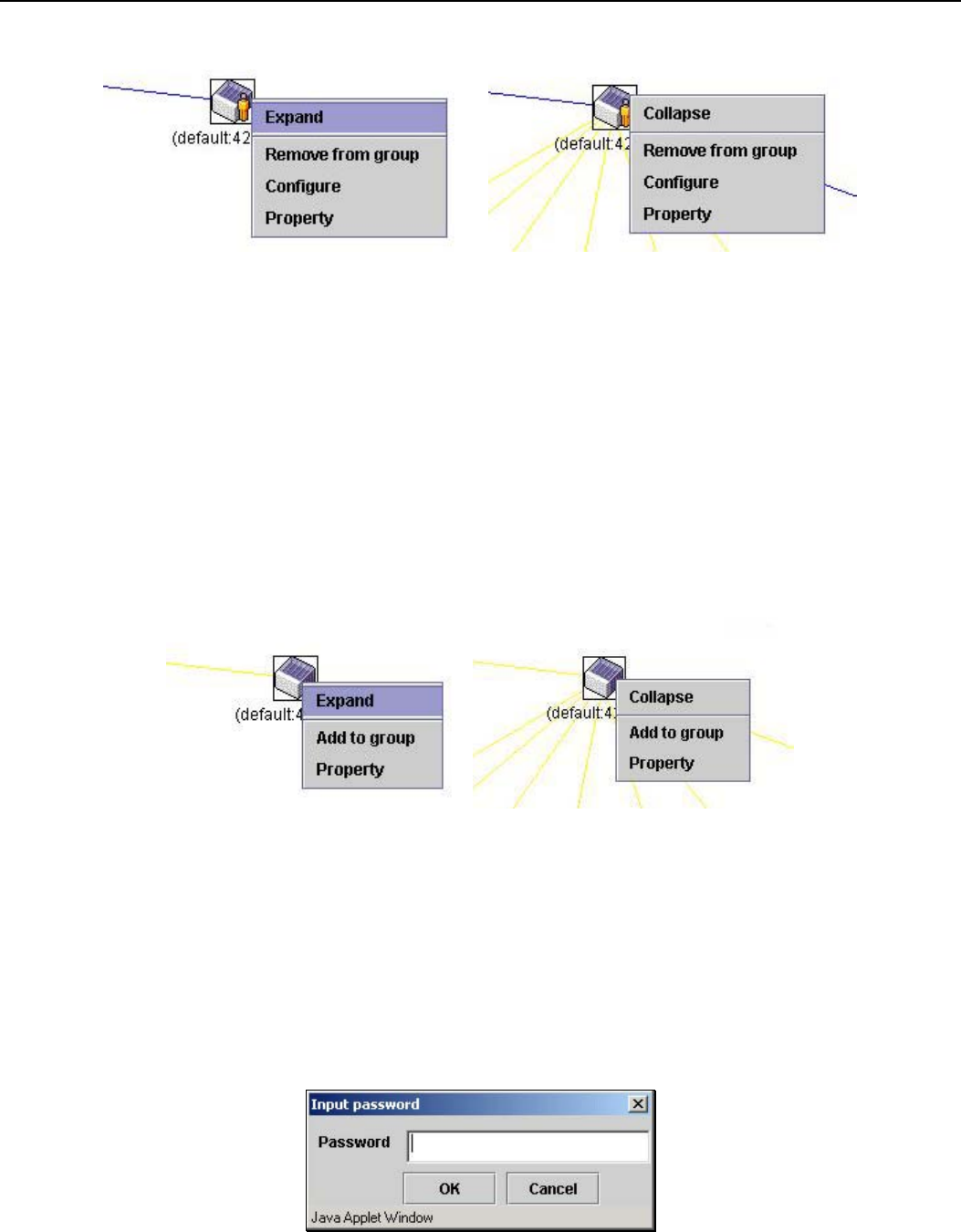
xStack® DGS-3200 Series Layer 2 Managed Gigabit Ethernet Switch Web UI Reference Guide
44
Member Switch Icon
Figure 2 - 55. Right-Clicking a Member icon
The following options may appear for the user to configure:
• Collapse – To collapse the group that will be represented by a single icon.
• Expand – To expand the SIM group, in detail.
• Remove from group – Remove a member from a group.
• Configure – Launch the web management to configure the Switch.
• Property – To pop up a window to display the device information.
Candidate Switch Icon
Figure 2 - 56. Right-Clicking a Candidate icon
The following options may appear for the user to configure:
• Collapse – To collapse the group that will be represented by a single icon.
• Expand – To expand the SIM group, in detail.
• Add to group – Add a candidate to a group. Clicking this option will reveal the following dialog box for the user to enter a
password for authentication from the Candidate Switch before being added to the SIM group. Click OK to enter the
password or Cancel to exit the dialog box.
Figure 2 - 57. Input password dialog box
• Property – To pop up a window to display the device information.
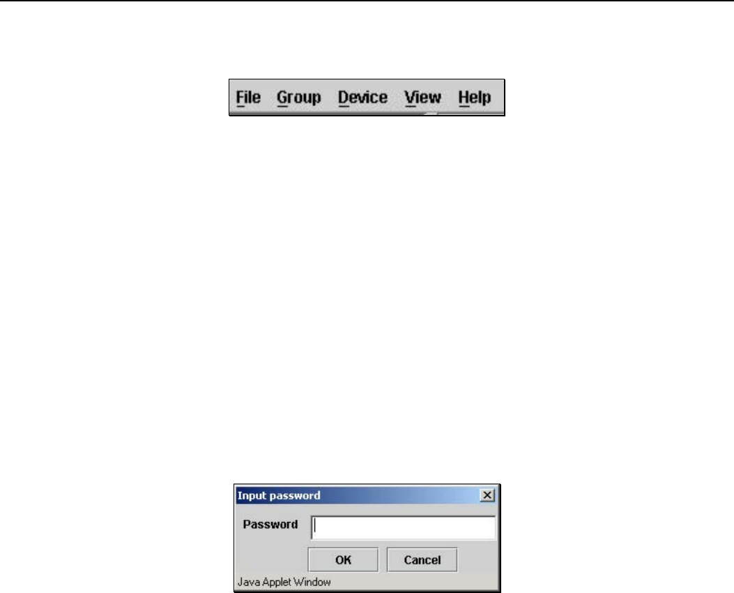
xStack® DGS-3200 Series Layer 2 Managed Gigabit Ethernet Switch Web UI Reference Guide
45
Menu Bar
The Single IP Management window contains a menu bar for device configurations, as seen below.
Figure 2 - 58. Menu Bar of the Topology View
The five menus on the menu bar are as follows.
File
• Print Setup – Will view the image to be printed.
• Print Topology – Will print the topology map.
• Preference – Will set display properties, such as polling interval, and the views to open at SIM startup.
Group
• Add to group – Add a candidate to a group. Clicking this option will reveal the following dialog box for the user to enter a
password for authentication from the Candidate Switch before being added to the SIM group. Click OK to enter the
password or Cancel to exit the dialog box.
Figure 2 - 59. Input password dialog box
• Remove from Group – Remove an MS from the group.
Device
• Configure – Will open the Web manager for the specific device.
View
• Refresh – Update the views with the latest status.
• Topology – Display the Topology view.
Help
• About – Will display the SIM information, including the current SIM version.
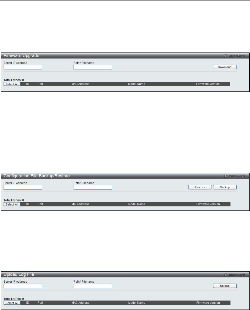
xStack® DGS-3200 Series Layer 2 Managed Gigabit Ethernet Switch Web UI Reference Guide
46
Firmware Upgrade
The Commander Switch may be used for firmware upgrades of member switches. Member Switches will be listed in the table and
will be specified by Port (port on the CS where the MS resides), MAC Address, Model Name and Version. To specify a certain
Switch for firmware download, click its corresponding check box under the Port heading. To update the firmware, enter the Server
IP Address where the firmware resides and enter the Path/Filename of the firmware. Click Download to initiate the file transfer.
To view the following window, click Configuration > Single IP Management > Firmware Upgrade:
Figure 2 - 60. Firmware Upgrade window for Single IP Management
Configuration File Backup/Restore
The Commander Switch can instruct configuration file backup and restore to the Member Switch using a TFTP server. Member
Switches will be listed in the table and will be specified by Port (port on the CS where the MS resides), MAC Address, Model
Name and Version. To specify a certain Switch for upgrading configuration files, click its corresponding radio button under the
Port heading. To update the configuration file, enter the Server IP Address where the file resides and enter the Path/Filename of
the configuration file. Click Restore to initiate the file transfer from a TFTP server to the Switch. Click Backup to backup the
configuration file to a TFTP server.
To view the following window, click Configuration > Single IP Management > Configuration File Backup/Restore:
Figure 2 - 61. Configuration File Backup/Restore window for Single IP Management
Upload Log File
The Commander Switch can order a log file from a member switch sent to a server. Provide the Server IP address for storing the
log and the log file path and filename on the member switch. Click Upload to send the log file to a TFTP server.
To view the following window, click Configuration > Single IP Management > Upload Log File:
Figure 2 - 62. Upload Log File window for Single IP Management
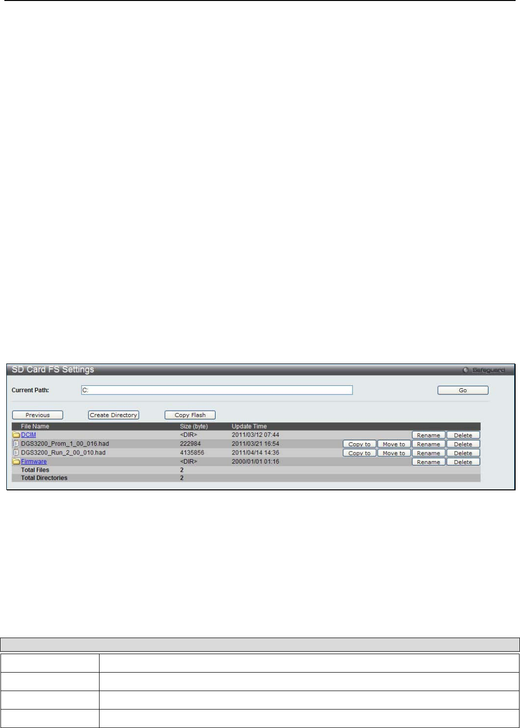
xStack® DGS-3200 Series Layer 2 Managed Gigabit Ethernet Switch Web UI Reference Guide
47
SD Card FS Settings (DGS-3200-24 Only)
Users can plug an SD flash card into a front slot on the DGS-3200-24 (DGS-3200-10 and DGS-3200-16 do not support this
feature). The SD flash card allows users to carry out the following:
• Save the Switch log to the SD card
• Save the Switch configuration to the SD card
• Save the Switch Runtime image to the SD card
• Save the Switch Prom image to the SD card
• Copy images from the SD card to the flash memory on the Switch to replace Runtime image 1 or Runtime image 2
• Copy configuration files from the SD card to the flash memory on the Switch to replace configuration 1 or configuration 2
• Replace the Prom image by copying a Prom image from the SD card to the flash memory
• Download Runtime image and save to the SD card
• Download configuration and save to the SD card
• Access the files on the SD card via a PC (e.g. using Microsoft Windows)
• Boot up the Switch using a runtime image stored on the SD card
• Boot up the Switch using a configuration stored on the SD card
• SD card is hot swappable
• Switch automatically creates new directories and files automatically on the SD card. A warning message will display if
there is an existing file or folder with the same name, asking the user to overwrite or keep the existing file or folder
To view the following window, click Configuration > SD Card FS Settings:
Figure 2 - 63. SD Card FS Settings window
To use a firmware image and configuration on an SD card, carry out the following steps:
1. Insert the SD flash card into the SD card slot on the front of the Switch.
2. Type the path of the firmware image in the Current Path field.
3. Click Go.
In addition to using a firmware image and configuration from an SD flash card, the SD Card FS Settings window allows users to
manage the directories and files stored on the SD card. The table below describes the buttons used to manage the files and
directories, stored on the SD flash card.
Parameter Description
Previous Click this button to navigate to the previous folder.
Create Directory Click this button to create a new directory.
Copy Flash Click this button to copy files from/to the SD Flash card or internal Flash memory.
Format If you have inserted a new SD Flash card this button will appear.
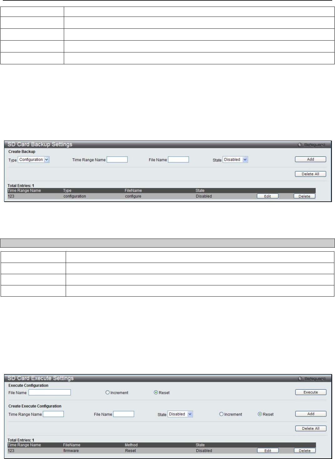
xStack® DGS-3200 Series Layer 2 Managed Gigabit Ethernet Switch Web UI Reference Guide
48
Click this button to format the new SD Flash card.
Copy to Click this button to copy a file to another location.
Move to Click this button to move a file to another location.
Rename Click this button to rename the corresponding file or folder.
Delete Click this button to delete the corresponding file or folder.
SD Card Management (DGS-3200-24 Only)
SD Card Backup Settings
This window is used to create a schedule to back up the configuration or log to file system.
To view the following window, click Configuration > SD Card management > SD Card Backup Settings:
Figure 2 - 64. SD Card Backup Settings window
The following parameter may be configured:
Parameter Description
Type Use the drop-down menu to back up configuration or log.
Time Range Name Specify the schedule to back up the configuration or log.
File Name Specify the backup file name.
State Use the drop-down menu to enable or disable the backup schedule.
Click Add to create a new entry. Click Delete All to remove all the entries from the table. Click Edit to modify the specific entry.
Click Delete to remove the specific entry.
SD Card Execute Settings
This window is used to configure a schedule to execute the configuration on file system.
To view the following window, click Configuration > SD Card management > SD Card Execute Settings:
Figure 2 - 65. SD Card Execute Settings window
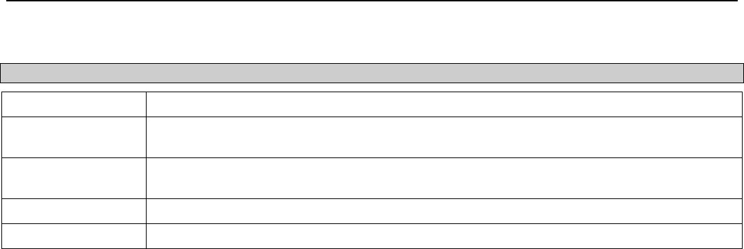
xStack® DGS-3200 Series Layer 2 Managed Gigabit Ethernet Switch Web UI Reference Guide
49
The following parameter may be configured:
Parameter Description
File Name The filename of the configuration on file system.
Increment If this option is specified, the current configuration will not be reset before executing the
configuration.
Reset If this option is specified, the current configuration will be reset before executing the
configuration.
Time Range Name The time range for schedule to execute the configuration.
State Enable or disable the executive schedules.
Click Execute to execute configuration on file system. Click Add to create a new entry. Click Delete All to remove all the entries
from the table. Click Edit to modify the specific entry. Click Delete to remove the specific entry.

xStack® DGS-3200 Series Layer 2 Managed Gigabit Ethernet Switch Web UI Reference Guide
50
Section 3
L2 Features
VLAN
Layer 2 Protocol Tunneling Settings
Egress Filter Settings
L2 Multicast Control
Multicast Filtering
Port Mirroring
Spanning Tree
Link Aggregation
Forwarding & Filtering
LLDP
NLB FDB Settings
VLAN
802.1Q VLAN
Understanding IEEE 802.1p Priority
Priority tagging is a function defined by the IEEE 802.1p standard designed to provide a means of managing traffic on a network
where many different types of data may be transmitted simultaneously. It is intended to alleviate problems associated with the
delivery of time critical data over congested networks. The quality of applications that are dependent on such time critical data,
such as video conferencing, can be severely and adversely affected by even very small delays in transmission.
Network devices that are in compliance with the IEEE 802.1p standard have the ability to recognize the priority level of data
packets. These devices can also assign a priority label or tag to packets. Compliant devices can also strip priority tags from
packets. This priority tag determines the packet’s degree of expeditiousness and determines the queue to which it will be assigned.
Priority tags are given values from 0 to 7 with 0 being assigned to the lowest priority data and 7 assigned to the highest. The
highest priority tag 7 is generally only used for data associated with video or audio applications, which are sensitive to even slight
delays, or for data from specified end users whose data transmissions warrant special consideration.
The Switch allows you to further tailor how priority tagged data packets are handled on your network. Using queues to manage
priority tagged data allows you to specify its relative priority to suit the needs of your network. There may be circumstances where
it would be advantageous to group two or more differently tagged packets into the same queue. Generally, however, it is rec-
ommended that the highest priority queue, Queue 7, be reserved for data packets with a priority value of 7. Packets that have not
been given any priority value are placed in Queue 0 and thus given the lowest priority for delivery.
Strict mode and weighted round robin system are employed on the Switch to determine the rate at which the queues are emptied of
packets. The ratio used for clearing the queues is 4:1. This means that the highest priority queue, Queue 7, will clear 4 packets for
every 1 packet cleared from Queue 0.
Remember, the priority queue settings on the Switch are for all ports, and all devices connected to the Switch will be affected.
This priority queuing system will be especially beneficial if your network employs switches with the capability of assigning
priority tags.
VLAN Description
A Virtual Local Area Network (VLAN) is a network topology configured according to a logical scheme rather than the physical
layout. VLANs can be used to combine any collection of LAN segments into an autonomous user group that appears as a single
LAN. VLANs also logically segment the network into different broadcast domains so that packets are forwarded only between
ports within the VLAN. Typically, a VLAN corresponds to a particular subnet, although not necessarily.

xStack® DGS-3200 Series Layer 2 Managed Gigabit Ethernet Switch Web UI Reference Guide
51
VLANs can enhance performance by conserving bandwidth, and improve security by limiting traffic to specific domains.
A VLAN is a collection of end nodes grouped by logic instead of physical location. End nodes that frequently communicate with
each other are assigned to the same VLAN, regardless of where they are physically on the network. Logically, a VLAN can be
equated to a broadcast domain, because broadcast packets are forwarded to only members of the VLAN on which the broadcast
was initiated.
Notes about VLANs on the Switch
• No matter what basis is used to uniquely identify end nodes and assign these nodes VLAN membership, packets cannot
cross VLANs without a network device performing a routing function between the VLANs.
• The Switch supports IEEE 802.1Q VLANs. The port untagging function can be used to remove the 802.1Q tag from
packet headers to maintain compatibility with devices that are tag-unaware.
• The Switch’s default is to assign all ports to a single 802.1Q VLAN named “default.”
• The “default” VLAN has a VID = 1.
• The member ports of Port-based VLANs may overlap, if desired.
IEEE 802.1Q VLANs
Some relevant terms:
• Tagging – The act of putting 802.1Q VLAN information into the header of a packet.
• Untagging – The act of stripping 802.1Q VLAN information out of the packet header.
• Ingress port – A port on a switch where packets are flowing into the Switch and VLAN decisions must be made.
• Egress port – A port on a switch where packets are flowing out of the Switch, either to another switch or to an end
station, and tagging decisions must be made.
IEEE 802.1Q (tagged) VLANs are implemented on the Switch. 802.1Q VLANs require tagging, which enables them to span the
entire network (assuming all switches on the network are IEEE 802.1Q-compliant).
VLANs allow a network to be segmented in order to reduce the size of broadcast domains. All packets entering a VLAN will only
be forwarded to the stations (over IEEE 802.1Q enabled switches) that are members of that VLAN, and this includes broadcast,
multicast and unicast packets from unknown sources.
VLANs can also provide a level of security to your network. IEEE 802.1Q VLANs will only deliver packets between stations that
are members of the VLAN.
Any port can be configured as either tagging or untagging. The untagging feature of IEEE 802.1Q VLANs allows VLANs to work
with legacy switches that don’t recognize VLAN tags in packet headers. The tagging feature allows VLANs to span multiple
802.1Q-compliant switches through a single physical connection and allows Spanning Tree to be enabled on all ports and work
normally.
The IEEE 802.1Q standard restricts the forwarding of untagged packets to the VLAN the receiving port is a member of.
The main characteristics of IEEE 802.1Q are as follows:
• Assigns packets to VLANs by filtering.
• Assumes the presence of a single global spanning tree.
• Uses an explicit tagging scheme with one-level tagging.
• 802.1Q VLAN Packet Forwarding
• Packet forwarding decisions are made based upon the following three types of rules:
• Ingress rules – rules relevant to the classification of received frames belonging to a VLAN.
• Forwarding rules between ports – decides whether to filter or forward the packet.
• Egress rules – determines if the packet must be sent tagged or untagged.

xStack® DGS-3200 Series Layer 2 Managed Gigabit Ethernet Switch Web UI Reference Guide
52
Figure 3 - 1. IEEE 802.1Q Packet Forwarding
802.1Q VLAN Tags
The figure below shows the 802.1Q VLAN tag. There are four additional octets inserted after the source MAC address. Their
presence is indicated by a value of 0x8100 in the EtherType field. When a packet’s EtherType field is equal to 0x8100, the packet
carries the IEEE 802.1Q/802.1p tag. The tag is contained in the following two octets and consists of 3 bits of user priority, 1 bit of
Canonical Format Identifier (CFI – used for encapsulating Token Ring packets so they can be carried across Ethernet backbones),
and 12 bits of VLAN ID (VID). The 3 bits of user priority are used by 802.1p. The VID is the VLAN identifier and is used by the
802.1Q standard. Because the VID is 12 bits long, 4094 unique VLANs can be identified.
The tag is inserted into the packet header making the entire packet longer by 4 octets. All of the information originally contained
in the packet is retained.
Figure 3 - 2. IEEE 802.1Q Tag
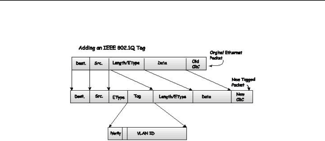
xStack® DGS-3200 Series Layer 2 Managed Gigabit Ethernet Switch Web UI Reference Guide
53
The EtherType and VLAN ID are inserted after the MAC source address, but before the original EtherType/Length or Logical
Link Control. Because the packet is now a bit longer than it was originally, the Cyclic Redundancy Check (CRC) must be
recalculated.
Figure 3 - 3. Adding an IEEE 802.1Q Tag
Port VLAN ID
Packets that are tagged (are carrying the 802.1Q VID information) can be transmitted from one 802.1Q compliant network device
to another with the VLAN information intact. This allows 802.1Q VLANs to span network devices (and indeed, the entire
network, if all network devices are 802.1Q compliant).
Unfortunately, not all network devices are 802.1Q compliant. These devices are referred to as tag-unaware. 802.1Q devices are
referred to as tag-aware.
Prior to the adoption of 802.1Q VLANs, port-based and MAC-based VLANs were in common use. These VLANs relied upon a
Port VLAN ID (PVID) to forward packets. A packet received on a given port would be assigned that port’s PVID and then be
forwarded to the port that corresponded to the packet’s destination address (found in the Switch’s forwarding table). If the PVID
of the port that received the packet is different from the PVID of the port that is to transmit the packet, the Switch will drop the
packet.
Within the Switch, different PVIDs mean different VLANs (remember that two VLANs cannot communicate without an external
router). So, VLAN identification based upon the PVIDs cannot create VLANs that extend outside a given switch (or switch stack).
Every physical port on a switch has a PVID. 802.1Q ports are also assigned a PVID, for use within the Switch. If no VLANs are
defined on the Switch, all ports are then assigned to a default VLAN with a PVID equal to 1. Untagged packets are assigned the
PVID of the port on which they were received. Forwarding decisions are based upon this PVID, in so far as VLANs are con-
cerned. Tagged packets are forwarded according to the VID contained within the tag. Tagged packets are also assigned a PVID,
but the PVID is not used to make packet-forwarding decisions, the VID is.
Tag-aware switches must keep a table to relate PVIDs within the Switch to VIDs on the network. The Switch will compare the
VID of a packet to be transmitted to the VID of the port that is to transmit the packet. If the two VIDs are different, the Switch
will drop the packet. Because of the existence of the PVID for untagged packets and the VID for tagged packets, tag-aware and
tag-unaware network devices can coexist on the same network.
A switch port can have only one PVID, but can have as many VIDs as the Switch has memory in its VLAN table to store them.
Because some devices on a network may be tag-unaware, a decision must be made at each port on a tag-aware device before
packets are transmitted – should the packet to be transmitted have a tag or not? If the transmitting port is connected to a tag-
unaware device, the packet should be untagged. If the transmitting port is connected to a tag-aware device, the packet should be
tagged.
Tagging and Untagging
Every port on an 802.1Q compliant switch can be configured as tagging or untagging.
Ports with tagging enabled will put the VID number, priority and other VLAN information into the header of all packets that flow
into and out of it. If a packet has previously been tagged, the port will not alter the packet, thus keeping the VLAN information

xStack® DGS-3200 Series Layer 2 Managed Gigabit Ethernet Switch Web UI Reference Guide
54
intact. Other 802.1Q compliant devices on the network to make packet-forwarding decisions can then use the VLAN information
in the tag.
Ports with untagging enabled will strip the 802.1Q tag from all packets that flow into and out of those ports. If the packet doesn’t
have an 802.1Q VLAN tag, the port will not alter the packet. Thus, all packets received by and forwarded by an untagging port
will have no 802.1Q VLAN information. (Remember that the PVID is only used internally within the Switch). Untagging is used
to send packets from an 802.1Q-compliant network device to a non-compliant network device.
Ingress Filtering
A port on a switch where packets are flowing into the Switch and VLAN decisions must be made is referred to as an ingress port.
If ingress filtering is enabled for a port, the Switch will examine the VLAN information in the packet header (if present) and
decide whether or not to forward the packet.
If the packet is tagged with VLAN information, the ingress port will first determine if the ingress port itself is a member of the
tagged VLAN. If it is not, the packet will be dropped. If the ingress port is a member of the 802.1Q VLAN, the Switch then
determines if the destination port is a member of the 802.1Q VLAN. If it is not, the packet is dropped. If the destination port is a
member of the 802.1Q VLAN, the packet is forwarded and the destination port transmits it to its attached network segment.
If the packet is not tagged with VLAN information, the ingress port will tag the packet with its own PVID as a VID (if the port is
a tagging port). The switch then determines if the destination port is a member of the same VLAN (has the same VID) as the
ingress port. If it does not, the packet is dropped. If it has the same VID, the packet is forwarded and the destination port transmits
it on its attached network segment.
This process is referred to as ingress filtering and is used to conserve bandwidth within the Switch by dropping packets that are
not on the same VLAN as the ingress port at the point of reception. This eliminates the subsequent processing of packets that will
just be dropped by the destination port.
Default VLANs
The Switch initially configures one VLAN, VID = 1, called “default.” The factory default setting assigns all ports on the Switch to
the “default.” As new VLANs are configured in Port-based mode, their respective member ports are removed from the “default.”
Packets cannot cross VLANs. If a member of one VLAN wants to connect to another VLAN, the link must be through an external
router.
NOTE: If no VLANs are configured on the Switch, then all packets will be forwarded to any
destination port. Packets with unknown source addresses will be flooded to all ports.
Broadcast and multicast packets will also be flooded to all ports.
An example is presented below:
VLAN Name VID Switch Ports
System (default) 1 5, 6, 7
Engineering 2 9, 10
Sales 5 1, 2, 3, 4
Table 3 - 1. VLAN Example – Assigned Ports
Port-based VLANs
Port-based VLANs limit traffic that flows into and out of switch ports. Thus, all devices connected to a port are members of the
VLAN(s) the port belongs to, whether there is a single computer directly connected to a switch, or an entire department.
On port-based VLANs, NICs do not need to be able to identify 802.1Q tags in packet headers. NICs send and receive normal
Ethernet packets. If the packet’s destination lies on the same segment, communications take place using normal Ethernet
protocols. Even though this is always the case, when the destination for a packet lies on another switch port, VLAN considerations
come into play to decide if the packet gets dropped by the Switch or delivered.
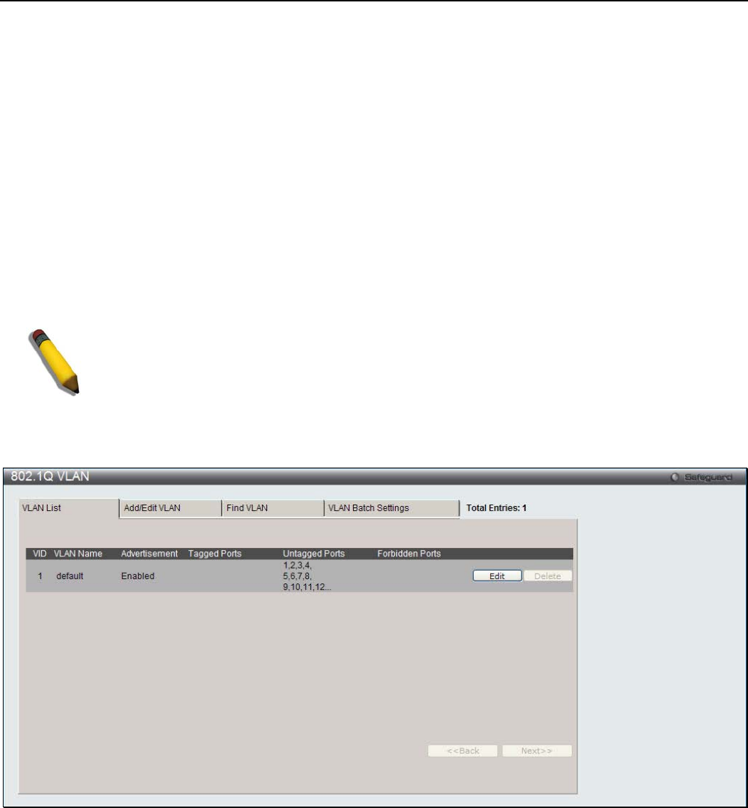
xStack® DGS-3200 Series Layer 2 Managed Gigabit Ethernet Switch Web UI Reference Guide
55
VLAN Segmentation
Take for example a packet that is transmitted by a machine on Port 1 that is a member of VLAN 2. If the destination lies on
another port (found through a normal forwarding table lookup), the Switch then looks to see if the other port (Port 10) is a member
of VLAN 2 (and can therefore receive VLAN 2 packets). If Port 10 is not a member of VLAN 2, then the packet will be dropped
by the Switch and will not reach its destination. If Port 10 is a member of VLAN 2, the packet will go through. This selective
forwarding feature based on VLAN criteria is how VLANs segment networks. The key point being that Port 1 will only transmit
on VLAN 2.
VLAN and Trunk Groups
The members of a trunk group have the same VLAN setting. Any VLAN setting on the members of a trunk group will apply to
the other member ports.
NOTE: In order to use VLAN segmentation in conjunction with port trunk groups, first set the
port trunk group(s), and then configure the VLAN settings. To change the port trunk grouping
with VLANs already in place it is unnecessary to reconfigure the VLAN settings after changing
the port trunk group settings. VLAN settings will automatically change in conjunction with the
change of the port trunk group settings.
To view the following window, click L2 Features > VLAN > 802.1Q VLAN:
Figure 3 - 4. VLAN List tab of the 802.1Q VLAN window
The VLAN List tab lists all previously configured VLANs by VLAN ID and VLAN Name. To delete an existing 802.1Q VLAN,
click the corresponding Delete button.
To create a new 802.1Q VLAN or modify an existing 802.1Q VLAN, click the Add/Edit VLAN tab. A new tab will appear, as
shown below, to configure the port settings and to assign a unique name and number to the new VLAN. See the table on the next
page for a description of the parameters in the new window.

xStack® DGS-3200 Series Layer 2 Managed Gigabit Ethernet Switch Web UI Reference Guide
56
Figure 3 - 5. Add/Edit VLAN tab of the 802.1Q VLAN window
The following fields can then be set in the Add/Edit VLAN tab:
Parameter Description
VID (VLAN ID) Allows the entry of a VLAN ID or displays the VLAN ID of an existing VLAN in the Add/Edit
VLAN tab. VLANs can be identified by either the VID or the VLAN name.
VLAN Name Allows the entry of a name for the new VLAN or for editing the VLAN name in the Add/Edit
VLAN tab.
Advertisement Enabling this function will allow the Switch to send out GVRP packets to outside sources,
notifying that they may join the existing VLAN.
Port Shows all ports of the Switch for the 802.1Q configuration option.
Tagged Specifies the port as 802.1Q tagging. Clicking the radio button will designate the port as tagged.
Untagged Specifies the port as 802.1Q untagged. Clicking the radio button will designate the port as
untagged.
Forbidden Click the radio button to specify the port as not being a member of the VLAN and that the port is
forbidden from becoming a member of the VLAN dynamically.
Not Member Click the radio button to allow an individual port to be specified as a non-VLAN member.
Click Apply to implement changes made.
To search for a VLAN, click the Find VLAN tab. A new tab will appear, as shown below. Enter the VLAN ID number in the
field offered and then click the Find button. You will be redirected to the VLAN List tab. See the table on the next page for a
description of the parameters in the new window.
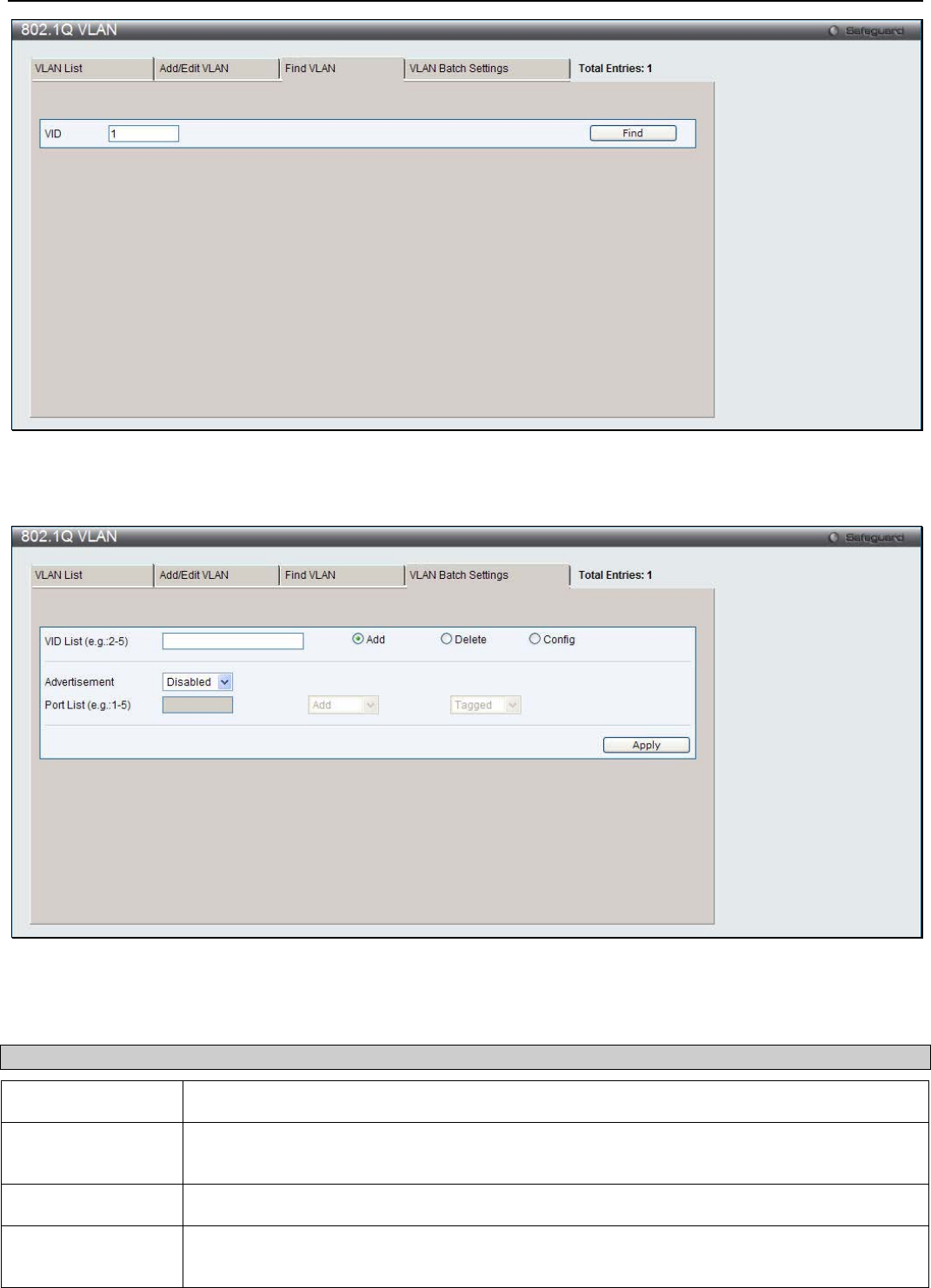
xStack® DGS-3200 Series Layer 2 Managed Gigabit Ethernet Switch Web UI Reference Guide
57
Figure 3 - 6. Find VLAN tab of the 802.1Q VLAN window
To create a VLAN Batch entry click the VLAN Batch Settings tab, as shown below.
Figure 3 - 7. VLAN Batch Settings tab of the 802.1Q VLAN window
The following fields can be set in the VLAN Batch Settings windows:
Parameter Description
VID List (e.g.: 2-5) Enter a VLAN ID List that can be added, deleted or configured.
Advertisement Enabling this function will allow the Switch to send out GVRP packets to outside sources,
notifying that they may join the existing VLAN.
Port List (e.g.: 1-5) Allows an individual port list to be added or deleted as a member of the VLAN.
Tagged Specifies the port as 802.1Q tagged. Use the drop-down menu to designate the port as
tagged.
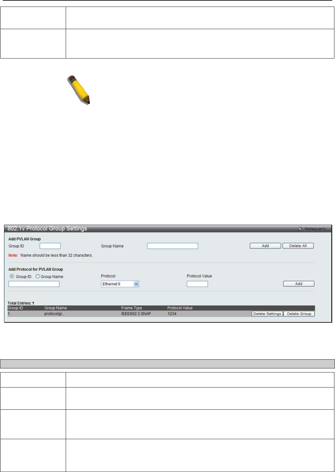
xStack® DGS-3200 Series Layer 2 Managed Gigabit Ethernet Switch Web UI Reference Guide
58
Untagged Specifies the port as 802.1Q untagged. Use the drop-down menu to designate the port as
untagged.
Forbidden Specifies the port as not being a member of the VLAN and that the port is forbidden from
becoming a member of the VLAN dynamically. Use the drop-down menu to designate the port
as forbidden.
Click Apply to implement changes made.
NOTE: The Switch supports up to 4k static VLAN entries.
802.1v Protocol VLAN
The 802.1v Protocol VLAN folder contains two windows: 802.1v Protocol Group Settings and 802.1v Protocol VLAN
Settings.
802.1v Protocol Group Settings
Users can create Protocol VLAN groups and add protocols to that group. The 802.1v Protocol VLAN Group Settings support
multiple VLANs for each protocol and allows the user to configure the untagged ports of different protocols on the same physical
port. For example, it allows the user to configure an 802.1Q and 802.1v untagged port on the same physical port. The lower half
of the table displays any previously created groups.
To view the following window, click L2 Features > VLAN > 802.1v Protocol VLAN > 802.1v Protocol Group Settings:
Figure 3 - 8. 802.1v Protocol Group Settings window
The following fields can be set:
Parameter Description
Group ID Select an ID number for the group, between 1 and 8.
Group Name This is used to identify the new Protocol VLAN group. Type an alphanumeric string of up to 32
characters.
Protocol This function maps packets to protocol-defined VLANs by examining the type octet within the
packet header to discover the type of protocol associated with it. Use the drop-down menu to
toggle between Ethernet II, IEEE802.3 LLC, and IEEE802.3 SNAP.
Protocol Value Enter a value for the Group. The protocol value is used to identify a protocol of the frame type
specified. The form of the input is 0x0 to 0xffff. Depending on the frame type, the octet string
will have one of the following values: For Ethernet II, this is a 16-bit (2-octet) hex value. For
example, IPv4 is 800, IPv6 is 86dd, ARP is 806, etc. For IEEE802.3 SNAP, this is this is a 16-
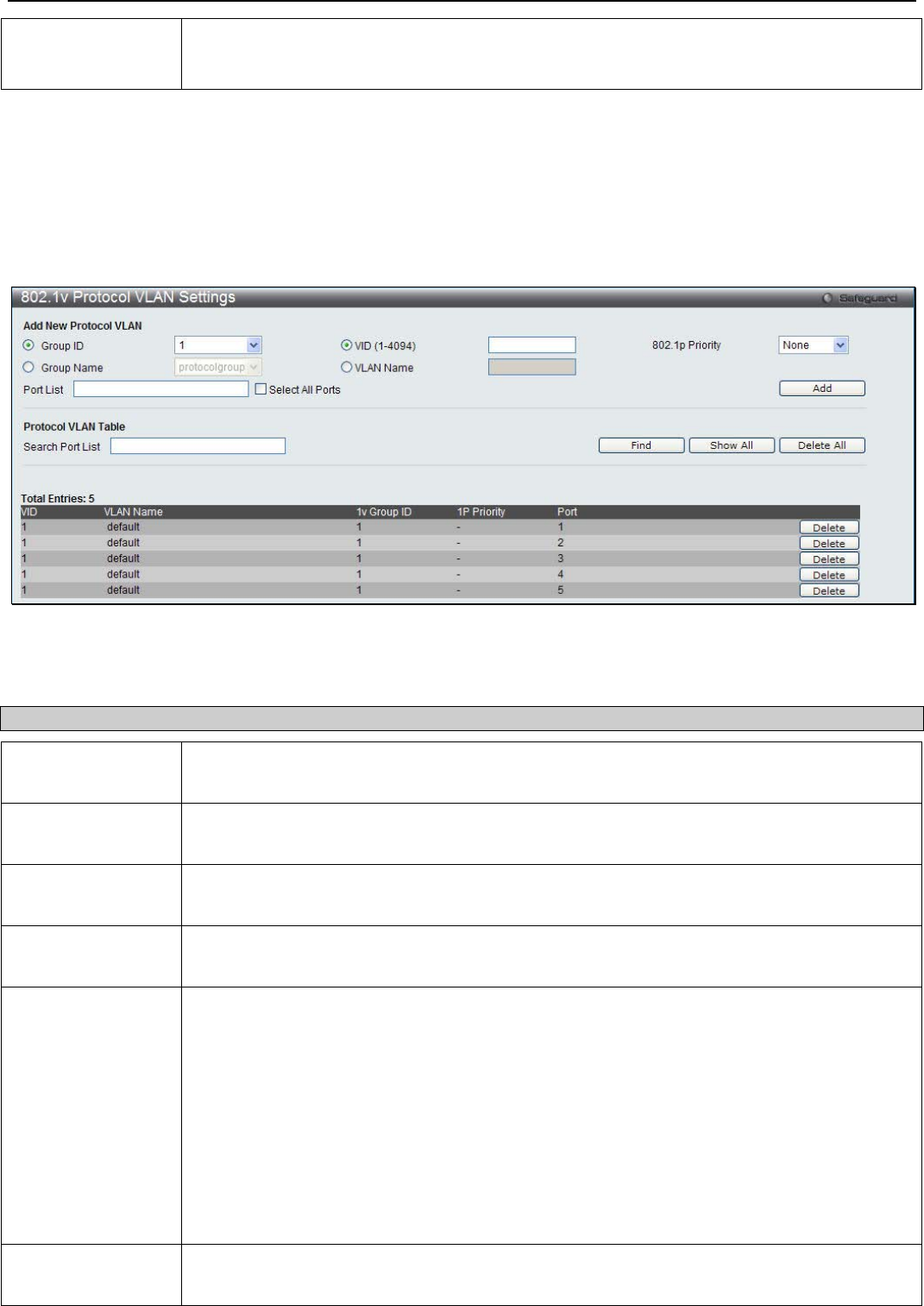
xStack® DGS-3200 Series Layer 2 Managed Gigabit Ethernet Switch Web UI Reference Guide
59
bit (2-octet) hex value. For IEEE802.3 LLC, this is the 2-octet IEEE 802.2 Link Service Access
Point (LSAP) pair. The first octet is for Destination Service Access Point (DSAP) and the
second octet is for Source.
Click Add to make a new entry. Click Delete All to remove an entry. Click Delete Settings to remove the configuration from the
specific entry. Click Delte Group to remove the specific entry from the group.
802.1v Protocol VLAN Settings
Users can configure Protocol VLAN settings. The lower half of the table displays any previously created settings.
To view the following window, click L2 Features > VLAN > 802.1v Protocol VLAN > 802.1v Protocol VLAN Settings:
Figure 3 - 9. 802.1v Protocol VLAN Settings window
The following fields can be set:
Parameter Description
Group ID Highlight the corresponding RADIUS button to select a previously configured Group ID from
the drop-down menu.
Group Name Highlight the corresponding RADIUS button to select a previously configured Group Name
from the drop-down menu.
VID (1-4094) Highlight the RADIUS button to enter the VID. This is the VLAN ID that, along with the VLAN
Name, identifies the VLAN the user wishes to create.
VLAN Name Highlight the RADIUS button to enter a VLAN Name. This is the VLAN Name that, along with
the VLAN ID, identifies the VLAN the user wishes to create.
802.1p Priority This parameter is specified if you want to re-write the 802.1p default priority previously set in
the Switch, which is used to determine the CoS queue to which packets are forwarded to.
Once this field is specified, packets accepted by the Switch that match this priority are
forwarded to the CoS queue specified previously by the user.
Click the corresponding box if you want to set the 802.1p default priority of a packet to the
value entered in the Priority (0-7) field, which meets the criteria specified previously in this
command, before forwarding it on to the specified CoS queue. Otherwise, a packet will have
its incoming 802.1p user priority re-written to its original value before being forwarded by the
Switch.
For more information on priority queues, CoS queues and mapping for 802.1p, see the QoS
section of this manual.
Port List Select the specified ports you wish to configure by entering the port number in this field, or tick
the Select All Ports check box.
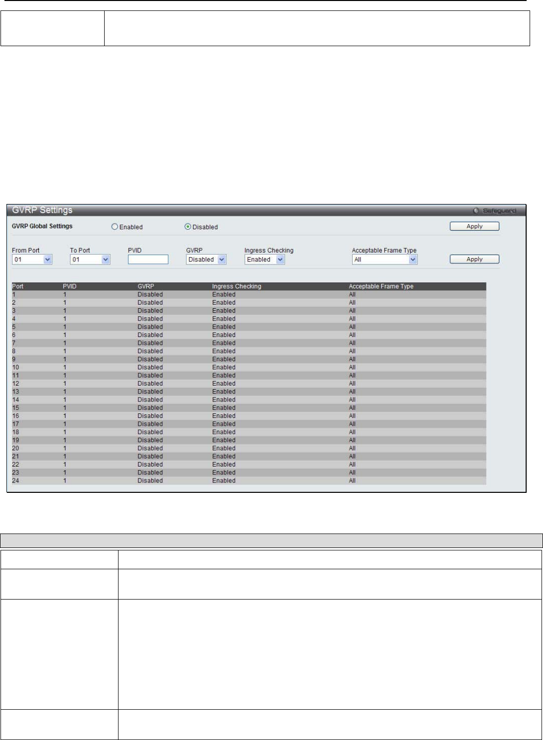
xStack® DGS-3200 Series Layer 2 Managed Gigabit Ethernet Switch Web UI Reference Guide
60
Search Port List This function allows the user to search all previously configured port list settings and display
them on the lower half of the table.
Click Add to create a new entry. To search for a port list enter the port number you wish to view and click Find. To display all
previously configured port lists on the bottom half of the screen click the Show All button, to clear all previously configured lists
click the Delete All button. Click Delete to remove the specific entry.
GVRP Settings
Users can determine whether the Switch will share its VLAN configuration information with other GARP VLAN Registration
Protocol (GVRP) enabled switches. In addition, Ingress Checking can be used to limit traffic by filtering incoming packets whose
PVID does not match the PVID of the port. Results can be seen in the table under the configuration settings.
To view the following window, click L2 Features > VLAN > GVRP Settings:
Figure 3 - 10. GVRP Settings window
The following fields can be set:
Parameter Description
GVRP Global Settings Click the radio buttons to enable or disable GVRP settings.
From Port / To Port Use the drop-down menus to select a range of ports that will be included in the Port-based
VLAN.
PVID This field is used to manually assign a PVID to a VLAN. The Switch's default is to assign all
ports to the default VLAN with a VID of 1.The PVID is used by the port to tag outgoing,
untagged packets, and to make filtering decisions about incoming packets. If the port is
specified to accept only tagged frames - as tagging, and an untagged packet is forwarded to
the port for transmission, the port will add an 802.1Q tag using the PVID to write the VID in
the tag. When the packet arrives at its destination, the receiving device will use the PVID to
make VLAN forwarding decisions. If the port receives a packet, and Ingress filtering is
Enabled, the port will compare the VID of the incoming packet to its PVID. If the two are
unequal, the port will drop the packet. If the two are equal, the port will receive the packet.
GVRP The GARP VLAN Registration Protocol (GVRP) enables the port to dynamically become a
member of a VLAN. GVRP is Disabled by default.
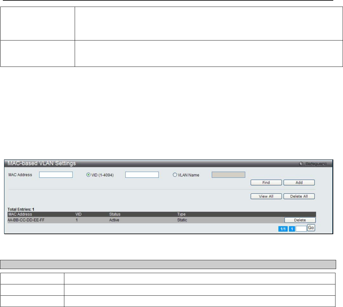
xStack® DGS-3200 Series Layer 2 Managed Gigabit Ethernet Switch Web UI Reference Guide
61
Ingress Checking This drop-down menu allows the user to enable the port to compare the VID tag of an
incoming packet with the PVID number assigned to the port. If the two are different, the port
filters (drops) the packet. Disabled disables ingress filtering. Ingress checking is Enabled by
default.
Acceptable Frame
Type This field denotes the type of frame that will be accepted by the port. The user may choose
between Tagged Only, which means only VLAN tagged frames will be accepted, and All,
which mean both tagged and untagged frames will be accepted. All is enabled by default.
Click Apply to implement changes made.
MAC-based VLAN Settings
Users can create new MAC-based VLAN entries and search, edit, and delete existing entries. When an entry is created for a port,
the port will automatically become the untagged member port of the specified VLAN. When a static MAC-based VLAN entry is
created for a user, the traffic from this user will be able to be serviced under the specified VLAN regardless of the authentication
function operating on this port.
To view the following window, click L2 Features > VLAN > MAC-based VLAN Settings:
Figure 3 - 11. MAC-based VLAN Settings window
The following fields can be set:
Parameter Description
MAC Address Specify the MAC address to be reauthenticated by entering it into the MAC Address field.
VID (1-4094) Click this button and enter the VLAN ID.
VLAN Name Enter the VLAN name of a previously configured VLAN.
Click Find to search for the information entered. Click Add to add the entry. Click View All to see all the entries. Click Delete
All to remove all the entries. Click Delete to remove the specific entry.
Private VLAN Settings
The Switch allows users to create private VLANs. A private VLAN divides the Layer 2 broadcast domain of a VLAN into
subdomains and are particularly useful for service providers who need to assign a unique VLAN to each of their customers. Each
subdomain is made up of several pairs of private VLANs, with each private VLAN pair consisting of a primary and secondary
VLAN. All of the VLAN pairs in a private VLAN domain are members of the same primary VLAN. Each subdomain is identified
using the secondary VLAN ID.
The diagram below illustrates the structure of a Private VLAN domain:

xStack® DGS-3200 Series Layer 2 Managed Gigabit Ethernet Switch Web UI Reference Guide
62
Figure 3 - 12. Private VLAN domain
The ports in a private VLAN can be one of the following three types:
Port Type Description
Promiscuous A promiscuous port is a port that is a member of a primary VLAN that can communicate with
all interfaces, including ports that have been configured as community and isolated ports on
secondary VLANs that are associated with the primary VLAN.
Isolated An isolated port is used to describe a host port that is a member of an isolated secondary
VLAN. An isolated port is completely isolated at Layer 2 from other ports within the same
private VLAN domain, apart from promiscuous ports. All traffic destined to isolated ports is
blocked, except for traffic originating from promiscuous ports. Any traffic originating from an
isolated port is only forwarded to promiscuous ports.
Community A community port is used to describe a host port that is a member of a community secondary
VLAN. A community port can communicate with both ports that are members of the same
community VLAN and promiscuous ports. Interfaces that are configured as community ports
are isolated at Layer 2 from all other interfaces that are members of a different community and
from isolated ports that are members of the same private VLAN domain.
To view the following window, click L2 Features > VLAN > Private VLAN Settings:
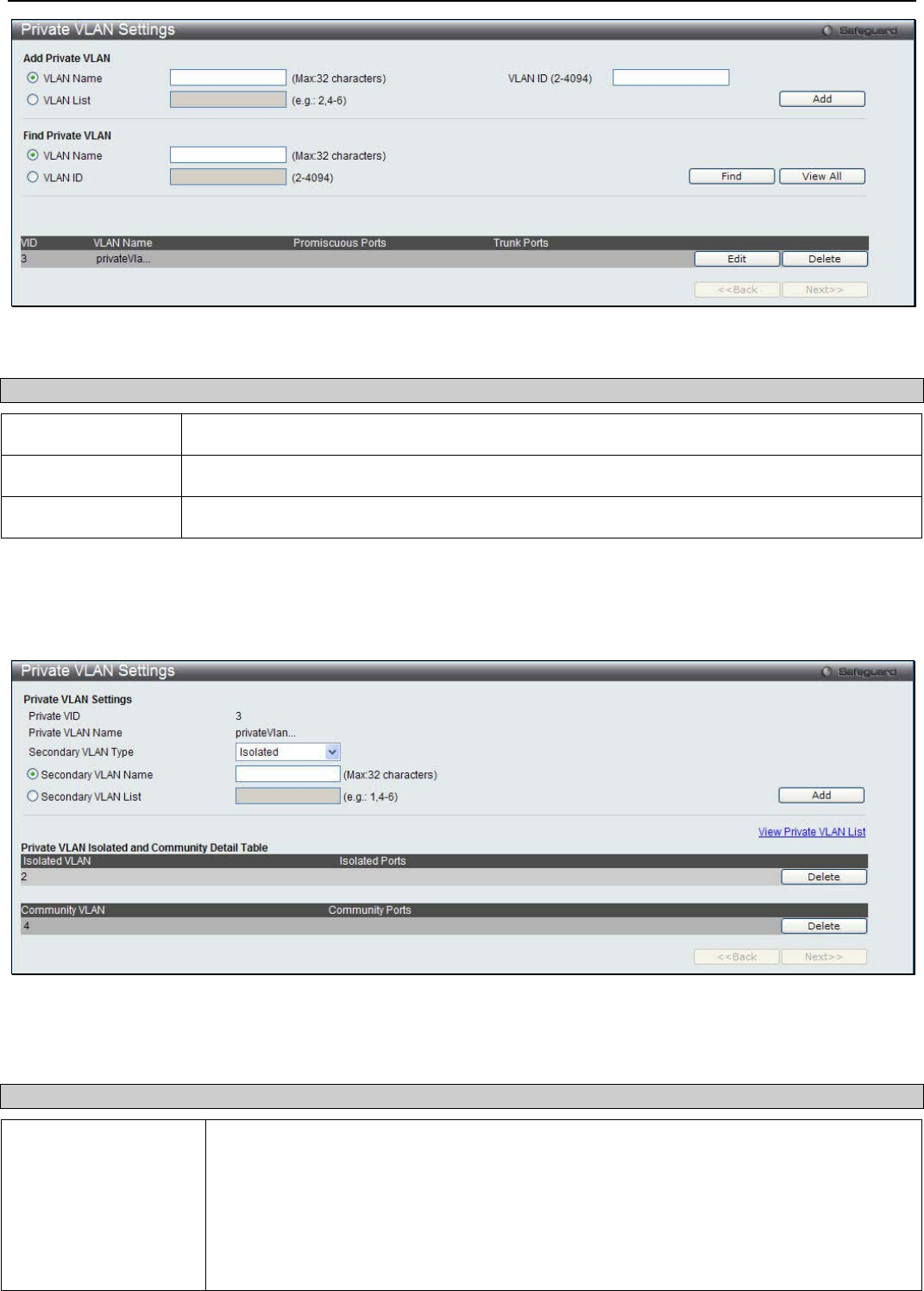
xStack® DGS-3200 Series Layer 2 Managed Gigabit Ethernet Switch Web UI Reference Guide
63
Figure 3 - 13. Private VLAN Settings window
The following parameters can be configured:
Parameter Description
VLAN Name Click the radio button and enter the name of the private VLAN.
VLAN ID (2-4094) Specify the VLAN ID of the Private VLAN.
VLAN List Specify a list of VLAN IDs.
Click Add to create the new Private VLAN entry. Click Find to search for the specific information entered. Click View All to see
all the entries. Click Edit to configure the specific entry. Click Delete to remove the specific entry.
Click Edit to see the following window.
Figure 3 - 14. Private VLAN Settings - Edit window
The following parameters can be configured:
Parameter Description
Secondary VLAN Type Use the drop-down menu to specify the Secondary VLAN Type. The available options are
described below:
Isolated- An Isolated VLAN is a secondary VLAN whose distinctive characteristic is that all
hosts connected to its ports are isolated at Layer 2. The primary advantage of an isolated
VLAN is that it allows a Private VLAN to only use two VLAN identifiers to provide port
isolation and serve any number of end users. A Private VLAN can only support one
isolated VLAN.
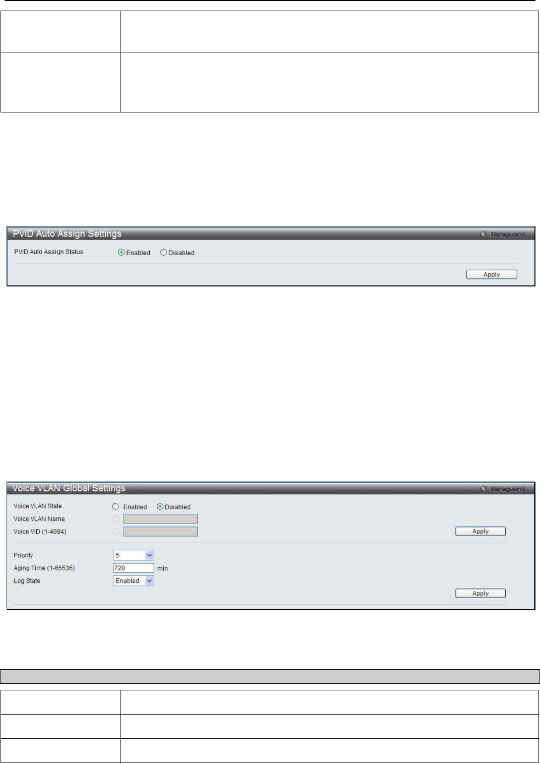
xStack® DGS-3200 Series Layer 2 Managed Gigabit Ethernet Switch Web UI Reference Guide
64
Community- A Community VLAN is a secondary VLAN that is associated with a group of
ports that connects to a certain "community" of end devices with mutual trust relationships.
There can be multiple distinct community VLANs in a Private VLAN domain.
Secondary VLAN
Name Click the radio button and enter the secondary VLAN name.
Secondary VLAN List Click the radio button and enter a list of VLAN IDs.
Click Add to create a new entry. Click Delete to remove the specific entry.
PVID Auto Assign Settings
Users can enable or disable PVID Auto Assign Status. The default setting is enabled.
To view the following window, click L2 Features > VLAN > PVID Auto Assign Settings:
Figure 3 - 15. PVID Auto Assign Settings window
Click Apply to implement the changes made. Please see the previous section for more information about PVIDs.
Voice VLAN
Voice VLAN Global Settings
This window is used to enable the global voice VLAN function on the Switch.
To view the following window, click L2 Features > VLAN > Voice VLAN > Voice VLAN Global Settings:
Figure 3 - 16. Voice VLAN Global Settings window
The following parameters can be configured:
Parameter Description
Voice VLAN State Click to enable or disable the voice VLAN state.
Voice VLAN Name Specify the name of the voice VLAN.
Voie VID (1-4094) Specify the VLAN ID of the voice VLAN.
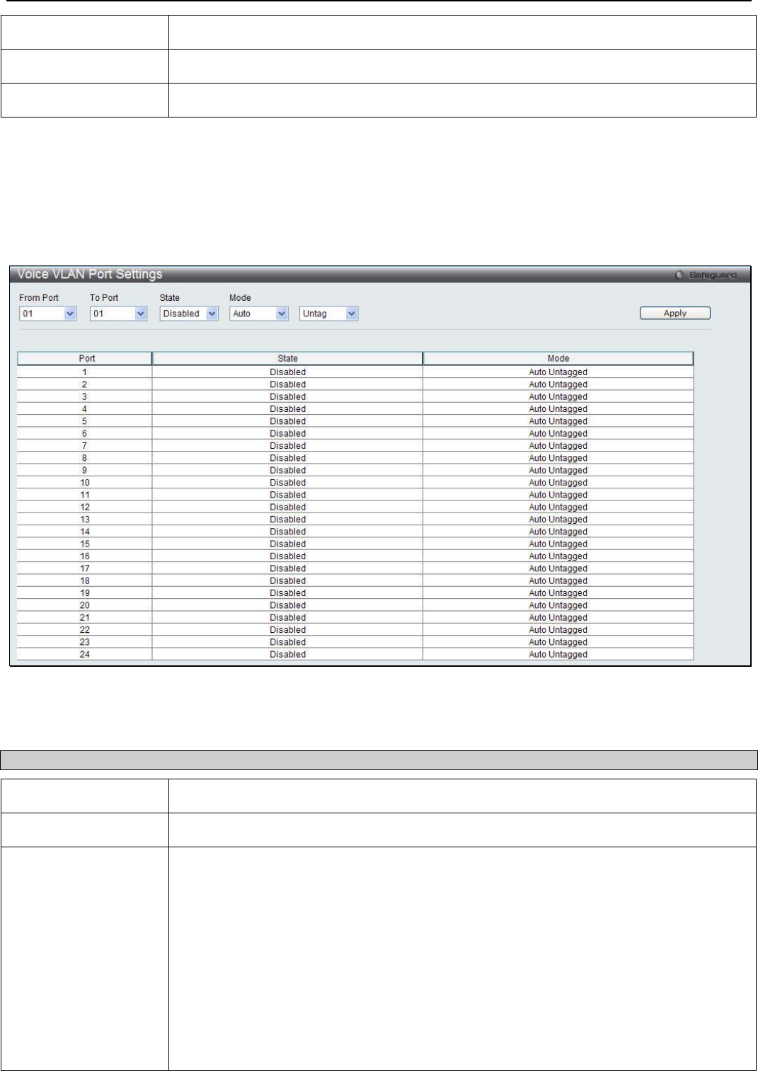
xStack® DGS-3200 Series Layer 2 Managed Gigabit Ethernet Switch Web UI Reference Guide
65
Priority Specify the priority of the voice VLAN.
Aging Time (1-65535) Specify the aging time between 1 and 65535 minutes.
Log State Use the drop-down menu to enable the voice VLAN log state.
Click Apply to implement the changes made.
Voice VLAN Port Settings
This window is used to configure the voice VLAN ports.
To view the following window, click L2 Features > VLAN > Voice VLAN > Voice VLAN Port Settings:
Figure 3 - 17. Voice VLAN Port Settings window
The following parameters can be configured:
Parameter Description
From Port / To Port Use the drop-down menus to select a range of ports to be configured.
State Use the drop-down menu to enable or disable the voice VLAN function state on ports.
Mode Specify the voice VLAN mode.
Auto - When the mode is auto, the port may become the voice VLAN member port by auto-
learning. If the MAC address of the received packet matches the configured OUI, the port
will be learned as dynamic member port. The dynamic membership will be removed via the
aging out mechanism.
Tag - Specify the port to join the voice VLAN as a tagged member.
Untag - Specify the port to join the voice VLAN as an untagged member.
• When the port is working in auto tagged mode, and learns about a voice device
through the device’s OUI, it will join the voice VLAN as a tagged member
automatically. When the voice device sends voice VLAN tagged packets, the switch
will change its priority. When the voice device sends untagged packets, it will
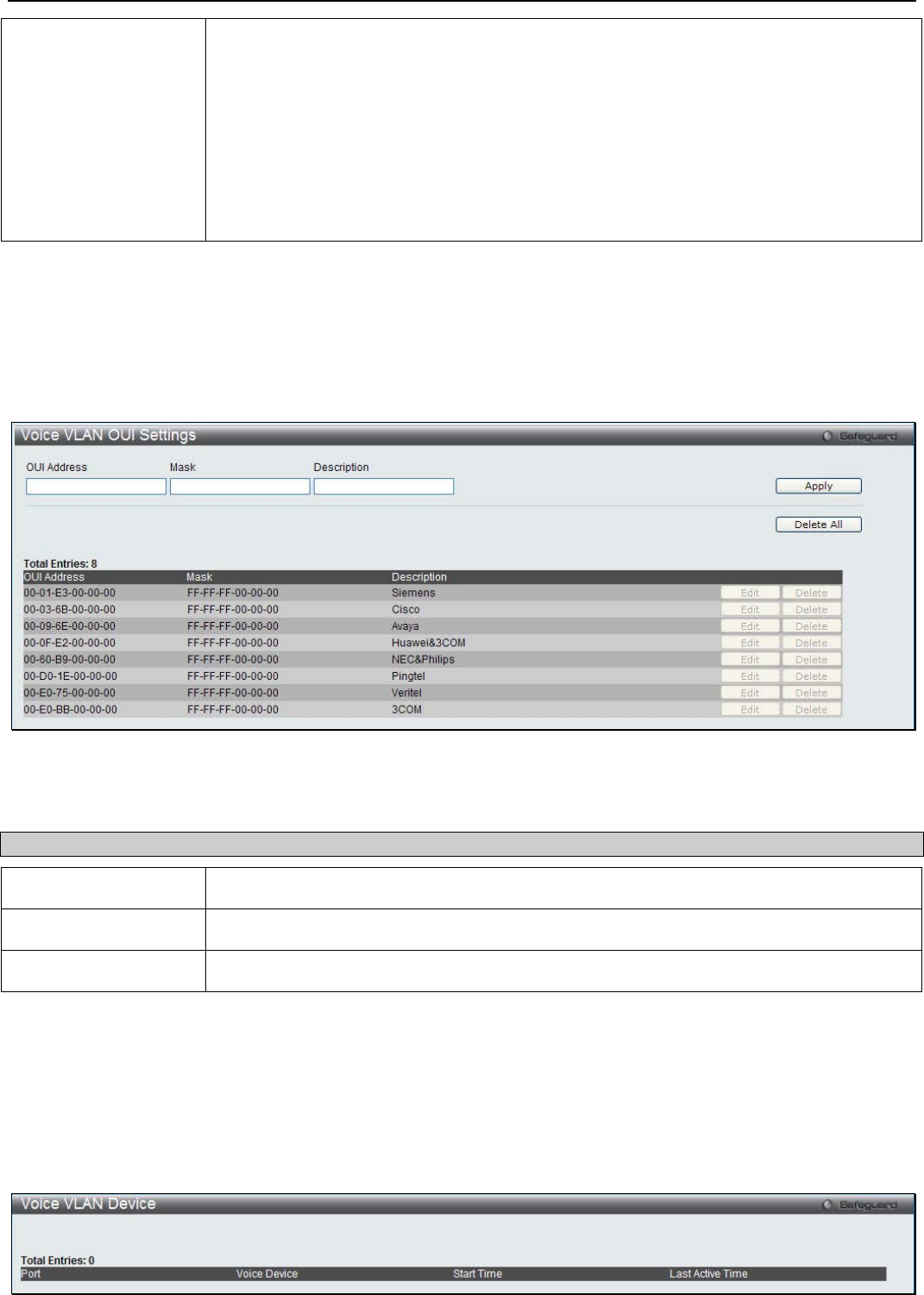
xStack® DGS-3200 Series Layer 2 Managed Gigabit Ethernet Switch Web UI Reference Guide
66
forward them to port’s PVID VLAN.
• When the port is working in auto untagged mode, and the port captures a voice
device through the device’s OUI, it will join the voice VLAN as an untagged member
automatically. When the voice device sends voice VLAN, tagged packets, the switch
will change its priority. Should the voice device send untagged packets, the switch
will assign priority to those and add the voice VLAN ID into this packet
• When the switch receives LLDP-MED packets, it checks the VLAN ID, tagged flag
and priority flag.The switch should follow the tagged flag and priority setting.
Manual - When the mode is set to manual, the port needs to be manually added into or
removed from the voice VLAN by 802.1Q VLAN configuration command.
Click Apply to implement the changes made.
Voice VLAN OUI Settings
This window is used to configure the user-defined voice traffic’s OUI.
To view the following window, click L2 Features > VLAN > Voice VLAN > Voice VLAN OUI Settings:
Figure 3 - 18. Voice VLAN OUI Settings window
The following parameters can be configured:
Parameter Description
OUI Address Specify a user-defined OUI MAC address.
Mask Specify a user-defined OUI MAC address mask.
Description Specify a description for the user-defined OUI.
Click Apply to implement the changes made. Click Delete All to remove all the user-defined entries. Click Edit to configure the
specific entry. Click Delete to remove the specific entry.
Voice VLAN Device
This window is used to show voice devices that are connected to the ports.
To view the following window, click L2 Features > VLAN > Voice VLAN > Voice VLAN Device:
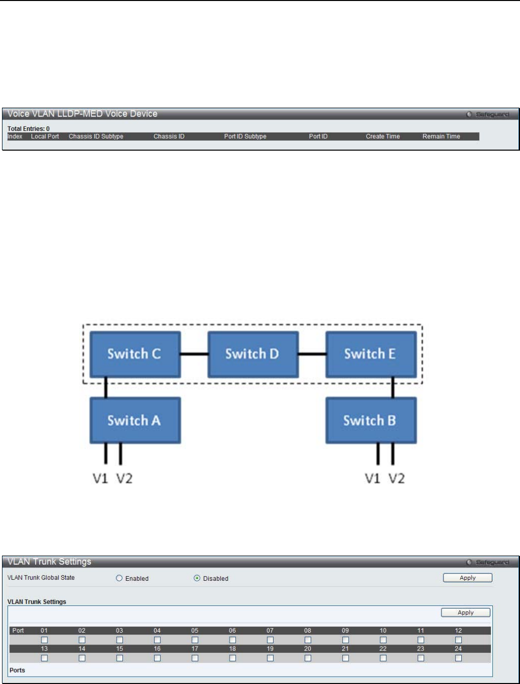
xStack® DGS-3200 Series Layer 2 Managed Gigabit Ethernet Switch Web UI Reference Guide
67
Figure 3 - 19. Voice VLAN Device window
Voice VLAN LLDP-MED Voice Device
This window is used to show the voice devices being discovered by the LLDP-MED.
To view the following window, click L2 Features > VLAN > Voice VLAN > Voice VLAN LLDP-MED Voice Device:
Figure 3 - 20. Voice VLAN LLDP-MED Voice Device window
VLAN Trunk Settings
Enable VLAN on a port to allow frames belonging to unknown VLAN groups to pass through that port. This is useful if you want
to set up VLAN groups on end devices without having to configure the same VLAN groups on intermediary devices.
Refer to the following figure for an illustrated example. Suppose you want to create VLAN groups 1 and 2 (V1 and V2) on
devices A and B. Without a VLAN Trunk, you must first configure VLAN groups 1 and 2 on all intermediary switches C, D and
E; otherwise they will drop frames with unknown VLAN group tags. However, with VLAN Trunk enabled on a port(s) in each
intermediary switch, you only need to create VLAN groups in the end devices (A and B). C, D and E automatically allow frames
with VLAN group tags 1 and 2 (VLAN groups that are unknown to those switches) to pass through their VLAN trunking port(s).
Users can combine a number of VLAN ports together to create VLAN trunks. To create VLAN Trunk Port settings on the Switch,
select the ports to be configured, change the VLAN Trunk Global State to Enabled, and click Apply, the new settings will appear
in the VLAN Trunk Settings table in the lower part of the window.
To view the following window, click L2 Features > VLAN > VLAN Trunk Settings:
Figure 3 - 21. VLAN Trunk Settings window
The following parameters can be configured:
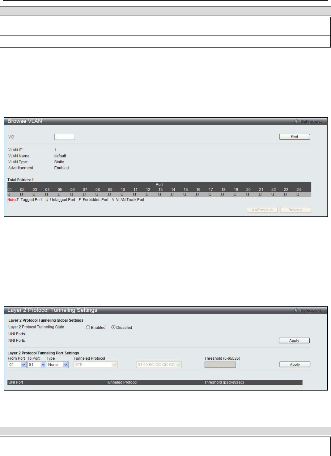
xStack® DGS-3200 Series Layer 2 Managed Gigabit Ethernet Switch Web UI Reference Guide
68
Parameter Description
VLAN Trunk Global
State Use the radio buttons to Enable or Disable the VLAN trunking global state.
Ports The ports to be configured.
Click Apply to implement the changes made.
Browse VLAN
This window is used to display the VLAN status.
To view the following window, click L2 Features > VLAN > Browse VLAN:
Figure 3 - 22. Browse VLAN window
Enter a VLAN ID in VID field and click Find to display the VLAN status.
Layer 2 Protocol Tunneling Settings
This window is used to configure Layer 2 protocol tunneling settings.
To view the following window, click L2 Features > Layer 2 Protocol Tunneling Settings:
Figure 3 - 23. Layer 2 Protocol Tunneling Settings window
The following parameters can be configured:
Parameter Description
Layer 2 Protocol
Tunneling State Click to enable or disable the Layer 2 protocol tunneling state.
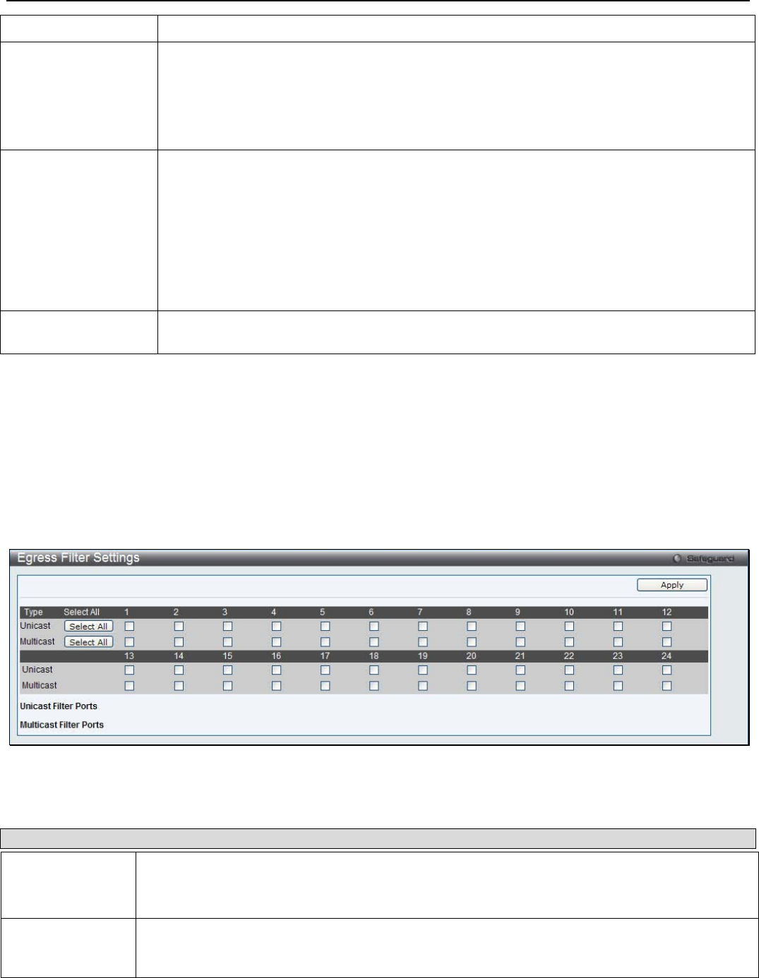
xStack® DGS-3200 Series Layer 2 Managed Gigabit Ethernet Switch Web UI Reference Guide
69
From Port / To Port Use the drop-down menus to select a range of ports to be configured.
Type Specify the type of the ports.
UNI - Specify the ports as UNI ports.
NNI - Specify the ports as NNI ports.
None - Disable tunnel on it.
Tunneled Protocol Specify tunneled protocols on the UNI ports.
STP - Specify to use the STP protocol.
GVRP - Specify to use the GVRP protocol.
Protocol MAC - Specify the destination MAC address of the L2 protocol packets that will
tunneled on these UNI ports. The MAC address can be 01-00-0C-CC-CC-CC or 01-00-0C-
CC-CC-CD.
All - All tunnel-abled Layer 2 protocols will be tunneled on the ports.
Threshold (0-65535) Specify the drop threshold for packets-per-second accepted on the UNI ports. The ports drop
the PDU if the protocol’s threshold is exceeded.
Click Apply to implement the changes made.
Egress Filter Settings
Users can configure an egress filter on specific ports for unknown unicast and unregistered multicast packets.
The Switch drops all unknown unicast/multicast packets on egress ports when it detects unknown unicast/multicast packets for
egress ports. Therefore, a user can select which port is permitted or not permitted to receive unknown unicast/multicast packets.
To view the following window, click L2 Features > Egress Filter Settings:
Figure 3 - 24. Egress Filter Settings window
The following fields can then be set:
Parameter Description
Unicast Select ports to filter unknown unicast packets. These packets will not be forwarded to those
ports. Unselected ports will not filter unknown unicast packets and the packets may be forwarded
to those ports.
Multicast Select ports to filter unregistered multicast packets. These packets will not be forwarded to those
ports. Unselected ports will not filter unregistered multicast packets and the packets may be
forwarded to those ports.
Click Apply to implement changes made.
L2 Multicast Control
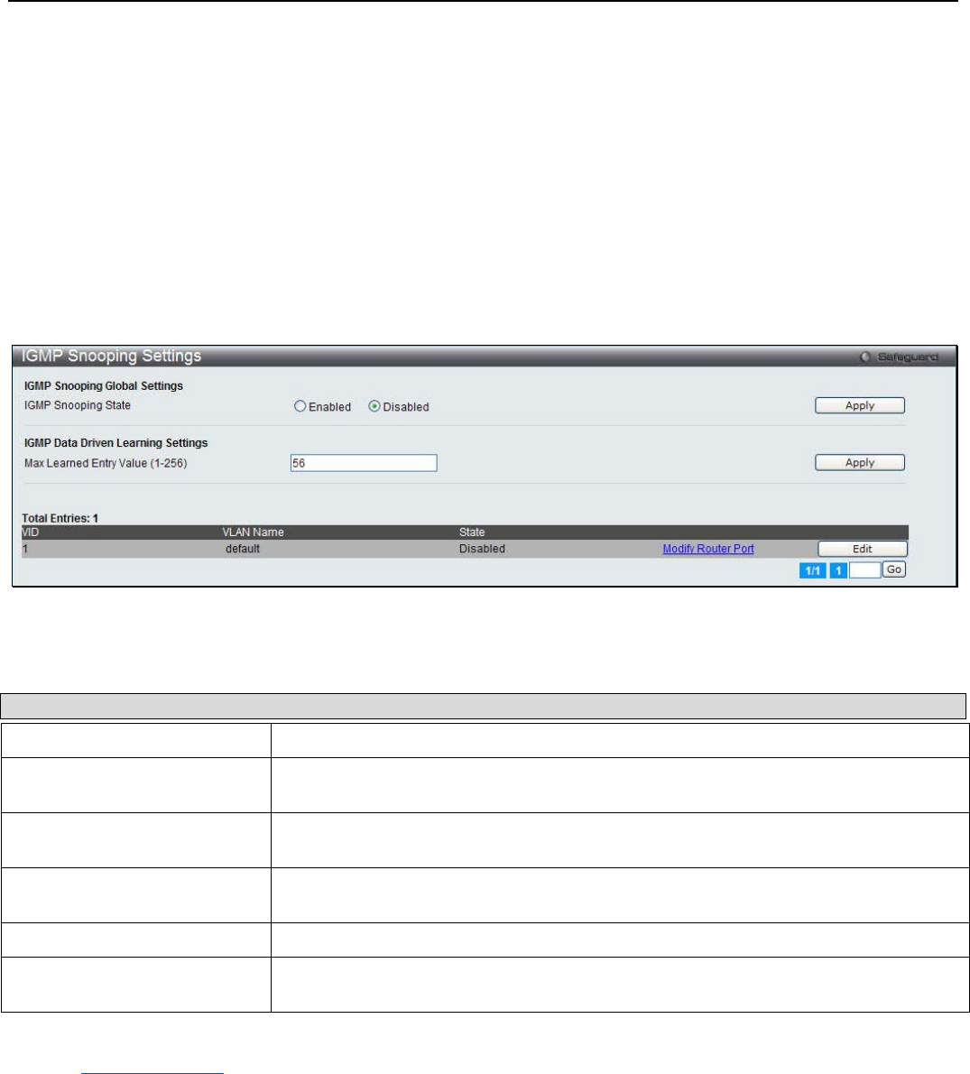
xStack® DGS-3200 Series Layer 2 Managed Gigabit Ethernet Switch Web UI Reference Guide
70
IGMP Snooping
Internet Group Management Protocol (IGMP) snooping allows the Switch to recognize IGMP queries and reports sent between
network stations or devices and an IGMP host. When enabled for IGMP snooping, the Switch can open or close a port to a
specific device based on IGMP messages passing through the Switch.
IGMP Snooping Settings
In order to use IGMP Snooping it must first be enabled for the entire Switch under IGMP Global Settings at the top of the
window. You may then fine-tune the settings for each VLAN by clicking the corresponding Edit button. When enabled for IGMP
snooping, the Switch can open or close a port to a specific multicast group member based on IGMP messages sent from the device
to the IGMP host or vice versa. The Switch monitors IGMP messages and discontinues forwarding multicast packets when there
are no longer hosts requesting that they continue.
To view the following window, click L2 Features > L2 Multicast Control > IGMP Snooping > IGMP Snooping Settings:
Figure 3 - 25. IGMP Snooping Settings window
The following parameters may be viewed or configured:
Parameter Description
IGMP Snooping State Click the radio button to enable or disable the IGMP snooping state.
Max Learned Entry Value (1-
256) Specify the maximum number of groups that can be learned by the data driven
mechanism.
VID (VLAN ID) This is the VLAN ID that, along with the VLAN Name, identifies the VLAN the user
wishes to modify the IGMP Snooping Settings for.
VLAN Name This is the VLAN Name that, along with the VLAN ID, identifies the VLAN the user
wishes to modify the IGMP Snooping Settings for.
State Select Enabled to implement IGMP Snooping. This field is Disabled by default.
Parameter Settings Click the Edit button next to the VLAN you want to edit the IGMP Snooping
parameters for.
Click Apply to implement changes made. Click the Edit button to configure the IGMP Snooping Parameters Settings.
Click the Modify Router Port link to configure the IGMP Snooping Router Port Settings.
Click the Edit button to see the following window:
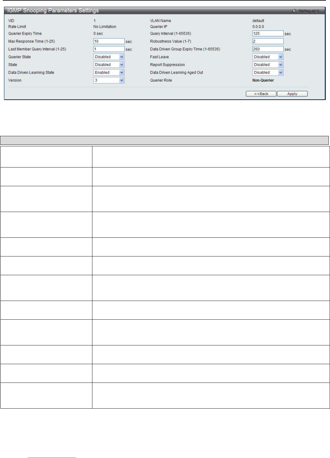
xStack® DGS-3200 Series Layer 2 Managed Gigabit Ethernet Switch Web UI Reference Guide
71
Figure 3 - 26. IGMP Snooping Parameters Settings window
The following parameters can be configured:
Parameter Description
Query Interval (1-65535) This parameter specifies the length of time between sending IGMP Queries.
Default= 125.
Max Response Time (1-25) This parameter is used to set the maximum amount of time allowed before sending
an IGMP response report. Default= 10.
Robustness Value (1-7) This parameter is used as a tuning variable that allows for a large number of packets
being lost on subnetworks. Specify a value between 1 and 255. Specify a high value
if you expect your subnetworks to lose a large number of packets. Default= 2.
Last Member Query Interval
(1-25) This parameter is used to set the maximum amount of time between group-specific
query messages, including messages that have been sent in response to leave
group messages. Default= 2.
Data Driven Group Expiry
Time (1-65535) Specify the data driven group lifetime in seconds.
Querier State Choose Enabled from the drop-down menu to enable the transmission of IGMP
Query Packets or choose Disabled to disable. Default = Disabled.
Fast Leave Choose Enabled from the drop-down menu to enable the Fast Leave function or
choose Disabled to disable. If Fast Leave is Enabled, the membership will
immediately be removed when the system receives an IGMP leave message.
State Use the drop-down menu to Enable or Disable the IGMP Snooping feature for the
specified VLAN.
Report Suppression Use the drop-down menu to enable or disable report suppression function. The
Switch uses IGMP report suppression to forward only one IGMP report per multicast
router query to multicast devices.
Data Driven Learning State Use the drop-down menu to enable or disable the data driven learning of an IGMP
snooping group.
Data Driven Learning Aged
Out Use the drop-down menu to enable or disable the aging on the entry.
Version Use the drop-down menu to specify the version of IGMP packets that will be sent by
the specified ports. If an IGMP packet received by the interface has a version higher
then the specified version, the packet will be dropped.
After setting the above parameters, click the Apply button in the top section of the window to allow your changes to be
implemented. Click the <<Back button to discard the changes made and return to the previous page.
Click the Modify Router Port link to see the following window:
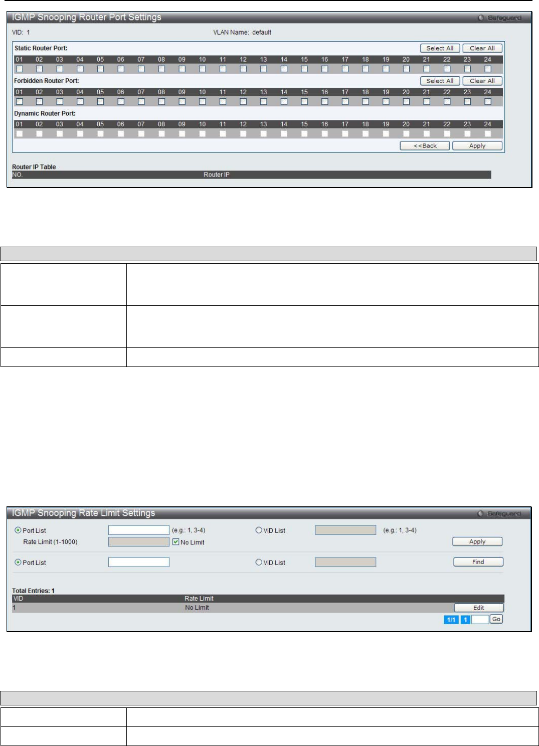
xStack® DGS-3200 Series Layer 2 Managed Gigabit Ethernet Switch Web UI Reference Guide
72
Figure 3 - 27. IGMP Snooping Router Port Settings window
The following parameters can be configured:
Parameter Description
Static Router Port This section is used to designate a range of ports as being connected to multicast-enabled
routers. This will ensure that all packets with such a router as its destination will reach the
multicast-enabled router regardless of the protocol.
Forbidden Router Port This section is used to designate a range of ports as being not connected to multicast-
enabled routers. This ensures that the forbidden router port will not propagate routing
packets out.
Dynamic Router Port Displays router ports that have been dynamically configured.
Click the Select All button to select all the ports for configuration. Click the Clear All button to unselect all the ports for
configuration. Click the Apply button to accept the changes made. Click the <<Back button to discard the changes made and
return to the previous page.
IGMP Snooping Rate Limit Settings
This window is used to configure the IGMP snooping rate limit parameters.
To view the following window, click L2 Features > L2 Multicast Control > IGMP Snooping > IGMP Snooping Rate Limit
Settings:
Figure 3 - 28. IGMP Snooping Rate Limit Settings window
The following parameters can be configured:
Parameter Description
Port List Enter the port list used for this configuration.
VID List Enter the VID list used for this configuration.

xStack® DGS-3200 Series Layer 2 Managed Gigabit Ethernet Switch Web UI Reference Guide
73
Rate Limit (1-1000) Enter the IGMP snooping rate limit used. By selecting the No Limit check box, the rate
limit for the entered port(s) will be ignored.
Click the Apply button to accept the changes made. Click the Find button to locate a specific entry based on the information
entered. Click the Edit button to re-configure the specific entry. Enter a page number and click the Go button to navigate to a
specific page when multiple pages exist.
IGMP Snooping Static Group Settings
This window is used to view the Switch’s IGMP Snooping Group Table. IGMP Snooping allows the Switch to read the Multicast
Group IP address and the corresponding MAC address from IGMP packets that pass through the Switch.
To view the following window, click L2 Features > L2 Multicast Control > IGMP Snooping > IGMP Snooping Static Group
Settings:
Figure 3 - 29. IGMP Snooping Static Group Settings window
The following parameters can be configured:
Parameter Description
VLAN Name The VLAN name of the multicast group.
VID List The VID list of the multicast group.
IPv4 Address Enter the IPv4 address.
Click the Find button to locate a specific entry based on the information entered. Click the Create button to add a new entry
based on the information entered. Click the Delete button to remove the specific entry based on the information entered. Click the
View All button to display all the existing entries. Click the Edit button to re-configure the specific entry. Enter a page number
and click the Go button to navigate to a specific page when multiple pages exist.
Click the Edit button to see thw following window.
Figure 3 - 30. IGMP Snooping Static Group Settings – Edit window
Select the appropriate ports individually to include them in the IGMP snooping static group settings.
Click the Select All button to select all the ports for configuration. Click the Clear All button to unselect all the ports for
configuration. Click the Apply button to accept the changes made. Click the <<Back button to discard the changes made and
return to the previous page.
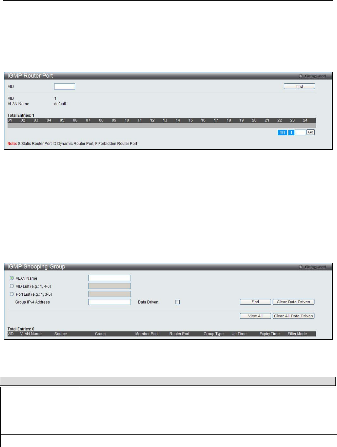
xStack® DGS-3200 Series Layer 2 Managed Gigabit Ethernet Switch Web UI Reference Guide
74
IGMP Router Port
This window is used to display which of the Switch’s ports are currently configured as router ports. A router port configured by a
user (using the console or Web-based management interfaces) is displayed as a static router port, designated by S. A router port
that is dynamically configured by the Switch is designated by D, while a Forbidden port is designated by F.
To view the following window, click L2 Features > L2 Multicast Control > IGMP Snooping > IGMP Router Port:
Figure 3 - 31. IGMP Router Port window
Enter a VID (VLAN ID) in the field at the top of the window.
Click the Find button to locate a specific entry based on the information entered. Enter a page number and click the Go button to
navigate to a specific page when multiple pages exist.
IGMP Snooping Group
This window is used to display the Switch’s IGMP Snooping Group Table. IGMP Snooping allows the Switch to read the
Multicast Group IP address and the corresponding MAC address from IGMP packets that pass through the Switch.
To view the following window, click L2 Features > L2 Multicast Control > IGMP Snooping > IGMP Snooping Group:
Figure 3 - 32. IGMP Snooping Group window
The following parameters can be configured:
Parameter Description
VLAN Name The VLAN name of the multicast group.
VID List The VID list of the multicast group.
Port List Specify the port number(s) used to find a multicast group.
Group IPv4 Address Enter the IPv4 address.
Data Driven Tick to display data-driven IGMP snooping group entries.
Click the Find button to locate a specific entry based on the information entered. Click Clear Data Driven to delete the specified
IGMP snooping group learned by the data-driven mechanism. Click View All to see all the entries. Click Clear All Data Driven
to delete all the IGMP snooping groups learned by the data-driven mechanism.
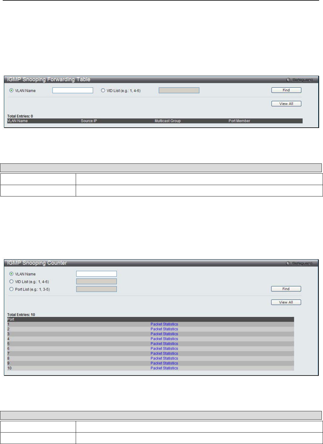
xStack® DGS-3200 Series Layer 2 Managed Gigabit Ethernet Switch Web UI Reference Guide
75
IGMP Snooping Forwarding Table
This page displays the switch’s current IGMP snooping forwarding table. It provides an easy way for user to check the list of ports
that the multicast group comes from and specific sources that it will be forwarded to. The packet comes from the source VLAN.
They will be forwarded to the forwarding VLAN. The IGMP snooping further restricts the forwarding ports.
To view the following window, click L2 Features > L2 Multicast Control > IGMP Snooping > IGMP Snooping Forwarding
Table:
Figure 3 - 33. IGMP Snooping Forwarding Table window
The following parameters can be configured:
Parameter Description
VLAN Name The VLAN name of the multicast group.
VID List The VID list of the multicast group.
Click the Find button to locate a specific entry based on the information entered. Click View All to see all the entries.
IGMP Snooping Counter
This window is used to display the Switch’s IGMP Snooping counter table.
To view the following window, click L2 Features > L2 Multicast Control > IGMP Snooping > IGMP Snooping Counter:
Figure 3 - 34. IGMP Snooping Counter window
The following parameters can be configured:
Parameter Description
VLAN Name The VLAN name of the multicast group.
VID List The VID list of the multicast group.

xStack® DGS-3200 Series Layer 2 Managed Gigabit Ethernet Switch Web UI Reference Guide
76
Port List Specify the port number(s) used to find a multicast group.
Click the Find button to locate a specific entry based on the information entered. Click View All to see all the entries. Click the
Packet Statistics link to view the IGMP Snooping Counter Table.
Click the Packet Statistics link to see the following window.
Figure 3 - 35. Browse IGMP Snooping Counter window
Click the Clear Counter button to clear all the information displayed in the fields. Click the Refresh button to refresh the display
table so that new information will appear. Click the <<Back button to return to the previous page.
IGMP Host Table
This window is used to display the IGMP hosts that have joined groups on specific ports or specific VLANs.
To view the following window, click L2 Features > L2 Multicast Control > IGMP Snooping > IGMP Host Table:
Figure 3 - 36. IGMP Host Table window
The following parameters can be configured:
Parameter Description
VLAN Name Specify the name of the VLAN on which the router port resides.
VID List Specify a list of VIDs on which the router port resides.
Port List Specify the list of ports to display the host information.
Group Address Specify the group to display the host information.

xStack® DGS-3200 Series Layer 2 Managed Gigabit Ethernet Switch Web UI Reference Guide
77
Click the Find button to locate a specific entry based on the information entered. Click View All to see all the entries.
MLD Snooping
MLD Snooping Settings
Multicast Listener Discovery (MLD) Snooping is an IPv6 function used similarly to IGMP snooping in IPv4. It is used to discover
ports on a VLAN that are requesting multicast data. Instead of flooding all ports on a selected VLAN with multicast traffic, MLD
snooping will only forward multicast data to ports that wish to receive this data through the use of queries and reports produced by
the requesting ports and the source of the multicast traffic.
MLD snooping is accomplished through the examination of the layer 3 part of an MLD control packet transferred between end
nodes and a MLD router. When the Switch discovers that this route is requesting multicast traffic, it adds the port directly attached
to it into the correct IPv6 multicast table, and begins the process of forwarding multicast traffic to that port. This entry in the
multicast routing table records the port, the VLAN ID, and the associated multicast IPv6 multicast group address, and then
considers this port to be an active listening port. The active listening ports are the only ones to receive multicast group data.
MLD Control Messages
Three types of messages are transferred between devices using MLD snooping. These three messages are all defined by four
ICMPv6 packet headers, labeled 130, 131, 132, and 143.
1. Multicast Listener Query – Similar to the IGMPv2 Host Membership Query for IPv4, and labeled as 130 in the
ICMPv6 packet header, this message is sent by the router to ask if any link is requesting multicast data. There are two
types of MLD query messages emitted by the router. The General Query is used to advertise all multicast addresses that
are ready to send multicast data to all listening ports, and the Multicast Specific query, which advertises a specific
multicast address that is also ready. These two types of messages are distinguished by a multicast destination address
located in the IPv6 header and a multicast address in the Multicast Listener Query Message.
2. Multicast Listener Report, Version 1 – Comparable to the Host Membership Report in IGMPv2, and labeled as 131 in
the ICMP packet header, this message is sent by the listening port to the Switch stating that it is interested in receiving
multicast data from a multicast address in response to the Multicast Listener Query message.
3. Multicast Listener Done – Akin to the Leave Group Message in IGMPv2, and labeled as 132 in the ICMPv6 packet
header, this message is sent by the multicast listening port stating that it is no longer interested in receiving multicast data
from a specific multicast group address, therefore stating that it is “done” with the multicast data from this address. Once
this message is received by the Switch, it will no longer forward multicast traffic from a specific multicast group address
to this listening port.
4. Multicast Listener Report, Version 2 - Comparable to the Host Membership Report in IGMPv3, and labeled as 143 in
the ICMP packet header, this message is sent by the listening port to the Switch stating that it is interested in receiving
multicast data from a multicast address in response to the Multicast Listener Query message.
Users can configure the settings for MLD snooping.
To view the following window, click L2 Features > L2 Multicast Control > MLD Snooping > MLD Snooping Settings:
Figure 3 - 37. MLD Snooping Settings window
The following parameters can be viewed or configured:
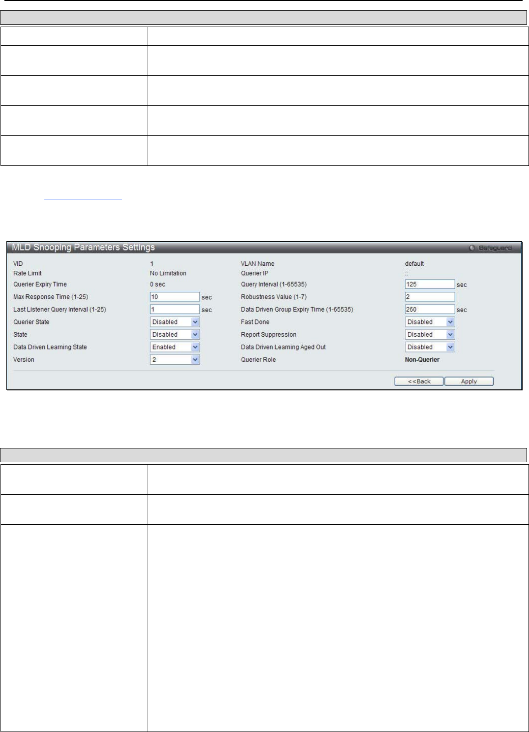
xStack® DGS-3200 Series Layer 2 Managed Gigabit Ethernet Switch Web UI Reference Guide
78
Parameter Description
MLD Snooping State Click the radio button to enable or disable the MLD snooping state.
Max Learned Entry Value (1-
256) Specify the maximum number of groups that can be learned by the data driven
mechanism.
VID This is the VLAN ID that, along with the VLAN Name, identifies the VLAN for which
to modify the MLD Snooping Settings.
VLAN Name This is the VLAN Name that, along with the VLAN ID, identifies the VLAN for which
to modify the MLD Snooping Settings.
State Used to enable or disable MLD snooping for the specified VLAN. This field is
Disabled by default.
Click Apply to implement changes made. Click the Edit button to configure the MLD Snooping Parameters Settings.
Click the Modify Router Port link to configure the MLD Snooping Router Port Settings.
Click the Edit button to see the following window:
Figure 3 - 38. MLD Snooping Parameters Settings window
The following parameters can be configured:
Parameter Description
Query Interval (1-65535 sec) This parameter is used to specify the amount of time in seconds between general
query transmissions. Default: 125 seconds.
Max Response Time (1-25
sec) This parameter is used to specify the maximum amount of time in seconds to wait for
reports from listeners. Default: 10 seconds.
Robustness Variable (1-7) This parameter is used to provide fine-tuning that allows for expected packet losses
on a subnet. The value of the robustness variable is used in calculating the following
MLD message intervals:
• Group listener interval—Amount of time that must pass before a multicast
router decides there are no more listeners of a group on a network. This
interval is calculated as follows: (robustness variable * query interval) + (1 *
query response interval).
• Other querier present interval—Amount of time that must pass before a
multicast router decides that there is no longer another multicast router that
is the querier. This interval is calculated as follows: (robustness variable *
query interval) + (0.5 * query response interval).
• Last listener query count—Number of group-specific queries sent before the
router assumes there are no local listeners of a group. The default number is
the value of the robustness variable.
• By default, the robustness variable is set to 2. You might want to increase
this value if you expect a subnet to lose a high number of packets.
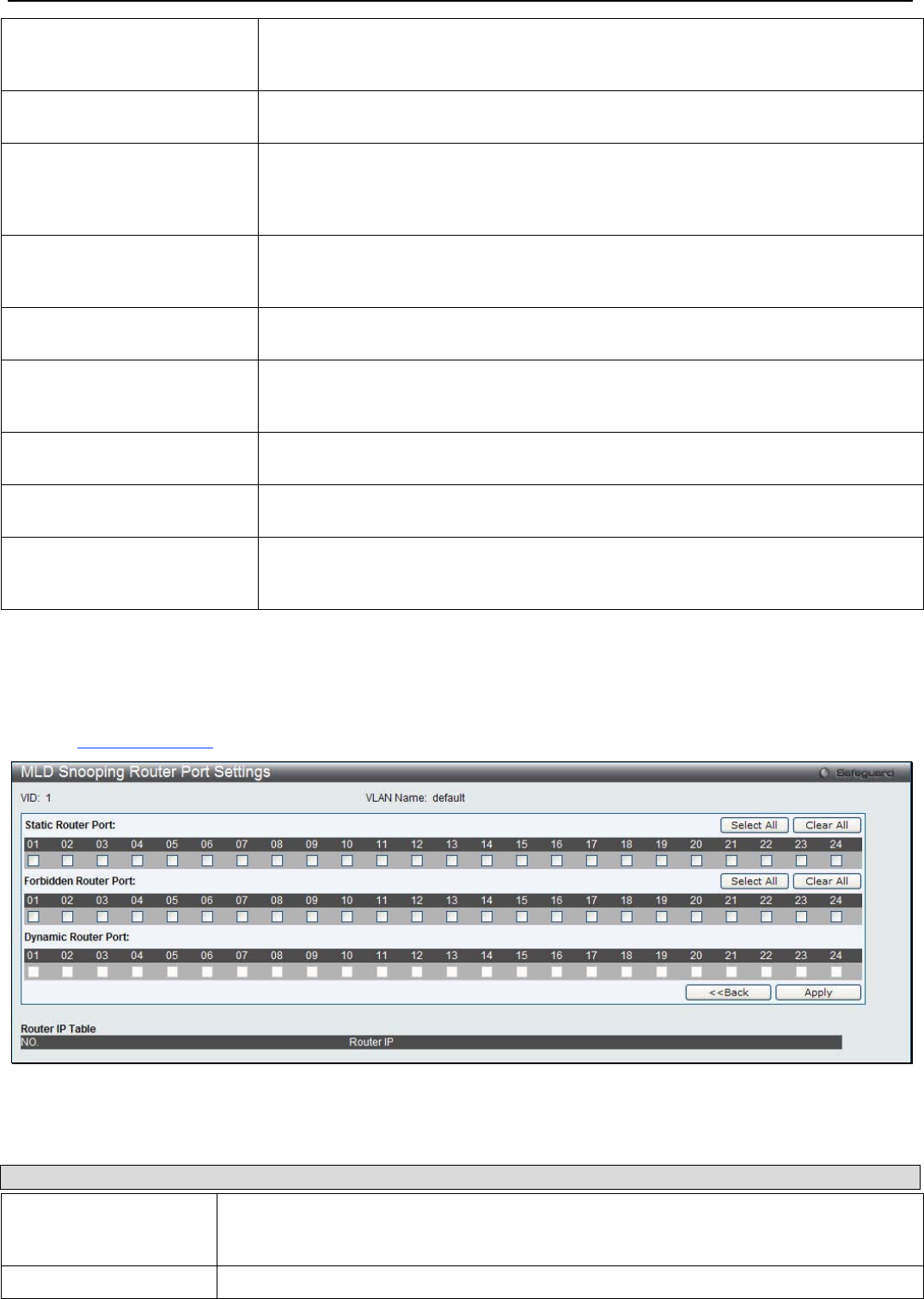
xStack® DGS-3200 Series Layer 2 Managed Gigabit Ethernet Switch Web UI Reference Guide
79
Last Member Query Interval
(1-25) This parameter is used to set the maximum amount of time between group-specific
query messages, including messages that have been sent in response to leave
group messages.
Data Driven Group Expiry
Time (1-65535) Specify the data driven group lifetime in seconds.
Querier State Choose Enabled from the drop-down menu to specify that the Switch should act as
an MLD Querier (sends MLD query packets). Choose Disabled from the drop-down
menu to specify that the Switch should act as a Non-Querier (does not send MLD
query packets).
Fast Done Choose Enabled from the drop-down menu to enable the Fast Done function or
choose Disabled to disable. If it is enabled, the membership is immediately removed
when the system receive the MLD leave message.
State Use the drop-down menu to specify if MLD Snooping should be Enabled or Disabled
from the specified VLAN.
Report Suppression Use the drop-down menu to enable or disable report suppression function. The
Switch uses MLD report suppression to forward only one MLD report per multicast
router query to multicast devices.
Data Driven Learning State Use the drop-down menu to enable or disable the data driven learning of a MLD
snooping group.
Data Driven Learning Aged
Out Use the drop-down menu to enable or disable the aging on the entry.
Version Use the drop-down menu to specify the version of MLD packets that will be sent by
the specified ports. If an MLD packet received by the interface has a version higher
then the specified version, the packet will be dropped.
After setting the above parameters, click the Apply button in the top section of the window to allow your changes to be
implemented. Click the <<Back button to discard the changes made and return to the previous page.
Click the Modify Router Port link to see the following window:
Figure 3 - 39. MLD Snooping Router Port Settings window
The following parameters can be configured:
Parameter Description
Static Router Port This section is used to designate a range of ports as being connected to multicast-enabled
routers. This will ensure that all packets with such a router as its destination will reach the
multicast-enabled router regardless of the protocol.
Forbidden Router Port This section is used to designate a range of ports as being not connected to multicast-

xStack® DGS-3200 Series Layer 2 Managed Gigabit Ethernet Switch Web UI Reference Guide
80
enabled routers. This ensures that the forbidden router port will not propagate routing
packets out.
Dynamic Router Port Displays router ports that have been dynamically configured.
Click the Select All button to select all the ports for configuration. Click the Clear All button to unselect all the ports for
configuration. Click the Apply button to accept the changes made. Click the <<Back button to discard the changes made and
return to the previous page.
MLD Snooping Rate Limit Settings
This window is used to configure the MLD snooping rate limit parameters.
To view the following window, click L2 Features > L2 Multicast Control > MLD Snooping > MLD Snooping Rate Limit
Settings:
Figure 3 - 40. MLD Snooping Rate Limit Settings window
The following parameters can be configured:
Parameter Description
Port List Enter the port list used for this configuration.
VID List Enter the VID list used for this configuration.
Rate Limit (1-1000) Enter the MLD snooping rate limit used. By selecting the No Limit check box, the rate limit
for the entered port(s) will be ignored.
Click the Apply button to accept the changes made. Click the Find button to locate a specific entry based on the information
entered. Click the Edit button to re-configure the specific entry. Enter a page number and click the Go button to navigate to a
specific page when multiple pages exist.
MLD Snooping Static Group Settings
This window is used to view the Switch’s MLD Snooping Group Table. MLD Snooping allows the Switch to read the Multicast
Group IP address and the corresponding MAC address from MLD packets that pass through the Switch.
To view the following window, click L2 Features > L2 Multicast Control > MLD Snooping > MLD Snooping Static Group
Settings:
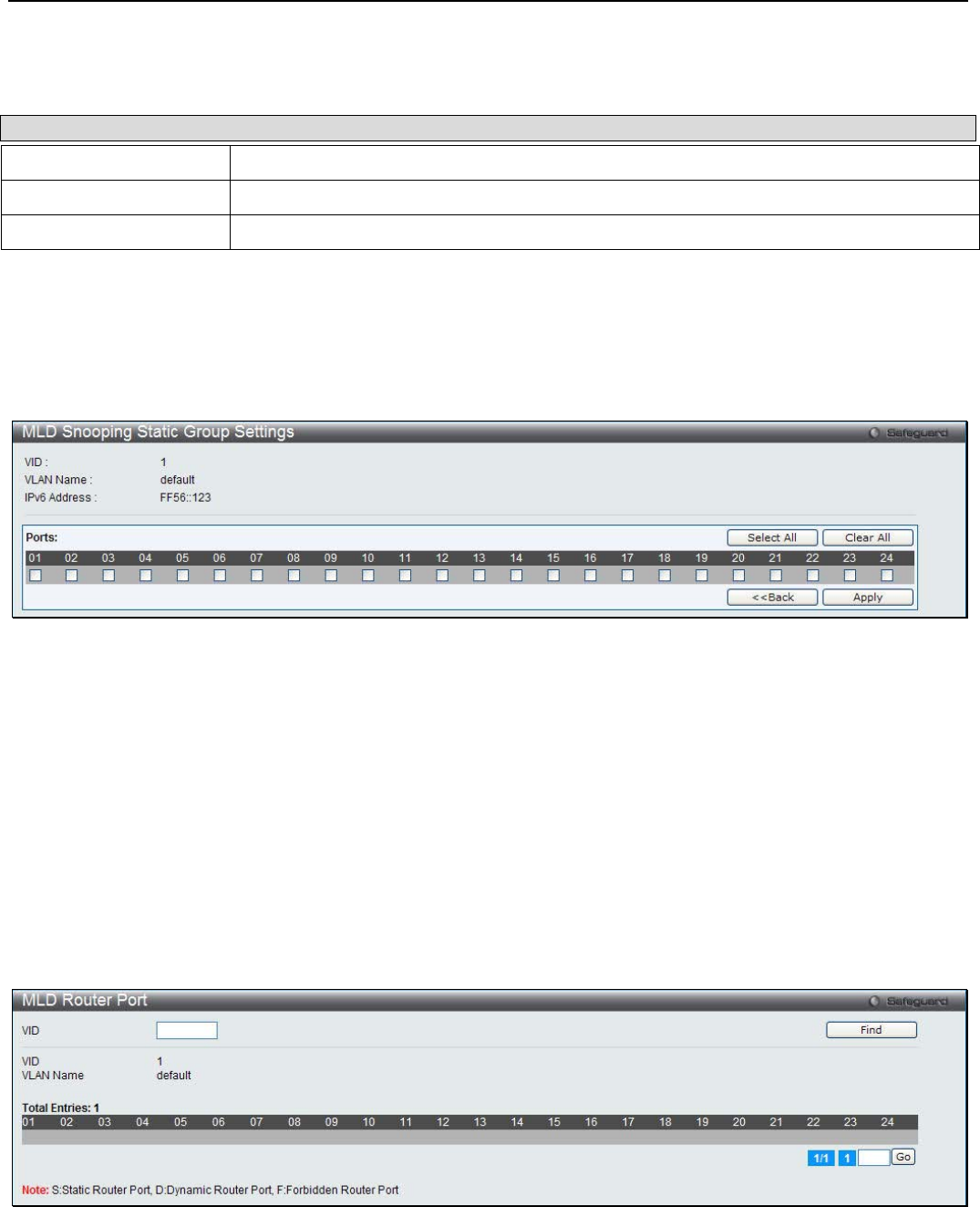
xStack® DGS-3200 Series Layer 2 Managed Gigabit Ethernet Switch Web UI Reference Guide
81
Figure 3 - 41. MLD Snooping Static Group Settings window
The following parameters can be configured:
Parameter Description
VLAN Name The VLAN name of the multicast group.
VID List The VID list of the multicast group.
IPv6 Address Enter the IPv6 address.
Click the Find button to locate a specific entry based on the information entered. Click the Create button to add a new entry
based on the information entered. Click the Delete button to remove the specific entry based on the information entered. Click the
View All button to display all the existing entries. Click the Edit button to re-configure the specific entry. Enter a page number
and click the Go button to navigate to a specific page when multiple pages exist.
Click Edit to see the following window.
Figure 3 - 42. MLD Snooping Static Group Settings – Edit window
Select the appropriate ports individually to include them in the MLD snooping static group settings.
Click the Select All button to select all the ports for configuration. Click the Clear All button to unselect all the ports for
configuration. Click the Apply button to accept the changes made. Click the <<Back button to discard the changes made and
return to the previous page.
MLD Router Port
This window is used to display which of the Switch’s ports are currently configured as router ports in IPv6. A router port
configured by a user (using the console or Web-based management interfaces) is displayed as a static router port, designated by S.
A router port that is dynamically configured by the Switch is designated by D, while a Forbidden port is designated by F.
To view the following window, click L2 Features > L2 Multicast Control > MLD Snooping > MLD Router Port:
Figure 3 - 43. MLD Router Port window
Enter a VID (VLAN ID) in the field at the top of the window.
Click the Find button to locate a specific entry based on the information entered. Enter a page number and click the Go button to
navigate to a specific page when multiple pages exist.
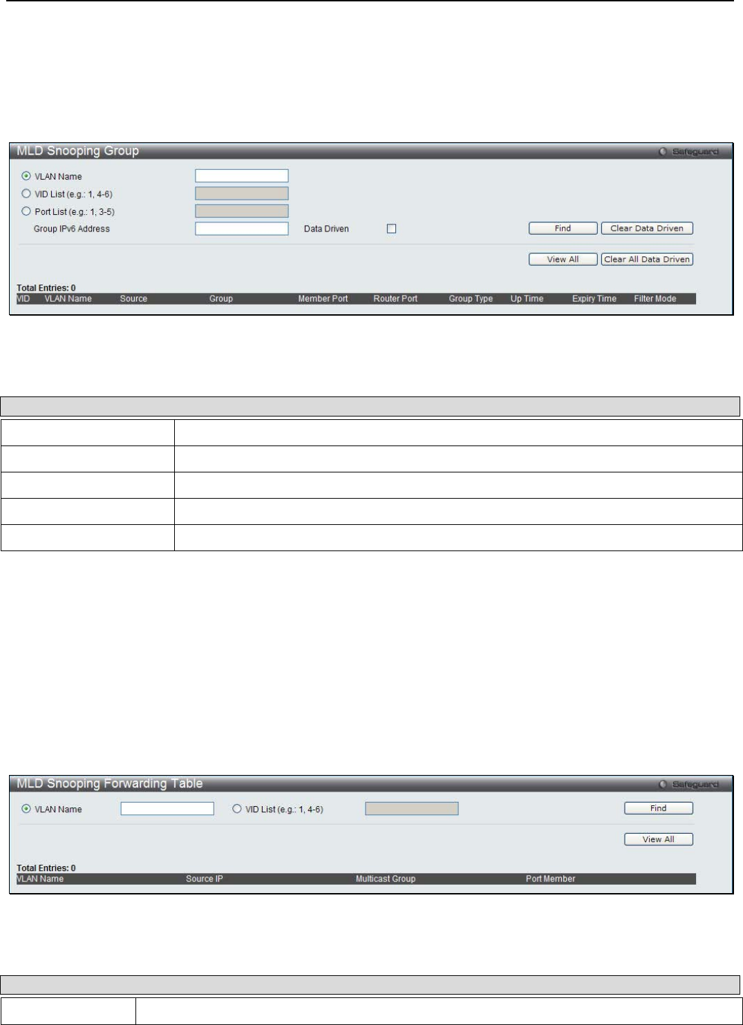
xStack® DGS-3200 Series Layer 2 Managed Gigabit Ethernet Switch Web UI Reference Guide
82
MLD Snooping Group
This window is used to display MLD Snooping Groups present on the Switch. MLD Snooping is an IPv6 function comparable to
IGMP Snooping for IPv4.
To view the following window, click L2 Features > L2 Multicast Control > MLD Snooping > MLD Snooping Group:
Figure 3 - 44. MLD Snooping Group window
The following parameters can be configured:
Parameter Description
VLAN Name The VLAN name of the multicast group.
VID List The VID list of the multicast group.
Port List Specify the port number(s) used to find a multicast group.
Group IPv6 Address Enter the IPv6 address.
Data Driven Tick to display data-driven IGMP snooping group entries.
Click the Find button to locate a specific entry based on the information entered. Click Clear Data Driven to delete the specified
IGMP snooping group learned by the data-driven mechanism. Click View All to see all the entries. Click Clear All Data Driven
to delete all the IGMP snooping groups learned by the data-driven mechanism.
MLD Snooping Forwarding Table
This window is used to display the switch’s current MLD snooping forwarding table. It provides an easy way for user to check the
list of ports that the multicast group comes from and specific sources that it will be forwarded to. The packet comes from the
source VLAN. They will be forwarded to the forwarding VLAN. The MLD snooping further restricts the forwarding ports.
To view the following window, click L2 Features > L2 Multicast Control > MLD Snooping > MLD Snooping Forwarding
Table:
Figure 3 - 45. MLD Snooping Forwaring Table window
The following parameters can be configured:
Parameter Description
VLAN Name The name of the VLAN for which you want to view MLD snooping forwarding table information.
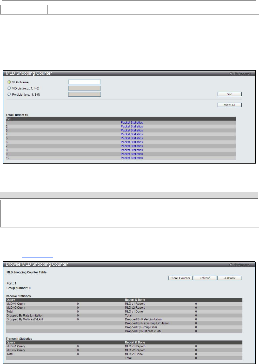
xStack® DGS-3200 Series Layer 2 Managed Gigabit Ethernet Switch Web UI Reference Guide
83
VID List The ID of the VLAN for which you want to view MLD snooping forwarding table information.
Click the Find button to locate a specific entry based on the information entered. Click View All to see all the entries.
MLD Snooping Counter
This window is used to display the statistics counter for MLD protocol packets that are received by the switch since MLD
Snooping is enabled.
To view the following window, click L2 Features > L2 Multicast Control > MLD Snooping > MLD Snooping Counter:
Figure 3 - 46. MLD Snooping Counter window
The following parameters can be configured:
Parameter Description
VLAN Name Specify a VLAN name to be displayed.
VID List Specify a list of VLANs to be displayed.
Port List Specify a list of ports to be displayed.
Click the Find button to locate a specific entry based on the information entered. Click View All to see all the entries. Click the
Packet Statistics link to view the MLD Snooping Counter Table.
Click the Packet Statistics link to see the following window.

xStack® DGS-3200 Series Layer 2 Managed Gigabit Ethernet Switch Web UI Reference Guide
84
Figure 3 - 47. Browse MLD Snooping Counter window
Click the Clear Counter button to clear all the information displayed in the fields. Click the Refresh button to refresh the display
table so that new information will appear. Click the <<Back button to return to the previous page.
MLD Host Table
This window is used to display the MLD hosts that have joined groups on specific ports or specific VLANs.
To view the following window, click L2 Features > L2 Multicast Control > MLD Snooping > MLD Host Table:
Figure 3 - 48. MLD Host Table window
The following parameters can be configured:
Parameter Description
VLAN Name Specify the name of the VLAN on which the router port resides.
VID List Specify a list of VIDs on which the router port resides.
Port List Specify the list of ports to display the host information.
Group Address Specify the group to display the host information.
Click the Find button to locate a specific entry based on the information entered. Click View All to see all the entries.
Multicast VLAN
IGMP Multicast Group Profile Settings
Users can add a profile to which multicast address reports are to be received on specified ports on the Switch. This function will
therefore limit the number of reports received and the number of multicast groups configured on the Switch. The user may set an
IP Multicast address or range of IP Multicast addresses to accept reports (Permit) or deny reports (Deny) coming into the specified
switch ports.
To view the following window, click L2 Features > L2 Multicast Control > Multicast VLAN > IGMP Multicast Group
Profile Settings:
Figure 3 - 49. IGMP Multicast Group Profile Settings window
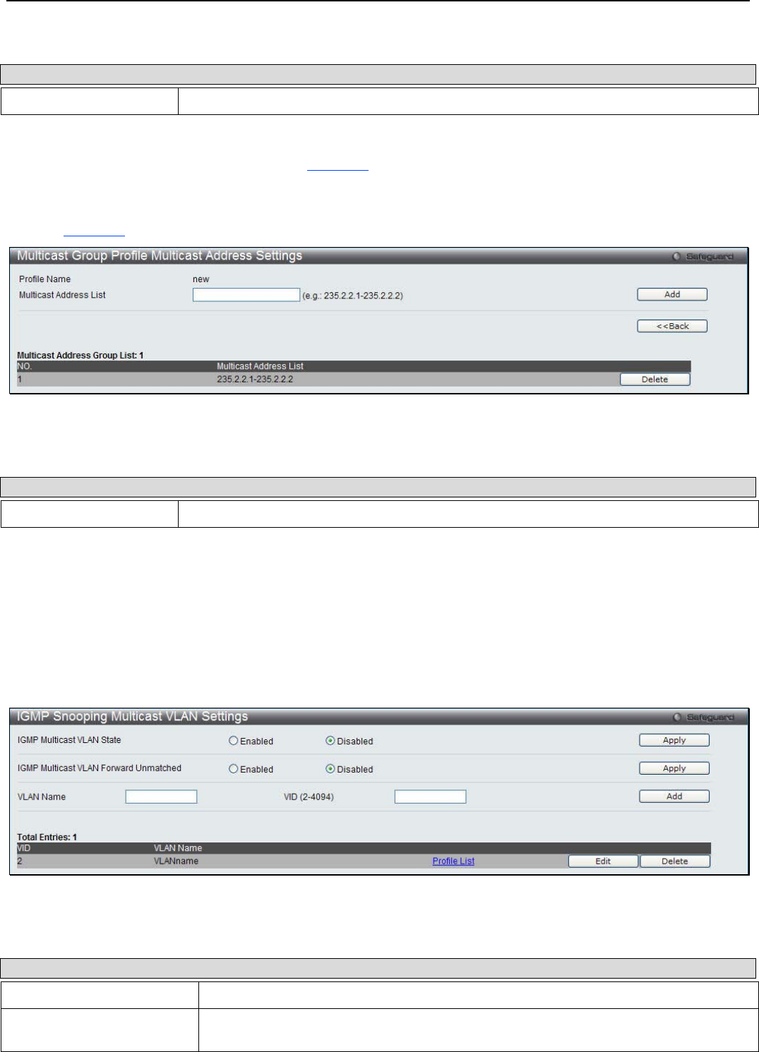
xStack® DGS-3200 Series Layer 2 Managed Gigabit Ethernet Switch Web UI Reference Guide
85
The following parameters can be configured:
Parameter Description
Profile Name Enter a name for the IP Multicast Profile.
Click the Add button to add a new entry. Click the Find button to locate a specific entry based on the information entered. Click
the Delete All button to remove all the entries listed. Click the View All button to display all the existing entries. Click the Delete
button to remove the corresponding entry. Click the Group List link to configure the Multicast Group Profile Address Settings for
the specific entry.
Click the Group List link to see the following window.
Figure 3 - 50. Multicast Group Profile Multicast Address Settings window
The following parameters can be configured:
Parameter Description
Multicast Address List Enter the multicast address list value.
Click the Add button to add a new entry based on the information entered. Click the <<Back button to discard the changes made
and return to the previous page. Click the Delete button to remove the corresponding entry.
IGMP Snooping Multicast VLAN Settings
This window is used to configure the IGMP snooping multicast VLAN parameters.
To view the following window, click L2 Features > L2 Multicast Control > Multicast VLAN > IGMP Snooping Multicast
VLAN Settings:
Figure 3 - 51. IGMP Snooping Multicast VLAN Settings window
The following parameters can be configured:
Parameter Description
IGMP Multicast VLAN State Click the radio buttons to enable or disable the IGMP Multicast VLAN state.
IGMP Multicast VLAN
Forward Unmatched Click the radio buttons to enable or disable the IGMP Multicast VLAN Forwarding state.
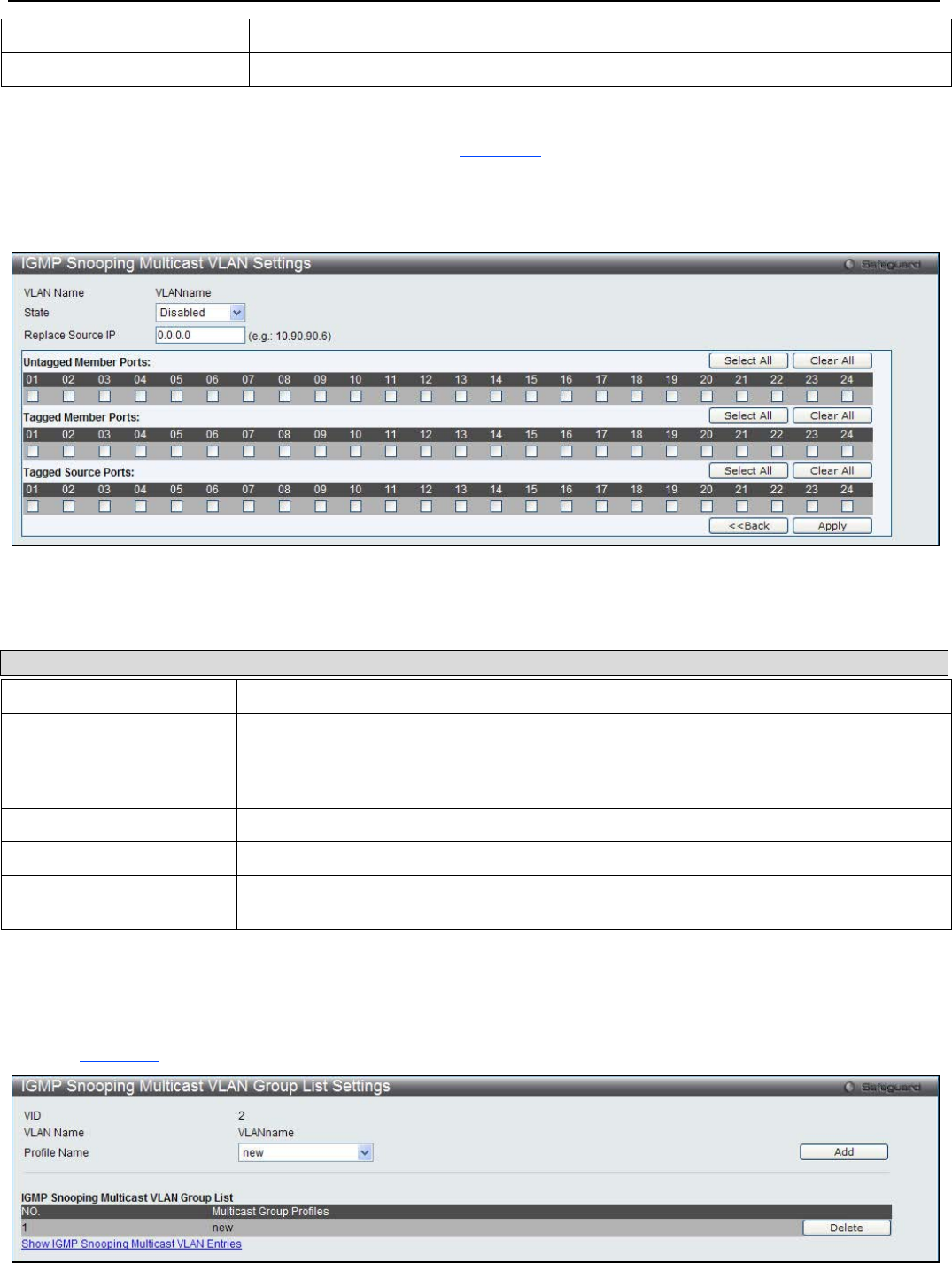
xStack® DGS-3200 Series Layer 2 Managed Gigabit Ethernet Switch Web UI Reference Guide
86
VLAN Name Enter the VLAN Name used.
VID (2-4094) Enter the VID used.
Click the Apply button to accept the changes made for each individual section. Click the Add button to add a new entry based on
the information entered. Click the Edit button to configure the IGMP Snooping Multicast VLAN Settings for the specific entry.
Click the Delete button to remove the specific entry. Click the Profile List link to configure the IGMP Snooping Multicast VLAN
Settings for the specific entry.
Click the Edit button to see the following window.
Figure 3 - 52. IGMP Snooping Multicast VLAN Settings – Edit window
The following parameters can be configured:
Parameter Description
State Use the drop-down menu to enable or disable the state.
Replace Source IP With the IGMP snooping function, the IGMP report packet sent by the host will be
forwarded to the source port. Before forwarding of the packet, the source IP address in
the join packet needs to be replaced by this IP address. If none is specified, the source
IP address will use zero IP address.
Untagged Member Ports Specify the untagged member port of the multicast VLAN.
Tagged Member Ports Specify the tagged member port of the multicast VLAN.
Tagged Source Ports Specify the source port or range of source ports as tagged members of the multicast
VLAN.
Click the Select All button to select all the ports for configuration. Click the Clear All button to unselect all the ports for
configuration. Click the Apply button to accept the changes made. Click the <<Back button to discard the changes made and
return to the previous page.
Click the Profile List link to see the following window.
Figure 3 - 53. IGMP Snooping Multicast VLAN Group List Settings window

xStack® DGS-3200 Series Layer 2 Managed Gigabit Ethernet Switch Web UI Reference Guide
87
The following parameters can be configured:
Parameter Description
Profile Name Use the drop-down menu to select the IGMP Snooping Multicast VLAN Group Profile name.
Click the Add button to add a new entry based on the information entered. Click the Delete button to remove the specific entry.
Click the Show IGMP Snooping Multicast VLAN Entries link to view the IGMP Snooping Multicast VLAN Settings.
Multicast Filtering
IPv4 Multicast Filtering
IPv4 Multicast Profile Settings
Users can add a profile to which multicast address(s) reports are to be received on specified ports on the Switch. This function will
therefore limit the number of reports received and the number of multicast groups configured on the Switch. The user may set an
IPv4 Multicast address or range of IPv4 Multicast addresses to accept reports (Permit) or deny reports (Deny) coming into the
specified switch ports.
To view the following window, click L2 Features > Multicast Filtering > IPv4 Multicast Filtering > IPv4 Multicast Porfile
Settings:
Figure 3 - 54. IPv4 Multicast Profile Settings window
The following parameters can be configured:
Parameter Description
Profile ID (1-24) Enter a Profile ID between 1 and 24.
Profile Name Enter a name for the IP Multicast Profile.
Click the Add button to add a new entry based on the information entered. Click the Find button to locate a specific entry based
on the information entered. Click the Delete All button to remove all the entries listed. Click the Group List link to configure the
multicast address group list settings for the specific entry. Click the Edit button to re-configure the specific entry. Click the Delete
button to remove the specific entry.
Click the Group List link to see the following window.

xStack® DGS-3200 Series Layer 2 Managed Gigabit Ethernet Switch Web UI Reference Guide
88
Figure 3 - 55. Multicast Address Group List Settings window
The following parameters can be configured:
Parameter Description
Multicast Address List Enter the multicast address list.
Click the Add button to add a new entry based on the information entered. Click the <<Back button to discard the changes made
and return to the previous page. Click the Edit button to re-configure the specific entry. Click the Delete button to remove the
specific entry.
IPv4 Limited Multicast Range Settings
Users can configure the ports and VLANs on the Switch that will be involved in the Limited IPv4 Multicast Range. The user can
configure the range of multicast ports that will be accepted by the source ports to be forwarded to the receiver ports.
To view the following window, click L2 Features > Multicast Filtering > IPv4 Multicast Filtering > IPv4 Limited Multicast
Range Settings:
Figure 3 - 56. IPv4 Limited Multicast Range Settings window
The following parameters can be configured:
Parameter Description
Ports / VID List Select the appropriate port(s) or VLAN IDs used for the configuration.
Access Assign access permissions to the ports selected. Options listed are Permit and Deny.
Profile ID / Profile Name Use the drop-down menu to select the profile ID or profile name used and then assign
Permit or Deny access to them.
Click the Apply button to accept the changes made. Click the Add button to add a new entry based on the information entered.
Click the Delete button to remove the specific entry. Click the Find button to locate a specific entry based on the information
entered. Enter a page number and click the Go button to navigate to a specific page when multiple pages exist.
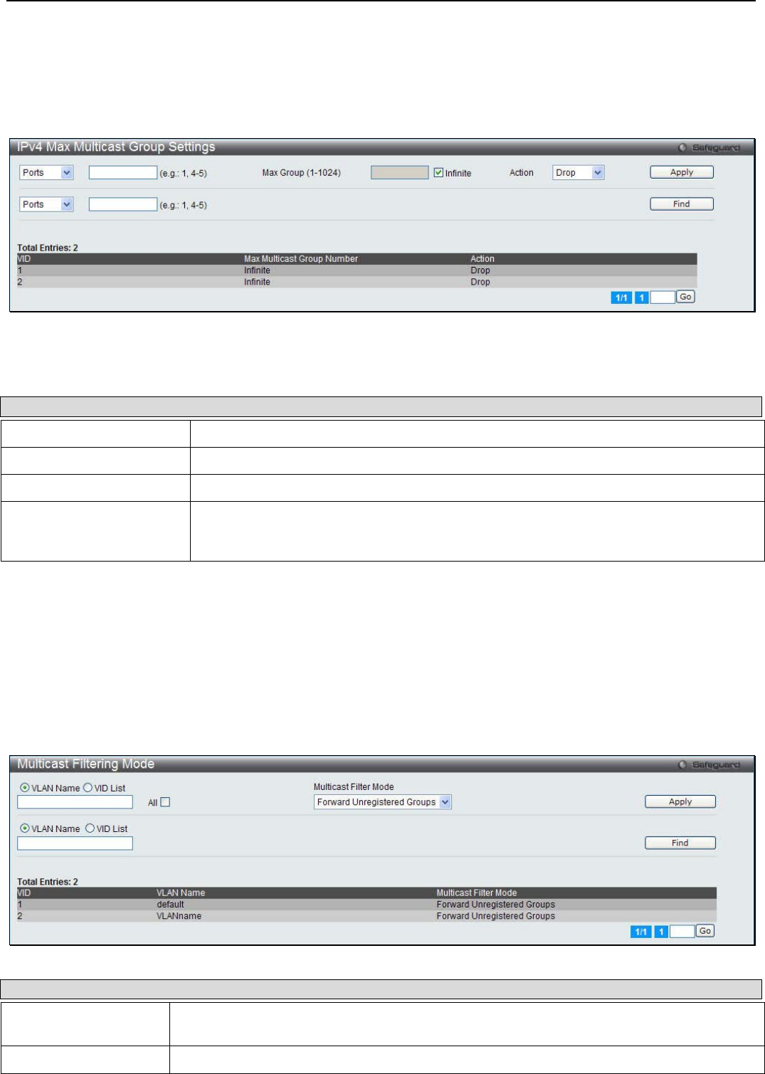
xStack® DGS-3200 Series Layer 2 Managed Gigabit Ethernet Switch Web UI Reference Guide
89
IPv4 Max Multicast Group Settings
Users can configure the ports and VLANs on the switch that will be a part of the maximum filter group, up to a maximum of
1024.
To view the following window, click L2 Features > Multicast Filtering > IPv4 Multicast Filtering > IPv4 Multicast Group
Settings:
Figure 3 - 57. IPv4 Max Multicast Group Settings window
The following parameters can be configured:
Parameter Description
Ports / VID List Select the appropriate port(s) or VLAN IDs used for the configuration here.
Max Group (1-1024) If the checkbox Infinite is not selected, the user can enter a Max Group value.
Infinite Tick the check box to enable or disable the use of the Infinite value.
Action Use the drop-down menu to select the appropriate action for this rule. The user can
select Drop to initiate the drop action or the user can select Replace to initiate the
replace action.
Click the Apply button to accept the changes made. Click the Find button to locate a specific entry based on the information
entered. Enter a page number and click the Go button to navigate to a specific page when multiple pages exist.
Multicast Filtering Mode
Users can configure the multicast filtering mode.
To view the following window, click L2 Features > Multicast Filtering > IPv4 Multicast Filtering > Multicast Filtering
Mode:
Figure 3 - 58. Multicast Filtering Mode window
Parameter Description
VLAN Name / VID List The VLAN to which the specified filtering action applies. Select the All option to apply the
action to all VLANs on the Switch.
Filtering Mode This drop-down menu allows you to select the action the Switch will take when it receives a
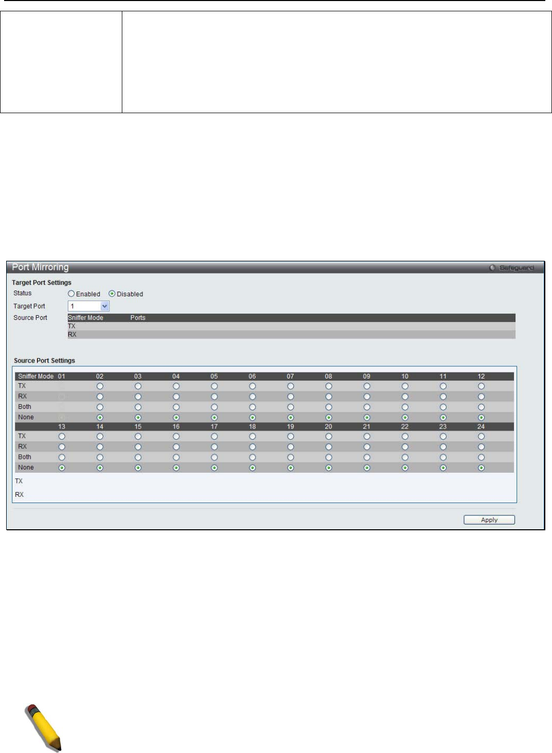
xStack® DGS-3200 Series Layer 2 Managed Gigabit Ethernet Switch Web UI Reference Guide
90
multicast packet that requires forwarding to a port in the specified VLAN.
• Forward Unregistered Groups – This will instruct the Switch to forward a multicast
packet whose destination is an unregistered multicast group residing within the
range of ports specified above.
• Filter Unregistered Groups – This will instruct the Switch to filter any multicast
packets whose destination is an unregistered multicast group residing within the
range of ports specified above.
Click Apply to implement changes made. Click the Find button to locate a specific entry based on the information entered. Enter
a page number and click the Go button to navigate to a specific page when multiple pages exist.
Port Mirroring
The Switch allows you to copy frames transmitted and received on a port and redirect the copies to another port. You can attach a
monitoring device to the mirrored port, such as a sniffer or an RMON probe, to view details about the packets passing through the
first port. This is useful for network monitoring and troubleshooting purposes.
To view the following window, click L2 Features > Port Mirroring:
Figure 3 - 59. Port Mirroring window
To configure a mirror port:
1. Use the radio button to change the Target Port Settings Status to Enabled.
2. Use the drop-down menu to select the Target Port to which frames will be copied, which receives the copies from the
source port
3. Select the Source Port Setting Direction, TX (Egress), Rx (Ingress), Both, or None.
4. Click Apply to let the changes take effect.
NOTE: You cannot mirror a fast port onto a slower port. For example, if you try to mirror the traffic
from a 100 Mbps port onto a 10 Mbps port, this can cause throughput problems. The port you are
copying frames from should always support an equal or lower speed than the port to which you
are sending the copies. Also, the target port for the mirroring cannot be a member of a trunk
group. Please note a target port and a source port cannot be the same port.

xStack® DGS-3200 Series Layer 2 Managed Gigabit Ethernet Switch Web UI Reference Guide
91
NOTE: Target mirror ports cannot be members of a trunking group. Attempting to do so will
produce an error message and the configuration will not be set.
Spanning Tree
This Switch supports three versions of the Spanning Tree Protocol: 802.1D-1998 STP, 802.1D-2004 Rapid STP, and 802.1Q-2005
MSTP. 802.1D-1998 STP will be familiar to most networking professionals. However, since 802.1D-2004 RSTP and 802.1Q-
2005 MSTP have been recently introduced to D-Link managed Ethernet switches, a brief introduction to the technology is
provided below followed by a description of how to set up 802.1D-1998 STP, 802.1D-2004 RSTP, and 802.1Q-2005 MSTP.
802.1Q-2005 MSTP
Multiple Spanning Tree Protocol, or MSTP, is a standard defined by the IEEE community that allows multiple VLANs to be
mapped to a single spanning tree instance, which will provide multiple pathways across the network. Therefore, these MSTP
configurations will balance the traffic load, preventing wide scale disruptions when a single spanning tree instance fails. This will
allow for faster convergences of new topologies for the failed instance. Frames designated for these VLANs will be processed
quickly and completely throughout interconnected bridges utilizing any of the three spanning tree protocols (STP, RSTP or
MSTP).
This protocol will also tag BPDU packets so receiving devices can distinguish spanning tree instances, spanning tree regions and
the VLANs associated with them. An MSTI ID will classify these instances. MSTP will connect multiple spanning trees with a
Common and Internal Spanning Tree (CIST). The CIST will automatically determine each MSTP region, its maximum possible
extent and will appear as one virtual bridge that runs a single spanning tree. Consequentially, frames assigned to different VLANs
will follow different data routes within administratively established regions on the network, continuing to allow simple and full
processing of frames, regardless of administrative errors in defining VLANs and their respective spanning trees.
Each switch utilizing the MSTP on a network will have a single MSTP configuration that will have the following three attributes:
1. A configuration name defined by an alphanumeric string of up to 32 characters (defined in the MST Configuration
Identification window in the Configuration Name field).
2. A configuration revision number (named here as a Revision Level and found in the MST Configuration Identification
window) and;
3. A 4094-element table (defined here as a VID List in the MST Configuration Identification window), which will
associate each of the possible 4094 VLANs supported by the Switch for a given instance.
To utilize the MSTP function on the Switch, three steps need to be taken:
1. The Switch must be set to the MSTP setting (found in the STP Bridge Global Settings window in the STP Version
field)
2. The correct spanning tree priority for the MSTP instance must be entered (defined here as a Priority in the MSTI Config
Information window when configuring MSTI ID settings).
3. VLANs that will be shared must be added to the MSTP Instance ID (defined here as a VID List in the MST
Configuration Identification window when configuring an MSTI ID settings).
802.1D-2004 Rapid Spanning Tree
The Switch implements three versions of the Spanning Tree Protocol, the Multiple Spanning Tree Protocol (MSTP) as defined by
the IEEE 802.1Q-2005, the Rapid Spanning Tree Protocol (RSTP) as defined by the IEEE 802.1D-2004 specification and a
version compatible with the IEEE 802.1D-1998 STP. RSTP can operate with legacy equipment implementing IEEE 802.1D-1998;
however the advantages of using RSTP will be lost.
The IEEE 802.1D-2004 Rapid Spanning Tree Protocol (RSTP) evolved from the 802.1D-1998 STP standard. RSTP was
developed in order to overcome some limitations of STP that impede the function of some recent switching innovations, in
particular, certain Layer 3 functions that are increasingly handled by Ethernet switches. The basic function and much of the
terminology is the same as STP. Most of the settings configured for STP are also used for RSTP. This section introduces some
new Spanning Tree concepts and illustrates the main differences between the two protocols.
xStack® DGS-3200 Series Layer 2 Managed Gigabit Ethernet Switch Web UI Reference Guide
92
Port Transition States
An essential difference between the three protocols is in the way ports transition to a forwarding state and in the way this
transition relates to the role of the port (forwarding or not forwarding) in the topology. MSTP and RSTP combine the transition
states disabled, blocking and listening used in 802.1D-1998 and creates a single state Discarding. In either case, ports do not
forward packets. In the STP port transition states disabled, blocking or listening or in the RSTP/MSTP port state discarding, there
is no functional difference, the port is not active in the network topology. Table 7-3 below compares how the three protocols differ
regarding the port state transition.
All three protocols calculate a stable topology in the same way. Every segment will have a single path to the root bridge. All
bridges listen for BPDU packets. However, BPDU packets are sent more frequently - with every Hello packet. BPDU packets are
sent even if a BPDU packet was not received. Therefore, each link between bridges is sensitive to the status of the link. Ultimately
this difference results in faster detection of failed links, and thus faster topology adjustment. A drawback of 802.1D-1998 is this
absence of immediate feedback from adjacent bridges.
802.1Q-2005 MSTP 802.1D-2004 RSTP 802.1D-1998 STP Forwarding Learning
Disabled Disabled Disabled No No
Discarding Discarding Blocking No No
Discarding Discarding Listening No No
Learning Learning Learning No Yes
Forwarding Forwarding Forwarding Yes Yes
Table 3 - 2. Comparing Port States
RSTP is capable of a more rapid transition to a forwarding state - it no longer relies on timer configurations - RSTP compliant
bridges are sensitive to feedback from other RSTP compliant bridge links. Ports do not need to wait for the topology to stabilize
before transitioning to a forwarding state. In order to allow this rapid transition, the protocol introduces two new variables: the
edge port and the point-to-point (P2P) port.
Edge Port
The edge port is a configurable designation used for a port that is directly connected to a segment where a loop cannot be created.
An example would be a port connected directly to a single workstation. Ports that are designated as edge ports transition to a
forwarding state immediately without going through the listening and learning states. An edge port loses its status if it receives a
BPDU packet, immediately becoming a normal spanning tree port. The ege port is supported when STP is selected in STP
Version.
P2P Port
A P2P port is also capable of rapid transition. P2P ports may be used to connect to other bridges. Under RSTP/MSTP, all ports
operating in full-duplex mode are considered to be P2P ports, unless manually overridden through configuration.
802.1D-1998/802.1D-2004/802.1Q-2005 Compatibility
MSTP or RSTP can interoperate with legacy equipment and is capable of automatically adjusting BPDU packets to 802.1D-1998
format when necessary. However, any segment using 802.1D-1998 STP will not benefit from the rapid transition and rapid
topology change detection of MSTP or RSTP. The protocol also provides for a variable used for migration in the event that legacy
equipment on a segment is updated to use RSTP or MSTP.
The Spanning Tree Protocol (STP) operates on two levels:
1. On the switch level, the settings are globally implemented.
2. On the port level, the settings are implemented on a per user-defined group of ports basis.
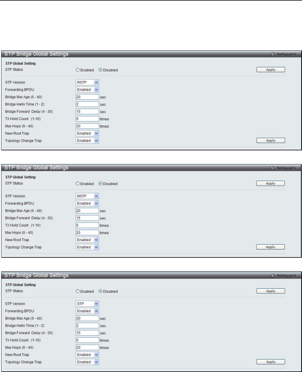
xStack® DGS-3200 Series Layer 2 Managed Gigabit Ethernet Switch Web UI Reference Guide
93
STP Bridge Global Settings
Use the STP Status radio buttons to enable or disable STP globally, and use the STP Version drop-down menu to choose the STP
method.
To view the following windows, click L2 Features > Spanning Tree > STP Bridge Global Settings:
Figure 3 - 60. STP Bridge Global Settings window – RSTP (default)
Figure 3 - 61. STP Bridge Global Settings window – MSTP
Figure 3 - 62. STP Bridge Global Settings window – STP Compatible
See the table below for descriptions of the STP versions and corresponding setting options.

xStack® DGS-3200 Series Layer 2 Managed Gigabit Ethernet Switch Web UI Reference Guide
94
NOTE: The Bridge Hello Time cannot be longer than the Bridge Max Age. Otherwise, a
configuration error will occur. Observe the following formulas when setting the above
parameters:
Bridge Max Age <= 2 x (Bridge Forward Delay - 1 second)
Bridge Max Age > 2 x (Bridge Hello Time + 1 second)
Configure the following parameters for STP:
Parameter Description
STP Status Use the radio button to globally enable or disable STP.
STP Version Use the drop-down menu to choose the desired version of STP:
STP - Select this parameter to set the Spanning Tree Protocol (STP) globally on the
switch.
RSTP - Select this parameter to set the Rapid Spanning Tree Protocol (RSTP) globally on
the Switch.
MSTP - Select this parameter to set the Multiple Spanning Tree Protocol (MSTP) globally
on the Switch.
Forwarding BPDU This field can be Enabled or Disabled. When Enabled, it allows the forwarding of STP
BPDU packets from other network devices. The default is Enabled.
Bridge Max Age (6 –
40) The Max Age may be set to ensure that old information does not endlessly circulate
through redundant paths in the network, preventing the effective propagation of the new
information. Set by the Root Bridge, this value will aid in determining that the Switch has
spanning tree configuration values consistent with other devices on the bridged LAN. The
user may choose a time between 6 and 40 seconds. The default value is 20 seconds.
Bridge Hello Time (1 –
2) The Hello Time can be set from 1 to 2 seconds. This is the interval between two
transmissions of BPDU packets sent by the Root Bridge to tell all other switches that it is
indeed the Root Bridge. This field will only appear here when STP or RSTP is selected for
the STP Version. For MSTP, the Hello Time must be set on a port per port basis. The
default is 2 seconds.
Bridge Forward Delay
(4 – 30) The Forward Delay can be from 4 to 30 seconds. Any port on the Switch spends this time
in the listening state while moving from the blocking state to the forwarding state. The
default is 15 seconds
TX Hold Count (1-10) Used to set the maximum number of Hello packets transmitted per interval. The count can
be specified from 1 to 10. The default is 6.
Max Hops (6-40) Used to set the number of hops between devices in a spanning tree region before the
BPDU (bridge protocol data unit) packet sent by the Switch will be discarded. Each switch
on the hop count will reduce the hop count by one until the value reaches zero. The Switch
will then discard the BPDU packet and the information held for the port will age out. The
user may set a hop count from 6 to 40. The default is 20.
New Root Trap Used to enable or disable the sending of new root traps. The default is Enabled.
Topology Change Trap Used to enable or disable the sending of topology change traps. The default is Enabled.
Click Apply to implement changes made.
STP Port Settings
STP can be set up on a port per port basis.
To view the following window, click L2 Features > Spanning Tree > STP Port Settings:
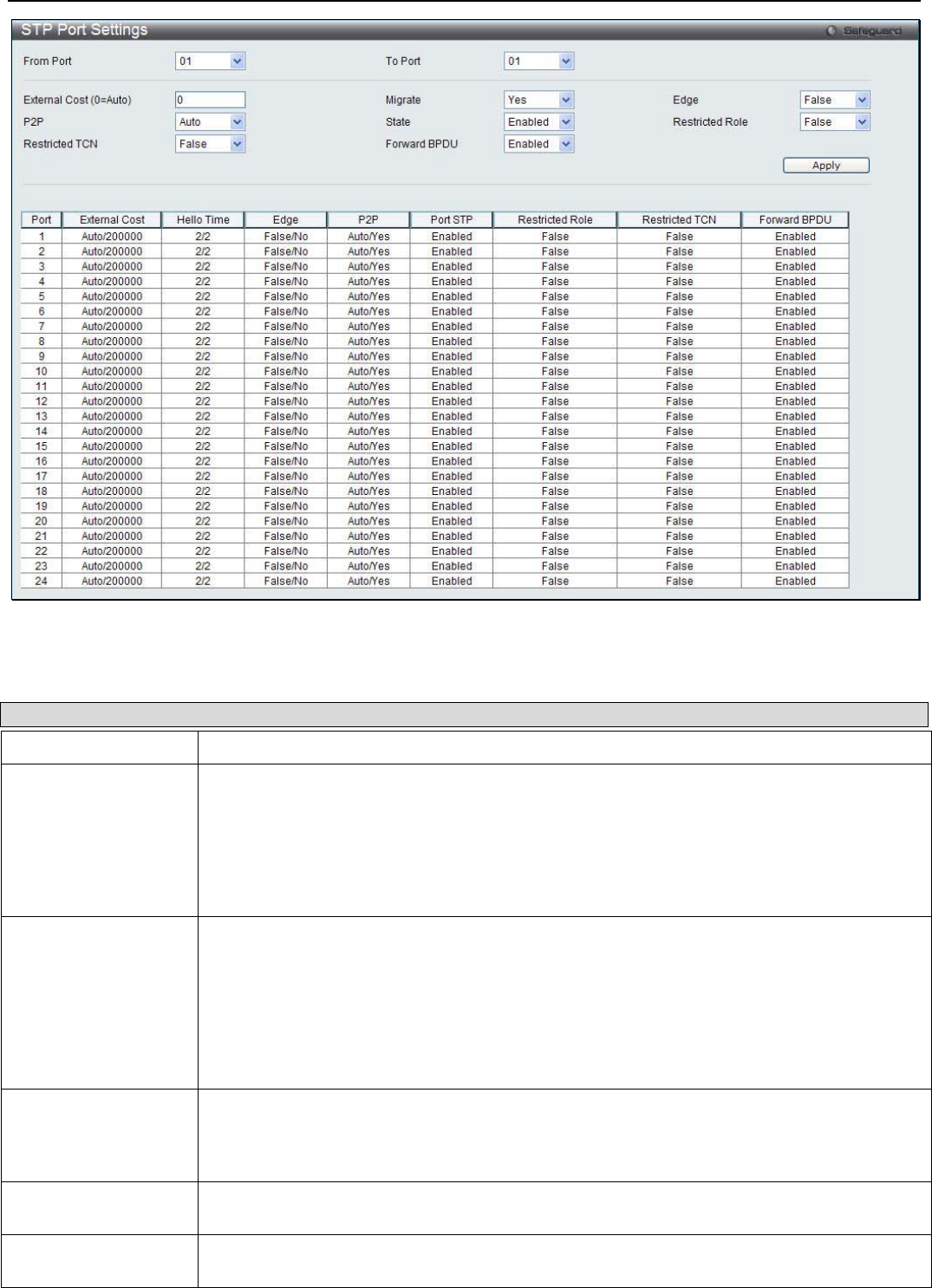
xStack® DGS-3200 Series Layer 2 Managed Gigabit Ethernet Switch Web UI Reference Guide
95
Figure 3 - 63. STP Port Settings window
It is advisable to define an STP Group to correspond to a VLAN group of ports.
The following parameters can be configured:
Parameter Description
From Port / To Port Use the drop-down menu to select a range of ports to be configured.
External Cost
(0=Auto) This defines a metric that indicates the relative cost of forwarding packets to the specified
port list. Port cost can be set automatically or as a metric value. The default value is 0 (auto).
Setting 0 for the external cost will automatically set the speed for forwarding packets to the
specified port(s) in the list for optimal efficiency. The default port cost for a 100Mbps port is
200000 and the default port cost for a Gigabit port is 20000. Enter a value between 1 and
200000000 to determine the External Cost. The lower the number, the greater the probability
the port will be chosen to forward packets.
P2P Choosing the True parameter indicates a point-to-point (P2P) shared link. P2P ports are
similar to edge ports; however they are restricted in that a P2P port must operate in full
duplex. Like edge ports, P2P ports transition to a forwarding state rapidly thus benefiting
from RSTP. A P2P value of False indicates that the port cannot have P2P status. Auto allows
the port to have P2P status whenever possible and operate as if the P2P status were True. If
the port cannot maintain this status, (for example if the port is forced to half-duplex operation)
the P2P status changes to operate as if the P2P value were False. The default setting for this
parameter is Auto.
Restricted TCN Topology Change Notification is a simple BPDU that a bridge sends out to its root port to
signal a topology change. Restricted TCN can be toggled between True and False. If set to
True, this stops the port from propagating received topology change notifications and
topology changes to other ports. The default is False.
Migrate When operating in RSTP mode, selecting Yes forces the port that has been selected to
transmit RSTP BPDUs.
State This drop-down menu allows you to enable or disable STP for the selected group of ports.
The default is Enabled.
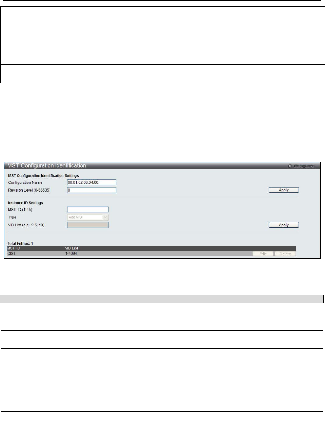
xStack® DGS-3200 Series Layer 2 Managed Gigabit Ethernet Switch Web UI Reference Guide
96
Forward BPDU Use the drop-down menu to enable or disable the flooding of BPDU packets when STP is
disabled.
Edge Choosing the True parameter designates the port as an edge port. Edge ports cannot create
loops, however an edge port can lose edge port status if a topology change creates a poten-
tial for a loop. An edge port normally should not receive BPDU packets. If a BPDU packet is
received, it automatically loses edge port status. Choosing the False parameter indicates that
the port does not have edge port status. Alternatively, the Auto option is available.
Restricted Role Use the drop-down menu to toggle Restricted Role between True and False. If set to True,
the port will never be selected to be the Root port. The default is False.
Click Apply to implement changes made.
MST Configuration Identification
This window allows the user to configure a MSTI instance on the Switch. These settings will uniquely identify a multiple
spanning tree instance set on the Switch. The Switch initially possesses one CIST, or Common Internal Spanning Tree, of which
the user may modify the parameters for but cannot change the MSTI ID for, and cannot be deleted.
To view the following window, click L2 Features > Spanning Tree > MST Configuration Identification:
Figure 3 - 64. MST Configuration Identification window
The window above contains the following information:
Parameter Description
Configuration Name This name uniquely identifies the MSTI (Multiple Spanning Tree Instance). If a
Configuration Name is not set, this field will show the MAC address to the device running
MSTP.
Revision Level (0-
65535) This value, along with the Configuration Name, identifies the MSTP region configured on
the Switch.
MSTI ID (1-15) Enter a number between 1 and 15 to set a new MSTI on the Switch.
Type This field allows the user to choose a desired method for altering the MSTI settings. The
user has two choices:
Add VID - Select this parameter to add VIDs to the MSTI ID, in conjunction with the VID
List parameter.
Remove VID - Select this parameter to remove VIDs from the MSTI ID, in conjunction with
the VID List parameter.
VID List (e.g.: 2-5, 10) This field is used to specify the VID range from configured VLANs set on the Switch.
Supported VIDs on the Switch range from ID number 1 to 4094.
Click Apply to implement changes made. To modify an entry on the table at the bottom of the window, click the corresponding
Edit button. To remove an entry on the table at the bottom of the window, click the corresponding Delete button.
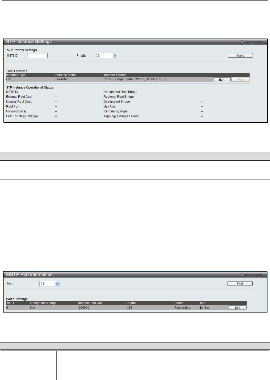
xStack® DGS-3200 Series Layer 2 Managed Gigabit Ethernet Switch Web UI Reference Guide
97
STP Instance Settings
This window displays MSTIs currently set on the Switch and allows users to change the Priority of the MSTIs.
To view the following window, click L2 Features > Spanning Tree > STP Instance Settings:
Figure 3 - 65. STP Instance Settings window
The window above contains the following information:
Parameter Description
MSTI ID Enter the MSTI ID in this field. An entry of 0 denotes the CIST (default MSTI).
Priority Enter the priority in this field. The available range of values is from 0 to 61440.
Click Apply to implement the new priority setting. To modify an entry on the table at the top of the window, click the
corresponding Edit button. To view more information about an entry on the table at the top of the window, click the
corresponding View button.
MSTP Port Information
This window displays the current MSTI configuration information and can be used to update the port configuration for an MSTI
ID. If a loop occurs, the MSTP function will use the port priority to select an interface to put into the forwarding state. Set a higher
priority value for interfaces to be selected for forwarding first. In instances where the priority value is identical, the MSTP
function will implement the lowest MAC address into the forwarding state and other interfaces will be blocked. Remember that
lower priority values mean higher priorities for forwarding packets.
To view the following window, click L2 Features > Spanning Tree > MSTP Port Information:
Figure 3 - 66. MSTP Port Information window
The following parameters can be configured:
Parameter Description
Port Use the drop-down menu to select a port to be displayed.
Internal Path Cost
(1-200000000) This parameter is set to represent the relative cost of forwarding packets to specified ports
when an interface is selected within an STP instance. Selecting this parameter with a value
in the range of 1 to 200000000 will set the quickest route when a loop occurs. A lower
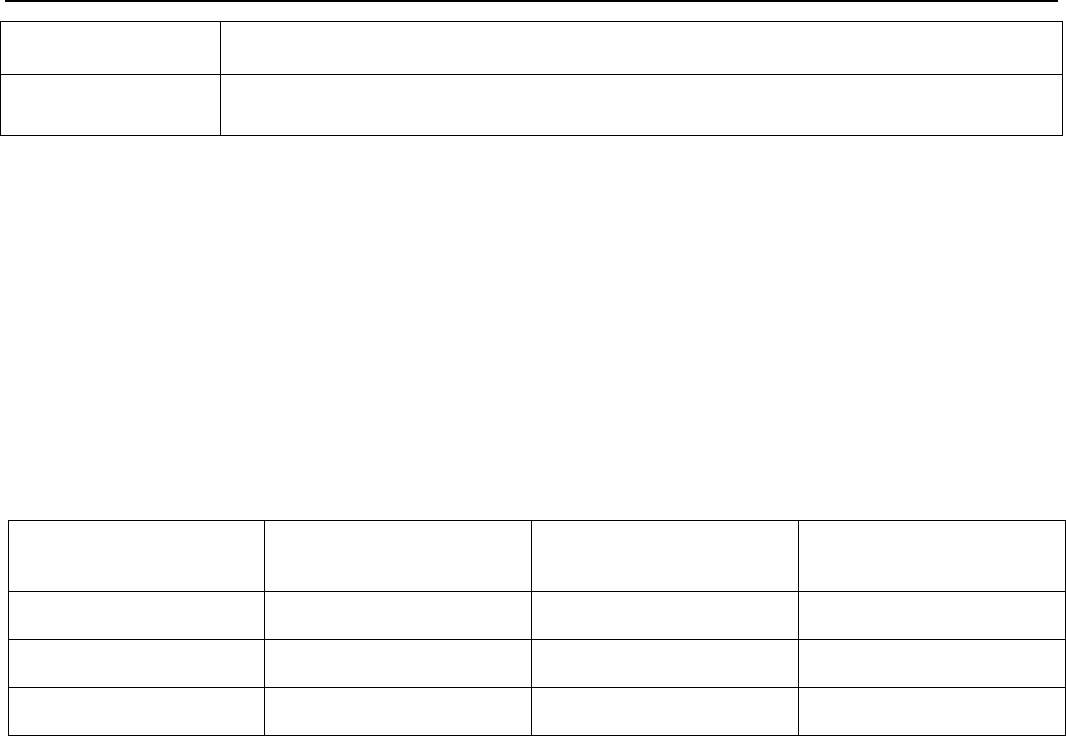
xStack® DGS-3200 Series Layer 2 Managed Gigabit Ethernet Switch Web UI Reference Guide
98
Internal cost represents a quicker transmission. Selecting 0 (zero) for this parameter will set
the quickest route automatically and optimally for an interface.
Priority Enter a value between 0 and 240 to set the priority for the port interface. A higher priority will
designate the interface to forward packets first. A lower number denotes a higher priority.
Click Find to see the information of the specific port. To modify the settings for a particular MSTI instance, click the Edit button
and then enter a value in the Internal Path Cost field and use the drop-down menu to select a value for Priority.
Link Aggregation
Port Trunking
Understanding Port Trunk Groups
Port trunk groups are used to combine a number of ports together to make a single high-band-width data pipeline. Another
advantage of implementing port trunk groups is redundancy, as if one of the ports or links fails in the port trunk group, the
network connection to the remote Switch will be maintained. The table below shows the maximum amount of groups supported
for each trunk group and the potential bit rate for the DGS-3200-10, DGS-3200-16, and DGS-3200-24 Switches.
Model Maximum Number of
Groups Maximum Number of
Ports Potential Bit Rate
DGS-3200-10 5 8 8000 Mbps
DGS-3200-16 8 8 8000 Mbps
DGS-3200-24 12 8 8000 Mbps
Figure 3 - 67. Port Trunk Group Table for DGS-3200-10/DGS-3200-16/DGS-3200-24
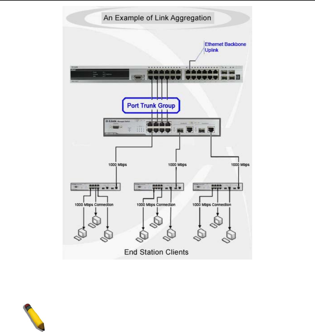
xStack® DGS-3200 Series Layer 2 Managed Gigabit Ethernet Switch Web UI Reference Guide
99
Figure 3 - 68. Example of Typical Port Trunk Group
The Switch treats all ports in a trunk group as a single port. Data transmitted to a specific host (destination address) will always be
transmitted over the same port in a trunk group. This allows packets in a data stream to arrive in the same order they were sent.
NOTE: If any ports within the trunk group become disconnected, packets intended for
the disconnected port will be load shared among the other linked ports of the link
aggregation group.
Link aggregation allows several ports to be grouped together and to act as a single link. This gives a bandwidth that is a multiple
of a single link's bandwidth.
Link aggregation is most commonly used to link a bandwidth intensive network device or devices, such as a server, to the
backbone of a network.
The DGS-3200 Switch series supports the following link aggregation groups:
• The DGS-3200-10 model allows the creation of up to five link aggregation groups, each group consisting of 2 to 8 links
(ports).
• The DGS-3200-16 model allows the creation of up to eight link aggregation groups, each group consisting of 2 to 8 links
(ports).
• The DGS-3200-24 model allows the creation of up to twelve link aggregation groups, each group consisting of 2 to 8
links (ports).

xStack® DGS-3200 Series Layer 2 Managed Gigabit Ethernet Switch Web UI Reference Guide
100
The (optional) Gigabit ports can only belong to a single link aggregation group. All of the ports in the group must be members of
the same VLAN, and their STP status, static multicast, traffic control; traffic segmentation and 802.1p default priority
configurations must be identical. Port locking, port mirroring and 802.1X must not be enabled on the trunk group. Further, the
LACP aggregated links must all be of the same speed and should be configured as full duplex.
The Master Port of the group is to be configured by the user, and all configuration options, including the VLAN configuration that
can be applied to the Master Port, are applied to the entire link aggregation group.
Load balancing is automatically applied to the ports in the aggregated group, and a link failure within the group causes the
network traffic to be directed to the remaining links in the group.
The Spanning Tree Protocol will treat a link aggregation group as a single link, on the switch level. For STP, the path cost of the
link aggregation group is determined by the active port number of the link aggregation group. If two redundant link aggregation
groups are configured on the Switch, STP will block one entire group; in the same way STP will block a single port that has a
redundant link.
To view the following window, click L2 Features > Link Aggregation > Port Trunking:
Figure 3 - 69. Port Trunking window
The following parameters can be configured or viewed:
Parameter Description
Algorithm Toggle between MAC Source Dest and IP Source Dest.
Group ID (1-12) Select an ID number for the group, between 1 and 5 for the DGS-3200-10, between 1 and 8
for the DGS-3200-16, and between 1 and 12 for the DGS-3200-24.
Type This drop-down menu allows users to select between Static and LACP (Link Aggregation
Control Protocol). LACP allows for the automatic detection of links in a Port Trunking Group.
Master Port Choose the Master Port for the trunk group using the drop-down menu.
State Use the drop-down menu to toggle between Enabled and Disabled. This is used to turn a
port trunking group on or off. This is useful for diagnostics, to quickly isolate a bandwidth
intensive network device or to have an absolute backup aggregation group that is not under
automatic control.
Trap Use the drop-down menu to enable or disable trap. When set to enable, Link Up and Link
Down notifications are enabled for this link aggregation group. When set to disable, Link Up
and Link Down notifications are disabled for link aggregation group. By default, the trap
status for a link aggregation group is disabled. This notification is generated when LACP
logical interface link up (the first member port link up) and link down (the last member port
link down).
Member Ports Choose the members ports for the trunked group. Up to eight ports per group can be
assigned to a group.
Active Ports Shows the ports that are currently forwarding packets.
Click the Apply button to accept the changes made. Click the Clear All button to clear out all the information entered. Click the
Add button to add a new entry based on the information entered.
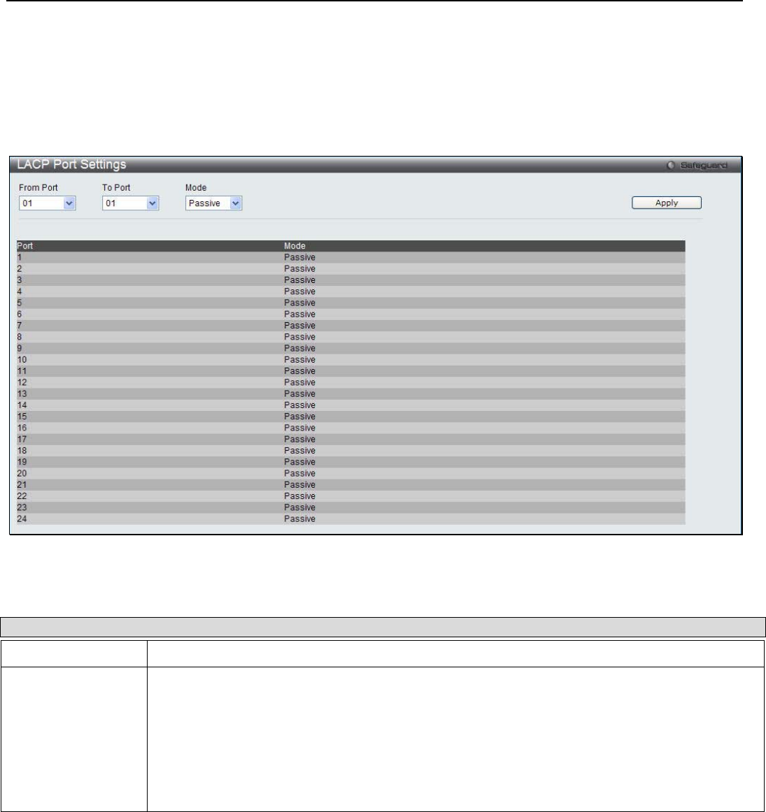
xStack® DGS-3200 Series Layer 2 Managed Gigabit Ethernet Switch Web UI Reference Guide
101
LACP Port Settings
In conjunction with the Trunking window, users can create port trunking groups on the Switch. Using the following window, the
user may set which ports will be active and passive in processing and sending LACP control frames.
To view the following window, click L2 Features > Link Aggregation > LACP Port Settings:
Figure 3 - 70. LACP Port Settings window
The user may set the following parameters:
Parameter Description
From Port / To Port Use the drop-down menus to select a range of ports to be configured.
Mode Active - Active LACP ports are capable of processing and sending LACP control frames. This
allows LACP compliant devices to negotiate the aggregated link so the group may be changed
dynamically as needs require. In order to utilize the ability to change an aggregated port group,
that is, to add or subtract ports from the group, at least one of the participating devices must
designate LACP ports as active. Both devices must support LACP.
Passive - LACP ports that are designated as passive cannot initially send LACP control frames.
In order to allow the linked port group to negotiate adjustments and make changes dynamically,
one end of the connection must have "active" LACP ports (see above).
Click Apply to implement the changes.
Forwarding & Filtering
Unicast Forwarding
Users can set up unicast forwarding on the Switch.
To view the following window, click L2 Features > Forwarding & Filtering > Unicast Forwarding:
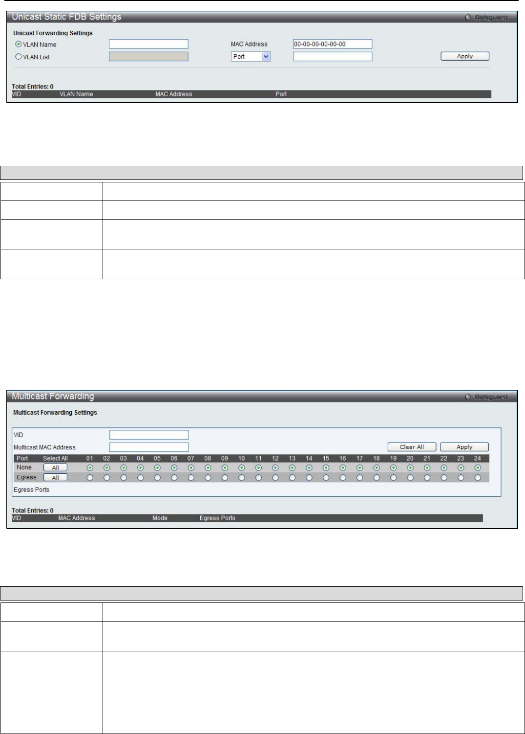
xStack® DGS-3200 Series Layer 2 Managed Gigabit Ethernet Switch Web UI Reference Guide
102
Figure 3 - 71. Unicast Forwarding window
To add an entry to the Static Unicast Forwarding Table, define the following parameters. To modify an entry on the Static Unicast
Forwarding Table, click the Edit button corresponding to the entry. To delete an entry in the Static Unicast Forwarding Table,
click the corresponding Delete button.
Parameter Description
VLAN Name Click the radio button and specify the name of VLAN.
VLAN List Click the radio button and specify a list of VLAN IDs.
MAC Address The MAC address to which packets will be statically forwarded. This must be a unicast MAC
address.
Port / Drop Select Port and enter the port number to forward traffic to the specified device through this
port. Select Drop to have the Switch to drop traffic.
Click Apply to implement the changes made.
Multicast Forwarding
Users can set up multicast forwarding on the Switch.
To view the following window, click L2 Features > Forwarding & Filtering > Multicast Forwarding:
Figure 3 - 72. Multicast Forwarding window
The following parameters can be configured:
Parameter Description
VID The VLAN ID of the VLAN the corresponding MAC address belongs to.
Multicast MAC
Address The static destination MAC address of the multicast packets. This must be a multicast MAC
address. The format of the destination MAC address is 01-xx-xx-xx-xx-xx.
Port Allows the selection of ports that will be members of the static multicast group and ports that
are either forbidden from joining dynamically, or that can join the multicast group dynamically,
using GMRP. The options are:
None - No restrictions on the port dynamically joining the multicast group. When None is
chosen, the port will not be a member of the Static Multicast Group.
Egress - The port is a static member of the multicast group.
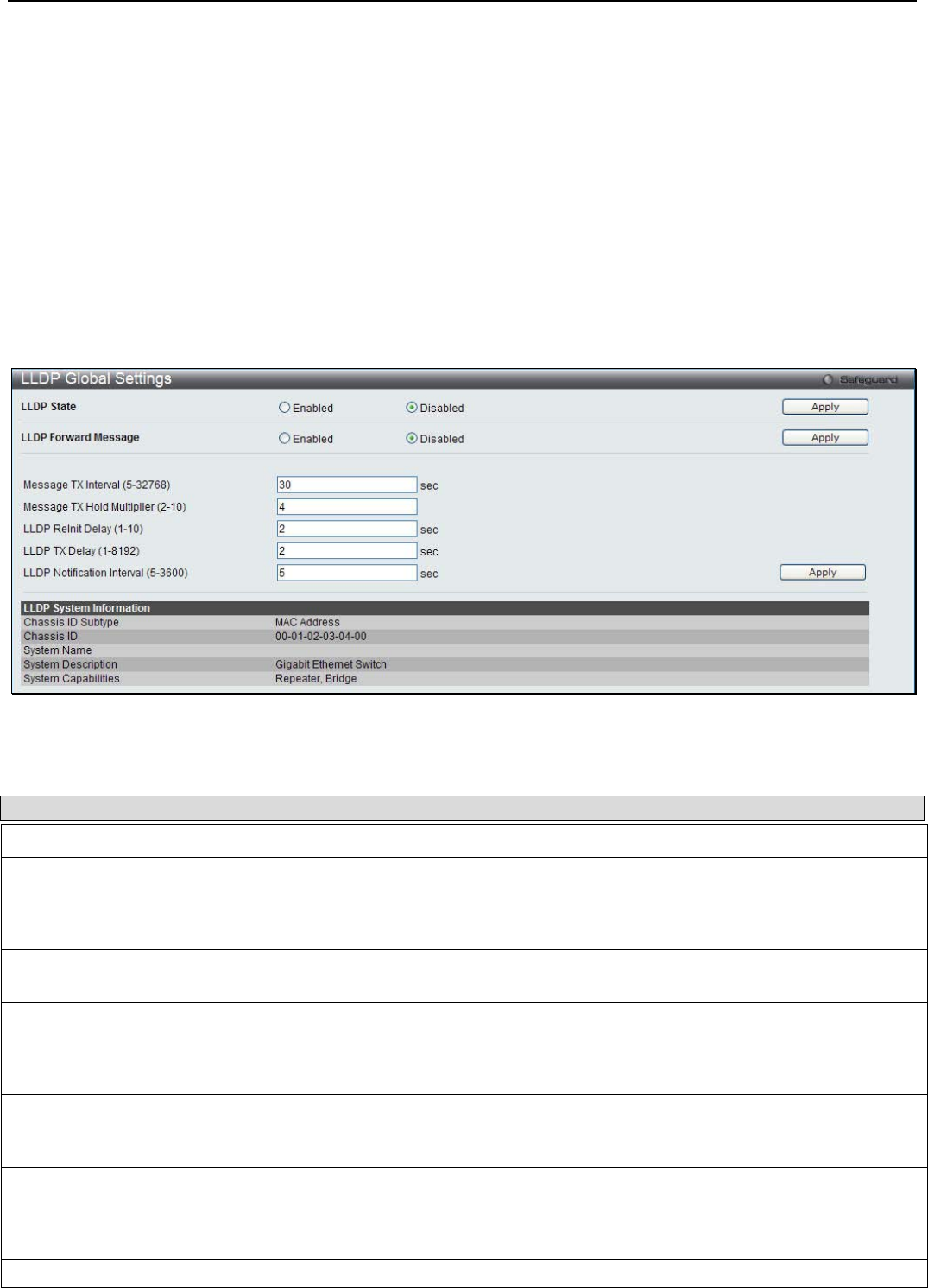
xStack® DGS-3200 Series Layer 2 Managed Gigabit Ethernet Switch Web UI Reference Guide
103
Click Apply to implement the changes made. Click Clear All to remove all the information entered. Click All to select all ports.
LLDP
LLDP
LLDP Global Settings
This window is used to configure the LLDP global settings.
To view the following window, click L2 Features > LLDP > LLDP > LLDP Global Settings:
Figure 3 - 73. LLDP Global Settings window
The following parameters can be configured:
Parameter Description
LLDP State Click the radio buttons to enable or disable the LLDP feature.
LLDP Forward Message When LLDP is disabled, this function controls the LLDP packet forwarding message
based on individual ports. If LLDP is enabled on a port, it will flood the LLDP packet to all
ports that have the same port VLAN and will advertise to other stations attached to the
same IEEE 802 LAN.
Message TX Interval (5-
32768) This interval controls how often active ports retransmit advertisements to their neighbors.
To change the packet transmission interval, enter a value between 5 and 35768 seconds.
Message TX Hold
Multiplier (2-10) This function calculates the Time-to-Live for creating and transmitting the LLDP
advertisements to LLDP neighbors by changing the multiplier used by an LLDP Switch.
When the Time-to-Live for an advertisement expires the advertised data is then deleted
from the neighbor Switch’s MIB.
LLDP Relnit Delay (1-
10) The LLDP re-initialization delay interval is the minimum time that an LLDP port will wait
before reinitializing after receiving an LLDP disable command. To change the LLDP re-init
delay, enter a value between 1 and 10 seconds.
LLDP TX Delay (1-8192) LLDP TX Delay allows the user to change the minimum time delay interval for any LLDP
port which will delay advertising any successive LLDP advertisements due to change in
the LLDP MIB content. To change the LLDP TX Delay, enter a value between 1 and 8192
seconds.
LLDP Notification
LLDP Notification Interval is used to send notifications to configured SNMP trap
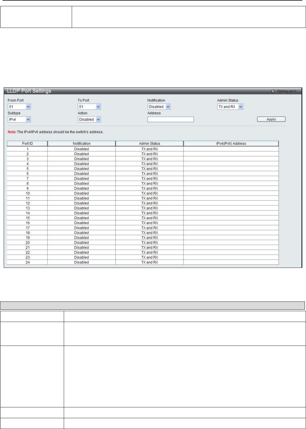
xStack® DGS-3200 Series Layer 2 Managed Gigabit Ethernet Switch Web UI Reference Guide
104
Interval (5-3600)
receiver(s) when an LLDP change is detected in an advertisement received on the port
from an LLDP neighbor. To set the LLDP Notification Interval, enter a value between 5
and 3600 seconds.
Click Apply to implement the changes made.
LLDP Port Settings
This window is used to configure the LLDP port parameters.
To view the following window, click L2 Features > LLDP > LLDP > LLDP Port Settings:
Figure 3 - 74. LLDP Port Settings window
The following parameters can be configured:
Parameter Description
From Port / To Port Use the drop-down menus to select a range of ports to be configured.
Notification Use the drop-down menu to enable or disable the status of the LLDP notification. This
function controls the SNMP trap however it cannot implement traps on SNMP when the
notification is disabled.
Admin Status This function controls the local LLDP agent and allows it to send and receive LLDP frames on
the ports. This option contains TX, RX, TX And RX or Disabled.
TX - the local LLDP agent can only transmit LLDP frames.
RX - the local LLDP agent can only receive LLDP frames.
TX and RX - the local LLDP agent can both transmit and receive LLDP frames.
Disabled - the local LLDP agent can neither transmit nor receive LLDP frames.
The default value is TX And RX.
Subtype Use the drop-down menu to select the type of the IP address information will be sent.
Action Use the drop-down menu to enable or disable the action field.
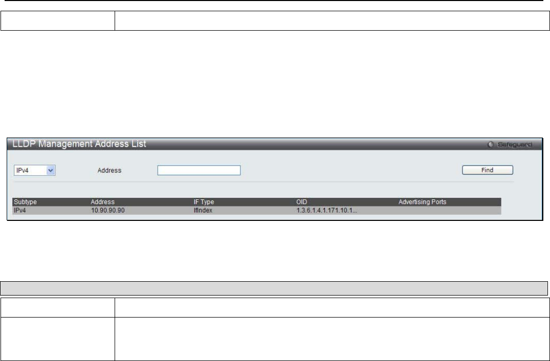
xStack® DGS-3200 Series Layer 2 Managed Gigabit Ethernet Switch Web UI Reference Guide
105
Address Enter the IP address that will be sent.
Click Apply to implement the changes made.
LLDP Management Address List
This window is used to view the LLDP management address list.
To view the following window, click L2 Features > LLDP > LLDP > LLDP Management Address List:
Figure 3 - 75. LLDP Management Address List window
The following parameters can be configured:
Parameter Description
IPv4 / IPv6 Use the drop-down menu to select either IPv4 or IPv6.
Address Enter the management IP address or the IP address of the entity you wish to advertise to.
The IPv4 address is a management IP address, so the IP information will be sent with the
frame.
Click the Find button to locate a specific entry based on the information entered.
LLDP Basic TLVs Settings
TLV stands for Type-length-value, which allows the specific sending information as a TLV element within LLDP packets. This
window is used to enable the settings for the Basic TLVs Settings. An active LLDP port on the Switch always included mandatory
data in its outbound advertisements. There are four optional data types that can be configured for an individual port or group of
ports to exclude one or more of these data types from outbound LLDP advertisements. The mandatory data type includes four
basic types of information (end of LLDPDU TLV, chassis ID TLV, port ID TLV, and Time to Live TLV). The mandatory data
types cannot be disabled. There are also four data types which can be optionally selected. These include Port Description, System
Name, System Description and System Capability.
To view the following window, click L2 Features > LLDP > LLDP > LLDP Basic TLVs Settings:

xStack® DGS-3200 Series Layer 2 Managed Gigabit Ethernet Switch Web UI Reference Guide
106
Figure 3 - 76. LLDP Basic TLVs Settings window
The following parameters can be configured:
Parameter Description
From Port / To Port Use the drop-down menus to select a range of ports to be configured.
Port Description Use the drop-down menu to enable or disable the Port Description option.
System Name Use the drop-down menu to enable or disable the System Name option.
System Description Use the drop-down menu to enable or disable the System Description option.
System Capabilities Use the drop-down menu to enable or disable the System Capabilities option.
Click Apply to implement the changes made.
LLDP Dot1 TLVs Settings
LLDP Dot1 TLVs are organizationally specific TLVs which are defined in IEEE 802.1 and used to configure an individual port or
group of ports to exclude one or more of the IEEE 802.1 organizational port VLAN ID TLV data types from outbound LLDP
advertisements.
To view the following window, click L2 Features > LLDP > LLDP > LLDP Dot1 TLVs Settings:
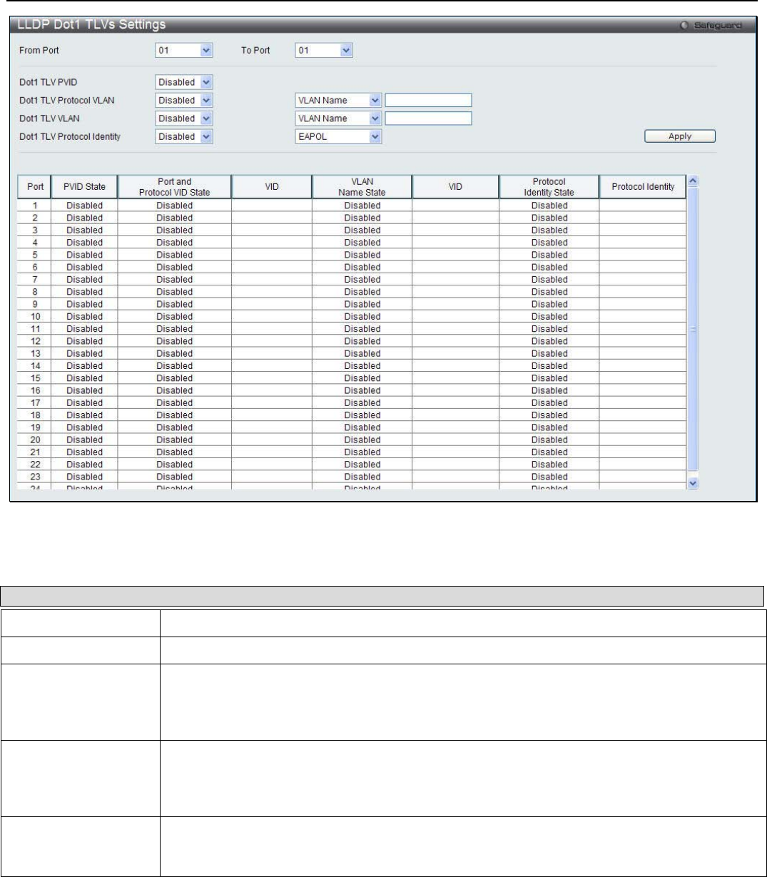
xStack® DGS-3200 Series Layer 2 Managed Gigabit Ethernet Switch Web UI Reference Guide
107
Figure 3 - 77. LLDP Dot1 TLVs Settings window
The following parameters can be configured:
Parameter Description
From Port / To Port Use the drop-down menus to select a range of ports to be configured.
Dot1 TLV PVID Use the drop-down menu to enable or disable and configure the Dot1 TLV PVID option.
Dot1 TLV Protocol
VLAN Use the drop-down menu to enable or disable, and configure the Dot1 TLV Protocol VLAN
option. After enabling this option, the user can select to use either VLAN Name, VLAN ID or
All in the next drop-down menu. After selecting this, the user can enter either the VLAN name
or VLAN ID in the space provided.
Dot1 TLV VLAN Use the drop-down menu to enable or disable, and configure the Dot1 TLV VLAN option.
After enabling this option, the user can select to use either VLAN Name, VLAN ID or All in the
next drop-down menu. After selecting this, the user can enter either the VLAN name or VLAN
ID in the space provided.
Dot1 TLV Protocol
Identity Use the drop-down menu to enable or disable, and configure the Dot1 TLV Protocol Identity
option. After enabling this option the user can select to either use EAPOL, LACP, GVRP,
STP, or All.
Click Apply to implement the changes made.
LLDP Dot3 TLVs Settings
This window is used to configure an individual port or group of ports to exclude one or more IEEE 802.3 organizational specific
TLV data type from outbound LLDP advertisements.
To view the following window, click L2 Features > LLDP > LLDP > LLDP Dot3 TLVs Settings:
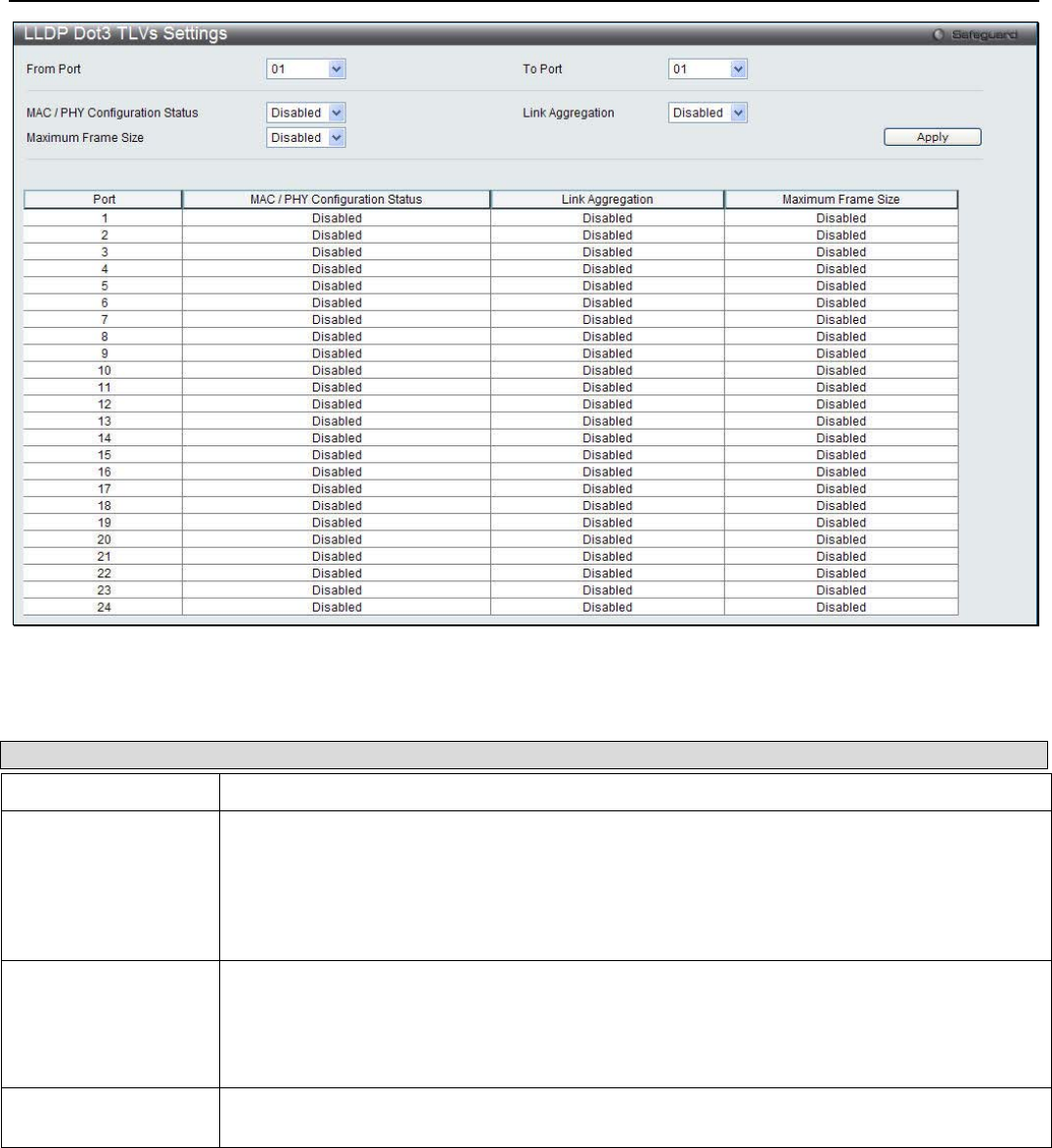
xStack® DGS-3200 Series Layer 2 Managed Gigabit Ethernet Switch Web UI Reference Guide
108
Figure 3 - 78. LLDP Dot3 TLVs Settings window
The following parameters can be configured:
Parameter Description
From Port / To Port Use the drop-down menus to select a range of ports to be configured.
MAC / PHY
configuration Status This TLV optional data type indicates that the LLDP agent should transmit the MAC/PHY
configuration/status TLV. This indicates it is possible for two ends of an IEEE 802.3 link to be
configured with different duplex and/or speed settings and still establish some limited network
connectivity. More precisely, the information includes whether the port supports the auto-
negotiation function, whether the function is enabled, whether it has auto-negotiated
advertised capability, and what is the operational MAU type. The default state is Disabled.
Link Aggregation The Link Aggregation option indicates that LLDP agents should transmit 'Link Aggregation
TLV'. This indicates the current link aggregation status of IEEE 802.3 MACs. More precisely,
the information should include whether the port is capable of doing link aggregation, whether
the port is aggregated in an aggregated link, and what is the aggregated port ID. The default
state is Disabled.
Maximun Frame Size The Maximum Frame Size indicates that LLDP agent should transmit 'Maximum-frame-size
TLV. The default state is Disabled.
Click Apply to implement the changes made.
LLDP Statistics System
This window displays an overview of the neighbor detection activity, LLDP Statistics and the settings for individual ports on the
Switch.
To view the following window, click L2 Features > LLDP > LLDP > LLDP Statistcs System:
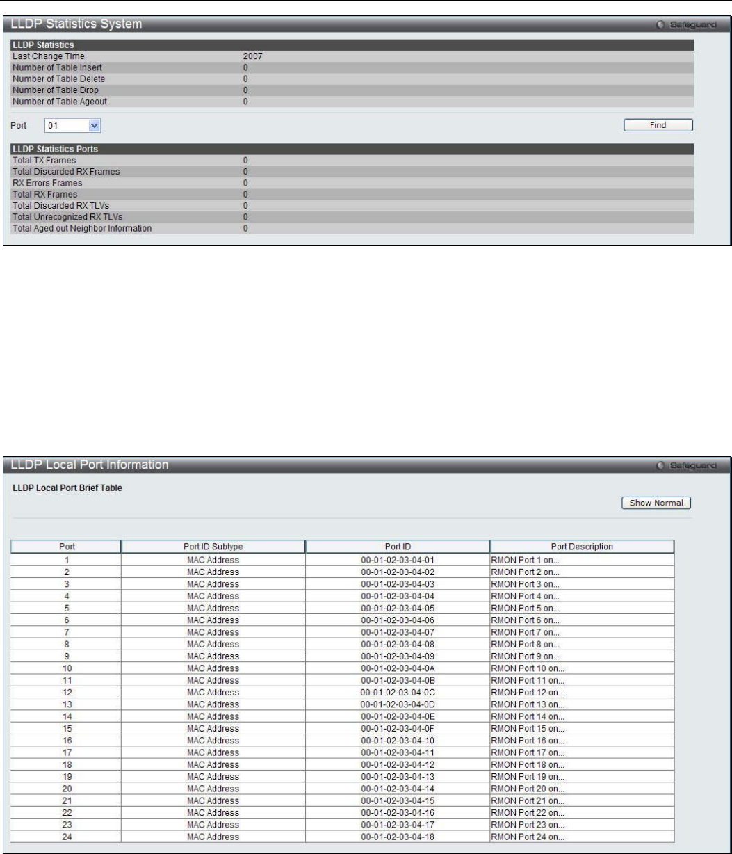
xStack® DGS-3200 Series Layer 2 Managed Gigabit Ethernet Switch Web UI Reference Guide
109
Figure 3 - 79. LLDP Statistics System window
Select a Port number from the drop-down menu and click the Find button to view statistics for a certain port.
LLDP Local Port Information
This window displays the information on a per port basis currently available for populating outbound LLDP advertisements in the
local port brief table shown below.
To view the following window, click L2 Features > LLDP > LLDP > LLDP Local Port Information:
Figure 3 - 80. LLDP Local Port Information window
To view the normal LLDP Local Port information page per port, click the Show Normal button.
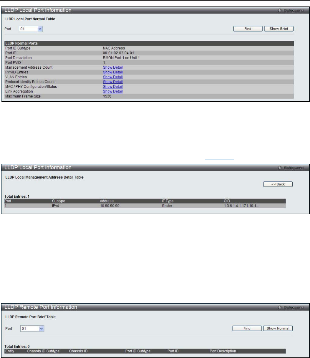
xStack® DGS-3200 Series Layer 2 Managed Gigabit Ethernet Switch Web UI Reference Guide
110
Figure 3 - 81. LLDP Local Port Information – Show Normal window
Select a Port number and click the Find button to locate a specific entry. To view the brief LLDP Local Port information page per
port, click the Show Brief button.
To view more details about, for example, the Management Address Count, click the Show Detail hyperlink.
Figure 3 - 82. LLDP Local Port Information – Show Detail window
Click the <<Back button to return to the previous page.
LLDP Remote Port Information
This window displays port information learned from the neighbors. The Switch receives packets from a remote station but is able
to store the information as local.
To view the following window, click L2 Features > LLDP > LLDP > LLDP Local Port Information:
Figure 3 - 83. LLDP Remote Port Information window
Select a Port number and click the Find button to locate a specific entry.
To view the normal LLDP Local Port information page per port, click the Show Normal button.
xStack® DGS-3200 Series Layer 2 Managed Gigabit Ethernet Switch Web UI Reference Guide
111
Figure 3 - 84. LLDP Local Port Information – Show Normal window
Click the <<Back button to return to the previous page.
LLDP-MED
LLDP-MED System Settings
This window is used to configure the LLDP-MED log state and the fast start repeat count, and display the LLDP-MED system
information.
To view the following window, click L2 Features > LLDP > LLDP-MED > LLDP-MED System Settings:
Figure 3 - 85. LLDP-MED System Settings window
The following parameters can be configured:
Parameter Description
LLDP-MED Log State Click the radio buttons to enable or disable the log state of LLDP-MED events.
Fast Start Repeat Count
(1-10) Enter a value between 1 and 10 for the fast start repeat count. When an LLDP-MED
Capabilities TLV is detected for an MSAP identifier not associated with an existing LLDP
remote system MIB, then the application layer shall start the fast start mechanism and set
the ‘medFastStart’ timer to ‘medFastStartRepeatCount’ times 1. The default value is 4.
Click Apply to implement the changes made.
LLDP-MED Port Settings
This window is used to enable or disable transmitting LLDP-MED TLVs.
To view the following window, click L2 Features > LLDP > LLDP-MED > LLDP-MED Port Settings:
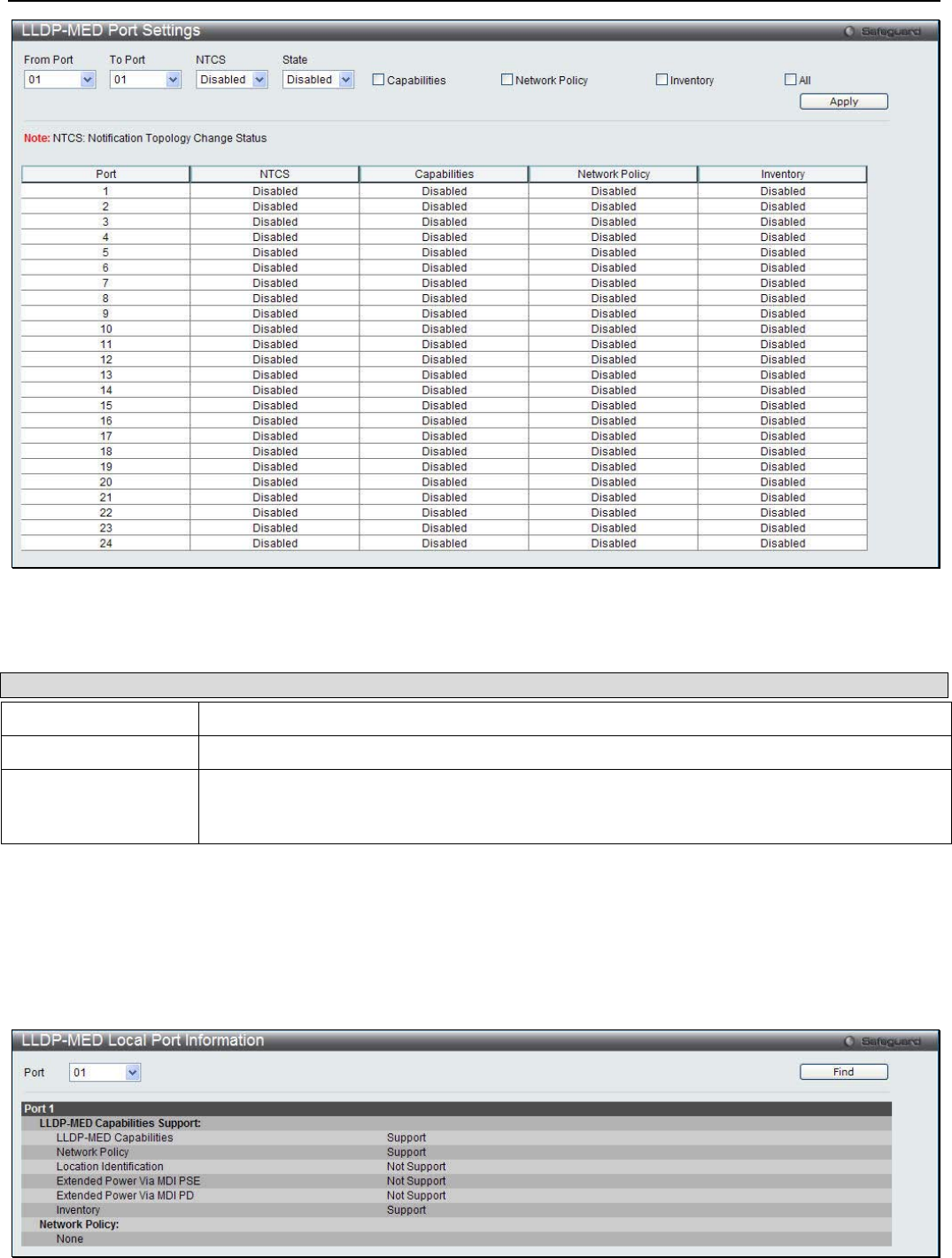
xStack® DGS-3200 Series Layer 2 Managed Gigabit Ethernet Switch Web UI Reference Guide
112
Figure 3 - 86. LLDP-MED Port Settings window
The following parameters can be configured:
Parameter Description
From Port / To Port Use the drop-down menus to select a range of ports to be configured.
NTCS Use the drop-down menu to enable or disable Notification Topology Change Status.
State Use the drop-down menu to enable or disable transmit LLDP-MED TLVs, and tick the check
boxes of the TLV types that the LLDP agent should transmit. TLV types are Capabilities,
Network Policy, and Inventory. Tick the All check box to select all TLV types.
Click Apply to implement the changes made.
LLDP-MED Local Port Information
This window displays the per-port information currently available for populating outbound LLDP-MED advertisements.
To view the following window, click L2 Features > LLDP > LLDP-MED > LLDP-MED Local Port Information:
Figure 3 - 87. LLDP-MED Local Port Information window
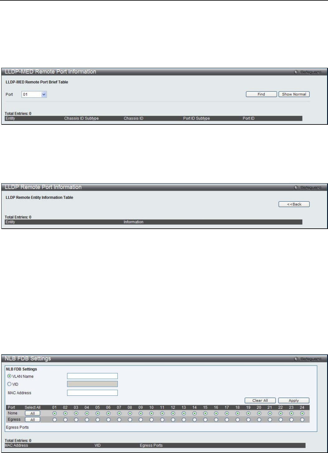
xStack® DGS-3200 Series Layer 2 Managed Gigabit Ethernet Switch Web UI Reference Guide
113
Select a Port number and click the Find button to locate a specific entry.
LLDP-MED Remote Port Information
This window displays the information learned from the neighbor parameters.
To view the following window, click L2 Features > LLDP > LLDP-MED > LLDP-MED Remote Port Information:
Figure 3 - 88. LLDP-MED Remote Port Information window
Select a Port number and click the Find button to locate a specific entry.
To view the normal LLDP Remote Port information page per port, click the Show Normal button.
Figure 3 - 89. LLDP-MED Remote Port Information – Show Normal window
Click the <<Back button to return to the previous page.
NLB FDB Settings
The Switch supports Network Load Balancing (NLB). This is a MAC forwarding control for supporting the Microsoft server load
balancing application where multiple servers can share the same IP address and MAC address. The requests from clients will be
forwarded to all servers, but will only be processed by one of them. In multicast mode, the client uses a multicast MAC address as
the destination MAC to reach the server. Regardless of the mode, the destination MAC is the shared MAC. The server uses its
own MAC address (rather than the shared MAC) as the source MAC address of the reply packet. The NLB multicast FDB entry
will be mutually exclusive with the L2 multicast entry.
To view the following window, click L2 Features > NLB FDB Settings:
Figure 3 - 90. NLB FDB Settings window
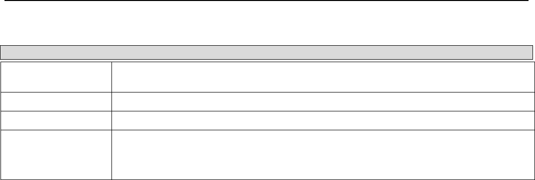
xStack® DGS-3200 Series Layer 2 Managed Gigabit Ethernet Switch Web UI Reference Guide
114
The following parameters can be configured:
Parameter Description
VLAN Name Click the radio button and enter the VLAN name of the NLB multicast FDB entry to be
created.
VID Click the radio button and enter the VLAN by the VLAN ID.
MAC Address Enter the MAC address of the NLB multicast FDB entry to be created.
Port Choose the forwarding ports for the specified NLB multicast FDB entry.
None – The port is not the forwarding port.
Egress - The port is the forwarding port.
Click Apply to implement the changes made. Click Clear All to remove all the information entered. Click All to select all ports.
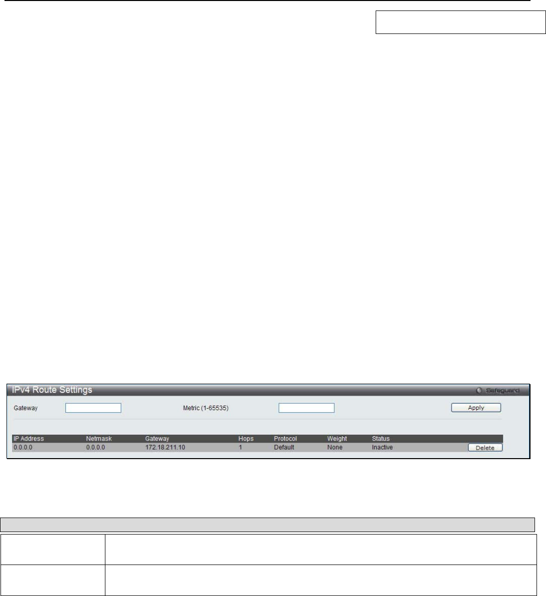
xStack® DGS-3200 Series Layer 2 Managed Gigabit Ethernet Switch Web UI Reference Guide
115
Section 4
L3 Features
IPv4 Static/Default Router Settings
IPv4 Route Table
IPv6 Interface Settings
IPv6 Route Settings
IPv6 Neighbor Settings
IPv4 Static/Default Route Settings
The Switch supports static routing for IPv4 formatted addressing. Users can create up to 512 static route entries for IPv4. For IPv4
static routes, once a static route has been set, the Switch will send an ARP request packet to the next hop router that has been set
by the user. Once an ARP response has been retrieved by the switch from that next hop, the route becomes enabled. However, if
the ARP entry already exists, an ARP request will not be sent.
The Switch also supports a floating static route, which means that the user may create an alternative static route to a different next
hop. This secondary next hop device route is considered as a backup static route for when the primary static route is down. If the
primary route is lost, the backup route will uplink and its status will become Active.
Entries into the Switch’s forwarding table can be made using both an IP address subnet mask and a gateway.
To view the following window, click L3 Features > IPv4 Static/Default Route Settings:
Figure 4 - 1. IPv4 Route Settings Window
The following parameters can be configured:
Parameter Description
Gateway This field allows the entry of a Gateway IP Address to be applied to the corresponding gateway
of the IP address.
Metric (1-65535) Represents the metric value of the IP interface entered into the table. This field may read a
number between 1 and 65535.
Click Apply to implement the changes made. Click Delete to remove the specific entry.
IPv4 Route Table
The IP routing table stores all the external routes information of the switch. This window displays all the external route
information on the Switch.
To view the following window, click L3 Features > IPv4 Route Table:
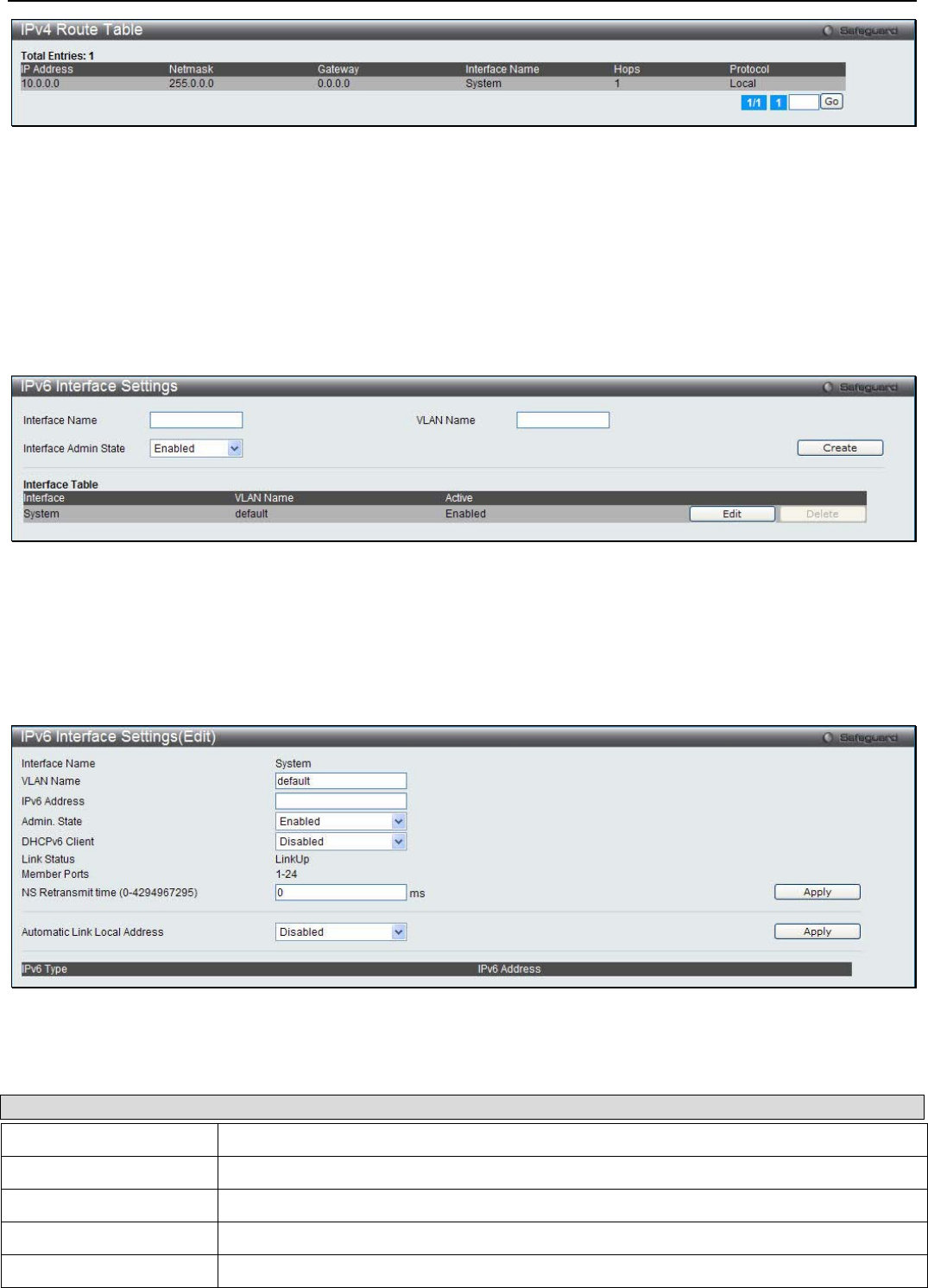
xStack® DGS-3200 Series Layer 2 Managed Gigabit Ethernet Switch Web UI Reference Guide
116
Figure 4 - 2. IPv4 Route Settings Window
Enter a page number and click the Go button to navigate to a specific page when multiple pages exist.
IPv6 Interface Settings
This window is used to display the Switch’s current IPv6 interface settings.
To view the following window, click L3 Features > IPv6 Interface Settings:
Figure 4 - 3. IPv6 Interface Settings Window
To configure IPv6 interface settings, enter an Interface Name, a VLAN Name, and make sure the Interface Admin. State is
Enabled. Click the Create button. The new entry will appear in the Interface Table at the bottom of the window.
To modify an IPv6 Interface Table entry, click the corresponding Edit button. The following window opens:
Figure 4 - 4. IPv6 Interface Settings (Edit) Window
The following parameters can be configured or viewed:
Parameter Description
Interface Name The name of the IPv6 interface being modified.
VLAN Name Enter the VLAN name of the IPv6 interface.
IPv6 Address Enter the IPv6 address of the interface to be modified.
Admin. State Toggle the state between Enabled and Disabled.
DHCPv6 Client Use the drop-down menu to enable or disable DHCPv6 client.

xStack® DGS-3200 Series Layer 2 Managed Gigabit Ethernet Switch Web UI Reference Guide
117
Link Status Displays whether the IPv6 Interface is Up or Down.
Member Ports Displays the port numbers that are part of the IPv6 Interface.
NS Retransmit Time (0-
4294967295) Enter a value between 0 and 4294967295. This is the neighbor solicitation’s retransmit
timer in milliseconds. The default is zero.
Automatic Link Local
Address Toggle between Enabled and Disabled. Enabling this is helpful when no external source
of network addressing information is available.
After making the desired changes, click the Apply button in the top section of the window.
IPv6 Route Settings
A static entry of an IPv6 address can be entered into the Switch’s routing table for IPv6 formatted addresses.
To view the following window, click L3 Features > IPv6 Route Settings:
Figure 4 - 5. IPv6 Route Settings Window
The following parameters can be configured:
Parameter Description
Interface Name The IP Interface where the static IPv6 route is created.
Nexthop Address The corresponding IPv6 address for the next hop Gateway address in IPv6 format.
Metric (1-65535) The metric of the IPv6 interface entered into the table representing the number of routers
between the Switch and the IPv6 address above. Metric values allowed are between 1 and
65535.
Click Apply to implement the changes made. Click Delete All to remove all the entries.
IPv6 Neighbor Settings
The user can configure the Switch’s IPv6 neighbor settings. The Switch’s current IPv6 neighbor settings will be displayed in the
table at the bottom of this window.
To view the following window, click L3 Features > IPv6 Neighbor Settings:
Figure 4 - 6. IPv6 Neighbor Settings Window
xStack® DGS-3200 Series Layer 2 Managed Gigabit Ethernet Switch Web UI Reference Guide
118
The following parameters may be configured or viewed:
Parameter Description
Interface Name Enter the name of the IPv6 neighbor. To search for all the current interfaces on the Switch, go to
the second Interface Name field in the middle part of the window, tick the All check box, and then
click the Find button.
Neighbor IPv6
Address Enter the neighbor IPv6 address.
Link Layer MAC
Address Enter the link layer MAC address.
State Use the drop-down menu to select All, Address, Static, or Dynamic.
Enter the Interface Name, Neighbor IPv6 Address, and the Link Layer MAC Address and then click the Add button. The State
can be set to All, Address, Static, or Dynamic.
To look for an IPv6 Neighbor Settings table entry, enter the Interface Name, select the desired State in the middle section of this
window, and then click the Find button.
To delete all the entries being displayed on the table at the bottom of this window, click the Clear button.

xStack® DGS-3200 Series Layer 2 Managed Gigabit Ethernet Switch Web UI Reference Guide
119
Section 5
QoS
Bandwidth Control
Queue Bandwidth Control Settings
Traffic Control
802.1p Default Priority
802.1p User Priority
QoS Scheduling Mechanism
QoS is an implementation of the IEEE 802.1p standard that allows network administrators a method of reserving bandwidth for
important functions that require a large bandwidth or have a high priority, such as VoIP (voice-over Internet Protocol), web
browsing applications, file server applications or video conferencing. Not only can a larger bandwidth be created, but other less
critical traffic can be limited, so excessive bandwidth can be saved. The Switch has separate hardware queues on every physical
port to which packets from various applications can be mapped to, and, in turn prioritized. View the following map to see how the
Switch implements basic 802.1P priority queuing.
Figure 5 - 1. An Example of the Default QoS Mapping on the Switch
The picture above shows the default priority setting for the Switch. Class-7 has the highest priority of the seven priority classes of
service on the Switch. In order to implement QoS, the user is required to instruct the Switch to examine the header of a packet to
see if it has the proper identifying tag. Then the user may forward these tagged packets to designated classes of service on the
Switch where they will be emptied, based on priority.

xStack® DGS-3200 Series Layer 2 Managed Gigabit Ethernet Switch Web UI Reference Guide
120
For example, let’s say a user wishes to have a video conference between two remotely set computers. The administrator can add
priority tags to the video packets being sent out, utilizing the Access Profile commands. Then, on the receiving end, the
administrator instructs the Switch to examine packets for this tag, acquires the tagged packets and maps them to a class queue on
the Switch. Then in turn, the administrator will set a priority for this queue so that will be emptied before any other packet is
forwarded. This results in the end user receiving all packets sent as quickly as possible, thus prioritizing the queue and allowing
for an uninterrupted stream of packets, which optimizes the use of bandwidth available for the video conference.
Understanding QoS
The Switch supports 802.1p priority queuing. The Switch has eight priority queues. These priority queues are numbered from 7
(Class 7) — the highest priority queue — to 0 (Class 0) — the lowest priority queue. The eight priority tags specified in IEEE
802.1p (p0 to p7) are mapped to the Switch’s priority queues as follows:
• Priority 0 is assigned to the Switch’s Q2 queue.
• Priority 1 is assigned to the Switch’s Q0 queue.
• Priority 2 is assigned to the Switch’s Q1 queue.
• Priority 3 is assigned to the Switch’s Q3 queue.
• Priority 4 is assigned to the Switch’s Q4 queue.
• Priority 5 is assigned to the Switch’s Q5 queue.
• Priority 6 is assigned to the Switch’s Q6 queue.
• Priority 7 is assigned to the Switch’s Q7 queue.
For strict priority-based scheduling, any packets residing in the higher priority classes of service are transmitted first. Multiple
strict priority classes of service are emptied based on their priority tags. Only when these classes are empty, are packets of lower
priority transmitted.
For weighted round-robin queuing, the number of packets sent from each priority queue depends upon the assigned weight. For a
configuration of eight CoS queues, A~H with their respective weight value: 8~1, the packets are sent in the following sequence:
A1, B1, C1, D1, E1, F1, G1, H1, A2, B2, C2, D2, E2, F2, G2, A3, B3, C3, D3, E3, F3, A4, B4, C4, D4, E4, A5, B5, C5, D5, A6,
B6, C6, A7, B7, A8, A1, B1, C1, D1, E1, F1, G1, H1.
For weighted round-robin queuing, if each CoS queue has the same weight value, then each CoS queue has an equal opportunity
to send packets just like round-robin queuing.
For weighted round-robin queuing, if the weight for a CoS is set to 0, then it will continue processing the packets from this CoS
until there are no more packets for this CoS. The other CoS queues that have been given a nonzero value, and depending upon the
weight, will follow a common weighted round-robin scheme.
Remember that the Switch has seven configurable priority queues (and seven Classes of Service) for each port on the Switch.
NOTICE: The Switch contains eight classes of service for each port on the Switch. One of
these classes is reserved for internal use on the Switch and is therefore not configurable. All
references in the following section regarding classes of service will refer to only the seven
classes of service that may be used and configured by the administrator.
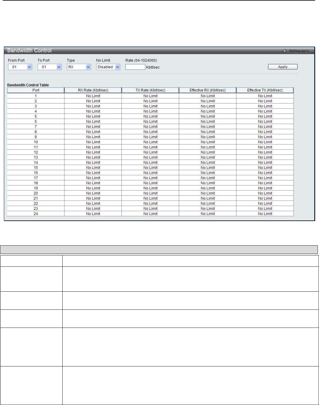
xStack® DGS-3200 Series Layer 2 Managed Gigabit Ethernet Switch Web UI Reference Guide
121
Bandwidth Control
The bandwidth control settings are used to place a ceiling on the transmitting and receiving data rates for any selected port.
To view the following window, click QoS > Bandwidth Control:
Figure 5 - 2. Bandwidth Control window
The following parameters can be set or are displayed:
Parameter Description
From Port / To Port Use the drop-down menus to select a range of ports to be configured.
Type This drop-down menu allows a selection between RX (receive), TX (transmit), and Both. This
setting will determine whether the bandwidth ceiling is applied to receiving, transmitting, or both
receiving and transmitting packets.
No Limit This drop-down menu allows the user to specify that the selected port will have no bandwidth
limit or not.
Rate (64-1024000) This field allows the input of the data rate that will be the limit for the selected port. The user
may choose a rate between 64 and 1024000 Kbits per second.
Effective RX If a RADIUS server has assigned the RX bandwidth, then it will be the effective RX bandwidth.
The authentication with the RADIUS sever can be per port or per user. For per user
authentication, there may be multiple RX bandwidths assigned if there are multiple users
attached to this specific port. The final RX bandwidth will be the largest one among these
multiple RX bandwidths.
Effective TX If a RADIUS server has assigned the TX bandwidth, then it will be the effective TX bandwidth.
The authentication with the RADIUS sever can be per port or per user. For per user
authentication, there may be multiple TX bandwidths assigned if there are multiple users
attached to this specific port. The final TX bandwidth will be the largest one among these
multiple TX bandwidths.
Click Apply to set the bandwidth control for the selected ports. Results of configured Bandwidth Settings are displayed in the
Bandwidth Control Table at the bottom of the window.
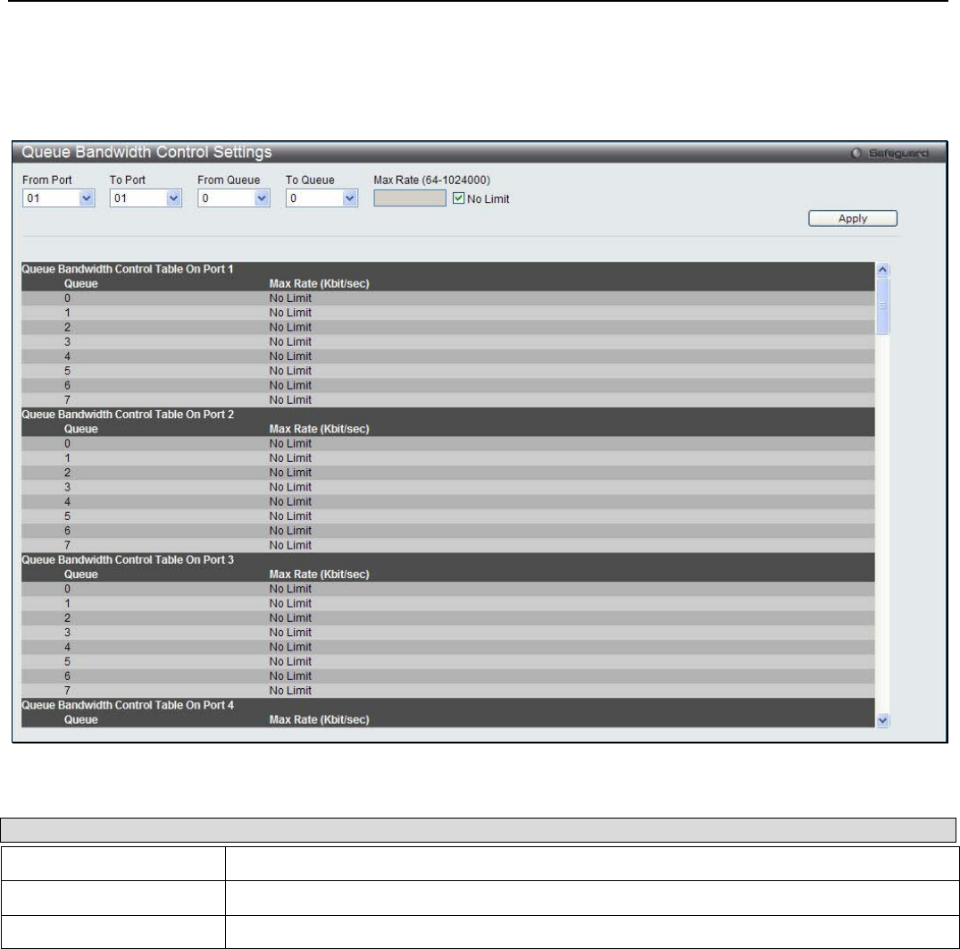
xStack® DGS-3200 Series Layer 2 Managed Gigabit Ethernet Switch Web UI Reference Guide
122
Queue Bandwidth Control Settings
This window is used to configure queue bandwidth control settings.
To view the following window, click QoS > Queue Bandwidth Control Settings:
Figure 5 - 3. Bandwidth Control window
The following parameters can be set or are displayed:
Parameter Description
From Port / To Port Use the drop-down menus to select a range of ports to be configured.
From Queue / To Queue Use the drop-down menu to select the queue range to use for this configuration.
Max Rate (64-1024000) Enter the maximum rate for the queue. For no limit select the No Limit option.
Click Apply to implement the changes.
Traffic Control
On a computer network, packets such as Multicast packets and Broadcast packets continually flood the network as normal
procedure. At times, this traffic may increase do to a malicious endstation on the network or a malfunctioning device, such as a
faulty network card. Thus, switch throughput problems will arise and consequently affect the overall performance of the switch
network. To help rectify this packet storm, the Switch will monitor and control the situation.
Packet storms are monitored to determine if too many packets are flooding the network based on threshold levels provided by the
user. Once a packet storm has been detected, the Switch will drop packets coming into the Switch until the storm has subsided.
This method can be utilized by selecting the Drop option of the Action parameter in the window below.
The Switch will also scan and monitor packets coming into the Switch by monitoring the Switch’s chip counter. This method is
only viable for Broadcast and Multicast storms because the chip only has counters for these two types of packets. Once a storm
has been detected (that is, once the packet threshold set below has been exceeded), the Switch will shut down the port to all
incoming traffic, with the exception of STP BPDU packets, for a time period specified using the Count Down parameter.

xStack® DGS-3200 Series Layer 2 Managed Gigabit Ethernet Switch Web UI Reference Guide
123
If a Time Interval parameter times-out for a port configured for traffic control and a packet storm continues, that port will be
placed in Shutdown Forever mode, which will cause a warning message to be sent to the Trap Receiver. To utilize this method of
Storm Control, choose the Shutdown option of the Action parameter in the window below.
Use this window to enable or disable storm control and adjust the threshold for multicast and broadcast storms.
To view the following window, click QoS > Traffic Control:
Figure 5 - 4. Traffic Control window
To configure Traffic Control, set the parameters described in the table below:
Parameter Description
From Port / To Port Use the drop-down menus to select a range of ports to be configured.
Action Select the method of traffic control from the drop-down menu. The choices are:
Drop – Utilizes the hardware Traffic Control mechanism, which means the Switch’s hardware will
determine the Packet Storm based on the Threshold value stated and drop packets until the
issue is resolved.
Shutdown – Utilizes the Switch’s software Traffic Control mechanism to determine the Packet
Storm occurring. Once detected, the port will deny all incoming traffic to the port except STP
BPDU packets, which are essential in keeping the Spanning Tree operational on the Switch. If
the Count Down timer has expired and yet the Packet Storm continues, the port will be placed in
Shutdown Forever mode and is no longer operational until the user manually resets the port
using the Port Settings window (Configuration > Port Configuration> Port Settings).
Choosing this option obligates the user to configure the Time Interval setting as well, which will
provide packet count samplings from the Switch’s chip to determine if a Packet Storm is
occurring.
Count Down (0 or
5-30) The Count Down timer is set to determine the amount of time, in minutes, that the Switch will wait
before shutting down the port that is experiencing a traffic storm. This parameter is only useful for
ports configured as Shutdown in their Action field and therefore will not operate for hardware-
based Traffic Control implementations. The possible time settings for this field are 0 and 5 to 30

xStack® DGS-3200 Series Layer 2 Managed Gigabit Ethernet Switch Web UI Reference Guide
124
minutes. Tick the Disabled check box to disable the countdown timer. When the Action is
Shutdown, Countdown is disabled, and the Switch detects a storm, it directly shuts down the
port. The default is 0.
Time Interval (5-30) The Time Interval will set the time between Multicast and Broadcast packet counts sent from the
Switch’s chip to the Traffic Control function. These packet counts are the determining factor in
deciding when incoming packets exceed the Threshold value. The Time Interval may be set
between 5 and 30 seconds, with a default setting of 5 seconds.
Threshold (512-
1024000) Specifies the maximum number of kbit per second that will trigger the Traffic Control function to
commence. The configurable threshold range is from 512 to 1024000, with a default setting of
512 Kbps.
Storm Control Type Specifies the desired Storm Control Type: None, Broadcast, Multicast, Unknown Unicast,
Broadcast + Multicast, Broadcast + Unknown Unicast, Multicast + Unknown Unicast, and
Broadcast + Multicast + Unknown Unicast.
Traffic Trap
Settings Enable sending of Storm Trap messages when the type of action taken by the Traffic Control
function in handling a Traffic Storm is one of the following:
• None – Will not send any Storm trap warning messages, regardless of the action taken
by the Traffic Control mechanism.
• Storm Occurred – Will send Storm Trap warning messages upon the occurrence of a
Traffic Storm only.
• Storm Cleared – Will send Storm Trap messages when a Traffic Storm has been
cleared by the Switch only.
• Both – Will send Storm Trap messages when a Traffic Storm has been both detected
and cleared by the Switch.
This function cannot be implemented in the hardware mode. (When Drop is chosen for the Action
parameter.
Traffic Log
Settings Use the drop-down menu to enable or disable the function. If enabled, the traffic control states
are logged when a storm occurs and when a storm is cleared. If the log state is disabled, the
traffic control events are not logged.
Traffic Auto
Recover Time (0-
65535)
Enter the time allowed for auto recovery from shutdown for a port. The default value is 0, which
means there is no auto recovery and the port remains in shutdown forever mode. This requires
manual entry of the CLI command config ports [ <portlist> | all ] state enable to return the port
to a forwarding state.
Click Apply to implement the settings of each field.
NOTE: Traffic Control cannot be implemented on ports that are set for
Link Aggregation (Port Trunking).
NOTE: Ports that are in the Shutdown Forever mode will be seen as
Discarding in Spanning Tree windows and implementations though these
ports will still be forwarding BPDUs to the Switch’s CPU.
NOTE: Ports that are in Shutdown Forever mode will be seen as link down
in all windows and screens until the user recovers these ports.

xStack® DGS-3200 Series Layer 2 Managed Gigabit Ethernet Switch Web UI Reference Guide
125
802.1p Default Priority
The Switch allows the assignment of a default 802.1p priority to each port on the Switch.
To view the following window, click QoS > 802.1p Default Priority:
Figure 5 - 5. 802.1p Default Priority window
This page allows the user to assign a default 802.1p priority to any given port on the Switch. The priority and effective priority
tags are numbered from 0, the lowest priority, to 7, the highest priority. The effective priority indicates the actual priority assigned
by RADIUS. If the RADIUS assigned value exceeds the specified limit, the value will be set at the default priority. For example,
if the RADIUS assigns a limit of 8 and the default priority is 0, the effective priority will be 0. To implement a new default
priority, first choose a port range by using the From Port and To Port drop-down menus and then use the Priority drop-down menu
to select a value from 0 to 7. Click Apply to implement the settings.
802.1p User Priority
The Switch allows the assignment of a class of service to each of the 802.1p priorities.
To view the following window, click QoS > 802.1p User Priority:
Figure 5 - 6. 802.1p User Priority window
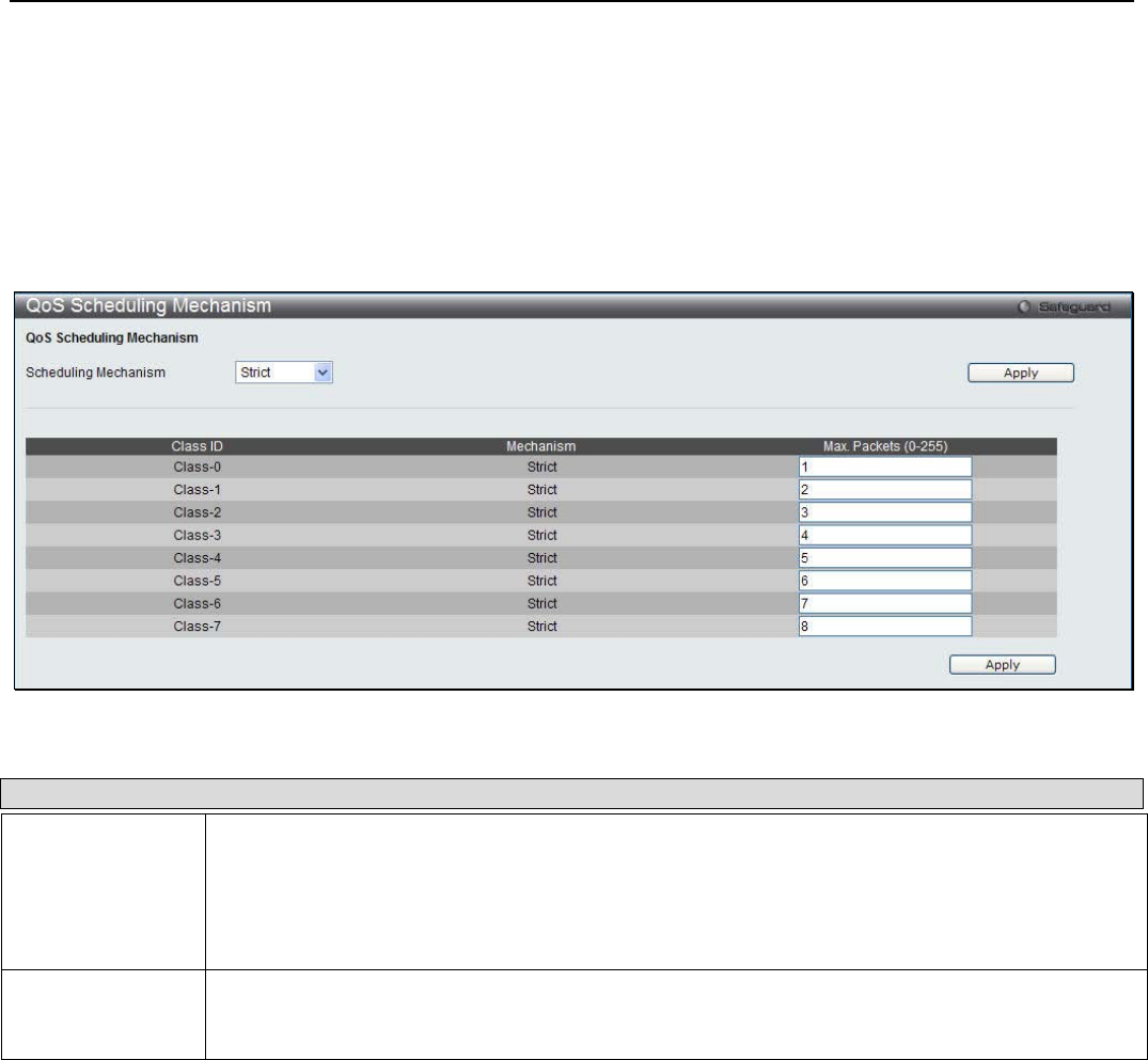
xStack® DGS-3200 Series Layer 2 Managed Gigabit Ethernet Switch Web UI Reference Guide
126
Once a priority has been assigned to the port groups on the Switch, then a Class may be assigned to each of the eight levels of
802.1p priorities using the drop-down menus on this window. Click Apply to set the changes.
QoS Scheduling Mechanism
The Scheduling Mechanism drop-down menu allows a selection between a Weight Fair and a Strict mechanism for emptying the
priority classes.
To view the following window, click QoS > QoS Scheduling Mechanism:
Figure 5 - 7. QoS Scheduling Mechanism window
The QoS Scheduling Mechanism window has the following parameters.
Parameter Description
Scheduling
Mechanism Use the drop-down menu to select one of the following options:
Strict- The highest class of service is the first to process traffic. That is, the highest class of
service will finish before other queues empty.
Weight Fair- Use the weighted round-robin (WRR) algorithm to handle packets in an even
distribution in priority classes of service.
Max. Packets (0-
255) Specifies the maximum number of packets the above specified hardware priority class of service
will be allowed to transmit before allowing the next lowest priority queue to transmit its packets. A
value between 0 and 255 can be specified.
Click Apply to implement the changes.

xStack® DGS-3200 Series Layer 2 Managed Gigabit Ethernet Switch Web UI Reference Guide
127
Section 6
Security
RADIUS
IP-MAC-Port Binding (IMPB)
Port Security
DHCP Server Screening
802.1X
SSL
SSH
Access Authentication Control
MAC-based Access Control (MAC)
Web-based Access Control (WAC)
Japanese Web-based Access Control (JWAC)
Compound Authentication
IGMP Access Control Settings
ARP Spoofing Prevention Settings
BPDU Attack Protection
Loopback Detection Settings
Traffic Segmentation
Safeguard Engine Settings
Trusted Host Settings
RADIUS
Authentication RADIUS Server Settings
The RADIUS feature of the Switch allows the user to facilitate centralized user administration as well as providing protection
against a sniffing, active hacker. The Web manager offers three windows.
To view the following window, click Security > RADIUS > Authentication RADIUS Server Settings:
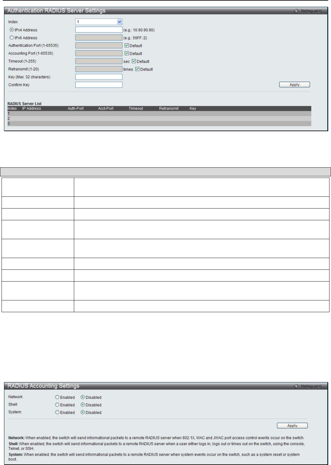
xStack® DGS-3200 Series Layer 2 Managed Gigabit Ethernet Switch Web UI Reference Guide
128
Figure 6 - 1. Authentication RADIUS Server Settings window
The following parameters can be configured:
Parameter Description
Index Choose the desired RADIUS server to configure: 1, 2 or 3 and select either IPv4 Address
or IPv6 Address.
IPv4 Address Click the radio button and set the RADIUS server IPv4 address.
IPv6 Address Click the radio button and set the RADIUS server IPv6 address.
Authentication Port
(1-65535) Set the RADIUS authentic server(s) UDP port which is used to transmit RADIUS data
between the Switch and the RADIUS server. The default port is 1812.
Accounting Port (1-
65535) Set the RADIUS account server(s) UDP port which is used to transmit RADIUS accounting
statistics between the Switch and the RADIUS server. The default port is 1813.
Timeout (1-255) Set the RADIUS server age-out, in seconds.
Retransmit (1-20) Set the RADIUS server retransmit time, in seconds.
Key (Max. length 32
bytes) Set the key the same as that of the RADIUS server.
Confirm Key Re-type the key which is the same as the above.
Click Apply to implement the changes.
RADIUS Accounting Settings
This window is used to configure the state of the specified RADIUS accounting service.
To view the following window, click Security > RADIUS > RADIUS Accounting Settings:
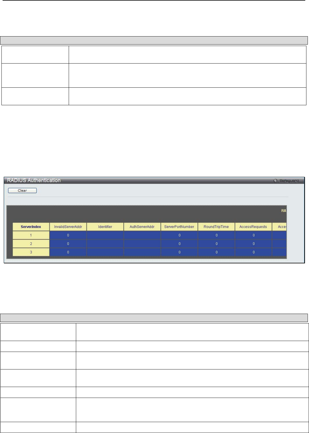
xStack® DGS-3200 Series Layer 2 Managed Gigabit Ethernet Switch Web UI Reference Guide
129
Figure 6 - 2. RADIUS Accounting Settings window
The following parameters can be configured:
Parameter Description
Network When enabled, the Switch will send informational packets to a remote RADIUS server
when 802.1X and WAC port access control events occur on the Switch.
Shell When enabled, the Switch will send informational packets to a remote RADIUS server
when a user either logs in, logs out or times out on the Switch, using the console, Telnet,
or SSH.
System When enabled, the Switch will send informational packets to a remote RADIUS server
when system events occur on the Switch, such as a system reset or system boot.
Click Apply to implement the changes.
RADIUS Authentication
This window is used to display information concerning the activity of the RADIUS authentication client on the client side of the
RADIUS authentication protocol.
To view the following window, click Security > RADIUS > RADIUS Authentication:
Figure 6 - 3. RADIUS Authentication window
The user may also select the desired time interval to update the statistics, between 1s and 60s, where “s” stands for seconds. The
default value is one second. To clear the current statistics shown, click the Clear button in the top left hand corner.
The following information is displayed:
Parameter Description
ServerIndex The identification number assigned to each RADIUS Authentication server that the client
shares a secret with.
InvalidServerAddr The number of RADIUS Access-Response packets received from unknown addresses.
Identifier The NAS-Identifier of the RADIUS authentication client. (This is not necessarily the same
as sysName in MIB II.)
AuthServerAddr The (conceptual) table listing the RADIUS authentication servers with which the client
shares a secret.
ServerPortNumber The UDP port the client is using to send requests to this server.
RoundTripTime The time interval (in hundredths of a second) between the most recent Access-
Reply/Access-Challenge and the Access-Request that matched it from this RADIUS
authentication server.
AccessRequests The number of RADIUS Access-Request packets sent to this server. This does not
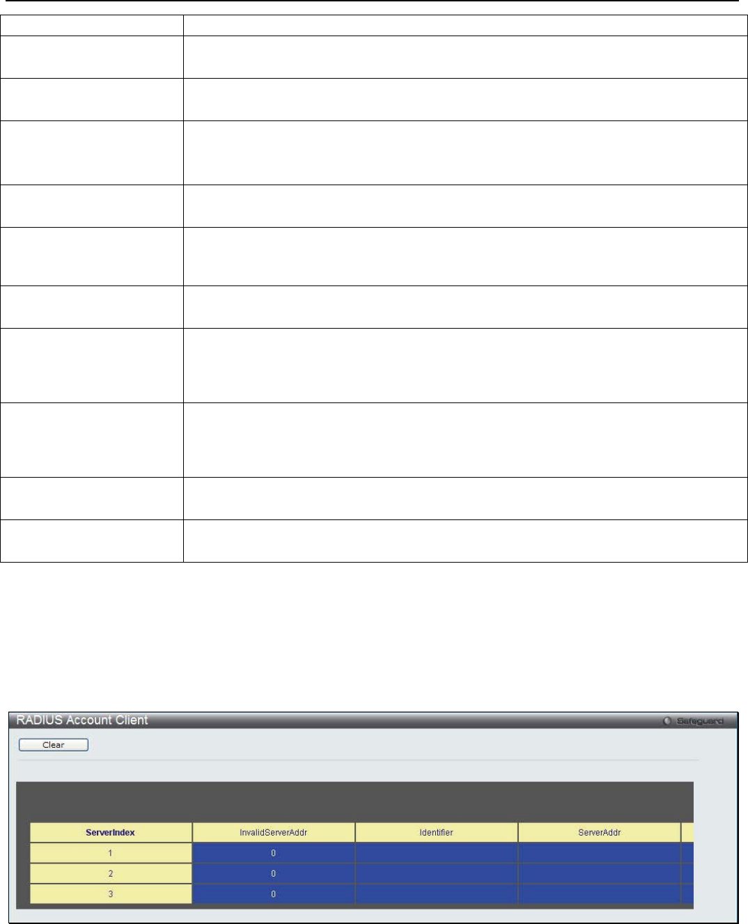
xStack® DGS-3200 Series Layer 2 Managed Gigabit Ethernet Switch Web UI Reference Guide
130
include retransmissions.
AccessRetrans The number of RADIUS Access-Request packets retransmitted to this RADIUS
authentication server.
AccessAccepts The number of RADIUS Access-Accept packets (valid or invalid) received from this
server.
AccessRejects The number of RADIUS Access-Reject packets (valid or invalid) received from this
server.
AccessChallenges The number of RADIUS Access-Challenge packets (valid or invalid) received from this
server.
AccessResponses The number of malformed RADIUS Access-Response packets received from this server.
Malformed packets include packets with an invalid length. Bad authenticators or
Signature attributes or known types are not included as malformed access responses.
BadAuthenticators The number of RADIUS Access-Response packets containing invalid authenticators or
Signature attributes received from this server.
PendingRequests The number of RADIUS Access-Request packets destined for this server that have not
yet timed out or received a response. This variable is incremented when an Access-
Request is sent and decremented due to receipt of an Access-Accept, Access-Reject or
Access-Challenge, a timeout or retransmission.
Timeouts The number of authentication timeouts to this server. After a timeout the client may retry
to the same server, send to a different server, or give up. A retry to the same server is
counted as a retransmit as well as a timeout. A send to a different server is counted as a
Request as well as a timeout.
UnknownTypes The number of RADIUS packets of unknown type which were received from this server
on the authentication port
PacketsDropped The number of RADIUS packets of which were received from this server on the
authentication port and dropped for some other reason.
RADIUS Account Client
This window is used to display managed objects used for managing RADIUS accounting clients, and the current statistics
associated with them.
To view the following window, click Security > RADIUS > RADIUS Account Client:
Figure 6 - 4. RADIUS Account Client window
The user may also select the desired time interval to update the statistics, between 1s and 60s, where “s” stands for seconds. The
default value is one second. To clear the current statistics shown, click the Clear button in the top left hand corner.
The following information is displayed:
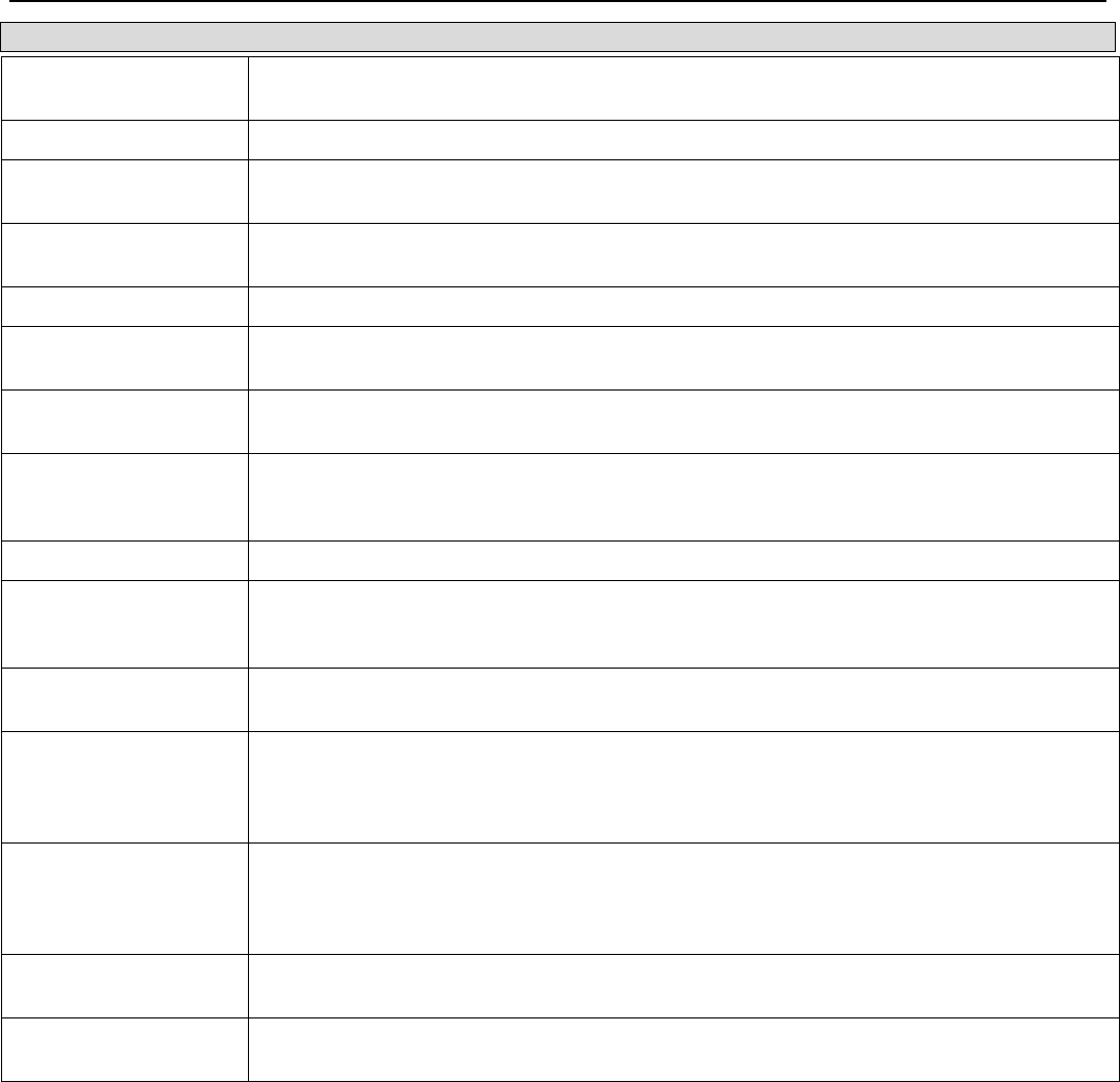
xStack® DGS-3200 Series Layer 2 Managed Gigabit Ethernet Switch Web UI Reference Guide
131
Parameter Description
ServerIndex The identification number assigned to each RADIUS Accounting server that the client
shares a secret with.
InvalidServerAddr The number of RADIUS Accounting-Response packets received from unknown addresses.
Identifier The NAS-Identifier of the RADIUS accounting client. (This is not necessarily the same as
sysName in MIB II.)
ServerAddr The (conceptual) table listing the RADIUS accounting servers with which the client shares a
secret.
ServerPortNumber The UDP port the client is using to send requests to this server.
RoundTripTime The time interval between the most recent Accounting-Response and the Accounting-
Request that matched it from this RADIUS accounting server.
Requests The number of RADIUS Accounting-Request packets sent. This does not include
retransmissions.
Retransmissions The number of RADIUS Accounting-Request packets retransmitted to this RADIUS
accounting server. Retransmissions include retries where the Identifier and Acct-Delay have
been updated, as well as those in which they remain the same.
Responses The number of RADIUS packets received on the accounting port from this server.
MalformedResponses The number of malformed RADIUS Accounting-Response packets received from this
server. Malformed packets include packets with an invalid length. Bad authenticators and
unknown types are not included as malformed accounting responses.
BadAuthenticators The number of RADIUS Accounting-Response packets, which contained invalid
authenticators, received from this server.
PendingRequests The number of RADIUS Accounting-Request packets sent to this server that have not yet
timed out or received a response. This variable is incremented when an Accounting-
Request is sent and decremented due to receipt of an Accounting-Response, a timeout or a
retransmission.
Timeouts The number of accounting timeouts to this server. After a timeout the client may retry to the
same server, send to a different server, or give up. A retry to the same server is counted as
a retransmit as well as a timeout. A send to a different server is counted as an Accounting-
Request as well as a timeout.
UnknownTypes The number of RADIUS packets of unknown type which were received from this server on
the accounting port.
PacketsDropped The number of RADIUS packets, which were received from this server on the accounting
port and dropped for some other reason.
IP-MAC-Port Binding (IMPB)
General Overview
The DGS-3200 Series switches offer IP-MAC-Port Binding (IMPB), a D-Link security application used most often on edge
switches directly connected to network hosts. IMPB is also an integral part of D-Link’s End-to-End Security Solution (E2ES). The
primary purpose of IP-MAC-Port Binding is to restrict client access to a switch by enabling administrators to configure pairs of
client MAC and IP addresses that are allowed to access networks through a switch. Specifically, IMPB binds together the four-
byte IP address and the six-byte Ethernet link layer MAC address to allow the transmission of data between the layers.
The IMPB function is port-based, meaning that a user can enable or disable the function on any individual port. Once IMPB is
enabled on a switch port, the switch will restrict or allow client access by checking the pair of IP-MAC addresses with the pre-
configured database, also known as the “IMPB white list”. If an unauthorized user tries to access an IMPB-enabled port, the
system will block access by dropping its packet. The creation of authorized users can be manually configured by CLI or Web.
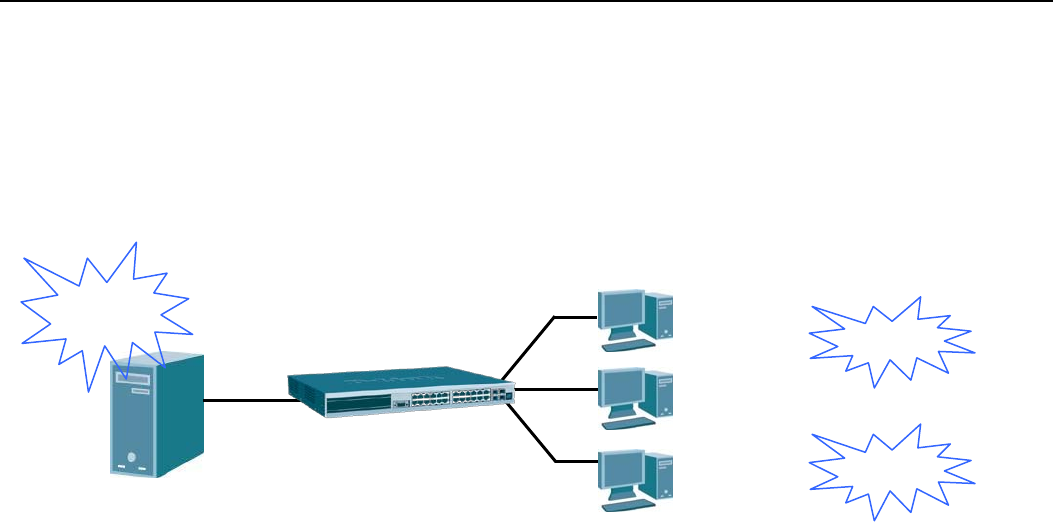
xStack® DGS-3200 Series Layer 2 Managed Gigabit Ethernet Switch Web UI Reference Guide
132
Common IP Management Security Issues
Currently, certain limitations and issues in IP management structures can lead to serious security problems. Auditing mechanisms,
such as syslog, application log, firewall log, etc, are mainly based on client IP information. However, such log information is
meaningless if the client IP address can be easily changed. IP conflict, the most common problem in today’s networks, is another
major security concern. Without IMPB, any user can change an IP address manually and cause conflict with other resources, such
as other PCs, core switches, routers or servers. Not only does this duplicate IP create an auditing issue, it also poses potential risk
to the entire network.
Figure 5 - 8. Illustration of Common IP Security Problems
ARP spoofing attacks in which malicious users intercept traffic or interrupt connections by manipulating ARP packets are another
serious challenge in securing today’s network. Further information on how ARP spoofing attacks work can be found in the
Appendix, "Mitigating ARP Spoofing Attack via Packet Content ACL," located in the back of this manual.
Solutions to Improve IP Management Security
DGS-3200 Series switches have introduced IMPB technology to protect networks from attacks. By using IP-MAC-Port Binding,
all packets are dropped by a switch when the MAC address, IP address, and connected port are not in the IMPB white list. IMPB
allows the user to choose either ARP or ACL mode. In addition, an IMPB white list can be dynamically created with the DHCP
snooping option. DHCP snooping is a global setting and can be enabled on top of ACL or ARP mode. Each option has its
advantages and disadvantages.
ARP Mode
In ARP Mode, a switch performs ARP Packet Inspection in which it checks the IP-MAC pairs in ARP packets and denies
unauthorized ones. An advantage of ARP mode is that it does not consume any ACL rules on the switch. Nonetheless, since the
switch only checks ARP packets, it cannot block unauthorized clients who do not send out ARP packets.
ACL Mode
In ACL Mode, a switch performs IP Packet Inspection in addition to ARP Packet Inspection. Essentially, ACL rules will be used
to permit statically configured IMPB entries and deny other IP packets with the incorrect IP-MAC pairs. The distinct advantage of
ACL Mode is that it ensures better security by checking both ARP Packets and IP Packets. However, doing so requires the use of
ACL rules. ACL Mode can be viewed as an enhanced version of ARP Mode because ARP Mode is enabled by default when ACL
Mode is selected.
Strict and Loose State
Other than ACL and ARP mode, users can also configure the state on a port for granular control. There are two states, Strict and
Loose, and only one state can be selected per port. If a port is set to Strict state, all packets sent to the port are denied (dropped) by
default. The switch will continuously compare all IP and ARP packets it receives on that port with its IMPB entries. If the IP-
MAC pair in the packet matches the IMPB entry, the MAC address will be unblocked and subsequent packets sent from this client
will be forwarded. On the other hand, if a port is set to Loose state, all packets sent to the port are permitted (forwarded) by
default. The switch will continuously compare all ARP packets it receives on that port with its IMPB entries. If the IP-MAC pair
in the ARP packet does not match the IMPB white list, the MAC address will be blocked and subsequent packets sent from this
client will be dropped.
192.168.1.1
00E0-0211-1111
192.168.1.2
00E0-0211-2222
192.168.1.3
00E0-0211-3333
IP Conflict
IP Conflict
Auditing
Problem

xStack® DGS-3200 Series Layer 2 Managed Gigabit Ethernet Switch Web UI Reference Guide
133
DHCP Snooping Option
If DHCP snooping is enabled, the switch learns IP-MAC pairs by snooping DHCP packets automatically and then saving them to
the IP-MAC-Port Binding white list. This enables a hassle-free configuration because the administrator does not need to manually
enter each IMPB entry. A prerequisite for this is that the valid DHCP server’s IP-MAC pair must be on the switch’s IMPB list;
otherwise the DHCP server packets will be dropped. DHCP snooping is generally considered to be more secure because it
enforces all clients to acquire IP through the DHCP server.
An example of DHCP snooping in which PC-A and PC-B get their IP addresses from a DHCP server is depicted below. The
switch snoops the DHCP conversation between PC-A, PC-B, and the DHCP server. The IP address, MAC address, and connecting
ports of both PC-A and PC-B are learned and stored in the switch’s IMPB white list. Therefore, these PCs will be able to connect
to the network. Then there is PC-C, whose IP address is manually configured by the user. Since this PC’s IP-MAC pair does not
match the one on Switch’s IMPB white list, traffic from PC-C will be blocked.
192.168.1.1 00E0-0211-111 Port 1
192.168.1.2 00E0-0211-222 Port 2
Figure 6 - 5. Example of DHCP Snooping
The IP-MAC-Port Binding (IMPB) folder contains five windows: IMPB Global Settings, IMPB Port Settings, IMPB Entry
Settings, DHCP Snooping Entries, and MAC Blocked List.
IMPB Global Settings
Users can enable or disable the global IMPB settings: Trap Log State and DHCP Snoop state, on the Switch.
The Trap/Log field will enable and disable the sending of trap log messages for IP-MAC binding. When enabled, the Switch will
send a trap message to the SNMP agent and the Switch log when an ARP packet is received that doesn’t match the IP-MAC
binding configuration set on the Switch.
The DHCP Snoop State field will enable and disable the DHCP Snooping option.
To view the following window, click Security > IP-MAC-Port Binding (IMPB) > IMPB Global Settings:
Figure 6 - 6. IMPB Global Settings window
IMP Binding Enabled
Address Learning
White List
(IP assigned by DHCP for
PC-A and PC-B)
192.168.1.2
00E0-0211-2222
192.168.1.1
00E0-0211-3333
(IP manually configured by user)
DHCP Server
PC-B
PC-C
PC-A
Doesn’t match the
White List block PC-C
192.168.1.1
00E0-0211-1111
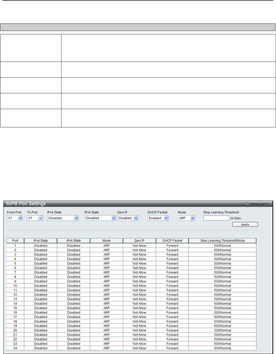
xStack® DGS-3200 Series Layer 2 Managed Gigabit Ethernet Switch Web UI Reference Guide
134
The following parameters can be set:
Parameter Description
Trap / Log Click the radio buttons to enable or disable the sending of trap/log messages for IP-MAC-
port binding. When Enabled, the Switch will send a trap message to the SNMP agent and
the Switch log when an ARP/IP packet is received that doesn’t match the IP-MAC-port
binding configuration set on the Switch. The default is Disabled.
DHCP Snooping (IPv4) Click the radio buttons to enable or disable DHCP snooping (IPv4) for IP-MAC-port binding.
The default is Disabled.
DHCP Snooping (IPv6) Click the radio buttons to enable or disable DHCP snooping (IPv6) for IP-MAC-port binding.
The default is Disabled.
ND Snooping Click the radio buttons to enable or disable enable ND snooping on the Switch. The default
is Disabled.
Recover Learning
Ports
Enter the port numbers used to recover the learning port state. Tick the All check box to
apply to all ports.
Click Apply to implement the changes.
IMPB Port Settings
Users can configure IMPB settings on a port basis.
Select a port or a range of ports with the From Port and To Port fields. Enable or disable the port with Strict or Loose State, enable
or disable Allow Zero IP and Forward DHCP Packet fields, and configure the port’s Max IMPB entry.
To view this window, click Security > IP-MAC-Port Binding (IMPB) > IMPB Port Settings, as shown below:
Figure 6 - 7. IMPB Port Settings window
The following fields can be configured:

xStack® DGS-3200 Series Layer 2 Managed Gigabit Ethernet Switch Web UI Reference Guide
135
Parameter Description
From Port/To Port Select a range of ports to set for IP-MAC-port binding.
IPv4 State / IPv6 State Use the drop-down menu to enable or disable these ports for IP-MAC Binding.
Enabled (Strict) – This state provides a stricter method of control. If the user selects this
mode, all packets are blocked by the Switch by default. The Switch will compare all
incoming ARP and IP Packets and attempt to match them against the IMPB white list. If the
IP-MAC pair matches the white list entry, the packets from that MAC address are
unblocked. If not, the MAC address will stay blocked. While the Strict state uses more CPU
resources from checking every incoming ARP and IP packet, it enforces better security and
is thus the recommended setting.
Enabled (Loose) – This mode provides a looser way of control. If the user selects loose
mode, the Switch will forward all packets by default. However, it will still inspect incoming
ARP packets and compare them with the Switch’s IMPB white list entries. If the IP-MAC
pair of a packet is not found in the white list, the Switch will block the MAC address. A major
benefit of Loose state is that it uses less CPU resources because the Switch only checks
incoming ARP packets. However, it also means that Loose state cannot block users who
send only unicast IP packets. An example of this is that a malicious user can perform DoS
attacks by statically configuring the ARP table on their PC. In this case, the Switch cannot
block such attacks because the PC will not send out ARP packets.
Zero IP Use the drop-down menu to enable or disable this feature. Once Enabled, the Switch will
allow ARP packets with a Source IP of 0.0.0.0 to pass through.
This is useful in some scenarios when a client (for example, a
wireless Access Point,)
sends out an ARP request packet before accepting the IP address from a DHCP server. In
this case, the ARP request packet sent out from the client will contain a Source IP of
0.0.0.0. The Switch will need to allow such packets to pass, or else the client cannot know if
there is another duplicate IP address in the network.
DHCP Packet By default, the Switch will forward all DHCP packets. However, if the port state is set to
Strict, all DHCP packets will be dropped. In that case, select Enabled so that the port will
forward DHCP packets even under Strict state. Enabling this feature also ensures that
DHCP snooping works properly.
Mode Use the drop-down menu to select ARP or ACL mode.
ARP – When selecting this mode, the Switch will perform ARP Packet Inspection only and
no ACL rules will be used.
ACL – When selecting this mode, the Switch will perform IP Packet Inspection in addition to
ARP Packet Inspection. ACL rules will be used under this mode.
Stop Learning
Threshold Whenever a MAC address is blocked by the Switch, it will be recorded in the Switch’s L2
Forwarding Database (FDB) and each entry associated with a particular port. To prevent
the Switch FDB from overloading in case of an ARP DoS attack, the administrator can
configure the threshold when a port should stop learning illegal MAC addresses.
Enter a stop learning threshold between 0 and 500. Entering 500 means the port will enter
the Stop Learning state after 500 illegal MAC entries and will not allow additional MAC
entries, neither legal nor illegal, to be learned on this port. In the Stop Learning state, the
port will also automatically purge all blocked MAC entries on this port. Traffic from legal
MAC entries is still forwarded.
Entering 0 means no limit has been set and the port will keep learning illegal MAC
addresses.
Click Apply to implement the changes made.
IMPB Entry Settings
This window is used to create static IP-MAC-binding port entries and view all IMPB entries on the Switch.
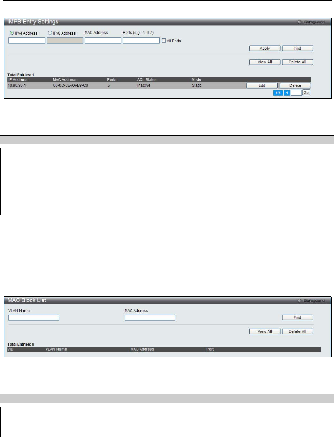
xStack® DGS-3200 Series Layer 2 Managed Gigabit Ethernet Switch Web UI Reference Guide
136
To view this window, click Security > IP-MAC-Port Binding (IMPB) > IMPB Entry Settings as shown below:
Figure 6 - 8. IMPB Entry Settings window
The following fields can be set or modified:
Parameter Description
IPv4 Address Click the radio button and enter the IPv4 address to bind to the MAC address set below.
IPv6 Address Click the radio button and enter the IPv6 address to bind to the MAC address set below.
MAC Address Enter the MAC address to bind to the IP Address set above.
Ports Specify the switch ports for which to configure this IP-MAC binding entry (IP Address + MAC
Address). Click the All check box to configure this entry for all ports on the Switch.
Click Apply to implement changes. Click Find to search for an entry. Click View All for the table to display all entries or Delete
All to remove all the static entries. Click the Edit button to configure the specified entry. Click the Delete button to remove the
specified entry.
MAC Block List
This window is used to view unauthorized devices that have been blocked by IP-MAC binding restrictions.
To view this window, click Security > IP-MAC-Port Binding (IMPB) > MAC Block List, as shown below:
Figure 6 - 9. MAC Block List window
The following fields can be configured:
Parameter Description
VLAN Name Enter the name of the VLAN you want to find or delete.
MAC Address Enter the MAC address of the MAC Address you want to find or delete.
To find an unauthorized device MAC address that has been blocked by the IP-MAC binding restrictions, enter the VID and MAC
Address in the appropriate fields and click Find. To view all entries, click the View All button. To delete an entry, click the
Delete button next to the entry’s port. To delete all the entries in this window, click the Delete All button.
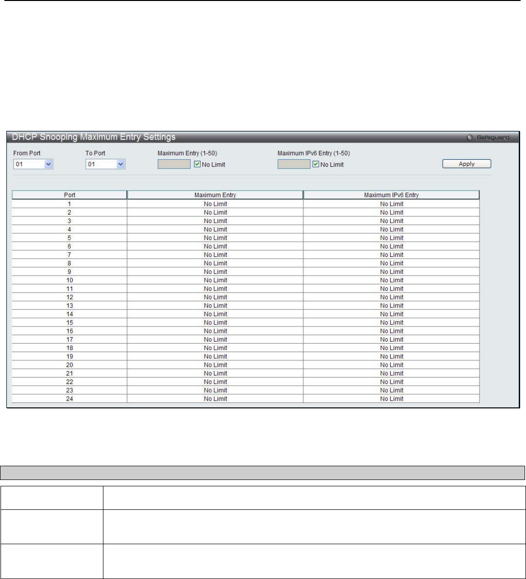
xStack® DGS-3200 Series Layer 2 Managed Gigabit Ethernet Switch Web UI Reference Guide
137
DHCP Snooping
DHCP Snooping Maximum Entry Settings
This window is used to configure the maximum DHCP snooping entry for ports on this page.
To view the following window, click Security > IP-MAC-Port Binding (IMPB) > DHCP Snooping > DHCP Snooping
Maximum Entry Settings:
Figure 6 - 10. DHCP Snooping Maximum Entry Settings window
The following fields can be configured:
Parameter Description
From Port / To Port Use the drop-down menus to select a range of ports to use.
Maximum Entry (1-
50)
Enter the maximum entry value. Tick the No Limit check box to have unlimited maximum
number of the learned entries.
Maximum IPv6
Entry (1-50)
Enter the maximum entry value for IPv6 DHCP Snooping. Tick the No Limit check box to have
unlimited maximum number of the learned entries.
Click the Apply button to accept the changes made.
DHCP Snooping Entry
This window is used to view DHCP snooping entries on specific ports.
To view the following window, click Security > IP-MAC-Port Binding (IMPB) > DHCP Snooping > DHCP Snooping Entry:

xStack® DGS-3200 Series Layer 2 Managed Gigabit Ethernet Switch Web UI Reference Guide
138
Figure 6 - 11. DHCP Snooping Entry window
The following fields can be configured:
Parameter Description
Port Use the drop-down menu to select the desired port.
Ports (e.g.: 1, 7-12) Specify the ports for DHCP snooping entries. Tick the All Ports check box to select all entries
for all ports. Tick the IPv4 check box to select IPv4 DHCP snooping learned entries. Tick the
IPv6 check box to select IPv6 DHCP snooping learned entries.
To view particular port settings, select the port number and click Find. To delete an entry, click Clear. To view all entries click
View All.
ND Snoop
ND Snoop Maximum Entry Settings
This window is used to configure the maximum ND Snooping entry for ports on this page.
To view the following window, click Security > IP-MAC-Port Binding (IMPB) > ND Snoop > ND Snoop Maximum Entry
Settings:
Figure 6 - 12. ND Snooping Maximum Entry Settings window
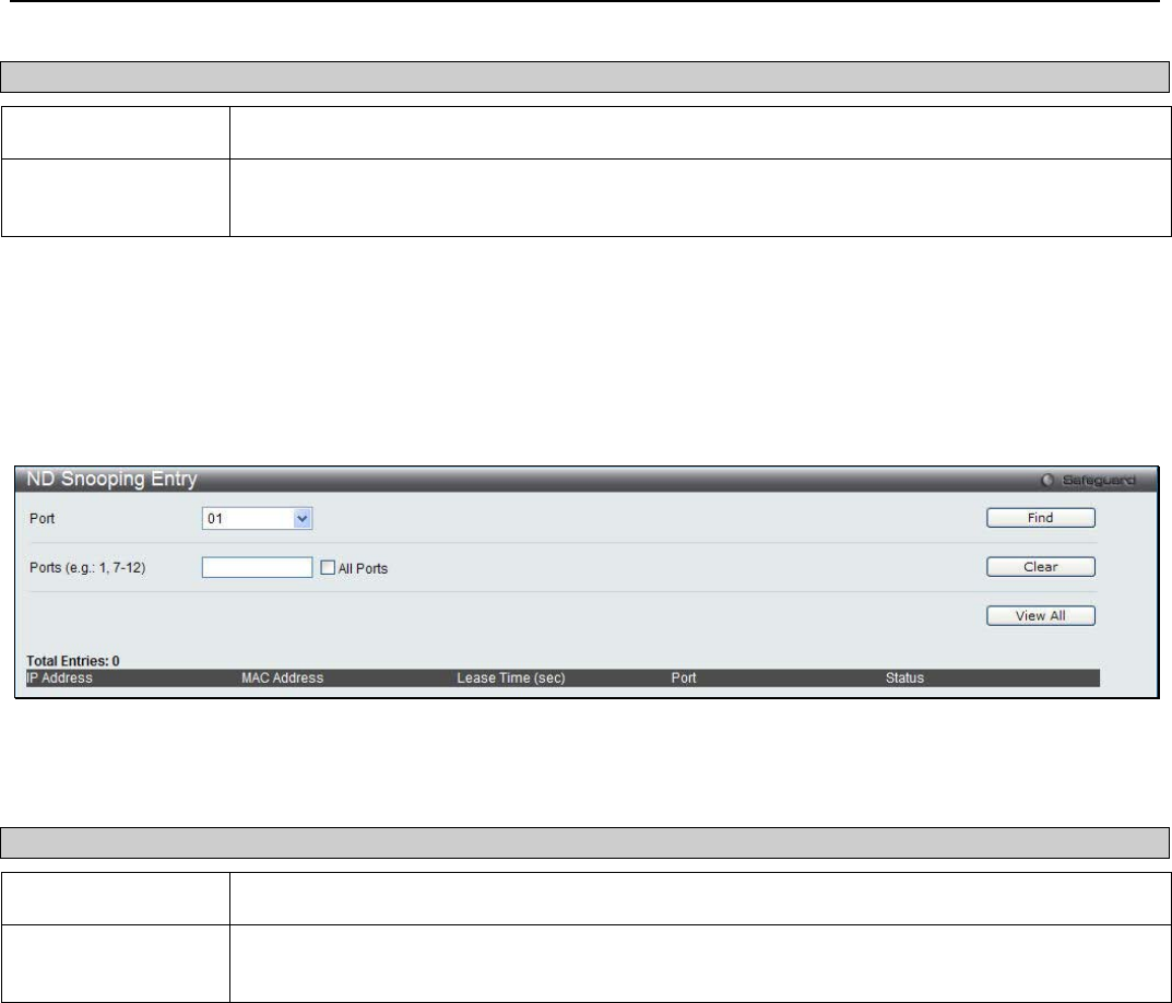
xStack® DGS-3200 Series Layer 2 Managed Gigabit Ethernet Switch Web UI Reference Guide
139
The following fields can be configured:
Parameter Description
From Port / To Port Use the drop-down menus to select a range of ports to use.
Maximum Entry (1-
10)
Enter the maximum entry value. Tick the No Limit check box to have unlimited maximum
number of the learned entries.
Click the Apply button to accept the changes made.
ND Snoop Entry
This window is used to view dynamic entries on specific ports.
To view the following window, click Security > IP-MAC-Port Binding (IMPB) > ND Snoop > ND Snoop Entry:
Figure 6 - 13. ND Snooping Entry window
The following fields can be configured:
Parameter Description
Port Use the drop-down menu to select the desired port.
Ports (e.g.: 1, 7-12) Specify the ports for which to view DHCP snooping entries. Tick the All Ports check box to
view all ND snooping ports on the Switch.
To view particular port settings, select the port number and click Find. To delete an entry, click Clear. To view all entries click
View All.
Port Security
The Port Security folder contains two windows: Port Security Settings and Port Lock Entries.
Port Security Settings
A given port’s (or a range of ports') dynamic MAC address learning can be locked such that the current source MAC addresses
entered into the MAC address forwarding table can not be changed once the port lock is enabled. The port can be locked by
changing the Admin State drop-down menu to Enabled and clicking Apply.
Port Security is a security feature that prevents unauthorized computers (with source MAC addresses) unknown to the Switch
prior to locking the port (or ports) from connecting to the Switch's locked ports and gaining access to the network.
To view the following window, click Security > Port Security > Port Security Settings:
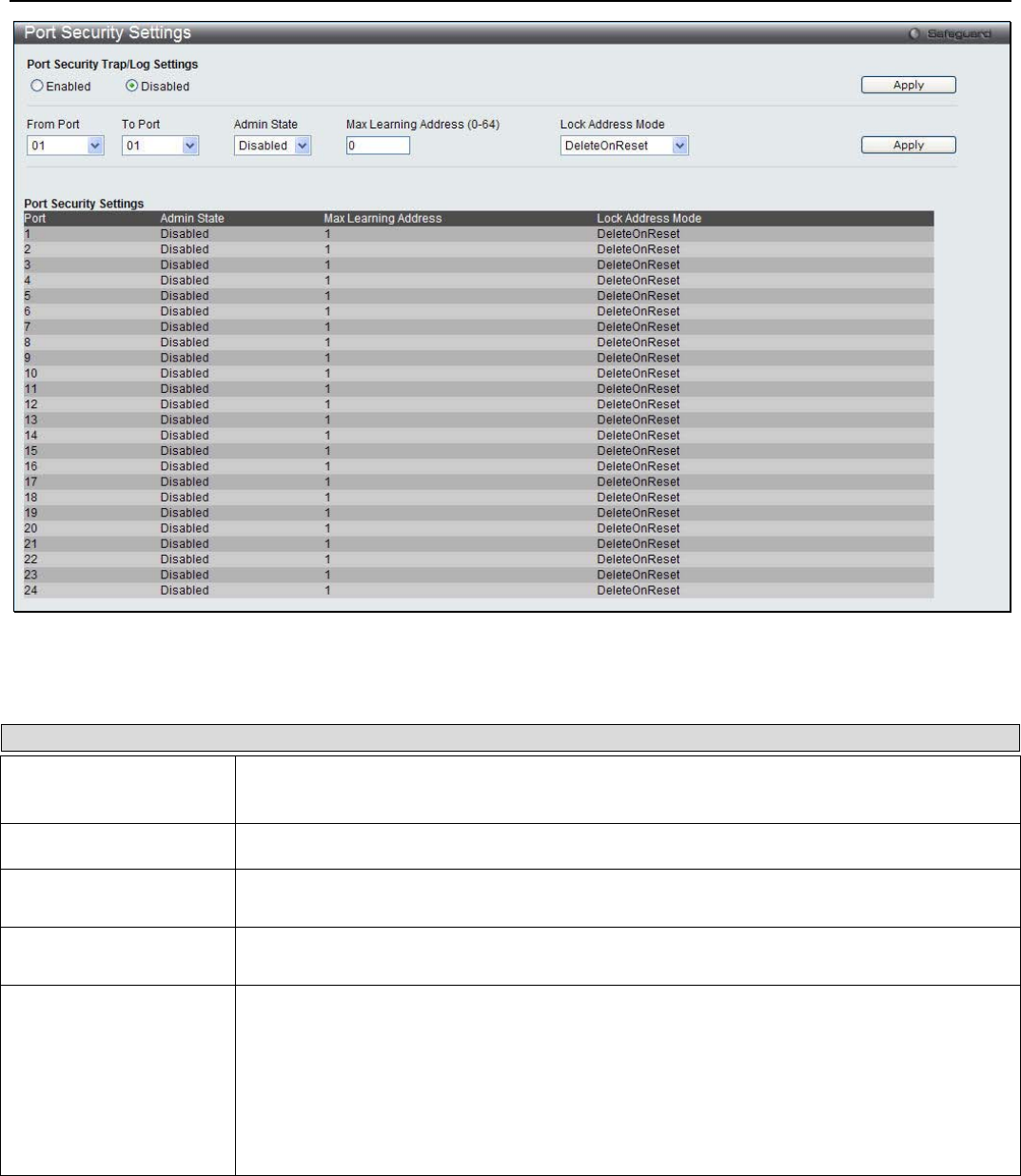
xStack® DGS-3200 Series Layer 2 Managed Gigabit Ethernet Switch Web UI Reference Guide
140
Figure 6 - 14. Port Security Settings window
The following parameters can be set:
Parameter Description
Port Security Trap/Log
Settings
Use the radio button to enable or disable Port Security Traps and Log Settings on the
Switch.
From Port / To Port Use the drop-down menu to select a range of ports to be configured.
Admin State This drop-down menu allows the user to enable or disable Port Security (locked MAC
address table for the selected ports).
Max Learning Address
(0-64) The number of MAC addresses that will be in the MAC address forwarding table for the
selected switch and group of ports.
Lock Address Mode This drop-down menu allows the option of how the MAC address table locking will be
implemented on the Switch, for the selected group of ports. The options are:
Permanent – Unless users manually delete these secured addresses from the switch, the
locked addresses will never be aged out, even when the Switch is restarted.
DeleteOnTimeout – The locked addresses will age out after the aging timer expires.
DeleteOnReset – The locked addresses will not age out until the Switch has been reset or
rebooted.
Click Apply to implement changes made.
Port Lock Entries
Users can remove an entry from the port security entries learned by the Switch and entered into the forwarding database. This
function is only operable if the Mode in the Port Security Settings window is selected as Permanent or DeleteOnReset, or in
other words, only addresses that are statically learned by the Switch can be deleted.
To view the following window, click Security > Port Security > Port Lock Entries:
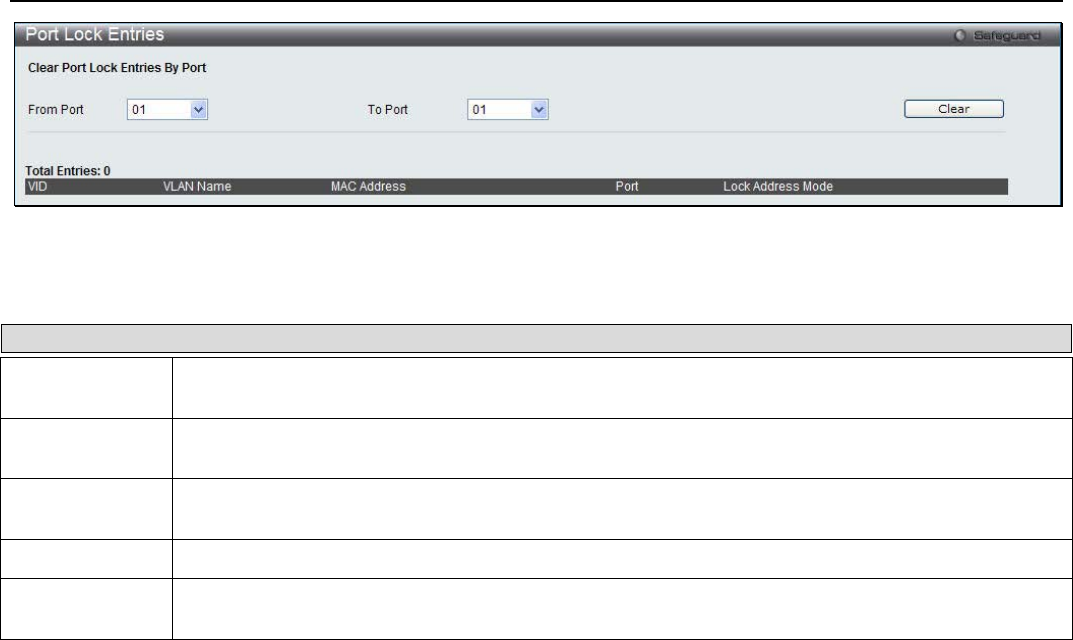
xStack® DGS-3200 Series Layer 2 Managed Gigabit Ethernet Switch Web UI Reference Guide
141
Figure 6 - 15. Port Lock Entries window
This window displays the following information:
Parameter Description
VID The VLAN ID of the entry in the forwarding database table that has been permanently learned by
the Switch.
VLAN Name The VLAN Name of the entry in the forwarding database table that has been permanently learned
by the Switch.
MAC Address The MAC address of the entry in the forwarding database table that has been permanently learned
by the Switch.
Port The ID number of the port that has permanently learned the MAC address.
Lock Address
Mode The lock address mode in the forwarding database table. Only entries marked Permanent or Delete
on Reset can be deleted.
Click Clear to remove the entry.
DHCP Server Screening
DHCP Screening Port Settings
The Switch supports DHCP Server Screening, a feature that denies access to rogue DHCP servers. When the DHCP server filter
function is enabled, all DHCP server packets will be filtered from a specific port.
To view the following window, click Security > DHCP Server Screening > DHCP Screening Port Settings:
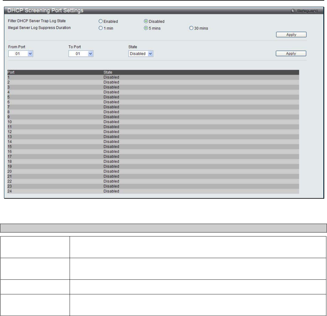
xStack® DGS-3200 Series Layer 2 Managed Gigabit Ethernet Switch Web UI Reference Guide
142
Figure 6 - 16. DHCP Screening Port Settings window
The user may set the following parameters:
Parameter Description
From DHCP Server
Trap Log State Enable or disable this feature.
Illegal Server Log
Suppress Duration Choose an illegal server log suppress duration of 1 minute, 5 minutes, or 30 minutes.
From Port / To Port Use the drop-down menu to select a range of ports.
State Choose Enabled to enable the DHCP server screening or Disabled to disable it. The default
is Disabled.
After setting the previous parameters, click Apply to allow your changes to be implemented.
DHCP Offer Filtering
This function allows the user to not only restrict all DHCP Server packets but also to receive any specified DHCP server packet by
any specified DHCP client, it is useful when one or more DHCP servers are present on the network and both provide DHCP
services to different distinct groups of clients. The first time the DHCP filter is enabled it will create both an access profile entry
and an access rule per port entry, it will also create other access rules. These rules are used to block all DHCP server packets. In
addition to a permit DHCP entry, it will also create one access profile and one access rule entry the first time the DHCP client
MAC address is used as the client MAC address. The Source IP address is the same as the DHCP server’s IP address (UDP source
port number 67). These rules are used to permit the DHCP server packets with specific fields, which the user has configured.
To view the following window, click Security > DHCP Server Screening > DHCP Offer Filtering:
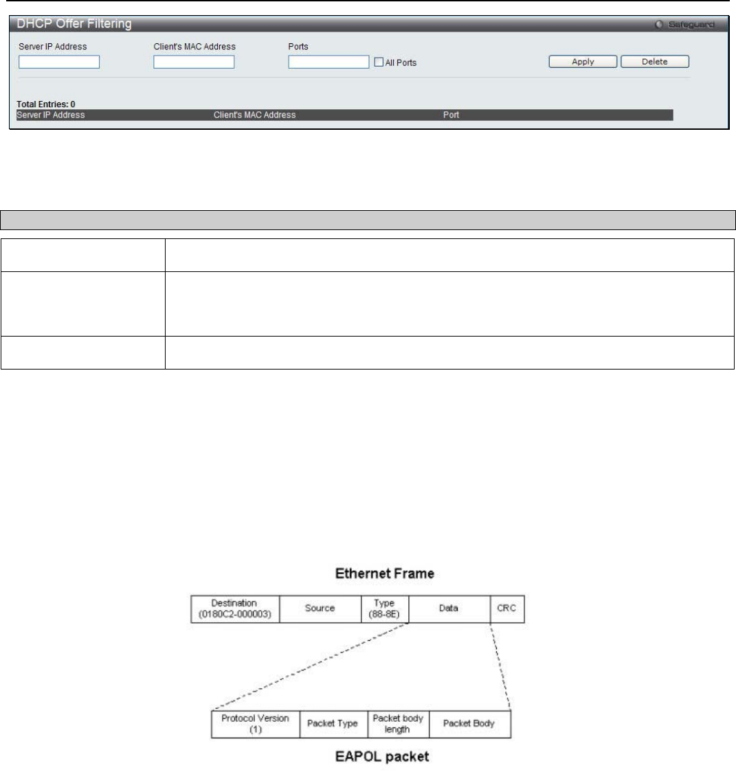
xStack® DGS-3200 Series Layer 2 Managed Gigabit Ethernet Switch Web UI Reference Guide
143
Figure 6 - 17. DHCP Offer Filtering window
The user may set the following parameters:
Parameter Description
Server IP Address The IP address of the DHCP server to be filtered.
Client’s MAC Address The MAC address of the DHCP client. Only multiple legal DHCP servers on the network
need to be entered in this field. If there is only one legal DHCP server on the network, no
input to this field is allowed.
Ports The port numbers of the filter DHCP server. Tick All ports to select all.
After setting the previous parameters, click Apply to allow your changes to be implemented. Click Delete to remove the specific
entry.
802.1X (Port-based and Host-based Access Control)
The IEEE 802.1X standard is a security measure for authorizing and authenticating users to gain access to various wired or
wireless devices on a specified Local Area Network by using a Client and Server based access control model. This is
accomplished by using a RADIUS server to authenticate users trying to access a network by relaying Extensible Authentication
Protocol over LAN (EAPOL) packets between the Client and the Server. The following figure represents a basic EAPOL packet:
Figure 6 - 18. EAPOL Packet
Utilizing this method, unauthorized devices are restricted from connecting to a LAN through a port to which the user is connected.
EAPOL packets are the only traffic that can be transmitted through the specific port until authorization is granted. The 802.1X
Access Control method has three roles, each of which are vital to creating and up keeping a stable and working Access Control
security method.
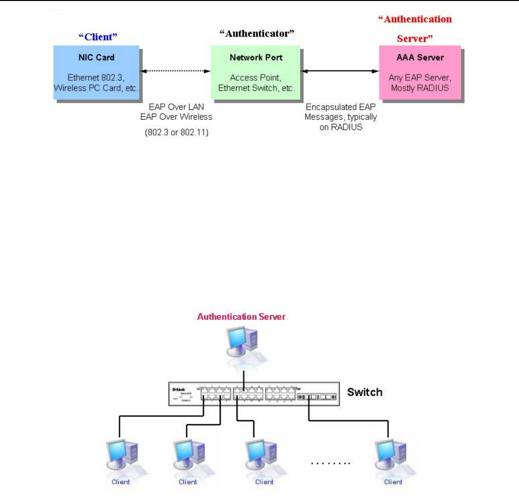
xStack® DGS-3200 Series Layer 2 Managed Gigabit Ethernet Switch Web UI Reference Guide
144
Figure 6 - 19. Three Roles of 802.1X
The following section will explain the three roles of Client, Authenticator and Authentication Server in greater detail.
Authentication Server
The Authentication Server is a remote device that is connected to the same network as the Client and Authenticator, must be
running a RADIUS Server program and must be configured properly on the Authenticator (Switch). Clients connected to a port on
the Switch must be authenticated by the Authentication Server (RADIUS) before attaining any services offered by the Switch on
the LAN. The role of the Authentication Server is to certify the identity of the Client attempting to access the network by
exchanging secure information between the RADIUS server and the Client through EAPOL packets and, in turn, informs the
Switch whether or not the Client is granted access to the LAN and/or switches services.
Figure 6 - 20. Authentication Server
Authenticator
The Authenticator (the Switch) is an intermediary between the Authentication Server and the Client. The Authenticator serves two
purposes when utilizing the 802.1X function. The first purpose is to request certification information from the Client through
EAPOL packets, which is the only information allowed to pass through the Authenticator before access is granted to the Client.
The second purpose of the Authenticator is to verify the information gathered from the Client with the Authentication Server, and
to then relay that information back to the Client.
Three steps must be implemented on the Switch to properly configure the Authenticator.
1. The 802.1X State must be Enabled. (Security / 802.1X /802.1X Settings)
2. The 802.1X settings must be implemented by port (Security / 802.1X / 802.1X Settings)
3. A RADIUS server must be configured on the Switch. (Security / 802.1X / Authentic RADIUS Server)
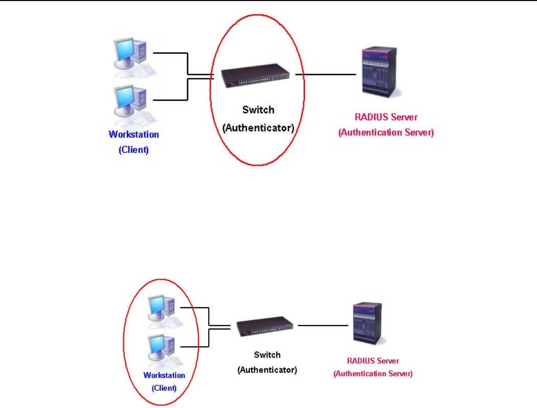
xStack® DGS-3200 Series Layer 2 Managed Gigabit Ethernet Switch Web UI Reference Guide
145
Figure 6 - 21. Authenticator
Client
The Client is simply the endstation that wishes to gain access to the LAN or switch services. All end stations must be running
software that is compliant with the 802.1X protocol. For users running Windows XP and Windows Vista, that software is included
within the operating system. All other users are required to attain 802.1X client software from an outside source. The Client will
request access to the LAN and or Switch through EAPOL packets and, in turn will respond to requests from the Switch.
Figure 6 - 22. Client
Authentication Process
Utilizing the three roles stated above, the 802.1X protocol provides a stable and secure way of authorizing and authenticating
users attempting to access the network. Only EAPOL traffic is allowed to pass through the specified port before a successful
authentication is made. This port is “locked” until the point when a Client with the correct username and password (and MAC
address if 802.1X is enabled by MAC address) is granted access and therefore successfully “unlocks” the port. Once unlocked,
normal traffic is allowed to pass through the port. The following figure displays a more detailed explanation of how the
authentication process is completed between the three roles stated above.

xStack® DGS-3200 Series Layer 2 Managed Gigabit Ethernet Switch Web UI Reference Guide
146
Figure 6 - 23. 802.1X Authentication Process
The D-Link implementation of 802.1X allows network administrators to choose between two types of Access Control used on the
Switch, which are:
1. Port-based Access Control – This method requires only one user to be authenticated per port by a remote RADIUS server
to allow the remaining users on the same port access to the network.
2. Host-based Access Control – Using this method, the Switch will automatically learn up to sixteen MAC addresses by port
and set them in a list. Each MAC address must be authenticated by the Switch using a remote RADIUS server before
being allowed access to the Network.
Understanding 802.1X Port-based and Host-based Network Access Control
The original intent behind the development of 802.1X was to leverage the characteristics of point-to-point in LANs. As any single
LAN segment in such infrastructures has no more than two devices attached to it, one of which is a Bridge Port. The Bridge Port
detects events that indicate the attachment of an active device at the remote end of the link, or an active device becoming inactive.
These events can be used to control the authorization state of the Port and initiate the process of authenticating the attached device
if the Port is unauthorized. This is the Port-Based Network Access Control.
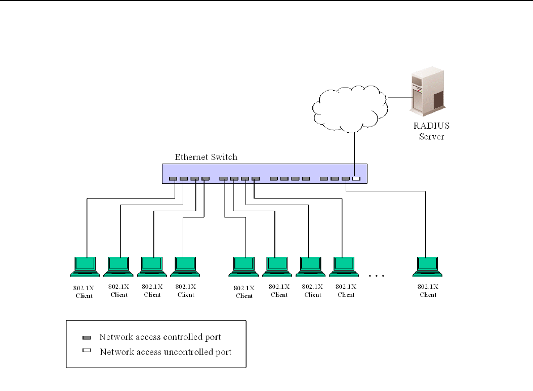
xStack® DGS-3200 Series Layer 2 Managed Gigabit Ethernet Switch Web UI Reference Guide
147
Port-based Network Access Control
Figure 6 - 24. Example of Typical Port-based Configuration
Once the connected device has successfully been authenticated, the Port then becomes Authorized, and all subsequent traffic on
the Port is not subject to access control restriction until an event occurs that causes the Port to become Unauthorized. Hence, if the
Port is actually connected to a shared media LAN segment with more than one attached device, successfully authenticating one of
the attached devices effectively provides access to the LAN for all devices on the shared segment. Clearly, the security offered in
this situation is open to attack.
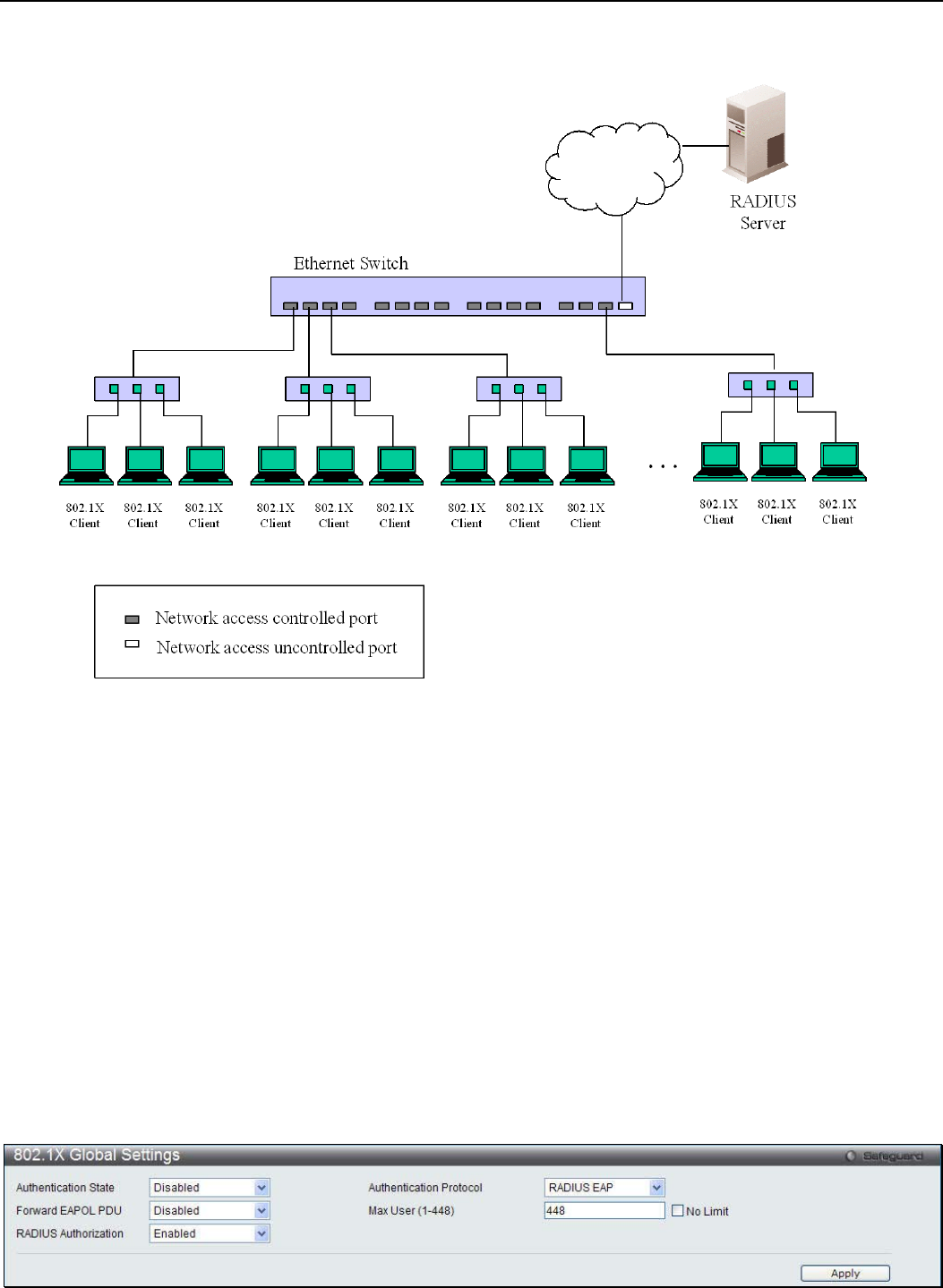
xStack® DGS-3200 Series Layer 2 Managed Gigabit Ethernet Switch Web UI Reference Guide
148
Host-based Network Access Control
Figure 6 - 25. Example of Typical Host-based Configuration
In order to successfully make use of 802.1X in a shared media LAN segment, it would be necessary to create “logical” Ports, one
for each attached device that required access to the LAN. The Switch would regard the single physical Port connecting it to the
shared media segment as consisting of a number of distinct logical Ports, each logical Port being independently controlled from
the point of view of EAPOL exchanges and authorization state. The Switch learns each attached devices’ individual MAC
addresses, and effectively creates a logical Port that the attached device can then use to communicate with the LAN via the
Switch.
The 802.1X folder contains seven windows (depending on the current 802.1X) settings: 802.1X Settings, 802.1X User, Initialize
Port(s) (Port-based and MAC-based), Reauthenticate Port(s) (Port-based and MAC-based), and Authentic RADIUS Server.
802.1X Global Settings
Users can configure 802.1X authenticator settings.
To view the following window, click Security > 802.1X > 802.1X Global Settings:
Figure 6 - 26. 802.1X Global Settings window

xStack® DGS-3200 Series Layer 2 Managed Gigabit Ethernet Switch Web UI Reference Guide
149
The following parameters can be configured:
Parameter Description
Authentication State Use the drop-down menu to enable or disable the 802.1X function.
Authentication
Protocol
Choose the authenticator protocol, Local or RADIUS EAP.
Forward EAPOL PDU This is a global setting to control the forwarding of EAPOL PDU. When 802.1X functionality
is disabled globally or for a port, and if 802.1X forward PDU is enabled both globally and for
the port, a received EAPOL packet on the port will be flooded in the same VLAN to those
ports for which 802.1X forward PDU is enabled and 802.1X is disabled (globally or just for
the port). The default state is disabled.
Max User (1-448) Specifies the maximum number of users. The limit on the maximum users is 448 users.
This the No Limit check box to have unlimited users.
RADIUS Authorization This option is used to enable or disable acceptation of authorized configuration. When the
authorization is enabled for 802.1X’s RADIUS, the authorized data assigned by the
RADIUS server will be accepted if the global authorization network is enabled.
Click Apply to implement configuration changes.
802.1X Port Settings
This window is used to configure the 802.1X authenticator port settings.
To view the following window, click Security > 802.1X > 802.1X Port Settings:
Figure 6 - 27. 802.1X Port Settings window
The following parameters can be configured:
Parameter Description

xStack® DGS-3200 Series Layer 2 Managed Gigabit Ethernet Switch Web UI Reference Guide
150
From Port / To Port Select a range of ports you wish to configure.
QuietPeriod (0-65535) This allows the user to set the number of seconds that the Switch remains in the quiet state
following a failed authentication exchange with the client. The default setting is 60 seconds.
SuppTimeout (1-
65535) This value determines timeout conditions in the exchanges between the Authenticator and
the client. The default setting is 30 seconds. It is defined in SuppTimeout, IEEE-802.1X-
2001, page 47. The initialization value is used for the awhile timer when timing out the
Supplicant. Its default value is 30 seconds; however, if the type of challenge involved in the
current exchange demands a different value of timeout (for example, if the challenge
requires an action on the part of the user), then the timeout value is adjusted accordingly. It
can be set by management to any value in the range from 1 to 65535 seconds.
ServerTimeout (1-
65535) This value determines timeout conditions in the exchanges between the Authenticator and
the authentication server. The default setting is 30 seconds.
MaxReq (1-10) The maximum number of times that the Switch will retransmit an EAP Request to the client
before it times out of the authentication sessions. The default setting is 2. It is defined in
MaxReq, IEEE-802.1X-2001 page 47. The maximum number of times that the state
machine will retransmit an EAP Request packet to the Supplicant before it times out the
authentication session. Its default value is 2; it can be set by management to any value in
the range from 1 to 10.
TxPeriod (1-65535) This sets the TxPeriod of time for the authenticator PAE state machine. This value
determines the period of an EAP Request/Identity packet transmitted to the client. The
default setting is 30 seconds.
ReAuthPeriod (1-
65535) A constant that defines a nonzero number of seconds between periodic re-authentication of
the client. The default setting is 3600 seconds.
ReAuthentication Determines whether regular re-authentication will take place on this port. The default setting
is Disabled.
Port Control This allows the user to control the port authorization state.
Select ForceAuthorized to disable 802.1X and cause the port to transition to the authorized
state without any authentication exchange required. This means the port transmits and
receives normal traffic without 802.1X-based authentication of the client.
If ForceUnauthorized is selected, the port will remain in the unauthorized state, ignoring all
attempts by the client to authenticate. The Switch cannot provide authentication services to
the client through the interface.
If Auto is selected, it will enable 802.1X and cause the port to begin in the unauthorized
state, allowing only EAPOL frames to be sent and received through the port. The
authentication process begins when the link state of the port transitions from down to up, or
when an EAPOL-start frame is received. The Switch then requests the identity of the client
and begins relaying authentication messages between the client and the authentication
server.
The default setting is Auto.
Capability This allows the 802.1X Authenticator settings to be applied on a per-port basis. Select
Authenticator to apply the settings to the port. When the setting is activated, a user must
pass the authentication process to gain access to the network. Select None disable 802.1X
functions on the port.
Direction Sets the administrative-controlled direction to Both. Control is exerted over both incoming
and outgoing traffic through the controlled port selected in the first field.
Forward EAPOL PDU This is a port-based setting to control the forwarding of EAPOL PDU. When 802.1X
functionality is disabled globally or for a port, and if 802.1X forward PDU is enabled both
globally and for the port, a received EAPOL packet on the port will be flooded in the same
VLAN to those ports for which 802.1X forward PDU is enabled and 802.1X is disabled
(globally or just for the port). The default state is disabled.
Max Users (1-448) Specifies the maximum number of users. The maximum user limit is 448 users. The default
is 16. Tick No Limit to have unlimited users.
Click the Refresh button to refresh the display table so that new entries will appear. Click Apply to implement configuration
changes.
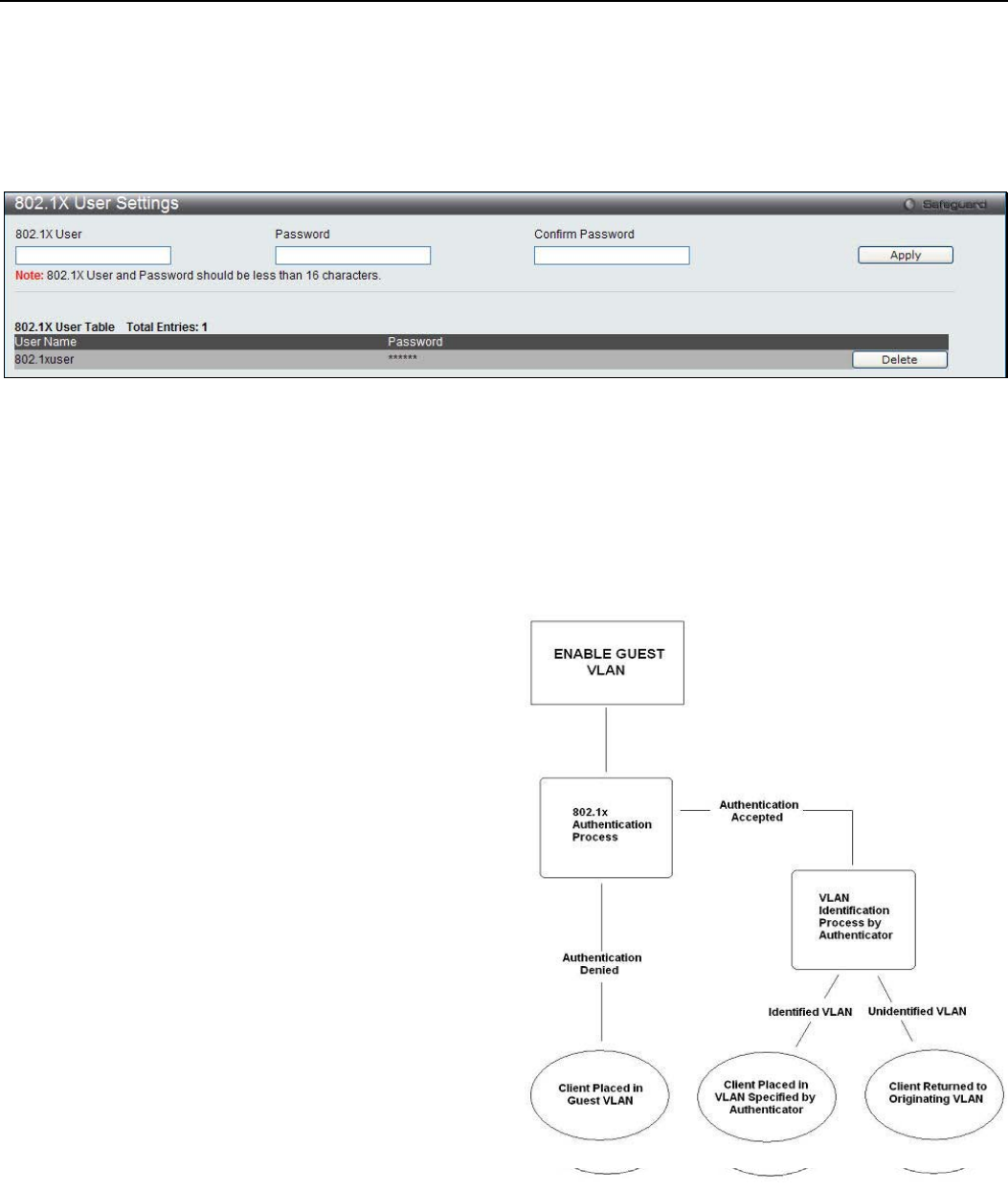
xStack® DGS-3200 Series Layer 2 Managed Gigabit Ethernet Switch Web UI Reference Guide
151
802.1X User Settings
Users can set different local users on the Switch.
To view the following window, click Security > 802.1X > 802.1X User Settings:
Figure 6 - 28. 802.1X User Settings window
Enter an 802.1X user name, password, and confirmation of that password. Properly configured local users will be displayed in the
802.1X User Table at the bottom of the window. Click Apply to implement configuration changes. Click Delete to remove the
specific entry.
Guest VLAN Settings
Figure 6 - 29. Guest VLAN Authentication Process
Limitations Using the Guest VLAN
1. Ports supporting Guest VLANs cannot be GVRP enabled and vice versa.
2. A port cannot be a member of a Guest VLAN and a static VLAN simultaneously.
3. Once a client has been accepted into the target VLAN, it can no longer access the Guest VLAN.
4. If a port is a member of multiple VLANs, it cannot become a member of the Guest VLAN.
On 802.1X security-enabled networks, there is a need for non-
802.1X supported devices to gain limited access to the network,
due to lack of the proper 802.1X software or incompatible
devices, such as computers running Windows 98 or older
operating systems, or the need for guests to gain access to the
network without full authorization or local authentication on the
Switch. To supplement these circumstances, this switch now
implements 802.1X Guest VLANs. These VLANs should have
limited access rights and features separate from other VLANs on
the network.
To implement 802.1X Guest VLANs, the user must first create a
VLAN on the network with limited rights and then enable it as an
802.1X guest VLAN. Then the administrator must configure the
guest accounts accessing the Switch to be placed in a Guest
VLAN when trying to access the Switch. Upon initial entry to the
Switch, the client wishing services on the Switch will need to be
authenticated by a remote RADIUS Server or local authentication
on the Switch to be placed in a fully operational VLAN. If
authenticated and the authenticator possesses the VLAN
placement information, that client will be accepted into the fully
operational target VLAN and normal switch functions will be
open to the client. If the authenticator does not have target VLAN
placement information, the client will be returned to its
originating VLAN. Yet, if the client is denied authentication by
the authenticator, it will be placed in the Guest VLAN where it
has limited rights and access. The adjacent figure should give the
user a better understanding of the Guest VLAN process.

xStack® DGS-3200 Series Layer 2 Managed Gigabit Ethernet Switch Web UI Reference Guide
152
Remember, to set an 802.1X guest VLAN, the user must first configure a normal VLAN, which can be enabled here for guest
VLAN status.
To view the following window, click Security > 802.1X > Guest VLAN Settings:
Figure 6 - 30. Guest VLAN Settings window
The following fields may be modified to enable the 802.1X guest VLAN:
Parameter Description
VLAN Name Enter the pre-configured VLAN name to create as an 802.1X guest VLAN.
Port Set the ports to be enabled for the 802.1X guest VLAN. Click All to select all ports.
Click Apply to implement the guest VLAN settings entered. Only one VLAN may be assigned as the 802.1X guest VLAN.
Authenticator State
This window is used to display the authenticator state. This window appears when the Authentication State is enabled in 802.1X
Global Settings window.
To view the following window, click Security > 802.1X > Authenticator State:
Figure 6 - 31. Authenticator State window
The following parameter can be configured:
Parameter Description
Port Use the drop-down menu to select a port.
Click the Find button to locate a specific entry based on the information entered. Click the Refresh button to refresh the display
table so that new entries will appear.
Authenticator Statistics
This window is used to display the authenticator statistics information. This window appears when the Authentication State is
enabled in 802.1X Global Settings window.
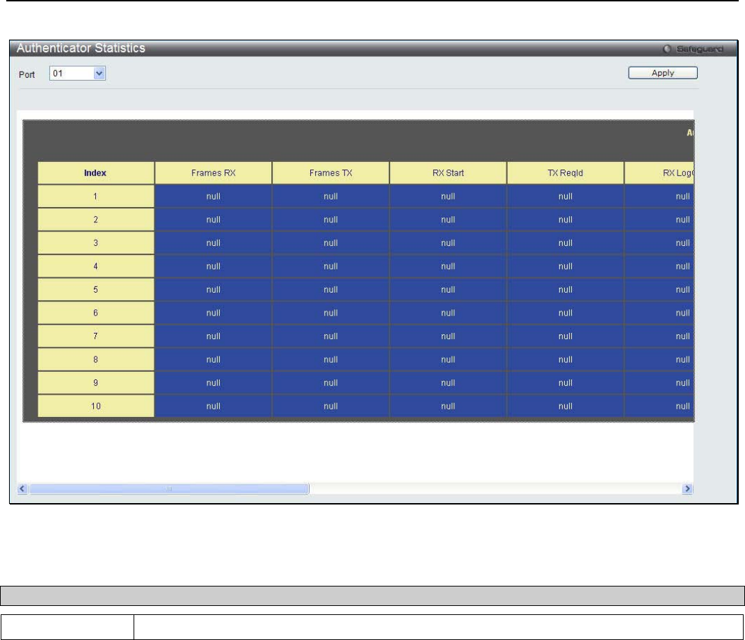
xStack® DGS-3200 Series Layer 2 Managed Gigabit Ethernet Switch Web UI Reference Guide
153
To view the following window, click Security > 802.1X > Authenticator Statistics:
Figure 6 - 32. Authenticator Statistics window
The following parameter can be configured:
Parameter Description
Port Use the drop-down menu to select a port.
Click the Apply button to accept the changes made.
Authenticator Session Statistics
This window is used to display the authenticator session statistics information. This window appears when the Authentication
State is enabled in 802.1X Global Settings window.
To view the following window, click Security > 802.1X > Authenticator Session Statistics:
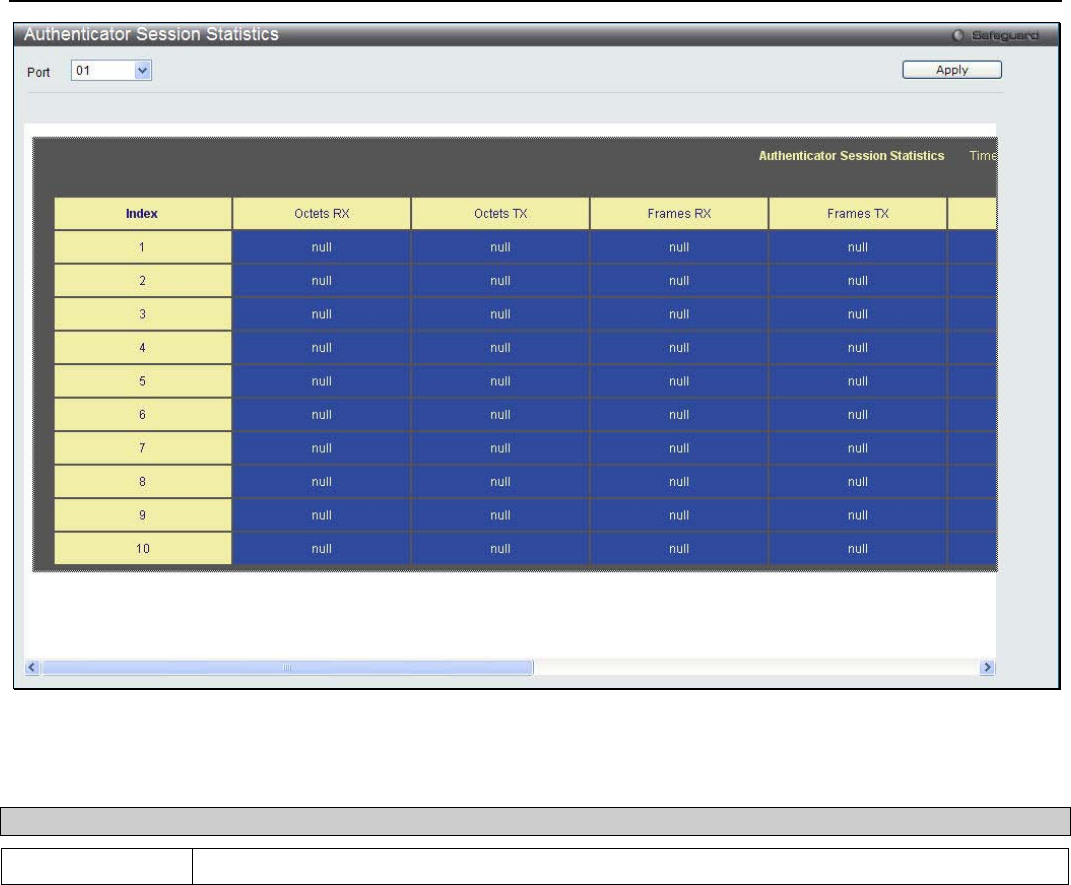
xStack® DGS-3200 Series Layer 2 Managed Gigabit Ethernet Switch Web UI Reference Guide
154
Figure 6 - 33. Authenticator Session Statistics window
The following parameter can be configured:
Parameter Description
Port Use the drop-down menu to select a port.
Click the Apply button to accept the changes made.
Authenticator Diagnostics
This window is used to display the authenticator diagnostics information. This window appears when the Authentication State is
enabled in 802.1X Global Settings window.
To view the following window, click Security > 802.1X > Authenticator Diagnostics:
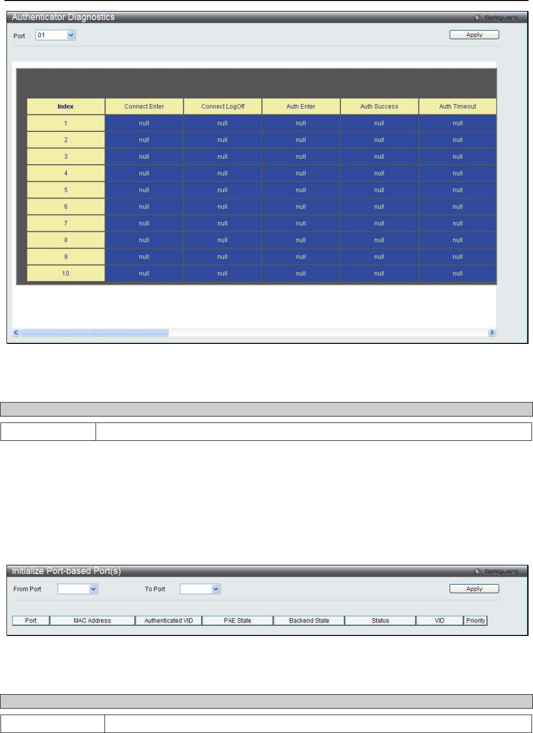
xStack® DGS-3200 Series Layer 2 Managed Gigabit Ethernet Switch Web UI Reference Guide
155
Figure 6 - 34. Authenticator Diagnostics window
The following parameter can be configured:
Parameter Description
Port Use the drop-down menu to select a port.
Click the Apply button to accept the changes made.
Initialize Port-based Port(s)
This window displays the current initialized port-based ports. This window appears when the Authentication State is enabled in
802.1X Global Settings window.
To view the following window, click Security > 802.1X > Initialize Port-based Port(s):
Figure 6 - 35. Initialize Port-based Port(s) window
The following parameter can be configured:
Parameter Description
From Port / To Port Use the drop-down menus to select a range of ports.
Click the Apply button to accept the changes made.

xStack® DGS-3200 Series Layer 2 Managed Gigabit Ethernet Switch Web UI Reference Guide
156
Initialize Host-based Port(s)
This window displays the current initialized host-based ports. This window appears when the Authentication State is enabled in
802.1X Global Settings window.
To view the following window, click Security > 802.1X > Initialize Host-based Port(s):
Figure 6 - 36. Initialize Host-based Port(s) window
The following parameter can be configured:
Parameter Description
From Port / To Port Use the drop-down menus to select a range of ports.
MAC Address Tick the check box and enter the authenticated MAC address of the client connected to the
corresponding port.
Click the Apply button to accept the changes made.
Reauthenticate Port-based Port(s)
This window is used to display the current status of the re-authenticated port-based port(s). This window appears when the
Authentication State is enabled in 802.1X Global Settings window.
To view the following window, click Security > 802.1X > Reauthenticate Port-based Port(s):
Figure 6 - 37. Reauthenticate Port-based Port(s) window
The following parameter can be configured:
Parameter Description
From Port / To Port Use the drop-down menus to select a range of ports.
Click the Apply button to accept the changes made.
Reauthenticate Host-based Port(s)
This window is used to display the current status of the re-authenticated host-based port(s). This window appears when the
Authentication State is enabled in 802.1X Global Settings window.
To view the following window, click Security > 802.1X > Reauthenticate Host-based Port(s):
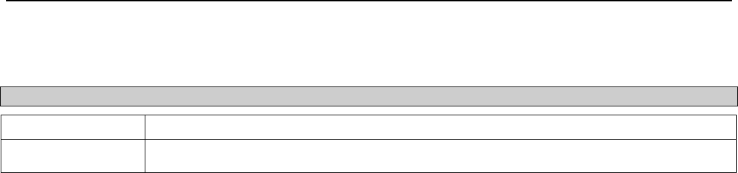
xStack® DGS-3200 Series Layer 2 Managed Gigabit Ethernet Switch Web UI Reference Guide
157
Figure 6 - 38. Reauthenticate Host-based Port(s) window
The following parameter can be configured:
Parameter Description
From Port / To Port Use the drop-down menus to select a range of ports.
MAC Address The authenticated MAC address of the client connected to the corresponding port, if any.
Click the Apply button to accept the changes made.
SSL
SSL Settings
Secure Sockets Layer, or SSL, is a security feature that will provide a secure communication path between a host and client
through the use of authentication, digital signatures and encryption. These security functions are implemented through the use of a
cyphersuite, which is a security string that determines the exact cryptographic parameters, specific encryption algorithms and key
sizes to be used for an authentication session and consists of three levels:
1. Key Exchange: The first part of the cyphersuite string specifies the public key algorithm to be used. This switch utilizes
the Rivest Shamir Adleman (RSA) public key algorithm and the Digital Signature Algorithm (DSA), specified here as the
DHE DSS Diffie-Hellman (DHE) public key algorithm. This is the first authentication process between client and host as
they “exchange keys” in looking for a match and therefore authentication to be accepted to negotiate encryptions on the
following level.
2. Encryption: The second part of the ciphersuite that includes the encryption used for encrypting the messages sent
between client and host. The Switch supports two types of cryptology algorithms:
Stream Ciphers – There are two types of stream ciphers on the Switch, RC4 with 40-bit keys and RC4 with 128-bit keys. These
keys are used to encrypt messages and need to be consistent between client and host for optimal use.
CBC Block Ciphers – CBC refers to Cipher Block Chaining, which means that a portion of the previously encrypted block of
encrypted text is used in the encryption of the current block. The Switch supports the 3DES EDE encryption code defined by the
Data Encryption Standard (DES) to create the encrypted text.
3. Hash Algorithm: This part of the ciphersuite allows the user to choose a message digest function which will determine a
Message Authentication Code. This Message Authentication Code will be encrypted with a sent message to provide
integrity and prevent against replay attacks. The Switch supports two hash algorithms, MD5 (Message Digest 5) and SHA
(Secure Hash Algorithm).
These three parameters are uniquely assembled in four choices on the Switch to create a three-layered encryption code for secure
communication between the server and the host. The user may implement any one or combination of the ciphersuites available,
yet different ciphersuites will affect the security level and the performance of the secured connection. The information included in
the ciphersuites is not included with the Switch and requires downloading from a third source in a file form called a certificate.
This function of the Switch cannot be executed without the presence and implementation of the certificate file and can be
downloaded to the Switch by utilizing a TFTP server. The Switch supports SSLv3. Other versions of SSL may not be compatible
with this Switch and may cause problems upon authentication and transfer of messages from client to host.
The SSL Settings window located on the next page will allow the user to enable SSL on the Switch and implement any one or
combination of listed ciphersuites on the Switch. A ciphersuite is a security string that determines the exact cryptographic
parameters, specific encryption algorithms and key sizes to be used for an authentication session. The Switch possesses four
possible ciphersuites for the SSL function, which are all enabled by default. To utilize a particular ciphersuite, disable the
unwanted ciphersuites, leaving the desired one for authentication.
When the SSL function has been enabled, the web will become disabled. To manage the Switch through the web based
management while utilizing the SSL function, the web browser must support SSL encryption and the header of the URL must
begin with https://. (Ex. https://xx.xx.xx.xx) Any other method will result in an error and no access can be authorized for the web-
based management.
Users can download a certificate file for the SSL function on the Switch from a TFTP server. The certificate file is a data record
used for authenticating devices on the network. It contains information on the owner, keys for authentication and digital
signatures. Both the server and the client must have consistent certificate files for optimal use of the SSL function. The Switch
only supports certificate files with .der file extensions. Currently, the Switch comes with a certificate pre-loaded though the user
may need to download more, depending on user circumstances.
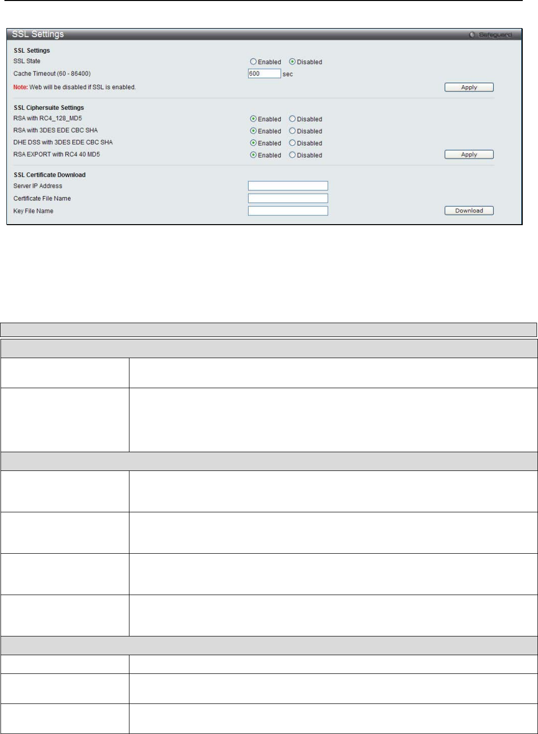
xStack® DGS-3200 Series Layer 2 Managed Gigabit Ethernet Switch Web UI Reference Guide
158
To view the following window, click Security > SSL > SSL Settings:
Figure 6 - 39. SSL Settings window
To set up the SSL function on the Switch, configure the parameters in the SSL Settings section described below and click Apply.
To set up the SSL ciphersuite function on the Switch, configure the parameters in the SSL Ciphersuite Settings section described
below and click Apply.
To download SSL certificates, configure the parameters in the SSL Certificate Download section described below and click
Download.
Parameter Description
SSL Settings
SSL State Use the radio buttons to enable or disable the SSL status on the Switch. The default is
Disabled.
Cache Timeout (60-
86400) This field will set the time between a new key exchange between a client and a host using
the SSL function. A new SSL session is established every time the client and host go
through a key exchange. Specifying a longer timeout will allow the SSL session to reuse
the master key on future connections with that particular host, therefore speeding up the
negotiation process. The default setting is 600 seconds.
SSL Ciphersuite Settings
RSA with RC4_128_MD5 This ciphersuite combines the RSA key exchange, stream cipher RC4 encryption with 128-
bit keys and the MD5 Hash Algorithm. Use the radio buttons to enable or disable this
ciphersuite. This field is Enabled by default.
RSA with 3DES EDE
CBC SHA This ciphersuite combines the RSA key exchange, CBC Block Cipher 3DES_EDE
encryption and the SHA Hash Algorithm. Use the radio buttons to enable or disable this
ciphersuite. This field is Enabled by default.
DHE DSS with 3DES EDE
CBC SHA This ciphersuite combines the DSA Diffie Hellman key exchange, CBC Block Cipher
3DES_EDE encryption and SHA Hash Algorithm. Use the radio buttons to enable or
disable this ciphersuite. This field is Enabled by default.
RSA EXPORT with RC4
40 MD5 This ciphersuite combines the RSA Export key exchange and stream cipher RC4
encryption with 40-bit keys. Use the radio buttons to enable or disable this ciphersuite. This
field is Enabled by default.
SSL Certificate Download
Server IP Address Enter the IPv4 address of the TFTP server where the certificate files are located.
Certificate File Name Enter the path and the filename of the certificate file to download. This file must have a .der
extension. (Ex. c:/cert.der)
Key File Name Enter the path and the filename of the key file to download. This file must have a .der
extension (Ex. c:/pkey.der)
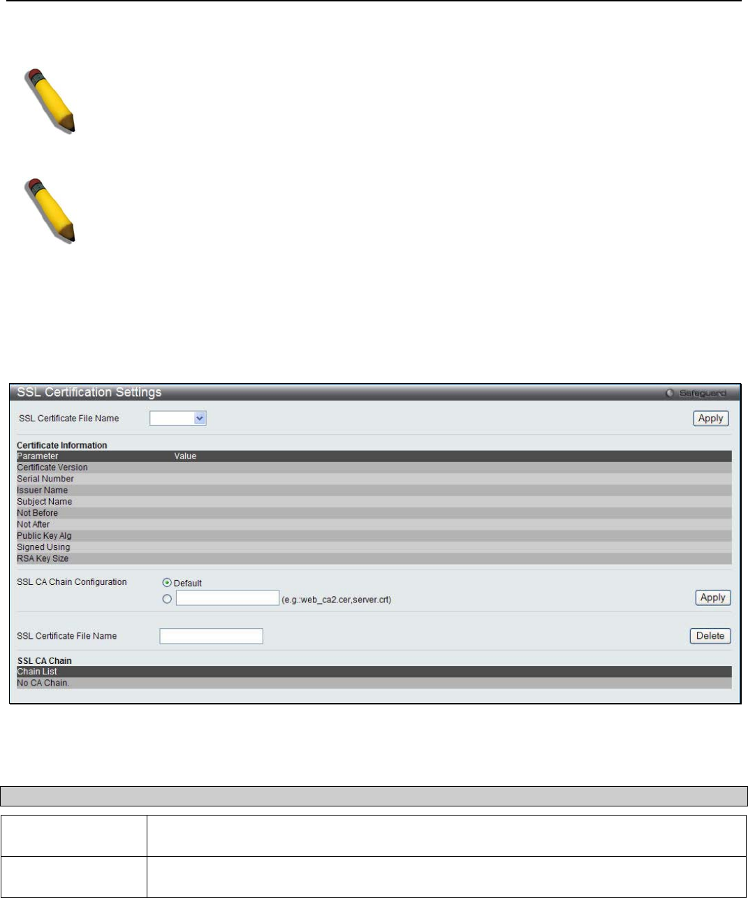
xStack® DGS-3200 Series Layer 2 Managed Gigabit Ethernet Switch Web UI Reference Guide
159
Click Apply to implement changes made.
NOTE: Certain implementations concerning the function and configuration of SSL are not available
on the web-based management of this Switch and need to be configured using the command line
interface.
NOTE: Enabling the SSL command will disable the web-based switch management. To log on to
the Switch again, the header of the URL must begin with https://. Entering anything else into the
address field of the web browser will result in an error and no authentication will be granted.
SSL Certification Settings
This window is used to display SSL certification settings
To view the following window, click Security > SSL > SSL Certification Settings:
Figure 6 - 40. SSL Certification Settings window
The following parameter can be configured:
Parameter Description
SSL Cerficate File
Name Specify the SSL certificate file name.
SSL CA Chain
Configuration Click the Default radio button to use the build-in certification on the Switch, or click the radio
button below to specify chain of certifications on the Switch.
Click the Apply button to accept the changes made. Click Delete to remove the specified entry.
SSH
SSH is an abbreviation of Secure Shell, which is a program allowing secure remote login and secure network services over an
insecure network. It allows a secure login to remote host computers, a safe method of executing commands on a remote end node,
and will provide secure encrypted and authenticated communication between two non-trusted hosts. SSH, with its array of

xStack® DGS-3200 Series Layer 2 Managed Gigabit Ethernet Switch Web UI Reference Guide
160
unmatched security features is an essential tool in today’s networking environment. It is a powerful guardian against numerous
existing security hazards that now threaten network communications.
The steps required to use the SSH protocol for secure communication between a remote PC (the SSH client) and the Switch (the
SSH server) are as follows:
1. Create a user account with admin-level access using the User Accounts window (Configuration > Port Configuration
> User Accounts). This is identical to creating any other admin-level User Account on the Switch, including specifying a
password. This password is used to logon to the Switch, once a secure communication path has been established using
the SSH protocol.
2. Configure the User Account to use a specified authorization method to identify users that are allowed to establish SSH
connections with the Switch using the SSH User Authentication Mode window. There are three choices as to the
method SSH will use to authorize the user, which are Host Based, Password, and Public Key.
3. Configure the encryption algorithm that SSH will use to encrypt and decrypt messages sent between the SSH client and
the SSH server, using the SSH Authmode and Algorithm Settings window.
4. Finally, enable SSH on the Switch using the SSH Configuration window.
After completing the preceding steps, a SSH Client on a remote PC can be configured to manage the Switch using a secure, in
band connection.
SSH Settings
Users can configure and view settings for the SSH server.
To view the following window, click Security > SSH > SSH Settings:
Figure 6 - 41. SSH Settings window
To configure the SSH server on the Switch, modify the following parameters and click Apply:
Parameter Description
SSH Server State Use the radio buttons to enable or disable SSH on the Switch. The default is Disabled.
Max Session (1-8) Enter a value between 1 and 8 to set the number of users that may simultaneously access
the Switch. The default setting is 8.
Connection Timeout
(120-600 sec) Allows the user to set the connection timeout. The user may set a time between 120 and 600
seconds. The default setting is 120 seconds.
Authfail Attempts (2-
20) Allows the Administrator to set the maximum number of attempts that a user may try to log
on to the SSH Server utilizing the SSH authentication. After the maximum number of
attempts has been exceeded, the Switch will be disconnected and the user must reconnect
to the Switch to attempt another login. The number of maximum attempts may be set
between 2 and 20. The default setting is 2.
Rekey Timeout This field is used to set the time period that the Switch will change the security shell
encryptions by using the drop-down menu. The available options are Never, 10 min, 30 min,
and 60 min. The default setting is Never.
TCP Port Number (1-
65535) Enter the TCP Port Number used for SSH. The default value is 22.
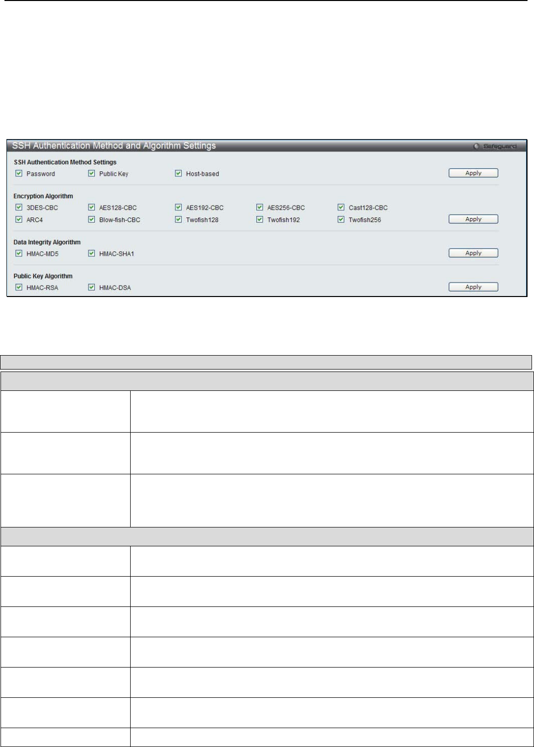
xStack® DGS-3200 Series Layer 2 Managed Gigabit Ethernet Switch Web UI Reference Guide
161
Click Apply to implement the changes.
SSH Authentication Method and Algorithm Settings
Users can configure the desired types of SSH algorithms used for authentication encryption. There are three categories of
algorithms listed and specific algorithms of each may be enabled or disabled by ticking their corresponding check boxes. All
algorithms are enabled by default.
To view the following window, click Security > SSH > SSH Authentication Method and Algorithm Settings:
Figure 6 - 42. SSH Authentication method and Algorithm Settings window
The following algorithms may be set:
Parameter Description
SSH Authentication Mode Settings
Password This may be enabled or disabled to choose if the administrator wishes to use a locally
configured password for authentication on the Switch. This parameter is enabled by
default.
Public Key This may be enabled or disabled to choose if the administrator wishes to use a public key
configuration set on a SSH server, for authentication. This parameter is enabled by
default.
Host-based This may be enabled or disabled to choose if the administrator wishes to use a host
computer for authentication. This parameter is intended for Linux users requiring SSH
authentication techniques and the host computer is running the Linux operating system
with a SSH program previously installed. This parameter is enabled by default.
Encryption Algorithm
3DES-CBC Use the check box to enable or disable the Triple Data Encryption Standard encryption
algorithm with Cipher Block Chaining. The default is enabled.
AES128-CBC Use the check box to enable or disable the Advanced Encryption Standard AES128
encryption algorithm with Cipher Block Chaining. The default is enabled.
AES192-CBC Use the check box to enable or disable the Advanced Encryption Standard AES192
encryption algorithm with Cipher Block Chaining. The default is enabled.
AES256-CBC Use the check box to enable or disable the Advanced Encryption Standard AES-256
encryption algorithm with Cipher Block Chaining. The default is enabled.
Cast128-CBC Use the check box to enable or disable the Cast128 encryption algorithm with Cipher
Block Chaining. The default is enabled.
ARC4 Use the check box to enable or disable the Arcfour encryption algorithm with Cipher
Block Chaining. The default is enabled.
Blow-fish CBC Use the check box to enable or disable the Blowfish encryption algorithm with Cipher
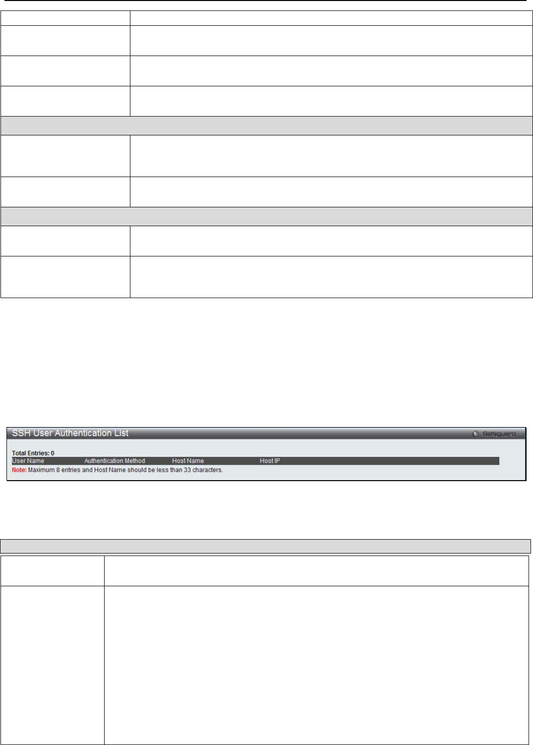
xStack® DGS-3200 Series Layer 2 Managed Gigabit Ethernet Switch Web UI Reference Guide
162
Block Chaining. The default is enabled.
Twofish128 Use the check box to enable or disable the twofish128 encryption algorithm. The default
is enabled.
Twofish192 Use the check box to enable or disable the twofish192 encryption algorithm. The default
is enabled.
Twofish256 Use the check box to enable or disable the twofish256 encryption algorithm. The default
is enabled.
Data Integrity Algorithm
HMAC-MD5 Use the check box to enable or disable the HMAC (Hash for Message Authentication
Code) mechanism utilizing the MD5 Message Digest encryption algorithm. The default is
enabled.
HMAC-SHA1 Use the check box to enable or disable the HMAC (Hash for Message Authentication
Code) mechanism utilizing the Secure Hash algorithm. The default is enabled.
Public Key Algorithm
HMAC-RSA Use the check box to enable or disable the HMAC (Hash for Message Authentication
Code) mechanism utilizing the RSA encryption algorithm. The default is enabled.
HMAC-DSA Use the check box to enable or disable the HMAC (Hash for Message Authentication
Code) mechanism utilizing the Digital Signature Algorithm (DSA) encryption. The default
is enabled.
Click Apply to implement changes made.
SSH User Authentication List
Users can configure parameters for users attempting to access the Switch through SSH. In the window above, the User Account
“username” has been previously set using the User Accounts window in the Configuration folder. A User Account MUST be set
in order to set the parameters for the SSH user.
To view the following window, click Security > SSH > SSH User Authentication List:
Figure 6 - 43. SSH User Authentication List window
The user may view or set the following parameters:
Parameter Description
User Name A name of no more than 15 characters to identify the SSH user. This User Name must be a
previously configured user account on the Switch.
Authentication
Method The administrator may choose one of the following to set the authorization for users
attempting to access the Switch.
Host Based – This parameter should be chosen if the administrator wishes to use a remote
SSH server for authentication purposes. Choosing this parameter requires the user to input
the following information to identify the SSH user.
• Host Name – Enter an alphanumeric string of no more than 32 characters to identify
the remote SSH user.
• Host IP – Enter the corresponding IP address of the SSH user.
Password – This parameter should be chosen if the administrator wishes to use an
administrator-defined password for authentication. Upon entry of this parameter, the Switch
will prompt the administrator for a password, and then to re-type the password for
confirmation.

xStack® DGS-3200 Series Layer 2 Managed Gigabit Ethernet Switch Web UI Reference Guide
163
Public Key – This parameter should be chosen if the administrator wishes to use the public
key on an SSH server for authentication.
Host Name Enter an alphanumeric string of no more than 32 characters to identify the remote SSH user.
This parameter is only used in conjunction with the Host Based choice in the Auth. Mode field.
Host IP Enter the corresponding IP address of the SSH user. This parameter is only used in
conjunction with the Host Based choice in the Auth. Mode field.
Click Apply to implement changes made.
NOTE: To set the SSH User Authentication Mode parameters on the Switch, a
User Account must be previously configured.
Access Authentication Control
The TACACS / XTACACS / TACACS+ / RADIUS commands allow users to secure access to the Switch using the TACACS /
XTACACS / TACACS+ / RADIUS protocols. When a user logs in to the Switch or tries to access the administrator level
privilege, he or she is prompted for a password. If TACACS / XTACACS / TACACS+ / RADIUS authentication is enabled on the
Switch, it will contact a TACACS / XTACACS / TACACS+ / RADIUS server to verify the user. If the user is verified, he or she
is granted access to the Switch.
There are currently three versions of the TACACS security protocol, each a separate entity. The Switch's software supports the
following versions of TACACS:
• TACACS (Terminal Access Controller Access Control System) - Provides password checking and authentication, and
notification of user actions for security purposes utilizing via one or more centralized TACACS servers, utilizing the
UDP protocol for packet transmission.
• Extended TACACS (XTACACS) - An extension of the TACACS protocol with the ability to provide more types of
authentication requests and more types of response codes than TACACS. This protocol also uses UDP to transmit
packets.
• TACACS+ (Terminal Access Controller Access Control System plus) - Provides detailed access control for
authentication for network devices. TACACS+ is facilitated through Authentication commands via one or more
centralized servers. The TACACS+ protocol encrypts all traffic between the Switch and the TACACS+ daemon, using
the TCP protocol to ensure reliable delivery
In order for the TACACS / XTACACS / TACACS+ / RADIUS security function to work properly, a TACACS / XTACACS /
TACACS+ / RADIUS server must be configured on a device other than the Switch, called an Authentication Server Host and it
must include usernames and passwords for authentication. When the user is prompted by the Switch to enter usernames and
passwords for authentication, the Switch contacts the TACACS / XTACACS / TACACS+ / RADIUS server to verify, and the
server will respond with one of three messages:
The server verifies the username and password, and the user is granted normal user privileges on the Switch.
The server will not accept the username and password and the user is denied access to the Switch.
The server doesn't respond to the verification query. At this point, the Switch receives the timeout from the server and then moves
to the next method of verification configured in the method list.
The Switch has four built-in Authentication Server Groups, one for each of the TACACS, XTACACS, TACACS+ and RADIUS
protocols. These built-in Authentication Server Groups are used to authenticate users trying to access the Switch. The users will
set Authentication Server Hosts in a preferable order in the built-in Authentication Server Groups and when a user tries to gain
access to the Switch, the Switch will ask the first Authentication Server Hosts for authentication. If no authentication is made, the
second server host in the list will be queried, and so on. The built-in Authentication Server Groups can only have hosts that are
running the specified protocol. For example, the TACACS Authentication Server Groups can only have TACACS Authentication
Server Hosts.
The administrator for the Switch may set up six different authentication techniques per user-defined method list (TACACS /
XTACACS / TACACS+ / RADIUS / local / none) for authentication. These techniques will be listed in an order preferable, and
defined by the user for normal user authentication on the Switch, and may contain up to eight authentication techniques. When a
user attempts to access the Switch, the Switch will select the first technique listed for authentication. If the first technique goes
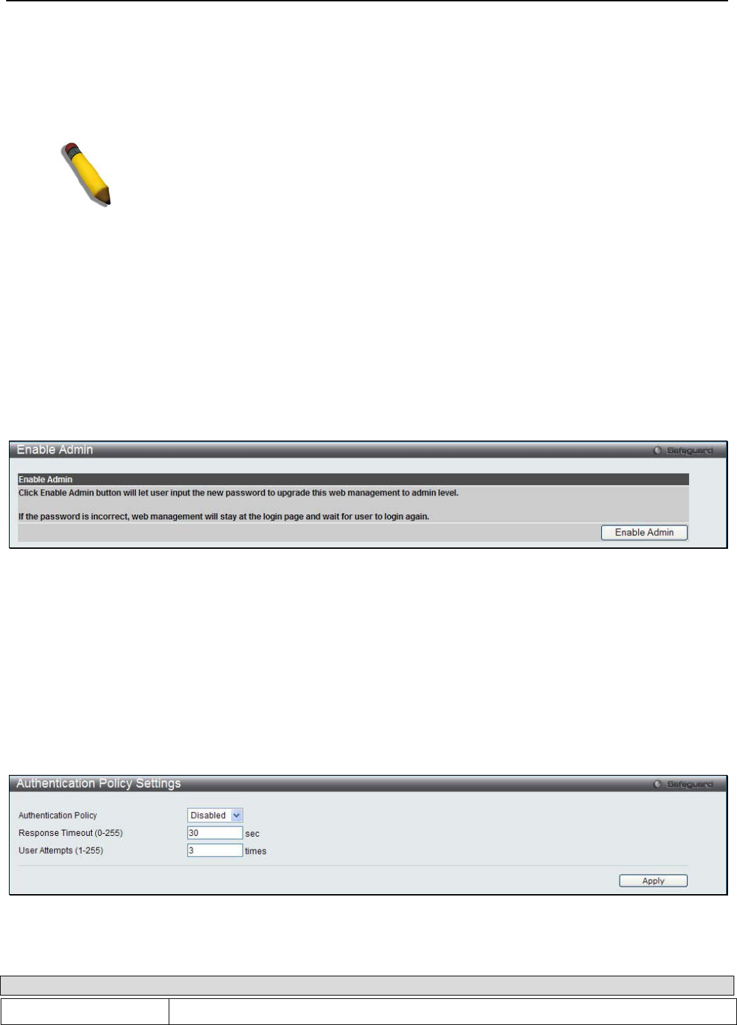
xStack® DGS-3200 Series Layer 2 Managed Gigabit Ethernet Switch Web UI Reference Guide
164
through its Authentication Server Hosts and no authentication is returned, the Switch will then go to the next technique listed in
the server group for authentication, until the authentication has been verified or denied, or the list is exhausted.
Please note that users granted access to the Switch will be granted normal user privileges on the Switch. To gain access to
administrator level privileges, the user must access the Enable Admin window and then enter a password, which was previously
configured by the administrator of the Switch.
NOTE: TACACS, XTACACS and TACACS+ are separate entities and are not
compatible. The Switch and the server must be configured exactly the same, using the
same protocol. (For example, if the Switch is set up for TACACS authentication, so
must be the host server.)
Enable Admin
Users who have logged on to the Switch on the normal user level and wish to be promoted to the administrator level can use this
window. After logging on to the Switch, users will have only user level privileges. To gain access to administrator level
privileges, the user will open this window and will have to enter an authentication password. Possible authentication methods for
this function include TACACS/XTACACS/TACACS+/RADIUS, user defined server groups, local enable (local account on the
Switch), or no authentication (none). Because XTACACS and TACACS do not support the enable function, the user must create a
special account on the server host, which has the username "enable", and a password configured by the administrator that will
support the "enable" function. This function becomes inoperable when the authentication policy is disabled.
To view the following window, click Security > Access Authentication Control > Enable Admin:
Figure 6 - 44. Enable Admin window
When this window appears, click the Enable Admin button revealing a window for the user to enter authentication (password,
username), as seen below. A successful entry will promote the user to Administrator level privileges on the Switch.
Authentication Policy Settings
Users can enable an administrator-defined authentication policy for users trying to access the Switch. When enabled, the device
will check the Login Method List and choose a technique for user authentication upon login.
To view the following window, click Security > Access Authentication Control > Authentication Policy Settings:
Figure 6 - 45. Authentication Policy Settings window
The following parameters can be set:
Parameter Description
Authentication Policy Use the drop-down menu to enable or disable the Authentication Policy on the Switch.
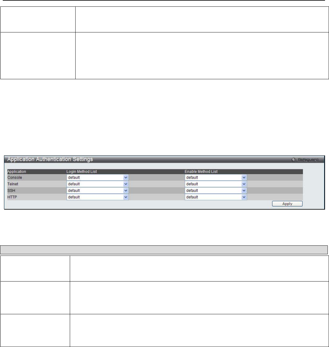
xStack® DGS-3200 Series Layer 2 Managed Gigabit Ethernet Switch Web UI Reference Guide
165
Response Timeout (0-
255) This field will set the time the Switch will wait for a response of authentication from the
user. The user may set a time between 0 and 255 seconds. The default setting is 30
seconds.
User Attempts (1-255) This command will configure the maximum number of times the Switch will accept
authentication attempts. Users failing to be authenticated after the set amount of attempts
will be denied access to the Switch and will be locked out of further authentication
attempts. Command line interface users will have to wait 60 seconds before another
authentication attempt. Telnet and web users will be disconnected from the Switch. The
user may set the number of attempts from 1 to 255. The default setting is 3.
Click Apply to implement changes made.
Application Authentication Settings
Users can configure Switch configuration applications (console, Telnet, SSH, web) for login at the user level and at the
administration level (Enable Admin) utilizing a previously configured method list.
To view the following window, click Security > Access Authentication Control > Application Authentication Settings:
Figure 6 - 46. Application Authentication Settings window
The following parameters can be set:
Parameter Description
Application Lists the configuration applications on the Switch. The user may configure the Login Method
List and Enable Method List for authentication for users utilizing the Console (Command Line
Interface) application, the Telnet application, SSH, and the Web (HTTP) application.
Login Method List Using the drop-down menu, configure an application for normal login on the user level,
utilizing a previously configured method list. The user may use the default Method List or
other Method List configured by the user. See the Login Method Lists window, in this
section, for more information.
Enable Method List Using the drop-down menu, configure an application for normal login on the user level,
utilizing a previously configured method list. The user may use the default Method List or
other Method List configured by the user. See the Enable Method Lists window, in this
section, for more information
Click Apply to implement changes made.
Authentication Server Group
Users can set up Authentication Server Groups on the Switch. A server group is a technique used to group
TACACS/XTACACS/TACACS+/RADIUS server hosts into user-defined categories for authentication using method lists. The
user may define the type of server group by protocol or by previously defined server group. The Switch has three built-in
Authentication Server Groups that cannot be removed but can be modified. Up to eight authentication server hosts may be added
to any particular group.
To view the following window, click Security > Access Authentication Control > Authentication Server Group:
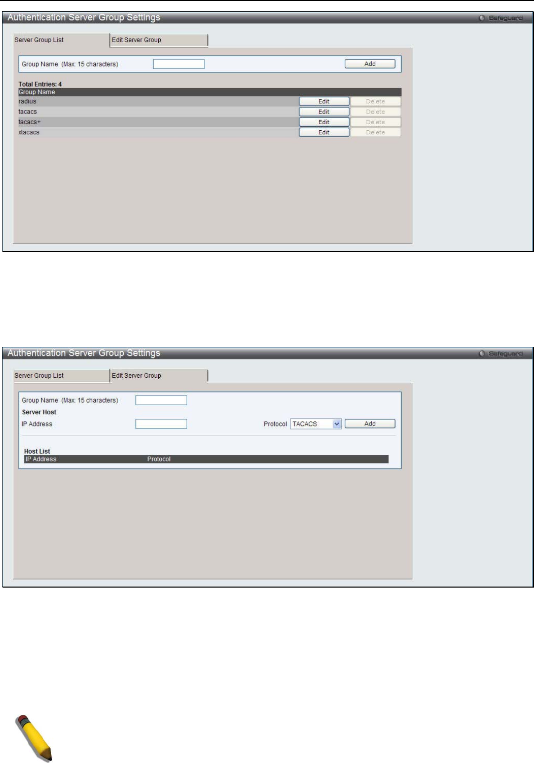
xStack® DGS-3200 Series Layer 2 Managed Gigabit Ethernet Switch Web UI Reference Guide
166
Figure 6 - 47. Authentication Server Group Settings window
This window displays the Authentication Server Groups on the Switch. The Switch has four built-in Authentication Server Groups
that cannot be removed but can be modified. To add a new Server Group, enter a name in the Group Name field and then click the
Add button. To modify a particular group, click the Edit button (or the Edit Server Group tab), which will then display the
following Edit Server Group tab:
Figure 6 - 48. Edit Server Group tab of the Authentication Server Group window
To add an Authentication Server Host to the list, enter its name in the Group Name field, IP address in the IP Address field, use
the drop-down menu to choose the Protocol associated with the IP address of the Authentication Server Host, and then click Add
to add this Authentication Server Host to the group. The entry should appear in the Host List at the bottom of this tab.
To add a server group other than the ones listed, enter a name of up to 15 characters in the Group Name field, an IP address in the
IP Address field, use the drop-down menu to choose the Protocol associated with the IP address, and then click Apply. The entry
should appear in the Server Group List tab.
NOTE: The user must configure Authentication Server Hosts using the Authentication Server
Hosts window before adding hosts to the list. Authentication Server Hosts must be configured for
their specific protocol on a remote centralized server before this function can work properly.
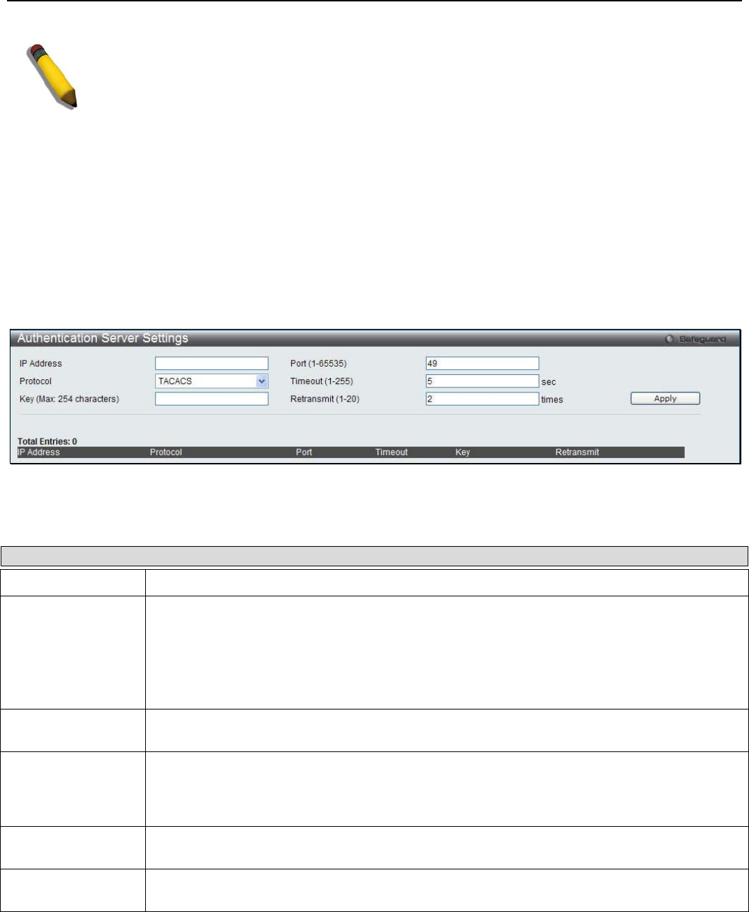
xStack® DGS-3200 Series Layer 2 Managed Gigabit Ethernet Switch Web UI Reference Guide
167
NOTE: The three built-in server groups can only have server hosts running the same TACACS
daemon. TACACS/XTACACS/TACACS+ protocols are separate entities and are not compatible
with each other.
Authentication Server Settings
User-defined Authentication Server Hosts for the TACACS / XTACACS / TACACS+ / RADIUS security protocols can be set on
the Switch. When a user attempts to access the Switch with Authentication Policy enabled, the Switch will send authentication
packets to a remote TACACS / XTACACS / TACACS+ / RADIUS server host on a remote host. The TACACS / XTACACS /
TACACS+ / RADIUS server host will then verify or deny the request and return the appropriate message to the Switch. More than
one authentication protocol can be run on the same physical server host but, remember that TACACS / XTACACS / TACACS+ /
RADIUS are separate entities and are not compatible with each other. The maximum supported number of server hosts is 16.
To view the following window, click Security > Access Authentication Control > Authentication Server Settings:
Figure 6 - 49. Authentication Server Settings window
Configure the following parameters to add an Authentication Server Host:
Parameter Description
IP Address The IP address of the remote server host to add.
Protocol The protocol used by the server host. The user may choose one of the following:
TACACS - Enter this parameter if the server host utilizes the TACACS protocol.
XTACACS - Enter this parameter if the server host utilizes the XTACACS protocol.
TACACS+ - Enter this parameter if the server host utilizes the TACACS+ protocol.
RADIUS - Enter this parameter if the server host utilizes the RADIUS protocol.
Key Authentication key to be shared with a configured TACACS+ or RADIUS servers only. Specify
an alphanumeric string up to 254 characters.
Port (1-65535) Enter a number between 1 and 65535 to define the virtual port number of the authentication
protocol on a server host. The default port number is 49 for TACACS/XTACACS/TACACS+
servers and 1813 for RADIUS servers but the user may set a unique port number for higher
security.
Timeout (1-255) Enter the time in seconds the Switch will wait for the server host to reply to an authentication
request. The default value is 5 seconds.
Retransmit (1-20) Enter the value in the retransmit field to change how many times the device will resend an
authentication request when the TACACS server does not respond.
Click Apply to add the server host.

xStack® DGS-3200 Series Layer 2 Managed Gigabit Ethernet Switch Web UI Reference Guide
168
NOTE: More than one authentication protocol can be run on the same physical
server host but, remember that TACACS/XTACACS/TACACS+ are separate
entities and are not compatible with each other.
Login Method Lists Settings
User-defined or default Login Method List of authentication techniques can be configured for users logging on to the Switch. The
sequence of techniques implemented in this command will affect the authentication result. For example, if a user enters a sequence
of techniques, for example TACACS - XTACACS- local, the Switch will send an authentication request to the first TACACS host
in the server group. If no response comes from the server host, the Switch will send an authentication request to the second
TACACS host in the server group and so on, until the list is exhausted. At that point, the Switch will restart the same sequence
with the following protocol listed, XTACACS. If no authentication takes place using the XTACACS list, the local account
database set in the Switch is used to authenticate the user. When the local method is used, the privilege level will be dependant on
the local account privilege configured on the Switch.
Successful login using any of these techniques will give the user a "User" privilege only. If the user wishes to upgrade his or her
status to the administrator level, the user must use the Enable Admin window, in which the user must enter a previously
configured password, set by the administrator.
To view the following window, click Security > Access Authentication Control > Login Method Lists:
Figure 6 - 50. Login Method List Settings window
The following parameters can be configured:
Parameter Description
Method List Name Enter a method list name defined by the user of up to 15 characters.
Priority 1, 2, 3, 4 The user may add one, or a combination of up to four of the following authentication methods
to this method list:
tacacs - Adding this parameter will require the user to be authenticated using the TACACS
protocol from a remote TACACS server.
xtacacs - Adding this parameter will require the user to be authenticated using the XTACACS
protocol from a remote XTACACS server.
tacacs+ - Adding this parameter will require the user to be authenticated using the TACACS+
protocol from a remote TACACS+ server.
radius - Adding this parameter will require the user to be authenticated using the RADIUS
protocol from a remote RADIUS server.
local - Adding this parameter will require the user to be authenticated using the local user
account database on the Switch.
none - Adding this parameter will require no authentication to access the Switch.
Click Apply to implement the changes. The Switch contains one Method List that is set and cannot be removed, yet can be
modified. To delete a Login Method List defined by the user, click the Delete button corresponding to the entry desired to be
deleted. To modify a Login Method List, click on its corresponding Edit button.
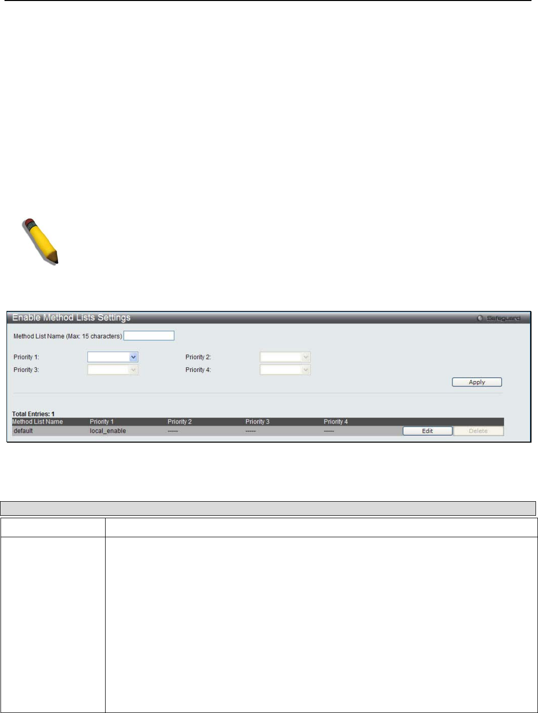
xStack® DGS-3200 Series Layer 2 Managed Gigabit Ethernet Switch Web UI Reference Guide
169
Enable Method Lists Settings
Users can set up Method Lists to promote users with user level privileges to Administrator (Admin) level privileges using
authentication methods on the Switch. Once a user acquires normal user level privileges on the Switch, he or she must be
authenticated by a method on the Switch to gain administrator privileges on the Switch, which is defined by the Administrator. A
maximum of eight Enable Method Lists can be implemented on the Switch, one of which is a default Enable Method List. This
default Enable Method List cannot be deleted but can be configured.
The sequence of methods implemented in this command will affect the authentication result. For example, if a user enters a
sequence of methods like TACACS - XTACACS - Local Enable, the Switch will send an authentication request to the first
TACACS host in the server group. If no verification is found, the Switch will send an authentication request to the second
TACACS host in the server group and so on, until the list is exhausted. At that point, the Switch will restart the same sequence
with the following protocol listed, XTACACS. If no authentication takes place using the XTACACS list, the Local Enable
password set in the Switch is used to authenticate the user.
Successful authentication using any of these methods will give the user an "Admin" privilege.
NOTE: To set the Local Enable Password, see the next section, entitled Local Enable Password.
To view the following window, click Security > Access Authentication Control > Enable Method Lists Settings:
Figure 6 - 51. Enable Method List Settings window
The following parameters can be configured:
Parameter Description
Method List Name Enter a method list name defined by the user of up to 15 characters.
Priority 1, 2, 3, 4 The user may add one, or a combination of up to four of the following authentication methods
to this method list:
local_enable - Adding this parameter will require the user to be authenticated using the local
enable password database on the Switch. The local enable password must be set by the user
in the next section entitled Local Enable Password.
none - Adding this parameter will require no authentication to access the Switch.
radius - Adding this parameter will require the user to be authenticated using the RADIUS
protocol from a remote RADIUS server.
tacacs - Adding this parameter will require the user to be authenticated using the TACACS
protocol from a remote TACACS server.
xtacacs - Adding this parameter will require the user to be authenticated using the XTACACS
protocol from a remote XTACACS server.
tacacs+ - Adding this parameter will require the user to be authenticated using the TACACS
protocol from a remote TACACS server.
Click Apply to implement the changes. To delete an Enable Method List defined by the user, click the Delete button
corresponding to the entry desired to be deleted. To modify an Enable Method List, click on its corresponding Edit button.
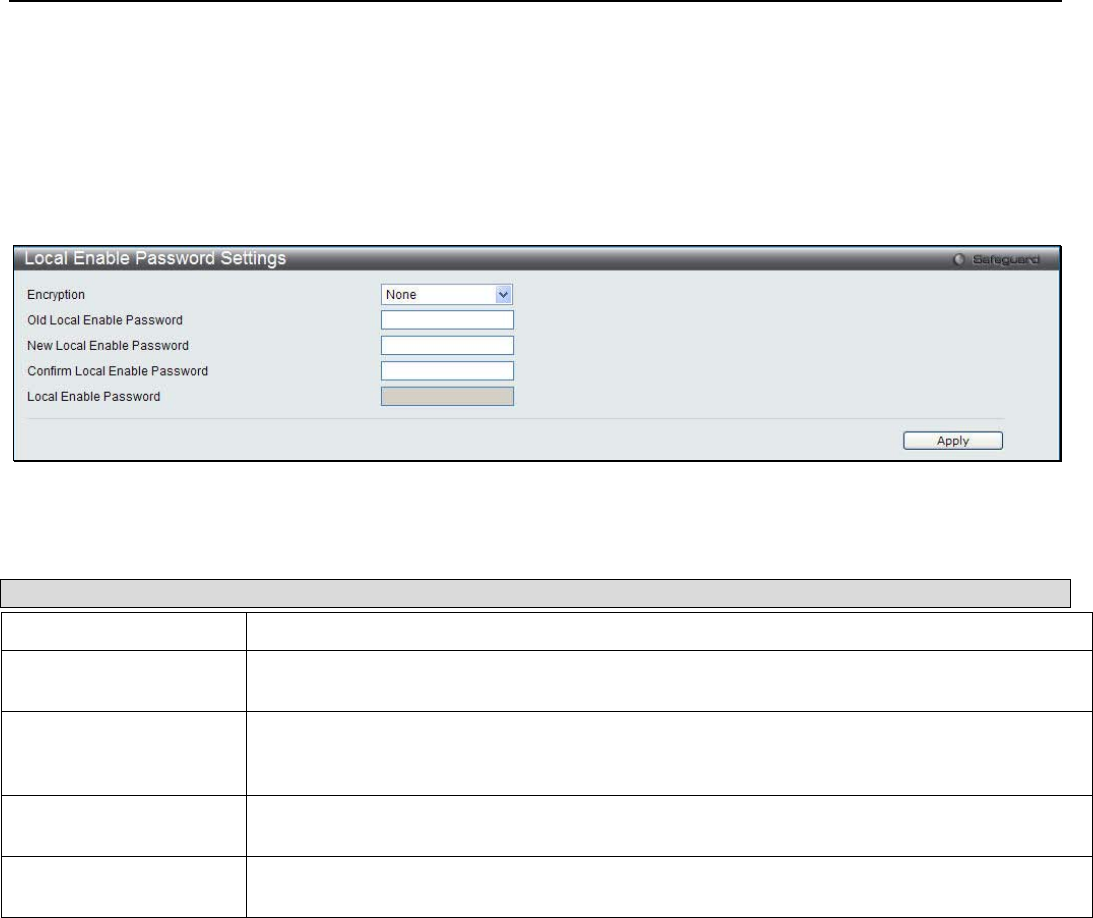
xStack® DGS-3200 Series Layer 2 Managed Gigabit Ethernet Switch Web UI Reference Guide
170
Local Enable Password Settings
Users can configure the locally enabled password for Enable Admin. When a user chooses the "local_enable" method to promote
user level privileges to administrator privileges, he or she will be prompted to enter the password configured here that is locally
set on the Switch.
To view the following window, click Security > Access Authentication Control > Local Enable Password Settings:
Figure 6 - 52. Local Enable Password Settings window
The following parameters can be configured:
Parameter Description
Encryption Use the drop-down menu to select the encryption type.
Old Local Enable
Password If a password was previously configured for this entry, enter it here in order to change it to a
new password
New Local Enable
Password Enter the new password that you wish to set on the Switch to authenticate users attempting
to access Administrator Level privileges on the Switch. The user may set a password of up to
15 characters.
Confirm Local Enable
Password Confirm the new password entered above. Entering a different password here from the one
set in the New Local Enabled field will result in a fail message.
Local Enable
Password Specify the password in plain text or SHA-1 encrypted form.
Click Apply to implement changes made.
MAC-based Access Control (MAC)
MAC-based Access Control is a method to authenticate and authorize access using either a port or host. For port-based MAC, the
method decides port access rights, while for host-based MAC, the method determines the MAC access rights.
A MAC user must be authenticated before being granted access to a network. Both local authentication and remote RADIUS
server authentication methods are supported. In MAC-based Access Control, MAC user information in a local database or a
RADIUS server database is searched for authentication. Following the authentication result, users achieve different levels of
authorization.
Notes about MAC-based Access Control
There are certain limitations and regulations regarding MAC-based Access Control:
1. Once this feature is enabled for a port, the Switch will clear the FDB of that port.
2. If a port is granted clearance for a MAC address in a VLAN that is not a Guest VLAN, other MAC addresses on that port
must be authenticated for access and otherwise will be blocked by the Switch.
3. A port accepts a maximum of two hundred authenticated MAC addresses per physical port of a VLAN that is not a Guest
VLAN. Other MAC addresses attempting authentication on a port with the maximum number of authenticated MAC
addresses will be blocked.

xStack® DGS-3200 Series Layer 2 Managed Gigabit Ethernet Switch Web UI Reference Guide
171
4. Ports that have been enabled for Link Aggregation, Port Security, or GVRP authentication cannot be enabled for MAC-based
Authentication.
MAC-based Access Control Settings
This window is used to configure the MAC Settings for the MAC-based Access Control function on the Switch. The user can set
the running state, method of authentication, RADIUS password, view the Guest VLAN configuration to be associated with the
MAC-based Access Control function of the Switch, and configure ports to be enabled or disabled for the MAC-based Access
Control feature of the Switch. Please remember, ports enabled for certain other features, listed previously, can not be enabled for
MAC-based Access Control.
To view the following window, click Security > MAC-based Access Control (MAC) > MAC-based Access Control Settings:
Figure 6 - 53. MAC-based Access Control Settings window
The MAC Settings window is divided into four main sections. The top section configures the MAC Global State, the second
section is used to specify and configure the method used for authentication, the third section is used to configure the Guest VLAN
settings, and the fourth section is used to configure the ports that require MAC Settings configuration.
Configuring the MAC Global State:
Configure the parameter as described below:
Parameter Description
MAC Global State Toggle to globally enable or disable the MAC-based Access Control function on the Switch.
Click the Apply button in the top section to implement the configuration changes.
Configuring the MAC Authentication Method:
Configure the parameters as described below:

xStack® DGS-3200 Series Layer 2 Managed Gigabit Ethernet Switch Web UI Reference Guide
172
Parameter Description
Method Use this drop-down menu to choose the type of authentication to be used when
authentication MAC addresses on a given port. The user may choose between the
following methods:
Local – Use this method to utilize the locally set MAC address database as the
authenticator for MAC-based Access Control. This MAC address list can be configured in
the MAC Local Settings window.
RADIUS – Use this method to utilize a remote RADIUS server as the authenticator for
MAC-based Access Control. Remember, the MAC list must be previously set on the
RADIUS server and the settings for the server must be first configured on the Switch.
Trap State Use the drop-down menu to enable or disable sending out the trap for MAC-based Access
Control.
Log State Use the drop-down menu to enable or disable log state.
RADIUS Authorization Use the drop-down menu to enable or disable the use of RADIUS Authorization.
Password Type Use the drop-down menu to select the password type. Available options are Manual
String and Client MAC Address.
Password Enter the password for the RADIUS server, which is to be used for packets being sent
requesting authentication. The default password is “default”.
Max User (1-4096) Enter the maximum amount of users of the Switch. Tick the No Limit check box to have
unlimited users.
Local Authorization Use the drop-down menu to enable or disable the use of Local Authorization.
Click the Apply button in the second section to implement the configuration changes.
Configuring the Guest VLAN Settings:
Parameter Description
VLAN Name Enter the name of the previously configured Guest VLAN being used for this function.
VID (1-4904) Click the button and enter a Guest VLAN ID.
Member Ports (e.g.: 1-5, 9) Enter the list of ports that have been configured for the Guest VLAN.
Click the Add button to create a new entry.
Click the Delete button in the third section to delete the Guest VLAN configuration.
Configuring MAC Settings Configuration on Ports:
Parameter Description
From Port / To Port Use the drop-down menus to select a range of ports.
State Use this drop-down menu to enable or disable MAC-based Access Control on the port or
range of ports selected in the Port Settings section of this window.
Aging Time (1-1440) Enter a value between 1 and 1440 minutes. The default is 1440. Tick the adjacent Infinite
checkbox to disable aging.
Block Time (0-300) Enter a value between 0 and 300 seconds. The default is 300.
Max User (1-4096) Enter the maximum amount of users of the Switch. Tick the No Limit check box to have
unlimited users. The default is 200.
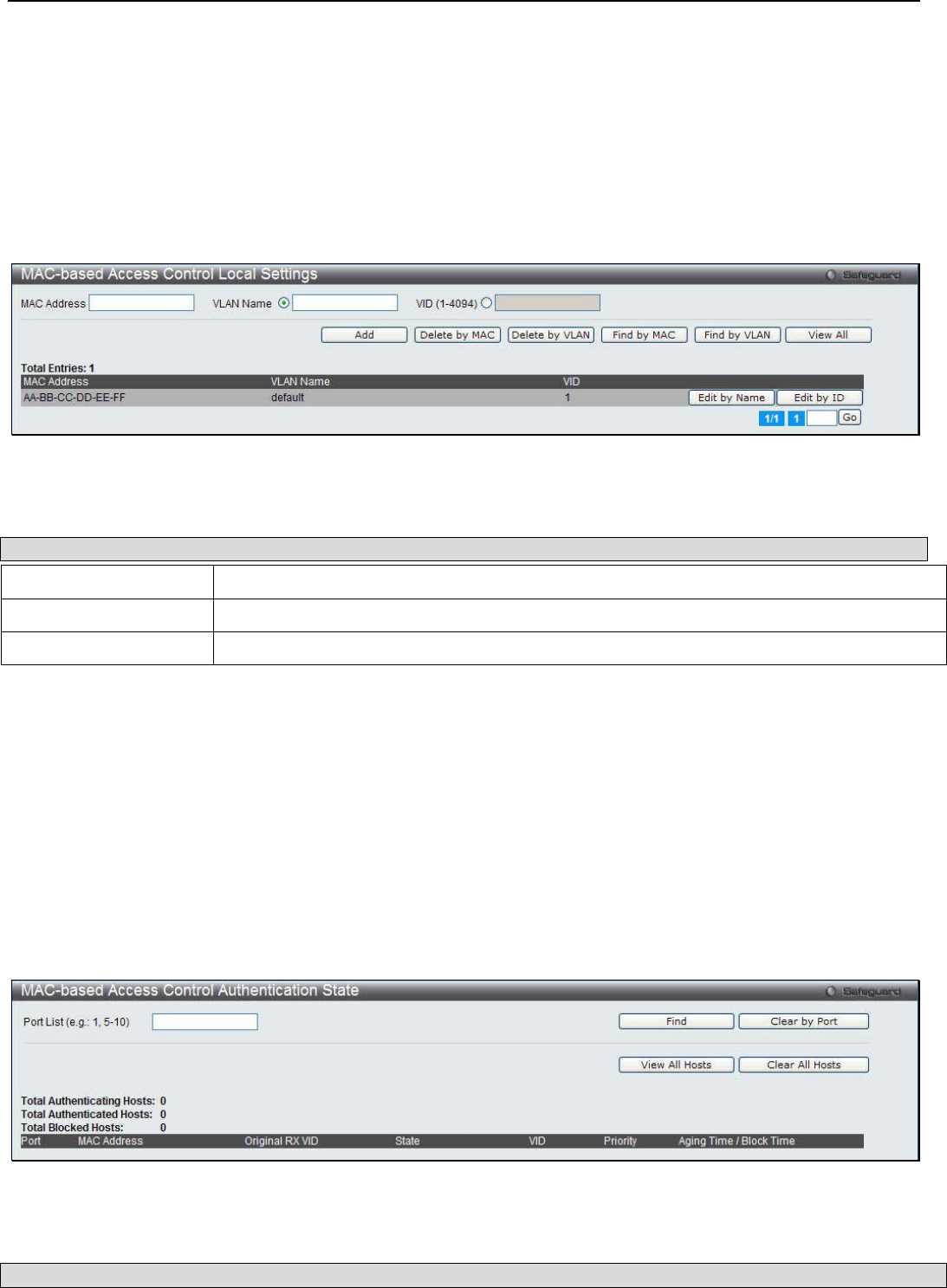
xStack® DGS-3200 Series Layer 2 Managed Gigabit Ethernet Switch Web UI Reference Guide
173
Click the Apply button in the fourth section to implement the configuration changes.
MAC-based Access Control Local Settings
Users can set a list of MAC addresses, along with their corresponding target VLAN, which will be authenticated for the Switch.
Once a queried MAC address is matched in this window, it will be placed in the VLAN associated with it here. The Switch
administrator may enter up to 128 MAC addresses to be authenticated using the local method configured here.
To view the following window, click Security > MAC-based Access Control (MAC)> MAC-based Access Control Local
Settings:
Figure 6 - 54. MAC-based Access Control Local Settings window
The following parameters can be configured:
Parameter Description
MAC Address Enter the MAC address that will be added to the local authentication list.
VLAN Name Enter the VLAN name of the corresponding MAC address.
VID (1-4094) Enter the VLAN ID of the corresponding MAC address.
Click the Delete by MAC button to remove the specific entry based on the MAC address entered. Click the Delete by VLAN
button to remove the specific entry based on the VLAN name or ID entered. Click the Find by MAC button to locate a specific
entry based on the MAC address entered. Click the Find by VLAN button to locate a specific entry based on the VLAN name or
ID entered. Click the View All button to display all the existing entries. Click the Edit by Name button to change the specific
MAC address’ VLAN name. Click the Edit by ID button to change the specific MAC address’ VLAN ID. Enter a page number
and click the Go button to navigate to a specific page when multiple pages exist.
MAC-based Access Control Authentication State
Users can use the MAC Authentication State window to display the MAC-based Access Control authentication MAC addreses.
To view the following window, click Security > MAC-based Access Control (MAC) > MAC-based Access Control
Authentication State:
Figure 6 - 55. MAC-based Access Control Authentication State window
The following parameters can be configured:
Parameter Description

xStack® DGS-3200 Series Layer 2 Managed Gigabit Ethernet Switch Web UI Reference Guide
174
Port List (e.g.: 1,
5-10) Enter a list of ports.
Click the Find button to locate a specific entry based on the information entered. Click the Clear by Port button to clear all the
information linked to the port number entered. Click the View All Hosts button to display all the existing hosts. Click the Clear
All hosts button to clear out all the existing hosts.
Web-based Access Control (WAC)
Web-based Authentication Login is a feature designed to authenticate a user when the user is trying to access the Internet via the
Switch. The authentication process uses the HTTP protocol. The Switch enters the authenticating stage when users attempt to
browse Web pages (e.g., http://www.dlink.com) through a Web browser. When the Switch detects HTTP packets and this port is
un-authenticated, the Switch will launch a pop-up user name and password window to query users. Users are not able to access the
Internet until the authentication process is passed.
The Switch can be the authentication server itself and do the authentication based on a local database, or be a RADIUS client and
perform the authentication process via the RADIUS protocol with a remote RADIUS server. The client user initiates the
authentication process of WAC by attempting to gain Web access.
D-Link’s implementation of WAC uses a virtual IP that is exclusively used by the WAC function and is not known by any other
modules of the Switch. In fact, to avoid affecting a Switch’s other features, WAC will only use a virtual IP address to
communicate with hosts. Thus, all authentication requests must be sent to a virtual IP address but not to the IP address of the
Switch’s physical interface.
Virtual IP works like this, when a host PC communicates with the WAC Switch through a virtual IP, the virtual IP is transformed
into the physical IPIF (IP interface) address of the Switch to make the communication possible. The host PC and other servers’ IP
configurations do not depend on the virtual IP of WAC. The virtual IP does not respond to any ICMP packets or ARP requests,
which means it is not allowed to configure a virtual IP on the same subnet as the Switch’s IPIF (IP interface) or the same subnet as
the host PCs’ subnet.
As all packets to a virtual IP from authenticated and authenticating hosts will be trapped to the Switch’s CPU, if the virtual IP is
the same as other servers or PCs, the hosts on the WAC-enabled ports cannot communicate with the server or PC which really
own the IP address. If the hosts need to access the server or PC, the virtual IP cannot be the same as the one of the server or PC. If
a host PC uses a proxy to access the Web, to make the authentication work properly the user of the PC should add the virtual IP to
the exception of the proxy configuration. Whether or not a virtual IP is specified, users can access the WAC pages through the
Switch’s system IP. When a virtual IP is not specified, the authenticating Web request will be redirected to the Switch’s system IP.
The Switch’s implementation of WAC features a user-defined port number that allows the configuration of the TCP port for either
the HTTP or HTTPS protocols. This TCP port for HTTP or HTTPS is used to identify the HTTP or HTTPS packets that will be
trapped to the CPU for authentication processing, or to access the login page. If not specified, the default port number for HTTP is
80 and the default port number for HTTPS is 443. If no protocol is specified, the default protocol is HTTP.
The following diagram illustrates the basic six steps all parties go through in a successful Web Authentication process:
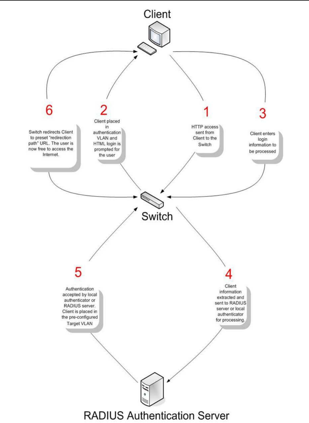
xStack® DGS-3200 Series Layer 2 Managed Gigabit Ethernet Switch Web UI Reference Guide
175
Figure 6 - 56. Six Basic Steps in a Successful Web Authentication Process

xStack® DGS-3200 Series Layer 2 Managed Gigabit Ethernet Switch Web UI Reference Guide
176
Conditions and Limitations
1. If the client is utilizing DHCP to attain an IP address, the authentication VLAN must provide a DHCP server or a DHCP
relay function so that client may obtain an IP address.
2. Certain functions exist on the Switch that will filter HTTP packets, such as the Access Profile function. The user needs to
be very careful when setting filter functions for the target VLAN, so that these HTTP packets are not denied by the
Switch.
3. If a RADIUS server is to be used for authentication, the user must first establish a RADIUS Server with the appropriate
parameters, including the target VLAN, before enabling Web Authentication on the Switch.
WAC Global Settings
Users can configure the Switch for Web authentication.
To view the following window, click Security > Web-based Access Control (WAC) > WAC Global Settings:
Figure 6 - 57. WAC Global Settings window
To set the Web Authentication for the Switch, complete the following fields:
Parameter Description
WAC Global State Use this selection menu to either enable or disable the Web Authentication on the Switch.
Virtual IP Enter a virtual IP address. This address is only used by WAC and is not known by any other
modules of the Switch.
Redirection Path Enter the URL of the website that authenticated users placed in the VLAN are directed to
once authenticated.
RADIUS Authorization The user can enable or disable this option to enable RADIUS Authorization or not.
HTTP(s) Port
(1-65535)
Enter a HTTP port number. Port 80 is the default.
HTTP – Specifies that the TCP port will run the WAC HTTP protocol. The default value is
80. HTTP port cannot run at TCP port 443.
HTTPS – Specifies that the TCP port will run the WAC HTTPS protocol. The default value
is 443. HTTPS cannot run at TCP port 80.
Method Use this drop-down menu to choose the authenticator for Web-based Access Control. The
user may choose:
Local – Choose this parameter to use the local authentication method of the Switch as the
authenticating method for users trying to access the network via the switch. This is, in fact,
the username and password to access the Switch configured using the WAC User
Settings window (Security > Web-based Access Control (WAC) > WAC User Settings)
seen below.
RADIUS – Choose this parameter to use a remote RADIUS server as the authenticating
method for users trying to access the network via the switch. This RADIUS server must
have already been pre-assigned by the administrator using the Authentic RADIUS Server
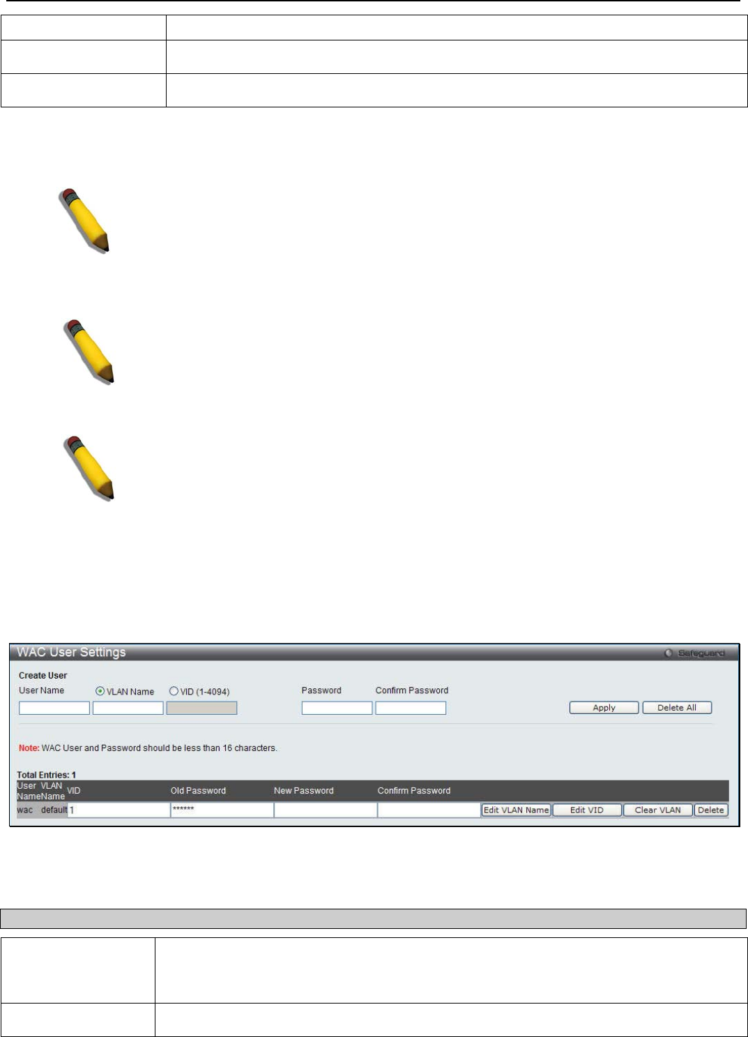
xStack® DGS-3200 Series Layer 2 Managed Gigabit Ethernet Switch Web UI Reference Guide
177
window (Security > 802.1X > Authentic RADIUS Server).
Clear Redirection Path The user can enable or disable this option to clear the redirection path.
Local Authorizations he user can enable or disable this option to enable Local Authorization or not.
Click Apply to implement changes made.
NOTE: To enable the Web Authentication function, the redirection path field must have
the URL of the website that users will be directed to once they enter the limited
resource, pre-configured VLAN. Users that attempt t
o apply settings without the
Redirection Page field set will be prompted with an error message and Web
Authentication
will not be enabled. The URL should follow the form
http(s)://www.dlink.com
NOTE: The subnet of the IP address of the authentication VLAN must be the same as
that of the client, or the client will always be denied authentication.
NOTE: A successful authentication should direct the client to the stated web page. If
the client does not reach this web page, yet does not receive a Fail! Message, the
client will already be authenticated and therefore should refresh the current browser
window or attempt to open a different web page.
WAC User Settings
Users can view and set user accounts for Web authentication.
To view the following window, click Security > Web-based Access Control (WAC) > WAC User Settings:
Figure 6 - 58. WAC User Settings window
To set the User Account settings for the Web authentication by the Switch, complete the following fields:
Parameter Description
User Name Enter the user name of up to 15 alphanumeric characters of the guest wishing to access the
Web through this process. This field is for administrators who have selected Local as their
Web-based authenticator.
VLAN Name Click the button and enter a VLAN Name in this field.
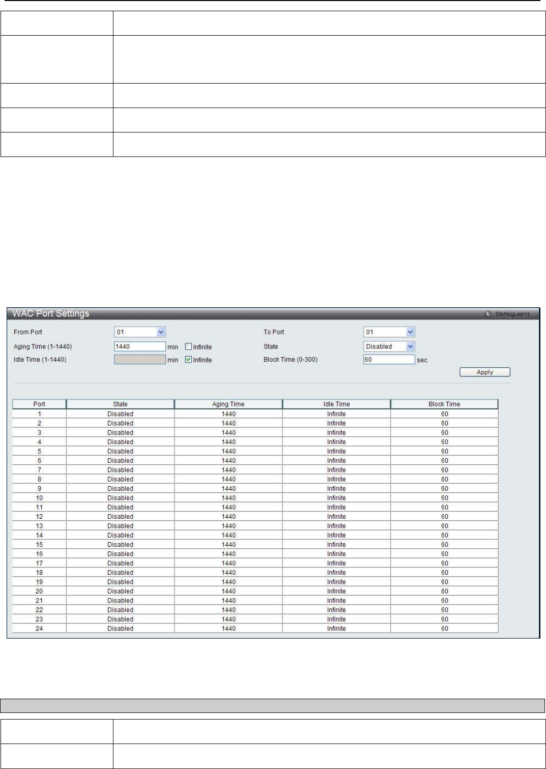
xStack® DGS-3200 Series Layer 2 Managed Gigabit Ethernet Switch Web UI Reference Guide
178
VID (1-4094) Click the button and enter a VID in this field.
Password Enter the password the administrator has chosen for the selected user. This field is case-
sensitive and must be a complete alphanumeric string. This field is for administrators who
have selected Local as their Web-based authenticator.
Old Password Enter the original password.
New Password Enter the new password
Confirm Password Retype the password entered in the previous field.
Click the Apply button to accept the changes made. Click the Delete All button to remove all the entries listed. Click the Edit
VLAN Name button to re-configure the specific entry’s VLAN Name. Click the Edit VID button to re-configure the specific
entry’s VLAN ID. Click the Clear VLAN button to remove the VLAN information from the specific entry. Click the Delete
button to remove the specific entry.
WAC Port Settings
Users can view and set port configurations for Web authentication.
To view the following window, click Security > Web-based Access Control (WAC) > WAC Port Settings:
Figure 6 - 59. WAC Port Settings window
To set the WAC on individual ports for the Switch, complete the following fields:
Parameter Description
From Port / To Port Use this drop-down menus to select a range of ports to be enabled as WAC ports.
Aging Time (1-1440) This parameter specifies the time period during which an authenticated host will remain in the

xStack® DGS-3200 Series Layer 2 Managed Gigabit Ethernet Switch Web UI Reference Guide
179
authenticated state. Enter a value between 0 and 1440 minutes. A value of 0 indicates the
authenticated host will never age out on the port. The default value is 1440 minutes (24
hours). Tick the adjacent Infinite textbox to disable aging. The default value is infinite.
State Use this drop-down menu to enable the configured ports as WAC ports.
Idle Time (1-1440) If there is no traffic during the Idle Time parameter, the host will be moved back to the
unauthenticated state. Enter a value between 0 and 1440 minutes. A value of 0 indicates the
Idle state of the authenticated host on the port will never be checked. Tick the adjacent
Infinite textbox to disable the idle time. The default value is infinite.
Block Time (0-300) This parameter is the period of time a host will be blocked if it fails to pass authentication.
Enter a value between 0 and 300 seconds. The default value is 30 seconds.
Click Apply to implement changes made.
WAC Authenticating State
Users can display the current WAC authentication state and delete WAC authentication state settings.
To view the following window, click Security > Web-based Access Control (WAC) > WAC Authenticating State:
Figure 6 - 60. WAC Authentication State window
The following fields and settings can be viewed:
Parameter Description
Port List (e.g.: 1,
5-10) Enter a port or range of ports, and tick the appropriate check box(s), Authenticated,
Authenticating, and Blocked.
Authenticated Tick this check box to display all authenticated users for a port.
Authenticating Tick this check box to display all authenticating users for a port.
Blocked Tick this check box to display all blocked users for a port.
Click the Find button to locate a specific entry based on the information entered. Click the Clear by Port button to remove entry
based on the port list entered. Click the View All Hosts button to display all the existing entries. Click the Clear All Hosts button
to remove all the entries listed.
WAC Customize Page
This window is used to customize the authenticate page elements.
To view the following window, click Security > Web-based Access Control (WAC) > WAC Customize Page:
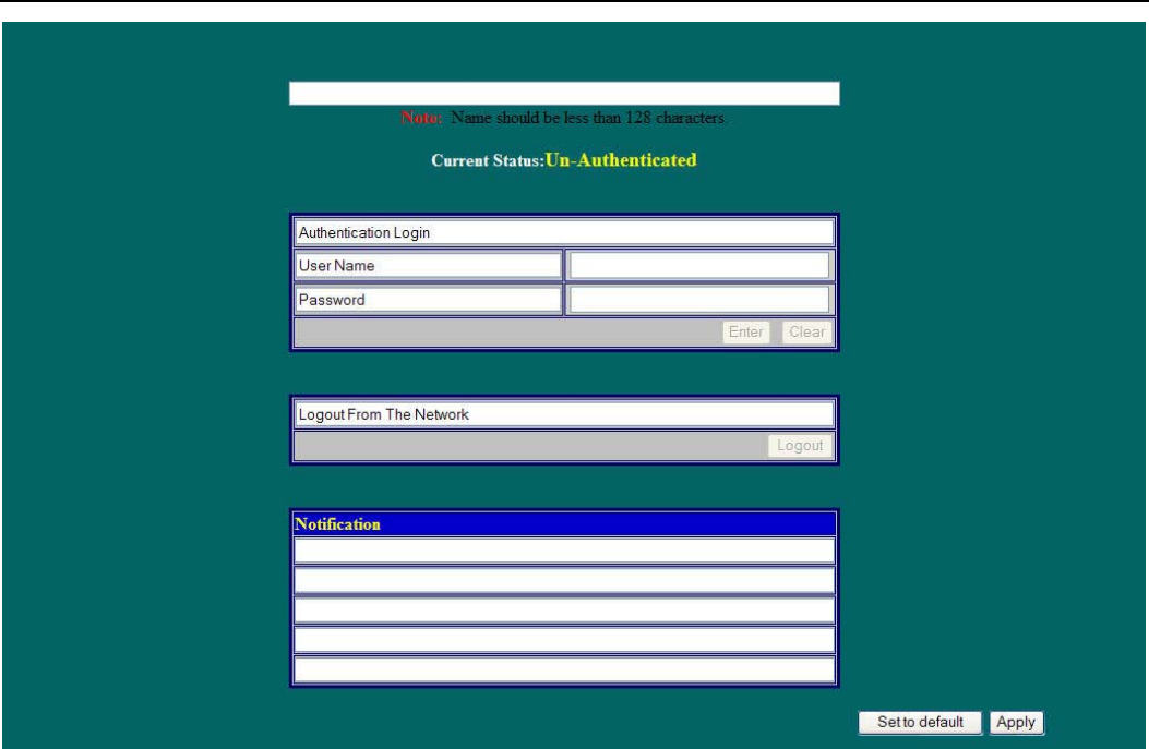
xStack® DGS-3200 Series Layer 2 Managed Gigabit Ethernet Switch Web UI Reference Guide
180
Figure 6 - 61. WAC Customize Page window
Complete the WAC authentication information on this window to set the WAC page settings. Click the Apply button to
implement the changes made. Click the Set to default button to go back to the default settings of all elements. Click the Edit
button to re-configure the elements.
Japanese Web-based Access Control (JWAC)
JWAC Global Settings
Users can enable and configure Japanese Web-based Access Control on the Switch. Please note that JWAC and Web
Authentication are mutually exclusive functions. That is, they cannot be enabled at the same time. To use the JWAC feature,
computer users need to pass through two stages of authentication. The first stage is to do the authentication with the quarantine
server and the second stage is the authentication with the Switch. For the second stage, the authentication is similar to Web
Authentication, except that there is no port VLAN membership change by JWAC after a host passes authentication. The RADIUS
server will share the server configuration defined by the 802.1X command set.
To view the following window, click Security > Japanese Web-based Access Control (JWAC) > JWAC Global Settings:
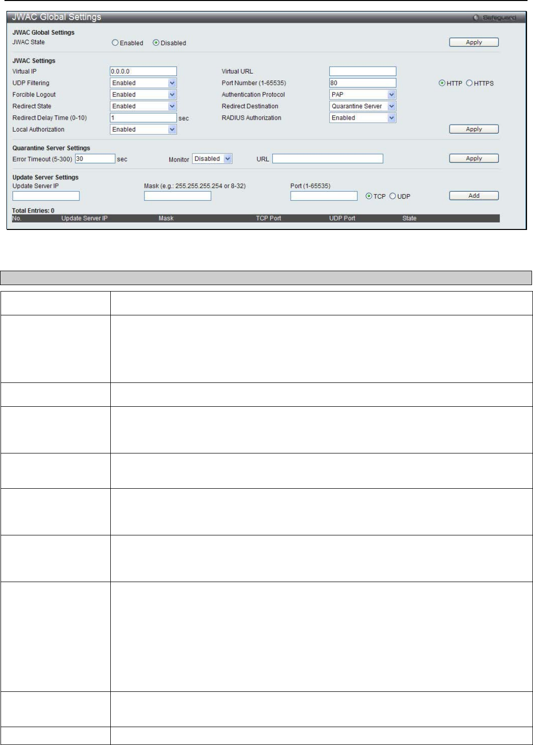
xStack® DGS-3200 Series Layer 2 Managed Gigabit Ethernet Switch Web UI Reference Guide
181
Figure 6 - 62. JWAC Global Settings window
To set the Web authentication for the Switch, complete the following fields:
Parameter Description
JWAC State Use this drop-down menu to either enable or disable JWAC on the Switch.
Virtual IP Enter the JWAC Virtual IP address that is used to accept authentication requests from an
unauthenticated host. The Virtual IP address of JWAC is used to accept authentication
requests from an unauthenticated host. Only requests sent to this IP will get a correct
response.
NOTE: This IP does not respond to ARP requests or ICMP packets.
Virtual URL Enter the Virtual URL used.
UDP Filtering This parameter enables or disables JWAC UDP Filtering. When UDP Filtering is Enabled, all
UDP and ICMP packets except DHCP and DNS packets from unauthenticated hosts will be
dropped.
Port Number (1-
65535) Enter the TCP port that the JWAC Switch listens to and uses to finish the authenticating
process.
Forcible Logout This parameter enables or disables JWAC Forcible Logout. When Forcible Logout is
Enabled, a Ping packet from an authenticated host to the JWAC Switch with TTL=1 will be
regarded as a logout request, and the host will move back to the unauthenticated state.
Authentication
Protocol This parameter specifies the RADIUS protocol used by JWAC to complete a RADIUS
authentication. The options include Local, EAP MD5, PAP, CHAP, MS CHAP, and MS
CHAPv2.
Redirect State This parameter enables or disables JWAC Redirect. When the redirect quarantine server is
enabled, the unauthenticated host will be redirected to the quarantine server when it tries to
access a random URL. When the redirect JWAC login page is enabled, the unauthenticated
host will be redirected to the JWAV login page in the Switch to finish authentication. When
redirect is disabled, only access to the quarantine server and the JWAC login page from the
unauthenticated host are allowed, all other web access will be denied.
NOTE: When enabling redirect to the quarantine server, a quarantine server must be
configured first.
Redirect Destination This parameter specifies the destination before an unauthenticated host is redirected to either
the Quarantine Server or the JWAC Login Page.
Redirect Delay Time
This parameter specifies the Delay Time before an unauthenticated host is redirected to the

xStack® DGS-3200 Series Layer 2 Managed Gigabit Ethernet Switch Web UI Reference Guide
182
(0-10)
Quarantine Server or JWAC Login Page. Enter a value between 0 and 10 seconds. A value
of 0 indicates no delay in the redirect.
RADIUS
Authorization
Use the drop-down menu to enable or disable RADIUS Authorization.
Local Authorization Use the drop-down menu to enable or disable Local Authorization.
Error Timeout (5-
300) This parameter is used to set the Quarantine Server Error Timeout. When the Quarantine
Server Monitor is enabled, the JWAC Switch will periodically check if the Quarantine works
okay. If the Switch does not receive any response from the Quarantine Server during the
configured Error Timeout, the Switch then regards it as not working properly. Enter a value
between 5 and 300 seconds.
Monitor This parameter enables or disables the JWAC Quarantine Server Monitor. When Enabled,
the JWAC Switch will monitor the Quarantine Server to ensure the server is okay. If the
Switch detects no Quarantine Server, it will redirect all unauthenticated HTTP access
attempts to the JWAC Login Page forcibly if the Redirect is enabled and the Redirect
Destination is configured to be a Quarantine Server.
URL This parameter specifies the JWAC Quarantine Server URL. If the Redirect is enabled and
the Redirect Destination is the Quarantine Server, when an unauthenticated host sends the
HTTP request packets to a random Web server, the Switch will handle this HTTP packet and
send back a message to the host to allow it access to the Quarantine Server with the
configured URL. When a computer is connected to the specified URL, the quarantine server
will request the computer user to input the user name and password to compl
ete the
authentication process.
Update Server IP This parameter specifies the Update Server IP address.
Mask This parameter specifies the Server IP net mask.
Port Enter the port number used by the Update Server.
Click Apply to implement changes made.
JWAC Port Settings
Users can configure JWAC port settings for the Switch.
To view the following window, click Security > Japanese Web-based Access Control (JWAC) > JWAC Port Settings:
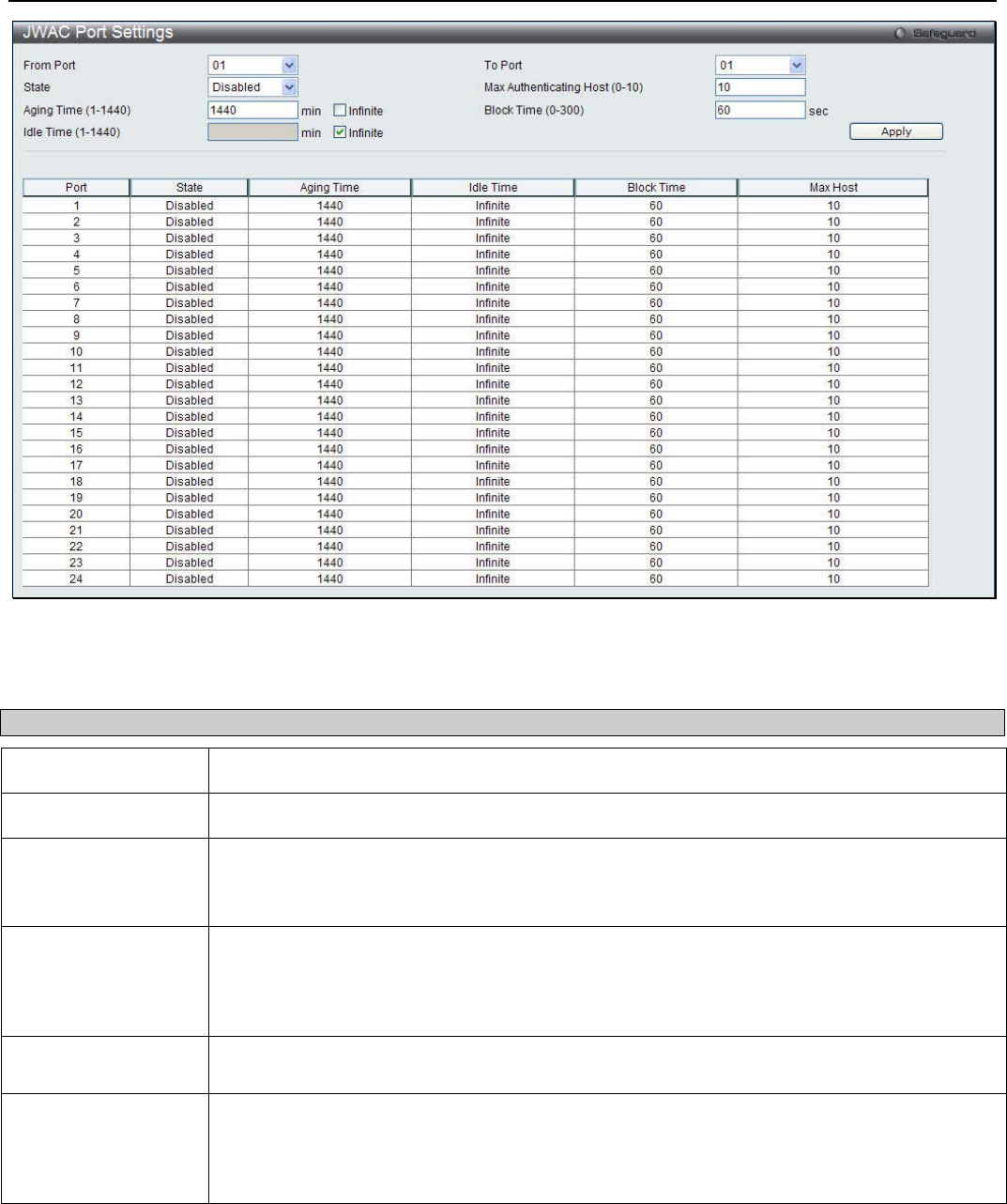
xStack® DGS-3200 Series Layer 2 Managed Gigabit Ethernet Switch Web UI Reference Guide
183
Figure 6 - 63. JWAC Port Settings window
The following parameters can be configured:
Parameter Description
From Port / To Port Use this drop-down menu to select a range of ports to be enabled as JWAC ports.
State Use this drop-down menu to enable the configured ports as JWAC ports.
Max Authenticating
Host (1-10) This parameter specifies the maximum number of host process authentication attempts
allowed on each port at the same time. The default value is 10. Enter a value between 1 and
10 attempts.
Aging Time (1-1440) This parameter specifies the time period during which an authenticated host will remain in the
authenticated state. Enter a value between 0 and 1440 minutes or tick the Infinite check box.
The default value is 1440. A value of 0 indicates the authenticated host will never age out on
the port.
Block Time (0-300) This parameter is the period of time a host will be blocked if it fails to pass authentication.
Enter a value between 0 and 300 seconds. The default value is 0.
Idle Time (1-1440) If there is no traffic during the Idle Time parameter, the host will be moved back to the
unauthenticated state. The default value is infinite. To change this value, first untick the
Infinite check box and then enter a value between 0 and 1440 minutes. A value of 0
indicates the Idle state of the authenticated host on the port will never be checked.
Click Apply to implement changes made.
JWAC User Settings
Users can configure JWAC user settings for the Switch.
To view the following window, click Security > Japanese Web-based Access Control (JWAC) > JWAC User Settings:
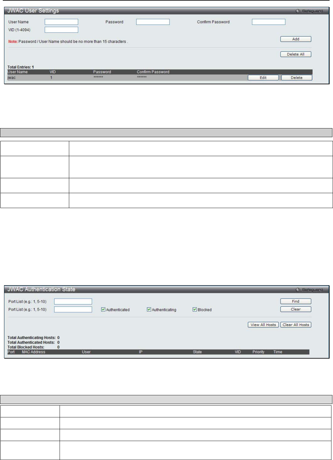
xStack® DGS-3200 Series Layer 2 Managed Gigabit Ethernet Switch Web UI Reference Guide
184
Figure 6 - 64. JWAC User Settings window
To set the User Account settings for the JWAC by the Switch, complete the following fields and then click the Add button. To
clear the current JWAC user settings in the table at the bottom of the window, click the Delete All button.
Parameter Description
User Name Enter a username of up to 15 alphanumeric characters.
Password Enter the password the administrator has chosen for the selected user. This field is case-
sensitive and must be a complete alphanumeric string.
Confirm Password Retype the password entered in the previous field.
VID (1-4094) Enter a VLAN ID number between 1 and 4094.
Click the Add button to add a new entry based on the information entered. Click the Delete All button to remove all the entries
listed. Click the Edit button to re-configure the specific entry. Click the Delete button to remove the specific entry.
JWAC Authentication State
Users can display Japanese Web-based Access Control Host Table information.
To view the following window, click Security > Japanese Web-based Access Control (JWAC) > JWAC Authentication Sate:
Figure 6 - 65. JWAC Authentication State window
The following fields and settings can be viewed:
Parameter Description
Port List Enter a port or range of ports.
Authenticated Tick this check box to only show authenticated client hosts.
Authenticating Tick this check box to only show client hosts in the authenticating process.
Blocked Tick this check box to only show client hosts being temporarily blocked because of the failure of
authentication.
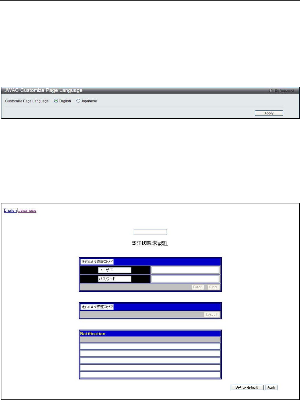
xStack® DGS-3200 Series Layer 2 Managed Gigabit Ethernet Switch Web UI Reference Guide
185
Click the Find button to locate a specific entry based on the information entered. Click the Clear button to remove entry based on
the port list entered. Click the View All Hosts button to display all the existing entries. Click the Clear All Hosts button to
remove all the entries listed.
JWAC Customize Page Language
Users can configure JWAC page and language settings for the Switch. The current firmware supports either English or Japanese.
To view the following window, click Security > Japanese Web-based Access Control (JWAC) > JWAC Customize Page
Language:
Figure 6 - 66. JWAC Customize Page Language window
To set the language used on the JWAC page, click the radio button for either English or Japanese. Click the Apply button.
JWAC Customize Page
Users can configure JWAC page settings for the Switch.
To view the following window, click Security > Japanese Web-based Access Control (JWAC) > JWAC Customize Page:
Figure 6 - 67. JWAC Customize Page window
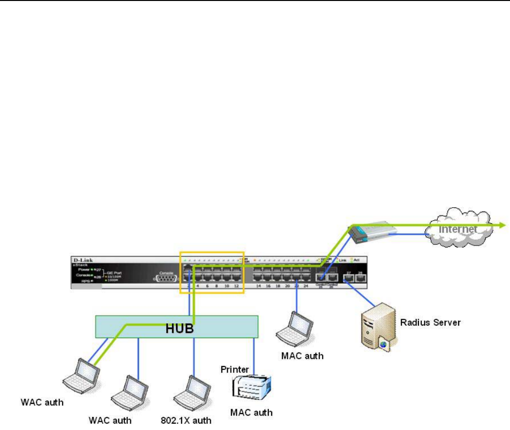
xStack® DGS-3200 Series Layer 2 Managed Gigabit Ethernet Switch Web UI Reference Guide
186
Complete the JWAC authentication information on this window to set the JWAC page settings. Enter a name for the
Authentication in the first field and then click the Apply button. Next, enter a User Name and a Password and then click the Enter
button.
Compound Authentication
Modern networks employ many authentication methods. The Compound Authentication methods supported by this Switch include
802.1X, MAC-based Access Control (MAC), Web-based Access Control (WAC), Japan Web-based Access Control (JWAC), and
IP-MAC-Port Binding (IMPB). The Compound Authentication feature allows clients running different authentication methods to
connect to the network using the same switch port.
The Compound Authentication feature can be implemented using one of the following modes:
Any (MAC, 802.1X or WAC) Mode
Figure 6 - 68. Any (MAC, 802.1X or WAC) Mode
In the diagram above the Switch port has been configured to allow clients to authenticate using 802.1X, MAC, or WAC. When a
client tries to connect to the network, the Switch will try to authenticate the client using one of these methods and if the client
passes they will be granted access to the network.

xStack® DGS-3200 Series Layer 2 Managed Gigabit Ethernet Switch Web UI Reference Guide
187
Any (MAC, 802.1X or JWAC) Mode
Figure 6 - 69. Any (MAC, 802.1X or JWAC) Mode
In the diagram above the Switch port has been configured to allow clients to authenticate using 802.1X, MAC, or JWAC. When a
client tries to connect to the network, the Switch will try to authenticate the client using one of these methods and if the client
passes they will be granted access to the network.
802.1X & IMPB Mode
Figure 6 - 70. 802.1X & IMPB Mode
This mode adds an extra layer of security by checking the IP MAC-Binding Port Binding (IMPB) table before trying one of the
supported authentication methods. The IMPB Table is used to create a ‘white list’ that checks if the IP streams being sent by
authorized hosts have been granted or not. In the above diagram the Switch port has been configured to allow clients to
authenticate using 802.1X. If the client is in the IMPB table and tries to connect to the network using this authentication method
and the client is listed in the white list for legal IP/MAC/port checking, access will be granted. If a client fails one of the
authentication methods, access will be denied.
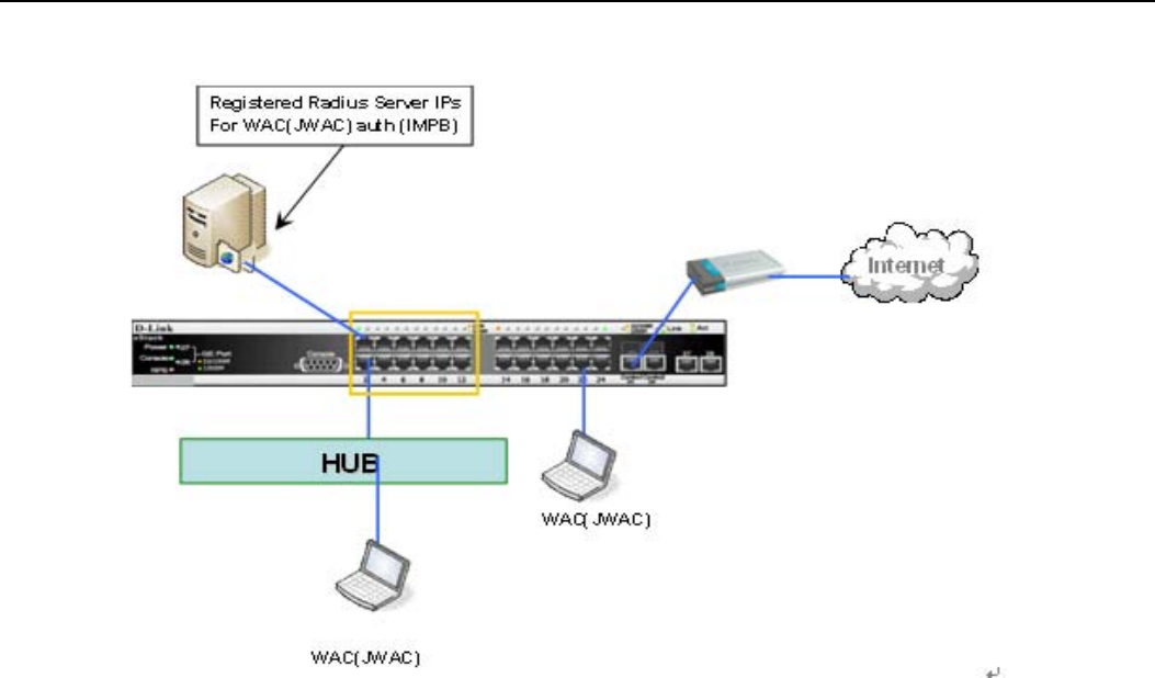
xStack® DGS-3200 Series Layer 2 Managed Gigabit Ethernet Switch Web UI Reference Guide
188
IMPB & WAC/JWAC Mode
Figure 6 - 71. IMPB & WAC/JWAC Mode
This mode adds an extra layer of security by checking the IP MAC-Binding Port Binding (IMPB) table before trying one of the
supported authentication methods. The IMPB Table is used to create a ‘white-list’ that checks if the IP streams being sent by
authorized hosts have been granted or not. In the above diagram, the Switch port has been configured to allow clients to
authenticate using either WAC or JWAC. If the client is in the IMPB table and tries to connect to the network using either of these
supported authentication methods and the client is listed in the white list for legal IP/MAC/port checking, access will be granted.
If a client fails one of the authentication methods, access will be denied.
MAC & IMPB Mode
This mode adds an extra layer of security by checking the IP MAC-Binding Port Binding (IMPB) table before trying one of the
supported authentication methods. The IMPB Table is used to create a ‘white-list’ that checks if the IP streams being sent by
authorized hosts have been granted or not. In the above diagram, the Switch port has been configured to allow clients to
authenticate by using MAC. If the client is in the IMPB table and tries to connect to the network by using MAC and the client is
listed in the white list for legal IP/MAC/port checking, access will be granted. If a client fails one of the authentication methods,
access will be denied.
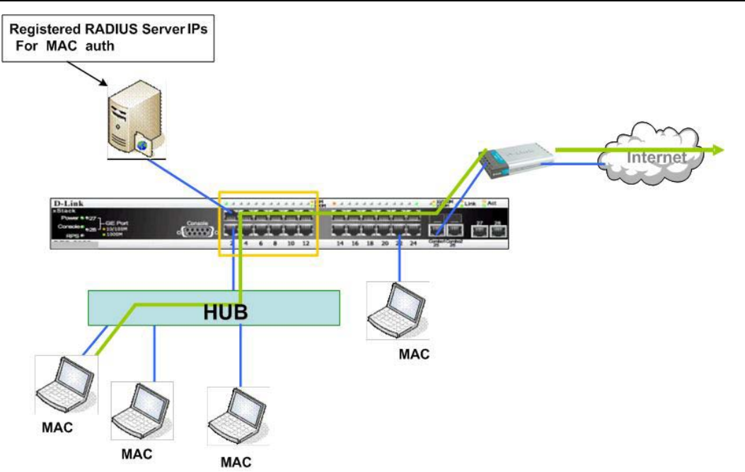
xStack® DGS-3200 Series Layer 2 Managed Gigabit Ethernet Switch Web UI Reference Guide
189
Figure 6 - 72. MAC & IMPB Mode
Compound Authentication Settings
Users can configure Authorization Network State Settings for the Switch.
To view the following window, click Security > Compound Authentication > Compound Authentication Settings:
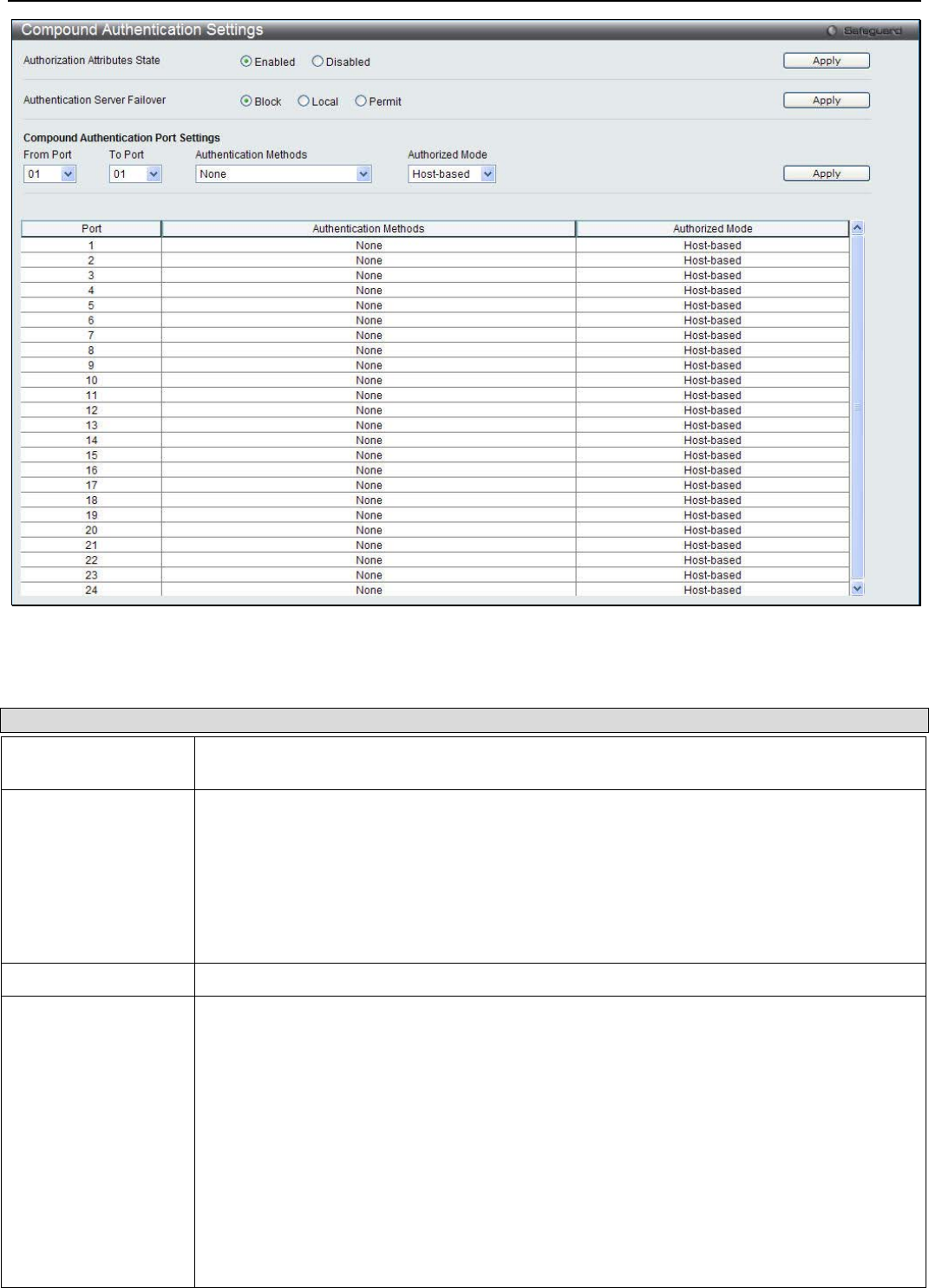
xStack® DGS-3200 Series Layer 2 Managed Gigabit Ethernet Switch Web UI Reference Guide
190
Figure 6 - 73. Compound Authentication Settings window
The following fields and settings can be viewed:
Parameter Description
Authorization
Attributes State Click the radio buttons to enable of disable the Authorization Attributes State.
Authentication
Server Failover Click the radio buttons to configure the authentication server failover function.
Block (default setting) - The client is always regarded as un-authenticated.
Local - The switch will resort to using the local database to authenticate the client. If the
client fails on local authentication, the client is regarded as un-authenticated, otherwise, it
authenticated.
Permit - The client is always regarded as authenticated. If guest VLAN is enabled, clients
will stay on the guest VLAN, otherwise, they will stay on the original VLAN.
From Port / To Port Use the drop-down menus to select a range of ports.
Authentication
Methods The compound authentication method options include: None, Any (MAC, 802.1X or
WAC/JWAC), 802.1X+IMPB, IMPB+JWAC, and IMPB+WAC.
None means all compound authentication methods are disabled.
Any (MAC, 802.1X, JWAC or WAC) means if any of the authentication methods
pass, then access will be granted. In this mode, MAC, 802.1X and WAC/JWAC)
can be enabled on a port at the same time. In Any (MAC, 802.1X or WAC/JWAC
mode, whether an individual security module is active on a port depends on its
system state. As system states of WAC and JWAC are mutually exclusive, only one of
them will active on a port at the same time.
802.1X+IMPB means 802.1X will be verified first, and then IMPB will be verified.
Both authentication methods need to be passed.
IMPB+JWAC means JWAC will be verified first, and then IMPB will be verified.
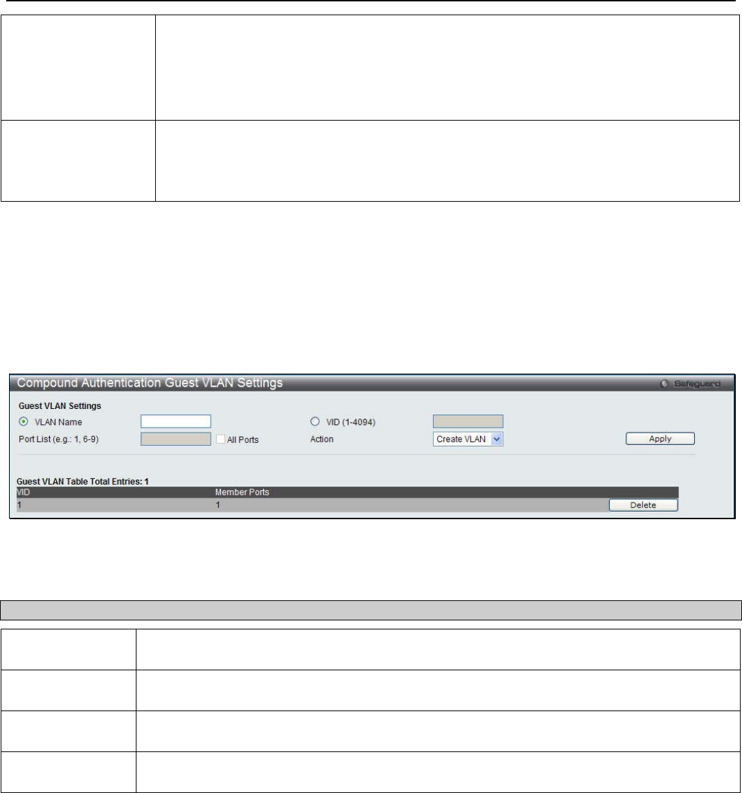
xStack® DGS-3200 Series Layer 2 Managed Gigabit Ethernet Switch Web UI Reference Guide
191
Both authentication methods need to be passed.
IMPB+WAC means WAC will be verified first, and then IMPB will be verified. Both
authentication methods need to be passed.
MAC+IMPB means MAC will be verified first, and then IMPB will be verified. Both
authentication methods need to be passed.
Authorized Mode Toggle between Host-based and Port-based. When Port-based is selected, if one of the
attached hosts passes the authentication, all hosts on the same port will be granted access
to the network. If the user fails the authorization, this port will keep trying the next
authentication method. When Host-based is selected, users are authenticated individually.
Click Apply to implement the changes made.
Compound Authentication Guest VLAN Settings
Users can assign ports to or remove ports from a guest VLAN.
To view the following window, click Security > Compound Authentication > Compound Authentication Guest VLAN
Settings:
Figure 6 - 74. Compound Authentication Auest VLAN Settings window
The following fields may be modified to configure Guest VLANs:
Parameter Description
VLAN Name Click the button and assign a VLAN as a Guest VLAN. The VLAN must be an existing static
VLAN.
VID (1-4094) Click the button and assign a VLAN ID for a Guest VLAN. The VLAN must be an existing static
VLAN before this VID can be configured.
Port List (e.g.:1,
6-9) The list of ports to be configured. Alternatively, tick the All check box to set every port at once.
Action Use the drop-down menu to choose the desired operation: Create VLAN, Add Ports, or Delete
Ports.
Click the Apply button to accept the changes made. Click the Delete button to remove the specific entry.
Compound Authentication MAC Format Settings
This window is used to set the MAC address format that will be used for authentication username via the RADIUS server.
To view the following window, click Security > Compound Authentication > Compound Authentication MAC Format
Settings:
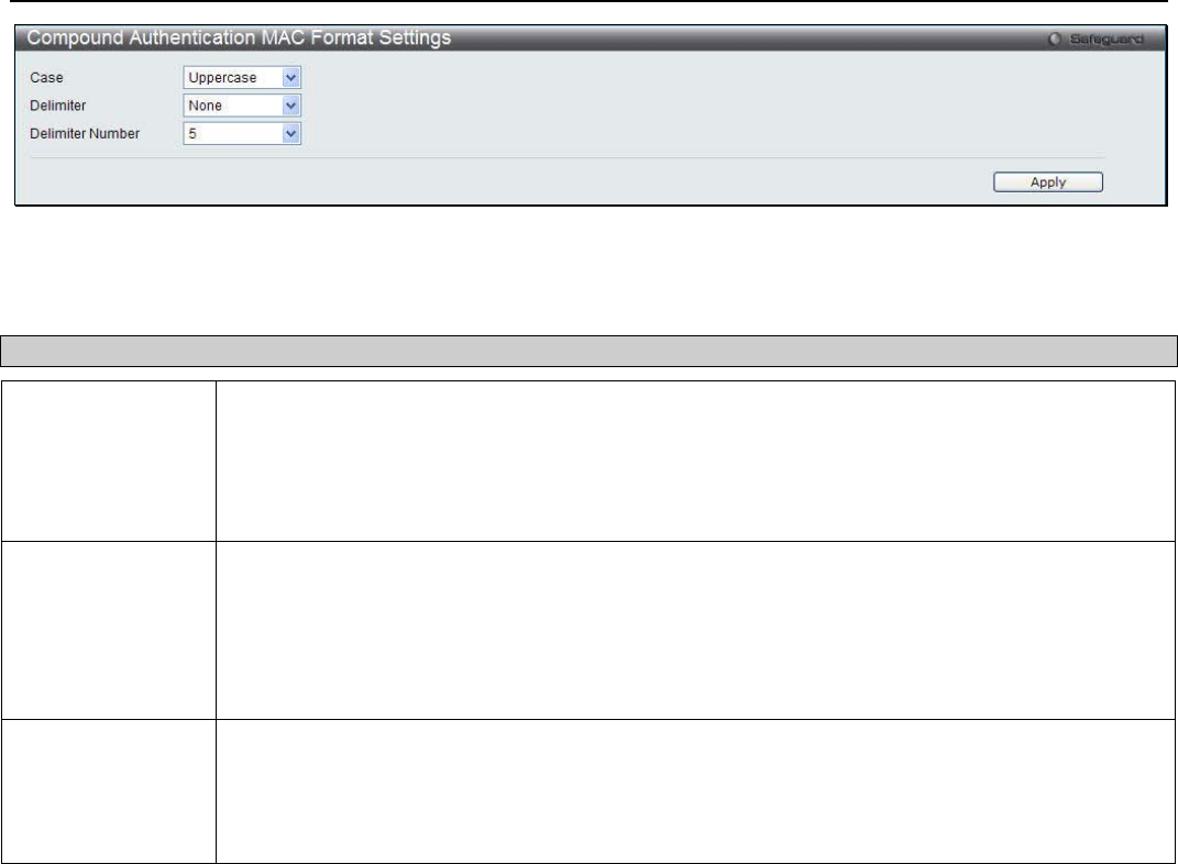
xStack® DGS-3200 Series Layer 2 Managed Gigabit Ethernet Switch Web UI Reference Guide
192
Figure 6 - 75. Compound Authentication MAC Format Settings window
The following fields may be modified to configure Guest VLANs:
Parameter Description
Case Use the drop-down menu to select the format for the RADIUS authentication username.
Lowerercase - Use lowercase format, the RADIUS authentication username will be formatted
as: aa-bb-cc-dd-ee-ff.
Uppercase - Use uppercase format, the RADIUS authentication username will be formatted as:
AA-BB-CC-DD-EE-FF.
Delimiter Use the drop-down menu to select the delimiter format.
Hyphen - Use "-" as delimiter, the format is: AA-BB-CC-DD-EE-FF.
Colon - Use ":" as delimiter, the format is: AA:BB:CC:DD:EE:FF.
Dot - Use "." as delimiter, the format is: AA.BB.CC.DD.EE.FF.
None – Do not use any delimiter, the format is: AABBCCDDEEFF.
Delimiter Number Use the drop-down menu to select the delimiter number.
1 - Single delimiter, the format is: AABBCC.DDEEFF.
2 - Double delimiter, the format is: AABB.CCDD.EEFF.
5 - Multiple delimiter, the format is: AA.BB.CC.DD.EE.FF.
Click the Apply button to accept the changes made.
IGMP Access Control Settings
Users can set IGMP authentication, otherwise known as IGMP access control, on individual ports on the Switch. When the
Authentication State is Enabled, and the Switch receives an IGMP join request, the Switch will send the access request to the
RADIUS server to do the authentication.
IGMP authentication processes IGMP reports as follows: When a host sends a join message for the interested multicast group, the
Switch has to do authentication before learning the multicast group/port. The Switch sends an Access-Request to an authentication
server and the information including host MAC, switch port number, switch IP, and multicast group IP. When the Access-Accept
is answered from the authentication server, the Switch learns the multicast group/port. When the Access-Reject is answered from
the authentication server, the Switch won’t learn the multicast group/port and won’t process the packet further. The entry (host
MAC, switch port number, and multicast group IP) is put in the “authentication failed list.” When there is no answer from the
authentication server after T1 time, the Switch resends the Access-Request to the server. If the Switch doesn’t receive a response
after N1 times, the result is denied and the entry (host MAC, switch port number, multicast group IP) is put in the “authentication
failed list.” In general case, when the multicast group/port is already learned by the switch, it won’t do the authentication again. It
only processes the packet as standard.
IGMP authentication processes IGMP leaves as follows: When the host sends leave message for the specific multicast group, the
Switch follows the standard procedure for leaving a group and then sends an Accounting-Request to the accounting server for
notification. If there is no answer from the accounting server after T2 time, the Switch resends the Accounting-Request to the
server. The maximum number of retry times is N2.
To view the following window, click Security > IGMP Access Control Settings:
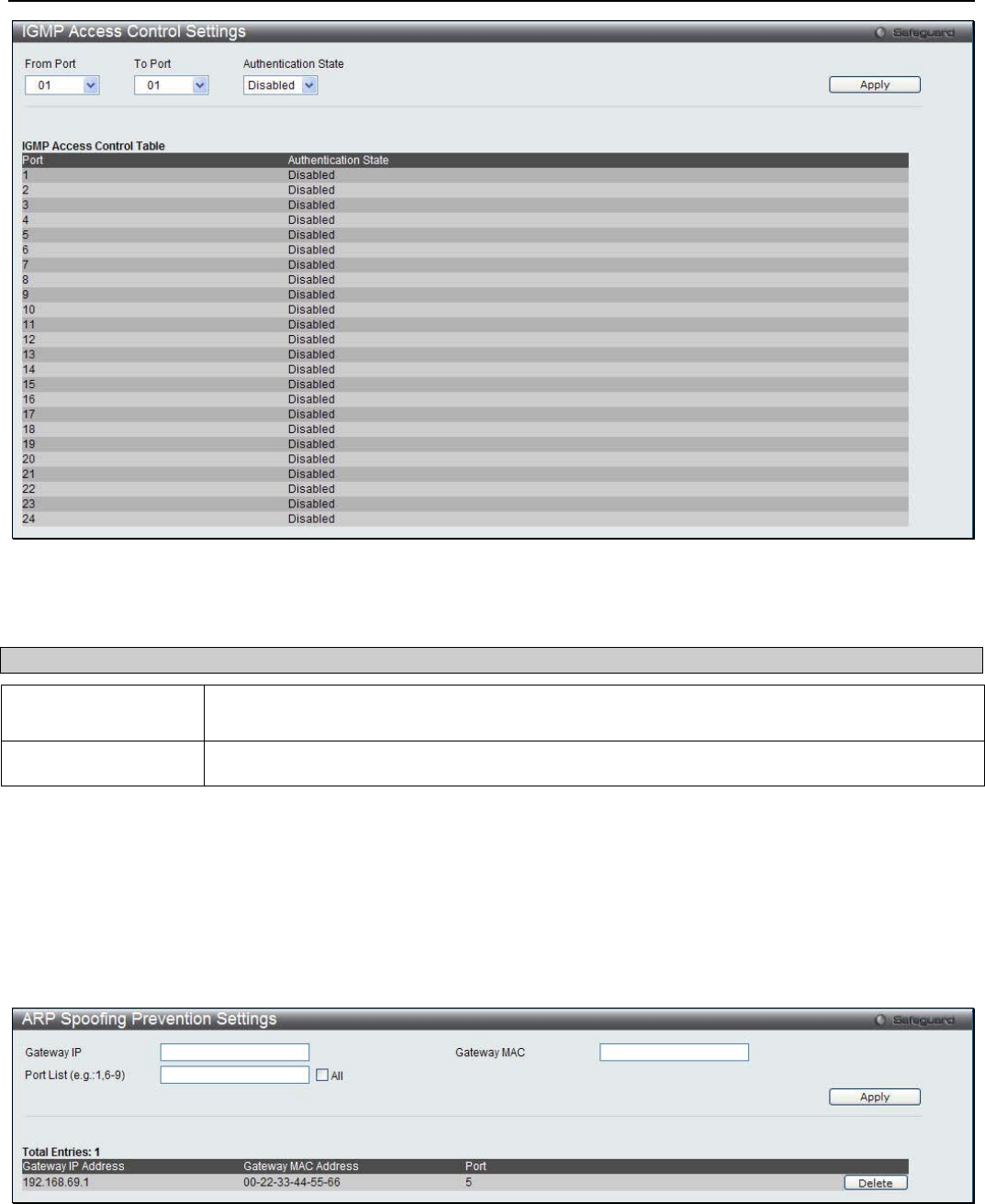
xStack® DGS-3200 Series Layer 2 Managed Gigabit Ethernet Switch Web UI Reference Guide
193
Figure 6 - 76. IGMP Acess Control Settings window
To set up IGMP access control on individual ports for the Switch, complete the following fields:
Parameter Description
From Port / To Port Use the drop-down menus to select t a range of ports to be enabled/disabled as IGMP
access control ports.
Authentication State Toggle to enable and disable the RADIUS authentication function on the specified ports.
Click Apply to implement the changes made.
ARP Spoofing Prevention Settings
Users can try to prevent ARP spoofing by hackers and other unauthorized parties trying to access the Switch by using the
following security feature.
To view the following window, click Security > ARP Spoofing Prevention Settings:
Figure 6 - 77. ARP Spoofing Prevention Settings window
Enter a Gateway IP address, Gateway MAC address, and a Port List and then click the Apply button.
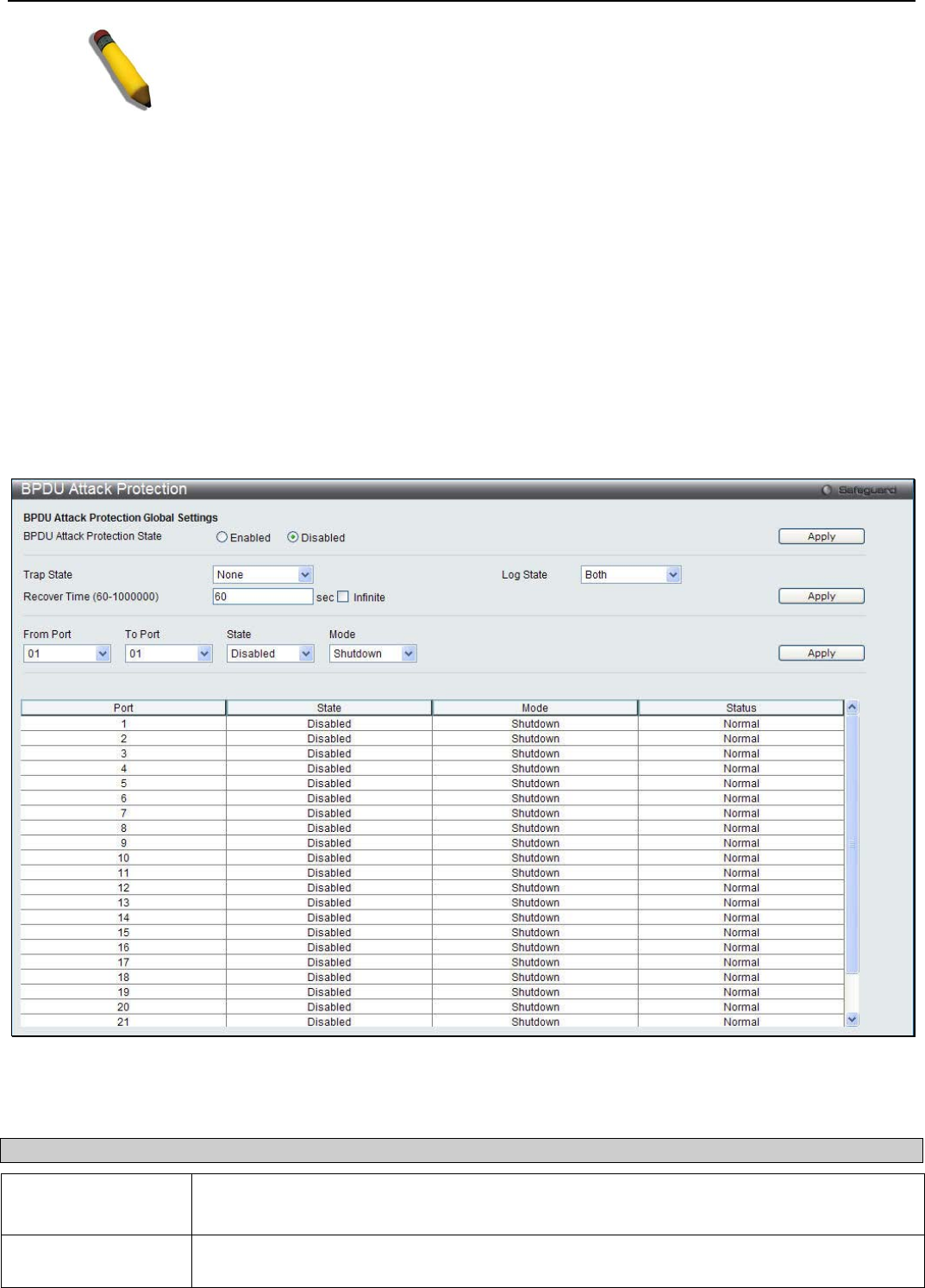
xStack® DGS-3200 Series Layer 2 Managed Gigabit Ethernet Switch Web UI Reference Guide
194
NOTE: See Appendix A for more information on how to prevent ARP Spoofing
attacks.
BPDU Attack Protection
This window is used to configure the BPDU protection function for the ports on the switch. In generally, there are two states in
BPDU protection function. One is normal state, and another is under attack state. The under attack state have three modes: drop,
block, and shutdown. A BPDU protection enabled port will enter an under attack state when it receives one STP BPDU packet.
And it will take action based on the configuration. Thus, BPDU protection can only be enabled on the STP-disabled port.
BPDU protection has a higher priority than the FBPDU setting configured by configure STP command in the determination of
BPDU handling. That is, when FBPDU is configured to forward STP BPDU but BPDU protection is enabled, then the port will
not forward STP BPDU.
BPDU protection also has a higher priority than the BPDU tunnel port setting in determination of BPDU handling. That is, when a
port is configured as BPDU tunnel port for STP, it will forward STP BPDU. But if the port is BPDU protection enabled. Then the
port will not forward STP BPDU.
To view the following window, click Security > BPDU Attack Protection:
Figure 6 - 78. BPDU Attack Protection window
The following parameters can be configured:
Parameter Description
BPDU Attack
Protection State
Click the radio buttons to enable or disable the BPDU Attack Protection state.
Trap State Specify when a trap will be sent. Options to choose from are None, Attack Detected, Attack
Cleared or Both.
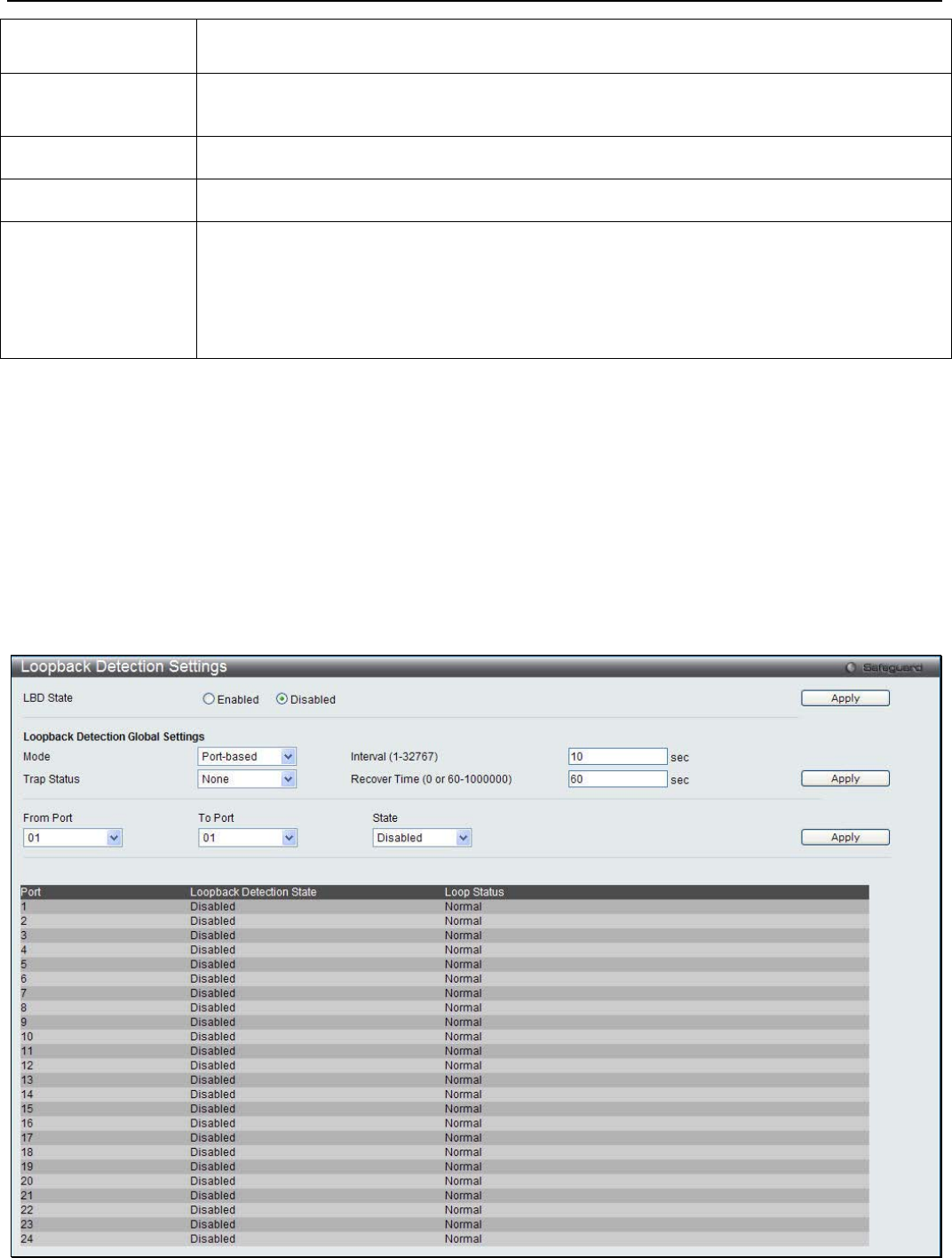
xStack® DGS-3200 Series Layer 2 Managed Gigabit Ethernet Switch Web UI Reference Guide
195
Log State Specify when a log entry will be sent. Options to choose from are None, Attack Detected,
Attack Cleared or Both.
Recover Time (60-
1000000)
Enter the BPDU protection Auto-Recovery timer. The default value of the recovery timer is
60. Tick the Infinite check box for not auto recovering.
From Port / To Port Use the drop-down menus to select t a range of ports.
State Use the drop-down menu to enable or disable the protection mode for a specific port.
Mode Specify the BPDU protection mode. The default mode is shutdown.
Drop – Drop all received BPDU packets when the port enters under attack state.
Block – Drop all packets (include BPDU and normal packets) when the port enters under
attack state.
Shutdown – Shut down the port when the port enters under attack state.
Click Apply to implement the changes made.
Loopback Detection Settings
The Loopback Detection function is used to detect the loop created by a specific port. This feature is used to temporarily
shutdown a port on the Switch when a CTP (Configuration Testing Protocol) packet has been looped back to the Switch. When
the Switch detects CTP packets received from a port or a VLAN, this signifies a loop on the network. The Switch will
automatically block the port or the VLAN and send an alert to the administrator. The Loopback Detection port will restart (change
to discarding state) when the Loopback Detection Recover Time times out. The Loopback Detection function can be implemented
on a range of ports at a time. The user may enable or disable this function using the drop-down menu.
To view the following window, click Security > Loopback Detection Settings:
Figure 6 - 79. Loopback Detection Settings window

xStack® DGS-3200 Series Layer 2 Managed Gigabit Ethernet Switch Web UI Reference Guide
196
The following parameters may be viewed or modified:
Parameter Description
LBD State Use the drop-down menu to enable or disable loopback detection. The default is Disabled.
Mode Use the drop-down menu to toggle between Port-based and VLAN-based.
Trap Status Set the desired trap status: None, Loop Detected, Loop Cleared, or Both.
Interval (1-32767) The time interval (in seconds) that the device will transmit all the CTP (Configuration Test
Protocol) packets to detect a loop-back event. The valid range is from 1 to 32767 seconds.
The default setting is 10 seconds.
Recover Time (0 or 60-
1000000) Time allowed (in seconds) for recovery when a Loopback is detected. The Loopdetect
Recover Time can be set at 0 seconds, or 60 to 1000000 seconds. Entering 0 will disable
the Loopdetect Recover Time. The default is 60 seconds.
From Port / To Port Use the drop-down menus to select a range of ports to be configured.
State Use the drop-down menu to toggle between Enabled and Disabled.
Click Apply to let the changes take effect.
Traffic Segmentation
Traffic segmentation is used to limit traffic flow from a single or group of ports, to a group of ports. This method of segmenting
the flow of traffic is similar to using VLANs to limit traffic, but is more restrictive. It provides a method of directing traffic that
does not increase the overhead of the Master switch CPU.
To view the following window, click Security > Traffic Segmentation:
Figure 6 - 80. Traffic Segmentation window
To configure traffic segmentation on the Switch, first specify the Source Ports using the From and To drop-down menus at the top
of the window. Next, specify which ports on the Switch are able to receive packets from the port(s) specified in the first step.
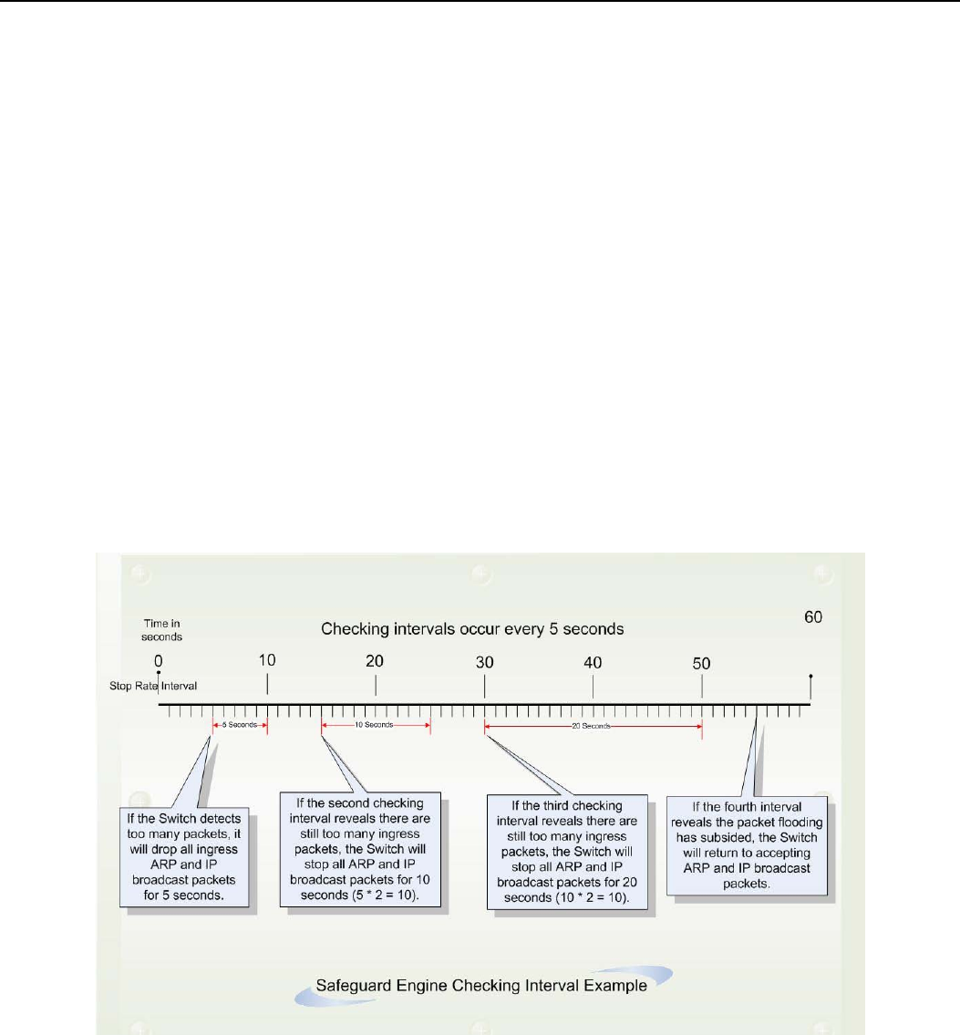
xStack® DGS-3200 Series Layer 2 Managed Gigabit Ethernet Switch Web UI Reference Guide
197
Clicking the Apply button will enter the combination of transmitting port(s) and allowed receiving ports into the Switch’s Traffic
Segmentation table.
Safeguard Engine Settings
Periodically, malicious hosts on the network will attack the Switch by utilizing packet flooding (ARP Storm) or other methods.
These attacks may increase the switch load beyond its capability. To alleviate this problem, the Safeguard Engine function was
added to the Switch’s software.
The Safeguard Engine can help the overall operability of the Switch by minimizing the workload of the Switch while the attack is
ongoing, thus making it capable to forward essential packets over its network in a limited bandwidth. The Safeguard Engine has
two operating modes that can be configured by the user, Strict and Fuzzy. In Strict mode, when the Switch either (a) receives too
many packets to process or (b) exerts too much memory, it will enter the Exhausted mode. When in this mode, the Switch will
drop all ARP and IP broadcast packets and packets from untrusted IP addresses for a calculated time interval. Every five seconds,
the Safeguard Engine will check to see if there are too many packets flooding the Switch. If the threshold has been crossed, the
Switch will initially stop all ingress ARP and IP broadcast packets and packets from untrusted IP addresses for five seconds. After
another five-second checking interval arrives, the Switch will again check the ingress flow of packets. If the flooding has stopped,
the Switch will again begin accepting all packets. Yet, if the checking shows that there continues to be too many packets flooding
the Switch, it will stop accepting all ARP and IP broadcast packets and packets from untrusted IP addresses for double the time of
the previous stop period. This doubling of time for stopping these packets will continue until the maximum time has been reached,
which is 320 seconds and every stop from this point until a return to normal ingress flow would be 320 seconds. For a better
understanding, please examine the following example of the Safeguard Engine.
Figure 6 - 81. Safeguard Engine example
For every consecutive checking interval that reveals a packet flooding issue, the Switch will double the time it will discard ingress
ARP and IP broadcast packets and packets from untrusted IP addresses. In the example above, the Switch doubled the time for
dropping ARP and IP broadcast packets when consecutive flooding issues were detected at 5-second intervals. (First stop = 5
seconds, second stop = 10 seconds, third stop = 20 seconds) Once the flooding is no longer detected, the wait period for dropping
ARP and IP broadcast packets will return to 5 seconds and the process will resume.
In Fuzzy mode, once the Safeguard Engine has entered the Exhausted mode, the Safeguard Engine will decrease the packet flow
by half. After returning to Normal mode, the packet flow will be increased by 25%. The switch will then return to its interval
checking and dynamically adjust the packet flow to avoid overload of the Switch.
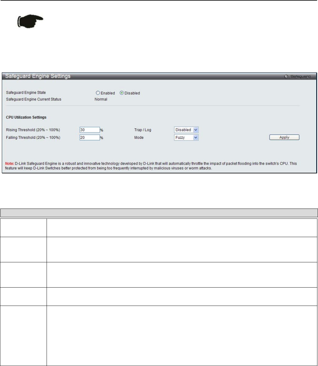
xStack® DGS-3200 Series Layer 2 Managed Gigabit Ethernet Switch Web UI Reference Guide
198
NOTICE: When Safeguard Engine is enabled, the Switch will allot bandwidth to various
traffic flows (ARP, IP) using the FFP (Fast Filter Processor) metering table to control the
CPU utilization and limit traffic. This may limit the speed of routing traffic over the network.
Users can enable the Safeguard Engine or configure advanced Safeguard Engine settings for the Switch.
To view the following window, click Security > Safeguard Engine Settings:
Figure 6 - 82. Safeguard Engine Settings window
The following parameters can be configured:
Parameter Description
Safeguard
Engine State Use the radio button to globally enable or disable Safeguard Engine settings for the Switch.
Rising
Threshold
(20% - 100%)
Used to configure the acceptable level of CPU utilization before the Safeguard Engine mechanism
is enabled. Once the CPU utilization reaches this percentage level, the Switch will move into
Exhausted mode, based on the parameters provided in this window.
Falling
Threshold
(20% - 100%)
Used to configure the acceptable level of CPU utilization as a percentage, where the Switch leaves
the Safeguard Engine state and returns to normal mode.
Trap / Log Use the drop-down menu to enable or disable the sending of messages to the device’s SNMP
agent and switch log once the Safeguard Engine has been activated by a high CPU utilization rate.
Mode Used to select the type of Safeguard Engine to be activated by the Switch when the CPU utilization
reaches a high rate. The user may select:
Fuzzy – If selected, this function will instruct the Switch to minimize the IP and ARP traffic flow to
the CPU by dynamically allotting an even bandwidth to all traffic flows.
Strict – If selected, this function will stop accepting all ARP packets not intended for the Switch, and
will stop receiving all unnecessary broadcast IP packets, until the storm has subsided.
The default setting is Fuzzy mode.
Click Apply to implement the changes.
Trusted Host Settings
Up to ten trusted host secure IP addresses may be configured and used for remote Switch management. It should be noted that if
one or more trusted hosts are enabled, the Switch will immediately accept remote instructions from only the specified IP address
or addresses. If you enable this feature, be sure to first enter the IP address of the station you are currently using.
To view the following window, click Security > Trusted Host Settings:
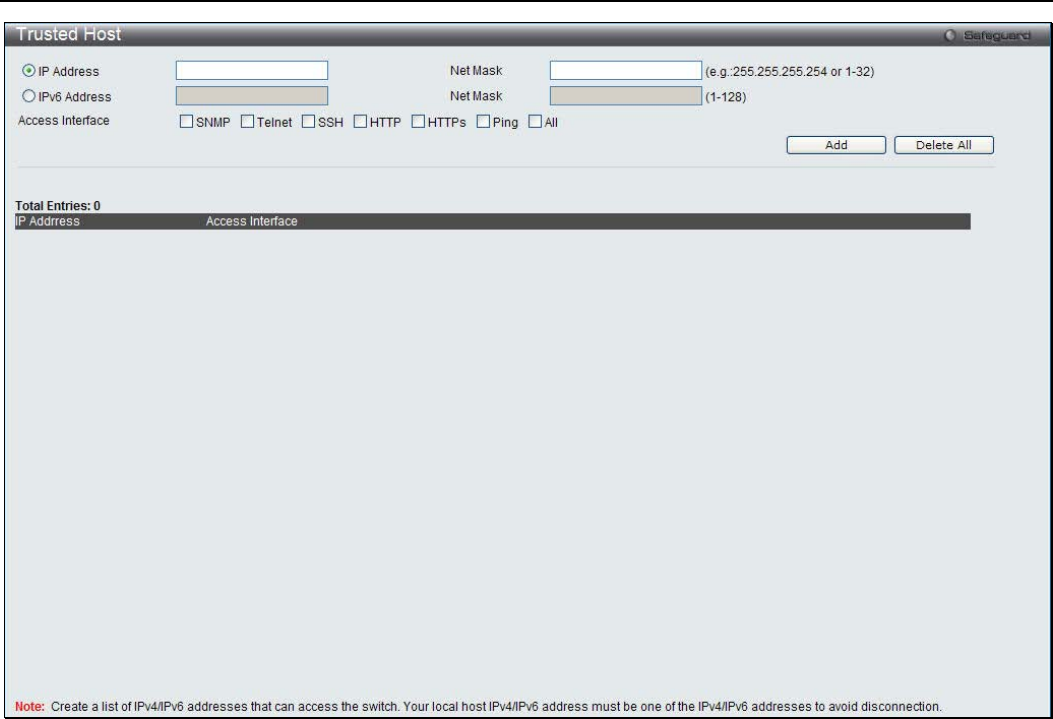
xStack® DGS-3200 Series Layer 2 Managed Gigabit Ethernet Switch Web UI Reference Guide
199
Figure 6 - 83. Trusted Host window
To configure secure IP addresses for trusted host management of the Switch, type the IP address and the net mask of the station
you are currently using in the two fields, as well as up to nine additional IP addresses of trusted hosts, one by one. Click the Apply
button to assign trusted host status to the IP addresses. This goes into effect immediately.
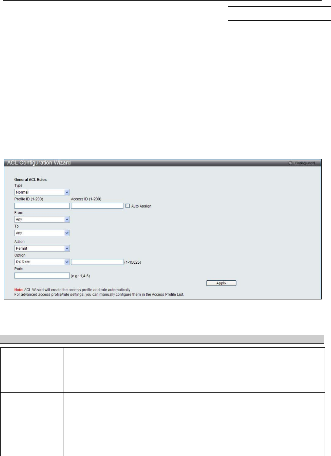
xStack® DGS-3200 Series Layer 2 Managed Gigabit Ethernet Switch Web UI Reference Guide
200
Section 7
ACL
ACL Configuration Wizard
Access Profile List
CPU Access Profile List
Time Range Settings
ACL Configuration Wizard
In order to make access profile and rule creation significantly easier to use, an ACL wizard has been introduced in the current
firmware release. Of course, advanced users can still manually configure access profiles and rules in the Access Profile List in the
next section.
To view the following window, click ACL > ACL Configuration Wizard:
Figure 7 - 1. ACL Configuration Wizard window
The following parameters can be configured:
Parameter Description
Type Use the drop-down menu to select the general ACL Rule types:
Normal – Selecting this option will create a Normal ACL Rule.
CPU – Selecting this option will create a CPU ACL Rule.
Profile ID (1-200) Enter the Profile ID for the new rule.
Access ID (1-200) Enter the Access ID for the new rule. Selecting the Auto Assign option will allow the switch to
automatically assign an unused access ID to this rule.
From / To This rule can be created to apply to four different categories:
Any – Selecting this option will include any starting category to this rule.
MAC Address – Selecting this option will allow the user to enter a range of MAC addresses for
this rule.
IPv4 Address – Selecting this option will allow the user to enter a range of IPv4 addresses for
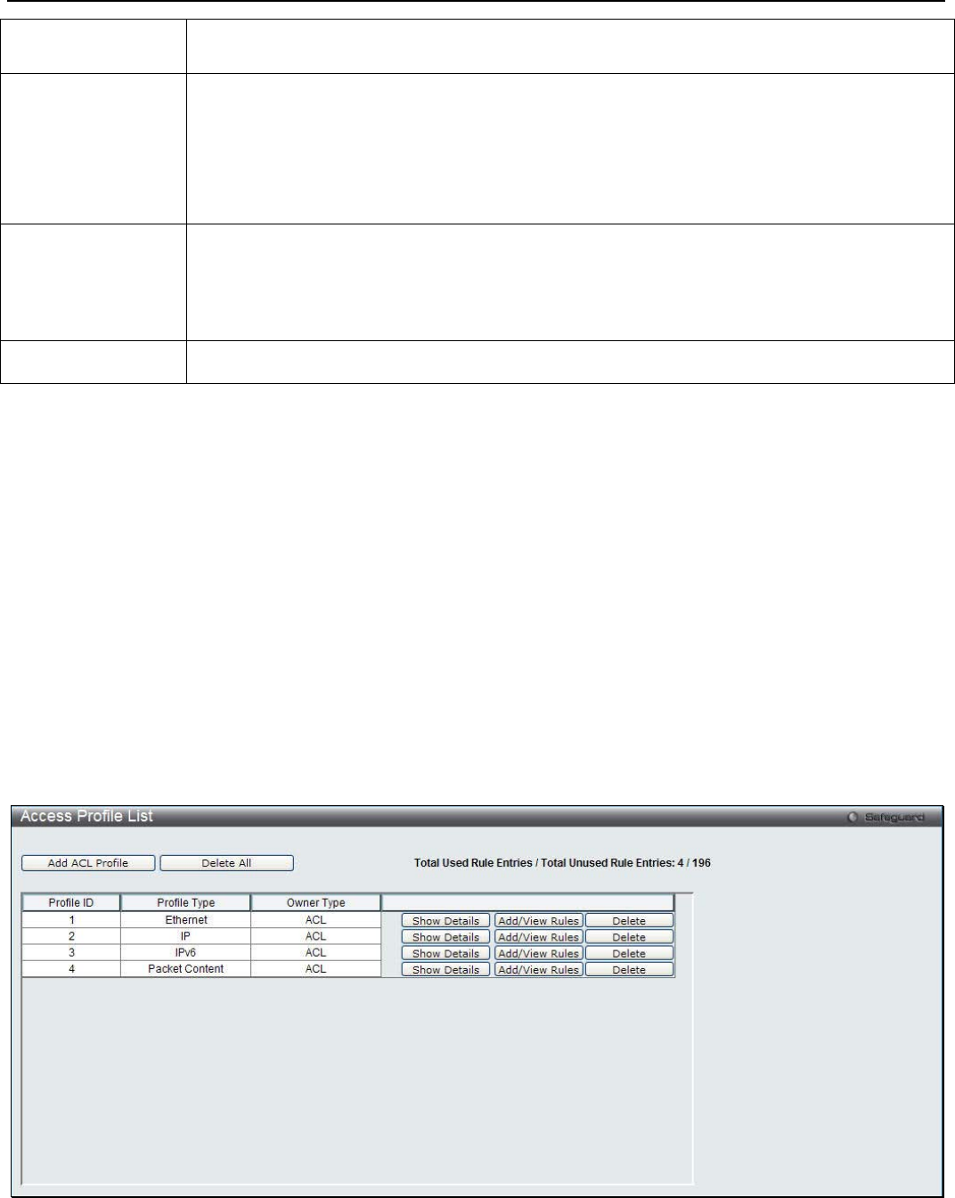
xStack® DGS-3200 Series Layer 2 Managed Gigabit Ethernet Switch Web UI Reference Guide
201
this rule.
IPv6 – Selecting this option will allow the user to enter a range of IPv6 addresses for this rule.
Action Select Permit to specify that the packets that match the access profile are forwarded by the
Switch, according to any additional rule added (see below).
Select Deny to specify that the packets that match the access profile are not forwarded by the
Switch and will be filtered.
Select Mirror to specify that packets that match the access profile are mirrored to a port
defined in the mirror port section. Port Mirroring must be enabled and a target port must be set.
Option After selecting the Permit action, the user can select one of the following options:
RX Rate – Enter the RX rate value.
Replace DSCP – Enter the DSCP value.
Replace ToS Precedence – Enter the ToS Precedence value.
Ports Enter a port or range of ports.
Click Apply to implement the changes made.
For more information about each of the parameters used in the ACL wizard, please see the detailed descriptions for each type of
ACL rule in the rest of this chapter.
Access Profile List
Access profiles allow you to establish criteria to determine whether the Switch will forward packets based on the information
contained in each packet's header.
The Switch supports four Profile Types, Ethernet ACL, IPv4 ACL, IPv6 ACL, and Packet Content ACL.
Creating an access profile is divided into two basic parts. The first is to specify which part or parts of a frame the Switch will
examine, such as the MAC source address or the IP destination address. The second part is entering the criteria the Switch will use
to determine what to do with the frame. The entire process is described below in two parts.
Users can display the currently configured Access Profiles on the Switch.
To view the following window, click ACL > Access Profile List (one access profile of each type has been created for explanatory
purposes):
Figure 7 - 2. Access Profile List window
To add an entry to the Access Profile List window, click the Add ACL Profile button. To remove all access profiles from this
table, click Delete All.
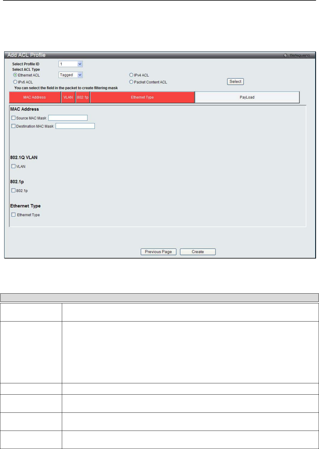
xStack® DGS-3200 Series Layer 2 Managed Gigabit Ethernet Switch Web UI Reference Guide
202
There are four Add Access Profile windows; one for Ethernet (or MAC address-based) profile configuration, one for IPv6
address-based profile configuration, one for IPv4 address-based profile configuration, and one for packet content profile
configuration.
The window shown below is the Add ACL Profile window for Ethernet:
Figure 7 - 3. Add ACL Profile window for Ethernet ACL
The following parameters can be set for the Ethernet ACL type:
Parameter Description
Select Profile ID Use the drop-down menu to select a unique identifier number for this profile set. This value can
be set from 1 to 200.
Select ACL Type Select profile based on Ethernet (MAC Address), IPv4 address, IPv6 address, or packet
content. This will change the window according to the requirements for the type of profile.
Select Ethernet ACL to instruct the Switch to examine the layer 2 part of each packet header.
Select IPv4 ACL to instruct the Switch to examine the IPv4 address in each frame's header.
Select IPv6 ACL to instruct the Switch to examine the IPv6 address in each frame's header.
Select Packet Content to instruct the Switch to examine the packet content in each frame’s
header.
Source MAC Mask Enter a MAC address mask for the source MAC address.
Destination MAC
Mask Enter a MAC address mask for the destination MAC address.
802.1Q VLAN Selecting this option instructs the Switch to examine the 802.1Q VLAN identifier of each packet
header and use this as the full or partial criterion for forwarding.
802.1p Selecting this option instructs the Switch to examine the 802.1p priority value of each packet
header and use this as the, or part of the criterion for forwarding.
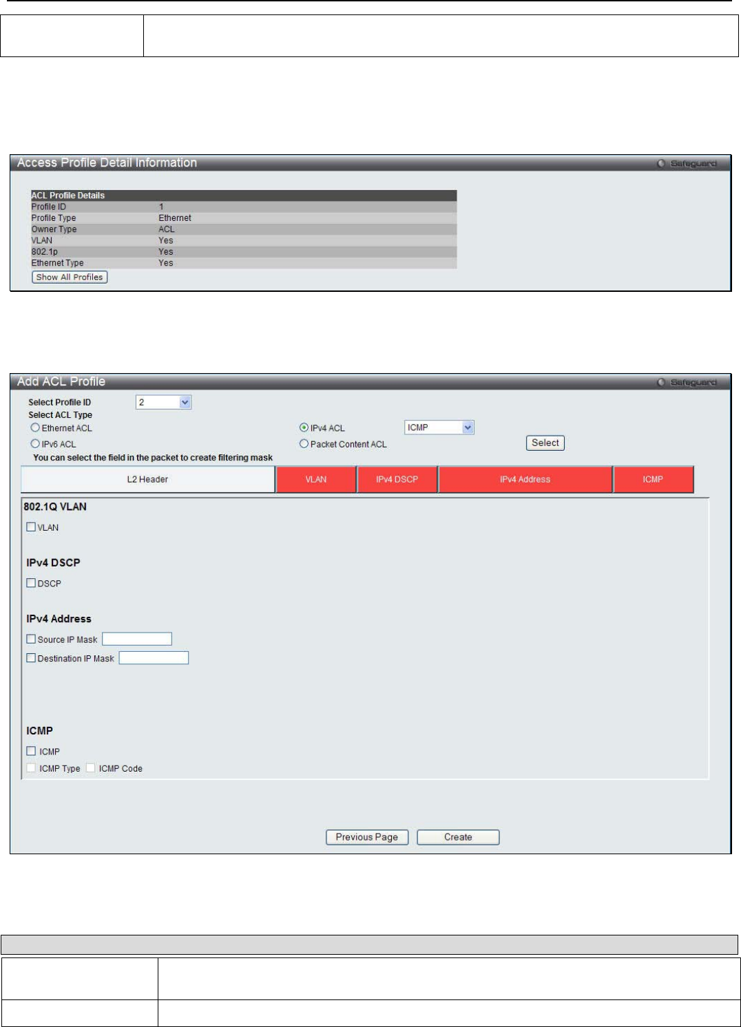
xStack® DGS-3200 Series Layer 2 Managed Gigabit Ethernet Switch Web UI Reference Guide
203
Ethernet Type Selecting this option instructs the Switch to examine the Ethernet type value in each frame's
header.
Click Create to create the new ACL Profile.
To view the setting details for a created profile, click the Show Details button for the corresponding entry on the Access Profile
List window, revealing the following window:
Figure 7 - 4. Access Profile Detail Information window for Ethernet
The window shown below is the Add ACL Profile window for IPv4:
Figure 7 - 5. Add ACL Profile window for IPv4 ACL
The following parameters can be set for the IPv4 ACL type:
Parameter Description
Select Profile ID Use the drop-down menu to select a unique identifier number for this profile set. This value
can be set from 1 to 200.
Select ACL Type Select profile based on Ethernet (MAC Address), IPv4 address, IPv6 address, or packet

xStack® DGS-3200 Series Layer 2 Managed Gigabit Ethernet Switch Web UI Reference Guide
204
content. This will change the window according to the requirements for the type of profile.
Select Ethernet ACL to instruct the Switch to examine the layer 2 part of each packet header.
Select IPv4 ACL to instruct the Switch to examine the IPv4 address in each frame's header.
Select IPv6 ACL to instruct the Switch to examine the IPv6 address in each frame's header.
Select Packet Content to instruct the Switch to examine the packet content in each frame’s
header.
802.1Q VLAN Selecting this option instructs the Switch to examine the 802.1Q VLAN identifier of each
packet header and use this as the full or partial criterion for forwarding.
IPv4 DSCP Selecting this option instructs the Switch to examine the DiffServ Code part of each packet
header and use this as the, or part of the criterion for forwarding.
IPv4 Source IP Mask Enter an IP address mask for the source IP address.
IPv4 Destination IP
Mask Enter an IP address mask for the destination IP address.
Protocol Selecting this option instructs the Switch to examine the protocol type value in each frame's
header. Then the user must specify what protocol(s) to include according to the following
guidelines:
Select ICMP to instruct the Switch to examine the Internet Control Message Protocol (ICMP)
field in each frame's header.
• Select Type to further specify that the access profile will apply an ICMP type value,
or specify Code to further specify that the access profile will apply an ICMP code
value.
Select IGMP to instruct the Switch to examine the Internet Group Management Protocol
(IGMP) field in each frame's header.
• Select Type to further specify that the access profile will apply an IGMP type value.
Select TCP to use the TCP port number contained in an incoming packet as the forwarding
criterion. Selecting TCP requires that you specify a source port mask and/or a destination
port mask.
• src port mask - Specify a TCP port mask for the source port in hex form (hex 0x0-
0xffff), which you wish to match.
• dst port mask - Specify a TCP port mask for the destination port in hex form (hex
0x0-0xffff) which you wish to match.
• flag bit - The user may also identify which flag bits to match. Flag bits are parts of a
packet that determine what to do with the packet. The user may filter packets by
filtering certain flag bits within the packets, by checking the boxes corresponding to
the flag bits of the TCP field. The user may choose among the urg (urgent), ack
(acknowledgement), psh (push), rst (reset), syn (synchronize), and fin (finish)
options.
• Select UDP to use the UDP port number contained in an incoming packet as the
forwarding criterion. Selecting UDP requires that you specify a source port mask
and/or a destination port mask.
• src port mask - Specify a UDP port mask for the source port in hex form (hex 0x0-
0xffff).
• dst port mask - Specify a UDP port mask for the destination port in hex form (hex
0x0-0xffff).
Protocol ID - Enter a value defining the protocol ID in the packet header to mask. Specify the
protocol ID mask in hex form (hex 0x0-0xff).
Click Create to implement changes made.
To view the setting details for a created profile, click the Show Details button for the corresponding entry on the Access Profile
List window, revealing the following window:
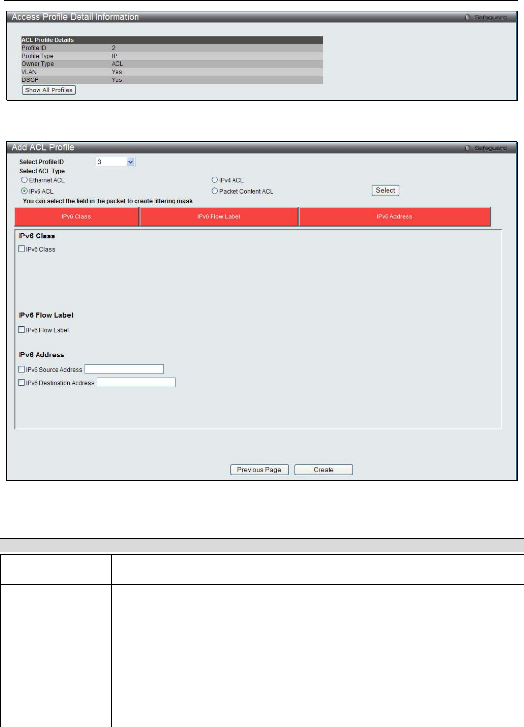
xStack® DGS-3200 Series Layer 2 Managed Gigabit Ethernet Switch Web UI Reference Guide
205
Figure 7 - 6. Access Profile Detail Information window for IPv4
The window shown below is the Add ACL Profile window for IPv6:
Figure 7 - 7. Add ACL Profile window for IPv6
The following parameters can be set for the IPv6 ACL type:
Parameter Description
Select Profile ID Use the drop-down menu to select a unique identifier number for this profile set. This value
can be set from 1 to 200.
Select ACL Type Select profile based on Ethernet (MAC Address), IPv4 address, IPv6 address, or packet
content. This will change the window according to the requirements for the type of profile.
Select Ethernet ACL to instruct the Switch to examine the layer 2 part of each packet header.
Select IPv4 ACL to instruct the Switch to examine the IPv4 address in each frame's header.
Select IPv6 ACL to instruct the Switch to examine the IPv6 address in each frame's header.
Select Packet Content to instruct the Switch to examine the packet content in each frame’s
header.
IPv6 Class Ticking this check box will instruct the Switch to examine the class field of the IPv6 header.
This class field is a part of the packet header that is similar to the Type of Service (ToS) or
Precedence bits field in IPv4.
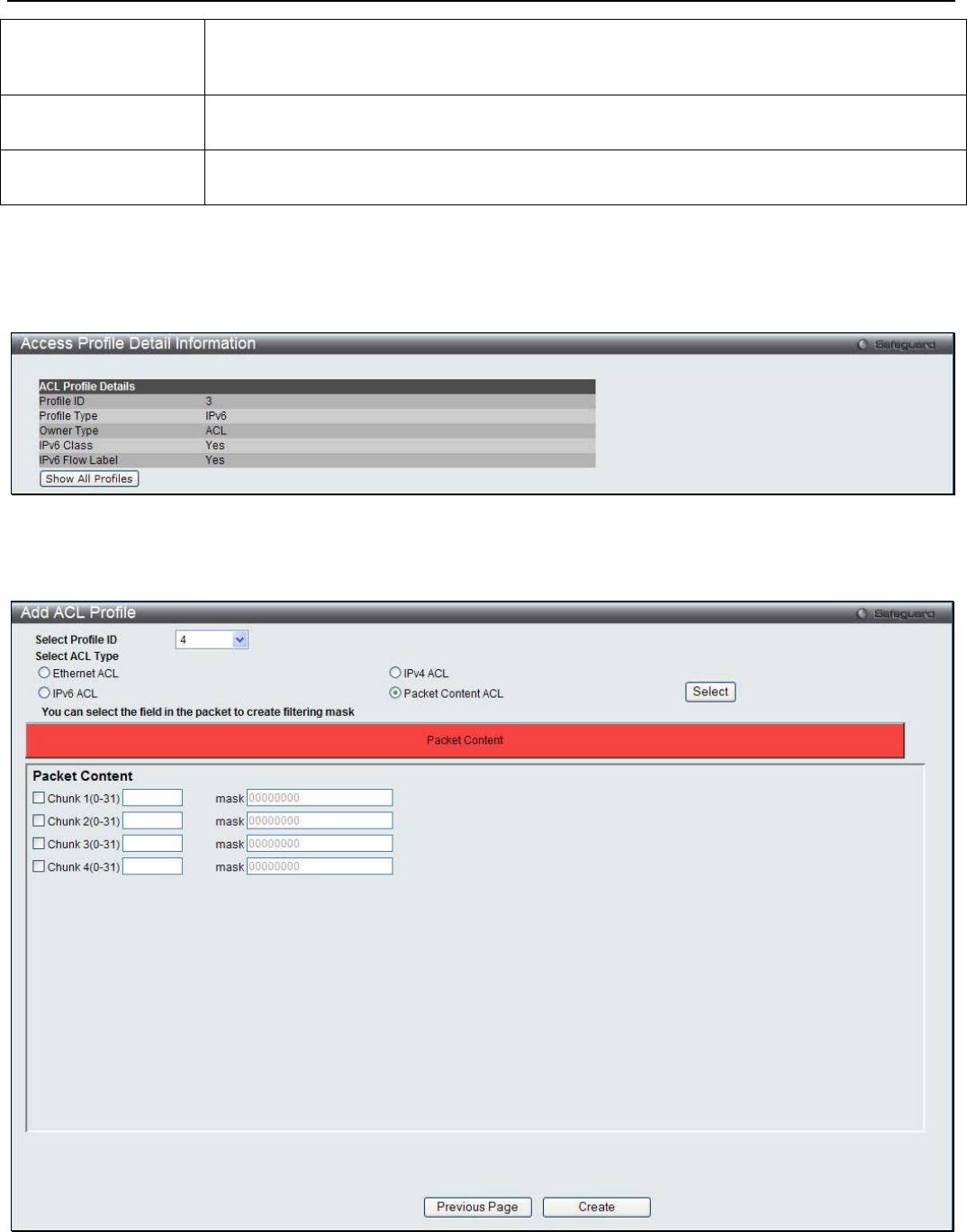
xStack® DGS-3200 Series Layer 2 Managed Gigabit Ethernet Switch Web UI Reference Guide
206
IPv6 Flow Label Ticking this check box will instruct the Switch to examine the flow label field of the IPv6
header. This flow label field is used by a source to label sequences of packets such as non-
default quality of service or real time service packets.
IPv6 Source Address The user may specify an IP address mask for the source IPv6 address by ticking the
corresponding check box and entering the IP address mask.
IPv6 Destination
Address The user may specify an IP address mask for the destination IPv6 address by ticking the
corresponding check box and entering the IP address mask.
Click Create to implement changes made.
To view the setting details for a created profile, click the Show Details button for the corresponding entry on the Access Profile
List window, revealing the following window:
Figure 7 - 8. Access Profile Detail Information window for IPv6
The window shown below is the Add ACL Profile window for Packet Content:
Figure 7 - 9. Add ACL Profile window for Packet Content
The following parameters can be set for the Packet Content type:

xStack® DGS-3200 Series Layer 2 Managed Gigabit Ethernet Switch Web UI Reference Guide
207
Parameter Description
Select Profile ID Use the drop-down menu to select a unique identifier number for this profile set. This value
can be set from 1 to 200.
Select ACL Type Select profile based on Ethernet (MAC Address), IPv4 address, IPv6 address, or packet
content. This will change the window according to the requirements for the type of profile.
Select Ethernet ACL to instruct the Switch to examine the layer 2 part of each packet header.
Select IPv4 ACL to instruct the Switch to examine the IPv4 address in each frame's header.
Select IPv6 ACL to instruct the Switch to examine the IPv6 address in each frame's header.
Select Packet Content to instruct the Switch to examine the packet content in each frame’s
header.
Packet Content Allows users to examine up to four specified offset chunks within a packet, one at a time. A
chunk mask presents four bytes. Four offset chunks can be selected from a possible 32
predefined offset chunks as described below:
offset_chunk_1,
offset_chunk_2,
offset_chunk_3,
offset_chunk_4.
chunk0 chunk1 chunk2 …… chunk29 chunk30 chunk31
B126,
B127,
B0,
B1
B2,
B3,
B4,
B5
B6,
B7,
B8,
B9
…… B114,
B115,
B116,
B117
B118,
B119,
B120,
B121
B122,
B123,
B124,
B125
Example:
offset_chunk_1 0 0xffffffff will match packet byte offset 126, 127, 0, 1
offset_chunk_1 0 0x0000ffff will match packet byte offset, 0,1
NOTE: Only one packet content mask profile can be created at a time. Use of the D-Link
xStack switch family’s advanced Packet Content Mask (also known as Packet Content
Access Control List – ACL) feature can effectively mitigate common network attacks such as
ARP Spoofing. The Switch’s implementation of Packet Content ACL enables inspection of
any packet’s specified content regardless of the protocol layer.
Click Create to implement changes made.
To view the setting details for a created profile, click the Show Details button for the corresponding entry on the Access Profile
List window, revealing the following window:
Figure 7 - 10. Access Profile Detail Information window for Packet Content
NOTE: Address Resolution Protocol (ARP) is the standard for finding a host’s hardware
address (MAC address). However, ARP is vulnerable as it can be easily spoofed and utilized
to attack a LAN (i.e. an ARP spoofing attack). For a more detailed explanation on how ARP
protocol works and how to employ D-Link’s un
ique Packet Content ACL to prevent ARP
spoofing attack, please see Appendix E at the end of this manual.
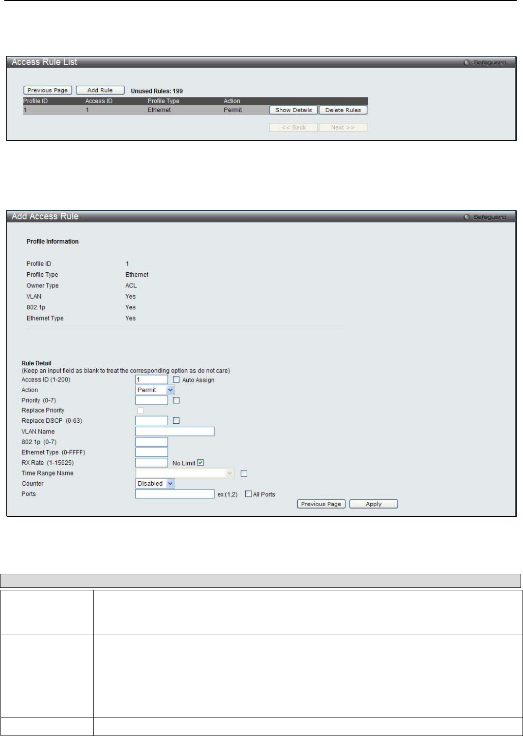
xStack® DGS-3200 Series Layer 2 Managed Gigabit Ethernet Switch Web UI Reference Guide
208
To establish the rule for a previously created Access Profile:
To configure the Access Rules for Ethernet, open the Access Profile List window and click Add/View Rules for an Ethernet
entry. This will open the following window:
Figure 7 - 11. Access Rule List window for Ethernet
To remove a previously created rule, click the corresponding Delete Rules button. To add a new Access Rule, click the Add Rule
button:
Figure 7 - 12. Add Access Rule window for Ethernet
The following parameters can be cconfigured:
Parameter Description
Access ID (1-200) Type in a unique identifier number for this access. This value can be set from 1 to 200.
Auto Assign – Ticking this check box will instruct the Switch to automatically assign an Access ID
for the rule being created.
Action Select Permit to specify that the packets that match the access rule are forwarded by the Switch,
according to any additional rule added (see below).
Select Deny to specify that packets that match the access rule are not forwarded by the Switch
and will be filtered.
Select Mirror to specify that packets that match the access rule are mirrored to a port defined in
the config mirror port command. Port Mirroring must be enabled and a target port must be set.
Priority (0-7) Tick the corresponding check box if you want to re-write the 802.1p default priority of a packet to
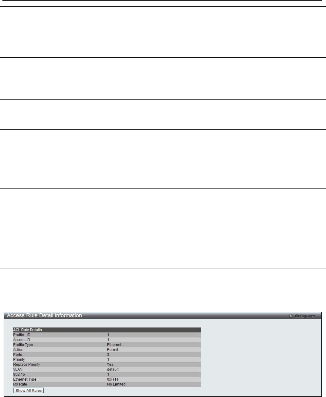
xStack® DGS-3200 Series Layer 2 Managed Gigabit Ethernet Switch Web UI Reference Guide
209
the value entered in the Priority field, which meets the criteria specified previously in this
command, before forwarding it on to the specified CoS queue. Otherwise, a packet will have its
incoming 802.1p user priority re-written to its original value before being forwarded by the Switch.
For more information on priority queues, CoS queues and mapping for 802.1p, see the QoS
section of this manual.
Replace Priority Tick this check box to replace the Priority value in the adjacent field.
Replace DSCP (0-
63) Select this option to instruct the Switch to replace the DSCP value (in a packet that meets the
selected criteria) with the value entered in the adjacent field.
Note: When an ACL rule is added to change both the priority and DSCP of an IPv4 packet, only
one of them can be modified due to a chip limitation. Currently the priority is changed when both
the priority and DSCP are set to be modified.
VLAN Name Allows the entry of a name for a previously configured VLAN.
802.1p (0-7) Enter a value from 0 to 7 to specify that the access profile will apply only to packets with this
802.1p priority value.
RX Rate (1-15625) Use this to limit RX bandwidth for the profile being configured. This rate is implemented using the
following equation: 1 value = 64kbit/sec. (ex. If the user selects an RX rate of 10 then the ingress
rate is 640kbit/sec.) The user many select a value between 1 and 15625 or tick the No Limit
check box. The default setting is No Limit.
Time Range
Name Tick the check box and enter the name of the Time Range settings that has been previously
configured in the Time Range Settings window. This will set specific times when this access rule
will be implemented on the Switch.
Counter Use the drop-down menu to specify if the Counter feature should be Enabled or Disabled. The
Counter feature is used to keep a record of the number of packets that have matched the Access
Rule. For example if you create an Ethernet ACL that permits the source MAC address of 00-00-
00-00-00-01 access to the Switch and a 1000 packets with the source MAC address of 00-00-00-
00-00-01 is received by the Switch, the counter values will be 1000, to indicate that the ACL has
matched 1000 packets.
Ports When a range of ports is to be configured, the Auto Assign check box MUST be ticked in the
Access ID field of this window. If not, the user will be presented with an error message and the
access rule will not be configured. Ticking the All Ports check box will denote all ports on the
Switch.
Click Apply to implement the changes.
To view the settings of a previously correctly configured rule, click the corresponding Show Details button on the Access Rule
List window to view the following window:
Figure 7 - 13. Access Rule Detail Information window for Ethernet
To establish the rule for a previously created Access Profile:
To configure the Access Rules for IPv4, open the Access Profile List window and click Add/View Rules for an IPv4 entry. This
will open the following window:
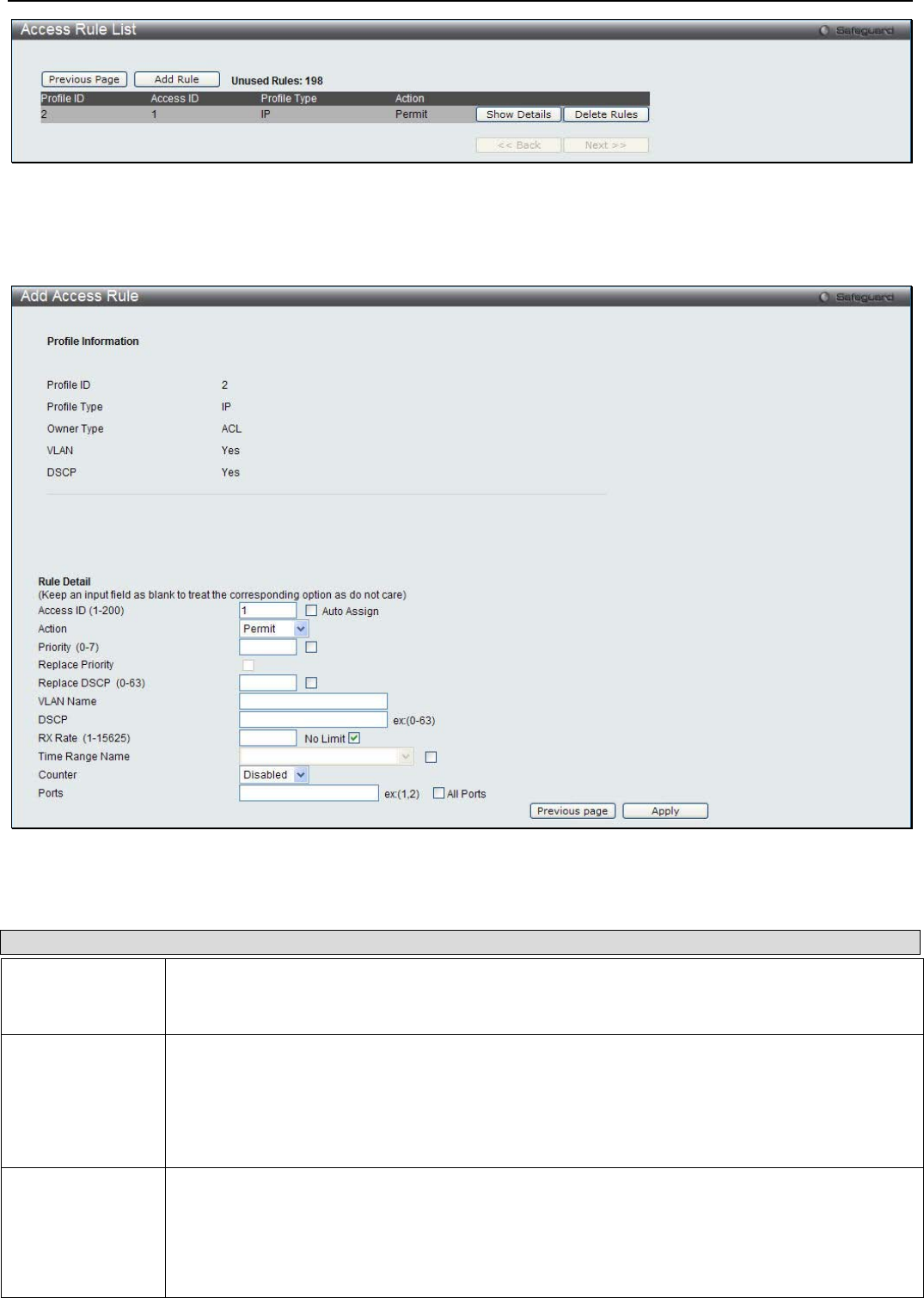
xStack® DGS-3200 Series Layer 2 Managed Gigabit Ethernet Switch Web UI Reference Guide
210
Figure 7 - 14. Access Rule List window for IPv4
To remove a previously created rule, click the corresponding Delete Rules button. To add a new Access Rule, click the Add Rule
button:
Figure 7 - 15. Add Access Rule window for IPv4
The following parameters can be cconfigured:
Parameter Description
Access ID (1-200) Type in a unique identifier number for this access. This value can be set from 1 to 200.
Auto Assign – Ticking this check box will instruct the Switch to automatically assign an Access ID
for the rule being created.
Action Select Permit to specify that the packets that match the access rule are forwarded by the Switch,
according to any additional rule added (see below).
Select Deny to specify that packets that match the access rule are not forwarded by the Switch
and will be filtered.
Select Mirror to specify that packets that match the access rule are mirrored to a port defined in
the config mirror port command. Port Mirroring must be enabled and a target port must be set.
Priority (0-7) Tick the corresponding check box if you want to re-write the 802.1p default priority of a packet to
the value entered in the Priority field, which meets the criteria specified previously in this
command, before forwarding it on to the specified CoS queue. Otherwise, a packet will have its
incoming 802.1p user priority re-written to its original value before being forwarded by the Switch.
For more information on priority queues, CoS queues and mapping for 802.1p, see the QoS
section of this manual.
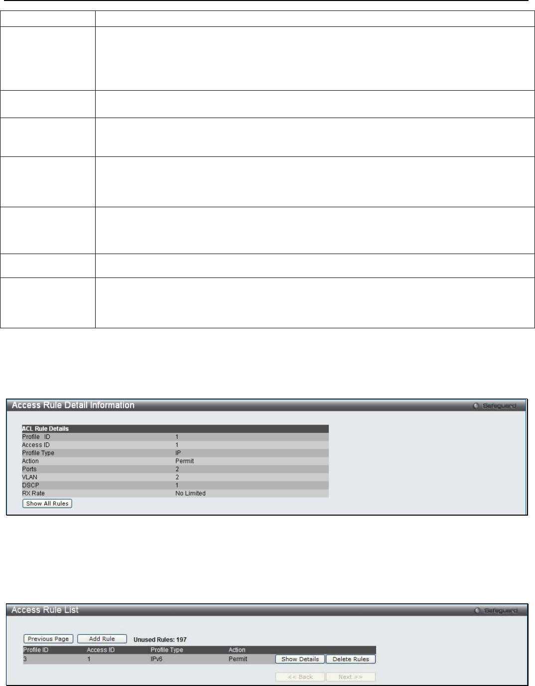
xStack® DGS-3200 Series Layer 2 Managed Gigabit Ethernet Switch Web UI Reference Guide
211
Replace Priority Tick this check box to replace the Priority value in the adjacent field.
Replace DSCP (0-
63) Select this option to instruct the Switch to replace the DSCP value (in a packet that meets the
selected criteria) with the value entered in the adjacent field.
Note: When an ACL rule is added to change both the priority and DSCP of an IPv4 packet, only
one of them can be modified due to a chip limitation. Currently the priority is changed when both
the priority and DSCP are set to be modified.
VLAN Name This field allows the user to enter a VLAN Name in the space provided, which will instruct the
Switch to examine the VLAN identifier of each packet header.
DSCP This field allows the user to enter a DSCP value in the space provided, which will instruct the
Switch to examine the DiffServ Code part of each packet header and use this as the, or part of
the criterion for forwarding. The user may choose a value between 0 and 63.
RX Rate (1-15625) Use this to limit RX bandwidth for the profile being configured. This rate is implemented using the
following equation: 1 value = 64kbit/sec. (ex. If the user selects an RX rate of 10 then the ingress
rate is 640kbit/sec.) The user many select a value between 1 and 15625 or tick the No Limit
check box. The default setting is No Limit.
Time Range
Name Tick the check box and enter the name of the Time Range settings that has been previously
configured in the Time Range Settings window. This will set specific times when this access rule
will be implemented on the Switch.
Counter Use the drop-down menu to specify if the Counter feature should be Enabled or Disabled.
Ports When a range of ports is to be configured, the Auto Assign check box MUST be ticked in the
Access ID field of this window. If not, the user will be presented with an error message and the
access rule will not be configured. Ticking the All Ports check box will denote all ports on the
Switch.
Click Apply to implement the changes.
To view the settings of a previously correctly configured rule, click the corresponding Show Details button on the Access Rule
List window to view the following window:
Figure 7 - 16. Access Rule Detail Information window for IPv4
To establish the rule for a previously created Access Profile:
To configure the Access Rules for IPv6, open the Access Profile List window and click Add/View Rules for an IPv6 entry. This
will open the following window:
Figure 7 - 17. Access Rule List window for IPv6
To remove a previously created rule, click the corresponding Delete Rules button. To add a new Access Rule, click the Add Rule
button:

xStack® DGS-3200 Series Layer 2 Managed Gigabit Ethernet Switch Web UI Reference Guide
212
Figure 7 - 18. Add Access Rule window for IPv6
The following parameters can be cconfigured:
Parameter Description
Access ID (1-200) Type in a unique identifier number for this access. This value can be set from 1 to 200.
Auto Assign – Ticking this check box will instruct the Switch to automatically assign an Access ID
for the rule being created.
Action Select Permit to specify that the packets that match the access rule are forwarded by the Switch,
according to any additional rule added (see below).
Select Deny to specify that packets that match the access rule are not forwarded by the Switch
and will be filtered.
Select Mirror to specify that packets that match the access rule are mirrored to a port defined in
the config mirror port command. Port Mirroring must be enabled and a target port must be set.
Priority (0-7) Tick the corresponding check box to re-write the 802.1p default priority of a packet to the value
entered in the Priority field, which meets the criteria specified previously in this command, before
forwarding it on to the specified CoS queue. Otherwise, a packet will have its incoming 802.1p
user priority re-written to its original value before being forwarded by the Switch.
For more information on priority queues, CoS queues and mapping for 802.1p, see the QoS
section of this manual.
Replace Priority Tick this check box to replace the Priority value in the adjacent field.
Replace DSCP (0-
63) Select this option to instruct the Switch to replace the DSCP value (in a packet that meets the
selected criteria) with the value entered in the adjacent field.
Note: When an ACL rule is added to change both the priority and DSCP of an IPv6 packet, only
one of them can be modified due to a chip limitation. Currently the priority is changed when both
the priority and DSCP are set to be modified.
Class Use this option to specify the IPv6 class mask.
RX Rate (1-15625) Use this to limit RX bandwidth for the profile being configured. This rate is implemented using the
following equation: 1 value = 64kbit/sec. (ex. If the user selects an RX rate of 10 then the ingress
rate is 640kbit/sec.) The user many select a value between 1 and 15625 or tick the No Limit
check box. The default setting is No Limit.
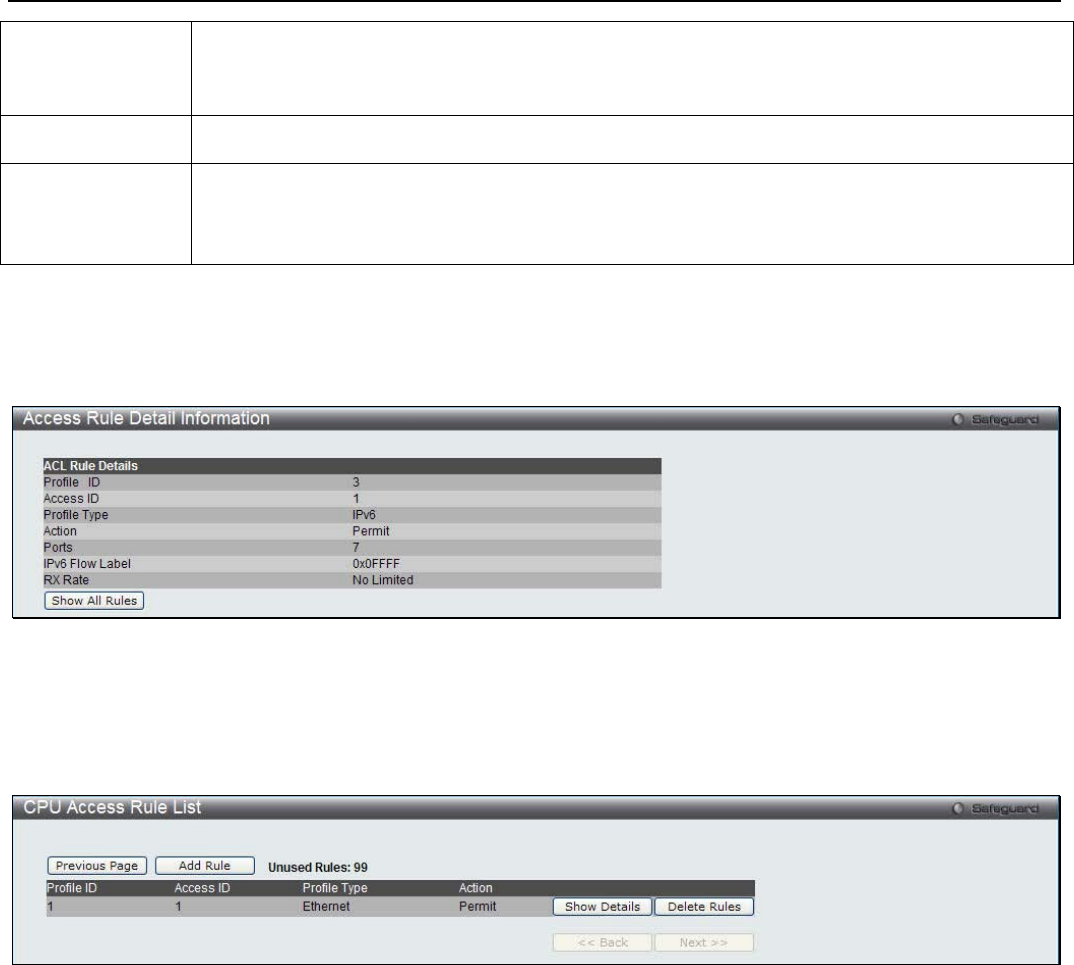
xStack® DGS-3200 Series Layer 2 Managed Gigabit Ethernet Switch Web UI Reference Guide
213
Time Range
Name Tick the check box and enter the name of the Time Range settings that has been previously
configured in the Time Range Settings window. This will set specific times when this access rule
will be implemented on the Switch.
Counter Use the drop-down menu to specify if the Counter feature should be Enabled or Disabled.
Ports When a range of ports is to be configured, the Auto Assign check box MUST be ticked in the
Access ID field of this window. If not, the user will be presented with an error message and the
access rule will not be configured. Ticking the All Ports check box will denote all ports on the
Switch.
Click Apply to implement the changes.
To view the settings of a previously correctly configured rule, click the corresponding Show Details button on the Access Rule
List window to view the following window:
Figure 7 - 19. Access Rule Detail Information window for IPv6
To establish the rule for a previously created Access Profile:
To configure the Access Rules for Packet Content, open the Access Profile List window and click Add/View Rules for a Packet
Content entry. This will open the following window:
Figure 7 - 20. Access Rule List window for Packet Content
To remove a previously created rule, click the corresponding Delete Rules button. To add a new Access Rule, click the Add Rule
button:
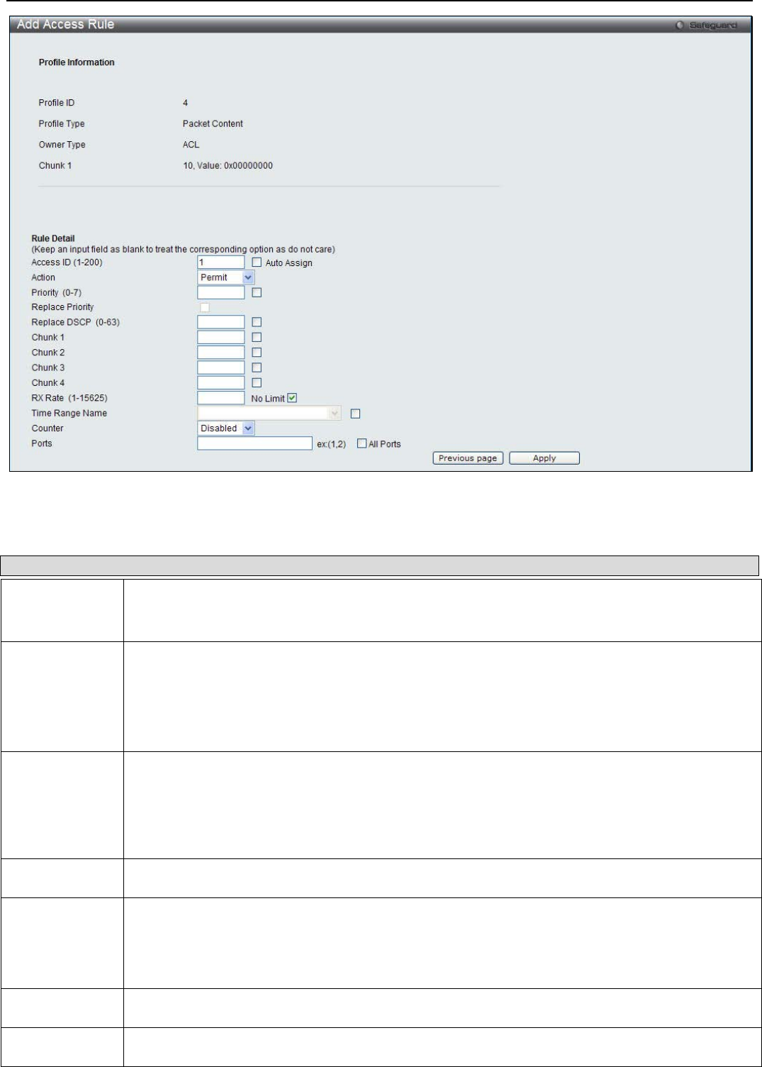
xStack® DGS-3200 Series Layer 2 Managed Gigabit Ethernet Switch Web UI Reference Guide
214
Figure 7 - 21. Add Access Rule window for Packet Content
The following parameters can be cconfigured:
Parameter Description
Access ID (1-
200) Type in a unique identifier number for this access. This value can be set from 1 to 200.
Auto Assign – Ticking this check box will instruct the Switch to automatically assign an Access ID
for the rule being created.
Action Select Permit to specify that the packets that match the access rule are forwarded by the Switch,
according to any additional rule added (see below).
Select Deny to specify that packets that match the access rule are not forwarded by the Switch and
will be filtered.
Select Mirror to specify that packets that match the access rule are mirrored to a port defined in the
config mirror port command. Port Mirroring must be enabled and a target port must be set.
Priority (0-7) Tick the corresponding check box if you want to re-write the 802.1p default priority of a packet to
the value entered in the Priority field, which meets the criteria specified previously in this command,
before forwarding it on to the specified CoS queue. Otherwise, a packet will have its incoming
802.1p user priority re-written to its original value before being forwarded by the Switch.
For more information on priority queues, CoS queues and mapping for 802.1p, see the QoS
section of this manual.
Replace
Priority Tick this check box to replace the Priority value in the adjacent field.
Replace DSCP
(0-63) Select this option to instruct the Switch to replace the DSCP value (in a packet that meets the
selected criteria) with the value entered in the adjacent field.
Note: When an ACL rule is added to change both the priority and DSCP of an IPv4 packet, only
one of them can be modified due to a chip limitation. Currently the priority is changed when both
the priority and DSCP are set to be modified.
Chunk This field will instruct the Switch to mask the packet header beginning with the offset value
specified.
RX Rate (1-
15625) Use this to limit RX bandwidth for the profile being configured. This rate is implemented using the
following equation: 1 value = 64kbit/sec. (ex. If the user selects an RX rate of 10 then the ingress
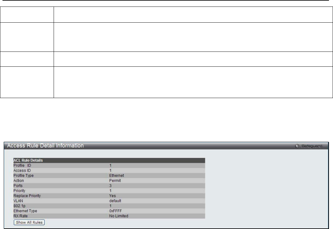
xStack® DGS-3200 Series Layer 2 Managed Gigabit Ethernet Switch Web UI Reference Guide
215
rate is 640kbit/sec.) The user many select a value between 1 and 15625 or tick the No Limit check
box. The default setting is No Limit.
Time Range
Name Tick the check box and enter the name of the Time Range settings that has been previously
configured in the Time Range Settings window. This will set specific times when this access rule
will be implemented on the Switch.
Counter Use the drop-down menu to specify if the Counter feature should be Enabled or Disabled.
Ports When a range of ports is to be configured, the Auto Assign check box MUST be ticked in the
Access ID field of this window. If not, the user will be presented with an error message and the
access rule will not be configured. Ticking the All Ports check box will denote all ports on the
Switch.
Click Apply to implement the changes.
To view the settings of a previously correctly configured rule, click the corresponding Show Details button on the Access Rule
List window to view the following window:
Figure 7 - 22. Access Rule Detail Information window for Packet Content
CPU Access Profile List
Due to a chipset limitation and needed extra switch security, the Switch incorporates CPU Interface filtering. This added feature
increases the running security of the Switch by enabling the user to create a list of access rules for packets destined for the
Switch’s CPU interface. Employed similarly to the Access Profile feature previously mentioned, CPU interface filtering examines
Ethernet, IP and Packet Content Mask packet headers destined for the CPU and will either forward them or filter them, based on
the user’s implementation. As an added feature for the CPU Filtering, the Switch allows the CPU filtering mechanism to be
enabled or disabled globally, permitting the user to create various lists of rules without immediately enabling them.
Creating an access profile for the CPU is divided into two basic parts. The first is to specify which part or parts of a frame the
Switch will examine, such as the MAC source address or the IP destination address. The second part is entering the criteria the
Switch will use to determine what to do with the frame. The entire process is described below.
Users may globally enable or disable the CPU Interface Filtering State mechanism by using the radio buttons to change the
running state. Choose Enabled to enable CPU packets to be scrutinized by the Switch and Disabled to disallow this scrutiny.
To view the following window, click ACL > CPU Access Profile List:
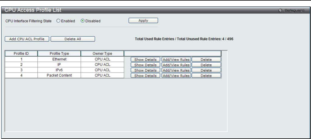
xStack® DGS-3200 Series Layer 2 Managed Gigabit Ethernet Switch Web UI Reference Guide
216
Figure 7 - 23. CPU Access Profile List window
This window displays the CPU Access Profile List entries created on the Switch (one CPU access profile of each type has been
created for explanatory purposes). To view the configurations for an entry, click the corresponding Show Details button.
To add an entry to the CPU Access Profile List, click the Add CPU ACL Profile button. This will open the Add CPU ACL
Profile window, as shown below. To remove all CPU Access Profile List entries, click the Delete All button.
The Switch supports four CPU Access Profile types: Ethernet (or MAC address-based) profile configuration, IP (IPv4) address-
based profile configuration, IPv6 address-based profile configuration, and Packet Content Mask.
The window shown below is the Add CPU ACL Profile window for Ethernet.
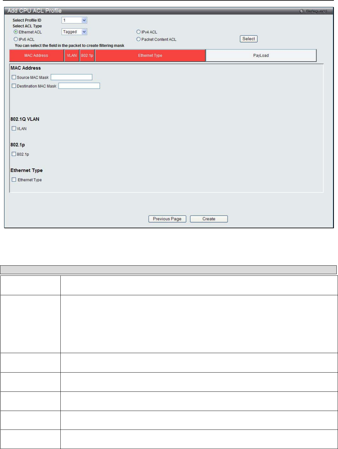
xStack® DGS-3200 Series Layer 2 Managed Gigabit Ethernet Switch Web UI Reference Guide
217
Figure 7 - 24. Add CPU ACL Profile window for Ethernet
The following parameters can be cconfigured:
Parameter Description
Select Profile ID
(1-5) Use the drop-down menu to select a unique identifier number for this profile set. This value can
be set from 1 to 5.
Select ACL Type Select profile based on Ethernet (MAC Address), IPv4 address, IPv6 address, or packet content
mask. This will change the window according to the requirements for the type of profile.
Select Ethernet to instruct the Switch to examine the layer 2 part of each packet header.
Select IPv4 to instruct the Switch to examine the IPv4 address in each frame's header.
Select IPv6 to instruct the Switch to examine the IPv6 address in each frame's header.
Select Packet Content Mask to specify a mask to examine the content of the packet header.
Source MAC
Mask Enter a MAC address mask for the source MAC address.
Destination MAC
Mask Enter a MAC address mask for the destination MAC address.
802.1Q VLAN Selecting this option instructs the Switch to examine the VLAN identifier of each packet header
and use this as the full or partial criterion for forwarding.
802.1p Selecting this option instructs the Switch to specify that the access profile will apply only to
packets with this 802.1p priority value.
Ethernet Type Selecting this option instructs the Switch to examine the Ethernet type value in each frame's
header.
Click Create to implement the changes.

xStack® DGS-3200 Series Layer 2 Managed Gigabit Ethernet Switch Web UI Reference Guide
218
To view the settings of a previously correctly created profile, click the corresponding Show Details button on the CPU Access
Profile List window to view the following window:
Figure 7 - 25. CPU Access Profile Detail Information window for Ethernet
The window shown below is the Add CPU ACL Profile window for IPv4.
Figure 7 - 26. Add CPU ACL Profile window for IPv4
The following parameters can be cconfigured:
Parameter Description
Select Profile ID Use the drop-down menu to select a unique identifier number for this profile set. This value
can be set from 1 to 5.
Select ACL Type Select profile based on Ethernet (MAC Address), IPv4 address, IPv6 address, or packet
content mask. This will change the menu according to the requirements for the type of
profile.
Select Ethernet to instruct the Switch to examine the layer 2 part of each packet header.
Select IPv4 to instruct the Switch to examine the IPv4 address in each frame's header.
Select IPv6 to instruct the Switch to examine the IPv6 address in each frame's header.
Select Packet Content Mask to specify a mask to examine the content of the packet header.
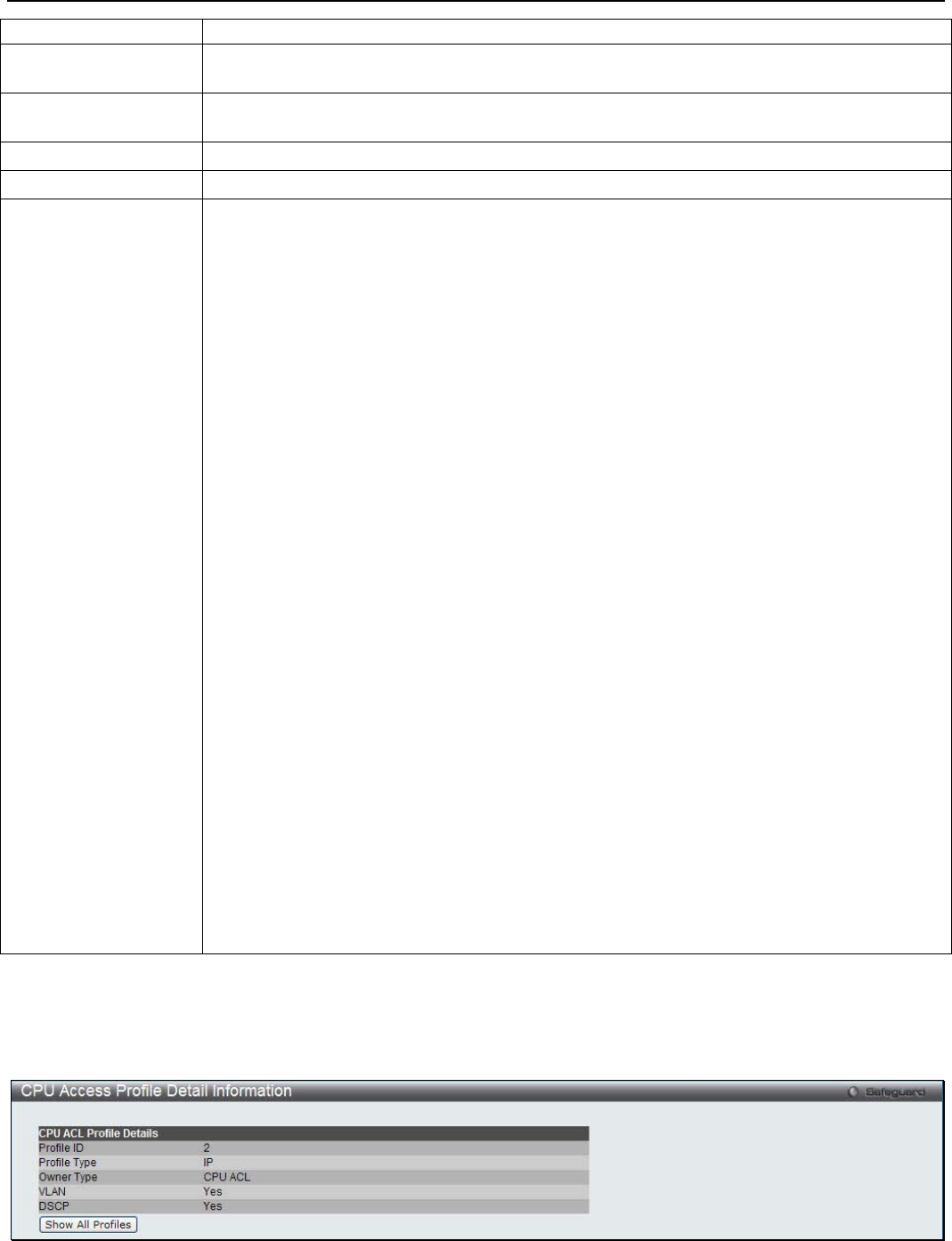
xStack® DGS-3200 Series Layer 2 Managed Gigabit Ethernet Switch Web UI Reference Guide
219
802.1Q VLAN Selecting this option instructs the Switch to examine the VLAN part of each packet header
and use this as the, or part of the criterion for forwarding.
IPv4 DSCP Selecting this option instructs the Switch to examine the DiffServ Code part of each packet
header and use this as the, or part of the criterion for forwarding.
Source IP Mask Enter an IP address mask for the source IP address.
Destination IP Mask Enter an IP address mask for the destination IP address.
Protocol Selecting this option instructs the Switch to examine the protocol type value in each frame's
header. You must then specify what protocol(s) to include according to the following
guidelines:
Select ICMP to instruct the Switch to examine the Internet Control Message Protocol (ICMP)
field in each frame's header.
• Select Type to further specify that the access profile will apply an ICMP type value,
or specify Code to further specify that the access profile will apply an ICMP code
value.
Select IGMP to instruct the Switch to examine the Internet Group Management Protocol
(IGMP) field in each frame's header.
• Select Type to further specify that the access profile will apply an IGMP type value.
Select TCP to use the TCP port number contained in an incoming packet as the forwarding
criterion. Selecting TCP requires a source port mask and/or a destination port mask is to be
specified. The user may also identify which flag bits to filter. Flag bits are parts of a packet
that determine what to do with the packet. The user may filter packets by filtering certain flag
bits within the packets, by checking the boxes corresponding to the flag bits of the TCP field.
The user may choose between urg (urgent), ack (acknowledgement), psh (push), rst (reset),
syn (synchronize), fin (finish).
• src port mask - Specify a TCP port mask for the source port in hex form (hex 0x0-
0xffff), which you wish to filter.
• dst port mask - Specify a TCP port mask for the destination port in hex form (hex
0x0-0xffff) which you wish to filter.
Select UDP to use the UDP port number contained in an incoming packet as the forwarding
criterion. Selecting UDP requires that you specify a source port mask and/or a destination
port mask.
• src port mask - Specify a UDP port mask for the source port in hex form (hex 0x0-
0xffff).
• dst port mask - Specify a UDP port mask for the destination port in hex form (hex
0x0-0xffff).
Protocol ID - Enter a value defining the protocol ID in the packet header to mask. Specify the
protocol ID mask in hex form (hex 0x0-0xff).
Click Create to implement the changes.
To view the settings of a previously correctly created profile, click the corresponding Show Details button on the CPU Access
Profile List window to view the following window:
Figure 7 - 27. CPU Access Profile Detail Information window for IPv4
The window shown below is the Add CPU ACL Profile window for IPv6.
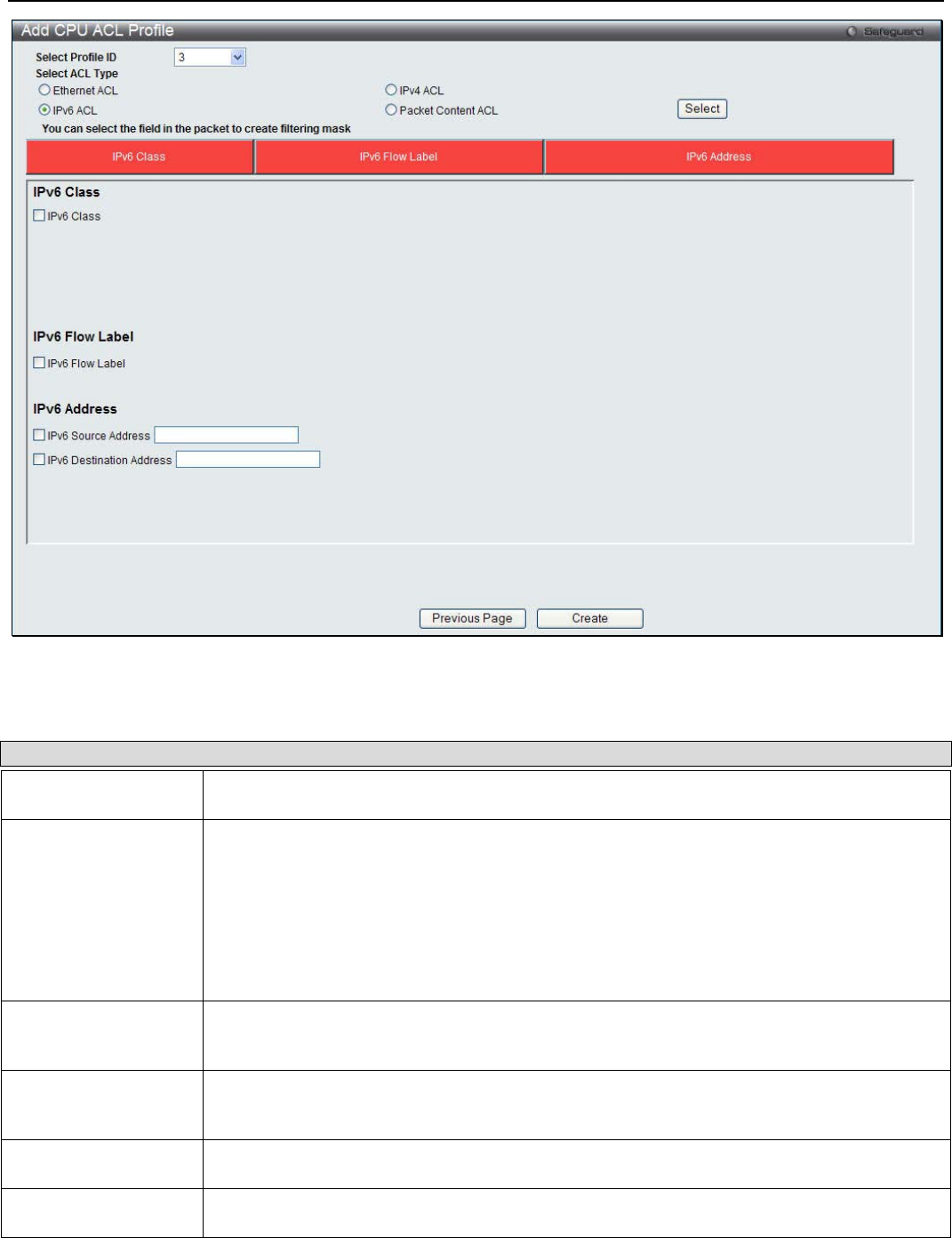
xStack® DGS-3200 Series Layer 2 Managed Gigabit Ethernet Switch Web UI Reference Guide
220
Figure 7 - 28. Add CPU ACL Profile window for IPv6
The following parameters can be cconfigured:
Parameter Description
Select Profile ID Use the drop-down menu to select a unique identifier number for this profile set. This value
can be set from 1 to 5.
Select ACL Type Select profile based on Ethernet (MAC Address), IPv4 address, IPv6 address, or packet
content mask. This will change the menu according to the requirements for the type of
profile.
Select Ethernet to instruct the Switch to examine the layer 2 part of each packet header.
Select IPv4 to instruct the Switch to examine the IPv4 address in each frame's header.
Select IPv6 to instruct the Switch to examine the IPv6 address in each frame's header.
Select Packet Content Mask to specify a mask to examine the content of the packet header.
IPv6 Class Checking this field will instruct the Switch to examine the class field of the IPv6 header. This
class field is a part of the packet header that is similar to the Type of Service (ToS) or
Precedence bits field in IPv4.
IPv6 Flow Label Checking this field will instruct the Switch to examine the flow label field of the IPv6 header.
This flow label field is used by a source to label sequences of packets such as non-default
quality of service or real time service packets.
IPv6 Source Address The user may specify an IP address mask for the source IPv6 address by checking the
corresponding box and entering the IP address mask.
IPv6 Destination
Address The user may specify an IP address mask for the destination IPv6 address by checking the
corresponding box and entering the IP address mask.
Click Create to implement the changes.
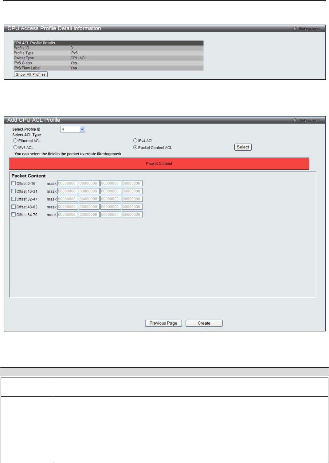
xStack® DGS-3200 Series Layer 2 Managed Gigabit Ethernet Switch Web UI Reference Guide
221
To view the settings of a previously correctly created profile, click the corresponding Show Details button on the CPU Access
Profile List window to view the following window:
Figure 7 - 29. CPU Access Profile Detail Information window for IPv6
The window shown below is the Add CPU ACL Profile window for Packet Content.
Figure 7 - 30. Add CPU ACL Profile window for Packet Content
The following parameters can be cconfigured:
Parameter Description
Select Profile
ID Use the drop-down menu to select a unique identifier number for this profile set. This value can
be set from 1 to 5.
Select ACL
Type Select profile based on Ethernet (MAC Address), IPv4 address, IPv6 address, or packet content
mask. This will change the menu according to the requirements for the type of profile.
Select Ethernet to instruct the Switch to examine the layer 2 part of each packet header.
Select IPv4 to instruct the Switch to examine the IPv4 address in each frame's header.
Select IPv6 to instruct the Switch to examine the IPv6 address in each frame's header.
Select Packet Content Mask to specify a mask to examine the content of the packet header.
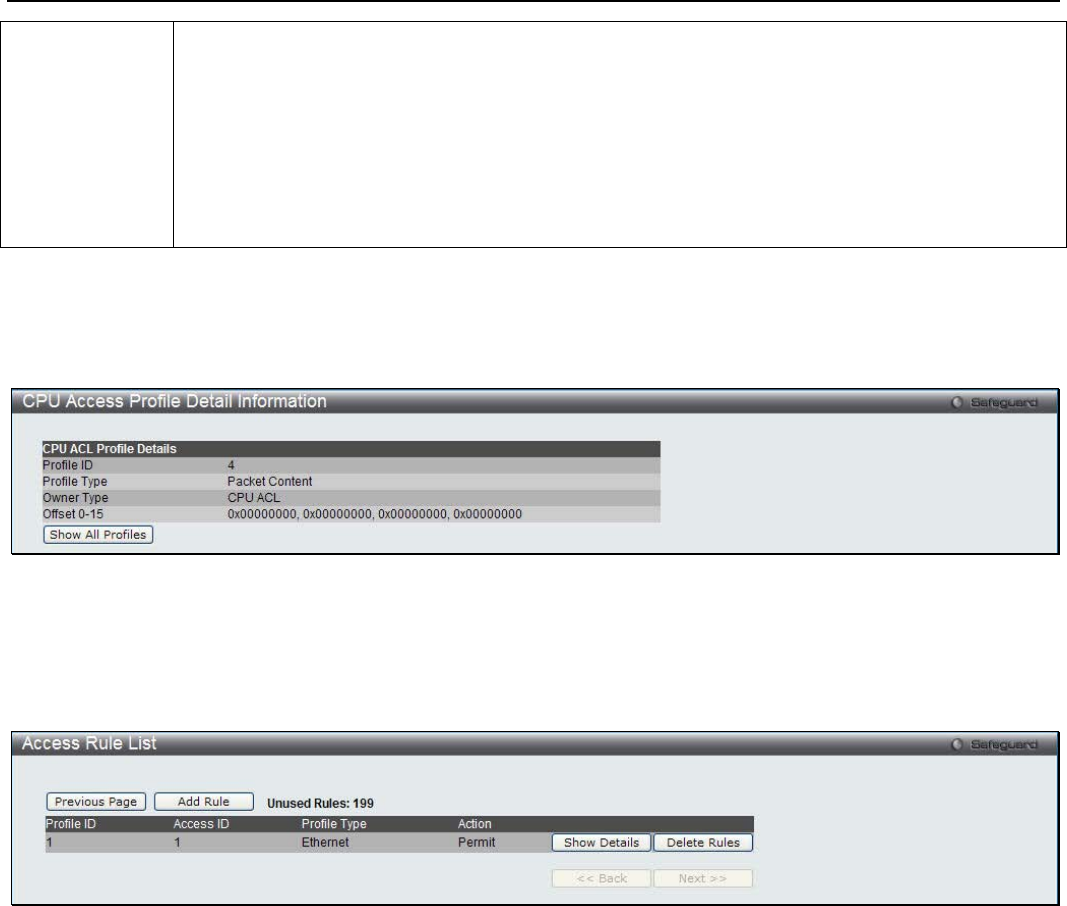
xStack® DGS-3200 Series Layer 2 Managed Gigabit Ethernet Switch Web UI Reference Guide
222
Offset This field will instruct the Switch to mask the packet header beginning with the offset value
specified:
• 0-15 - Enter a value in hex form to mask the packet from the beginning of the packet to
the 15th byte.
• 16-31 – Enter a value in hex form to mask the packet from byte 16 to byte 31.
• 32-47 – Enter a value in hex form to mask the packet from byte 32 to byte 47.
• 48-63 – Enter a value in hex form to mask the packet from byte 48 to byte 63.
• 64-79 – Enter a value in hex form to mask the packet from byte 64 to byte 79.
Click Create to implement the changes.
To view the settings of a previously correctly created profile, click the corresponding Show Details button on the CPU Access
Profile List window to view the following window:
Figure 7 - 31. CPU Access Profile Detail Information window for Packet Content
To establish the rule for a previously created CPU Access Profile:
To configure the Access Rules for Ethernet, open the CPU Access Profile List window and click Add/View Rules for an
Ethernet entry. This will open the following window.
Figure 7 - 32. CPU Access Rule List window for Ethernet
To remove a previously created rule, click the corresponding Delete Rules button. To add a new Access Rule, click the Add Rule
button:
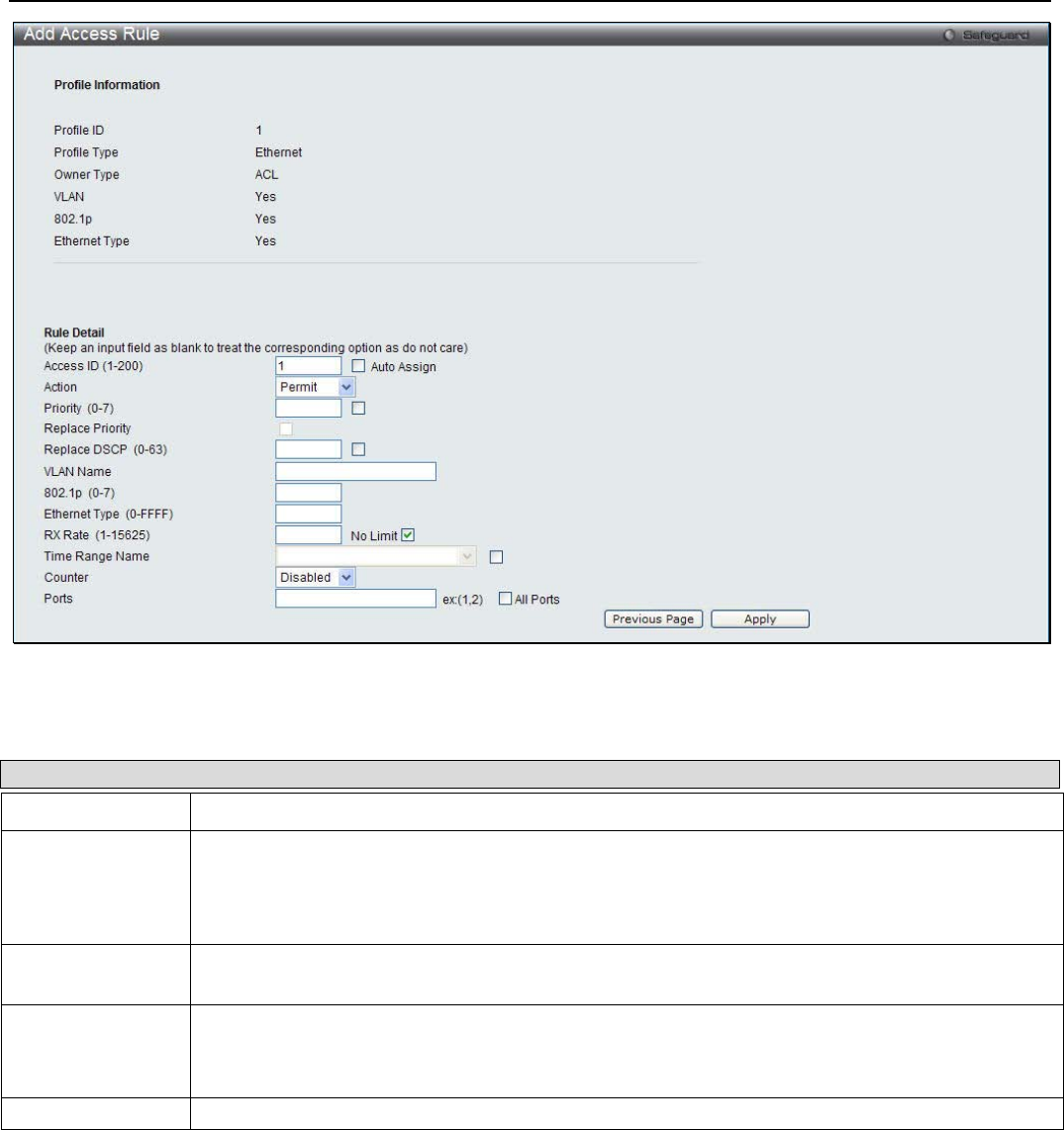
xStack® DGS-3200 Series Layer 2 Managed Gigabit Ethernet Switch Web UI Reference Guide
223
Figure 7 - 33. Add Access Rule window for Ethernet
The following parameters can be cconfigured:
Parameter Description
Access ID (1-100) Type in a unique identifier number for this access. This value can be set from 1 to 100.
Action Select Permit to specify that the packets that match the access rule are forwarded by the Switch,
according to any additional rule added (see below).
Select Deny to specify that packets that match the access rule are not forwarded by the Switch
and will be filtered.
Ethernet Type (0-
FFFF) Enter the appropriate Ethernet Type information.
Time Range
Name Tick the check box and enter the name of the Time Range settings that has been previously
configured in the Time Range Settings window. This will set specific times when this access rule
will be implemented on the Switch.
Ports Ticking the All Ports check box will denote all ports on the Switch.
Click Apply to implement the changes.
To view the settings of a previously correctly configured rule, click the corresponding Show Details button on the CPU Access
Rule List window to view the following window:
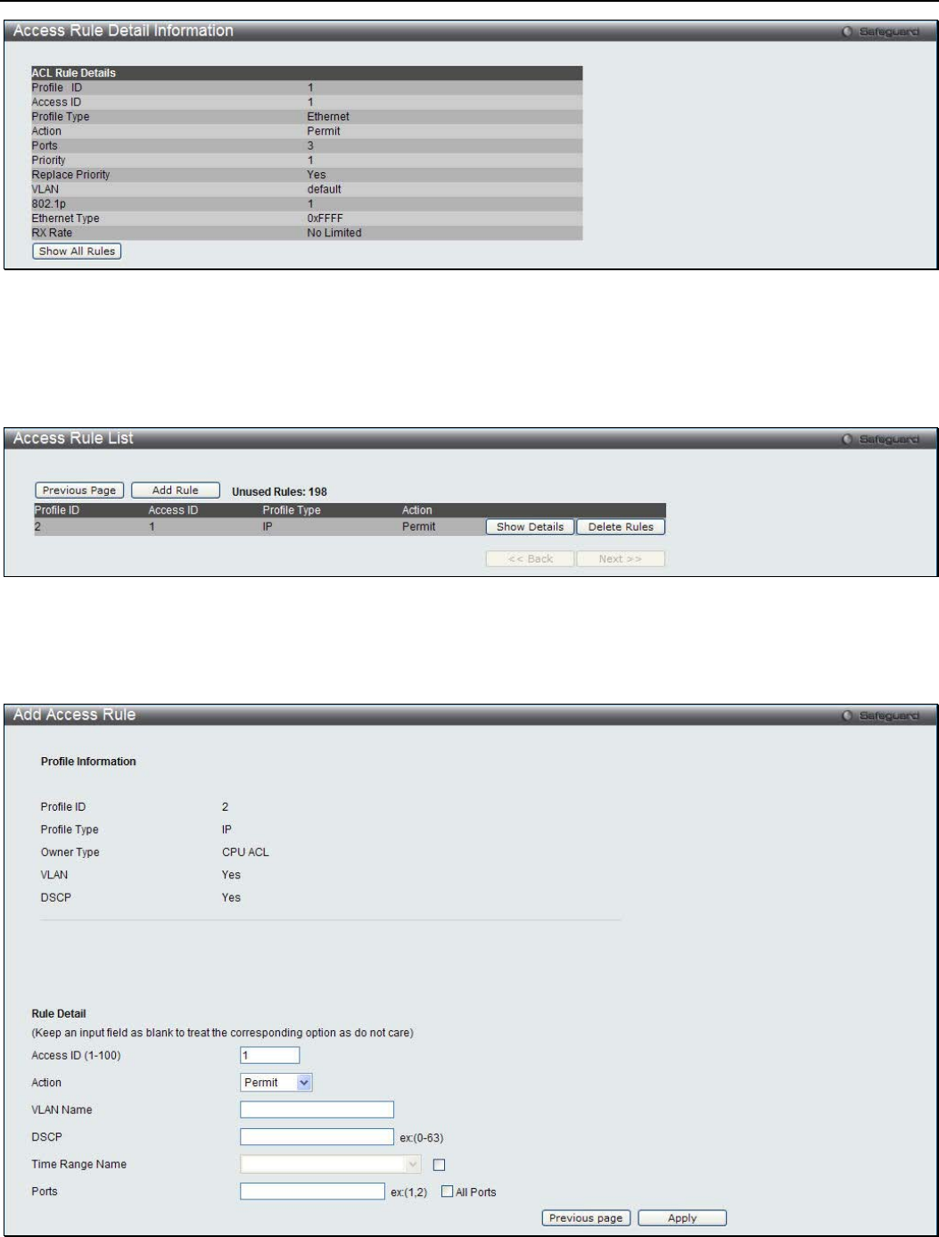
xStack® DGS-3200 Series Layer 2 Managed Gigabit Ethernet Switch Web UI Reference Guide
224
Figure 7 - 34. CPU Access Rule Detail Information window for Ethernet
To establish the rule for a previously created CPU Access Profile:
To configure the Access Rules for IP, open the CPU Access Profile List window and click Add/View Rules for an IPv4 entry.
This will open the following window.
Figure 7 - 35. CPU Access Rule List window for IPv4
To remove a previously created rule, click the corresponding Delete Rules button. To add a new Access Rule, click the Add Rule
button:
Figure 7 - 36. Add Access Rule window for IPv4
The following parameters can be cconfigured:
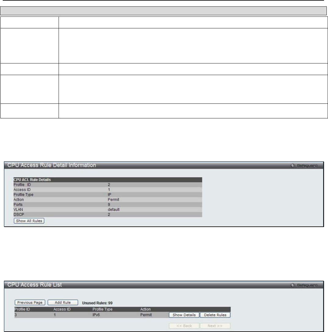
xStack® DGS-3200 Series Layer 2 Managed Gigabit Ethernet Switch Web UI Reference Guide
225
Parameter Description
Access ID (1-100) Type in a unique identifier number for this access. This value can be set from 1 to 100.
Action Select Permit to specify that the packets that match the access rule are forwarded by the Switch,
according to any additional rule added (see below).
Select Deny to specify that packets that match the access rule are not forwarded by the Switch
and will be filtered.
VLAN Name Allows the entry of a name for a previously configured VLAN.
Time Range
Name Tick the check box and enter the name of the Time Range settings that has been previously
configured in the Time Range Settings window. This will set specific times when this access rule
will be implemented on the Switch.
Ports Ticking the All Ports check box will denote all ports on the Switch.
Click Apply to implement the changes.
To view the settings of a previously correctly configured rule, click the corresponding Show Details button on the CPU Access
Rule List window to view the following window:
Figure 7 - 37. CPU Access Rule Detail Information window for IPv4
To establish the rule for a previously created CPU Access Profile:
To configure the Access Rules for IP, open the CPU Access Profile List window and click Add/View Rules for an IPv6 entry.
This will open the following window.
Figure 7 - 38. CPU Access Rule List window for IPv6
To remove a previously created rule, click the corresponding Delete Rules button. To add a new Access Rule, click the Add Rule
button:
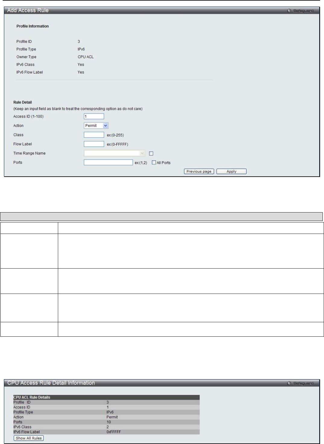
xStack® DGS-3200 Series Layer 2 Managed Gigabit Ethernet Switch Web UI Reference Guide
226
Figure 7 - 39. Add Access Rule window for IPv6
The following parameters can be cconfigured:
Parameter Description
Access ID (1-100) Type in a unique identifier number for this access. This value can be set from 1 to 100.
Action Select Permit to specify that the packets that match the access rule are forwarded by the Switch,
according to any additional rule added (see below).
Select Deny to specify that packets that match the access rule are not forwarded by the Switch
and will be filtered.
Flow Label Configuring this field, in hex form, will instruct the Switch to examine the flow label field of the
IPv6 header. This flow label field is used by a source to label sequences of packets such as non-
default quality of service or real time service packets.
Time Range
Name Tick the check box and enter the name of the Time Range settings that has been previously
configured in the Time Range Settings window. This will set specific times when this access rule
will be implemented on the Switch.
Ports Ticking the All Ports check box will denote all ports on the Switch.
Click Apply to implement the changes.
To view the settings of a previously correctly configured rule, click the corresponding Show Details button on the CPU Access
Rule List window to view the following window:
Figure 7 - 40. CPU Access Rule Detail Information window for IPv6
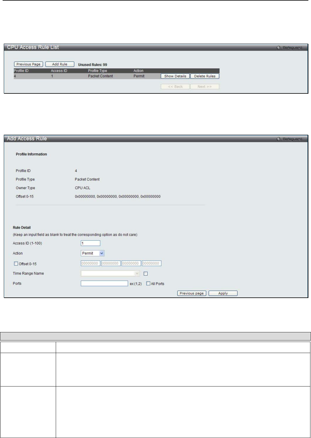
xStack® DGS-3200 Series Layer 2 Managed Gigabit Ethernet Switch Web UI Reference Guide
227
To establish the rule for a previously created CPU Access Profile:
To configure the Access Rules for IP, open the CPU Access Profile List window and click Add/View Rules for a Packet Content
entry. This will open the following window.
Figure 7 - 41. CPU Access Rule List window for Packet Content
To remove a previously created rule, click the corresponding Delete Rules button. To add a new Access Rule, click the Add Rule
button:
Figure 7 - 42. Add Access Rule window for Packet Content
The following parameters can be cconfigured:
Parameter Description
Access ID (1-100) Type in a unique identifier number for this access. This value can be set from 1 to 100.
Action Select Permit to specify that the packets that match the access rule are forwarded by the Switch,
according to any additional rule added (see below).
Select Deny to specify that packets that match the access rule are not forwarded by the Switch
and will be filtered.
Offset This field will instruct the Switch to mask the packet header beginning with the offset value
specified:
Offset 0-15 - Enter a value in hex form to mask the packet from the beginning of the packet to
the 15th byte.
Offset 16-31 - Enter a value in hex form to mask the packet from byte 16 to byte 31.
Offset 32-47 - Enter a value in hex form to mask the packet from byte 32 to byte 47.
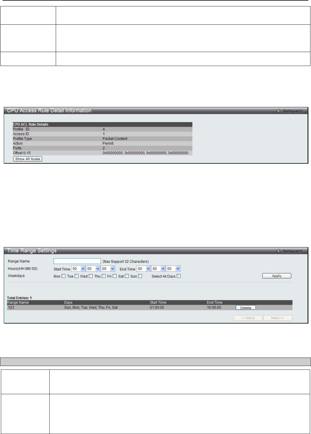
xStack® DGS-3200 Series Layer 2 Managed Gigabit Ethernet Switch Web UI Reference Guide
228
Offset 48-63 - Enter a value in hex form to mask the packet from byte 48 to byte 63.
Offset 64-79 - Enter a value in hex form to mask the packet from byte 64 to byte 79.
Time Range
Name Tick the check box and enter the name of the Time Range settings that has been previously
configured in the Time Range Settings window. This will set specific times when this access
rule will be implemented on the Switch.
Ports Ticking the All Ports check box will denote all ports on the Switch.
Click Apply to implement the changes.
To view the settings of a previously correctly configured rule, click the corresponding Show Details button on the CPU Access
Rule List window to view the following window:
Figure 7 - 43. CPU Access Rule Detail Information window for Packet Content
Time Range Settings
In conjunction with the Access Profile feature, the time range settings determine a starting point and an ending point, based on
days of the week, when an Access Profile configuration will be enabled on the Switch. Once configured here, the time range
settings are to be applied to an access profile rule using the Access Profile table. The user may enter up to 64 time range entries on
the Switch.
To view the following window, click ACL > Time Range Settings:
Figure 7 - 44. Time Range Settings window
The user may adjust the following parameters to configure a time range on the Switch:
Parameter Description
Range Name Enter a name of no more than 32 alphanumeric characters that will be used to identify this time
range on the Switch. This range name will be used in the Access Profile table to identify the
access profile and associated rule to be enabled during this time range.
Hours This parameter is used to set the time in the day that this time range is to be enabled using the
following parameters:
• Start Time - Use this parameter to identify the starting time of the time range, in hours,
minutes and seconds, based on the 24-hour time system.
•
End Time - Use this parameter to identify the ending time of the time range, in hours,
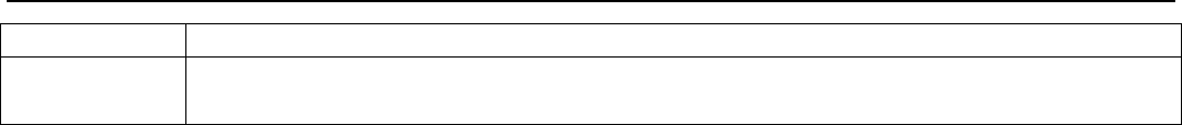
xStack® DGS-3200 Series Layer 2 Managed Gigabit Ethernet Switch Web UI Reference Guide
229
minutes and seconds, based on the 24-hour time system.
Weekdays Use the check boxes to select the corresponding days of the week that this time range is to be
enabled. Tick the Select All Days check box to configure this time range for every day of the week.
Click Apply to implement changes made. Currently configured entries will be displayed in the Time Range Information table in
the bottom half of the window shown above.
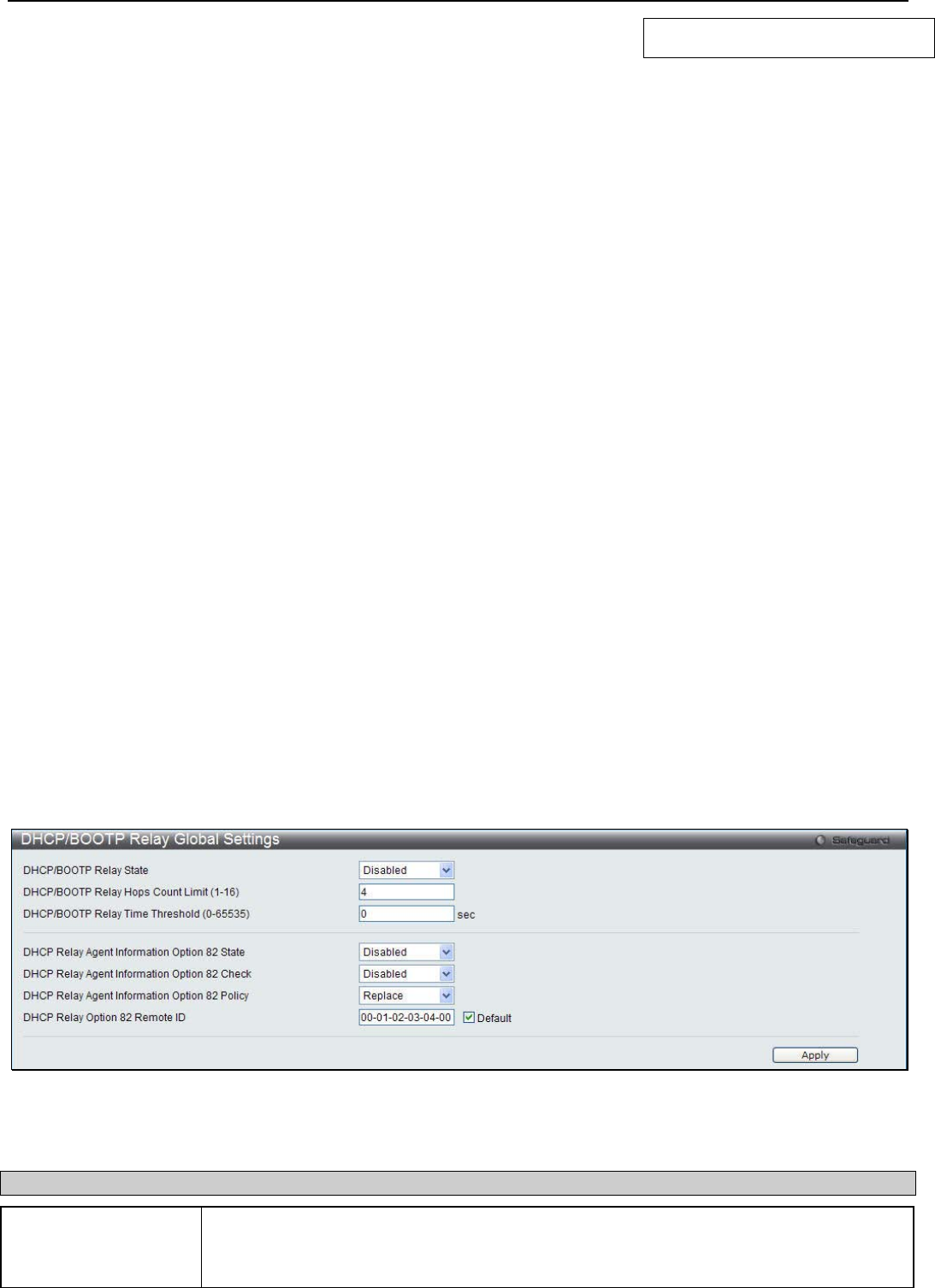
xStack® DGS-3200 Series Layer 2 Managed Gigabit Ethernet Switch Web UI Reference Guide
230
Section 8
Network Application
DHCP/BOOTP Relay
DHCPv6 Relay
DHCP Server
DHCP Local Relay Settings
DHCP Auto Configuration Settings
DHCP Option 12 Settings
DNS Resolver
PPPoE Circuit ID Insertiions Settings
SMTP Settings
SNTP Settings
Ping Test
DHCP/BOOTP Relay
The DHCP/BOOTP Relay folder contains two windows: DHCP/BOOTP Relay Global Settings and DHCP/BOOTP Relay
Interface Settings.
DHCP/BOOTP Relay Global Settings
Users can enable and configure DHCP/BOOTP Relay Global Settings. The relay hops count limit allows the maximum number of
hops (routers) that the DHCP/BOOTP messages can be relayed through to be set. If a packet’s hop count is more than the hop
count limit, the packet is dropped. The range is between 1 and 16 hops, with a default value of 4. The relay time threshold sets the
minimum time (in seconds) that the Switch will wait before forwarding a BOOTREQUEST packet. If the value in the seconds
field of the packet is less than the relay time threshold, the packet will be dropped. The range is between 0 and 65,535 seconds,
with a default value of 0 seconds.
To view the following window, click Network Application > DHCP/BOOTP Relay > DHCP/BOOTP Relay Global Settings:
Figure 8 - 1. DHCP/BOOTP Relay Global Settings window
The following parameters may be configured:
Parameter Description
DHCP/BOOTP Relay
State This field can be toggled between Enabled and Disabled using the drop-down menu. It is
used to enable or disable the DHCP/BOOTP Relay service on the Switch. The default is
Disabled.

xStack® DGS-3200 Series Layer 2 Managed Gigabit Ethernet Switch Web UI Reference Guide
231
DHCP/BOOTP Relay
Hops Count Limit (1-
16)
This field allows an entry between 1 and 16 to define the maximum number of router hops
DHCP/BOOTP messages can be forwarded. The default hop count is 4.
DHCP/BOOTP Relay
Time Threshold (0-
65535)
Allows an entry between 0 and 65535 seconds, and defines the maximum time limit for
routing a DHCP/BOOTP packet. If a value of 0 is entered, the Switch will not process the
value in the seconds field of the BOOTP or DHCP packet. If a non-zero value is entered,
the Switch will use that value, along with the hop count to determine whether to forward a
given BOOTP or DHCP packet.
DHCP Relay Agent
Information Option 82
State
This field can be toggled between Enabled and Disabled using the drop-down menu. It is
used to enable or disable the DHCP Relay Agent Information Option 82 on the Switch. The
default is Disabled.
Enabled –When this field is toggled to Enabled, the relay agent will insert and remove
DHCP relay information (option 82 field) in messages between DHCP servers and clients.
When the relay agent receives the DHCP request, it adds the option 82 information, and
the IP address of the relay agent (if the relay agent is configured), to the packet. Once the
option 82 information has been added to the packet it is sent on to the DHCP server. When
the DHCP server receives the packet, if the server is capable of option 82, it can implement
policies like restricting the number of IP addresses that can be assigned to a single remote
ID or circuit ID. Then the DHCP server echoes the option 82 field in the DHCP reply. The
DHCP server unicasts the reply back to the relay agent if the request was relayed to the
server by the relay agent. The switch verifies that it originally inserted the option 82 data.
Finally, the relay agent removes the option 82 field and forwards the packet to the switch
port that connects to the DHCP client that sent the DHCP request.
Disabled- When the field is toggled to Disabled, the relay agent will not insert and remove
DHCP relay information (option 82 field) in messages between DHCP servers and clients,
and the check and policy settings will have no effect.
DHCP Relay Agent
Information Option 82
Check
This field can be toggled between Enabled and Disabled using the drop-down menu. It is
used to enable or disable the Switches ability to check the validity of the packet’s option 82
field.
Enabled – When the field is toggled to Enabled, the relay agent will check the validity of the
packet’s option 82 field. If the switch receives a packet that contains the option 82 field from
a DHCP client, the switch drops the packet because it is invalid. In packets received from
DHCP servers, the relay agent will drop invalid messages.
Disabled – When the field is toggled to Disabled, the relay agent will not check the validity
of the packet’s option 82 field.
DHCP Relay Agent
Information Option 82
Policy
This field can be toggled between Replace, Drop, and Keep by using the drop-down menu.
It is used to set the Switches policy for handling packets when the DHCP Relay Agent
Information Option 82 Check is set to Disabled. The default is Replace.
Replace – The option 82 field will be replaced if the option 82 field already exists in the
packet received from the DHCP client.
Drop – The packet will be dropped if the option 82 field already exists in the packet
received from the DHCP client.
Keep – The option 82 field will be retained if the option 82 field already exists in the packet
received from the DHCP client.
DHCP Relay Option
82 Remote ID Enter the DHCP Relay Agent Information Option 82 Remote ID.
Click Apply to implement any changes that have been made.

xStack® DGS-3200 Series Layer 2 Managed Gigabit Ethernet Switch Web UI Reference Guide
232
NOTE: If the Switch receives a packet that contains the option 82 field from a DHCP
client and the information-checking feature is enabled, the Switch drops the packet
because it is invalid. However, in some instances, users may configure a client with the
option 82 field. In this situation, disable the information check feature so that the Switch
does not remove the option 82 field from the packet. Users may configure the action that
the Switch takes when it receives a packet with existing option 82 information by
configuring the DHCP Agent Information Option 82 Policy.
Implementation of DHCP Relay Agent Information Option 82
The config dhcp_relay option_82 command configures the DHCP relay agent information option 82 setting of the Switch. The
formats for the circuit ID sub-option and the remote ID sub-option are as follows:
NOTE: For the circuit ID sub-option of a standalone switch, the module field is always zero.
Circuit ID sub-option format:
1. 2. 3. 4. 5. 6. 7.
1 6 0 4 VLAN Module
Port
1 byte 1 byte 1 byte 1 byte 2 bytes 1 byte 1 byte
1. Sub-option type
2. Length
3. Circuit ID type
4. Length
5. VLAN: the incoming VLAN ID of DHCP client packet.
6. Module: For a standalone switch, the Module is always 0; for a stackable switch, the Module is the Unit ID.
7. Port: The incoming port number of the DHCP client packet, the port number starts from 1.
Remote ID sub-option format:
1. 2. 3. 4. 5.
2 8 0 6 MAC address
1 byte 1 byte 1 byte 1 byte 6 bytes
1. Sub-option type
2. Length
3. Remote ID type
4. Length
5. MAC address: The Switch’s system MAC address.
Figure 8 - 2. Circuit ID and Remote ID Sub-option Format
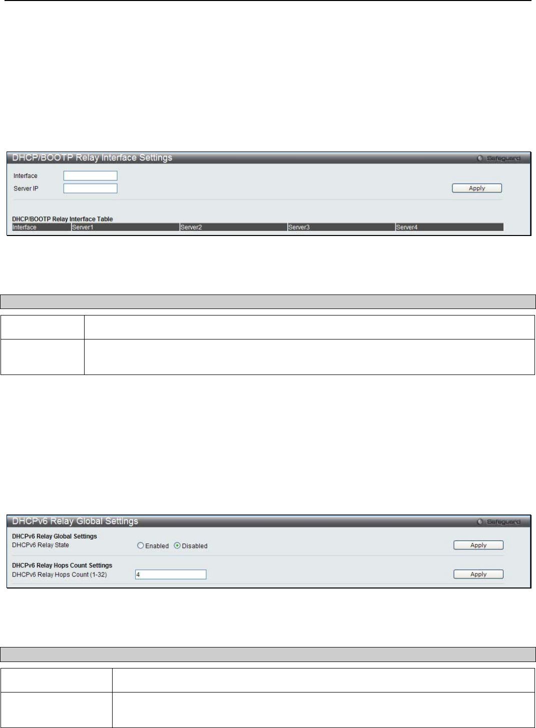
xStack® DGS-3200 Series Layer 2 Managed Gigabit Ethernet Switch Web UI Reference Guide
233
DHCP/BOOTP Relay Interface Settings
Users can set up a server, by IP address, for relaying DHCP/BOOTP information to the Switch. The user may enter a previously
configured IP interface on the Switch that will be connected directly to the DHCP/BOOTP server using this window. Properly
configured settings will be displayed in the DHCP/BOOTP Relay Interface Table at the bottom of the window, once the user
clicks the Apply button. The user may add up to four server IPs per IP interface on the Switch. Entries may be deleted by clicking
the corresponding Delete button.
To view the following window, click Network Application > DHCP/BOOTP Relay > DHCP/BOOTP Relay Interface
Settings:
Figure 8 - 3. DHCP/BOOTP Relay Interface Settings window
The following parameters may be configured:
Parameter Description
Interface The IP interface on the Switch that will be connected directly to the Server.
Server IP Enter the IP address of the DHCP/BOOTP server. Up to four server IPs can be configured per IP
Interface.
Click Apply to include this Server IP.
DHCPv6 Relay
DHCPv6 Relay Global Settings
This window is used to configure the DHCPv6 relay function on the Switch.
To view the following window, click Network Application > DHCPv6 Relay > DHCPv6 Relay Global Settings:
Figure 8 - 4. DHCPv6 Relay Global Settings window
The following parameters may be configured:
Parameter Description
DHCPv6 Relay State Click the radio buttons to enable or disable the DHCPv6 relay function.
DHCPv6 Relay Hops
Count (1-32)
Enter the number of relay agents that have to be relayed in this message. The default value
is 4.
Click the Apply button to accept the changes made for each individual section.
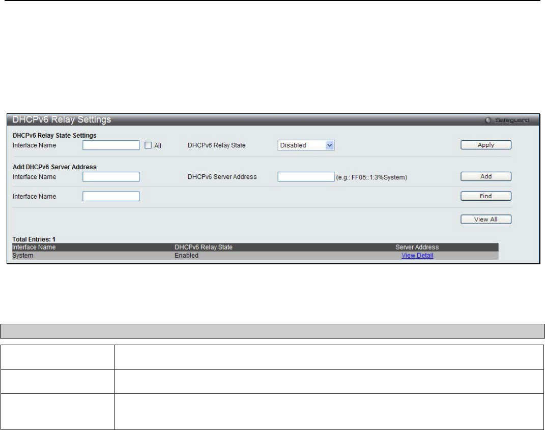
xStack® DGS-3200 Series Layer 2 Managed Gigabit Ethernet Switch Web UI Reference Guide
234
DHCPv6 Relay Settings
This window is used to configure the DHCPv6 relay state of one or all of the specified interfaces, and add or display a destination
IPv6 address to or from the switch’s DHCPv6 relay table.
To view the following window, click Network Application > DHCPv6 Relay > DHCPv6 Relay Settings:
Figure 8 - 5. DHCPv6 Relay Settings window
The following parameters may be configured:
Parameter Description
Interface Name Enter the name of the IPv6 interface. Tick the All check box to select all IPv6 interfaces.
DHCPv6 Relay State Use the drop-down menu to enable or disable the DHCPv6 relay state of the interface.
DHCPv6 Server
Address
Enter the DHCPv6 server IPv6 address.
Click the Apply button to accept the changes made. Click the Add button to add a new entry based on the information entered.
Click the Find button to locate a specific entry based on the information entered. Click the View All button to display all the
existing entries.
DHCP Server
DHCP, or Dynamic Host Configuration Protocol, allows the switch to delegate IP addresses, subnet masks, default gateways and
other IP parameters to devices that request this information. This occurs when a DHCP enabled device is booted on or attached to
the locally attached network. This device is known as the DHCP client and when enabled, it will emit query messages on the
network before any IP parameters are set. When the DHCP server receives this request, it returns a response to the client,
containing the previously mentioned IP information that the DHCP client then utilizes and sets on its local configurations.
The user can configure many DHCP related parameters that it will utilize on its locally attached network, to control and limit the
IP settings of clients desiring an automatic IP configuration, such as the lease time of the allotted IP address, the range of IP
addresses that will be allowed in its DHCP pool, the ability to exclude various IP addresses within the pool so as not to make
identical entries on its network, or to assign the IP address of an important device (such as a DNS server or the IP address of the
default route) to another device on the network.
Users also have the ability to bind IP addresses within the DHCP pool to specific MAC addresses in order to keep consistent the
IP addresses of devices that may be important to the upkeep of the network that require a static IP address.

xStack® DGS-3200 Series Layer 2 Managed Gigabit Ethernet Switch Web UI Reference Guide
235
DHCP Server Global Settings
This window is used to configure the DHCP server global parameters.
To view the following window, click Network Application > DHCP Server > DHCP Server Global Settings:
Figure 8 - 6. DHCP Server Global Settings window
The following parameters may be configured:
Parameter Description
DHCP Server State Click the radio buttons to enable or disable the DHCP Server State.
Ping Packets (0-10) Enter the numbers of ping packet that the Switch will send out on the network containing the
IP address to be allotted. If the ping request is not returned, the IP address is considered
unique to the local network and then allotted to the requesting client. 0 means there is no
ping test. The default value is 2.
Ping Timeout (10-
2000)
Enter the amount of time the DHCP server must waits before timing out a ping packet. The
default value is 100.
Click the Apply button to accept the changes made for each individual section.
DHCP Server Exclude Address Settings
The DHCP server assumes that all IP addresses in a DHCP pool subnet are available for assigning to DHCP clients. You must use
this page to specify the IP address that the DHCP server should not assign to clients. This command can be used multiple times in
order to define multiple groups of excluded addresses.
To view the following window, click Network Application > DHCP Server > DHCP Server Exclude Address Settings:
Figure 8 - 7. DHCP Server Exclude Address Settings window
The following parameters may be configured:
Parameter Description
Begin Address Enter the starting IP Address.
End Address Enter the ending IP Address.
Click the Add button to add a new entry based on the information entered. Click the Delete All button to remove all the entries
listed. Click the Delete button to remove the specific entry.
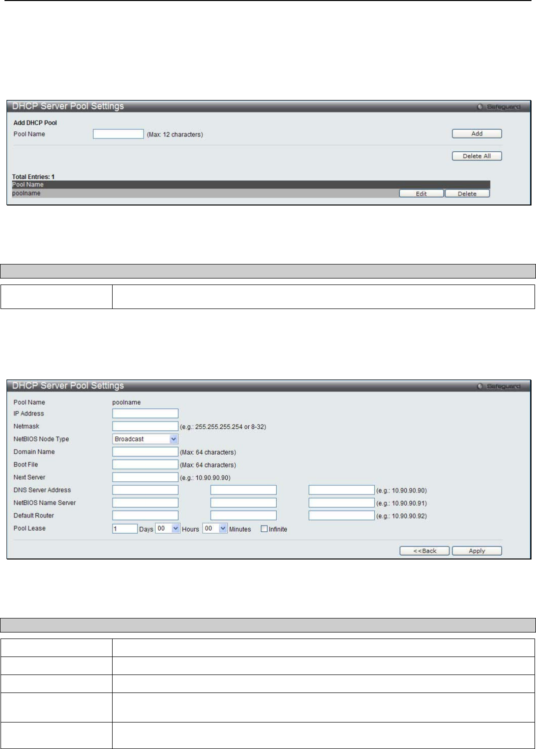
xStack® DGS-3200 Series Layer 2 Managed Gigabit Ethernet Switch Web UI Reference Guide
236
DHCP Server Pool Settings
This window is used to add and delete the DHCP server pool.
To view the following window, click Network Application > DHCP Server > DHCP Server Pool Settings:
Figure 8 - 8. DHCP Server Pool Settings window
The following parameters may be configured:
Parameter Description
Pool Name Enter the DHCP Server Pool name.
Click the Add button to add a new entry based on the information entered. Click the Delete All button to remove all the entries
listed. Click the Edit button to re-configure the specific entry. Click the Delete button to remove the specific entry.
Click the Edit button to see the following window:
Figure 8 - 9. DHCP Server Pool Settings – Edit window
The following parameters may be configured:
Parameter Description
IP Address Enter the network address of the pool.
Netmask Enter the Netmask for the network address.
NetBIOS Node Type NetBIOS node type for a Microsoft DHCP client.
Domain Name Domain name of client. The domain name configured here will be used as the default
domain name by the client.
Boot File File name of boot image. The boot file is used to store the boot image for the client. The boot
image is generally the operating system the client uses to load. If this option is input twice for

xStack® DGS-3200 Series Layer 2 Managed Gigabit Ethernet Switch Web UI Reference Guide
237
the same pool, the second command will overwrite the first command. If the boot file is not
specified, the boot file information will not be provided to the client.
Next Server Enter the next server IP address.
DNS Server Address IP address of DNS server. Specifies the IP address of a DNS server that is available to a
DHCP client. Up to three IP addresses can be specified in one command line.
NetBIOS Name
Server IP address of WINS server. Windows Internet Naming Service (WINS) is a name resolution
service that Microsoft DHCP clients use to correlate host names to IP addresses within a
general grouping of networks. Up to three IP addresses can be specified in one command
line.
Default Router IP address of default router. Specifies the IP address of the default router for a DHCP client.
Up to three IP addresses can be specified in one command line.
Pool Lease By default, each IP address assigned by a DHCP server comes with a one-day lease, which
is the amount of time that the address is valid. Tick the Infinite check box to have infinite
lease.
Days – Days of lease.
Hours – Hours of lease.
Minutes – Minutes of lease
Click the Apply button to accept the changes made. Click the <<Back button to discard the changes made and return to the
previous page.
DHCP Server Manual Binding
An address binding is a mapping between the IP address and MAC address of a client. The IP address of a client can be assigned
manually by an administrator or assigned automatically from a pool by a DHCP server. The dynamic binding entry will be created
when an IP address is assigned to the client from the pool network’s address.
To view the following window, click Network Application > DHCP Server > DHCP Server Manual Binding:
Figure 8 - 10. DHCP Server Manual Binding window
The following parameters may be configured:
Parameter Description
Pool Name Enter the DHCP Server Pool name.
IP Address IP address which will be assigned to specified client.
Hardware Address Enter the hardware address.
Type Either Ethernet or IEEE802 can be specified.
Click the Add button to add a new entry based on the information entered. Click the Delete All button to remove all the entries
listed. Click the Delete button to remove the specific entry.
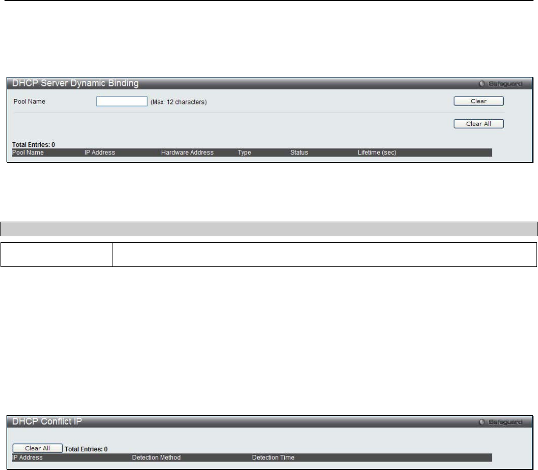
xStack® DGS-3200 Series Layer 2 Managed Gigabit Ethernet Switch Web UI Reference Guide
238
DHCP Server Dynamic Binding
This window is used to delete the DHCP server dynamic binding table.
To view the following window, click Network Application > DHCP Server > DHCP Server Dynamic Binding:
Figure 8 - 11. DHCP Server Dynamic Binding window
The following parameters may be configured:
Parameter Description
Pool Name Enter the DHCP Server Pool name.
Click the Clear button to clear all the information entered in the fields. Click the Clear All button to remove all the entries listed
in the table.
DHCP Conflict IP
The DHCP server will use PING packet to determine whether an IP address is conflict with other host before binding this IP. The
IP address which has been identified conflict will be moved to the conflict IP database. The system will not attempt to bind the IP
address in the conflict IP database unless the user clears it from the conflict IP database.
To view the following window, click Network Application > DHCP Server > DHCP conflict IP:
Figure 8 - 12. DHCP Conflict IP window
Click the Clear All button to remove all the entries listed in the table.
DHCP Local Relay Settings
The DHCP local relay settings allows the user to add option 82 into DHCP request packets when the DHCP client gets an IP
address from the same VLAN. If the DHCP local relay settings are not configured, the Switch will flood the packets to the VLAN.
In order to add option 82 into the DHCP request packets, the DHCP local relay settings and the state of the Global VLAN need to
be enabled.
To view the following window, click Network Application > DHCP Local Relay Settings:
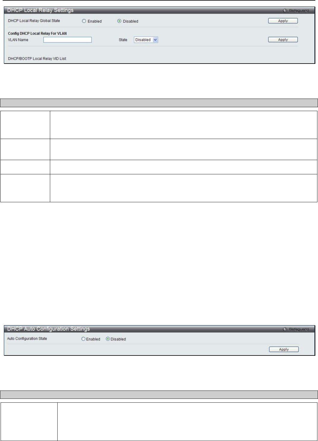
xStack® DGS-3200 Series Layer 2 Managed Gigabit Ethernet Switch Web UI Reference Guide
239
Figure 8 - 13. DHCP Local Relay Settings window
The following parameters may be configured or viewed:
Parameter Description
DHCP Local
Relay Global
State
Enable or disable the DHCP Local Relay Global State. The default is Disabled.
VLAN Name This is the VLAN Name that identifies the VLAN the user wishes to apply the DHCP Local Relay
operation.
State Enable or disable the Config DHCP Local Relay for VLAN state.
DHCP/BOOTP
Local Relay
VID List
This is a list of VLAN IDs the user wishes to apply the DHCP/BOOTP Local Relay operations.
Click Apply to implement the new DHCP Local Relay Settings.
DHCP Auto Configuration Settings
This window is used to enable the DHCP auto configuration feature on the Switch. When enabled, the Switch is instructed to
receive a configuration file from a TFTP server, which will set the Switch to become a DHCP client automatically on boot-up. To
employ this method, the DHCP server must be set up to deliver the TFTP server IP address and configuration file name
information in the DHCP reply packet. The TFTP server must be up and running and hold the necessary configuration file stored
in its base directory when the request is received from the Switch. For more information about loading a configuration file for use
by a client, see the DHCP server and/or TFTP server software instructions. The user may also consult the Upload Log File
window description located in the Tools section of this manual.
If the Switch is unable to complete the DHCP auto configuration, the previously saved configuration file present in the Switch’s
memory will be used.
To view the following window, click Network Application > DHCP Auto Configuration Settings:
Figure 8 - 14. DHCP Auto Configuration Settings window
The following parameter may be configured or viewed:
Parameter Description
Auto
Configuration
State
Enable or disable the Switch’s DHCP auto configuration feature. When enabled, the Switch is
instructed to receive a configuration file from a TFTP server, which will set the Switch to become
a DHCP client automatically on boot-up. To employ this method, the DHCP server must be set
up to deliver the TFTP server IP address and configuration file name information in the DHCP
reply packet. The TFTP server must be up and running and hold the necessary configuration file
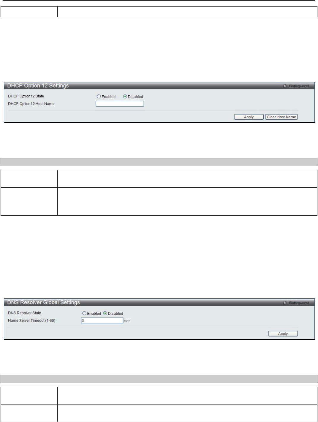
xStack® DGS-3200 Series Layer 2 Managed Gigabit Ethernet Switch Web UI Reference Guide
240
stored in its base directory when the request is received from the Switch.
Click Apply to set the DHCP Auto Configuration State.
DHCP Option 12 Settings
This window is used to configure DHCP Option 12 settings.
To view the following window, click Network Application > DHCP Option 12 Settings:
Figure 8 - 15. DHCP Option 12 Settings window
The following parameter may be configured:
Parameter Description
DHCP Option 12
State Click the radio buttons to enable or disable the DHCP Option 12 state.
DHCP Option 12
Host Name Specify the host name to be inserted in the DHCPDISCOVER and DHCPREQUEST message.
The specified host name must start with a letter, end with a letter or digit, and have only letters,
digits, and hyphen as interior characters; the maximum length is 63.
Click Apply to implement the changes. Click Clear Host Name to clear the hostname setting.
DNS Resolver
DNS Resolver Global Settings
This window is used to configure the DNS Resolver global state of the Switch.
To view the following window, click Network Application > DNS Resolver > DNS Resolver Global Settings:
Figure 8 - 16. DNS Resolver Global Settings window
The following parameter may be configured:
Parameter Description
DNS Resolver
State Click the radio buttons to enable or disable the DNS resolver state.
Name Server
Timeout (1-60) The maximum time waiting for a response from a specified name server.
Click Apply to implement the changes.
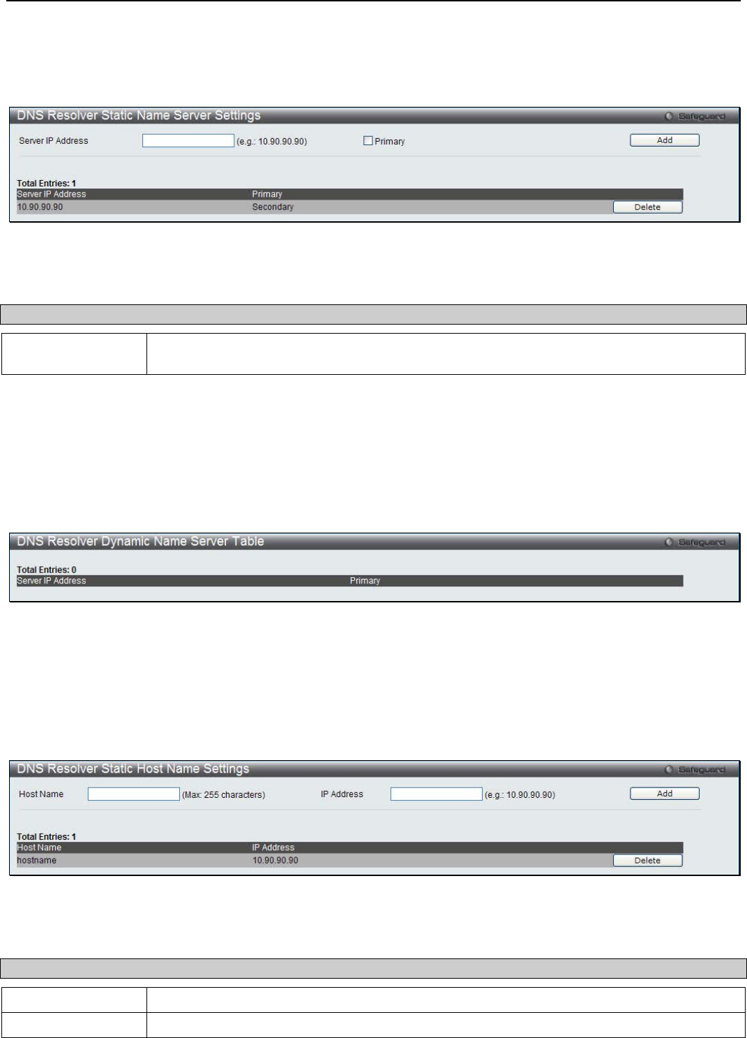
xStack® DGS-3200 Series Layer 2 Managed Gigabit Ethernet Switch Web UI Reference Guide
241
DNS Resolver Static Name Server Settings
The window is used to create the DNS Resolver name server of the Switch.
To view the following window, click Network Application > DNS Resolver > DNS Resolver Static Name Server Settings:
Figure 8 - 17. DNS Resolver Static Name Server Settings window
The following parameter may be configured:
Parameter Description
Server IP Address Enter a DNS Resolver name server. Tick the Primary check box to set the name server as a
primary name server.
Click the Add button to add a new entry based on the information entered. Click the Delete button to remove the specific entry.
DNS Resolver Dynamic Name Server Table
This window displays the current DNS Resolver name servers.
To view the following window, click Network Application > DNS Resolver > DNS Resolver Dynamic Name Server Table:
Figure 8 - 18. DNS Resolver Dynamic Name Server Table window
DNS Resolver Static Host Name Settings
The window is used to create the static host name entry of the switch.
To view the following window, click Network Application > DNS Resolver > DNS Resolver Static Host Name Settings:
Figure 8 - 19. DNS Resolver Static Host Name Settings window
The following parameter may be configured:
Parameter Description
Host Name Enter the name of the host.
IP Address Enter the IP address of the host.

xStack® DGS-3200 Series Layer 2 Managed Gigabit Ethernet Switch Web UI Reference Guide
242
Click the Add button to add a new entry based on the information entered. Click the Delete button to remove the specific entry.
DNS Resolver Dynamic Host Name Table
This window displays the current host name entries.
To view the following window, click Network Application > DNS Resolver > DNS Resolver Dynamic Host Name Table:
Figure 8 - 20. DNS Resolver Dynamic Host Name Table window
PPPoE Circuit ID Insertions Settings
This window is used to configure the PPPoE circuit ID insertion function.
To view the following window, click Network Application > PPPoE Circuit ID Insertions Settings:
Figure 8 - 21. PPPoE circuit ID Insertions Settings window
The following parameter may be configured:
Parameter Description
PPPoE circuit ID
Insertion Click the radio buttons to enable or disable the PPPoE circuit ID insertion on the Switch.
From Port / To Port Use the drop-down menus to select a range of ports to be configured.
State Use the drop-down menu to enable or disable port’s PPPoE circuit ID insertion function.
Circuit ID Use the drop-down menu to select the device ID part for encoding of the circuit ID option.
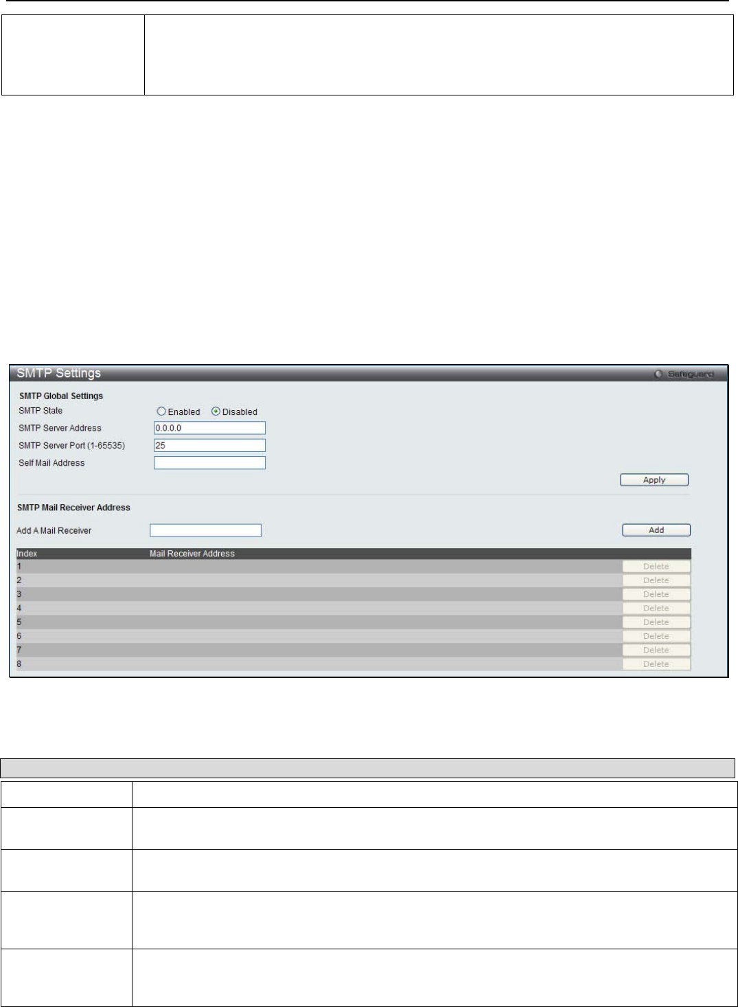
xStack® DGS-3200 Series Layer 2 Managed Gigabit Ethernet Switch Web UI Reference Guide
243
MAC - The MAC address of the Switch will be used to encode the circuit ID option.
IP - The Switch’s IP address will be used to encode the circuit ID option. This is the default.
UDF - A user specified string to be used to encode the circuit ID option. The maximum length
is 32.
Click the Apply button to accept the changes made for each individual section.
SMTP Settings
SMTP or Simple Mail Transfer Protocol is a function of the Switch that will send switch events to mail recipients based on e-mail
addresses entered in the window below. The Switch is to be configured as a client of SMTP while the server is a remote device
that will receive messages from the Switch, place the appropriate information into an e-mail and deliver it to recipients configured
on the Switch. This can benefit the Switch administrator by simplifying the management of small workgroups or wiring closets,
increasing the speed of handling emergency Switch events, and enhancing security by recording questionable events occurring on
the Switch.
Users can set up the SMTP server for the Switch, along with setting e-mail addresses to which switch log files can be sent when a
problem arises on the Switch.
To view the following window, click Network Application > SMTP Settings:
Figure 8 - 22. SMTP Settings window
The following parameters may be configured or viewed:
Parameter Description
SMTP State Use the radio button to enable or disable the SMTP service on this device.
SMTP Server
Address Enter the IP address of the SMTP server on a remote device. This will be the device that sends
out the mail for you.
SMTP Server Port
(1-65535) Enter the virtual port number that the Switch will connect with on the SMTP server. The common
port number for SMTP is 25, yet a value between 1 and 65535 can be chosen.
Self Mail Address Enter the e-mail address from which mail messages will be sent. This address will be the “from”
address on the e-mail message sent to a recipient. Only one self-mail address can be configured
for this Switch. This string can be no more that 64 alphanumeric characters.
Add A Mail
Receiver Enter an e-mail address and click the Add button. Up to eight e-mail addresses can be added
per Switch. To delete these addresses from the Switch, click the corresponding Delete button in
the SMTP Mail Receiver Address table at the bottom of the window.
Click Apply to implement the changes.
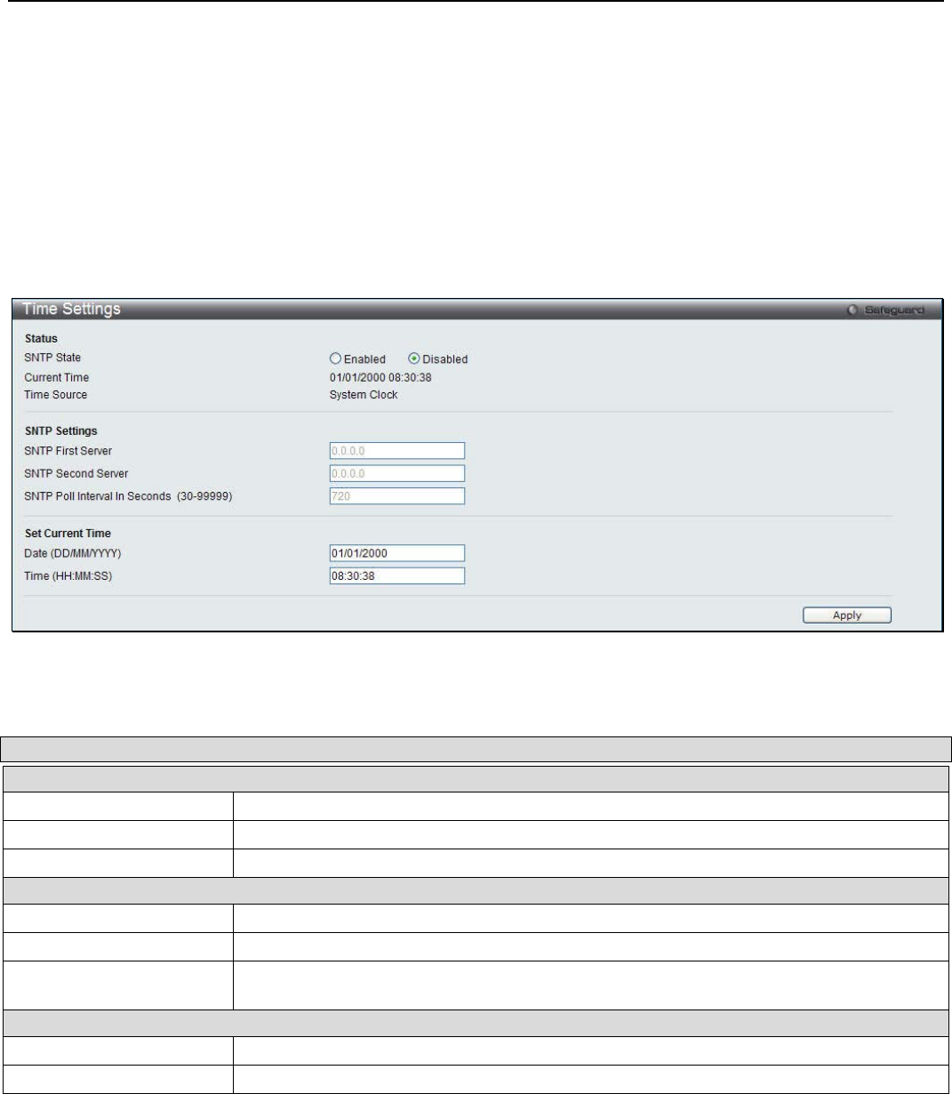
xStack® DGS-3200 Series Layer 2 Managed Gigabit Ethernet Switch Web UI Reference Guide
244
SNTP Settings
SNTP or Simple Network Time Protocol is used by the Switch to synchronize the clock of the computer.
Time Settings
Users can configure the time settings for the Switch.
To view the following window, click Network Application > SNTP Settings > Time Settings:
Figure 8 - 23. Time Settings window
The following parameters can be set or are displayed:
Parameter Description
Status
SNTP State Use this radio button to enable or disable SNTP.
Current Time Displays the Current Time.
Time Source Displays the time source for the system.
SNTP Settings
SNTP First Server The IP address of the primary server from which the SNTP information will be taken.
SNTP Second Server The IP address of the secondary server from which the SNTP information will be taken.
SNTP Poll Interval In
Seconds (30-99999) The interval, in seconds, between requests for updated SNTP information.
Set Current Time
Date (DD/MM/YYYY) Enter the current day, month, and year to update the system clock.
Time (HH:MM:SS) Enter the current time in hours, minutes, and seconds.
Click Apply to implement your changes.
Time Zone Settings
Users can configure time zones and Daylight Savings Time settings for SNTP.
To view the following window, click Network Application > SNTP Settings > Time Zone Settings:
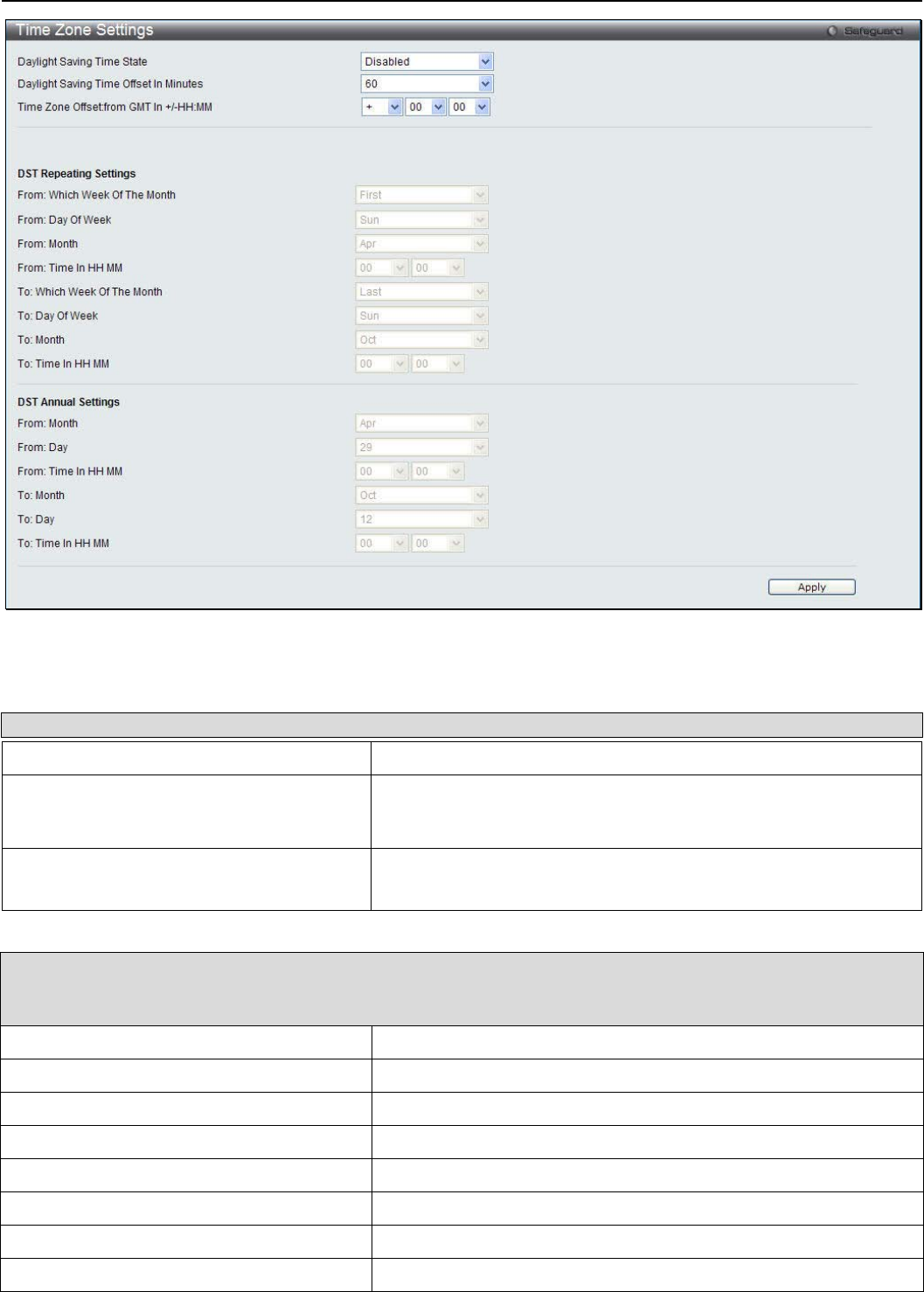
xStack® DGS-3200 Series Layer 2 Managed Gigabit Ethernet Switch Web UI Reference Guide
245
Figure 8 - 24. Time Zone Settings window
The following parameters can be set:
Parameter Description
Daylight Saving Time State Use this drop-down menu to enable or disable the DST Settings.
Daylight Saving Time Offset In Minutes Use this drop-down menu to specify the amount of time that will
constitute your local DST offset. The available options are 30, 60,
90, or 120 minutes.
Time Zone Offset From GMT In +/- HH:MM Use these drop-down menus to specify your local time zone’s offset
from Greenwich Mean Time (GMT.)
DST Repeating Settings – Using repeating mode will enable DST seasonal time adjustment. Repeating mode
requires that the DST beginning and ending date be specified using a formula. For example, specify to begin DST on
Saturday during the second week of April and end DST on Sunday during the last week of October.
From: Which Week Of The Month Enter the week of the month that DST will start.
From: Day Of Week Enter the day of the week that DST will start on.
From: Month Enter the month DST will start on.
From: Time In HH:MM Enter the time of day that DST will start on.
To: Which Week Of The Month Enter the week of the month the DST will end.
To: Day Of Week Enter the day of the week that DST will end.
To: Month Enter the month that DST will end.
To: Time In HH:MM Enter the time DST will end.
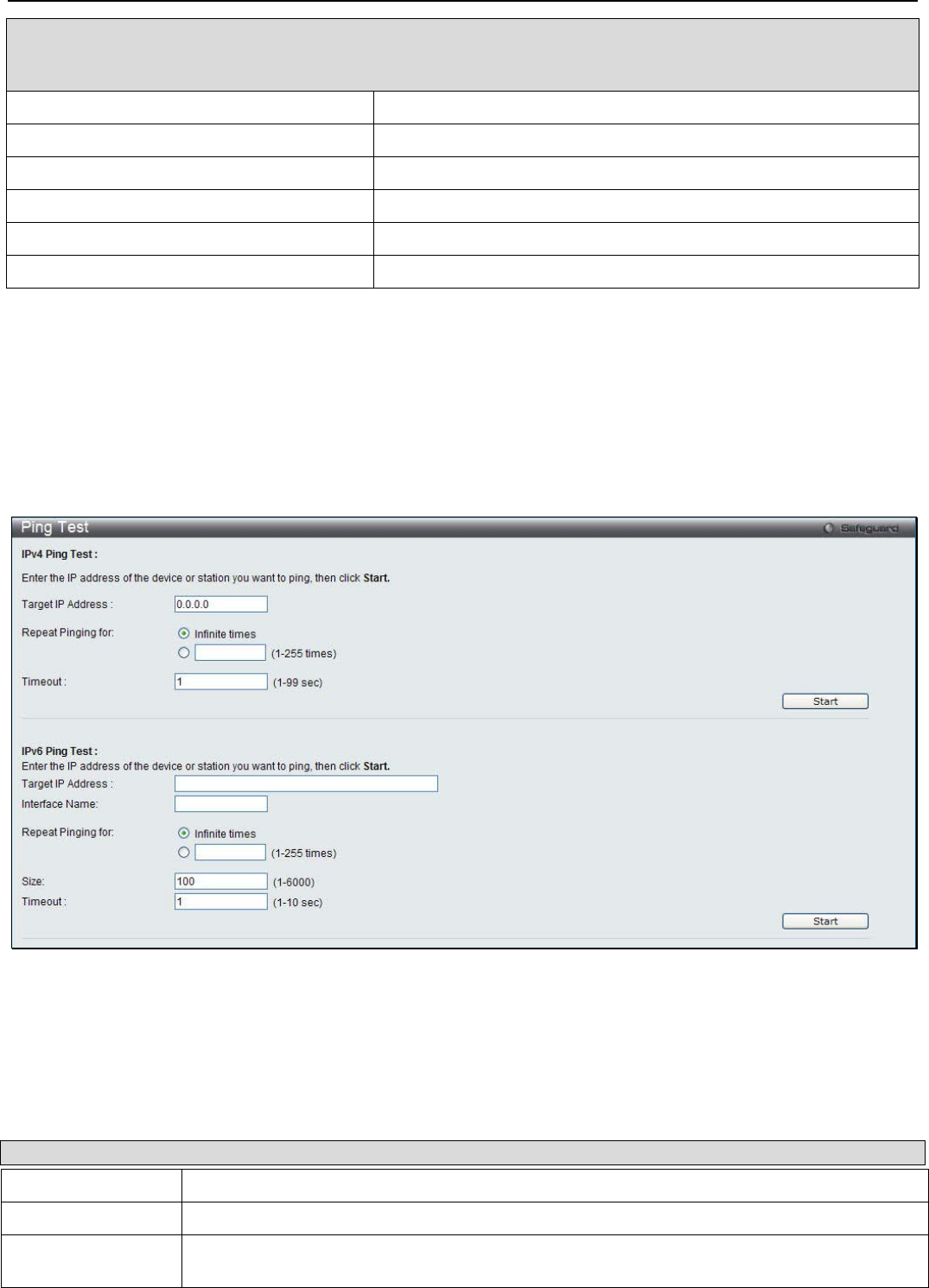
xStack® DGS-3200 Series Layer 2 Managed Gigabit Ethernet Switch Web UI Reference Guide
246
DST Annual Settings – Using annual mode will enable DST seasonal time adjustment. Annual mode requires that
the DST beginning and ending date be specified concisely. For example, specify to begin DST on April 3 and end
DST on October 14.
From: Month Enter the month DST will start on, each year.
From: Day Enter the day of the month DST will start on, each year.
From: Time In HH:MM Enter the time of day DST will start on, each year.
To: Month Enter the month DST will end on, each year.
To: Day Enter the day of the month DST will end on, each year.
To: Time In HH:MM Enter the time of day that DST will end on, each year.
Click Apply to implement changes made to this window.
Ping Test
Users can Ping either an IPv4 address or an IPv6 address. Ping is a small program that sends ICMP Echo packets to the IP address
you specify. The destination node then responds to or “echoes” the packets sent from the Switch. This is very useful to verify
connectivity between the Switch and other nodes on the network.
To view the following window, click Network Application > Ping Test:
Figure 2 - 66. Ping Test window
The user may click the Infinite times radio button, in the Repeat Pinging for field, which will tell the ping program to keep
sending ICMP Echo packets to the specified IP address until the program is stopped. The user may opt to choose a specific
number of times to ping the Target IP Address by clicking its radio button and entering a number between 1 and 255. Click Start
to initiate the Ping program.
The following parameters may be configured or viewed:
Parameter Description
Target IP Address Enter an IP address to be Pinged.
Interface Name For IPv6 only, enter the name of the interface to be Pinged.
Repeat Pinging for Enter the number of times desired to attempt to Ping either the IPv4 address or the IPv6
address configured in this window. Users may enter a number of times between 1 and 255.
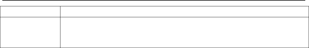
xStack® DGS-3200 Series Layer 2 Managed Gigabit Ethernet Switch Web UI Reference Guide
247
Size For IPv6 only, enter a value between 1 and 6000. The default is 100.
Timeout For IPv4, select a timeout period between 1 and 99 seconds for this Ping message to reach its
destination. For IPv6, select a timeout period between 1 and 10 seconds for this Ping message
to reach its destination. In either case, if the packet fails to find the IP address in this specified
time, the Ping packet will be dropped.
Click Start to initialize the Ping program.
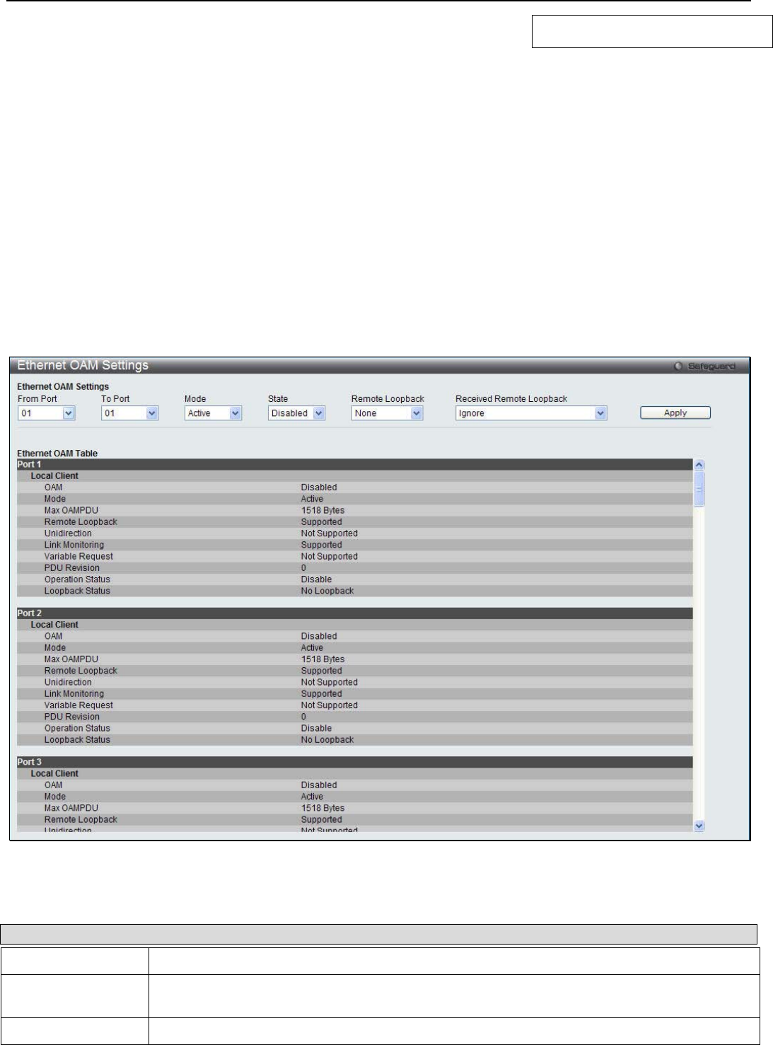
xStack® DGS-3200 Series Layer 2 Managed Gigabit Ethernet Switch Web UI Reference Guide
248
Section 9
OAM
Ethernet OAM
DULD Settings
Cable Diagnostics
Ethernet OAM
Ethernet OAM Settings
This window is used to configure the Ethernet OAM settings.
To view the following window, click OAM > Ethernet OAM > Ethernet OAM Settings:
Figure 9 - 1. Ethernet OAM Settings window
The following parameters can be configured:
Parameter Description
From Port / To Port Select a range of ports you wish to configure.
Mode Use the drop-down menu to select to operate in either Active or Passive. The default mode is
Active.
State Use the drop-down menu to enable or disable the OAM function.
xStack® DGS-3200 Series Layer 2 Managed Gigabit Ethernet Switch Web UI Reference Guide
249
Remote Loopback Use the drop-down menu to select Ethernet OAM remote loopback.
None – Select to disable the remote loopback.
Start – Select to request the peer to change to the remote loopback mode.
Stop - Select to request the peer to change to the normal operation mode.
Received Remote
Loopback Use the drop-down menu to configure the client to process or to ignore the received Ethernet
OAM remote loopback command.
Process – Select to process the received Ethernet OAM remote loopback command.
Ignore - Select to ignore the received Ethernet OAM remote loopback command.
Click Apply to implement the chages.
Ethernet OAM Configuration Settings
This window is used to configure Ethernet OAM configuration settings.
To view the following window, click OAM > Ethernet OAM > Ethernet OAM Configuration Settings:
Figure 9 - 2. Ethernet OAM Configuration Settings window
The following parameters can be configured:
Parameter Description
From Port / To Port Select a range of ports you wish to configure.
Link Event Use the drop-down menu to select the link events, Link Monitor or Critical Link Event.
Link Monitor Use the drop-down menu to select link monitor. Available options are Error Symbol, Error
Frame, Error Frame Period, and Error Frame Seconds.
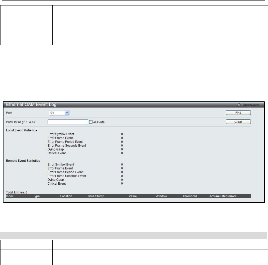
xStack® DGS-3200 Series Layer 2 Managed Gigabit Ethernet Switch Web UI Reference Guide
250
Critical Link Event Use the drop-down menu to select between Dying Gasp and Critical Event.
Threshold (0-
4294967295) Enter the number of error frame or symbol in the period is required to be equal to or greater
than in order for the event to be generated.
Window (1000-
60000) Enter the period of error frame or symbol in milliseconds summary event.
Click Apply to implement the chages.
Ethernet OAM Event Log
The window is used to show ports Ethernet OAM event log information.
To view the following window, click OAM > Ethernet OAM > Ethernet OAM Event Log:
Figure 9 - 3. Ethernet OAM Event Log window
The following parameters can be configured:
Parameter Description
Port Use the drop-down menu to select the unit ID and the port number to view.
Port List (e.g.: 1, 4-
6) Enter a list of ports. Tick the All Ports check box to select all ports.
Click the Find button to locate a specific entry based on the information entered. Click the Clear button to clear all the
information entered in the fields.
Ethernet OAM Statistics
The window is used to show ports Ethernet OAM statistics information.
To view the following window, click OAM > Ethernet OAM > Ethernet OAM Statistics:
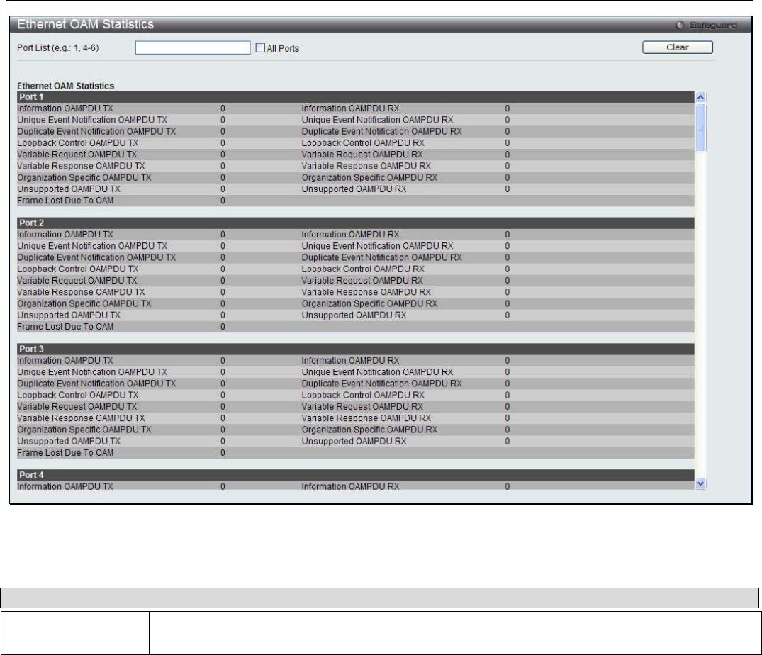
xStack® DGS-3200 Series Layer 2 Managed Gigabit Ethernet Switch Web UI Reference Guide
251
Figure 9 - 4. Ethernet OAM Statistics window
The following parameters can be configured:
Parameter Description
Port List (e.g.: 1, 4-
6) Enter a list of ports. Tick the All Ports check box to select all ports.
Click the Clear button to clear all the information entered in the fields.
DULD Settings
This window is used to configure and display D-LINK Unidirectional Link Detection (DULD) on port. It provides a mechanism
that can be used to detect unidirectional link for Ethernet switches which PHYs don’t support unidirectional OAM operation. As
this function is established based on OAM, OAM should be enabled before starting detection.
To view the following window, click OAM > DULD Settings:
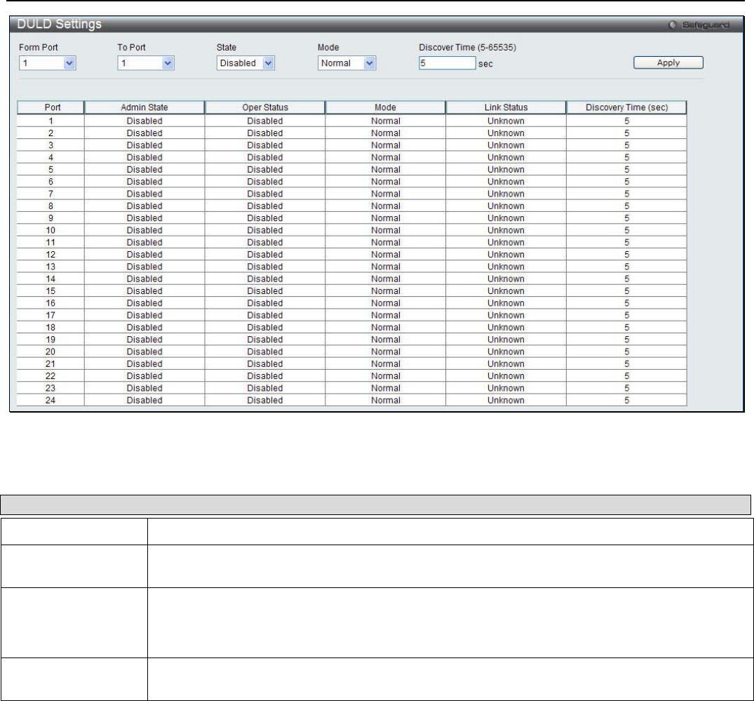
xStack® DGS-3200 Series Layer 2 Managed Gigabit Ethernet Switch Web UI Reference Guide
252
Figure 9 - 5. DULD Settings window
The following parameters can be configured:
Parameter Description
From Port / To Port Select a range of ports you wish to configure.
State Use the drop-down menu to enable or disable the selected ports unidirectional link detection
status.
Mode Use the drop-down menu to select Mode between Shutdown and Normal.
Shutdown – If any unidirectional link is detected, disable the port and log an event.
Normal - Only log an event when a unidirectional link is detected.
Discover Time (5-
65535) Enter these ports neighbor discovery time. If the discovery is timeout, the unidirectional link
detection will start.
Click the Apply button to implement the changes.
Cable Diagnostics
The cable diagnostics feature is designed primarily for administrators or customer service representatives to verify and test copper
cables; it can rapidly determine the quality of the cables and the types of error.
To view the following window, click OAM > Cable Diagnostics:
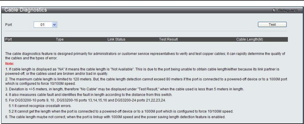
xStack® DGS-3200 Series Layer 2 Managed Gigabit Ethernet Switch Web UI Reference Guide
253
Figure 9 - 6. Cable Diagnostics window
To view the cable diagnostics for a particular port, use the drop-down menu to choose the port and click Test The information will
be displayed in this window.
Cable Diagnostics Notes
1. The following two conditions apply for ports 9 and 10 on the DGS-3200-10, for ports 13, 14, 15, and 16 on the
DGS-3200-16, and ports 25, 26, 27, and 28 on the DGS-3200-24: crosstalk errors cannot be recognized and the length
cannot be obtained when the port is connected to a 1000Mbytes port which is either forced to 10/100Mbytes or powered
down.
2. If cable length is displayed as “NA,” this means the cable length is “Not Available”.
3. The cable length cannot exceed 80 meters if the port is connected to a powered-off device or to a port which is configured to
force 10/100Mbytes speed.
4. Accurate measurement cannot be obtained when the cable is shorter than 1 meter.
5. The error deviation is +/-5 meters in length.
6. Cable fault is measured and the fault length is identified according to the distance from the switch.

xStack® DGS-3200 Series Layer 2 Managed Gigabit Ethernet Switch Web UI Reference Guide
254
Section 10
Monitoring
Device Environment (DGS-3200-16 and DGS-3200-24 only)
CPU Utilization
DRAM & Flash Utilization
Port Utilization
Packet Size
Packets
Errors
Browse ARP Table
Browse Router Port
Browse MLD Router Port
Browse Session Table
IGMP Snooping Group
MLD Snooping Group
MAC Address Table
System Log
Device Environment
The device environment feature displays the Switch internal temperature status (DGS-3200-16 and DGS-3200-24 only).
To view the following window, click Monitoring > Device Environment:
Figure 10 - 1. Device Environment window (DGS-3200-16)
Figure 10 - 2. Device Environment window (DGS-3200-24)
Click Refresh to update the information displayed in these windows.
CPU Utilization
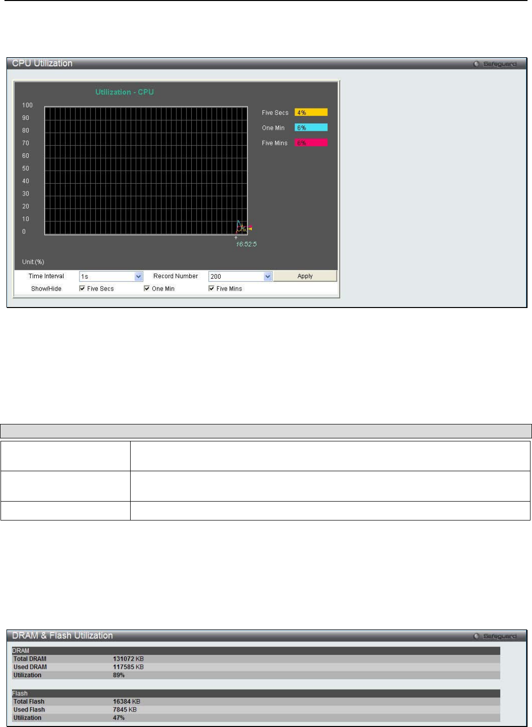
xStack® DGS-3200 Series Layer 2 Managed Gigabit Ethernet Switch Web UI Reference Guide
255
This window is used to display the percentage of the CPU being used, expressed as an integer percentage and calculated as a
simple average by time interval.
To view the following window, click Monitoring > CPU Utilization:
Figure 10 - 3. CPU Utilization window
To view the CPU utilization by port, use the real-time graphic of the Switch and/or switch stack at the top of the web page by
simply clicking a port. Click Apply to implement the configured settings. The window will automatically refresh with new
updated statistics.
The following parameters can be configured:
Parameter Description
Time Interval Select the desired setting between 1s and 60s, where "s" stands for seconds. The
default value is one second.
Record Number Select number of times the Switch will be polled between 20 and 200. The default value
is 200.
Show/Hide Check whether or not to display Five Secs, One Min, and Five Mins.
Click Apply to implement the changes.
DRAM & Flash Utilization
This window is used to display information regarding the DRAM and Flash utilization.
To view the following window, click Monitoring > DRAM & Flash Utilization:
Figure 10 - 4. DRAM & Flash Utilization window
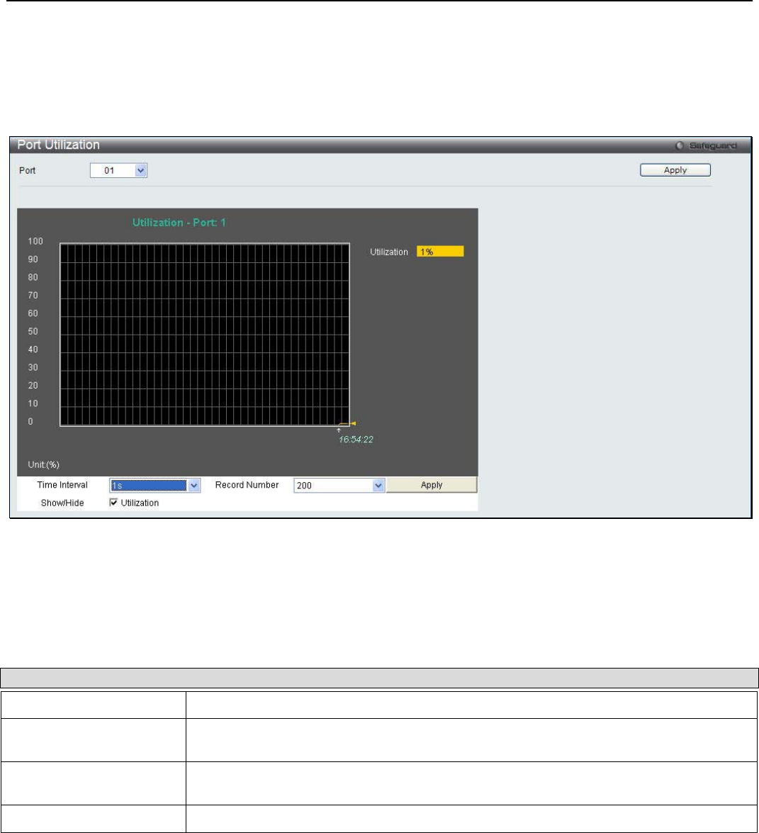
xStack® DGS-3200 Series Layer 2 Managed Gigabit Ethernet Switch Web UI Reference Guide
256
Port Utilization
Users can display the percentage of the total available bandwidth being used on the port.
To view the following window, click Monitoring > Port Utilization:
Figure 10 - 5. Port Utilization window
To select a port to view these statistics for, select the port by using the Port drop-down menu. The user may also use the real-time
graphic of the Switch at the top of the web page by simply clicking on a port.
The following parameters can be configured:
Parameter Description
Port Use the drop-down menu to choose the port that will display statistics.
Time Interval Select the desired setting between 1s and 60s, where "s" stands for seconds. The
default value is one second.
Record Number Select number of times the Switch will be polled between 20 and 200. The default value
is 200.
Show/Hide Check whether or not to display Port Util.
Click Apply to implement the changes.
Packet Size
Users can display packets received by the Switch, arranged in six groups and classed by size, as either a line graph or a table. Two
windows are offered. To select a port to view these statistics for, select the port by using the Port drop-down menu. The user may
also use the real-time graphic of the Switch at the top of the web page by simply clicking on a port.
To view the following windows, click Monitoring > Packet Size:
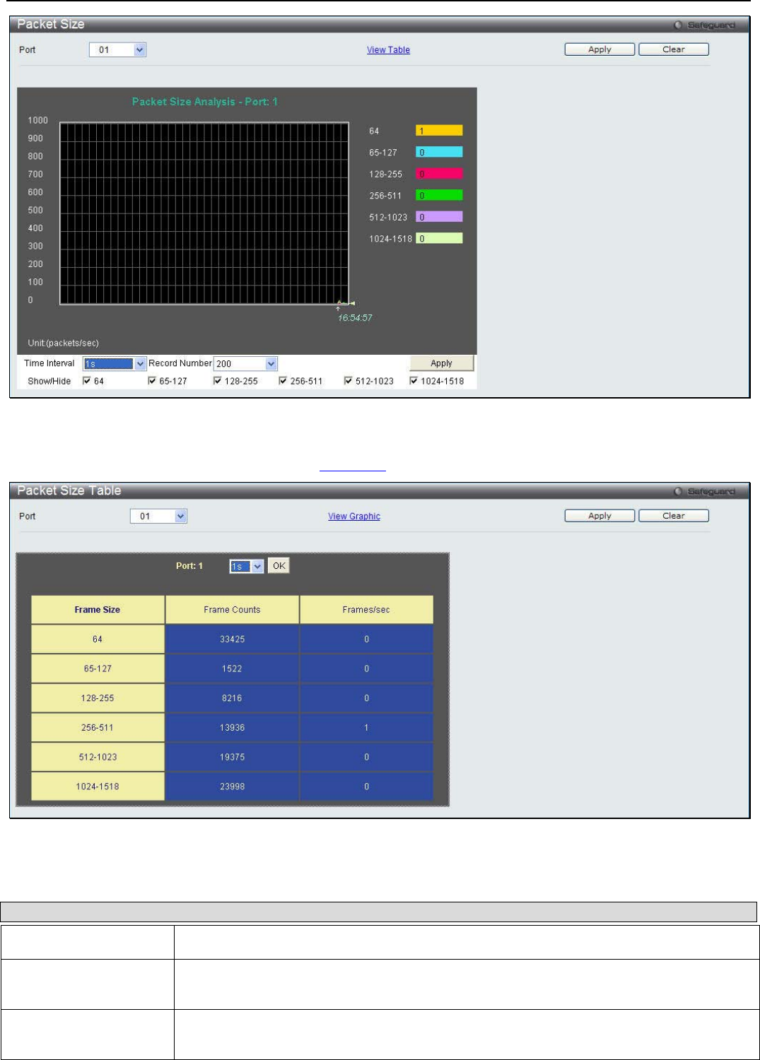
xStack® DGS-3200 Series Layer 2 Managed Gigabit Ethernet Switch Web UI Reference Guide
257
Figure 10 - 6. Packet Size window
To view the Packet Size Table window, click the link View Table, which will show the following table:
Figure 10 - 7. Packet Size Table window
The following fields can be set or viewed:
Parameter Description
Port Use the drop-down menu to choose the port that will display statistics.
Time Interval Select the desired setting between 1s and 60s, where "s" stands for seconds. The default
value is one second.
Record Number Select number of times the Switch will be polled between 20 and 200. The default value is
200.
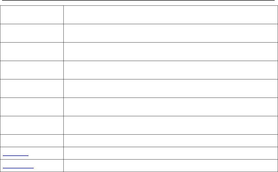
xStack® DGS-3200 Series Layer 2 Managed Gigabit Ethernet Switch Web UI Reference Guide
258
64 The total number of packets (including bad packets) received that were 64 octets in length
(excluding framing bits but including FCS octets).
65-127 The total number of packets (including bad packets) received that were between 65 and
127 octets in length inclusive (excluding framing bits but including FCS octets).
128-255 The total number of packets (including bad packets) received that were between 128 and
255 octets in length inclusive (excluding framing bits but including FCS octets).
256-511 The total number of packets (including bad packets) received that were between 256 and
511 octets in length inclusive (excluding framing bits but including FCS octets).
512-1023 The total number of packets (including bad packets) received that were between 512 and
1023 octets in length inclusive (excluding framing bits but including FCS octets).
1024-1518 The total number of packets (including bad packets) received that were between 1024 and
1518 octets in length inclusive (excluding framing bits but including FCS octets).
Show/Hide Check whether or not to display 64, 65-127, 128-255, 256-511, 512-1023, and 1024-1518
packets received.
Clear Clicking this button clears all statistics counters on this window.
View Table Clicking this button instructs the Switch to display a table rather than a line graph.
View Graphic Clicking this button instructs the Switch to display a line graph rather than a table.
Packets
The Web manager allows various packet statistics to be viewed as either a line graph or a table.
Received (RX)
To select a port to view these statistics for, select the port by using the Port drop-down menu. The user may also use the real-time
graphic of the Switch at the top of the web page by simply clicking on a port.
To view the following windows, click Monitoring > Packets > Received (RX):
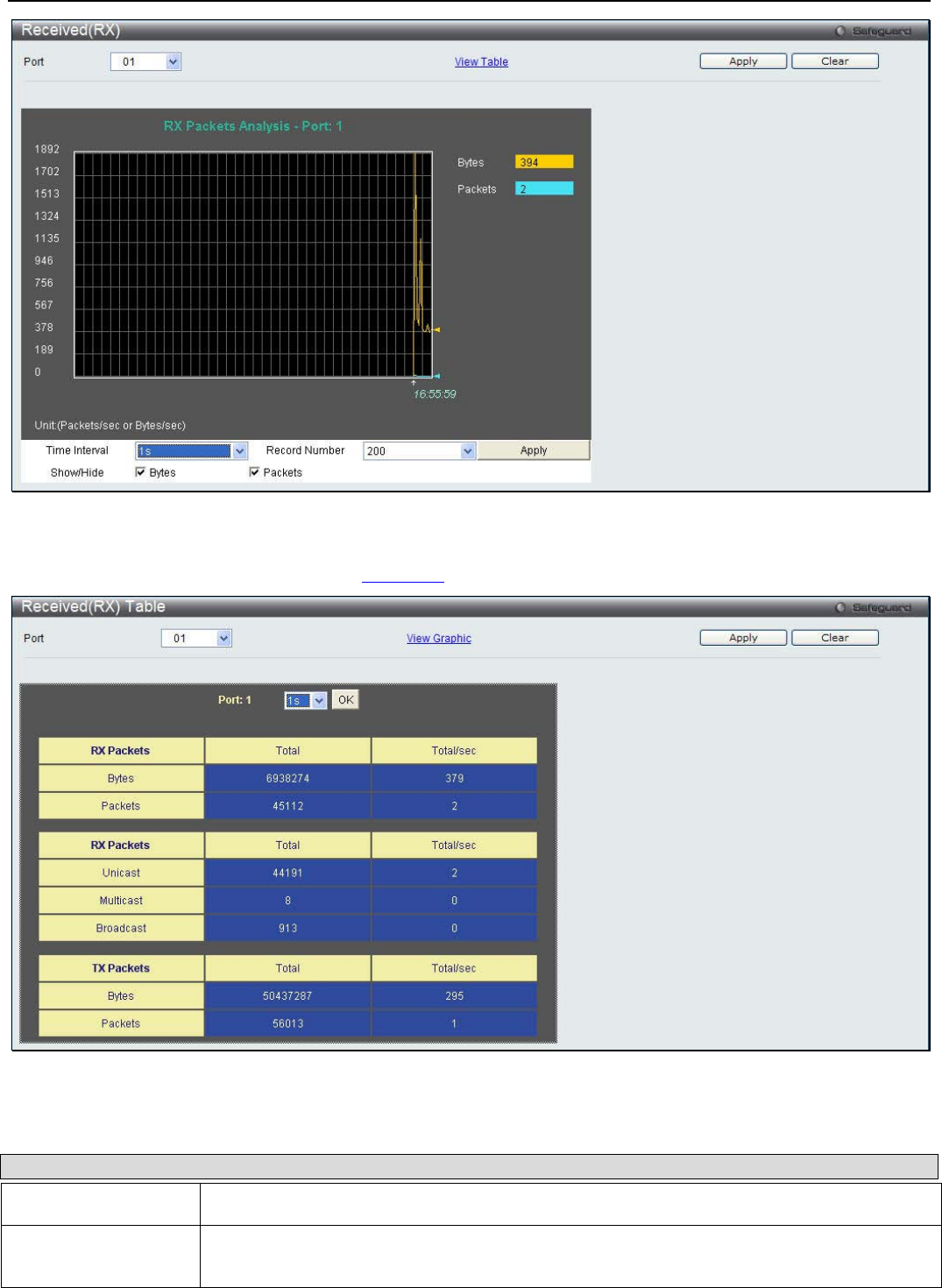
xStack® DGS-3200 Series Layer 2 Managed Gigabit Ethernet Switch Web UI Reference Guide
259
Figure 10 - 8. Received (RX) window (for Bytes and Packets)
To view the Received (RX) Table window, click View Table.
Figure 10 - 9. Received (RX) Table window (for Bytes and Packets)
The following fields may be set or viewed:
Parameter Description
Port Use the drop-down menu to choose the port that will display statistics.
Time Interval Select the desired setting between 1s and 60s, where "s" stands for seconds. The default
value is one second.
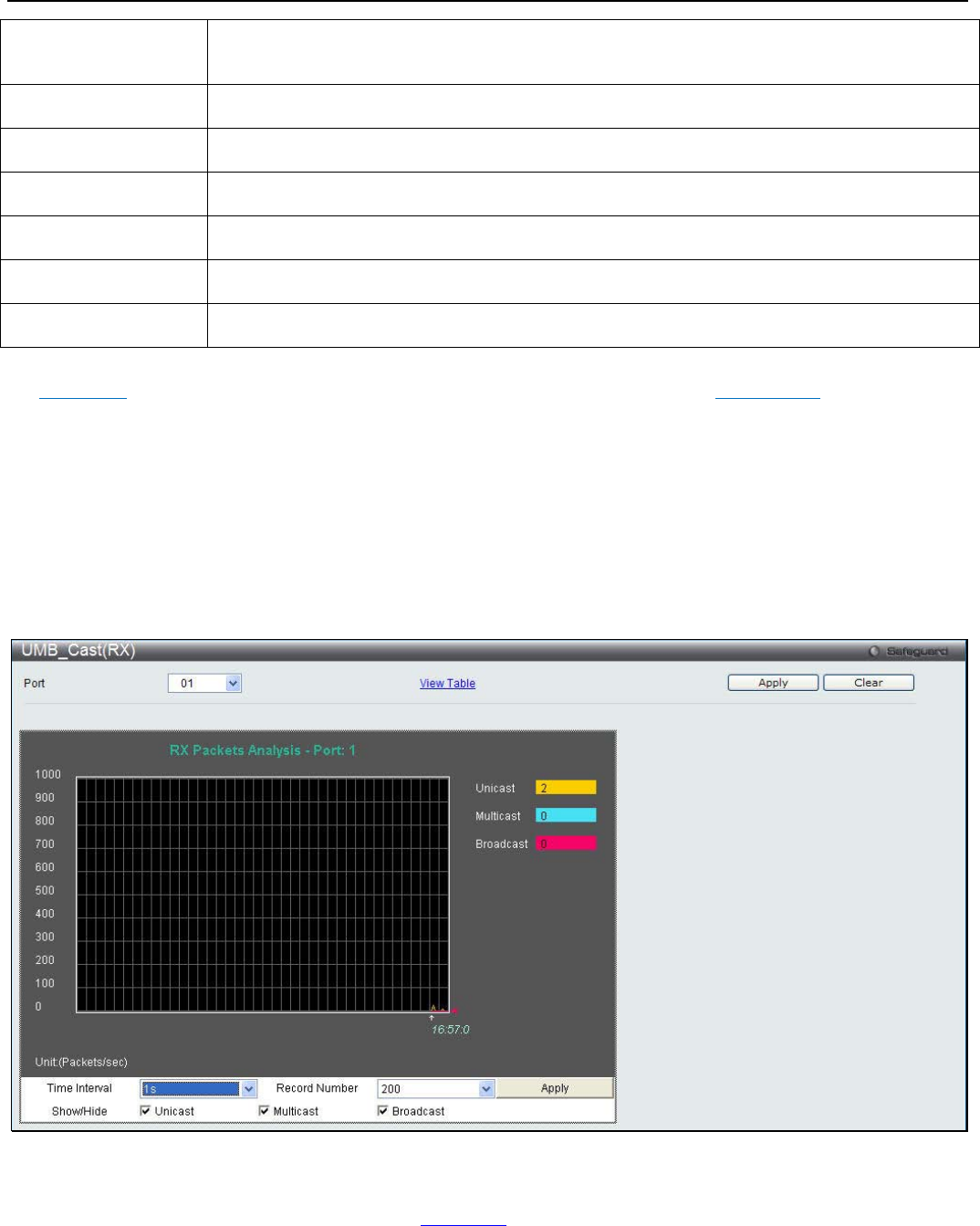
xStack® DGS-3200 Series Layer 2 Managed Gigabit Ethernet Switch Web UI Reference Guide
260
Record Number Select number of times the Switch will be polled between 20 and 200. The default value is
200.
Bytes Counts the number of bytes received on the port.
Packets Counts the number of packets received on the port.
Unicast Counts the total number of good packets that were received by a unicast address.
Multicast Counts the total number of good packets that were received by a multicast address.
Broadcast Counts the total number of good packets that were received by a broadcast address.
Show/Hide Check whether to display Bytes and Packets.
Click the Apply button to accept the changes made. Click the Clear button to clear all statistics counters on this window. Click
the View Table link to display the information in a table rather than a line graph. Click the View Graphic link to display the
information in a line graph rather than a table.
UMB_Cast (RX)
To select a port to view these statistics for, select the port by using the Port drop-down menu. The user may also use the real-time
graphic of the Switch at the top of the web page by simply clicking on a port.
To view the following windows, click Monitoring > Packets > UMB_Cast (RX):
Figure 10 - 10. UMB_Cast (RX) window (for Unicast, Multicast, and Broadcast Packets)
To view the UMB_Cast (RX) Table window, click the View Table link.
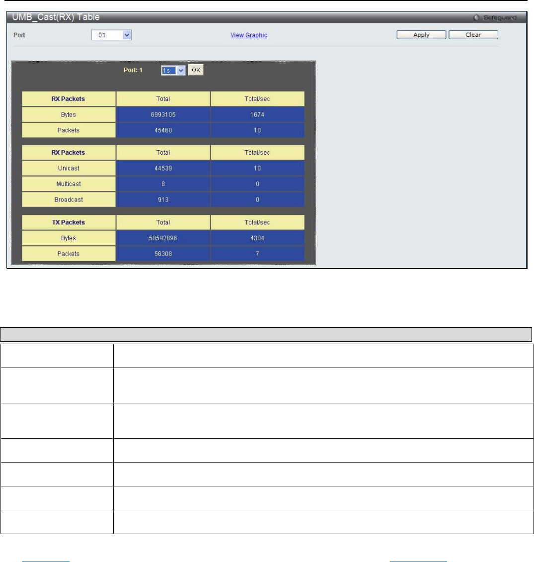
xStack® DGS-3200 Series Layer 2 Managed Gigabit Ethernet Switch Web UI Reference Guide
261
Figure 10 - 11. UMB_Cast (RX) Table window (for Unicast, Multicast, and Broadcast Packets)
The following fields may be set or viewed:
Parameter Description
Port Use the drop-down menu to choose the port that will display statistics.
Time Interval Select the desired setting between 1s and 60s, where "s" stands for seconds. The default
value is one second.
Record Number Select number of times the Switch will be polled between 20 and 200. The default value is
200.
Unicast Counts the total number of good packets that were received by a unicast address.
Multicast Counts the total number of good packets that were received by a multicast address.
Broadcast Counts the total number of good packets that were received by a broadcast address.
Show/Hide Check whether or not to display Multicast, Broadcast, and Unicast Packets.
Click the Apply button to accept the changes made. Click the Clear button to clear all statistics counters on this window. Click
the View Table link to display the information in a table rather than a line graph. Click the View Graphic link to display the
information in a line graph rather than a table.
Transmitted (TX)
To select a port to view these statistics for, select the port by using the Port drop-down menu. The user may also use the real-time
graphic of the Switch at the top of the web page by simply clicking on a port.
To view the following windows, click Monitoring > Packets > Transmitted (TX):

xStack® DGS-3200 Series Layer 2 Managed Gigabit Ethernet Switch Web UI Reference Guide
262
Figure 10 - 12. Transmitted (TX) window (for Bytes and Packets)
To view the Transmitted (TX) Table window, click the link View Table.
Figure 10 - 13. Transmitted (TX) Table window (for Bytes and Packets)
The following fields may be set or viewed:
Parameter Description
Port Use the drop-down menu to choose the port that will display statistics.
Time Interval Select the desired setting between 1s and 60s, where "s" stands for seconds. The default
value is one second.
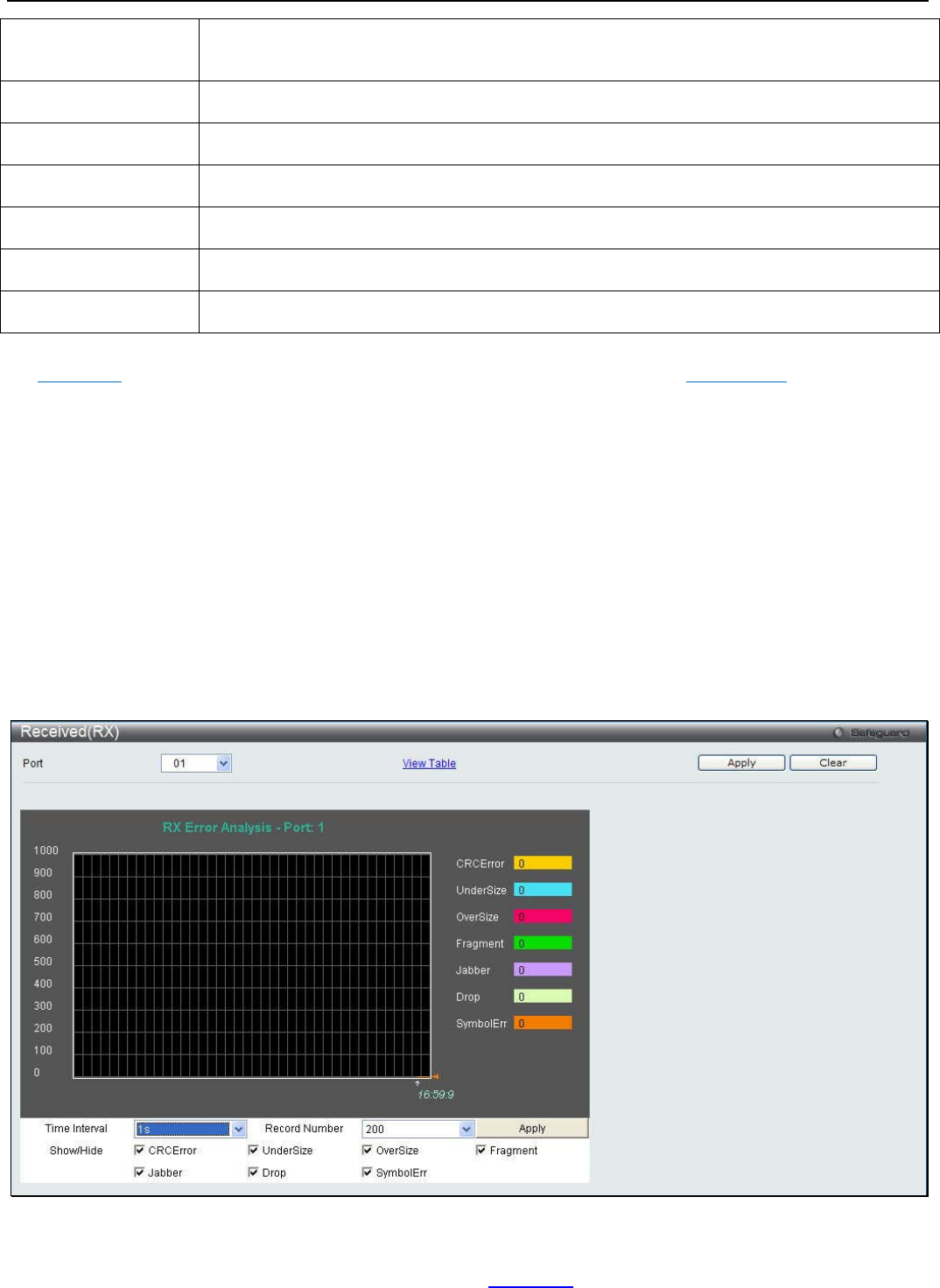
xStack® DGS-3200 Series Layer 2 Managed Gigabit Ethernet Switch Web UI Reference Guide
263
Record Number Select number of times the Switch will be polled between 20 and 200. The default value is
200.
Bytes Counts the number of bytes successfully sent on the port.
Packets Counts the number of packets successfully sent on the port.
Unicast Counts the total number of good packets that were transmitted by a unicast address.
Multicast Counts the total number of good packets that were transmitted by a multicast address.
Broadcast Counts the total number of good packets that were transmitted by a broadcast address.
Show/Hide Check whether or not to display Bytes and Packets.
Click the Apply button to accept the changes made. Click the Clear button to clear all statistics counters on this window. Click
the View Table link to display the information in a table rather than a line graph. Click the View Graphic link to display the
information in a line graph rather than a table.
Errors
The Web manager allows port error statistics compiled by the Switch's management agent to be viewed as either a line graph or a
table. Four windows are offered.
Received (RX)
To select a port to view these statistics for, select the port by using the Port drop-down menu. The user may also use the real-time
graphic of the Switch at the top of the web page by simply clicking on a port.
To view the following windows, click Monitoring > Errors > Received (RX):
Figure 10 - 14. Received (RX) window (for errors)
To view the Received (RX) Table window for errors, click the link View Table, which will show the following table:
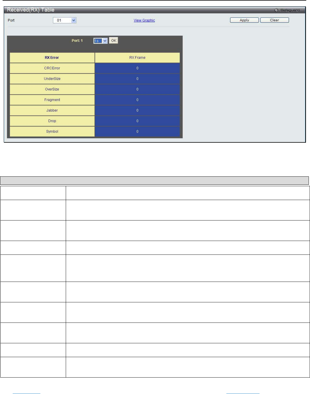
xStack® DGS-3200 Series Layer 2 Managed Gigabit Ethernet Switch Web UI Reference Guide
264
Figure 10 - 15. Received (RX) Table window (for errors)
The following fields can be set:
Parameter Description
Port Use the drop-down menu to choose the port that will display statistics.
Time Interval Select the desired setting between 1s and 60s, where "s" stands for seconds. The default
value is one second.
Record Number Select number of times the Switch will be polled between 20 and 200. The default value is
200.
CRCError Counts otherwise valid packets that did not end on a byte (octet) boundary.
UnderSize The number of packets detected that are less than the minimum permitted packets size of 64
bytes and have a good CRC. Undersize packets usually indicate collision fragments, a nor-
mal network occurrence.
OverSize Counts valid packets received that were longer than 1518 octets and less than the
MAX_PKT_LEN. Internally, MAX_PKT_LEN is equal to 1536.
Fragment The number of packets less than 64 bytes with either bad framing or an invalid CRC. These
are normally the result of collisions.
Jabber Counts invalid packets received that were longer than 1518 octets and less than the
MAX_PKT_LEN. Internally, MAX_PKT_LEN is equal to 1536.
Drop The number of packets that are dropped by this port since the last Switch reboot.
Symbol Counts the number of packets received that have errors received in the symbol on the
physical labor.
Click the Apply button to accept the changes made. Click the Clear button to clear all statistics counters on this window. Click
the View Table link to display the information in a table rather than a line graph. Click the View Graphic link to display the
information in a line graph rather than a table.

xStack® DGS-3200 Series Layer 2 Managed Gigabit Ethernet Switch Web UI Reference Guide
265
Transmitted (TX)
To select a port to view these statistics for, select the port by using the Port drop-down menu. The user may also use the real-time
graphic of the Switch at the top of the web page by simply clicking on a port.
To view the following windows, click Monitoring > Errors > Transmitted (TX):
Figure 10 - 16. Transmitted (TX) window (for errors)
To view the Transmitted (TX) Table window, click the link View Table, which will show the following table:
Figure 10 - 17. Transmitted (TX) Table window (for errors)
The following fields may be set or viewed:
Parameter Description
Port Use the drop-down menu to choose the port that will display statistics.
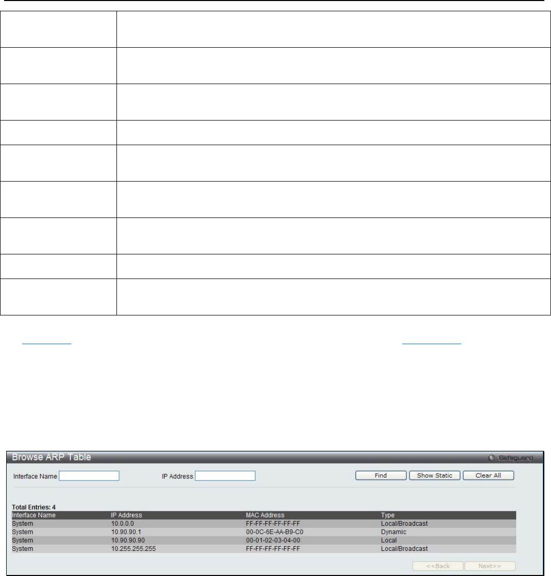
xStack® DGS-3200 Series Layer 2 Managed Gigabit Ethernet Switch Web UI Reference Guide
266
Time Interval Select the desired setting between 1s and 60s, where "s" stands for seconds. The default
value is one second.
Record Number Select number of times the Switch will be polled between 20 and 200. The default value is
200.
ExDefer Counts the number of packets for which the first transmission attempt on a particular
interface was delayed because the medium was busy.
CRC Error Counts otherwise valid packets that did not end on a byte (octet) boundary.
LateColl Counts the number of times that a collision is detected later than 512 bit-times into the
transmission of a packet.
ExColl Excessive Collisions. The number of packets for which transmission failed due to excessive
collisions.
SingColl Single Collision Frames. Th
e number of successfully transmitted packets for which
transmission is inhibited by more than one collision.
Collision An estimate of the total number of collisions on this network segment.
Show/Hide Check whether or not to display ExDefer, CRCError, LateColl, ExColl, SingColl, and Collision
errors.
Click the Apply button to accept the changes made. Click the Clear button to clear all statistics counters on this window. Click
the View Table link to display the information in a table rather than a line graph. Click the View Graphic link to display the
information in a line graph rather than a table.
Browse ARP Table
This window is used to display current ARP entries on the Switch.
To view the following window, click Monitoring > Browse ARP Table:
Figure 10 - 18. Browse ARP Table window
To search a specific ARP entry, enter an Interface Name or an IP Address at the top of the window and click Find. Click the
Show Static button to display static ARP table entries. To clear the ARP Table, click Clear All.
Browse Router Port
Users can display which of the Switch’s ports are currently configured as router ports. A router port configured by a user (using
the console or Web-based management interfaces) is displayed as a static router port, designated by S. A router port that is
dynamically configured by the Switch is designated by D, while a Forbidden port is designated by F.
To view the following window, click Monitoring > Browse Router Port:
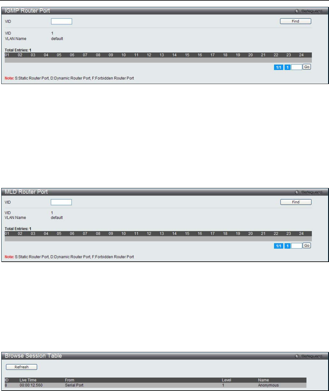
xStack® DGS-3200 Series Layer 2 Managed Gigabit Ethernet Switch Web UI Reference Guide
267
Figure 10 - 19. Browse Router Port window
Enter a VID (VLAN ID) in the field at the top of the window and click the Find button.
Browse MLD Router Port
Users can display which of the Switch’s ports are currently configured as router ports in IPv6. A router port configured by a user
(using the console or Web-based management interfaces) is displayed as a static router port, designated by S. A router port that is
dynamically configured by the Switch is designated by D, while a Forbidden port is designated by F.
To view the following window, click Monitoring > Browse MLD Router Port:
Figure 10 - 20. Browse MLD Router Port window
Enter a VID (VLAN ID) in the field at the top of the window and click the Find button.
Browse Session Table
Users can display the management sessions since the Switch was last rebooted.
To view the following window, click Monitoring > Browse Session Table:
Figure 7 - 1. Browse Session Table window
Click Refresh to update the information.

xStack® DGS-3200 Series Layer 2 Managed Gigabit Ethernet Switch Web UI Reference Guide
268
IGMP Snooping Group
Users can view the Switch’s IGMP Snooping Group Table. IGMP Snooping allows the Switch to read the Multicast Group IP
address and the corresponding MAC address from IGMP packets that pass through the Switch.
To view the following window, click Monitoring > IGMP Snooping Group:
Figure 10 - 21. IGMP Snooping Group window
The following parameters can be configured:
Parameter Description
VLAN Name The VLAN Name of the multicast group.
VID List (e.g.: 1, 4-6) The VLAN ID list of the multicast group.
Port List (e.g.: 1, 3-5) Specify the port number(s) used to find a multicast group.
Group IPv4 Address Enter the IPv4 address.
Click the Find button to locate a specific entry based on the information entered. Click the View All button to display all the
existing entries.
NOTE: To configure IGMP snooping for the Switch, go to the L2 Features folder and
select IGMP Snooping > IGMP Snooping Settings.
MLD Snooping Group
Users can view MLD Snooping Groups present on the Switch. MLD Snooping is an IPv6 function comparable to IGMP Snooping
for IPv4.
To view the following window, click Monitoring > MLD Snooping Group:
Figure 10 - 22. MLD Snooping Group window
The following parameters can be configured:
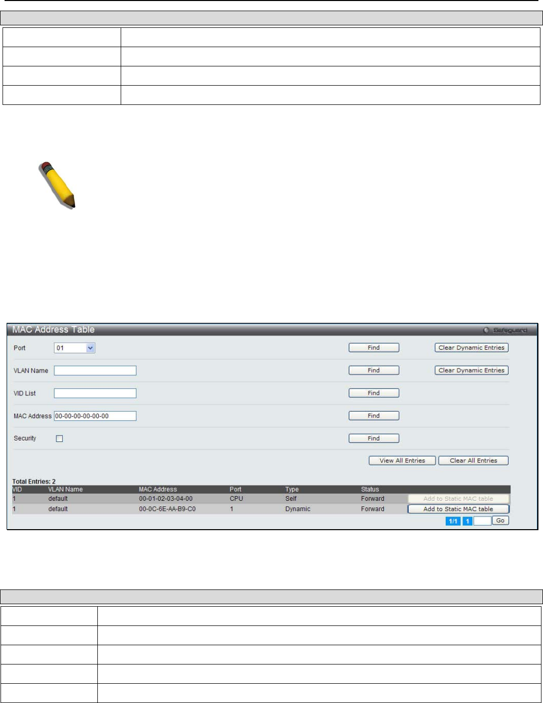
xStack® DGS-3200 Series Layer 2 Managed Gigabit Ethernet Switch Web UI Reference Guide
269
Parameter Description
VLAN Name The VLAN Name of the multicast group.
VID List (e.g.: 1, 4-6) The VLAN ID list of the multicast group.
Port List (e.g.: 1, 3-5) Specify the port number(s) used to find a multicast group.
Group IPv4 Address Enter the IPv4 address.
Click the Find button to locate a specific entry based on the information entered. Click the View All button to display all the
existing entries.
NOTE: To configure MLD snooping for the Switch, go to the L2 Features folder and
select MLD Snooping > MLD Snooping Settings.
MAC Address Table
This allows the Switch's dynamic MAC address forwarding table to be viewed. When the Switch learns an association between a
MAC address and a port number, it makes an entry into its forwarding table. These entries are then used to forward packets
through the Switch.
To view the following window, click Monitoring > MAC Address Table:
Figure 10 - 23. MAC Address Table window
The following parameters can be configured:
Parameter Description
Port The port to which the MAC address below corresponds.
VLAN Name Enter a VLAN Name for the forwarding table to be browsed by.
VID List Enter a list of VLAN for the forwarding table to be browsed by.
MAC Address Enter a MAC address for the forwarding table to be browsed by.
Security Tick the check box to diaplsy the FDB entries that are created by the security module.
Click the Find button to locate a specific entry based on the information entered. Click the Clear Dynamic Entries button to
delete all dynamic entries of the address table. Click the View All Entries button to display all the existing entries. Click the
Clear All Entries button to remove all the entries listed in the table. Click the Add to Static MAC table button to add the
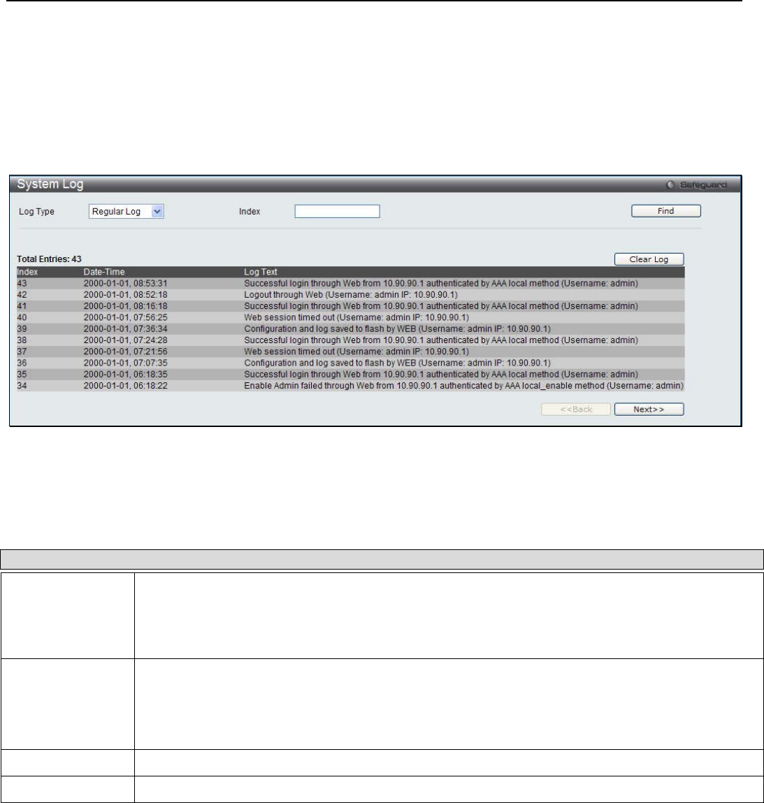
xStack® DGS-3200 Series Layer 2 Managed Gigabit Ethernet Switch Web UI Reference Guide
270
specific entry to the Static MAC table. Enter a page number and click the Go button to navigate to a specific page when multiple
pages exist.
System Log
Users can view the history log as compiled by the Switch's management agent.
To view the following window, click Monitoring > System Log:
Figure 10 - 24. System Log window
The Switch can record event information in its own logs, to designated SNMP trap receiving stations, and to the PC connected to
the console manager. Clicking Clear Log will allow the user to delete all the present entries in the Switch History Log.
The following parameters can be configured or displayed:
Parameter Description
Log Type Choose the type of log to view. There are two choices:
Regular Log – Choose this option to view regular switch log entries, such as logins or firmware
transfers.
Attack Log – Choose this option to view attack log entries, such as spoofing attacks.
Index To view a specific log entry, enter the Index number in the field at the top of the window and then
click the Find button. The index is a counter incremented whenever an entry to the Switch's history
log is made. Unless a specific index is entered in this field, the table on this window will display a
series of entries, starting with the last entry (highest sequence number) first. Click the Next>> or
<<Previous buttons to navigate around the logs for the Switch.
Date-Time Displays the time, in days, hours, minutes, and seconds, when the event was triggered.
Log Text Displays text describing the event that triggered the history log entry.

xStack® DGS-3200 Series Layer 2 Managed Gigabit Ethernet Switch Web UI Reference Guide
271
Section 11
Save and Tools
Save Configuration
Save Log
Save All
Download Configuration File/Download Configuration File to NV-RAM (DGS-3200-24 only)
Download Configuration File to SD Card (DGS-3200-24 only)
Download Firmware/Download Firmware to NV-RAM (DGS-3200-24 only)
Download Firmware to SD Card (DGS-3200-24 only)
Upload Configuration File/Upload Configuration File to TFTP
Upload Log File/Upload Log File to TFTP
Reset
Reboot System
The three main Save windows include: Save Configuration, Save Log, and Save All.
The options include:
• Save Configuration to save the configuration file indexed as Active, ID 1 or 2 (or SD Card for the DGS-3200-24 only).
• Save Log to save the current log to NV-RAM (or SD Card for the DGS-3200-24 only).
• Save All to immediately save the current configuration file and the current log.
The eight main Tools windows include: Download Configuration File/Download Configuration File to NV-RAM, Download
Configuration File to SD Card, Download Firmware/Download Firmware to NV-RAM, Download Firmware to SD Card,
Upload Configuration File/Upload Configuration File to TFTP, Upload Log File/Upload Log File to TFTP, Reset, and
Reboot System
The options include:
• Download Configuration File/Download Configuration File to NV-RAM to download a configuration file from a TFTP
server indexed as ID 1, 2, or Active to NV-RAM.
• Download Configuration File to SD Card to download a configuration file from a TFTP server indexed as ID 1, 2, or
Active to an SD Card.
• Download Firmware/Download Firmware to NV-RAM to download a firmware file from a TFTP server indexed as ID 1,
2, or Active to NV-RAM.
• Download Firmware to SD Card to download a firmware file from a TFTP server indexed as ID 1, 2, or Active to an SD
Card
• Upload Configuration File/Upload Configuration File to TFTP to upload a configuration file to a TFTP server indexed as
ID 1, 2, or Active.
• Upload Log File/Upload Log File to TFTP to upload a log file to a TFTP server.
• Reset to reset the system with the exception of the IP address, log, user account, and banner; to reset configuration to the
factory default values; or to reset the system to the factory default values and reboot the Switch.
• Reboot System to restart the Switch and save the settings from the current session or not.
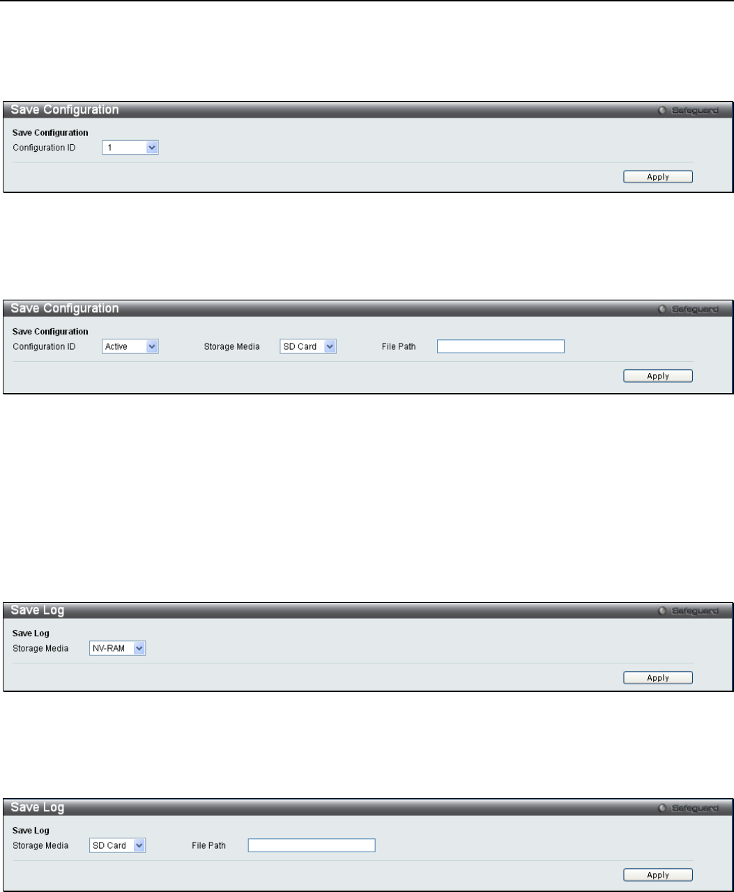
xStack® DGS-3200 Series Layer 2 Managed Gigabit Ethernet Switch Web UI Reference Guide
272
Save Configuration
Open the Save drop-down menu on the left-hand side of the menu bar at the top of the Web manager and click Save
Configuration to open the following window:
Figure 11 - 1. Save Configuration window (DGS-3200-10 and DGS-3200-16)
Use the drop-down menu to choose a configuration file indexed as ID 1 or 2 and then click Apply.
Figure 11 - 2. Save Configuration window (DGS-3200-24)
Use the drop-down menu to choose a configuration file indexed as ID 1, 2, or Active, select a Storage Media as a destination (SD
Card or NV-RAM, enter a File Path, and then click Apply.
Save Log
Open the Save drop-down menu on the left-hand side of the menu bar at the top of the Web manager and click Save Log to open
the following window:
Figure 11 - 3. Save Log window (DGS-3200-10 and DGS-3200-16)
To save the current log to NV-RAM, click Apply.
Figure 11 - 4. Save Log window (DGS-3200-24)
To save the current log, select a Storage Media as a destination (SD Card or NV-RAM, enter a File Path, and then click Apply.
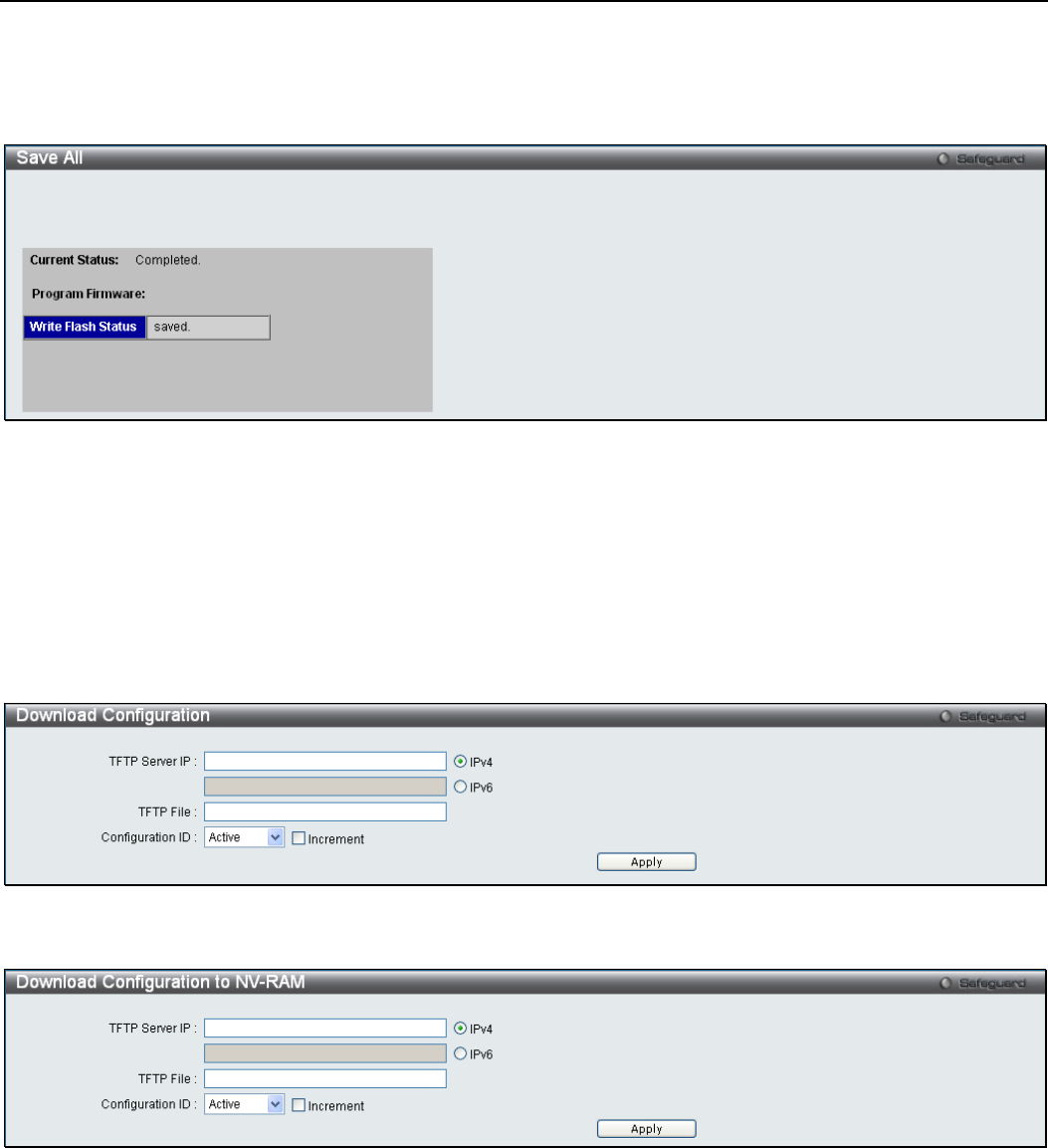
xStack® DGS-3200 Series Layer 2 Managed Gigabit Ethernet Switch Web UI Reference Guide
273
Save All
Open the Save drop-down menu on the left-hand side of the menu bar at the top of the Web manager and click Save All to
immediately save the current configuration file and current log. The following window will open:
Figure 11 - 5. Save All window
Download Configuration File/Download Configuration File to
NV-RAM
The Switch can store dual configuration files. The configuration files are indexed as Active, 1, or 2.
Open the Tools drop-down menu on the left-hand side of the menu bar at the top of the Web manager and click Download
Configuration File to open the following window:
Figure 11 - 6. Download Configuration window (DGS-3200-10 and DGS-3200-16)
Figure 11 - 7. Download Configuration to NV-RAM window (DGS-3200-24)
Use the radio button to select either IPv4 or IPv6. Enter the TFTP Server IP address for the type of IP selected. Specify the
path/file name of the TFTP File. Select the desired Configuration ID, Active, 1 or 2. Tick the Increment checkbox to allow the
download of a partial switch configuration file. This allows a file to be downloaded that will change only the switch parameters
explicitly stated in the configuration file. All other switch parameters will remain unchanged.
Click Apply to initiate the file transfer.
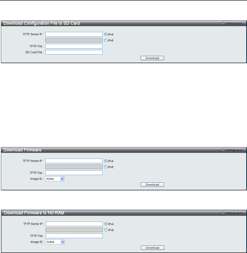
xStack® DGS-3200 Series Layer 2 Managed Gigabit Ethernet Switch Web UI Reference Guide
274
Download Configuration File to SD Card
Figure 11 - 8. Download Configuration File to SD Card window (DGS-3200-24)
Use the radio button to select either IPv4 or IPv6. Enter the TFTP Server IP address for the type of IP selected. Specify the
path/file name of the TFTP File. Specify the SD Card File name. Click Download to initiate the file transfer.
Download Firmware/Download Firmware to NV-RAM
The Switch supports dual image storage for firmware file backup and restoration. The firmware images are indexed as Active, 1,
or 2.
Open the Tools drop-down menu on the left-hand side of the menu bar at the top of the Web manager and click Download
Firmware to open the following window:
Figure 11 - 9. Download Firmware window (DGS-3200-10 and DGS-3200-16)
Figure 11 - 10. Download Firmware to NV-RAM window (DGS-3200-24)
Use the radio button to select either IPv4 or IPv6. Enter the TFTP Server IP address for the type of IP selected. Specify the
path/file name of the TFTP File. Select the desired Image ID, Active, 1 or 2. Click Download to initiate the file transfer.
Download Firmware to SD Card
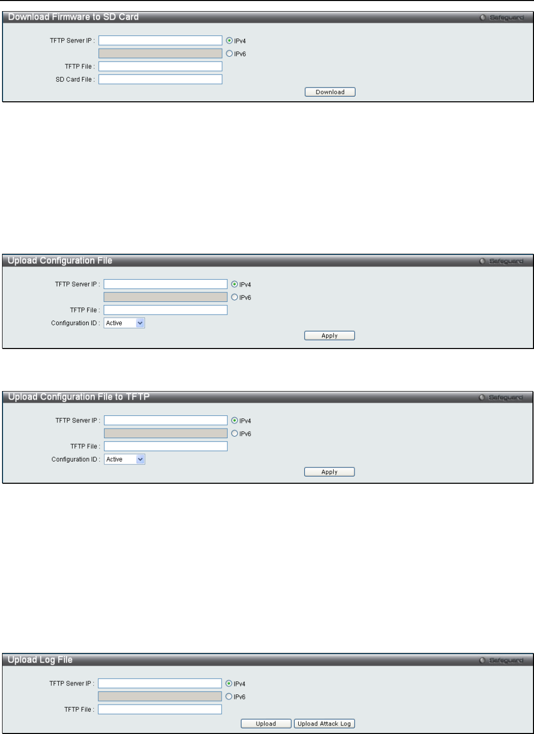
xStack® DGS-3200 Series Layer 2 Managed Gigabit Ethernet Switch Web UI Reference Guide
275
Figure 11 - 11. Download Firmware to SD Card window (DGS-3200-24)
Use the radio button to select either IPv4 or IPv6. Enter the TFTP Server IP address for the type of IP selected. Specify the
path/file name of the TFTP File. Specify the SD Card File name. Click Download to initiate the file transfer.
Upload Configuration File/Upload Configuration File to TFTP
The Switch can store dual configuration files. The configuration files are indexed as Active, 1, or 2.
Open the Tools drop-down menu on the left-hand side of the menu bar at the top of the Web manager and click Upload
Configuration File to open the following window:
Figure 11 - 12. Upload Configuration File window (DGS-3200-10 and DGS-3200-16)
Figure 11 - 13. Upload Configuration File to TFTP window (DGS-3200-24)
Use the radio button to select either IPv4 or IPv6. Enter the TFTP Server IP address for the type of IP selected. Specify the
path/file name of the TFTP File. Select the desired Configuration ID, Active, 1 or 2. Click Apply to initiate the file transfer.
Upload Log File/Upload Log File to TFTP
A history and attack log can be uploaded from the Switch to a TFTP server.
Open the Tools drop-down menu on the left-hand side of the menu bar at the top of the Web manager and click Upload Log File
to open the following window:
Figure 11 - 14. Upload Log File window (DGS-3200-10 and DGS-3200-16)

xStack® DGS-3200 Series Layer 2 Managed Gigabit Ethernet Switch Web UI Reference Guide
276
Figure 11 - 15. Upload Log File to TFTP window (DGS-3200-24)
To upload a log file, enter a TFTP Server IP address and TFTP File/path name. Select either IPv4 or IPv6 and then click Upload
or Upload Attack Log.
Reset
The Reset function has several options when resetting the Switch. Some of the current configuration parameters can be retained
while resetting all other configuration parameters to their factory defaults. Reset gives the option of retaining the Switch's User
Accounts and History Log, while resetting all other configuration parameters to their factory defaults. If the Switch is reset using
this window, and neither Save Configuration nor Save All is executed, the Switch will return to the last saved configuration
when rebooted.
Open the Tools drop-down menu on the left-hand side of the menu bar at the top of the Web manager and click Reset to open the
following window:
Figure 11 - 16. Reset System window
NOTE: Only the Reset System option will enter the factory default parameters into the Switch's
non-volatile RAM, and then restart the Switch. All other options enter the factory default values
into the current configuration, but do not save this configuration. Reset System will return the
Switch's configuration to the state it was when it left the factory.
Reboot System
The following window is used to restart the Switch.
Open the Tools drop-down menu on the left-hand side of the menu bar at the top of the Web manager and click Reboot System to
open the following window:
Figure 11 - 17. Reboot System window
Click the Yes radio button will instruct the Switch to save the current configuration to non-volatile RAM before restarting the
Switch. Click the No radio button instructs the Switch not to save the current configuration before restarting the Switch. All of the
configuration information entered from the last time either Save Configuration or Save All was executed will be lost.
Click the Reboot button to restart the Switch.
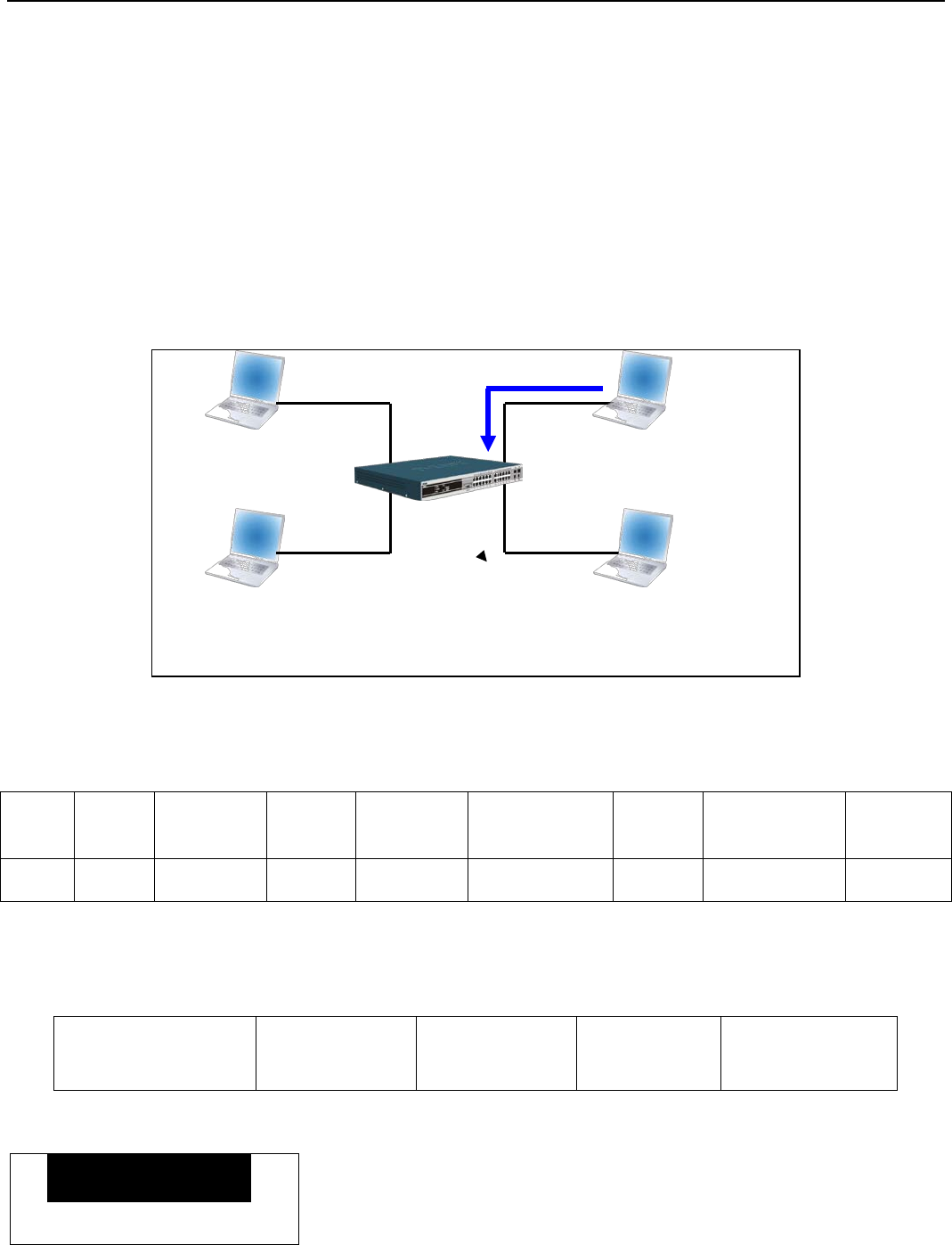
xStack® DGS-3200 Series Layer 2 Managed Gigabit Ethernet Switch Web UI Reference Guide
277
Appendix A – Mitigating ARP Spoofing Attacks
Using Packet Content ACL
How Address Resolution Protocol works
Address Resolution Protocol (ARP) is the standard method for finding a host’s hardware address (MAC address) when only its IP
address is known. However, this protocol is vulnerable because hackers can spoof the IP and MAC information in the ARP
packets to attack a LAN (known as ARP spoofing). This document is intended to introduce the ARP protocol, ARP spoofing
attacks, and the countermeasures brought by D-Link’s switches to thwart ARP spoofing attacks.
In the process of ARP, PC A will first issue an ARP request to query PC B’s MAC address. The network structure is shown in
Figure 1.
Figure 1
In the meantime, PC A’s MAC address will be written into the “Sender H/W Address” and its IP address will be written into the
“Sender Protocol Address” in the ARP payload. As PC B’s MAC address is unknown, the “Target H/W Address” will be “00-00-
00-00-00-00,” while PC B’s IP address will be written into the “Target Protocol Address,” shown in Table1.
Table 1. ARP Payload
H/W
Type Protocol
Type H/W
Address
Length
Protocol
Address
Length
Operation Sender
H/W Address Sender
Protocol
Address
Target
H/W Address Target
Protocol
Address
ARP request 00-20-5C-01-11-11 10.10.10.1 00-00-00-00-00-00 10.10.10.2
The ARP request will be encapsulated into an Ethernet frame and sent out. As can be seen in Table 2, the “Source Address” in the
Ethernet frame will be PC A’s MAC address. Since an ARP request is sent via broadcast, the “Destination address” is in a format
of Ethernet broadcast (FF-FF-FF-FF-FF-FF).
Table 2. Ethernet Frame Format
Destination Address
FF-FF-FF-FF-FF-FF
Source Address
00-20-5C-01-11-11
Ether-Type ARP FCS
When the switch receives the frame, it will check the “Source Address” in the Ethernet frame’s header. If the address is not in its
Forwarding Table, the switch will learn PC A’s MAC and the associated port into its Forwarding Table.
Port 1 00-20-5C-01-11-11
In addition, when the switch receives the broadcasted ARP request, it will flood the frame to all ports except the source port, port
1 (see Figure 2).
Figure 2
Sender
Port 4
Port 1
Port 2
Port 3
D
C
00-20-5C-01-33-33
10.10.10.3
00-20-5C-01-44-44
10.10.10.4
00-20-5C-01-11-11
10.10.10.1
00-20-5C-01-22-22
10.10.10.2
B
A
Target
Who is 10.10.10.2?
Forwarding Table
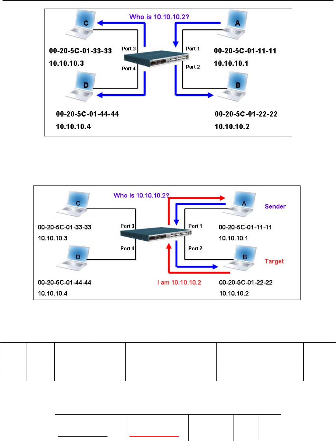
xStack® DGS-3200 Series Layer 2 Managed Gigabit Ethernet Switch Web UI Reference Guide
278
When the switch floods the frame of ARP request to the network, all PCs will receive and examine the frame but only PC B will
reply the query as the destination IP matched (see Figure 3).
Figure 3
When PC B replies to the ARP request, its MAC address will be written into “Target H/W Address” in the ARP payload shown in
Table 3. The ARP reply will be then encapsulated into an Ethernet frame again and sent back to the sender. The ARP reply is in a
form of Unicast communication.
Table 3. ARP Payload
H/W
Type Protocol
Type H/W
Address
Length
Protocol
Address
Length
Operation Sender
H/W Address Sender
Protocol
Address
Target
H/W Address Target
Protocol
Address
ARP reply 00-20-5C-01-11-11 10.10.10.1 00-20-5C-01-22-22 10.10.10.2
When PC B replies to the query, the “Destination Address” in the Ethernet frame will be changed to PC A’s MAC address. The
“Source Address” will be changed to PC B’s MAC address (see Table 4).
Table 4. Ethernet Frame Format
Destination Address
00-20-5C-01-11-11
Source Address
00-20-5C-01-22-22
Ether-Type ARP FCS
The switch will also examine the “Source Address” of the Ethernet frame and find that the address is not in the Forwarding Table.
The switch will learn PC B’s MAC and update its Forwarding Table.

xStack® DGS-3200 Series Layer 2 Managed Gigabit Ethernet Switch Web UI Reference Guide
279
Port1 00-20-5C-01-11-11
Port2 00-20-5C-01-22-22
Forwarding Table
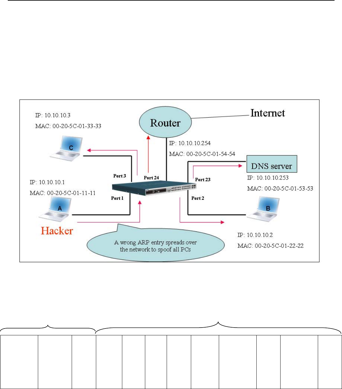
xStack® DGS-3200 Series Layer 2 Managed Gigabit Ethernet Switch Web UI Reference Guide
280
How ARP Spoofing Attacks a Network
ARP spoofing, also known as ARP poisoning, is a method to attack an Ethernet network which may allow an attacker to sniff data
frames on a LAN, modify the traffic, or stop the traffic altogether (known as a Denial of Service – DoS attack). The principle of
ARP spoofing is to send the fake or spoofed ARP messages to an Ethernet network. Generally, the aim is to associate the attacker's
or random MAC address with the IP address of another node (such as the default gateway). Any traffic meant for that IP address
would be mistakenly re-directed to the node specified by the attacker.
IP spoofing attack is caused by Gratuitous ARP that occurs when a host sends an ARP request to resolve its own IP address.
Figure-4 shows a hacker within a LAN to initiate ARP spoofing attack.
Figure 4
In the Gratuitous ARP packet, the “Sender protocol address” and “Target protocol address” are filled with the same source IP
address itself. The “Sender H/W Address” and “Target H/W address” are filled with the same source MAC address itself. The
destination MAC address is the Ethernet broadcast address (FF-FF-FF-FF-FF-FF). All nodes within the network will immediately
update their own ARP table in accordance with the sender’s MAC and IP address. The format of Gratuitous ARP is shown in the
following table.
Table 5
Destination
Address Source
Address Ethernet
Type H/W Type Protocol
Type H/W
Address
Length
Protocol
Address
Length
Operation Sender H/W
Address Sender
Protocol
Address
Target H/W
Address Target
Protocol
Address
(6-byte) (6-byte) (2-byte) (2-byte) (2-byte) (1-byte) (1-byte) (2-byte) (6-byte) (4-byte) (6-byte) (4-byte)
FF-FF-FF-FF-FF-FF 00-20-5C-01-11-11 0806 ARP relay 00-20-5C-01-11-11 10.10.10.254 00-20-5C-01-11-11 10.10.10.254
A common DoS attack today can be done by associating a nonexistent or any specified MAC address to the IP address of the
network’s default gateway. The malicious attacker only needs to broadcast one Gratuitous ARP to the network claiming it is the
gateway so that the whole network operation will be turned down as all packets to the Internet will be directed to the wrong node.
Likewise, the attacker can either choose to forward the traffic to the actual default gateway (passive sniffing) or modify the data
before forwarding it (man-in-the-middle attack). The hacker cheats the victim PC that it is a router and cheats the router that it is
the victim. As can be seen in Figure 5 all traffic will be then sniffed by the hacker but the users will not discover.
Ethernet Header Gratuitous ARP
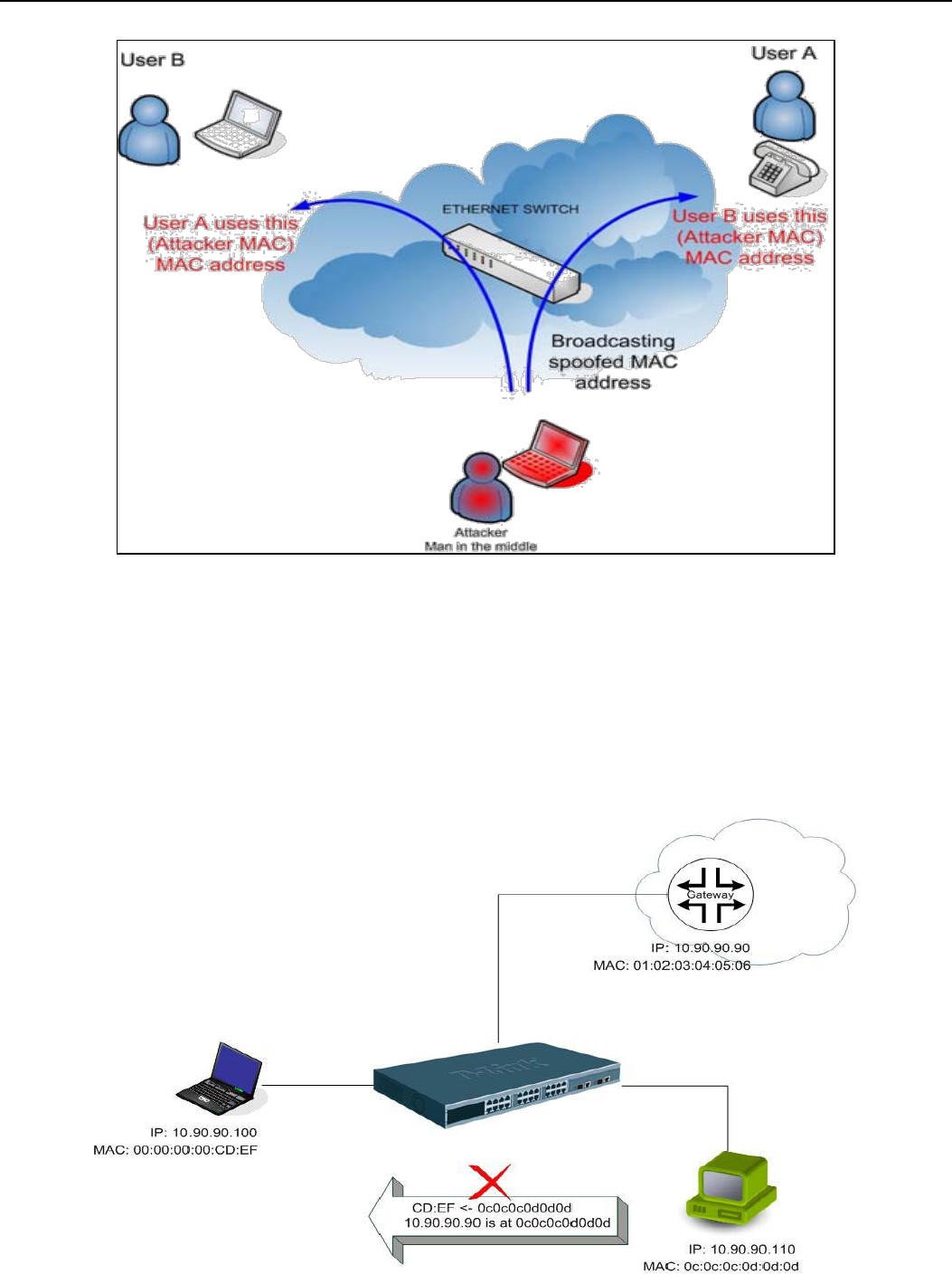
xStack® DGS-3200 Series Layer 2 Managed Gigabit Ethernet Switch Web UI Reference Guide
281
Figure 5
Prevent ARP Spoofing via Packet Content ACL
D-Link managed switches can effectively mitigate common DoS attacks caused by ARP spoofing via a unique Package Content
ACL.
For the reason that basic ACL can only filter ARP packets based on packet type, VLAN ID, Source, and Destination MAC
information, there is a need for further inspections of ARP packets. To prevent ARP spoofing attack, we will demonstrate here via
using Packet Content ACL on the Switch to block the invalid ARP packets which contain faked gateway’s MAC and IP binding.
Example topology
Configuration
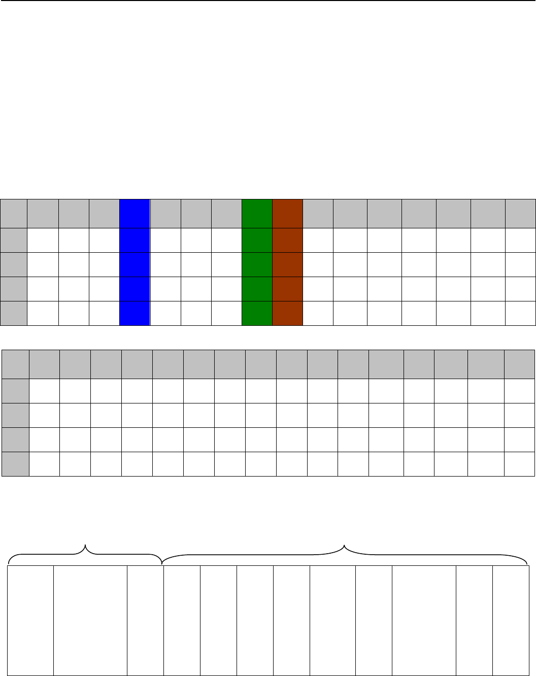
xStack® DGS-3200 Series Layer 2 Managed Gigabit Ethernet Switch Web UI Reference Guide
282
The configuration logic is as follows:
1. Only if the ARP matches Source MAC address in Ethernet, Sender MAC address and Sender IP address in ARP protocol can
pass through the switch. (In this example, it is the gateway’s ARP.)
2. The switch will deny all other ARP packets which claim they are from the gateway’s IP.
The design of Packet Content ACL on the Switch enables users to inspect any offset chunk. An offset chunk is a 4-byte block in a
HEX format, which is utilized to match the individual field in an Ethernet frame. Each profile is allowed to contain up to a
maximum of four offset chunks. Furthermore, only one single profile of Packet Content ACL can be supported per switch. In
other words, up to 16 bytes of total offset chunks can be applied to each profile and a switch. Therefore, a careful consideration is
needed for planning and configuration of the valuable offset chunks.
In Table 6, you will notice that the Offset_Chunk0 starts from the 127th byte and ends at the 128th byte. It also can be found that
the offset chunk is scratched from 1 but not zero.
Table 6. Chunk and Packet Offset
Offset
Chunk
Offset
Chunk0 Offset
Chunk1 Offset
Chunk2 Offset
Chunk3 Offset
Chunk4 Offset
Chunk5 Offset
Chunk6 Offset
Chunk7 Offset
Chunk8 Offset
Chunk9 Offset
Chunk10 Offset
Chunk11 Offset
Chunk12 Offset
Chunk13 Offset
Chunk14 Offset
Chunk15
Byte 127 3 7 11 15 19 23 27 31 35 39 43 47 51 55 59
Byte 128 4 8 12 16 20 24 28 32 36 40 44 48 52 56 60
Byte 1 5 9 13 17 21 25 29 33 37 41 45 49 53 57 61
Byte 2 6 10 14 18 22 26 30 34 38 42 46 50 54 58 62
Offset
Chunk Offset
Chunk16 Offset
Chunk17
Offset
Chunk18 Offset
Chunk19
Offset
Chunk20
Offset
Chunk21 Offset
Chunk22
Offset
Chunk23 Offset
Chunk24
Offset
Chunk25 Offset
Chunk26
Offset
Chunk27 Offset
Chunk28 Offset
Chunk29 Offset
Chunk30 Offset
Chunk31
Byte 63 67 71 75 79 83 87 91 95 99 103 107 111 115 119 123
Byte 64 68 72 76 80 84 88 92 96 100 104 108 112 116 120 124
Byte 65 69 73 77 81 85 89 93 97 101 105 109 113 117 121 125
Byte 66 70 74 78 82 86 90 94 98 102 106 110 114 118 122 126
The following table indicates a completed ARP packet contained in Ethernet frame which is the pattern for the calculation of
packet offset.
Table 7. A Completed ARP Packet Contained in an Ethernet Frame
Destination
Address Source Address Ethernet
Type H/W
Type Protocol
Type H/W
Address
Length
Protocol
Address
Length
Operation Sender
H/W
Address
Sender Protocol
Address Target
H/W
Address
Target
Protocol
Address
(6-byte) (6-byte) (2-byte) (2-byte) (2-byte) (1-byte) (1-byte) (2-byte) (6-byte) (4-byte) (6-byte) (4-byte)
01 02 03 04 05 06 0806 0a5a5a5a
(10.90.90.90)
Ethernet Header ARP

xStack® DGS-3200 Series Layer 2 Managed Gigabit Ethernet Switch Web UI Reference Guide
283
xStack® DGS-3200 Series Layer 2 Managed Gigabit Ethernet Switch Web UI Reference Guide
284
Appendix B – Password Recovery Procedure
This document describes the procedure for resetting passwords on D-Link Switches.
Authenticating any user who tries to access networks is necessary and important. The basic authentication method used to accept
qualified users is through a local login, utilizing a Username and Password. Sometimes, passwords get forgotten or destroyed, so
network administrators need to reset these passwords. This document will explain how the Password Recovery feature can help
network administrators reach this goal.
The following steps explain how to use the Password Recovery feature on D-Link devices to easily recover passwords.
Complete these steps to reset the password:
1. For security reasons, the Password Recovery feature requires the user to physically access the device. Therefore this
feature is only applicable when there is a direct connection to the console port of the device. It is necessary for the
user needs to attach a terminal or PC with terminal emulation to the console port of the switch.
2. Power on the Switch. After the runtime image is loaded to 100%, the Switch will allow 2 seconds for the user to
press the hotkey [^] (Shift + 6) to enter the “Password Recovery Mode.” Once the Switch enters the “Password
Recovery Mode,” all ports on the Switch will be disabled.
Boot Procedure V1.00.B008
-----------------------------------------------------------------------------
Power On Self Test ........................................ 100%
MAC Address : 00-21-91-92-E3-5E
H/W Version : A2
Please Wait, Loading V1.50.B017 Runtime Image.............. 100%
Password Recovery Mode
>
3. In the “Password Recovery Mode” only the following commands can be used.
Command Parameters
reset config
{force_agree} This command resets the whole configuration back to the default
values.
reboot
{force_agree} This command exits the Reset Password Recovery Mode and
restarts the switch. A confirmation message will be displayed to allow
the user to save the current settings.
reset account The reset account command deletes all the previously created
accounts.
reset password
{<username>} The reset password command resets the password of the specified
user. If a username is not specified, the passwords of all users will be
reset.
show account The show account command displays all previously created
accounts.

xStack® DGS-3200 Series Layer 2 Managed Gigabit Ethernet Switch Web UI Reference Guide
285
Appendix C – System Log Entries
The following table lists all possible entries and their corresponding meanings that will appear in the System Log of this Switch.
Category Event Description Log Information Severity Remark
System System started up System started up Critical
Configuration saved
to flash
Configuration saved to
flash by
console(Username:
<username>)
Informational
"by console" and "IP": <ipaddr>,
MAC: <macaddr>" are XOR
shown in log string, which means
if user login by console, there will
no IP and MAC information for
logging.
System log saved to
flash
System log saved to
flash by console
(Username:
<username>, IP:
<ipaddr>, MAC:
<macaddr>)
Informational
"by console"and "IP": <ipaddr>,
MAC: <macaddr>" are XOR
shown in log string, which means
if user login by console, there will
no IP and MAC information for
logging.
Configuration and log
saved to flash
Configuration and log
saved to flash by
console (Username:
<username>, IP:
<ipaddr>, MAC:
<macaddr>)
Informational
"by console" and "IP": <ipaddr>,
MAC: <macaddr>" are XOR
shown in log string, which means
if user login by console, there will
no IP and MAC information for
logging.
Left side fan failed Left side fan <fanID>
failed Critical For DGS3200-16 and DGS3200-24
only
Left side fan
recovered Left side fan <fanID>
recovered Critical For DGS3200-16 and DGS3200-24
only
Internal Power failed Internal Power failed Critical For DGS3200-24 only
Internal Power is
recovered Internal Power is
recovered Critical For DGS3200-24 only
Redundant Power
failed Redundant Power failed Critical For DGS3200-24 only
Redundant Power is
working Redundant Power is
working Critical For DGS3200-24 only
Up/Down-load Firmware upgraded
successfully by
console
Firmware upgraded
successfully by
console(Username:
<username>, IP:
<ipaddr>)
Informational
“by console" and "IP": <ipaddr>,
MAC: <macaddr>" are XOR
shown in log string, which means
if user login by console, will no IP
and MAC information for logging
Firmware upgrade
was unsuccessful by
console
Firmware upgrade was
unsuccessful by
console! (Username:
<username>, IP:
<ipaddr>)
Warning
“by console" and "IP": <ipaddr>,
MAC: <macaddr>" are XOR
shown in log string, which means
if user login by console, will no IP
and MAC information for logging
Configuration
successfully
downloaded by
Configuration
successfully
downloaded by console
Informational "by console" and "IP": <ipaddr>,
MAC: <macaddr>" are XOR
shown in log string, which means

xStack® DGS-3200 Series Layer 2 Managed Gigabit Ethernet Switch Web UI Reference Guide
286
console
(Username:
<username>, IP:
<ipaddr>)
if user login by console, will no IP
and MAC information for logging
Configuration
download was
unsuccessful by
console
Configuration download
was unsuccessful by
console! (Username:
<username>, IP:
<ipaddr>)
Warning
"by console" and "IP": <ipaddr>,
MAC: <macaddr>" are XOR
shown in log string, which means
if user login by console, will no IP
and MAC information for logging
Configuration
successfully uploaded
by console
Configuration
successfully uploaded
by console (Username:
<username>, IP:
<ipaddr>, MAC:
<macaddr>)
Informational
"by console" and "IP": <ipaddr>,
MAC: <macaddr>" are XOR
shown in log string, which means
if user login by console, will no IP
and MAC information for logging
Configuration upload
was unsuccessful by
console
Configuration upload
was unsuccessful by
console! (Username:
<username>, IP:
<ipaddr>, MAC:
<macaddr>)
Warning
"by console" and "IP": <ipaddr>,
MAC: <macaddr>" are XOR
shown in log string, which means
if user login by console, will no IP
and MAC information for logging
Log message
successfully uploaded
by console
Log message
successfully uploaded
by console (Username:
<username>, IP:
<ipaddr>)
Informational
"by console" and "IP": <ipaddr>,
MAC: <macaddr>" are XOR
shown in log string, which means
if user login by console, will no IP
and MAC information for logging
Log message upload
was unsuccessful by
console
Log message upload by
console was
unsuccessful!
(Username:
<username>, IP:
<ipaddr>)
Warning
"by console" and "IP": <ipaddr>,
MAC: <macaddr>" are XOR
shown in log string, which means
if user login by console, will no IP
and MAC information for logging
Firmware upgraded
successfully by web
Firmware upgraded
successfully by
Web(Username:
<username>, IP:
<ipaddr>)
Informational
“by console" and "IP": <ipaddr>,
MAC: <macaddr>" are XOR
shown in log string, which means
if user login by console, will no IP
and MAC information for logging
Firmware upgrade
was unsuccessful by
web
Firmware upgrade was
unsuccessful by Web!
(Username:
<username>, IP:
<ipaddr>)
Warning
“by console" and "IP": <ipaddr>,
MAC: <macaddr>" are XOR
shown in log string, which means
if user login by console, will no IP
and MAC information for logging
Configuration
successfully
downloaded by web
Configuration
successfully
downloaded by Web
(Username:
<username>, IP:
<ipaddr>)
Informational
"by console" and "IP": <ipaddr>,
MAC: <macaddr>" are XOR
shown in log string, which means
if user login by console, will no IP
and MAC information for logging
Configuration
download was
unsuccessful by web
Configuration download
by Web was
unsuccessful by Web!
(Username:
<username>, IP:
<ipaddr>)
Warning
"by console" and "IP": <ipaddr>,
MAC: <macaddr>" are XOR
shown in log string, which means
if user login by console, will no IP
and MAC information for logging

xStack® DGS-3200 Series Layer 2 Managed Gigabit Ethernet Switch Web UI Reference Guide
287
Configuration
successfully uploaded
by web
Configuration
successfully uploaded
by web (Username:
<username>, IP:
<ipaddr>, MAC:
<macaddr>)
Informational
"by console" and "IP": <ipaddr>,
MAC: <macaddr>" are XOR
shown in log string, which means
if user login by console, will no IP
and MAC information for logging
Configuration upload
was unsuccessful by
web
Configuration upload
was unsuccessful by
Web! (Username:
<username>, IP:
<ipaddr>, MAC:
<macaddr>)
Warning
"by console" and "IP": <ipaddr>,
MAC: <macaddr>" are XOR
shown in log string, which means
if user login by console, will no IP
and MAC information for logging
Log message
successfully uploaded
by web
Log message
successfully uploaded
by web (Username:
<username>, IP:
<ipaddr>)
Informational
"by console" and "IP": <ipaddr>,
MAC: <macaddr>" are XOR
shown in log string, which means
if user login by console, will no IP
and MAC information for logging
Log message upload
was unsuccessful by
web
Log message upload
was unsuccessful by
Web! (Username:
<username>, IP:
<ipaddr>)
Warning
"by console" and "IP": <ipaddr>,
MAC: <macaddr>" are XOR
shown in log string, which means
if user login by console, will no IP
and MAC information for logging
Firmware upgraded
successfully by telnet
Firmware upgraded
successfully Telnet
(Username:
<username>, IP:
<ipaddr>)
Informational
“by console" and "IP": <ipaddr>,
MAC: <macaddr>" are XOR
shown in log string, which means
if user login by console, will no IP
and MAC information for logging
Firmware upgrade
was unsuccessful by
telnet
Firmware upgrade was
unsuccessful by Telnet !
(Username:
<username>, IP:
<ipaddr>)
Warning
“by console" and "IP": <ipaddr>,
MAC: <macaddr>" are XOR
shown in log string, which means
if user login by console, will no IP
and MAC information for logging
Configuration
successfully
downloaded by telnet
Configuration
successfully
downloaded by Telnet
(Username:
<username>, IP:
<ipaddr>)
Informational
"by console" and "IP": <ipaddr>,
MAC: <macaddr>" are XOR
shown in log string, which means
if user login by console, will no IP
and MAC information for logging
Configuration
download was
unsuccessful by telnet
Configuration download
was unsuccessful by
Telnet! (Username:
<username>, IP:
<ipaddr>)
Warning
"by console" and "IP": <ipaddr>,
MAC: <macaddr>" are XOR
shown in log string, which means
if user login by console, will no IP
and MAC information for logging
Configuration
successfully uploaded
by telnet
Configuration
successfully uploaded
by Telnet (Username:
<username>, IP:
<ipaddr>, MAC:
<macaddr>)
Informational
"by console" and "IP": <ipaddr>,
MAC: <macaddr>" are XOR
shown in log string, which means
if user login by console, will no IP
and MAC information for logging
Configuration upload
was unsuccessful by
telnet
Configuration upload
was unsuccessful by
Telnet! (Username:
<username>, IP:
<ipaddr>, MAC:
Warning
"by console" and "IP": <ipaddr>,
MAC: <macaddr>" are XOR
shown in log string, which means
if user login by console, will no IP

xStack® DGS-3200 Series Layer 2 Managed Gigabit Ethernet Switch Web UI Reference Guide
288
<macaddr>)
and MAC information for logging
Log message
successfully uploaded
by telnet
Log message
successfully uploaded
by Telnet (Username:
<username>, IP:
<ipaddr>)
Informational
"by console" and "IP": <ipaddr>,
MAC: <macaddr>" are XOR
shown in log string, which means
if user login by console, will no IP
and MAC information for logging
Log message upload
was unsuccessful by
telnet
Log message upload
was unsuccessful by
Telnet! (Username:
<username>, IP:
<ipaddr>)
Warning
"by console" and "IP": <ipaddr>,
MAC: <macaddr>" are XOR
shown in log string, which means
if user login by console, will no IP
and MAC information for logging
Firmware upgraded
successfully by snmp
Firmware upgraded
successfully SNMP
(Username:
<username>, IP:
<ipaddr>)
Informational
“by console" and "IP": <ipaddr>,
MAC: <macaddr>" are XOR
shown in log string, which means
if user login by console, will no IP
and MAC information for logging
Firmware upgrade
was unsuccessful by
snmp
Firmware upgrade was
unsuccessful by SNMP !
(Username:
<username>, IP:
<ipaddr>)
Warning
“by console" and "IP": <ipaddr>,
MAC: <macaddr>" are XOR
shown in log string, which means
if user login by console, will no IP
and MAC information for logging
Configuration
successfully
downloaded by snmp
Configuration
successfully
downloaded by
SNMP(Username:
<username>, IP:
<ipaddr>)
Informational
"by console" and "IP": <ipaddr>,
MAC: <macaddr>" are XOR
shown in log string, which means
if user login by console, will no IP
and MAC information for logging
Configuration
download was
unsuccessful by snmp
Configuration download
was unsuccessful by
SNMP! (Username:
<username>, IP:
<ipaddr>)
Warning
"by console" and "IP": <ipaddr>,
MAC: <macaddr>" are XOR
shown in log string, which means
if user login by console, will no IP
and MAC information for logging
Configuration
successfully uploaded
by snmp
Configuration
successfully uploaded
by SNMP (Username:
<username>, IP:
<ipaddr>, MAC:
<macaddr>)
Informational
"by console" and "IP": <ipaddr>,
MAC: <macaddr>" are XOR
shown in log string, which means
if user login by console, will no IP
and MAC information for logging
Configuration upload
was unsuccessful by
snmp
Configuration upload
was unsuccessful by
SNMP! (Username:
<username>, IP:
<ipaddr>, MAC:
<macaddr>)
Warning
"by console" and "IP": <ipaddr>,
MAC: <macaddr>" are XOR
shown in log string, which means
if user login by console, will no IP
and MAC information for logging
Log message
successfully uploaded
by snmp
Log message
successfully uploaded
by SNMP (Username:
<username>, IP:
<ipaddr>)
Informational
"by console" and "IP": <ipaddr>,
MAC: <macaddr>" are XOR
shown in log string, which means
if user login by console, will no IP
and MAC information for logging
Log message upload
was unsuccessful by
snmp
Log message upload
was unsuccessful by
SNMP! (Username:
<username>, IP:
Warning
"by console" and "IP": <ipaddr>,
MAC: <macaddr>" are XOR
shown in log string, which means
if user login by console, will no IP

xStack® DGS-3200 Series Layer 2 Managed Gigabit Ethernet Switch Web UI Reference Guide
289
<ipaddr>)
and MAC information for logging
Interface Port link up Port <portNum> link up,
<link state> Informational link state, for ex: , 100Mbps FULL
duplex
Port link down Port <portNum> link
down Informational
Link aggregation
Group
linkUp/linkDown
Link aggregation Group
%d (Interface: %d) link
up/Link aggregation
Group %d (Interface:
%d) link down
Information
Console Successful login
through Console
Successful login through
Console (Username:
<username>) Informational There are no IP and MAC if login
by console.
Login failed through
Console
Login failed through
Console (Username:
<username>) Warning There are no IP and MAC if login
by console.
Logout through
Console
Logout through Console
(Username:
<username>) Informational There are no IP and MAC if login
by console.
Console session timed
out
Console session timed
out (Username:
<username>) Informational There are no IP and MAC if login
by console.
Web Successful login
through Web
Successful login through
Web (Username:
<username>, IP:
<ipaddr>)
Informational
Login failed through
Web
Login failed through
Web (Username:
<username>, IP:
<ipaddr>)
Warning
Logout through Web
Logout through Web
(Username:
<username>, IP:
<ipaddr>)
Informational
Successful login
through Web (SSL)
Successful login through
Web (SSL) (Username:
<username>, IP:
<ipaddr>)
Informational
Login failed through
Web (SSL)
Login failed through
Web (SSL) (Username:
<username>, IP:
<ipaddr>)
Warning
Logout through Web
(SSL)
Logout through Web
(SSL) (Username:
<username>, IP:
<ipaddr>)
Informational
Web (SSL) session
timed out Web (SSL) session
timed out (Username: Informational

xStack® DGS-3200 Series Layer 2 Managed Gigabit Ethernet Switch Web UI Reference Guide
290
<username>, IP:
<ipaddr>)
Telnet Successful login
through Telnet
Successful login through
Telnet (Username:
<username>, IP:
<ipaddr>)
Informational
Login failed through
Telnet
Login failed through
Telnet (Username:
<username>, IP:
<ipaddr>)
Warning
Logout through
Telnet
Logout through Telnet
(Username:
<username>, IP:
<ipaddr>)
Informational
Telnet session timed
out
Telnet session timed out
(Username:
<username>, IP:
<ipaddr>)
Informational
SNMP SNMP request
received with invalid
community string
SNMP request received
from <ipAddress> with
invalid community
string!
Informational
STP Topology changed Topology changed
(Instance: <InstanceID>
port:<portNum>)] Informational Detected Topology changed port
New Root selected
[CIST | MIST Regional]
New root selected [(
[Instance:
<InstanceID>] Root
bridge MAC:
<macaddr> Priority
:<value>)]
Informational root bridge MAC address and
priority at the instance
Spanning Tree
Protocol is enabled Spanning Tree Protocol
is enabled Informational
Spanning Tree
Protocol is disabled Spanning Tree Protocol
is disabled Informational
DoS Spoofing attack Possible spoofing attack
from <macAddress>
port <portNum> Critical
Spoofing attack
enhance
Possible spoofing attack
from IP: <ipAddress>
MAC: <macAddress>
port: <portNum>
Critical
SSH Successful login
through SSH
Successful login through
SSH (Username:
<username>, IP:
<ipaddr>)
Informational
Login failed through
SSH
Login failed through
SSH (Username:
<username>, IP:
Warning

xStack® DGS-3200 Series Layer 2 Managed Gigabit Ethernet Switch Web UI Reference Guide
291
<ipaddr>)
Logout through SSH
Logout through SSH
(Username:
<username>, IP:
<ipaddr>)
Informational
SSH session timed out
SSH session timed out
(Username:
<username>, IP:
<ipaddr>)
Informational
SSH server is enabled SSH server is enabled Informational
SSH server is disabled SSH server is disabled Informational
AAA Authentication Policy
is enabled Authentication Policy is
enabled (Module: AAA) Informational
Authentication Policy
is disabled
Authentication Policy is
disabled (Module:
AAA) Informational
Successful login
through Console
authenticated by AAA
local method
Successful login through
Console authenticated
by AAA local method
(Username:
<username>)
Informational
Login failed through
Console authenticated
by AAA local method
Login failed through
Console authenticated
by AAA local method
(Username:
<username>)
Warning
Successful login
through Web
authenticated by AAA
local method
Successful login through
Web from <userIP>
authenticated by AAA
local method
(Username:
<username>)
Informational
Login failed through
Web authenticated by
AAA local method
Login failed failed
through Web from
<userIP> authenticated
by AAA local method
(Username:
<username>)
Warning
Successful login
through Web (SSL)
authenticated by AAA
local method
Successful login through
Web (SSL) from
<userIP> authenticated
by AAA local method
(Username:
<username>)
Informational
Login failed through
Web (SSL)
authenticated by AAA
local method
Login failed through
Web (SSL) from
<userIP> authenticated
by AAA local method
(Username:
<username>)
Warning

xStack® DGS-3200 Series Layer 2 Managed Gigabit Ethernet Switch Web UI Reference Guide
292
Successful login
through Telnet
authenticated by AAA
local method
Successful login through
Telnet from <userIP>
authenticated by AAA
local method
(Username:
<username>)
Informational
Login failed through
Telnet authenticated
by AAA local method
Login failed through
Telnet from <userIP>
authenticated by AAA
local method
(Username:
<username>)
Warning
Successful login
through SSH
authenticated by AAA
local method
Successful login through
SSH from <userIP>
authenticated by AAA
local method
(Username:
<username>)
Informational
Login failed through
SSH authenticated by
AAA local method
Login failed through
SSH from <userIP>
authenticated by AAA
local method
(Username:
<username>)
Warning
Successful login
through Console
authenticated by AAA
none method
Successful login through
Console authenticated
by AAA none method
(Username:
<username>)
Informational
Successful login
through Web
authenticated by AAA
none method
Successful login through
Web from <userIP>
authenticated by AAA
none method
(Username:
<username>)
Informational
Successful login
through Web (SSL)
authenticated by AAA
none method
Successful login through
Web (SSL) from
<userIP> authenticated
by AAA none method
(Username:
<username>)
Informational
Successful login
through Telnet
authenticated by AAA
none method
Successful login through
Telnet from <userIP>
authenticated by AAA
none method
(Username:
<username>)
Informational
Successful login
through SSH
authenticated by AAA
none method
Successful login through
SSH from <userIP>
authenticated by AAA
none method
(Username:
<username>)
Informational

xStack® DGS-3200 Series Layer 2 Managed Gigabit Ethernet Switch Web UI Reference Guide
293
Successful login
through Console
authenticated by AAA
server
Successful login through
Console authenticated
by AAA server
<serverIP> (Username:
<username>)
Informational There are no IP and MAC if login
by console.
Login failed through
Console authenticated
by AAA server
Login failed through
Console authenticated
by AAA server
<serverIP> (Username:
<username>)
Warning There are no IP and MAC if login
by console.
Login failed through
Console due to AAA
server timeout or
improper
configuration
Login failed through
Console due to AAA
server timeout or
improper configuration
(Username:
<username>)
Warning
Successful login
through Web
authenticated by AAA
server
Successful login through
Web from <userIP>
authenticated by AAA
server <serverIP>
(Username:
<username>)
Informational
Login failed through
Web authenticated by
AAA server
Login failed through
Web from <userIP>
authenticated by AAA
server <serverIP>
(Username:
<username>)
Warning
Login failed through
Web due to AAA
server timeout or
improper
configuration
Login failed through
Web from <userIP> due
to AAA server timeout
or improper
configuration
(Username:
<username>)
Warning
Successful login
through Web (SSL)
authenticated by AAA
server
Successful login through
Web(SSL) from
<userIP> authenticated
by AAA server
<serverIP> (Username:
<username>)
Informational
Login failed through
Web (SSL)
authenticated by AAA
server
Login failed through
Web (SSL) from
<userIP> authenticated
by AAA server
<serverIP> (Username:
<username>)
Warning
Login failed through
Web (SSL) due to
AAA server timeout
or improper
configuration
Login failed through
Web (SSL) from
<userIP> due to AAA
server timeout or
improper configuration
(Username:
<username>)
Warning

xStack® DGS-3200 Series Layer 2 Managed Gigabit Ethernet Switch Web UI Reference Guide
294
Successful login
through Telnet
authenticated by AAA
server
Successful login through
Telnet from <userIP>
authenticated by AAA
server <serverIP>
(Username:
<username>)
Informational
Login failed through
Telnet authenticated
by AAA server
Login failed through
Telnet from <userIP>
authenticated by AAA
server <serverIP>
(Username:
<username>)
Warning
Successful login
through SSH
authenticated by AAA
server
Successful login through
SSH from <userIP>
authenticated by AAA
server <serverIP>
(Username:
<username>)
Informational
Successful Enable
Admin through
Console authenticated
by AAA local_enable
method
Successful Enable
Admin through Console
authenticated by AAA
local_enable method
(Username:
<username>)
Informational
Enable Admin failed
through Console
authenticated by AAA
local_enable method
Enable Admin failed
through Console
authenticated by AAA
local_enable method
(Username:
<username>)
Warning
Successful Enable
Admin through Web
authenticated by AAA
local_enable method
Successful Enable
Admin through Web
from <userIP>
authenticated by AAA
local_enable method
(Username:
<username>)
Informational
Enable Admin failed
through Web
authenticated by AAA
local_enable method
Enable Admin failed
through Web from
<userIP> authenticated
by AAA local_enable
method (Username:
<username>)
Warning
Successful Enable
Admin through Telnet
authenticated by AAA
local_enable method
Successful Enable
Admin through Telnet
from <userIP>
authenticated by AAA
local_enable method
(Username:
<username>)
Informational
Successful Enable
Admin through SSH
authenticated by AAA
local_enable method
Successful Enable
Admin through SSH
from <userIP>
authenticated by AAA
local_enable method
Informational

xStack® DGS-3200 Series Layer 2 Managed Gigabit Ethernet Switch Web UI Reference Guide
295
(Username:
<username>)
Enable Admin failed
through SSH
authenticated by AAA
local_enable method
Enable Admin failed
through SSH from
<userIP> authenticated
by AAA local_enable
method (Username:
<username>)
Warning
Successful Enable
Admin through
Console authenticated
by AAA none method
Successful Enable
Admin through Console
authenticated by AAA
none method
(Username:
<username>)
Informational
Successful Enable
Admin through Web
authenticated by AAA
none method
Successful Enable
Admin through Web
from <userIP>
authenticated by AAA
none method
(Username:
<username>)
Informational
Successful Enable
Admin through Web
(SSL) authenticated
by AAA none method
Successful Enable
Admin through Web
(SSL) from <userIP>
authenticated by AAA
none method
(Username:
<username>)
Informational
Successful Enable
Admin through Telnet
authenticated by AAA
none method
Successful Enable
Admin through Telnet
from <userIP>
authenticated by AAA
none method
(Username:
<username>)
Informational
Successful Enable
Admin through SSH
authenticated by AAA
none method
Successful Enable
Admin through SSH
from <userIP>
authenticated by AAA
none method
(Username:
<username>)
Informational
Successful Enable
Admin through
Console authenticated
by AAA server
Successful Enable
Admin through Console
authenticated by AAA
server <serverIP>
(Username:
<username>)
Informational
Enable Admin failed
through Console
authenticated by AAA
server
Enable Admin failed
through Console
authenticated by AAA
server <serverIP>
(Username:
<username>)
Warning

xStack® DGS-3200 Series Layer 2 Managed Gigabit Ethernet Switch Web UI Reference Guide
296
Enable Admin failed
through Console due
to AAA server
timeout or improper
configuration
Enable Admin failed
through Console due to
AAA server timeout or
improper configuration
(Username:
<username>)
Warning
Successful Enable
Admin through Web
authenticated by AAA
server
Successful Enable
Admin through Web
from <userIP>
authenticated by AAA
server <serverIP>
(Username:
<username>)
Informational
Enable Admin failed
through Web
authenticated by AAA
server
Enable Admin failed
through Web from
<userIP> authenticated
by AAA server
<serverIP> (Username:
<username>)
Warning
Enable Admin failed
through Web due to
AAA server timeout
or improper
configuration
Enable Admin failed
through Web from
<userIP> due to AAA
server timeout or
improper configuration
(Username:
<username>)
Warning
Successful Enable
Admin through Web
(SSL) authenticated
by AAA server
Successful Enable
Admin through Web
(SSL) from <userIP>
authenticated by AAA
server <serverIP>
(Username:
<username>)
Informational
Enable Admin failed
through Web (SSL)
authenticated by AAA
server
Enable Admin failed
through Web (SSL)
from <userIP>
authenticated by AAA
server <serverIP>
(Username:
<username>)
Warning
Enable Admin failed
through Web (SSL)
due to AAA server
timeout or improper
configuration
Enable Admin failed
through Web (SSL)
from <userIP> due to
AAA server timeout or
improper configuration
(Username:
<username>)
Warning
Successful Enable
Admin through Telnet
authenticated by AAA
server
Successful Enable
Admin through Telnet
from <userIP>
authenticated by AAA
server <serverIP>
(Username:
<username>)
Informational

xStack® DGS-3200 Series Layer 2 Managed Gigabit Ethernet Switch Web UI Reference Guide
297
Enable Admin failed
through Telnet
authenticated by AAA
server
Enable Admin failed
through Telnet from
<userIP> authenticated
by AAA server
<serverIP> (Username:
<username>)
Warning
Enable Admin failed
through Telnet due to
AAA server timeout
or improper
configuration
Enable Admin failed
through Telnet from
<userIP> due to AAA
server timeout or
improper configuration
(Username:
<username>)
Warning
Successful Enable
Admin through SSH
authenticated by AAA
server
Successful Enable
Admin through SSH
from <userIP>
authenticated by AAA
server <serverIP>
(Username:
<username>)
Informational
Enable Admin failed
through SSH
authenticated by AAA
server
Enable Admin failed
through SSH from
<userIP> authenticated
by AAA server
<serverIP> (Username:
<username>)
Warning
Enable Admin failed
through SSH due to
AAA server timeout
or improper
configuration
Enable Admin failed
through SSH from
<userIP> due to AAA
server timeout or
improper configuration
(Username:
<username>)
Warning
AAA server timed out AAA server <serverIP>
(Protocol: <protocol>)
connection failed Warning <protocol> is one of TACACS,
XTACACS, TACACS+, RADIUS
AAA server ACK
error
AAA server <serverIP>
(Protocol: <protocol>)
response is wrong Warning <protocol> is one of TACACS,
XTACACS, TACACS+, RADIUS
AAA does not support
this functionality AAA doesn't support
this functionality Informational
IP-MAC-PORT
Binding
Unauthenticated IP
address and discard
by IP MAC port
binding
Unauthenticated IP-
MAC address and
discarded by IP MAC
port binding (IP: <
ipaddr > | < ipv6addr >,
MAC: <macaddr>, Port
<portNum>)
Warning
Dynamic IMPB entry
is conflict with static
FDB
Dynamic IMPB entry is
conflict with static FDB
(IP: < ipaddr > | <
ipv6addr >, MAC:
<macaddr>, Port
Warning

xStack® DGS-3200 Series Layer 2 Managed Gigabit Ethernet Switch Web UI Reference Guide
298
<portNum>)
Dynamic IMPB entry
is conflict with static
ARP
Dynamic IMPB entry is
conflict with static ARP
(IP: <ipaddr>, MAC:
<macaddr>, Port
<portNum>)
Warning
Dynamic IMPB entry
is conflict with static
IMPB
Dynamic IMPB entry is
conflict with
staticIIMPB (IP: <
ipaddr > | < ipv6addr >,
MAC: <macaddr>, Port
<portNum>)
Warning
Creating IMPB entry
Failed due to no ACL
rule available
Creating IMPB entry
Failed due to no ACL
rule available(IP: <
ipaddr > | < ipv6addr >,
MAC: <macaddr>, Port
<portNum>)
Warning
Port enter IMPB
block state Port <portNum> enter
IMPB block state Warning
Port recover from
IMPB block state
Port <portNum>
recover from IMPB
block state Warning
Dynamic IMPB entry
is conflict with static
NDP
Dynamic IMPB entry is
conflict with static
NDP(IP: <ipv6addr>,
MAC: <macaddr>, Port
<portNum>
Warning
IP and Password
Changed IP Address change
activity
Management IP address
was changed by
(Username:
<username>,IP:<ipaddr
>,MAC:<macaddr>)
Informational
Password change
activity
Password was changed
by (Username:
<username>,IP:<ipaddr
>,MAC:<macaddr>)
Informational
Dual
Configuration
Excution error
encountered druring
system boot-up
Configuration had <int>
syntax error and <int>
execute error Warning
Safeguard
Engine Safeguard Engine is
in normal mode Safeguard Engine enters
NORMAL mode Informational
Safeguard Engine is
in filtering packet
mode
Safeguard Engine enters
EXHAUSTED mode Warning
Packet Storm Broadcast strom
occurrence
Port <portNum>
Broadcast storm is
occurring Warning
Broadcast storm Port <portNum>
Broadcast storm has
Informational

xStack® DGS-3200 Series Layer 2 Managed Gigabit Ethernet Switch Web UI Reference Guide
299
cleared
cleared
Multicast storm
occurrence
Port <portNum>
Multicast storm is
occurring Warning
Multicast storm
cleared
Port <portNum>
Multicast storm has
cleared Informational
Port shut down due to
a packet storm
Port <portNum> is
currently shut down due
to a packet storm Warning
JWAC When a client host
authenticated
successful
JWAC authenticated
user (Username:
<string>, IP: <ipaddr>,
MAC: <macaddr>, Port:
<portNum>)
Informational
When a client host
fails to authenticate
JWAC unauthenticated
user (User Name:
<string>, IP: <ipaddr>,
MAC: <macaddr>, Port:
<portNum>)
Warning
WAC When a client host
authenticated
successful
WAC authenticated user
(Username: <string>, IP:
<ipaddr>, MAC:
<macaddr>, Port:
<portNum>)
Informational
When a client host
fails to authenticate
WAC unauthenticated
user (User Name:
<string>, IP: <ipaddr>,
MAC: <macaddr>, Port:
<portNum>)
Warning
Loopback
Detection Port loop occurred Port <portNum> LBD
loop occurred. Port
blocked. Critical
Port loop detection
restarted after interval
time
Port <portNum> LBD
port recovered. Loop
detection restarted. Informational
Port with VID loop
occurred
Port <portNum> VID
vvlanID> LBD loop
occurred. Packet discard
begun.
Critical
Port with VID Loop
detection restarted
after interval time
Port <portNum> VID
<vlanID> LBD
recovered. Loop
detection restarted.
Informational
RADIUS
VID assigned from
RADIUS server after
RADIUS client is
authenticated by
RADIUS server
successfully .This
VID will be assigned
RADIUS server
<ipaddr> assigned VID
:<vlanID> to port
<portNum> (account
:<username> )
Informational
Parameters description:
ipaddr: The IP address of the
RADIUS server.
vlanID: The VID of RADIUS
assigned VLAN.
unitID: The unit ID.
portNum: The port number.

xStack® DGS-3200 Series Layer 2 Managed Gigabit Ethernet Switch Web UI Reference Guide
300
to the port and this
port will be the
VLAN untagged port
member.
Username: The user that is being
authenticated.
Ingress bandwidth
assigned from
RADIUS server after
RADIUS client is
authenticated by
RADIUS server
successfully .This
Ingress bandwidth
will be assigned to the
port.
RADIUS server
<ipaddr> assigned
ingress bandwith
:<ingressBandwidth> to
port <portNum>
(account : <username>)
Informational
Parameters description:
ipaddr: The IP address of the
RADIUS server.
ingressBandwidth: The ingress
bandwidth of RADIUS assign.
unitID: The unit ID.
portNum: The port number.
Username: The user that is being
authenticated.
Egress bandwidth
assigned from
RADIUS server after
RADIUS client is
authenticated by
RADIUS server
successfully .This
egress bandwidth will
be assigned to the
port.
RADIUS server
<ipaddr> assigned
egress bandwith
:<egressBandwidth> to
port <portNum>
(account: <username>)
Informational
ipaddr: The IP address of the
RADIUS server.
egressBandwidth: The egress
bandwidth of RADIUS assign.
unitID: The unit ID.
portNum: The port number.
Username: The user that is being
authenticated.
802.1p default priority
assigned from
RADIUS server after
RADIUS client is
authenticated by
RADIUS server
successfully. This
802.1p default priority
will be assigned to the
port.
RADIUS server
<ipaddr> assigned
802.1p default
priority:<priority> to
port <portNum>
(account : <username>)
Informational
Parameters description:
ipaddr: The IP address of the
RADIUS server.
priority: Priority of RADIUS
assign.
unitID: The unit ID.
portNum: The port number.
Username: The user that is being
authenticated.
Failed to assign ACL
profiles/rules from
RADIUS server.
RADIUS server
<ipaddr> assigns
<username> ACL
failure at port
<portNum> (<string>)
Informational
Parameters description:
ipaddr: The IP address of the
RADIUS server.
unitID: The unit ID.
portNum: The port number.
Username: The user that is being
authenticated.
string: The failed RADIUS ACL
command string.
802.1x 802.1x Authentication
failure
802.1x Authentication
failure [for <reason> ]
from (Username:
<username>, Port:
<portNum>, MAC:
<macaddr> )
Warning stand-alone device port
<portNum> stackable device Port:
<unitID:portNum>
802.1x Authentication
success
802.1x Authentication
success from
(Username:
<username>, Port:
<portNum>, MAC:
<macaddr>)
Informational stand-alone device port
<portNum> stackable device Port:
<unitID:portNum>
DHCP Detect untrusted Detected untrusted Informational

xStack® DGS-3200 Series Layer 2 Managed Gigabit Ethernet Switch Web UI Reference Guide
301
DHCP server IP
address
DHCP server(IP:
<ipaddr>, Port:
<portNum>)
MAC-based
Access Control Login OK
MAC-AC login
successful (MAC:
<macaddr>, port:
<portNum>, VID:
<vlanID>)
Informational
Login Fail
MAC-AC login rejected
(MAC: <macaddr>,
port: <portNum>, VID:
<vlanID>)
Warning
Aged out
MAC-AC host aged out
(MAC: <macaddr>,
port: <portNum>, VID:
<vlanID>)
Informational
Voice VLAN When a new voice
device is detected in
the port
New voice device
detected (Port
<portNum>, MAC
<macaddr>)
Informational
When a port which is
in auto Voice VLAN
mode joins the Voice
VLAN
Port < portNum > add
into Voice VLAN <vid
> Informational
When a port leaves
the Voice VLAN and
at the same time, no
voice device is
detected in the aging
interval for that port,
the log message will
be sent
Port < portNum >
remove from Voice
VLAN <vid > Informational
DULD The port is
unidirectional Port:<portNumver> is
unidirection Information
Gratuitous ARP ip conflict occure conflict
ip,mac,port,interface information
LLDP LLDP-MED
Topology change
detected
LLDP-MED Topology
change detected (on port
%d. chassis id: %d, %s,
port id: %d, %s, device
class: %d)
notice
Conflict LLDP-MED
device type detected
Conflict LLDP-MED
device type detected (on
port %d. chassis id: %d,
%s, port id: %d, %s,
device class: %d)
notice
Incompatible LLDP-
MED TLV set
detected
Incompatible LLDP-
MED TLV set detected
(on port %d. chassis id:
%d, %s, port id: %d,
%s, device class: %d)
notice

xStack® DGS-3200 Series Layer 2 Managed Gigabit Ethernet Switch Web UI Reference Guide
302
PortSecurity Address full on a port
Port security violation
mac addrss %s on
locking address full port
%s
Warning
BPDU-
Protection BPDU attack
happened.
Port <port> enter BPDU
under protection state
(mode: drop / block /
shutdown)
Informational
BPDU attack
automatically recover.
Port <port> recover
from BPDU under
protection state
automatically
Informational
BPDU attack
manually recover.
Port <port> recover
from BPDU under
protection state
manually
Informational
DHCPV6RELA
Y Interface relay state
change
DHCPv6 relay on
interface %s changed
state to %s Informational
DNSResolver
Create a host name
entry which already
exist in dynamic host
name table
Duplicate Domain name
case name: %s, static IP:
%s, dynamic IP: %s Informational
DHCPV6Client
DHCPv6 client
interface
administrator state
changed.
DHCPv6 client on
interface <intf-name>
changed state to
<enabled | disabled>
Informational
DHCPv6 client
obtains an ipv6
address from a
DHCPv6 server
DHCPv6 client obtains
an ipv6 address <
ipv6address > on
interface <intf-name>
Informational
The IPv6 address
obtained from a
DHCPv6 server starts
renewing.
The IPv6 address <
ipv6address > on
interface <intf-name>
starts renewing.
Informational
The IPv6 address
obtained from a
DHCPv6 server
renews success.
The IPv6 address <
ipv6address > on
interface <intf-name>
renews success.
Informational
The IPv6 address
obtained from a
DHCPv6 server starts
rebinding.
The IPv6 address <
ipv6address > on
interface <intf-name>
starts rebinding.
Informational
The IPv6 address
obtained from a
DHCPv6 server
rebinds success.
The IPv6 address <
ipv6address > on
interface <intf-name>
rebinds success.
Informational
The IPv6 address
from a DHCPv6
The IPv6 address <
ipv6address > on
interface <intf-name>
Informational

xStack® DGS-3200 Series Layer 2 Managed Gigabit Ethernet Switch Web UI Reference Guide
303
server was deleted.
was deleted.
SD Card
Managemnet Backup failure
Backup
<type>:<filename> at
time <time-range>
failure.
Warnning
Backupsuccess
Backup
<type>:<filename>
success at time <time-
range>.
Informational
Execute configuration
failure
Error when execute
configuration
<filename>
line:<lineno> at time <
time-range>.
Warnning
Only the first error line of
configuration will be logged.
If <lineno> is 0, means maybe read
configuration file fail (not existed
or file system error or system
busy).
Execute configuration
success
Execute configuration
<filename> success at
time < time-range>. Informational

xStack® DGS-3200 Series Layer 2 Managed Gigabit Ethernet Switch Web UI Reference Guide
304
Appendix D – Trap Logs
This table lists the trap logs found on the DGS-3200 Series Switches.
Log Entry Description ID
FirmwareUpgrade This trap is sent when the process of
upgrading the firmware via SNMP has
finished.
1.3.6.1.4.1.171.12.1.7.2.0.7
CfgOperCompleteTrap The trap is sent when the configuration
is completely saved, uploaded or
downloaded.
1.3.6.1.4.1.171.12.1.7.2.0.9
MACNotificationTrap This trap indicates the MAC address
variations in the address table. 1.3.6.1.4.1.171.11.101.1.2.100.1.2.0.1
1.3.6.1.4.1.171.11.101.2.2.100.1.2.0.1
1.3.6.1.4.1.171.11.101.3.2.100.1.2.0.1
(DGS-3200-10/16/24)
PortSecurityViolationTrap When the port security trap is enabled,
new MAC addresses that violate the pre-
defined port security configuration will
trigger trap messages to be sent out.
1.3.6.1.4.1.171.11.101.1.2.100.1.2.0.2
1.3.6.1.4.1.171.11.101.2.2.100.1.2.0.2
1.3.6.1.4.1.171.11.101.3.2.100.1.2.0.2
PortLoopOccurredTrap This trap is sent when a Port loop
occurs. 1.3.6.1.4.1.171.11.101.1.2.100.1.2.0.3
1.3.6.1.4.1.171.11.101.2.2.100.1.2.0.3
1.3.6.1.4.1.171.11.101.3.2.100.1.2.0.3
PortLoopRestart This trap is sent when a Port loop
restarts after the interval time. 1.3.6.1.4.1.171.11.101.1.2.100.1.2.0.4
1.3.6.1.4.1.171.11.101.2.2.100.1.2.0.4
1.3.6.1.4.1.171.11.101.3.2.100.1.2.0.4
VlanLoopOccurred This trap is sent when a Port with a VID
loop occurs. 1.3.6.1.4.1.171.11.101.1.2.100.1.2.0.5
1.3.6.1.4.1.171.11.101.2.2.100.1.2.0.5
1.3.6.1.4.1.171.11.101.3.2.100.1.2.0.5
VlanLoopRestart This trap is sent when a Port with a VID
loop restarts after the interval time. 1.3.6.1.4.1.171.11.101.1.2.100.1.2.0.6
1.3.6.1.4.1.171.11.101.2.2.100.1.2.0.6
1.3.6.1.4.1.171.11.101.3.2.100.1.2.0.6
SafeGuardChgToExhausted This trap indicates System change
operation mode from normal to
exhausted.
1.3.6.1.4.1.171.12.19.4.1.0.1
SafeGuardChgToNormal This trap indicates System change
operation mode from exhausted to
normal.
1.3.6.1.4.1.171.12.19.4.1.0.2
PktStormOccurred This trap is sent when a packet storm is
detected by the packet storm mechanism
and takes shutdown as an action.
1.3.6.1.4.1.171.12.25.5.0.1
PktStormCleared
This trap is sent when the packet storm is
cleared by the packet storm mechanism. 1.3.6.1.4.1.171.12.25.5.0.2

xStack® DGS-3200 Series Layer 2 Managed Gigabit Ethernet Switch Web UI Reference Guide
305
swPktStormDisablePort
The trap is sent when the port is disabled
by the packet storm mechanism. 1.3.6.1.4.1.171.12.25.5.0.3
swIpMacBindingViolationTrap When the IP-MAC Binding trap is
enabled, if there's a new MAC that
violates the pre-defined port security
configuration, a trap will be sent out.
1.3.6.1.4.1.171.12.23.5.0.1
swIpMacBindingIPv6ViolationTrap When the IP-MAC Binding trap is
enabled, if there's a new MAC that
violates the pre-defined IPv6 IP-MAC
Binding configuration, a trap will be
sent out.
1.3.6.1.4.1.171.12.23.5.0.4
MacBasedAuthLoggedSuccess This trap is sent when a MAC-based
access control host is successfully
logged in.
1.3.6.1.4.1.171.12.35.11.1.0.1
MacBasedAuthLoggedFail This trap is sent when a MAC-based
access control host login fails. 1.3.6.1.4.1.171.12.35.11.1.0.2
MacBasedAuthAgesOut This trap is sent when a MAC-based
access control host ages out. 1.3.6.1.4.1.171.12.35.11.1.0.3
FilterDetectedTrap This trap is sent when an illegal DHCP
server is detected. The same illegal
DHCP server IP address detected is just
sent once to the trap receivers within the
log ceasing unauthorized duration.
1.3.6.1.4.1.171.12.37.100.0.1
SingleIPMSColdStart The commander switch will send
swSingleIPMSColdStart notification to
the indicated
1.3.6.1.4.1.171.12.8.6.0.11
SingleIPMSWarmStart The commander switch will send
swSingleIPMSWarmStart notification to
the indicated host when its member
generates a warm start notification.
1.3.6.1.4.1.171.12.8.6.0.12
SingleIPMSLinkDown The commander switch will send
swSingleIPMSLinkDown notification to
the indicated host when its member
generates a link down notification.
1.3.6.1.4.1.171.12.8.6.0.13
SingleIPMSLinkUp The commander switch will send
swSingleIPMSLinkUp notification to the
indicated host when its member
generates a link up notification.
1.3.6.1.4.1.171.12.8.6.0.14
SingleIPMSAuthFail The commander switch will send
swSingleIPMSAuthFail notification to
the indicated host when its member
generates an authentication failure
notification
1.3.6.1.4.1.171.12.8.6.0.15
SingleIPMSnewRoot The commander switch will send
swSingleIPMSnewRoot notification to
the indicated host when its member
generates a new root notification.
1.3.6.1.4.1.171.12.8.6.0.16
SingleIPMSTopologyChange The commander switch will send 1.3.6.1.4.1.171.12.8.6.0.17

xStack® DGS-3200 Series Layer 2 Managed Gigabit Ethernet Switch Web UI Reference Guide
306
swSingleIPMSTopologyChange
notification to the indicated host when its
member generates a topology change
notification.
coldStart A coldStart trap signifies that the
sending protocol entity is reinitializing
itself such that the agent's configuration
or the protocol entity implementation
may be altered.
1.3.6.1.6.3.1.1.5.1
warmStart A warmStart trap signifies that the
sending protocol entity is reinitializing
itself such that neither the agent
configuration nor the protocol entity
implementation is altered.
1.3.6.1.6.3.1.1.5.2
linkDown A linkDown trap signifies that the
sending protocol entity recognizes a
failure in one of the communication links
represented in the agent's configuration.
1.3.6.1.6.3.1.1.5.3
linkUp A linkUp trap signifies that the sending
protocol entity recognizes that one of the
communication links represented in the
agent's configuration has come up.
1.3.6.1.6.3.1.1.5.4
authenticationFailure An authenticationFailure trap signifies
that the sending protocol entity is the
address of a protocol message that is not
properly authenticated.While
implementations of the SNMP must be
capable of generating this trap, they
must also be capable of suppressing the
emission of such traps via an
implementation- specific mechanism.
1.3.6.1.6.3.1.1.5.5
newRoot The newRoot trap indicates that the
sending agent has become the new root
of the Spanning Tree; the trap is sent by
a bridge soon after its election as the
new root, e.g., upon action of the
Topology Change Timer immediately
subsequent to its election.
Implementation of this trap is optional.
1.3.6.1.2.1.17.0.1
topologyChange A topologyChange trap is sent by a
bridge when any of its configured ports
transitions from the Learning state to the
Forwarding state, or from the
Forwarding state to the Blocking state.
The trap is not sent if a newRoot trap is
sent for the same transition.
Implementation of this trap is optional.
1.3.6.1.2.1.17.0.2
PowerFailure The PowerFailure trap indicates that at
least one power supply has failed. 1.3.6.1.4.1.171.12.11.2.2.2.0.2
(only DGS-3200-24)
PowerRecover
The PowerRecover trap indicates that
the failed power is recovered. 1.3.6.1.4.1.171.12.11.2.2.2.0.3
(only DGS-3200-24)
FanFailure The FanFailure trap indicates that any 1.3.6.1.4.1.171.12.11.2.2.3.0.1

xStack® DGS-3200 Series Layer 2 Managed Gigabit Ethernet Switch Web UI Reference Guide
307
fan fails
(DGS-3200-16/24)
FanRecover
The FanRecover trap indicates that the
failed fan is recovered. 1.3.6.1.4.1.171.12.11.2.2.3.0.2
(DGS-3200-16/24)
agentGratuitousARPTrap
This trap is sent when there is an IP
address conflict. 1.3.6.1.4.1.171.12.1.7.2.0.5
ifMauJabberTrap This trap is sent whenever a managed
interface MAU enters the jabber
state.The agent MUST throttle the
generation of consecutive
ifMauJabberTraps so that there is at
least a five-second gap between them.
1.3.6.1.2.1.26.0.2
lldpRemTablesChange This trap is initialed when a LLDP entry
is added to or deleted from remote DB. 1.0.8802.1.1.2.0.0.1
lldpXMedTopologyChangeDetected
A notification generated by the local
device sensing a change in the topology
that indicates that a new remote device
attached to a local port, or a remote
device disconnected or moved from one
port to another.
1.0.8802.1.1.2.1.5.4795.0.1
swBpduProtectionUnderAttackingTrap
The Bpdu protection under attacking
trap indicates that BPDU attack
happened, enter drop / block / shutdown
mode.
1.3.6.1.4.1.171.12.76.4.0.1
swBpduProtectionRecoveryTrap The Bpdu protection recovery trap
indicates that BPDU attack
automatically recover.
1.3.6.1.4.1.171.12.76.4.0.2
