1514866903DGS 1016D 1024D REVH MANUAL V5.20 WW EN
1514867221DGS-1016D_1024D_REVH_MANUAL_v5.20_WW_EN DLINK DGS-1024D - SWITCH pdf | FreeUserManuals.com
User Manual: DLINK DGS-1016D - SWITCH pdf | FreeUserManuals.com
Open the PDF directly: View PDF ![]() .
.
Page Count: 36
- Preface
- Package Contents
- Introduction
- Hardware Overview
- Safety Instructions
- Hardware Installation
- Cable Diagnostics
- DIP Switches
- Technical Specifications
- Regulatory Information

iD-Link DGS-1016D/DGS-1024D User Manual
D-Link reserves the right to revise this publication and to make changes in the content hereof without obligation to notify any
person or organization of such revisions or changes.
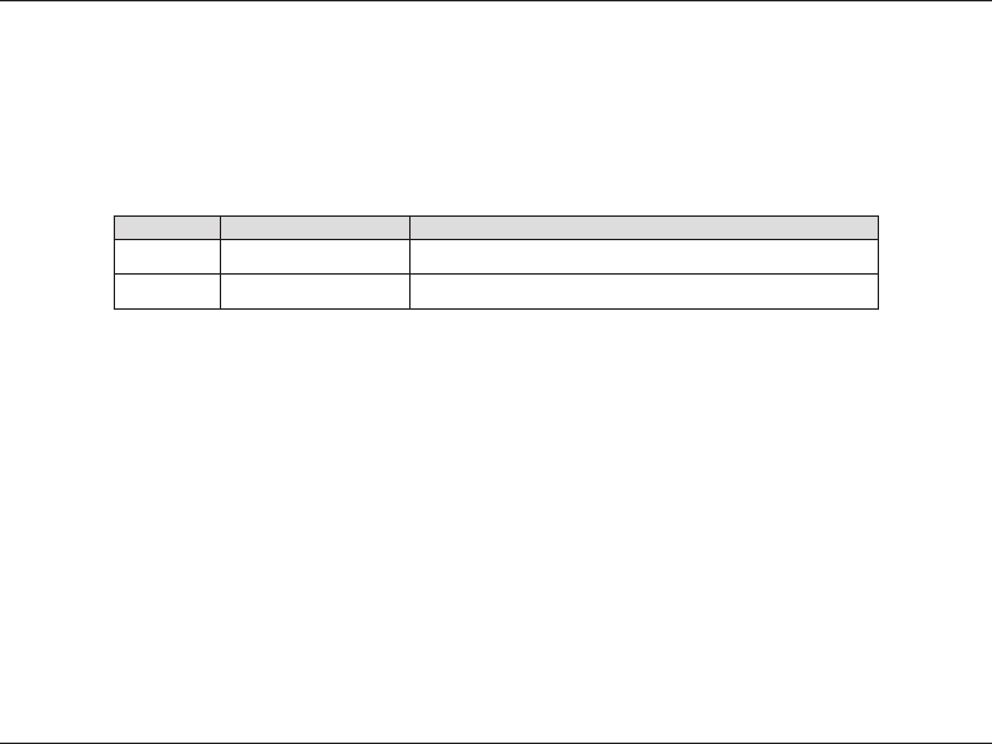
Preface
Revision Date Description
2 June 11, 2015 • Initial release
5.20 September 25, 2017 • HW revision to Rev.H1
D-Link and the D-Link logo are trademarks or registered trademarks of D-Link Corporation or its subsidiaries in the United States or other countries.
All other company or product names mentioned herein are trademarks or registered trademarks of their respective companies.
Internet Explorer®, Windows® and the Windows logo are trademarks of the Microsoft group of companies.
Copyright © 2017 by D-Link Corporation, Inc.
All rights reserved. This publication may not be reproduced, in whole or in part, without prior expressed written permission from D-Link Corporation, Inc.
Trademarks
Manual Revisions

iiD-Link DGS-1016D/DGS-1024D User Manual
Table of Contents
Preface ................................................................................. i
Trademarks ...................................................................................... i
Manual Revisions ........................................................................... i
Package Contents .............................................................. 1
Introduction ...................................................................... 2
D-Link Green Technology .......................................................... 3
Power Saving Technology ......................................................... 3
Features ........................................................................................... 4
Hardware Overview ........................................................... 5
Front Panel ...................................................................................... 5
LED Indicators ................................................................................ 6
Rear Panel ........................................................................................ 7
Safety Instructions ............................................................ 8
Safety Precautions ........................................................................ 8
Electrical Power Guidelines ..................................................... 10
Protecting Against Electrostatic Discharge .......................12
Hardware Installation .....................................................13
Step 1 - Before Connecting to the Network ...................... 13
Step 2 - Switch Installation ...................................................... 14
Desktop or Shelf Installation .........................................14
Attaching the Rubber Feet ..............................................14
Rack Installation .................................................................15
General Precautions for Rack-Mountable Products 17
Step 3 – Installing the Power Cord Retainer .....................19
Step 4 – Grounding the Switch ..............................................23
Step 5 – Plugging in the AC Power Cord ............................24
Power Failure ........................................................................24
Cable Diagnostics ............................................................25
DIP Switches .................................................................... 26
EEE .................................................................................................... 27
Flow Control .................................................................................27
Port Isolation ................................................................................28
Storm Control ..............................................................................28
Technical Specications ..................................................29
Regulatory Information ..................................................32
Table of Contents

1D-Link DGS-1016D/DGS-1024D User Manual
Section 1 - Product Overview
If any of the above items are missing, please contact your reseller.
One D-Link DGS-1016D 16-Port or DGS-1024D 24-Port 10/100/1000BASE-T Gigabit Ethernet Switch
One AC power cord
Four rubber feet
Screws and two mounting brackets
Quick Install Guide
Power cord retainer
Tie wrap
Package Contents

2D-Link DGS-1016D/DGS-1024D User Manual
Section 1 - Product Overview
Introduction
Thank you and congratulations on the purchase of your new D-Link DGS-1016D/DGS-1024D Gigabit Ethernet Switch.
D-Link's next generation DGS-1016D and DGS-1024D switches blend plug-and-play simplicity with exceptional value and
reliability for small and medium-sized business (SMB) networking. All models are housed in a rack-mountable metal case with
easy-to-view front panel diagnostic LEDs. This standalone switch is very easy to set up. No network management is required;
simply power on the switch and connect the cables.
The 16-port DGS-1016D and 24-port DGS-1024D switches provide dedicated 10, 100 or 1000 Mbps Ethernet bandwidth on each
port. The ports will automatically detect the speed, duplex, and MDI/MDIX status of the device it is connecting to and adjust
these settings accordingly. The switch ports can be used to network computers, printers, servers, routers, other switches, or any
device equipped with an Ethernet port. For best performance, use Category 5 or better Ethernet cabling. However, please keep
in mind that standard Ethernet rules state cable lengths cannot exceed 100 meters (or 300 feet) from one device to another.
For more detailed information, please refer to the User’s Manual or visit http://www.dlink.com

3D-Link DGS-1016D/DGS-1024D User Manual
Section 1 - Product Overview
D-Link Green Technology
The brand-new DGS-1016D and DGS-1024D switches are green by design with IEEE 802.3az Energy Ecient Ethernet compliant
(abbreviated as EEE) and D-Link Green Technologies. This allows signicant power saving during periods of low data activity.
In most environments, switches are idle 90% or more of the time. If there has been no network trac over a short period of
time, ports on DGS-1016D/DGS-1024D switch will change to power saving mode automatically. Upon receiving a packet, the
switch wakes up the eected port or ports, returning to normal functionality immediately. By using EEE compliant devices,
such as PCs and servers, the network can save energy without compromising any performance. Even when connecting to
legacy devices which do not support IEEE 802.3az, D-Link Green Technologies can reduce power consumption by changing
the power state of the link.
Power Saving Technology
This switch supports power saving by link status. If there is no link on a port, such as when there is no computer connected to
the port or the connected computer is powered o, D-Link’s Green Technology will enter a "sleep mode", drastically reducing
power used for that port.

4D-Link DGS-1016D/DGS-1024D User Manual
Section 1 - Product Overview
Features
The DGS-1016D and DGS-1024D switches are designed for easy installation, exibility, and high performance. They do not
require any management. Connect devices to the switch as the scale and volume of network trac increases.
• 10/100/1000 Base-T on all ports
• Store and Forward Switching Method
• Cable Diagnostics at boot
• D-Link Green Technology
• Auto MDI/MDIX
• Auto Negotiation of Duplex Mode
• Full/Half Duplex Transfer Mode on 10/100 Mbps
• Full Duplex Transfer Mode on 1000 Mbps
• Wire-Speed reception and transmission
• 8K absolute MAC Address
• 512 KB RAM for data buering
• Easy to read diagnostic LEDs
• IEEE 802.3x Flow Control for Full-duplex mode
• Back Pressure Flow Control for Half-duplex mode
• IEEE 802.1p QoS (support 4 Queues, Strict Mode)
• Jumbo Frame support (10K Bytes)
• IEEE802.3az EEE
5D-Link DGS-1016D/DGS-1024D User Manual
Section 1 - Product Overview
1 3 5 7 9 11 13 15
2 4 6 8 10 1 2 14 1 6
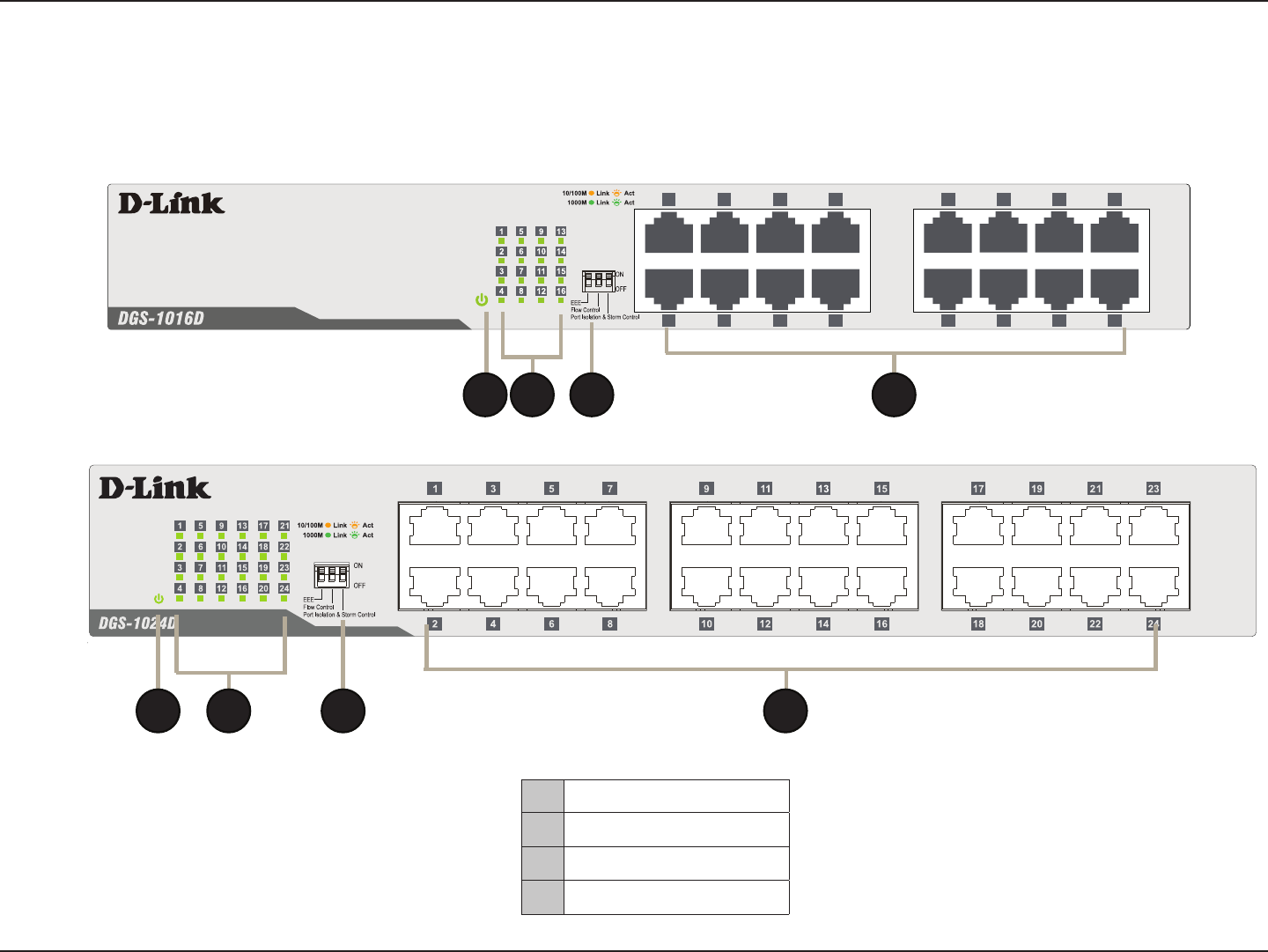
Hardware Overview
Front Panel
1Power
2Link/Act/Speed LED
3DIP Switches
4RJ 45 Ethernet Ports
1
1
2
2
3
3
4
4
6D-Link DGS-1016D/DGS-1024D User Manual
Section 1 - Product Overview
1 3 5 7 9 11 13 15
2 4 6 8 10 12 14 16
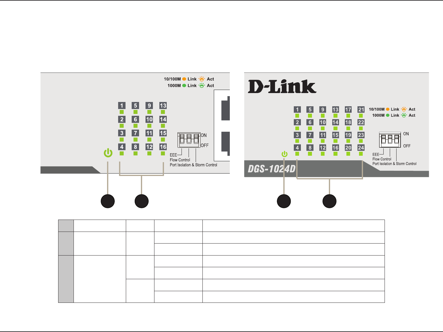
LED Indicators
The LED Indicators allow you to monitor, diagnose, and troubleshoot any potential problem with the switch, connection, or
attached devices.
LED Color State Indication
1Power Green Light on Power on
Light o Power o
2Link/Act/Speed
Green On Connection (or link) at 1000 Mbps
Blinking Reception or Transmission at 1000 Mbps
Amber On Connection (or link) at 10/100 Mbps
Blinking Reception or Transmission at 10/100 Mbps
1 12 2
7D-Link DGS-1016D/DGS-1024D User Manual
Section 1 - Product Overview
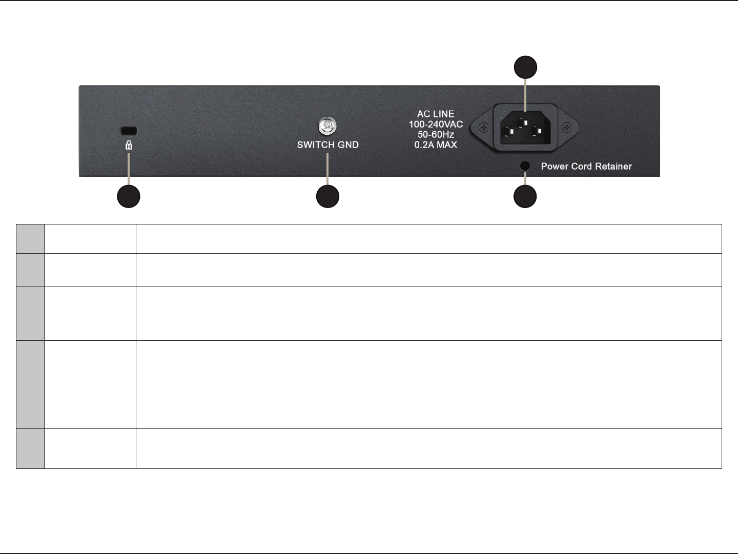
Rear Panel
#Name Function Description
1Kensington
Security Slot The D-Link DGS-1016D/24D may be physically secured via a Kensington Security Lock to help deter theft.
2 Switch Ground
A ground screw hole is provided for grounding the switch. Grounding is optional, but recommended as it
provides an additional layer of protection in the event of an electrical fault. Please refer to Hardware Installation
– Grounding the Switch for more information.
3 Power Input
The switch is equipped with an internal universal power supply. The switch’s power supply will adjust to the local
power source automatically and may be turned on without having any or all LAN segment cables connected. The
AC power connector is a standard three-pronged connector which connects to the power cord. Please refer to
Safety Instructions – Electrical Power Guidelines for more information.
4Power Cord
Retainer
Prevents accidental removal of the AC power cord. Please refer to Hardware Installation – Installing the Power
Cord Retainer for more information.
1 2
3
4

8D-Link DGS-1016D/DGS-1024D User Manual
Section 2 - Safety Instructions
Safety Instructions
Follow these guidelines to ensure personal safety and to help protect the system from potential damage. Throughout this
safety section, the caution icon is used to indicate cautions and precautions that need to be reviewed and followed.
Safety Precautions
To reduce the risk of bodily injury, electrical shock, re, and damage to the equipment, observe the following precautions:
• As with any electronic device, you should place the equipment where it will not be subjected to extreme temperatures,
humidity, or electromagnetic interference.
• Keep the switch away from radiators and heat sources.
• Do not block cooling vents.
• Leave at least 10 cm (4 inches) of space around the switch for adequate ventilation
• Do not place heavy objects on the switch.
• Do not place any device on top of or next to the switch, or place the switch on top of any device or object that will block
the free ow of air through the ventilation slots or that will generate a signicant amount of heat.
• Keep hands away from top and bottom of device since it generates a signicant amount of heat.
• Do not spill food or liquids on the switch, and never operate the product in a wet environment.
• Do not push any objects into the openings of the device. Doing so can cause a re or an electric shock by shorting out
interior components.

9D-Link DGS-1016D/DGS-1024D User Manual
Section 2 - Safety Instructions
• Use the product only with approved equipment.
Observe and follow service markings. Do not service any product except as explained in the system documentation. Opening
or removing covers that are marked with a triangular symbol with a lightning bolt may expose you to an electrical shock. Only
a trained service technician should service components inside these compartments.
If any of the following conditions occur, unplug the product from the electrical outlet and replace the part or contact a trained
service provider:
• The power cable, extension cable, or plug is damaged.
• An object has fallen onto the product.
• The product has been exposed to water.
• The product has been dropped or damaged.
• The product does not operate correctly when following the operating instructions.

10D-Link DGS-1016D/DGS-1024D User Manual
Section 2 - Safety Instructions
Electrical Power Guidelines
• Operate the product only from the type of external power source indicated on the electrical ratings label. If unsure of the
type of power source required, consult a service provider or local power company.
• The purpose of this product is to create a constant network connection for your devices. As such, it does not have a
standby mode or use a power management mode. If you wish to power down this product, please simply unplug it from
the power outlet.
To help avoid damaging the system, be sure the voltage selection switch (if provided) on the power supply is set to match
the local power available. Also be sure that attached devices are electrically rated to operate with the local power available.
• 115 volts (V)/60 hertz (Hz) in most of North and South America and some Asian countries such as South Korea
and Taiwan
• 100 V/50 Hz in eastern Japan and 100 V/60 Hz in western Japan.
• 230 V/50 Hz in most of Europe, the Middle East, and the Far East.
• Use only approved power cable(s).
• If a suitable power cable has not been provided for the system or any AC-powered option intended for the system, purchase
a power cable that is approved for use in the country of use. The power cable must be rated for the product and for the
voltage and current marked on the product's electrical ratings label. The voltage and current rating of the cable should
be greater than the ratings marked on the product.
• To help prevent an electric shock, plug the system and peripheral power cables into properly grounded electrical outlets.
These cables are equipped with three-prong plugs to help ensure proper grounding. Do not use adapter plugs or remove
the grounding prong from a cable. If an extension cable must be used, use a 3-wire cable with properly grounded plugs.
• Observe extension cable and power strip ratings. Make sure that the total ampere rating of all products plugged into the
extension cable or power strip does not exceed 80 percent of the ampere ratings limit for the extension cable or power strip.

11D-Link DGS-1016D/DGS-1024D User Manual
Section 2 - Safety Instructions
• To help protect the system from sudden, transient increases and decreases in electrical power, use a surge suppressor, line
conditioner, or uninterruptible power supply (UPS).
• Position system cables and power cables carefully; route cables so that they cannot be stepped on or tripped over. Be sure
that nothing rests on any cables.
• Do not modify power cables or plugs. Consult a licensed electrician or local power company for site modications. Always
follow local/national wiring rules.
• When connecting or disconnecting power to hot-pluggable power supplies, if oered with the system, observe the
following guidelines:
• Install the power supply before connecting the power cable to the power supply.
• Unplug the power cable before removing the power supply.
• If the system has multiple sources of power, disconnect power from the system by unplugging all power cables
from the power supplies.
• Move products with care; ensure that all casters and/or stabilizers are rmly connected to the system. Avoid
sudden stops and uneven surfaces.

12D-Link DGS-1016D/DGS-1024D User Manual
Section 2 - Safety Instructions
Protecting Against Electrostatic Discharge
Static electricity can harm delicate components inside the system. To prevent static damage, discharge static electricity from
your body before touching any of the electronic components, such as the microprocessor. This can be done by periodically
touching an unpainted metal surface on the chassis.
The following steps can help to prevent damage from electrostatic discharge (ESD):
1. When unpacking a static-sensitive component from its shipping carton, do not remove the component from the antistatic
packing material until ready to install the component in the system. Just before unwrapping the antistatic packaging, be
sure to discharge static electricity from your body.
2. When transporting a sensitive component, rst place it in an antistatic container or packaging.
3. Handle all sensitive components in a static-safe area. If possible, use antistatic oor pads, workbench pads, and an antistatic
grounding strap.

13D-Link DGS-1016D/DGS-1024D User Manual
Section 3 - Hardware Installation
Hardware Installation
This chapter provides unpacking and installation information for the D-Link DGS-1016D/DGS-1024D Gigabit Ethernet Switch.
Step 1 - Before Connecting to the Network
The site where the switch is installed may greatly aect its performance. For the switch to perform safely at its optimal level,
please select a site which meets the following requirements:
1. Install the DGS-1016D / DGS-1024D in a fairly cool and dry place. See Technical Specications page in the manual for the
acceptable operation temperature and humidity ranges.
2. Install the switch in a site free from strong electromagnetic eld generators (such as motors), vibration, dust, and direct
exposure to sunlight.
3. Leave at least 10cm of space around the switch for ventilation.
4. Place the switch within 1.82 meters (6 feet) of a power outlet.
14D-Link DGS-1016D/DGS-1024D User Manual
Section 3 - Hardware Installation
Step 2 - Switch Installation
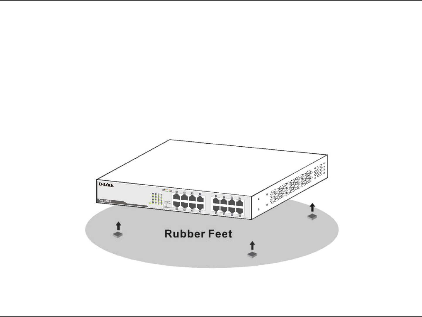
Desktop or Shelf Installation
Select an install site for the switch which is level and can support at least 3 kg (6.6 lbs) of weight.
• Do not place heavy objects on the switch.
• Use the rubber feet provided to cushion the switch, protect the casing from scratches and prevent it from scratching other
surfaces.
Attaching the Rubber Feet
Position and apply the rubber feet to the bottom corners of the DGS-1016D/1024D switch.
Attach the adhesive rubber pads to the bottom
15D-Link DGS-1016D/DGS-1024D User Manual
Section 3 - Hardware Installation
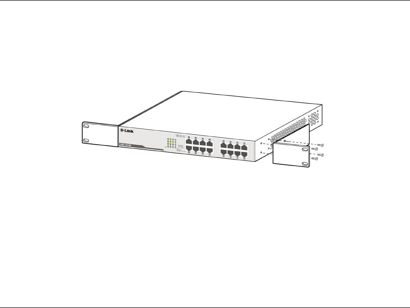
Rack Installation
The DGS-1016D/1024D can easily be mounted in an EIA standard size 19-inch rack which can be placed in a wiring closet with
other equipment. If opting for a rack installation, make sure that the front panel is exposed in order to view the LEDs.
To install, attach the mounting brackets provided for this purpose to the switch’s side panels (one on each side) and secure
them with the screws provided. Please note that these brackets are not designed for palm size switches.
Attach the mounting brackets to the switch
16D-Link DGS-1016D/DGS-1024D User Manual
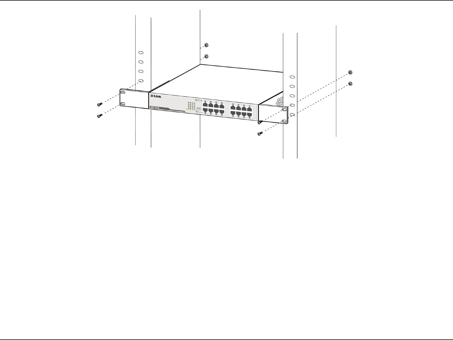
Section 3 - Hardware Installation
Mount the switch in the rack or chassis using the screws provided with the equipment rack.

17D-Link DGS-1016D/DGS-1024D User Manual
Section 3 - Hardware Installation
General Precautions for Rack-Mountable Products
Observe the following precautions for rack stability and safety. Also refer to the rack installation documentation accompanying
the system and the rack for specic caution statements and procedures. Systems are considered to be components in a rack.
Thus, "component" refers to any system as well as to various peripherals or supporting hardware.
CAUTION: Installing systems in a rack without the front and side stabilizers installed could cause the rack to tip over,
potentially resulting in bodily injury under certain circumstances. Therefore, always install the stabilizers before installing
components in the rack.
• After installing system/components in a rack, never pull more than one component out of the rack on its slide assemblies at
a time. The weight of more than one extended component could cause the rack to tip over and may result in serious injury.
• Before working on the rack, make sure that the stabilizers are secured, extended to the oor, and that the full weight of
the rack rests on the oor. Install front and side stabilizers on a single rack or front stabilizers for joined multiple racks
before working on the rack.
• Always load the rack from the bottom up, and load the heaviest item in the rack rst.
• Make sure that the rack is level and stable before extending a component from the rack.
• Use caution when pressing the component rail release latches and sliding a component into or out of a rack; the slide rails
can pinch ngers.
• After a component is inserted into the rack, carefully extend the rail into a locking position, and then slide the component
into the rack.
• Do not overload the AC supply branch circuit that provides power to the rack. The total rack load should not exceed 80
percent of the branch circuit rating.

18D-Link DGS-1016D/DGS-1024D User Manual
Section 3 - Hardware Installation
• Ensure that proper airow is provided to components in the rack.
• Do not step on or stand on any component when servicing other components in a rack.
CAUTION: Never defeat the ground conductor or operate the equipment in the absence of a suitably installed ground
conductor. Contact the appropriate electrical inspection authority or an electrician if uncertain that suitable grounding
is available.
CAUTION: The system chassis must be positively grounded to the rack cabinet frame. Do not attempt to connect power
to the system until grounding cables are connected. Completed power and safety ground wiring must be inspected
by a qualied electrical inspector. An energy hazard will exist if the safety ground cable is omitted or disconnected.
Please be aware of following safety instructions when installing rack-mountable products:
A. Elevated Operating Ambient Temperature - If installed in a closed or multi-unit rack assembly, the operating ambient
temperature of the rack environment may be greater than room temperature. Therefore, consideration should be given to
installing the equipment in an environment compatible with the maximum ambient temperature (Tma) specied by the
manufacturer.
B. Reduced Air Flow - Installation of the equipment in a rack should be such that the amount of air ow required for safe
operation of the equipment is not compromised.
C. Mechanical Loading - Mounting of the equipment in the rack should be such that a hazardous condition is not achieved
due to uneven mechanical loading.
D. Circuit Overloading - Consideration should be given to the connection of the equipment to the supply circuit and the eect
that overloading of the circuits might have on overcurrent protection and supply wiring. Appropriate consideration of
equipment nameplate ratings should be used when addressing this concern.
E. Reliable Grounding - Reliable grounding of rack-mounted equipment should be maintained. Particular attention should be
given to supply connections other than direct connections to the branch circuit (e.g. use of power strips).
19D-Link DGS-1016D/DGS-1024D User Manual
Section 3 - Hardware Installation
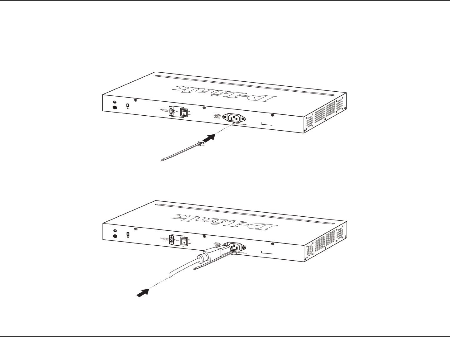
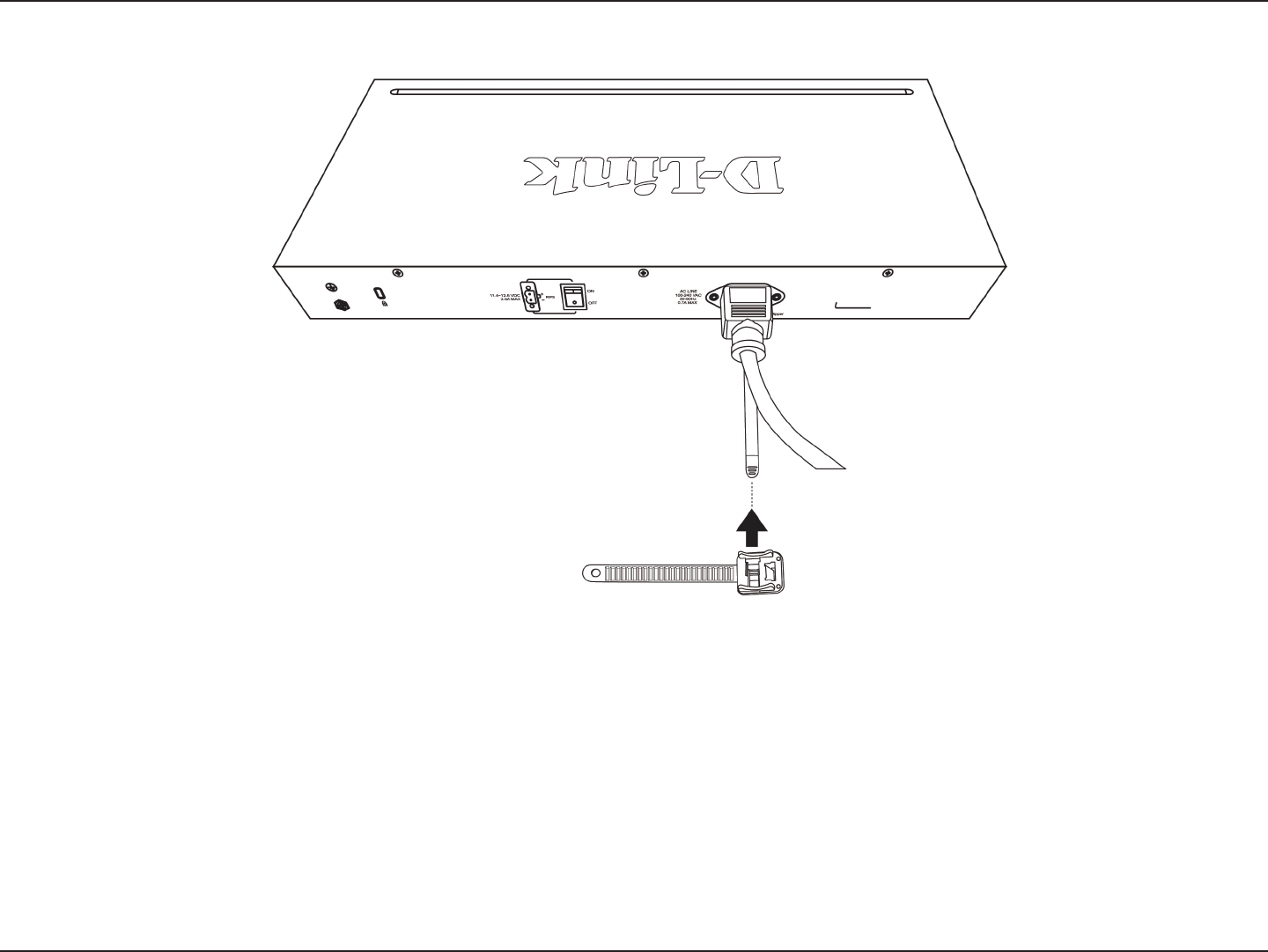
Step 3 – Installing the Power Cord Retainer
Installation of the power cord retainer is recommended to prevent accidental removal of the AC power cord.
A. Insert a tie wrap with the rough side facing down into the hole below the power socket.
Insert tie wrap
B. Connect the AC power cord into the AC power inlet of the switch.
Connect the power cord to the switch
20D-Link DGS-1016D/DGS-1024D User Manual
Section 3 - Hardware Installation
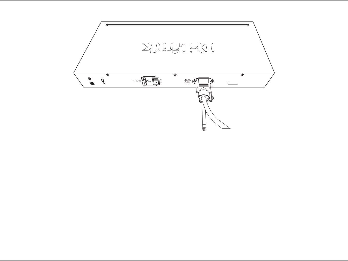
C. Attach the retainer to the tie wrap and slide it up to the end of the cord.
Attach the retainer to the tie wrap
21D-Link DGS-1016D/DGS-1024D User Manual
Section 3 - Hardware Installation
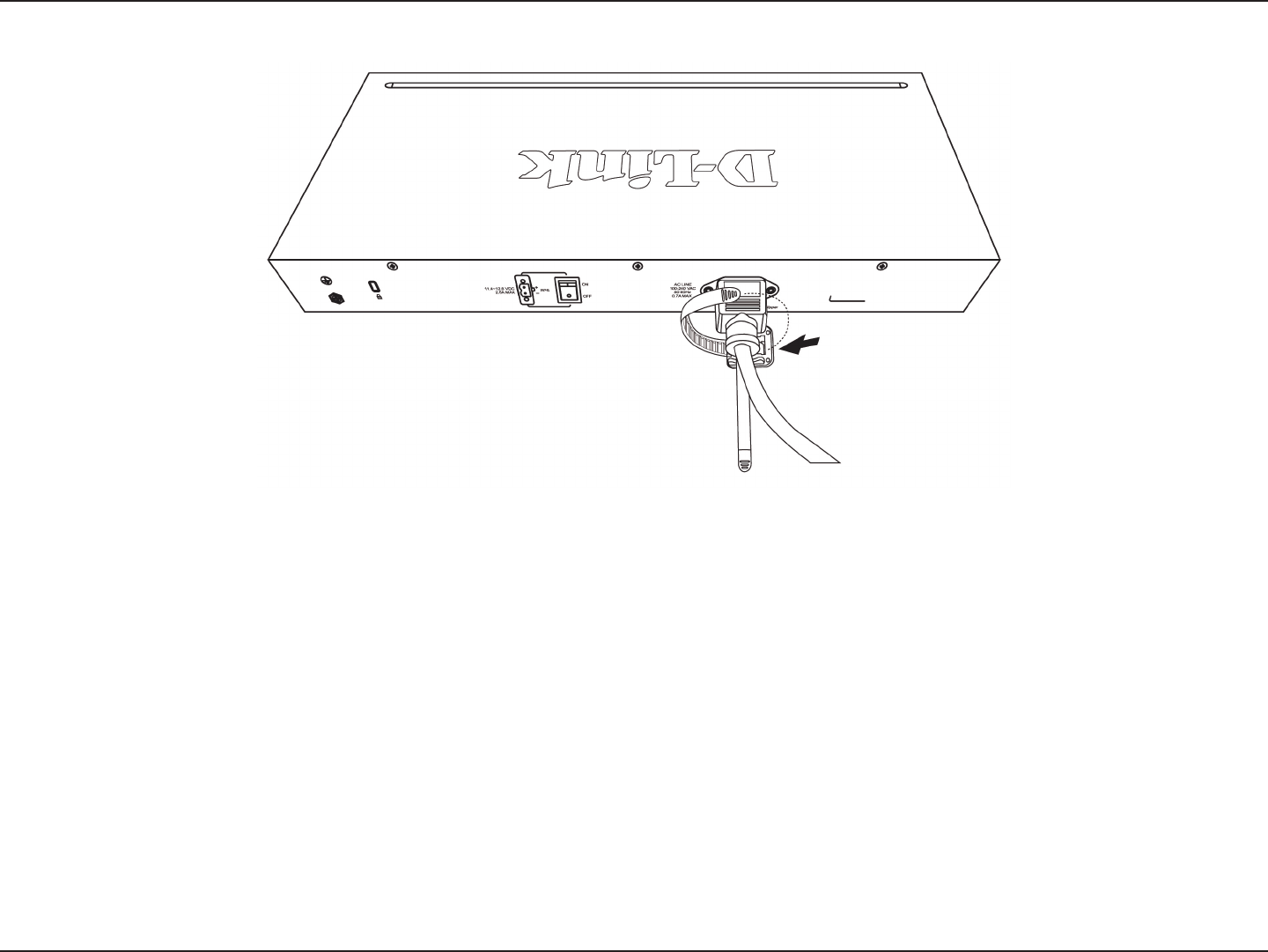
D. Wrap the retainer around the power cord and insert the free end into the fastener.
Wrap the retainer around the power cord
22D-Link DGS-1016D/DGS-1024D User Manual
Section 3 - Hardware Installation
E. Fasten the retainer by pulling on it until secure.
Secure the power cord
23D-Link DGS-1016D/DGS-1024D User Manual
Section 3 - Hardware Installation
Step 4 – Grounding the Switch
This section describes how to connect the DGS-1016D/DGS-1024D Switch to ground. Completion of this step is strongly advised
for added protection from over voltage and over current from lightning strikes.
Required Tools and Equipment
• Ground screws (included in the accessory kit): One M4 x 6 mm (metric) pan-head screw
• Ground cable (not included in the accessory kit): The grounding cable should be sized according to local and national
installation requirements. Depending on the power supply and system, a 12 to 6 AWG copper conductor is required for
U.S installation. Commercially available 6 AWG wire is recommended. The length of the cable depends on the proximity
of the switch to proper grounding facilities. A #8 terminal lug ring should be fastened to the grounding wire.
• A screwdriver (not included in the accessory kit)
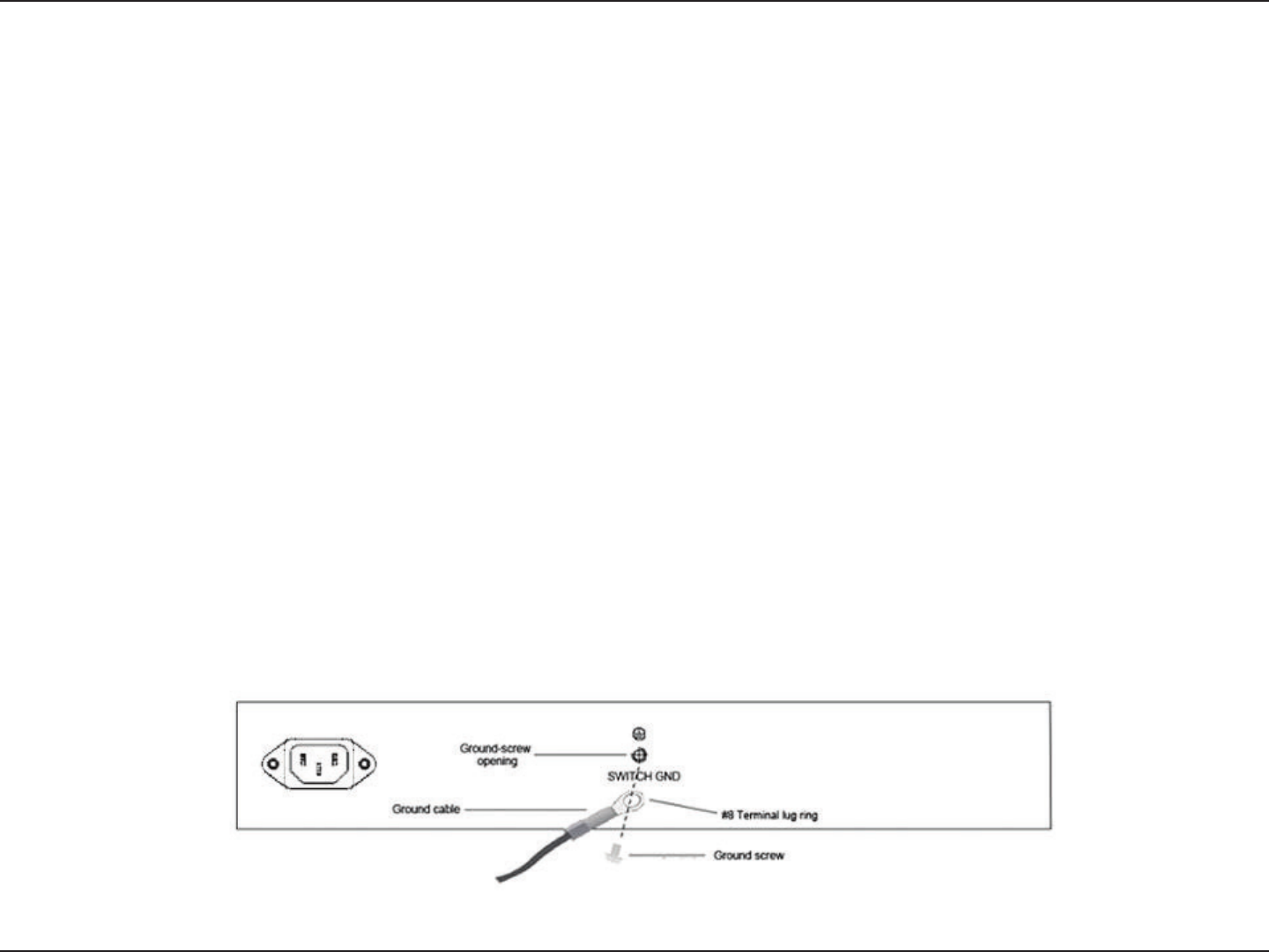
Use the following steps to connect the switch to a protective ground:
1. Verify system is powered o.
2. Use the ground cable to place the #8 terminal lug ring on top of the ground-screw opening, as seen in the illustration below.
3. Insert the ground screw into the ground-screw opening.
4. Using a screwdriver, tighten the ground screw to secure the ground cable to the switch.
5. Attach the terminal lug ring at the other end of the grounding cable to an appropriate grounding stud or bolt on rack where
the switch is installed.
6. Verify that the connections to the ground connector on the switch and to the rack are securely attached.
Ground cable, screw and #8 terminal lug rings
24D-Link DGS-1016D/DGS-1024D User Manual
Section 3 - Hardware Installation
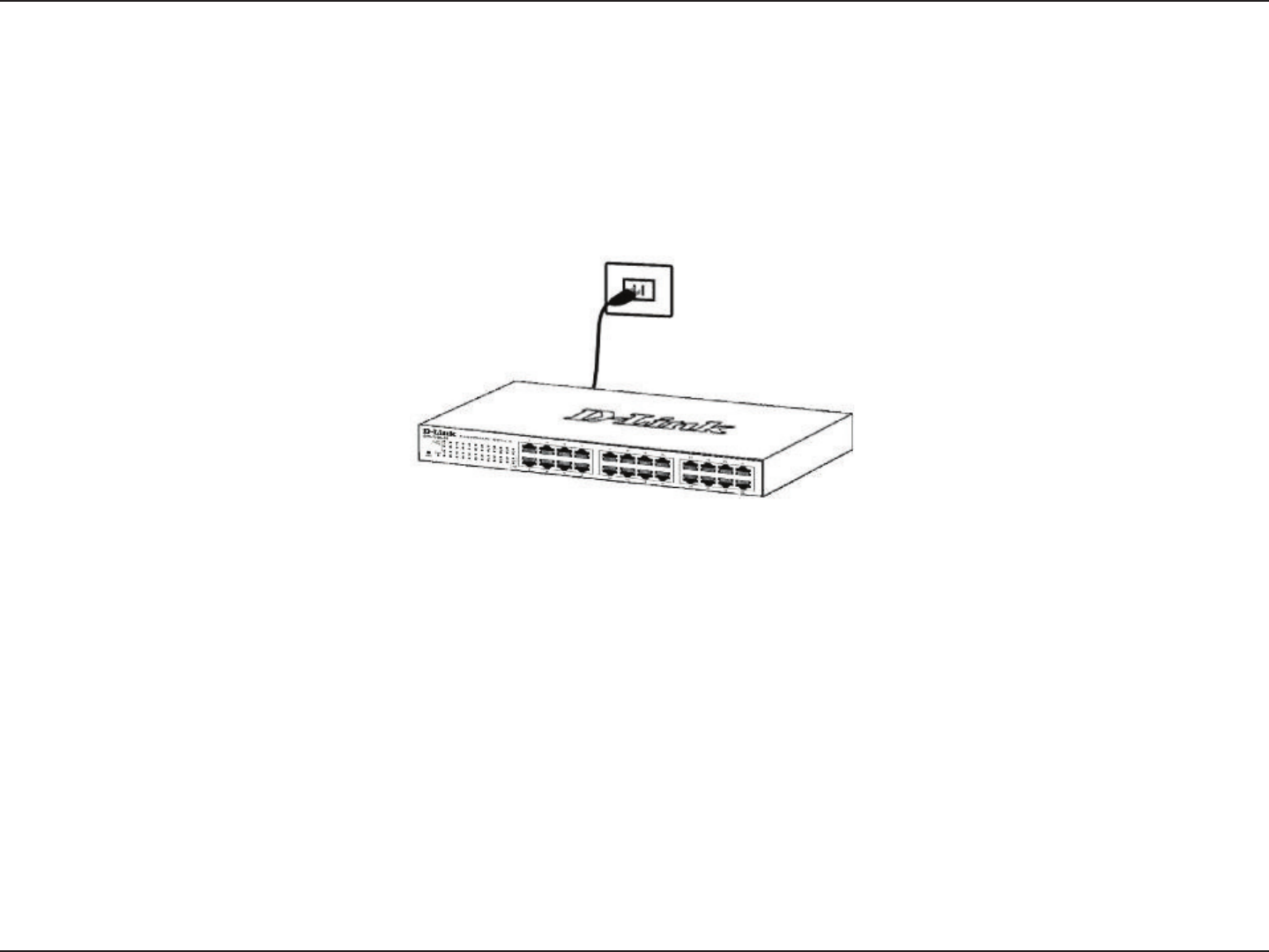
Step 5 – Plugging in the AC Power Cord
To power on the switch, plug in device end of the provided AC power cord into the AC inlet on the back of the switch, and the
male end of the cord into a suitable power source (preferably one that is grounded and surge protected). The switch’s power
supply will adjust to the local power source automatically and may be turned on without having any or all LAN segment cables
connected.
After the switch is powered on, the LED indicators will blink briey while the system resets.
Power Failure
As a precaution, unplug the switch in the event of a power failure. Plug the switch back in when power is resumed.

25D-Link DGS-1016D/DGS-1024D User Manual
Section 4 - Cable Diagnostics
Cable Diagnostics
The Cable Diagnostics function helps network administrators to diagnose network connectivity issues. This function is initialized
when the switch is rst powered on. Each port is scanned to determine if the Ethernet cable and connectors are in good working
order. This diagnostic test looks for two types of common faults in Ethernet cable: an open circuit or a short circuit. An open
circuit is usually caused by a lack of continuity between the pins at each end of the Ethernet cable or a disconnected cable,
while a short circuit occurs when two or more conductors have an unintended connection. Either of these common cable
faults will be detected by the Cable Diagnostics function.
During the diagnostics the LED for each port blinks green in sequential order. If a cable fault is detected, the corresponding
port’s Link/Act/Speed LED will light amber. Once the cable diagnostic function has completed, the switch then proceeds with
normal operation.
NOTE: the Cable Diagnostics function does not detect the length of Ethernet cabling. Remember that the length of
cabling between two Ethernet devices may not exceed 100 meters (or 300 feet).
Link/Act/Speed LED Color Status
Green No Fault/Good Cable Connection
Amber Open or Short Circuit
26D-Link DGS-1016D/DGS-1024D User Manual
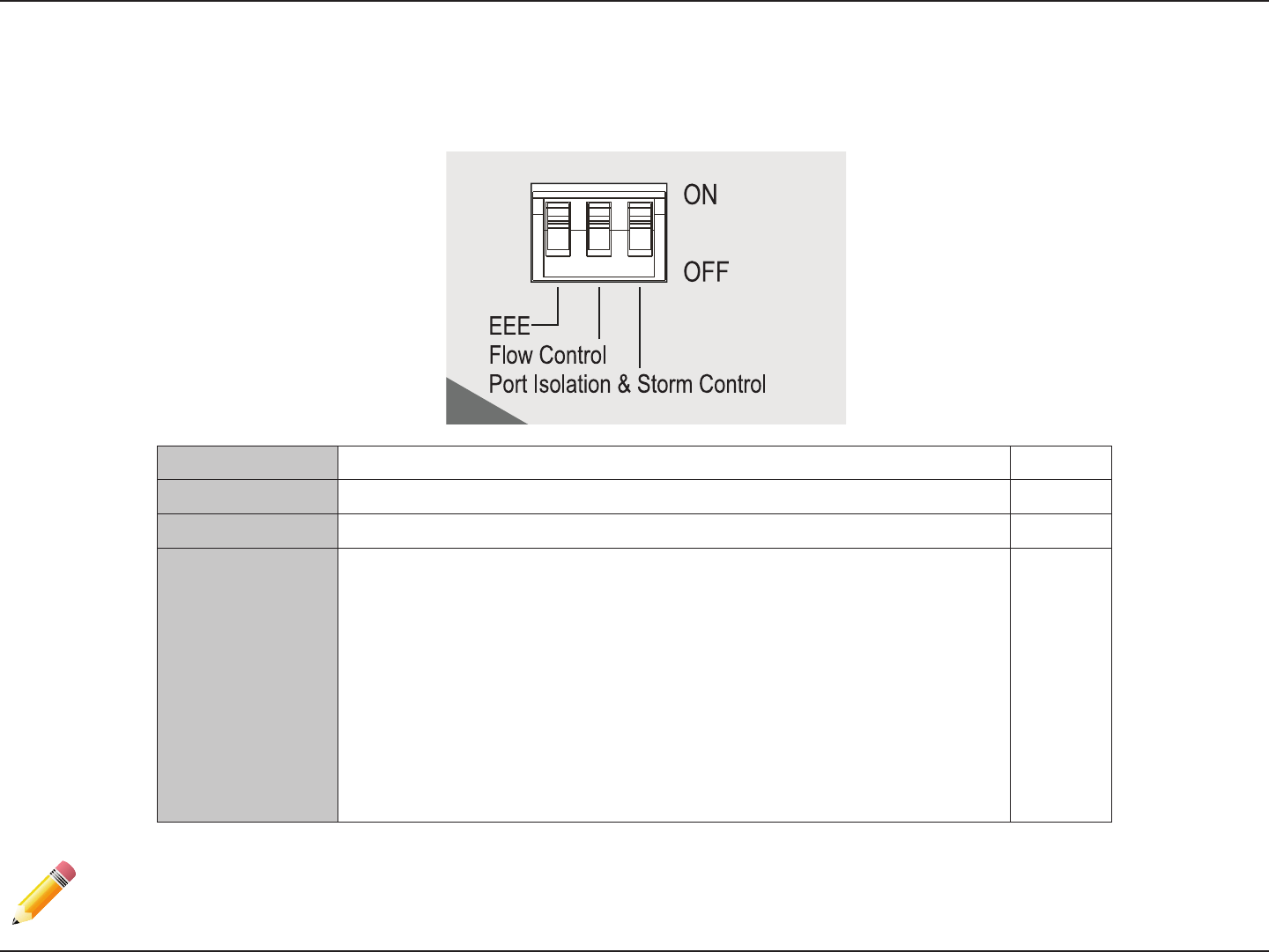
Section 5 - DIP Switches
DIP Switch Function Description Default
EEE Enable/Disable Energy-Ecient Ethernet (EEE) Feature O
Flow Control Enable/Disable Flow Control Feature On
Port Isolation
and Storm
Control
When enabled a broadcast storm control threshold value of 128kbps will be
applied to incoming broadcast packets on all ports.
Port Isolation:
DGS-1016D - When enabled, ports 1 to 15 will be isolated from each other,
but will still be able to communicate with port 16. Port 16 will be able to
communicate with all the ports available on this switch.
DGS-1024D - When enabled, ports 1 to 23 will be isolated from each other,
but will still be able to communicate with port 24. Port 24 will be able to
communicate with all the ports available on this switch.
O
DIP Switches
The DIP Switches on the front panel allow easy conguration of the advanced features of the DGS-1016D and DGS-1024D.
Note: The switch must be power cycled after changing DIP Switch settings for new settings to take eect.

27D-Link DGS-1016D/DGS-1024D User Manual
Section 5 - DIP Switches
EEE
IEEE 802.3az Energy-Ecient Ethernet (EEE) is the rst standard in the history of Ethernet to address proactive reduction in
energy consumption for networked devices. The IEEE 802.3 EEE standard denes mechanisms and protocols intended to reduce
the energy consumption of network links during periods of low utilization, by transitioning interfaces into a low-power state
without interrupting the network connection.
Flow Control
As the demand on network resources grow, due to higher and higher amounts of data being generated from applications and
users, individual network links may be pushed to their limit. This is especially the case where multiple network links aggregate
to generate many times more data than any single link can handle. In this scenario, switch packet buer memory will quickly
be depleted and overall network performance will decrease due to continued data retransmission of dropped packets. In the
event that a bottleneck exists, such as multiple users trying to transfer data to a network server at the same time, enabling
the ow control feature of this switch may help to alleviate network congestion at the expense of total network throughput.
The ow control feature of this switch works by sending Ethernet "PAUSE" frames dened by the IEEE 802.x standard to multicast
address 01-80-C2-00-00-01. Upon reception of this frame, the sender will hault transmission for a specicied period of time.
An assessment of currently employed networking technologies should be made before enabling ow control.
Note: The switch must be power cycled after changing DIP switch settings for new settings to take eect.

28D-Link DGS-1016D/DGS-1024D User Manual
Section 5 - DIP Switches
Port Isolation
Port Isolation, also known as Private VLAN, is a feature of this switch which restricts switch ports to communicating with
only a single uplink port. When enabled, all private port trac will be forwarded to the uplink port, regardless of VLAN ID or
destination MAC address and prevented from communicating with all other ports. However, the uplink port will still be able to
communicate with all switch ports. This may desired for network environments where Internet connections shared between
dierent apartments or hotel rooms where network segmentation for privacy and security is desired.
Storm Control
A broadcast storm occurs when a message is exponentially retransmitted creating excessive broadcast trac which consume
network resources as to render it unable to transport normal trac. When this switch's broadcast storm control feature is
enabled, incoming broadcast frames are monitored and prevented from being forwarded if exceeding a 128 kbps value.
While this does not resolve broadcast radiation problems, it will help a network administrator to diagnose and resolve the
root cause of the broadcast storm.
Note: The switch must be power cycled after changing DIP switch settings for new settings to take eect.

29D-Link DGS-1016D/DGS-1024D User Manual
Appendix A - Technical Specications
Technical Specications
DGS-1016D DGS-1024D
General
Number of Ports
16 10/100/1000 Gigabit ports
24 10/100/1000 Gigabit ports
Standards
IEEE 802.3 10BASE-T
IEEE 802.3u
IEEE 802.3ab
IEEE 802.1p QoS
IEEE 802.3x Flow Control supported for Full Duplex, Auto-Negotiation
IEEE 802.3az Energy Eciency Ethernet
Data Transfer Rate
Ethernet: 10 Mbps/20 Mbps (Half-duplex/Full-duplex)
Fast Ethernet: 100 Mbps/200 Mbps (Half-duplex/Full-duplex)
Gigabit Ethernet: 2000 Mbps (Full-duplex)
Network Cables
Ethernet: 2-pair UTP Cat.3/4/5/5e, Unshield Twisted Pair (UTP )Cable
Fast Ethernet: 2-pair UTP Cat.5/5e, Unshield Twisted Pair (UTP )Cable
Gigabit Ethernet: 4-pair UTP Cat.5/ 5e, Unshield Twisted Pair (UTP )Cable
Functionality
D-Link Green Technologies
Power saving by link status
Security
Storm Control
QoS (Quality of Service)
802.1p priority,
4 queues
VLAN
Port Based VLAN
L2 Features
Cable Diagnostics
Switching
Features
Protocol
CSMA/CD
Packet Buer RAM
512 KBytes per device/Kbits per device
Filtering Address Table
8K MAC address per device
Packet Filtering/Forwarding Rate
Full wire speed
MAC Address Learning
Self-learning, auto-aging
Forwarding Mode
Store-and-forward
Topology
Star

30D-Link DGS-1016D/DGS-1024D User Manual
Appendix A - Technical Specications
DGS-1016D DGS-1024D
Performance
Switching Capacity
32 Gbps
48 Gbps
Max. Forwarding Rate
23.8 Mpps
35.71 Mpps
Port Packet Filtering
10M: 14,880 pps
100M: 148,800 pps
1000M: 1,488,000 pps
Physical
LEDs
Power LED
16 Link/Activity/Speed LEDs (one per port)
24 Link/Activity/Speed LEDs (one per port)
DIP Switches
Energy-Ecient Ethernet (EEE)
Flow Control
Port Isolation and Storm Control
AC Input
Internal universal power supply
Power Consumption (Maximum)
10.07 watts
13.3 watts
Power Consumption (Standby)
3.02 watts
4.4 watts
Heat Dissipation (Maximum)
34.3 BTU/hr
45.35 BTU/hr
MTBF
1,882,372 Hours
863,100 hours
Acoustic Value
0dB(A) Fanless
Temperature (Operating)
0 ºC ~ 40 ºC (32ºF ~ 104ºF)
Temperature (Storage)
-10ºC ~ 70ºC (14ºF ~ 158ºF)
Humidity (Operating)
5% ~ 90% RH, non-condensing
Humidity (Storage)
5% ~ 95% RH
Dimensions
280 x 125 x 44 mm (11.02 x 4.92 x 1.73 inches)
280 x 180 x 44 mm (11.02 x 7.09 x 1.73 inches)
Weight
1.023 kg ( 2.26 pounds)
1.3 kg ( 2.87 pounds)

31D-Link DGS-1016D/DGS-1024D User Manual
Appendix A - Technical Specications
Certications
Emission Certications (EMI)
FCC Class A
ICES-003 Class A
CE Class A
VCCI Class A
C-Tick Class A
CCC
BSMI
KCC
Safety
cUL/UL
CB
CCC
BSMI
CE(LVD)

32D-Link DGS-1016D/DGS-1024D User Manual
Regulatory Information
Caution: Do not remove the plug and connect it to a power outlet by itself; always attach
the plug to the power adaptor rst before connecting it to a power outlet.
Federal Communication Commission Interference Statement:
This equipment has been tested and found to comply with the limits for a Class A digital device, pursuant to part
15 of the FCC Rules. These limits are designed to provide reasonable protection against harmful interference
when the equipment is operated in a commercial environment. This equipment generates, uses, and can radiate
radio frequency energy and, if not installed and used in accordance with the instruction manual, may cause
harmful interference to radio communications. Operation of this equipment in a residential area is likely to cause
harmful interference in which case the user will be required to correct the interference at his own expense.
Non-modications Statement:
Any changes or modications not expressly approved by the party responsible for
compliance could void the user's authority to operate the equipment
Caution:
This device complies with Part 15 of the FCC Rules. Operation is subject to the following two
conditions: (1) This device may not cause harmful interference, and (2) this device must accept
any interference received, including interference that may cause undesired operation.
Industry Canada statement:
This Class A digital apparatus complies with Canadian ICES-003.
Cet appareil numérique de la classe A est conforme à la norme NMB-003 du Canada."
Regulatory Information

33D-Link DGS-1016D/DGS-1024D User Manual
Regulatory Information
" この装置は、クラス A 情報技術装置です。 この装置を家庭環境で使用すると電波妨害を引き起こすことがあり
ます。 この場合には使用者が適切な対策を講ずるよう要求されることがあります。 VCCI-A
Japan Voluntary Control Council for Interference Statement
This is a Class A product based on the standard of the Voluntary Control Council for
Interference (VCCI). If this equipment is used in a domestic environment, radio interference
may occur, in which case the user may be required to take corrective actions."
Korea
"이 기기는 업무용(A급) 전자파적합기기로서 판 매자 또는 사용자는 이 점을 주의하시기 바라 며, 가정외의
지역에서 사용하는 것을 목적으로 합니다.
This equipment is Industrial (Class A) electromagnetic wave suitability equipment and seller or user
should take notice of it, and this equipment is to be used in the places except for home. "
"警告使用者:
此為甲的資訊技術設備,在居住環境中使用時,可能會造成射頻擾動,在這種情況下,使用者會被要求採取某些適當的對策。"
CE EMI Class A Warning:
This is a Class A product. In a domestic environment, this product may cause radio
interference, in which case the user may be required to take adequate measures.
