1514976612DSR SERIES MANUAL 3.04 EN WW
User Manual: DLINK DSR-500 pdf | FreeUserManuals.com
Open the PDF directly: View PDF ![]() .
.
Page Count: 337 [warning: Documents this large are best viewed by clicking the View PDF Link!]
- Preface
- Introduction
- Installation
- Basic Configuration
- LAN Configuration
- Connect to the Internet
- Wireless Settings
- VPN
- Security
- Maintenance
- Status and Statistics
- Troubleshooting
- Appendix A - Glossary
- Appendix B - Factory Default Settings
- Appendix C - Standard Services for Port Forwarding & Firewall Configuration
- Appendix D - Log Output Reference
- Appendix E - RJ-45 Pin-outs
- Appendix F - New Wi Fi Frequency table ( New appendix section )
- Appendix G - Product Statement

Wireless Services Router
User Manual
DSR-150/150N/250/250N/500/1000/500AC/1000AC
Version 3.04 | May 26, 2016

D-Link DSR-Series User Manual i
The information in this document is subject to change without notice. The manufacturer makes no representations
or warranties with respect to the contents hereof and specically disclaim any implied warranties of merchantability
or tness for any particular purpose. The manufacturer reserves the right to revise this publication and to make
changes from time to time in the content hereof without obligation of the manufacturer to notify any person of
such revision or changes.
Manual Revisions
Revision Date Description
2.00 July 31, 2014 • DSR Products with rmware version 2.00
2.01 November 17, 2014 • Added License Update section
2.02 January 28, 2015 • DSR Products with rmware version 2.02
3.02 May 06, 2015 • Added new DSR series models DSR-500AC and DSR-1000AC
3.04 May 26, 2016 • Updated regulatory statements, removed DSR-500N and
DSR-1000N
Trademarks/Copyright Notice
D-Link and the D-Link logo are trademarks or registered trademarks of D-Link Corporation or its subsidiaries in
the United States or other countries. All other company or product names mentioned herein are trademarks or
registered trademarks of their respective companies.
© 2016 D-Link Corporation, All Rights Reserved
This publication, including all photographs, illustrations and software, is protected under international copyright
laws, with all rights reserved. Neither this manual, nor any of the material contained herein, may be reproduced
without written consent of the author.
Limitations of Liability
UNDER NO CIRCUMSTANCES SHALL D-LINK OR ITS SUPPLIERS BE LIABLE FOR DAMAGES OF ANY CHARACTER
(E.G. DAMAGES FOR LOSS OF PROFIT, SOFTWARE RESTORATION, WORK STOPPAGE, LOSS OF SAVED DATA OR
ANY OTHER COMMERCIAL DAMAGES OR LOSSES) RESULTING FROM THE APPLICATION OR IMPROPER USE OF
THE D-LINK PRODUCT OR FAILURE OF THE PRODUCT, EVEN IF D-LINK IS INFORMED OF THE POSSIBILITY OF SUCH
DAMAGES. FURTHERMORE, DLINK WILL NOT BE LIABLE FOR THIRD-PARTY CLAIMS AGAINST CUSTOMER FOR
LOSSES OR DAMAGES. D-LINK WILL IN NO EVENT BE LIABLE FOR ANY DAMAGES IN EXCESS OF THE AMOUNT
D-LINK RECEIVED FROM THE END-USER FOR THE PRODUCT.
Preface
Preface

D-Link DSR-Series User Manual ii
Use the following safety guidelines to ensure your own personal safety and to help protect your system from
potential damage.
Safety Cautions
To reduce the risk of bodily injury, electrical shock, re, and damage to the equipment, observe the following
precautions:
• Observe and follow service markings.
• Do not service any product except as explained in your system documentation.
• Opening or removing covers that are marked with the triangular symbol with a lightning bolt
may expose you to electrical shock.
• Only a trained service technician should service components inside these compartments.
• If any of the following conditions occur, unplug the product from the electrical outlet and replace the
part or contact your trained service provider:
• The power cable, extension cable, or plug is damaged.
• An object has fallen into the product.
• The product has been exposed to water.
• The product has been dropped or damaged.
• The product does not operate correctly when you follow the operating instructions.
• Keep your system away from radiators and heat sources. Also, do not block cooling vents.
• Do not spill food or liquids on your system components, and never operate the product in a wet
environment. If the system gets wet, see the appropriate section in your troubleshooting guide or
contact your trained service provider.
• Do not push any objects into the openings of your system. Doing so can cause re or electric shock by
shorting out interior components.
• Use the product only with approved equipment.
• Allow the product to cool before removing covers or touching internal components.
• Operate the product only from the type of external power source indicated on the electrical ratings
label. If you are not sure of the type of power source required, consult your service provider or local
power company.
• Also, be sure that attached devices are electrically rated to operate with the power available in your
location.
• Use only approved power cable(s). If you have not been provided with a power cable for your system or
for any AC powered option intended for your system, purchase a power cable that is approved for use
in your country. The power cable must be rated for the product and for the voltage and current marked
on the product’s electrical ratings label. The voltage and current rating of the cable should be greater
than the ratings marked on the product.
• To help prevent electric shock, plug the system and peripheral power cables into properly grounded
electrical outlets.
Safety Instructions
Preface

D-Link DSR-Series User Manual iii
• These cables are equipped with three-prong plugs to help ensure proper grounding. Do not use
adapter plugs or remove the grounding prong from a cable. If you must use an extension cable, use a
3-wire cable with properly grounded plugs.
• Observe extension cable and power strip ratings. Make sure that the total ampere rating of all products
plugged into the extension cable or power strip does not exceed 80 percent of the ampere ratings limit
for the extension cable or power strip.
• To help protect your system from sudden, transient increases and decreases in electrical power, use a
surge suppressor, line conditioner, or uninterruptible power supply (UPS).
• Position system cables and power cables carefully; route cables so that they cannot be stepped on or
tripped over. Be sure that nothing rests on any cables.
• Do not modify power cables or plugs. Consult a licensed electrician or your power company for site
modications.
• Always follow your local/national wiring rules.
• When connecting or disconnecting power to hot-pluggable power supplies, if oered with your system,
observe the following guidelines:
• Install the power supply before connecting the power cable to the power supply.
• Unplug the power cable before removing the power supply.
• If the system has multiple sources of power, disconnect power from the system by unplugging all
power cables from the power supplies.
• Move products with care; ensure that all casters and/or stabilizers are rmly connected to the system.
Avoid sudden stops and uneven surfaces.
Preface

D-Link DSR-Series User Manual iv
Static electricity can harm delicate components inside your system. To prevent static damage, discharge static
electricity from your body before you touch any of the electronic components, such as the microprocessor. You can
do so by periodically touching an unpainted metal surface on the chassis.
You can also take the following steps to prevent damage from electrostatic discharge (ESD):
1. When unpacking a static-sensitive component from its shipping carton, do not remove the
component from the antistatic packing material until you are ready to install the component
in your system. Just before unwrapping the antistatic packaging, be sure to discharge static
electricity from your body.
2. When transporting a sensitive component, rst place it in an antistatic container or package.
3. Handle all sensitive components in a static-safe area. If possible, use antistatic oor pads,
workbench pads and an antistatic grounding strap.
Protecting Against Electrostatic Discharge
Preface
Power Usage
All Models
This device is an Energy Related Product (ErP) with High Network Availability (HiNA), and automatically switches
to a power-saving Network Standby mode within 1 minute of no packets being transmitted. It can also be
turned o through a power switch to save energy when it is not needed.
DSR-500
Network Standby: 6.93 watts
Switched O: 0.08 watts
DSR-1000
Network Standby: 7.12 watts
Switched O: 0.07 watts
DSR-500AC
Network Standby: 6.68 watts
Switched O: 0.07 watts
DSR-1000AC
Network Standby: 7.96 watts
Switched O: 0.07 watts
DSR-150
Network Standby: 6.91 watts
Switched O: 0.13 watts
DSR-150N
Network Standby: 7.86 watts
Switched O: 0.13 watts
DSR-250
Network Standby: 7.86 watts
Switched O: 0.13 watts
DSR-250N
Network Standby: 6.23 watts
Switched O: 0.13 watts
DSR-500/DSR-1000/DSR-500AC/DSR-1000AC
EU Battery & WEEE Directives Disposal and Recycling
This product may contain a battery. Recycle or dispose of batteries in accordance with the battery
manufacturer’s instructions and local/national disposal and recycling regulations. For more information,
please refer to the warranty guide.

D-Link DSR-Series User Manual vi
Table of Contents
Preface ........................................................................................................................................................... i
Manual Revisions ........................................................................................................................................................................i
Trademarks/Copyright Notice ...............................................................................................................................................i
Limitations of Liability ..............................................................................................................................................................i
Safety Instructions ....................................................................................................................................................................ii
Safety Cautions .................................................................................................................................................................ii
Protecting Against Electrostatic Discharge .......................................................................................................... iv
Power Usage ...............................................................................................................................................................................v
Introduction ................................................................................................................................................. 1
Installation ................................................................................................................................................... 3
Before you Begin ...................................................................................................................................................................... 3
Connect to your Network ...................................................................................................................................................... 3
Basic Conguration ..................................................................................................................................... 4
#1 Log in to the Web UI .......................................................................................................................................................... 5
#2 Change LAN IP Address .................................................................................................................................................... 6
#3 Congure DHCP Server .................................................................................................................................................... 7
#4 Set Time and Date .............................................................................................................................................................. 8
#5 Internet Connection Setup ............................................................................................................................................. 9
#6 Wireless Network Setup ................................................................................................................................................. 12
#7 Create Users........................................................................................................................................................................13
#8 Security/VPN Wizard .......................................................................................................................................................14
#9 Dynamic DNS Wizard ......................................................................................................................................................16
LAN Conguration ..................................................................................................................................... 17
LAN Settings.............................................................................................................................................................................18
DHCP Server ....................................................................................................................................................................19
DHCP Relay ......................................................................................................................................................................20
DHCP Reserved IPs .......................................................................................................................................................21
IGMP Setup ...............................................................................................................................................................................22
UPnP Setup ...............................................................................................................................................................................23
Jumbo Frames ......................................................................................................................................................................... 24
VLAN ...........................................................................................................................................................................................25
VLAN Settings .................................................................................................................................................................25
Captive Portal ..........................................................................................................................................................27
Port/Wireless VLAN .......................................................................................................................................................28
Connect to the Internet ............................................................................................................................. 30
Dynamic IP .......................................................................................................................................................................30
Table of Contents

D-Link DSR-Series User Manual vii
Static IP .............................................................................................................................................................................31
PPPoE .................................................................................................................................................................................32
PPTP ...................................................................................................................................................................................33
L2TP ....................................................................................................................................................................................34
Japanese PPPoE ............................................................................................................................................................. 35
Russian PPPoE ................................................................................................................................................................36
Russian PPTP ................................................................................................................................................................... 37
Russian L2TP ...................................................................................................................................................................38
WAN2 Settings.........................................................................................................................................................................39
WAN ...................................................................................................................................................................................39
DMZ....................................................................................................................................................................................40
WAN3 (3G Internet) ...............................................................................................................................................................41
WAN Mode ................................................................................................................................................................................42
Single WAN Port .............................................................................................................................................................42
Auto-Rollover using WAN IP ......................................................................................................................................43
Load Balancing ...............................................................................................................................................................44
Round Robin ............................................................................................................................................................45
Spillover ..................................................................................................................................................................... 46
Routing Mode.................................................................................................................................................................47
NAT or Classical .......................................................................................................................................................47
Transparent ..............................................................................................................................................................48
Bridge .........................................................................................................................................................................49
IP Aliasing .........................................................................................................................................................................50
DMZ Settings .................................................................................................................................................................. 51
DMZ LAN DHCP Reserved IPs ............................................................................................................................52
Dynamic DNS Settings ................................................................................................................................................ 53
Trac Management ..................................................................................................................................................... 54
Bandwidth Proles .................................................................................................................................................54
Trac Shaping .........................................................................................................................................................56
Routing ......................................................................................................................................................................................57
Static Routes ...................................................................................................................................................................57
RIP ....................................................................................................................................................................................... 59
OSPF ...................................................................................................................................................................................60
Protocol Binding ............................................................................................................................................................62
IPv6 ..............................................................................................................................................................................................63
IP Mode .............................................................................................................................................................................63
WAN Settings ..................................................................................................................................................................64
Dynamic IP ................................................................................................................................................................64
Static IP.......................................................................................................................................................................65
PPPoE ..........................................................................................................................................................................66
Static Routing ................................................................................................................................................................. 67
OSPFv3 .............................................................................................................................................................................. 69
6 to 4 Tunneling .............................................................................................................................................................71
Table of Contents

D-Link DSR-Series User Manual viii
ISATAP ................................................................................................................................................................................72
LAN Settings ...................................................................................................................................................................73
DHCPv6 Server ........................................................................................................................................................ 73
IPv6 Address Pools .................................................................................................................................................75
IPv6 Prex Length ..................................................................................................................................................76
Router Advertisement ..........................................................................................................................................77
Advertisement Prexes ........................................................................................................................................ 78
IPv6 Tunnels Status ................................................................................................................................................ 79
Wireless Settings ....................................................................................................................................... 80
Access Points ............................................................................................................................................................................80
Proles ........................................................................................................................................................................................82
Radio Settings .........................................................................................................................................................................84
802.11AC Conguration ......................................................................................................................................85
WMM Settings ......................................................................................................................................................................... 86
WDS .............................................................................................................................................................................................87
Advanced Settings .................................................................................................................................................................88
WPS .............................................................................................................................................................................................89
VPN ............................................................................................................................................................. 91
IPSec VPN ..................................................................................................................................................................................92
Policies ..............................................................................................................................................................................92
Tunnel Mode ...................................................................................................................................................................96
Split DNS Names ............................................................................................................................................................97
DHCP Range ....................................................................................................................................................................98
Certicates .......................................................................................................................................................................99
Trusted Certicates ................................................................................................................................................99
Active Self Certicates ........................................................................................................................................100
Self Certicate Requests ....................................................................................................................................101
Easy VPN Setup ............................................................................................................................................................102
PPTP VPN .................................................................................................................................................................................103
Server ..............................................................................................................................................................................103
Client................................................................................................................................................................................104
PPTP Active Users List .........................................................................................................................................105
L2TP VPN .................................................................................................................................................................................106
Server ..............................................................................................................................................................................106
Client................................................................................................................................................................................107
L2TP Active Users List .........................................................................................................................................108
SSL VPN ....................................................................................................................................................................................109
Server Policies ..............................................................................................................................................................109
Portal Layouts ...............................................................................................................................................................111
Resources .......................................................................................................................................................................113
Add New Resource...............................................................................................................................................113
Port Forwarding ....................................................................................................................................................115
Table of Contents

D-Link DSR-Series User Manual ix
Client................................................................................................................................................................................116
Client Routes .................................................................................................................................................................117
Open VPN ................................................................................................................................................................................118
Settings ...........................................................................................................................................................................118
Server ........................................................................................................................................................................118
Client .........................................................................................................................................................................119
Access Server Client ............................................................................................................................................120
OmniSSL Conguration .....................................................................................................................................121
Local Networks .............................................................................................................................................................122
Remote Networks .......................................................................................................................................................123
Authentication .............................................................................................................................................................124
GRE ............................................................................................................................................................................................125
Security .................................................................................................................................................... 127
Groups ......................................................................................................................................................................................127
Login Policies ................................................................................................................................................................128
Browser Policies ...........................................................................................................................................................129
IP Policies........................................................................................................................................................................130
Users .........................................................................................................................................................................................131
User Management ......................................................................................................................................................131
Import User Database ...............................................................................................................................................132
Create a User Database (CSV File) .........................................................................................................................133
External Authentication Servers .....................................................................................................................................134
RADIUS Server ..............................................................................................................................................................134
POP3 Server...................................................................................................................................................................135
POP3 Trusted Server ...................................................................................................................................................136
LDAP Server ..................................................................................................................................................................137
AD Server .......................................................................................................................................................................138
NT Domain Server .......................................................................................................................................................140
Login Proles .........................................................................................................................................................................141
Web Content Filtering ........................................................................................................................................................144
Static Filtering ..............................................................................................................................................................144
Approved URLs ............................................................................................................................................................145
Blocked Keywords .......................................................................................................................................................146
Dynamic Filtering ........................................................................................................................................................147
Firewall .....................................................................................................................................................................................148
Firewall Rules ................................................................................................................................................................148
Schedules .......................................................................................................................................................................150
Custom Services ..........................................................................................................................................................151
ALGs .................................................................................................................................................................................152
SMTP ALGs ..............................................................................................................................................................153
Approved Mail IDs ................................................................................................................................................154
Blocked Mail IDs ....................................................................................................................................................155
Mail Filtering ..........................................................................................................................................................156
Table of Contents

D-Link DSR-Series User Manual x
VPN Passthrough .........................................................................................................................................................157
Dynamic Port Forwarding ........................................................................................................................................158
Application Rules .................................................................................................................................................158
Attack Checks ...............................................................................................................................................................160
Intel® AMT ......................................................................................................................................................................161
IPS .....................................................................................................................................................................................162
Maintenance ............................................................................................................................................163
System Settings ....................................................................................................................................................................163
Date and Time .......................................................................................................................................................................164
Session Settings ....................................................................................................................................................................165
License Updates ....................................................................................................................................................................166
USB Share Ports .....................................................................................................................................................................167
SMS Service ............................................................................................................................................................................168
Inbox ................................................................................................................................................................................168
Create SMS .....................................................................................................................................................................169
Package Manager .................................................................................................................................................................170
Set Language .........................................................................................................................................................................172
Web GUI Management .......................................................................................................................................................173
Remote Management .........................................................................................................................................................174
SNMP ........................................................................................................................................................................................175
SNMP User List .............................................................................................................................................................175
SNMP Trap List ..............................................................................................................................................................176
Access Control ..............................................................................................................................................................177
SNMP System Info .......................................................................................................................................................178
Diagnostics .............................................................................................................................................................................179
Ping an IP Address/Domain Name ........................................................................................................................179
Using Traceroute .........................................................................................................................................................180
Performing DNS Lookups .........................................................................................................................................181
Capture Packets ...........................................................................................................................................................182
System Check ...............................................................................................................................................................183
Power Saving ................................................................................................................................................................184
Firmware Upgrade ...............................................................................................................................................................185
Check Update ...............................................................................................................................................................185
Using PC .........................................................................................................................................................................186
Using USB .......................................................................................................................................................................187
Conguration Files......................................................................................................................................................188
Backup ......................................................................................................................................................................188
Restore .....................................................................................................................................................................189
Conguration Settings .......................................................................................................................................190
Soft Reboot ...................................................................................................................................................................191
Reset to Factory Default Settings ..........................................................................................................................192
Log Settings ...........................................................................................................................................................................193
Table of Contents

D-Link DSR-Series User Manual xi
Dening What to Log .................................................................................................................................................193
Routing Logs .................................................................................................................................................................195
System Logs ..................................................................................................................................................................196
Remote Logs .................................................................................................................................................................197
Syslog Server ................................................................................................................................................................199
Event Logs .....................................................................................................................................................................200
IPv6 Logs ........................................................................................................................................................................201
SMS Logging .................................................................................................................................................................202
Status and Statistics ................................................................................................................................203
Dashboard ..............................................................................................................................................................................203
Manage Dashboard ....................................................................................................................................................204
System ......................................................................................................................................................................................205
LAN Info ...................................................................................................................................................................................206
WAN1 ........................................................................................................................................................................................207
WAN2 ........................................................................................................................................................................................208
WAN3 ........................................................................................................................................................................................209
Wireless ....................................................................................................................................................................................210
All Logs .....................................................................................................................................................................................211
Current Logs ..................................................................................................................................................................211
Firewall Logs .................................................................................................................................................................212
IPSec VPN Logs .............................................................................................................................................................213
SSL VPN Logs ................................................................................................................................................................214
USB Status ...............................................................................................................................................................................215
Network Information ..........................................................................................................................................................216
DHCP Leased Clients ..................................................................................................................................................216
Active Sessions .............................................................................................................................................................217
Active VPNs....................................................................................................................................................................218
Interface Statistics .......................................................................................................................................................219
View Wireless Clients..................................................................................................................................................220
Device Stats ...................................................................................................................................................................221
Wireless Statistics ........................................................................................................................................................222
View LAN Clients .........................................................................................................................................................223
Troubleshooting ...................................................................................................................................... 224
Internet Connection ............................................................................................................................................................224
Date and time ........................................................................................................................................................................226
Pinging to Test LAN Connectivity ...................................................................................................................................227
Testing the LAN path from your PC to your router ........................................................................................227
Testing the LAN path from your PC to a remote device ................................................................................228
Restoring factory-default conguration settings .....................................................................................................229
Appendix A - Glossary ............................................................................................................................. 230

D-Link DSR-Series User Manual xii
Appendix B - Factory Default Settings ...................................................................................................232
Appendix C - Standard Services for Port Forwarding & Firewall Conguration ................................233
Appendix D - Log Output Reference ......................................................................................................234
Appendix E - RJ-45 Pin-outs ................................................................................................................... 297
Appendix F - New Wi Fi Frequency table ( New appendix section ) .................................................... 298
Appendix G - Product Statement ........................................................................................................... 301

D-Link DSR-Series User Manual 1
Section 1 - Introduction
Introduction
D-Link Services Routers oer a secure, high performance networking solution to address the growing needs
of small and medium businesses. Integrated high-speed IEEE 802.11n/ac and 3G wireless technologies oer
comparable performance to traditional wired networks, but with fewer limitations. Optimal network security is
provided via features such as virtual private network (VPN) tunnels, IP Security (IPsec), Point-to-Point Tunneling
Protocol (PPTP), Layer 2 Tunneling Protocol (L2TP), and Secure Sockets Layer (SSL). Empower your road warriors
with clientless remote access anywhere and anytime using SSL VPN tunnels.
With the D-Link Services Router you are able to experience a diverse set of benets:
• Comprehensive Management Capabilities
The DSR-500, DSR-1000, DSR-500AC, and DSR-1000AC include dual-WAN Gigabit Ethernet
which provides policy-based service management ensuring maximum productivity for your
business operations. The failover feature maintains data trac without disconnecting when
a landline connection is lost. The Outbound Load Balancing feature adjusts outgoing trac
across two WAN interfaces and optimizes the system performance resulting in high availability.
The solution supports conguring a port as a dedicated DMZ port allowing you to isolate
servers from your LAN.
Note: DSR-150/150N/250/250N product have a single WAN interface, and thus it does not support
Auto Failover and Load Balancing scenarios.
• Superior Wireless Performance
Next generation wireless performance is available on the DSR-500AC and DSR-1000AC, which
introduce 802.11AC support to the family. Available on the 5 GHz band, the combination of
wider RF bandwidths and up to 8 MIMO streams take data rates available to supporting AC
clients to the next level.
Note: DSR-150N and DSR-250N support the 2.4GHz radio band only.
• Flexible Deployment Options
The DSR series supports Third Generation (3G) Networks via an extendable USB 3G dongle. This
3G network capability oers an additional secure data connection for networks that provide
critical services. The product can be congured to automatically switch to a 3G network
whenever a physical link is lost.
• Robust VPN features
A fully featured virtual private network (VPN) provides your mobile workers and branch oces
with a secure link to your network. The DSR products are capable of simultaneously managing
5, 5, 10, 20 Secure Sockets Layer (SSL) VPN tunnels respectively, empowering your mobile
users by providing remote access to a central corporate database. Site-to-site VPN tunnels
use IP Security (IPsec) Protocol, Point-to-Point Tunneling Protocol (PPTP), or Layer 2 Tunneling
Protocol (L2TP) to facilitate branch oce connectivity through encrypted virtual links. The
DSR-150/150N, DSR-250/250N, DSR-500/500N and DSR-1000/1000N support 10, 25, 35 and
100 simultaneous IPsec VPN tunnels respectively. The DSR-500AC and DSR-1000AC support 35
and 100 simultaneous IPsec VPN tunnels respectively.

D-Link DSR-Series User Manual 2
Section 1 - Introduction
• Ecient D-Link Green Technology
As a concerned member of the global community, D-Link is devoted to providing eco-friendly
products. D-Link Green Wi-Fi and D-Link Green Ethernet save power and prevent waste. The
D-Link Green WLAN scheduler reduces wireless power automatically during o-peak hours.
Likewise the D-Link Green Ethernet program adjusts power usage based on the detected cable
length and link status. In addition, compliance with RoHS (Restriction of Hazardous Substances)
and WEEE (Waste Electrical and Electronic Equipment) directives make D-Link Green certied
devices the environmentally responsible choice.

D-Link DSR-Series User Manual 3
Section 2 - Installation
Installation
Observe the following precautions to help prevent shutdowns, equipment failures, and injuries:
• Ensure that the room in which you operate the device has adequate air circulation and that the
room temperature does NOT exceed 40˚C (104˚F).
• Allow 1 meter (3 feet) of clear space to the front and back of the device.
• Do NOT place the device in an equipment rack frame that blocks the air vents on the sides of the
chassis. Ensure that enclosed racks have fans and louvered sides.
• Before installation, please correct these hazardous conditions: moist or wet oors, leaks,
ungrounded or frayed power cables, or missing safety grounds.
Before you Begin
This section provides information and steps on how to connect your DSR router to your network.
Connect to your Network
This section provides basic information about physically connecting the DSR-250 to a network.
1. Connect an Ethernet cable from the port labeled WAN to the external router or modem. The
port WAN is pre-allocated to the WAN network segment.
2. Connect an Ethernet cable from one of the LAN ports to a switch or a computer in the LAN
network segment.
3. Connect an RJ45-to-DB9 cable from the console port for CLI (Command Line Interface)
management access (optional).
Note: Refer to the Quick Installation Guide included with your router for more information on
network connectivity, port, and LED information.

D-Link DSR-Series User Manual 4
Section 3 - Basic Conguration
Basic Conguration
After you install the router, perform the basic conguration instructions described in this section which includes:
• “#1 Log in to the Web UI” on page 5
• “#2 Change LAN IP Address” on page 6
• “#3 Congure DHCP Server” on page 7
• “#4 Set Time and Date” on page 8
• “#5 Internet Connection Setup” on page 9
• “#6 Wireless Network Setup” on page 12
• “#7 Create Users” on page 13
• “#8 Security/VPN Wizard” on page 14
• “#9 Dynamic DNS Wizard” on page 16
D-Link DSR-Series User Manual 5
Section 3 - Basic Conguration
Note: The workstation from which you manage the router must be in the same subnet as the router (192.169.10.0/24).
To access the device with the Web UI:
1. Connect your workstation to an available LAN port on the router.
2. Ensure your workstation has DHCP enabled or is assigned a static IP address within the
192.168.10.0/24 subnet.
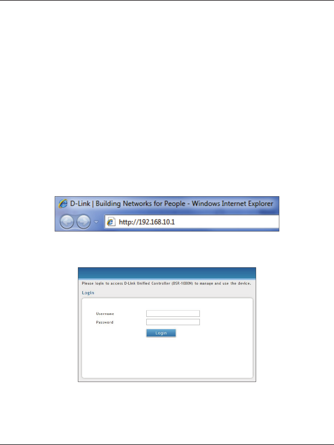
Note: Disable pop-up blocking software or add the management IP address http://192.168.10.1 to
your pop-up blocker’s allow list.
3. Launch a browser, enter the IP address for the LAN interface (default = http://192.168.10.1), and
then press Enter.
4. Enter your username (default = admin) and your password (default = admin), then click Login.
#1 Log in to the Web UI
The LAN connection may be through the wired Ethernet ports available on the router, or once the initial setup
is complete, the DSR may also be managed through its wireless interface. Access the router’s Web user interface
(Web UI) for management by using any web browser, such as Internet Explorer, Firefox, Chrome, or Safari.
5. The web management interface opens with the Status > Dashboard page. This page displays
general, LAN, and WLAN status information. You can return to this page at any time by clicking
Status > Dashboard.
D-Link DSR-Series User Manual 6
Section 3 - Basic Conguration
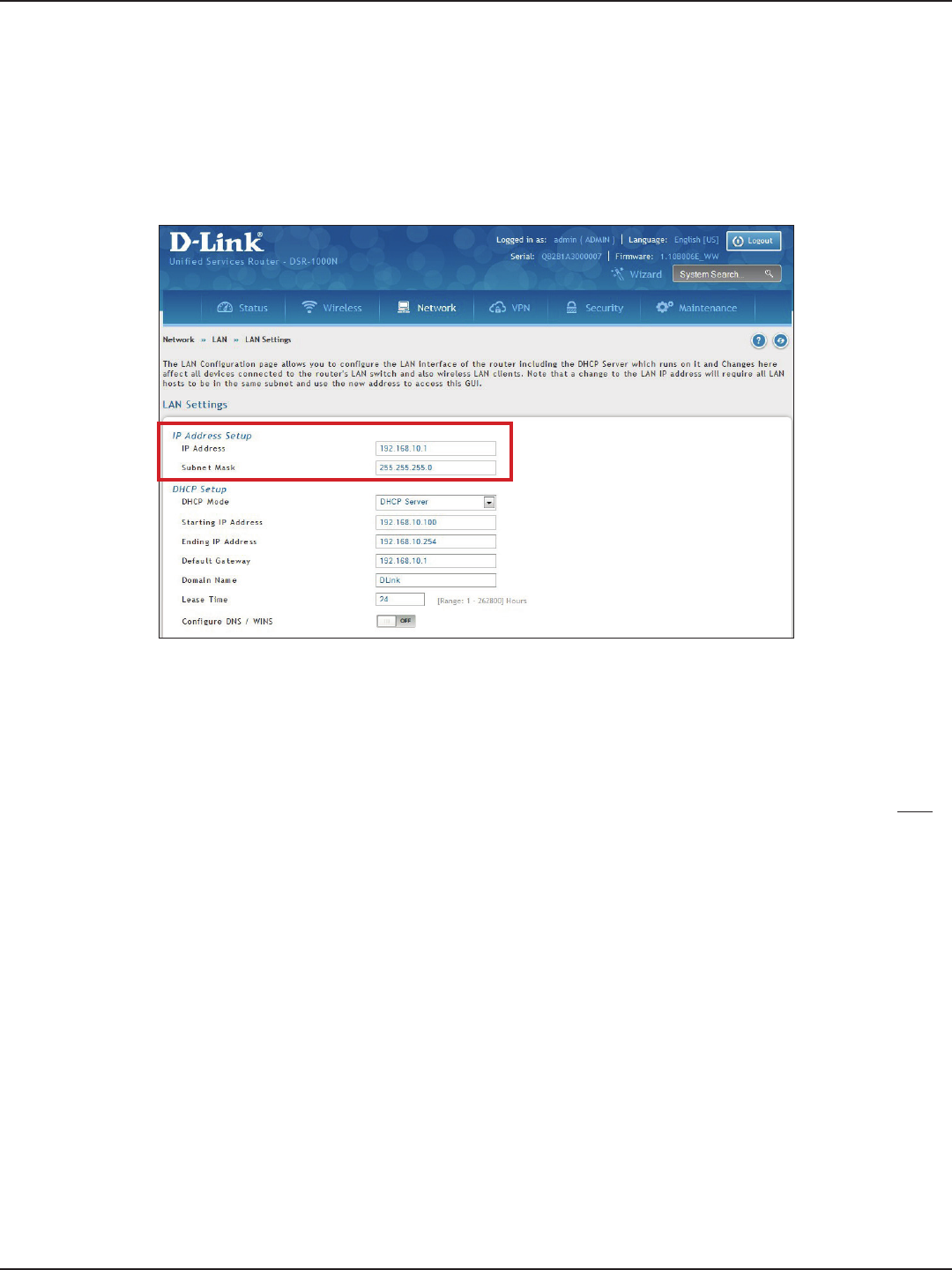
#2 Change LAN IP Address
1. Log in to the router.
2. Click Network > LAN > LAN Settings. The LAN Settings page will appear.
To change the LAN IP address of the router, follow the steps below:
Note: If you change the IP address and click Save, the Web UI will not respond. Open a new connection to the new IP
address and log in again. Be sure the LAN host (the machine used to manage the router) has obtained an IP address
from newly assigned pool (or has a static IP address in the router’s LAN subnet) before accessing the router via changed
IP address.
3. Under IP Address Setup, enter a new IP address for the router.
4. Enter a new subnet mask if needed.
5. Click Save at the bottom of the page.
D-Link DSR-Series User Manual 7
Section 3 - Basic Conguration
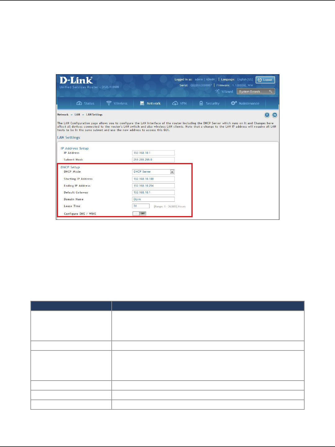
#3 Congure DHCP Server
1. Log in to the router.
2. Click Network > LAN > LAN Settings. The LAN Settings page will appear.
To change the DHCP settings of the router, follow the steps below:
3. From the DHCP Mode drop-down menu under DHCP Setup, select None (disable), DHCP Server
(enable), or DHCP Relay.
Note: DHCP Relay will allow DHCP clients on the LAN to receive IP address leases and corresponding
information from a DHCP server on a dierent subnet. When LAN clients make a DHCP request it will be
passed along to the server accessible via the Relay Gateway IP address you enter.
4. If enabled, ll in the following elds:
Field Description
Starting IP Address
Enter the starting IP address in the DHCP address pool. Any new DHCP
client joining the LAN is assigned an IP address within the starting and
ending IP address range. Starting and ending IP addresses should be in
the same IP address subnet as the wireless controller’s LAN IP address.
Ending IP Address Enter the ending IP address in the DHCP address pool.
Default Gateway
By default this setting is router’s LAN IP address. It can be customized to any
valid IP within the LAN subnet, in the event that the network’s gateway is
not this router. The DHCP server will give the congured IP address as the
Default Gateway to its DHCP clients.
Domain Name Enter a domain name.
Lease Time Enter the time, in hours, for which IP addresses are leased to clients.
Congure DNS/WINS Toggle to On and enter DNS and/or WINS server IP address(es).
5. Click Save at the bottom of the page.
D-Link DSR-Series User Manual 8
Section 3 - Basic Conguration
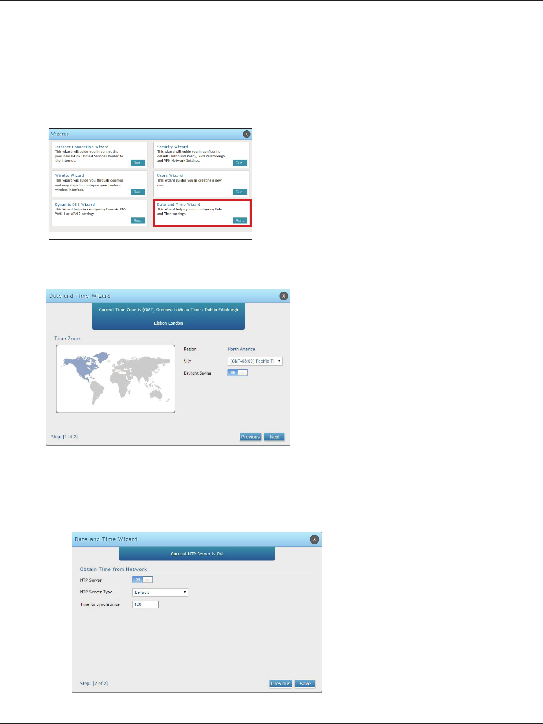
#4 Set Time and Date
1. Log in to the router.
2. Click Wizard in the upper-right side of the page. If you want to manually congure your date/time
settings, refer to “Date and Time” on page 164.
3. Click Run in the Date and Time Wizard box.
4. Click the continent from the map and then next to City, select your time zone from the drop-down
menu. Toggle Daylight Saving to ON if it applies to you and then click Next.
5. Toggle NTP server to ON to use a time server or toggle to OFF to manually enter the time and date.
6. If you selected ON, select either Default or Custom from the drop-down menu. If you selected Custom,
enter a primary and secondary NTP server address.
7. Enter the time to synchronize with the NTP server and click Save.
8. A summary page will appear. Verify your settings and then click Finish.
D-Link DSR-Series User Manual 9
Section 3 - Basic Conguration
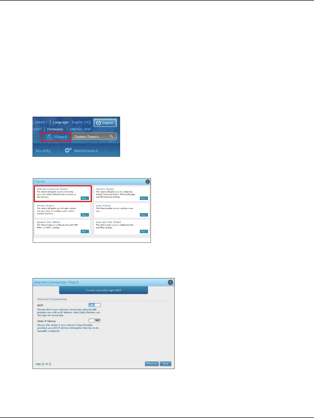
#5 Internet Connection Setup
1. Log in to the router.
2. Click Wizard in the upper-right side of the page. If you want to manually congure your Internet
settings, refer to “Connect to the Internet” on page 30.
This router has two WAN ports that can be used to establish a connection to the internet. It is assumed that you
have arranged for internet service with your Internet Service Provider (ISP). Please contact your ISP or network
administrator for the conguration information that will be required to setup the router. Supported Internet
connection types include Dynamic, Static, PPPoE, PPTP, L2TP, Japanese PPPoE, and Russian PPPoE/PPTP/L2TP.
To congure your router to connect to the Internet, follow the steps below:
3. Click Run in the Internet Connection Wizard box.
4. Toggle On next to either DHCP or Static IP Address and click Next. If your connection type is not listed,
refer to “Connect to the Internet” on page 30.
D-Link DSR-Series User Manual 10
Section 3 - Basic Conguration
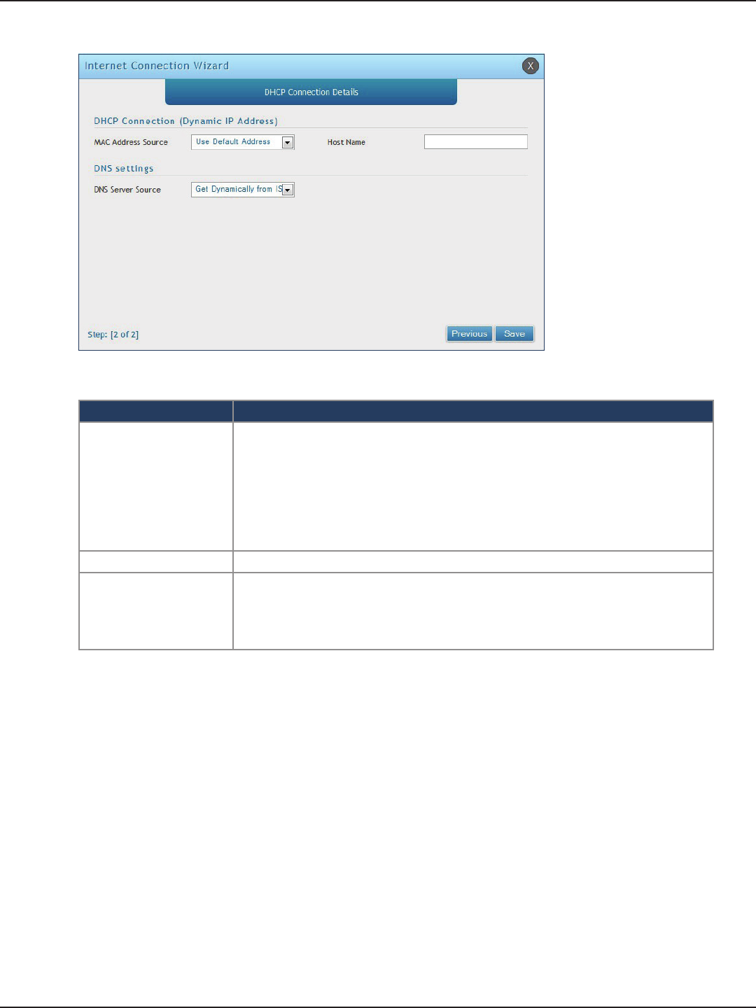
a. If you selected DHCP, complete the elds below:
Field Description
MAC Address Source
This MAC address will be recognized by your ISP. Select from the following three
options:
• Use Default Address - Uses the default MAC address of the router.
• Clone your PC’s MAC Address - Select to use the MAC address of the computer
you are currently connecting with.
• Use this MAC Address - Select to manually enter a MAC address and enter the
address in the box.
Host Name Enter a host name if required by your ISP.
DNS Server Source
Select from the following two options:
• Get Dynamically from ISP - Select to use the DNS servers assigned by your ISP.
• Use these DNS Servers - Select to manually enter a primary and secondary
DNS server address(es).
Skip to Step 5 on the bottom of the next page.
D-Link DSR-Series User Manual 11
Section 3 - Basic Conguration
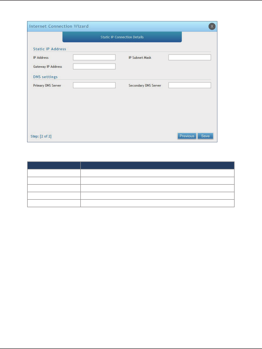
b. If you selected Static, complete the elds below:
Field Description
IP Address Enter the IP address assigned by your ISP.
Gateway IP Address Enter the gateway IP address assigned by your ISP.
IP Subnet Mask Enter the subnet mask assigned by your ISP.
Primary DNS Server Enter the primary DNS server IP address assigned by your ISP.
Secondary DNS Server Enter the secondary DNS server IP address assigned by your ISP.
5. Click Save. The router will reboot and attempt to connect to your ISP. Please allow one to two minutes
to connect.
D-Link DSR-Series User Manual 12
Section 3 - Basic Conguration
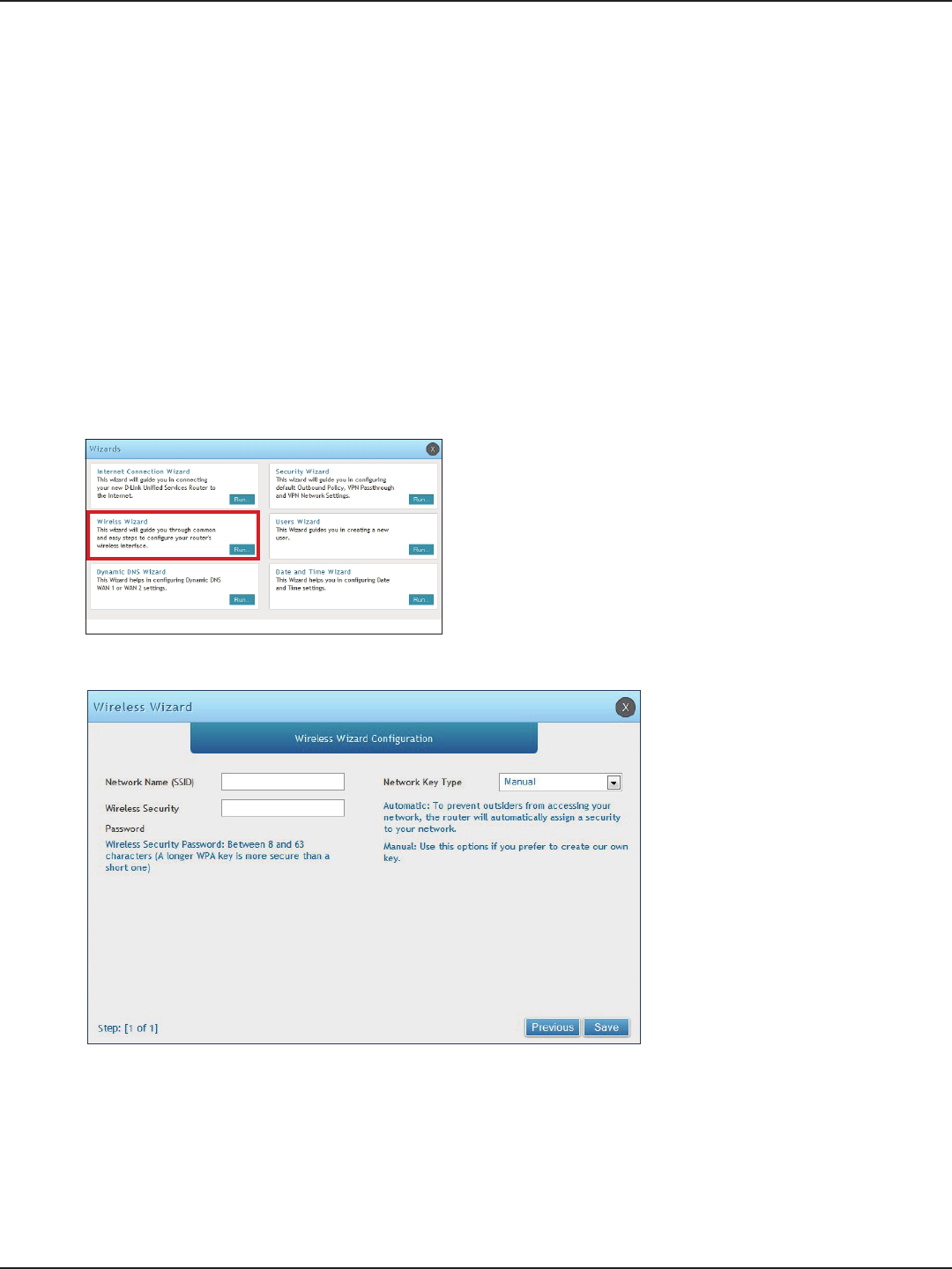
#6 Wireless Network Setup
1. Log in to the router.
2. Click Wizard in the upper-right side of the page.
This wizard provides a step-by-step guide to create and secure a new access point on the router. The network
name (SSID) is the AP identier that will be detected by supported clients. The Wizard uses a TKIP+AES cipher for
WPA / WPA2 security; depending on support on the client side, devices associate with this AP using either WPA
or WPA2 security with the same pre -shared key.
The wizard has the option to automatically generate a network key for the AP. This key is the pre-shared key
for WPA or WPA2 type security. Supported clients that have been given this PSK can associate with this AP. The
default (auto-assigned) PSK is “passphrase”.
5. Enter a SSID, which is the name of your wireless network.
6. Next to Network Key Type, select Manual.
7. Enter a password for the wireless network. Wireless devices connecting to this network must enter this
password to connect. The password is case-sensitive.
8. Click Save.
9. A window will appear with a summary of your settings. Click Finish.
3. Click Run in the Wireless Wizard box.
4. The wizard screen will appear.
D-Link DSR-Series User Manual 13
Section 3 - Basic Conguration
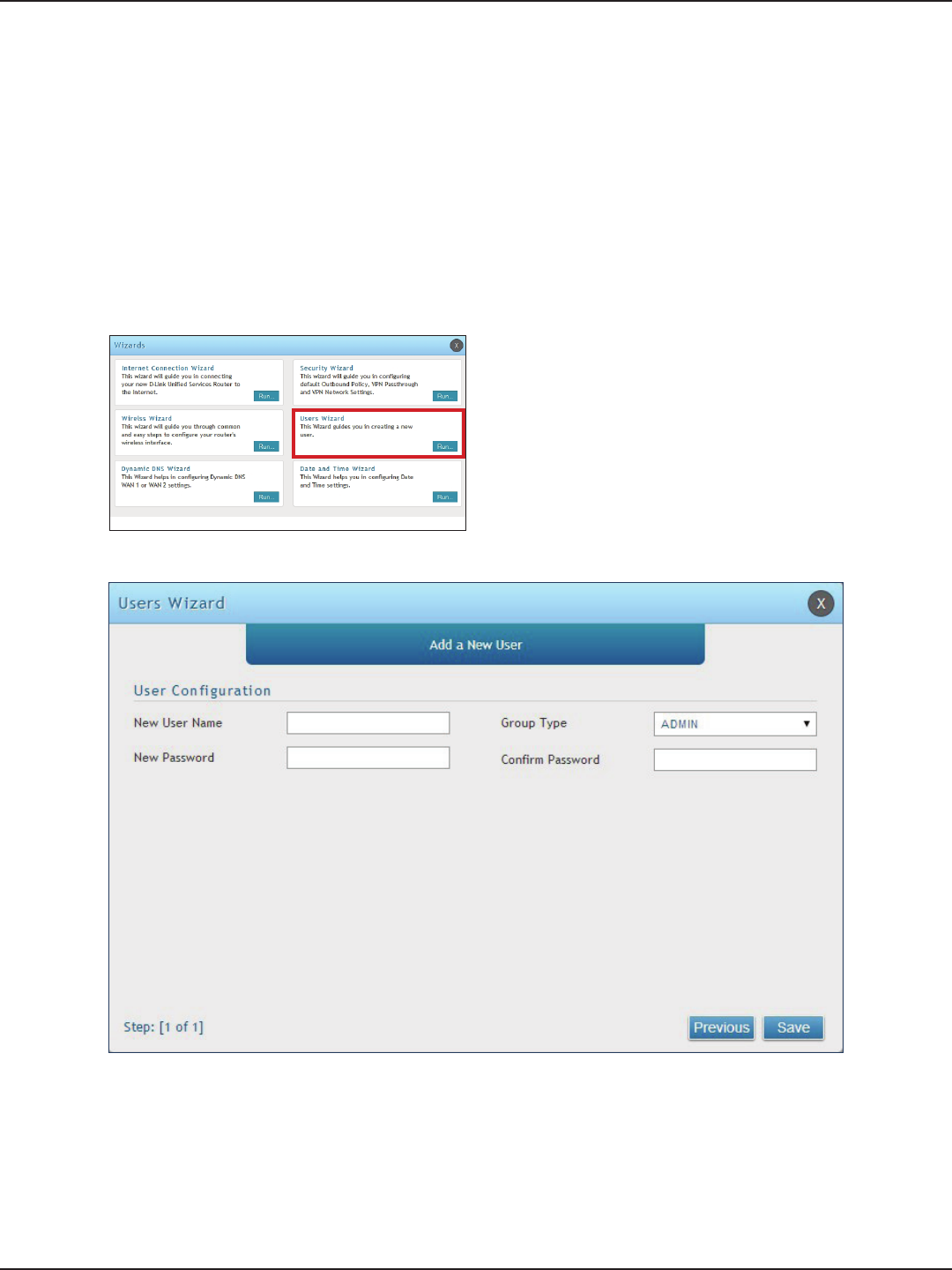
#7 Create Users
1. Log in to the router.
2. Click Wizard in the upper-right side of the page.
3. Click Run in the Users Wizard box.
The Users Wizard allows you to create user account that you can assign to groups. Refer to “Users” on page 131 for
more information. You may want to create Groups before users so you may assign them to groups as you create
them. To create groups, refer to “Groups” on page 127.
To create new users, follow the steps below:
5. Enter a unique user name.
6. Select the group type from the drop-down menu. For more information on groups, refer to “Groups”
on page 127.
7. Enter a password for the user.
8. Enter the password again for conrmation.
9. Click Save.
4. The wizard screen will appear.
D-Link DSR-Series User Manual 14
Section 3 - Basic Conguration
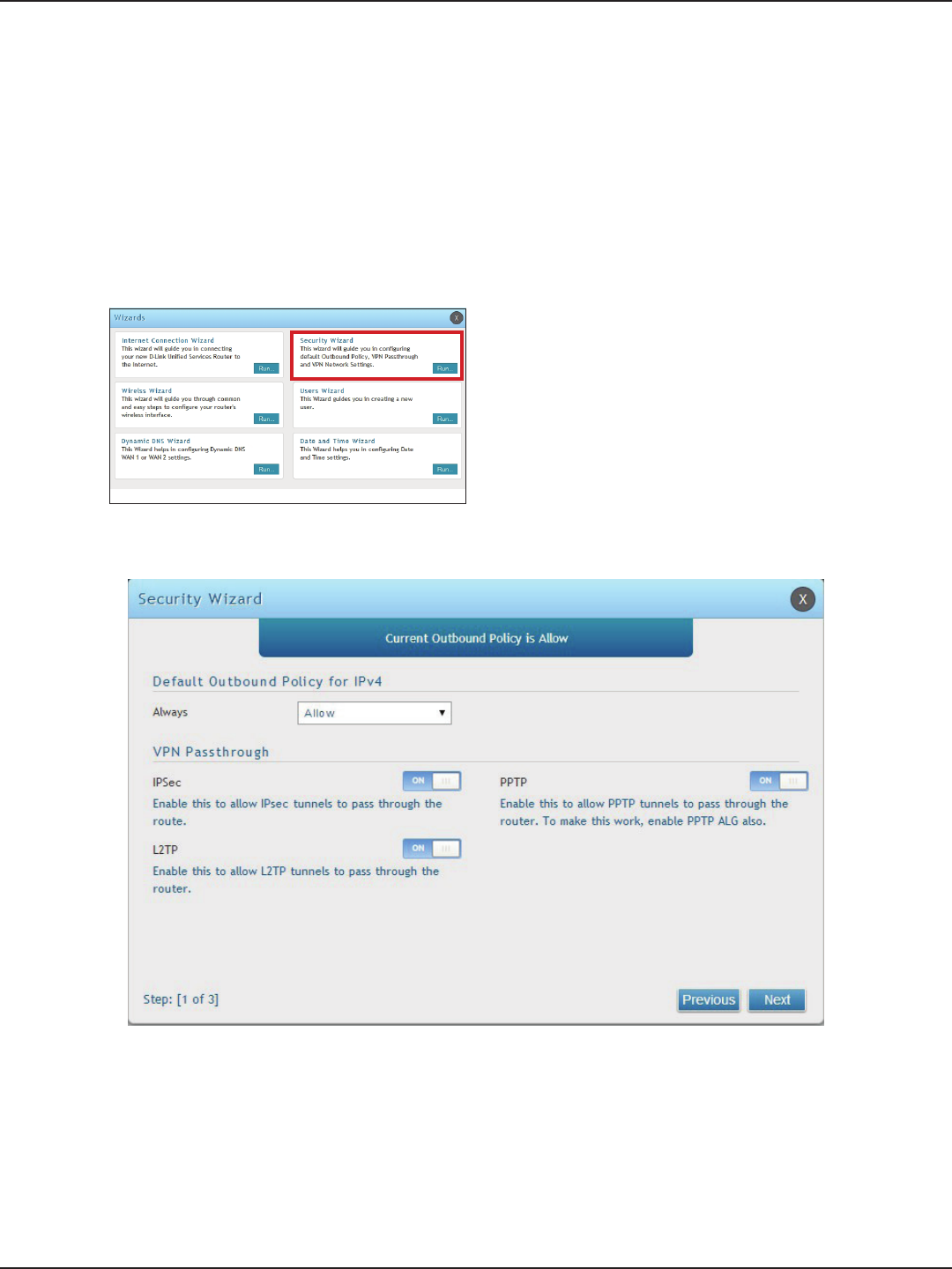
#8 Security/VPN Wizard
1. Log in to the router.
2. Click Wizard in the upper-right side of the page.
3. Click Run in the Security Wizard box.
The Security Wizard allows you to enable VPN passthrough and create a VPN.
Follow the steps below:
4. The wizard screen will appear.
5. Select the default outbound policy from the drop-down menu.
6. Toggle which type(s) of VPN you want allowed to pass through the router to ON and click Next.
D-Link DSR-Series User Manual 15
Section 3 - Basic Conguration
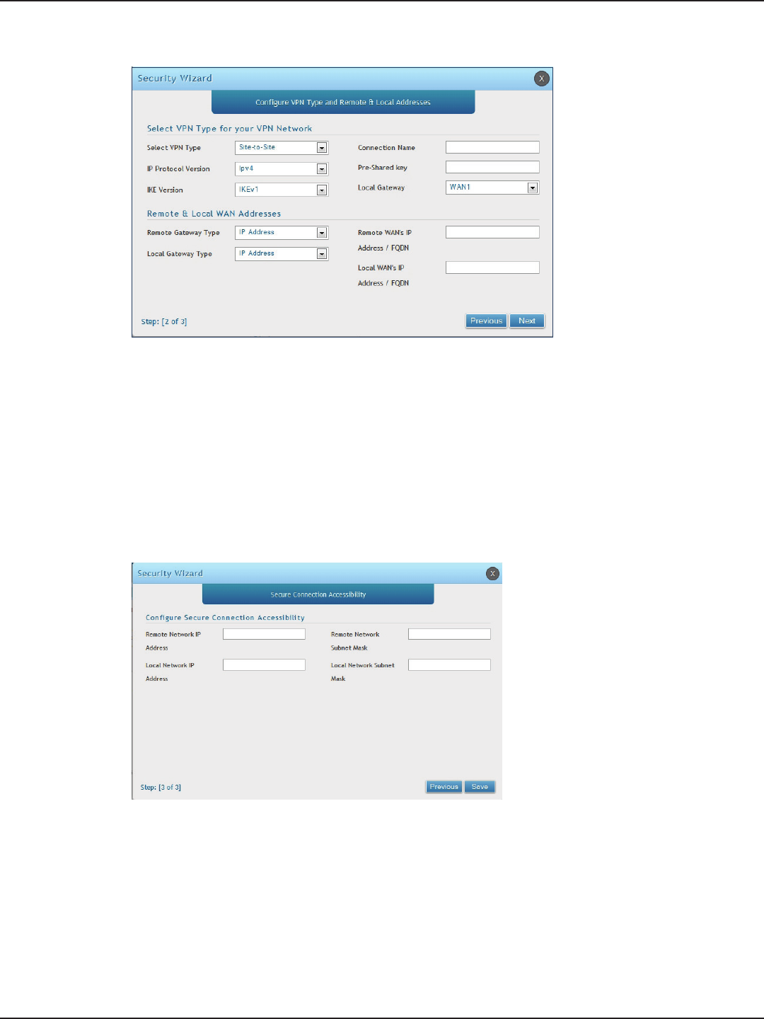
Note: The IP address range used on the remote LAN must be dierent from the IP address range used on the local LAN.
7. You can quickly create both IKE and VPN policies. Once the IKE or VPN policy is created, you can modify
it as required.
8. From the Select VPN Type drop-down menu, select either Site to Site or Remote Access.
9. Next to Connection Name, enter a name for this VPN connection.
10. Next to IP Protocol Version, select either IPv4 or IPv6.
11. Next to IKE Version, select the version of IKE.
12. Next to Pre-Shared Key, enter the pre-shared key used.
13. Next to Local Gateway, select which WAN port used for the local gateway.
14. Next to Remote Gateway Type and Local Gateway Type, select either IP Address or FQDN.
15. Enter the Remote and Local WAN IP Address or FQDN and click Next.
16. Enter the remote network IP address and subnet mask.
17. Enter the local network IP address and subnet mask.
18. Click Save.
D-Link DSR-Series User Manual 16
Section 3 - Basic Conguration
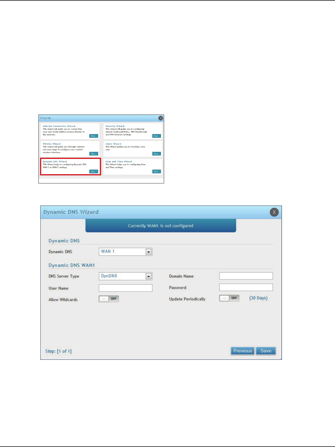
#9 Dynamic DNS Wizard
Dynamic DNS (DDNS) is an Internet service that allows routers with varying public IP addresses to be located
using Internet domain names. To use DDNS, you must setup an account with a DDNS provider such as DynDNS.
org, D-Link DDNS, or Oray.net. Refer to “Dynamic DNS Settings” on page 53 for more information.
Follow the steps below:
5. Next to Dynamic DNS, select WAN1 or WAN2.
6. Select the DNS Server Type from the drop-down menu.
7. Depending on your service, enter your DDNS user name, password, and domain name.
8. Toggle Allow Wildcards to ON if required by your DDNS service.
9. Toggle Update Periodically to ON to auto update every 30 days.
10. Click Save.
1. Log in to the router.
2. Click Wizard in the upper-right side of the page.
3. Click Run in the Dynamic DNS Wizard box.
4. The wizard screen will appear.

D-Link DSR-Series User Manual 17
Section 4 - LAN Conguration
LAN Conguration
By default, the router functions as a Dynamic Host Conguration Protocol (DHCP) server to the hosts on the LAN
and WLAN network. With DHCP, PCs and other LAN devices can be assigned IP addresses as well as addresses
for DNS servers, Windows Internet Name Service (WINS) servers, and the default gateway. With DHCP server
enabled the router’s IP address serves as the gateway address for LAN and WLAN clients. The PCs in the LAN are
assigned IP addresses from a pool of addresses specied in this procedure. Each pool address is tested before it
is assigned to avoid duplicate addresses on the LAN.
For most applications, the default DHCP and TCP/IP settings are satisfactory. If you want another PC on your
network to be the DHCP server or if you are manually conguring the network settings of all of your PCs, set the
DHCP mode to ‘none’. DHCP relay can be used to forward DHCP lease information from another DHCP server on
the network. This is particularly useful for wireless clients.
Instead of using a DNS server, you can use a Windows Internet Naming Service (WINS) server. A WINS server is the
equivalent of a DNS server but uses the NetBIOS protocol to resolve host names. The router includes the WINS
server IP address in the DHCP conguration when acknowledging a DHCP request from a DHCP client.
You can also enable DNS proxy for the LAN. When this is enabled the router then as a proxy for all DNS requests
and communicates with the ISP’s DNS servers. When disabled all DHCP clients receive the DNS IP addresses of
the ISP.
D-Link DSR-Series User Manual 18
Section 4 - LAN Conguration
Field Description
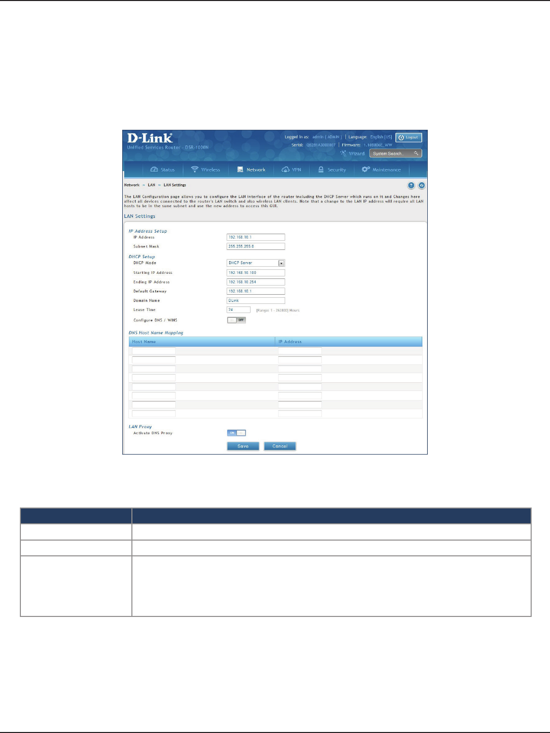
IP Address Enter an new IP address for the router. Default is 192.168.10.1.
Subnet Mask Enter the subnet mask for your network. Default is 255.255.255.0.
DHCP Mode
Select one of the following modes:
• None - Turns o DHCP.
• DHCP Server (default) - The router will act as the DHCP server on your network.
• DHCP Relay - DHCP clients on your network will receive IP address leases from a DHCP
server on a dierent subnet.
LAN Settings
Path: Network > LAN > LAN Settings
To congure the LAN settings on the router:
1. Click Network > LAN > LAN Settings.
2. Complete the elds in the table below and click Save.
D-Link DSR-Series User Manual 19
Section 4 - LAN Conguration
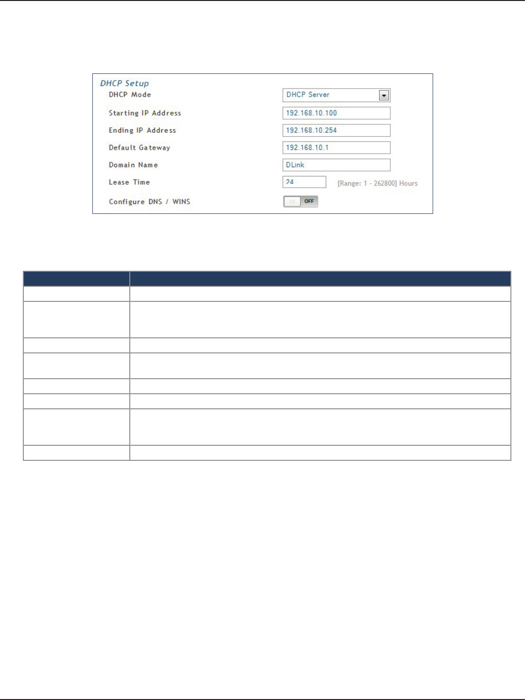
DHCP Server
Field Description
DHCP Mode Select DHCP Server from the drop-down menu.
Starting IP Address
Enter the starting IP address in the DHCP address pool. Any new DHCP client joining the LAN
is assigned an IP address within the starting and ending IP address range. Starting and ending
IP addresses must be in the same IP address subnet as the router’s LAN IP address.
Ending IP Address Enter the ending IP address in the DHCP address pool.
Default Gateway Enter the default gateway IP address you want to assign to your DHCP clients. This IP is usually
the router’s LAN IP address (default is 192.168.10.1).
Domain Name Enter a domain name.
Lease Time Enter the time, in hours, for which IP addresses are leased to clients.
Congure DNS/WINS
Toggle to On to manually enter DNS and/or WINS server IP address(es). If set to O, your
router’s LAN IP address will be assigned the DNS server to your clients and the router will get
the DNS information from your ISP.
Save Click Save at the bottom to save and activate your settings.
2. Complete the elds in the table below and click Save.
1. Select DHCP Server from the drop-down menu.
D-Link DSR-Series User Manual 20
Section 4 - LAN Conguration
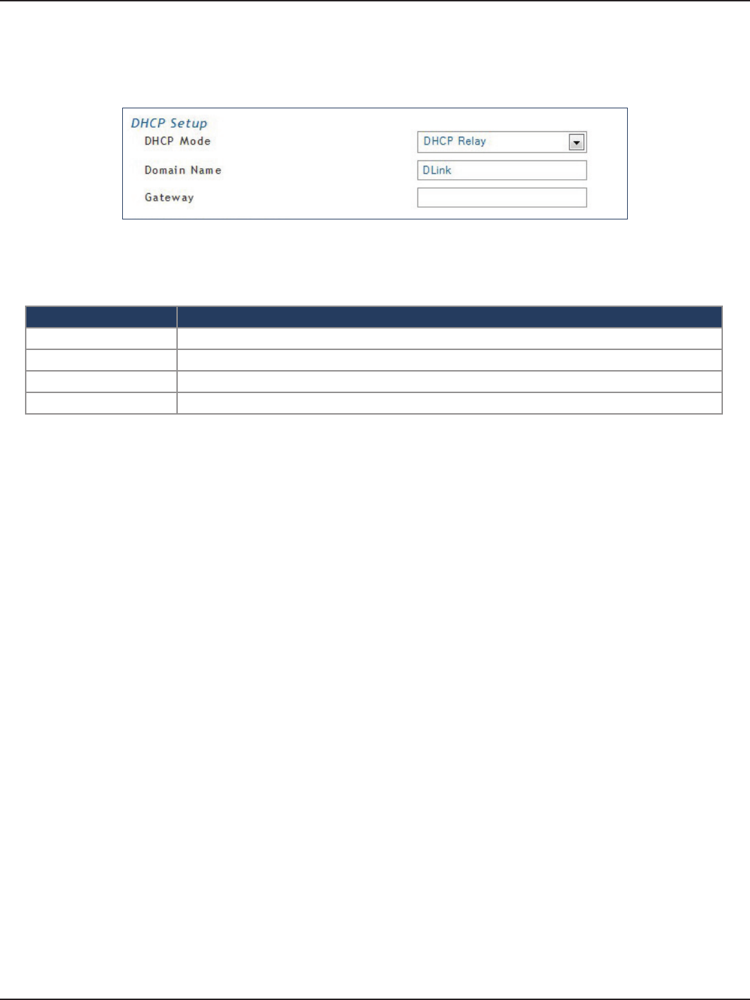
DHCP Relay
Field Description
DHCP Mode Select DHCP Relay from the drop-down menu.
Domain Name Enter the domain name of your network.
Gateway Enter the relay gateway IP address.
Save Click Save at the bottom to save and activate your settings.
2. Complete the elds in the table below and click Save.
1. Select DHCP Relay from the drop-down menu.
D-Link DSR-Series User Manual 21
Section 4 - LAN Conguration
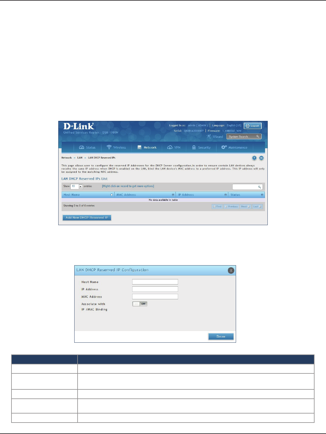
DHCP Reserved IPs
The router’s DHCP server can assign IP settings to your clients on your network by adding a client’s MAC address
and the IP address to be assigned. Whenever the router receives a request from a client, the MAC address of that
client is compared with the MAC address list present in the database. If an IP address is already assigned to that
computer or device in the database, the customized IP address is congured otherwise an IP address is assigned
to the client automatically from the DHCP pool.
Field Description
Host Name Enter a host name for this device. Do not use spaces.
IP Address Enter the IP address you want to assign to this device. Note that this IP address must be in the
same range as the starting/ending IP address under DHCP Settings.
MAC Address Enter the MAC address of this device (xx:xx:xx:xx:xx:xx format). This is not case-sensitive.
Associate with IP/MAC
Binding Toggle ON to associate this device’s information with IP/MAC binding.
Save Click Save to save and activate your settings.
Path: Network > LAN > LAN DHCP Reserved IPs
To create DHCP reservations:
1. Click Network > LAN > LAN DHCP Reserved IPs.
2. Click Add New DHCP Reserved IP.
3. Enter the following information and click Save.
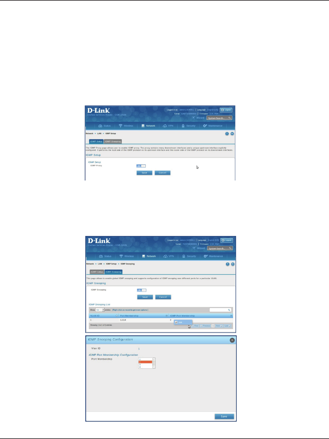
D-Link DSR-Series User Manual 22
Section 4 - LAN Conguration
IGMP Setup
Path: Network > LAN > IGMP Setup
IGMP snooping (IGMP Proxy) allows the router to ‘listen’ in on IGMP network trac through the router. This then
allows the router to lter multicast trac and direct it only to hosts that need this stream. This is helpful when
there is a lot of multicast trac on the network where all LAN hosts do not need to receive this multicast trac.
To enable IGMP Proxy:
1. Click Network > LAN > IGMP Setup.
2. Toggle IGMP Proxy to On.
3. Click Save.
1. the IGMP proxy is switched on
2. Click IGMP Snooping tab
3. Toggle IGMP Snooping to On
4. click Save.
5. Right click to Edit any of the VLAN IDs
Note: Not support IGMP Snooping on DSR-150/150N
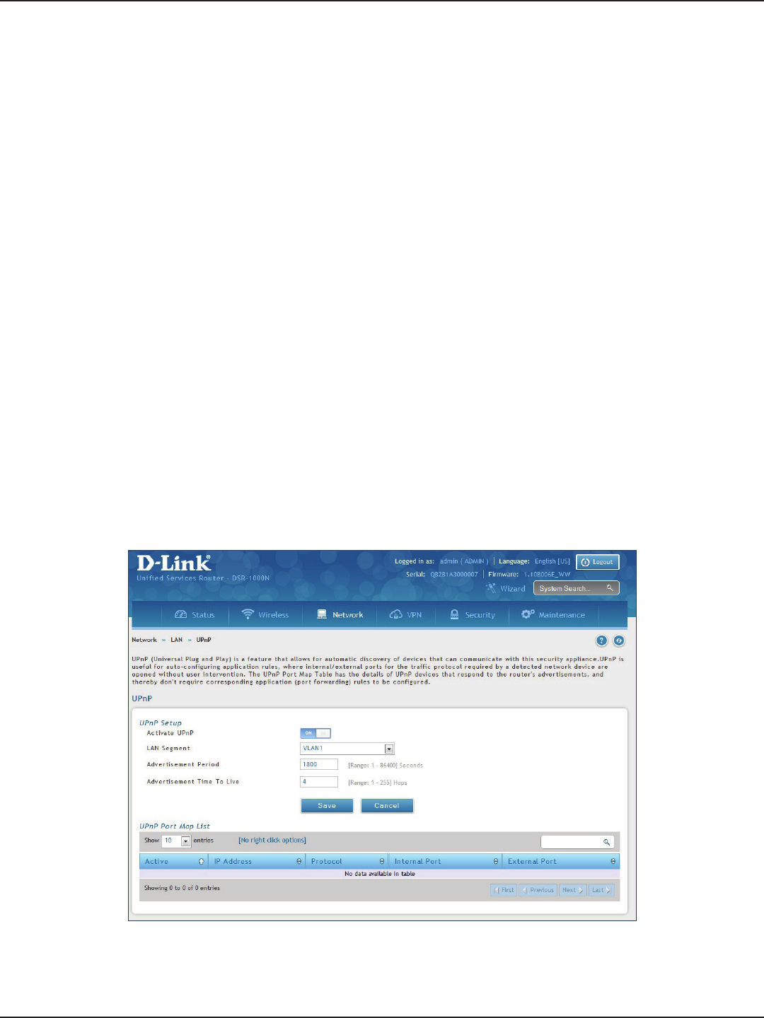
D-Link DSR-Series User Manual 23
Section 4 - LAN Conguration
UPnP Setup
Path: Network > LAN > UPnP
Universal Plug and Play (UPnP) is a feature that allows the router to discover devices on the network that can
communicate with the router and allow for auto-conguration. If a network device is detected by UPnP, the
router can open internal or external ports for the trac protocol required by that network device. If disabled, the
router will not allow for automatic device conguration and you may have to manually open/forward ports to
allow applications to work.
To congure the UPnP settings:
1. Click Network > LAN > UPnP.
2. Toggle Activate UPnP to On.
3. Select a VLAN from the LAN Segment drop-down menu.
4. Enter a value for Advertisement Period. This is the frequency that the router broadcasts UPnP information
over the network. A large value will minimize network trac but cause delays in identifying new UPnP
devices to the network.
5. Enter a value for Advertisement Time to Live. This is the number of steps a packet is allowed to propagate
before being discarded. Small values will limit the UPnP broadcast range. A default of 4 is typical for
networks with a few number of switches.
6. Click Save.
7. Your entry will be displayed in the UPnP Port Map List. To edit or delete, right-click an entry and select
the action from the menu. Repeat steps 2-6 to add multiple entries.
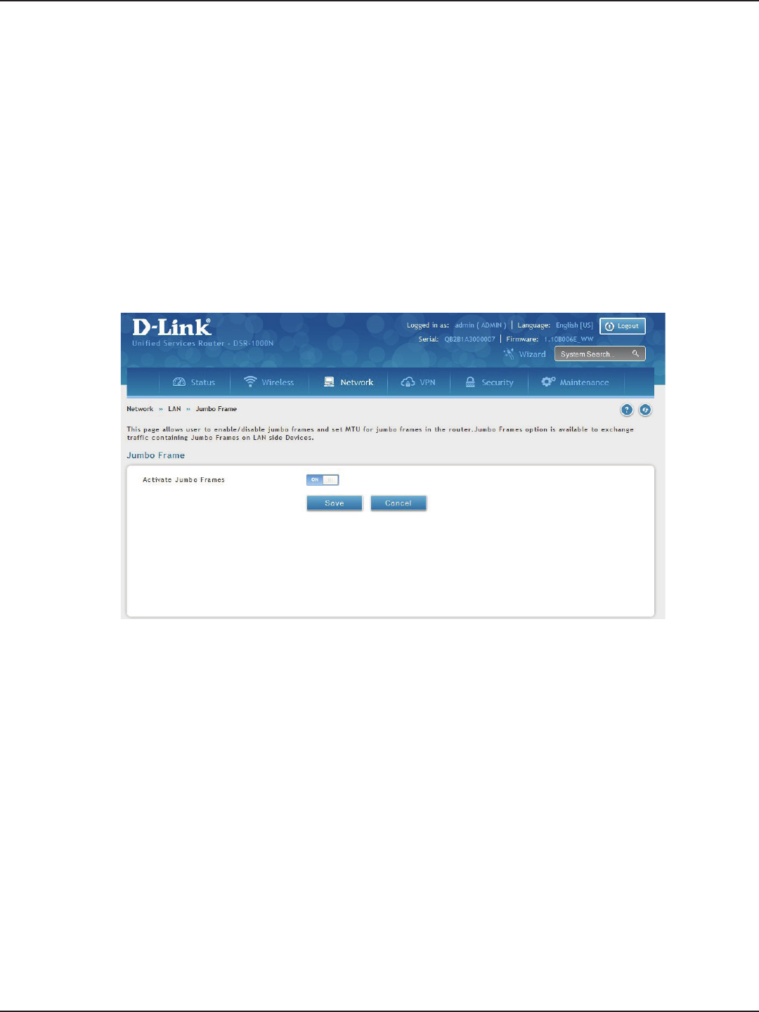
D-Link DSR-Series User Manual 24
Section 4 - LAN Conguration
Jumbo Frames
Jumbo frames are Ethernet frames with more than 1500 bytes of payload. When this option is enabled, the LAN
devices can exchange information at Jumbo frames rate.
Path: Network > LAN > Jumbo Frames
To enable jumbo frames:
1. Click Network > LAN > Jumbo Frames.
2. Toggle Activate Jumbo Frames to On.
3. Click Save.
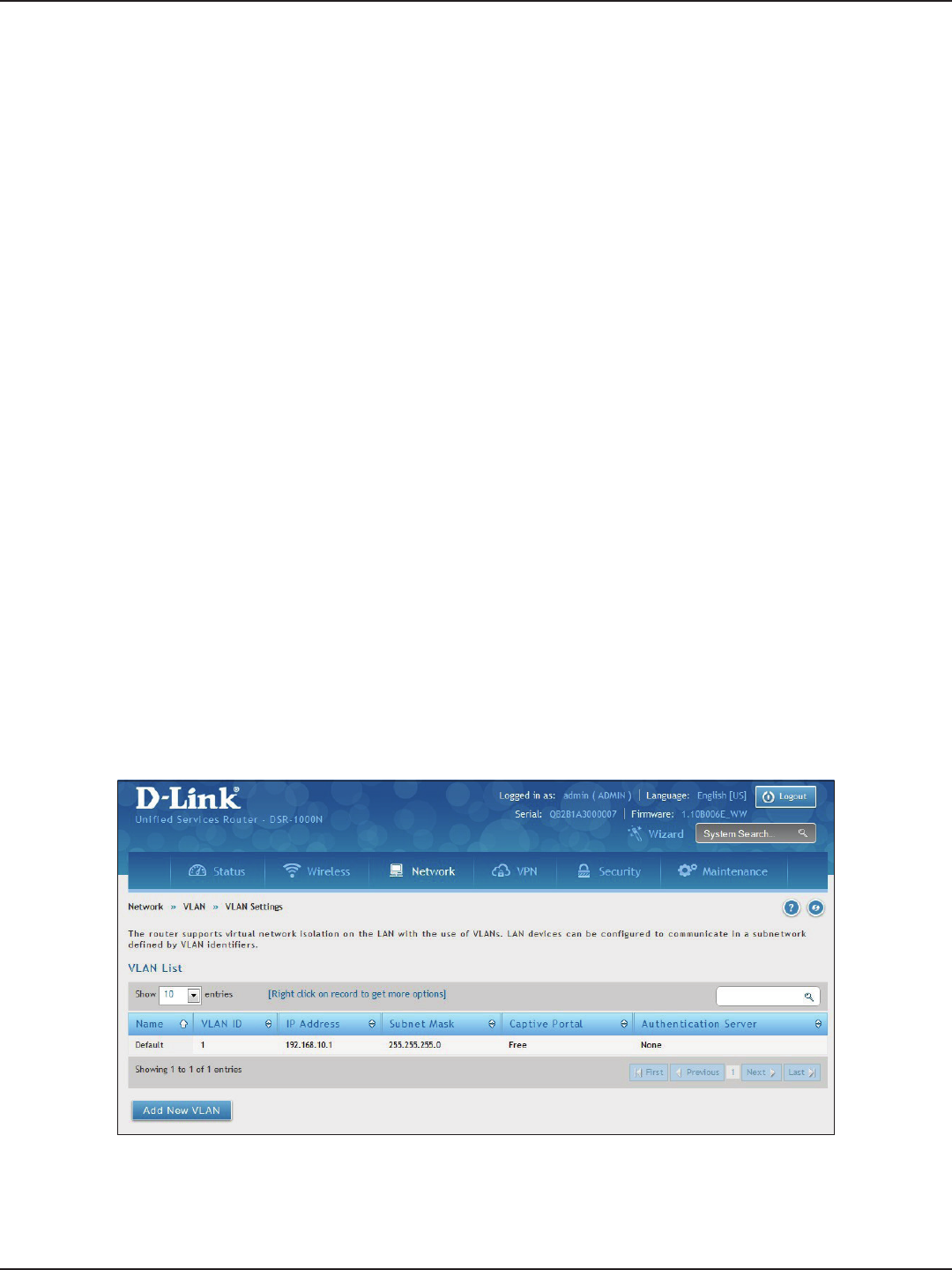
D-Link DSR-Series User Manual 25
Section 4 - LAN Conguration
VLAN
VLAN Settings
Path: Network > VLAN > VLAN Settings
The VLAN List page displays a list of congured VLANs by name and VLAN ID. A VLAN membership can be created
by clicking the Add New VLAN button below the list.
A VLAN membership entry consists of a VLAN identier and the numerical VLAN ID which is assigned to the VLAN
membership. The VLAN ID value can be any number from 2 to 4091. VLAN ID 1 is reserved for the default VLAN,
which is used for untagged frames received on the interface.
The router supports virtual network isolation on the LAN with the use of VLANs. LAN devices can be congured
to communicate in a sub network dened by VLAN identiers. LAN ports can be assigned unique VLAN IDs so
that trac to and from that physical port can be isolated from the general LAN.
VLAN ltering is particularly useful to limit broadcast packets of a device in a large network VLAN support is
enabled by default in the router. In the VLAN Conguration page, enable VLAN support on the router and then
proceed to the next section to dene the virtual network.
To create a new VLAN:
1. Click Network > LAN > VLAN Settings.
2. Click Add New VLAN at the bottom.
3. Enter the following required information from the table on the next page.
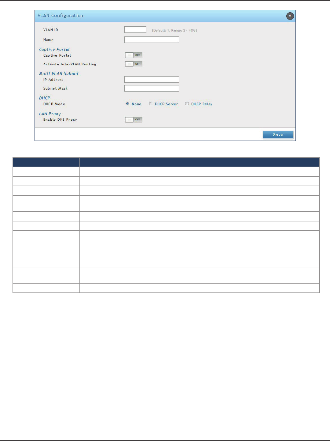
D-Link DSR-Series User Manual 26
Section 4 - LAN Conguration
Field Description
VLAN ID Enter a number between 2 and 4053.
Name Enter a name for your VLAN.
Captive Portal Toggle ON to enable Captive Portal (refer to the next page for more information).
Activate InterVLAN
Routing
Toggle ON to allow routing between multiple VLANs or OFF to deny communication between
VLANs.
IP Address Enter the IP address for the VLAN.
Subnet Mask Enter the subnet mask for the VLAN.
DHCP Mode
Select one of the following modes:
• None - Turns o DHCP for your VLAN.
• DHCP Server (default) - The router will act as the DHCP server for your VLAN.
• DHCP Relay - DHCP clients on your VLAN will receive IP address leases from a DHCP server
on a dierent subnet.
Enable DNS Proxy Toggle ON to enable the router to act as a proxy for all DNS requests and communicate with the
ISP’s DNS servers.
Save Click Save to save and activate your settings.
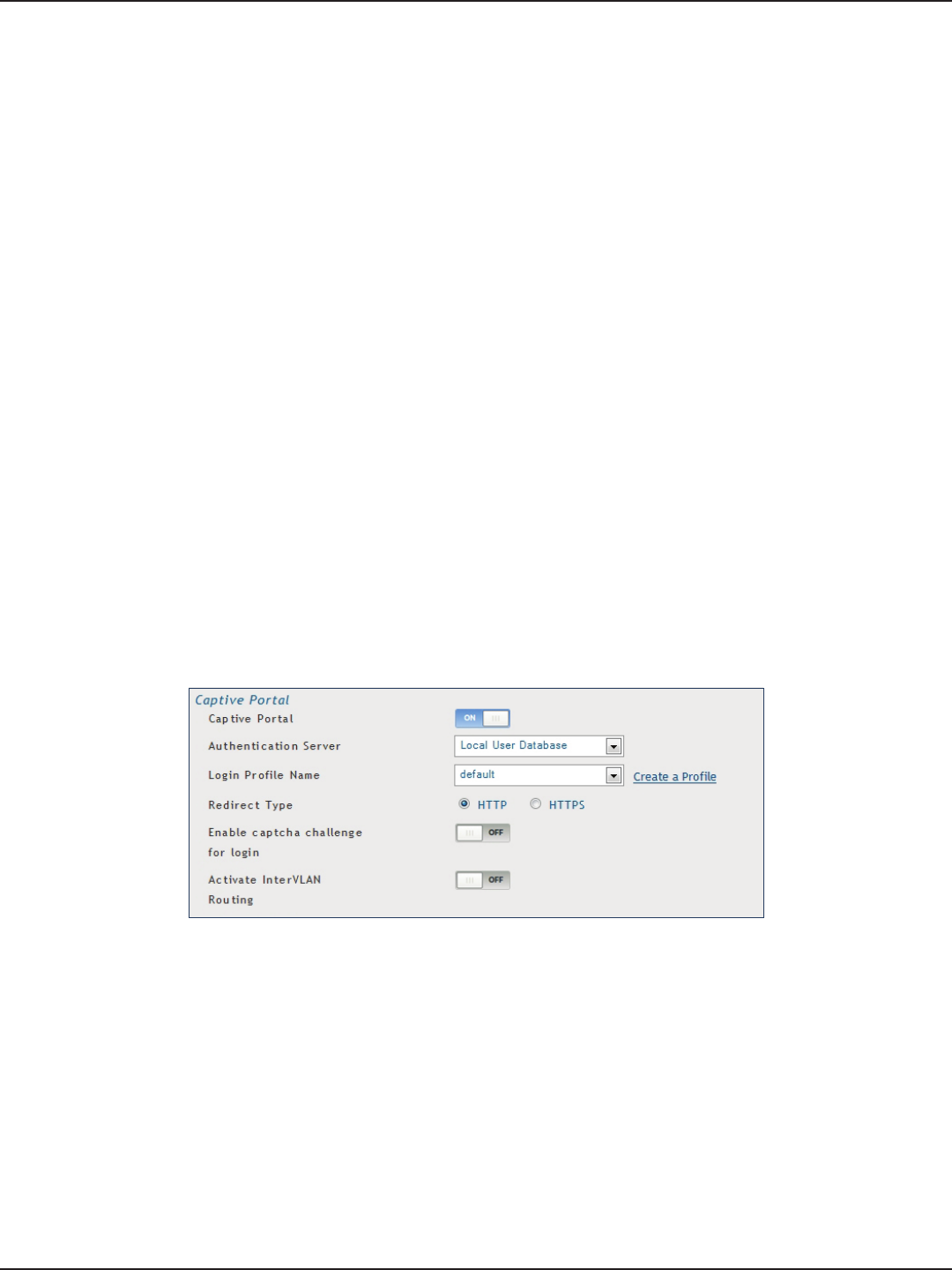
D-Link DSR-Series User Manual 27
Section 4 - LAN Conguration
Captive Portal
Note: The DSR-150/150N/250/250N routers do not have support for the Captive Portal feature. Captive Portal is
available for LAN users only and not for DMZ hosts.
Captive Portals can be enabled on a per-VLAN basis. Hosts of a particular VLAN can be directed to authenticate
via the Captive Portal, which may be a customized portal with unique instructions and branding as compared to
another VLAN. The most critical aspect of this conguration page is choosing the authentication server. All users
(VLAN hosts) that want to gain internet access via the selected Captive Portal will be authenticated through the
selected server.
To enable Creative Portal to a specic VLAN:
1. Click Network > LAN > VLAN Settings.
2. Click Add New VLAN at the bottom or right-click an existing VLAN and select Edit.
3. Toggle Captive Portal to ON.
4. Next to Authentication Server, select an authentication server from the drop-down menu.
5. Next to Login Prole Name, select a prole from the drop-down or click Create a Prole to create a new
one.
6. Select either HTTP or HTTPS for the redirect type.
7. If you want users to enter a CAPTCHA challenge at login, toggle to ON.
8. If you would like communication between VLANs, toggle Activate InterVLAN Routing to ON.
9. Make any other changes/selections and click Save.
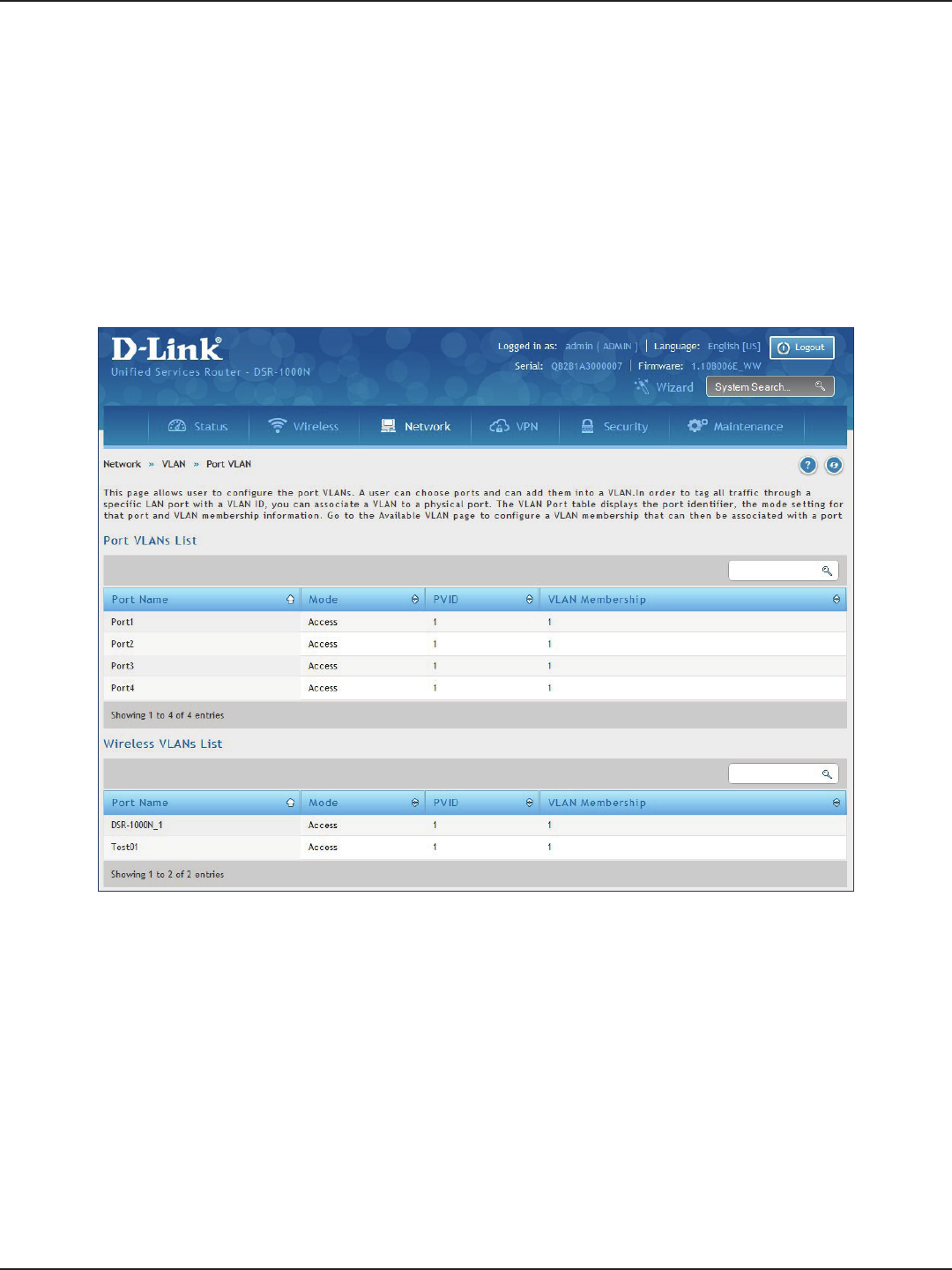
D-Link DSR-Series User Manual 28
Section 4 - LAN Conguration
Port/Wireless VLAN
Path: Network > VLAN Settings > Port VLAN
In order to tag all trac through a specic LAN port with a VLAN ID, you can associate a VLAN to a physical port
and wireless segment.
VLAN membership properties for the LAN and wireless LAN are listed on this page. The VLAN Port table displays
the port identier, the mode setting for that port and VLAN membership information. The conguration page is
accessed by selecting one of the four physical ports or a congured access point and clicking Edit.
To edit, right-click on the port and select Edit. The edit page oers the following conguration options:
• Mode: The mode of this VLAN can be General, Access (default), or Trunk. Refer to the next page for
more information on the dierent modes.
• Select PVID for the port when General mode is selected.
• Congured VLAN memberships will be displayed on the VLAN Membership Conguration for the
port. By selecting one more VLAN membership options for a General or Trunk port, trac can be
routed between the selected VLAN membership IDs.
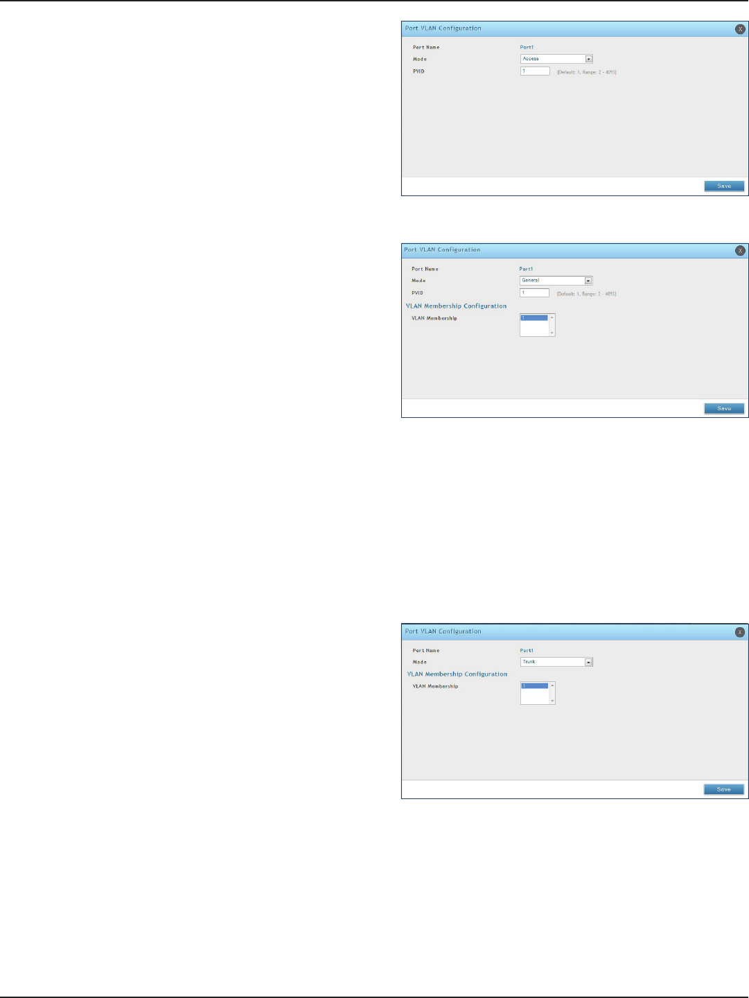
D-Link DSR-Series User Manual 29
Section 4 - LAN Conguration
In Access mode the port is a member of a single VLAN
(and only one). All data going into and out of the port is
untagged. Trac through a port in access mode looks
like any other Ethernet frame.
In General mode the port is a member of a user selectable
set of VLANs. The port sends and receives data that is
tagged or untagged with a VLAN ID. If the data into the
port is untagged, it is assigned the dened PVID.
For example, if Port 3 is a General port with PVID 3, then
the untagged data into Port 3 will be assigned PVID 3. All
tagged data sent out of the port with the same PVID will
be untagged. This is mode is typically used with IP Phones
that have dual Ethernet ports. Data coming from phone
to the switch port on the router will be tagged. Data
passing through the phone from a connected device will
be untagged.
Note: The DSR-150/150N do not support General mode due
to hardware limitations.
In Trunk mode the port is a member of a user
selectable set of VLANs. All data going into and out
of the port is tagged. Untagged coming into the port
is not forwarded, except for the default VLAN with
PVID=1, which is untagged. Trunk ports multiplex
trac for multiple VLANs over the same physical link.
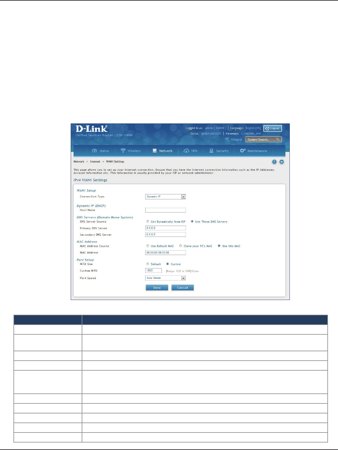
D-Link DSR-Series User Manual 30
Section 5 - Connect to the Internet
Connect to the Internet
This router has two WAN ports that can be used to establish a connection to the internet. It is assumed that you
have arranged for internet service with your Internet Service Provider (ISP). Please contact your ISP or network
administrator for the conguration information that will be required to setup the router.
Dynamic IP
Path: Network > Internet > WAN1 Settings
Select Dynamic IP (DHCP) to obtain IP address information automatically from your Internet Service Provider.
Field Description
Host Name Enter a host name if required by your ISP.
DNS Server Source Select either Get Dynamically from ISP or Use These DNS Servers to manually enter DNS
servers
Primary DNS Server If you selected “Use These DNS Servers”, enter the primary DNS server IP address.
Secondary DNS Server If you selected “Use These DNS Servers”, enter the secondary DNS server IP address.
MAC Address Source
Select Use Default MAC to use the MAC address from the WAN1 port to associate with your
modem/ISP, Clone your PC’s MAC to use the MAC address of the computer you are currently
using to associate with your modem/ISP, or Use this MAC to manually enter a MAC address.
MAC Address If you selected Use this MAC, enter the MAC address you want to associate with your ISP.
MTU Size Select to use the default MTU value (1500) or select Custom to enter your own value.
Custom MTU Enter a MTU value to optimize performance with your ISP.
Port Speed Select a value from the drop-down menu. The default value is Auto-Sense.
Save Click Save to save and activate your settings.
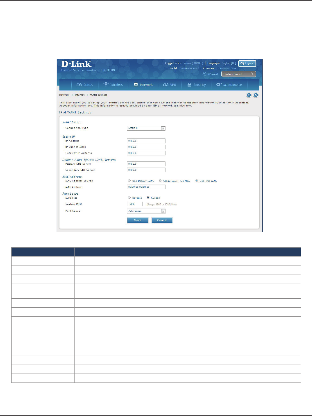
D-Link DSR-Series User Manual 31
Section 5 - Connect to the Internet
Static IP
Path: Network > Internet > WAN1 Settings
Select Static IP to manually enter the Internet settings supplied by your Internet Service Provider.
Field Description
IP Address Enter the IP address supplied by your ISP.
IP Subnet Mask Enter the subnet mask supplied by your ISP.
Gateway IP Address Enter the gateway IP address supplied by your ISP.
DNS Server Source Select either Get Dynamically from ISP or Use These DNS Servers to manually enter DNS
servers.
Primary DNS Server If you selected “Use These DNS Servers”, enter the primary DNS server IP address.
Secondary DNS Server If you selected “Use These DNS Servers”, enter the secondary DNS server IP address.
MAC Address Source
Select Use Default MAC to use the MAC address from the WAN1 port to associate with your
modem/ISP, Clone your PC’s MAC to use the MAC address of the computer you are currently
using to associate with your modem/ISP, or Use this MAC to manually enter a MAC address.
MAC Address If you selected Use this MAC, enter the MAC address you want to associate with your ISP.
MTU Size Select to use the default MTU value (1500) or select Custom to enter your own value.
Custom MTU Enter a MTU value to optimize performance with your ISP.
Port Speed Select a value from the drop-down menu. The default value is Auto-Sense.
Save Click Save to save and activate your settings.
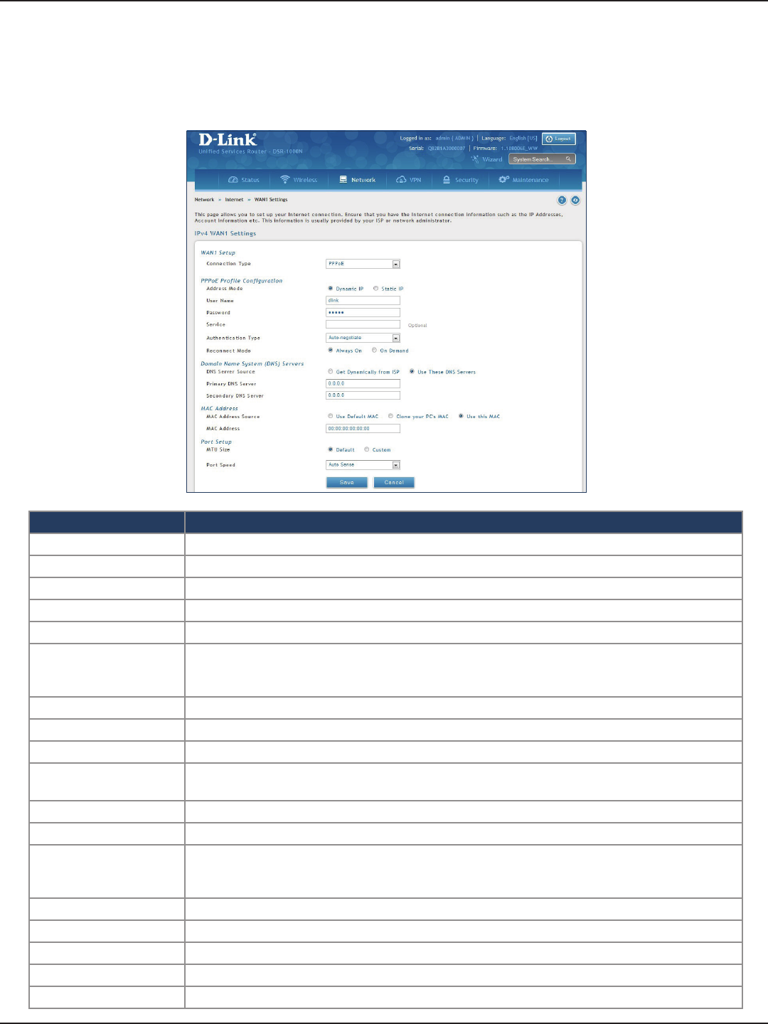
D-Link DSR-Series User Manual 32
Section 5 - Connect to the Internet
PPPoE
Path: Network > Internet > WAN1 Settings
Select PPPoE to enter the PPPoE Internet settings supplied by your Internet Service Provider.
Field Description
Address Mode Select Dynamic IP or Static IP (IP settings supplied by your ISP).
User Name Enter your PPPoE user name.
Password Enter your PPPoE password.
Service Enter if your ISP requires it.
Authentication Type Select the authentication type from the drop-down menu.
Reconnect Mode
Some ISPs may require you to pay for usage time. Select On Demand if this is the case. This will
have the router connect to the Internet only when you initiate an Internet connection. Select
Always On to have the router stay connected to the Internet.
IP Address If you selected Static IP, enter the IP address supplied by your ISP.
IP Subnet Mask If you selected Static IP, enter the subnet mask supplied by your ISP.
Gateway IP Address If you selected Static IP, enter the gateway IP address supplied by your ISP.
DNS Server Source Select either Get Dynamically from ISP or Use These DNS Servers to manually enter DNS
servers.
Primary DNS Server If you selected “Use These DNS Servers”, enter the primary DNS server IP address.
Secondary DNS Server If you selected “Use These DNS Servers”, enter the secondary DNS server IP address.
MAC Address Source
Select Use Default MAC to use the MAC address from the WAN1 port to associate with your
modem/ISP, Clone your PC’s MAC to use the MAC address of the computer you are currently
using to associate with your modem/ISP, or Use this MAC to manually enter a MAC address.
MAC Address If you selected Use this MAC, enter the MAC address you want to associate with your ISP.
MTU Size Select to use the default MTU value (1500) or select Custom to enter your own value.
Custom MTU Enter a MTU value to optimize performance with your ISP.
Port Speed Select a value from the drop-down menu. The default value is Auto-Sense.
Save Click Save to save and activate your settings.
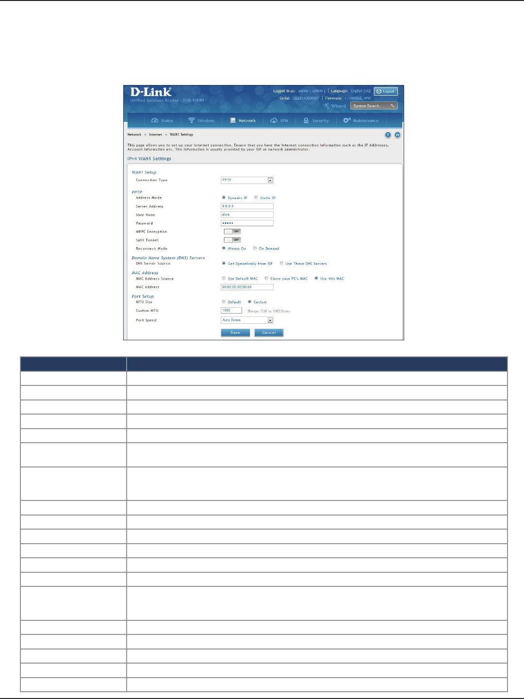
D-Link DSR-Series User Manual 33
Section 5 - Connect to the Internet
PPTP
Path: Network > Internet > WAN1 Settings
Select PPTP to enter the PPTP Internet settings supplied by your Internet Service Provider.
Field Description
Address Mode Select Dynamic IP or Static IP (IP settings supplied by your ISP).
Server Address Enter your PPTP server address.
User Name Enter your PPTP user name.
Password Enter your PPTP password.
MPPE Encryption Toggle to ON and select the level of MPPE encryption.
Split Tunnel Toggle to ON to use split tunnelling. This will allow you to connect to a VPN and Internet using the same
physical connection.
Reconnect Mode
Some ISPs may require you to pay for usage time. Select On Demand if this is the case. This will have the
router connect to the Internet only when you initiate an Internet connection. Select Always On to have the
router stay connected to the Internet.
IP Address If you selected Static IP, enter the IP address supplied by your ISP.
IP Subnet Mask If you selected Static IP, enter the subnet mask supplied by your ISP.
Gateway IP Address If you selected Static IP, enter the gateway IP address supplied by your ISP.
DNS Server Source Select either Get Dynamically from ISP or Use These DNS Servers to manually enter DNS servers.
Primary DNS Server If you selected “Use These DNS Servers”, enter the primary DNS server IP address.
Secondary DNS Server If you selected “Use These DNS Servers”, enter the secondary DNS server IP address.
MAC Address Source
Select Use Default MAC to use the MAC address from the WAN1 port to associate with your modem/ISP,
Clone your PC’s MAC to use the MAC address of the computer you are currently using to associate with
your modem/ISP, or Use this MAC to manually enter a MAC address.
MAC Address If you selected Use this MAC, enter the MAC address you want to associate with your ISP.
MTU Size Select to use the default MTU value (1500) or select Custom to enter your own value.
Custom MTU Enter a MTU value to optimize performance with your ISP.
Port Speed Select a value from the drop-down menu. The default value is Auto-Sense.
Save Click Save to save and activate your settings.
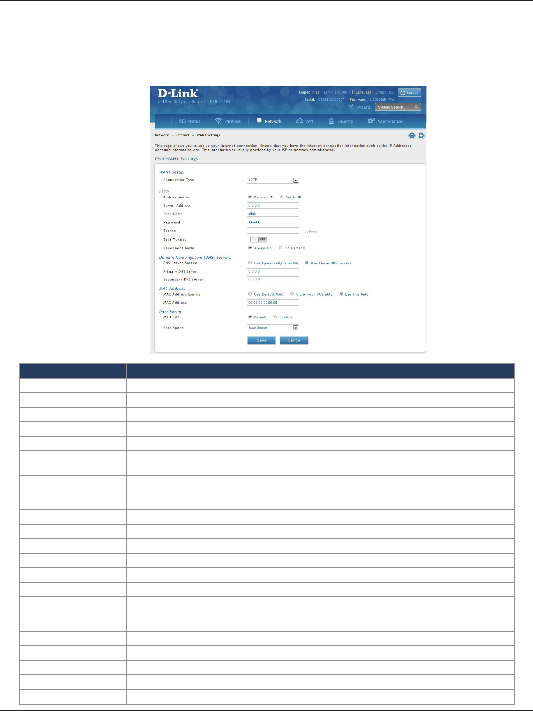
D-Link DSR-Series User Manual 34
Section 5 - Connect to the Internet
L2TP
Field Description
Address Mode Select Dynamic IP or Static IP (IP settings supplied by your ISP).
Server Address Enter your PPTP server address.
User Name Enter your PPTP user name.
Password Enter your PPTP password.
Secret Enter a shared secret if required.
Split Tunnel Toggle to ON to use split tunnelling. This will allow you to connect to a VPN and Internet using the same
physical connection.
Reconnect Mode
Some ISPs may require you to pay for usage time. Select On Demand if this is the case. This will have the
router connect to the Internet only when you initiate an Internet connection. Select Always On to have the
router stay connected to the Internet.
IP Address If you selected Static IP, enter the IP address supplied by your ISP.
IP Subnet Mask If you selected Static IP, enter the subnet mask supplied by your ISP.
Gateway IP Address If you selected Static IP, enter the gateway IP address supplied by your ISP.
DNS Server Source Select either Get Dynamically from ISP or Use These DNS Servers to manually enter DNS servers.
Primary DNS Server If you selected “Use These DNS Servers”, enter the primary DNS server IP address.
Secondary DNS Server If you selected “Use These DNS Servers”, enter the secondary DNS server IP address.
MAC Address Source
Select Use Default MAC to use the MAC address from the WAN1 port to associate with your modem/ISP,
Clone your PC’s MAC to use the MAC address of the computer you are currently using to associate with
your modem/ISP, or Use this MAC to manually enter a MAC address.
MAC Address If you selected Use this MAC, enter the MAC address you want to associate with your ISP.
MTU Size Select to use the default MTU value (1500) or select Custom to enter your own value.
Custom MTU Enter a MTU value to optimize performance with your ISP.
Port Speed Select a value from the drop-down menu. The default value is Auto-Sense.
Save Click Save to save and activate your settings.
Path: Network > Internet > WAN1 Settings
Select L2TP to enter the L2TP Internet settings supplied by your Internet Service Provider.
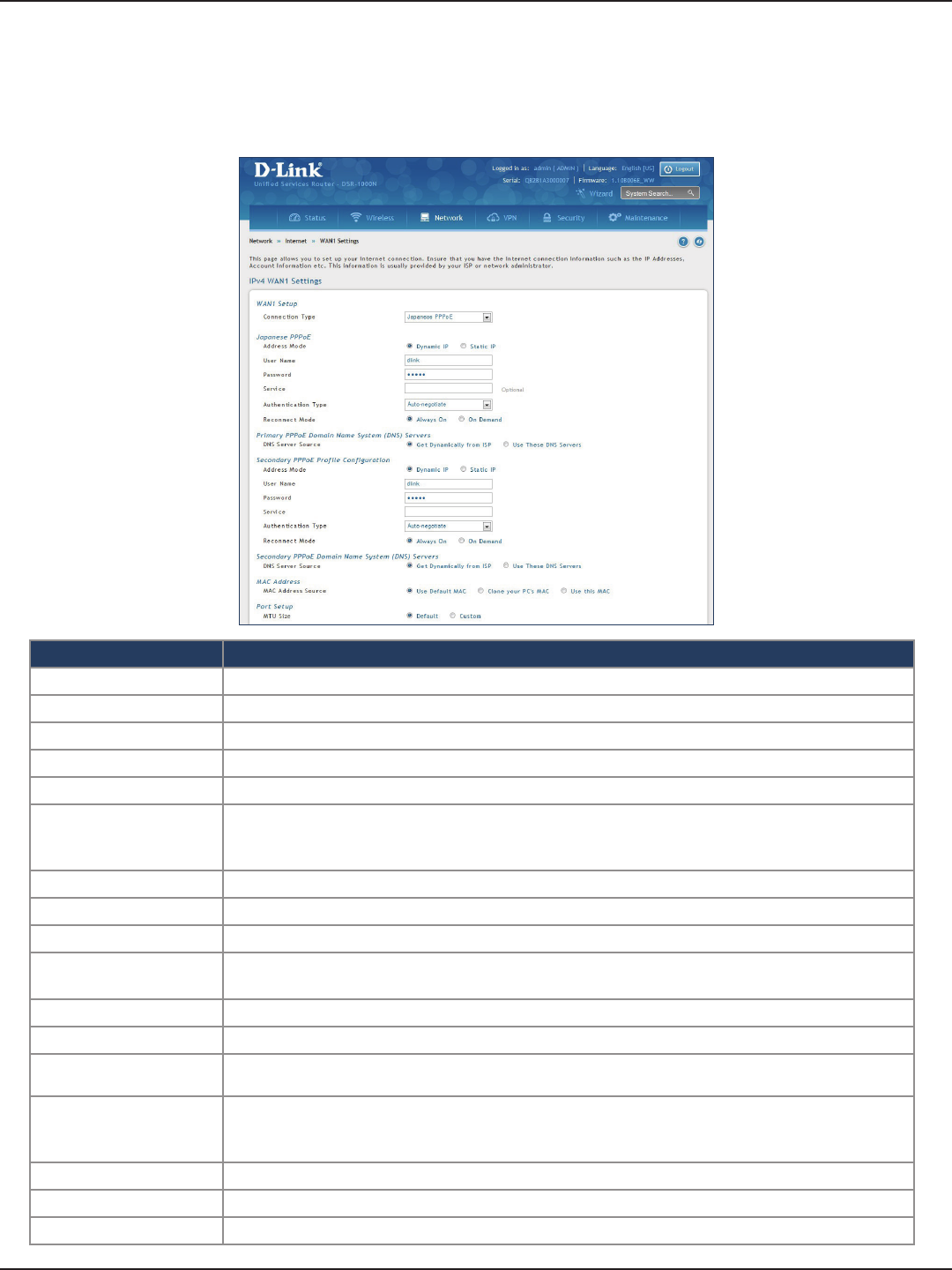
D-Link DSR-Series User Manual 35
Section 5 - Connect to the Internet
Japanese PPPoE
Path: Network > Internet > WAN1 Settings
Select Japanese PPPoE to enter the PPPoE Internet settings supplied by your Internet Service Provider.
Field Description
Address Mode Select Dynamic IP or Static IP (IP settings supplied by your ISP).
User Name Enter your PPPoE user name.
Password Enter your PPPoE password.
Service Enter if your ISP requires it.
Authentication Type Select the authentication type from the drop-down menu.
Reconnect Mode
Some ISPs may require you to pay for usage time. Select On Demand if this is the case. This will
have the router connect to the Internet only when you initiate an Internet connection. Select
Always On to have the router stay connected to the Internet.
IP Address If you selected Static IP, enter the IP address supplied by your ISP.
IP Subnet Mask If you selected Static IP, enter the subnet mask supplied by your ISP.
Gateway IP Address If you selected Static IP, enter the gateway IP address supplied by your ISP.
Primary PPPoE DNS
Servers
Select either Get Dynamically from ISP or Use These DNS Servers to manually enter DNS
servers.
Primary DNS Server If you selected “Use These DNS Servers”, enter the primary DNS server IP address.
Secondary DNS Server If you selected “Use These DNS Servers”, enter the secondary DNS server IP address.
Secondary PPPoE
Prole You may create a secondary PPPoE prole.
MAC Address Source
Select Use Default MAC to use the MAC address from the WAN1 port to associate with your
modem/ISP, Clone your PC’s MAC to use the MAC address of the computer you are currently
using to associate with your modem/ISP, or Use this MAC to manually enter a MAC address.
MAC Address If you selected Use this MAC, enter the MAC address you want to associate with your ISP.
Port Speed Select a value from the drop-down menu. The default value is Auto-Sense.
Save Click Save to save and activate your settings.
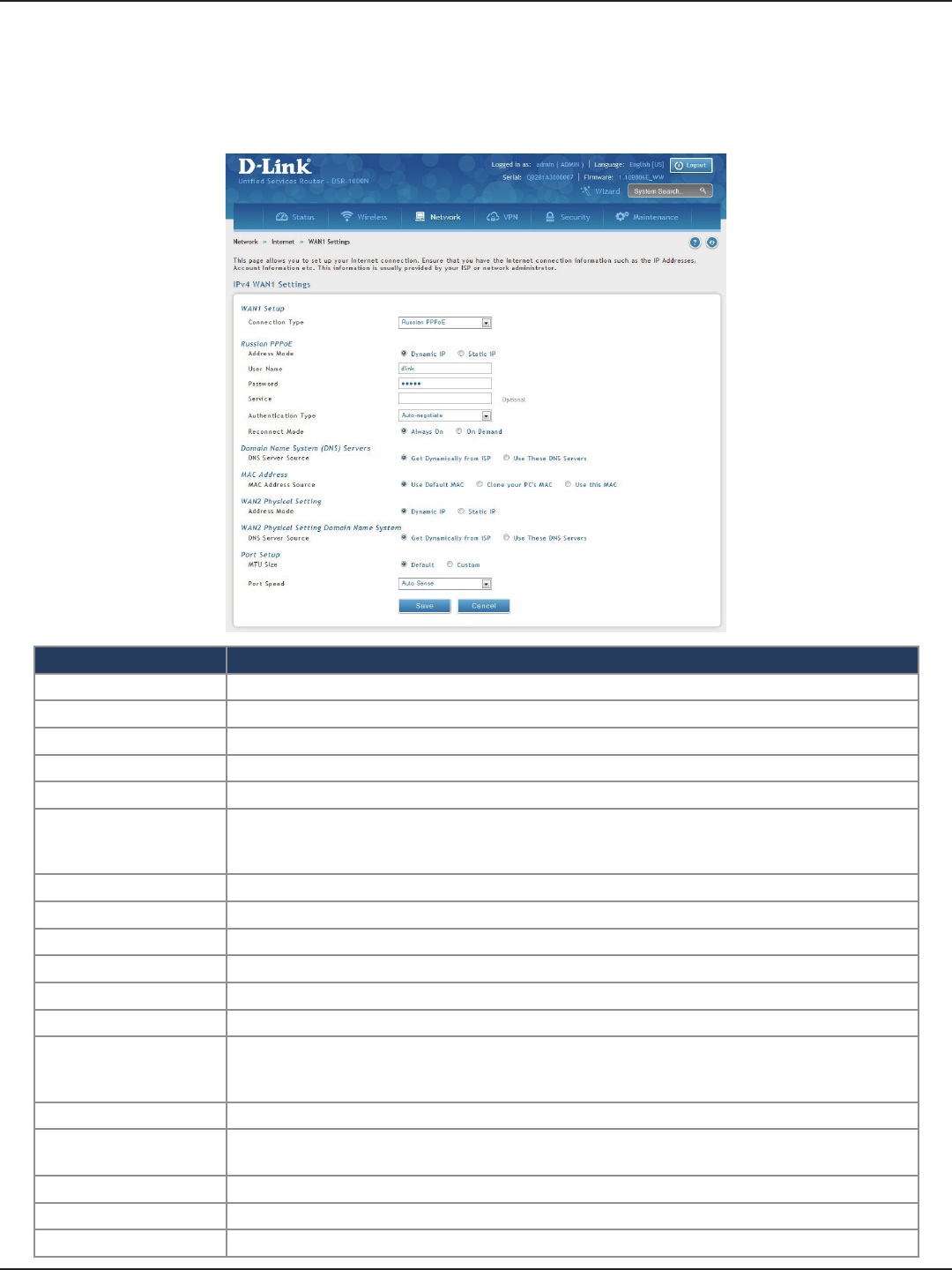
D-Link DSR-Series User Manual 36
Section 5 - Connect to the Internet
Russian PPPoE
Path: Network > Internet > WAN1 Settings
Select Russian PPPoE to enter the PPPoE Internet settings supplied by your Internet Service Provider.
Field Description
Address Mode Select Dynamic IP or Static IP (IP settings supplied by your ISP).
User Name Enter your PPPoE user name.
Password Enter your PPPoE password.
Service Enter if your ISP requires it.
Authentication Type Select the authentication type from the drop-down menu.
Reconnect Mode
Some ISPs may require you to pay for usage time. Select On Demand if this is the case. This will
have the router connect to the Internet only when you initiate an Internet connection. Select
Always On to have the router stay connected to the Internet.
IP Address If you selected Static IP, enter the IP address supplied by your ISP.
IP Subnet Mask If you selected Static IP, enter the subnet mask supplied by your ISP.
Gateway IP Address If you selected Static IP, enter the gateway IP address supplied by your ISP.
DNS Server Source Select either Get Dynamically from ISP or Use These DNS Servers to manually enter DNS servers.
Primary DNS Server If you selected “Use These DNS Servers”, enter the primary DNS server IP address.
Secondary DNS Server If you selected “Use These DNS Servers”, enter the secondary DNS server IP address.
MAC Address Source
Select Use Default MAC to use the MAC address from the WAN1 port to associate with your
modem/ISP, Clone your PC’s MAC to use the MAC address of the computer you are currently using
to associate with your modem/ISP, or Use this MAC to manually enter a MAC address.
MAC Address If you selected Use this MAC, enter the MAC address you want to associate with your ISP.
WAN2 Physical Setting Select Dynamic IP or Static IP (IP settings supplied by your ISP). If you select Static IP, enter the IP
settings supplied by your ISP.
WAN2 Physical DNS Select either Get Dynamically from ISP or Use These DNS Servers to manually enter DNS servers.
Port Speed Select a value from the drop-down menu. The default value is Auto-Sense.
Save Click Save to save and activate your settings.
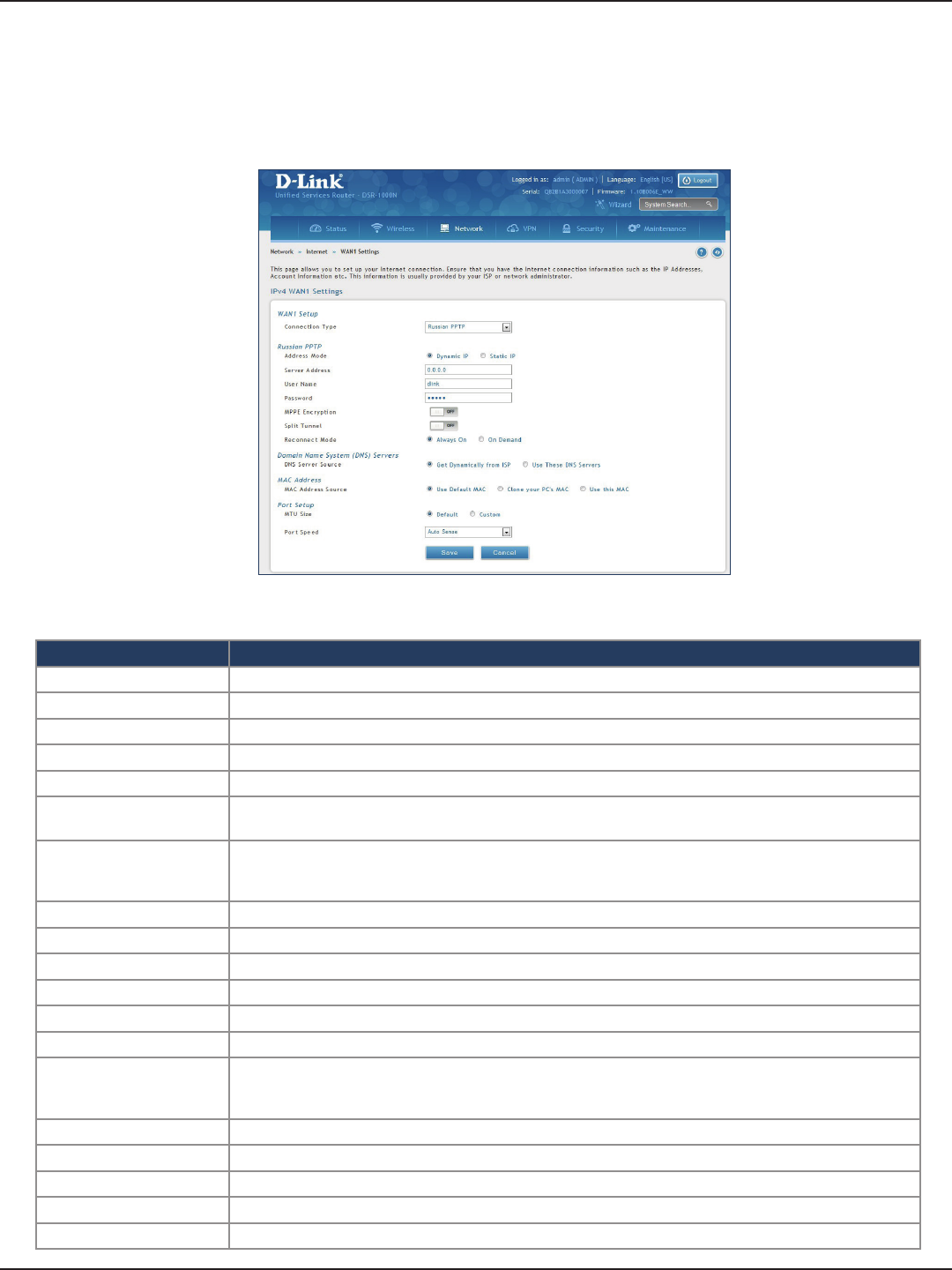
D-Link DSR-Series User Manual 37
Section 5 - Connect to the Internet
Russian PPTP
Field Description
Address Mode Select Dynamic IP or Static IP (IP settings supplied by your ISP).
Server Address Enter your PPTP server address.
User Name Enter your PPTP user name.
Password Enter your PPTP password.
MPPE Encryption Toggle to ON and select the level of MPPE encryption.
Split Tunnel Toggle to ON to use split tunnelling. This will allow you to connect to a VPN and Internet using the same
physical connection.
Reconnect Mode
Some ISPs may require you to pay for usage time. Select On Demand if this is the case. This will have the
router connect to the Internet only when you initiate an Internet connection. Select Always On to have the
router stay connected to the Internet.
IP Address If you selected Static IP, enter the IP address supplied by your ISP.
IP Subnet Mask If you selected Static IP, enter the subnet mask supplied by your ISP.
Gateway IP Address If you selected Static IP, enter the gateway IP address supplied by your ISP.
DNS Server Source Select either Get Dynamically from ISP or Use These DNS Servers to manually enter DNS servers.
Primary DNS Server If you selected “Use These DNS Servers”, enter the primary DNS server IP address.
Secondary DNS Server If you selected “Use These DNS Servers”, enter the secondary DNS server IP address.
MAC Address Source
Select Use Default MAC to use the MAC address from the WAN1 port to associate with your modem/ISP,
Clone your PC’s MAC to use the MAC address of the computer you are currently using to associate with
your modem/ISP, or Use this MAC to manually enter a MAC address.
MAC Address If you selected Use this MAC, enter the MAC address you want to associate with your ISP.
MTU Size Select to use the default MTU value (1500) or select Custom to enter your own value.
Custom MTU Enter a MTU value to optimize performance with your ISP.
Port Speed Select a value from the drop-down menu. The default value is Auto-Sense.
Save Click Save to save and activate your settings.
Path: Network > Internet > WAN1 Settings
Select Russian PPTP to enter the PPTP Internet settings supplied by your Internet Service Provider.
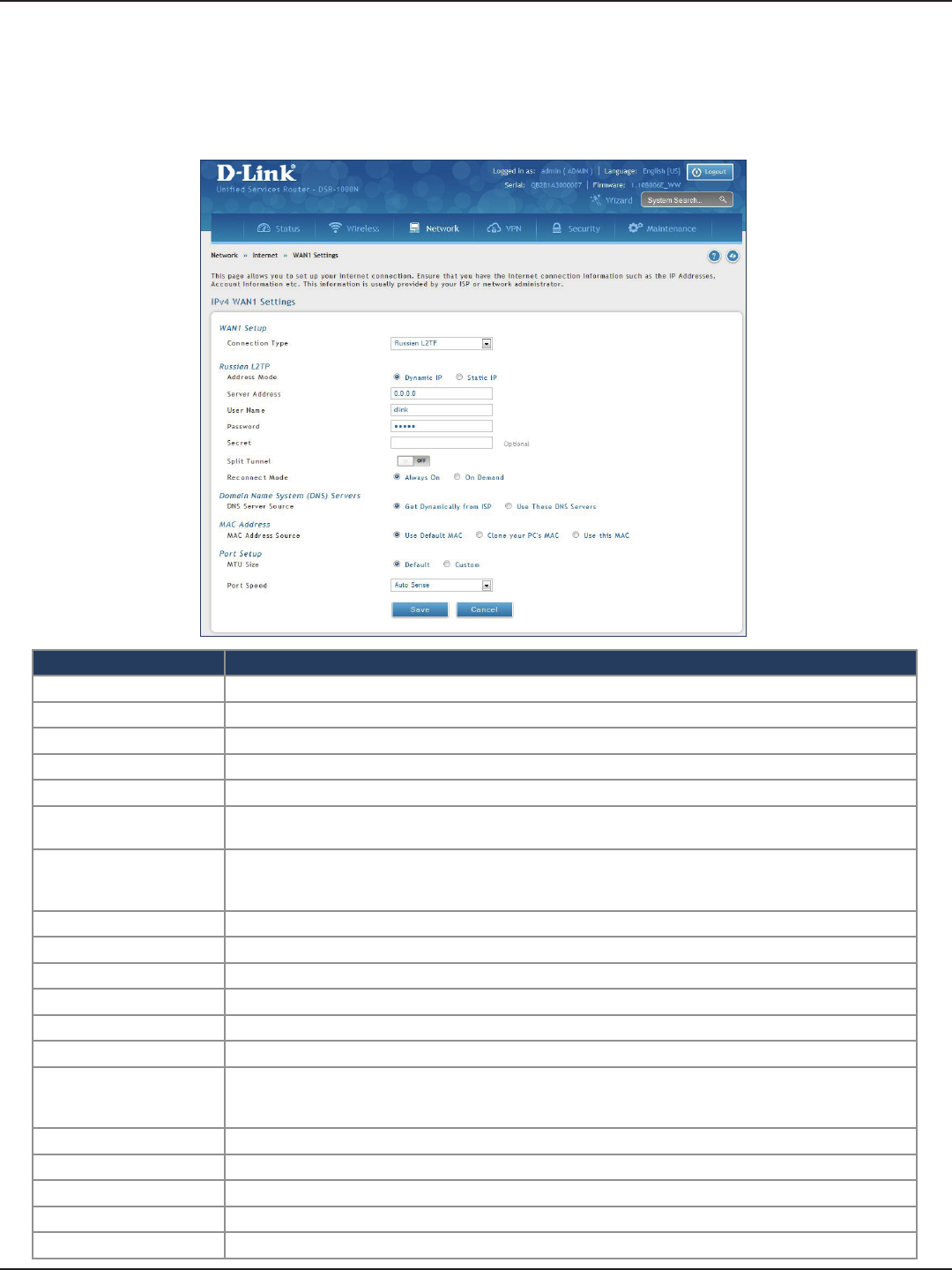
D-Link DSR-Series User Manual 38
Section 5 - Connect to the Internet
Russian L2TP
Path: Network > Internet > WAN1 Settings
Select Russian L2TP to enter the L2TP Internet settings supplied by your Internet Service Provider.
Field Description
Address Mode Select Dynamic IP or Static IP (IP settings supplied by your ISP).
Server Address Enter your PPTP server address.
User Name Enter your PPTP user name.
Password Enter your PPTP password.
Secret Enter a shared secret if required.
Split Tunnel Toggle to ON to use split tunnelling. This will allow you to connect to a VPN and Internet using the same
physical connection.
Reconnect Mode
Some ISPs may require you to pay for usage time. Select On Demand if this is the case. This will have the
router connect to the Internet only when you initiate an Internet connection. Select Always On to have the
router stay connected to the Internet.
IP Address If you selected Static IP, enter the IP address supplied by your ISP.
IP Subnet Mask If you selected Static IP, enter the subnet mask supplied by your ISP.
Gateway IP Address If you selected Static IP, enter the gateway IP address supplied by your ISP.
DNS Server Source Select either Get Dynamically from ISP or Use These DNS Servers to manually enter DNS servers.
Primary DNS Server If you selected “Use These DNS Servers”, enter the primary DNS server IP address.
Secondary DNS Server If you selected “Use These DNS Servers”, enter the secondary DNS server IP address.
MAC Address Source
Select Use Default MAC to use the MAC address from the WAN1 port to associate with your modem/ISP,
Clone your PC’s MAC to use the MAC address of the computer you are currently using to associate with
your modem/ISP, or Use this MAC to manually enter a MAC address.
MAC Address If you selected Use this MAC, enter the MAC address you want to associate with your ISP.
MTU Size Select to use the default MTU value (1500) or select Custom to enter your own value.
Custom MTU Enter a MTU value to optimize performance with your ISP.
Port Speed Select a value from the drop-down menu. The default value is Auto-Sense.
Save Click Save to save and activate your settings.
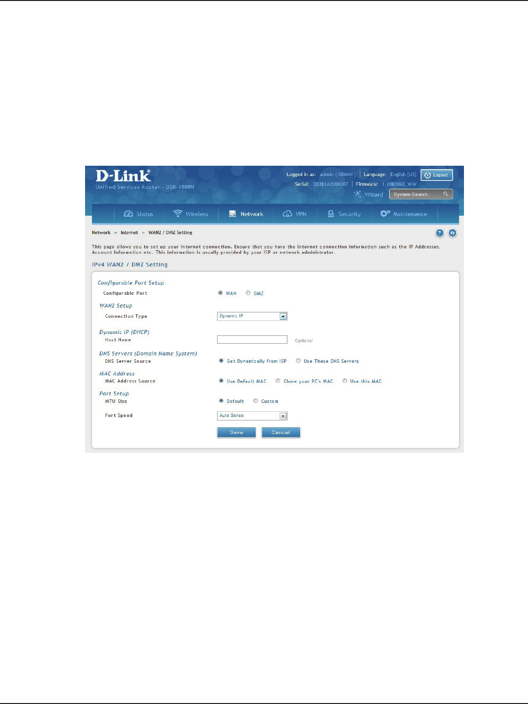
D-Link DSR-Series User Manual 39
Section 5 - Connect to the Internet
WAN2 Settings
WAN
Path: Network > Internet > WAN2 Settings
Select WAN and select the Internet connection type. Please refer to the previous pages (41-49) for more
information. If you want to set WAN2 port to DMZ, skip to the next page.
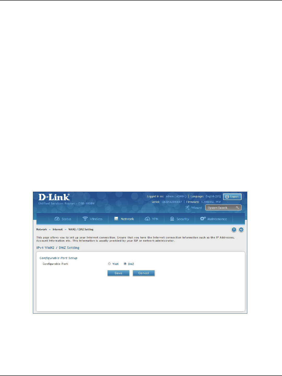
D-Link DSR-Series User Manual 40
Section 5 - Connect to the Internet
DMZ
This router supports one of the physical ports to be congured as a secondary WAN Ethernet port or a dedicated
DMZ port. A DMZ is a sub network that is open to the public but behind the rewall. The DMZ adds an additional
layer of security to the LAN, as specic services/ports that are exposed to the internet on the DMZ do not have
to be exposed on the LAN. It is recommended that hosts that must be exposed to the internet (such as web or
email servers) be placed in the DMZ network.
Firewall rules can be allowed to permit access specic services/ports to the DMZ from both the LAN or WAN. In
the event of an attack to any of the DMZ nodes, the LAN is not necessarily vulnerable as well.
DMZ conguration is identical to the LAN conguration. There are no restrictions on the IP address or subnet
assigned to the DMZ port, other than the fact that it cannot be identical to the IP address given to the LAN
interface of this gateway.
Note: DSR-500/1000/500N/1000N/500AC/1000AC, in order to congure a DMZ port, the router’s congurable port
must be set to DMZ in the Network > Internet > DMZ Settings page.
Note: For DSR-150N and DSR-250N, enabling DMZ will result in port 8 of the LAN switch being used for a dedicated
DMZ port. The other 7 LAN ports remain unchanged.
1. Click Network > Internet > WAN2 / DMZ Settings.
2. Select DMZ and click Save.
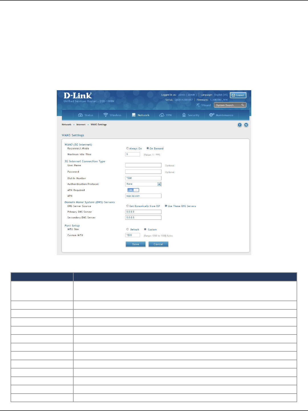
D-Link DSR-Series User Manual 41
Section 5 - Connect to the Internet
WAN3 (3G Internet)
Path: Network > Internet > WAN3 Settings
This router supports the use of 3G Internet access. Cellular 3G internet access is available on WAN3 via a 3G USB
modem for DSR series. The cellular ISP that provides the 3G data plan will provide the authentication requirements
to establish a connection. The dial Number and APN are specic to the cellular carriers. Once the connection type
settings are congured and saved, navigate to the WAN status page (Setup > Internet Settings > WAN3 Status)
and Enable the WAN3 link to establish the 3G connection.
Field Description
Reconnect Mode
Some ISPs may require you to pay for usage time. Select On Demand if this is the case. This will have the
router connect to the Internet only when you initiate an Internet connection. Select Always On to have the
router stay connected to the Internet.
Maximum Idle Time Enter the idle time in minutes before the router disconnects from the Internet (On Demand only).
User Name Enter your 3G account user name.
Password Enter your 3G account password.
Dial-in Number Enter the phone number to access your Internet.
Authentication Protocol Select one of following protocols from the drop-down menu: None, PAP or CHAP.
APN Required Toggle to ON if your ISP requires APN to connect.
APN Enter the APN (Access Point Name) provided by the ISP.
DNS Server Source Select either Get Dynamically from ISP or Use These DNS Servers to manually enter DNS servers.
Primary DNS Server If you selected “Use These DNS Servers”, enter the primary DNS server IP address.
Secondary DNS Server If you selected “Use These DNS Servers”, enter the secondary DNS server IP address.
MTU Size Select to use the default MTU value (1500) or select Custom to enter your own value.
Custom MTU Enter a MTU value to optimize performance with your ISP.
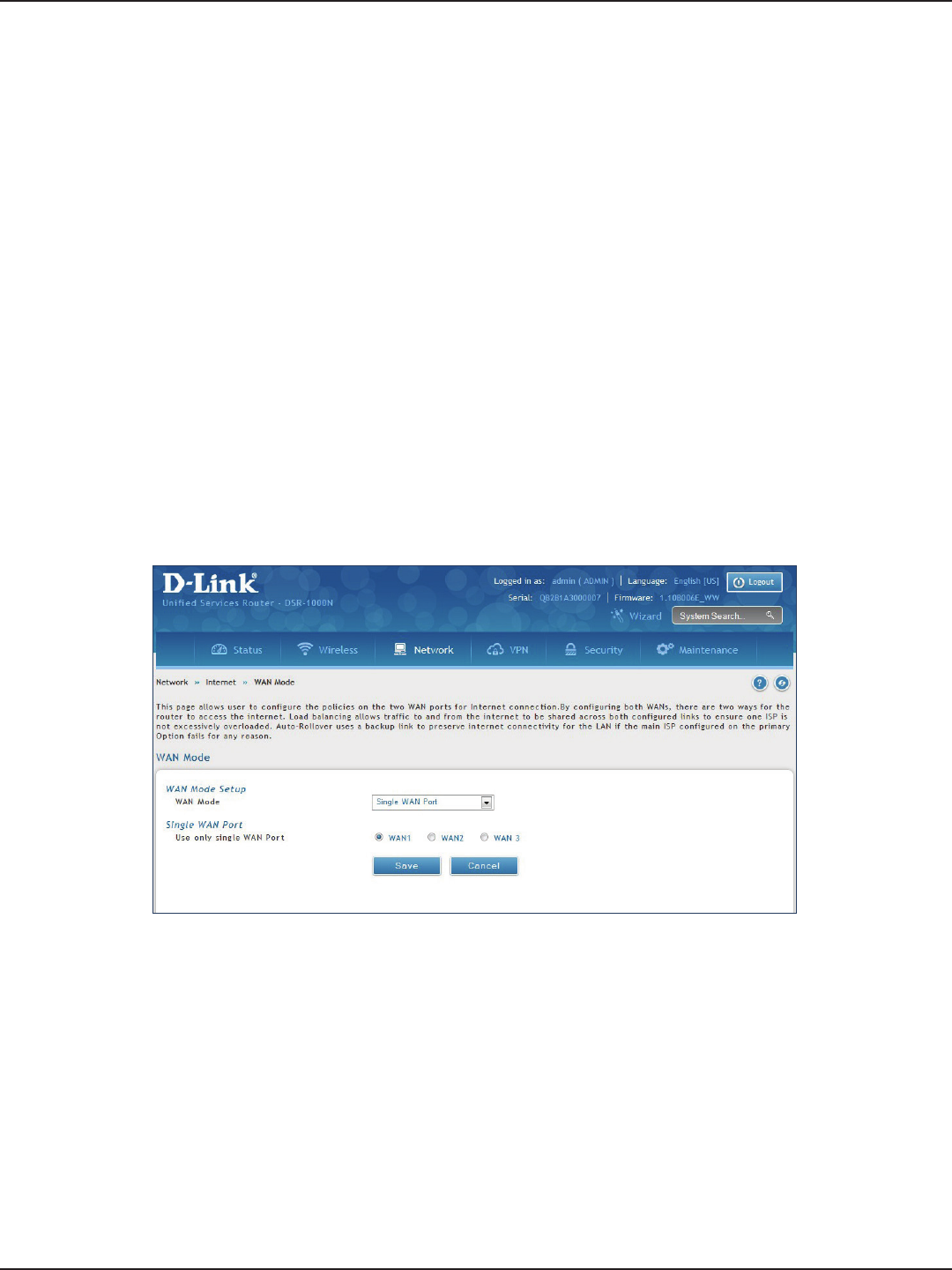
D-Link DSR-Series User Manual 42
Section 5 - Connect to the Internet
WAN Mode
Single WAN Port
Path: Network > Internet > WAN Mode
This router supports multiple WAN links. This allows you to take advantage of failover and load balancing
features to ensure certain internet dependent services are prioritized in the event of unstable WAN connectivity
on one of the ports.
To use Auto Failover or Load Balancing, WAN link failure detection must be congured. This involves accessing
DNS servers on the internet or ping to an internet address (user dened). If required, you can congure the
number of retry attempts when the link seems to be disconnected or the threshold of failures that determines
if a WAN port is down.
If you do not want to use Auto Failover or Load Balancing, select Single WAN Port from the WAN Mode drop-down
menu and select the WAN port you want to set. Click Save.
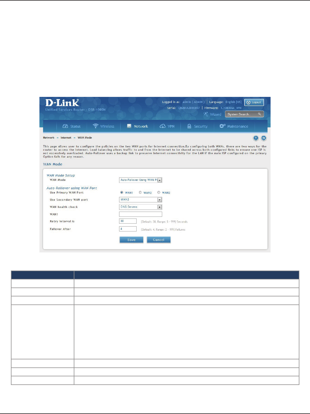
D-Link DSR-Series User Manual 43
Section 5 - Connect to the Internet
Auto-Rollover using WAN IP
In this mode one of your WAN ports is assigned as the primary internet link for all internet trac and the
secondary WAN port is used for redundancy in case the primary link goes down for any reason. Both WAN ports
(primary and secondary) must be congured to connect to the respective ISP’s before enabling this feature. The
secondary WAN port will remain unconnected until a failure is detected on the primary link (either port can be
assigned as the primary). In the event of a failure on the primary port, all internet trac will be rolled over to
the backup port. When congured in Auto-Failover mode, the link status of the primary WAN port is checked at
regular intervals as dened by the failure detection settings.
Field Description
WAN Mode Select Auto-Rollover Using WAN IP from the drop-down menu.
Use Primary WAN Port Select which WAN port is the primary.
Use Secondary WAN Port Select which port to use if the primary port fails.
WAN Health Check
• DNS lookup using WAN DNS Servers: DNS Lookup of the DNS Servers of the primary link is used to
detect primary WAN connectivity.
• DNS lookup using DNS Servers: DNS Lookup of the custom DNS Servers can be specied to check
the connectivity of the primary link.
• Ping these IP addresses: These IP’s will be pinged at regular intervals to check the connectivity of the
primary link.
• Retry Interval is: The number tells the router how often it should run the above congured failure
detection method.
• Failover after: This sets the number of retries after which failover is initiated.
WAN1/WAN2/WAN3 Enter the DNS server or IP address to ping.
Retry Interval Enter the time in seconds to initiate the WAN health check. Default is every 30 seconds.
Failover After Enter the number of failures before the router will enable the failover process.
Note: The DSR series routers support 3G USB Modem as a failover link when the internet access is lost.
1. Click Network > Internet > WAN Mode.
2. Complete the elds from the table below and click Save.

D-Link DSR-Series User Manual 44
Section 5 - Connect to the Internet
Load Balancing
Path: Network > Internet > WAN Mode
This feature allows you to use multiple WAN links (and presumably multiple ISP’s) simultaneously. After
conguring more than one WAN port, the load balancing option is available to carry trac over more than one
link. Protocol bindings are used to segregate and assign services over one WAN port in order to manage internet
ow. The congured failure detection method is used at regular intervals on all congured WAN ports when in
Load Balancing mode.
This router currently supports three algorithms for Load Balancing:
Round Robin: This algorithm is particularly useful when the connection speed of one WAN port greatly
diers from another. In this case you can dene protocol bindings to route low-latency services (such
as VOIP) over the higher -speed link and let low-volume background trac (such as SMTP) go over the
lower speed link. Protocol binding is explained in next section.
Spillover: If Spillover method is selected, the primary WAN acts as a dedicated link until a dened
bandwidth threshold are reached. After this, the secondary WAN will be used for new connections.
Inbound connections on the secondary WAN are permitted with this mode, as the spillover logic governs
outbound connections moving from the primary to secondary WAN. You can congure spillover mode
by using following options:
• Load Tolerance: It is the percentage of bandwidth after which the router switches to
secondary WAN.
• Max Bandwidth: This sets the maximum bandwidth tolerable by the primary WAN for
outbound trac.
If the link bandwidth of outbound trac goes above the load tolerance value of max bandwidth, the
router will spillover the next connections to secondary WAN.
For example, if the maximum bandwidth of primary WAN is 1Kbps and the load tolerance is set to 70. Now
every time a new connection is established the bandwidth increases. After a certain number of connections say
bandwidth reached 70% of 1Kbps, the new outbound connections will be spilled over to secondary WAN. The
maximum value of load tolerance is 80% and the minimum is 20%.
Note: The DSR-1000 and DSR-500 routers support the trac load balancing between physical WAN port and a 3G USB
Modem.
Load balancing is particularly useful when the connection speed of one WAN port greatly diers from another.
In this case you can dene protocol bindings to route low-latency services (such as VOIP) over the higher-speed
link and let low-volume background trac (such as SMTP) go over the lower speed link.
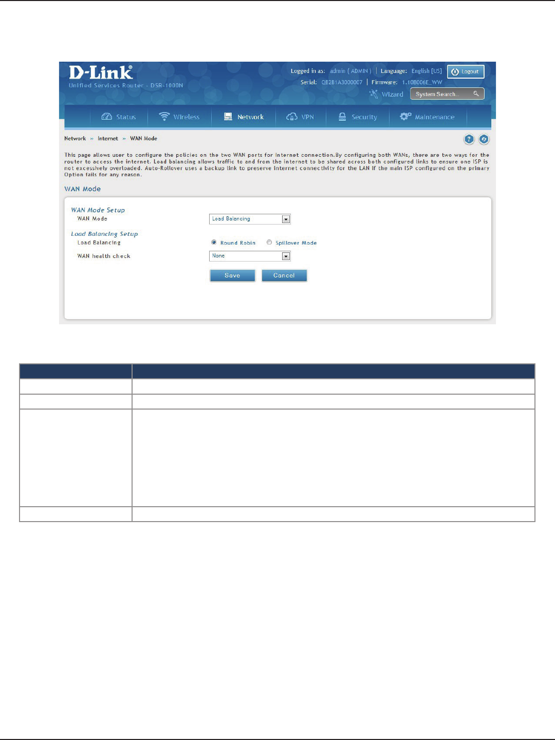
D-Link DSR-Series User Manual 45
Section 5 - Connect to the Internet
Field Description
WAN Mode Select Load Balancing from the drop-down menu.
Load Balance Select Round Robin.
WAN Health Check
• DNS lookup using WAN DNS Servers: DNS Lookup of the DNS Servers of the primary link is used to
detect primary WAN connectivity.
• DNS lookup using DNS Servers: DNS Lookup of the custom DNS Servers can be specied to check
the connectivity of the primary link.
• Ping these IP addresses: These IP’s will be pinged at regular intervals to check the connectivity of the
primary link.
• Retry Interval is: The number tells the router how often it should run the above congured failure
detection method.
• Failover after: This sets the number of retries after which failover is initiated.
Save Click to save and activate your settings.
Round Robin
1. Click Network > Internet > WAN Mode.
2. Complete the elds from the table below and click Save.
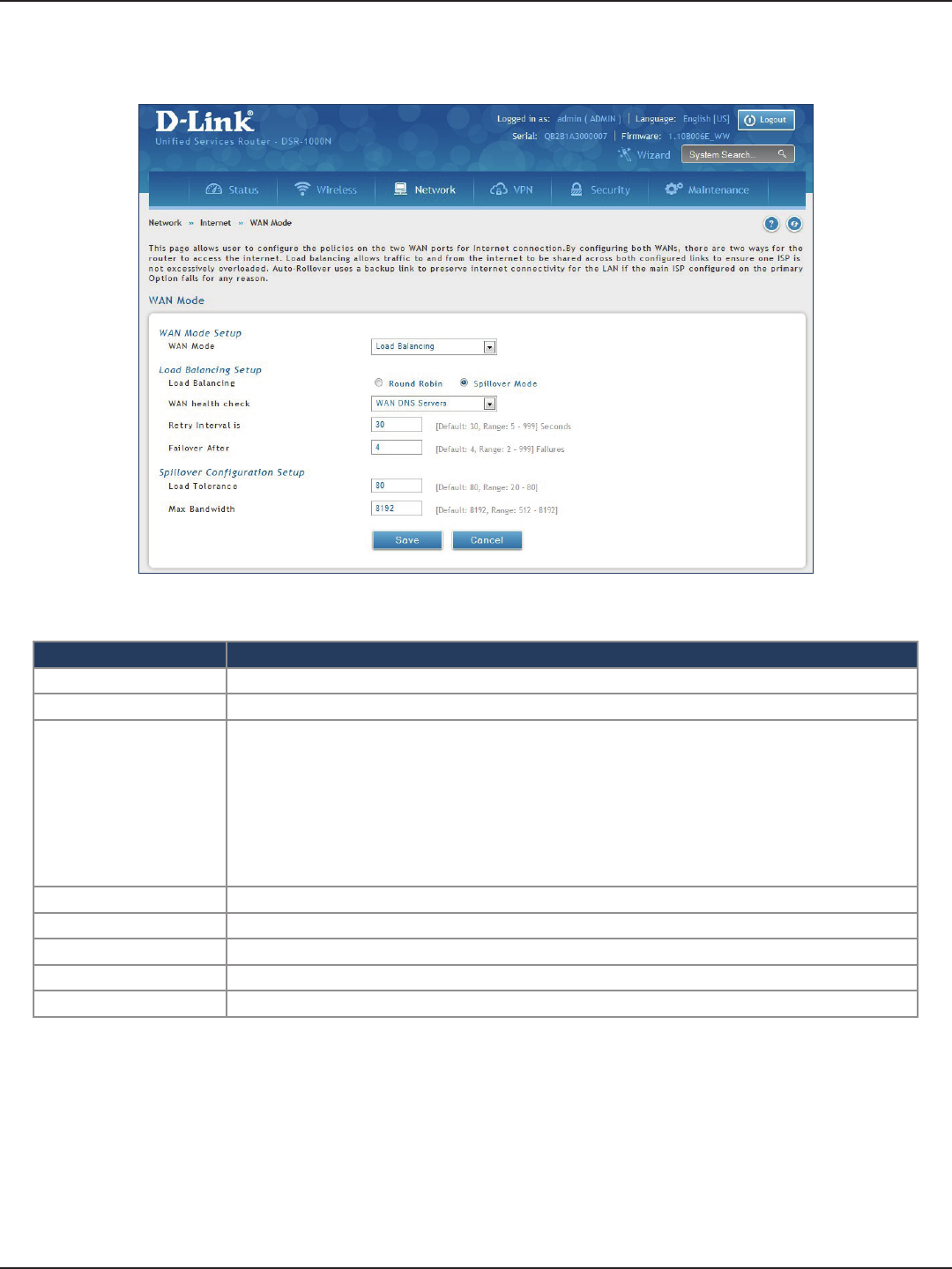
D-Link DSR-Series User Manual 46
Section 5 - Connect to the Internet
Field Description
WAN Mode Select Load Balancing from the drop-down menu.
Load Balance Select Spillover Mode.
WAN Health Check
• DNS lookup using WAN DNS Servers: DNS Lookup of the DNS Servers of the primary link is used to
detect primary WAN connectivity.
• DNS lookup using DNS Servers: DNS Lookup of the custom DNS Servers can be specied to check
the connectivity of the primary link.
• Ping these IP addresses: These IP’s will be pinged at regular intervals to check the connectivity of the
primary link.
• Retry Interval is: The number tells the router how often it should run the above congured failure
detection method.
• Failover after: This sets the number of retries after which failover is initiated.
Retry Interval is Enter the time in seconds to initiate the WAN health check. Default is every 30 seconds.
Failover After Enter the number of failures before the router will enable the failover process.
Load Tolerance Enter the percentage of bandwidth after which the router switches to the secondary WAN.
Max Bandwidth This sets the maximum bandwidth tolerable by the primary WAN for outbound trac.
Save Click to save and activate your settings.
Spillover
1. Click Network > Internet > WAN Mode.
2. Complete the elds from the table below and click Save.
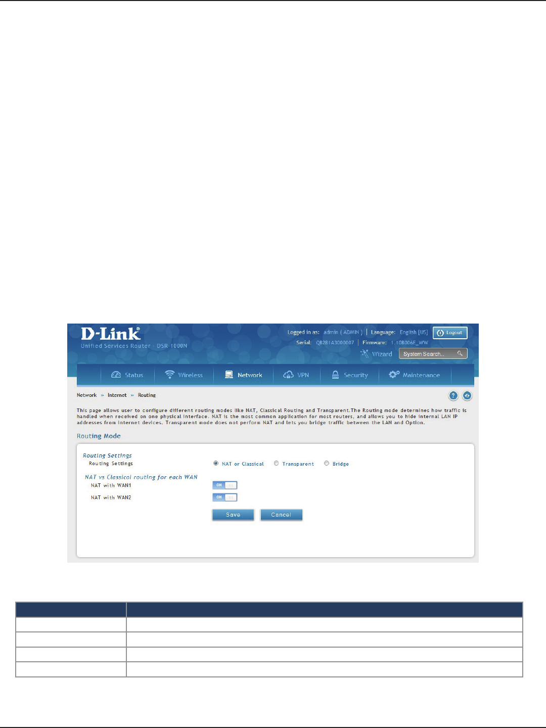
D-Link DSR-Series User Manual 47
Section 5 - Connect to the Internet
Routing Mode
Routing between the LAN and WAN will impact the way this router handles trac that is received on any of
its physical interfaces. The routing mode of the gateway is core to the behavior of the trac ow between the
secure LAN and the internet.
NAT or Classical
Field Description
Routing Settings Select NAT or Classical.
NAT with WAN1 Toggle to ON to use NAT with WAN1 or OFF for classical.
NAT with WAN2 Toggle to ON to use NAT with WAN2 or OFF for classical.
Save Click to save and activate your settings.
Path: Network > Internet > Routing Mode
With classical routing, devices on the LAN can be directly accessed from the internet with their public IP addresses
(assuming appropriate rewall settings are congured). If your ISP has assigned an IP address for each of the
computers/devices that you use, select Classical.
NAT is a technique which allows several computers and devices on your local network to share an Internet
connection. The computers on the LAN use a “private” IP address range while the WAN port on the router is
congured with a single “public” IP address. Along with connection sharing, NAT also hides internal IP addresses
from the computers on the Internet. NAT is required if your ISP has assigned only one IP address to you. The
computers/devices that connect through the router will need to be assigned IP addresses from a private subnet.
1. Click Network > Internet > Routing Mode.
2. Complete the elds from the table below and click Save.
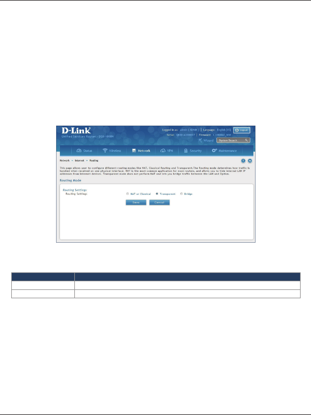
D-Link DSR-Series User Manual 48
Section 5 - Connect to the Internet
Transparent
Field Description
Routing Settings Select Transparent.
Save Click to save and activate your settings.
When Transparent Routing Mode is enabled, NAT is not performed on trac between the LAN and WAN
interfaces. Broadcast and multicast packets that arrive on the LAN interface are switched to the WAN and vice
versa, if they do not get ltered by rewall or VPN policies. To maintain the LAN and WAN in the same broadcast
domain select Transparent mode, which allows bridging of trac from LAN to WAN and vice versa, except
for router-terminated trac and other management trac. All DSR features (such as 3G modem support) are
supported in transparent mode assuming the LAN and WAN are congured to be in the same broadcast domain.
Note: NAT routing has a feature called “NAT Hair -pinning” that allows internal network users on the LAN and DMZ to
access internal servers (e.g., an internal FTP server) using their externally-known domain name. This is also referred to as
“NAT loopback” since LAN generated trac is redirected through the rewall to reach LAN servers by their external name.
1. Click Network > Internet > Routing.
2. Complete the elds from the table below and click Save.
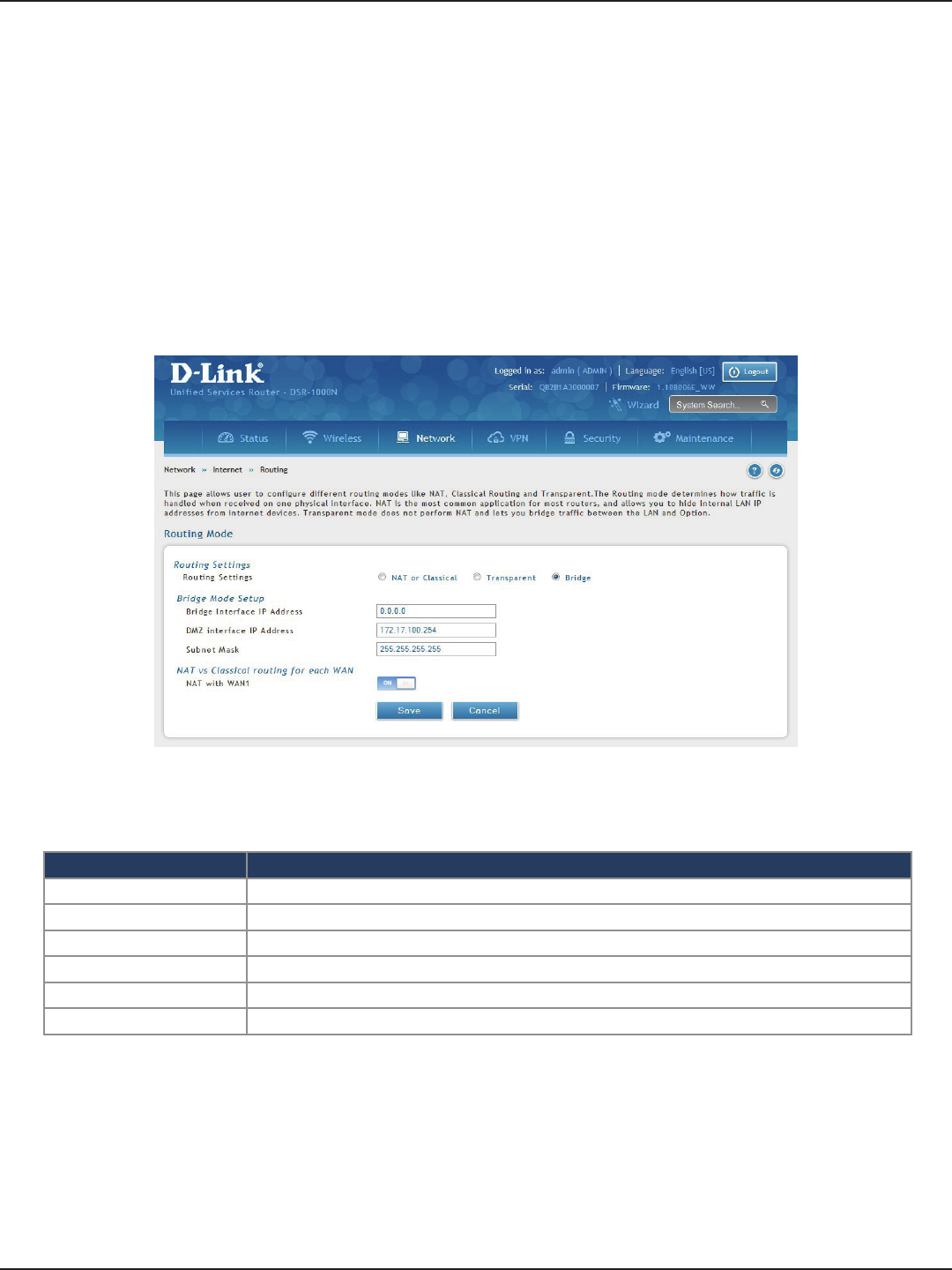
D-Link DSR-Series User Manual 49
Section 5 - Connect to the Internet
Bridge
Field Description
Routing Settings Select Bridge.
Bridge Interface IP Address Enter the bridge interface IP address.
DMZ Interface IP Address Enter the DMZ interface IP address.
Subnet Mask Enter the subnet mask.
NAT with WAN1 Toggle ON to turn NAT on WAN1 or OFF for classical.
Save Click to save and activate your settings.
When Bridge Mode routing is enabled, the rst physical LAN port and secondary WAN/DMZ (port 2) interfaces
are bridged together at Layer 2, creating an aggregate network. The other LAN ports and the primary WAN
(WAN1) are not part of this bridge, and the router asks as a NAT device for these other ports. With Bridge mode
for the LAN port 1 and WAN2/DMZ interfaces, L2 and L3 broadcast trac as well as ARP / RARP packets are
passed through. When WAN2 receives tagged trac the tag information will be removed before the packet is
forwarded to the LAN port 1 interface.
Note: Bridge mode option is available on DSR-500 / 500N / 500AC 1000 / 1000N / 1000AC routers only.
1. Click Network > Internet > Routing.
2. Complete the elds from the table below and click Save.

D-Link DSR-Series User Manual 50
Section 5 - Connect to the Internet
IP Aliasing
Path: Network > Internet > IP Aliasing
A single WAN Ethernet port can be accessed via multiple IP addresses by adding an alias to the port. This is done
by conguring an IP Alias address. To edit or delete any existing aliases, right-click the alias and select either Edit
or Delete.
Field Description
Interface Select either WAN1 or WAN2.
IP Address Enter an alias IP address for the WAN interface you selected.
Subnet Mask Enter a subnet mask for the WAN interface you selected.
Save Click to save and activate your settings.
To create a new alias:
1. Click Network > Internet > IP Aliasing.
2. Click Add New IP Aliasing.
3. Enter the following information and click Save.
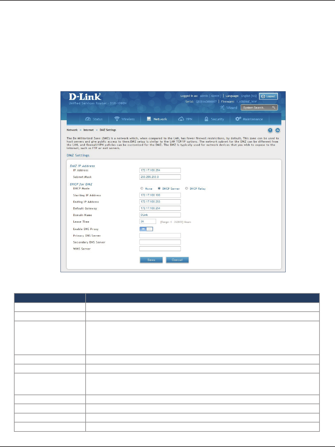
D-Link DSR-Series User Manual 51
Section 5 - Connect to the Internet
Field Description
IP Address Enter an IP address for the DMZ interface.
Subnet Mask Enter the subnet mask for the DMZ interface.
DHCP Mode
Select one of the following modes:
• None - Turns o DHCP.
• DHCP Server (default) - The router will act as the DHCP server on your network.
• DHCP Relay - DHCP clients on your network will receive IP address leases from a DHCP server on
a dierent subnet.
DHCP Server Refer to “DHCP Server” on page 19 for more information.
DHCP Relay Refer to “DHCP Relay” on page 20 for more information.
Enable DNS Proxy
Toggle to On to manually enter DNS and/or WINS server IP address(es). If set to O, your router’s LAN
IP address will be assigned the DNS server to your clients and the router will get the DNS information
from your ISP.
Primary DNS Server If DNS Proxy is set to ON, enter the primary DNS server IP address.
Secondary DNS Server If DNS Proxy is set to ON, enter the secondary DNS server IP address.
WINS Server If DNS Proxy is set to ON, enter the WINS server IP address.
Save Click to save and activate your settings.
DMZ Settings
Path: Network > Internet > DMZ Settings
If you set WAN2 port to DMZ, you will need to congure the port here.
To congure the DMZ Settings:
1. Click Network > Internet > DMZ Settings.
2. Complete the elds from the table below and click Save.
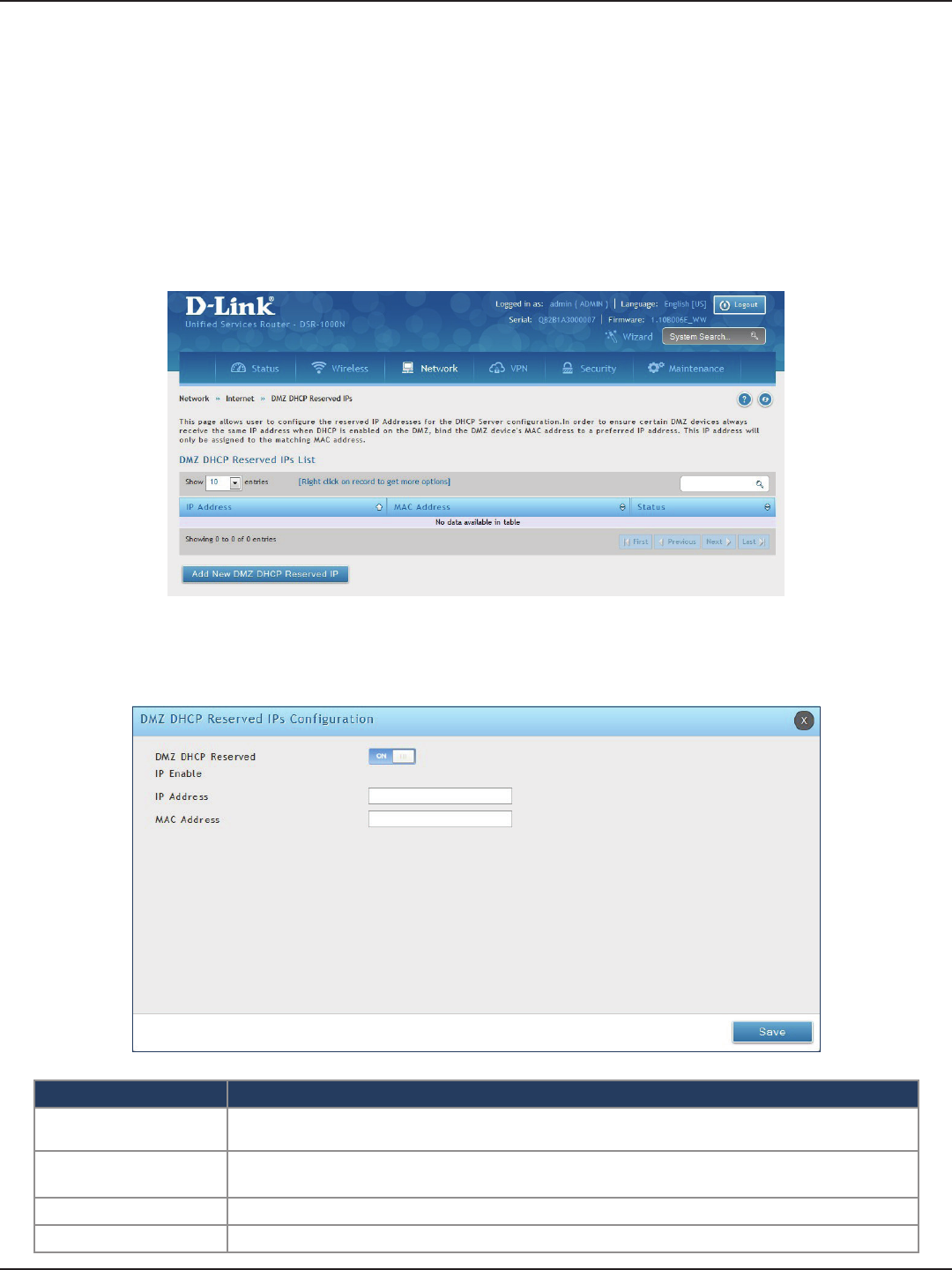
D-Link DSR-Series User Manual 52
Section 5 - Connect to the Internet
The router’s DHCP server can assign IP settings to your DMZ clients on your network by adding a client’s MAC
address and the IP address to be assigned. Whenever the router receives a request from a client, the MAC address
of that client is compared with the MAC address list present in the database. If an IP address is already assigned
to that computer or device in the database, the customized IP address is congured otherwise an IP address is
assigned to the client automatically from the DMZ DHCP pool.
To create DHCP reservations:
1. Click Network > Internet > DMZ LAN DHCP Reserved IPs.
2. Click Add New DMZ DHCP Reserved IP.
3. Enter the following information and click Save.
Field Description
DMZ DHCP Reserved IP
Enable Toggle to ON to enable this reservation.
IP Address Enter the IP address you want to assign to this device. Note that this IP address must be in the
same range as the starting/ending IP address under DHCP Settings.
MAC Address Enter the MAC address of this device (xx:xx:xx:xx:xx:xx format).
Save Click Save to save your reservation.
DMZ LAN DHCP Reserved IPs
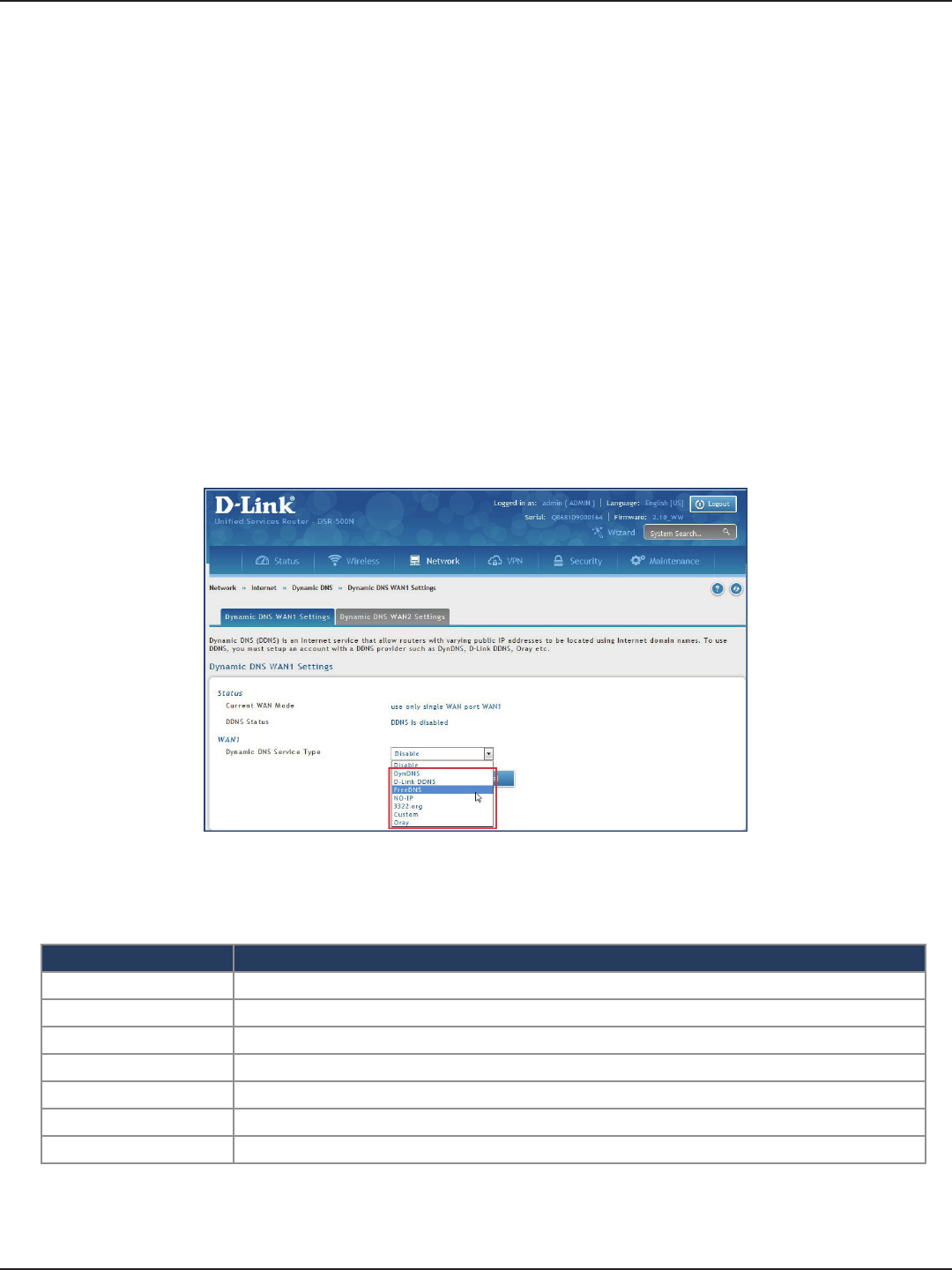
D-Link DSR-Series User Manual 53
Section 5 - Connect to the Internet
Dynamic DNS Settings
Path: Network > Internet > Dynamic DNS
Dynamic DNS (DDNS) is an Internet service that allows routers with varying public IP addresses to be located
using Internet domain names. To use DDNS, you must setup an account with a DDNS provider such as DynDNS.
org, D-Link DDNS, or Oray.net.
Each congured WAN can have a dierent DDNS service if required. Once congured, the router will update
DDNS services changes in the WAN IP address so that features that are dependent on accessing the router’s WAN
via FQDN will be directed to the correct IP address. When you set up an account with a DDNS service, the host
and domain name, username, password and wildcard support will be provided by the account provider.
To congure DDNS:
1. Click Network > Internet > Dynamic DNS
2. Click the tab on top to select which WAN port you want to congure DDNS to.
3. Next to Dynamic DNS Service Type, select your DDNS service.
4. Enter the following information and click Save. The information below is for DynDNS. Other services
will have similar elds.
Field Description
User Name Enter your DDNS user name.
Domain Name Enter the domain name.
Password Enter your DDNS password.
Status Displays the current connection status.
Allow Wildcards Toggle to ON to allow wildcards.
Update Periodically Toggle to ON to set a forced update.
Save Click Save to save your reservation.
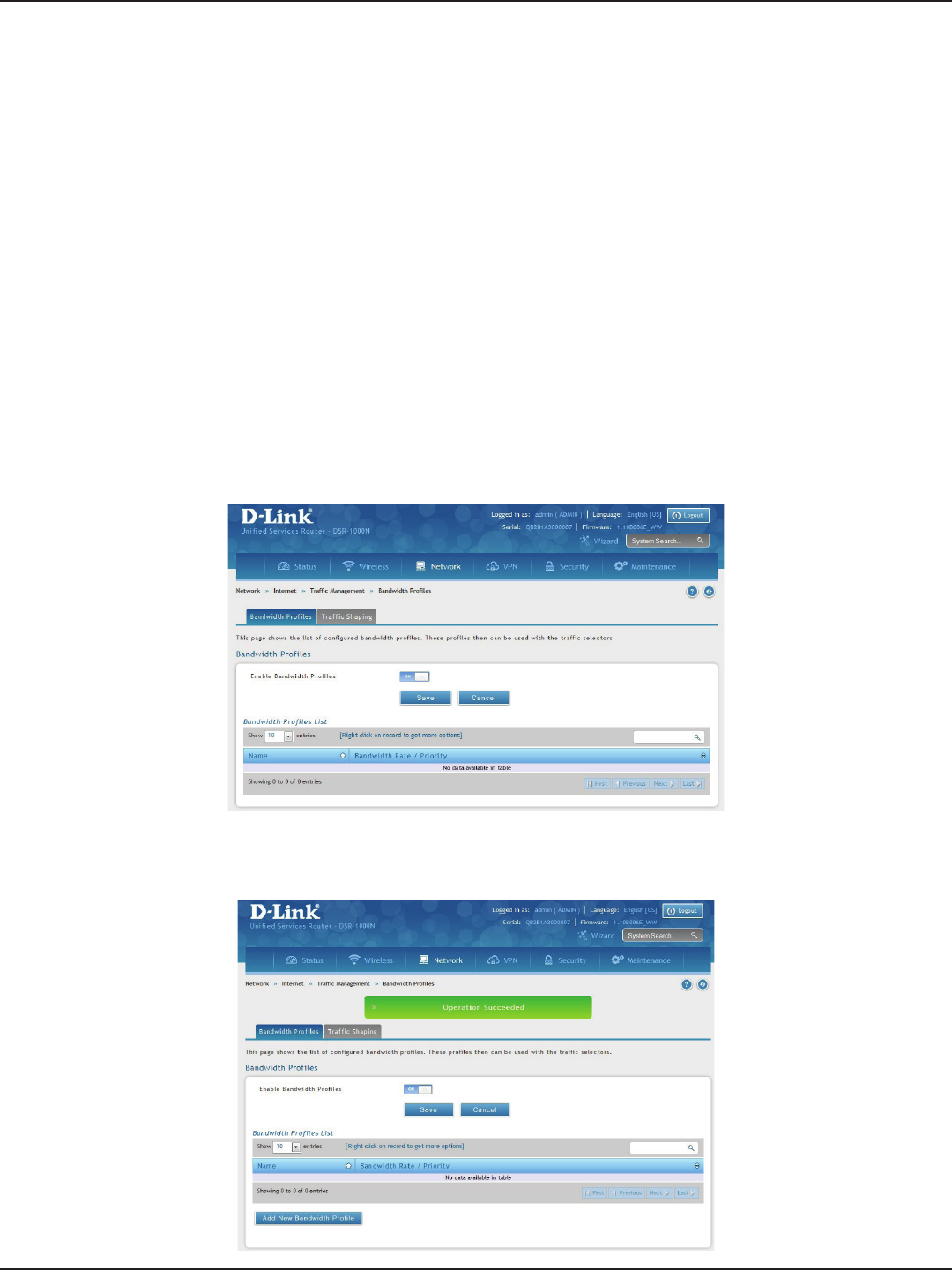
D-Link DSR-Series User Manual 54
Section 5 - Connect to the Internet
Trac Management
Path: Network > Internet > Trac Management > Bandwidth Proles
Bandwidth proles allow you to regulate the trac ow from the LAN to WAN 1 or WAN 2. This is useful to ensure
that low priority LAN users (like guests or HTTP service) do not monopolize the available WAN’s bandwidth for
cost-savings or bandwidth-priority-allocation purposes.
Bandwidth proles conguration consists of enabling the bandwidth control feature from the GUI and adding
a prole which denes the control parameters. The prole can then be associated with a trac selector, so that
bandwidth prole can be applied to the trac matching the selectors. Selectors are elements like IP addresses
or services that would trigger the congured bandwidth regulation.
To edit, delete, or create a new bandwidth prole:
1. Click Network > Internet > Trac Management > Bandwidth Proles.
2. Toggle Enable Bandwidth Proles to ON and click Save.
Bandwidth Proles
3. Click Add New Bandwidth Prole.
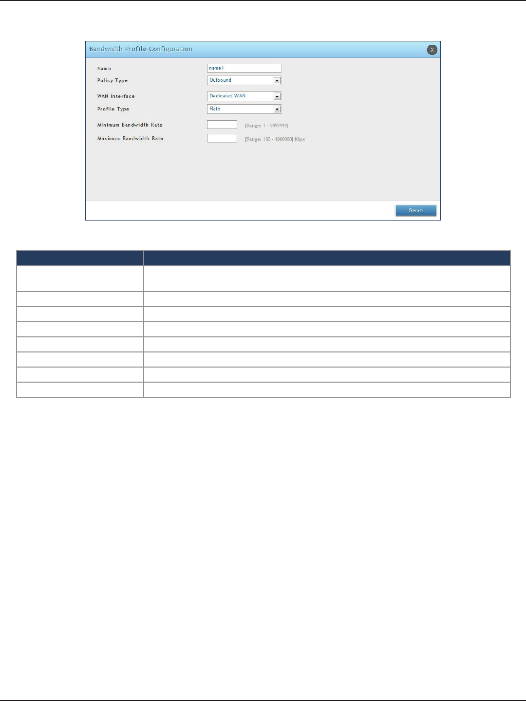
D-Link DSR-Series User Manual 55
Section 5 - Connect to the Internet
4. Enter the following information and click Save.
Field Description
Name Enter a name for your prole. This identier is used to associate the congured prole to the
trac selector.
Policy Type Select the policy type (Inbound or Outbound) from the drop-down menu.
WAN Interface Select which WAN interface you want to associate this prole with.
Prole Type Select either Priority or Rate from the drop-down menu.
Priority If you selected Priority, select Low, Medium, or High.
Minimum Bandwidth Rate If you selected Rate, enter the minimum bandwidth rate.
Maximum Bandwidth Rate If you selected Rate, enter the maximum bandwidth rate.
Save Click Save to save your reservation.
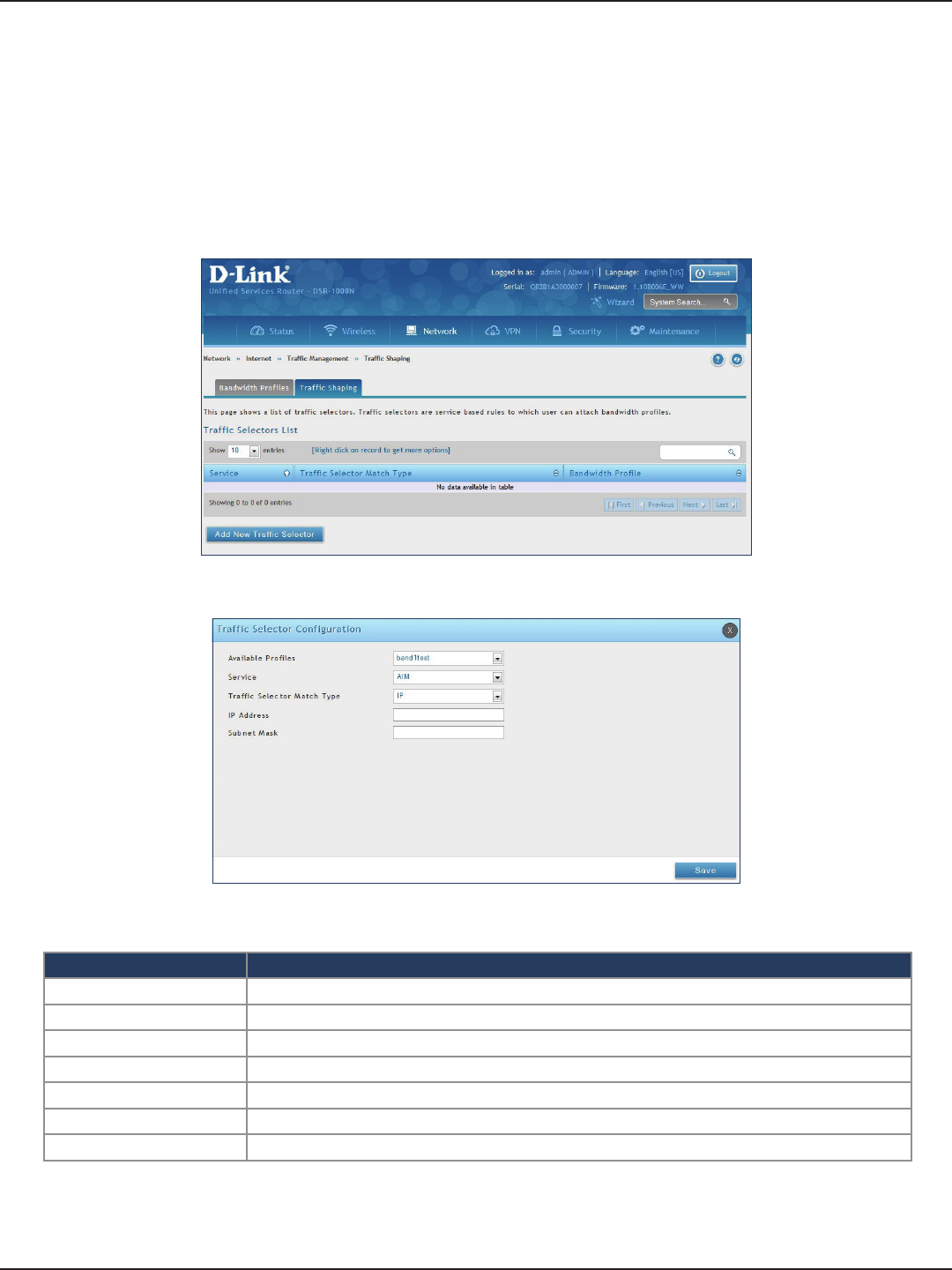
D-Link DSR-Series User Manual 56
Section 5 - Connect to the Internet
Path: Network > Internet > Trac Management > Trac Shaping
Once a prole has been created it can then be associated with a trac ow from the LAN to WAN. Trac selector
conguration binds a bandwidth prole to a type or source of LAN trac with the following settings.
To create a trac selector:
1. Click Network > Internet > Trac Management > Trac Shaping.
Trac Shaping
2. Click Add New Trac Selector.
Field Description
Available Proles Select a bandwidth prole from the drop-down menu.
Service Select a service from the drop-down menu.
Trac Selector Match Type Select IP or MAC Address.
IP Address If you selected IP, enter the IP address of the source associated with this prole.
Subnet Mask If you selected IP, enter a subnet mask.
MAC Address If you selected MAC, enter the MAC address of the source associated with this prole.
Save Click to save and activate your settings.
3. Complete the elds from the table below and click Save.
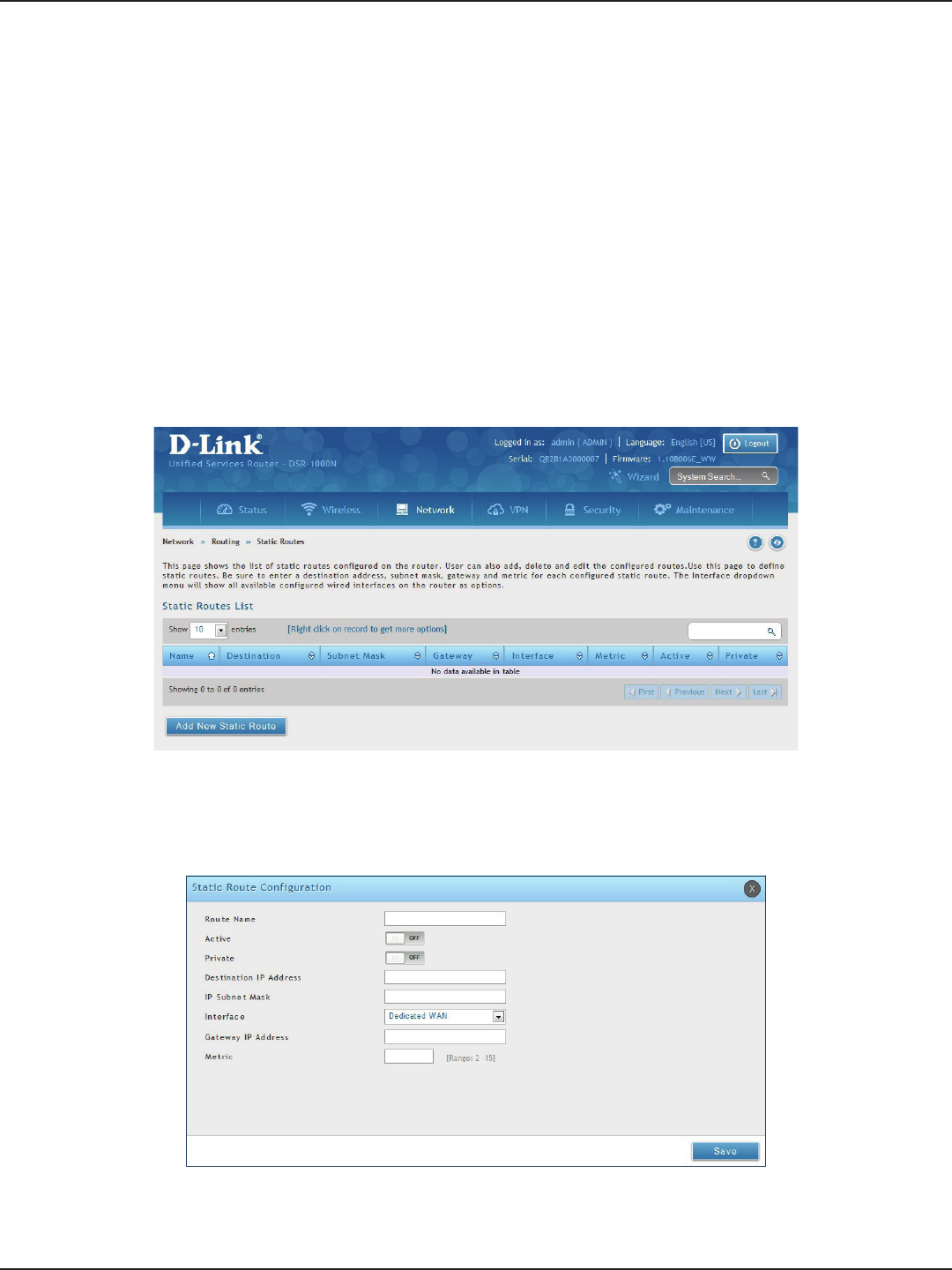
D-Link DSR-Series User Manual 57
Section 5 - Connect to the Internet
Path: Network > Routing > Static Routes
Manually adding static routes to this device allows you to dene the path selection of trac from one interface
to another. There is no communication between this router and other devices to account for changes in the path;
once congured the static route will be active and eective until the network changes.
The List of Static Routes displays all routes that have been added manually by an administrator and allows several
operations on the static routes.
To create a new static route:
1. Click Network > Routing > Static Routes.
Static Routes
2. Click Add New Static Route.
3. Complete the elds in the table on the next page and click Save.
Routing

D-Link DSR-Series User Manual 58
Section 5 - Connect to the Internet
Field Description
Route Name Enter a name for your route.
Active Toggle to ON to activate this route or to OFF to deactivate.
Private Toggle to ON to make this route private. If the route is made private, then the route will not be
shared in a RIP broadcast or multicast.
Destination IP Address Enter the IP address of the static route’s destination.
IP Subnet Mask Enter the subnet mask of the static route.
Interface The physical network interface (WAN1, WAN2, WAN3, DMZ or LAN), through which this route is
accessible.
Gateway IP Address IP address of the gateway through which the destination host or network can be reached.
Metric Determines the priority of the route. If multiple routes to the same destination exist, the route with
the lowest metric is chosen.
Save Click Save to save your route.
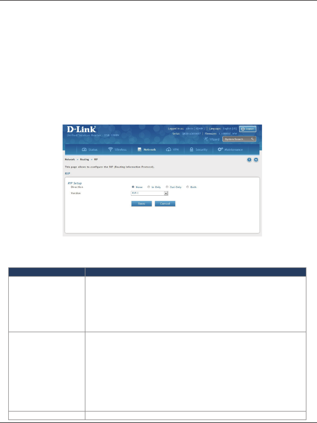
D-Link DSR-Series User Manual 59
Section 5 - Connect to the Internet
RIP
Dynamic routing using the Routing Information Protocol (RIP) is an Interior Gateway Protocol (IGP) that is
common in LANs. With RIP this router can exchange routing information with other supported routers in the
LAN and allow for dynamic adjustment of routing tables in order to adapt to modications in the LAN without
interrupting trac ow.
Note: The DSR-150/150N/250/250N routers do not support RIP.
Path: Network > Routing > RIP
To congure RIP:
1. Click Network > Routing > RIP.
2. Complete the elds in the table below and click Save.
Field Description
Direction
The RIP direction will dene how this router sends and receives RIP packets. Select one of the following:
• Both: The router both broadcasts its routing table and also processes RIP information received
from other routers. This is the recommended setting in order to fully utilize RIP capabilities.
• Out Only: The router broadcasts its routing table periodically but does not accept RIP information
from other routers.
• In Only: The router accepts RIP information from other routers, but does not broadcast its routing
table.
• None: The router neither broadcasts its route table nor does it accept any RIP packets from other
routers. This eectively disables RIP.
Version
The RIP version is dependent on the RIP support of other routing devices in the LAN.
• Disabled: This is the setting when RIP is disabled.
• RIP-1: A class-based routing version that does not include subnet information. This is the most
commonly supported version.
• RIP-2: Includes all the functionality of RIPv1 plus it supports subnet information. Though the data
is sent in RIP-2 format for both RIP-2B and RIP-2M, the mode in which packets are sent is dierent.
RIP-2B broadcasts data in the entire subnet while RIP-2M sends data to multicast addresses.
Note: If RIP-2B or RIP-2M is the selected version, authentication between this router and other
routers (congured with the same RIP version) is required. MD5 authentication is used in a rst/
second key exchange process. The authentication key validity lifetimes are congurable to
ensure that the routing information exchange is with current and supported routers detected on
the LAN.
Save Click Save to save your settings.
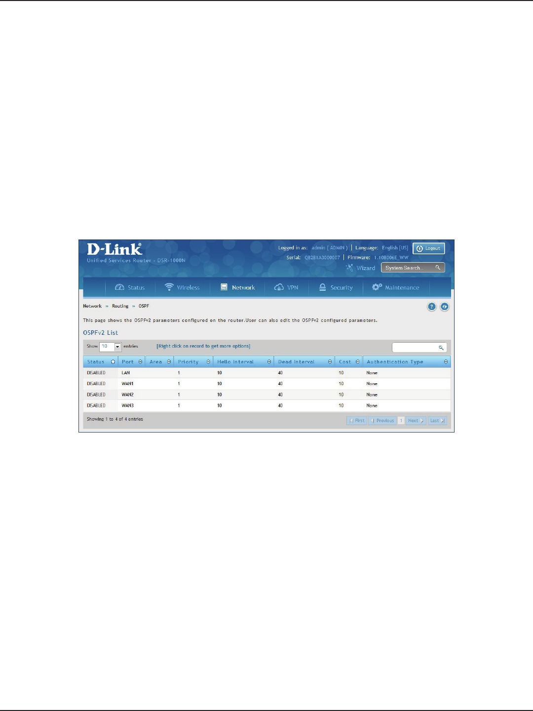
D-Link DSR-Series User Manual 60
Section 5 - Connect to the Internet
OSPF
Path: Network > Routing > OSPF
OSPF is an interior gateway protocol that routes Internet Protocol (IP) packets solely within a single routing
domain. It gathers link state information from available routers and constructs a topology map of the network.
OSPF version 2 is a routing protocol which described in RFC2328 - OSPF Version 2. OSPF is IGP (Interior Gateway
Protocols). OSPF is widely used in large networks such as ISP backbone and enterprise networks.
Note: The DSR-150/150N/250/250N routers do not support OSPFv2.
To congure OSPF:
1. Click Network > Routing > OSPF.
2. Right-click the port you want to edit (LAN/WAN1/WAN2/WAN3) and select Edit.
3. Complete the elds in the table on the next page and click Save.
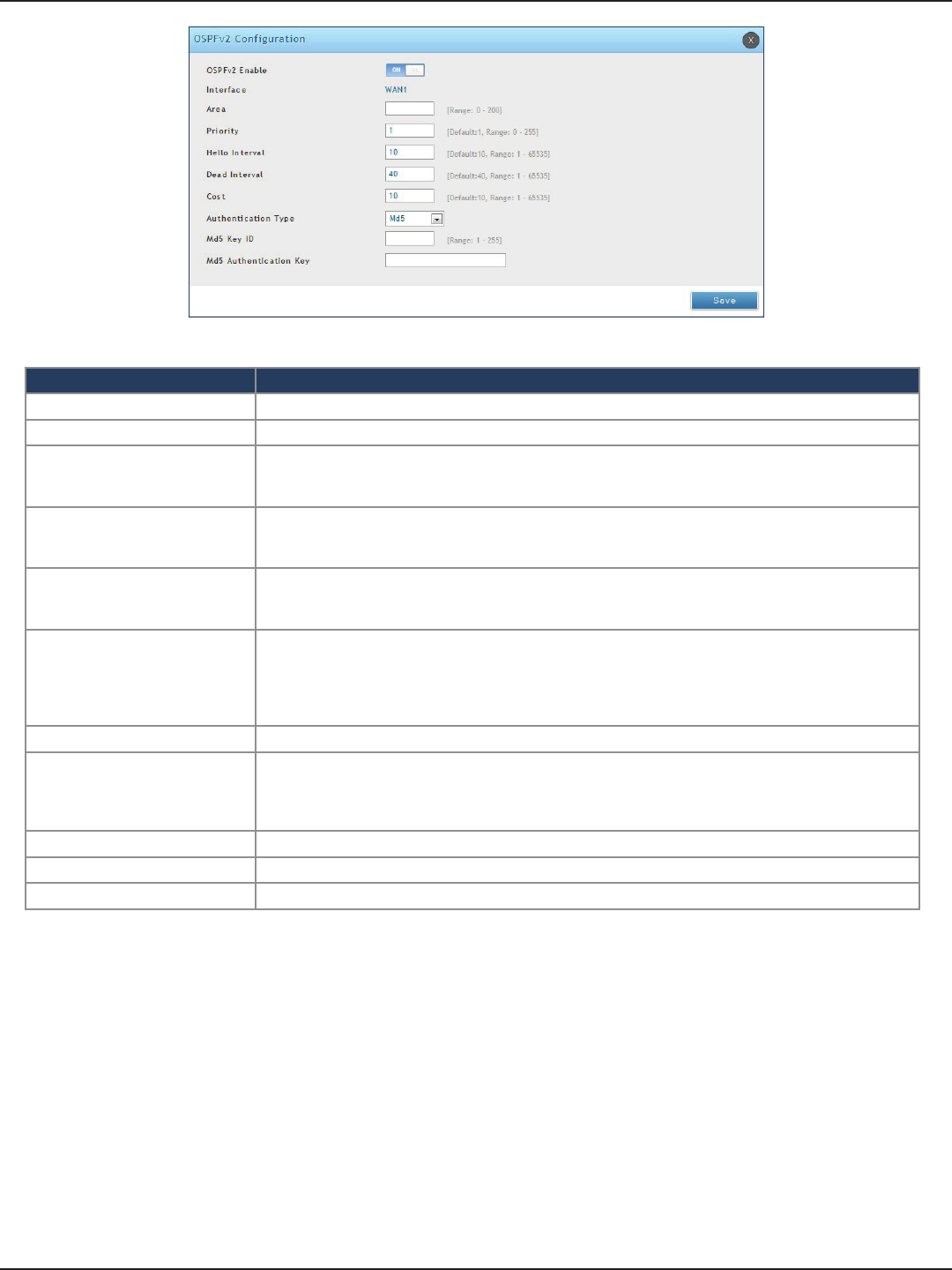
D-Link DSR-Series User Manual 61
Section 5 - Connect to the Internet
Field Description
OSPFv2 Enable Toggle ON to enable OSPF.
Interface Displays the physical network interface on which OSPFv2 is Enabled/Disabled.
Area
Enter the area to which the interface belongs. Two routers having a common segment; their interfaces
have to belong to the same area on that segment. The interfaces should belong to the same subnet
and have similar mask.
Priority
Helps to determine the OSPFv2 designated router for a network. The router with the highest priority
will be more eligible to become Designated Router. Setting the value to 0 makes the router ineligible
to become Designated Router. The default value is 1. Lower the value means higher the priority.
Hello Interval
The number of seconds for Hello Interval timer value. Enter the number in seconds that the Hello
packet will be sent. This value must be the same for all routers attached to a common network. The
default value is 10 seconds.
Dead Interval
The number of seconds that a device’s hello packets must not have been seen before its neighbors
declare the OSPF router down. This value must be the same for all routers attached to a common
network. The default value is 40 seconds. OSPF requires these intervals to be exactly the same between
two neighbors. If any of these intervals are dierent, these routers will not become neighbors on a
particular segment.
Cost Enter the cost of sending a packet on an OSPFv2 interface.
Authentication Type
Select one of the following authentication types:
• None: The interface does not authenticate OSPF packets.
• Simple: OSPF packets are authenticated using simple text key.
• MD5: The interface authenticates OSPF packets with MD5 authentication.
Md5 Key ID If MD5 authentication is selected, enter the MD5 key ID.
Md5 Authentication Key If MD5 authentication is selected, enter the MD5 authentication key.
Save Click Save to save your settings.
OSPF support on L2TP over IPsec
Apart from LAN, WAN1 and WAN2, the user can exchange routes via L2TP over IPsec. OSPF supports a virtual
interface created in L2TP over an IPsec channel. The static routes which are added have to be exchanged over
these interfaces.
L2TP over IPsec wraps a stimulated data link layer in IPsec. Plain IPsec just encrypts the network layer. When the
L2TP over IPsec conguration is saved, the tunnel initiation starts automatically but the establishment of the
tunnel depends on the conguration at the client and the server side, and the response from the server.
Ensure that the L2TP tunnel over the IPsec is established before enabling OSPF
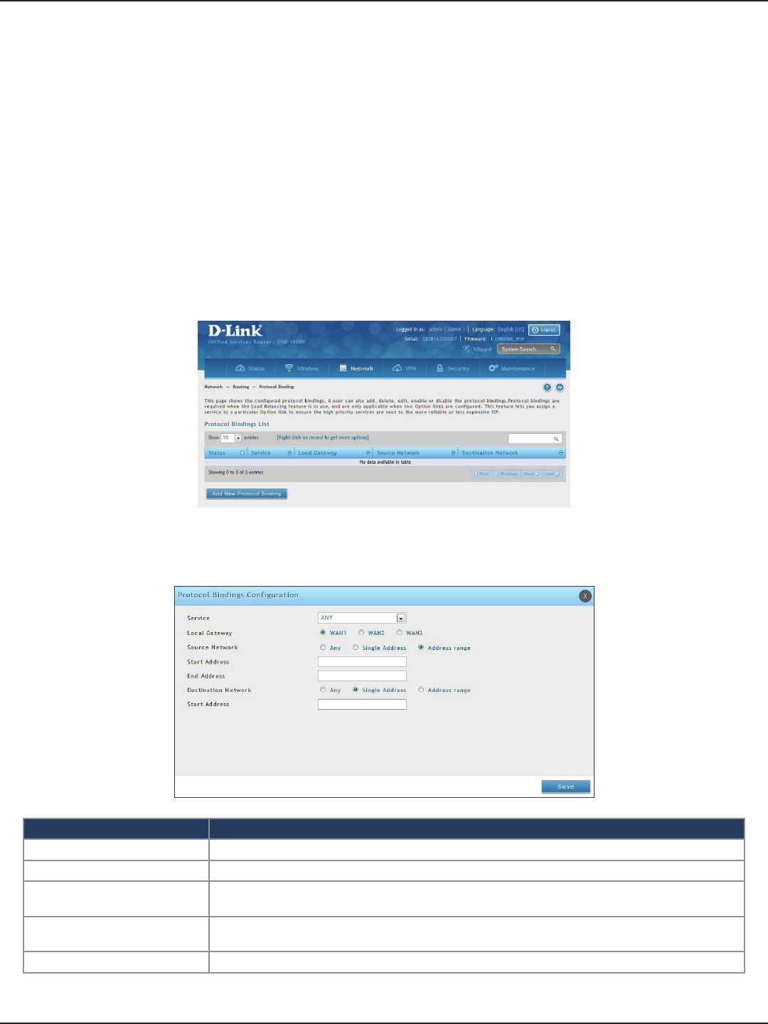
D-Link DSR-Series User Manual 62
Section 5 - Connect to the Internet
Protocol Binding
Path: Network > Routing > Protocol Binding
Protocol bindings are useful when the Load Balancing feature is in use. Selecting from a list of congured services
or any of the user-dened services, the type of trac can be assigned to go over only one of the available WAN
ports. For increased exibility the source network or machines can be specied as well as the destination network
or machines. For example, the VOIP trac for a set of LAN IP addresses can be assigned to one WAN and any
VOIP trac from the remaining IP addresses can be assigned to the other WAN link. Protocol bindings are only
applicable when load balancing mode is enabled and more than one WAN is congured.
To add, edit, or delete a protocol binding entry:
1. Click Network > Routing > Protocol Binding.
2. Right-click a current entry and select Edit or Delete. To add a new entry, click Add New Protocol Binding.
3. Complete the elds in the table below and click Save.
Field Description
Service Select a service from the drop-down menu.
Local Gateway Select a WAN interface.
Source Network Select the source network: Any, Single Address, or Address Range. If Single Address or Address
Range is selected, enter the IP address or IP range.
Destination Network Select the destination network: Any, Single Address, or Address Range. If Single Address or
Address Range is selected, enter the IP address or IP range.
Save Click Save to save your settings.
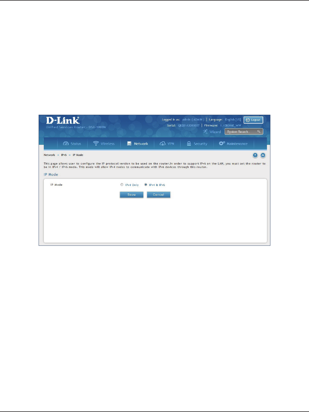
D-Link DSR-Series User Manual 63
Section 5 - Connect to the Internet
IPv6
IP Mode
Path: Network > IPv6 > IP Mode
This page allows you to congure the IP protocol version to be used on the router. In order to support IPv6 on
your local network (LAN), you must set the router to be in IPv4 / IPv6 mode. This mode will allow IPv4 nodes to
communicate with IPv6 devices through this router.
To enable IPv6 on the router:
1. Click Network > IPv6 > IP Mode.
2. Select IPv4 & IPv6.
3. Click Save.
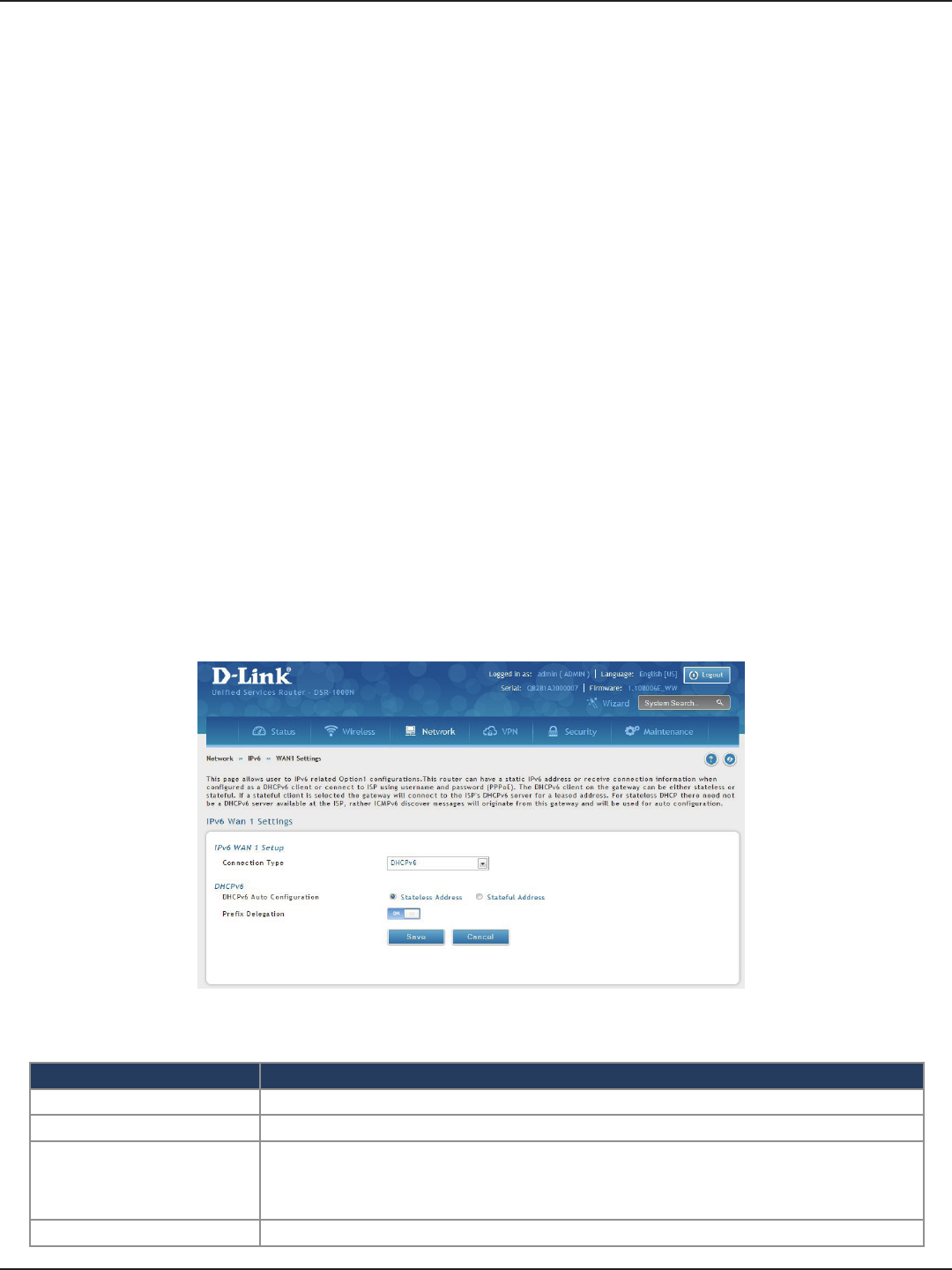
D-Link DSR-Series User Manual 64
Section 5 - Connect to the Internet
WAN Settings
Path: Network > IPv6 > WAN1 Settings
For IPv6 WAN connections, this router can have a static IPv6 address or receive connection information when
congured as a DHCPv6 client. In the case where the ISP assigns you a xed address to access the internet, the
static conguration settings must be completed. In addition to the IPv6 address assigned to your router, the
IPv6 prex length dened by the ISP is needed. The default IPv6 Gateway address is the server at the ISP that
this router will connect to for accessing the internet. The primary and secondary DNS servers on the ISP’s IPv6
network are used for resolving internet addresses, and these are provided along with the static IP address and
prex length from the ISP.
When the ISP allows you to obtain the WAN IP settings via DHCP, you need to provide details for the DHCPv6
client conguration. The DHCPv6 client on the gateway can be either stateless or stateful. If a stateful client is
selected the gateway will connect to the ISP’s DHCPv6 server for a leased address. For stateless DHCP there need
not be a DHCPv6 server available at the ISP, rather ICMPv6 discover messages will originate from this gateway
and will be used for auto conguration.
A third option to specify the IP address and prex length of a preferred DHCPv6 server is available as well.
To congure a dynamic (DHCP) IPv6 Internet connection:
1. Click Network > IPv6 > WAN1 Settings.
2. Complete the elds in the table below and click Save.
Field Description
Connection Type Select DHCPv6 from the drop-down menu.
DHCPv6 Auto Conguration Select either Stateless Address or Stateful Address.
Prex Delegation
Select this option to request router advertisement prex from any available
DHCPv6 servers available on the ISP, the obtained prex is updated to the advertised prexes on
the LAN side. This option can be selected only in Stateless Address Auto Conguration mode of
DHCPv6 Client.
Save Click Save to save your settings.
Dynamic IP
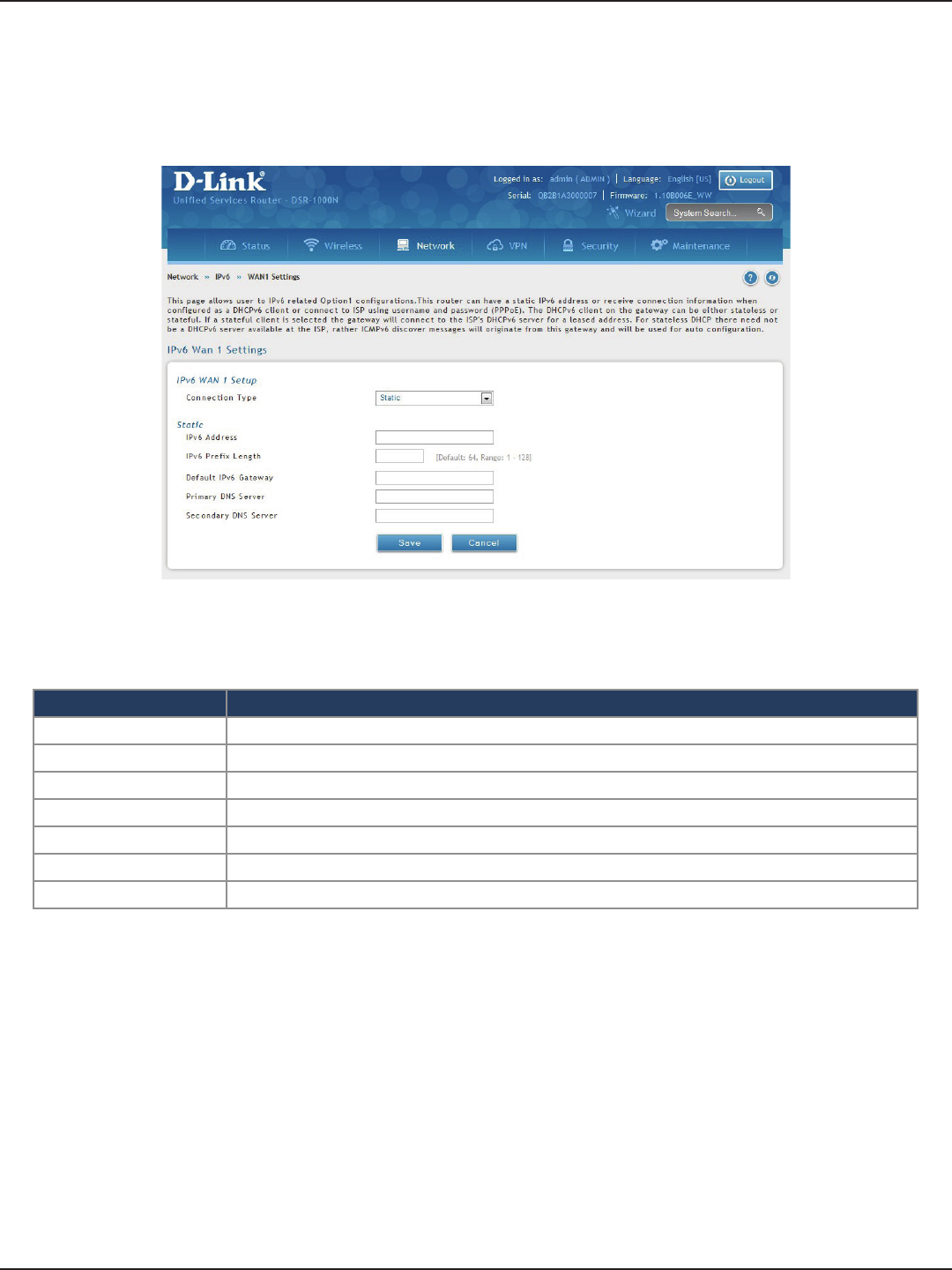
D-Link DSR-Series User Manual 65
Section 5 - Connect to the Internet
To congure a static IPv6 Internet connection:
1. Click Network > IPv6 > WAN1 Settings.
2. Complete the elds in the table below and click Save.
Static IP
Field Description
Connection Type Select Static.
IPv6 Address Enter the IP address supplied by your ISP.
IPv6 Prex Length Enter the IPv6 prex length supplied by your ISP.
Default IPv6 Gateway Enter the IPv6 gateway address supplied by your ISP.
Primary DNS Server Enter the primary DNS server IP address.
Secondary DNS Server Enter the secondary DNS server IP address.
Save Click Save to save and activate your settings.
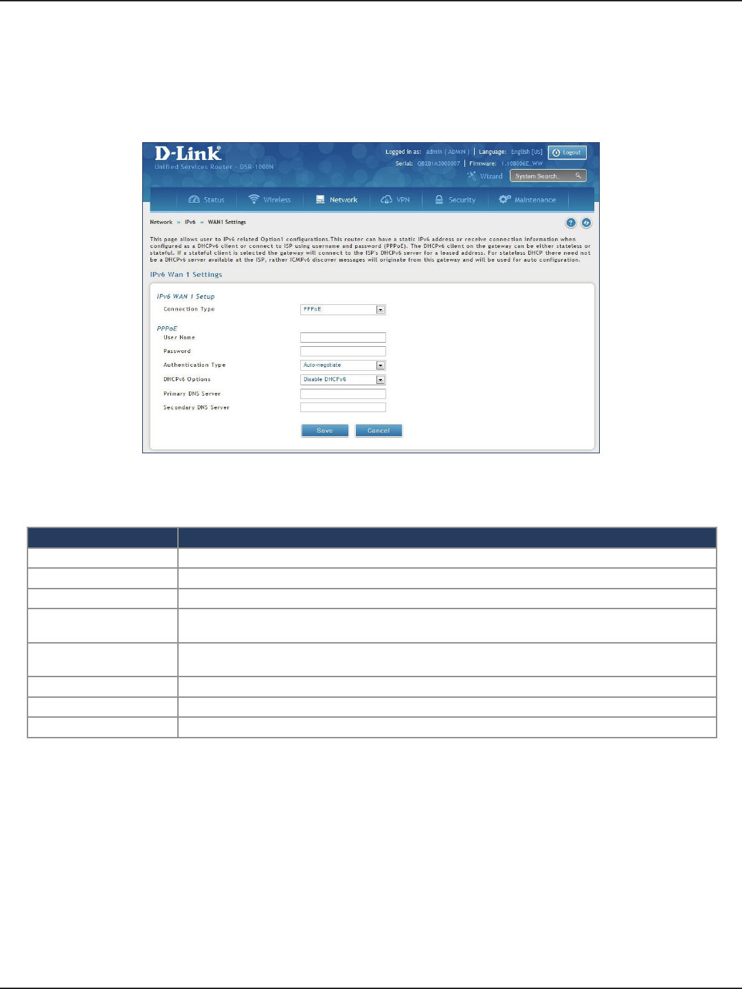
D-Link DSR-Series User Manual 66
Section 5 - Connect to the Internet
To congure a dynamic (DHCP) IPv6 Internet connection:
1. Click Network > IPv6 > WAN1 Settings.
PPPoE
2. Complete the elds in the table below and click Save.
Field Description
Connection Type Select PPPoE.
User Name Enter your PPPoE user name.
Password Enter your PPPoE password.
Authentication Type Select the authentication type from the drop-down menu (Auto-negotiate/PAP/CHAP/MS-CHAP/MS-
CHAPv2).
DHCPv6 Options Select the mode of DHCPv6 client that will start in this mode (Disable dhcpv6/Stateless dhcpv6/Stateful
dhcpv6/Stateless dhcpv6 with prex delegation.
Primary DNS Server Enter the primary DNS server IP address.
Secondary DNS Server Enter the secondary DNS server IP address.
Save Click Save to save and activate your settings.
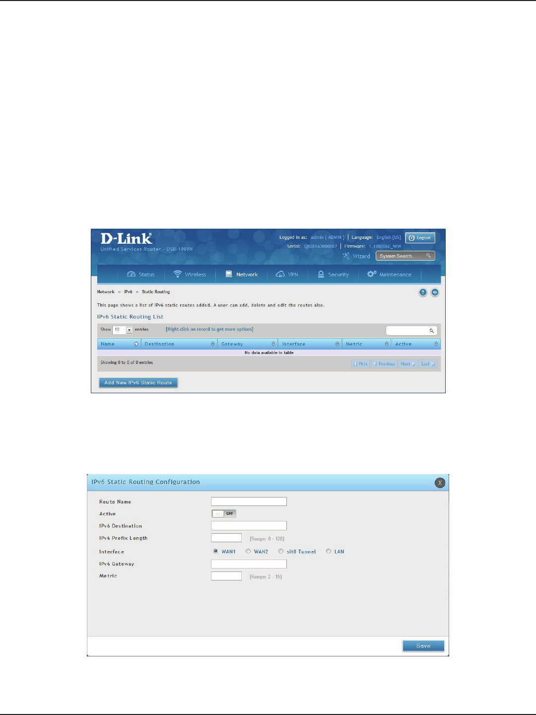
D-Link DSR-Series User Manual 67
Section 5 - Connect to the Internet
Path: Network > IPv6 > Static Routing
Manually adding static routes to this device allows you to dene the path selection of trac from one interface
to another. There is no communication between this router and other devices to account for changes in the path;
once congured the static route will be active and eective until the network changes.
The List of Static Routes displays all routes that have been added manually by an administrator and allows several
operations on the static routes.
To create a new static route:
1. Click Network > IPv6 > Static Routing.
Static Routing
2. Click Add New IPv6 Static Route.
3. Complete the elds in the table on the next page and click Save.

D-Link DSR-Series User Manual 68
Section 5 - Connect to the Internet
Field Description
Route Name Enter a name for your route.
Active Toggle to ON to activate this route or to OFF to deactivate.
IPv6 Destination Enter the IP address of the static route’s destination.
IPv6 Prex Length Enter the prex length of the static route.
Interface The physical network interface (WAN1, WAN2, WAN3, DMZ or LAN), through which this route is
accessible.
IPv6 Gateway IPv6 address of the gateway through which the destination host or network can be reached.
Metric Determines the priority of the route. If multiple routes to the same destination exist, the route with
the lowest metric is chosen.
Save Click Save to save your route.
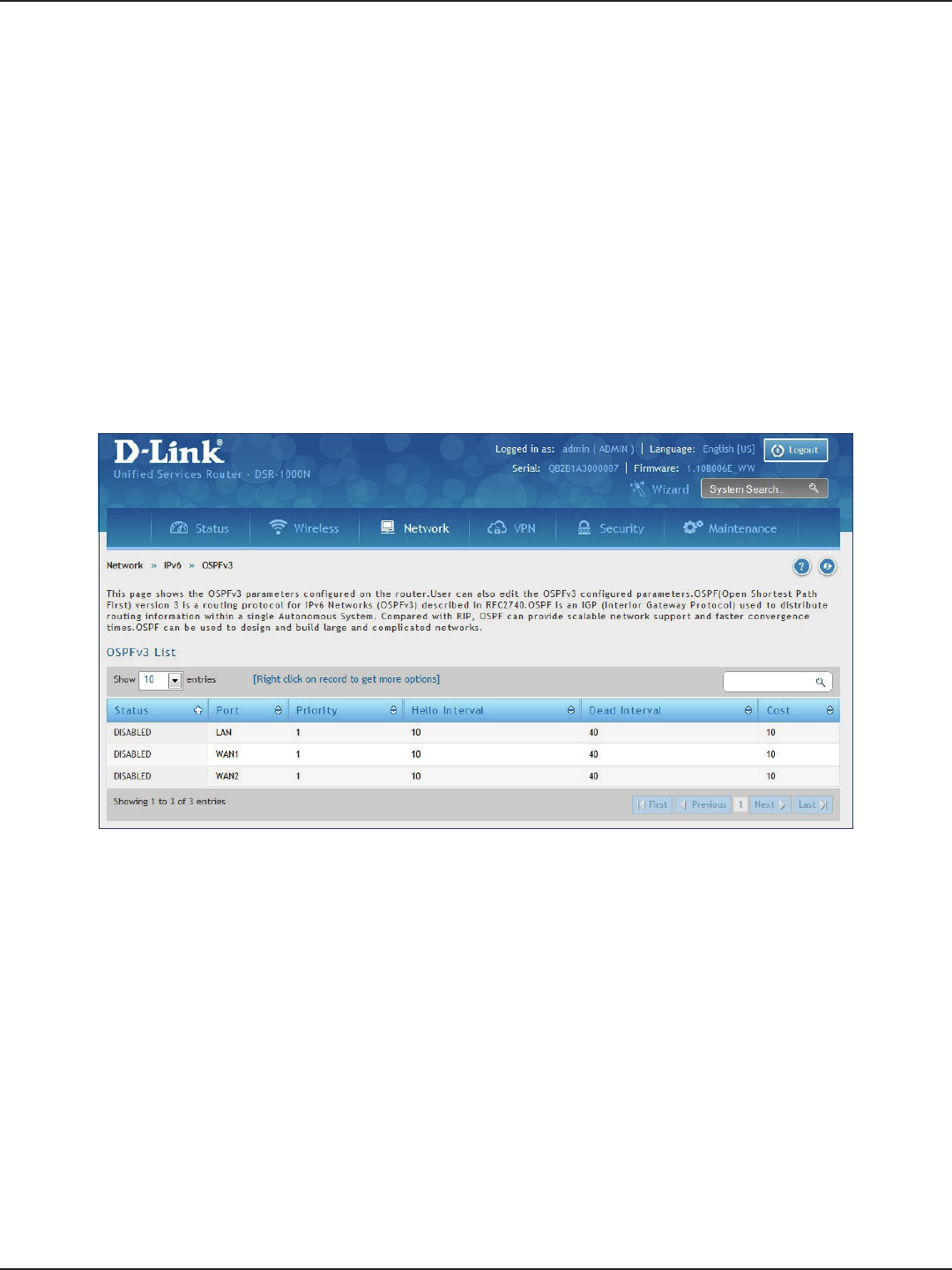
D-Link DSR-Series User Manual 69
Section 5 - Connect to the Internet
Path: Network > IPv6 > OSPFv3
OSPF is an interior gateway protocol that routes Internet Protocol (IP) packets solely within a single routing
domain. It gathers link state information from available routers and constructs a topology map of the network.
Open Shortest Path First version 3 (OSPFv3) supports IPv6. To enable an OSPFv3 process on a router, you need to
enable the OSPFv3 process globally, assign the OSPFv3 process a router ID, and enable the OSPFv3 process on
related interfaces.
Note: The DSR-150/150N/250/250N routers do not support OSPFv3.
To congure OSPF:
1. Click Network > IPv6 > OSPFv3.
2. Right-click the port you want to edit (LAN/WAN1/WAN2) and select Edit.
3. Complete the elds in the table on the next page and click Save.
OSPFv3
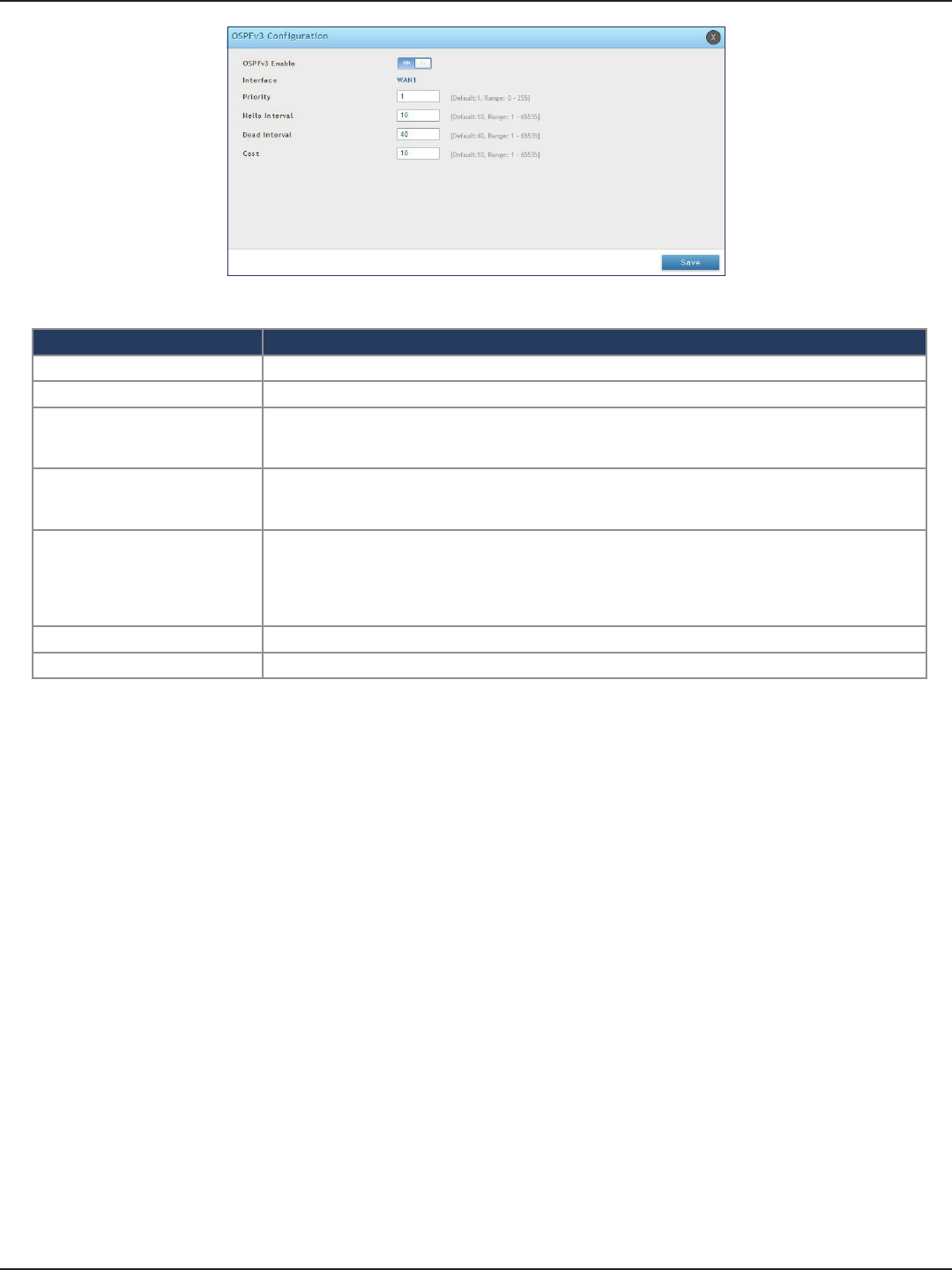
D-Link DSR-Series User Manual 70
Section 5 - Connect to the Internet
Field Description
OSPFv3 Enable Toggle ON to enable OSPFv3.
Interface Displays the physical network interface on which OSPFv3 is Enabled/Disabled.
Priority
Helps to determine the OSPFv3 designated router for a network. The router with the highest priority
will be more eligible to become Designated Router. Setting the value to 0 makes the router ineligible
to become Designated Router. The default value is 1. Lower the value means higher the priority.
Hello Interval
The number of seconds for Hello Interval timer value. Enter the number in seconds that the Hello
packet will be sent. This value must be the same for all routers attached to a common network. The
default value is 10 seconds.
Dead Interval
The number of seconds that a device’s hello packets must not have been seen before its neighbors
declare the OSPF router down. This value must be the same for all routers attached to a common
network. The default value is 40 seconds. OSPF requires these intervals to be exactly the same between
two neighbors. If any of these intervals are dierent, these routers will not become neighbors on a
particular segment.
Cost Enter the cost of sending a packet on an OSPFv3 interface.
Save Click Save to save your settings.
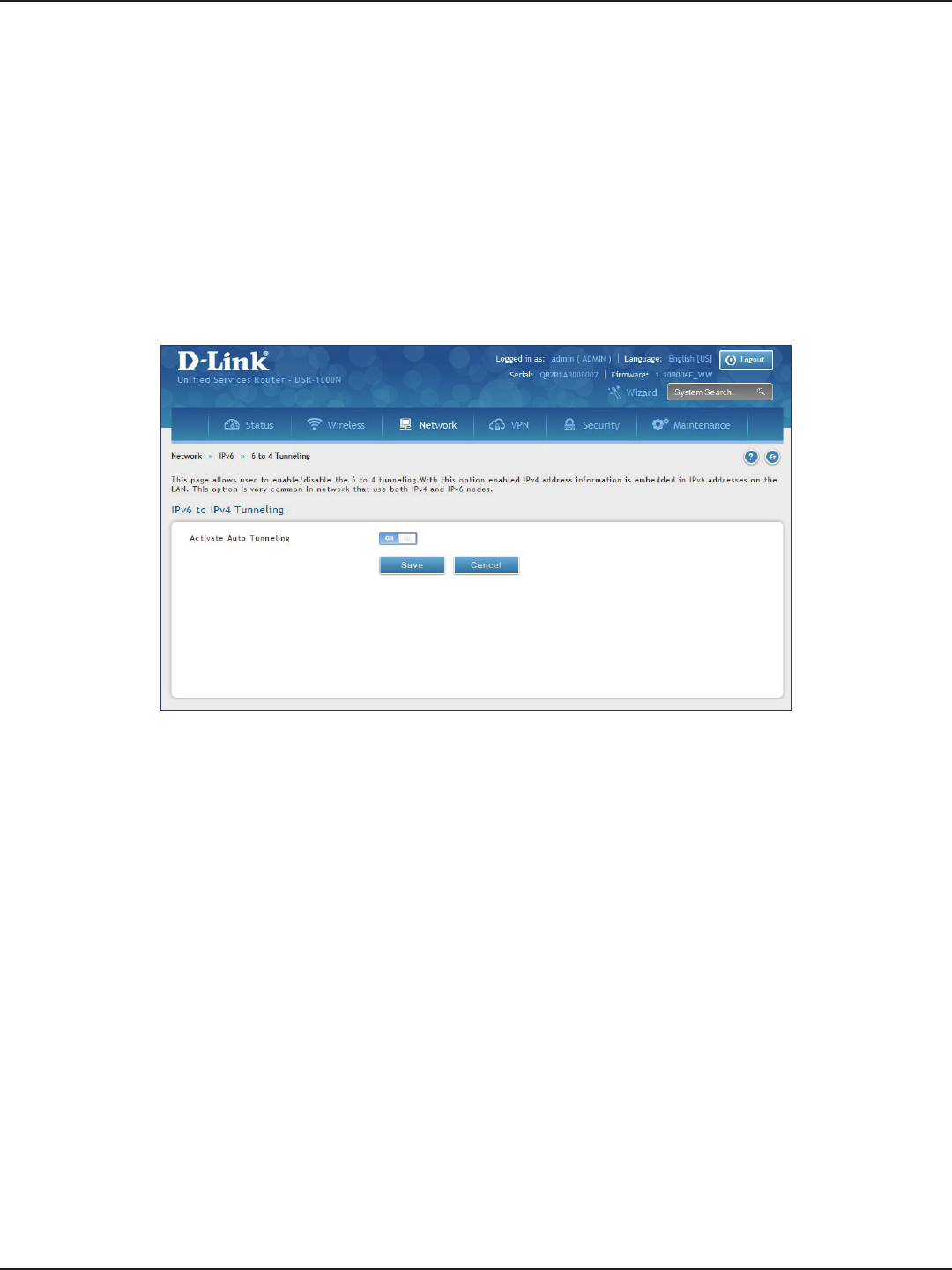
D-Link DSR-Series User Manual 71
Section 5 - Connect to the Internet
Path: Network > IPv6 > 6 to 4 Tunneling
6to4 is an Internet transition mechanism for migrating from IPv4 to IPv6, a system that allows IPv6 packets to be
transmitted over an IPv4 network. Select the check box to Enable Automatic Tunneling and allow trac from an
IPv6 LAN to be sent over an IPv4 Option to reach a remote IPv6 network.
To enable 6 to 4 tunneling:
1. Click Network > IPv6 > 6 to 4 Tunneling.
2. Toggle Activate Auto Tunneling to ON.
3. Click Save.
6 to 4 Tunneling
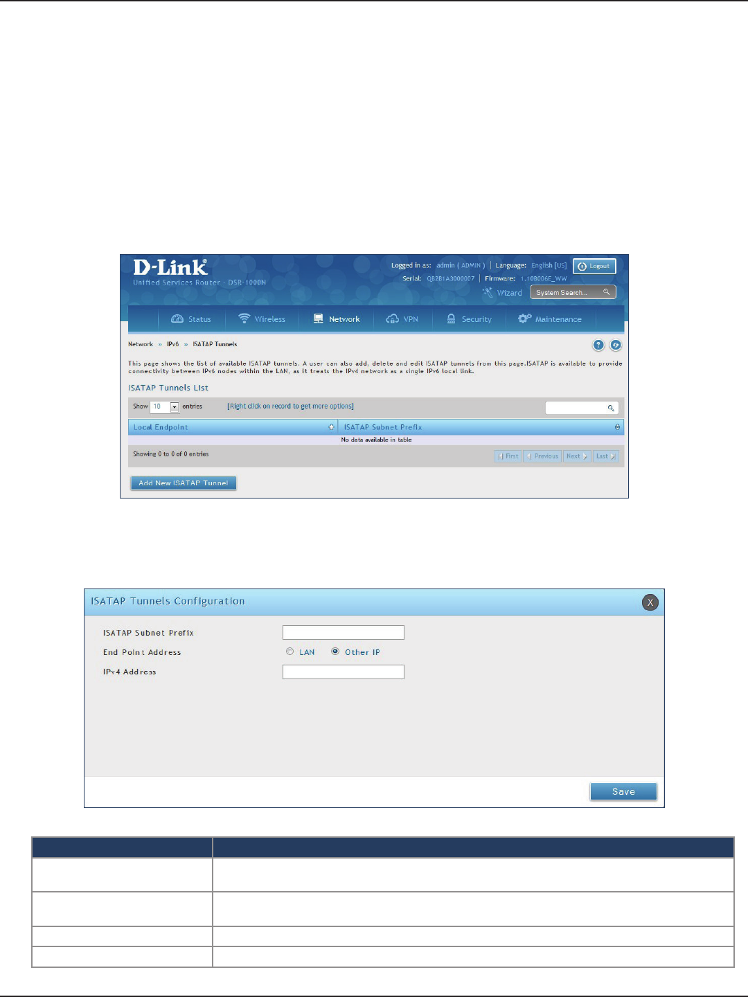
D-Link DSR-Series User Manual 72
Section 5 - Connect to the Internet
Path: Network > IPv6 > 6 to 4 Tunneling
ISATAP (Intra-Site Automatic Tunnel Addressing Protocol) is an IPv6 transition mechanism meant to transmit
IPv6 packets between dual-stack nodes on top of an IPv4 network. ISATAP species an IPv6-IPv4 compatibility
address format as well as a means for site border router discovery. ISATAP also species the operation of IPv6 over
a specic link layer - that being IPv4 used as a link layer for IPv6.
ISATAP
To add, edit, or delete a ISATAP entry:
1. Click Network > IPv6 > ISATAP.
2. Right-click a current entry and select Edit or Delete. To add a new entry, click Add New ISATAP Tunnel.
3. Complete the elds in the table below and click Save.
Field Description
ISATAP Subnet Prex This is the 64-bit subnet prex that is assigned to the logical ISATAP subnet for this intranet. This can be
obtained from your ISP or internet registry, or derived from RFC 4193.
End Point Address This is the endpoint address for the tunnel that starts with this router. The endpoint can be the LAN
interface (assuming the LAN is an IPv4 network), or a specic LAN IPv4 address.
IPv4 Address The end point address if not the entire LAN.
Save Click Save to save your settings.
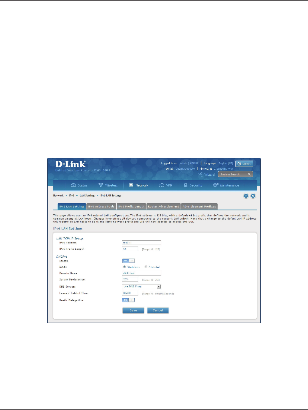
D-Link DSR-Series User Manual 73
Section 5 - Connect to the Internet
LAN Settings
Path: Network > IPv6 > LAN Settings > IPv6 LAN Settings
In IPv6 mode, the LAN DHCP server is disabled by default (similar to IPv4 mode). The DHCPv6 server will serve
IPv6 addresses from congured address pools with the IPv6 Prex Length assigned to the LAN.
The default IPv6 LAN address for the router is fec0::1. You can change this 128-bit IPv6 address based on your
network requirements. The other eld that denes the LAN settings for the router is the prex length. The IPv6
network (subnet) is identied by the initial bits of the address called the prex. By default this is 64 bits long. All
hosts in the network have common initial bits for their IPv6 address; the number of common initial bits in the
network’s addresses is set by the prex length eld.
To congure IPv6 LAN settings on the router:
1. Click Network > IPv6 > LAN Settings > IPv6 LAN Settings.
2. Complete the elds in the table on the next page and click Save.
DHCPv6 Server

D-Link DSR-Series User Manual 74
Section 5 - Connect to the Internet
Field Description
IPv6 Address Enter the IPv6 LAN address for the router.
IPv6 Prex Length Enter the prex length.
Status Toggle to ON to enable DHCPv6.
Mode
The IPv6 DHCP server is either stateless or stateful. If stateless is selected an external IPv6 DHCP server is
not required as the IPv6 LAN hosts are auto-congured by this router. In this case the router advertisement
daemon (RADVD) must be congured on this device and ICMPv6 router discovery messages are used
by the host for auto-conguration. There are no managed addresses to serve the LAN nodes. If stateful
is selected the IPv6 LAN host will rely on an external DHCPv6 server to provide required conguration
settings.
Domain Name Enter a domain name (optional).
Server Preference
Server Preference is used to indicate the preference level of this DHCP server. DHCP advertise messages
with the highest server preference value to a LAN host are preferred over other DHCP server advertise
messages. The default is 255.
DNS Servers
The DNS server details can be manually entered here (primary/secondary options. An alternative is to
allow the LAN DHCP client to receive the DNS server details from the ISP directly. By selecting Use DNS
proxy, this router acts as a proxy for all DNS requests and communicates with the ISP’s DNS servers (a WAN
conguration parameter).
Lease / Rebind Time Enter the duration of the DHCPv6 lease from this router to the LAN client.
Prex Delegation Toggle to ON to enable prex delegation in DHCPv6 server. This option can be selected only in Stateless
Address Auto Conguration mode of DHCPv6 server.
Save Click Save at the bottom to save and activate your settings.
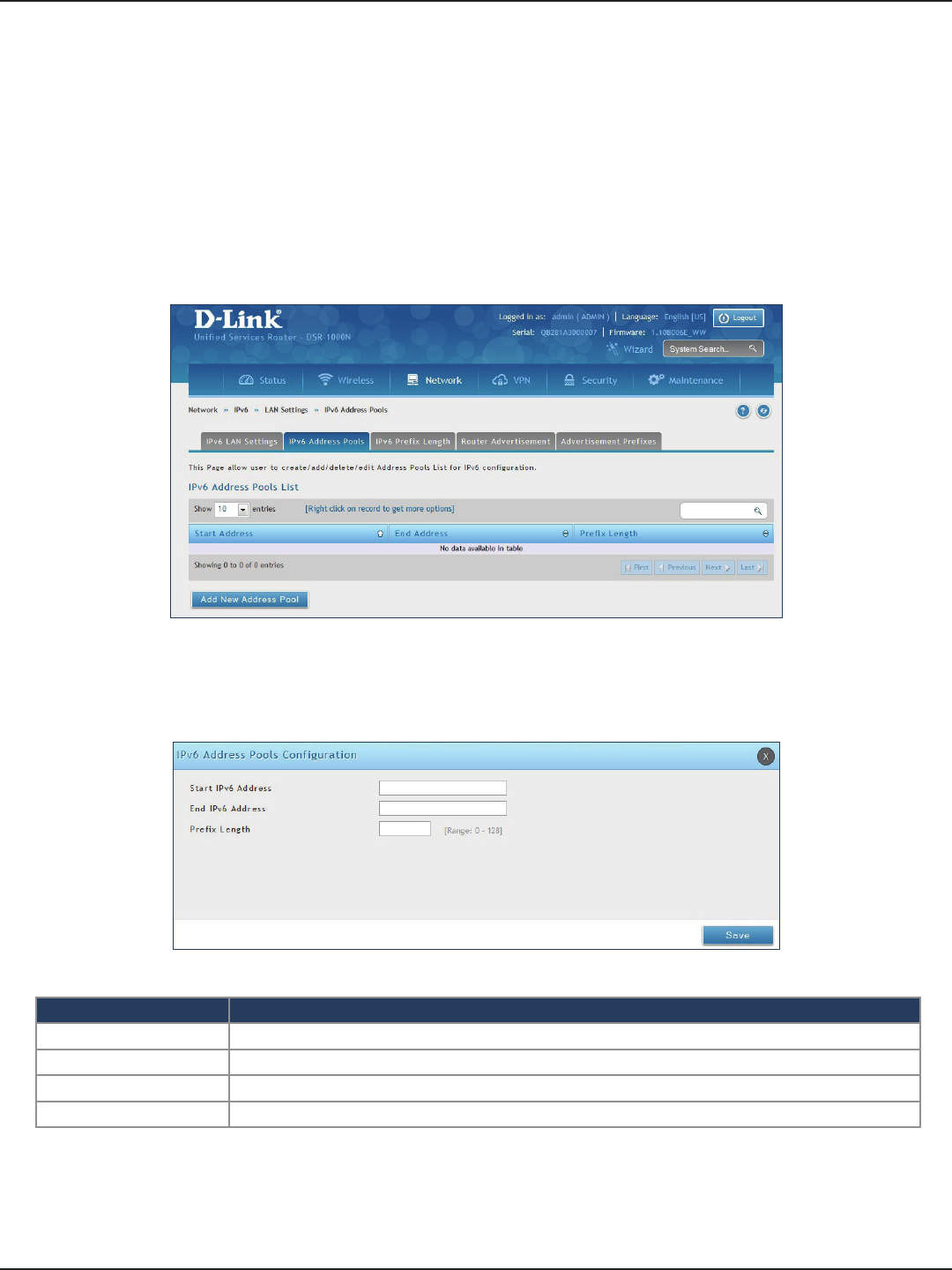
D-Link DSR-Series User Manual 75
Section 5 - Connect to the Internet
IPv6 Address Pools
Path: Network > IPv6 > LAN Settings > IPv6 Address Pools
This feature allows you to dene the IPv6 delegation prex for a range of IP addresses to be served by the
router’s DHCPv6 server. Using a delegation prex you can automate the process of informing other networking
equipment on the LAN of DHCP information specic for the assigned prex.
To add, edit, or delete a IPv6 address pool entry:
1. Click Network > IPv6 > LAN Settings > IPv6 Address Pools tab.
2. Right-click a current entry and select Edit or Delete. To add a new entry, click Add New Address Pool.
3. Complete the elds in the table below and click Save.
Field Description
Start IPv6 Address Enter the starting IPv6 LAN address.
End IPv6 Address Enter the ending IPv6 LAN address.
Prex Length Enter the prex length.
Save Click Save at the bottom to save and activate your settings.
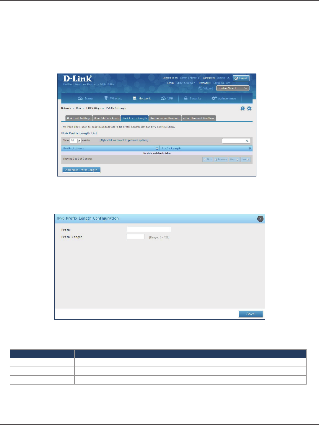
D-Link DSR-Series User Manual 76
Section 5 - Connect to the Internet
IPv6 Prex Length
Path: Network > IPv6 > LAN Settings > IPv6 Prex Length
To add, edit, or delete a IPv6 prex length entry:
1. Click Network > IPv6 > LAN Settings > IPv6 Prex Length tab.
2. Right-click a current entry and select Edit or Delete. To add a new entry, click Add New Prex Length.
3. Complete the elds in the table below and click Save.
Field Description
Prole Enter a name for this prole.
Prex Length Enter the prex length.
Save Click Save at the bottom to save and activate your settings.
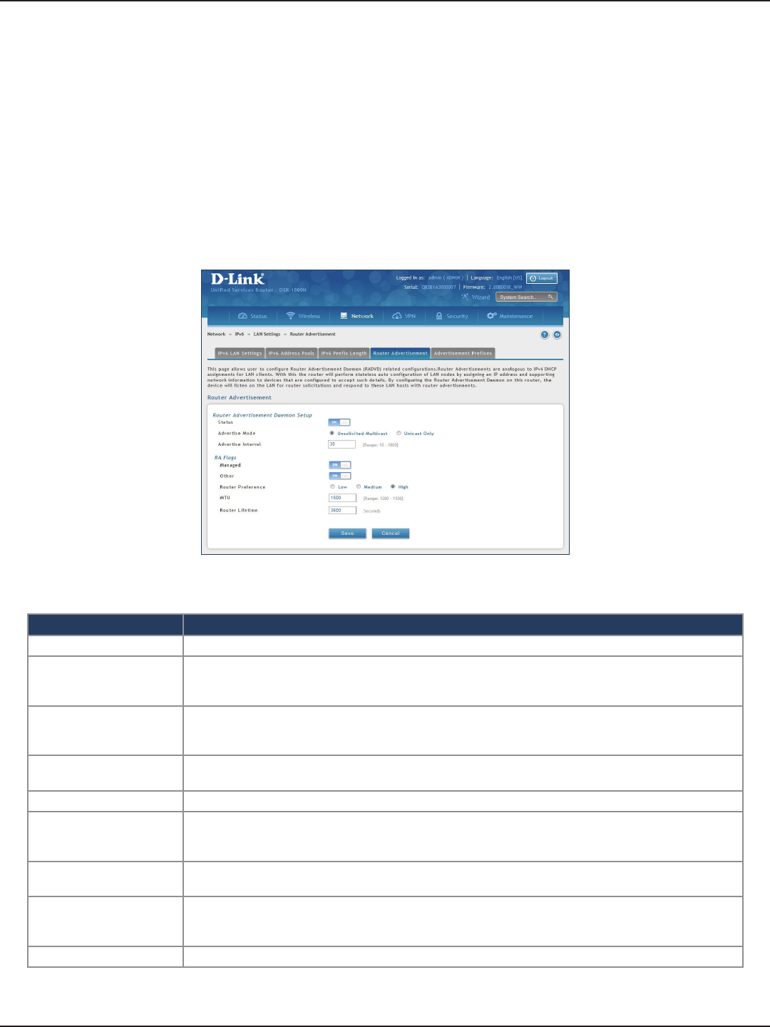
D-Link DSR-Series User Manual 77
Section 5 - Connect to the Internet
Router Advertisement
Path: Network > IPv6 > LAN Settings > Router Advertisement
To congure router advertisement settings:
1. Click Network > IPv6 > LAN Settings > Router Advertisement tab.
2. Complete the elds in the table on the next page and click Save.
Field Description
Status Toggle to ON to enable this feature.
Advertise Mode
Select Unsolicited Multicast to send router advertisements (RA’s) to all interfaces in the multicast group.
To restrict RA’s to well-known IPv6 addresses on the LAN, and thereby reduce overall network trac, select
Unicast only.
Advertise Interval
When advertisements are unsolicited multicast packets, this interval sets the maximum time between
advertisements from the interface. The actual duration between advertisements is a random value
between one third of this eld and this eld. The default is 30 seconds.
Managed Toggle to ON to use the administered/stateful protocol for address auto-conguration. If set to OFF, the
host uses administered/stateful protocol for non-address auto conguration.
Other Toggle to ON to use administered/stateful protocol of other (i.e., non-address) information auto conguration.
Router Preference
This parameter (low/medium/high) determines the preference associated with the RADVD process of the
router. This is useful if there are other RADVD-enabled devices on the LAN as it helps avoid conicts for
IPv6 clients.
MTU The router advertisement will set this maximum transmission unit (MTU) value for all nodes in the LAN that
are auto-congured by the router. The default is 1500.
Router Lifetime
This value is present in RAs and indicates the usefulness of this router as a default router for the interface.
The default is 3600 seconds. Upon expiration of this value, a new RADVD exchange must take place
between the host and this router.
Save Click Save at the bottom to save and activate your settings.
Router Advertisements are analogous to IPv4 DHCP assignments for LAN clients, in that the router will assign
an IP address and supporting network information to devices that are congured to accept such details. Router
Advertisement is required in an IPv6 network is required for stateless auto conguration of the IPv6 LAN.
By conguring the Router Advertisement Daemon on this router, the router will listen on the LAN for router
solicitations and respond to these LAN hosts with router advisements.
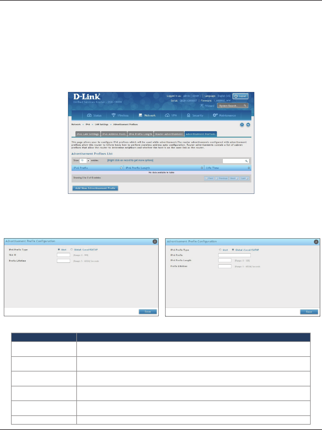
D-Link DSR-Series User Manual 78
Section 5 - Connect to the Internet
Advertisement Prexes
Path: Network > IPv6 > LAN Settings > Advertisement Prexes
To add, edit, or delete an advertisement prex entry:
1. Click Network > IPv6 > LAN Settings > Advertisement Prexes tab.
Router advertisements congured with advertisement prexes allow this router to inform hosts how to perform
stateless address auto conguration. Router advertisements contain a list of subnet prexes that allow the router
to determine neighbors and whether the host is on the same link as the router.
2. Right-click a current entry and select Edit or Delete. To add a new entry, click Add New Advertisement
Length.
3. Complete the elds in the table below and click Save.
Field Description
IPv6 Prex Type To ensure hosts support IPv6 to IPv4 tunnel select the 6to4 prex type. Selecting Global/Local/ISATAP will
allow the nodes to support all other IPv6 routing options.
SLA ID The SLA ID (Site-Level Aggregation Identier) is available when 6to4 Prexes are selected. This should be
the interface ID of the router’s LAN interface used for router advertisements.
IPv6 Prex When using Global/Local/ISATAP prexes, this eld is used to dene the IPv6 network advertised by this
router.
IPv6 Prex Length This value indicates the number contiguous, higher order bits of the IPv6 address that dene up the
network portion of the address. Typically this is 64.
Prex Lifetime This denes the duration (in seconds) that the requesting node is allowed to use the advertised prex. It
is analogous to DHCP lease time in an IPv4 network.
Save Click Save at the bottom to save and activate your settings.
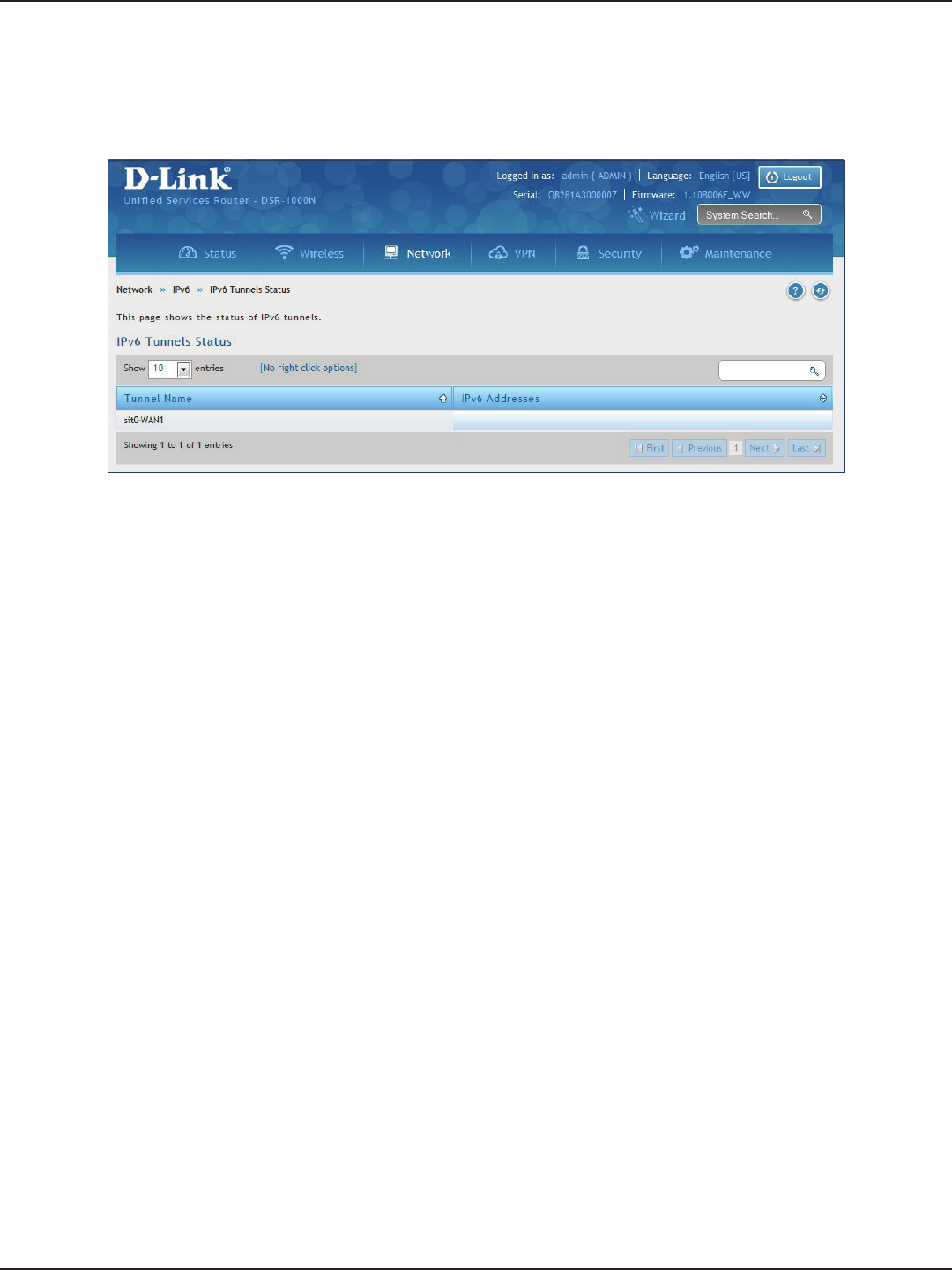
D-Link DSR-Series User Manual 79
Section 5 - Connect to the Internet
IPv6 Tunnels Status
Path: Network > IPv6 > IPv6 Tunnels Status
This page displays the current status of IPv6 Tunnels.
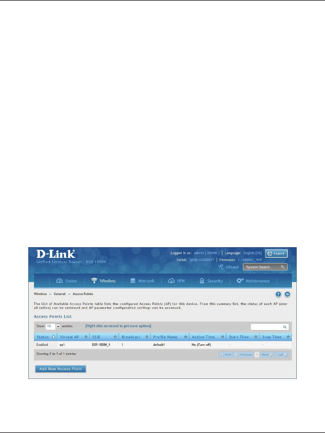
D-Link DSR-Series User Manual 80
Section 6 - Wireless Settings
Wireless Settings
Access Points
This router has an integrated 802.11n/ac radio that allows you to create an access point for wireless LAN clients.
The security/encryption/authentication options are grouped in a wireless Prole, and each congured prole
will be available for selection in the AP conguration menu. The prole denes various parameters for the AP,
including the security between the wireless client and the AP, and can be shared between multiple APs instances
on the same device when needed.
Up to four unique wireless networks can be created by conguring multiple “virtual” APs . Each such virtual AP
appears as an independent AP (unique SSID) to supported clients in the environment, but is actually running on
the same physical radio integrated with this router.
Note: Proles may be thought of as a grouping of AP parameters that can then be applied to not just one but multiple
AP instances (SSIDs), thus avoiding duplication if the same parameters are to be used on multiple AP instances or SSIDs.
The Wireless Network Setup Wizard is available for users new to wireless networking. By going through a few
conguration pages you can enable a Wi-Fi™ network on your LAN and allow supported 802.11 clients to connect
to the congured Access Point. To run the wizard, refer to “#6 Wireless Network Setup” on page 12.
Path: Wireless > General > Access Points
To add, edit, or delete an access point entry:
1. Click Wireless > General > Access Points.
2. Right-click a current entry and select Edit or Delete. To add a new entry, click Add New Access Point.
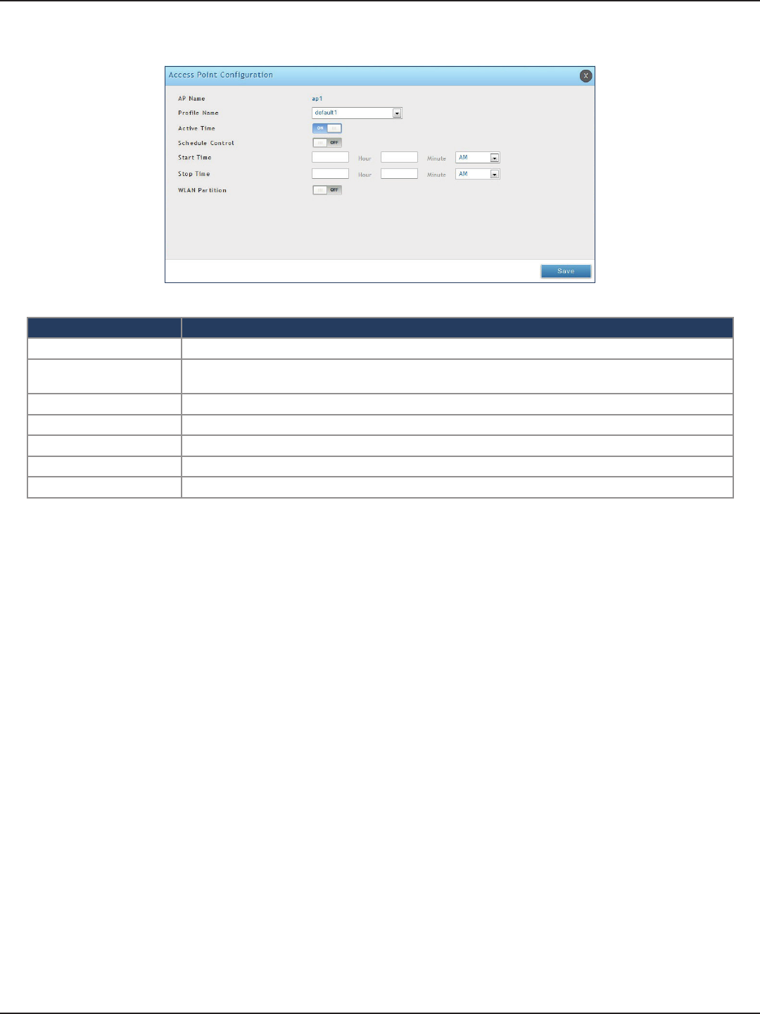
D-Link DSR-Series User Manual 81
Section 6 - Wireless Settings
3. Complete the elds in the table below and click Save.
Field Description
AP Name Enter a name for your virtual access point.
Prole Name Select a prole from the drop-down menu to associate this access point with. If you do not want to use
the default prole, create a prole (refer to the next page) and then create an access point.
Active Time Toggle to ON to “turn on” this access point.
Schedule Control Toggle to ON if you want to specify a time to have this access point turned on.
Start/Stop Time Enter a start and stop time.
WLAN Partition Toggle to ON to prevent associated wireless clients from communicating with each other.
Save Click Save at the bottom to save and activate your settings.
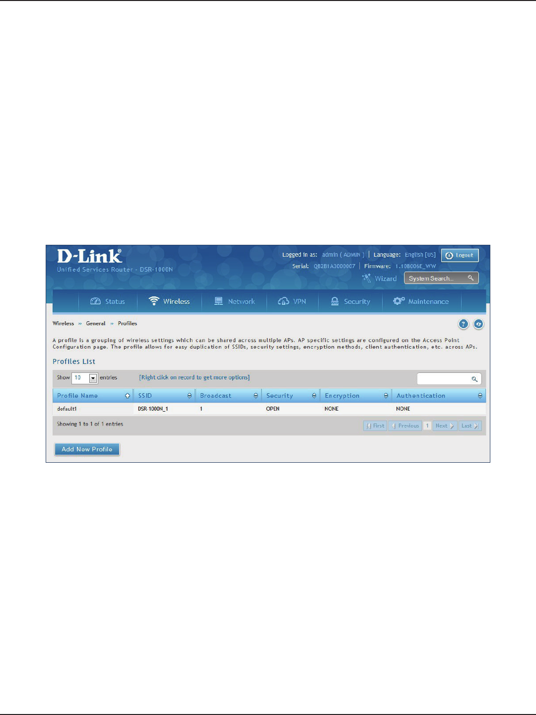
D-Link DSR-Series User Manual 82
Section 6 - Wireless Settings
Proles
Creating a prole allows you to assign the security type, encryption and authentication to use when connecting
the AP to a wireless client. The default mode is “open”, i.e., no security. This mode is insecure as it allows any
compatible wireless clients to connect to an AP congured with this security prole.
To create a new prole, use a unique prole name to identify the combination of settings. Congure a unique
SSID that will be the identier used by the clients to communicate to the AP using this prole. By choosing to
broadcast the SSID, compatible wireless clients within range of the AP can detect this prole’s availability. The AP
oers all advanced 802.11 security modes, including WEP, WPA, and WPA2.
To add, edit, or delete a prole:
1. Click Wireless > General > Proles.
Path: Wireless > General > Proles
2. Right-click a current entry and select Edit or Delete. To add a new entry, click Add New Access Point.
3. Complete the elds in the table on the next page and click Save.
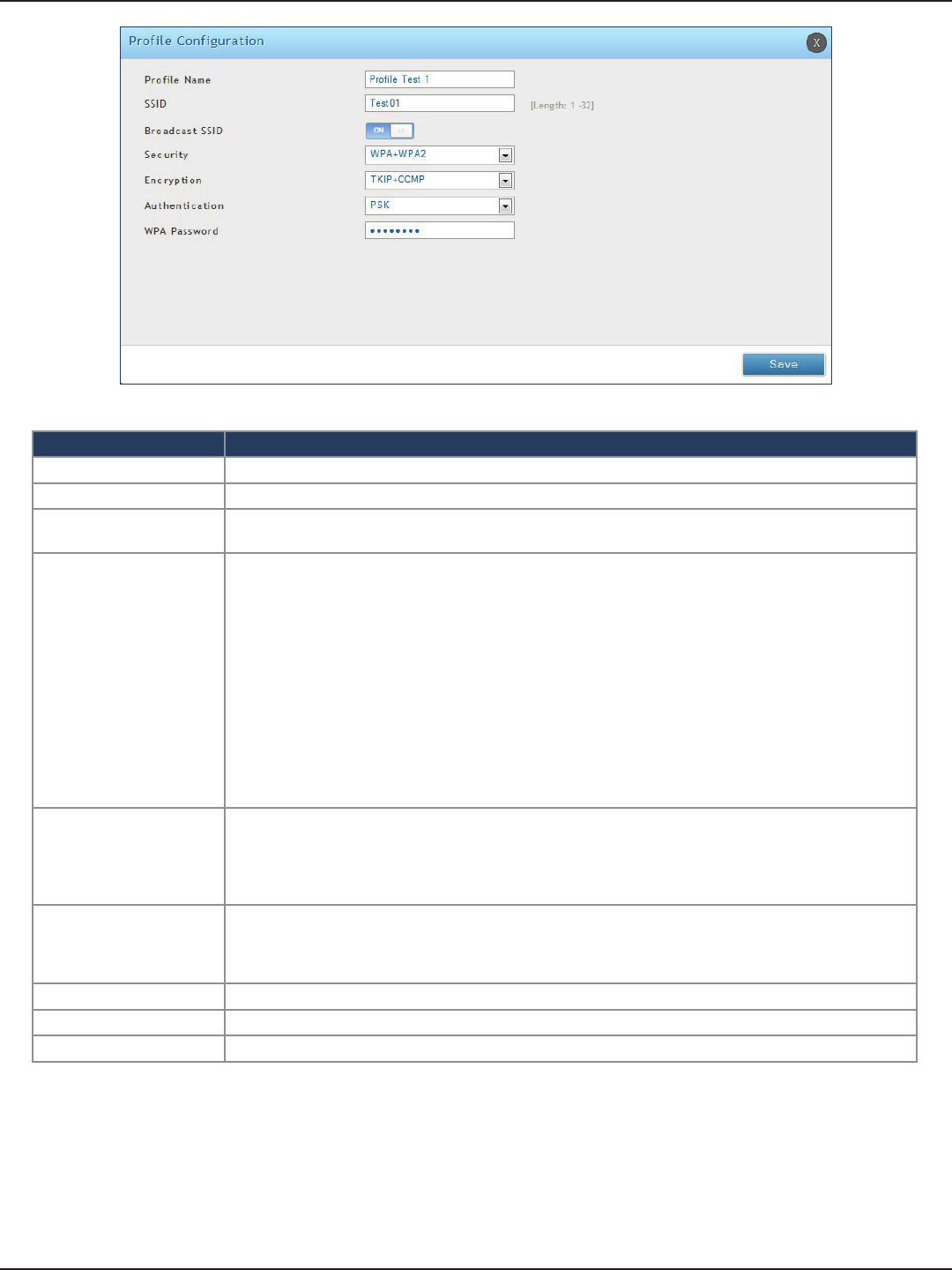
D-Link DSR-Series User Manual 83
Section 6 - Wireless Settings
Field Description
Prole Name Enter a name for your prole.
SSID Enter a name for your wireless network (SSID).
Broadcast SSID Toggle to ON if you want your SSID broadcast openly or toggle to OFF to hide it. Clients will have to
know the SSID to connect.
Security
Select what kind of wireless security you want to use:
• Open: Select this option to create a public “open” network to allow unauthenticated devices to access
this wireless gateway.
• WEP (Wired Equivalent Privacy): This option requires a static (pre -shared) key to be shared between
the AP and wireless client . Note that WEP does not support 802.11n data rates; is it appropriate for
legacy 802.11 connections.
• WPA (Wi-Fi Protected Access): For stronger wireless security than WEP, choose this option. The
encryption for WPA will use TKIP and also CCMP if required. The authentication can be a preshared
key (PSK), Enterprise mode with RADIUS server, or both. Note that WPA does not support 802.11n
data rates; is it appropriate for legacy 802.11 connections.
• WPA2: This security type uses CCMP encryption (and the option to add TKIP encryption) on either
PSK (pre-shared key) or Enterprise (RADIUS Server) authentication.
• WPA + WPA2: This uses both encryption algorithms, TKIP and CCMP. WPA clients will use TKIP and
WPA2 clients will use CCMP encryption algorithms.
Encryption
Select the encryption type:
• WEP - Select Open or Shared.
• WPA - Select TKIP or TKIP+CCMP.
• WPA2 - Select CCMP or TKIP+CCMP.
• WPA+WPA2 - TKIP+CCMP will be the only option.
Authentication
Select the authentication type:
• WEP - Select 64-bit or 128-bit.
• WPA/WPA2/WPA+WPA2 - Select PSK (passphrase), RADIUS (RADIUS server), or PSK+RADIUS
(both).
WEP Passphrase/Key (1-4) If you selected WEP, enter a passphrase or up to four hexadecimal keys (a-f, 0-9, A-F).
WPA Password If you selected WPA, WPA2, or WPA+WPA2, enter a WPA password.
Save Click Save at the bottom to save and activate your settings.
The AP conguration page allows you to create a new AP and link to it one of the available proles. This router
supports multiple AP’s referred to as virtual access points (VAPs). Each virtual AP that has a unique SSIDs appears
as an independent access point to clients. This valuable feature allows the router’s radio to be congured in a way
to optimize security and throughput for a group of clients as required by the user. To create a VAP, refer to “Access
Points” on page 80. After setting the AP name, the prole drop-down menu is used to select one of the congured
proles.
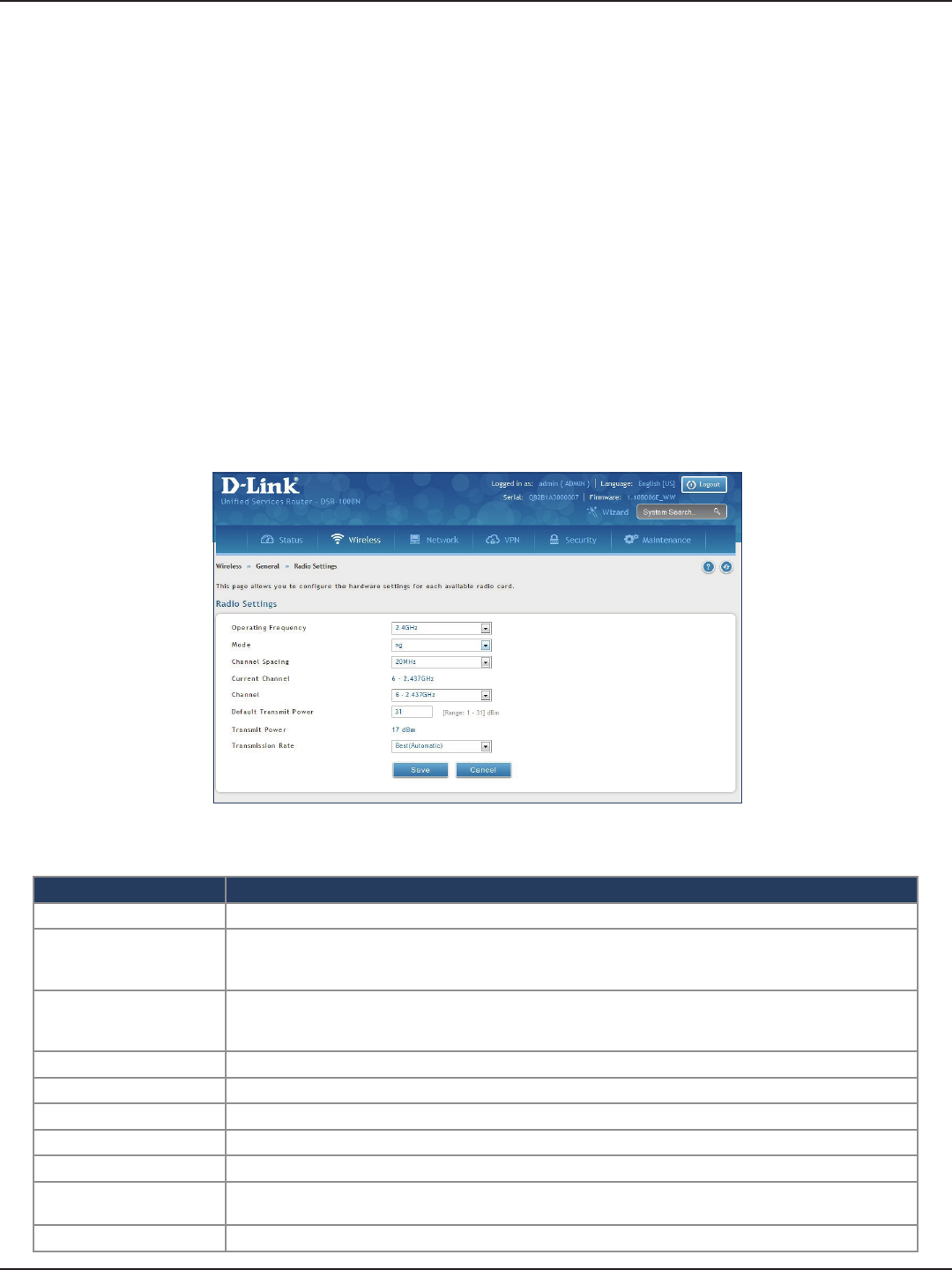
D-Link DSR-Series User Manual 84
Section 6 - Wireless Settings
Radio Settings
Path: Wireless > General > Radio Settings
You may congure the channels and power levels available for the AP’s enabled on the router. The router has a dual
band 802.11n radio, meaning either 2.4 GHz or 5 GHz frequency of operation can be selected (not concurrently
though). Based on the selected operating frequency, the mode selection will let you dene whether legacy
connections or only 802.11n connections (or both) are accepted on congured APs.
The ratied 802.11n support on this radio requires selecting the appropriate broadcast mode, and then dening
the channel spacing and control side band for 802.11n trac. The default settings are appropriate for most
networks. For example, changing the channel spacing to 40MHz can improve bandwidth at the expense of
supporting earlier 802.11n clients. The available transmission channels are governed by regulatory constraints
based on the region setting of the router.
To congure the radio settings:
1. Click Wireless > General > Radio Settings.
2. Complete the elds in the table below and click Save.
Field Description
Operating Frequency Select 2.4GHz or 5GHz.
Mode
Select the 802.11 mode:
• 2.4GHz - g and b, g only, n and g, or n only.
• 5GHz - a only, n and a, or n only.
Channel Spacing
Select the Channel Width:
Auto 20/40 - This is the default setting. Select if you are using both 802.11n and non-802.11n wireless devices.
20MHz - Select if you are not using any 802.11n wireless clients.
Control Side Band Select Upper or Lower. Available for 802.11n only.
Current Channel Displays the current channel.
Channel Select the channel you want to use.
Default Transmit Power Enter the default transmit power (0-31).
Transmit Power Displays the current transmit power.
Transmission Rate Select a transmission rate from the drop-down menu. This will lock the transmission rate of your wireless
connection. It is strongly recommended to use Best (Automatic).
Save Click Save at the bottom to save and activate your settings.
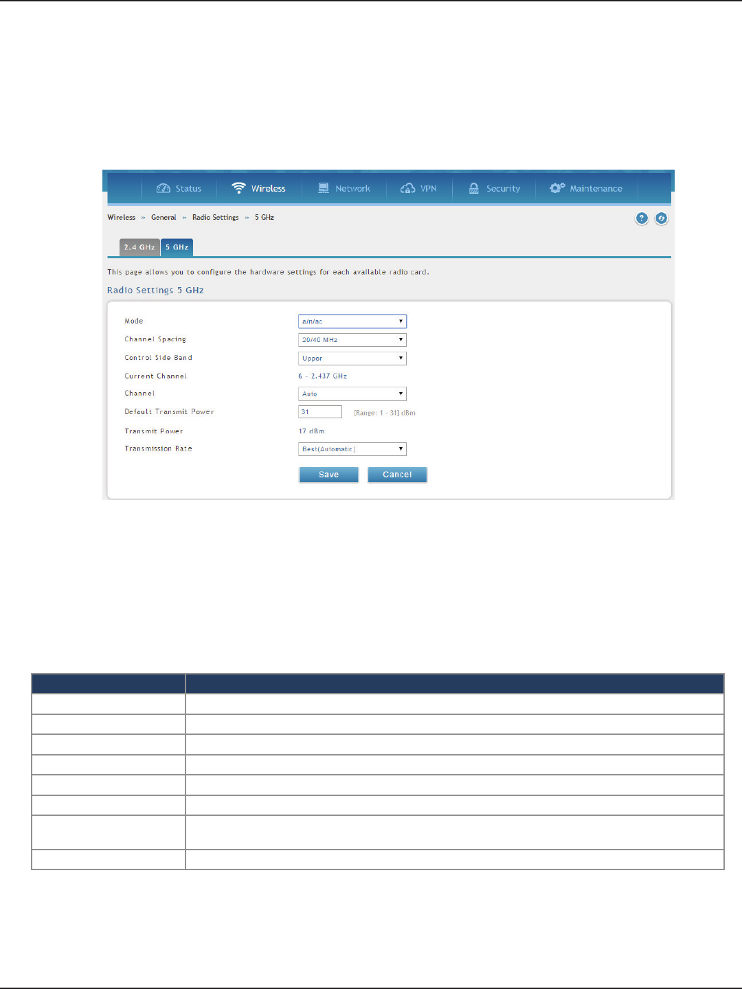
D-Link DSR-Series User Manual 85
Section 6 - Wireless Settings
802.11AC Conguration
Path: Wireless > General >Radio Settings > 5 Ghz
This section provides conguration options to use the DSR-500AC or DSR-1000AC advanced wireless capabilities
in the 5 GHz band.
With 802.11AC, data throughput can be signicantly increased as compared to 802.11n rates as the channel
bandwidth can be as high as 80 MHz. The available channels and spacing bandwidth are regulated by the
regulatory setting of the specic country the DSR-500AC or DSR-1000AC is deployed in. By selecting 802.11AC
rates, the 5 GHz radio will use the enhance capability of the new design and will send more data in a single
packet (via wireless frame aggragation).
Field Description
Mode This is the 802.11 modulaition technique being used
Channel Spacing Distance in MHz between the successive channels
Current Channel Channel being used in the available spectrum.
Channel Channel number selected by user, this is dened by the country code for the device.
Default Transmit Power Output transmit power set by user
Transmit Power Transmit power currently in use by the radio.
Transmission Rate Select a transmission rate from the drop-down menu. This will lock the transmission rate of your wireless
connection. It is strongly recommended to use Best (Automatic).
Save Rates used by device to download the data to client.
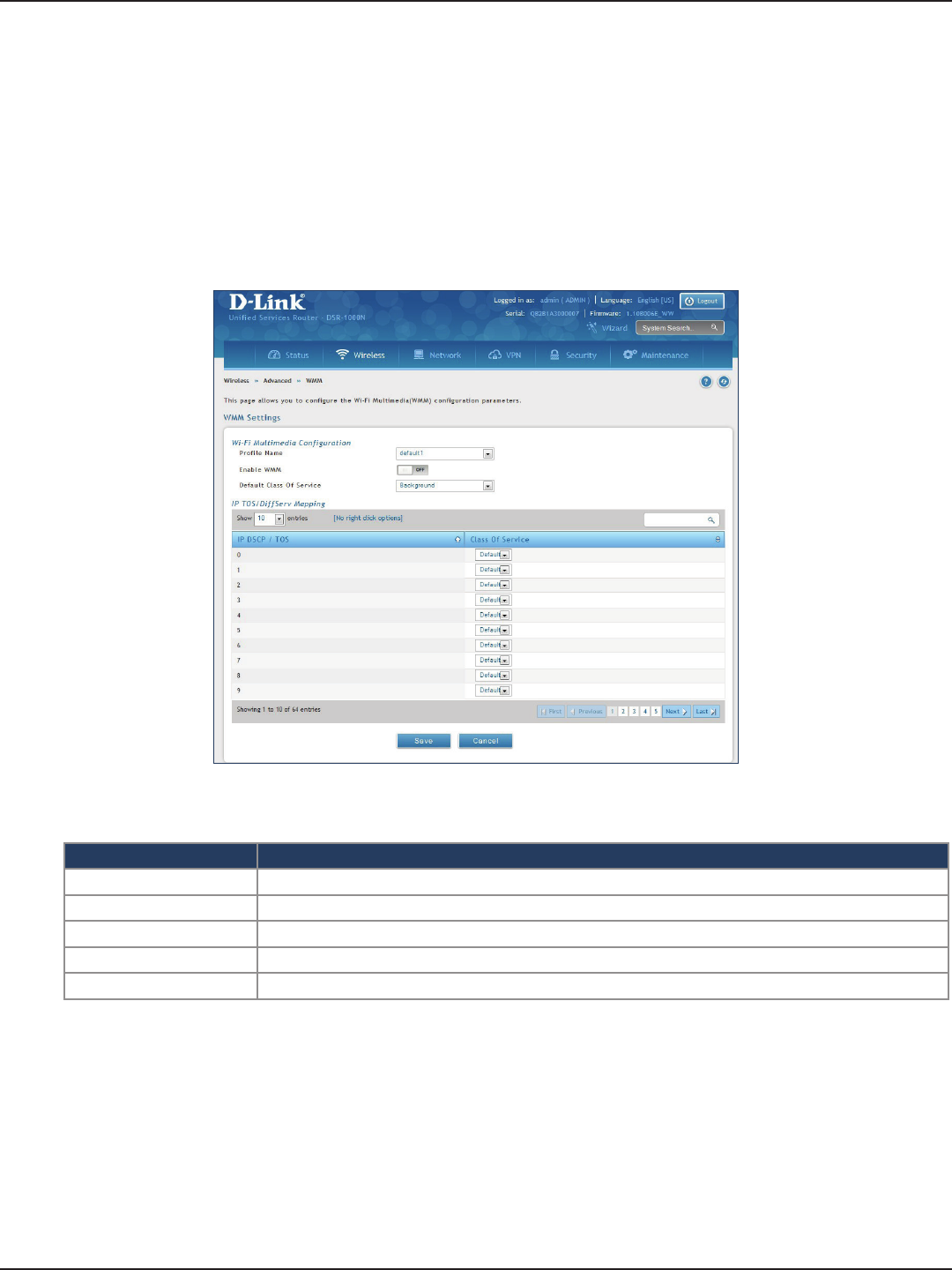
D-Link DSR-Series User Manual 86
Section 6 - Wireless Settings
WMM Settings
Path: Wireless > Advanced > WMM
Wi-Fi Multimedia (WMM) provides basic Quality of Service (QoS) features to IEEE 802.11 networks. WMM prioritizes
trac according to four Access Categories (AC) - voice, video, best eort, and background.
To congure the radio settings:
1. Click Wireless > Advanced > WMM.
2. Complete the elds in the table below and click Save.
Field Description
Prole Name Select the prole to associate this conguration to from the drop-down menu.
Enable WMM Toggle to ON to enable WMM.
Default Class of Service Select an available access category (voice, video, best eort, or background) to assign as “default”.
IP DSCP / TOS Under Class of Service, select a service and map it to the IP DSCP / TOS value.
Save Click Save at the bottom to save and activate your settings.
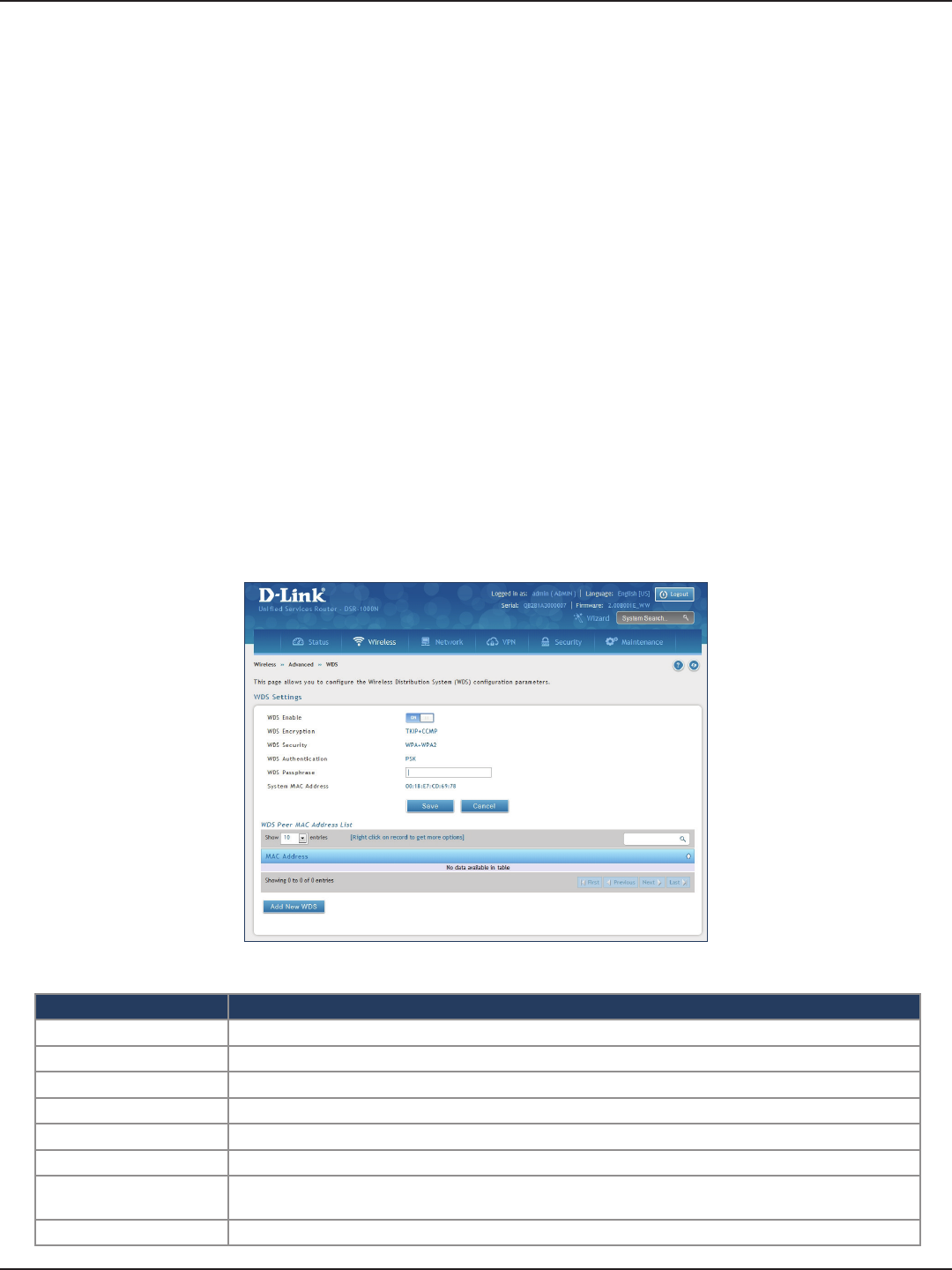
D-Link DSR-Series User Manual 87
Section 6 - Wireless Settings
WDS
Path: Wireless > Advanced > WDS
Wireless Distribution System (WDS) is a system enabling the wireless interconnection of access points in a
network. This feature is only guaranteed to work between devices of the same type (i.e., using the same chipset/
driver).
When you enable WDS, use the same security conguration as the default access point. The WDS links do not
have true WPA/WPA2 support, as in there is no WPA key handshake performed. Instead the Session Key to be
used with a WDS Peer is computed using a hashing function (similar to the one used for computing a WPA PMK).
The inputs to this function are a PSK (congurable by an administrator from the WDS page) and an internal
“magic” string (non-congurable).
In eect the WDS links use TKIP/AES encryption, depending on the encryption congured for the default AP. In
case the default AP uses mixed encryption (TKIP + AES). The WDS link will use the AES encryption scheme.
Note: For a WDS link to function properly the Radio settings on the WDS peers have to be the same.
To congure the radio settings:
1. Click Wireless > Advanced > WDS.
2. Complete the elds in the table below and click Save.
Field Description
WDS Enable Toggle to ON to enable WDS and click Save.
WDS Encryption Displays the current wireless encryption used.
WDS Security Displays the current security type.
WDS Authentication Displays the current authentication type.
WDS Passphrase Enter the WDS passphrase (if WEP, WPA, WPA2, or WPA+WPA2 is enabled).
System MAC Address Displays the system MAC address.
Add New WDS Once you enabled WDS (and clicked Save), click Add New WDS and enter the MAC address of a WDS peer.
You can add up to four WDS peers.
Save Click Save at the bottom to save and activate your settings.
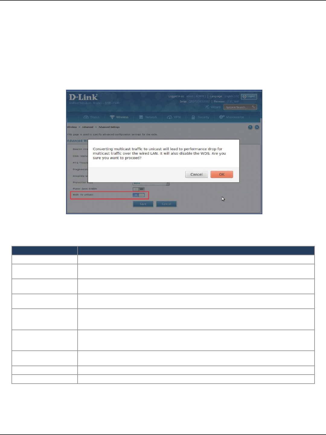
D-Link DSR-Series User Manual 88
Section 6 - Wireless Settings
Advanced Settings
Path: Wireless > Advanced > Advanced Settings
You can modify the 802.11 communication parameters in this page. Generally, the default settings are appropriate
for most networks.
Field Description
Beacon Interval Beacons are packets sent by an Access Point to synchronize a wireless network. The default value is 100.
DTIM Interval (Delivery Trac Indication Message) 3 is the default setting. A DTIM is a countdown informing clients of the
next window for listening to broadcast and multicast messages.
RTS Threshold This value should remain at its default setting of 2432. If inconsistent data ow is a problem, only a minor
modication should be made.
Fragmentation Threshold The fragmentation threshold, which is specied in bytes, determines whether packets will be fragmented.
Packets exceeding the 2346 byte setting will be fragmented before transmission. 2346 is the default setting.
Preamble Mode
Select either Long or Short. The Preamble Type denes the length of the CRC (Cyclic Redundancy Check)
block for communication between the Access Point and roaming wireless adapters. High network trac
areas should use Short preamble type.
Protection Mode
Select either None or CTS-to-Self Protection. Select the CTS-to-Self Protection to enable CTS-to-Self
protection mechanism, which is used to minimize collisions among stations in a mixed 802.11b & g
environment. The default selection is None.
Power Save Enable Toggle to ON to enable the Unscheduled Automatic Power Save Delivery (also referred to as WMM Power
Save) feature that allows the radio to conserve power.
Save Click Save at the bottom to save and activate your settings.
Milti to Unicast Toggle to ON to enable IGMP Snooping on Wireless Clients.
1. Click Wireless > Advanced > Advanced Settings.
2. Complete the elds in the table below and click Save.
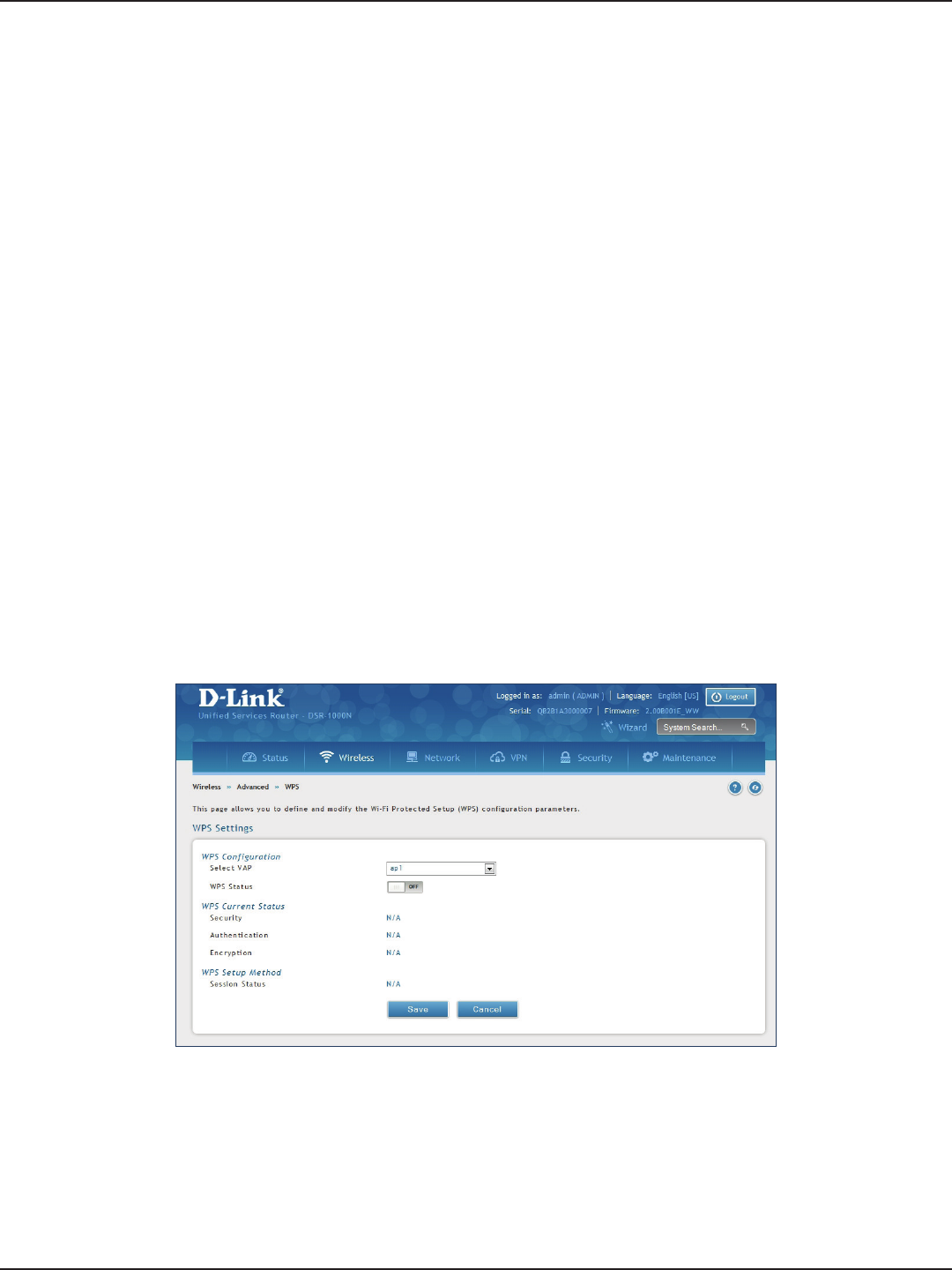
D-Link DSR-Series User Manual 89
Section 6 - Wireless Settings
WPS
Path: Wireless > Advanced > WPS
WPS is a simplied method to add supporting wireless clients to the network. WPS is only applicable for APs that
employ WPA or WPA2 security. To use WPS, select the eligible VAPs from the drop-down menu of APs that have
been congured with this security and enable WPS status for this AP.
The WPS Current Status section outlines the security, authentication, and encryption settings of the selected AP.
These are consistent with the AP’s prole. There are two setup options:
• Personal Identication Number (PIN): The wireless device that supports WPS may have an
alphanumeric PIN, if it does add the PIN in this eld. The router will connect within 60 seconds
of clicking the “Congure via PIN” button immediately below the PIN eld. There is no LED
indication that a client has connected.
• Push Button Conguration (PBC): For wireless devices that support PBC, press and hold the
WPS button for two seconds, and then press the WPS button (or initiate WPS via GUI) on your
wireless client within two minutes. The AP will detect the wireless device and establish a secure
link to the client.
To enable and connect clients using WPS:
1. Click Wireless > Advanced > WPS.
2. Select which VAP you want to perform the WPS process from the drop-down menu.
3. Toggle WPS Status to ON and click Save.
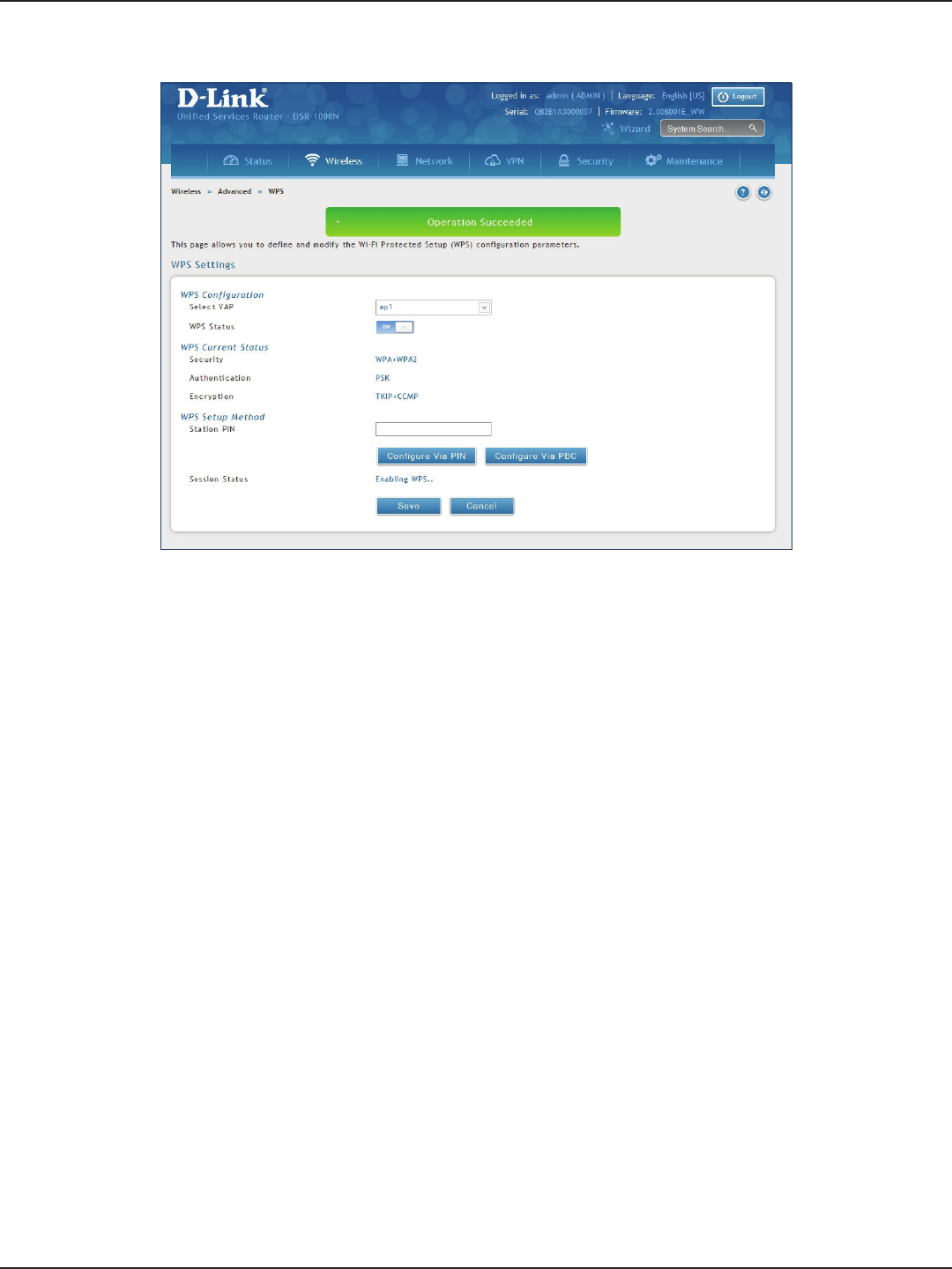
D-Link DSR-Series User Manual 90
Section 6 - Wireless Settings
4. Once enabled the following screen will appear.
5. Under WPS Setup Method, decide to either use PIN or PBC (Push Button).
6. If you want to use PIN method, enter the PIN next to Station PIN and click Congure Via PIN. You will
need to enter the PIN on your wireless client and start the WPS process within one minute.
7. If you want to use push button method, click Congure Via PBC. This will initiate the WPS session. You
will need to press the WPS button (or initiate through an interface) on your client within one minute.
8. Allow up to two minutes to connect. Check the Session Status to see if it successfully connected.

D-Link DSR-Series User Manual 91
Section 7 - VPN
VPN
A VPN provides a secure communication channel (“tunnel”) between two gateway routers or a remote PC client.
The following types of tunnels can be created:
• Gateway-to-gateway VPN: To connect two or more routers to secure trac between remote
sites.
• Remote Client (client-to-gateway VPN tunnel): A remote client initiates a VPN tunnel as the
IP address of the remote PC client is not known in advance. The gateway in this case acts as a
responder.
• Remote client behind a NAT router: The client has a dynamic IP address and is behind a NAT
Router. The remote PC client at the NAT router initiates a VPN tunnel as the IP address of the
remote NAT router is not known in advance. The gateway WAN port acts as responder.
• PPTP server for LAN / WAN PPTP client connections.
• L2TP server for LAN / WAN L2TP client connections.
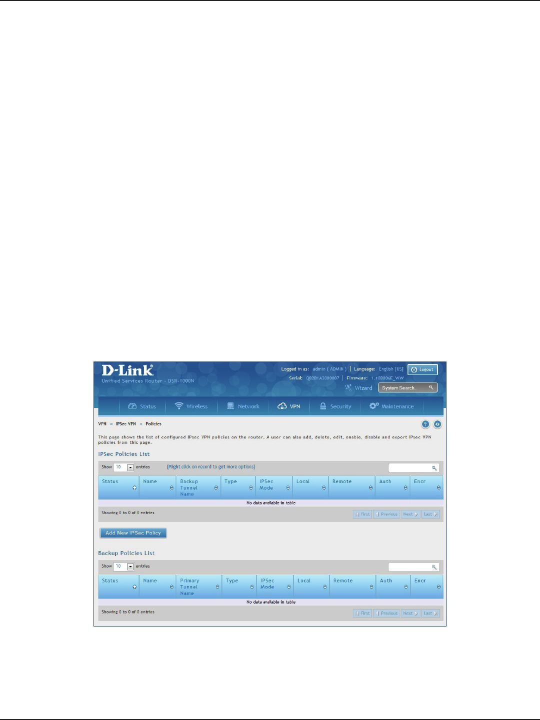
D-Link DSR-Series User Manual 92
Section 7 - VPN
IPSec VPN
Policies
Path: VPN > IPSec VPN > Policies
An IPsec policy is between this router and another gateway or this router and an IPsec client on a remote host.
The IPsec mode can be either tunnel or transport depending on the network being traversed between the two
policy endpoints.
• Transport: This is used for end-to-end communication between this router and the tunnel
endpoint, either another IPsec gateway or an IPsec VPN client on a host. Only the data payload
is encrypted and the IP header is not modied or encrypted.
• Tunnel: This mode is used for network-to-network IPsec tunnels where this gateway is one
endpoint of the tunnel. In this mode the entire IP packet including the header is encrypted
and/or authenticated.
When tunnel mode is selected, you can enable NetBIOS and DHCP over IPsec. DHCP over IPsec allows this router
to serve IP leases to hosts on the remote LAN. As well in this mode you can dene the single IP address, range of
IPs, or subnet on both the local and remote private networks that can communicate over the tunnel.
To congure the radio settings:
1. Click VPN > IPSec VPN > Policies.
2. Click Add new IPSec Policy. Fill out the General section which you will name the VPN, select policy
type, dene the tunnel type, and dene endpoints.
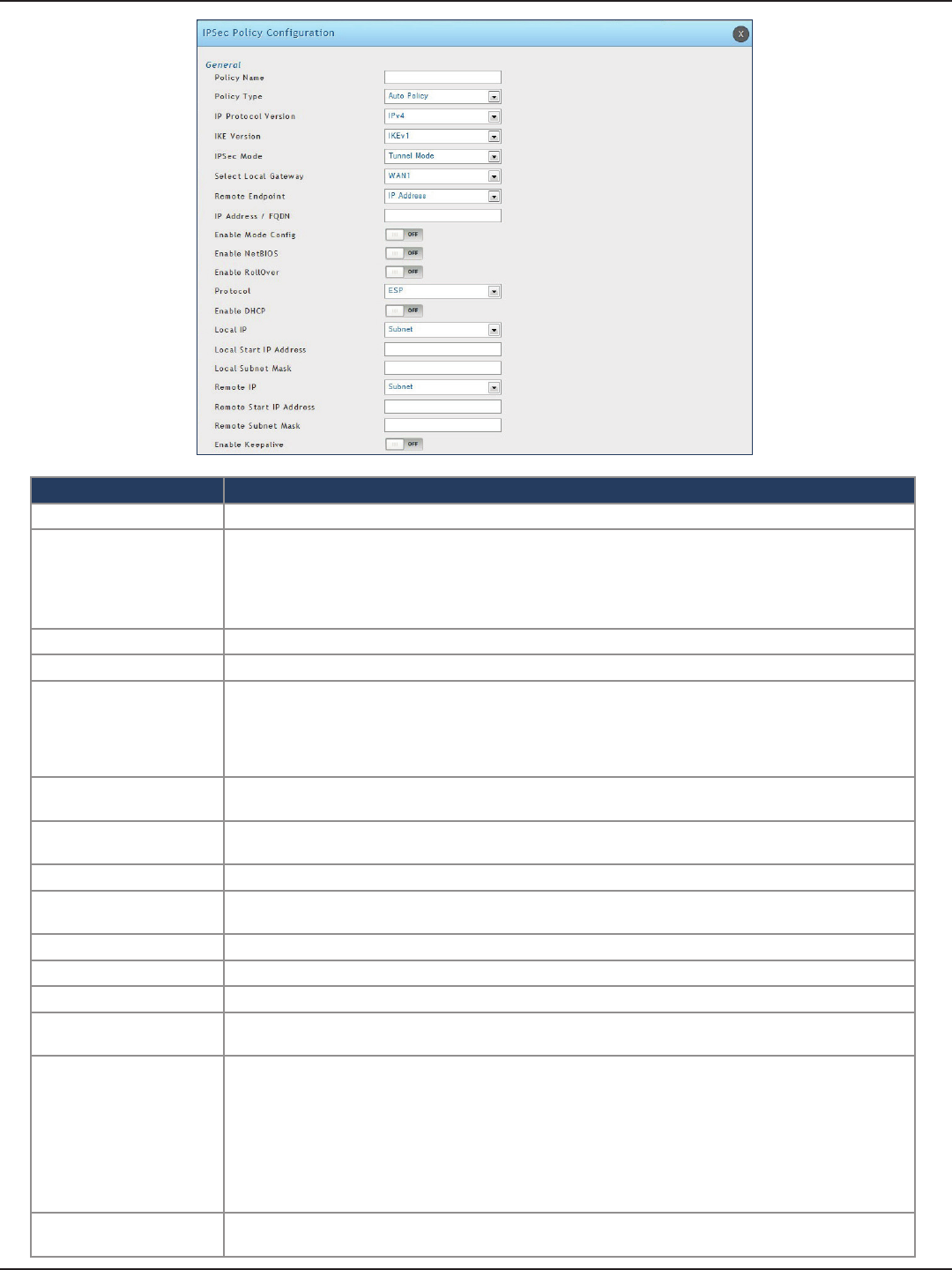
D-Link DSR-Series User Manual 93
Section 7 - VPN
Field Description
Policy Name Enter a unique name for the VPN Policy. This name is not an identier for the remote WAN/client.
Policy Type
Select either Manual or Auto.
• Manual: All settings (including the keys) for the VPN tunnel are manually input for each end point. No
third-party server or organization is involved.
• Auto: Some parameters for the VPN tunnel are generated automatically. This requires using the IKE
(Internet Key Exchange) protocol to perform negotiations between the two VPN Endpoints.
IP Protocol Version Select either IPv4 or IPv6.
IKE Version Select the version of IKE.
IPSec Mode
Select either Tunnel or Transport. IPsec tunnel mode is useful for protecting trac between dierent
networks, when trac must pass through an intermediate, untrusted network. Tunnel mode is primarily
used for interoperability with gateways, or end-systems that do not support L2TP/IPsec or PPTP
connections. Transport mode is the default mode for IPsec, and it is used for end-to-end communications
(for example, for communications between a client and a server).
Select Local Gateway In the event that two WAN ports are congured to connect to your ISP, select the gateway that will be used
as the local endpoint for this IPsec tunnel.
Remote Endpoint Select the type of identier that you want to provide for the router at the remote endpoint (either IP
Address or FQDN [Fully Qualied Domain Name])
IP Address/FQDN Enter the identier for the router.
Enable Mode Cong Toggle to ON to enable. Mode Cong is similar to DHCP and is used to assign IP addresses to the remote
VPN clients.
Enable NetBIOS Toggle to ON to allow NetBIOS broadcasts to travel over the VPN tunnel
Enable RollOver Toggle to ON to enable VPN rollover. You must have the WAN Mode set to Rollover.
Protocol Select a protocol from the drop-down menu.
Enable DHCP Toggle to ON to allow VPN clients that are connected to your router over IPsec to receive an assigned IP
using DHCP.
Local IP/Remote IP
Select the type of identier that you want to provide for the endpoint:
• Any: Species that the policy is for trac from the given end point (local or remote). Note that
selecting Any for both local and remote end points is not valid.
• Single: Limits the policy to one host. Enter the IP address of the host that will be part of the VPN.
• Range: Allows computers within an IP address range to connect to the VPN. Enter the Start IP Address
and End IP Address in the provided elds.
• Subnet: Allows an entire subnet to connect to the VPN. Enter the network address and subnet mask
in the provided elds.
Enable Keepalive Toggle to ON to periodically send ping packets to the host on the peer side of the network to keep the
tunnel alive.
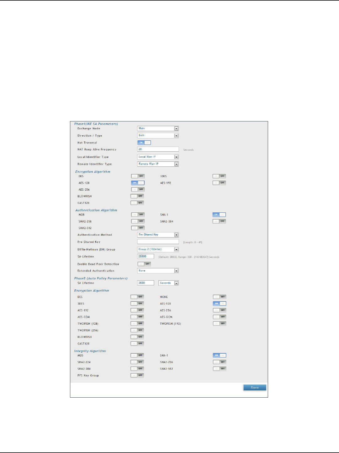
D-Link DSR-Series User Manual 94
Section 7 - VPN
3. Once the tunnel type and endpoints of the tunnel are dened you can determine the Phase 1/ Phase
2 negotiation to use for the tunnel. This is covered in the IPsec mode setting, as the policy can be
Manual or Auto. For Auto policies, the Internet Key Exchange (IKE) protocol dynamically exchanges
keys between two IPsec hosts. The Phase 1 IKE parameters are used to dene the tunnel’s security
association details.
The Phase 2 Auto policy parameters cover the security association lifetime and encryption/authentication
details of the phase 2 key negotiation.
The VPN policy is one half of the IKE/VPN policy pair required to establish an Auto IPsec VPN tunnel. The
IP addresses of the machine or machines on the two VPN endpoints are congured here, along with
the policy parameters required to secure the tunnel.

D-Link DSR-Series User Manual 95
Section 7 - VPN
A Manual policy does not use IKE and instead relies on manual keying to exchange authentication
parameters between the two IPsec hosts. The incoming and outgoing security parameter index
(SPI) values must be mirrored on the remote tunnel endpoint. As well the encryption and integrity
algorithms and keys must match on the remote IPsec host exactly in order for the tunnel to establish
successfully. Note that using Auto policies with IKE are preferred as in some IPsec implementations the
SPI (security parameter index) values require conversion at each endpoint.
DSR routers supports VPN roll-over feature. This means that policies congured on the primary WAN
will rollover to the secondary WAN in case of a link failure. This feature can be used only if your WAN is
congured in Auto-Rollover mode.
Note: Once you have created an IPSec policy, you may right-click the policy and select Export to save
as a le. You can then upload this to another DSR router or keep as a backup. To upload a saved policy,
refer to “Easy VPN Setup” on page 102.
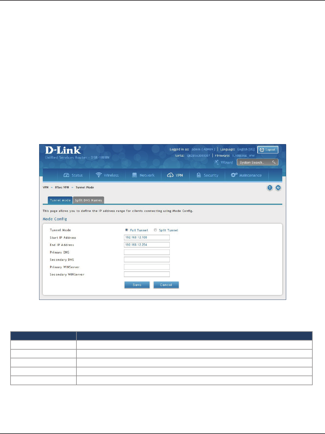
D-Link DSR-Series User Manual 96
Section 7 - VPN
Tunnel Mode
Path: VPN > IPSec VPN > Tunnel Mode
When tunnel mode is selected, you can enable NetBIOS and DHCP over IPSec. DHCP over IPSec allows this router
to serve IP leases to hosts on the remote LAN. You can also dene a single IP address, a range of IPs, or a subnet
on both the local and remote private networks that can communicate over the tunnel.
The router allows full tunnel and split tunnel support. Full tunnel mode just sends all trac from the client across
the VPN tunnel to the router. Split tunnel mode only sends trac to the private LAN based on pre-specied client
routes. These client routes give the client access to specic private networks, thereby allowing access control
over specic LAN services.
1. Click VPN > IPSec VPN > Tunnel Mode.
2. Complete the elds in the table below and click Save.
Field Description
Tunnel Mode Select either Full Tunnel or Split Tunnel.
Start/End IP Address Enter the starting and ending IP addresses.
Primary/Secondary DNS Enter the primary and secondary DNS server addresses.
Primary/Secondary WINS Enter the primary and secondary WINS server addresses.
Save Click Save to save and activate your settings.
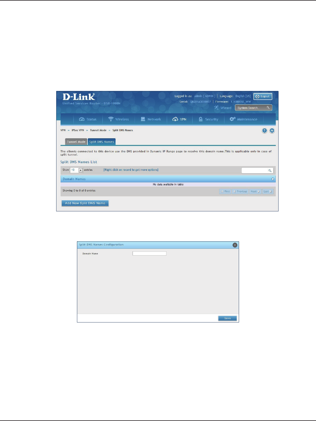
D-Link DSR-Series User Manual 97
Section 7 - VPN
Split DNS Names
To add a DNS name:
1. Click VPN > IPSec VPN > Tunnel Mode > Split DNS Names tab.
2. Click Add New Split DNS name. You can right-click any created entries to edit or delete.
3. Enter a domain name and click Save.
In a split DNS infrastructure, you create two zones for the same domain, one to be used by the internal network,
the other used by the external network. Split DNS directs internal hosts to an internal domain name server for
name resolution and external hosts are directed to an external domain name server for name resolution.
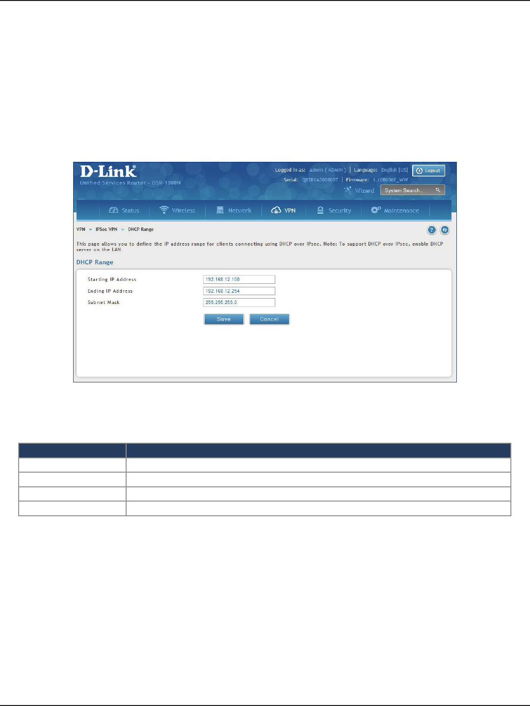
D-Link DSR-Series User Manual 98
Section 7 - VPN
DHCP Range
To congure the DHCP over IPSec DHCP server settings:
1. Click VPN > IPSec VPN > DHCP Range.
2. Complete the elds in the table below and click Save.
Field Description
Starting IP Address Enter the starting IP address to issue your clients connecting using DHCP over IPSec.
Ending IP Address Enter the ending IP address.
Subnet Mask Enter the subnet mask.
Save Click Save to save and activate your settings.
This page displays the IP range to be assigned to clients connecting using DHCP over IPsec. By default the range
is in 192.168.12.0 subnet.
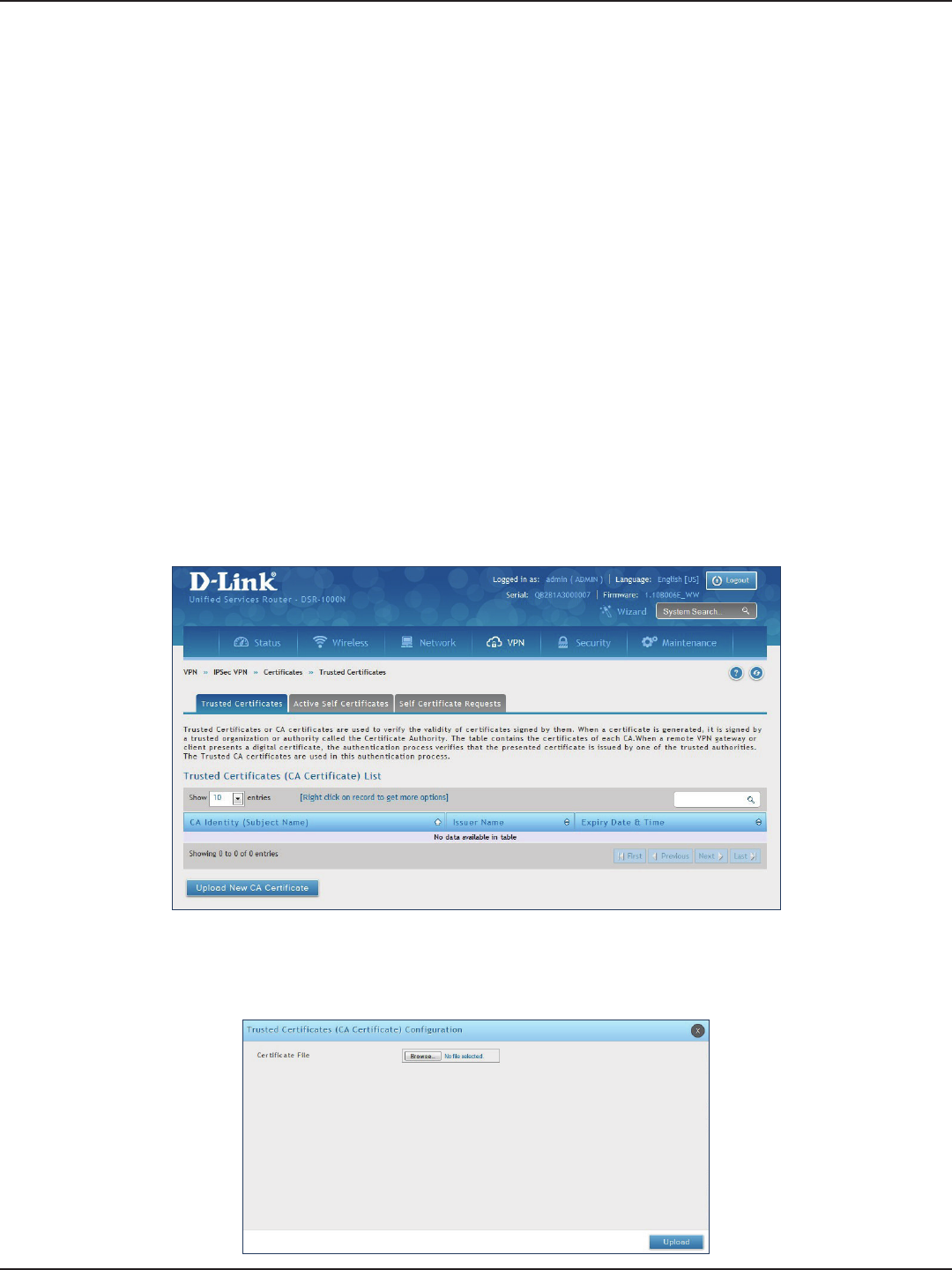
D-Link DSR-Series User Manual 99
Section 7 - VPN
Certicates
Trusted Certicates
This router uses digital certicates for IPsec VPN authentication. You can obtain a digital certicate from a well-
known Certicate Authority (CA) such as VeriSign, or generate and sign your own certicate using functionality
available on this gateway.
The router comes with a self-signed certicate, and this can be replaced by one signed by a CA as per your
networking requirements. A CA certicate provides strong assurance of the server’s identity and is a requirement
for most corporate network VPN solutions.
The certicates menu allows you to view a list of certicates (both from a CA and self-signed) currently loaded on
the router. The following certicate data is displayed in the list of Trusted (CA) certicates:
CA Identity (Subject Name): The certicate is issued to this person or organization
Issuer Name: This is the CA name that issued this certicate
Expiry Time: The date after which this Trusted certicate becomes invalid
To upload a certicate:
1. Click VPN > IPSec VPN > Certicate > Trusted Certicates tab.
2. Click the Browse button. Locate your certicate and click Open.
3. Click Upload.
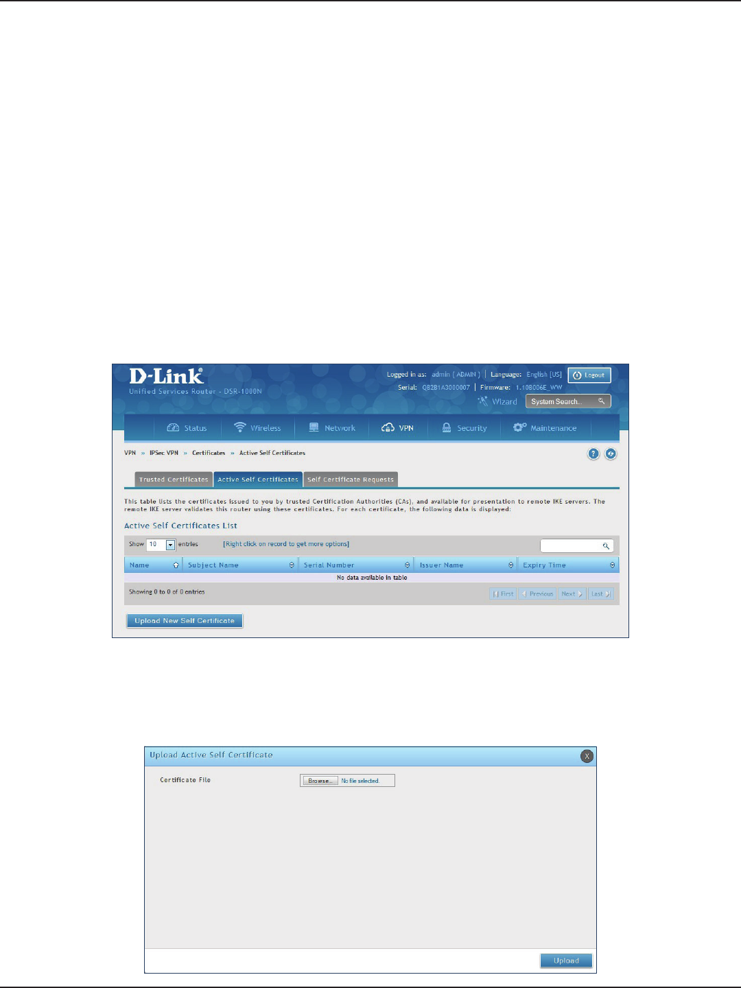
D-Link DSR-Series User Manual 100
Section 7 - VPN
Active Self Certicates
A self certicate is a certicate issued by a CA identifying your device (or self-signed if you don’t want the identity
protection of a CA). The Active Self Certicate table lists the self certicates currently loaded on the router. The
following information is displayed for each uploaded self certicate:
Name: The name you use to identify this certicate, it is not displayed to IPsec VPN peers.
Subject Name: This is the name that will be displayed as the owner of this certicate. This should be your
ocial registered or company name, as IPsec or SSL VPN peers are shown this eld.
Serial Number: The serial number is maintained by the CA and used to identify this signed certicate.
Issuer Name: This is the CA name that issued (signed) this certicate
Expiry Time: The date after which this signed certicate becomes invalid. You should renew the certicate
before it expires.
To upload a certicate:
1. Click VPN > IPSec VPN > Certicate > Active Self Certicates tab.
2. Click the Browse button. Locate your certicate and click Open.
3. Click Upload.
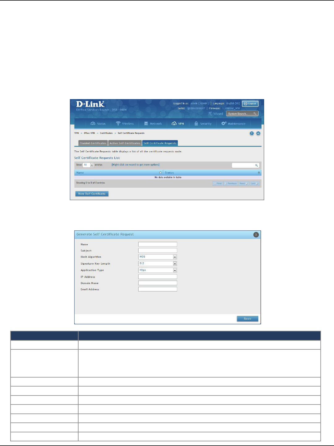
D-Link DSR-Series User Manual 101
Section 7 - VPN
Self Certicate Requests
To request a self certicate to be signed by a CA, you can generate a Certicate Signing Request from the router
by entering identication parameters and passing it along to the CA for signing. Once signed, the CA’s Trusted
Certicate and signed certicate from the CA are uploaded to activate the self -certicate validating the identity
of this gateway. The self certicate is then used in IPsec and SSL connections with peers to validate the gateway’s
authenticity.
To generate a certicate signing request:
1. Click VPN > IPSec VPN > Certicates > Self Certicate Requests.
2. Click New Self Certicate.
3. Complete the elds in the table below and click Save.
Field Description
Name Enter a name (identier) for the certicate.
Subject
This eld will populate the CN (Common Name) entry of the generated certicate. Subject names are
usually dened in the following format: CN=<device name>, OU=<department>, O=<organization>,
L=<city>, ST=<state>, C=<country>. For example: CN=router1, OU=my_company, O=mydept, L=SFO,
C=US.
Hash Algorithm Select the algorithm from the drop-down menu. Select either MD5 or SHA-1.
Signature Key Length Select the signature key length from the drop-down menu. Select either 512, 1024, or 2048
Application Type Select the application type from the drop-down menu. Select either HTTPS or IPSec.
IP Address Enter an IP address (optional).
Domain Name Enter a domain name (optional).
Email Address Enter your email address.
Save Click Save to save and activate your settings.
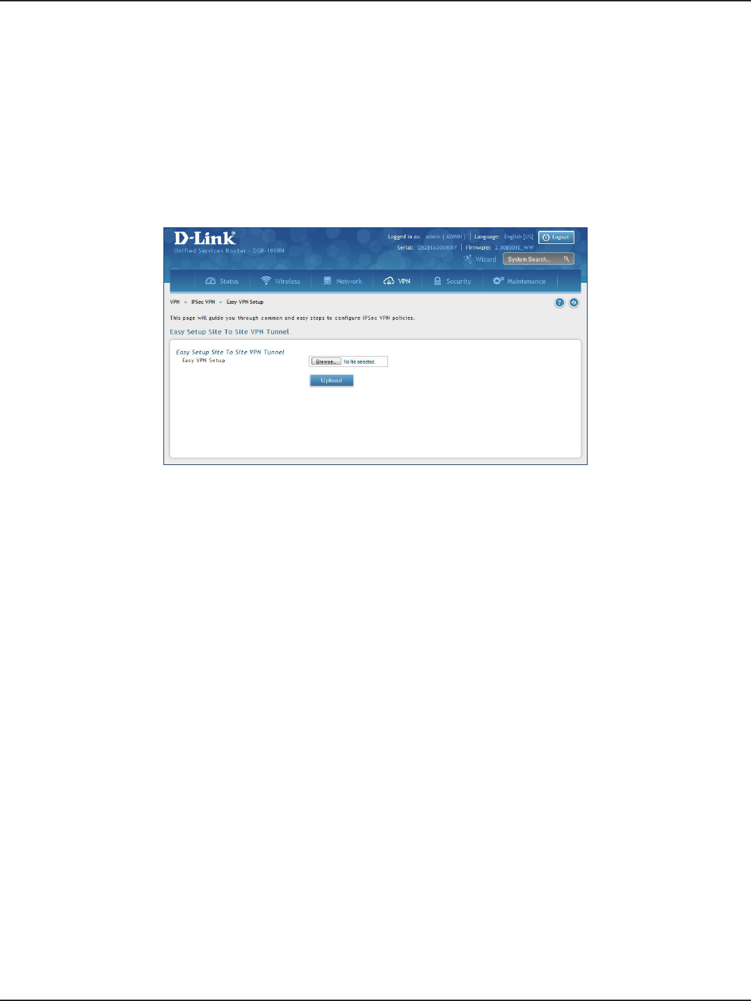
D-Link DSR-Series User Manual 102
Section 7 - VPN
Easy VPN Setup
To upload an exported IPSec VPN policy:
1. Click VPN > IPSec VPN > Easy VPN Setup.
2. Click Browse and navigate to the policy le you want to upload. Select it and click Open.
3. Click Upload.
4. Once uploaded, go to VPN > IPSec VPN > Policies and the loaded VPN will be listed. Right-click it to
edit or delete.
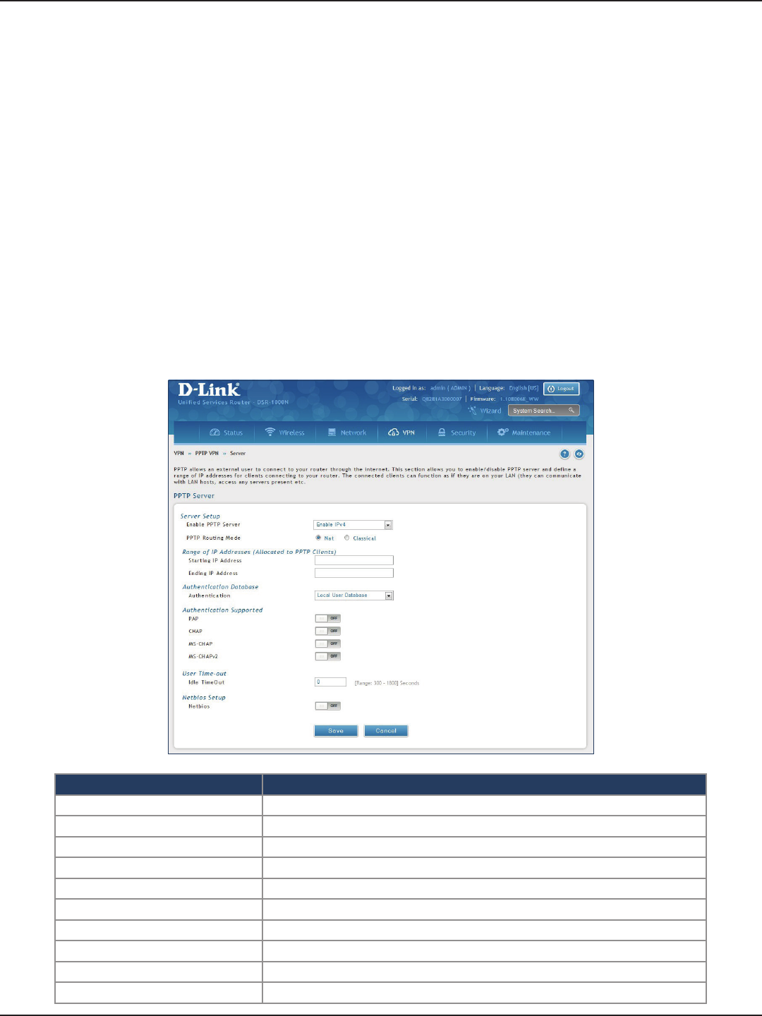
D-Link DSR-Series User Manual 103
Section 7 - VPN
PPTP VPN
Server
Path: VPN > PPTP VPN > Server
A PPTP VPN can be established through this router. Once enabled a PPTP server is available on the router for LAN
and WAN PPTP client users to access. Once the PPTP server is enabled, PPTP clients that are within the range of
congured IP addresses of allowed clients can reach the router’s PPTP server. Once authenticated by the PPTP
server (the tunnel endpoint), PPTP clients have access to the network managed by the router.
The range of IP addresses allocated to PPTP clients can coincide with the LAN subnet. As well the PPTP server
will default to local PPTP user authentication, but can be congured to employ an external authentication server
should one be congured.
Field Description
Enable PPTP Server Select either IPv4 or IPv6.
PPTP Routing Mode Select either NAT or Classical.
Starting/Ending IP Address Enter the IP address range to assign your PPTP clients.
IPv6 Prex If you selected IPv6, enter the IPv6 prex.
IPv6 Prex Length If you selected IPv6, enter the IPv6 prex length.
Authentication Select the authentication type from the drop-down menu.
Authentication Supported Toggle which type of authentication you want to enable to ON.
Idle TimeOut Enter the amount of time in seconds that the connection will disconnect when idle.
NetBIOS Toggle to ON to allow NetBIOS broadcasts to travel over the VPN tunnel.
Save Click to save your settings.
To create a PPTP VPN server:
1. Click VPN > PPTP VPN > Server.
2. Complete the elds in the table below and click Save.
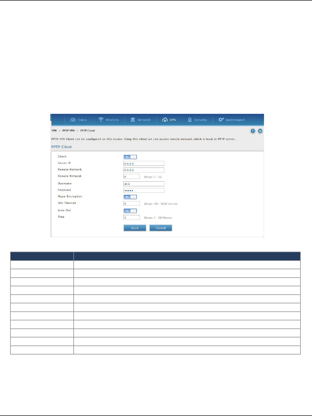
D-Link DSR-Series User Manual 104
Section 7 - VPN
Client
Path: VPN > PPTP VPN > Client
PPTP VPN Client can be congured on this router. Using this client you can access remote network which is
local to PPTP server. Once client is enabled, the user can access Status > Active VPNs page and establish PPTP
VPN tunnel clicking Connect.
Field Description
Client Toggle to ON to enable PPTP client.
Server IP Enter the IP address of the PPTP server you want to connect to.
Remote Network Enter the remote network address. This address is local for the PPTP Server.
Remote Netmask Enter the remote network subnet mask.
Username Enter your PPTP user name.
Password Enter your PPTP password.
MPPE Encryption Toggle to ON to enable Microsoft Point-to-Point Encryption (MPPE).
Idle Time Out Enter the amount of time (in seconds) that you will disconnect from the PPTP server when idle.
Save Click Save to save and activate your settings.
Auto Dial Toggle to On to enable Auto Dial
Time Reconnect time
To congure the router as a PPTP VPN client:
1. Click VPN > PPTP VPN > Client tab.
2. Toggle Client to ON and complete the elds in the table below.
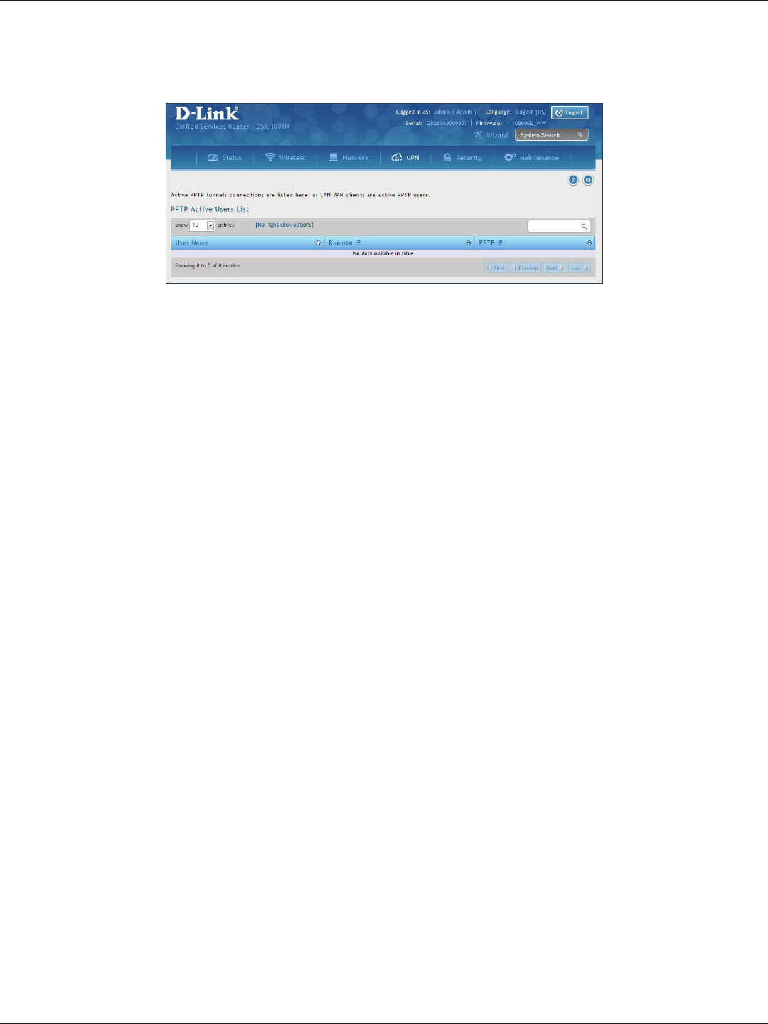
D-Link DSR-Series User Manual 105
Section 7 - VPN
PPTP Active Users List
A list of PPTP connections will be displayed on this page. Right-click the connection to connect and disconnect.
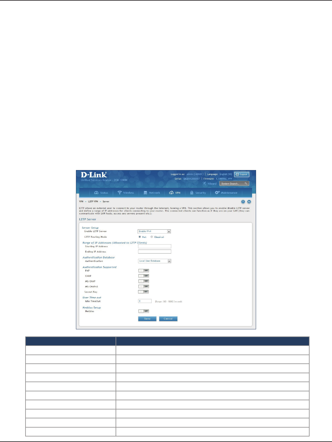
D-Link DSR-Series User Manual 106
Section 7 - VPN
L2TP VPN
Server
Path: VPN > L2TP VPN > Server
A L2TP VPN can be established through this router. Once enabled a L2TP server is available on the router for LAN
and WAN L2TP client users to access. Once the L2TP server is enabled, PPTP clients that are within the range of
congured IP addresses of allowed clients can reach the router’s L2TP server. Once authenticated by the L2TP
server (the tunnel endpoint), L2TP clients have access to the network managed by the router.
The range of IP addresses allocated to L2TP clients can coincide with the LAN subnet. As well the L2TP server
will default to local L2TP user authentication, but can be congured to employ an external authentication server
should one be congured.
Field Description
Enable L2TP Server Select either IPv4 or IPv6.
L2TP Routing Mode Select either NAT or Classical.
Starting/Ending IP Address Enter the IP address range to assign your L2TP clients.
IPv6 Prex If you selected IPv6, enter the IPv6 prex.
IPv6 Prex Length If you selected IPv6, enter the IPv6 prex length.
Authentication Select the authentication type from the drop-down menu.
Authentication Supported Toggle which type of authentication you want to enable to ON.
Idle TimeOut Enter the amount of time in seconds that the connection will disconnect when idle.
NetBIOS Toggle to ON to allow NetBIOS broadcasts to travel over the VPN tunnel.
Save Click to save your settings.
To create a L2TP VPN server:
1. Click VPN >L2TP VPN > Server.
2. Complete the elds in the table below and click Save.
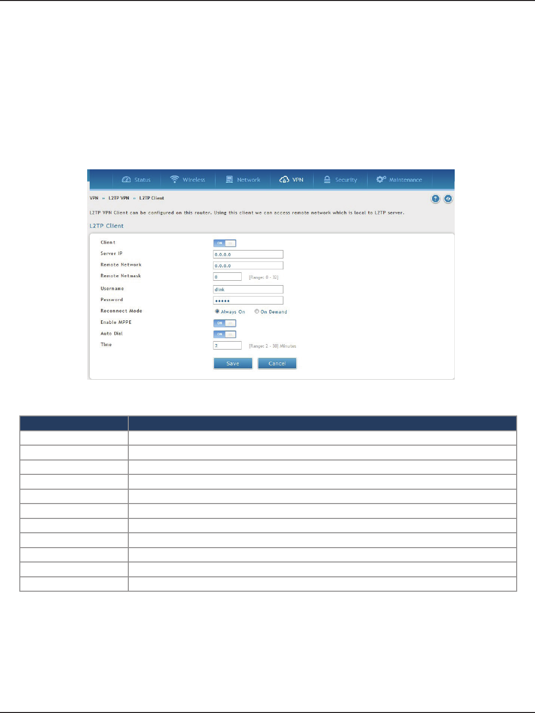
D-Link DSR-Series User Manual 107
Section 7 - VPN
Client
Field Description
Client Toggle to ON to enable L2TP client.
Server IP Enter the IP address of the L2TP server you want to connect to.
Remote Network Enter the remote network address. This address is local for the L2TP Server.
Remote Netmask Enter the remote network subnet mask.
Username Enter your L2TP user name.
Password Enter your L2TP password.
Reconnect Mode Select Always On or On Demand.
MPPE Encryption Toggle to ON to enable Microsoft Point-to-Point Encryption (MPPE).
Save Click Save to save and activate your settings.
Auto Dial Toggle to On to enable Auto Dial
Time Reconnect time
L2TP VPN Client can be congured on this router. Using this client we can access remote network which is local to
L2TP server. Once client is enabled, the user can access Status > Active VPNs page and establish L2TP VPN tunnel
clicking Connect.
To congure the router as a L2TP VPN client:
1. Click VPN > L2TP VPN > Client tab.
2. Toggle Client to ON and complete the elds in the table below.
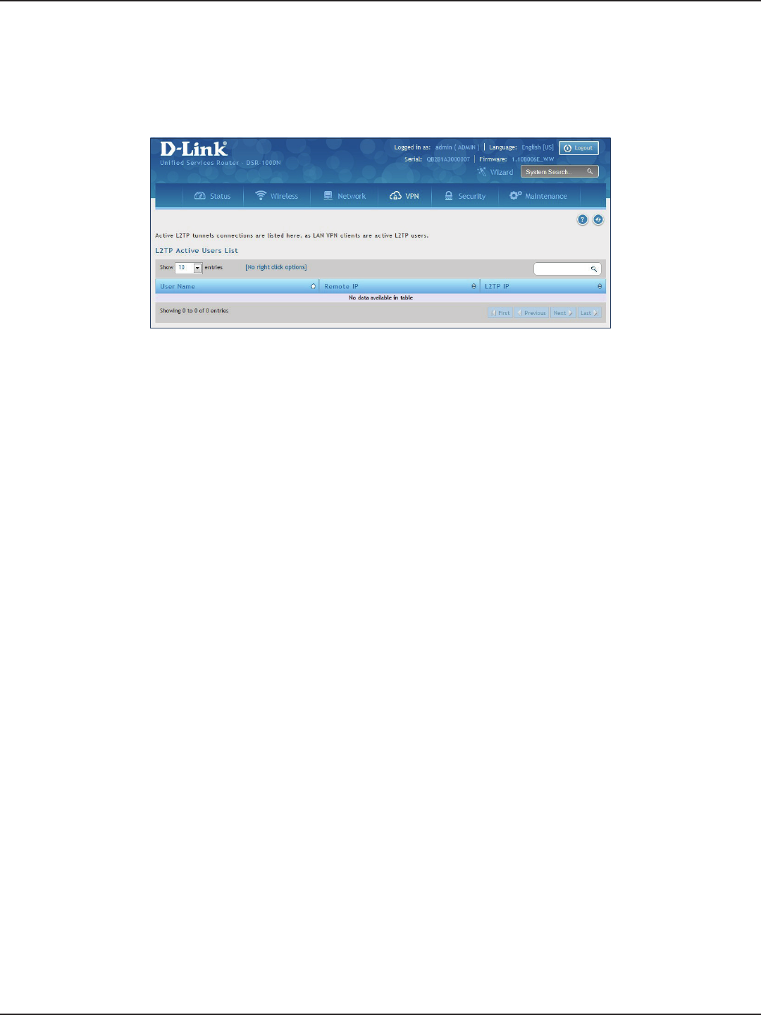
D-Link DSR-Series User Manual 108
Section 7 - VPN
L2TP Active Users List
A list of L2TP connections will be displayed on this page. Right-click the connection to connect and disconnect.
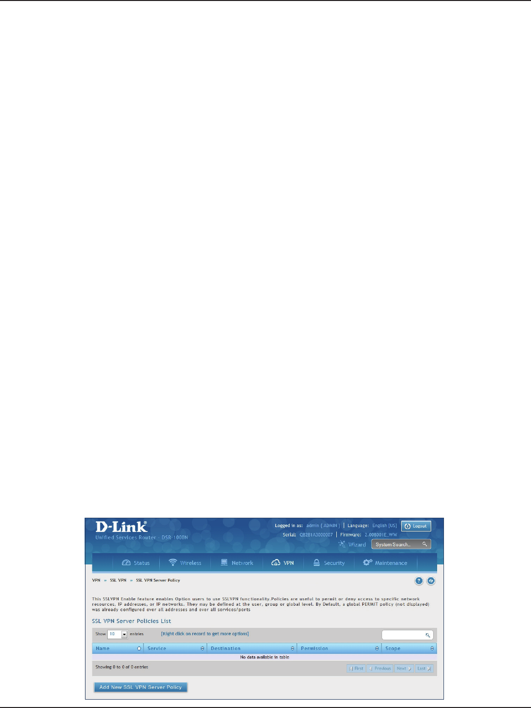
D-Link DSR-Series User Manual 109
Section 7 - VPN
SSL VPN
SSL VPN Policies can be created on a Global, Group, or User level. User level policies take precedence over Group
level policies and Group level policies take precedence over Global policies. These policies can be applied to a
specic network resource, IP address, or IP ranges on the LAN, or to dierent SSL VPN services supported by the
router. The List of Available Policies can be ltered based on whether it applies to a user, group, or all users (global).
To add a SSL VPN policy, you must rst assign it to a user, group, or make it global (i.e., applicable to all SSL VPN
users). If the policy is for a group, the available congured groups are shown in a drop-down menu and one
must be selected. Similarly, for a user-dened policy, a SSL VPN user must be chosen from the available list of
congured users.
The next step is to dene the policy details. The policy name is a unique identier for this rule. The policy can
be assigned to a specic Network Resource (details follow in the subsequent section), IP address, IP network,
or all devices on the LAN of the router. Based on the selection of one of these four options, the appropriate
conguration elds are required (i.e., choosing the network resources from a list of dened resources, or dening
the IP addresses). For applying the policy to addresses the port range/port number can be dened.
The nal steps require the policy permission to be set to either permit or deny access to the selected addresses
or network resources. As well the policy can be specied for one or all of the supported SSL VPN services (i.e. VPN
tunnel).
Once dened, the policy goes into eect immediately. The policy name, SSL service it applies to, destination
(network resource or IP addresses), and permission (deny/permit) is outlined in a list of congured policies for
the router.
Note: You must enable Remote Management. Refer to “Remote Management” on page 174.
To create a new SSL VPN policy:
1. Make sure you have enabled remote management and have created user(s) and group(s) to assign to
this policy.
2. Click VPN > SSL VPN > SSL VPN Server Policy.
3. Click Add New SSL VPN Server Policy.
Server Policies

D-Link DSR-Series User Manual 110
Section 7 - VPN
4. Complete the elds from the table below and click Save.
Field Description
Policy Type Select Global, Group, or User.
Available Groups/Users If you selected Group, select a group from the drop-down menu. If you selected User,
select a user from the drop-down menu.
Apply Policy To Select Network Resource, IP Address, IP Network, or All Addresses.
Policy Name Enter a unique name for this policy.
IP Address If you selected IP Address or IP Network, enter the IP address.
Mask Length If you selected IP Network, enter the mask length (0-32).
ICMP Toggle to ON to include ICMP trac.
Begin/End Enter a port range or leave blank to include all TCP and UDP ports. These elds are not
available when selecting Network Resource.
Dened Resources
If you selected Network Resource, select the resource for the Dened Resource drop-
down menu. If you have not created a resource, refer to “Resources” on page 113 to
create a dened resource.
Service Select either VPN Tunnel, Port Forwarding, or All. This eld is not available when
selecting Network Resource.
Permission Select either Permit or Deny.
Save Click to save your settings.
Network Resource IP Address
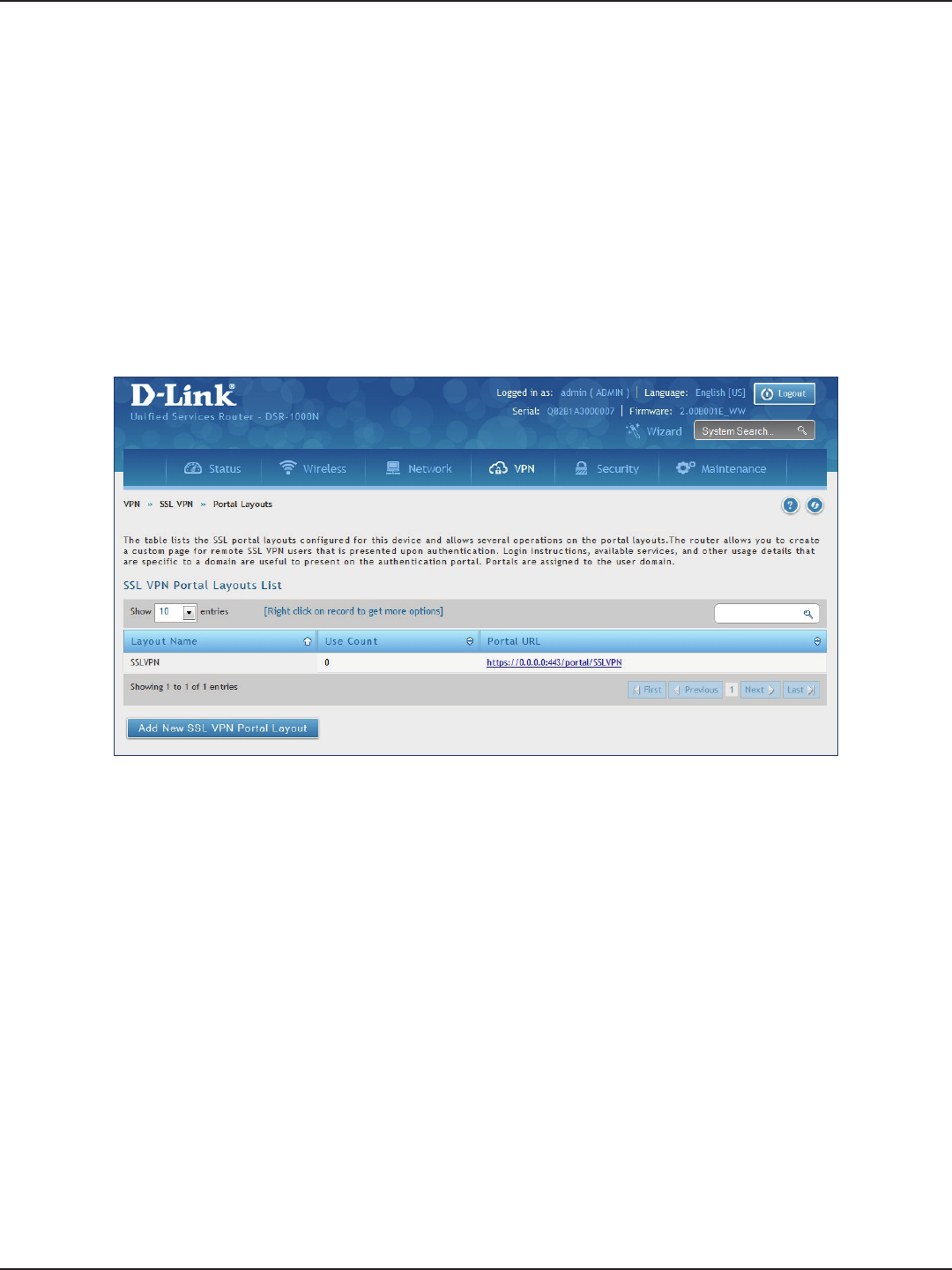
D-Link DSR-Series User Manual 111
Section 7 - VPN
Portal Layouts
Path: VPN > SSL VPN > Portal Layouts
You may create a custom page for remote VPN users that is viewed during authentication. You may include
login instructions, services, and other details. Note that the default portal LAN IP address is https://192.168.10.1/
scgi-bin/userPortal/portal. This is the same page that opens when the “User Portal” link is clicked on the SSL VPN
menu of the router web UI.
To create a new portal layout:
1. Click VPN > SSL VPN > Portal Layouts.
2. Click Add New SSL VPN Portal Layout.
Note: You may right-click a layout from the list and edit or delete a layout.
3. Complete the elds from the table on the next page and click Save.
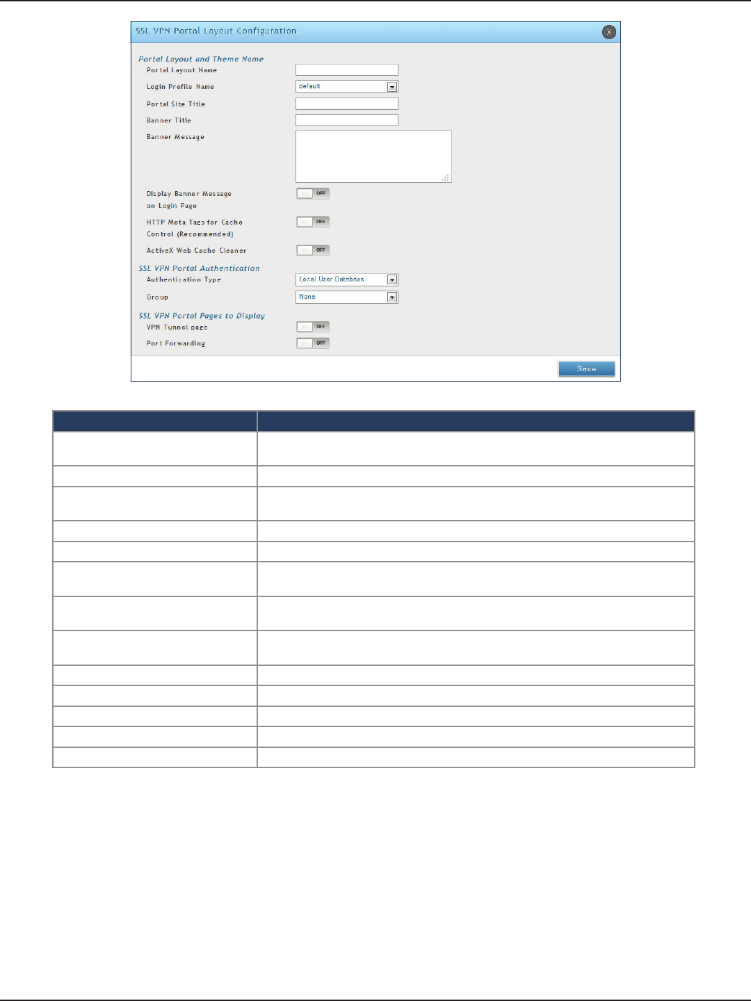
D-Link DSR-Series User Manual 112
Section 7 - VPN
Field Description
Portal Layout Name Enter a name for this portal. This name will be used as part of the path for the SSL
portal URL. Only alphanumeric characters are allowed for this eld.
Login Prole View Select a login prole from the drop-down menu.
Portal Site Title Enter the portal web browser window title that appears when the client accesses this
portal. This eld is optional.
Banner Title The banner title that is displayed to SSL VPN clients prior to login. This eld is optional.
Banner Message Enter a message you want to display.
Display Banner Message on Login
Page
Toggle to ON to display the banner title and message or OFF to hide the banner title
and message.
HTTP Meta Tags for Cache Control Toggle to ON or OFF. This security feature prevents expired web pages and data from
being stored in the client‘s web browser cache. It is recommended to toggle to ON.
Active X Web Cache Cleaner Toggle to ON or O. An ActiveX cache control web cleaner can be pushed from the
gateway to the client browser whenever users login to this SSL VPN portal.
Authentication Type Select the type of authentication from the drop-down menu.
Group Select what group to include from the drop-down menu.
VPN Tunnel Page Toggle to ON to allow remote users to view this page.
Port Forwarding Toggle to ON to allow remote users to view this page.
Save Click to save your settings.
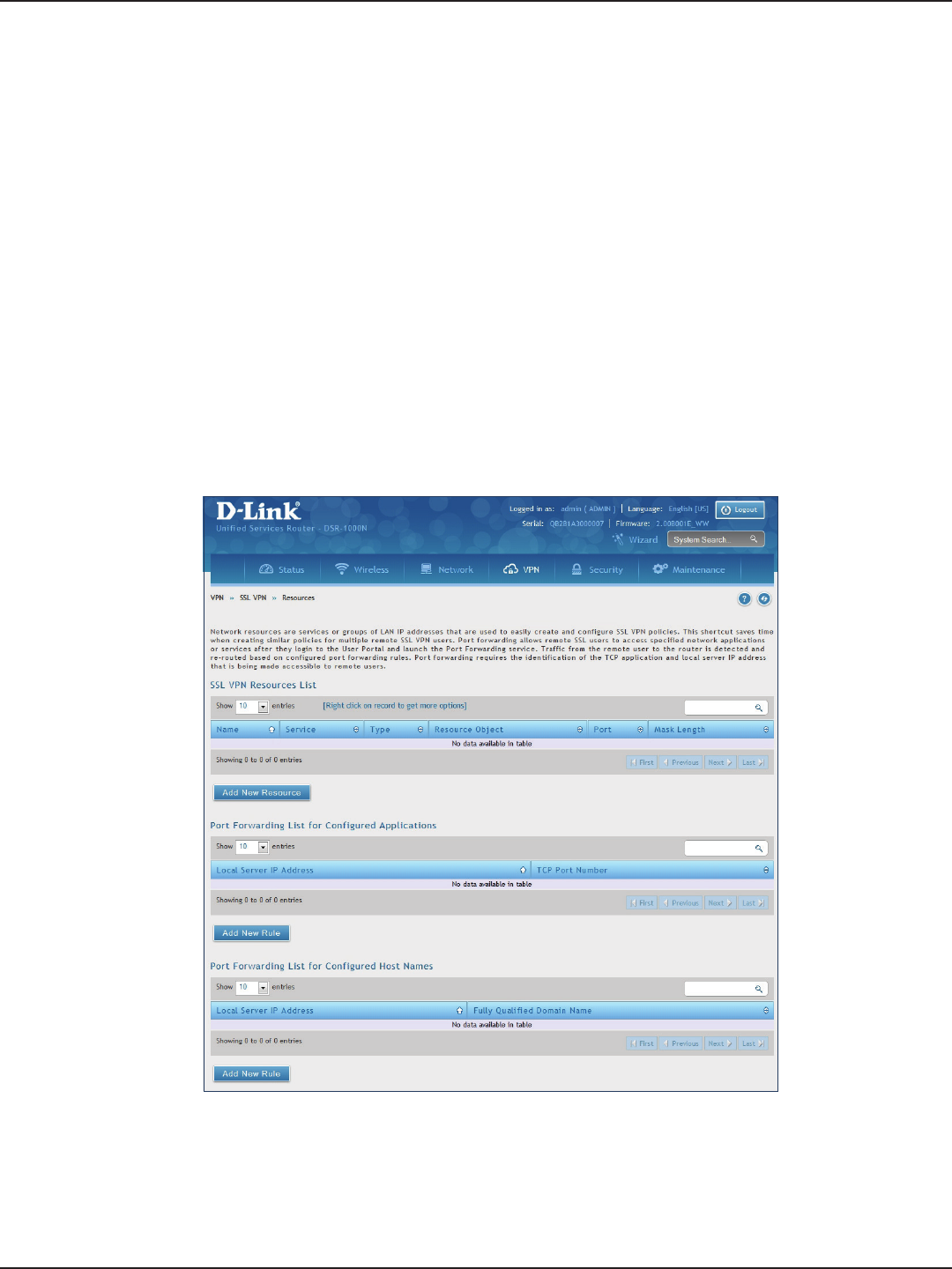
D-Link DSR-Series User Manual 113
Section 7 - VPN
Resources
Path: VPN > SSL VPN > Resources
Network resources are services or groups of LAN IP addresses that are used to easily create and congure SSL
VPN policies. This shortcut saves time when creating similar policies for multiple remote SSL VPN users.
Adding a Network Resource involves creating a unique name to identify the resource and assigning it to one or
all of the supported SSL services. Once this is done, editing one of the created network resources allows you to
congure the object type (either IP address or IP range) associated with the service. The Network Address, Mask
Length, and Port Range/Port Number can all be dened for this resource as required.
3. Complete the elds from the table on the next page and click Save.
Add New Resource
To add a new resource:
1. Click VPN > SSL VPN > Resources.
2. Click Add New Resource.
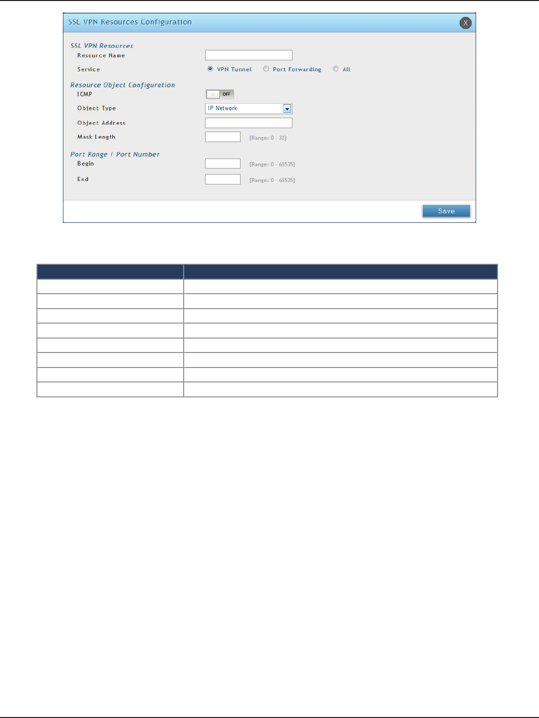
D-Link DSR-Series User Manual 114
Section 7 - VPN
Field Description
Resource Name Enter a unique name for this resource.
Service Select VPN Tunnel, Port Forwarding, or All.
ICMP Toggle to ON to include ICMP trac.
Object Type Select Single IP Address or IP Network.
Object Address Enter the IP address.
Mask Length If you selected IP Network, enter the mask length (0-32).
Begin/End Enter a port range for the object.
Save Click to save your settings.
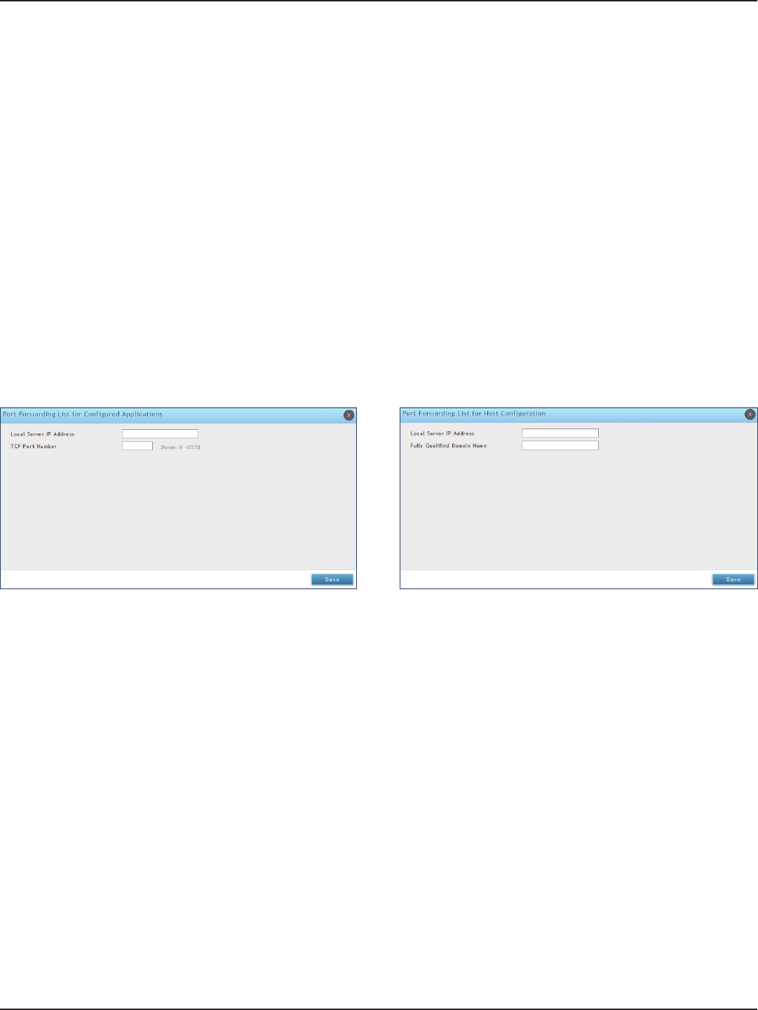
D-Link DSR-Series User Manual 115
Section 7 - VPN
Port Forwarding
To add a port forwarding rule:
1. Click VPN > SSL VPN > Resources.
2. Click Add New Rule under either Port Forwarding List for Congured Applications (TCP Port) or under
Port Forwarding List for Congured Host Names (FQDN).
3. Enter the IP address of the local server.
4. Next enter either the TCP port number or the domain name (FQDN).
5. Click Save.
Port forwarding allows remote SSL users to access specied network applications or services after they login to
the User Portal and launch the Port Forwarding service. Trac from the remote user to the router is detected and
re-routed based on congured port forwarding rules.
Internal host servers or TCP applications must be specied as being made accessible to remote users. Allowing
access to a LAN server requires entering the local server IP address and TCP port number of the application to be
tunnelled.
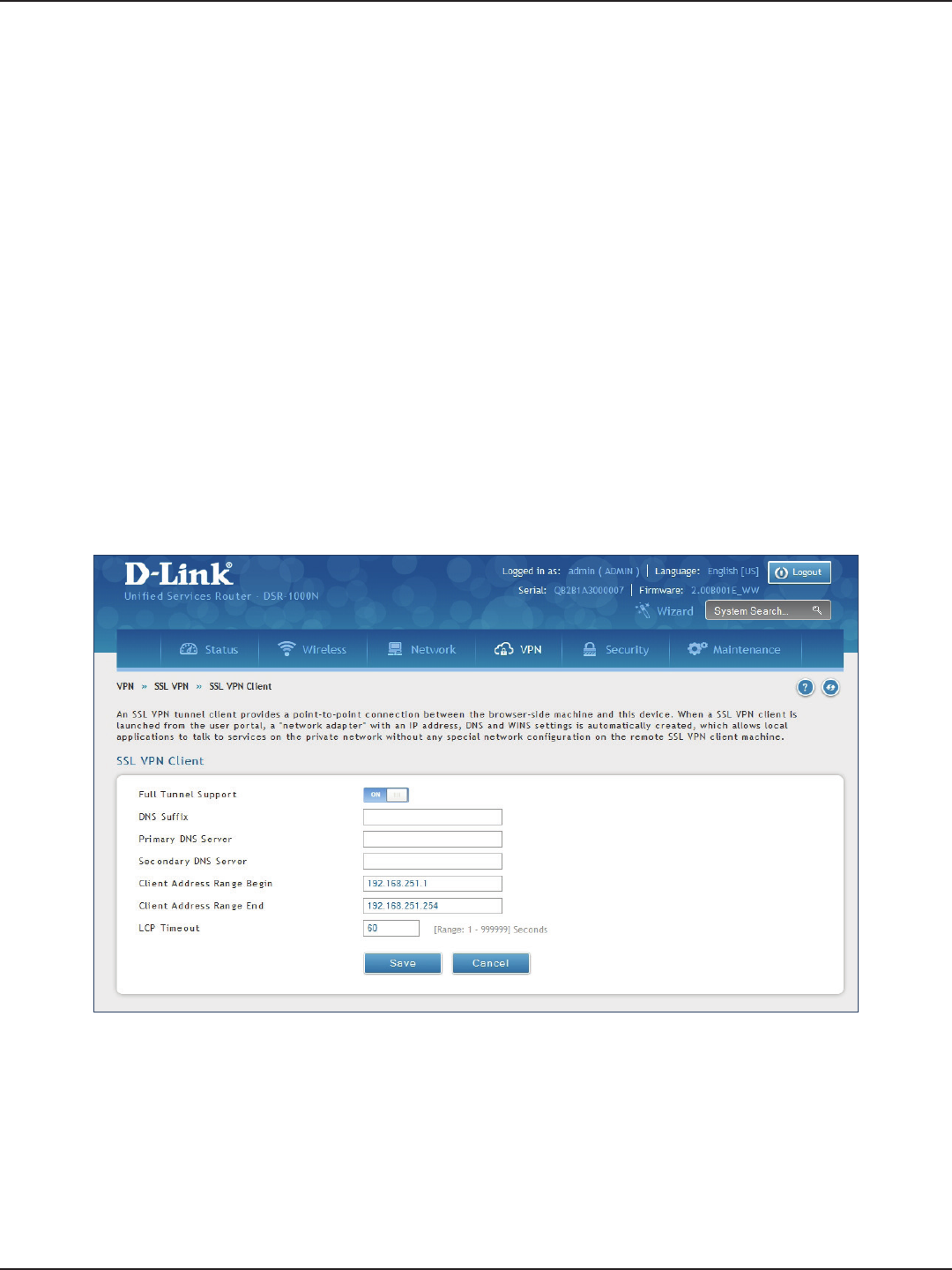
D-Link DSR-Series User Manual 116
Section 7 - VPN
Client
To congure client mode:
1. Click VPN > SSL VPN > SSL VPN Client.
Path: VPN > SSL VPN > SSL VPN Client
An SSL VPN tunnel client provides a point-to-point connection between the browser-side machine and this
router. When a SSL VPN client is launched from the user portal, a "network adapter" with an IP address from the
corporate subnet, DNS and WINS settings is automatically created. This allows local applications to access services
on the private network without any special network conguration on the remote SSL VPN client machine.
It is important to ensure that the virtual (PPP) interface address of the VPN tunnel client does not conict with
physical devices on the LAN. The IP address range for the SSL VPN virtual network adapter should be either in a
dierent subnet or non-overlapping range as the corporate LAN.
The router allows full tunnel and split tunnel support. Full tunnel mode just sends all trac from the client
across the VPN tunnel to the router. Split tunnel mode only sends trac to the private LAN based on pre-
specied client routes. These client routes give the SSL client access to specic private networks, thereby
allowing access control over specic LAN services.
2. Toggle Full Tunnel Support to ON to support full tunnel or OFF to enable split tunnel.
3. Enter a DNS sux to assign to this client (optional).
3. Enter a primary and secondary DNS server addresses (optional).
4. Enter the range of IP addresses clients will be assigned (DHCP).
5. Next to LCP Timeout, set the value for LCP echo interval (in seconds).
6. Click Save.
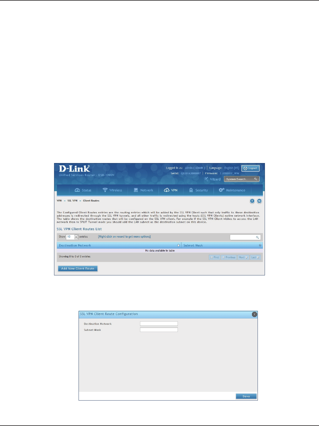
D-Link DSR-Series User Manual 117
Section 7 - VPN
Client Routes
Path: VPN > SSL VPN > SSL VPN Client
If the SSL VPN client is assigned an IP address in a dierent subnet than the corporate network, a client route
must be added to allow access to the private LAN through the VPN tunnel. As well a static route on the private
LAN‘s rewall (typically this router) is needed to forward private trac through the VPN Firewall to the remote
SSL VPN client.
When split tunnel mode is enabled, the user is required to congure routes for VPN tunnel clients:
• Destination network: The network address of the LAN or the subnet information of the
destination network from the VPN tunnel clients‘ perspective is set here.
• Subnet mask: The subnet information of the destination network is set here.
To congure a client route:
1. Click VPN > SSL VPN > Client Routes.
2. Click Add New Client Route.
3. Enter the destination network and subnet mask.
4. Click Save.
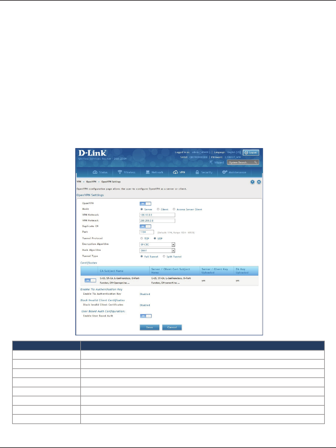
D-Link DSR-Series User Manual 118
Section 7 - VPN
Open VPN
VPN > OpenVPN > Settings
OpenVPN allows peers to authenticate each other using a pre-shared secret key, certicates, or username/password.
When used in a multiclient-server conguration, it allows the server to release an authentication certicate for every
client, using signature and Certicate authority. An OpenVPN can be established through this router.
You can select server mode, client mode, or access server client mode. In access server client mode, the user has to
download the auto login prole from the OpenVPN Access Server and upload the same to connect.
Server
Settings
Field Description
Mode Select Server.
VPN Network Enter the IP network for the VPN.
Duplicate CN Toggle On to allow a same certication for multiple clients.
VPN Netmask Enter the netmask.
Port Enter what port to use. The default port is 1194.
Tunnel Protocol Select either TCP or UDP.
Encryption Algorithm Select the encryption algorithm from the drop-down menu.
Hash Algorithm Select the hash algorithm from the drop-down menu.
To congure the router as an OpenVPN Server:
1. Click VPN > OpenVPN > Settings.
2. Toggle OpenVPN to ON and complete the elds in the table below.
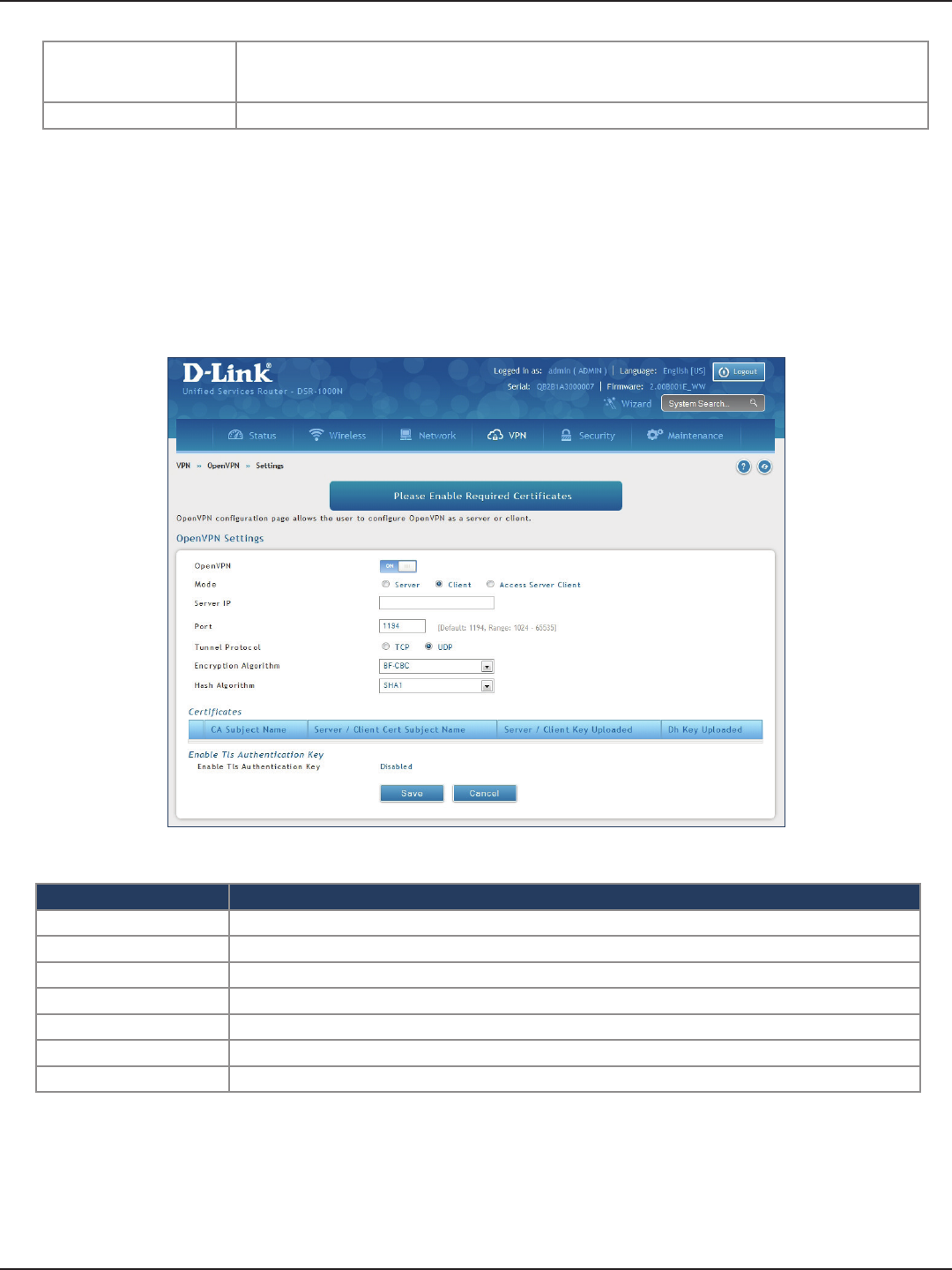
D-Link DSR-Series User Manual 119
Section 7 - VPN
Client
Field Description
Mode Select Client.
Server IP Enter the IP address of the OpenVPN server.
Port Enter what port to use. The default port is 1194.
Tunnel Protocol Select either TCP or UDP.
Encryption Algorithm Select the encryption algorithm from the drop-down menu.
Hash Algorithm Select the hash algorithm from the drop-down menu.
Save Click Save to save and activate your settings.
To congure the router as an OpenVPN client:
1. Click VPN > OpenVPN > Settings.
2. Toggle OpenVPN to ON and complete the elds in the table below.
Tunnel Type
Select either Full Tunnel or Split Tunnel. Full Tunnel mode just sends all trac from the client across the
VPN tunnel to the router. Split Tunnel mode only sends trac to the private LAN based on pre-specied
client routes. If you select Split Tunnel, refer to “Local Networks” on page 122 to create local networks.
Save Click Save to save and activate your settings.
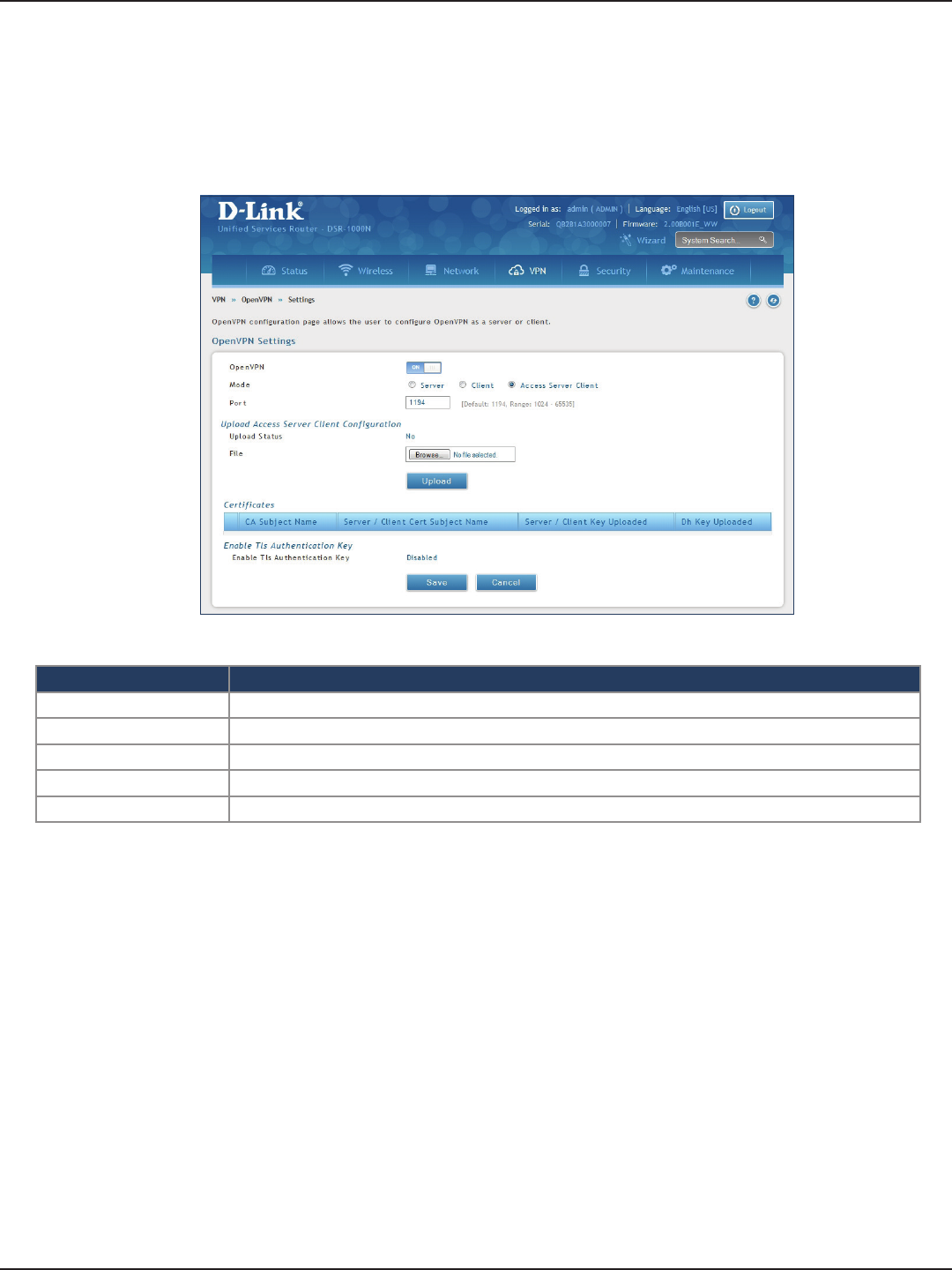
D-Link DSR-Series User Manual 120
Section 7 - VPN
Access Server Client
Field Description
Mode Select Access Server Client.
Port Enter what port to use. The default port is 1194.
Upload Status Displays if a conguration le has been uploaded.
File Click Browse and locate the conguration le. Click Open and then click Upload.
Save Click Save to save and activate your settings.
To congure the router as an OpenVPN access server client:
1. Click VPN > OpenVPN > Settings.
2. Toggle OpenVPN to ON and complete the elds in the table below.
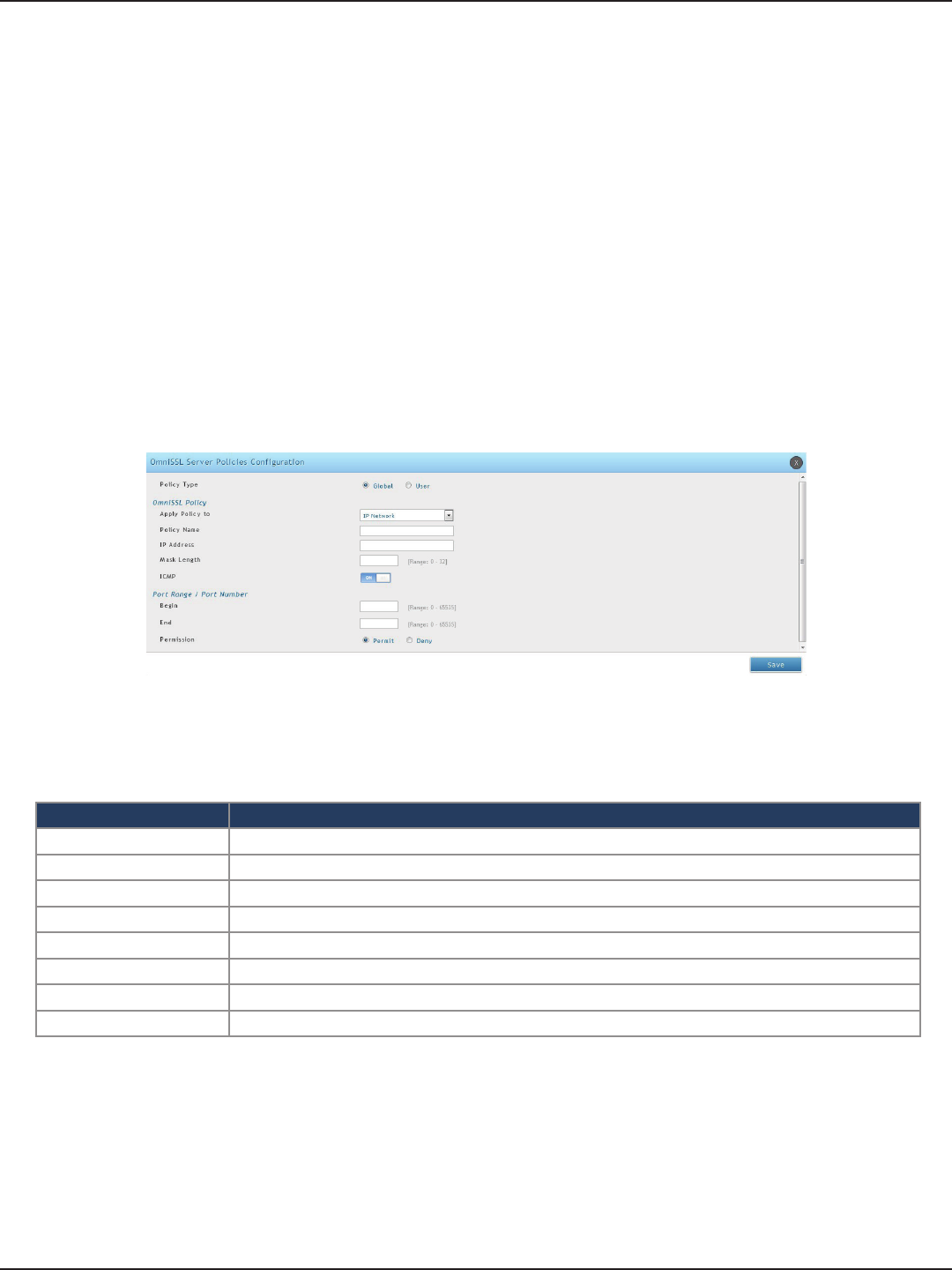
D-Link DSR-Series User Manual 121
Section 7 - VPN
OmniSSL Conguration
The router provides OmniSSL feature as an alternate to the SSL VPN connectivity while supporting most of the
SSL VPN features. OmniSSL support facilitates the client installation from the device via portal page and is an
enhancement to the existing OpenVPN. Additionally, this VPN tool can be used via mobile devices, thereby,
eliminating browser and Java dependencies typical to SSL VPN solutions including that oered in the DSR
VPN > Open VPN > OmniSSL Conguration
The OmniSSL Conguration page allows the user to generate client’s conguration. OmniSSL is an adaptable
feature as it supports and can get installed on various operating systems following their respective procedures
(for more details, please refer: Application Note on OmniSSL Client Portal).
1. Click VPN > OpenVPN > OmniSSL Server Policy
2. Click Add NewOmniSSL Server policy
Field Description
Policy Type Select this option to add a policy applicable to all the users or particular of the device
Apply Policy To Select accessible IP address or IP network
Policy Name Enter a unique name used to identify the policy.
ICMP Toggle On to support ICMP trac.
IP Address/Network Congure accessible IP address or IP network
Mask Length Subnet mask for the above IP address.
Begin and End A range of port numbers to apply
Permission Select Permit or Deny for the respective policy.
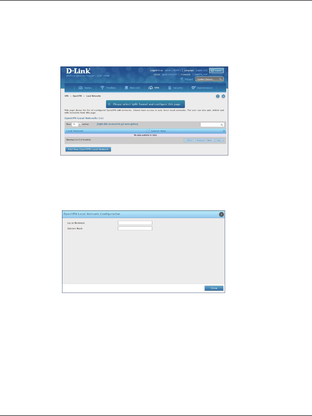
D-Link DSR-Series User Manual 122
Section 7 - VPN
Local Networks
If you selected Split Tunnel (from OpenVPN Server), you can create a local network by following the steps below:
1. Click VPN > OpenVPN > Local Networks.
2. Click Add New OpenVPN Local Network.
3. Enter a local IP network.
4. Enter the subnet mask.
5. Click Save.
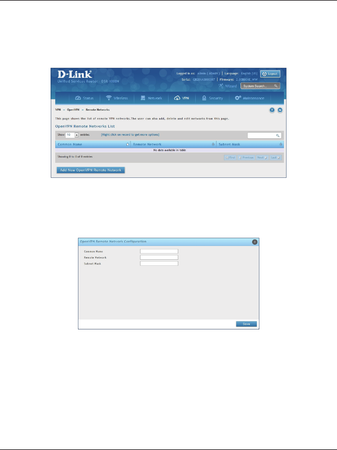
D-Link DSR-Series User Manual 123
Section 7 - VPN
Remote Networks
To create remote networks:
1. Click VPN > OpenVPN > Remote Networks.
2. Click Add New OpenVPN Remote Network.
3. Enter a name of the remote network.
4. Enter a local IP network.
5. Enter the subnet mask.
6. Click Save.
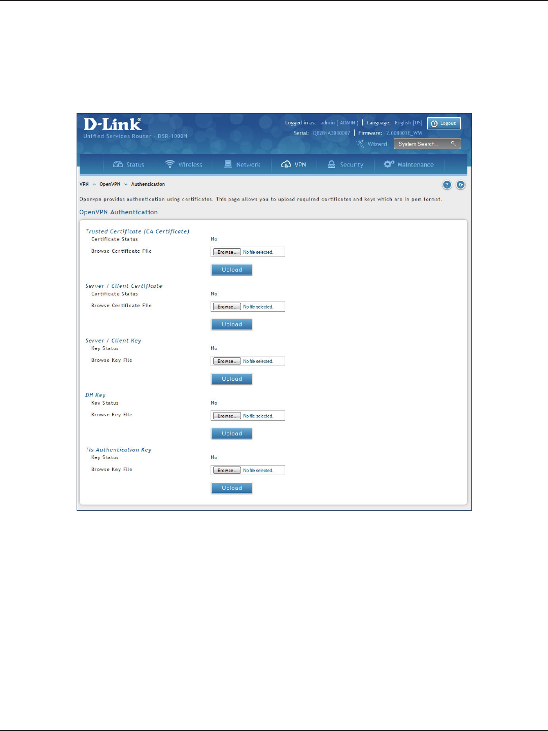
D-Link DSR-Series User Manual 124
Section 7 - VPN
Authentication
This page will allow you to upload certicates and keys. Click Browse and select the le you want to upload. Click
Open and then click Upload.

D-Link DSR-Series User Manual 125
Section 7 - VPN
GRE
VPN > VPN Settings > GRE
GRE tunnels allow for broadcast trac on the LAN of the router to be passed over the internet and received by
remote LAN hosts. This is primarily useful in the D-Link Discovery Protocol (DDP) application where broadcast
trac from one LAN host is to be received by all LAN hosts in the local subnets of the GRE endpoints.
Note the following limits for the number of supported GRE tunnels per product:
• DSR-150/150N: 5
• DSR-250/250N: 10
• DSR-500/500N/500AC: 15
• DSR-1000/1000N/1000AC: 20
There are two simple steps involved in establishing a GRE tunnel on the router:
1. Create a GRE tunnel from the GUI
2. Setup a static route for the remote local networks using the GRE tunnel
When creating the GRE tunnel, the IP Address should be a unique address that identies that GRE tunnel endpoint.
It will be referenced in the other router’s static route as the Gateway IP address. The Remote End Address in the
GRE tunnel conguration page is the WAN IP address of the other endpoint router.
Once the tunnel is established, a static route on the router can be made using the interface set to the congured
GRE tunnel name. The destination IP address of the static route is the remote LAN subnet, and the route’s gateway
IP address will be the GRE tunnel IP of the terminating router (the same router that manages the remote LAN
subnet). Once these two steps are completed, all DDP broadcast trac can ow between remote LAN subnets
via the GRE Tunnel.
To create a GRE tunnel:
1. Click VPN > GRE > GRE Tunnels.
2. Click Add New GRE Tunnel.
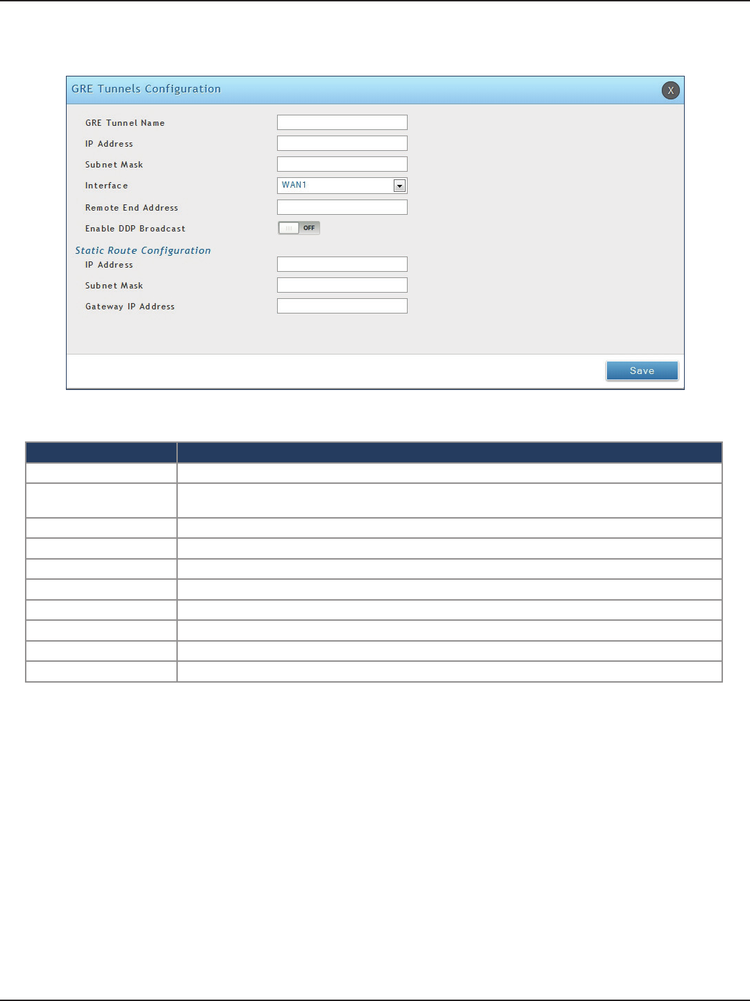
D-Link DSR-Series User Manual 126
Section 7 - VPN
3. Complete the elds in the table below and then click Save.
Field Description
GRE Tunnel Name Enter a name for the tunnel.
IP Address Enter the IP address of this endpoint. It will be referenced in the other router’s static route as the Gateway
IP address.
Subnet Mask Enter the subnet mask.
Interface Select the interface to create this tunnel with from the drop-down menu.
Remote End Address Enter the WAN IP address of the endpoint router.
Enable DDP Broadcast Toggle to ON to enable DDP broadcasting.
IP Address Enter the destination IP address of the static route from the remote LAN subnet.
Subnet Mask Enter the subnet mask.
Gateway IP Address Enter the IP address of the termination router.
Save Click Save to save and activate your settings.
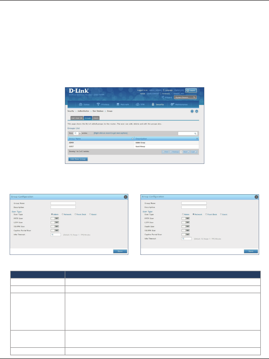
D-Link DSR-Series User Manual 127
Section 8 - Security
Field Description
Group Name Enter a name for the group.
Description Enter a description for the group.
User Type
Select the user type:
• Admin - Grants all users in this group super-user privileges. By default, there is one admin user.
• Network - Grants the next level of privileges.
• Front Desk - Grants permissions to create temporary users who can Internet/network access (Hotspot).
• Guest - Guest users will only have read access.
Network and Admin users can toggle ON PPTP, L2TP, Xauth (Network only), SSLVPN, and Captive Portal.
Idle Timeout
Enter the number of minutes of inactivity that must occur before the users in this user group are logged
out of their web management session automatically. Entering an Idle Timeout value of 0 (zero) means
never log out.
Save Click Save at the bottom to save and activate your settings.
Groups
Path: Security > Authentication > User Database > Groups
The group page allows creating, editing, and deleting groups. The groups are associated to set of user types.
To edit/delete an existing group, or add a new group:
1. Click Security > Authentication > User Database > Groups tab.
2. Right-click a group entry and select either Edit or Delete. To add a new group, click Add New Group.
3. Complete the elds in the table below and click Save.
Admin User Type Network User Type
Security
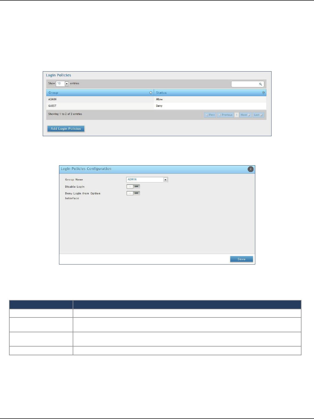
D-Link DSR-Series User Manual 128
Section 8 - Security
Login Policies
Path: Security > Authentication > Internal User Database > Groups
Using the following procedure, you can grant or deny a user group login access to the web management interface.
1. Click Security > Authentication > Internal User Database > Groups tab.
2. Click Add Login Policies.
3. Complete the elds from the table below and click Save.
Field Description
Group Name Select the group you want to congure.
Disable Login Toggle ON to deny login access to the web management interface for all users in this user group. Toggle
OFF will allow users to log in.
Deny Login from Option
Interface
Toggle ON to deny login access to the web management interface from the WAN2/DMZ Port for all users
in this user group. Toggle OFF will allow users.
Save Click Save at the bottom to save and activate your settings.
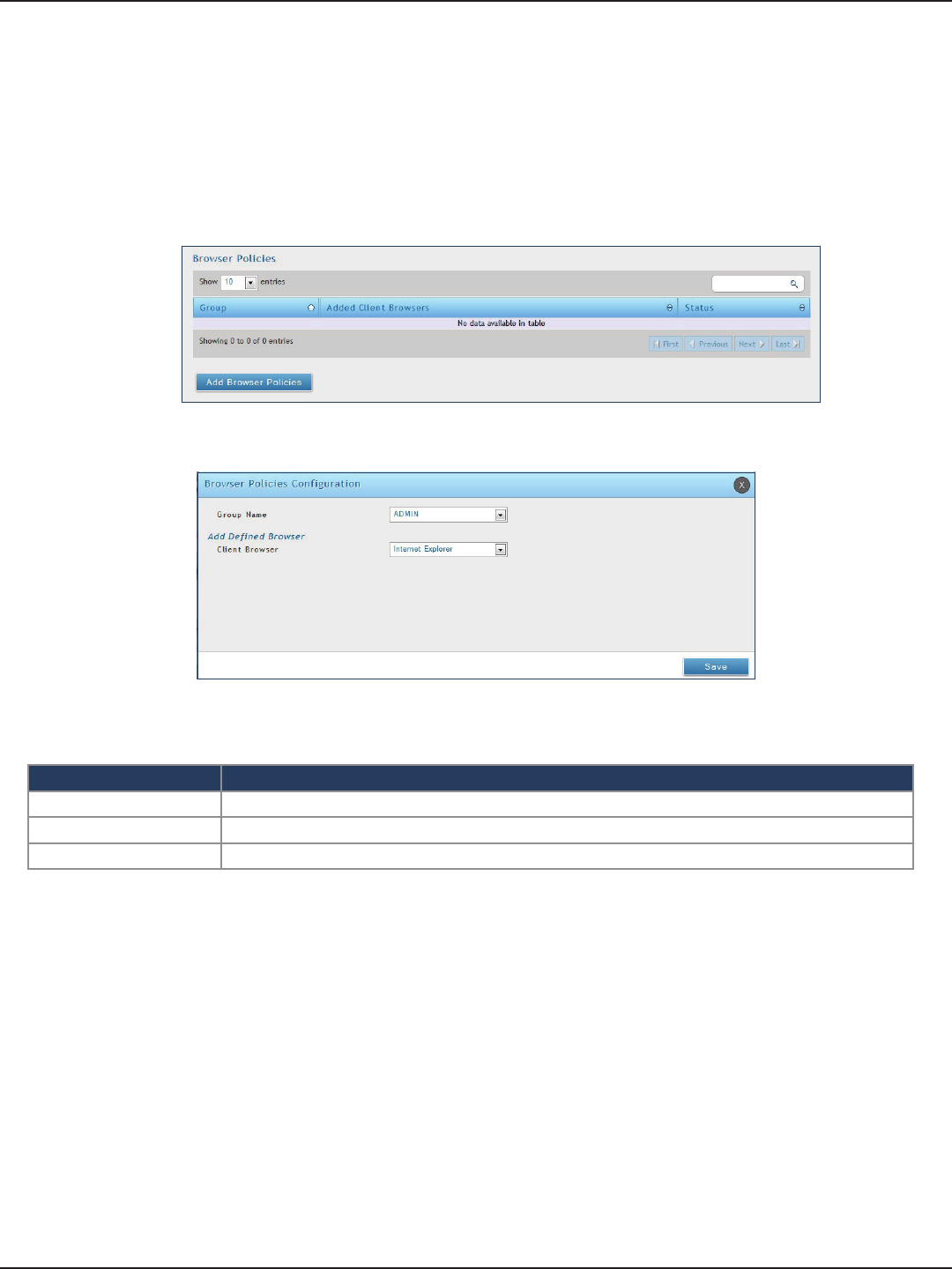
D-Link DSR-Series User Manual 129
Section 8 - Security
Path: Security > Authentication > Internal User Database > Groups
Use this feature to allow or deny users in a selected group from using a particular web browser to log in to the
router’s web management interface.
1. Click Security > Authentication > Internal User Database > Groups tab.
Browser Policies
2. Click Add Browser Policies.
3. Complete the elds from the table below and click Save.
Field Description
Group Name Select the group you want to congure from the drop-down menu.
Client Browser Select a web browser from the drop-down menu.
Save Click Save at the bottom to save and activate your settings.
4. Your policy will now be in the browser policies list. By default the status will be set to deny. If you
want to set the status to allow, right-click the policy and select Allow.
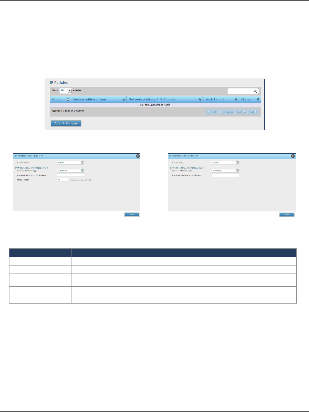
D-Link DSR-Series User Manual 130
Section 8 - Security
Path: Security > Authentication > Internal User Database > Groups
Use this feature to allow or deny users in a user group to log in to the router’s web management interface from
a particular network or IP address.
1. Click Security > Authentication > Internal User Database > Groups tab.
IP Policies
2. Click Add IP Policies.
3. Complete the elds from the table below and click Save.
Field Description
Group Name Select the group you want to congure from the drop-down menu.
Source Address Type Select either Network to specify a IP network or IP Address to specify a specic IP address.
Network Address/IP
Address Enter the network address or IP address.
Mask Length If you selected Network, enter the mask length.
Save Click Save at the bottom to save and activate your settings.
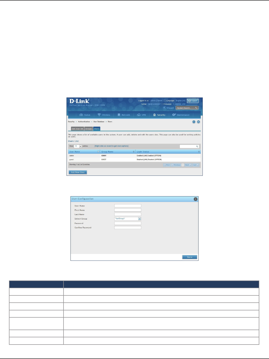
D-Link DSR-Series User Manual 131
Section 8 - Security
Users
Path: Security > Authentication > Internal User Database > Users
After you add user groups, you can add users to the user groups. Users can be added individually, or they can
be imported from a comma-separated-value (CSV) formatted le. After you add users, you can edit them when
changes are required or delete users when you no longer need them.
To edit/delete existing users, or add a new user:
1. Click Security > Authentication > Internal User Database > Users tab.
User Management
3. Complete the elds from the table below and click Save.
Field Description
User Name Enter the user name for this user. This name is a unique identier
First Name Enter the user’s rst name.
Last Name Enter the user’s last name.
Select Group Select the group you want to assign this user to from the drop-down menu.
Password Enter a case-sensitive login password that the user must specify at the login prompt to access the web
management interface. For security, each typed password character is masked with a dot (•).
Conrm Password Enter the password to conrm.
Save Click Save at the bottom to save and activate your settings.
2. Right-click a group entry and select either Edit or Delete. To add a new group, click Add New User.
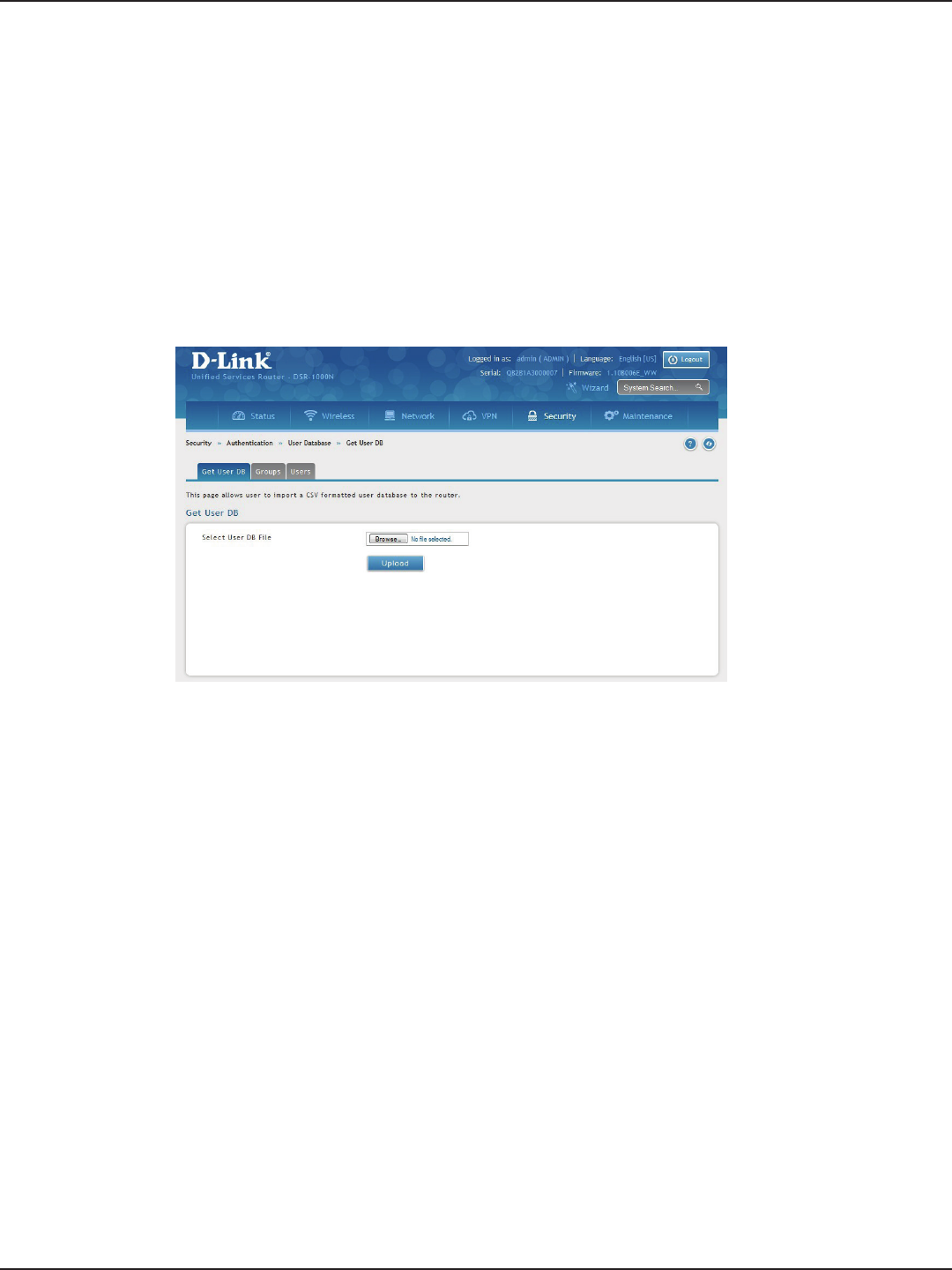
D-Link DSR-Series User Manual 132
Section 8 - Security
Path: Security > Authentication > Internal User Database > Get User DB
The DSR administrator can add users to the local built-in database directly via an appropriately-formatted comma
separated value (CSV) le. The advantage of this feature is to allow for a large number of users to be added to
the system with one operation, and the same le can be uploaded to multiple DSR devices as needed. Once
uploaded the specic users in the local user database can be modied via the GUI as needed.
To import a user database:
1. Click Security > Authentication > Internal User Database > Get User DB tab.
2. Click Browse and locate the le you want to upload. Select it and click Open.
3. Click Upload.
4. Once completed, go to Security > Authentication > User Database > Users and your imported users
will be displayed in the Users List.
5. From the list you can right-click the user to edit or delete.
Import User Database

D-Link DSR-Series User Manual 133
Section 8 - Security
The following parameters must be used to dene the User database CSV le.
1. Create an empty text le with a .csv extension.
2. Each line in the le corresponds to a single user entry. Every line should end with carriage return
equivalent of CRLF. Do not add comments or other text in this le.
3. Formatting rules:
a) All the elds must be enclosed within double quotes.
b) Consecutive elds are separated by commas.
c) There should be no leading or trailing spaces in a line.
d) There should be no spaces between elds.
Each line in the CSV user database le should follow the following format:
"UserName","FirstName","LastName","GroupName",“Password”,”MultiLogin”
The above sample has elds that can assume the following values:
• Username (text eld): Name of the user and identier in the DSR’s database, and so it must
be unique in the local user database.
• FirstName (text eld): This is a user detail and need not be unique.
• LastName (text eld): This is a user detail and need not be unique.
• GroupName (text eld): The group that is associated with this user.
• MultiLogSup (Boolean value): With this enabled (“1”), then multiple users can share a single
username and password.
• Password (text eld): password to assign for this username
• The Group for a corresponding user (“GroupName” in the CSV) must be created via the GUI
in advance of the User Database CSV upload action.
• None of the above elds can be left empty or NULL in the User Database CSV.
Create a User Database (CSV File)
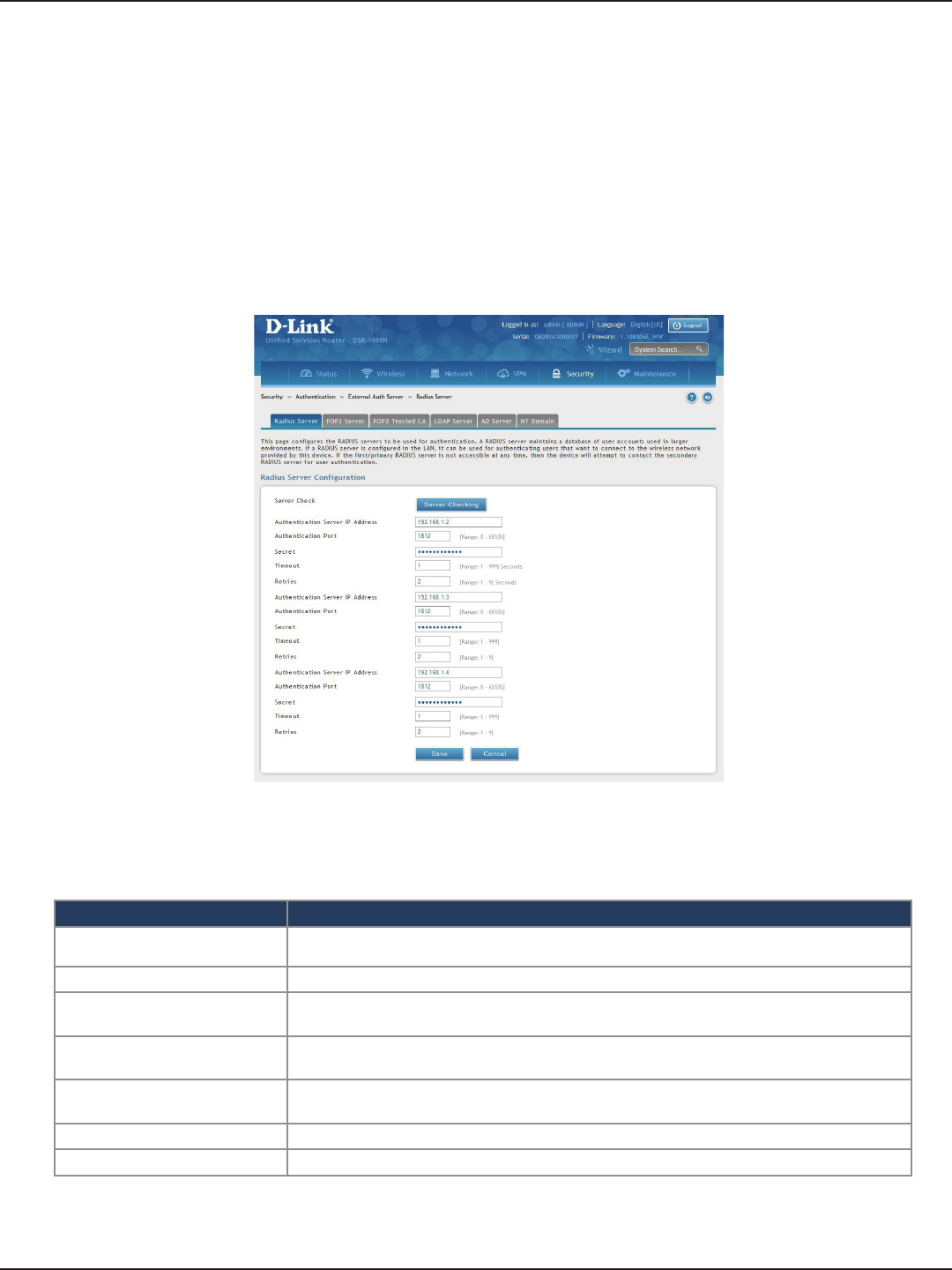
D-Link DSR-Series User Manual 134
Section 8 - Security
External Authentication Servers
Path: Security > Authentication > External Auth Server > RADIUS Server
A RADIUS server can be congured and accessible by the router to authenticate client connections.
To congure the router to connect to your RADIUS server:
1. Click Security > Authentication > External Auth Server > RADIUS Server tab.
RADIUS Server
Field Description
Authentication Server IP
Address Enter the IP address of your RADIUS server.
Authentication Port Enter the RADIUS authentication server port.
Secret Enter the secret key that allows the device to log into the congured RADIUS server. It must
match the secret on RADIUS server.
Timeout Set the amount of time in seconds that the router should wait for a response from the RADIUS
server.
Retries This determines the number of tries the controller will make to the RADIUS server before
giving up.
Save Click Save at the bottom to save and activate your settings.
Server Check Click to test the connection(s) to your RADIUS Server(s).
2. Complete the RADIUS server information from the table below and click Save. You can congure up to
three servers.
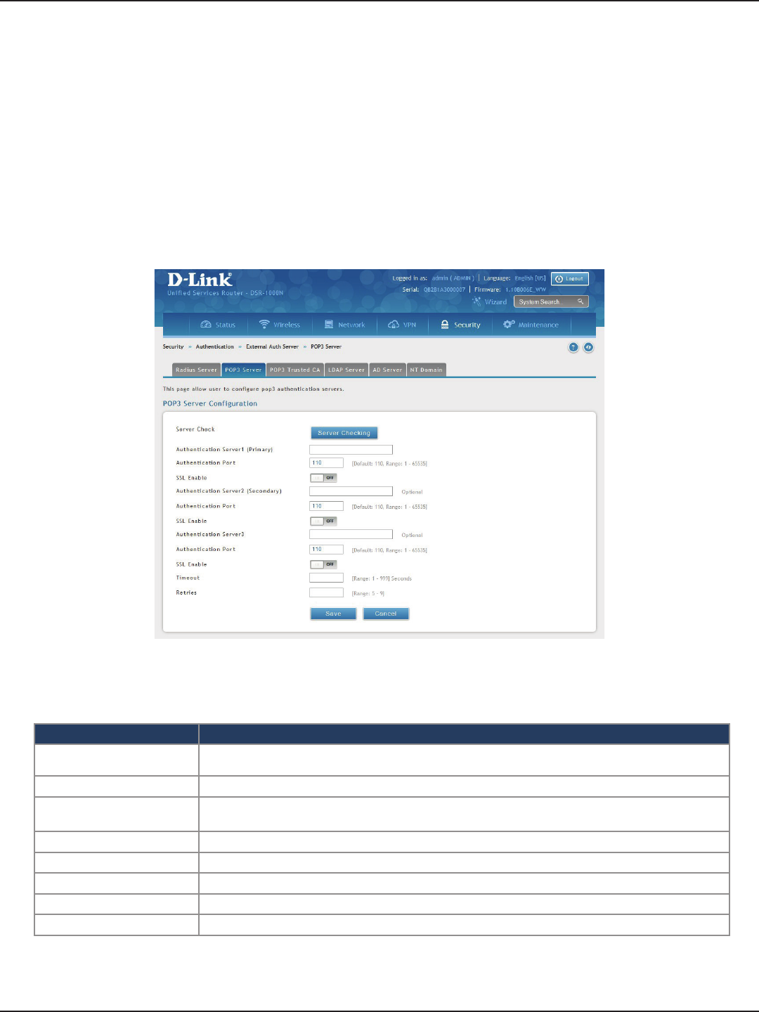
D-Link DSR-Series User Manual 135
Section 8 - Security
Path: Security > Authentication > External Auth Server > POP3 Server
POP3 is an application layer protocol most commonly used for e-mail over a TCP/IP connection. The authentication
server can be used with SSL encryption over port 995 to send encrypted trac to the POP3 server. The POP3
server’s certicate is veried by a user-uploaded CA certicate. If SSL encryption is not used, port 110 will be used
for the POP3 authentication trac.
To congure the router to connect to your POP3 server:
1. Click Security > Authentication > External Auth Server > POP3 Server tab.
POP3 Server
Field Description
Authentication Server IP
Address Enter the IP address of your POP3 server.
Authentication Port Enter the POP3 authentication server port.
SSL Enable Toggle to ON to enable SSL support for POP3. If this option is enabled, it is mandatory to select a
certicate authority for it.
CA File Certicate Authority to verify POP3 server’s certicate.
Timeout Set the amount of time in seconds that the router should wait for a response from the POP3 server.
Retries This determines the number of tries the controller will make to the POP3 server before giving up.
Save Click Save at the bottom to save and activate your settings.
Server Check Click to test the connection(s) to your POP3 Server(s).
2. Complete the POP3 server information from the table below and click Save. You can congure up to
three servers.
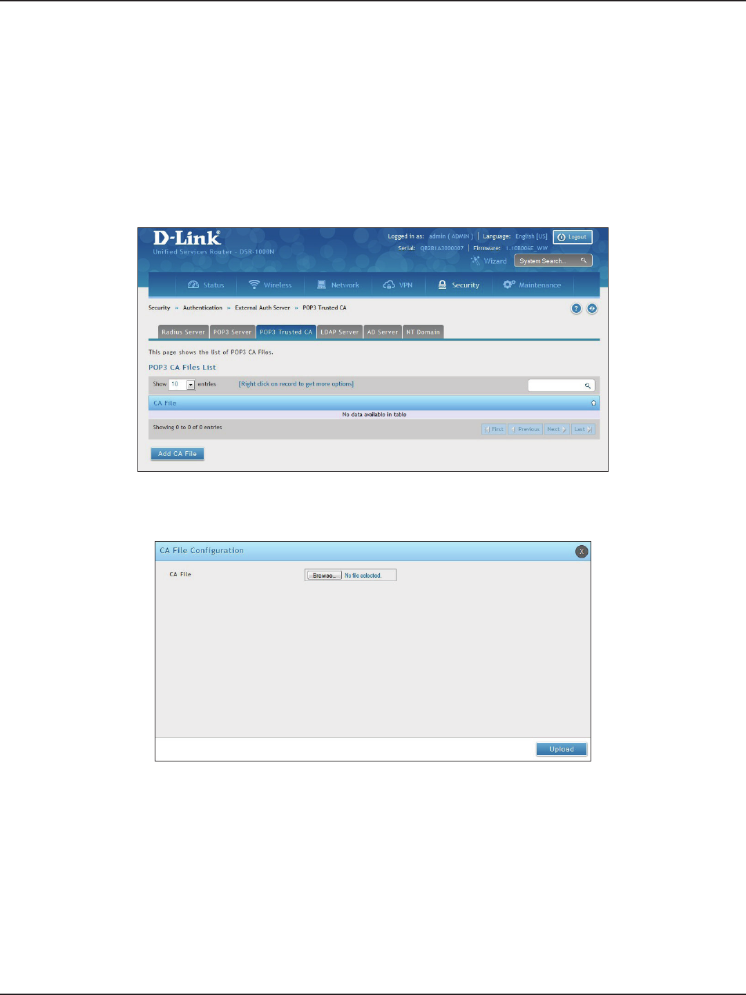
D-Link DSR-Series User Manual 136
Section 8 - Security
Path: Security > Authentication > External Auth Server > POP3 Trusted CA
A CA le is used as part of the POP3 negotiation to verify the congured authentication server identity. Each of
the three congured servers can have a unique CA used for authentication.
To congure:
1. Click Security > Authentication > External Auth Server > POP3 Trusted CA tab.
POP3 Trusted Server
2. Click Add CA File.
3. Click Browse and select a CA le. Click Open and then click Upload.
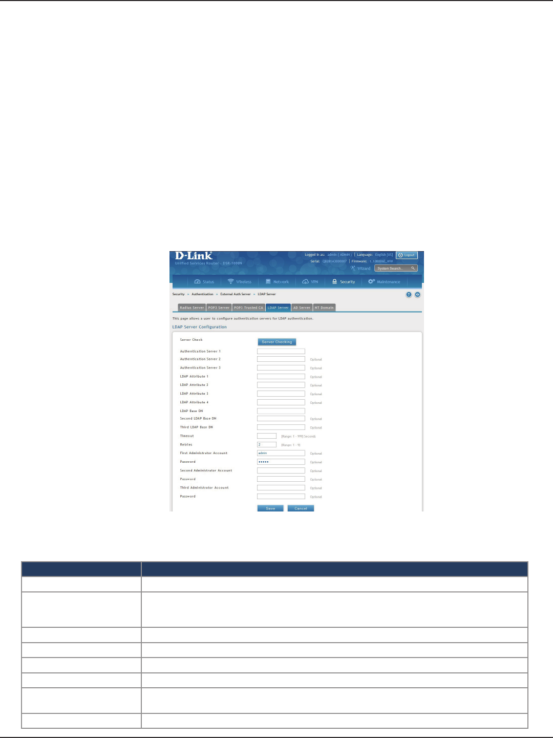
D-Link DSR-Series User Manual 137
Section 8 - Security
Path: Security > Authentication > External Auth Server > LDAP Server
The LDAP authentication method uses LDAP to exchange authentication credentials between the router and an
external server. The LDAP server maintains a large database of users in a directory structure, so users with the
same user name but belonging to dierent groups can be authenticated since the user information is stored in
a hierarchal manner. Also of note is that conguring a LDAP server on Windows or Linux servers is considerably
less complex than setting up NT Domain or Active Directory servers for user authentication.
The details congured on the controller will be passed for authenticating the router and its hosts. The LDAP
attributes, domain name (DN), and in some cases the administrator account & password are key elds in allowing
the LDAP server to authenticate the controller.
To congure the router to connect to your LDAP server:
1. Click Security > Authentication > External Auth Server > LDAP Server tab.
LDAP Server
Field Description
Authentication Server (1-3) Enter the IP address of your primary LDAP server.
LDAP Attribute (1-4)
These are attributes related to LDAP users congured in LDAP server. These may include attributes like
SAM account name, associated domain name etc. These can be used to distinguish between dierent
users having same user name.
LDAP Base DN Enter the base domain name.
Timeout Set the amount of time in seconds that the router should wait for a response from the LDAP server.
Retries This determines the number of tries the controller will make to the LDAP server before giving up.
Save Click Save at the bottom to save and activate your settings.
Administrator Account Enter the admin account information that will be used when LDAP authentication is required for PPTP/
L2TP connection.
Server Check Click to test the connection(s) to your LDAP Server(s).
2. Complete the LDAP server information from the table below and click Save. You can congure up to
three servers.

D-Link DSR-Series User Manual 138
Section 8 - Security
Path: Security > Authentication > External Auth Server > AD Server
Active Directory authentication is an enhanced version of NT Domain authentication. The Kerberos protocol is
leveraged for authentication of users, who are grouped in Organizational Units (OUs). In particular the Active
Directory server can support more than a million users given is structure while the NT Domain server is limited to
thousands. The congured Authentication Servers and Active Directory domain(s) are used to validate the user
with the directory of users on the external Windows based server. This authentication option is common for SSL
VPN client users and is also useful for IPsec / PPTP / L2TP client authentication.
To congure the router to connect to your AD server:
1. Click Security > Authentication > External Auth Server > AD Server tab.
AD Server
2. Complete the AD server information from the table on the next page and click Save. You can congure
up to three servers.

D-Link DSR-Series User Manual 139
Section 8 - Security
Field Description
Authentication Server (1-3) Enter the IP address of your AD server(s).
Active Directory Domain
(1-3) Enter the active directory domain name(s).
Timeout Set the amount of time in seconds that the router should wait for a response from the AD server.
Retries This determines the number of tries the controller will make to the AD server before giving up.
Administrator Account Enter the admin account information that will be used when authentication is required for PPTP/L2TP
connection.
Save Click Save at the bottom to save and activate your settings.
Server Check Click to test the connection(s) to your AD Server(s).
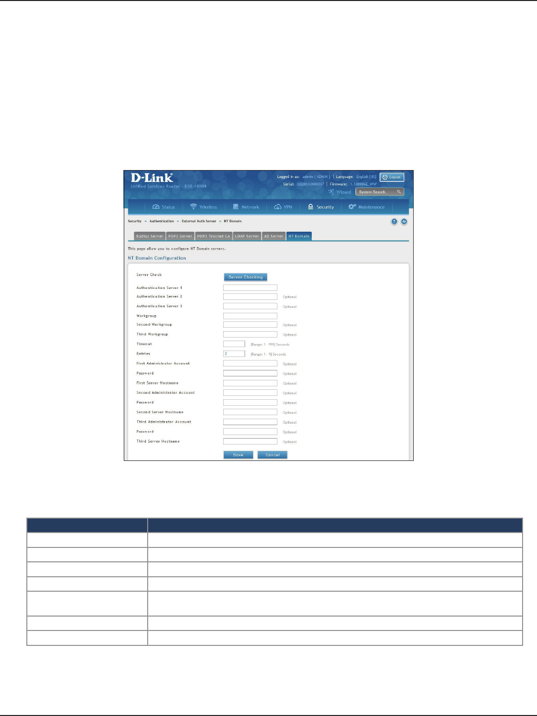
D-Link DSR-Series User Manual 140
Section 8 - Security
Path: Security > Authentication > External Auth Server > NT Domain
The NT Domain server allows users and hosts to authenticate themselves via a pre-congured Workgroup
eld. Typically Windows or Samba servers are used to manage the domain of authentication for the centralized
directory of authorized users.
To congure the router to connect to your NT domain server:
1. Click Security > Authentication > External Auth Server > NT Domain tab.
NT Domain Server
2. Complete the NT server information from the table below and click Save. You can congure up to
three servers.
Field Description
Authentication Server (1-3) Enter the IP address of your NT server(s).
Workgroup (1-3) Enter the NT workgroup name(s).
Timeout Set the amount of time in seconds that the router should wait for a response from the AD server.
Retries This determines the number of tries the controller will make to the AD server before giving up.
Administrator Account Enter the admin account information that will be used when authentication is required for PPTP/L2TP
connection.
Save Click Save at the bottom to save and activate your settings.
Server Check Click to test the connection(s) to your AD Server(s).
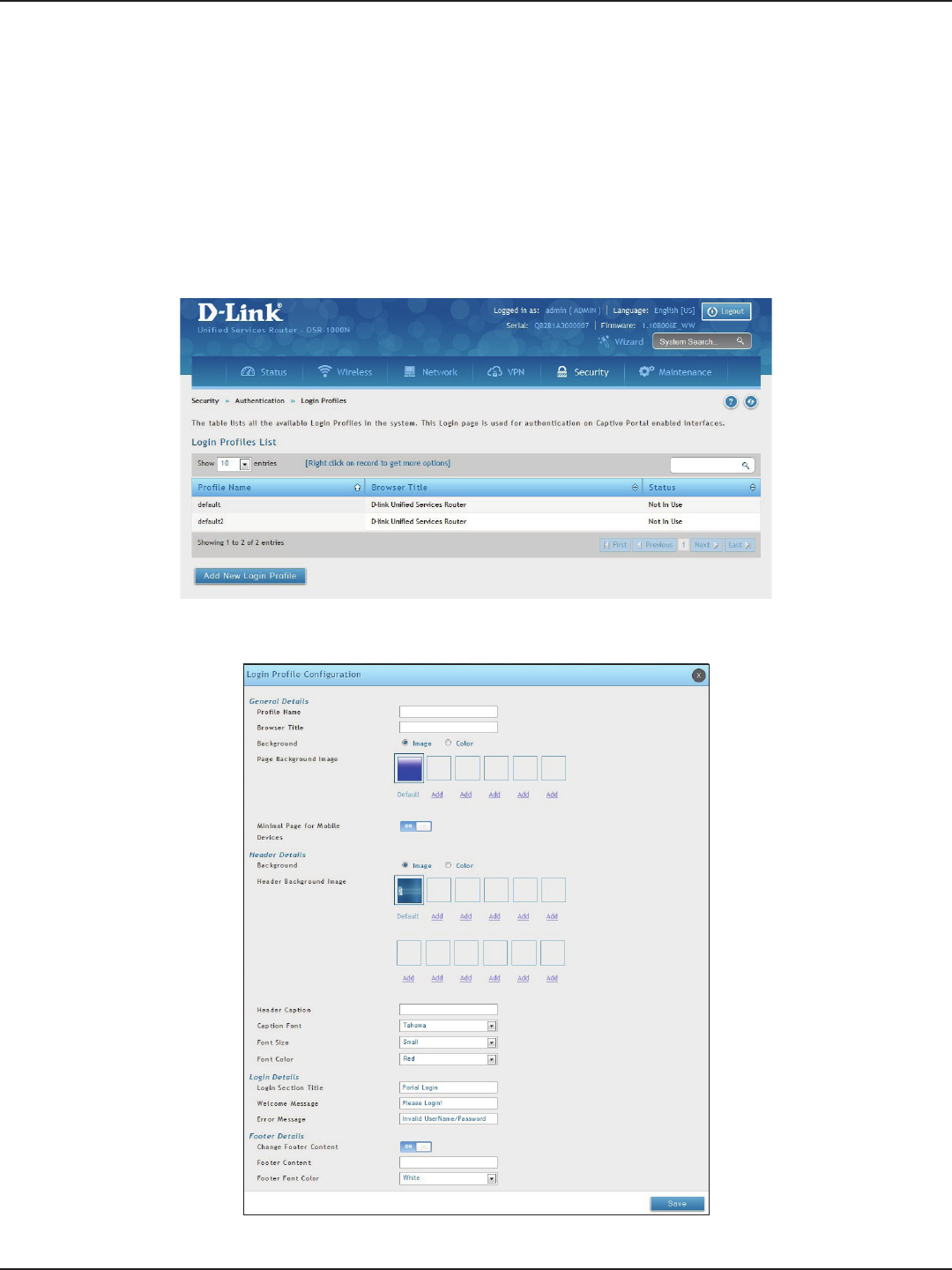
D-Link DSR-Series User Manual 141
Section 8 - Security
Path: Security > Authentication > Login Proles
When a wireless client connects to the SSIDs or VLANs, the user sees a login page. The Login Prole and SLA page
allows you to customize the appearance of that page with specic text and images. The wireless router supports
multiple login and SLA pages. Associate login page or SLAs on SSIDs or VLANs separately.
To add, delete, or edit login proles:
1. Click Security > Authentication > Login Proles tab.
Login Proles
3. Complete the elds from the table on the next page and click Save.
2. Right-click an entry and select either Edit or Delete. To add a new group, click Add New Login Prole.

D-Link DSR-Series User Manual 142
Section 8 - Security
Field Description
General Details
Prole Name Enter a name for this captive portal prole. The name should allow you to dierentiate this captive prole from
others you may set up.
Browser Title Enter the text that will appear in the title of the browser during the captive portal session.
Background
Select whether the login page displayed during the captive portal session will show an image or color. Choices
are:
• Image: Displays an image as the background on the page. Use the Page Background Image eld to select a
background image.
• Color: Sets the background color on the page. Select the color from the drop-down menu
Page Background Image If you set Background to Image, upload the image le by clicking Add > Browse. Select an image, click Open and
then click the Upload button. The maximum size of the image is 100 kb.
Page Background Upload Choose the le you want to upload.
Page Background Color If you set Background to Color, select the background color of the page that will appear during the captive portal
session from the drop-down menu.
Custom Color If you choose Custom on Page Background Color, enter the HTML color code.
Minimal Page for Mobile
Devices Toggle to ON to allow the web page to be properly viewed from a mobile device.
Header Details
Background
Select whether the login page displayed during the captive portal session will show an image or color. Choices
are:
• Image: Show image on the page. Use the Header Background Color eld to select a background color. The
maximum size of the image is 100 kb.
• Color: Show background color on the page. Use the radio buttons to select an image.
Header Background Image If you set Background to Image, upload the image le by clicking Add > Browse. Select an image, click Open and
then click the Upload button. The maximum size of the image is 100 kb.
Header Background Upload Choose the le you want to upload.
Header Background Color If you set Background to Color, select the header color from the drop-down menu.
Custom Color If you choose Custom on Page Background Color, you can choose particular color by lling in the HTML color
code.
Header Caption Enter the text that appears in the header of the login page during the captive portal session.
Caption Font Select the font for the header text.
Font Size Select the font size for the header text.
Font Color Select the font color for the header text.
Login Details
Login Section Title Enter the text that appears in the title of the login box when the user logs in to the captive portal session. This
eld is optional.
Welcome Message Enter the welcome message that appears when users log in to the captive session successfully. This eld is
optional.
Error Message Enter the error message that appears when users fail to log in to the captive session successfully. This eld is
optional.
Footer Details
Change Footer Content Enables or disables changes to the footer content on the login page.
Footer Content If Change Footer Content is checked, enter the text that appears in the footer.
Footer Font Color If Change Footer Content is checked, select the color of the text that appears in the footer.
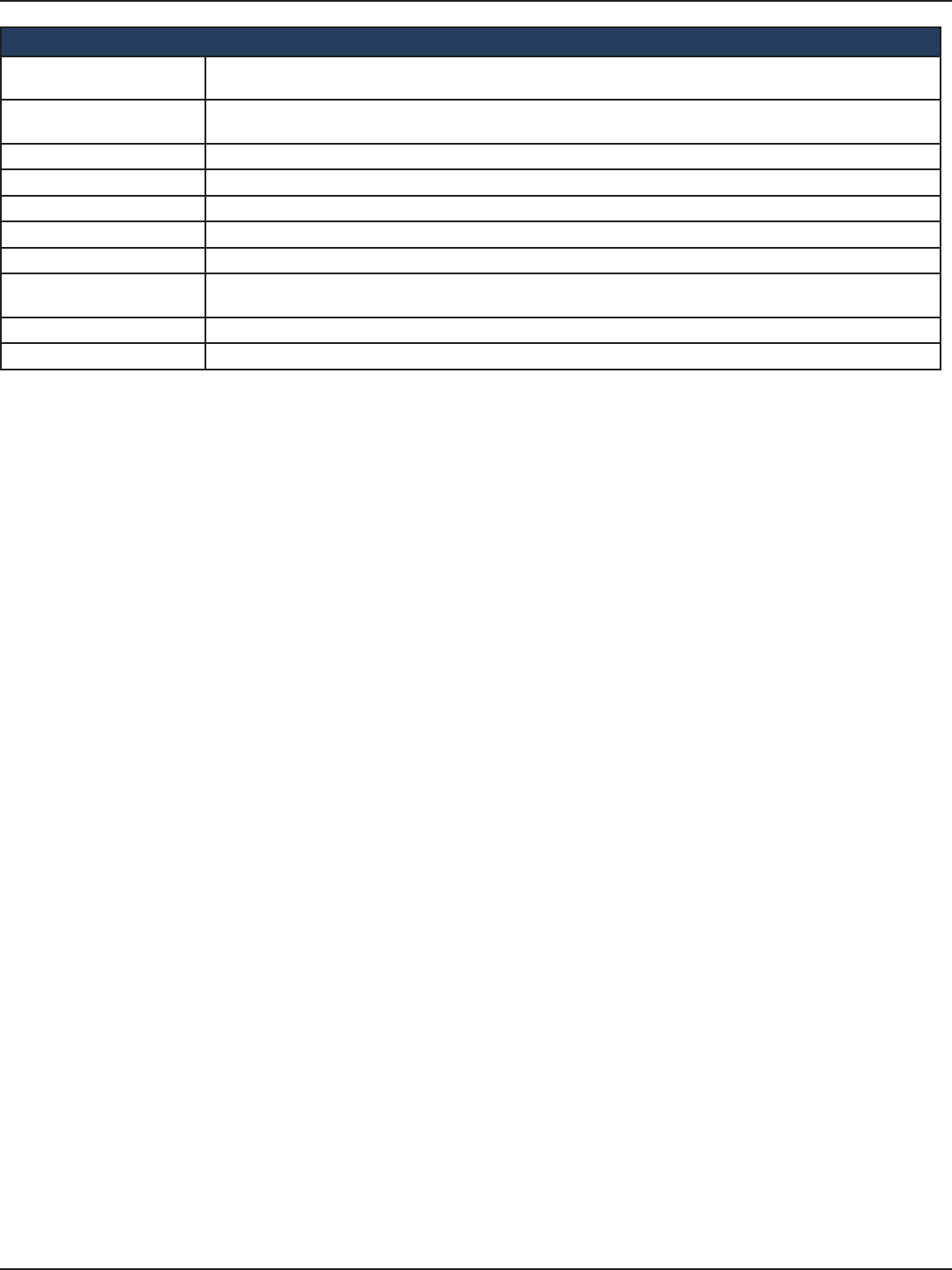
D-Link DSR-Series User Manual 143
Section 8 - Security
External Payment Gateway
Enable External Payment
Gateway Enables or disables external payment gateway and online wireless service purchasing from on the login page.
Session Title 1 Enter the text that appears in the title of the online purchasing login box when the user logs in to the captive
portal session.
Message Enter the text appears in the online purchasing login box when the user logs in to the captive portal session.
Session Title 2 Enter the text that appears in the title of the message box while online purchasing is complete.
Success Message Enter the text that appears in the message box while online purchasing is complete.
Session Title 3 Enter the text that appears in the title of the message box while online purchasing is fail.
Failure Message Enter the text that appears in the message box while online purchasing is fail.
Enable Billing Prole Select the billing prole which will be shown on the login page. The table only listed the billing proles which are
set Unit Price. Enable the billing prole by switch ON on STATUS.
Service Disclaimer Text Enter the service disclaimer text which is shown before user select and purchase wireless service.
Payment Server Select the payment received account and its payment agent.
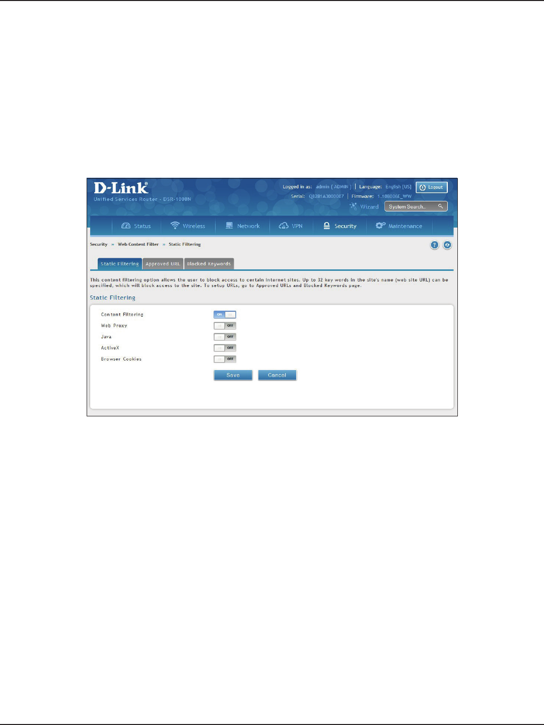
D-Link DSR-Series User Manual 144
Section 8 - Security
Path: Security > Authentication > Static Filtering
You may block access to certain Internet services.
To block or allow a service:
1. Click Security > Web Content Filter > Static Filtering tab.
Static Filtering
Web Content Filtering
2. Toggle Content Filtering to ON.
3. Toggle the service to ON to block. Toggle to OFF to allow.
4. Click Save.
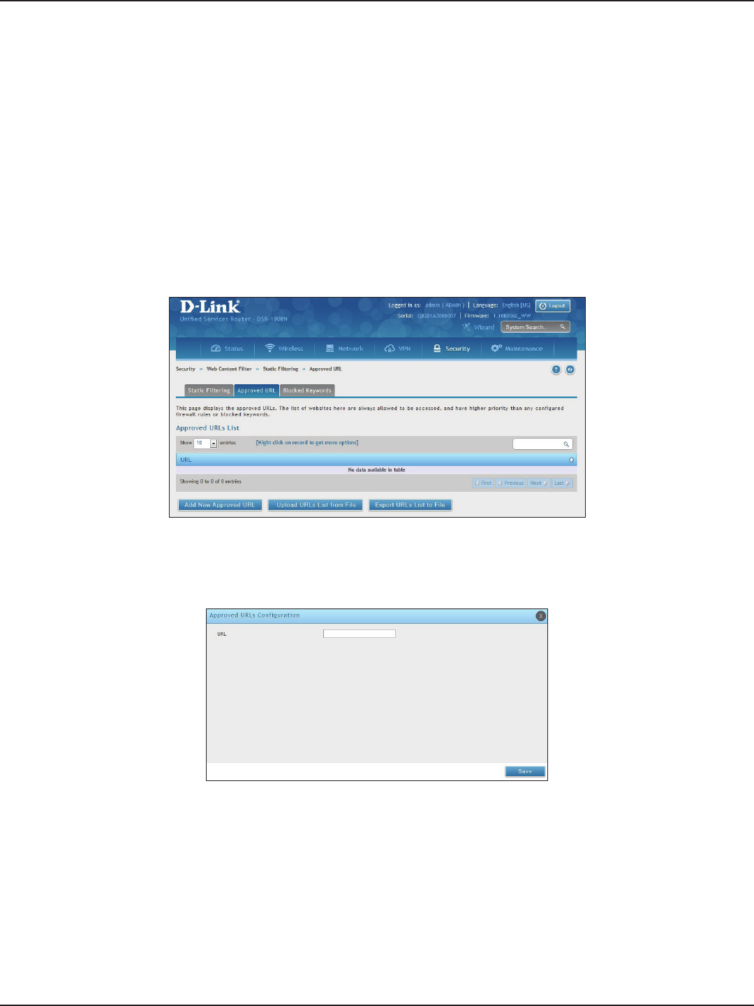
D-Link DSR-Series User Manual 145
Section 8 - Security
Path: Security > Web Content Filter > Static Filtering > Approved URL
The approved URL list is an acceptance list for all URL domain names. Domains added to this list are allowed
in any form. For example, if the domain “dlink” is added to this list then all of the following URL’s are permitted
access from the LAN: www.dlink.com, support.dlink.com, etc.
Importing/exporting from a text or CSV le is also supported.
To add/import/export URLs to the approved list:
1. Click Security > Web Content Filter > Static Filtering > Approved URL tab.
Approved URLs
2. To import a list from a text/CSV le, click Upload URLs List from File. If you want to export the current
list, click Export URLs List to File. To add a new URL, click Add New Approved URL.
3. Enter a URL and click Save.
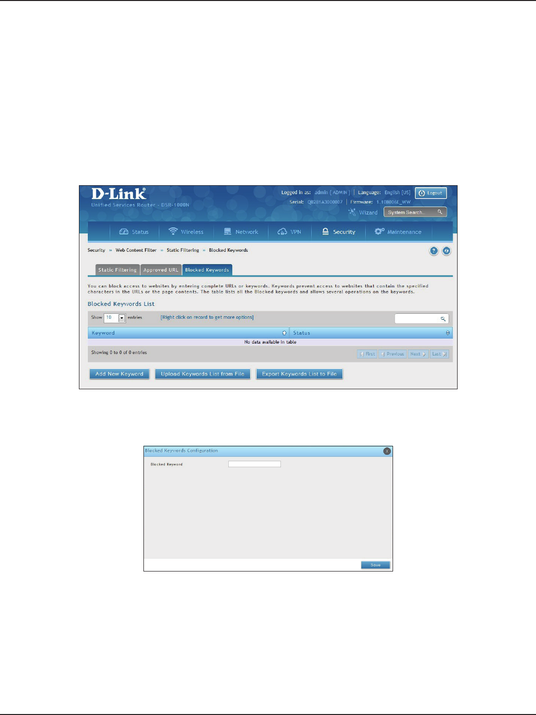
D-Link DSR-Series User Manual 146
Section 8 - Security
Path: Security > Web Content Filter > Static Filtering > Blocked Keywords
Keyword blocking allows you to block all website URL’s or site content that contains the keywords in the
congured list. This is lower priority than the Approved URL List; i.e. if a blocked keyword is present in a site
allowed by a trusted domain in the Approved URL List, then access to that site will be allowed. Import/export
from a text or CSV le is also supported.
To add/import/export URLs to the approved list:
1. Click Security > Web Content Filter > Static Filtering > Blocked Keywords tab.
Blocked Keywords
2. To import a list from a text/CSV le, click Upload Keywords List from File. If you want to export the
current list, click Export Keywords List to File. To add a new URL, click Add New Keyword.
3. Enter a keyword and click Save.
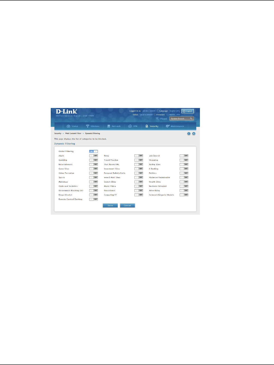
D-Link DSR-Series User Manual 147
Section 8 - Security
Path: Security > Web Content Filter > Dynamic Filtering
Dynamic Filtering will allow you to lter content from a list of categories. The router must be upgraded with the
WCF license and then the Content Filtering option, which allows the user to lter out internet sites, needs to be
enabled. When enabled, access to a website belonging to one of these congured categories will be blocked
with an error page.
To add/import/export URLs to the approved list:
1. Click Security > Web Content Filter > Dynamic Filtering.
Dynamic Filtering
2. Toggle Global Filtering to ON to enable dynamic ltering.
3. Toggle any of the listed categories to ON to block. Toggle to OFF to allow.
4. Click Save.
Note: Dynamic WCF license is not available in some regions, please contact D-Link worldwide oce for product
information.
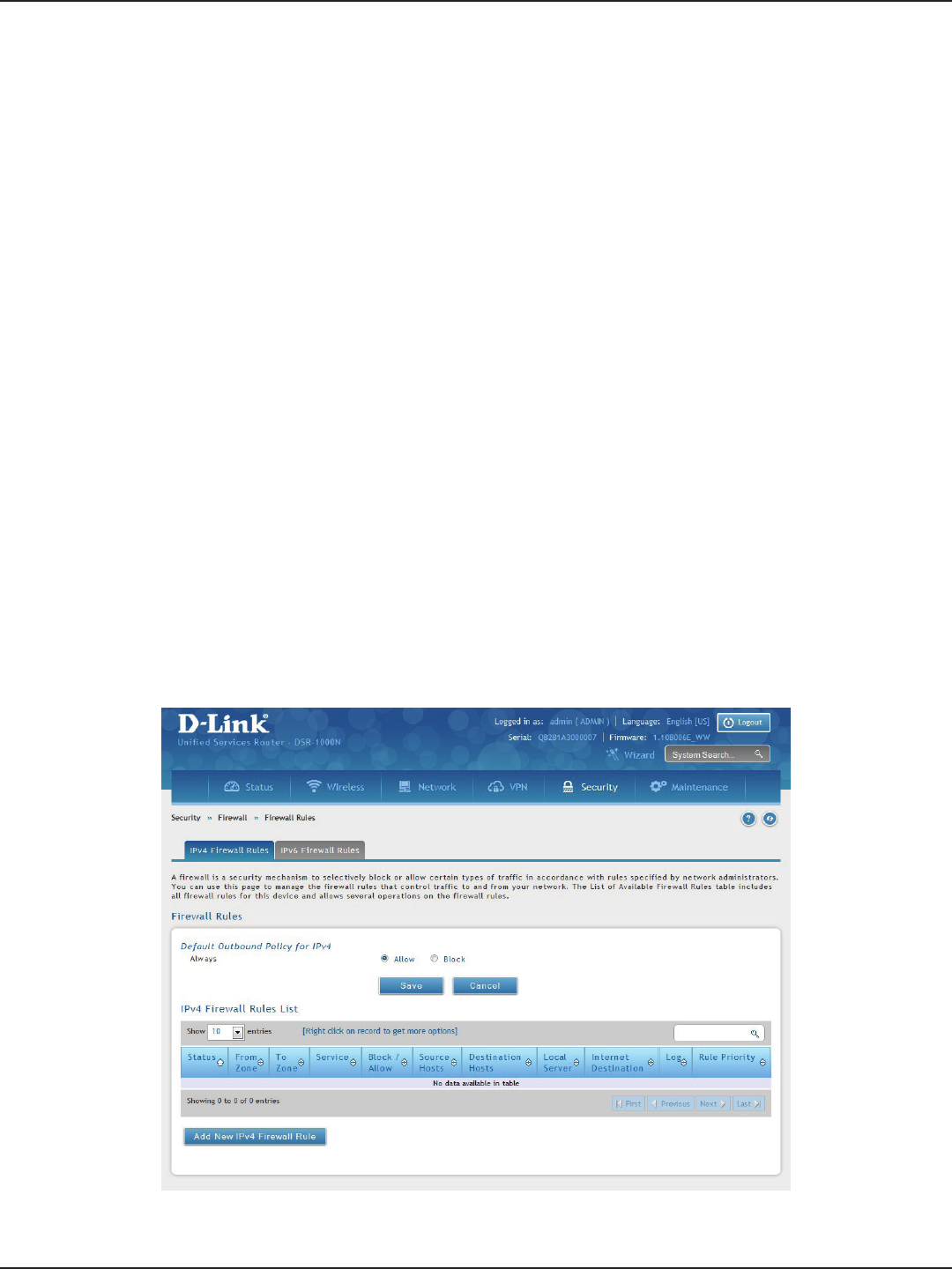
D-Link DSR-Series User Manual 148
Section 8 - Security
Path: Security > Firewall > Firewall Rules > IPv4 Firewall Rules or IPv6 Firewall Rules
Inbound (WAN to LAN/DMZ) rules restrict access to trac entering your network, selectively allowing only
specic outside users to access specic local resources. By default all access from the insecure WAN side are
blocked from accessing the secure LAN, except in response to requests from the LAN or DMZ. To allow outside
devices to access services on the secure LAN, you must create an inbound rewall rule for each service.
If you want to allow incoming trac, you must make the router’s WAN port IP address known to the public. This is
called “exposing your host.” How you make your address known depends on how the WAN ports are congured;
for this router you may use the IP address if a static address is assigned to the WAN port, or if your WAN address
is dynamic a DDNS (Dynamic DNS) name can be used.
Outbound (LAN/DMZ to WAN) rules restrict access to trac leaving your network, selectively allowing only
specic local users to access specic outside resources. The default outbound rule is to allow access from
the secure zone (LAN) to either the public DMZ or insecure WAN. On other hand the default outbound rule
is to deny access from DMZ to insecure WAN. You can change this default behavior in the Firewall Settings >
Default Outbound Policy page. When the default outbound policy is allow always, you can to block hosts on
the LAN from accessing internet services by creating an outbound rewall rule for each service.
To create a new rewall rule:
1. Click Security > Firewall > IPv4 Firewall Rules tab or IPv6 Firewall Rules tab.
Firewall
Firewall Rules
2. Right-click an entry and select either Edit or Delete. To add a new group, click Add New IPv4/IPv6
Firewall Rule.

D-Link DSR-Series User Manual 149
Section 8 - Security
3. Complete the elds from the table below and click Save.
Field Description
From Zone Select the source of originating trac: either secure LAN, public DMZ, or insecure WAN. For an inbound
rule WAN should be selected.
To Zone
Select the destination of trac covered by this rule. If the From Zone is the WAN, the To Zone can be the
public DMZ or secure LAN. Similarly if the From Zone is the LAN, then the To Zone can be the public DMZ
or insecure WAN.
Service Select a service from the drop-down menu. ANY means all trac is aected by this rule.
Action Select an action from the drop-down menu.
Source Hosts Select a source host. If you select Single Address or Address Range, you will need to enter the IP address
or IP range.
Destination Hosts Select a Destination host. If you select Single Address or Address Range, you will need to enter the IP
address or IP range.
Log Select whether to log rewall trac or not.
QoS Priority (IPv4 only)
Outbound rules (where To Zone = insecure WAN only) can have the trac marked with a QoS priority tag.
Select a priority level:
• Normal-Service: ToS=0 (lowest QoS)
• Minimize-Cost: ToS=1
• Maximize-Reliability: ToS=2
• Maximize-Throughput: ToS=4
• Minimize-Delay: ToS=16

D-Link DSR-Series User Manual 150
Section 8 - Security
Schedules
Path: Security > Firewall > Schedules
Firewall rules can be enabled or disabled automatically if they are associated with a congured schedule. The
schedule conguration page allows you to dene days of the week and the time of day for a new schedule, and
then this schedule can be selected in the rewall rule conguration page.
Note: All schedules will follow the time in the router’s congured time zone. Refer to the section on choosing your Time
Zone and conguring NTP servers for more information.
To add, delete, or edit a schedule:
1. Click Security > Firewall > Schedules.
2. Right-click an entry and select either Edit or Delete. To add a new schedule, click Add New Schedule.
Field Description
Name Enter a name for your schedule.
Scheduled Days Select All Days or Specic Days.
Monday - Sunday If you selected Specic Days, toggle each day you want to ON.
Scheduled Time of Day Select All Day or Specic Times.
Start Time/End Time
If you selected Specic Times, use the mouse on the blue boxes representing the hour, minutes, and am/
pm to select the start time and end time. Click, hold, and move up to decrease the value or move down to
increase the value.
Save Click to save your settings.
Specic Days enabled Specic Times enabled
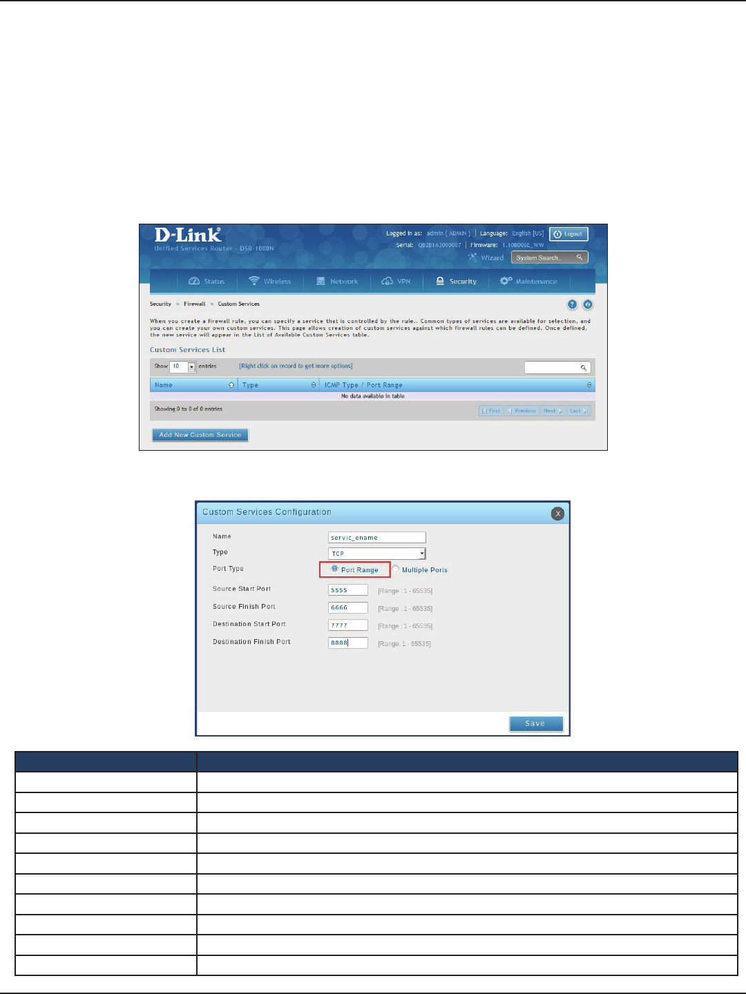
D-Link DSR-Series User Manual 151
Section 8 - Security
Custom Services
Path: Security > Firewall > Custom Services
Custom services can be dened to add to the list of services available during rewall rule conguration. While
common services have known TCP/UDP/ICMP ports for trac, many custom or uncommon applications exist in the
LAN or WAN. In the custom service conguration menu you can dene a range of ports and identify the trac type
(TCP/UDP/ICMP) for this service. Once dened, the new service will appear in the services list of the rewall rules
conguration menu.
To add, delete, or edit a custom service:
1. Click Security > Firewall > Custom Services.
2. Right-click an entry and select either Edit or Delete. To add a new schedule, click Add New Custom
Service.
Field Description
Name Enter a name for your custom service.
Type Enter the layer 3 protocol that the service uses (TCP, UDP, BOTH, or ICMP).
Port Type Select Port Range or Multiple Ports.
Source Start Port If you selected Port Range, enter the rst source(TCP, UDP or BOTH) port of a range that the service uses.
Source Finish Port If you selected Port Range, enter the last source port of a range that the service uses.
Destination Start Port If you selected Port Range, enter the rst destination port of a range that the service uses.
Destination Start Port If you selected Port Range, enter the last destination port of a range that the service uses.
Ports If you selected Multiple Ports, enter the port or ports separated by a comma.
ICMP Type The ICMP type is a numeric value that can range between 0 and 40.
Save Click to save your settings.

D-Link DSR-Series User Manual 152
Section 8 - Security
ALGs
Path: Security > Firewall > ALGs
Application Level Gateways (ALGs) are security components that enhance the rewall and NAT support of this
router to seamlessly support application layer protocols. In some cases enabling the ALG will allow the rewall
to use dynamic ephemeral TCP/ UDP ports to communicate with the known ports a particular client application
(such as H.323 or RTSP) requires, without which the admin would have to open large number of ports to
accomplish the same support. Because the ALG understands the protocol used by the specic application that it
supports, it is a very secure and ecient way of introducing support for client applications through the router’s
rewall.
1. Click Security > Firewall > ALGs tab.
2. Toggle the protocol(s) to ON that you want to allow through the router.
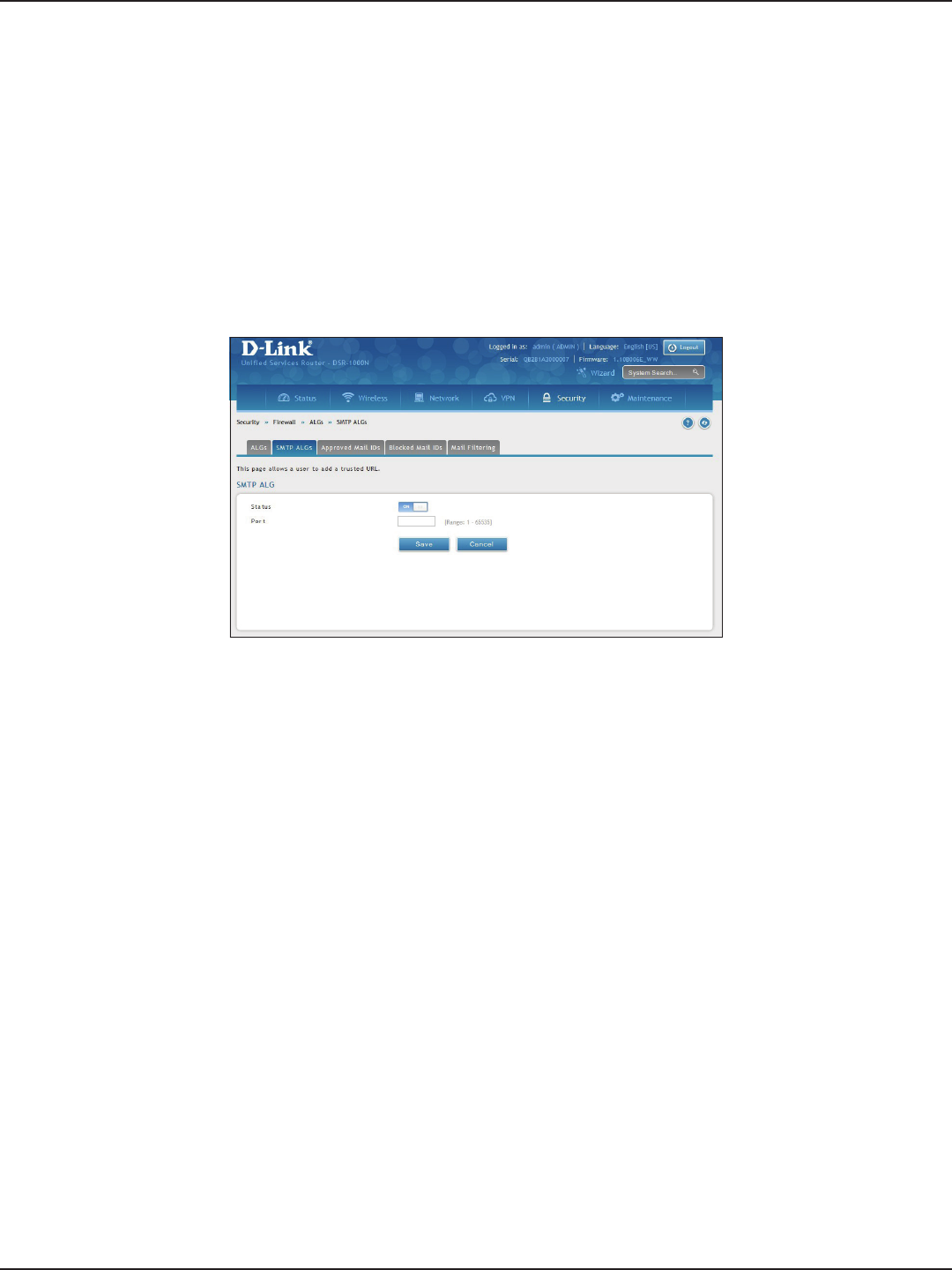
D-Link DSR-Series User Manual 153
Section 8 - Security
SMTP ALGs
Path: Security > Firewall > ALGs > SMTP ALGs
Simple Mail Transfer Protocol (SMTP) is a text based protocol used for transferring email between mail servers
over the Internet. Typically the local SMTP server will be located on a DMZ so that mail sent by remote SMTP
servers will traverse the router to reach the local server. Local users will then use email client software to retrieve
their email from the local SMTP server. SMTP is also used when clients are sending email and SMTP ALG can be
used to monitor SMTP trac originating from both clients and servers.
1. Click Security > Firewall > ALGs > SMTP ALGs tab.
2. Toggle Status to ON.
3. Enter the port at which the SMTP packets are inspected.
4. Click Save.
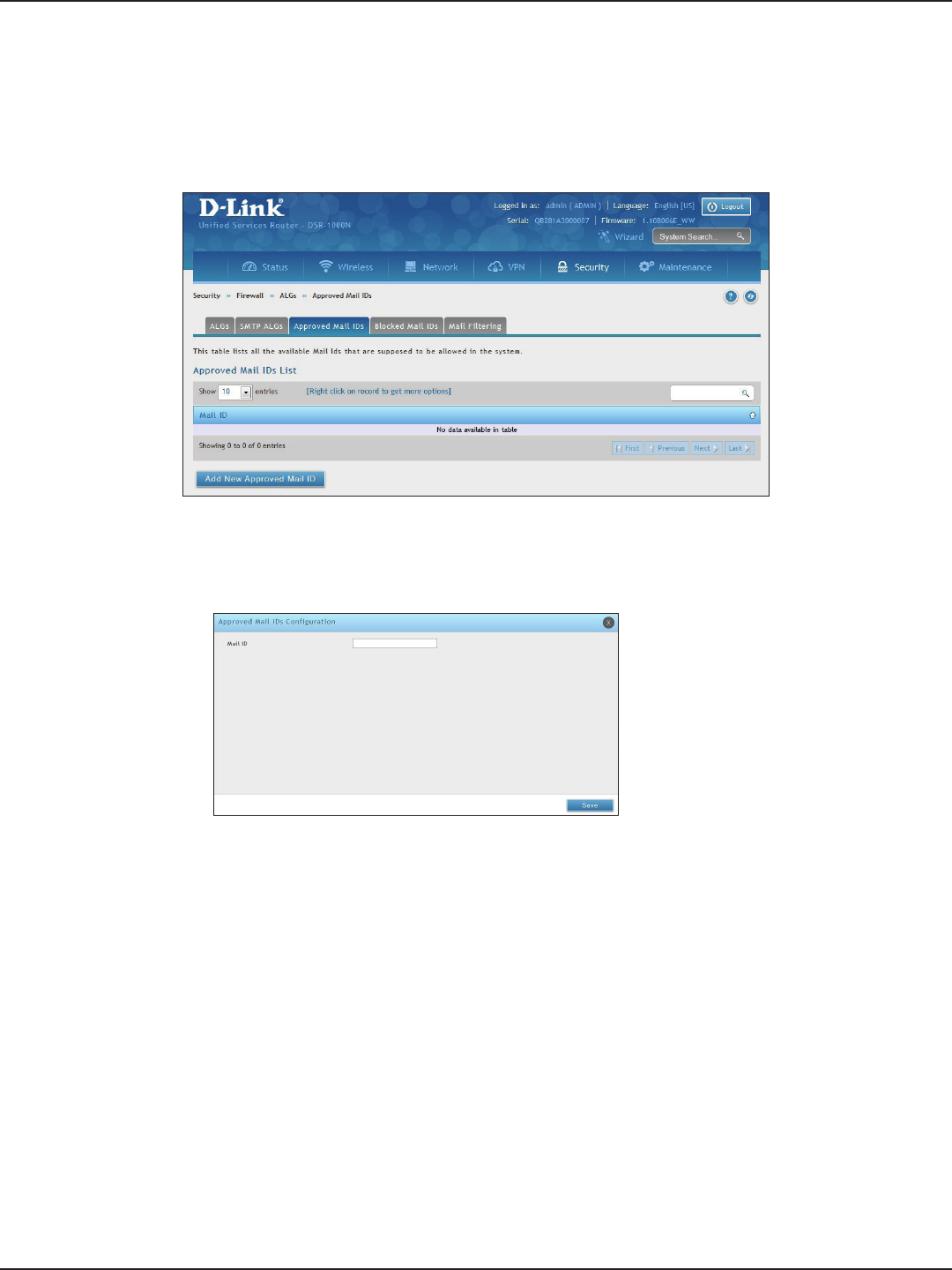
D-Link DSR-Series User Manual 154
Section 8 - Security
Approved Mail IDs
Path: Security > Firewall > ALGs > Approved Mail IDs
1. Click Security > Firewall > ALGs > Approved Mail IDs tab.
2. Right-click an entry and select either Edit or Delete. To add a new mail ID, click Add New Approved
Mail ID.
3. Enter a mail ID and click Save.
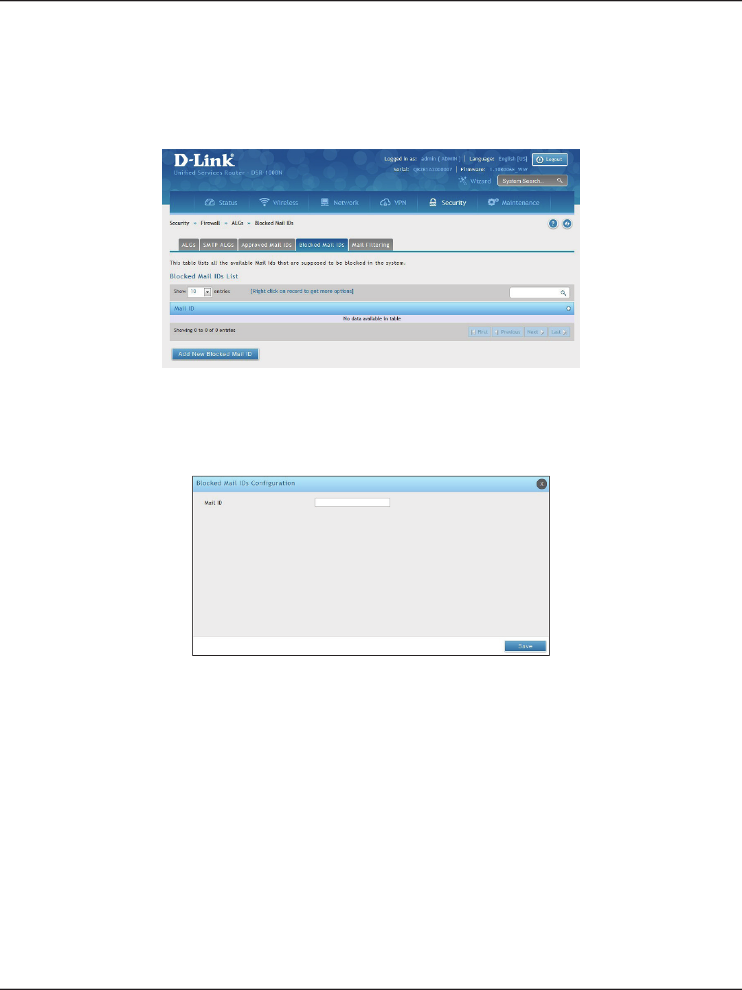
D-Link DSR-Series User Manual 155
Section 8 - Security
Blocked Mail IDs
Path: Security > Firewall > ALGs > Blocked Mail IDs
1. Click Security > Firewall > ALGs > Blocked Mail IDs tab.
2. Right-click an entry and select either Edit or Delete. To add a new mail ID, click Add New Blocked Mail
ID.
3. Enter a mail ID and click Save.
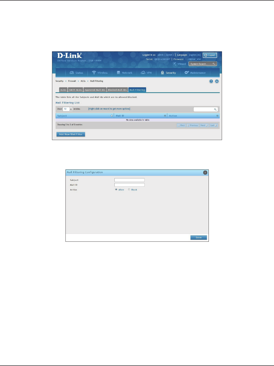
D-Link DSR-Series User Manual 156
Section 8 - Security
Mail Filtering
Path: Security > Firewall > ALGs > Mail Filtering
1. Click Security > Firewall > ALGs > Mail Filtering tab.
2. Right-click an entry and select either Edit or Delete. To add a new mail ID, click Add New Mail Filter.
3. Enter a subject and a mail ID.
4. Select to allow or block.
5. Click Save.
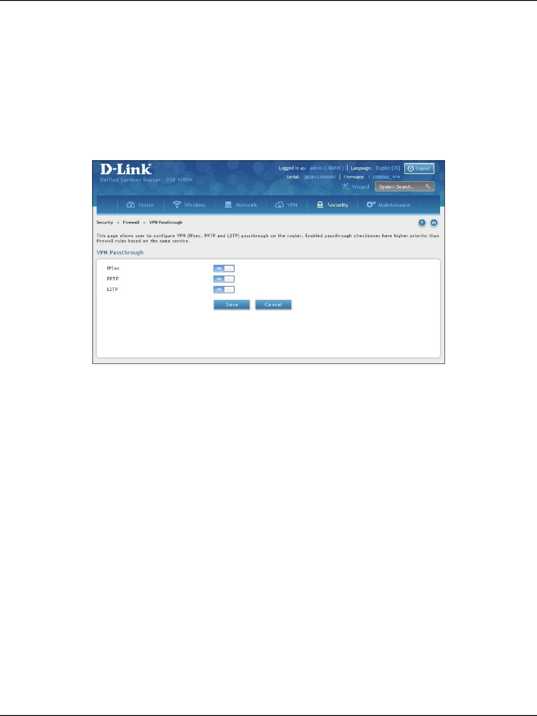
D-Link DSR-Series User Manual 157
Section 8 - Security
VPN Passthrough
Path: Security > Firewall > VPN Passthrough
This router’s rewall settings can be congured to allow encrypted VPN trac for IPsec, PPTP, and L2TP VPN tunnel
connections between the LAN and internet. A specic rewall rule or service is not appropriate to introduce this
passthrough support; instead the options in the VPN Passthrough page must be toggled to ON.
1. Click Security > Firewall > VPN Passthrough.
2. Toggle the VPN protocol you want to allow to ON and click Save.
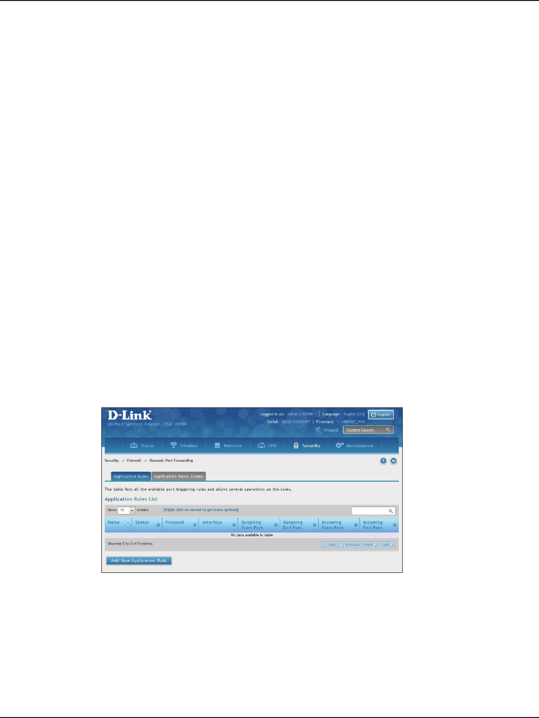
D-Link DSR-Series User Manual 158
Section 8 - Security
Dynamic Port Forwarding
Path: Security > Firewall > Dynamic Port Forwarding > Application Rules
Application rules are also referred to as port triggering. This feature allows devices on the LAN or DMZ to request
one or more ports to be forwarded to them. Port triggering waits for an outbound request from the LAN/DMZ
on one of the dened outgoing ports, and then opens an incoming port for that specied type of trac. This can
be thought of as a form of dynamic port forwarding while an application is transmitting data over the opened
outgoing or incoming port(s).
Port triggering application rules are more exible than static port forwarding that is an available option when
conguring rewall rules. This is because a port triggering rule does not have to reference a specic LAN IP or IP
range. As well ports are not left open when not in use, thereby providing a level of security that port forwarding
does not oer.
Note: Port triggering is not appropriate for servers on the LAN, since there i s a dependency on the LAN device making
an outgoing connection before incoming ports are opened.
Some applications require that when external devices connect to them, they receive data on a specic port or
range of ports in order to function properly. Th e router must send all incoming data for that application only on
the required port or range of ports. The router has a list of common applications and games with corresponding
outbound and inbound ports to open. You can also specify a port triggering rule by dening the type of trac
(TCP or UDP) and the range of incoming and outgoing ports to open when enabled.
1. Click Security > Firewall > Dynamic Port Forwarding > Application Rules tab.
Application Rules
2. Right-click an entry and select either Edit or Delete. To add a new schedule, click Add New Application
Rule.
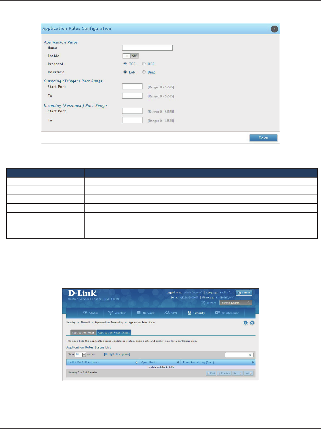
D-Link DSR-Series User Manual 159
Section 8 - Security
3. Complete the elds from the table below and click Save.
Field Description
Name Enter a name for your rule.
Enable Toggle to ON to activate the rule.
Protocol Select TCP or UDP.
Interface Select either LAN or DMZ.
Outgoing (Trigger) Port Range Enter the start and end trigger port range.
Incoming Port Range Enter the port range to open.
Save Click to save your settings.
4. Click on the Application Rules Status tab to see a list of rules and their status.

D-Link DSR-Series User Manual 160
Section 8 - Security
Attack Checks
Path: Security > Firewall > Attack Checks
Attacks can be malicious security breaches or unintentional network issues that render the router unusable
Attack checks allow you to manage WAN security threats such as continual ping requests and discovery via ARP
scans. TCP and UDP ood attack checks can be enabled to manage extreme usage of WAN resources.
Additionally certain Denial-of-Service (DoS) attacks can be blocked. These attacks, if uninhibited, can use up
processing power and bandwidth and prevent regular network services from running normally. ICMP packet
ooding, SYN trac ooding, and Echo storm thresholds can be congured to temporarily suspect trac from
the oending source.
1. Click Security > Firewall > Attack Checks.
2. Complete the elds from the table below and click Save.
Field Description
Stealth Mode If this option is toggled to ON, the router will not respond to port scans from the WAN. This makes it less
susceptible to discovery and attacks.
Block TCP Flood If this option is toggled to ON, the router will drop all invalid TCP packets and be protected from a SYN
ood attack.
Block UDP Flood
If this option is toggled to ON, the router will not accept more than 20 simultaneous, active UDP connec-
tions from a single computer on the LAN. You can set the number of simultaneous active UDP connections
to be accepted from a single computer on the LAN; the default is 25.
Allow Ping from LAN Toggle to ON to allow local computers to ping.
Block ICMP Notication Toggle to ON to prevent ICMP packets from being identied as such. ICMP packets, if identied, can be
captured and used in a Ping (ICMP) ood DoS attack.
Block Fragmented Packets Toggle to ON to drop any fragmented packets through or to the gateway
Block Multicast Packets Toggle to ON to drop multicast packets, which could indicate a spoof attack, through or to the router.
Block Spoofed IP Packets Toggle to ON to block any spoofed IP packets.
SYN Flood Detect Rate The rate at which the SYN Flood can be detected.
Echo Storm The number of ping packets per second at which the router detects an Echo storm attack from the WAN
and prevents further ping trac from that external address.
ICMP Flood The number of ICMP packets per second at which the router detects an ICMP ood attack from the WAN
and prevents further ICMP trac from that external address.
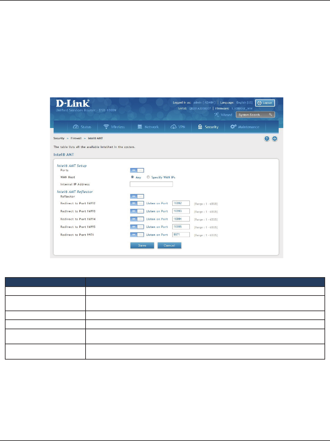
D-Link DSR-Series User Manual 161
Section 8 - Security
Intel® AMT
Path: Security > Firewall > Intel® AMT
Intel® Active Management Technology (AMT) allows you to remotely access and manage every networked
device, even those that lack a working operating system or hard drive, or are turned o as long as the computer
is connected to line power and to the network. Intel AMT uses a separate management processor that runs
independently on the client machine and can be reached through the wired or wireless network.
1. Click Security > Firewall > Intel AMT.
2. Complete the elds from the table below and click Save.
Field Description
Ports When enabled, inbound/outbound rewall rules are added for certain ports to enable Intel AMT service.
WAN Host Select ANY to allow all hosts access or select Specify WAN IPs and enter IP addresses of hosts (separate
with a comma) you want to grant access to. Do not use spaces.
Internal IP Address Enter the LAN IP address.
Reector Toggle to ON to enable Reector. This will send data back to the client on selected ports.
Redirect to Port 16992-16995 Toggle to ON to use the selected port. Enter the listening port on which the server will listen for incoming
connections.
Redirect to Port 9971 Toggle to ON to use the selected port. Enter the listening port on which the server will listen for incoming
connections.
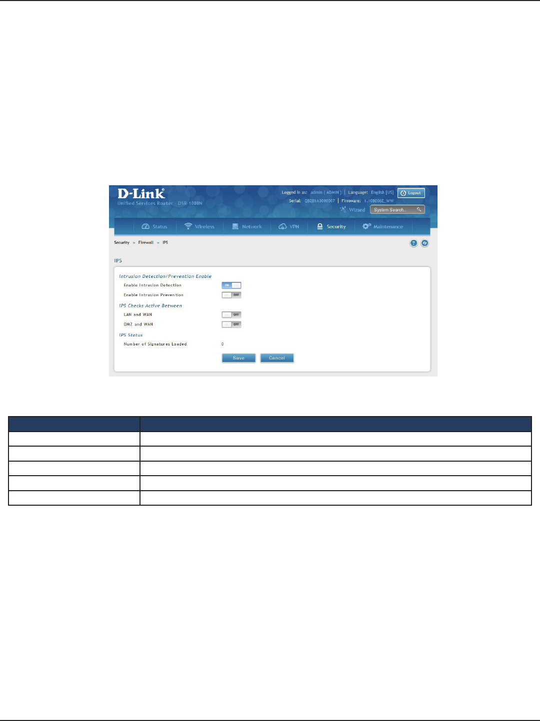
D-Link DSR-Series User Manual 162
Section 8 - Security
IPS
Path: Security > Firewall > IPS
The router’s Intrusion Prevention System (IPS) prevents malicious attacks from the internet from accessing
the private network. Static attack signatures loaded to the router allow common attacks to be detected and
prevented. The checks can be enabled between the WAN and DMZ or LAN, and a running counter will allow the
administrator to see how many malicious intrusion attempts from the WAN have been detected and prevented.
Note: The DSR-150/150N routers do not support Intrusion Prevention System.
1. Click Security > Firewall > IPS.
2. Complete the elds from the table below and click Save.
Field Description
Enable Intrusion Detection Toggle to ON to enable intrusion detection.
Enable Intrusion Prevention Toggle to ON to enable intrusion prevention.
LAN and WAN Toggle to ON to detect intrusions between the LAN and WAN interfaces.
DMZ and WAN Toggle to ON to detect intrusions between the DMZ and WAN interfaces.
Number of Signatures Loaded Displays the number of signatures loaded.

D-Link DSR-Series User Manual 163
Section 9 - Maintenance
System Settings
Path: Maintenance > Administration > System Setting
You may change the name of the router here.
1. Click Maintenance > Administration > System Setting.
Maintenance
2. Complete the elds from the table below and click Save.
Field Description
Current System Name Displays the current name for the router.
New Name for System Enter a new name for the router.
Save Click to save and activate your settings.
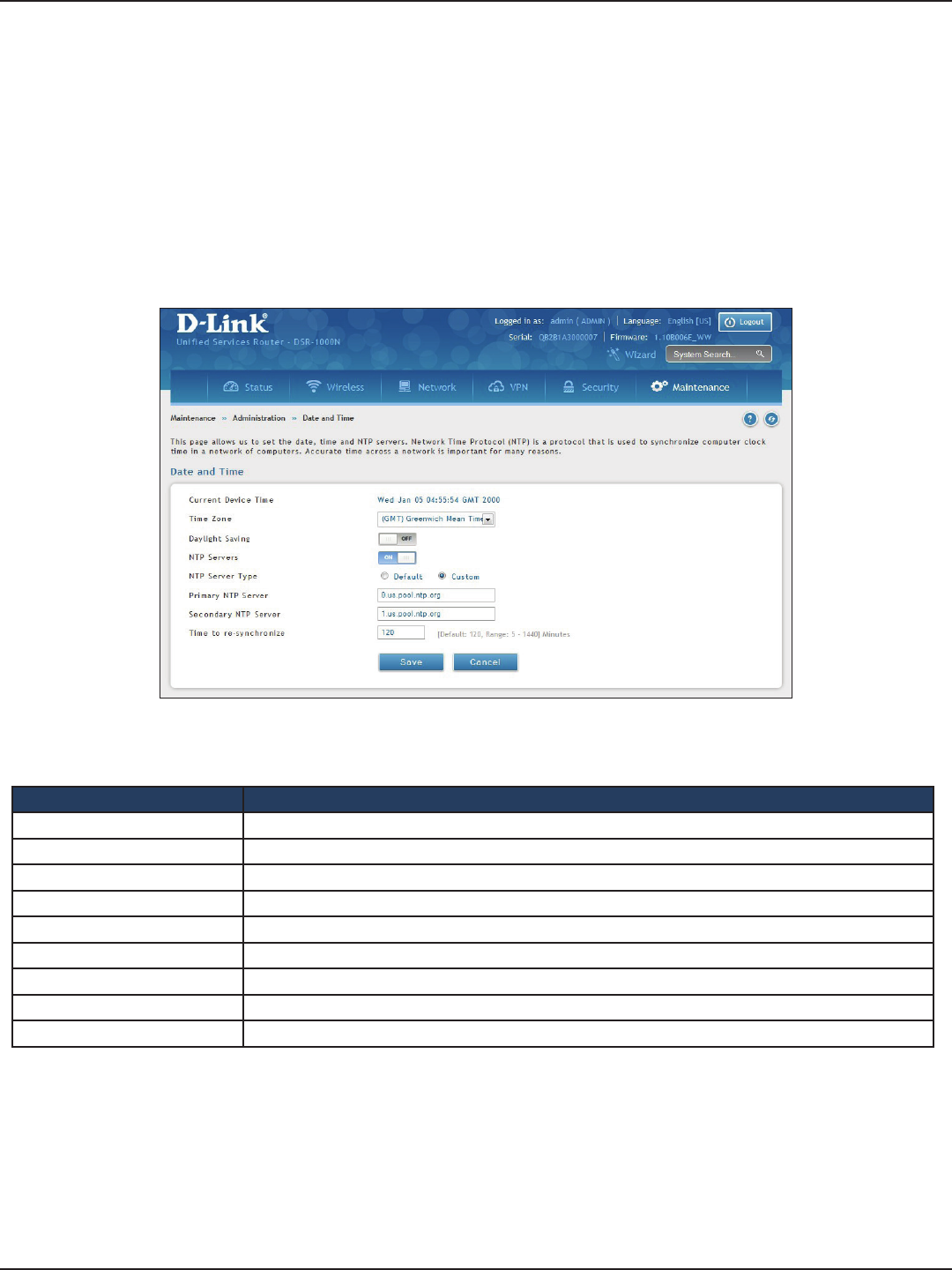
D-Link DSR-Series User Manual 164
Section 9 - Maintenance
Date and Time
Path: Maintenance > Administration > Date and Time
You can congure your time zone, whether or not to adjust for Daylight Savings Time, and with which Network
Time Protocol (NTP) server to synchronize the date and time. You can choose to set Date and Time manually,
which will store the information on the router’s real time clock (RTC). If the router has access to the internet, the
most accurate mechanism to set the router time is to enable NTP server communication.
1. Click Maintenance > Administration > Date and Time.
2. Complete the elds from the table below and click Save.
Field Description
Current Device Time Displays the current date and time on the router.
Time Zone Select your time zone from the drop-down menu.
Daylight Saving Toggle to ON to enable daylight saving time.
NTP Servers Toggle to ON to use NTP servers on the Internet.
NTP Server Type Select either Default or Custom to enter specic NTP Server addresses.
Primary NTP Server If you selected Custom, enter the primary NTP server address.
Secondary NTP Server If you selected Custom, enter the secondary NTP server address.
Time to re-synchronize Enter the time in minutes for the router to re-synch with the NTP server(s).
Save Click to save and activate your settings.
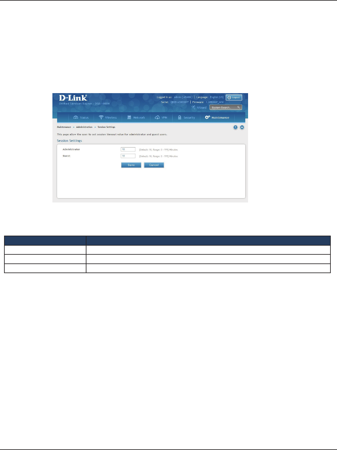
D-Link DSR-Series User Manual 165
Section 9 - Maintenance
Session Settings
Path: Maintenance > Administration > Session Settings
Here you can set the timeout value for admin and guest logins.
1. Click Maintenance > Administration > Session Settings.
2. Complete the elds from the table below and click Save.
Field Description
Administrator Enter the timeout value in minutes for the Administrator account.
Guest Enter the timeout value in minutes for the Guest account.
Save Click to save and activate your settings.
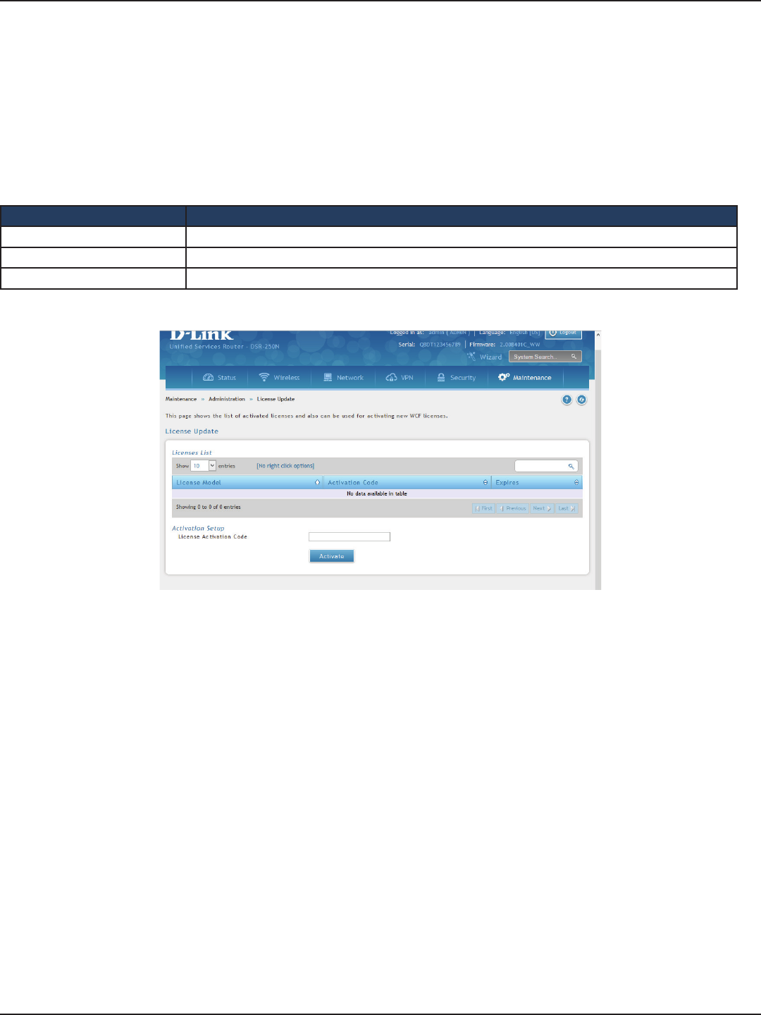
D-Link DSR-Series User Manual 166
Section 8 - Security
License Updates
Path: Maintenance > Administration > License Update
Certain features can be added to the router by purchasing a license key. An activation code is provided based on
the router’s MAC Address, so it will be unique to that particular device.
Each license has the following three parameters:
Field Description
Model The license model as it relates to the feature being added.
Activation Code The activation code corresponding to this license.
Expiration Licenses can either have a xed duration, or are perpetual for the life of this router.
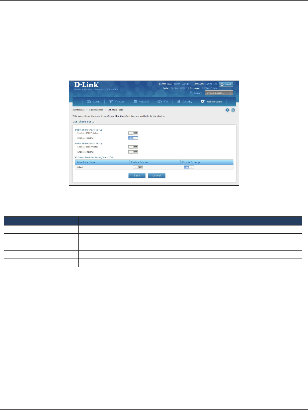
D-Link DSR-Series User Manual 167
Section 9 - Maintenance
USB Share Ports
Path: Maintenance > Administration > USB Share Ports
This page allows congure the SharePort feature available on this router.
1. Click Maintenance > Administration > USB Share Ports.
2. Complete the elds from the table below and click Save.
Field Description
USB Port 1 Printer Toggle to ON to enable USB port 1. Once enabled you will need to enter your printer information.
USB Port 2 Printer Toggle to ON to enable USB port 2. Once enabled you will need to enter your printer information.
Interface Name Displays the name of the printer interface.
Enable Printer Displays if the printer is enabled or not. Toggle to ON to enable.
Save Click to save and activate your settings.
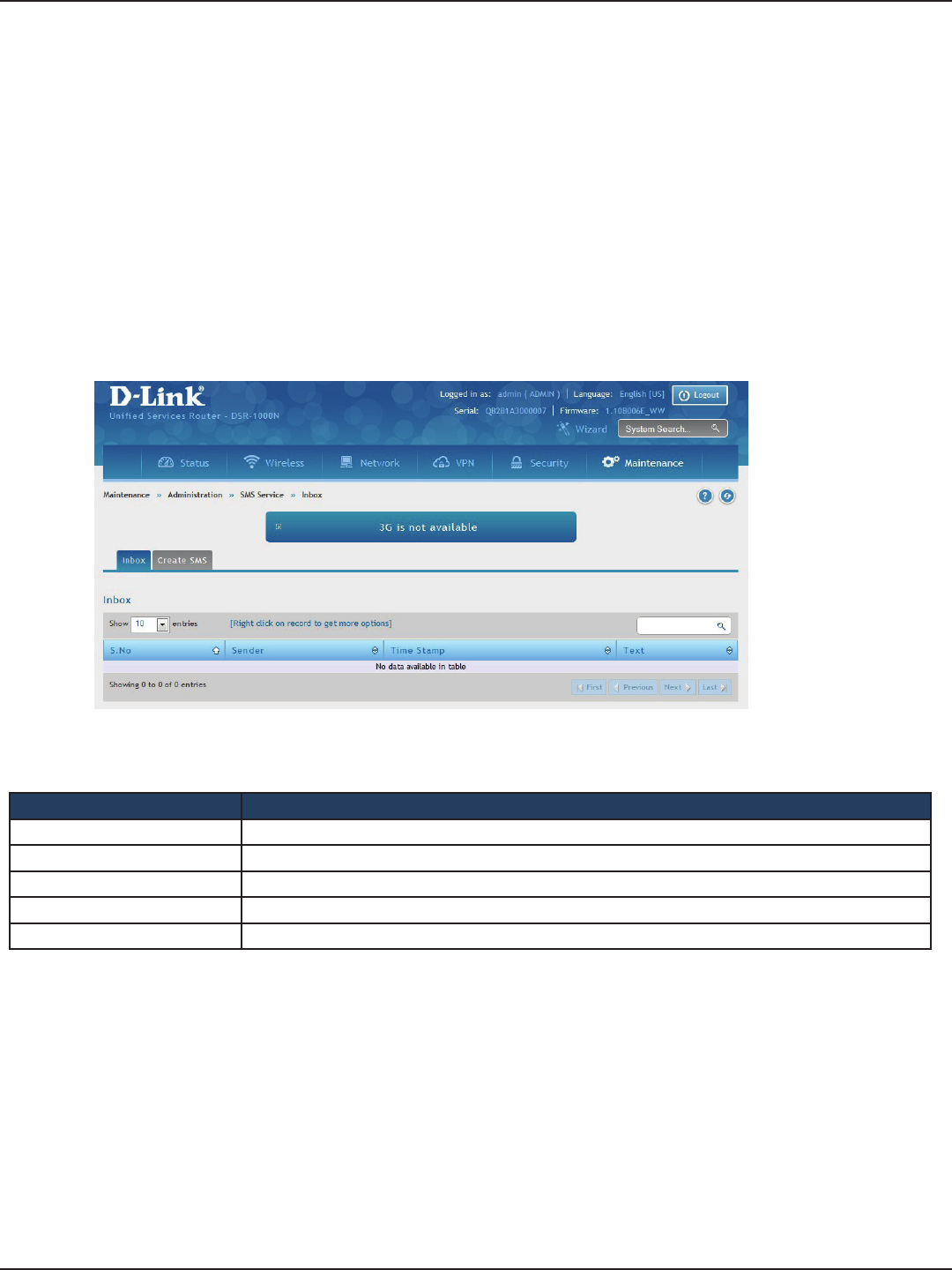
D-Link DSR-Series User Manual 168
Section 9 - Maintenance
SMS Service
Path: Maintenance > Administration > SMS Service > Inbox
The D-Link Services Router has a USB interface to connect 3G modem support to send and receive Short
Messaging Service (SMS). The received messages can be seen in the Inbox and allows the user to create a new
SMS. If WAN3 is used in dedicated WAN mode, load balancing mode, or if the 3G USB device is not connected to
router then the controls on this page will not be available.
To view any incoming messages:
1. Click Maintenance > Administration > SMS Service > Inbox tab.
2. The following details are displayed.
Field Description
S. No Displays the serial number of the message.
Sender Displays the sender of the message.
Time Stamp Displays the time when the message was sent.
Text Displays the content of the message.
Save Click to save and activate your settings.
Inbox
3. Right-click the entry to delete, refresh, reply, or forward the message.
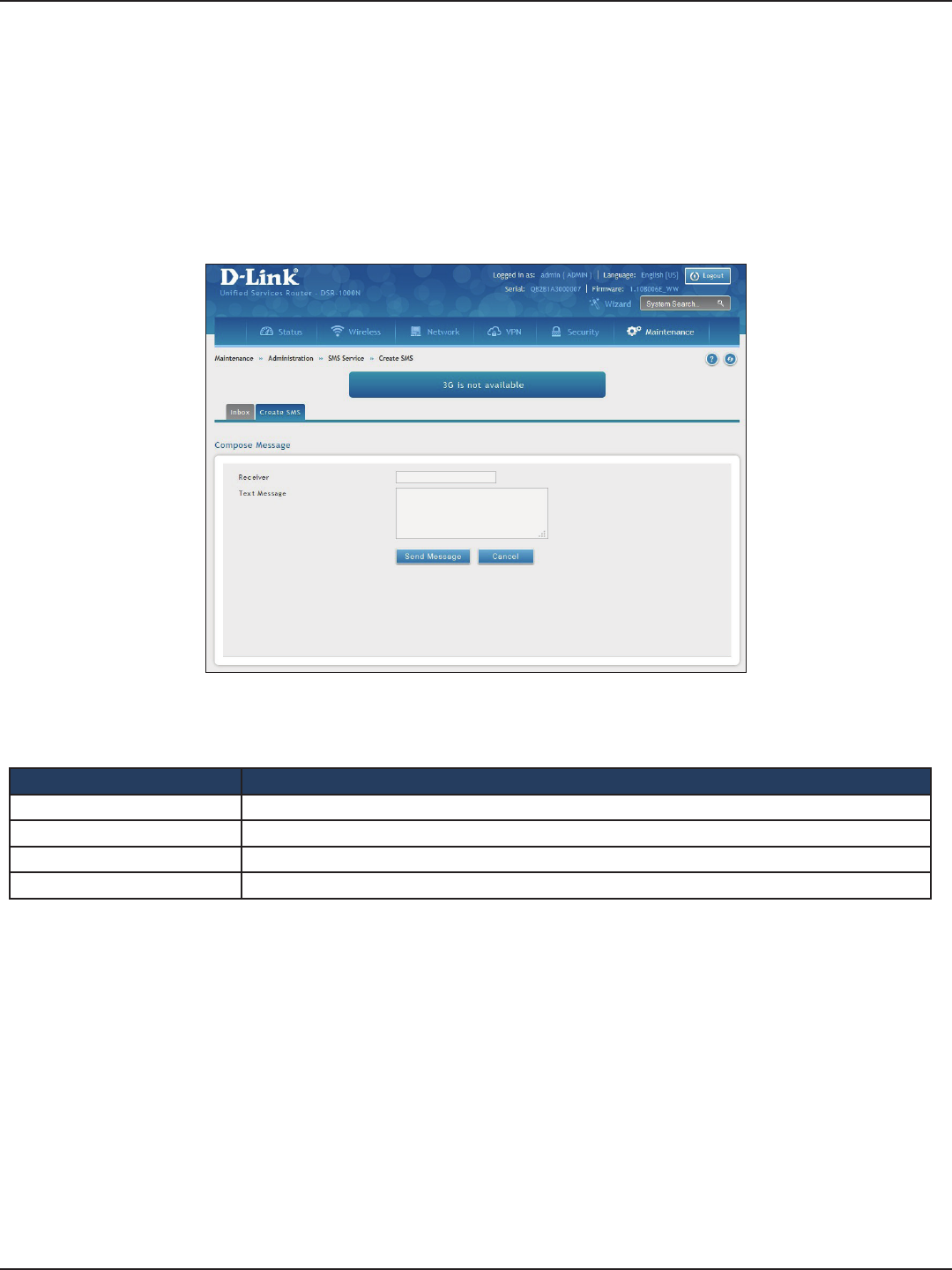
D-Link DSR-Series User Manual 169
Section 9 - Maintenance
Create SMS
Path: Maintenance > Administration > SMS Service> Create SMS
This page allows you to send a message using the SMS service.
1. Click Maintenance > Administration > SMS Service > Create SMS tab.
2. Complete the elds from the table below and click Send Message.
Field Description
Receiver Enter the phone number of the intended receiver.
Text Message Enter the message you want to send.
Send Message Click to send your message.
Cancel Click to reset the elds.
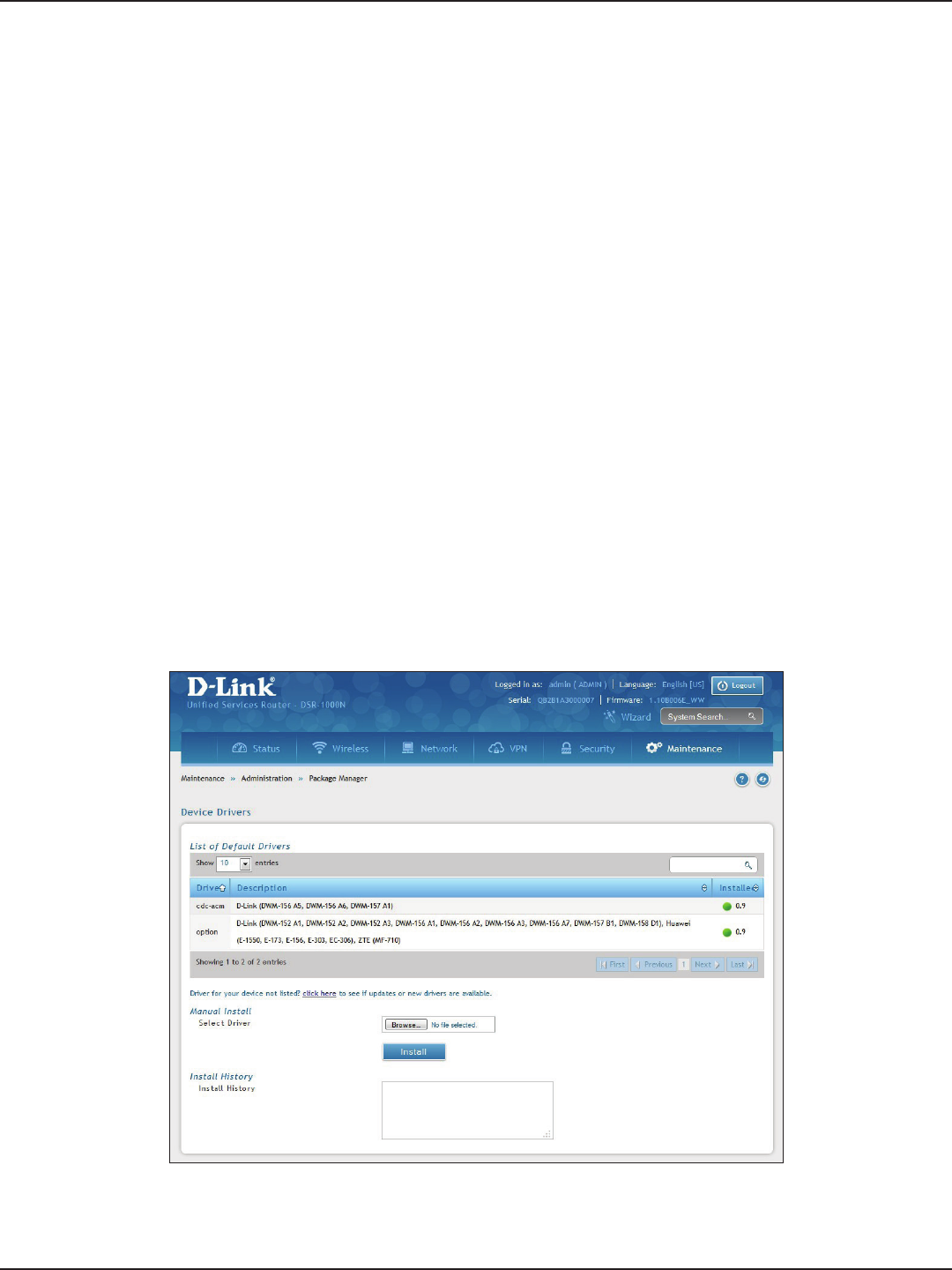
D-Link DSR-Series User Manual 170
Section 9 - Maintenance
Package Manager
Path: Maintenance > Administration > Package Manager
A package is a set of les which are installed by the router from D-Link’s repositories. This feature allows users
to download new drivers for supported USB devices and language packs to enable multi-lingual support for
the router’s management interface. Multi-lingual support via the package manager allows the user to choose
a language of choice so that the entire textual content in the router’s user interface is presented in the selected
language.
This feature supports a single driver and single language pack to be stored in the router (i.e. these les are
available for use after device reboot) . There are 2 types of installations supported by this feature:
1. Manual Installation: Upon selecting manual installation, the user has to download the
package which will then display the available languages that the router GUI now supports.
Note: Only drivers provided by D-Link can be used for manual installation. A validation process will
be performed during installation.
2. Auto Installation: By selecting the link “click here” the auto-installation of the package is
exercised. A page showing the list of available drivers / language packs is displayed from which
the user can select and install one of the options. For this type of installation the router must be
able to access the internet, as this will allow the user to download the package from a repository
server which consists of all the available languages.
1. Click Maintenance > Administration > Package Manager.

D-Link DSR-Series User Manual 171
Section 9 - Maintenance
Field Description
List of Default Drivers Displays the default drivers that are installed.
Click Here Click to display a list of available packages for download. You must be connected to the Internet. Here
you can select the driver to update or install.
Manual Install If you have downloaded a packed, click Browse and select the package. Click Open and then click
Install.
Install History Displays a list of package installations.
2. Complete the elds from the table below.
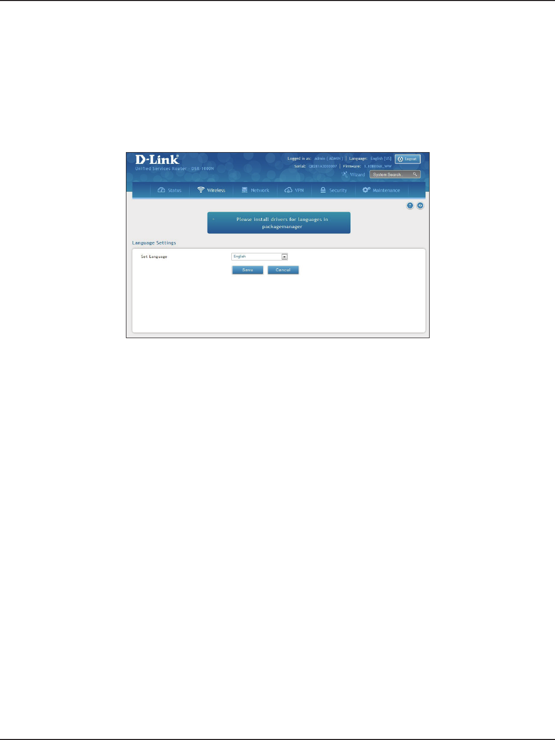
D-Link DSR-Series User Manual 172
Section 9 - Maintenance
Path: Maintenance > Administration > Set Language
You can download language packs (refer to “Package Manager” on page 170) and install them on the router. Once
you have downloaded a pack, follow the steps below to install:
1. Click Maintenance > Administration > Set Language.
2. Select a loaded language pack from the drop-down menu and click Save.
Set Language
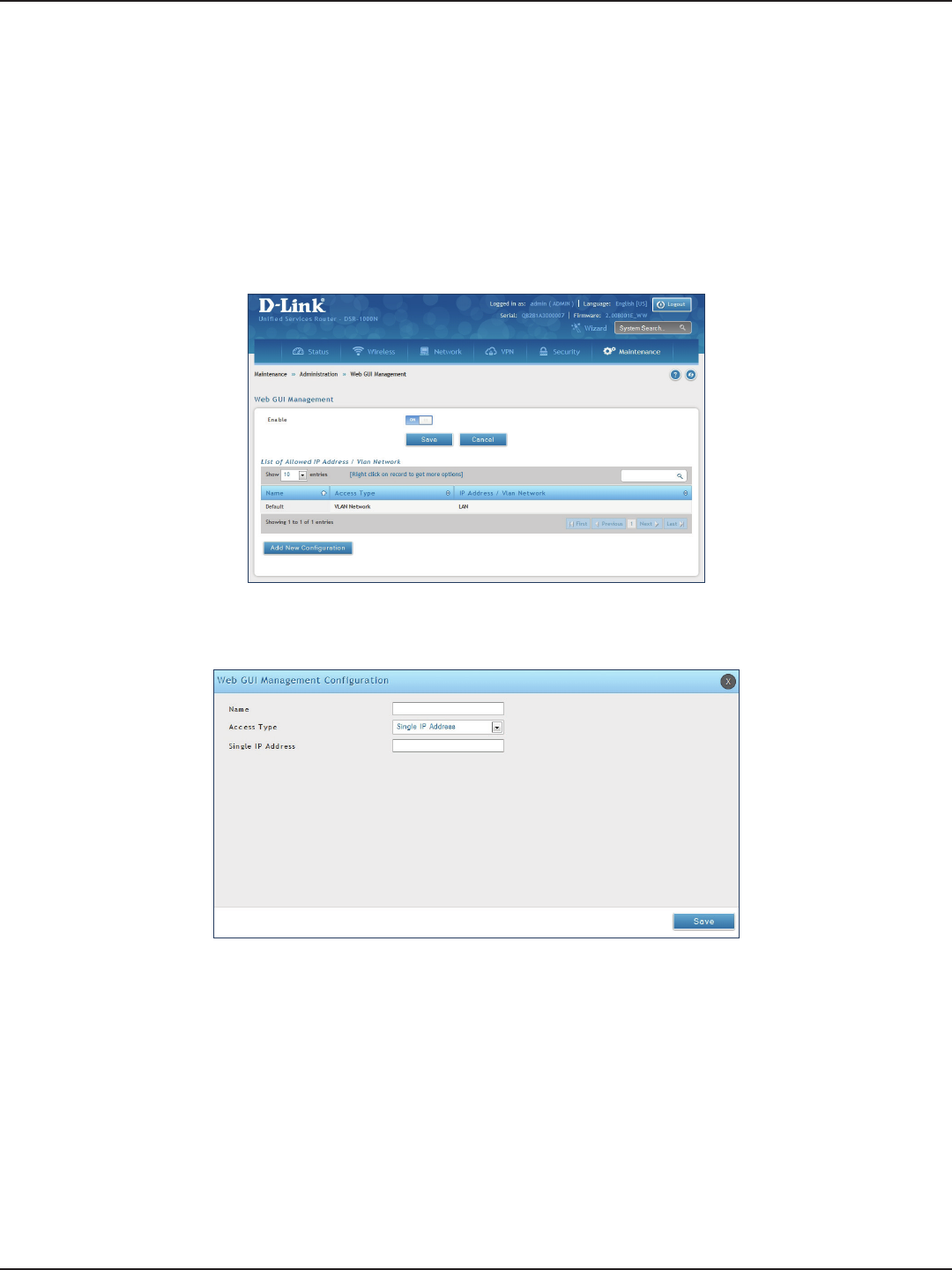
D-Link DSR-Series User Manual 173
Section 9 - Maintenance
Web GUI Management
Path: Maintenance > Administration > Web GUI Management
The Web GUI Management page will allow you to specify by IP address or VLAN what users can congure the
router using the web GUI.
1. Click Maintenance > Administration > Web GUI Management.
2. Toggle Enable to ON and click Save.
3. Click Add New Conguration.
4. Enter a name for this conguration.
5. Select either Single IP Address and enter the IP address of the computer/device or VLAN Network
and enter the VLAN ID that you want to allow access to the web GUI.
6. Click Save.
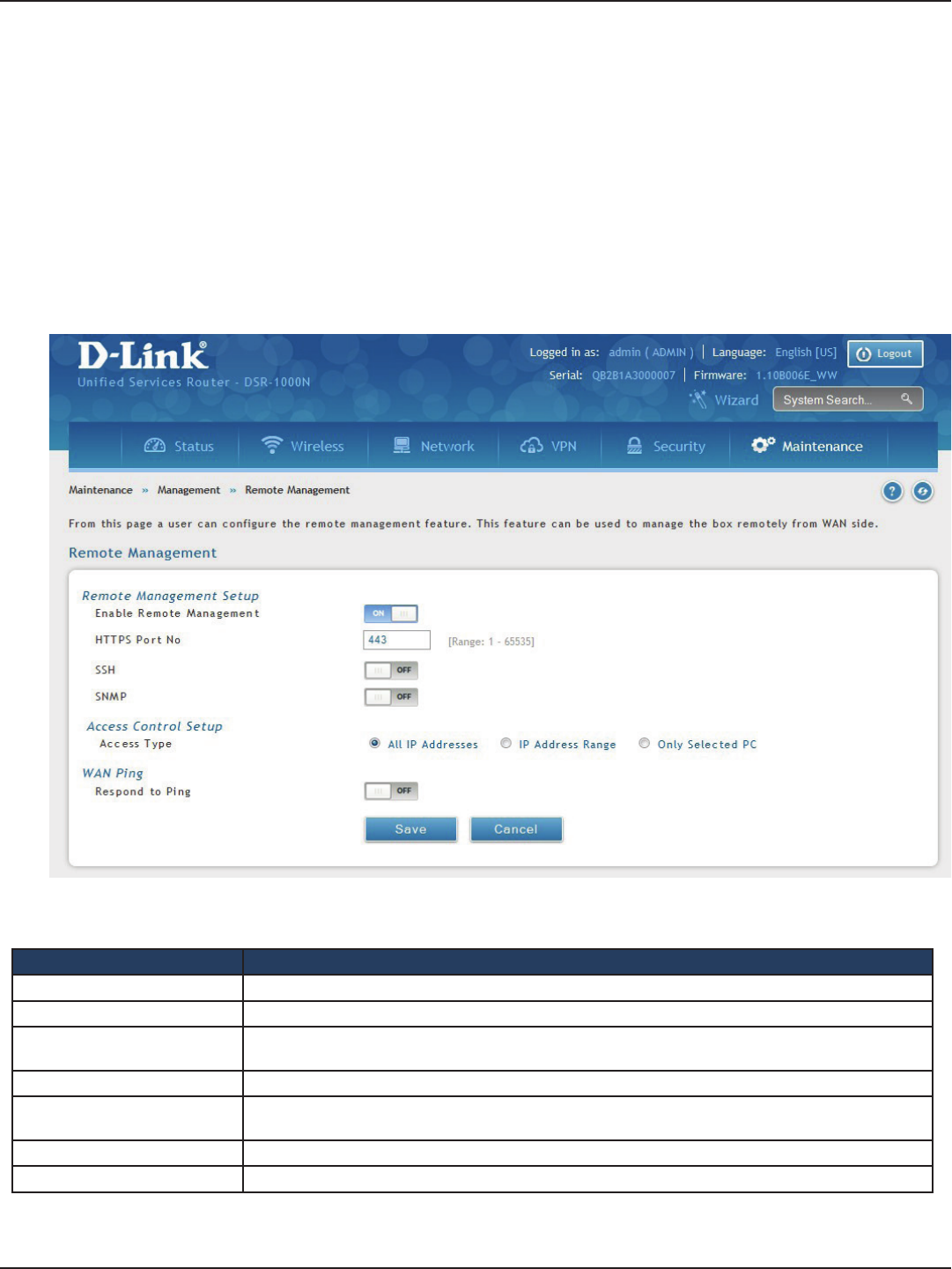
D-Link DSR-Series User Manual 174
Section 9 - Maintenance
Remote Management
Path: Maintenance > Management > Remote Management
Enable this feature to be able to manage the router from a remote location, using HTTPS or Telnet. Both HTTPS
and Telnet access can be restricted to a subset of IP addresses. The router administrator can dene a known PC,
single IP address or range of IP addresses that are allowed to access the GUI with HTTPS. The opened port for SSL
trac can be changed from the default of 443 at the same time as dening the allowed remote management IP
address range.
1. Click Maintenance > Management > Remote Management.
2. Complete the elds from the table below and click Save.
Field Description
Enable Remote Management Toggle to ON to enable remote management.
HTTPS Port No. Enter the port for HTTPS access. The default port is 443.
SSH Toggle ON to enable SSH (Secure Shell) protocol which can be used to access the CLI over the network
from a remote host.
SNMP Toggle to ON to enable SNMP for remote management.
Access Type Select either All IP Addresses, IP Address Range (enter an IP range), or Only Selected PC (enter an IP
address).
Respond to Ping Toggle to ON to allow the router to respond to ping requests from the WAN.
Save Click to save and activate your settings.
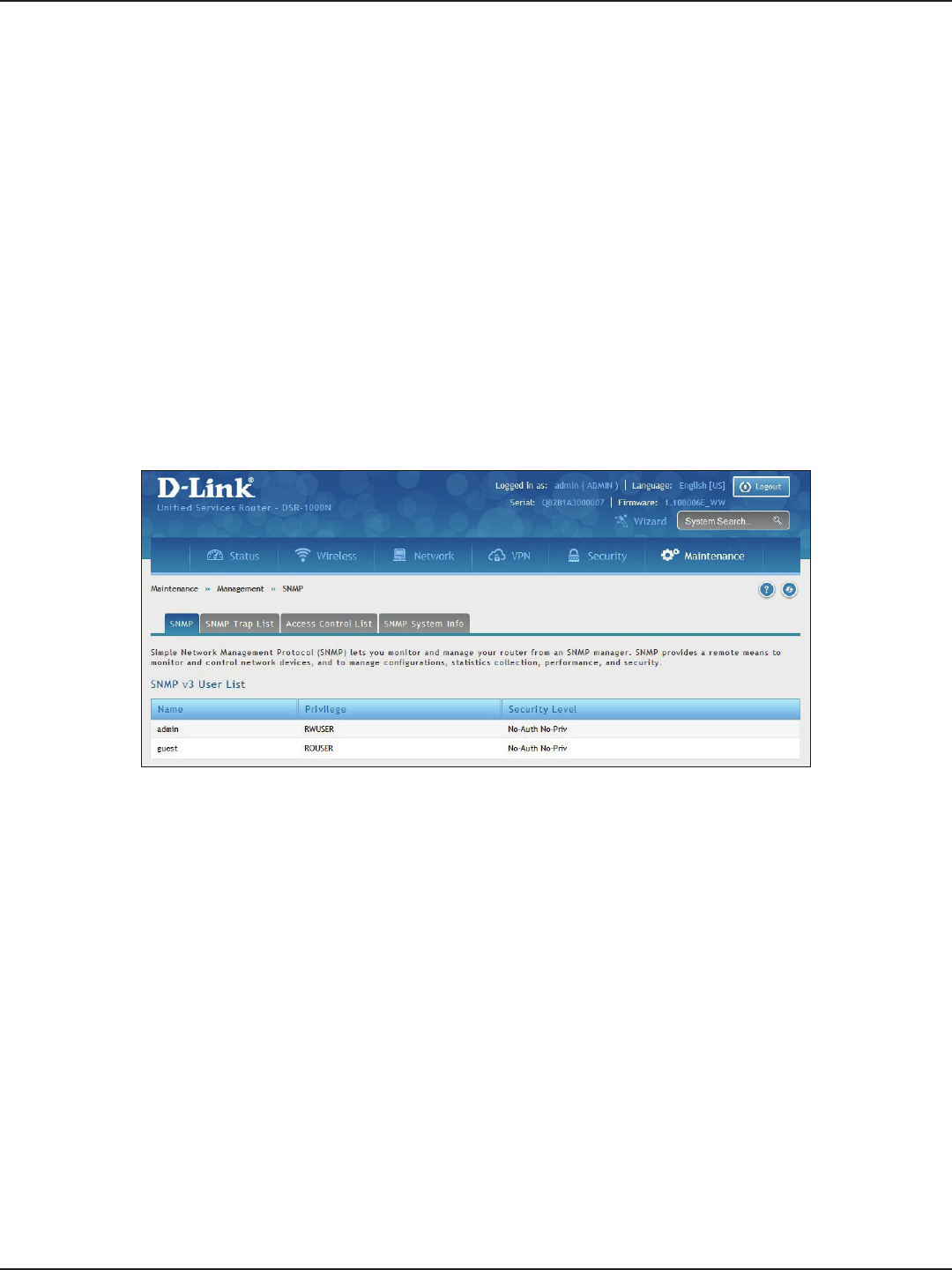
D-Link DSR-Series User Manual 175
Section 9 - Maintenance
SNMP
Path: Maintenance > Management > SNMP
SNMP is an additional management tool that is useful when multiple routers in a network are being managed by
a central Master system. When an external SNMP manager is provided with this router’s Management Information
Base (MIB) le, the manager can update the router’s hierarchal variables to view or update conguration
parameters. The router as a managed device has an SNMP agent that allows the MIB conguration variables
to be accessed by the Master (the SNMP manager). The Access Control List on the router identies managers
in the network that have read-only or read-write SNMP credentials. The Traps List outlines the port over which
notications from this router are provided to the SNMP community (managers) and also the SNMP version (v1,
v2c, v3) for the trap.
1. Click Maintenance > Management > SNMP > SNMP tab.
SNMP User List
2. Right-click a user and select Edit if you want to change the security level.
3. Select the security level from the drop-down list. Select one of the following:
• No-Auth No-Priv: Only requires a user name match for authentication.
• Auth No-Priv: Provides authentication based on the MD5 or SHA algorithms.
• Auth Priv: Provides authentication based on the MD5 or SHA algorithms as well as encryption
privacy with the DES 256-bit standard.
4. Click Save.
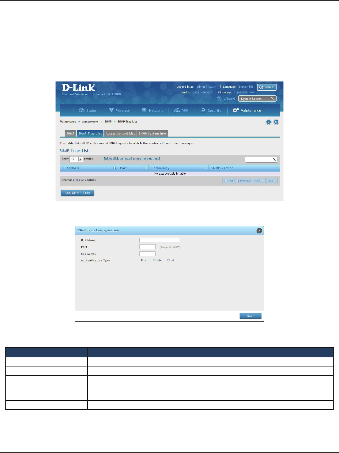
D-Link DSR-Series User Manual 176
Section 9 - Maintenance
Path: Maintenance > Management > SNMP > SNMP Trap List
To create a new SNMP trap:
1. Click Maintenance > Management > SNMP > SNMP Trap List tab.
SNMP Trap List
2. Right-click an entry and select either Edit or Delete. To add a new trap, click Add SNMP Trap.
3. Complete the elds from the table below and click Save.
Field Description
IP Address The IP Address of the SNMP trap agent.
Port The SNMP trap port to which the trap messages will be sent.
Community The community string to which the agent belongs. Most agents are congured to listen for traps in the
Public community.
Authentication Type The SNMP version used by the trap agent. The choices are v1, v2c, or v3.
Save Click to save and activate your settings.
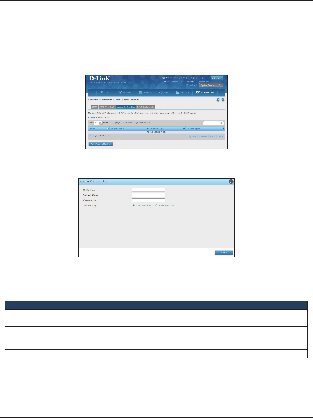
D-Link DSR-Series User Manual 177
Section 9 - Maintenance
Path: Maintenance > Management > SNMP > Access Control List
To edit, delete, or create a new access control entry:
1. Click Maintenance > Management > SNMP > Access Control List tab.
Access Control
2. Right-click an entry and select either Edit or Delete. To add a new trap, click Add Access Control.
3. Complete the elds from the table below and click Save.
Field Description
IP Address The IP Address of the SNMP agent.
Subnet Mask The network mask used to determine the list of allowed SNMP managers.
Community The community string to which the agent belongs. Most agents are congured to listen for traps in the
Public community.
Access Type Access will be either read only (ROcommunity) or read-write (RWcommunity).
Save Click to save and activate your settings.
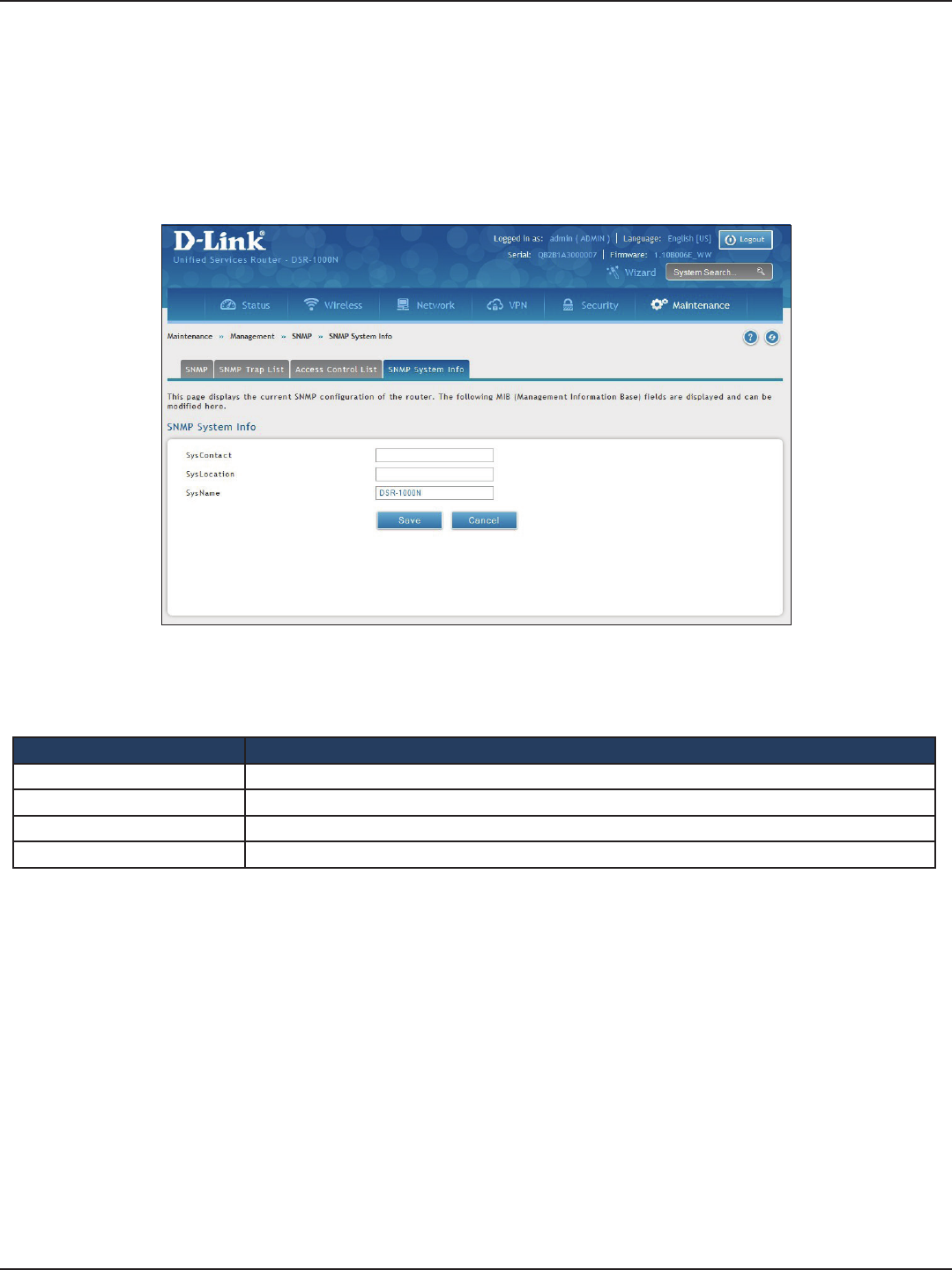
D-Link DSR-Series User Manual 178
Section 9 - Maintenance
Path: Maintenance > Management > SNMP > SNMP System Info
To create a new SNMP trap:
1. Click Maintenance > Management > SNMP > SNMP System Info tab.
SNMP System Info
2. Complete the elds from the table below and click Save.
Field Description
SysContact The name of the contact person for this router. Examples: admin, John Doe.
SysLocation The physical location of the router: Example: Rack #2, 4th Floor.
SysName A name given for easy identication of the router.
Save Click to save and activate your settings.
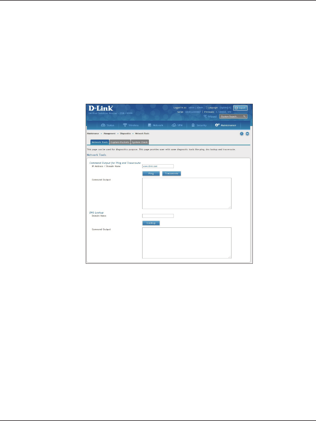
D-Link DSR-Series User Manual 179
Section 9 - Maintenance
Path: Maintenance > Management > Diagnostics > Network Tools
As part of the diagnostics functions on the router, you can ping an IP address or domain name. You can use this
function to test connectivity between the router and another device on the network or the Internet.
1. Click Maintenance > Diagnostics > Network Tools tab.
Diagnostics
Ping an IP Address/Domain Name
2. Under Command Output for Ping and Traceroute, in the IP Address/Domain Name eld, enter an IP
address or domain name.
3. Click Ping. The results will appear in the Command Output display below.

D-Link DSR-Series User Manual 180
Section 9 - Maintenance
Path: Maintenance > Management > Diagnostics > Network Tools
The router provides a Traceroute function that lets you map the network path to a public host. Up to 30 “hops”
between this router and the destination will be displayed.
1. Click Maintenance > Diagnostics > Network Tools tab.
Using Traceroute
2. Under Command Output for Ping and Traceroute, in the IP Address/Domain Name eld, enter an IP
address or domain name.
3. Click Traceroute. The results will appear in the Command Output display below.
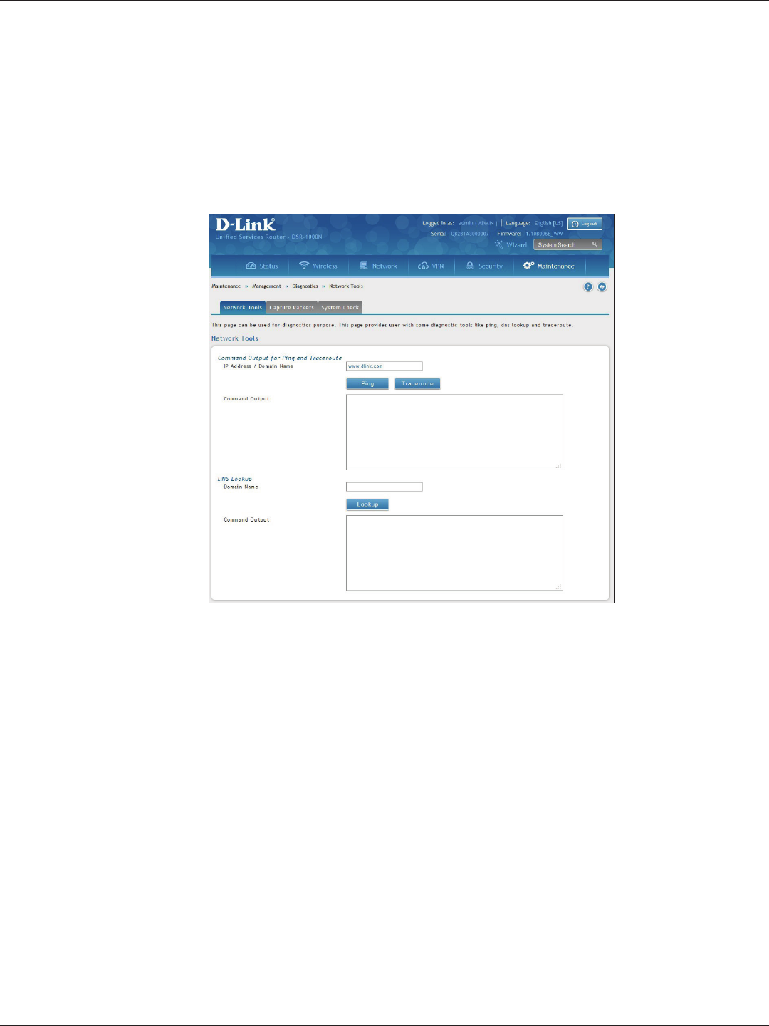
D-Link DSR-Series User Manual 181
Section 9 - Maintenance
Path: Maintenance > Management > Diagnostics > Network Tools
The router provides a DNS lookup function that lets you retrieve the IP address of a Web, FTP, Mail, or any other
server on the Internet.
1. Click Maintenance > Diagnostics > Network Tools tab.
Performing DNS Lookups
2. Under DNS Lookup, in the Domain Name eld, enter an Internet name.
3. Click Lookup. The results will appear in the Command Output display. If the host or domain entry exists,
a response will appear with the IP address. If the message Host Unknown appears, the Internet name
does not exist.
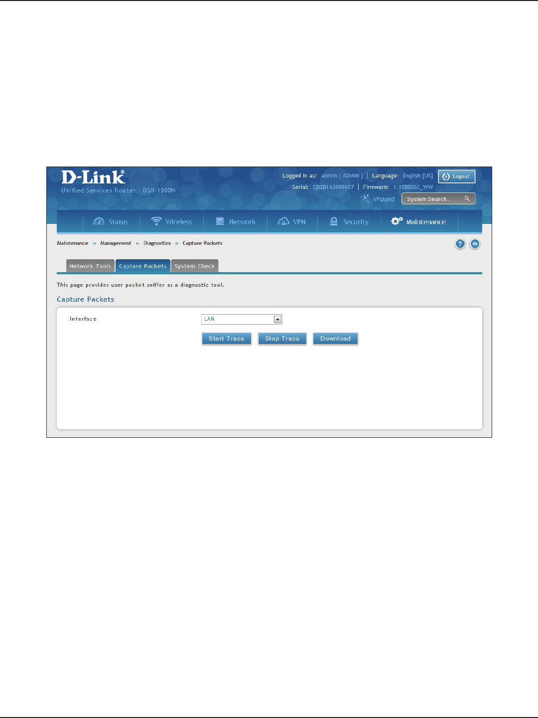
D-Link DSR-Series User Manual 182
Section 9 - Maintenance
Path: Maintenance > Management > Diagnostics > Capture Packets
The router lets you capture all packets that pass through the LAN and WAN interfaces. The packet trace is limited
to 1MB of data per capture session. If the capture le size exceeds 1MB, it is deleted automatically and a new
capture le is created.
1. Click Maintenance > Diagnostics > Capture Packets tab.
Capture Packets
2. Select an interface from the drop-down menu.
3. Click Start Trace. The trace can be downloaded by clicking the Download button, which will
immediately begin the download to the browser’s default download location. To stop the trace click
Stop Trace.
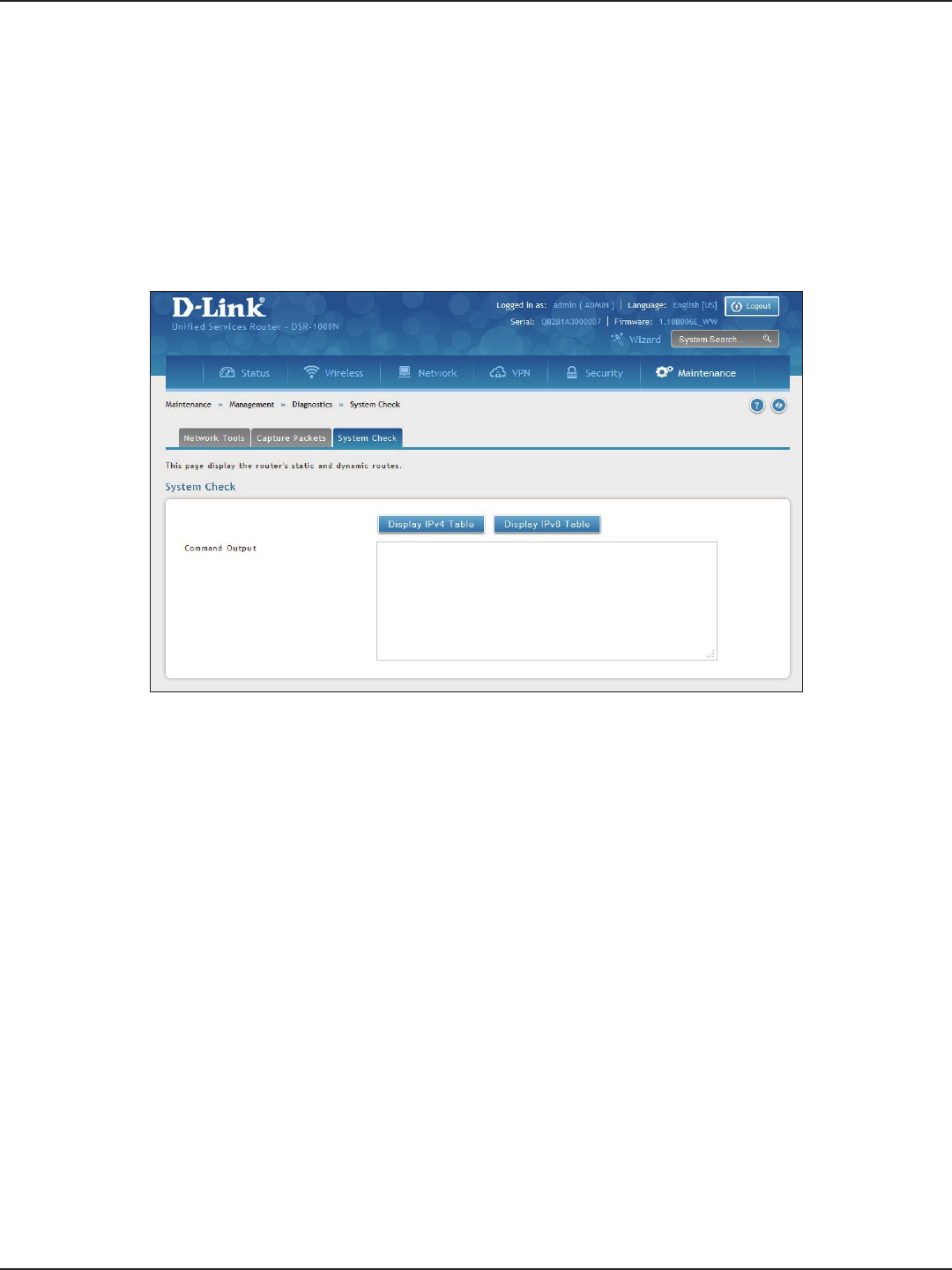
D-Link DSR-Series User Manual 183
Section 9 - Maintenance
Path: Maintenance > Management > Diagnostics > System Check
As part of the diagnostics functions on the router, you can view the static and dynamic routes for both IPv4 and IPv6.
1. Click Maintenance > Diagnostics > System Check tab.
System Check
2. Click Display IPv4 Table or Display IPv6 Table. The results will appear in the Command Output
display.
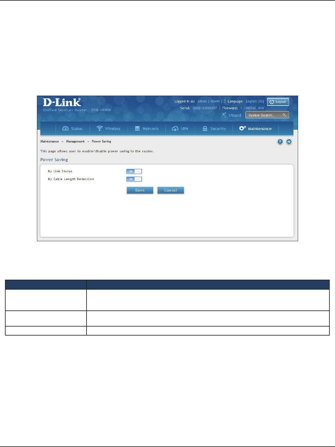
D-Link DSR-Series User Manual 184
Section 9 - Maintenance
Path: Maintenance > Management > Power Saving
The router allows you to adjust the power consumption of the hardware based on your actual usage. The two
“green” options available for your LAN switch are Power Saving by Link Status and Length Detection State.
1. Click Maintenance > Diagnostics > Power Saving.
Power Saving
Field Description
By Link Status
With “Power Saving by Link Status” option toggled to ON, the total power consumption by the LAN switch
is dependent function of on the number of connected ports. The overall current draw when a single port
is connected is less than when all the ports are connected.
By Cable Length Detection With “Length Detection State” option toggled to ON, the overall current supplied to a LAN port is reduced
when a smaller cable length is connected on a LAN port.
Save Click to save and activate your settings.
2. Complete the elds from the table below and click Save.
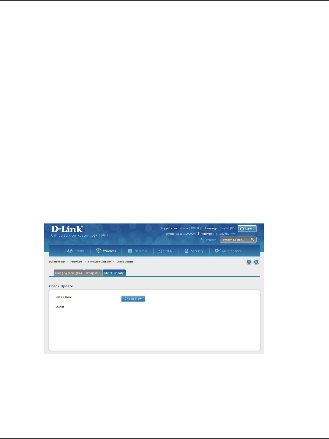
D-Link DSR-Series User Manual 185
Section 9 - Maintenance
You can upgrade to a newer rmware version from the Administration web page. In the Firmware Upgrade
section, to upgrade your rmware, click Browse, locate and select the rmware image on your host, and click
Upgrade. After the new rmware image is validated, the new image is written to ash and the router will
automatically reboot with the new rmware.
Warning: During the rmware upgrade, do NOT try to go online, turn o the DSR, shut down your PC, or interrupt the
process in anyway until the operation is complete. This should take only a minute or so including the reboot process.
Interrupting the upgrade process at specic points when the ash is being written to may corrupt the ash memory
and render the router unusable without a low-level process of restoring the ash rmware (not through the web GUI).
Firmware Upgrade
Path: Maintenance > Firmware > Firmware Upgrade
This router supports an automated notication to determine if a newer rmware version is available for this
router. By clicking the Check Now button in the notication section, the router will check a D-Link server to see
if a newer rmware version for this router is available for download.
To see if a new version is available:
1. Click Maintenance > Firmware > Firmware Upgrade > Check Update tab.
Check Update
2. Click Check Now. If new rmware is available or if you have the most current version a message will
appear under Status.
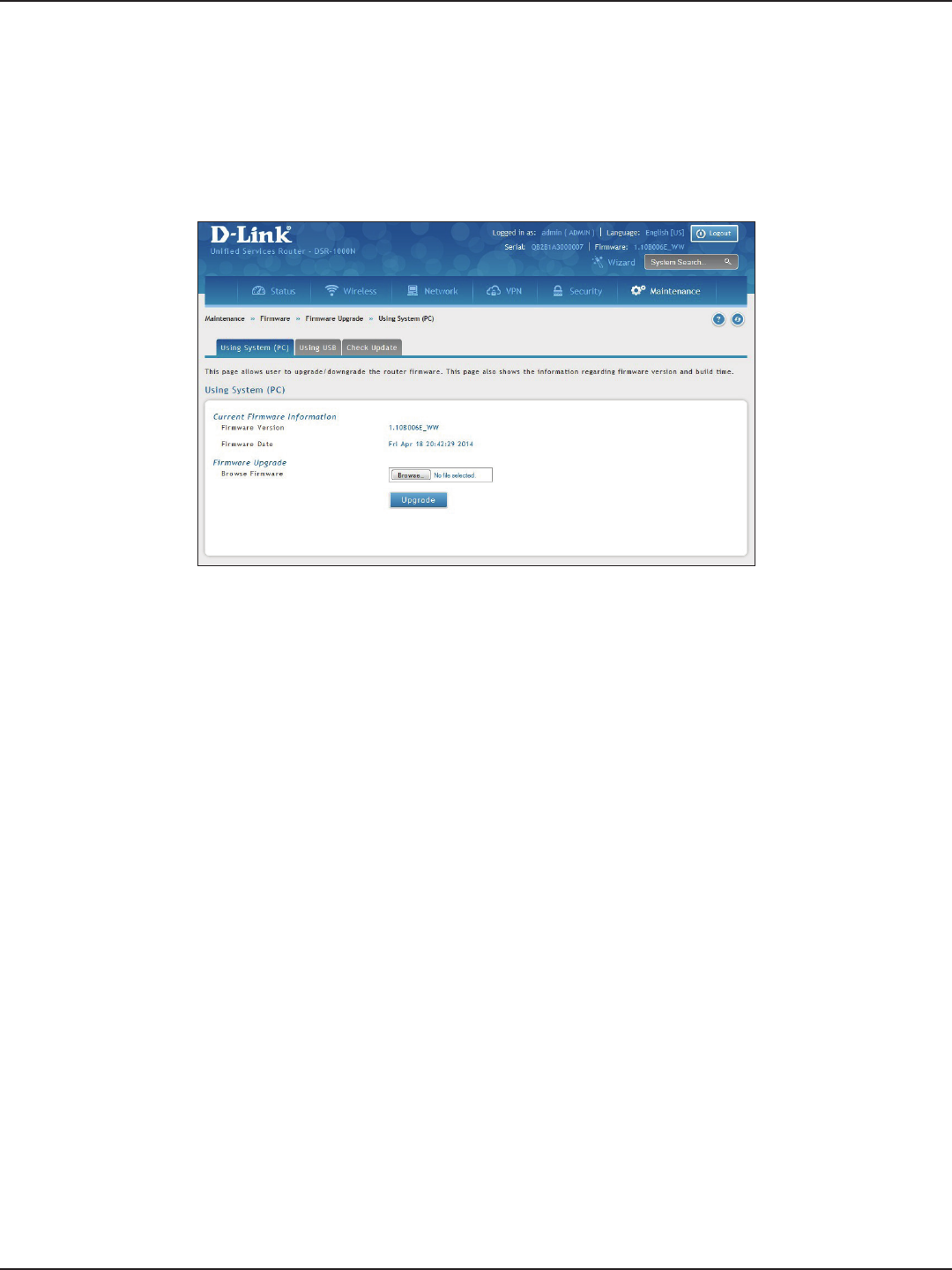
D-Link DSR-Series User Manual 186
Section 9 - Maintenance
To upgrade the rmware from a PC:
1. Download the latest rmware version from the D-Link support website.
2. Once downloaded, log in to the router and click Maintenance > Firmware > Firmware Upgrade >
Using System (PC) tab.
Using PC
3. Click Browse and locate the rmware le you downloaded. Select it and click Open.
4. Click Upgrade.
Note: The upgrade process takes a few minutes. Do not interrupt the upgrade or turn o the router;
otherwise you can damage the rmware. Wait for the upgrade to complete before browsing any sites from
your browser.
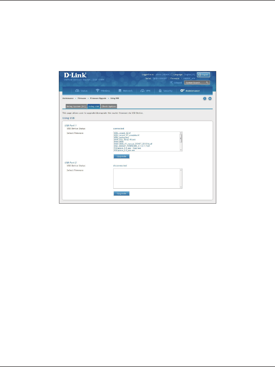
D-Link DSR-Series User Manual 187
Section 9 - Maintenance
Using USB
To upgrade the rmware using a USB thumb drive:
1. Download the latest rmware version from the D-Link support website and copy the le to a USB
thumb drive.
2. Plug the USB thumb drive into a USB port on the router.
3. Log in to the router and click Maintenance > Firmware > Firmware Upgrade > Using USB tab.
4. Select the rmware le from the list and click Upgrade.
Note: The upgrade process takes a few minutes. Do not interrupt the upgrade or turn o the router;
otherwise you can damage the rmware. Wait for the upgrade to complete before browsing any sites from
your browser.
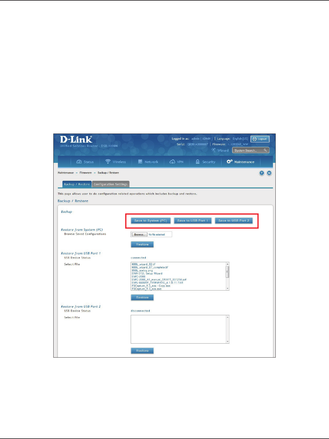
D-Link DSR-Series User Manual 188
Section 9 - Maintenance
Conguration Files
To backup your conguration les:
1. Click Maintenance > Firmware > Backup / Restore tab.
Path: Maintenance > Firmware > Backup / Restore
After you congure the router, you can back up the conguration settings. When you back up the settings, they
are saved as a le. You can then use the le to restore the settings on the same router if something goes wrong
or on a dierent router (must be the same model) that will replace the existing router.
Backup
2. To save the le to your computer, click Save to System (PC). If you have a USB thumb drive connected
to the router, you can click Save to USB Port 1 (or Port 2).
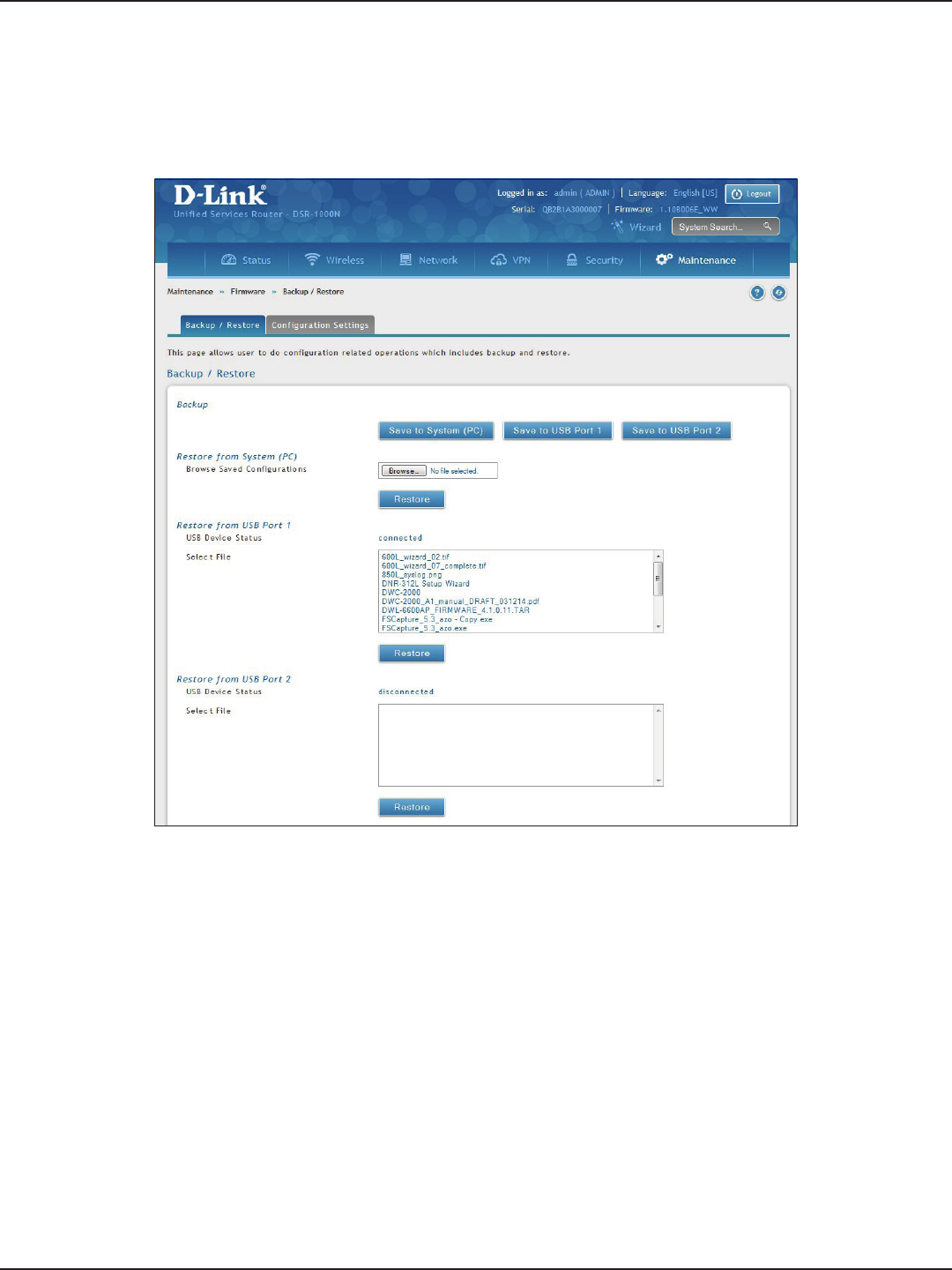
D-Link DSR-Series User Manual 189
Section 9 - Maintenance
To restore your settings from a saved backup le:
1. Click Maintenance > Firmware > Backup / Restore.
2. To restore the le from your computer, click Browse and select the le. Click Open and then click
Restore.
To restore the le from a USB thumb drive, select the le in the list under the corresponding USB port
and click Restore.
Restore

D-Link DSR-Series User Manual 190
Section 9 - Maintenance
If there is a USB storage device currently plugged in to the router, you can enable auto-backup. The snapshot of
current conguration settings will be updated on the USB storage device and overwrite any les with the same
lename (i.e., if there was an earlier conguration backup done to this location).
1. Click Maintenance > Firmware > Backup / Restore > Conguration Settings tab.
Conguration Settings
2. Toggle Backup Conguration to USB Automatically to ON to automatically save your conguration
settings to a le on your USB storage device.
3. Toggle Encrypt Conguration File to ON to encrypt the conguration le. This will ensure condential
information like system username/passwords are not available for view by unauthorized sources.
Enabling this option will apply to conguration les backed up on the host as well as a USB drive.
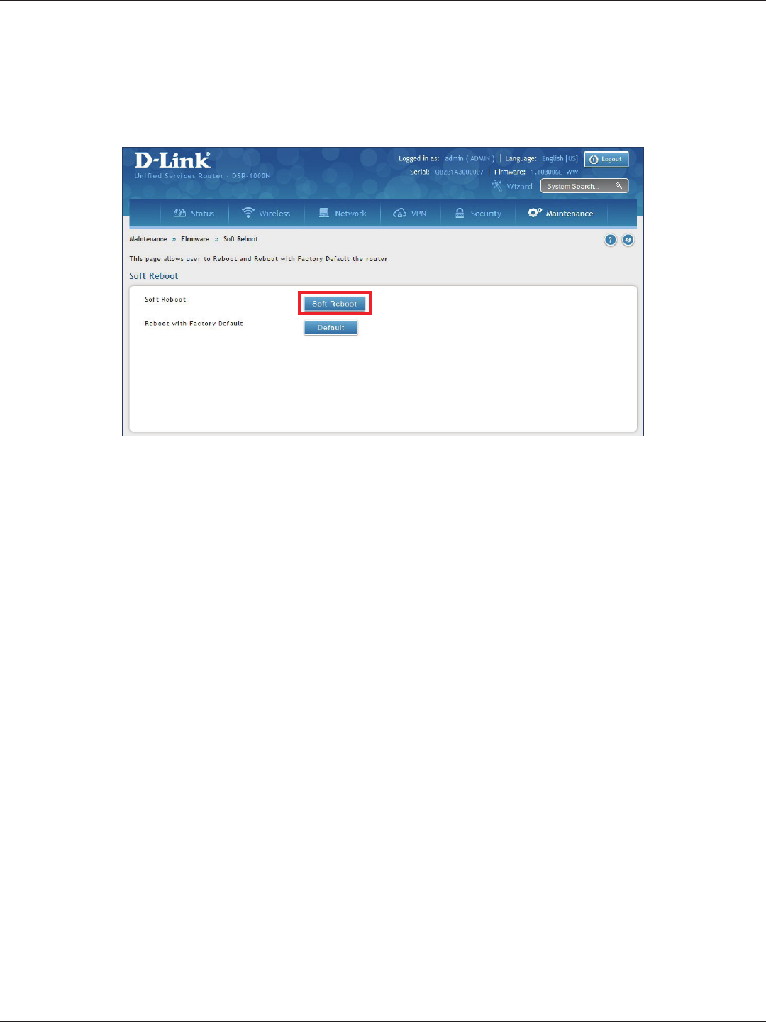
D-Link DSR-Series User Manual 191
Section 9 - Maintenance
Soft Reboot
Performing a soft reboot simply performs a power cycle.
1. Click Maintenance > Firmware > Soft Reboot.
2. Click Soft Reboot. The router will power cycle.
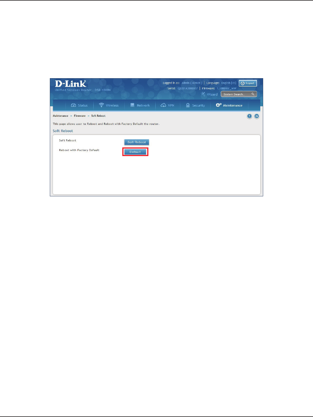
D-Link DSR-Series User Manual 192
Section 9 - Maintenance
Reset to Factory Default Settings
If you reset the router to its factory default settings, it returns to the state when it was new — all changes you
made to the default conguration are lost. Examples of settings that get restored include critical things you need
to get online, such as login password, SSID, IP addresses, and wireless security keys.
1. Click Maintenance > Firmware > Soft Reboot.
2. Click Default. The router will power cycle and reset all settings to the default values.
Note: After restoring to the factory default settings, the router’s default LAN IP address is 192.168.10.1, the
default login user name is ‘admin’, and the default login password is ‘admin’.
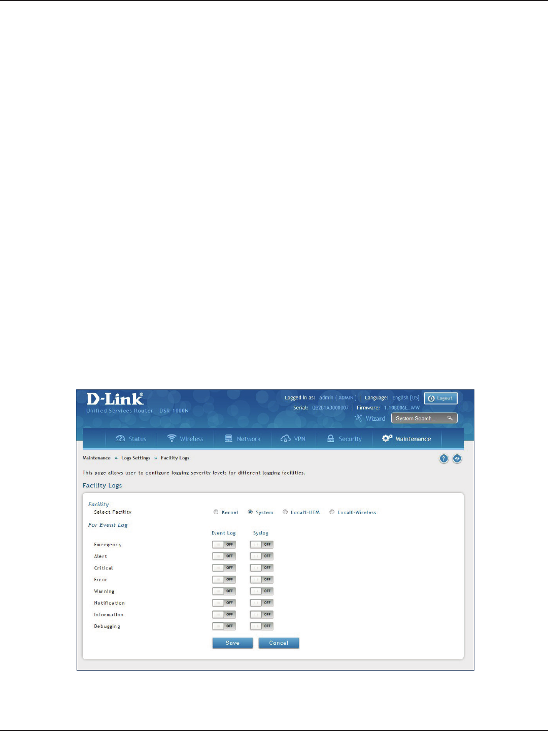
D-Link DSR-Series User Manual 193
Section 9 - Maintenance
Log Settings
The router allows you capture log messages. You can monitor the type of trac that goes through the router
and be notied of potential attacks or errors when they are detected by the controller. The following sections
describe the log conguration settings and the ways you can access these logs.
Dening What to Log
Path: Maintenance > Logs Settings > Log Facilities
The Facility Logs page lets you determine the granularity of logs to receive from the wireless controller. Select
one of the following facilities:
• Kernel: The Linux kernel. Log messages that correspond to this facility would correspond to
trac through the rewall or network stack.
• System: Application and management-level features available on this router for managing the
unit.
• Local1-UTM: This facility corresponds to IPS (Intrusion Prevention System) which helps in
detecting malicious intrusion attempts from the WAN.
• Local0-Wireless: This facility corresponds to the 802.11 driver used for providing AP
functionality to your network.
1. Click Maintenance > Log Settings > Log Facilities.
2. Select the facility and then toggle ON which events you want to log and click Save.

D-Link DSR-Series User Manual 194
Section 9 - Maintenance
For each facility, the following events (in order of severity) can be logged:
• Emergency: system is unusable
• Alert: action must be taken immediately
• Critical: critical conditions
• Error: error conditions
• Warning: warning conditions
• Notication: normal but signicant condition
• Information: informational
• Debugging: debug-level messages
When a particular severity level is selected, all events with severity equal to and greater than the chosen severity
are captured. For example if you have congured CRITICAL level logging for the Wireless facility, then 802.11
logs with severities CRITICAL, ALERT, and EMERGENCY are logged.
The display for logging can be customized based on whether the logs are sent to the Event Log viewer in the
web management interface (the Event Log viewer is in the Status > System Information > All Logs > Current
Logs) or a remote Syslog server for later review. E-mail logs, discussed in a subsequent section, follow the same
conguration as logs congured for a Syslog server.

D-Link DSR-Series User Manual 195
Section 9 - Maintenance
Routing Logs
Path: Maintenance > Logs Settings > Routing Logs
Trac can be tracked based on whether the packet was accepted or dropped by the rewall. Denial of service
attacks, general attack information, login attempts, dropped packets, and similar events can be captured for
review.
Note: Enabling logging options may generate a signicant volume of log messages and is recommended for
debugging purposes only.
Trac through each network segment (LAN, WAN, DMZ) can be tracked based on whether the packet was
accepted or dropped by the rewall.
Accepted Packets are those that were successfully transferred through the corresponding network segment (i.e.,
LAN to WAN). This option is particularly useful when the Default Outbound Policy is “Block Always” so you can
monitor trac that is passed through the rewall.
Dropped Packets are packets that were intentionally blocked from being transferred through the corresponding
network segment. This option is useful when the Default Outbound Policy is “Allow Always”.
1. Click Maintenance > Log Settings > Routing Logs.
2. Toggle which events you want to log to ON and click Save.
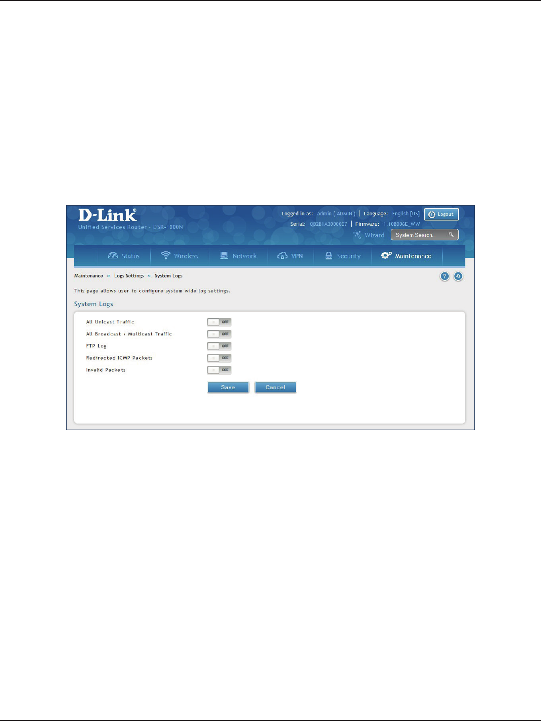
D-Link DSR-Series User Manual 196
Section 9 - Maintenance
System Logs
Path: Maintenance > Logs Settings > System Logs
In addition to network segment logging, unicast and multicast trac can be logged. Unicast packets have a
single destination on the network, whereas broadcast (or multicast) packets are sent to all possible destinations
simultaneously. One other useful log control is to log packets that are dropped due to congured bandwidth
proles over a particular interface. This data will indicate to the admin whether the bandwidth prole has to be
modied to account for the desired internet trac of LAN users.
1. Click Maintenance > Log Settings > System Logs.
2. Toggle which events you want to log to ON and click Save.
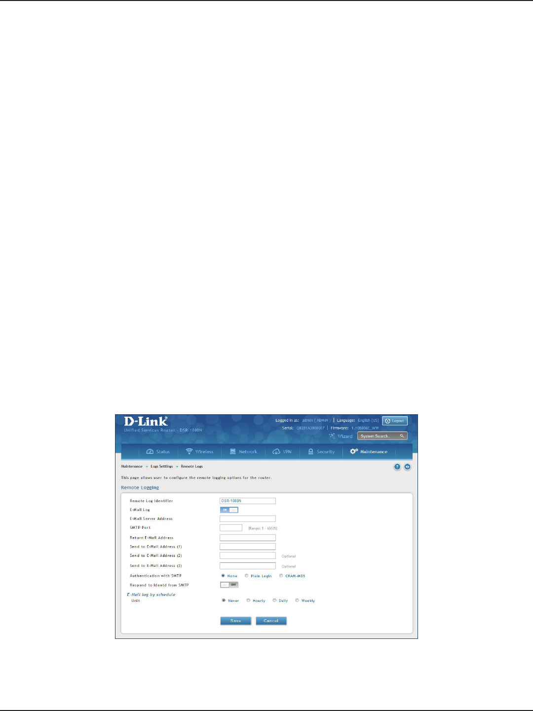
D-Link DSR-Series User Manual 197
Section 9 - Maintenance
Remote Logs
Path: Maintenance > Logs Settings > Remote Logs
Once you have congured the type of logs that you want the router to collect, they can be sent to either a Syslog
server or an E-Mail address. For remote logging a key conguration eld is the Remote Log Identier. Every
logged message will contain the congured prex of the Remote Log Identier, so that syslog servers or email
addresses that receive logs from more than one router can sort for the relevant device’s logs.
Once you enable the option to e-mail logs, enter the e-mail server’s address (IP address or FQDN) of the SMTP
server. The router will connect to this server when sending e-mails out to the congured addresses. The SMTP
port and return e-mail addresses are required elds to allow the router to package the logs and send a valid e-mail
that is accepted by one of the congured “send-to” addresses. Up to three e-mail addresses can be congured as
log recipients.
In order to establish a connection with the congured SMTP port and server, dene the server’s authentication
requirements. The router supports Login Plain (no encryption) or CRAM-MD5 (encrypted) for the username and
password data to be sent to the SMTP server. Authentication can be disabled if the server does not have this
requirement. In some cases the SMTP server may send out IDENT requests, and this router can have this response
option enabled as needed.
Once the e-mail server and recipient details are dened you can determine when the router should send out
logs. E-mail logs can be sent out based on a dened schedule by rst choosing the unit (i.e., the frequency) of
sending logs: Hourly, Daily, or Weekly. Selecting Never will disable log e-mails but will preserve the e-mail server
settings.
1. Click Maintenance > Log Settings > Remote Logs.
2. Complete the elds from the table on the next page and click Save.

D-Link DSR-Series User Manual 198
Section 9 - Maintenance
Field Description
Remote Log Identier Enter a prex used to identify the source of the message. This identier is prexed to both e-mail and
Syslog messages.
E-Mail Log Toggle to ON to enable E-Mail logs.
E-Mail Server Address Enter the IP address or network address of the SMTP server. The router will connect to this server to send
e-mail logs when required. The SMTP server must be operational for e-mail notications to be received.
SMTP Port Enter the SMTP port of the e-mail server.
Return E-Mail Address Enter the e-mail address where replies from the SMTP server are to be sent (required for failure messages).
Send to E-Mail Address (1-3) Enter up to three e-mail addresses where logs and alerts are to be sent.
Authentication with SMTP
Select an authentication if the SMTP server requires authentication before accepting connections. Choices
are:
• None: No authentication is used. The User Name and Password elds are not available.
• Login Plain: Authentication used to log in using Base64-encoded passwords over non-encrypted
communication session. Base64-encoded passwords oer no cryptographic protection, making
them vulnerable.
• CRAM-MD5: A challenge-response authentication mechanism dened in RFC 2195 based on the
HMAC-MD5 MAC algorithm. CRAM-MD5 oers a higher level of authentication than Login Plain.
User Name If Authentication with SMTP is set to Login Plain or CRAM-MD5, enter the user name to be used for
authentication.
Password If Authentication with SMTP is set to Login Plain or CRAM-MD5, enter the case-sensitive password to be
used for authentication.
Respond to identd from SMTP Toggle to ON to have the router respond to IDENT requests from the SMTP server.
Unit
Select the period of time that you need to send the log. This option is useful when you do not want to
receive logs by e-mail, but want to keep e-mail options congured, so you can use the Send Log function
Event Log viewer pages. Choices are:
• Never: Disable sending of logs.
• Hourly: Send logs every hour.
• Daily: Send logs every day at the Time specied.
• Weekly: Send logs weekly, at the Day and Time specied.
Day If Unit is set to Weekly, select the day of the week when logs will be sent.
Time If Unit is set to Daily or Weekly, select the time when logs will be sent.
Save Click to save and activate your settings.
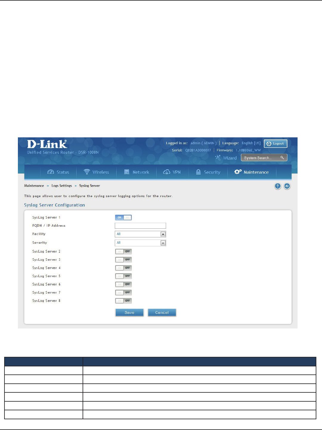
D-Link DSR-Series User Manual 199
Section 9 - Maintenance
Syslog Server
Path: Maintenance > Logs Settings > Syslog Server
An external Syslog server is often used to collect and store logs from the router. This remote device typically has
less memory constraints than the local Event Viewer on the router. Therefore, a number of logs can be collected
over a sustained period. This is useful for debugging network issues or to monitor router trac over a long
duration.
The router supports eight concurrent Syslog servers. Each server can be congured to receive dierent log
facility messages of varying severity using the Remote Logs page. This page also lets you send conguration
logs to three email recipients.
1. Click Maintenance > Log Settings > Syslog Server.
2. Complete the elds from the table on the next page and click Save.
Field Description
Syslog Server 1 Toggle to ON to setup a Syslog server.
FQDN / IP Address Enter the IP address or Internet Name of the Syslog server.
Facility Select which facility you want to log. Refer to “Dening What to Log” on page 193 for denitions.
Severity Select the severity level you want to log. Refer to “Dening What to Log” on page 193 for denitions.
Syslog Server 2-8 Toggle to ON to setup another Syslog server. Repeat the elds above for each server you want to setup.
Save Click to save and activate your settings.
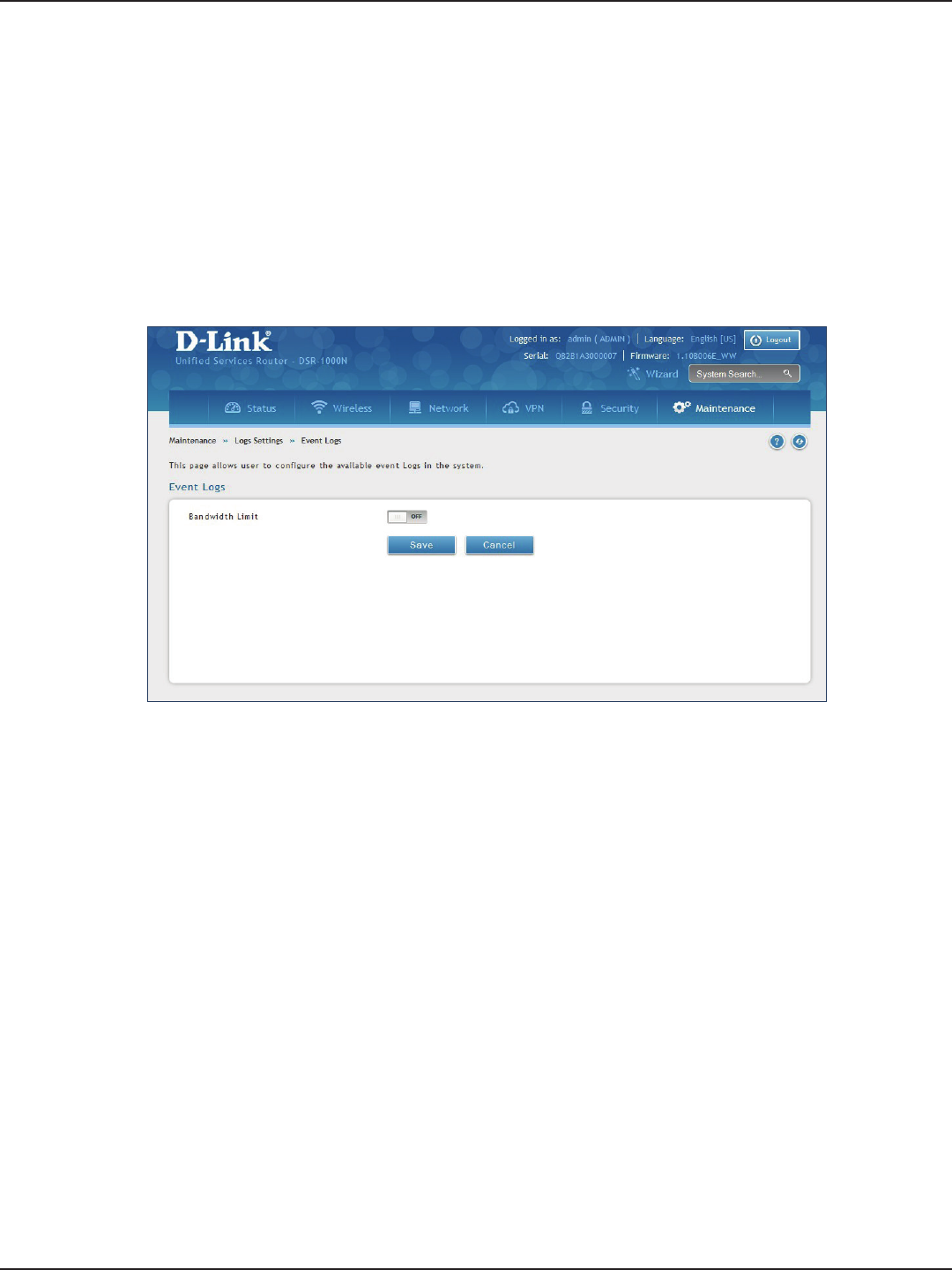
D-Link DSR-Series User Manual 200
Section 9 - Maintenance
Event Logs
Path: Maintenance > Logs Settings > Event Logs
The router’s web management interface displays congured log messages from the Status menu. When trac
through or to the router matches settings in the Facility Logs page or Routing Logs page, the corresponding log
message will appear in this window with a timestamp.
1. Click Maintenance > Log Settings > Event Logs.
2. Toggle to ON and click Save.
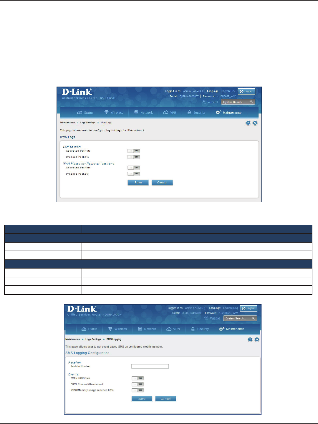
D-Link DSR-Series User Manual 201
Section 9 - Maintenance
IPv6 Logs
Path: Maintenance > Logs Settings > IPv6 Logs
This page allows you to congure what IPv6 events you want to log.
1. Click Maintenance > Log Settings > IPv6 Logs.
2. Complete the elds from the table below and click Save.
Field Description
LAN to WAN
Accepted Packets Toggle to ON to log accepted packets.
Dropped Packets Toggle to ON to log dropped packets.
WAN
Accepted Packets Toggle to ON to log accepted packets.
Dropped Packets Toggle to ON to log dropped packets.
Save Click to save and activate your settings.

D-Link DSR-Series User Manual 202
Section 9 - Maintenance
SMS Logging
Path: Maintenance > Logs Settings > SMS logging
This page allows the user to get events based SMS on congured mobile number.
1. Click Maintenance > Log Settings >SMS logging
2. Enter the phone number and toggle On for events from the table below
3. Click Save
Field Description
Mobile Number Enter a valid mobile number to receive SMS message
WAN Up/Down Toggle to On to receive SMS based on WAN UP/Down event.
VPN Connect/Disconnect Toggle to On to receive SMS whenever VPN tunnel connects or disconnects.
CPU/Memory usage reaches
80% Toggle to On to receive SMS whenever CPU/Memory utilization reaches to 80%.
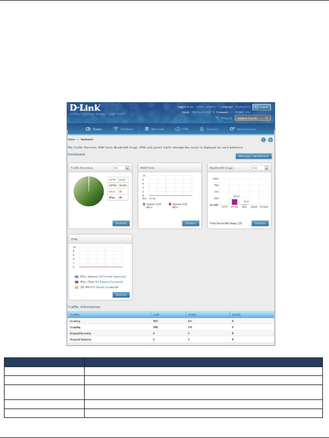
D-Link DSR-Series User Manual 203
Section 10 - Status and Statistics
Status and Statistics
Path: Status > Dashboard
The router provides a dashboard that displays about the resources the system is using. The dashboard page is
organized into the following sections:
Field Description
Trac Overview Displays a chart of trac overview by service for each interface.
WAN Ports Displays a chart of trac overview by bandwidth and packet information for WAN trac.
Bandwidth Usage Displays bandwidth usage by network segment such as WAN or LAN. The data is broken into by applications
service such as HTTP, HTTPS, DNS, SNMP, and others.
VPNs Displays a chart of VPN trac by bandwidth and number of tunnels.
Trac Information Displays a grid of trac statistics for each interface.
Dashboard
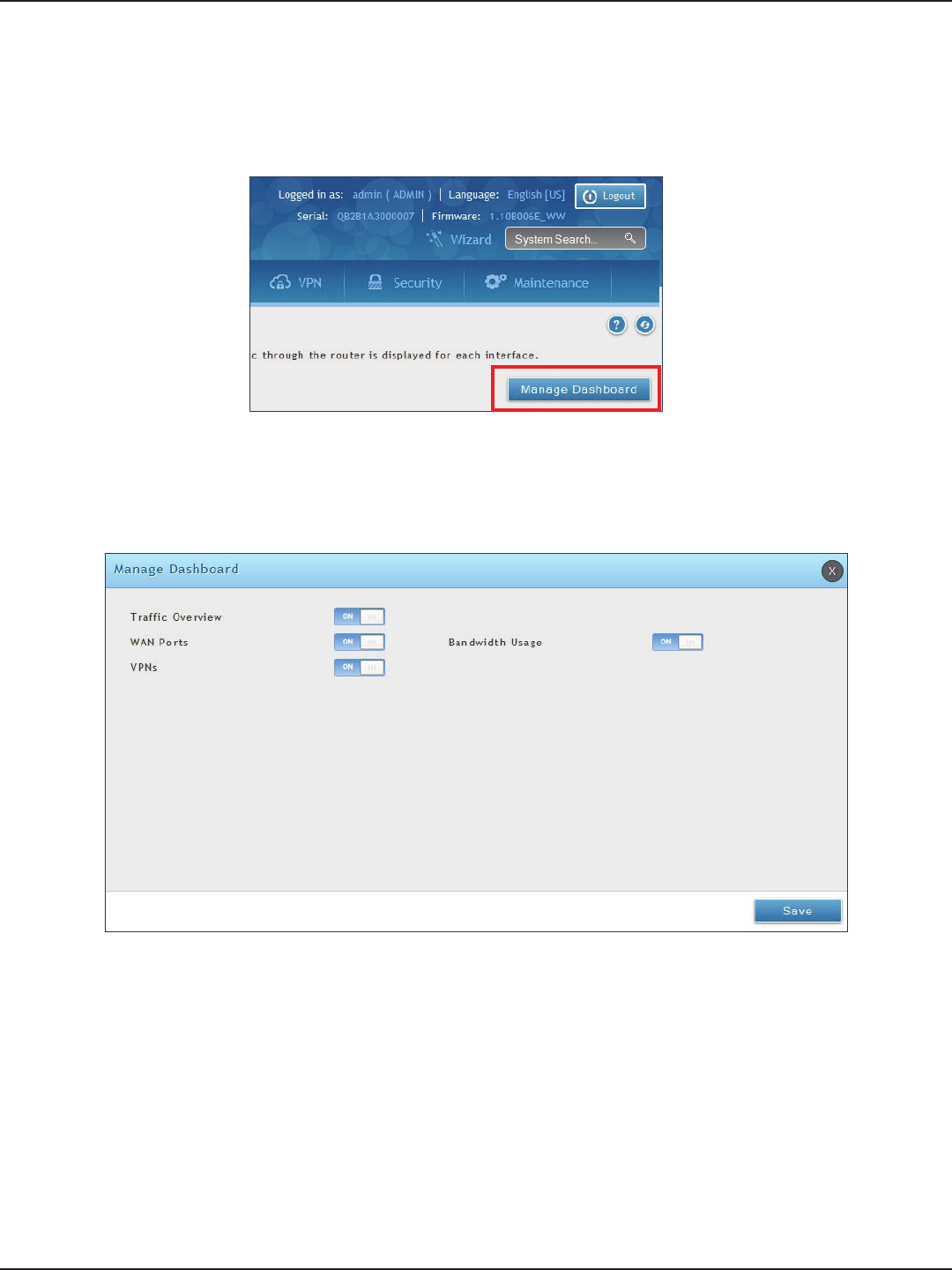
D-Link DSR-Series User Manual 204
Section 10 - Status and Statistics
Manage Dashboard
To manage the dashboard:
1. Click on the Manage Dashboard button.
2. The following window will pop out and allow you to enable or disable the overview panels shown on
the dashboard. Toggle the panel to ON or OFF and click Save.
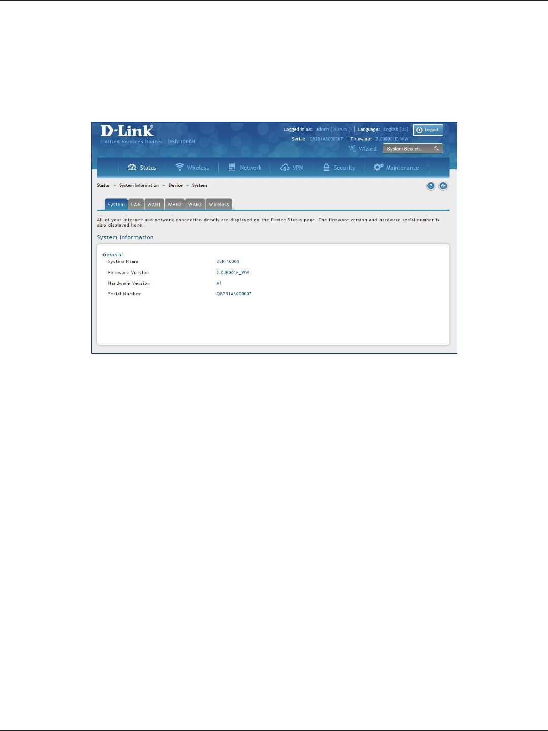
D-Link DSR-Series User Manual 205
Section 10 - Status and Statistics
System
Path: Status > System Information > Device > System
The System Info page displays the current system name, rmware version, hardware version, and serial number.
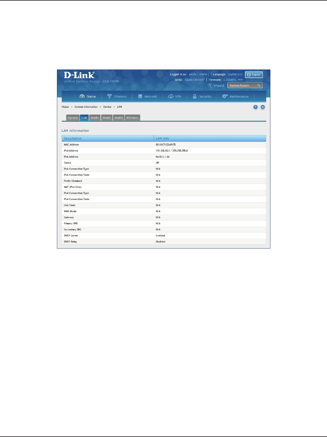
D-Link DSR-Series User Manual 206
Section 10 - Status and Statistics
LAN Info
Path: Status > System Information > Device > LAN
The LAN Information page summarizes the LAN settings including MAC address, IP address, and link state.
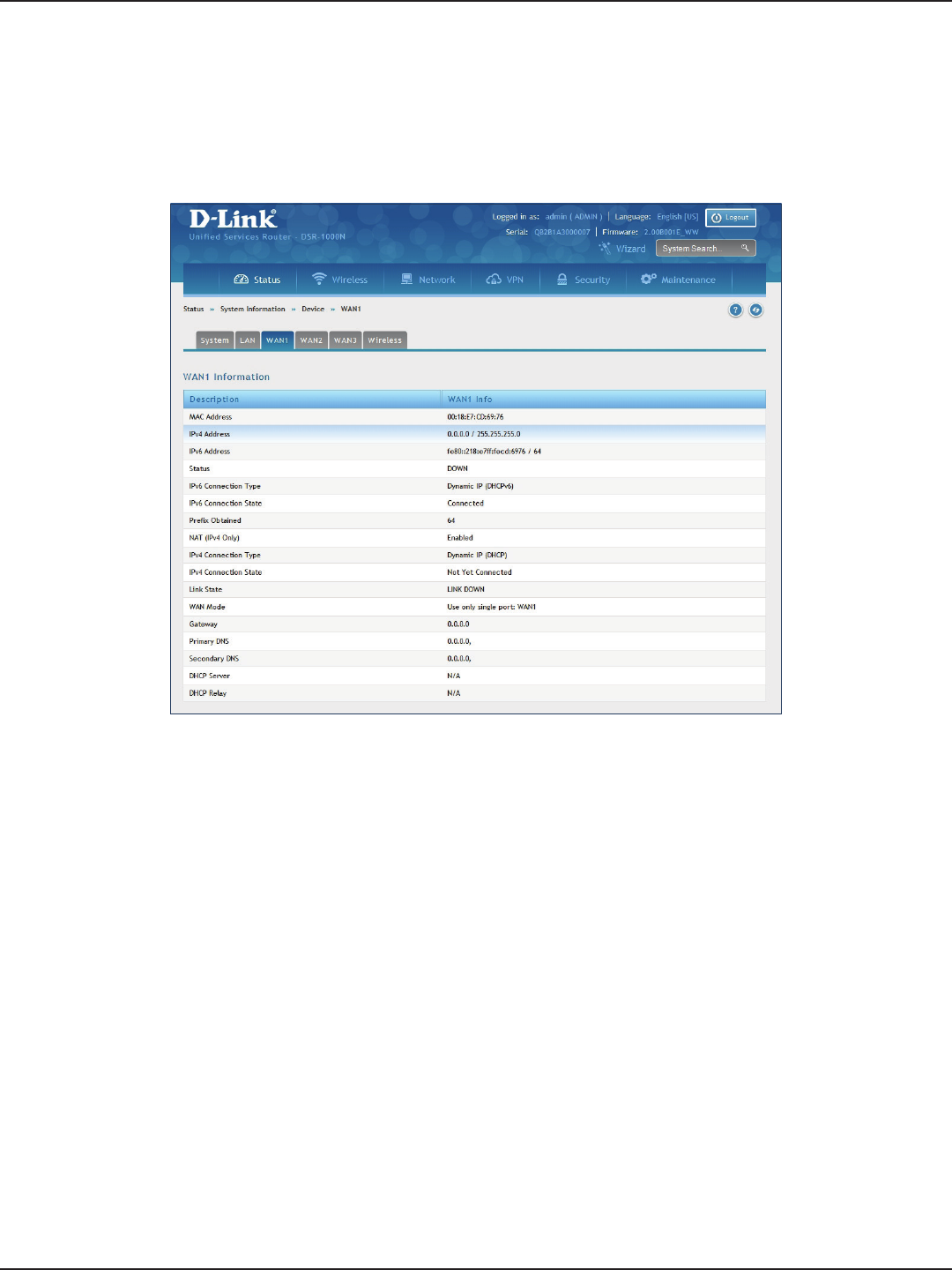
D-Link DSR-Series User Manual 207
Section 10 - Status and Statistics
WAN1
Path: Status > System Information > Device > WAN1
The WAN1 Information page summarizes the WAN1 port settings.
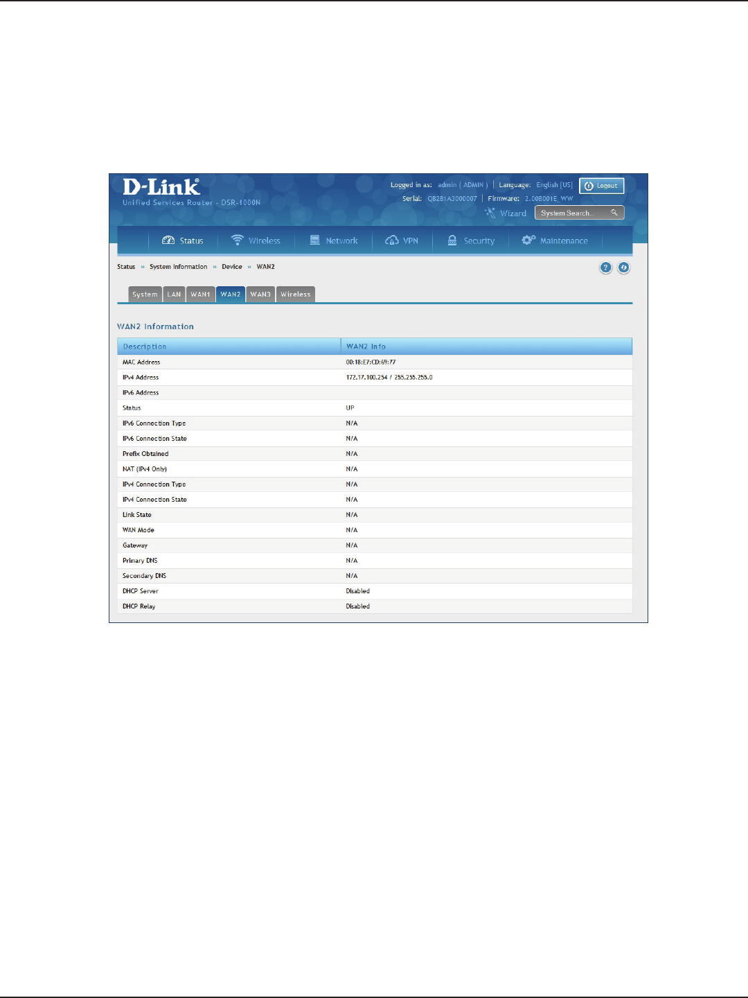
D-Link DSR-Series User Manual 208
Section 10 - Status and Statistics
WAN2
Path: Status > System Information > Device > WAN2
The WAN2 Information page summarizes the WAN2 port settings.
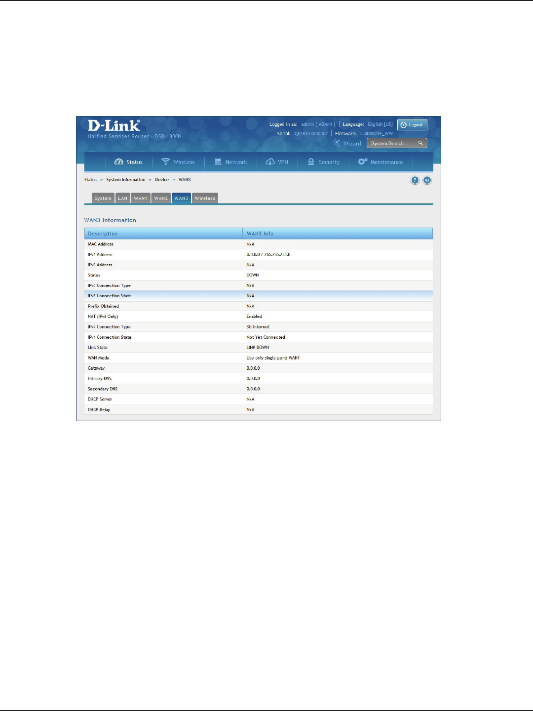
D-Link DSR-Series User Manual 209
Section 10 - Status and Statistics
WAN3
Path: Status > System Information > Device > WAN3
The WAN3 Information page summarizes the WAN3 settings.
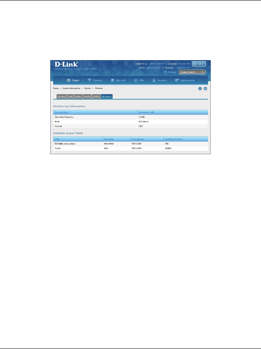
D-Link DSR-Series User Manual 210
Section 10 - Status and Statistics
Wireless
Path: Status > System Information > Device > Wireless
The Wireless Information page displays trac statistics for each enabled access point. This page will give a
snapshot of how much trac is being transmitted over each wireless link.
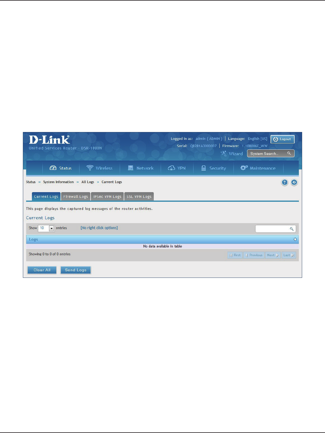
D-Link DSR-Series User Manual 211
Section 10 - Status and Statistics
All Logs
Current Logs
Path: Status > System Information > All Logs > Current Logs
The Current Logs window displays congured log messages from the router as they appear. Each log will appear
with a timestamp as determined by the router's congured time. If remote logging such as a Syslog server or
e-mail logging is congured, the same logs are sent to the remote interface while being displayed here.
Click Clear All to remove all entries in the Display Logs screen or click Send Logs to send all logs in the Current
Logs screen to precongured e-mail recipients.
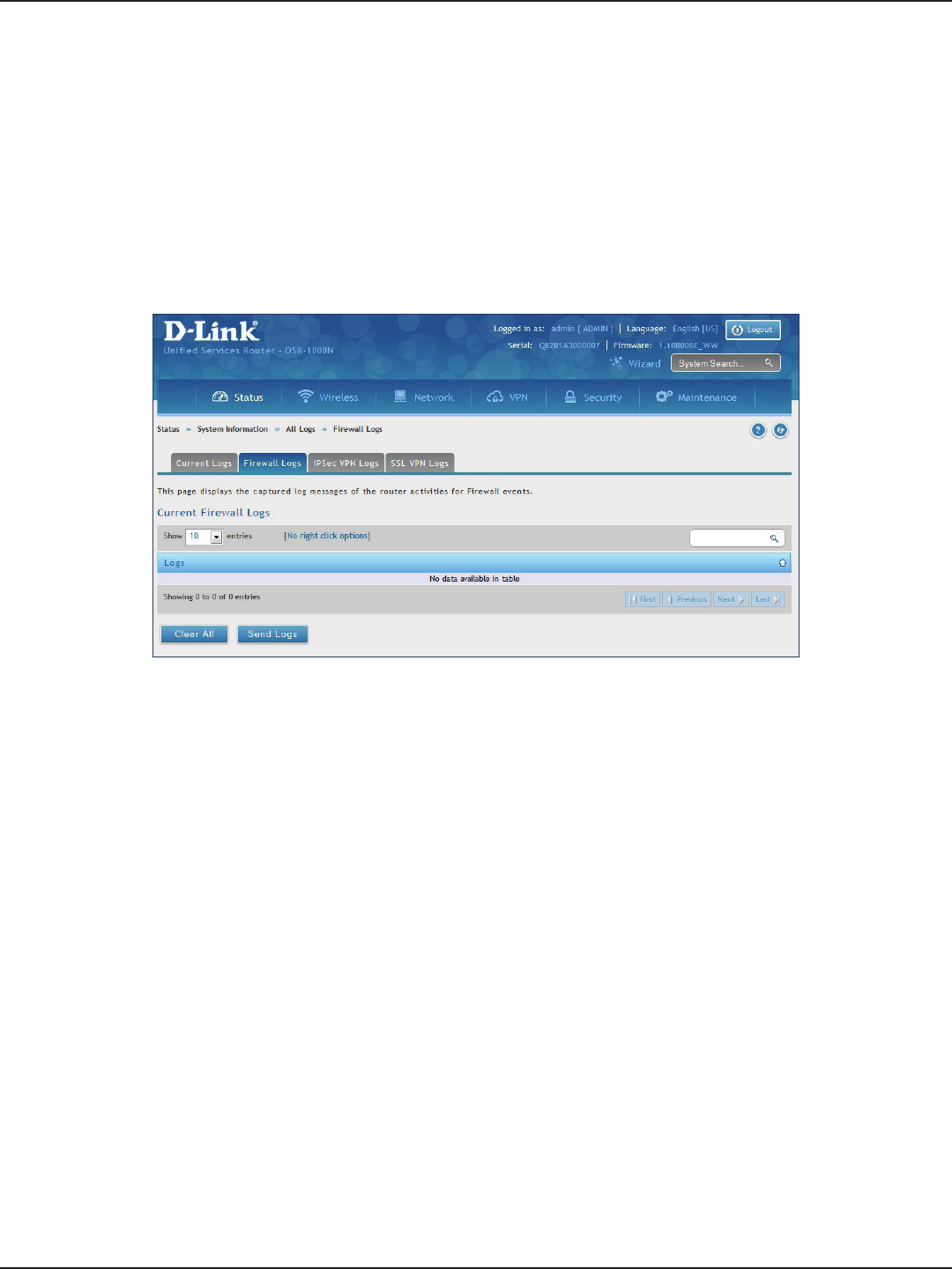
D-Link DSR-Series User Manual 212
Section 10 - Status and Statistics
Firewall Logs
Path: Status > System Information > All Logs > Firewall Logs
The Firewall Logs window displays congured rewall event messages from the router as they appear. Each log
will appear with a timestamp as determined by the router's congured time.
Click Clear All to remove all entries in the Display Logs screen or click Send Logs to send all logs in the Current
Logs screen to precongured e-mail recipients.

D-Link DSR-Series User Manual 213
Section 10 - Status and Statistics
IPSec VPN Logs
Path: Status > System Information > All Logs > IPSec VPN Logs
The IPSec VPN Logs window displays IPSec VPN event messages from the router as they appear. Each log will
appear with a timestamp as determined by the router's congured time.
Click Clear All to remove all entries in the Display Logs screen or click Send Logs to send all logs in the Current
Logs screen to precongured e-mail recipients.
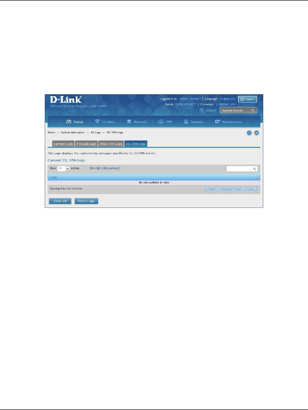
D-Link DSR-Series User Manual 214
Section 10 - Status and Statistics
SSL VPN Logs
Path: Status > System Information > All Logs > SSL VPN Logs
The SSL VPN Logs window displays SSL VPN event messages from the router as they appear. Each log will appear
with a timestamp as determined by the router's congured time.
Click Clear All to remove all entries in the Display Logs screen or click Send Logs to send all logs in the Current
Logs screen to precongured e-mail recipients.
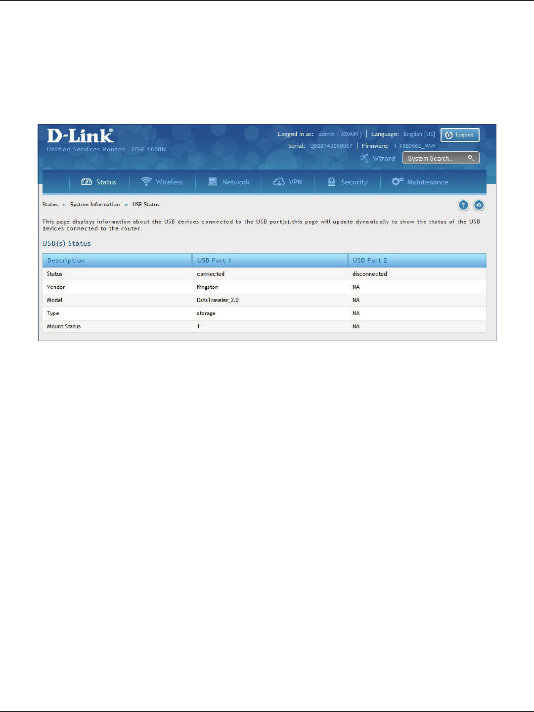
D-Link DSR-Series User Manual 215
Section 10 - Status and Statistics
USB Status
Path: Status > System Information > USB Status
The USB Status page summarizes the USB devices connected to the router. You may connect USB printer and
USB storage device directly to the router.
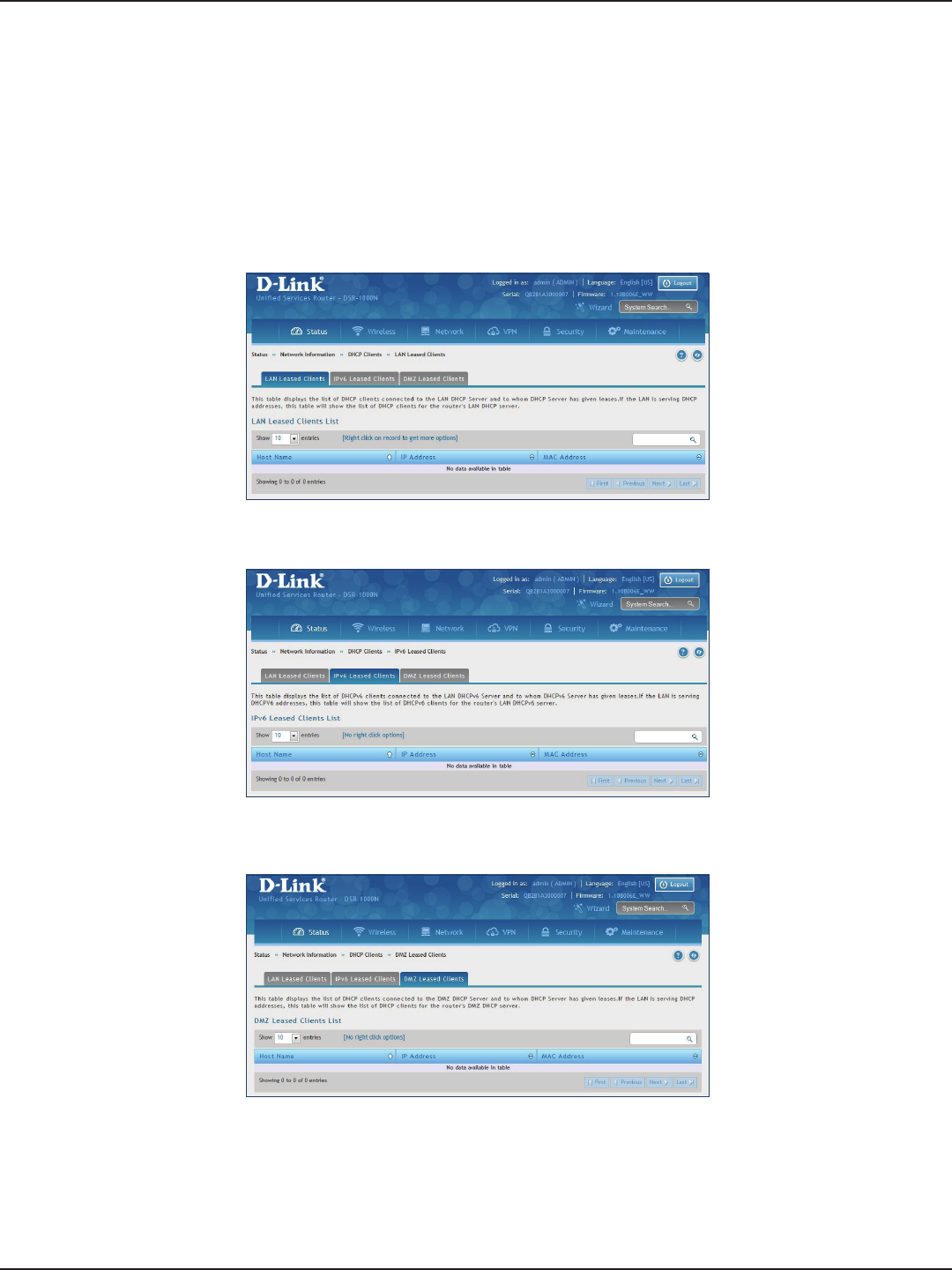
D-Link DSR-Series User Manual 216
Section 10 - Status and Statistics
Network Information
DHCP Leased Clients
Path: Status > Network Information > DHCP Clients
Three separated tabs display a list of clients whom get IP leased from the router: LAN leased clients, IPv6 leased
clients, and DMZ leased clients.
LAN Leased Clients
IPv6 Leased Clients
DMZ Leased Clients
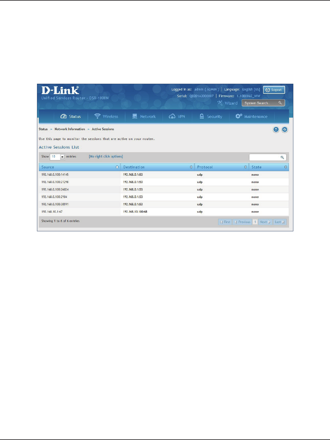
D-Link DSR-Series User Manual 217
Section 10 - Status and Statistics
Path: Status > Network Information > Active Sessions
This table lists the active internet sessions through the router’s rewall. The session’s protocol, state, local, and
remote IP addresses are shown.
Active Sessions
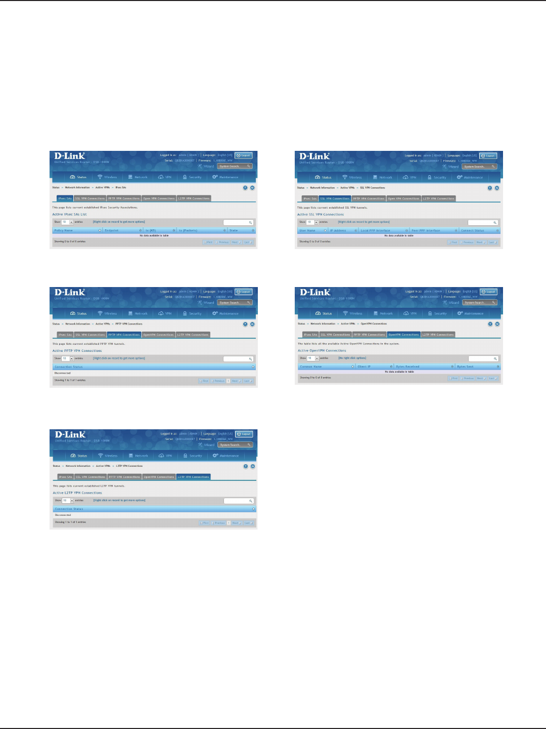
D-Link DSR-Series User Manual 218
Section 10 - Status and Statistics
Path: Status > Network Information > Active VPNs
You can view and change the status (connect or drop) of the router’s VPN associations/connections. Here, the
active VPN associations/connections are listed along with the trac details and tunnel state. The trac is a
cumulative measure of transmitted/received packets since the tunnel was established.
Active VPNs
IPSec SAs
PPTP VPN Connections
L2TP VPN Connections
SSL VPN Connections
OpenVPN Connections
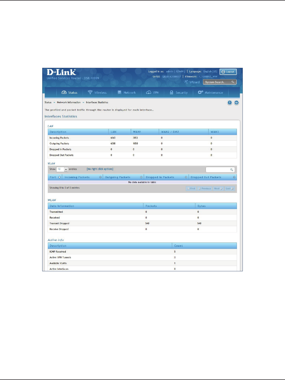
D-Link DSR-Series User Manual 219
Section 10 - Status and Statistics
Path: Status > Network Information > Interfaces Statistics
This page displays packet information on the LAN, VLAN, and WLAN interfaces.
Interface Statistics
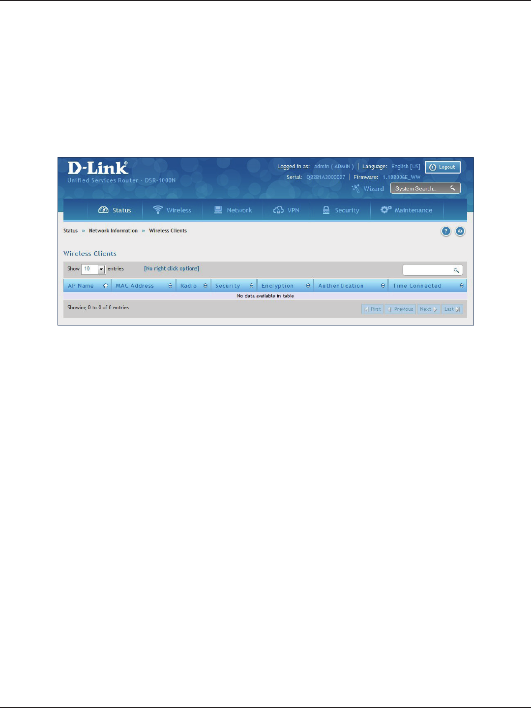
D-Link DSR-Series User Manual 220
Section 10 - Status and Statistics
Path: Status > Network Information > Wireless Clients
The clients connected to a particular AP can be viewed on this page. Connected clients are sorted by the MAC
address and indicate the security parameters used by the wireless link, as well as the time connected to the
corresponding AP. The statistics table has auto-refresh control which allows display of the most current port level
data at each page refresh. The default auto-refresh for this page is 10 seconds.
View Wireless Clients
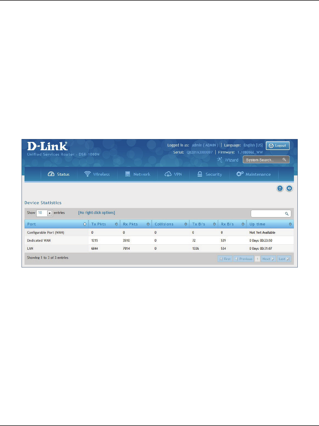
D-Link DSR-Series User Manual 221
Section 10 - Status and Statistics
Path: Status > Network Information > Device Stats
Detailed transmit and receive statistics for each physical port are presented here. Each interface (WAN1, WAN2/
DMZ, LAN, and VLANs) have port specic packet level information provided for review. Transmitted/received
packets, port collisions, and the cumulating bytes/sec for transmit/receive directions are provided for each
interface along with the port up time. If you suspect issues with any of the wired ports, this table will help
diagnose uptime or transmit level issues with the port.
The statistics table has auto-refresh control which allows display of the most current port level data at each page
refresh. The default auto-refresh for this page is 10 seconds.
Device Stats
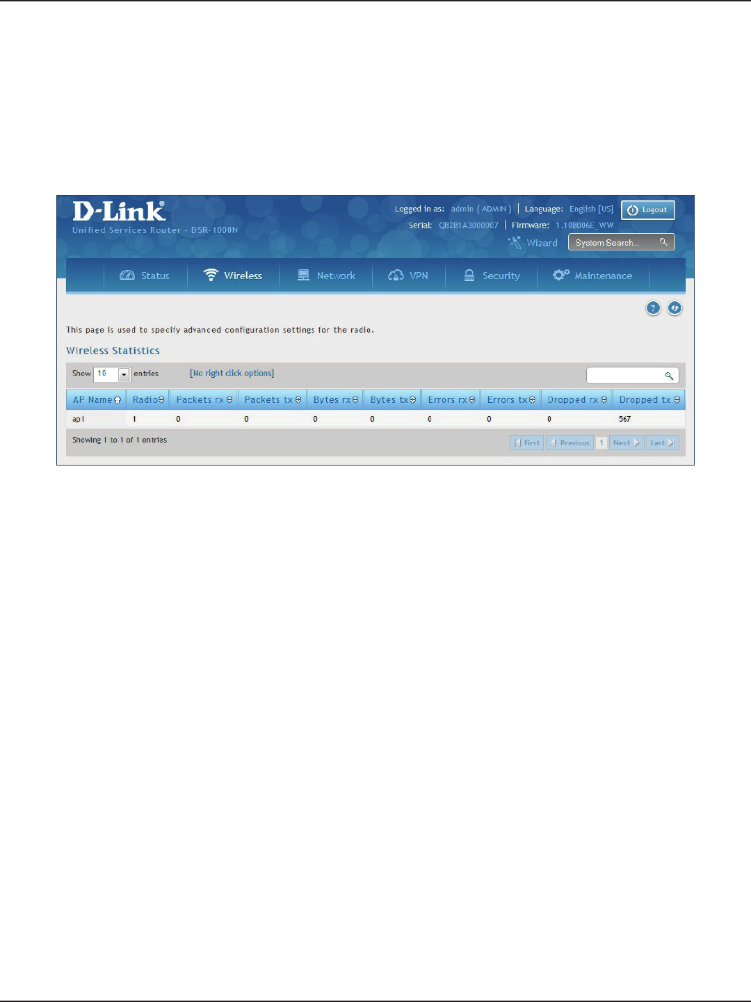
D-Link DSR-Series User Manual 222
Section 10 - Status and Statistics
Path: Status > Network Information > Wireless Statistics
The Wireless Statistics page displays the incrementing trac statistics for each enabled access point. This page
will give a snapshot of how much trac is being transmitted over each wireless link. If you suspect that a radio
or VAP may be down, the details on this page would conrm if trac is being sent and received through the VAP.
Wireless Statistics

D-Link DSR-Series User Manual 223
Section 10 - Status and Statistics
Path: Status > Network Information > LAN Clients
The LAN clients to the router are identied by an ARP scan through the LAN switch. The NetBIOS name (if
available), IP address, and MAC address of discovered LAN hosts are displayed.
View LAN Clients

D-Link DSR-Series User Manual 224
Section 11 - Troubleshooting
Troubleshooting
Symptom: You cannot access the router’s web-conguration interface from a PC on your LAN.
Recommended action:
1. Check the Ethernet connection between the PC and the router.
2. Ensure that your PC’s IP address is on the same subnet as the router. If you are using the recommended
addressing scheme, your PC’s address should be in the range 192.168.10.2 to 192.168.10.254.
3. Check your PC’s IP address. If the PC cannot reach a DHCP server, some versions of Windows and
Mac OS generate and assign an IP address. These auto-generated addresses are in the range
169.254.x.x. If your IP address is in this range, check the connection from the PC to the rewall and
reboot your PC.
4. If your router’s IP address has changed and you don’t know what it is, reset the router conguration
to factory defaults (this sets the rewall’s IP address to 192.168.10.1).
5. If you do not want to reset to factory default settings and lose your conguration, reboot the
router and use a packet snier (such as Ethereal™) to capture packets sent during the reboot. Look
at the Address Resolution Protocol (ARP) packets to locate the router’s LAN interface address.
6. Launch your browser and ensure that Java, JavaScript, or ActiveX is enabled. If you are using
Internet Explorer, click Refresh to ensure that the Java applet is loaded. Close the browser and
launch it again.
7. Ensure that you are using the correct login information. The factory default login name is admin
and the password is password. Ensure that CAPS LOCK is o when entering this information.
Symptom: Router does not save conguration changes.
Recommended action:
1. When entering conguration settings, click Apply before moving to another menu or tab;
otherwise your changes are lost.
2. Click Refresh or Reload in the browser. Your changes may have been made, but the browser may
be caching the old conguration.
Symptom: Router cannot access the Internet.
Possible cause: If you use dynamic IP addresses, your router may not have requested an IP address from the ISP.
Recommended action:
1. Launch your browser and go to an external site such as www.google.com.
2. Access the rewall’s conguration main menu at http://192.168.10.1.
3. Select Monitoring > Router Status.
4. Ensure that an IP address is shown for the WAN port. If 0.0.0.0 is shown, your rewall has not
obtained an IP address from your ISP. See the next symptom.
Internet Connection

D-Link DSR-Series User Manual 225
Section 11 - Troubleshooting
Symptom: Router cannot obtain an IP address from the ISP.
Recommended action:
1. Turn o power to the cable or DSL modem.
2. Turn o the router.
3. Wait ve minutes, and then reapply power to the cable or DSL modem.
4. When the modem LEDs indicate that it has resynchronized with the ISP, reapply power to the
router. If the router still cannot obtain an ISP address, see the next symptom.
Symptom: Router still cannot obtain an IP address from the ISP.
Recommended action:
1. Ask your ISP if it requires a login program — PPP over Ethernet (PPPoE) or some other type of login.
2. If yes, verify that your congured login name and password are correct.
3. Ask your ISP if it checks for your PC’s hostname.
4. If yes, select Network Conguration > WAN Settings > Ethernet ISP Settings and set the account
name to the PC hostname of your ISP account.
5. Ask your ISP if it allows only one Ethernet MAC address to connect to the Internet, and therefore
checks for your PC’s MAC address.
6. If yes, inform your ISP that you have bought a new network device, and ask them to use the rewall’s
MAC address.
7. Alternatively, select Network Conguration > WAN Settings > Ethernet ISP Settings and congure
your router to spoof your PC’s MAC address.
Symptom: Router can obtain an IP address, but PC is unable to load Internet pages.
Recommended action:
1. Ask your ISP for the addresses of its designated Domain Name System (DNS) servers. Congure
your PC to recognize those addresses. For details, see your operating system documentation.
2. On your PC, congure the router to be its TCP/IP gateway.

D-Link DSR-Series User Manual 226
Section 11 - Troubleshooting
Date and time
Symptom: Date shown is January 1, 1970.
Possible cause: The router has not yet successfully reached a network time server (NTS).
Recommended action:
1. If you have just congured the router, wait at least ve minutes, select Administration > Time Zone,
and recheck the date and time.
2. Verify your Internet access settings.
Symptom: Time is o by one hour.
Possible cause: The router does not automatically adjust for Daylight Savings Time.
Recommended action:
1. Select Administration > Time Zone and view the current date and time settings.
2. Click to check or uncheck “Automatically adjust for Daylight Savings Time”, then click Apply.

D-Link DSR-Series User Manual 227
Section 11 - Troubleshooting
Pinging to Test LAN Connectivity
Most TCP/IP terminal devices and rewalls contain a ping utility that sends an ICMP echo-request packet to the
designated device. The DSR responds with an echo reply. Troubleshooting a TCP/IP network is made very easy by
using the ping utility in your PC or workstation.
Testing the LAN path from your PC to your router
1. From the PC’s Windows toolbar, Click Start and in the search box at the bottom, type cmd and
press Enter.
2. At the prompt, type ping <IP_address> where <IP_address> is the router’s IP address. Example:
ping 192.168.10.1.
3. Press Enter.
4. Observe the display:
• If the path is working, you will see this message sequence:
Pinging <IP address> with 32 bytes of data
Reply from <IP address>: bytes=32 time=NN ms TTL=xxx
• If the path is not working, you will see this message sequence:
Pinging <IP address> with 32 bytes of data
Request timed out
5. If the path is not working, Test the physical connections between PC and router:
• If the LAN port LED is o, go to the “LED displays” section on your Install Guide and follow
instructions for “LAN or Internet port LEDs are not lit.”
• Verify that the corresponding link LEDs are lit for your network interface card and for any
hub ports that are connected to your workstation and rewall.
6. If the path is still not up, test the network conguration:
• Verify that the Ethernet card driver software and TCP/IP software are installed and
congured on the PC.
• Verify that the IP address for the router and PC are correct and on the same subnet.

D-Link DSR-Series User Manual 228
Section 11 - Troubleshooting
1. From the PC’s Windows toolbar, Click Start and in the search box at the bottom, type cmd and
press Enter.
2. Type ping -n 10 <IP_address> where -n 10 species a maximum of 10 tries and <IP address> is
the IP address of a remote device such as your ISP’s DNS server. Example: ping -n 10 10.1.1.1.
3. Press Enter and then observe the display (see the previous procedure).
4. If the path is not working, do the following:
• Check that the PC has the IP address of your rewall listed as the default gateway. (If the
IP conguration of your PC is assigned by DHCP, this information is not visible in your PC’s
Network Control Panel.)
• Verify that the network (subnet) address of your PC is dierent from the network address
of the remote device.
• Verify that the cable or DSL modem is connected and functioning.
• Ask your ISP if it assigned a hostname to your PC. If yes, select Network Conguration >
WAN Settings > Ethernet ISP Settings and enter that hostname as the ISP account name.
• Ask your ISP if it rejects the Ethernet MAC addresses of all but one of your PCs.
Many broadband ISPs restrict access by allowing trac from the MAC address of only your
broadband modem; but some ISPs additionally restrict access to the MAC address of just a single
PC connected to that modem. If this is the case, congure your rewall to clone or spoof the MAC
address from the authorized PC.
Testing the LAN path from your PC to a remote device

D-Link DSR-Series User Manual 229
Section 11 - Troubleshooting
Restoring factory-default conguration settings
To restore factory-default conguration settings, do either of the following:
1. Do you know the account password and IP address?
• If yes, select Maintenance > Firmware & Cong > Soft Reboot and click Default.
• If no, do the following:
On the rear panel of the router, press and hold the Reset button about 10 seconds, until
the test LED lights and then blinks. Release the button and wait for the router to reboot.
2. If the router does not restart automatically; manually restart it to make the default settings eective.
3. After a restore to factory defaults —whether initiated from the conguration interface or the Reset
button — the following settings apply:
• LAN IP address: 192.168.10.1
• Username: admin
• Password: admin
• DHCP server on LAN: enabled
• WAN port conguration: Get conguration via DHCP

D-Link DSR-Series User Manual 230
Appendix A - Glossary
Appendix A - Glossary
ARP Address Resolution Protocol. Broadcast protocol for mapping IP addresses to MAC addresses.
CHAP Challenge-Handshake Authentication Protocol. Protocol for authenticating users to an ISP.
DDNS Dynamic DNS. System for updating domain names in real time. Allows a domain name to be
assigned to a device with a dynamic IP address.
DHCP Dynamic Host Conguration Protocol. Protocol for allocating IP addresses dynamically so that
addresses can be reused when hosts no longer need them.
DNS
Domain Name System. Mechanism for translating H.323 IDs, URLs, or e-mail IDs into IP addresses.
Also used to assist in locating remote gatekeepers and to map IP addresses to hostnames of
administrative domains.
FQDN Fully qualied domain name. Complete domain name, including the host portion. Example:
serverA.companyA.com.
FTP File Transfer Protocol. Protocol for transferring les between network nodes.
HTTP Hypertext Transfer Protocol. Protocol used by web browsers and web servers to transfer les.
IKE Internet Key Exchange. Mode for securely exchanging encryption keys in ISAKMP as part of
building a VPN tunnel.
IPsec
IP security. Suite of protocols for securing VPN tunnels by authenticating or encrypting IP packets
in a data stream. IPsec operates in either transport mode (encrypts payload but not packet
headers) or tunnel mode (encrypts both payload and packet headers).
ISAKMP Internet Key Exchange Security Protocol. Protocol for establishing security associations and
cryptographic keys on the Internet.
ISP Internet service provider.
MAC Address Media-access-control address. Unique physical-address identier attached to a network adapter.
MTU Maximum transmission unit. Size, in bytes, of the largest packet that can be passed on. The MTU
for Ethernet is a 1500-byte packet.
NAT
Network Address Translation. Process of rewriting IP addresses as a packet passes through a
router or rewall. NAT enables multiple hosts on a LAN to access the Internet using the single
public IP address of the LAN’s gateway router.
NetBIOS Microsoft Windows protocol for le sharing, printer sharing, messaging, authentication, and
name resolution.
NTP Network Time Protocol. Protocol for synchronizing a router to a single clock on the network,
known as the clock master.
PAP Password Authentication Protocol. Protocol for authenticating users to a remote access server or
ISP.

D-Link DSR-Series User Manual 231
Appendix A - Glossary
PPPoE Point-to-Point Protocol over Ethernet. Protocol for connecting a network of hosts to an ISP
without the ISP having to manage the allocation of IP addresses.
PPTP Point-to-Point Tunneling Protocol. Protocol for creation of VPNs for the secure transfer of data
from remote clients to private servers over the Internet.
RADIUS Remote Authentication Dial-In User Service. Protocol for remote user authentication and
accounting. Provides centralized management of usernames and passwords.
RSA Rivest-Shamir-Adleman. Public key encryption algorithm.
TCP Transmission Control Protocol. Protocol for transmitting data over the Internet with guaranteed
reliability and in-order delivery.
UDP User Data Protocol. Protocol for transmitting data over the Internet quickly but with no
guarantee of reliability or in-order delivery.
VPN
Virtual private network. Network that enables IP trac to travel securely over a public TCP/IP
network by encrypting all trac from one network to another. Uses tunneling to encrypt all
information at the IP level.
WINS
Windows Internet Name Service. Service for name resolution. Allows clients on dierent IP
subnets to dynamically resolve addresses, register themselves, and browse the network without
sending broadcasts.
XAUTH
IKE Extended Authentication. Method, based on the IKE protocol, for authenticating not just
devices (which IKE authenticates) but also users. User authentication is performed after device
authentication and before IPsec negotiation.

D-Link DSR-Series User Manual 232
Appendix B - Factory Default Settings
Appendix B - Factory Default Settings
Feature Description Default Settings
Device Login
User Login URL http://192.168.10.1
User Name admin
Password admin
Internet Connection
WAN MAC Address Use default address
WAN MTU size 1500
Port Speed Autosense
Local Area Network (LAN)
IP Address 192.168.10.1
IPv4 Subnet Mask 255.255.255.0
RIP Direction None
RIP Version Disabled
RIP Authentication Disabled
DHCP Server Enabled
DHCP Starting IP Address 192.168.10.2
DHCP Ending IP Address 192.168.10.100
Time Zone GMT
Daylight Saving Time Disabled
SNMP Disabled
Remote Management Disabled
Firewall
Inbound Communication from Internet Disabled (except Port 80 HTTP)
Outbound Communication to Internet Enabled (all)
Source MAC Filtering Disabled
Stealth Mode Enabled

D-Link DSR-Series User Manual 233
Appendix C - Standard Services Available for Port Forwarding & Firewall Conguration
Appendix C - Standard Services for Port
Forwarding & Firewall Conguration
• ANY
• AIM
• BGP
• BOOTP_CLIENT
• BOOTP_SERVER
• CU-SEEME:UDP
• CU-SEEME:TCP
• DNS:UDP
• DNS:TCP
• FINGER
• FTP
• HTTP
• HTTPS
• ICMP-TYPE-3
• ICMP-TYPE-4
• ICMP-TYPE-5
• ICMP-TYPE-6
• ICMP-TYPE-7
• ICMP-TYPE-8
• ICMP-TYPE-9
• ICMP-TYPE-10
• ICMP-TYPE-11
• ICMP-TYPE-13
• ICQ
• IMAP2
• IMAP3
• IRC
• NEWS
• NFS
• NNTP
• PING
• POP3
• PPTP
• RCMD
• REAL-AUDIO
• REXEC
• RLOGIN
• RTELNET
• RTSP:TCP
• RTSP:UDP
• SFTP
• SMTP
• SNMP:TCP
• SNMP:UDP
• SNMP-TRAPS:TCP
• SNMP-TRAPS:UDP
• SQL-NET
• SSH:TCP
• SSH:UDP
• STRMWORKS
• TACACS
• TELNET
• TFTP
• VDOLIVE

D-Link DSR-Series User Manual 234
Appendix D - Log Output Reference
Appendix D - Log Output Reference
Facility: System (Networking)
Log Message Severity Log Message Severity
DBUpdate event: Table: %s opCode:%d
rowId:%d DEBUG BridgeCong: too few arguments to
command %s ERROR
networkIntable.txt not found DEBUG BridgeCong: too few arguments to
command %s ERROR
sqlite3QueryResGet failed DEBUG sqlite3QueryResGet failed.Query:%s ERROR
Interface is already deleted in bridge DEBUG ddnsDisable failed ERROR
removing %s from bridge %s... %s DEBUG sqlite3QueryResGet failed.Query:%s ERROR
adding %s to bridge %s... %s DEBUG sqlite3QueryResGet failed.Query:%s ERROR
stopping bridge... DEBUG ddnsDisable failed ERROR
stopping bridge... DEBUG failed to call ddns enable ERROR
stopping bridge... DEBUG ddnsDisable failed ERROR
%s:DBUpdate event: Table: %s opCode:%d
rowId:%d DEBUG sqlite3QueryResGet failed.Query:%s ERROR
Wan is not up DEBUG Error in executing DB update handler ERROR
%s:DBUpdate event: Table: %s opCode:%d
rowId:%d DEBUG sqlite3QueryResGet failed.Query:%s ERROR
doDNS:failed DEBUG Illegal invocation of ddnsView (%s) ERROR
doDNS:failed DEBUG sqlite3QueryResGet failed.Query:%s ERROR
doDNS:Result = FAILED DEBUG sqlite3QueryResGet failed.Query:%s ERROR
doDNS:Result SUCCESS DEBUG ddns: SQL error: %s ERROR
Write Old Entry: %s %s %s: to %s DEBUG Illegal operation interface got deleted ERROR
Write New Entry: %s %s #%s : to %s DEBUG sqlite3QueryResGet failed.Query:%s ERROR
Write Old Entry: %s %s %s: to %s DEBUG sqlite3QueryResGet failed.Query:%s ERROR
Write New Entry: %s %s #%s : to %s DEBUG sqlite3QueryResGet failed.Query:%s ERROR
ifStaticMgmtDBUpdateHandler: returning
with “ DEBUG ddnsDisable failed ERROR
nimfLinkStatusGet: buer: \ DEBUG ddns: SQL error: %s ERROR
nimfLinkStatusGetErr: returning with
status: %d DEBUG Failed to call ddns enable ERROR
nimfAdvOptSetWrap: current Mac Option:
%d DEBUG ddns: SQL error: %s ERROR
nimfAdvOptSetWrap: current Port Speed
Option: %d DEBUG sqlite3QueryResGet failed.Query:%s ERROR
nimfAdvOptSetWrap: current Mtu Option:
%d DEBUG Failed to call ddns enable ERROR

D-Link DSR-Series User Manual 235
Appendix D - Log Output Reference
nimfAdvOptSetWrap: looks like we are
reconnecting. “ DEBUG ddns: SQL error: %s ERROR
nimfAdvOptSetWrap: Mtu Size: %d DEBUG ddnsDisable failed ERROR
nimfAdvOptSetWrap: NIMF table is %s DEBUG ddns: SQL error: %s ERROR
nimfAdvOptSetWrap:WAN_MODE
TRIGGER DEBUG sqlite3QueryResGet failed.Query:%s ERROR
nimfAdvOptSetWrap: MTU: %d DEBUG Failed to call ddns enable ERROR
nimfAdvOptSetWrap: MacAddress: %s DEBUG ddns: SQL error: %s ERROR
nimfAdvOptSetWrap: old Mtu Flag: %d DEBUG ddnsDisable failed ERROR
nimfAdvOptSetWrap: user has changed
MTU option DEBUG ddns: SQL error: %s ERROR
nimfAdvOptSetWrap: MTU: %d DEBUG sqlite3QueryResGet failed.Query:%s ERROR
nimfAdvOptSetWrap: old MTU size: %d DEBUG sqlite3QueryResGet failed.Query:%s ERROR
nimfAdvOptSetWrap: old Port Speed
Option: %d DEBUG ddnsDisable failed ERROR
nimfAdvOptSetWrap: old Mac Address
Option: %d DEBUG ddns: SQL error: %s ERROR
nimfAdvOptSetWrap: MacAddress: %s DEBUG sqlite3QueryResGet failed.Query:%s ERROR
Setting LED [%d]:[%d] For %s DEBUG sqlite3QueryResGet failed.Query:%s ERROR
l2tpEnable: command string: %s DEBUG ddnsDisable failed ERROR
nimfAdvOptSetWrap: handling reboot
scenario DEBUG failed to call ddns enable ERROR
nimfAdvOptSetWrap: INDICATOR = %d DEBUG ddns: SQL error: %s ERROR
nimfAdvOptSetWrap: UpdateFlag: %d DEBUG ddnsDisable failed ERROR
nimfAdvOptSetWrap: returning with
status: %s DEBUG sqlite3QueryResGet failed.Query:%s ERROR
nimfGetUpdateMacFlag: MacTable Flag
is: %d DEBUG Error in executing DB update handler ERROR
nimfMacGet: Mac Option changed DEBUG Failed to open the resolv.conf le.
Exiting./n ERROR
nimfMacGet: Update Flag: %d DEBUG Could not write to the resolv.conf le.
Exiting. ERROR
nimfMacGet: MacAddress: %s DEBUG Error opening the lanUptime File ERROR
nimfMacGet: MacAddress: %s DEBUG Error Opening the lanUptime File. ERROR
nimfMacGet: MacAddress: %s DEBUG failed to open %s ERROR
nimfMacGet: MacAddress: %s DEBUG failed to open %s ERROR
nimfMacGet: MacAddress: %s DEBUG failed to query networkInterface table ERROR
nimfMacGet:Mac option Not changed \ DEBUG failed to query networkInterface table ERROR
nimfMacGet: MacAddress: %s DEBUG sqlite3QueryResGet failed.Query:%s ERROR

D-Link DSR-Series User Manual 236
Appendix D - Log Output Reference
nimfMacGet: MacAddress: %s DEBUG failed to enable IPv6 forwarding ERROR
nimfMacGet: MacAddress: %s DEBUG failed to set capabilities on the “ ERROR
nimfMacGet: returning with status: %s DEBUG failed to enable IPv6 forwarding ERROR
Now in enableing LanBridge function DEBUG failed to set capabilities on the “ ERROR
sucessfully executed the command %s DEBUG failed to disable IPv6 forwarding ERROR
Now in disableing LanBridge function DEBUG failed to set capabilities on the “ ERROR
sucessfully executed the command %s DEBUG failed to open %s ERROR
congPortTblHandler:Now we are in
Sqlite Update “ DEBUG Could not create ISATAP Tunnel ERROR
The Old Conguration of ConPort
was:%s DEBUG Could not destroy ISATAP Tunnel ERROR
The New Conguration of ConPort
was:%s DEBUG Could not congure ISATAP Tunnel ERROR
The user has deselected the congurable
port DEBUG Could not de-congure ISATAP Tunnel ERROR
failed query %s DEBUG nimfStatusUpdate: updating
NimfStatus failed ERROR
failed query %s DEBUG nimfStatusUpdate: updating
NimfStatus failed ERROR
failed query %s DEBUG nimfLinkStatusGet: determinig link’s
status failed ERROR
%s:DBUpdate event: Table: %s opCode:%d
rowId:%d DEBUG nimfLinkStatusGet: opening status le
failed ERROR
%s:DBUpdate event: Table: %s opCode:%d
rowId:%d DEBUG Failed to commit ERROR
%s:%d SIP ENABLE: %s DEBUG ifStatusDBUpdate: Failed to begin “ ERROR
sipTblHandler:failed to update ifStatic DEBUG %s: SQL error: %s ERROR
sipTblHandler:failed to update Congport DEBUG %s: Failed to commit “ ERROR
%s:%d SIP DISABLE: %s DEBUG nimfNetIfaceTblHandler: unable to get
LedPinId ERROR
%s:%d SIP SET CONF: %s DEBUG nimfNetIfaceTblHandler: unable to get
LedPinId ERROR
Failed to open %s: %s DEBUG nimfNetIfaceTblHandler: unable to get
LedPinId ERROR
Failed to start sipalg DEBUG %s: unable to kill dhclient ERROR
Failed to stop sipalg DEBUG nimfAdvOptSetWrap: unable to get
current Mac Option ERROR

D-Link DSR-Series User Manual 237
Appendix D - Log Output Reference
Failed to get cong info DEBUG nimfAdvOptSetWrap: unable to get
current Port “ ERROR
Network Mask: 0x%x DEBUG nimfAdvOptSetWrap: unable to get
current MTU Option ERROR
RTP DSCP Value: 0x%x DEBUG nimfAdvOptSetWrap: error getting
Mac Address from “ ERROR
Need more arguments DEBUG nimfAdvOptSetWrap: unable to get
the MTU ERROR
Invalid lanaddr DEBUG nimfAdvOptSetWrap: error setting
interface advanced “ ERROR
Invalid lanmask DEBUG nimfAdvOptSetWrap: error getting
MTU size ERROR
Invalid option DEBUG nimfAdvOptSetWrap: unable to get
Mac Address ERROR
Failed to set cong info DEBUG nimfAdvOptSetWrap: error setting
interface advanced “ ERROR
Unknown option DEBUG nimfAdvOptSetWrap: failed to get old
connectiontype ERROR
sshdTblHandler DEBUG nimfAdvOptSetWrap: old connection
type is: %s ERROR
pPort: %s DEBUG nimfAdvOptSetWrap: failed to get old
MTU Option ERROR
pProtocol: %s DEBUG nimfAdvOptSetWrap: error getting
MTU size ERROR
pListerAddr: %s DEBUG nimfOldFieldValueGet: failed to get
old “ ERROR
pKeyBits: %s DEBUG nimfOldFieldValueGet: user has
changed MTU size ERROR
pRootEnable: %s DEBUG nimfAdvOptSetWrap: failed to get old
Port Speed “ ERROR
pRsaEnable: %s DEBUG nimfAdvOptSetWrap: user has
changed Port Speed ERROR
pDsaEnable: %s DEBUG nimfAdvOptSetWrap: failed to get old
Mac Address “ ERROR
pPassEnable: %s DEBUG nimfAdvOptSetWrap: user has
changed Mac Address “ ERROR
pEmptyPassEnable: %s DEBUG nimfAdvOptSetWrap: unable to get
Mac Address ERROR
pSftpEnable: %s DEBUG nimfAdvOptSetWrap:Failed to RESET
the ag ERROR
pScpEnable: %s DEBUG nimfAdvOptSetWrap: setting
advanced options failed ERROR
pSshdEnable: %s DEBUG nimfAdvOptSetWrap: interface
advanced options applied ERROR
pPrivSep: %s DEBUG nimfGetUpdateMacFlag: unable to get
Flag from MacTable ERROR
%s:DBUpdate event: Table: %s opCode:%d
rowId:%d DEBUG nimfMacGet: Updating MAC address
failed ERROR
Re-Starting sshd daemon.... DEBUG sqlite3QueryResGet failed.Query:%s ERROR
sshd re-started successfully. DEBUG error executing the command %s ERROR
sshd stopped . DEBUG error executing the command %s ERROR
failed query %s DEBUG error executing the command %s ERROR

D-Link DSR-Series User Manual 238
Appendix D - Log Output Reference
vlan disabled, not applying vlan
conguration.. DEBUG disableLan function is failed to disable
CongPort” ERROR
failed query %s DEBUG sqlite3QueryResGet failed.Query:%s ERROR
failed query %s DEBUG sqlite3QueryResGet failed.Query:%s ERROR
no ports present in this vlanId %d DEBUG Unable to Disable congurable port
from ERROR
failed query %s DEBUG congPortTblHandler has failed ERROR
vlan disabled, not applying vlan
conguration.. DEBUG sqlite3QueryResGet failed.Query:%s ERROR
disabling vlan DEBUG Error in executing DB update handler ERROR
enabling vlan DEBUG sqlite3QueryResGet failed ERROR
vlan disabled, not applying vlan
conguration.. DEBUG Failed to execute switchCong for
port\ ERROR
no ports present in this vlanId %d DEBUG Failed to execute switchCong for port
enable ERROR
failed query %s DEBUG Failed to execute ifcong for port
enable ERROR
vlan disabled, not applying vlan
conguration.. DEBUG Failed to execute ethtool for\ ERROR
removing %s from bridge%s... %s DEBUG Failed to execute switchCong for port
disable ERROR
adding %s to bridge%d... %s DEBUG Failed to execute ifcong for port
disable ERROR
restarting bridge... DEBUG sqlite3QueryResGet failed ERROR
[switchCong] Ignoring event on port
number %d DEBUG sqlite3_mprintf failed ERROR
restarting bridge... DEBUG sqlite3QueryResGet failed ERROR
executing %s ... %s DEBUG Failed to execute switchCong for port
mirroring ERROR
removing %s from bridge%s... %s DEBUG Usage:%s <DB Name> <Entry Name>
<logFile> <subject> ERROR
adding %s to bridge%d... %s DEBUG sqlite3QueryResGet failed ERROR
[switchCong] Ignoring event on %s DEBUG Could not get all the required variables
to email the Logs. ERROR
restarting bridge... DEBUG runSmtpClient failed ERROR
[switchCong] Ignoring event on port
number %d DEBUG getaddrinfo returned %s ERROR
[switchCong] executing %s ... %s DEBUG le not found ERROR
restarting bridge... DEBUG sqlite3QueryResGet failed.Query:%s ERROR
UserName: %s DEBUG sqlite3QueryResGet failed.Query:%s ERROR
Password: %s DEBUG sqlite3QueryResGet failed.Query:%s ERROR
IspName: %s DEBUG No memory to allocate ERROR

D-Link DSR-Series User Manual 239
Appendix D - Log Output Reference
DialNumber: %s DEBUG Failed to Open SSHD Conguration File ERROR
Apn: %s DEBUG Ipaddress should be provided with
accessoption 1 ERROR
GetDnsFromIsp: %s DEBUG Subnetaddress should be provided
with accessoption 2 ERROR
IdleTimeOutFlag: %s DEBUG Failed to restart sshd ERROR
IdleTimeOutValue: %d DEBUG unable to open the “ ERROR
AuthMetho: %d DEBUG sqlite3QueryResGet failed.Query:%s ERROR
executing %s ... %s DEBUG Error in executing DB update handler ERROR
removing %s from bridge%d... %s DEBUG Error in executing DB update handler ERROR
adding %s to bridge%d... %s DEBUG unknown vlan state ERROR
stopping bridge... DEBUG Failed to execute vlanCong binary for
vlanId %d ERROR
restarting bridge... DEBUG sqlite3_mprintf failed ERROR
Could not congure 6to4 Tunnel Interface DEBUG Access port can be present only in
single vlan ERROR
Could not de-congure 6to4 Tunnel
Interface DEBUG Failed to execute vlanCong binary for
vlanId %d ERROR
failed to restart 6to4 tunnel interfaces DEBUG unknown vlan state ERROR
BridgeCong: too few arguments to
command %s DEBUG Failed to execute vlanCong binary for
port number %d ERROR
BridgeCong: unsupported command %d DEBUG Failed to clear vlan for oldPVID %d ERROR
BridgeCong returned error=%d DEBUG Failed to execute vlanCong binary for
port number %d ERROR
sqlite3QueryResGet failed DEBUG Failed to clear vlan for %d ERROR
Error in executing DB update handler DEBUG Failed to set vlan entry for vlan %d ERROR
sqlite3QueryResGet failed DEBUG Failed to set vlan entries, while
enabling \ ERROR
Failed to remove vlan Interface for vlanId \ DEBUG sqlite3QueryResGet failed ERROR
sqlite3QueryResGet failed DEBUG Failed to execute vlanCong binary for
port number %d ERROR
Invalid oidp passed DEBUG Failed to execute vlanCong binary for
vlanId %d ERROR

D-Link DSR-Series User Manual 240
Appendix D - Log Output Reference
Invalid oidp passed DEBUG Failed to enable vlan ERROR
Failed to get oid from the tree DEBUG Failed to disable vlan ERROR
threegEnable: Input to wrapper %s DEBUG Failed to set vlanPort table entries,
while \ ERROR
threegEnable: spawning command %s DEBUG Failed to enable vlan ERROR
threegMgmtHandler: query string: %s DEBUG unknown vlan state ERROR
threegMgmtHandler: returning with
status: %s DEBUG Error in executing DB update handler ERROR
adding to dhcprealy ifgroup failed DEBUG unknown vlan state ERROR
adding to ipset fwDhcpRelay failed DEBUG Failed to execute vlanCong binary for
vlanId %d ERROR
Disabling Firewall Rule for DHCP Relay
Protocol DEBUG sqlite3_mprintf failed ERROR
Enabling Firewall Rule for DHCP Relay
Protocol DEBUG Access port can be present only in
single vlan ERROR
prerouting Firewall Rule add for Relay
failed DEBUG Failed to execute vlanCong binary for
vlanId %d ERROR
prerouting Firewall Rule add for Relay
failed DEBUG unknown vlan state ERROR
%s: SQL get query: %s DEBUG Failed to execute vlanCong binary for
port number %d ERROR
%s: sqlite3QueryResGet failed DEBUG Failed to clear vlan for oldPVID %d ERROR
%s: no result found DEBUG Failed to execute vlanCong binary for
port number %d ERROR
%s: buer overow DEBUG Failed to clear vlan for %d ERROR
%s: value of %s in %s table is: %s DEBUG Failed to set vlan entry for vlan %d ERROR
%s: returning with status: %s DEBUG Failed to set vlan entries, while
enabling \ ERROR
dnsResolverCongure: addressFamily: %d DEBUG Failed to execute vlanCong binary for
port number %d ERROR
dnsResolverCongure: LogicalIfName: %s DEBUG Failed to execute vlanCong binary for
vlanId %d ERROR
chap-secrets File found DEBUG Failed to enable vlan ERROR
PID File for xl2tpd found DEBUG Failed to disable vlan ERROR
pid: %d DEBUG Failed to set vlanPort table entries,
while \ ERROR
options.xl2tpd le found DEBUG Failed to enable vlan ERROR
options.xl2tpd le not found DEBUG unknown vlan state ERROR
Conf File for xl2tpd found DEBUG threegMgmtInit: unable to open the
database le %s ERROR
xl2tpd.conf not found DEBUG threegConnEnable: failed to get the
WanMode ERROR
Chap Secrets le found DEBUG threegEnable:spawning failed ERROR
Chap Secrets le not found DEBUG threegDisable: unable to kill ppp
daemon ERROR
%s:DBUpdate event: Table: %s opCode:%d
rowId:%d DEBUG threegMgmtHandler: Query: %s ERROR
chap-secrets File found DEBUG threegMgmtHandler: error in
executing database update ERROR

D-Link DSR-Series User Manual 241
Appendix D - Log Output Reference
PID File for pptpd found DEBUG Error in executing DB update handler ERROR
pid: %d DEBUG are we getting invoked twice ?? ERROR
PID File for pptpd interface found DEBUG could not open %s to append ERROR
pid: %d DEBUG could not write nameserver %s to %s ERROR
options.pptpd le found DEBUG could not write nameserver %s to %s ERROR
options.pptpd le not found DEBUG could not open %s to truncate ERROR
Conf File for pptpd found DEBUG dnsResolverCongMgmtInit: unable to
open the “ ERROR
pptpd.conf not found DEBUG resolverCongDBUpateHandler:
sqlite3QueryResGet “ ERROR
Chap Secrets le found DEBUG could not congure DNS resolver ERROR
Chap Secrets le not found DEBUG dnsResolverCongure: could not write
nameserver:%s,” ERROR
%s:DBUpdate event: Table: %s opCode:%d
rowId:%d DEBUG unboundMgmt: unable to open the “ ERROR
chap-secrets File found DEBUG ioctl call Failed-could not update
active user Details ERROR
pppoeMgmtTblHandler: MtuFlag: %d DEBUG sqlite3QueryResGet failed.Query:%s ERROR
pppoeMgmtTblHandler: Mtu: %d DEBUG Can’t kill xl2tpd ERROR
pppoeMgmtTblHandler: IdleTimeOutFlag:
%d DEBUG xl2tpd restart failed ERROR
pppoeMgmtTblHandler:
IdleTimeOutValue: %d DEBUG failed to get eld value ERROR
pppoeMgmtTblHandler: UserName: %s DEBUG failed to get eld value ERROR
pppoeMgmtTblHandler: Password: %s DEBUG sqlite3QueryResGet failed.Query:%s ERROR
pppoeMgmtTblHandler: DNS specied:
%s DEBUG sqlite3QueryResGet failed.Query:%s ERROR
pppoeMgmtTblHandler: Service: %s DEBUG unboundMgmt: unable to open the “ ERROR
pppoeMgmtTblHandler: StaticIp: %s DEBUG writing options.xl2tpd failed ERROR
pppoeMgmtTblHandler: NetMask: %s DEBUG xl2tpdStop failed ERROR
pppoeMgmtTblHandler: AuthOpt: %d DEBUG writing xl2tpd.conf failed ERROR
pppoeMgmtTblHandler: Satus: %d DEBUG writing options.xl2tpd failed ERROR
pppoeEnable: ppp dial string: %s DEBUG xl2tpdStop failed ERROR
pppoeMgmtDBUpdateHandler: returning
with status: %s DEBUG xl2tpdStart failed ERROR
pptpMgmtTblHandler: MtuFlag: %d DEBUG sqlite3QueryResGet failed.Query:%s ERROR
pptpMgmtTblHandler: Mtu: %d DEBUG writing Chap-secrets/Pap-Secrets
failed ERROR
pptpMgmtTblHandler: IdleTimeOutFlag:
%d DEBUG xl2tpdStop failed ERROR
pptpMgmtTblHandler: IdleTimeOutValue:
%d DEBUG xl2tpdStart failed ERROR
pptpMgmtTblHandler: GetDnsFromIsp:
%d DEBUG sqlite3QueryResGet failed.Query:%s ERROR

D-Link DSR-Series User Manual 242
Appendix D - Log Output Reference
pptpMgmtTblHandler: UserName: %s DEBUG writing Chap-secrets/Pap-Secrets
failed ERROR
pptpMgmtTblHandler: Password: %s DEBUG xl2tpdStop failed ERROR
pptpMgmtTblHandler: dynamic MyIp
congured DEBUG xl2tpdStart failed ERROR
pptpMgmtTblHandler: MyIp: %s DEBUG sqlite3QueryResGet failed.Query:%s ERROR
pptpMgmtTblHandler: ServerIp: %s DEBUG writing Chap-secrets/Pap-Secrets
failed ERROR
pptpMgmtTblHandler: StaticIp: %s DEBUG Error in executing DB update handler ERROR
pptpMgmtTblHandler: NetMask: %s DEBUG unboundMgmt: unable to open the “ ERROR
pptpMgmtTblHandler:
MppeEncryptSupport: %s DEBUG Can’t kill pptpd ERROR
pptpMgmtTblHandler: SplitTunnel: %s DEBUG pptpd restart failed ERROR
pptpEnable: ppp dial string: %s DEBUG Can’t kill pptpd ERROR
pptpEnable: spawning command %s DEBUG failed to get eld value ERROR
PID File for dhcpc found DEBUG failed to get eld value ERROR
pid: %d DEBUG unboundMgmt: unable to open the “ ERROR
pptpMgmtDBUpdateHandler: query
string: %s DEBUG writing options.pptpd failed ERROR
pptpMgmtDBUpdateHandler: returning
with status: %s DEBUG pptpdStop failed ERROR
dhcpcReleaseLease: dhcpc release
command: %s DEBUG writing pptpd.conf failed ERROR
dhcpcMgmtTblHandler: MtuFlag: %d DEBUG writing options.pptpd failed ERROR
dhcpcMgmtTblHandler: Mtu: %d DEBUG pptpdStop failed ERROR
DHCPv6 Server started successfully. DEBUG pptpdStart failed ERROR
DHCPv6 Server stopped successfully DEBUG writing Chap-secrets/Pap-Secrets
failed ERROR
DHCPv6 Client started successfully. DEBUG Error in executing DB update handler ERROR
DHCPv6 Client stopped successfully. DEBUG pppStatsUpdate: unable to get default
MTU ERROR
DHCPv6 Client Restart successful DEBUG pppoeMgmtInit: unable to open the
database le %s ERROR
l2tpMgmtTblHandler: MtuFlag: %d DEBUG pppoeDisable: unable to kill ppp
daemon ERROR

D-Link DSR-Series User Manual 243
Appendix D - Log Output Reference
l2tpMgmtTblHandler: Mtu: %d DEBUG pppoeMultipleEnableDisable: pppoe
enable failed ERROR
l2tpMgmtTblHandler: IspName: %s DEBUG pppoeMultipleEnableDisable: pppoe
disable failed ERROR
l2tpMgmtTblHandler: UserName: %s DEBUG pppoeMgmtTblHandler: unable to get
current Mtu Option ERROR
l2tpMgmtTblHandler: Password: %s DEBUG pppoeMgmtTblHandler: unable to get
the Mtu ERROR
l2tpMgmtTblHandler: AccountName: %s DEBUG pppoeMgmtTblHandler: pppoe enable
failed ERROR
l2tpMgmtTblHandler: DomainName: %s DEBUG pppoeMgmtDBUpdateHandler: failed
query: %s ERROR
l2tpMgmtTblHandler: Secret: not specied DEBUG pppoeMgmtDBUpdateHandler: error
in executing “ ERROR
l2tpMgmtTblHandler: Secret: %s DEBUG pptpMgmtInit: unable to open the
database le %s ERROR
l2tpMgmtTblHandler: dynamic MyIp
congured DEBUG pptpEnable: error executing
command: %s ERROR
l2tpMgmtTblHandler: MyIp: %s DEBUG pptpEnable: unable to resolve address:
%s ERROR
l2tpMgmtTblHandler: ServerIp: %s DEBUG pptpEnable: inet_aton failed ERROR
l2tpMgmtTblHandler: StaticIp: %s DEBUG pptpEnable: inet_aton failed ERROR
l2tpMgmtTblHandler: NetMask: %s DEBUG pptpEnable:spawning failed ERROR
l2tpMgmtTblHandler: SplitTunnel: %s DEBUG pptpDisable: unable to kill ppp
daemon ERROR
needToStartHealthMonitor: returning
with status: %s DEBUG pptpMgmtTblHandler: unable to get
current MTU Option ERROR
l2tpEnable: command string: %s DEBUG pptpMgmtTblHandler: unable to get
the Mtu ERROR
l2tpEnable: command: %s DEBUG pptpMgmtTblHandler:
dbRecordValueGet failed for %s “ ERROR
l2tpEnable: command string: %s DEBUG pptpMgmtTblHandler: pptp enable
failed ERROR
PID File for dhcpc found DEBUG pptpMgmtTblHandler: pptp disable
failed ERROR
pid: %d DEBUG pptpMgmtDBUpdateHandler:
sqlite3QueryResGet “ ERROR
l2tpMgmtDBUpdateHandler: query string:
%s DEBUG pptpMgmtDBUpdateHandler: error in
executing “ ERROR
l2tpMgmtDBUpdateHandler: returning
with status: %s DEBUG Illegal invocation of dhcpCong (%s) ERROR
RADVD started successfully DEBUG dhcpLibInit: unable to open the
database le %s ERROR
RADVD stopped successfully DEBUG sqlite3QueryResGet failed.Query:%s ERROR
empty update. nRows=%d nCols=%d WARN dhcpcMgmtInit: unable to open the
database le %s ERROR

D-Link DSR-Series User Manual 244
Appendix D - Log Output Reference
Wan is not up or in load balencing mode WARN dhcpcReleaseLease: unable to release
lease ERROR
threegMgmtHandler: no row found.
nRows = %d nCols = %d WARN dhcpcEnable: unable to kill dhclient ERROR
pppoeMgmtDBUpdateHandler: empty
update. WARN dhcpcEnable: enabling dhcpc failed
on: %s ERROR
dhcpcEnable: dhclient already running
on: %s WARN dhcpcDisable: unable to kill dhclient ERROR
dhcpcDisable: deleted dhclient.leases WARN dhcpcDisable: delete failed for
dhclient.leases ERROR
l2tpMgmtInit: unable to open the
database le %s ERROR dhcpcDisable: failed to reset the ip ERROR
l2tpEnable: unable to resolve address: %s ERROR dhcpcMgmtTblHandler: unable to get
current Mtu Option ERROR
l2tpEnable: inet_aton failed ERROR dhcpcMgmtTblHandler: unable to get
the Mtu ERROR
The Enable Command is %s ERROR dhcpcMgmtTblHandler: dhclient
enable failed ERROR
l2tpEnable:Executing the Command failed ERROR dhcpcMgmtTblHandler: dhcpc release
failed ERROR
l2tpDisable: command string: %s ERROR dhcpcMgmtTblHandler: dhcpc disable
failed ERROR
l2tpDisable: unable to stop l2tp session ERROR dhcpcMgmtDBUpdateHandler: failed
query: %s ERROR
l2tpMgmtTblHandler: unable to get
current MTU option ERROR dhcpcMgmtDBUpdateHandler: error in
executing “ ERROR
l2tpMgmtTblHandler: unable to get the
Mtu ERROR DHCPv6 Client start failed. ERROR
l2tpMgmtTblHandler: dbRecordValueGet
failed for %s “ ERROR DHCPv6 Client stop failed. ERROR
l2tpMgmtTblHandler: l2tpEnable failed ERROR failed to create/open DHCPv6 client “ ERROR
l2tpMgmtTblHandler: disabling l2tp failed ERROR failed to write DHCPv6 client
conguration le ERROR
l2tpMgmtDBUpdateHandler:
sqlite3QueryResGet “ ERROR failed to restart DHCPv6 Client ERROR
l2tpMgmtDBUpdateHandler: error in
executing ERROR failed to create/open DHCPv6 Server “ ERROR
Illegal invocation of tcpdumpCong (%s) ERROR Restoring old conguration.. ERROR
Failed to start tcpdump ERROR DHCPv6 Server conguration update
failed ERROR
Failed to stop tcpdump ERROR DHCPv6 Server Restart failed ERROR
Invalid tcpdumpEnable value ERROR sqlite3QueryResGet failed.Query:%s ERROR

D-Link DSR-Series User Manual 245
Appendix D - Log Output Reference
Facility: System (VPN)
Log Message Severity Log Message Severity
%d command not supported by eapAuth DEBUG PEAP key derive: ERROR ERROR
pCtx NULL. DEBUG PEAP context is NULL: ERROR ERROR
Current cert subject name= %s DEBUG Constructing P2 response: ERROR ERROR
X509_STORE_CTX_get_ex_data failed. DEBUG innerEapRecv is NULL: ERROR ERROR
Cannot get cipher, no session est. DEBUG Decrypting TLS data: ERROR ERROR
%s: SSL_ERROR_WANT_X509_LOOKUP DEBUG Wrong identity size: ERROR ERROR
err code = (%d) in %s DEBUG Wrong size for extensions packet:
ERROR ERROR
BIO_write: Error DEBUG innerEapRecv is NULL: ERROR. ERROR
Decrypting: BIO reset failed DEBUG Inner EAP processing: ERROR ERROR
Encrypting BIO reset: ERROR DEBUG TLS handshake: ERROR. ERROR
BIO_read: Error DEBUG Sending P1 response: ERROR ERROR
EAP state machine changed from %s to
%s. DEBUG Unexpected tlsGlueContinue return
value. ERROR
EAP state machine changed from %s to
%s. DEBUG No more fragments in message. ERROR ERROR
Received EAP Packet with code %d DEBUG No phase 2 data or phase 2 data buer
NULL: ERROR ERROR
Response ID %d DEBUG Allocating memory for PEAP Phase 2
payload: ERROR ERROR
Response Method %d DEBUG TLS encrypting response: ERROR ERROR
Created EAP/PEAP context: OK DEBUG Setting message in fragment buer:
ERROR ERROR
Deleted EAP/PEAP context: OK DEBUG Allocating TLS read buer is NULL:
ERROR ERROR
Upper EAP sent us: decision = %d method
state = %d DEBUG Setting last fragment: ERROR ERROR
P2 decision=(%d); methodState=(%d) DEBUG Getting message: ERROR ERROR
Writing message to BIO: ERROR. DEBUG Processing PEAP message: ERROR ERROR
Encrypted (%d) bytes for P2 DEBUG Setting fragment: ERROR ERROR
P2: sending fragment. DEBUG Creating receive buer: ERROR ERROR
P2: message size = %d DEBUG Setting rst fragment: ERROR ERROR
P2: sending unfragmented message. DEBUG Sending P1 response: ERROR ERROR
P1: Sending fragment. DEBUG NULL request (or response) PDU or
NULL context: ERROR ERROR
P1: Total TLS message size = (%d) DEBUG Expecting start packet, got something
else: ERROR ERROR
P1: sending unfragmented message. DEBUG Protocol version mismatch: ERROR ERROR
peapFragFirstProcess: TLS record size to
receive = (%d) DEBUG Processing PEAP message (from frag):
ERROR ERROR

D-Link DSR-Series User Manual 246
Appendix D - Log Output Reference
Setting version %d DEBUG Processing PEAP message: ERROR ERROR
PEAP pkt rcvd: data len=(%d) ags=(%d)
version=(%d) DEBUG Processing PEAP message: ERROR ERROR
Got PEAP/Start packet. DEBUG Indicated length not valid: ERROR ERROR
Got rst fragment DEBUG Did not get Acknowledged result:
ERROR ERROR
Got fragment (n) DEBUG Cannot understand AVP value: ERROR ERROR
Got last fragment DEBUG eapExtResp is NULL: ERROR ERROR
Got unfragmented message DEBUG eapWscCtxCreate: EAPAUTH_MALLOC
failed. ERROR
Got frag ack. DEBUG eapWscProcess: umiIoctl req to WSC
failed, status = %d ERROR
Ext AVP parsed: ags=(0x%x) DEBUG eapWscCheck: Invalid frame ERROR
Mandatory bit not set: WARNING DEBUG eapWscBuildReq: Invalid state %d ERROR
Ext AVP parsed: type=(%d) DEBUG eapWscProcessWscResp: Invalid data
recd pData = %p, dataLen” ERROR
Ext AVP parsed: value=(%d) DEBUG Data received for invalid context,
dropping it ERROR
Got PEAPv0 success! DEBUG eapWscProcessWscResp: Build Request
failed ERROR
Got PEAPv0 failure! DEBUG eapWscProcessWscResp: Invalid state
%d ERROR
pCtx NULL. DEBUG eapWscProcessWscResp: Message
processing failed 0x%X ERROR
Authenticator response check: Error DEBUG eapWscProcessWscData: Invalid
notication recd %d ERROR
Authenticator response check: Failed DEBUG unable to initialize MD5 ERROR
MS-CHAP2 Response AVP size = %u DEBUG MDString: adpDigestInit for md5 failed ERROR
Created EAP/MS-CHAP2 context: OK. DEBUG EAPAUTH_MALLOC failed. ERROR
pCtx NULL. DEBUG EAPAUTH_MALLOC failed. ERROR
Deleted EAP/MS-CHAPv2 context: OK DEBUG NULL context created: Error ERROR
Not authenticated yet. DEBUG NULL context received: Error ERROR
Authenticator response invalid DEBUG Authenticator ident invalid. ERROR
EAP-MS-CHAPv2 password changed. DEBUG Success request message invalid: Error ERROR
rcvd. opCode %d. DEBUG Plugin context is NULL ERROR
pCtx NULL. DEBUG Deriving implicit challenge: Error ERROR
TLS message len changed in the fragment,
ignoring. DEBUG Generating NT response: Error ERROR
no data to send while fragment ack
received. DEBUG NULL in/out buer: Error ERROR
TLS handshake successful. DEBUG Incorrect vendor id. ERROR
Created EAP/TTLS context: OK DEBUG Allocating memory for outBu: ERROR ERROR

D-Link DSR-Series User Manual 247
Appendix D - Log Output Reference
Deleted EAP/TTLS context: OK DEBUG AVP code not recognized ERROR
No more fragments in message. ERROR DEBUG EAPAUTH_MALLOC failed. ERROR
Upper EAP sent us: method state = %d;
decision = %d DEBUG Converting password to unicode: Error ERROR
P2: sending fragment. DEBUG Generating password hash: Error. ERROR
P2 send unfragmented message. DEBUG Generating password hash hash: Error. ERROR
P1: sending fragment. DEBUG Generating master key: Error. ERROR
P1: sending unfragmented message. DEBUG Generating rst 16 bytes of session key:
Error.n ERROR
\tTLSMsgLen = 0x%x DEBUG Generating second 16 bytes of session
key: Error.n ERROR
Send req ptr = 0x%x; Send resp ptr = 0x%x DEBUG Converting password to unicode: Error ERROR
P2 decision=(%d); methodState=(%d) DEBUG Constructing failure response: ERROR ERROR
Default EAP: method state = %d; decision
= %d DEBUG Error checking authenticator response. ERROR
TTLS pkt: data len=(%d) ags=(0x%x) DEBUG Error generating NT response. ERROR
Got start DEBUG Username string more than 256 ASCII
characters: ERROR ERROR
Got rst fragment (n). DEBUG Invalid Value-Size. ERROR
Got fragment (n). DEBUG Invalid MS-Length. Got (%d), expected
(%d) ERROR
Got last fragment DEBUG Error constructing response. ERROR
Got unfragmented message. DEBUG Got type (%d), expecting (%d) ERROR
Got frag ack. DEBUG Cannot handle message; opCode = %d ERROR
Rcvd. AVP Code-%u: ags-0x%x: len-%u:
vendorId-%u: “ DEBUG EAPAUTH_MALLOC failed. ERROR
MOD EAP: method state from upper = %d;
decision = %d DEBUG tlsGlueCtxCreate failed. ERROR
Got AVP len = %ul. Should be less than
16777215 DEBUG client certicate must be set in the
prole. ERROR
AVP length extract: Error DEBUG received TLS message length too big. ERROR
pFB is NULL DEBUG total frags len > initial total TLS length. ERROR
Requesting message before assembly
complete DEBUG total frags len > initial total TLS length. ERROR
pFB is NULL DEBUG total data rcvd(%d) doesnt match the
initial “ ERROR
pFB is NULL DEBUG couldnt write %d data to TLS buer. ERROR
Buer cannot hold message: ERROR DEBUG invalid ags %s passed to
eapTlsBuildResp. ERROR
pFB is NULL: Error DEBUG EAPAUTH_MALLOC failed. ERROR
pFB is NULL DEBUG tlsGlueCtxCreate failed. ERROR
TLS_FB* is NULL. DEBUG Context NULL: ERROR ERROR
pFB->msgBu is NULL. DEBUG Setting prole to glue layer: ERROR. ERROR
Error calculating binary. DEBUG _eapCtxCreate failed. ERROR

D-Link DSR-Series User Manual 248
Appendix D - Log Output Reference
Error calculating binary. DEBUG %d authentication not enabled in the
system. ERROR
adpDigestInit for SHA1 failed. DEBUG Initializing inner non-EAP auth plugin:
ERROR ERROR
adpDigestInit for SHA1 failed. DEBUG TTLS key derive: ERROR ERROR
E = %d DEBUG TTLS context from EAP plugin is NULL:
ERROR ERROR
R = %d DEBUG Allocating memory for TTLS Phase 2
payload: ERROR ERROR
Could not initialize des-ecb DEBUG TLS Encrypting response: ERROR ERROR
adpDigestInit for MD4 failed. DEBUG Allocating TLS read buer is NULL:
ERROR ERROR
adpDigestInit for SHA1 failed. DEBUG Inner authentication (id: %d)
unhandled ERROR
adpDigestInit for SHA1 failed. DEBUG innerEapRecv is NULL: ERROR. ERROR
Error converting received auth reponse
to bin. DEBUG Decrypting TLS data: ERROR ERROR
Gnerating challenge hash: Error DEBUG Processing Phase 2 method: Error ERROR
Generating password hash: Error DEBUG Writing message to BIO: ERROR. ERROR
Generating challenge response: Error DEBUG TLS handshake: ERROR. ERROR
Conn cipher name=%s ver=%s: %s DEBUG Unexpected tlsGlueContinue return
value. ERROR
Send req ptr = 0x%x; Send resp ptr = 0x%x DEBUG NULL request (or response) PDU or
NULL context ERROR
Request ptr = 0x%x; DEBUG Protocol version mismatch: ERROR ERROR
Response ptr = 0x%x DEBUG Creating receive buer: ERROR ERROR
Rcvd. AVP Code - %ul DEBUG Setting rst fragment: ERROR ERROR
Rcvd. AVP ags - 0x%02x DEBUG Setting fragment: ERROR ERROR
Rcvd. AVP len - %ul DEBUG Setting last fragment: ERROR ERROR
Rcvd. AVP vendor id - %ul DEBUG Getting message: ERROR ERROR
\tCode = %d DEBUG Processing TTLS message: ERROR ERROR
\tIdent = %d DEBUG Processing TTLS message: ERROR ERROR
\tLen = %d DEBUG Processing TTLS message: ERROR ERROR
\tType = %d DEBUG Decapsulating AVP: ERROR ERROR
\tOpCode = %d DEBUG Processing EAP receive: Error ERROR
\tMSID = %d DEBUG AVP code not EAP: Error ERROR
\tmsLen = %d DEBUG Encapsulating AVP: ERROR ERROR
\tvalSize = %d DEBUG prole %s doesnt exist. ERROR
Frag Buer bytes left = (%d) DEBUG prole %s is in use. ERROR

D-Link DSR-Series User Manual 249
Appendix D - Log Output Reference
Stripped username=(%s) DEBUG prole %s already exists. ERROR
digestLen = %d. DEBUG EAPAUTH_MALLOC failed ERROR
ClearText = DEBUG User not found. ERROR
CipherText = DEBUG EAP-MD5 not enabled in system
conguration. ERROR
digestLen = %d. DEBUG EAP-MSCHAPV2 not enabled in system
conguration. ERROR
digestLen1 = %d. DEBUG EAP-TLS not enabled in system
conguration. ERROR
digestLen2 = %d. DEBUG EAP-TTLS not enabled in system
conguration. ERROR
password change is not allowed for this
user DEBUG EAP-PEAP not enabled in system
conguration. ERROR
completed writing the policy DEBUG EAP-WSC not enabled in system
conguration. ERROR
completed writing the SA DEBUG PAP not enabled in system
conguration. ERROR
completed writing the proposal block DEBUG CHAP not enabled in system
conguration. ERROR
cmdBuf: %s DEBUG MSCHAP not enabled in system
conguration. ERROR
X509_DEBUG : Invalid Certicate for the
generated” DEBUG MSCHAPV2 not enabled in system
conguration. ERROR
X590_ERROR : Failed to create File ‘%s’ DEBUG PAP/Token not enabled in system
conguration. ERROR
x509TblHandler DEBUG EAP-MD5 not enabled in system
conguration. ERROR
pCertType: %s DEBUG EAP-MSCHAPV2 not enabled in system
cong. ERROR
pRowQueryStr: %s DEBUG EAP-TLS not enabled in system
conguration. ERROR
x509SelfCertTblHandler DEBUG EAP-TTLS and EAP-PEAP are not valid
as inner” ERROR
pRowQueryStr: %s DEBUG invalid innerAuth %d. ERROR
%s:DBUpdate event: Table: %s opCode:%d
rowId:%d DEBUG prole %s doesnt exist. ERROR
umiRegister failed ERROR Re-assembling fragments incorrect size ERROR
eapAuthHandler: Invalid data received ERROR Error creating cipher context. ERROR
EAPAUTH_MALLOC failed. ERROR Error initializing cipher context. ERROR
malloc failed. ERROR Error creating digest context. ERROR

D-Link DSR-Series User Manual 250
Appendix D - Log Output Reference
BIO_new_mem_buf failed. ERROR Error initializing digest context. ERROR
malloc failed. ERROR Error initializing DES in Klite ERROR
BIO_new_mem_buf failed. ERROR Error initializing MD4 in Klite ERROR
SSL_CTX_new (TLSv1_client_method)
failed. ERROR Error initializing RC4 in Klite ERROR
unable to set user congured CIPHER list
%s ERROR Error initializing SHA in Klite ERROR
Certicate verication failed. ERROR Error cleaning cipher context. ERROR
Server name match failed. Got (%s)
expected “ ERROR Error destroying cipher context. ERROR
SSL_CTX_use_certicate_le (cert, PEM)
failed. ERROR Error cleaning digest context. ERROR
SSL_CTX_use_PrivateKey_le failed. ERROR Error destroying digest context. ERROR
private key does not match public key ERROR Error stripping domain name. ERROR
SSL_CTX_load_verify_locations failed ERROR Error cleaning digest context. ERROR
SSL_new failed. ERROR Error cleaning digest context. ERROR
Both SSL_VERIFY_PEER and SSL_VERIFY_
NONE set: Error ERROR Challenge not present in failure packet. ERROR
EAPAUTH_MALLOC failed. ERROR Wrong challenge length. ERROR
EAPAUTH_MALLOC failed. ERROR Incorrect password change version
value. ERROR
eapTimerCreate failed. ERROR Error generating password hash. ERROR
eapCtxDelete:pCtx == NULL ERROR Error generating password hash. ERROR
eapRole != EAP_ROLE_PEER or EAP_ROLE_
AUTHENTICATOR ERROR Error encrypting password hash with
block ERROR
pEapCtx == NULL or pPDU == NULL. ERROR Could not initialize des-ecb ERROR
received EAP pdu bigger than EAP_MTU_
SIZE. ERROR Error cleaning cipher context. ERROR
received EAP pdu bigger than EAP_MTU_
SIZE. ERROR Error cleaning cipher context. ERROR
state machine is in invalid state. ERROR Error cleaning digest context. ERROR
unable to create method context. ERROR Error cleaning digest context. ERROR
method ctxCreate failed. ERROR adpDigestInit for SHA1 failed. ERROR
method prole set failed. ERROR X509_ERROR : .Query:%s ERROR
state machine is in invalid state. ERROR X509_ERROR : Invalid Certicate for
the “ ERROR
Only StandAlone authenticator supported
currently. ERROR invalid x509 certicate ERROR
state machine is in invalid state. ERROR Couldn’t get the x509 cert hash ERROR
BuildReq operation failed ERROR Memory allocation failed ERROR
No method ops dened for current
method ERROR FileName too lengthy ERROR

D-Link DSR-Series User Manual 251
Appendix D - Log Output Reference
Process operation failed ERROR Couldn’t execute command ERROR
state machine is in invalid state. ERROR Memory allocation failed ERROR
Packet length mismatch %d, %d ERROR Memory allocation failed ERROR
eapAuthTypeToType: Invalid eapAuthType
%d ERROR invalid certicate data ERROR
eapTypeToAuthType: Invalid eapType %d ERROR .Query:%s ERROR
unable to create method context. ERROR .Query:%s ERROR
method ctxCreate failed. ERROR Memory allocation failed ERROR
Invalid condition, methodState = %d,
respMethod = %d ERROR X509_ERROR : Failed to validate the
certcate “ ERROR
A EAP Ctx map already exists ERROR Memory allocation failed ERROR
eapTimerCreate: Currently unsupported
for Peer role ERROR .Query:%s ERROR
eapTimerStart: Currently unsupported for
Peer role ERROR Invalid Sign Key Length : %d ERROR
eapTimerDestroy: Currently unsupported
for Peer role ERROR Invalid Hash Alg : %d ERROR
eapTimerCancel: Currently unsupported
for Peer role ERROR Invalid Sign Alg : %d ERROR
eapTimerHandler: Currently unsupported
for Peer role ERROR No Memory Available ERROR
pCtx is NULL: ERROR ERROR Certicate Request Failed ERROR
tlsGlueCtxCreate failed ERROR File Open Failed ERROR
eapVars is NULL ERROR File is Empty ERROR
Context NULL: ERROR ERROR Memory Allocation Failed ERROR
Initializing inner EAP auth: ERROR ERROR File Open Failed ERROR
pCtx is NULL: ERROR ERROR File is Empty ERROR
Memory Allocation Failed ERROR Error in executing DB update handler ERROR

D-Link DSR-Series User Manual 252
Appendix D - Log Output Reference
Facility: System (Admin)
Log Message Severity Log Message Severity
Usage:%s <DBFile> DEBUG unable to register to UMI ERROR
Could not open database: %s DEBUG sqlite3QueryResGet failed ERROR
CPU LOG File not found DEBUG radSendtoServer: socket: %s ERROR
MEM LOG File not found DEBUG radSendtoServer: bind() Failed: %s: %s ERROR
cpuMemUsageDBUpdateHandler: update
query: %s DEBUG radRecvfromServer: recvfrom() Failed:
%s ERROR
Printing the whole list after inserting DEBUG radRecvfromServer: Packet too small
from %s:%d: %s ERROR
%s at %d(minute) %d(hour)
%d(dayOfMonth) %d(month)” DEBUG radCheckMsgAuth: Invalid Message-
Authenticator length in” ERROR
adpCmdExec exited with return code=%d DEBUG radDictLoad: couldn’t open dictionary
%s: %s ERROR
%s op=%d row=%d DEBUG radBuildAndSendReq: Invalid Request
Code %d ERROR
sqlite3_mprintf failed DEBUG radPairAssign: bad attribute value
length ERROR
sqlite3QueryResGet failed: query=%s DEBUG radPairAssign: unknown attribute type
%d ERROR
Printing the whole list after delete DEBUG radPairNew: unknown attribute %d ERROR
%s at %d(minute) %d(hour)
%d(dayOfMonth) %d(month)” DEBUG radPairGen: Attribute(%d) has invalid
length ERROR
Printing the whole list after inserting DEBUG radPairValue: unknown attribute type
%d ERROR
%s at %d(minute) %d(hour)
%d(dayOfMonth) %d(month)” DEBUG radPairValueLen: unknown attribute
type %d ERROR
email logs: No logging events enabled DEBUG radPairLocate: Attribute(%d) has
invalid length ERROR
%s DEBUG radPairUnpackDefault: Unknown-
Attribute[%d]: ERROR
Mail sent and the Database is reset. DEBUG radCongure: can’t open %s: %s ERROR
Disabled syslog server DEBUG radCongure: %s: line %d: bogus
format: %s ERROR
Event logs are full, sending logs to email DEBUG radConfAssert: No AuthServer
Specied ERROR
Email logs sending failed DEBUG radConfAssert: No Default Timeout
Specied ERROR
Packing attribute: %s DEBUG radConfAssert: No Default Retry Count
Specied ERROR
Server found: %s, secret: %s DEBUG radExtractMppeKey: Invalid MS-MPPE-
Key Length ERROR
Packed Auth. Reqest: code:%d, id:%d,
len:%d DEBUG radVendorMessage: Invalid Length in
Vendor Message ERROR
Sending Packet to %x:%d .... DEBUG radVendorMessage: Unknown Vendor
ID received:%d ERROR
Receiving Reply Packet.... DEBUG radVendorAttrGet: Invalid Length in
Vendor Message ERROR
Veried Reply Packet Integrity DEBUG radVendorAttrGet: Unknown Vendor
ID:%d ERROR
Generated Reply Attribute-Value pairs DEBUG radVendorMessagePack: Unknown
Vendor ID:%d ERROR

D-Link DSR-Series User Manual 253
Appendix D - Log Output Reference
Veried Message-Authenticator DEBUG radGetIPByName: couldn’t resolve
hostname: %s ERROR
Unloaded RADIUS Dictionary DEBUG radGetHostIP: couldn’t get hostname ERROR
Adding Dictionary Attribute %s DEBUG radGetHostIP: couldn’t get host IP
address ERROR
Adding Dictionary Value %s DEBUG RADIUS dictionary loading failed ERROR
Loaded Dictionary %s DEBUG Failed to set default timeout value ERROR
Adding Dictionary Attribute ‘%s’ DEBUG Failed to set default retries value ERROR
Adding Dictionary Value %s DEBUG ERROR: incomplete DB update
information. ERROR
Receiving attribute: %s DEBUG old values result does not contain 2
rows ERROR
Processing attribute: %s DEBUG sqlite3QueryResGet failed ERROR
Processing attribute: %s DEBUG empty update. nRows=%d nCols=%d ERROR
Processing attribute: %s DEBUG Error in executing DB update handler ERROR
Processing attribute: %s DEBUG sqlite3QueryResGet failed ERROR
radConfGet: “ DEBUG Invalid SQLITE operation code - %d ERROR
Added Server %s:%d with “ DEBUG sqlite3QueryResGet failed ERROR
Added Server %s:%d with “ DEBUG empty result. nRows=%d nCols=%d ERROR
Default Timeout Set to %d DEBUG sqlite3QueryResGet failed ERROR
Default Retry Count Set to %d DEBUG empty result. nRows=%d nCols=%d ERROR
%s - %s : %d DEBUG RADIUS Accounting Exchange Failed ERROR
Deleting Server %s:%d with “ DEBUG Unable to set debug for radAcct. ERROR
Adding RowId:%d to Server %s:%d with “ DEBUG Unable to set debug level for radAcct. ERROR
rowIds: %d - %d DEBUG ERROR: option value not specied ERROR
Deleting Server %s:%d with “ DEBUG ERROR: option value not specied ERROR
RADIUS Decongured DEBUG Unable to initialize RADIUS ERROR
Found Option %s on line %d of le %s DEBUG radEapMsgQueueAdd: Invalid EAP
packet length(%d) ERROR
Setting Option %s with value %s DEBUG radEapRecvTask: invalid EAP code:%d ERROR
RADIUS Congured DEBUG radEapRecvTask: Packet length
mismatch %d, %d ERROR
%d : Server %s:%d with “ DEBUG No attributes received in Access-
Challenge message ERROR
DBUpdate event: Table: %s opCode:%d
rowId:%d DEBUG No State Attribute in Access-Challenge
message ERROR
Host IP address: %s DEBUG radEapRecvTask: “ ERROR
Adding Packet for existing cookie:%p DEBUG failed to initialize UMI ERROR
Adding Packet and cookie:%p DEBUG umiRegister failed. errno=%d ERROR

D-Link DSR-Series User Manual 254
Appendix D - Log Output Reference
Releasing Packet and cookie:%p DEBUG Invalid arguments to ioctl handler ERROR
Releasing Packet with cookie:%p DEBUG radEapSendRtn: Invalid Arguments ERROR
Received EAP-Identity from Pnac: %s DEBUG radEapSendRtn: failed to allocate
buer ERROR
Filling User-Name: %s DEBUG umiIoctl failed ERROR
Filling State: DEBUG failed to initialize EAP message queue ERROR
Filling EAP-Message: DEBUG Unable to set debug for radEap. ERROR
Filling Service-Type: %d DEBUG Unable to set debug level for radEap. ERROR
Filling Framed-MTU: %d DEBUG ERROR: option value not specied ERROR
Received Access-Challenge from Server DEBUG ERROR: option value not specied ERROR
Sending Reply EAP Packet to Pnac DEBUG could not initialize MGMT framework ERROR
Error sending packet to Pnac DEBUG Unable to initialize RADIUS ERROR
RADIUS Authentication Failed; “ DEBUG Unable to set debug for radEap. ERROR
RADIUS Authentication Successful; “ DEBUG Unable to set debug level for radEap. ERROR
Got Packet with cookie:%p DEBUG ERROR: option value not specied ERROR
Next DNS Retry after 1 min DEBUG Unable to initialize RADIUS ERROR
Next Synchronization after” DEBUG Invalid username or password ERROR
Next Synchronization after” DEBUG Unable to set debug for radAuth. ERROR
Next Synchronization after %d \ DEBUG Unable to set debug level for radAuth. ERROR
Primary is not available, “ DEBUG ERROR: option value not specied ERROR
Secondary is not available, “ DEBUG Unable to initialize RADIUS ERROR
Invalid value for use default servers, “ DEBUG Invalid username, challenge or
response ERROR
No server is congured, “ DEBUG Unable to set debug for radAuth. ERROR
Backing o for %d seconds DEBUG Unable to set debug level for radAuth. ERROR
Requesting time from %s DEBUG ERROR: option value not specied ERROR
Synchronized time with %s DEBUG Unable to initialize RADIUS ERROR
Received KOD packet from %s DEBUG Invalid username or password ERROR
No suitable server found %s DEBUG usage : %s <DB leName> ERROR
Received Invalid Length packet from %s DEBUG ntpd : umi initialization failed ERROR
Received Invalid Version packet from %s DEBUG ntpd : ntpInit failed ERROR
Received Invalid Mode packet from %s DEBUG ntpd : ntpMgmtInit failed ERROR
Request Timed out from %s DEBUG There was an error while getting the
timeZoneChangeScript.” ERROR
Looking Up %s DEBUG unexpected reply from %d cmd=%d ! ERROR
Timezone dierence :%d DEBUG cmd %d not supported. caller %d ERROR
Could not open le: %s DEBUG default reached ERROR

D-Link DSR-Series User Manual 255
Appendix D - Log Output Reference
Could not read data from le DEBUG Unable to initialize ntpControl ERROR
ntpTblHandler DEBUG ntpMgmt : Couldn’t open database %s ERROR
status: %d DEBUG ERROR : incomplete DB update
information ERROR
tz: %d DEBUG empty update. nRows=%d nCols=%d ERROR
DayLightsaving: %d DEBUG Error in executing DB update handler ERROR
pNtpControl->ServerNames[PRIMARY_
SERVER]: %s DEBUG requestNtpTime: Invalid addr ERROR
pNtpControl->ServerNames[SECONDARY_
SERVER]: %s DEBUG failed to take lock for compId: %d ERROR
DS: %d DEBUG failed to convert ioctl args to buer for” ERROR
pPriServ %s DEBUG request timeout dst(%d) <-- src(%d) ERROR
pSecServ %s DEBUG failed to take lock for compId: %d ERROR
Making request from %d --> %d DEBUG umiIoctlArgsToBuf: failed to allocate
memory ERROR
sent request dst(%d) <-- src(%d) using
option %d DEBUG umiRecvFrom: could not allocate
memory ERROR
received request too small!(%d bytes) DEBUG adpMalloc failed ERROR
Received a UMI request from %d DEBUG context with ID: %d already registered ERROR
sent a reply src(%d) ---> dst(%d) DEBUG Failed to allocate memory for creating
UMI context ERROR
umiRegister (%x,%x,%x,%x) DEBUG Failed to create recvSem for UMI
context ERROR
srcId=%d(%s) --> destId=%d(%s) cmd=%d
inLen=%d outLen=%d DEBUG Failed to create mutex locks for UMI
context ERROR
waiting for reply...Giving Up DEBUG Failed to create mutex recvQLock for
UMI context ERROR
No request in the list after semTake DEBUG Invalid arguments to umiIoctl ERROR
reply timeout DEBUG could not nd the destination context ERROR
timeout after semTake DEBUG memPartAlloc for %d size failed ERROR
srcId=%d(%s) <-- destId=%d(%s) cmd=%d DEBUG memPartAlloc for %d size failed ERROR
Un-registerting component with Id %d DEBUG No Handler registered for this UMI
context ERROR
failed to send ioctl request: dst(%d) <---
src(%d) DEBUG Couldn’t nd component with ID (%d),” ERROR
processed a reply dst(%d) <-- src(%d) DEBUG id=%d handler=%x ERROR
request with no result option dst(%d) <--
src(%d) DEBUG Received NULL buer in
umiBufToIoctlArgs() ERROR
cmd = %s DEBUG usbMgmtInit: unable to open the
database le %s ERROR
cmdstring is %s %s:%d DEBUG call to printCong failed ERROR
Calling printerCong binary ... DEBUG Failed to Disable Network Storage” ERROR
Calling unmount for USB ... DEBUG Some error occurred while removing
device ERROR
Calling mount for USB ... DEBUG Some error occurred while removing
device ERROR
usbdevice is %d %s:%d DEBUG Sqlite update failed ERROR

D-Link DSR-Series User Manual 256
Appendix D - Log Output Reference
Query string: %s DEBUG Failed to enable printer properly ERROR
sqlite3QueryResGet failed.Query:%s DEBUG Failed to mount device on system ERROR
%s: 1. usb is already disconnected for old
usb type. “ DEBUG Failed to enable network storage
device” ERROR
%s: 2.call disable for new usb type ! DEBUG Failed to mount device on system ERROR
%s: 3. usb is already disconnected for old
usb type. “ DEBUG Sqlite update failed ERROR
%s: 4. Disabled old usb type . Now “ DEBUG USB1 Touch failed ERROR
usbdevice is %d %s:%d DEBUG USB2 Touch failed ERROR
USB: failed to begin transaction: %s DEBUG Sqlite update failed ERROR
USB: SQL error: %s pSetString = %s DEBUG Failed query: %s ERROR
USB: failed to commit transaction: %s DEBUG Failed to execute usb database update
handler ERROR
USB: updated table: %s DEBUG Usage:%s <DBFile> <opType>
<tblName> <rowId> ERROR
USB: returning with status: %s DEBUG Illegal invocation of snmpCong (%s) ERROR
%s:DBUpdate event: Table: %s opCode:%d
rowId:%d DEBUG Invalid Community Access Type ERROR
executing %s status =%d DEBUG Invalid User Access Type ERROR
executing %s DEBUG Invalid Security Level ERROR
%s returned status=%d DEBUG Invalid Authentication Algorithm ERROR
%s returned status=%d DEBUG Invalid Privacy Algorithm ERROR
snmpd.conf not found DEBUG Invalid Argument ERROR
[SNMP_DEBUG] : Fwrite Successful DEBUG Failed to allocate memory for engineID ERROR
[SNMP_DEBUG] : Fwrite failed DEBUG [SNMP_DEBUG]: Failed to get host
address ERROR
radPairGen: received unknown attribute
%d of length %d WARN [SNMP_DEBUG] : FOPEN failed ERROR
radPairGen: %s has unknown type WARN sqlite3QueryResGet failed.Query:%s ERROR
radPairLocate: unknown attribute %ld of
length %d WARN sqlite3QueryResGet failed.Query:%s ERROR
radPairLocate: %s has unknown type WARN Invalid Security Level ERROR
Illegal invocation of cpuMemUsage (%s) ERROR Invalid Authentication Algorithm ERROR
cpuMemUsageDBUpdateHandler: SQL
error: %s ERROR Invalid Privacy Algorithm ERROR
unable to open the DB le %s ERROR Failed to Get Host Address ERROR
umiInit failed ERROR Invalid version ERROR
unable to register to UMI ERROR snmp v3 Trap Conguration Failed ERROR
Error Reading from the Database. ERROR sqlite3QueryResGet failed query:%s ERROR
short DB update event request! ERROR sqlite3QueryResGet failed.Query:%s ERROR
Error in executing DB update handler ERROR Failed to Open Snmp Conguration File ERROR

D-Link DSR-Series User Manual 257
Appendix D - Log Output Reference
adpListNodeRemove : Returned with an
error ERROR Failed to write access control entries ERROR
command too long. Try increasing “ ERROR Failed to write snmpv3 users entries ERROR
failed to allocate memory for CRON_NODE ERROR Failed to write snmp trap entries ERROR
sqlite3QueryResGet failed ERROR Failed to write system entries. ERROR
There was an error while reading the
schedules. ERROR Failed to restart snmp ERROR
unable to register to UMI ERROR %s failed with status ERROR
short DB update event request! ERROR Error in executing DB update handler ERROR
malloc(DB_UPDATE_NODE) failed ERROR %s: Unable to open le: %s ERROR
short ifDev event request! ERROR RADVD start failed ERROR
sqlite3_mprintf failed ERROR RADVD stop failed ERROR
no component id matching %s ERROR failed to create/open RADVD
conguration le %s ERROR
umiIoctl (%s, UMI_CMD_DB_UPDATE(%d))
failed. ERROR Restoring old conguration.. ERROR
sqlite3_mprintf failed ERROR failed to write/update RADVD
conguration le ERROR
sqlite3_mprintf failed ERROR upnpDisableFunc failed ERROR
no component id matching %s ERROR upnpEnableFunc failed ERROR
umiIoctl (%s, UMI_CMD_IFDEV_
EVENT(%d)) failed. ERROR sqlite3QueryResGet failed.Query:%s ERROR
klogctl(9) failed ERROR Error in executing DB update handler ERROR
malloc failed for %d bytes ERROR unable to open the DB le %s ERROR
klogctl(4) failed ERROR umiInit failed ERROR
emailLogs: Invalid Number of Arguments!!
Exiting. ERROR unable to register to UMI ERROR
sqlite3QueryResGet failed ERROR short DB update event request! ERROR
Could not execute the smtpClient. ERROR short ifDev event request! ERROR
Error while cleaning the database.Exiting.
%s ERROR sqlite3_mprintf failed ERROR
%s failed. status=%d ERROR

D-Link DSR-Series User Manual 258
Appendix D - Log Output Reference
Facility: System (Firewall)
Log Message Severity Log Message Severity
Enabling rule for protocol binding. DEBUG Disable all NAT rules. DEBUG
Disabling rule for protocol binding. DEBUG Enable all NAT rules. DEBUG
Enabling Remote SNMP on WAN. DEBUG Enabling NAT URL lter rules. DEBUG
Disabling Remote SNMP on WAN DEBUG Restarting all NAT rules. DEBUG
wan trac counters are restared DEBUG Deleting schedule based rewall rules. DEBUG
Trac limit has been reached DEBUG Deleting schedule based rewall rules
from DB. DEBUG
Trac meter monthly limit has been
changed to %d. DEBUG Update schedule based rewall rules in
DB. DEBUG
Enabling trac meter for only dowload. DEBUG Restart schedule based rewall rules. DEBUG
Enabling trac meter for both directions. DEBUG inter vlan routing enabled DEBUG
Enabling trac meter with no limit. DEBUG inter vlan routing disabled DEBUG
Email alert in trac meter disabled. DEBUG Disabling Content Filter for %d DEBUG
Email alert in trac meter enabled. DEBUG Enabling Content Filter for %d DEBUG
Trac Meter:Monthly limit %d MB has
been “ DEBUG ./src/rewall/linux/user/
rewalld.c:59:#undef ADP_DEBUG2 DEBUG
Trac Metering: Adding rule to drop all
trac DEBUG
./src/rewall/linux/user/
rewalld.c:61:#dene ADP_DEBUG2
printf
DEBUG
Trac Metering: %sabling Email trac DEBUG Enabling Source MAC Filtering DEBUG
Disabling attack checks for IPv6 rules. DEBUG Disabling Source MAC Filtering DEBUG
Enabling attack checks for IPv6 rules. DEBUG Adding MAC Filter Policy for Block &
Permit Rest DEBUG
Conguring one to one NAT settings with
%s private start IP “ DEBUG Adding MAC Filter Policy for Permit &
Block Rest DEBUG
Deleting forward one to one NAT having
setting %s private start” DEBUG Restarting Source MAC Address Policy DEBUG
Disabling attack check for Block ping to
WAN interface. DEBUG Disabling Firewall Rule for DHCP Relay
Protocol DEBUG
Disabling attack check for Stealth mode
for tcp DEBUG Enabling Firewall Rule for DHCP Relay
Protocol DEBUG
Disabling attack check for Stealth mode
for udp DEBUG prerouting Firewall Rule add for Relay
failed DEBUG

D-Link DSR-Series User Manual 259
Appendix D - Log Output Reference
Disabling attack check for TCP Flood. DEBUG prerouting Firewall Rule add for Relay
failed DEBUG
Disabling attack check for UDP Flood. DEBUG Deleting MAC Filter Policy for Address
%s DEBUG
Disabling attack check for IPsec. DEBUG Adding MAC Filter Policy for Address %s DEBUG
Disabling attack check for PPTP. DEBUG Disabling Firewall Rules for DMZ host DEBUG
Disabling attack check for L2TP. DEBUG Enabling Firewall Rules for DMZ host DEBUG
Disabling attack check for UDP Flood. DEBUG Disabling Firewall Rules for Spill Over
Load Balancing DEBUG
Disabling attack check for IPsec. DEBUG Disabling Firewall Rules for Load
Balancing DEBUG
Disabling attack check for PPTP. DEBUG Enabling Firewall Rules for Load
Balancing DEBUG
Disabling attack check for L2TP. DEBUG Enabling Firewall Rules for Spill Over
Load Balancing DEBUG
Enabling attack check for Block ping to
WAN “ DEBUG Enabling Firewall Rules for Auto Failover DEBUG
Enabling attack check for Stealth Mode
for tcp. DEBUG Enabling Firewall Rules for Load
Balancing . DEBUG
Enabling attack check for Stealth Mode
for udp. DEBUG Enabling Firewall Rules for Spill Over
Load Balancing . DEBUG
Enabling attack check for TCP Flood. DEBUG Enabling Firewall Rules for Auto Failover DEBUG
Enabling attack check for UDP Flood. DEBUG Deleting BlockSites Keyword \ DEBUG
Enabling attack check for IPsec. DEBUG Enabling BlockSites Keyword \ DEBUG
Enabling attack check for PPTP. DEBUG Disabling BlockSites Keyword \ DEBUG
Enabling attack check for L2TP. DEBUG Updating BlockSites Keyword from \ DEBUG
Enabling attack check for UDP Flood. DEBUG Inserting BlockSites Keyword \ DEBUG
Enabling attack check for IPsec. DEBUG Deleting Trusted Domain \ DEBUG
Enabling attack check for PPTP. DEBUG Adding Trusted Domain \ DEBUG
Enabling attack check for L2TP. DEBUG Restarting Schedule Based Firewall Rules DEBUG
Enabling DoS attack check with %d
SyncFlood detect rate, “ DEBUG Enabling Remote SNMP DEBUG
Disabling DoS attack check having %d
SyncFlood detect rate,” DEBUG Disabling Remote SNMP DEBUG
Enabling ICSA Notication Item for ICMP
notication. DEBUG Enabling Remote SNMP DEBUG
Enabling ICSA Notication Item for
Fragmented Packets. DEBUG Disabling DOS Attacks DEBUG
Enabling ICSA Notication Item for Multi
cast Packets. DEBUG Enabling DOS Attacks DEBUG
Disabling ICSA Notication Item for ICMP
notication. DEBUG Enabling DOS Attacks DEBUG
Disabling ICSA Notication Item for
Fragmented Packets. DEBUG Restarting Firewall [%d]:[%d] For %s DEBUG
Disabling ICSA Notication Item for Multi
cast Packets. DEBUG restartStatus = %d for LogicalIfName =
%s DEBUG

D-Link DSR-Series User Manual 260
Appendix D - Log Output Reference
Adding IP/MAC binding rule for %s MAC
address “ DEBUG Deleting Lan Group %s DEBUG
Deleting IP/MAC binding rule for %s MAC
“DEBUG Adding Lan Group %s DEBUG
./src/rewall/linux/user/
rewalld.c:60:#undef ADP_DEBUG DEBUG Deleting lan host %s from group %s DEBUG
./src/rewall/linux/user/
rewalld.c:62:#dene ADP_DEBUG printf DEBUG Adding lan host %s from group %s DEBUG
Restarting trac meter with %d mins, %d
hours, “ DEBUG Disabling Firewall Rule for IGMP Protocol DEBUG
Updating trac meter with %d mins, %d
hours, “ DEBUG Enabling Firewall Rule for IGMP Protocol DEBUG
Deleting trac meter. DEBUG Deleting IP/MAC Bind Rule for MAC
address %s and IP “ DEBUG
Disabling block trac for trac meter. DEBUG Adding IP/MAC Bind Rule for MAC
address %s and IP DEBUG
Enabling trac meter. DEBUG Deleting Protocol Bind Rule for Service
%s DEBUG
Adding lan group %s. DEBUG Deleting Protocol Bind Rule for Service
%s DEBUG
Deleting lan group %s. DEBUG Deleting Protocol Bind Rule for Service
%s DEBUG
Renaming lan group from %s to %s. DEBUG Adding Protocol Bind Rule for Service %s DEBUG
Deleting host %s from %s group. DEBUG %s Session Settings DEBUG
Adding host %s to %s group. DEBUG Restarting IPv6 Firewall Rules... DEBUG
Enabling Keyword blocking for %s
keyword. DEBUG Deleting Port Trigger Rule for
%d:%d:%d:%d:%d DEBUG
Disabling keyword Blocking for %s
keyword . DEBUG Deleting Port Trigger Rule for
%d:%d:%d:%d:%d DEBUG
Deleting trusted domain with keyword
%s. DEBUG Enabling Port Trigger Rule for
%d:%d:%d:%d:%d DEBUG
Adding %s keyword to trusted domain. DEBUG Disabling Port Trigger Rule for
%d:%d:%d:%d:%d DEBUG
Enabling Management Access from
Internet on port %d DEBUG Enabling Port Trigger Rule for
%d:%d:%d:%d:%d DEBUG
Enabling remote access management for
IP address range” DEBUG Disabling Port Trigger Rule for
%d:%d:%d:%d:%d DEBUG
Enabling remote access management to
only this PC. DEBUG Adding Port Trigger Rule for
%d:%d:%d:%d:%d DEBUG
Disabling Management Access from
Internet on port %d DEBUG Enabling Content Filter DEBUG
Disabling remote access management for
IP address range” DEBUG Disabling Content Filter DEBUG
Disabling remote access management
only to this PC. DEBUG Enabling Content Filter DEBUG
MAC Filtering %sabled for BLOCK and
PERMIT REST. DEBUG Setting NAT mode for pLogicalIfName
= %s DEBUG
MAC Filtering %sabled for PERMIT and
BLOCK REST. DEBUG Enabling DROP for INPUT DEBUG
Enabling Content Filtering. DEBUG Enabling DROP for FORWARD DEBUG
Disabling Content Filtering. DEBUG Enabling NAT based Firewall Rules DEBUG

D-Link DSR-Series User Manual 261
Appendix D - Log Output Reference
Deleting rule, port triggering for protocol
T C P. DEBUG Setting transparent mode for
pLogicalIfName \ DEBUG
Deleting rule, port triggering for protocol
UDP. DEBUG Enabling Accept for INPUT DEBUG
Deleting rule, port triggering for protocol
T C P. DEBUG Enabling Accept for FORWARD DEBUG
Deleting rule, port triggering for protocol
UDP. DEBUG Setting Routing mode for
pLogicalIfName \ DEBUG
Enabling rule, port triggering for protocol
T C P. DEBUG Enabling DROP for INPUT DEBUG
Enabling rule, port triggering for protocol
UDP. DEBUG Enabling DROP for FORWARD DEBUG
Enabling rule, port triggering for protocol
T C P. DEBUG Disabling NAT based Firewall Rules DEBUG
Enabling rule, port triggering for protocol
UDP. DEBUG Enabling Firewall Rules for URL Filtering
& “ DEBUG
Enabling DNS proxy. DEBUG Adding Firewall Rule for RIP Protocol DEBUG
Restarting DNS proxy. DEBUG Restarting Schedule Based Firewall Rules DEBUG
checking DNS proxy for Secure zone. DEBUG enabling IPS checks between %s and %s
zones. DEBUG
checking DNS proxy for Public zone. DEBUG disabling IPS checks between %s and
%s zones. DEBUG
Enabling Block trac from %s zone. DEBUG Stopping IPS...%s DEBUG
Conguring rewall session settings for “ DEBUG IPS started. DEBUG
Disabling DMZ DEBUG Route already exists DEBUG
Disabling WAN-DMZ rules . DEBUG Route addition failed: Network
Unreachable DEBUG
Enabling WAN DMZ rules . DEBUG Route addition failed: Network is down DEBUG
Restarting DMZ rule having %s address
with %s address. DEBUG Route addition failed DEBUG
Enabling LAN DHCP relay. DEBUG Failed to add rule in iptables DEBUG
OneToOneNat congured successfully DEBUG Failed to delete rule from iptables DEBUG
OneToOneNat conguration failed DEBUG fwLBSpillOverCongure: Something
going wrong here ERROR
Deleting scheduled IPv6 rules. DEBUG fwLBSpillOverCongure: unable to get
interfaceName ERROR
delete from FirewallRules6 where
ScheduleName = ‘%s’. DEBUG fwLBSpillOverCongure: Could not set
PREROUTING rules ERROR
Update FirewallRules6 where
ScheduleName = ‘%s’ to New “ DEBUG fwLBSpillOverCongure: Could not set
POSTROUTING rules ERROR
Dns proxy Restart failed DEBUG fwLBSpillOverCongure: Something
going wrong Here ERROR
deleting interface to ifgroup failed DEBUG fwL2TPGenericRules.c: unable to open
the database le “ ERROR
adding interface to ifgroup failed DEBUG fwL2TPGenericRules.c: inet_aton failed ERROR
deleting interface pVirtIface %s from
ifgroup %d” DEBUG fwPPTPGenericRules.c: unable to open
the database le “ ERROR
adding interface pVirtIface %s to ifgroup
%d failed DEBUG fwPPTPGenericRules.c: inet_aton failed ERROR
Deleting IP address %s. DEBUG DNS proxy rewall rule add failed for %s ERROR
Adding new IP address %s. DEBUG deleting interface %s from ifgroup %d
failed ERROR
Updating old IP address %s to new IP
address %s. DEBUG adding interface %s to ifgroup %d failed ERROR

D-Link DSR-Series User Manual 262
Appendix D - Log Output Reference
Restarting Firewall For %s Address
Update from %s:%s DEBUG nimfBridgeTblHandler: unable to get
interfaceName ERROR
Disabling Firewall Rule for MSS packet
marking DEBUG nimfBridgeTblHandler: \ ERROR
Enabling Firewall Rule for MSS packet
marking DEBUG nimfBridgeTblHandler: unable to get \ ERROR
Enabling packet marking rule for %s IDLE
timer DEBUG Failed to %s trac from %s to %s to IPS. ERROR
Deleted rewall rule %s for service %s
with action %s DEBUG Failed to %s trac from %s to %s to IPS. ERROR
%s rewall rule %s for service %s with
action %s DEBUG failed to start IPS service. ERROR
Added rewall rule %s for service %s with
action %s DEBUG Timeout in waiting for IPS service to
start. ERROR
Deleting inbound(WAN-LAN) rewall rule. DEBUG Usage:%s <DBFile> <opType>
<tblName> <rowId> “ ERROR
Deleting inbound(WAN-DMZ) rewall
rule. DEBUG xlr8NatCong: illegal invocation of (%s) ERROR
RIPng disabled. DEBUG Illegal invocation of [%s] ERROR
RIPng enabled. DEBUG xlr8NatMgmtTblHandler: failed query:
%s ERROR
Disable IPv6 rewall rule. DEBUG Could not open le: %s ERROR
Enable IPv6 rewall rule. DEBUG Rip Error Command Too Long ERROR
Deleting IGMP proxy rule. DEBUG No authentication for Ripv1 ERROR
Enable IGMP proxy rule. DEBUG Invalid Rip Direction ERROR
Restarting IGMP rule. DEBUG Invalid Rip Version ERROR
Trac meter enabled with no limit type. DEBUG Invalid Password for 1st Key ERROR
Trac meter enabled for only download. DEBUG Invalid Time for 1st Key ERROR
Trac meter enabled for both directions. DEBUG Invalid Password for 2nd Key ERROR
Deleted rewall rule %s for service %s
with action %s DEBUG Invalid Time for 2nd Key ERROR
%s rewall rule %s for service %s with
action %s DEBUG Invalid First KeyId ERROR
Added rewall rule %s for service %s with
action %s DEBUG Invalid Second KeyId ERROR
Enabling Inter VLAN routing. DEBUG Invalid Authentication Type ERROR
Updating inter VLAN routing status. DEBUG ripDisable failed ERROR
Deleting inter VLAN routing. DEBUG ripEnable failed ERROR

D-Link DSR-Series User Manual 263
Appendix D - Log Output Reference
Facility: Local0 (Wireless)
Log Message Severity Log Message Severity
(node=%s) setting %s to val = %d DEBUG sqlite3QueryResGet failed ERROR
Custom wireless event: ‘%s’ DEBUG sqlite3QueryResGet failed ERROR
Wireless event: cmd=0x%x len=%d DEBUG VAP(%s) set beacon interval failed ERROR
New Rogue AP
(%02x:%02x:%02x:%02x:%02x:%02x)
detected
DEBUG VAP(%s) set DTIM interval failed ERROR
WPS session in progress, ignoring enrolle
assoc request DEBUG VAP(%s) set RTS Threshold failed ERROR
ran query %s DEBUG VAP(%s) set Fragmentation Threshold
failed ERROR
DBUpdate event: Table: %s opCode:%d
rowId:%d DEBUG VAP(%s) set Protection Mode failed ERROR
%sing VAPs using prole %s DEBUG VAP(%s) set Tx Power failed ERROR
%sing VAP %s DEBUG WDS Prole %s not found ERROR
ran query %s DEBUG Failed to initalize WPS on %s ERROR
%sing VAP instance %s DEBUG failed to get prole %s ERROR
VAP(%s) set Short Preamble failed DEBUG could not initialize MGMT framework ERROR
VAP(%s) set Short Retry failed DEBUG could not initialize MGMT framework ERROR
VAP(%s) set Long Retry failed DEBUG dot11VapBssidUpdt SQL error: %s ERROR
Decrypting context with key %s DEBUG sqlite3QueryResGet failed.Query:%s ERROR
Unknown IAPP command %d received. DEBUG KDOT11_GET_PARAM(IEEE80211_IOC_
CHANNEL) failed ERROR
unexpected reply from %d cmd=%d ! DEBUG Failed to get the channel setting for %s ERROR
unexpected reply from %d cmd=%d ! DEBUG sqlite3QueryResGet failed.Query:%s ERROR
Recvied DOT11_EAPOL_KEYMSG DEBUG sqlite3QueryResGet failed.Query:%s ERROR
shutting down AP:%s DEBUG prole %s not found ERROR
APCtx Found DEBUG sqlite3QueryResGet failed.Query:%s ERROR
APCtx Not-Found DEBUG Interface name and policy must be
specied ERROR

D-Link DSR-Series User Manual 264
Appendix D - Log Output Reference
node not found *:*:*:%x:%x:%x DEBUG Interface name and policy must be
specied ERROR
error installing unicast key for %s DEBUG invalid ACL type %d ERROR
cmd =%d i_type =%d i_val=%d DEBUG interface name not specied ERROR
join event for new node %s DEBUG interface name not specied ERROR
wpa/rsn IE id %d/%d not supported DEBUG Invalid interface - %s specied ERROR
wpa IE id %d not supported DEBUG buer length not specied ERROR
leave event for node %s DEBUG Invalid length(%d) specied ERROR
NodeFree request for node : %s DEBUG failed created iappdLock ERROR
installing key to index %d DEBUG failed to create cipher contexts. ERROR
iReq.i_val : %d DEBUG unable to register to UMI ERROR
pIfName : %s DEBUG iappSockInit() failed ERROR
iReq.i_val : %d DEBUG iappInit got error, unregistering it with
UMI ERROR
setting mode: %d DEBUG umiIoctl(UMI_COMP_UDOT11,%d,%d)
failed ERROR
Global counter wrapped, re-generating... DEBUG umiIoctl(UMI_COMP_KDOT11,%d,%d)
failed ERROR
Got PNAC_EVENT_PREAUTH_SUCCESS
event for : %s DEBUG UDP failed, received Length is %d ERROR
event for non-existent node %s DEBUG umiIoctl(UMI_COMP_KDOT11, ERROR
PNAC_EVENT_EAPOL_START event
received DEBUG umiIoctl(UMI_COMP_UDOT11,%d,%d) \ ERROR
PNAC_EVENT_EAPOL_LOGOFF event
received DEBUG umiIoctl(UMI_COMP_KDOT11,%d,%d) \ ERROR
PNAC_EVENT_REAUTH event received DEBUG No IAPP Node found for req id %d ERROR
PNAC_EVENT_AUTH_SUCCESS event
received DEBUG umiIoctl(UMI_COMP_UDOT11,%d,%d) \ ERROR
PNAC_EVENT_PORT_STATUS_CHANGED
event received DEBUG umiIoctl(UMI_COMP_KDOT11,%d,%d) \ ERROR
unsupported event %d from PNAC DEBUG umiIoctl(UMI_COMP_UDOT11,%d,%d)
failed ERROR
event for non-existent node %s. Create
new node. DEBUG UDP socket is not created ERROR
Add new node to DOT11 Node list DEBUG UDP send failed ERROR
Update dot11STA database DEBUG IAPP: socket (SOCK_STREAM) failed. ERROR
Add PMKSA to the list DEBUG IAPP: TCP connect failed to %s. ERROR
eapolRecvAuthKeyMsg: received key
message DEBUG cmd %d not supported.sender=%d ERROR
node not found DEBUG umiIoctl(UMI_COMP_KDOT11,%d,%d)
failed ERROR

D-Link DSR-Series User Manual 265
Appendix D - Log Output Reference
eapolRecvKeyMsg: replay counter not
incremented DEBUG IAPP-CACHE-NOTIFY-REQUEST send to ERROR
eapolRecvKeyMsg: replay counter is not
same DEBUG ./src/dot11/iapp/iappLib.c:1314:
ADP_ERROR ( ERROR
processing pairwise key message 2 DEBUG BSSID value passed is NULL ERROR
RSN IE matching: OK DEBUG reserved requestId is passed ERROR
processing pairwise key message 4 DEBUG interface name is NULL ERROR
processing group key message 2 DEBUG IP address value passed is NULL ERROR
processing key request message from
client DEBUG opening receive UDP socket failed ERROR
WPA version %2x %2x not supported DEBUG enabling broadcast for UDP socket
failed ERROR
(%s) group cipher %2x doesn’t match DEBUG opening receive TCP socket for new AP
failed ERROR
(%s)Pairwise cipher %s not supported DEBUG ./src/dot11/iapp/iappLib.c:1784:
ADP_ERROR( ERROR
(%s) authentication method %d not
supported DEBUG ./src/dot11/iapp/iappLib.c:1794:
ADP_ERROR( ERROR
%s:Auth method=%s pairwise cipher=%s
IE size=%d DEBUG ./src/dot11/iapp/iappLib.c:1803:
ADP_ERROR( ERROR
WPA version %2x %2x not supported DEBUG failed created dot11dLock. ERROR
Unable to obtain IE of type %d DEBUG failed initialize prole library. ERROR
PTK state changed from %s to %s DEBUG failed to create cipher contexts. ERROR
using PMKSA from cache DEBUG unable to register to UMI ERROR
PTK GK state changed from %s to %s DEBUG could not create MIB tree ERROR
GK state changed from %s to %s DEBUG unable to register to PNAC ERROR
Sending PTK Msg1 DEBUG Max registration attempts by DOT11 to
PNAC exceeded ERROR
Sending PTK Msg3 DEBUG Creation of EAP WPS Prole Failed ERROR
Sending GTK Msg1 DEBUG umiIoctl(UMI_COMP_IAPP,%d ) failed ERROR
sending EAPOL pdu to PNAC... DEBUG DOT11_RX_EAPOL_KEYMSG: unknown
ifname %s ERROR
creating pnac authenticator with values
%d %d - %s DEBUG cmd %d not supported.sender=%d ERROR
Prole %s does not exist DEBUG inteface name passed is NULL ERROR
IAPP initialized. DEBUG BSSID passed is NULL ERROR
Encrypting context key=%s for DEBUG inteface name passed is NULL ERROR
could not nd access point context for %s DEBUG unable to allocate memory for DOT11_
CTX ERROR
join event for existing node %s DEBUG unable to install wme mapping on %s ERROR

D-Link DSR-Series User Manual 266
Appendix D - Log Output Reference
failed to send PNAC_FORCE_AUTHORIZED
“DEBUG unable to get %s mac address ERROR
failed to send PNAC_AUTHORIZED “ DEBUG Failed to set %s SSID ERROR
failed to send PNAC_VAR_KEY_AVAILABLE
(TRUE) “ DEBUG Failed to set SSID broadcast status ERROR
failed to send PNAC_VAR_KEY_TX_EN
(TRUE) “ DEBUG Failed to set PreAuth mode ERROR
failed to send PNAC_VAR_KEY_TX_EN
(FALSE) “ DEBUG unable to install key ERROR
failed to send PNAC_FORCE_AUTHORIZED
“DEBUG KDOT11_SET_PARAM:IEEE80211_IOC_
AUTHMODE failed ERROR
failed to send PNAC_AUTHORIZED “ DEBUG KDOT11_SET_PARAM:IEEE80211_IOC_
PRIVACY failed ERROR
mic verication: OK DEBUG wpaInit failed ERROR
pnacIfCong: Invalid supplicant” DEBUG dot11InstallProle: unable to get
interface index ERROR
Failed to process user request DEBUG adpHmacInit(%s) failed ERROR
Failed to process user request - %s(%d) DEBUG interface %s not found ERROR
pnacIfCongUmiIoctl: umiIoctl failed DEBUG AP not found on %s ERROR
pnacIfCongUmiIoctl: usrPnac returned
%d DEBUG keyLen > PNAC_KEY_MAX_SIZE ERROR
pnacIfCongUmiIoctl: usrPnac returned
%d DEBUG Invalid prole name passed ERROR
pnacIfCongUmiIoctl: usrPnac returned
%d DEBUG Creation of WPS EAP Prole failed ERROR
pnacKernNotier: invalid PAE
conguration “ DEBUG unsupported command %d ERROR
From pnacEapDemoAuthRecv:
unsupported response “ DEBUG device %s not found ERROR
From pnacEapDemoAuthRecv: invalid
codes received DEBUG unsupported command %d ERROR
From pnacRadXlateDemoRecv: received
unknown “ DEBUG dot11NodeAlloc failed ERROR
From pnacRadXlateDemoRecv: invalid
codes received DEBUG Getting WPA IE failed for %s ERROR
Error from pnacRadXlateDemoRecv:
malloc failed DEBUG Getting WPS IE failed for %s ERROR
From pnacRadXlateRadPktHandle:
received a non-supported” DEBUG Failed initialize authenticator for node
%s ERROR
Only md5 authentication scheme
currently supported. “ DEBUG Failed to get the system up time while
adding node %s ERROR
Message from authenticator: DEBUG error creating PNAC port for node %s ERROR
from pnacPDUXmit: bufsize = %d, pktType
= %d,” DEBUG dot11NodeAlloc failed ERROR
pnacPDUXmit: sending eap packet. code
= %d, “ DEBUG Invalid arguments. ERROR
pnacRecvRtn: no corresponding pnac port
pae found DEBUG umiIoctl(UMI_COMP_IAPP,%d) failed ERROR
sending unicast key DEBUG Invalid IE. ERROR
sending broadcast key DEBUG umiIoctl(UMI_COMP_KDOT11_VAP,%d
) failed ERROR
from pnacAuthPAEDisconnected: calling
pnacTxCannedFail DEBUG umiIoctl(UMI_COMP_KDOT11,%d ,%d)
failed ERROR
from pnacAuthPAEForceUnauth: calling
pnacTxCannedFail DEBUG KDOT11_SET_PARAM:IEEE80211_IOC_
WME_CWMIN failed ERROR

D-Link DSR-Series User Manual 267
Appendix D - Log Output Reference
state changed from %s to %s DEBUG KDOT11_SET_PARAM:IEEE80211_IOC_
WME_CWMAX failed ERROR
PNAC user comp id not set. dropping
event %d DEBUG KDOT11_SET_PARAM:IEEE80211_IOC_
WME_AIFS failed ERROR
sending event %d to %d DEBUG KDOT11_SET_PARAM:80211_IOC_
WME_TXOPLIMIT failed ERROR
requesting keys informantion from %d DEBUG KDOT11_SET_PARAM:IEEE80211_IOC_
WME_ACM failed ERROR
pnacUmiPortPaeParamSet: error in getting
port pae DEBUG KDOT11_SET_PARAM:IEEE80211_IOC_
WME failed ERROR
pnacUmiPortPaeParamSet: invalid param
- %d DEBUG invalid group cipher %d ERROR
pnacRecvASInfoMessage: Skey of length
%d set DEBUG KDOT11_SET_PARAM:IEEE80211_IOC_
MCASTCIPHER failed ERROR
pnacRecvASInfoMessage: reAuthPeriod
set to: %d DEBUG KDOT11_SET_PARAM:IEEE80211_IOC_
MCASTKEYLEN failed ERROR
pnacRecvASInfoMessage: suppTimeout
set to: %d DEBUG KDOT11_SET_PARAM:IEEE80211_IOC_
UCASTCIPHERS failed ERROR
PORT SUCCESSFULLY DESTROYED DEBUG KDOT11_SET_PARAM:IEEE80211_IOC_
KEYMGTALGS failed ERROR
creating physical port for %s DEBUG KDOT11_SET_PARAM:IEEE80211_IOC_
WPA failed ERROR
pnacAuthInit: using defualt
pnacAuthParams DEBUG unknow cipher type = %d ERROR
pnacSuppInit: using defualt
pnacSuppParams DEBUG umiIoctl(UMI_COMP_IAPP,%d) failed ERROR
Error from
pnacCombinedStMachTriggerFunc: “ DEBUG invalid media value=%d ERROR
Error from
pnacCombinedStMachTriggerFunc: “ DEBUG invalid mediaOpt value=%d ERROR
Error from
pnacCombinedStMachTriggerFunc: “ DEBUG invalid mode value=%d ERROR
Error from
pnacCombinedStMachTriggerFunc: “ DEBUG dot11PnacIfCreate failed ERROR
Error from
pnacCombinedStMachTriggerFunc: “ DEBUG wpaPRF failed ERROR
Error from
pnacCombinedStMachTriggerFunc: “ DEBUG Error generating global key counter ERROR
Error from
pnacCombinedStMachTriggerFunc: “ DEBUG wpaCalcMic: unsupported key
descriptor version ERROR
Error from
pnacCombinedStMachTriggerFunc: “ DEBUG integrity failed. need to stop all stations
“ERROR
Error from
pnacCombinedStMachTriggerFunc: “ DEBUG couldn’t nd AP context for %s
interface ERROR
received a pdu on %s DEBUG dot11Malloc failed ERROR
pnacRecvMapi: protoType: %04x
pPhyPort->authToASSendRtn:%p DEBUG dot11Malloc failed ERROR
port not found DEBUG eapolRecvKeyMsg: unknown descType
=%d ERROR
from pnacRecvMapi: pkt body len = %d,
pktType = %d DEBUG eapolRecvKeyMsg: invalid descriptor
version ERROR
from pnacPDUProcess: received PNAC_
EAP_PACKET DEBUG eapolRecvKeyMsg: incorrect descriptor
version ERROR
from pnacPDUProcess: currentId = %d DEBUG eapolRecvKeyMsg: Ack must not be set ERROR

D-Link DSR-Series User Manual 268
Appendix D - Log Output Reference
from pnacPDUProcess: code = %d,
identier = %d, “ DEBUG eapolRecvKeyMsg: MIC bit must be set ERROR
from pnacPDUProcess: setting rxResp true DEBUG wpaAuthRecvPTKMsg2: unexpected
packet received ERROR
from pnacPDUProcess: code = %d,
identier = %d, “ DEBUG wpaAuthRecvPTKMsg2: mic check
failed ERROR
from pnacPDUProcess: received “ DEBUG wpaAuthRecvPTKMsg2: rsn ie mismatch ERROR
from pnacPDUProcess: received “ DEBUG wpaAuthRecvPTKMsg4: unexpected
packet received ERROR
from pnacPDUProcess: received PNAC_
EAPOL_KEY_PACKET DEBUG wpaAuthRecvPTKMsg4: keyDataLength
not zero ERROR
doing pnacTxCannedFail DEBUG wpaAuthRecvPTKMsg4: mic check
failed ERROR
doing pnacTxCannedSuccess DEBUG wpaAuthRecvGTKMsg2: unexpected
packet received ERROR
doing pnacTxReqId DEBUG secureBit not set in GTK Msg2 ERROR
doing pnacTxReq DEBUG wpaAuthRecvGTKMsg2: keyDataLength
not zero ERROR
doing pnacTxStart DEBUG wpaAuthRecvGTKMsg2: mic check
failed ERROR
doing pnacTxLogo DEBUG wpaAuthRecvKeyReq: unexpected
packet received ERROR
doing pnacTxRspId: 1st cond DEBUG wpaAuthRecvKeyReq: keyDataLength
not zero ERROR
doing pnacTxRspId: entering 2nd cond DEBUG wpaAuthRecvKeyReq: mic check failed ERROR
from pnacTxRspId: code = %d, identier =
%d, length = %d, “ DEBUG invalid OUI %x %x %x ERROR
doing pnacTxRspId: 2nd cond DEBUG (%s) invalid OUI %x %x %x ERROR
doing pnacTxRspAuth: 1st cond DEBUG [%s:%d] Cipher in WPA IE : %x ERROR
doing pnacTxRspAuth: 2nd cond DEBUG (%s) invalid OUI %x %x %x ERROR
message for unknown port PAE DEBUG short WPA IE (length = %d) received ERROR
from pnacACToSuppRecvRtn: calling
pnacEapPktRecord DEBUG PTK state machine in unknown state. ERROR
from pnacEapPktRecord: code = %d,
identier = %d, “ DEBUG dot11InstallKeys failed ERROR
from pnacEapPktRecord: received success
pkt DEBUG group state machine entered into WPA_
AUTH_GTK_INIT ERROR
from pnacEapPktRecord: received failure
pkt DEBUG dot11Malloc failed ERROR
from pnacEapPktRecord: received request
pkt DEBUG dot11Malloc failed ERROR
unknown EAP-code %d DEBUG dot11Malloc failed ERROR
Authenticator[%d]: DEBUG aesWrap failed ERROR
Auth PAE state = %s DEBUG unknown key descriptor version %d ERROR
Auth Reauth state = %s DEBUG dot11Malloc failed ERROR
Back auth state = %s DEBUG could not initialize AES128ECB ERROR

D-Link DSR-Series User Manual 269
Appendix D - Log Output Reference
Supplicant[%d]: DEBUG could not initialize AES-128-ECB ERROR
Supp Pae state = %s DEBUG MD5 initialization failed ERROR
from pnacBackAuthFail: calling
pnacTxCannedFail DEBUG RC4 framework initialization failed ERROR
%s returned ERROR DEBUG PNAC framework initialization failed ERROR
pnacUmiIoctlHandler: cmd: %s(%d) DEBUG ERROR: option value not specied ERROR
%s not congured for 802.1x DEBUG ERROR: -u can be used only with -s ERROR
could not process PDU received from the
wire DEBUG ERROR: user-name not specied ERROR
pnacPDUForward: failed to foward the
received PDU DEBUG failed to enable debug ERROR
Creating PHY port with AUTH backend :
%s SendRtn: %p RecvRtn:%p DEBUG [%s]: failed to convert string to MAC “ ERROR
pnacUmiAuthCong: %s not congured
for 802.1x DEBUG failed to initialize UMI ERROR
pnacSuppRegisterUserInfo: not a valid AC DEBUG pnacPhyPortParamSet:invalid
arguments ERROR
pnacIfCong: autoAuth Enabled DEBUG pnacPhyPortParamSet:Failed to create
socket ERROR
pnacSendRtn: no pnac port pae found
for “ DEBUG Error from pnacPhyPortParamSet:%s-
device invalid ERROR
sending portStatus: %s[%d] to dot11 DEBUG Error from pnacPhyPortParamSet:%s-
Getting MAC address “ ERROR
pnacRecvASInfoMessage: Rkey of length
%d set DEBUG pnacPhyPortParamSet:Failed to add
802.1X multicast “ ERROR
ASSendRtn: %p ASToAuthRecv: %p DEBUG pnacIsInterfaceUp: failed to create a
raw socket ERROR
adpRand failed:unable to generate
random unicast key WARN pnacIsInterfaceUp: failed to get
interface ags ERROR
using group key as unicast key WARN failed to allocate buer ERROR
Integrity check failed more than once in
last 60 secs. WARN UMI initialization failed ERROR
MIC failed twice in last 60 secs, taking
countermeasures WARN UMI initialization failed ERROR
Failed to set dot11 port status WARN Error from pnacEapDemoAuthLibInit:
malloc failed ERROR
PTK state machine in NO_STATE. WARN Error from pnacEapDemoAuthRecv:
received null EAP pkt ERROR
PTK state machine in NO_STATE!! WARN Error from pnacEapDemoAuthRecv:
send “ ERROR

D-Link DSR-Series User Manual 270
Appendix D - Log Output Reference
PMKSA refcount not 1 WARN Error from pnacRadXlateASAdd: cannot
open socket ERROR
IV verication failednknown subtype> WARN Error from pnacRadXlateDemoRecv:
received null EAP pkt ERROR
pnacIfCong: overwriting previous
interface “ WARN From pnacRadXlateDemoRecv: send “ ERROR
pnacIfCong: overwriting previous “ WARN Error from pnacRadXlateDemoRecv:
RADIUS “ ERROR
pnacIfCong: overwriting previous
username” WARN Error from pnacRadXlateDemoRecv:
RADIUS “ ERROR
pnacIfCong: overwriting previous
password” WARN
Error from
pnacRadXlateRadIdRespSend: send to
failed
ERROR
%s: Failed to set port status WARN
Error from
pnacRadXlateRadNonIdRespSend: send
to failed
ERROR
%s: Failed to notify event to dot11 WARN Error from pnacRadXlateRadRecvProc:
recvfrom failed ERROR
pnacLibDeinit: Failed to destroy the
phyPort:%s WARN From pnacRadXlateRadPktIntegrityChk:
no corresponding “ ERROR
pnacPortPaeDecong:kpnacPortPaeDeco
ng failed WARN
Error from
pnacRadXlateRadPktIntegrityChk: no
message “
ERROR
pnacPortPaeDecong:kpnacPortPaeDeco
ng failed WARN Error from
pnacRadXlateRadPktIntegrityChk: “ ERROR
pnacBackAuthSuccess: failed to notify the
destination “ WARN From pnacRadXlateRadChalPktHandle:
no encapsulated eap “ ERROR
could not initialize MGMT framework ERROR
Error from
pnacRadXlateRadChalPktHandle:
malloc for eap “
ERROR
umiInit failed ERROR
Error from
pnacEapDemoSuppUserInfoRegister:
invalid “
ERROR
iappInit failed ERROR Error from pnacEapDemoSuppRecv:
received null EAP pkt ERROR
could not initialize IAPP MGMT. ERROR Error from pnacEapDemoSuppRecv:
send ptr to pnac supplicant” ERROR
dot11Malloc failed ERROR From pnacEapDemoSuppRecv: user
info not entered yet ERROR
buer length not specied ERROR Error from pnacEapDemoSuppRecv:
couldn’t “ ERROR
Invalid length(%d) specied ERROR MDString: adpDigestInit for md5 failed ERROR
Failed to get information about
authorized AP list. ERROR pnacUmiInit: UMI initialization failed ERROR
Recd IE data for non-existent AP %s ERROR could not start PNAC task ERROR
Recd IE data for wrong AP %s ERROR invalid aruments ERROR
Received Invalid IE data from WSC ERROR pnacIfNameToIndex failed ERROR

D-Link DSR-Series User Manual 271
Appendix D - Log Output Reference
Recd IE data for non-existent AP %s ERROR pnacPhyPortParamSet: device invalid
%s%d ERROR
Recd WSC Start command without
interface name ERROR pnacPhyPortParamSet: EIOCGADDR
ioctl failed ERROR
Recd WSC start for non-existent AP %s ERROR pnacPhyPortParamSet: multicast addr
add ioctl failed ERROR
Recd WSC start for wrong AP %s ERROR pnacPhyPortParamUnset: multicast
addr del ioctl failed ERROR
Unable to send WSC_WLAN_CMD_PORT
to WSC ERROR pnacPDUXmit: Invalid arguments ERROR
Failed to get the ap context for %s ERROR pnacPDUXmit: failed to get M_BLK_ID ERROR
WPS can only be applied to WPA/WPA2
security proles ERROR from pnacIsInterfaceUp: device %s%d
invalid ERROR
wpsEnable: running wsccmd failed ERROR pnacRecvRtn: dropping received packet
as port is” ERROR
Failed to get the ap context for %s ERROR pnacSendRtn: Invalid arguments ERROR
WPS conf. under non WPA/WPA2 security
setting ERROR pnacSendRtn: no physical port
corresponding to” ERROR
Failed to reset the Beacon Frame IE in the
driver ERROR pnacSendRtn: dropping packet as port” ERROR
Failed to reset the Beacon Frame IE in the
driver ERROR pnacAuthBuildRC4KeyDesc:
adpEncryptInit(RC4) failed ERROR
WPS method cannot be NULL ERROR pnacAuthBuildRC4KeyDesc:
adpCipherContextCtrl” ERROR
PIN value length should be a multiple of
4 !! ERROR pnacDot11UserSet: incorrect buer
length ERROR
Failed to initiate PIN based association,
PIN = %s ERROR PNAC user component id not set. ERROR
Failed to initiate PBC based enrolle
association ERROR pnacKeyInfoGet:failed to allocate buer ERROR
Invalid association mode. (Allowed modes
: PIN/PBC) ERROR PNAC user comp id not set. dropping
EAPOL key pkt ERROR
wpsEnable: running wsccmd failed ERROR pnacUmiPortPaeParamSet: invalid
buer received ERROR
Failed to send QUIT command to WSC
from DOT11 ERROR Error from pnacRecvASInfoMessage: “ ERROR
Failed to clear o the WPS process ERROR pnacRecvASInfoMessage: “ ERROR
missing prole name ERROR pnacRecvASInfoMessage: Bad info
length ERROR
A prole exists with the same name ERROR Error from pnacLibInit: malloc failed ERROR
Error in allocating memory for prole ERROR could not create phy ports lock ERROR
missing prole name ERROR could not create nodes ports lock ERROR
missing prole name ERROR port exists for iface - %s ERROR
Prole name and interface name must be
specied ERROR pnacPhyPortCreate failed ERROR
Prole %s does not exist ERROR kpnacPhyPortCreate failed ERROR
Could not set prole %s on the interface
%s ERROR invalid argument ERROR
missing prole name ERROR pnacAuthCong: maxAuth limit
reached ERROR
Prole %s does not exist ERROR pnacAuthCong: malloc failed ERROR
Prole %s does not exist ERROR Error from pnacAuthCong: pAsArg
cannot be NULL ERROR
SSID should not be longer than %d ERROR Error from pnacAuthCong: receive
routine hook “ ERROR
Prole %s does not exist ERROR pnacAuthCong: pnacAuthInit failed ERROR

D-Link DSR-Series User Manual 272
Appendix D - Log Output Reference
Prole %s does not exist ERROR kpnacPortPaeCong failed ERROR
Prole %s does not exist ERROR Invalid arguments ERROR
Prole %s does not exist ERROR Error from pnacSuppCong: malloc
failed ERROR
Prole %s does not exist ERROR Error from pnacSuppCong: receive
routine hook “ ERROR
Prole %s does not exist ERROR Error from pnacSuppCong:
pnacSuppInit failed ERROR
SSID not set. SSID is needed to generate
password hash ERROR kpnacPortPaeCong failed ERROR
Password string too big ERROR pnacAuthDecong failed: pPortPae
NULL ERROR
dot11Malloc failed ERROR Error from pnacPhyPortDestroy: port
not congured ERROR
Prole %s does not exist ERROR pnacPhyPortDestroy: Failed to
decongure port ERROR
Hex string should only have %d hex chars ERROR pnacPhyPortParamUnset FAILED ERROR
dot11Malloc failed ERROR Error from pnacPhyPortCreate: malloc
failed ERROR
Prole %s does not exist ERROR Error from pnacPhyPortCreate:
pnacPhyPortParamSet” ERROR
invalid key index %d. key index should be
0-3. ERROR error from pnacPhyPortCreate: malloc
failed ERROR
wepKey length incorrect ERROR Error from pnacAuthInit:
pnacPortTimersInit failed ERROR
Prole %s does not exist ERROR Error from pnacAuthInit:
pnacAuthPAEInit failed ERROR
Invalid Cipher type %d ERROR Error from pnacAuthInit:
pnacAuthKeyTxInit failed ERROR
Prole supports WEP stas,Group cipher
must be WEP ERROR Error from pnacAuthInit:
pnacReauthTimerInit failed ERROR
Prole %s does not exist ERROR Error from pnacAuthInit:
pnacBackAuthInit failed ERROR
Prole %s does not exist ERROR Error from pnacAuthInit: pnacCtrlDirInit
failed ERROR
Prole %s does not exist ERROR Error from pnacAuthInit:
pnacKeyRecvInit failed ERROR
invalid pairwise cipher type %d ERROR Error from pnacSuppInit: malloc failed ERROR
Cipher %s is already in the list. ERROR Error from pnacSuppInit:
pnacPortTimersInit failed ERROR
Prole %s does not exist ERROR Error from pnacSuppInit:
pnacKeyRecvInit failed ERROR
Invalid Cipher type %d ERROR Error from pnacSuppInit:
pnacSuppKeyTxInit failed ERROR
Cipher %s not found in the list. ERROR Error from pnacSuppInit:
pnacSuppPAEInit failed ERROR
Prole %s does not exist ERROR Error from pnacRecvRtn: invalid
arguments ERROR
Prole %s does not exist ERROR Error from pnacRecvMapi: unsupported
PDU received ERROR
Auth method %s is already in the list ERROR suppToACSendRtn returned not OK! ERROR
Prole %s does not exist ERROR Error from pnacBasicPktCreate: malloc
failed ERROR
Auth method %s not found in the list. ERROR Error from pnacEAPPktCreate: basic pkt
create failed ERROR
Prole %s does not exist ERROR Error from pnacTxCannedFail: eap pkt
create failed ERROR

D-Link DSR-Series User Manual 273
Appendix D - Log Output Reference
Prole %s does not exist ERROR Error from pnacTxCannedSuccess: eap
pkt create failed ERROR
Prole %s does not exist ERROR Error from pnacTxReqId: eap pkt create
failed ERROR
invalid type value %d. supported values
are 1,2,3,4 ERROR Error from pnacTxReq: eap pkt create
failed ERROR
Prole %s does not exist ERROR Error from pnacSendRespToServer:
malloc failed ERROR
invalid type value %d. supported values
are 1,2,3,4 ERROR Error from pnacSendRespToServer: no
AS congured ERROR
Prole %s does not exist ERROR Error from pnacTxStart: basic pkt create
failed ERROR
invalid type value %d. supported values
are 1,2,3,4 ERROR Error from pnacTxStart: basic pkt create
failed ERROR
Prole %s does not exist ERROR Error from pnacTxRspId: eap pkt create
failed ERROR
invalid type value %d. supported values
are 1,2,3,4 ERROR Error from pnacTxRspAuth: eap pkt
create failed ERROR
Prole %s does not exist ERROR Error from pnacEapPktRecord: EAP
packet too” ERROR
invalid type value %d. supported values
are 1,2,3,4 ERROR Error from pnacEapPktRecord: “ ERROR
Prole %s does not exist ERROR from pnacBackAuthTimeout: calling
pnacTxCannedFail ERROR
ERROR: incomplete DB update
information. ERROR hmac_md5: adpHmacContextCreate
failed ERROR
old values result does not contain 2 rows ERROR hmac_md5:adpHmacInit failed ERROR
sqlite3QueryResGet failed ERROR pnacUmiIoctlHandler: invalid cmd: %d ERROR
Error in executing DB update handler ERROR pnacEapRadAuthSend: Invalid
arguments ERROR
sqlite3QueryResGet failed ERROR pnacEapRadAuthSend: failed to allocate
inbuer ERROR
ERROR: incomplete DB update
information. ERROR pnacXmit : umiIoctl failed[%d] ERROR
old values result does not contain 2 rows ERROR pnacPDUForward: Invalid input ERROR
sqlite3QueryResGet failed ERROR pnacPDUForward: error in getting port
pae information ERROR
Error in executing DB update handler ERROR pnacPDUForward: error allocating
memory ERROR
sqlite3QueryResGet failed.Query:%s ERROR pnacUmiIfMacAddrChange: %s not
congured for 802.1x ERROR
sqlite3QueryResGet failed.Query:%s ERROR pnacUmiIfMacAddrChange: could not
process PDU received” ERROR
sqlite3QueryResGet failed.Query:%s ERROR pnacUmiPhyPortCong: Invalid cong
data ERROR
sqlite3QueryResGet failed.Query:%s ERROR pnacUmiPhyPortCong: Invalid
backend name specied ERROR
startStopVap failed to stop %s ERROR pnacUmiPhyPortCong: could not
create PNAC physical” ERROR
Invalid SQLITE operation code - %d ERROR pnacUmiAuthCong: Invalid cong
data ERROR
./src/dot11/mgmt/dot11Mgmt.c:1177:
ADP_ERROR ( ERROR pnacUmiAuthCong: Invalid backend
name specied ERROR
only delete event expected on
dot11RogueAP. ERROR unable to create new EAP context. ERROR
sqlite3QueryResGet failed ERROR unable to apply %s prole on the EAP
context. ERROR
unhandled database operation %d ERROR pnacUmiAuthCong: could not
congure PNAC PAE “ ERROR

D-Link DSR-Series User Manual 274
Appendix D - Log Output Reference
sqlite3QueryResGet failed ERROR pnacUmiSuppCong: Invalid cong
data ERROR
failed to congure WPS on %s ERROR pnacUmiSuppCong: Invalid backend
name specied ERROR
sqlite3QueryResGet failed ERROR pnacUmiSuppCong: %s not
congured for 802.1x ERROR
sqlite3QueryResGet failed ERROR pnacUmiSuppCong: could not PNAC
port Access” ERROR
sqlite3QueryResGet failed ERROR pnacUmiSuppCong: Failed to register
user information ERROR
sqlite3QueryResGet failed ERROR pnacPortByMacDecong: port not
found ERROR
sqlite3QueryResGet failed ERROR pnacPortByMacDecong: port not
found ERROR
no VAP rows returned. expected one ERROR pnacUmiIfDown: Invalid cong data ERROR
multiple VAP rows returned. expected one ERROR pnacUmiIfDown: Invalid cong data ERROR
sqlite3QueryResGet failed ERROR Error from pnacPortDecong: port not
congured ERROR
invalid query result. ncols=%d nrows=%d ERROR pnacUmiIfDown: could not de-
congure port ERROR
%s:VAP(%s) create failed ERROR pnacUmiPhyPortDestroy: Invalid cong
data ERROR
sqlite3QueryResGet failed ERROR pnacUmiPhyPortDestroy: Invalid cong
data ERROR
invalid query result. ncols=%d nrows=%d ERROR pnacUmiPhyPortDestroy: Failed to
destroy the port ERROR
Invalid cong data ERROR
Facility: Kernel
Log Message Severity Log Message Severity
DNAT: multiple ranges no longer supported DEBUG %s: %s%s:%d -> %s:%d %s, DEBUG
DNAT: Target size %u wrong for %u ranges, DEBUG %s: %s%s:%d %s, DEBUG
DNAT: wrong table %s, tablename DEBUG %s: Failed to add WDS MAC: %s, dev-
>name, DEBUG
DNAT: hook mask 0x%x bad, hook_mask DEBUG %s: Device already has WDS mac
address attached, DEBUG
%s%d: resetting MPPC/MPPE compressor, DEBUG %s: Added WDS MAC: %s, dev->name, DEBUG
%s%d: wrong oset value: %d, DEBUG %s: WDS MAC address %s is not
known by this interface, DEBUG
%s%d: wrong length of match value: %d, DEBUG [madwi] %s() : Not enough space.,
__FUNCTION__ DEBUG
%s%d: too big oset value: %d, DEBUG Returning to chan %d, ieeeChan DEBUG
%s%d: cannot decode oset value, DEBUG WEP DEBUG
%s%d: wrong length code: 0x%X, DEBUG AES DEBUG
%s%d: short packet (len=%d), __FUNCTION__, DEBUG AES_CCM DEBUG
%s%d: bad sequence number: %d, expected: %d, DEBUG CKIP DEBUG

D-Link DSR-Series User Manual 275
Appendix D - Log Output Reference
%s%d: bad sequence number: %d, expected: %d, DEBUG TKIP DEBUG
PPPIOCDETACH le->f_count=%d, DEBUG %s: cannot map channel to mode; freq
%u ags 0x%x, DEBUG
PPP: outbound frame not passed DEBUG %s: %s, vap->iv_dev->name, buf DEBUG
PPP: VJ decompression error DEBUG %s: [%s] %s, vap->iv_dev->name, DEBUG
PPP: inbound frame not passed DEBUG %s: [%s] %s, vap->iv_dev->name,
ether_sprintf(mac), buf DEBUG
PPP: reconstructed packet DEBUG [%s:%s] discard %s frame, %s, vap-
>iv_dev->name, DEBUG
PPP: no memory for DEBUG [%s:%s] discard frame, %s, vap->iv_
dev->name, DEBUG
missed pkts %u..%u, DEBUG [%s:%s] discard %s information
element, %s, DEBUG
%s%d: resetting MPPC/MPPE compressor, DEBUG [%s:%s] discard information element,
%s, DEBUG
%s%d: wrong oset value: %d, DEBUG [%s:%s] discard %s frame, %s, vap-
>iv_dev->name, DEBUG
%s%d: wrong length of match value: %d, DEBUG [%s:%s] discard frame, %s, vap->iv_
dev->name, DEBUG
%s%d: too big oset value: %d, DEBUG ifmedia_add: null ifm DEBUG
%s%d: cannot decode oset value, DEBUG Adding entry for DEBUG
%s%d: wrong length code: 0x%X, DEBUG ifmedia_set: no match for 0x%x/0x%x, DEBUG
%s%d: short packet (len=%d), __FUNCTION__, DEBUG ifmedia_set: target DEBUG
%s%d: bad sequence number: %d, expected: %d, DEBUG ifmedia_set: setting to DEBUG
%s%d: bad sequence number: %d, expected: %d, DEBUG ifmedia_ioctl: no media found for
0x%x, DEBUG
PPPIOCDETACH le->f_count=%d, DEBUG ifmedia_ioctl: switching %s to , dev-
>name DEBUG
PPP: outbound frame not passed DEBUG ifmedia_match: multiple match for DEBUG
PPP: VJ decompression error DEBUG <unknown type> DEBUG
PPP: inbound frame not passed DEBUG desc->ifmt_string DEBUG
PPP: reconstructed packet DEBUG mode %s, desc->ifmt_string DEBUG
PPP: no memory for DEBUG <unknown subtype> DEBUG
missed pkts %u..%u, DEBUG %s, desc->ifmt_string DEBUG
%s: INC_USE_COUNT, now %d, __FUNCTION__,
mod_use_count \ DEBUG %s%s, seen_option++ ? , : , DEBUG
%s: DEC_USE_COUNT, now %d, __FUNCTION__,
mod_use_count \ DEBUG %s%s, seen_option++ ? , : , DEBUG
PPPOL2TP %s: _fmt, DEBUG %s, seen_option ? > : DEBUG
PPPOL2TP: --> %s, __FUNCTION__) DEBUG %s: %s, dev->name, buf DEBUG
PPPOL2TP: <-- %s, __FUNCTION__) DEBUG %s: no memory for sysctl table!,
__func__ DEBUG
%s: recv: , tunnel->name DEBUG %s: no memory for VAP name!,
__func__ DEBUG
%s: xmit:, session->name DEBUG %s: failed to register sysctls!, vap-
>iv_dev->name DEBUG

D-Link DSR-Series User Manual 276
Appendix D - Log Output Reference
%s: xmit:, session->name DEBUG %s: no memory for new proc entry
(%s)!, __func__, DEBUG
%s: module use_count is %d, __FUNCTION__,
mod_use_count DEBUG %s: 0x%p len %u, tag, p, len DEBUG
PPPOL2TP %s: _fmt, DEBUG %03d:, i DEBUG
PPPOL2TP: --> %s, __FUNCTION__) DEBUG %02x, ((u_int8_t *)p)[i] DEBUG
PPPOL2TP: <-- %s, __FUNCTION__) DEBUG rst dierence at byte %u, i DEBUG
%s: recv: , tunnel->name DEBUG %s: , t->name DEBUG
%s: xmit:, session->name DEBUG FAIL: ieee80211_crypto_newkey failed DEBUG
%s: xmit:, session->name DEBUG FAIL: ieee80211_crypto_setkey failed DEBUG
PPPOL2TP %s: _fmt, DEBUG FAIL: unable to allocate skbu DEBUG
PPPOL2TP: --> %s, __FUNCTION__) DEBUG FAIL: wep decap failed DEBUG
PPPOL2TP: <-- %s, __FUNCTION__) DEBUG FAIL: decap botch; length mismatch DEBUG
%s: recv: , tunnel->name DEBUG FAIL: decap botch; data does not
compare DEBUG
%s: xmit:, session->name DEBUG FAIL: wep encap failed DEBUG
%s: xmit:, session->name DEBUG FAIL: encap data length mismatch DEBUG
IRQ 31 is triggered DEBUG FAIL: encrypt data does not compare DEBUG
[%s:%d] , __func__, __LINE__\ DEBUG PASS DEBUG
\t[R%s %#0x %#0x 0x%08x%08x], (status ==
ERROR ? # : ), page, addr, (uint32_t)(*pValue >>
32), (uint32_t)(*pValue & 0x)
DEBUG %u of %u 802.11i WEP test vectors
passed, pass, total DEBUG
\t[W%s %#0x %#0x 0x%08x%08x], (status ==
ERROR ? # : ), page, addr, (uint32_t)(value >> 32),
(uint32_t)(value & 0x)
DEBUG %s: 0x%p len %u, tag, p, len DEBUG
%s: mac_add
%02X:%02X:%02X:%02X:%02X:%02X, dev-
>name, addr[0], addr[1], addr[2], addr[3], addr[4],
addr[5]
DEBUG %03d:, i DEBUG
%s: mac_del
%02X:%02X:%02X:%02X:%02X:%02X, dev-
>name, addr[0], addr[1], addr[2], addr[3], addr[4],
addr[5]
DEBUG %02x, ((u_int8_t *)p)[i] DEBUG
%s: mac_kick
%02X:%02X:%02X:%02X:%02X:%02X, dev-
>name, addr[0], addr[1], addr[2], addr[3], addr[4],
addr[5]
DEBUG rst dierence at byte %u, i DEBUG
%s: mac_undened
%02X:%02X:%02X:%02X:%02X:%02X, dev-
>name, addr[0], addr[1], addr[2], addr[3], addr[4],
addr[5]
DEBUG %s: , t->name DEBUG
%s: addr_add
%02X:%02X:%02X:%02X:%02X:%02X, dev-
>name, addr[0], addr[1], addr[2], addr[3], addr[4],
addr[5]
DEBUG FAIL: ieee80211_crypto_newkey failed DEBUG
%s: addr_del
%02X:%02X:%02X:%02X:%02X:%02X, dev-
>name, addr[0], addr[1], addr[2], addr[3], addr[4],
addr[5]
DEBUG FAIL: ieee80211_crypto_setkey failed DEBUG
%s: mac_undened
%02X:%02X:%02X:%02X:%02X:%02X, dev-
>name, addr[0], addr[1], addr[2], addr[3], addr[4],
addr[5]
DEBUG FAIL: unable to allocate skbu DEBUG
%s: set_oat %d;%d, DEBUG FAIL: ccmp encap failed DEBUG

D-Link DSR-Series User Manual 277
Appendix D - Log Output Reference
IRQ 32 is triggered DEBUG FAIL: encap data length mismatch DEBUG
ip_nish_output2: No header cache and no
neighbour! DEBUG FAIL: encrypt data does not compare DEBUG
a guy asks for address mask. Who is it? DEBUG FAIL: ccmp decap failed DEBUG
icmp v4 hw csum failure) DEBUG FAIL: decap botch; length mismatch DEBUG
expire>> %u %d %d %d, expire, DEBUG FAIL: decap botch; data does not
compare DEBUG
expire++ %u %d %d %d, expire, DEBUG PASS DEBUG
rt_cache @%02x: %u.%u.%u.%u, hash, DEBUG %u of %u 802.11i AES-CCMP test
vectors passed, pass, total DEBUG
rt_bind_peer(0) @%p, NET_CALLER(iph) DEBUG %s: 0x%p len %u, tag, p, len DEBUG
ip_rt_advice: redirect to DEBUG %03d:, i DEBUG
ip_rt_bug: %u.%u.%u.%u -> %u.%u.%u.%u, %s, DEBUG %02x, ((u_int8_t *)p)[i] DEBUG
udp cork app bug 2) DEBUG rst dierence at byte %u, i DEBUG
udp cork app bug 3) DEBUG ieee80211_crypto_newkey failed DEBUG
udp v4 hw csum failure.) DEBUG ieee80211_crypto_setkey failed DEBUG
UDP: short packet: From %u.%u.%u.%u:%u
%d/%d to %u.%u.%u.%u:%u, DEBUG unable to allocate skbu DEBUG
UDP: bad checksum. From %d.%d.%d.%d:%d to
%d.%d.%d.%d:%d ulen %d, DEBUG tkip enmic failed DEBUG
%s: lookup policy [list] found=%s, DEBUG enmic botch; length mismatch DEBUG
%s: called: [output START], __FUNCTION__ DEBUG enmic botch DEBUG
%s: ow dst=%s, __FUNCTION__,
XFRMSTRADDR(->4_dst, family) DEBUG tkip encap failed DEBUG
%s: ow src=%s, __FUNCTION__,
XFRMSTRADDR(->4_src, family) DEBUG encrypt phase1 botch DEBUG
%s: ow dst=%s, __FUNCTION__,
XFRMSTRADDR(->6_dst, family) DEBUG encrypt data length mismatch DEBUG
%s: ow src=%s, __FUNCTION__,
XFRMSTRADDR(->6_src, family) DEBUG encrypt data does not compare DEBUG
a guy asks for address mask. Who is it? DEBUG tkip decap failed DEBUG
icmp v4 hw csum failure) DEBUG decrypt phase1 botch DEBUG
expire>> %u %d %d %d, expire, DEBUG decrypt data does not compare DEBUG
expire++ %u %d %d %d, expire, DEBUG decap botch; length mismatch DEBUG
rt_cache @%02x: %u.%u.%u.%u, hash, DEBUG decap botch; data does not compare DEBUG
rt_bind_peer(0) @%p, NET_CALLER(iph) DEBUG tkip demic failed DEBUG
ip_rt_advice: redirect to DEBUG 802.11i TKIP test vectors passed DEBUG
ip_rt_bug: %u.%u.%u.%u -> %u.%u.%u.%u, %s, DEBUG %s, buf DEBUG
UDP: short packet: From %u.%u.%u.%u:%u
%d/%d to %u.%u.%u.%u:%u, DEBUG Atheros HAL assertion failure: %s: line
%u: %s, DEBUG

D-Link DSR-Series User Manual 278
Appendix D - Log Output Reference
UDP: bad checksum. From %d.%d.%d.%d:%d to
%d.%d.%d.%d:%d ulen %d, DEBUG ath_hal: logging to %s %s, ath_hal_
logle, DEBUG
a guy asks for address mask. Who is it? DEBUG ath_hal: logging disabled DEBUG
b_add_ifaddr: bug: prim == NULL DEBUG %s%s, sep, ath_hal_buildopts[i] DEBUG
b_del_ifaddr: bug: prim == NULL DEBUG ath_pci: No devices found, driver not
installed. DEBUG
expire>> %u %d %d %d, expire, DEBUG _fmt, __VA_ARGS__ DEBUG
expire++ %u %d %d %d, expire, DEBUG %s: Warning, using only %u entries in
%u key cache, DEBUG
rt_cache @%02x: %u.%u.%u.%u, hash, DEBUG %s: TX99 support enabled, dev-
>name DEBUG
rt_bind_peer(0) @%p, DEBUG %s:grppoll Buf allocation failed
,__func__ DEBUG
ip_rt_advice: redirect to DEBUG %s: %s: unable to start recv logic, DEBUG
ip_rt_bug: %u.%u.%u.%u -> %u.%u.%u.%u, %s, DEBUG %s: %s: unable to start recv logic, DEBUG
%s: lookup policy [list] found=%s, DEBUG %s: no skbu, __func__ DEBUG
%s: called: [output START], __FUNCTION__ DEBUG %s: hardware error; resetting, dev-
>name DEBUG
%s: ow dst=%s, __FUNCTION__,
XFRMSTRADDR(->4_dst, family) DEBUG %s: rx FIFO overrun; resetting, dev-
>name DEBUG
%s: ow src=%s, __FUNCTION__,
XFRMSTRADDR(->4_src, family) DEBUG %s: unable to reset hardware: ‘%s’
(HAL status %u) DEBUG
%s: ow dst=%s, __FUNCTION__,
XFRMSTRADDR(->6_dst, family) DEBUG %s: unable to start recv logic, dev-
>name DEBUG
%s: ow src=%s, __FUNCTION__,
XFRMSTRADDR(->6_src, family) DEBUG %s: %s: unable to reset hardware: ‘%s’
(HAL status %u), DEBUG
a guy asks for address mask. Who is it? DEBUG %s: %s: unable to start recv logic, DEBUG
icmp v4 hw csum failure) DEBUG ath_mgtstart: discard, no xmit buf DEBUG
expire>> %u %d %d %d, expire, DEBUG %s: [%02u] %-7s , tag, ix, ciphers[hk-
>kv_type] DEBUG
expire++ %u %d %d %d, expire, DEBUG %02x, hk->kv_val[i] DEBUG
rt_cache @%02x: %u.%u.%u.%u, hash, DEBUG mac %s, ether_sprintf(mac) DEBUG
rt_bind_peer(0) @%p, NET_CALLER(iph) DEBUG %s , sc->sc_splitmic ? mic : rxmic DEBUG
ip_rt_advice: redirect to DEBUG %02x, hk->kv_mic[i] DEBUG

D-Link DSR-Series User Manual 279
Appendix D - Log Output Reference
ip_rt_bug: %u.%u.%u.%u -> %u.%u.%u.%u, %s, DEBUG txmic DEBUG
UDP: short packet: From %u.%u.%u.%u:%u
%d/%d to %u.%u.%u.%u:%u, DEBUG %02x, hk->kv_txmic[i] DEBUG
UDP: bad checksum. From %d.%d.%d.%d:%d to
%d.%d.%d.%d:%d ulen %d, DEBUG %s: unable to update h/w beacon
queue parameters, DEBUG
REJECT: ECHOREPLY no longer supported. DEBUG %s: stuck beacon; resetting (bmiss
count %u), DEBUG
ipt_rpc: only valid for PRE_ROUTING, FORWARD,
POST_ROUTING, LOCAL_IN and/or LOCAL_OUT
targets.
DEBUG move data from NORMAL to XR DEBUG
ip_nat_init: can’t setup rules. DEBUG moved %d buers from NORMAL to
XR, index DEBUG
ip_nat_init: can’t register in hook. DEBUG move buers from XR to NORMAL DEBUG
ip_nat_init: can’t register out hook. DEBUG moved %d buers from XR to
NORMAL, count DEBUG
ip_nat_init: can’t register adjust in hook. DEBUG %s:%d %s, __FILE__, __LINE__,
__func__ DEBUG
ip_nat_init: can’t register adjust out hook. DEBUG %s:%d %s, __FILE__, __LINE__,
__func__ DEBUG
ip_nat_init: can’t register local out hook. DEBUG %s: no buer (%s), dev->name,
__func__ DEBUG
ip_nat_init: can’t register local in hook. DEBUG %s: no skbu (%s), dev->name,
__func__ DEBUG
ipt_hook: happy cracking. DEBUG %s: HAL qnum %u out of range, max
%u!, DEBUG
ip_conntrack: can’t register pre-routing defrag
hook. DEBUG grppoll_start: grppoll Buf allocation
failed DEBUG
ip_conntrack: can’t register local_out defrag
hook. DEBUG %s: HAL qnum %u out of range, max
%u!, DEBUG
ip_conntrack: can’t register pre-routing hook. DEBUG %s: AC %u out of range, max %u!, DEBUG
ip_conntrack: can’t register local out hook. DEBUG %s: unable to update hardware queue DEBUG
ip_conntrack: can’t register local in helper hook. DEBUG %s: bogus frame type 0x%x (%s), dev-
>name, DEBUG
ip_conntrack: can’t register postrouting helper
hook. DEBUG ath_stoprecv: rx queue 0x%x, link %p, DEBUG
ip_conntrack: can’t register post-routing hook. DEBUG %s: %s: unable to reset channel %u
(%u MHz) DEBUG
ip_conntrack: can’t register local in hook. DEBUG %s: %s: unable to restart recv logic, DEBUG
ip_conntrack: can’t register to sysctl. DEBUG %s: unable to allocate channel table,
dev->name DEBUG
ip_conntrack_rtsp v IP_NF_RTSP_VERSION
loading DEBUG %s: unable to allocate channel table,
dev->name DEBUG

D-Link DSR-Series User Manual 280
Appendix D - Log Output Reference
ip_conntrack_rtsp: max_outstanding must be a
positive integer DEBUG %s: unable to collect channel list from
HAL; DEBUG
ip_conntrack_rtsp: setup_timeout must be a
positive integer DEBUG R (%p %llx) %08x %08x %08x %08x
%08x %08x %c, DEBUG
ip_conntrack_rtsp: ERROR registering port %d,
ports[i] DEBUG T (%p %llx) %08x %08x %08x %08x
%08x %08x %08x %08x %c, DEBUG
ip_nat_rtsp v IP_NF_RTSP_VERSION loading DEBUG %s: no memory for sysctl table!,
__func__ DEBUG
%s: Sorry! Cannot nd this match option., __
FILE__ DEBUG %s: no memory for device name
storage!, __func__ DEBUG
ipt_time loading DEBUG %s: failed to register sysctls!, sc->sc_
dev->name DEBUG
ipt_time unloaded DEBUG %s: mac %d.%d phy %d.%d, dev-
>name, DEBUG
ip_conntrack_irc: max_dcc_channels must be a
positive integer DEBUG 5 GHz radio %d.%d 2 GHz radio
%d.%d, DEBUG
ip_conntrack_irc: ERROR registering port %d, DEBUG radio %d.%d, ah->ah_analog5GhzRev
>> 4, DEBUG
ip_nat_h323: ip_nat_mangle_tcp_packet DEBUG radio %d.%d, ah->ah_analog5GhzRev
>> 4, DEBUG
ip_nat_h323: ip_nat_mangle_udp_packet DEBUG %s: Use hw queue %u for %s trac, DEBUG
ip_nat_h323: out of expectations DEBUG %s: Use hw queue %u for CAB trac,
dev->name, DEBUG
ip_nat_h323: out of RTP ports DEBUG %s: Use hw queue %u for beacons,
dev->name, DEBUG
ip_nat_h323: out of TCP ports DEBUG Could not nd Board Conguration
Data DEBUG
ip_nat_q931: out of TCP ports DEBUG Could not nd Radio Conguration
data DEBUG
ip_nat_ras: out of TCP ports DEBUG ath_ahb: No devices found, driver not
installed. DEBUG
ip_nat_q931: out of TCP ports DEBUG _fmt, __VA_ARGS__ DEBUG
ip_conntrack_core: Frag of proto %u., DEBUG _fmt, __VA_ARGS__ DEBUG
Broadcast packet! DEBUG xlr8NatIpFinishOutput: Err.. skb2 ==
NULL ! DEBUG
Should bcast: %u.%u.%u.%u->%u.%u.%u.%u
(sk=%p, ptype=%u), DEBUG xlr8NatSoftCtxEnqueue: Calling
xlr8NatIpFinishOutput () .., status DEBUG
ip_conntrack version %s (%u buckets, %d max) DEBUG
xlr8NatSoftCtxEnqueue:
xlr8NatIpFinishOutput () returned
[%d], status
DEBUG
ERROR registering port %d, DEBUG icmpExceptionHandler: Exception! DEBUG
netlter PSD loaded - (c) astaro AG DEBUG fragExceptionHandler: Exception! DEBUG

D-Link DSR-Series User Manual 281
Appendix D - Log Output Reference
netlter PSD unloaded - (c) astaro AG DEBUG algExceptionHandler: Exception! DEBUG
%s , SELF DEBUG dnsExceptionHandler: Exception! DEBUG
%s , LAN DEBUG IPsecExceptionHandler: Exception! DEBUG
%s , WAN DEBUG ESP Packet Src:%x Dest:%x Sport:%d
dport:%d secure:%d spi:%d isr:%p, DEBUG
TRUNCATED DEBUG xlr8NatConntrackPreHook: We found
the valid context, DEBUG
SRC=%u.%u.%u.%u DST=%u.%u.%u.%u , DEBUG xlr8NatConntrackPreHook: Not a
secured packet. DEBUG
LEN=%u TOS=0x%02X PREC=0x%02X TTL=%u
ID=%u , DEBUG xlr8NatConntrackPreHook: isr=[%p],
pIsr DEBUG
FRAG:%u , ntohs(ih->frag_o) & IP_OFFSET DEBUG xlr8NatConntrackPreHook:
secure=[%d], secure DEBUG
TRUNCATED DEBUG Context found for ESP %p,pFlowEntry-
>post.pIsr[0] DEBUG
PROTO=TCP DEBUG xlr8NatConntrackPreHook: New
connection. DEBUG
INCOMPLETE [%u bytes] , DEBUG xlr8NatConntrackPostHook:
postSecure=[%d] postIsr=[%p %p], DEBUG
SPT=%u DPT=%u , DEBUG proto %d spi %d <-------> proto %d spi
%d,pPktInfo->proto,pPktInfo->spi, DEBUG
SEQ=%u ACK=%u , DEBUG IPSEC_INF Clock skew detected DEBUG
WINDOW=%u , ntohs(th->window) DEBUG IPSEC_ERR [%s:%d]: Max (%d) No of
SA Limit reached, DEBUG
RES=0x%02x , (u8)(ntohl(tcp_ag_word(th) &
TCP_RESERVED_BITS) >> 22) DEBUG IPSEC_ERR [%s:%d]: Max (%d) No of
SA Limit reached, DEBUG
URGP=%u , ntohs(th->urg_ptr) DEBUG IPSEC_ERR [%s:%d]: time(secs): %u DEBUG
TRUNCATED DEBUG ERROR: Failed to add entry to IPsec sa
table DEBUG
%02X, op[i] DEBUG ERROR: Failed to add entry to IPsec sa
table DEBUG
PROTO=UDP DEBUG ERROR: Failed to add entry to IPsec sa
table DEBUG
INCOMPLETE [%u bytes] , DEBUG ERROR: Failed to add entry to IPsec sa
table DEBUG
SPT=%u DPT=%u LEN=%u , DEBUG ERROR: Failed to add entry to IPsec sa
table DEBUG
SPT=%u DPT=%u LEN=%u , DEBUG ERROR: Failed to add entry to IPsec sa
table DEBUG
PROTO=ICMP DEBUG unknown oid ‘%s’, varName DEBUG
INCOMPLETE [%u bytes] , DEBUG could not nd oid pointer for ‘%s’,
varName DEBUG
TYPE=%u CODE=%u , ich->type, ich->code DEBUG unRegistering IPsecMib ..... DEBUG
INCOMPLETE [%u bytes] , DEBUG ERROR: Failed to add entry to IPsec sa
table DEBUG
ID=%u SEQ=%u , DEBUG ERROR: Failed to add entry to IPsec sa
table DEBUG

D-Link DSR-Series User Manual 282
Appendix D - Log Output Reference
PARAMETER=%u , DEBUG ERROR: Failed to add entry to IPsec sa
table DEBUG
GATEWAY=%u.%u.%u.%u , DEBUG ERROR: Failed to add entry to IPsec sa
table DEBUG
MTU=%u , ntohs(ich->un.frag.mtu) DEBUG ERROR: Failed to add entry to IPsec sa
table DEBUG
PROTO=AH DEBUG ERROR: Failed to add entry to IPsec sa
table DEBUG
INCOMPLETE [%u bytes] , DEBUG unknown oid ‘%s’, varName DEBUG
SPI=0x%x , ntohl(ah->spi) DEBUG could not nd oid pointer for ‘%s’,
varName DEBUG
PROTO=ESP DEBUG unRegistering IPsecMib ..... DEBUG
INCOMPLETE [%u bytes] , DEBUG . %u.%u.%u.%u, NIPQUAD(trt->rt_dst) DEBUG
SPI=0x%x , ntohl(eh->spi) DEBUG %02x, *p DEBUG
PROTO=%u , ih->protocol DEBUG . %u.%u.%u.%u, NIPQUAD(trt->rt_dst) DEBUG
UID=%u , skb->sk->sk_socket->le->f_uid DEBUG %02x, *p DEBUG
<%d>%sIN=%s OUT=%s , loginfo->u.log.level, DEBUG . %u.%u.%u.%u, NIPQUAD(trt->rt_dst) DEBUG
level_string DEBUG %02x, *p DEBUG
%sIN=%s OUT=%s , DEBUG . %u.%u.%u.%u, NIPQUAD(trt->rt_dst) DEBUG
%s , prex == NULL ? loginfo->prex : prex DEBUG %02x, *p DEBUG
IN= DEBUG unable to register vIPsec kernel comp
to UMI DEBUG
OUT= DEBUG unregistering VIPSECK from UMI .... DEBUG
PHYSIN=%s , physindev->name DEBUG in vIPsecKIoctlHandler cmd - %d, cmd DEBUG
PHYSOUT=%s , physoutdev->name DEBUG %s: Error. DST Refcount value less than
1 (%d), DEBUG
MAC= DEBUG for %s DEVICE refcnt: %d ,pDst->dev-
>name, DEBUG
%02x%c, *p, DEBUG %s: Got Null m:%p *m:%p sa:%p
*sa:%p,__func__,ppBufMgr, DEBUG
NAT: no longer support implicit source local NAT DEBUG %s Got Deleted SA:%p state:%d,__
func__,pIPsecInfo,pIPsecInfo->state DEBUG
NAT: packet src %u.%u.%u.%u -> dst
%u.%u.%u.%u, DEBUG %s: %s: fmt, __FILE__, __FUNCTION__
, ## args) INFO
SNAT: multiple ranges no longer supported DEBUG %s: %s: fmt, __FILE__, __FUNCTION__
, ## args) INFO
format,##args) DEBUG ipt_TIME: format, ## args) INFO
version DEBUG
IPT_ACCOUNT_NAME : checkentry()
wrong parameters (not equals existing
table parameters).
INFO
oset_before=%d, oset_after=%d, correction_
pos=%u, x->oset_before, x->oset_after,
x->correction_pos
DEBUG IPT_ACCOUNT_NAME : checkentry()
too big netmask. INFO
ip_ct_h323: DEBUG
IPT_ACCOUNT_NAME : checkentry()
failed to allocate %zu for new table
%s., sizeof(struct t_ipt_account_table),
info->name
INFO
ip_ct_h323: incomplete TPKT (fragmented?) DEBUG IPT_ACCOUNT_NAME : checkentry()
wrong network/netmask. INFO
ip_ct_h245: decoding error: %s, DEBUG
account: Wrong netmask given by
netmask parameter (%i). Valid is 32 to
0., netmask
INFO
ip_ct_h245: packet dropped DEBUG IPT_ACCOUNT_NAME : checkentry()
failed to create procfs entry. INFO
ip_ct_q931: decoding error: %s, DEBUG IPT_ACCOUNT_NAME : checkentry()
failed to register match. INFO
ip_ct_q931: packet dropped DEBUG failed to create procfs entry . INFO
ip_ct_ras: decoding error: %s, DEBUG MPPE/MPPC encryption/compression
module registered INFO

D-Link DSR-Series User Manual 283
Appendix D - Log Output Reference
ip_ct_ras: packet dropped DEBUG MPPE/MPPC encryption/compression
module unregistered INFO
ERROR registering port %d, DEBUG PPP generic driver version PPP_
VERSION INFO
ERROR registering port %d, DEBUG MPPE/MPPC encryption/compression
module registered INFO
ipt_connlimit [%d]: src=%u.%u.%u.%u:%d
dst=%u.%u.%u.%u:%d %s, DEBUG MPPE/MPPC encryption/compression
module unregistered INFO
ipt_connlimit [%d]: src=%u.%u.%u.%u:%d
dst=%u.%u.%u.%u:%d new, DEBUG PPP generic driver version PPP_
VERSION INFO
ipt_connlimit: Oops: invalid ct state ? DEBUG PPPoL2TP kernel driver, %s, INFO
ipt_connlimit: Hmm, kmalloc failed :-( DEBUG PPPoL2TP kernel driver, %s, INFO
ipt_connlimit: src=%u.%u.%u.%u
mask=%u.%u.%u.%u DEBUG PPPoL2TP kernel driver, %s, INFO
_lvl PPPOL2TP: _fmt, ##args DEBUG failed to create procfs entry . INFO
%02X, ptr[length] DEBUG proc dir not created .. INFO
%02X, ((unsigned char *) m->msg_iov[i].iov_
base)[j] DEBUG Initialzing Product Data modules INFO
%02X, skb->data[i] DEBUG De initializing by \ INFO
_lvl PPPOL2TP: _fmt, ##args DEBUG kernel UMI module loaded INFO
%02X, ptr[length] DEBUG kernel UMI module unloaded INFO
%02X, ((unsigned char *) m->msg_iov[i].iov_
base)[j] DEBUG Loading bridge module INFO
%02X, skb->data[i] DEBUG Unloading bridge module INFO
_lvl PPPOL2TP: _fmt, ##args DEBUG unsupported command %d, cmd INFO
%02X, ptr[length] DEBUG Loading ifDev module INFO
%02X, ((unsigned char *) m->msg_iov[i].iov_
base)[j] DEBUG Unloading ifDev module INFO
%02X, skb->data[i] DEBUG ERROR#%d in alloc_chrdev_region,
result INFO
KERN_EMERG THE value read is %d,value*/ DEBUG ERROR#%d in cdev_add, result INFO
KERN_EMERG Factory Reset button is pressed DEBUG using bcm switch %s, bcmswitch INFO
KERN_EMERG Returing error in INTR registration DEBUG privlegedID %d wanporttNo: %d,
privlegedID,wanportNo INFO
KERN_EMERG Initialzing Factory defaults
modules DEBUG Loading mii INFO
Failed to allocate memory for pSipListNode DEBUG Unloading mii INFO
SIPALG: Memeory allocation failed for
pSipNodeEntryTbl DEBUG %s: Version 0.1 INFO
pkt-err %s, pktInfo.error DEBUG %s: driver unloaded, dev_info INFO
pkt-err %s, pktInfo.error DEBUG wlan: %s backend registered, be-
>iab_name INFO
pkt-err %s, pktInfo.error DEBUG wlan: %s backend unregistered, INFO
%s Len=%d, msg, len DEBUG wlan: %s acl policy registered, iac-
>iac_name INFO
%02x , ((uint8_t *) ptr)[i] DEBUG wlan: %s acl policy unregistered, iac-
>iac_name INFO
End DEBUG %s, tmpbuf INFO
CVM_MOD_EXP_BASE MISMATCH cmd=%x
base=%x, cmd, DEBUG VLAN2 INFO
op->sizeofptr = %ld, op->sizeofptr DEBUG VLAN3 INFO
opcode cmd = %x, cmd DEBUG VLAN4 <%d %d>, INFO
modexp opcode received DEBUG %s: %s, dev_info, version INFO
Memory Allocation failed DEBUG %s: driver unloaded, dev_info INFO
modexpcrt opcode received DEBUG %s, buf INFO
kmalloc failed DEBUG %s: %s (, dev_info, ath_hal_version INFO
kmalloc failed DEBUG %s: driver unloaded, dev_info INFO
kmalloc failed DEBUG %s: %s: mem=0x%lx, irq=%d hw_
base=0x%p, INFO
kmalloc failed DEBUG %s: %s, dev_info, version INFO
kmalloc Failed DEBUG %s: driver unloaded, dev_info INFO

D-Link DSR-Series User Manual 284
Appendix D - Log Output Reference
kmalloc failed DEBUG %s: %s: mem=0x%lx, irq=%d, INFO
unknown cyrpto ioctl cmd received %x, cmd DEBUG %s: %s: mem=0x%lx, irq=%d, INFO
register_chrdev returned ZERO DEBUG %s: %s, dev_info, version INFO
const char *descr, krb5_keyblock *k) { DEBUG %s: driver unloaded, dev_info INFO
F password, &pdata DEBUG %s, buf INFO
test key, key DEBUG %s: %s (, dev_info, ath_hal_version INFO
pre-hashed key, key DEBUG %s: driver unloaded, dev_info INFO
const char *descr, krb5_keyblock *k) { DEBUG %s: driver unloaded, dev_info INFO
AES 128-bit key, &key DEBUG %s: Version 2.0.0 INFO
const char *descr, krb5_keyblock *k) { DEBUG %s: driver unloaded, dev_info INFO
test key, key DEBUG %s: driver unloaded, dev_info INFO
pre-hashed key, key DEBUG wlan: %s backend registered, be-
>iab_name INFO
const char *descr, krb5_keyblock *k) { DEBUG wlan: %s backend unregistered, INFO
128-bit AES key,&dk DEBUG wlan: %s acl policy registered, iac-
>iac_name INFO
256-bit AES key, &dk DEBUG wlan: %s acl policy unregistered, iac-
>iac_name INFO
WARNING: DEBUG %s: %s, dev_info, version INFO
bwMonMultipathNxtHopSelect:: checking rates DEBUG %s: driver unloaded, dev_info INFO
hop :%d dev:%s usableBwLimit = %d
currBwShare = %d lastHopSelected = %d
weightedHopPrefer = %d ,
DEBUG %s: %s (, dev_info, ath_hal_version INFO
1. selecting hop: %d lastHopSelected = %d ,
selHop, lastHopSelected DEBUG %s: driver unloaded, dev_info INFO
4. hop :%d dev:%s usableBwLimit = %d
currBwShare = %d lastHopSelected = %d
weightedHopPrefer = %d ,
DEBUG %s: %s: mem=0x%lx, irq=%d, INFO
2. selecting hop: %d lastHopSelected = %d ,
selHop, lastHopSelected DEBUG %s: %s, dev_info, version INFO

D-Link DSR-Series User Manual 285
Appendix D - Log Output Reference
3. selecting hop: %d lastHopSelected = %d ,
selHop, lastHopSelected DEBUG %s: driver unloaded, dev_info INFO
bwMonitor multipath selection enabled DEBUG ath_pci: switching rfkill capability %s, INFO
bwMonitor multipath selection disabled DEBUG Unknown autocreate mode: %s, INFO
weightedHopPrefer set to %d
,weightedHopPrefer DEBUG %s: %s: mem=0x%lx, irq=%d, INFO
bwMonitor sysctl registration failed DEBUG %s: %s, dev_info, version INFO
bwMonitor sysctl registered DEBUG %s: driver unloaded, dev_info INFO
bwMonitor sysctl not registered DEBUG %s: %s, dev_info, version INFO
Unregistered bwMonitor sysctl DEBUG %s: unloaded, dev_info INFO
CONFIG_SYSCTL enabled ... DEBUG %s: %s, dev_info, version INFO
Initialized bandwidth monitor ... DEBUG %s: unloaded, dev_info INFO
Removed bandwidth monitor ... DEBUG %s: %s, dev_info, version INFO
Oops.. AES_GCM_encrypt failed (keylen:%u),key-
>cvm_keylen DEBUG %s: unloaded, dev_info INFO
Oops.. AES_GCM_decrypt failed (keylen:%u),key-
>cvm_keylen DEBUG failed to create procfs entry . INFO
%s, msg DEBUG ICMP: %u.%u.%u.%u: INFO
%02x%s, data[i], DEBUG ICMP: %u.%u.%u.%u: Source INFO
Failed to set AES encrypt key DEBUG Wrong address mask %u.%u.%u.%u
from INFO
Failed to set AES encrypt key DEBUG Redirect from %u.%u.%u.%u on %s
about INFO
AES %s Encrypt Test Duration: %d:%d, hard ?
Hard : Soft, DEBUG IP: routing cache hash table of %u
buckets, %ldKbytes, INFO
Failed to set AES encrypt key DEBUG source route option %u.%u.%u.%u ->
%u.%u.%u.%u, INFO
Failed to set AES encrypt key DEBUG ICMP: %u.%u.%u.%u: INFO
AES %s Decrypt Test Duration: %d:%d, hard ?
Hard : Soft, DEBUG ICMP: %u.%u.%u.%u: Source INFO
Failed to set AES encrypt key DEBUG Wrong address mask %u.%u.%u.%u
from INFO
Failed to set AES encrypt key DEBUG Redirect from %u.%u.%u.%u on %s
about INFO
Failed to set AES encrypt key DEBUG IP: routing cache hash table of %u
buckets, %ldKbytes, INFO
Failed to set AES encrypt key DEBUG source route option %u.%u.%u.%u ->
%u.%u.%u.%u, INFO

D-Link DSR-Series User Manual 286
Appendix D - Log Output Reference
Failed to set DES encrypt key[%d], i DEBUG Wrong address mask %u.%u.%u.%u
from INFO
Failed to set DES decrypt key[%d], i DEBUG Redirect from %u.%u.%u.%u on %s
about INFO
Failed to set DES encrypt key[%d], i DEBUG source route option INFO
Failed to set DES decrypt key[%d], i DEBUG ICMP: %u.%u.%u.%u: INFO
Failed to set DES encrypt key DEBUG ICMP: %u.%u.%u.%u: Source INFO
Failed to set DES decrypt key DEBUG Wrong address mask %u.%u.%u.%u
from INFO
Failed to set DES encrypt key DEBUG Redirect from %u.%u.%u.%u on %s
about INFO
Failed to set DES decrypt key DEBUG IP: routing cache hash table of %u
buckets, %ldKbytes, INFO
AES Software Test: DEBUG source route option %u.%u.%u.%u ->
%u.%u.%u.%u, INFO
AES Software Test %s, aesSoftTest(0) ? Failed :
Passed DEBUG IPsec: device unregistering: %s, dev-
>name INFO
AES Hardware Test: DEBUG IPsec: device down: %s, dev->name INFO
AES Hardware Test %s, aesHardTest(0) ? Failed :
Passed DEBUG mark: only supports 32bit mark WARNING
3DES Software Test: DEBUG ipt_time: invalid argument WARNING
3DES Software Test %s, des3SoftTest(0) ? Failed :
Passed DEBUG ipt_time: IPT_DAY didn’t matched WARNING
3DES Hardware Test: DEBUG ./Logs_kernel.txt:45:KERN_WARNING WARNING
3DES Hardware Test %s, des3HardTest(0) ? Failed
: Passed DEBUG ./Logs_kernel.txt:59:KERN_WARNING WARNING
DES Software Test: DEBUG ipt_LOG: not logging via system
console WARNING
DES Software Test %s, desSoftTest(0) ? Failed :
Passed DEBUG %s: wrong options length: %u, fname,
opt_len WARNING
DES Hardware Test: DEBUG %s: options rejected: o[0]=%02x,
o[1]=%02x, WARNING
DES Hardware Test %s, desHardTest(0) ? Failed :
Passed DEBUG %s: wrong options length: %u, WARNING
SHA Software Test: DEBUG %s: options rejected: o[0]=%02x,
o[1]=%02x, WARNING
SHA Software Test %s, shaSoftTest(0) ? Failed :
Passed DEBUG %s: don’t know what to do:
o[5]=%02x, WARNING
SHA Hardware Test: DEBUG %s: wrong options length: %u, fname,
opt_len WARNING
SHA Hardware Test %s, shaHardTest(0) ? Failed :
Passed DEBUG %s: options rejected: o[0]=%02x,
o[1]=%02x, WARNING
MD5 Software Test: DEBUG %s: wrong options length: %u, WARNING
MD5 Software Test %s, md5SoftTest(0) ? Failed :
Passed DEBUG %s: options rejected: o[0]=%02x,
o[1]=%02x, WARNING
MD5 Hardware Test: DEBUG %s: don’t know what to do:
o[5]=%02x, WARNING
MD5 Hardware Test %s, md5HardTest(0) ? Failed
: Passed DEBUG *** New port %d ***, ntohs(expinfo-
>natport) WARNING
AES Software Test: %d iterations, iter DEBUG ** skb len %d, dlen %d,(*pskb)->len, WARNING
AES Software Test Duration: %d:%d, DEBUG ********** Non linear skb WARNING
AES Hardware Test: %d iterations, iter DEBUG End of sdp %p, nexthdr WARNING
AES Hardware Test Duration: %d:%d, DEBUG %s: unknown pairwise cipher %d, WARNING
3DES Software Test: %d iterations, iter DEBUG %s: unknown group cipher %d, WARNING
3DES Software Test Duration: %d:%d, DEBUG %s: unknown SIOCSIWAUTH ag %d, WARNING
3DES Hardware Test: %d iterations, iter DEBUG %s: unknown SIOCGIWAUTH ag %d, WARNING
3DES Hardware Test Duration: %d:%d, DEBUG %s: unknown algorithm %d, WARNING
DES Software Test: %d iterations, iter DEBUG %s: key size %d is too large, WARNING
DES Software Test Duration: %d:%d, DEBUG try_module_get failed \ WARNING
DES Hardware Test: %d iterations, iter DEBUG %s: request_irq failed, dev->name WARNING

D-Link DSR-Series User Manual 287
Appendix D - Log Output Reference
DES Hardware Test Duration: %d:%d, DEBUG try_module_get failed WARNING
SHA Software Test: %d iterations, iter DEBUG try_module_get failed \ WARNING
SHA Software Test Duration: %d:%d, DEBUG %s: unknown pairwise cipher %d, WARNING
SHA Hardware Test: %d iterations, iter DEBUG %s: unknown group cipher %d, WARNING
SHA Hardware Test Duration: %d:%d, DEBUG %s: unknown SIOCSIWAUTH ag %d, WARNING
MD5 Software Test: %d iterations, iter DEBUG %s: unknown SIOCGIWAUTH ag %d, WARNING
MD5 Software Test Duration: %d:%d, DEBUG %s: unknown algorithm %d, WARNING
MD5 Hardware Test: %d iterations, iter DEBUG %s: key size %d is too large, WARNING
MD5 Hardware Test Duration: %d:%d, DEBUG unable to load %s, scan_
modnames[mode] WARNING
./pnac/src/pnac/linux/kernel/
xcalibur.c:209:#dene DEBUG_PRINTK printk DEBUG Failed to mkdir /proc/net/madwi WARNING
bcmDeviceInit: registration failed DEBUG try_module_get failed WARNING
bcmDeviceInit: pCdev Add failed DEBUG %s: request_irq failed, dev->name WARNING
REG Size == 8 Bit DEBUG too many virtual ap’s (already got %d),
sc->sc_nvaps WARNING
Value = %x ::: At Page = %x : Addr = %x DEBUG %s: request_irq failed, dev->name WARNING
REG Size == 16 Bit DEBUG rix %u (%u) bad ratekbps %u mode
%u, WARNING
Value = %x ::: At Page = %x : Addr = %x DEBUG cix %u (%u) bad ratekbps %u mode
%u, WARNING
REG Size == 32 Bit DEBUG %s: no rates for %s?, WARNING
Value = %x ::: At Page = %x : Addr = %x DEBUG no rates yet! mode %u, sc->sc_
curmode WARNING
REG Size == 64 Bit DEBUG %u.%u.%u.%u sent an invalid ICMP WARNING
REG Size is not in 8/16/32/64 DEBUG dst cache overow WARNING
Written Value = %x ::: At Page = %x : Addr = %x DEBUG Neighbour table overow. WARNING
bcm_ioctl :Unknown Ioctl Case : DEBUG host %u.%u.%u.%u/if%d ignores WARNING
=========Register Dump for Port Number #
%d=========,port DEBUG martian destination %u.%u.%u.%u
from WARNING
%s : Read Status=%s data=%#x,regName[j], DEBUG martian source %u.%u.%u.%u from WARNING
%s : Read Status=%s data=%#x,regName[j], DEBUG ll header: WARNING
powerDeviceInit: device registration failed DEBUG %u.%u.%u.%u sent an invalid ICMP WARNING
powerDeviceInit: adding device failed DEBUG dst cache overow WARNING
%s: Error: Big jump in pn number. TID=%d, from
%x %x to %x %x. DEBUG Neighbour table overow. WARNING
%s: The MIC is corrupted. Drop this frame.,
__func__ DEBUG host %u.%u.%u.%u/if%d ignores WARNING
%s: The MIC is OK. Still use this frame and update
PN., __func__ DEBUG martian destination %u.%u.%u.%u
from WARNING
ADDBA send failed: recipient is not a 11n node DEBUG martian source %u.%u.%u.%u from WARNING
Cannot Set Rate: %x, value DEBUG ll header: WARNING
Getting Rate Series: %x,vap->iv_xed_rate.series DEBUG %u.%u.%u.%u sent an invalid ICMP WARNING
Getting Retry Series: %x,vap->iv_xed_rate.
retries DEBUG dst cache overow WARNING
IC Name: %s,ic->ic_dev->name DEBUG Neighbour table overow. WARNING

D-Link DSR-Series User Manual 288
Appendix D - Log Output Reference
usage: rtparams rt_idx <0|1> per <0..100>
probe_intval <0..100> DEBUG host %u.%u.%u.%u/if%d ignores WARNING
usage: acparams ac <0|3> RTS <0|1> aggr scaling
<0..4> min mbps <0..250> DEBUG martian source %u.%u.%u.%u from WARNING
usage: hbrparams ac <2> enable <0|1> per_low
<0..50> DEBUG ll header: WARNING
%s(): ADDBA mode is AUTO, __func__ DEBUG martian destination %u.%u.%u.%u
from WARNING
%s(): Invalid TID value, __func__ DEBUG %u.%u.%u.%u sent an invalid ICMP WARNING
%s(): ADDBA mode is AUTO, __func__ DEBUG dst cache overow WARNING
%s(): Invalid TID value, __func__ DEBUG Neighbour table overow. WARNING
%s(): Invalid TID value, __func__ DEBUG host %u.%u.%u.%u/if%d ignores WARNING
Addba status IDLE DEBUG martian destination %u.%u.%u.%u
from WARNING
%s(): ADDBA mode is AUTO, __func__ DEBUG martian source %u.%u.%u.%u from WARNING
%s(): Invalid TID value, __func__ DEBUG ll header: WARNING
Error in ADD- no node available DEBUG Unable to create ip_set_list ERROR
%s(): Channel capabilities do not match, chan
ags 0x%x, DEBUG Unable to create ip_set_hash ERROR
%s: cannot map channel to mode; freq %u ags
0x%x, DEBUG ip_conntrack_in: Frag of proto %u
(hook=%u), ERROR
ic_get_currentCountry not initialized yet DEBUG Unable to register netlter socket
option ERROR
Country ie is %c%c%c, DEBUG Unable to create ip_conntrack_hash ERROR
%s: wrong state transition from %d to %d, DEBUG Unable to create ip_conntrack slab
cache ERROR
%s: wrong state transition from %d to %d, DEBUG Unable to create ip_expect slab cache ERROR
%s: wrong state transition from %d to %d, DEBUG Unable to create ip_set_iptreeb slab
cache ERROR
%s: wrong state transition from %d to %d, DEBUG Unable to create ip_set_iptreed slab
cache ERROR
%s: wrong state transition from %d to %d, DEBUG %s: cannot allocate space for
%scompressor, fname, ERROR
%s: wrong state transition from %d to %d, DEBUG %s: cannot allocate space for MPPC
history, ERROR
ieee80211_deliver_l2uf: no buf available DEBUG %s: cannot allocate space for MPPC
history, ERROR
%s: %s, vap->iv_dev->name, buf /* NB: no */ DEBUG %s: cannot load ARC4 module, fname ERROR
%s: [%s] %s, vap->iv_dev->name, DEBUG %s: cannot load SHA1 module, fname ERROR
%s: [%s] %s, vap->iv_dev->name, ether_
sprintf(mac), buf DEBUG %s: CryptoAPI SHA1 digest size too
small, fname ERROR
[%s:%s] discard %s frame, %s, vap->iv_dev-
>name, DEBUG %s: cannot allocate space for SHA1
digest, fname ERROR

D-Link DSR-Series User Manual 289
Appendix D - Log Output Reference
[%s:%s] discard frame, %s, vap->iv_dev->name, DEBUG %s%d: trying to write outside history ERROR
[%s:%s] discard %s information element, %s, DEBUG %s%d: trying to write outside history ERROR
[%s:%s] discard information element, %s, DEBUG %s%d: trying to write outside history ERROR
[%s:%s] discard %s frame, %s, vap->iv_dev-
>name, DEBUG %s%d: too big uncompressed packet:
%d, ERROR
[%s:%s] discard frame, %s, vap->iv_dev->name, DEBUG %s%d: encryption negotiated but not
an ERROR
HBR list dumpNode\tAddress\t\t\tState\tTrigger\
tBlock DEBUG %s%d: error - not an MPPC or MPPE
frame ERROR
Nodes informationAddress\t\t\tBlock\t\tDroped
VI frames DEBUG Kernel doesn’t provide ARC4 and/or
SHA1 algorithms ERROR
%d\t %2.2x:%2.2x:%2.2x:%2.2x:%2.2x:%2.2x\t%s\
t%s\t%s, DEBUG PPP: not interface or channel?? ERROR
%2.2x:%2.2x:%2.2x:%2.2x:%2.2x:%2.2x\t%s\t\
t%d, DEBUG PPP: no memory (VJ compressor) ERROR
[%d]\tFunction\t%s, j, ni->node_trace[i].funcp DEBUG failed to register PPP device (%d), err ERROR
[%d]\tMacAddr\t%s, j, DEBUG PPP: no memory (VJ comp pkt) ERROR
[%d]\tDescp\t\t%s, j, ni->node_trace[i].descp DEBUG PPP: no memory (comp pkt) ERROR
[%d]\tValue\t\t%llu(0x%llx), j, ni->node_trace[i].
value, DEBUG ppp: compressor dropped pkt ERROR
ifmedia_add: null ifm DEBUG PPP: no memory (fragment) ERROR
Adding entry for DEBUG PPP: VJ uncompressed error ERROR
ifmedia_set: no match for 0x%x/0x%x, DEBUG ppp_decompress_frame: no memory ERROR
ifmedia_set: target DEBUG ppp_mp_reconstruct bad seq %u <
%u, ERROR
ifmedia_set: setting to DEBUG PPP: couldn’t register device %s (%d), ERROR
ifmedia_ioctl: switching %s to , dev->name DEBUG ppp: destroying ppp struct %p but
dead=%d ERROR
ifmedia_match: multiple match for DEBUG ppp: destroying undead channel %p !, ERROR
<unknown type> DEBUG PPP: removing module but units
remain! ERROR
desc->ifmt_string DEBUG PPP: failed to unregister PPP device ERROR
mode %s, desc->ifmt_string DEBUG %s: cannot allocate space for
%scompressor, fname, ERROR
<unknown subtype> DEBUG %s: cannot allocate space for MPPC
history, ERROR
%s, desc->ifmt_string DEBUG %s: cannot allocate space for MPPC
history, ERROR
%s%s, seen_option++ ? , : , DEBUG %s: cannot load ARC4 module, fname ERROR
%s%s, seen_option++ ? , : , DEBUG %s: cannot load SHA1 module, fname ERROR
%s, seen_option ? > : DEBUG %s: CryptoAPI SHA1 digest size too
small, fname ERROR

D-Link DSR-Series User Manual 290
Appendix D - Log Output Reference
%s: %s, dev->name, buf DEBUG %s: cannot allocate space for SHA1
digest, fname ERROR
%s: no memory for sysctl table!, __func__ DEBUG %s%d: trying to write outside history ERROR
%s: failed to register sysctls!, vap->iv_dev->name DEBUG %s%d: trying to write outside history ERROR
Atheros HAL assertion failure: %s: line %u: %s, DEBUG %s%d: trying to write outside history ERROR
ath_hal: logging to %s %s, ath_hal_logle, DEBUG %s%d: too big uncompressed packet:
%d, ERROR
ath_hal: logging disabled DEBUG %s%d: encryption negotiated but not
an ERROR
%s%s, sep, ath_hal_buildopts[i] DEBUG %s%d: error - not an MPPC or MPPE
frame ERROR
ath_pci: No devices found, driver not installed. DEBUG Kernel doesn’t provide ARC4 and/or
SHA1 algorithms ERROR
---:%d pri:%d qd:%u ad:%u sd:%u tot:%u amp:%d
%02x:%02x:%02x, DEBUG PPP: not interface or channel?? ERROR
SC Pushbutton Notify on %s::%s,dev->name,vap-
>iv_dev->name DEBUG PPP: no memory (VJ compressor) ERROR
Could not nd Board Conguration Data DEBUG failed to register PPP device (%d), err ERROR
Could not nd Radio Conguration data DEBUG PPP: no memory (comp pkt) ERROR
%s: No device, __func__ DEBUG ppp: compressor dropped pkt ERROR
ath_ahb: No devices found, driver not installed. DEBUG PPP: no memory (VJ comp pkt) ERROR
PKTLOG_TAG %s:proc_dointvec failed, __
FUNCTION__ DEBUG PPP: no memory (comp pkt) ERROR
PKTLOG_TAG %s:proc_dointvec failed, __
FUNCTION__ DEBUG PPP: no memory (fragment) ERROR
%s: failed to register sysctls!, proc_name DEBUG PPP: VJ uncompressed error ERROR
PKTLOG_TAG %s: proc_mkdir failed, __
FUNCTION__ DEBUG ppp_decompress_frame: no memory ERROR
PKTLOG_TAG %s: pktlog_attach failed for %s, DEBUG ppp_mp_reconstruct bad seq %u <
%u, ERROR
PKTLOG_TAG %s:allocation failed for pl_info,
__FUNCTION__ DEBUG PPP: couldn’t register device %s (%d), ERROR
PKTLOG_TAG %s:allocation failed for pl_info,
__FUNCTION__ DEBUG ppp: destroying ppp struct %p but
dead=%d ERROR
PKTLOG_TAG %s: create_proc_entry failed for %s, DEBUG ppp: destroying undead channel %p !, ERROR
PKTLOG_TAG %s: sysctl register failed for %s, DEBUG PPP: removing module but units
remain! ERROR
PKTLOG_TAG %s: page fault out of range, __
FUNCTION__ DEBUG PPP: failed to unregister PPP device ERROR
PKTLOG_TAG %s: page fault out of range, __
FUNCTION__ DEBUG JBD: bad block at oset %u, ERROR
PKTLOG_TAG %s: Log buer unavailable, __
FUNCTION__ DEBUG JBD: corrupted journal superblock ERROR
PKTLOG_TAG DEBUG JBD: bad block at oset %u, ERROR

D-Link DSR-Series User Manual 291
Appendix D - Log Output Reference
Logging should be disabled before changing
bufer size DEBUG JBD: Failed to read block at oset %u, ERROR
%s:allocation failed for pl_info, __func__ DEBUG JBD: error %d scanning journal, err ERROR
%s: Unable to allocate buer, __func__ DEBUG JBD: IO error %d recovering block ERROR
%s:allocation failed for pl_info, __func__ DEBUG ./Logs_kernel.txt:303:KERN_ERR ERROR
%s: Unable to allocate buer, __func__ DEBUG ./Logs_kernel.txt:304:KERN_ERR ERROR
Atheros HAL assertion failure: %s: line %u: %s, DEBUG JBD: recovery pass %d ended at ERROR
ath_hal: logging to %s %s, ath_hal_logle, DEBUG %s: %s:%d: BAD SESSION MAGIC \ ERROR
ath_hal: logging disabled DEBUG %s: %s:%d: BAD TUNNEL MAGIC \ ERROR
%s%s, sep, ath_hal_buildopts[i] DEBUG msg->msg_namelen wrong, %d, msg-
>msg_namelen ERROR
failed to allocate rx descriptors: %d, error DEBUG addr family wrong: %d, usin->sin_
family ERROR
ath_stoprecv: rx queue %p, link %p, DEBUG udp addr=%x/%hu, usin->sin_addr.s_
addr, usin->sin_port ERROR
no mpdu (%s), __func__ DEBUG %s: %s:%d: BAD TUNNEL MAGIC ERROR
Reset rx chain mask. Do internal reset. (%s),
__func__ DEBUG %s: %s:%d: BAD TUNNEL MAGIC ERROR
OS_CANCEL_TIMER failed!! DEBUG socki_lookup: socket le changed! ERROR
%s: unable to allocate channel table, __func__ DEBUG %s: %s:%d: BAD TUNNEL MAGIC ERROR
%s: unable to collect channel list from hal; DEBUG %s: %s:%d: BAD SESSION MAGIC \ ERROR
%s: cannot map channel to mode; freq %u ags
0x%x, DEBUG %s: %s:%d: BAD TUNNEL MAGIC \ ERROR
%s: unable to reset channel %u (%uMhz) DEBUG msg->msg_namelen wrong, %d, msg-
>msg_namelen ERROR
%s: unable to restart recv logic, DEBUG addr family wrong: %d, usin->sin_
family ERROR
%s: start DFS WAIT period on channel %d, __
func__,sc->sc_curchan.channel DEBUG udp addr=%x/%hu, usin->sin_addr.s_
addr, usin->sin_port ERROR
%s: cancel DFS WAIT period on channel %d,
__func__, sc->sc_curchan.channel DEBUG %s: %s:%d: BAD TUNNEL MAGIC ERROR
Non-DFS channel, cancelling previous DFS wait
timer channel %d, sc->sc_curchan.channel DEBUG %s: %s:%d: BAD TUNNEL MAGIC ERROR
%s: unable to reset hardware; hal status %u DEBUG socki_lookup: socket le changed! ERROR
%s: unable to start recv logic, __func__ DEBUG %s: %s:%d: BAD TUNNEL MAGIC ERROR
%s: unable to start recv logic, __func__ DEBUG %s: %s:%d: BAD SESSION MAGIC \ ERROR
%s: unable to reset hardware; hal status %u, DEBUG %s: %s:%d: BAD TUNNEL MAGIC \ ERROR
hardware error; reseting DEBUG msg->msg_namelen wrong, %d, msg-
>msg_namelen ERROR

D-Link DSR-Series User Manual 292
Appendix D - Log Output Reference
rx FIFO overrun; reseting DEBUG addr family wrong: %d, usin->sin_
family ERROR
%s: During Wow Sleep and got BMISS, __func__ DEBUG udp addr=%x/%hu, usin->sin_addr.s_
addr, usin->sin_port ERROR
AC\tRTS \tAggr Scaling\tMin Rate(Kbps)\tHBR \
tPER LOW THRESHOLD DEBUG %s: %s:%d: BAD TUNNEL MAGIC ERROR
BE\t%s\t\t%d\t%6d\t\t%s\t%d, DEBUG %s: %s:%d: BAD TUNNEL MAGIC ERROR
BK\t%s\t\t%d\t%6d\t\t%s\t%d, DEBUG socki_lookup: socket le changed! ERROR
VI\t%s\t\t%d\t%6d\t\t%s\t%d, DEBUG %s: %s:%d: BAD TUNNEL MAGIC ERROR
VO\t%s\t\t%d\t%6d\t\t%s\t%d, DEBUG rebootHook: null function pointer ERROR
--%d,%p,%lu:0x%x 0x%x 0x%p 0x%x 0x%x 0x%x
0x%x, DEBUG Bad ioctl command ERROR
bb state: 0x%08x 0x%08x, bbstate(sc, 4ul),
bbstate(sc, 5ul) DEBUG fResetMod: Failed to congure gpio
pin ERROR
%08x %08x %08x %08x %08x %08x %08x
%08x%08x %08x %08x %08x, DEBUG fResetMod: Failed to register interrupt
handler ERROR
noise oor: (%d, %d) (%d, %d) (%d, %d), DEBUG registering char device failed ERROR
%p: %08x %08x %08x %08x %08x %08x %08x
%08x %08x %08x %08x %08x, DEBUG unregistering char device failed ERROR
--%d,%p,%lu:0x%x 0x%x 0x%p 0x%x 0x%x 0x%x
0x%x, DEBUG proc entry delete failed ERROR
%08x %08x %08x %08x %08x %08x %08x
%08x%08x %08x %08x %08x, DEBUG proc entry initialization failed ERROR
%s: unable to allocate device object., __func__ DEBUG testCompHandler: received %s from
%d, (char *)pInBuf, ERROR
%s: unable to attach hardware; HAL status %u, DEBUG UMI proto registration failed %d,ret ERROR
%s: HAL ABI msmatch; DEBUG AF_UMI registration failed %d,ret ERROR
%s: Warning, using only %u entries in %u key
cache, DEBUG umi initialization failed %d,ret ERROR
unable to setup a beacon xmit queue! DEBUG kernel UMI registration failed! ERROR
unable to setup CAB xmit queue! DEBUG ./Logs_kernel.txt:447:KERN_ERR ERROR
unable to setup xmit queue for BE trac! DEBUG ERROR msm not found properly %d,
len %d, msm, ERROR
%s DFS attach failed, __func__ DEBUG ModExp returned Error ERROR
%s: Invalid interface id = %u, __func__, if_id DEBUG ModExp returned Error ERROR
%s:grppoll Buf allocation failed ,__func__ DEBUG %s: 0x%p len %u, tag, p, (unsigned
int)len ERROR
%s: unable to start recv logic, DEBUG %03d:, i ERROR
%s: Invalid interface id = %u, __func__, if_id DEBUG %02x, ((unsigned char *)p)[i] ERROR
%s: unable to allocate channel table, __func__ DEBUG mic check failed ERROR
%s: Tx Antenna Switch. Do internal reset., __
func__ DEBUG %s: 0x%p len %u, tag, p, (unsigned
int)len ERROR

D-Link DSR-Series User Manual 293
Appendix D - Log Output Reference
Radar found on channel %d (%d MHz), DEBUG %03d:, i ERROR
End of DFS wait period DEBUG %02x, ((unsigned char *)p)[i] ERROR
%s error allocating beacon, __func__ DEBUG mic check failed ERROR
failed to allocate UAPSD QoS NULL tx descriptors:
%d, error DEBUG [%s] Wrong parameters, __func__ ERROR
failed to allocate UAPSD QoS NULL wbuf DEBUG [%s] Wrong Key length, __func__ ERROR
%s: unable to allocate channel table, __func__ DEBUG [%s] Wrong parameters, __func__ ERROR
%s: unable to update h/w beacon queue
parameters, DEBUG [%s] Wrong Key length, __func__ ERROR
ALREADY ACTIVATED DEBUG [%s] Wrong parameters, __func__ ERROR
%s: missed %u consecutive beacons, DEBUG [%s] Wrong Key length, __func__ ERROR
%s: busy times: rx_clear=%d, rx_frame=%d, tx_
frame=%d, __func__, rx_clear, rx_frame, tx_frame DEBUG [%s] Wrong parameters, __func__ ERROR
%s: unable to obtain busy times, __func__ DEBUG [%s] Wrong Key length, __func__ ERROR
%s: beacon is ocially stuck, DEBUG [%s]: Wrong parameters, __func__ ERROR
Busy environment detected DEBUG [%s] Wrong Key Length %d, __func__,
des_key_len ERROR
Inteference detected DEBUG [%s] Wrong parameters %d, __func__,
des_key_len ERROR
rx_clear=%d, rx_frame=%d, tx_frame=%d, DEBUG [%s] Wrong Key Length %d, __func__,
des_key_len ERROR
%s: resume beacon xmit after %u misses, DEBUG [%s] Wrong parameters, __func__ ERROR
%s: stuck beacon; resetting (bmiss count %u), DEBUG [%s] Wrong Key Length, __func__ ERROR
EMPTY QUEUE DEBUG [%s] Wrong parameters, __func__ ERROR
SWRInfo: seqno %d isswRetry %d retryCnt %d,wh
? (*(u_int16_t *)&wh->i_seq[0]) >> 4 : 0, bf->bf_
isswretry,bf->bf_swretries
DEBUG [%s] Wrong Key Length, __func__ ERROR
Buer #%08X --> Next#%08X Prev#%08X
Last#%08X,bf, TAILQ_NEXT(bf,bf_list), DEBUG [%s] Wrong parameters, __func__ ERROR
Stas#%08X ag#%08X Node#%08X,
bf->bf_status, bf->bf_ags, bf->bf_node DEBUG [%s] Wrong parameters, __func__ ERROR
Descr #%08X --> Next#%08X Data#%08X
Ctl0#%08X Ctl1#%08X, bf->bf_daddr, ds->ds_
link, ds->ds_data, ds->ds_ctl0, ds->ds_ctl1
DEBUG [%s] Wrong parameters, __func__ ERROR
Ctl2#%08X Ctl3#%08X Sta0#%08X
Sta1#%08X,ds->ds_hw[0], ds->ds_hw[1], lastds-
>ds_hw[2], lastds->ds_hw[3]
DEBUG [%s] Wrong parameters, __func__ ERROR
Error entering wow mode DEBUG device name=%s not found, pReq-
>ifName ERROR
Wakingup due to wow signal DEBUG unable to register KIFDEV to UMI ERROR
%s, wowStatus = 0x%x, __func__, wowStatus DEBUG ERROR: %s: Timeout at page %#0x
addr %#0x ERROR

D-Link DSR-Series User Manual 294
Appendix D - Log Output Reference
Pattern added already DEBUG ERROR: %s: Timeout at page %#0x
addr %#0x ERROR
Error : All the %d pattern are in use. Cannot add a
new pattern , MAX_NUM_PATTERN DEBUG Invalid IOCTL %#08x, cmd ERROR
Pattern added to entry %d ,i DEBUG %s: unable to register device, dev-
>name ERROR
Remove wake up pattern DEBUG ath_pci: 32-bit DMA not available ERROR
mask = %p pat = %p ,maskBytes,patternBytes DEBUG ath_pci: cannot reserve PCI memory
region ERROR
mask = %x pat = %x ,(u_int32_t)maskBytes,
(u_int32_t)patternBytes DEBUG ath_pci: cannot remap PCI memory
region) ; ERROR
Pattern Removed from entry %d ,i DEBUG ath_pci: no memory for device state ERROR
Error : Pattern not found DEBUG %s: unable to register device, dev-
>name ERROR
PPM STATE ILLEGAL %x %x, forcePpmStateCur,
afp->forceState DEBUG ath_dev_probe: no memory for device
state ERROR
FORCE_PPM %4d %6.6x %8.8x %8.8x %8.8x
%3.3x %4.4x, DEBUG %s: no memory for device state,
__func__ ERROR
failed to allocate tx descriptors: %d, error DEBUG kernel MIBCTL registration failed! ERROR
failed to allocate beacon descripotrs: %d, error DEBUG Bad ioctl command ERROR
failed to allocate UAPSD descripotrs: %d, error DEBUG WpsMod: Failed to congure gpio pin ERROR
hal qnum %u out of range, max %u!, DEBUG WpsMod: Failed to register interrupt
handler ERROR
HAL AC %u out of range, max %zu!, DEBUG registering char device failed ERROR
HAL AC %u out of range, max %zu!, DEBUG unregistering char device failed ERROR
%s: unable to update hardware queue %u!, DEBUG %s:%d - ERROR: non-NULL node
pointer in %p, %p<%s>! ERROR
Multicast Q: DEBUG %s:%d - ERROR: non-NULL node
pointer in %p, %p<%s>! ERROR
%p , buf DEBUG can’t alloc name %s, name ERROR
buf ags - 0x%08x --------- , buf->bf_ags DEBUG %s: unable to register device, dev-
>name ERROR
buf status - 0x%08x, buf->bf_status DEBUG failed to automatically load module:
%s; \ ERROR
# frames in aggr - %d, length of aggregate - %d,
length of frame - %d, sequence number - %d,
tidno - %d,
DEBUG Unable to load needed module: %s;
no support for \ ERROR
isdata: %d isaggr: %d isampdu: %d ht: %d
isretried: %d isxretried: %d shpreamble: %d isbar:
%d ispspoll: %d aggrburst: %d calcairtime: %d
qosnulleosp: %d,
DEBUG Module \%s\ is not known, buf ERROR
%p: 0x%08x 0x%08x 0x%08x 0x%08x 0x%08x
0x%08x 0x%08x 0x%08x 0x%08x 0x%08x, DEBUG Error loading module \%s\, buf ERROR
0x%08x 0x%08x 0x%08x 0x%08x 0x%08x 0x%08x
0x%08x 0x%08x 0x%08x 0x%08x, DEBUG Module \%s\ failed to initialize, buf ERROR
0x%08x 0x%08x 0x%08x 0x%08x, DEBUG ath_pci: 32-bit DMA not available ERROR
sc_txq[%d] : , i DEBUG ath_pci: cannot reserve PCI memory
region ERROR
tid %p pause %d : , tid, tid->paused DEBUG ath_pci: cannot remap PCI memory
region) ; ERROR
%d: %p , j, tid->tx_buf[j] DEBUG ath_pci: no memory for device state ERROR
%p , buf DEBUG %s: unable to attach hardware: ‘%s’
(HAL status %u), ERROR
axq_q: DEBUG %s: HAL ABI mismatch; ERROR

D-Link DSR-Series User Manual 295
Appendix D - Log Output Reference
%s: unable to reset hardware; hal status %u,
__func__, status DEBUG %s: failed to allocate descriptors: %d, ERROR
****ASSERTION HIT**** DEBUG %s: unable to setup a beacon xmit
queue!, ERROR
MacAddr=%s, DEBUG %s: unable to setup CAB xmit queue!, ERROR
TxBufIdx=%d, i DEBUG %s: unable to setup xmit queue for %s
trac!, ERROR
Tid=%d, tidno DEBUG %s: unable to register device, dev-
>name ERROR
AthBuf=%p, tid->tx_buf[i] DEBUG %s: autocreation of VAP failed: %d, ERROR
%s: unable to reset hardware; hal status %u, DEBUG ath_dev_probe: no memory for device
state ERROR
%s: unable to reset hardware; hal status %u, DEBUG kdot11RogueAPEnable called with
NULL argument. ERROR
%s: unable to start recv logic, DEBUG kdot11RogueAPEnable: can not add
more interfaces ERROR
_fmt, __VA_ARGS__ \ DEBUG kdot11RogueAPGetState called with
NULL argument. ERROR
sample_pri=%d is a multiple of refpri=%d,
sample_pri, refpri DEBUG kdot11RogueAPDisable called with
NULL argument. ERROR
===========ft->ft_
numlters=%u===========, ft->ft_numlters DEBUG %s: SKB does not exist., __
FUNCTION__ ERROR
lter[%d] lterID = %d rf_numpulses=%u;
rf->rf_minpri=%u; rf->rf_maxpri=%u; rf-
>rf_threshold=%u; rf->rf_lterlen=%u; rf->rf_
mindur=%u; rf->rf_maxdur=%u,j, rf->rf_pulseid,
DEBUG %s: recvd invalid skb ERROR
NOL DEBUG unable to register KIFDEV to UMI ERROR
WARNING!!! 10 minute CAC period as channel is a
weather radar channel DEBUG The system is going to factory
defaults........!!! CRITICAL
%s disable detects, __func__ DEBUG %s, msg CRITICAL
%s enable detects, __func__ DEBUG %02x, *(data + i) CRITICAL
%s disable FFT val=0x%x , __func__, val DEBUG Inside crypt_open in driver ###### CRITICAL
%s enable FFT val=0x%x , __func__, val DEBUG Inside crypt_release in driver ###### CRITICAL
%s debug level now = 0x%x , __func__, dfs_
debug_level DEBUG Inside crypt_init module in driver
@@@@@@@@ CRITICAL
RateTable:%d, maxvalidrate:%d, ratemax:%d,
pRc->rateTableSize,k,pRc->rateMaxPhy DEBUG Inside crypt_cleanup module in driver
@@@@@@@@ CRITICAL
%s: txRate value of 0x%x is bad., __FUNCTION__,
txRate DEBUG SKB is null : %p ,skb CRITICAL
Valid Rate Table:- DEBUG DST is null : %p ,dst CRITICAL
Index:%d, value:%d, code:%x, rate:%d, ag:%x, i,
(int)validRateIndex[i], DEBUG DEV is null %p %p ,dev,dst CRITICAL
RateTable:%d, maxvalidrate:%d, ratemax:%d,
pRc->rateTableSize,k,pRc->rateMaxPhy DEBUG Packet is Fragmented %d,pBufMgr-
>len CRITICAL
Can’t allocate memory for ath_vap. DEBUG
Marked the packet proto:%d
sip:%x dip:%x sport:%d dport:%d
spi:%d,isr:%p:%p %p
CRITICAL
Unable to add an interface for ath_dev. DEBUG SAV CHECK FAILED IN DECRYPTION CRITICAL
%s: [%02u] %-7s , tag, ix, ciphers[hk->kv_type] DEBUG FAST PATH Breaks on BUF CHECK CRITICAL
%02x, hk->kv_val[i] DEBUG FAST PATH Breaks on DST CHECK CRITICAL
mac %02x-%02x-%02x-%02x-%02x-%02x,
mac[0], mac[1], mac[2], mac[3], mac[4], mac[5] DEBUG
FAST PATH Breaks on MTU %d %d
%d,bufMgrLen(pBufMgr),mtu,dst_
mtu(pDst->path)
CRITICAL

D-Link DSR-Series User Manual 296
Appendix D - Log Output Reference
mac 00-00-00-00-00-00 DEBUG
FAST PATH Breaks on MAX PACKET %d
%d,bufMgrLen(pBufMgr),IP_MAX_
PACKET
CRITICAL
%02x, hk->kv_mic[i] DEBUG SAV CHECK FAILED IN ENCRYPTION CRITICAL
txmic DEBUG
Match Found proto %d spi
%d,pPktInfo->proto,pFlowEntry->pre.
spi
CRITICAL
%02x, hk->kv_txmic[i] DEBUG
PRE: proto: %u srcip:%u.%u.%u.%u
sport :%u dstip: %u.%u.%u.%u dport:
%u,
CRITICAL
Cannot support setting tx and rx keys individually DEBUG
POST: proto: %u srcip:%u.%u.%u.%u
sport :%u dstip: %u.%u.%u.%u dport:
%u,
CRITICAL
bogus frame type 0x%x (%s), DEBUG Clearing the ISR %p,p CRITICAL
ERROR: ieee80211_encap ret NULL DEBUG PROTO:%d %u.%u.%u.%u---
>%u.%u.%u.%u, CRITICAL
ERROR: ath_amsdu_attach not called DEBUG ESP-DONE: %p %p,sav,m CRITICAL
%s: no memory for cwm attach, __func__ DEBUG ESP-BAD: %p %p,sav,m CRITICAL
%s: error - acw NULL. Possible attach failure,
__func__ DEBUG Bug in ip_route_input_slow(). CRITICAL
%s: unable to abort tx dma, __func__ DEBUG Bug in ip_route_input_slow(). CRITICAL
%s: no memory for attach, __func__ DEBUG Bug in ip_route_input \ CRITICAL
Failed to initiate PBC based enrolle association DEBUG Bug in ip_route_input_slow(). CRITICAL
KERN_EMERG Returing error in INTR registration DEBUG AH: Assigning the secure ags for sav
:%p,sav CRITICAL
KERN_EMERG Initialzing Wps module DEBUG
ESP: Assigning the secure ags for sav
:%p skb:%p src:%x dst:%x,sav,skb,ip-
>ip_src.s_addr,ip->ip_dst.s_addr
CRITICAL
%s:%d %s, __FILE__, __LINE__, __func__ DEBUG
%s Buer %d mtu %d path mtu %d
header %d trailer %d,__func__,bufM
grLen(pBufMgr),mtu,dst_mtu(pDst-
>path),pDst->header_len,pDst-
>trailer_len
CRITICAL

D-Link DSR-Series User Manual 297
Appendix E - RJ-45 Pin-outs
Appendix E - RJ-45 Pin-outs
Signal RJ-45 Cable Adapter Signal
RJ-45 PIN DB-9 PIN
CTS NC NC NC
DTR NC NC NC
TxD 6 3 RxD
GND 5 5 GND
GND 4 5 GND
RxD 3 2 TxD
DSR NC NC NC
RTS NC NC NC

D-Link DSR-Series User Manual 298
Appendix F - New Wi Fi Frequency table ( New appendix section )
Appendix F - New Wi Fi Frequency table
( New appendix section )
Country Channel supported in20
Mhz Channel supported in 40 Mhz
Upper side
band
Lower side
band
1) Australia 2.4Ghz 1, 2, 3, 4, 5, 6, 7, 8, 9, 10,
11, 12, 13
5, 6, 7, 8, 9, 10,
11, 12, 13
1, 2, 3, 4, 5, 6,
7, 8, 9
5 Ghz 36, 40, 44, 48, 149, 153,
157, 161, 165 40, 48, 153, 161 36, 44, 149, 157
2) Russia 2.4Ghz 1, 2, 3, 4, 5, 6, 7, 8, 9, 10,
11, 12, 13
5, 6, 7, 8, 9, 10,
11, 12, 13
1, 2, 3, 4, 5, 6,
7, 8, 9
5 Ghz 36, 40, 44, 48, 149, 153,
157, 161, 165 40, 48, 153, 161 36, 44, 149, 157
3) Iceland 2.4Ghz 1, 2, 3, 4, 5, 6, 7, 8, 9, 10,
11, 12, 13
5, 6,7, 8, 9, 10,
11, 12, 13
1, 2, 3, 4, 5, 6,
7, 8, 9
5 Ghz 36, 40, 44, 48 40, 48 36,44
4) Singapore 2.4Ghz 1, 2, 3, 4, 5, 6, 7, 8, 9, 10,
11, 12, 13
5, 6,7, 8, 9, 10,
11, 12, 13
1, 2, 3, 4, 5, 6,
7, 8, 9
5 Ghz 36, 40, 44, 48 40, 48 36,44
5) Sweden 2.4Ghz 1, 2, 3, 4, 5, 6, 7, 8, 9, 10,
11, 12, 13
5, 6,7, 8, 9, 10,
11, 12, 13
1, 2, 3, 4, 5, 6,
7, 8, 9
5 Ghz 36, 40, 44, 48 40, 48 36,44
6) Taiwan 2.4Ghz 1, 2, 3, 4, 5, 6, 7, 8, 9,
10, 11
5, 6,7, 8, 9, 10,
11 1, 2, 3, 4, 5, 6, 7
5 Ghz 56, 60, 64, 149, 153,
157, 161, 165 64, 153, 161 60, 149, 157
7) Finland 2.4Ghz 1, 2, 3, 4, 5, 6, 7, 8, 9, 10,
11, 12, 13
5, 6,7, 8, 9, 10,
11, 12, 13
1, 2, 3, 4, 5, 6,
7, 8, 9
5 Ghz 36, 40, 44, 48 40, 48 36,44
8) Slovenia 2.4Ghz 1, 2, 3, 4, 5, 6, 7, 8, 9, 10,
11, 12, 13
5, 6,7, 8, 9, 10,
11, 12, 13
1, 2, 3, 4, 5, 6,
7, 8, 9
5 Ghz 36, 40, 44, 48 40, 48 36,44
9) Ireland 2.4Ghz 1, 2, 3, 4, 5, 6, 7, 8, 9, 10,
11, 12, 13
5, 6,7, 8, 9, 10,
11, 12, 13
1, 2, 3, 4, 5, 6,
7, 8, 9
5 Ghz 36, 40, 44, 48 40, 48 36,44
10) United states 2.4Ghz 1, 2, 3, 4, 5, 6, 7, 8, 9,
10, 11
5, 6,7, 8, 9, 10,
11 1, 2, 3, 4, 5, 6, 7
5 Ghz 36, 40, 44, 48, 149, 153,
157, 161, 165 40, 48, 153, 161 36, 44, 149, 157

D-Link DSR-Series User Manual 299
Appendix F - New Wi Fi Frequency table ( New appendix section )
11) Latin America 2.4Ghz 1, 2, 3, 4, 5, 6, 7, 8, 9, 10,
11, 12, 13
5, 6,7, 8, 9, 10,
11, 12, 13
1, 2, 3, 4, 5, 6,
7, 8, 9
5 Ghz 36, 40, 44, 48, 149, 153,
157, 161, 165
40, 48, 153,
161 36, 44, 149, 157
12) Denmark 2.4Ghz 1, 2, 3, 4, 5, 6, 7, 8, 9, 10,
11, 12, 13
5, 6,7, 8, 9, 10,
11, 12, 13
1, 2, 3, 4, 5, 6,
7, 8, 9
5 Ghz 36, 40, 44, 48 40, 48 36,44
13) Germany 2.4Ghz 1, 2, 3, 4, 5, 6, 7, 8, 9, 10,
11, 12, 13
5, 6,7, 8, 9, 10,
11, 12, 13
1, 2, 3, 4, 5, 6,
7, 8, 9
5 Ghz 36, 40, 44, 48 40, 48 36,44
14) Netherlands 2.4Ghz 1, 2, 3, 4, 5, 6, 7, 8, 9, 10,
11, 12, 13
5, 6,7, 8, 9, 10,
11, 12, 13
1, 2, 3, 4, 5, 6,
7, 8, 9
5 Ghz 36, 40, 44, 48 40, 48 36,44
15) Norway 2.4Ghz 1, 2, 3, 4, 5, 6, 7, 8, 9, 10,
11, 12, 13
5, 6,7, 8, 9, 10,
11, 12, 13
1, 2, 3, 4, 5, 6,
7, 8, 9
5 Ghz 36, 40, 44, 48 40, 48 36, 44
16) Poland 2.4Ghz 1, 2, 3, 4, 5, 6, 7, 8, 9, 10,
11, 12, 13
5, 6,7, 8, 9, 10,
11, 12, 13
1, 2, 3, 4, 5, 6,
7, 8, 9
5 Ghz 36, 40, 44, 48 40, 48 36,44
17) Luxembourg 2.4Ghz 1, 2, 3, 4, 5, 6, 7, 8, 9, 10,
11, 12, 13
5, 6,7, 8, 9, 10,
11, 12, 13
1, 2, 3, 4, 5, 6,
7, 8, 9
5 Ghz 36, 40, 44, 48 40, 48 36,44
18) South Africa 2.4Ghz 1, 2, 3, 4, 5, 6, 7, 8, 9, 10,
11, 12, 13
5, 6,7, 8, 9, 10,
11, 12, 13
1, 2, 3, 4, 5, 6,
7, 8, 9
5 Ghz 36, 40, 44, 48 40, 48 36,44
19) United
Kingdom 2.4Ghz 1, 2, 3, 4, 5, 6, 7, 8, 9, 10,
11, 12, 13
5, 6,7, 8, 9, 10,
11, 12, 13
1, 2, 3, 4, 5, 6,
7, 8, 9
5 Ghz 36, 40, 44, 48 40, 48 36,44
20) Ireland 2.4Ghz 1, 2, 3, 4, 5, 6, 7, 8, 9, 10,
11, 12, 13
5, 6,7, 8, 9, 10,
11, 12, 13
1, 2, 3, 4, 5, 6,
7, 8, 9
5 Ghz 36, 40, 44, 48 40, 48 36,44
21) France 2.4Ghz 1, 2, 3, 4, 5, 6, 7, 8, 9, 10,
11, 12, 13
5, 6,7, 8, 9, 10,
11, 12, 13
1, 2, 3, 4, 5, 6,
7, 8, 9
5 Ghz 36, 40, 44, 48 40, 48 36,44
22) Israel 2.4Ghz 1, 2, 3, 4, 5, 6, 7, 8, 9, 10,
11, 12, 13
5, 6,7, 8, 9, 10,
11, 12, 13
1, 2, 3, 4, 5, 6,
7, 8, 9
5 Ghz 36, 40, 44, 48 40, 48 36,44
23) Korea 2.4Ghz 1, 2, 3, 4, 5, 6, 7, 8, 9, 10,
11, 12, 13
5, 6,7, 8, 9, 10,
11, 12, 13
1, 2, 3, 4, 5, 6,
7, 8, 9
5 Ghz 36, 40, 44, 48, 149, 153,
157, 161 40, 48, 153, 161 36, 44, 149, 157
24) Japan 2.4Ghz 1, 2, 3, 4, 5, 6, 7, 8, 9, 10,
11, 12, 13
5, 6,7, 8, 9, 10,
11, 12, 13
1, 2, 3, 4, 5, 6,
7, 8, 9
5 Ghz 36, 40, 44, 48 40, 48 36,44
25) Egypt 2.4Ghz 1, 2, 3, 4, 5, 6, 7, 8, 9, 10,
11, 12, 13
5, 6,7, 8, 9, 10,
11, 12, 13
1, 2, 3, 4, 5, 6,
7, 8, 9
5 Ghz 36, 40, 44, 48, 52, 56,
60, 64 40, 48, 56, 64 36, 44, 52, 60
26) Brazil 2.4Ghz 1, 2, 3, 4, 5, 6, 7, 8, 9, 10,
11,12,13
5, 6,7, 8, 9, 10,
11,12,13
1, 2, 3, 4, 5, 6,
7,8,9

D-Link DSR-Series User Manual 300
Appendix F - New Wi Fi Frequency table ( New appendix section )
5 Ghz 36, 40, 44, 48, 149, 153,
157, 161, 165 40, 48, 153, 161 36, 44, 149, 157
27) Canada 2.4Ghz 1, 2, 3, 4, 5, 6, 7, 8, 9,
10, 11
5, 6, 7, 8, 9, 10,
11 1, 2, 3, 4, 5, 6, 7
5 Ghz 36, 40, 44, 48, 149, 153,
157, 161, 165
40, 48, 153,
161
36, 44, 149,
157
28) China 2.4Ghz 1, 2, 3, 4, 5, 6, 7, 8, 9, 10,
11, 12, 13
5, 6,7, 8, 9, 10,
11, 12, 13
1, 2, 3, 4, 5, 6,
7, 8, 9
5 Ghz 36, 40, 44, 48, 149, 153,
157, 161, 165
40, 48, 153,
161 36, 44, 149, 157

D-Link DSR-Series User Manual 301
Appendix G - Product Statement
Appendix G - Product Statement
USA
All Models
Federal Communication Commission Interference Statement
This equipment has been tested and found to comply with the limits for a Class B digital device, pursuant
to Part 15 of the FCC Rules. These limits are designed to provide reasonable protection against harmful
interference in a residential installation. This equipment generates, uses and can radiate radio frequency
energy and, if not installed and used in accordance with the instructions, may cause harmful interference
to radio communications. However, there is no guarantee that interference will not occur in a particular
installation. If this equipment does cause harmful interference to radio or television reception, which can be
determined by turning the equipment o and on, the user is encouraged to try to correct the interference
by one of the following measures:
- Reorient or relocate the receiving antenna.
- Increase the separation between the equipment and receiver.
- Connect the equipment into an outlet on a circuit dierent from that to which the receiver is
connected.
- Consult the dealer or an experienced radio/TV technician for help.
Non-modications Statement:
Any changes or modications not expressly approved by the party responsible for compliance could void
the user’s authority to operate this equipment.
Caution:
This device complies with Part 15 of the FCC Rules. Operation is subject to the following two conditions:
(1) This device may not cause harmful interference, and (2) this device must accept any interference
received, including interference that may cause undesired operation.
DSR-500AC/DSR-1000AC
RF Frequency Requirements
This device is for indoor use only when using all channels in the 5.150 - 5.250 GHz, 5.250 - 5.350 GHz, 5.470 -
5.725 GHz, and 5.725 - 5.850 GHz frequency ranges. High power radars are allocated as primary users of the
5.150 - 5.250 GHz, 5.250 - 5.350 GHz, 5.470 - 5.725 GHz, and 5.725 - 5.850 GHz bands. These radar stations can
cause interference with and/or damage this device. This device will not operate on channels which overlap
the 5600 - 5650 MHz band.
It is restricted to indoor environments only.

D-Link DSR-Series User Manual 302
Appendix G - Product Statement
DSR-500/DSR-1000/DSR-500AC/DSR-1000AC
Safety Warning:
CAUTION: Risk of explosion if battery is replaced by an incorrect type. Dispose of used batteries according
to the instructions.
ATTENTION: Risque d’explosion si la batterie est remplacée par un type incorrect. Jetezles piles usagées
selon les instructions.
DSR-150N/DSR-250N/DSR-500AC/DSR-1000AC
This device and its antenna(s) must not be co-located or operating in conjunction with any other antenna
or transmitter except in accordance with FCC multi-transmitter product procedures. For product available in
the USA/Canada market, only channel 1~11 can be operated. Selection of other channels is not possible.
Note
The country code selection is for non-USA models only and is not available to all USA models. Per FCC
regulations, all WiFi product marketed in the USA must be xed to USA operational channels only.
IMPORTANT NOTICE:
FCC Radiation Exposure Statement
This equipment complies with FCC radiation exposure limits set forth for an uncontrolled environment. This
equipment should be installed and operated with minimum distance 20 cm between the radiator and your
body.

D-Link DSR-Series User Manual 303
Appendix G - Product Statement
Canada
All Models
Innovation, Science and Economic Development Canada (ISED) Statement:
This Class B digital apparatus complies with Canadian ICES-003.
Cet appareil numérique de la classe B est conforme à la norme NMB-003 du Canada.
DSR-500AC
Innovation, Science and Economic Development Canada (ISED) Statement:
This device complies with ISED licence-exempt RSS standard(s). Operation is subject to the following two
conditions:
(1) this device may not cause interference, and
(2) this device must accept any interference, including interference that may cause undesired
operation of the device.
Le présent appareil est conforme aux CNR d’ISED applicables aux appareils radio exempts de licence.
L’exploitation est autorisée aux deux conditions suivantes :
(1) l’appareil ne doit pas produire de brouillage, et
(2) l’utilisateur de l’appareil doit accepter tout brouillage radioélectrique subi, même si le brouillage est
susceptible d’en compromettre le fonctionnement.
(i) the device for operation in the band 5150-5250 MHz is only for indoor use to reduce the potential for
harmful interference to co-channel mobile satellite systems;
(i) les dispositifs fonctionnant dans la bande 5150-5250 MHz sont réservés uniquement pour une utilisation
à l’intérieur an de réduire les risques de brouillage préjudiciable aux systèmes de satellites mobiles utilisant
les mêmes canaux;
(ii) for devices with detachable antenna(s), the maximum antenna gain permitted for devices in the bands
5250-5350 MHz and 5470-5725 MHz shall be such that the equipment still complies with the e.i.r.p. limit;
(ii) pour les dispositifs munis d’antennes amovibles, le gain maximal d’antenne permis pour les dispositifs
utilisant les bandes de 5250 à 5350 MHz et de 5470 à 5725 MHz doit être conforme à la limite de la p.i.r.e;
(iii) for devices with detachable antenna(s), the maximum antenna gain permitted for devices in the band
5725-5850 MHz shall be such that the equipment still complies with the e.i.r.p. limits specied for point-to-
point and non-point-to-point operation as appropriate;
(iii) pour les dispositifs munis d’antennes amovibles, le gain maximal d’antenne permis (pour les dispositifs
utilisant la bande de 5725 à 5850 MHz) doit être conforme à la limite de la p.i.r.e. spéciée pour l’exploitation
point à point et l’exploitation non point à point, selon le cas;
Operations in the 5.25-5.35 GHz band are restricted to indoor usage only.
Les opérations dans la bande de 5.25-5.35 GHz sont limités à un usage intérieur seulement.

D-Link DSR-Series User Manual 304
Appendix G - Product Statement
For transmitters equipped with detachable antennas. This radio transmitter (IC: 4216A-SR500ACA1) has been
approved by Industry Canada to operate with the antenna types listed below with the maximum permissible
gain and required antenna impedance for each antenna type indicated. Antenna types not included in this
list, having a gain greater than the maximum gain indicated for that type, are strictly prohibited for use with
this device.
Le présent émetteur radio (IC: 4216A-SR500ACA1) a été approuvé par Industrie Canada pour fonctionner
avec les types d’antenne énumérés ci-dessous et ayant un gain admissible maximal et l’impédance requise
pour chaque type d’antenne. Les types d’antenne non inclus dans cette liste, ou dont le gain est supérieur
au gain maximal indiqué, sont strictement interdits pour l’exploitation de l’émetteur.
Type Manufacture Gain Connector
Dipole WHA YU 2dBi R-SMA
DSR-1000AC
Innovation, Science and Economic Development Canada (ISED) Statement:
This device complies with ISED licence-exempt RSS standard(s). Operation is subject to the following two
conditions:
(1) this device may not cause interference, and
(2) this device must accept any interference, including interference that may cause undesired
operation of the device.
Le présent appareil est conforme aux CNR d’ISED applicables aux appareils radio exempts de licence.
L’exploitation est autorisée aux deux conditions suivantes :
(1) l’appareil ne doit pas produire de brouillage, et
(2) l’utilisateur de l’appareil doit accepter tout brouillage radioélectrique subi, même si le brouillage est
susceptible d’en compromettre le fonctionnement.
(i) the device for operation in the band 5150-5250 MHz is only for indoor use to reduce the potential for
harmful interference to co-channel mobile satellite systems;
(i) les dispositifs fonctionnant dans la bande 5150-5250 MHz sont réservés uniquement pour une utilisation
à l’intérieur an de réduire les risques de brouillage préjudiciable aux systèmes de satellites mobiles utilisant
les mêmes canaux;
(ii) for devices with detachable antenna(s), the maximum antenna gain permitted for devices in the bands
5250-5350 MHz and 5470-5725 MHz shall be such that the equipment still complies with the e.i.r.p. limit;
(ii) pour les dispositifs munis d’antennes amovibles, le gain maximal d’antenne permis pour les dispositifs
utilisant les bandes de 5250 à 5350 MHz et de 5470 à 5725 MHz doit être conforme à la limite de la p.i.r.e;
(iii) for devices with detachable antenna(s), the maximum antenna gain permitted for devices in the band
5725-5850 MHz shall be such that the equipment still complies with the e.i.r.p. limits specied for point-to-
point and non-point-to-point operation as appropriate;
(iii) pour les dispositifs munis d’antennes amovibles, le gain maximal d’antenne permis (pour les dispositifs
utilisant la bande de 5725 à 5850 MHz) doit être conforme à la limite de la p.i.r.e. spéciée pour l’exploitation
point à point et l’exploitation non point à point, selon le cas;

D-Link DSR-Series User Manual 305
Appendix G - Product Statement
Operations in the 5.25-5.35 GHz band are restricted to indoor usage only.
Les opérations dans la bande de 5.25-5.35 GHz sont limités à un usage intérieur seulement.
For transmitters equipped with detachable antennas. This radio transmitter (IC: 4216A-SR1000ACA1) has
been approved by Industry Canada to operate with the antenna types listed below with the maximum
permissible gain and required antenna impedance for each antenna type indicated. Antenna types not
included in this list, having a gain greater than the maximum gain indicated for that type, are strictly
prohibited for use with this device.
Le présent émetteur radio (IC: 4216A-SR1000ACA1) a été approuvé par Industrie Canada pour fonctionner
avec les types d’antenne énumérés ci-dessous et ayant un gain admissible maximal et l’impédance requise
pour chaque type d’antenne. Les types d’antenne non inclus dans cette liste, ou dont le gain est supérieur
au gain maximal indiqué, sont strictement interdits pour l’exploitation de l’émetteur.
Type Manufacture Gain Connector
Dipole WHA YU 2dBi R-SMA
DSR-250N
Innovation, Science and Economic Development Canada (ISED) Statement:
This device complies with ISED licence-exempt RSS standard(s). Operation is subject to the following two
conditions:
(1) this device may not cause interference, and
(2) this device must accept any interference, including interference that may cause undesired
operation of the device.
Le présent appareil est conforme aux CNR d’ISED applicables aux appareils radio exempts de licence.
L’exploitation est autorisée aux deux conditions suivantes :
(1) l’appareil ne doit pas produire de brouillage, et
(2) l’utilisateur de l’appareil doit accepter tout brouillage radioélectrique subi, même si le brouillage est
susceptible d’en compromettre le fonctionnement.
Radiation Exposure Statement
This equipment complies with ISED radiation exposure limits set forth for an uncontrolled environment. This
equipment should be installed and operated with minimum distance 20 cm between the radiator and your
body.
Déclaration d’exposition aux radiations
Cet équipement est conforme aux limites d’exposition aux rayonnements ISED établies pour un
environnement non contrôlé. Cet équipement doit être installé et utilisé avec un minimum de 20 cm de
distance entre la source de rayonnement et votre corps.
This radio transmitter has been approved by Industry Canada to operate with the antenna types listed below
with the maximum permissible gain and required antenna impedance for each antenna type indicated.
Antenna types not included in this list, having a gain greater than the maximum gain indicated for that type,
are strictly prohibited for use with this device.

D-Link DSR-Series User Manual 306
Appendix G - Product Statement
Le présent émetteur radio a été approuvé par Industrie Canada pour fonctionner avec les types d’antenne
énumérés ci-dessous et ayant un gain admissible maximal et l’impédance requise pour chaque type
d’antenne. Les types d’antenne non inclus dans cette liste, ou dont le gain est supérieur au gain maximal
indiqué, sont strictement interdits pour l’exploitation de l’émetteur.
Ant. Brand Model Name Antenna Type Connector Gain (dBi)
1SSR-02521 Dipole R-SMA 2.85
2SSR-02521 Dipole R-SMA 2.71
This device complies with FCC radiation exposure limits set forth for an uncontrolled environment and it also
complies with Part 15 of the FCC RF Rules. This equipment must be installed and operated in accordance with
provided instructions and the antenna(s) used for this transmitter must be installed to provide a separation
distance of at least 20 cm from all persons and must not be co-located or operating in conjunction with any
other antenna or transmitter. End-users and installers must be provided with antenna installation instructions
and consider removing the no-collocation statement.
DSR-150N/DSR-500AC/DSR-1000AC
Innovation, Science and Economic Development Canada (ISED) Statement:
This device complies with ISED licence-exempt RSS standard(s). Operation is subject to the following two
conditions:
(1) this device may not cause interference, and
(2) this device must accept any interference, including interference that may cause undesired
operation of the device.
Le présent appareil est conforme aux CNR d’ISED applicables aux appareils radio exempts de licence.
L’exploitation est autorisée aux deux conditions suivantes :
(1) l’appareil ne doit pas produire de brouillage, et
(2) l’utilisateur de l’appareil doit accepter tout brouillage radioélectrique subi, même si le brouillage est
susceptible d’en compromettre le fonctionnement.
Radiation Exposure Statement
This equipment complies with ISED radiation exposure limits set forth for an uncontrolled environment. This
equipment should be installed and operated with minimum distance 20 cm between the radiator and your
body.
Déclaration d’exposition aux radiations
Cet équipement est conforme aux limites d’exposition aux rayonnements ISED établies pour un
environnement non contrôlé. Cet équipement doit être installé et utilisé avec un minimum de 20 cm de
distance entre la source de rayonnement et votre corps.

D-Link DSR-Series User Manual 307
Appendix G - Product Statement
DSR-500/DSR-1000/DSR-500AC/DSR-1000AC
Safety Warning:
CAUTION: Risk of explosion if battery is replaced by an incorrect type. Dispose of used batteries according
to the instructions.
ATTENTION: Risque d’explosion si la batterie est remplacée par un type incorrect. Jetezles piles usagées
selon les instructions.

D-Link DSR-Series User Manual 308
Appendix G - Product Statement
Japan
DSR-500/DSR-1000/DSR-500AC/DSR-1000AC
Japan Voluntary Control Council for Interference Statement
この装置は、クラス B情報技術装置です。この装置は、家庭環境で使用することを目的としていますが、この
装置がラジオやテレビジョン受信機に近接して使用されると、受信障害を引き起こすことがあります。
取扱説明書に従って正しい取り扱いをして下さい。
VCCI-B
Japan Voluntary Control Council for Interference Statement
This is a Class B product based on the standard of the VCCI Council. If this is used near a radio or television
receiver in a domestic environment, it may cause radio interference. Install and use the equipment according
to the instruction manual.
DSR-500AC/DSR-1000AC
電波法により5GHz帯は屋内使用に限ります。

D-Link DSR-Series User Manual 309
Appendix G - Product Statement
Taiwan
DSR-150N
以下警語適用台灣地區
依據 低功率電波輻射性電機管理辦法
第十二條: 經型式認證合格之低功率射頻電機,非經許可,公司、商號或使用者均不得擅自變更頻率、
加大功率或變更原設計之特性及功能。
第十四條: 低功率射頻電機之使用不得影響飛航安全及干擾合法通信;經發現有干擾現象時,應立即停
用,並改善至無干擾時方得繼續使用。前項合法通信,指依電信法規定作業之無線電通信。低功率射頻
電機須忍受合法通信或工業、科學及醫療用電波輻射性電機設備之干擾。
本模組於取得認證後將依規定於模組本體標示審驗合格標籤系統廠商應於平台上標示「本產品內含射頻
模 組:
CCAI12LP168AT1」字樣
電磁波曝露量MPE標準值(MPE) 1 mW/cm2,送測產品實值為 0 mW/cm2
DSR-500AC
以下警語適用台灣地區
依據 低功率電波輻射性電機管理辦法
第十二條: 經型式認證合格之低功率射頻電機,非經許可,公司、商號或使用者均不得擅自變更頻率、
加大功率或變更原設計之特性及功能。
第十四條: 低功率射頻電機之使用不得影響飛航安全及干擾合法通信;經發現有干擾現象時,應立即停
用,並改善至無干擾時方得繼續使用。前項合法通信,指依電信法規定作業之無線電通信。低功率射頻
電機須忍受合法通信或工業、科學及醫療用電波輻射性電機設備之干擾。
本模組於取得認證後將依規定於模組本體標示審驗合格標籤系統廠商應於平台上標示「本產品內含射頻
模 組:
CCAF15LP0920T8」字樣
電磁波曝露量MPE標準值(MPE) 1 mW/cm2,送測產品實值為 0.085 mW/cm2
DSR-1000AC
以下警語適用台灣地區
依據 低功率電波輻射性電機管理辦法
第十二條: 經型式認證合格之低功率射頻電機,非經許可,公司、商號或使用者均不得擅自變更頻率、
加大功率或變更原設計之特性及功能。
第十四條: 低功率射頻電機之使用不得影響飛航安全及干擾合法通信;經發現有干擾現象時,應立即停
用,並改善至無干擾時方得繼續使用。前項合法通信,指依電信法規定作業之無線電通信。低功率射頻
電機須忍受合法通信或工業、科學及醫療用電波輻射性電機設備之干擾。
本模組於取得認證後將依規定於模組本體標示審驗合格標籤系統廠商應於平台上標示「本產品內含射頻
模 組:
CCAF15LP0930T1」字樣
電磁波曝露量MPE標準值(MPE) 1 mW/cm2,送測產品實值為 0.174 mW/cm2

D-Link DSR-Series User Manual 310
Appendix G - Product Statement
DSR-500AC/DSR-1000AC
無線傳輸設備 (UNII)
在 5.25-5.35 秭赫頻帶內操作之無線資訊傳輸設備,限於室內使用。無線資訊傳輸設備忍受合法通信之
干擾且不得干擾合法通信;如造成干擾,應立即停用,俟無干擾之虞,始得繼續使用。無線資訊傳設備
的製造廠商應確保頻率穩定性,如依製造廠商使用手冊上所述正常操作,發射的信號應維持於操作頻帶
中。
DSR-500/DSR-1000/DSR-500AC/DSR-1000AC
電池警語
廢電池請回收。
廢電池請回收

D-Link DSR-Series User Manual 311
Appendix G - Product Statement
European Union
DSR-150N/DSR-250N/DSR-500AC/DSR-1000AC
Frequency Band(s)
Frequenzband
Fréquence bande(s)
Bandas de Frecuencia
Frequenza/e
Frequentie(s)
Max. Output Power (EIRP)
Max. Output Power
Consommation d’énergie max.
Potencia máxima de Salida
Potenza max. Output
Max. Output Power
5 G 5.15 – 5.25 GHz 200 mW
5.25 – 5.35 GHz 200 mW
5.47 – 5.725 GHz 1 W
2.4 G 2.4 – 2.4835 GHz 100 mW
European Community Declaration of Conformity:
Česky [Czech]
Tímto D-Link Corporation prohlašuje, že tento produkt, jeho příslušenství
a software jsou v souladu se směrnicí 2014/53/EU. Celý text ES prohlášení
o shodě vydaného EU a o rmwaru produktu lze stáhnout na stránkách k
produktu www.dlink.com.
Dansk [Danish]
D-Link Corporation erklærer herved, at dette produkt, tilbehør og software
er i overensstemmelse med direktiv 2014/53/EU. Den fulde tekst i EU-
overensstemmelseserklæringen og produktrmware kan wnloades fra
produktsiden hos www.dlink.com.
Deutsch [German]
Hiermit erklärt die D-Link Corporation, dass dieses Produkt, das Zubehör und
die Software der Richtlinie 2014/53/EU entsprechen. Der vollständige Text der
Konformitätserklärung der Europäischen Gemeinschaft sowie die Firmware
zum Produkt stehen Ihnen zum Herunterladen von der Produktseite im
Internet auf www.dlink.com zur Verfügung.
Eesti [Estonian]
Käesolevaga kinnitab D-Link Corporation, et see toode, tarvikud ja tarkvara
on kooskõlas direktiiviga 2014/53/EL. Euroopa Liidu vastavusdeklaratsiooni
täistekst ja toote püsivara on allalaadimiseks saadaval tootelehel www.dlink.
com.
English
Hereby, D-Link Corporation, declares that this product, accessories, and
software are in compliance with directive 2014/53/EU. The full text of the EU
Declaration of Conformity and product rmware are available for download
from the product page at www.dlink.com

D-Link DSR-Series User Manual 312
Appendix G - Product Statement
Español [Spanish]
Por la presente, D-Link Corporation declara que este producto, accesorios
y software cumplen con las directivas 2014/53/UE. El texto completo de
la declaración de conformidad de la UE y el rmware del producto están
disponibles y se pueden descargar desde la página del producto en www.
dlink.com.
Ελληνική [Greek]
Με την παρούσα, η D-Link Corporation δηλώνει ότι αυτό το προϊόν, τα
αξεσουάρ και το λογισμικό συμμορφώνονται με την Οδηγία 2014/53/ΕΕ. Το
πλήρες κείμενο της δήλωσης συμμόρφωσης της ΕΕ και το υλικολογισμικό
του προϊόντος είναι διαθέσιμα για λήψη από τη σελίδα του προϊόντος στην
τοποθεσία www.dlink.com.
Français [French]
Par les présentes, D-Link Corporation déclare que ce produit, ces accessoires
et ce logiciel sont conformes aux directives 2014/53/UE.Le texte complet de
la déclaration de conformité de l'UE et le icroprogramme du produit sont
disponibles au téléchargement sur la page des produits à www.dlink.com.
Italiano [Italian]
Con la presente, D-Link Corporation dichiara che questo prodotto, i relativi
accessori e il software sono conformi alla direttiva 2014/53/UE. Il testo
completo della dichiarazione di conformità UE e il rmware del prodotto sono
disponibili per il download dalla pagina del prodotto su www.dlink.com.
Latviski [Latvian]
Ar šo uzņēmums D-Link Corporation apliecina, ka šis produkts, piederumi un
programmatūra atbilst direktīvai 2014/53/ES. ES atbilstības deklarācijas pilno
tekstu un produkta aparātprogrammatūru var lejupielādēt attiecīgā produkta
lapā vietnē www.dlink.com.
Lietuvių [Lithuanian]
Šiuo dokumentu „D-Link Corporation“ pareiškia, kad šis gaminys, priedai ir
programinė įranga atitinka direktyvą 2014/53/ES. Visą ES atitikties deklaracijos
tekstą ir gaminio programinę aparatinę įrangą galima atsisiųsti iš gaminio
puslapio adresu www.dlink.com.
Nederlands [Dutch]
Hierbij verklaart D-Link Corporation dat dit product, accessoires en software
voldoen aan de richtlijnen 2014/53/EU. De volledige tekst van de EU
conformiteitsverklaring en productrmware is beschikbaar voor download van
de productpagina op www.dlink.com.
Malti [Maltese]
Bil-preżenti, D-Link Corporation tiddikjara li dan il-prodott, l-aċċessorji, u
s-software huma konformi mad-Direttiva 2014/53/UE. Tista’ tniżżel it-test sħiħ
tad-dikjarazzjoni ta’ konformità tal-UE u l-rmware tal-prodott mill-paġna tal-
prodott fuq www.dlink.com.
Magyar [Hungarian]
Ezennel a D-Link Corporation kijelenti, hogy a jelen termék, annak tartozékai
és szoftvere megfelelnek a 2014/53/EU sz. rendeletek rendelkezéseinek. Az
EU Megfelelőségi nyilatkozat teljes szövege és a termék rmware a termék
oldaláról tölthető le a www.dlink.com címen.
Polski [Polish]
D-Link Corporation niniejszym oświadcza, że ten produkt, akcesoria oraz
oprogramowanie są zgodne z dyrektywami 2014/53/EU. Pełen tekst deklaracji
zgodności UE oraz oprogramowanie sprzętowe do produktu można pobrać na
stronie produktu w witrynie www.dlink.com.

D-Link DSR-Series User Manual 313
Appendix G - Product Statement
Português [Portuguese]
Desta forma, a D-Link Corporation declara que este produto, os acessórios e o
software estão em conformidade com a diretiva 2014/53/UE. O texto completo
da declaração de conformidade da UE e do rmware
Slovensko[Slovenian]
Podjetje D-Link Corporation s tem izjavlja, da so ta izdelek, dodatna oprema
in programnska oprema skladni z direktivami 2014/53/EU. Celotno besedilo
izjave o skladnosti EU in vdelana programska oprema sta na voljo za prenos na
strani izdelka na www.dlink.com.
Slovensky [Slovak]
Spoločnosť D-Link týmto vyhlasuje, že tento produkt, príslušenstvo a softvér
sú v súlade so smernicou 214/53/EÚ. Úplné znenie vyhlásenia EÚ o zhode a
rmvéri produktu sú k dispozícii na prevzatie zo stránky produktu www.dlink.
com.
Suomi [Finnish]
D-Link Corporation täten vakuuttaa, että tämä tuote, lisävarusteet ja
ohjelmisto ovat direktiivin 2014/53/EU vaatimusten mukaisia. Täydellinen EU-
vaatimustenmukaisuusvakuutus samoin kuin tuotteen laiteohjelmisto ovat
ladattavissa osoitteesta www.dlink.com.
Svenska[Swedish]
D-Link Corporation försäkrar härmed att denna produkt, tillbehör och
programvara överensstämmer med direktiv 2014/53/EU. Hela texten med
EU-försäkran om överensstämmelse och produkt-rmware kan hämtas från
produktsidan på www.dlink.com.
Íslenska [Icelandic]
Hér með lýsir D-Link Corporation því yr að þessi vara, fylgihlutir og
hugbúnaður eru í samræmi við tilskipun 2014/53/EB. Sækja má ESB-
samræmisyrlýsinguna í heild sinni og fastbúnað vörunnar af vefsíðu vörunnar
á www.dlink.com.
Norsk [Norwegian]
Herved erklærer D-Link Corporation at dette produktet, tilbehøret og
programvaren er i samsvar med direktivet 2014/53/EU. Den fullstendige
teksten i EU-erklæring om samsvar og produktets fastvare er tilgjengelig for
nedlasting fra produktsiden på www.dlink.com.
Warning Statement:
The power outlet should be near the device and easily accessible.

D-Link DSR-Series User Manual 314
Appendix G - Product Statement
NOTICE OF WIRELESS RADIO LAN USAGE IN THE EUROPEAN COMMUNITY FOR
WIRELESS PRODUCT ONLY:
• This device is restricted to indoor use when operated in the European Community using channels in the
5.15-5.35 GHz band to reduce the potential for interference.
• This device is a 2.4 GHz wideband transmission system (transceiver), intended for use in all EU member
states and EFTA countries. This equipment may be operated in AL, AD, BE, BG, DK, DE, FI, FR, GR, GW, IS, IT,
HR, LI, LU, MT, MK, MD, MC, NL, NO, AT, PL, PT, RO, SM, SE, RS, SK, ES, CI, HU, and CY.
Usage Notes:
• To remain in conformance with European National spectrum usage regulations, frequency and channel
limitations will be applied on the products according to the country where the equipment will be
deployed.
• This device is restricted from functioning in Ad-hoc mode while operating in 5 GHz. Ad-hoc mode is
direct peer-to-peer communication between two client devices without an Access Point.
• Access points will support DFS (Dynamic Frequency Selection) and TPC (Transmit Power Control)
functionality as required when operating in 5 GHz band within the EU.
• Please refer to the product manual or datasheet to check whether your product uses 2.4 GHz and/or 5
GHz wireless.
HINWEIS ZUR VERWENDUNG VON DRAHTLOS-NETZWERK (WLAN) IN DER
EUROPÄISCHEN GEMEINSCHAFT ( NUR FÜR EIN DRAHTLOSES PRODUKT )
• Der Betrieb dieses Geräts in der Europäischen Gemeinschaft bei Nutzung von Kanälen im 5,15-5,35 GHz
Frequenzband ist ausschließlich auf Innenräume beschränkt, um das Interferenzpotential zu reduzieren.
• Bei diesem Gerät handelt es sich um ein zum Einsatz in allen EU-Mitgliedsstaaten und in EFTA-Ländern
- ausgenommen Frankreich. Der Betrieb dieses Geräts ist in den folgenden Ländern erlaubt: AL, AD, BE,
BG, DK, DE, FI, FR, GR, GW, IS, IT, HR, LI, LU, MT, MK, MD, MC, NL, NO, AT, PL, PT, RO, SM, SE, RS, SK, ES, CI,
HU, CY
Gebrauchshinweise:
• Um den in Europa geltenden nationalen Vorschriften zum Nutzen des Funkspektrums weiterhin zu
entsprechen, werden Frequenz und Kanalbeschränkungen, dem jeweiligen Land, in dem das Gerät zum
Einsatz kommt, entsprechend, auf die Produkte angewandt.
• Die Funktionalität im Ad-hoc-Modus bei Betrieb auf 5 GHz ist für dieses Gerät eingeschränkt. Bei dem
Ad-hoc-Modus handelt es sich um eine Peer-to-Peer-Kommunikation zwischen zwei Client-Geräten
ohneeinen Access Point.
• Access Points unterstützen die Funktionen DFS (Dynamic Frequency Selection) und TPC (Transmit Power
Control) wie erforderlich bei Betrieb auf 5 GHz innerhalb der EU.
• Bitte schlagen Sie im Handbuch oder Datenblatt nach nach, ob Ihr Gerät eine 2,4 GHz und / oder 5 GHz
Verbindung nutzt.

D-Link DSR-Series User Manual 315
Appendix G - Product Statement
AVIS CONCERNANT L’UTILISATION DE LA RADIO SANS FIL LAN DANS LA COMMUNAUTÉ
EUROPÉENNE (UNIQUEMENT POUR LES PRODUITS SANS FIL)
• Cet appareil est limité à un usage intérieur lorsqu’il est utilisé dans la Communauté européenne sur les
canaux de la bande de 5,15 à 5,35 GHz an de réduire les risques d’interférences.
• Cet appareil est un système de transmission à large bande (émetteur-récepteur) de 2,4 GHz, destiné à
être utilisé dans tous les États-membres de l’UE et les pays de l’AELE. Cet équipement peut être utilisé
dans les pays suivants : AL, AD, BE , BG, DK, DE, FI, FR, GR, GW, IS, IT, HR, LI, LU, MT , MK, MD, MC, NL, NO,
AT, PL, PT, RO, SM, SE, RS, SK, ES, CI, HU, CY
Notes d’utilisation:
• Pour rester en conformité avec la réglementation nationale européenne en matière d’utilisation
du spectre, des limites de fréquence et de canal seront appliquées aux produits selon le pays où
l’équipement sera déployé.
• Cet appareil ne peut pas utiliser le mode Ad-hoc lorsqu’il fonctionne dans la bande de 5 GHz. Le mode
Adhoc fournit une communication directe pair à pair entre deux périphériques clients sans point d’accès.
• Les points d’accès prendront en charge les fonctionnalités DFS (Dynamic Frequency Selection) et TPC
(Transmit Power Control) au besoin lors du fonctionnement dans la bande de 5 GHz au sein de l’UE.
• Merci de vous référer au guide d’utilisation ou de la che technique an de vérier si votre produit utilise
2.4 GHz et/ou 5 GHz sans l.
AVISO DE USO DE LA LAN DE RADIO INALÁMBRICA EN LA COMUNIDAD EUROPEA (SOLO
PARA EL PRODUCTO INALÁMBRICO)
• El uso de este dispositivo está restringido a interiores cuando funciona en la Comunidad Europea
utilizando canales en la banda de 5,15-5,35 GHz, para reducir la posibilidad de interferencias.
• Este dispositivo es un sistema de transmisión (transceptor) de banda ancha de 2,4 GHz, pensado para su
uso en todos los estados miembros de la UE y en los países de la AELC. Este equipo se puede utilizar en
AL, AD, BE, BG, DK, DE, FI, FR, GR, GW, IS, IT, HR, LI, LU, MT, MK, MD, MC, NL, NO, AT, PL, PT, RO, SM, SE, RS,
SK, ES, CI, HU, CY
Notas de uso:
• Para seguir cumpliendo las normas europeas de uso del espectro nacional, se aplicarán limitaciones de
frecuencia y canal en los productos en función del país en el que se pondrá en funcionamiento el equipo.
• Este dispositivo tiene restringido el funcionamiento en modo Ad-hoc mientras funcione a 5 Ghz. El modo
Ad-hoc es la comunicación directa de igual a igual entre dos dispositivos cliente sin un punto de acceso.
• Los puntos de acceso admitirán la funcionalidad DFS (Selección de frecuencia dinámica) y TPC (Control
de la potencia de transmisión) si es necesario cuando funcionan a 5 Ghz dentro de la UE.
• Por favor compruebe el manual o la cha de producto para comprobar si el producto utiliza las bandas
inalámbricas de 2.4 GHz y/o la de 5 GHz.
AVVISO PER L’USO DI LAN RADIO WIRELESS NELLA COMUNITÀ EUROPEA (SOLO PER
PRODOTTI WIRELESS)
• Nella Comunità europea, l’uso di questo dispositivo è limitato esclusivamente agli ambienti interni
sui canali compresi nella banda da 5,15 a 5,35 GHz al ne di ridurre potenziali interferenze. Questo
dispositivo è un sistema di trasmissione a banda larga a 2,4 GHz (ricetrasmittente), destinato all’uso in
tutti gli stati membri dell’Unione europea e nei paesi EFTA.
• Questo dispositivo può essere utilizzato in AL, AD, BE, BG, DK, DE, FI, FR, GR, GW, IS, IT, HR, LI, LU, MT, MK,
MD, MC, NL, NO, AT, PL, PT, RO, SM, SE, RS, SK, ES, CI, HU, CY

D-Link DSR-Series User Manual 316
Appendix G - Product Statement
Note per l’uso
• Al ne di mantenere la conformità alle normative nazionali europee per l’uso dello spettro di frequenze,
saranno applicate limitazioni sulle frequenze e sui canali per il prodotto in conformità alle normative del
paese in cui il dispositivo viene utilizzato.
• Questo dispositivo non può essere attivato in modalità Ad-hoc durante il funzionamento a 5 Ghz. La
modalità Ad-hoc è una comunicazione diretta peer-to-peer fra due dispositivi client senza un punto di
accesso.
• I punti di accesso supportano le funzionalità DFS (Dynamic Frequency Selection) e TPC (Transmit Power
Control) richieste per operare a 5 Ghz nell’Unione europea.
• Ti invitiamo a fare riferimento al manuale del prodotto o alla scheda tecnica per vericare se il tuo
prodotto utilizza le frequenze 2,4 GHz e/o 5 GHz.
KENNISGEVING VAN DRAADLOOS RADIO LAN-GEBRUIK IN DE EUROPESE
GEMEENSCHAP (ALLEEN VOOR DRAADLOOS PRODUCT)
• Dit toestel is beperkt tot gebruik binnenshuis wanneer het wordt gebruikt in de Europese Gemeenschap
gebruik makend van kanalen in de 5.15-5.35 GHz band om de kans op interferentie te beperken.
• Dit toestel is een 2.4 GHz breedband transmissiesysteem (transceiver) dat bedoeld is voor gebruik in alle
EU lidstaten en EFTA landen. Deze uitrusting mag gebruikt worden in AL, AD, BE, BG, DK, DE, FI, FR, GR,
GW, IS, IT, HR, LI, LU, MT, MK, MD, MC, NL, NO, AT, PL, PT, RO, SM, SE, RS, SK, ES, CI, HU, CY
Gebruiksaanwijzingen:
• Om de gebruiksvoorschriften van het Europese Nationale spectrum na te leven, zullen frequentie- en
kanaalbeperkingen worden toegepast op de producten volgens het land waar de uitrusting gebruikt zal
worden.
• Dit toestel kan niet functioneren in Ad-hoc mode wanneer het gebruikt wordt in 5 GHz. Ad-hoc mode is
directe peer-to-peer communicatie tussen twee klantenapparaten zonder een toegangspunt.
• Toegangspunten ondersteunen DFS (Dynamic Frequency Selection) en TPC (Transmit Power Control)
functionaliteit zoals vereist bij gebruik in 5 GHz binnen de EU.
• Raadpleeg de handleiding of de datasheet om te controleren of uw product gebruik maakt van 2.4 GHz
en/of 5 GHz.

D-Link DSR-Series User Manual 317
Appendix G - Product Statement
All Models
SAFETY INSTRUCTIONS
The following general safety guidelines are provided to help ensure your own personal safety and protect
your product from potential damage. Remember to consult the product user instructions for more details.
• Static electricity can be harmful to electronic components. Discharge static electricity from your body
(i.e. touching grounded bare metal) before touching the product.
• Do not attempt to service the product and never disassemble the product. For some products with a
user replaceable battery, please read and follow the instructions in the user manual.
• Do not spill food or liquid on your product and never push any objects into the openings of your
product.
• Do not use this product near water, areas with high humidity, or condensation unless the product is
specically rated for outdoor application.
• Keep the product away from radiators and other heat sources.
• Always unplug the product from mains power before cleaning and use a dry lint free cloth only.
SICHERHEITSVORSCHRIFTEN
Die folgenden allgemeinen Sicherheitsvorschriften dienen als Hilfe zur Gewährleistung Ihrer eigenen
Sicherheit und zum Schutz Ihres Produkts. Weitere Details nden Sie in den Benutzeranleitungen zum
Produkt.
• Statische Elektrizität kann elektronischen Komponenten schaden. Um Schäden durch statische
Auadung zu vermeiden, leiten Sie elektrostatische Ladungen von Ihrem Körper ab,
(z. B. durch Berühren eines geerdeten blanken Metallteils), bevor Sie das Produkt berühren.
• Unterlassen Sie jeden Versuch, das Produkt zu warten, und versuchen Sie nicht, es in seine Bestandteile
zu zerlegen. Für einige Produkte mit austauschbaren Akkus lesen Sie bitte das Benutzerhandbuch und
befolgen Sie die dort beschriebenen Anleitungen.
• Vermeiden Sie, dass Speisen oder Flüssigkeiten auf Ihr Produkt gelangen, und stecken Sie keine
Gegenstände in die Gehäuseschlitze oder -önungen Ihres Produkts.
• Verwenden Sie dieses Produkt nicht in unmittelbarer Nähe von Wasser und nicht in Bereichen mit
hoher Luftfeuchtigkeit oder Kondensation, es sei denn, es ist speziell zur Nutzung in Außenbereichen
vorgesehen und eingestuft.
• Halten Sie das Produkt von Heizkörpern und anderen Quellen fern, die Wärme erzeugen.
• Trennen Sie das Produkt immer von der Stromzufuhr, bevor Sie es reinigen und verwenden Sie dazu
ausschließlich ein trockenes fusselfreies Tuch.
CONSIGNES DE SÉCURITÉ
Les consignes générales de sécurité ci-après sont fournies an d’assurer votre sécurité personnelle et de
protéger le produit d’éventuels dommages. Veuillez consulter les consignes d’utilisation du produit pour
plus de détails.
• L’électricité statique peut endommager les composants électroniques. Déchargez l’électricité statique de
votre corps (en touchant un objet en métal relié à la terre par exemple) avant de toucher le produit.
• N’essayez pas d’intervenir sur le produit et ne le démontez jamais. Pour certains produits contenant
une batterie remplaçable par l’utilisateur, veuillez lire et suivre les consignes contenues dans le manuel
d’utilisation.
• Ne renversez pas d’aliments ou de liquide sur le produit et n’insérez jamais d’objets dans les orices.

D-Link DSR-Series User Manual 318
Appendix G - Product Statement
• N’utilisez pas ce produit à proximité d’un point d’eau, de zones très humides ou de condensation sauf si
le produit a été spéciquement conçu pour une application extérieure.
• Éloignez le produit des radiateurs et autres sources de chaleur.
• Débranchez toujours le produit de l’alimentation avant de le nettoyer et utilisez uniquement un chion
sec non pelucheux.
INSTRUCCIONES DE SEGURIDAD
Las siguientes directrices de seguridad general se facilitan para ayudarle a garantizar su propia seguridad
personal y para proteger el producto frente a posibles daños. No olvide consultar las instrucciones del
usuario del producto para obtener más información.
• La electricidad estática puede resultar nociva para los componentes electrónicos. Descargue la
electricidad estática de su cuerpo (p. ej., tocando algún metal sin revestimiento conectado a tierra) antes
de tocar el producto.
• No intente realizar el mantenimiento del producto ni lo desmonte nunca. Para algunos productos con
batería reemplazable por el usuario, lea y siga las instrucciones del manual de usuario.
• No derrame comida o líquidos sobre el producto y nunca deje que caigan objetos en las aberturas del
mismo.
• No utilice este producto cerca del agua, en zonas con humedad o condensación elevadas a menos que el
producto esté clasicado especícamente para aplicación en exteriores.
• Mantenga el producto alejado de los radiadores y de otras fuentes de calor.
• Desenchufe siempre el producto de la alimentación de red antes de limpiarlo y utilice solo un paño seco
sin pelusa.
ISTRUZIONI PER LA SICUREZZA
Le seguenti linee guida sulla sicurezza sono fornite per contribuire a garantire la sicurezza personale degli
utenti e a proteggere il prodotto da potenziali danni. Per maggiori dettagli, consultare le istruzioni per
l’utente del prodotto.
• L’elettricità statica può essere pericolosa per i componenti elettronici. Scaricare l’elettricità statica dal
corpo (ad esempio toccando una parte metallica collegata a terra) prima di toccare il prodotto.
• Non cercare di riparare il prodotto e non smontarlo mai. Per alcuni prodotti dotati di batteria sostituibile
dall’utente, leggere e seguire le istruzioni riportate nel manuale dell’utente.
• Non versare cibi o liquidi sul prodotto e non spingere mai alcun oggetto nelle aperture del prodotto.
• Non usare questo prodotto vicino all’acqua, in aree con elevato grado di umidità o soggette a condensa
a meno che il prodotto non sia specicatamente approvato per uso in ambienti esterni.
• Tenere il prodotto lontano da caloriferi e altre fonti di calore.
• Scollegare sempre il prodotto dalla presa elettrica prima di pulirlo e usare solo un panno asciutto che
non lasci lacce.
VEILIGHEIDSINFORMATIE
De volgende algemene veiligheidsinformatie werd verstrekt om uw eigen persoonlijke veiligheid te
waarborgen en uw product te beschermen tegen mogelijke schade. Denk eraan om de gebruikersinstructies
van het product te raadplegen voor meer informatie.
• Statische elektriciteit kan schadelijk zijn voor elektronische componenten. Ontlaad de statische
elektriciteit van uw lichaam (d.w.z. het aanraken van geaard bloot metaal) voordat uhet product
aanraakt.

D-Link DSR-Series User Manual 319
Appendix G - Product Statement
• U mag nooit proberen het product te onderhouden en u mag het product nooit demonteren.
Voor sommige producten met door de gebruiker te vervangen batterij, dient u de instructies in de
gebruikershandleiding te lezen en te volgen.
• Mors geen voedsel of vloeistof op uw product en u mag nooit voorwerpen in de openingen van uw
product duwen.
• Gebruik dit product niet in de buurt van water, gebieden met hoge vochtigheid of condensatie, tenzij
het product speciek geclassiceerd is voor gebruik buitenshuis.
• Houd het product uit de buurt van radiators en andere warmtebronnen.
• U dient het product steeds los te koppelen van de stroom voordat u het reinigt en gebruik uitsluitend
een droge pluisvrije doek.
Disposing of and Recycling Your Product
ENGLISH EN
This symbol on the product or packaging means that according to local laws and regulations
this product should be not be disposed of in household waste but sent for recycling. Please
take it to a collection point designated by your local authorities once it has reached the end
of its life, some will accept products for free. By recycling the product and its packaging in this
manner you help to conserve the environment and protect human health.
D-Link and the Environment
At D-Link, we understand and are committed to reducing any impact our operations and products may have
on the environment. To minimise this impact D-Link designs and builds its products to be as environmentally
friendly as possible, by using recyclable, low toxic materials in both products and packaging.
D-Link recommends that you always switch o or unplug your D-Link products when they are not in use. By
doing so you will help to save energy and reduce CO2 emissions.
To learn more about our environmentally responsible products and packaging please visit www.dlinkgreen.
com.
DEUTSCH DE
Dieses Symbol auf dem Produkt oder der Verpackung weist darauf hin, dass dieses Produkt
gemäß bestehender örtlicher Gesetze und Vorschriften nicht über den normalen Hausmüll
entsorgt werden sollte, sondern einer Wiederverwertung zuzuführen ist. Bringen Sie es bitte zu
einer von Ihrer Kommunalbehörde entsprechend amtlich ausgewiesenen Sammelstelle, sobald
das Produkt das Ende seiner Nutzungsdauer erreicht hat. Für die Annahme solcher Produkte
erheben einige dieser Stellen keine Gebühren. Durch ein auf diese Weise durchgeführtes
Recycling des Produkts und seiner Verpackung helfen Sie, die Umwelt zu schonen und die
menschliche Gesundheit zu schützen.

D-Link DSR-Series User Manual 320
Appendix G - Product Statement
D-Link und die Umwelt
D-Link ist sich den möglichen Auswirkungen seiner Geschäftstätigkeiten und seiner Produkte auf die
Umwelt bewusst und fühlt sich verpichtet, diese entsprechend zu mindern. Zu diesem Zweck entwickelt
und stellt D-Link seine Produkte mit dem Ziel größtmöglicher Umweltfreundlichkeit her und verwendet
wiederverwertbare, schadstoarme Materialien bei Produktherstellung und Verpackung.
D-Link empehlt, Ihre Produkte von D-Link, wenn nicht in Gebrauch, immer auszuschalten oder vom Netz
zu nehmen. Auf diese Weise helfen Sie, Energie zu sparen und CO2-Emissionen zu reduzieren.
Wenn Sie mehr über unsere umweltgerechten Produkte und Verpackungen wissen möchten, nden Sie
entsprechende Informationen im Internet unter www.dlinkgreen.com.
FRANÇAIS FR
Ce symbole apposé sur le produit ou son emballage signie que, conformément aux lois et
règlementations locales, ce produit ne doit pas être éliminé avec les déchets domestiques mais
recyclé. Veuillez le rapporter à un point de collecte prévu à cet eet par les autorités locales;
certains accepteront vos produits gratuitement. En recyclant le produit et son emballage de
cette manière, vous aidez à préserver l’environnement et à protéger la santé de l’homme.
D-Link et l’environnement
Chez D-Link, nous sommes conscients de l'impact de nos opérations et produits sur l'environnement et
nous engageons à le réduire. Pour limiter cet impact, D-Link conçoit et fabrique ses produits de manière
aussi écologique que possible, en utilisant des matériaux recyclables et faiblement toxiques, tant dans ses
produits que ses emballages.
D-Link recommande de toujours éteindre ou débrancher vos produits D-Link lorsque vous ne les utilisez pas.
Vous réaliserez ainsi des économies d’énergie et réduirez vos émissions de CO2.
Pour en savoir plus sur les produits et emballages respectueux de l’environnement, veuillez consulter le
www.dlinkgreen.com.
ESPAÑOL ES
Este símbolo en el producto o el embalaje signica que, de acuerdo con la legislación y la
normativa local, este producto no se debe desechar en la basura doméstica sino que se debe
reciclar. Llévelo a un punto de recogida designado por las autoridades locales una vez que ha
llegado al n de su vida útil; algunos de ellos aceptan recogerlos de forma gratuita. Al reciclar el
producto y su embalaje de esta forma, contribuye a preservar el medio ambiente y a proteger
la salud de los seres humanos.
D-Link y el medio ambiente
En D-Link, comprendemos y estamos comprometidos con la reducción del impacto que puedan tener
nuestras actividades y nuestros productos en el medio ambiente. Para reducir este impacto, D-Link diseña
y fabrica sus productos para que sean lo más ecológicos posible, utilizando materiales reciclables y de baja
toxicidad tanto en los productos como en el embalaje.
D-Link recomienda apagar o desenchufar los productos D-Link cuando no se estén utilizando. Al hacerlo,
contribuirá a ahorrar energía y a reducir las emisiones de CO2.
Para obtener más información acerca de nuestros productos y embalajes ecológicos, visite el sitio www.
dlinkgreen.com.

D-Link DSR-Series User Manual 321
Appendix G - Product Statement
ITALIANO IT
La presenza di questo simbolo sul prodotto o sulla confezione del prodotto indica che, in
conformità alle leggi e alle normative locali, questo prodotto non deve essere smaltito nei
riuti domestici, ma avviato al riciclo. Una volta terminato il ciclo di vita utile, portare il prodotto
presso un punto di raccolta indicato dalle autorità locali. Alcuni questi punti di raccolta accettano
gratuitamente i prodotti da riciclare. Scegliendo di riciclare il prodotto e il relativo imballaggio,
si contribuirà a preservare l'ambiente e a salvaguardare la salute umana.
D-Link e l'ambiente
D-Link cerca da sempre di ridurre l'impatto ambientale dei propri stabilimenti e dei propri prodotti. Allo
scopo di ridurre al minimo tale impatto, D-Link progetta e realizza i propri prodotti in modo che rispettino
il più possibile l'ambiente, utilizzando materiali riciclabili a basso tasso di tossicità sia per i prodotti che per
gli imballaggi.
D-Link raccomanda di spegnere sempre i prodotti D-Link o di scollegarne la spina quando non vengono
utilizzati. In questo modo si contribuirà a risparmiare energia e a ridurre le emissioni di anidride carbonica.
Per ulteriori informazioni sui prodotti e sugli imballaggi D-Link a ridotto impatto ambientale, visitate il sito
all'indirizzo www.dlinkgreen.com.
NEDERLANDS NL
Dit symbool op het product of de verpakking betekent dat dit product volgens de plaatselijke
wetgeving niet mag worden weggegooid met het huishoudelijk afval, maar voor recyclage
moeten worden ingeleverd. Zodra het product het einde van de levensduur heeft bereikt,
dient u het naar een inzamelpunt te brengen dat hiertoe werd aangeduid door uw plaatselijke
autoriteiten, sommige autoriteiten accepteren producten zonder dat u hiervoor dient te
betalen. Door het product en de verpakking op deze manier te recyclen helpt u het milieu en
de gezondheid van de mens te beschermen.
D-Link en het milieu
Bij D-Link spannen we ons in om de impact van onze handelingen en producten op het milieu te beperken.
Om deze impact te beperken, ontwerpt en bouwt D-Link zijn producten zo milieuvriendelijk mogelijk, door
het gebruik van recycleerbare producten met lage toxiciteit in product en verpakking.
D-Link raadt aan om steeds uw D-Link producten uit te schakelen of uit de stekker te halen wanneer u ze
niet gebruikt. Door dit te doen bespaart u energie en beperkt u de CO2-emissies.
Breng een bezoek aan www.dlinkgreen.com voor meer informatie over onze milieuverantwoorde producten
en verpakkingen.
POLSKI PL
Ten symbol umieszczony na produkcie lub opakowaniu oznacza, że zgodnie z miejscowym
prawem i lokalnymi przepisami niniejszego produktu nie wolno wyrzucać jak odpady
czy śmieci z gospodarstwa domowego, lecz należy go poddać procesowi recyklingu. Po
zakończeniu użytkowania produktu, niektóre odpowiednie do tego celu podmioty przyjmą
takie produkty nieodpłatnie, dlatego prosimy dostarczyć go do punktu zbiórki wskazanego
przez lokalne władze. Poprzez proces recyklingu i dzięki takiemu postępowaniu z produktem
oraz jego opakowaniem, pomogą Państwo chronić środowisko naturalne i dbać o ludzkie
zdrowie.
D-Link DSR-Series User Manual 322
Appendix G - Product Statement
D-Link i środowisko
D-Link podchodzimy w sposób świadomy do ochrony otoczenia oraz jesteśmy zaangażowani w zmniejszanie
wpływu naszych działań i produktów na środowisko naturalne. W celu zminimalizowania takiego wpływu
rma D-Link konstruuje i wytwarza swoje produkty w taki sposób, aby były one jak najbardziej przyjazne
środowisku, stosując do tych celów materiały nadające się do powtórnego wykorzystania, charakteryzujące
się małą toksycznością zarówno w przypadku samych produktów jak i opakowań.
Firma D-Link zaleca, aby Państwo zawsze prawidłowo wyłączali z użytku swoje produkty D-Link, gdy nie są one
wykorzystywane. Postępując w ten sposób pozwalają Państwo oszczędzać energię i zmniejszać emisje CO2.
Aby dowiedzieć się więcej na temat produktów i opakowań mających wpływ na środowisko prosimy zapoznać
się ze stroną Internetową www.dlinkgreen.com.
ČESKY CZ
Tento symbol na výrobku nebo jeho obalu znamená, že podle místně platných předpisů se
výrobek nesmí vyhazovat do komunálního odpadu, ale odeslat k recyklaci. Až výrobek doslouží,
odneste jej prosím na sběrné místo určené místními úřady k tomuto účelu. Některá sběrná
místa přijímají výrobky zdarma. Recyklací výrobku i obalu pomáháte chránit životní prostředí
i lidské zdraví.
D-Link a životní prostředí
Ve společnosti D-Link jsme si vědomi vlivu našich provozů a výrobků na životní prostředí a snažíme se o
minimalizaci těchto vlivů. Proto své výrobky navrhujeme a vyrábíme tak, aby byly co nejekologičtější, a ve
výrobcích i obalech používáme recyklovatelné a nízkotoxické materiály.
Společnost D-Link doporučuje, abyste své výrobky značky D-Link vypnuli nebo vytáhli ze zásuvky vždy, když
je nepoužíváte. Pomůžete tak šetřit energii a snížit emise CO2.
Více informací o našich ekologických výrobcích a obalech najdete na adrese www.dlinkgreen.com.
MAGYAR HU
Ez a szimbólum a terméken vagy a csomagoláson azt jelenti, hogy a helyi törvényeknek és
szabályoknak megfelelően ez a termék nem semmisíthető meg a háztartási hulladékkal
együtt, hanem újrahasznosításra kell küldeni. Kérjük, hogy a termék élettartamának elteltét
követően vigye azt a helyi hatóság által kijelölt gyűjtőhelyre. A termékek egyes helyeken ingyen
elhelyezhetők. A termék és a csomagolás újrahasznosításával segíti védeni a környezetet és az
emberek egészségét.
A D-Link és a környezet
A D-Linknél megértjük és elkötelezettek vagyunk a műveleteink és termékeink környezetre gyakorolt
hatásainak csökkentésére. Az ezen hatás csökkentése érdekében a D-Link a lehető leginkább környezetbarát
termékeket tervez és gyárt azáltal, hogy újrahasznosítható, alacsony károsanyag-tartalmú termékeket gyárt
és csomagolásokat alkalmaz.
A D-Link azt javasolja, hogy mindig kapcsolja ki vagy húzza ki a D-Link termékeket a tápforrásból, ha nem
használja azokat. Ezzel segít az energia megtakarításában és a széndioxid kibocsátásának csökkentésében.
Környezetbarát termékeinkről és csomagolásainkról további információkat a www.dlinkgreen.com
weboldalon tudhat meg.
D-Link DSR-Series User Manual 323
Appendix G - Product Statement
NORSK NO
Dette symbolet på produktet eller forpakningen betyr at dette produktet ifølge lokale lover og
forskrifter ikke skal kastes sammen med husholdningsavfall, men leveres inn til gjenvinning.
Vennligst ta det til et innsamlingssted anvist av lokale myndigheter når det er kommet til slutten
av levetiden. Noen steder aksepteres produkter uten avgift. Ved på denne måten å gjenvinne
produktet og forpakningen hjelper du å verne miljøet og beskytte folks helse.
D-Link og miljøet
Hos D-Link forstår vi oss på og er forpliktet til å minske innvirkningen som vår drift og våre produkter kan ha
på miljøet. For å minimalisere denne innvirkningen designer og lager D-Link produkter som er så miljøvennlig
som mulig, ved å bruke resirkulerbare, lav-toksiske materialer både i produktene og forpakningen.
D-Link anbefaler at du alltid slår av eller frakobler D-Link-produkter når de ikke er i bruk. Ved å gjøre dette
hjelper du å spare energi og å redusere CO2-utslipp.
For mer informasjon angående våre miljøansvarlige produkter og forpakninger kan du gå til www.dlinkgreen.
com.
DANSK DK
Dette symbol på produktet eller emballagen betyder, at dette produkt i henhold til lokale love
og regler ikke må bortskaes som husholdningsaald, mens skal sendes til genbrug. Indlever
produktet til et indsamlingssted som angivet af de lokale myndigheder, når det er nået til
slutningen af dets levetid. I nogle tilfælde vil produktet blive modtaget gratis. Ved at indlevere
produktet og dets emballage til genbrug på denne måde bidrager du til at beskytte miljøet og
den menneskelige sundhed.
D-Link og miljøet
Hos D-Link forstår vi og bestræber os på at reducere enhver indvirkning, som vores aktiviteter og produkter
kan have på miljøet. For at minimere denne indvirkning designer og producerer D-Link sine produkter, så
de er så miljøvenlige som muligt, ved at bruge genanvendelige materialer med lavt giftighedsniveau i både
produkter og emballage.
D-Link anbefaler, at du altid slukker eller frakobler dine D-Link-produkter, når de ikke er i brug. Ved at gøre
det bidrager du til at spare energi og reducere CO2-udledningerne.
Du kan nde ere oplysninger om vores miljømæssigt ansvarlige produkter og emballage på www.dlinkgreen.
com.
SUOMI FI
Tämä symboli tuotteen pakkauksessa tarkoittaa, että paikallisten lakien ja säännösten
mukaisesti tätä tuotetta ei pidä hävittää yleisen kotitalousjätteen seassa vaan se tulee toimittaa
kierrätettäväksi. Kun tuote on elinkaarensa päässä, toimita se lähimpään viranomaisten
hyväksymään kierrätyspisteeseen. Kierrättämällä käytetyn tuotteen ja sen pakkauksen autat
tukemaan sekä ympäristön että ihmisten terveyttä ja hyvinvointia.

D-Link DSR-Series User Manual 324
Appendix G - Product Statement
D-Link ja ympäristö
D-Link ymmärtää ympäristönsuojelun tärkeyden ja on sitoutunut vähentämään tuotteistaan ja niiden
valmistuksesta ympäristölle mahdollisesti aiheutuvia haittavaikutuksia. Nämä negatiiviset vaikutukset
minimoidakseen D-Link suunnittelee ja valmistaa tuotteensa mahdollisimman ympäristöystävällisiksi
käyttämällä kierrätettäviä, alhaisia pitoisuuksia haitallisia aineita sisältäviä materiaaleja sekä tuotteissaan
että niiden pakkauksissa.
Suosittelemme, että irrotat D-Link-tuotteesi virtalähteestä tai sammutat ne aina, kun ne eivät ole käytössä.
Toimimalla näin autat säästämään energiaa ja vähentämään hiilidioksiidipäästöjä.
Lue lisää ympäristöystävällisistä D-Link-tuotteista ja pakkauksistamme osoitteesta www.dlinkgreen.com.
SVENSKA SE
Den här symbolen på produkten eller förpackningen betyder att produkten enligt lokala lagar
och föreskrifter inte skall kastas i hushållssoporna utan i stället återvinnas. Ta den vid slutet
av dess livslängd till en av din lokala myndighet utsedd uppsamlingsplats, vissa accepterar
produkter utan kostnad. Genom att på detta sätt återvinna produkten och förpackningen hjälper
du till att bevara miljön och skydda människors hälsa.
D-Link och miljön
På D-Link förstår vi och är fast beslutna att minska den påverkan våra verksamheter och produkter kan ha
på miljön. För att minska denna påverkan utformar och bygger D-Link sina produkter för att de ska vara så
miljövänliga som möjligt, genom att använda återvinningsbara material med låg gifthalt i både produkter
och förpackningar.
D-Link rekommenderar att du alltid stänger av eller kopplar ur dina D-Link produkter när du inte använder
dem. Genom att göra detta hjälper du till att spara energi och minska utsläpp av koldioxid.
För mer information om våra miljöansvariga produkter och förpackningar www.dlinkgreen.com.
PORTUGUÊS PT
Este símbolo no produto ou embalagem signica que, de acordo com as leis e regulamentações
locais, este produto não deverá ser eliminado juntamente com o lixo doméstico mas enviado
para a reciclagem. Transporte-o para um ponto de recolha designado pelas suas autoridades
locais quando este tiver atingido o m da sua vida útil, alguns destes pontos aceitam produtos
gratuitamente. Ao reciclar o produto e respectiva embalagem desta forma, ajuda a preservar o
ambiente e protege a saúde humana.
A D-Link e o ambiente
Na D-Link compreendemos e comprometemo-nos com a redução do impacto que as nossas operações e
produtos possam ter no ambiente. Para minimizar este impacto a D-Link concebe e constrói os seus produtos
para que estes sejam o mais inofensivos para o ambiente possível, utilizando meteriais recicláveis e não
tóxicos tanto nos produtos como nas embalagens.
A D-Link recomenda que desligue os seus produtos D-Link quando estes não se encontrarem em utilização.
Com esta acção ajudará a poupar energia e reduzir as emissões de CO2.
Para saber mais sobre os nossos produtos e embalagens responsáveis a nível ambiental visite www.
dlinkgreen.com.
