1532_Technical_Bulletins 1532 Technical Bulletins
1532_Technical_Bulletins 1532_Technical_Bulletins
User Manual: 1532_Technical_Bulletins
Open the PDF directly: View PDF ![]() .
.
Page Count: 15
TECHNICAL
BULLETIN
UNIVAC I CUSTOMER SERVICES
DIVISION
2.7.1
2.7.1.1
2.7.1.2
2.7.1.3
2.7.2
2.7.3
2.7.4
N
ovember
1980
CONTENTS
SECTION
7
1532
(OA-7984)
INPUT/OUTPUT
CONSOLE
ADJUSTMENTS
AND
PROCEDURES
CONSOLE
ADJUSTMENT
PROCEDURE
PUNCH
MOTOR
DELAYS
PUNCH
CLEANING
PROCEDURE
MISCELLANEOUS
INFORMATION
(INCLUDES
TECHNICAL
NOTES,
TROUBLESHOOTING
AIDS,
HAZAR
DS,
ETC.)
DOCUMENTATION
FIELD
CHANGE
ORDERS
1
TECHNICAL
BULLETIN
UNIVAC
I CUSTOMER SERVICES
DIVISION
2.7.1.1
1532
I/O
CONSOLE
ADJUSTHENT
PROCEDURES
The
following
ad
justment
procedures
sh
ould
be
used
in
conjunction
with
the
listed
references.
REFERENCES
1.
Model 2500
Digitronics
Reader
Hanual,
Technical
Manual
for
Perforated
T
&pe
Reader
2.
Bulletin
281B, Volume
I,
Technical
Manual
for
Teletypewriter
(Theory
of
Operation)
3.
Bulletin
281B, Volume
II,
Technical
Manual
for
Teletypewriter
(Adjust-
mont s)
4.
PX
3618-0-2,
Technical
Manual
for
1532
I/O
Console
(Theory
of
Operation)
5.
Bulletin
215B,
Technical
Manual
for
High Speed Punch
READER
ADJUSTMENTS
1.
Capstan
Alignment.
a) Check
horizontal
and
vertical
alignment
of
the
capstan
with
a
small
machinist's
square.
b)
If
the
shaft
is
not
in
perfect
alignment,
place
small
shims
under
the
motor
mounting
screws.
The
bottom
edge
of
the
capstan
must be
on
the
same
level
or
slightly
above
the
read
head
assembly.
This
ad
justment
should
be
checked
whenever
the
motor
assembly
is
removed
for
drive
belt
replacement.
2.
Pinch
Roller
Alignment.
a)
Visually
check
horizontal
alignment
of
the
pinch
roller.
b)
If
adjustment
is
necessary,
loosen
the
four
screws
on
the
pinch
r011er
spring.
(See
figure
6-3
in
the
Digitronics
manual.)
c) Check
the
vertical
alig
nm
ent
or
parallelism
between
the
pi
nch
roller
and
capstan
by
plac
ing a
feeler
gauge
between
the
rollers.
The
gap
spacing
sh
ould
be
equal
at
both
ends
or
tape
will
tend
to
skew.
d)
If
adjustment
is
necessary
,
loosen
the
two
screws
th
at
hold
the
r o
ller
mount
bl
ock t o t he b
racke
t s
ol
e
no
id
m
ounting
and move
roll
er
mo
unt
b
lock
unti
l pi nch
roller
i s p
arallel
.
3.
Re
t
urn
Spring
Adj
ustment .
a)
Enable
the
reader
by
~r
c
undi
ng
t
es
t
~o
int
G1
C
in
the
r
ea
der
log
ics
.
March 1971
TECHNICAL
BULLETIN
UNIVAC I CUSTOMER SERVICES
DIVISION
2.7.1.1
b) .
~sing
a
spring
scale,
pull
the
pinch
roller
away from
the
capstan
until
solenoid
deactivates.
This
force
should
be
2-1/2
pounds minimum.
c)
If
adjustment
is
necessary,
turn
locknut
no.
4
as
shown on
figure
6-3
in
the
Digitronics
manual
until
solenoid
deactivates.
d)
Turn
locknut
counterclockwise
until
solenoid
reactivates
and
give
an
additional
half
turn.
e)
If
the
force
is
less
than
2-1/2
pounds minimum, check gap
spacing
and
readjust
return
spring.
4.
Pinch
Roller-Capstan
Gap
Adjustment.
a)
Check
the
gap
spacing
between
the
pinch
roller
and
the
capstan.
The
gap
should
be
0.008
inch
with
the
pinch
roller
deactivated.
b)
If
adjustment
is
necessary,
loosen
the
two
allen
screws
that
hold
the
solenoid
assembly
to
the
front
panel.
c)
Adjust
for
an
0.008
inch
gap.
5. Brake Assembly Alignment.
a) Read a
tape
off-line,
stopping
tape
periodically.
The
feedhole
should
be
centered
over
the
photodiode
with
tape
stopped.
b) Reform
the
brake
spring
if
the
brake
armature
does
not
res
t
squarel
y
~
and
evenly
upon
the
poles
of
the
coil
assembly.
c)
If
the
tape
feedhole
is
stopping
slightly
past
the
photocell,
the
brake
spring
tension
should
be
increased.
6. Reader Checks.
a)
Depress
READ
indicator.
1)
2)
3)
READ
indicator
should
light.
Reader motor
should
begin
running
(power
switch
Oh,
reader
must
be
on).
Light
source
on
reader
should
be
on.
b)
Set
tape
levels
switch
to
8.
c)
Pull
tape
width
guide
out
as
far
as
possibl
e and
put
it
in
the
down
position.
1)
All
eight
indicators
of
the
input
regis
te
r
should
light
and
stay
lighted.
d)
Clear
READ.
1)
READ
indicator
should
clear.
2)
Reader motor
should
stop.
J)
All
eight
bits
of
the
inpu
t
data
register
should
clear.
2 March
1971
TECHNICAL
BULLETIN
UNIVAC
I
CUSTOMER
SERVICES
DIVISION
2.7.1.1
/1
~
,
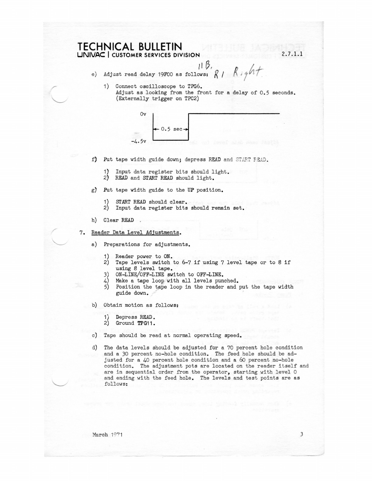
e)
Adj"Llst
read
delay
19FOO
as
follows:
R /
f)
g)
1) Connect
oscilloscope
to
TPG6.
Put
1)
2)
Put
1)
2)
Adjust
as
looking
from
the
front
for
a
delay
of
0.5
seconds.
(Externally
trigger
on
TPC2)
Ov
-4.5v
tape
width
guide
down;
depress
READ
and 8T
PET
f,
EAD .
Input
data
register
bits
should
light.
READ
and
START
READ
should
light.
tape
width
guide
to
the
UP
position.
START
READ
should
clear.
Input
data
register
bits
should
remain
set.
h)
Clear
READ
7.
Reader
Data
Level
Adjustments.
a)
Preparations
for
adjustments.
1)
Reader
power
to
ON.
2) Tape
levels
switch
to
6-7
if
using
7
level
tape
or
to
8
if
using
8
level
tape.
3) ON-LINE/OFF-LINE
switch
to
OFF-LINE.
4)
Make
a
tape
loop
with
all
levels
punched.
5)
Position
the
tape
loop
in
the
reader
and
put
the
tape
width
guide
down.
b)
Obtain
motion
as
follows:
1)
Depress
READ.
2) Ground TPG11.
c}
Tape
should
be
read
at
normal
operating
speed.
d) The
data
levels
should
be
adjusted
for
a 70
percent
hole
condition
and a 30
percent
no-hole
condition.
The
feed
hole
should
be
ad-
justed
for
a 40
percent
hole
co
nd
ition
and a 60
percent
no-hole
condition.
The
adjustment
pots
are
located
on
the
re
ader
itself
and
are
in
se
qu
entia
l o
rd
er
from
the
operator,
starting
with
level
0
and end
in
g
with
the
feed
hole.
The
levels
and
test
points
are
as
follows:
Ma
rch
1°
71
:3
TECHNICAL
BULLETIN
UNIVAC
I CUSTOMER SERVICES
DIVISION
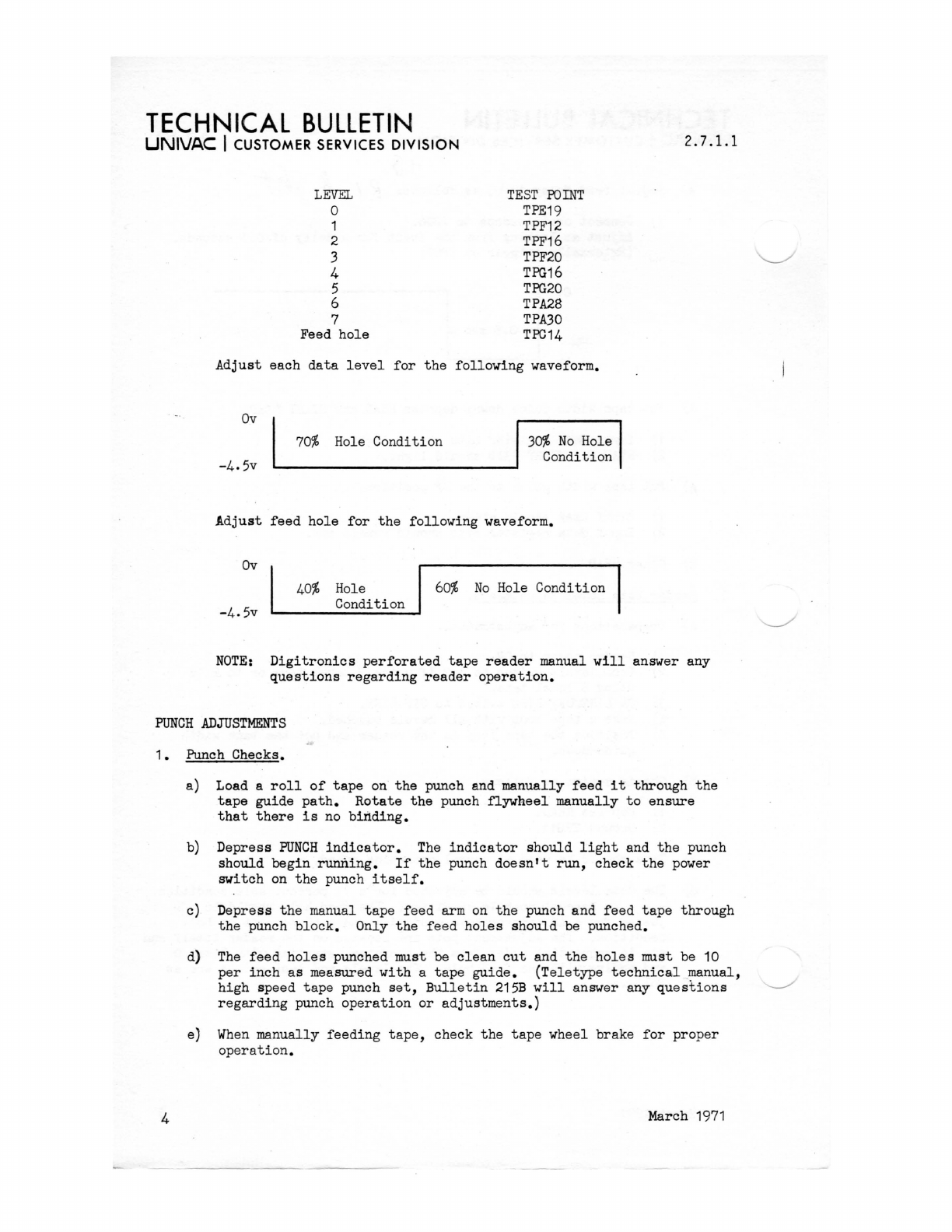
LEVEL
o
1
2
3
4
5
6
7
Feed
hole
TEST
POINT
TPE19
TPF12
TPF16
TPF20
TPG16
TPG20
TPA28
TPA30
TPC14
Adjust
each
data
level
for
the
following
waveform.
Ov
-4.5v
70%
Hole
Condition
30%
No
Hole
Condition
Adjust
feed
hole
for
the
following
waveform.
Ov
-4.5v
40%
Hole
Condition
60%
No
Hole
Condition
2.7.1.1
NOTE:
Digitronics
perforated
tape
reader
manual
will
answer any
questions
regarding
reader
operation.
PUNCH
ADJUSTMENTS
1.
Punch Checks.
a) Load a
roll
of
tape
on
the
punch and
manually
feed
it
through
the
tape
guide
path.
Rotate
the
punch
flywheel
manually
to
ensure
that
there
is
no
binding.
b)
Depress
PUNCH
indicator.
The
indicator
should
light
and
the
punch
should
begin
running.
If
the
punch
doesn't
run,
check
the
power
switch
on
the
punch
itself.
c)
Depress
the
manual
tape
feed
arm
on
the
punch
and
feed
tape
through
the
punch
block.
Only
the
feed
holes
should
be punched.
d)
The
feed
holes
punched must be
clean
cut
and
the
holes
must be 10
per
inch
as
measured
with
a
tape
guide.
(Teletype
technical
_manual,
high
speed
tape
punch
set,
Bulletin
215B
will
answer any
questions
~
regarding
punch
operation
or
adjustments.)
e)
When
manually
feeding
tape,
check
the
tape
wheel
brake
for
proper
operation.
4 March
1971
TECHNICAL
BULLETIN
UNIVAC
I CUSTOMER SERVICES
DIVISION
2.7.1.1
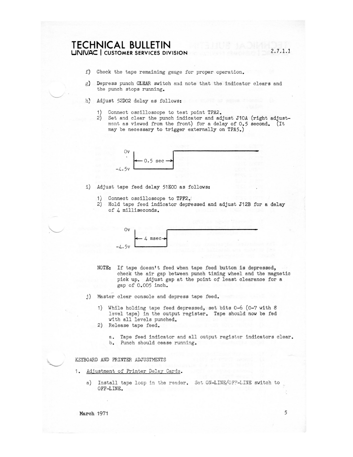
f)
Check
the
tape
remaining
gauge
for
proper
operation
.
g)
Depress
punch
CLEAR
switch
and
note
that
the
indicator
clears
and
the
punch
stops
running
.
h)
Adjust
52D02
delay
as
follows:
1) Connect
oscilloscope
to
test
point
TPA2.
2)
Set
and
clear
the
punch
indicator
and
adjust
J10A
(right
adjust-
ms
nt
as
viewed from
the
front)
for
a
delay
of
0.5
second.
(It
may
be
necessary
to
trigger
externally
on TPA5.)
i)
Adjust
tape
feed
delay
51EOO
as
follows:
1) Connect
oscilloscope
to
TPF2.'
2)
Hold
tape
feed
indicator
depressed
and
adjust
J12B
for
a
delay
of
4
milliseconds.
NOTE:
If
tape
doesn't
feed
when
tape
feed
button
is
depressed,
check
the
air
gap between punch
timing
wheel
and
the
magnetic
pick
up.
Adjust
gap
at
the
point
of
least
cl
earan
ce
for
a
gap
of
0. 005
inch.
j)
Master
clear
console
and
depress
tape
feed.
1)
While
holding
tape
feed
depressed,
set
bits
0- 6
(0-7
with
8
level
tape)
in
the
output
register.
Tape
should
now
be
fed
with
all
levels
punched.
2)
Release
tape
feed
.
a . Tape
feed
indicator
and
all
output
regis
t er
indicators
clear.
b. Punch
should
cease
run
n
ing.
KEYBOARD
AND
PRINTER
ADJUSTMENTS
1.
Adj
u
stment
of
Printer
De
~
ay
Ca
rds.
a)
Install
tape
loop
in
th
e r eader . Set
ON
-LI
N
E
/
O
F~
-
L
I
N E
switch
to
OFF-LINE
.
March 1971 5
TECHNICAL
BULLETIN
UNIVAC
I CUSTOMER SERVICES
DIVISION
2.7.1.1
b)
Set
tape
width
guide
to
the
dow
n
po
si
t
io
n.
c)
Set
READ,
START
READ,
PRINT
and
put
the
READ/READ·~)NE
switch
to
READ.
d)
Conn
e
ct
scope
to
TPC
22
and
adju
st J25C
(76H
02
)
for
a 4
milli-second
del
ay.
e)
Adjust
serializer
delays
at
th
e
followin
g
test
points
for
th
e
speci-
fied
delay.
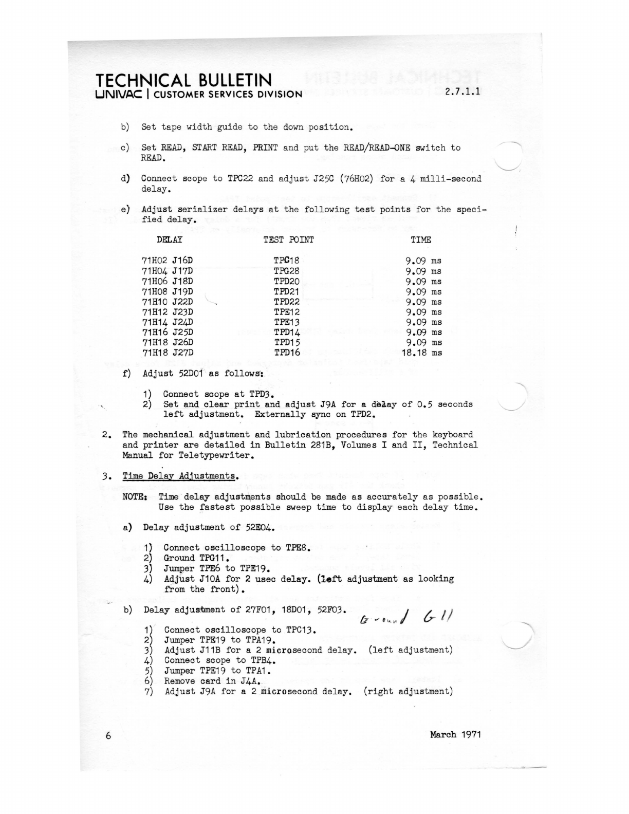
f)
DELAY
TEST
POINT
TIME
71H
02
J16D
TFC18
9.09
ms
71H04
J17D
TPG28
9.09
ms
71H06
J18D
TPD20
9.09
ms
71H08
J19D
TPD21
9.09
ms
71H10
J22D
TPD22
9.09
ms
71H12
J23D
TPE12
9.09
ms
71H14
J24D
TPE13
9.09
ms
71H16
J25D
TPD14
9.09
ms
71H18
J26D
TPD15
9.09
ms
71H18
J27D
TPD16
18.18
ms
Adjust
52D01
as
follows
':
1) Connect scope
at
TPD3.
2)
Set
and
clear
print
and
adjust
J9A
for
a
de.J.ay
of
0.5
sec
onds
left
adjustment.
Externally
sync on
TPD2.
2.
The
mechanical
adjustment
and
lubrication
procedures
for
the
keyboard
and
printer
are
detailed
in
Bulletin
281B, Volumes I and
II,
Technical
Manual
for
Teletypewriter.
3.
Time
Delay
Adjustments.
6
NOTEz
Time
delay
adjust~ents
should
be
made
as
accurate
ly
as
possible.
Use
the
fastest
possible
sweep time
to
display
each
delay
time.
a}
Delay
adjustment
of
52E04.
1)
Connect
oscilloscope
to
TPE8.
2)
Ground
TPG11.
3) Jumper
TPE6
to
TPE19.
4)
Adjust
J10A
for
2
usec
delay.
(left
adjustment
as
looking
from
the
front).
b) Delay
adjustment
of
27F01, 18D01, 52F03.
tr
1/
1) Connect
oscilloscope
to
TPC13.
2)
Jumper
TPE19
to
TPA19.
3)
Adjust
J11B
for
a 2 microsecond
delay.
(left
adjustment)
4) Connect scope
to
TPB4.
5)
Jumper
TPE19
to
TPA1.
6)
Remove
card
in
J4A.
7)
Adjust
J9A
for
a 2 microsecond
delay.
(right
adjustment)
March
1971
TECHNICAL
BULLETIN
UNIVAC
I CUSTOMER SERVICES
DIVISION
2.7.1.1
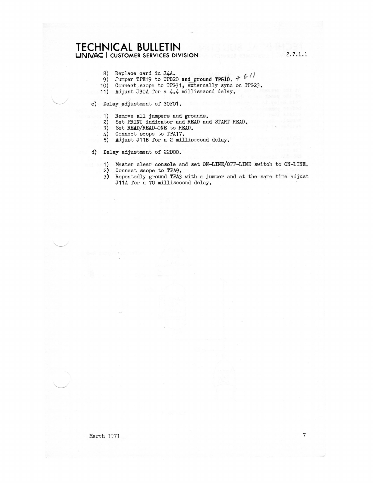
8) Replace
card
in
J4A.
6-
!)
9) Jumper
TPE19
to
TPB20
and ground
TPGio.
~
10) Connect scope
to
TPG31,
externally
s~c
on
TPG23.
11)
Adjust
J30A
for
a 4.4
millisecond
delay.
c) Delay
adjustment
of
30F01.
1)
Remove
all
jumpers and
grounds.
2)
Set
PRINT
indicator
and
READ
and
START
READ.
3)
Set
READ/READ-ONE
to
READ.
4)
Connect scope
to
TPA17.
5)
Adjust
J11B
for
a 2
millisecond
delay.
d) Delay
adjustment
of
22DOO.
1) Master
clear
console
and
set
ON-LINE/OFF-LINE
switch
to
ON-LINE.
2}
Connect scope
to
TPA9.
3)
Repeatedly
ground
TPA3
with
a jumper and
at
the
same
time a
djust
J11A
for
a 70
millisecond
delay.
March
19
71
7
TECHNICAL
BULLETIN
UNIVAC I CUSTOMER SERVICES
DIVISION
2.7.1.2
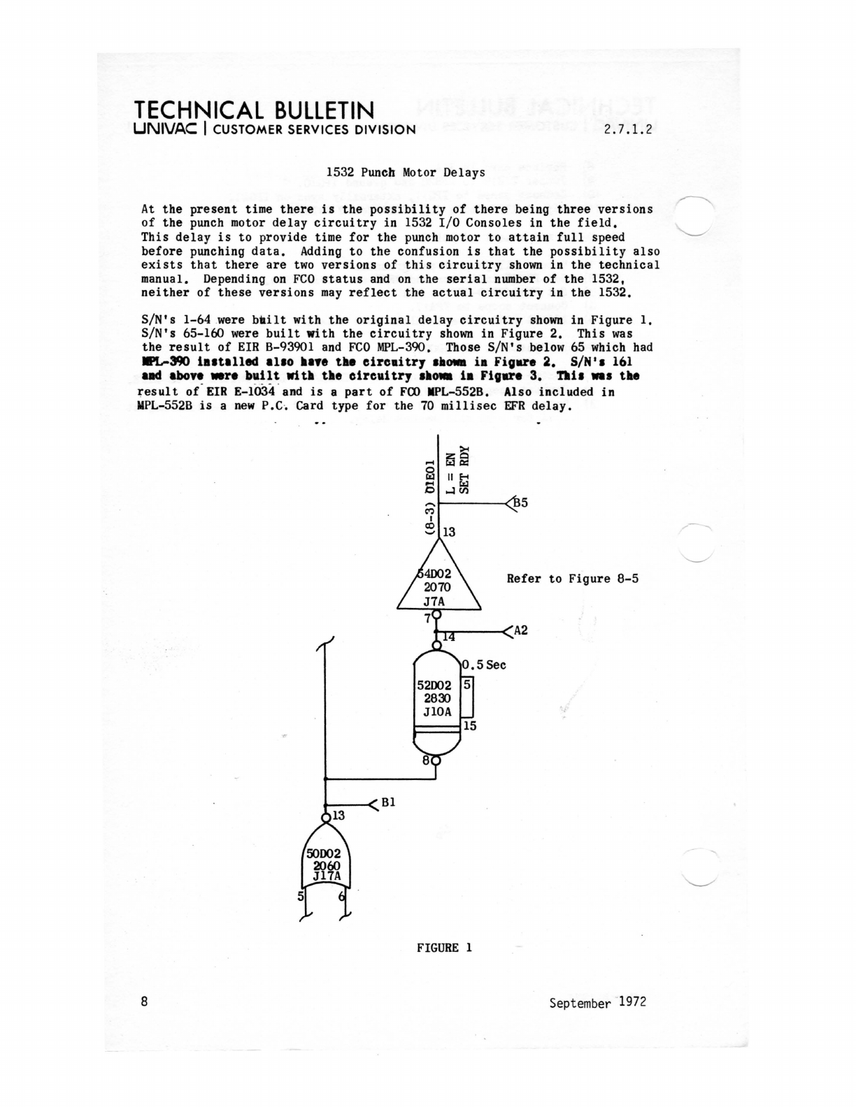
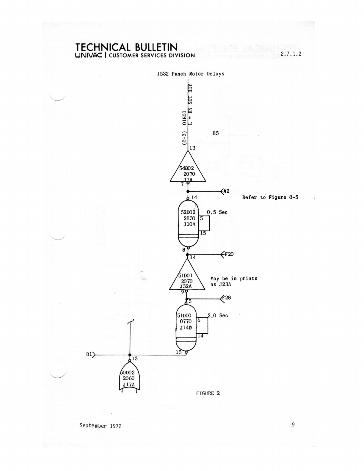
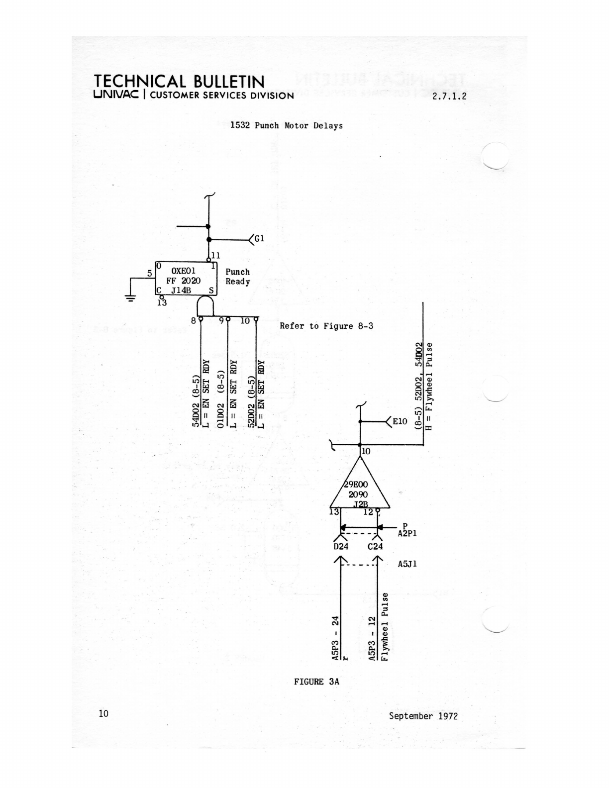
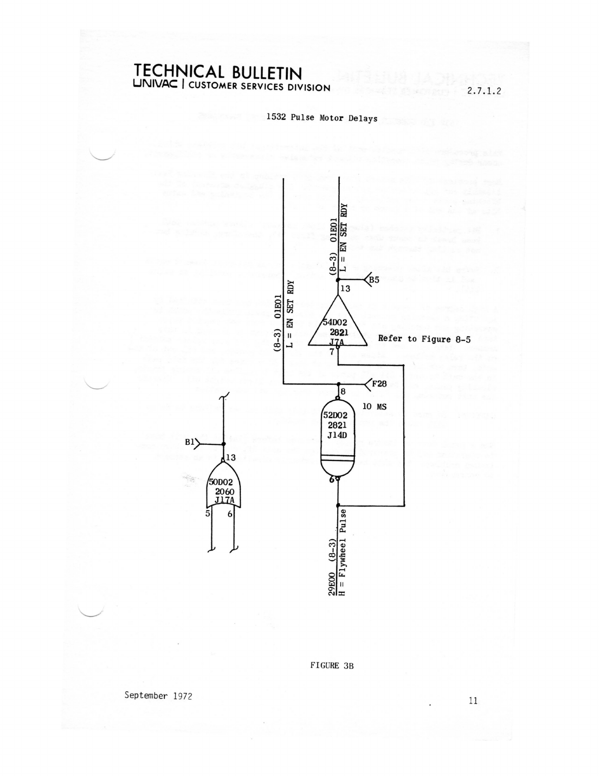
1532 Punch
Motor
Delays
At
the
present
time
there
is
the
possibility
of
there
being
three
versions
of
the
punch motor
delay
circuitry
in
1532
I/O Consoles
in
the
field.
This
delay
is
to
provide time
for
the
punch motor
to
attain
full
speed
before
punching
data.
Adding
to
the
confusion
is
that
the
possibility
also
exists
that
there
are
two
versions
of
this
circuitry
shown
in
the
technical
manual. Depending
on
FCO
status
and
on
the
serial
number
of
the
1532,
neither
of
these
versions
may
reflect
the
actual
circuitry
in
the
1532.
SIN's 1-64 were
bhilt
with
the
original
delay
circuitry
shown
in
Figure
1.
SIN's
65-160 were
built
with
the
circuitry
shown
in
Figure
2. This
was
the
result
of
EIR
B-93901
and
FCO
MPL-39O.
Those
SiN's
below
65
which
had
1PL-390
ialtalled
al.o
~Iye
t~.
circaitry
.aowa
ia
Fig.re
2.
SiN'.
161
lad
abo"
wr.
bull
t
wi
t~
the
circui
try
.~o_
i.
Figar.
3.
nil
w.
t~e
result
of-ElK E-1034 'and
is
8
part
of
FOO
IPL-552B. Also
included
in
IIPL-552B
is
a
new
P.C. Card type
for
the 70
millisec
EFR
delay.
~
:z:~
~o::
0
~
liE-!
S
...:I~
.....
5
M
,
co
13
'-'
Refer
to
Figure
8-5
......
r---<A2
1----<
Bl
FIGURE
1
8 September
1972
TECHNICAL
BULLETIN
UNIVAC
I CUSTOMER SERVICES
DIVISION
2.7.1.2
1532
Punch
Motor Delays
B5
.-.------(.
A2
Refer
to
'
Figure
8-5
6-:-.----~F20
May
be
in
prints
as
J23A
....
---.£f28
Bl>-------~----------~~
FIGURE
2
September
1972 9
TECHNICAL
BULLETIN
UNIVAC
I CUSTOMER SERVICES
DIVISION
5
1532
Punch
Motor
Delays
...---~Gl
11
Punch
Ready
2.7.1.2
Refer
to
F
igure
8-3
10
NEil
8
II
...-i
0....:1
FIGURE
D24
-.:1'
C'\I
C'";)
c..
U")
<l:J.i
3A
.....
--<
ElO
P
A2Pl
C24
A5Jl
Q)
III
...-i
:s
c..
N
...-i ...-i
Q)
I
Q)
.c
C'";)
~
c..
U") ...-i
<I:
t...
September 1972
TECHNICAL
BUllETIN
UNIVAC I CUSTOMER SERVICES
DIVISION
2.7.1.2
1532 Pulse Motor Delays
~
53
"""'
g~
"""'(/)
0 z:
w
"'"
C')
"
I
co
...;j
'-'
~
85
0
13
ex:
"""'
@
~
"""'(/)
0 z:
w
"'"
C')
"
I
co...;j
Refer
to
Figure
8-5
'-'
L-.
___
+-_-(
F28
81,-----.,.
13
FIG
U
RE
38
September 1972
11
TECHNICAL
BULLETIN
UNIVAC
I CUSTOMER SERVICES
DIVISION
2.7.1.3
1532 I/O
CONSOLE,
TTY
BRPE-11
PUNCH
CLEANING
PROCEDURE
This procedure
will
resolve
most
of
the
intermittant
bit
problems which
occur
during
punch
operation
without
extensive
disassembly
or
realignment.
Most problems
of
this
nature
stem from
dirt
buildup
in
the
Blocking Pawl
Assembly and
not
in
mechanical
alignment.
The
sluggish
movement
of
the
blocking
pawls cause
partially
punched
bits
at
the
beginning
and
extra
bits
at
the
end
of
a frame
or
block
of
"1's".
1.
Bit
partially
punched
(sluggish
block
movement
allows
partial
pawl
knee
break
to
occur
when
punching
first
"1",
therefore,
marking
but
not
cutting
through
the
tape).
2.
-
Extra
bit
after
punching a "1"
(sluggish
block
movement
doesn't
catch
pawl
in
time
to
cause
pawl knee
action,
therefore,
punching an
extra
bit).
A
high
degree
of
success
in
resolving
this
problem has been
attained
by
squirting
a
cleaning
solvent
into
the
blocking
pawls while
the
punch
is
operating
and punching
all
"1'
sn.
This
portion
does
not
require
paper
tape
in
the
punch and
the
whole mechanical
unit
can be
cleaned
in
this
manner. Take
care
not
to
get
caught
in
the
moving
parts
or
splash
solvent
on
the
relay
pullers.
Rinse
all
of
the
dirt,
old
grease,
and
oil
out
of
the
unit,
turn
off
'
the
punch, and
allow
at
least
30 minutes
for
the
felt
pads
in
the
unit
to
dry.
Oil
all
parts
of
the
unit
including
all
moving
joints,
blocking
pawls, and
felt
pads
with
a good grade
light
weight
oil.
Operate
the
unit
punching
all
"1'
s"
to
insure
thorough
oil
penetration.
~
CAUTION:
Be
sure
to
saturate
all
felt
pads
with
oil
as
failure
to
do
so
will
cause
the
punch~
wear
rapidly.
Run
a punch
test
to
insure
proper
operation
before
placing
the
unit
back
in
operation
and
be
prepared
to
realign
the
unit
if,
due
to
the
above men-
tioned
problems,
the
unit
had been
previously
misaligned
in
an
attempt
to
compensate.
12
February
1970
TECHNICAL
BULLETIN
UNIVAC
I CUSTOMER SERVICES
DIVISION
2.7.2
1532
MISCELLANEOUS
NOTES
TALOS
ASSEMBLY
BOARD
REPLACEMENT
If
the
capacitor-coil
assembly
board,
part
number 7051182-00,
is
replaced
on
the
teletypewriter
of
TALOS
1532's
below
sIN
165,
it
should
be
modified
to
the
same
shape
as
the
one
it
is
replacing.
The
board
(located
in
the
front
left
corner)
will
interfere
with
the
teletypewriter
door
latch
unless
it
is
modified
by
filing
off
the
corner
of
the
board.
The
board
has been
moved
to
a
new
position,
out
of
the
way
of
the
door
latch,
on
TALOS
1532's
sIN
165 and
up.
1532
I/O
Console
Modification
For
Operation
In
Keyboard
Interrupt
Mode
1.
As
of
1973
SSN-688
and
DDG
NTDS
systems
and
others
for-
seen
may
desire
to
use
the
1532
I/O
Console
for
Tele-
typewriter
Keyboard
Interrupt
generation
in
the
mock-up
or
tactical
environment
or
both.
2.
To
place
the
1532
I/O
Console
constantly
in
keyboard
interrupt
mode
without
the
necessity
of
holding
keyboard
interrupt
indicator
switch
XDS22
constantly
depressed
it
is
suggested
that
pin
3
of
indicator
switch
XDS22
be
shorted
to
pin
5
to
effect
continuous
keyboard
interrupt
mode.
3.
This
continuity
may
be
selectively
switched
thru
the
usage
of
an
externally
attached
on-off
micro
switch
attached
to
the
1532
control
panel
front
and
wired
to
XDS22.
Alternately,
if
not
in
conflict
with
paper
tape
reading
requirements
on
site,
paper
tape
LEVEL SWITCH
52
may
be
wired
at
pin
10
and
1
or
2
or
3
as
desired
to
obtain
continuity
when
switch
is
in
positions
5
or
6-7
or
8
respectively.
4.
Any
such
modifications
to
the
1532
I/O
Console
are
unofficial
and
should
be
temporarily
plugged
only
as
necessary
on
site
and
removed
if
console
is
moved
to
any
new
usage.
November
1976
1
TECHNICAL
BULLETIN
UNIVAC
I CUSTOMER SERVICES
DIVISION
PRODUCT
1532
November
1980
UNIVAC
EQUIPMENT
MANUALS
HARDWARE
NAME
I/O
Console
Maintenance Study
Guide
Maintenance Test
18-30
Bit
Digitronics
Reader
2.7.3
PX
NO.
3618-0-2
3949-0-1
4236-0-2
3871-0-1
1
