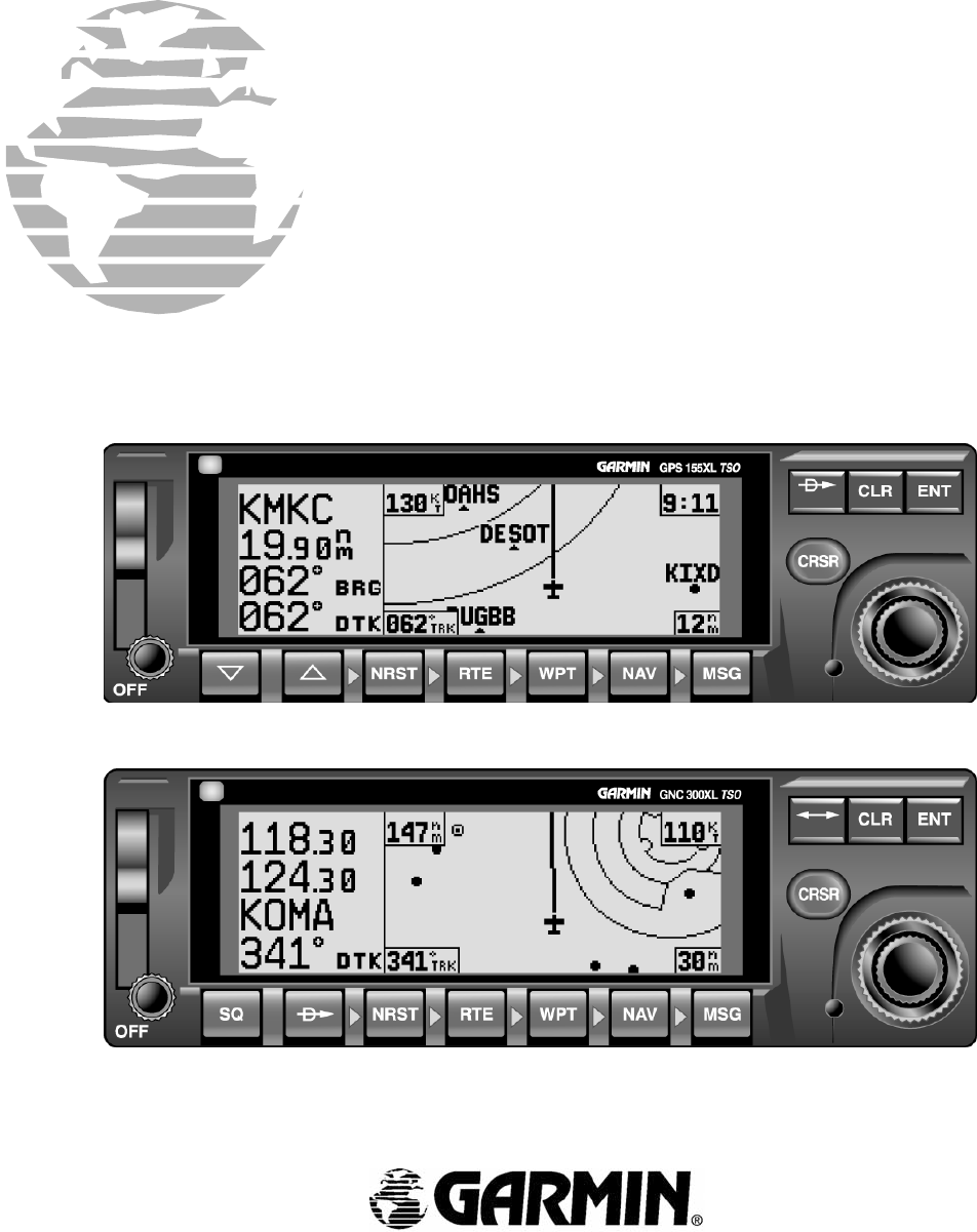
300XL 155 & Installation Manual
User Manual: 300XL
Open the PDF directly: View PDF ![]() .
.
Page Count: 57
*36;/*1&;/
,167$//$7,210$18$/
Garmin International
1200 E. 151st Street
Olathe, KS 66062 USA
190-00067-22 (Rev E) September 2000

GPS 155XL/GNC 300XL Installation Manual
P/N 190-00067-22 Rev E Page i
© Copyright 2000
GARMIN Corporation
All Rights Reserved
Except as expressly provided below, no part of this manual may be reproduced, copied, transmitted, disseminated, downloaded or
stored in any storage medium, for any purpose without the express prior written consent of GARMIN Corporation. GARMIN
Corporation hereby grants permission to download a single copy of this manual and of any revision to this manual onto a hard
drive or other electronic storage medium to be viewed and to print one copy of this manual or of any revision hereto, provided that
such electronic or printed copy of this manual or revision must contain the complete text of this copyright notice and provided
further that any unauthorized commercial distribution of this manual or any revision hereto is strictly prohibited.
GARMIN International, Inc.
1200 E. 151st Street
Olathe, KS 66062 USA
Telephone: 913-397-8200
Dealer Line: 1-800-800-1420
Web Site Address: www.garmin.com
REVISION RECORD
REVISIONREVISION
DATE
DESCRIPTION
A02/03/98Initial Release
B03/31/98Misc Changes
C06/22/98Changes to Figure 5-1, Misc Changes
D10/12/99Add German Certification, JTSO, Plus Misc Changes
E 9/07/00 Add Export Control Laws, Correct Fig 5-6, Add ICA, Sec 6
GPS 155XL/GNC 300XL Installation Manual
P/N 190-00067-22 Rev E Page ii
GENERAL MAINTENANCE PRECAUTIONS
The following are general safety precautions that are not related to any specific procedure and therefore do not
appear elsewhere in this maintenance manual. These are recommended precautions that personnel should understand
and apply during the many phases of maintenance and repair.
KEEP AWAY FROM LIVE CIRCUITS. Maintenance personnel shall observe all safety regulations at all times.
Do not replace components inside the equipment when potentially lethal voltages are present. Turn off system power
before making or breaking electrical connections. Regard any exposed connector, terminal board, or circuit board as
a possible shock hazard. Components that retain a charge shall be discharged only when such grounding does not
result in equipment damage. If a test connection to energized equipment is required, make the test equipment ground
connection before probing the voltage or signal to be tested.
DO NOT SERVICE ALONE. Personnel shall not under any circumstances reach into or enter any enclosure for the
purpose of servicing or adjusting the equipment without immediate presence or assistance of another person capable
of rendering aid.
INFORMATION SUBJECT TO EXPORT CONTROL LAWS
This document may contain information which is subject to the Export Administration Regulations ("EAR")
issued by the United States Department of Commerce (15 CFR, Chapter VII, Subchapter C) and which may
not be exported, released, or disclosed to foreign nationals inside or outside of the United States without first
obtaining an export license. A violation of the EAR may be subject to a penalty of up to 10 years
imprisonment and a fine of up to $1,000,000 under Section 2410 of the Export Administration Act of 1979.
Include this notice with any reproduced portion of this document.
Specialized test equipment and extensive depot level repair training are required for testing the equipment covered in this manual.
Therefore, this manual may not be used to test or repair the subject equipment unless the using facility has been specifically
authorized by GARMIN to do so. This manual does not need to be kept current if it only used for reference purposes.

GPS 155XL/GNC 300XL Installation Manual
P/N 190-00067-22 Rev E Page iii
TABLE OF CONTENTS
SECTION 1
GENERAL DESCRIPTION
PARAGRAPH PAGE
1.1 INTRODUCTION .............................................................................................................................1-1
1.2 TECHNICAL CHARACTERISTICS ............................................................................................... 1-1
1.2.1 Physical Characteristics .........................................................................................................1-1
1.2.2 Operational Characteristics....................................................................................................1-1
1.2.3 Interfaces................................................................................................................................1-2
1.2.4 J101 Connector Pin Functions ...............................................................................................1-2
1.2.5 J102 Connector Pin Functions ...............................................................................................1-3
1.2.6 Comm Antenna Connector (J4, GNC 300XL Only)..............................................................1-3
1.3 LICENSE REQUIREMENTS........................................................................................................... 1-4
1.4 CERTIFICATION .............................................................................................................................1-4
1.4.1 German Certification..............................................................................................................1-4
1.5 LIMITED WARRANTY................................................................................................................... 1-5
SECTION 2
INSTALLATION
2.1 INTRODUCTION .............................................................................................................................2-1
2.2 ANTENNA CONSIDERATIONS ....................................................................................................2-1
2.2.1 GPS Antenna Location...........................................................................................................2-1
2.2.2 Communication Antenna Location (GNC 300XL)................................................................2-1
2.2.3 Electrical Bonding..................................................................................................................2-1
2.2.4 Antenna Limitations...............................................................................................................2-1
2.2.5 VHF Comm Interference of GPS...........................................................................................2-2
2.2.6 Comm Antenna Installation Considerations (GNC 300XL)..................................................2-3
2.3 RACK CONSIDERATIONS.............................................................................................................2-3
2.3.1 Accessibility........................................................................................................................... 2-3
2.4 CABLING AND WIRING ................................................................................................................ 2-3
2.5 COOLING AIR..................................................................................................................................2-3
2.6 MINIMUM INSTALLATION REQUIREMENTS...........................................................................2-4
2.7 EXTERNAL ALTITUDE INPUT.....................................................................................................2-5

GPS 155XL/GNC 300XL Installation Manual
P/N 190-00067-22 Rev E Page iv
SECTION 3
INSTALLATION PROCEDURE
PARAGRAPH PAGE
3.1 INSTALLATION ACCESSORIES...................................................................................................3-1
3.2 DATA BASE OPTIONS ................................................................................................................... 3-2
3.3 ANNUNCIATOR OPTIONS ............................................................................................................3-2
3.4 MISCELLANEOUS OPTIONS ........................................................................................................3-3
3.5 REQUIRED INSTALLATION ACCESSORIES NOT SUPPLIED................................................. 3-3
3.6 ANTENNA INSTALLATION.......................................................................................................... 3-3
3.7 CABLE INSTALLATION ................................................................................................................3-4
3.8 RACK INSTALLATION..................................................................................................................3-6
3.9 GPS 155XL/GNC 300XL INSTALLATION AND REMOVAL ..................................................... 3-6
3.10 J101 & J102 PIN FUNCTIONS ........................................................................................................3-7
3.11 COMM ANTENNA INSTALLATION CHECK (GNC 300XL) .....................................................3-8
SECTION 4
POST-INSTALLATION CONFIGURATION & CHECKOUT PROCEDURE
4.1 INTRODUCTION .............................................................................................................................4-1
4.2 TEST MODE OPERATIONS...........................................................................................................4-1
4.3 INSTALLATION CONFIGURATION............................................................................................. 4-1
4.3.1 Display Adjustment................................................................................................................ 4-2
4.3.2 I/O Channel 1.........................................................................................................................4-2
4.3.3 ARINC 429 Channel.............................................................................................................. 4-3
4.3.4 CDI Calibration...................................................................................................................... 4-5
4.3.5 Selected Course Calibration................................................................................................... 4-5
4.3.6 Approach Settings..................................................................................................................4-5
4.3.7 Configuration .........................................................................................................................4-6
4.3.8 Remote Battery Settings......................................................................................................... 4-6
4.3.9 I/O Channel 2.........................................................................................................................4-7
4.4 GROUND TEST................................................................................................................................4-7
4.4.1 Power Test..............................................................................................................................4-8
4.4.2 CDI and Flag Test .................................................................................................................. 4-8
4.4.3 Annunciator Test....................................................................................................................4-9
4.4.4 External Switch Test ..............................................................................................................4-9
4.4.5 Communications Loopback Test..........................................................................................4-10
4.4.6 Altitude Input Test ...............................................................................................................4-10

GPS 155XL/GNC 300XL Installation Manual
P/N 190-00067-22 Rev E Page v
PARAGRAPH PAGE
4.4.7 OBI Test...............................................................................................................................4-10
4.4.8 Signal Acquisition Test........................................................................................................ 4-10
4.5 VHF COMM INTERFERENCE CHECK.......................................................................................4-11
4.6 VHF COMM CHECK (GNC 300XL)............................................................................................. 4-11
SECTION 5
DIAGRAMS
5.1 GENERAL......................................................................................................................................... 5-1
SECTION 6
CONTINUED AIRWORTHINESS
6.1 CONTINUED AIRWORTHINESS...................................................................................................6-1
APPENDIX A
CERTIFICATION DOCUMENTS
A.1 GENERAL........................................................................................................................................ A-1
A.2 ENVIRONMENTAL QUALIFICATION FORM—GPS 155XL/GNC 300XL.............................. A-2
A.3 ENVIRONMENTAL QUALIFICATION FORM—GA 56 GPS AVIATION ANTENNA............ A-3
APPENDIX B
CONNECTOR CHANGES
B.1 REMOTE BATTERY PIN ASSIGNMENTS.................................................................................. B-1
APPENDIX C
STC PERMISSION
C.1 GPS 155XL ...................................................................................................................................... C-1
C.2 GNC 300XL ..................................................................................................................................... C-1

GPS 155XL/GNC 300XL Installation Manual
P/N 190-00067-22 Rev E Page vi
LIST OF FIGURES
FIGURE PAGE
2-1 GPS ANTENNA INSTALLATION CONSIDERATIONS ..............................................................2-2
2-2 SWITCH/ANNUNCIATOR LAYOUT ............................................................................................2-4
3-1 COAX CABLE INSTALLATION.................................................................................................... 3-5
3-2 VIEW OF J101 FROM BACK OF RACK ....................................................................................... 3-7
3-3 VIEW OF J102 FROM BACK OF RACK ....................................................................................... 3-8
5-1 GA 56 ANTENNA INSTALLATION DRAWING.......................................................................... 5-2
5-2 AVIATION RACK DIMENSIONS ..................................................................................................5-3
5-3 AVIATION RACK INSTALLATION.............................................................................................. 5-4
5-4 INTERCONNECT WIRING DIAGRAM, REMOTE BATTERY AND ENCODING
ALTIMETER CONNECTIONS .......................................................................................................5-5
5-5 INTERCONNECT WIRING DIAGRAM, NAVIGATION INDICATOR CONNECTIONS.......... 5-6
5-6 INTERCONNECT WIRING DIAGRAM, BENDIX/KING KI 209A CONNECTIONS.................5-7
5-7 INTERCONNECT WIRING DIAGRAM, SWITCH ANNUNCIATOR CONNECTIONS.............5-8
5-8 INTERCONNECT WIRING DIAGRAM, OPTIONAL ACCESSORY CONNECTIONS..............5-9
5-9 INTERCONNECT WIRING DIAGRAM, AUDIO CONNECTIONS .............................................5-10
GPS 155XL/GNC 300XL Installation Manual
P/N 190-00067-22 Rev E Page 1-1
SECTION 1
GENERAL DESCRIPTION
1.1 INTRODUCTION
This manual describes the physical, mechanical, and electrical characteristics and the installation requirements for the
GPS 155XL/GNC 300XL Aviation Kit. After installation of the GPS 155XL/GNC 300XL system, FAA Form 337
must be completed by an appropriately certified agency to return the aircraft to service.
1.2 TECHNICAL CHARACTERISTICS
The conditions and tests required for TSO C129a approval of the GPS 155XL/GNC 300XL are minimum
performance standards. It is the responsibility of the agency installing this system either on or within a specific type
or class of aircraft to determine that the aircraft installation conditions are within the TSO standards. The system
may be installed only if evaluation by the applicant documents an acceptable installation and is approved by the
administrator. For TSO/JTSO Compliance, see Appendix A.
1.2.1 Physical Characteristics
Width 6.25 inches
Height 2 inches
Depth 5.65 inches
GPS 155XL Weight (Unit Only) 2.05 lbs.
GNC 300XL Weight (Unit Only) 2.55 lbs.
GA 56 Antenna Weight .25 lbs.
Aviation Rack Weight (w/connector) .83 lbs.
Max Air Speed
(Structural rating for antenna) Subsonic
1.2.2 Operational Characteristics
Operating Temperature Range -20°C to +55°C
Humidity 95% non-condensing
Altitude Range -1,500 to 50,000 ft.
Power Range (GNC 300XL) 10 to 15.1 VDC
Power Range (GPS 155XL) 10 to 33 VDC
Power Requirements (GNC 300XL) 1.35A @ 13.8V (not transmitting);
5.5A @ 13.8V (transmitting)
Power Requirements (GPS 155XL) 0.95A @ 13.8V

GPS 155XL/GNC 300XL Installation Manual
P/N 190-00067-22 Rev E Page 1-2
1.2.3 Interfaces
The GPS 155XL/GNC 300XL provides an interface to various general aviation instruments. Table 3-2 defines the
function of each pin on the 37-pin DSUB connector located at the back of the rack. Table 3-3 lists the function of
each pin in the 26-pin HD-DSUB connector (J102) located above the 37-pin connector at the back of the rack.
Figures 5-4 through 5-7 define the interconnects between the rack and other instruments. J101 and J102 pin
functions are provided in paragraphs 1.2.4 and 1.2.5.
1.2.4 J101 Connector Pin Functions (37-pin)
CDI
(Pins 1 and 4) Capable of driving up to three 1000 ohm parallel loads, +150 millivolts
full scale deflection with a maximum output of +300 millivolts.
To/From
(Pins 2 and 4) Capable of driving up to three 200 ohm parallel loads, +190 millivolts
full scale deflection.
Nav Flag
(Pins 3 and 4)
Capable of driving up to three 1000 ohm parallel loads, 375 millivolts
for flag out-of-view, and +40 millivolts for flag in-view.
OBI Data
(Pins 7, 8, and 23) Output providing bearing to waypoint data for a Bendix/King RMI (KI
229 or equivalent).
Message Annunciator
(Pin 20) Output capable of driving negative logic message annunciators by
sinking up to 500 mA.
RS232 Chan 1 Output Data
(Pin 24) Output capable of driving devices as listed in Section 4. Conforms to the
EIA specification RS-232C.
RS232 Chan 2 Output Data
(Pin 19) Output capable of driving devices as listed in Section 4. Conforms to the
EIA specification RS-232C.
RS232 Chan 1 Input Data
(Pin 17) Input capable of receiving data from devices listed in Section 4.
Conforms to the EIA specification RS-232C.
RS232 Chan 2 Input Data
(Pin 18) Input capable of receiving data from devices listed in Section 4.
Conforms to the EIA specification RS-232C.
Arrival Annunciator
(Pin 12) Output capable of driving negative logic annunciator by sinking up to
500 mA.
GPS Approach Active
Annunciator (Pin 13) Output capable of driving negative logic annunciator by sinking up to
500 mA. See GPS 155XL/GNC 300XL Pilot’s Guide (GPN 190-00067-
20 and 190-00067-30), for more information.
GPS Approach Arm
Annunciator (Pin 28) Output capable of driving negative logic annunciator by sinking up to
500 mA. See GPS 155XL/GNC 300XL Pilot’s Guide (GPN 190-00067-
20 and GPN 190-00067-30), for more information.
ARINC 429 Output A & B
(Pins 15 and 16) Output capable of interfacing with any device that has an input
conforming to the GAMA ARINC 429 (low speed) specification.
NAV Super Flag Output
(Pin 10) Output capable of driving positive logic NAV Super Flag by sourcing up
to 500 mA for flag out of view (NAV valid).
GPS Approach Arm Low
(Pin 9) Input, when grounded, controls approach mode.
GPS OBS
(Pins 4, 14, 35 and 37) Capable of interfacing with a standard OBS resolver.

GPS 155XL/GNC 300XL Installation Manual
P/N 190-00067-22 Rev E Page 1-3
ARINC 429 Input A & B
(Pins 32 and 33) Input capable of receiving data from ARINC 429 (low speed) devices as
listed in Section 4.
Battery +,-, Charge Enable
(Pins 30, 34, and 29) Connection for GARMIN remote battery accessory.
1.2.5 J102 Connector Pin Functions (26 pin)
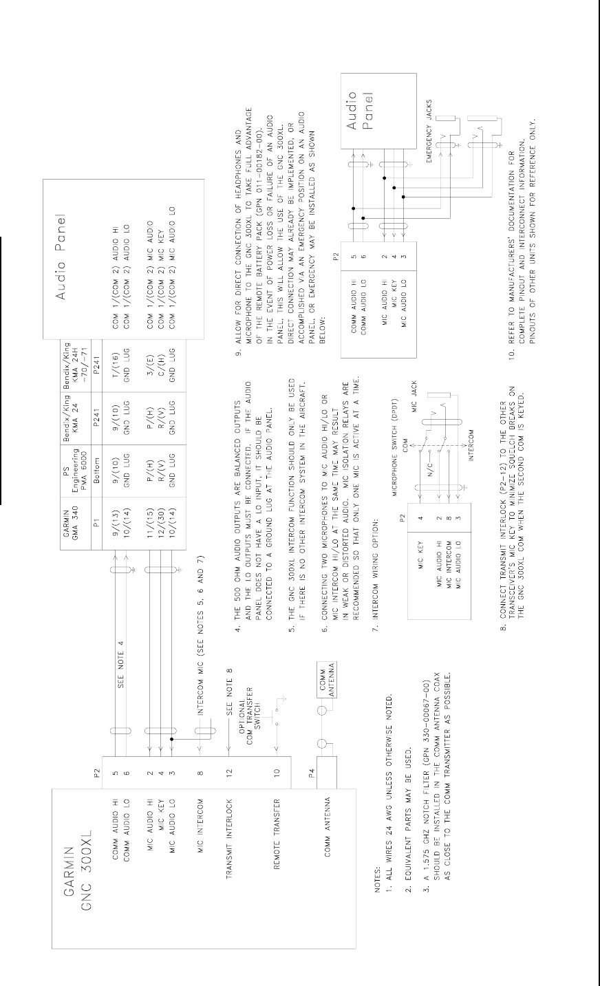
MIC Audio Hi and Lo
(Pins 2 and 3, GNC 300XL Only) Input requiring 275mV RMS into 470 ohm load
(Standard carbon or dynamic MIC containing
transistorized pre-amp).
MIC Key
(Pin 4, GNC 300XL Only) Input, when grounded, keys the transmitter.
COMM Audio Hi and Lo (Pins 5
and 6, GNC 300XL Only) Output capable of driving a 500-ohm load with 100mW.
MIC Intercom
(Pin 8, GNC 300XL Only) Input requiring 125 mV RMS into 470 ohm load
(Standard carbon or dynamic MIC containing
transistorized pre-amp).
Remote Transfer
(Pin 10, GNC 300XL Only) Input, when grounded, swaps the active and standby
COMM frequencies.
TX Interlock
(Pin 12, GNC 300XL Only) Input, when grounded, reduces receiver sensitivity so
squelch will not break when another transceiver is keyed.
Altimeter input
(Pins 14-24) Capable of receiving encoded output data from any
parallel altimeter device.
Remote Enter
(Pin 26) Input, when ground, functions the same as the enter key
on the GPS 155XL/GNC 300XL front panel.
Sequence Hold Low
(Pin 13) Input, when grounded, activates HOLD mode. See GPS
155XL Pilot’s Guide (GPN 190-00067-20) or the GNC
300XL Pilot's Guide (GPN 190-00067-30) for more
information.
1.2.6 Comm Antenna Connector (J4, GNC 300XL Only)
Capable of providing 5 watts, minimum, at 13.8V sensitivity of 6 dB SNR, minimum, at 2 uV hard. The COMM
antenna shall be approved to TSO C37( ) and C38( ).

GPS 155XL/GNC 300XL Installation Manual
P/N 190-00067-22 Rev E Page 1-4
1.3 LICENSE REQUIREMENTS
If any of these devices are connected to a personal computer used in home or in office, then the four following
paragraphs are applicable.
These devices comply with Part 15 of the FCC limits for Class B digital devices. This equipment generates, uses,
and can radiate radio frequency energy and, if not installed and used in accordance with the instructions, may
cause harmful interference to radio communications. However, there is no guarantee that interference will not
occur in a particular installation. If this equipment does cause harmful interference to other equipment, which can
be determined by turning the equipment off and on, the user is encouraged to try and correct the interference by
relocating the equipment or connecting the equipment to a different circuit than the affected equipment.
Consult an authorized dealer or other qualified avionics service technician for additional help if these remedies
do not correct the problem. These devices comply with Part 15 of the FCC rules. Operation is subject to the
following conditions: (1) This device may not cause harmful interference, and (2) this device must accept any
interference received, including interference that may cause undesired operation.
These units do not contain any user-serviceable parts. Repairs should only be made by an authorized GARMIN
service center. Unauthorized repairs or modifications could void your warranty and your authority to operate this
device under Part 15 Regulations.
The FCC requires GARMIN to inform users that these units meet the more stringent requirements "For Home or
Office Use".
The following guidance is provided to help ensure the proper licensing of the GNC 300XL Comm.
1. The Telecommunications Act of 1996 effective February 8, 1996 provides the FCC discretion to eliminate
radio station license requirements for aircraft. At present, an individual license to operate the GNC
300XL aboard a private aircraft is not needed in many circumstances. Please see FCC Fact Sheet PR5000
or contact the FCC at 1-800-322-1117 for more information.
2. No license change is required for aircraft that already have a station license per FCC 404 Instructions
dated 1994.
3. If an aircraft license is required or desired, contact the FCC at 1-800-322-1117 to request FCC form 404,
“Application for Aircraft Radio Station License,” to apply for FCC authorization. The FCC also has a
"Fax on Demand" service to provide forms by fax at 202-418-0177.
1.4 CERTIFICATION
The GNC 300XL/GPS 155XL is certified for IFR enroute, terminal, and non-precision approaches. The GNC
300XL/GPS 155XL initial certification was accomplished via an STC by GARMIN in a Piper PA32 aircraft. See
Appendix C for a copy of the STCs.
All installations must be certified. For more information, see FAA Advisory Circular "Airworthiness Approval of
Global Positioning System (GPS) Navigation Equipment for use as a VFR and IFR Supplemental Navigation
System," Appendix 1. All new certifications after GARMIN's Piper PA32 installation will be "Follow-On."
1.4.1 German Certification
For installations required to meet German regulation REG TP 321 ZV 034, Lowpass Filter (GPN 330-00157-00)
must be installed on the GNC 300XL COM RF connector, J4, instead of the GPS Notch Filter (GPN 330-00067-00).

GPS 155XL/GNC 300XL Installation Manual
P/N 190-00067-22 Rev E Page 1-5
1.5 LIMITED WARRANTY
GARMIN Corporation warrants this product to be free from defects in materials and manufacture for one year from
the date of purchase. GARMIN will, at its sole option, repair or replace any components that fail in normal use.
Such repairs or replacement will be made at no charge to the customer for parts or labor. The customer is, however,
responsible for any transportation costs. This warranty does not cover failures due to abuse, misuse, accident or
unauthorized alteration or repairs.
THE WARRANTIES AND REMEDIES CONTAINED HEREIN ARE EXCLUSIVE AND IN LIEU OF ALL
OTHER WARRANTIES EXPRESS OR IMPLIED OR STATUTORY, INCLUDING ANY LIABILITY ARISING
UNDER ANY WARRANTY OF MERCHANTABILITY OR FITNESS FOR A PARTICULAR PURPOSE,
STATUTORY OR OTHERWISE. THIS WARRANTY GIVES YOU SPECIFIC LEGAL RIGHTS, WHICH MAY
VARY FROM STATE TO STATE.
IN NO EVENT SHALL GARMIN BE LIABLE FOR ANY INCIDENTAL, SPECIAL, INDIRECT OR
CONSEQUENTIAL DAMAGES, WHETHER RESULTING FROM THE USE, MISUSE, OR INABILITY TO USE
THIS PRODUCT OR FROM DEFECTS IN THE PRODUCT. SOME STATES DO NOT ALLOW THE
EXCLUSION OF INCIDENTAL OR CONSEQUENTIAL DAMAGES, SO THE ABOVE LIMITATIONS MAY
NOT APPLY TO YOU.
To obtain warranty service, call the GARMIN Customer Service department (913-397-8200) for a returned
merchandise tracking number. The unit should be securely packaged with the tracking number clearly marked on the
outside of the package and sent freight prepaid and insured to a GARMIN warranty service station. A copy of the
original sales receipt is required as the proof of purchase for warranty repairs. GARMIN retains the exclusive right
to repair or replace the unit or software or offer a full refund of the purchase price at its sole discretion. SUCH
REMEDY SHALL BE YOUR SOLE AND EXCLUSIVE REMEDY FOR ANY BREACH OF WARRANTY.

GPS 155XL/GNC 300XL Installation Manual
P/N 190-00067-22 Rev E Page 2-1
SECTION 2
INSTALLATION
2.1 INTRODUCTION
Careful planning and consideration of the suggestions in this section are required to achieve the desired performance
and reliability from the GPS 155XL/GNC 300XL.
2.2 ANTENNA CONSIDERATIONS
2.2.1 GPS Antenna Location
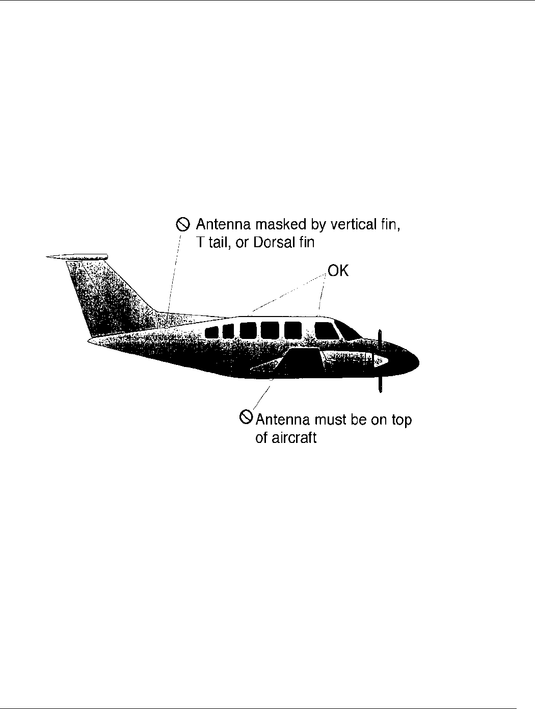
The GPS 155XL/GNC 300XL GA 56 Antenna must be mounted on top of the aircraft. For best performance, select a
location with an unobstructed view of the sky above the aircraft when in level flight. Figure 2-1 illustrates a typical
GPS antenna installation. The antenna should be located at least 3 feet from transmitting antennas such as VHF
Comm, HF transmitter, DME, Transponder, and Radar.
For rotorcraft, locate the GA 56 Antenna as far as possible from the main rotor hub. This reduces the percentage of
time the blade blocks the antenna. Also mount it as far below the blade surface as possible if installing the antenna
under the blade. This reduces signal distortion caused by the blades.
2.2.2 Communication Antenna Location (GNC 300XL)
The COMM antenna should be well removed from all projections, engines, and propellers. The ground plane surface
directly below the antenna should be a flat plane over as large an area as possible (18 inches square minimum). The
antenna should be mounted a minimum of 6 feet from any DME antennas, 4 feet from any ADF sense antennas, and 3
feet from the GNC 300XL and its GPS antenna.
The GNC 300XL COMM antenna connector is specified to have a 1.57542 GHz notch filter installed (GPN
330-00067-00) to minimize interfering harmonics.
Installations required to meet German regulation REG TP 321 ZV 034, must have Lowpass Filter (GPN 330-00157-
00) installed on the GNC 300XL COM RF connector J4 instead of the GPS Notch Filter (GPN 330-00067-00).
2.2.3 Electrical Bonding
No special precautions need to be taken to provide a bonding path between the GPS antenna and the aircraft
structure. Follow the manufacturer’s instructions for the COMM antenna (GNC 300XL).
2.2.4 Antenna Limitations
GARMIN’s GA 56 Antennas are recommended for installations where the airspeed of the aircraft will be subsonic.
In such installations, GARMIN's GA 56—Mod 1 or later—must be used. See the COMM antenna specification for
its limitations (GNC 300XL).
GPS 155XL/GNC 300XL Installation Manual
P/N 190-00067-22 Rev E Page 2-2
2.2.5 VHF Comm Interference of GPS
On many panel-mounted aircraft installations, VHF Communication radios can radiate strong harmonics from the
comm transceivers and their antenna. The GNC 300XL COMM section will not interfere with its GPS section.
However, placement of the GNC 300XL GPS antenna relative to a COMM and COMM antenna, including its own, is
critical.
Figure 2-1. GPS Antenna Installation Considerations
Use the following guidelines, in addition to others in this document, when locating the GPS 155XL/GNC 300XL and
its antenna(s).
• GPS Antenna—Locate as far as possible from all COMM antennas and all COMMs (including the GNC
300XL). The GPS antenna will be much less sensitive to COMM antennas that use a 1.57542 GHz notch
filter.
• GPS 155XL/GNC 300XL—Locate as far as possible from all COMM antennas.

GPS 155XL/GNC 300XL Installation Manual
P/N 190-00067-22 Rev E Page 2-3
If a COMM antenna is found to be the problem, a 1.57542 GHz notch filter (GPN 330-00067-00) may be installed in
the VHF COMM coax, as close to the COMM as possible. This filter (GPN 330-00067-00) is required for the GNC
300XL transmitter.
If a COMM is found to be radiating, the following can be done:
1. Replace or clean the VHF COMM rack connector to ensure a good coax ground.
2. Place a grounding brace between the GNC 300XL, the VHF COMM, and ground.
3. Shield the VHF COMM wiring harness.
2.2.6 Comm Antenna Installation Instructions (GNC 300XL)
Install the COMM antenna according to the manufacturer's recommendations.
2.3 RACK CONSIDERATIONS
2.3.1 Accessibility
Plan a location that gives the pilot comfortable access to the keypad and provides good visibility from the pilot's
perspective. Check that there is adequate depth for the rack in the instrument panel. A location away from heating
vents or other sources of heat generation is optimal. Figure 2-1 illustrates a typical aviation rack installation.
2.4 CABLING AND WIRING
The recommended antenna cable type for both antennas is M17/155-0001 (RG-58A/U) per MIL-C-17. Maximum
allowable length for the GPS antenna using this cable type is 40 feet. Other cable types with 50 ohms nominal
impedance and longer lengths can be used for the GPS antenna, provided the installer insures that the attenuation
does not exceed 10 dB at 1.5 GHz for the specific installation.
Check that there is ample space for the cabling and mating connectors. Avoid sharp bends in cabling, particularly the
GNC 300XL COMM antenna cable, and routing near aircraft control cables. Cabling for the GPS 155XL/GNC
300XL should not be routed near components or cabling which are sources of electrical noise. Do not route the GNC
300XL COMM antenna cable near any ADF antenna cables. Route the GPS antenna cable as far as possible away
from all COMMs and COMM antenna cable.
2.5 COOLING AIR
The GPS 155XL/GNC 300XL units meet all TSO requirements without external cooling. However, as with all
electronic equipment, lower operating temperatures extend equipment life. On the average, reducing the operating
temperature by 15-20 °C (25 to 35 °F) doubles the mean time between failure (MTBF). Recommended airflow rating
is 1 CFM (cubic foot per minute) at a pressure equivalent to 0.1 inches of water.
Units tightly packed in the avionics stack heat each other through radiation, convection, and sometimes by direct
conduction. Even a single unit operates at a much higher temperature in still air than in moving air. Fans or some
other means of moving the air around electronic equipment are usually a worthwhile investment. A 5/8” diameter air
fitting is provided on the rear of the mounting rack for the purpose of admitting cooling air under such conditions. If
a form of forced air cooling is installed, make certain that rainwater cannot enter and be sprayed on the equipment.

GPS 155XL/GNC 300XL Installation Manual
P/N 190-00067-22 Rev E Page 2-4
2.6 MINIMUM INSTALLATION REQUIREMENTS
The following is a list of required devices for A1 and A2 certification. For a specific list of equipment used in the
initial STC, see GPN 190-00067-26 for the GPS 155XL and GPN 190-00067-36 for the GNC 300XL. Deviations
from this equipment should be approved by the FAA or the governing organization.
• Pressure Altitude Device—This device delivers pressure altitude data to the GPS 155XL/GNC 300XL. This data
comes from an encoder or altitude data digitizer.
• Manual Course Device—This device delivers the manual course selected to the GPS 155XL/GNC 300XL.
Course information can come from an analog resolver or from an EFIS via the ARINC 429 bus.
• HSI/CDI Device—This device displays Nav Flag, Left/Right, and To/From information. This can be displayed
on the EFIS, HSI or CDI.
• External Annunciators and Switches:
NAV Annunciator
GPS Annunciator
NAV/GPS Switch
HOLD Annunciator
AUTO Annunciator
GPS Sequence Switch
Approach Active Annunciator (not required for A2)
Approach Arm Annunciator (not required for A2)
GPS Approach Switch (not required for A2)
Message Annunciator
Arrival Annunciator
The installer is advised to ensure that the switches and annunciators are the functional equivalent to and perform
at least as well as the GARMIN devices used in the initial STC. The GARMIN switches and annunciators are
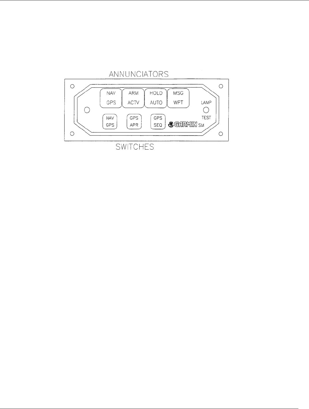
sunlight readable and in the primary view of the pilot. Figure 2-2 shows what the GARMIN switch/annunciators
look like. For other information concerning switch/annunciators see the Generic Airplane Flight Manual
Supplement (GPN 190-00067-24 for the GPS 155XL and GPN 190-00067-34 for the GNC 300XL) as well as
current FAA directives.
• Qualified GPS Antenna—This antenna must be one of those listed in the accessories list.
GPS 155XL/GNC 300XL Installation Manual
P/N 190-00067-22 Rev E Page 2-5
2.7 EXTERNAL ALTITUDE INPUT
Pressure altitude input from an external source may be derived from a RS-232 compatible serial altitude input or
Parallel Gray Code/Gillham Altitude as described in Section 4 of this manual. Gillham Altitude is not required when
serial altitude is used.
Figure 2-2. Switch/Annunciator Layout
GPS 155XL/GNC 300XL Installation Manual
P/N 190-00067-22 Rev E Page 3-1
SECTION 3
INSTALLATION PROCEDURE
3.1 INSTALLATION ACCESSORIES
The following installation accessories are available:
1. Antenna and Rack Options:
• GA 56 Antenna Kit, without cable (Mod 1 or later, P/N 010-10040-01). This kit contains the following
items:
DESCRIPTION GPN QTY
GA 56 ANTENNA SUB-ASSEMBLY 011-00134-00 1
BACKING PLATE 115-00031-00 1
NUT, SELF-LOCKING, #8-32 210-10004-09 4
ANTENNA GASKET 253-00002-00 1
• GA 56 Flange Mount Antenna Kit, (Mod 1 or later, P/N 010-10040-02). This kit contains the following
items:
DESCRIPTION GPN QTY
FLANGE MOUNT GA 56 ANTENNA
SUB-ASSEMBLY
011-00147-00 1
NUT PLATE 115-00080-00 1
SCREW, # 10-32 X 5/8 211-62212-14 4
ANTENNA GASKET 253-00011-00 1
2. Other accessories include the following:
• Connector, BNC, Male, Clamp, (P/N 330-00087-00)
• Low-Loss Aviation Antenna Extension Cable with Right Angle BNC Connector, 15 ft., (P/N 320-00003-
00)
• Low-Loss Aviation Antenna Extension Cable with Right Angle BNC Connector, 30 ft., (P/N 320-00003-
02)
NOTE: One cable assembly and one BNC connector are required to make the antenna cable, or it can be
fabricated by the installer from materials meeting the requirements of paragraph 2.4.
• Mounting Rack (without connectors), P/N 011-00154-00

GPS 155XL/GNC 300XL Installation Manual
P/N 190-00067-22 Rev E Page 3-2
NOTE: A mounting rack is required for approved installations. The following hardware is required for
installation of the mounting rack, but is not provided—#6-32 Flat Head Screw (4 ea.) #6-32
Self-locking Nut (4 ea.)
• Connector, (JI and J2) Kit, P/N 011-00313-00
• Sample Flight Manual Supplement, GARMIN GPS 155XL, P/N 190-00067-24
• Sample Flight Manual Supplement, GARMIN GNC 300XL, P/N 190-00067-34
• Pilot’s Guide, GARMIN GPS 155XL, P/N 190-00067-20
• Pilot’s Guide, GARMIN GNC 300XL, P/N 190-00067-30
3.2 DATA BASE OPTIONS
DESCRIPTION GPN
MEMORY CARD - WORLDWIDE DATABASE 010-10051-00
MEMORY CARD - AMERICAS DATABASE 010-10051-01
MEMORY CARD - INTERNATIONAL DATABASE 010-10051-02
MEMORY CARD - USER 010-10032-03
3.3 ANNUNCIATOR OPTIONS
DESCRIPTION GPN MID-CONTINENT P/N
INTEGRATED SW/ANN UNIT. HOR. 28V 013-00029-10 MD41-448
INTEGRATED SW/ANN UNIT, HOR. 14V 013-00029-11 MD41-444
INTEGRATED SW/ANN UNIT, HOR, 28V (5V
LIGHTING)
013-00029-12 MD41-448 (5V)
INTEGRATED SW/ANN UNIT, VERT. 28V 013-00029-15 MD41-458
INTEGRATED SW/ANN UNIT, VERT, 14V 013-00029-16 MD41-454
INTEGRATED SW/ANN UNIT, VERT. 28V
(5V LIGHTING)
013-00029-17 MD41-458 (5V)

GPS 155XL/GNC 300XL Installation Manual
P/N 190-00067-22 Rev E Page 3-3
3.4 MISCELLANEOUS OPTIONS
DESCRIPTION GPN
PC KIT 010-10075-00
GPS 155XL PILOT’S GUIDE 190-00067-20
GPS 155XL QUICK REFERENCE GUIDE 190-00067-21
GPS 155XL IN PIPER PA32 DOCUMENTED INSTALLATION 190-00067-26
GNC 300XL PILOT’S GUIDE 190-00067-30
GNC 300XL QUICK REFERENCE GUIDE 190-00067-31
GNC 300XL IN PIPER PA32 DOCUMENTED INSTALLATION 190-00067-36
GPS 1.57542 GHz NOTCH FILTER (GNC 300XL ONLY) 330-00067-00
WALL ADAPTER - 110 VAC 362-00014-00
28 TO 14V CONVERTER (GNC 300XL ONLY) (CONSISTS OF
011-00181-00)
010-10057-00
REMOTE BATTERY PACK (CONSISTS OF 011-00182-00) 010-10074-00
3.5 REQUIRED INSTALLATION ACCESSORIES NOT SUPPLIED
The following installation accessories are required but not provided (GNC 300XL only).
• Comm Antenna—Broad Band 50 Ohm Vertically Polarized with Coaxial Cable
• Headphones—500 Ohm Nominal Impedance
• Microphone—Low Impedance Carbon or Dynamic with Transistorized Preamp
3.6 ANTENNA INSTALLATION
For the COMM antenna, follow the manufacturer's instructions (GNC 300XL). The remainder of this section applies
to the GPS antenna. The GA 56 Antenna outline and footprint dimensions are shown in Figure 5-1.
1. Using the backing plate as a template, mark the location of the mounting holes and the through hole for
the coaxial cable. Drill or punch the holes.
2. The antenna installation must provide adequate support for the antenna considering a maximum drag load
of 5 lbs. for the GA 56 antennas (at subsonic speed). Install a doubler plate to reinforce thin skinned
aircraft. Observe guidelines for acceptable installation practices as outlined in AC 43.13-2A.
3. Seal the antenna and gasket to the fuselage using a good quality electrical grade sealant. Use caution to
ensure that the antenna connector is not contaminated with sealant. Ensure that the mounting screws are
fully tightened and that the antenna base is well seated against the gasket.
CAUTION: Do not use construction grade RTV sealant or sealants containing acetic acid. These
sealants may damage the electrical connections to the antenna. Use of these types sealants
may void the antenna warranty.
GPS 155XL/GNC 300XL Installation Manual
P/N 190-00067-22 Rev E Page 3-4
3.7 CABLE INSTALLATION
1. Route the coaxial cable to the rack location keeping in mind the recommendations of Section 2. Secure
the cable in accordance with good mechanical practices.
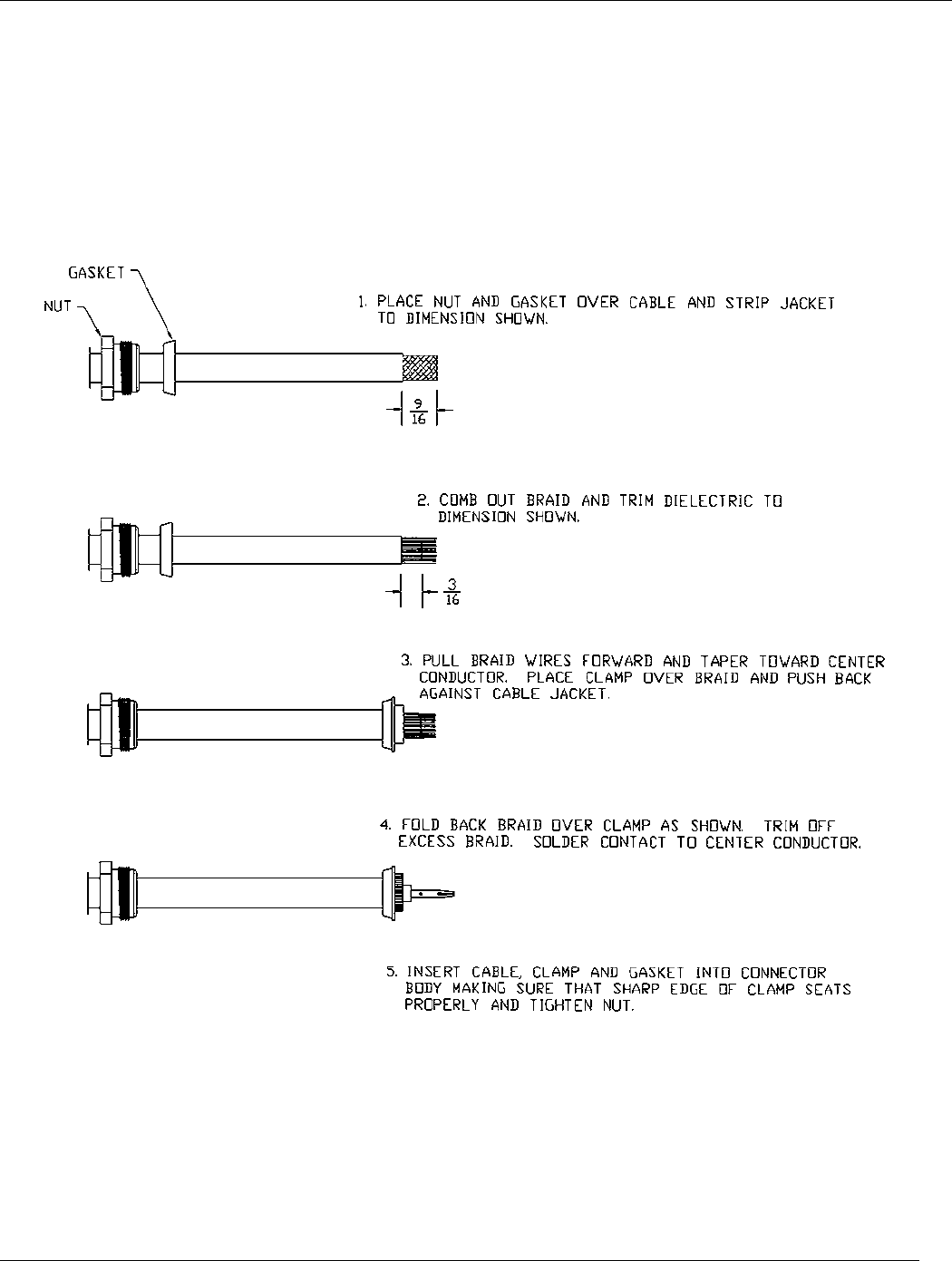
2. Trim the coaxial cable to the desired length and install the BNC connector (330-0087-00) per the cabling
instructions in Figure 3-1. If the connector is provided by the installer, follow the connector
manufacturer's instructions for cable preparation.
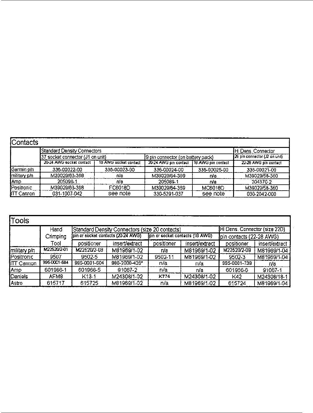
3. Contacts for the 37 and 26 pin connectors must be crimped into the individual wires of the aircraft wiring
harness.
Table 3-1 lists contact part numbers (for reference) and crimp tools.
Table 3-1. Contact Part Numbers and Recommended Crimp Tools
Notes regarding the table:
• Insert/Extract tools from ITT Cannon are all plastic, others are plastic with metal tip.
• Non-GARMIN part numbers shown are not maintained by GARMIN and consequently are subject to
change without notice.
• Alternate contacts for 18 AWG wire: As an alternate to the Positronic contacts listed (and provided in the
install kit), the installer may use contacts made by ITT Cannon as follows:
GPS 155XL/GNC 300XL Installation Manual
P/N 190-00067-22 Rev E Page 3-5
Socket Contact - ITT Cannon P/N 031-10007-001, Pin Contact - ITT Cannon P/N 330-5291-055. These
contacts require the use of a different crimp tool positioner than shown in the table, with the part numbers as
follows: Daniels P/N K250, Astro P/N 616245, or ITT Cannon P/N: 980-00005-722.
Figure 3-1. Coax Cable Installation

GPS 155XL/GNC 300XL Installation Manual
P/N 190-00067-22 Rev E Page 3-6
3.8 RACK INSTALLATION
1. Figure 5-2 shows outline dimensions for the aviation rack. Install the rack in a rectangular 6.320" x
2.000" hole in the instrument panel. Exercise caution when installing the rack into the instrument panel.
The rack is designed to facilitate removal of the GPS 155XL/GNC 300XL for portable use. Deformation
of the rack may make it difficult to install and remove the GPS 155XL/GNC 300XL.
2. Install the rack in the aircraft panel using four #6-32 countersunk screws and four self-locking nuts or
other FAA-approved methods as per Advisory Circular 43.13-1A. The screws are inserted from the
inside through the holes in the sides of the rack (see Figure 5-3).
3.9 GPS 155XL/GNC 300XL INSTALLATION AND REMOVAL
1. The GPS 155XL/GNC 300XL is installed in the rack by gently sliding it straight in until it rests against
the back of the rack. A 3/32-inch hex drive tool is then inserted into the access hole at the bottom of the
unit face. Rotate the hex tool clockwise while pressing on the left side of the Bezel until the unit is
firmly seated in the rack.
2. To remove the unit from the rack, insert the hex drive tool into the access hole on the unit face and rotate
counter-clockwise until the mounting screw turns freely and the unit protrudes about 3/8 inch from the
panel.
3. Be sure not to over-tighten the unit into the rack. The application of hex drive tool torque exceeding 15
in.-lbs. can damage the locking mechanism.

GPS 155XL/GNC 300XL Installation Manual
P/N 190-00067-22 Rev E Page 3-7
3.10 J101 and J102 Pin Functions
Figure 3-2. View of J101 Connector From Back of Rack
J101 PIN PIN FUNCTION
1 DEVIATION-BAR LEFT +
2TO +
3 FLAG +
4 FLAG -, DEVIATION BAR RIGHT +, FROM +, STATOR E, STATOR G
5 RESERVED
6 RESERVED
7 OBI CLOCK
8OBI DATA
9 APPROACH ARM LOW
10 NAV SUPER FLAG
11 RESERVED
12 ARRIVAL ANNUN
13 APPROACH ACTV ANNUN
14 ROTOR C
15 ARINC 429 OUT B
16 ARINC 429 OUT A
17 RS232 IN 1
18 RS232 IN 2
19 RS232 OUT 2
20 MESSAGE ANNUN
21 AIRCRAFT POWER (14 VDC GNC 300XL) (14-28 VDC GPS 155XL)
22 GROUND
23 OBI SYNC
24 RS232 OUT 1
25 AIRCRAFT POWER (14 VDC GNC 300XL) (14-28 VDC GPS 155XL)
26 GROUND
27 RESERVED
28 APPROACH ARM ANNUN
29 CHARGE ENABLE
30 BATTERY + (POSITIVE)
31 RESERVED
32 ARINC 429 IN A
33 ARINC 429 IN B
34 BATTERY - (NEGATIVE)
35 STATOR D
36 RESERVED
37 STATOR F
Table 3-2. J101 Pin Functions
13
12111098765
4321
31
30
29282726 373635343332
1918
17
161514
25
24
23222120

GPS 155XL/GNC 300XL Installation Manual
P/N 190-00067-22 Rev E Page 3-8
Figure 3-3. View of J102 Connector From Back of Rack
J101 PIN PIN FUNCTION
1 RESERVED
2 MIC AUDIO HI (GNC 300XL)
3 MIC AUDIO LO (GNC 300XL)
4 MIC KEY (GNC 300XL)
5 COMM AUDIO HI (GNC 300XL)
6 COMM AUDIO LO (GNC 300XL)
7 RESERVED
8 MIC INTERCOM (GNC 300XL)
9 RESERVED
10 REMOTE TRANSFER (GNC 300XL)
11 RESERVED
12 TRANSMIT INTERLOCK (GNC 300XL)
13 SEQUENCE HOLD LOW
14 ALTITUDE D4
15 ALTITUDE A1
16 ALTITUDE A2
17 ALTITUDE A4
18 ALTITUDE B1
19 ALTITUDE B2
20 ALTITUDE B4
21 ALTITUDE C1
22 ALTITUDE C2
23 ALTITUDE C4
24 ALTITUDE COMMON
25 GROUND
26 REMOTE ENTER
Table 3-3. J102 Pin Functions
3.11 COMM ANTENNA INSTALLATION CHECK (GNC 300XL)
Check for insertion loss and VSWR. VSWR should be checked with an in-line type wattmeter inserted in the coaxial
transmission line between the transceiver and the antenna. Any problem with the antenna installation will most likely
be seen as a high reflected power. A VSWR of 3:1 will result in a 25% loss in power.
123456789
101112131415
161718
192021
22
23242526

GPS 155Xl/GNC 300XL Installation Manual
P/N 190-00067-22 Rev E Page 4-1
SECTION 4
POST-INSTALLATION CONFIGURATION &
CHECKOUT PROCEDURE
4.1 INTRODUCTION
NOTE: Configuration initialization must be performed when the unit is installed or when replacing a
unit or reinstallation of the same unit in an airplane. Failure to ensure that installation
configuration is correct could cause erroneous operation.
The unit must be initialized before starting the checkout procedure. To initialize:
1. Remove any data cards.
2. Turn the unit on.
3. Press enter in response to "Select operating mode Normal ok?”
4. Press enter in response to "No Jeppesen database rte/prx limited to user wpts ok?”
5. After the satellite status page is displayed for 5 seconds, the unit may be turned off.
After initialization, proceed with the following steps.
4.2 TEST MODE OPERATIONS
With power applied to the aviation rack and the GPS 155XL/GNC 300XL unit turned off, depress and hold the ENT
key and turn the unit on (release the ENT key when the display activates). The first page displayed is the Display
Test Page. While in TEST MODE, test pages can be selected by ensuring the flashing cursor is off and rotating the
large knob in either direction.
To change data on the displayed test page, depress the CRSR key. The cursor will highlight the standby COMM
frequency on the GNC 300XL and the configuration section for the GPS 155XL. Press cursor again to move to
configuration selections on the GNC 300XL.
The small knob will change the data on the selected field. The ENT key or the large knob will advance to the next
field on the page. Pressing the CRSR key again will remove the cursor from the current field, allowing the large
knob to select the next test page. The ENT key is used to enter a new value into the OBI data field after selecting the
desired value using the large and small knobs (see the appropriate chapter of the Pilot's Guide for more information
on page and data selection).
Note that some pages found in test mode are intended for bench testing and are not discussed here.
4.3 INSTALLATION CONFIGURATION
The following pages are in the order found when rotating the large knob clockwise starting at the Display Test Page.
See Section 4. 2 to find out how to get to this page.

GPS 155Xl/GNC 300XL Installation Manual
P/N 190-00067-22 Rev E Page 4-2
4.3.1 Display Adjustment
This page allows the setting of display parameters that affect the display backlight and lighting brightness in
automatic mode.
• "response time" sets the speed with which the brightness responds to ambient light changes. The higher
the number, the slower the display responds.
• " min" sets the minimum brightness of the display. The higher the number, the brighter the minimum
brightness.
• " slope" sets the sensitivity the brightness of the display has to changes in ambient light. The higher the
number, the brighter the display will be for a given increase in ambient lighting.
For more information on the display setting, see the display contrast and mode set page and the backlight set page
described in the Pilot’s Guide (P/N 190-00067-20 for the GPS 155XL and P/N 190-00067-30 for the GNC 300XL).
4.3.2 I/O Channel 1
Select the I/O CHANNEL 1 Test Page. Change the selectable input and output to match that of the installed
equipment. The available options are:
Input: Field Description
off No units connected to Channel 1 input
icarus-alt Serial altitude received from:
Icarus, Model 3000, Mode C Serializer
shadin-alt Serial altitude received from:
Shadin 9000T Serializer System (Non-TSO'd)
Shadin 9200T Series Serializer System (Non-TSO'd)
Shadin 8800T Series Encoder System (TSO'd)
shadin-fuel Fuel information received from:
Shadin 91204XT Series Digital Fuel Management System (TSO'd)
Shadin 91053XT Series Digital Fuel Management System (TSO'd)
arnav/ei-fuel Fuel information received from:
Arnav, Model FC- 10, Fuel Computer (TSO'd)
Arnav, Model FT- 10, Fuel Totalizer (TSO'd)
Electronics International, Model FP-5L, Fuel Flow
Computer (Non-TSO'd)
shadin-adc Air data information received from various models from the 9628XX-X family
shadin-fadc Fuel/Air data information received from various models from the 9628XX-X
family

GPS 155Xl/GNC 300XL Installation Manual
P/N 190-00067-22 Rev E Page 4-3
NOTE: Verify with the manufacturer of the data input device that the unit supports a GARMIN
interface.
Output: Field Description
off No units connected to Channel 1 output
aviation Serial position, velocity and navigation data to:
Argus, Model 3000, Moving Map
Argus, Model 5000, Moving Map
Argus, Model 7000, Moving Map
Stormscope, Series II with Navaid, Moving Map
Shadin, 91204XM Digital Fuel Management System (TSO’d)
Shadin, 91053XM Digital Fuel Management System
Electronics International, Model FP-5L, Fuel Flow Computer (Non-TSO’d)
Shadin, Model 9628XX-X Fuel/Airdata Computer (TSO’d)
GARMIN GPS 195
GARMIN GPS III
4.3.3 ARINC 429 Channel
Select the ARINC 429 Channel Test Page. Change the selectable output to match that of the installed equipment.
The available options are:
Input: Field Description
off No units connected to ARINC 429 output
Selected course Any ARINC 429 compatible unit that transmits the “Selected Course” word
(label 100)
Course/heading Any ARINC 429 compatible unit that transmits the “Selected Course” word
(label 100), as well as the “True heading” (label 314) and/or “Magnetic
heading” (label 320) words
Heading Any ARINC 429 compatible unit that transmits the “True heading” (label
314) and/or “Magnetic heading” (label 320) words
Output: Field Description
off No units connected to ARINC 429 output
Collins PL2 EFS Collins Pro Line 2 EFIS connected (w/ GAMA)
King EFS 40/50 King Radio EFIS 40 or 50 connected (w/ GAMA)
w/o GAMA labels Any unit that receives standard 429 output

GPS 155Xl/GNC 300XL Installation Manual
P/N 190-00067-22 Rev E Page 4-4
The following is a list of labels output by the GPS 155XL/GNC 300XL:
Navigation/Position Data:
Label
(octal) Description
100 Selected course
114 Desired track
115 Bearing to waypoint
116 Cross track error
121 Horizontal command (to autopilot)
251 Distance to go
252 Time to go
310 Present position latitude
311 Present position longitude
312 Ground speed
313 Ground track
314 True heading
320 Magnetic heading
147* Magnetic variation
261* GPS navigation mode
275* Navigation status
326* Lateral scale factor
351* Distance to destination
352* Time to destination
Flight Plan Data:
Label
(octal) Description
074* Flight plan header
075* Active from/to waypoints
113* Message checksum
300* Station magnetic variation/type/class
303* Message length/type/number
304* Waypoint identifier characters 1-3
305* Waypoint identifier characters 4-6
306* Waypoint latitude
307* Waypoint longitude

GPS 155Xl/GNC 300XL Installation Manual
P/N 190-00067-22 Rev E Page 4-5
Identification Data:
Label
(octal) Description
377 Equipment identifier
371* General Aviation equipment identifier
*These labels are formatted per the General Aviation Manufacturers Association (GAMA) definition. Note that the
use of a 429-device w/o GAMA will cause the loss of the above asterisked labels. Some may be required for A1
certification. For example, label 326 changes the CDI scale for approach.
4.3.4 CDI Calibration
Select the test page displaying CDI output calibration. Place the cursor on the alignment field by using the large
knob. Use the small knob to adjust the CDI needle until it is centered. Once centered, turn the cursor off to complete
the calibration process.
4.3.5 Selected Course Calibration
Select the test page displaying the selected course input. Using an extremely accurate input source, input 150° to the
GPS 155XL/GNC 300XL. The input course will indicate close to 150 and a "Calib?" field will appear in the lower
right corner. Selecting the "Calib?" field will calibrate the GPS 155XL/GNC 300XL to match the input source.
Verify OBS operation by checking that the bearing displayed on the GPS 155XL/GNC 300XL is within 2° of the
selected bearing. Do this for every multiple of 30° around the OBS.
4.3.6 Approach Settings
Select the Approach Settings Test Page. Move the cursor over the approach switch field to change the installation
state. The available options are:
Appr switch: Field Description
none The approach switch is not present
instld The approach switch is installed
NOTE: To verify the installation of the approach switch, the "instld" setting requires the approach
switch to be pressed to confirm its presence. The following prompt is displayed in this case:
"press appr switch to confirm" along with a “?” following "instld". When the switch press is
recognized, the prompts are cleared and the "instld" setting is confirmed.

GPS 155Xl/GNC 300XL Installation Manual
P/N 190-00067-22 Rev E Page 4-6
4.3.7 Configuration
Select the Configuration Test Page. Change the selectable Strap and Fuel selections to match that of the aircraft. The
available options are:
Fuel: av gas using Aviation gas (5.8 lbs/gal)
jet A Using Jet A/Jet A-1 fuel (6.7 lbs/gal)
jet B Using Jet B (JP-4) fuel (6.5 lbs/gal)
NOTE: The Fuel option is used to designate the type of fuel used so that the correct fuel density will
be used in calculations.
Strap: Field Description
lnav 1 Number I (Pilot) long range NAV
lnav 2 Number 2 (Co-Pilot) long range NAV
common Common long range NAV
NOTE: The strap option affects the interpretation of ARINC 429 input data.
For ARINC 429 input data, the following applies:
Lnav 1 Only data with SDI=0 or SDI=1 is used
Lnav 2 Only data with SDI=0 or SDI=2 is used
common Only data with SDI=0 is used
NOTE: SDI=0 is an "all call".
4.3.8 Remote Battery Settings
Remote Battery: none
instld
NOTE: If "instld" is selected when a battery is not installed, erroneous voltages will be shown on the
Power Test page and invalid battery messages will be issued in normal operating modes.
Low Battery—Selectable between 8.0 volts and 9.6 volts by 0.2 volt steps
NOTE: In normal operating modes, the "Battery Low" message will be issued when the battery
voltage is below the low battery value. The default value is 9.0 volts.

GPS 155Xl/GNC 300XL Installation Manual
P/N 190-00067-22 Rev E Page 4-7
4.3.9 I/O Channel 2
NOTE: This page is not found in the Test Pages but is included here to aid installation. For more
information, see SET pages in the Pilot’s Guide (GPN 190-00067-20 for the GPS 155XL or
190-00067-30 for the GNC 300XL).
Select the I/O CHANNEL 2 Set Page. Change the selectable input and output to match that of the installed
equipment. The available options are:
Input: Field Description
off NO AVAILABLE SELECTIONS
rtcm 104 RTCM SC-104 Compatible Differential GPS Receiver
NOTE: Below is a list of the RTCM SC-104 messages that the unit will receive:
• Message Type 1: Differential GPS Corrections
• Message Type 2: Delta Differential GPS Corrections
• Message Type 3: Reference Station Parameters
• Message Type 9: High Rate Differential Corrections
Output: Field Description
off No units connected to Channel 2 output
plotting Serial position, velocity, navigation and satellite data
to: NMEA 0183 Version 2.0 compatible mapping device
or GARMIN PC software
NOTE: The following is a list of the NMEA 0183 sentences (with maximum number of characters)
that the GPS 155XL/GNC 300XL transmits.
RMC -70 characters
GGA -72 characters
GSA -57 characters
GSV -140 characters (70 characters x 2 sentences)
RMB -70 characters
BOD -35 characters
WPL -38 characters
*PGRME -35 characters
*GARMIN proprietary accuracy error sentence that is not a part of the NMEA 0183 standard.
4.4 GROUND TEST
The GPS 155XL/GNC 300XL ground test procedure incorporates a series of display pages to test CDI/flag, OBI,
annunciators, external switches, altitude inputs, and power functions of the unit.

GPS 155Xl/GNC 300XL Installation Manual
P/N 190-00067-22 Rev E Page 4-8
The following pages are in the order found when rotating the large knob counterclockwise, starting at the Display
Test page. See Section 4.2 to find out how to get to this page.
4.4.1 Power Test
Select the Power Test page. This page reports the status of the GPS 155XL/GNC 300XL external power source,
remote battery, and internal memory battery. During the power test, "voltage" represents the voltage currently
measured for that function.
The first line of power information shows the following sources of external power:
• External Power "voltage"
• Battery Power
• Wall Adapter
The presence of a wall adapter will override the other two sources. Battery power will not be shown unless the
Remote Battery is selected as "instld" on the Remote Battery Settings Page. The higher voltage of external power or
battery power will determine which is shown.
The next line shows the status of the remote battery as follows:
Rmt Bat none (if Remote Battery is selected as none on the Configuration Page)
Rmt Bat "voltage" "mode" "auto status"
“mode" represents the mode of the charger and is selectable. "On" enables the charger. "Off" disables the charger.
"Auto" enables the charger if the External Power is the current source and its voltage is high enough. When in
"Auto" mode, "auto status" will be either "on" or "off" reflecting whether the charger is enabled or disabled.
The next line reports the status of the internal memory battery as follows:
Mem Bat ok/low.
The “TX” field will light on the display but the transmitter will not actually transmit when the GNC 300XL is
powered from the wall charger.
4.4.2 CDI and Flag Test
Select the CDI Test Page. Using the controls on the GPS 155XL/GNC 300XL front panel, make the selections
indicated below and verify the interfaces as appropriate:
CDI max left Ensure the CDI is deflected maximum scale left (10 dots)
full left Ensure the CDI is deflected full scale left (5 dots)
centered Ensure the CDI is centered
full right Ensure the CDI is deflected full scale right (5 dots)
max right Ensure the CDI is deflected maximum scale right (10 dots)

GPS 155Xl/GNC 300XL Installation Manual
P/N 190-00067-22 Rev E Page 4-9
TO/FROM/FLAG
TO Ensure TO flag is visible
FROM Ensure FROM flag is visible
FLAG Ensure TO and FROM are NOT visible
CDI FLAG
IN VIEW Ensure CDI flag is in view
OUT OF VIEW Ensure CDI flag is out of view
SUPERFLAG
IN VIEW Ensure superflag in view
OUT OF VIEW Ensure superflag out of view
4.4.3 Annunciator Test
Select the Annunicator Test Page. Using the controls on the GPS 155XL/GNC 300XL front panel, make the
selections indicated below and verify the interfaces as appropriate:
Panel Annunciators
OFF Ensure the unit panel annunciators are OFF
ON Ensure the unit panel annunciators are ON
MSG Annunciator
OFF Ensure the Message Annunciator is OFF
ON Ensure the Message Annunciator is ON
Arrival Annunciator
OFF Ensure the Arrival Annunciator is OFF
ON Ensure the Arrival Annunciator is ON
Approach Annunciator
OFF Ensure all Approach Annunciators are OFF
ACTV Ensure the Approach Active Annunciator is ON (Arm is OFF)
ARM Ensure the Approach Arm Annunciator is ON (Active is OFF)
4.4.4 External Switch Test
Select the External COM Switches Page (GNC 300XL). For each of the following installed remote switches perform
the following:
1. Press Remote Enter and verify the Rmt ent field changes from off to on (GNC 300XL).
2. Press PTT and verify the PTT field changes from off to on.
3. Press Remote Transfer and verify the Rmt xfr field changes from off to on.
Next, select the External Switches Page. For each of the following installed remote switches, perform the following:
1. Press GPS Appr and verify the "appr" field changes from off to on.
2. Press GPS Sequence and verify the "hold" field changes from off to on.
3. Press Remote Enter and verify the “remote ent” field changes from off to on (GPS 155XL).

GPS 155Xl/GNC 300XL Installation Manual
P/N 190-00067-22 Rev E Page 4-10
4.4.5 Communications Loopback Test
This page displays the results of communication loopback tests. Three channels are tested: RS232 channels 1 and 2,
and ARINC 429. Results of the test are either "OPEN" or "OK." Open means the channel’s transmitter and receiver
are not connected or the test failed. The tests are performed continuously while on this page except for RS232
channel 2 (this channel is only tested at power on and the results are displayed on this page). Therefore, the unit
must be turned off and the receiver/transmitter connected or disconnected. Then turn the unit on to perform the test.
To test the channels:
• RS232 channel 1—Connect RS232 channel 1 receiver and transmitter
• RS232 channel 2—Connect RS232 channel 2 receiver and transmitter
• ARINC 429—Connect ARINC 429 receiver and transmitter
4.4.6 Altitude Input Test
Select the Gray Code Altitude Test Page if this input is used. Verify that the altitude input is reading the correct
altitude. NOTE: This does not display serial altitude.
4.4.7 OBI Test
Select the OBI Test Page. Using the controls on the GPS 155XL/GNC 300XL front panel, make the selections
indicated below and verify the interfaces as appropriate:
OBI Data
VALID—Ensure that the OBI indicates the proper value
INVALID—Ensure the OBI is invalid
OBI Value—Ensure that the OBI displays the value entered when the VALID option is selected
NOTE: The 3 lines that make up the OBI interface may be toggled individually. This may be done
from the "Value" field. Cycle this field to the desired line (either CLOCK, DATA, or SYNC)
and toggle the output to HIGH or LOW.
4.4.8 Signal Acquisition Test
Following normal power-up, the Self Test Page will be displayed followed by the Data Base Page. Upon approval of
the Data Base Page, the Satellite Status Page will be displayed. If the unit is unable to acquire satellites, relocate the
aircraft away from obstructions which might be shading reception. If the situation does not improve, check the
antenna installation.
Once GPS position information is available, use the DIRECT-TO key to activate the navigation function to a nearby
NAVAID, intersection, or airport. Ensure any connected equipment is transmitting data to and/or is receiving data
from the GPS 155XL/GNC 300XL and is functioning properly (see the Pilot's Guide for more information on the
DIRECT-TO function).

GPS 155Xl/GNC 300XL Installation Manual
P/N 190-00067-22 Rev E Page 4-11
4.5 VHF COMM INTERFERENCE CHECK
1. Go to the Satellite Status Page and verify that 7 to 8 satellites have been acquired.
2. See that the "NAV" flag is out of view.
3. Select 121.15 MHz on COMM 1.
4. Transmit for a period of 20 seconds.
5. Verify that the flag does not come into view.
6. Repeat steps 4 and 5 for the following frequencies:
• 121.175
• 121.20
• 131.250
• 131.275
• 131.300
7. Repeat steps 3-6 for all COMMs installed in the aircraft
8. If the "NAV" flag comes into view, refer to Section 2.2.5 for options to improve performance.
4.6 VHF COMM CHECK (GNC 300XL)
A flight test is recommended after the installation is complete to ensure satisfactory performance. To check the
communications transceiver, maintain an appropriate altitude and contact a ground station facility at a range of at
least 50 nautical miles. Contact a close ground station. Press the squelch disable button to defeat the automatic
squelch feature and listen for any unusual electrical noise which would reduce the COMM receiver sensitivity by
increasing the squelch threshold. If possible, verify the communications capability on both the high and low end of
the VHF COMM band.

GPS 155XL/GNC 300XL Installation Manual
P/N 190-00067-22 Rev E Page 5-1
SECTION 5
DIAGRAMS
5.1 GENERAL
The following diagrams are provided in this section as an aid to installation. Select the diagram(s) appropriate for
your installation:
Figure 5-1—GA 56 Antenna Installation Drawing
Figure 5-2—Aviation Rack Dimensions
Figure 5-3—Aviation Rack Installation
Figure 5-4—Interconnect Wiring Diagram, Remote battery and Encoding Altimeter Connections
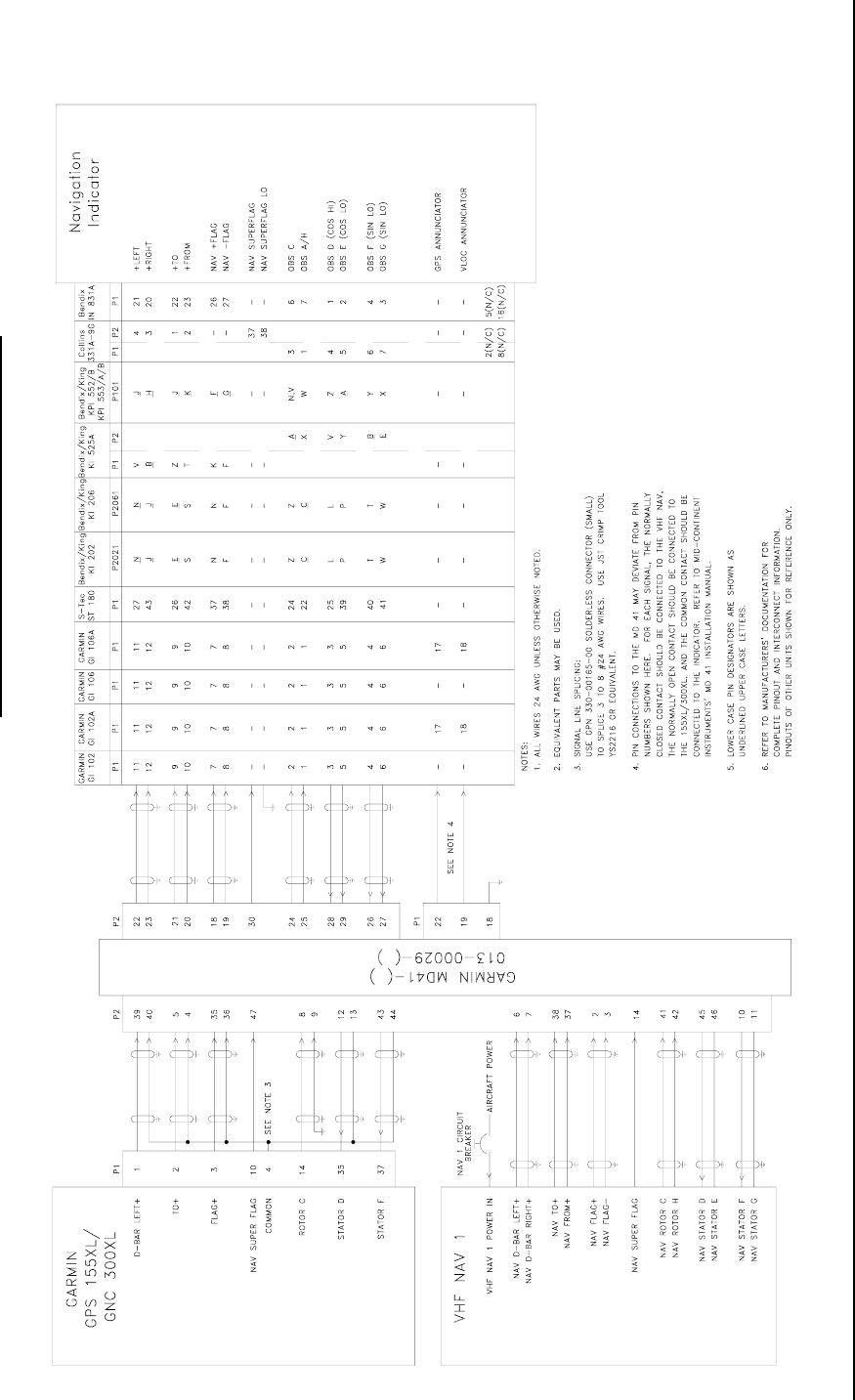
Figure 5-5—Interconnect Wiring Diagram, Navigation Indicator Connections
Figure 5-6— Interconnect Wiring Diagram, Bendix/King KI 209A Connections
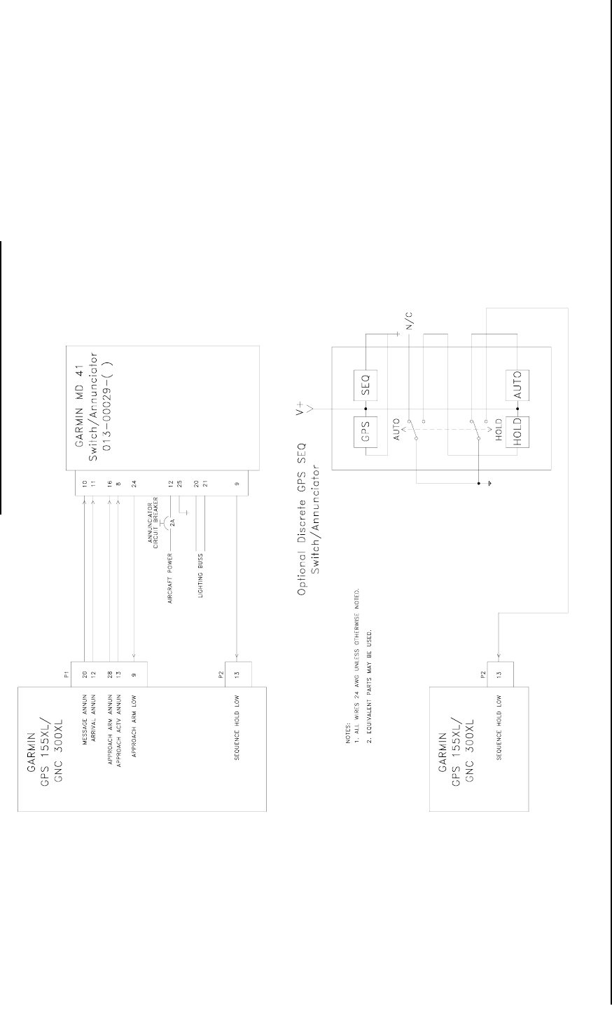
Figure 5-7—Interconnect Wiring Diagram, Switch Annunciator Connections
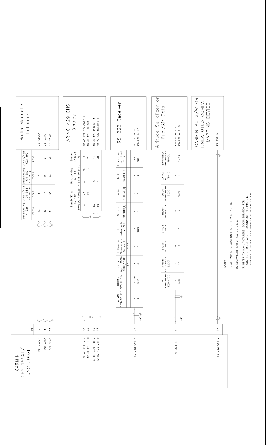
Figure 5-8—Interconnect Wiring Diagram, Optional Accessory Connections
Figure 5-9—Interconnect Wiring Diagram, Audio Connections
GPS 155XL/GNC 300XL INSTALLATION MANUAL
FIGURE 5-1. GA 56 ANTENNA INSTALLATION DRAWING
190-00067-22 REV E PAGE 5-2
GPS 155XL/GNC 300XL INSTALLATION MANUAL
FIGURE 5-2. AVIATION RACK DIMENSIONS
190-00067-22 REV E PAGE 5-3
GPS 155XL/GNC 300XL INSTALLATION MANUAL
FIGURE 5-3. AVIATION RACK INSTALLATION
190-00067-22 REV E PAGE 5-4
GPS 155XL/GNC 300 XL INSTALLATION MANUAL
FIGURE 5-4 INTERCONNECT WIRING DIAGRAM, REMOTE BATTERY AND ENCODING ALTIMETER CONNECTIONS
190-00067-22 REV E PAGE 5-5
GPS 155XL/GNC 300 XL INSTALLATION MANUAL
FIGURE 5-5 INTERCONNECT WIRING DIAGRAM, NAVIGATION INDICATOR CONNECTIONS
190-00067-22 REV E PAGE 5-6
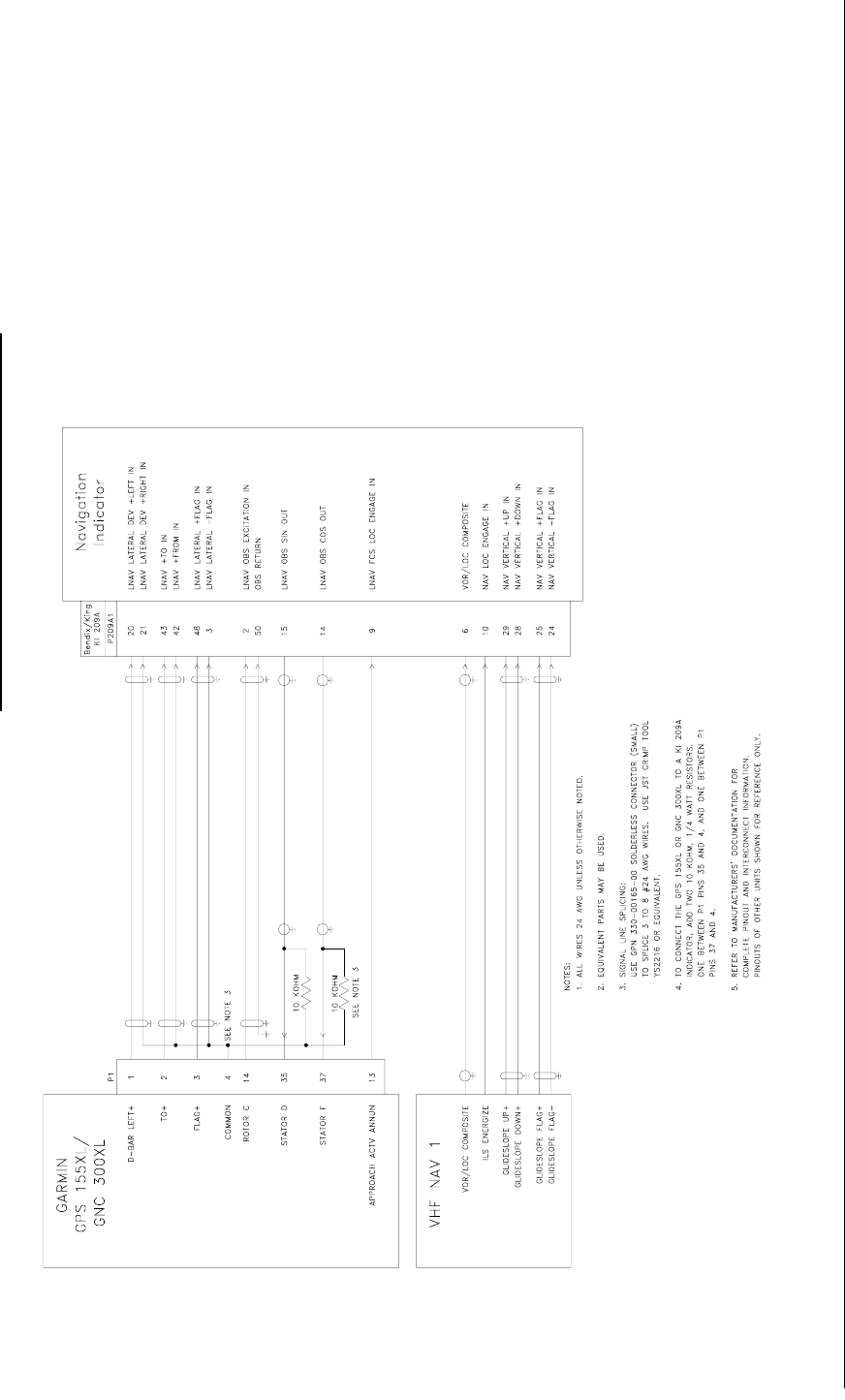
GPS 155XL/GNC 300 XL INSTALLATION MANUAL
FIGURE 5-6 INTERCONNECT WIRING DIAGRAM, BENDIX/KING KI 209A CONNECTIONS
190-00067-22 REV E PAGE 5-7
GPS 155XL/GNC 300 XL INSTALLATION MANUAL
FIGURE 5-7 INTERCONNECT WIRING DIAGRAM, SWITCH ANNUNCIATOR CONNECTIONS
190-00067-22 REV E PAGE 5-8
GPS 155XL/GNC 300 XL INSTALLATION MANUAL
FIGURE 5-8 INTERCONNECT WIRING DIAGRAM, OPTIONAL ACCESSORY CONNECTIONS
190-00067-22 REV E PAGE 5-9
GPS 155XL/GNC 300 XL INSTALLATION MANUAL
FIGURE 5-9 INTERCONNECT WIRING DIAGRAM, AUDIO CONNECTIONS
190-00067-22 REV E PAGE 5-10

GPS 155XL/GNC 300XL Installation Manual
P/N 190-00067-22 Rev E Page 6-1
SECTION 6
CONTINUED AIRWORTHINESS
6.1 CONTINUED AIRWORTHINESS
This section provides assistance to the installing agency in preparing Instructions for Continued Airworthiness (ICA)
in response to Bulletin Number HBAW 98-18, “Checklist for Instructions for Continued Airworthiness for Major
Alterations Approved Under the Field Approval Process”, effective 10/7/98.
Aviation Authority approved installers are hereby granted permission to reference appropriate service instructions
and excerpts from this Installation Manual to accomplish the Instructions for Continued Airworthiness. This
permission does not construe suitability of the documents. It is the applicant’s responsibility to determine the
suitability of the documents for the ICA.
Following is a suggested ICA for a GARMIN GPS 155XL or GNC 300XL installation. Some of the checklist items
do not apply, in which case they should be marked “N/A” (Not Applicable). In this sample, square braces are used to
indicate instances where explicit words should be substituted (e.g., replace “[GPS 155XL/GNC 300XL]” with “GNC
300XL”).
INSTRUCTIONS FOR CONTINUED AIRWORTHINESS, GARMIN [GPS 155XL/GNC 300XL]
1. Introduction
[Aircraft that has been altered: Registration (N-) number, Make, Model and Serial Number]
Content, Scope,
Purpose and Arrangement: This document identifies the Instructions for Continued Airworthiness for the
modification of the above aircraft by installation of a GARMIN [GPS 155XL/GNC
300XL].
Applicability: Applies to aircraft altered by installation of the GARMIN [GPS 155XL/GNC
300XL].
Definitions and
Abbreviations: None, N/A.
Precautions: None, N/A.
Units of Measurement: None, N/A.
Referenced Publications: GARMIN GPS 155XL/GNC 300XL Installation Manual, P/N 190-00067-22
GARMIN GPS 155XL/GNC 300XL Maintenance Manual, P/Ns 190-00067-25 and
190-00067-35 respectively.
GARMIN STC # [applicable STC number for the specific model installed, refer to
Appendix C of this manual].
GARMIN [GPS 155XL/GNC 300XL] Sample Flight Manual Supplement, refer to
Section 3, paragraph 3-1 of this manual.
GARMIN [GPS 155XL/GNC 300XL] Pilot’s Guide, refer to Section 3, paragraph
3-1 of this manual.
Distribution: This document should be a permanent aircraft record.

GPS 155XL/GNC 300XL Installation Manual
P/N 190-00067-22 Rev E Page 6-2
2. Description of the Alteration
Installation of the GARMIN GPS 155XL/GNC 300XL, with interface to external altitude encoder and CDI
[include other equipment/systems as appropriate]. Refer to Sections 1 and 2, and Figures 5-4 through 5-9 of this
manual for interconnect information. Antenna installation, removal and replacement should be in accordance
with applicable provisions of AC43.13-1B and 43.13-2A.
3. Control, Operation Information
Refer to the [GPS 155XL/GNC 300XL] Pilot’s Guide.
4. Servicing Information
N/A
5. Maintenance Instructions
Maintenance of the [GPS 155XL/GNC 300XL] is ‘on condition’ only. Periodic maintenance is not required.
Refer to the [GPS 155XL/GNC 300XL] Maintenance Manual.
6. Troubleshooting Information
Refer to the [GPS 155XL/GNC 300XL] Maintenance Manual.
7. Removal and Replacement Information
Refer to Section 3 paragraph 3.9 of this manual. If the unit is removed and reinstalled, a functional check of the
equipment should be conducted in accordance with Section 4 of this manual.
8. Diagrams
Refer to Sections 5 of this manual.
9. Special Inspection Requirements
N/A
10. Application of Protective Treatments
N/A
11. Data: Relative to Structural Fasteners
Antenna installation, removal and replacement should be in accordance with applicable provisions of
AC43.13-1A and 43.13-2A. Also, refer to Sections 1 and 2 of this manual.
12. Special Tools
N/A
13. This Section is for Commuter Category Aircraft Only
A. Electrical loads: Refer to Section 1 of this manual.
B. Methods of balancing flight controls: N/A.
C. Identification of primary and secondary structures: N/A.
D. Special repair methods applicable to the airplane: Antenna installation, removal, and replacement should be in
accordance with applicable provisions of AC43.13-1B and 43.13-2A.
14. Overhaul Period
No additional overhaul time limitations.

GPS 155XL/GNC 300XL Installation Manual
P/N 190-00067-22 Rev E Page 6-3
15. Airworthiness Limitation Section
Refer to the [GPS 155XL/GNC 300XL] Sample Flight Manual Supplement.
16. Revision
To revise this ICA, a letter must be submitted to the local FSDO with a copy of the revised FAA Form 337, and
revised ICA. The FAA inspector accepts the change by signing Block 3 and including the following statement:
“The attached revised/new Instructions for Continued Airworthiness (date ______) for the above aircraft or
component major alteration have been accepted by the FAA, superseding the Instructions for Continued
Airworthiness (date ______).”
17. Assistance
Flight Standards Inspectors have the resources to respond to questions regarding the ICA.
18. Implementation and Record Keeping
For major alterations performed in accordance with FAA field approval policy, the owner/operator operating
under Part 91 is responsible for ensuring that the ICA is made part of the applicable section 91.409 inspection
program for their aircraft. This is accomplished when a maintenance entry is made in the aircraft’s maintenance
record in accordance with section 43.9. This entry records the major alteration and identifies the original ICA
location (e.g., Block 8 of FAA Form 337, dated ______) along with a statement that the ICA is now part of the
aircraft’s inspection/maintenance requirements.

GPS 155XL/GNC 300XL Installation Manual
P/N 190-00067-22 Rev E Page A-1
APPENDIX A
CERTIFICATION DOCUMENTS
A.1 GENERAL
This section contains the environmental qualification form for the GARMIN GPS 155XL, GNC 300XL, and GA 56
GPS Antenna. The connector changes and STCs are also included.

GPS 155XL/GNC 300XL Installation Manual
P/N 190-00067-22 Rev E Page A-2
A.2 ENVIRONMENTAL QUALIFICATION FORM—GPS 155XL and GNC 300XL
NOMENCLATURE: GPS 155XL GPS Airborne RNAV System and GNC 300XL GPS Airborne
RNAV/Comm System
TYPE/MODEL/ PART NO.: 011-00412-00 (GPS 155XL), 011-00433-00 (GNC 300XL)
GPS TSO: C129a Class A (1)
VHF COMM TRANSMITTER TSO/JTSO: C37d CLASS 4/2C37e (GNC 300XL)
VHF COMM RECEIVER TSO/JTSO: C38d CLASS 4/2C38e (GNC 300XL)
MANUFACTURER’S SPECIFICATION AND/OR OTHER APPLICABLE SPECIFICATION: 004-00014-00
MANUFACTURER: GARMIN International
ADDRESS: 1200 E. 151st St, Olathe, Kansas 66062
NOTE: The following information provides examples only. It is not intended to be a comprehensive
listing of all test conditions. Information is applicable to both the GPS 155XL and the GNC
300XL.
CONDITIONS SECTION DESCRIPTION OF CONDUCTED TESTS
Temperature and Altitude 4.0 Equipment tested to Category A1 and D1 except as noted
Low Temperature 4.5.1
High Temperature 4.5.2, 4.5.3
In-flight Loss of Cooling 4.5.4 Cooling air not required
Altitude 4.6.1
Decompression 4.6.2
Overpressure 4.6.3
Temperature variation 5.0 Equipment tested to Category C
Humidity 6.0 Equipment tested to Category A
Shock 7.0 Equipment tested per DO-160C, Par. 7.2.1
Operational 7.2 Equipment tested per DO-160C, Par. 7.2.1
Crash Safety 7.3 Equipment tested per DO-160C, Par. 7.2.1
Vibration 8.0 Equipment tested without shock mounts to Categories B,
M, and N (Table 8-1)
Explosion 9.0 Equipment identified as Category X, no test required
Waterproofness 10.0 Equipment identified as Category S
Fluids Susceptibility 11.0 Equipment identified as Category X, no test required
Sand and Dust 12.0 Equipment identified as Category X, no test required
Fungus 13.0 Equipment identified as Category X, no test required
Salt Spray 14.0 Equipment identified as Category X, no test required
Magnetic Effect 15.0 Equipment tested is class Z
Power Input 16.0 Equipment tested to Category B

GPS 155XL/GNC 300XL Installation Manual
P/N 190-00067-22 Rev E Page A-3
Voltage Spike 17.0 Equipment tested to Category A
Audio Frequency Susceptibility 18.0 Equipment tested to Category B
Induced Signal Susceptibility 19.0 Equipment tested to Category A
Radio Frequency Susceptibility 20.0 Equipment tested to Category T
Radio Frequency Emission 21.0 Equipment tested to Category Z
Lightning Induced Transient
Susceptibility 22.0 Equipment identified as Category XXXX, no test required
Lightning Direct Effects Test 23.0 Equipment identified as Category 2A
Icing 24.0 Equipment identified as Category C
Other Tests:
Remarks:
A.3 ENVIRONMENTAL QUALIFICATION FORM—GA 56 GPS AVIATION ANTENNA
NOMENCLATURE: GA 56, GPS Aviation Antenna
TYPE/MODEL/ PART NO.: 011-00134-00 (Stud Mount)
011-00147-00 (Flange Mount)
TSO: C129 Class A (1)
MANUFACTURER’S SPECIFICATION AND/OR OTHER APPLICABLE SPECIFICATION: 004-00015-00
MANUFACTURER: GARMIN International
ADDRESS: 1200 E. 151st St, Olathe, Kansas 66062
NOTE: The following information provides examples only. It is not intended to be a comprehensive
listing of all test conditions.
CONDITIONS SECTION DESCRIPTION OF CONDUCTED TESTS
Temperature and Altitude 4.0 Equipment tested to Category F2
Low Temperature 4.5.1
High Temperature 4.5.2, 4.5.3
In-flight Loss of Cooling 4.5.4 Cooling air not required
Altitude 4.6.1
Decompression 4.6.2 Not Tested
Overpressure 4.6.3 Not Tested
Temperature variation 5.0 Equipment tested to Category A
Humidity 6.0 Equipment tested to Category C
Shock 7.0 Equipment tested per DO-160C, Par. 7.2.1
Operational 7.2
Crash Safety 7.3 Not Applicable
Vibration 8.0 Equipment tested without shock mounts to Categories C,
L, M and Y (Table 8-1)

GPS 155XL/GNC 300XL Installation Manual
P/N 190-00067-22 Rev E Page A-4
Explosion 9.0 Equipment identified as Category X, no test required
Waterproofness 10.0 Equipment identified as Category S, no test required
Fluids Susceptibility 11.0 Equipment tested to catagory F with Ethlene Glycol De-
Icing Fluid
Sand and Dust 12.0 Equipment identified as Category X, no test required
Fungus 13.0 Equipment identified as Category X, no test required
Salt Spray 14.0 Equipment identified as Category X, no test required
Magnetic Effect 15.0 Equipment identified as Category X, no test required
Power Input 16.0 Equipment identified as Category X, no test required
Voltage Spike 17.0 Equipment identified as Category X, no test required
Audio Frequency Susceptibility 18.0 Equipment identified as Category X, no test required
Induced Signal Susceptibility 19.0 Equipment identified as Category A, no test required
Radio Frequency Susceptibility 20.0 Equipment identified as Category T, no test required
Radio Frequency Emission 21.0 Equipment identified as Category Z, no test required
Lightning Induced Transient
Susceptibility 22.0 Equipment identified as Category X, no test required
Lightning Direct Effects Test 23.0 Equipment identified as Category 2A, no test required
Icing 24.0 Equipment identified as Category C, no test required
Other Tests:
Remarks:
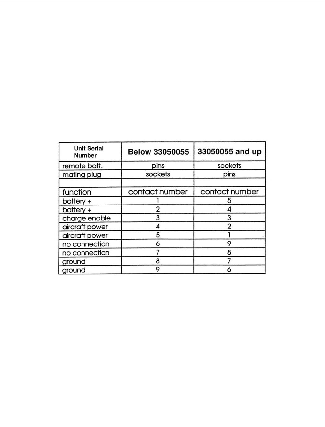
GPS 155XL/GNC 300XL Installation Manual
P/N 190-00067-22 Rev E Page B-1
APPENDIX B
CONNECTOR CHANGES
B.1 REMOTE BATTERY PIN ASSIGNMENTS
A change was made to the remote battery connectors starting with serial numbers 33050055. Units with lower
serial numbers have pin contacts on the battery pack. Units 33050055 and up use socket contacts on the battery,
and the pin numbers are different, however the individual contact locations are unchanged. The following table
shows the pin assignments for the two different types of connectors.

GPS 155XL/GNC 300XL Installation Manual
P/N 190-00067-22 Rev E Page C-1
APPENDIX C
STC PERMISSION
C.1 GPS 155XL
Consistent with N8110.69 or Order 8110.4, Aviation Authority approved installers are hereby granted permission
to use STC # SA00639WI data to modify aircraft.
C.2 GNC 300XL
Consistent with N8110.69 or Order 8110.4, Aviation Authority approved installers are hereby granted permission
to use STC # SA00640WI data to modify aircraft.
GPS 155XL/GNC 300XL Installation Manual
P/N 190-00067-22 Rev E Page C-2
GPS 155XL/GNC 300XL Installation Manual
P/N 190-00067-22 Rev E Page C-3
