Layout1 16001664+Approved+Plans+ +BLD+&+PLAN 16001664 Approved Plans BLD & PLAN
User Manual: 16001664+Approved+Plans+-+BLD+&+PLAN of /wp-content/uploads
Open the PDF directly: View PDF ![]() .
.
Page Count: 36
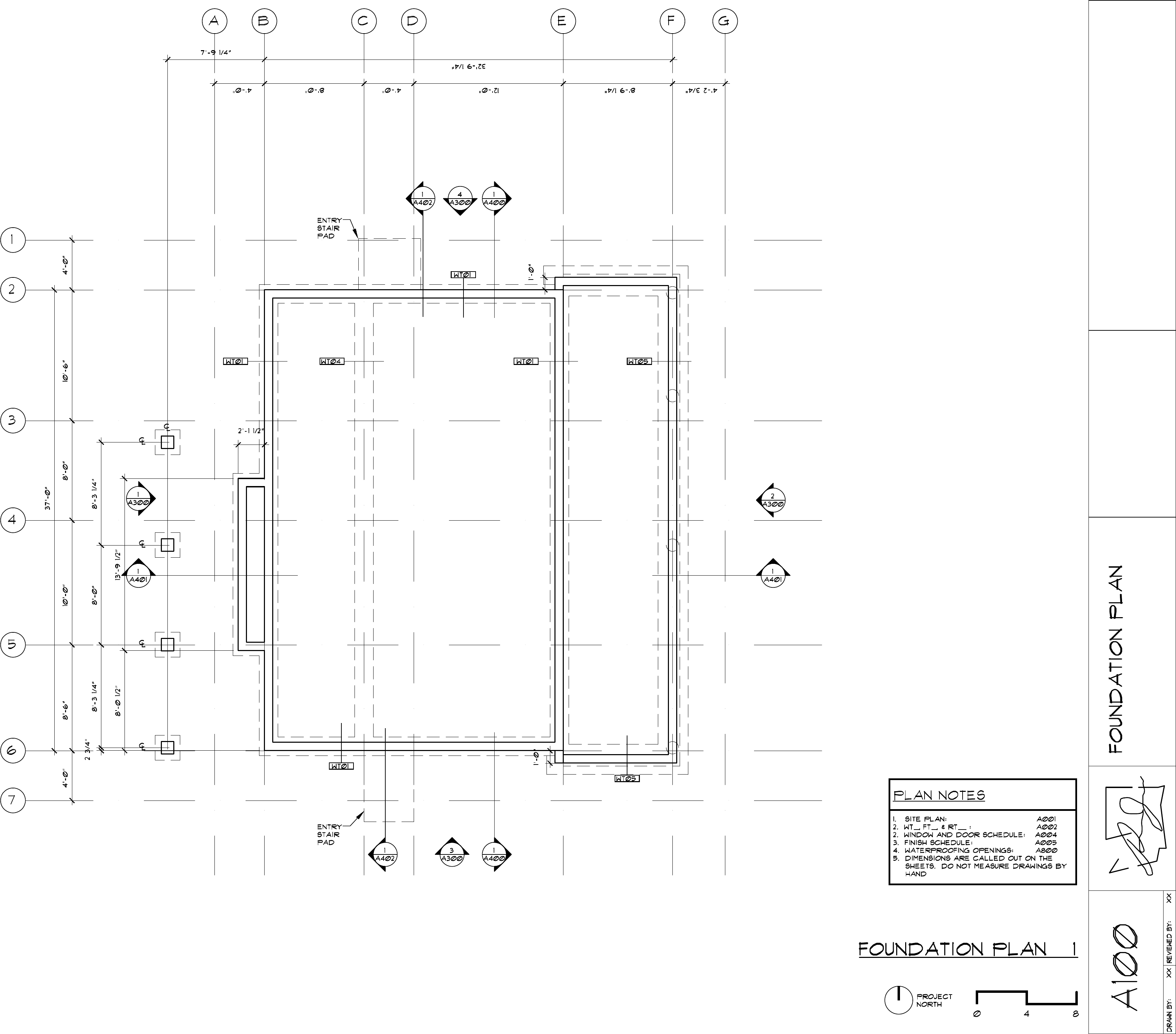
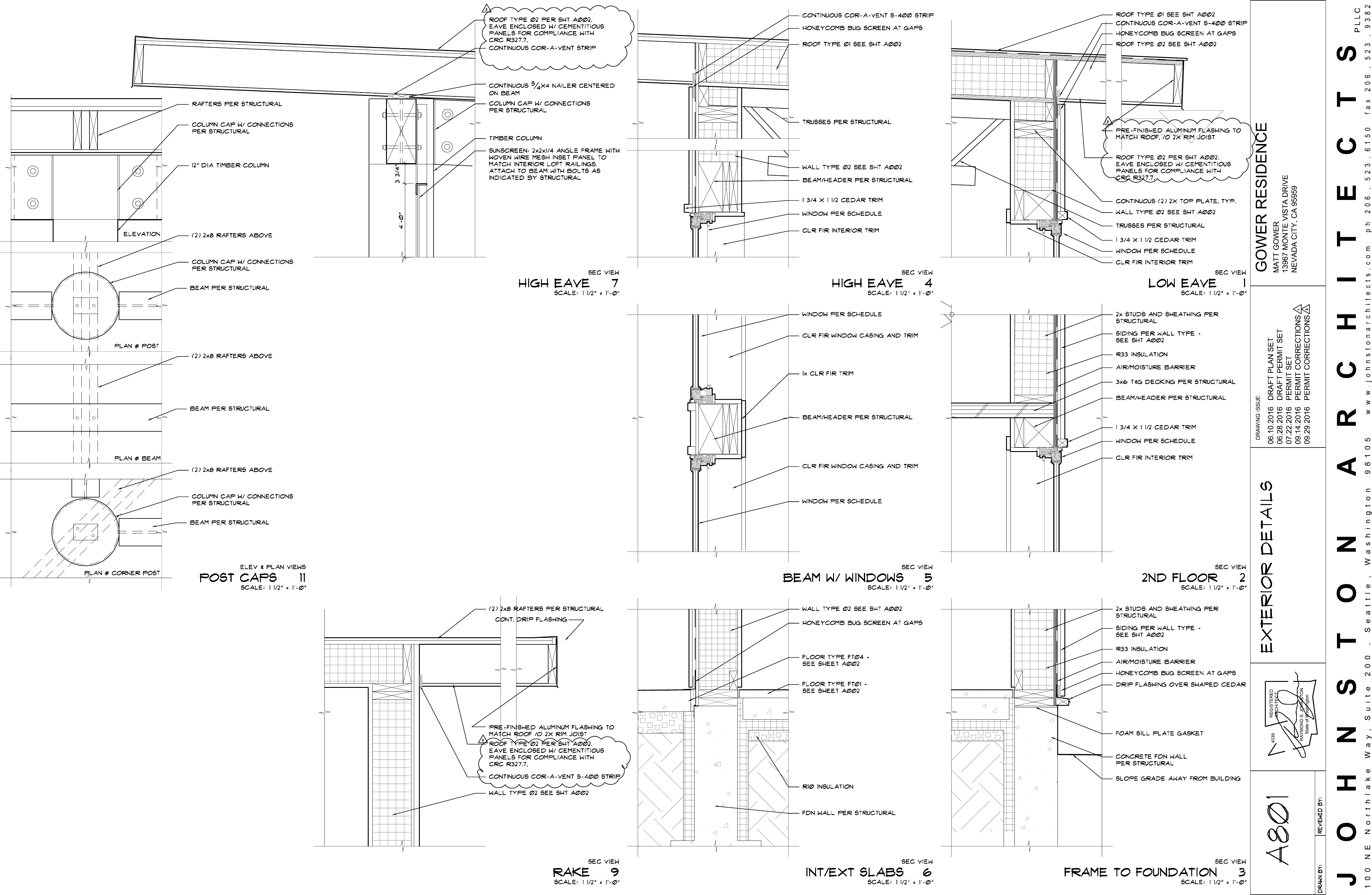
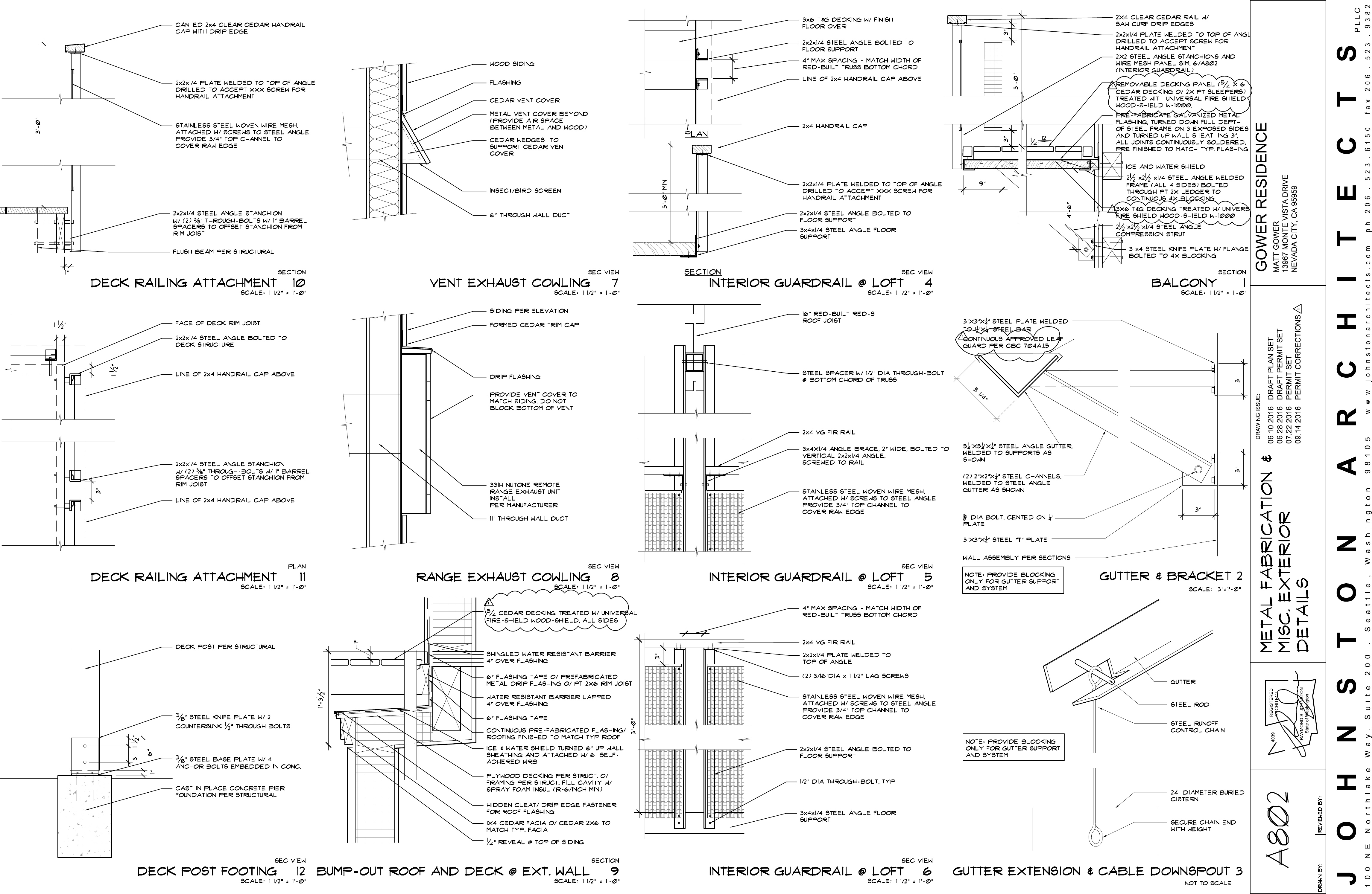
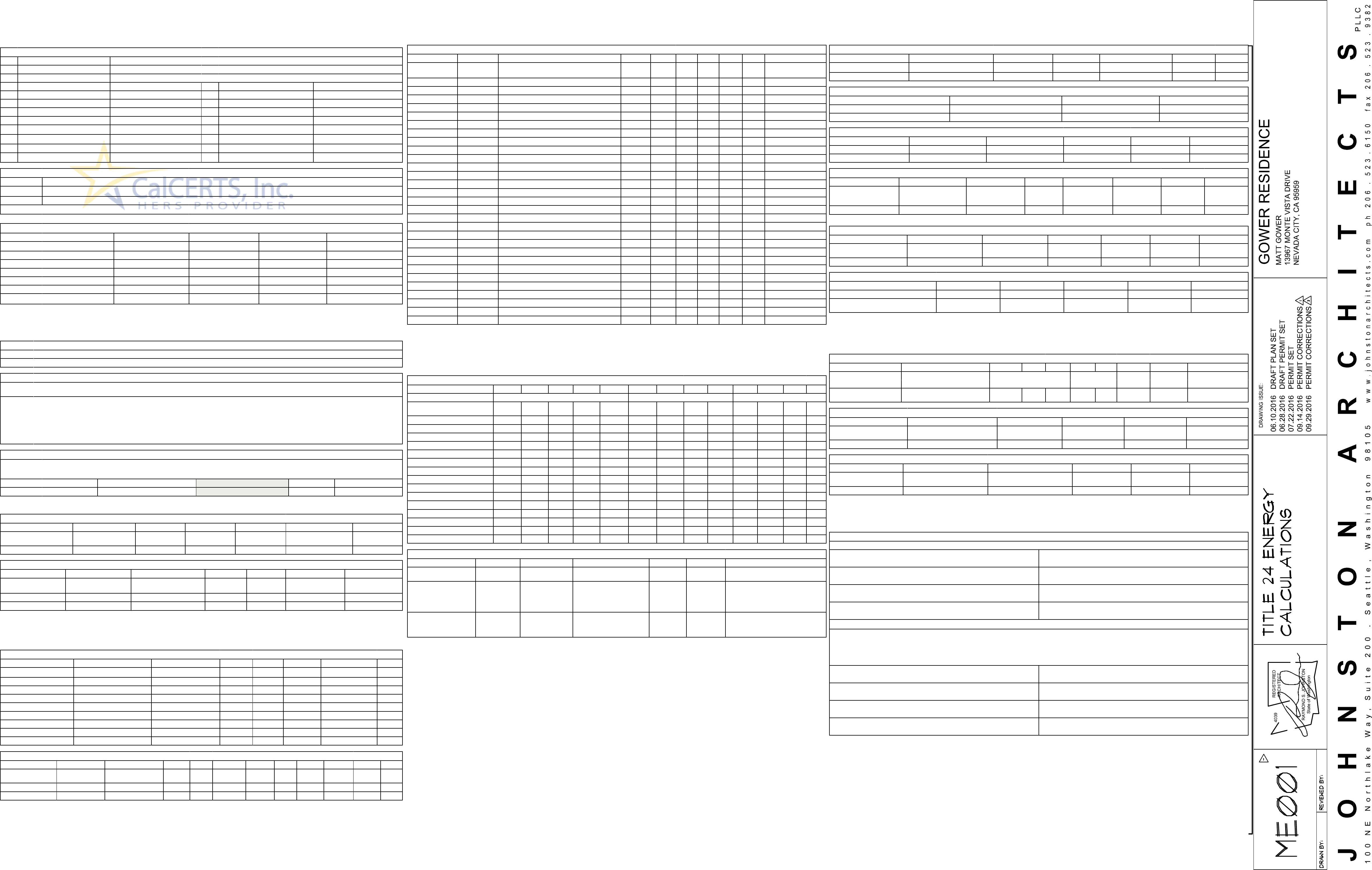
DRAWING ISSUE: GOWER RESIDENCE
MATT GOWER
13967 MONTE VISTA DRIVE
NEVADA CITY, CA 95959
P L L C
J O H N S T O N A R C H I T E C T S
1 0 0 N E N o r t h l a k e W a y , S u i t e 2 0 0 . S e a t t l e , W a s h i n g t o n 9 8 1 0 5 w w w . j o h n s t o n a r c h i t e c t s . c o m p h 2 0 6 . 5 2 3 . 6 1 5 0 f a x 2 0 6 . 5 2 3 . 9 3 8 2
REGISTERED
ARCHITECT
4039
RAYMOND S. JOHNSTON
State of Washington
06.10.2016 DRAFT PLAN SET
06.28.2016 DRAFT PERMIT SET
07.22.2016 PERMIT SET
GOWER RESIDENCE
NEVADA CITY, CALIFORNIA
Nicholas McBurney
Oct 04, 2016
11:13 am

DRAWING ISSUE: GOWER RESIDENCE
MATT GOWER
13967 MONTE VISTA DRIVE
NEVADA CITY, CA 95959
P L L C
J O H N S T O N A R C H I T E C T S
1 0 0 N E N o r t h l a k e W a y , S u i t e 2 0 0 . S e a t t l e , W a s h i n g t o n 9 8 1 0 5 w w w . j o h n s t o n a r c h i t e c t s . c o m p h 2 0 6 . 5 2 3 . 6 1 5 0 f a x 2 0 6 . 5 2 3 . 9 3 8 2
REGISTERED
ARCHITECT
4039
RAYMOND S. JOHNSTON
State of Washington
06.10.2016 DRAFT PLAN SET
06.28.2016 DRAFT PERMIT SET
07.22.2016 PERMIT SET
LEGAL AND GENERAL NOTES


CHAPTER 4
RESIDENTIAL MANDATORY MEASURES
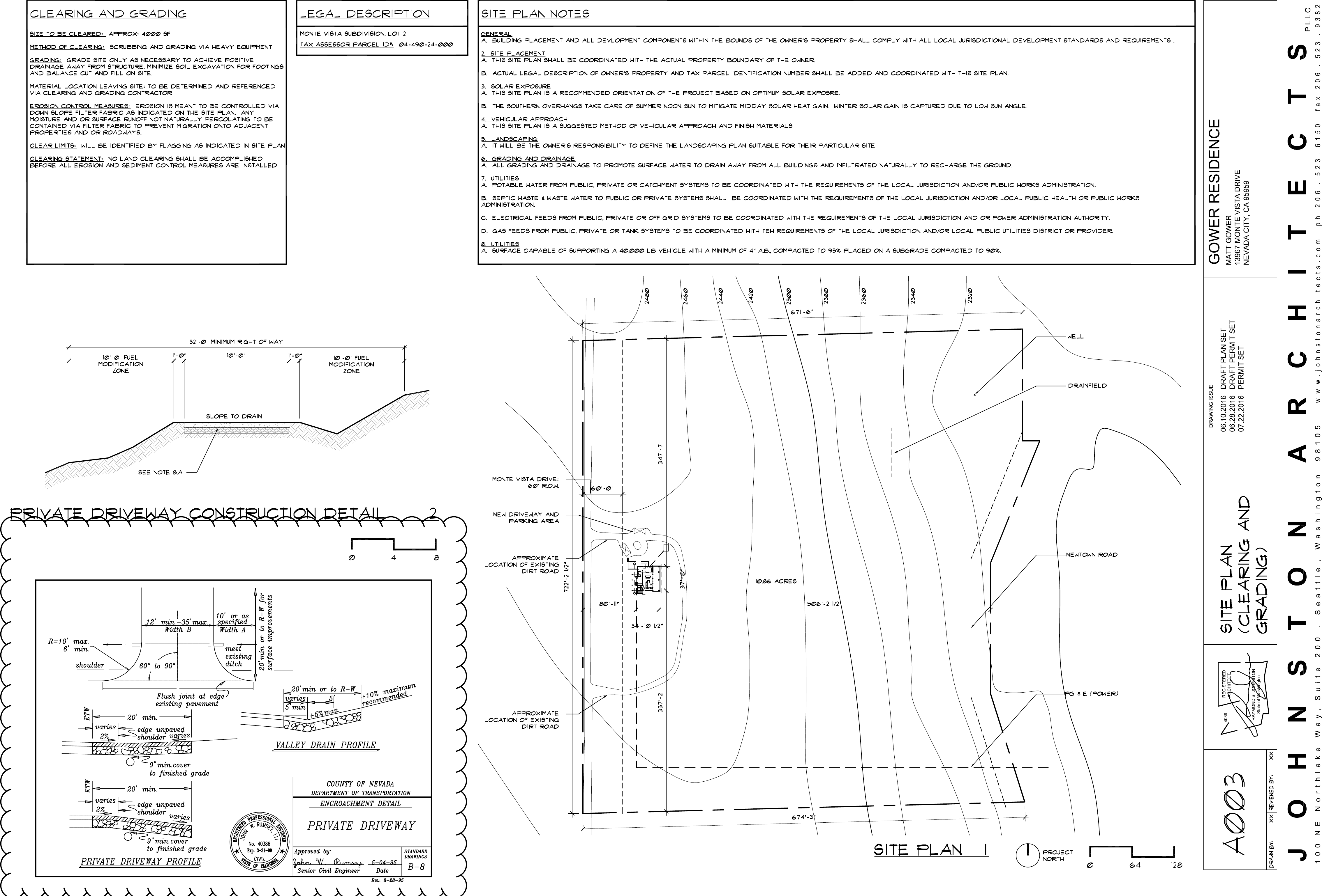
4.106 SITE DEVELOPMENT
4.106.1 GENERAL. Preservation and use of available natural resources shall be accomplished through evaluation
and careful planning to minimize negative effects on the site and adjacent areas. Preservation of slopes,
management of storm water drainage and erosion controls shall comply with this section.
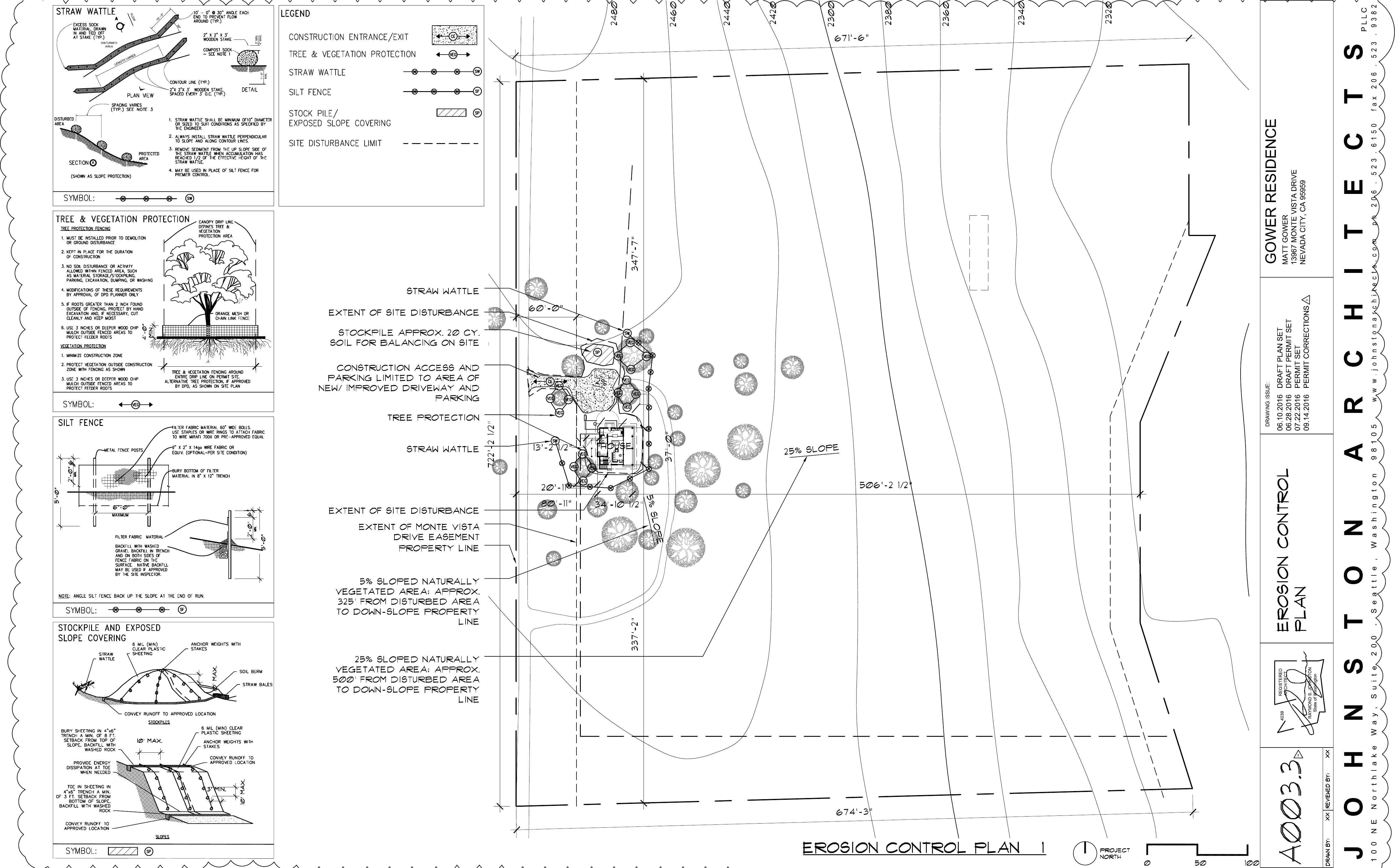
4.106.2 STORM WATER DRAINAGE AND RETENTION DURING CONSTRUCTION. Projects which disturb less
than one acre of soil and are not part of a larger common plan of development which in total disturbs one acre or
more, shall manage storm water drainage during construction. In order to manage storm water drainage during
construction, one or more of the following measures shall be implemented to prevent flooding of adjacent property,
prevent erosion and retain soil runoff on the site.
1. Retention basins of sufficient size shall be utilized to retain storm water on the site.
2. Where storm water is conveyed to a public drainage system, collection point, gutter or similar
disposal method, water shall be filtered by use of a barrier system, wattle or other method approved by
the enforcing agency.
3. Compliance with a lawfully enacted storm water management ordinance.
4.106.3 GRADING AND PAVING. Construction plans shall indicate how the site grading or drainage system will
manage all surface water flows to keep water from entering buildings. Examples of methods to manage surface
water include, but are not limited to, the following:
1. Swales
2. Water collection and disposal systems
3. French drains
4. Water retention gardens
5. Other water measures which keep surface water away from buildings and aid in groundwater
recharge.
Exception: Additions and alterations not altering the drainage path.
DIVISION 4.1 PLANNING AND DESIGN
4.201 GENERAL
4.201.1 SCOPE (MINIMUM STANDARDS FOR ENERGY EFFICIENCY). For the purposes of mandatory energy
efficiency standards in this code, the California Energy Commission will continue to adopt mandatory standards.
DIVISION 4.2 ENERGY EFFICIENCY
DIVISION 4.3 WATER EFFICIENCY AND CONSERVATION
4.406 ENHANCED DURABILITY AND REDUCED MAINTENANCE
4.406.1 RODENT PROOFING. Annular spaces around pipes, electric cables, conduits or other openings in
sole/bottom plates at exterior walls shall be protected against the passage of rodents by closing such
openings with cement mortar, concrete masonry or a similar method acceptable to the enforcing agency.
4.408 CONSTRUCTION WASTE REDUCTION, DISPOSAL AND RECYCLING
4.408.1 CONSTRUCTION WASTE MANAGEMENT. Recycle and/or salvage for reuse a minimum of 50
percent of the non-hazardous construction and demolition waste in accordance with either Section
4.408.2, 4.408.3 or 4.408.4, or meet a more stringent local construction and demolition waste
management ordinance.
Exceptions:
1. Excavated soil and land-clearing debris.
2. Alternate waste reduction methods developed by working with local agencies if diversion or recycle
facilities capable of compliance with this item do not exist or are not located reasonably close to the
jobsite.
3. The enforcing agency may make exceptions to the requirements of this section when isolated
jobsites are located in areas beyond the haul boundaries of the diversion facility.
4.408.2 CONSTRUCTION WASTE MANAGEMENT PLAN. Submit a construction waste management plan
in conformance with Items 1 through 5. The construction waste management plan shall be updated as
necessary and shall be available during construction for examination by the enforcing agency.
1. Identify the construction and demolition waste materials to be diverted from disposal by recycling,
reuse on the project or salvage for future use or sale.
2. Specify if construction and demolition waste materials will be sorted on-site (source separated) or
bulk mixed (single stream).
3. Identify diversion facilities where the construction and demolition waste material collected will be
taken.
4. Identify construction methods employed to reduce the amount of construction and demolition waste
generated.
5. Specify that the amount of construction and demolition waste materials diverted shall be calculated
by weight or volume, but not by both.
4.408.3 WASTE MANAGEMENT COMPANY. Utilize a waste management company, approved by the
enforcing agency, which can provide verifiable documentation that the percentage of construction and
demolition waste material diverted from the landfill complies with Section 4.408.1.
Note: The owner or contractor may make the determination if the construction and demolition waste
materials will be diverted by a waste management company.
4.408.4 WASTE STREAM REDUCTION ALTERNATIVE. Projects that generate a total combined weight of
construction and demolition waste disposed of in landfills, which do not exceed four (4) lbs./sq.ft. of the
building area shall meet the minimum 50% construction waste reduction requirement in Section 4.408.1
4.408.4.1 WASTE STREAM REDUCTION ALTERNATIVE. [HR] Projects that generate a total
combined weight of construction and demolition waste disposed of in landfills, which do not exceed two
(2) lbs./sq.ft. of the building area shall meet the minimum 50% construction waste reduction requirement
in Section 4.408.1
4.408.5 DOCUMENTATION. Documentation shall be provided to the enforcing agency which demonstrates
compliance with Section 4.408.2, items 1 through 5, Section 4.408.3 or Section 4.408.4..
Notes:
1. Sample forms found in "A Guide to the California Green Building Standards Code (Residential)"
located at www.hcd.ca.gov/CALGreen.html may be used to assist in documenting compliance with this
section.
2. Mixed construction and demolition debris (C & D) processors can be located at the California
Department of Resources Recycling and Recovery (CalRecycle).
4.410 BUILDING MAINTENANCE AND OPERATION
4.410.1 OPERATION AND MAINTENANCE MANUAL. At the time of final inspection, a manual, compact
disc, web-based reference or other media acceptable to the enforcing agency which includes all of the
following shall be placed in the building:
1. Directions to the owner or occupant that the manual shall remain with the building throughout the life
cycle of the structure.
2. Operation and maintenance instructions for the following:
a. Equipment and appliances, including water-saving devices and systems, HVAC systems,
water-heating systems and other major appliances and equipment.
b. Roof and yard drainage, including gutters and downspouts.
c. Space conditioning systems, including condensers and air filters.
d. Landscape irrigation systems.
e. Water reuse systems.
3. Information from local utility, water and waste recovery providers on methods to further reduce
resource consumption, including recycle programs and locations.
4. Public transportation and/or carpool options available in the area.
5. Educational material on the positive impacts of an interior relative humidity between 30-60 percent
and what methods an occupant may use to maintain the relative humidity level in that range.
6. Information about water-conserving landscape and irrigation design and controllers which conserve
water.
7. Instructions for maintaining gutters and downspouts and the importance of diverting water at least 5
feet away from the foundation.
8. Information on required routine maintenance measures, including, but not limited to, caulking,
painting, grading around the building, etc.
9. Information about state solar energy and incentive programs available.
10. A copy of all special inspections verifications required by the enforcing agency or this [California
Green Building Standards] code.
DIVISION 4.4 MATERIAL CONSERVATION AND RESOURCE
EFFICIENCY
4.503 FIREPLACES
4.503.1 GENERAL. Any installed gas fireplace shall be a direct-vent sealed-combustion type. Any installed
woodstove or pellet stove shall comply with U.S. EPA Phase II emission limits where applicable.
Woodstoves, pellet stoves and fireplaces shall also comply with applicable local ordinances.
4.504 POLLUTANT CONTROL
4.504.1 COVERING OF DUCT OPENINGS & PROTECTION OF MECHANICAL EQUIPMENT DURING
CONSTRUCTION. At the time of rough installation, during storage on the construction site and until final
startup of the heating, cooling and ventilating equipment, all duct and other related air distribution
component openings shall be covered with tape, plastic, sheet metal or other methods acceptable to the
enforcing agency to reduce the amount of water, dust or debris which may enter the system.
4.504.2 FINISH MATERIAL POLLUTANT CONTROL. Finish materials shall comply with this section.
4.504.2.1 Adhesives, Sealants and Caulks. Adhesives, sealant and caulks used on the project shall
meet the requirements of the following standards unless more stringent local or regional air pollution or
air quality management district rules apply:
1. Adhesives, adhesive bonding primers, adhesive primers, sealants, sealant primers and caulks
shall comply with local or regional air pollution control or air quality management district rules where
applicable or SCAQMD Rule 1168 VOC limits, as shown in Table 4.504.1 or 4.504.2, as applicable.
Such products also shall comply with the Rule 1168 prohibition on the use of certain toxic
compounds (chloroform, ethylene dichloride, methylene chloride, perchloroethylene and
tricloroethylene), except for aerosol products, as specified in Subsection 2 below.
2. Aerosol adhesives, and smaller unit sizes of adhesives, and sealant or caulking compounds (in
units of product, less packaging, which do not weigh more than 1 pound and do not consist of more
than 16 fluid ounces) shall comply with statewide VOC standards and other requirements, including
prohibitions on use of certain toxic compounds, of California Code of Regulations, Title 17,
commencing with section 94507.
4.504.2.2 Paints and Coatings. Architectural paints and coatings shall comply with VOC limits in Table 1
of the ARB Architectural Suggested Control Measure, as shown in Table 4.504.3, unless more stringent
local limits apply. The VOC content limit for coatings that do not meet the definitions for the specialty
coatings categories listed in Table 4.504.3 shall be determined by classifying the coating as a Flat,
Nonflat or Nonflat-High Gloss coating, based on its gloss, as defined in subsections 4.21, 4.36, and 4.37
of the 2007 California Air Resources Board, Suggested Control Measure, and the corresponding Flat,
Nonflat or Nonflat-High Gloss VOC limit in Table 4.504.3 shall apply.
4.504.2.3 Aerosol Paints and Coatings. Aerosol paints and coatings shall meet the Product-weighted
MIR Limits for ROC in Section 94522(a)(3) and other requirements, including prohibitions on use of
certain toxic compounds and ozone depleting substances, in Sections 94522(c)(2) and (d)(2) of California
Code of Regulations, Title 17, commencing with Section 94520; and in areas under the jurisdiction of the
Bay Area Air Quality Management District additionally comply with the percent VOC by weight of product
limits of Regulation 8, Rule 49.
4.504.2.4 Verification. Verification of compliance with this section shall be provided at the request of the
enforcing agency. Documentation may include, but is not limited to, the following:
1. Manufacturer's product specification.
2. Field verification of on-site product containers.
DIVISION 4.5 ENVIRONMENTAL QUALITY
4.303 INDOOR WATER USE
4.303.1 WATER CONSERVING PLUMBING FIXTURES AND FITTINGS. Plumbing fixtures (water closets and
urinals) and fittings (faucets and showerheads) shall comply with the following:
4.303.1.1 Water Closets. The effective flush volume of all water closets shall not exceed 1.28 gallons per
flush. Tank-type water closets shall be certified to the performance criteria of the U.S. EPA WaterSense
Specification for Tank-type Toilets.
Note: The effective flush volume of dual flush toilets is defined as the composite, average flush volume
of two reduced flushes and one full flush.
4.303.1.2 Urinals. The effective flush volume of urinals shall not exceed 0.5 gallons per flush.
4.303.1.3 Showerheads.
4.303.1.3.1 Single Showerhead. Showerheads shall have a maximum flow rate of not more than 2.0
gallons per minute at 80 psi. Showerheads shall be certified to the performance criteria of the U.S. EPA
WaterSense Specification for Showerheads.
4.303.1.3.2 Multiple showerheads serving one shower. When a shower is served by more than one
showerhead, the combined flow rate of all the showerheads and/or other shower outlets controlled by
a single valve shall not exceed 2.0 gallons per minute at 80 psi, or the shower shall be designed to only
allow one shower outlet to be in operation at a time.
Note: A hand-held shower shall be considered a showerhead.
4.303.1.4 Faucets.
4.303.1.4.1 Residential Lavatory Faucets. The maximum flow rate of residential lavatory faucets shall not
exceed 1.5 gallons per minute at 60 psi. The minimum flow rate of residential lavatory faucets shall not be
less than 0.8 gallons per minute at 20 psi.
4.303.1.4.2 Lavatory Faucets in Common and Public Use Areas. The maximum flow rate of lavatory
faucets installed in common and public use areas (outside of dwellings or sleeping units) in residential
buildings shall not exceed 0.5 gallons per minute at 60 psi.
4.303.1.4.3 Metering Faucets. Metering faucets when installed in residential buildings shall not deliver more
than 0.25 gallons per cycle.
4.303.1.4.4 Kitchen Faucets. The maximum flow rate of kitchen faucets shall not exceed 1.8 gallons per
minute at 60 psi. Kitchen faucets may temporarily increase the flow above the maximum rate, but not to
exceed 2.2 gallons per minute at 60 psi, and must default to a maximum flow rate of 1.8 gallons per minute at
60 psi.
Note: Where complying faucets are unavailable, aerators or other means may be used to achieve
reduction.
4.303.2 STANDARDS FOR PLUMBING FIXTURES AND FITTINGS. Plumbing fixtures and fittings shall be installed
in accordance with the California Plumbing Code, and shall meet the applicable standards referenced in Table
1401.1 of the California Plumbing Code.
2013 CALIFORNIA GREEN BUILDING STANDARDS CODE
RESIDENTIAL MANDATORY MEASURES, SHEET 1
INSPECTOR
SIGNOFF
INSPECTOR
SIGNOFF
INSPECTOR
SIGNOFF
INSPECTOR
SIGNOFF
TABLE - MAXIMUM FIXTURE WATER USE
FIXTURE TYPE FLOW RATE
SHOWER HEADS
(RESIDENTIAL) 2.0 GMP @ 80 PSI
LAVATORY FAUCETS
(RESIDENTIAL) MAX. 1.5 GPM @ 60 PSI
MIN. 0.8 GPM @ 20 PSI
LAVATORY FAUCETS IN
COMMON & PUBLIC USE AREAS 0.5 GPM @ 60 PSI
KITCHEN FAUCETS 1.8 GPM @ 60 PSI
METERING FAUCETS 0.25 GAL/CYCLE
WATER CLOSET 1.28 GAL/FLUSH
URINALS 0.5 GAL/FLUSH
TABLE 4.504.1 - ADHESIVE VOC LIMIT1,2
(Less Water and Less Exempt Compounds in Grams per Liter)
ARCHITECTURAL APPLICATIONS CURRENT VOC LIMIT
INDOOR CARPET ADHESIVES 50
CARPET PAD ADHESIVES 50
OUTDOOR CARPET ADHESIVES 150
WOOD FLOORING ADHESIVES 100
RUBBER FLOOR ADHESIVES 60
SUBFLOOR ADHESIVES 50
CERAMIC TILE ADHESIVES 65
VCT & ASPHALT TILE ADHESIVES 50
DRYWALL & PANEL ADHESIVES 50
COVE BASE ADHESIVES 50
MULTIPURPOSE CONSTRUCTION ADHESIVE 70
STRUCTURAL GLAZING ADHESIVES 100
SINGLE-PLY ROOF MEMBRANE ADHESIVES 250
OTHER ADHESIVES NOT LISTED 50
SPECIALTY APPLICATIONS
PVC WELDING 510
CPVC WELDING 490
ABS WELDING 325
PLASTIC CEMENT WELDING 250
ADHESIVE PRIMER FOR PLASTIC 550
CONTACT ADHESIVE 80
SPECIAL PURPOSE CONTACT ADHESIVE 250
STRUCTURAL WOOD MEMBER ADHESIVE 140
TOP & TRIM ADHESIVE 250
SUBSTRATE SPECIFIC APPLICATIONS
METAL TO METAL 30
PLASTIC FOAMS 50
POROUS MATERIAL (EXCEPT WOOD) 50
WOOD 30
FIBERGLASS 80
1. IF AN ADHESIVE IS USED TO BOND DISSIMILAR SUBSTRATES TOGETHER,
THE ADHESIVE WITH THE HIGHEST VOC CONTENT SHALL BE ALLOWED.
2. FOR ADDITIONAL INFORMATION REGARDING METHODS TO MEASURE
THE VOC CONTENT SPECIFIED IN THIS TABLE, SEE SOUTH COAST AIR
QUALITY MANAGEMENT DISTRICT RULE 1168.
TABLE 4.504.2 - SEALANT VOC LIMIT
(Less Water and Less Exempt Compounds in Grams per Liter)
SEALANTS CURRENT VOC LIMIT
ARCHITECTURAL 250
MARINE DECK 760
NONMEMBRANE ROOF 300
ROADWAY 250
SINGLE-PLY ROOF MEMBRANE 450
OTHER 420
SEALANT PRIMERS
ARCHITECTURAL
NON-POROUS 250
POROUS 775
MODIFIED BITUMINOUS 500
MARINE DECK 760
OTHER 750
TABLE 4.504.5 - FORMALDEHYDE LIMITS1
MAXIMUM FORMALDEHYDE EMISSIONS IN PARTS PER MILLION
PRODUCT CURRENT LIMIT
HARDWOOD PLYWOOD VENEER CORE 0.05
HARDWOOD PLYWOOD COMPOSITE CORE 0.05
PARTICLE BOARD 0.09
MEDIUM DENSITY FIBERBOARD 0.11
THIN MEDIUM DENSITY FIBERBOARD20.13
1. VALUES IN THIS TABLE ARE DERIVED FROM THOSE SPECIFIED
BY THE CALIF. AIR RESOURCES BOARD, AIR TOXICS CONTROL
MEASURE FOR COMPOSITE WOOD AS TESTED IN ACCORDANCE
WITH ASTM E 1333. FOR ADDITIONAL INFORMATION, SEE CALIF.
CODE OF REGULATIONS, TITLE 17, SECTIONS 93120 THROUGH
93120.12.
2. THIN MEDIUM DENSITY FIBERBOARD HAS A MAXIMUM
THICKNESS OF 5/16" (8 MM).
TABLE 4.504.3 - VOC CONTENT LIMITS FOR
ARCHITECTURAL COATINGS2,3
GRAMS OF VOC PER LITER OF COATING, LESS WATER & LESS EXEMPT
COMPOUNDS
COATING CATEGORY CURRENT VOC LIMIT
FLAT COATINGS 50
NON-FLAT COATINGS 100
NONFLAT-HIGH GLOSS COATINGS 150
SPECIALTY COATINGS
ALUMINUM ROOF COATINGS 400
BASEMENT SPECIALTY COATINGS 400
BITUMINOUS ROOF COATINGS 50
BITUMINOUS ROOF PRIMERS 350
BOND BREAKERS 350
CONCRETE CURING COMPOUNDS 350
CONCRETE/MASONRY SEALERS 100
DRIVEWAY SEALERS 50
DRY FOG COATINGS 150
FAUX FINISHING COATINGS 350
FIRE RESISTIVE COATINGS 350
FLOOR COATINGS 100
FORM-RELEASE COMPOUNDS 250
GRAPHIC ARTS COATINGS (SIGN PAINTS) 500
HIGH TEMPERATURE COATINGS 420
INDUSTRIAL MAINTENANCE COATINGS 250
LOW SOLIDS COATINGS1120
MAGNESITE CEMENT COATINGS 450
MASTIC TEXTURE COATINGS 100
METALLIC PIGMENTED COATINGS 500
MULTICOLOR COATINGS 250
PRETREATMENT WASH PRIMERS 420
PRIMERS, SEALERS, & UNDERCOATERS 100
REACTIVE PENETRATING SEALERS 350
RECYCLED COATINGS 250
ROOF COATINGS 50
RUST PREVENTATIVE COATINGS 250
SHELLACS
CLEAR 730
OPAQUE 550
SPECIALTY PRIMERS, SEALERS &
UNDERCOATERS 100
STAINS 250
STONE CONSOLIDANTS 450
SWIMMING POOL COATINGS 340
TRAFFIC MARKING COATINGS 100
TUB & TILE REFINISH COATINGS 420
WATERPROOFING MEMBRANES 250
WOOD COATINGS 275
WOOD PRESERVATIVES 350
ZINC-RICH PRIMERS 340
1. GRAMS OF VOC PER LITER OF COATING, INCLUDING WATER &
EXEMPT COMPOUNDS
2. THE SPECIFIED LIMITS REMAIN IN EFFECT UNLESS REVISED LIMITS
ARE LISTED IN SUBSEQUENT COLUMNS IN THE TABLE.
3. VALUES IN THIS TABLE ARE DERIVED FROM THOSE SPECIFIED BY
THE CALIFORNIA AIR RESOURCES BOARD, ARCHITECTURAL COATINGS
SUGGESTED CONTROL MEASURE, FEB. 1, 2008. MORE INFORMATION IS
AVAILABLE FROM THE AIR RESOURCES BOARD.
4.304 OUTDOOR WATER USE
4.304.1 IRRIGATION CONTROLLERS. Automatic irrigation system controllers for landscaping provided by the
builder and installed at the time of final inspection shall comply with the following:
1. Controllers shall be weather- or soil moisture-based controllers that automatically adjust irrigation in response
to changes in plants' needs as weather conditions change.
2. Weather-based controllers without integral rain sensors or communication systems that account for local
rainfall shall have a separate wired or wireless rain sensor which connects or communicates with the
controller(s). Soil moisture-based controllers are not required to have rain sensor input.
Note: More information regarding irrigation controller function and specifications is available from the
Irrigation Association.
SEE:
(detail, sheet,
spec. section)
SEE:
(detail, sheet,
spec. section)
SEE:
(detail, sheet,
spec. section)
SEE:
(detail, sheet,
spec. section)
CHAPTER 3
GREEN BUILDING
SECTION 301 GENERAL
301.1 SCOPE. Buildings shall be designed to include the green building measures specified as mandatory in
the application checklists contained in this code. Voluntary green building measures are also included in the
application checklists and may be included in the design and construction of structures covered by this code, but
are not required unless adopted by a city, county, or city and county as specified in Section 101.7.
301.1.1 Additions and alterations. [HCD] The mandatory provisions of Chapter 4 shall be applied to additions
or alterations of existing residential buildings where the addition or alteration increases the building's conditioned
area, volume, or size. The requirements shall apply only to and/or within the specific area of the addition or
alteration.
301.2 LOW-RISE AND HIGH-RISE RESIDENTIAL BUILDINGS. [HCD] The provisions of
individual sections of CALGreen may apply to either low-rise residential buildings high-rise residential buildings,
or both. Individual sections will be designated by banners to indicate where the section applies specifically to
low-rise only (LR) or high-rise only (HR). When the section applies to both low-rise and high-rise buildings, no
banner will be used.
SECTION 302 MIXED OCCUPANCY BUILDINGS
302.1 MIXED OCCUPANCY BUILDINGS. In mixed occupancy buildings, each portion of a building
shall comply with the specific green building measures applicable to each specific occupancy.
ABBREVIATION DEFINITIONS:
HCD Department of Housing and Community Development
BSC California Building Standards Commission
DSA-SS Division of the State Architect, Structural Safety
OSHPD Office of Statewide Health Planning and Development
LR Low Rise
HR High Rise
AA Additions and Alterations
N New
NOTE:
THIS TABLE COMPILES THE DATA IN SECTION 4.303.1, AND
IS INCLUDED AS A CONVENIENCE FOR THE USER.

CHAPTER 7
INSTALLER & SPECIAL INSPECTOR QUALIFICATIONS
702 QUALIFICATIONS
702.1 INSTALLER TRAINING. HVAC system installers shall be trained and certified in the proper
installation of HVAC systems including ducts and equipment by a nationally or regionally recognized
training or certification program. Uncertified persons may perform HVAC installations when under the
direct supervision and responsibility of a person trained and certified to install HVAC systems or
contractor licensed to install HVAC systems. Examples of acceptable HVAC training and certification
programs include but are not limited to the following:
1. State certified apprenticeship programs.
2. Public utility training programs.
3. Training programs sponsored by trade, labor or statewide energy consulting or verification
organizations.
4. Programs sponsored by manufacturing organizations.
5. Other programs acceptable to the enforcing agency.
702.2 SPECIAL INSPECTION [HCD]. When required by the enforcing agency, the owner or
the responsible entity acting as the owner's agent shall employ one or more special inspectors to provide
inspection or other duties necessary to substantiate compliance with this code. Special inspectors shall
demonstrate competence to the satisfaction of the enforcing agency for the particular type of inspection
or task to be performed. In addition to other certifications or qualifications acceptable to the enforcing
agency, the following certifications or education may be considered by the enforcing agency when
evaluating the qualifications of a special inspector:
1. Certification by a national or regional green building program or standard publisher.
2. Certification by a statewide energy consulting or verification organization, such as HERS raters,
building performance contractors, and home energy auditors.
3. Successful completion of a third party apprentice training program in the appropriate trade.
4. Other programs acceptable to the enforcing agency.
Notes:
1. Special inspectors shall be independent entities with no financial interest in the materials or the
project they are inspecting for compliance with this code.
2. HERS raters are special inspectors certified by the California Energy Commission (CEC) to rate
homes in California according to the Home Energy Rating System (HERS).
[BSC] When required by the enforcing agency, the owner or the responsible entity acting as the owner's
agent shall employ one or more special inspectors to provide inspection or other duties necessary to
substantiate compliance with this code. Special inspectors shall demonstrate competence to the
satisfaction of the enforcing agency for the particular type of inspection or task to be performed. In
addition, the special inspector shall have a certification from a recognized state, national or international
association, as determined by the local agency. The area of certification shall be closely related to the
primary job function, as determined by the local agency.
Note: Special inspectors shall be independent entities with no financial interest in the materials or
the project they are inspecting for compliance with this code.
703 VERIFICATIONS
703.1 DOCUMENTATION. Documentation used to show compliance with this code shall include
but is not limited to, construction documents, plans, specifications, builder or installer certification,
inspection reports, or other methods acceptable to the enforcing agency which demonstrate substantial
conformance. When specific documentation or special inspection is necessary to verify compliance, that
method of compliance will be specified in the appropriate section or identified applicable checklist.
4.505 INTERIOR MOISTURE CONTROL
4.505.1 General. Buildings shall meet or exceed the provisions of the California Building Standards Code.
4.505.2 CONCRETE SLAB FOUNDATIONS. Concrete slab foundations required to have a vapor retarder by
California Building Code, Chapter 19, or concrete slab-on-ground floors required to have a vapor retarder
by the California Residential Code, Chapter 5, shall also comply with this section.
4.505.2.1 Capillary break. A capillary break shall be installed in compliance with at least one of the
following:
1. A 4-inch (101.6 mm) thick base of 1/2 inch (12.7mm) or larger clean aggregate shall be provided
with a vapor barrier in direct contact with concrete and a concrete mix design, which will address
bleeding, shrinkage, and curling, shall be used. For additional information, see American Concrete
Institute, ACI 302.2R-06.
2. Other equivalent methods approved by the enforcing agency.
3. A slab design specified by a licensed design professional.
4.505.3 MOISTURE CONTENT OF BUILDING MATERIALS. Building materials with visible signs of water
damage shall not be installed. Wall and floor framing shall not be enclosed when the framing members
exceed 19 percent moisture content. Moisture content shall be verified in compliance with the following:
1. Moisture content shall be determined with either a probe-type or contact-type moisture meter.
Equivalent moisture verification methods may be approved by the enforcing agency and shall satisfy
requirements found in Section 101.8 of this code.
2. Moisture readings shall be taken at a point 2 feet (610 mm) to 4 feet (1219 mm) from the grade
stamped end of each piece verified.
3. At least three random moisture readings shall be performed on wall and floor framing with
documentation acceptable to the enforcing agency provided at the time of approval to enclose the wall
and floor framing.
Insulation products which are visibly wet or have a high moisture content shall be replaced or allowed to
dry prior to enclosure in wall or floor cavities. Wet-applied insulation products shall follow the
manufacturers' drying recommendations prior to enclosure.
4.506 INDOOR AIR QUALITY AND EXHAUST
4.506.1 Bathroom exhaust fans. Each bathroom shall be mechanically ventilated and shall comply with the
following:
1. Fans shall be ENERGY STAR compliant and be ducted to terminate outside the building.
2. Unless functioning as a component of a whole house ventilation system, fans must be controlled by a
humidity control.
a. Humidity controls shall be capable of adjustment between a relative humidity range less than or
equal to 50% to a maximum of 80%. A humidity control may utilize manual or automatic means of
adjustment.
b. A humidity control may be a separate component to the exhaust fan and is not required to be
integral (i.e., built-in)
Notes:
1. For the purposes of this section, a bathroom is a room which contains a bathtub, shower or
tub/shower combination.
2. Lighting integral to bathroom exhaust fans shall comply with the California Energy Code.
4.507 ENVIRONMENTAL COMFORT
4.507.2 HEATING AND AIR-CONDITIONING SYSTEM DESIGN. Heating and air conditioning systems shall
be sized, designed and have their equipment selected using the following methods:
1. The heat loss and heat gain is established according to ANSI/ACCA 2 Manual J - 2004 (Residential
Load Calculation), ASHRAE handbooks or other equivalent design software or methods.
2. Duct systems are sized according to ANSI/ACCA 1 Manual D - 2009 (Residential Duct Systems),
ASHRAE handbooks or other equivalent design software or methods.
3. Select heating and cooling equipment according to ANSI/ACCA 3 Manual S - 2004 (Residential
Equipment Selection), or other equivalent design software or methods.
Exception: Use of alternate design temperatures necessary to ensure the system functions are
acceptable.
INSPECTOR
SIGNOFF
INSPECTOR
SIGNOFF
INSPECTOR
SIGNOFF
INSPECTOR
SIGNOFF
4.504.3 CARPET SYSTEMS. All carpet installed in the building interior shall meet the testing and product
requirements of at least one of the following:
1. Carpet and Rug Institute's Green Label Plus Program.
2. California Department of Public Health, "Standard Method for the Testing and Evaluation of Volatile
Organic Chemical Emissions from Indoor Sources Using Environmental Chambers" Version 1.1,
February 2010 (also known as Specification 01350).
3. NSF/ANSI 140 at the Gold level.
4. Scientific Certifications Systems Indoor AdvantageTM Gold.
4.504.3.1 Carpet cushion. All carpet cushion installed in the building interior shall meet the
requirements of the Carpet and Rug Institute's Green Label program.
4.504.3.2 Carpet adhesive. All carpet adhesive shall meet the requirements of Table 4.504.1.
4.504.4 RESILIENT FLOORING SYSTEMS. Where resilient flooring is installed , at least 80% of floor area receiving
resilient flooring shall comply with one or more of the following:
1. VOC emission limits defined in the Collaborative for High Performance Schools (CHPS) High
Performance Products Database.
2. Products compliant with CHPS criteria certified under the Greenguard Children & Schools program.
3. Certification under the Resilient Floor Covering Institute (RFCI) FloorScore program.
4. Meet the California Department of Public Health, "Standard Method for the Testing and Evaluation of
Volatile Organic Chemical Emissions from Indoor Sources Using Environmental Chambers", Version 1.1,
February 2010 (also known as Specification 01350).
4.504.5 COMPOSITE WOOD PRODUCTS. Hardwood plywood, particleboard and medium density fiberboard
composite wood products used on the interior or exterior of the buildings shall meet the requirements for
formaldehyde as specified in ARB's Air Toxics Control Measure for Composite Wood (17 CCR 93120 et seq.),
by or before the dates specified in those sections, as shown in Table 4.504.5
4.504.5.1 Documentation. Verification of compliance with this section shall be provided as requested
by the enforcing agency. Documentation shall include at least one of the following:
1. Product certifications and specifications.
2. Chain of custody certifications.
3. Product labeled and invoiced as meeting the Composite Wood Products regulation (see
CCR, Title 17, Section 93120, et seq.).
4. Exterior grade products marked as meeting the PS-1 or PS-2 standards of the Engineered
Wood Association, the Australian AS/NZS 2269 or European 636 3S standards.
5. Other methods acceptable to the enforcing agency.
DIVISION 4.5 ENVIRONMENTAL QUALITY (continued)
2013 CALIFORNIA GREEN BUILDING STANDARDS CODE
RESIDENTIAL MANDATORY MEASURES, SHEET 2
SEE:
(detail, sheet,
spec. section)
SEE:
(detail, sheet,
spec. section)
SEE:
(detail, sheet,
spec. section)
SEE:
(detail, sheet,
spec. section)

VERTICAL CLEARANCES SHALL BE FIFTEEN (15) FEET MINIMUM,
MEASURED FROM THE OUTSIDE EDGE OF SHOULDER.
10.04.2016 PLANNING CORRECTIONS
45.5852"
22

Tod Herman
2016.10.04
11:38:23
-07'00'

DRAWING ISSUE: GOWER RESIDENCE
MATT GOWER
13967 MONTE VISTA DRIVE
NEVADA CITY, CA 95959
P L L C
J O H N S T O N A R C H I T E C T S
1 0 0 N E N o r t h l a k e W a y , S u i t e 2 0 0 . S e a t t l e , W a s h i n g t o n 9 8 1 0 5 w w w . j o h n s t o n a r c h i t e c t s . c o m p h 2 0 6 . 5 2 3 . 6 1 5 0 f a x 2 0 6 . 5 2 3 . 9 3 8 2
REGISTERED
ARCHITECT
4039
RAYMOND S. JOHNSTON
State of Washington
06.10.2016 DRAFT PLAN SET
06.28.2016 DRAFT PERMIT SET
07.22.2016 PERMIT SET

CERTIFICATE OF COMPLIANCE - RESIDENTIAL PERFORMANCE COMPLIANCE METHOD CF1R-PRF-01
Project Name: Gower Cabin Calculation Date/Time: 15:32, Mon, Jul 18, 2016 Page 1 of 8
Calculation Description: Title 24 Analysis Input File Name: Gower Cabin.xml
GENERAL INFORMATION
01 Project Name Gower Cabin
02 Calculation Description Title 24 Analysis
03 Project Location 13967 Monte Vista Drive
04 City Nevada City 05 Standards Version Compliance 2015
06 Zip Code 98959 07 Compliance Manager Version BEMCmpMgr 2013-4 (744)
08 Climate Zone CZ11 09 Software Version EnergyPro 6.6
10 Building Type Single Family 11 Front Orientation (deg/Cardinal) 90
12 Project Scope Newly Constructed 13 Number of Dwelling Units 1
14 Total Cond. Floor Area (ft2)1346 15 Number of Zones 2
16 Slab Area (ft2)888 17 Number of Stories 2
18 Addition Cond. Floor Area N/A 19 Natural Gas Available No
20 Addition Slab Area (ft2)N/A 21 Glazing Percentage (%) 43.6%
COMPLIANCE RESULTS
01 Building Complies with Computer Performance
02 This building incorporates features that require field testing and/or verification by a certified HERS rater under the supervision of a CEC-approved HERS provider.
03 This building incorporates one or more Special Features shown below
ENERGY USE SUMMARY
04 05 06 07 08
Energy Use (kTDV/ft2-yr) Standard Design Proposed Design Compliance Margin Percent Improvement
Space Heating 29.05 22.92 6.13 21.1%
Space Cooling 63.87 84.38 -20.51 -32.1%
IAQ Ventilation 2.28 2.28 0.00 0.0%
Water Heating 45.63 25.72 19.91 43.6%
Photovoltaic Offset ---- 0.00 0.00 ----
Compliance Energy Total 140.83 135.30 5.53 3.9%
CERTIFICATE OF COMPLIANCE - RESIDENTIAL PERFORMANCE COMPLIANCE METHOD CF1R-PRF-01
Project Name: Gower Cabin Calculation Date/Time: 15:32, Mon, Jul 18, 2016 Page 2 of 8
Calculation Description: Title 24 Analysis Input File Name: Gower Cabin.xml
REQUIRED SPECIAL FEATURES
The following are features that must be installed as condition for meeting the modeled energy performance for this computer analysis.
• Window overhangs and/or fins
HERS FEATURE SUMMARY
The following is a summary of the features that must be field-verified by a certified HERS Rater as a condition for meeting the modeled energy performance for this computer analysis. Additional detail is
provided in the building components tables below.
Building-level Verifications:
• IAQ mechanical ventilation
Cooling System Verifications:
• -- None --
HVAC Distribution System Verifications:
• -- None --
Domestic Hot Water System Verifications:
• -- None --
ENERGY DESIGN RATING
This is the sum of the annual TDV energy consumption for energy use components included in the performance compliance approach for the Standard Design Building (Energy Budget) and the annual
TDV energy consumption for lighting and components not regulated by Title 24, Part 6 (such as domestic appliances and consumer electronics) and accounting for the annual TDV energy offset by an
on-site renewable energy system.
Reference Energy Use Energy Design Rating Margin Percent Improvement
Total Energy (kTDV/f2-yr)* 210.61 205.08 5.53 2.6%
* includes calculated Appliances and Miscellaneous Energy Use (AMEU)
BUILDING - FEATURES INFORMATION
01 02 03 04 05 06 07
Project Name Conditioned Floor Area (ft2) Number of Dwelling
Units Number of Bedrooms Number of Zones Number of Ventilation
Cooling Systems Number of Water
Heating Systems
Gower Cabin 1346 1 6 2 0 1
ZONE INFORMATION
01 02 03 04 05 06 07
Zone Name Zone Type HVAC System Name
Zone Floor Area
(ft2)Avg. Ceiling
Height Water Heating System 1 Water Heating System 2
1st floor Conditioned Residential1 888 10 DHW Sys 1
2nd floor Conditioned Residential1 458 10 DHW Sys 1
CERTIFICATE OF COMPLIANCE - RESIDENTIAL PERFORMANCE COMPLIANCE METHOD CF1R-PRF-01
Project Name: Gower Cabin Calculation Date/Time: 15:32, Mon, Jul 18, 2016 Page 3 of 8
Calculation Description: Title 24 Analysis Input File Name: Gower Cabin.xml
OPAQUE SURFACES
01 02 03 04 05 06 07 08
Name Zone Construction Azimuth Orientation Gross Area (ft2) Window & Door Area (ft2) Tilt (deg)
Wall @ Front 1st floor R21 2x6 90 Front 370 145.182 90
Wall @ L 1st floor R21 2x6 180 Left 240 50.9848 90
Wall @ Rear 1st floor R21 2x6 270 Back 370 20 90
Wall @ Right 1st floor R21 2x6 0 Right 240 33.7 90
Wall @ Front 2 2nd floor R21 2x6 90 Front 370 182.447 90
Wall @ L 2 2nd floor R21 2x6 180 Left 260 36.0002 90
Wall @ Rear 2 2nd floor R21 2x6 270 Back 370 85.5 90
Wall @ Right 2 2nd floor R21 2x6 0 Right 260 33 90
OPAQUE SURFACES – Cathedral Ceilings
01 02 03 04 05 06 07 08 09 10 11
Name Zone Type Orientatio
n Area (ft2)Skylight Area
(ft2) Roof Rise
(x in 12) Roof
Pitch Roof Tilt
(deg) Roof
Reflectance Roof
Emittance Framing
Factor
Roof 1st floor Roof 2x8 filled Front 444 0 0 0 0 0.1 0.85 0.1
Roof 2 2nd floor Roof 2x8 filled Front 458 0 0 0 0 0.1 0.85 0.1
CERTIFICATE OF COMPLIANCE - RESIDENTIAL PERFORMANCE COMPLIANCE METHOD CF1R-PRF-01
Project Name: Gower Cabin Calculation Date/Time: 15:32, Mon, Jul 18, 2016 Page 4 of 8
Calculation Description: Title 24 Analysis Input File Name: Gower Cabin.xml
WINDOWS
01 02 03 04 05 06 07 08 09 10
Name Type Surface (Orientation-Azimuth) Width (ft) Height (ft) Multipli
er
Area
(ft2) U-factor SHGC Exterior Shading
02 frdr 41.25 Window Wall @ Front (Front-90) 5.5 7.5 1.001 41.3 0.30 0.35 Insect Screen (default)
05 31 Window Wall @ Front (Front-90) 5.6 5.5 1.006 31.0 0.30 0.35 Insect Screen (default)
01 12.25 Window Wall @ Front (Front-90) 3.5 5.5 0.639 12.3 0.30 0.35 Insect Screen (default)
07 19.8 Window Wall @ Front (Front-90) 3.7 5.5 0.973 19.8 0.30 0.35 Insect Screen (default)
07 19.8 2 Window Wall @ Front (Front-90) 3.7 5.5 0.973 19.8 0.30 0.35 Insect Screen (default)
03 21 Window Wall @ Front (Front-90) 3.8 5.5 1.005 21.0 0.30 0.35 Insect Screen (default)
frdr20 Window Wall @ L (Left-180) ---- ---- 1 20.0 0.30 0.35 Insect Screen (default)
05 31 2 Window Wall @ L (Left-180) 5.6 5.5 1.006 31.0 0.30 0.35 Insect Screen (default)
14 16 Window Wall @ Rear (Back-270) ---- ---- 1 16.0 0.30 0.35 Insect Screen (default)
12 4 Window Wall @ Rear (Back-270) ---- ---- 1 4.0 0.30 0.35 Insect Screen (default)
01 frdr20 Window Wall @ Right (Right-0) ---- ---- 1 20.0 0.30 0.35 Insect Screen (default)
11 13.65 Window Wall @ Right (Right-0) ---- ---- 1 13.7 0.30 0.35 Insect Screen (default)
04 25.25 Window Wall @ Front 2 (Front-90) 3.8 6.5 1.024 25.3 0.30 0.35 Insect Screen (default)
06 36 Window Wall @ Front 2 (Front-90) 5.5 6.5 1.007 36.0 0.30 0.35 Insect Screen (default)
08 22.75 Window Wall @ Front 2 (Front-90) 3.6 6.5 0.974 22.8 0.30 0.35 Insect Screen (default)
09 35.75 Window Wall @ Front 2 (Front-90) 5.5 6.5 1.001 35.8 0.30 0.35 Insect Screen (default)
13 17 Window Wall @ Front 2 (Front-90) 4.0 4.3 0.988 17.0 0.30 0.35 Insect Screen (default)
02 22.75 Window Wall @ Front 2 (Front-90) 3.6 6.5 0.974 22.8 0.30 0.35 Insect Screen (default)
08 22.75 2 Window Wall @ Front 2 (Front-90) 3.6 6.5 0.974 22.8 0.30 0.35 Insect Screen (default)
06 36 2 Window Wall @ L 2 (Left-180) 5.5 6.5 1.007 36.0 0.30 0.35 Insect Screen (default)
12 4 2 Window Wall @ Rear 2 (Back-270) ---- ---- 1 4.0 0.30 0.35 Insect Screen (default)
10 12.25 Window Wall @ Rear 2 (Back-270) ---- ---- 1 12.3 0.30 0.35 Insect Screen (default)
10 12.25 2 Window Wall @ Rear 2 (Back-270) ---- ---- 1 12.3 0.30 0.35 Insect Screen (default)
10 12.25 3 Window Wall @ Rear 2 (Back-270) ---- ---- 1 12.3 0.30 0.35 Insect Screen (default)
10 12.25 4 Window Wall @ Rear 2 (Back-270) ---- ---- 1 12.3 0.30 0.35 Insect Screen (default)
10 12.25 5 Window Wall @ Rear 2 (Back-270) ---- ---- 1 12.3 0.30 0.35 Insect Screen (default)
01 frdr20 2 Window Wall @ Rear 2 (Back-270) ---- ---- 1 20.0 0.30 0.35 Insect Screen (default)
11 13 Window Wall @ Right 2 (Right-0) ---- ---- 1 13.0 0.30 0.35 Insect Screen (default)
01 frdr20 3 Window Wall @ Right 2 (Right-0) ---- ---- 1 20.0 0.30 0.35 Insect Screen (default)
CERTIFICATE OF COMPLIANCE - RESIDENTIAL PERFORMANCE COMPLIANCE METHOD CF1R-PRF-01
Project Name: Gower Cabin Calculation Date/Time: 15:32, Mon, Jul 18, 2016 Page 5 of 8
Calculation Description: Title 24 Analysis Input File Name: Gower Cabin.xml
OVERHANGS AND FINS
01 02 03 04 05 06 07 08 09 10 11 12 13 14
Overhang Left Fin Right Fin
Window Depth Dist Up Left
Extent Right
Extent Flap Ht. Depth Top Up DistL Bot Up Depth Top Up Dist R Bot Up
02 frdr 41.25 12 8 0 0 0 0 0 0 0 0 0 0 0
05 31 12 8 0 0 0 0 0 0 0 0 0 0 0
01 12.25 12 8 0 0 0 0 0 0 0 0 0 0 0
07 19.8 12 8 0 0 0 0 0 0 0 0 0 0 0
07 19.8 2 12 8 0 0 0 0 0 0 0 0 0 0 0
03 21 12 8 0 0 0 0 0 0 0 0 0 0 0
05 31 2 0 0 0 0 0 0 0 0 0 0 0 0 0
04 25.25 12 3 0 0 0 0 0 0 0 0 0 0 0
06 36 12 3 0 0 0 0 0 0 0 0 0 0 0
08 22.75 12 3 0 0 0 0 0 0 0 0 0 0 0
09 35.75 12 3 0 0 0 0 0 0 0 0 0 0 0
13 17 12 3 0 0 0 0 0 0 0 0 0 0 0
02 22.75 12 3 0 0 0 0 0 0 0 0 0 0 0
08 22.75 2 12 3 0 0 0 0 0 0 0 0 0 0 0
06 36 2 0 0 0 0 0 0 0 0 0 0 0 0 0
OPAQUE SURFACE CONSTRUCTIONS
01 02 03 04 05 06 07
Construction Name Surface Type Construction Type Framing Total Cavity
R-value Winter Design
U-value Assembly Layers
Roof 2x8 filled Cathedral Ceilings Wood Framed Ceiling 2x4 @ 16 in. O.C. none 0.034
• Inside Finish: Gypsum Board
• Cavity / Frame: no insul. / 2x4
• Roof Deck: Wood Siding/sheathing/decking
• Above Deck Insulation: R27 Sheathing
• Roofing: Light Roof (Asphalt Shingle)
R21 2x6 Exterior Walls Wood Framed Wall 2x6 @ 16 in. O.C. R 21 0.066
• Inside Finish: Gypsum Board
• Cavity / Frame: R-21 / 2x6
• Exterior Finish: Wood
Siding/sheathing/decking
CERTIFICATE OF COMPLIANCE - RESIDENTIAL PERFORMANCE COMPLIANCE METHOD CF1R-PRF-01
Project Name: Gower Cabin Calculation Date/Time: 15:32, Mon, Jul 18, 2016 Page 6 of 8
Calculation Description: Title 24 Analysis Input File Name: Gower Cabin.xml
SLAB FLOORS
01 02 03 04 05 06 07
Name Zone Area (ft2) Perimeter (ft) Edge Insul. R-value & Depth Carpeted Fraction Heated
Slab-on-Grade 1st floor 888 128 R-5, 48 inches 0.8 No
BUILDING ENVELOPE - HERS VERIFICATION
01 02 03 04
Quality Insulation Installation (QII) Quality Installation of Spray Foam Insulation Building Envelope Air Leakage CFM50
Not Required Not Required Not Required ---
WATER HEATING SYSTEMS
01 02 03 04 05 06
Name System Type Distribution Type Water Heater Number of Heaters Solar Fraction (%)
DHW Sys 1 - 1/1 DHW Standard DHW Heater 1 1 .0%
WATER HEATERS
01 02 03 04 05 06 07 08
Name Heater Element Type Tank Type Tank Volume
(gal) Energy Factor or
Efficiency Input Rating
Tank Exterior
Insulation
R-value Standby Loss
(Fraction)
DHW Heater 1 Propane Small Instantaneous 1 0.92 150000-Btu/hr 0 0
WATER HEATING - HERS VERIFICATION
01 02 03 04 05 06 07
Name Pipe Insulation Parallel Piping Compact Distribution Point-of Use Recirculation
Control Central DHW
Distribution
DHW Sys 1 - 1/1 --- --- --- --- --- ---
SPACE CONDITIONING SYSTEMS
01 02 03 04 05 06
SC Sys Name System Type Heating Unit Name Cooling Unit Name Fan Name Distribution Name
:Heat Pump System 1:::2 Heat Pump Heating and
Cooling System Heat Pump System 1 Heat Pump System 1 None None
CERTIFICATE OF COMPLIANCE - RESIDENTIAL PERFORMANCE COMPLIANCE METHOD CF1R-PRF-01
Project Name: Gower Cabin Calculation Date/Time: 15:32, Mon, Jul 18, 2016 Page 7 of 8
Calculation Description: Title 24 Analysis Input File Name: Gower Cabin.xml
HVAC - HEAT PUMPS
01 02 03 04 05 06 07 08 09 10
Heating Cooling Zonally Multispeed HERS
Name Type HSPF/COP Cap 47 Cap 17 SEER EER Controlled Compressor Verification
Heat Pump System 1 DuctlessHeatPump 9 32000 27000 14 12 No No Heat Pump System
1-hers-cool
HVAC COOLING - HERS VERIFICATION
01 02 03 04 05 06
Name Verified Airflow Airflow Target Verified EER Verified SEER Verified Refrigerant
Charge
Heat Pump System 1-hers-cool Not Required ---- Not Required Not Required Not Required
IAQ (Indoor Air Quality) FANS
01 02 03 04 05 06
Dwelling Unit IAQ CFM IAQ Watts/CFM IAQ Fan Type IAQ Recovery
Effectiveness(%) HERS Verification
SFam IAQVentRpt 65.96 0.25 Default 0 Required
CERTIFICATE OF COMPLIANCE - RESIDENTIAL PERFORMANCE COMPLIANCE METHOD CF1R-PRF-01
Project Name: Gower Cabin Calculation Date/Time: 15:32, Mon, Jul 18, 2016 Page 8 of 8
Calculation Description: Title 24 Analysis Input File Name: Gower Cabin.xml
Registration Number: Registration Date/Time: HERS Provider:
CA Building Energy Efficiency Standards - 2013Residential Compliance Report Version - CF1R-04072016-744 Report Generated at:2016-07-18 15:34:59
DOCUMENTATION AUTHOR'S DECLARATION STATEMENT
1. I certify that this Certificate of Compliance documentation is accurate and complete.
Documentation Author Name: Documentation Author Signature:
Company: Signature Date:
Address: CEA/HERS Certification Identification (If applicable):
City/State/Zip: Phone:
RESPONSIBLE PERSON'S DECLARATION STATEMENT
I certify the following under penalty of perjury, under the laws of the State of California:
1. I am eligible under Division 3 of the Business and Professions Code to accept responsibility for the building design identified on this Certificate of Compliance.
2. I certify that the energy features and performance specifications identified on this Certificate of Compliance conform to the requirements of Title 24, Part 1 and Part 6 of the California Code of
Regulations.
3. The building design features or system design features identified on this Certificate of Compliance are consistent with the information provided on other applicable compliance documents,
worksheets, calculations, plans and specifications submitted to the enforcement agency for approval with this building permit application.
Responsible Designer Name: Responsible Designer Signature:
Company: Date Signed:
Address: License:
City/State/Zip: Phone:
Ann Wolfe
SolData Energy Consulting
2235 Challenger Way, Suite 103
Santa Rosa, CA 95407
2016-07-18 15:41:48
N/A
707-545-4440
Matt Purvis
Johnston Architects, PLLC
100 NE Northlake Way
Seattle, WA 98105
2016-07-18 15:48:28
N/A
206-523-6150
Ann Wolfe
Matt Purvis
Digitally signed by CalCERTS. This digital signature is provided in order to secure the content of this registered document, and in no way implies Registration Provider responsibility for the accuracy of the
information.
216-N0261725B-000000000-0000 2016-07-18 15:48:28 CalCERTS inc.
2013 Low-Rise Residential Mandatory Measures Summary
NOTE: Low-rise residential buildings subject to the Standards must comply with all applicable mandatory measures listed, regardless of the
compliance approach used. Exceptions may apply. Review the respective code section for more information.
Building Envelope Measures:
§110.6(a)1:
Doors and windows between conditioned and unconditioned spaces are manufactured to limit air leakage.
§110.6(a)5:
Fenestration products (except field-fabricated windows) have a label listing the certified U-Factor, certified Solar Heat Gain
Coefficient (SHGC), and infiltration that meets the requirements of §10-111(a).
§110.7:
Exterior doors and windows are weatherstripped; all joints and penetrations are caulked and sealed.
§110.8(a):
Insulation specified or installed meets Standards for Insulating Material. Indicate type and include on the CF2R.
§110.8(i):
The thermal emittance and aged solar reflectance values of the cool roofing material meets the requirements of §110.8(i) when the
installation of a cool roof is specified on the CF1R.
§110.8(j):
A radiant barrier shall have an emittance of 0.05 or less when the installation of a radiant barrier is specified on the CF1R.
§150.0(
a):
Minimum R-30 insulation in wood-frame ceiling; or the weighted average U-factor shall not exceed 0.031. Minimum R-19 in a
ra
fter roof alteration. Attic access doors shall have permanently attached
insulation using adhesive or mechanical fasteners. The
attic access shall be gasketed to prevent air leakage.
§150.0(b):
Loose fill insulation shall conform with manufacturer’s installed design labeled R-value.
§150.0(c):
Minimum R-13 insulation in 2x4 inch wood framing wall or have a U-factor of 0.102 or less (R-19 in 2x6 or 0.074 maximum U-
factor).
§150.0(d):
Minimum R-19 insulation in raised wood-frame floor or 0.037 maximum U-factor.
§150.0(
g)1:
In Climate Zones 14 and 16 a Class II vapor retarder shall be installed on the conditioned space side of all insulation in all exterior
walls, vented attics and unvented attics with air-permeable insulation.
§150.0(g)2:
In Climate Zones 1-16 with unvented crawl spaces the earth floor of the crawl space shall be covered with a Class I or Class II
vapor retarder.
§150.0(g)3:
In a building having a controlled ventilation crawl space, a Class I or Class II vapor retarder shall be placed over the earth floor of
the crawl space to reduce moisture entry and protect insulation from condensation, as specified in the
exception to Section
150.0(d).
§150.0(l):
Slab edge insulation shall: have a water absorption rate, for the insulation material alone without facings, no greater than 0.3%;
have
water vapor permeance rate is no greater than 2.0 perm/inch, be protected
from physical damage and UV light deterioration;
and when installed as part of a heated slab floor meets the requirements of §110.8(g).
§150.0(q):
Fenestration, including skylights, separating conditioned space from unconditioned space or outdoors shall have a maximum U-
factor of 0.58; or the weighted average U-factor of all fenestration shall not exceed 0.58.
Fireplaces, Decorative Gas Appliances and Gas Log Measures:
§150.0(e)1A:
Masonry or factory-built fireplaces have a closable metal or glass door covering the entire opening of the firebox.
§150.0(e)1
B
:
Masonry or factory-built fireplaces have a combustion outside air intake, which is at least six square inches in area and is
equipped with a readily accessible, operable, and tight-fitting damper or a combustion-air control device.
§150.0(e)1C:
Masonry or factory-built fireplaces have a flue damper with a readily accessible control.
§150.0(e)2:
Continuous burning pilot lights and the use of indoor air for cooling a firebox jacket, when that indoor air is vented to the outside
of the building, are prohibited.
Space Conditioning, Water Heating and Plumbing System Measures:
§110.0-§110.3:
HVAC equipment, water heaters, showerheads, faucets and all other regulated appliances are certified to the Energy Commission.
§110.3(c)
5:
Water heating recirculation loops serving multiple dwelling units meet the air release
valve, backflow prevention, pump isolation
valve, and recirculation loop connection requirements of §110.3(c)5.
§110.5:
Continuously burning pilot lights are prohibited for natural gas: fan-type central furnaces, household cooking appliances (appli-
ances without an electrical supply voltage connection with pilot lights that consume less than 150 Btu/hr are exempt), and pool
and spa heaters.
§150.0(h)
1:
Heating and/or cooling loads are calculated in accordance with ASHRAE, SMACNA or ACCA using design conditions specified
in §150.0(h)2.
§150.0(h)3A:
Installed air conditioner and heat pump outdoor condensing units shall have a clearance of at least five feet from the outlet of any
dryer vent.
§150.0(i):
Heating systems are equipped with thermostats that meet the setback requirements of §110.2(c).
§150.0(j)1A:
Storage gas water heaters with an energy factor equal to or less than the federal minimum standards shall be externally wrapped
with insulation having an installed thermal resistance of R-12 or greater.
§150.0(j)1B:
Unfired hot water tanks, such as storage tanks and backup storage tanks for solar water-heating systems, have R-12 external
insulation or R-16 internal insulation where the internal insulation R-value is indicated on the exterior of the tank.
§150.0(j)2
A
:
For domestic hot water system piping, whether buried or unburied: the first 5 feet of hot and cold water pipes from the storage
tank, all piping with a nominal diameter of 3/4 inch or larger, all piping associated with a domestic hot water recirculation
system
regardless of the pipe diameter, piping from the heating source to storage tank or between tanks,
piping buried below grade, and
all hot water pipes from the heating source to kitchen fixtures must be insulated according to the requirements of T
ABLE
120.3-
A.
§150.0(j)2
B
:
All domestic hot water pipes that are buried below grade must be installed in a water proof and non-crushable casing or sleeve
that allows for installation, removal, and replacement of the enclosed pipe and insulation.
2013 Low-Rise Residential Mandatory Measures Summary
§150.0(j)2
C
:
Pipe for cooling system lines shall be insulated as specified in §150.0(j)2A. Piping insulation for steam and hydronic heating
systems or hot water systems with pressure > 15 psig shall meet the requirements in TABLE 120.3-A.
§150.0(j)3:
Insulation is protected from damage, including that due to sunlight, moisture, equipment maintenance, and wind.
§150.0(j)3A:
Insulation exposed to weather shall either be rated for outdoor use or installed with a cover suitable for outdoor service. For
example, protected by aluminum, sheet metal, painted canvas, or plastic cover. Cellular foam insulation protected as specified or
painted with coating that is water retardant and provides shielding from solar radiation that degrades the material.
§150.0(j)3
B
:
Insulation covering chilled water piping and refrigerant suction piping located outside the conditioned space shall have a Class I
or Class II vapor retarding facing, or the insulation shall be installed at the thickness that qualifies as a Class I or Class II vapor
retarder.
§150.0(n)1:
Systems using gas or propane water heaters to serve individual dwelling units shall include: a 120V electrical receptacle within 3
feet of the water heater; a
Category III or IV vent, or a Type B vent with straight pipe between the outside termination and the
space where the water heater is installed; a condensate drain that is no
more than 2 inches higher than the base of the installed
water heater, and allows natural draining without pump assistance
; and a gas supply line with a capacity of at least 200,000
Btu/hr.
§150.0(n)2:
Recirculating loops serving multiple dwelling units shall meet the requirements of §110.3(c)5.
§150.0(n)3:
Solar water-heating systems and collectors shall be certified and rated by the Solar Rating and Certification Corporation (SRCC)
or by a testing agency approved by the Executive Director.
Ducts and Fans Measures:
§150.0(m)1:
All air-distribution system ducts and plenums installed are sealed and insulated to meet the requirements of CMC §601.0, §602.0,
§
603.0, §604.0, §605.0 and ANSI/SMACNA-006-2006 HVAC Duct Construction Standards Metal and Flexible 3rd Edition.
S
upply-air and return-air ducts and plenums are insulated to a minimum installed level of R-6.0
(or higher if required by CMC
§
605.0) or enclosed entirely in directly conditioned space as confirmed through field verification and diagnostic testing
(RA3.1.4.3.8)
. Connections of metal ducts and inner core of flexible ducts are mechanically fastened.
Openings shall be sealed
with mastic, tape
, or other duct-closure system that meets the applicable requirements of UL 181, UL 181A, or UL 181B or
aerosol sealant that meets the requirements of UL 723. If mas
tic or tape is used to seal openings greater than ¼ inch, the
combination of mastic and either mesh or tape shall be used.
Building cav
ities, support platforms for air handlers, and plenums
defined or constructed with materials other than sealed sheet metal, duct board or flexible duct shall not be used for conveying
conditioned air. Building cavities and support platforms may contain du
cts. Ducts installed in cavities and support platforms
shall not be compressed to cause reductions in the cross-sectional area of the ducts.
§150.0(m)2:
Factory-Fabricated Duct Systems shall comply with specified requirements for duct construction, connections, and closures; joints
and seams of duct systems and their components shall not be sealed with cloth back rubber adhesive duct tapes unless such tape is
used in combination with mastic and draw bands.
§150.0(m)3-6:
Field-Fabricated Duct Systems shall comply with requirements for: pressure-sensitive tapes, mastics, sealants, and other
requirements specified for duct construction; duct insulation R-value ratings; duct insulation thickness; and duct labeling.
§150.0(m)7:
All fan systems that exchange air between the conditioned space and the outside of the building must have backdraft or automatic
dampers.
§150.0(m)8:
Gravity ventilating systems serving conditioned space have either automatic or readily accessible, manually operated dampers
except combustion inlet and outlet air openings and elevator shaft vents.
§150.0(m)9:
Insulation shall be protected from damage, including that due to sunlight, moisture, equipment maintenance, and wind but not
limited to the following:
insulation exposed to weather shall be suitable for outdoor service. For example, protected by aluminum,
sheet metal, painted canvas, or plastic cover.
Cellular foam insulation shall be protected as above or painted with a coating that is
water retardant and provides shielding from solar radiation.
§150.0(m)10:
Flexible ducts cannot have porous inner cores.
§150.0(m)11:
When space conditioning systems use forced air duct systems to supply conditioned air to an occupiable space, the ducts shall be
sealed
and duct leakage tested, as confirmed through field verification and diagnostic testing, in accordance with Reference
Residential Appendix RA3.
§150.0(m)12:
Mechanical systems that supply air to an occupiable space through ductwork exceeding 10 feet in length and through a thermal
conditioning component, except evaporative coolers, shall be p
rovided with air filter devices that meet the requirements of
§150.0(m)12.
§150.0(m)13:
Space conditioning systems that utilize forced air ducts to supply cooling to an occupiable space shall have a hole for the
placement of a static pressure probe (HSPP), or a permanently installed static pressure probe (PSPP) in the supply plenum. The
space conditioning system must also
demonstrate airflow ≥ 350 CFM per ton of nominal cooling capacity through the return
grilles, and an air
-handling unit fan efficacy ≤ 0.58 W/CFM as confirmed by field verification and diagnostic testing, in
accordance with Reference Residential Appendix RA3.
§150.0(m)15:
Zonally controlled central forced air cooling systems shall be capable of simultaneously delivering, in every zonal control mode,
an airflow from the dwelling, through the air han
dler fan and delivered to the dwelling, of ≥ 350 CFM per
ton of nominal cooling
capacity, and operating at an air
-
handling unit fan efficacy of ≤ 0.58 W/CFM as confirmed by field verification and diagnostic
testing, in accordance with Reference Residential Appendix RA3.
§150.0(o):
All dwelling units shall meet the requirements of ASHRAE Standard 62.2. Neither window operation nor continuous operation of
central forced air system air han
dlers used in central fan integrated ventilation systems
are permissible methods of providing the
Whole Building Ventilation.
§150.0(o)1
A
:
Whole Building Ventilation airflow shall be confirmed through field verification and diagnostic testing, in accordance with
Reference Residential Appendix RA3.
Pool and Spa Heating Systems and Equipment Measures:
§110.4(a):
Any pool or spa heating system shall be certified to have: a thermal efficiency that complies with the Appliance Efficiency
Regula
tions; an on-off switch mounted outside of the heater
that allows shutting off the heater without adjusting the thermostat
setting; a permanent weatherproof plate or card with operating instructions; and shall not use electric resistance heating.
2013 Low-Rise Residential Mandatory Measures Summary
§110.4(b)1:
Any pool or spa heating equipment shall be installed with at least 36 inches of pipe between filter and heater or dedicated suction
and return lines, or built-up connections for future solar heating.
§110.4(b)2:
Outdoor pools or spas that have a heat pump or gas heater shall have a cover.
§110.4(b)3:
Pools shall have directional inlets that adequately mix the pool water, and a time switch that will allow all pumps to be set or pro-
grammed to run only during off-peak electric demand periods.
§110.5:
Natural gas pool and spa heaters shall not have a continuous burning pilot light.
§150.0(p):
Residential pool systems or equipment shall meet specified pump sizing, flow rate, piping, filters, and valve requirements.
Lighting Measures:
§110.9:
All lighting control devices and systems, ballasts, and luminaires shall meet the applicable requirements of §110.9.
§150.0(k)1A:
Installed luminaires shall be classified as high-efficacy or low-efficacy for compliance with §150.0(k) in accordance with TABLE
150.0-A or TABLE 150.0-B, as applicable.
§150.0(k)1B:
When a high efficacy and low efficacy lighting system are combined in a single luminaire, each system shall separately comply
with the applicable provisions of §150.0(k).
§150.0(k)1C:
The wattage and classification of permanently installed luminaires in residential kitchens shall be determined in accordance with
§130.0(c). In residential kitchens, the wattage of electrical boxes finished with a blank cover or where no electrical equipment has
been
installed, and where the electrical box can be used for a luminaire or a surface mounted ceiling fan, shall be calculated as 180
watts of low efficacy lighting per electrical box.
§150.0(k)1D:
Ballasts for fluorescent lamps rated 13 watts or greater shall be electronic and shall have an output frequency no less than 20 kHz.
§150.0(k)1E:
Permanently installed night lights and night lights integral to installed luminaires or exhaust fans shall be rated to consume no
m
ore than 5 watts of power per luminaire or exhaust fan as determined in accordance with §130.0(c). Night lights do not need
to
be controlled by vacancy sensors.
§150.0(k)1F:
Lighting integral to exhaust fans (except when installed by the manufacturer in kitchen exhaust hoods) shall meet the applicable
requirements of §150.0(k).
§150.0(k)2A:
High efficacy luminaires must be switched separately from low efficacy luminaires.
§150.0(k)2B:
Exhaust fans shall be switched separately from lighting systems.
§150.0(k)2C:
Luminaires shall be switched with readily accessible controls that permit the luminaires to be manually switched ON and OFF.
§150.0(k)2D:
Controls and equipment are installed in accordance with manufacturer’s instructions.
§150.0(k)2E:
No control shall bypass a dimmer or vacancy sensor function if the control is installed to comply with §150.0(k).
§150.0(k)2F:
Lighting controls comply with applicable requirements of §110.9.
§150.0(k)2G:
An Energy Management Control System (EMCS) may be used to comply with dimmer requirements if: it functions as a dimmer
according to §110.9
; meets Installation Certificate requirements of §130.4; the EMCS requirements of §130.5; and all other
requirements in §150.0(k)2.
§150.0(k)2H:
An Energy Management Control System (EMCS) may be used to comply with vacancy sensor requirements of §150.0(k) if: it
functions as a vacancy sensor according to §110.9
; meets Installation Certificate requirements of §130.4;
the EMCS requirements
of §130.5; and all other requirements in §150.0(k)2.
§150.0(k)2I:
A multiscene programmable controller may be used to comply with dimmer requirements of this section if it provides the
functionality of a dimmer according to §110.9, and complies with all other applicable requirements in §150.0(k)2.
§150.0(k)3A:
A minimum of 50 percent of the total rated wattage of permanently installed lighting in kitchens shall be high efficacy.
§150.0(k)3B:
Kitchen lighting includes all permanently installed lighting in the kitchen except internal lighting in cabinets that illuminate only
the inside of the cabinets. Lighting in areas adjacent to the kitchen, including but not limited to dining and nook areas, ar
e
considered kitchen lighting if they are not separately switched from kitchen lighting.
§150.0(k)4:
Permanently installed lighting that is internal to cabinets shall use no more than 20 watts of power per linear foot of illuminated
cabinet.
§150.0(k)5:
A minimum of one high efficacy luminaire shall be installed in each bathroom; and all other lighting installed in each bathroom
shall be high efficacy or controlled by vacancy sensors.
§
150.0(k)6:
Lighting installed in attached and detached garages, laundry rooms, and utility rooms shall be high efficacy luminaires and
controlled by vacancy sensors.
§150.0(k)7:
Lighting installed in rooms or areas other than in kitchens, bathrooms, garages, laundry rooms, and utility rooms shall be high
efficacy, or shall be controlled by either dimmers or vacancy sensors.
§
150.0(k)8:
Luminaires recessed into ceilings shall: be listed for zero clearance insulation contact (IC) by Underwriters Laboratories or other
nationally recognized testing/rating laboratory; have a label that certifies that the luminaire is airtight with air leakage less than 2.0
CFM at 75 Pascals when tested in accordance with ASTM E283; be sealed with a gasket or caulk between the luminaire housing
and ceiling, and shall have all air leak paths between conditioned and unconditioned spa
ces sealed with a gasket or caulk; and
allow ballast maintenance and replacement without requiring cutting holes in the ceiling
.
For recessed compact fluorescent luminaries with ballasts to qualify as high efficacy for compliance with
§150.0(k), the ballas
ts
shall be certified to the Energy Commission to comply with the applicable requirements in §110.9.
§150.0(k)9A:
For single-family residential buildings, outdoor lighting permanently mounted to a residential building or other buildings on the
same lot
shall be high efficacy, or may be low efficacy if it meets all of the following requirements:
i. Controlled by a manual ON and OFF switch that does not override to ON the automatic actions of Items ii or iii be
low; and
ii. Controlled by a motion sensor no
t having an override or bypass switch that disables the motion sensor, or controlled by a
motion sensor having a temporary override switch which temporarily bypasses the motion sensing func
tion and automatically
reactivates the motion sensor within 6 hou
rs; and
iii. Controlled by one of the following methods:
2013 Low-Rise Residential Mandatory Measures Summary
a. Photocontrol not having an override or bypass switch that disables the photocontrol; or
b. Astronomical time clock not having an override or bypass switch that disables the astronomical time clock
, and which is
programmed to automatically turn the outdoor lighting OFF during daylight hours; or
c. Energy management control system which meets all of the following requirements: At a minimum provides the functionality of
an astronomical time clock in a
ccordance with §110.9; meets the Installation Certification requirements in §130.4; meets the
requirements for an EMCS in §130.5; does not have an override or bypass switch that allows the luminaire to be always ON; and,
is programmed to automatically turn the outdoor lighting OFF during daylight hours.
§150.0(k)9B:
For low-rise multifamily residential buildings, outdoor lighting for private patios, entrances, balconies, and porches; and outdoor
lighting for residential parking lots and residential carpo
rts with less than eight vehicles per site shall comply with one of the
following requirements:
i. Shall comply with §150.0(k)9A; or
ii. Shall comply with the applicable requirements in §110.9, §130.0, §130.2, §130.4, §140.7 and §141.0.
§150.0(k)9C:
For low-rise residential buildings with four or more dwelling units, outdoor lighting not regulated by §150.0(k)9B or 150.0(k)9D
shall comply with the applicable requirements in §110.9, §130.0, §130.2, §130.4, §140.7 and §141.0.
§150.0(k)9D:
Outdoor lighting for residential parking lots and residential carports with a total of eight or more vehicles per site shall comply
with the applicable requirements in §110.9, §130.0, §130.2, §130.4, §140.7 and §141.0.
§150.0(k)10:
Internally illuminated address signs shall comply with §140.8; or shall consume no more than 5 watts of power as determined
according to §130.0(c).
§150.0(k)11:
Lighting for residential parking garages for eight or more vehicles shall comply with the applicable requirements for
nonresidential garages in §110.9, §130.0, §130.1, §130.4, §140.6, and §141.0.
§150.0(k)12A:
In a low-rise multifamily residential building where the total interior common area in a single building equals 20 percent or less of
the floor area, permanently installed lighting for the interior common areas in that building shall be high efficacy luminaires or
controlled by an occupant sensor.
§150.0(k)12B:
In a low-rise multifamily residential building where the total interior common area in a single building equals more than 20
percent of the floor area, permanently installed lighting in that building shall:
i. Comply with the applicable requirements in §110.9,
§130.0, §130.1, §140.6 and §141.0; and
ii. Lighting installed in corridors and stairwells s
hall be controlled by occupant sensors that reduce the lighting power in each
s
pace by at least 50 percent. The occupant sensors shall be capable of turning the light fully On and Off from all designed pa
ths of
ingress and egress.
Solar Ready Buildings:
§110.10(a)1:
Single family residences located in subdivisions with ten or more single family residences and where the application for a
tentative subdivision map for the residences has been deemed complete, by the enforcement agency, on or after January 1,
2014,
shall comply with the requirements of §110.10(b) through §110.10(e).
§110.10(a)2:
Low-rise multi-family buildings shall comply with the requirements of §110.10(b) through §110.10(d).
§110.10(b)1:
The solar zone shall have a minimum total area as described below. The solar zone shall comply with access, pathway, smoke
ventilation, and spacing requirements as specified in Title 24, Part 9 or other Parts of Title 24 or in any requirements adopted by a
local jurisdiction. The solar zone total area sh
all be comprised of areas that have no dimension less than 5
feet and are no less than
80 square feet each for buildings with roof areas less than or equal to 10,000 square feet or no less than 160 square feet each for
buildings with roof areas greater than 10,000 square feet.
For single family residences the solar
zone shall be located on the roof or overhang of the building and have a total area no less
than 250 square feet. For l
ow-rise multi-family buildings t
he solar zone shall be located on the roof or overhang of the building or
on the roof or overhang of an
other structure located within 250 feet of the building or on covered parking installed with the
building project and have a total area no less than 15 percent of the total roof area of the building excluding any skylight area.
§110.10(b)2:
All sections of the solar zone located on steep-sloped roofs shall be oriented between 110 degrees and 270 degrees of true north.
§110.10(b)3A:
No obstructions, including but not limited to, vents, chimneys, architectural features, and roof mounted equipment, shall be
located in the solar zone.
§110.10(b)3B:
Any obstruction, located on the roof or any other part of the building that projects above a solar zone shall be located at least twice
the distance, measured in the horizontal plane, of the height difference
between the highest point of the obstruction and the
horizontal projection of the nearest point of the solar zone, measured in the vertical plane.
§110.10(b)4:
For areas of the roof designated as solar zone, the structural design loads for roof dead load and roof live load shall be clearly
indicated on the construction documents.
§110.10
(c):
The construction documents shall indicate: a location for inverters and metering equipment and a pathway for routing of conduit
from the solar zone to the point of
interconnection with the electrical service (for single family residences the point of
interconnection will be the main service panel
); a pathway for routing of plumbing from the solar zone to the water-heating
system.
§110.10(d):
A copy of the construction documents or a comparable document indicating the information from §110.10(b) through §110.10(c)
shall be provided to the occupant.
§110.10(e)1:
The main electrical service panel shall have a minimum busbar rating of 200 amps.
§110.10(e)2:
The main electrical service panel shall have a reserved space to allow for the installation of a double pole circuit breaker for a
future solar electric installation.
The reserved space shall be: p
ositioned at the opposite (load) end from the input feeder location or
main circuit location, and permanently marked as “For Future Solar Electric”.

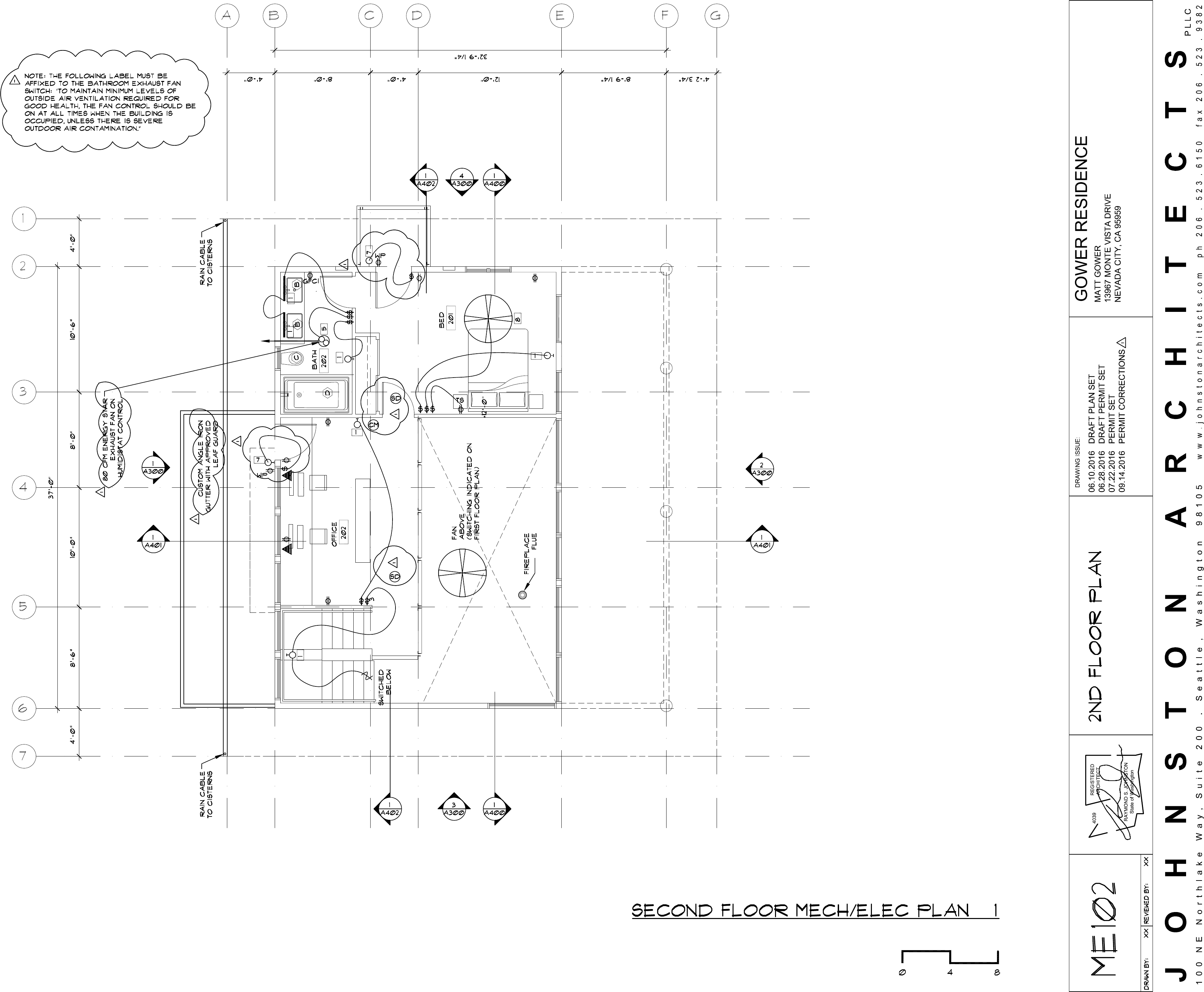

BTL
ENGINEERING P.S.
19011 Woodinville Snohomish Road NE, Suite 100
PHONE: 425-814-8448 FAX: 425-821-2120
WOODINVILLE, WA 98072-4436
DRAWING ISSUE: GOWER RESIDENCE
MATT GOWER
13967 MONTE VISTS DR.
NEVADA CITY, CA
95959
P L L C
J O H N S T O N A R C H I T E C T S
1 0 0 N E N o r t h l a k e W a y , S u i t e 2 0 0 . S e a t t l e , W a s h i n g t o n 9 8 1 0 5 w w w . j o h n s t o n a r c h i t e c t s . c o m p h 2 0 6 . 5 2 3 . 6 1 5 0 f a x 2 0 6 . 5 2 3 . 9 3 8 2
R
E
G
I
S
T
E
R
E
D
P
R
O
F
E
S
S
I
O
N
A
L
E
N
G
I
N
E
E
R
E
R
I
C
A.
D
A
N
N
NO. S4130
Exp. 9-30-16
S
T
A
E
O
F
C
A
L
I
F
O
R
N
I
A
T
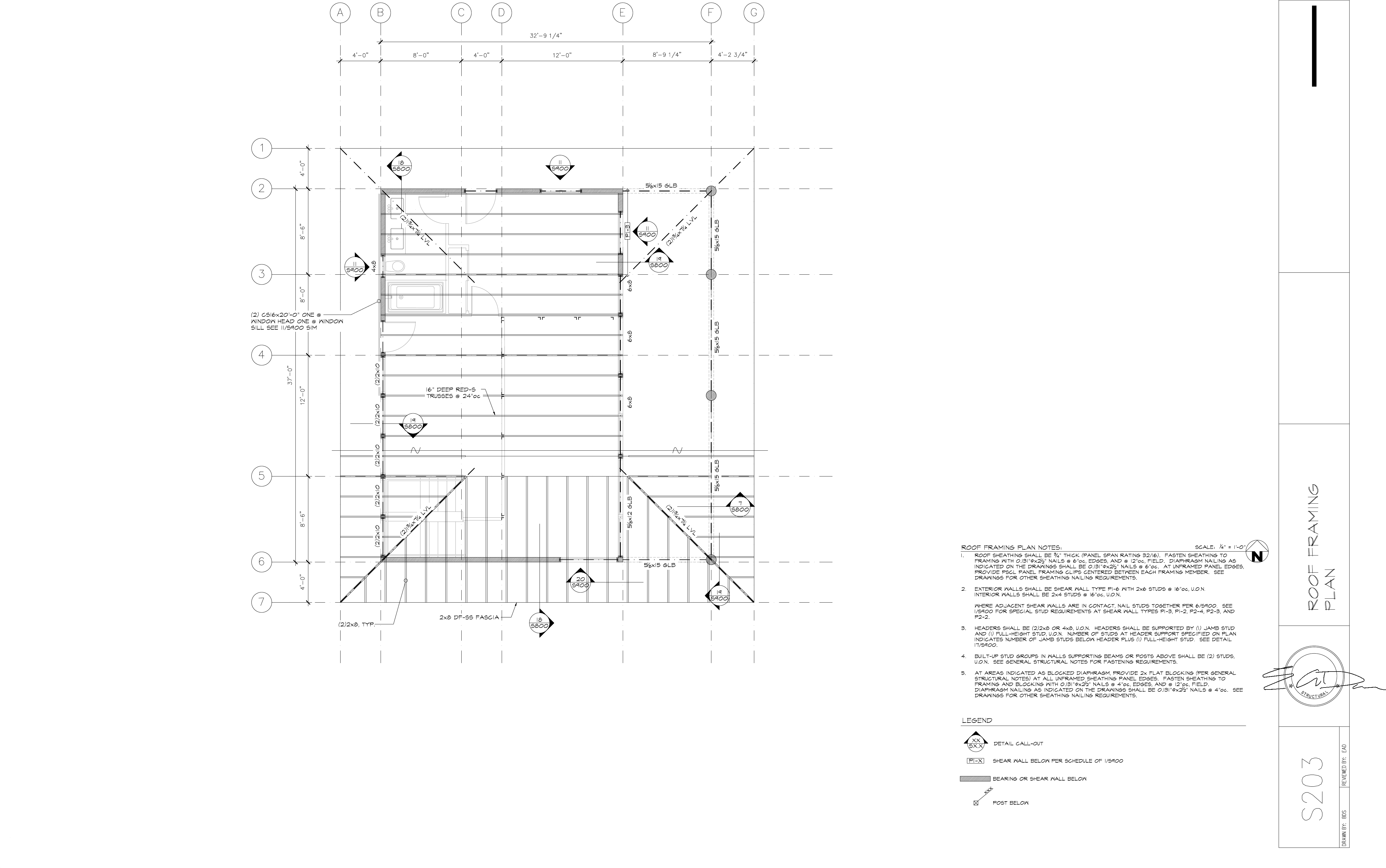
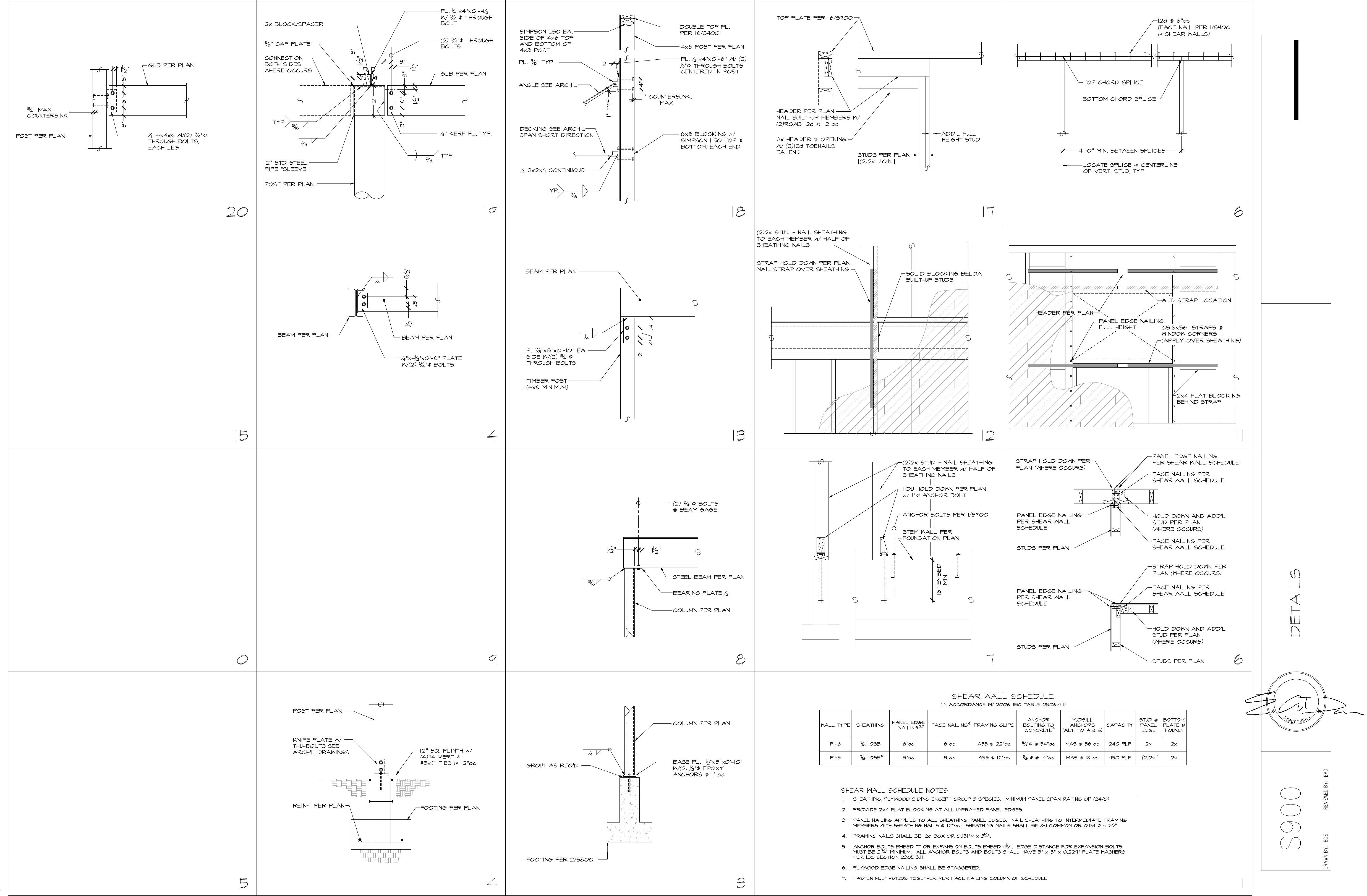
