6923_01_cov.pmd Jenn Air Oven JGS8860BD 16026923 Maytag Jgs Gas In Range
User Manual: Jenn-Air Oven JGS8860BD
Open the PDF directly: View PDF ![]() .
.
Page Count: 73

16026923
March 2006
© 2006 Maytag Services
This Base Manual covers general information
Refer to individual Technical Sheet
for information on specific models
This manual includes, but is
not limited to the following:
Service
This manual is to be used by qualified appliance
technicians only. Maytag does not assume any
responsibility for property damage or personal
injury for improper service procedures done by
an unqualified person.
JGS8750BD*
JGS8850BD*
JGS8860BD*
JGS9900BD*
Gas
Slide-In
Range
2 16026923 © 2006 Maytag Services
Maytag will not be responsible for personal injury or property damage from improper service procedures. Pride and
workmanship go into every product to provide our customers with quality products. It is possible, however, that
during its lifetime a product may require service. Products should be serviced only by a qualified service technician
who is familiar with the safety procedures required in the repair and who is equipped with the proper tools, parts,
testing instruments and the appropriate service information. IT IS THE TECHNICIANS RESPONSIBLITY TO
REVIEW ALL APPROPRIATE SERVICE INFORMATION BEFORE BEGINNING REPAIRS.
Important Notices for Servicers and Consumers
!WARNING
To avoid risk of severe personal injury or death, disconnect power before servicing/working on appliance to avoid
electrical shock.
To locate an authorized servicer, please consult your telephone book or the dealer from whom you purchased this
product. For further assistance, please contact:
Customer Service Support Center
CAIR Center
Web Site Telephone Number
WWW.JENNAIR.COM ............................................. 1-800-536-6247
WWW.MAYTAG.COM ............................................. 1-800-688-9900
WWW.AMANA.COM................................................ 1-800-843-0304
CAIR Center in Canada ................................................ 1-800-688-2002
Recognize Safety Symbols, Words, and Labels
DANGER!
DANGER—Immediate hazards which WILL result in severe personal injury or death.
WARNING!
WARNING—Hazards or unsafe practices which COULD result in severe personal injury or death.
CAUTION!
CAUTION—Hazards or unsafe practices which COULD result in minor personal injury, product or property
damage.
Important Information

© 2006 Maytag Services 16026923 3
Table of Contents
Important Information ................................................... 2
Important Safety Information
What to Do if You Smell Gas ................................... 4
Oven Fires ............................................................... 4
Safety Practices for Servicer .................................. 4
Servicing.................................................................. 4
Receiving Oven ........................................................ 5
Using the Oven ......................................................... 5
Baking, Broiling, and Roasting ................................. 6
Connecting Range to Gas ........................................ 6
Electrical Requirements ........................................... 6
Extension Cord ........................................................ 6
Product Safety Devices ........................................... 6
General Information
Cooking Nomenclature ............................................. 7
Specifications .......................................................... 8
Placement of the Oven ............................................. 8
Do Not Block Air Vents ............................................ 8
Location of Model Number........................................ 8
Model Identification .................................................. 8
Service ..................................................................... 8
Parts and Accessories............................................. 8
Extended Service Plan ............................................. 8
Grounding ................................................................ 9
Range Description ...................................................10
Troubleshooting Procedures
Troubleshooting Chart ............................................ 11
Description of Fault Codes for EOC III .................. 13
Fault Code Chart.................................................... 13
Oven Sensor, Meat Probe and
Cooling Fan Temperature Charts ..................... 14
Testing Procedures
Component Testing Procedures ............................. 15
Cooling Fan Temperature Chart............................. 18
Electronic Oven Control (EOC III)
Testing Procedures .......................................... 19
Relay Logic for EOC III ......................................... 21
“Quick Test” Mode for EOC III ............................... 22
Oven Sensor and Meat Probe Resistances ............ 22
Description of Fault Codes for EOC III .................. 23
Disassembly Procedures
Removing and Replacing Range ............................ 24
Front Side Trim Removal........................................ 24
Cartridge Assembly Removal (Select Models)........ 24
Maintop Assembly Removal (Select Models) .......... 24
Top Burner Assembly Removal (Select Models) .... 24
Lower Burner Assembly Removal (Select Models) . 24
Spark Module Replacement ................................... 25
Manifold Assembly Removal ................................... 25
Control Panel Assembly Removal ........................... 25
Electronic Control Replacement ............................. 25
Burner Switch Replacement................................... 25
Meat Probe Receptacle Replacement
(Select Models) ................................................ 25
Back Panel Removal .............................................. 25
Cooling Fan Replacement ...................................... 26
Downdraft Blower Motor Removal (Select Models) . 26
Convection Motor Removal (Select Models) ........... 26
Convection Element Replacement (Select Models) 26
Bake Burner and Ignitor Removal .......................... 26
Broil Burner and ignitor Removal ........................... 26
Oven Sensor Replacement ..................................... 26
Regulator Removal ................................................. 27
Gas Valve Removal (Select Models) ....................... 27
Oven Light Bulb/Oven Light Socket Replacement .. 27
Oven Vent/Smoke Eliminator Removal ................... 27
Oven Hi-Limit Thermostat Replacement ................. 27
Oven Door Latch Replacement .............................. 28
Oven Door Hinge Removal ..................................... 28
Bottom Access Panel Removal (Select Models) ..... 28
Bottom Access Panel Disassembly
(Select Models) ................................................ 28
Storage Drawer Removal (Select Models).............. 28
Storage Drawer Track Disassembly
(Select Models) ................................................ 28
Storage Drawer Disassembly ................................ 28
Warming Drawer Removal (Select Models) ........... 28
Warming Drawer Element Removal
(Select Models) ................................................ 28
Warming Drawer Hi-Limit Switch Replacement
(Select Models) ................................................ 29
Oven Door Removal ............................................... 29
Warming Drawer Track Disassembly
(Select Models) ................................................ 29
Warming Drawer Disassembly .............................. 29
Oven Door Disassembly ........................................ 29
Oven Door, Warming Drawer/Storage Drawer
and Access Panel Disassembly Illustration ...... 30
Appendix A
Installation Instructions .......................................... A-2
Appendix B
Use and Care ....................................................... B-2
Appendix C: Gas Conversion Instructions
Model JGS8750BD* ..............................................C-2
Models JGS8850BD*, JGS8860BD* .....................C-6
Model JGS9900BD* ............................................ C-13
4 16026923 © 2006 Maytag Services
Important Safety Information
As with all appliances, there are certain rules to follow
for safe operation. Verify everyone who operates oven is
familiar with the operations and with these precautions.
Use appliance only for its intended purpose as
described. Pay close attention to the safety sections of
this manual. Recognize the safety section by looking for
the symbol or the word safety.
Recognize this symbol as a safety precaution.
!
WARNING
!
If the information in this manual is not followed exactly,
a fire or explosion may result causing property
damage, personal injury or death.
Do not store or use gasoline or other flammable
vapors and liquids in the vicinity of this or any other
appliance.
WHAT TO DO IF YOU SMELL GAS
• Extinguish any open flame.
• Do not try to light any appliance.
• Do not touch any electrical switch; do not use any
phone in your building.
• Immediately call your gas supplier from a neighbor’s
phone. Follow the gas supplier’s instructions.
• If you cannot reach your gas supplier, call fire
department.
Installation and service must be performed by an
authorized installer, service agency or gas supplier.
WARNING
!
To avoid risk of electrical shock, property damage,
personal injury, or death, verify wiring is correct, if
components were replaced. Verify proper and
complete operation of unit after servicing.
WARNING
!
This gas appliance contains or produces a chemical
or chemicals which are known to the state of
California to cause cancer, birth defects, or other
reproductive harm. To reduce the risk from substances
in the fuel or from fuel combustion make sure this
appliance is installed, operated and maintained
according to the instructions in this manual.
Due to the nature of cooking, fires can occur as a
result of overcooking or excessive grease. Although a
fire is unlikely, if one occurs proceed as follows:
Oven Fires
1. Do not open the oven door.
2. Turn all controls to OFF.
3. As an added precaution turn off the electricity at
the main circuit breaker or fuse box and the gas
at the main supply valve.
4. Allow the food or grease to burn itself out in the
oven.
If smoke or fire persist call the local fire department.
To avoid the risk of property damage or personal injury
do not obstruct the flow of combustion or ventilation air
to the oven.
To avoid the risk of electrical shock, serious personal
injury or death: Make sure your oven has been
properly grounded and always disconnect the
electrical supply before servicing this unit.
NOTE: The maximum gas supply pressure for these
models must not exceed 14 inches W.C.P.
Safety Practices for Servicer
Safe and satisfactory operation of gas ranges depends
upon its design and proper installation. However, there is
one more area of safety to be considered:
Servicing
Listed below are some general precautions and safety
practices which should be followed in order to protect
the service technician and consumer during service and
after service has been completed.
1. Gas smell—Extinguish any and all open flames and
open windows.
2. Turn gas off—Service range with gas turned off
unless testing requires it.
© 2006 Maytag Services 16026923 5
Important Safety Information
3. Checking for gas leaks—Never check for leaks with
any kind of open flame. Soap and water solution
should be used for this purpose. Apply solution to
suspected area and watch for air bubbles which
indicates a leak. Correct leaks by tightening fittings,
screws, connections, applying approved compound,
or installing new parts.
4. Using lights—Use a hand flashlight when servicing
ranges or checking for gas leaks. Electric switches
should not be operated where leaks are suspected.
This will avoid creating arcing or sparks which could
ignite the gas. If electric lights are already turned on,
they should not be turned off.
5. Do not smoke—Never smoke while servicing gas
ranges, especially when working on piping that
contains or has contained gas.
6. Check range when service is completed—After
servicing, make visual checks on electrical
connection, and check for gas leaks. Inform
consumer of the condition of range before leaving.
7. Adhere to all local regulations and codes when
performing service.
Receiving Oven
• Installer needs to show consumer location of the range
gas shut-off valve and how to shut it off.
• Authorized servicer must install the range, in
accordance with the Installation Instructions.
Adjustments and service should be performed only by
authorized servicer.
• Plug range into a 120–volt grounded outlet only. Do
not remove round grounding prong from the plug. If in
doubt about grounding of the home electrical system, it
is consumers responsibility and obligation to have an
ungrounded outlet replaced with a properly grounded
three-prong outlet in accordance with the National
Electrical Code. Do not use an extension cord with this
appliance.
• Insure all packing materials are removed from the
range before operating it, to prevent fire or smoke
damage should the packing material ignite.
• Ensure range is correctly adjusted by a qualified
service technician or installer for the type of gas
(Natural or LP). Some ranges can be converted for
use with Natural or LP gas.
•With prolonged use of a range, high floor
temperatures could result. Many floor coverings will not
be able to withstand this kind of use. Never install
range over vinyl tile or linoleum that cannot withstand
high temperatures. Never install range directly over
carpeting.
Using the Oven
• Do not leave children alone or unattended where a
range is hot or in operation. They could be seriously
burned.
• Do not allow anyone to climb, stand or hang on the
door. They could damage the range and cause severe
personal injury.
• Wear proper apparel. Loose fitting or hanging
garments should never be worn when using oven.
Flammable material could ignite if brought in contact
with flame or hot oven surfaces which may cause
severe burns.
• Never use range for warming or heating a room. This
may cause burns, injuries, or a fire.
• Do not use water on grease fires.
• Do not let grease or other flammable materials collect
in or around range.
• Do not repair or replace any part of range unless it is
recommended in this manual.
• Use only dry potholders. Moist or damp potholders
used on hot surfaces may result in a burn from steam.
Do not let a potholder touch the flame. Do not use a
towel or a bulky cloth as a potholder.
• Never leave range unattended while cooking. Boilovers
can cause smoking and may ignite.
• Only certain types of glass/ceramic, earthenware, or
other glazed utensils are suitable for oven use.
Unsuitable utensils may break due to sudden
temperature change.
• Use care when opening oven door. Let hot air or steam
escape before removing or replacing food.
• Do not heat unopened food containers in oven.
Build-up of pressure may cause a container to burst
and result in injury.
• Keep range vent ducts unobstructed.
• Place oven racks in desired location while oven is
cool. If a rack must be moved while oven is hot, use a
dry potholder.
• Do not use aluminum foil to line oven bottom or racks.
Aluminum foil can cause a fire will seriously affect
baking results, and damage to porcelain surface's.
• Do not touch interior surfaces of oven during or
immediately after use. Do not let clothing or other
flammable materials come in contact with bake or broil
burners.
• Other areas of the oven can become hot enough to
cause burns, such as vent openings, window, oven
door and oven racks.
• To avoid steam burns, do not use a wet sponge or
cloth to wipe up spills on hot cooking area.
• Do not store combustible or flammable materials, such
as, gasoline or other flammable vapors and liquids
near or in oven.
• Do not clean oven door gasket located on back of the
door. Gasket is necessary to seal the oven and can be
damaged as a result of rubbing or being moved.
• Do not drape towels or any materials on oven door
handles. These items may ignite causing a fire.
6 16026923 © 2006 Maytag Services
Important Safety Information
CAUTION
!
Do not store items of interest to children in cabinets
above range. Children may climb on oven to reach
these items and become seriously injured.
Baking, Broiling, and Roasting
• Do not use oven area for storage.
• Stand back from range when opening door of a hot
oven. Hot air or steam can cause burns to hands,
face, and eyes.
• Do not use aluminum foil anywhere in the oven. This
could result in a fire hazard and damage the range.
• Use only glass cookware appropriate for use in gas
ovens.
• Always remove broiler pan from oven when finished
broiling. Grease left in pan can catch fire if oven is
used without removing grease from the broiler pan.
• When broiling, meat that is close to the flame, may
ignite. Trim any excess fat to help prevent excessive
flare-ups.
• Make sure broiler pan is placed correctly to reduce
any possibility of grease fires.
• Should a grease fire occur in the broiler pan, turn off
oven, and keep oven door closed until fire burns out.
Connecting Range to Gas
Install manual shut-off valve in gas line for easy
accessibility outside range. Be aware of the location of
the shut-off valve.
Electrical Requirements
120-volt, 60 Hertz, 20 amp, individual circuit which is
properly grounded, polarized and protected by a circuit
breaker or fuse.
Extension Cord
Do not use extension cords with this product.
Product Safety Devices
Safety devices and features have been engineered into
the product to protect consumer and servicer. Safety
devices must never be removed, bypassed, or altered in
such a manner as to defeat the purpose for which they
were intended.
Listed below are various safety devices together with the
reason each device is incorporated in the gas ranges.
Pressure Regulator Maintains proper and
steady gas pressure for
operation of oven
controls.
Regulator must be set
for the type of gas being
used Natural or LP.
After servicing regulator,
make certain it is set
properly before
completing service.
Gas Burner Orifices Universal orifices are
used on most valves.
They must be adjusted
for the type of gas being
used Natural or LP.
After servicing a valve
or orifice verify it is
adjusted properly before
completing service.
Oven Safety Valve Oven valve is designed
to be a safety valve. Two
basic designs are used
in gas ranges:
Hydraulic and Electric
Both types are safety
valves because they are
indirectly operated by
the oven thermostat,
which controls a pilot
flame or electric ignitor,
to open and close the
oven valve.
Grounded Oven Frame Ground prong on power
cord is connected to the
frame, usually a green
lead fastened by a
screw. In addition, any
part or component
capable of conducting
an electric current is
grounded by its
mounting.
If any ground wire,
screw, strap, nut, etc. is
removed for service, or
any reason, it must be
reconnected to its
original position with
original fastener before
the appliance is put into
operation again.
Failure to do so can
create a possible shock
hazard.
© 2006 Maytag Services 16026923 7
This manual contains information needed by authorized
service technicians to install and service gas ranges.
There may be, however, some parts which need further
explanation. Refer to the Installation Instructions, Use
and Care, Technical Sheets or the toll-free technical
support line.
This manual provides basic instructions and suggestions
for handling, installing and servicing gas ranges.
The directions, information, and warnings in this manual
are developed from experience with, and careful testing
of the product. If the unit is installed according to this
manual, it will operate properly and will require minimal
servicing. A unit in proper operating order ensures the
consumer all the benefits provided by clean, modern gas
cooking.
General Information
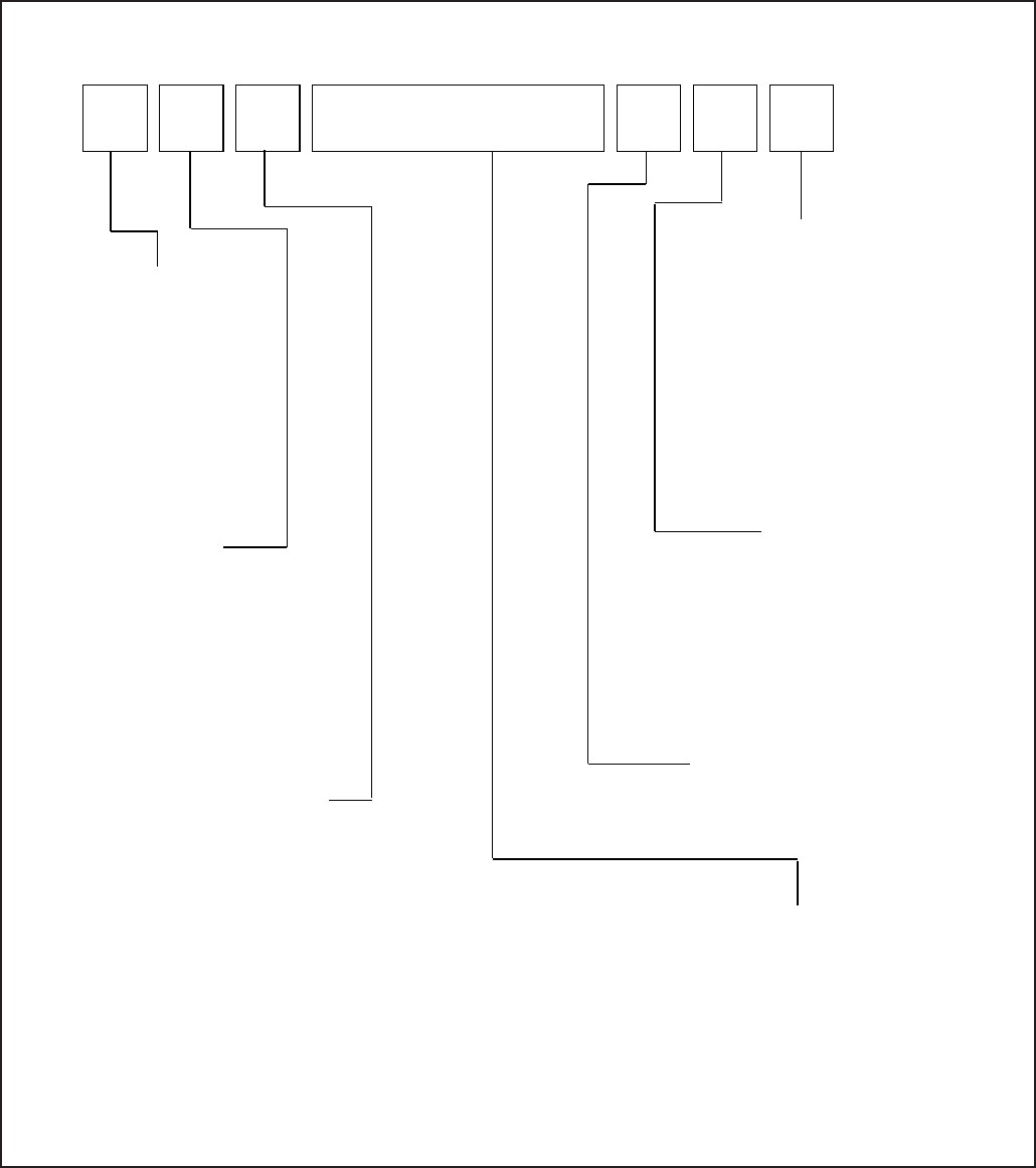
Cooking Nomenclature
J G S 9 9 0 0 B D B
Brand
A Amana
C Magic Chef
G Graffer &
Sattler
H Hardwick
J Jenn-Air
M Maytag
N Norge
U Universal
Y Crosley
Product Type
A Accessory/Cartridge
C Cooktop Updraft/Countertop
D Downdraft Cooktop or Warming Drawer
E Eyelevel Range
G Grill
L Range (20")
M Range (36")
P Drop In (24")
Q Wall Oven (27")
R Range, Free-Standing (30")
S Slide-In (30")
T Range Hood
V OTR
W Wall Oven
Y RV Range
Z RV Top
Fuel
B Butane
D Dual Fuel
E/J Electric
G Gas, Natural
L Liquid Propane
M Microwave
P Standing Pilot
X No Fuel
W Warming Drawer
Listing
A UL/AGA
C CSA/CGA/CUL
D Dual Listed
G 220-240 V / 50-60 Hz
M Military Model
P PSB Approved
(Singapore)
X Export 120 V / 60 Hz
Feature Content
1000-3999 Brands
4000-6999 Maytag/Amana
7000-9999 Jenn Air
Production Code
This identifies the
production version.
Color
A Almond on Almond
B Black
C Brushed Chrome
H Traditional White
L Traditional Almond
P Prostyle
Q Monochromatic Bisque
S Stainless
T Traditional Bisque
W White on White
F Frost White (True Color White)
N Natural Bisque (True Color Bisque)
8 16026923 © 2006 Maytag Services
Specifications
Refer to individual Technical Sheet for specification
information.
Placement of the Oven
This freestanding range must be placed in the kitchen or
comparable room. All safety guidelines must be followed
and free air flow around the range is essential.
Do Not Block Air Vents
All air vents must be kept clear during cooking. If air
vents are covered during operation, the oven may
overheat. If this occurs, a sensitive, thermal safety device
automatically removes power to the oven, rendering the
oven inoperable. The oven will remain in this state until it
has sufficiently cooled.
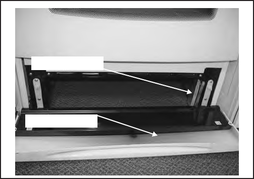
Location of Model Number
To request service information or replacement parts, the
service center will require the complete model, serial, and
manufacturing number of your slide-in range. The
number can be found on the oven chassis behind the
front Access Panel. Remove the front Access Panel to
view the data.
Model Number
Access Panel
Ask a qualified electrician if you do not understand the
grounding instructions or if you have questions when
grounding the appliance. Keep the electrical power cord
dry and keep it from getting crushed or pinched. For a
permanently connected appliance: This appliance must
be connected to a grounded, metallic, permanent wiring
system, or an equipment grounding conductor should be
run with the circuit conductors and connected to the
equipment grounding terminal or lead on the appliance.
General Information
Model Identification
Complete enclosed registration card and promptly return.
If registration card is missing:
• For Jenn-Air product call 1-800-536-6247 or visit the
Web Site at www.jennair.com
• For Maytag product call 1-800-688-9900 or visit the
Web Site at www.jennair.com
• For Amana product call 1-800-843-0304 or visit the
Web Site at www.jennair.com
• For product inCanada call 1-800-688-2002.
When contacting provide product information located on
rating plate. Record the following:
Model Number: ___________________
Manufacturing Number: ___________________
Serial or S/N Number: ___________________
Date of purchase: ___________________
Dealer’s name and address: ___________________
Service
Keep a copy of sales receipt for future reference or in
case warranty service is required. To locate an
authorized servicer:
• For Jenn-Air/Maytag product call 1-800-462-9824 or
visit the Web Sites at www.jennair.com or
www.maytag.com
• For Amana product call 1-800-628-5782 or visit the
Web Site at www.amana.com
• For product inCanada call 1-800-688-2002.
Warranty service must be performed by an authorized
servicer. We also recommend contacting an authorized
servicer, if service is required after warranty expires.
Parts and Accessories
Purchase replacement parts and accessories over the
phone. To order accessories for your product call:
• For Jenn-Air product call 1-800-536-6247 or visit the
Web Site at www.jennair.com
• For Maytag product call 1-800-688-9900 or visit the
Web Site at www.jennair.com
• For Amana product call 1-800-843-0304 or visit the
Web Site at www.jennair.com
• For product inCanada call 1-800-688-2002.
Extended Service Plan
We offer long-term service protection for this new oven.
• Asure™ Extended Service Plan is specially designed
to supplement Maytag and Amana’s strong warranties.
These plans cover parts, labor, and travel charges.
Call 1-866-232-6244 for information.
• Dependability PlusSM Extended Service Plan is
specially designed to supplement Jenn-Air’s strong
warranty. This plan covers parts, labor, and travel
charges. Call 1-800-925-2020 for information.
© 2006 Maytag Services 16026923 9
General Information
Grounding
NOTE: This appliance must be properly grounded, for
personal safety.
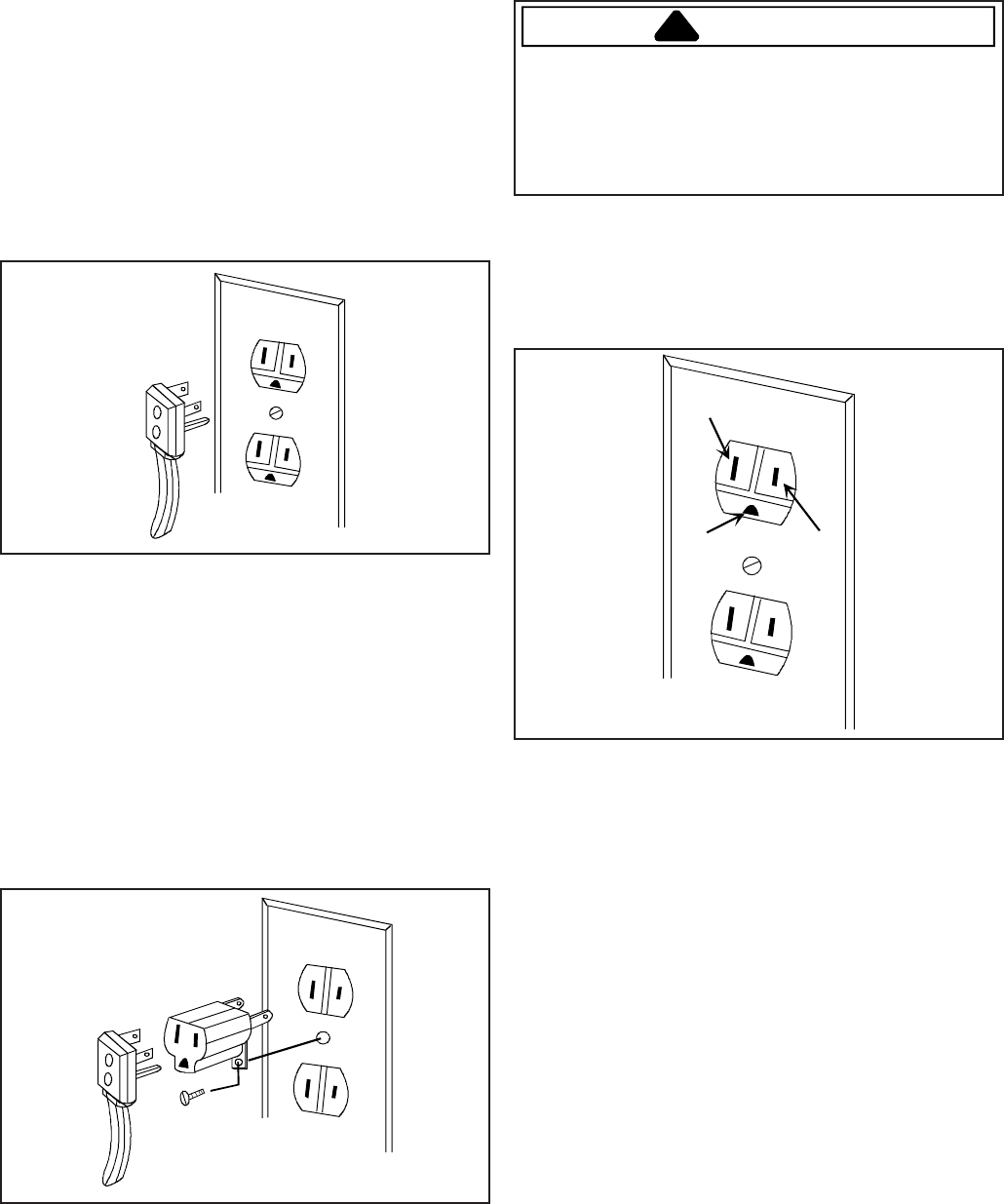
Power cord on this appliance is equipped with a three-
prong grounding plug. This matches standard three-
prong grounding wall receptacle to prevent possibility of
electric shock from this appliance.
Consumer should have wall receptacle and circuit
checked by qualified electrician to verify receptacle is
properly grounded.
It is the consumers responsibility to replace standard two-
prong wall receptacles with properly grounded three-prong
wall receptacles.
DO NOT, UNDER ANY CIRCUMSTANCES, CUT OR
REMOVE THE THIRD (GROUND) PRONG FROM
POWER CORD.
For 15 amp circuits only, do not use an adapter on 20
amp circuit. Where local codes permit, a TEMPORARY
CONNECTION may be made to a properly grounded two-
prong wall receptacle by the use of a UL listed adapter
(available at most hardware stores).
Larger slot on adapter must be aligned with larger slot in
the wall receptacle to provide proper polarity.
WARNING
!
Attaching adapter ground terminal to wall receptacle
cover screw does not ground appliance unless the
cover screw is metal and not insulated, and wall
receptacle is grounded through the house wiring.
Consumer should have circuit checked by a qualified
electrician to verify receptacle is properly grounded.
When disconnecting power cord from adapter, always
hold adapter with one hand. If this is not done, adapter
ground terminal is very likely to break with repeated use.
Should this happen, DO NOT USE appliance until a
proper ground has been established.
Neutral Wire
Hot Line
Ground
NOTE: Circuit tester can be used to verify voltage at
outlet. Connect one lead to hot line and the
other lead to ground. Circuit tester should light.
10 16026923 © 2006 Maytag Services
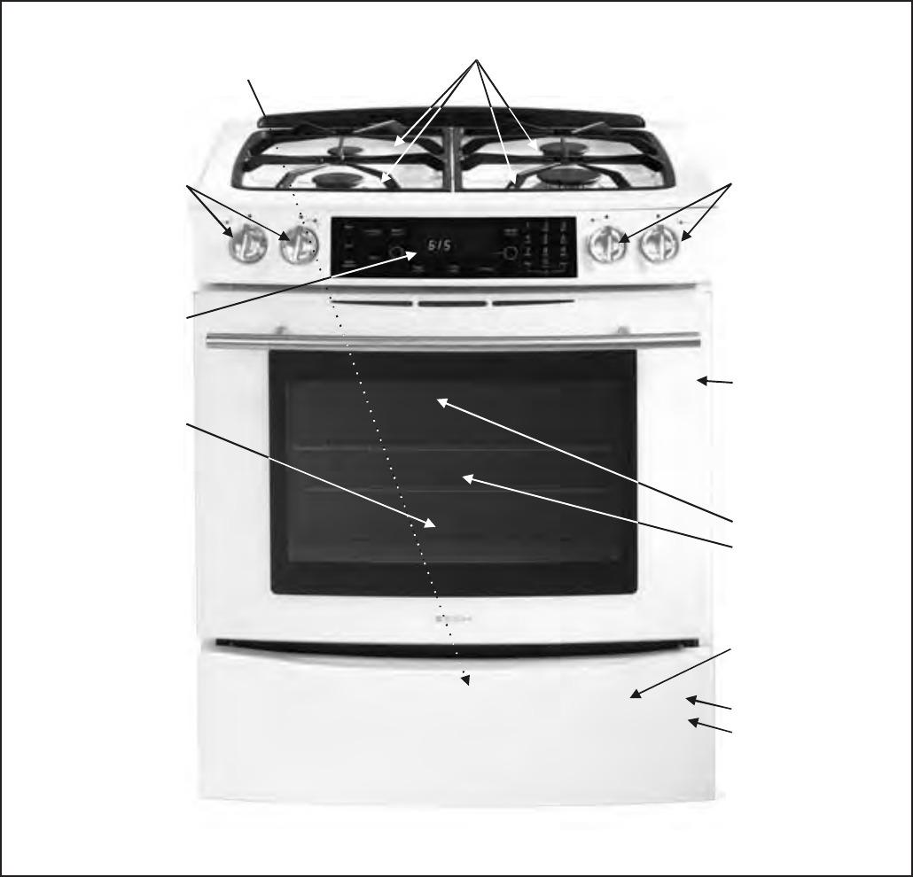
Range Description
Broil Burner
Bake Burner
Storage or Warming
Drawer
Convection Fan
and Element
Shut-off Valve/
Pressure Regulator
(Backside of Range)
Electronic Control
and Touchpad
Top Surface
Burners and Grates
Model Number
Rating Label
Burner Control Valves Burner Control Valves
Oven Cavity

Troubleshooting Procedures
!
WARNING
To avoid risk of electrical shock, personal injury, or death, disconnect power and gas to range before servicing,
unless testing requires power and/or gas.
© 2006 Maytag Services 16026923 11
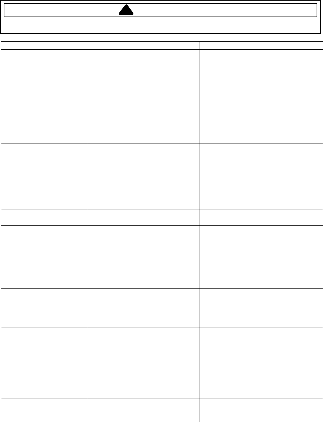
Troubleshooting Chart
Problem Possible Cause Correction
Burners will not ignite; no
spark at top burner.
Poor ground on burner cap ...................
.
Weak or failed spark module ................
.
Low gas pressure..................................
.
Clogged burner port ..............................
.
• Clean burner cap.
• Replace spark module.
• Verify pressure 4" WCP for natural, 10"
WCP for LP.
• Clean burner cap.
Burner will not ignite. No
spark to burner ignitors
when burner knob is rotated
to "LITE" position.
No 120 VAC to range............................
.
Micro switch contacts not closing .........
.
Faulty wiring. Bad connection at
burner electrode and electrode socket .
.
Inoperative spark module .....................
.
Electrode dirty. Burner cap dirty ...........
.
Cracked or broken electrode,
electrode wire or electrode socket ........
.
• Verify voltage at wall outlet.
• Check wiring against appropriate wiring
diagram. Verify all terminals and
connections are correct and tight.
Check micro switch contacts.
• Check wiring against appropriate wiring
diagram. Verify all terminals and
connections are correct and tight.
• Check module according to testing
procedures information.
• Clean electrode or burner cap.
• Replace electrode.
No spark or only random
spark at one ignitor.
Check for cracked ignitor/pinched wire.
.
Poor continuity to burner cap................
.
Bad ground connection or lack of
continuity to ground or ignitor ...............
.
Cracked or broken ignitor extension
lead .......................................................
.
• Replace ignitor lead or electrode.
• Clean burner cap and lead.
• Tighten ground connection and correct
any breaks in ground path from ignitor
path to unit ground path.
• Replace ignitor lead.
Unit continues to spark after
knob is turned to OFF
position.
Shorted valve switch/harness ...............
.
Switch has slipped off the valve............
.
• Replace switch/harness. If shorting is
caused by excessive spillovers,
customer education is advised.
• Carefully reposition switch on valve and
rotate from OFF to high, several times
to verify switch is not broken.
No oven operation in bake or
broil.
No voltage to control. ............................
.
No voltage from control.........................
.
Loose wire connection or broken wire ..
.
• Check for 120 VAC at control. If no
voltage check power source.
• Check 120 VAC to ignitor, if no voltage,
replace control.
• Verify all connections are clean and
tight, replace broken wire.
No gas flows to burner.
Ignitor glows red.
Failed ignitor. ........................................
.
Gas pressure too high...........................
.
Failed gas valve ....................................
.
Loose wire connection or broken wire ..
.
• Check ignitor current draw, 3.2 – 3.6
Amps. Replace ignitor if it fails test.
• Check for correct gas pressure. Natural
gas pressure should be 5" WCP and LP
gas pressure should be 10" WCP.
• Check gas valve for continuity.
• Verify all connections are clean and
tight, replace broken wire.
Troubleshooting Procedures
!
WARNING
To avoid risk of electrical shock, personal injury, or death, disconnect power and gas to range before servicing,
unless testing requires power and/or gas.
12 16026923
© 2006 Maytag Services
Problem Possible Cause Correction
Gas flows to bake/broil
burner, but burner does not
light.
Ignitor positioned too far from burner....
.
Dirt or grease in orifice or burner ..........
.
Insufficient gas pressure .......................
.
Power outage ........................................
.
• Reposition ignitor closer to bake/broil
burner.
• Clean orifice or burner.
• Check for correct gas pressure. Natural
gas pressure should be 5" WCP and LP
gas pressure should be 10" WCP.
• Verify power is present at unit. Verify
circuit breaker is not tripped/replace fuse.
Broil burner shuts off shortly
after the start of self-clean
operation. Bake and broil
functions operate normally.
Power outage ........................................
.
Control Error..........................................
.
• Verify power is present at unit. Verify
circuit breaker is not tripped.
• Replace household fuse.
• See "Control Systems Troubleshooting."
Fan motor does not operate.
No power to fan motor ..........................
.
Failed fan motor or winding/frozen
shaft ......................................................
.
• Check for 120 VAC supplied at fan
motor. If voltage is not present, check
for broken/loose wiring between fan
motor and relay board. If voltage is
present at fan motor, go to next step.
• Check motor winding for continuity.
Check for a frozen motor shaft. Check
for broken wiring between motor and
neutral terminal block.
Oven smokes/odor first few
times of usage.
Normal...................................................
.
• Minor smoking and/or odor is normal
the first few times of oven usage.
Failure Codes. Electronically Controlled .......................
.
• See "Fault Code Chart."
Oven not operating.
Programming error................................
.
Power outage ........................................
.
Unit in Sabbath mode ...........................
.
• Switch range circuit breaker off for five
minutes and try oven again.
• Verify power is present at unit and
circuit breaker is not tripped.
• Replace household fuse.
• Refer to Use & Care manual to remove
unit from Sabbath mode.
Clock and timer not working. Power outage ........................................
.
Electronic Control locked ......................
.
• Verify power is present at unit and
circuit breaker is not tripped.
• Replace household fuse.
• Refer to Use and Care manual to
unlock electronic control.
Oven light does not operate. Failed oven lamp...................................
.
Failed wiring ..........................................
.
Failed light socket .................................
.
• Check lamp and replace is necessary.
• Check for broken, loose or dirty
connections.
• Check light socket for continuity.
Oven door will not unlock. Oven is self-cleaning.............................
.
Oven is still hot......................................
.
• Allow cycle to complete.
• Will not unlock until unit has cooled to
safe temperature. Do not force door
open, this will void warranty. Blow cool
air on latch area to quicken process.
Self-clean cycle not working. Programming error................................
.
Door lock ...............................................
.
• Turn off circuit breaker for five minutes
and try self-clean again.
• Verify door lock energizes & engages.
Troubleshooting Procedures
!
WARNING
To avoid risk of electrical shock, personal injury, or death, disconnect power and gas to range before servicing,
unless testing requires power and/or gas.
© 2006 Maytag Services 16026923 13
Description of Fault Codes for EOC III
Each fault code consists of 4 digits and is structured as follows:
1st (Leftmost) Digit:
Primary Failure System 2nd Digit: Alpha-Character 3rd Digit: Secondary
Failure Mechanism 4th Digit : Oven
Cavity Number
1 – Local to Control System d – Diagnostic Failure (measurable) 1 – Upper (Single) Oven
3 – Sensor or Meat Probe c – Control-Related Error (not measurable) 2 – Lower Oven
4 – Input to Control System
c – Control System
9 – Door Lock
If a fault is detected, then one of the following three messages will be scrolled on the display:
FAULT DETECTED PRESS ENTER TO TRY AGAIN. This message displays when a fault is detected while a
cooking function is active. Clear by pressing the Cancel keypad.
FEATURE NOT AVAILABLE. This message displays when a fault is detected while entering data during initial
programming and also when a locked out function is detected. Clear by pressing any key.
FAULT DETECTED DISABLE POWER TO CLEAR. This message displays when a runaway temperature condition
is detected while the control is in idle mode. Press any key to clear the message, but the fault remains until the
control senses a Power-On reset.
Fault Code Chart
Fault
Code Description Component to Troubleshoot/Replace
1c1c Shorted key. Ensure ribbon cable is securely connected, inspect ribbon cable and
connector (shorts, breakage, corrosion, etc.). If OK, replace control.
1c2c Membrane keyboard disconnected. Ensure ribbon cable is securely connected, inspect ribbon cable and
connector (shorts, breakage, corrosion, etc.). If OK, replace control.
1c4c Board – to – Board communication failure. Replace control.
1c6c EEPROM hardware fault. Replace control.
1c7c Control not calibrated. Replace control.
1c8c EEPROM CRC error – User Options. Replace control.
1c81 EEPROM CRC error – Cook Profile. Replace control.
1d11 Unlocked runaway temperature – 600° F Ohm sensor and harness (see "Oven Sensor" chart). If OK, change
control.
1d21 Locked runaway temperature – 950° F Ohm sensor and harness (see "Oven Sensor" chart). If OK, change
control.
3d11 Temperature sensor open. Check connections, sensor (see "Oven Sensor" chart) and harness. If
OK, replace control.
3d21 Temperature sensor shorted. Check connections, sensor (see "Oven Sensor" chart) and harness. If
OK, replace control.
3d41 Meat probe shorted. Check probe jack and harness. If OK, check meat probe (see "Meat
Probe" chart).
3d51 Meat probe not calibrated. Check probe jack and harness. If OK, check meat probe (see "Meat
Probe" chart).
4d11 Door switch not closed when locked. Check connections, switch, harness, and motor. If OK, replace control.
4d21 No cooling fan rotation. Check cooling fan motor and harness. If OK, replace control.
4d31 Cooling fan on when de-energized. Check cooling fan motor and harness. If OK, replace control.
4d41 Cooling fan overspeed. Check cooling fan motor and harness. If OK, replace control.
4d51 Door switch circuit fault. Check connections, harness, and motor. If OK, replace control.
9d11 Latch will not lock. Check wire connections. If OK, replace motorized door lock.
9d21 Latch will not unlock. Check wire connections. If OK, replace motorized door lock.
9d31 Latch both locked and unlocked. Check wire connections. If OK, replace motorized door lock.
Troubleshooting Procedures
!
WARNING
To avoid risk of electrical shock, personal injury, or death, disconnect power and gas to range before servicing,
unless testing requires power and/or gas.
14 16026923
© 2006 Maytag Services
Oven Sensor, Meat Probe and Cooling Fan Temperature Charts
OVEN SENSOR
Sensor Type: RTD 1000 Ω platinum
Calibration: 1654 Ω (350° F / 177° C)
Temperature F (C) Resistance (Ohms)
100 (38) 1143
200 (94) 1350
300 (149) 1553
350 (177) 1654
400 (204) 1753
500 (260) 1949
600 (316) 2142
700 (371) 2331
800 (427) 2516
900 (483) 2697
1000 (538) 2874
MEAT PROBE
Type: NTC Thermistor
Calibration: 9938 Ω (150° F / 65.5° C)
Temperature F (C) Resistance (Ohms)
32 (0) 163300
68 (20) 62450
95 (35) 32660
122 (50) 18020
158 (70) 8760
185 (85) 5360
212 (100) 3400
COOLING FAN TEMPERATURES
MODE FAN ON TEMP F (C) FAN OFF TEMP F (C)
Bake 350 (177) 300 (149)
Broil Six (6) minute delay
after cycle started 225 (107)
Clean Six (6) minute delay
after cycle started 225 (107)
Testing Procedures
!WARNING
To avoid risk of electrical shock, personal injury or death; disconnect power and gas to range before servicing,
unless testing requires power and/or gas.
© 2006 Maytag Services 16026923 15
Component Testing Procedures
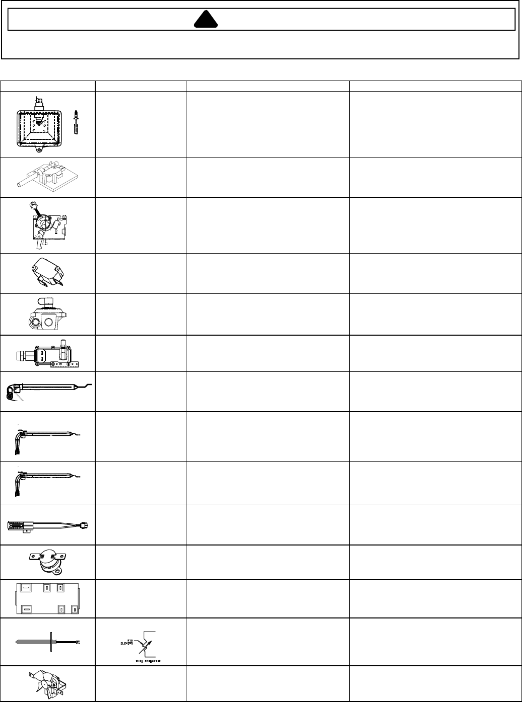
Illustration Component Test Procedure Results
Oven light & housing Disconnect connector and test
resistance of terminals .............................
Measure voltage at oven light...................
Verify bulb is properly inserted.
Continuity with bulb inserted.
120 VAC, see wiring diagram for terminal
identification.
If voltage is not present at oven light,
check wiring or light switches.
Door plunger switch Remove switch from unit and measure
the following points:
Door closed...........................................
Door open.............................................
COM-NO: .....Continuity (closed).
COM-NO: .....Infinity (open).
Autolatch assembly Disconnect wires and test for continuity
per wiring diagram....................................
Refer to Parts Manual for correct
autolatch switch associated with the
correct manufacturing number.
See wiring diagram for schematic layout.
Common is in neutral position unless
locking or unlocking autolatch assembly.
COM
NO
Door lock switch Switch connection in the following
positions:
Door latch locked......................................
Door latch unlocked..................................
COM-NO: .....Continuity (closed).
COM-NO: .....Infinity (open).
Pressure regulator Verify gas pressure (W.C.P.)....................
If on LP service verify proper gas supply
conversion.
5" Natural.
10" LP/propane.
Gas ON: .......Switch up.
Gas OFF: .....Switch down.
Oven valve Verify gas supply is turned on at
regulator ...................................................
Attached to pressure regulator.
Gas ON: .......Switch up (at regulator).
Gas OFF: .....Switch down (at regulator).
Broil burner Verify gas is supplied.
Orifice adjusted for Natural or LP .............
Check for obstructions or contamination
in ports .....................................................
Factory set to Natural Gas.
Adjust as necessary.
Air shutter opening set to .281 to .343.
Replace if punctured or torn.
JGS9900BD*
Bake burner Verify gas is supplied.
Orifice adjusted for Natural or LP .............
Check for obstructions or contamination
in ports .....................................................
Factory set to Natural Gas.
Adjust as necessary.
Air shutter opening set to .281 to .343.
Replace if punctured or torn.
Bake burner Verify gas is supplied.
Orifice adjusted for Natural or LP .............
Check for obstructions or contamination
in ports .....................................................
Factory set to Natural Gas.
Adjust as necessary.
Air shutter opening set to .469 to .531.
Replace if punctured or torn.
Ignitor Test for voltage at terminals .....................
Test for circuit amperage..........................
(Ignitor may glow but not have sufficient
amperage to open valve.)
120 VAC.
3.2 - 3.6 Amps. If not, replace.
Hi-limit temperature
switch
Normally closed, verify operation:
Open: 249° to 271° F (121° to 133° C) ...
Closed: 173° to 207° F (78° to 97° C) ....
Infinite.
Continuity.
LAB
A1 B1N
Spark module 4 + 0 Test for voltage at terminals L and N........
Check polarity and ground........................
120 VAC.
See wiring diagram.
Temperature sensor
Measure resistance.................................. Approximately 1000 at room
temperature 75° F (23.8° C).
Cooling fan motor Measure voltage.......................................
Check motor windings to ground ..............
120 VAC.
No continuity.
RPM: ............Approximately 1670 to 2070.
Testing Procedures
!WARNING
To avoid risk of electrical shock, personal injury or death; disconnect power and gas to range before servicing,
unless testing requires power and/or gas.
16 16026923
© 2006 Maytag Services
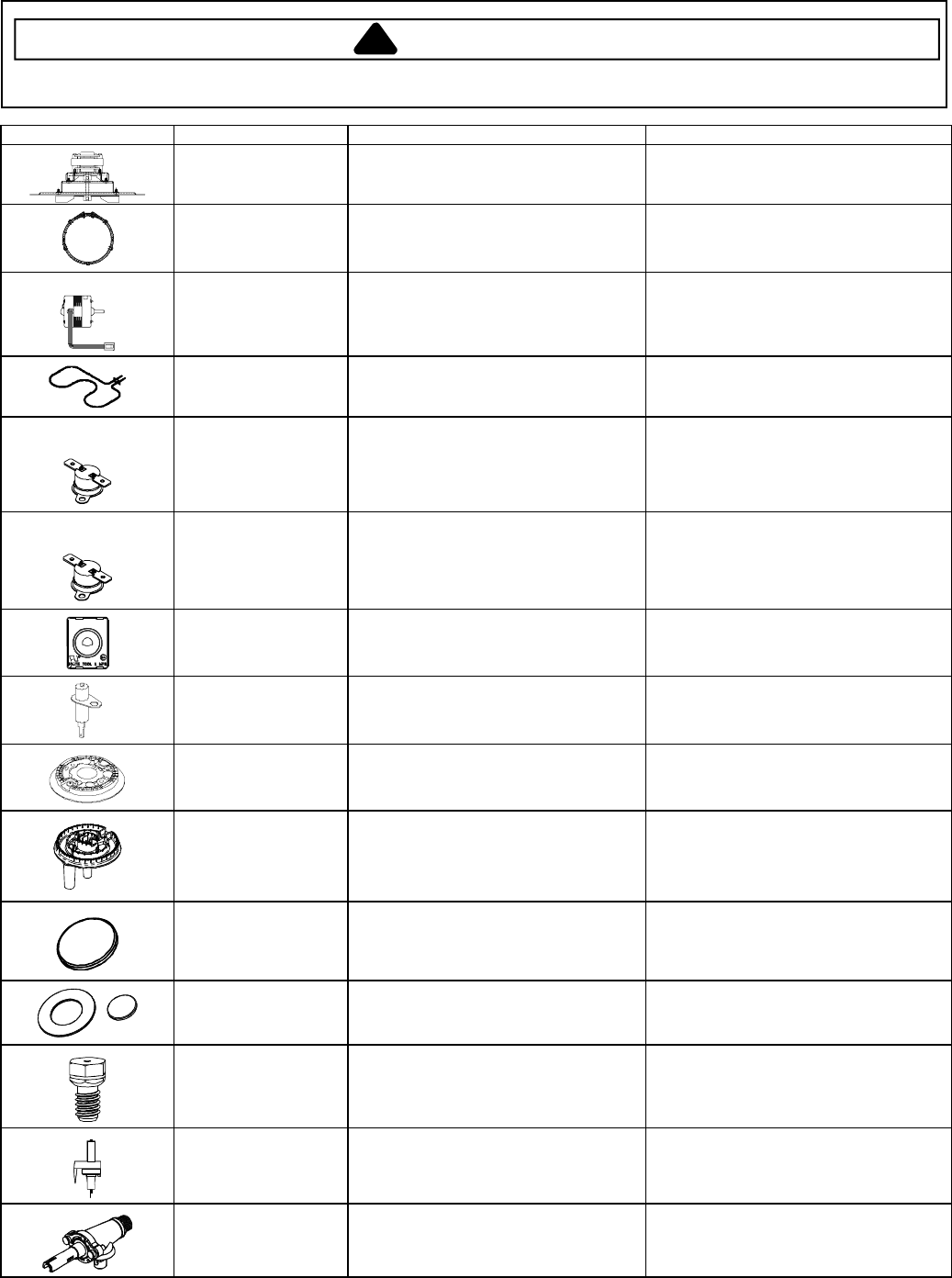
Illustration Component Test Procedure Results
Convection motor,
single speed
Measure voltage ......................................
Check motor windings to ground..............
120 VAC.
No continuity.
RPM:............ Approximately 900
Convection element Disconnect wiring to element and
measure cold resistance of terminals.......
Measure voltage at convect element........
Approximately 31 .
120 VAC.
JGS9900BD*
Downdraft motor Measure voltage ......................................
Check motor windings to ground..............
120 VAC.
No continuity.
RPM:............ Approximately 1550.
Warmer element Disconnect wiring to element and
measure cold resistance of terminals.......
Measure voltage at broil element .............
Approx. 12.5 to 18 .
120 VAC.
JGS8850BD*,
JGS8860BD*
Hi-limit temperature
switch
(Warming Drawer)
Normally closed, verify operation:
Open: 135° to 145° F (57° to 63° C).......
Closed: 114° to 126° F (46° to 52° C)....
Infinite.
Continuity.
JGS8850BD*,
JGS8860BD*
Hi-limit temperature
switch
(Warming Drawer)
Normally closed, verify operation:
Open: 95° to 105° F (35° to 41° C).........
Closed: 79° to 91° F (26° to 33° C)........
Infinite.
Continuity.
Spark switch Test for voltage at terminals.....................
Disconnect wiring and check for
continuity in LITE position ........................
120 VAC.
Continuity in LITE position.
Spark ignition
electrode
Test for resistance of spark lead ..............
Test ignitor to chassis ..............................
Continuity.
No continuity from ignitor to chassis.
Top surface burner
5 K btu, 9.2 K btu
16 K btu
Verify gas is supplied ...............................
Verify burner cap is positioned correctly...
Gas supplied.
Check for obstructions in burner ports.
Top surface,
dual ring burner
15 K btu
Inner: 3 K btu
Outer: 12 K btu
Verify gas is supplied ...............................
Verify burner cap is positioned correctly...
Gas supplied.
Check for obstructions in burner ports.
Top surface,
burner cap
5 K btu, 9.2 K btu
16 K btu
Verify cap is positioned correctly.............. Check for obstructions in burner ports.
Top surface,
burner cap, dual ring
(inner and outer rings)
Verify cap is positioned correctly.............. Check for obstructions in burner ports.
Orifice Check for debris....................................... Clean as needed.
Orifice holder
5 K btu, 9.2 K btu
16 K btu
Verify gas pressure..................................
Check orifice for debris ............................
5" Natural.
10" LP/propane.
Clean as needed.
Burner valve,
push-to-turn, 270°
5 K btu, 9.2 K btu
16 K btu
Verify gas is supplied ...............................
Orifice adjusted for Natural or LP.
Adjust set screw for simmer control.
Gas supplied.
Testing Procedures
!WARNING
To avoid risk of electrical shock, personal injury or death; disconnect power and gas to range before servicing,
unless testing requires power and/or gas.
© 2006 Maytag Services 16026923 17
Illustration Component Test Procedure Results
Orifice holder,
dual ring burner
12 K btu
3 K btu
Verify gas pressure..................................
.
Check orifice for debris............................
.
5" Natural.
10" LP/propane.
Clean as needed.
Dual ring burner valve
Verify gas is supplied...............................
.
Orifices adjusted for Natural or LP.
Gas supplied.
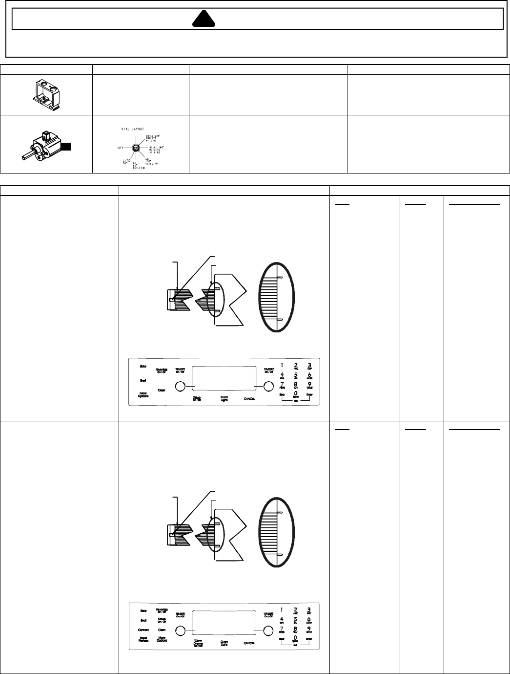
Control Component Test Procedure Results
Switch membrane assembly
NOTE: To avoid equipment
damage, use caution when
checking electronic control
circuitry.
JGS8750BD*
Closed circuitry resistance
(defined as continuity): 2000 Max
Pins 1 & 8 are shorted together for control
configuration purposes
Detail B
See Detail B
Trace # 1
Latch
Pad
1
2
3
4
5
6
7
8
9
0
Cancel
Bake
Broil
Clean
Favorites
More Options
Setup
ATM 1
ATM 2
Back
Enter
Timer 1
Timer 2
Oven Light
Trace
2 & 7
2 & 8
2 & 9
2 & 10
2 & 11
2 & 12
3 & 6
3 & 7
3 & 8
2 & 6
4 & 9
4 & 10
4 & 11
5 & 7
4 & 12
5 & 8
5 & 6
4 & 6
4 & 7
3 & 9
3 & 10
3 & 11
3 & 12
4 & 8
Measurement
Continuity
Continuity
Continuity
Continuity
Continuity
Continuity
Continuity
Continuity
Continuity
Continuity
Continuity
Continuity
Continuity
Continuity
Continuity
Continuity
Continuity
Continuity
Continuity
Continuity
Continuity
Continuity
Continuity
Continuity
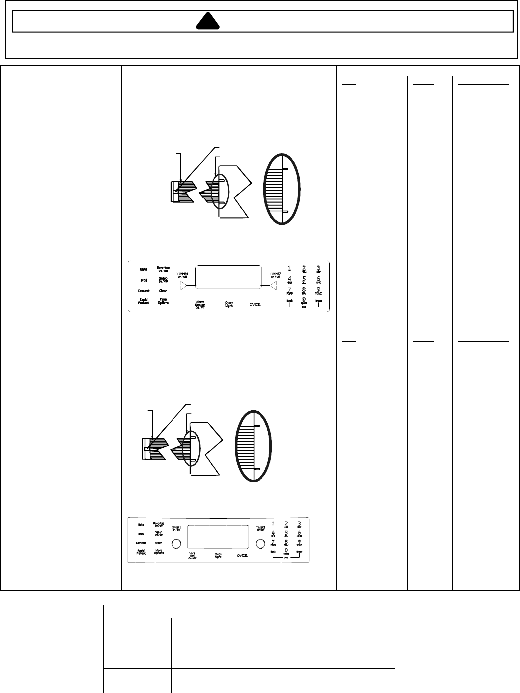
Switch membrane assembly
NOTE: To avoid equipment
damage, use caution when
checking electronic control
circuitry.
JGS8850BD*
Closed circuitry resistance
(defined as continuity): 2000 Max
Pins 1 & 7 are shorted together for control
configuration purposes
Detail B
See Detail B
Trace # 1
Latch
Pad
1
2
3
4
5
6
7
8
9
0
Cancel
Bake
Broil
Convect
Clean
Favorites
Rapid Preheat
Warming Drawer
More Options
Setup
ATM 1
ATM 2
Back
Enter
Timer 1
Timer 2
Oven Light
Trace
2 & 7
2 & 8
2 & 9
2 & 10
2 & 11
2 & 12
3 & 6
3 & 7
3 & 8
2 & 6
4 & 9
4 & 10
4 & 11
5 & 9
5 & 7
4 & 12
5 & 10
5 & 11
5 & 8
5 & 6
4 & 6
4 & 7
3 & 9
3 & 10
3 & 11
3 & 12
4 & 8
Measurement
Continuity
Continuity
Continuity
Continuity
Continuity
Continuity
Continuity
Continuity
Continuity
Continuity
Continuity
Continuity
Continuity
Continuity
Continuity
Continuity
Continuity
Continuity
Continuity
Continuity
Continuity
Continuity
Continuity
Continuity
Continuity
Continuity
Continuity
Testing Procedures
!WARNING
To avoid risk of electrical shock, personal injury or death; disconnect power and gas to range before servicing,
unless testing requires power and/or gas.
18 16026923
© 2006 Maytag Services
Control Component Test Procedure Results
Switch membrane assembly
NOTE: To avoid equipment
damage, use caution when
checking electronic control
circuitry.
JGS8860BD*
Closed circuitry resistance
(defined as continuity): 2000 Max
Pins 1 & 7 are shorted together for control
configuration purposes
Detail B
See Detail B
Trace # 1
Latch
Pad
1
2
3
4
5
6
7
8
9
0
Cancel
Bake
Broil
Convect
Clean
Favorites
Rapid Preheat
Warming Drawer
More Options
Setup
ATM 1
ATM 2
Back
Enter
Timer 1
Timer 2
Oven Light
Trace
2 & 7
2 & 8
2 & 9
2 & 10
2 & 11
2 & 12
3 & 6
3 & 7
3 & 8
2 & 6
4 & 9
4 & 10
4 & 11
5 & 9
5 & 7
4 & 12
5 & 10
5 & 11
5 & 8
5 & 6
4 & 6
4 & 7
3 & 9
3 & 10
3 & 11
3 & 12
4 & 8
Measurement
Continuity
Continuity
Continuity
Continuity
Continuity
Continuity
Continuity
Continuity
Continuity
Continuity
Continuity
Continuity
Continuity
Continuity
Continuity
Continuity
Continuity
Continuity
Continuity
Continuity
Continuity
Continuity
Continuity
Continuity
Continuity
Continuity
Continuity
Switch membrane assembly
NOTE: To avoid equipment
damage, use caution when
checking electronic control
circuitry.
JGS9900BD*
Closed circuitry resistance
(defined as continuity): 2000 Max
Pins 1 & 10 are shorted together for control
configuration purposes
Detail B
See Detail B
Trace # 1
Latch
Pad
1
2
3
4
5
6
7
8
9
0
Cancel
Bake
Broil
Convect
Clean
Favorites
Rapid Preheat
Vent Fan
More Options
Setup
ATM 1
ATM 2
Back
Enter
Timer 1
Timer 2
Oven Light
Trace
2 & 7
2 & 8
2 & 9
2 & 10
2 & 11
2 & 12
3 & 6
3 & 7
3 & 8
2 & 6
4 & 9
4 & 10
4 & 11
5 & 9
5 & 7
4 & 12
5 & 10
5 & 11
5 & 8
5 & 6
4 & 6
4 & 7
3 & 9
3 & 10
3 & 11
3 & 12
4 & 8
Measurement
Continuity
Continuity
Continuity
Continuity
Continuity
Continuity
Continuity
Continuity
Continuity
Continuity
Continuity
Continuity
Continuity
Continuity
Continuity
Continuity
Continuity
Continuity
Continuity
Continuity
Continuity
Continuity
Continuity
Continuity
Continuity
Continuity
Continuity
COOLING FAN TEMPERATURES
MODE FAN ON TEMP F (C) FAN OFF TEMP F (C)
Bake 350 (177) 300 (149)
Broil Six (6) minute delay
after cycle started 225 (107)
Clean Six (6) minute delay
after cycle started 225 (107)
Testing Procedures
!WARNING
To avoid risk of electrical shock, personal injury or death; disconnect power and gas to range before servicing,
unless testing requires power and/or gas.
© 2006 Maytag Services 16026923 19
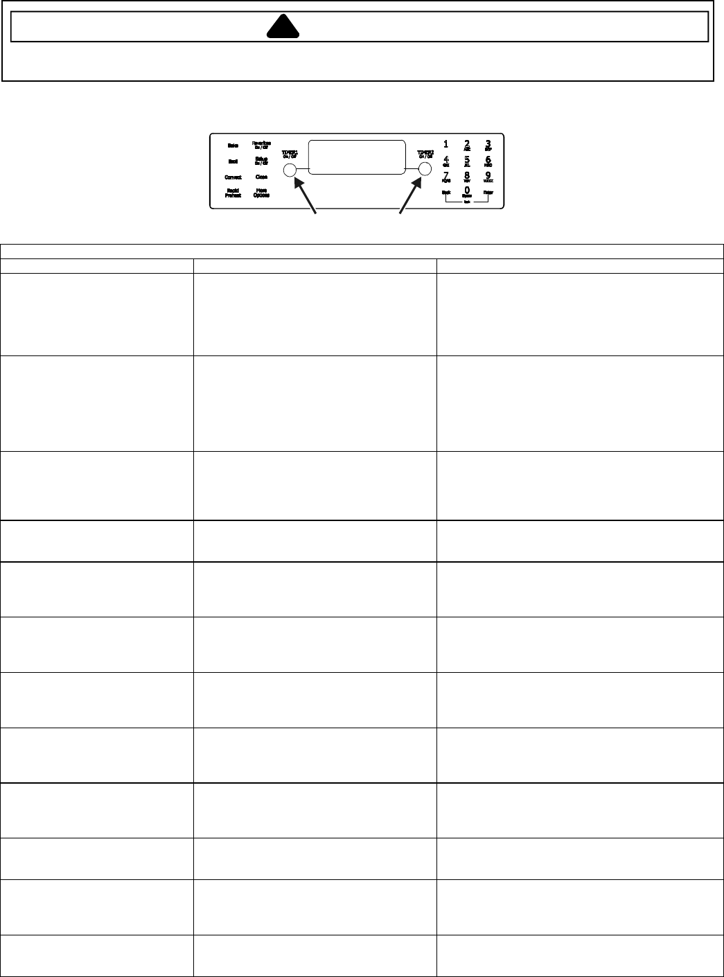
Electronic Oven Control (EOC) III Testing Procedures
Warm
Drawer
ATM PADS
ELECTRONIC OVEN CONTROL (EOC) III TESTING/PROGRAMMING PROCEDURES
Feature Access Procedure Modification Procedure
Control Reset
Resets control to factory default
values.
Press the Setup pad, then press the right
ATM pad until SERVICE displays. Press
the left ATM pad to select SERVICE menu
options.
Press and hold the Back and Enter pads for 5
seconds to enter SERVICE menu options. Press
the right ATM pad to scroll to CONTROL RESET.
Press the left ATM pad to select CONTROL
RESET, then press the left ATM pad again to reset
the control logic. Press Setup to exit.
Oven Temperature Adjustment
Determines oven cavity offset
temperature (range from -35° F to
+35° F, or -21° C to +21° C).
Press the Setup pad, then press the right
ATM pad until TEMP ADJUST displays.
Press the left ATM pad to select oven
TEMP ADJUSTMENT settings.
Enter the offset temperature setting desired using
the digits pads. Press the right ATM pad for +
temperature adjustment, or the left ATM pad for –
temperature adjustment. Press 0 to reset control
back to no temperature adjustment. Wait 3
seconds for the control to accept the request.
Press Setup to exit.
Sabbath Mode
Based on the Jewish guidelines
for Sabbath/Holiday
requirements.
Press the Setup pad, then press the right
ATM pad until SABBATH displays. Press
the left ATM pad to select SABBATH
settings.
Press the left ATM pad to select Manual Sabbath
mode, or the right ATM pad to select Auto Sabbath
mode. Press the left ATM pad to turn on Sabbath
mode, or the right ATM pad to turn off Sabbath
mode. Press Setup to exit.
Time Options
Determines control time, day of
week, 12/24 hour clock.
Press the Setup pad, then the left ATM
pad to select TIME OPTIONS.
Press the right ATM pad to scroll to the desired
function to modify.
Time Set
Determines time of day to display
on control.
Press the Setup pad, then the left ATM
pad, then the left ATM pad again to set the
time of day clock.
Enter the correct time using the digits pads and
press Enter. Press the left ATM pad to select AM
or the right ATM pad to select PM. Press Setup to
exit.
Day of Week
Determines day of week (Monday
thru Sunday) to display on
control.
Press the Setup pad, then the left ATM
pad, then press the right ATM pad until
DAY displays. Press the left ATM pad to
set the day of the week.
Press the right ATM pad until the correct day
displays, then press the left ATM pad to select.
Press Setup to exit.
12/24-Hour Clock Display
Determines 12-hour or 24-hour
clock display on control.
Press the Setup pad, then the left ATM
pad, then press the right ATM pad until
12/24HR displays. Press the left ATM pad
to select 12/24 HR clock.
Press the left ATM pad to select 12-hour clock, or
the right ATM pad to select 24-hour clock. Press
Setup to exit.
Clock & Day Display Disable
Determines if time of day and day
of week will display on control.
Press the Setup pad, then press the right
ATM pad until DISABLE displays. Press
the left ATM pad to select DISABLE
settings.
Press the left ATM pad to select TIME, or the right
ATM pad to scroll to DAY, press the left ATM pad.
Press the left ATM pad to enable display or the right
ATM pad to disable display. Press Setup to exit.
Language Display
Determines language display on
control (English, French,
Spanish).
Press the Setup pad, then press the right
ATM pad until LANGUAGE displays.
Press the left ATM pad to set LANGUAGE
settings.
Press the right ATM pad until the desired language
displays (English, French, Spanish). Press the left
ATM pad. Press Setup to exit.
C/F (Celsius/Fahrenheit) Display
Determines temperature display on
control (C or F).
Press the Setup pad, then press the right
ATM pad until C/F displays. Press the left
ATM pad to select C/F settings.
Press the left ATM pad to select Celsius or the right
ATM pad to select Fahrenheit. Press Setup to exit.
Auto Convection
When enabled, reduces the
Convection Bake and Pastry
temperatures by 25° F (-3.9° C).
Press the Setup pad, then press the right
ATM pad until AUTO CONVECT displays.
Press the left ATM pad to select AUTO
CONVECT settings.
Press the left ATM pad to turn on auto convect, or
the right ATM pad to turn off auto convect. Press
Setup to exit.
208/240 V Setting
Determines range operating
voltage (208 or 240 VAC).
Press the Setup pad, then press the right
ATM pad until 208/240 displays. Press the
left ATM pad to select 208/240 V settings.
Press the left ATM pad to select 208 VAC, or the
right ATM pad to select 240 VAC. Press Setup to
exit.
Testing Procedures
!WARNING
To avoid risk of electrical shock, personal injury or death; disconnect power and gas to range before servicing,
unless testing requires power and/or gas.
20 16026923
© 2006 Maytag Services
Feature Access Procedure Modification Procedure
Tone Options
Determines cook tones, timer
tones and volume settings.
Press the Setup pad, then press the right ATM
pad until TONES displays. Press the left ATM
pad to select TONES options.
Press the right ATM pad to scroll to the desired
tone to modify. Press Setup to exit.
12-Hour Shutoff
Disables 12-hour shutoff,
allowing the oven to operate
indefinitely.
Press the Setup pad, then press the right ATM
pad until 12HR SHUTOFF displays. Press the
left ATM pad to select 12-HOUR SHUTOFF
settings.
Press the left ATM pad to turn on 12-hour
shutoff, or the right ATM pad to turn off 12-hour
shutoff. Press Setup to exit.
Cook Tones
Determines the number and
duration of cook time reminder
chimes.
Press the Setup pad, then press the right ATM
pad until TONES displays. Press the left ATM
pad. Press the left ATM pad again to select
COOK TONES settings.
Press the left ATM pad to select 1 – 30 (1 chime
every 30 seconds after the initial 4 chimes), or
press the right ATM pad to scroll to 1 – 60 (1
chime every 60 seconds after the initial 4 chimes)
or 1 BEEP (no additional chimes after the initial 4
chimes). Press the left ATM pad to select the
desired setting. Press Setup to exit.
Timers Tones
Determines the number and
duration of timer reminder
chimes.
Press the Setup pad, then press the right ATM
pad until TONES displays. Press the left ATM
pad. Press the right ATM pad to scroll to
TIMERS TONES. Press the left ATM pad to
select TIMERS TONES settings.
Press the left ATM pad to select 2 – 30, or 2
chimes every 30 seconds for up to 5 minutes
(after the initial chime), or press the right ATM
pad to scroll to 2 – 60, or 2 chimes every 60
seconds for up to 30 minutes (after the initial
chime), or 1 BEEP (no additional chimes after the
initial chime). Press the left ATM pad to select
the desired setting. Press Setup to exit.
Volume
Determines volumes of cook
and timer tones.
Press the Setup pad, then press the right ATM
pad until TONES displays. Press the left ATM
pad to select VOLUME settings.
Press the right ATM pad until VOLUME displays.
Press the left ATM pad. Press the left ATM pad
to select HIGH, or the right ATM pad to scroll to
MEDIUM or LOW. Press the left ATM pad to
select. Press Setup to exit.
Energy Saver Mode
Enables a 1 watt standby
feature. If no pad is pressed
within 5 minutes, the control
enters into a sleep mode.
Press the Setup pad, then press the right ATM
pad until ENERGY SAVER displays. Press
the left ATM pad to select ENERGY SAVER
mode settings.
Press the left ATM pad to enter the energy saver
mode or the right ATM pad to exit the energy
saver mode.
Demo Mode
Enables a 1 watt standby
feature. If no pad is pressed
within 5 minutes, the control
enters into a sleep mode.
Press the Setup pad, then press the right ATM
pad until DEMO displays. Press the left ATM
pad to select DEMO mode settings.
Press the left ATM pad to enable the DEMO
mode or the right ATM pad to exit the DEMO
mode. Once the DEMO mode begins, press any
key to exit. Press Setup to exit, also.
Service Mode
Enables access to service
menus.
Press the Setup pad, then press the right ATM
pad until SERVICE displays. Press the left
ATM pad to select SERVICE menu options.
Press and hold the Back and Enter pads for 5
seconds to enter SERVICE menu options. Press
Setup to exit.
Test Access
Enables access to service
menus.
Press the Setup pad, then press the right ATM
pad until SERVICE displays. Press the left
ATM pad to select SERVICE menu options.
Press and hold the Back and Enter pads for 5
seconds to enter SERVICE menu options. Press
the right ATM pad to scroll to TEST menu. Press
the left ATM pad to select TEST options. Press
Setup to exit.
Faults Access
Displays the 10 most recent
faults produced by the controller.
Press the Setup pad, then press the right ATM
pad until SERVICE displays. Press the left
ATM pad to select SERVICE menu options.
Press and hold the Back and Enter pads for 5
seconds to enter SERVICE menu options. Press
the right ATM pad to scroll to the FAULTS menu.
Press the left ATM pad to select FAULTS
options. Press Setup to exit.
Software Versions Access
Displays the software and
EEPROM revision levels.
Press the Setup pad, then press the right ATM
pad until SERVICE displays. Press the left
ATM pad to select SERVICE menu options.
Press and hold the Back and Enter pads for 5
seconds to enter SERVICE menu options. Press
the right ATM pad to scroll to the VERSIONS
menu. Press the left ATM pad to view. Press
Setup to exit.
Display Test
Illuminates all lamps on the
control.
Press the Setup pad, then press the right ATM
pad until SERVICE displays. Press the left
ATM pad to select SERVICE menu options.
Press and hold the Back and Enter pads for 5
seconds to enter SERVICE menu options. Press
the right ATM pad to scroll to DISPLAY TEST.
Press the left ATM pad. Press Setup to exit.
Control Lockout
Disables the touch keypad
control and locks the oven cavity
door.
Press the Back and Setup pads
simultaneously for 5 seconds to lock.
Press the Back and Setup pads simultaneously
for 5 seconds to unlock.
Testing Procedures
!WARNING
To avoid risk of electrical shock, personal injury or death; disconnect power and gas to range before servicing,
unless testing requires power and/or gas.
© 2006 Maytag Services 16026923 21
Relay Logic for EOC III
NOTE: Subsequent changes implemented after the release of this technical sheet may have altered the parameters
identified in this chart.
INDEX
± - OFF
O - ON
- CYCLING
- ON OR OFF (DETERMINED BY
USER INPUT)
COOKING MODE
BAKE ELEMENT
BROIL ELEMENT
CONVECT ELEMENT
CONVECT FAN
WARMING DRAWER
OVEN LIGHT
IDLE r r r r r
BAKE RAPID PREHEAT O r r r r
BAKE PREHEAT O r r r r
BAKE r r r r
HIGH BROIL PREHEAT r O r r r
HIGH BROIL r r r r
LOW BROIL PREHEAT r O r r r
LOW BROIL r r r r
CLEAN PREHEAT r r r
CLEAN r r r
KEEP WARM PREHEAT O r r r r
KEEP WARM r r r r
WARMING DRAWER HIGH r r r r O
WARMING DRAWER LOW r r r r O
CONVECT ROAST PREHEAT r r O r r
CONVECT ROAST r r O* r
CONVECT BAKE RAPID PREHEAT r r O r r
CONVECT BAKE PREHEAT r r O r r
CONVECT BAKE r r r r
CONVECT PASTRY RAPID PREHEAT r r O O* r
CONVECT PASTRY PREHEAT r r O O* r
CONVECT PASTRY r r O* r
THAW-SERVE r r r
DRYING PREHEAT r r O r r
DRYING r r r r
RAPID PROOFING r r O O r
STANDARD PROOFING r r O r r
*Convection fan stops when oven door is opened.
Testing Procedures
!WARNING
To avoid risk of electrical shock, personal injury or death; disconnect power and gas to range before servicing,
unless testing requires power and/or gas.
22 16026923
© 2006 Maytag Services
"Quick Test" Mode for EOC III
Follow the procedure below to perform the EOC III quick test. Once the control is in the quick test mode, any relay
may be activated in any sequence. The test mode will be exited after 10 minutes of inactivity (no pads pressed
within 10 minutes).
1. Press the Setup pad, then press the right ATM pad.
2. Press the left ATM pad, then press and hold Back and Enter pads for 5 seconds to enter SERVICE menu options.
3. Press the right ATM pad to scroll to the TEST menu.
4. Press the left ATM pad to select TEST options.
5. Press the left ATM pad again to enter the "Quick Test" mode.
6. Press each of the following pads indicated in the table below.
7. Press Cancel or Setup pads to exit.
NOTE: Press and hold the applicable pad to activate the associated response.
Release the applicable pad to deactivate the associated response.
The control automatically enters the engineering mode so visual feedback of relay operations is available on the
control display. Any time a load is activated, the cooling fan is activated. When the load is deactivated, the cooling
fan is also deactivated.
Display will indicate the following:
Pad Response
BAKE....................................................Bake relay activated.
BROIL ..................................................Broil relay activated.
CONVECT............................................Convection Bake and Cooling Fan relays activated.
OVEN LIGHT .......................................Oven light relay activated.
RAPID PREHEAT ................................Convection Fan (HIGH/LOW) activated.
WARMING ZONE ................................Warming Zone relay activated.
VENT (DOWNDRAFT) FAN ................Vent Fan relay activated.
CLEAN .................................................Motorized Door Lock relay activated.
SETUP .................................................1 Second Beep.
FAN ......................................................Downdraft Fan (HIGH/LOW) relay activated.
WARMING DRAWER ..........................Warming Drawer (HIGH/LOW) relay activated.
Oven Sensor and Meat Probe Resistances
MEAT PROBE
Type: NTC Thermistor
Calibration: 9938 (150° F/65.5° C)
Temperature F (C) Resistance (Ohms)
32 (0) 163300
68 (20) 62450
95 (35) 32660
122 (50) 18020
158 (70) 8760
185 (85) 5360
212 (100) 3400
OVEN SENSOR
Sensor Type: RTD 1000 platinum
Calibration: 1654 (350° F/177° C)
Temperature F (C) Resistance (Ohms)
200 (94) 1350
350 (177) 1654
550 (287) 2047
900 (483) 2697
Testing Procedures
!WARNING
To avoid risk of electrical shock, personal injury or death; disconnect power and gas to range before servicing,
unless testing requires power and/or gas.
© 2006 Maytag Services 16026923 23
Description of Fault Codes for EOC III
Each fault code consists of 4 digits and is structured as follows:
1st (Leftmost) Digit:
Primary Failure System 2nd Digit: Alpha-Character 3rd Digit: Secondary
Failure Mechanism 4th Digit : Oven
Cavity Number
1 – Local to Control System d – Diagnostic Failure (measurable) 1 – Upper (Single) Oven
3 – Sensor or Meat Probe c – Control-Related Error (not measurable) 2 – Lower Oven
4 – Input to Control System
c – Control System
9 – Door Lock
If a fault is detected, then one of the following three messages will be scrolled on the display:
FAULT DETECTED PRESS ENTER TO TRY AGAIN. This message displays when a fault is detected while a
cooking function is active. Clear by pressing the Cancel keypad.
FEATURE NOT AVAILABLE. This message displays when a fault is detected while entering data during initial
programming and also when a locked out function is detected. Clear by pressing any key.
FAULT DETECTED DISABLE POWER TO CLEAR. This message displays when a runaway temperature condition
is detected while the control is in idle mode. Press any key to clear the message, but the fault remains until the
control senses a Power-On reset.
Fault
Code Description Component to Troubleshoot/Replace
1c1c Shorted key. Ensure ribbon cable is securely connected, inspect ribbon cable and
connector (shorts, breakage, corrosion, etc.). If OK, replace control.
1c2c Membrane keyboard disconnected. Ensure ribbon cable is securely connected, inspect ribbon cable and
connector (shorts, breakage, corrosion, etc.). If OK, replace control.
1c4c Board – to – Board communication failure. Replace control.
1c6c EEPROM hardware fault. Replace control.
1c7c Control not calibrated. Replace control.
1c8c EEPROM CRC error – User Options. Replace control.
1c81 EEPROM CRC error – Cook Profile. Replace control.
1d11 Unlocked runaway temperature – 600° Ohm sensor and harness (see "Oven Sensor" chart). If OK, change
control.
1d21 Locked runaway temperature – 950° Ohm sensor and harness (see "Oven Sensor" chart). If OK, change
control.
3d11 Temperature sensor open. Check connections, sensor (see "Oven Sensor" chart) and harness. If
OK, replace control.
3d21 Temperature sensor shorted. Check connections, sensor (see "Oven Sensor" chart) and harness. If
OK, replace control.
3d41 Meat probe shorted. Check probe jack and harness. If OK, check meat probe (see "Meat
Probe" chart).
3d51 Meat probe not calibrated. Check probe jack and harness. If OK, check meat probe (see "Meat
Probe" chart).
4d11 Door switch not closed when locked. Check connections, switch, harness, and motor. If OK, replace control.
4d21 No cooling fan rotation. Check cooling fan motor and harness. If OK, replace control.
4d31 Cooling fan on when de-energized. Check cooling fan motor and harness. If OK, replace control.
4d41 Cooling fan overspeed. Check cooling fan motor and harness. If OK, replace control.
4d51 Door switch circuit fault. Check connections, harness, and motor. If OK, replace control.
9d11 Latch will not lock. Check wire connections. If OK, replace motorized door lock.
9d21 Latch will not unlock. Check wire connections. If OK, replace motorized door lock.
9d31 Latch both locked and unlocked. Check wire connections. If OK, replace motorized door lock.
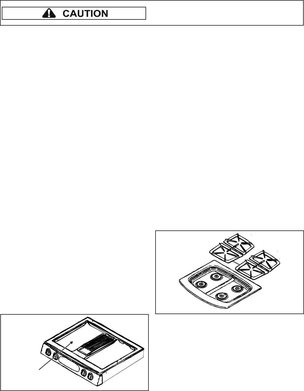
24 16026923 © 2006 Maytag Services
Disassembly Procedures
To avoid risk of electrical shock, personal injury or
death; disconnect power and gas before servicing,
unless testing requires power and/or gas.
Maintop Assembly Removal (Select Models)
1. Remove power from unit.
2. Remove range from installation position, see
“Removing and Replacing Range” procedure.
3. Remove front side trim, see "Front Side Trim
Removal" procedure.
4. Remove air grill, grill grates, filter, aeration pan and
cartridges (cartridge models).
5. Remove cartridge receptacles and grill pans
(cartridge models).
6. Remove screws from plenum area at front of main
top cartridge opening (cartridge models).
7. Remove screws securing top burner assembly to
lower burner assembly.
8. Label and disconnect wire terminals to ignitors.
9. Remove perimeter screws securing main top to
chassis.
10.Gently lift main top away from chassis.
11. Reverse procedure to reinstall maintop assembly.
Top Burner Assembly Removal
(Select Models)
1. Disconnect power before servicing.
2. Remove screws securing burner top assembly to
lower assembly.
3. Label and remove wire terminals to ignitor.
4. Reverse procedures to reassemble.
Lower Burner Assembly Removal
(Select Models)
1. Remove top burner, see "Top Burner Assembly
Removal (Select Models)" procedure.
2. Disconnect tubing from lower assembly.
3. Reverse procedures to reassemble.
NOTE: Perform gas leak test.
Removing and Replacing Range
1. Turn off power and remove gas supply from unit.
2. Slide range forward from installation position.
3. Unplug power cord and disconnect gas line from unit.
4. Disconnect downdraft blower motor and remove flex
ducting to the blower and range (select models).
NOTE: To avoid countertop damage, do not move
range forward until range has been raised
enough to clear all cabinetry.
5. Pull the range forward out of the cabinet opening.
6. Disconnect or unplug the power cord leading from
unit to fuse box or junction box depending on unit.
7. Replace the oven using the installation instructions
and anti-tip bracket(s).
Front Side Trim Removal
1. Remove power from unit.
2. Slide unit out far enough to access side trim.
3. Remove screws securing front side trim piece(s) to
oven chassis (left and right trim pieces).
4. Gently grasp trim piece with both hands, pull forward
and roll trim piece off retainer clips.
5. Reverse procedure to reinstall front side trim piece(s).
Cartridge Assembly Removal
(Select Models)
Cooktop cartridges are installed on the left side of the
range cooktop.
1. Remove power from unit.
2. Lift up on the tab (located on the cartridge) until top of
cartridge clears the opening on the range by 2 inches.
NOTE: Lifting the cartridge too high while still engaged
in the receptacle could damage the terminal
plug.
3. Hold cartridge by the sides and slide away from
terminal receptacle.
4. Lift cartridge out when fully unplugged.
Install cartridges here
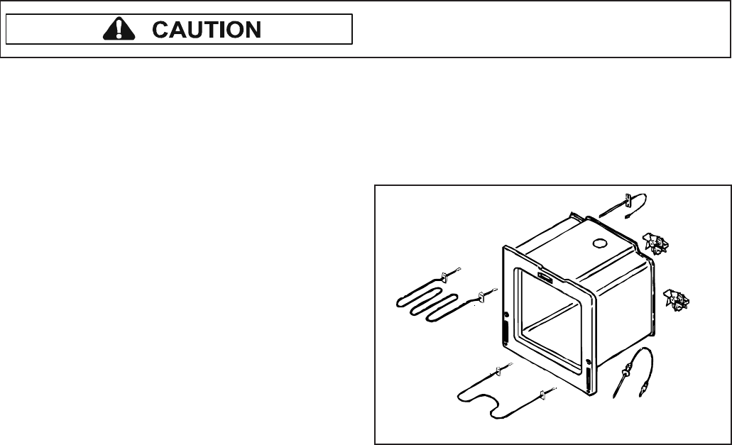
© 2006 Maytag Services 16026923 25
To avoid risk of electrical shock, personal injury or
death; disconnect power and gas before servicing,
unless testing requires power and/or gas.
Disassembly Procedures
Burner Switch Replacement
1. Remove control panel, see "Control Panel Assembly
Removal" procedure.
2. Disengage burner switch from burner valve and
remove switch from valve.
3. Reverse procedure to reinstall burner switch.
Oven Sensor
Meat
Probe
Broil Element
Bake
Element
Cooling
Fan
Convection
Fan
Meat Probe Receptacle Replacement
(Select Models)
1. Remove power from unit.
2. Remove range from installation position, see
“Removing and Replacing Range” procedure.
3. Remove front side trim, see "Front Side Trim
Removal" procedure.
4. Remove screws securing side panel to chassis and
main top.
5. Open oven door and remove nut securing meat probe
receptacle to oven cavity.
6. Label and disconnect wire terminals from receptacle.
7. Gently slide meat probe receptacle through oven
cavity.
8. Reverse procedure to reinstall meat probe receptacle.
Back Panel Removal
1. Remove power from unit.
2. Remove range from installation position, see
“Removing and Replacing Range” procedure.
3. Remove screws securing back panel to unit.
4. Slide back panel up and out to remove.
5. Reverse procedure to reinstall back panel.
Spark Module Replacement
1. Remove unit from installation position, see
“Removing and Replacing Range” procedure.
2. Remove screws securing rear access panel.
3. Disconnect and label wire connections from the spark
module.
4. Remove screws securing spark module to unit
chassis.
5. Replace and reverse procedure to reassemble.
Manifold Assembly Removal
1. Remove maintop, see "Maintop Assembly Removal"
procedure.
NOTE: If replacing manifold only, skip step 2.
2. Loosen and disconnect fittings securing surface
burner tubing to burner assembly and manifold.
3. Remove bolt(s) securing surface valve(s) to manifold.
4. Remove bolt securing shut-off valve from manifold.
5. Disconnect tubing from manifold to the regulator.
6. Reverse procedures to reassemble.
NOTE: Perform gas leak test.
Control Panel Assembly Removal
1. Remove power from unit.
2. Remove burner switch control knobs.
3. Remove front screws securing control panel to
chassis.
4. Remove screws located on the left and right sides of
the control panel.
5. Grasp control panel on the far left and right sides and
gently pull the control panel out and down.
NOTE: The electronic control located in the control
panel is a sensitive item, handle gently.
6. Label and disconnect wire terminals.
7. Remove infinite switch control knobs, infinite
switches, indicator lights, rocker switches, and
electronic control/clock (as necessary) and transfer to
the new control panel.
8. Reverse procedure to reinstall control panel.
Electronic Control Replacement
1. Remove control panel, see “Control Panel Assembly
Replacement” procedure, steps 1 through 5.
2. Remove screws securing electronic control bracket to
control panel.
3. Label and disconnect terminal wiring from electronic
control.
4. Slide electronic control down and out of bracket,
applying slight outward pressure to the inside edges
of the electronic control bracket.
5. Reverse procedure to reinstall electronic control.
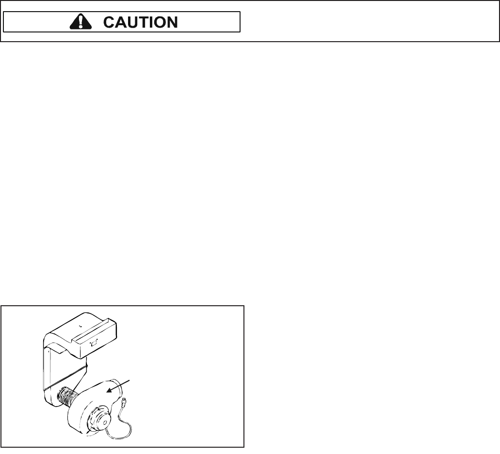
26 16026923 © 2006 Maytag Services
Disassembly Procedures
To avoid risk of electrical shock, personal injury or
death; disconnect power and gas before servicing,
unless testing requires power and/or gas.
Cooling Fan Replacement
1. Remove power from unit.
2. Remove range from installation position, see
"Removing and Replacing Range" procedure.
3. Remove back panel, see "Back Panel Removal"
procedure.
4. Label and disconnect wire terminals from cooling fan.
5. Remove screws securing fan to range chassis.
6. Reverse procedure to reinstall cooling fan.
Downdraft Blower Motor Removal
(Select Models)
1. Remove power from unit.
2. Remove bottom access panel, see "Bottom Access
Panel Removal" procedure.
3. Disconnect ducting to allow for downdraft blower
motor removal.
4. Label and disconnect wire terminals.
5. Remove screws securing motor assembly.
6. Reverse procedure to reinstall downdraft blower
motor (select models).
Downdraft
blower motor
assembly
Convection Motor Removal (Select Models)
1. Remove power from unit.
2. Open oven door and remove rack(s).
3. Remove screws securing convection element and fan
cover (on rear wall of oven cavity).
4. Remove screw securing fan blade to fan motor shaft.
5. Remove screws securing fan motor to cavity wall.
6. Slide motor into oven cavity.
7. Label and disconnect wire terminals from motor.
8. Reverse procedure to reinstall convection motor.
Convection Element Replacement
(Select Models)
1. Remove power from unit.
2. Open oven door and remove rack(s).
3. Remove screws securing convection element and fan
cover (on rear wall of oven cavity).
4. Remove screw securing convection element to rear
oven cavity wall.
5. Label and disconnect wire terminals from element.
6. Reverse procedure to reinstall convection element.
Bake Burner and Ignitor Removal
1. Turn off electrical power and gas to the range.
2. Disconnect gas and power from unit.
3. Remove oven door, racks and oven bottom.
4. Remove screws securing bottom bake cover.
5. Raise the back of the bake burner cover and slide
cover back to release the front edge of cover and lift
out of oven cavity.
6. Remove screws securing bake burner assembly to
the oven chassis.
7. Maneuver bake burner from the burner orifice and out
of the slotted location.
8. Pull forward on assembly to allow the ignitor terminal
plug to pass through the back of the oven cavity.
9. Disconnect terminal plug and remove assembly from
the oven cavity.
10.Remove screws securing ignitor to bake burner.
11.Replace and reassemble in reverse order.
Broil Burner and Ignitor Removal
1. Turn off electrical power and gas to the range.
2. Disconnect gas and power from unit.
3. Remove oven door and racks.
4. Remove screws securing ignitor wire plate cover to
back of the oven cavity.
5. Maneuver ignitor wire terminal plug through the rear
of the oven cavity.
6. Disconnect ignitor wire terminal plug.
7. Remove screws securing broiler to oven cavity.
8. Carefully maneuver burner off of the broiler orifice
spud and remove from cavity.
9. Remove screws securing ignitor to broiler.
10.Remove wing nut securing flame spreader to broiler.
11.Replace and reassemble in reverse order.
Oven Sensor Replacement
1. Remove power from unit.
2. Open oven door and remove screws securing sensor
to oven cavity.
NOTE: Gently pull wiring through cavity wall.
3. Label and disconnect wire terminals.
4. Reverse procedure to reinstall sensor.
NOTE: Verify sensor wires are pushed through the
insulation.
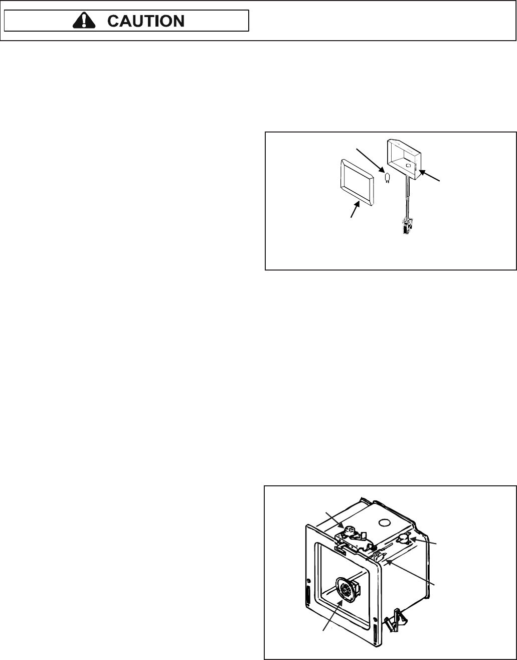
© 2006 Maytag Services 16026923 27
To avoid risk of electrical shock, personal injury or
death; disconnect power and gas before servicing,
unless testing requires power and/or gas.
Disassembly Procedures
Regulator Removal
1. Disconnect power before servicing.
2. Remove range from installation position, see
"Removing and Replacing Range" procedure.
3. Disconnect tubing from regulator.
4. Remove screws securing bracket to back of unit.
5. Remove screws securing regulator to support
bracket.
6. Reverse procedures to reassemble.
NOTE: When reconnecting supply line to regulator, use
pipe dope compound to seal the connection.
NOTE: Perform gas leak test.
Gas Valve Removal (Select Models)
NOTE: Removal of range from installation position is
required.
1. Disconnect power before servicing.
2. Remove range from installation position, see
"Removing and Replacing Range" procedure.
3. Remove screws securing bottom rear access panel to
chassis.
4. Remove screws securing top rear access panel to
chassis.
5. Disconnect tubing from gas valve.
6. Disconnect and label wire terminals from gas valve.
7. Remove screws securing gas valve to chassis.
8. Reverse procedures to reassemble.
NOTE: Perform gas leak test.
Oven Light Bulb/Oven Light Socket
Replacement
The light automatically illuminates when the door is
opened. The light will not operate during a clean cycle.
1. Remove power from unit.
2. Open oven door and locate oven light.
3. Grasp lens cover and pull outward on one side to
gain access to the bulb.
4. Carefully remove old bulb by lifting bulb straight out of
base.
5. When installing the new bulb, place cover over socket
so the cut-out in the glass cover aligns with the base
on the socket.
NOTE: To avoid damaging the new bulb and
decreasing life of the bulb, do not touch new
bulb with bare hands or fingers.
Hold with a cloth or paper towel.
NOTE: Proceed with the following steps for oven light
socket removal.
6. Remove power to unit.
7. Remove screw securing light socket to oven cavity.
8. Label and disconnect wire terminals from light socket.
9. Reverse procedure to reinstall light socket.
NOTE: Reposition fiberglass insulation around light
socket to eliminate the possibility of any heat
related problems.
Lens
Bulb
Socket
Bulb specifications
G5.3 Type Halogen Bi-Pin 25W-120V
Oven Vent/Smoke Eliminator Removal
(Select Models)
1. Remove power from unit.
2. Locate tabs on bottom of smoke eliminator and turn
counterclockwise to release locking ears.
3. Gently pull smoke eliminator down and align locking
ears with notches in oven cavity to remove.
4. Reverse procedure to reinstall smoke eliminator.
Oven Hi-Limit Thermostat Replacement
1. Remove maintop assembly, see "Maintop Assembly
Removal" procedure.
2. Remove screws securing hi-limit thermostat to oven
chassis.
3. Label and remove wire terminals.
4. Reverse procedure to reinstall hi-limit thermostat.
Convection
Fan
Hi-Limit
Thermostat
Door Hinge
Receiver
Oven
Light
Switch
Door
Latch

28 16026923 © 2006 Maytag Services
Disassembly Procedures
To avoid risk of electrical shock, personal injury or
death; disconnect power and gas before servicing,
unless testing requires power and/or gas.
Oven Door Latch Replacement
1. Remove control panel, see "Control Panel Removal"
procedure.
2. Remove screws securing door latch to the front of the
oven cavity outer shell.
3. Slide oven door latch assembly forward to diagnose.
4. Label and disconnect wire terminals from latch
assembly.
5. Reverse procedure to reinstall door latch assembly.
Oven Door Hinge Removal
1. Remove power from unit.
2. Remove unit from installation position, see “Removing
and Replacing Range” procedure.
3. Remove oven door, see "Oven Door Removal"
procedure.
4. Remove front side trim, see "Front Side Trim
Removal" procedure.
5. Remove screws securing side panel to chassis.
6. Remove the top and bottom screws securing hinge
receiver to the front frame.
7. Remove hinge receiver from oven chassis.
8. Reverse procedure to reinstall oven door hinge.
Bottom Access Panel Removal
(Select Models)
1. Grasp top of bottom access panel and gently pull
down and out.
2. Reverse procedure to reinstall bottom access panel.
Bottom Access Panel Disassembly
(Select Models)
1. Grasp top of bottom access panel and gently pull
down and out.
2. Remove screws securing front panel to glass panel.
3. Reverse procedure to reassemble bottom access
panel.
NOTE: See page 30 for illustration.
Storage Drawer Removal (Select Models)
1. Slide strorage drawer out until drawer stops.
2. Press tabs up or down (depending on side) on
storage drawer "stops" to release drawer from slide
track.
3. Slide storage drawer completely out of slide track.
4. Reverse procedure to reinstall storage drawer.
Storage Drawer Track Disassembly
(Select Models)
1. Remove storage drawer, see "Storage Drawer
Removal (Select Models)" procedure.
2. Place drawer on a protected surface.
3. Remove screws securing front panel to glass panel.
4. Remove screws front panel to storage drawer.
5. Remove screws securing "sliding tracks" to storage
drawer.
6. Reverse procedure to reassemble.
Storage Drawer Disassembly
1. Remove warming door, see "Storage Drawer
Removal (Select Models)" procedure.
2. Place door on a protected surface.
3. Remove screws securing front panel to glass panel.
4. Remove screws securing front panel to storage
drawer.
5. Remove screws securing "sliding tracks" to storage
drawer.
6. Reverse procedure to reassemble storage drawer.
NOTE: See page 30 for illustration.
Warming Drawer Removal (Select Models)
1. Slide warming drawer out until drawer stops.
2. Press tabs up or down (depending on side) on
warming drawer "stops" to release drawer from slide
track.
3. Slide warming drawer completely out of slide track.
4. Reverse procedure to reinstall warming drawer.
Warming Drawer Element Removal
(Select Models)
1. Remove warming drawer, see "Warming Drawer
Removal" procedure.
2. Remove screws securing element brackets to oven
chassis and element.
3. Remove element and slide toward front of unit.
4. Label and disconnect element wiring.
5. Reverse procedure to reinstall warming drawer
element.
© 2006 Maytag Services 16026923 29
To avoid risk of electrical shock, personal injury or
death; disconnect power and gas before servicing,
unless testing requires power and/or gas.
Disassembly Procedures
Warming Drawer Hi-Limit Switch
Replacement (Select Models)
1. Remove unit from installation position, see
“Removing and Replacing Range” procedure.
2. Remove front side trim, see "Front Side Trim
Removal" procedure.
3. Remove warming drawer, see "Warming Drawer
Removal (Select Models)" procedure.
4. Remove screws securing side panel to oven chassis.
5. Remove screws securing hi-limit switch to warming
drawer support frame.
6. Label and disconnect hi-limit switch wire terminals.
7. Remove hi-limit switch from outside the warming
drawer support frame.
NOTE: Do not pull hi-limit switch and wiring through
cavity wall.
8. Reverse procedure to reinstall warming drawer hi-
limit switch.
Oven Door Removal
WARNING
!
To avoid risk of personal injury or property damage,
do not lift oven door by the handle.
1. Open oven door slightly and grasp door on both
sides.
2. Lift up and off the hinge receivers.
3. Reverse procedure to reinstall oven door.
Warming Drawer Track Disassembly
(Select Models)
1. Remove warming drawer, see "Warming Drawer
Removal (Select Models)" procedure.
2. Place door on a protected surface.
3. Remove screws securing front panel to glass panel.
4. Remove screws front panel to warming drawer.
5. Remove screws securing "sliding tracks" to warming
drawer.
6. Reverse procedure to reassemble warming drawer.
Warming Drawer Disassembly
1. Remove warming door, see "Warming Drawer
Removal (Select Models)" procedure.
2. Place door on a protected surface.
3. Remove screws securing front panel to glass panel.
4. Remove screws securing front panel to warming
drawer.
5. Remove screws securing "sliding tracks" to warming
drawer.
6. Reverse procedure to reassemble oven door.
NOTE: See page 30 for illustration.
Oven Door Disassembly
1. Remove oven door, see "Oven Door Removal"
procedure.
2. Place door on a protected surface.
3. Remove screws securing door glass to oven door
trim and frame (screws located along the top and
bottom edge of oven door).
NOTE: Proceed with the following steps if replacing door
handle.
4. Remove screws securing door handle to door glass.
5. Remove screws securing upper and lower shields.
6. Remove screws securing door baffle.
7. Remove oven door insulation.
8. Remove screws securing outer and inner door glass
(and glass frame).
9. Remove oven door liner, if replacing.
10.Reverse procedure to reassemble oven door.
NOTE: See page 30 for illustration.

30 16026923 © 2006 Maytag Services
Disassembly Procedures
To avoid risk of electrical shock, personal injury or
death; disconnect power and gas before servicing,
unless testing requires power and/or gas.
Door Gasket
Door Lining
Oven Door Insulation
Door Trim
and Frame
Door Handle
Upper Shield
Glass Frame
Inner Glass
Outer Glass
Door Glass
Lower Shield
Door
Baffle
Access Panel
(Select Models)
WarmingDrawer/
Storage Drawer
(Select Models)
Front
Panel
Glass
Panel
Oven Door, Warming Drawer/
Storage Drawer and Access
Panel Disassembly
© 2006 Maytag Services 16026923 A – 1
Appendix A
The Installation information provided in this service manual is representative of a limited
number of models. Reference the customer’s Installation literature included with the product,
order a copy (if needed), or consult Jenn-Air’s website for the specific model.
www.jennair.com
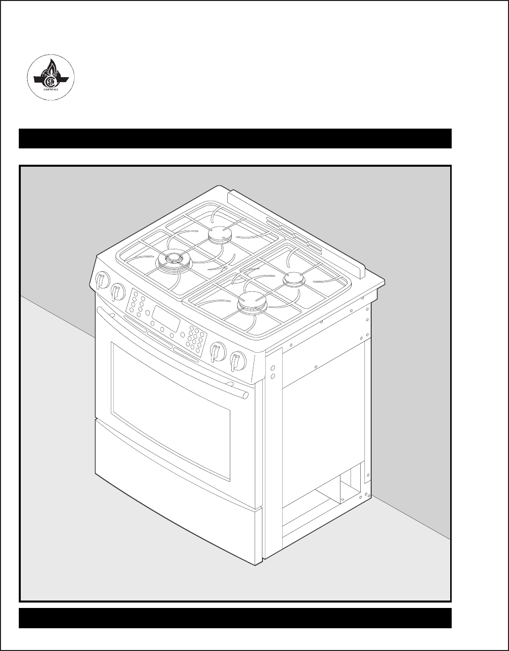
A – 2 16026923 © 2006 Maytag Services
Installation Instructions
Printed in USA ©2005 Maytag Corporation Rev 0-10/05 8101P697-60
INSTALLER: Leave these instructions with the appliance./INSTALLATEUR : Laissez ces instructions avec l’appareil./
INSTALADOR: Deje estas instrucciones con el electrodoméstico.
Jenn-Air Updraft
Gas Slide-In Range
Installation Instructions/Instructions d’installation/Instrucciones de Instalación
Cuisinière à gaz encastrable à circulation ascendante Jenn-Air/
Estufa deslizante a gas de corriente ascendente Jenn-Air
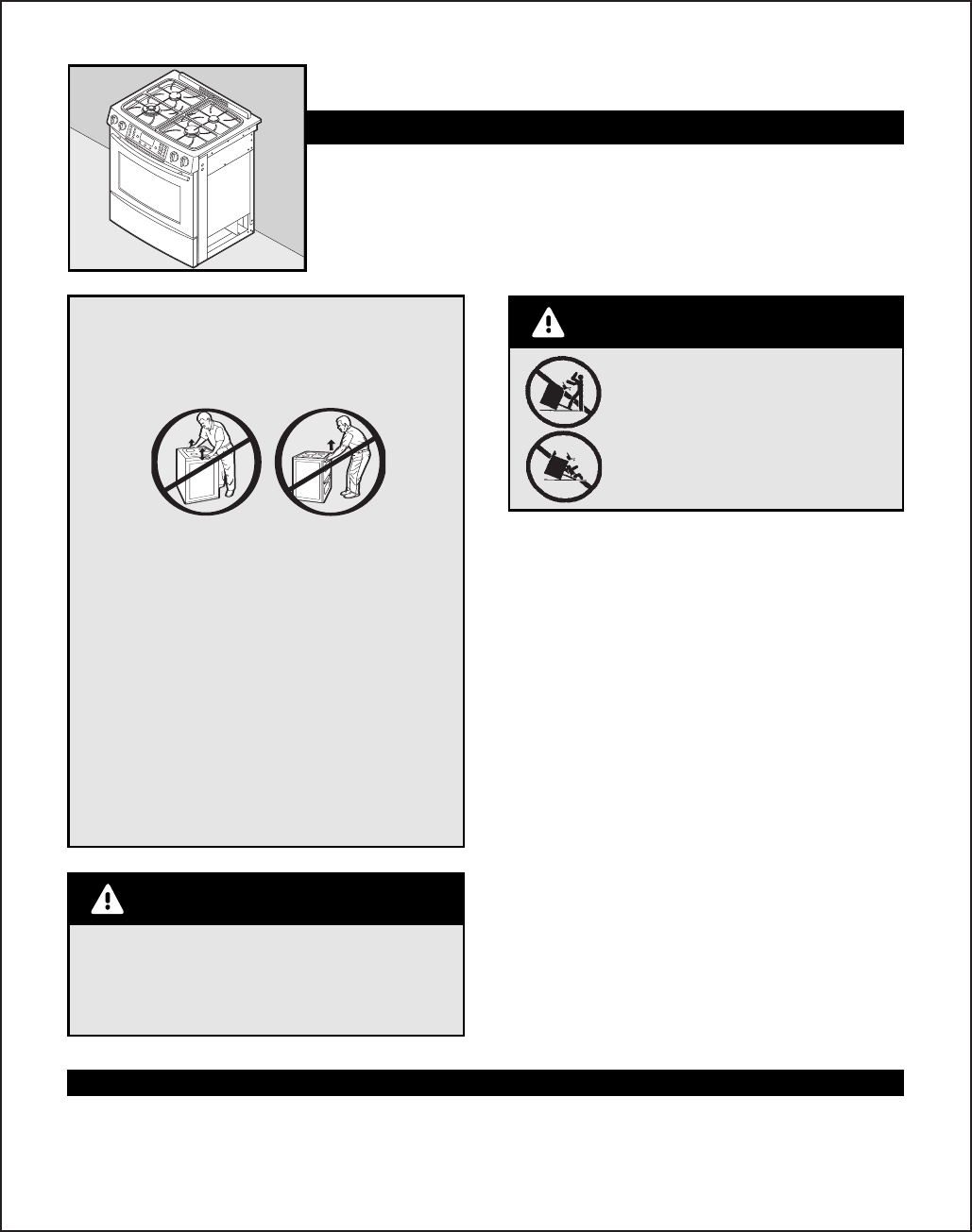
© 2006 Maytag Services 16026923 A – 3
Installation Instructions
Jenn-Air Updraft Gas Slide-In Range
INSTALLATION INSTRUCTIONS
PLEASE KEEP THIS MANUAL FOR FUTURE REFERENCE
This manual is intended to assist in the initial installation and adjustments of the range.
• Only qualified personnel should install or service this range.
• Read “Safety Instructions” in Use & Care book before using range.
• Improper installation, adjustment, alteration, service, maintenance or use of range
can result in serious injury or property damage.
• Installer, take care not to damage flooring.
Do not lift or move range by grasping door handles or main top.
This range has been designed in accordance with the
requirements of various safety agencies and complies with
the maximum allowable wood cabinet temperatures of 194˚F.
If this range is installed with cabinets that have a lower
working temperature than 194˚F, discoloration, delamination
or melting may occur.
Place range in a well lit area. Do not set range over holes in
the floor or other locations where it may be subject to strong
drafts. Any opening in the wall behind the range and in the
floor under the range should be sealed. Make sure the flow
of cooling/ventilation air is not obstructed below the range.
Note: A range should NOT be installed over kitchen carpeting.
High Altitude Notice: The specified gas burner ratings
typically apply to elevations up to 2000 feet. For higher
altitudes, the rates may need to be reduced to achieve
satisfactory operation. A local certified gas servicer will be
able to advise if a reduction is necessary.
A risk of range tip-over exists if the appliance is not installed in
accordance with the provided installation instructions. The proper use
of the ANTI-TIP device minimizes the risk of TIP-OVER. In using this
device the consumer must still observe the safety precautions as
stated in the USE and CARE MANUAL and avoid using the oven doors as
a step stool. Installation instructions are provided for wood and cement
in either floor or wall. Any other type of construction may require
special installation techniques as deemed necessary to provide
adequate fastening of the ANTI-TIP bracket to the floor or wall. The
bracket must be installed to engage the RIGHT rear leveling foot. Install
the bracket as shown in step 2.
MOBILE HOMES
The installation of a range designed for mobile home installation must
conform with the Manufactured Home Construction and Safety
Standard, Title 24 CFR, Part 3280 (formerly the Federal Standard for
Mobile Home Construction and Safety, Title 24 HUD, Part 280) or, when
such standard is not applicable, the Standard for Manufactured Home
Installations ANSI A225.1/NFPA 501A, or with local codes. In Canada
the range must be installed in accordance with the current CSA
Standard C22.1 - Canadian Electrical Code Part 1 and Section Z240.4.1
- Installation Requirements for Gas Burning Appliances in Mobil Homes
(CSA Standard CAN/CSA - Z240MH).
RECREATIONAL PARK TRAILERS
The installation of a range designed for recreational park trailers must
conform with state or other codes or, in the absence of such codes,
with the Standard for Recreational Park Trailers, ANSI A119.5-latest
edition. In Canada the range must be installed in accordance with
CAN/CSA - Z240.6.2 - Electrical Requirements for R.V.’s (CSA Standard
CAN/CSA - Z240 RV Series) and Section Z240.4.2 - Installation
Requirements for Propane Appliances and Equipment in R.V.’s (CSA
Standard CAN/CSA - Z240 RV Series).
CONNECTING THE RANGE
Electric Supply
The appliance, when installed, must be electrically grounded in
accordance with local codes or, in the absence of local codes, with the
National Electrical Code, ANSI/NFPA 70. In Canada the range must be
installed in accordance with the current CSA Standard C22.1 -
Canadian Electrical Code Part 1.
Electrical Supply Connection
The range requires 120 volts, 60 cycle alternating current from a
dedicated grounded outlet with a 15 amp circuit breaker. See serial
plate for rating, located on front frame behind storage drawer. User
may experience occasional circuit tripping if Ground Fault Circuit
Interrupter (GFCI) outlet or breaker is in use.
Electrical Grounding Instructions – This appliance is equipped
with a (three-prong) grounding plug for your protection against
shock hazard and should be plugged directly into a properly
grounded receptacle. Do not cut or remove the grounding prong
from this plug.
WARNING
WARNINGCAUTIONS
• All RANGES CAN TIP AND CAUSE
INJURIES TO PERSONS.
• INSTALL ANTI-TIP DEVICES PACKED
WITH RANGE.
• FOLLOW ALL INSTALLATION
INSTRUCTIONS.
A – 4 16026923 © 2006 Maytag Services
Installation Instructions
CONNECTING THE RANGE (cont)
A QUALIFIED SERVICEMAN OR GAS APPLIANCE INSTALLER
MUST MAKE THE GAS SUPPLY CONNECTION. Leak testing of the
appliance shall be conducted by the installer according to the
instructions given in Step 7.
Apply a non-corrosive leak detection fluid to all joints and fittings in
the gas connection between the supply line shut-off valve and the
range. Include gas fittings and joints in the range if connections were
disturbed during installation. Check for leaks! Bubbles appearing
around fittings and connections will indicate a leak. If a leak appears,
turn off supply line gas shut-off valve, tighten connections, turn on the
supply line gas shut off valve, and retest for leaks.
CAUTION: NEVER CHECK FOR LEAKS WITH A FLAME. WHEN
LEAK CHECK IS COMPLETE, WIPE OFF ALL RESIDUE.
NATURAL GAS SUPPLY LINE MUST HAVE A NATURAL GAS SERVICE
REGULATOR. INLET PRESSURE TO THIS APPLIANCE SHOULD BE
REDUCED TO A MAXIMUM OF 14 INCHES WATER COLUMN (0.5 POUNDS
PER SQUARE INCH (P.S.I.) LIQUEFIED PETROLEUM (L.P.)/PROPANE GAS
SUPPLY LINE MUST HAVE A L.P. GAS PRESSURE REGULATOR. INLET
PRESSURE TO THIS APPLIANCE SHOULD BE REDUCED TO A MAXIMUM
OF 14 INCHES WATER COLUMN (0.5 P.S.I.). INLET PRESSURES IN
EXCESS OF 0.5 P.S.I. CAN DAMAGE THE APPLIANCE PRESSURE
REGULATOR AND OTHER GAS COMPONENTS IN THIS APPLIANCE AND
CAN RESULT IN A GAS LEAK.
GAS SUPPLY CONNECTION
Follow these procedures to remove appliance for servicing:
1. Slide range forward to disengage range from the anti-tip bracket.
2. Shut off gas supply to appliance.
3. Disconnect electrical supply to appliance, if equipped.
4. Disconnect gas supply tubing to appliance.
5. Reverse procedure to reinstall. If gas line has been disconnected,
check for gas leaks after reconnection.
6. To prevent range from accidentally tipping, range must be secured to the floor by sliding rear leveling leg into the anti-tip bracket.
NOTE: A qualified servicer should disconnect and reconnect the gas supply. The servicer MUST follow installation instructions provided with the gas
appliance connector and the warning label attached to the connector.
HOW TO REMOVE RANGE FOR SERVICING
SERVICE-PARTS INFORMATION
When your range requires service or replacement parts, contact your dealer or authorized service agency. Please give the complete model and serial
number of the range which is located on front frame behind storage drawer.
Your range may not be equipped with some of the features referred to in this manual.
Gas Supply
Installation of this range must conform with local codes or, in the
absence of local codes, with the National Fuel Gas Code, ANSI Z223.1-
latest edition. In Canada the range must be installed in accordance
with the current CGA Standard CAN/CGA-B149 - Installation Codes for
Gas Burning Appliances and Equipment and/or local codes.
In The Commonwealth Of Massachusetts
This product must be installed by a licensed plumber or gas fitter when
installed within the Commonwealth of Massachusetts. A “T” handle
type manual gas valve must be installed in the gas supply line to this
appliance. A flexible gas connector, when used, must not exceed a
length of three (3) feet / 36 inches.
Gas supply pressure for testing regulator must be at least 1” water
column pressure above manifold pressure shown on serial plate.
Check Pressure of House Piping System
1. The appliance and its individual shutoff valve must be
disconnected from the gas supply piping system during any
pressure testing of that system at test pressures in excess of
1/2 lbs./sq. in. (3.5 kPa) (13.8 in. water column).
2. The appliance must be isolated from the gas supply piping
system by closing its individual manual shutoff valve during any
pressure testing of the gas supply piping system at test
pressures equal to or less than 1/2 lbs./sq. in. (3.5 kPa)
(13.8 in. water column).
A GAS SHUT-OFF VALVE SHOULD BE PUT IN AN ACCESSIBLE LOCATION
IN THE SUPPLY LINE AHEAD OF THE RANGE, FOR TURNING ON AND
TURNING OFF GAS SUPPLY. CONNECTOR NUTS MUST NOT BE
CONNECTED DIRECTLY TO PIPE THREADS. THE CONNECTORS MUST BE
INSTALLED WITH ADAPTORS PROVIDED WITH THE CONNECTOR.
The house piping and/or range connector used to connect the range to
the main gas supply must be clean, free of metal shavings, rust, dirt
and liquids (oil or water). Dirt, etc. in the supply lines can work its way
into the range manifold and in turn cause failure of the gas valves or
controls and clog burners and/or pilot orifices.
Gas leaks may occur in your system and result in a dangerous
situation. Gas leaks may not be detected by smell alone. Gas
suppliers recommend you purchase and install an UL approved
gas detector. Install and use in accordance with manufacturer’s
instructions.
NOTE: It is recommended to use a new CSA certified 1/2” flexible connector no longer than 36” (91.4 cm) with a minimum BTU/HR rating of
60,000 be used. Rigid pipe may also be used.
DISCONNECT ELECTRICAL SUPPLY BEFORE SERVICING
THE APPLIANCE.
WARNING
WARNING
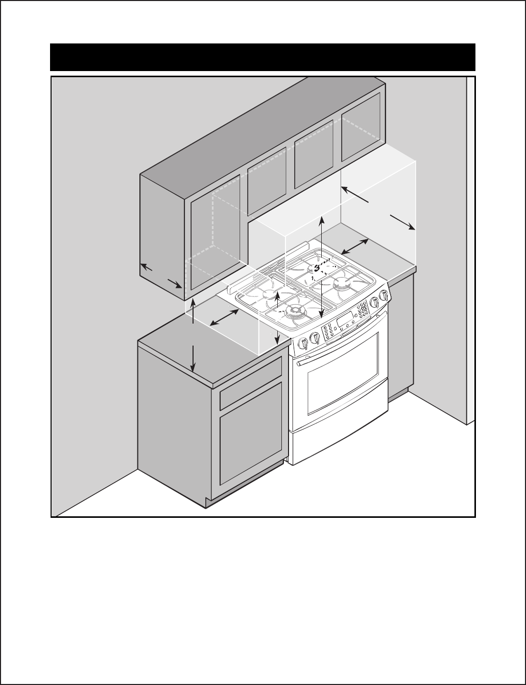
© 2006 Maytag Services 16026923 A – 5
Installation Instructions
IMPORTANT: Keep for Local Inspector/IMPORTANT : À conserver pour l’inspecteur local/
IMPORTANTE: Guarde esta información para el inspector local.
CLEARANCE DIMENSIONS
Range may be installed with zero inches clearance adjacent to (against) combustible construction at the rear and on the sides below the cooktop.
For complete information in regard to the installation of wall cabinets above the range and clearances to combustible wall above the cooking
top see the installation drawings. For SAFETY CONSIDERATIONS do not install a range in any combustible cabinetry which is not in accord with
the installation drawings.
* NOTE: 30 inch (76.2 cm) dimension between cooking top and wall cabinet shown on illustration does not apply to ranges with an elevated
oven or microwave. The installation instructions of the elevated oven will specify the minimum acceptable dimension between the cooktop
and elevated oven. The 30 inch (76.2 cm) dimension may be reduced to not less than 24 inches (61 cm) when the wall cabinets in a domestic
home are protected with fireproof materials in accordance with American National Standards - National Fuel Gas Code or in mobile homes
when they are protected with fireproof materials in accordance with the Federal Standard for Mobile Home Construction and Safety.
To eliminate the risk of burns or fire by reaching over heated surface units, cabinet storage space located above the surface units should be
avoided. If cabinet storage is to be provided, the risk can be reduced by installing a range hood that projects horizontally a minimum of 5
inches (13 cm) beyond the bottom of the cabinets
Combustible
Building Walls/
Murs en matériaux
combustibles/
Paredes
combustibles
de la vivienda
Combustible
Wall Cabinets/
Armoires de
cuisine en
matériaux
combustibles/
Armarios de pared
combustible
13" (33 cm) Max.
Depth of cabinets
above cooktop
Profondeur max.,
des armoires
audessus
de l’appareil :
33 cm (13 po)
Profundidad máx.
de los armarios sobre
la cubierta:
13” (33 cm)
30”
30”
(76.2 cm)
(76.2 cm)
30”
(76.2 cm)
30”
30”
(76.2 cm)
(76.2 cm)
18”
(45.7 cm)
13”
(33 cm)
3”
(7.6 cm)
25”
(63.5cm)
18”
(45.7 cm)
3”
(7.6 cm)
NOTE: Figure may not be representative of actual unit./REMARQUE : L’illustration peut ne pas présenter l’appareil actuel./NOTA: La
figura puede no ser exacta a la unidad.
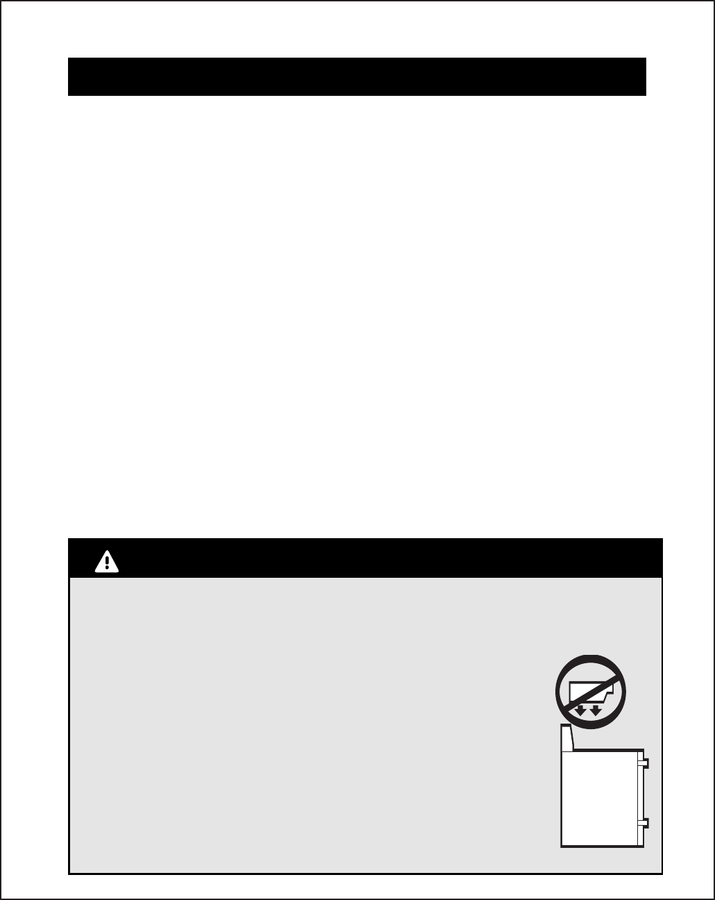
A – 6 16026923 © 2006 Maytag Services
Installation Instructions
THIS PRODUCT SHOULD NOT BE INSTALLED BELOW VENTILATION TYPE HOOD SYSTEM THAT DIRECTS AIR IN A DOWNWARD DIRECTION.
THESE SYSTEMS MAY CAUSE IGNITION AND COMBUSTION PROBLEMS WITH THE GAS BURNERS RESULTING IN PERSONAL INJURY AND MAY
EFFECT THE COOKING PERFORMANCE OF THE UNIT.
NOTE: THE FIGURE MAY NOT ACCURATELY REPRESENT YOUR RANGE COOKTOP; HOWEVER, THIS WARNING APPLIES TO ALL GAS COOKING
PRODUCTS.
CE PRODUIT NE DOIT PAS ÊTRE INSTALLÉ SOUS UNE HOTTE D’EXTRACTION QUI RENVOIE L’AIR VERS LE BAS.
CES SYSTÈMES PEUVENT ENTRAÎNER DES PROBLÈMES D’INFLAMMATION ET DE COMBUSTION AVEC LES BRÛLEURS
À GAZ, ENTRAÎNANT DES BLESSURES ET RISQUANT D’AFFECTER LA PERFORMANCE DE CUISSON DE L’APPAREIL.
REMARQUE : L’ILLUSTRATION PEUT NE PAS REPRÉSENTER PRÉCISÉMENT LA TABLE DE CUISSON DE VOTRE
CUISINIÈRE; CEPENDANT, CET AVERTISSEMENT CONCERNE TOUS LES APPAREILS DE CUISSON À GAZ.
ESTE PRODUCTO NO SE DEBE INSTALAR DEBAJO DE SISTEMAS DE CAMPANAS DE VENTILACIÓN QUE DIRIJAN EL
FLUJO DE AIRE HACIA ABAJO.
ESTOS SISTEMAS PUEDEN CAUSAR PROBLEMAS DE ENCENDIDO Y DE COMBUSTIÓN DE LOS QUEMADORES, LO
QUE PUEDE RESULTAR EN LESIONES PERSONALES Y AFECTAR EL RENDIMIENTO DE LA COCCIÓN DE LA UNIDAD.
NOTA: LA FIGURA PUEDE NO REPRESENTAR CON EXACTITUD SU CUBIERTA. SIN EMBARGO, ESTA ADVERTENCIA SE
APLICA A TODOS LOS PRODUCTOS DE COCCIÓN A GAS.
IMPORTANT: Keep for Local Inspector (cont)/IMPORTANT : À conserver pour l’inspecteur local (suite)/
IMPORTANTE: Guarde esta información para el inspector local (cont.)
DÉGAGEMENTS
La cuisinière peut être installée avec un dégagement nul contre des matériaux combustibles à l’arrière et sur les côtés en dessous de la table
de cuisson. Pour des renseignements complets concernant l’installation des armoires au-dessus de la cuisinière et les dégagements aux
parois combustibles au-dessus de la surface de cuisson, consultez les schémas sur l’installation. Pour des RAISONS DE SÉCURITÉ, n’installez
pas une cuisinière dans des armoires en matériaux combustibles non conformes aux schémas de l’installation.
* REMARQUE : La dimension de 76,2 cm (30 po) entre la surface de cuisson et les armoires murales présentées sur l’illustration ne concerne pas les
cuisinières avec un four surélevé ou un micro-ondes. Les instructions d’installation du four surélevé précisent la dimension minimale acceptable
entre la surface de cuisson et le four surélevé. La dimension de 76,2 cm (30 po) peut être réduite à pas moins de 61 cm (24 po) lorsque les armoires
murales d’une résidence sont protégées par des matériaux ignifuges conformément aux normes de l’American National Standards – National Fuel
Gas Code (Code national des combustibles gazeux), ou lorsque les armoires murales d’une maison mobile sont protégées par des matériaux
ignifuges selon la norme fédérale : Mobile Home construction and Safety (norme de sécurité et de construction des maisons mobiles).
Pour éliminer le risque de brûlure ou d’incendie, en passant la main au-dessus des éléments de surface chauffés, l’espace de rangement dans les
armoires situées au-dessus des éléments de surface doit être évité. Si une armoire de rangement existe, le risque peut être réduit en installant
une hotte d’extraction qui dépasse horizontalement d’un minimum de 13 cm (5 po) de la partie inférieure des armoires.
DIMENSIONES DE LOS ESPACIOS DE DESPEJE
Esta estufa se puede instalar sin espacios de despeje contra superficies combustibles en la parte trasera y a los costados de la misma por
debajo de la cubierta. Para obtener información completa sobre la instalación de los armarios sobre la cubierta y los espacios de despeje
para las paredes combustibles sobre la cubierta vea las figuras de instalación. Por RAZONES DE SEGURIDAD, no instale una estufa en ninguna
ubicación con armarios combustibles que no concuerden con las figuras de instalación.
* NOTA: El despeje de 30 pulgadas (76,2 cm) entre la cubierta de cocción y el armario que se muestra en la figura no se aplica a las estufas
con hornos elevados o a los microondas. Las instrucciones de instalación del horno elevado especificarán el espacio mínimo entre la cubierta
y el horno elevado. El despeje de 30 pulgadas (76,2 cm) puede ser reducido a no menos de 24 pulgadas (61 cm) cuando los armarios del hogar
están protegidos con materiales a prueba de fuego de acuerdo con las Normas Nacionales de Estados Unidos (ANS) y el Código Nacional de Gas
o en las casas rodantes cuando las mismas están protegidas con materiales a prueba de fuego de acuerdo con la Norma Federal de Construcción
y Seguridad de Viviendas Móviles.
Para eliminar el riesgo de quemaduras o de incendios cuando se intenta alcanzar algún objeto sobre los elementos superiores, evite almacenar
artículos en los armarios que están sobre la estufa. Si se instala un armario sobre la cubierta, se puede reducir el riesgo instalando una campana
de ventilación que se proyecte horizontalmente en un mínimo de 5 pulgadas (13 cm) más allá de la base de los armarios.
WARNING/AVERTISSEMENT/ADVERTENCIA
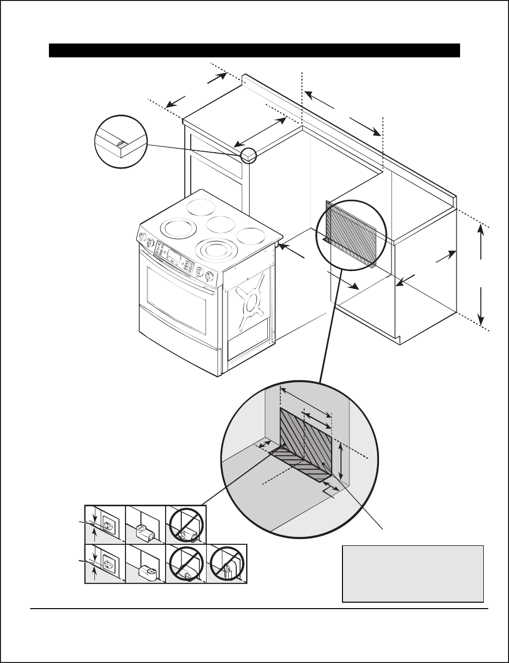
© 2006 Maytag Services 16026923 A – 7
Installation Instructions
5.5”
(14 cm)
10”
(25.4cm)
19”
(48.3cm)
9 1/2”
(24.13 cm)
24”
(61cm)
2 1/4”
(5.71 cm)
23.25”
(
59.1cm)
36”
(91.4c
m
30”
(76.2cm)
25”
(63.5cm)
30”
(76.2cm)
1-1/2"min
(3.8 cm)
1-1/2"min
(3.8 cm)
Dimensions/Dimensions/Dimensiones
Important: Because of continuing product improvements, Maytag reserves the right to change specifications without notice. Dimensional specifications are provided for planning purposes only.
Important : En raison de l’amélioration continue de ses produits, Maytag se réserve le droit de changer les spécifications sans préavis. Les dimensions ne sont fournies qu'à titre indicatif.
Importante: Debido a las mejoras continuas del producto, Maytag se reserva el derecho de cambiar sus especificaciones sin aviso previo. Las especificaciones dimensionales se proporcionan para propósitos de
planificación únicamente.
NOTE: As an option to make gas valve accessible, it can be
located in the adjacent cabinet.
REMARQUE: Pour que le robinet de gaz soit accessible, il peut
être situé dans l'armoire adjacente.
NOTA: A modo opcional para facilitar el acceso a la válvula de
gas, la misma puede ser instalada en el gabinete adyacente.
CAUTION:
Some white European style
cabinets are equipped with
delicate white vinyl drawer
and door fronts. The vinyl
may not be designed to
withstand the heat
produced by the normal safe
operation of a self-clean range.
Discoloration or delamination may
occur. To avoid possible damage, we
recommend increasing the 30” cabinet opening
to 31 1/4” minimum and using heat shield (CABKIT V).
The countertop cut-out must remain 30”.
ATTENTION:
Certaines armoires de couleur blanche et de style européen sont
équipées de façades de porte et de tiroir en vinyle blanc fragile.
Le vinyle peut ne pas être conçu pour résister à la chaleur
produite par un autonettoyage normal. Il peut se produire une
décoloration ou une déstratification. Pour éviter le risque de
dommages, nous vous recommandons d'agrandir l'ouverture
dans les armoires de 30 po (76,2 cm) à 31 1/4 po (79,4 cm)
minimum et d'utiliser un ensemble d'écran thermique (CABKIT V).
L'ouverture dans le plan de travail doit toujours être de 30 po
(76,2 cm).
If cabinet backsplash behind unit is not present,
kit UXA9107AA (B= black, S=stainless, W=
white) may be ordered
from dealer.
If end cabinet is not present, side
panel kit UXA1100AA (B= black,
W= white, S= Stainless) may be
ordered from dealer.
) a su
When replacing an existing unit, a maximum of 23 1/2” is
acceptable. If the cut depth exceeds 23 1/2”, use filler kit
K71FILL (B= black, W= white, S= Stainless) may be
ordered from dealer.
NOTE:
For counter tops with
formed front edge, shave
raised section to clear top.
REMARQUE:
Pour les
hauts de comptoir avec un
rebord avant moulé, raboter
la section relevée pour
dégager le haut.
NOTA:
Para los mostradores
con borde delantero formado,
cepille la sección elevada
para que la parte superior
calce.
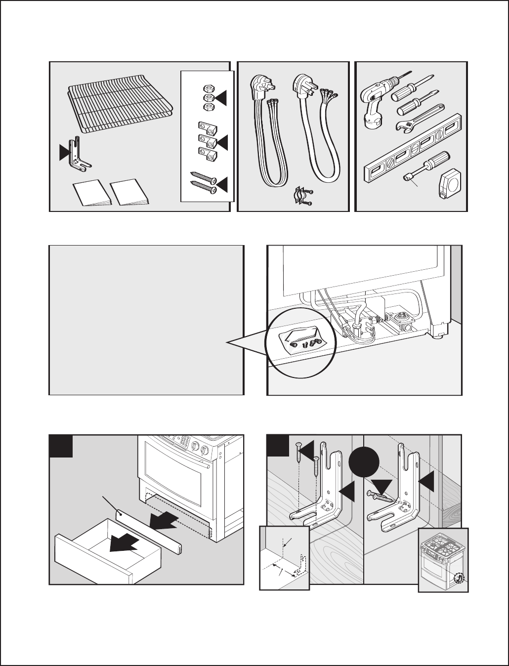
A – 8 16026923 © 2006 Maytag Services
Installation Instructions
B
D
C
5/16"
Use & Care
Guide
Installation
Instructions
A
2
1
1
(Cardboard Cross Support)
(Support transversal en carton)
(Soporte cruzado de la caja)
Remove drawer (check Use and Care manual for directions) and insure
all packing (cardboard cross support) is removed and discarded./
Retirez le tiroir (vérifiez le manuel d’utilisation et d’entretien pour les
instructions) et assurez-vous que tout le matériau d’emballage (support
transversal en carton) est enlevé et jeté./Retire el cajón (consulte el
manual de uso y cuidado para obtener instrucciones) y asegúrese de
que todo el material de empaque (soporte transversal de la caja de
cartón) sea removido y desechado.
A
D
DA
Center
14 1/4”
(36.19mm)
2
or
ou
o
Drill 1/8” (3mm holes). Mount ANTI-TIP bracket to wall or floor with 2 screws./
Percez des trous de 1/8 po (3 mm). Installez le support ANTIRENVERSEMENT
au mur ou au sol avec deux vis./Taladre agujeros de 1/8” (3 mm). Instale
el soporte ANTIVUELCO en la pared o en el piso usando 2 tornillos.
Included./Compris./Se incluye. Not Included./Non inclus./No se
incluye.
Tools Needed./Outils nécessaires./
Herramientas Necesarias.
If you have LP (propane) it is recommended to
initiate the conversion prior to installation. The
conversion instruction kit can be found on the
regulator shelf behind the shield./
Avec le GPL, il est recommandé de faire la
conversion avant l'installation. L'ensemble de
conversion se trouve sur la tablette du détendeur
derrière le blindage./
Si utiliza gas LP (propano), se recomienda que
inicie la conversión antes de realizar la instalación.
Puede encontrar el kit de instrucciones en el
estante del regulador detrás del protector.
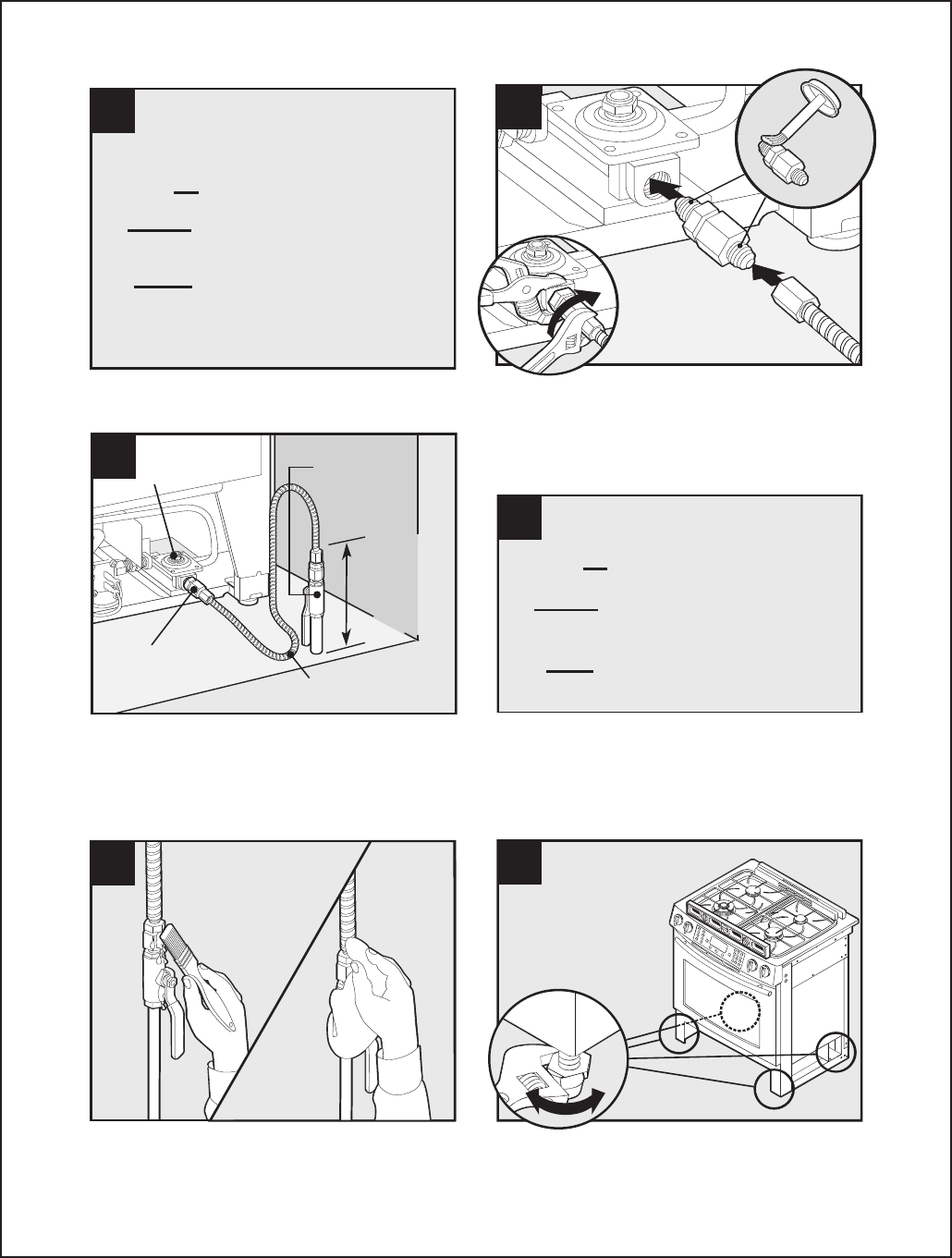
© 2006 Maytag Services 16026923 A – 9
Installation Instructions
7
Check all gas connection joints and fittings for leaks with a non-corrosive
leak detection fluid, then wipe off./Vérifiez l’absence de fuite à tous les
raccordements de gaz avec un liquide de détection des fuites non corrosif,
puis essuyez-le./Verifique todas las conexiones y juntas del suministro de
gas a la estufa usando un líquido de detección de escapes no corrosivo
para asegurarse de que no hayan escapes. Limpie el líquido cuando
haya terminado.
8
Adjust legs. Note: Check counter top height (see dimensions) to allow
range top to clear countertop. Installer, take caution not to damage floor./
Ajustez les pieds. Remarque: Vérifiez la hauteur du plan de travail (voyez
les dimensions) pour que le dessus de la cuisinière se trouve au-dessus
du plan de travail. Installateur: faites attention de ne pas endommager le
sol./Ajuste los tornillos niveladores. Nota: Verifique la altura de la
encimera (vea las dimensiones) para permitir que la parte superior de la
estufa pase por la misma. Instalador: tenga cuidado de no dañar el piso.
3
TURN OFF GAS SUPPLY TO PRODUCT.
COUPEZ L'ALIMENTATION EN GAZ DE
L'APPAREIL.
CIERRE EL SUMINISTRO DE GAS AL
PRODUCTO.
2
4
1
3
Apply pipe thread compound approved for LP gas to all threads. Always
hold the regulator in stable position while attaching gas supply
line./Appliquez sur tous les filetages un composé à joints approuvé
pour le GPL. Tenez toujours le détendeur en position stable lors du
raccordement de la conduite d'alimentation en gaz./Aplique compuesto
para roscas de tuberías aprobado para gas LP a todas las roscas.
Siempre sostenga el regulador en una posición estable mientras
conecta la tubería de suministro.
Adaptor
Flexible Connector
5
Flexible Connector/
Tuyau de raccordement/
Conector flexible
Shut-Off Valve/
Robinet d’arrêt/
Válvula de cierre
10” Max
straight pipe/
Tuyau rectiligne 10
po (25,4 cm)
max./Máx. 10"
(25,4 cm)
de tubería recta
Regulator/
Détendeur/
Regulador
Adaptor/
Adaptateur/
Adaptador
Only qualified personnel should install range. Must be installed in
accordance with local codes. See instructions in front of this
manual./Seul du personnel qualifié doit installer la cuisinière. Elle doit être
installée selon les codes locaux. Voyez les instructions au début de ce
manuel./ La estufa sólo debe ser instalada por personal calificado. La
estufa debe instalarse de acuerdo con los códigos locales. Vea las
instrucciones en la parte delantera de este manual.
6
TURN ON GAS SUPPLY TO PRODUCT.
OUVREZ L'ALIMENTATION EN GAZ DE
L'APPAREIL.
ABRA EL SUMINISTRO DE GAS AL
PRODUCTO.
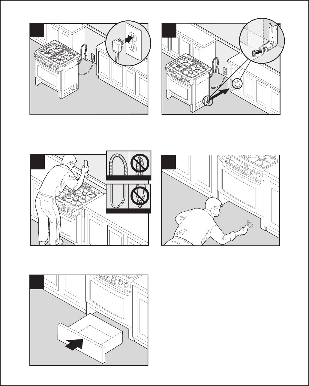
A – 10 16026923 © 2006 Maytag Services
Installation Instructions
9
10
Insert plug into grounded outlet./Insérez la fiche dans la prise mise à la
terre./Conecte el enchufe en un tomacorriente puesto a tierra.
Slide range into position. Installer, take caution not to damage floor. Do
not tilt range side-to-side; may damage end trim./ Introduisez la
cuisinière en place. Installateur : N'endommagez pas le sol. N'inclinez
pas la cuisinière sur un côté, au risque d'endommager la garniture./
Deslice la estufa a su lugar definitivo. Instalador: tenga cuidado de no
dañar el piso. No incline la estufa de lado a lado; se podría dañar el
marco del borde.
11
Gas/À gaz/Gas
Electric/Électrique/Eléctrica
Make sure flexible connector and electrical cord are not kinked./
Assurez-vous que le raccord flexible et le cordon d'alimentation ne sont
pas entortillés./Asegúrese de que el conector flexible y el cordón
eléctrico no estén doblados.
13
Replace drawer./Replacez le tiroir./Vuelva a instalar el cajón.
12
Check leg position in ANTI-TIP bracket./Vérifiez la position du pied dans
la bride ANTI-BASCULEMENT./Verifique la posición de la pata en el
soporte ANTIVUELCO.
© 2006 Maytag Services 16026923 B – 1
Appendix B
The Use and Care information provided in this service manual is representative of a limited
number of models. Reference the customer’s Use and Care literature included with the
product, order a copy (if needed), or consult Jenn-Air’s website for the specific model.
www.jennair.com

B – 2 16026923 © 2006 Maytag Services
Use & Care
JENN-AIR
®
GAS
DOWNDRAFT SLIDE-IN RANGE
USE & CARE
GUIDE
®
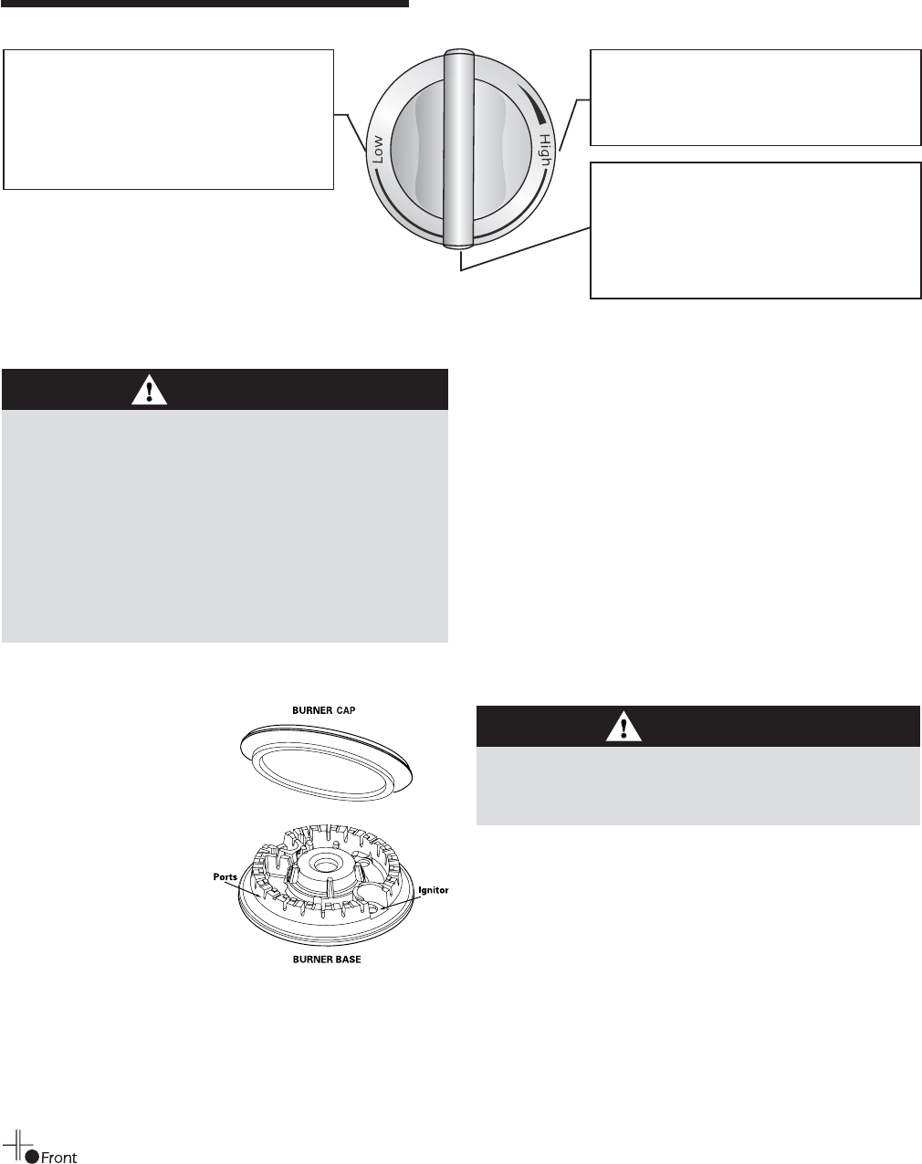
© 2006 Maytag Services 16026923 B – 3
Use & Care
SURFACE COOKING
Surface Controls
Pilotless Ignition
Pilotless ignition eliminates the
need for a constant standing
pilot light. Each surface burner
has a spark ignitor. Use care
when cleaning around the
surface burner.
If the surface burner does
not light, check if ignitor is
broken, soiled or wet.
Setting the controls:
The size and type of cookware will affect the heat setting.
1. Place a pan on the burner grate.
•
The burner flame may lift off or appear separated from
the port if a pan is not placed on the grate.
2. Push in and turn the knob to the desired setting.
•
A clicking (spark) sound will be heard and the burner
will light.
Important: Each surface burner is equipped to provide
automatic reignition if the flame should somehow get
blown out.
Operating During a
Power Failure
Surface Control Knobs
Use to turn on the surface burners. An infinite choice of heat
settings is available from Low to High. At the High setting a
detent or notch may be felt. The knobs can be set on or
between any of the settings.
Graphics next to the knob identify which burner
the knob controls. For example, the graphic at left
shows the right front burner location.
CAUTION
• If flame should go out during a cooking operation and
the burner does not reignite itself, turn the burner off. If a
strong gas odor is detected, open a window and wait five
minutes before relighting the burner.
• Be sure all surface controls are set in the OFF position
prior to supplying gas to the range.
•NEVER touch cooktop until it has cooled. Expect some
parts of the cooktop, especially around the burners, to
become warm or hot during cooking. Use potholders to
protect hands.
CAUTION
When lighting the surface burners, be sure all of the
controls are in the OFF position. Strike the match first and
hold it in position before turning the knob on.
High: Use to bring liquid to a boil, or reach
pressure in a pressure cooker. Always
reduce setting to a lower heat when liquids
begin to boil or foods begin to cook.
An intermediate flame size is used to
continue cooking. Food will not cook any
faster when a higher flame setting is used
than needed to maintain a gentle boil.
Water boils at the same temperature
whether boiling gently or vigorously.
Low: Use to simmer foods, keep foods
warm and melt chocolate or butter. Some
cooking may take place on the Low
setting if the pan is covered. It is possible
to reduce the heat by rotating the knob
toward OFF. Be sure flame is stable.
1. Hold a lighted match to the desired surface burner head.
2. Push in and turn the control knob slowly on.
3. Adjust the flame to the desired level.
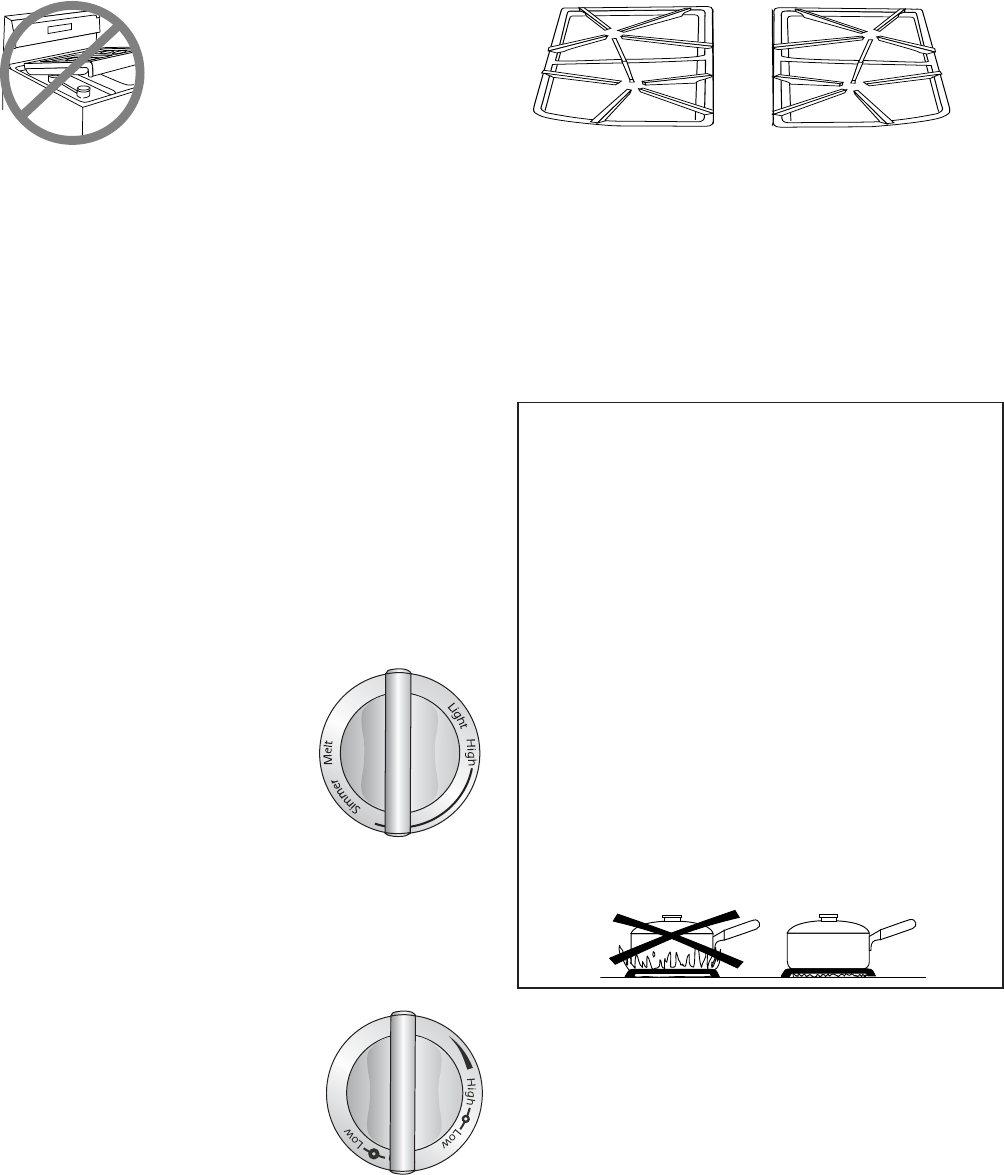
B – 4 16026923 © 2006 Maytag Services
Use & Care
Cooktop
Notes:
•
A properly adjusted burner with clean ports will light
within a few seconds. If using natural gas, the flame
will be blue with a deeper blue inner cone.
If the burner flame is yellow or is noisy, the air/gas
mixture may be incorrect. Contact a service technician
to adjust. (Adjustments are not covered by the
warranty.)
With LP gas, slight yellow tips on the flames are
acceptable. This is normal and adjustment is not
necessary.
•With some types of gas, you may hear a “popping”
sound when the surface burner is turned off. This is a
normal operating sound of the burner.
•If the control knob is turned very quickly from High to
Low, the flame may go out, particularly if the burner is
cold. If this occurs, turn the knob to the OFF position,
wait several seconds and relight the burner.
•The flame should be adjusted so it does not extend
beyond the edge of the pan.
To prevent the cooktop from discoloring
or staining:
•Clean cooktop after each use.
•Wipe acidic or sugary spills as soon as the cooktop has
cooled as these spills may discolor the
porcelain.
Unlike a range with standard gas burners,
this cooktop does not lift up nor is it
removable. Do not attempt to lift the
cooktop for any reason.
Burner Grates
The grates must be properly positioned before cooking.
When installing the grates, place the tab ends toward the
center, matching the straight bars.
Improper installation of the grates may result in chipping of
the cooktop.
Sealed Burners
The sealed burners of your range are secured to the cooktop
and are not designed to be removed. Since the burners are
sealed into the cooktop, boilovers or spills will not seep
underneath the cooktop.
However, the burner should be cleaned after each use. The
cap portion of the burner is easily removed for cleaning. (See
page 7 for cleaning directions.)
The burner caps must be correctly placed on the burner base
for proper operation of the burner.
High Performance Burner
There is one 16,000 BTU* high speed burner on your range,
located in the right front position. This burner offers higher
speed cooking that can be used to quickly bring water to a
boil and for large-quantity cooking.
Low Turn Down Burner
This burner is located in the right rear
position. The Simmer setting can be
used to steam or poach foods, to cook
delicate sauces or continue cooking
covered foods. The ultra-low Melt
setting is best for melting
chocolate and butter.
Important: When using the normal settings
for preparing foods, it may take a few minutes for the cooking
area to cool to the Melt heat setting.
* BTU ratings will vary when using LP gas.
Dual Ring Burner (select models)
The cooking surface is equipped with a dual
ring burner located in the left front
position. To operate, push in on the
control knob and turn counterclockwise
to light the burner. Continue turning
until the desired setting is reached. The
lighting sequence is: inner burner on
High, then inner burner on Low, then both
rings on High, then both rings on Low.
Do not operate the burners without a pan on the grate.
The grate’s porcelain finish may chip without a pan to
absorb the heat from the burner flame.
Use care when stirring food in a pot/pan sitting on the burner
grate. The grates have a smooth finish for ease of cleaning.
The pot/pan will slide if the handle is not held. This may result
in spilling of hot food items and may be a burn hazard.
Although the burner grates are durable, they will gradually
lose their shine and/or discolor, due to the high temperatures
of the gas flame.
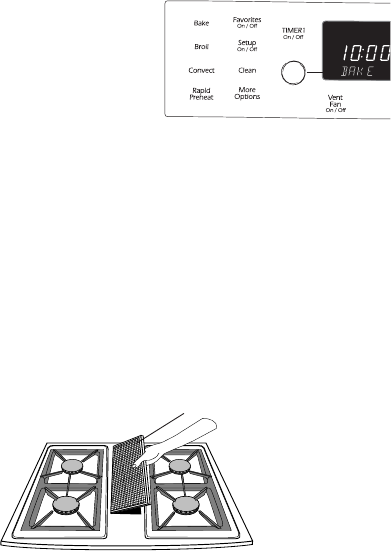
© 2006 Maytag Services 16026923 B – 5
Use & Care
FILTER
Ventilation System
The built-in ventilation system removes cooking vapors, odors
and smoke from foods prepared on your cooktop and grill.
• To operate the ventilation
system manually, push the
Vent Fan pad located on the
electronic control. Push once
for Low, push again for High
and a third time to turn the
fan Off.
➞
• The ventilation system will operate automatically when the
grill element is in use.
• The fan can be used to remove strong odors from the
kitchen as when chopping onions near the fan.
Care and Cleaning of the
Ventilation System
•Air Grille: The air grille lifts off easily. Wipe clean or wash in
dishwasher or sink with mild household detergents. To
prevent scratching the surface, do not use abrasive
cleaners or scrubbing pads.
•Filter: Turn off ventilation system before removing. The filter
is a permanent type and should be cleaned when soiled.
Clean in sink with warm water and detergent or in
dishwasher.
IMPORTANT: DO NOT OPERATE SYSTEM WITHOUT
FILTER. Filter should always be placed at an angle. As you
face the front of the range, the top of the filter should rest
against the left side of the vent opening. The bottom should
rest against the right side of the vent chamber at the
bottom. Important: If filter is flat against the fan wall,
ventilation effectiveness is reduced.
•Ventilation Chamber: This area, which houses the filter,
should be cleaned in the event of spills or whenever it
becomes coated with a film of grease. It can be cleaned with
paper towel, damp cloth, or sponge and mild household
detergent or cleanser.
Important: The oven vent is located under the right side of
the air grille. When using or cleaning the oven, hot and
moist air may be noticed in this area. The area near the vent
may become hot enough to cause burns. Be careful not to
spill anything into this vent. The air grille must be
removed before the self-clean cycle.
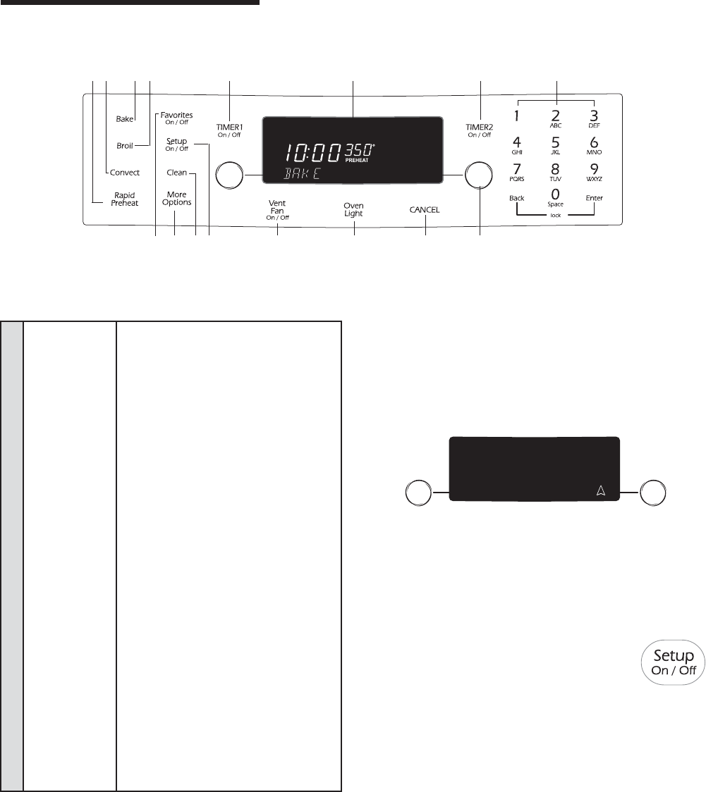
B – 6 16026923 © 2006 Maytag Services
Use & Care
O
VEN
C
OOKING
ARapid Preheat Use to decrease preheating time.
BConvect Use for convection baking and roasting.
CBake Use for baking and roasting.
DBroil Use for broiling and top browning.
ETIMER 1 Sets timer.
FDisplay Displays oven functions, options and
window time of day.
GTIMER 2 Sets timer.
HNumber Pads Use to enter time and temperature,
or to enter Favorites names.
IFavorites Use to access, program or save
baking cycles.
JMore Options Use to access additional features.
KClean Use to set self-clean cycle.
LSetup Use to view or change factory
default settings.
MVent Fan Activates the ventilation fan on
the cooktop.
NOven Light Use to turn the oven light on or off.
OCANCEL Cancels all operations except Timer,
Clock, Favorites, Setup and Vent Fan.
PQuickset pads Use to select options in display
window (next to display window
on both sides).
The control panel is designed for ease in programming. The display window shows options for each function and moves from step
to step through the programming process. Control panel features vary by model. Oven display above is programmed for a bake
operation.
A B C D E F G H
Control Panel
Quickset Pads
Quickset pads are located on each side of the display window
and are used to select the desired function or option in the
display window. To select the option or function, press the
Quickset pad next to the word.
Important: Four seconds after entering the function,
option, number or letter, the function will automatically be
entered. If more than 30 seconds elapse between steps in
programming, the function will be canceled and the
display will return to the previous display.
Clock
Setting the Clock:
1. Press the Setup pad.
2. Select CLOCK using the Quickset pads.
3. Select TIME.
4. Enter the time using the number pads.
5. Press Enter pad.
6. Select AM or PM in 12 hour mode. (For 24 hour clock, see
page 16.)
7. To exit the Setup mode, press Setup pad.
If you need to back out of a function or option in the display,
press the Back pad. When your programming is complete,
press the Enter pad or wait four seconds and the function will
start automatically.
Up arrows indicate additional screens with additional options.
Press the Quickset pads next to the arrows to scroll through
the display.
I J K L M N O P
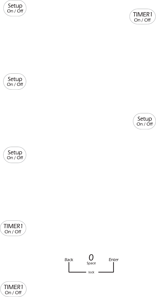
© 2006 Maytag Services 16026923 B – 7
Use & Care
Activating and canceling the clock/day
of week display:
1. Press Setup pad.
2. Select CLOCK.
3. Press the arrow to scroll until DISABLE is displayed.
4. Select DISABLE.
5. Select TIME.
6. Select OFF to turn the clock display off, or select ON to turn
the clock display on.
7. Select OFF to turn the day of the week display off. Select
ON to turn the weekday display on.
8. To exit the Setup mode, press Setup pad.
Entering the day of the week:
1. Press Setup pad.
2. Select CLOCK.
3. Press the arrow to scroll until DAY is displayed.
4. Use Quickset arrow to scroll through the days.
5. Select day desired.
6. To exit the Setup mode, press Setup pad.
To set the clock for a 12 or 24 hour format:
The clock can be set to display time in either a 12 hour or 24
hour format.
1. Press the Setup pad.
2. Select CLOCK.
3. Use the arrow to scroll to the next screen.
4. Select 12/24 HOUR.
5. Select 12 HR or 24 HR.
6. To exit Setup mode, press Setup pad.
Timers
Setting the Timers (Timer 1 or Timer 2):
1. Press TIMER 1 or TIMER 2 pad.
2. Press one of the displayed times using the
Quickset pads, or press the number pads to
enter the desired time.
Important: Each press of the displayed time choices adds
additional time. For example, pressing “10 MIN” three
times provides 30 minutes on the timer (0:30).
3. Press Enter pad.
Changing the amount of time entered once the
Timer starts:
1. Press the TIMER 1 or TIMER 2 pad once.
2. Press the displayed times on the Quickset
pads repeatedly until the desired time is entered.
OR
3. Press the number pads to enter the new desired time.
4. Press Enter pad.
Canceling the Timer:
1. Press the TIMER 1 or TIMER 2 pad twice.
If both Timers are active:
If the desired Timer is already in the foreground, press once
for edit mode and twice to cancel the Timer. If the desired
Timer is not in the foreground, follow the steps below.
1. Press the desired TIMER pad once. The selected Timer will
come to the foreground.
2. Press the TIMER pad a second time to access the edit
mode in order to make changes.
3. Pressing the TIMER pad a third time will cancel the Timer.
Changing the Timer beeps:
The signal beeps for TIMER 1 and TIMER 2 can be changed.
The options available are two beeps every thirty seconds, two
beeps every sixty seconds or one beep only. The default
setting is one beep.
1. Press the Setup pad.
2. Select the arrow to scroll until TONES
is displayed.
3. Select TONES.
4. Select TIMERS TONES.
5. Select the desired timer beep format (2-30 SEC, 2-60 SEC
or 1 BEEP).
6. Press Setup pad to exit Setup mode.
Locking the Control and Oven Door
The oven control and oven door can be locked to prevent
accidental programming. If an oven function is currently
being used, the control and door cannot be locked.
To lock the control and door:
Press the Back and Enter pads at the same time, holding for
three seconds or until CONTROL LOCKED appears in the
display.
To unlock the control and door:
Press the Back and Enter pads at the same time, holding for
three seconds. UNLOCKING DOOR will appear in the display
when the control and door are unlocking.
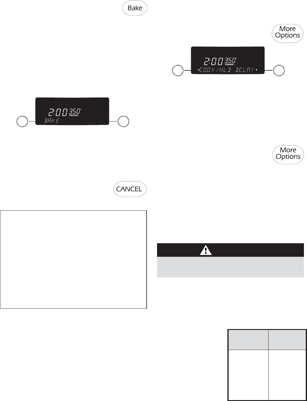
B – 8 16026923 © 2006 Maytag Services
Use & Care
Notes:
• If more than thirty seconds elapse between pressing a
pad and pressing a number pad, the display will return
to the previous display.
• Whenever the temperature appears in the display, the
oven is heating.
• To change the oven temperature during cooking, press
the Bake pad and select a displayed temperature or use
the number pads to enter the desired temperature.
• The oven will automatically shut off after 12 hours if it is
accidentally left on. To set a Sabbath Mode, see Sabbath
Mode, page 25.
Bake Options
• The temperature in the display will increase in 1°
increments until the oven reaches the preset
temperature. Allow about 15 minutes for the oven
to preheat.
• When the oven is preheated, the oven will beep and
PREHEAT will no longer be displayed.
3. At the end of cooking, turn the oven off by
pressing the CANCEL pad. Remove food
from the oven. The oven will continue
operating until the CANCEL pad is pressed.
Baking
To set Bake:
1. Press the Bake pad.
2. Select the oven temperature using the Quickset pads.
OR
Enter the desired temperature using the number pads.
Press Enter pad to set.
• The temperature can be set from 170° F to 550° F
in 5° increments.
• After three seconds, the oven will begin to preheat.
BAKE and PREHEAT will appear in the display along
with 100° or the actual oven temperature, whichever
is higher.
To set a Delay:
1. After Bake has been programmed, press
the More Options pad.
2. Select DELAY.
3. Select the amount of time you want to delay the start of
cooking using the displayed times or the number pads.
4. Select the amount of time you want to cook using the
displayed times or the number pads.
5. The display will show BAKE, the temperature, the delay
time and the cook time countdown.
6. When the delay time has expired, the oven will begin
heating. COOK TIME, the cook time countdown, PREHEAT,
BAKE and the actual oven temperature will be displayed.
CAUTION
Do not use delayed baking for highly perishable foods such
as dairy products, pork, poultry or seafood.
Cook & Hold and Delay options are available when baking.
When using the Cook & Hold option, the oven begins to heat
immediately after the control has been set. Then, the oven
cooks for a specified length of time. When that time has
elapsed, the oven will automatically reduce temperature to
170° F and keep the food warm for up to an hour and then
automatically turn off.
When using Delay, the oven begins to cook later in the day.
Set the amount of time that you want to delay before the oven
turns on and how long you want to cook. The oven begins to
heat at the selected time and cooks for the specified length of
time. When that time has elapsed, the oven will keep the food
warm for up to an hour then automatically turn off.
To set Cook & Hold:
1. After Bake has been programmed, press
the More Options pad.
2. Select COOK/HLD.
3. Select the amount of time you want to bake by pressing
the Quickset pads or the number pads.
4. Press ENTER.
5. COOK TIME, the cook time countdown, PREHEAT, BAKE
and the actual temperature will be displayed.
The oven will cook for the selected time, then keep food warm
for one hour.
Convect Options
Cook & Hold and Delay
options are available when
convect cooking. See
page 21 for information on
how to program a Cook &
Hold or Delay option.
Convect
Convection uses a fan to circulate hot air evenly over, under and
around the food. As a result, foods are evenly cooked and
browned, often in shorter times, at lower temperatures and with
the flexibility of using more than one rack at a time.
CONVECT CONVECT
BAKE ROAST
Multiple-Rack Whole Chicken
Baking of Whole Turkey
Cookies/Biscuits Vegetables
Breads Pork Roasts
Casseroles Beef Roasts
Tarts/Tortes
Cakes
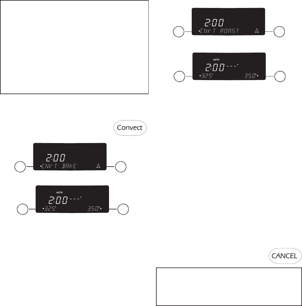
© 2006 Maytag Services 16026923 B – 9
Use & Care
Notes:
• The oven control comes from the factory set for Auto
Convect Conversion. When using Convect Bake enter the
conventional baking temperature. The control
automatically converts the temperature to 25° less than
the conventional temperature.
• When using Convect Roast the temperature will not be
automatically reduced. Enter the conventional roasting
temperature and time. The control then lets you know
when 75% of the time has elapsed and alerts you to check
the food for doneness.
• To turn Auto Convect Conversion off, see page 24.
Convect Bake
To set Convect Bake:
1. Press the Convect pad.
2. Select CNVT BAKE using the Quickset pads.
3. Select the oven temperature using the Quickset pads
OR
Enter the desired temperature using the number pads.
Press Enter pad to set.
• The temperature can be set from 195° F to 550° F
degrees in 5° increments.
• After three seconds, the oven will begin to preheat. CNVT
BAKE and PREHEAT will appear in the display along with
100° or the actual oven temperature, whichever is higher.
• The temperature in the display will increase in 1°
increments until the oven reaches the preset temperature.
Allow about 15 minutes for the oven to preheat.
• When the oven is preheated, the oven will beep, and
PREHEAT will turn off and CNVT BAKE will be displayed.
AUTO will be displayed if Auto Convect Conversion
feature is turned on.
• Place food in the oven.
4. At the end of cooking, turn the oven off by pressing the
CANCEL pad. Remove food from the oven. The oven will
continue operating until the CANCEL pad is pressed.
Cont.
Convect Roast
To set Convect Roast:
1. Place food in the oven.
2. Press the Convect pad.
Rapid Preheat
Use to decrease preheating time when using Bake or Convect
Bake. Use for all foods when baking on one rack.
• After Bake or Convect Bake has been programmed and
activated, press the Rapid Preheat pad.
• 1 RACK ONLY will display, after 10 seconds the display will
show RAPID and PREHEAT.
To return to Standard Preheat:
• Press Rapid Preheat pad again. This will provide standard
preheat and PREHEAT and the selected function will be
displayed.
3. Select CNVT ROAST using the Quickset pads.
4. Select the oven temperature using the Quickset pads.
OR
Enter the desired temperature using the number pads.
Press Enter pad to set.
• The temperature can be set from 195° F to 550° F
degrees in 5° increments. If Auto Convect Conversion is
turned off, you can set 170° F.
5. Enter desired cook time. Enter the conventional roasting
time using the number pads.
• After three seconds, the oven will begin to heat. CNVT
ROAST will appear in the display along with 100° or the
actual oven temperature, whichever is higher.
• The temperature in the display will increase in 1°
increments until the oven reaches the preset
temperature.
• Cook time will begin to count down.
6. At 75% of the cooking time the oven will beep to let you
know to check food. Check food using a meat thermom-
eter. If food is done, take food out of oven and press
CANCEL pad to turn oven off.
7. If food is not done, continue roasting.
Once the set time has elapsed the oven will automatically
go into Keep Warm mode for 1 hour. If
food is taken from the oven before the hour
has elapsed, press CANCEL pad.
Notes:
• If the recipe suggests preheating the oven, add time to
cook time.
• If Auto is off, roast time will not be required.
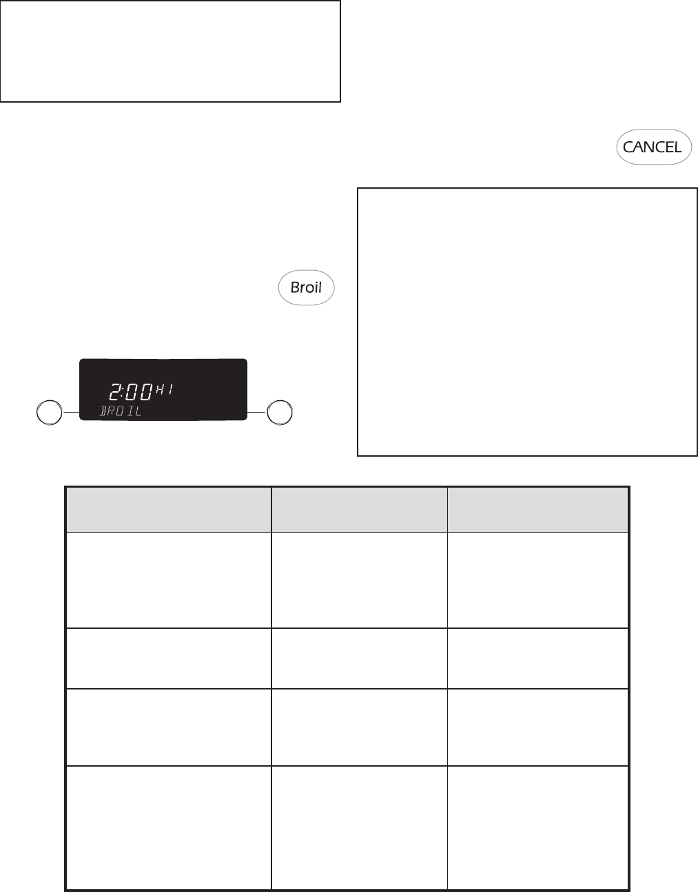
B – 10 16026923 © 2006 Maytag Services
Use & Care
Broil
For optimal results, preheat for five minutes with the door
closed and use a pan designed for broiling. Oven door should
be open to the broil stop position (about 4 inches) when
broiling.
To set Broil:
1. Place the oven rack in the proper rack position (see
Broiling Chart).
2. Press the Broil pad.
3. Select HIGH – 550° F for high broil.
OR
Select LOW – 450° F for low broil.
• The oven has a variable broil feature which means that
a lower broil temperature can be selected (300°-550° F).
To select a lower temperature, press the appropriate
number pads. Press Enter pad to set the lower
temperature.
4. Preheat the oven for five minutes.
5. Place food in the oven and close the door to the broil stop
position.
6. Press the CANCEL pad when broiling
is done.
Notes:
• See Broiling Chart for foods and broiling times.
• If more than 30 seconds elapse between pressing the Broil
pad, Quickset pads, or number pads, the oven will not be
set and the display will return to the previous display.
• HIGH is used for most broiling. Use a lower broil
temperature when broiling longer-cooking foods. The
lower temperature allows food to cook to the well done
stage without excessive browning.
• Expect broil times to increase and browning to be slightly
lighter if the appliance is installed on a 208 volt circuit.
• Food should be turned halfway through broiling time.
• Broil times may be longer when lower broiling
temperatures are selected.
Notes:
• For best results, use rack position 2 or 3 when using the
Rapid Preheat option.
• For optimum baking and browning results, Rapid Preheat
is not recommended when baking on multiple racks.
SUGGESTED RACK
FOODS BROIL TIME POSITION*
Beef (broiled to 165° F)
6 Hamburgers, 1/2” thick 10 – 12 minutes 4
2 Ribeye Steaks, 1” thick 18 - 22 minutes 4
2 New York Strip Steaks, 1” thick 18 - 22 minutes 4
2 T-Bone Steaks, 1” thick 18 - 22 minutes 4
Poultry (broiled to 170° F on Low) Low Broil
4 Boneless/Skinless Breasts 12 – 15 minutes 4
4 Bone-In Chicken Breasts 20 – 33 minutes 3
Pork (broiled to 160° F)
4 Boneless Pork Chops, 1” thick 20 - 28 minutes 4
4 Bone-In Pork Chops, 1” thick 25 - 28 minutes 4
Ham Slice, 1” thick 12 - 16 minutes 4
Fish (broiled to 140° F)
4 Swordfish Steaks, 1” thick 10 - 14 minutes 3
2 Halibut Steaks, 1” thick 10 - 14 minutes 3
Orange Roughy, 1 ” thick 10 - 12 minutes 4
Shrimp (16-20 ct. per lb.) 8 - 10 minutes 4
2 Salmon Fillets, 1/2” thick 8 - 12 minutes 4
2 Salmon Steaks, 1” thick 10 - 14 minutes 3
*Important: To reduce browning and excess smoke when broiling, use a lower rack position and increase
the broil time.
Broiling Chart
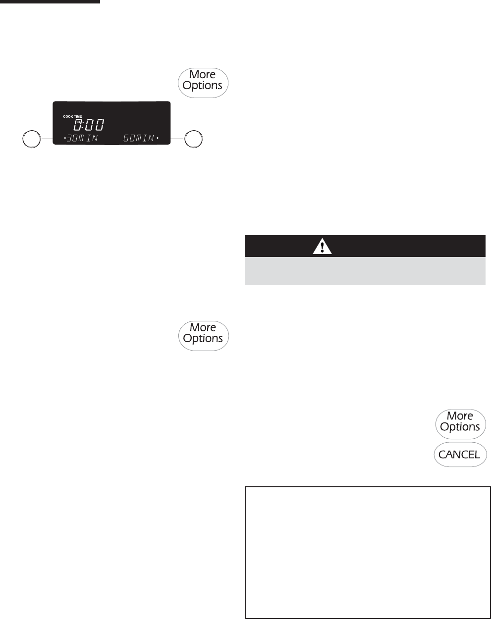
© 2006 Maytag Services 16026923 B – 11
Use & Care
OPTIONS
More Options
Cook & Hold
1. Press the More Options pad.
2. Select COOK/HOLD.
5. The display will show CONVECT DELAY, the selected function,
the preset temperature and the delay time countdown. When
the delay time has expired, the cook time will be displayed and
the oven will begin to preheat.
To set Delay Clean:
1. Follow “Delay” steps 1-4 (see below left).
2. REMOVE RACKS will show in the display. Remove the racks
from the oven and select CONTINUE.
3. Set LIGHT soil level by entering 200 using the number pads
for two hours of cleaning time. Select MEDIUM or HEAVY
soil level using the Quickset pads. There is a brief delay while
the door locks.
4. DELAY CLEAN, the cleaning time, the delay time and unlock
time (based on the selected soil level) will show in the display.
When the delay time has expired, the clean time will be
displayed and the oven will begin to preheat.
For more information on self-cleaning, see pages 5-6.
3. Enter cook time using Quickset pads or the number pads.
4. Select BAKE or CONVECT.
5. When BAKE is pressed, select the temperature using
Quickset pads or the number pads.
6. When CONVECT is pressed, select CNVT BAKE or CNVT
ROAST then select the desired temperature using the
Quickset pads or the number pads.
The oven will cook for the selected time, then Keep Warm for
one hour. The oven will automatically turn off.
Important: If the recipe recommends preheating the oven,
add 15 minutes to the cook time.
Delay
1. Press the More Options pad.
2. Press the arrow until DELAY is displayed.
3. Select DELAY.
4. Select Delay time using Quickset pads or the number
pads.
5. Select BAKE, CONVECT or CLEAN, then select
temperature using the Quickset or number pads.
To set Delay Bake:
1. Follow “Delay” steps 1-4 (see above).
2. Select from the displayed temperatures or use the
number pads to enter the temperature.
3. Select the time to cook from the displayed times or use
the number pads to enter the cooking time.
4. The display will show DELAY TIME, the selected function,
the preset temperature and the delay time countdown.
When the delay time has expired, the cook time will be
displayed and the oven will begin to preheat.
To set Delay Convect:
1. Follow “Delay” steps 1-4 (see above).
2. Select BAKE or ROAST.
3. Select from the displayed temperatures or use the
number pads to enter the temperature.
4. Select the time to cook from the displayed times or use
the number pads to enter the cooking time.
Notes:
• For any dough that requires one rise, either Standard or
Rapid Proofing can be used.
• When using frozen bread dough, choose RAPID PROOFING.
There is no need to thaw dough before proofing.
• For dough requiring two rises, Standard Proofing must be
used for the first rising period. Either Standard or Rapid
Proofing can be used for the second rise.
• If oven temperature is too high for proofing, OVEN COOLING
will appear in the display.
Proofing
The Proofing feature can be used to raise yeast-based bread
products prior to baking. There are two proofing methods
available – Rapid and Standard.
Standard proofing in the oven protects dough from room
temperature changes or drafts that commonly affect proofing
done on the countertop.
Rapid proofing provides faster proofing results than countertop
or Standard proofing, without harming the yeast.
1. Press More Options pad.
2. Select PROOFING.
3. Select RAPID or STANDARD.
4. When proofing is complete, remove the
dough from the oven and press the CANCEL pad.
CAUTION
Do not use delayed baking for highly perishable foods such
as dairy products, pork, poultry, or seafood.
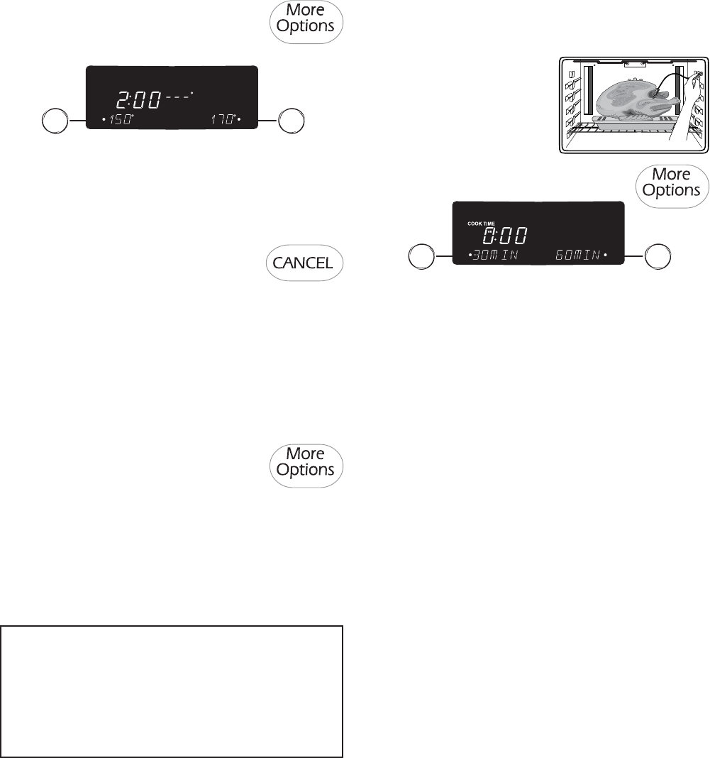
B – 12 16026923 © 2006 Maytag Services
Use & Care
Notes:
• Food should be hot when placed in oven.
• For optimal food quality, foods should be kept warm for
no longer than 1 hour.
• To keep foods from drying, cover loosely with foil or a
glass lid.
4. Select one of the displayed temperatures or enter desired
temperature using the number pads. Temperatures can be
selected between 145° and 190° F.
5. KEEP WARM and the temperature will be displayed.
6. When oven has preheated, a beep sounds and KEEP
WARM and the temperature will be displayed.
7. When finished, press the CANCEL pad and
remove food or plates from the oven.
To Warm Dinner Rolls:
• Cover rolls loosely with foil and place in oven.
• Press More Options pad.
• Select KEEP WARM.
• Select 170° temperature. Warm for 12-15 minutes.
To Warm Plates:
• Place two stacks of up to four plates each in the oven.
• Press More Options pad.
• Select KEEP WARM.
• Select 170° temperature.
• Warm for five minutes. Turn off the oven by pressing the
CANCEL pad and leave plates in the oven for 15 minutes
more.
• Use only oven-safe plates, check with the manufacturer.
•Do not set warm dishes on a cold surface as rapid
temperature changes could cause crazing or breakage.
6. Set the internal food temperature desired by selecting
one of the displayed temperatures or enter the
temperature using the number pads. The probe
temperature can be set from 100° - 185° F. If the meat
probe is not inserted, INSERT PROBE will be displayed.
7. Select BAKE or CONVECT.
8. Set the oven temperature by selecting one of the
displayed temperatures or enter the temperature using
the number pads.
Meat Probe
Using the probe supplied with your oven assures excellent
roasting results every time.
1. Insert the probe into the food item. For meats, the probe
tip should be located in the center of the thickest part of
the meat and not into the fat or touching a bone.
2. Insert the probe plug into the
receptacle located on the top
right of the oven. Be sure to
insert plug into the receptacle
all the way.
3. Press More Options pad.
4. Press the arrow to scroll.
5. Select MEAT PROBE.
Important: If the probe is removed from the oven
receptacle at any time during the cooking process, the
control will prompt INSERT PROBE. If the probe is not
reinserted within 30 seconds, the program will be canceled
and the oven will turn off.
When BAKE is selected:
• The display will briefly show the selected temperatures
for the oven and probe.
• After 10 seconds, the display will show the actual oven
temperature and actual probe temperature.
When CONVECT is selected:
• Select CNVT BAKE or CNVT ROAST.
• Set the oven temperature by selecting one of the
displayed temperatures or enter the temperature using
the number pads.
• The display will briefly show the selected temperatures
for the oven and probe.
• After 10 seconds, the display will show the actual oven
temperature and actual probe temperature.
Keep Warm
The Keep Warm feature is used to safely keep hot foods warm
or for warming breads and plates.
1. Press More Options pad.
2. Press the arrow to scroll.
3. Select KEEP WARM.
Cont.
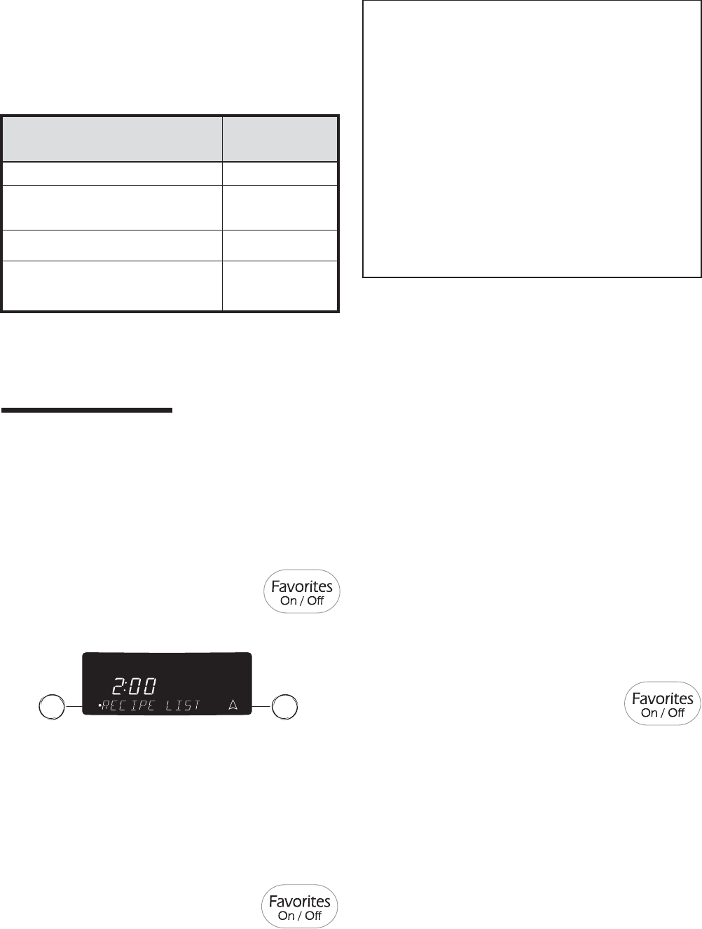
© 2006 Maytag Services 16026923 B – 13
Use & Care
9. When the selected internal temperature of the food has
been reached, the oven will shut off and a beep will sound.
10. Remove the probe from the oven receptacle. The probe
will be hot. Hold probe plug with an oven mitt or
potholder when removing from the oven.
Notes:
• The probe must be removed from the oven when it is not
being used.
• Because of the excellent insulation of the oven, the
retained heat continues to cook the food after the beep
has sounded and the oven has turned off. For this
reason, it is important to remove the food from the oven
as soon as the beep sounds.
• Use the handle of the probe for inserting or removing.
Do not pull on the cable.
•The probe is hot after cooking – use a potholder or
oven mitt to remove.
• To clean cooled probe, wipe with a soapy dishcloth.
Do not submerge probe in water or wash in
dishwasher.
INTERNAL
FOOD TEMPERATURE
Ground Beef 165° F
Fresh Beef, Veal, Lamb Medium Rare 145° F
Medium 160° F
Well Done 170° F
Chicken, Turkey Whole 180° F
Breast 170° F
Pork Medium 160° F
Well Done 170° F
Ham, Precooked 140° F
Suggested Internal Food Temperatures
FAVORITES
Favorites
Favorites stores the oven mode, cook time and temperature
for up to 10 of your favorite recipes. Convection ovens come
with five preprogrammed recipes.
To select a recipe from the preset Recipe List:
1. Press Favorites pad.
2. Select RECIPE LIST.
3. Select desired recipe on screen or press
arrow key to scroll to the desired recipe.
4. Once the recipe is selected, oven will begin preheating to
the set program.
• You may press the More Options pad to add
COOK/HOLD or DELAY.
5. When finished, press the CANCEL pad and remove food
from the oven.
To Save the Last Recipe Completed:
(Bake, Convect Bake, Convect Roast, Broil, Keep Warm)
1. Press Favorites pad.
2. Select SAVE LAST.
3. Enter the name using the keypads.
• For example, to save lasagna, press the <JKL> pad
three times for “L”; Press the <ABC> pad once for “A”;
press the <STU> pad once for “S”. Continue until you’ve
finished the word.
4. After each desired letter appears, wait three seconds or
press Enter pad before moving on the next letter.
• Up to 14 letters including spaces can be used.
5. When the recipe name has been entered, the last settings
will be displayed for a few seconds.
6. RECIPE LIST will then be displayed to scroll through the
list.
7. Press Favorites pad to exit the Favorites menu.
To Create a New Favorite Recipe:
1. Press Favorites pad.
2. Press arrow key to scroll through selections.
3. Select CREATE NEW with touchpad on left.
4. Enter the name using the keypads.
• For example, to save lasagna, press the <JKL> pad three
times for “L”; Press the <ABC> pad once for “A”; press
the <STU> pad once for “S”. Continue until you’ve
finished the word.
• After each desired letter wait three seconds until an
underline appears in the next space or press
Enter pad before moving on the next letter.
• Up to 14 letters including spaces can be used.
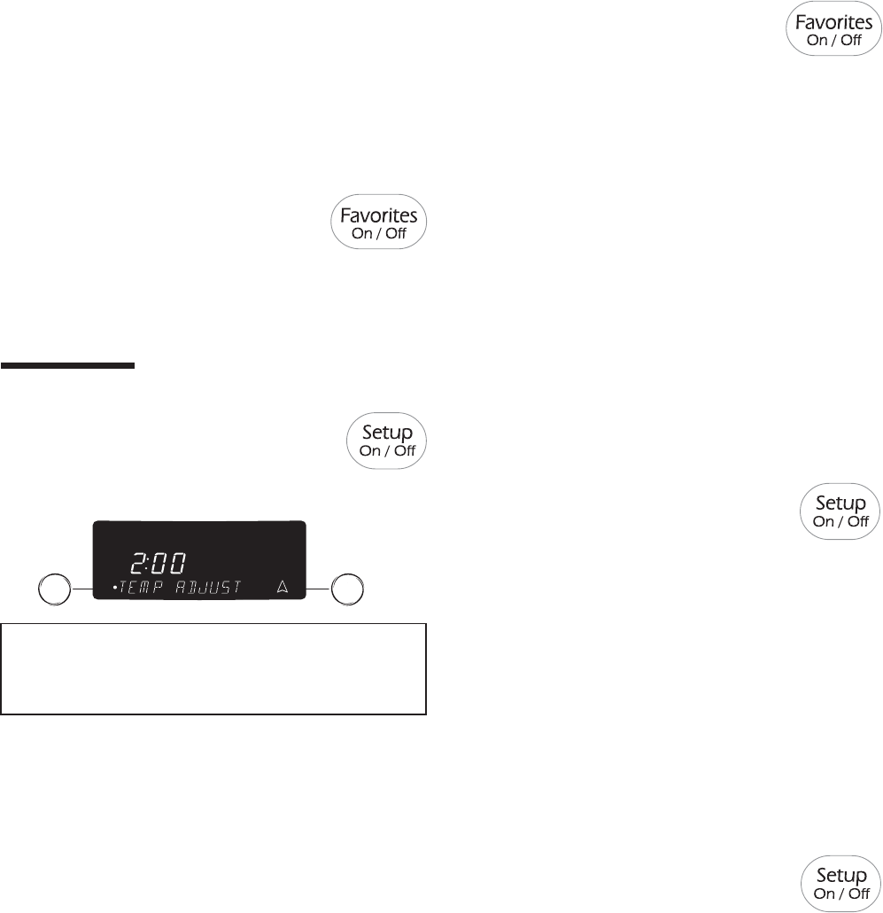
B – 14 16026923 © 2006 Maytag Services
Use & Care
To Edit a Saved Recipe:
1. Press Favorites pad.
5. Select ENTER to save name.
6. Select cooking mode, such as BAKE, CONVECT BAKE,
CONVECT ROAST, etc.
7. Select the oven temperature using the Quickset pads.
OR
Enter the desired temperature using the number pads.
8. Add Cook/Hold by selecting YES or omit Cook/Hold by
selecting NO.
9. If you selected YES, enter cook time using the Quickset
pads or the number pads.
10. Add Delay by selecting YES or omit Delay by selecting
NO.
11. If you selected YES, enter the delay time by using the
Quickset pads or the number pads.
12. The control will display programmed settings then return
to the Favorites menu.
13. Press Favorites pad to exit the Favorites menu.
SETUP
Setup
1. Press the Setup pad.
2. Use the arrow to scroll through the Setup options.
3. Select the desired option by pressing the Quickset pads.
Note: To back out of a screen without making any
changes, press the Setup pad. The display will return to
the time of day.
Clock
See pages 15-16 for more details. Use the Clock option to:
• Set the time of day.
• Set day of week.
• Select AM or PM (12-hour mode only). AM or PM will not
show with the time of day in the display.
• Choose a 12 or 24 hour clock display.
• Disable the clock display.
Language
The language of the screens in the display window can be
set to English, French or Spanish. To change the display
language from English:
1. Press Setup pad.
2. Select LANGUAGE.
3. Use the arrow to scroll to next screen, if needed.
4. Select the desired language.
5. Press Setup pad to exit the Setup menu.
2. Press arrow key to scroll.
3. Select EDIT RECIPE.
4. Select desired recipe to edit. You may need to press arrow
key to find desired recipe.
5. Follow menu to revise recipe settings as desired.
6. The display will return to the Favorites menu. RECIPE LIST
will be displayed.
7. Press Favorites pad to exit Favorites menu.
To Delete a Favorite Recipe:
1. Press Favorites pad.
2. Press arrow key to scroll.
3. Select DELETE RECIPE.
4. Find recipe to be deleted. You may need to press arrow
key to find desired recipe.
5. The Control will ask again to make sure you want to delete
that recipe. Select YES or NO.
6. Press Favorites pad to exit Favorites menu.
To exit out of Favorites at any time, press the Favorites pad.
Cont.
Auto Convect Conversion
The oven comes from the factory set for Auto Convect
Conversion.
Auto Convect Conversion automatically reduces the set
temperature by 25° for Convect Bake.
For Convect Roast the control will alert you at 75% of the
programmed roasting time to check foods for doneness.
Convect roast temperatures are not reduced.
To deactivate Auto Convect Conversion:
1. Press Setup pad.
2. Select AUTO CONVECT.
3. Select OFF.
4. Press Setup pad to exit the Setup menu.

© 2006 Maytag Services 16026923 B – 15
Use & Care
Notes:
• When using Convect Bake and Convect Pastry with the
Auto Convect Conversion option turned off, reduce the
set temperature by 25° F.
• If Convect Roasting with the Auto Convect Conversion
option turned off, you will not be required to program a
cooking time. Check food at 75% of the conventional
time.
To reactivate Auto Convect Conversion:
1. Press Setup pad.
2. Select AUTO CONVECT.
3. Select ON.
4. Press Setup pad to exit the Setup menu.
Sabbath Mode
The oven is set to shut off after 12 hours if you accidentally
leave it on. The Sabbath Mode overrides the 12-hour shut-off
and can either be set to come on automatically or can be set
manually as desired.
Only Bake or Cook/Hold Bake will operate when the oven is in
Sabbath Mode. All other functions are invalid. If a function other
than Bake or Cook/Hold Bake is in operation when Sabbath
Mode starts, the function will be canceled.
To activate Sabbath Mode:
1. Press Setup pad.
2. Press the arrow to scroll.
3. Select SABBATH.
4. Select AUTO or MANUAL.
• AUTO will automatically prompt you to enter a Bake
temperature on Friday at 2 pm and stay in Sabbath
mode for 33 hours. SABBATH and SABBATH ENABLE
appear in the display for 90 minutes. If Bake or Cook/
Hold Bake are desired during Sabbath Mode, they must
be programmed during this 90 minute time before AUTO
Sabbath Mode is active.
• MANUAL sets the oven to Sabbath Mode for 72 hours.
SABBATH and SABBATH ENABLE appear in the display
for five minutes. If Bake or Cook/Hold Bake are desired
during Sabbath Mode, they must be programmed during
this five minute time before the MANUAL Sabbath Mode
is active.
5. Select ON or OFF.
6. Press Setup pad to exit the Setup menu.
To cancel Sabbath Mode:
Press and hold the Setup pad for five seconds.
The Bake mode may be cancelled by pressing
the CANCEL pad during Sabbath.
Temp Adjust
Oven temperatures are carefully tested at the factory. It is
normal to notice some baking time or browning differences
between a new oven and an old one. As ovens get older, the
oven temperature can shift.
You may adjust the oven temperature if you think the oven is
not baking or browning correctly. To decide how much to
change the temperature, set the oven temperature 25° F higher
or lower than the temperature in your recipes, then bake. The
results of the first bake should give you an idea of how much to
adjust the temperature.
To adjust the oven temperature:
1. Press Setup pad.
2. Press the arrow to scroll.
3. Select TEMP ADJUST.
4. Enter the desired temperature change using the number
pads.
5. Select “+/-” to indicate an increase or decrease in
temperature. The temperature change is displayed at the
top of the window.
6. Press Enter pad or wait three seconds to accept the change.
7. Press Setup pad to exit the menu.
The oven temperature does not need to be readjusted if there is
a power failure or interruption.
Broiling and cleaning temperatures cannot be adjusted.
C/F
The displayed temperature scale can be changed from
Fahrenheit to Celsius.
To change the scale:
1. Press Setup pad.
2. Use the arrow to scroll to the next screen.
3. Select C/F.
4. Select the desired temperature scale.
5. Press Setup pad to exit the Setup menu.
Notes:
• The oven must be idle to program Sabbath Mode.
• Sabbath Mode cannot be turned on if the keypads are
locked out or when the door is locked.
• If the oven is baking when Auto Sabbath Mode starts,
there will be no audible beeps.
• All prompts, messages and beeps are deactivated when
the Sabbath Mode is active.
• If the oven light is desired while in Sabbath Mode, it
must be turned on before the Sabbath Mode is set.
• The self-clean cycle and automatic door lock do not
operate during the Sabbath Mode.
• The Bake temperature can be changed during an Active
Sabbath Mode. Simply press the Bake pad and then
enter the desired temperature using the Quick set pads.
• Pressing the CANCEL pad will cancel a Bake cycle,
however the control will stay in the Sabbath Mode.
• The day of the week and AM/PM must be set for
Sabbath Mode to operate correctly.
B – 16 16026923 © 2006 Maytag Services
Use & Care
Tones (beeps)
The number of beeps heard at the end of cooking and at the
end of timer operation and their volume can be adjusted.
To adjust the beeps:
1. Press Setup pad.
2. Use the arrow to scroll.
3. Select TONES.
To change the beeps at the end of cooking:
1. Follow “Tones” steps 1-3 (see above).
2. Select COOK TONE.
3. Use the arrow to scroll.
4. Select 1-30 MIN to hear one beep every thirty seconds.
OR
Select 1-60 MIN to hear one beep every sixty seconds.
OR
Select 1 BEEP to hear one beep only at the end of cooking.
5. Press the Setup pad to exit.
To change the timer beeps:
1. Follow “Tones” steps 1-3 (see above).
2. Select TIMERS TONES.
3. Use the arrow to scroll.
4. Select 2-30 SEC to hear two beeps every thirty seconds.
OR
Select 2-60 SEC to hear two beeps every sixty seconds.
OR
Select 1 BEEP to hear one beep only at the end of the
set time.
5. Press the Setup pad to exit.
To change the volume of the beeps:
1. Follow “Tones” steps 1-3 (see above).
2. Press the arrow to scroll.
3. Select VOLUME.
4. Select HIGH for the highest volume.
OR
Select MEDIUM for medium volume.
OR
Select LOW for the lowest volume.
5. Press the Setup pad to exit.
12 HR Shutoff
The oven will automatically turn off at the end of 12 hours if
you accidentally leave it on.
To turn off this feature:
1. Press Setup pad.
2. Use the arrow to scroll.
3. Select 12HR SHUTOFF.
3. Select ON or OFF using the Quickset pads.
4. Press the Setup pad to exit.
Energy Saver
To save energy, the display can be set to go dark if it is not
being used.
To set the Energy Saver feature:
1. Press Setup pad.
2. Use the arrow to scroll.
3. Select ENERGY SAVER.
4. Select ON or OFF using the Quickset pads.
5. Press the Setup pad to exit.
Press any pad to “wake up” the display.
Service
This area of the oven control displays the Jenn-Air Customer
Service toll-free phone number.
1. Press Setup pad.
2. Use the arrow to scroll.
3. Select SERVICE.
4. Press the Setup pad to exit.
Demo
When Demo is selected, you will see a short presentation
highlighting the features of your new Jenn-Air range.
1. Press Setup pad.
2. Use the arrow to scroll.
3. Select DEMO.
4. Select ON or OFF using the Quickset pads.
5. Press the Setup pad to exit.
© 2006 Maytag Services 16026923 C – 1
Appendix C
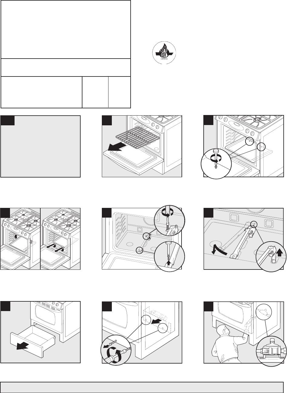
C – 2 16026923 © 2006 Maytag Services
Gas Conversion Instructions, JGS8750BD*
1
Turn off gas and electrical
supply to product.
Fermez le gaz et coupez
l'électricité alimentant l'appareil.
Cierre el suministro de gas y desconecte
el suministro eléctrico al producto.
2
3
Remove oven rack./Retirez la grille du four./Retire la
parrilla del horno.
Remove oven bottom screws./Retirez les vis de la sole
du four./Retire los tornillos inferiores del horno.
4
5
1
6
2
Lift up and remove oven bottom./Soulevez la sole du
four et retirez-la./Levante y retire el fondo del horno.
Remove bake burner screws./Retirez les vis du
brûleur de cuisson au four./Retire los tornillos del
quemador de horneado.
Swing bake burner to the side and lift bake burner off
the oven orifice./Pivotez le brûleur de cuisson sur le
côté et soulevez-le pour le séparer de son gicleur./Gire
el quemador del horno a un lado y levántelo para
sacarlo del orificio.
7
8
1
2
9
2
Remove storage drawer./Retirez le tiroir de
rangement./Retire el cajón de almacenamiento.
Remove screws from panel and then remove
panel./Retirez les vis du panneau puis le panneau lui-
même./Retire los tornillos del panel y retire el panel.
Locate regulator from the front./Repérez le détendeur à
l'avant./Ubique el regulador desde la parte delantera.
Part No. 8101P684-60
LP Propane
Conversion
Instructions
Instructions de conversion au GPL/
Instrucciones de conversión a gas LP propano
• Only qualified personnel should convert this range./Seul un personnel qualifié doit procéder à la
conversion de cette cuisinière./La estufa sólo debe ser convertida por personal calificado. • Retain natural
orifices for future conversion./Conservez les gicleurs pour gaz naturel pour une conversion ultérieure./
Guarde los orificios de gas natural para una conversión futura. • Reverse this procedure for LP to natural
conversion./Procédez inversement pour la conversion du GPL au gaz naturel./Invierta este procedimiento
para convertir el producto de gas LP a gas natural.
This range is equipped with fixed orifices on all burners and a convertible appliance regulator. The unit serial plate
states which gas it was adjusted for at the factory. To convert the unit to either Natural gas or LP gas will require
replacement of the oven orifice hoods, and the top burner orifice hoods, and adjustment of the oven burner shutters
and the appliance pressure regulator converter cap.
Cette cuisinière est équipée de gicleurs fixes sur tous les brûleurs et d'un détendeur convertible. La plaque
signalétique de cet appareil indique le réglage fait à l’usine pour un certain gaz. La conversion de l'appareil au
gaz naturel ou au GPL nécessite le remplacement des têtes de gicleur du four et des têtes de gicleur du brûleur
supérieur, ainsi que le réglage des obturateurs de brûleur du four et du capuchon du convertisseur du détendeur.
Esta estufa viene equipada con orificios fijos en todos los quemadores y con un regulador convertible para
electrodomésticos. La placa de serie de la unidad indica para qué tipo de gas se calibró en la fábrica. Para
convertir la unidad a gas natural o a gas LP es necesario reemplazar las caperuzas de los orificios del horno y los
orificios de los quemadores superiores, además de ajustar los obturadores del quemador del horno y la tapa del
convertidor del regulador de presión del electrodoméstico.
Inlet pressure to the appliance pressure regulator should be as follows for both operation and checking of
appliance pressure regulator setting:/La pression d'arrivée au détendeur de l'appareil doit être la suivante pour
le fonctionnement et la vérification du réglage du détendeur :/La presión de entrada al regulador de presión debe
ser la siguiente tanto para el funcionamiento normal como para verificar el ajuste del regulador de presión:
Inlet Pressure in inches of water column Natural Gas LP Gas
Pression d'arrivée en pouces à la colonne d'eau Gaz naturel GPL
Presión de entrada en pulgadas c.d.a. Gas natural Gas LP
Max/Max./Máx. 14 (36 cm) 14 (36 cm)
Min/Min./Mín. 6 (16 cm) 11 (28 cm)
Printed in USA ©2005 Maytag Corporation
Note: Your range may not be equipped with some of the features referred to in this manual./Remarque: Votre cuisinière peut ne pas comporter certaines des caractéristiques mentionnées dans
ce manuel./Nota: Es posible que esta estufa no venga equipada con todas las características que se indican en este manual.
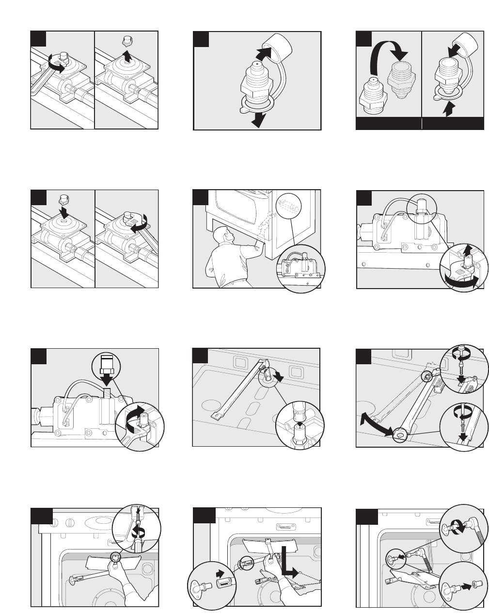
© 2006 Maytag Services 16026923 C – 3
Gas Conversion Instructions, JGS8750BD*
10
11
12
NATURAL/NATUREL/GAS NATURAL PROPANE/PROPANE/PROPANO
Unscrew the regulator cap./Dévissez le capuchon du
détendeur./Desenrosque la tapa del regulador.
Remove the plastic cap./Retirez le capuchon en
plastique./Retire la tapa de plástico.
13
14
2
15
2
1
49
Screw the cap securely back into place. DO NOT OVER
TIGHTEN./ Revissez bien le chapeau. NE LE SERREZ
PAS TROP FORT./ Enrosque la tapa firmemente en su
lugar. NO APRIETE DEMASIADO.
Locate oven orifice hood from the front./Identifiez la tête
de gicleur du four par l'avant./Ubique la caperuza del
orificio del quemador del horno desde la parte delantera.
Remove #49 natural oven orifice hood./Retirez la tête
de gicleur du four n° 49 pour gaz naturel./Retire la
caperuza del orificio de gas natural #49 del horno.
.
0512
16
Black/
Noir/
Negro
.0512
17
18
Install black .0512 LP orifice hood. (4-5 turns-DO NOT
OVERTIGHTEN)/Installez la tête de gicleur noire .0512
pour GPL. (4-5 tours – NE SERREZ PAS TROP
FORT)/Instale la caperuza negra de 0,0512 para gas LP
del orificio del quemador. (4 a 5 vueltas – NO APRIETE
DEMASIADO)
Position bake burner over bake orifice
hood./Positionnez le brûleur de cuisson au-dessus de
la tête de gicleur./Coloque el quemador del horno sobre
la caperuza del orificio del quemador del horno.
Reposition bake burner and replace/tighten bake
burner screws./Repositionnez le brûleur de cuisson et
remettez puis resserrez les vis du brûleur de
cuisson./Cambie de posición el quemador del horno y
vuelva a instalar/apretar los tornillos del quemador del
horno.
19
20
1
21
3
2
.52
Remove broil burner screw./Enlevez la vis du brûleur
de gril./Retire el tornillo del quemador de asar. Remove #52 natural broil orifice hood./Retirez la tête
du gicleur de gril n° 52 pour gaz naturel./Retire la
caperuza del orificio de gas natural #52 del quemador
de asar.
Flip the regulator cap and replace the plastic
cap./Abattez le capuchon du détendeur et installez le
capuchon en plastique./Invierta la tapa del regulador y
vuelva a colocar la tapa de plástico.
*CAUTION: Ignitor and wires are fragile./ATTENTION: Allunmeur et fils fragiles./ATENCIÒN: El encendedor y el cableado son fràgiles.
You MUST start all hoods by hand to avoid cross threading./Vous DEVEZ commencer le vissage de toutes les têtes de gicleur à la
main pour éviter de fausser le filetage./UstedDEBE iniciar el enroscado de las tapas a mano para evitar dañar las roscqas
Slip the broil burner off the broil orifice hood./Sortez le
brûleur de gril de la tête du gicleur de gril./Deslice el
quemador de asar para sacarlo de la caperuza del
orificio.
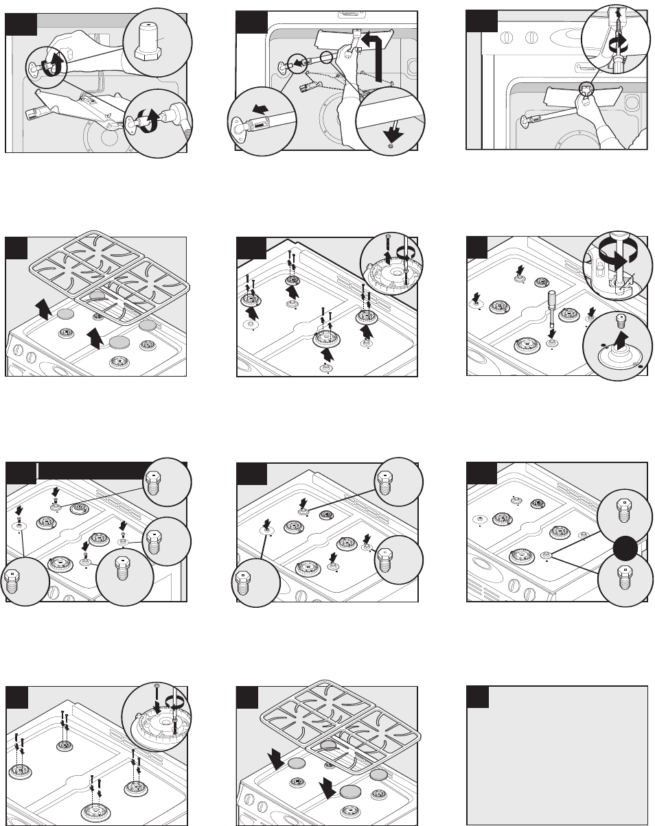
C – 4 16026923 © 2006 Maytag Services
Gas Conversion Instructions, JGS8750BD*
22
1
2
Green/
Vert/
Verde
.0430
.0430
Install green .0430 LP broil orifice hood.
(4-5 turns-DO NOT OVERTIGHTEN)/Installez la tête du
gicleur de gril, verte .0430 pour GPL. (4 à 5 tours – NE
SERREZ PAS TROP)/Instale la caperuza verde de 0,0430
para gas LP del orificio del quemador de asar.
(4 a 5 vueltas – NO APRIETE DEMASIADO)
25
27
3
2
(7mm)
9/32”
1
27A
NATURAL/NATUREL/GAS NATURAL
Green/
Vert/
Verde
1.07mm
1.42mm
1.95mm
1.61mm
1.42mm
Remove the top grates. Remove the burner
caps./Retirez les grilles supérieures. Retirez les
chapeaux de brûleur./Retire las rejillas superiores.
Retire las tapas de los quemadores.
IMPORTANT: Keep old natural gas orifice
hoods./IMPORTANT: Conservez les anciennes têtes de
gicleur pour gaz naturel./IMPORTANTE: Conserve las
caperuzas usadas de los orificios de gas natural.
28
A
1.14mm
.97mm
or/
ou/o
Replace with LP gas orifice hood. (1.95 black–replace with
1.14 red or 1.61 no color–replace with .97 green.)
DO NOT OVERTIGHTEN./Remplacez par une tête de gicleur
pour GPL. (Noir 1.95 : remplacez par rouge 1.14. Sans couleur
1.61 : remplacez par vert .97.) NE SERREZ PAS
TROP./Reemplácela con una caperuza de orificios de gas LP.
(1,95 negro–reemplace con 1,14 rojo, o 1,61 sin
color–reemplace con 0,97 verde.) NO APRIETE DEMASIADO.
28
Blue/
Bleu/
Azul
.64mm
.91mm
.91mm
29
Replace with LP gas orifice hoods. DO NOT
OVERTIGHTEN./Remplacez-les avec des têtes de gicleur
pour GPL. NE SERREZ PAS TROP./Reemplácelas con
caperuzas de orificios de gas LP. NO
APRIETE DEMASIADO.
Remount burner heads and replace screws.
(Hand tighten)./Réinstallez les têtes de brûleur et
remettez les vis. (Serrez-les à la main.)/Vuelva a
instalar las cabezas de los quemadores y vuelva a
colocar los tornillos. (Apriete a mano).
Carefully remove gas orifice hoods and convert one
burner at a time./Enlevez soigneusement les têtes de
gicleur pour gaz naturel et convertissez un brûleur à la
fois./Retire cuidadosamente las caperuzas de los
orificios de gas y convierta un quemador a la vez.
1
23
2
1
Place the broil burner on the broil orifice hood.
CAUTION: Carefully insert burner pin in oven back./
Mettez le brûleur de gril sur la tête du gicleur de gril.
ATTENTION : Insérez soigneusement le tenon du brûleur dans
le four./Coloque el quemador de asar en la caperuza del
orificio.PRECAUCIÓN: Inserte cuidadosamente el pasador en la
parte trasera del horno.
26
Remove screws and burner head./Retirez les vis et la
tête de brûleur./Retire los tornillos y la cabeza del
quemador.
31
Turn on gas and electrical
supply to product.
Ouvrez le gaz et l'électricité
alimentant l'appareil.
Abra el suministro de gas y conecte
el suministro eléctrico al producto.
30
Replace burner caps. Replace grates./Remettez les
chapeaux de brûleur. Remettez les grilles./Vuelva a
instalar las tapas de los quemadores. Vuelva a instalar
las rejillas.
24
Reposition the broiler burner and tighten screw. Re-assemble
oven. (See steps 2-4)/Remettez en place le brûleur de gril et
serrez la vis. Remontez le four. (Voyez les étapes 2-4)/Vuelva a
colocar ei quemador de asar en su lugar y apriete el tornillo.
Vuelva a ensamblar el horno. (Vea los pasos 2 al 4.)
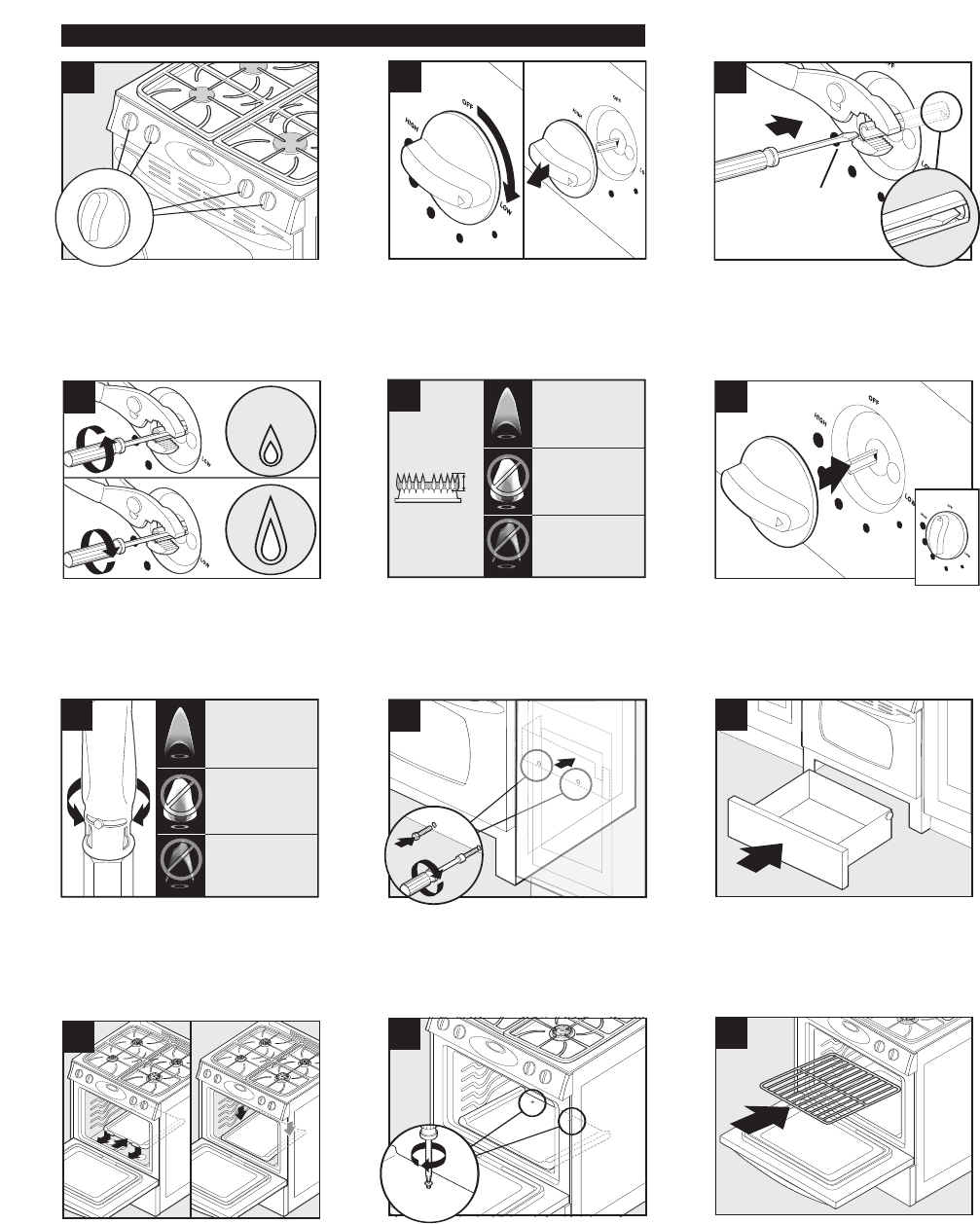
© 2006 Maytag Services 16026923 C – 5
Gas Conversion Instructions, JGS8750BD*
32
33
NOTE: Repeat steps 33-37 for all burners.
RMARQUE: Répétez les étapes 33 à 37 pour tous les
brûleurs.
NOTA: Repita los pasos 33 al 37 para todos
los quemadores.
Adjust each surface burner one at a time. Light burner
and turn to lowest setting. Remove knob./Ajustez
chaque brûleur de surface un par un. Allumez le
brûleur et réglez-le au niveau le plus bas. Enlevez le
bouton./Ajuste los quemadores superiores uno a la vez.
Encienda el quemador y ajústelo al nivel más bajo.
Retire la perilla.
1/8" Flat head
Screwdriver/
Tournevis à lame
plate de 1/8 po/
Destornillador de
1/8” de cabeza plana
34
35
1/4"
CORRECT
BON
CORRECTO
YELLOW
JAUNE
AMARILLA
BLUE LIFTING
FLAMME BLEUE SE SOULEVANT
AZUL QUE SE SEPARA DEL QUEMADOR
36
Hold knob stem in LOW position. Insert screwdriver to
engage screw./Tenez la tige du bouton en position
LOW. Introduisez le tournevis pour tourner la
vis./Mantenga la varilla de la perilla en el ajuste ‘LOW’
(Bajo). Inserte el destornillador en el tornillo.
Adjust flame height with screwdriver./Ajustez la
hauteur de la flamme avec le tournevis./Ajuste la altura
de la llama con el destornillador.
Correct flame height and appearance./Flamme de
hauteur et d'aspect apporopriés./Altura y apariencia
correctas de la llama.
1
2
2
41
Replace oven bottom./
Remettez le panneau inférieur du four./
Vuelva a instalar el panel inferior del horno.
Replace oven bottom screws./Remettez les vis de la
sole du four./Vuelva a instalar los tornillos inferiores
del horno.
37
Replace knobs. Turn OFF burners./Remettez les
boutons. Mettez les brûleurs sur OFF (ARRÊT)./Vuelva a
instalar las perillas. APAGUE los quemadores.
CORRECT
BON
CORRECTO
YELLOW
(Open shutter to correct)
JAUNE
Ouvrez l'obturateur pour rectifier
AMARILLA
Abra el obturador para corregir
la situación.
BLUE LIFTING
(Close shutter to correct)
FLAMME BLEUE SE SOULEVANT
Fermez l'obturateur pour rectifier
AZUL QUE SE SEPARA DEL QUEMADOR
Cierre el obturador para corregir
la situación.
38
39
1
2
If necessary, adjust both oven burner shutters for
correct flames. Secure shutter opening with screw./Au
besoin, ajustez les deux obturateurs du brûleur du four
pour obtenir les flammes appropriées. Fixez
l'obturateur avec la vis./De ser necesario, ajuste ambos
obturadores del quemador del horno para obtener la
llama correcta. Fije la abertura del obturador con el
tornillo.
40
42
Low Flow Adjustment/Réglage bas débit/Ajuste del flujo minimo
Replace storage drawer./Remettez le tiroir de
rangement./Vuelva a instalar el cajón de
almacenamiento.
Replace panel and screws./Remettez le panneau et les
vis./Vuelva a instalar el panel y los tornillos.
Replace oven rack./Remettre la grille de four./Vuelva a
instalar la rejilla del horno.
43
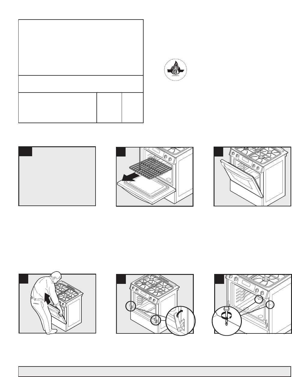
C – 6 16026923 © 2006 Maytag Services
Gas Conversion Instructions, JGS8850BD*, JGS8860BD*
Printed in USA ©2005 Maytag Corporation
Note: Your range may not be equipped with some of the features referred to in this manual./Remarque: Votre cuisinière peut ne pas comporter certaines des caractéristiques mentionnées dans
ce manuel./Nota: Es posible que esta estufa no venga equipada con todas las características que se indican en este manual.
1
Turn off gas and electrical
supply to product.
Fermez le gaz et coupez
l'électricité alimentant l'appareil.
Cierre el suministro de gas y desconecte
el suministro eléctrico al producto.
4
2
5
3
6
Remove oven rack./Retirez la grille du four./Retire la
parrilla del horno.
Remove oven bottom screws./Retirez les vis de la sole
du four./Retire los tornillos inferiores del horno.
Rev 1-1/06 Gas Updraft/Part No. 8101P724-60
LP Propane
Conversion
Instructions
Instructions de conversion au GPL/
Instrucciones de conversión a gas LP propano
• Only qualified personnel should convert this range./Seul un personnel qualifié doit procéder à la
conversion de cette cuisinière./La estufa sólo debe ser convertida por personal calificado. • Retain natural
orifices for future conversion./Conservez les gicleurs pour gaz naturel pour une conversion ultérieure./
Guarde los orificios de gas natural para una conversión futura. • Reverse this procedure for LP to natural
conversion./Procédez inversement pour la conversion du GPL au gaz naturel./Invierta este procedimiento
para convertir el producto de gas LP a gas natural.
This range is equipped with fixed orifices on all burners and a convertible appliance regulator. The unit serial plate
states which gas it was adjusted for at the factory. To convert the unit to either Natural gas or LP gas will require
replacement of the oven orifice hoods, and the top burner orifice hoods, and adjustment of the oven burner shutters
and the appliance pressure regulator converter cap.
Cette cuisinière est équipée de gicleurs fixes sur tous les brûleurs et d'un détendeur convertible. La plaque
signalétique de cet appareil indique le réglage fait à l’usine pour un certain gaz. La conversion de l'appareil au
gaz naturel ou au GPL nécessite le remplacement des têtes de gicleur du four et des têtes de gicleur du brûleur
supérieur, ainsi que le réglage des obturateurs de brûleur du four et du capuchon du convertisseur du détendeur.
Esta estufa viene equipada con orificios fijos en todos los quemadores y con un regulador convertible para
electrodomésticos. La placa de serie de la unidad indica para qué tipo de gas se calibró en la fábrica. Para
convertir la unidad a gas natural o a gas LP es necesario reemplazar las caperuzas de los orificios del horno y los
orificios de los quemadores superiores, además de ajustar los obturadores del quemador del horno y la tapa del
convertidor del regulador de presión del electrodoméstico.
Inlet pressure to the appliance pressure regulator should be as follows for both operation and checking of
appliance pressure regulator setting:/La pression d'arrivée au détendeur de l'appareil doit être la suivante pour
le fonctionnement et la vérification du réglage du détendeur:/La presión de entrada al regulador de presión debe
ser la siguiente tanto para el funcionamiento normal como para verificar el ajuste del regulador de presión:
Inlet Pressure in inches of water column Natural Gas LP Gas
Pression d'arrivée en pouces à la colonne d'eau Gaz naturel GPL
Presión de entrada en pulgadas c.d.a. Gas natural Gas LP
Max/Max./Máx. 14 (36 cm) 14 (36 cm)
Min/Min./Mín. 6 (16 cm) 11 (28 cm)
Open oven door to the first stop position./Ouvrez la
porte du four jusqu’à la première position d’arrêt.
/Abra la puerta del horno hasta el primer tope.
Remove oven door by holding both sides and pulling up./
Retirez la porte du four en la tenant par les deux côtés
et en la tirant vers le haut./Retire la puerta del horno
sosteniendo ambos lados y tirando de ella hacia arriba.
Move hinges to the closed position./Placez les
charnières à la position fermée./Mueva las bisagras a
la posición cerrada.
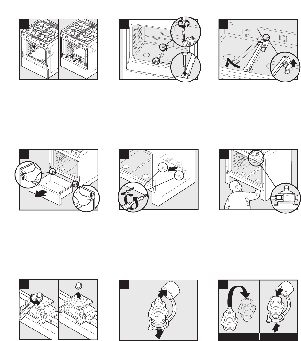
© 2006 Maytag Services 16026923 C – 7
Gas Conversion Instructions, JGS8850BD*, JGS8860BD*
7
8
1
9
2
Caution: Burner igniter is fragile./Attention: L’allumeur de
brûleur est fragile./Precaución: El encendedor del
quemador es frágil.
Lift up and remove oven bottom./Soulevez la sole du
four et retirez-la./Levante y retire el fondo del horno.
Remove bake burner screws./Retirez les vis du
brûleur de cuisson au four./Retire los tornillos del
quemador de horneado.
Swing bake burner to the side and lift bake burner off
the oven orifice./Pivotez le brûleur de cuisson sur le
côté et soulevez-le pour le séparer de son gicleur./Gire
el quemador del horno a un lado y levántelo para
sacarlo del orificio.
10
11
1
2
12
Remove warming drawer./Retirez le tiroir de
réchauffage./Retire el cajón de calentamiento.
Remove screws from panel and then remove
panel./Retirez les vis du panneau puis le panneau lui-
même./Retire los tornillos del panel y retire el panel.
Locate regulator from the front./Repérez le détendeur à
l'avant./Ubique el regulador desde la parte delantera.
13
14
15
NATURAL/NATUREL/GAS NATURAL PROPANE/PROPANE/PROPANO
Unscrew the regulator cap./Dévissez le capuchon du
détendeur./Desenrosque la tapa del regulador.
Remove the plastic cap./Retirez le capuchon en
plastique./Retire la tapa de plástico.
Flip the regulator cap and replace the plastic
cap./Abattez le capuchon du détendeur et installez le
capuchon en plastique./Invierta la tapa del regulador y
vuelva a colocar la tapa de plástico.
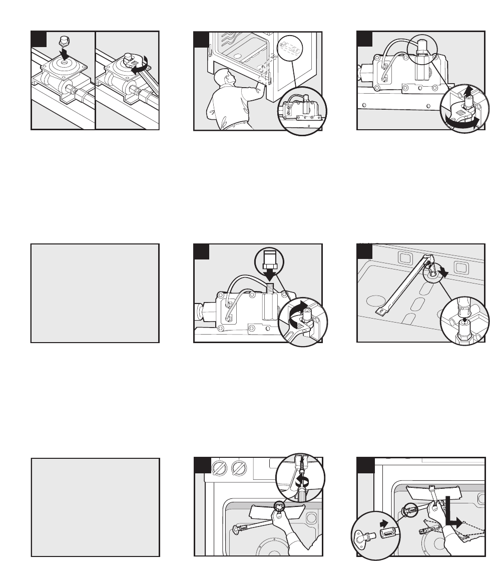
C – 8 16026923 © 2006 Maytag Services
Gas Conversion Instructions, JGS8850BD*, JGS8860BD*
16
17
2
18
2
1
49
Screw the cap securely back into place. DO NOT OVER
TIGHTEN./ Revissez bien le chapeau. NE LE SERREZ
PAS TROP FORT./ Enrosque la tapa firmemente en su
lugar. NO APRIETE DEMASIADO.
Locate oven orifice hood from the front./Identifiez la tête
de gicleur du four par l'avant./Ubique la caperuza del
orificio del quemador del horno desde la parte delantera.
Remove #49 natural oven orifice hood./Retirez la tête
de gicleur du four n° 49 pour gaz naturel./Retire la
caperuza del orificio de gas natural #49 del horno.
.
0512
19
Black/
Noir/
Negro
.0512
20
Install black .0512 LP orifice hood. DO NOT
OVERTIGHTEN./Installez la tête de gicleur noire .0512
pour GPL. NE SERREZ PAS TROP FORT./Instale la
caperuza negra de 0,0512 para gas LP del orificio del
quemador. NO APRIETE DEMASIADO.
Position bake burner over bake orifice
hood./Positionnez le brûleur de cuisson au-dessus de
la tête de gicleur./Coloque el quemador del horno sobre
la caperuza del orificio del quemador del horno.
21
Remove screw and slide the broil burner forward until
the pin clears rear wall./Enlevez la vis et faites glisser
en avant le brûleur de gril jusqu'à ce que le tenon se
trouve dégagé de la paroi arrière./Retire el tornillo y
deslice el quemador de asar hacia adelante hasta que
el pasador quede libre de la pared trasera.
Reverse steps 6 through 9
to reassemble oven.
Pour assembler à nouveau
le four, suivez les étapes 6 à 9
en inversant leur ordre.
Invierta los pasos 6 al 9 para
reensamblar el horno.
You MUST start bake and broil hoods
by hand to avoid cross threading.
Vous DEVEZ faire démarrer les têtes de
gicleur de cuisson et de gril à la main
afin d’éviter qu’un filetage ne soit faussé.
Usted DEBE iniciar el enroscado de las
tapas de horneado y asado a mano
para evitar dañar las roscas.
22
Caution: Burner igniter is fragile./Attention: L’allumeur
de brûleur est fragile./Precaución: El encendedor del
quemador es frágil.
Slip the broil burner off the broil orifice hood./Sortez le
brûleur de gril de la tête du gicleur de gril./Deslice el
quemador de asar para sacarlo de la caperuza del
orificio.
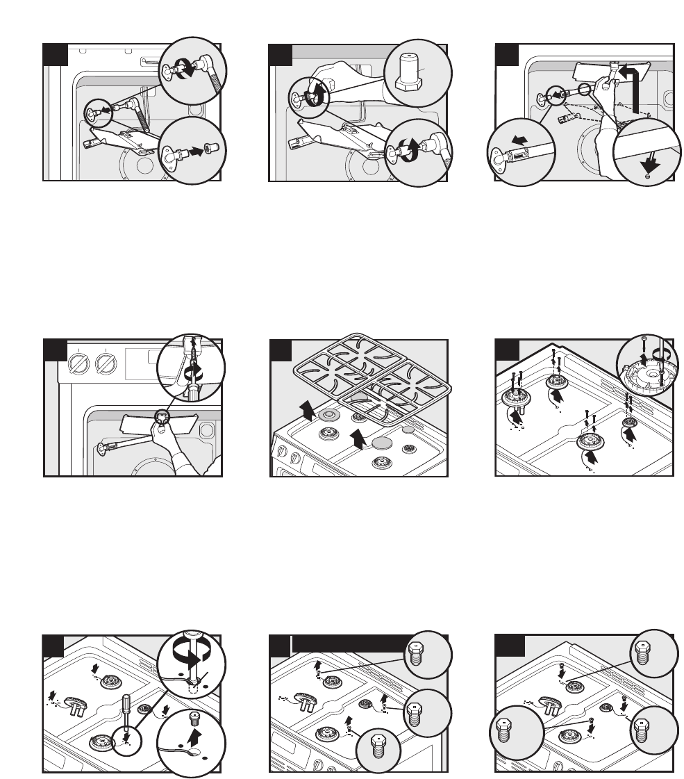
© 2006 Maytag Services 16026923 C – 9
Gas Conversion Instructions, JGS8850BD*, JGS8860BD*
24
1
2
Green/
Vert/
Verde
.0430
.0430
Install green .0430 LP broil orifice hood.
DO NOT OVERTIGHTEN./Installez la tête du gicleur de gril,
verte .0430 pour GPL. NE SERREZ PAS TROP./Instale la
caperuza verde de 0,0430 para gas LP del orificio del
quemador de asar. NO APRIETE DEMASIADO.
27
29
3
2
(7mm)
9/32”
1
30
NATURAL/NATUREL/GAS NATURAL
Green/
Vert/
Verde
1.07mm
1.42mm
1.95mm
Remove the top grates. Remove the burner
caps./Retirez les grilles supérieures. Retirez les
chapeaux de brûleur./Retire las rejillas superiores.
Retire las tapas de los quemadores.
IMPORTANT: Remove and keep old natural gas orifice
hoods./IMPORTANT: Retirez et conservez les anciennes
têtes de gicleur pour gaz naturel./IMPORTANTE: Retire y
conserve las tapas usadas de los orificios de gas
natural.
1.14mm
Red
Rouge
Rojo
Blue/
Bleu/
Azul
.64mm
.91mm
30A
Replace with LP gas orifice hoods. DO NOT
OVERTIGHTEN./Remplacez-les avec des têtes de gicleur
pour GPL. NE SERREZ PAS TROP./Reemplácelas con
caperuzas de orificios de gas LP. NO
APRIETE DEMASIADO.
Carefully remove gas orifice hoods and convert one
burner at a time./Enlevez soigneusement les têtes de
gicleur pour gaz naturel et convertissez un brûleur à la
fois./Retire cuidadosamente las caperuzas de los
orificios de gas y convierta un quemador a la vez.
1
25
2
1
Place the broil burner on the broil orifice hood.
CAUTION: Carefully insert burner pin in oven back./
Mettez le brûleur de gril sur la tête du gicleur de gril.
ATTENTION: Insérez soigneusement le tenon du brûleur dans
le four./Coloque el quemador de asar en la caperuza del
orificio.PRECAUCIÓN: Inserte cuidadosamente el pasador en la
parte trasera del horno.
28
Remove screws and burner head./Retirez les vis et la
tête de brûleur./Retire los tornillos y la cabeza del
quemador.
26
Reposition the broiler burner and tighten screw. Re-
assemble oven./Remettez en place le brûleur de gril et
serrez la vis. Remontez le four./Vuelva a colocar ei
quemador de asar en su lugar y apriete el tornillo.
Vuelva a ensamblar el horno.
1
23
3
2
.52
Remove #52 natural broil orifice hood./Retirez la tête
du gicleur de gril n° 52 pour gaz naturel./Retire la
caperuza del orificio de gas natural #52 del quemador
de asar.
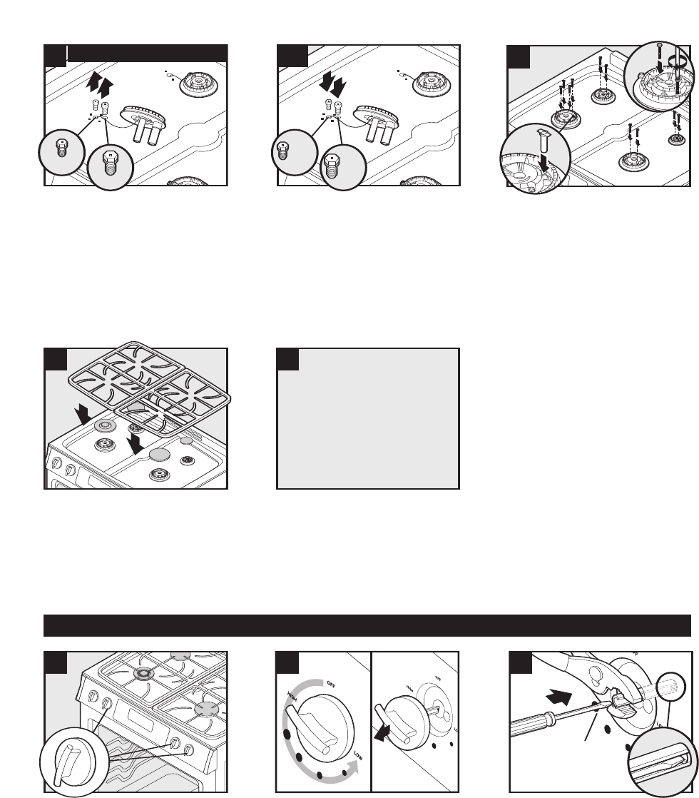
C – 10 16026923 © 2006 Maytag Services
Gas Conversion Instructions, JGS8850BD*, JGS8860BD*
31A
.55 mm
White
Blanc
Blanco
.97 mm
Orange
Orange
Naranja
32
33
Replace with LP gas orifice hoods. DO NOT
OVERTIGHTEN./Remplacez-les avec des têtes de gicleur
pour GPL. NE SERREZ PAS TROP./Reemplácelas con
caperuzas de orificios de gas LP. NO
APRIETE DEMASIADO.
Replace burner heads and screws.
(Hand tighten.) Drop in LP choke./Réinstallez les têtes
de brûleur et les vis. (Serrez-les à la main.) Posez
l’étrangleur pour GPL./Vuelva a instalar las cabezas y
los tornillos del quemador. (Apriete a mano). Coloque el
obturador de gas LP en su lugar.
Replace burner caps. Replace grates./Remettez les
chapeaux de brûleur. Remettez les grilles./Vuelva a
instalar las tapas de los quemadores. Vuelva a instalar
las rejillas.
34
Turn on gas and electrical
supply to product.
Ouvrez le gaz et l'électricité
alimentant l'appareil.
Abra el suministro de gas y conecte
el suministro eléctrico al producto.
35
36
1/8" Flat head
Screwdriver/
Tournevis à lame
plate de 1/8 po/
Destornillador de
1/8” de cabeza plana
37
NOTE: Repeat steps 37-39 for single burners./
REMARQUE: Répétez les étapes 37 à 39 pour les
brûleurs simples./NOTA: Repita los pasos 37 a 39 para
los quemadores sencillos.
Adjust each single surface burner one at a time. Light
burner and turn to lowest setting. Remove knob./
Ajustez chaque brûleur de surface simple un par un.
Allumez le brûleur et réglez-le au niveau le plus bas.
Retirez le bouton./Ajuste los quemadores superiores
sencillos uno a la vez. Encienda el quemador y ajústelo
al nivel másbajo. Retire la perilla.
Hold knob stem in LOW position. Insert screwdriver to
engage screw./Tenez la tige du bouton en position
LOW. Introduisez le tournevis pour tourner la
vis./Mantenga la varilla de la perilla en el ajuste ‘LOW’
(Bajo). Inserte el destornillador en el tornillo.
.80 mm
1.65mm
31
NATURAL/NATUREL/GAS NATURAL
IMPORTANT: Remove and keep old natural gas orifice
hoods./IMPORTANT: Retirez et conservez les anciennes
têtes de gicleur pour gaz naturel./IMPORTANTE: Retire y
conserve las tapas usadas de los orificios de gas
natural.
Low Flow Adjustment/Réglage bas débit/Ajuste del flujo minimo
NOTE: When reversing an LP conversion back
to natural gas, the LP choke in step 32 MUST
be removed.
REMARQUE : Lorsque vous faites une
reconversion du GPL au gaz naturel,
l’étrangleur pour GPL de l’étape 32 DOIT être
retiré.
NOTA: Cuando revierta una conversión de gas
LP para usar gas natural, DEBE retirar el
obturador de gas LP en el paso 32.
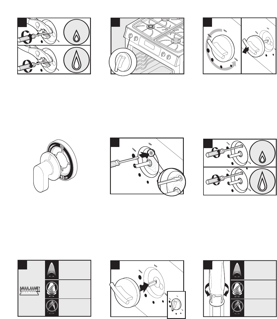
© 2006 Maytag Services 16026923 C – 11
Gas Conversion Instructions, JGS8850BD*, JGS8860BD*
38
39
40
Adjust flame height with screwdriver./Ajustez la
hauteur de la flamme avec le tournevis./Ajuste la altura
de la llama con el destornillador.
Adjust double surface burner. Light burner and turn to
lowest setting where both inner and outer ring are lit.
Remove knob./Ajuster le brûleur de surface double.
Allumez le brûleur et réglez-le au niveau le plus bas où
les deux cercles (intérieur et extérieur) sont allumés.
Retirez le bouton./Ajuste el quemador superior doble.
Encienda el quemador y ajústelo al nivel más bajo en el
que se enciendan los anillos interior y exterior. Retire la
perilla.
41
42
Adjust flame height with screwdriver./Ajustez la
hauteur de la flamme avec le tournevis./Ajuste la altura
de la llama con el destornillador.
Insert screwdriver to engage screw./Introduisez le
tournevis pour tourner la vis./Inserte el destornillador
en el tornillo.
NOTE: For this style of knob, the bezel MUST be
removed to make the flame adjustments to the Double
Burner./REMARQUE: Pour ce style de bouton, la plaque
DOIT être retirée pour effectuer les réglages des
flammes du brûleur double./NOTA: Para este tipo de
perilla, DEBE retirar el marco de la perilla para realizar
los ajustes de las llamas del quemador doble.
1/4"
CORRECT
BON
CORRECTO
YELLOW
JAUNE
AMARILLA
BLUE LIFTING
FLAMME BLEUE SE SOULEVANT
AZUL QUE SE SEPARA DEL QUEMADOR
43
44
CORRECT
BON
CORRECTO
YELLOW
(Open shutter to correct)
JAUNE
Ouvrez l'obturateur pour rectifier
AMARILLA
Abra el obturador para corregir
la situación.
BLUE LIFTING
(Close shutter to correct)
FLAMME BLEUE SE SOULEVANT
Fermez l'obturateur pour rectifier
AZUL QUE SE SEPARA DEL QUEMADOR
Cierre el obturador para corregir
la situación.
45
Verify proper flame height and appearance./Vérifiez la
taille appropriée des flammes et leur apparence./
Verifique la altura y apariencia correctas de la llama.
Replace knob. Turn OFF burners./Remettez les boutons.
Mettez les brûleur sur OFF (ARRÊT)./Vuelva a instalar
las perilla. APAGUE los quemadores.
If necessary, adjust both oven burner shutters for
correct flames. Secure shutter opening with screw./Au
besoin, ajustez les deux obturateurs du brûleur du four
pour obtenir les flammes appropriées. Fixez
l'obturateur avec la vis./De ser necesario, ajuste ambos
obturadores del quemador del horno para obtener la
llama correcta. Fije la abertura del obturador con el
tornillo.
NOTE: Double burner only./REMARQUE: Brûleur double
uniquement./NOTA: Quemador doble solamente.

C – 12 16026923 © 2006 Maytag Services
Gas Conversion Instructions, JGS8850BD*, JGS8860BD*
Replace oven rack./Remettre la grille de four./Vuelva a
instalar la rejilla del horno.
46
1
2
47
Replace panel and screws./Remettez le panneau et les
vis./Vuelva a instalar el panel y los tornillos.
48
Replace warming drawer./Replacez le tiroir de
réchauffage./Vuelva a instalar el cajón de
calentamiento.
Move hinges into the first stop position./Placez les
charnières à la première position d’arrêt./Mueva las
bisagras al primer tope.
49
Replace oven door./Replacez la porte du four.
/Vuelva a instalar la puerta del horno.
50
Close oven door. Complete./Fermez la porte du four.
Terminé./Cierre la puerta del horno. Completo.
51
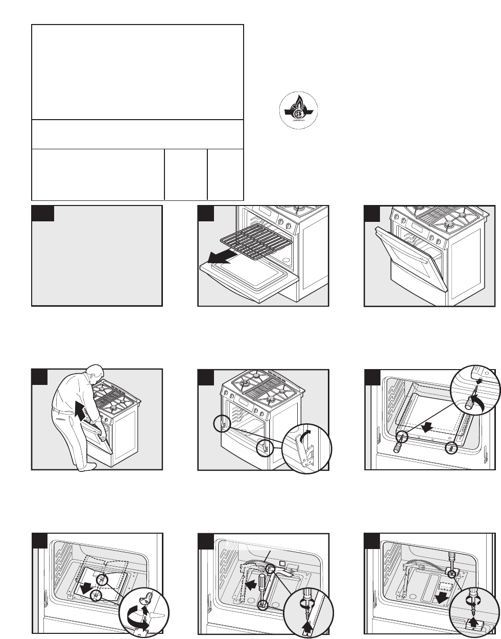
© 2006 Maytag Services 16026923 C – 13
Gas Conversion Instructions, JGS9900BD*
1
Turn off gas and electrical
supply to product.
Fermez le gaz et coupez
l'électricité alimentant l'appareil.
Cierre el suministro de gas y desconecte
el suministro eléctrico al producto.
2
3
Remove oven rack./Retirez la grille du
four./Retire la parrilla del horno. Open oven door to the first stop position./
Ouvrez la porte du four jusqu’à la première
position d’arrêt./Abra la puerta del horno hasta
el primer tope.
4
5
1
2
6
Remove oven door by holding both sides and
pulling up./Retirez la porte du four en la tenant
par les deux côtés et en la tirant vers le haut./
Retire la puerta del horno sosteniendo ambos
lados y tirando de ella hacia arriba.
Move hinges to the closed position./Placez les
charnières à la position de fermeture.
/Mueva las bisagras a la posición cerrada.
Remove oven bottom./Retirez la sole du four.
/Retire el fondo del horno.
7
2
1
Caution: Burner igniter is fragile./
Attention : L’allumeur de brûleur est fragile./
Precaución: El encendedor del quemador es frágil.
8
1
2
9
2
1
Remove oven baffle./Enlevez le déflecteur de
four./Retire el deflector del horno.
Remove oven burner./Retirez le brûleur du
four./Retire el quemador del horno.
Remove cover./Retirez le couvercle./Retire la
cubierta.
Rev 2-1/06 Gas Downdraft/Part No. 8101P725-60
LP Propane
Conversion
Instructions
Instructions de conversion au GPL/
Instrucciones de conversión a gas LP propano
• Only qualified personnel should convert this range./Seul un personnel qualifié doit procéder à la
conversion de cette cuisinière./La estufa sólo debe ser convertida por personal calificado. • Retain natural
orifices for future conversion./Conservez les gicleurs pour gaz naturel pour une conversion ultérieure./
Guarde los orificios de gas natural para una conversión futura. • Reverse this procedure for LP to natural
conversion./Procédez inversement pour la conversion du GPL au gaz naturel./Invierta este procedimiento
para convertir el producto de gas LP a gas natural.
This range is equipped with fixed orifices on all burners and a convertible appliance regulator. The unit serial plate
states which gas it was adjusted for at the factory. To convert the unit to either Natural gas or LP gas will require
replacement of the oven orifice hoods, and the top burner orifice hoods, and adjustment of the oven burner shutters
and the appliance pressure regulator converter cap.
Cette cuisinière est équipée de gicleurs fixes sur tous les brûleurs et d'un détendeur convertible. La plaque
signalétique de cet appareil indique le réglage fait à l’usine pour un certain gaz. La conversion de l'appareil au
gaz naturel ou au GPL nécessite le remplacement des têtes de gicleur du four et des têtes de gicleur du brûleur
supérieur, ainsi que le réglage des obturateurs de brûleur du four et du capuchon du convertisseur du détendeur.
Esta estufa viene equipada con orificios fijos en todos los quemadores y con un regulador convertible para
electrodomésticos. La placa de serie de la unidad indica para qué tipo de gas se calibró en la fábrica. Para
convertir la unidad a gas natural o a gas LP es necesario reemplazar las caperuzas de los orificios del horno y los
orificios de los quemadores superiores, además de ajustar los obturadores del quemador del horno y la tapa del
convertidor del regulador de presión del electrodoméstico.
Inlet pressure to the appliance pressure regulator should be as follows for both operation and checking of
appliance pressure regulator setting:/La pression d'arrivée au détendeur de l'appareil doit être la suivante pour
le fonctionnement et la vérification du réglage du détendeur :/La presión de entrada al regulador de presión debe
ser la siguiente tanto para el funcionamiento normal como para verificar el ajuste del regulador de presión:
Inlet Pressure in inches of water column Natural Gas LP Gas
Pression d'arrivée en pouces à la colonne d'eau Gaz naturel GPL
Presión de entrada en pulgadas c.d.a. Gas natural Gas LP
Max/Max./Máx. 14 (36 cm) 14 (36 cm)
Min/Min./Mín. 6 (16 cm) 11 (28 cm)
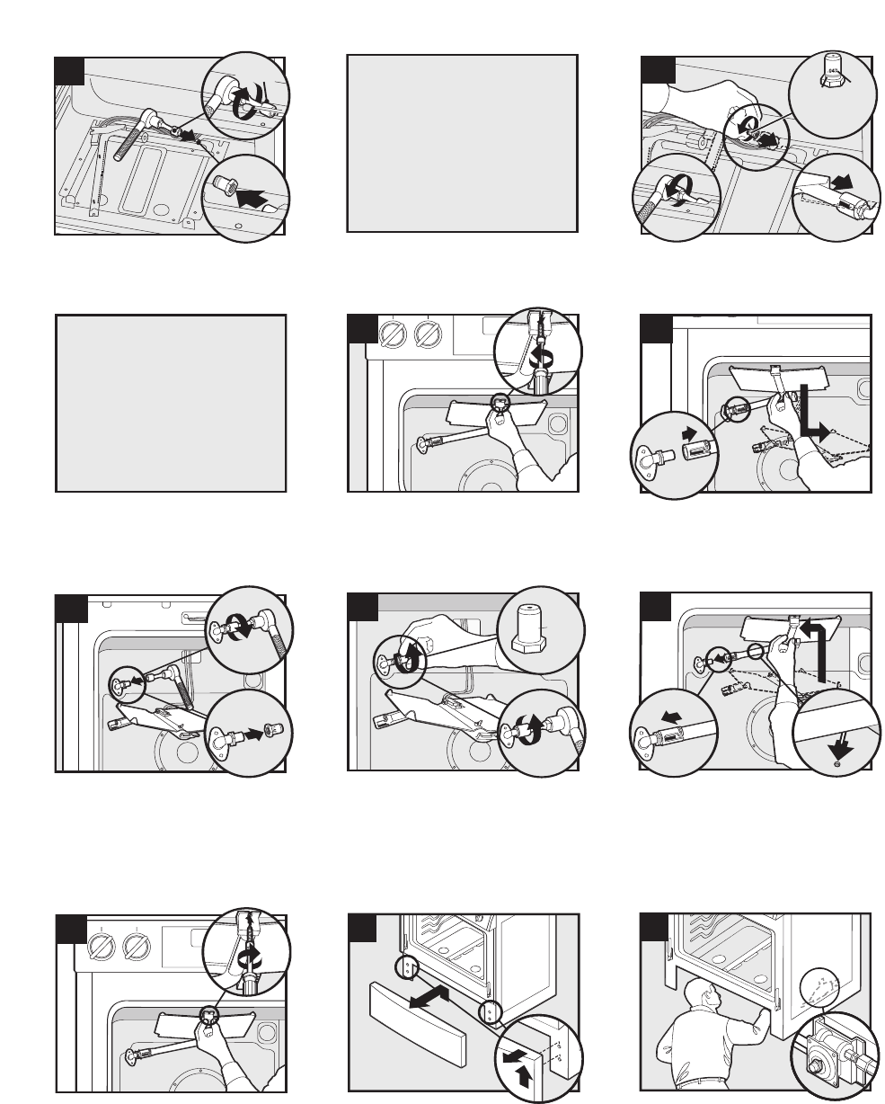
C – 14 16026923 © 2006 Maytag Services
Gas Conversion Instructions, JGS9900BD*
1
14
3
2
1.42mm
Remove 1.42 natural broil orifice hood./Retirez la tête
du gicleur de gril n° 1,42 pour gaz naturel./Retire la
caperuza del orificio de gas natural 1.42 del quemador
de asar..
15
1
2
.038
.038
1
16
2
1
Install .038 LP broil orifice hood.
(4-5 turns-DO NOT OVERTIGHTEN)/Installez la tête du
gicleur de gril, .038 pour GPL. (4 à 5 tours – NE SERREZ
PAS TROP)/Instale la caperuza de 0,038 para gas LP del
orificio del quemador de asar.
(4 a 5 vueltas – NO APRIETE DEMASIADO)
Place the broil burner on the broil orifice hood.
CAUTION: Carefully insert burner pin in oven back./
Mettez le brûleur de gril sur la tête du gicleur de gril.
ATTENTION : Insérez soigneusement le tenon du brûleur
dans le four./Coloque el quemador de asar en la
caperuza del orificio.PRECAUCIÓN: Inserte
cuidadosamente el pasador en la parte trasera del horno.
Reverse steps 6 through 9
to reassemble oven.
Pour assembler à nouveau le four,
suivez les étapes 6 à 9 en inversant
leur ordre.
Invierta los pasos 6 al 9 para
reensamblar el horno.
12
13
Caution: Burner igniter is fragile./
Attention : L’allumeur de brûleur est fragile./
Precaución: El encendedor del quemador es frágil.
Remove screw and slide the broil burner forward until the
pin clears rear wall./Enlevez la vis et faites glisser en avant
le brûleur de gril jusqu'à ce que le tenon se trouve dégagé
de la paroi arrière./Retire el tornillo y deslice el quemador
de asar hacia adelante hasta que el pasador quede libre de
la pared trasera.
Slip the broil burner off the broil orifice hood./Sortez
le brûleur de gril de la tête du gicleur de gril./Deslice
el quemador de asar para sacarlo de la caperuza del
orificio.
17
Reposition the broiler burner and tighten screw. Re-
assemble oven. (See steps 2-4)/Remettez en place le
brûleur de gril et serrez la vis. Remontez le four.
(Voyez les étapes 2-4)/Vuelva a colocar ei quemador
de asar en su lugar y apriete el tornillo. Vuelva a
ensamblar el horno. (Vea los pasos 2 al 4.)
18
1
2
19
2
Remove access panel./Retirez le panneau
d’accès./Retire el panel de acceso.
Locate regulator from the front./Repérez le détendeur
à l'avant./Ubique el regulador desde la parte
delantera.
*CAUTION: Pin MUST be inserted into back of hole on oven to secure burners (C5)./*ATTENTION : Le tenon DOIT être introduit à l'arrière du trou du four pour bien loger les brûleurs
(C5)./*ATENCIÓN: El pasador DEBE ser introducido en la parte trasera del agujero en el horno para asegurar los quemadores (C5).
1
2
3
1/2"
(12.5 cm)
#50
#50
10
1
11
2
.047/
0,047/
.047
Orange/
Orange/
Naranja
3
Remove brass orifice hood./Retirez la tête de gicleur
en laiton./Retire la tapa de bronce del orific
Replace orifice hood. DO NOT OVER TIGHTEN./
Remettez la tête de gicleur SANS TROP LA SERRER./
Reemplace la tapa del orificio. NO APRIETE
DEMASIADO.
You MUST start bake and broil hoods
by hand to avoid cross threading.
Vous DEVEZ insérer les têtes de gicleur
de cuisson et de gril à la main afin
d’éviter qu’un filetage ne soit faussé.
Usted DEBE iniciar el enroscado de las
tapas de horneado y asado a mano
para evitar dañar las roscas.
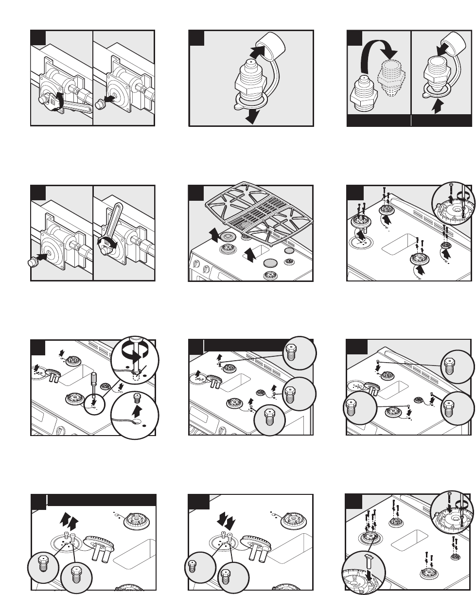
© 2006 Maytag Services 16026923 C – 15
Gas Conversion Instructions, JGS9900BD*
21
22
NATURAL/NATUREL/GAS NATURAL PROPANE/PROPANE/PROPANO
23
Remove the plastic cap./Retirez le capuchon en
plastique./Retire la tapa de plástico.
Flip the regulator cap and replace the plastic
cap./Abattez le capuchon du détendeur et installez le
capuchon en plastique./Invierta la tapa del regulador
y vuelva a colocar la tapa de plástico.
Screw the cap securely back into place. DO NOT OVER
TIGHTEN./ Revissez bien le chapeau. NE LE SERREZ
PAS TROP FORT./ Enrosque la tapa firmemente en su
lugar. NO APRIETE DEMASIADO.
24
25
26
3
2
(7mm)
9/32”
1
Remove the top grates. Remove the burner
caps./Retirez les grilles supérieures. Retirez les
chapeaux de brûleur./Retire las rejillas superiores.
Retire las tapas de los quemadores.
Remove screws and burner head./Retirez les vis et la
tête de brûleur./Retire los tornillos y la cabeza del
quemador.
Carefully remove gas orifice hoods and convert one
burner at a time./Enlevez soigneusement les têtes de
gicleur pour gaz naturel et convertissez un brûleur à
la fois./Retire cuidadosamente las caperuzas de los
orificios de gas y convierta un quemador a la vez.
27
NATURAL/NATUREL/GAS NATURAL
1.09 mm
1.40 mm
1.95 mm
27
A
Red
Rouge
Rojo
1.14 mm
Blue/
Bleu/
Azul
.64 mm
.91 mm
.80 mm
1.65 mm
28
NATURAL/NATUREL/GAS NATURAL
IMPORTANT: Remove and keep old natural gas orifice
hoods./IMPORTANT : Retirez et conservez les
anciennes têtes de gicleur pour gaz naturel./
IMPORTANTE: Retire y conserve las tapas usadas de
los orificios de gas natural.
Replace with LP gas orifice hoods. DO NOT OVERTIGHTEN./
Remplacez-les avec des têtes de gicleur pour GPL. NE
SERREZ PAS TROP./Reemplácelas con caperuzas de orificios
de gas LP. NOAPRIETE DEMASIADO.
IMPORTANT: Remove and keep old natural gas orifice
hoods./IMPORTANT : Retirez et conservez les anciennes
têtes de gicleur pour gaz naturel./ IMPORTANTE: Retire y
conserve las tapas usadas de los orificios de gas natural.
28A
.55 mm
White
Blanc
Blanco
.97mm
Orange
Orange
Naranja
29
Replace with LP gas orifice hoods. DO NOT OVERTIGHTEN./
Remplacez-les avec des têtes de gicleur pour GPL. NE
SERREZ PAS TROP./Reemplácelas con caperuzas de orificios
de gas LP. NOAPRIETE DEMASIADO.
Replace burner heads and screws. (Hand tighten.)
Drop in LP choke./Réinstallez les têtes de brûleur et
les vis. (Serrez-les à la main.) Posez l’étrangleur pour
GPL./Vuelva a instalar las cabezas y los tornillos del
quemador. (Apriete a mano). Coloque el obturador de
gas LP en su lugar.
20
Unscrew the regulator cap./Dévissez le capuchon du
détendeur./Desenrosque la tapa del regulador.
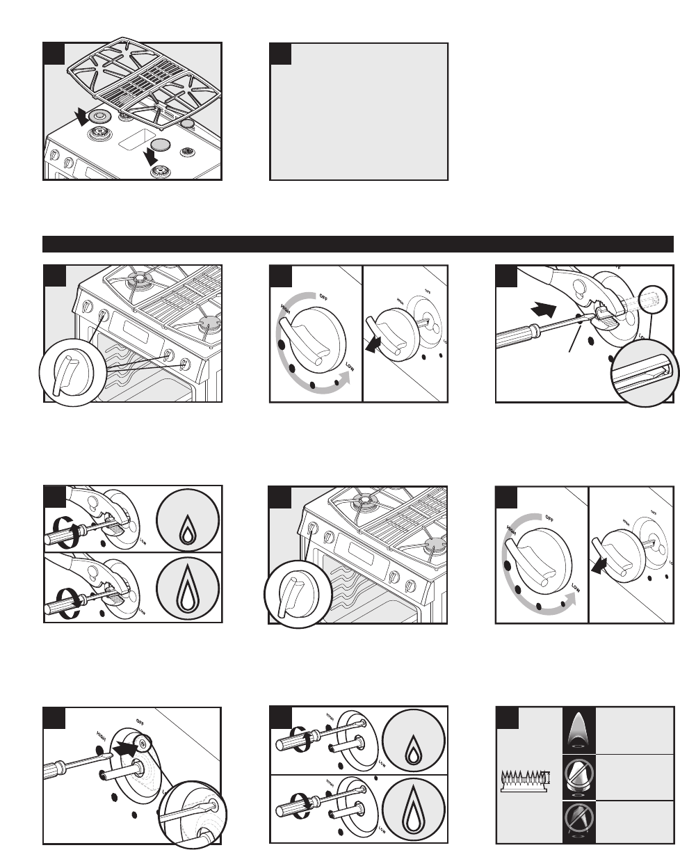
C – 16 16026923 © 2006 Maytag Services
Gas Conversion Instructions, JGS9900BD*
31
Turn on gas and electrical
supply to product.
Ouvrez le gaz et l'électricité
alimentant l'appareil.
Abra el suministro de gas y conecte
el suministro eléctrico al producto.
32
33
1/8" Flat head
Screwdriver/
Tournevis à lame
plate de 1/8 po/
Destornillador de
1/8” de cabeza plana
34
NOTE: Repeat steps 33-35 for single burners./
REMARQUE : Répétez les étapes 33 à 35 pour les
brûleurs simples./NOTA: Repita los pasos 33 a 35
para los quemadores sencillos.
Hold knob stem in LOW position. Insert screwdriver to
engage screw./Tenez la tige du bouton en position
LOW. Introduisez le tournevis pour tourner la
vis./Mantenga la varilla de la perilla en el ajuste
‘LOW’ (Bajo). Inserte el destornillador en el tornillo.
35
36
37
Adjust flame height with screwdriver./Ajustez la
hauteur de la flamme avec le tournevis./Ajuste la
altura de la llama con el destornillador.
NOTE: Double burner only./REMARQUE : Brûleur
double uniquement./NOTA: Quemador doble
solamente.
38
39
1/4"
CORRECT
BON
CORRECTO
YELLOW
JAUNE
AMARILLA
BLUE LIFTING
FLAMME BLEUE SE SOULEVANT
AZUL QUE SE SEPARA DEL QUEMADOR
40
Insert screwdriver to engage screw./Introduisez le
tournevis pour tourner la vis./Inserte el destornillador
en el tornillo.
Adjust flame height with screwdriver./Ajustez la
hauteur de la flamme avec le tournevis./Ajuste la
altura de la llama con el destornillador.
Verify proper flame height and appearance./Vérifiez
la taille des flammes et leur apparence./Verifique la
altura y apariencia correctas de la llama.
Low Flow Adjustment/Réglage bas débit/Ajuste del flujo minimo
30
Replace burner caps. Replace grates./Remettez les
chapeaux de brûleur. Remettez les grilles./Vuelva a
instalar las tapas de los quemadores. Vuelva a
instalar las rejillas.
Adjust each single surface burner one at a time. Light
burner and turn to lowest setting. Remove knob./
Ajustez chaque brûleur de surface simple un par un.
Allumez le brûleur et réglez-le au niveau le plus bas.
Retirez le bouton./Ajuste los quemadores superiores
sencillos uno a la vez. Encienda el quemador y
ajústelo al nivel más bajo. Retire la perilla.
Adjust double surface burner. Light burner and turn to
lowest setting where both inner and outer ring are lit.
Remove knob./Ajustez le brûleur de surface double.
Allumez le brûleur et réglez-le au niveau le plus bas
où les deux cercles (intérieur et extérieur) sont
allumés. Retirez le bouton./Ajuste el quemador
superior doble. Encienda el quemador y ajústelo al
nivel más bajo en el que se encienden los anillos
interior y exterior. Retire la perilla.
NOTE: When reversing an LP conversion back
to natural gas, the LP choke in step 29 MUST
be removed.
REMARQUE : Lorsque vous faites une
reconversion du GPL au gaz naturel,
l’étrangleur pour GPL de l’étape 29 DOIT être
retiré.
NOTA: Cuando revierta una conversión de gas
LP para usar gas natural, DEBE retirar el
obturador de gas LP en el paso 29.

© 2006 Maytag Services 16026923 C – 17
Gas Conversion Instructions, JGS9900BD*
41
CORRECT
BON
CORRECTO
YELLOW
(Open shutter to correct)
JAUNE
Ouvrez l'obturateur pour rectifier
AMARILLA
Abra el obturador para corregir
la situación.
BLUE LIFTING
(Close shutter to correct)
FLAMME BLEUE SE SOULEVANT
Fermez l'obturateur pour rectifier
AZUL QUE SE SEPARA DEL QUEMADOR
Cierre el obturador para corregir
la situación.
42
43
2
1
Replace knobs. Turn OFF burners./Remettez les
boutons. Mettez les brûleurs sur OFF (ARRÊT)./Vuelva
a instalar las perillas. APAGUE los quemadores.
If necessary, adjust both oven burner shutters for correct
flames. Secure shutter opening with screw./Au besoin,
ajustez les deux obturateurs du brûleur du four pour obtenir
les flammes appropriées. Fixez l'obturateur avec la vis./De
ser necesario, ajuste ambos obturadores del quemador del
horno para obtener la llama correcta. Fije la abertura del
obturador con el tornillo.
Replace access panel./Remettez le tiroir de
rangement./Vuelva a instalar el cajón de
almacenamiento.
44
45
46
Replace oven rack./Remettre la grille de four./Vuelva
a instalar la rejilla del horno.
Move hinges into the first stop position./Placez les
charnières à la première position d’arrêt./Mueva las
bisagras al primer tope.
Replace oven door./Replacez la porte du four./
Vuelva a instalar la puerta del horno.
47
Close oven door./Fermez la porte du four.
/Cierre la puerta del horno.
Complete./Terminé./Completo.
