160323 Studio Desk Maker Guide
User Manual:
Open the PDF directly: View PDF ![]() .
.
Page Count: 20
Studio Desk
Maker Guide

Welcome to your new Opendesk
Every piece of Opendesk furniture is made to order by independent local makers. Opendesk makers produce
products on-demand using digital fabricators (CNC- machines) combined with traditional cra skills - working from
designs contributed by a global community of designers and hosted on opendesk.cc.
The product you have in your hands is therefore the result of a new model sitting at the union of the internet, new
advancements in digital technologies, and age-old making techniques. We call this Open Making.
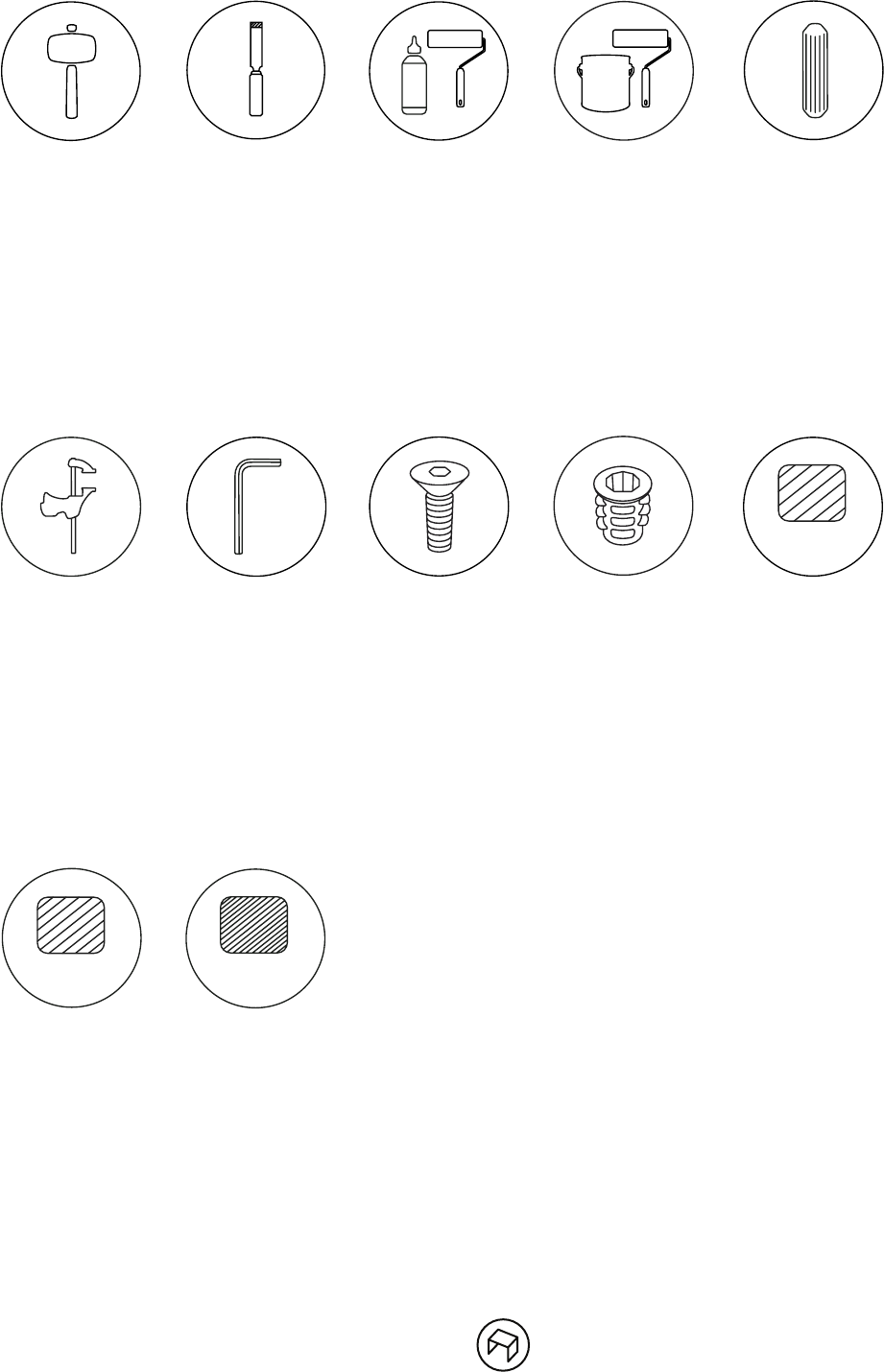
Mallet
A good joint will require
a gentle nudge. Using
a rubber mallet with a
white head will avoid any
marks or damage on the
furniture.
Chisel
Chiseling should not be
required on Opendesk
furniture. Should you
absolutely have to use
one, ensure you use a
sharp chisel and take
o small amounts of
material at a time.
Tools
PVA glue
We recommend using a
standard PVA based wood
adhesive. Use a good
quality paint brush or
roller to apply glue on the
product.
Oil
We recommend the use
of Osmo Raw Oil 3044.
Use a good quality paint
brush or roller to apply
oil on the product once
properly sanded.
Dowel
Dowels are used for the
glueing of two parts
together. Holes for the
dowels are part of the
cutting file. 6mm x 25mm.
Clamp
Use clamps when glueing
two parts together. Be
sure to protect the parts
from the clamp heads
using ocuts or similar
methods.
Allen Key
Use a size 5 Allen key to
secure the bolts.
M6 Bolt
We use this fixing for the
assembly of the Studio
Desk. Use the M6 Bolt
(25mm) with the M6 Insert
(13mm).
M6 Insert
We use this fixing for the
assembly of the Studio
Desk. Use the M6 Insert
(13mm) with the M6 Bolt
(25mm).
Sanding Paper - P120 grit
P120 grit is usually
associated with a C type
of finish.
Further information on
finishing can be found in
our maker guide.
Sanding Paper - P240 grit
P240 grit is usually
associated with a B type
of finish.
Further information on
finishing can be found in
our maker guide.
Sanding Paper - P320 grit
P320 grit is usually
associated with an A type
of finish.
Further information on
finishing can be found in
our maker guide.
P120
P320
P240
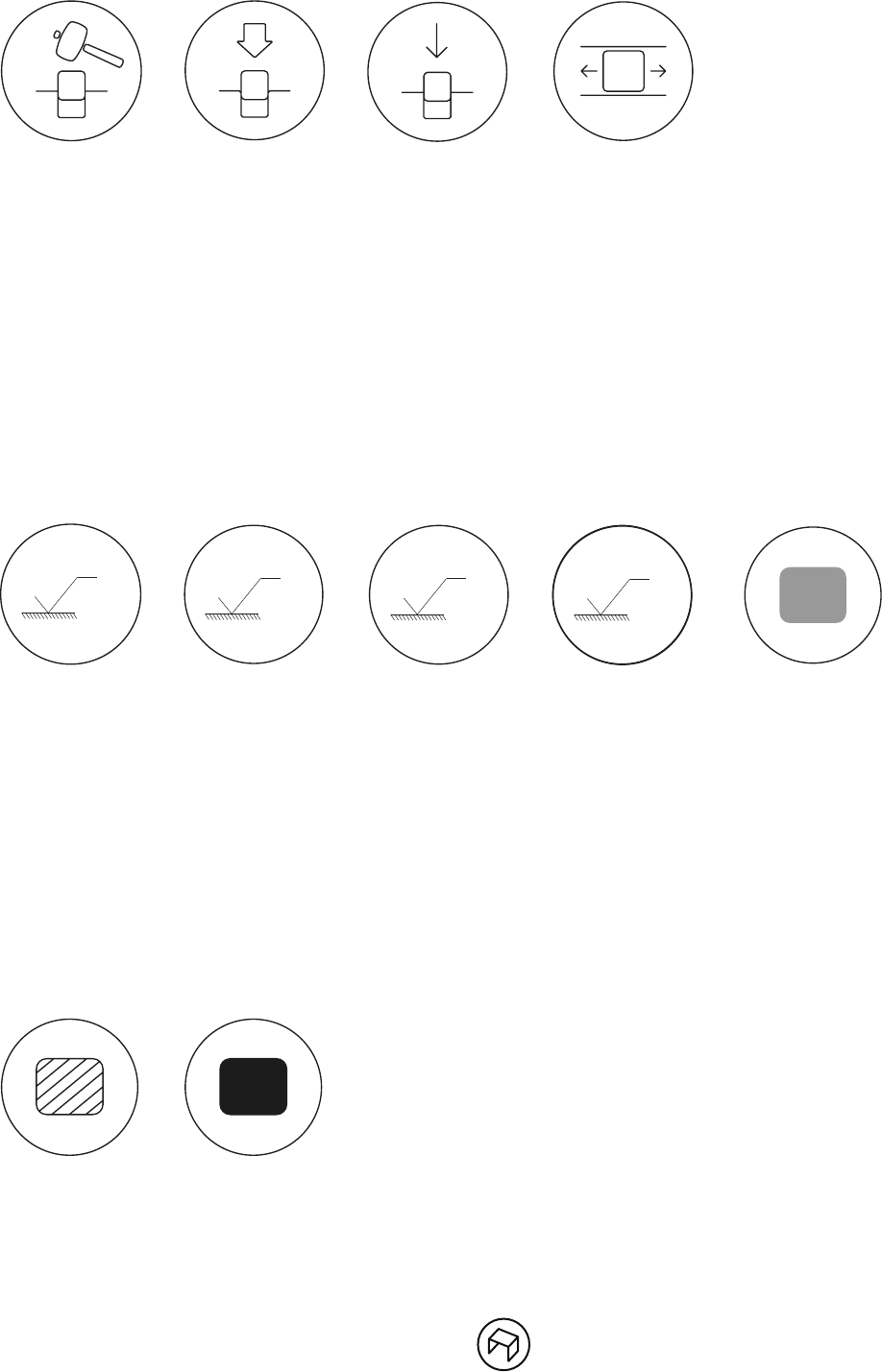
Mallet Fit
- 0.60mm total
The use of a mallet is
needed to push the part
into its respective slot.
Press Fit
0.00mm total
The joint is an exact
fit. This will require a
significant amount of
force, through hand
pressure or the use of a
mallet.
Type of fit
Push Fit
+ 0.20mm total
This joint should only
require hand pressure to
slot together.
Slide Fit
+ 0.50mm total
This joint should be easy
to assemble without being
too loose.
A face/edge
Surfaces such as tops and
top edges are always visible
and of high contact so
require an A type of finish.
Recommended procedure:
1. P120 grit
2. P240 grit
3. oil
4. P240 grit
5. oil
6. P320 grit
B face/edge
Surfaces which are
highly visible or easily
contactable.
Recommended procedure:
1. P120 grit
2. P240 grit
3. oil
4. P240 grit
Type of finishing
C face/edge
Surfaces that are not
directly visible or of low
contact. Generally areas
within joints.
Recommended procedure:
1. P120 grit
Deburring Glued surface
This indicates the area for
glue application.
Oiled surface
This indicates the area for
an oil application.
No finish
This indicates the area
that have to be le raw.
A
320
B
240
C
120
D
01
02
03
04
05
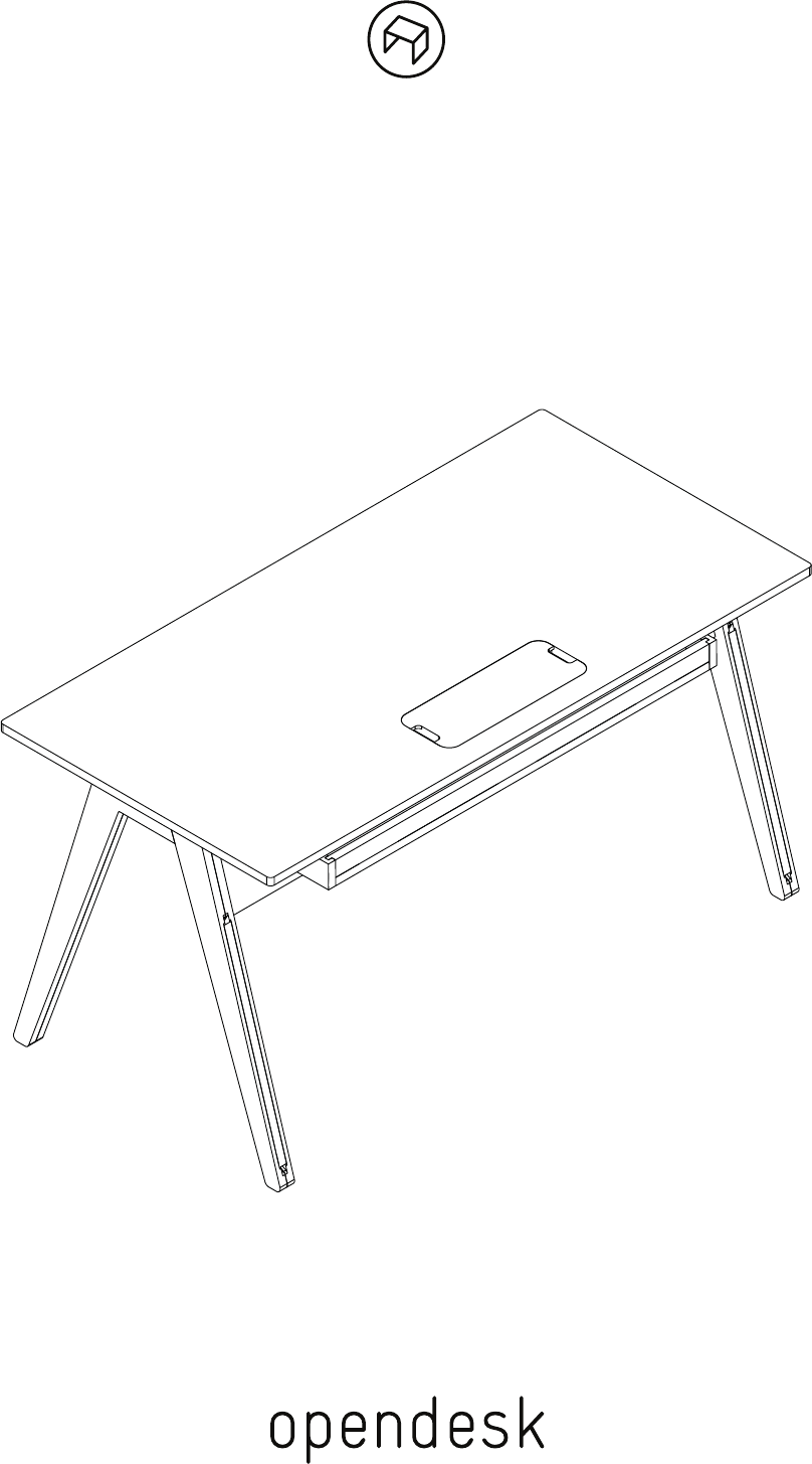
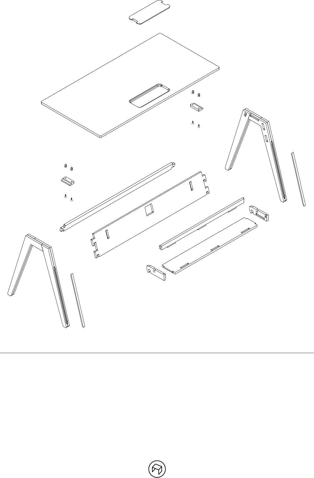
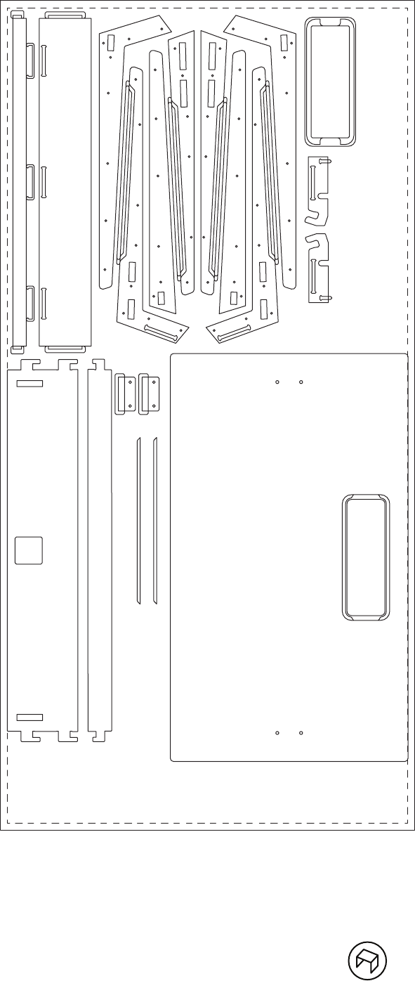
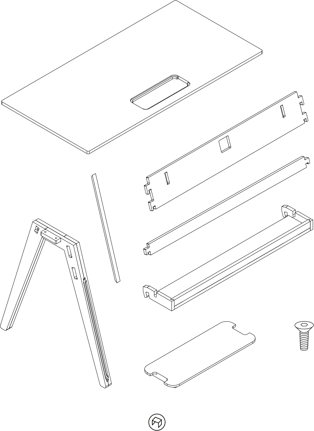
01 - desk top
02 - right leg
03 - le leg
04 - front brace beam
05 - back brace beam
06 - cable tray brace
07 - cable tray base
08 - le cable tray hook
09 - right cable tray hook
10 - cable concealing strip
11 - screw plate
12 - cable cover
13 - M6 insert - type P insert nut (13mm)
14 - M6 bolt (25mm)
06 07
08
10
11
12
13
14
09

Suggested Method
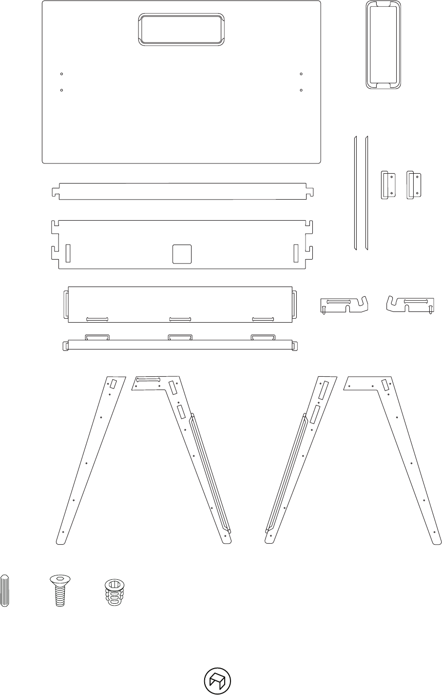
Parts:
1x Table top
1x Cable cover
1x Brace beam front
1x Brace beam back
1x Cable tray back
1x Cable tray base
2x Cable tray sides
2x Leg A (L+R)
2x Leg B (L+R)
2x Leg C (L+R)
2x Leg D (L+R)
2x Screw plates
2x Leg cable concealing strips
4x M6 Inserts and bolts
28x Dowels, 6x25mm
Standard Steps:
1. Assemble, sand, oil legs
2. Sand, oil, assemble cable tray
3. Sand and oil all plates and beams
4. Sand and oil table top and cable cover
5. Assemble
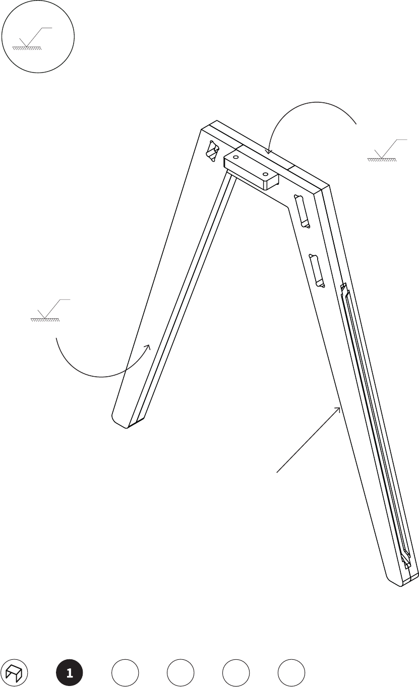
Instructions:
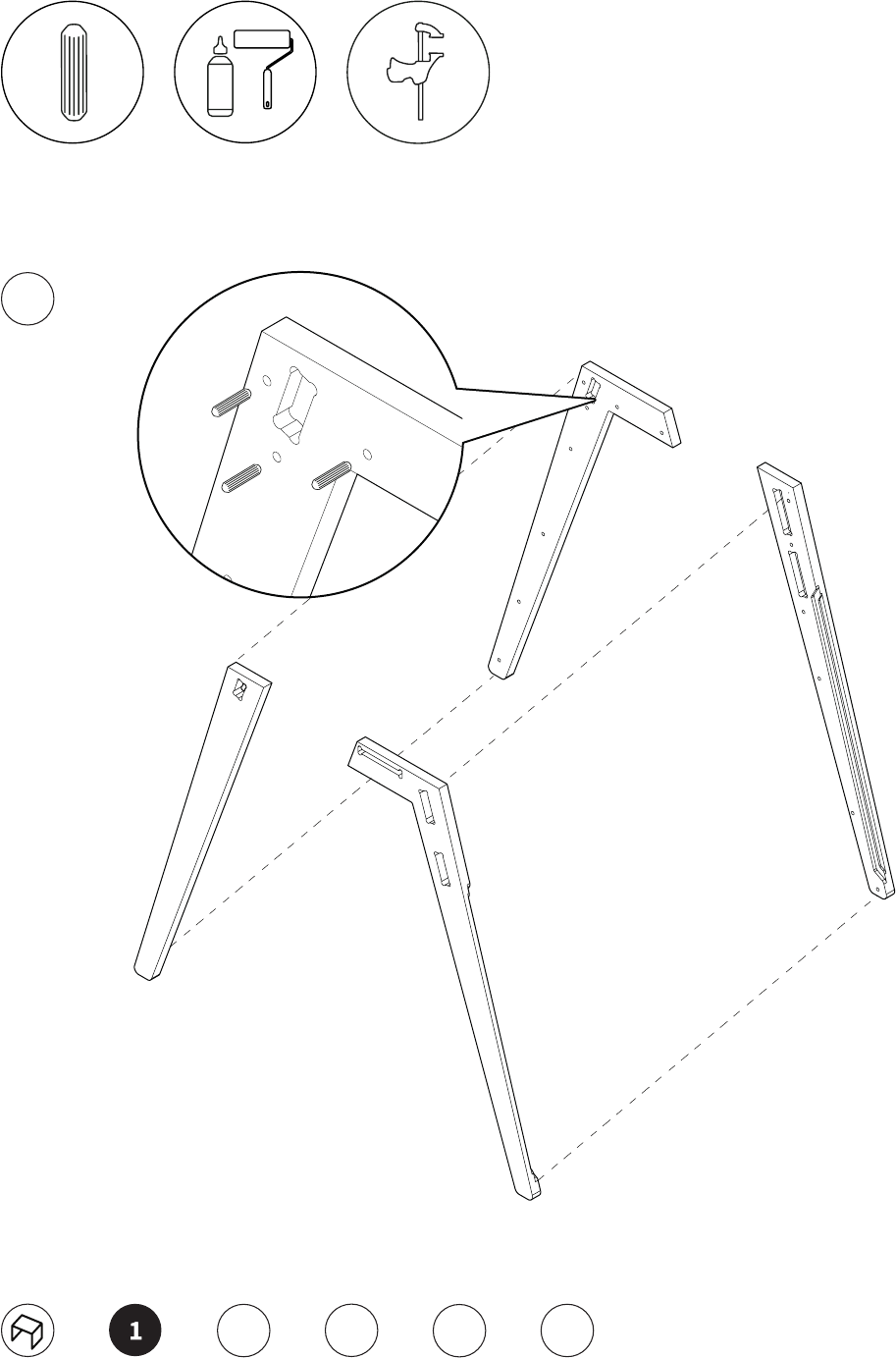
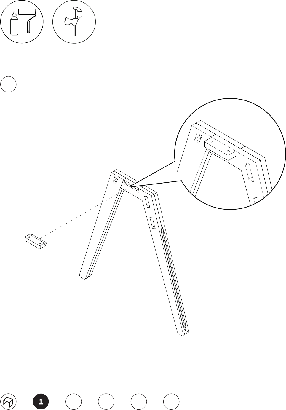
1. Spread one side of leg parts out on the workbench in order BCDA. Dab a drop of glue in each of the C and
D holes and add the dowels. With a roller spread the glue evenly on the B and A faces. Join together B C and
D A, then join these two sets together, BC DA. When bringing the legs together, C and A will overlap at the top.
Sandwich the legs together and bang to close the gap with a mallet. Check that the gap is closed up and flush.
Repeat the whole process on the right side leg. With Grit 240 individually sand each set of legs. Sand all the ply
edges first and then the facings. Oil in the same order. Wipe o any excess and put to the side. Sand the two
leg cable cover inserts with 240, then oil, wipe dry and check that they fit tight into the back of the legs. Once
finish, put legs, with cover inserts to the side.
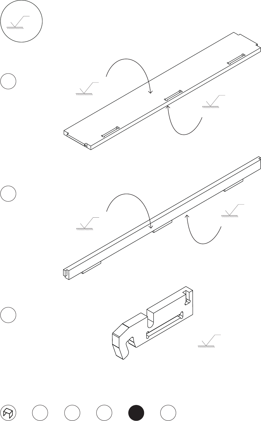
2. Sand the ply edge of the two side pieces for the cable tray together, then the faces, with grit 240. Oil, then
wipe dry. Do the same with the base of the cable tray, then the back. Glue up all pockets and assemble the
back to the base then add the two sides. Put to one side, or under the workbench.

Suggested Method
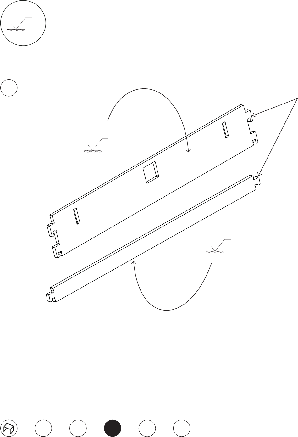
3. Sand the plates with grit 240. Sand the edge grain first on both long sides, then the faces. Oil in the same
order you sanded, however avoid getting oil on one end of the plates to allow for glue. Wipe o any excess oil.
Repeat the process with the two brace beams. Put parts to side.
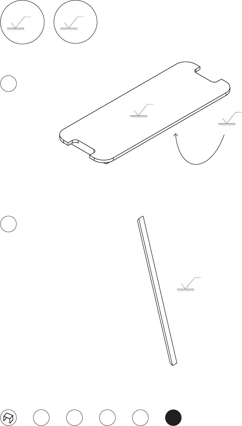
4. Sand the cable cover around the edge then the faces with Grit 400, Oil, wipe dry and put to the side. Make
sure the workbench is completely wiped down and free of debris. Place table top on the workbench length-
ways but up on its edge. Using 240, sand around the plywood edge first in an ‘L’ formation, rotating the ta-
ble top so the sanding pressure is always facing down where possible. Make sure chamfers are also sanded
smoothly. Laying the table top upside down, sand the underside with 400. Hand sand the rim of the cable
cover hole with 240 grit. Oil the whole underside evenly with a roller then wipe dry. Flip the top over and sand
with 400. Oil the edge and the top, wipe down any excess. Flip the top over again, add the inserts to all 4 holes.
5. Place the table top upside down on the workbench. Insert the brace bars into one set of legs, the larger bar
goes onto the leg with the cable slot in the back. Force them down so they are flush with the top of the leg. Do
the same process with the other set of legs, you now have your frame. Flip the frame over onto the table top
and align the insert holes. With an allen key turn the bolts until tight in the hole.
Standard Checks:
1. Flip over the table onto the floor and test for rigidity.
2. Make sure the rim and chamfer around the tabletop is smooth to the touch.
3. Check the inserts and bolts are fully locked in place.
Standard Estimated Timings:
1. Assemble, sand, oil legs A -5.5, S -14, O- 3.5 24 min
2. Sand, oil, assemble cable tray S- 5, O -2, A -2 9 min
3. Sand, oil plates and beams S -7, O- 3 10 min
4. Sand and oil tabletop with cable cover S -19, O- 7 A -1 27 min
5. Assemble A- 3 3-5 min
Estimated Total: 73 min
Cutting Sheet
a. desk top
b. cable concealing strip
c. front brace beam
d. back brace beam
e. cable tray brace
f. cable tray base
A. outside/front leg component
B. outside/back leg component
C. inside/back leg component
D. inside/front leg component
h. le cable tray hooks
i. right cable tray hook
j. cable cover
k. screw plates
a
b
cd
e f
B
D
C
A
h
j
k
i
Leg components
Components
Desk top
X2
h
a
B
D C A
j
e
f
b
c
d
k
i
X14 X4 X4
Leg Exploded
D
B
X2
X14
(6mmx25mm)
1.1
C
A
2345
dowels, glue, and clamps to glue parts
together
Leg Exploded
X2
1.2
k
2345
apply glue in screw plate
X2
Complete Leg
B
240
B
240
B
240
1mm edge all round
2345
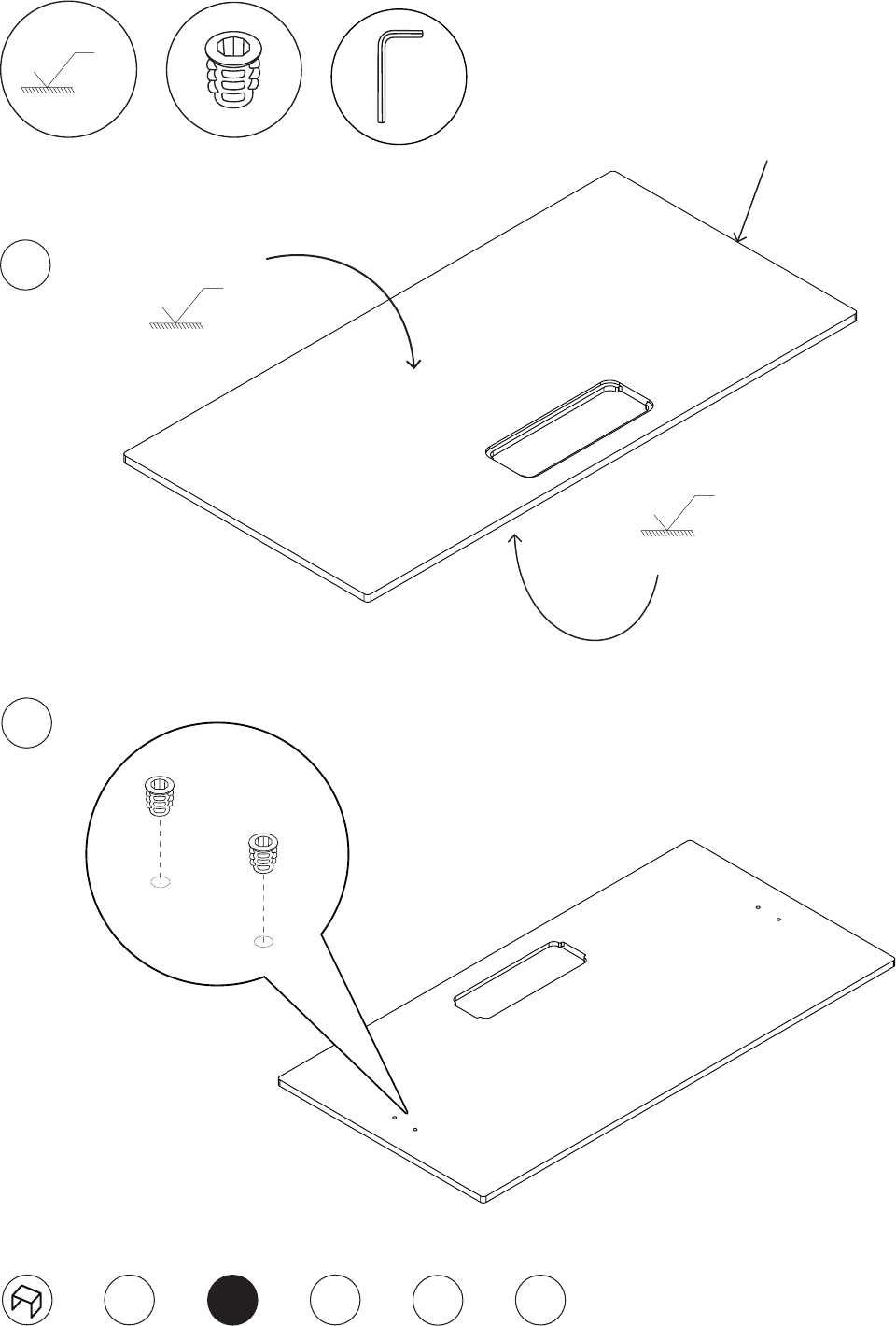
Table Top
A
320
2mm chamfer all round
A
320
a
A
320
X2
2345
2.1
2.2
2
1
Brace Beams
B
240
B
240
1mm edge all round
B
240
d
c
3.0
2345
1
Cable Tray Parts
B
240
B
240
B
240
B
240
B
240
B
240
2345
1
4.1
4.2
4.3
h/i
e
f
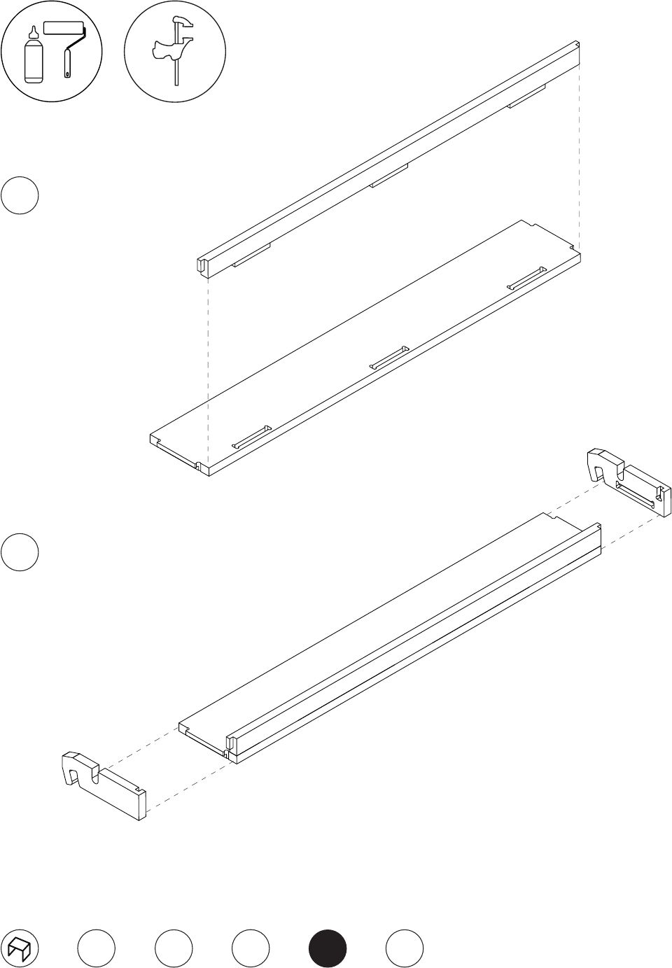
Cable Tray Exploded
2345
1
4.4
4.5
h
i
e
f
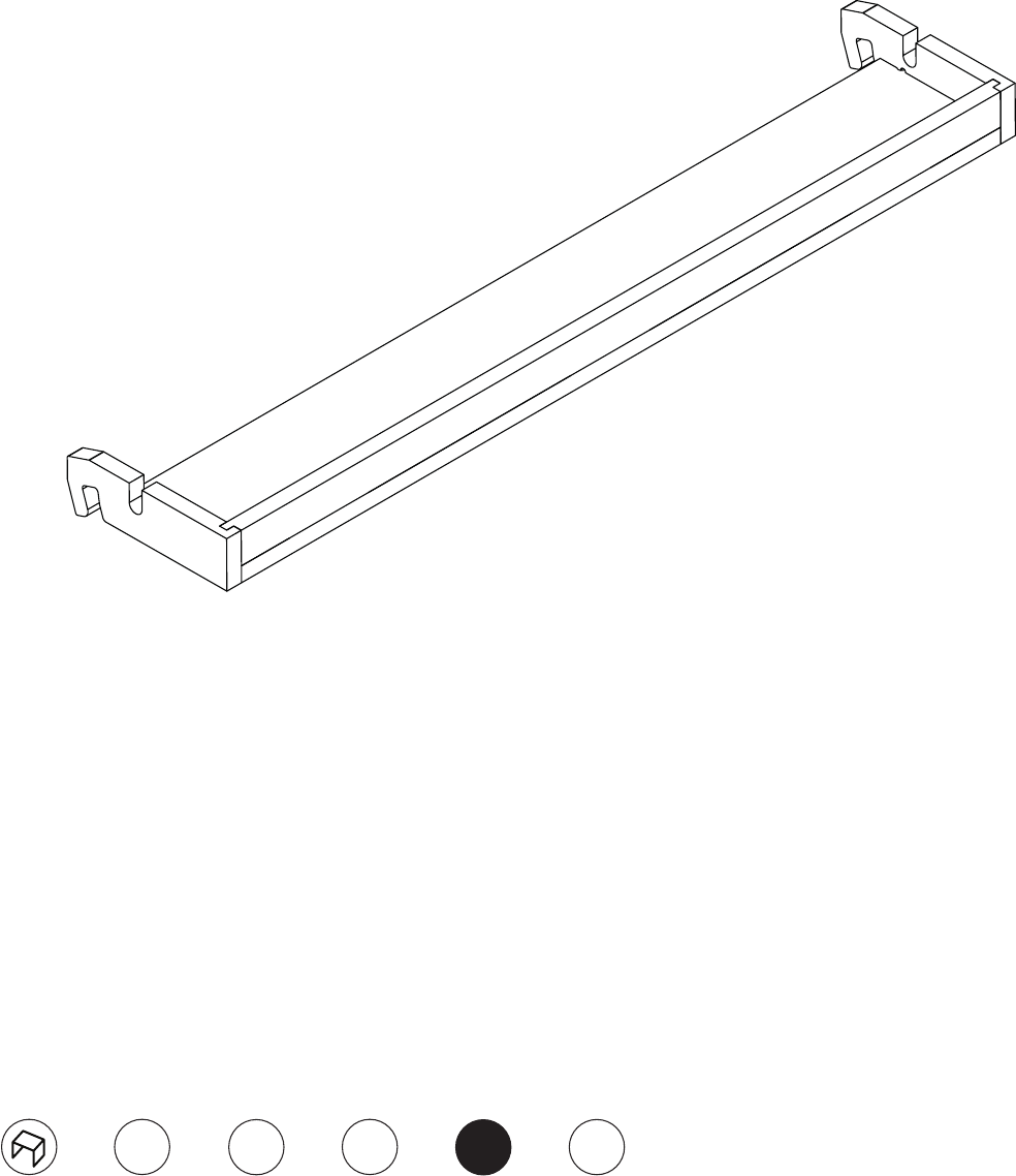
Completed Cable Tray
2345
1
Cable Cover and Cable Concealing Strips
B
240
A
320
A
320 A
320
B
240
2345
1
5.1
5.2
X2
j
b
X2
X2
X4
Checklist for Assembly

Tel: +44 (0)20 8986 9063
Email: info@opendesk.cc
@open_desk
