1604 VLZ PRO 16 Channel Mic/Line Mixer Spec Sheet Mackie Specifications 1604vlzpro Ss
1604-VLZ to the manual 2482868d-f419-4376-b4a7-1441ea965f44
Mackie 1604-VLZ Pro Specifications 1604vlzpro_ss Mackie - 1604-VLZ Pro - Specifications
User Manual: Mackie 1604-VLZ Pro Specifications Mackie - 1604-VLZ Pro - Specifications
Open the PDF directly: View PDF ![]() .
.
Page Count: 8
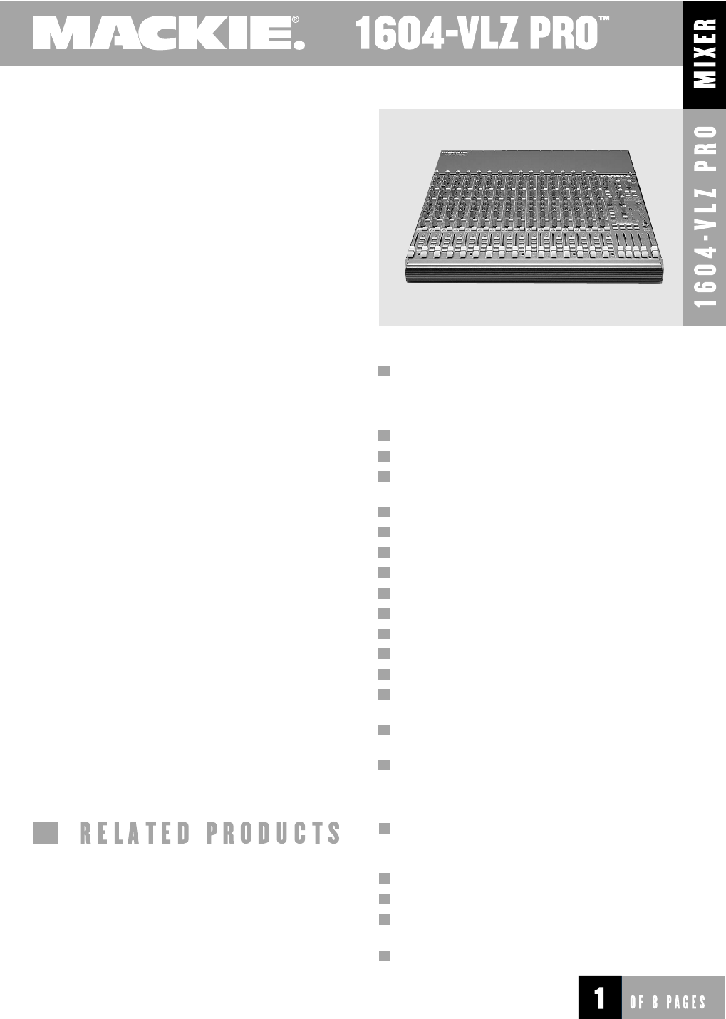
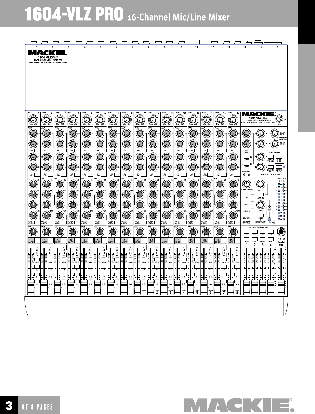
16-Channel Mic/Line Mixer
Continued on Page 2
Features
Applications
Introduction
The 1604-VLZ PRO is the latest update of our
CR1604-VLZ, incorporating our new ultra-high quality
XDR™ (Extended Dynamic Range) mic preamps with
the best RFI rejection of any compact mixer design on
the market and maximum freedom from ground loops.
Like all Mackie mixers, the 1604-VLZ PRO is
designed for rugged, 24-hour-a-day use. It is a
supremely fl exible mixer, not just because of its mul-
tiple input/output confi gurations, but because of its
true 4-bus architecture, 6 aux sends (with 3-4/5-6 shift
switch), and extensive routing capabilities.
No matter what the application, the 1604-VLZ
PRO can be confi gured for optimal use. As a table-
top mixer, input/output jacks can be positioned at
the rear of the unit, or with the optional RotoPod Kit
(RP1604-VLZ), positioned on the same plane as the
controls. Placed in a rack system, the 1604-VLZ PRO
can be set so that jacks are facing front (using the
RotoPod kit) or facing the rear to keep wandering
hands from playing with cords. Whether used in a
permanent installation, or as a portable mixer, the
1604-VLZ PRO is completely at home.
Built like a tank, the 1604-VLZ PRO is a team
player that can stand up to vigorous use, day in
and day out, any place it is installed. Its sturdy-yet-
light steel monocoque construction houses rugged,
double-sided through-hole-plated fi berglass circuit
boards, and 60mm faders with ultra-tight lip seals
for keeping out dust and other contaminants.
Impact-resistant knobs are mounted so they "ride"
just above the steel chassis — they absorb impact
without trouble. They’re designed to last, too,
thanks to co-molded potentiometers that don’t get
brittle and crack up. Then, we use metal stand-offs
RP1604-VLZ RotoPod bracket kit, 1604-VLZ Dirt Avert™
Ballistic Nylon Dust Cover, 1604-VLZ Fabric Mixer Bag and
1604-VLZ Suede Mixer Bag for 1604-VLZ PRO. 12-inch
and 18-inch Running Light Gooseneck lamps. 1202-VLZ
PRO 12-Channel Mic/Line Mixer, 1402-VLZ PRO 14-Chan-
nel Mic/Line Mixer, 1642-VLZ PRO 16-Channel Mic/Line
Mixer, SRM350/SRM450 Active 2-Way SR Loudspeakers,
M•800/M•1400i/M•1400 Power Amplifi ers, C200/
C300z passive 2-way SR Loudspeakers
Live sound mixing for churches, clubs,
schools, conference centers, board-
rooms, tradeshows, presentations
Keyboard, drum machine and DJ
Multitrack studio and fi eld recording
A/V presentations, video post produc-
tion, CD authoring, multimedia
Live broadcast remotes, ENG, ad production
16 low noise/high headroom XDR™ (Extended
Dynamic Range) XLR mic inputs with the best
RFI rejection of any compact mixer design and
maximum freedom from ground loops.
16 balanced/unbalanced mono line inputs
True 4-bus design
Multi-way physical confi guration via rotatable
I/O pod, or optional RotoPod Kit (RP1604-VLZ)
Inserts on all channels
Direct outs on channels 1–8
3-band EQ with sweepable mids
75Hz, 18dB/oct. Low Cut fi lter on each channel
PFL/AFL (Solo In-Place) on all channels (global)
Very Low Impedance (VLZ) architecture
Control Room/Phones source matrix
6 aux sends, 2 with master level controls
Wide input gain range with “virtual pad”
Stereo main outputs plus mono main output
with separate level control
Balanced inputs and outputs (except RCAs,
phones & inserts)
Level set LED and marker
2
Specifi cations footnotes:
1) 20Hz–20kHz bandwidth, 1/4" Main out, Channel Trims @ unity gain, channel EQs fl at, all
channels assigned to Main Mix, odd channels Pan left, even channels Pan right. Reference
+4dBu.
2) 1kHz @ +14dBu, 20Hz–20kHz.
3) 1kHz relative to 0dBu, 20Hz–20kHz bandwidth, Line in, 1⁄4" Main Out, Trim @ unity.
4) Any input to any output.
Specifi cations
Mic Preamp
Equivalent Input Noise (20Hz–20kHz):
150Ω –129.5dBu
50Ω –131.0dBu
0Ω –134.5dBu
Frequency Response:
–1dB 5Hz–100kHz
–3dB 3Hz–192kHz
IM Distortion (4:1 SMPTE),35dB gain 0.0008%
Harmonic Distortion (20Hz–20kHz), 35dB gain 0.0007%
Gain: Max +60dB
Min 0dB or Unity
Max Input +22dB
Input Impedance 1.3kΩ
Common Mode Rejection > 90dB
Common Mode Rejection Ratio > 140dB
Main Mix Noise1
Main Mix fader @ unity, ch. faders down: –90.5dB
Main Mix fader @ unity, ch. faders @ unity: –88.0dB
Total Harmonic Distortion (THD)2 0.005%
Attenuation (Crosstalk)3
Channel Mute switch engaged: –84dBu
Channel Fader down: –84dBu
Frequency Response4
20Hz to 60kHz: +0dB/–1dB
20Hz to 100kHz: +0dB/–3dB
Other Maximum Levels
All other inputs: +22dBu
Main Mix 1⁄4” TRS outputs: +28dBu
All other outputs: +22dBu
Other Impedances
Channel Insert return: 2.5kΩ
All other inputs: > 10kΩ
Tape out: 1.1kΩ
All other outputs: 120Ω
EQ
High Shelving: ±15db @ 12kHz
Mid Peaking: ±15dB, sweep 100Hz–8kHz
Low Shelving: ±15db @ 80Hz
Low Cut Filter: 18dB/octave, –3dB @ 75Hz
Power Consumption
120VA.C., 50/60Hz, 50 watts
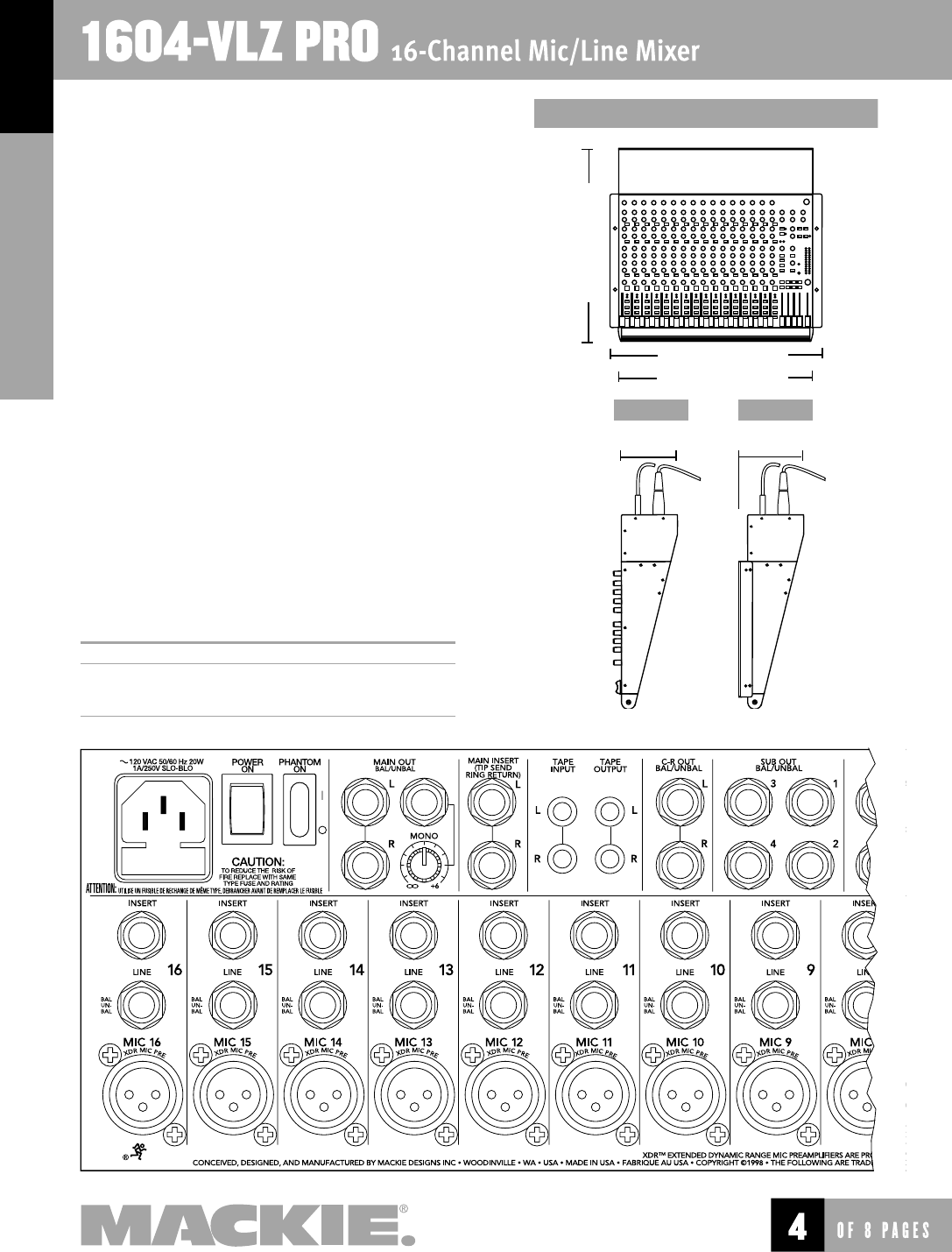
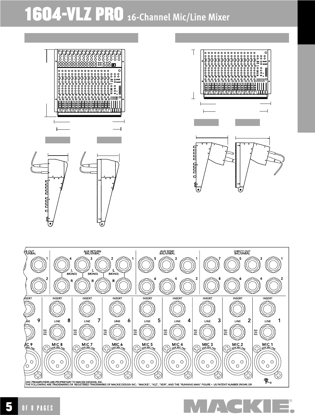
Physical
Dimensions see drawings on page 4 & 5
Weight 20 lbs. (9.1kg)
at regular intervals to mount thick fi berglass
circuit boards inside the mixer.
Radio frequency interference from TV/radio
stations and cellular phone users is virtually
eliminated, thanks to Mackie’s new XDR mic
preamp design.
The mixer’s built-in power supply is beefy
enough to handle major power consumption
without breaking up. And there’s no bulky “wall
wart” to be kicked out of place or to cover up
extra outlets.
All of this adds up to an extremely durable
mixer that can withstand major use and
misuse. Multi-user applications like churches,
night clubs, A/V rooms and schools are perfect
homes for the 1604-VLZ PRO.
Sixteen XDR mic preamps deliver the fi nest
quality sound ever offered in a compact mixer.
They cannot be damaged by hot patching. And
they are impedance-independent: frequency
response remains the same whether the mic
preamp is presented with an extremely high or
low-impedance load. Additionally, each chan-
nel has its own switchable low cut fi lter
(18dB/octave @ 75Hz), so mic thumps, room
rumble and stage mishaps are left out of the
mix without diminishing the audible bass fre-
quency range.
Four buses add mixing fl exibility. Channels
can be assigned to buses 1-2, 3-4 and/or Main
Mix L/R, and the 4 subs can be assigned to
left and/or right main mix. A Control Room/
Phones source matrix lets you route any com-
bination of tape, subs 1-2, 3-4, main mix or
Aux Return 4 to headphones, control room out-
puts, and meters. This enables you to monitor
2-track tape output or route a click/cue track
to phones, create special phones or broadcast
mixes via the subs, or create an extra stereo mix
(with its own gain control) for another zone, like
3
a cry room, lobby, or other such place.
For that matter, the 1604-VLZ PRO’s Mono Main Out
has its own level control, so a mono mix can be sent to
another zone and adjusted accordingly.
The 1604-VLZ PRO has six aux sends, in a four-
knob per channel strip format with Aux Sends 1 & 2
switchable pre- or post-fader, and the next two knobs
switchable between Aux Sends 3 & 4 or 5 & 6 (all four
are post-fader).
Solo has its own volume control and is switchable
from AFL (In-Place) to PFL. Level setting is easy in PFL,
especially when used in conjunction with the mixer’s
level set LED and marker (near the 12-segment stereo
LED ladder). Check a channel’s stereo placement
4
FILES FOR DOWNLOADING
1604VLZP.PDF this specifi cation sheet
1604VPAE.TXT text version of Architects
and Engineering Specifi cations
for insertion into proposals
17.6" (447.0mm)
10 rack spaces
5.0" (127mm)
19.0" (482.6mm)
5.6" (142.2mm)
17.3" (442.0mm)
recessednormal
Input/Output Pod mounted to top
by switching to AFL; the 1604-VLZ PRO’s constant-
power pan pots maintain a consistent loudness
across the stereo horizon.
Log-taper 60mm faders deliver a consistent fade
throughout the fader’s throw, so choppy fade-ins
and fade-outs are history. These faders have a co-
polymer membrane that provides a continuously
sealed barrier against dust and liquids without
interfering with fader travel. Similarly, the fader’s
long-wearing contact material (fi rst designed for
use in exterior automotive sensors) means longer
fader life and improved resistance to the elements.
The 1604-VLZ PRO is designed for continuous,
hassle-free use in any application or installation.
And it’s packed with useful features and practical
routing capabilities. Simply stated, this mixer
offers more features, more peace of mind and more
possibilities than any mixer in its class.
And it’s a Mackie.
5
17.9" (454.7mm)
11 rack spaces
6.0" (152.4mm)
19.0" (482.6mm)
17.3" (442.0mm)
6.6" (167.6mm)
recessednormal
13.0" (325.1mm)
8 rack spaces
8.7" (221mm)
19.0" (482.6mm)
17.3" (442.0mm)
9.3" (236.2mm)
recessednormal
Input/Output Pod mounted to front* Input/Output Pod mounted to back
*Via optional RP1604-VLZ RotoPod bracket (sold separately)
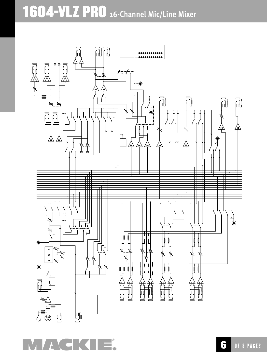
6
MAIN L
SUB 3
MAIN R
SUB 2
SUB 1
SUB 4
AUX 1
AUX 2
AUX 3
AUX 4
AUX 5
AUX 6
SIP L
SIP R
PFL
LOGIC
75Hz
HPF
MID HI
80100–8K12K
LO L
R
1
2
3
4
SIP L
SIP R
PFL
PHANTOM POWER
(GLOBAL SWITCH TRIM
MIC IN
LINE IN
DIRECT OUT
(CH'S 1–8 ONLY)
INSERT
LOW CUT
–20 (FLICKER)
SOLO (GLOW)
OL (FLICKER)
MUTE (GLOW)
EQ
GAIN FREQ
FADER
MUTE PAN ASSIGN
PRE
AUX 1
AUX 2
AUX 3
AUX 4 SHIFT 5/6
INPUT CHANNEL
(1 OF 16)
AUX RETURN 1
AUX RETURN 2
AUX RETURN 4
AUX RETURN 3
L
R
L
R
L
R
L
R
EFX TO
MON
LEVEL
LEVEL
LEVEL
LEVEL ASSIGN TO
C-R/PHNS
ONLY
MAIN/SUBS
1–2/3–4
EFX TO
MON
SOLO
TO SOLO LED
SIP L
SIP R
PFL
SOLO
CR/PHN L
CR/PHN R
SOLO
RELAY
ASSIGN
TO MIX
MAIN MIX
INSERT
FADER L
R
MAIN MIX MONO OUT
MAIN MIX LEFT OUT
TAPE OUT LEFT
TAPE OUT RIGHT
MAIN MIX RIGHT OUT
METERS
(0VU = 0dBu)
TAPE IN
L
R
TAPE LEVEL
C-R/
PHONES
SOURCE
MAIN
TAPE
1–2
RUDE SOLO LED
C-R/PHONES MIX
C-R/
PHONES
LEVEL CONTROL ROOM OUT
L
R
PHONES OUT
SIP/PFL
SOLO LEVEL
SOLO MIX
SUB 1 MIX
FADER
FADER
ASSIGN TO MAIN MIX
L
R
SUB 1 OUT
SUBMIX 1
(SUBMIX 3 IDENTICAL)
SUB 2 MIX
ASSIGN TO MAIN MIX
L
R
SUB 2 OUT
SUBMIX 2
(SUBMIX 4 IDENTICAL)
AUX MIX
LEVEL
AUX SEND 1
(#2 IDENTICAL)
AUX 1 OUT
AUX SEND 3
(#4–6 IDENTICAL)
AUX 3 OUT
SOLO
3–4
(FROM SUB 3 OUT)
(FROM SUB 4 OUT)
28
10
7
4
2
0
2
4
7
10
20
30
LEVEL SET
(PFL) LED
MONO LEVEL
7
Architect & Engineering Specifi cations
1. GENERAL CONFIGURATION. The mixer shall accommo-
date 16 line and/or 16 microphone signals, channels 1–16;
and shall include 16 Send/Return channel Inserts; 8 chan-
nel Direct Outputs, channels 1–8; 4 stereo pairs of Aux
Return inputs; 1 stereo pair of Main Mix outputs; 1 Main
Mix Mono output, 1 stereo pair of Control Room outputs;
4 Submaster outputs; 6 Aux Send outputs; 1 stereo pair
of RCA-type phono Tape outputs; and 1 stereo Headphones
output. The mixer shall be capable of placement on a table
or installation in a standard 19-inch rack mount via rack
rail brackets (included); shall be fi tted with 1 rocker-type
Power switch; 1 3-pin power receptacle with user-replace-
able 5x20mm fuse drawer; 1 BNC socket, providing 12VDC
for fi tting an external lamp (not included); and shall be
entirely self-contained.
2. MIXER INPUTS.
CHANNELS 1–16: Each channel shall include an XDR™
(Extended Dynamic Range) electronically balanced micro-
phone input, using an XLR-3-F-type connector, accepting
nominal levels from –60dBu to +4dBu via a rotary Trim
control. Phantom power shall be globally-controlled via
a rocker-type switch. 16 Balanced/unbalanced (bal/unbal)
line inputs shall be wired in parallel, using 1/4" TRS
phone jacks, accepting nominal levels from –40dBu to
+4dBu. Each channel shall include a pre-fader Insert
point, using 1/4" TRS phone jacks (tip=send, ring=return,
sleeve=ground), delivering and accepting nominal levels
from –10dBV to +4dBu.
OTHER INPUTS: The mixer shall include 8 bal/unbal
Aux Return inputs, forming four stereo pairs, using 1/4"
TRS phone jacks, accepting nominal levels from –10dBV
to +4dBu; and 1 stereo pair of Tape In jacks, using unbal-
anced RCA-type phono jacks, accepting nominal levels from
–10dBV to +4dBu.
3. MIXER OUTPUTS.
MAIN OUTPUTS: The mixer’s Main Mix stereo outputs
shall be fi tted in two ways: Using symmetrically balanced
(also accepting unbalanced) 1/4" TRS phone jacks, deliv-
ering maximum output of +28dBu; and using unbalanced
RCA-type phono jacks (labeled TAPE OUT), delivering nomi-
nal levels from –10dBV to +4dBu; and the Main Mix Mono
output shall be fi tted with one symmetrically balanced
(also accepting unbalanced) 1/4" TRS phone jack, delivering
nominal levels from –10dBV to +4dBu.
OTHER OUTPUTS: Input channels 1–8 shall each include
a post-fader Direct Output, using bal/unbal 1/4" TRS phone
jacks, delivering nominal levels from –10dBV to +4dBu.
The mixer shall include 4 Submaster outputs, using bal/
unbal 1/4" TRS phone jacks, delivering nominal levels
from –10dBV to +4dBu; 1 stereo pair of Control Room
outputs, using bal/unbal 1/4" TRS phone jacks, delivering
nominal levels from –10dBV to +4dBu; 6 Aux Send outputs
using bal/unbal 1/4" TRS phone jacks, delivering nominal
levels from –10dBV to +4dBu; and 1 stereo Headphones
output, using an unbalanced 1/4" TRS phone jack (tip=left,
ring=right, sleeve=ground).
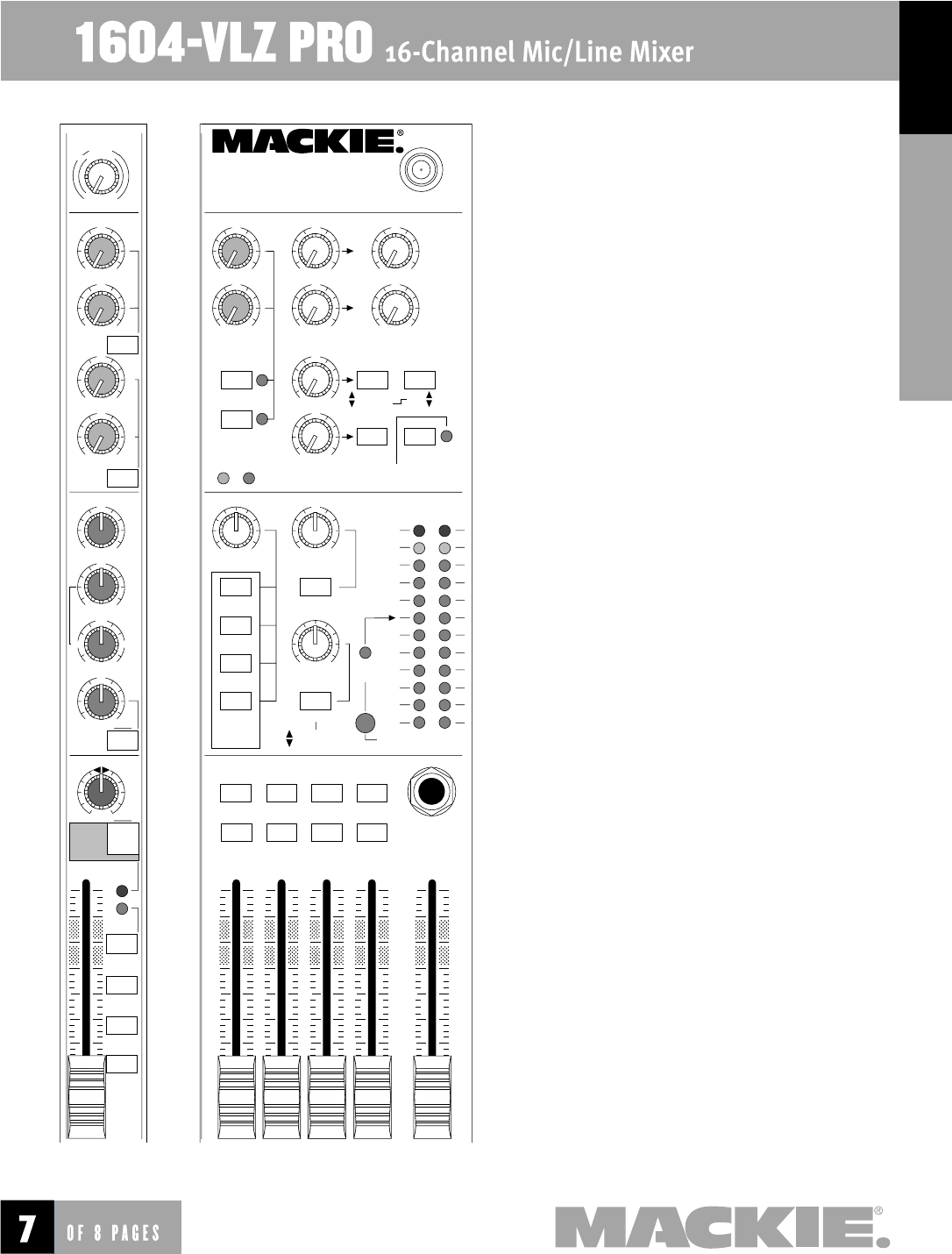
4. MIXER INPUT SECTION. In addition to the controls
listed in section 2 (MIXER INPUTS), each channel shall
include 4 rotary Aux Send controls and 1 Shift switch, pro-
viding up to 15dB gain, routing signals to Aux Sends 1, 2,
3 and 4 when the Shift switch is disengaged, and to Aux
PAN
AUX
3
1
2
EQ
5
46
5/6
SHIFT
PRE
TRIM 1
SOLO
L - R
3–4
1–2
OL
-20
U
OO
+15
U
OO
+15
U
OO
+15
U
+15-15
U
+15-15
800
2k200
8k
U
+15-15
12k
HI
MID
80Hz
LOW CUT
75 Hz
18dB/OCT
LOW
10 0
U
OO
+15
1
MUTE
M
I
C
G
A
I
N
060
+15dB -45dB
-
1
0
d
B
V
LR
OO
U
AUX
SEND
STEREO AUX RETURN
EFFECTS TO
MONITORS
TO AUX
SEND 2
TO AUX
SEND 1
1
2
PWR
PHAN
SOLO
SOLO
1
2
1
2
3
4
1
2
C-R / PHNS
ONLY
RETURNS
SOLO
MAIN MIX
TO SUBS
ASSIGN OPTIONS
1–2
3–4
U
OO
+20
U
OO
+20
U
OO
+15
U
OO
+15
U
OO
+20
U
OO
+20
U
OO
+10
U
OO
+10
LEFT RIGHT
PHONES
LAMP
12 V
0.5A
TAPE IN
SOLO
RUDE
SOLO
LIGHT
CTL ROOM / PHONES
SUBS 3–4
SUBS 1–2
MAIN MIX
CTL ROOM
SOURCE
TAPE TAPE TO
MAIN MIX
MAIN
MIX
RIGHT
1234
LEFT
RIGHT
LEFT
RIGHT
LEFT
RIGHT
LEFT
28
10
7
4
2
2
0
4
7
10
20
30
ASSIGN TO MAIN MIX
LEVEL
SET
MODE
(AFL)
LEVEL SET
NORMAL
(PFL)
U
OO
+20
OO
OO
MAX
0 dB=0 dBu
MAX
dB
30
20
10
OO
40
50
5
5
U
60
10
dB
30
20
10
OO
40
50
5
5
U
60
10
1604-VLZ PRO
16- CHANNEL MIC / LINE MIXER
WITH PREMIUM XDR
TM
MIC PREAMPLIFIERS
Part No. 091-296-00 Rev. B
8
Sends 1, 2, 5 and 6 when the Shift switch is engaged, and
Aux Sends 1 and 2 shall have a pre/post switch; 4 rotary
equalization (EQ) controls: ±15dB fi xed 12kHz shelving gain,
±15dB midrange peaking gain, 100Hz – 8kHz midrange fre-
quency, and ±15dB fi xed 80Hz shelving; 1 75Hz 18dB/oct.
Low Cut fi lter switch; 1 rotary Pan control, 4dB attenuation
panned center; 1 Mute switch; 1 dual-mode Solo switch (AFL
or PFL, globally switched); 3 output Assign switches, deliver-
ing the channel’s signal, relative to its Pan setting, to the
Main L-R Mix, Submasters 1–2 and Submasters 3–4; and
1 channel Fader, providing up to 10dB above unity gain.
Additionally, each channel shall include two LED indicators; a
–20/Solo LED acting as a Signal Present indicator by fl icker-
ing and as a channel Solo indicator by glowing steadily; and
an OL/Mute LED, acting as an overload indicator by fl ickering
and as a channel Mute indicator by glowing steadily.
5. MIXER OUTPUT SECTION. The mixer shall have 1 Main
Mix stereo fader, providing up to 10dB gain; 4 Submaster
mono faders, each providing up to 10dB gain; independent
left and right Assign to Main Mix switches for each Submas-
ter; 1 Control Room/Phones level rotary stereo control, pro-
viding up to 10dB gain; 1 Source Matrix, including 4 switches
to deliver any combination of stereo signals to the Control
Room, Phones and Meters, including Main Mix, Submasters
1–2, Submasters 3–4 and Tape, which shall be replaced
by solo signals resulting from the engagement of any Solo
switch; 1 rotary stereo Tape In level control, providing up to
20dB gain; 1 Tape to Main Mix switch; 1 Solo Mode switch
to globally determine solo type (pre-fader listen or after-fader
listen, in place); 1 rotary stereo Solo level control, providing
up to 10dB gain; 4 rotary stereo Aux Return level controls,
providing up to 20dB gain; two Effects to Monitor rotary
controls, providing up to 15dB gain, delivering summed Aux
Return 1 or 2 signals to Aux Send 1 or 2, respectively; an Aux
Return 3 Assign switch, used in conjunction with a 1–2/3–4
switch, delivering Aux Return 3 signals to one output pair,
including Main Mix, Submasters 1–2 and Submasters 3–4; an
Aux Return 4 to Control Room/Phones Only switch; a global
Aux Return Solo switch with associated LED; 2 rotary Aux Send
Master controls for Aux Sends 1 and 2, providing up to 10dB
above unity gain; a Solo switch with associated LED for each of
Aux Sends 1 and 2; a blinking master Solo indicator LED, a Level
Set LED, indicating a PFL solo condition, a Power indicator LED;
and a Phantom Power indicator LED.
6. METERING. The mixer shall include 1 stereo 12-seg-
ment LED meter with points at –30, –20, –10, –7, –4, –2, 0,
+2, +4, +7, +10 and +28dB. The source signals for the meters
shall be the same signals selected in the Source Matrix, and
a solo condition shall replace the Source selection with the
soloed channel(s). The meters shall be calibrated so that a
0dBu signal at the Control Room output shall be indicated as
0dB on the meters, ±1LED.
7. PHYSICAL CONFIGURATION. The mixer shall be made
of steel and aluminum, painted dark gray and black with
light gray graphics. The mixer shall weigh 20 lbs, 0 oz (9.1
kg). Included rackmount brackets shall allow the mixer to be
mounted in a rack system, with either the chassis surface
or the control knobs’ tops to be fl ush with the rack rail.
Additionally, the jackfi eld portion of the mixer, referred to
as the Pod, shall be adjustable in three different positions;
Desktop Mode (stock confi guration), with jackfi eld connec-
tions to rear as seen laying horizontally on a table; Rackmount
mode, with the jackfi eld connections to the rear of the rack
when mounted vertically; and RotoPod mode, requiring an
RP1604-VLZ RotoPod Bracket (not included), with jackfi eld
connections on the same plane as the faders. Dimensions
of the mixer shall be, in Desktop Mode, 17.3" (442mm) in
width, 17.6" (447mm) in depth, and 5.0" (127mm) in height;
in Rackmount Mode, 19" (483mm) in width (including rack
rails) 13.0" (325mm) in height, and 9.3" (236mm) in depth;
in RotoPod Mode (using optional brackets sold separately)
19" (483mm) in width (including rack rails), 17.9" (455mm) in
height and 6.6" (168mm) in depth.
8. SPECIFICATIONS. In addition to specifi cations already
cited, the mixer shall meet or exceed the following specifi ca-
tions. Frequency response, microphone input to any output,
20Hz to 60kHz, +0dB/–1dB; Total Harmonic Distortion (THD),
any input to any output, 1kHz @ +14dBu, 0.0007%; Equiv-
alent Input Noise (EIN), microphone input to insert send,
–129.5dBm; Common Mode Rejection (CMR), microphone
input to insert send, maximum gain, 1kHz, better than 90dB;
Typical Main Output noise, all channels assigned, odd chan-
nels panned left, even channels panned right, all faders down
–100dBu; Signal to Noise ratio, ref +4dBu operating level,
90dB; Attenuation, ref. 0dB @ 1kHz, Main Mix level control
down, –85dBu; Channel Mute engaged, –84dBu; Channel
Gain control down, –83dBu; Input impedance, microphone
inputs, 1.3 kΩ; Channel Insert return, 2.5 kΩ; All other inputs,
greater than 10 kΩ; Output impedance, Tape Out, 1.1 kΩ; All
other outputs, 120Ω.
The mixer shall be a Mackie 1604-VLZ PRO.
LOUD Technologies continually engages in research related to product improvement. New material,
production methods, and design refi nements are introduced into existing products without notice
as a routine expression of that philosophy. For this reason, any current LOUD Technologies product
may differ in some respect from its published description, but will always equal or exceed the
original design specifi cations unless otherwise stated. ©1999-2004 LOUD Technologies Inc. All
rights reserved.
www.mackie.com
16220 Wood-Red Road NE, Woodinville, WA 98072 USA
800.898.3211, fax 425.487.4337, sales@mackie.com
UK +44.1268.570.808, fax +44.1268.570.809, uk@mackie.com
