ASME Section III, Div 1 NB 2000 16792
User Manual: NB 2000
Open the PDF directly: View PDF ![]() .
.
Page Count: 77
- Today’s Agenda
- ASME Code Usage
- Trend for Boiler Explosions in the U.S.
- Today’s Agenda
- ASME Section III, Div. 1
- Component Classification
- Section III Subsection Organization
- NCA-1140 Use of Code Editions and Addenda
- NCA-1140 Use of Code Editions and Addenda
- Today’s Agenda
- Code Interpretations
- Inquiry on Code Edition and Addenda
- Inquiry on Code Edition and Addenda
- NCA-1140 Accompanying Code Change
- Code Cases
- NCA-1140 Code Case
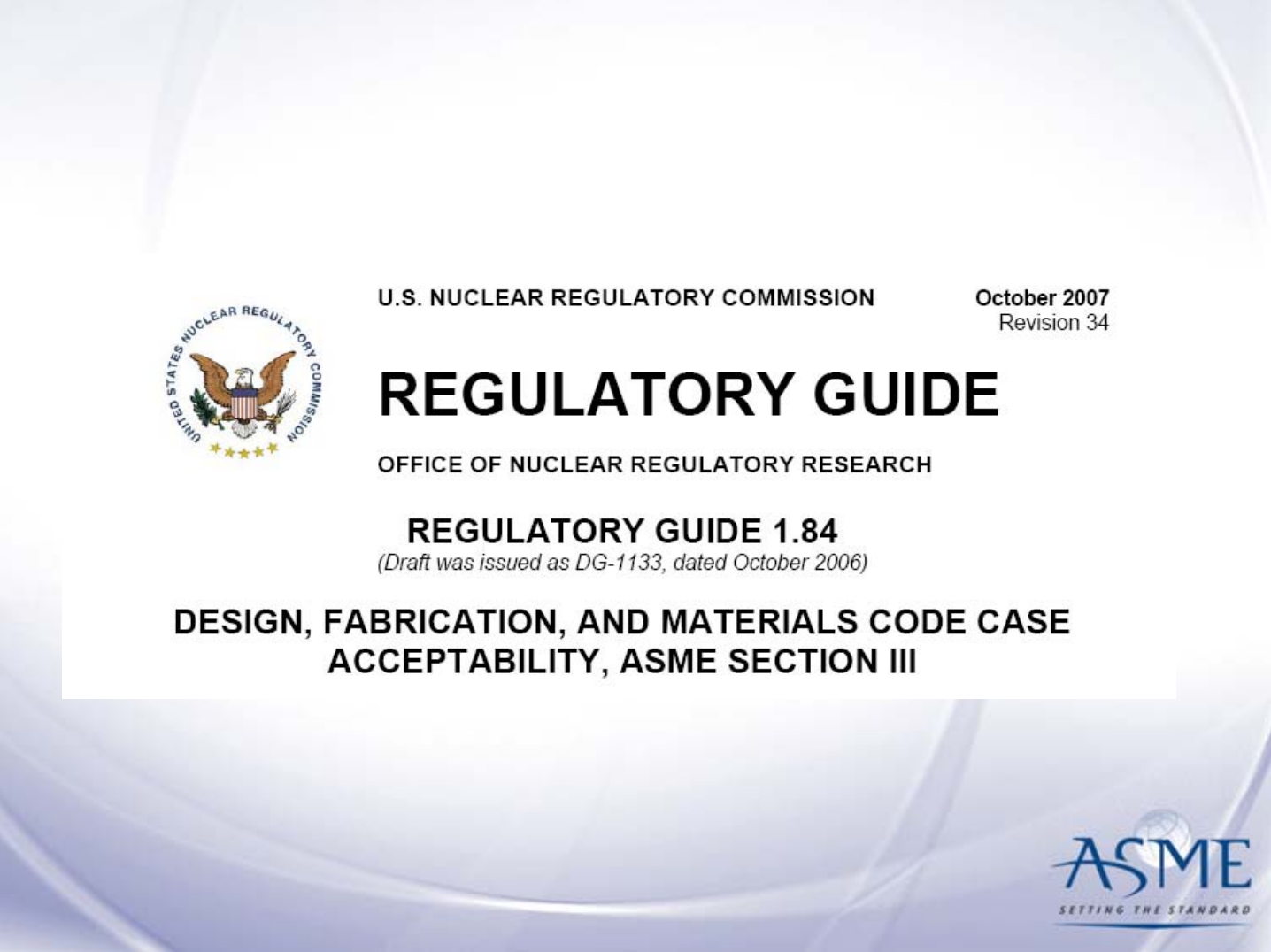
- Regulatory Approval of Code Cases
- Other Code Case Regulatory Guides
- Today’s Agenda
- Basic Definitions
- Section III Material Requirements
- Important Concepts/Requirements
- Important Concepts/Requirements
- Jurisdictional Boundaries (Detail)
- Today’s Agenda
- Structure of Section III Subsections
- Subsection NB Class 1 Components
- Article NB-2000 Materials
- Article NB-2000 Materials (cont.)
- Article NB-2000 Materials (cont.)
- Design NB-3000
- NB-3100 General Design
- NB-3200 Design by Analysis
- NB-3200 Design By Analysis (cont.)
- NB-3200 Design By Analysis (cont.)
- Section III Design by Rule
- NB-3300 Vessel Design
- NB-3300 Vessel Design
- Design, Fabrication & Examination Integration
- Design NC/ND-3000
- Fabrication and Installation NB-4000
- NB-4100 General Requirements
- NB-4200 Forming Fitting and Aligning
- NB-4200 Forming Fitting and Aligning (cont.)
- NB-4200 Forming Fitting and Aligning
- NB-4200 Forming Fitting and Aligning
- NB-4200 Forming Fitting and Aligning
- NB-4200 Forming Fitting and Aligning
- NB-4200 Forming Fitting and Aligning
- NB-4300 Welding Qualifications
- NB-4400 Rules Governing Making, Examining and Repairing Welds
- NB-4500 thru NB-4700
- NB-4600 Postweld Heat Treatment
- NC/ND-4000 Fabrication and Installation
- Examination NB-5000
- NB-5000 Examination
- NB-5000 Examination (cont.)
- Testing NB-6000
- NB-6000 Testing
- NC/ND-6000 Testing
- Overpressure Protection NB/NC/ND-7000
- NB-7300 Relieving Capacity Requirements
- NB-7500 Operating Design Requirements for Pressure Relief Valves
- Article NB/NC/ND-8000 Nameplates, Stamping and Reports
- Today’s Agenda
- Section III, Appendices
- Mandatory Appendix Example
- Nonmandatory Appendix Example
- Section III: Mandatory Appendices
- Section III: Nonmandatory Appendices
- Appendices of Interest
- Overall Summary
- Thank You

Session 3
Section III - Component Design and Construction
ASME Nuclear Codes and Standards
Supporting New Build and Nuclear
Manufacturing in South Africa
Sandton, South Africa, October 7-8, 2008
Ralph S. Hill III, PMP
Consulting Engineer, Westinghouse Electric Company

Today’s Agenda
1. Small Advertisement for the ASME Code
2. Structure and Use of Section III
3. Code Interpretations and Code Cases
4. Basic Terms & Important Concepts
5. Subsections of Section III
6. Appendices

ASME Code Usage
60 Countries – ASME B&PV Code
15 Countries –Section III/XI Nuclear Code
20 Countries – Section III Certificate Holders
30 Countries purchase items to Section III/XI
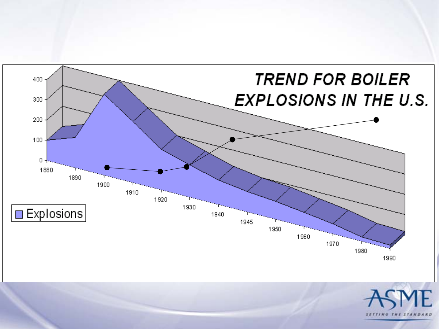
Trend for Boiler Explosions in the U.S.
400 psi
500 psi
650 psi
1600 psi
5000 psi
PRESSURE LEVEL

Today’s Agenda
1. Small Advertisement for the ASME Code
2. Structure and Use of Section III
3. Code Interpretations and Code Cases
4. Basic Terms & Important Concepts
5. Subsections of Section III
6. Appendices
ASME Section III, Div. 1
– 8 Subsections
• NCA: General Requirements
• NB: Class 1 Components
• NC: Class 2 Components
• ND: Class 3 Components
• NE: Class MC Components
• NF: Supports
• NG: Core Support Structures
• NH: Class 1 Components in Elevated Temp.
Service
– Appendices
– Code Cases Nuclear Components

Component Classification
Class 1 Components (III, Subsection NB)
Those components that are part of the primary core
cooling system
Components (III, Subsection NH)
Those components that are used in elevated temperature
service
Class 2 Components (III, Subsection NC)
Those components that are part of various important-to-
safety emergency core cooling systems
Class 3 Components (III, Subsection ND)
Those components that are part of the various systems
needed for plant operation

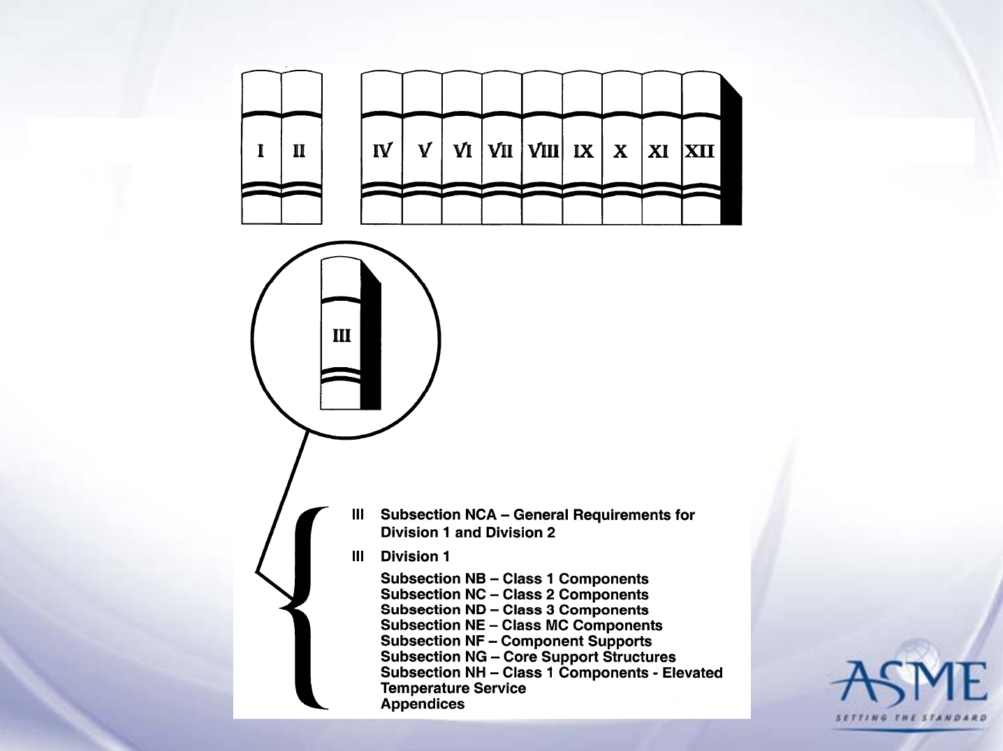
Section III Subsection Organization
• materials
• design
• fabrication
• examination
• inspection
• testing
• overpressure protection
• certification
organization =
NX-2000
NX-3000
NX-4000
NX-5000
NX-5000
NX-6000
NX-7000
NX-8000
“construction” =

NCA-1140 Use of Code
Editions and Addenda
(a)(1) Under the rules of Section III, the Owner or his
designee shall establish the Code Edition and
Addenda to be included in the Design Specifications.
All items of a nuclear power plant may be
constructed to a single Code Edition and Addenda, or
each item may be constructed to individually
specified Code Editions and Addenda.

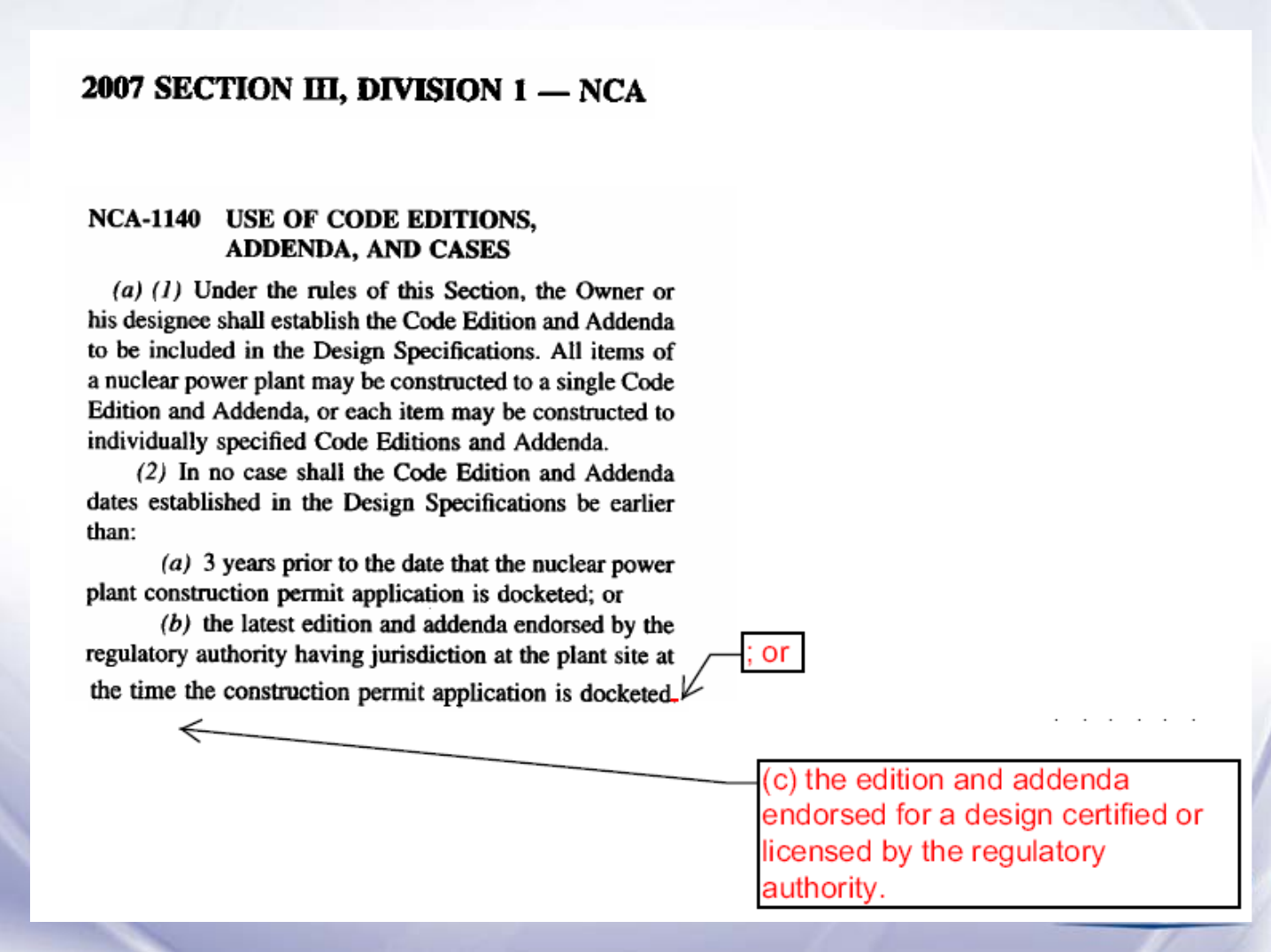
NCA-1140 Use of Code
Editions and Addenda
(a)(2) In no case shall the Code Edition and Addenda
dates established in the Design Specifications be
earlier than:
(a) 3 years prior to the date that the nuclear
power plant construction permit application is
docketed; or
(b) The latest edition and addenda endorsed by
the regulatory authority having jurisdiction at the
plant site at the time the construction permit
application is docketed.

Today’s Agenda
1. Small Advertisement for the ASME Code
2. Structure and Use of Section III
3. Code Interpretations and Code
Cases
4. Basic Terms & Important Concepts
5. Subsections of Section III
6. Appendices

Code Interpretations
• Provide answers to questions about the
Code
• Anyone can request
– Appendix XX provides instructions
• Are published in the Code so answers
are available to everyone

Inquiry on Code Edition and Addenda
10CFR52 Design Certification Process
• Regulator may have approved Edition and
Addenda earlier than latest endorsed by
regulator at time Combined License
Application is docketed
• Regulator may have approved Edition and
Addenda from the Design Certification
Document at time Combined License
Application is docketed

Inquiry: As described in NCA-1140(a)(2)(b), does
“the endorsement of the latest Code Edition and
Addenda by the regulatory authority at the time
the construction permit is docketed” include the
Code Edition and Addenda endorsed by the
regulator through the design certification process
and included in the combined operating license
(COL) at the time the COL is docketed?
Proposed Reply: Yes.
Inquiry on Code Edition and Addenda
NCA-1140
Accompanying
Code Change

Code Cases
Provide:
• Relief from an existing Code requirement
• Treatment of topics not currently addressed
Are:
• Permissive, not mandatory
• Issued periodically by Code Committee
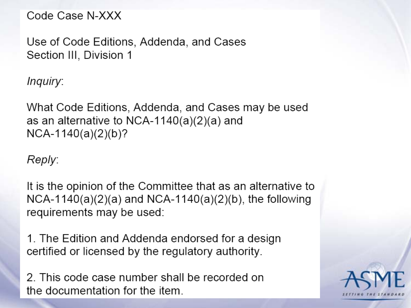
NCA-1140
Code Case
Regulatory Approval of Code Cases

Other Code Case Regulatory Guides
•Regulatory Guide 1.147 lists Code Case
Acceptability for Section XI, In-Service
Inspection
•Regulatory. Guide 1.192 lists the Operation
and Maintenance Code Case Acceptability.
•Unendorsed Code Cases are listed in
Regulatory Guide 1.193

Today’s Agenda
1. Small Advertisement for the ASME Code
2. Structure and Use of Section III
3. Basic Terms & Important Concepts
4. Subsections of Section III
5. Appendices
6. Code Cases

Basic Definitions
•Material
•Component

Section III Material Requirements
• Material Specification
– Section II: Parts A, B, C, & D
• Control of Material
– Section III: NCA-3800
• Special Material Requirements
– Section III: NX- 2000

Important Concepts/Requirements
TRACEABILITY
•Identification
– NCA-3856 Identification, Marking, and Material Control
– NB-4122 Material Identification
•Certification of Material
– NCA-3861 Certification Requirements for Material
Organizations
– NCA-3862 Certification of Material
– NCA-3862.1 Material Certification
– NCA-3862.2 Quality System Program Statement

Important Concepts/Requirements
• Thermal stresses explicitly considered
• Basis for stress limits shifted from maximum
principal stress theory to more accurate
maximum shear stress theory
• Fatigue recognized as possible failure mode
• Brittle fracture specifically treated
• Plastic limit analysis established as a reliable
predictor of ductile failure after some plastic
action
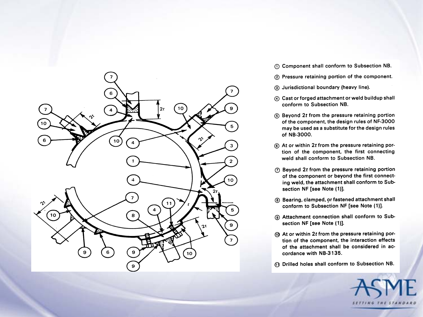
Jurisdictional Boundaries
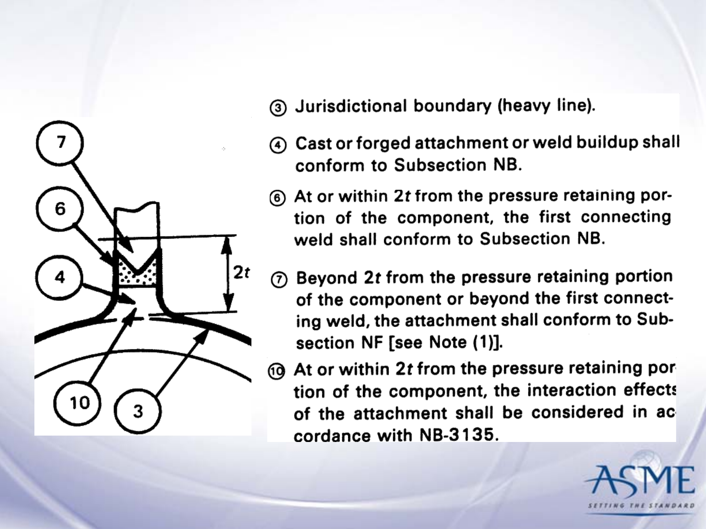
Jurisdictional Boundaries (Detail)

Today’s Agenda
1. Small Advertisement for the ASME Code
2. Structure and Use of Section III
3. Code Interpretations and Code Cases
4. Basic Terms & Important Concepts
5. Subsections of Section III
6. Appendices

Structure of Section III Subsections
Article NX-1000 Introduction
Article NX-2000 Material
Article NX-3000 Design
Article NX-4000 Fabrication and Installation
Article NX-5000 Examination (NDE)
Article NX-6000 Pressure Testing
Article NX-7000 Overpressure Protection
Article NX-8000 Nameplates, Stamping & Reports

Subsection NB Class 1 Components
Article NB-1000 Introduction
Article NB-2000 Material
Article NB-3000 Design
Article NB-4000 Fabrication and Installation
Article NB-5000 Examination (NDE)
Article NB-6000 Pressure Testing
Article NB-7000 Overpressure Protection
Article NB-8000 Nameplates, Stamping & Reports

Article NB-2000 Materials
NB-2100 General Requirements for Material
NB-2200 Material Test Coupons and
Specimens for Ferritic Steel Material
NB-2300 Fracture Toughness Requirements
NB-2400 Welding and Brazing Material

Article NB-2000 Materials (cont.)
NB-2500 Examination and Repair of
Pressure Retaining Material
─Plate ─Forgings and Bars
─Seamless and Welded Tubular Products
and Fittings
─Tubular Products and Fittings with Filler
Metal
─Statically & Centrifugally Cast Products
─Bolts, Studs and Nuts

NB-2600 Material Manufacturers’ Quality
System Program
NB-2700 Dimensional Standards
NB-2160 Deterioration of Material
– Outside scope of Section III
– Covered in Design Specification
Article NB-2000 Materials (cont.)

Design NB-3000
NB-3100 General Design
NB-3200 Design by Analysis
NB-3300 Vessel Design
NB-3400 Pump Design
NB-3500 Valve Design
NB-3600 Piping Design

NB-3100 General Design
• Loading Criteria
–Loading conditions (pressure, impact loads, weight,
reaction, etc.)
–Design loadings (design pressure, design temperature and
design mechanical loadings)
• Special Considerations
–Corrosion
–Cladding stresses
–Welding (dissimilar welds, fillet weld attachments)
• External Pressure Analysis

NB-3200 Design by Analysis
• Design Criteria
– Basis for determining stresses (maximum shear
stress theory)
– Terms relating to stress analysis
– Stress classification
– Derivation of stress intensities
NB-3200 Design By Analysis (cont.)
Stress Limit Failure Mode
Primary (Pm,
Pb& PL)
Plastic deformation and provide nominal
factor of safety on ductile burst pressure
Primary plus
secondary
(P+Q)
Excessive plastic deformation leading to
incremental collapse and validate fatigue
evaluation elastic analysis
Peak (Sa) Fatigue failure as a result of cyclic
loadings
Special Elastic and inelastic instability

NB-3200 Design By Analysis (cont.)
• Stress Limits for Components
– Design Condition Limits
– Level A Service Condition Limits (Normal)
– Level B Service Condition Limits (Upset)
– Level C Service Condition Limits (Emergency)
– Level D Service Condition Limits (Faulted )
– Test Condition Limits
• Fatigue Analysis Procedure
• Thermal Stress Ratchetting
• Plastic Analysis
• Limit Analysis
• Simplified Elastic Plastic Analysis

Section III Design by Rule
• Uses simple equations
• Sets rules on geometry of construction
• Uses conservative design values for
pressure and temperature
• Justification is based on allowing only low
stresses combined with “over-design”

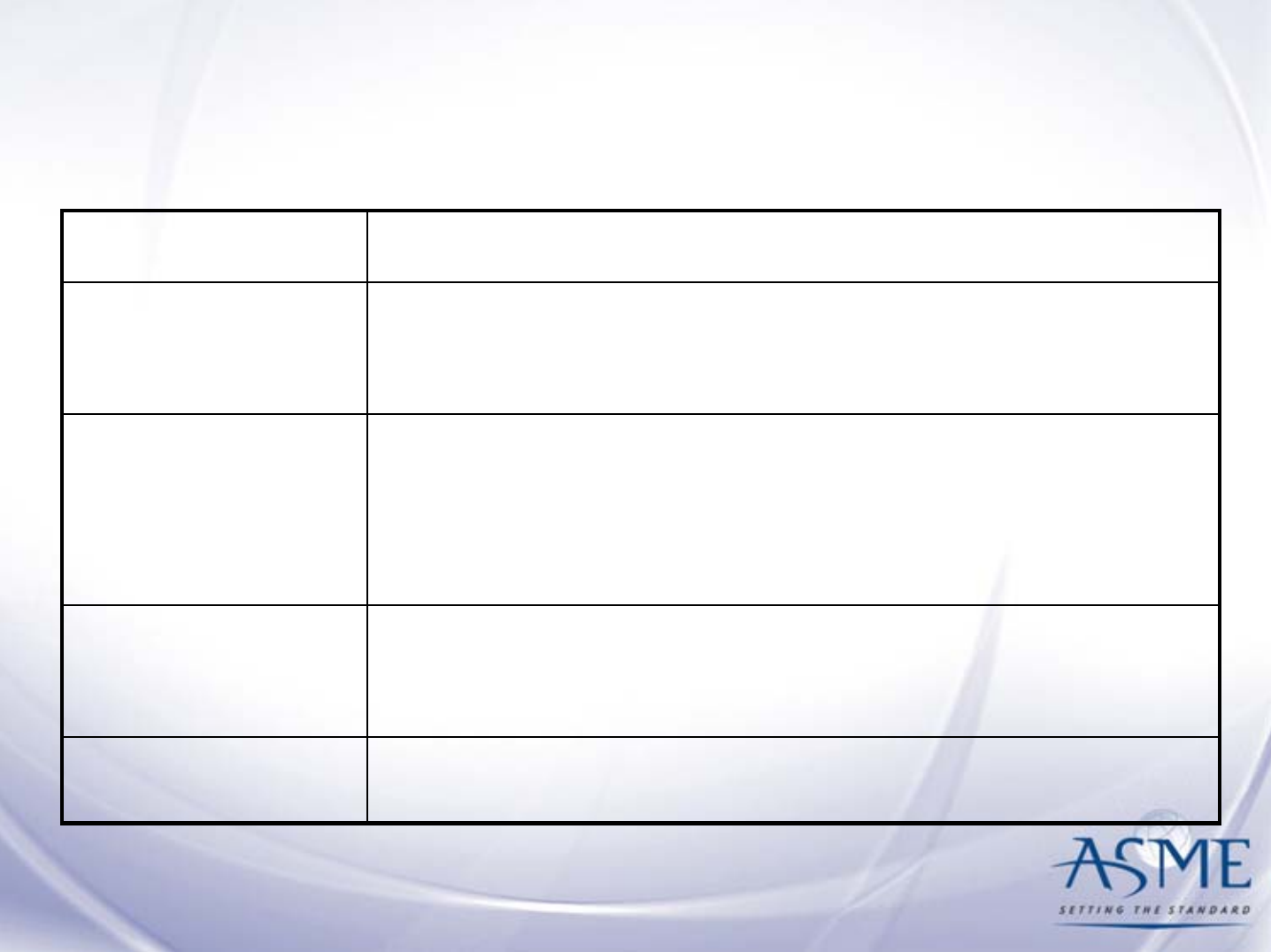
NB-3300 Vessel Design
• General Requirements
• Design Considerations
– Minimum Pressure Thickness Calculations
• Openings and Reinforcement
• Design of Welded Construction
NB-3300 Vessel Design

Design, Fabrication &
Examination Integration
NB-3352.1 Joints of Category A
All welded joints of Category A as defined
in NB-3351 shall meet the fabrication
requirements of NB-4241 and shall be
capable of being examined in accordance
with NB-5210.

Design NC/ND-3000
NC/ND-3100 General Design
NC/ND-3200 Alternate Design Rules for Vessels
NC/ND-3300 Vessel Design
NC/ND-3400 Pump Design
NC/ND-3500 Valve Design
NC/ND-3600 Piping Design
NC/ND-3700 Electrical and Mechanical
Penetration Assemblies
NC/ND-3800 Atmospheric Storage Tanks
NC/ND-3900 Storage Tanks 0-15 psig (0-103 kPa)

Fabrication and Installation NB-4000
NB-4100 General Requirements
NB-4200 Forming, Fitting and Aligning
NB-4300 Welding Qualifications
NB-4400 Making, Examining and Repairing Welds
NB-4500 Brazing
NB-4600 Heat Treatment
NB-4700 Mechanical Joints

NB-4100 General Requirements
• Certification of materials
• Fabrication by certificate holder
• Repair of materials

NB-4200 Forming Fitting and Aligning
• Cutting
– Material may be cut to shape and sized by mechanical
means, such as:
• Machining
•Shearing
• Chipping
•Grinding
• Thermal cutting
• Recommendations for preheating prior to thermal
cutting in Appendix D Preheat Procedures

• Forming and Bending Processes
– May be hot or cold provided impact properties are not
reduced below specified values
– Heat treatment may be used to restore properties
• Qualification of Forming Processes for Impact
Property Requirements
– Procedure qualification test required
– Acceptance standard based on impact properties
NB-4200 Forming Fitting and Aligning
(cont.)
NB-4200 Forming Fitting and Aligning
NB-4200 Forming Fitting and Aligning
NB-4200 Forming Fitting and Aligning
NB-4200 Forming Fitting and Aligning
NB-4200 Forming Fitting and Aligning

NB-4300 Welding Qualifications
• Types of processes permitted
• Required qualifications
• Requirements for welding procedure qualification
tests
• Special qualification requirements for tube-to-
tubesheet welds
• Qualification requirements for welding specially
designed welded seals

NB-4400 Rules Governing Making,
Examining and Repairing Welds
• Precautions before welding
• Rules for making welded joints
• Welding of attachments
• Repair of weld metal defects

NB-4500 thru NB-4700
NB-4500 Brazing
– Rules for brazing
– Qualification requirements
– Fitting and aligning
– Examination
NB-4600 Heat Treatment
– Welding preheat requirements
– Post-weld heat treatment requirements
– Intermediate post-weld heat treatment
– Heat treatment after bending or forming for
pipes, pumps and valves
– Heat treatment of electroslag welds
NB-4700 Mechanical Joints
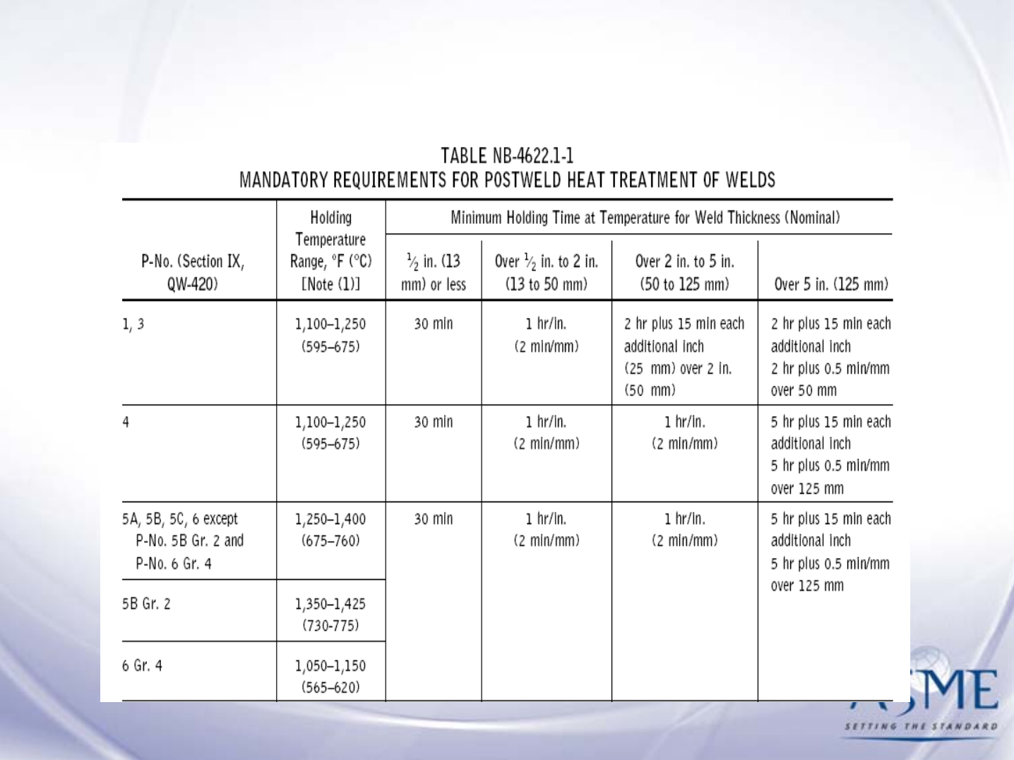
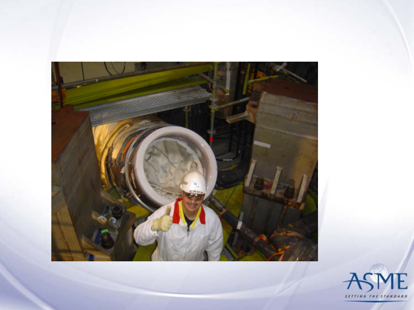
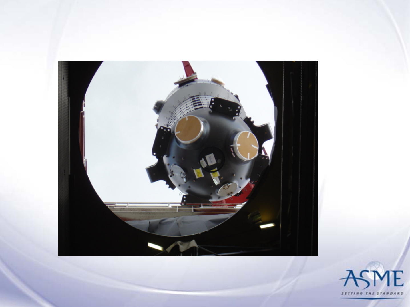
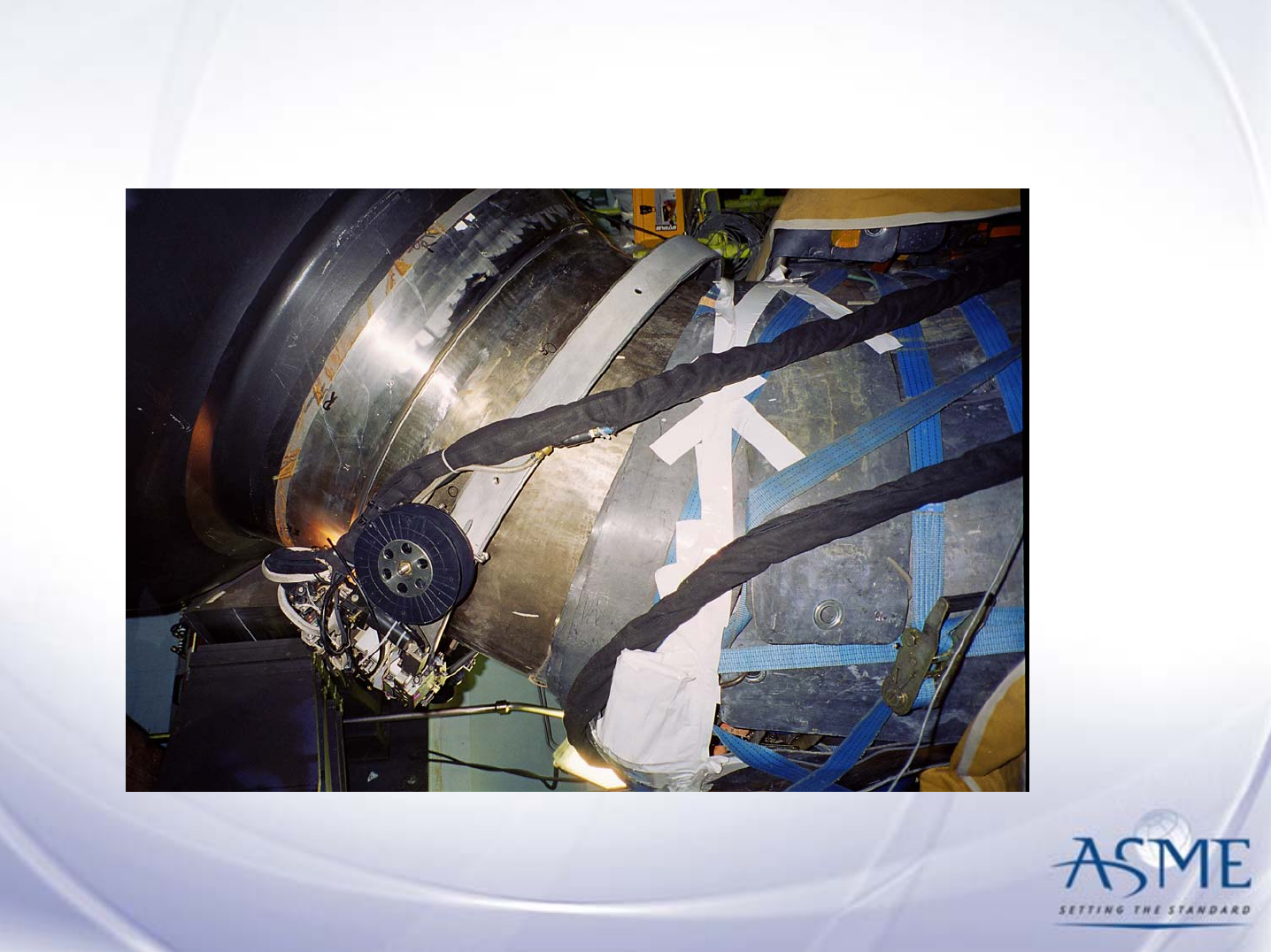
NB-4600 Postweld Heat Treatment

NC/ND-4000 Fabrication and Installation
NC/ND-4800 Expansion Joints
NC/ND-4100 General Requirements
NC/ND-4200 Forming, Fitting and Aligning
NC/ND-4300 Welding Qualifications
NC/ND-4400 Making, Examining and Repairing Welds
NC/ND-4500 Brazing
NC/ND-4600 Heat Treatment
NC/ND-4700 Mechanical Joints

Examination NB-5000
NB-5100 General Requirements
NB-5200 Examination of Welds
NB-5300 Acceptance Standards
NB-5400 Final Examination of Vessels
NB-5500 Qualification and Certification
of NDE Personnel

NB-5000 Examination
NB-5100 General Requirements for Examination
– Fabrication (F) Preservice Base Line (PS)
NB-5200 Required Examination of Welds
– Category A Welded Joints (Longitudinal Welds)
– Category B Welded Joints (Circ Welds)
– Category C Welded Joints (Flange to Shell, etc.)
– Category D Welded Joints (Nozzle to vessel, etc.)
– Fillet, partial penetration and socket welds
– Structural attachment welds
– Special welds (e.g., Canopy Seal Welds)
– Preservice Examination

NB-5000 Examination (cont.)
NB-5300 Acceptance Standards
– Radiographic
– Ultrasonic
– Magnetic particle
– Liquid Penetrant
– Eddy Current
–Visual
– Gas and bubble formation testing
NB-5400 Final Examination of Vessels
NB-5500 Qualifications and Certification of
Nondestructive Examination Personnel

NC/ND-5000 Examination
•NC/ND-5100 General Requirements
•NC/ND-5200 Examination of Welds
•NC/ND-5300 Acceptance Standards
•NC/ND-5400 Final Examination of Components
•NC/ND-5500 Qualification and Certification of
NDE Personnel
•NC/ND-5700 Examination Requirements for
Expansion Joints

Testing NB-6000
NB-6100 General Requirements
NB-6200 Hydrostatic Tests
NB-6300 Pneumatic Tests
NB-6400 Pressure Test Gauge
NB-6600 Special Test Pressure Situations
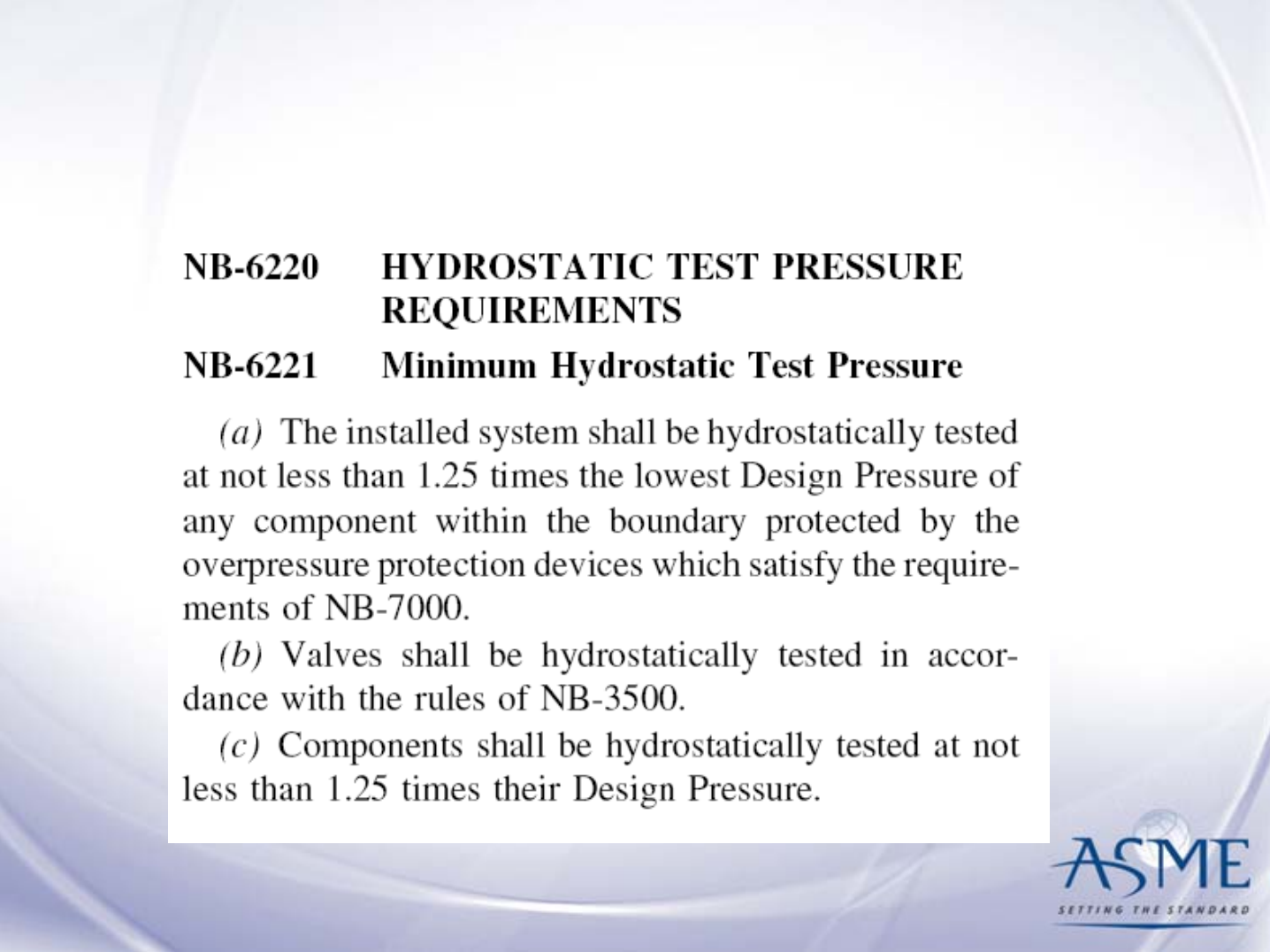
NB-6000 Testing

NC/ND-6000 Testing
• NC/ND-6100 General Requirements
• NC/ND-6200 Hydrostatic Tests
• NC/ND-6300 Pneumatic Tests
• NC/ND-6400 Pressure Test
• NC/ND-6600 Special Test Pressure Situations
• NC/ND-6500 Atmospheric & 0-15 psig Storage Tanks
• NC/ND-6900 Proof Tests to Establish Design Pressure

Overpressure Protection NB/NC/ND-7000
NB-7100 General Requirements
NB-7200 Overpressure Protection Report
NB-7300 Relieving Capacity Requirements
NB-7400 Set pressures of Pressure Relief Devices
NB-7500 Operating and Design Requirements for
Pressure Relief Valves
NB-7600 Non-reclosing Pressure Relief Devices
NB-7700 Certification
NB-7800 Marking, Stamping & Data Reports

NB-7300 Relieving Capacity Requirements
At least 2 relief devices are needed for a system
– Capacity of the smallest must exceed 50% of
the largest
– At least 1 relief device needed for each
isolatable component

NB-7500 Operating Design
Requirements for Pressure Relief Valves
• Safety, safety relief and relief valves
• Pilot operated pressure relief valves
• Power actuated pressure relief valves
• Safety valves and pilot operated pressure
relief valves with auxiliary actuating devices
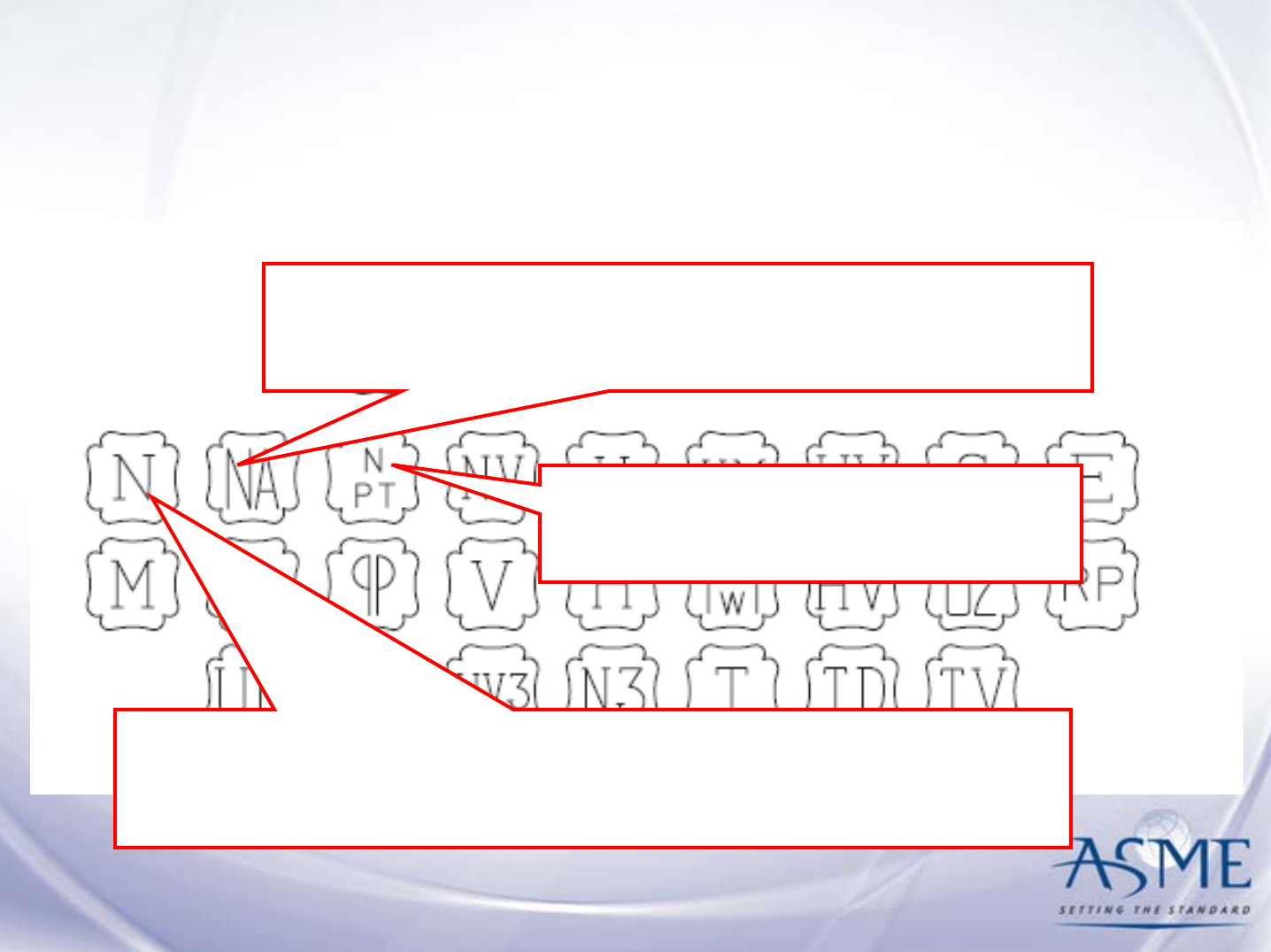
Article NB/NC/ND-8000
Nameplates, Stamping and
Reports
N completed ASME Code component that the
Certificate Holder supplies to a customer.
NPT piping, parts, and
appurtenances.
NA components that are being installed
in the power plant.

Today’s Agenda
1. Small Advertisement for the ASME Code
2. Structure and Use of Section III
3. Code Interpretations and Code Cases
4. Basic Terms & Important Concepts
5. Subsections of Section III
6. Appendices

Section III, Appendices
Mandatory
• Invoked within the text of a Code paragraph and
are required.
Nonmandatory
• Invoked by a footnote to a Code paragraph and
provide information or guidance.

Mandatory Appendix Example
NB-3680 Stress Indices and Flexibility
Factors
NB-3681(d) For piping products not covered
by NB-3680, stress indices and flexibility
factors shall be established by experimental
analysis (Appendix II) or theoretical
analysis.

Nonmandatory Appendix Example
NB-3252 Contents of Design
Specifications 3
(a) The Design Specification shall contain
sufficient detail to provide a complete
basis for Division 1 construction …
3See Appendix B

Section III: Mandatory Appendices
Appendix I* Design Stress Intensity Values, Allowable Stresses, Material Properties, and Fatigue Curves
Appendix II Experimental Stress Analysis
Appendix III Basis for Establishing Design Stress Intensity Values and Allowable Stress Values
Appendix IV Approval of New Materials Under the ASME Boiler and Pressure Vessel Code
Appendix V Certificate Holders’ Data Report Forms, Instructions, and Application Forms
Appendix VI Rounded Indications
Appendix VII Charts and Tables for Determining Shell Thickness of Cylindrical and Spherical
Components Under External Pressure
Appendix XI Rules for Bolted Flange Connections for Class 2 and 3 Components and Class MC Vessels
Appendix XII Design Considerations for Bolted Flange Connections
Appendix XIII Design Based on Stress Analysis for Vessels Designed in Accordance With NC-3200
Appendix XIV Design Based on Fatigue Analysis for Vessels Designed in Accordance With NC-3200
Appendix XVIII Capacity Conversions for Pressure Relief Valves
Appendix XIX Integral Flat Head With a Large Opening
Appendix XX* Submittal of Technical Inquiries to the Boiler and Pressure Vessel Committee
Appendix XXI Adhesive Attachment of Nameplates
Appendix XXII Design of Reinforcement for Come-to-Cylinder Junction Under External Pressure
Appendix XXIII* Qualifications and Duties of Specialized Professional Engineers

Section III: Nonmandatory Appendices
Appendix A Stress Analysis Methods
Appendix B* Owner’s Design Specifications
Appendix C* Certificate Holder’s Design Report
Appendix D Nonmandatory Preheat Procedures
Appendix E Minimum Bolt Cross-Sectional Area
Appendix F* Rules for Evaluation of Service Loadings With Level D Service Limits
Appendix G Protection Against Nonductile Failure
Appendix J* Owner’s Design Specifications for Core Support Structures
Appendix K Tolerances
Appendix L Class FF Flange Design for Class 2 and 3 Components and Class MC Vessels
Appendix M Control of Welding, Postweld Heat Treatment, and Nondestructive Examination of Welds
Appendix N Dynamic Analysis Methods
Appendix O Rules for Design of Safety Valve Installations
Appendix P Contents of Certified Material Test Reports
Appendix Q Design Rules for Clamp Connections
Appendix R Permissible Lowest Service Metal Temperature From TNDT for Classes 2 and MC Construction
Appendix S Pump Shaft Design Methods
Appendix T Recommended Tolerances for Reconciliation of Piping Systems
Appendix U Rules for Pump Internals
Appendix V Interruption of Code Work
Appendix W Environmental Effects on Components

Appendices of Interest
Mandatory Appendices
I Material Properties (Fatigue curves and other properties in older Codes)
XX Submittal of Technical Inquiries to the Boiler and Pressure Vessel
Committee
XXIII Qualifications and Duties of Specialized Professional Engineers
Non-Mandatory Appendices
B Owner’s Design Specification
C Certificate Holder’s Design Report
E Minimum Bolt Cross Sectional Area
F Rules for Faulted (Level D) Condition Analysis
G Rules for Fracture Mechanics Analysis
W Environmental Effects on Components

Overall Summary
•Is Dynamic – evolves and changes to reflect new
technology and industry needs
•Is Comprehensive - provides rules for materials,
design, fabrication, examination, inspection,
testing, certification, and pressure relief
•Is Integrated – materials, design, fabrication,
inspection and testing rules are integrated – a
change in one area may require a change in another
ASME Code: