170S8 170S8F
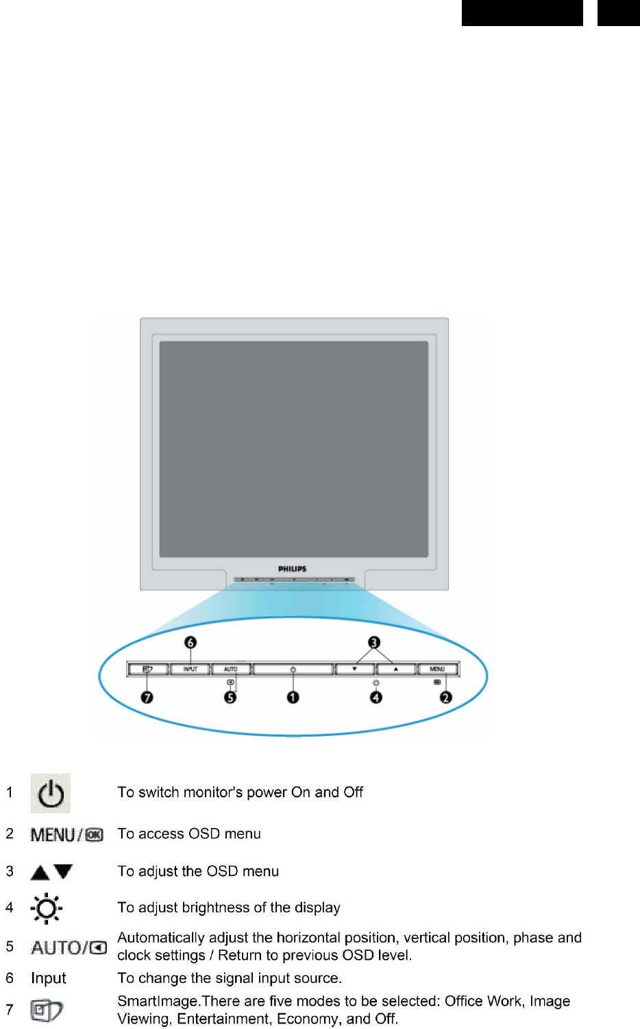
170S8FB 09071115472084
User Manual: 170S8F
Open the PDF directly: View PDF ![]() .
.
Page Count: 123 [warning: Documents this large are best viewed by clicking the View PDF Link!]
17" LCD Color Monitor Chassis: HUDSON 8
Service
Service
Service
Description Page Description Page
SAFETY NOTICE
ANY PERSON ATTEMPTING TO SERVICE THIS CHASSIS MUST FAMILIARIZE HIMSELF WITH THE
CHASSIS AND BE AWARE OF THE NECESSARY SAFETY PRECAUTIONS TO BE USED WHEN SERVICING
ELECTRONIC EQUIPMENT CONTAINING HIGH VOLTAGES.
CAUTION: USE A SEPARATE ISOLATION TRANSFOMER FOR THIS UNIT WHEN SERVICING
Table Of Contents........................................………….1
Revision List................................................…………….2
Important Safety Notice………….................................3
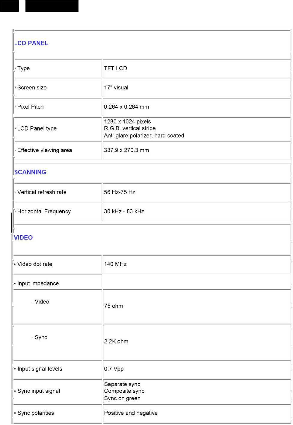
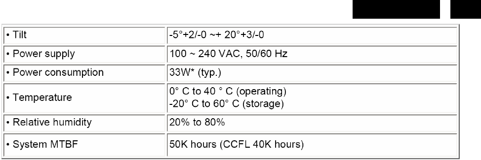
1. Monitor Specifications……...................................…..4
2. LCD Monitor Description………..…….........................6
3. Operation instructions…………….......................…....7
3.1General Instructions…………………..…..…………7
3.2 Control buttons…………..……………………………7
3.3 Adjusting the Picture……....................................…..9
3.4 Connecting to the PC ….........…….…........……....11
4. Input/Output Specification.........................………….12
4.1 Input Signal Connector...........................…………..12
4.2 Factory Preset Display Modes...............................13
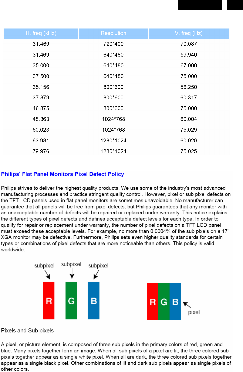
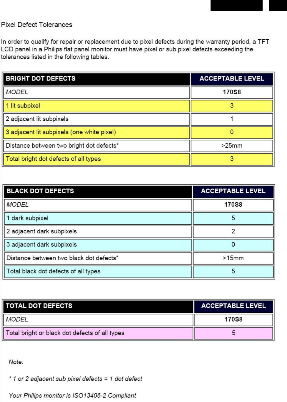
4.3 Pixel Defect Policy……………………………………13
4.4 Failure Mode OF Panel………………………..…..16
5. Block Diagram……………………………................17
5.1 Software Flow Chart............................………….....17
5.2 Electrical Block Diagram..................……….........19
6. Schematic Diagram…….....................……….........21
6.1 Scalar Board…….……………..…………………………21
6.2 Power Board…………………………..…………………25
6.3 Key Board…….………………………..…………………27
7. PCB Layout.....……......................……………………..28
7.1 Scalar Board.....…….......................…….…………......28
7.2 Power Board.……................…..…………….............30
7.3 Key Board………...………………………………………32
8. Wiring Diagram……………………………………….…..33
9. Mechanical Instructions.....……...…………..…..........34
10.Trouble shooting…..…………………………...……..44
11. Repair Flow Chart…….…….……………………………46
12. ISP Instructions..…..........................………..............52
13. DDC Instructions……......…….............….................59
14. White Balance, Luminance Adjustment……............73
15. Monitor Exploded View………..…….………..............75
16. Recommended & Spare Parts List...…….....................76
17. Different Parts List...……….....………....................96
18. General Product Specification……………………….99
GB 312278517290
REFER TO BACK COVER FOR IMPORTANT SAFETY GUIDELINES
Published by Philips CE Copyright reserved Subject to modification ○
K Aug, 22, 2007
170S8FS/00
170S8FB/00
170S8FB/27
170S8FS/62
170S8FB/62
170S8FB/78
http://www.wjel.net

2 HUDSON 8
Revision List
Version Release Date Revision History
A00 Jul.05, 2007 Initial release, Draft Version
A01 Jul.17,2007 Add new BOM in Item 17
A02 Jul.27,2007 Add new BOM in Item 17
A03 Sep.12,2007 Add new BOM in Item 17
Add Second Panel Source
A04 Nov.07,2007
Update C907 in Item 16
A05 Nov.24,2007 Add Philips 12NC for 715GT039 A
A06 Dec.22,2007 Add Philips 12NC for Model 170S8FB/00 and 170S8FS/00
A07 Feb.02,2007 Add new BOM in Item 17
A08 Mar.05,2008 Add Second Panel Source
Add a new BOM for CTV Model 170S8FS/00 in Item16
A09 Apr.11,2008
Add a new BOM for CTV Model 170S8FB/00 in Item17
http://www.wjel.net

3
HUDSON 8
Important Safety Notice
Proper service and repair is important to the safe, reliable operation of all Philips Company Equipment. The service
procedures recommended by Philips and described in this service manual are effective methods of performing
service operations. Some of these service operations require the use of tools specially designed for the purpose.
The special tools should be used when and as recommended.
It is important to note that this manual contains various CAUTIONS and NOTICES which should be carefully read in
order to minimize the risk of personal injury to service personnel. The possibility exists that improper service
methods may damage the equipment. It is also important to understand that these CAUTIONS and NOTICES ARE
NOT EXHAUSTIVE. Philips could not possibly know, evaluate and advise the service trade of all conceivable ways
in which service might be done or of the possible hazardous consequences of each way. Consequently, Philips has
not undertaken any such broad evaluation. Accordingly, a servicer who uses a service procedure or tool which is not
recommended by Philips must first satisfy himself thoroughly that neither his safety nor the safe operation of the
equipment will be jeopardized by the service method selected.
Hereafter throughout this manual, Philips Company will be referred to as Philips.
WARNING
Use of substitute replacement parts, which do not have the same, specified safety characteristics may create shock,
fire, or other hazards.
Under no circumstances should the original design be modified or altered without written permission from Philips.
Philips assumes no liability, express or implied, arising out of any unauthorized modification of design.
Servicer assumes all liability.
FOR PRODUCTS CONTAINING LASER:
DANGER-Invisible laser radiation when open. AVOID DIRECT EXPOSURE TO BEAM.
CAUTION-Use of controls or adjustments or performance of procedures other than those specified herein may
result in hazardous radiation exposure.
CAUTION -The use of optical instruments with this product will increase eye hazard.
TO ENSURE THE CONTINUED RELIABILITY OF THIS PRODUCT, USE ONLY ORIGINAL MANUFACTURER'S
REPLACEMENT PARTS, WHICH ARE LISTED WITH THEIR PART NUMBERS IN THE PARTS LIST SECTION OF
THIS SERVICE MANUAL.
Take care during handling the LCD module with backlight unit
-Must mount the module using mounting holes arranged in four corners.
-Do not press on the panel, edge of the frame strongly or electric shock as this will result in damage to the screen.
-Do not scratch or press on the panel with any sharp objects, such as pencil or pen as this may result in damage to
the panel.
-Protect the module from the ESD as it may damage the electronic circuit (C-MOS).
-Make certain that treatment person’s body is grounded through wristband.
-Do not leave the module in high temperature and in areas of high humidity for a long time.
-Avoid contact with water as it may a short circuit within the module.
-If the surface of panel becomes dirty, please wipe it off with a soft material. (Cleaning with a dirty or rough cloth may
damage the panel.)
http://www.wjel.net
6 HUDSON 8
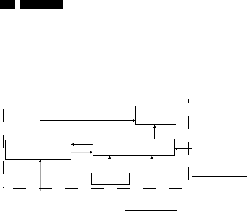
2. LCD Monitor Description
The LCD monitor will contain a scalar board, a power board and a key board which house the flat panel control logic,
brightness control logic and DDC.
The power board will provide AC to DC Inverter voltage to drive the backlight of panel and the main board chips
each voltage.
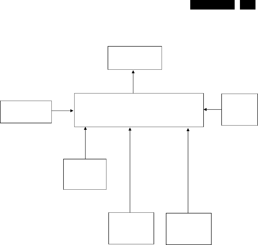
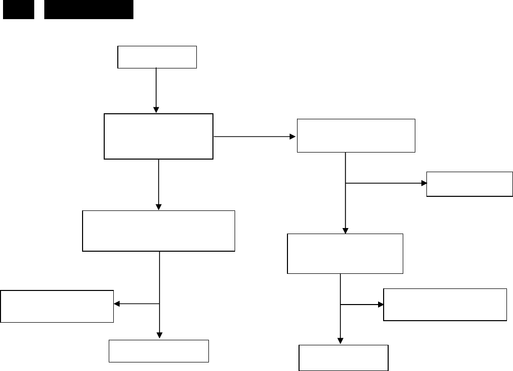
Monitor Block Diagram
AC-IN
100V-240V
Power board
(
Include: ada
p
ter
,
inverter
)
Flat Panel and
CCFL backlight
Main Board RS232 Connector
For white balance
adjustment in factory
mode
CCFL Drive.
Video signal, DDC
Key Board
HOST Computer
http://www.wjel.net
7
HUDSON 8
3. Operating Instructions
3.1 General Instructions
Press the power button to turn the monitor on or off. The other control buttons are located at the front of the
panel of the monitor.
By changing these settings, the picture can be adjusted to your personal preferences.
- The power cord should be connected.
- Connect the video cable from the monitor to the video card.
- Press the power button to turn on the monitor, the power indicator will light up.
3.2 Control Buttons
Front View
http://www.wjel.net
9
HUDSON 8
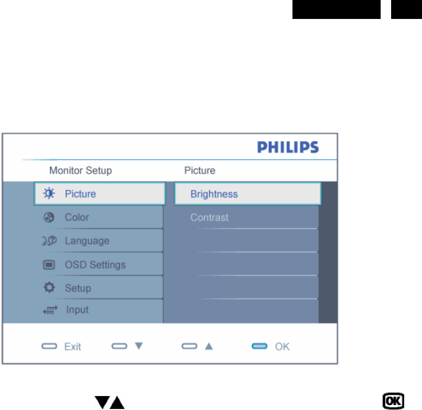
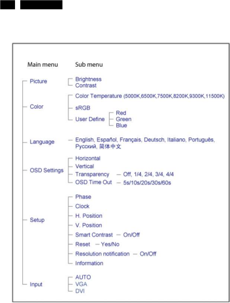
3.3 Adjusting the Picture
Description of the On Screen Display
On-Screen Display (OSD) is a feature in all Philips LCD monitors. It allows an end user to adjust screen
performance or select functions of the monitors directly through an on-screen instruction window. A user friendly on
screen display interface is shown as below:
In the OSD shown above users can press buttons at the front bezel of the monitor to move the cursor, to
confirm the choice or change.
To Lock/Unlock OSD function (User Mode)
The OSD function can be locked by pressing “MENU” button for more than 10 seconds.
Locked OSD function can be released by pressing “MENU” button for more than 10 seconds again.
http://www.wjel.net
11
HUDSON 8
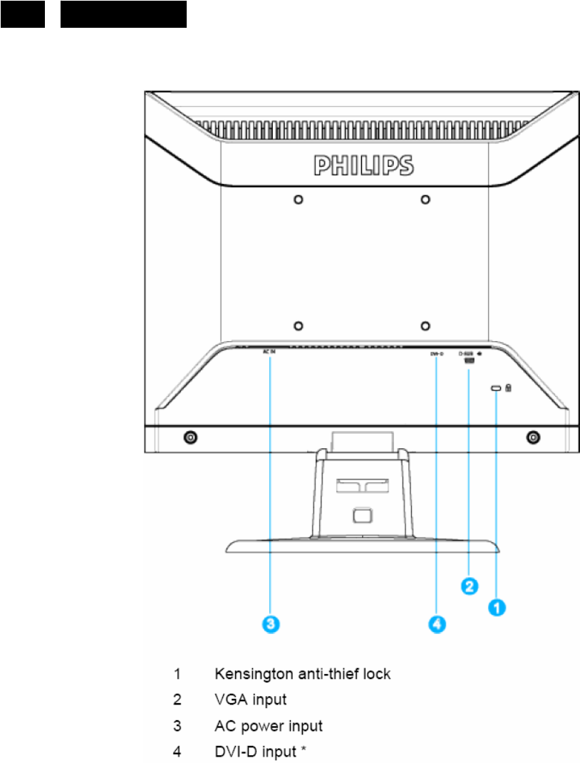
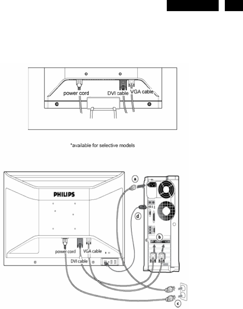
3.4 Connecting to the PC
1) Connect the power cord to the back of the monitor firmly. (Philips has pre-connected VGA cable for the first
installation.
2) Connect to PC
(a) Turn off your computer and unplug its power cable.
(b) Connect the monitor signal cable to the video connector on the back of your computer.
(c) Plug the power cord of your computer and your monitor into a nearby outlet.
(d) Turn on your computer and monitor. If the monitor displays an image,
installation is complete.
http://www.wjel.net
12 HUDSON 8
4. Input/Output Specification
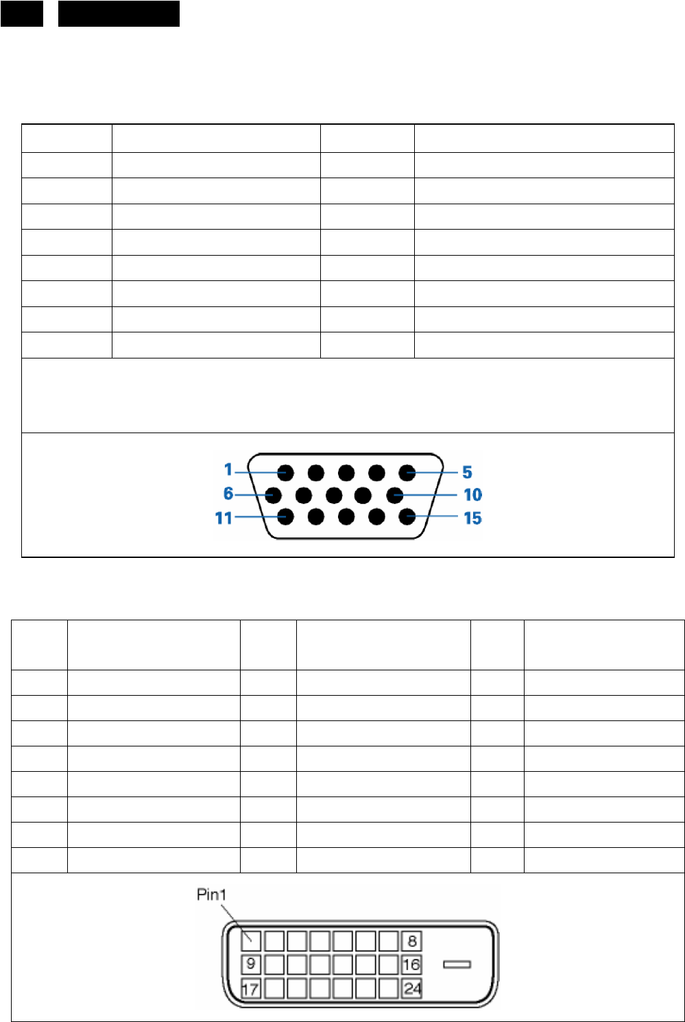
4.1 Input Signal Connector
Analog connectors
Pin No. Description Pin No. Description
1. Red video input 9. DDC +3.3V or +5V
2. Green video input 10. Logic Ground
3. Blue video input 11. Ground
4. Sense (GND) 12. Serial data line (SDA)
5. Cable detect (GND) 13. H. Sync
6. Red video ground 14. V. Sync
7. Green video ground 15. Data clock line (SCL)
8. Blue video ground
VGA connector layout
DVI connectors
Pin
No. Description Pin
No. Description Pin
No. Description
1. T.M.D.S Data2- 9. T.M.D.S Data1- 17. T.M.D.S Data0-
2. T.M.D.S Data2+ 10. T.M.D.S Data1+ 18. T.M.D.S Data0+
3. T.M.D.S Data2 Shield 11. T.M.D.S Data1 Shield 19. T.M.D.S Data0 Shield
4. No connector 12. No connector 20. No connector
5. No connector 13. No connector 21. No connector
6. DDC Clock 14. +5V Power 22. T.M.D.S Clock Shield
7. DDC Data 15. Ground (for +5V) 23. T.M.D.S Clock+
8. No connector 16. Hot Plug Detection 24. T.M.D.S Clock-
http://www.wjel.net
16 HUDSON 8
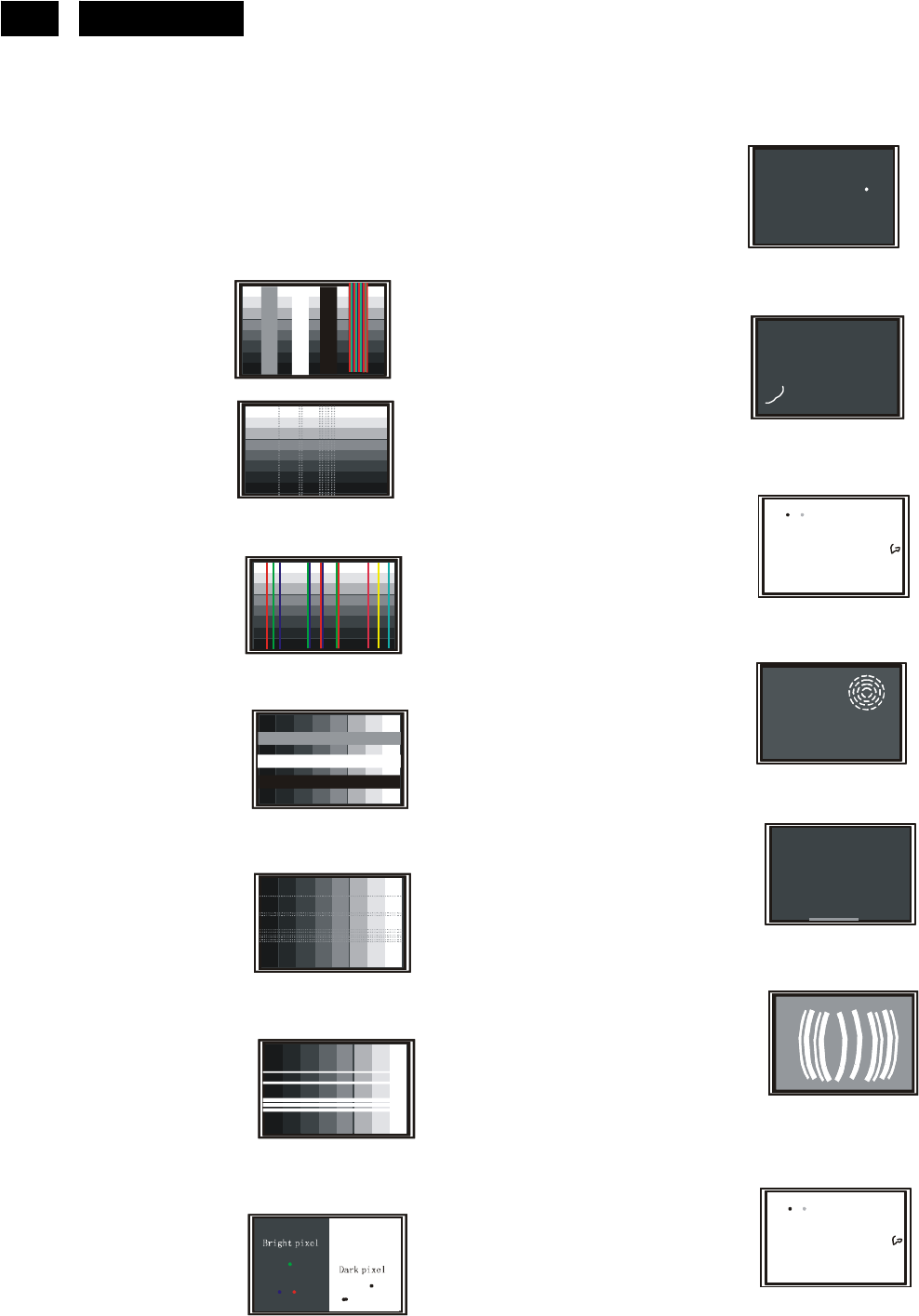
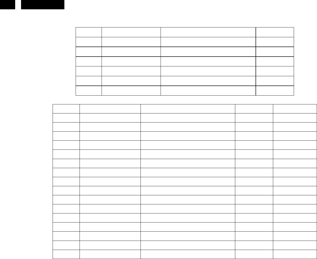
4.4 Failure Mode Of Panel
Failure description Phenomenon
Vertical block defect
Vertical dim lines
Vertical lines defect
(Always bri
g
ht or dark)
Horizontal block defect
Horizontal dim lines
Horizontal lines defect
(Always bri
g
ht or dark)
Has bri
g
ht or dark pixel
Polarizer has bubbles
Polarizer has bubbles
Foreign material inside
polarizer. It shows liner or
dot shape.
Concentric circle formed
Bottom back light of LCD is
brighter than normal
Back light un-uniformity
Backli
g
ht has forei
g
n material.
Black or white color, liner or
circular type
Quick reference for failure mode of LCD panel
this pa
g
e presents problems that could be made by LCD panel.
It is not necessary to repair circuit board. Simply follow the mechanical
instruction on this manual to eliminate failure by replace LCD panel.
http://www.wjel.net

18 HUDSON 8
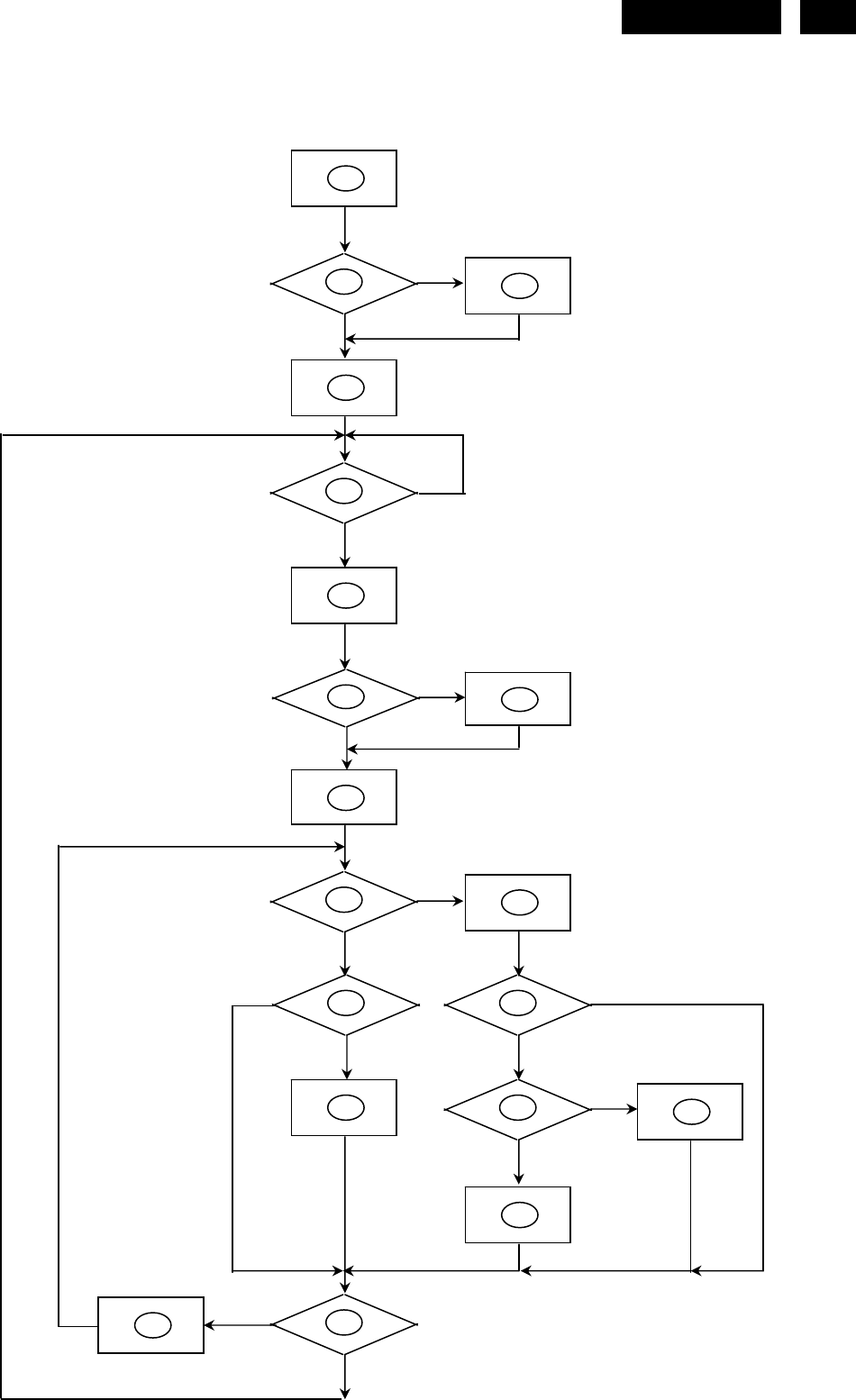
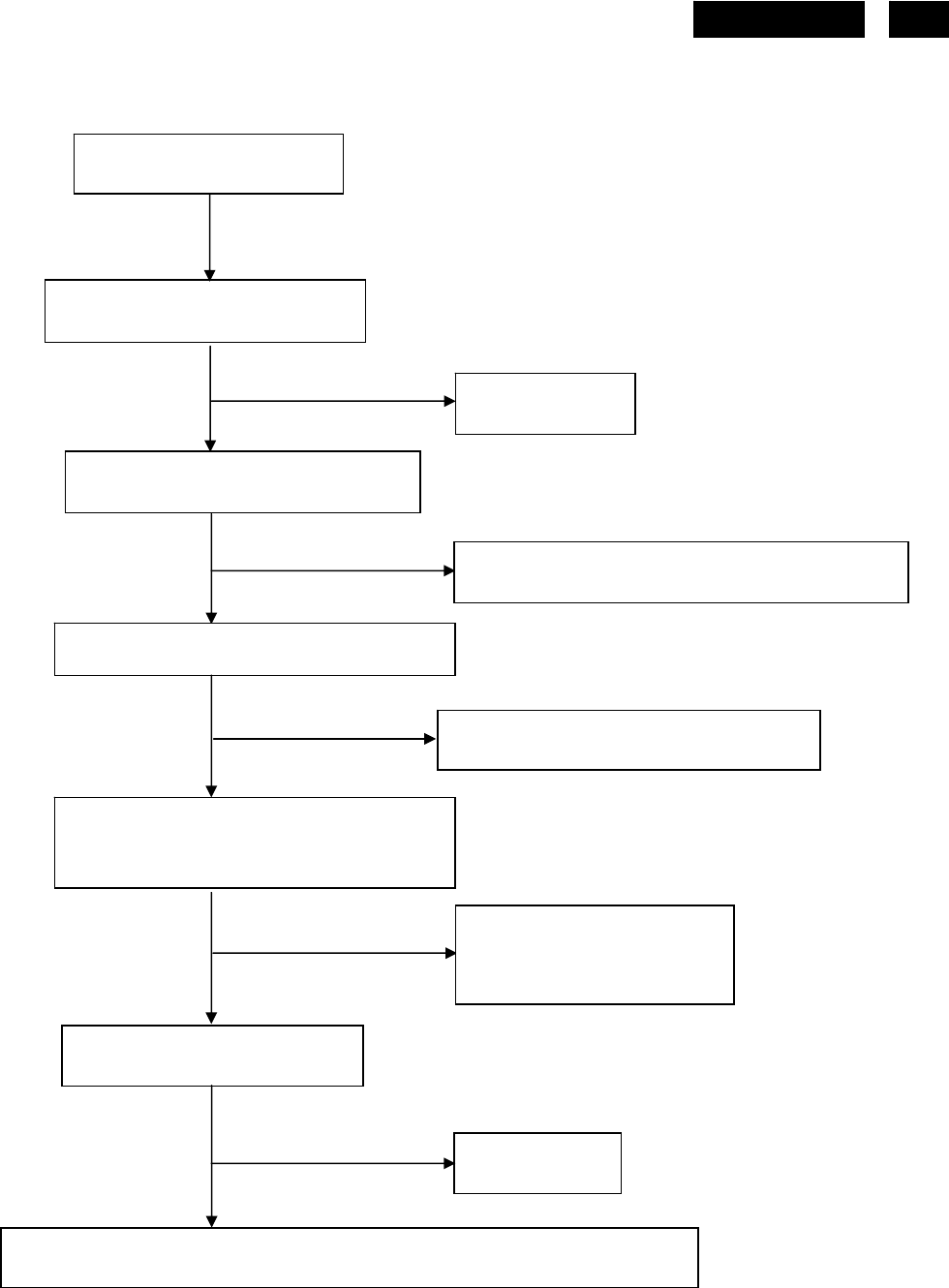
1) MCU initialize.
2) Is the EPROM blank?
3) Program the EPROM by default values.
4) Get the PWM value of brightness from EPROM.
5) Is the power key pressed?
6) Clear all global flags.
7) Are the AUTO and SELECT keys pressed?
8) Enter factory mode.
9) Save the power key status into EPROM.
Turn on the LED and set it to green color.
Scalar initializes.
10) In standby mode?
11) Update the lifetime of back light.
12) Check the analog port, are there any signals coming?
13) Does the scalar send out an interrupt request?
14) Wake up the scalar.
15) Are there any signals coming from analog port?
16) Display "No connection Check Signal Cable" message. And go into standby mode after the message
disappear.
17) Program the scalar to be able to show the coming mode.
18) Process the OSD display.
19) Read the keyboard. Is the power key pressed?
http://www.wjel.net
19
HUDSON 8
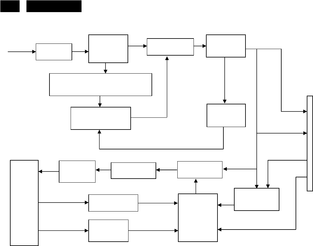
5.2 Electrical Block Diagram
5.2.1 Main Board
Panel Interface
(CN402)
Crystal
12.000MHZ
(X201)
Keypad Interface
(CN407)
Scalar NT68665MFG
(Include MCU, ADC, OSD)
(U203)
D-Sub
Connector
(CN101)
RGB
H sync
V sync
VGA_SDA,
VGA SCL
DVI
Connector
(CN102)
D-Data
D-Clock
DVI_SDA,
DVI_SCL
EEPROM
M24C16
(U204)
http://www.wjel.net
20 HUDSON 8
5.2.2 Inverter/Power Board
DIM
EMI filter
Start Circuit: R905
Transformer
AC input
12V
ON/OFF
Control
Transformer MOSFET
Lamp
ON/OFF
5V
Bridge
Rectifier
and Filter
Feedback
Circuit
Rectifier
diodes
CN902
Output
Circuit
PWM
Control IC
(IC801)
Over Voltage
Feedback
Circuit
PWM Control IC
(IC901)
http://www.wjel.net
21
HUDSON 8
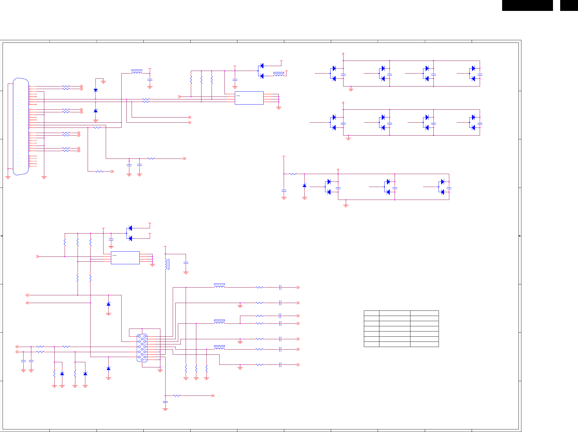
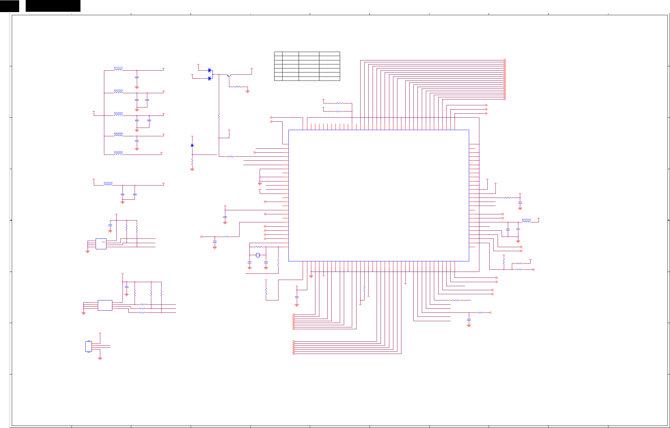
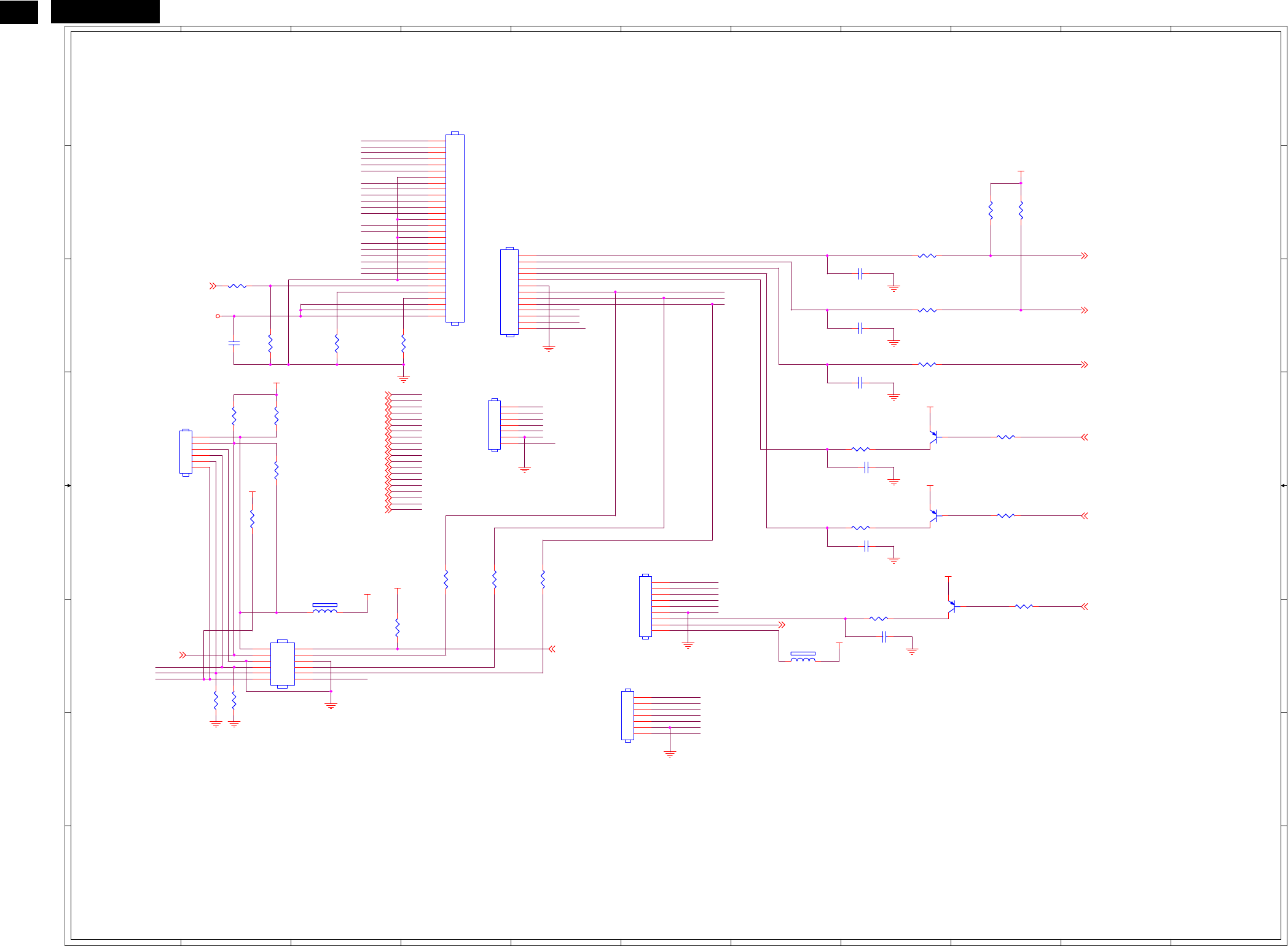
6. Schematic
6.1 Scalar Board
715G2561-1
1
1
2
2
3
3
4
4
5
5
6
6
7
7
8
8
9
9
10
10
11
11
A A
B B
C C
D D
E E
F F
G G
H H
EXT_EDID
U101
U102
24C02
24C02 NC
NC
INT_EDID
Q201 NC 3906
R206 NC 4.7K
NCD201 BAV70
FB201 120 NC
CN101 F3 CN102 A1
C101 E4 C102 A8
C103 A9 C104 A10
C105 A11 C106 A4
C107 A5 C110 B8
C111 B9 C112 B10
C113 B11 C114 C3
C115 E3 C116 C8
C117 C9 C118 C10
C121 E6 C122 F6
C123 F6 C124 F6
C125 G6 C126 G6
C127 G1 C128 G1
C129 G6 C130 H4
C131 D6 C132 C3
D101 A9 D102 A6
D103 A7 D104 A8
D105 A10 D106 B7
D107 B8 D108 B9
D109 B10 D110 D3
D111 C7 D112 C9
D113 C10 FB101 A3
FB102 E4 FB103 E5
FB104 F5 FB105 G2
FB106 G5 FB107 A6
R101 G4 R102 C7
R103 A5 R104 A5
R105 A4 R106 A2
R107 A2 R108 B3
R109 B3 R110 B2
R111 B2 R113 B2
R115 B2 R116 B2
R117 C2 R118 C2
R120 C4 R122 C2
R123 E2 R124 E2
R125 E2 R126 E6
R127 E2 R128 E2
R129 F6 R131 F6
R132 F6 R133 G6
R134 G1 R135 G6
R136 G1 R138 G6
R139 G5 R140 G5
R141 G2 R142 G2
R144 H4 U101 B5
U102 E3 ZD101 G3
ZD102 C7 ZD103 A2
ZD104 B2 ZD105 F3
ZD106 G2 ZD107 G2
DVI/D-SUB
RX1MRX2P RX1PRX2M
RXCPRX0MRX0P RXCM
GRB
B
R
G
DDCSDA
VIN
DDCSCL
DDCSCL_D
RX0P
RX1P
RX2P
RX1M
DDCSDA_D
RX0M
RXCP
RXCM
RX2M
VGA_SDA
RIN+
RIN-
SOG
GIN+
GIN-
BIN+
BIN-
VGA_CABLE
VS
VGA_SCL
HS
DDC_WP
RX2+ 3
DVI_SCL 3
RX2- 3
RX1- 3
RX0- 3
DVI-HPD 3
RX0+ 3
DVI_CABLE 3
RXC- 3
DDC_WP3
RX1+ 3
DVI_SDA 3
RXC+ 3
+5V_ESD
+5V_ESD
+5V_ESD
+5V
VGA_5V
VGA_5V
VGA_VDD
+5V
DVI_5V
DVI_5V
DVI_VDD
+5V
R132 100R 1/16W
C113
0.1uF 16V
R127
100R 1/16W
C118
0.1uF 16V
R128
100R 1/16W
C106
0.1uF 16V
C132
470PF 50V
R113 1K 1/16W
D105
BAV99
3
1
2
D111
BAV99
3
1
2
C125
0.047uF
C102
0.1uF 16V
R116 10R 1/16W
R134 100R 1/16W
FB105
0R05 1/8W
C127330pF 50V
CN102
JACK
1
2
3
4
5
6
7
8
9
10
11
12
13
14
15
16
17
18
19
20
21
22
23
24
26
25
C1
C2
C3
C4
C5
RX2-
RX2+
GND
RX4-
RX4+
SCL
SDA
VS
RX1-
RX1+
GND
RX3-
RX3+
5V
GND
HP
RX0-
RX0+
GND
RX5-
RX5+
GND
RXC+
RXC-
26
25
RED
GRN
BLU
HS
GND
D107
BAV99
3
1
2
ZD105
RLZ5.6B
R125
NC
R117
10R 1/16W
R107
10R 1/16W
D101
BAV99
3
1
2
CN101
DB15
1
6
2
7
3
8
4
9
5
11
12
13
14
15
10
1716
R122
1K 1/16W
D112
BAV99
3
1
2
C121
0.047uF
R129 150 OHM 1/16W
C111
0.1uF 16V
R124
4K7 1/16W
C115
1uF 16V
C104
0.1uF 16V
R118
10R 1/16W
C126
0.047uF
R108 100R 1/16W
C122
0.047uF
D104
BAV99
3
1
2
R139
75R 1/16W
D109
BAV99
3
1
2
ZD106
RLZ5.6B
R103
4K7 1/16W
C129
0.047uF
FB106
30 OHM
1 2
C114
0.1uF 16V
D113
BAV99
3
1
2
R144
1K 1/16W
ZD107
RLZ5.6B
D108
BAV99
3
1
2
FB102
120 OHM
12
FB107
120 OHM
1 2
FB104
30 OHM
1 2
C123
1000pF
R105
NC
R141
2K2 1/16W
D103
BAV99
3
1
2
C116
0.1uF 16V
C131
1000pF
C112
0.1uF 16V
FB103
30 OHM
1 2
ZD102
RLZ5.6B
C117
0.1uF 16V
ZD104
RLZ5.6B
C105
0.1uF 16V
R131 390R 1/16W
R126 100R 1/16W
R140
75R 1/16W
U102
NC
1
2
3
45
6
7
8NC/NC/NC/E0/E0
NC/NC/E1/E1/E1
NC/E2/E2/E2/E2
VSSSDA
SCL
WC
VCC
C107
1uF 16V
R136 100R 1/16W
R110
10R 1/16W
D102
BAV70
C128
33pF
R123
4K7 1/16W
D106
BAV99
3
1
2
R138 150 OHM 1/16W
ZD101
RLZ5.6B
R120
1K 1/16W
R142
2K2 1/16W
R109 100R 1/16W
R111
10R 1/16W
R106
10R 1/16W
R133 150 OHM 1/16W
R102
1K 1/16W
FB101
120 OHM
1 2
ZD103
RLZ5.6B
R135 100R 1/16W
C110
0.1uF 16V
R101
75R 1/16W
C124
0.047uF
C101
0.1uF 16V
C103
0.1uF 16V
D110
BAV70
C130
0.1uF 16V
R104
4K7 1/16W
R115
10R 1/16W
U101
NC/M24C02-WMN6TP
1
2
3
45
6
7
8NC/NC/NC/E0/E0
NC/NC/E1/E1/E1
NC/E2/E2/E2/E2
VSSSDA
SCL
WC
VCC
http://www.wjel.net
22 HUDSON 8
1
1
2
2
3
3
4
4
5
5
6
6
7
7
8
8
9
9
10
10
11
11
A A
B B
C C
D D
E E
F F
G G
H H
NC 0.1u
C211 NC 0.1u
52
53
U203
NONE OD OD
SMT TYPE
OPTION(HDCP)
26
15
90
6
115
TO RS232
SMT TYPE
17
NT68665 NT68670
NCR209 0R
NCR228 0R
22R NC
1
2
3
5
4
1
2
3
4
5
6
6
NO. PARTS
EXT_EDID MCU POWER
C212
modify
part-
070102
modify
parts
1/18
modify
parts
1/18
R218
VGA cable
detect(high to
low)
DVI cable
detect(high to
low)
(for flash )
INT_EDID MCU POWER
CN202 G2 C201 F5
C202 F8 C203 B3
C204 B3 C205 B3
C206 C3 C207 C3
C208 C3 C209 D2
C210 D3 C211 D9
C212 D4 C213 E2
C214 E9 C215 E9
C216 E4 C219 E4
C220 E5 C222 F2
D201 B4 FB201 C2
FB202 A2 FB203 B2
FB204 B2 FB205 C2
FB206 D2 FB207 D9
Q201 B4 R201 E5
R202 C3 R205 F8
R206 B4 R207 E9
R209 D9 R210 B6
R211 B6 R213 E2
R214 E4 R215 E3
R218 E5 R219 E9
R220 E9 R221 F6
R223 F3 R224 F3
R225 F5 R228 F8
R229 F3 R230 F3
R231 F3 R232 F3
R233 B4 R234 C4
U201 F2 U203 C5
U204 E2 X201 E5
MCU+SCALAR
TCLK
IICSCL
24C16_WP
RX
VSO
VSO
HSO
IICSDA
HSO
H_SDA
RX
TX
IRQN
IRQN
TCLK
IICSCL
IICSDA
24C16_WP
TX
H_SCL
H_SDA
H_SCL
5V_DECT
DDC_WP
5V_DECT5V_DECT
PANEL_PWR
VGA_CABLE
RX2+
RXC+
HS
RX2-
GIN-
RX1-
RIN-
VS
DDC_WP
RIN+
BIN+
BRIGHTNESS
DVI_SCL
RX0-
KEY_PWR
DVI_SDA
VGA_SCL
RX1+
SOG
LED_B/G
DVI-HPD
KEY1
RX0+
LED_R
LF_LED
VGA_SDA
GIN+
VOLUME
KEY2
RXC-
PANEL_IDX
BIN-
DVI_CABLE
T7P
T6M
T6P
T7M
TCLK2P
T0M
TCLK1M
T4P
T1M
T2M
T5P
T3P
T5M
T2P
TCLK2M
T4M
TCLK1P
T1P
T0P
T3M
AUDIO_STDBY
LIGHT_SEN
BL_CONTROL
MCU_VDD
CVDD18
CVDD18
MCU_VDD
DVDD
AVCC
+1.8VCC
MCU_VDD
+1.8VCC
+5V
PVCC
DVDD
MCU_VDD
MCU_VDD
ADC_VAA
DVDD
+3.3VCC
AVCC
CVDD18
ADC_VAA
DVDD
AVCC
PVCC
CVDD18
DVI_VDD
VGA_VDD
MCU_VDD
MCU_VDD
MCU_VDD
+5V
MCU_VDD
CVDD18
C206
0.1uF 16V
R224
NC
FB204
120 OHM
1 2
R225
100R 1/16W
R229
NC
C222
NC
C209
0.1uF 16V
R230
NC
C212
NC
R202
10K 1/16W
R223
NC
C220
22pF
U201
NC
4
8
5
6
1
2
3
7
GND
VCC
SDA
SCL
A0
A1
A2
WP
FB203
120 OHM
1 2
R215
4K7 1/16W
C204
0.1uF 16V
R206
4K7 1/16W
R220
NC
FB202
120OHM
1 2
R219
NC
C207
0.1uF 16V
C216
0.1uF 16V
C201
0.1uF 16V
R228
0R05 1/16W
R213
4K7 1/16W
ZD201
RLZ2.2B
C211
NC
R207
NC
C219
22pF
+
C214
100uF/16V
R214
4K7 1/16W
R205
NC
R201
1M 1/16W
U204
M24C16
1
2
3
4 5
6
7
8
NC
NC
NC
VSS SDA
SCL
WC
VCC
FB201
NC
1 2
FB205
120 OHM
1 2
R231
NC/4K7 1/16W
C208
0.1uF 16V
R209
NC
C213
1uF 16V
C205
0.1uF 16V
U203
NT68665MFG-128
39
46
47
50
51
52
53
54
40
48
49
17
18
19
20
21
22
23
24
25
26
27
28
29
30
31
32
33
34
35
36
37
38
6
7
8
9
11
12
69
70
71
72
78
79
111
1
2
3
4
5
10
13
14
16
15
41
42
43
44
45
65
66
67
68
89
90
91
92
101
103
102
104
110
109
108
107
106
105
117
116
115
114
113
112
118
119
120
121
122
124
123
126
125
128
127
55
56
57
58
59
60
61
62
63
64
73
74
75
76
77
80
81
82
84
83
85
86
87
88
94
93
96
95
98
97
100
99
PA6*/PWM8*
PB5*/DDC_SDA0
PB4*/DDC_SCL0
SCL/P34
IRQn
CVDD
DVDD
RSBA1P/V0
PA7*/PWM9*
RSTn/PD5
SDA/P35
PVCC
PGND
BIN1+
BIN1-
SOG1I
GIN1+
GIN1-
RIN1+
RIN1-
ADC_VAA
ADC_GNDA
PC2
PD6
PB3/ADC3/INT1
P31/TXD
P30/RXD
PB2/ADC2/INT0
PB7*/DDC_SDA1
PB6*/DDC_SCL1
PA3/PWM5
PA4*/PWM6*
PA5*/PWM7*
AVCC
RX1+
RX1-
AGND
RX0-
AGND
RSGA2M/T7M
RSGA3P/TCLK2P
RSGA3M/TCLK2M
RSRA1P/T6P/RSBB0P
DGND/CGND
RSBB1P/T3P
AD0/GPO2
RSTB
MCU_VCC
MCU_GND
RX2+
RX2-
RX0+
RXC+
RXC-
REXT
AVCC
HSYNCI1
TOUTP/VSYNCI1
PLL_GND
TCLK
PLL_VDD
PA0/PWM2
PA2/PWM4
PA1/PWM3
RSGA2P/T7P
SP
DVDD
RSGB2P
RSGB2M
DGND/CGND
PC7
PC6
PD0
GPO1
NC/(HSYNCI)
PD4
PD3
PD2
PD1
PWMA/GPO7
GPO6
CVDD
INT_HSO/GPO5
INT_VSO/GPO4
AD1/GPO3
PWMB/GPO8
NC/(VSYNCI)
PC0*
PC1*
PC3/PWM0
PC5
PC4/PWM1
PB0/ADC0
PB1/ADC1
OSCO
OSCI
RSBA1M/V1
RSBA2P/V2
RSBA2M/V3
RSBA3P/V4
RSBA3M/V5
RSCLKAP/V6
RSCLKAM/V7
RSGA1P/VCKI
RSGA1M
CGND/DGND
RSRA1M/T6M/RSBB0M
RSRA2P/T5P/RSGB0P
RSRA2M/T5M/RSGB0M
RSRA3P/T4P/RSRB0P
RSRA3M/T4M/RSRB0M
RSBB1M/T3M
RSBB2P/TCLK1P
RSBB2M/TCLK1M
RSBB3M/T2M
RSBB3P/T2P
RSCLKBP/T1P
RSCLKBM/T1M
RSGB1P/T0P
RSGB1M/T0M
RSGB3M
RSGB3P
RSRB1M
RSRB1P
RSRB2M
RSRB2P
RSRB3M
RSRB3P
R233
NC
R221
470R 1/16W
FB207
1000OHM
1 2
R210
NC
C203
0.1uF 16V
CN202
NC
1
2
3
4
R218
22R 1/16W
R234
220R 1/16W
C210
0.1uF 16V
D201
BAV70
Q201
2N3906S-RTK/PS
FB206
120OHM
1 2
C215
0.1uF 16V
X201
12.000MHz
1 2
R232
NC/0R05 1/16W
C202
NC
R211
0R05 1/16W
http://www.wjel.net
23
HUDSON 8
1
1
2
2
3
3
4
4
5
5
6
6
7
7
8
8
9
9
10
10
11
11
A A
B B
C C
D D
E E
F F
G G
H H
modify
1/8
CN301 D1
C301 B7
C302 A3
C303 A4
C304 B3
C305 B7
C306 B9
C307 B8
C308 B2
C309 E7
C310 E9
C311 E7
C312 E9
C315 D3
C316 E1
C317 D3
D301 E6
FB302 B4
FB303 D2
Q301 B2
Q302 B3
Q305 E4
R301 E4
R302 A4
R303 A4
R304 B1
R305 B2
R307 B2
R308 B2
R309 D1
R311 D4
R312 D5
R314 D3
R316 E4
U301 B8
U302 D8
U303 A8
U304 D8
DC-DC
BL_CONTROL
BRIGHTNESS
PANEL_PWR
PANEL_IDX
+1.8VCC
+3.3VCC
+3.3VCC
+12V
+5V
PANEL_VCC
+5V
+5V
+3.3VCC
+5V
+5V
FB303
120OHM
+
C306
100uF/16V
R308 4K7 1/16W
C317
0.1uF 16V
+
C309
100uF/16V
C308
1uF 16V
R304
10K 1/16W
U303
NC
3 2
1
VI VO
GND
R311
1K 1/16W
C316
0.1uF/25V
C304
1uF 16V
R316 4K7 1/16W
Q305
2N3904S-RTK/PS
U302
NC
1
2
3
ADJ/GND
OUTPUT
INPUT
R307
51K OHM 1/16W
C312
0.1uF 16V
+
C302
10uF/16V
CN301
CONN
1
2
3
4
5
6
7
8
9
C307
0.1uF 16V
Q302
AO3401
R312
1K 1/16W
D301
SM340A
R303
330 OHM 1/4W
+
C310
100uF/16V
U304
AP1117E18LA
3 2
1
VI VO
GND
C311
0.1uF 16V
Q301
2N3904S-RTK/PS
C303
0.1uF 16V
+
C305
100uF/16V
FB302
120OHM
R305
10K 1/16W
R301
1K 1/16W
R309
100R 1/16W
+
C315
100uF/16V
R302
330 OHM 1/4W
U301
AP1117D33LA
1
2
3
ADJ(GND)
VOUT
VIN
C301
0.1uF 16V
R314
4K7 1/16W
http://www.wjel.net
24 HUDSON 8
1
1
2
2
3
3
4
4
5
5
6
6
7
7
8
8
9
9
10
10
11
11
A A
B B
C C
D D
E E
F F
G G
H H
LVDS OUTPUT
OPTION(AUDIO CONTROL)
Menu/Up/Down key
Auto/Left/Right key
modify
1/18
CN401 B4 CN402 A4
CN403 F2 CN404 E6
CN405 F5 CN406 D1
CN407 D4 C401 F8
C402 C8 C403 C8
C404 D8 C405 C2
C406 D8 C407 E8
FB401 F7 FB403 E3
Q402 D8 Q403 E8
Q404 E8 R402 B9
R403 B9 R404 E4
R407 B8 R410 C8
R411 C2 R412 C8
R413 C3 R414 C3
R415 D9 R416 D8
R417 E9 R418 E8
R421 F3 R423 E9
R424 F8 R430 C2
R431 E5 R432 E4
R433 D2 R434 F2
R435 F2 R436 E2
R437 D2 R438 D2
CONNECTOR
T3P
T0P
TCLK1M
T4M
T1M
T4P
T7P
T5M
T6M
TCLK1P
T7M
T1P
T3M
T2M
TCLK2M
T0M
T6P
T2P
T5P
TCLK2P
EAR-L
EAR-R
LED_O
KEY1_PAD
KEY2_PAD
OUT-R+
EAR-R
EAR-SENSE
POWER
LED_G
LIGHT_SEN
OUT-L+
OUT-L-
5V_FB
OUT-R-
LF_B
LED_O
KEY1_PAD
5V_FB
POWER
LED_G
KEY2_PAD
LF_B
LED_G
KEY1_PAD
LED_O
POWER
LF_B
KEY2_PAD
OUT-L-
OUT-L+
EAR-L
LED_G
LF_B
LED_O
KEY1_PAD
KEY2_PAD
POWER
LED_R
LED_B/G
KEY1
KEY2
KEY_PWR
T1P
T2M
T6P
T2P
T1M
T5M
T7P
T0M
T7M
TCLK2P
T0P
T6M
T3M
TCLK1M
T4M
T3P
T4P
T5P
TCLK1P
TCLK2M
BRIGHTNESS
LF_LED
VOLUME
AUDIO_STDBY
LIGHT_SEN
+3.3VCC
+3.3VCC
+3.3VCC
+5V
PANEL_VCC
+3.3VCC
+12V
+5V
+3.3VCC
+5V
R404
NC
R424 NC
CN401
NC/CONN
1
2
3
4
5
6
7
8
9
10
11
12
13
R407
100R 1/16W
FB401
NC
1 2
R415 10K 1/16W
R435
NC
C403
0.1uF 16V
R436
NC
R421
NC/10K 1/16W
R413
NC
R410
100R 1/16W
C407
0.1uF 16V
CN407
CONN
1
2
3
4
5
6
7
Q402
2N3906S-RTK/PS
R403
3.9K OHM 1/16W
C402
0.1uF 16V
R431
NC
R430
NC
R417 10K 1/16W
C401
NC
CN403
NC/CONN
2
4
6
8
10
12
1
3
5
7
9
11
CN405
NC
1
2
3
4
5
6
7
R438
NC
R416 100R 1/16W
R411
NC
R423 NC
R434
NC
R433
NC
FB403
NC
1 2
C404
0.1uF 16V
CN404
NC
1
2
3
4
5
6
7
8
9
R418 100R 1/16W
CN406
NC
1
2
3
4
5
6
C405
0.1uF 16V
Q404
NC
CN402
CONN
1
2
3
4
5
6
7
8
9
10
11
12
13
14
15
16
17
18
19
20
21
22
23
24
25
26
27
28
29
30
R402
3.9K OHM 1/16W
Q403
2N3906S-RTK/PS
C406
0.1uF 16V
R432
NC/0R05 1/16W
R414
NC
R412 1K 1/16W
R437
NC
http://www.wjel.net
25
HUDSON 8
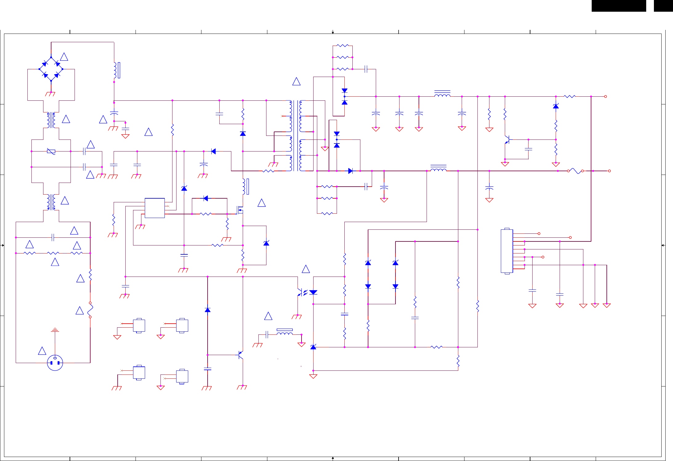
6.2 Power Board
715G2594-1
1
1
2
2
3
3
4
4
5
5
6
6
7
7
8
8
9
9
10
10
A A
B B
C C
D D
E E
F F
12V
CHANGE 13X20mm
F903
JUMPER
BD901 A1 CN901 E1
CN902 C8 C900 E4
C901 B2 C902 B2
C903 B2 C904 B8
C907 B2 C909 D1
C910 B4 C911 B3
C912 B2 C913 D3
C914 D2 C915 F4
C916 B2 C920 A6
C921 C6 C922 B6
C923 B6 C924 B7
C925 B7 C926 C6
C927 C8 C928 E6
C929 E7 C930 D9
C931 D8 D900 B4
D901 B4 D910 C3
D911 E4 D915 D6
D916 D6 D920 A6
D921 B5 D922 C6
FB901 C4 FB902 E5
FB903 A2 F901 E2
F902 A9 F903 C9
GND1 E2 GND2 E3
HS1 F2 HS5 F3
IC901 C3 IC902 D5
IC903 E5 L901 C1
L902 B1 L921 A7
L922 B7 NR901 D2
Q900 C4 Q902 B8
Q910 E4 R900 D1
R901 D1 R902 D2
R903 B9 R905 B3
R907 B8 R908 B9
R909 B4 R910 C4
R911 C2 R912 C3
R913 D4 R915 C4
R916 D4 R922 D6
R923 E7 R924 D7
R925 D6 R926 E8
R927 E6 R928 E6
R929 E7 R930 E7
R931 B8 R951 A6
R952 A6 R953 A6
R954 C5 R955 C5
R956 C5 S1 A1
S2 B1 S3 B2
S4 C2 S5 C1
S6 D1 S7 D2
S8 E2 S9 E1
S10 B2 S11 A5
S12 C4 S13 D5
S16 E4 S17 B3
S19 C1 S20 D2
S21 D1 T901 B5
VAR901 B1 ZD901 C3
ZD902 D4 ZD920 B9
ZD921 D6 ZD922 D6
POWER
+12V
+5V
ON/OFF
DIM
+5V
R900
330K 1/4W
HS1
HEAT SINK(Q900)
1
2
C931
0.1uF 50V
C900
2200PF
C902
1000pF
R956 47 1/4W
ǂ
R922
330R 1/8W
R915
10K 1/8W
L921
3.5uH
!
GND1
GND
1
2
R954 47 1/4W
ǂ
C903
1000PF
F902
0R05 1/4W
!
-
+
BD901
KBP208G
2
1
3
4
R909
100K 2W
ǂ
C904
0.001uF 50V
IC902
PC123X2YFZOF
12
43
ZD902
NC
1 2
R930
1K 1/8W
FB901
BEAD
12
ZD921
RLZ13B
1 2
Q900
STP10NK70ZFP
FB902
Jumper
1 2
ZD922
RLZ5.1B
1 2
!
CN901
SOCKET
12
3
D920
SBT150-10LST
1
2
3
D915
LL4148WP
CN902
CONNECTOR
1
2
3
4
5
6
7
8
9
10
!
R95147 1/4W
ǂ
IC901
LD7575PS
1
2
3
4 5
6
7
8
RT
COMP
CS
GNDOUT
VCC
NC
HV
ZD901
NC
1 2
D901
UF4003PT
R95347 1/4W
ǂ
L901
4.0mH
1
2
4
3
Q902
PMBS3904
C920
0.001uF/500V
C930
0.1uF 50V
L902
L
1
4
2
3
!
D922
31DQ06FC3
!
+
C911
22uF/50V
D916
LL4148WP
+
C922
680uF/25V
GND2
GND
1
2
D910 LL4148WP
R95247 1/4W
ǂ
D911
NC
C910
1500PF/2KV
+
C924
NC
D900
BA159GPT
!
R901
330K 1/4W
!
!
R903
1K 1/8W
ǂ
C929
0.1uF 50V
R924
3K6 1/8W
!
C901
1000pF
R926
33K 1/8W
VAR901
NC
!
C912
0.1uF 50V
+
C907
100uF/450V
!
T901
80GL17T-33-N2
4
7
9
5
6
4
6
11
10
8
12
1
3
F901
FUSE
R902
330K 1/4W
!
NR901
NTCR
R910
2.2 1/4W
ǂ
C916
0.1uF 50V
R929
2.4K 1/8W
ǂ
ZD920
RLZ13B
1 2
Q910
NC
+
C923
680uF/25V
C913
220pF 50V
C928
0.1uF 50V
C914
470pF/25V
!
C915
NC
+
C925
470uF/25V
R931
10K 1/4W
ǂ
!
R911
100K 1/8W
ǂ
R925
1K 1/8W
!
R916
0.43 2W
ǂ
+
C927
470uF/16V
R955 47 1/4W
ǂ
+
C926
1000uF/16V
D921
NC
1
2
3
IC903
KIA431A-AT/P
R912
10R 1/4W
C921
0.001uF/500V
L922
3.5uH
R913
1K 1/8W
!
C909 0.47uF
HS5
HEAT SINK(D920)
1
2
R923
10K 1/8W
R927
1K 1/8W
R928
1K 1/8W
R908
470 1/8W
FB903
BEAD
12
R905
10K 1/4W
ǂ
R907
150 1W
ǂ
!
http://www.wjel.net
26 HUDSON 8
1
1
2
2
3
3
4
4
5
5
6
6
7
7
8
8
9
9
10
10
A A
B B
C C
D D
E E
F F
CHANGE UPDATE
CN801 A10 CN802 A10 CN803 D10
CN804 E10 C801 A8 C802 A2
C803 B7 C804 B4 C805 B7
C806 C3 C807 C3 C808 C2
C809 D3 C810 D6 C811 E7
C812 D8 C813 E3 C814 E1
C815 E3 C816 D7 C817 E3
C818 E3 C819 B2 C820 D4
C821 B6 C822 E7 C823 B7
C824 E7 D801 B8 D802 B9
D803 B3 D806 D2 D807 D1
D808 E2 D809 E8 D810 E9
D811 C2 D812 C3 D813 B5
IC801 C4 L801 A9 L802 D9
PT801 A7 PT802 D7 Q801 A3
Q802 A2 Q803 B2 Q804 B6
Q805 C6 Q806 C7 Q807 D4
Q808 D1 Q809 E6 Q810 C6
Q811 C7 Q812 B5 R801 A9
R802 A3 R803 B5 R804 A9
R805 A5 R806 A8 R807 A9
R808 A2 R809 A2 R810 A6
R811 B8 R812 B9 R813 B2
R814 B4 R815 B3 R816 B2
R817 B3 R818 C3 R819 C3
R820 C2 R821 C2 R822 C3
R823 C3 R824 C3 R825 D4
R826 D4 R827 D1 R828 D2
R829 D3 R830 D9 R831 D3
R832 D9 R833 D3 R834 E8
R835 E9 R836 E1 R837 D7
R838 E3 R839 E8 R840 E3
R841 E9 R842 C4 R843 D4
R844 C6 R845 C6 R846 C7
R847 C7 R848 D6 R849 D7
R850 A6 R851 E7 R852 D5
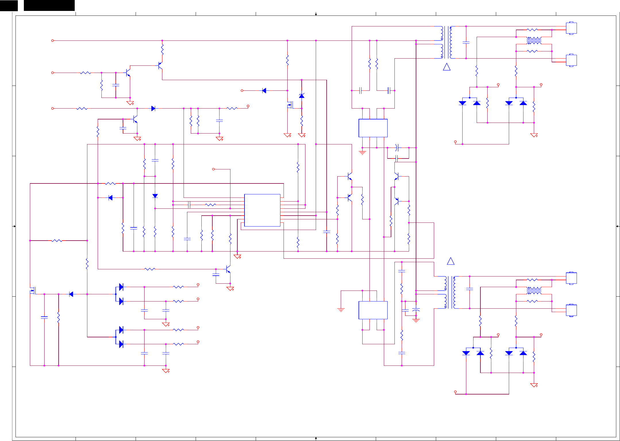
R853 C5 S14 A8 S15 D8
INVERTER
OLP1 OLP2
FB
FB
OLP1
OLP3
OLP4
OLP2
OLP4
FB
OLP3
+12V
ON/OFF
DIM
DTC
DTC
C824
0.1uF/25V
PT802
POWER X'FMR
6
3
7
4
81
+
C805
470uF/25V
R813
100 1/10W 5%
PT801
POWER X'FMR
6
3
7
4
81
R803
2.4K 1/10W
ǂ
R825 51K 1% 1/8W
ǂ
R850
15 1/4W
ǂ
R827
1K 1/10W 1%
R838
10K 1/10W 1%
C813
0.0022uF
D812
LL4148WP
C817
0.0022uF
D806
BAW56
3
1
2
C
B
E
R823 10K 1/10W
Q803
PMBS3904
R829
68K 1% 1/10W
ǂ
R840
10K 1/10W 1%
C801
10pF/3KV
R806
1K 1/10W 1%
C804
0.1uF/16V
D809
BAV99
3
1
2
R817
NC
Q809
AM9945N-T1-PF
1
2
3
4
8
7
6
5
S
G
S
G
D
D
D
D
R839
1K 1/10W 1%
C806
1uF/16V
CN803
CONN
1
2
L802
NC
1
4
2
3
D811
LL4148WP
Q812
RK7002
R807
1K 1/10W 1%
R802
100R 1/8W 5%
D808
BAW56
3
1
2
C
B
E
C802 1uF 16V
R808
10K 1/10W 1%
R815
47K 1/10W 1%
R844
22R 1/10W 5%
R810
15 1/4W
ǂ
Q805
PMBS3906
C820
NC
R822 47K 1/10W 1%
R824
10K 1/10W 1%
CN801
CONN
1
2
R818
NC
D803
LL4148WP
R834
1K 1/10W 1%
C809 220pF
R814
75K 1/10W 1%
D801
BAV99
3
1
2
C818
0.0022uF
R812
1K 1/10W 1%
R847
22R 1/10W 5%
R837
15 1/4W
ǂ
C819
NC
+
C811
470uF/25V
!
Q810
PMBS3904
C816
1500PF/50V
R835
1K 1/10W 1%
Q811
PMBS3904
!
R830 0R05 1/10W 5%
D802
BAV99
3
1
2
Q807
PMBS3904
R846
22R 1/10W 5%
R819
10K 1/10W 1%
Q804
AM9945N-T1-PF
1
2
3
4
8
7
6
5
S
G
S
G
D
D
D
D
ZD801
10K 1/4W 5%
1 2
C807
0.1uF/16V
L801
NC
1
4
2
3
C822
1500PF/50V
R832 0R05 1/10W 5%
R804 0R05 1/10W 5%
R841
1K 1/10W 1%
R821 1M 1/10W 5%
R826
180K 1% 1/8W
ǂ
R816
68K 1% 1/10W
ǂ
R853
10K 1/10W 1%
R828
47K 1/10W 1%
IC801
TL494IDR
1
2
3
4
5
6
7
8 9
10
11
12
13
14
15
16
1IN+
1IN-
FEEDBACK
DTC
CT
RT
GND
C1 E1
E2
C2
VCC
OUTPUT CTRL
REF
2IN-
2IN+
CN804
CONN
1
2
D813
LL4148WP
R820
560K 1/10W 5%
ǂ
R842
47K 1/10W 1%
C812
10pF/3KV
Q808
RK7002
Q801
PDTA144WK
R851
15 1/4W
ǂ
R849
1K 1/10W 1%
C808 2.2uF/16V
Q802
PDTC144WK
R809
NC
R852
10K 1/10W 1%
D807
LL4148WP
D810
BAV99
3
1
2
C821
1500PF/50V
C814
0.1uF/16V
R811
1K 1/10W 1%
Q806
PMBS3906
R831
10K 1/10W 1%
R843 NC
C823
0.1uF/25V
R845
22R 1/10W 5%
R801 0R05 1/10W 5%
C803
1500PF/50V
CN802
CONN
1
2
C810
0.1uF/25V
R836
1M 1/10W 5%
R833
10K 1/10W 1%
C815
0.0022uF
R805
4.7K 1/10W 5%
R848
1K 1/10W 1%
http://www.wjel.net
27
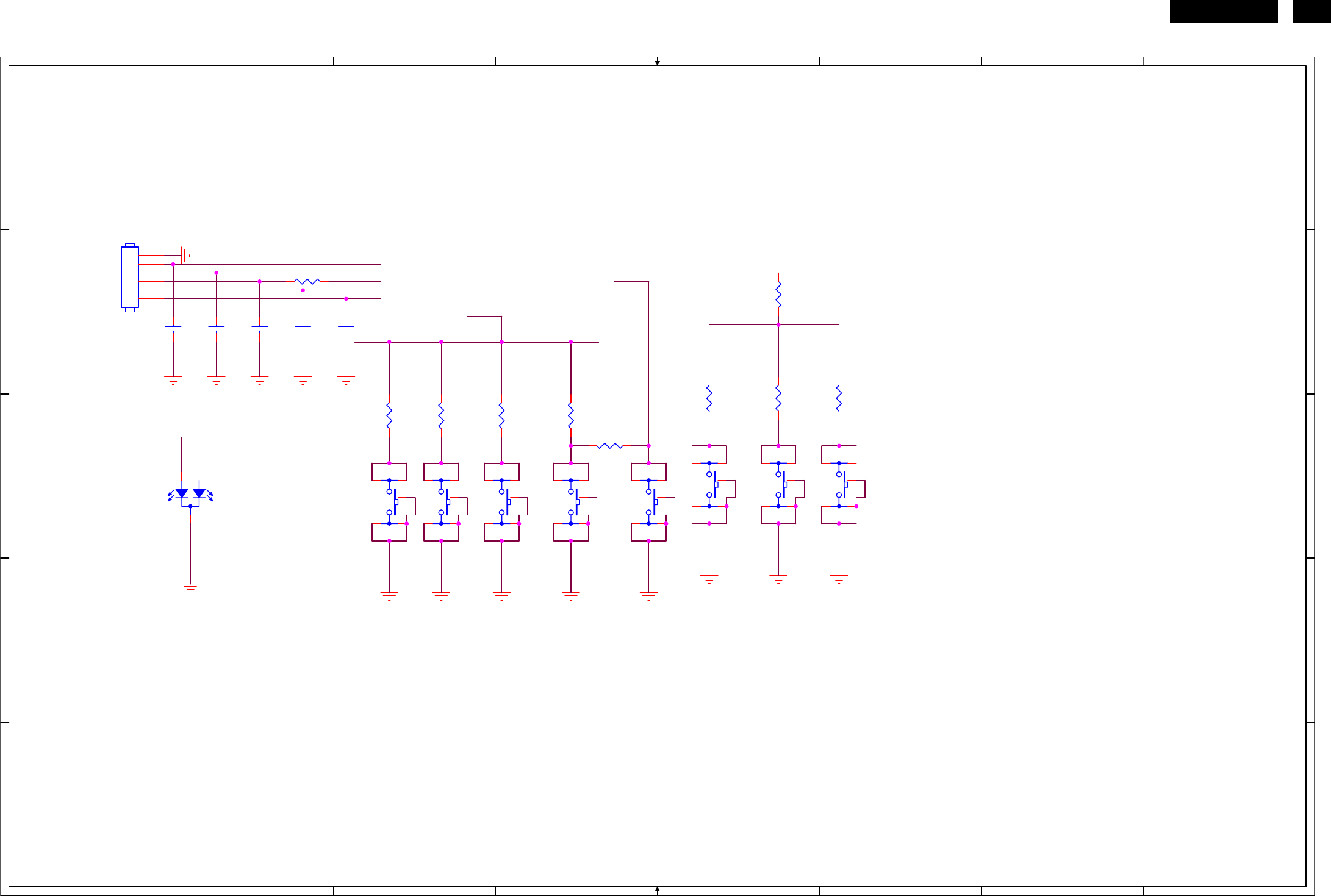
HUDSON 8
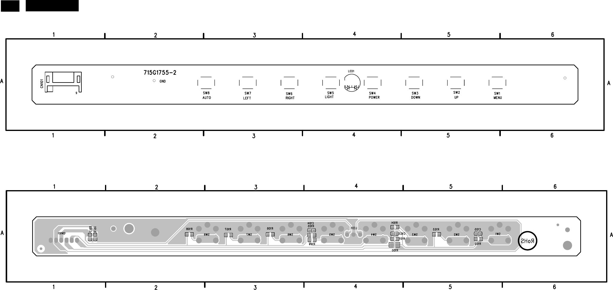
6.3 Key Board
715G1755-2
1
1
2
2
3
3
4
4
5
5
6
6
7
7
8
8
A A
B B
C C
D D
E E
KEY-BRIGHTNESS
KEY-MENU/ENTERKEY-SOURCE
KEY-SMART IMAGE
KEY-VOLUME
KEY-AUTO/BACK
KEY-LIGHT FRAME
KEY-POWER
KEY2
add on Mar.-31-07
CN101 B1
C101 B1
C102 B2
C103 B2
C104 B2
C105 B3
LED1 C1
R100 B5
R101 B2
R102 B6
R103 B5
R104 B5
R105 C4
R106 C3
R107 C3
R108 C3
R109 C4
SW1 C6
SW2 C5
SW3 C5
SW4 C4
SW5 C4
SW6 C3
SW7 C3
SW8 C3
LED-O
LED-G
K-PWR
KEY2
K-PWR
LED-G
LED-O
KEY1
KEY1
R103
910ȍ 1/10W
SW1
SW
21
3 4
5
C103
0.01uF
R108
2.4Kȍ 1/10W
R109
0R05 1/10W 5%
C104
0.01uF
SW8
SW
21
3 4
5
LED1
LED
1
3
2
R100
0R05 1/8W
C102
0.01uF
C101
0.01uF
C105
0.01uF
R106
4K3 1/10W
R101
100R 1/10W 5%
R107
910ȍ 1/10W
R102
4K3 1/10W
SW5
SW
21
3 4
5
SW4
SW
21
3 4
5
R104
2.4Kȍ 1/10W
SW3
SW
21
3 4
5
SW6
SW
21
3 4
5
SW2
SW
21
3 4
5
R105
NC
CN101 CONN
1
2
3
4
5
6
SW7
SW
21
3 4
5
http://www.wjel.net
28 HUDSON 8
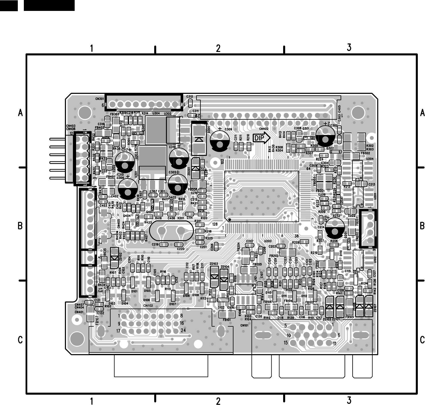
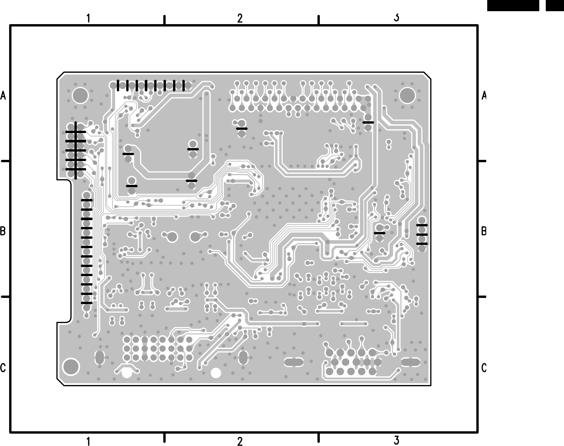
7. PCB Layout
7.1 Scalar Board
715G2561-1
C101 B3 C215 B3 D105 C1 Q301 A3 R144 C2 R410 B1
C102 C1 C216 A1 D106 C2 Q302 A3 R201 B2 R411 A3
C103 C1 C219 B2 D107 C2 Q305 A1 R202 A2 R412 B1
C104 B1 C220 B2 D108 C2 Q402 B2 R205 A1 R413 A3
C105 C2 C222 B3 D109 C2 Q403 B2 R206 B3 R414 A3
C106 C2 C301 B2 D110 B3 Q404 B1 R207 B3 R415 B2
C107 C2 C302 A3 D111 C3 R101 C3 R209 B3 R416 B2
C110 B1 C303 A3 D112 C3 R102 C1 R210 A2 R417 B2
C111 B2 C304 A3 D113 C2 R103 C2 R211 A2 R418 B1
C112 B2 C305 B2 D201 B3 R104 C2 R213 B3 R421 B2
C113 C2 C306 B1 D301 A2 R105 C2 R214 B2 R423 B1
C114 B2 C307 B1 FB101 C2 R106 C1 R215 B3 R424 B1
C115 C3 C308 A3 FB102 B3 R107 C1 R218 B2 R430 A3
C116 C3 C309 A2 FB103 C3 R108 C2 R219 B3 R431 B1
C117 C3 C310 A2 FB104 C3 R109 B2 R220 A1 R432 A1
C118 C2 C311 A2 FB105 C3 R110 B1 R221 B2 R433 A1
C121 B3 C312 A2 FB106 C2 R111 B1 R223 B3 R434 B1
C122 B3 C315 A1 FB107 C1 R113 C2 R224 A3 R435 B1
C123 B2 C316 A1 FB201 B3 R115 C2 R225 B2 R436 B1
C124 B3 C317 A1 FB202 B3 R116 C2 R228 B3 R437 A1
C125 B3 C401 B1 FB203 B3 R117 B2 R229 B3 R438 A1
C126 B2 C402 B1 FB204 B2 R118 B2 R230 B3 R439 B1
C127 B3 C403 B1 FB205 B2 R120 B2 R231 B3 U101 B2
C128 C3 C404 B1 FB206 B2 R122 C2 R232 B3 U102 B3
C129 B2 C405 A3 FB207 B3 R123 B3 R233 B3 U201 B3
C130 C2 C406 B2 FB302 A3 R124 B3 R234 B2 U203 B2
C131 C1 C407 B1 FB303 A1 R125 B3 R301 A1 U204 B3
C132 C1 CN101 C3 FB401 B1 R126 C3 R302 A3 U301 B1
C201 B2 CN102 C2 FB403 A1 R127 C3 R303 A3 U302 A2
C202 A1 CN202 B3 FDT1 B3 R128 C3 R304 A3 U303 B1
C203 B2 CN301 A2 FDT10 <1 R129 C3 R305 A3 U304 A2
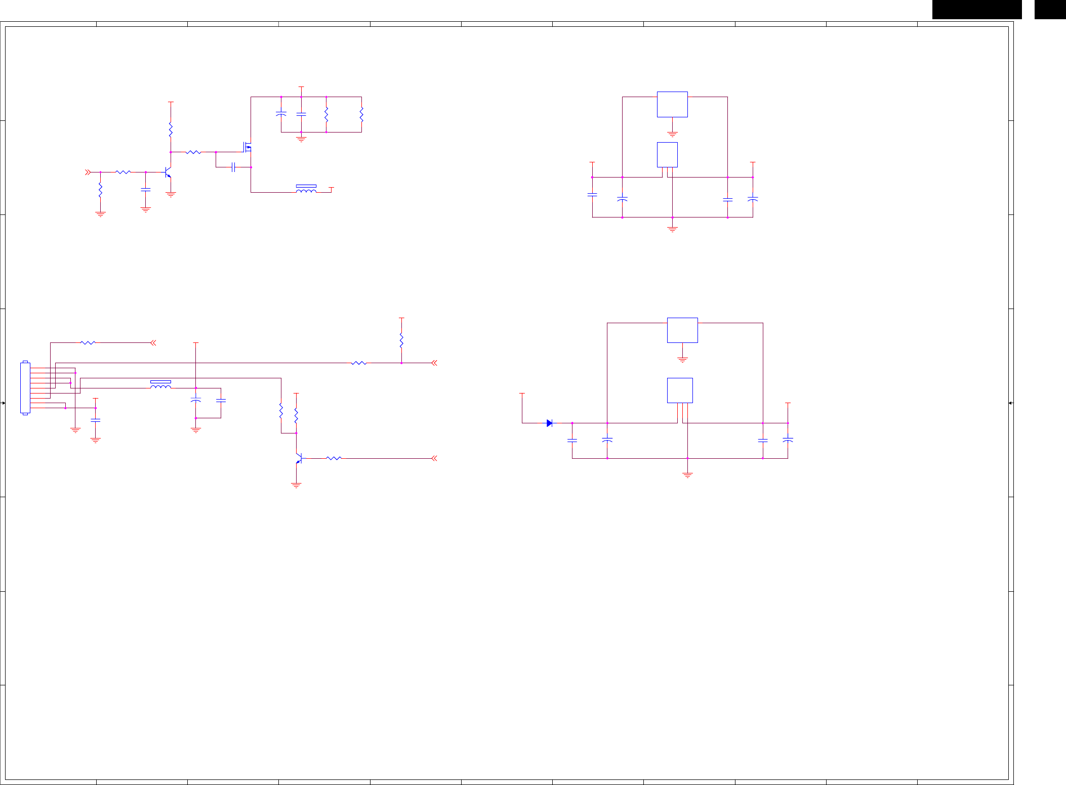
C204 B3 CN401 B1 FDT11 C8 R131 C2 R307 A3 X201 B2
C205 B3 CN402 A2 FDT12 <8 R132 C3 R308 A3 ZD101 C3
C206 B2 CN403 B1 FDT13 C1 R133 C3 R309 A1 ZD102 B1
C207 B2 CN404 B1 FDT2 A2 R134 C3 R311 A1 ZD103 B2
C208 B2 CN405 B1 FDT3 A3 R135 C2 R312 A1 ZD104 B2
C209 B3 CN406 A1 FDT4 C1 R136 C3 R314 A1 ZD105 C3
C210 B2 CN407 B1 FDT5 C1 R138 C2 R316 A1 ZD106 C3
C211 A2 D101 C1 FDT6 <1 R139 C3 R402 B1 ZD107 C3
C212 B2 D102 C2 FDT7 C8 R140 C2 R403 B1 ZD201 B2
C213 B3 D103 C1 FDT8 <8 R141 C3 R404 A1
C214 B3 D104 C1 Q201 B3 R142 C3 R407 B1
http://www.wjel.net
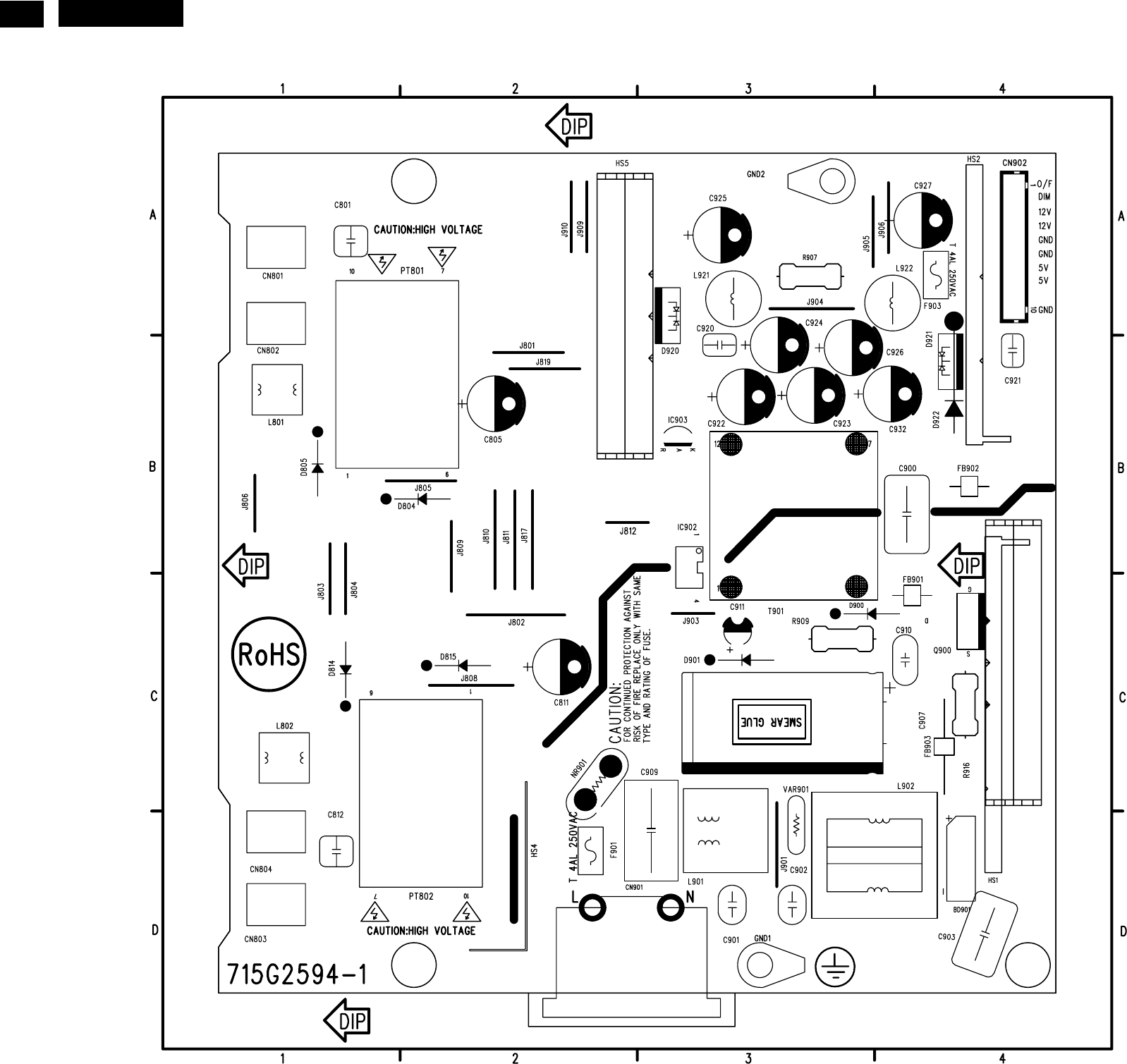
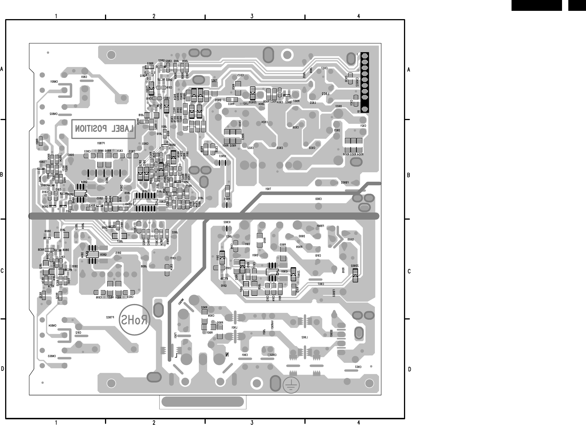
30 HUDSON 8
7.2 Power Board
715G2594-1
BD901 D4 J802 C2
C801 A1 J803 B1
C805 B2 J804 B1
C811 C2 J805 B2
C812 D1 J806 B1
C900 B4 J808 C2
C901 D3 J809 C2
C902 D3 J810 C2
C903 D4 J811 C2
C907 C4 J812 B2
C909 D3 J817 C2
C910 C4 J819 B2
C911 C3 J901 D3
C920 B3 J903 C3
C921 B4 J904 A3
C922 B3 J905 A3
C923 B3 J906 A4
C924 B3 J909 A2
C925 A3 J910 A2
C926 B3 L801 B1
C927 A4 L802 C1
C932 B4 L901 D3
CN801 A1 L902 D4
CN802 A1 L921 A3
CN803 D1 L922 A4
CN804 D1 NR901 C2
CN901 D2 PT801 B1
CN902 A4 PT802 C2
D804 B1 Q900 C4
D805 B1 R907 A3
D814 C1 R909 C3
D815 C2 R916 C4
D900 C3 SG11 C4
D901 C3 SG12 D2
D920 A3 SG19 D2
D921 B4 SG22 D4
D922 A4 SG25 D4
F901 D2 SG27 D3
F903 A4 SG28 C3
FB901 C4 SG31 D3
FB902 B4 SG33 A1
FB903 C4 SG34 A1
HS10 A3 SG35 A1
HS13 A3 SG36 A1
HS14 A2 SG39 A1
HS16 A2 SG40 D1
HS17 B4 SG42 D1
HS20 A8 SG44 D1
HS28 A7 SG45 D1
HS29 B1 SG46 C4
HS31 B4 SG47 C4
IC902 B3 SG49 C4
IC903 B3 T901 C3
J801 B2 VAR901 D3
http://www.wjel.net
31
HUDSON 8
C802 A2 J907 C3 R843 B2
C803 B1 J908 C3 R844 B2
C804 B2 Q801 A2 R845 B1
C806 B2 Q802 A2 R846 B1
C807 C2 Q803 A2 R847 C2
C808 B2 Q804 B1 R848 B2
C809 C2 Q805 B1 R849 B2
C810 A2 Q806 B1 R850 B2
C813 B1 Q807 B2 R851 C2
C814 B2 Q808 B2 R852 B2
C815 B1 Q809 C1 R853 B2
C816 C1 Q810 C2 R900 D3
C817 C1 Q811 B1 R901 D3
C818 C1 Q812 A2 R902 C2
C819 A2 Q902 A3 R903 A3
C820 B2 Q910 C3 R905 C3
C821 B2 R801 B1 R908 A3
C822 C2 R802 B2 R910 C3
C823 B2 R803 A2 R911 C3
C824 C2 R804 B1 R912 C3
C904 A3 R805 B2 R913 C3
C912 C3 R806 B1 R915 C3
C913 C3 R807 B1 R922 A3
C914 C3 R808 A2 R923 A2
C915 C3 R809 A2 R924 A2
C916 C3 R810 B1 R925 B3
C928 B3 R811 B1 R926 A3
C929 B2 R812 B1 R927 B2
C930 A4 R813 A2 R928 B3
C931 A4 R814 C2 R929 B2
D801 B1 R815 B2 R930 B2
D802 B1 R816 B2 R931 A3
D803 A2 R817 B2 R951 B3
D806 B1 R818 B2 R952 B3
D807 B2 R819 B2 R953 B3
D808 C1 R820 B2 R954 B4
D809 C1 R821 B2 R955 B4
D810 C1 R822 C2 R956 B4
D811 B2 R823 B2 SG10 C3
D812 B2 R824 C2 SG15 D3
D813 B2 R825 B2 SG17 D3
D910 C3 R826 B2 SG18 D4
D911 C3 R827 B2 SG20 D4
D915 A2 R828 B2 SG21 D3
D916 A2 R829 B2 SG23 D4
F902 A3 R830 C1 SG24 D3
HS11 D4 R831 B1 SG26 D4
HS15 A1 R832 C1 SG29 C3
HS21 A7 R833 B1 SG30 D3
HS22 A1 R834 C1 SG32 D3
IC801 B2 R835 C1 SG37 D2
IC901 C3 R836 B2 SG38 D2
J807 C2 R837 C2 ZD801 A2
J813 C1 R838 C1 ZD901 C3
J814 C1 R839 C1 ZD902 C4
J815 C1 R840 C1 ZD920 A3
J816 B2 R841 C1 ZD921 A2
J818 A2 R842 C2 ZD922 A2
http://www.wjel.net
39
HUDSON 8
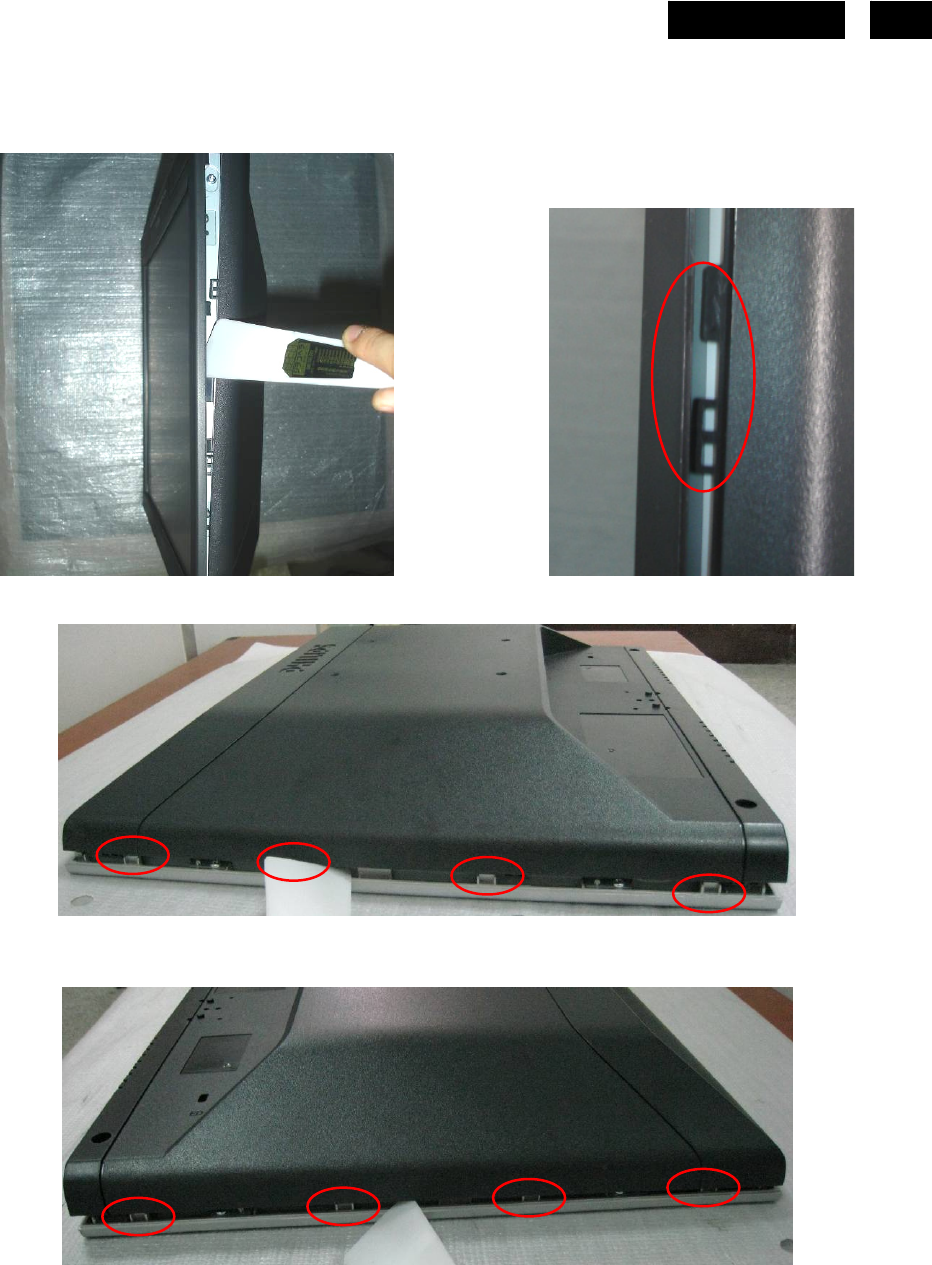
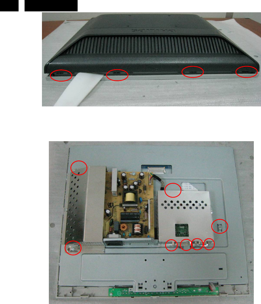
c. Insert plastic putty knife into the gap between front bezel and back cover to release 4 snaps on the left, 4 snaps on
the right and 4 snaps on the top as Fig12 - Fig15
Fig12
Fig13
Fig14
Insert plastic
putty knife into
the gap between
front bezel and
back cover
Front Bezel Back cover
4 snaps on the left
4 snaps on the right
http://www.wjel.net
41
HUDSON 8
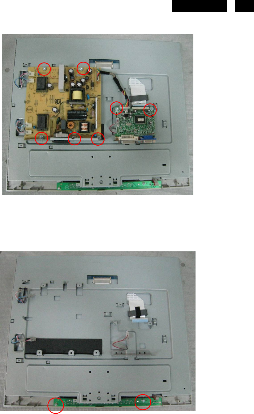
8. Remove main board and power board as Fig17.
Remove 7 screws to remove main board and power board as Fig17.
Fig17
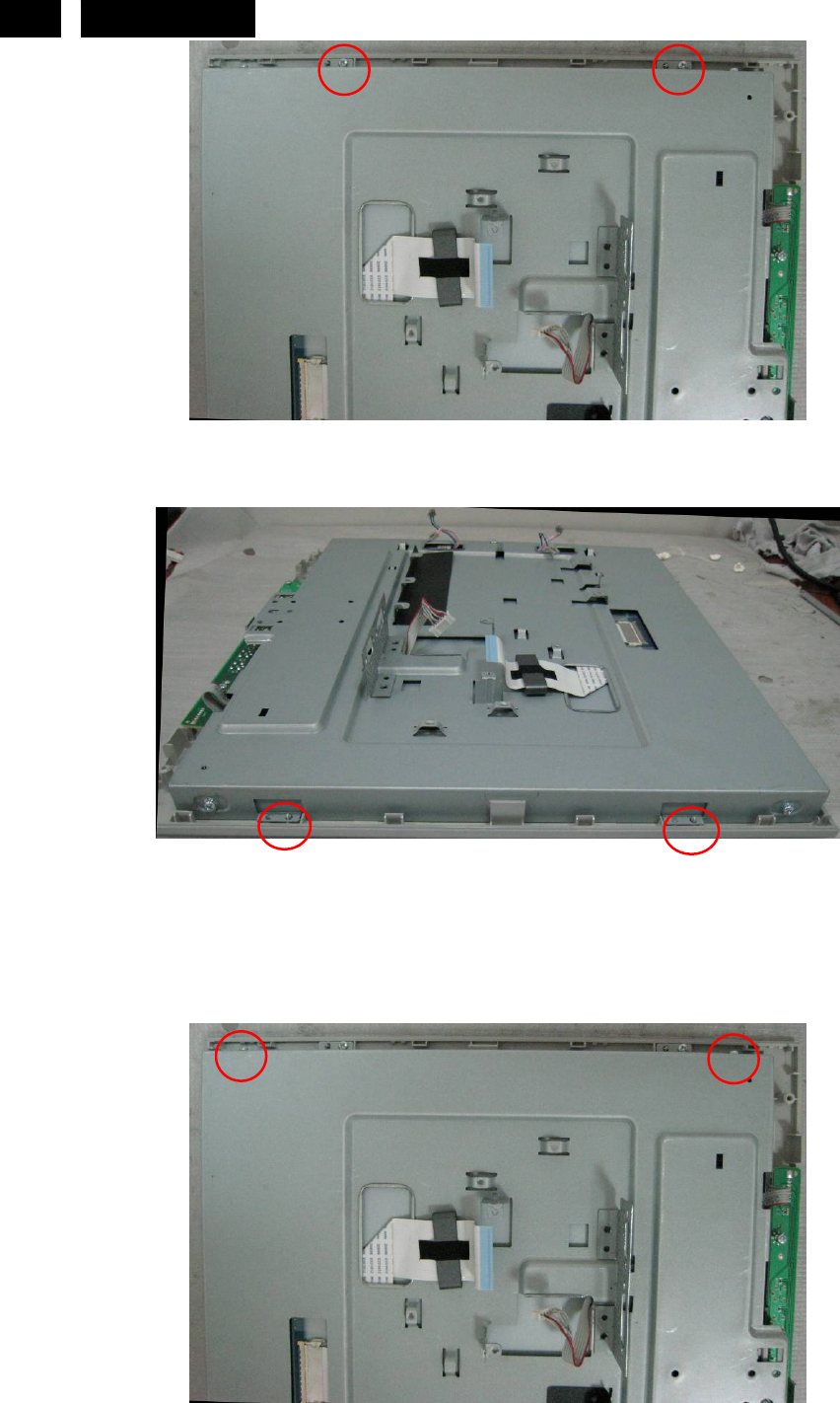
9. Remove the bezel as Fig18- Fig20
a. Remove 2 screws to remove the key board as Fig18
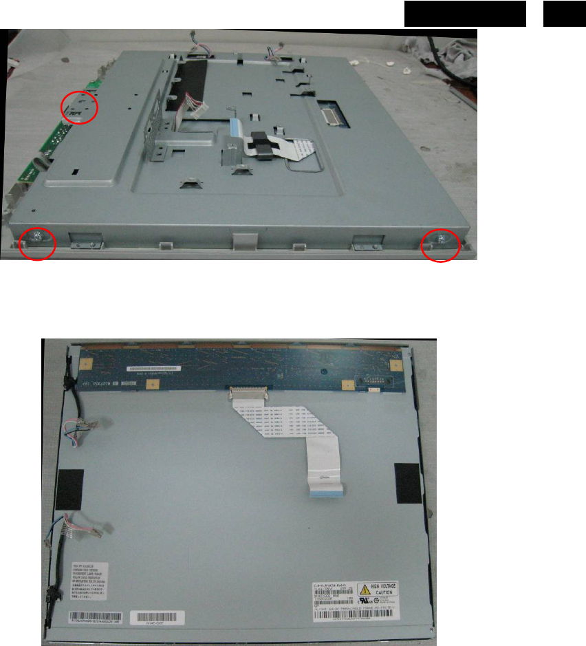
b. Remove 2 screws at the left of bezel as Fig19
c. Remove 2 screws at the right of bezel as Fig20
Fig18
http://www.wjel.net
46 HUDSON 8
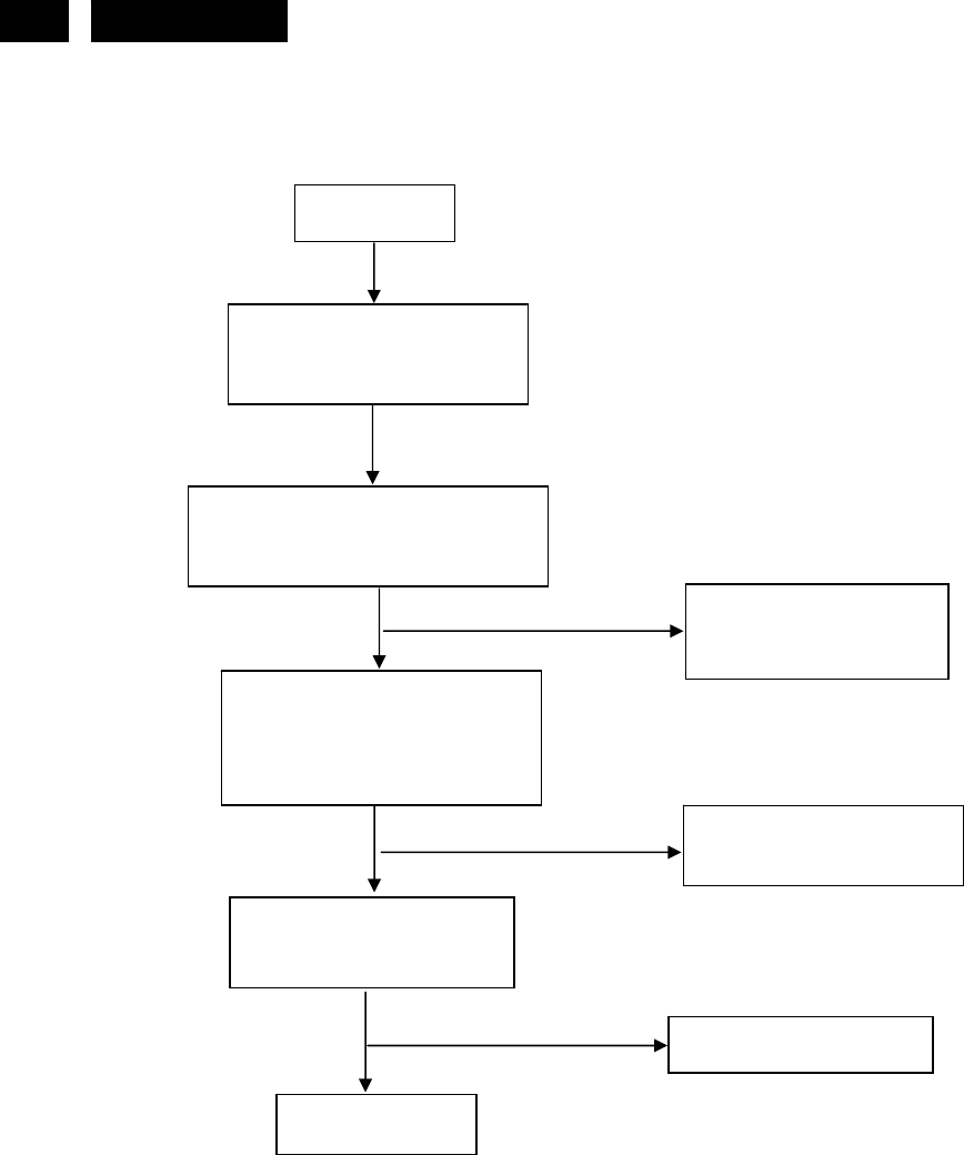
11. Repair Flow Chart
11.1 Main Board
(1). No Power
No power
Press power key and look
if the picture is normal
Please reinsert and make sure
the AC of 100-240 is normal
Reinsert or check the
Adapter/Inverter
section
X201 oscillate waveforms
are normal
Replace D301, U301 or
U304
Replace U203
Replace X201
OK
OK
OK
NG
NG
NG
NG
Measure U301 PIN2=3.3V
Measure U304 PIN2=1.8V
http://www.wjel.net
47
HUDSON 8
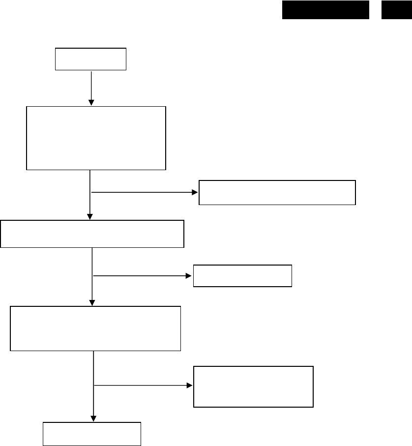
(2). No Picture
No picture
OK
OK
NG
NG
Replace D301, U301 or U304
X201 oscillate waveforms are normal
Replace X201
Check if the sync signal from
computer is output and video cable
is connected normally
Input the sync signal of
computer, or change
the cable
Replace U203
NG
OK
Measure U301 PIN2=3.3V
Measure U304 PIN2=1.8V
http://www.wjel.net
48 HUDSON 8
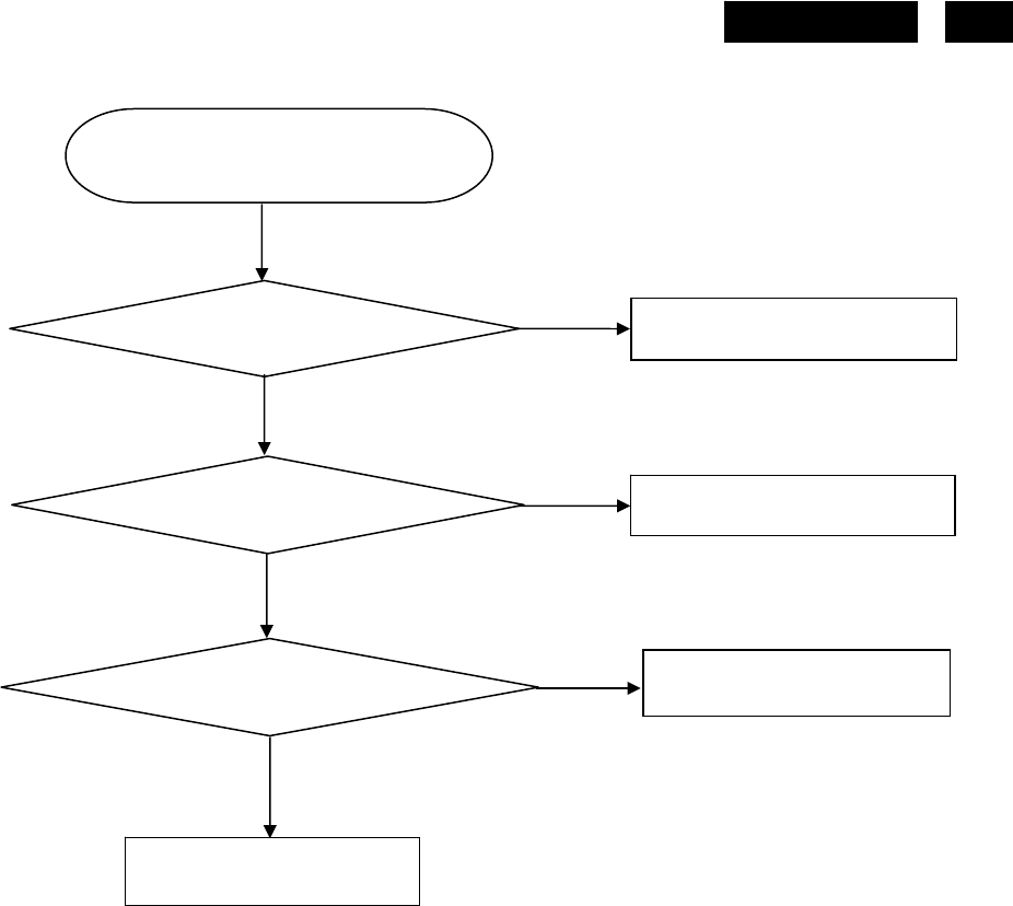
(3). White screen
White screen
Check Q301, Q302 is broken
or CN402 solder?
Check Correspondent
com
p
onent.
Replace Panel
Check Correspondent
com
p
onent.
Replace U203
OK OK Replace X201
OK
NG
NG
NG
NG
Check reset circuit of
U203 is normal
OK
X201 oscillate
waveform is normal
Measure Q301 base
is high level?
http://www.wjel.net
49
HUDSON 8
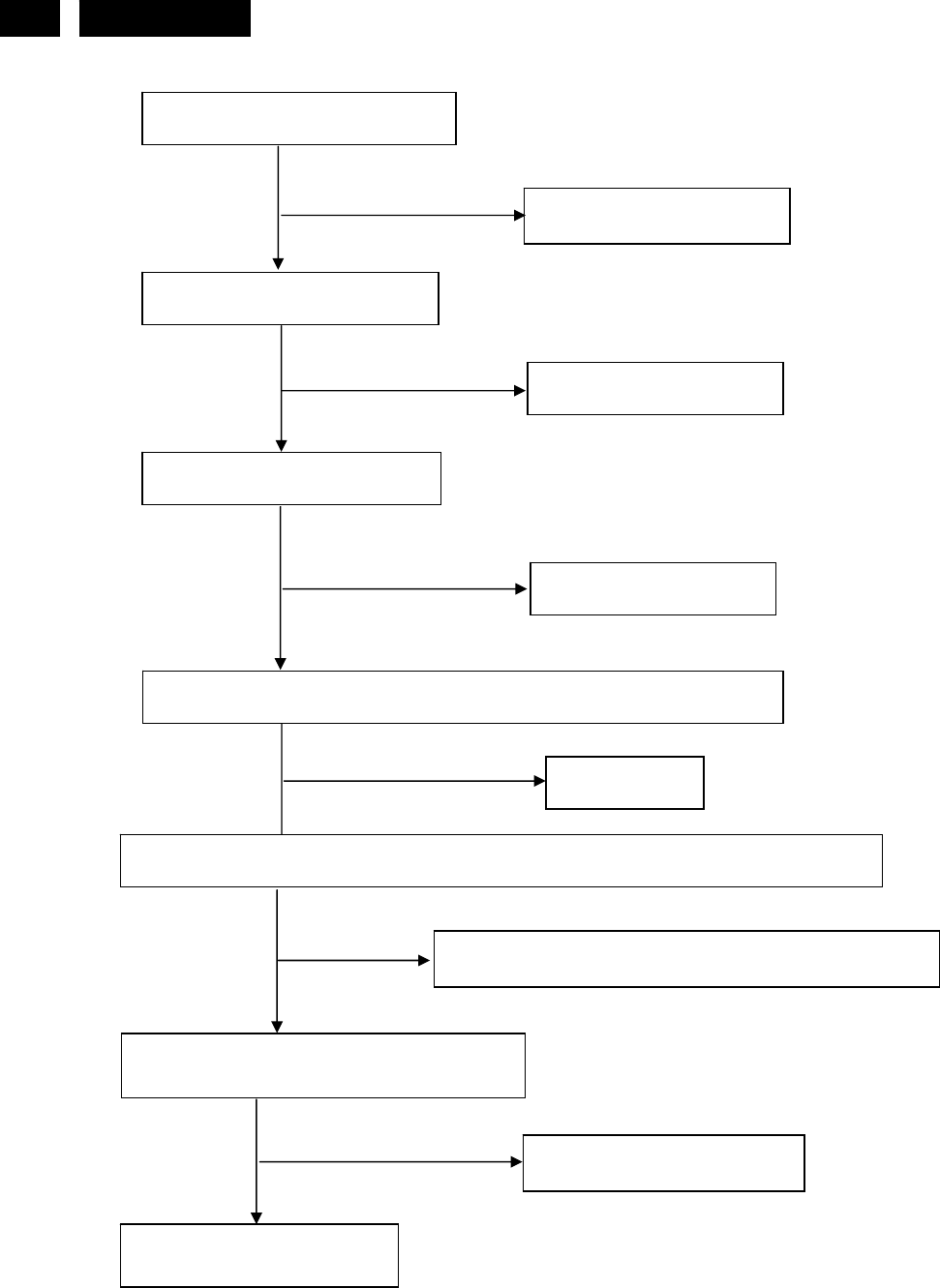
11.2. Power/Inverter Board
(1) No power
Check CN902 pin4, 5 = 12V
Check AC line volt 110V or 220V
Check AC input
Check the voltage of C907 (+)
Check bridge rectified circuit and F901 circuit
Check start voltage for the pin8 of IC901
Check R905 and Change IC901
NG
Check the auxiliary voltage is bigger than
10V and smaller than 20V
1) Check IC901
2) Check R910, D901 circuit
OK
OK
NG
Check D910, Q900, D900, IC902, F902, ZD921, ZD922, D915, D916
OK
Check IC901 pin5 PWM wave
OK
Check IC901
NG
NG
NG
OK
NG
http://www.wjel.net
50 HUDSON 8
(2) W / LED, No Backlight
Check CN902 pin4, 5 = 12V
NG
OK
Check adapter or MB
Check ON/OFF signal
Check Interface board
NG
OK
Check IC801 PIN12=12V
NG
OK
Change Q801
Check IC801 PIN10, 9 have the output of square wave at short time
NG
OK Change IC801
Check Q804, Q809 PIN5, 6, 7, 8 have the output of square wave at short time.
NG
OK Check Q804, Q805, Q806, Q809, Q810, Q811
Check the output of PT801, PT802
Check connecter & lamp
OK NG Change PT801, PT802
http://www.wjel.net

59
HUDSON 8
13. DDC Instruction
General
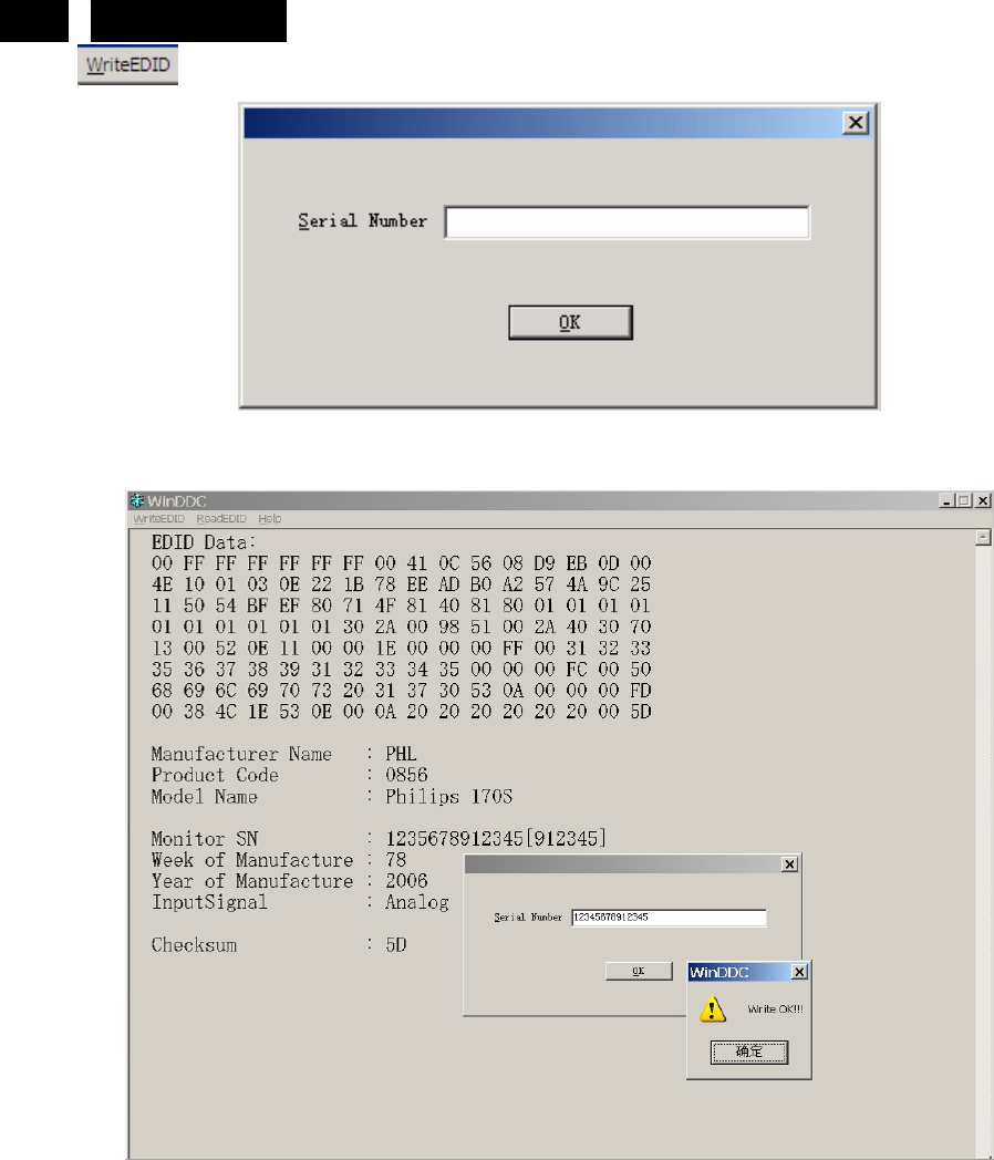
DDC Data Re-programming
In case the main EEPROM with Software DDC which store all factory settings were replaced because a defect,
repaired monitor’ the serial numbers have to be re-programmed.
It is advised to re- soldered the main EEPROM with Software DDC from the old board onto the new board if
circuit board have been replaced, in this case the DDC data does not need to be re-programmed.
Additional information about DDC (Display Data Channel) may be obtained from Video Electronics Standards
Association (VESA). Extended Display Identification Data (EDID) information may be also obtained from
VESA.
1. An i486 (or above) personal computer or compatible.
2. Microsoft operation system Windows 95/98/2000/XP.
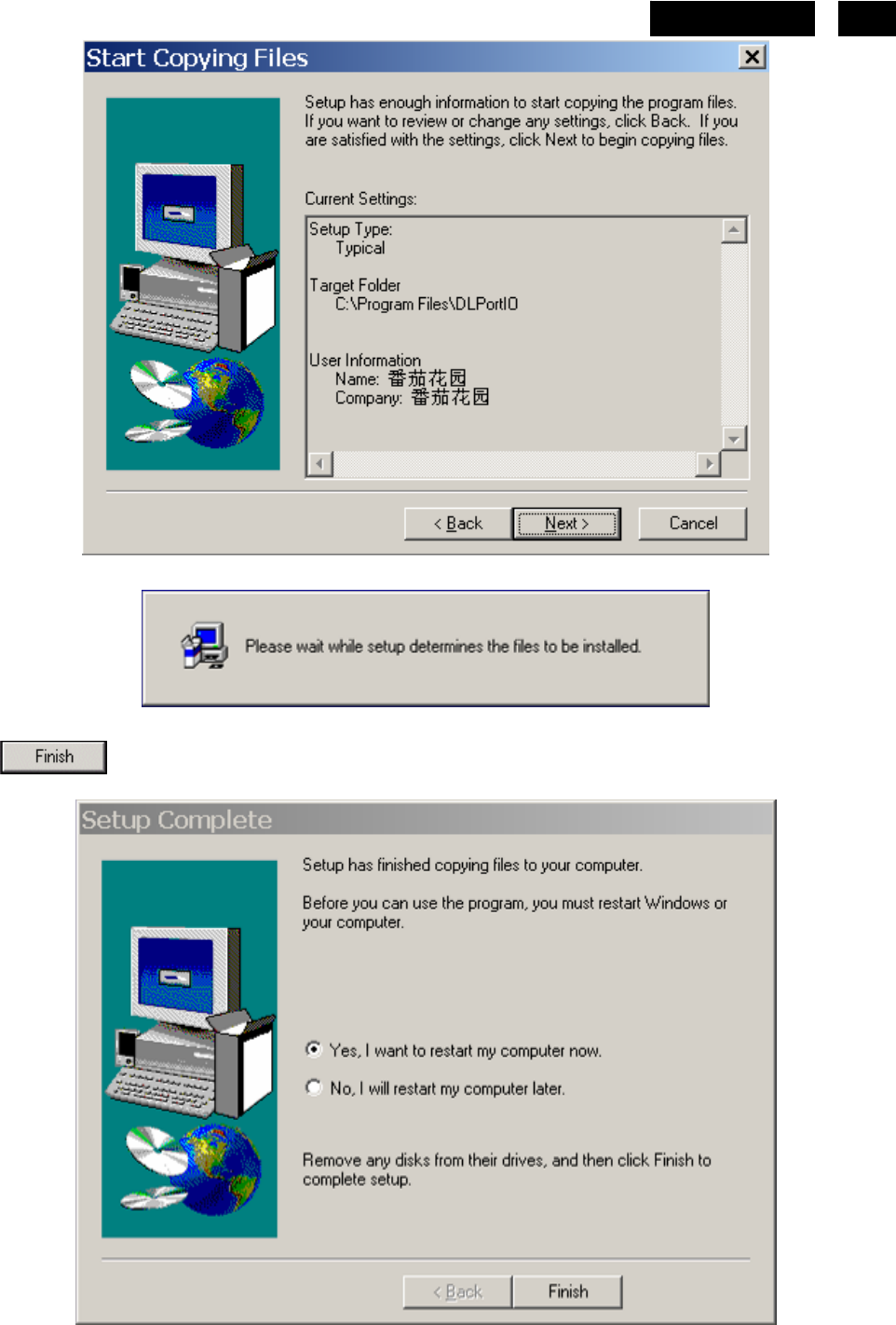
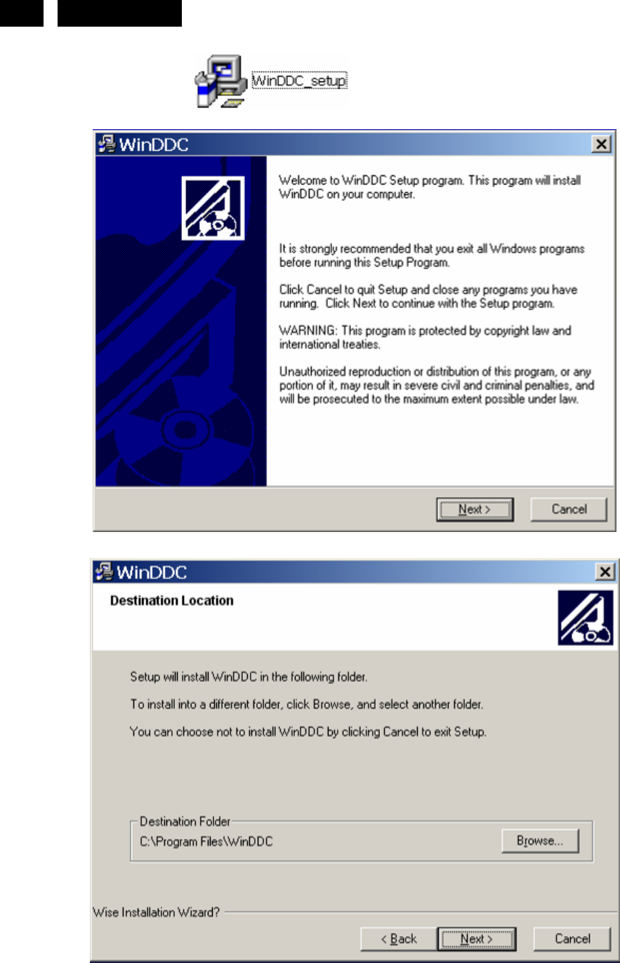
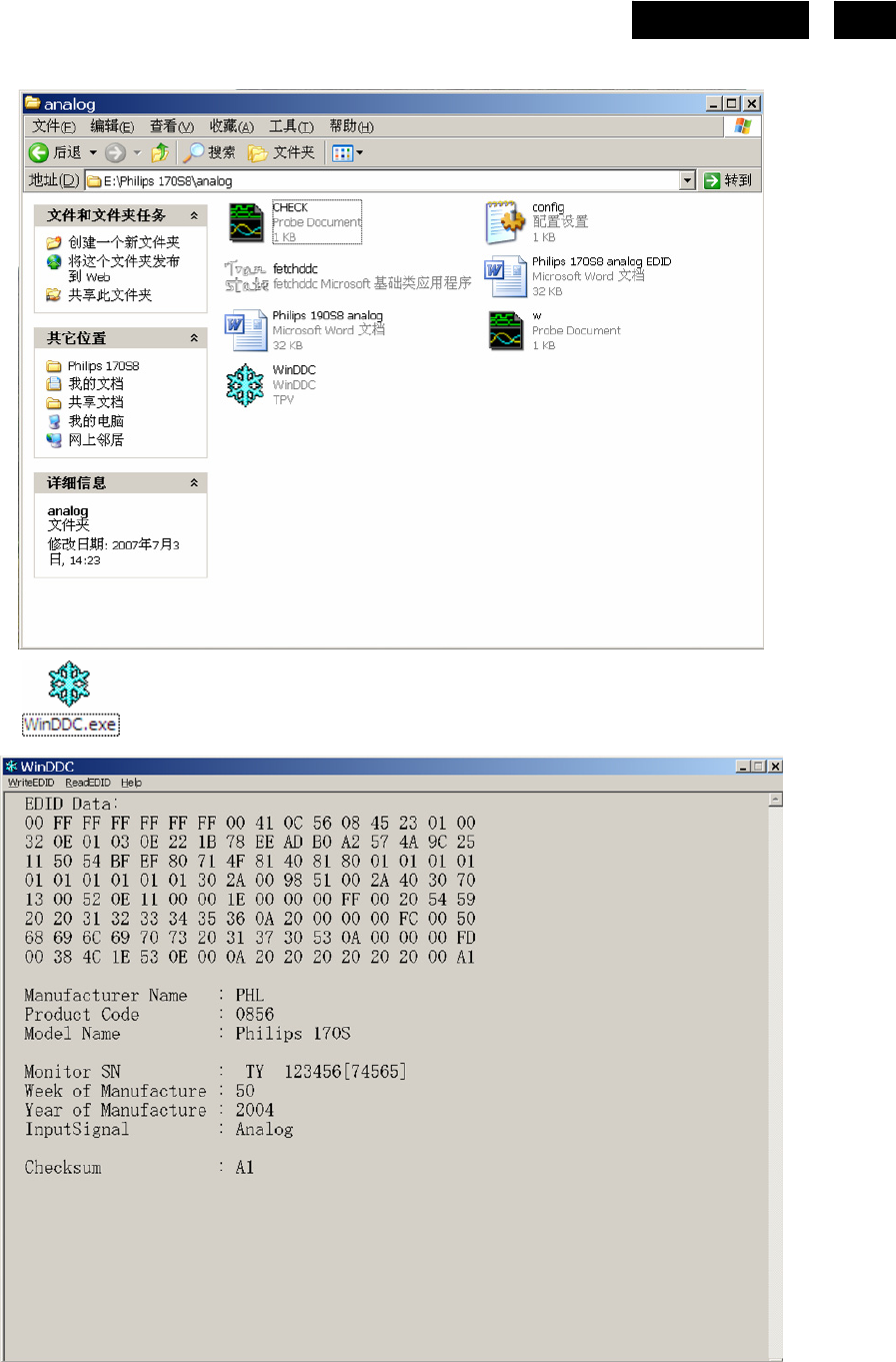
3. “ PORT95NT.exe, WinDDC_ setup” program.
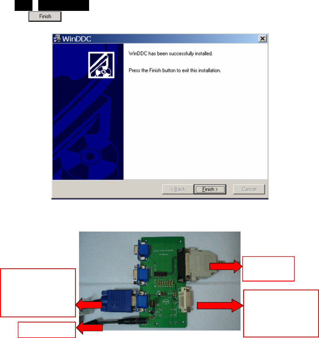
4. Software OSD SN Alignment kits
The kit contents:
a. OSD SN BOARD x1
b. Printer cablex1
c. VGA cable x1
d. Digital cable x1
e. 12V DC power source
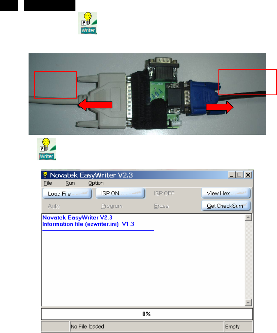
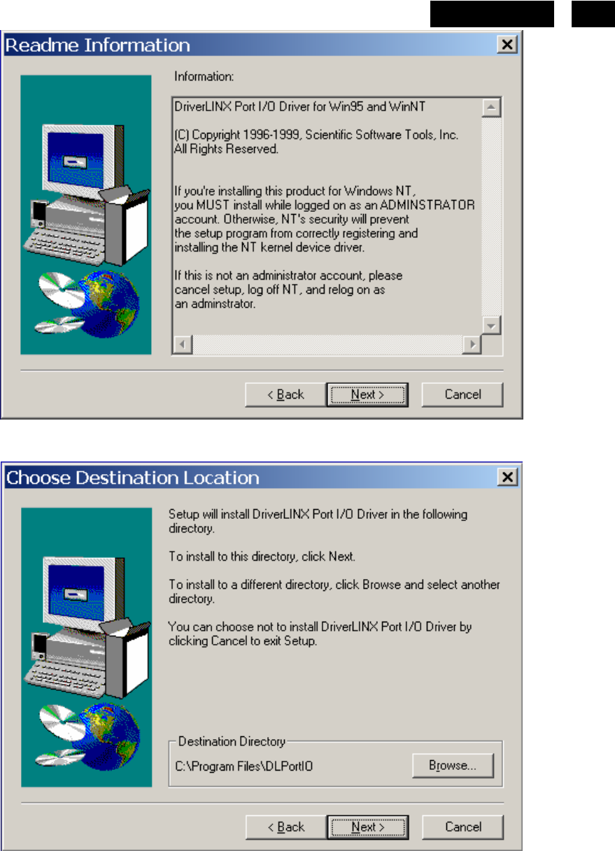
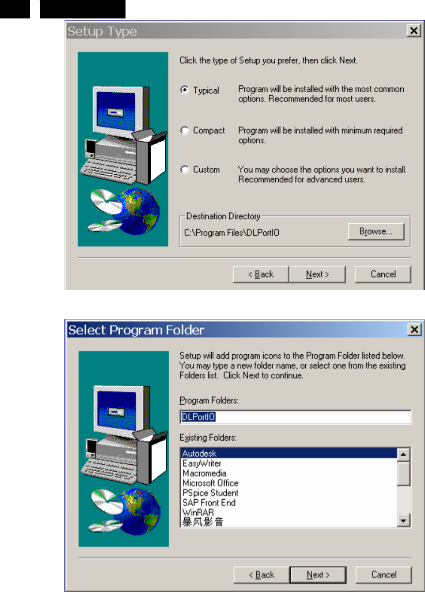
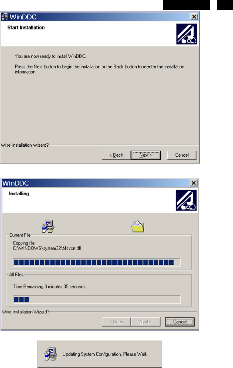
1. Install the “PORT95NT.EXE”, and restart the computer.
You must install the at the first. The processing as follows:
http://www.wjel.net

69
HUDSON 8
170S8 EDID
Analog
128 bytes EDID Data (Hex):
00 01 02 03 04 05 06 07 08 09 10 11 12 13 14 15
0: 00 FF FF FF FF FF FF 00 41 0C 59 08 01 01 01 01
16: 0C 0D 01 03 0E 26 1E 78 EE A1 50 A3 57 4C 9D 25
32: 11 50 54 BF EF 80 71 4F 81 40 81 80 01 01 01 01
48: 01 01 01 01 01 01 30 2A 00 98 51 00 2A 40 30 70
64: 13 00 78 2D 11 00 00 1E 00 00 00 FF 00 32 31 33
80: 32 33 31 32 33 32 31 33 32 33 00 00 00 FC 00 50
96: 68 69 6C 69 70 73 20 31 39 30 53 0A 00 00 00 FD
112: 00 38 4C 1E 53 0E 00 0A 20 20 20 20 20 20 00 A2
Decoded EDID data
<---Header--->
Header: 00 FF FF FF FF FF FF 00
<-x-Header-x->
<---Vendor/Product Identification--->
ID Manufacturer Name: PHL
ID Product Code: 0859
ID Serial Number: 01010101
Week of Manufacture: 12
Year of Manufacture: 2003
<-x-Vendor/Product Identification-x->
<---EDID Structure Version/Revision--->
EDID Version#: 01
EDID Revision#: 03
<-x-EDID Structure Version/Revision-x->
<---Basic Display Parameters/Features--->
Video i/p definition: Analog
Signal Level Standard: 0.700V/0.300V(0.700Vpp)
Setup: Blank-to-Black not expected
Separate Sync Support: Yes
Composite Sync Support: Yes
Sync. on green video supported:Yes
Serration of the Vsync.Pulse is not required.
Max. H. Image Size : 38cm.
Max. V. Image Size : 30cm.
Display Gamma: 2.2
DPMS Features, Stand-by: Yes.
DPMS Features, Suspend: Yes.
DPMS Features, Active off: Yes.
Display Type: R/G/B color display.
Standard Default Color Space: Yes.
Preferred Timing Mode: Yes.
<---Basic Display Parameters/Features--->
<---Color Characteristics--->
Red x: 0.6386718750
Red y: 0.3417968750
Green x: 0.2968750000
Green y: 0.6142578125
Blue x: 0.1455078125
Blue y: 0.0673828125
http://www.wjel.net

70 HUDSON 8
White x: 0.3125000000
White y: 0.3291015625
<-x-Color Characteristics-x->
<---Established Timings--->
Established Timings 1: BF
-720x400 @70Hz VGA,IBM
-640x480 @60Hz VGA,IBM
-640x480 @67Hz Apple,Mac II
-640x480 @72Hz VESA
-640x480 @75Hz VESA
-800x600 @56Hz VESA
-800x600 @60Hz VESA
Established Timings 2: EF
-800x600 @72Hz VESA
-800x600 @75Hz VESA
-832x624 @75Hz Apple,Mac II
-1024x768 @60Hz VESA
-1024x768 @70Hz VESA
-1024x768 @75Hz VESA
-1280x1024 @75Hz VESA
Established Timings 3: 80
-1152x870 @75Hz Apple,Mac II
<-x-Established Timings-x->
<---Standard Timing Identification--->
-1152x864 @75
-1280x960 @60
-1280x1024 @60
<-x-Standard Timing Identification-x->
<---Detailed Timing Descriptions--->
Detailed Timing: 1280x1024 @ 60Hz.
<-x-Detailed Timing Descriptions-x->
<---Detailed Timing Descriptions--->
Detailed Timing: FF (Monitor SN) '213231232132'
Detailed Timing: FC (Monitor Name) 'Philips 190S'
Detailed Timing: FD (Monitor limits)
Min. V. rate: 56Hz
Max. V. rate: 76Hz
Min. H. rate: 30KHz
Max. H. rate: 83KHz
Max. Pixel Clock: 140MHz
<-x-Detailed Timing Descriptions-x->
Extension Flag: 00
Checksum: A2
http://www.wjel.net

71
HUDSON 8
170S8 EDID
Digital
128 bytes EDID Data (Hex):
00 01 02 03 04 05 06 07 08 09 10 11 12 13 14 15
0: 00 FF FF FF FF FF FF 00 41 0C 56 08 FD E0 01 00
16: 17 0B 01 03 80 22 1B 78 EE AD B0 A2 57 4A 9C 25
32: 11 50 54 BF EF 80 71 4F 81 40 81 80 01 01 01 01
48: 01 01 01 01 01 01 30 2A 00 98 51 00 2A 40 30 70
64: 13 00 52 0E 11 00 00 1E 00 00 00 FF 00 32 33 31
80: 33 31 32 33 31 32 33 31 33 33 00 00 00 FC 00 50
96: 68 69 6C 69 70 73 20 31 37 30 53 0A 00 00 00 FD
112: 00 38 4C 1E 53 0E 00 0A 20 20 20 20 20 20 00 36
Decoded EDID data
<---Header--->
Header: 00 FF FF FF FF FF FF 00
<-x-Header-x->
<---Vendor/Product Identification--->
ID Manufacturer Name: PHL
ID Product Code: 0856
ID Serial Number: 0001e0fd
Week of Manufacture: 23
Year of Manufacture: 2001
<-x-Vendor/Product Identification-x->
<---EDID Structure Version/Revision--->
EDID Version#: 01
EDID Revision#: 03
<-x-EDID Structure Version/Revision-x->
<---Basic Display Parameters/Features--->
Video i/p definition: Digital
Max. H. Image Size : 34cm.
Max. V. Image Size : 27cm.
Display Gamma: 2.2
DPMS Features, Stand-by: Yes.
DPMS Features, Suspend: Yes.
DPMS Features, Active off: Yes.
Display Type: R/G/B color display.
Standard Default Color Space: Yes.
Preferred Timing Mode: Yes.
<---Basic Display Parameters/Features--->
<---Color Characteristics--->
Red x: 0.6347656250
Red y: 0.3417968750
Green x: 0.2929687500
Green y: 0.6103515625
Blue x: 0.1464843750
Blue y: 0.0693359375
White x: 0.3125000000
White y: 0.3291015625
<-x-Color Characteristics-x->
<---Established Timings--->
Established Timings 1: BF
-720x400 @70Hz VGA,IBM
http://www.wjel.net

72 HUDSON 8
-640x480 @60Hz VGA,IBM
-640x480 @67Hz Apple,Mac II
-640x480 @72Hz VESA
-640x480 @75Hz VESA
-800x600 @56Hz VESA
-800x600 @60Hz VESA
Established Timings 2: EF
-800x600 @72Hz VESA
-800x600 @75Hz VESA
-832x624 @75Hz Apple,Mac II
-1024x768 @60Hz VESA
-1024x768 @70Hz VESA
-1024x768 @75Hz VESA
-1280x1024 @75Hz VESA
Established Timings 3: 80
-1152x870 @75Hz Apple,Mac II
<-x-Established Timings-x->
<---Standard Timing Identification--->
-1152x864 @75
-1280x960 @60
-1280x1024 @60
<-x-Standard Timing Identification-x->
<---Detailed Timing Descriptions--->
Detailed Timing: 1280x1024 @ 60Hz.
<-x-Detailed Timing Descriptions-x->
<---Detailed Timing Descriptions--->
Detailed Timing: FF (Monitor SN) '231312312313'
Detailed Timing: FC (Monitor Name) 'Philips 170S'
Detailed Timing: FD (Monitor limits)
Min. V. rate: 56Hz
Max. V. rate: 76Hz
Min. H. rate: 30KHz
Max. H. rate: 83KHz
Max. Pixel Clock: 140MHz
<-x-Detailed Timing Descriptions-x->
Extension Flag: 00
Checksum: 36
http://www.wjel.net
73
HUDSON 8
14. White Balance, Luminance Adjustment
1. Apparatuses and program: analyzer CA-210, PC, tool, FGA adjustment program (FGAWB0.15SN), Pattern
generator.
2. Equipment installation:
a. Connect analyzer CA-210 to PC by USB connector, install drive program CA-SDK Ver4.00 for CA-210 and
restart PC after finish installing.
b. Install Port95NT drive program, set PC printer connector mode as ECP mode and restart PC after finish
installing.
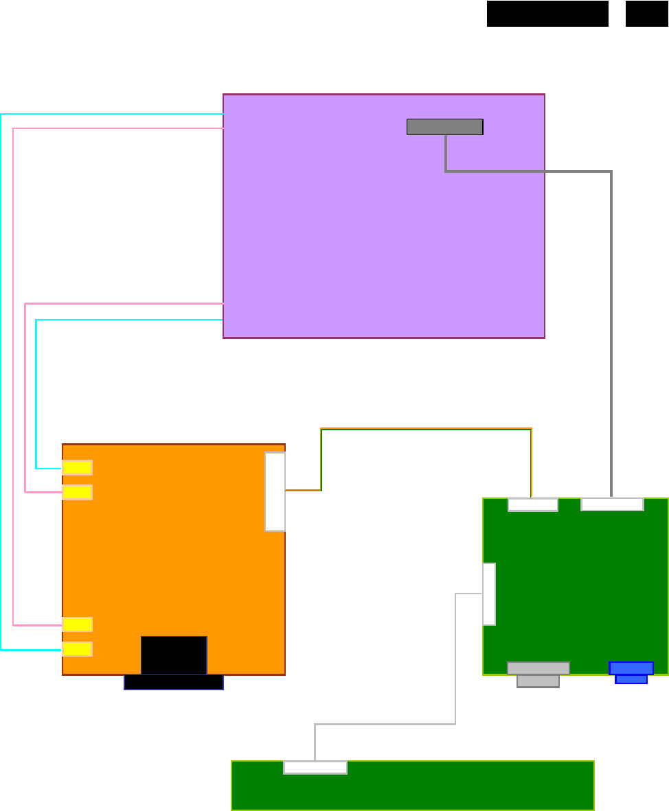
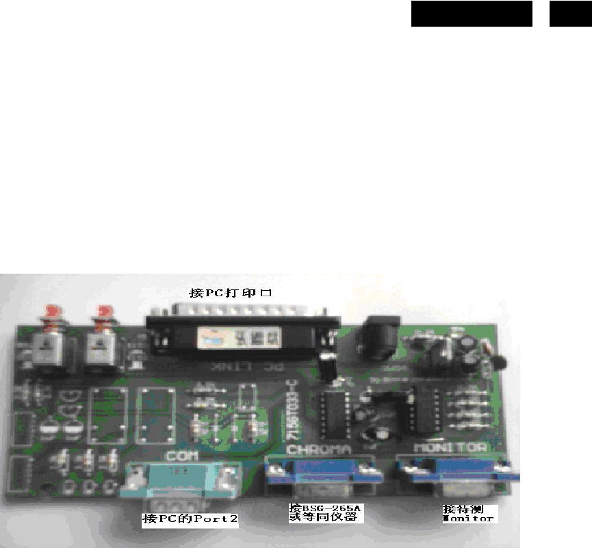
c. Connect tools as follow:
(Note: It is not necessary to connect Port2 )
3. Adjustment
Preparation before adjustment:
(1) Monitor should be warmed up for more than half an hour.
(2) Make sure that the tools are connected right and drive programs have been installed OK.
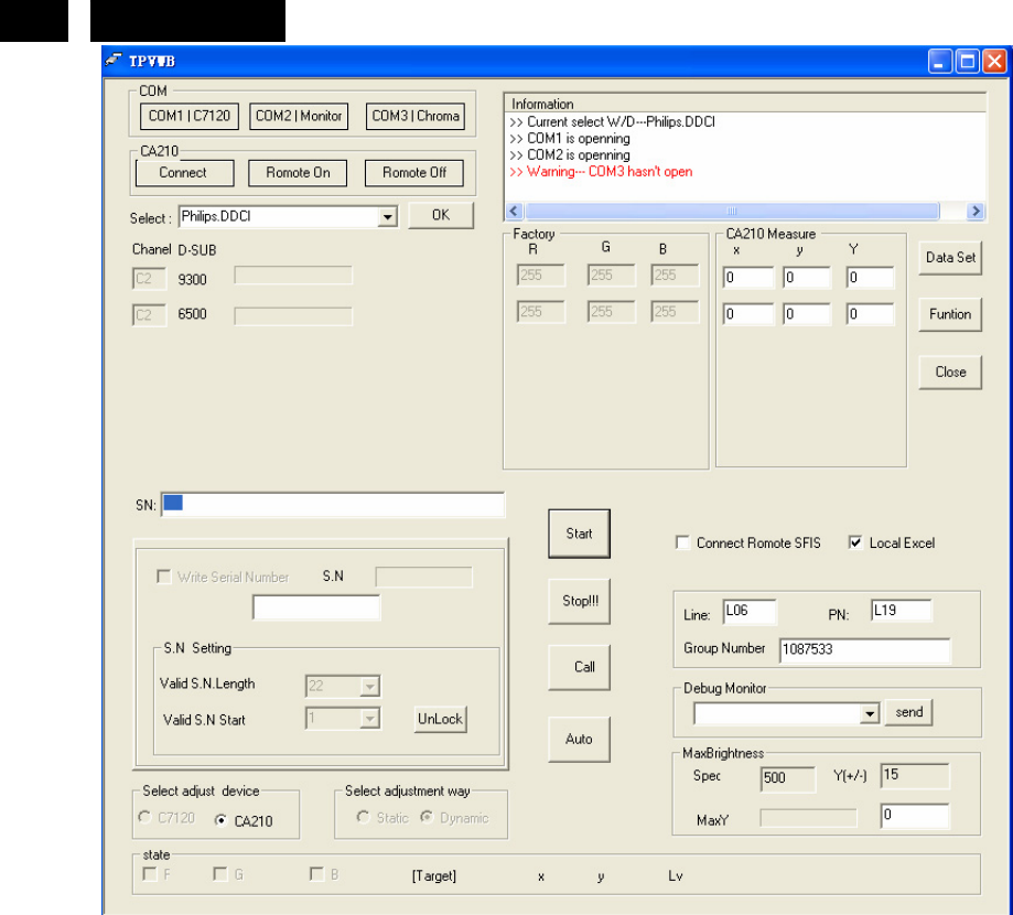
Adjustment process:
(1) Press the power of CA-210, shut off the lens, press 0-Cal and open the lens after analyzer reset.
(2) Start white balance adjustment program, select the right parameter according with the program and click OK.
(3) Make sure that the lens of CA-210 aims at the center of the screen, then click Start and start adjusting.
(4) After finish adjusting, the adjustment program displays pass, and the Start Button is changed to Next, which
means you can adjust another monitor.
http://www.wjel.net

76 HUDSON 8
16. Recommended & Spare Parts List
Recommended Parts List
170S8FS/00
Item Location Part No. Description Philips 12NC
Remark
1 FQ010 P34G1846 VOE1T BEZEL L17-7phb1 996510010270
1 FQ010 P34G1846 VOE1B BEZEL L17-7phb1
2 FQ009 P33G4989 VPB1C CONTROL BUTTON 996510010269
3 FQ005 750GLG70E3L12M000F PANEL LM170E03-TLL1 PHILIPS 996510006277
3 FQ006 750GLG70E3L42M000F PANEL LM170E03-TLL4 PHILIPS LPL 996510006278
3 FQ005 750GLG170E3G23M0PH PANEL LM170E03-TLG2 GZ LPL Second Source
3 FQ006 750GLG170E3G43M0PH PANEL LM170E03-TLG4 GZ LPL Second Source
3 FQ006 750GLC70A7P43M000F PANEL CLAA170EA07P 040 FZ 996510006441
3 FQ022 750GLB70A7P41M000F PANEL CLAA170EA07P 040 FQ CTOC 996510010276 Second Source
3 FQ022 750GLC70A7P43N CPT-CLAA170EA07P-040 Second Source
3 FQ022 750GLB70A7P41N CTOC-CLAA170EA07P-040 Second Source
3 FQ023 750GLB70A7P51M000F PANEL CLAA170EA07P 050 FQ CTOC 996510010261 Second Source
3 FQ023 750GLC70A7P53N CPT-CLAA170EA07P-050 Second Source
3 FQ023 750GLB70A7P51N CTOC-CLAA170EA07P-050 Second Source
4 FQ011 P34G1850 VB 2T REAR COVER(17") 996510008030
4 FQ011 P34G1850 VB 2B REAR COVER(17")
5 FQ008 A33G0259 VB 1L0100 COVER HINGE 996510006443
6 FQ004 705GQ734307 STAND&BASE ASS'Y 996510006439
7 FQ029 A34G0484 VB 1B0133 BASE_170A8/170S8
8 FQ030 A34G0443 VB 1B0100 STAND HEAD
9 FQ031 A34G0461 VB 1B0100 STAND BOTTOM
http://www.wjel.net

77
HUDSON 8
10 FQ032 A37G0045 1 PHILIPS 170S8 HINGE ASSY
11 FQ017 CBPC7CNAPHQ4 SCALAR BOARD ASSY (CPT) 996510010263
11 FQ018 CBPC7GNAPHQ6 SCALAR BOARD ASSY (LG) 996510010260
11 FQ017 CBPC7GNAPHQ1 SCALER BOARD ASSY
12 FQ020 PWPC942GR1P POWER BOARD ASSY (CPT)
12 FQ021 PWPC742GR3 POWER BOARD ASSY (LG) 996510010274
E089B 089G 728LAA 21 SIGNAL CABLE 996510005683
FQ001 089G179E30H 4 FFC CABLE 996500042351
FQ002 089G404A18N YH POWER CABLE 996500037502
E08901 089G404A18N IS POWER CORD 32E1818018
FQ003 095G8014 7D514 WIRE HARNESS
E09502 095G8014 7X514 WIRE HARNESS
E089B 089G 728HAA 21 SIGNAL CABLE 996510005679
FQ012 Q40G 17N81322A RATING LABEL
FQ012 Q40G 17N81322B RATING LABEL
FQ013 Q44G7057 1 EPS 996510010257
FQ014 Q44G7057 2 EPS 996510010258
FQ028 705TQ7CS067 CUSHION ASSY
FQ027 P45G 88609 36 R EPE BAG FOR MONITOR
FQ015 Q44G7057813 1A CARTON
FQ015 Q44G7057813 1C CARTON
FQ016 Q70G170081312A 170S8 DVI CD
FQ016 Q70G170081312B CD MANUAL
FQ019 KEPC7QS5 KEY BOARD ASSY 996510010272
U301 056G 563 52 IC AP1117D33LA TO252-3L ATC 996510005697
http://www.wjel.net

78 HUDSON 8
U304 056G 56327A IC AP1117E18LA SOT223-3L 996510005698
U204 056G1133 56 M24C16-WMN6TP 996500037783
U203 705GQ756024 MCU ASS'Y 996510010271
IC902 056G 139 3A IC PC123Y22FZ0F 996500036055
IC801 056G 379 22 IC TL494IDR SOIC-16 996510006256
IC901 056G 379 61 LD7575PS SOP-8 996500039747
IC903 056G 158 12 KIA431A-AT/P TO-92 996500036054
http://www.wjel.net
79
HUDSON 8
Spare Parts List
Service Kit
170S8FS/00
Description Part No. Philips 12NC Remark
DDC Kit 715L2005C2 9965 000 43197 for all model
OSD SN Kit 715GT033 C 9965 000 43252 for all model
for all hudson 7
NOVATEK ISP Kit 715LT035A 9965 000 43198 for 170A8, 190B8, 150S8,
170S8,190S8, 170V8,190V8
MSTAR ISP Kit 715GT039 A 996510010027 200CW8
REALTEK ISP Kit 715GT039 A 996510010027 170CW8
Panel
Location Part No. Description Philips 12NC Remark
FQ005 750GLG70E3L12M000F PANEL LM170E03-TLL1 PHILIPS 996510006277
FQ005 750GLG170E3G23M0PH PANEL LM170E03-TLG2 GZ LPL Second Source
FQ006 750GLG70E3L42M000F PANEL LM170E03-TLL4 PHILIPS LPL 996510006278
FQ006 750GLG170E3G43M0PH PANEL LM170E03-TLG4 GZ LPL Second Source
FQ006 750GLC70A7P43M000F PANEL CLAA170EA07P 040 FZ 996510006441
FQ022 750GLB70A7P41M000F PANEL CLAA170EA07P 040 FQ CTOC 996510010276 Second Source
FQ022 750GLC70A7P43N CPT-CLAA170EA07P-040 Second Source
FQ022 750GLB70A7P41N CTOC-CLAA170EA07P-040 Second Source
FQ023 750GLB70A7P51M000F PANEL CLAA170EA07P 050 FQ CTOC 996510010261 Second Source
FQ023 750GLC70A7P53N CPT-CLAA170EA07P-050 Second Source
FQ023 750GLB70A7P51N CTOC-CLAA170EA07P-050 Second Source
http://www.wjel.net
80 HUDSON 8
Board ASS’Y
Location Part No. Description Philips 12NC
FQ017 CBPC7CNAPHQ4 SCALAR BOARD ASSY (CPT) 996510010263
FQ018 CBPC7GNAPHQ6 SCALAR BOARD ASSY (LG) 996510010260
FQ017 CBPC7GNAPHQ1 SCALER BOARD ASSY
FQ020 PWPC942GR1P POWER BOARD ASSY (CPT)
FQ021 PWPC742GR3 POWER BOARD ASSY (LG) 996510010274
FQ019 KEPC7QS5 KEY BOARD ASSY 996510010272
Accessory and Mechanical
Location Part No. Description Philips 12NC Remark
E089B 089G 728LAA 21 SIGNAL CABLE 996510005683
FQ001 089G179E30H 4 FFC CABLE 996500042351
FQ002 089G404A18N YH POWER CABLE 996500037502
E08901 089G404A18N IS POWER CORD 32E1818018
FQ003 095G8014 7D514 WIRE HARNESS
E09502 095G8014 7X514 WIRE HARNESS
FQ004 705GQ734307 STAND&BASE ASS'Y 996510006439
FQ005 750GLG70E3L12M000F PANEL LM170E03-TLL1 PHILIPS 996510006277
FQ005 750GLG170E3G23M0PH PANEL LM170E03-TLG2 GZ LPL Second Source
FQ006 750GLG70E3L42M000F PANEL LM170E03-TLL4 PHILIPS LPL 996510006278
FQ006 750GLG170E3G43M0PH PANEL LM170E03-TLG4 GZ LPL Second Source
FQ006 750GLC70A7P43M000F PANEL CLAA170EA07P 040 FZ 996510006441
FQ022 750GLB70A7P41M000F PANEL CLAA170EA07P 040 FQ CTOC 996510010276 Second Source
FQ022 750GLC70A7P43N CPT-CLAA170EA07P-040 Second Source
FQ022 750GLB70A7P41N CTOC-CLAA170EA07P-040 Second Source
FQ023 750GLB70A7P51M000F PANEL CLAA170EA07P 050 FQ CTOC 996510010261 Second Source
http://www.wjel.net

81
HUDSON 8
FQ023 750GLC70A7P53N CPT-CLAA170EA07P-050 Second Source
FQ023 750GLB70A7P51N CTOC-CLAA170EA07P-050 Second Source
E089B 089G 728HAA 21 SIGNAL CABLE 996510005679
FQ008 A33G0259 VB 1L0100 COVER HINGE 996510006443
FQ009 P33G4989 VPB1C CONTROL BUTTON 996510010269
FQ010 P34G1846 VOE1T BEZEL L17-7phb1 996510010270
FQ010 P34G1846 VOE1B BEZEL L17-7phb1
FQ011 P34G1850 VB 2T REAR COVER(17") 996510008030
FQ011 P34G1850 VB 2B REAR COVER(17")
FQ012 Q40G 17N81322A RATING LABEL
FQ012 Q40G 17N81322B RATING LABEL
FQ013 Q44G7057 1 EPS 996510010257
FQ014 Q44G7057 2 EPS 996510010258
FQ028 705TQ7CS067 CUSHION ASSY
FQ015 Q44G7057813 1A CARTON
FQ015 Q44G7057813 1C CARTON
FQ027 P45G 88609 36 R EPE BAG FOR MONITOR
FQ016 Q70G170081312A 170S8 DVI CD
FQ016 Q70G170081312B CD MANUAL
http://www.wjel.net

82 HUDSON 8
Board Parts
Location Part No. Description Philips 12NC
FQ017 CBPC7GNAPHQ6 SCALER BOARD ASSY(LPL) 996510010260
FQ017 CBPC7GNAPHQ1 SCALER BOARD ASSY
CN402 033G801930F H FPC CONN. 1.0MM 30P
C101 065G0402104 12 CHIP 0.1UF 50V X7R 996510005716
C102 065G0402104 12 CHIP 0.1UF 50V X7R 996510005716
C103 065G0402104 12 CHIP 0.1UF 50V X7R 996510005716
C104 065G0402104 12 CHIP 0.1UF 50V X7R 996510005716
C105 065G0402104 12 CHIP 0.1UF 50V X7R 996510005716
C106 065G0402104 12 CHIP 0.1UF 50V X7R 996510005716
C107 065G060310517T MLCC 0603 CAP 1UF Z 16V Y5V 996510005722
C110 065G0402104 12 CHIP 0.1UF 50V X7R 996510005716
C111 065G0402104 12 CHIP 0.1UF 50V X7R 996510005716
C112 065G0402104 12 CHIP 0.1UF 50V X7R 996510005716
C113 065G0402104 12 CHIP 0.1UF 50V X7R 996510005716
C115 065G060310517T MLCC 0603 CAP 1UF Z 16V Y5V 996510005722
C116 065G0402104 12 CHIP 0.1UF 50V X7R 996510005716
C117 065G0402104 12 CHIP 0.1UF 50V X7R 996510005716
C118 065G0402104 12 CHIP 0.1UF 50V X7R 996510005716
C121 065G0402473 12 CHIP 0.047UF 16V X7R 996510005721
C122 065G0402473 12 CHIP 0.047UF 16V X7R 996510005721
C123 065G0402102 32 1000PF +-10% 50V X7R 996510005715
C124 065G0402473 12 CHIP 0.047UF 16V X7R 996510005721
C125 065G0402473 12 CHIP 0.047UF 16V X7R 996510005721
C126 065G0402473 12 CHIP 0.047UF 16V X7R 996510005721
C127 065G0402331 32 CHIP 330PF 50V X7R 996510005719
C128 065G0402330 31 33PF +-50% 50V NPO 996510005718
C129 065G0402473 12 CHIP 0.047UF 16V X7R 996510005721
C130 065G0402104 12 CHIP 0.1UF 50V X7R 996510005716
C131 065G0402102 32 1000PF +-10% 50V X7R 996510005715
C132 065G040247132K T CAP CHIP 0402 470PF 50V X7R 996510005720
C201 065G0402104 12 CHIP 0.1UF 50V X7R 996510005716
C203 065G0402104 12 CHIP 0.1UF 50V X7R 996510005716
C204 065G0402104 12 CHIP 0.1UF 50V X7R 996510005716
C205 065G0402104 12 CHIP 0.1UF 50V X7R 996510005716
C206 065G0402104 12 CHIP 0.1UF 50V X7R 996510005716
C207 065G0402104 12 CHIP 0.1UF 50V X7R 996510005716
C208 065G0402104 12 CHIP 0.1UF 50V X7R 996510005716
C209 065G0402104 12 CHIP 0.1UF 50V X7R 996510005716
C210 065G0402104 12 CHIP 0.1UF 50V X7R 996510005716
C213 065G060310517T MLCC 0603 CAP 1UF Z 16V Y5V 996510005722
C214 067G305V101 3 105C 10UF +-20% 16V 996510005694
http://www.wjel.net

83
HUDSON 8
C215 065G0402104 12 CHIP 0.1UF 50V X7R 996510005716
C216 065G0402104 12 CHIP 0.1UF 50V X7R 996510005716
C219 065G0402220 31 CHIP 22PF 50V NPO 996510005717
C220 065G0402220 31 CHIP 22PF 50V NPO 996510005717
C301 065G0402104 12 CHIP 0.1UF 50V X7R 996510005716
C302 067G305V100 3 105DEG 10UF -20% 16V 996500037413
C303 065G0402104 12 CHIP 0.1UF 50V X7R 996510005716
C304 065G060310517T MLCC 0603 CAP 1UF Z 16V Y5V 996510005722
C305 067G305V101 3 105C 10UF +-20% 16V 996510005694
C306 067G305V101 3 105C 10UF +-20% 16V 996510005694
C307 065G0402104 12 CHIP 0.1UF 50V X7R 996510005716
C308 065G060310517T MLCC 0603 CAP 1UF Z 16V Y5V 996510005722
C309 067G305V101 3 105C 10UF +-20% 16V 996510005694
C310 067G305V101 3 105C 10UF +-20% 16V 996510005694
C311 065G0402104 12 CHIP 0.1UF 50V X7R 996510005716
C312 065G0402104 12 CHIP 0.1UF 50V X7R 996510005716
C315 067G305V101 3 105C 10UF +-20% 16V 996510005694
C316 065G0603104 22 CHIP 0.1UF 25V X7R 996500042674
C317 065G0402104 12 CHIP 0.1UF 50V X7R 996510005716
C402 065G0402104 12 CHIP 0.1UF 50V X7R 996510005716
C403 065G0402104 12 CHIP 0.1UF 50V X7R 996510005716
C405 065G0402104 12 CHIP 0.1UF 50V X7R 996510005716
D101 093G 6433S DIODE BAV99 SEMTECH 996510005726
D102 093G 64 42 PP BAV70 SOT-23 996500035995
D103 093G 6433S DIODE BAV99 SEMTECH 996510005726
D104 093G 6433S DIODE BAV99 SEMTECH 996510005726
D105 093G 6433S DIODE BAV99 SEMTECH 996510005726
D106 093G 6433S DIODE BAV99 SEMTECH 996510005726
D107 093G 6433S DIODE BAV99 SEMTECH 996510005726
D108 093G 6433S DIODE BAV99 SEMTECH 996510005726
D109 093G 6433S DIODE BAV99 SEMTECH 996510005726
D110 093G 64 42 PP BAV70 SOT-23 996500035995
D111 093G 6433S DIODE BAV99 SEMTECH 996510005726
D112 093G 6433S DIODE BAV99 SEMTECH 996510005726
D113 093G 6433S DIODE BAV99 SEMTECH 996510005726
D201 093G 64 42 PP BAV70 SOT-23 996500035995
D301 093G3004 3 SM340A 996510005728
Q201 057G 417 13 T KEC 2N3906S-RTK/PS 996500035967
Q301 057G 417 12 T PMBS3904 SOT23 CHIP 996510002429
Q302 057G 763 1 A03401 SOT23 BY AOS(A1) 996500035968
Q305 057G 417 12 T PMBS3904 SOT23 CHIP 996510002429
Q402 057G 417 13 T KEC 2N3906S-RTK/PS 996500035967
Q403 057G 417 13 T KEC 2N3906S-RTK/PS 996500035967
http://www.wjel.net

84 HUDSON 8
R101 061G0402750 RST CHIPR 75 OHM +-5% 1/16W 996510005713
R102 061G0402102 RST CHIPR 1 KOHM +-5% 1/16W 996510005702
R103 061G0402472 RST CHIPR 4.7 KOHM +-5% 1/16W 996510005711
R104 061G0402472 RST CHIPR 4.7 KOHM +-5% 1/16W 996510005711
R106 061G0402100 RST CHIPR 10 OHM +-5% 1/16W 996510005700
R107 061G0402100 RST CHIPR 10 OHM +-5% 1/16W 996510005700
R108 061G0402101 RST CHIPR 100 OHM +-5% 1/16W 996510005701
R109 061G0402101 RST CHIPR 100 OHM +-5% 1/16W 996510005701
R110 061G0402100 RST CHIPR 10 OHM +-5% 1/16W 996510005700
R111 061G0402100 RST CHIPR 10 OHM +-5% 1/16W 996510005700
R113 061G0402102 RST CHIPR 1 KOHM +-5% 1/16W 996510005702
R115 061G0402100 RST CHIPR 10 OHM +-5% 1/16W 996510005700
R116 061G0402100 RST CHIPR 10 OHM +-5% 1/16W 996510005700
R117 061G0402100 RST CHIPR 10 OHM +-5% 1/16W 996510005700
R118 061G0402100 RST CHIPR 10 OHM +-5% 1/16W 996510005700
R120 061G0402102 RST CHIPR 1 KOHM +-5% 1/16W 996510005702
R122 061G0402102 RST CHIPR 1 KOHM +-5% 1/16W 996510005702
R123 061G0402472 RST CHIPR 4.7 KOHM +-5% 1/16W 996510005711
R124 061G0402472 RST CHIPR 4.7 KOHM +-5% 1/16W 996510005711
R126 061G0402101 RST CHIPR 100 OHM +-5% 1/16W 996510005701
R127 061G0402101 RST CHIPR 100 OHM +-5% 1/16W 996510005701
R128 061G0402101 RST CHIPR 100 OHM +-5% 1/16W 996510005701
R129 061G0402151 RST CHIP 150R 1/16W 5% 996510005704
R131 061G0402391 RST CHIPR 390 OHM +-5% 1/16W 996510005708
R132 061G0402101 RST CHIPR 100 OHM +-5% 1/16W 996510005701
R133 061G0402151 RST CHIP 150R 1/16W 5% 996510005704
R134 061G0402101 RST CHIPR 100 OHM +-5% 1/16W 996510005701
R135 061G0402101 RST CHIPR 100 OHM +-5% 1/16W 996510005701
R136 061G0402101 RST CHIPR 100 OHM +-5% 1/16W 996510005701
R138 061G0402151 RST CHIP 150R 1/16W 5% 996510005704
R139 061G0402750 RST CHIPR 75 OHM +-5% 1/16W 996510005713
R140 061G0402750 RST CHIPR 75 OHM +-5% 1/16W 996510005713
R141 061G0402222 RST CHIPR 2.2 KOHM +-5% 1/16W 996510005707
R142 061G0402222 RST CHIPR 2.2 KOHM +-5% 1/16W 996510005707
R144 061G0402102 RST CHIPR 1 KOHM +-5% 1/16W 996510005702
R201 061G0402105 RST CHIPR 1MOHM +-5% 1/16W 996510005703
R202 061G0402103 RST CHIPR 10 KOHM -5% 1/16W 996500044984
R206 061G0402472 RST CHIPR 4.7 KOHM +-5% 1/16W 996510005711
R211 061G0402000 RST CHIPR 0 OHM +-5% 1/16W 996510005699
R213 061G0402472 RST CHIPR 4.7 KOHM +-5% 1/16W 996510005711
R214 061G0402472 RST CHIPR 4.7 KOHM +-5% 1/16W 996510005711
R215 061G0402472 RST CHIPR 4.7 KOHM +-5% 1/16W 996510005711
R218 061G0402220 RST CHIPR 22 OHM +-5% 1/16W 996510005705
http://www.wjel.net

85
HUDSON 8
R221 061G0402471 RST CHIPR 470 OHM +-5% 1/16W 996510005710
R225 061G0402101 RST CHIPR 100 OHM +-5% 1/16W 996510005701
R228 061G0402000 RST CHIPR 0 OHM +-5% 1/16W 996510005699
R234 061G0402221 RST CHIPR 220 OHM +-5% 1/16W 996510005706
R301 061G0402102 RST CHIPR 1 KOHM +-5% 1/16W 996510005702
R302 061G1206331 RST CHIPR 330 OHM +-5% 1/4W 996510005714
R303 061G1206331 RST CHIPR 330 OHM +-5% 1/4W 996510005714
R304 061G0402103 RST CHIPR 10 KOHM -5% 1/16W 996500044984
R305 061G0402103 RST CHIPR 10 KOHM -5% 1/16W 996500044984
R307 061G0402513 RST CHIP 51K 1/16W 5% 996510005712
R308 061G0402472 RST CHIPR 4.7 KOHM +-5% 1/16W 996510005711
R309 061G0402101 RST CHIPR 100 OHM +-5% 1/16W 996510005701
R311 061G0402102 RST CHIPR 1 KOHM +-5% 1/16W 996510005702
R312 061G0402102 RST CHIPR 1 KOHM +-5% 1/16W 996510005702
R314 061G0402472 RST CHIPR 4.7 KOHM +-5% 1/16W 996510005711
R316 061G0402472 RST CHIPR 4.7 KOHM +-5% 1/16W 996510005711
R402 061G0402392 RST CHIP 3.9K 1/16W 5% 996510005709
R403 061G0402392 RST CHIP 3.9K 1/16W 5% 996510005709
R407 061G0402101 RST CHIPR 100 OHM +-5% 1/16W 996510005701
R410 061G0402101 RST CHIPR 100 OHM +-5% 1/16W 996510005701
R412 061G0402102 RST CHIPR 1 KOHM +-5% 1/16W 996510005702
R415 061G0402103 RST CHIPR 10 KOHM -5% 1/16W 996500044984
R416 061G0402101 RST CHIPR 100 OHM +-5% 1/16W 996510005701
R417 061G0402103 RST CHIPR 10 KOHM -5% 1/16W 996500044984
R418 061G0402101 RST CHIPR 100 OHM +-5% 1/16W 996510005701
U203 705GQ756024 MCU ASSY(LPL) 996510010271
U203 705GQ756098 MCU ASS'Y(17")
U204 056G1133 56 M24C16-WMN6TP 996500037783
U301 056G 563 52 IC AP1117D33LA TO252-3L ATC 996510005697
U304 056G 56327A IC AP1117E18LA SOT223-3L 996510005698
X201 093G 2251B MXS12.000AC20F-KAB5 HC-49/US 996510005696
CN101 088G 35315F H D-SUB 15PIN 996500035960
CN102 088G 35424F N DVI 24PIN CONN F 996510005695
FB101 071G 56D121 JA CHIP BEAD 120 OHM 0805 1A 996510005725
FB102 071G 56D121 JA CHIP BEAD 120 OHM 0805 1A 996510005725
FB103 071G 59B300 K BEAD 30 996500036934
FB104 071G 59B300 K BEAD 30 996500036934
FB105 061G0805000 0 OHM 1/10W 996500042284
FB106 071G 59B300 K BEAD 30 996500036934
FB107 071G 56D121 JA CHIP BEAD 120 OHM 0805 1A 996510005725
FB202 071G 56D121 JA CHIP BEAD 120 OHM 0805 1A 996510005725
FB203 071G 56D121 JA CHIP BEAD 120 OHM 0805 1A 996510005725
FB204 071G 56D121 JA CHIP BEAD 120 OHM 0805 1A 996510005725
http://www.wjel.net

86 HUDSON 8
FB205 071G 56D121 JA CHIP BEAD 120 OHM 0805 1A 996510005725
FB206 071G 56D121 JA CHIP BEAD 120 OHM 0805 1A 996510005725
FB207 071G 56D102 MA CHIP HEAD 1000OHM 0805 1A 996510005723
FB302 071G 56K121 M CHIP BEAD 996500036567
FB303 071G 56K121 M CHIP BEAD 996500036567
ZD101 093G 39S 24 T RLZ 5.6B LLDS 996510004052
ZD102 093G 39S 24 T RLZ 5.6B LLDS 996510004052
ZD103 093G 39S 24 T RLZ 5.6B LLDS 996510004052
ZD104 093G 39S 24 T RLZ 5.6B LLDS 996510004052
ZD105 093G 39S 24 T RLZ 5.6B LLDS 996510004052
ZD106 093G 39S 24 T RLZ 5.6B LLDS 996510004052
ZD107 093G 39S 24 T RLZ 5.6B LLDS 996510004052
ZD201 093G 39G586 RLZ2.2B 996510005727
FQ018 KEPC7QS5 KEY BOARD ASSY 996510010272
SW1 077G 600 1GCJ TACT SWITCH 996510002796
SW2 077G 600 1GCJ TACT SWITCH 996510002796
SW3 077G 600 1GCJ TACT SWITCH 996510002796
SW4 077G 600 1GCJ TACT SWITCH 996510002796
SW5 077G 600 1GCJ TACT SWITCH 996510002796
SW6 077G 600 1GCJ TACT SWITCH 996510002796
SW7 077G 600 1GCJ TACT SWITCH 996510002796
SW8 077G 600 1GCJ TACT SWITCH 996510002796
C101 065G0603103 32 0.01UF -10% 50V X7R 996500036004
C102 065G0603103 32 0.01UF -10% 50V X7R 996500036004
C103 065G0603103 32 0.01UF -10% 50V X7R 996500036004
C104 065G0603103 32 0.01UF -10% 50V X7R 996500036004
C105 065G0603103 32 0.01UF -10% 50V X7R 996500036004
LED1 081G 12 1F GP LED GP32032M/G307-ZY-50 996510006457
R100 061G0805000 0 OHM 1/10W 996500042284
R101 061G0603101 RST CHIPR 100 OHM -5% 1/10W 996500042213
R102 061G0603432 RST CHIPR 4.3 KOHM -5% 1/10W 996500044045
R103 061G0603911 RST CHIPR 910 OHM +-5% 1/10W 996510006459
R104 061G0603242 RST CHIPR 2.4 KOHM +-5% 1/10W 996510006258
R106 061G0603432 RST CHIPR 4.3 KOHM -5% 1/10W 996500044045
R107 061G0603911 RST CHIPR 910 OHM +-5% 1/10W 996510006459
R108 061G0603242 RST CHIPR 2.4 KOHM +-5% 1/10W 996510006258
R109 061G0603000 RST CHIPR 0 OHM -5% 1/10W 996500042212
CN101 033G3802 6H WAFER 6P RIGHT ANGLE PITCH 2.0 996510010273
FQ019 PWPC742GR3 POWER BOARD ASSY(LPL) 996510010274
C801 065G 6J1006ET 10PF 5% SL 6KV 996500036942
C802 065G0603105 12 CHIP 1UF 16VX7R 0603 996510002499
C803 065G0805152 32 CHIP 1500PF 50V X7R 0805 996500044871
C804 065G0603104 12 CER2 0603 X7R 16V 100N PM10 R 996500036918
http://www.wjel.net

87
HUDSON 8
C805 067G215D4714KV E.C 105_J CAP 470UF M 25V 996510006239
C806 065G0603105 12 CHIP 1UF 16VX7R 0603 996510002499
C807 065G0603104 12 CER2 0603 X7R 16V 100N PM10 R 996500036918
C808 065G0805225 12 CHIP 2.2UF 16V X7R 0805 996510006267
C809 065G080522131G 220PF 50V NPO 2% 996510007400
C810 065G0603104 22 CHIP 0.1UF 25V X7R 996500042674
C811 067G215D4714KV E.C 105_J CAP 470UF M 25V 996510006239
C812 065G 6J1006ET 10PF 5% SL 6KV 996500036942
C813 065G0603222 22 CHIP 2200PF 25V X7R 996510006266
C814 065G0603104 12 CER2 0603 X7R 16V 100N PM10 R 996500036918
C815 065G0603222 22 CHIP 2200PF 25V X7R 996510006266
C816 065G0805152 32 CHIP 1500PF 50V X7R 0805 996500044871
C817 065G0603222 22 CHIP 2200PF 25V X7R 996510006266
C818 065G0603222 22 CHIP 2200PF 25V X7R 996510006266
C821 065G0805152 32 CHIP 1500PF 50V X7R 0805 996500044871
C822 065G0805152 32 CHIP 1500PF 50V X7R 0805 996500044871
C823 065G0805104 22 0.1UF -10% 25V X7R 080 996500036040
C824 065G0805104 22 0.1UF -10% 25V X7R 080 996500036040
C900 065G306M2222BP 2200PF -20% 400VAC 996500036050
C901 065G305M1022EM Y2 1000PF -20% 250VAC 996500036006
C902 065G305M1022EM Y2 1000PF -20% 250VAC 996500036006
C903 065G306M1022BP 1000PF Y1.CAP 996510006237
C904 065G0603102 32 1000PF -10% 50V X7R 996500037517
C907 067G 40Z10115K CAP 105 J 100UF M 450V 996510007388
C909 063G107K474 US 0.47UF +-10% 996510007384
C910 065G 2K152 1T6921 CAP 1.5NF/2KV Y5P +-10% 996510006274
C911 067G 2152207NT KY50VB22M-TP5 5*11 996510006275
C912 065G0805104 32 CHIP 0.1U 50V X7R 996500036041
C913 065G0805221 31 220PF 50V NPO 996500039769
C914 065G0805471 21 CHIP 470PF 25V NPO 996510002754
C916 065G0805104 32 CHIP 0.1U 50V X7R 996500036041
C920 065G517K102 5T 1000PF 10% Y5P 500V 996500036077
C921 065G517K102 5T 1000PF 10% Y5P 500V 996500036077
C922 067G215D6814KV CAP 105_J 680UF M 25V 996510006240
C923 067G215D6814KV CAP 105_J 680UF M 25V 996510006240
C925 067G215D4714KV E.C 105_J CAP 470UF M 25V 996510006239
C926 067G215S1023KV 105 J 1000UF M 16V 996510007389
C927 067G215S4713KV EC 105_J CAP 470UF M 16V 996510006242
C928 065G0805104 32 CHIP 0.1U 50V X7R 996500036041
C929 065G0805104 32 CHIP 0.1U 50V X7R 996500036041
C930 065G0805104 32 CHIP 0.1U 50V X7R 996500036041
C931 065G0805104 32 CHIP 0.1U 50V X7R 996500036041
C932 067G215S1023KV 105℃ 1000UF M 16V
http://www.wjel.net

88 HUDSON 8
CN901 087G 501 32 DL AC SOCKET DIP 3PIN+2PIN GROUND
PT802 S80GL17T40V TRANSFORMER ASSY
PT801 S80GL17T40V TRANSFORMER ASSY
Q809 057G 600 55 P5506 HVG SO-8
Q804 057G 600 55 P5506 HVG SO-8
D900 093G1100 1152T DIODE PR1007R 1A/1000V DO-41
D801 093G 64 33 DIO SIG SM BAV99 (PHSE)R 996500035994
D802 093G 64 33 DIO SIG SM BAV99 (PHSE)R 996500035994
D803 093G 64S511SEM IN4148W 996500039779
D806 093G 64S 10 DIODE BAW56PT SOT-23 CHENMKO 996510006271
D807 093G 64S511SEM IN4148W 996500039779
D808 093G 64S 10 DIODE BAW56PT SOT-23 CHENMKO 996510006271
D809 093G 64 33 DIO SIG SM BAV99 (PHSE)R 996500035994
D810 093G 64 33 DIO SIG SM BAV99 (PHSE)R 996500035994
D811 093G 64S511SEM IN4148W 996500039779
D812 093G 64S511SEM IN4148W 996500039779
D813 093G 64S511SEM IN4148W 996500039779
D900 093G1100 1052T BA159GPT DO-41 CHENMKO 996510007274
D901 093G 6038T52T FR103 996500036095
D910 093G 64S511SEM IN4148W 996500039779
D915 093G 64S511SEM IN4148W 996500039779
D916 093G 64S511SEM IN4148W 996500039779
D920 093G 60276 DIODE SBT150-10LST SANYO 996510006255
D922 093G3006 1 1 31DQ06FC3 NIHON INTER 996510006253
F901 084G 56 4W FUSE 4.0A 250V 996510006276
F902 061G1206000 4 RST CHIPR 0 OHM +-5% 1/4W 996510010275
J807 061G1206000 0 OHM 1/8W 996500039751
J813 061G1206000 0 OHM 1/8W 996500039751
J814 061G1206000 0 OHM 1/8W 996500039751
J815 061G1206000 0 OHM 1/8W 996500039751
J816 061G1206000 0 OHM 1/8W 996500039751
J818 061G1206000 0 OHM 1/8W 996500039751
J907 061G1206000 0 OHM 1/8W 996500039751
J908 061G1206000 0 OHM 1/8W 996500039751
L901 S73G17476V LINE FILTER ASSY 996510007403
L902 073G 174 65 H LINE FILTER 996500036088
L921 073G 253 91 H CHOKE COIL 996500036026
L922 073G 253 91 H CHOKE COIL 996500036026
Q801 057G 760 4B PDTA144WK SOT346 996500036962
Q802 057G 760 5B PDTC144WK SOT346 996510006257
Q803 057G 417 4 PMBS3904/PHILIPS-SMT(04) 996500035966
Q804 057G 763 14 AM9945N 996500036100
Q805 057G 417 6 PMBS3906/PHILIPS-SMT(06) 996510002478
http://www.wjel.net

89
HUDSON 8
Q806 057G 417 6 PMBS3906/PHILIPS-SMT(06) 996510002478
Q807 057G 417 4 PMBS3904/PHILIPS-SMT(04) 996500035966
Q808 057G 759 2 RK7002 SOT-23 BY ROHM 996510003293
Q809 057G 763 14 AM9945N 996500036100
Q810 057G 417 4 PMBS3904/PHILIPS-SMT(04) 996500035966
Q811 057G 417 4 PMBS3904/PHILIPS-SMT(04) 996500035966
Q812 057G 759 2 RK7002 SOT-23 BY ROHM 996510003293
Q902 057G 417 4 PMBS3904/PHILIPS-SMT(04) 996500035966
R801 061G0603000 RST CHIPR 0 OHM -5% 1/10W 996500042212
R802 061G0805101 RST CHIPR 100 OHM -5% 1/8W 996500043379
R803 061G0603362 RST CHIPR 3.6 KOHM -5% 1/10W 996500042734
R804 061G0603000 RST CHIPR 0 OHM -5% 1/10W 996500042212
R805 061G0603472 RST CHIPR 4.7KOHM -5% 1/10W 996500042225
R806 061G0603100 1F RST CHIPR 1 KOHM -1% 1/10W 996500043955
R807 061G0603100 1F RST CHIPR 1 KOHM -1% 1/10W 996500043955
R808 061G0603100 2F RST CHIPR 10 KOHM -1% 1/10W 996500042395
R810 061G1206150 RST CHIPR 15 OHM +-5% 1/4W 996510006263
R811 061G0603100 1F RST CHIPR 1 KOHM -1% 1/10W 996500043955
R812 061G0603100 1F RST CHIPR 1 KOHM -1% 1/10W 996500043955
R813 061G0603101 RST CHIPR 100 OHM -5% 1/10W 996500042213
R814 061G0603680 2F RST CHIPR 68 KOHM +-1% 1/10W 996510006225
R815 061G0603470 2F RSTR 47 KOHM +-1% 1/10W 996510005994
R816 061G0603680 2F RST CHIPR 68 KOHM +-1% 1/10W 996510006225
R819 061G0603100 2F RST CHIPR 10 KOHM -1% 1/10W 996500042395
R820 061G0603564 RST CHIPR 560 KOHM +-5% 1/10W 996510006224
R821 061G0603105 RST CHIPR 1 MOHM -5% 1/10W 996500042216
R822 061G0603473 RST CHIPR 47 KOHM -5% 1/10W 996500042277
R823 061G0603103 RST CHIPR 10 KOHM -5% 1/10W 996500042214
R824 061G0603100 2F RST CHIPR 10 KOHM -1% 1/10W 996500042395
R825 061G0805510 2F RST CHIPR 51 KOHM +-1% 1/8W 996510006262
R826 061G0805180 3F RST CHIPR 180 KOHM +-1% 1/8W 996510006259
R827 061G0603100 1F RST CHIPR 1 KOHM -1% 1/10W 996500043955
R828 061G0603470 2F RSTR 47 KOHM +-1% 1/10W 996510005994
R829 061G0603680 2F RST CHIPR 68 KOHM +-1% 1/10W 996510006225
R830 061G0603000 RST CHIPR 0 OHM -5% 1/10W 996500042212
R831 061G0603100 2F RST CHIPR 10 KOHM -1% 1/10W 996500042395
R832 061G0603000 RST CHIPR 0 OHM -5% 1/10W 996500042212
R833 061G0603100 2F RST CHIPR 10 KOHM -1% 1/10W 996500042395
R834 061G0603100 1F RST CHIPR 1 KOHM -1% 1/10W 996500043955
R835 061G0603100 1F RST CHIPR 1 KOHM -1% 1/10W 996500043955
R836 061G0603105 RST CHIPR 1 MOHM -5% 1/10W 996500042216
R837 061G1206150 RST CHIPR 15 OHM +-5% 1/4W 996510006263
R838 061G0603100 2F RST CHIPR 10 KOHM -1% 1/10W 996500042395
http://www.wjel.net

90 HUDSON 8
R839 061G0603100 1F RST CHIPR 1 KOHM -1% 1/10W 996500043955
R840 061G0603100 2F RST CHIPR 10 KOHM -1% 1/10W 996500042395
R841 061G0603100 1F RST CHIPR 1 KOHM -1% 1/10W 996500043955
R842 061G0603470 2F RSTR 47 KOHM +-1% 1/10W 996510005994
R844 061G0603220 RST CHIPR 22 OHM -5% 1/10W 996500042217
R845 061G0603220 RST CHIPR 22 OHM -5% 1/10W 996500042217
R846 061G0603220 RST CHIPR 22 OHM -5% 1/10W 996500042217
R847 061G0603220 RST CHIPR 22 OHM -5% 1/10W 996500042217
R848 061G0603100 1F RST CHIPR 1 KOHM -1% 1/10W 996500043955
R849 061G0603100 1F RST CHIPR 1 KOHM -1% 1/10W 996500043955
R850 061G1206150 RST CHIPR 15 OHM +-5% 1/4W 996510006263
R851 061G1206150 RST CHIPR 15 OHM +-5% 1/4W 996510006263
R852 061G0603100 2F RST CHIPR 10 KOHM -1% 1/10W 996500042395
R853 061G0603100 2F RST CHIPR 10 KOHM -1% 1/10W 996500042395
R900 061G1206334 RST CHIPR 330KOHM +-5% 1/4W 996510006264
R901 061G1206334 RST CHIPR 330KOHM +-5% 1/4W 996510006264
R902 061G1206334 RST CHIPR 330KOHM +-5% 1/4W 996510006264
R903 061G0805102 CHIP 1KOHM 1/10W 996500043380
R905 061G1206103 10 KOHM 1/8W 996500040048
R907 061G 208151 64 RST MOFR 150 OHM +-5% 1W 996510006232
R908 061G0805471 470&8 1/10W 996500043397
R909 061G152M104 64 100KOHM 5% 2W 996500036939
R910 061G1206229 RST CHIP 2R2 1/4W 5% 996500044647
R911 061G0805100 3F RST CHIPR 100KOHM +-1% 1/8W 996510006227
R912 061G1206100 RST CHIP 10R 1/4W 5% 996500043976
R913 061G0805100 1F RST CHIPR 1KOHM +-1% 1/8W 996510006226
R915 061G0805100 2F RST CHIPR 10KOHM -1% 1/8W 996500044853
R916 061G152M43852T RST MOF 0R43 5% 2W 996510009151
R922 061G0805331 RST CHIPR 330 OHM -5% 1/8W 996500043393
R923 061G0805100 2F RST CHIPR 10KOHM -1% 1/8W 996500044853
R924 061G0805360 1F RST CHIPR 3.6KOHM +-1% 1/8W 996510006261
R925 061G0805100 1F RST CHIPR 1KOHM +-1% 1/8W 996510006226
R926 061G0805330 2F RST CHIPR 33 KOHM +-1% 1/8W 996510006260
R927 061G0805100 1F RST CHIPR 1KOHM +-1% 1/8W 996510006226
R928 061G0805100 1F RST CHIPR 1KOHM +-1% 1/8W 996510006226
R929 061G0805240 1F RST CHIPR 2.4 KOHM +-1% 1/8W 996510004364
R930 061G0805100 1F RST CHIPR 1KOHM +-1% 1/8W 996510006226
R931 061G1206103 10 KOHM 1/8W 996500040048
R951 061G1206470 RST CHIPR 47 OHM +-5% 1/4W 996510006265
R952 061G1206470 RST CHIPR 47 OHM +-5% 1/4W 996510006265
R953 061G1206470 RST CHIPR 47 OHM +-5% 1/4W 996510006265
R954 061G1206470 RST CHIPR 47 OHM +-5% 1/4W 996510006265
R955 061G1206470 RST CHIPR 47 OHM +-5% 1/4W 996510006265
http://www.wjel.net

91
HUDSON 8
R956 061G1206470 RST CHIPR 47 OHM +-5% 1/4W 996510006265
T901 080GL17T 33 N2 XFMR POWER 550UH YUVA 996510006247
BD901 093G 50460 28 BRIDGE DIODE KBP208G LITEON 996500039742
FB901 071G 55 29 FERRITE BEAD 996500036053
FB903 071G 55 29 FERRITE BEAD 996500036053
IC801 056G 379 22 IC TL494IDR SOIC-16 996510006256
IC901 056G 379 61 LD7575PS SOP-8 996500039747
IC902 056G 139 3A PC123Y22FZOF 996500036055
IC903 056G 158 12 KIA431A-AT/P TO-92 996500036054
NR901 061G 58100 W RST NTCR 10 OHM +20% 5A 996510007230
PT801 080GL17T 40 DN X'FMR TK.2001U.101 996510006252
PT802 080GL17T 40 DN X'FMR TK.2001U.101 996510006252
ZD801 061G1206103 10 KOHM 1/8W 996500040048
ZD920 093G 39S 40 T RLZ 13B LLDS 996500039777
ZD921 093G 39S 40 T RLZ 13B LLDS 996500039777
ZD922 093G 39S 25 T RLZ5.1B LLDS 996500037002
FQ020 750GLC70A7P43M000F PANEL CLAA170EA07P 040 CPT 996510006441
FQ021 750GLB70A7P41M000F PANEL CLAA170EA07P 040 FQ CTOC 996510010276
FQ022 750GLB70A7P51M000F PANEL CLAA170EA07P 050 FQ CTOC 996510010261
FQ023 750GLC70A7P53M000F PANEL CLAA170EA07P 050 FZ CPT 996510010262
FQ024 CBPC7CNAPHQ4 SCALER BOARD ASSY(CPT,CTOC) 996510010263
U203 705GQ756023 MCU ASSY(CPT,CTOC) 996510010264
FQ025 PWPC942GR1 POWER BOARD ASSY 996510010288
C802 065G0603105 12 CHIP 1UF 16VX7R 0603 996510002499
C803 065G0805152 32 CHIP 1500PF 50V X7R 0805 996500044871
C804 065G0603104 12 CER2 0603 X7R 16V 100N PM10 R 996500036918
C805 067G215D4714KV E.C 105_J CAP 470UF M 25V 996510006239
C806 065G0603105 12 CHIP 1UF 16VX7R 0603 996510002499
C807 065G0603104 12 CER2 0603 X7R 16V 100N PM10 R 996500036918
C808 065G0805225 12 CHIP 2.2UF 16V X7R 0805 996510006267
C809 065G080522131G 220PF 50V NPO 2% 996510007400
C810 065G0603104 22 CHIP 0.1UF 25V X7R 996500042674
C811 067G215D4714KV E.C 105_J CAP 470UF M 25V 996510006239
C812 065G 6J1006ET 10PF 5% SL 6KV 996500036942
C813 065G0603222 22 CHIP 2200PF 25V X7R 996510006266
C814 065G0603104 12 CER2 0603 X7R 16V 100N PM10 R 996500036918
C815 065G0603222 22 CHIP 2200PF 25V X7R 996510006266
C816 065G0805152 32 CHIP 1500PF 50V X7R 0805 996500044871
C817 065G0603222 22 CHIP 2200PF 25V X7R 996510006266
C818 065G0603222 22 CHIP 2200PF 25V X7R 996510006266
C821 065G0805152 32 CHIP 1500PF 50V X7R 0805 996500044871
C822 065G0805152 32 CHIP 1500PF 50V X7R 0805 996500044871
C823 065G0805104 22 0.1UF -10% 25V X7R 080 996500036040
http://www.wjel.net

92 HUDSON 8
C824 065G0805104 22 0.1UF -10% 25V X7R 080 996500036040
C900 065G306M2222BP 2200PF -20% 400VAC 996500036050
C901 065G305M1022EM Y2 1000PF -20% 250VAC 996500036006
C902 065G305M1022EM Y2 1000PF -20% 250VAC 996500036006
C903 065G306M1022BP 1000PF Y1.CAP 996510006237
C904 065G0603102 32 1000PF -10% 50V X7R 996500037517
C907 067G 40Z10115K CAP 105 J 100UF M 450V 996510007388
C909 063G107K474 US 0.47UF +-10% 996510007384
C910 065G 2K152 1T6921 CAP 1.5NF/2KV Y5P +-10% 996510006274
C911 067G 2152207NT KY50VB22M-TP5 5*11 996510006275
C912 065G0805104 32 CHIP 0.1U 50V X7R 996500036041
C913 065G0805221 31 220PF 50V NPO 996500039769
C914 065G0805471 21 CHIP 470PF 25V NPO 996510002754
C916 065G0805104 32 CHIP 0.1U 50V X7R 996500036041
C920 065G517K102 5T 1000PF 10% Y5P 500V 996500036077
C921 065G517K102 5T 1000PF 10% Y5P 500V 996500036077
C922 067G215D6814KV CAP 105_J 680UF M 25V 996510006240
C923 067G215D6814KV CAP 105_J 680UF M 25V 996510006240
C925 067G215D4714KV E.C 105_J CAP 470UF M 25V 996510006239
C926 067G215S1023KV 105 J 1000UF M 16V 996510007389
C927 067G215S4713KV EC 105_J CAP 470UF M 16V 996510006242
C928 065G0805104 32 CHIP 0.1U 50V X7R 996500036041
C929 065G0805104 32 CHIP 0.1U 50V X7R 996500036041
C930 065G0805104 32 CHIP 0.1U 50V X7R 996500036041
C931 065G0805104 32 CHIP 0.1U 50V X7R 996500036041
D801 093G 64 33 DIO SIG SM BAV99 (PHSE)R 996500035994
D802 093G 64 33 DIO SIG SM BAV99 (PHSE)R 996500035994
D803 093G 64S511SEM IN4148W 996500039779
D806 093G 64S 10 DIODE BAW56PT SOT-23 CHENMKO 996510006271
D807 093G 64S511SEM IN4148W 996500039779
D808 093G 64S 10 DIODE BAW56PT SOT-23 CHENMKO 996510006271
D809 093G 64 33 DIO SIG SM BAV99 (PHSE)R 996500035994
D810 093G 64 33 DIO SIG SM BAV99 (PHSE)R 996500035994
D811 093G 64S511SEM IN4148W 996500039779
D812 093G 64S511SEM IN4148W 996500039779
D813 093G 64S511SEM IN4148W 996500039779
D900 093G1100 1052T BA159GPT DO-41 CHENMKO 996510007274
D901 093G 6038T52T FR103 996500036095
D910 093G 64S511SEM IN4148W 996500039779
D915 093G 64S511SEM IN4148W 996500039779
D916 093G 64S511SEM IN4148W 996500039779
D920 093G 60276 DIODE SBT150-10LST SANYO 996510006255
D922 093G3006 1 1 31DQ06FC3 NIHON INTER 996510006253
http://www.wjel.net

93
HUDSON 8
F901 084G 56 4W FUSE 4.0A 250V 996510006276
F902 061G1206000 4 RST CHIPR 0 OHM +-5% 1/4W 996510010275
J807 061G1206000 0 OHM 1/8W 996500039751
J813 061G1206000 0 OHM 1/8W 996500039751
J814 061G1206000 0 OHM 1/8W 996500039751
J815 061G1206000 0 OHM 1/8W 996500039751
J816 061G1206000 0 OHM 1/8W 996500039751
J818 061G1206000 0 OHM 1/8W 996500039751
J907 061G1206000 0 OHM 1/8W 996500039751
J908 061G1206000 0 OHM 1/8W 996500039751
L901 S73G17476V LINE FILTER ASSY 996510007403
L902 073G 174 65 H LINE FILTER 996500036088
L921 073G 253 91 H CHOKE COIL 996500036026
L922 073G 253 91 H CHOKE COIL 996500036026
Q801 057G 760 4B PDTA144WK SOT346 996500036962
Q802 057G 760 5B PDTC144WK SOT346 996510006257
Q803 057G 417 4 PMBS3904/PHILIPS-SMT(04) 996500035966
Q804 057G 763 14 AM9945N 996500036100
Q805 057G 417 6 PMBS3906/PHILIPS-SMT(06) 996510002478
Q806 057G 417 6 PMBS3906/PHILIPS-SMT(06) 996510002478
Q807 057G 417 4 PMBS3904/PHILIPS-SMT(04) 996500035966
Q808 057G 759 2 RK7002 SOT-23 BY ROHM 996510003293
Q809 057G 763 14 AM9945N 996500036100
Q810 057G 417 4 PMBS3904/PHILIPS-SMT(04) 996500035966
Q811 057G 417 4 PMBS3904/PHILIPS-SMT(04) 996500035966
Q812 057G 759 2 RK7002 SOT-23 BY ROHM 996510003293
Q900 057G 667 21 STP10NK70ZFP 996500039743
Q902 057G 417 4 PMBS3904/PHILIPS-SMT(04) 996500035966
R801 061G0603000 RST CHIPR 0 OHM -5% 1/10W 996500042212
R802 061G0805101 RST CHIPR 100 OHM -5% 1/8W 996500043379
R803 061G0603362 RST CHIPR 3.6 KOHM -5% 1/10W 996500042734
R804 061G0603000 RST CHIPR 0 OHM -5% 1/10W 996500042212
R805 061G0603472 RST CHIPR 4.7KOHM -5% 1/10W 996500042225
R806 061G0603100 1F RST CHIPR 1 KOHM -1% 1/10W 996500043955
R807 061G0603100 1F RST CHIPR 1 KOHM -1% 1/10W 996500043955
R808 061G0603100 2F RST CHIPR 10 KOHM -1% 1/10W 996500042395
R810 061G1206150 RST CHIPR 15 OHM +-5% 1/4W 996510006263
R811 061G0603100 1F RST CHIPR 1 KOHM -1% 1/10W 996500043955
R812 061G0603100 1F RST CHIPR 1 KOHM -1% 1/10W 996500043955
R813 061G0603101 RST CHIPR 100 OHM -5% 1/10W 996500042213
R814 061G0603750 2F RST CHIPR 75KOHM -1% 1/10W 996500042257
R815 061G0603470 2F RSTR 47 KOHM +-1% 1/10W 996510005994
R816 061G0603680 2F RST CHIPR 68 KOHM +-1% 1/10W 996510006225
http://www.wjel.net

94 HUDSON 8
R819 061G0603100 2F RST CHIPR 10 KOHM -1% 1/10W 996500042395
R820 061G0603564 RST CHIPR 560 KOHM +-5% 1/10W 996510006224
R821 061G0603105 RST CHIPR 1 MOHM -5% 1/10W 996500042216
R822 061G0603473 RST CHIPR 47 KOHM -5% 1/10W 996500042277
R823 061G0603103 RST CHIPR 10 KOHM -5% 1/10W 996500042214
R824 061G0603100 2F RST CHIPR 10 KOHM -1% 1/10W 996500042395
R825 061G0805510 2F RST CHIPR 51 KOHM +-1% 1/8W 996510006262
R826 061G0805180 3F RST CHIPR 180 KOHM +-1% 1/8W 996510006259
R827 061G0603100 1F RST CHIPR 1 KOHM -1% 1/10W 996500043955
R828 061G0603470 2F RSTR 47 KOHM +-1% 1/10W 996510005994
R829 061G0603680 2F RST CHIPR 68 KOHM +-1% 1/10W 996510006225
R830 061G0603000 RST CHIPR 0 OHM -5% 1/10W 996500042212
R831 061G0603100 2F RST CHIPR 10 KOHM -1% 1/10W 996500042395
R832 061G0603000 RST CHIPR 0 OHM -5% 1/10W 996500042212
R833 061G0603100 2F RST CHIPR 10 KOHM -1% 1/10W 996500042395
R834 061G0603100 1F RST CHIPR 1 KOHM -1% 1/10W 996500043955
R835 061G0603100 1F RST CHIPR 1 KOHM -1% 1/10W 996500043955
R836 061G0603105 RST CHIPR 1 MOHM -5% 1/10W 996500042216
R837 061G1206150 RST CHIPR 15 OHM +-5% 1/4W 996510006263
R838 061G0603100 2F RST CHIPR 10 KOHM -1% 1/10W 996500042395
R839 061G0603100 1F RST CHIPR 1 KOHM -1% 1/10W 996500043955
R840 061G0603100 2F RST CHIPR 10 KOHM -1% 1/10W 996500042395
R841 061G0603100 1F RST CHIPR 1 KOHM -1% 1/10W 996500043955
R842 061G0603470 2F RSTR 47 KOHM +-1% 1/10W 996510005994
R844 061G0603220 RST CHIPR 22 OHM -5% 1/10W 996500042217
R845 061G0603220 RST CHIPR 22 OHM -5% 1/10W 996500042217
R846 061G0603220 RST CHIPR 22 OHM -5% 1/10W 996500042217
R847 061G0603220 RST CHIPR 22 OHM -5% 1/10W 996500042217
R848 061G0603100 1F RST CHIPR 1 KOHM -1% 1/10W 996500043955
R849 061G0603100 1F RST CHIPR 1 KOHM -1% 1/10W 996500043955
R850 061G1206150 RST CHIPR 15 OHM +-5% 1/4W 996510006263
R851 061G1206150 RST CHIPR 15 OHM +-5% 1/4W 996510006263
R852 061G0603100 2F RST CHIPR 10 KOHM -1% 1/10W 996500042395
R853 061G0603100 2F RST CHIPR 10 KOHM -1% 1/10W 996500042395
R900 061G1206334 RST CHIPR 330KOHM +-5% 1/4W 996510006264
R901 061G1206334 RST CHIPR 330KOHM +-5% 1/4W 996510006264
R902 061G1206334 RST CHIPR 330KOHM +-5% 1/4W 996510006264
R903 061G0805102 CHIP 1KOHM 1/10W 996500043380
R905 061G1206103 10 KOHM 1/8W 996500040048
R907 061G 208151 64 RST MOFR 150 OHM +-5% 1W 996510006232
R908 061G0805471 470&8 1/10W 996500043397
R909 061G152M104 64 100KOHM 5% 2W 996500036939
R910 061G1206229 RST CHIP 2R2 1/4W 5% 996500044647
http://www.wjel.net

95
HUDSON 8
R911 061G0805100 3F RST CHIPR 100KOHM +-1% 1/8W 996510006227
R912 061G1206100 RST CHIP 10R 1/4W 5% 996500043976
R913 061G0805100 1F RST CHIPR 1KOHM +-1% 1/8W 996510006226
R915 061G0805100 2F RST CHIPR 10KOHM -1% 1/8W 996500044853
R916 061G152M43852T RST MOF 0R43 5% 2W 996510009151
R922 061G0805331 RST CHIPR 330 OHM -5% 1/8W 996500043393
R923 061G0805100 2F RST CHIPR 10KOHM -1% 1/8W 996500044853
R924 061G0805360 1F RST CHIPR 3.6KOHM +-1% 1/8W 996510006261
R925 061G0805100 1F RST CHIPR 1KOHM +-1% 1/8W 996510006226
R926 061G0805330 2F RST CHIPR 33 KOHM +-1% 1/8W 996510006260
R927 061G0805100 1F RST CHIPR 1KOHM +-1% 1/8W 996510006226
R928 061G0805100 1F RST CHIPR 1KOHM +-1% 1/8W 996510006226
R929 061G0805240 1F RST CHIPR 2.4 KOHM +-1% 1/8W 996510004364
R930 061G0805100 1F RST CHIPR 1KOHM +-1% 1/8W 996510006226
R931 061G1206103 10 KOHM 1/8W 996500040048
R951 061G1206470 RST CHIPR 47 OHM +-5% 1/4W 996510006265
R952 061G1206470 RST CHIPR 47 OHM +-5% 1/4W 996510006265
R953 061G1206470 RST CHIPR 47 OHM +-5% 1/4W 996510006265
R954 061G1206470 RST CHIPR 47 OHM +-5% 1/4W 996510006265
R955 061G1206470 RST CHIPR 47 OHM +-5% 1/4W 996510006265
R956 061G1206470 RST CHIPR 47 OHM +-5% 1/4W 996510006265
T901 080GL17T 33 N2 XFMR POWER 550UH YUVA 996510006247
BD901 093G 50460 28 BRIDGE DIODE KBP208G LITEON 996500039742
FB903 071G 55 29 FERRITE BEAD 996500036053
IC801 056G 379 22 IC TL494IDR SOIC-16 996510006256
IC901 056G 379 61 LD7575PS SOP-8 996500039747
IC903 056G 158 12 KIA431A-AT/P TO-92 996500036054
NR901 061G 58100 W RST NTCR 10 OHM +20% 5A 996510007230
PT801 080GL17T 40 DN X'FMR TK.2001U.101 996510006252
PT802 080GL17T 40 DN X'FMR TK.2001U.101 996510006252
ZD801 061G1206103 10 KOHM 1/8W 996500040048
ZD920 093G 39S 40 T RLZ 13B LLDS 996500039777
ZD921 093G 39S 40 T RLZ 13B LLDS 996500039777
ZD922 093G 39S 25 T RLZ5.1B LLDS 996500037002
FQ026 CBPC7ANAPHQ1 SCALER BOARD ASSY(AUO) 996510010267
C404 065G0402104 12 CHIP 0.1UF 50V X7R 996510005716
Q900 057G 667 21 STP10NK70ZFP 996500039743
R814 061G0603750 2F RST CHIPR 75KOHM -1% 1/10W 996500042257
U203 705GQ756048 MCU ASSY(AUO) 996510010268
E08902 089G 728HAA 21 SIGNAL CABLE 996510005679
http://www.wjel.net
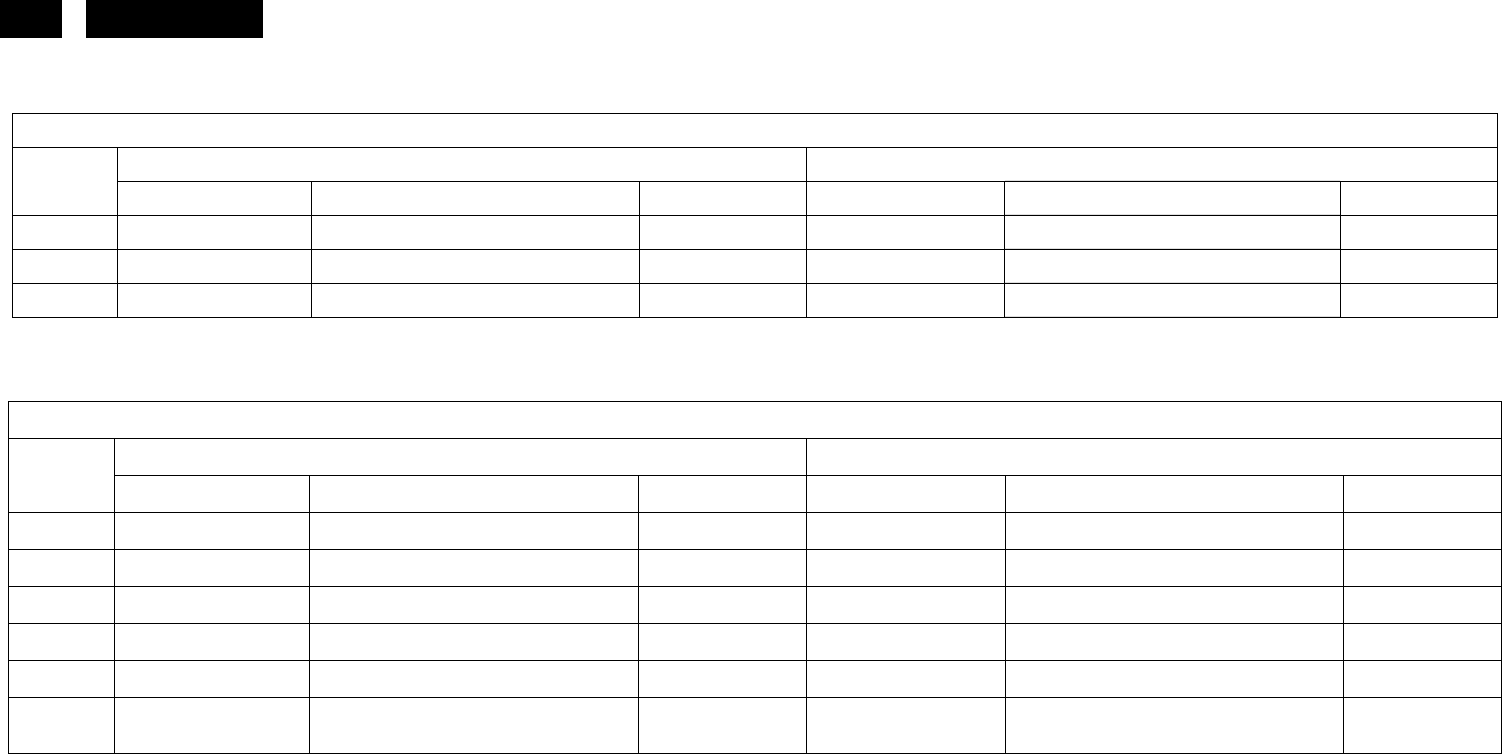
96 HUDSON 8
17. Different Parts List
Diversity of 170S8FB/00 compared with 170S8FS/00
170S8FB/00 170S8FS/00
Location Part No. Description Philips 12NC Part No. Description Philips 12NC
FQ009 P33G4989 VQB1C CONTROL BUTTON 996510010255 P33G4989 VPB1C CONTROL BUTTON 996510010269
FQ010 P34G1846 VBF1T BEZEL L17-7PHB1 996510010256 P34G1846 VOE1T BEZEL L17-7PHB1 996510010270
FQ010 P34G1846 VBF1B BEZEL L17-7PHB1 P34G1846 VOE1B BEZEL L17-7PHB1
Diversity of 170S8FB/27 compared with 170S8FS/00
170S8FB/27 170S8FS/00
Location
Part No. Description Philips 12NC Part No. Description Philips 12NC
FQ002 089G402A18N IS POWER CORD 089G404A18N YH POWER CABLE 996500037502
FQ009 P33G4989 VQB1C CONTROL BUTTON P33G4989 VPB1C CONTROL BUTTON 996510010269
FQ010 P34G1846 VBF1T BEZEL L17-7phb1 P34G1846 VOE1T BEZEL L17-7phb1 996510010270
FQ012 Q40G 17N81325B RATING LABEL Q40G 17N81322A RATING LABEL
FQ012 Q40G 17N81325C RATING LABEL (Second source) Q40G 17N81322A RATING LABEL
FQ022 089G1748GAA AC
SIGNAL CABLE DVI
GREATLAND
http://www.wjel.net
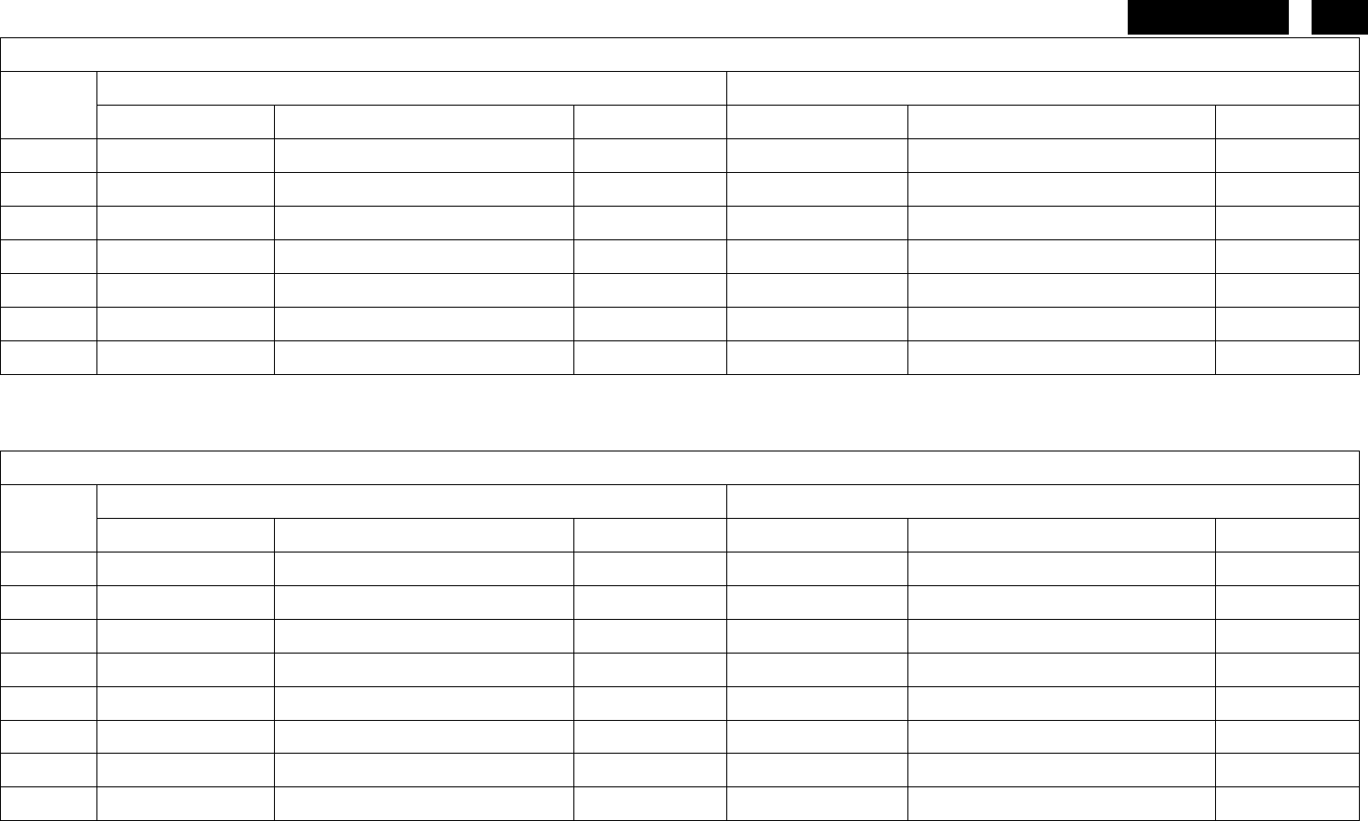
97
HUDSON 8
Diversity of 170S8FS/62 compared with 170S8FS/00
170S8FS/62 170S8FS/00
Location
Part No. Description Philips 12NC Part No. Description Philips 12NC
FQ011 P34G1850 VB 1T REAR COVER P34G1850 VB 2T REAR COVER(17") 996510008030
FQ015 Q44G7057813 4A CARTON Q44G7057813 1A CARTON
FQ015 Q44G7057813 5A CARTON (Second source) Q44G7057813 1A CARTON
FQ018 CBPC7GNAPHQ8 SCALAR BOARD ASSY(LPL) CBPC7GNAPHQ6 SCALAR BOARD ASSY (LG) 996510010260
FQ017 CBPC7CNAPHQ8 SCALAR BOARD ASSY(CPT) CBPC7CNAPHQ4 SCALAR BOARD ASSY(CPT) 996510010263
U203 705GQ756032 MCU ASS'Y (17")(LPL) 705GQ756024
MCU ASS'Y (LG) 996510010271
U203 705GQ756031 MCU ASS'Y (17")(CPT) 705GQ756023
MCU ASS'Y (CPT) 996510010264
Diversity of 170S8FB/62 compared with 170S8FS/00
170S8FB/62 170S8FS/00
Location
Part No. Description Philips 12NC Part No. Description Philips 12NC
FQ009 P33G4989 VQB1C CONTROL BUTTON P33G4989 VPB1C CONTROL BUTTON 996510010269
FQ010 P34G1846 VBF1T BEZEL L17-7phb1 P34G1846 VOE1T BEZEL L17-7phb1 996510010270
FQ011 P34G1850 VB 1T REAR COVER P34G1850 VB 2T REAR COVER(17") 996510008030
FQ015 Q44G7057813 4A CARTON Q44G7057813 1A CARTON
FQ018 CBPC7GNAPHQ8 SCALAR BOARD ASSY(LPL) CBPC7GNAPHQ6 SCALAR BOARD ASSY (LG) 996510010260
FQ017 CBPC7CNAPHQ8 SCALAR BOARD ASSY(CPT) CBPC7CNAPHQ4 SCALAR BOARD ASSY(CPT) 996510010263
U203 705GQ756032 MCU ASS'Y (17")(LPL) 705GQ756024
MCU ASS'Y (LG) 996510010271
U203 705GQ756031 MCU ASS'Y (17")(CPT) 705GQ756023
MCU ASS'Y (CPT) 996510010264
http://www.wjel.net

98 HUDSON 8
Diversity of 170S8FB/78 compared with 170S8FS/00
170S8FB/78 170S8FS/00
Location
Part No. Description Philips 12NC Part No. Description Philips 12NC
E08902 089G402A18NIS1 POWER CORD
E08902 089G402A18NLS1 POWER CORD
FQ004 705GQ734427 170S8 STAND&BASE SKD
ASS'Y 705GQ734307 STAND&BASE ASS'Y 996510006439
FQ009 P33G4989 VQB1C CONTROL BUTTON P33G4989 VPB1C CONTROL BUTTON 996510010269
FQ010 P34G1846 VBF1B BEZEL L17-7phb1 P34G1846 VOE1T BEZEL L17-7phb1 996510010270
FQ012 Q40G 17N81328A RATING LABEL Q40G 17N81322A RATING LABEL
FQ017 CBPC7CNAPHQA SCALER BOARD CBPC7CNAPHQ4 SCALER BOARD ASSY (CPT) 996510010263
FQ019 PWPC7942GQA8 POWER BOARD ASSY PWPC942GR1P POWER BOARD(CPT) 996510006441
CN801 033G8021 2E U INVERT CONNECTOR
CN802 033G8021 2E U INVERT CONNECTOR
CN803 033G8021 2E U INVERT CONNECTOR
CN804 033G8021 2E U INVERT CONNECTOR
C909 063G107K474 TS CAP X2 0.47UF K 275VAC 063G107K474 HS 0.47UF +-10% 996510007384
C907 067G305T10115H ELCAP 105℃ 100UF M 450V
L902 073G 174 65 T LINE FILTER 7mH MIN TDK
T901 080GL17T 33 T2 X'FMR 550uH
SRW28EC-T147H015
L902 S73G17465VW LINE FILTER ASS'Y 073G 174 65 H LINE FILTER 996500036088
L921 S73G25391V CHOKE COIL ASS'Y 073G 253 91 H CHOKE COIL 996500036026
L922 S73G25391V CHOKE COIL ASS'Y 073G 253 91 H CHOKE COIL 996500036026
T901 S80GL17T33V2 TRANSFORMER ASS'Y 080GL17T 33 N2 XFMR POWER 550uH YUVA 996510006247
IC903 056G 158 10 T IC AZ431AZ-AE1 TO-92 BY AAC 056G 158 12 KIA431A-AT/P TO-92 996500036054
FQ018 KEPC7QS6 KEY BOARD ASSY KEPC7QS5 KEY BOARD ASSY 996510010272
http://www.wjel.net

99
HUDSON 8
18. General Product Specification
CONTENTS
ANALOG AND DIGITAL DUAL INPUT
1 FOREWORD
2 PRODUCT PROFILE
2.1 LCD
2.2 SCANNING FREQUENCIES
2.3 AMBIENT TEMPERATURE: 0 °C - 35 °C
3 ELECTRICAL CHARACTERISTICS
3.1 INTERFACE SIGNALS
VIDEO: 0.7 Vp-p, INPUT IMPEDANCE, 75 OHM @DC
3.2 INTERFACE
3.3 TIMING REQUIREMENT
3.4 HORIZONTAL SCANNING
3.5 VERTICAL SCANNING
3.6 POWER INPUT CONNECTION
3.7 POWER MANAGEMENT
3.8 DISPLAY IDENTIFICATION
3.9 DISPLAY IDENTIFECATION
3.10 USB SUPPORT: NOTE
3.11 DDC/CI SUPPORT
3.12 EDID
3.13 HOT-KEY DEFINITION
3.14 SMART CONTRAST (DYNAMIC CONTRAST RATIO)
3.16 SMART IMAGE
4 VISUAL CHARACTERISTICS
4.1 TEST CONDITIONS
4.2 BRIGHTNESS
4.3 IMAGE SIZE
4.4 BRIGHTNESS UNIFORMITY
4.5 CHECK CROSS TALK (S)
4.6 WHITE COLOR ADJUSTMENT
5 MECHANICAL CHARACTERISTICS
5.1 COSMETIC PHILIPS ID
5.2 MECHANICAL DATA FILES PROE FILES REQUIRED
5.3 LOCATION OF PHILIPS LOGO PER PHILIPS MAKE-UP SHEET
5.4 GAP BETWEEN PANEL AND FRONT BEZEL <0.8 (TYP) MM
5.5 LOCATION OF CONTROL ICONS PER PHILIPS GRAPHIC SHEET
5.6 COLOR FOR RESIN/PAINT PER PHILIPS MAKE-UP SHEET
5.7 RESINS
5.8 IF RAINT IS USED
5.9 PLASITIC MOLD TOOLING
5.10 PLASTICS FLAMMABILITY
http://www.wjel.net

100 HUDSON 8
5.11 TEXTURE/GLOSSING OF HOUSING
5.12 TILT AND SWIVEL BASE
5.13 KENSINGTON LOCK
5.14 LABEL
5.15 PRODUCT DIMENSION/WEIGHT (PREFER TO SHT 191)
5.16 TRANSPORTATION
5.17 PALLET/CONTAINER LOADING
6. ENVIRONMENTAL CHARACTERISTICS
6.1 SUSCEPTIBILITY OF DISPLAY TO EXTERNAL ENVIRONMENT
6.2 TRANSPORTATION TESTS
6.3 DISPLAY DISTURBANCES FROM EXTERNAL ENVIRONMENT
6.4 DISPLAY DISTURBANCES TO EXTERNAL ENVIRONMENT
7. RELIABILITY
7.1 MEAN TIME BETWEEN FAILURES
8. QUALITY ASSURANCE REQUIREMENTS
8.1 ACCEPTANCE TEST
9. PHILIPS’ FLAT PANEL MONITORS PIXEL DEFECT POLICY
10 REGULATORY COMPLIANCE
10.1 WORLDWIDE REGULATORY
10.2 EMC REQUIREMENTS
10.3 ROHS
10.4 WEEE
10.5 ONGOING REGULATORY
http://www.wjel.net

101
HUDSON 8
1. FOREWORD
This specification describes a 17" SXGA multi-scan color TFT LCD monitor with maximum resolution up to 1280 x
1024 /76 Hz non-interlaced. All optical characteristics (including WHITE-D, Brightness, and so on) are determined
according to panel specification after warming up approximate 30 minutes that brightness stability is optimal, and
follow strictly after panel specification.
2. PRODUCT PROFILE
This display monitor unit is a color display monitor enclosed in PHILIPS styling cabinet which has an integrated tilt
base.
2.1 LCD
Priority : LPL/CPT/AUO
Type : TN + film
LPL LM170E03-TLL1/TLL4
Resolution : 1280x1024 (SXGA)
Outside dimensions :
Pitch ( mm ) : 0.264 mm x 0.264 mm
Color pixel arrangement : RGB vertical stripes
Display surface : Hard coating (3H), Anti-glare treatment of the front polarizer
Color depth : 16.7 M colors (with A-FRC)
Backlight : CCFL edge light system
Active area(WxH) : 337.9*270.3
View angle (CR>10 ) : 160/160 (typ)
Contrast ratio :800:1 (typ)
White luminance : 300 nit (typ)
Color gamut :72% (typ)
Gate IC :
Source IC :
Response time : 5 ms
CPT CLAA170EA07P-040/050
Resolution : 1280x1024 (SXGA)
Outside dimensions :
Pitch ( mm ) : 0.264 mm x 0.264 mm
Color pixel arrangement : RGB vertical stripes
Display surface : Anti-glare
Color depth : 16.7 M (6 bits + Hi -FRC)
Backlight : CCFL, 4 tables, edge-light(top*2/bottom*2)
Active area(WxH) : 337.9*270.3
View angle (CR>10) : 160/160 (typ)
Contrast ratio : 700:1 (typ)
White luminance : 300 nits (typ)
Color gamut : 72% (typ)
Gate IC :
Source IC :
Response time : 6ms
http://www.wjel.net

102 HUDSON 8
AUO M170EG01 VD
Resolution : 1280x1024 (SXGA)
Outside dimensions :
Pitch ( mm ) : 0.264 mm x 0.264 mm
Color pixel arrangement : RGB vertical stripes
Display surface : Anti-glare type, Hardness 3H
Color depth : 16.7 M color (RGB 6 bits + FRC data)
Backlight : CCFL
Active area(WxH) : 337.9*270.3
View angle (CR>10) : 160/160 (typ)
Contrast ratio : 800:1 (typ)
White luminance : 300 nits (typ)
Color gamut : 72% (typ)
Gate IC :
Source IC :
Response time : 5ms
2.2 Scanning frequencies
Hor. : 30 – 83 K Hz
Ver.: 56 - 76 Hz
Video dot rate: <140 MHz
Power input: 90-264 V AC, 50/60 ± 2 Hz
Power consumption : : 36 W typical
Functions:
(1)D-SUB analog R/G/B separate inputs, H/V sync separated, Composite (H+V) TTL level, SOG sync
(2) DVI digital Panel Link TMDS inputs
2.3 Ambient temperature: 0 °C - 40 °C
3. Electrical characteristics
3.1 Interface signals
1). D-Sub Analog
Input signal : Video, Hsync., Vsync
Video : 0.7 Vp-p, input impedance, 75 ohm @DC
Sync. : Separate sync TTL level , input impedance 2.2k ohm terminate
Hsync Positive/Negative
Vsync Positive/Negative
Composite sync TTL level, input impedance 2.2k ohm terminate (Positive/Negative)
Sync on green video 0.3 Vp-p Negative (Video 0.7 Vp-p Positive)
2). DVI-D Digital
Input signal: Single TMDS link (Three channels: RX0-/+, RX1-/+, RX2-/+)
3). Audio: NOTE
4). USB PLUG 2.0: NOTE
http://www.wjel.net
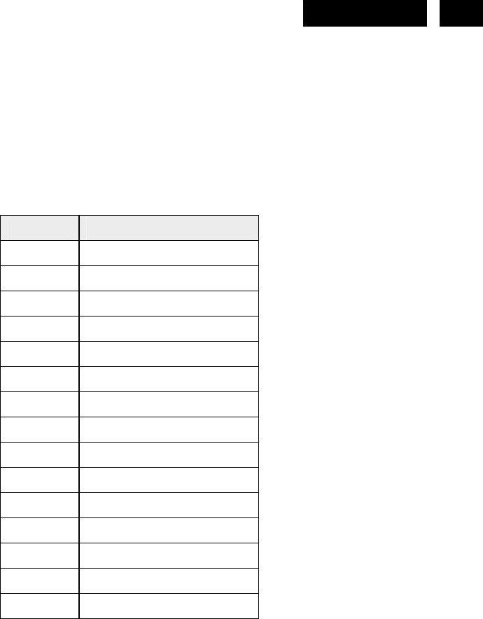
103
HUDSON 8
3.2 Interface
3.2.1 D-Sub Cable
Length : 1.8 M +/- 50 mm
Fix with monitor when packing, with transplant pin protective cover.
Connector type : D-Sub male with DDC2B pin assignments.
Blue connector thumb-operated jack screws
Pin assignment:
Pin No. Signal
1 Red
2 Green/ SOG
3 Blue
4 Sense (GND)
5 Cable Detect (GND)
6 Red GND
7 Green GND
8 Blue GND
9 DDC +3.3V or +5V
10 Logic GND
11 Sense (GND)
12 Bi-directional data
13 H/H+V sync
14 V-sync
15 Data clock
3.2.2 DVI Cable
The input signals are applied to the display through DVI-D cable.
Length. : 1.8 M +/- 50 mm
Connector type . : DVI-D male with DDC-2B pin assignments
White connector thumb-operated jackscrews
http://www.wjel.net

104 HUDSON 8
Pin Assignment:
Pin No. Description
1 T.M.D.S. data2-
2 T.M.D.S. data2+
3 T.M.D.S. data2 shield
4 No Connect
5 No Connect
6 DDC clock
7 DDC data
8 No Connect
9 T.M.D.S. data1-
10 T.M.D.S. data1+
11 T.M.D.S. data1 shield
12 No Connect
13 No Connect
14 +5V Power
15 Ground (for +5V)
16 Hot plug detect
17 T.M.D.S. data0-
18 T.M.D.S. data0+
19 T.M.D.S. data0 shield
20 No Connect
21 No Connect
22 T.M.D.S clock shield
23 T.M.D.S. clock+
24 T.M.D.S. clock-
3.2.3 USB Cable (High Full Speed): NOTE
3.2.4 Audio cable (suppliers to input the jack and cable color): NOTE
3.3 Timing requirement
Factory Preset mode definition :
1. Perfect FOS while presenting all required timings.
2. Required timings need to be specified in User's Manual
Preset mode definition :
1. Need to support those timings.
2. Perfect FOS after auto adjustment.
User mode
1. Can save those timing that not in Preset mode and can be showed (not over scalar or Panel spec.)
2. It needs to reserve the 12 timings space in memory size.
http://www.wjel.net

105
HUDSON 8
3.3.1 Mode storing capacity
Factory preset modes : 11
Preset modes : 45
User define modes : 12
Note: 1. Screen displays perfect picture at 11 factory-preset modes.
2. Screen displays visible picture with OSD warning when input modes are the 45 preset modes.
3.3.2 Factory preset modes (11 modes)
Factory modes and preset modes are defined in the enclosed timing table file.
Item H.Freq. (KHz) Mode Resolution V.Freq. (Hz) BW(MHz)
1 31.469 IBM VGA 10H 640x350 70.086 25.175 Y
2 31.469 IBM VGA 3H 720x400 70.087 28.322 Y
3 31.469 IBM VGA 12H 640x480 59.94 25.175 Y
4 35 MACINTOSH 640x480 66.667 30.24
Y
5 37.861 VESA 640x480 72.809 31.5 Y
6 37.5 VESA 640x480 75 31.5 Y
7 43.269 VESA 640x480 85.008 36 Y
8 35.156 VESA 800x600 56.25 36 Y
9 37.879 VESA 800x600 60.317 40 Y
10 48.077 VESA 800x600 72.188 50 Y
11 46.875 VESA 800x600 75 49.5 Y
12 53.674 VESA 800x600 85.061 56.25 Y
13 49.725 MACINTOSH 832x624 74.55 57.283 Y
14 56.4 - 960x720 75 N
15 44.75 - 960x720 60 N
16 48.363 VESA 1024x768 60.004 65 Y
17 56.476 VESA 1024x768 70.069 75 Y
18 60.023 VESA 1024x768 75.029 78.75 Y
19 61.08 IBM XGA-2 1024x768 75.782 86.001 Y
20 68.677 VESA 1024x768 84.997 94.5 Y
21 47.396 CVT 2.3MA 1280 x768 59.995 68.25 Y
22 60.289 CVT 2.3MA 1280 x768 74.893 102.25 Y
23 53.7 1152x864 60 81.624 Y
24 63.851 VESA 1152x864 70.012 94.5 Y
25 67.5 VESA 1152x864 75 108 Y
26 68.681 MACINTOSH 1152x870 75.62 100 Y
27 61.82 SUN WS 1152x900 65.977 92.978 Y
28 71.713 SUN WS 1152x900 76.047 105.561 Y
29 60 VESA 1280x960 60 108 Y
http://www.wjel.net

106 HUDSON 8
30 75.171 VESA 1280x960 75.021 129.895 Y
31 63.981 VESA 1280x1024 60.02 108 Y
32 71.691 SUN WS 1280x1024 67.189 117 Y
33 76.754 DOS/V 1280x1024 72.001 129.56 Y
34 79.976 VESA 1280x1024 75.025 135 Y
35 81.13 SUN WS 1280x1024 76.107 135 Y
36 91.146 VESA 1280x1024 85.24 157.5 Y
37 44.772 - 1280x720 59.855 74.5 Y
38 56.456 - 1280x720 74.777 95.75 Y
39 64.744
CVT-reduced
bl ki
1400x1050 59.948 101 N
40 82.278 CVT 1400x1050 74.867 156 N
41 93.881 CVT 1400x1050 84.96 179.5 N
42 55.469
VESA-reduced
bl ki d
1440x900 59.901 88.75 Y
43 55.935 VESA 1440x900 59.887 106.5 Y
44 70.635 VESA 1440x900 74.984 136.75 Y
45 75 VESA 1600x1200 60 162 Y
46 66.587 CVT 2.3MA-R 1920x1080
59.934 (for
DVI
D)
138.5 Y
47 65.29 CVT1.76MW 1680x1050 59.954 146.25 Y
48 64.674 CVT1.76MW-R 1680x1050 59.883 119 Y
49 74.038 CVT 2.3MA-R 1920x1200
59.95 (for
DVI
D)
154 Y
50 61.648 1600x1000 59.91 108.5 Y
3.3.3 Software control functions via OSD / control adjustable functions:
Please refer to following Hudson8 OSD definitions
Reset - No: Exit
Yes: Auto adjustment for displaying timing mode and recall factory preset
OSD Languages –8
Power On Logo: Power On Æ show up Philips logo 3 second Æ change to input signal
This picture is reference only. The official drawing will send out by PM.
http://www.wjel.net
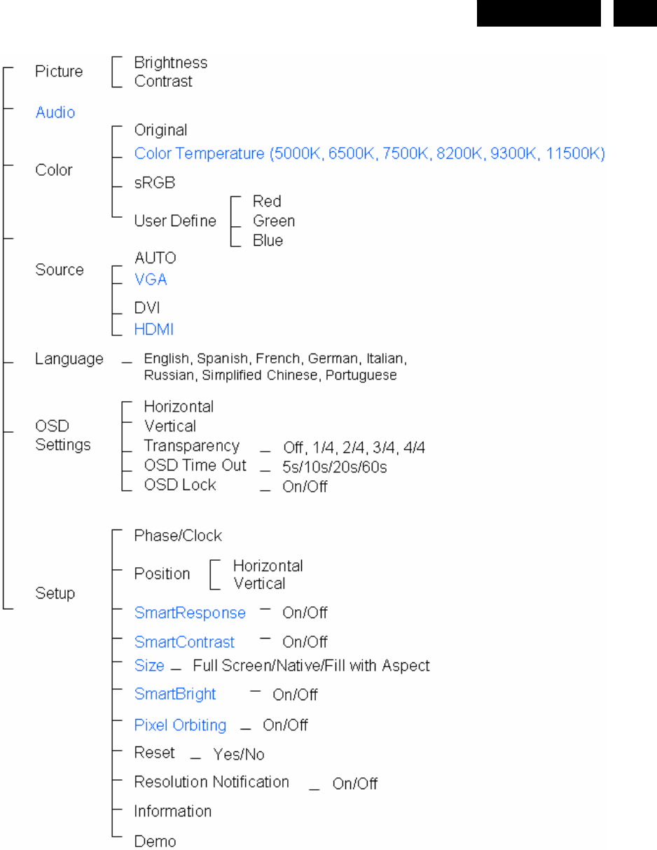
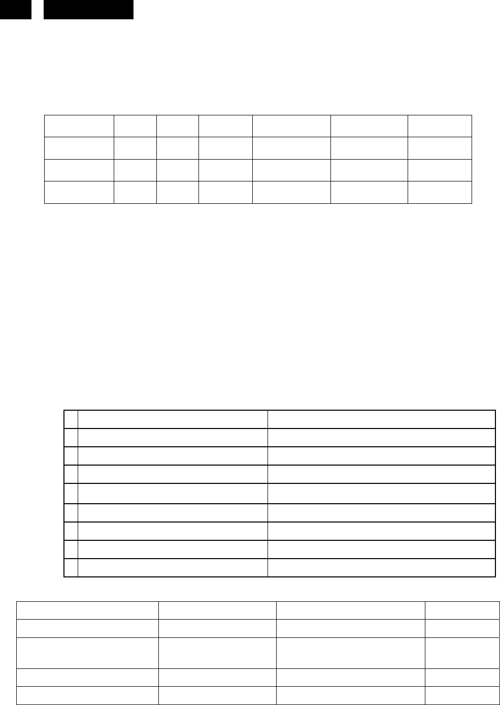
108 HUDSON 8
3.6 Power input connection
Power cord length : 1.8 M
Power cord type : 3 leads power cord with protective earth plug.
3.7 Power management
The monitor must comply with the Microsoft On Now specification, and meet EPA requirements.
Mode HSYNC VSYNC Video Power-cons. Indication Rec. time
Power-On On On active 36W typical Green LED --
Off Off Off blanked < 1 W Amber LED < 3 s
DC Power Off N/A < 1 W LED Off
3.8 Display identification
In accordance with VESA Display Channel Standard Ver.1.0 and DDC 2B capability
3.9 Display identification
In accordance with DVI requirement (DDWG digital Visual Interface revision 1.0)
use DDC-2B, DDC/CI, and EDID V1.3
3.10 USB support: NOTE
3.11 DDC/ CI Support
In accordance with VESA DDC/CI and MCCS ver.2.0, the monitor should be workable with Protrait Display
Tune at least.
3.12 EDID
Data for EDID & .inf file
1 User visible strings on .inf file Philips 170S (17inch LCD MONITOR 170S8)
2 Manufacturer ID ( EDID data) PHL
3 Product ID, "xxxx" 4 codes MSB(byte 12): 08
LSB (byte 11): 56
4 maximum resolution 1280x1024
5 Horizontal Frequency Range 30~83 KHz
6 Vertical Frequency Range 56~76Hz
7 Monitor Name (13 characteries max.) Philips 170S8
3.13 Hot-key definition
Key Key Press Time OSD Timeout
Monitor Controls Lock OK(Menu) 6 sec (lock/unlock) 3 sec
Factory Mode AUTO+ OK+ Power On Keep pressing when power on
Demo mode for smart image Smart Image Key 3 sec (Enter/Quit)
DDC/CI On/OFF for VISTA MENU+DOWN 6 sec (lock/unlock) 3 sec
http://www.wjel.net
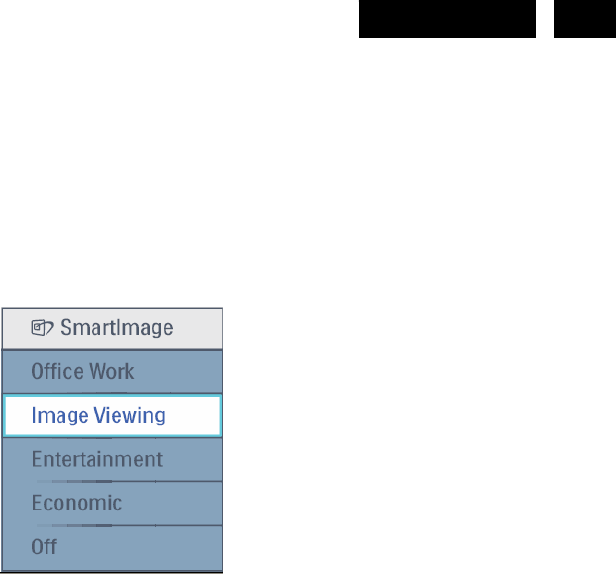
109
HUDSON 8
3.14 Smart contrast (Dynamic contrast ratio)
Smart Contrast is a kind of dynamic backlight control.
This function changes the panel backlight dynamically according to the frame brightness histogram.
the contrast ratio has to be 3000:1(typical).
3.15 Smart Image
3.15.1Smart Image OSD outlook (Economic Æ Economy)
3.15.2Smart Image OSD outlook
3.15.2.1 Position
Pressing the “Smart Image” button, the position is in the bottom center of the screen.
3.15.2.2 Smart Image Logo & Banner
As design to keep the Light Frame logo at header but change the name to “SmartImage” with bitmap format.
3.15.2.3 Icon of each profile
Each profile will use text instead of icon & text before.
3.15.2.4 User Operation Procedure
A. 5 different modes are switched to next in the sequence from 1 to 5 then back to 1 while pressing this button:
1) Office Work 2) Image Viewing 3) Entertainment 4) Economy 5) Off. The default setting is ‘Off”.
B. The FOS optimization will be changed in real time by which profile to be scrolled, users don’t need to
confirm to enable.
C. The Smart Image OSD will remain on screen for 5 seconds after user last action. Or user can also press
[MENU] to close the Smart Image OSD immediately.
D. Except using [MENU] button to scroll down profile. If Smart Image OSD already launched onscreen. User is
allowed to use up/down key to choose profile and press [MENU] to confirm selection and close the Smart
Image OSD.
E. If the model has multiple inputs including VGA and DVI, each input has their own set of profiles. When user
switch input, the profile to be applied will also change.
F. Each input can memorize their individual “Smart Image” profile status.
For example, Smart Image is on with “Office” profile at VGA input, when switch to DVI input, the Smart Image
will revert to previous profile of DVI. In the input switching process the “Smart Image” OSD will also show up to
present which profile is selected if “Smart Image” is enabled at that input. The Smart Image status will also be
stored after the monitor is resumed from AC on/off or power switch on/off.
http://www.wjel.net

110 HUDSON 8
3.15.2.5Linkage between Smart Image OSD and main OSD
A. Settings within main OSD have linkage with Smart Image OSD.
i. Brightness
ii. Contrast
iii. Color Temperature
B. Because each preset profiles will define default setting of these 3 parameters. Users can understand what is
the value of that in preset profile by open the main OSD.
C. When any SmartImage Lite profile had been enabled. The parameters in main OSD are still available for user
to adjust. But these adjustments are temporary only. If users switch to another profile and then go back. The
setting in main OSD will show preset values of that Smart Image profile enabled.
3.15.2.6 Profile Definitions (system integrators to input at design stages)
A. Office Work
i Purpose: Design for general office application, like word processing, Spreadsheet and email. The screen is
dominated by text.
ii. Enhancement point:
1.A little sharpness for increasing the details of e.g. an excel grid. No other type of enancement as it won't
bring value.
2. Color temperature remains in 6500°K.
3. Brightness level should be 70%.
4. Smart Response set to “Off”.
5. Smart Contrast set to “Off”.
B. Entertainment
i. Purpose: Design for video application, Like Microsoft Media Player or Real Player. The screen is
dominated by video.
ii Enhancement Point:
1. Dynamic contrast enhancement by histogram analysis (DLC) should be implemented.
2. Sharpness enhanced 90%.
3. Color enhancement set as the same with Video.
4. Color temperature set to 7500° (Based on final PQ settings) (if higher)
5. Brightness level sets to maximum.
6. SmartResponse set to “High”.(N/A for this model)
7. Gamma Table turn off to achieve
8. Fastest response time. (N/A for this model)
9. Smart Contrast set to “On”
C. Image Viewing
i. Purpose: Design for image viewing application, especially in slide show. The screen is dominated by
picture. Powerpoint presentation could use this profile also.
ii. Enhancement Point:
1.Dynamic contrast enhancement by histogram analysis (DLC) should be off.
2. Sharpness and color to be enhanced 75%.
3. Color temperature 6500°K
4. Brightness level sets to maximum.
5. Smart Response set to “Off”. (N/A for this model)
6. Smart Contrast set to “Off”.
http://www.wjel.net

111
HUDSON 8
D. Economy
i.Purpose: Adjust brightness level for reducing power consumptions
ii.No optimization by Smart Image.
iii.Design:
1. Brightness level set to 70%, a little higher brightness level than laptop PC, fine tune brightness level
before DVT exit.
2. Color temperature set to 6500K.
3. Gamma Table is turn on.
E. Off
i. Purpose: No optimization by SmartImage.
ii. Design:
1. This will follow user OSD setting. If any change by user, it will be saved. When switch back from other
SmartImage profiles, it will go back to last saved setting.
2. Gamma Table is turn on to reduce bad color tracking.
3.15.2.7Demo mode
A. Purpose: Built-in demo mode for sales in-store demo.
B. Design:
i. Dynamically split screen to 2 vertical frames with one vertical white line. The line width is 2 pixels. The
left frame will be enhanced by SmartImage and right frame remains original performance.
ii. There is OSD showing “SmartImage On” in left frame and “SmartImage Off ” in right frame.
iii. The OSD word color is white with transparent background.
C. The demo profile will be “entertainment profile setting.
D. Hot keys to trigger:
Press [SmartImage] 3 seconds or more to trigger the demo mode. When demo mode is On, press 3
seconds or more to turn off the demo mode. When the demo mode is enabled, the blue LED will
flash until demo mode disabled.(N/A for this model)
4. Visual characteristics
4.1 Test conditions
Unless otherwise specified, this specification is defined under the following conditions.
(1) Input signal : As defined in 3.3, 1280 x 1024
non-interlaced mode (1280 x 1024@60Hz 108MHz), signal
sources must have 75 ohm output impedance.
(2) Luminance setting : controls to be set to 300 nits (typical) with
full screen 100 % duty cycle white signal
(3) Warm up: more than 30 minutes after power on with signal supplied.
(4) Ambient light: 400 -- 600 lux.
(5) Ambient temperature: 20 ± 5 °C
4.2 Brightness
Follow Panel specification.
4.3 Image size
Actual display size 337.9 x 270.3 mm
http://www.wjel.net

112 HUDSON 8
4.4 Brightness uniformity
Set contrast at 100% and turn the brightness at 100%.
Apply the Fig 1, it should comply with the following formula:
B_min
X 100% >75%
B_max
Where B_max =Maximum brightness, B_min = Minimum brightness
4.5 Check Cross talk (S)
Apply Pattern 2. Set contrast and brightness at 100 %.
Measure YA. Then output Pattern 3 and measure YB.
the cross talk value :
ABS ( YA - YB )
⎯⎯⎯⎯⎯⎯⎯⎯⎯ X 100% < 1.5 %
YA
4.6 White color adjustment
There are seven factory preset white color 11500K, 9300K, 8200K, 7500K, 6500K, sRGB, 5000K
Apply full gray64 pattern, with brightness in 100 % position and the contrast control at 50 % position.
The 1931 CIE Chromaticity (color triangle) diagram (x ,y) coordinate for the screen center should be:
Product specification
CIE coordinates (x,y)
11500K x = 0.272 ± 0.02
y = 0.283 ± 0.02
9300K x = 0.283 ± 0.02
y = 0.297 ± 0.02
8200K x = 0.292 ± 0.02
y = 0.307 ± 0.02
7500K x = 0.299 ± 0.02
y = 0.315 ± 0.02
6500K/sRGB x = 0.313 ± 0.02
y = 0.329 ± 0.02
sRGB x = 0.313 ± 0.02
y = 0.329 ± 0.02
5000K x = 0.346 ± 0.02
y = 0.359 ± 0.02
http://www.wjel.net

113
HUDSON 8
Production alignment spec.
CIE coordinates (x,y)
11500K x = 0.272 ± 0.005
y = 0.283 ± 0.005
9300K x = 0.283 ± 0.005
y = 0.297 ± 0.005
8200K x = 0.292 ± 0.005
y = 0.307 ± 0.005
7500K x = 0.299 ± 0.005
y = 0.315 ± 0.005
6500K/sRGB x = 0.313 ± 0.005
y = 0.329 ± 0.005
sRGB x = 0.313 ± 0.005
y = 0.329 ± 0.005
5000K x = 0.346 ± 0.005
y = 0.359 ± 0.005
Quality Inspection specification:
CIE coordinates (x,y)
9300K x = 0.283 ± 0.015
y = 0.297 ± 0.015
6500K/sRGB x = 0.313 ± 0.015
y = 0.329 ± 0.015
sRGB x = 0.313 ± 0.015
y = 0.329 ± 0.015
5. Mechanical characteristics
5.1 Cosmetic - Philips ID
5.2 Mechanical data files - ProE files required
5.3 Location of Philips logo - Per Philips make-up sheet
5.4 Gap between panel and front bezel < 0.8 (typ) mm
5.5 Location of Control icons - Per Philips Graphic sheet
5.6 Color for resin/paint - Per Philips make-up sheet
5.7 Resins
z RoHS required
z WEEE required.
z Resin type/selection refer to Project Book Section 7.2 Plastic material.
http://www.wjel.net

114 HUDSON 8
5.8 If paint is used
z RoHS required
z WEEE require
z If new painting type need to implement, refer to UN-D 1235.
5.9 Plastic mold tooling
z Tooling to be designed to minimize cosmetic defects induced by molding process (sink, blush, weld lines,
gate marks, ejector marks, etc.). Refer to “TYV61-90007”.
z Painting to cover up cosmetic defects due to molding is strongly discouraged.
5.10 Plastics flammability
z All Plastics to be Flame Retardant UL 94-V0 or Better (if monitor weighs less than 18kg; UL94-V0 is OK).
z Base / Pedestal to be Flame Retardant UL 94-HB.
z All major plastic parts (bezel, back cover, base) need to be molded from same resin.
z ABS V0 is allowed to implement in China region for monitor body major plastic parts
(bezel, back cover, base).
z Plastic resin type selection should be referred to “TY R83-2-9002-1”s.
5.11 Texture/Glossing of housing
z The texture area and texture no should follow Philips make-up sheet.
z The exterior surfaces shall have a uniform texture.
z Philips must approve the mold texturing.
z Detail document for texture refer to “UN-D249”, “UN-D 600”.
z < = 20 gloss units
5.12 Tilt and swivel base
z Tilt angle : -5 ° +2/- 0 ° (forward)
+20 °+3/-0 ° (backward)
z Swivel angle : NA
z High Adjustment : NA
z Portrait Display : NA
5.13 Kensington Lock
z Must meet Kensington_slot.spec “TYE-M0004”.
z MMD request metal plate in Kinsington hole.
5.14 Label
z Regulatory label / Carton label should follow Philips requirement.
z China RoHS label
z Detail document refer to Philips Engineering Reference Book.
5.15 Product dimension / Weight (Refer to SHT 191 )
http://www.wjel.net

115
HUDSON 8
z Unit dimension : 403mm (W) * 392.5 (H) * 171mm(D)
z Packed unit dimension : 482mm(W) * 189mm(H) * 488 mm(D) for WW
: 490mm(W) * 191mm(H) * 497 mm(D) for China
z Net weight :
4.6Kg (Including I/F cable 300 g)
z Gross weight : 6.0 Kg for WW
: 6.1 Kg for China
5.16 Transportation
Transportation standards refer to TYE-M0002.
5.16.1 Transportation packages
Packaging and wrapping shall be sufficient to protect the product against damage or loss during shipment from
the supplier to the destination specified in the purchase order. All packaging materials are subject to test and
evaluation per TYE-M0002. The cushion material shall be constructed using EPS material.
5.16.2 Transportation Test
The overall test refer to TYE-M0002.
Vibration, drop test should be performed at ambient temperature(20°C to 23oC) and relative humidity (40% to
65% ).
A. Transportation test specification for all regions except China/India
• Package test
1. Random Vibration test
2. Drop test
3. Cold Drop test (for design reference)
• Un-package test
1. Half sine shock test (non operation)
B. Transportation test specification for China/India
• Package test
1. Random Vibration test
2. Drop test
3. Cold Drop test (for design reference)
• Un-package test
1. Sine vibration (operating)
2. Half sine shock test (non operation)
http://www.wjel.net

116 HUDSON 8
5.17 Pallet / Container loading
Transportation standards refer to TYE-M0002.
z Air shipment -
z Sea container 20'(pallet/slip sheet)
z Sea container 40'(pallet/slip sheet)
z Sea container 40' High Cube (pallet/slip sheet)
z Truck shipment-
Transportation request for all region except China/India
A. Air shipment
B. Container loading for WW
Transportation request for China and India
A. Container loading for China and India
B. Truck loading
6. Environmental characteristics
The following sections define the interference and susceptibility condition limits that might occur
between external environment and the display device.
6.1 Susceptibility of display to external environment
Operating
- Temperature : 0 to 40 degree C
- Humidity : 80% max
- Altitude : 0-3658m
- Air pressure : 600-1100 mBAR
Storage
- Temperature : -20 to 60 degree C
- Humidity : 95% max
- Altitude : 0-12192m
- Air pressure : 300-1100 mBAR
Note: recommend at 5 to 35°C, Humidity less than 60 %
6.2 Transportation tests
Refer to 5.15.2
6.3 Display disturbances from external environment
According to IEC 801-2 for ESD disturbances
6.4 Display disturbances to external environment
7. Reliability
7.1 Mean Time Between Failures
System MTBF (Including the LCD panel and CCFL) : 50,000 hrs
8. Quality assurance requirements
http://www.wjel.net

117
HUDSON 8
8.1 Acceptance test
According to MIL-STD-105D Control II level
AQL: 0.4 (major)
1.5 (minor)
(Please also refer to annual quality agreement)
Customer acceptance criteria: UAW0377/00
9. Philips’ Flat Panel Monitors Pixel Defect Policy
Philips’ Flat Panel Monitors Pixel Defect Policy
BRIGHT DOT DEFECTS ACCEPTABLE LEVEL
MODEL 170S8
1 lit sub-pixel 3
2 adjacent lit sub-pixels 1
3 adjacent lit sub-pixels (one white pixel) 0
Distance between two bright dots 15mm
Bright dot defects within 20 mm circle 0
Total bright dot defects of all type 3
BLACK DOT DEFECTS ACCEPTABLE LEVEL
MODEL 170S8
1 dark sub-pixel 5
2 adjacent dark sub-pixels 2
3 adjacent dark sub-pixels (one white pixel) 1
Distance between two black dots 15mm
Black dot defects within 20 mm circle* 1
Total black dot defects of all type 5
TOTAL DOT DEFECTS ACCEPTABLE LEVEL
MODEL 170S8
Total bright or black dot defects of all type 5
http://www.wjel.net
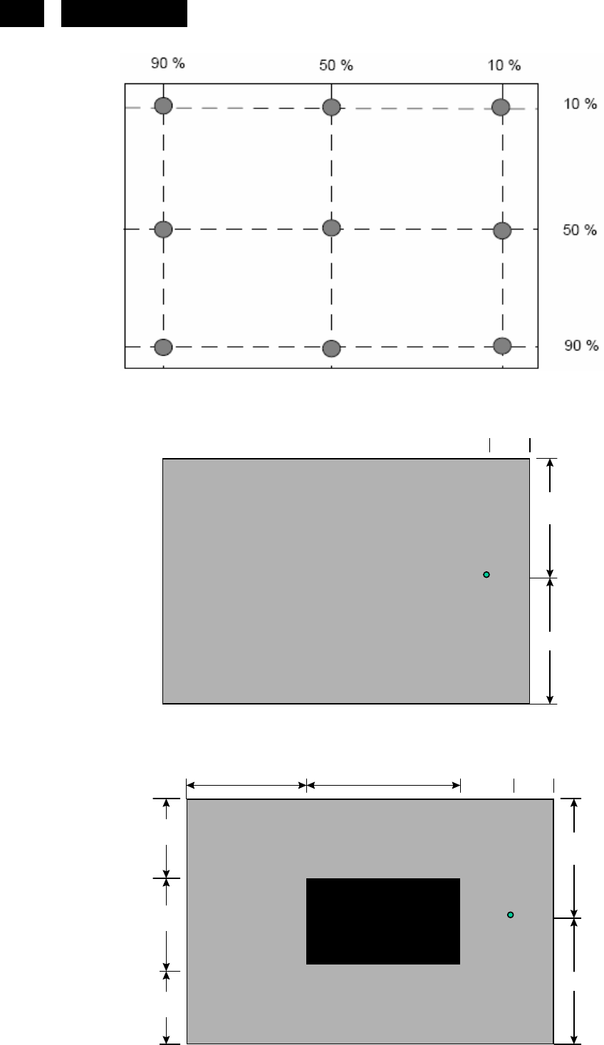
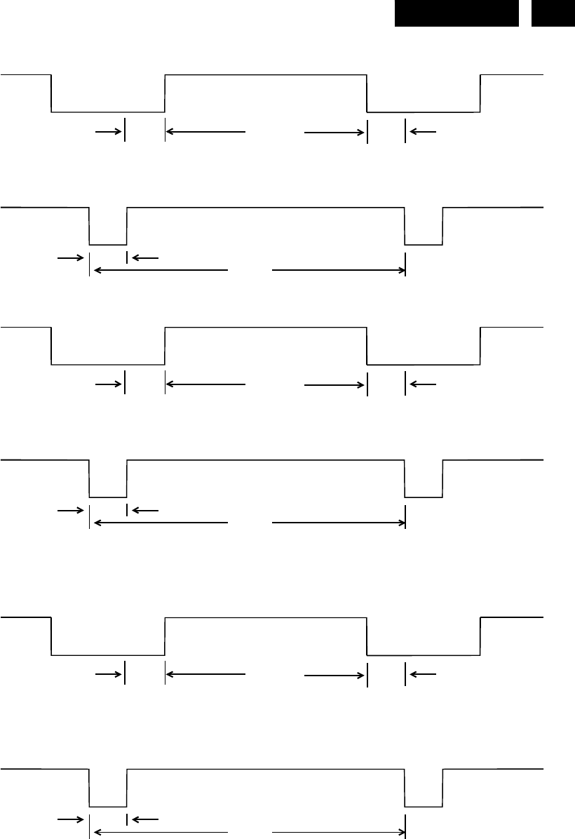
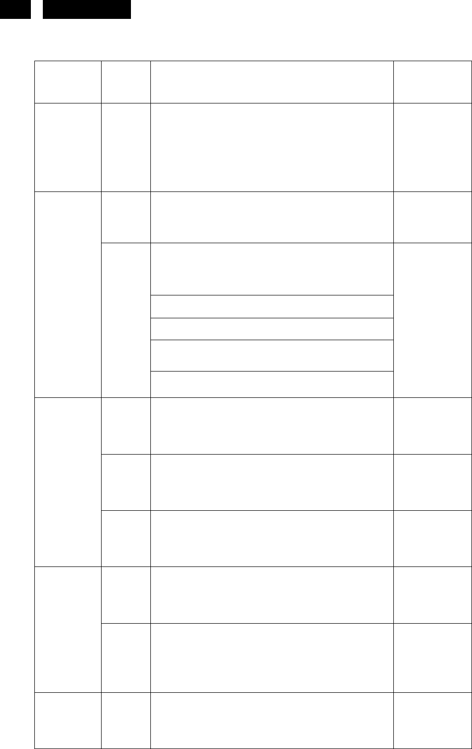
120 HUDSON 8
10. REGULATORY COMPLIANCE
10.1 Worldwide Regulatory
Country
Domain Safety / EMC / Ergonomics / Standards Documents
International Sa IEC60950-1:2001. Group -and national differences
of all countries listed in CB Bulletin No. 107A
CB Report
and CB
certificate
Sa European Low Voltage Directives 73/23/EEC and
93/68/EEC
Declaration of
Conformity
European Electromagnetic Compatibility Directive
89/336/EEC amended by the directive 93/68/EEC.
EN 55022:1998 Class B
EN 55024: 1998
EN 61000-3-2: 2000
IEC 61000-3-3: 1994/EN61000-3-3: 1995
Europe
E
CISPR 22:1997 Class B International EMC standard
Declaration of
Conformity
and Full
EMC/CE test
report
Sa EN60950-1:2001 TUV certificate
O ISO 13406-2: 2001 & prEN 50279:1998 TUV-ERG
certificate
Germany
O GS-Mark / EK1-ITB 2000 TUV-GS
certificate
Sa EN60950-1:2001 SEMKO
certificate
Sweden
O TCO 99 (TCO03)
TCO99
(TCO03)
report +
certificate
Russia Sa GOST R 50377-1992 GOST
certificate
http://www.wjel.net

121
HUDSON 8
South Africa Sa SABS IEC 60950 Certificate of
Conformity
Sa UL 60950-1: 2003 UL certificate
E FCC Part 15 Class B FCC ID grant
USA
O Energy Star EPA
registration
Sa CSA C22.2 No 60950 CSA certificate
Canada
E ICES-003 issue 3 Statement on
label
Mexico Sa NOM-019-SCFI-1994 NOM
certificate
Sa Korean Safety Control law IEC 60950 eK certificate
Korea
E Regulations laws: EMI 1996-78, 80. EMS
1996-79,81 MIC certificate
Singapore Sa IEC60950 PSB certificate
Sa GB4943-2001
China
E GB9254-1998; 17625.1-2003
CCC certificate
Sa CNS-14336 (IEC 60950-1)
Taiwan
E CNS-13438 (CISPR22) Class B
BSMI
certificate
Sa = Safety
E = Electromagnetic Compatibility
O = Other which including recycling, energy saving, ergonomics
http://www.wjel.net

122 HUDSON 8
10.2 EMC Requirements
Supplier DVT EMI test result must be submitted prior to DVT samples delivery, and PVT EMI test result must be
submitted again prior to PVT samples delivery, which also has to meet Philips' immunity testing specification.
10.3 RoHS
Restriction on the use of certain hazardous substances. Lead, Cadmium, Mercury, Hexavalent Chromium,
Polybrominated Bipheny1 (PBB) and Polybrominated Bipheny1 Ether (PBDE)(flame retardant).
10.4 WEEE
Producer (Philips) responsible for retailer take back schemes and recycling.
--System implemented.
--Collection and recycle targets.
10.5 Ongoing Regulatory
There's a possibility that other regulatory certificates will be required during the life of the product. It is the
responsibility of the supplier to provide related documentation.
http://www.wjel.net
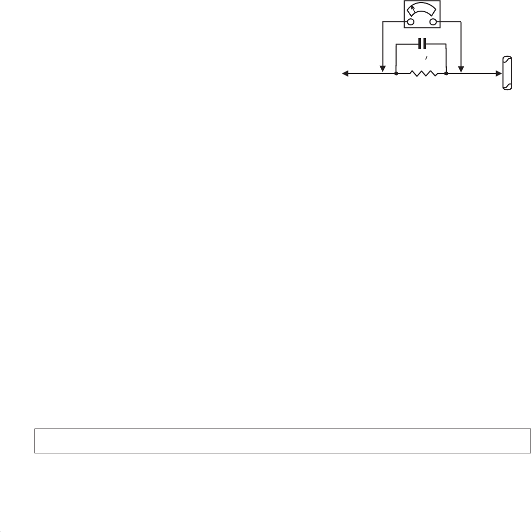
TELEVISION/MONITOR SAFFTY GUIDELINES FOR THE PROFESSIONAL SERVICE TECHNICIAN
Safety Checks
Fire and Shock Hazard
Implosion
X-radiation
After the original service problem has been corrected,a complete safety check
should be made. Be sure to check over the entire set, not just the areas
where you have worked. Some previous servicer may have left an unsafe
condition,which could be unknowingly passed on to your customer. Be sure
to check all of the following:
1. Be sure all components are positioned in such a way as to avoid the
possibility of adjacent component shorts. This is especially important
on those chassis which are transported to and from the service shop.
2. Never release a repaired unit unless all protective devices such as
insulators, barries, covers, strain reliefs, and other hardware have been
installed in accordance with the original design.
3. Soldering and wiring must be inspected to locate possible cold solder
joints,solder splashes,sharp solder points, frayed leads, pinched leads,
or damaged insulation ( including the ac cord).Be certain to remove
loose solder balls and all other loose foreign particles.
4. Check across-the-line components and other components for physical
evidence of damage or deterioration and replace if necessary. Follow
original layout,lead length, and dress.
5. No lead or component should touch a receiving tube or a resistor rated
at 1 watt or more. Lead tension around protruding metal surfaces or
edges must be avoided.
6. Critical components having special safety characteristics are identified
withansbytheRef.No.inthepartslistandenclosedwithinabrokenline
* (where several critical components are grouped in one area) along with
the safety symbols on the schematic diagrams and/or exploded views.
7. When servicing any unit, always use a separate isolation transformer
for the chassis Failure to use a separate isolation transformer may
expose you to possible shock hazard, and may cause damage to
servicing instruments.
8. Many electronic products use a polarized ac line cord (one wide pin on
the plug.) Defeating this safety feature may create a potential hazard to
the service and the user. Extension cords which do not incorporate the
polarizing feature should never be used.
9. After reassembly of the unit, always perform an leakage test or resistance
test from the line cord to all exposed metal parts of the cabinet. Also check
all metal control shafts(with knobs removed), antenna terminals, handles,
screws, etc. to be sure the unit may be safety operated without danger of
electrical shock.
* Broken line
1. All picture tubes used in current model receivers are equipped with an
integral implosion system. Care should always be used, and safety
glasses worn,whenever handling any picture tube. Avoid scratching or
otherwise damaging the picture tube during installation.
2. Use only replacement tubes specified by the manufacturer.
1. Be sure procedures and instructions to all your service personnel cover
the subject of X-radiation. Potential sources of X-rays in TV receivers are
the picture tube and the high voltage circuits. The basic precaution which
must be exercised is to keep the high voltage at the factory recommended
level.
2. To avoid possible exposure to X-radiation and electrical shock, only the
manufacturer's specified anode connectors must be used.
3. It is essential that the service technician has an accurate HV meter
available at all times. The calibration of this meter should be checked
periodically against a reference standard.
4. When the HV circuitry is operating properly there is no possibility of an x-
radiation problem. High voltage should always be kept at the manufacturer's
rated value-no higher - for optimum performance. Every time a color set is
serviced, the brightness should be run up and down while monitoring the
HV with a meter to be certain that the HV is regulated correctly and does
not exceed the specified value. We suggest that you and your technicians
review test procedures so that HV and HV regulation are always checked as
a standard servicing procedure, and the reason for this prudent routine is
clearly understood by everyone. It is important to use an accurate and
reliable HV meter. It is recommended that the HV recorded on each
customer's invoice, which will demonstrate a proper concern for the
customer's safety.
5. When troubleshooting and making test measurements in a receiver with
a problem of excessive high voltage, reduce the line voltage by means of
a Variac to bring the HV into acceptable limits while troubleshooting. Do
not operate the chassis longer than necessary to locate the cause of the
excessive HV.
:
:
WARNING OFF
SERVICE NOTE
Before removing the CRT anode cap, turn the unit and short the HIGH VOLTAGE to the CRT DAG ground.
The CRT DAG is not at chassis ground.
6. New picture tubes are specifically designed to withstand higher operathng
voltages without creating undesirable X-radiation. It is strongly
recommended that any shop test fixture which is to be used with the new
higher voltage chassis be equipped with one of the new type tubes
designed for this service. Addition of a permanently connected HV meter
to the shop test fixture is advisable. The CRT types used in these new
sets should never be replaced with any other types, as this may result in
excessive X-radiation.
7. It is essential to use the specified picture tube to avoid a possible X-diation
problem.
8. Most TV receivers contain some type of emergency "Hold Down" circuit to
prevent HV from rising to excessive levels in the presence of a failure
mode. These various circuits should be understood by all technicians
servicing them, especially since many hold down circuits are inoperative
as long as the receiver performs normally.
1. Unplug the ac line cord and connect a jumper between the two prongs of
the plug.
2. Turn on the power switch.
3. Measure the resistance value between the jumpered ac plug and all
exposed cabinet parts of the receiver, such as screw heads, antennas,
and control shafts. When the exposed metallic part has a return path to
the chassis, the reading should be between 1 megohm and 5.2 megohms.
When the exposed metal does not have a return path to the chassis, the
reading must be infinity. Remove the jumper from the ac line cord.
1. Do not use an isolation transformer for this test. Plug the completely
reassembled receiver directly into the ac outlet.
2. Connect a 1.5k, 10w resistor paralleled by a 0.15uf. capacitor between
each exposed metallic cabinet part and a good earth ground such as a
water pipe, as shown above.
3. Use an ac voltmeter with at least 5000 ohms volt sensitivity to measure
the potential across the resistor.
4. The potential at any point should not exceed 0.75 volts. A leakage current
tester may be used to make this test; leakage current must not exceed
0.5 milliamps. If a measurement is outside of the specified limits, there is
a possibility of shock hazard. The receiver should be repaired and
rechecked before returning it to the customer.
5. Repeat the above procedure with the ac plug reversed.( Note: An ac
adapter is necessary when a polarized plug is used. Do not defeat the
polarizing feature of the plug.)
The primary source of X-radiation in this television receiver is the picture
tube. The picture tube utilized in this chassis is specially constructed to limit
X-radiation emissions. For continued X-radiation protection, the replacement
tube must be the same type as the original, including suffix letter, or a Philips
approved type.
Many electrical and mechanical parts in Philips television sets have special
safety related characteristics. These characteristics are often not evident from
visual inspection nor can the protection afforded by them necessarily be
obtained by using replacement components rated for higher voltage, wattage,
etc. The use of a substitute part which does not have the same safety
characteristics as the Philips recommended replacement part shown in this
service manual may create shock, fire, or other hazards
Leakage Current Cold Check
Leakage Current Hot Check
Picture Tube Replacement
Parts Replacement
1500 ohm, 10W
0.15 uF WATER
PIPE
EARTH
GROUND
TO
INSTRUMENTS
EXPOSED
METAL PARTS
http://www.wjel.net
