376\377\0001\0007\0003\0004\0008\000 \000v\0002 17348 V2 Key PAC Solo Quick Start Guide
User Manual: 17348 v2 - KeyPAC Solo Quick Start Guide
Open the PDF directly: View PDF ![]() .
.
Page Count: 12
DATASHEET
PAC — A Stanley Security Products Business, 1 Park Gate Close, Bredbury, Stockport, SK6 2SZ
Tel: +44 (0) 161 406 3400 Fax: +44 (0) 161 406 8658 Web: www.stanleysecurityproducts.co.uk
Universal / Standard / VR KeyPAC Solo
Installation and Operation Instructions
17348 Ver 2.0 April 2011
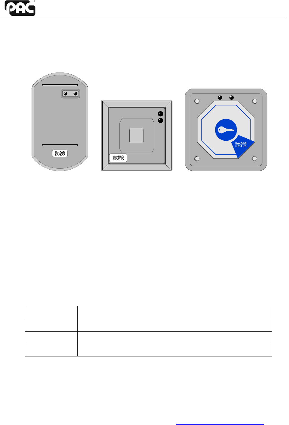
KeyPAC Solo Standard Vandal Resistant (VR)
1. Description
The KeyPAC Solo is a single-door controller combined with a proximity-device reader. It has a
relay output which is designed to power an electric door-lock. It can unlock a door when a valid
ID card is presented or when a Request to Exit (RTE) switch is pressed. It requires an external
power supply to operate and to supply the lock. These can be the same power supply where
necessary but check the rating before trying this.
The KeyPAC Solo can hold up to 2000 valid ID cards in memory. These are administered by
using Master cards (refer to Section 12.2 Add/Delete Operation – Edit Mode of this document.)
1.1 Compatible ID Devices
The KeyPAC Solo will not work with the older PAC ID devices.
Use the following part codes to order extra ID devices:
Part Number ID Device
20018 Wallet – card and shadow cards (10 of each)
20019 Wallet – token and shadow cards (10 of each)
21030 issue 5 KeyPAC Solo Master Card

Shadow ID Devices
17348 Ver 2.0 2 Universal / Standard / VR KeyPAC Solo
2. Shadow ID Devices
The KeyPAC Solo should be used with the KeyPAC ID Wallets that provide 10 ID devices and
10 Shadow ID devices.
Each user ID device provided has a corresponding Shadow ID Device, which are held by the
KeyPAC Solo administrator; and are used to delete their corresponding user ID device from the
KeyPAC Solo database if that ID device is lost.
Shadow ID devices are only to be used to delete user ID devices from the database and not as a
replacement, and should be discarded after being used. Refer to Section 12.2.2 Deleting ID
Devices below on how to use Shadow ID Devices to delete an ID device from the KeyPAC Solo
database.
If the ID device and its shadow card are lost then it cannot be deleted from the KeyPAC Solo
database. Therefore, in order to remove it, the entire database must be erased. Refer to Section
12.3 Erase Mode for information on how to do this.
3. Unpacking
Check that all the parts are supplied with your reader. If anything is missing or damaged, contact
your suppliers immediately. The KeyPAC Solo is supplied with the following:
Universal Solo Standard KeyPAC Solo Vandal Resistant KeyPAC
Solo
Two master cards
1
Two master cards
1
Two master cards
1
Two M3.5x30 screws Two M3.5x30 screws Four VR Screws
Ten cable crimps Ten cable crimps Ten cable crimps
Octagonal KeyPAC Solo
Label Octagonal KeyPAC Solo
Label Octagonal KeyPAC Solo
Label
This document This document This document
MOV MOV MOV
Snap fit decor cover Snap fit decor cover
Label Label
1
Programmed into the KeyPAC Solo.
KeyPAC Dimensions
17348 Ver 2.0 3 Universal / Standard / VR KeyPAC Solo
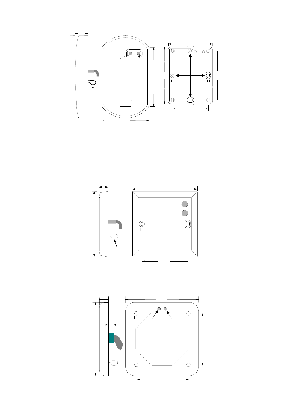
4. KeyPAC Dimensions
4.1 Universal Solo
22
80
140
100
75
96
60
4
4
4
83
Status
LED Edit
LED
Tamper
facility
Dimensions in millimetres.
Note
The screw holes indicated by the vertical and horizontal arrows are the recommended
mounting points for the back box. Use either the vertical or horizontal screws. Do not use
both as this may affect the reader’s performance.
4.2 Standard
15
86
86
Tamper
Loop 60
4
4
Status LED
Edit LED
Dimensions in millimetres.
4.3 Vandal Resistant
14
5
100
100
70
70
5
Status
LED
Edit
LED
Dimensions in millimetres.

Locating the Unit
17348 Ver 2.0 4 Universal / Standard / VR KeyPAC Solo
5. Locating the Unit
• Mount the Solo next to the door on the unhinged side, at about the same height as the
handle.
• You can mount the Solo behind non-metallic materials (glass, plastic, wood) without
reducing its range. This is not recommended for the Vandal Resistant Model.
• Do not mount it within one metre of another proximity reader (including the other side of
the wall).
• Mount the Solo inside or outside. For units mounted outside use a sealing compound to
prevent water ingress (sealing compound not provided).
• The reading range also extends behind the unit so mount it normally on the inside of the
wall. However, metal contained in the wall, including a metal back box, reduces the
reading range. This may effectively prevent the reader from reading from its back. Fit a
dummy reader label provided to the outside wall to indicate where to present ID devices.
• To allow easy viewing of the LED, avoid situating the unit in direct sunlight.
• The screws provided with the Standard Solo are for mounting it in a standard electrical
back-box. Where appropriate use the MK back-box MK 2120 WHI (white) for surface
mounting the reader.
• Leave enough room behind the unit for making cable connections.
• The Vandal Resistant KeyPAC Solo is provided with four vandal resistant screws. The
tool for these screws can be procured from PAC (p/n 1950).
6. Health And Safety
Installations must be wired in accordance with National Wiring Regulations (BS7671, IEE
National Wiring Regulations in the UK). Failure to do so can result in injury or death by electric
shock.
The installation must also comply with any local Fire, Health and Safety regulations.
WARNING: A secured door that may be part of an escape route must always be fitted with the
following. Failure to heed this advice can lead to injury or death in the event of a fire.
• A Fail-Safe lock (A). So that the door will be released if the power fails. Ideally a magnetic
lock should be used because these are less likely to jam or seize.
• A normally-closed Break-Glass or Manual Pull (B) in the lock supply wiring. So that in an
emergency the fail-safe lock can be immediately depowered.
A
+
B
CAUTION
Isolate the supply before working on the unit. Failure to do so can damage the unit.

Wiring
17348 Ver 2.0 5 Universal / Standard / VR KeyPAC Solo
7. Wiring
Note
The unit requires a 12V power supply capable of supplying at least 200mA. If you are
planning to power the locks, bell etc. from the same supply take this into consideration
when you specify the power supply.
Route the flying lead behind the unit and make the connections using the crimp connectors
supplied. If the connections are made in a location that may be wet or damp, then protect the
connectors with a sealing compound (not supplied), or use weatherproof crimps (not supplied).
All connections are made to an 8-conductor, flying lead. When using 0.22mm² (24AWG) cable,
twist the wires together and double them over before inserting them in the crimp. The overall
cable length, including the flying lead, should not exceed 3m.
Note
RS Components supply a suitable crimp tool. At the time of writing the part codes were as
follows: Crimps RS 534-907, Tool RS 253-4583.
7.1 Flying Lead
Length: Approximately 1.9m Gauge: 7/0.2, 0.22mm²
Colour Signal Notes
Black -V Power and signal return
Red +12v Unregulated 12V DC input 10.5-20V DC
Blue COM Common connection on the Solo relay
Green N/O Normally Open connection on the Solo relay
Yellow N/C Normally Closed connection on the Solo relay
White RTE Request to Exit connection
Brown DC Door Contact connection
Orange ALARM Alarm output pulls down to -V when active (open collector FET maximum
current 400mA, maximum voltage 50Vconnection)
WARNINGS
1. SOME FORM OF POWER LIMITING MUST BE FITTED. FAILURE TO DO SO COULD
RESULT IN INJURY OR DEATH BY ELECTRIC SHOCK. THIS MAY BE BUILT INTO
THE POWER SUPPLY UNIT OR BE A SUITABLE FUSE (RATING DEPENDS ON
LOAD) FITTED AS SHOWN IN THE DIAGRAM OVERLEAF.
2. THE RELAY CONNECTIONS ARE RATED AT MAX 30V DC, MAX 2A. DO NOT
ATTEMPT TO CONNECT MAINS ELECTRICITY TO THEM. THIS MAY CAUSE
INJURY OR DEATH BY FIRE OR ELECTRIC SHOCK.
Wiring
17348 Ver 2.0 6 Universal / Standard / VR KeyPAC Solo
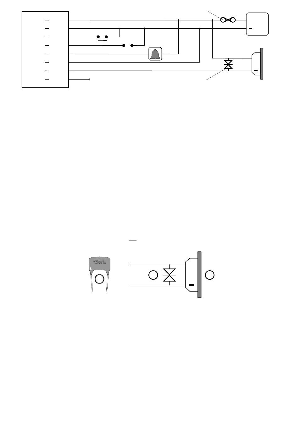
N/O
N/C
Reader
Red
Brown
White
Black
Blue
Yellow
Orange
Green
+12V
DC
RTE
-V
COM
N/C
Alarm
N/O
PSU
Lock
Bell
or light
Fuse
(
if PSU is not power limited)
MOV Suppressor
+
+
Example KeyPAC Solo wiring diagram showing fail-safe lock
Note
1. The Yellow or Green core will be used depending on the lock type.
Fail Safe = Yellow (N/C)
Fail Secure = Green (N/O)
2. The Solo relay is isolated so you can use a separate power supply for the lock.
3. If Alarm, RTE or relay contacts are not used they must be prevented from shorting (e.g.
crimp the individual ends)
4. If DC (door contact) is not used then it must be connected to -V.
5. Prevent shorting of unused wires (e.g. by crimping the end)
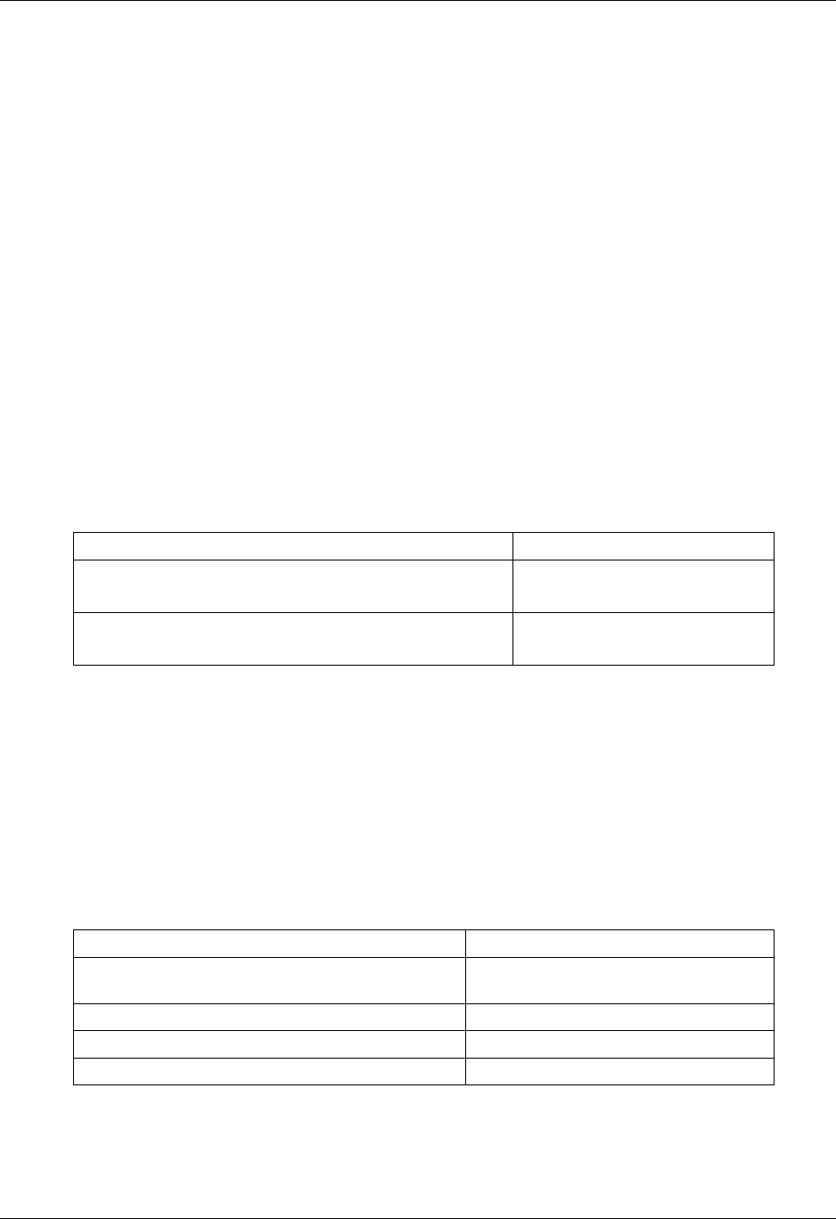
7.2 MOV - Lock Suppression
A metal-oxide-varistor (MOV) is provided with each KeyPAC Solo. This device prevents back
e.m.f. (high voltage 'spikes') being returned from the electric lock to the unit. High voltage spikes
can cause severe damage over a period of time, and erratic operation of the system if not
controlled.
CAUTION
Failure to fit the MOV at the lock will result in early failure of the unit. It will also invalidate
the warranty.
+
A
A
B
The MOV (A) should be fitted across the power terminals of the lock (B).
Tamper Facility
17348 Ver 2.0 7 Universal / Standard / VR KeyPAC Solo
8. Tamper Facility
A tamper facility is provided by a wire loop on the back of the unit. Snipping this loop, crimping
the ends together and then securing the crimp to the wall can provide basic tamper protection.
Forcibly removing the unit from the wall will break this connection and trigger the alarm.
Better protection can be provided by snipping the loop and fitting an appropriate normally closed
switch. The switch would be mounted so that the contacts open if the reader is forced off the
wall.
9. Alarm Facility
The unit has an internal sounder and an Alarm output which can be used to activate a bell, light
etc when a Warning Condition occurs. The output is activated when:
• The door is opened without a valid card being presented to the unit.
• The door is held open for longer than twice the lock release time.
• The tamper connection is broken.
• Six different invalid cards are presented to the unit in succession.
Removing the warning condition and presenting a valid card will cancel the Alarm output.
For a “door left open” condition closing the door can turn off the Alarm. The door can be left
open (e.g. when moving equipment) if the alarm is cancelled by presenting a Master card to the
unit.
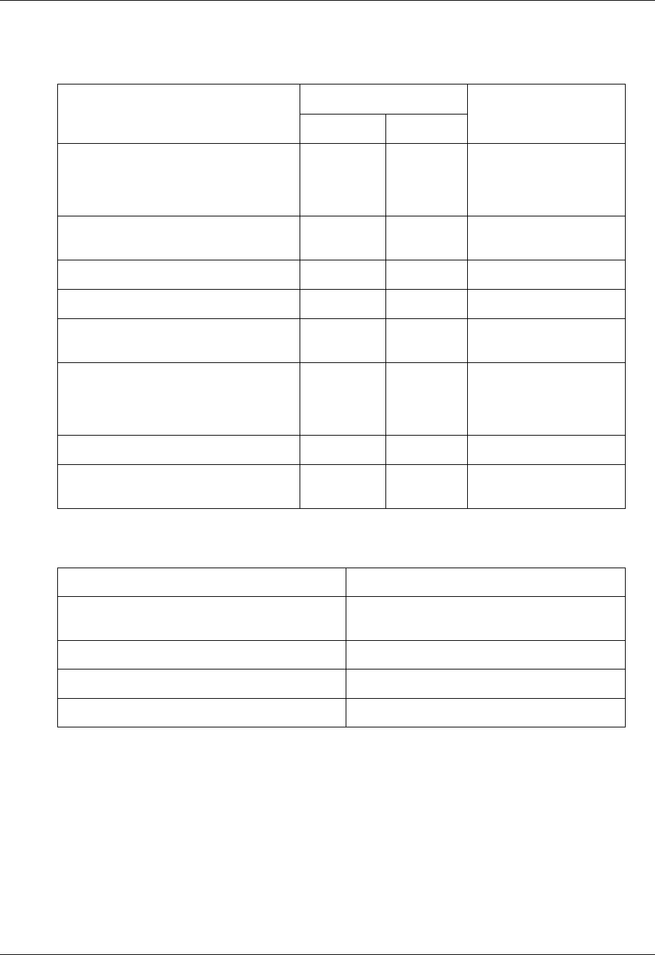
The table below shows warning conditions and the sounder types they trigger.
Warning Condition Sounder
Door tamper
Six invalid ID devices presented One tone beeping
Tamper connection broken
Door held open for longer than twice lock release time Two tone beeping
Note: The alarm is automatically cancelled after 15 to 20 minutes.
10. Using the KeyPAC Solo
Before the KeyPAC Solo can be used, user ID devices must be added to the database. Refer to
Section 12.2 Add/Delete Operation – Edit Mode for information on how to add ID devices.
Note: It is recommended that after an ID device is added to the database, its Shadow card
should be clearly identified and stored in a safe place.
11. Configuring the KeyPAC Solo
The following table lists KeyPAC Solo configuration options and the sections that describe how
to carry them out.
Configuration Option Section
Adding additional ID devices to the KeyPAC Solo Refer to Section 12.2 Add/Delete
Operation – Edit Mode
Adding additional Master Cards
1
Refer to Section 12.3 Erase Mode
Changing the Lock Release Time
1
Refer to Section 12.3 Erase Mode
Enabling Set / Rest Mode
1
Refer to Section 12.3 Erase Mode
1
CAUTION: Performing any of these actions will erase the KeyPAC Solo database.

KeyPAC Solo Modes
17348 Ver 2.0 8 Universal / Standard / VR KeyPAC Solo
12. KeyPAC Solo Modes
KeyPAC solo modes are indicated by the colour of the two LEDs present on the front of the unit.
Their locations are indicated in the diagrams in section 4.
On power up of the KeyPAC Solo the LEDs on the front of the reader will show red.
12.1 Normal Operation – Access Mode
Normal operation occurs after 1 or more Master Cards have been added to the KeyPAC Solo
database, and is characterised by the Status LED being red and the Edit LED not illuminated.
In normal operation mode a card presented to the unit that is:
• Valid (present in the KeyPAC Solo Database) will cause the Status LED to go from red to
green and the lock will operate. The LED stays green for the specified lock release time
(see Section 0 Changing Lock Release Time State)
• Invalid (not present in the KeyPAC Solo Database) will cause the Status LED to flash
red/green for a few seconds and a low pitch tone will indicate it is an invalid card.
Note: If a Master card is used then, when the Status LED goes green, and the Edit LED
briefly flashes yellow to indicate that the card is a Master.
12.2 Add/Delete Operation – Edit Mode
Edit mode is entered by presenting a Master card to the unit three times.
1. First presentation will cause the Edit LED to go yellow (ignore the Status LED).
2. After the yellow LED has gone out, present the Master card for a second time causing the
Edit LED to go yellow (ignore the Status LED).
3. After the Yellow LED has gone out, present the Master card to the unit for a third time. The
unit will indicate Edit Mode been entered by two “beeps”, the Status LED going out and the
Edit LED staying on.
Once in Edit mode, you can Add/Delete cards by presenting them to the unit.
Note: Do not leave an ID device within the reading range of the KeyPAC, otherwise it will be
repeatedly added and deleted.
12.2.1 Adding ID Devices
To add an ID device to the KeyPAC Solo database present it to the unit and its addition will be
indicated by the status LED turning green briefly, followed by a low/high tone.
12.2.2 Deleting ID Devices
To delete an ID device from the KeyPAC Solo Database present it to the unit and its deletion of
will be indicated by the status LED turning red briefly, followed by a high low tone.
If an ID device becomes lost, then it can be deleted from the KeyPAC solo database by
presenting its corresponding shadow card.
12.2.3 Exiting Edit Mode
Once ID devices have added/deleted as required, you can leave Edit mode by:
• Presenting the Master card to the unit
or
• Leaving the unit to time-out (20 seconds) causing it to return to Normal Operation
Mode.

KeyPAC Solo Modes
17348 Ver 2.0 9 Universal / Standard / VR KeyPAC Solo
12.3 Erase Mode
Erase Mode performs the following functions, in the listed order.
1. Erases the KeyPAC Solo Database.
2. Add new Master Cards.
3. Changes the Lock Release Time.
4. Enables Set / Reset Mode.
12.3.1 Entering Erase Mode
Erase Mode can be entered with or without the use of a Master Card.
Using a Master Card
To enter Erase Mode using a Master Card:
1. Tape the Master Card to the front of the KeyPAC Solo.
2. Push and hold the RTE button for at least 10 seconds.
3. Release the RTE button and remove the ID Device.
The unit will then enter Erase Mode.
Not Using a Master Card
To enter Erase Mode without using a Master Card:
1. Remove power from the unit.
2. Prop the door open (DC input floating) and remove power from the controller.
3. Short RTE (white), Bell (orange) and N/O (green).
4. Attach COM (blue) to ground (black) if not already connected.
5. Re-apply power.
The unit will then enter Erase Mode.
12.3.2 Erase Mode
Once erase mode has been entered the KeyPAC Solo will carry out the following functions one
after the other:
1. Database Erase.
2. Master Card Addition State.
3. Changing Lock Release Time State (optional).
4. Enabling Set/Reset State (optional).
Database Erase
This will occur immediately upon entering Erase Mode, and is indicated by the Edit LED flashing,
and upon completion the sounder will beep twice. This process may take up to 15 seconds.
After the erase is complete:
1. if Erase Mode was entered using a Master Card the KeyPAC Solo will enter into the
Master Card Addition State.
2. If Erase Mode was entered without using a Master Card:
a) Remove power and reconnect the wiring to the RTE, Alarm etc.
b) Re-apply power to start up in the Master Card Addition State.

KeyPAC Solo Modes
17348 Ver 2.0 10 Universal / Standard / VR KeyPAC Solo
Master Card Addition State
This state is entered after a database erase has occurred, and is indicated by the LEDs
alternately flashing: the Status LED will flash red and the Edit LED will flash yellow.
To add a master card:
1. Present an ID device to the KeyPAC Solo.
2. The KeyPAC Solo will then indicate successful addition of a master card by both LEDs
flashing simultaneously three times (the Status LED will flash green, and the Edit LED
flashes yellow), and the sounder emitting a low/high tone.
Changing Lock Release Time State
To change the lock release time (LRT), whilst in the Master Card Addition State:
1. Hold the RTE switch closed and count the number of beeps made by the KeyPAC
Solo; one beep is equal to one second.
2. When the desired LRT has been reached release the RTE switch to set the lock
release time.
Enabling Set/Reset Mode State
When Set/Reset Mode is enabled a valid ID device is used to unlock or lock the KeyPAC Solo
controlled door. A valid ID device will lock the door when unlocked, and unlock it when locked.
Note
Before using Set/Reset mode check that your lock is capable of constant operation.
To enter the enable Set/Reset state, whilst in the Master Card Addition state:
• Hold the RTE switch down and the KeyPAC Solo will begin to beep; after 15 beeps,
there will be a different pitched beep to indicate the state change.
12.3.3 Exiting Erase Mode
To exit Erase Mode (and retain any settings that have been made):
1. Remove and reconnect the power.
2. Allow the KeyPAC Solo to time out, which occurs after approximately 4 minutes.
Note
Erase Mode can only be exited when at least one Master Card has been added. If no
Master cards have been added:
• And power is disconnected and then reconnected the KeyPAC Solo will start up
again in the Add Master Card State.
• Erase Mode will not time out.
LED / Sounder Behaviour
17348 Ver 2.0 11 Universal / Standard / VR KeyPAC Solo
13. LED / Sounder Behaviour
The following table shows KeyPAC Solo operation modes and their accompanying LED and
Sounder states.
LED State
Mode Description Satus Edit Sounder
Add Master Mode
See the section “Operation – Add
Master Mode”
Flashing
red then
yellow N/A N/A
Erasing Database N/A Flashing
yellow Several low, low, high
beeps
Access Mode Default state Red N/A N/A
Access Mode Valid access Green
1
N/A N/A
Access Mode Invalid Access Red / green
flashing N/A Low tone for several
seconds
Edit Mode
See the section “Add / Delete
Operation – Edit Mode”
N/A Continuous
yellow N/A
Alarm Door tamper N/A N/A Continuous low beeping
Alarm Tamper connection broken N/A N/A Continuous low-high
beeping
1
The status LED will stay green for the specified lock release time, and will then return to red.
14. KeyPAC Solo Features
Integral LEDs: Status–Red/Green; Edit –Yellow Door Monitoring
Included in kit - two pre-programmed Master
cards External Alarm Output
Tamper facility Programmable Lock Time
Integral sounder Supports Fail Safe and Fail Secure locks
RTE Input Set/Reset option

Specification
17348 Ver 2.0 12 Universal / Standard / VR KeyPAC Solo
15. Specification
15.1 Dimensions
See diagrams in Section 4 KeyPAC Dimensions.
15.2 Reading Range
Standard Solo, typically 20cm for ISO cards.
Vandal Resistant Solo, typically 50mm for ISO cards.
The reading range will reduce if:
• there is metal in close proximity to the unit
• there is electromagnetic noise in the vicinity, for example, from cabling close to the
unit
• a noisy power supply is used, for example a switched mode PSU.
15.3 Power Requirements
Voltage
The units require the following power supply:
12V DC (nominal), tolerance +10.5V to +20V.
Current
Current consumption:
Idle: 85mA Relay activated: 120mA
Lock Relay
Single pole changeover 2A at 30V maximum
15.4 Environmental
Temperature: Operating -20°C to +55°C
Storage -30°C to +80°C
Humidity: Operating 0-90% RH at 30°C ±2C for 24 hours
15.5 Standards
Application of Council Directives 73/23/EEC
Standard(s) to which conformity is declared ETS 300.330, ETS 300.683
