ControlLogix System User Manual 1756 Um001 En P (Manual L7x)
User Manual:
Open the PDF directly: View PDF ![]() .
.
Page Count: 210 [warning: Documents this large are best viewed by clicking the View PDF Link!]
- 1756-UM001P-EN-P, ControlLogix System User Manual
- Important User Information
- Table of Contents
- Preface
- 1 - Install the 1756-L7x Controller
- 2 - Install the 1756-L6x Controller
- 3 - Start Using the Controller
- Make Connections
- Connect to the 1756-L7x Controller
- Connect to the 1756-L6x Controller
- Upgrade Controller Firmware
- Set the Communication Path
- Go Online with the Controller
- Download to the Controller
- Upload from the Controller
- Choose the Controller Operation Mode
- Load or Store to the Memory Card
- Use ControlLogix Energy Storage Modules (ESMs)
- Estimate the ESM Support of the WallClockTime
- Maintain the Battery (Only 1756-L6x Controllers)
- 4 - ControlLogix System and Controllers
- 5 - Communication Networks
- 6 - Serial Communication on 1756-L6x Controllers
- 7 - Manage Controller Communication
- 8 - I/O Modules
- 9 - Develop Motion Applications
- 10 - Develop Applications
- 11 - Using the PhaseManager Tool
- 12 - Redundant Systems
- A - Troubleshoot the Module
- Index
- Back Cover

ControlLogix System
Catalog Numbers 1756-L61, 1756-L62, 1756-L63, 1756-L63XT, 1756-L64, 1756-L65, 1756-L71, 1756-L72, 1756-L73,
1756-L73XT, 1756-L74, 1756-L75, 1756-L72EROM, 1756-L73EROM
User Manual
Original Instructions
Important User Information
Read this document and the documents listed in the additional resources section about installation, configuration, and
operation of this equipment before you install, configure, operate, or maintain this product. Users are required to
familiarize themselves with installation and wiring instructions in addition to requirements of all applicable codes, laws,
and standards.
Activities including installation, adjustments, putting into service, use, assembly, disassembly, and maintenance are
required to be carried out by suitably trained personnel in accordance with applicable code of practice.
If this equipment is used in a manner not specified by the manufacturer, the protection provided by the equipment may
be impaired.
In no event will Rockwell Automation, Inc. be responsible or liable for indirect or consequential damages resulting from
the use or application of this equipment.
The examples and diagrams in this manual are included solely for illustrative purposes. Because of the many variables and
requirements associated with any particular installation, Rockwell Automation, Inc. cannot assume responsibility or
liability for actual use based on the examples and diagrams.
No patent liability is assumed by Rockwell Automation, Inc. with respect to use of information, circuits, equipment, or
software described in this manual.
Reproduction of the contents of this manual, in whole or in part, without written permission of Rockwell Automation,
Inc., is prohibited
Throughout this manual, when necessary, we use notes to make you aware of safety considerations.
Labels may also be on or inside the equipment to provide specific precautions.
WARNING: Identifies information about practices or circumstances that can cause an explosion in a hazardous
environment, which may lead to personal injury or death, property damage, or economic loss.
ATTENTION: Identifies information about practices or circumstances that can lead to personal injury or death, property
damage, or economic loss. Attentions help you identify a hazard, avoid a hazard, and recognize the consequence.
IMPORTANT Identifies information that is critical for successful application and understanding of the product.
SHOCK HAZARD: Labels may be on or inside the equipment, for example, a drive or motor, to alert people that dangerous
voltage may be present.
BURN HAZARD: Labels may be on or inside the equipment, for example, a drive or motor, to alert people that surfaces may
reach dangerous temperatures.
ARC FLASH HAZARD: Labels may be on or inside the equipment, for example, a motor control center, to alert people to
potential Arc Flash. Arc Flash will cause severe injury or death. Wear proper Personal Protective Equipment (PPE). Follow ALL
Regulatory requirements for safe work practices and for Personal Protective Equipment (PPE).

Rockwell Automation Publication 1756-UM001P-EN-P - May 2017 3
Table of Contents
Preface . . . . . . . . . . . . . . . . . . . . . . . . . . . . . . . . . . . . . . . . . . . . . . . . . . . . . . . .9
Summary of Changes . . . . . . . . . . . . . . . . . . . . . . . . . . . . . . . . . . . . . . . . . . . 9
ControlLogix Controllers Overview . . . . . . . . . . . . . . . . . . . . . . . . . . . . . 9
Standard ControlLogix Controllers . . . . . . . . . . . . . . . . . . . . . . . . . 10
Redundant ControlLogix Controllers . . . . . . . . . . . . . . . . . . . . . . . 11
Extreme Environment ControlLogix Controllers . . . . . . . . . . . . 11
Armor ControlLogix Controllers . . . . . . . . . . . . . . . . . . . . . . . . . . . 11
Before You Begin. . . . . . . . . . . . . . . . . . . . . . . . . . . . . . . . . . . . . . . . . . . . . . 12
Required Software . . . . . . . . . . . . . . . . . . . . . . . . . . . . . . . . . . . . . . . . . 12
Additional Resources . . . . . . . . . . . . . . . . . . . . . . . . . . . . . . . . . . . . . . . . . . 13
Chapter 1
Install the 1756-L7x Controller Before You Begin. . . . . . . . . . . . . . . . . . . . . . . . . . . . . . . . . . . . . . . . . . . . . . 19
1756-L7x Controller Parts . . . . . . . . . . . . . . . . . . . . . . . . . . . . . . . . . . . . . 19
Parts Included with the 1756-L7x Controller . . . . . . . . . . . . . . . . 19
Parts Available for Use with the 1756-L7x Controller . . . . . . . . 20
1756-L7x Controller Installation . . . . . . . . . . . . . . . . . . . . . . . . . . . . . . . 20
Insert the Controller into the Chassis . . . . . . . . . . . . . . . . . . . . . . . . . . . 21
Insert the Key . . . . . . . . . . . . . . . . . . . . . . . . . . . . . . . . . . . . . . . . . . . . . . . . . 22
Install the SD Card. . . . . . . . . . . . . . . . . . . . . . . . . . . . . . . . . . . . . . . . . . . . 23
Remove the SD Card . . . . . . . . . . . . . . . . . . . . . . . . . . . . . . . . . . . . . . . . . . 25
Install the ESM . . . . . . . . . . . . . . . . . . . . . . . . . . . . . . . . . . . . . . . . . . . . . . . 26
Uninstall the ESM . . . . . . . . . . . . . . . . . . . . . . . . . . . . . . . . . . . . . . . . . . . . 27
Chapter 2
Install the 1756-L6x Controller Before You Begin. . . . . . . . . . . . . . . . . . . . . . . . . . . . . . . . . . . . . . . . . . . . . . 33
1756-L6x Controller Parts . . . . . . . . . . . . . . . . . . . . . . . . . . . . . . . . . . . . . 33
Parts Not Included with the 1756-L6x Controller. . . . . . . . . . . . 33
1756-L6x Controller Installation . . . . . . . . . . . . . . . . . . . . . . . . . . . . . . . 34
CompactFlash Card Installation and Removal . . . . . . . . . . . . . . . . . . . 34
Battery Connection and Replacement. . . . . . . . . . . . . . . . . . . . . . . . . . . 38
Insert the Controller into the Chassis . . . . . . . . . . . . . . . . . . . . . . . . . . . 40
Remove the Controller from the Chassis . . . . . . . . . . . . . . . . . . . . . . . . 42
Chapter 3
Start Using the Controller Make Connections . . . . . . . . . . . . . . . . . . . . . . . . . . . . . . . . . . . . . . . . . . . . 43
1756-L7x Connection Options . . . . . . . . . . . . . . . . . . . . . . . . . . . . . 43
1756-L6x Connection Options . . . . . . . . . . . . . . . . . . . . . . . . . . . . . 44
Connect to the 1756-L7x Controller. . . . . . . . . . . . . . . . . . . . . . . . . . . . 44
Configure the USB Driver . . . . . . . . . . . . . . . . . . . . . . . . . . . . . . . . . 45
Connect to the 1756-L6x Controller. . . . . . . . . . . . . . . . . . . . . . . . . . . . 47
Configure the Serial Driver. . . . . . . . . . . . . . . . . . . . . . . . . . . . . . . . . 48
Upgrade Controller Firmware. . . . . . . . . . . . . . . . . . . . . . . . . . . . . . . . . . 50
Determine Required Controller Firmware . . . . . . . . . . . . . . . . . . . 51

4Rockwell Automation Publication 1756-UM001P-EN-P - May 2017
Table of Contents
Obtain Controller Firmware . . . . . . . . . . . . . . . . . . . . . . . . . . . . . . . 52
Use ControlFLASH Software to Upgrade Firmware . . . . . . . . . 52
Use AutoFlash to Upgrade Firmware. . . . . . . . . . . . . . . . . . . . . . . . 57
Set the Communication Path . . . . . . . . . . . . . . . . . . . . . . . . . . . . . . . . . . 60
Go Online with the Controller . . . . . . . . . . . . . . . . . . . . . . . . . . . . . . . . . 61
Download to the Controller . . . . . . . . . . . . . . . . . . . . . . . . . . . . . . . . . . . 61
Use the Who Active Dialog Box to Download . . . . . . . . . . . . . . . 62
Use the Controller Status Menu to Download . . . . . . . . . . . . . . . 63
Upload from the Controller. . . . . . . . . . . . . . . . . . . . . . . . . . . . . . . . . . . . 63
Use the Who Active Dialog Box to Upload . . . . . . . . . . . . . . . . . . 63
Use the Controller Status Menu to Upload . . . . . . . . . . . . . . . . . . 64
Choose the Controller Operation Mode . . . . . . . . . . . . . . . . . . . . . . . . 65
Use the Mode Switch to Change the Operation Mode . . . . . . . . 65
Use Logix Designer to Change the Operation Mode. . . . . . . . . . 67
Load or Store to the Memory Card . . . . . . . . . . . . . . . . . . . . . . . . . . . . . 68
Store to the Memory Card . . . . . . . . . . . . . . . . . . . . . . . . . . . . . . . . . 68
Load from the Memory Card . . . . . . . . . . . . . . . . . . . . . . . . . . . . . . . 71
Other Memory Card Tasks. . . . . . . . . . . . . . . . . . . . . . . . . . . . . . . . . 73
Use ControlLogix Energy Storage Modules (ESMs) . . . . . . . . . . . . . . 73
Save the Program to On-board NVS Memory . . . . . . . . . . . . . . . . 74
Clear the Program from On-board NVS Memory . . . . . . . . . . . . 74
Estimate the ESM Support of the WallClockTime . . . . . . . . . . . . . . . 75
Maintain the Battery (Only 1756-L6x Controllers) . . . . . . . . . . . . . . 75
Check the Battery Status . . . . . . . . . . . . . . . . . . . . . . . . . . . . . . . . . . . 76
1756-BA1 or 1756-BATA Battery Life . . . . . . . . . . . . . . . . . . . . . . 76
1756-BATM Battery Module and Battery Life . . . . . . . . . . . . . . . 77
Estimate 1756-BA2 Battery Life . . . . . . . . . . . . . . . . . . . . . . . . . . . . 78
Estimate 1756-BA2 Battery Life After Warnings . . . . . . . . . . . . . 79
Battery Storage and Disposal . . . . . . . . . . . . . . . . . . . . . . . . . . . . . . . 80
Chapter 4
ControlLogix System and
Controllers
ControlLogix System . . . . . . . . . . . . . . . . . . . . . . . . . . . . . . . . . . . . . . . . . . 81
Configuration Options . . . . . . . . . . . . . . . . . . . . . . . . . . . . . . . . . . . . 81
Design a ControlLogix System . . . . . . . . . . . . . . . . . . . . . . . . . . . . . . . . . 84
ControlLogix Controller Features . . . . . . . . . . . . . . . . . . . . . . . . . . . . . . 85
System, Communication, and Programming Features. . . . . . . . . 85
Memory Options . . . . . . . . . . . . . . . . . . . . . . . . . . . . . . . . . . . . . . . . . . 86
Electronic Keying. . . . . . . . . . . . . . . . . . . . . . . . . . . . . . . . . . . . . . . . . . 87

Rockwell Automation Publication 1756-UM001P-EN-P - May 2017 5
Table of Contents
Chapter 5
Communication Networks Networks Available. . . . . . . . . . . . . . . . . . . . . . . . . . . . . . . . . . . . . . . . . . . . 89
EtherNet/IP Network Communication. . . . . . . . . . . . . . . . . . . . . . . . . 90
ControlLogix EtherNet/IP Module Features . . . . . . . . . . . . . . . . 91
ControlLogix EtherNet/IP Communication Modules. . . . . . . . 91
Software for EtherNet/IP Networks . . . . . . . . . . . . . . . . . . . . . . . . 92
Connections Over an EtherNet/IP Network. . . . . . . . . . . . . . . . . 92
Double Data Rate (DDR) Backplane Communication . . . . . . . 92
ControlNet Network Communication . . . . . . . . . . . . . . . . . . . . . . . . . 93
ControlLogix ControlNet Module Features . . . . . . . . . . . . . . . . . 94
ControlLogix ControlNet Modules. . . . . . . . . . . . . . . . . . . . . . . . . 95
Software for ControlNet Networks . . . . . . . . . . . . . . . . . . . . . . . . . 95
Connections Over a ControlNet Network. . . . . . . . . . . . . . . . . . . 96
DeviceNet Network Communication. . . . . . . . . . . . . . . . . . . . . . . . . . . 96
ControlLogix DeviceNet Module Features . . . . . . . . . . . . . . . . . . 97
ControlLogix DeviceNet Bridge Module and Linking Devices. 98
Software for DeviceNet Networks . . . . . . . . . . . . . . . . . . . . . . . . . . 98
Connections Over DeviceNet Networks . . . . . . . . . . . . . . . . . . . . 98
ControlLogix DeviceNet Module Memory . . . . . . . . . . . . . . . . . . 98
Data Highway Plus (DH+) Network Communication . . . . . . . . . . . 99
Communicate Over a DH+ Network . . . . . . . . . . . . . . . . . . . . . . 100
Universal Remote I/O (RIO) Communication . . . . . . . . . . . . . . . . . 101
Communicate over a Universal Remote I/O Network . . . . . . . 102
Foundation Fieldbus Communication . . . . . . . . . . . . . . . . . . . . . . . . . 102
HART Communication . . . . . . . . . . . . . . . . . . . . . . . . . . . . . . . . . . . . . . 104
Chapter 6
Serial Communication on
1756-L6x Controllers
1756-L6x Controller Serial Port . . . . . . . . . . . . . . . . . . . . . . . . . . . . . . . 105
ControlLogix Chassis Serial Communication Options. . . . . . . 106
Communication with Serial Devices . . . . . . . . . . . . . . . . . . . . . . . . . . . 106
DF1 Master Protocol . . . . . . . . . . . . . . . . . . . . . . . . . . . . . . . . . . . . . . . . . 106
DF1 Point to Point Protocol . . . . . . . . . . . . . . . . . . . . . . . . . . . . . . . . . . 107
DF1 Radio Modem Protocol . . . . . . . . . . . . . . . . . . . . . . . . . . . . . . . . . . 107
DF1 Radio Modem Advantages. . . . . . . . . . . . . . . . . . . . . . . . . . . . 108
DF1 Radio Modem Limitations . . . . . . . . . . . . . . . . . . . . . . . . . . . 108
DF1 Radio Modem Protocol Parameters . . . . . . . . . . . . . . . . . . . 109
DF1 Slave Protocol. . . . . . . . . . . . . . . . . . . . . . . . . . . . . . . . . . . . . . . . . . . 110
DH-485 Protocol . . . . . . . . . . . . . . . . . . . . . . . . . . . . . . . . . . . . . . . . . . . . 110
ASCII Protocol . . . . . . . . . . . . . . . . . . . . . . . . . . . . . . . . . . . . . . . . . . . . . . 111
Configure the 1756-L6x Controller for Serial Communication . . 112
Broadcast Messages Over a Serial Port. . . . . . . . . . . . . . . . . . . . . . . . . . 114
Configure Controller Serial Port Properties. . . . . . . . . . . . . . . . . 115
Program the Message Instruction . . . . . . . . . . . . . . . . . . . . . . . . . . 116
Modbus Support . . . . . . . . . . . . . . . . . . . . . . . . . . . . . . . . . . . . . . . . . . . . . 116

6Rockwell Automation Publication 1756-UM001P-EN-P - May 2017
Table of Contents
Chapter 7
Manage Controller
Communication
Connection Overview . . . . . . . . . . . . . . . . . . . . . . . . . . . . . . . . . . . . . . . . 117
Produce and Consume (Interlock) Data. . . . . . . . . . . . . . . . . . . . . . . . 118
Connection Requirements of a Produced or Consumed Tag . 118
Send and Receive Messages. . . . . . . . . . . . . . . . . . . . . . . . . . . . . . . . . . . . 120
Determine Whether to Cache Message Connections . . . . . . . . 120
Calculate Connection Use . . . . . . . . . . . . . . . . . . . . . . . . . . . . . . . . . . . . 121
Local Connections. . . . . . . . . . . . . . . . . . . . . . . . . . . . . . . . . . . . . . . . 121
Remote Connections . . . . . . . . . . . . . . . . . . . . . . . . . . . . . . . . . . . . . 122
Connections Example. . . . . . . . . . . . . . . . . . . . . . . . . . . . . . . . . . . . . 123
Chapter 8
I/O Modules Selecting ControlLogix I/O Modules . . . . . . . . . . . . . . . . . . . . . . . . . . 125
Local I/O Modules . . . . . . . . . . . . . . . . . . . . . . . . . . . . . . . . . . . . . . . . . . . 125
Add Local I/O to the I/O Configuration . . . . . . . . . . . . . . . . . . . 126
Remote I/O Modules. . . . . . . . . . . . . . . . . . . . . . . . . . . . . . . . . . . . . . . . . 127
Add Remote I/O to the I/O Configuration. . . . . . . . . . . . . . . . . 128
Distributed I/O . . . . . . . . . . . . . . . . . . . . . . . . . . . . . . . . . . . . . . . . . . . . . . 131
Add Distributed I/O to the I/O Configuration . . . . . . . . . . . . . 132
Reconfigure an I/O Module . . . . . . . . . . . . . . . . . . . . . . . . . . . . . . . . . . 134
Reconfigure an I/O Module Via the Module Properties. . . . . . 135
Reconfigure an I/O Module Via a Message Instruction . . . . . . 136
Add to the I/O Configuration While Online . . . . . . . . . . . . . . . . . . . 136
Modules and Devices That Can Be Added While Online . . . . 137
Online Additions - ControlNet Considerations. . . . . . . . . . . . . 137
Online Additions—EtherNet/IP Considerations . . . . . . . . . . . 140
Determine When Data Is Updated . . . . . . . . . . . . . . . . . . . . . . . . . . . . 141
Chapter 9
Develop Motion Applications Motion Control Options . . . . . . . . . . . . . . . . . . . . . . . . . . . . . . . . . . . . . 143
Motion Overview . . . . . . . . . . . . . . . . . . . . . . . . . . . . . . . . . . . . . . . . . . . . 144
Obtain Axis Information . . . . . . . . . . . . . . . . . . . . . . . . . . . . . . . . . . . . . 144
Program Motion Control . . . . . . . . . . . . . . . . . . . . . . . . . . . . . . . . . . . . . 145
Example . . . . . . . . . . . . . . . . . . . . . . . . . . . . . . . . . . . . . . . . . . . . . . . . . 146

Rockwell Automation Publication 1756-UM001P-EN-P - May 2017 7
Table of Contents
Chapter 10
Develop Applications Elements of a Control Application. . . . . . . . . . . . . . . . . . . . . . . . . . . . . 147
Tasks. . . . . . . . . . . . . . . . . . . . . . . . . . . . . . . . . . . . . . . . . . . . . . . . . . . . . . . . 148
Task Priority . . . . . . . . . . . . . . . . . . . . . . . . . . . . . . . . . . . . . . . . . . . . . 151
Programs . . . . . . . . . . . . . . . . . . . . . . . . . . . . . . . . . . . . . . . . . . . . . . . . . . . . 151
Scheduled and Unscheduled Programs . . . . . . . . . . . . . . . . . . . . . 153
Routines. . . . . . . . . . . . . . . . . . . . . . . . . . . . . . . . . . . . . . . . . . . . . . . . . . . . . 154
Parameters and Local Tags . . . . . . . . . . . . . . . . . . . . . . . . . . . . . . . . . . . . 155
Extended Properties . . . . . . . . . . . . . . . . . . . . . . . . . . . . . . . . . . . . . . 156
Access Extended Properties in Logic. . . . . . . . . . . . . . . . . . . . . . . . 156
Programming Languages . . . . . . . . . . . . . . . . . . . . . . . . . . . . . . . . . . . . . . 158
Add-On Instructions . . . . . . . . . . . . . . . . . . . . . . . . . . . . . . . . . . . . . . . . . 159
Access the Module Object. . . . . . . . . . . . . . . . . . . . . . . . . . . . . . . . . . . . . 160
Create the Add-On Instruction. . . . . . . . . . . . . . . . . . . . . . . . . . . . 160
Monitoring Controller Status . . . . . . . . . . . . . . . . . . . . . . . . . . . . . . . . . 161
Monitoring I/O Connections . . . . . . . . . . . . . . . . . . . . . . . . . . . . . . . . . 161
Determine If I/O Communication Has Timed Out . . . . . . . . . 163
Determine If I/O Communication to a Specific I/O
Module Has Timed Out . . . . . . . . . . . . . . . . . . . . . . . . . . . . . . . . . . 163
Interrupt the Execution of Logic and Execute the
Fault Handler . . . . . . . . . . . . . . . . . . . . . . . . . . . . . . . . . . . . . . . . . . . . 164
System Overhead Time Slice . . . . . . . . . . . . . . . . . . . . . . . . . . . . . . . . . . 165
Configure the System Overhead Time Slice. . . . . . . . . . . . . . . . . 166
Sample Controller Projects . . . . . . . . . . . . . . . . . . . . . . . . . . . . . . . . 167
Chapter 11
Using the PhaseManager Tool PhaseManager Overview . . . . . . . . . . . . . . . . . . . . . . . . . . . . . . . . . . . . . . 169
Minimum System Requirements. . . . . . . . . . . . . . . . . . . . . . . . . . . . . . . 171
State Model Overview . . . . . . . . . . . . . . . . . . . . . . . . . . . . . . . . . . . . . . . . 171
How Equipment Changes States. . . . . . . . . . . . . . . . . . . . . . . . . . . 172
Manually Change States. . . . . . . . . . . . . . . . . . . . . . . . . . . . . . . . . . . 173
PhaseManager Tool versus Other State Models . . . . . . . . . . . . . . . . . 174
Equipment Phase Instructions. . . . . . . . . . . . . . . . . . . . . . . . . . . . . . . . . 174
Chapter 12
Redundant Systems ControlLogix Redundancy Overview . . . . . . . . . . . . . . . . . . . . . . . . . . 175
System Requirements. . . . . . . . . . . . . . . . . . . . . . . . . . . . . . . . . . . . . . . . . 177
System Considerations. . . . . . . . . . . . . . . . . . . . . . . . . . . . . . . . . . . . . . . . 178
Enhanced Versus Standard Redundancy . . . . . . . . . . . . . . . . . . . . 179
Build a Redundant System . . . . . . . . . . . . . . . . . . . . . . . . . . . . . . . . . . . . 179
ControlNet Considerations in Redundant Systems . . . . . . . . . . . . . 180
EtherNet/IP Considerations in Redundant Systems. . . . . . . . . . . . . 180
IP Address Swapping . . . . . . . . . . . . . . . . . . . . . . . . . . . . . . . . . . . . . 180
Redundancy and Scan Time. . . . . . . . . . . . . . . . . . . . . . . . . . . . . . . . . . . 181

8Rockwell Automation Publication 1756-UM001P-EN-P - May 2017
Table of Contents
Appendix A
Troubleshoot the Module Use Logix Designer Application for Troubleshooting . . . . . . . . . . . 183
Fault Type Determination . . . . . . . . . . . . . . . . . . . . . . . . . . . . . . . . 185
1756-L7x Controller Status Display and Indicators . . . . . . . . . . . . . 186
1756-L7x Controller Status Display . . . . . . . . . . . . . . . . . . . . . . . . . . . 186
General Status Messages. . . . . . . . . . . . . . . . . . . . . . . . . . . . . . . . . . . 186
Fault Messages . . . . . . . . . . . . . . . . . . . . . . . . . . . . . . . . . . . . . . . . . . . 188
Major Fault Messages . . . . . . . . . . . . . . . . . . . . . . . . . . . . . . . . . . . . . 189
I/O Fault Codes. . . . . . . . . . . . . . . . . . . . . . . . . . . . . . . . . . . . . . . . . . 191
1756-L7x Controller Status Indicators . . . . . . . . . . . . . . . . . . . . . . . . . 194
RUN Indicator. . . . . . . . . . . . . . . . . . . . . . . . . . . . . . . . . . . . . . . . . . . 194
FORCE Indicator . . . . . . . . . . . . . . . . . . . . . . . . . . . . . . . . . . . . . . . . 194
SD Indicator . . . . . . . . . . . . . . . . . . . . . . . . . . . . . . . . . . . . . . . . . . . . . 195
OK Indicator . . . . . . . . . . . . . . . . . . . . . . . . . . . . . . . . . . . . . . . . . . . . 195
1756-L6x Status Indicators. . . . . . . . . . . . . . . . . . . . . . . . . . . . . . . . . . . . 196
RUN Indicator. . . . . . . . . . . . . . . . . . . . . . . . . . . . . . . . . . . . . . . . . . . 196
I/O Indicator . . . . . . . . . . . . . . . . . . . . . . . . . . . . . . . . . . . . . . . . . . . . 196
FORCE Indicator . . . . . . . . . . . . . . . . . . . . . . . . . . . . . . . . . . . . . . . . 197
RS232 Indicator. . . . . . . . . . . . . . . . . . . . . . . . . . . . . . . . . . . . . . . . . . 197
BAT Indicator . . . . . . . . . . . . . . . . . . . . . . . . . . . . . . . . . . . . . . . . . . . 197
OK Indicator . . . . . . . . . . . . . . . . . . . . . . . . . . . . . . . . . . . . . . . . . . . . 198
Index . . . . . . . . . . . . . . . . . . . . . . . . . . . . . . . . . . . . . . . . . . . . . . . . . . . . . . . 199

Rockwell Automation Publication 1756-UM001P-EN-P - May 2017 9
Preface
This publication provides this information:
• Design and planning considerations
• Installation procedures
• Configuration procedures
• Maintenance and troubleshooting methods
This publication is designed for use by anyone responsible for planning and
implementing a ControlLogix® system:
• Application engineers
• Control engineers
• Instrumentation technicians
The contents of this publication are for anyone who already has an
understanding of Logix5000™ control systems, programming techniques, and
communication networks.
Summary of Changes We’ve added the 1756-L72EROM and 1756-L73EROM Armor™
ControlLogix controllers to this user manual.
ControlLogix Controllers
Overview
There are five types of ControlLogix controllers available. These types include
the following:
• Standard ControlLogix controllers
• Extreme environment ControlLogix controllers
• Armor ControlLogix controllers
• Standard GuardLogix® controllers
• Armor GuardLogix controllers
This manual explains how to use standard, extreme environment, and Armor
ControlLogix controllers.
10 Rockwell Automation Publication 1756-UM001P-EN-P - May 2017
Preface
For detailed information about GuardLogix and Armor GuardLogix safety
controllers, see the following publications.
Standard ControlLogix Controllers
Two lines of standard ControlLogix controllers are now available. These
controllers are identified as 1756-L6x controllers and 1756-L7x controllers
according to abbreviations of their full catalog numbers.
The standard ControlLogix controllers share many similar features, but also
have some differences. Table 2 provides a brief overview the differences
between the controllers. For further details about these features and
differences, see the appropriate chapters of this manual.
For information on using ControlLogix controllers in SIL 2 applications, see
the Using ControlLogix in SIL 2 Applications Safety Reference Manual,
publication 1756-RM001.
Resource Description
GuardLogix 5570 Controllers User Manual,
publication 1756-UM022
Provides information on how to install, configure, and
operate GuardLogix 5570 controllers in Studio 5000®
projects, version 21 or later.
GuardLogix 5570 and Compact GuardLogix 5370
Controller Systems Reference Manual, publication
1756-RM099
Provides information on how to meet safety application
requirements for GuardLogix 5570 controllers in
Studio 5000 projects, version 21 or later.
GuardLogix Controllers User Manual, publication
1756-UM020
Provides information on how to install, configure, and
operate GuardLogix 5560 and GuardLogix 5570 controllers
in RSLogix 5000® projects, version 20 or earlier.
GuardLogix Controller Systems Safety Reference
Manual, publication 1756-RM093
Provides information on how to meet safety application
requirements for GuardLogix 5560 and GuardLogix 5570
controllers in RSLogix 5000 projects, version 20 or earlier.
GuardLogix Safety Application Instruction Set Safety
Reference Manual, publication 1756-RM095
Provides programmers with details about the GuardLogix
safety application instruction set.
Table 1 - ControlLogix Catalog Numbers
Abbreviated Cat. No. Cat. No.
1756-L6x1756-L61, 1756-L62,1756-L63, 1756-L64,1756-L65
1756-L7x 1756-L71, 1756-L72, 1756-L73,1756-L74, 1756-L75
Table 2 - Differences between 1756-L7x and 1756-L6x Controllers
Feature 1756-L7x1756-L6x
Clock support and backup used for
memory retention at powerdown
Energy Storage Module (ESM) Battery
Communication ports (built-in) USB Serial
Connections, controller 500 250
Memory, nonvolatile Secure Digital (SD) card CompactFlash card
Status display and status indicators Scrolling status display and four
status indicators
Six status indicators
Unconnected buffer defaults 20 (40, max) 10 (40, max)

Rockwell Automation Publication 1756-UM001P-EN-P - May 2017 11
Preface
Redundant ControlLogix Controllers
Certain ControlLogix controllers are also supported for use in redundant
systems. For more information about controllers and redundant systems, see
Chapter 12.
Extreme Environment ControlLogix Controllers
The extreme environment ControlLogix controllers, catalog numbers
1756-L73XT and 1756-L63XT, provide the same functionality as the 1756-
L73 and 1756-L63 controllers, but are designed to withstand temperatures
-25…+70 °C (-13…+158 °F).
Armor ControlLogix Controllers
The Armor ControlLogix controller combines a 1756-L72 or 1756-L73
ControlLogix controller with two EtherNet/IP DLR-capable 1756-EN3TR
communication modules in an IP67-rated housing for mounting on a machine.
For more information about the Armor ControlLogix controllers, catalog
numbers 1756-L72EROM and 1756-L73EROM, refer to the Armor
ControlLogix Controller Installation Instructions, publication 1756-IN061.
Though the 1756-L72EROM and 1756-L73EROM controllers have
functionality identical to that of the 1756-L72 and 1756-L73 controllers, the
Armor controller energy storage modules (ESM) cannot be removed or
replaced.
12 Rockwell Automation Publication 1756-UM001P-EN-P - May 2017
Preface
Before You Begin Before you begin using your ControlLogix controller, verify that you have the
applications that are required to configure and program the controller.
Required Software
Use Table 3 to identify the minimum software versions that are required to use
your ControlLogix controller.
Table 3 - Required Software for Controller Use
Cat. No. Studio 5000 Environment RSLogix 5000 Software RSLinx® Classic
1756-L61/A — Version 12.06.00 or later Any version
1756-L61/B — Version 13.04.00 or later
1756-L62/A — Version 12.06.00 or later
1756-L62/B — Version 13.04.00 or later
1756-L63/A — • If not using a CompactFlash
card, version 10.07.00 or
later
• If using a CompactFlash
card, version 11.16.00 or
later
1756-L63/B — Version 13.04.00 or later
1756-L63XT/B — Version 13.04.00 or later Version 2.55.00 or later
1756-L64/B — Version 16.03.00 or later Any version
1756-L65/B — Version 17.01.02 or later
1756-L71 Version 21.00.00 or later Version 20.01.02 Version 2.59.00 or later
1756-L72 Version 19.01.00 or later Version 2.57.00 or later
1756-L73
1756-L73XT
1756-L74
1756-L75
1756-L72EROM 2.59.02 or later
1756-L73EROM
Rockwell Automation Publication 1756-UM001P-EN-P - May 2017 13
Preface
Additional Resources These documents contain additional information concerning related products
from Rockwell Automation.
Resource Description
1756 ControlLogix and GuardLogix Controllers Technical
Data, publication 1756-TD001
Provides specifications for ControlLogix and GuardLogix
controllers.
1756 ControlLogix I/O Specifications Technical Data,
publication 1756-TD002
Provides specifications for ControlLogix I/O modules.
Armor ControlLogix Controllers Installation Instructions,
publication 1756-IN061
Provides information about how to install the Armor
ControlLogix controllers.
ControlLogix Battery Module Installation Instructions,
publication 1756-IN576
Provides information for battery module installation.
ControlLogix Chassis and Power Supply Installation
Instructions, publication 1756-IN005
Describes how to install and troubleshoot standard and
ControlLogix-XT™ versions of the 1756 chassis and
power supplies, including redundant power supplies.
ControlLogix Analog I/O Modules User Manual,
publication 1756-UM009
Provides information about analog I/O module
configuration properties.
ControlLogix Configurable Flowmeter Module User
Manual, publication 1756-UM010
Provides information about configurable flowmeter
configuration properties.
ControlLogix Data Highway Plus-Remote I/O
Communication Interface Module User Manual,
publication 1756-UM514
Provides information about Data Highway Plus™
communication and remote I/O communication module
configuration properties.
ControlLogix DH-485 Communication Module User
Manual, publication 1756-UM532
Describes how to connect a 1756-DH485 module to a
DH-485 network with multiple controllers.
ControlLogix Digital I/O Modules User Manual,
publication 1756-UM058
Provides information about digital I/O module
configuration properties.
ControlLogix Enhanced Redundancy System User
Manual, publication 1756-UM535
Provides detailed information about ControlLogix
redundancy systems.
ControlLogix HART Analog I/O Modules User Manual,
publication 1756-UM533
Describes how to use HART analog I/O modules.
ControlLogix High-speed Analog I/O Module User
Manual, publication 1756-UM005
Provides information about high-speed analog I/O
module configuration properties.
ControlLogix High-speed Counter Module User Manual,
publication 1756-UM007
Provides information about high-speed counter-module
configuration properties.
ControlLogix Low-speed Counter Module User Manual,
publication 1756-UM536
Provides information about low-speed counter-module
configuration properties.
ControlLogix Peer I/O Control Application Technique,
publication 1756-AT016
Describes typical peer control applications and provides
details about how to configure I/O modules for peer
control operation.
ControlLogix Programmable Limit Switch Module User
Manual, publication 1756-UM002
Provides information about programmable limit switch
configuration properties.
ControlLogix Redundancy System User Manual,
publication 1756-UM523
Provides information ControlLogix standard redundancy
systems.
ControlLogix Remote I/O Communication Module User
Manual, publication 1756-UM534
Provides information for remote I/O network
communication configuration.
ControlLogix SIL2 System Configuration Using RSLogix
5000 Subroutines Application Technique, publication
1756-AT010
Provides information about ControlLogix SIL2- certified
fault-tolerant systems.
ControlLogix SIL2 System Configuration Using SIL2
Add-On Instructions Application Technique, publication
1756-AT012
Provides information about ControlLogix SIL2- certified
fault-tolerant systems.
ControlLogix System Selection Guide, publication
1756-SG001
Describes how to design and select components for your
ControlLogix system.
14 Rockwell Automation Publication 1756-UM001P-EN-P - May 2017
Preface
ControlNet Network Configuration User Manual,
publication CNET-UM001
Describes how to use ControlNet modules.
DeviceNet Network Configuration User Manual,
publication DNET-UM004
Provides information about DeviceNet modules and
devices.
Ethernet Design Considerations Reference Manual,
publication ENET-RM002
Provides additional information about network design
for your system.
EtherNet/IP and ControlNet to FOUNDATION Fieldbus
Linking Device User Manual, publication 1788-UM057
Describes in detail how to use the available Foundation
Fieldbus devices.
EtherNet/IP Network Configuration User Manual,
publication ENET-UM001
Provides information about EtherNet/IP communication
modules.
FOUNDATION Fieldbus Design Considerations Reference
Manual, publication PROCES-RM005
Describes in detail how to use the available Foundation
Fieldbus devices.
Guidelines for Handling Lithium Batteries Technical
Data, publication AG-5.4
Describes how to store, handle, transport, and dispose
of lithium batteries.
Integrated Architecture and CIP Sync Configuration
Application Technique, publication IA-AT003
Describes how to configure CIP Sync with Integrated
Architecture® products and applications.
Integrated Motion on the EtherNet/IP Network
Configuration and Startup User Manual, publication
MOTION-UM003
Details how to design your ControlLogix system for
Integrated Motion on the EtherNet/IP network
applications.
Logix5000 Controllers Add-On Instructions
Programming Manual, publication 1756-PM010
Describes in detail how to use add-on instructions.
Logix5000 Controllers General Instructions Reference
Manual, publication 1756-RM003
Provides more information about GSV instructions, SSV
instructions, objects, and attributes.
Logix5000 Controllers I/O and Tag Data Programming
Manual, publication 1756-PM004
Describes how to create and configure program tags for
optimal task and program execution.
Logix5000 Controllers Major, Minor and I/O Faults
Programming Manual, publication 1756-PM014
Provides more information for I/O faults.
Logix5000 Controllers Messages Programming Manual,
publication 1756-PM012
Provides information for controller messages.
Logix5000 Controllers Motion Instructions Reference
Manual, publication MOTION-RM002
Provides programmers with details about the motion
instructions that are available for a Logix5000 controller.
Logix5000 Controllers Nonvolatile Memory Card
Programming Manual, publication 1756-PM017
Provides information about changing the project that is
available to load from nonvolatile memory,
Logix5000 Controllers Produced and Consumed Tags
Programming Manual, publication 1756-PM011
Provides more information for produced and consumed
tags.
Motion Coordinate System User Manual, publication
MOTION-UM002
Details how to create and configure a coordinated
motion application system.
PhaseManager™ User Manual, publication LOGIX-
UM001
Provides more information about instructions for use
with equipment phases.
SERCOS and Analog Motion Configuration and Startup
User Manual, publication MOTION-UM001
Details how to configure a sercos motion application
system.
Using ControlLogix in SIL2 Applications Safety Reference
Manual, publication 1756-RM001
Provides specific configuration and programming
considerations.
Using Logix5000 Controllers as Masters or Slaves on
Modbus Application Solution, publication CIG-AP129
Describes how to use Modbus sample programs.
Resource Description

Rockwell Automation Publication 1756-UM001P-EN-P - May 2017 15
Preface
You can view or download publications at
http://www.rockwellautomation.com/literature/. To order paper copies of
technical documentation, contact your local Allen-Bradley distributor or
Rockwell Automation sales representative.
Industrial Automation Wiring and Grounding Guidelines
Application Data, publication 1770-4.1
Provides general guidelines to install a Rockwell
Automation industrial system.
Product Certifications website,
http://www.rockwellautomation.com/
rockwellautomation/certification/overview.page
Provides declarations of conformity, certificates, and
other certification details.
Programmable Controllers Battery Reference,
http://www.ab.com/programmablecontrol/
batteries.html
Provides Material Safety Data Sheets (MSDS) for
individual replacement batteries.
Resource Description

16 Rockwell Automation Publication 1756-UM001P-EN-P - May 2017
Preface
Notes:
Rockwell Automation Publication 1756-UM001P-EN-P - May 2017 17
Chapter 1
Install the 1756-L7x Controller
Topic Page
Before You Begin 19
1756-L7x Controller Parts 19
1756-L7x Controller Installation 20
Insert the Controller into the Chassis 21
Insert the Key 22
Install the SD Card 23
Remove the SD Card 25
Install the ESM 26
Uninstall the ESM 27
ATTENTION: Personnel responsible for the application of safety-related programmable electronic systems (PES) shall be aware
of the safety requirements in the application of the system and shall be trained in using the system.
Table 4 - Environment and Enclosure
ATTENTION:
This equipment is intended for use in a Pollution Degree 2 industrial environment, in overvoltage Category II applications
(as defined in IEC 60664-1), at altitudes up to 2000 m (6562 ft) without derating.
This equipment is not intended for use in residential environments and may not provide adequate protection to radio
communication services in such environments.
This equipment is supplied as open-type equipment. It must be mounted within an enclosure that is suitably designed for those
specific environmental conditions that will be present and appropriately designed to prevent personal injury resulting from
accessibility to live parts. The enclosure must have suitable flame-retardant properties to prevent or minimize the spread of flame,
complying with a flame spread rating of 5VA or be approved for the application if nonmetallic. The interior of the enclosure must be
accessible only by the use of a tool. Subsequent sections of this publication may contain additional information regarding specific
enclosure type ratings that are required to comply with certain product safety certifications.
In addition to this publication, see the following:
• Industrial Automation Wiring and Grounding Guidelines, Rockwell Automation publication 1770-4.1, for additional installation
requirements
• NEMA Standard 250 and IEC 60529, as applicable, for explanations of the degrees of protection provided by enclosure
18 Rockwell Automation Publication 1756-UM001P-EN-P - May 2017
Chapter 1 Install the 1756-L7x Controller
Table 5 - North American Hazardous Location Approval
The following information applies when operating this equipment in
hazardous locations.
Informations sur l’utilisation de cet équipement en environnements
dangereux.
Products marked "CL I, DIV 2, GP A, B, C, D" are suitable for use in Class I Division 2
Groups A, B, C, D, Hazardous Locations and nonhazardous locations only. Each product is
supplied with markings on the rating nameplate indicating the hazardous location
temperature code. When combining products within a system, the most adverse
temperature code (lowest "T" number) may be used to help determine the overall
temperature code of the system. Combinations of equipment in your system are subject
to investigation by the local Authority Having Jurisdiction at the time of installation.
Les produits marqués "CL I, DIV 2, GP A, B, C, D" ne conviennent qu'à une utilisation en
environnements de Classe I Division 2 Groupes A, B, C, D dangereux et non dangereux.
Chaque produit est livré avec des marquages sur sa plaque d'identification qui
indiquent le code de température pour les environnements dangereux. Lorsque
plusieurs produits sont combinés dans un système, le code de température le plus
défavorable (code de température le plus faible) peut être utilisé pour déterminer le
code de température global du système. Les combinaisons d'équipements dans le
système sont sujettes à inspection par les autorités locales qualifiées au moment de
l'installation.
WARNING: EXPLOSION HAZARD
• Do not disconnect equipment unless power has been removed or
the area is known to be nonhazardous.
• Do not disconnect connections to this equipment unless power
has been removed or the area is known to be nonhazardous.
Secure any external connections that mate to this equipment by
using screws, sliding latches, threaded connectors, or other
means provided with this product.
• Substitution of components may impair suitability for Class I,
Division 2.
• If this product contains batteries, they must only be changed in
an area known to be nonhazardous.
WARNING: RISQUE D’EXPLOSION
• Couper le courant ou s'assurer que l'environnement est classé
non dangereux avant de débrancher l'équipement.
• Couper le courant ou s'assurer que l'environnement est classé
non dangereux avant de débrancher les connecteurs. Fixer tous
les connecteurs externes reliés à cet équipement à l'aide de vis,
loquets coulissants, connecteurs filetés ou autres moyens fournis
avec ce produit.
• La substitution de composants peut rendre cet équipement
inadapté à une utilisation en environnement de Classe I,
Division 2.
• S'assurer que l'environnement est classé non dangereux avant
de changer les piles.
Table 6 - European Hazardous Location Approval
The following applies when the product bears the Ex Marking.
This equipment is intended for use in potentially explosive atmospheres as defined by European Union Directive 94/9/EC and has been found to comply with the Essential Health
and Safety Requirements relating to the design and construction of Category 3 equipment intended for use in Zone 2 potentially explosive atmospheres, given in Annex II to this
Directive.
Compliance with the Essential Health and Safety Requirements has been assured by compliance with EN 60079-15 and EN 60079-0.
ATTENTION: This equipment is not resistant to sunlight or other sources of UV radiation.
WARNING:
• This equipment shall be mounted in an ATEX certified enclosure with a minimum ingress protection rating of at least IP54
(as defined in IEC60529) and used in an environment of not more than Pollution Degree 2 (as defined in IEC 60664-1) when
applied in Zone 2 environments. The enclosure must utilize a tool removable cover or door.
• This equipment shall be used within its specified ratings defined by Rockwell Automation.
• This equipment must be used only with ATEX certified Rockwell Automation backplanes.
• Secure any external connections that mate to this equipment by using screws, sliding latches, threaded connectors, or other
means provided with this product.
• Do not disconnect equipment unless power has been removed or the area is known to be nonhazardous.
Rockwell Automation Publication 1756-UM001P-EN-P - May 2017 19
Install the 1756-L7x Controller Chapter 1
Before You Begin See 1756-IN005 to install a ControlLogix® chassis and power supply before
you install your controller and power supply.
1756-L7x Controller Parts These sections describe parts that are included with the L7x controllers and
available accessory parts.
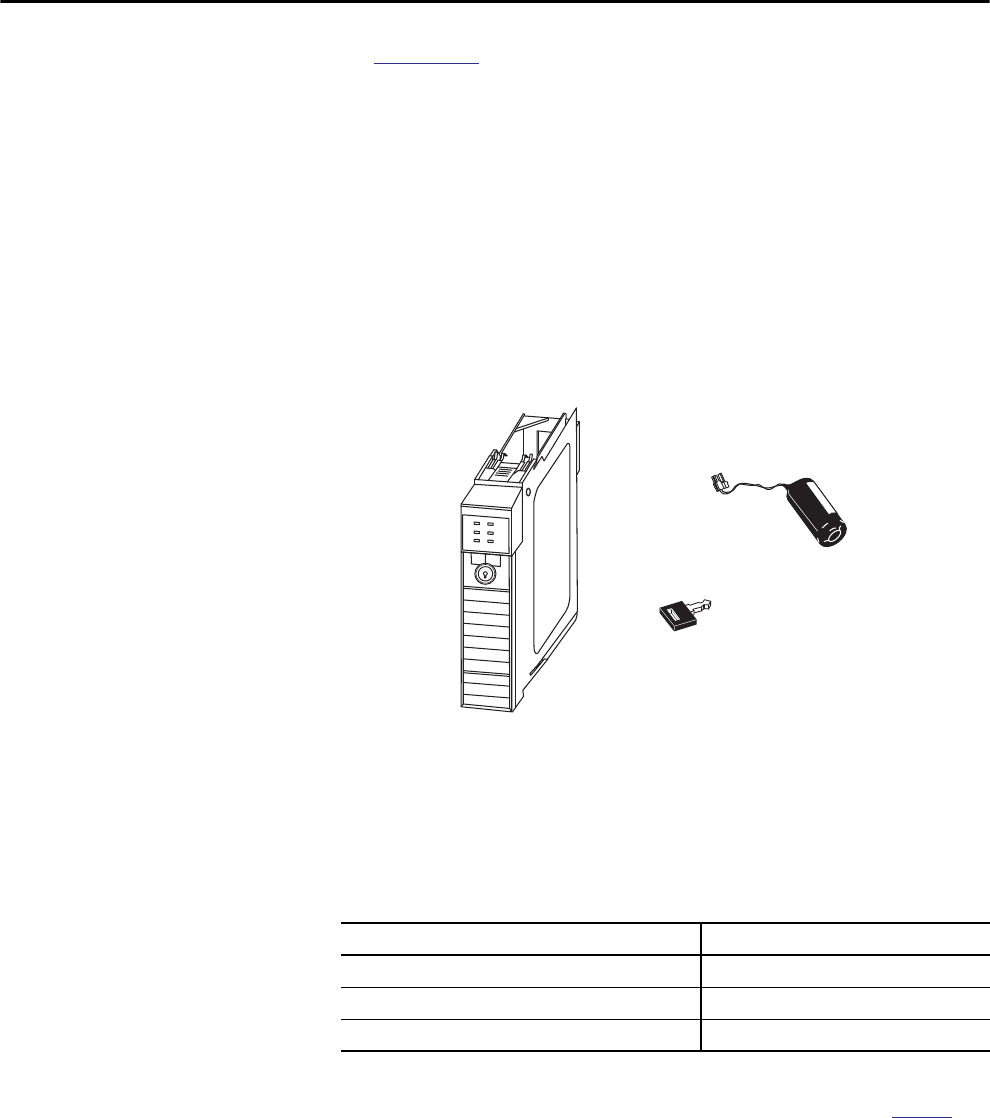
Parts Included with the 1756-L7x Controller
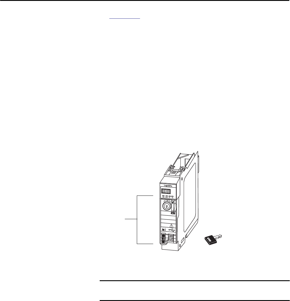
These parts are included with the controller:
• 1756-ESMCAP capacitor-based energy storage module (ESM)
• 1784-SD1 Secure Digital (SD) card, 1 GB
• 1747-KY controller key
Figure 1 - Parts with the 1756-L7x Controller
1756-ESMCAP
(installed)
1747-KY Key
SD Card (installed)
IMPORTANT The 1756-L7x controllers ship with an SD card installed. We recommend that
you leave the SD card installed.
20 Rockwell Automation Publication 1756-UM001P-EN-P - May 2017
Chapter 1 Install the 1756-L7x Controller
Parts Available for Use with the 1756-L7x Controller
You can choose to use the parts included with the controller and these parts
specific to your application.
.
1756-L7x Controller
Installation
These sections explain how to install the 1756-L7x controller. To install the
1756-L7x controller, complete the tasks summarized in this table.
If your application requires Then use this part
USB connection from a computer to the controller USB cable(1)
(1) The USB port is intended only for temporary local programming purposes and not intended for permanent connection. The USB
cable is not to exceed 3.0 m (9.84 ft) and must not contain hubs.
Nonvolatile memory 1784-SD1 (1 GB) or 1784-SD2 (2 GB)
ESM without WallClockTime back-up power 1756-ESMNSE
This ESM does not have WallClockTime back-up power.
Use this ESM if your application requires that the
installed ESM deplete its residual stored energy to 40 μJ
or less before transporting it into or out of your
application.(2) Additionally, you can use this ESM with
only a 1756-L73 (8 MB) or smaller memory-sized
controller.
(2) For information about the hold-up time of the ESMs, see Estimate the ESM Support of the WallClockTime on page 75 and stored
energy depletion rate on page 27.
ESM that secures the controller by blocking the USB
connection and SD card use(2)
This ESM provides your application an enhanced degree
of security.
1756-ESMNRM
WARNING: Do not use the USB port in hazardous locations.
ATTENTION:
• The USB port is intended only for temporary local programming purposes
and not intended for permanent connection.
• The USB cable is not to exceed 3.0 m (9.84 ft) and must not contain hubs.
Task Page
Insert the Controller into the Chassis 21
Insert the Key 22
Install the SD Card 23
Remove the SD Card 25
Install the ESM 26
Rockwell Automation Publication 1756-UM001P-EN-P - May 2017 21
Install the 1756-L7x Controller Chapter 1
Insert the Controller
into the Chassis
When installing a ControlLogix controller, you can do the following:
• Place the controller in any slot.
• Use multiple controllers in the same chassis.
You can install or remove a ControlLogix controller while chassis power is on
and the system is operating.
WARNING: When you insert or remove the module while backplane power
is on, an electrical arc can occur. This could cause an explosion in hazardous
location installations.
Be sure that power is removed or the area is nonhazardous before proceeding.
Repeated electrical arcing causes excessive wear to contacts on both the
controller and its mating connector on the chassis. Worn contacts may create
electrical resistance that can affect controller operation.
Table 7 - Prevent Electrostatic Discharge
ATTENTION: This equipment is sensitive to electrostatic discharge, which
can cause internal damage and affect normal operation. Follow these
guidelines when you handle this equipment:
• Touch a grounded object to discharge potential static.
• Wear an approved grounding wriststrap.
• Do not touch connectors or pins on component boards.
• Do not touch circuit components inside the equipment.
• Use a static-safe workstation, if available.
• Store the equipment in appropriate static-safe packaging when not in use.
IMPORTANT The ESM begins charging when one of these actions occurs:
• The controller and ESM are installed into a powered chassis.
• Power is applied to the chassis that contains a controller with the ESM
installed.
• An ESM is installed into a powered controller.
After power is applied, the ESM charges for up to two minutes as indicated
by CHRG or ESM Charging on the status display.
22 Rockwell Automation Publication 1756-UM001P-EN-P - May 2017
Chapter 1 Install the 1756-L7x Controller
1. Align the circuit board with the top and bottom guides in the chassis.
2. Slide the module into the chassis until it snaps into place.
3. Verify that the controller is flush with the power supply or other
installed modules.
After you have inserted the controller into the chassis, reference the
Troubleshoot the Module on page 183 for information to interpret the status
indicators.
Insert the Key After the controller is installed, insert the key.
31997-M
Top Circuit Board
Aligned
Bottom Circuit Board
Aligned
32001-M
Rockwell Automation Publication 1756-UM001P-EN-P - May 2017 23
Install the 1756-L7x Controller Chapter 1
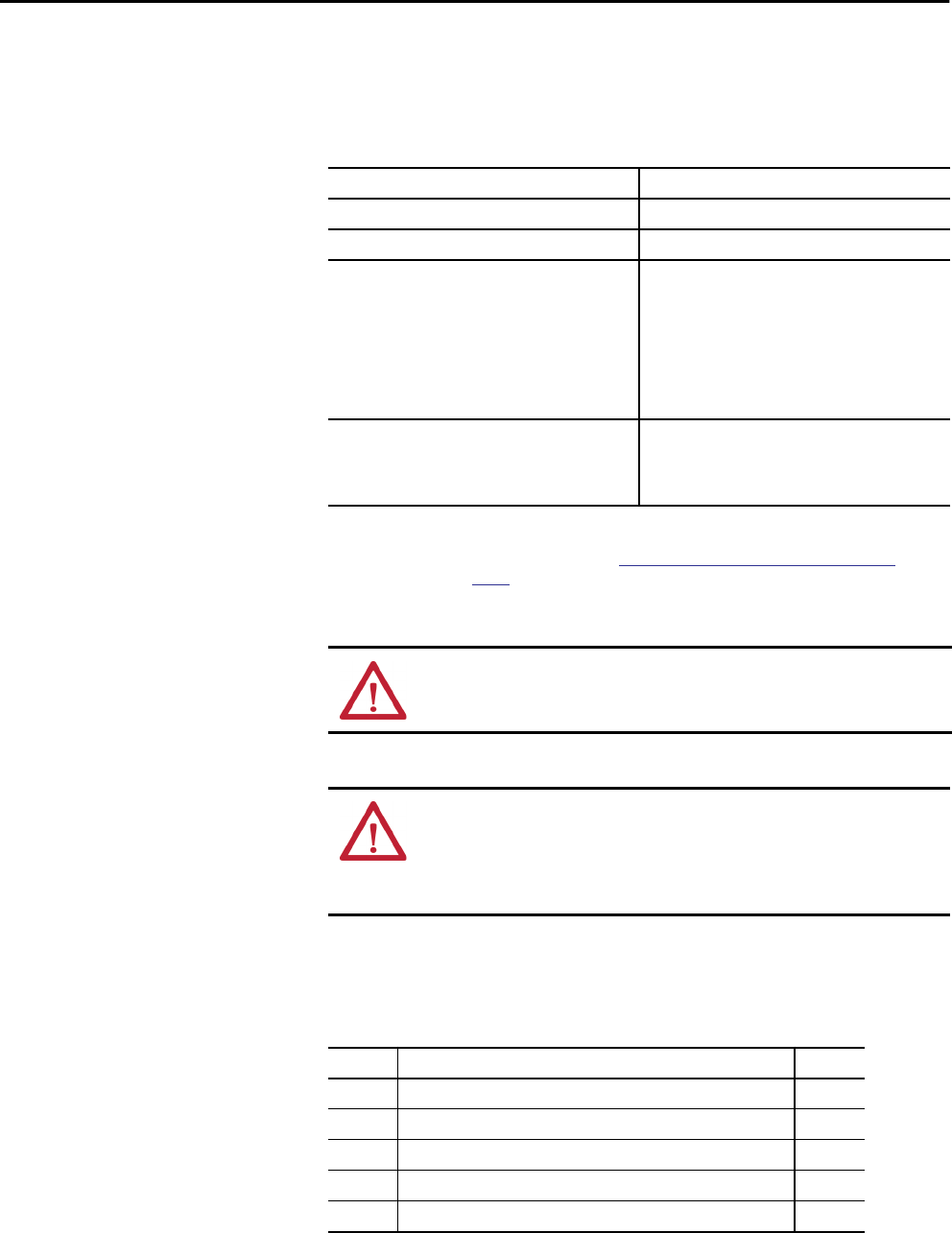
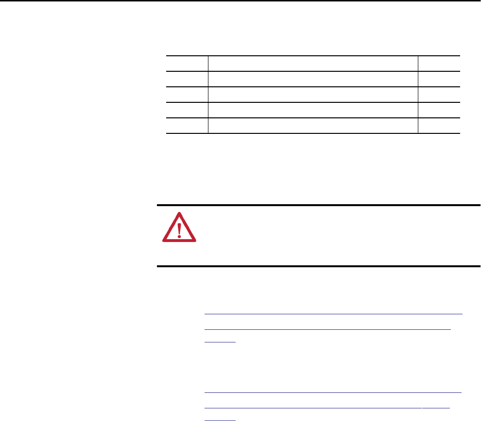
Install the SD Card Complete these steps to install the SD card in the 1756-L7x controllers.
We recommend that you leave the SD card in the controller, even when it is not
used. If the controller experiences a major nonrecoverable fault, fault
information is saved to the card.
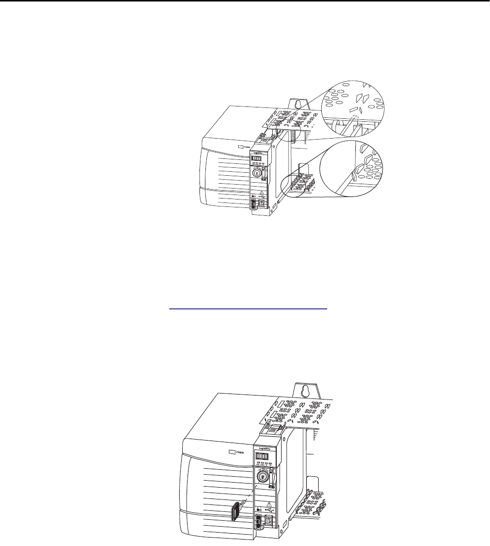
1. Verify that the SD card is locked or unlocked according to your
preference.
For more information about the lock/unlock memory settings, see the
Load or Store to the Memory Card on page 68.
2. Open the door for the SD card.
3. Insert the SD card into the SD card slot.
WARNING: When you insert or remove the Secure Digital (SD) memory card
while power is on, an electrical arc can occur. This could cause an explosion in
hazardous location installations.
Be sure that power is removed or the area is nonhazardous before proceeding.
Unlocked
Locked
RUNFORCE SDOK
24 Rockwell Automation Publication 1756-UM001P-EN-P - May 2017
Chapter 1 Install the 1756-L7x Controller
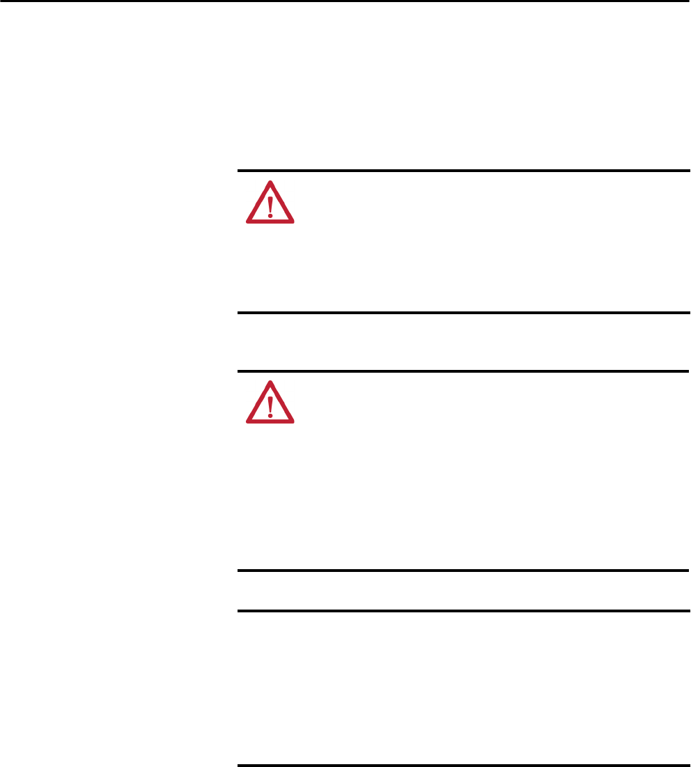
4. Gently press the card until it clicks into place.
5. Close the SD card door.
Logix 55xx
RUN FORCE
SD OK
Rockwell Automation Publication 1756-UM001P-EN-P - May 2017 25
Install the 1756-L7x Controller Chapter 1
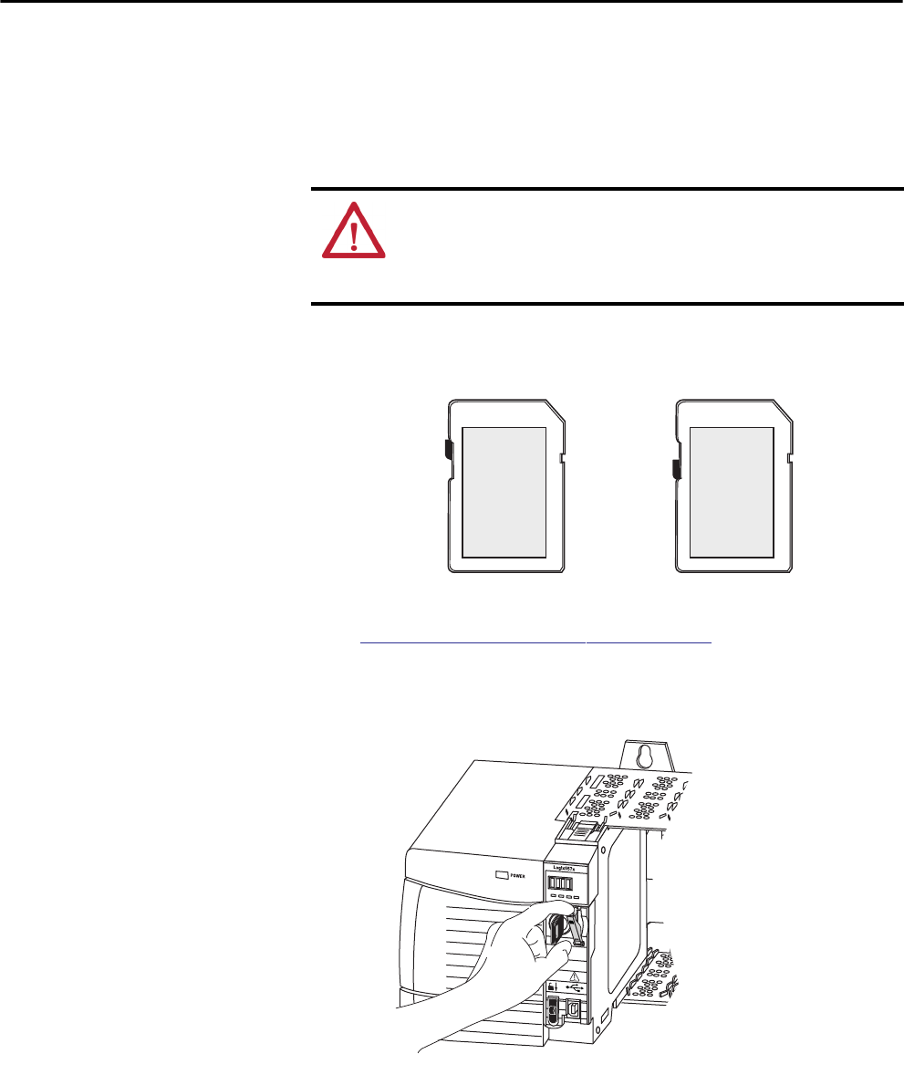
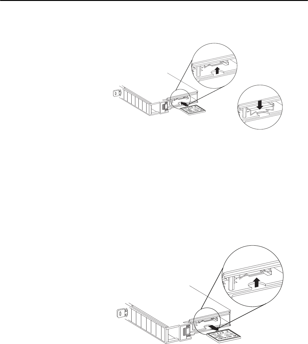
Remove the SD Card The 1756-L7x controller ships with an SD card installed. Complete these steps
to remove the SD card from the 1756-L7x controller.
1. Verify that the SD card is not in use by checking to be sure that the
SD indicator is Off.
2. Open the door to access the SD card.
WARNING: When you insert or remove the Secure Digital (SD) memory card
while power is on, an electrical arc can occur. This could cause an explosion in
hazardous location installations.
Be sure that power is removed or the area is nonhazardous before proceeding.
IMPORTANT • Verify that the SD card status indicator is off and that the card is not in
use before removing it.
• We recommend that you do the following:
– Leave an SD card installed.
– Use the SD cards available from Rockwell Automation
(catalog number 1784-SD1 or 1784-SD2).
• While other SD cards can be used with the controller,
Rockwell Automation has not tested the use of those cards with the
controller. If you use an SD card other than those cards that are available
from Rockwell Automation, you can experience data corruption or loss.
• Also, SD cards that are not provided by Rockwell Automation do not have
the same industrial, environmental, and certification ratings as those
cards that are available from Rockwell Automation.
TIP You can also put the controller into Hard Run mode to keep the controller
from writing to the SD card while it is removed.
26 Rockwell Automation Publication 1756-UM001P-EN-P - May 2017
Chapter 1 Install the 1756-L7x Controller
3. Press and release the SD card to eject it.
4. Remove the SD card and close the door.
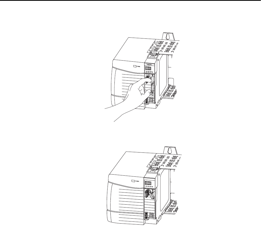
Install the ESM To install an ESM in the 1756-L7x controller, complete these steps.
1. Align the tongue-and-groove slots of the ESM and controller.
2. Slide the ESM back until it snaps into place.
The ESM begins charging after installation. The following status
messages indicate charging status:
•ESM Charging
•CHRG
ATTENTION: To avoid potential damage to the product when inserting the
ESM, align it in the track and slide forward with minimal force until the ESM
snaps into place.
Rockwell Automation Publication 1756-UM001P-EN-P - May 2017 27
Install the 1756-L7x Controller Chapter 1
After you install the ESM, it can take up to 15 seconds for the charging
status messages to display.
.
Uninstall the ESM
IMPORTANT Allow the ESM to finish charging before removing power from the controller.
Failure to do so can result in the loss of the application program. A type 1,
code 40 major fault is logged on powerup.
To verify that the ESM is fully charged, check the status display to confirm
that messages CHRG or ESM charging are no longer indicated.
TIP We recommend that you check the WallClockTime object attributes after
installing an ESM to verify that time of the controller is correct.
The ESM contains a real-time clock. If the ESM is new or came from another
controller, the WallClockTime object attributes for your controller can
change.
WARNING: If your application requires the ESM to deplete its residual stored
energy to 40 μJ or less before you transport it into or out of the application,
use only the 1756-(SP)ESMNSE(XT) module. In this case, complete these
steps before you remove the ESM.
• Turn power off to the chassis.
After you turn power off to the chassis, the controller’s OK status indicator
transitions from green to solid red to OFF.
• Wait at least 20 minutes for the residual stored energy to decrease to
40 μJ or less before you remove the ESM.
There is no visual indication of when the 20 minutes has expired. You must
track that time period.
WARNING: When you insert or remove the energy storage module while
backplane power is on, an electrical arc can occur. This could cause an
explosion in hazardous location installations.
Be sure that power is removed or the area is nonhazardous before proceeding.
Repeated electrical arcing causes excessive wear to contacts on both the module
and its mating connector.
IMPORTANT Before you remove an ESM, make necessary adjustments to your program to
account for potential changes to the WallClockTime attribute.

28 Rockwell Automation Publication 1756-UM001P-EN-P - May 2017
Chapter 1 Install the 1756-L7x Controller
Consider these points before removing the ESM:
• The following ESM modules can be currently installed in your
1756-L7x or 1756-L7xXT controller:
– 1756-ESMCAP
– 1756-ESMNSE
– 1756-ESMCAPXT
– 1756-ESMNSEXT
• The 1756-L7x controllers come with the 1756-ESMCAP module
installed. The 1756-L7xXT extreme temperature controller ships with a
1756-ESMCAPXT module installed. For more information on how to
use a 1756-ESMNSE, 1756-ESMNRM, 1756-ESMNSEXT, or
1756-ESMNRMXT module, see page 26.
• After the 1756-L7x or 1756-L7xXT controllers lose power, because the
chassis power is turned off or the controller has been removed from a
powered chassis, do not immediately remove the ESM.
Wait until the OK status indicator on the controller transitions from
Green to Solid Red to OFF before you remove the ESM.
• You can use the 1756-ESMNSE module with only a 1756-L73 (8 MB)
or smaller memory-sized controller.
• Use the 1756-ESMNSE module if your application requires that the
installed ESM deplete its residual stored energy to 40 μJ or less before
transporting it into or out of your application.
• Once it is installed, you cannot remove the 1756-ESMNRM or
1756-ESMNRMXT module from a 1756-L7x or 1756-L7xXT
controller.
• The Armor™ controller energy storage modules (ESM) cannot be
removed or replaced.
Rockwell Automation Publication 1756-UM001P-EN-P - May 2017 29
Install the 1756-L7x Controller Chapter 1
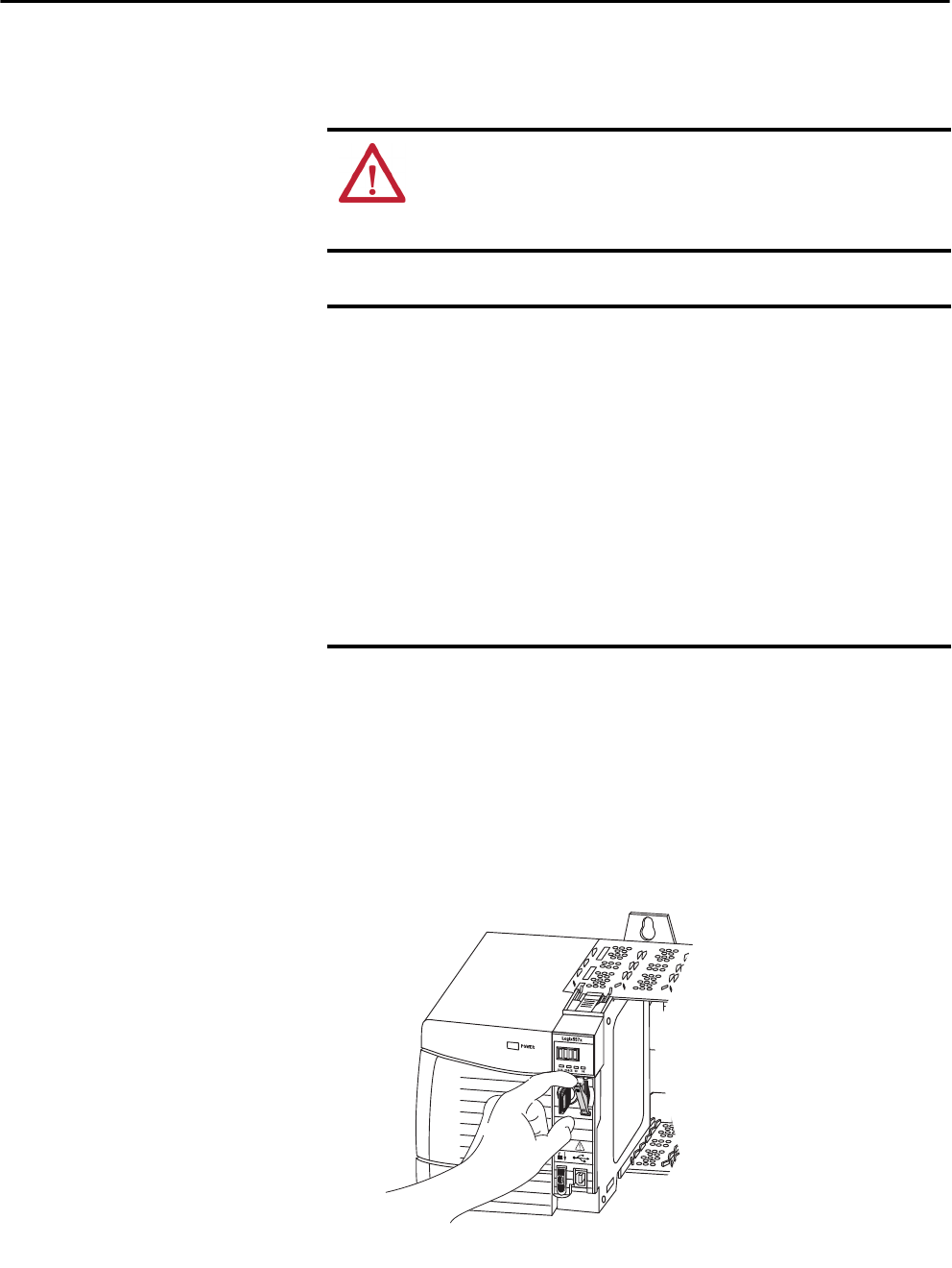
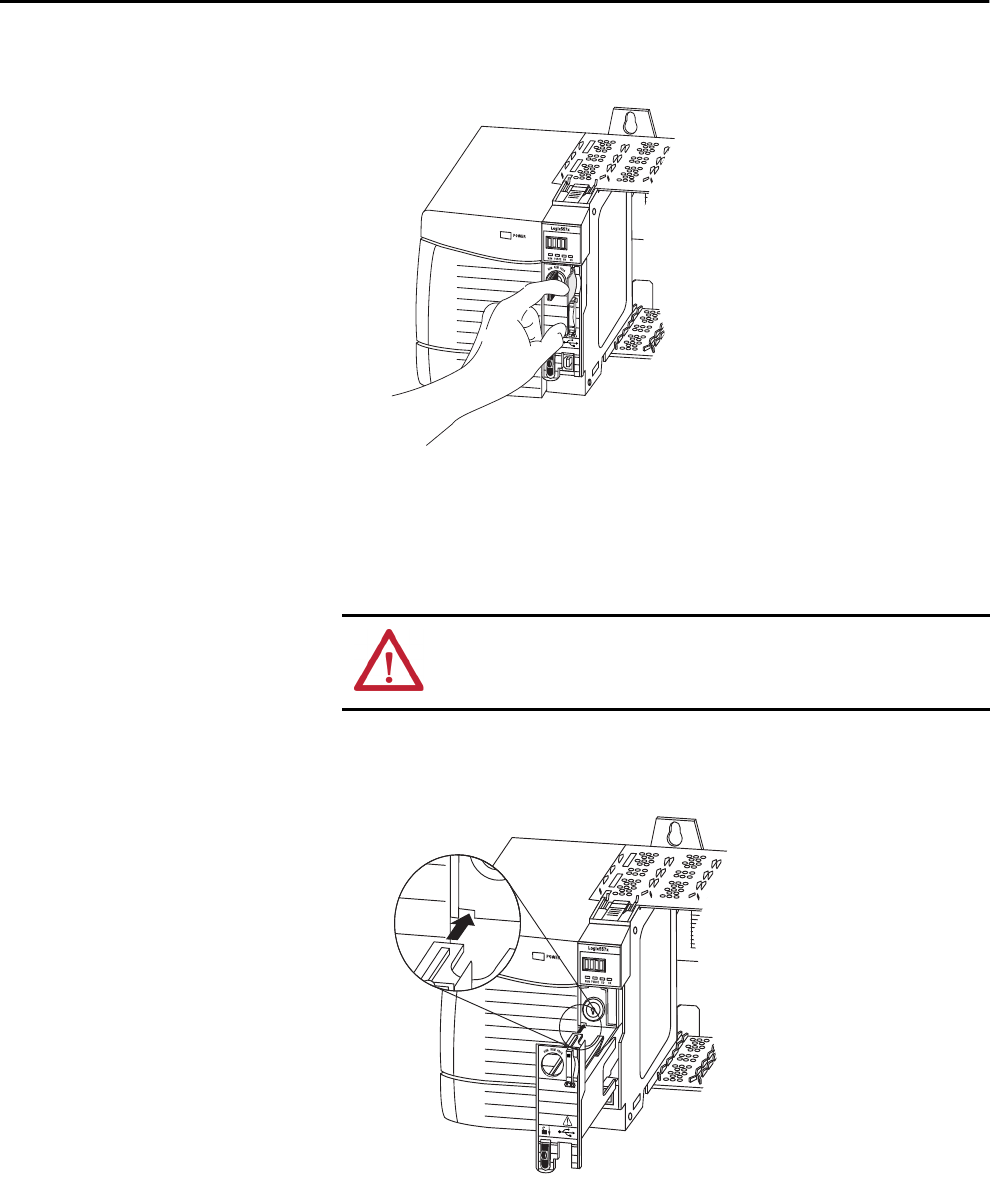
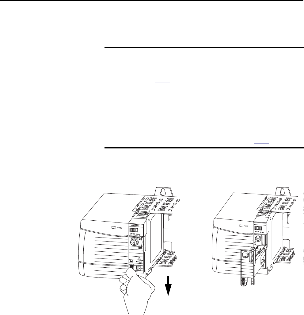
Complete these steps to remove an ESM module from the controller.
1. Remove the key from the mode switch.
2. Use your thumb to press down on the black release and pull the ESM
away from the controller.
IMPORTANT The next step depends on which of the following conditions applies to your
application.
• If you are removing the ESM from a powered 1756-L7x controller, go to
step 2.
• If you are removing the ESM from a 1756-L7x controller that is not
powered, because the chassis power is turned off or the controller has
been removed from a powered chassis, do not immediately remove
the ESM.
Wait until the OK status indicator on the controller transitions from Green to
Solid Red to OFF before you remove the ESM.
After the OK status indicator transitions to Off, go to step 2.
Logix 55xx
RUN FORCE
SD OK

30 Rockwell Automation Publication 1756-UM001P-EN-P - May 2017
Chapter 1 Install the 1756-L7x Controller
Notes:
Rockwell Automation Publication 1756-UM001P-EN-P - May 2017 31
Chapter 2
Install the 1756-L6x Controller
Topic Page
Before You Begin 33
1756-L6x Controller Parts 33
1756-L6x Controller Installation 34
CompactFlash Card Installation and Removal 34
Battery Connection and Replacement 38
Insert the Controller into the Chassis 40
Remove the Controller from the Chassis 42
ATTENTION: This equipment is not resistant to sunlight or other sources of UV radiation.
Table 8 - Environment and Enclosure
ATTENTION:
This equipment is intended for use in a Pollution Degree 2 industrial environment, in overvoltage Category II applications
(as defined in IEC 60664-1), at altitudes up to 2000 m (6562 ft) without derating.
This equipment is not intended for use in residential environments and may not provide adequate protection to radio
communication services in such environments.
This equipment is supplied as open-type equipment. It must be mounted within an enclosure that is suitably designed for those
specific environmental conditions that will be present and appropriately designed to prevent personal injury resulting from
accessibility to live parts. The enclosure must have suitable flame-retardant properties to prevent or minimize the spread of flame,
complying with a flame spread rating of 5VA or be approved for the application if nonmetallic. The interior of the enclosure must be
accessible only by the use of a tool. Subsequent sections of this publication may contain additional information regarding specific
enclosure type ratings that are required to comply with certain product safety certifications.
In addition to this publication, see the following:
• Industrial Automation Wiring and Grounding Guidelines, Rockwell Automation publication 1770-4.1, for additional installation
requirements
• NEMA Standard 250 and IEC 60529, as applicable, for explanations of the degrees of protection provided by enclosure
32 Rockwell Automation Publication 1756-UM001P-EN-P - May 2017
Chapter 2 Install the 1756-L6x Controller
Table 9 - North American Hazardous Location Approval
The following information applies when operating this equipment in
hazardous locations.
Informations sur l’utilisation de cet équipement en environnements
dangereux.
Products marked "CL I, DIV 2, GP A, B, C, D" are suitable for use in Class I Division 2
Groups A, B, C, D, Hazardous Locations and nonhazardous locations only. Each product is
supplied with markings on the rating nameplate indicating the hazardous location
temperature code. When combining products within a system, the most adverse
temperature code (lowest "T" number) may be used to help determine the overall
temperature code of the system. Combinations of equipment in your system are subject
to investigation by the local Authority Having Jurisdiction at the time of installation.
Les produits marqués "CL I, DIV 2, GP A, B, C, D" ne conviennent qu'à une utilisation en
environnements de Classe I Division 2 Groupes A, B, C, D dangereux et non dangereux.
Chaque produit est livré avec des marquages sur sa plaque d'identification qui
indiquent le code de température pour les environnements dangereux. Lorsque
plusieurs produits sont combinés dans un système, le code de température le plus
défavorable (code de température le plus faible) peut être utilisé pour déterminer le
code de température global du système. Les combinaisons d'équipements dans le
système sont sujettes à inspection par les autorités locales qualifiées au moment de
l'installation.
WARNING: EXPLOSION HAZARD
• Do not disconnect equipment unless power has been removed or
the area is known to be nonhazardous.
• Do not disconnect connections to this equipment unless power
has been removed or the area is known to be nonhazardous.
Secure any external connections that mate to this equipment by
using screws, sliding latches, threaded connectors, or other
means provided with this product.
• Substitution of components may impair suitability for Class I,
Division 2.
• If this product contains batteries, they must only be changed in
an area known to be nonhazardous.
WARNING: RISQUE D’EXPLOSION
• Couper le courant ou s'assurer que l'environnement est classé
non dangereux avant de débrancher l'équipement.
• Couper le courant ou s'assurer que l'environnement est classé
non dangereux avant de débrancher les connecteurs. Fixer tous
les connecteurs externes reliés à cet équipement à l'aide de vis,
loquets coulissants, connecteurs filetés ou autres moyens fournis
avec ce produit.
• La substitution de composants peut rendre cet équipement
inadapté à une utilisation en environnement de Classe I,
Division 2.
• S'assurer que l'environnement est classé non dangereux avant
de changer les piles.
Table 10 - European Hazardous Location Approval
The following applies when the product bears the Ex Marking.
This equipment is intended for use in potentially explosive atmospheres as defined by European Union Directive 94/9/EC and has been found to comply with the Essential Health
and Safety Requirements relating to the design and construction of Category 3 equipment intended for use in Zone 2 potentially explosive atmospheres, given in Annex II to this
Directive.
Compliance with the Essential Health and Safety Requirements has been assured by compliance with EN 60079-15 and EN 60079-0.
ATTENTION: This equipment is not resistant to sunlight or other sources of UV radiation.
WARNING:
• This equipment shall be mounted in an ATEX certified enclosure with a minimum ingress protection rating of at least IP54
(as defined in IEC60529) and used in an environment of not more than Pollution Degree 2 (as defined in IEC 60664-1) when
applied in Zone 2 environments. The enclosure must utilize a tool removable cover or door.
• This equipment shall be used within its specified ratings defined by Rockwell Automation.
• This equipment must be used only with ATEX certified Rockwell Automation backplanes.
• Secure any external connections that mate to this equipment by using screws, sliding latches, threaded connectors, or other
means provided with this product.
• Do not disconnect equipment unless power has been removed or the area is known to be nonhazardous.
Rockwell Automation Publication 1756-UM001P-EN-P - May 2017 33
Install the 1756-L6x Controller Chapter 2
Before You Begin See 1756-IN005 to install a ControlLogix® chassis and power supply before
you install your controller and power supply.
1756-L6x Controller Parts These sections describe parts that are included with the 1756-L6x controllers
and available accessory parts:
• One of the following batteries is included with your controller:
– For series A controllers, catalog number 1756-BA1
– For series B controllers, catalog number 1756-BA2
• Key, catalog number 1747-KY
Figure 2 - Parts Included with the 1756-L6x Controller
Parts Not Included with the 1756-L6x Controller
You can choose to use the parts included with the controller and these parts
specific to your application.
Logix 5563
RUN
RUN I/O
RS232
OK
BAT
FORCE
REM PROG
1756-L6x Controller
1747-KY Key
1756-BA1 or 1756-BA2
If your application requires Then use this component
RS-232 connection to the controller 1756-CP3 serial cable
Nonvolatile memory 1784-CF128 CompactFlash card
Expanded battery life for extended memory retention 1756-BATM battery module(1)
(1) The 1756-BATM can be used with series A controllers, but it cannot be used with series B controllers. Series B controllers use
battery power differently than previous controllers and therefore battery considerations for this series controller vary. For more
information to determine what battery to use, see the ControlLogix Controllers Selection Guide, publication 1756-SG001.
34 Rockwell Automation Publication 1756-UM001P-EN-P - May 2017
Chapter 2 Install the 1756-L6x Controller
1756-L6x Controller
Installation
These sections explain how to install a 1756-L6x controller. To install the
1756-L6x controller, complete the tasks summarized in this table.
CompactFlash Card
Installation and Removal
The installation and removal of a CompactFlash card depends on the
controller.
• If you are using a series A controller, reference these sections:
–Install a CompactFlash Card in a Series A Controller on page 35.
–Remove a CompactFlash Card from a Series A Controller on
page 35.
• If you are using a series B controller, reference these sections:
–Install a CompactFlash Card in a Series B Controller on page 36.
–Remove a CompactFlash Card from a Series B Controller on
page 37.
Task Page
CompactFlash Card Installation and Removal 34
Battery Connection and Replacement 38
Insert the Controller into the Chassis 40
Remove the Controller from the Chassis 42
WARNING: When you insert or remove the CompactFlash card while power
is on, an electrical arc can occur. This could cause an explosion in hazardous
location installations.
Be sure that power is removed or the area is nonhazardous before proceeding.
Rockwell Automation Publication 1756-UM001P-EN-P - May 2017 35
Install the 1756-L6x Controller Chapter 2
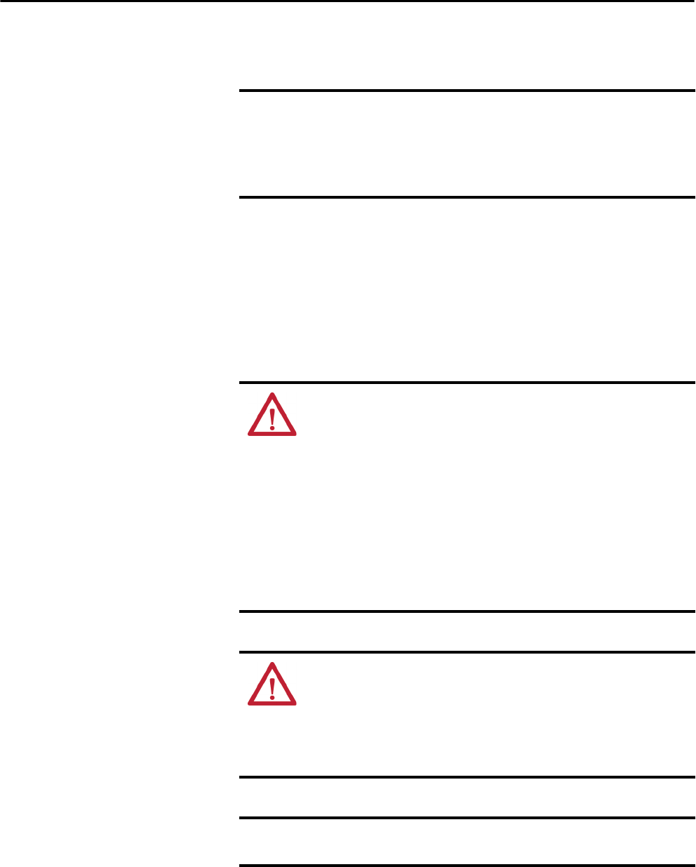
Install a CompactFlash Card in a Series A Controller
Complete these steps to install a CompactFlash card in a series A controller.
.
1. Lay the controller on its side with the front facing to the left.
2. Raise the locking clip.
3. Insert the CompactFlash card into the slot at the bottom of the
controller.
4. Pull the clip forward and downward until it snaps into place over the
card.
Remove a CompactFlash Card from a Series A Controller
Complete these steps to remove a CompactFlash card from a series A
controller.
1. Lay the controller in its side with the mode switch facing left.
2. Raise the locking clip.
3. Gently pull the card out of the slot.
1
2
3
4
1
2
3
36 Rockwell Automation Publication 1756-UM001P-EN-P - May 2017
Chapter 2 Install the 1756-L6x Controller
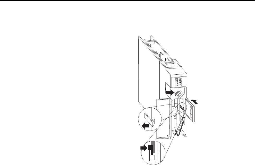
Install a CompactFlash Card in a Series B Controller
Complete these steps to install a CompactFlash card in a series B controller.
1. Open the door of the controller and push the CompactFlash latch to the
left.
2. Insert the CompactFlash card with the Allen-Bradley® logo pointing left.
3. Release the latch and secure it over the CompactFlash card.
1
2
3
4
Rockwell Automation Publication 1756-UM001P-EN-P - May 2017 37
Install the 1756-L6x Controller Chapter 2
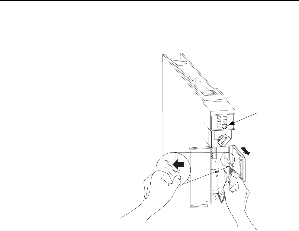
Remove a CompactFlash Card from a Series B Controller
Complete these steps to remove a CompactFlash card from a series B
controller.
1. Verify that the OK indicator is solid green and open the door of the
controller.
2. Push and hold the CompactFlash latch to the left.
3. Push the eject button and remove the card.
4. Release the latch.
1
2
3
38 Rockwell Automation Publication 1756-UM001P-EN-P - May 2017
Chapter 2 Install the 1756-L6x Controller
Battery Connection
and Replacement
Connection of the battery varies depending on your controller series:
• If you are using a series A controller, see page 39.
• If you are using a series B controller, see page 40.
This product contains a hermetically-sealed lithium battery that may need to be
replaced during the life of the product.
At the end of its life, the battery contained in this product should be collected
separately from any unsorted municipal waste.
The collection and recycling of batteries helps protect the environment and
contributes to the conservation of natural resources as valuable materials are
recovered.
WARNING: When you connect or disconnect the battery an electrical arc can
occur. This could cause an explosion in hazardous location installations. Be
sure that power is removed or the area is nonhazardous before proceeding.
For safety information on the handling of lithium batteries, including handling
and disposal of leaking batteries, see Guidelines for Handling Lithium Batteries,
publication AG-5.4.
IMPORTANT To prevent program loss, replace a 1756-BA1 or 1756-BA2 battery according
to the following schedule even if the BAT status indicator is Off.
ATTENTION: Store batteries in a cool, dry environment. We recommend
25 C (77 F) with 40…60% relative humidity. You can store batteries for up
to 30 days between -45…+85 C (-49…+185F), such as during
transportation. To avoid leakage or other hazards, do not store batteries
above 60C (140 F) for more than 30 days.
If the temperature 2.54 cm (1 in.)
below the chassis is
Replace the battery within
-25…+35 °C (-13…+95 F) No replacement required
36…40 °C (96.8…104 F) 3 years
41…45 °C (105.8…113 F) 2 years
46…50 °C (114.8…122 F) 16 months
51…55 °C (123.8…131 F) 11 months
56…70 °C (132.8…158F) 8 months
Rockwell Automation Publication 1756-UM001P-EN-P - May 2017 39
Install the 1756-L6x Controller Chapter 2
Install the Battery on a Series A Controller
Complete these steps to install a 1756-BA1 battery on a series A controller.
For information to install a 1756-BATM battery module or replace a
1756-BATM assembly, see the ControlLogix Battery Module Installation
Instructions, publication 1756-IN576.
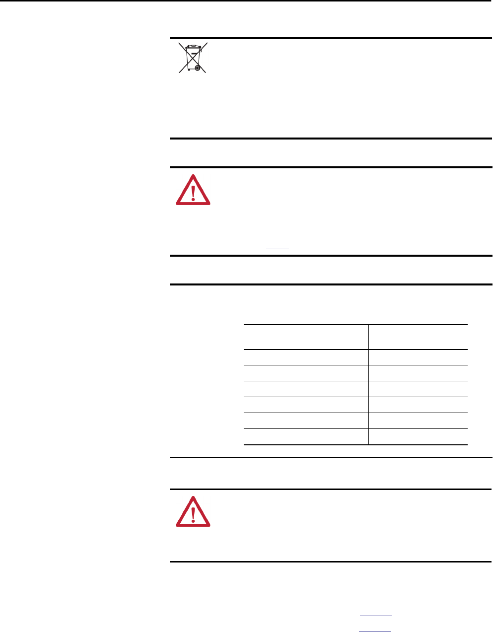
1. Connect the battery connector to the port to the right of the battery
slot.
2. Snap the battery into the battery slot.
3. Write the date on the battery label.
4. Attach the label to the inside of the controller door.
ATTENTION: For a series A controller, connect only a 1756-BA1 battery or a
1756-BATM battery module. The use of other batteries can damage the
controller.
Wire Terminal Location Connected Wire
Top No connection
Middle Black lead (-)
Bottom Red lead (+)
DATE
40 Rockwell Automation Publication 1756-UM001P-EN-P - May 2017
Chapter 2 Install the 1756-L6x Controller
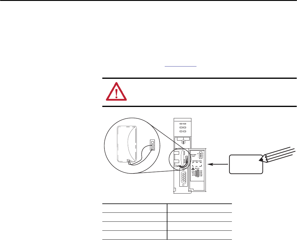
Install the Battery on a Series B Controller
Complete these steps to install the battery on a series B controller.
1. Plug the battery connector into the battery port (+ Red, - Black).
2. Insert the battery, with the arrow pointing up, into the battery slot.
3. Write the date on the battery label.
4. Attach the label to the inside of the controller door.
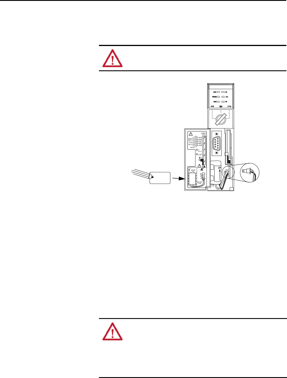
Insert the Controller
into the Chassis
When installing a ControlLogix controller, you can do the following:
• Place the controller in any slot.
• Use multiple controllers in the same chassis.
You can install a ControlLogix controller while chassis power is on and the
system is operating.
ATTENTION: For a series B controller, connect only a 1756-BA2 battery.
The use of other batteries can damage the controller.
DATE
WARNING: When you insert or remove the module while backplane power
is on, an electrical arc can occur. This could cause an explosion in hazardous
location installations. Be sure that power is removed or the area is
nonhazardous before proceeding.
Repeated electrical arcing causes excessive wear to contacts on both the
controller and its mating connector on the chassis. Worn contacts may create
electrical resistance that can affect controller operation.
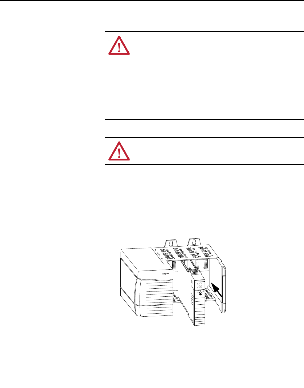
Rockwell Automation Publication 1756-UM001P-EN-P - May 2017 41
Install the 1756-L6x Controller Chapter 2
Complete these steps to insert the controller into the chassis.
1. Insert the key into the controller.
2. Turn the key to the PROG position.
3. Align the circuit board with the top and bottom guides in the chassis.
4. Slide the module into the chassis.
5. Verify that the controller is flush with the power supply or other
installed modules.
6. Verify that the top and bottom latches are engaged.
After you have inserted the controller into the chassis, review the state of the
controller information in Troubleshoot the Module on page 183.
Table 11 - Prevent Electrostatic Discharge
ATTENTION: This equipment is sensitive to electrostatic discharge, which
can cause internal damage and affect normal operation. Follow these
guidelines when you handle this equipment:
• Touch a grounded object to discharge potential static.
• Wear an approved grounding wriststrap.
• Do not touch connectors or pins on component boards.
• Do not touch circuit components inside the equipment.
• Use a static-safe workstation, if available.
• Store the equipment in appropriate static-safe packaging when not in use.
ATTENTION: If this equipment is used in a manner not specified by the
manufacturer, the protection provided by the equipment can be impaired.
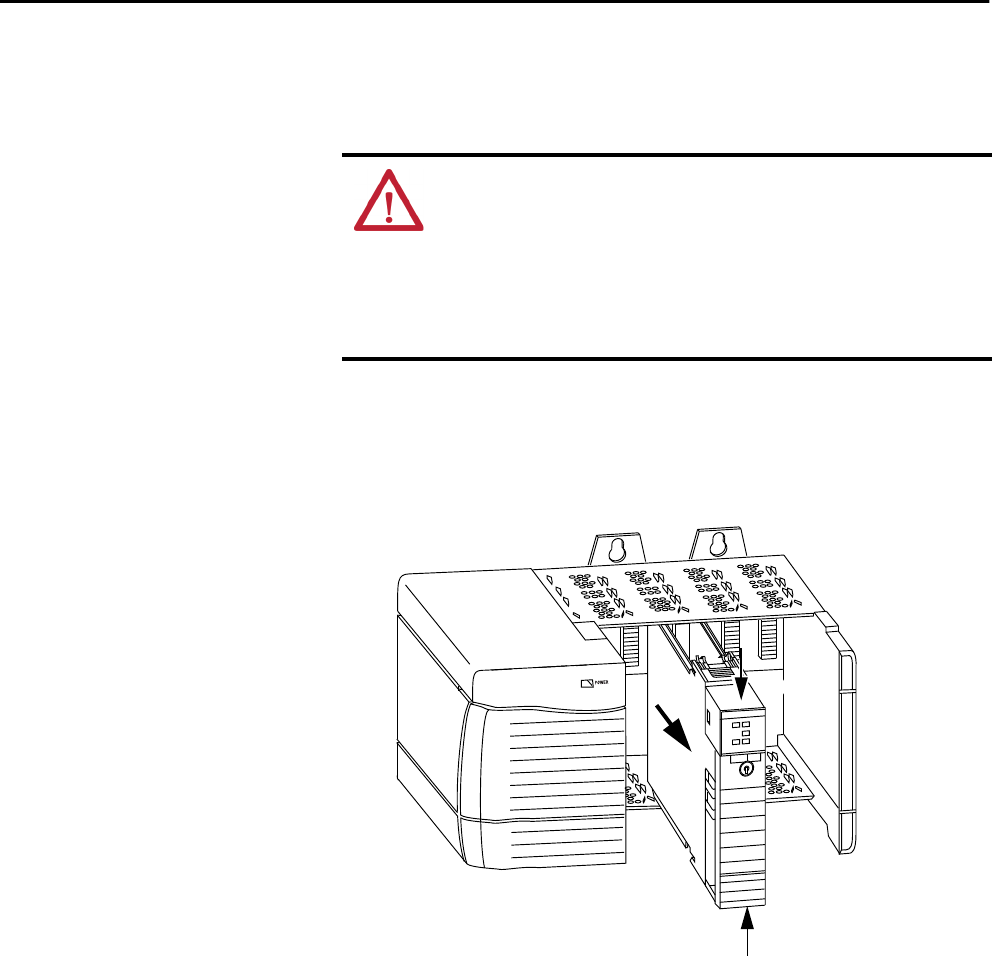
42 Rockwell Automation Publication 1756-UM001P-EN-P - May 2017
Chapter 2 Install the 1756-L6x Controller
Remove the Controller
from the Chassis
You can remove a controller while chassis power is on and the system is
operating. The devices that are owned by the controller go to their configured
fault state if you remove the controller.
Complete these steps to remove the controller from the chassis.
1. Press the locking tabs on the top and bottom of the controller.
2. Slide the controller out of the chassis.
WARNING: When you insert or remove the module while backplane power
is on, an electrical arc can occur. This could cause an explosion in hazardous
location installations. Be sure that power is removed or the area is
nonhazardous before proceeding.
Repeated electrical arcing causes excessive wear to contacts on both the
controller and its mating connector in the chassis. Worn contacts may create
electrical resistance that can affect controller operation.
1
2
1

Rockwell Automation Publication 1756-UM001P-EN-P - May 2017 43
Chapter 3
Start Using the Controller
Make Connections Before you can begin using your controller, you must make a connection to the
controller.
1756-L7x Connection Options
Connection options with the 1756-L7x include the following:
• Connect by using a USB cable as described in Connect to the
1756-L7x Controller on page 44.
• Install and configure a communication module in the chassis with the
controller as described in the installation instructions for the
communication module.
For information on Double Data Rate (DDR) backplane communication
usage, see Double Data Rate (DDR) Backplane Communication on page 92.
Topic Page
Make Connections 43
Connect to the 1756-L7x Controller 44
Connect to the 1756-L6x Controller 47
Upgrade Controller Firmware 50
Set the Communication Path 60
Go Online with the Controller 61
Download to the Controller 61
Upload from the Controller 63
Choose the Controller Operation Mode 65
Use the Mode Switch to Change the Operation Mode 65
Use Logix Designer to Change the Operation Mode 67
Load or Store to the Memory Card 68
Use ControlLogix Energy Storage Modules (ESMs) 73
Estimate the ESM Support of the WallClockTime 75
Maintain the Battery (Only 1756-L6x Controllers) 75
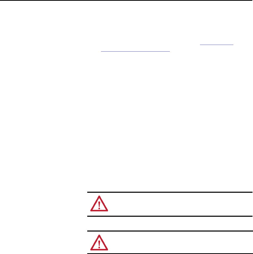
44 Rockwell Automation Publication 1756-UM001P-EN-P - May 2017
Chapter 3 Start Using the Controller
1756-L6x Connection Options
Connection options with the 1756-L6x include the following:
• Connect by using a serial cable as described in Connect to the
1756-L6x Controller on page 47.
• Install and configure a communication module in the chassis with the
controller as described in the installation instructions for the
communication module.
Connect to the
1756-L7x Controller
The controller has a USB port that uses a Type B receptacle. The port is USB
2.0 compatible and runs at 12 Mbps.
To use the USB port of the controller, you must have RSLinx® software,
version 2.56 or later, installed on your workstation. Use a USB cable to connect
your workstation to the USB port. With this connection, you can upgrade
firmware and download programs to the controller directly from your
workstation.
TIP When upgrading your 1756-L6x controller firmware, we recommend that
you use a network connection other than the serial cable. Serial connections
are much slower than other communication connections.
ATTENTION: The USB port is intended only for temporary local
programming purposes and not intended for permanent connection.
The USB cable is not to exceed 3.0 m (9.84 ft) and must not contain hubs.
WARNING: Do not use the USB port in hazardous locations.
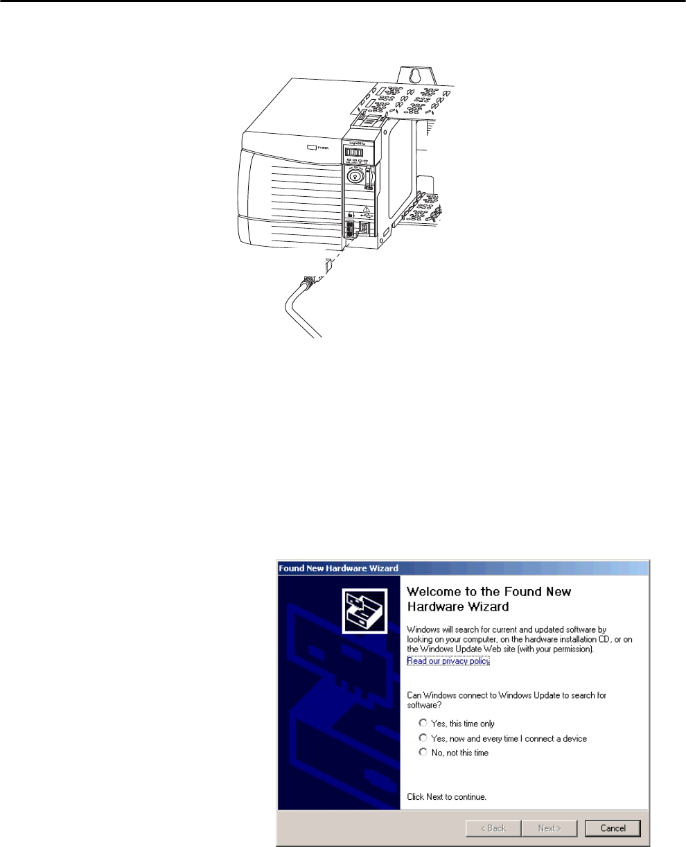
Rockwell Automation Publication 1756-UM001P-EN-P - May 2017 45
Start Using the Controller Chapter 3
Figure 3 - USB Connection
Configure the USB Driver
To configure RSLinx software to use a USB port, you must first configure a
USB driver.
To configure a USB driver, perform this procedure.
1. Connect your controller and workstation by using a USB cable.
The Found New Hardware Wizard dialog box appears.
2. Click any of the Windows Update connection options and click Next.
TIP If the software for the USB driver is not found and the installation is
canceled, verify that you have installed RSLinx Classic software, version 2.57
or later.
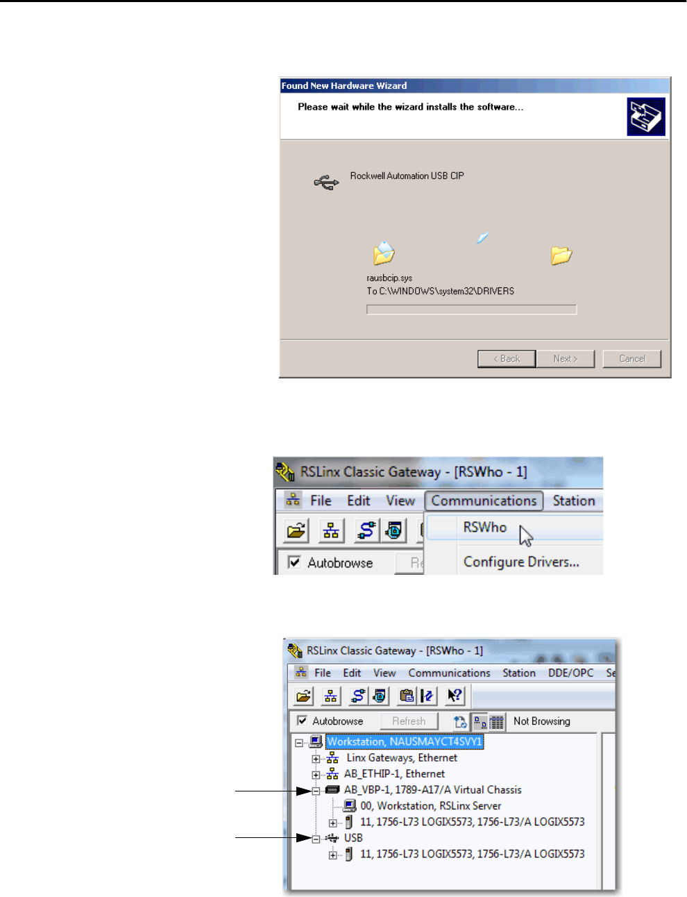
46 Rockwell Automation Publication 1756-UM001P-EN-P - May 2017
Chapter 3 Start Using the Controller
3. Click Install the software automatically (Recommended) and
click Next. The software is installed.
4. Click Finish to configure your USB driver.
5. From the Communications pull-down menu, choose RSWho.
The USB port driver appears.
Your controller appears under two drivers, a virtual chassis and the USB port.
You can use either driver to browse to your controller.
Virtual Chassis Driver
USB Driver
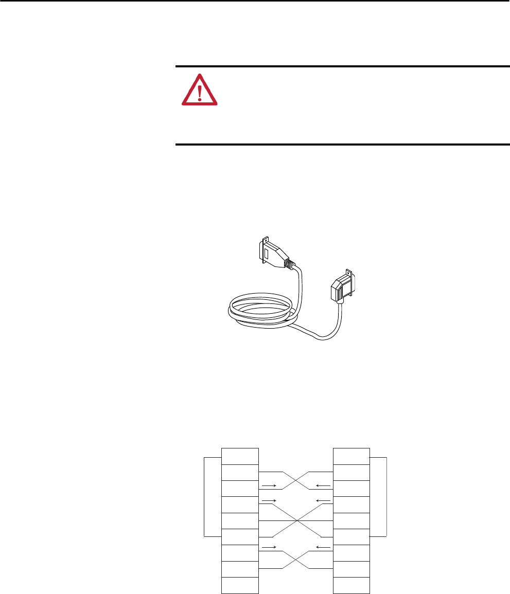
Rockwell Automation Publication 1756-UM001P-EN-P - May 2017 47
Start Using the Controller Chapter 3
Connect to the
1756-L6x Controller
The 1756-L6x ControlLogix® controller uses a serial port for workstation
connections.
To connect a workstation to the serial port, you can make your own serial cable
or use one of these cables:
• 1756-CP3 serial cable
• 1747-CP3 cable from the SLC™ product family (if you use this cable, it
can be difficult to close the controller door)
Follow these guidelines if you make your own serial cable:
• Limit the length to 15.2 m (50 ft).
• Wire the connectors as shown.
• Attach the shield to the connectors.
WARNING: If you connect or disconnect the serial cable with power applied
to this module or the serial device on the other end of the cable, an electrical
arc can occur. This could cause an explosion in hazardous location
installations.
Be sure that power is removed or the area is nonhazardous before proceeding.
To Workstation
To Controller
2 RDX
3 TXD
4 DTR
COMMON
6 DSR
7 RTS
8 CTS
9
1 CD
2 RDX
3 TXD
4 DTR
COMMON
6 DSR
7 RTS
8 CTS
9
1 CD
To Workstation To Controller
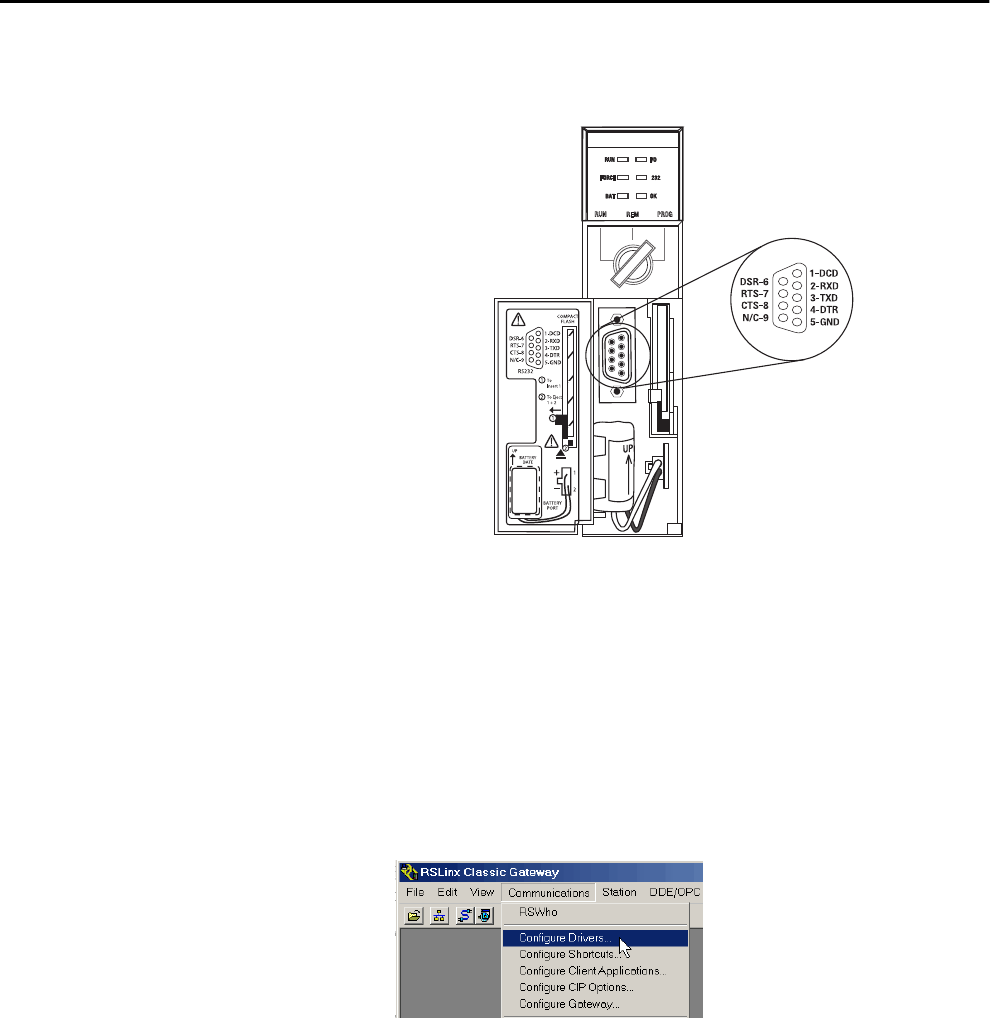
48 Rockwell Automation Publication 1756-UM001P-EN-P - May 2017
Chapter 3 Start Using the Controller
Plug the controller end of the serial cable into the RS-232 port on the front of
the controller.
Configure the Serial Driver
Use RSLinx software to configure the RS-232 DF1 device driver for serial
communication.
To configure the driver, perform this procedure.
1. In RSLinx software, from the Communications menu, choose
Configure Drivers.
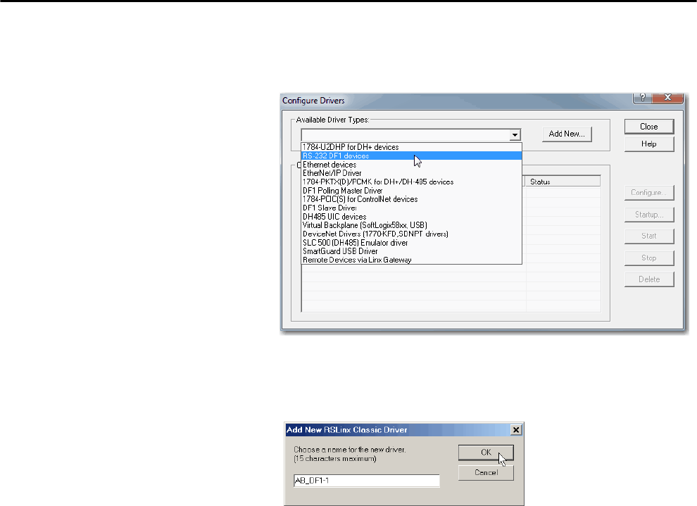
Rockwell Automation Publication 1756-UM001P-EN-P - May 2017 49
Start Using the Controller Chapter 3
2. From the Available Driver Types pull-down menu, choose the
RS-232 DF1 device driver.
3. Click Add New.
The Add New RSLinx Driver dialog box appears.
4. Type the driver name and click OK.
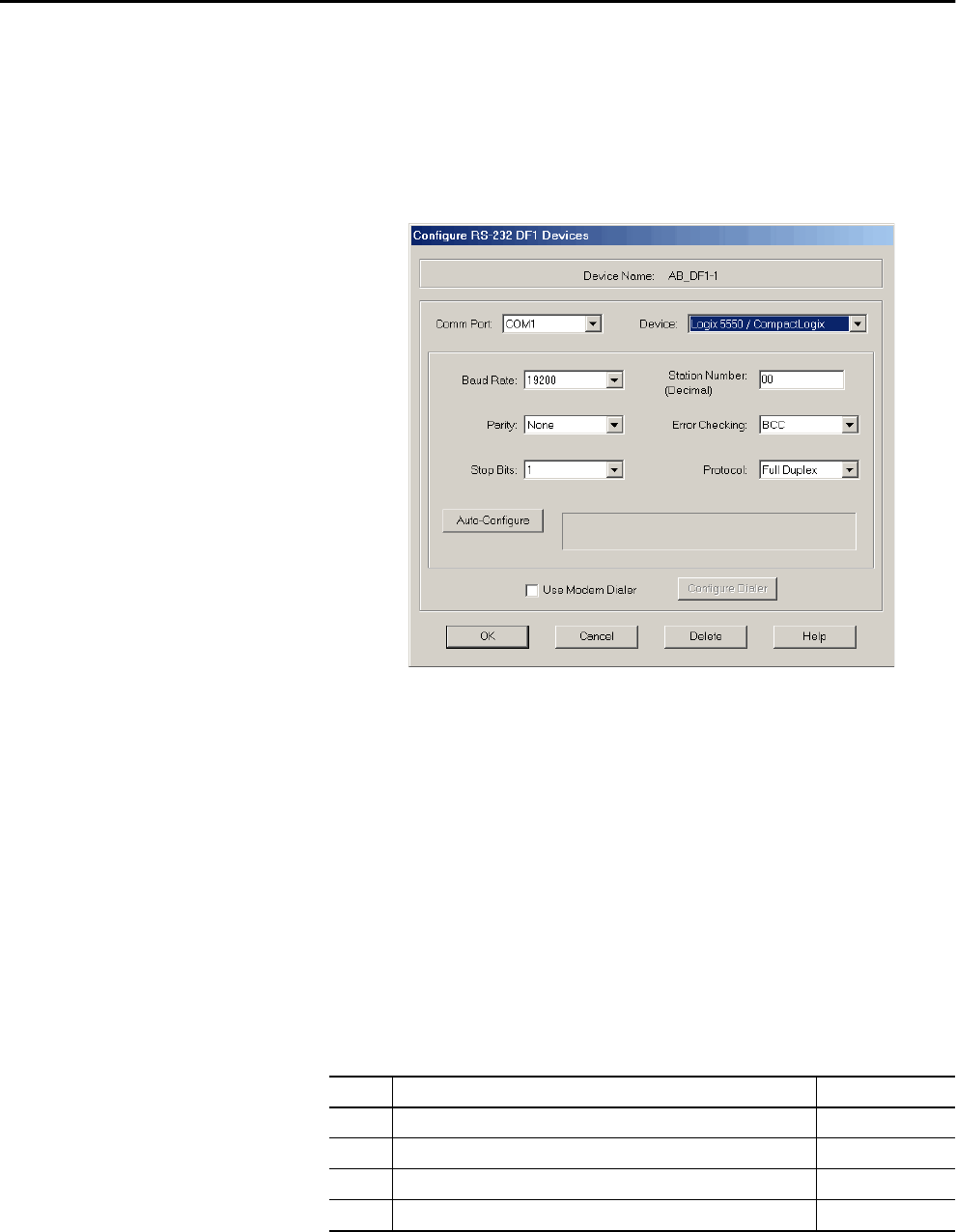
50 Rockwell Automation Publication 1756-UM001P-EN-P - May 2017
Chapter 3 Start Using the Controller
5. Specify the serial port settings.
a. From the Comm Port pull-down menu, choose the serial port on the
workstation to which the cable is connected.
b. From the Device pull-down menu, choose Logix 5550/
CompactLogix.
c. Click Auto-Configure.
6. If the auto configuration is successful, click OK.
If the auto configuration is not successful, verify that the correct Comm
Port was selected.
7. Click Close.
Upgrade Controller Firmware You can choose to upgrade controller firmware by using one of these tools:
• ControlFLASH™ software that is packaged with the Studio 5000®
environment
• AutoFlash feature of the Logix Designer application
To upgrade your controller firmware, complete the tasks that are listed in this
table.
Task Page
Determine Required Controller Firmware 51
Obtain Controller Firmware 52
Use ControlFLASH Software to Upgrade Firmware 52
Use AutoFlash to Upgrade Firmware 57
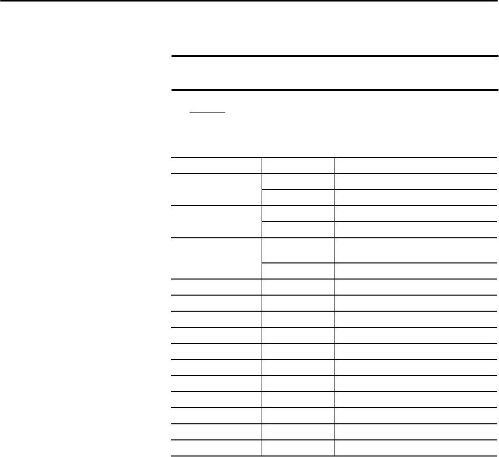
Rockwell Automation Publication 1756-UM001P-EN-P - May 2017 51
Start Using the Controller Chapter 3
Determine Required Controller Firmware
Use Table 12 to determine what firmware revision is required for your
controller.
IMPORTANT The controller must be in Remote Program or Program mode and all major
recoverable faults must be cleared to accept upgrades.
Table 12 - Firmware Required for Controllers
Controller Series Use this firmware revision
1756-L61 A 12.x or later
B 13.40 or later
1756-L62 A 12.x or later
B 13.40 or later
1756-L63 A • If not using a CompactFlash card, 10.x or later
• If using a CompactFlash card, 11.x or later
B 13.40 or later
1756-L63XT B 13.40 or later
1756-L64 B 16 or later
1756-L65 B 17 or later
1756-L71 A 20 or later
1756-L72 A 19 or later
1756-L72EROM A 19 or later
1756-L73 A 19 or later
1756-L73XT A 19 or later
1756-L73EROM A 19 or later
1756-L74 A 19 or later
1756-L75 A 19 or later
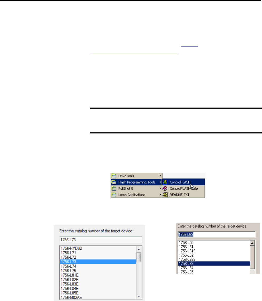
52 Rockwell Automation Publication 1756-UM001P-EN-P - May 2017
Chapter 3 Start Using the Controller
Obtain Controller Firmware
Controller firmware is packaged with the Studio 5000 environment. In
addition, controller firmware is also available for download from the Rockwell
Automation Technical Support website at http://
www.rockwellautomation.com/support/.
Use ControlFLASH Software to Upgrade Firmware
To upgrade your controller firmware with ControlFLASH software, complete
these steps.
1. Verify that the network connection is made and the network driver has
been configured in RSLinx software.
2. Start ControlFLASH software and click Next to begin the upgrade
process.
3. Select the catalog number of your controller and click Next.
IMPORTANT If the SD card is locked and the Load Image option of the store project is set
to On Power Up, the controller firmware is not updated as a result of these
steps. The previously stored firmware and project are loaded instead.
1756-L6x Controllers
1756-L7x Controllers
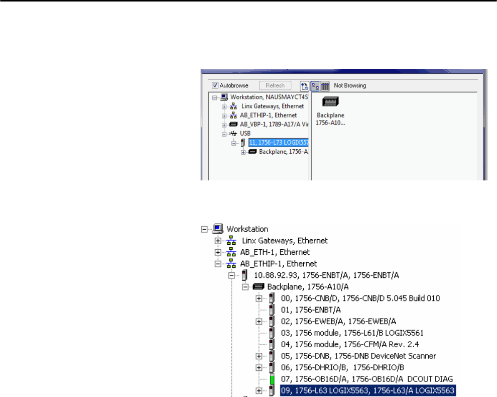
Rockwell Automation Publication 1756-UM001P-EN-P - May 2017 53
Start Using the Controller Chapter 3
4. Expand the network driver to locate your controller.
5. Select the controller and click Next.
1756-L7x Controller with USB Network Driver
1756-L6x Controller with Ethernet Network Driver
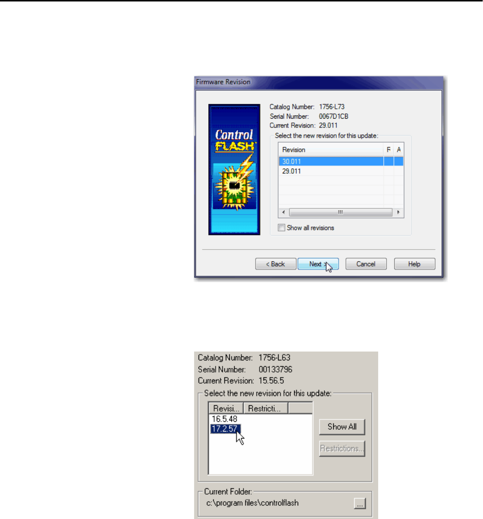
54 Rockwell Automation Publication 1756-UM001P-EN-P - May 2017
Chapter 3 Start Using the Controller
6. Select the desired firmware revision and click Next.
1756-L6x Controller Upgrade
1756-L7x Controller Upgrade
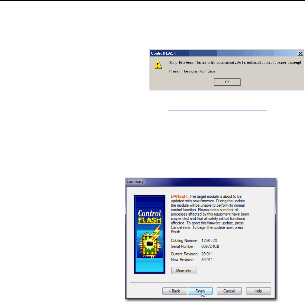
Rockwell Automation Publication 1756-UM001P-EN-P - May 2017 55
Start Using the Controller Chapter 3
7. Click Finish.
TIP If you are using a 1756-L7x controller and experience a Script File Error after
selecting the firmware revision number (see the following example), there
is likely an anomaly with your firmware files.
To recover, perform the following:
• Go to http://www.rockwellautomation.com/support/ and download
the firmware revision you are trying to upgrade. Replace the firmware
revision that you have previously installed with that posted on the
Technical Support website.
• If the replacement firmware revision does not resolve the anomaly,
contact Rockwell Automation Technical Support.
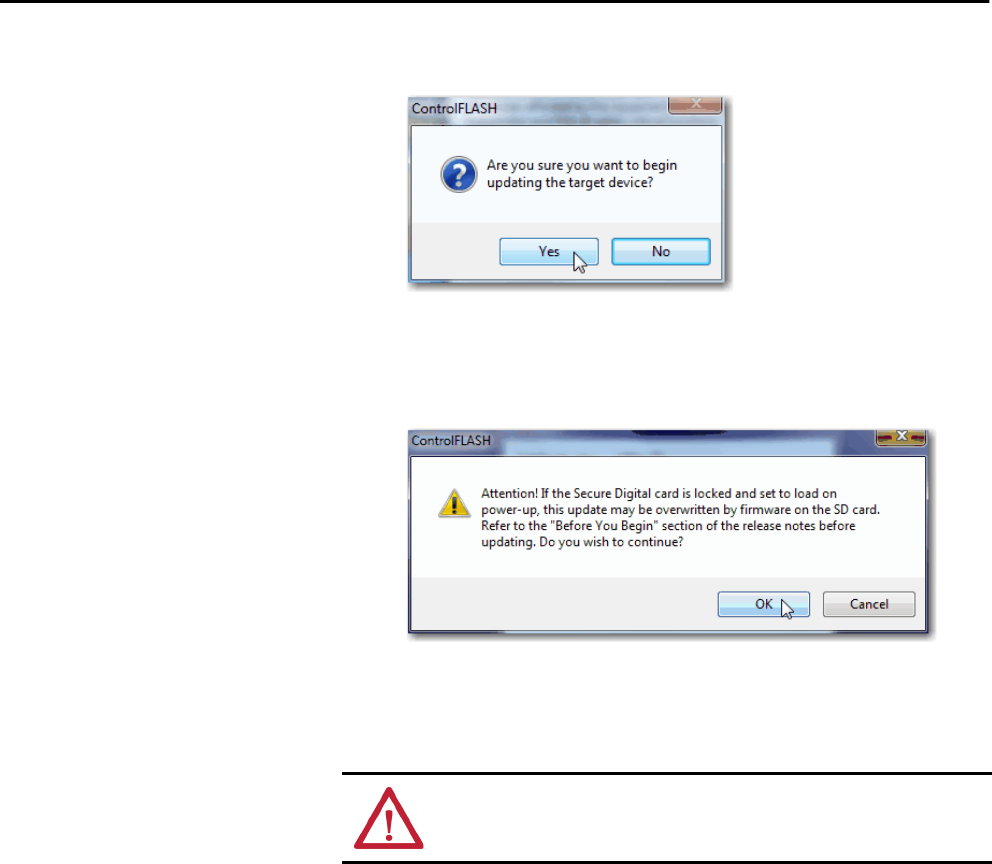
56 Rockwell Automation Publication 1756-UM001P-EN-P - May 2017
Chapter 3 Start Using the Controller
8. When a confirmation dialog box appears, click Yes.
Before the firmware update begins, this dialog box appears. Take the
required action for your application. In this example, the upgrade
continues when you click OK.
A progress dialog box indicates the progress of the firmware upgrade.
The 1756-L7x controllers show progress in updates and blocks. The
1756-L6x controllers show progress only in blocks.
WARNING: Let the firmware update to fully complete before cycling power
or otherwise interrupting the upgrade.
TIP If the ControlFLASH upgrade of the controller is interrupted, the controllers
revert to boot firmware, that is firmware revision 1.xxx.
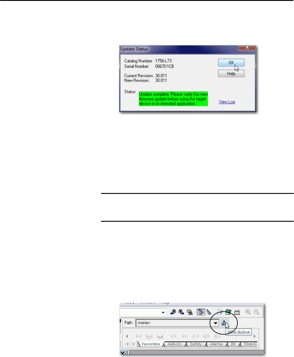
Rockwell Automation Publication 1756-UM001P-EN-P - May 2017 57
Start Using the Controller Chapter 3
When the upgrade is complete, the Update Status dialog box indicates
that the upgrade is complete.
9. Click OK.
10. Close ControlFLASH software.
Use AutoFlash to Upgrade Firmware
To upgrade your controller firmware with the AutoFlash feature, complete
these steps.
1. Verify the following:
• The network connection is made.
• The network driver has been configured in RSLinx Classic software.
• The controller is in Remote Program or Program mode and all major
recoverable faults are cleared.
2. Use the Logix Designer application to create a controller project.
3. On the Path bar, click Who Active.
IMPORTANT If the SD card is locked and the Load Image option of the stored project is set
to On Power Up, the controller firmware is not updated as a result of these
steps. The previously stored firmware and project are loaded instead.
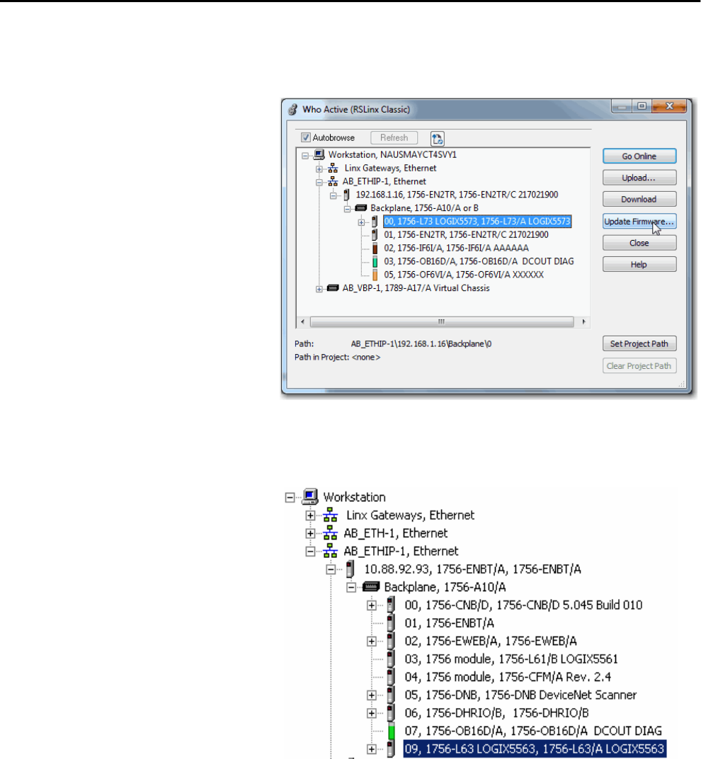
58 Rockwell Automation Publication 1756-UM001P-EN-P - May 2017
Chapter 3 Start Using the Controller
4. Select your controller and click Update Firmware.
1756-L6x Controller with Ethernet Driver
1756-L7x Controller with USB Driver
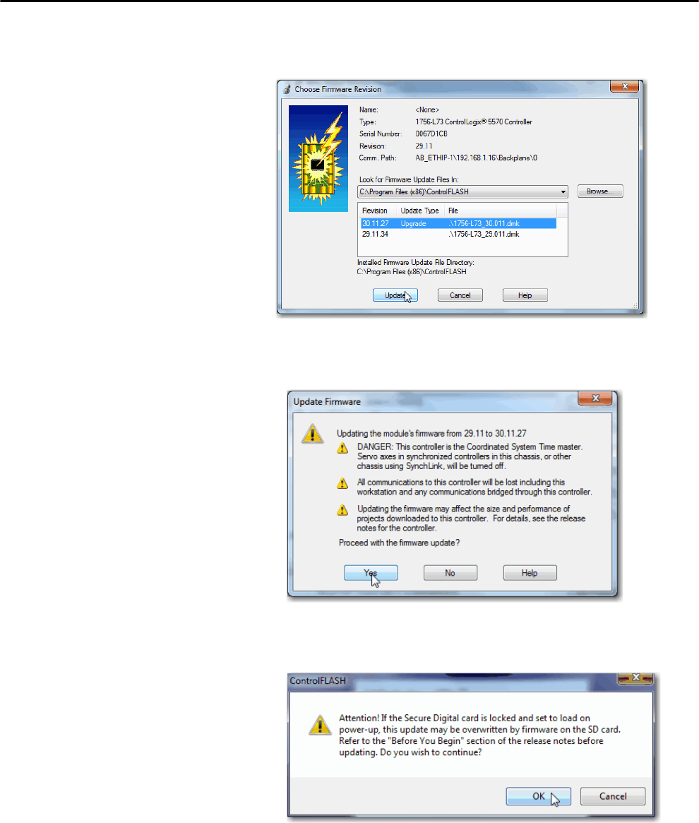
Rockwell Automation Publication 1756-UM001P-EN-P - May 2017 59
Start Using the Controller Chapter 3
5. Select the firmware revision to upgrade to and click Update.
6. On the Update Firmware dialog box, click Yes.
7. On the ControlFLASH dialog box, click OK.
A progress dialog box indicates the progress of the firmware upgrade.
The 1756-L7x controllers show progress in updates and blocks. The
1756-L6x controllers show progress only in blocks.
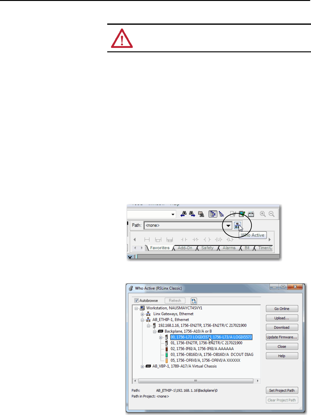
60 Rockwell Automation Publication 1756-UM001P-EN-P - May 2017
Chapter 3 Start Using the Controller
When the upgrade is complete, the Update Status dialog box indicates
that the upgrade is complete.
Set the Communication Path To go online with the controller, you must specify a communication path in the
Logix Designer application. You specify the communication path after you
create a controller program.
Complete these steps to specify the communication path after you have created
your program.
1. Click Who Active.
2. Expand the communication path and select the controller.
3. Click Set Project Path.
WARNING: Let the firmware update to fully complete before cycling power
or otherwise interrupting the upgrade.
TIP If the ControlFLASH upgrade of the controller is interrupted, the controllers
revert to boot firmware, that is firmware revision 1.xxx.
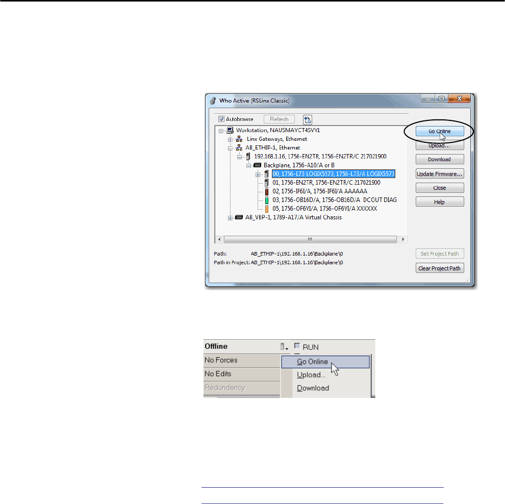
Rockwell Automation Publication 1756-UM001P-EN-P - May 2017 61
Start Using the Controller Chapter 3
Go Online with the Controller Use one of these methods to go online with the controller:
• After setting the communication path, click Go Online in the
Who Active dialog box.
• From the Controller Status menu, choose Go Online.
Download to the Controller When you download a project to the controller, it moves the project from the
Logix Designer application onto the controller. You can download a project in
two ways:
•Use the Who Active Dialog Box to Download on page 62
•Use the Controller Status Menu to Download on page 63
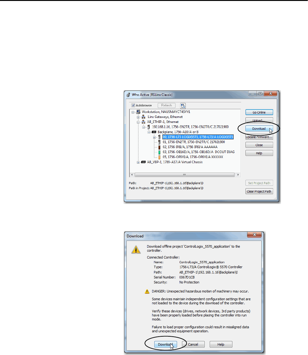
62 Rockwell Automation Publication 1756-UM001P-EN-P - May 2017
Chapter 3 Start Using the Controller
Use the Who Active Dialog Box to Download
You can use the features of the Who Active dialog box to download to your
controller after you have set the communication path. Complete these steps to
download to the controller.
1. After setting the communication path, click Download in the
Who Active dialog box.
2. Read the warnings on the Download dialog box and click Download.
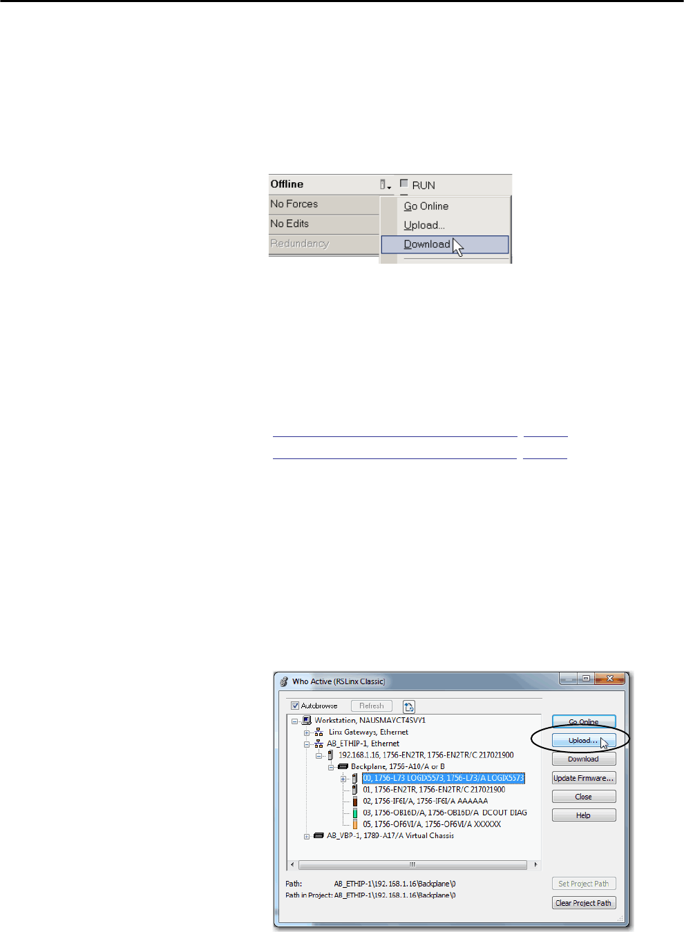
Rockwell Automation Publication 1756-UM001P-EN-P - May 2017 63
Start Using the Controller Chapter 3
Use the Controller Status Menu to Download
After you set a communication path in the Logix Designer application, you can
use the Controller Status menu to download to the controller. To download,
from the Controller Status menu, choose Download.
Figure 4 - Download Via the Controller Status Menu
Upload from the Controller When you upload a project to the controller, it copies the project from the
controller to the Logix Designer application. To upload a project, use one of
these methods:
•Use the Who Active Dialog Box to Upload, page 63
•Use the Controller Status Menu to Upload, page 64
Use the Who Active Dialog Box to Upload
You can use the features of the Who Active dialog box to upload from your
controller after you have set the communication path. Complete these steps to
upload from the controller.
1. After setting the communication path, click Upload in the Who Active
dialog box.
TIP After the download completes on a 1756-L7x controller, the project name is
indicated on the scrolling status display.
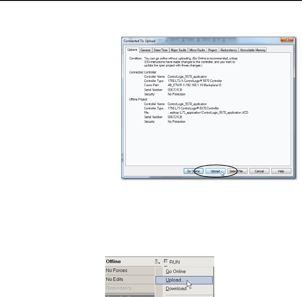
64 Rockwell Automation Publication 1756-UM001P-EN-P - May 2017
Chapter 3 Start Using the Controller
2. Click Upload after verifying the project that you are uploading in the
Connected to Upload dialog box.
Use the Controller Status Menu to Upload
After you have set a communication path in the project, you can use the
Controller Status menu to upload from the controller. To upload, from the
Controller Status menu, choose Upload.
Figure 5 - Upload Via the Controller Status Menu
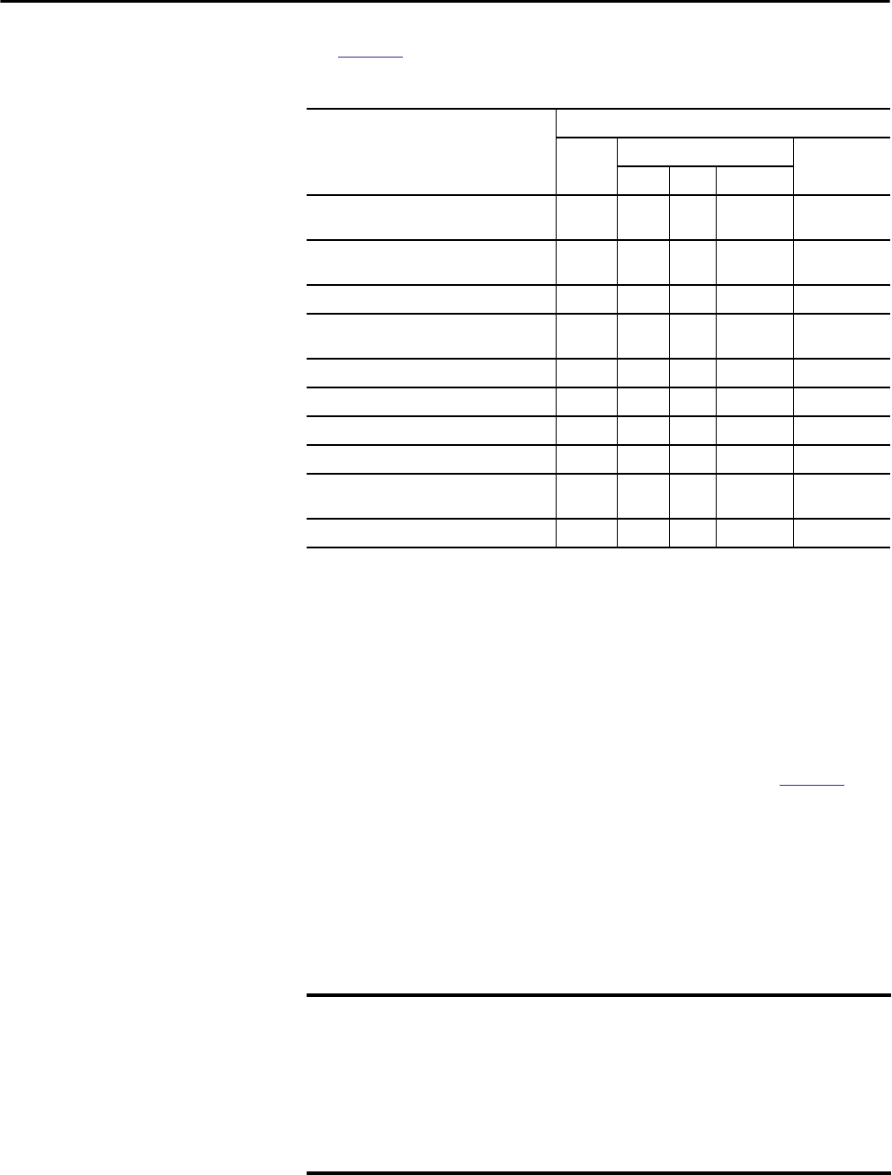
Rockwell Automation Publication 1756-UM001P-EN-P - May 2017 65
Start Using the Controller Chapter 3
Choose the Controller
Operation Mode
Use Table 13 as a reference when determining your controller Operation mode.
Use the Mode Switch to Change the Operation Mode
Use the mode switch to change the operation mode. The controller mode
switch provides a mechanical means to enhance controller and control system
security. You must physically move the mode switch on the controller to
change its operating mode from RUN, to REM, or to PROG. When the mode
switch on the controller is set to RUN mode, features like online editing,
program downloads, and firmware upgrades are prohibited. See Table 13 for a
complete list of prohibited features.
The physical mode switch can complement other authorization and
authentication methods that similarly control user-access to the controller,
such as the following:
• Logix CPU Security tool
• FactoryTalk® Security service
Table 13 - Controller Operation Modes and Meanings
If you want to Select one of these modes
Run Remote Program
Run Test Program
Turn outputs to the state commanded by the
logic of the project
XX
Turn outputs to their configured state for
Program mode
XX X
Execute (scan) tasks X X X
Change the mode of the controller via Logix
Designer application
XXX
Download a project X X X X
Schedule a ControlNet network X X
While online, edit the project X X X X
Send messages X X X
Send and receive data in response to a message
from another controller
XXXX X
Produce and consume tags X X X X X
IMPORTANT During runtime, we recommend that you place the controller mode switch in
RUN mode and remove the key (if applicable) from the switch. This can help
discourage unauthorized access to the controller or potential tampering
with the program of the controller, configuration, or device firmware. Place
the mode switch in REM or PROG mode during controller commissioning and
maintenance and whenever temporary access is necessary to change the
program, configuration, or firmware of the product.
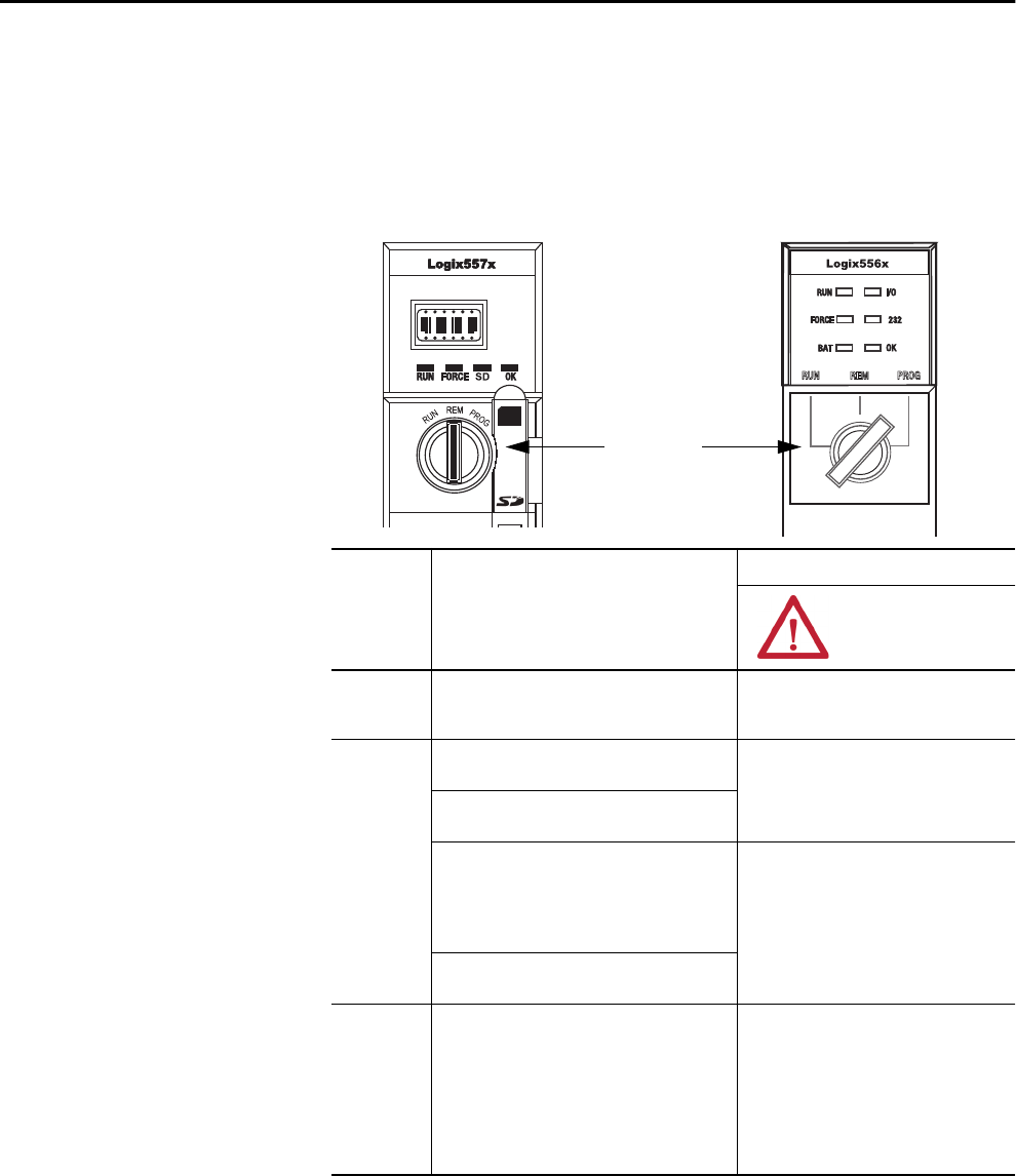
66 Rockwell Automation Publication 1756-UM001P-EN-P - May 2017
Chapter 3 Start Using the Controller
The mode switch on the front of the controller can be used to change the
controller to one of these modes:
• Run (RUN)
• Remote (REM)
• Program (PROG)
1756-L7x1756-L6x
Mode Switch
Mode Switch
Position
Available Controller Modes ATTENTION:
RUN Run mode—The controller is actively controlling
the process/machine. Projects cannot be edited in
the Logix Designer application when in Run mode.
Run mode is used only when all conditions are
safe.
REM Remote Run mode—This mode is identical to
Run mode except you can edit the project online.
You are able to modify a project file online in
Remote Run mode.
Be sure to control outputs with care to avoid
injury to personnel and damage to equipment.
Remote Program mode—This mode is identical
to Program mode.
Remote Test mode—The controller mode during
which code is executing. I/O is not controlled, and
limited editing operations are available.
Output modules are commanded to their Program
mode state (on, off, or hold).
Outputs are commanded to their Program
mode state, which can cause a dangerous
situation.
Note: The mode of the controller can be changed
from within the Logix Designer application.
PROG Program mode—The controller mode during
which programming language is not executing. I/O
is not controlled, and limited editing operations are
available.
Output modules are commanded to their Program
mode state (On, Off, or Hold).
In this position, controller modes cannot be
changed through the Logix Designer application.
Do not use Program mode as an emergency
stop (E-stop). Program mode is not a safety
device.
Outputs are commanded to their Program
mode state, which can cause a dangerous
situation.
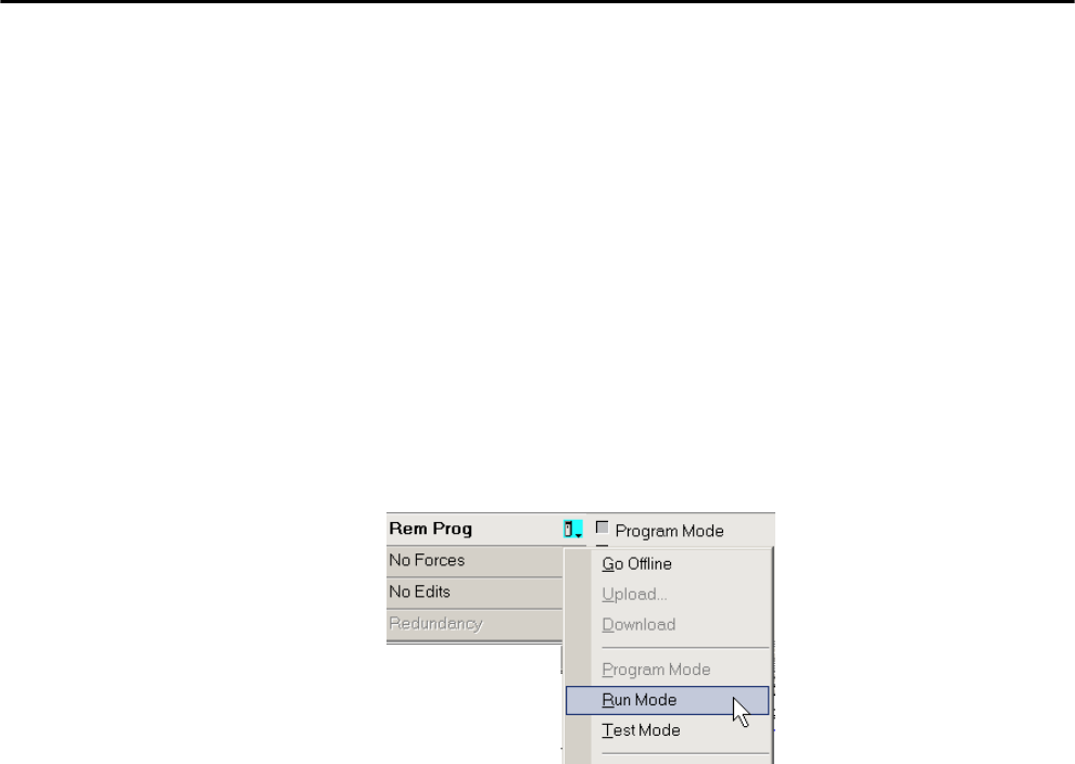
Rockwell Automation Publication 1756-UM001P-EN-P - May 2017 67
Start Using the Controller Chapter 3
Use Logix Designer to Change the Operation Mode
Dependent on the mode of the controller you specify by using the mode
switch, you can change the Operation mode of the controller in the Logix
Designer application.
After you are online with the controller and the controller mode switch is set to
Remote (REM or the center position), you can use the Controller Status menu
in the upper-left corner of the application window to specify these operation
modes:
• Remote Program
• Remote Run
• Remote Test
Figure 6 - Operation Mode
TIP For this example, the controller mode switch is set to Remote mode. If your
controller mode switch is set to Run or Program modes, the menu options
change.
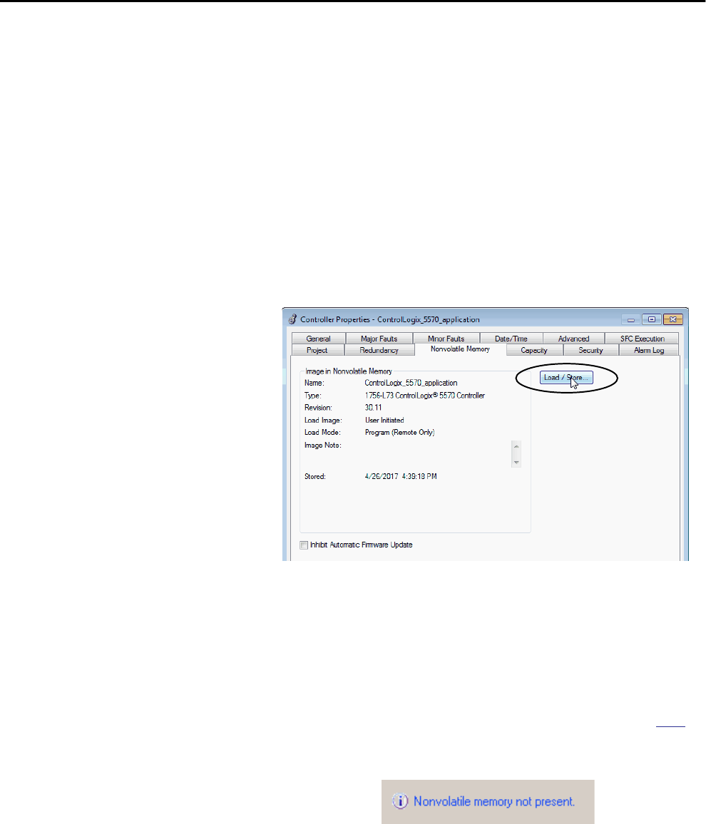
68 Rockwell Automation Publication 1756-UM001P-EN-P - May 2017
Chapter 3 Start Using the Controller
Load or Store to the
Memory Card
The memory card that is compatible with your ControlLogix controller is used
to load or store the contents of user memory for the controller.
Store to the Memory Card
After you are online with the controller and have changed the controller to
Program or Remote Program mode, complete these steps to store a project to
the memory card.
1. Open the Controller Properties dialog box and click the
Nonvolatile Memory tab.
2. Click Load/Store.
TIP If Load/Store is dimmed (unavailable), verify the following:
• You have specified the correct communication path and are online with
the controller in Program mode.
• The memory card is installed.
• With the 1756-L7x controllers, if the SD card is locked, Store is dimmed
(unavailable) and the locked status is indicated in the bottom-left
corner of the Nonvolatile memory/Load Store dialog box. See step 4.
If the memory card is not installed, a message in the lower-left corner of the
Nonvolatile Memory tab indicates the missing card as shown here.

Rockwell Automation Publication 1756-UM001P-EN-P - May 2017 69
Start Using the Controller Chapter 3
3. Change the Load Image, Load Mode, and Automatic Firmware Update
properties according to your application requirements.
The following table describes the Load Image options that you can
choose for the project.
The following table describes the Load Mode options that you can
choose for the project.
The following table describes the Automatic Firmware Update options
that you can choose for the project. The Automatic Firmware Update
property is also referred to as the Firmware Supervisor feature.
IMPORTANT If the SD card is locked and the Load Image option of the project is
set to On Power Up, the controller firmware is not updated as a
result of a firmware upgrade. The previously stored firmware and
project are loaded instead.
If you want the image (project) to load when Then choose
Power to the controller is applied or cycled On Power Up
The controller has lost the project and power has been cycled or
applied
On Corrupt Memory
Initiated via the Logix Designer application User Initiated
If you want the controller to go to this mode after
loading
Then choose
Program Program (remote only)
Run Run (remote only)
If you want to Then choose
Enable automatic firmware updates so I/O devices in the
configuration tree of the controller that are configured to use
Exact Match Keying are updated as required
Enable and Store Files to Image(1)
(1) The devices that are used with this option must support the revision of firmware being updated to.
Disable automatic firmware updates and remove any I/O
firmware files that are stored with the image
Disable and Delete Files from Image
Disable automatic firmware updates when there are no firmware
files are stored with the image
Disable
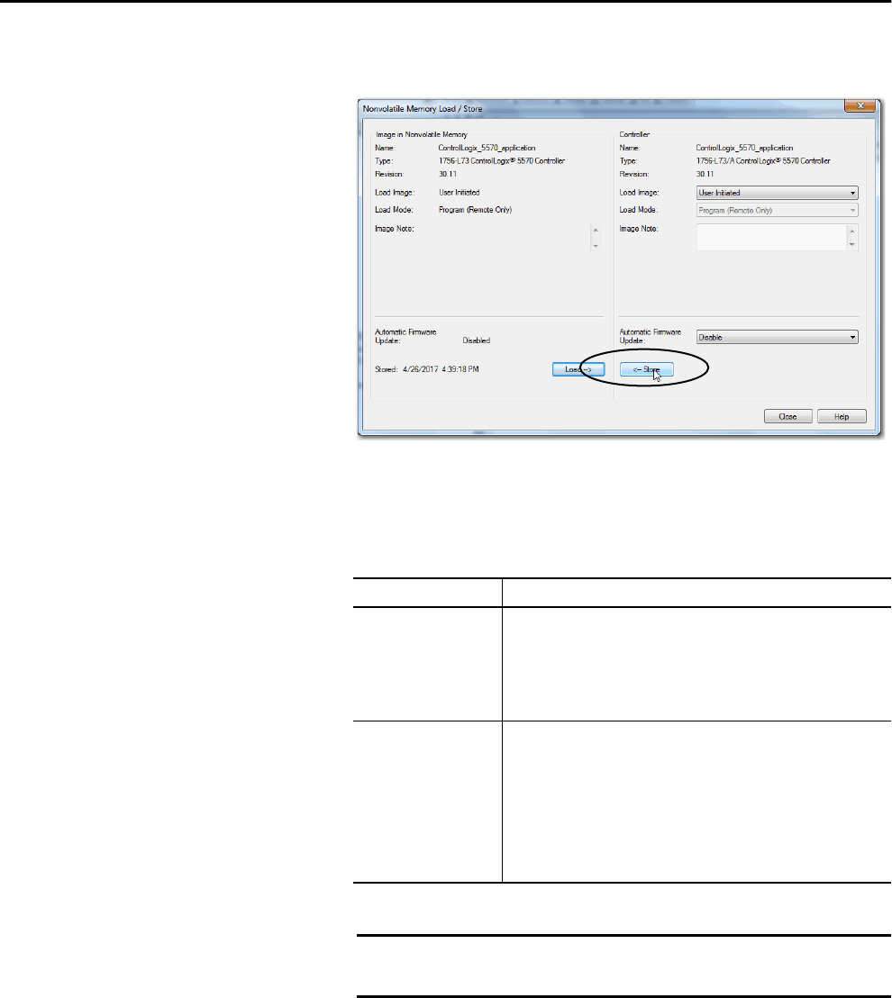
70 Rockwell Automation Publication 1756-UM001P-EN-P - May 2017
Chapter 3 Start Using the Controller
4. Click Store.
5. If a confirmation dialog box appears, click Yes.
The project is saved to the memory card as indicated by the controller
status indicators.
With these controllers These indications show the store status
1756-L6xWhile the store is in progress, the following occurs:
• OK indicator on the controller is solid red
• A dialog box in the Logix Designer application indicates that the store is
in progress
When the store is complete, the following occurs:
• OK indicator on the controller is momentarily red, then solid green
1756-L7xWhile the store is in progress, the following occurs:
• OK indicator is flashing green
• SD indicator is flashing green
• SAVE is shown on the status display
• A dialog box in the Logix Designer application indicates that the store is
in progress
When the store is complete, the following occurs:
• OK indicator on the controller is momentarily red, then solid green
• SD indicator on the controller is Off
IMPORTANT Allow the store to complete without interruption. If you interrupt
the store, data corruption or loss can occur.
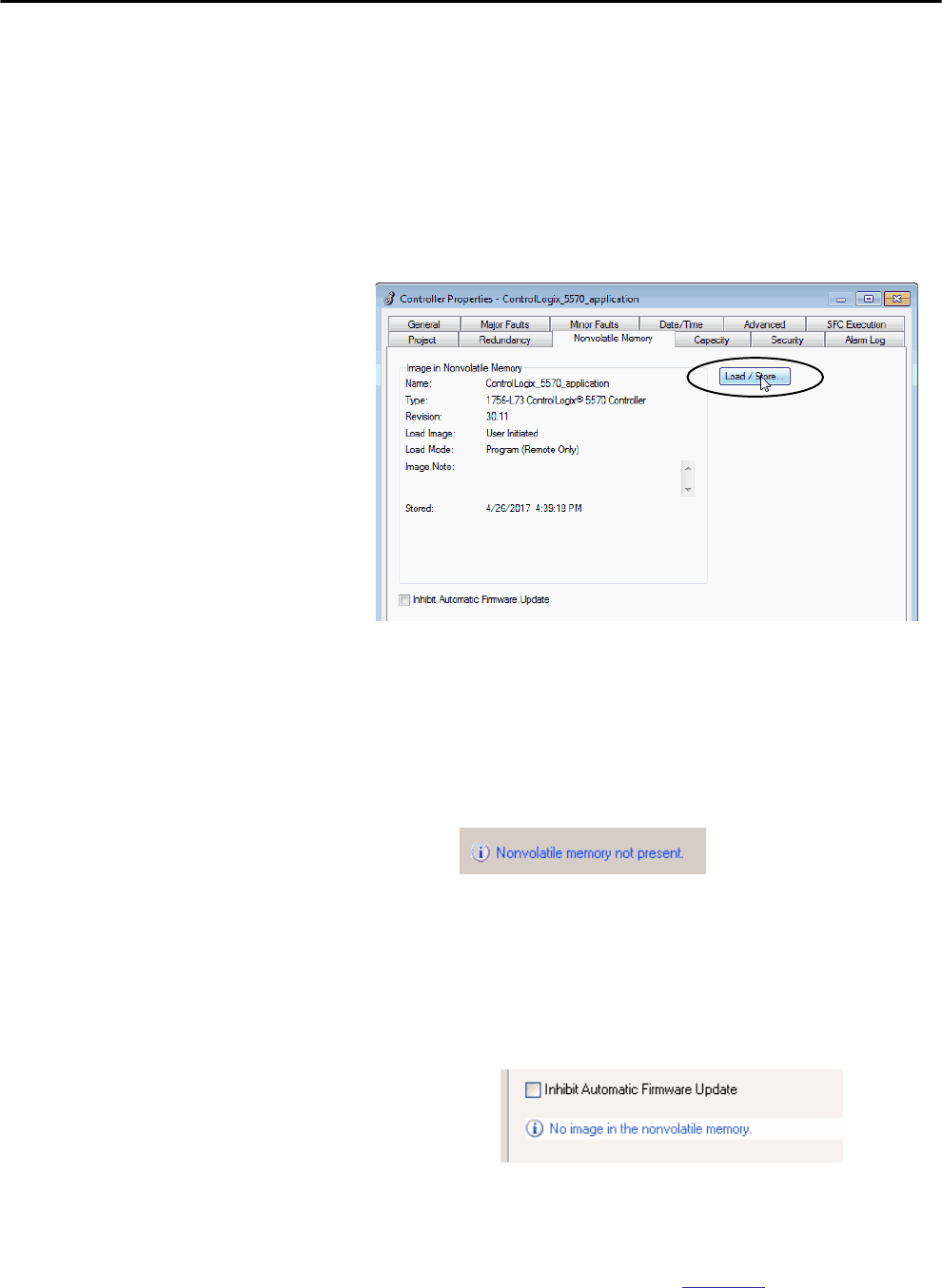
Rockwell Automation Publication 1756-UM001P-EN-P - May 2017 71
Start Using the Controller Chapter 3
Load from the Memory Card
After you have set the communication path, are online with the controller, and
have changed the controller to Program mode, complete these steps to load a
project to the controller from the memory card.
1. Open the Controller Properties and click the Nonvolatile Memory tab.
2. Click Load/Store.
3. Verify that the image in nonvolatile memory (that is, the project on the
memory card) is the project that you want to load.
TIP If Load/Store is dimmed (unavailable), verify the following:
• You have specified the correct communication path and are online with
the controller.
• The memory card is installed.
If the memory card is not installed, a message in the lower-left corner of the
Nonvolatile Memory tab indicates the missing card as shown here.
TIP If no project is stored on the memory card, a message in the lower-left
corner of the Nonvolatile Memory tab indicates that an image (or project) is
not available as shown here.
TIP For information to change the project that is available to load from
nonvolatile memory, see the Logix5000™ Controllers Nonvolatile Memory
Programming Manual, publication 1756-PM017.
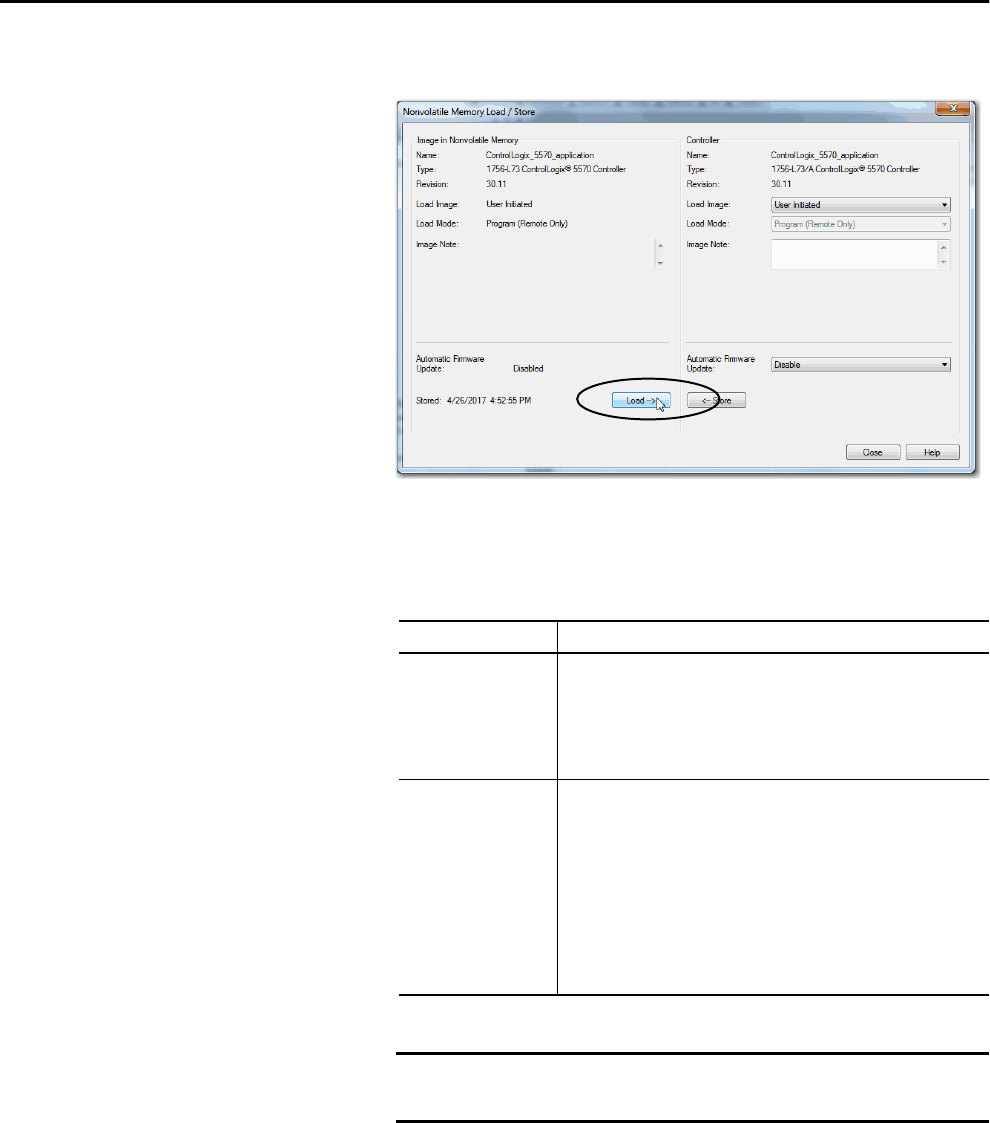
72 Rockwell Automation Publication 1756-UM001P-EN-P - May 2017
Chapter 3 Start Using the Controller
4. Click Load.
5. If a confirmation dialog box appears, click Yes.
The project is loaded to the controller as indicated by the controller
status indicators.
.
With these controllers These indications show the store status
1756-L6xWhile the load is in progress, the following occurs:
• OK indicator on the controller is flashing green
• A dialog box in the Logix Designer application indicates that the store is
in progress
When the load is complete, the following occurs:
• OK indicator on the controller is momentarily red, then solid green
1756-L7xWhile the load is in progress, the following occurs:
• OK indicator is solid red
• SD indicator is flashing green
• LOAD is shown on the status display
• UPDT can be shown on the status display if the firmware is also updating
with the load
• A dialog box in the Logix Designer application indicates that the store is
in progress
When the load is complete, the following occurs:
• OK indicator on the controller is momentarily red, then solid green
• SD indicator on the controller is Off
IMPORTANT Allow the load to complete without interruption. If you interrupt
the load, data corruption or loss can occur.

Rockwell Automation Publication 1756-UM001P-EN-P - May 2017 73
Start Using the Controller Chapter 3
Other Memory Card Tasks
Other tasks that you can complete by using the memory cards of the controller
include the following:
• Change the image that is loaded from the card
• Check for a load that was completed
• Clear an image from the memory card
• Store an empty image
• Change load parameters
• Read/write application data to the card
For more information to complete any of these tasks, see the Logix5000
Controllers Memory Card Programming Manual, publication 1756-PM017.
Use ControlLogix Energy
Storage Modules (ESMs)
You can use the ControlLogix ESMs to execute one of the following tasks:
• Provide power to 1756-L7x controllers to save the program to the on-
board nonvolatile storage (NVS) memory of the controller after power
is removed from the chassis or the controller is removed from a powered
chassis.
.
• Clear the program from the on-board NVS memory of the 1756-L7x
controller. For more information, see Clear the Program from On-board
NVS Memory.
This table describes the energy storage modules (ESM).
IMPORTANT When you are using an ESM to save the program to on-board NVS
memory, you are not saving the program to the SD card installed in
the controller.
Cat. No. Description
1756-ESMCAP Capacitor-based ESM
The 1756-L7x controllers come with this ESM installed.
1756-ESMNSE Capacitor-based ESM without WallClockTime back-up power
Use this ESM if your application requires that the installed ESM deplete its residual stored
energy to 40J or less before transporting it into or out of your application. Additionally,
you can use this ESM with only a 1756-L73 (8 MB) or smaller memory-sized controller.
1756-ESMNRM Secure capacitor-based ESM (non-removable)
This ESM provides your application an enhanced degree of security by blocking physical
access to the USB connector and the SD card.
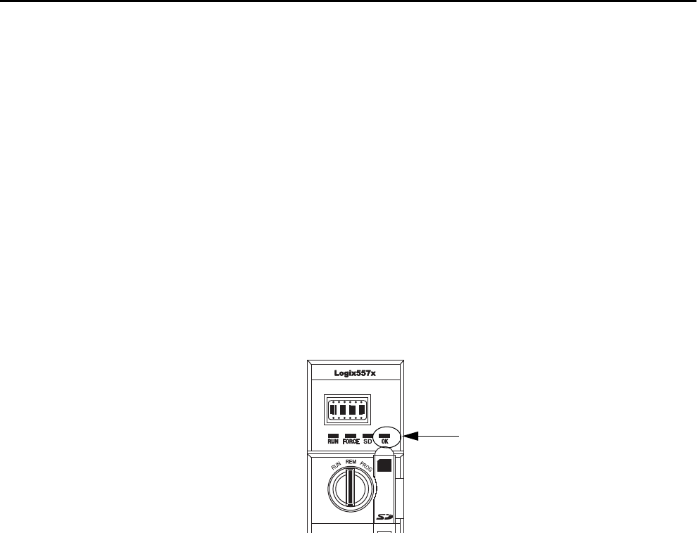
74 Rockwell Automation Publication 1756-UM001P-EN-P - May 2017
Chapter 3 Start Using the Controller
Save the Program to On-board NVS Memory
Follow these steps to save the program to NVS memory when the controller
loses power.
1. Remove power from the controller.
You can remove power in one of two ways:
• Turn power off to the chassis while the controller is installed in the
chassis.
• Remove the controller from a powered chassis.
Immediately after the controller is no longer powered, the program
starts saving while the OK status indicator is green (this green is a
dimmer green than normal operation), then turns red after program save
is complete. Once the ESM stops operating, it turns off.
This graphic shows the OK status indicator on the controller.
2. Leave the ESM on the controller until the OK status indicator is Off.
Clear the Program from On-board NVS Memory
If your application lets you, follow these steps to clear the program from the on-
board NVS memory of the 1756-L7x controller.
1. Remove the ESM from the controller.
2. Remove power from the controller.
You can remove power in one of the following two ways:
• Turn power off to the chassis while the controller is installed in the
chassis.
• Remove the controller from a powered chassis.
3. Reinstall the ESM into the controller.
4. Restore power to the controller in one of these two ways:
• If the controller is installed in the chassis, turn power back onto the
chassis.
• If the controller is not installed into the chassis, reinstall the
controller into the chassis and turn power back onto the chassis.
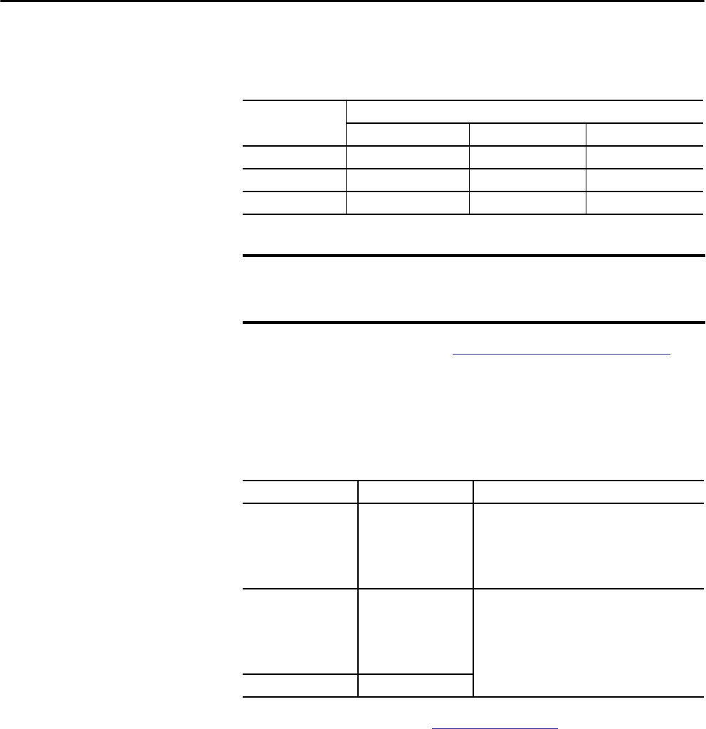
Rockwell Automation Publication 1756-UM001P-EN-P - May 2017 75
Start Using the Controller Chapter 3
Estimate the ESM Support
of the WallClockTime
The ESM provides support for the maintenance of the WallClockTime of the
controller when power is not applied. Use this table to estimate the hold-up
time of the ESM based on the temperature of the controller and installed ESM.
To check the status of the ESM, see General Status Messages on page 186.
Maintain the Battery
(Only 1756-L6x Controllers)
This section explains how to monitor and maintain the lithium batteries that
the ControlLogix controllers support.
For further information, see the Additional Resources section in the preface.
Hold-up Time (in days)
Temperature 1756-ESMCAP 1756-ESMNRM 1756-ESMNSE
20 °C (68 °F) 12 12 0
40 °C (104 °F) 10 10 0
60 °C (140 °F) 7 7 0
IMPORTANT Any action that causes the 1756-L7x controller to reset (hard or soft),
without an ESM installed, results in the controller’s wal clock time of the
controller being reset to the factory default of 01/01/1998.
Table 14 - 1756-L6x Controllers and Compatible Batteries
Cat. No. Series Compatible Battery
1756-L61
1756-L62
1756-L63
A 1756-BA1
or
1756-BATA
or
1756-BATM
1756-L61
1756-L62
1756-L63
1756-L64
1756-L65
B 1756-BA2
1756-L63XT B
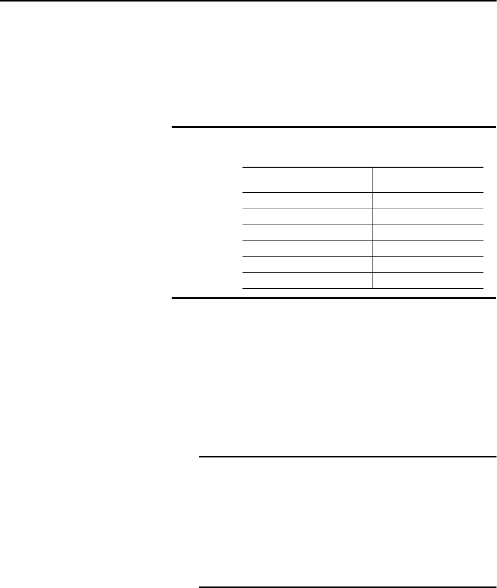
76 Rockwell Automation Publication 1756-UM001P-EN-P - May 2017
Chapter 3 Start Using the Controller
Check the Battery Status
When the battery is approximately 95% discharged, these low-battery
warnings are indicated:
• The BAT is solid red.
• A minor fault (type 10, code 10) is logged.
1756-BA1 or 1756-BATA Battery Life
To estimate how long a 1756-BA1 or 1756-BATA battery can support
controller memory on 1756-L6x, series A controllers, perform this procedure.
1. Determine the temperature 2.54 cm (1 in.) below the chassis.
2. Determine the weekly percentage of time that the controller is turned
on.
IMPORTANT To prevent possible battery leakage, even if the BAT status indicator is off,
replace a battery according to this schedule.
EXAMPLE If a controller is Off at one of these times:
• 8 hr/day during a 5-day work week
• All day Saturday and Sunday
Then the controller is off 52% of the time:
• Total hours per week = 7 x 24 = 168 hrs
• Total off hours per week = (5 days x 8 hr/day) + Saturday +
Sunday = 88 hrs
• Percentage off time = 88/168 = 52%
If the temperature 2.54 cm (1 in.)
below the chassis is
Replace the battery within
-25…35 C (-13…95 F) No replacement required
36…40 C (96.8…104 F) 3 years
41…45 C (105.8…113F) 2 years
46…50 C (114.8…122 F) 16 months
51…55 C (123.8…131 F) 11 months
56…70 C (132.8…158F) 8 months
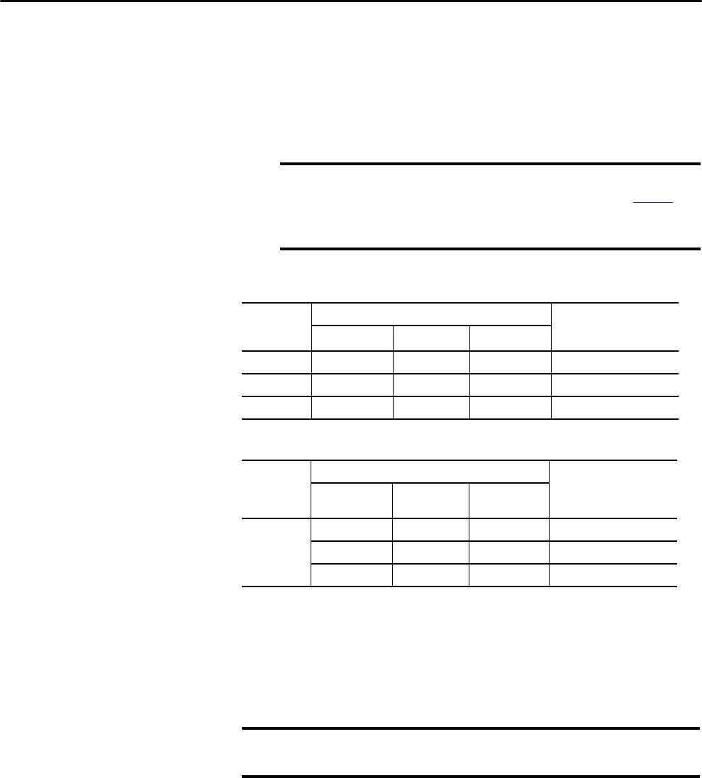
Rockwell Automation Publication 1756-UM001P-EN-P - May 2017 77
Start Using the Controller Chapter 3
3. Determine the estimated worst-case battery life before and after the
BAT status indicator turns on.
4. For each year of battery life, decrease the time before the BAT status
indicator turns on by the percentage that is shown in the table.
Do not decrease the time after the BAT status indicator turns on.
1756-BATM Battery Module and Battery Life
Use the 1756-BATM battery module with any 1756-L6x/A controller. The
battery module is highly recommended for higher-memory controllers.
When the 1756-BATA battery within the 1756-BATM module is
approximately 50% discharged, these low-battery warnings are indicated:
• The BAT is solid red.
• A minor fault (type 10, code 10) is logged.
IMPORTANT If the BAT status indicator turns on when you apply power to the
controller, the remaining battery life can be less than Table 15
indicates. Some of the battery life can be used up while the
controller is off and unable to turn on the BAT status indicator.
Table 15 - Worst-case Estimates of 1756-BA1 Battery Life
Temperature Battery Life Before BAT Status Indicator Turns On Battery Life After BAT
Status Indicator Turns On
and Power is Off
Power Off 100% Power Off 50% Yearly Decrease
60 °C (140 °F) 22 days 43 days 23% 6 hrs
25 °C (77 °F) 21 days 42 days 17% 28 hrs
0 °C (32 °F) 14 days 28 days 17% 2.5 days
Table 16 - Worst-case Estimates of 1756-BATA Battery Life
Temperature Battery Life Before BAT Status Indicator Turns On Battery Life After BAT
Status Indicator Turns On
and Power is Off
Power Off 100% Power Off 50% Yearly
Decrease
60 °C (140 °F) 98 days 204 days 11% 104 days
25 °C (77 °F) 146 days 268 days 5% 157 days
0 °C (32 °F) 105 days 222 days 6% 113 days
IMPORTANT If your project is not stored in nonvolatile memory, the use of the battery
module is highly recommended.
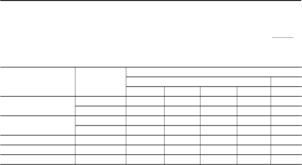
78 Rockwell Automation Publication 1756-UM001P-EN-P - May 2017
Chapter 3 Start Using the Controller
Estimate 1756-BA2 Battery Life
The 1756-BA2 batteries are for use in 1756-L6x/B controllers. Use Table 17 to
estimate how much time can elapse before the battery becomes low.
Table 17 - Worst-case Estimates of 1756-BA2 Life according to Temperatures and Power Cycles
Temperature 2.54 cm (1 in.) Below
the Chassis, max
Power Cycles Battery Life Before the BAT Status Indicator Turns Red
Project Size
1 MB 2 MB 4 MB 8 MB 16 MB
-25…35 °C (-13…95 °F) 3 per day 3 years 3 years 26 months 20 months 10 months
2 per day or less 3 years 3 years 3 years 31 months 16 months
41…45 °C (105.8…113 °F) 3 per day 2 years 2 years 2 years 20 months 10 months
2 per day or less 2 years 2 years 2 years 2 years 16 months
46…50 °C (105.8…113 °F) 3 per day or less 16 months 16 months 16 months 16 months 10 months
51…55 °C (123.8…131 °F) 3 per day or less 11 months 11 months 11 months 11 months 10 months
56…70 °C (132.8…158 °F) 3 per day or less 8 months 8 months 8 months 8 months 8 months

Rockwell Automation Publication 1756-UM001P-EN-P - May 2017 79
Start Using the Controller Chapter 3
Estimate 1756-BA2 Battery Life After Warnings
Use this table to estimate the battery life after the low-battery warnings are
indicated. Use these times even if the controller does not have power because
there is a small power-drain on the battery.
IMPORTANT When you power up the controller, see if there is a low-battery warning. If
you get a low-battery warning for the first time, you have less battery life
than this table shows. While powered down, the controller still drains the
battery but it cannot give the low-battery warning.
Temperature 2.54 cm (1 in.)
Below the Chassis, max
Power Cycles Battery Life After the BAT Status Indicator Turns Red (worst case)
Project Size
1 MB 2 MB 4 MB 8 MB 16 MB
0…20 °C (32…68 °F) 3 per day 26 weeks 18 weeks 12 weeks 9 weeks 5 weeks
1 per day 26 weeks 26 weeks 26 weeks 22 weeks 13 weeks
1 per month 26 weeks 26 weeks 26 weeks 26 weeks 26 weeks
21…40 °C (69.8…104 °F) 3 per day 18 weeks 14 weeks 10 weeks 8 weeks 5 weeks
1 per day 24 weeks 21 weeks 18 weeks 16 weeks 11 weeks
1 per month 26 weeks 26 weeks 26 weeks 26 weeks 26 weeks
41…45 °C (105.8…113 °F) 3 per day 12 weeks 10 weeks 7 weeks 6 weeks 4 weeks
1 per day 15 weeks 14 weeks 12 weeks 11 weeks 8 weeks
1 per month 17 weeks 17 weeks 17 weeks 17 weeks 16 weeks
46…50 °C (105.8…113 °F) 3 per day 10 weeks 8 weeks 6 weeks 6 weeks 3 weeks
1 per day 12 weeks 11 weeks 10 weeks 9 weeks 7 weeks
1 per month 12 weeks 12 weeks 12 weeks 12 weeks 12 weeks
51…55 °C (123.8…131 °F) 3 per day 7 weeks 6 weeks 5 weeks 4 weeks 3 weeks
1 per day 8 weeks 8 weeks 7 weeks 7 weeks 5 weeks
1 per month 8 weeks 8 weeks 8 weeks 8 weeks 8 weeks
56…60 °C (132.8…140 °F) 3 per day 5 weeks 5 weeks 4 weeks 4 weeks 2 weeks
1 per day 6 weeks 6 weeks 5 weeks 5 weeks 4 weeks
1 per month 6 weeks 6 weeks 6 weeks 6 weeks 6 weeks
EXAMPLE Under these conditions, the battery lasts at least 20 months before the BAT
status indicator turns red:
• The maximum temperature 2.54 cm (1 in.) below the
chassis = 45 °C (113 °F).
• You cycle power to the controller three times per day.
• The controller contains an 8 MB project.
80 Rockwell Automation Publication 1756-UM001P-EN-P - May 2017
Chapter 3 Start Using the Controller
Battery Storage and Disposal
Follow these general rules to store your batteries:
• Store batteries in a cool, dry environment. We recommend
25 °C (77 °F) with 40…60% relative humidity.
• You can store batteries for up to 30 days in temperatures from
-45…85 °C (-49…185 °F), such as during transportation.
• To avoid leakage or other hazards, do not store batteries above
60 °C (140 °F) for more than 30 days.
This product contains a sealed lithium battery that needs to be replaced
during the life of the product.
At the end of its life, the battery contained in this product should be
collected separately from any unsorted municipal waste.
The collection and recycling of batteries helps protect the environment
and contributes to the conservation of natural resources as valuable
materials are recovered.
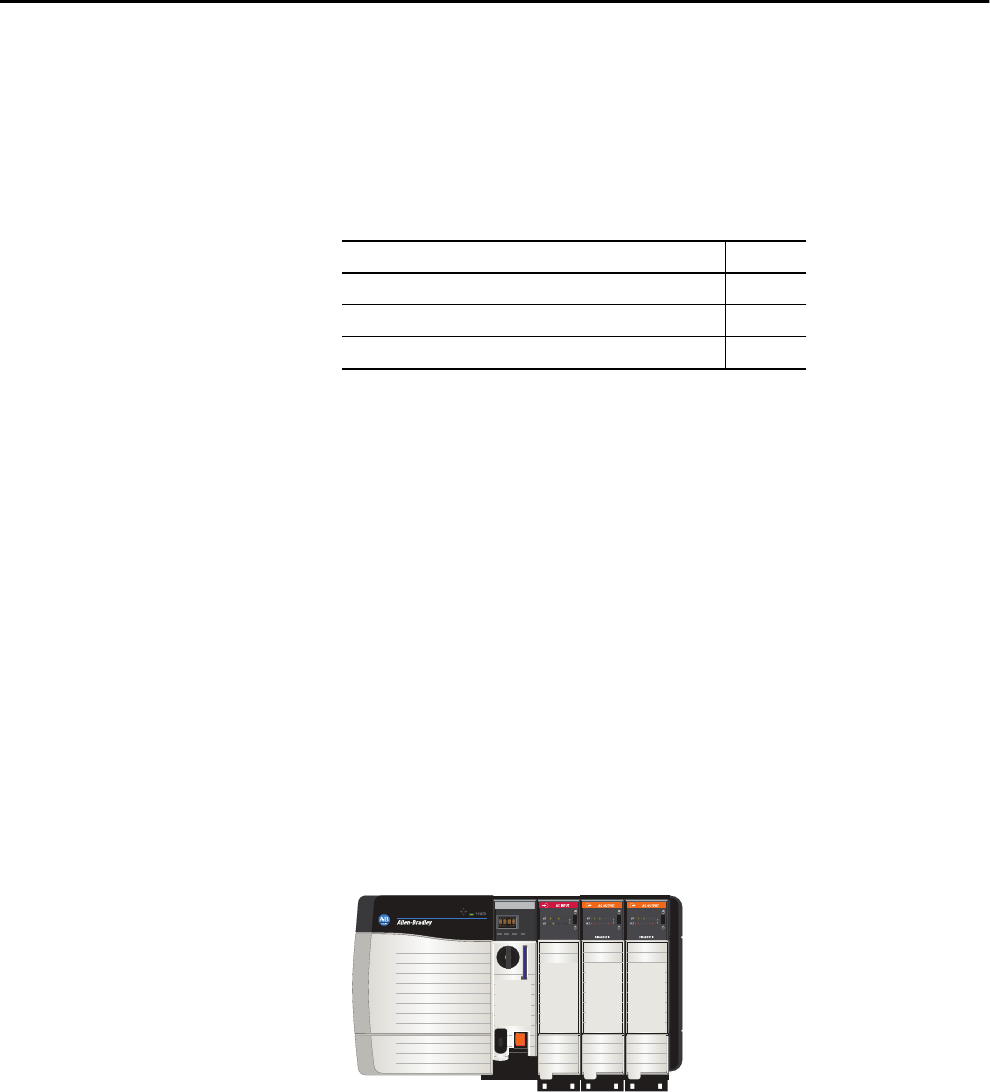
Rockwell Automation Publication 1756-UM001P-EN-P - May 2017 81
Chapter 4
ControlLogix System and Controllers
ControlLogix System The ControlLogix® system is chassis-based and provides the option to
configure a control system that uses sequential, process, motion, drive control,
and communication and I/O capabilities.
Configuration Options
This section describes some of the many system configuration options that are
available with ControlLogix controllers.
Standalone Controller and I/O
One of the simplest ControlLogix configurations is a standalone controller
with I/O assembled in one chassis.
Figure 7 - Standalone Controller and I/O5
Topic Page
ControlLogix System 81
Design a ControlLogix System 84
ControlLogix Controller Features 85
L75
Input
Output
Output
Input
L7
Input
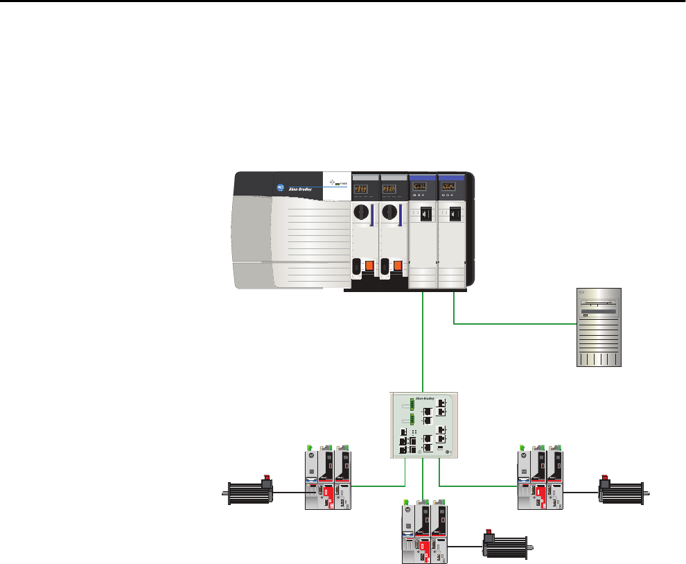
82 Rockwell Automation Publication 1756-UM001P-EN-P - May 2017
Chapter 4 ControlLogix System and Controllers
Multiple Controllers in One Chassis
For some applications, multiple controllers can be used in one ControlLogix
chassis. For example, for better performance, multiple controllers can be used
in motion applications.
Figure 8 - Multiple Controllers in One Chassis
L75
L75
EN2T
EN2T
FactoryTalk ®Server
Stratix 8000™ Switch
Kinetix 6500 Drive
Kinetix® 6500 Drive
Kinetix 6500 Drive
Motor
Motor
Motor
Ethernet
Ethernet
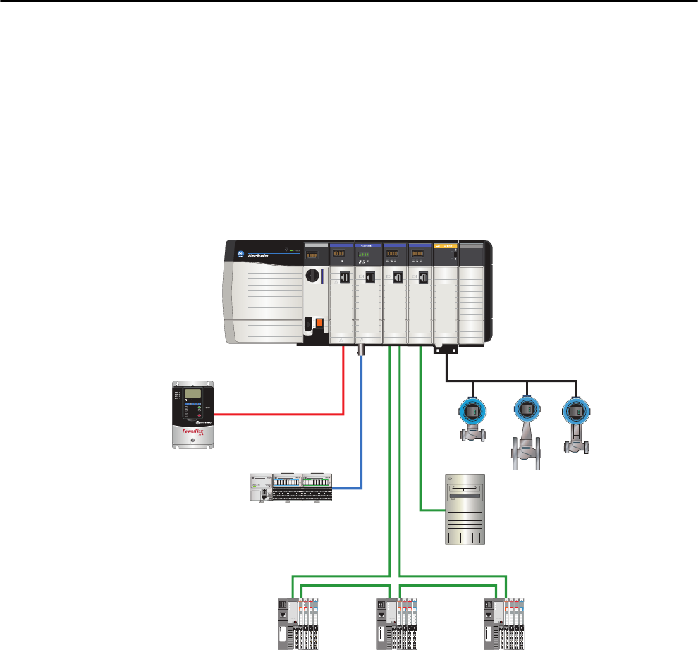
Rockwell Automation Publication 1756-UM001P-EN-P - May 2017 83
ControlLogix System and Controllers Chapter 4
Multiple Devices Connected Via Multiple Networks
For some applications, various devices can be connected to the ControlLogix
chassis via multiple communication networks. For example, a system can be
connected to the following:
• Distributed I/O via an Ethernet network
• A PowerFlex® drive connected via a DeviceNet network
• Flowmeters that are connected via a HART connection
Figure 9 - Multiple Devices Connected Via Multiple Networks
HART
L75
EN2T
DNB
CN2
EN2T
IF8H
PowerFlex Drive
DeviceNet
FLEX™ I/O
ControlNet
Ethernet Device-level
Ring Network
Ethernet
HART Endress + Hauser Flowmeters
FactoryTalk Server
POINT I/O™

84 Rockwell Automation Publication 1756-UM001P-EN-P - May 2017
Chapter 4 ControlLogix System and Controllers
Design a ControlLogix System When you design a ControlLogix system, there are several system components
to consider for your application. Some of these components include the
following:
• I/O devices
• Motion control and drive requirements
• Communication modules
• Controllers
• Chassis
• Power supplies
• Studio 5000® environment
For more information to design and select components for your ControlLogix
system, see the ControlLogix Selection Guide, publication 1756-SG001.
See the Additional Resources section in the preface for more information if
you are designing your ControlLogix System for any of the following
applications:
• Motion with Integrated Motion on the EtherNet/IP network
• Motion with the use of a coordinate system
• Motion with sercos or analog motion
• Enhanced redundancy
• Standard redundancy
•SIL2
• SIL2 fault-tolerant I/O with Studio 5000 subroutines
• SIL2 fault-tolerant I/O with Studio 5000 Add-On Instructions
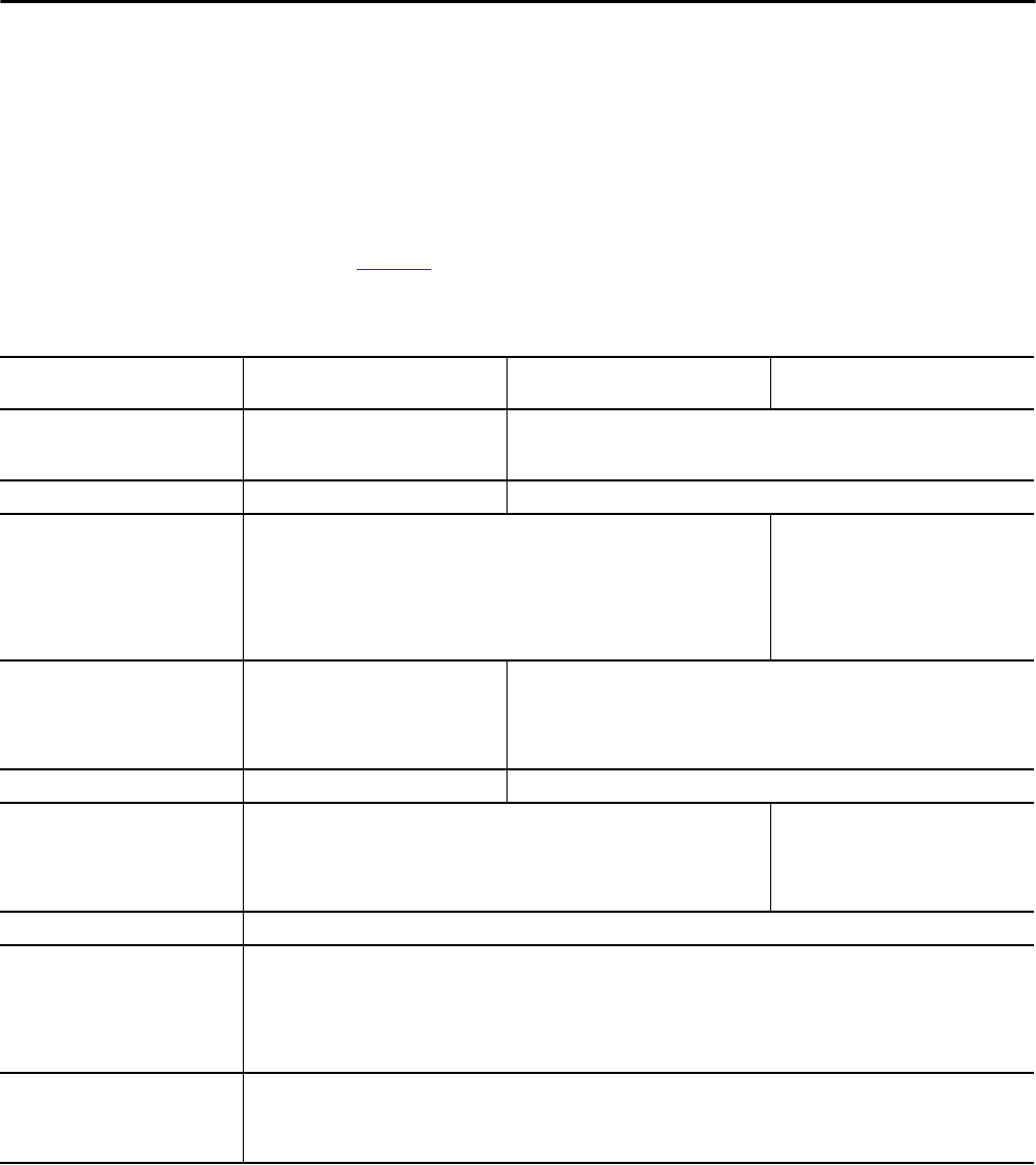
Rockwell Automation Publication 1756-UM001P-EN-P - May 2017 85
ControlLogix System and Controllers Chapter 4
ControlLogix Controller
Features
The ControlLogix controllers are part of the Logix5000™ family of controllers
that are offered by Rockwell Automation. The sections that follow describe the
differentiating features of the ControlLogix controllers.
System, Communication, and Programming Features
Table 18 lists the system, communication, and programming features available
with ControlLogix controllers.
Table 18 - ControlLogix Controller Features
Feature 1756-L61, 1756-L62, 1756-L63, 1756-
L64, 1756-L65
1756-L71, 1756-L72, 1756-L73, 1756-
L74, 1756-L75
1756-L72EROM, 1756-L73EROM
Controller tasks • 32 tasks
• 100 programs/task
• Event tasks: all event triggers
• 32 tasks
• 1000 programs/task
• Event tasks: all event triggers
Communication ports 1 port - RS-232 serial 1 port - USB, 2.0 full-speed, Type B
Communication options • EtherNet/IP
• ControlNet
• DeviceNet
• Data Highway Plus™
• Remote I/O
• SynchLink
• Third-party process and device networks
EtherNet/IP
Serial port communication • ASCII
• DF1 full/half-duplex
• DF1 radio modem
• DH-485
• Modbus via logic
N/A
Controller connections supported, max 250 500
Network connections, per network
module
• 128 ControlNet (1756-CN2/B)
• 100 ControlNet (1756-CN2/A)
• 40 ControlNet (1756-CNB)
• 256 EtherNet/IP; 128 TCP (1756-EN2x)
• 128 EtherNet/IP; 64 TCP (1756-ENBT)
256 EtherNet/IP; 128 TCP (1756-EN2x)
Controller redundancy Full support except for motion applications
Integrated motion • Integrated Motion on the EtherNet/IP network
• Sercos interface
• Analog options:
– Encoder input
– LDT input
– SSI input
Programming languages • Relay ladder
• Structured text
• Function block
• Sequential function chart (SFC)
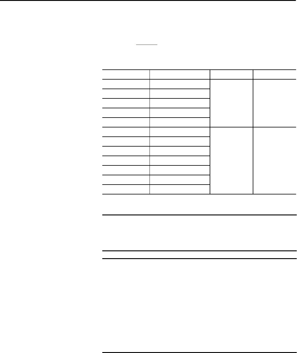
86 Rockwell Automation Publication 1756-UM001P-EN-P - May 2017
Chapter 4 ControlLogix System and Controllers
Memory Options
The ControlLogix controller is available in different combinations of user
memory. Use Table 19 to determine which controller meets your memory
requirements.
.
Table 19 - ControlLogix Controller Memory Options
Controller Memory for Data and Logic I/O Back-up Memory
1756-L61 2 MB 478 KB CompactFlash card(1)
(1) These nonvolatile memory cards are optional and do not come with the controller.
1756-L62 4 MB
1756-L63, 1756-L63XT 8 MB
1756-L64 16 MB
1756-L65 32 MB
1756-L71 2 MB 0.98 MB (1006 KB) SD card
1756-L72 4 MB
1756-L73, 1756-L73XT 8 MB
1756-L74 16 MB
1756-L75 32 MB
1756-L72EROM 4 MB
1756-L73EROM 8 MB
IMPORTANT The 1756-L7x controllers ship with an SD card installed. We recommend that
you leave the SD card installed, so if a fault occurs, diagnostic data is
automatically written to the card and Rockwell Automation can use the data
to troubleshoot the anomaly.
IMPORTANT We recommend that you use the SD cards available from
Rockwell Automation (catalog numbers 1784-SD1 or 1784-SD2).
While other SD cards can be used with the controller, Rockwell Automation
has not tested the use of those cards with the controller. If you use an SD
card other than those cards that are available from Rockwell Automation,
you can experience data corruption or loss.
Also, SD cards that are not provided by Rockwell Automation can have
different industrial, environmental, and certification ratings as those cards
that are available from Rockwell Automation and can have difficulty with
survival in the same industrial environments as the industrially rated
versions available from Rockwell Automation.

Rockwell Automation Publication 1756-UM001P-EN-P - May 2017 87
ControlLogix System and Controllers Chapter 4
Electronic Keying
Electronic Keying reduces the possibility that you use the wrong device in a
control system. It compares the device that is defined in your project to the
installed device. If keying fails, a fault occurs. These attributes are compared.
The following Electronic Keying options are available.
Carefully consider the implications of each keying option when selecting one.
More Information
For more detailed information on Electronic Keying, see Electronic Keying in
the Logix5000 Control Systems Application Technique, publication
LOGIX-AT001.
Attribute Description
Vendor The device manufacturer.
Device Type The general type of the product, for example, digital I/O module.
Product Code The specific type of the product. The Product Code maps to a catalog number.
Major Revision A number that represents the functional capabilities of a device.
Minor Revision A number that represents behavior changes in the device.
Keying Option Description
Compatible Module Lets the installed device accept the key of the device that is defined in the project when
the installed device can emulate the defined device. With Compatible Module, you can
typically replace a device with another device that has the following characteristics:
• Same catalog number
• Same or higher Major Revision
• Minor Revision as follows:
– If the Major Revision is the same, the Minor Revision must be the same or higher.
– If the Major Revision is higher, the Minor Revision can be any number.
Disable Keying Indicates that the keying attributes are not considered when attempting to communicate
with a device. With Disable Keying, communication can occur with a device other than
the type specified in the project.
ATTENTION: Be extremely cautious when using Disable Keying; if used incorrectly, this
option can lead to personal injury or death, property damage, or economic loss.
We strongly recommend that you do not use Disable Keying.
If you use Disable Keying, you must take full responsibility for understanding whether the
device being used can fulfill the functional requirements of the application.
Exact Match Indicates that all keying attributes must match to establish communication. If any
attribute does not match precisely, communication with the device does not occur.
IMPORTANT Changing Electronic Keying parameters online interrupts connections to the device
and any devices that are connected through the device. Connections from other
controllers can also be broken.
If an I/O connection to a device is interrupted, the result can be a loss of data.

88 Rockwell Automation Publication 1756-UM001P-EN-P - May 2017
Chapter 4 ControlLogix System and Controllers
Notes:
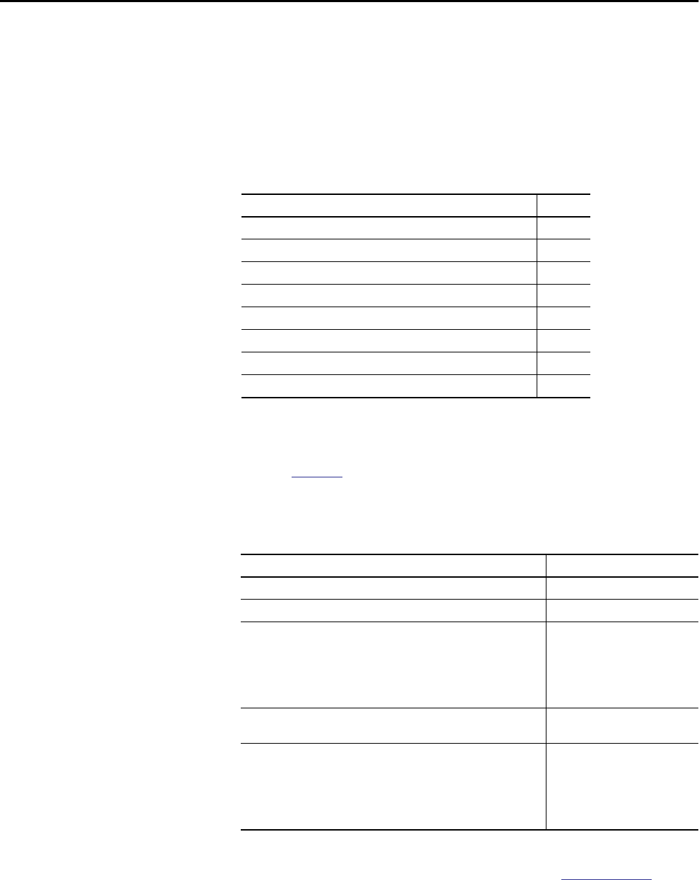
Rockwell Automation Publication 1756-UM001P-EN-P - May 2017 89
Chapter 5
Communication Networks
Networks Available Several communication networks are available for use with ControlLogix®
systems. Table 20 describes typical network applications that are used with
ControlLogix systems and lists the networks available to support such
applications.
For more information about network design for your system, see the Ethernet
Design Considerations Reference Manual, publication ENET-RM002.
Topic Page
Networks Available 89
EtherNet/IP Network Communication 90
ControlNet Network Communication 93
DeviceNet Network Communication 96
Data Highway Plus (DH+) Network Communication 99
Universal Remote I/O (RIO) Communication 101
Foundation Fieldbus Communication 102
HART Communication 104
Table 20 - Applications and Supported Networks
Application Type Supported Networks
Integrated Motion EtherNet/IP
Integrated Motion on the EtherNet/IP network for time synchronization EtherNet/IP
Control of distributed I/O • ControlNet
• DeviceNet
• EtherNet/IP
• Foundation Fieldbus
• HART
• Universal remote I/O
Produce/consume data between controllers • ControlNet
• EtherNet/IP
Messaging to and from other devices, including access to the controller via
the Studio 5000 Logix Designer® application
• ControlNet
• DeviceNet (only to devices)
• Data Highway Plus™ (DH+)
• DH-485
• EtherNet/IP
• Serial
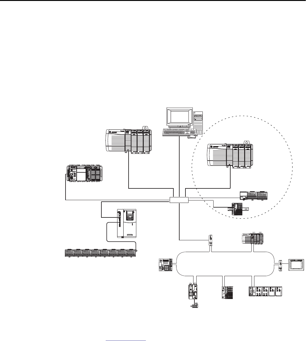
90 Rockwell Automation Publication 1756-UM001P-EN-P - May 2017
Chapter 5 Communication Networks
EtherNet/IP Network
Communication
The EtherNet/IP network offers a full suite of control, configuration, and data
collection services by layering the Common Industrial Protocol (CIP) over the
standard internet protocols, such as TCP/IP and UDP. This combination of
well-accepted standards provides the capability that is required to support
information data exchange and control applications.
The EtherNet/IP network uses commercially available Ethernet components
and physical media, providing you with a cost-effective plant-floor solution.
Figure 10 - EtherNet/IP Network Example
For more information about using EtherNet/IP modules, see the EtherNet/IP
Modules in Logix5000™ Control Systems User Manual, publication
ENET-UM001.
LINK NET OK
LINK NET OK
02
0
1734-AENTR
Module
Status
Network
Activity
Network
Status
Point Bus
Status
System
Power
Field
Power
POINT I O
Link 1
Activity/
Status
Link 2
Activity/
Status
IP ADDRESS
• ControlLogix
• 1756-EN2T
CompactLogix™
PowerFlex® 700S
Switch 1794-AENT
1756-EN2T
Distributed I/O
1734-AENT
Workstation
Device Level Ring (DLR) Topology
connected via 1783-ETAP with tap

Rockwell Automation Publication 1756-UM001P-EN-P - May 2017 91
Communication Networks Chapter 5
ControlLogix EtherNet/IP Module Features
The ControlLogix EtherNet/IP communication modules provide these
features:
• Support for messaging, produced/consumed tags, HMI, and
distributed I/O
• The ability to encapsulate messages within the standard TCP/UDP/IP
protocol
• A common application layer with ControlNet and DeviceNet networks
• Network connections via an RJ45 cable
• Support half/full duplex 10 MB or 100 MB operation
• Support standard switches
ControlLogix EtherNet/IP Communication Modules
For EtherNet/IP network communication in a ControlLogix system, you have
a number of modules to choose from. Table 21 lists their primary features.
Table 21 - EtherNet/IP Communication Modules and Capabilities
Module Is used to
1756-ENBT • Connect controllers to I/O modules (requires an adapter for distributed I/O).
• Communicate with other EtherNet/IP devices (messages).
• Serve as a pathway to share data between Logix5000 controllers (produce/consume).
• Bridge EtherNet/IP nodes to route messages to devices on other networks.
1756-EN2T • Perform the same functions as a 1756-ENBT module, with twice the capacity for more
demanding applications.
• Provide a temporary configuration connection via the USB port.
• Configure IP addresses quickly by using rotary switches.
• Supports as many as 8 CIP Motion axes
1756-EN2F • Perform the same functions as a 1756-EN2T module.
• Connect fiber media by an LC fiber connector on the module.
1756-EN2TR • Perform the same functions as a 1756-EN2T module.
• Support communication on a ring topology for a Device Level Ring (DLR) single-fault
tolerant ring network.
1756-EN2TRXT • Perform the same functions as a 1756-EN2T module.
• Support communication on a ring topology for a Device Level Ring (DLR) single-fault
tolerant ring network.
• Operate in extreme environments with -25…+70 °C (-13…+158 °F) temperatures.
1756-EN3TR • Perform the same functions as the 1756-EN2TR module.
• Extended Integrated Motion on EtherNet/IP network.
• Support of up to 128 motion axes.
1756-EN2TSC • Perform the same functions as a 1756-ENBT module, with twice the capacity for more
demanding applications.
• Provide a temporary configuration connection via the USB port.
• Configure IP addresses quickly by using rotary switches.
1756-EN2TXT • Perform the same functions as a 1756-EN2T module.
• Operate in extreme environments with -25…+70 °C (-13…+158 °F) temperatures.
1756-EWEB • Provide customizable web pages for external access to controller information.
• Provide remote access via an internet browser to tags in a local ControlLogix controller.
• Communicate with other EtherNet/IP devices (messages).
• Bridge EtherNet/IP nodes to route messages to devices on other networks.
• Support Ethernet devices that are not EtherNet/IP-based with a socket interface.
This module does not provide support for I/O or produced/consumed tags.

92 Rockwell Automation Publication 1756-UM001P-EN-P - May 2017
Chapter 5 Communication Networks
Software for EtherNet/IP Networks
Table 22 lists software that is used with the EtherNet/IP networks and
modules
.
Connections Over an EtherNet/IP Network
You indirectly determine the number of connections the controller uses by
configuring the controller to communicate with other devices in the system.
Connections are allocations of resources that provide more reliable
communication between devices as compared to unconnected messages.
All EtherNet/IP connections are unscheduled. The requested packet interval
(RPI) for I/O control or the program, such as a MSG instruction triggers an
unscheduled connection. Unscheduled messaging lets you send and receive
data when needed.
Double Data Rate (DDR) Backplane Communication
DDR communication can be achieved with the 1756-L7x controller. The
following communication modules support DDR when used with the
1756-L7x controller. Minimum series are indicated as follows:
• 1756-EN2T/C
• 1756-EN2TR/B
• 1756-EN2TF/B
• 1756-EN2TXT/C
• 1756-EN3TR/A
• 1756-RM/B
• 1756-RM2/A
DDR communication is achieved most efficiently when all modules in the
communication path are DDR modules, or, in other words, as one
conversation (connection) only between DDR modules.
Table 22 - Software for Use with EtherNet/IP Networks
Software Is used to Required or
Optional
Logix Designer application • Configure ControlLogix projects.
• Define EtherNet/IP communication.
Required
RSLinx® Classic or RSLinx Enterprise • Configure communication devices.
• Provide diagnostics.
• Establish communication between devices.
Required
BOOTP/DHCP Utility Assign IP addresses to devices on an EtherNet/IP network. Optional
RSNetWorx™ for EtherNet/IP™ • Configure EtherNet/IP devices by IP addresses and/or
host names.
• Provide bandwidth status.

Rockwell Automation Publication 1756-UM001P-EN-P - May 2017 93
Communication Networks Chapter 5
DDR communication is achievable in a chassis with a mix of DDR and non-
DDR modules. The DDR communication occurs between the modules that
support it. If non-DDR modules are also in the chassis, communication
between those modules is at the non-DDR rate.
For example, you can have a chassis with two 1756-L7x controllers in slots 0
and 1 communicating with each other by using DDR, and two 1756-L6x
controllers in slots 2 and 3 communicating by using non-DDR.
When multicast communication is used within a chassis to multiple modules,
the transmission rate is limited to the slowest module—or at the non-DDR
rate.
For example, if a 1756-L7x controller is producing a tag to a 1756-L7x
controller and a 1756-L6x controller on the same multicast connection, it
must use the non-DDR rate.
ControlNet Network
Communication
The ControlNet network is a real-time control network that provides high-
speed transport of time-critical I/O and interlocking data and messaging data.
This includes the upload and download of program and configuration data on
one physical-media link. The highly efficient data transfer capability of the
ControlNet network significantly enhances I/O performance and peer-to-peer
communication in any system or application.
The ControlNet network is highly deterministic and repeatable and is
unaffected when devices are connected or disconnected from the network.
This quality results in dependable, synchronized, and coordinated real-time
performance.
The ControlNet network often functions as the following:
• A substitute/replacement for the remote I/O (RIO) network because
the ControlNet network adeptly handles large numbers of I/O points
• A backbone for multiple distributed DeviceNet networks
• A peer interlocking network
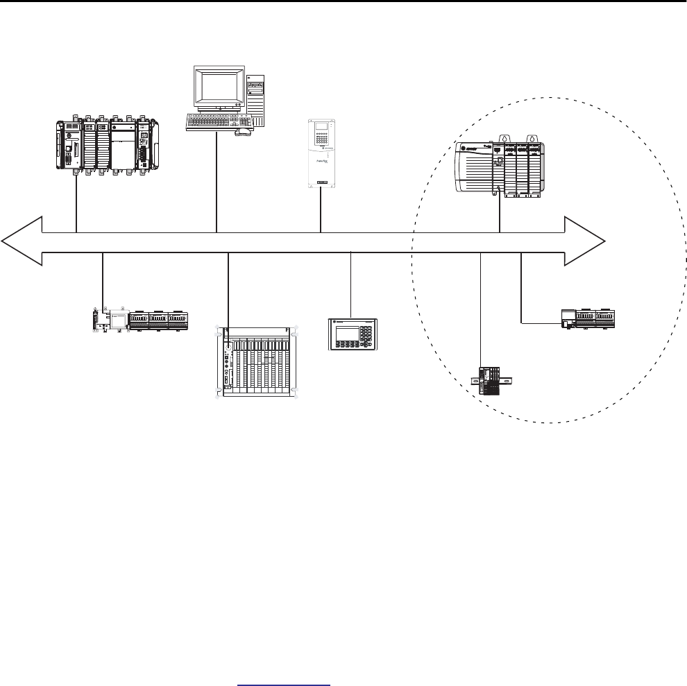
94 Rockwell Automation Publication 1756-UM001P-EN-P - May 2017
Chapter 5 Communication Networks
Figure 11 - ControlNet Network Overview
In this example, these actions occur via the ControlNet network:
• The controllers produce and consume tags.
• The controllers initiate MSG instructions that do the following:
– Send and receive data.
– Configure devices.
• The workstation is used to do the following:
– Configure the ControlNet devices and the ControlNet network.
– Download and upload projects from the controllers.
For more information about using ControlNet modules, see ControlNet
Modules in Logix5000 Control Systems User Manual, publication
CNET-UM001.
ControlLogix ControlNet Module Features
The ControlNet communication modules provide these features:
• Support for messaging, produced/consumed tags, and distributed I/O
• Use a common application layer with DeviceNet and EtherNet/IP
networks
• Requires no routing tables
• Support the use of coax and fiber repeaters for isolation and increased
distance
• Support redundant media (only 1756-CNBR, 1756-CN2R, and
1756-CN2RXT modules)
ControlNet
Distributed I/O
• 1756-CNB
• 1756 I/O
• 1794-ACN15
• 1794 I/O
Workstation
CompactLogix
FlexLogix™
• 1734-ACNR
• 1734 I/O
PanelView™
PLC-5/40C15
PowerFlex 700S
Rockwell Automation Publication 1756-UM001P-EN-P - May 2017 95
Communication Networks Chapter 5
ControlLogix ControlNet Modules
Table 23 lists the available ControlLogix ControlNet modules and their
primary features.
Software for ControlNet Networks
Table 24 lists software that is used with the ControlNet networks and
modules.
Table 23 - ControlNet Modules and Capabilities
Module Is used to
1756-CNB • Control I/O modules.
• Communicate with other ControlNet devices (messages).
• Share data with other Logix5000 controllers (produce/consume).
• Bridge ControlNet links to route messages to devices on other networks.
1756-CNBR • Perform the same functions as a 1756-CNB module.
• Support redundant ControlNet media.
1756-CN2 • Perform the same functions as a 1756-CNB module.
• Provide twice the capacity for more demanding applications.
1756-CN2R • Perform the same functions as a 1756-CN2 module.
• Support redundant ControlNet media.
1756-CN2RXT • Perform same functions as a 1756-CN2R module.
• Operate in extreme environments with -25…+70 °C (-13…+158 °F) temperatures.
Table 24 - Software for Use with ControlNet Networks
Software Is used to Required or
Optional
Logix Designer application • Configure ControlLogix projects.
• Define ControlNet communication.
Required
RSNetWorx™ for ControlNet™ • Configure ControlNet devices.
• Schedule a network.
RSLinx Classic or Enterprise • Configure communication devices.
• Provide diagnostics.
• Establish communication between devices.

96 Rockwell Automation Publication 1756-UM001P-EN-P - May 2017
Chapter 5 Communication Networks
Connections Over a ControlNet Network
You indirectly determine the number of connections the controller uses by
configuring the controller to communicate with other devices in the system.
Connections are allocations of resources that provide communication between
devices as compared to unconnected messages.
ControlNet Module Connections
The 1756-CNB and 1756-CNBR communication modules support 64 CIP
connections over a ControlNet network. However, for optimal performance,
configure a maximum of 48 connections for each module.
The 1756-CN2, 1756-CN2R, and 1756-CN2RXT communication modules
support 128 connections over a ControlNet network, all of which can be
configured without risk of performance degradation.
DeviceNet Network
Communication
The DeviceNet network uses the Common Industrial Protocol (CIP) to
provide the control, configuration, and data collection capabilities for
industrial devices. The DeviceNet network uses the proven Controller Area
Network (CAN) technology, which lowers installation costs and decreases
installation time and costly downtime.
A DeviceNet network provides access to the intelligence present in your
devices by letting you connect devices directly to plant-floor controllers
without having to hard-wire each device into an I/O module.
With a ControlLogix system, DeviceNet communication requires the use of a
1756-DNB DeviceNet communication module.
Table 25 - ControlNet Connections
Connection Definition
Scheduled
(unique to a
ControlNet network)
A scheduled connection is unique to ControlNet communication. A scheduled connection
lets you send and receive data repeatedly at a predetermined interval, which is the
requested packet interval (RPI). For example, a connection to an I/O module is a scheduled
connection because you repeatedly receive data from the module at a specified interval.
Other scheduled connections include connections to the following:
• Communication devices
• Produced/consumed tags
On a ControlNet network, you must use RSNetWorx for ControlNet software to enable all
scheduled connections and establish a network update time (NUT). A scheduled
connection reserves network bandwidth specifically to handle the connection.
Unscheduled An unscheduled connection is a message transfer between devices that the requested
packet interval (RPI) or the program, such as a MSG instruction, triggers. Unscheduled
messaging allows you to send and receive data when you must:
Unscheduled connections use the remainder of network bandwidth after scheduled
connections are allocated.
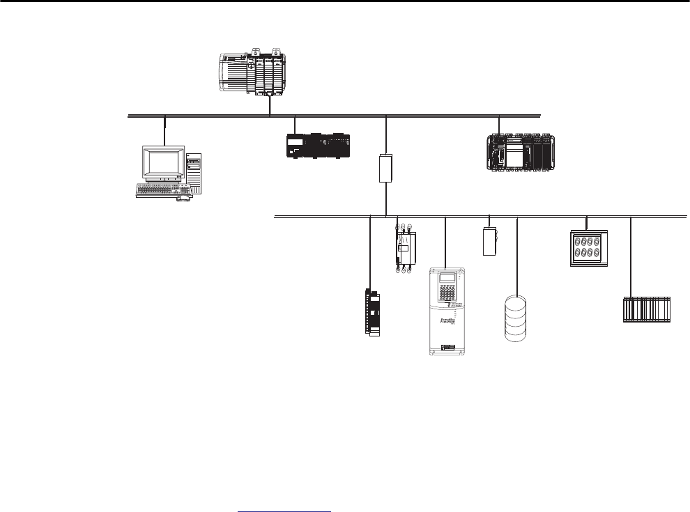
Rockwell Automation Publication 1756-UM001P-EN-P - May 2017 97
Communication Networks Chapter 5
Figure 12 - ControlLogix DeviceNet Network Overview
In this example, the ControlLogix controller is connected to the DeviceNet
network and devices via the 1788-EN2DNR linking device.
For more information about using DeviceNet modules and devices, see
DeviceNet Modules in Logix5000 Control Systems User Manual, publication
DNET-UM004.
ControlLogix DeviceNet Module Features
The DeviceNet communication module provides these features:
• Supports messaging to devices (not controller to controller)
• Shares a common application layer with ControlNet and EtherNet/IP
networks
• Offers diagnostics for improved data collection and fault detection
• Requires less wiring than standard, hard-wired systems
• ControlLogix
• 1756-ENBT
PowerFlex
Motor
Starter
Input/output Devices
Sensor
Push Button
Cluster
Barcode
Scanner
Indicator
Lights
DeviceNet Network
1788-EN2DNR
CompactLogix
FLEX™ I/O
EtherNet/IP Network
Personal Computer
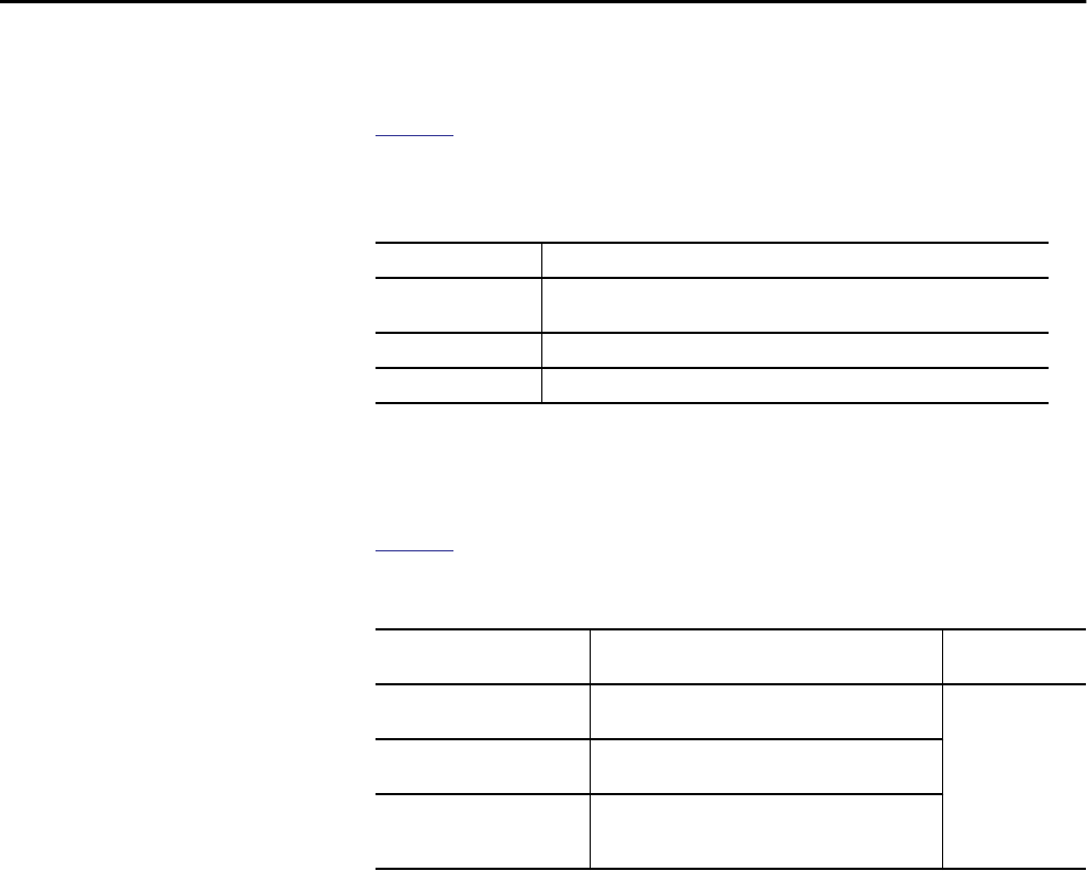
98 Rockwell Automation Publication 1756-UM001P-EN-P - May 2017
Chapter 5 Communication Networks
ControlLogix DeviceNet Bridge Module and Linking Devices
Table 26 lists the available ControlLogix DeviceNet bridge and linking devices
that can be used with the DeviceNet network.
Software for DeviceNet Networks
Table 27 lists software that is used with the DeviceNet networks and modules.
Connections Over DeviceNet Networks
The ControlLogix controller requires two connections for each 1756-DNB
module. One connection is for module status and configuration. The other
connection is a rack-optimized connection for the device data.
ControlLogix DeviceNet Module Memory
The 1756-DNB module has fixed sections of memory for the input and output
data of the DeviceNet devices on the network. Each device on your network
requires some input or output memory of the scanner. Some devices send and
receive data, so they need input and output memory. The 1756-DNB module
supports up to add the following:
• 124 DINTs of input data
• 123 DINTs of output data
Table 26 - DeviceNet Communication Modules and Capabilities
Module/Device Is used to
1756-DNB • Control I/O modules.
• Communicate with other DeviceNet devices (via messages).
1788-EN2DNR Link an EtherNet/IP network to a DeviceNet network.
1788-CN2DN Link a ControlNet network to a DeviceNet network.
Table 27 - Software for Use with DeviceNet Networks
Software Is used to Required or
Optional
Logix Designer application • Configure ControlLogix projects.
• Define DeviceNet communication.
Required
RSNetWorx™ for DeviceNet™ • Configure DeviceNet devices.
• Define the scan list for those devices.
RSLinx Classic or Enterprise • Configure communication devices.
• Provide diagnostics.
• Establish communication between devices.

Rockwell Automation Publication 1756-UM001P-EN-P - May 2017 99
Communication Networks Chapter 5
Data Highway Plus (DH+)
Network Communication
For DH+™ network communication, you have two module options for use in
the ControlLogix chassis. Table 28 lists the DH+ modules and capabilities.
For DH+ network communication, use a 1756-DHRIO or 1756-DHRIOXT
module in the ControlLogix chassis to exchange information between these
controllers:
• PLC and SLC™ controllers
• ControlLogix controllers and PLC or SLC controllers
• ControlLogix controllers
The DH+ network also provides the following:
• Data exchange between controllers
• Plant-wide data sharing
• Cellular level data sharing
You can connect a maximum of 32 stations to one DH+ link:
• Channel A supports 57.6 Kbps, 115.2 Kbps, and 230.4 Kbps.
• Channel B supports 57.6 Kbps and 115.2 Kbps.
Table 28 - DH+ Modules and Capabilities
RIO Module Is used to
1756-DHRIO • Function as a remote I/O (RIO) scanner.
• Support 32 logical rack connections or 16 block transfer connections per channel.
• Establish connections between controllers and I/O adapters.
• Distribute control so that each controller has its own I/O.
1756-DHRIOXT • Function as a remote I/O (RIO) scanner.
• Support 32 logical rack connections or 16 block transfer connections per channel.
• Establish connections between controllers and I/O adapters.
• Distribute control so that each controller has its own I/O.
• Operate in extreme environments with -25…70 °C (-13…158 °F) temperatures.
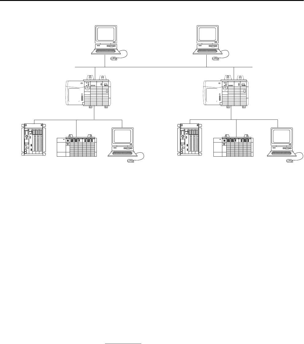
100 Rockwell Automation Publication 1756-UM001P-EN-P - May 2017
Chapter 5 Communication Networks
Figure 13 - ControlLogix DH+ Network Communication Example
Communicate Over a DH+ Network
For the controller to communicate to a workstation or other device over a
DH+ network, use RSLinx Classic software to do the following:
• Specify a unique link ID for each ControlLogix backplane and
additional network in the communication path.
• Configure the routing table for the 1756-DHRIO or 1756-DHRIOXT
module.
The 1756-DHRIO or 1756-DHRIOXT module can route a message through
up to four communication networks and three chassis. This limit applies only
to the routing of a message and not to the total number of networks or chassis
in a system.
For more information to configure and use a DH+ network via the
1756-DHRIO or 1756-DHRIOXT module, see the Data Highway Plus-
Remote I/O Communication Interface Module User Manual, publication
1756-UM514.
SLC™ 500
DH+ Network
Data Collection and Recipe
Management
PLC-5®
ControlLogix ControlLogix
DH+ Network
RSView® SLC 500
PLC-5 RSView
Workstation
EtherNet/IP Network
Rockwell Automation Publication 1756-UM001P-EN-P - May 2017 101
Communication Networks Chapter 5
Universal Remote I/O (RIO)
Communication
For universal remote I/O communication, you have two module options for
use in the ControlLogix chassis. Table 29 lists the RIO modules and
capabilities.
When a channel on the 1756-DHRIO or 1756-DHRIOXT module is
configured for remote I/O, the module acts as a scanner for a universal remote
I/O network. The controller communicates to the module to send and receive
the I/O data on the universal remote I/O network.
The 1756-RIO module can act as a scanner or adapter on a remote I/O
network. The 1756-RIO module transfers digital, block transfer, analog, and
specialty data without message instructions.
Figure 14 - ControlLogix Universal Remote I/O Communication Example
Table 29 - RIO Modules and Capabilities
RIO Module Is used to
1756-RIO • Function as an RIO scanner and adapter.
• Support connections to 32 racks in any combination of rack size or block transfers.
• Update data to the ControlLogix controller by using scheduled connections.
1756-DHRIO • Function as an RIO scanner.
• Support 32 logical rack connections or 16 block transfer connections per channel.
• Establish connections between controllers and I/O adapters.
• Distribute control so that each controller has its own I/O.
1756-DHRIOXT • Function as an RIO scanner.
• Support 32 logical rack connections or 16 block transfer connections per channel.
• Establish connections between controllers and I/O adapters.
• Distribute control so that each controller has its own I/O.
• Operate in extreme environments with -25…70 °C (-13…158 °F) temperatures.
Universal Remote I/O Network
ControlLogix
PLC-5
1746-ASB
1771-ASB
1794-ASB

102 Rockwell Automation Publication 1756-UM001P-EN-P - May 2017
Chapter 5 Communication Networks
Communicate over a Universal Remote I/O Network
For the controller to control I/O over a universal remote I/O network, you
must complete these tasks.
1. Configure the remote I/O adapter.
2. Lay out the remote I/O network cable.
3. Connect the remote I/O network cable.
4. Configure the scanner channel.
For more information to configure a remote I/O network with the 1756-RIO,
1756-DHRIO, or 1756-DHRIOXT modules, see these publications:
• Data Highway Plus-Remote I/O Communication Interface Module
User Manual, publication 1756-UM514
• ControlLogix Remote I/O Communication Module User Manual,
publication 1756-UM534
As you design your remote I/O network, remember the following:
• All devices that are connected to a remote I/O network must
communicate by using the same communication rate. These rates are
available for remote I/O:
– 57.6 Kbps
– 115.2 Kbps
– 230.4 Kbps
• You must assign unique partial and full racks to each channel used in
Remote I/O Scanner mode.
Both channels of a 1756-DHRIO or 1756-DHRIOXT module cannot
scan the same partial or full rack address. Both module channels can
communicate to 00…37 octal or 40…77 octal, but each channel can
communicate only with one address at a time in whichever of these two
ranges it falls.
Foundation Fieldbus
Communication
Foundation Fieldbus is an open interoperable fieldbus that is designed for
process control instrumentation. The fieldbus devices that are described in
Table 30 can be connected to the ControlLogix controller via another network
as shown in the following example.
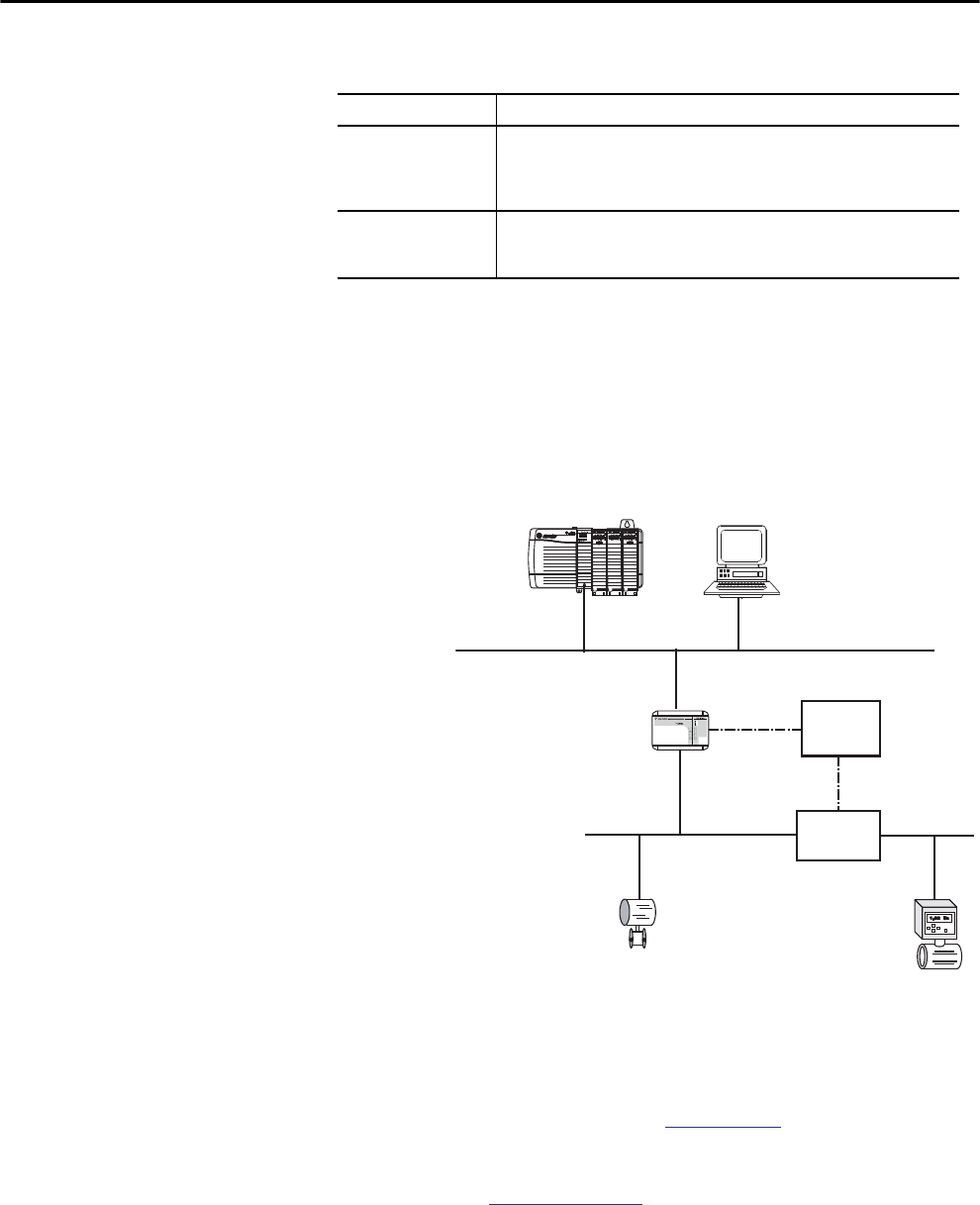
Rockwell Automation Publication 1756-UM001P-EN-P - May 2017 103
Communication Networks Chapter 5
Foundation Fieldbus distributes and executes control in the device. The
Foundation Fieldbus linking device does the following:
• Bridges from an EtherNet/IP network to an H1 connection
• Accepts HSE or EtherNet/IP messages and converts them to the H1
protocol
Figure 15 - Foundation Fieldbus Example
For more information about using the Foundation Fieldbus devices available
from Rockwell Automation, see these publications:
• EtherNet/IP and ControlNet to FOUNDATION Fieldbus Linking
Device User Manual, publication 1788-UM057
• FOUNDATION Fieldbus Design Considerations Reference Manual,
publication PROCES-RM005
Table 30 - Fieldbus Devices and Capabilities
Fieldbus Device Is used to
1788-EN2FFR • Bridge an EtherNet/IP network to Foundation Fieldbus.
• Connect via a low-speed serial (H1) and high-speed Ethernet (HSE) network
connections.
• Access devices directly via an OPC server.
1788-CN2FFR • Connect via low-speed serial (H1) connections.
• Bridge a ControlNet network to a Foundation Fieldbus.
• Support redundant ControlNet media.
RSFieldbus™ Software
24V DC
Power
Supply
Power
Conditioner
Field Device Field Device
1788-EN2FFR Linking Device
• ControlLogix
• 1756-ENBT
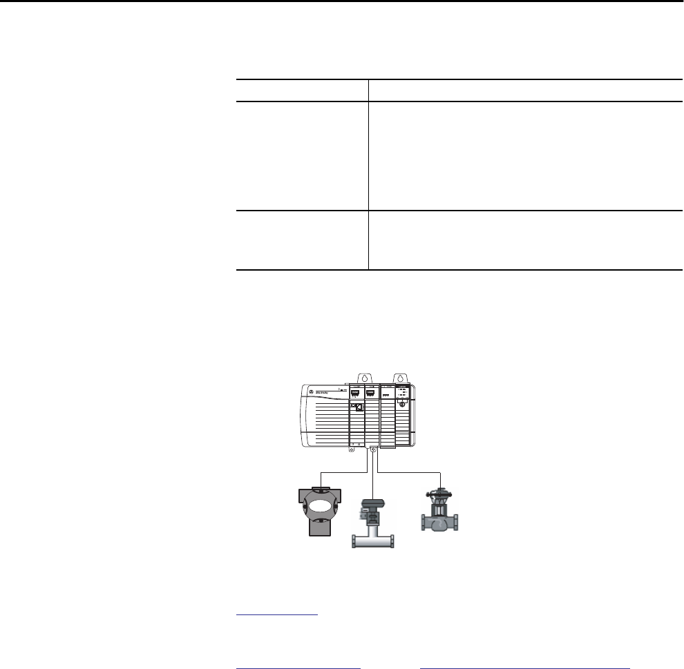
104 Rockwell Automation Publication 1756-UM001P-EN-P - May 2017
Chapter 5 Communication Networks
HART Communication HART (Highway Addressable Remote Transducer) is an open protocol that is
designed for process control instrumentation.
The HART protocol combines digital signals with analog signals to ready the
digital signal for the Process Variable (PV). The HART protocol also provides
diagnostic data from the transmitter.
Figure 16 - HART Protocol Example
For more information about using the HART I/O modules, see the
ControlLogix HART Analog I/O Modules User Manual, publication
1756-UM533.
For more information about the ProSoft HART interface, see the
ProSoft Technologies website at http://www.prosoft-technology.com.
Device Is used to
1756 analog HART I/O modules: • Act as HART master to allow communication with HART field devices.
• Interface directly with field devices (through built-in HART modems), which
eliminates the need for external hardware and more wiring.
• Provide access to more field device data, including voltage and current
measurements.
• Directly connect asset management software to HART devices.
• Support differential wiring for environments where improved noise
immunity is needed (input modules).
ProSoft interface
MVI56-HART
• Acquire data or control application with slow update requirements, such as a
tank farm.
• Does not require external hardware to access HART signal.
• Does not provide a direct connection to asset management software.
• ControlLogix
• 1756-IF8H or
• 1756-OF8H
HART Field Devices
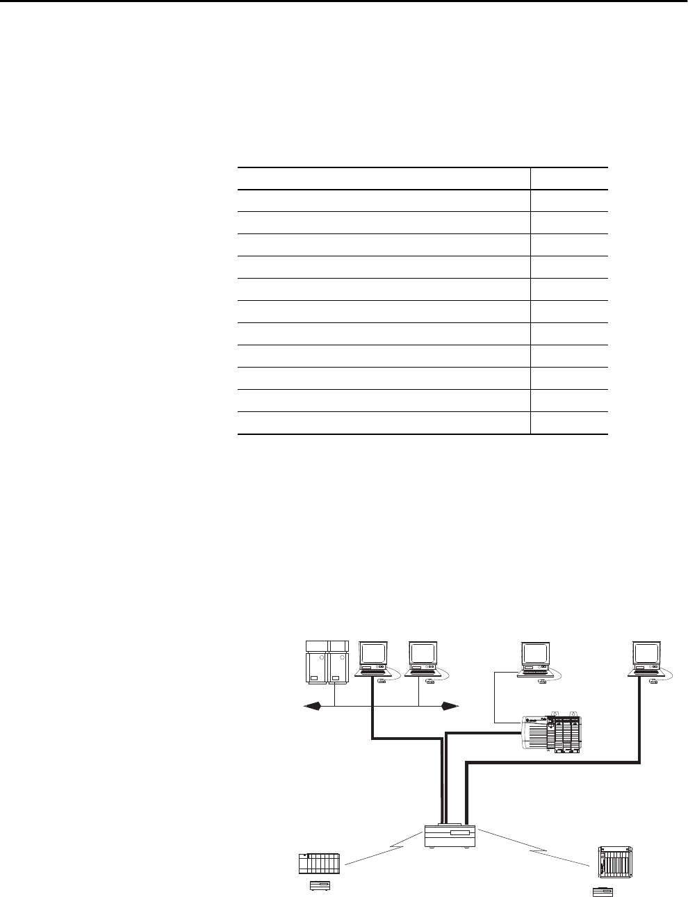
Rockwell Automation Publication 1756-UM001P-EN-P - May 2017 105
Chapter 6
Serial Communication on 1756-L6x Controllers
1756-L6x Controller
Serial Port
The 1756-L6x ControlLogix® controllers have a built-in RS-232 port that can
be used in various serial-based applications. The potential serial
communication applications include the following:
• DF1 modes (including broadcast message support)
• DF1 radio modem
• ASCII device communication
Figure 17 - ControlLogix DF1 Device Communication Example
Topic Page
1756-L6x Controller Serial Port 105
Communication with Serial Devices 106
DF1 Master Protocol 106
DF1 Point to Point Protocol 107
DF1 Radio Modem Protocol 107
DF1 Slave Protocol 110
DH-485 Protocol 110
ASCII Protocol 111
Configure the 1756-L6x Controller for Serial Communication 112
Broadcast Messages Over a Serial Port 114
Modbus Support 116
Modem
Modem Modem
RS-232 Connection
DH+™ Connection
EtherNet/IP
Network
RS-232 Connection
RS-232 Connection
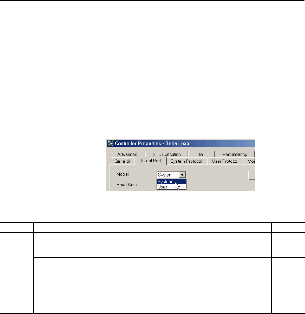
106 Rockwell Automation Publication 1756-UM001P-EN-P - May 2017
Chapter 6 Serial Communication on 1756-L6x Controllers
ControlLogix Chassis Serial Communication Options
You can use the serial port of the ControlLogix controller or use ProSoft
modules in the ControlLogix to achieve serial communication. Options
specific to the ControlLogix controller serial port are described in this chapter.
For more information about ProSoft modules that can be used to establish
serial communication, see the ProSoft Technology website or go to
http://www.prosoft-technology.com and browse available products.
Communication with
Serial Devices
When configuring the controller for serial communication, you first specify a
Serial Port mode (System or User), then a protocol.
Figure 18 - Serial Port Mode in the Controller Properties
Table 31 describes the serial communication protocols for use with each mode.
DF1 Master Protocol The master/slave network includes one controller that is configured as the
master node and up to 254 slave nodes. Link slave nodes by using modems or
line drivers.
A master/slave network can have node numbers from 0…254. Each node must
have a unique node address. Also, at least two nodes, one master and one slave,
must exist to define your link as a network.
Table 31 - Serial Port Modes, Protocols, and Uses
Mode Protocol Is used to Page
System DF1 Master Control polling and message transmission between the master and slave nodes. 106
DF1 Point to Point • Communicate between the controller and one other DF1-protocol-compatible device.
• Program the controller via the serial port.
107
DF1 Radio Modem • Communication with SLC 500™ and MicroLogix™ 1500 controllers.
• This protocol supports master/slave and store/forward configurations.
107
DF1 Slave Configure the controller as a slave station in a master/slave serial communication network. 110
DH-485 Communication with other DH-485 devices via a multi-master and token-passing network that enables
programming and peer-to-peer messaging.
110
User ASCII • Communicate with ASCII devices.
• Use ASCII instructions to read and write data from and to an ASCII device.
111
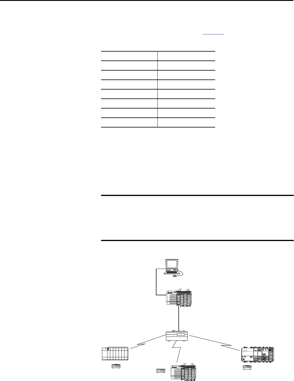
Rockwell Automation Publication 1756-UM001P-EN-P - May 2017 107
Serial Communication on 1756-L6x Controllers Chapter 6
DF1 Point to Point Protocol The DF1 Point to Point protocol is used when connecting from the controller
to one DF1 device. DF1 Point to Point protocol is the default System mode
protocol. Default parameters are listed in Table 32.
DF1 Radio Modem Protocol Your ControlLogix controller includes a driver that lets it communicate over
the DF1 Radio Modem protocol. The DF1 radio modem driver implements a
protocol, optimized for use with radio modem networks, that is a hybrid
between DF1 full-duplex protocol and DF1 half-duplex protocol, and
therefore is not compatible with these protocols.
Figure 19 - DF1 Radio Modem Network Example
Table 32 - Default DF1 Point to Point Parameters
Parameter Value
Baud Rate 19,200
Data Bits 8
Parity None
Stop Bits 1
Control Line No Handshake
RTS send Delay 0
RTS Off Delay 0
IMPORTANT The DF1 radio modem driver is used only among devices that support and
are configured for the DF1 Radio Modem protocol.
Additionally, there are some radio modem network configurations that do
not work with the DF1 radio modem driver. In these configurations, continue
to use DF1 half-duplex protocol.
Modem
Modem Modem
Modem
RS-232
EtherNet/IP Network

108 Rockwell Automation Publication 1756-UM001P-EN-P - May 2017
Chapter 6 Serial Communication on 1756-L6x Controllers
Like DF1 full-duplex protocol, the DF1 radio modem lets any node initiate to
any other node at any time (that is, if the radio modem network supports full-
duplex data-port buffering and radio-transmission collision avoidance). Like
DF1 half-duplex protocol, a node ignores any packets received that have a
destination address other than its own, except for broadcast packets and
passthru packets.
Unlike DF1 full-duplex or DF1 half-duplex protocols, the DF1 radio modem
protocol excludes ACKs, NAKs, ENQs, or poll packets. The CRC checksum
verifies Data integrity.
DF1 Radio Modem Advantages
The primary advantage of using the DF1 radio modem protocol for radio
modem networks is in transmission efficiency. Each read/write transaction
(command and reply) requires only one transmission by the initiator (to send
the command) and one transmission by the responder (to return the reply).
This efficiency minimizes the number of times the radios must key-up to
transmit, which maximizes radio life and minimizes radio power consumption.
In contrast, DF1 half-duplex protocol requires five transmissions for the DF1
master to complete a read/write transaction with a DF1 slave—three by the
master and two by the slave.
The DF1 radio modem driver can be used in a pseudo master/slave mode with
any radio modems, as long as the designated master node is the only node that
initiates MSG instructions, and as long as only one MSG instruction is
triggered at a time.
For modern serial radio modems that support full-duplex data port buffering
and radio transmission collision avoidance, the DF1 radio modem driver can
be used to configure a masterless peer-to-peer radio network, where any node
can initiate communication to any other node at any time, as long as the nodes
are within radio range so that they receive transmissions from each other.
DF1 Radio Modem Limitations
These considerations must be made if you can implement the new DF1 radio
modem driver in your radio modem network:
• If the devices on the network are ControlLogix controllers, you must
configure them with the DF1 radio modem driver via
RSLogix 5000® software, version 17.01.02 or later or Logix Designer
application, version 21.00.00 or later. If not, then make sure that the
nodes can support the DF1 radio modem protocol.

Rockwell Automation Publication 1756-UM001P-EN-P - May 2017 109
Serial Communication on 1756-L6x Controllers Chapter 6
• If each node receives the radio transmissions of each other node, being
within radio transmission/reception range and on a common receiving
frequency (via a Simplex radio mode or via one, common, full-duplex
repeater) the radio modems must handle full-duplex data port buffering
and radio transmission collision avoidance.
If so, you can take full advantage of the peer-to-peer message initiation
capability in each node (for example, the ladder logic in any node can
trigger a MSG instruction to any other node at any time).
If not all modems can handle full-duplex data port buffering and radio
transmission collision avoidance, you can use the DF1 radio modem
driver. Use the DF1 radio modem driver only if you limit MSG
instruction initiation to one master node who transmits to each other
node.
• If not all nodes receive the radio transmission of each other node, you
can use the DF1 radio modem driver. Use the DF1 radio modem driver
only if you limit MSG instruction initiation to the node connected to
the master radio modem who transmits to each other radio modem in
the network.
• You can take advantage of the ControlLogix controller channel-to-
channel passthru to program the other nodes via RSLinx® Classic and
Logix Designer applications that run on a personal computer that is
connected to a local ControlLogix controller via DH-485, DH+, or
Ethernet network.
DF1 Radio Modem Protocol Parameters
Use Table 33 as a reference when setting the parameters for the use of the DF1
Radio Modem Protocol.
Table 33 - DF1 Radio Protocol Parameters
Parameter Description
Station Address Specifies the node address of the controller on the serial network. Select a number 1…254 decimal, inclusive.
To optimize network performance, assign node addresses in sequential order. Initiators, such as personal computers, are assigned the lowest
address numbers to minimize the time that is required to initialize the network.
Error Detection Click one of the radio buttons to specify the error detection scheme that is used for all messages.
• BCC - the processor sends and accepts messages that end with a BCC byte.
• CRC - the processor sends and accepts messages with a 2 byte CRC.
Enable Store and Forward Check ’Enable Store and Forward’ if you want to enable the store and forward functionality. When enabled, the destination address of any
received message is compared to the Store and Forward tag table. If there is a match, the message is then forwarded (rebroadcasted) out the port.
From the Store and Forward Tag pull-down menu, choose an integer (INT[16]) tag.
Each bit is a station address. If this controller reads a message that is destined for a station that has its bit set in this table, it forwards the message.

110 Rockwell Automation Publication 1756-UM001P-EN-P - May 2017
Chapter 6 Serial Communication on 1756-L6x Controllers
DF1 Slave Protocol With the DF1 slave protocol, a controller uses DF1 half-duplex protocol. One
node is designated as the master and it controls who has access to the link. The
other nodes are slave stations and must wait for permission from the master
before transmitting.
Make these considerations when using the DF1 Slave protocol:
• If multiple slave stations are used on the network, link slave stations by
using modems or line drivers to the master.
• If you are using one slave station on the network, you do not need a
modem to connect the slave station to the master.
• Control parameters can be configured without handshaking.
• 2…255 nodes can be connected to one link.
DH-485 Protocol The controller can send and receive messages to and from other controllers on
a DH-485 network. The DH-485 connection supports remote programming
and monitoring via the Logix Designer application. However, excessive traffic
over a DH-485 connection can adversely affect overall controller performance
and lead to timeouts and decreased performance of the configuration.
You can also use a 1756-DH485 module to connect the ControlLogix chassis
to a DH-485 network with multiple controllers. For more information, see the
ControlLogix DH-485 Communication Module User Manual, publication
1756-UM532.
The DH-485 protocol uses RS-485 half-duplex as its physical interface.
RS-485 is a definition of electrical characteristics, not a protocol. You can
configure the RS-232 port of the ControlLogix controller to act as a DH-485
interface.
To connect the controller to the DH-485 network, you must use these
components:
• A 1761-NET-AIC converter (two controllers can be connected to one
converter)
• An RS-232 cable (catalog number 1756-CP3 or 1747-CP3) for each
controller to connect to the converter
IMPORTANT Use Logix5000™ controllers on DH-485 networks only when you want to add
controllers to an existing DH-485 network.
For new applications with Logix5000 controllers, we recommend that you
use networks in the NetLinx open architecture.
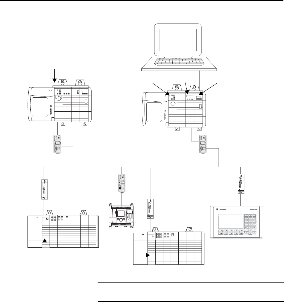
Rockwell Automation Publication 1756-UM001P-EN-P - May 2017 111
Serial Communication on 1756-L6x Controllers Chapter 6
Figure 20 - DH-485 Network Communication Overview
ASCII Protocol When you configure the serial port for User mode and the ASCII protocol,
you can use it to do the following:
• Read ASCII characters from a weigh scale module or barcode reader.
• Send and receive messages from an ASCII-triggered device, such as a
MessageView™ terminal.
EXTERNAL
TE
EXTERNAL
TE
TERM
T
A
A
A
Computer with Studio 5000® Environment
ControlLogix
ControlLogix 1756-DH485 1756-ENBT
AIC+ Link Coupler
AIC+ Link Coupler
AIC Link Coupler
AIC Link Coupler
AIC+ Link Coupler AIC Link Coupler
DH-485 Network
SLC 5/03
SLC™ 5/03
PanelView™
MicroLogix
44136
IMPORTANT A DH-485 network consists of multiple cable segments. Limit the total
length of the segments to 1219 m (4000 ft).
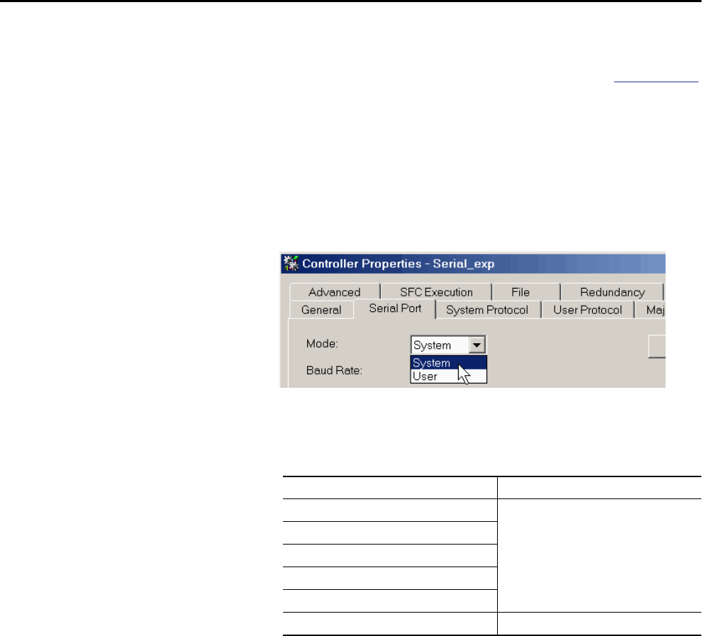
112 Rockwell Automation Publication 1756-UM001P-EN-P - May 2017
Chapter 6 Serial Communication on 1756-L6x Controllers
After you configure the controller for use with the ASCII protocol, program
the controller by using the ASCII instructions. Reference the Logix5000
Controllers General Instruction Reference Manual, publication 1756-RM003,
for information about the ASCII instructions.
Configure the 1756-L6x
Controller for Serial
Communication
Complete these steps to configure your 1756-L6x controller for serial
communication after creating a controller project in the Logix Designer
application.
1. Open the Controller Properties and click the Serial Port tab.
2. From the Mode pull-down menu, choose the mode that corresponds to
your intended protocol.
Use this table as a reference.
For this protocol Choose this mode
DF1 Master System
DF1 Point to Point
DF1 Radio Modem
DF1 Slave
DH-485
ASCII User
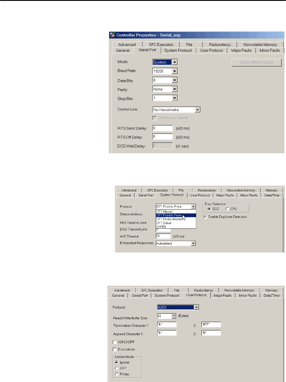
Rockwell Automation Publication 1756-UM001P-EN-P - May 2017 113
Serial Communication on 1756-L6x Controllers Chapter 6
3. Specify the remaining properties in the Serial Port tab according to your
communication preferences.
4. If you are using the System mode protocols, click the System Protocol
tab and specify the protocol parameters.
a. From the Protocol pull-down, choose the protocol that you need.
b. Specify the parameters for the protocol.
5. If you are using the User mode protocol (ASCII), click the User
Protocol tab and specify the ASCII parameters.

114 Rockwell Automation Publication 1756-UM001P-EN-P - May 2017
Chapter 6 Serial Communication on 1756-L6x Controllers
After you have configured the controller for ASCII protocol
communication, reference the Logix5000 Controllers General
Instruction Reference Manual, publication 1756-RM003, for the
available ASCII instructions.
Broadcast Messages Over
a Serial Port
You can broadcast messages over a serial port connection from a master
controller to its slave controllers by using several communication protocols.
These protocols include the following:
• DF1 Master
• DF1 Radio Modem
• DF1 Slave
Use the ‘message’ tag to broadcast over a serial port. Because messages are sent
to receiving controllers, only the ‘write’ type messages can be used for
broadcasting.
The broadcast feature can be configured by using ladder logic or structured
text. The broadcast feature can also be set by modifying the path value of a
message tag in the tag editor.
To configure and program the controller to broadcast messages via the serial
port, complete these procedures:
•Configure Controller Serial Port Properties on page 115
•Program the Message Instruction on page 116
For these procedure examples, ladder logic programming is used.
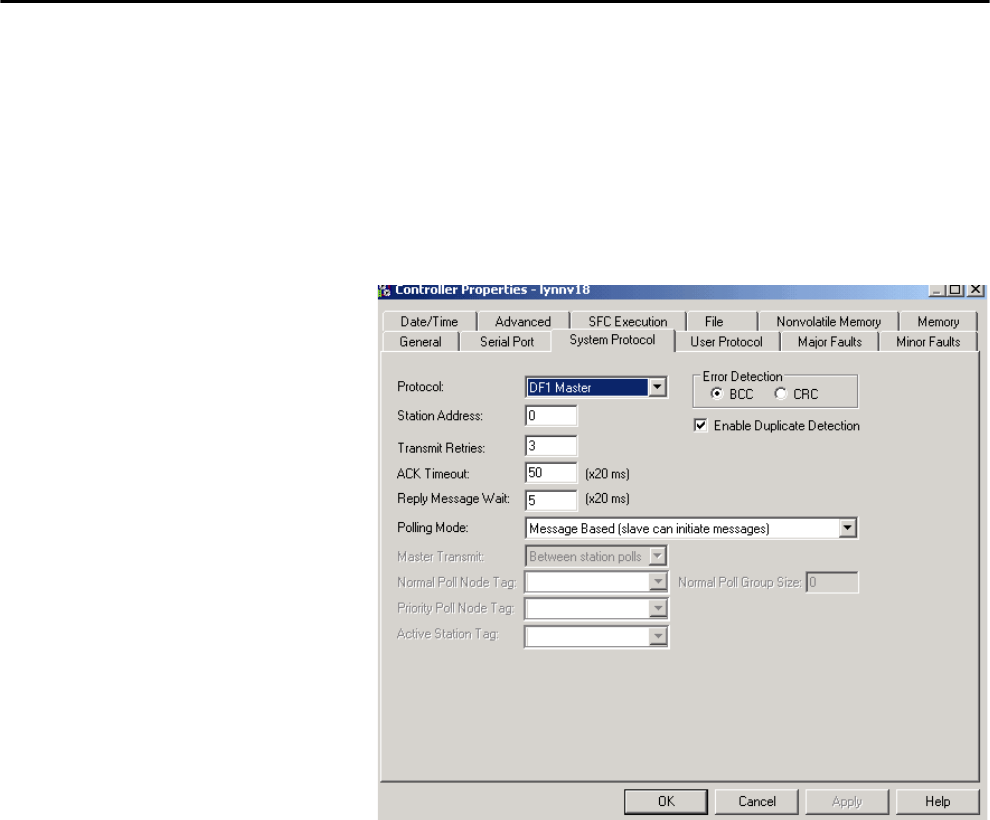
Rockwell Automation Publication 1756-UM001P-EN-P - May 2017 115
Serial Communication on 1756-L6x Controllers Chapter 6
Configure Controller Serial Port Properties
First, set the System Protocol by following these steps.
1. In the Controller Organizer, right-click the controller and choose
Properties.
2. In the Controller Properties dialog box, from the System Protocol tab,
choose the settings for the controller and click OK.
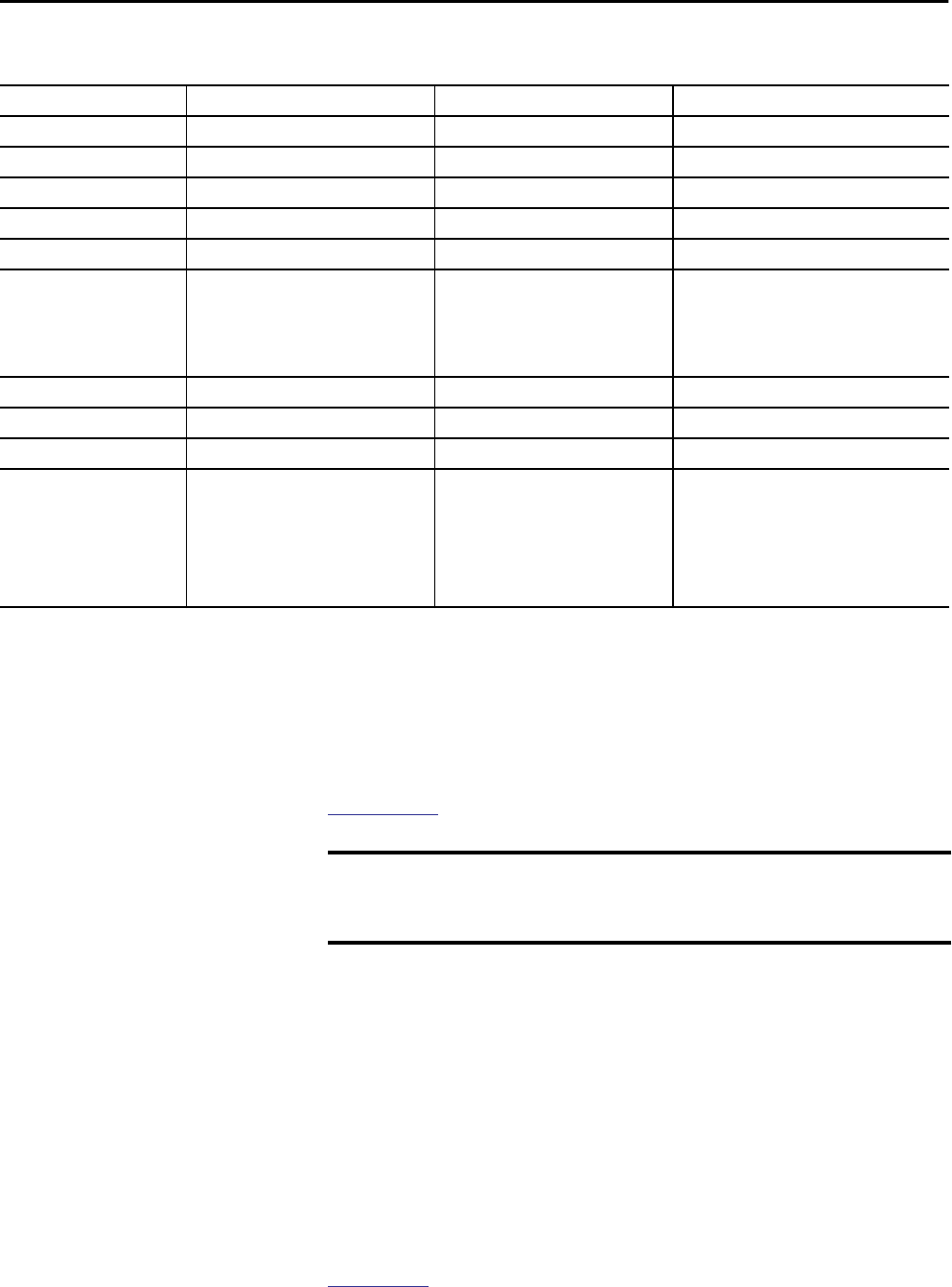
116 Rockwell Automation Publication 1756-UM001P-EN-P - May 2017
Chapter 6 Serial Communication on 1756-L6x Controllers
Use this table when specifying settings for the protocols listed.
Program the Message Instruction
Add and configure the Message instruction according to the protocol you are
using. For more information to specify the configuration details, see the
Logix5000 Controllers General Instruction Reference Manual, publication
1756-RM003.
Modbus Support To use ControlLogix controllers with the Modbus protocol, establish a serial
port connection and execute a ladder-logic routine.
Two controller projects specific to the Modbus network are available as sample
programs within the Logix Designer application:
• ModbusMaster.ACD
• ModbusSlave.ACD
For information about using these sample programs, see the Using Logix5000
Controllers as Masters or Slaves on Modbus Application Solution, publication
CIG-AP129.
Field DF-1 Master Protocol DF-1 Slave Protocol DF-1 Radio Modem Protocol
Station Address Controller station address number Controller station address number Controller station address number
Transmit Retries 3 3 N/A
ACK Timeout 50 N/A N/A
Slave Poll Timeout N/A 3000 N/A
Reply Message Wait 5 N/A N/A
Polling Mode Message: polls the slave by using the
Message instruction
Slave: initiates messages for slave-to-slave
broadcast
Standard: schedules polling for the slave
N/A N/A
EOT Suppression N/A Disable N/A
Error Detection BCC BCC BCC
Duplicate Detection Enabled Enabled N/A
Enable Store and Forward N/A N/A Choose enable if you want to use the store and
forward tag.
The last bit of the INT[16] Enable Store and
Forward array must be ’enabled.’ For example, say
that you create an INT[16] tag named
EnableSandF. Then EnableSandF[15].15 must be
set to 1 for broadcast to work on radio modem.
IMPORTANT When using structured text, broadcast over a serial port is set by typing
MSG(aMsg) and right-clicking an MSG to display the Message Configuration
dialog box.

Rockwell Automation Publication 1756-UM001P-EN-P - May 2017 117
Chapter 7
Manage Controller Communication
Connection Overview A Logix5000™ system uses a connection to establish a communication link
between two devices. The types of connections include the following:
• Controller-to-local I/O modules or local communication modules
• Controller-to-remote I/O or remote communication modules
• Controller-to-remote I/O (rack-optimized) modules
• Produced and consumed tags
• Messages
• Controller access via the Studio 5000 Logix Designer® application
• Controller access via RSLinx® Classic or RSLinx Enterprise applications
for HMI or other applications
Topic Page
Connection Overview 117
Produce and Consume (Interlock) Data 118
Send and Receive Messages 120
Calculate Connection Use 121
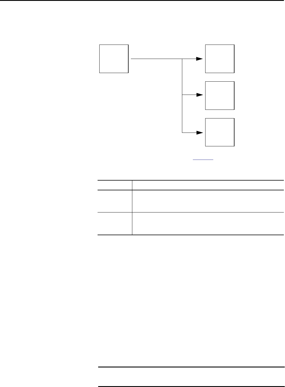
118 Rockwell Automation Publication 1756-UM001P-EN-P - May 2017
Chapter 7 Manage Controller Communication
Produce and Consume
(Interlock) Data
ControlLogix® controllers let you produce (transmit) and consume (receive)
system-shared tags.
Figure 21 - Illustration of Produced and Consumed Tags
The system-shared tags are explained in Table 34.
For two controllers to share produced or consumed tags, the controllers must
be attached to the same network. You cannot bridge produced and consumed
tags over two networks.
Produced and consumed tags use connections of the controller and the
communication modules being used. For a ControlNet network, produced and
consumed tags use scheduled connections.
Connection Requirements of a Produced or Consumed Tag
Produced and consumed tags each require connections. As you increase the
number of controllers that can consume a produced tag, you reduce the
number of connections the controller has available for other operations, like
communication and I/O.
Table 34 - Produced and Consumed Tag Definitions
Tag Definition
Produced tag A tag that a controller makes available for use by other controllers. Multiple
controllers can simultaneously consume (receive) the data. A produced tag sends its
data to one or more consumed tags (consumers) without using logic.
Consumed tag A tag that receives the data of a produced tag. The data type of the consumed tag
must match the data type (including any array dimensions) of the produced tag. The
RPI of the consumed tag determines the period at which the data updates.
IMPORTANT If a consumed-tag connection fails, the other tags being consumed from
that remote controller stop receiving new data.
Controller_2
Controller_3
Controller_4
Consumed Tag
Consumed Tag
Consumed Tag
Controller_1
Produced Tag
Rockwell Automation Publication 1756-UM001P-EN-P - May 2017 119
Manage Controller Communication Chapter 7
Each produced or consumed tag uses the number of connections that are listed
in Table 35. Adding status information to a produced/consumed tag does not
affect the number of connections used.
.
The number of available connections limits the number of tags that can be
produced or consumed. If the controller uses its connections for I/O and
communication devices, no connections are left for produced and consumed
tags.
For more information about produced/consumed tags, see the Logix5000
Controllers Produced and Consumed Tags Programming Manual, publication
1756-PM011.
Table 35 - Produced and Consumed Tag Connections
This Type of Tag Uses This Many Connections Of This Module
Produced tag number_of_configuredconsumers + 1 Controller
Consumed tag 1
Produced or consumed tag 1 Communication
EXAMPLE Calculations of connections for produced or consumed tags:
• A ControlLogix controller producing 4 tags for 1 controller uses
8 connections.
Each tag uses 2 connections (1 consumer + 1 = 2).
2 connections per tag x 4 tags = 8 connections.
• Consuming 4 tags from a controller uses 4 connections
(1 connection per tag x 4 tags = 4 connections).
Table 36 - ControlLogix Modules and Available Connections
Module Type Cat. No. Available Connections
Controller 1756-L7x500
1756-L6x250
EtherNet/IP • 1756-EN2F
• 1756-EN2T
• 1756-EN2TXT
• 1756-EN2TR
256
• 1756-ENBT
• 1756-EWEB
128
ControlNet • 1756-CN2
• 1756-CN2R
• 1756-CN2RXT
128
• 1756-CNB
• 1756-CNBR
64
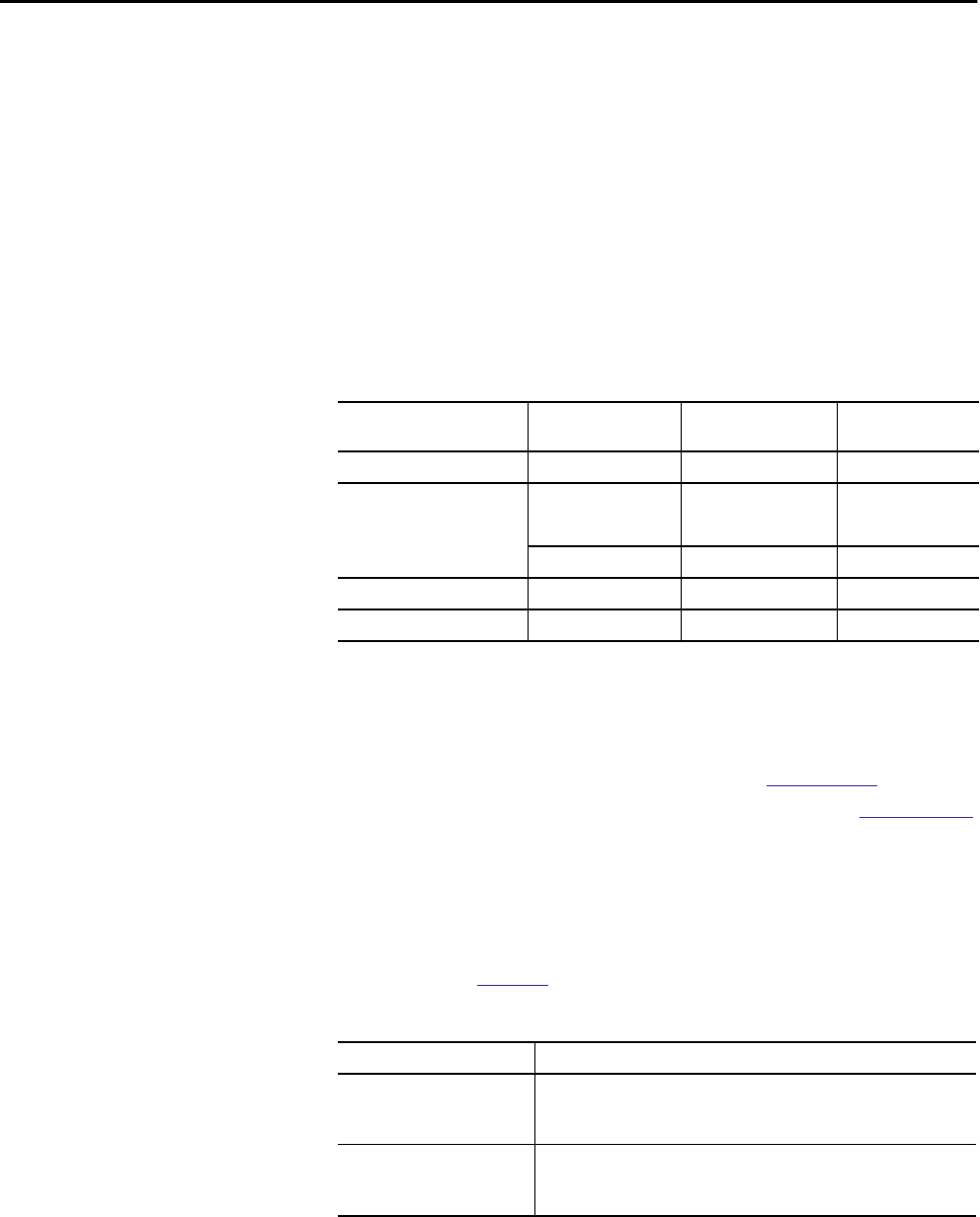
120 Rockwell Automation Publication 1756-UM001P-EN-P - May 2017
Chapter 7 Manage Controller Communication
Send and Receive Messages Messages transfer data to other devices, such as other controllers or operator
interfaces. The MSG instruction is a ladder logic output instruction that
asynchronously reads or writes a block of data to or from another module over
the backplane or a network. The size of the instruction depends on the data
types and message command that you program.
Messages use connection resources to send or receive data. Messages can leave
the connection open (cache) or closed when the message is done transmitting.
Each message uses one connection out of the controller, regardless of how
many devices are in the message path. To conserve connections, configure one
message to read from or write to multiple devices.
For more information about using messages, see these publications:
• Logix5000 Controllers Messages, publication 1756-PM012
• Logix5000 Controllers General Instructions, publication 1756-RM003
Determine Whether to Cache Message Connections
When you configure a MSG instruction, you can choose whether to cache the
connection. Use Table 38 to determine options for caching connections.
.
Table 37 - Message Types
Message Type Communication
Method
Connected Message Message Can Be
Cached
CIP data table read or write N/A Configurable Yes
PLC-2®, PLC-3®, PLC-5®, or SLC™
(all types)
CIP No No
CIP with Source ID No No
DH+ Yes Yes
CIP generic N/A Optional (1)
(1) You can connect CIP generic messages. However, for most applications we recommend that you leave CIP generic messages
unconnected.
Yes(2)
(2) Consider caching only if the target module requires a connection.
Block-transfer read or write N/A Yes Yes
Table 38 - Options for Caching Connections
If the message executes Then
Repeatedly Cache the connection.
This keeps the connection open and optimizes execution time. Opening a
connection each time the message executes increases execution time.
Infrequently Do not cache the connection.
This closes the connection upon completion of the message, which frees up
that connection for other uses.
TIP Cached connections transfer data faster than uncached connections.
The controller supports only 32 cached messages.
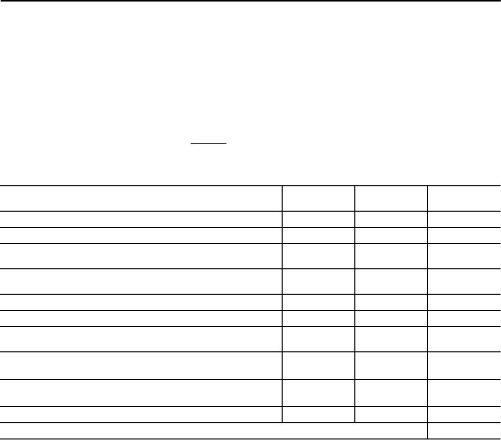
Rockwell Automation Publication 1756-UM001P-EN-P - May 2017 121
Manage Controller Communication Chapter 7
Calculate Connection Use The total connection requirements of a ControlLogix system include local and
remote connections.
Local Connections
Local connections refer to connections used to communicate between modules
that are housed in the same ControlLogix chassis (that is, the local modules).
Use Table 39 to calculate the number of local connections that are based on the
configuration of your local chassis.
Table 39 - Local Chassis Connections
Local Connection To Device Quantity Connections per
Device
Total Connections
Local I/O module (a direct connection) 1
1756-M16SE, 1756-M08SE, or 1756-M02AE servo module 3
• 1756-CN2, 1756-CN2R, 1756-CN2RXT ControlNet communication module
• 1756-CNB, 1756-CNBR ControlNet communication module
0
• 1756-EN2F, 1756-EN2T, 1756-EN2TXT, or 1756-EN2TR EtherNet/IP communication module
• 1756-ENBT EtherNet/IP communication module
0
1756-EWEB EtherNet/IP web server module 0
1756-DNB DeviceNet communication module 2
1756-RIO remote I/O communication module (Connection count depends on module configuration
and can be as many as 10 per module.)
1
1756-DHRIO DH+/universal remote I/O communication module
Each adapter that is associated with the module
1
1
1756-DHRIOXT DH+/universal remote I/O communication module
Each adapter that is associated with the module
1
1
1756-DH485 DH-485 communication module 1
Total
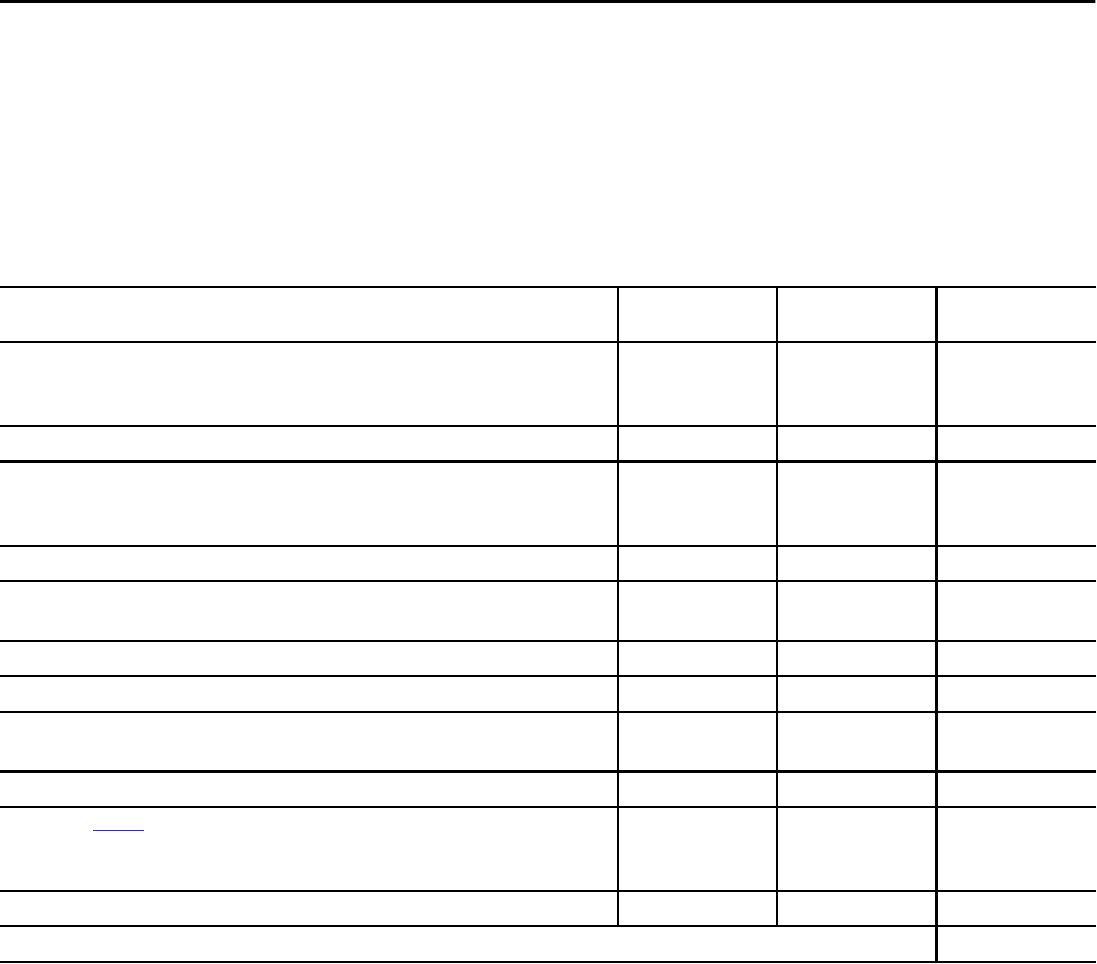
122 Rockwell Automation Publication 1756-UM001P-EN-P - May 2017
Chapter 7 Manage Controller Communication
Remote Connections
Use remote connections when the communication module is in a chassis that is
remote from the controller. The number of connections a communication
module supports determines how many remote connections the controller can
access through that module.
Table 40 - Remote Connections
Remote Connection Type Device Quantity Connections per
Device
Total Connections
Remote ControlNet communication module
I/O configured as direct connection (none)
I/O configured as rack-optimized connection
0
1
Remote I/O module over a ControlNet network (direct connection) 1
Remote EtherNet/IP communication module
I/O configured as direct connection (none)
I/O configured as rack-optimized connection
0
1
Remote I/O module over a EtherNet/IP network (direct connection) 1
Remote device over a DeviceNet network
(accounted for in rack-optimized connection for local 1756-DNB) 0
DeviceNet module in a remote chassis 2
Other remote communication adapter 1
Produced tag
Each consumer
1
1
Consumed tag 1
Message (see Table 37 for message types)
Connected
Unconnected
1
0
Block-transfer message 1
Total
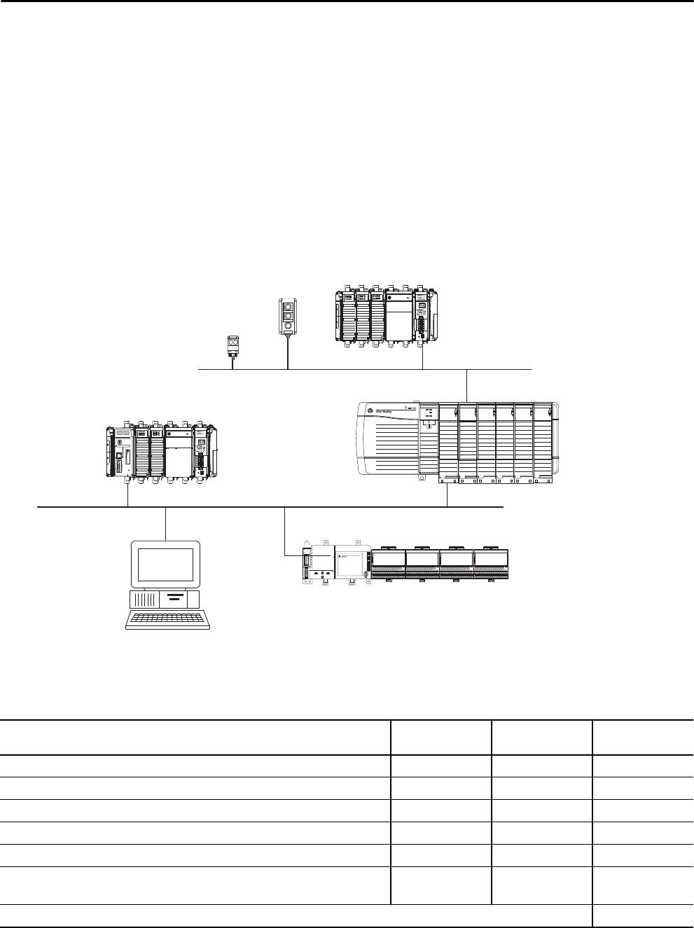
Rockwell Automation Publication 1756-UM001P-EN-P - May 2017 123
Manage Controller Communication Chapter 7
Connections Example
In this example system, the 1756 ControlLogix controller does the following:
• Controls local digital I/O modules in the same chassis
• Controls remote I/O devices on a DeviceNet network
• Sends and receives messages to and from a CompactLogix™ controller on
an EtherNet/IP network
• Produces one tag that the 1794 FlexLogix™ controller consumes
• Is programmed via the Logix Designer application
The ControlLogix controller in this example uses these connections.
• ControlLogix
• 1756-ENBT
• 1756-DNB
• 1769-ADN
• Compact I/O™
RediSTATION™
Series 9000™
DeviceNet
EtherNet/IP Network
• 1769-L35E CompactLogix
• 1769-SDN
FlexLogix
1788-DNBO
Table 41 - Connections Example Calculation
Connection Type Device Quantity Connections per
Device
Total Connections
Controller to local I/O modules 4 1 4
Controller to 1756-ENBT module 1 0 0
Controller to 1756-DNB module 1 2 2
Controller to Logix Designer application 1 1 1
Message to CompactLogix controller 2 1 2
Produced tag
Consumed by FlexLogix controller
1
1
1
1
1
1
Total 11

124 Rockwell Automation Publication 1756-UM001P-EN-P - May 2017
Chapter 7 Manage Controller Communication
Notes:

Rockwell Automation Publication 1756-UM001P-EN-P - May 2017 125
Chapter 8
I/O Modules
Selecting ControlLogix
I/O Modules
Rockwell Automation offers several ControlLogix® I/O modules for use in
ControlLogix systems. When you select your I/O modules, remember the
following:
• A wide variety of digital, analog, and specialty I/O modules are available
from Rockwell Automation. Some features of these I/O modules
include the following:
– Field-side diagnostics
– Electronic fusing
– Individually isolated inputs/outputs
• Removable terminal blocks (RTBs) or 1492 wiring systems are required
for use with I/O modules.
• 1492 PanelConnect™ modules and cables can be used to connect input
modules to sensors.
For more information about ControlLogix I/O module features,
specifications, and wiring options, see the ControlLogix System Selection
Guide, publication 1756-SG001.
Local I/O Modules The ControlLogix chassis that you choose affects how many local I/O modules
you can use. Several ControlLogix chassis sizes are available to suit your
configuration requirements. You can fill the slots of your chassis with any
combination of controllers, communication modules, and I/O modules.
Topic Page
Selecting ControlLogix I/O Modules 125
Local I/O Modules 125
Remote I/O Modules 127
Distributed I/O 131
Reconfigure an I/O Module 134
Add to the I/O Configuration While Online 136
Determine When Data Is Updated 141
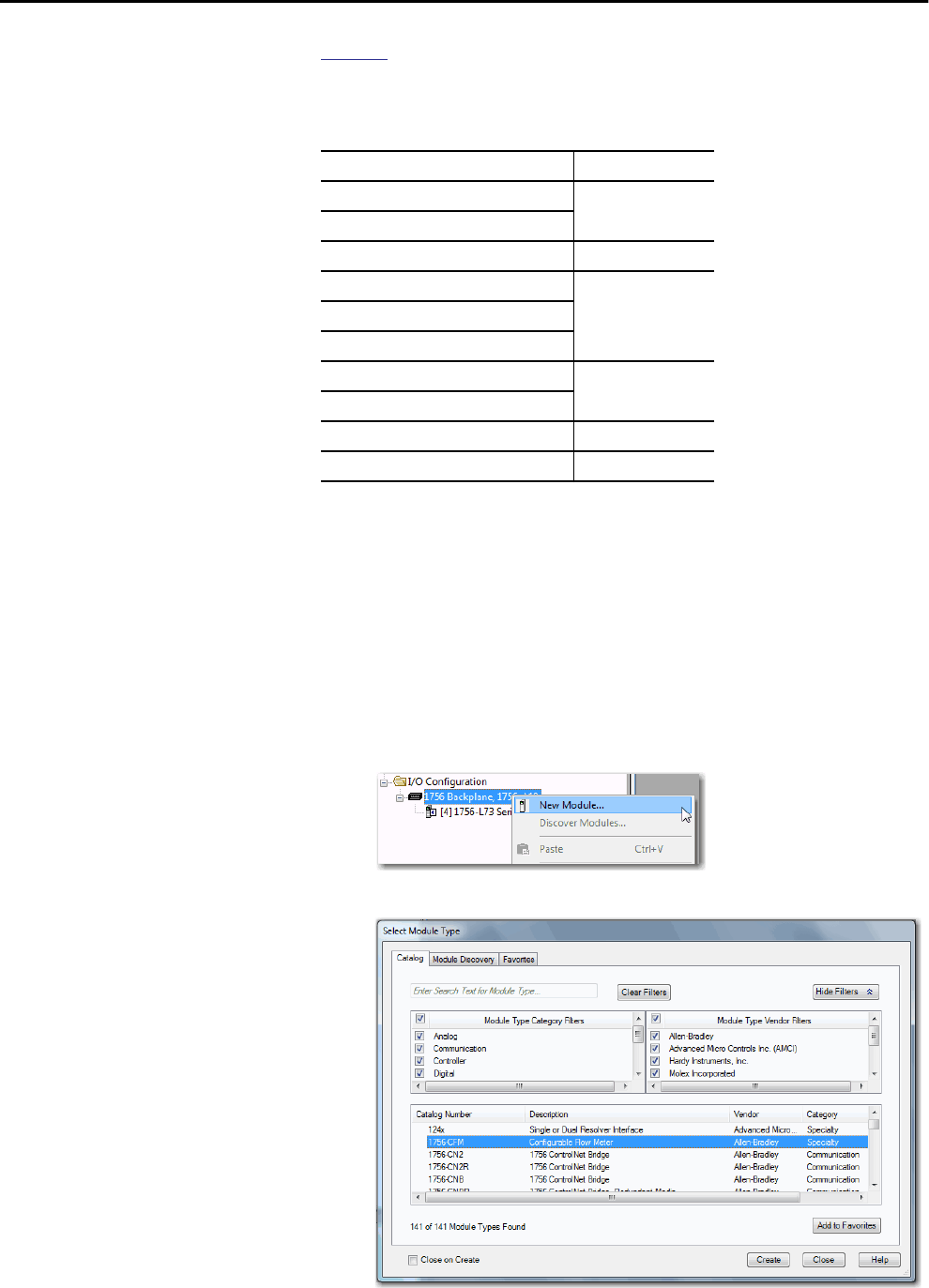
126 Rockwell Automation Publication 1756-UM001P-EN-P - May 2017
Chapter 8 I/O Modules
Table 42 lists the available ControlLogix and ControlLogix-XT™ chassis and
the number of slots available with each.
If you have empty slots in your chassis, use the 1756-N2 or 1756-N2XT
slot-filler module.
Add Local I/O to the I/O Configuration
If you are adding local I/O, add the I/O module to the backplane with the
controller. To add an I/O module to the local chassis, complete these steps.
1. Right-click the backplane and choose New Module.
2. Select the I/O module that you want to add and click OK.
Table 42 - ControlLogix and ControlLogix-XT Chassis and Slots
Chassis Slots
1756-A4 4
1756-A4LXT
1756-A5XT 5
1756-A7 7
1756-A7LXT
1756-A7XT
1756-A10 10
1756-A10XT
1756-A13 13
1756-A17 17
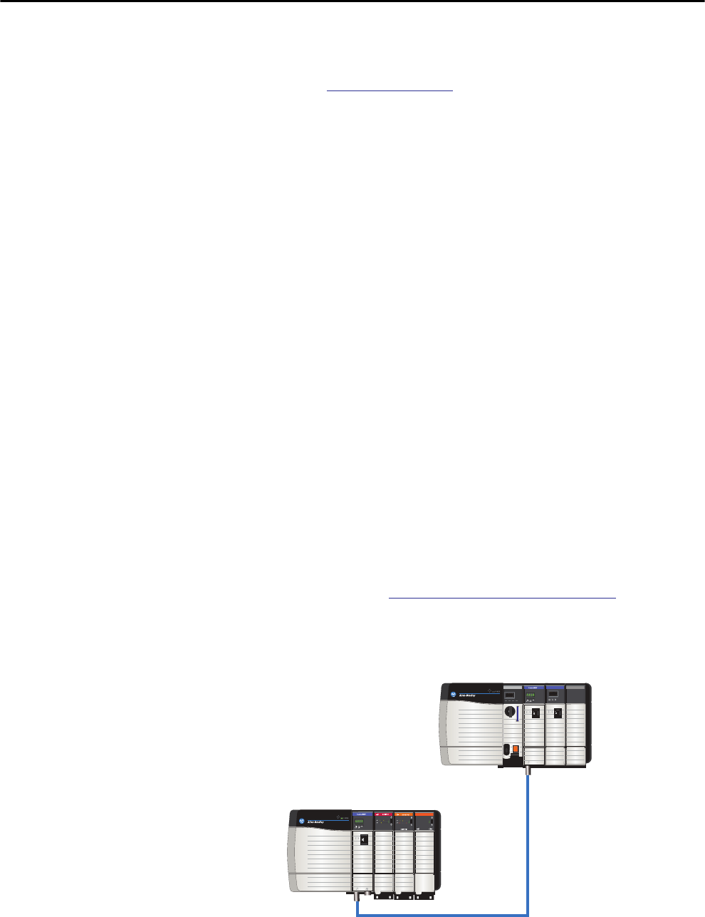
Rockwell Automation Publication 1756-UM001P-EN-P - May 2017 127
I/O Modules Chapter 8
3. Specify the configuration properties according to the module and
network configuration you are using.
See the Additional Resources section in the preface for more
information if you are designing your ControlLogix System for any of
the following modules:
• Analog I/O
• Configurable flowmeter
• Digital I/O
• HART analog I/O
• High-speed analog I/O
• High-speed counter
• Low-speed counter
• Programmable limit switch
Remote I/O Modules Remote I/O refers to I/O that is not in the local chassis and is connected to the
controller via a communication network.
The ControlLogix controller supports the use of remote I/O via these
networks:
• EtherNet/IP
•ControlNet
• DeviceNet
• Universal remote I/O
For more information about the network configurations that can be used to
connect remote I/O, see Communication Networks on page 89.
Figure 22 - ControlLogix Controller and Remote I/O Example
ControlLogix Controller Chassis
ControlLogix Remote I/O
ControlNet Network
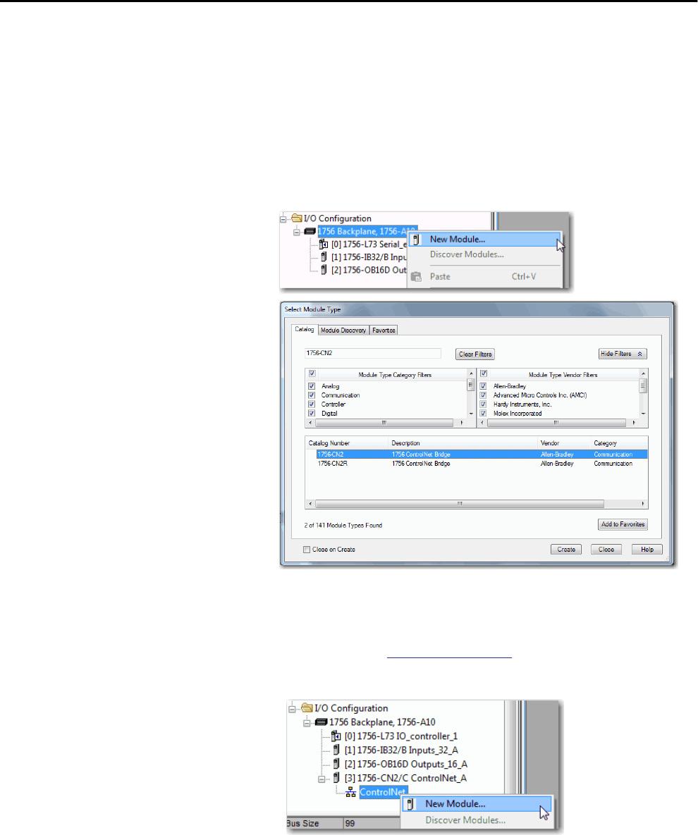
128 Rockwell Automation Publication 1756-UM001P-EN-P - May 2017
Chapter 8 I/O Modules
Add Remote I/O to the I/O Configuration
If you are adding remote I/O, add the I/O modules to the backplane of the
remote communication module that is connected to the controller. To add a
remote I/O to the I/O Configuration folder in the Logix Designer application,
complete these steps.
1. Add a communication module to the backplane that contains the
controller.
2. Specify the communication module properties according to your
network configuration.
For more information about the communication module and network
properties, see the Additional Resources section in the preface.
3. Right-click the communication network and choose New Module.
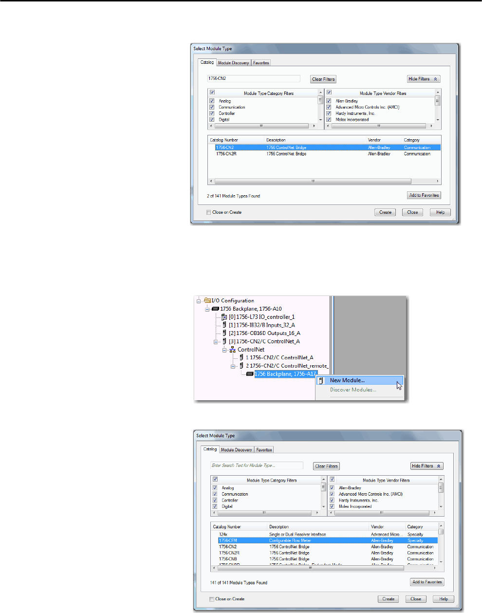
Rockwell Automation Publication 1756-UM001P-EN-P - May 2017 129
I/O Modules Chapter 8
4. Add the remote communication module that you are using.
5. Specify the chassis and connection properties according to your network
configuration.
6. Right-click the backplane of the newly added communication module
and choose New Module.
7. Select the I/O module that you want to add and click OK.
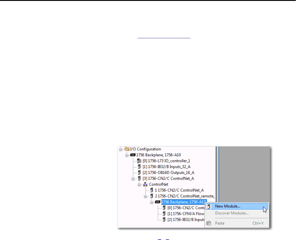
130 Rockwell Automation Publication 1756-UM001P-EN-P - May 2017
Chapter 8 I/O Modules
8. Specify the Module Properties according to your module and
application.
See the Additional Resources section in the preface for more
information about the module configuration properties for any of the
following modules:
• Analog I/O
• Configurable flowmeter
• Digital I/O
• HART analog I/O
• High-speed analog I/O
• High-speed counter
• Low-speed counter
• Programmable limit switch
9. Add any other I/O modules that you are using in the remote chassis.
10. Complete steps 1…9 until your remote I/O network and I/O modules
are configured.
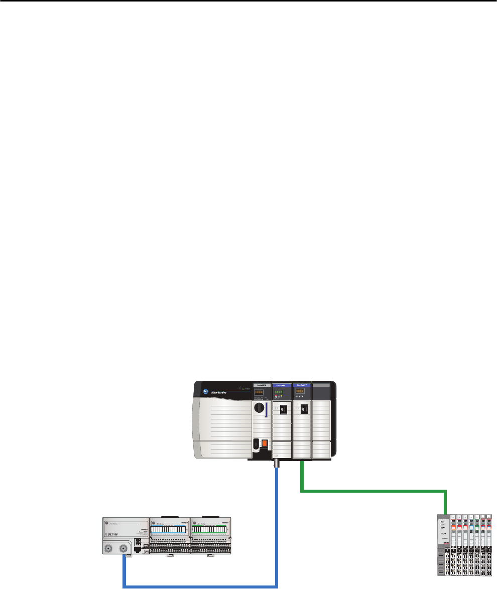
Rockwell Automation Publication 1756-UM001P-EN-P - May 2017 131
I/O Modules Chapter 8
Distributed I/O Distributed I/O refers to I/O that is remote from the controller and is not
designed for use with a specific controller. Examples of distributed I/O that can
be used with Logix5000™ controllers include the following:
• 1794 FLEX™ I/O modules
• 1734 POINT I/O™ modules
• 1797 FLEX Ex™ I/O modules
• 1738 ArmorPOINT® I/O modules
• 1732 ArmorBlock® I/O modules
• 1753 GuardPLC™ Safety I/O modules
• 1790 CompactBlock™ LDX I/O modules
• 1791 CompactBlock Guard Safety I/O modules
• 1791 CompactBlock I/O modules
• 1732DS ArmorBlock Guard Safety I/O modules
• 1792 ArmorBlock MaXum™ I/O modules
Distributed I/O is connected to the ControlLogix controller via a
communication network. The ControlLogix controller supports the use of
distributed I/O via these networks:
• EtherNet/IP
•ControlNet
• DeviceNet
Figure 23 - ControlLogix System with Distributed I/O Example
ControlLogix Controller Chassis
FLEX I/O
ControlNet
POINT I/O
EtherNet/IP
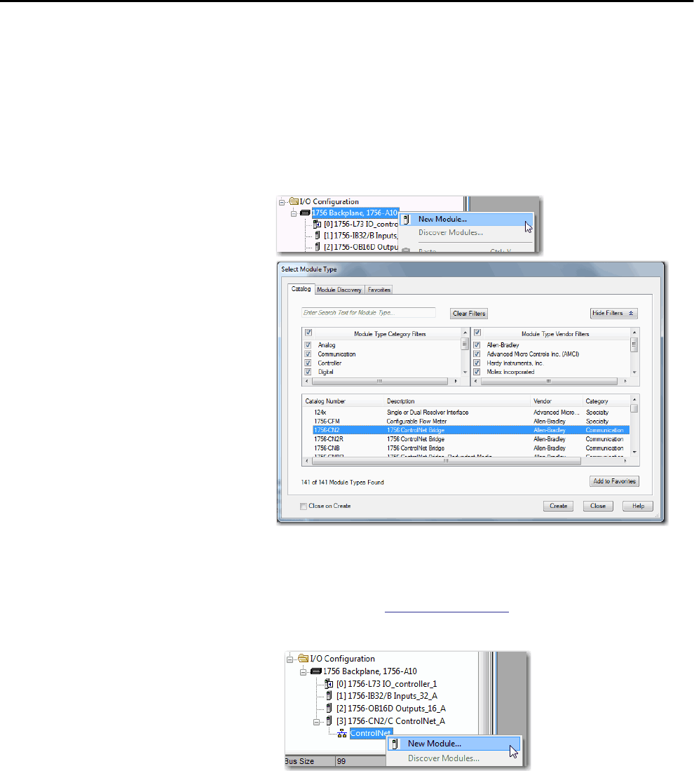
132 Rockwell Automation Publication 1756-UM001P-EN-P - May 2017
Chapter 8 I/O Modules
Add Distributed I/O to the I/O Configuration
If you are adding distributed I/O, add the I/O modules to the communication
adapter of the I/O. To add distributed I/O to the I/O Configuration folder for
the ControlLogix controller, complete these steps.
1. Add a communication module to the backplane that contains the
controller.
2. Specify the communication module properties according to your
network configuration.
For more information about the communication module and network
properties, see the Additional Resources section in the preface.
3. Right-click the communication network and choose New Module.
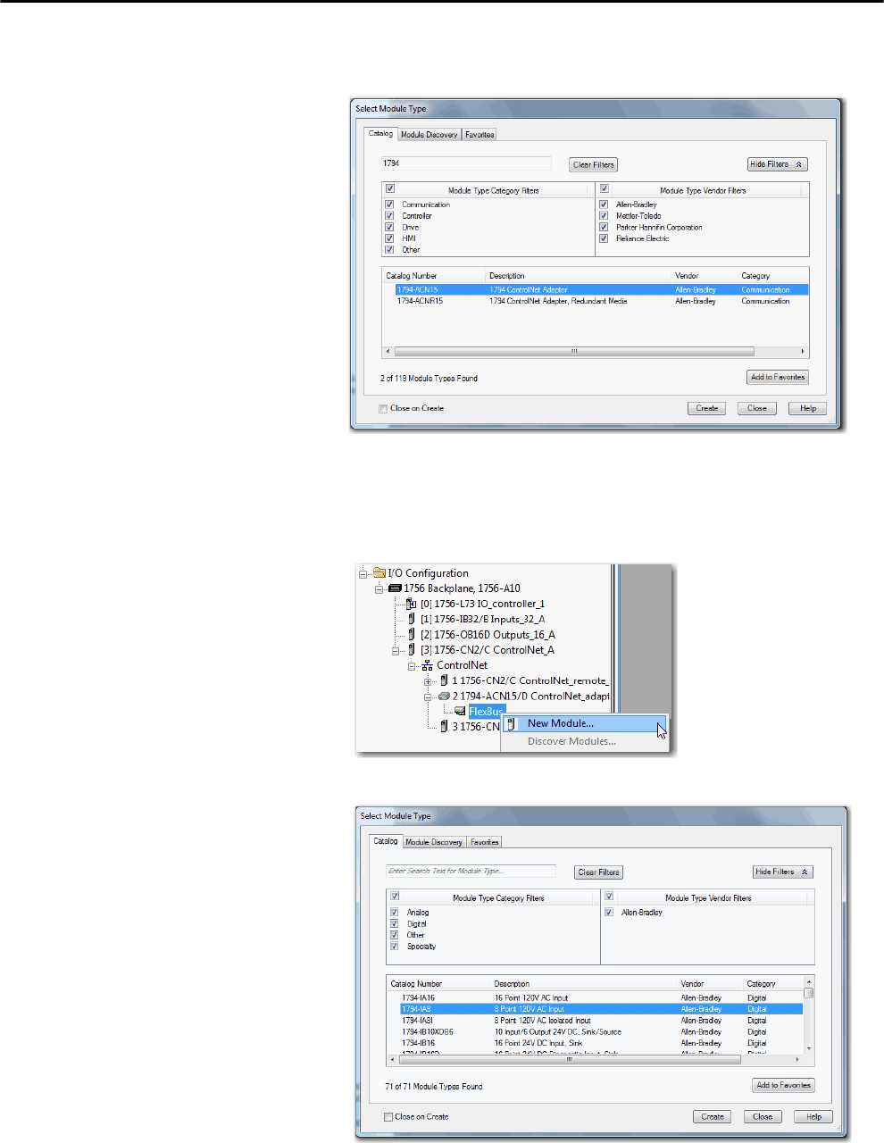
Rockwell Automation Publication 1756-UM001P-EN-P - May 2017 133
I/O Modules Chapter 8
4. Add the communication adapter for the distributed I/O platform that
you are using.
5. Specify the module and connection properties according to your
network configuration.
6. Right-click the bus of the newly added communication adapter and
choose New Module.
7. Select the I/O module that you want to add and click OK.
134 Rockwell Automation Publication 1756-UM001P-EN-P - May 2017
Chapter 8 I/O Modules
8. Specify the Module Properties according to your module and
application.
For more information about the module configuration properties, see
the user manual for the I/O module you are adding.
9. Add any other I/O modules that you are using in this bus.
10. Complete steps 1…9 until your remote I/O network and distributed I/
O modules are configured.
Reconfigure an I/O Module If an I/O module supports reconfiguration, you can reconfigure the module via
the following:
• The Module Properties dialog box in the I/O Configuration folder
• A MSG instruction in program logic
Use a MSG instruction of type Module Reconfigure to send new configuration
information to an I/O module. During the reconfiguration, consider the
following:
• Input modules continue to send input data to the controller
• Output modules continue to control their output devices
IMPORTANT Use care when changing the configuration of an I/O module. You can
inadvertently cause the I/O module to operate incorrectly.
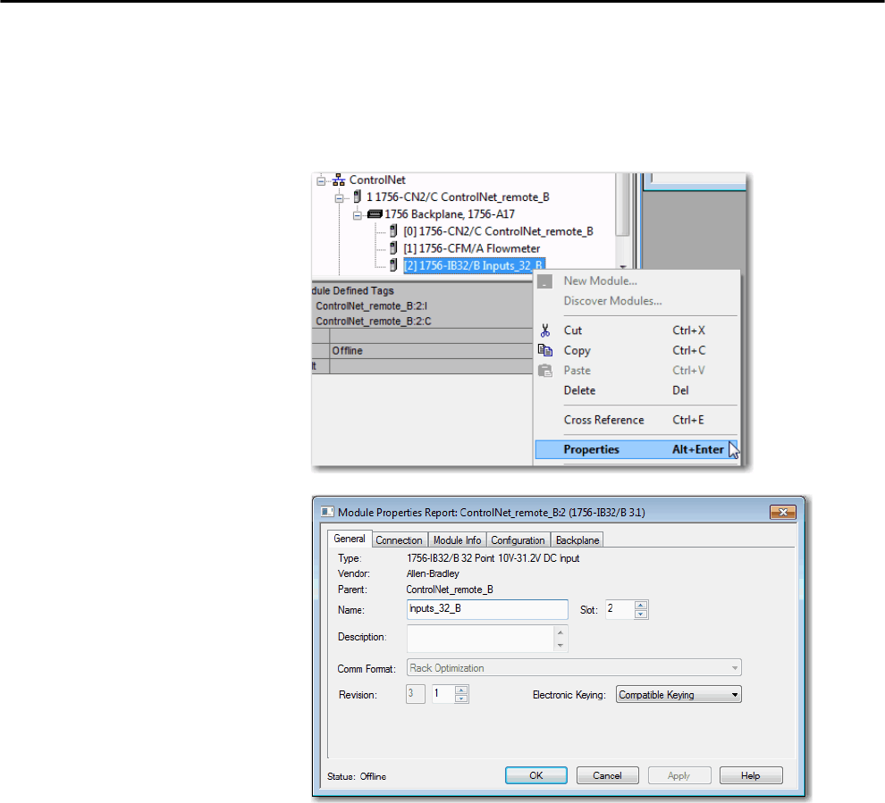
Rockwell Automation Publication 1756-UM001P-EN-P - May 2017 135
I/O Modules Chapter 8
Reconfigure an I/O Module Via the Module Properties
To reconfigure an I/O module by using the module properties, right-click the
module in the I/O Configuration tree and choose Properties. Then, edit the
properties that you must change and click Apply.
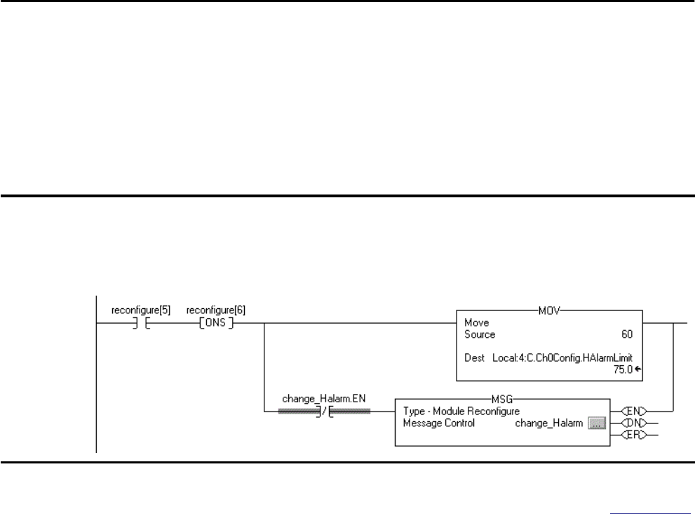
136 Rockwell Automation Publication 1756-UM001P-EN-P - May 2017
Chapter 8 I/O Modules
Reconfigure an I/O Module Via a Message Instruction
To reconfigure an I/O module via a message instruction, use this procedure.
1. Set the required member of the configuration tag of the module to the
new value.
2. Send a Module Reconfigure message to the module.
For more information about using Message instructions, see the Logix5000
Controllers General Instruction Reference Manual, publication 1756-RM003.
Add to the I/O Configuration
While Online
With RSLogix 5000 software, version 15.02.00 or later, and Logix Designer
application, version 21.00.00 or later, you can add I/O and other devices to the
controller configuration while you are online and in Run mode.
The modules and devices you can add while online depends on the version of
the software you are using. Later versions have more modules and devices that
can be added while online.
You can add these modules and devices to the local or remote chassis via the
unscheduled portion of a ControlNet network or via an EtherNet/IP network.
EXAMPLE Reconfigure an I/O module
When reconfigure[5] is on, the MOV instruction sets the high alarm to 60 for the local module in slot 4. The Module Reconfigure
message then sends the new alarm value to the module. The ONS instruction does not allow the rung to send multiple
messages to the module while the reconfigure[5] is on.

Rockwell Automation Publication 1756-UM001P-EN-P - May 2017 137
I/O Modules Chapter 8
Modules and Devices That Can Be Added While Online
These modules and devices can be added to the ControlLogix controller I/O
configuration while online as of RSLogix 5000 software, version 19.01.00 or
later and Logix Designer application, version 21.00.00 or later.
• 1756 controllers
• 1756 ControlNet modules
• 1756 DeviceNet bridges
• 1756 EtherNet/IP modules
• 1756 I/O and specialty modules
• 1756-DHRIO
• 1756-DHRIOXT
Online Additions - ControlNet Considerations
ControlNet considerations that must be made depend upon the ControlLogix
ControlNet modules you are using.
1756-CNB and 1756-CNBR Modules
When you add I/O to the ControlNet network via the 1756-CNB or
1756-CNBR modules while online, these considerations must be made:
• Digital I/O modules can be added as rack-optimized connections if the
parent module is configured with rack-optimized connections.
• Digital I/O modules can also be added as direct connections.
• Analog I/O modules can be added only as direct connections.
• Disable the Change of State (COS) feature on digital input modules
because it can cause inputs to be sent more quickly than the RPI.
IMPORTANT These ControlLogix modules cannot be added while online:
• Motion modules (1756-MO2AE, 1756-HYD02, 1756-MO2AS,
1756-MO3SE, 1756-MO8SE, 1756-MO8SEG, 1756-M16SE)
• 1756-RIO
• 1756-SYNCH
• 1756-56AMXN
TIP While you can add a new digital I/O module to an existing rack-optimized
connection, you cannot add rack-optimized connections while online.

138 Rockwell Automation Publication 1756-UM001P-EN-P - May 2017
Chapter 8 I/O Modules
• If you plan to add large amounts of I/O to the ControlNet network,
dedicate one ControlNet network for I/O. For the dedicated
ControlNet network, verify that there is little or none of the following:
– HMI traffic
– MSG traffic
– Programming workstations
• Requested Packet Intervals (RPIs) faster than 25 ms for unscheduled
modules can overload the 1756-CNB or 1756-CNBR communication
module. To avoid the overload, make these considerations:
– Use a NUT of 10 ms or more.
– Keep the SMAX and UMAX values as small as possible.
• If the module has a Real Time Sample (RTS), disable it or set it to a rate
that is greater than the RPI.
• You can add I/O modules until you reach these limits:
– 75% of CPU utilization of the 1756-CNB or 1756-CNBR
communication module
– Plan for a CPU-use increase of 1…4% of the 1756-CNB or
1756-CNBR module for each I/O module you add, depending on
the RPI.
– 48 connections on the 1756-CNB or 1756-CNBR communication
module
– Less than 400,000 unscheduled bytes per second are displayed in
RSNetWorx™ for ControlNet™ software after the network has been
scheduled.
1756-CN2, 1756-CN2R, 1756-CN2RXT Modules
The use of 1756-CN2/B, 1756-CN2R/B, and 1756-CN2RXT modules
provides increased capacity for adding I/O while online compared to
1756-CNB or 1756-CNBR modules. With this increased capacity, you can
easily add I/O and increase ControlNet connections that are used with less
impact on the overall system.
Table 43 demonstrates the performance factors of the 1756-CN2/B,
1756-CN2R/B, and 1756-CN2RXT modules when adding I/O online.
Rockwell Automation Publication 1756-UM001P-EN-P - May 2017 139
I/O Modules Chapter 8
Because of the increased performance that is provided by the 1756-CN2,
1756-CN2R, and 1756-CN2RXT modules, many of the considerations that
must be made with the 1756-CNB and 1756-CNBR modules are not
applicable. With the 1756-CN2, 1756-CN2R, and 1756-CN2RXT modules,
you can add I/O while online as long as you use reasonable RPI settings and
remain within the CPU limitations of the ControlNet module.
When adding to the I/O Configuration with 1756-CN2, 1756-CN2R, and
1756-CN2RXT modules, make these considerations:
• Digital I/O modules can be added as rack-optimized connections if the
parent module is configured with rack-optimized connections.
• Digital I/O modules can also be added as direct connections.
• Analog I/O modules can be added only as direct connections.
• Disable the Change of State (COS) feature on digital input modules
because it can cause inputs to be sent more quickly than the RPI.
Table 43 - 1756-CN2, 1756-CN2R, and 1756-CN2RXT Performance Example(1)
No. of Direct
Analog I/O
Connections
Added Online
RPI = 2 ms RPI = 4 ms RPI = 10 ms RPI = 20 ms RPI = 50 ms RPI = 100 ms
CPU %(2) Avg.
API(3) CPU %(2) Avg.
API(3) CPU %(2) Avg.
API(3) CPU %(2) Avg.
API(3) CPU %(2) Avg.
API(3) CPU %(2) Avg.
API(3)
0 1.50% N/A 1.50% N/A 1.50% N/A 1.50% N/A 1.50% N/A 1.50% N/A
1 4.80% 2.0 3.70% 4.0 2.50% 10.0 2.30% 20.0 1.90% 50.0 1.70% 100.0
2 7.00% 2.0 5.00% 4.0 3.30% 10.0 2.70% 20.0 2.10% 50.0 1.90% 100.0
3 9.00% 2.0 6.10% 4.0 3.80% 10.0 3.00% 20.0 2.20% 50.0 2.00% 100.0
4 11.20% 2.2 7.40% 4.0 4.40% 10.0 3.40% 20.0 2.40% 50.0 2.10% 100.0
5 11.50% 3.3 8.70% 4.0 5.00% 10.0 3.70% 20.0 2.60% 50.0 2.20% 100.0
6 12.80% 3.3 9.70% 4.0 5.50% 10.0 4.00% 20.0 2.70% 50.0 2.30% 100.0
7 13.80% 3.4 10.80% 4.0 5.90% 10.0 4.30% 20.0 2.90% 50.0 2.30% 100.0
8 15.10% 3.4 11.90% 4.0 6.40% 10.0 4.50% 20.0 3.00% 50.0 2.50% 100.0
9 15.00% 3.3 13.20% 4.0 7.00% 10.0 4.80% 20.0 3.20% 50.0 2.60% 100.0
10 15.60% 3.6 13.20% 4.0 7.50% 10.0 5.20% 20.0 3.40% 50.0 2.70% 100.0
11 16.40% 3.8 13.50% 4.0 8.20% 10.0 5.50% 20.0 3.50% 50.0 2.70% 100.0
12 17.00% 3.8 14.00% 4.0 8.80% 10.0 5.80% 20.0 3.70% 50.0 2.80% 100.0
13 17.80% 3.7 14.60% 4.0 9.30% 10.0 6.10% 20.0 3.80% 50.0 2.90% 100.0
14 18.50% 3.7 15.20% 4.0 9.90% 10.0 6.40% 20.0 4.00% 50.0 2.90% 100.0
15 19.40% 3.9 15.80% 4.0 10.50% 10.0 6.70% 20.0 4.10% 50.0 3.00% 100.0
(1) Example assumes that adequate unscheduled bandwidth is available.
(2) Approximate use of the central-processing unit (CPU) of the module in percent.
(3) The average Actual Packet Interval with 2000 samples (shown in ms).
TIP While you can add a new digital I/O module to an existing rack-optimized
connection, you cannot add rack-optimized connections while online.

140 Rockwell Automation Publication 1756-UM001P-EN-P - May 2017
Chapter 8 I/O Modules
• If you plan to add large amounts of I/O to the ControlNet network,
dedicate one ControlNet network for I/O. For the dedicated
ControlNet network, verify that there is little or none of the following:
– HMI traffic
– MSG traffic
– Programming workstations
• If the module has a Real Time Sample (RTS), disable it or set it to a rate
that is greater than the RPI.
• You can add I/O modules until you reach these limits:
– 80% of CPU utilization of the 1756-CN2, 1756-CN2R, or
1756-CN2RXT communication module.
– Less than 400,000 unscheduled bytes per second are displayed in
RSNetWorx for ControlNet software after the network has been
scheduled.
Online Additions—EtherNet/IP Considerations
When you add I/O modules to the EtherNet/IP network, make these
considerations:
• The EtherNet/IP I/O modules that you add can be added as these
connection types:
– Rack-optimized connections, including new and existing
connections
– Direct connections
• You can add I/O modules until you reach the limits of the
communication connections of the module.
For EtherNet/IP module limitations, see the EtherNet/IP Modules in
Logix5000 Control Systems User Manual, publication ENET-UM001.
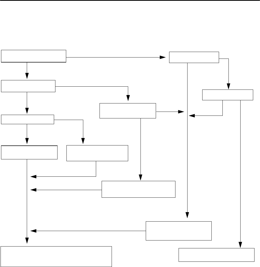
Rockwell Automation Publication 1756-UM001P-EN-P - May 2017 141
I/O Modules Chapter 8
Determine When Data Is
Updated
ControlLogix controllers update date asynchronously with the execution of
logic. Use this flowchart to determine when a producer, such as a controller,
input module, or bridge, sends data.
Figure 24 - Data Update Flowchart
Input or Output Data?
Input
Output
COS for any point on the Module?
Data is sent to the backplane at the RPI.
Remote or Local?
Analog
No
Yes
Data is sent to the backplane at the RPI and at
the end of each task.
Data is sent to the backplane at the RPI and at
the change of a specified point.
Data is sent to the backplane at the RTS
and RPI.
Data is sent to the backplane at the
RTS.
Analog or Digital?
Analog
Digital
Local
Remote
Digital
• Over a ControlNet network, remote data is sent at the actual packet interval.
• Over an EtherNet/IP network, remote data is usually sent close to the RPI.
Yes
No
RTS RPI?
Analog or Digital?
New data can appear in input tags at any point in the program scan. If the
control logic reads input tag values in multiple locations, do not assume
that the data remains unchanged throughout the scan of the logic.

142 Rockwell Automation Publication 1756-UM001P-EN-P - May 2017
Chapter 8 I/O Modules
Notes:

Rockwell Automation Publication 1756-UM001P-EN-P - May 2017 143
Chapter 9
Develop Motion Applications
Motion Control Options ControlLogix® controllers support digital, analog, and Integrated Motion
interfaces:
• Digital drive interfaces include EtherNet/IP connected drives and sercos
interface connected drives.
• Analog drives support ±10V analog output and can interface with
various feedback device types including quadrature encoder, SSI, and
LVDT feedback.
• Integrated Motion on an EtherNet/IP network supports Kinetix® 350,
Kinetix 5500, Kinetix 6500, and PowerFlex® 755 drives.
Topic Page
Motion Control Options 143
Motion Overview 144
Obtain Axis Information 144
Program Motion Control 145
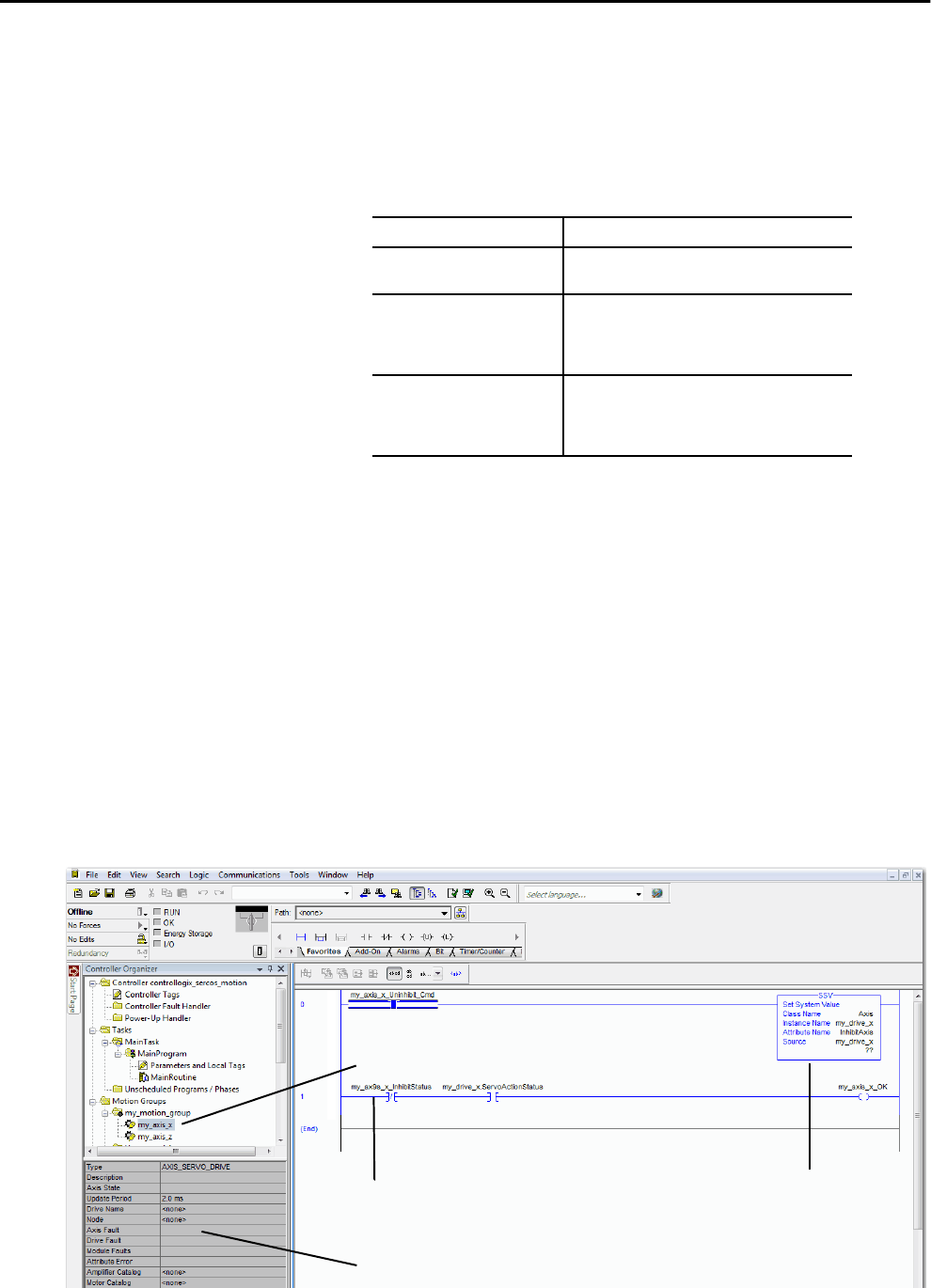
144 Rockwell Automation Publication 1756-UM001P-EN-P - May 2017
Chapter 9 Develop Motion Applications
Motion Overview The configuration process varies, depending on your application and your
drive selection. The following are general steps to configure a motion
application.
1. Create a controller project.
2. Select the type of drive.
3. Create axis tags as needed.
4. Configure the drive.
5. Create axes as needed.
Obtain Axis Information You can obtain axis information by using these methods:
• Double-click the axis to open the Axis Properties dialog box.
• Use a Get System Value (GSV) or Set System Value (SSV) instruction to
read or change the configuration at runtime.
• View the Quick View pane to see the state and faults of an axis.
• Use an axis tag for status and faults.
Figure 25 - Obtain Axis Information
Drive Type Requirements
CIP Sync • EtherNet/IP communication module
• Digital drive with an EtherNet/IP connection
Sercos interface Select a sercos interface module:
• 1756-M03SE
• 1756-M08SE
• 1756-M16SE
Analog interface Select an analog interface module:
• 1756-HYD02
• 1756-M02AE
• 1756-M02AS
Axis Properties Dialog Box
SSV (or GSV) Instruction
Axis Tag
Quick View Pane
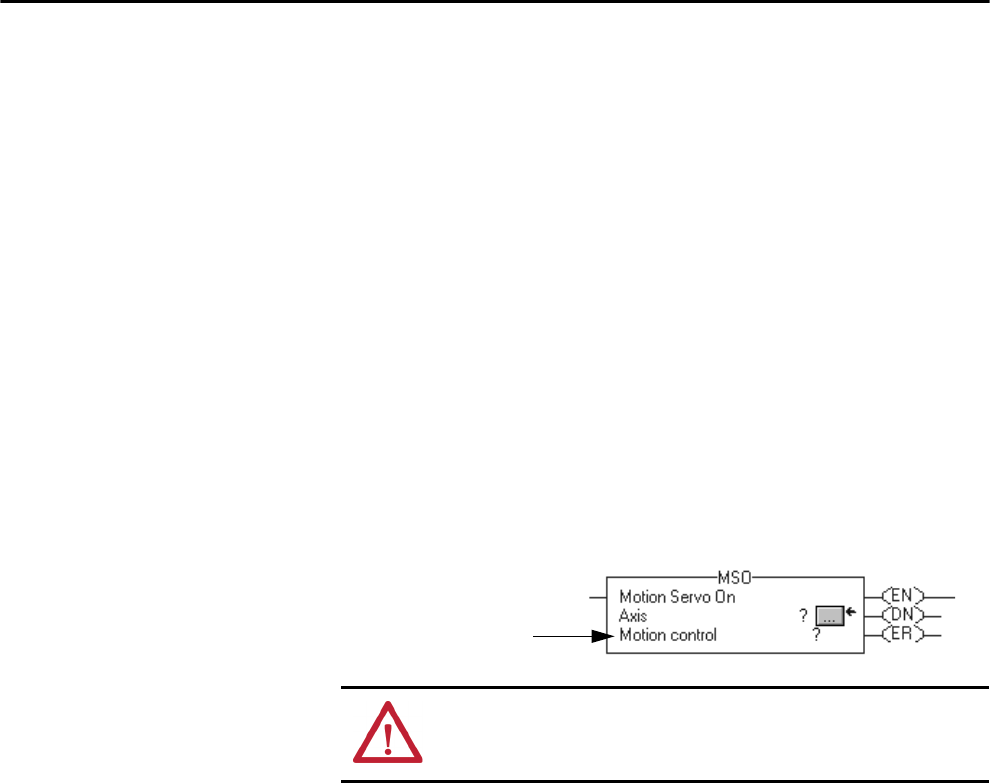
Rockwell Automation Publication 1756-UM001P-EN-P - May 2017 145
Develop Motion Applications Chapter 9
Program Motion Control The controller provides a set of motion control instructions for your axes:
• The controller uses these instructions just like the rest of the Logix5000™
instructions.
• Each motion instruction works on one or more axes.
• Each motion instruction needs a motion control tag. The tag uses a
MOTION_INSTRUCTION data type and stores the information
status of the instruction.
• You can program by using motion control instructions in these
programming languages:
– Ladder Diagram (LD)
– Structured Text (ST)
– Sequential Function Chart (SFC)
Figure 26 - Motion Control Instruction
ATTENTION: Use the tag for the motion control operation of motion
instruction only once. Unintended operation of the control variables can
happen if you reuse of the same motion control tag in other instructions.
Motion Control Tag
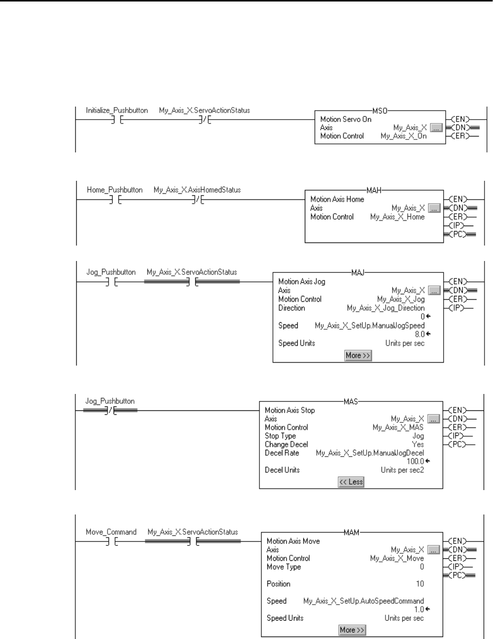
146 Rockwell Automation Publication 1756-UM001P-EN-P - May 2017
Chapter 9 Develop Motion Applications
Example
In this example, a simple ladder diagram that homes, jogs, and moves an axis.
If Initialize_Pushbutton = on and the axis = off (My_Axis_X.ServoActionStatus = off) then the MSO instruction turns on the axis.
If Home_Pushbutton = on and the axis hasn’t been homed (My_Axis_X.AxisHomedStatus = off) then the MAH instruction homes the axis.
If Jog_Pushbutton = on and the axis = on (My_Axis_X.ServoActionStatus = on) then the MAJ instruction jogs the axis forward at 8 units/second.
If Jog_Pushbutton = off then the MAS instruction stops the axis at 100 units/.second2. Make sure that Change Decel is Yes. Otherwise, the axis
decelerates at its maximum speed.
If Move_Command = on and the axis = on (My_Axis_X.ServoActionStatus = on) then the MAM instruction moves the axis. The axis moves to the
position of 10 units at 1 unit/second.

Rockwell Automation Publication 1756-UM001P-EN-P - May 2017 147
Chapter 10
Develop Applications
Elements of a
Control Application
A control application is comprised of several elements that require planning for
efficient application execution. Application elements include the following:
•Tasks
•Programs
• Routines
• Parameters and Local Tags
Topic Page
Elements of a Control Application 147
Tasks 148
Programs 151
Routines 154
Parameters and Local Tags 155
Programming Languages 158
Add-On Instructions 159
Access the Module Object 160
Monitoring Controller Status 161
Monitoring I/O Connections 161
System Overhead Time Slice 165
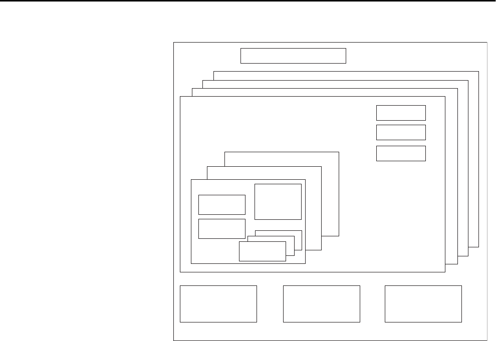
148 Rockwell Automation Publication 1756-UM001P-EN-P - May 2017
Chapter 10 Develop Applications
Figure 27 - Elements of a Control Program
Tasks A Logix5000™ controller lets you use multiple tasks to schedule and prioritize
the execution of your programs based on criteria. This multitasking allocates
the processing time of the controller among the operations in your application:
• The controller executes only one task at a time.
• One task can interrupt the execution of another and take control.
• In any given task, multiple programs can be used. However, only one
program executes at a time.
• You can display tasks in the Controller or Logical Organizer views, as
necessary.
Task 32
Task 1
Configuration
Status
Watchdog
Program 1000
Program 1
Main Routine
Fault Routine
Program (Local
Tags and
Parameters)
Other
Routines
I/O Data System-shared Data
Controller Fault Handler
Controller (global) Tags
40012
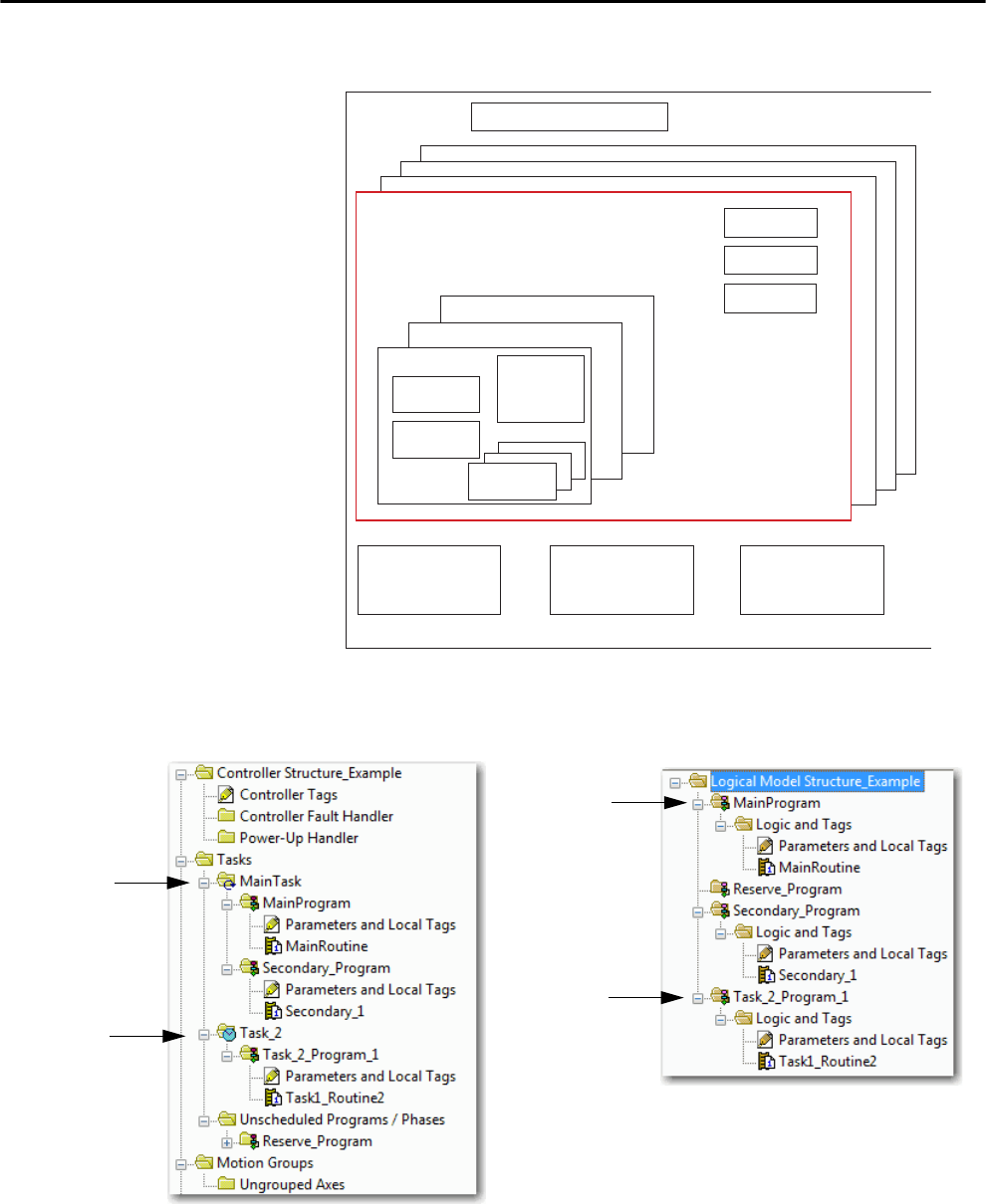
Rockwell Automation Publication 1756-UM001P-EN-P - May 2017 149
Develop Applications Chapter 10
Figure 28 - Task Within a Control Application
Figure 29 - Tasks
Task 32
Task 1 Configuration
Status
Watchdog
Program 1000
Program 1
Main Routine
Fault Routine
Other
Routines
Controller (global) Tags I/O Data System-shared Data
Controller Fault Handler
Program (Local
Tags and
Parameters)
Main Task
(continuous)
Task 2
(periodic)
Main Task
(continuous)
Task 2
(periodic)
Controller Organizer Logical Organizer
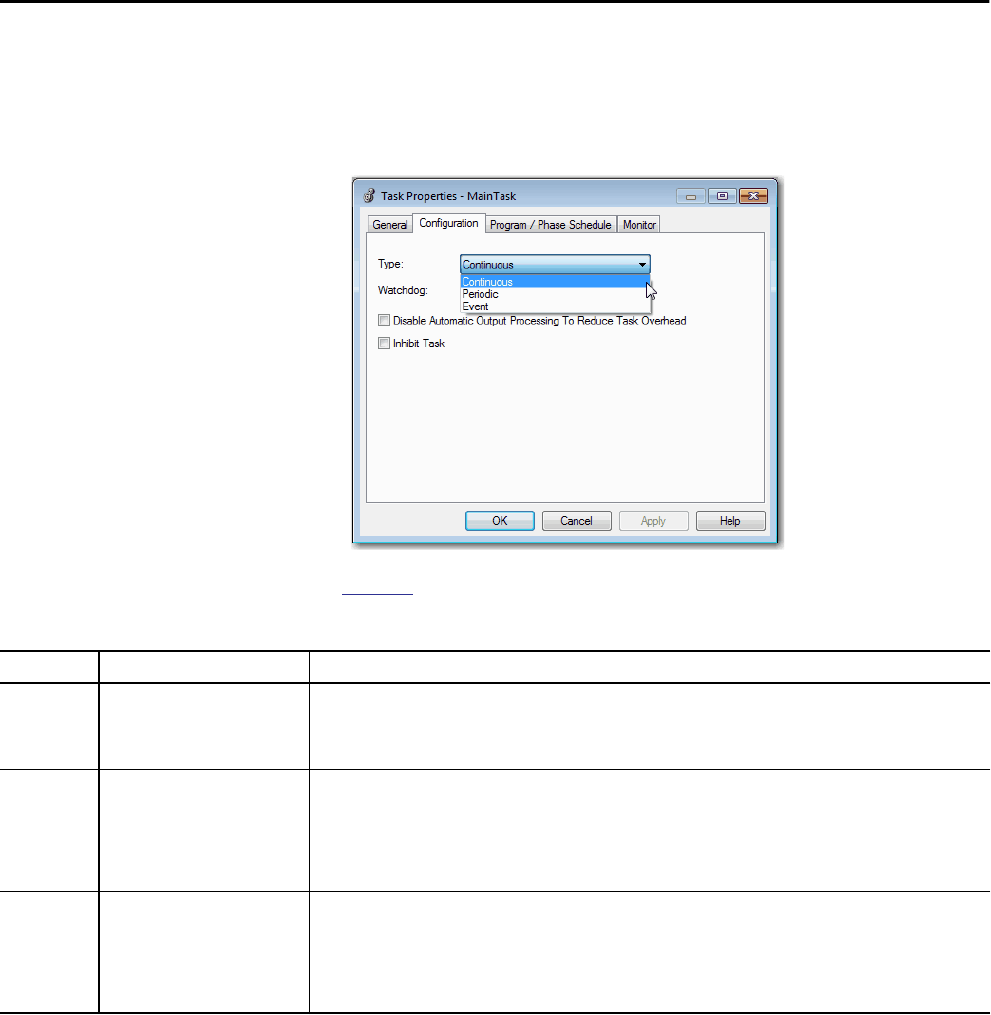
150 Rockwell Automation Publication 1756-UM001P-EN-P - May 2017
Chapter 10 Develop Applications
A task provides scheduling and priority information for a set of one or more
programs. Configure tasks as continuous, periodic, or event by using the Task
Properties dialog box.
Figure 30 - Configuring the Task Type
Table 44 explains the types of tasks you can configure.
The ControlLogix® controller supports up to 32 tasks, only one of which can
be continuous.
A task can have up to 1000 programs, starting with Logix Designer application,
version 24.00.00 and later, each with its own executable routines and program-
scoped tags. Once a task is triggered (activated), the programs that are assigned
to the task execute in the order in which they are grouped. Programs can appear
only once in the Controller Organizer and multiple tasks cannot share them.
Table 44 - Task Types and Execution Frequency
Task Type Task Execution Description
Continuous Constant The continuous task runs in the background. Any CPU time that is not allocated to other operations (such as motion,
communication, and other tasks) is used to execute the programs in the continuous task.
• The continuous task runs constantly. When the continuous task completes a full scan, it restarts immediately.
• A project does not require a continuous task. If used, there can be only one continuous task.
Periodic • At a set interval, such as each
100 ms
• Multiple times within the scan
of your other logic
A periodic task performs a function at an interval.
• Whenever the time for the periodic task expires, the task interrupts any lower priority tasks, executes once, and returns
control to where the previous task left off.
• You can configure the time period from 0.1…2,000,000.00 ms. The default is 10 ms. It is also controller and
configuration dependent.
• The performance of a periodic task depends on the type of Logix5000 controller and on the logic in the task.
Event Immediately when an event occurs An event task performs a function only when an event (trigger) occurs. The trigger for the event task can be the following:
• Module input data change of state
• A consumed tag trigger
• An EVENT instruction
• An axis trigger
• A motion event trigger
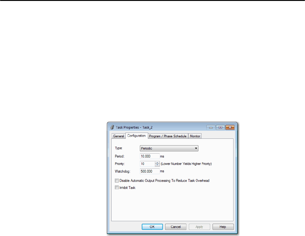
Rockwell Automation Publication 1756-UM001P-EN-P - May 2017 151
Develop Applications Chapter 10
Task Priority
Each task in the controller has a priority level. The operating system uses the
priority level to determine which task to execute when multiple tasks are
triggered. A higher priority task interrupts any lower priority task. The
continuous task has the lowest priority and a periodic or event task interrupts
it.
You can configure periodic and event tasks to execute from the lowest priority
of 15 up to the highest priority of 1. Configure the task priority by using the
Task Properties dialog box.
Figure 31 - Configure Task Priority
Programs The controller operating system is a preemptive multitasking system that is in
compliance with IEC 1131-3. This system provides the following:
• Programs to group data and logic
• Routines to encapsulate executable code that is written in one
programming language
Each program contains the following:
•Local Tags
• Parameters
• A main executable routine
• Other routines
• An optional fault routine
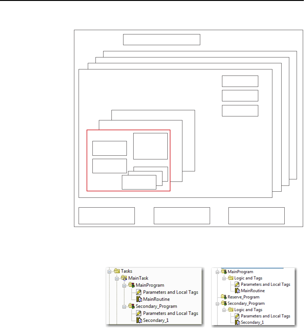
152 Rockwell Automation Publication 1756-UM001P-EN-P - May 2017
Chapter 10 Develop Applications
Figure 32 - Program Within a Control Application
Figure 33 - Programs
Controller Fault Handler
Task 32
Task 1
Configuration
Status
Watchdog
Program 1000
Program 1
Main Routine
Fault Routine
Other Routines
Controller (global) Tags I/O Data System-shared Data
Program (Local
Tags and
Parameters)
Controller Organizer Logical Organizer
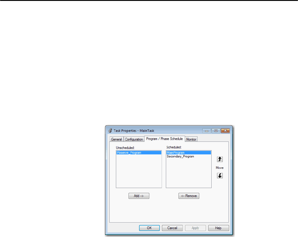
Rockwell Automation Publication 1756-UM001P-EN-P - May 2017 153
Develop Applications Chapter 10
Scheduled and Unscheduled Programs
The scheduled programs within a task execute to completion from first to last.
Programs that are not attached to any task show up as unscheduled programs.
Unscheduled programs within a task are downloaded to the controller with the
entire project. The controller verifies unscheduled programs but does not
execute them.
You must schedule a program within a task before the controller can scan the
program. To schedule an unscheduled program, use the Program/
Phase Schedule tab of the Task Properties dialog box.
Figure 34 - Scheduling an Unscheduled Program
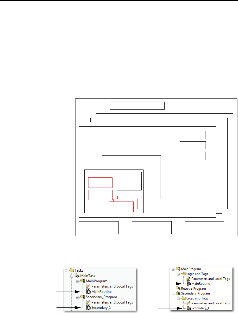
154 Rockwell Automation Publication 1756-UM001P-EN-P - May 2017
Chapter 10 Develop Applications
Routines A routine is a set of logic instructions in one programming language, such as
Ladder Diagram (ladder logic). Routines provide the executable code for the
project in a controller. A routine is similar to a program file or subroutine in a
PLC or SLC™ processor.
Each program has a main routine. The main is the first routine to execute when
the controller triggers the associated task and calls the associated program. Use
logic, such as the Jump to Subroutine (JSR) instruction, to call other routines.
You can also specify an optional program fault routine. The controller executes
this routine if it encounters an instruction-execution fault within any of the
routines in the associated program.
Figure 35 - Routines in a Control Application
Figure 36 - Routines
Controller Fault Handler
Task 32
Task 1 Configuration
Status
Watchdog
Program 1000
Program 1
Main Routine
Fault Routine
Other Routines
Controller (global) Tags I/O Data System-shared Data
Program (Local
Tags and
Parameters)
Routine
Routine
Routine
Routine
Controller Designer Logical Designer
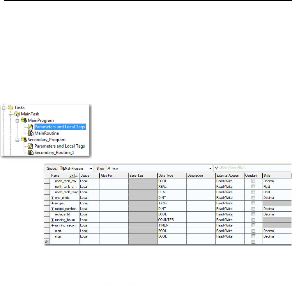
Rockwell Automation Publication 1756-UM001P-EN-P - May 2017 155
Develop Applications Chapter 10
Parameters and Local Tags With a Logix5000 controller, you use a tag (alphanumeric name) to address
data (variables). In Logix5000 controllers, there is no fixed, numeric format.
The tag name identifies the data and lets you do the following:
• Organize your data to mirror your machinery.
• Document your application as you develop it.
This example shows data tags that are created within the scope of the Main
Program of the controller.
Figure 37 - Tags Example
There are several guidelines for creating and configuring parameters and local
tags for optimal task and program execution. For more information, see the
Logix5000 Controllers and I/O Tag Data Programming Manual, publication
1756-PM004.
Controller Organizer —Main Program Parameters and Local Tags
Program Tags Window—Main Program Parameters and Local Tags
Digital I/O Device
Analog I/O Device
Integer Value
Storage Bit
Counter
Timer

156 Rockwell Automation Publication 1756-UM001P-EN-P - May 2017
Chapter 10 Develop Applications
Extended Properties
The Extended Properties feature lets you define more information, such as
limits, engineering units, or state identifiers, for various components within
your controller project.
Pass-through behavior is the ability to assign extended properties at a higher
level of a structure or Add-On Instruction and have that extended property
automatically available for all members. Pass-through behavior is available for
descriptions, state identifiers, and engineering units and you can configure it.
Configure pass-through behavior on the Project tab of the Controller
Properties dialog box. If you choose not to show pass-through properties, only
extended properties that have been configured for a given component are
displayed.
Pass-through behavior is not available for limits. When an instance of a tag is
created, if limits are associated with the data type, the instance is copied.
You must know which tags have limits that are associated with them as there is
no indication in the tag browser that extended properties are defined for a tag.
If, however, you try to use extended properties that have not been defined for a
tag, the editors show a visual indication and the routine does not verify.
Access Extended Properties in Logic
You can access limits that are defined on tags by using the .@Min and .@Max
syntax:
• You cannot write to extended properties values in logic.
• To use extended tag properties in an Add-On Instruction, you must pass
them in as input operands to the Add-On Instruction.
• Alias tags that have extended properties cannot access the extended
properties in logic.
• Limits can be configured for input and output parameters in Add-On
Instructions. However, limits cannot be defined on an InOut parameter
of an Add-On Instruction.
• Limits cannot be accessed inside Add-On Instruction logic. Limits are
only for use by HMI applications.
Component Extended Properties
Tag In the tag editor, add extended properties to a tag.
User-defined data type In the data type editor, add extended properties to data types.
Add-On Instructions In the properties that are associated with the Add-On Instruction definition, add
extended properties to Add-On Instructions.

Rockwell Automation Publication 1756-UM001P-EN-P - May 2017 157
Develop Applications Chapter 10
If an array tag is using indirect addressing to access limits in logic, the following
conditions apply:
• If the array tag has limits that are configured, the extended properties are
applied to any array element that does not explicitly have that particular
extended property configured. For example, if the array tag MyArray has
Max configured to 100, any element of the array that does not have Max
configured inherits the value of 100 when being used in logic. However,
it is not visible to you that the value inherited from MyArray is
configured in the tag properties.
• At least one array element must have a limit that is configured for
indirectly referenced array logic to verify. For example, if
MyArray[x].@Max is being used in logic, at least one array element of
MyArray[] must have Max extended property configured if MyArray has
not configured Max.
• Under the following circumstances a data type default value is used:
– Array is accessed programmatically with indirect reference.
– Array tag does not have the extended property configured.
– A member of an array does not have the extended property
configured.
For example, for an array of SINT type, when max limit is called in logic
for a member, the value 127 is used.
If an array element is directly accessed, the element has to have the extended
property defined. If not, verification fails.

158 Rockwell Automation Publication 1756-UM001P-EN-P - May 2017
Chapter 10 Develop Applications
Programming Languages The ControlLogix controller supports these programming languages: online
and offline.
For information about programming in these languages, see the Logix5000
Controllers Common Procedures Programming Manual, publication
1756-PM001.
Table 45 - ControlLogix Controller Programming Languages
Language Is best used in programs with
Relay ladder Continuous or parallel execution of multiple operations (not sequenced)
Boolean or bit-based operations
Complex logical operations
Message and communication processing
Machine interlocking
Operations that service or maintenance personnel have to interpret to
troubleshoot the machine or process
Function block diagram Continuous process and drive control
Loop control
Calculations in circuit flow
Sequential function chart (SFC) High-level management of multiple operations
Repetitive sequence of operations
Batch process
Motion control using structured text
State machine operations
Structured text Complex mathematical operations
Specialized array or table loop processing
ASCII string handling or protocol processing
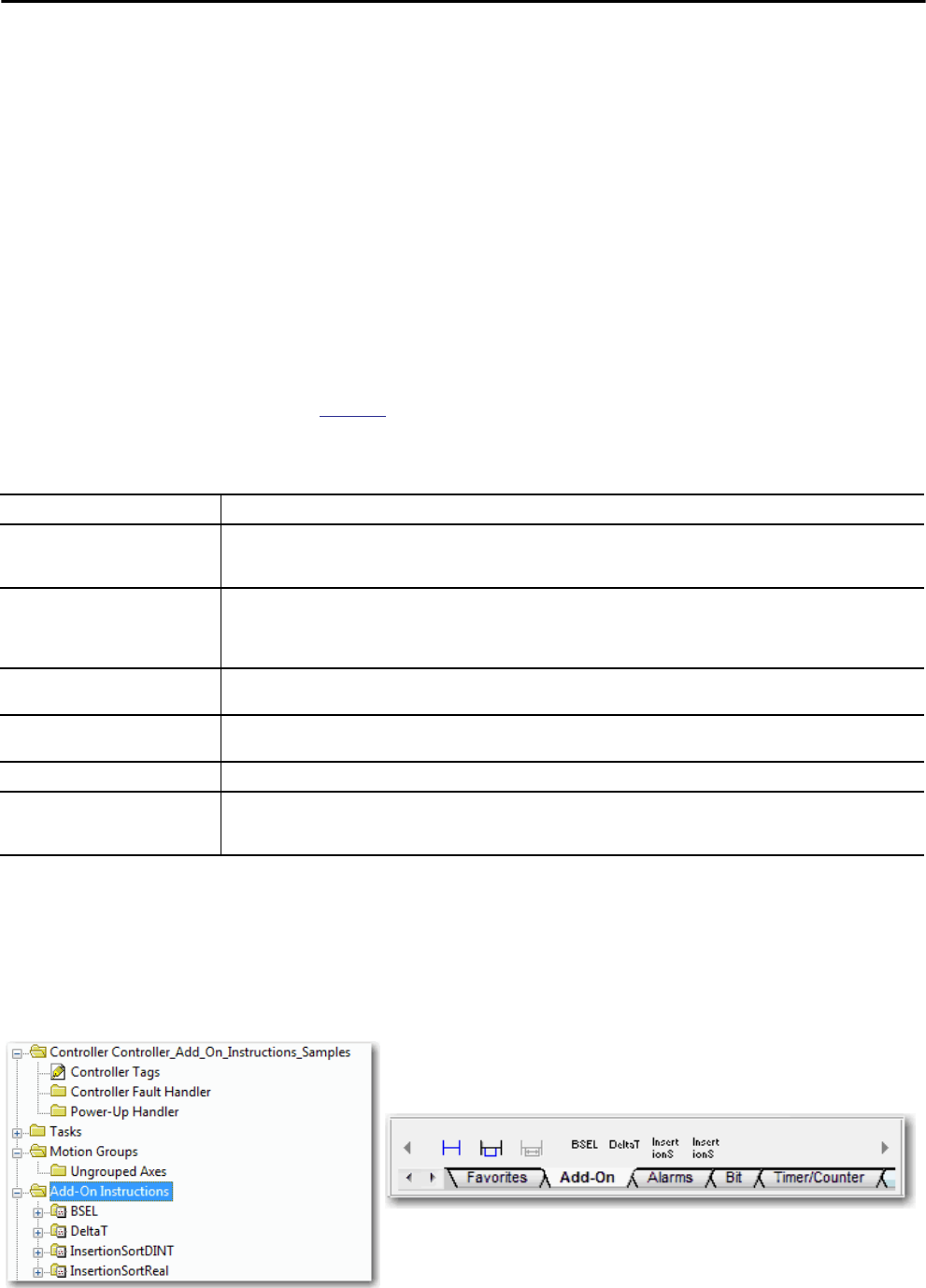
Rockwell Automation Publication 1756-UM001P-EN-P - May 2017 159
Develop Applications Chapter 10
Add-On Instructions With RSLogix 5000® software, version 16.03.00 or later, and Logix Designer
application, version 21.00.00 or later, you can design and configure sets of
commonly used instructions to increase project consistency. Similar to the
built-in instructions that are contained in Logix5000 controllers, these
instructions you create are called Add-On Instructions. Add-On Instructions
reuse common control algorithms. With them, you can do the following:
• Ease maintenance by animating logic for one instance.
• Help protect intellectual property with locking instructions.
• Reduce documentation development time.
You can use Add-On Instructions across multiple projects. You can define your
instructions, obtain them from somebody else, or copy them from another
project.
Table 46 explains some of the capabilities and advantages of use Add-On
Instructions.
Once defined in a project, Add-On Instructions behave similarly to the built-in
instructions in Logix5000 controllers. They appear on the instruction tool bar
for easy access along with internal instructions.
Figure 38 - Add-On Instructions
Table 46 - Add-On Instruction Capabilities
Capability Description
Save Time With Add-On Instructions, you can combine your most commonly used logic into sets of reusable instructions. You save time when you
create instructions for your projects and share them with others. Add-On Instructions increase project consistency because commonly
used algorithms all work in the same manner, regardless of who implements the project.
Use Standard Editors You create Add-On Instructions by using one of three programming editors:
• Relay Ladder
• Function Block Diagram
• Structured Text
Export Add-On Instructions You can export Add-On Instructions to other projects and copy and paste them from one project to another. Give each instruction a
unique name so that you don’t accidentally overwrite another instruction of the same name.
Use Context Views Context views let you visualize the logic of an instruction for instant, simplified online troubleshooting of your Add-On Instructions.
Each instruction contains a revision, a change history, and an auto-generated help page.
Create Custom Help When you create an instruction, you enter information for the description fields. This information becomes custom Help.
Apply Source Protection As the creator of Add-On Instructions, you can limit users of your instructions to read-only access, or you can bar access to the internal
logic or local parameters that are used by the instructions. This source protection lets you stop unwanted changes to your instructions
and helps protect your intellectual property.
Controller Organizer
Instruction Toolbar

160 Rockwell Automation Publication 1756-UM001P-EN-P - May 2017
Chapter 10 Develop Applications
Access the Module Object The MODULE object provides status information about a module. To select a
particular module object, set the Object Name operand of the GSV/SSV
instruction to the module name. The specified module must be present in the
I/O Configuration section of the controller organizer and must have a device
name.
Create the Add-On Instruction
With Logix Designer application, version 24.00.00 and later, you can access a
MODULE object directly from an Add-On Instruction. Previously, you could
access the MODULE object data but not from within an Add-On Instruction.
You must create a Module Reference parameter when you define the Add-On
Instruction to access the MODULE object data. A Module Reference
parameter is an InOut parameter of the MODULE data type that points to the
MODULE Object of a hardware module. You can use module reference
parameters in both Add-On Instruction logic and program logic.
For more information on the Module Reference parameter, see the Logix5000
Controllers Add-On Instructions Programming Manual, publication
1756-PM010 and the Logix Designer application online help.
The MODULE object uses the following attributes to provide status
information:
•EntryStatus
• FaultCode
•FaultInfo
• FWSupervisorStatus
•ForceStatus
• Instance
•LEDStatus
•Mode
•Path
The Path attribute is available with Logix Designer application, version
24.00.00 and later. This attribute provides a communication path to the
module.
For more information on the attributes available in the MODULE object, see
the Logix 5000 Controllers General Instructions Reference Manual,
publication 1756-RM003.
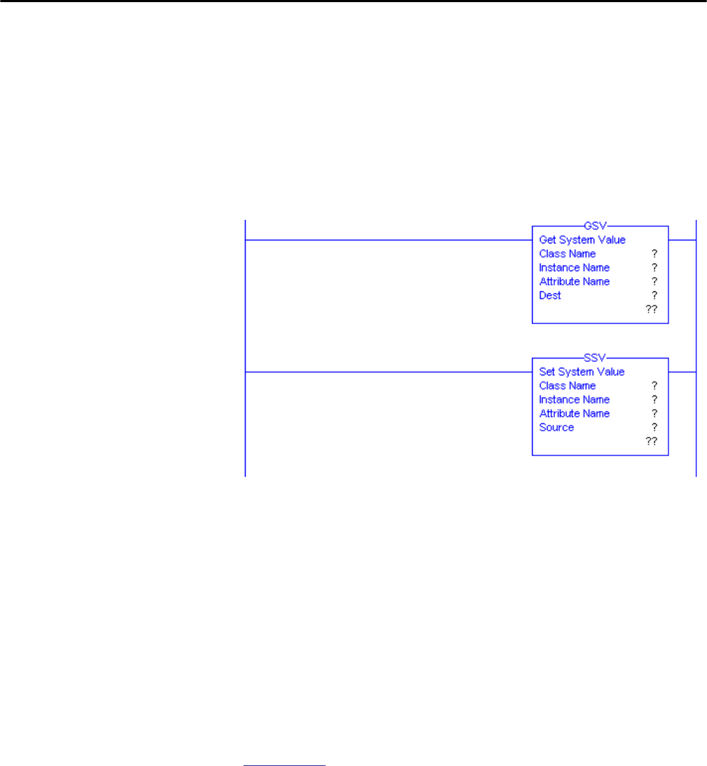
Rockwell Automation Publication 1756-UM001P-EN-P - May 2017 161
Develop Applications Chapter 10
Monitoring Controller Status The ControlLogix controller uses Get System Value (GSV) and Set System
Value (SSV) instructions to get and set (change) controller data. The controller
stores system data in objects. There is no status file, as in the PLC-5® processor.
The GSV instruction retrieves the specified information and places it in the
destination. The SSV instruction sets the specified attribute with data from the
source. Both instructions are available from the Input/Output tab of the
Instruction toolbar.
Figure 39 - GSV and SSV Instructions for Monitoring and Setting Attributes
When you add a GSV/SSV instruction to the program, the object classes,
object names, and attribute names for the instruction are shown. For the GSV
instruction, you can get values for the available attributes. For the SSV
instruction, only the attributes you can set are shown.
Some object types appear repeatedly, so you have to specify the object name.
For example, there can be several tasks in your application. Each task has its
own Task object that you access by the task name.
There are several objects and attributes that you can use the GSV and SSV
instructions to monitor and set the system. For more information about GSV
instructions, SSV instructions, objects, and attributes see the Logix5000
Controllers General Instructions Reference Manual, publication
1756-RM003.
Monitoring I/O Connections If communication with a device in the I/O configuration of the controller does
not occur in an application-specific period, the communication times out and
the controller produces warnings.
The minimum timeout period that, once expired without communication,
causes a timeout is 100 ms. The timeout period can be greater, depending on
the RPI of the application. For example, if your application uses the default
RPI = 20 ms, the timeout period is 160 ms.

162 Rockwell Automation Publication 1756-UM001P-EN-P - May 2017
Chapter 10 Develop Applications
For more information on how to determine the time for your application,
search the Rockwell Automation® Knowledgebase for answer ID 38535. The
document is available at http://www.rockwellautomation.com/
knowledgebase.
When a timeout does occur, the controller produces these warnings;
• An I/O fault status code is indicated on the status display of the
1756-L7x controller.
• The I/O status indicator on the front of the 1756-L6x controller flashes
green.
•A shows over the I/O configuration folder and over the devices that
have timed out.
• A module fault code is produced, which you can access via the
following:
– The Module Properties dialog box
– A GSV instruction
For more information about I/O faults, see the Major, Minor, and I/O Faults
Programming Manual, publication 1756-PM014.
!
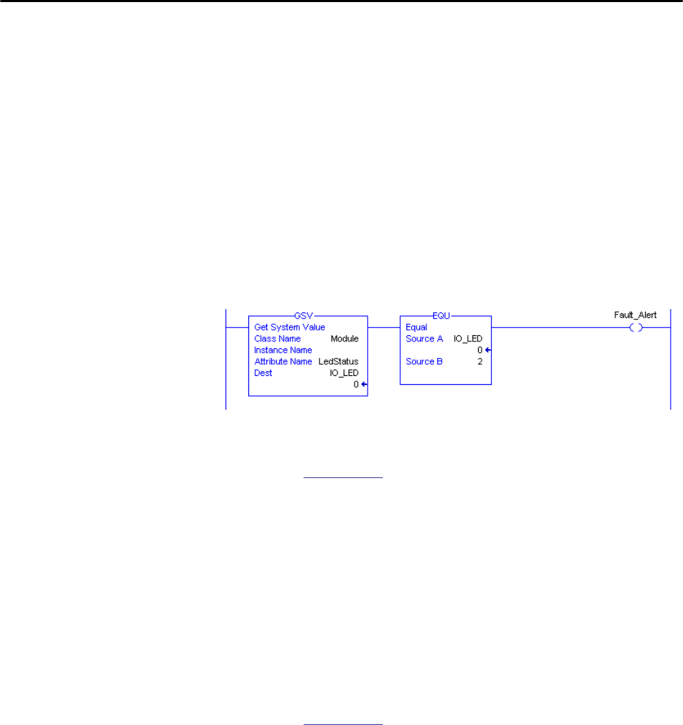
Rockwell Automation Publication 1756-UM001P-EN-P - May 2017 163
Develop Applications Chapter 10
Determine If I/O Communication Has Timed Out
This example can be used with the 1756-L7x or 1756-L6x controllers:
• The GSV instruction gets the status of the I/O status indicator (via the
LEDStatus attribute of the Module object) and stores it in the
IO_LED tag.
• IO_LED is a DINT tag that stores the status of the I/O status indicator
or status display on the front of the controller.
• If IO_LED equals 2, then at least one I/O connection has been lost and
the Fault_Alert is set.
Figure 40 - GSV Used to Identify I/O Timeout
For more information about attributes available with the Module object, see
the Logix5000 Controllers General Instructions Reference Manual,
publication 1756-RM003.
Determine If I/O Communication to a Specific I/O Module Has
Timed Out
If communication times out with a device (module) in the I/O configuration
of the controller, the controller produces a fault code and fault information for
the module. You can use GSV instructions to get fault code and information
via the FaultCode and FaultInfo attributes of the Module object.
For more information about attributes available with the Module object, see
the Logix5000 Controllers General Instructions Reference Manual,
publication 1756-RM003.
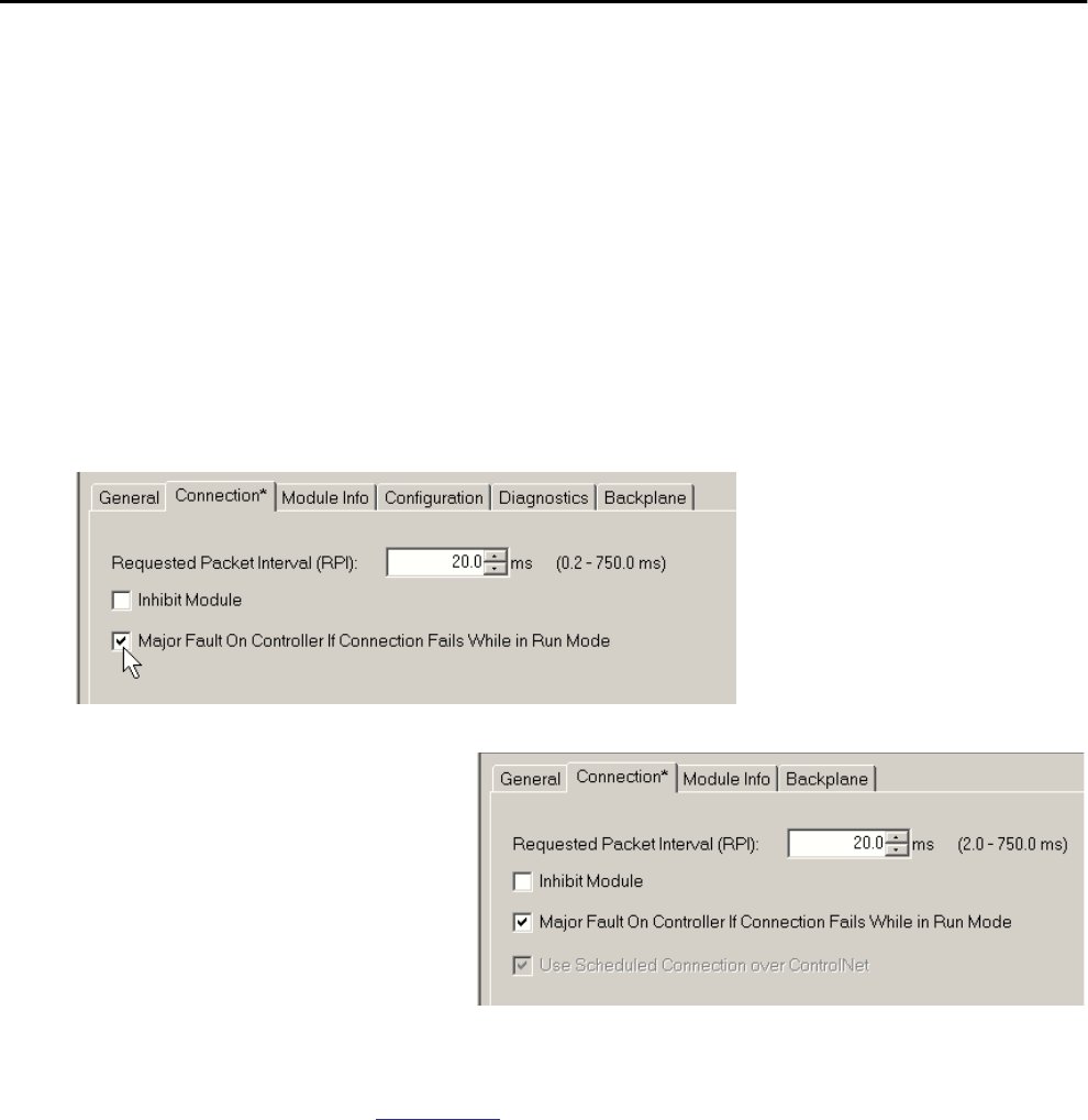
164 Rockwell Automation Publication 1756-UM001P-EN-P - May 2017
Chapter 10 Develop Applications
Interrupt the Execution of Logic and Execute the Fault Handler
Dependent on your application, you can want an I/O connection error to cause
the Controller Fault Handler to execute. To do so, set the module property that
causes a major fault to result from an I/O connection error. The major fault
causes the execution of the Controller Fault Handler.
First, develop a routine in the Controller Fault Handler that can respond to I/
O connection faults. Then, in the Module Properties dialog box of the I/O
module or parent communication module, check Major Fault On Controller If
Connection Fails While in Run Mode.
Figure 41 - I/O Connection Fault Causes Major Fault
For more information about programming the Controller Fault Handler, see
the Major, Minor, and I/O Faults Programming Manual, publication
1756-PM014.
Parent Communication Module Properties
I/O Module Properties
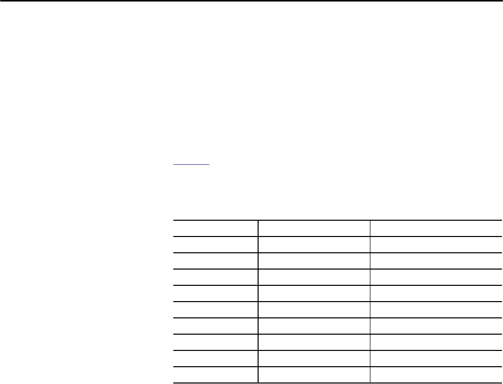
Rockwell Automation Publication 1756-UM001P-EN-P - May 2017 165
Develop Applications Chapter 10
System Overhead Time Slice The controller communicates with other devices at a specified rate (scheduled)
or when processing time is available to service the communication.
The system overhead time slice specifies the percentage of time a controller
devotes to service communication. If you have a continuous task, the system
overhead time slice that is entered on the Advanced tab of the Controller
Properties dialog box specifies the continuous task/service communication
ratio. However, if there is no continuous task, the overhead time slice has no
effect.
Table 47 shows the ratio between the continuous task and service
communication at various system overhead time slices for RSLogix 5000,
version 16.03.00 or later, and Logix Designer version 21.00.00 or later.
As shown in the table, if the system overhead time slice is less than or equal to
50%, the duration stays fixed at 1 ms. The same applies for 66% and higher,
except there are multiple 1 ms intervals. For example, at 66% there are two 1 ms
intervals of consecutive time and at 90% there are nine 1 ms intervals of
consecutive time.
Table 47 - Ratio between Continuous Task and Service Communication
Time Slice Continuous Task Duration Service Communication Duration
10% 9 ms 1 ms
20% 4 ms 1 ms
25% 3 ms 1 ms
33% 2 ms 1 ms
50% 1 ms 1 ms
66% 1 ms 2 ms
75% 1 ms 3 ms
80% 1 ms 4 ms
90% 1 ms 9 ms
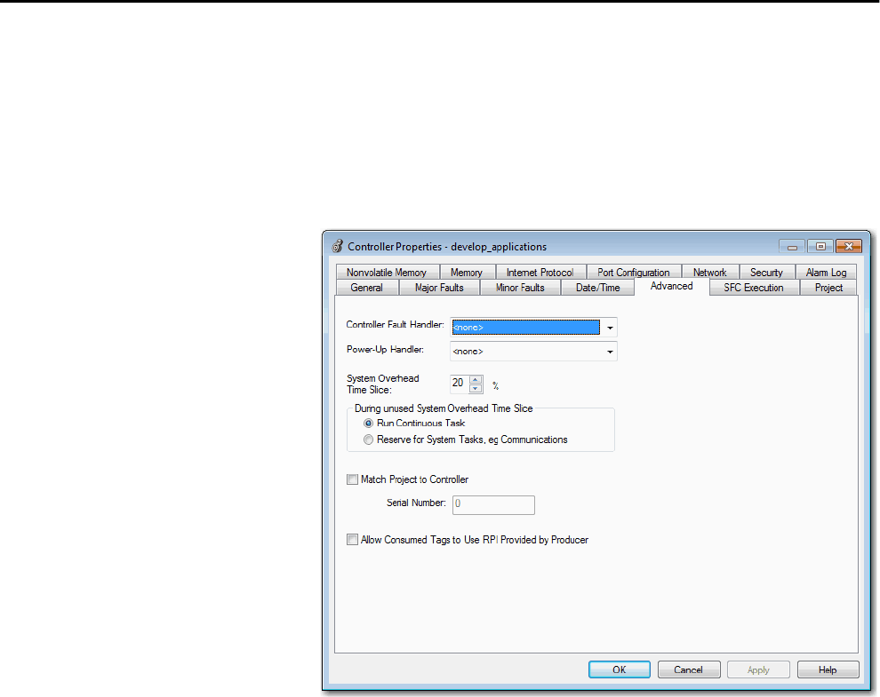
166 Rockwell Automation Publication 1756-UM001P-EN-P - May 2017
Chapter 10 Develop Applications
Configure the System Overhead Time Slice
To configure the system overhead time slice, perform this procedure.
1. In the Controller Organizer, right-click the controller and choose
Properties.
The Controller Properties dialog box appears.
2. Click the Advanced tab.
3. Enter a numeric value in the System Overhead Time Slice box.
4. Use Run Continuous Task (default) or Reserve for System Tasks.
• The Run Continue Task radio button is used when there is no
communication or background tasks to process; controller
immediately returns to the continuous task.
• The Reserve for System Task radio button allocates the entire 1 ms of
the system overhead time slice whether the controller has
communication or background tasks to perform before returning
back to the continuous task. This option lets you simulate a
communication load on the controller during design and
programming before HMIs, controller to controller messaging, and
so forth, are configured.
5. Click OK.
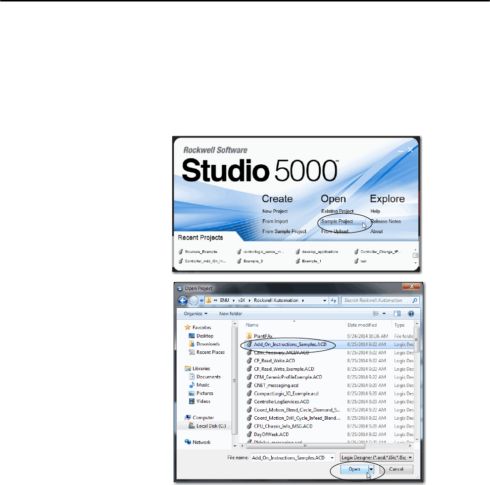
Rockwell Automation Publication 1756-UM001P-EN-P - May 2017 167
Develop Applications Chapter 10
Sample Controller Projects
The Studio 5000 Logix Designer® application includes sample projects that
you can copy and modify to fit your application. To access the sample projects,
choose Open Sample Project in the Studio 5000® interface and navigate to
Samples > ENU > v24 > Rockwell Automation.
Figure 42 - Opening Sample Projects

168 Rockwell Automation Publication 1756-UM001P-EN-P - May 2017
Chapter 10 Develop Applications
Notes:
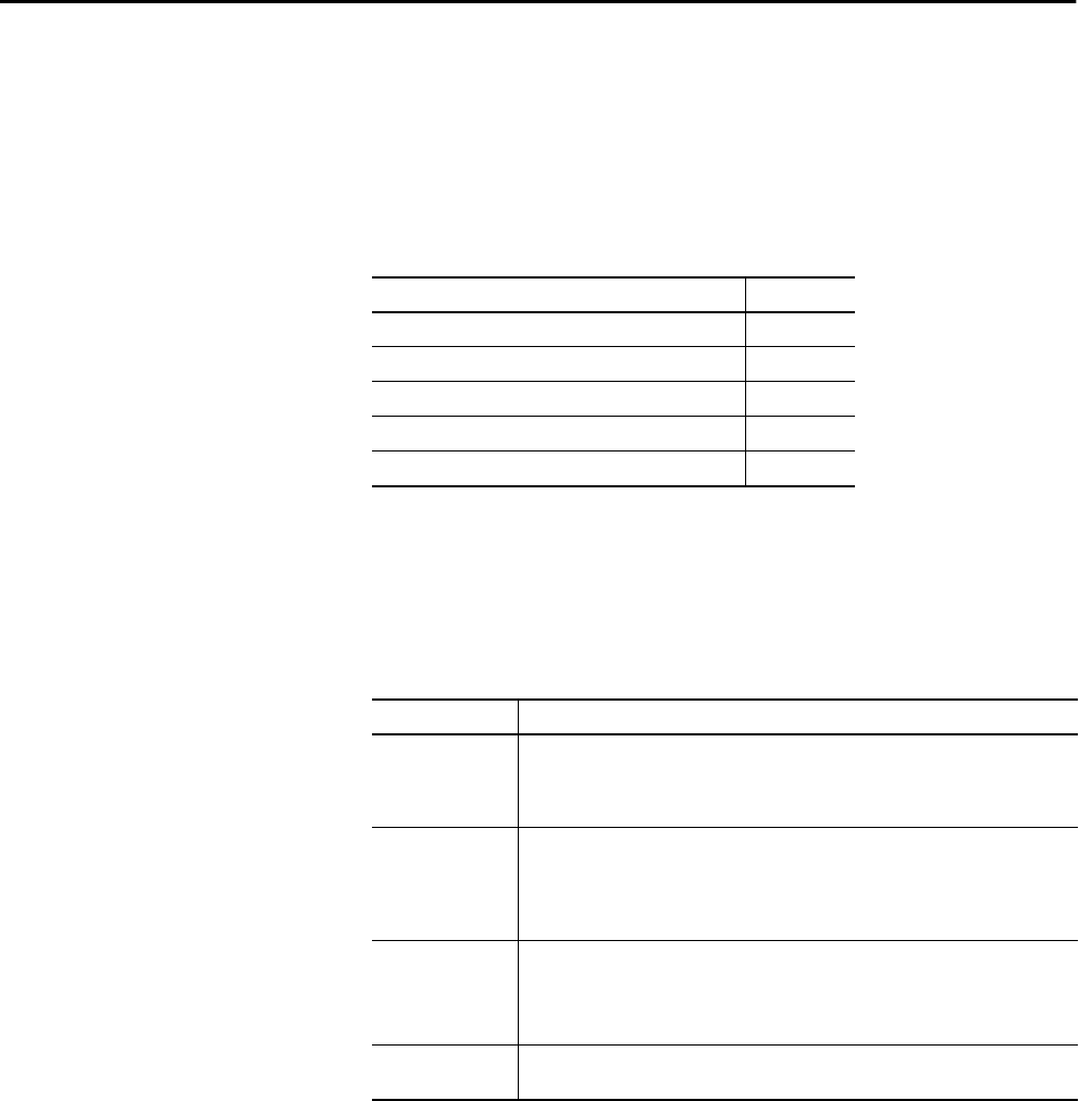
Rockwell Automation Publication 1756-UM001P-EN-P - May 2017 169
Chapter 11
Using the PhaseManager Tool
PhaseManager Overview The PhaseManager™ tool lets you add equipment phases to your controller. An
equipment phase helps you lay out your code in sections that are easier to write,
find, follow, and change.
Topic Page
PhaseManager Overview 169
Minimum System Requirements 171
State Model Overview 171
PhaseManager Tool versus Other State Models 174
Equipment Phase Instructions 174
Table 48 - PhaseManager Terminology
Term Description
Equipment phase • As with a program, an equipment phase is run in a task and is given a set of routines and
tags.
• Unlike a program, an equipment phase runs by a state model and lets you do one
activity.
State model • A state model divides the operating cycle of your equipment into a series of states. Each
state is an instance in the operation of the equipment, the actions, or conditions of the
equipment at a given time.
• The state model of an equipment phase resembles that of the S88 and PackML state
models.
State machine An equipment phase includes an embedded state machine that does the following:
• Calls the routine that is associated with an active state
• Manages the transitions between states with minimal coding
• Makes sure that the equipment goes from state to state along an allowable path
PHASE tag When you add an equipment phase, the application creates a tag for the equipment phase.
The tag uses the PHASE data type.
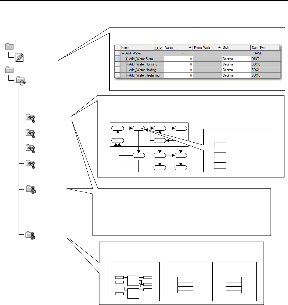
170 Rockwell Automation Publication 1756-UM001P-EN-P - May 2017
Chapter 11 Using the PhaseManager Tool
Figure 43 - PhaseManager Overview
MainTask
Tasks
Water Feed
Other code controls the actions of your equipment.
My Equipment Program
Mix Phase
MainProgram
Controller Tags
Controller
Add Water Phase
A PHASE tag gives you the status of an equipment phase.
An equipment phase directs one activity of your equipment.
A state model divides the activity into a series of states.
How to add water
Running State Routine
Drain Phase
Space Parts Phase
Conveyor Enable Axes
Equipment phase instructions control the transitions between states and handle faults.
PSC POVR PCLF PRNP PATT
PCMD PFL PXRQ PPD PDET
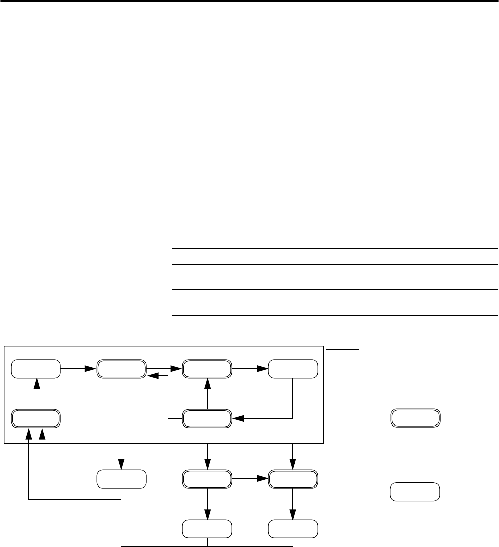
Rockwell Automation Publication 1756-UM001P-EN-P - May 2017 171
Using the PhaseManager Tool Chapter 11
Minimum System
Requirements
To develop PhaseManager programs, you need the following:
• A ControlLogix® controller at firmware revision 16 or later
• A communication path to the controller
• RSLogix 5000® software, version 16.03.00 or later or Logix Designer
application, version 21.00.00 or later
To enable PhaseManager support, you need the Full or Professional edition of
the software, or the software with PhaseManager software (catalog number
9324-RLDPMENE).
State Model Overview A state model defines what your equipment does under different conditions,
and how the states relate to each other. Each state can be described as an Acting
state or Waiting state.
Figure 44 - PhaseManager State Transitions
Table 49 - States in PhaseManager Software
State Description
Acting Does something or several things for a certain time or until certain conditions are met. An
acting state runs once or repeatedly.
Waiting Shows that certain conditions are met and the equipment is waiting for the signal to go to the
next state.
Holding
Hold
Idle
Start
Running
Hold
Held
Restarting
Restart
Stop
Stopping
Abort
Aborting
Stopped Aborted
Abort
Resetting
Complete
Reset
Reset
Your equipment can go from any state in the box
to the stopping or aborting state.
Acting
Waiting
Acting states are the things your
equipment does at a given time.
Waiting states are the condition
of your equipment when it is
between acting states.
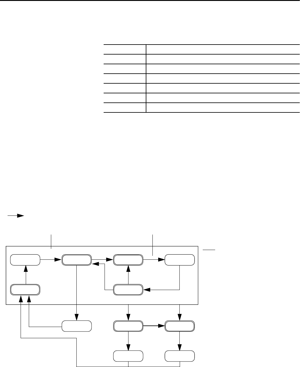
172 Rockwell Automation Publication 1756-UM001P-EN-P - May 2017
Chapter 11 Using the PhaseManager Tool
With a state model, you define the behavior of your equipment during Acting
states.
How Equipment Changes States
The arrows of the state model show the states through which your equipment
progresses:
• Each arrow is called a transition.
• A state model lets the equipment make only certain transitions. This
restriction standardizes the behavior of the equipment so that other
equipment using the same model behaves the same way.
Figure 45 - PhaseManager Transition Commands
Table 50 - Acting States in the PhaseManager State Model
State Question to Ask
Resetting How does the equipment get ready to run?
Running What does the equipment do to make product?
Holding How does the equipment temporarily stop making product without making scrap?
Restarting How does the equipment resume production after holding?
Stopping What happens during a normal shutdown?
Aborting How does the equipment shut down if a fault or failure occurs?
Holding
Hold
Idle
Start
Running
Hold
Held
Restarting
Restart
Stop
Stopping
Abort
Aborting
Stopped Aborted
Abort
Resetting
Complete
Reset
Reset
= Transition
Command Done — No command. Use PSC instruction instead.
Your equipment can go from any state in the box
when it receives a stop or abort commend.
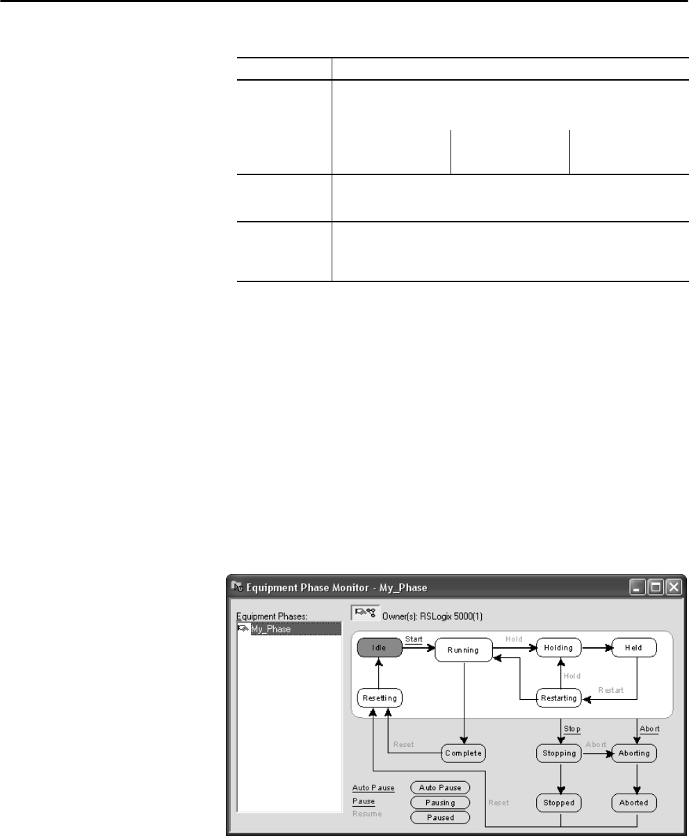
Rockwell Automation Publication 1756-UM001P-EN-P - May 2017 173
Using the PhaseManager Tool Chapter 11
Manually Change States
You can manually change an equipment phase. To change a PhaseManager
state, perform this procedure.
1. Open the Equipment Phase Monitor.
2. Take ownership of the equipment phase by clicking Owners and clicking
Yes .
3. Click the command that initiates the state you need (for example, Start
or Reset).
4. After you have finished manually changing the state, click Owners to
release your ownership.
Table 51 - PhaseManager Transitions
Type of Transition Description
Command A command tells the equipment to do something. For example, the operator pushes the
start button to begin production and the stop button to halt production.
The PhaseManager tool uses these commands:
Reset Stop Restart
Start Hold Abort
Done Equipment goes to a waiting state when it is finished with what it is doing. You do not give
the equipment a command. Instead, you configure your code to signal when the phase
state is finished.
Fault A fault tells you that something out of the ordinary has happened. You configure your code
to look for faults and act if it finds any. If you want to shut down your equipment as quickly
as possible when it detects a fault, configure your code to look for that fault and give the
abort command if it finds it.
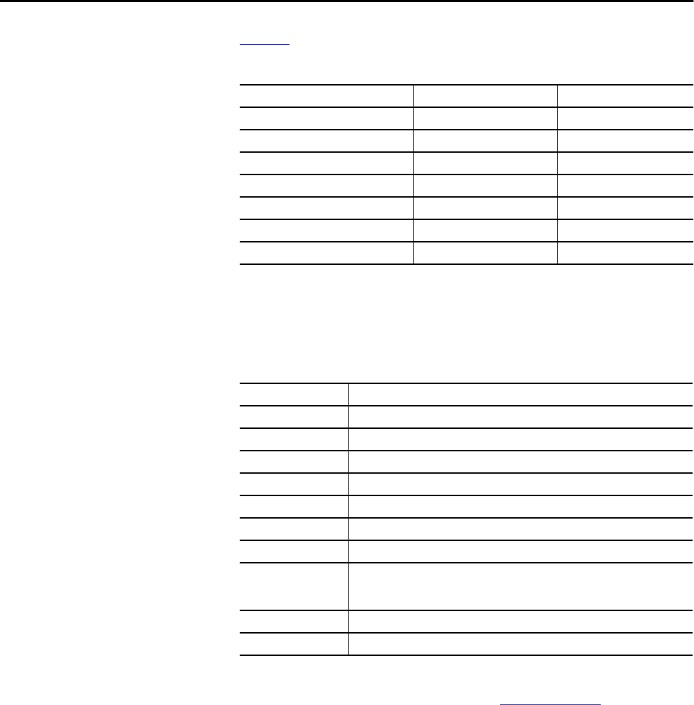
174 Rockwell Automation Publication 1756-UM001P-EN-P - May 2017
Chapter 11 Using the PhaseManager Tool
PhaseManager Tool versus
Other State Models
Table 52 compares PhaseManager state models to other state models.
Equipment Phase
Instructions
The controller supports several equipment-phase relay ladder and structured
text instructions.
For more information about instructions for use with equipment phases, see
the PhaseManager User Manual, publication LOGIX-UM001.
Table 52 - PhaseManager Tool and Other State Models
PhaseManager Tool S88 PackML
Resetting…Idle Idle Starting…Ready
Running…Complete Running…Complete Producing
Subroutines or breakpoints Pausing…Paused Standby
Holding…Held Holding…Held Holding…Held
Restarting Restarting None
Stopping…Stopped Stopping…Stopped Stopping…Stopped
Aborting…Aborted Aborting…Aborted Aborting…Aborted
Table 53 - Instructions for Use with PhaseManager Tool
Instruction Instruction Function
PSC Signal a phase that the state routine is complete and to go ahead to the next state.
PCMD Change the state or substate of a phase.
PFL Signal a failure for a phase.
PCLF Clear the failure code of a phase.
PXRQ Initiate communication with RSBizWare™ Batch software.
PRNP Clear the NewInputParameters bit of a phase.
PPD Configure breakpoints within the logic of a phase.
PATT Take ownership of a phase to one of the following:
• Stop another program or RSBizWare Batch software from commanding a phase.
• Make sure another program or RSBizWare Batch software does not own a phase.
PDET Relinquish ownership of a phase.
POVR Override a command.

Rockwell Automation Publication 1756-UM001P-EN-P - May 2017 175
Chapter 12
Redundant Systems
ControlLogix Redundancy
Overview
Redundancy provides more system availability by switching control to a
secondary controller chassis if a fault occurs in the primary controller chassis.
The redundant system switches control from the primary to the secondary
when these faults occur:
• Power loss to primary chassis
• Hardware or firmware failure of any module in the primary chassis
• A major fault in the user program on the primary controller
• Loss of communication between the primary chassis and remote
ControlNet or EtherNet/IP modules
• Disconnection of an Ethernet patch cable from an EtherNet/IP
communication module or ControlNet cable connector on ControlNet
communication module in the primary chassis
• Removal or insertion of any module in the primary chassis
• A user command that causes a switchover
Topic Page
ControlLogix Redundancy Overview 175
System Requirements 177
System Considerations 178
Build a Redundant System 179
ControlNet Considerations in Redundant Systems 180
EtherNet/IP Considerations in Redundant Systems 180
Redundancy and Scan Time 181
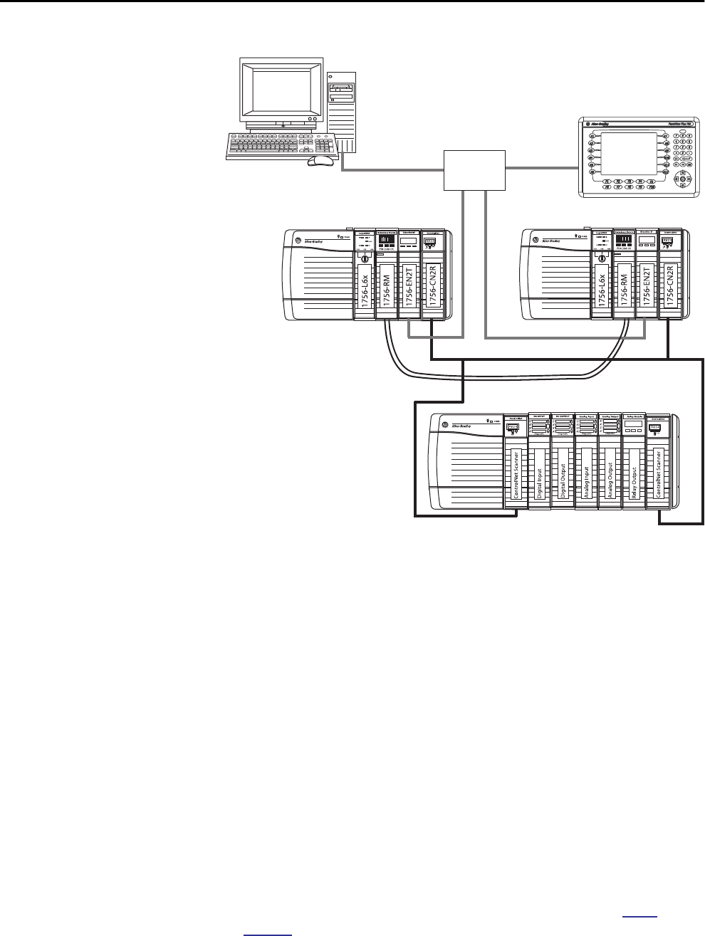
176 Rockwell Automation Publication 1756-UM001P-EN-P - May 2017
Chapter 12 Redundant Systems
Figure 46 - ControlLogix Enhanced Redundancy System
Redundancy requires no additional programming and is transparent to any
devices connected over an EtherNet/IP or ControlNet network.
Redundancy modules that are placed in each redundant chassis maintain the
communication between the redundant chassis.
Depending on how you organize your project, outputs can experience a change
in state (bump) during a switchover:
• During the switchover, outputs that are controlled by the highest
priority task experience a bumpless switchover. For example, outputs do
not revert to a previous state.
• Outputs in lower priority tasks can experience a change of state.
For detailed information about ControlLogix® redundancy systems, see the
ControlLogix Enhanced Redundancy User Manual, publication 1756-
UM535.
Workstation HMI
Redundant Chassis
Primary Secondary
I/O Connected via ControlNet Network
I/O can be connected via an EtherNet/IP network beginning with Enhanced Redundancy System revision 19.50.
Ethernet
Switch
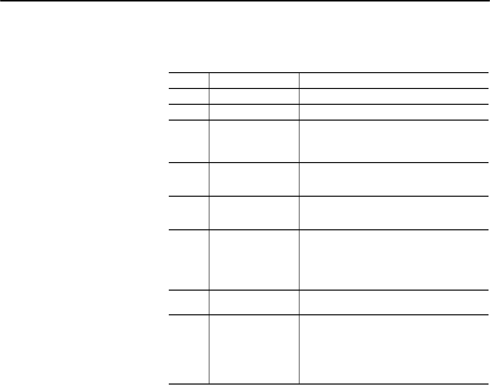
Rockwell Automation Publication 1756-UM001P-EN-P - May 2017 177
Redundant Systems Chapter 12
System Requirements Most redundant systems must use at least these system components. For some
applications, the ControlNet and EtherNet/IP modules are optional.
Table 54 - System Requirements
Quantity Item Notes
2 ControlLogix chassis Both chassis must be the same size.
2 ControlLogix power supply Must be the same in each chassis.
2 ControlLogix controller • Use 1756-L6x or 1756-L7x controllers.
• Use the same catalog number, series, firmware revision, and
memory size controllers in each chassis.
• Same slot placement.
2 ControlLogix ControlNet
communication module
• Use 1756-CN2/B, 1756-CN2R/B, or 1756-CN2RXT modules.
• ControlNet modules in the chassis must be identical in firmware
revision, in series, slot placement, and module type.
2 ControlLogix EtherNet/IP
communication modules
• Use the 1756-EN2T, 1756-EN2TXT, or 1756-EN2TR modules.
• Must be identical in firmware revision, slot placement, and
module type.
2 Redundancy module • Use 1756-RM2 or 1756-RM2XT modules.
• Redundancy modules in the chassis must be identical in
firmware revision and slot placement.
• For L7x high performance systems, RM modules must be RM/B
and must have the same series and firmware revision in the
chassis.
1 or 2 Redundancy module cable
(fiber-optic)
• Use the 1756-RMCx cable.
• Standard lengths are available.
2 Additional ControlNet nodes • Place all I/O in remote chassis or DIN rails.
• Add at least two nodes to each ControlNet network and the
redundant chassis pair.
• For enhanced redundancy, you must have at least one
keeper-capable ControlNet device at a node address lower than
the node addresses of the ControlNet modules in the redundant
chassis.

178 Rockwell Automation Publication 1756-UM001P-EN-P - May 2017
Chapter 12 Redundant Systems
System Considerations When you are configuring a redundant ControlLogix system, these
considerations to modules in the redundant chassis must be made.
For complete information about to design and plan modules for use in your
redundant ControlLogix chassis, see the ControlLogix Enhanced Redundancy
User Manual, publication 1756-UM535.
Items in Primary and
Secondary Chassis
Consideration
ControlLogix controller • When configured for redundancy, the secondary controller automatically
receives and buffers data.
• A redundant controller uses twice as much data memory and I/O memory space
as a nonredundant controller.
• A redundant controller has a longer scan time than a nonredundant controller.
• The ControlLogix Enhanced Redundancy User Manual, publication
1756-UM535, provides detailed information about minimizing the scan time
impact.
• You do not need a redundancy-specific version of Logix Designer software, but
it must match your Enhanced Redundancy System revision level.
• In an enhanced redundancy system, two controllers of the same type can reside
in a controller chassis.
Communication modules • In an enhanced redundancy system, as many as seven communication modules
can reside in a controller chassis in any combination of EtherNet/IP modules
and ControlNet modules.
• To connect to other networks, bridge through another ControlLogix chassis
outside the redundant system.
• For best results, use a separate network for HMI and I/O communication.
I/O modules • All I/O is remote from the redundant controller chassis.
• Beginning with Enhanced Redundancy System revision 19.50, EtherNet/IP
networks in redundant systems can be used for remote I/O or produced/
consumed data.
Redundant power supplies The 1756-PA75R and 1756-PB75R redundant power supplies provide reliable
chassis power.
Redundant ControlNet media Redundant media provide more reliable ControlNet communication.
Ethernet Device Level Ring Duel-port Ethernet modules (1756-EN2TR) can be used to connect to a ring to
provide more reliable Ethernet communication.
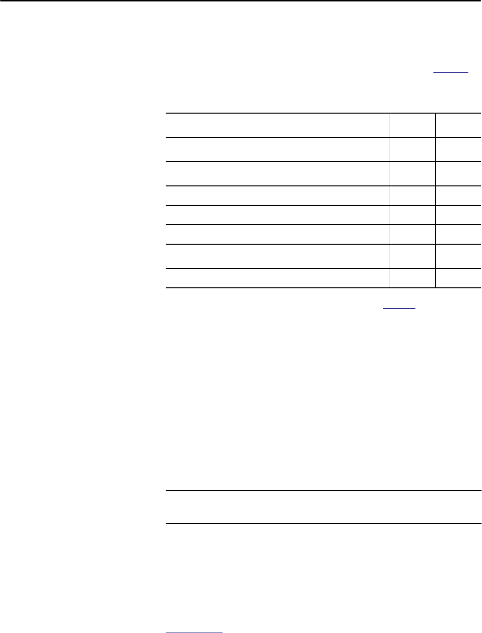
Rockwell Automation Publication 1756-UM001P-EN-P - May 2017 179
Redundant Systems Chapter 12
Enhanced Versus Standard Redundancy
While the enhanced and standard redundancy systems operate in a similar
manner, there are some key differences between the two platforms. Table 55
compares the enhanced and standard redundancy system features.
Build a Redundant System To build a typical redundant system, perform this procedure.
1. Install a ControlLogix chassis and power supply.
2. To the primary chassis, add 1756-L6x or 1756-L7x controllers.
You cannot mix 1756-L6x and 1756-L7x controllers in the same chassis.
3. Add one or more ControlNet or EtherNet/IP communication modules.
4. Add one redundancy module.
5. Configure a secondary chassis that is identical to the primary chassis.
6. Connect the redundancy modules in the chassis.
7. Add I/O modules to ControlNet or EtherNet/IP networks.
8. Add operator interfaces to ControlNet or EtherNet/IP networks.
For detailed information to design and build an enhanced redundant system,
see the ControlLogix Enhanced Redundancy System User Manual, publication
1756-UM535.
Table 55 - Comparison of Enhanced Redundancy to Standard Redundancy
Feature Enhanced
System(1)
(1) Availability of some features that are supported in enhanced redundancy is dependent on the system revision used. For more
information, see ControlLogix Enhanced Redundancy System User Manual, publication 1756-UM535.
Standard
System
Supports enhanced ControlLogix ControlNet and EtherNet/IP communication
modules, for example, the 1756-CN2/B or 1756-EN2T modules
Supports standard ControlLogix ControlNet and EtherNet/IP communication
modules, for example, the 1756-CNB/D or 1756-ENBT modules
Compatible with the single-slot 1756-RM redundancy modules
Compatible with the double-slot 1757-SRM redundancy modules
Support for all 1756-L6x and 1756-L7x ControlLogix controllers
Use of ControlLogix- system components, for example, the 1756-L63XT controller
and the 1756-CN2XT module
Availability of I/O over an EtherNet/IP network, including Redundant I/O systems
IMPORTANT Components in the redundant chassis pair must be identical in module
configuration.

180 Rockwell Automation Publication 1756-UM001P-EN-P - May 2017
Chapter 12 Redundant Systems
ControlNet Considerations
in Redundant Systems
You can have as many as seven ControlNet communication modules in a
redundant chassis.
For information on ControlNet considerations for enhanced redundant
systems, see the ControlLogix Enhanced Redundancy System User Manual,
publication 1756-UM535.
EtherNet/IP Considerations
in Redundant Systems
You can have as many as seven EtherNet/IP modules in the redundant chassis.
In a redundant system, you can use EtherNet/IP for HMI communication or
inter-controller messaging. HMI can communicate directly to with the
primary controller. You no longer need RSLinx® Alias Topics.
ControlLogix redundancy supports EtherNet/IP for I/O control or to
produce and consume data beginning with Enhanced Redundancy System
revision 19.50, and can be used for the following:
• 1715 Redundant I/O
• Remote I/O modules
• HMI connections to the primary controller
• Producing and consuming data
For information on EtherNet/IP considerations for enhanced redundant
systems, see the ControlLogix Enhanced Redundancy System User Manual,
publication 1756-UM535.
IP Address Swapping
Firmware revision 13, and later, supports IP address swapping in redundant
systems. With IP address swapping, you configure the primary and secondary
EtherNet/IP modules with the same IP address. The primary EtherNet/IP
module takes the IP address; the secondary module takes that address plus one
in the last address segment.
On a switchover, the EtherNet/IP modules swap IP addresses. HMI devices
automatically continue to communicate with the new primary controller
because the IP addresses were swapped. Because of the way EtherNet/IP
modules work, during a switchover, communication between the controller
and an HMI device halts for several seconds, typically less than a minute.
IMPORTANT With each ControlNet network, you must have at least two nodes external to
the redundant controller chassis to avoid timeouts on switchover.
The lowest node of each ControlNet network must be outside the redundant
controller chassis.

Rockwell Automation Publication 1756-UM001P-EN-P - May 2017 181
Redundant Systems Chapter 12
Redundancy and Scan Time At the end of each program, the primary controller synchronizes and crossloads
fresh data to the secondary controller. This process keeps the secondary
controller up-to-date and ready to take over. It also increases the scan time
when compared to a nonredundant system.
The amount of time a crossload consumes depends on how much data the
primary controller has to crossload:
• The primary controller synchronizes and crossloads any tag to which an
instruction wrote a value, even the same value, since the last crossload.
• Crossloading also requires a small amount of overhead time (1 ms per
crossload) to tell the secondary controller which program the primary
controller is executing.
Redundancy firmware revision 16.53, or later, limits which programs precede
synchronization and data crossloading. In many applications, changing this can
reduce the overall impact to the task scan time by reducing the number of times
a data area is synchronized. Removing a synchronization point results in 1ms
of overhead time that is saved and any time that was used to crossload the data.
For complete details about the scan time of a redundant system, see the
ControlLogix Enhanced Redundancy System User Manual, publication
1756-UM535.

182 Rockwell Automation Publication 1756-UM001P-EN-P - May 2017
Chapter 12 Redundant Systems
Notes:
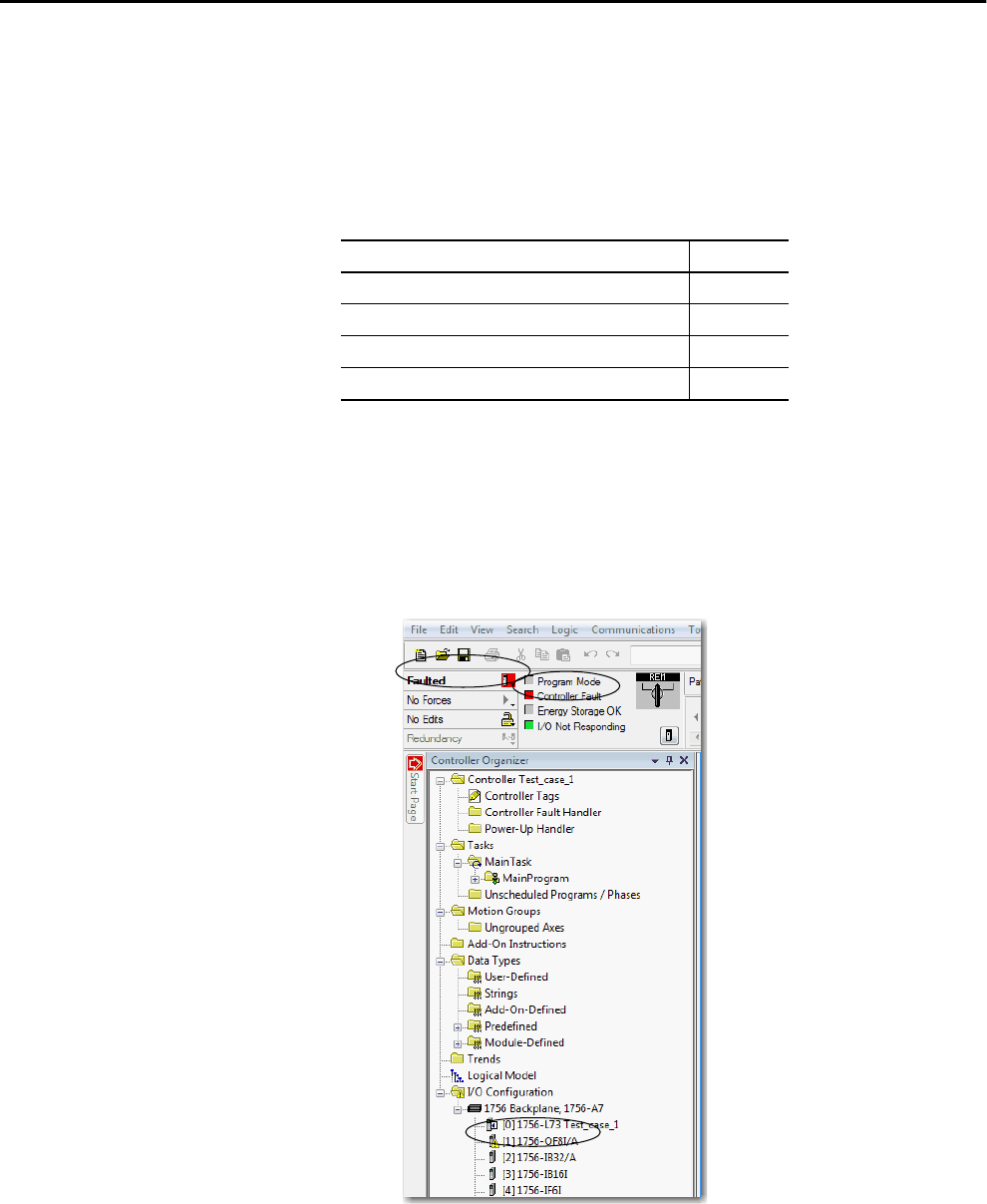
Rockwell Automation Publication 1756-UM001P-EN-P - May 2017 183
Appendix A
Troubleshoot the Module
Use Logix Designer
Application for
Troubleshooting
The Studio 5000 Logix Designer® application indicates fault conditions in the
following ways:
•Warning signal on the main screen next to the module - This occurs
when the connection to the module is broken. The controller state also
indicates Faulted and the Controller fault is illuminated in red.
Topic Page
1756-L7x Controller Status Display and Indicators 186
1756-L7x Controller Status Display 186
1756-L7x Controller Status Indicators 194
1756-L6x Status Indicators 196
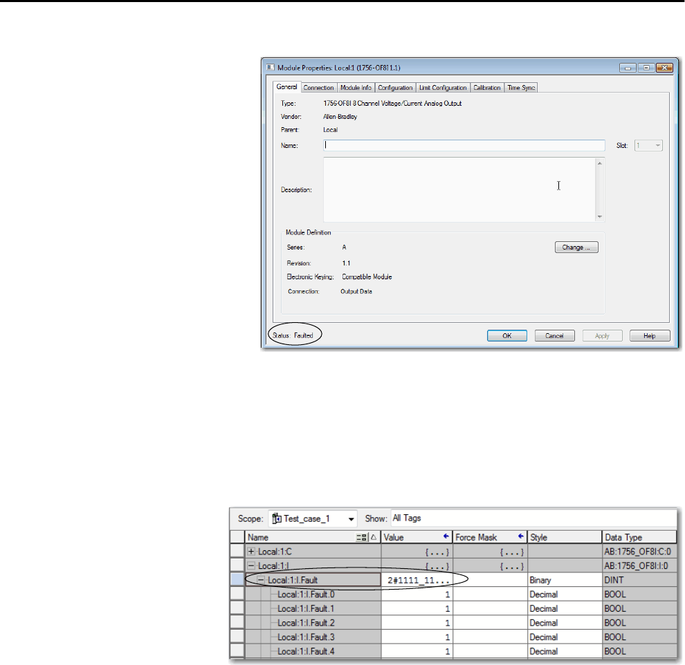
184 Rockwell Automation Publication 1756-UM001P-EN-P - May 2017
Appendix A Troubleshoot the Module
• Message in the status line of a screen.
On the Module Info tab, in the Status section, the Major and Minor Faults are
listed along with the Internal State of the module.
Notification in the Tag Editor - General module faults are also reported in
the Tag Editor. Diagnostic faults are reported only in the tag editor.
The Value field indicates a fault with the number 1.
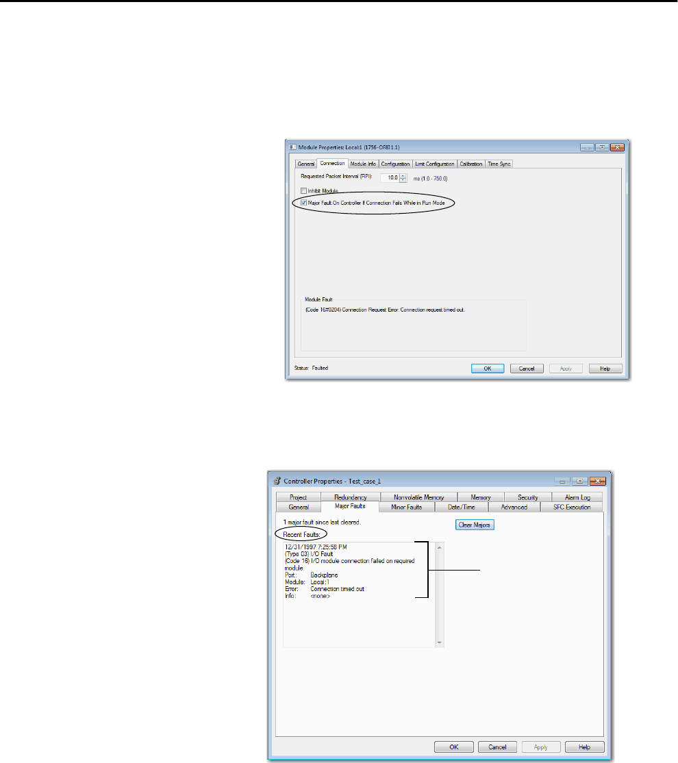
Rockwell Automation Publication 1756-UM001P-EN-P - May 2017 185
Troubleshoot the Module Appendix A
Fault Type Determination
To display recent fault information in the Major Faults tab of the Module
Properties screen, you must check the Major Fault on Controller option in the
Connection tab.
When you are monitoring the configuration properties of a module in the
Logix Designer application and receive a Communication fault message, the
Major Faults tab indicates the type of fault under Recent Faults.
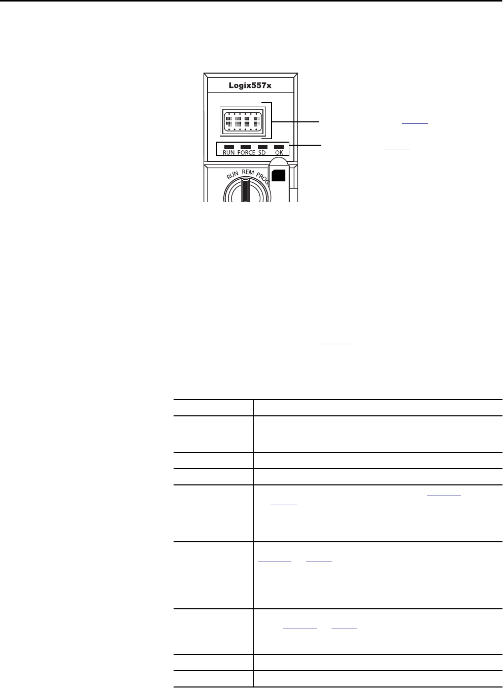
186 Rockwell Automation Publication 1756-UM001P-EN-P - May 2017
Appendix A Troubleshoot the Module
1756-L7x Controller Status
Display and Indicators
The 1756-L7x controllers have four status indicators and one four-character
scrolling status display.
Figure 47 - 1756-L7x Status Display and Indicators
1756-L7x Controller
Status Display
The 1756-L7x controller status display scrolls messages that provide
information about the firmware revision, ESM status, project status, and major
faults of the controller.
General Status Messages
The messages that are described in Table 56 are typically indicated upon
powerup, powerdown, and while the controller is running to show the status of
the controller and the ESM.
Scrolling Status Display, see page 186
Status Indicators, see page 194
Table 56 - General Status Messages
Message Interpretation
No message is indicated The controller is Off.
Check the OK indicator to determine if the controller is powered and determine the
state of the controller.
TEST The controller is conducting power-up tests.
PASS Power-up tests have been successfully completed.
SAVE A project is being saved to the SD card. You can also view the SD Indicator
(see page 195) for more status information.
Allow the save to complete before:
• removing the SD card.
• disconnecting power.
LOAD A project is being loaded from the SD card at controller powerup. You can also view the
SD Indicator (see page 195) for more status information.
Allow the load to complete before doing the following:
• Removing the SD card
• Disconnecting power
• Removing the ESM module
UPDT A firmware upgrade is being conducted from the SD card upon powerup. You can also
view the SD Indicator (see page 195) for more status information.
If you do not want the firmware to update upon powerup, change the Load Image
property of the controller.
CHRG The capacitor-based ESM is being charged.
1756-L7x/XThe controller catalog number and series.

Rockwell Automation Publication 1756-UM001P-EN-P - May 2017 187
Troubleshoot the Module Appendix A
Rev XX.xxx The major and minor revision of the firmware of the controller.
No Project No project is loaded on the controller.
To load a project, do one of the following:
• Use Logix Designer application to download the project to the controller
• Use a SD card to load a project to the controller
Project Name The name of the project that is currently loaded on the controller.
BUSY The I/O modules that are associated with the controller are not yet fully powered.
Allow time for powerup and I/O module self-testing.
Corrupt Certificate
Received
The security certificate that is associated with the firmware is corrupted.
Go to
http://www.rockwellautomation.com/support/
and download the firmware revision
you are trying to upgrade to. Replace the firmware revision that you have previously
installed with that posted on the Technical Support website.
Corrupt Image Received The firmware file is corrupted.
Go to
http://www.rockwellautomation.com/support/
and download the firmware revision
you are trying to upgrade to. Replace the firmware revision that you have previously
installed with that posted on the Technical Support website.
ESM Not Present An ESM is not present and the controller cannot save the application at powerdown.
Insert a compatible ESM, and, if using a capacitor-based ESM, do not remove power
until the ESM is charged.
ESM Incompatible The ESM is incompatible with the memory size of the controller.
Replace the incompatible ESM with a compatible ESM.
ESM Hardware Failure A failure with the ESM has occurred and the controller is incapable of saving of the
program in the event of a powerdown.
Replace the ESM before removing power to the controller so the controller program is
saved.
ESM Energy Low The capacitor-based ESM does not have sufficient energy to enable the controller to
save the program in the event of a powerdown.
Replace the ESM.
ESM Charging The capacitor-based ESM is charging.
Do not remove power until charging is complete.
Flash in Progress A firmware upgrade initiated via ControlFLASH™ or AutoFlash utilities is in progress.
Allow the firmware upgrade to complete without interruption.
Firmware Installation
Required
The controller is using boot firmware (that is revision 1.xxx) and requires a firmware
upgrade.
Upgrade controller firmware.
SD Card Locked An SD card that is locked is installed.
Table 56 - General Status Messages (Continued)
Message Interpretation
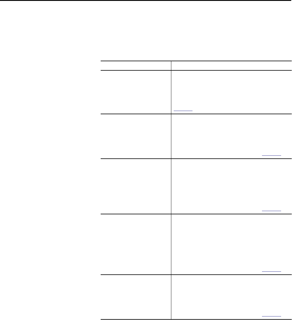
188 Rockwell Automation Publication 1756-UM001P-EN-P - May 2017
Appendix A Troubleshoot the Module
Fault Messages
If the controller displays a fault, these messages can be indicated on the status
display.
Table 57 - Fault Messages
Message Interpretation
Major Fault TXX:CXX message A major fault of Type XX and Code XX has been detected.
For example, if the status display indicates Major Fault T04:C42 Invalid
JMP Target, a JMP instruction is programmed to jump to an invalid LBL
instruction.
For details about major recoverable faults, see the Logix5000™ Major,
Minor, and I/O Fault Codes Programming Manual, publication
1756-PM014
.
I/O Fault Local:X #XXXX message An I/O fault has occurred on a module in the local chassis. The slot
number and fault code are indicated along with a brief description.
For example, I/O Fault Local:3 #0107 Connection Not Found indicates
that a connection to the local I/O module in slot three is not open.
Take corrective action specific to the type of fault indicated.
For details about each I/O fault code, see the Logix5000 Major, Minor,
and I/O Fault Codes Programming Manual, publication
1756-PM014
.
I/O Fault ModuleName #XXXX message An I/O fault has occurred on a module in a remote chassis. The name of
the faulted module is indicated with the fault code and brief description
of the fault.
For example, I/O Fault My_Module #0107 Connection Not Found
indicates that a connection to the module named My_Module is not
open.
Take corrective action specific to the type of fault indicated.
For details about each I/O fault code, see the Logix5000 Major, Minor,
and I/O Fault Codes Programming Manual, publication
1756-PM014
.
I/O Fault ModuleParent:X #XXXX message An I/O fault has occurred on a module in a remote chassis. The parent
name of the module is indicated because no module name is configured
in the I/O Configuration tree of Logix Designer application. In addition,
the fault code is indicated with a brief description of the fault.
For example, I/O Fault My_CNet:3 #0107 Connection Not Found
indicates that a connection to a module in slot 3 of the chassis with the
communication module named My_CNet is not open.
Take corrective action specific to the type of fault indicated.
For details about each I/O fault code, see the Logix5000 Major, Minor,
and I/O Fault Codes Programming Manual, publication
1756-PM014
.
X I/O Faults I/O faults are present and X = the number of I/O faults present.
If there are multiple I/O faults, the controller indicates that the first fault
reported. As each I/O fault is resolved, the number of faults indicated
decreases and the I/O Fault message indicates the next fault reported.
Take corrective action specific to the type of fault indicated.
For details about each I/O fault code, see the Logix5000 Major, Minor,
and I/O Fault Codes Programming Manual, publication
1756-PM014
.

Rockwell Automation Publication 1756-UM001P-EN-P - May 2017 189
Troubleshoot the Module Appendix A
Major Fault Messages
The Major Fault TXX:CXX message on the controller status display indicates
major faults. Table 58 lists fault types, codes, and the associated messages as
they are shown on the status display.
For detailed descriptions and suggested recovery methods for major faults, see
the Logix5000 Major, Minor, and I/O Fault Codes Programming Manual,
publication 1756-PM014.
Table 58 - Major Fault Status Messages
Type Code Message
1 1 Run Mode Powerup
1 60 Nonrecoverable
1 61 Nonrecoverable – Diagnostics Saved on CF Card
1 62 Nonrecoverable – Diagnostics and Program Saved on SD card
3 16 I/O Connection Failure
3 20 Chassis Failure
321
3 23 Connection Failure
4 16 Unknown Instruction
4 20 Invalid Array Subscript
4 21 Control Structure LEN or POS < 0
4 31 Invalid JSR Parameter
4 34 Timer Failure
4 42 Invalid JMP Target
4 82 SFC Jump Back Failure
4 83 Value Out of Range
4 84 Stack Overflow
4 89 Invalid Target Step
4 90 Invalid Instruction
4 91 Invalid Context
4 92 Invalid Action
4 990 User-defined
4 991
4 992
4 993
4 994
4 995
4 996
4 997
4 998
4 999

190 Rockwell Automation Publication 1756-UM001P-EN-P - May 2017
Appendix A Troubleshoot the Module
6 1 Task Watchdog Expired
7 40 Save Failure
7 41 Bad Restore Type
7 42 Bad Restore Revision
7 43 Bad Restore Checksum
7 44 Failed to Restore Processor Memory
8 1 Keyswitch Change Ignored
11 1 Positive Overtravel Limit Exceeded
11 2 Negative Overtravel Limit Exceeded
11 3 Position Error Tolerance Exceeded
11 4 Encoder Channel Connection Fault
11 5 Encoder Noise Event Detected
11 6 Sercos Drive Fault
11 7 Synchronous Connection Fault
11 8 Servo Module Fault
11 9 Asynchronous Connection Fault
11 10 Motor Fault
11 11 Motor Thermal Fault
11 12 Drive Thermal Fault
11 13 Sercos Communications Fault
11 14 Inactive Drive Enable Input Detected
11 15 Drive Phase Loss Detected
11 16 Drive Guard Fault
11 32 Motion Task Overlap Fault
11 33 CST Reference Loss Detected
12 32 Disqualified Secondary Controller Cycle Power
12 33 Unpartnered Controller Identified in New Primary Chassis
12 34 Keyswitch Positions of Primary and Secondary Controllers Mismatched
14 1 Safety Task Watchdog Expired
14 2 Error In Routine of Safety Task
14 3 Safety Partner Missing
14 4 Safety Partner Unavailable
14 5 Safety Partner Hardware Incompatible
14 6 Safety Partner Firmware Incompatible
14 7 Safety Task Inoperable
14 8 Coordinated System Time (CST) Not Found
14 9 Safety Partner Nonrecoverable Controller Fault
18 1 CIP Motion Initialization Fault
18 2 CIP Motion Initialization Fault Mfg
Table 58 - Major Fault Status Messages (Continued)
Type Code Message
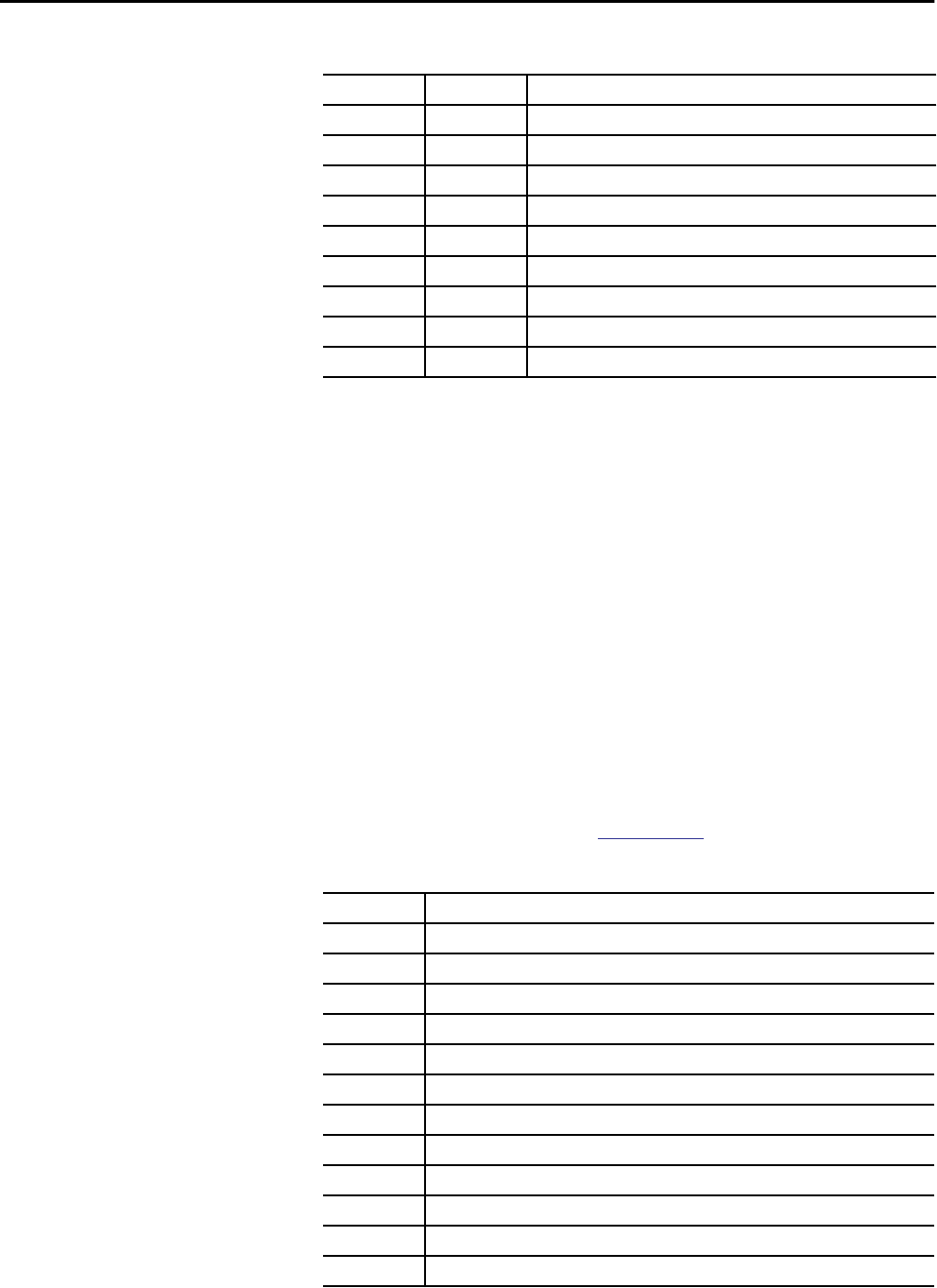
Rockwell Automation Publication 1756-UM001P-EN-P - May 2017 191
Troubleshoot the Module Appendix A
I/O Fault Codes
The controller indicates I/O faults on the status display in one of these
formats:
• I/O Fault Local:X #XXXX message
• I/O Fault ModuleName #XXXX message
• I/O Fault ModuleParent:X #XXXX message
The first part of the format is used to indicate the location of the module with
a fault. How the location is indicated depends on your I/O configuration and
the properties of the module that are specified in Logix Designer application.
The latter part of the format, #XXXX message, can be used to diagnose the
type of I/O fault and potential corrective actions. For details about each I/O
fault code, see the Logix5000 Major, Minor, and I/O Fault Codes
Programming Manual, publication 1756-PM014.
18 3 CIP Motion Axis Fault
18 4 CIP Motion Axis Fault Mfg
18 5 CIP Motion Fault
18 6 CIP Module Fault
18 7 Motion Group Fault
18 8 CIP Motion Configuration Fault
18 9 CIP Motion APR Fault
18 10 CIP Motion APR Fault Mfg
18 128 CIP Motion Guard Fault
Table 59 - I/O Fault Messages
Code Message
#0001 Connection Failure
#0002 Insufficient Resource
#0003 Invalid Value
#0004 IOI Syntax
#0005 Destination Unknown
#0006 Partial Data Transferred
#0007 Connection Lost
#0008 Service Unsupported
#0009 Invalid Attribute Value
#000A Attribute List Error
#000B State Already Exists
#000C Object Mode Conflict
Table 58 - Major Fault Status Messages (Continued)
Type Code Message

192 Rockwell Automation Publication 1756-UM001P-EN-P - May 2017
Appendix A Troubleshoot the Module
#000D Object Already Exists
#000E Attribute Not Settable
#000F Permission Denied
#0010 Device State Conflict
#0011 Reply Too Large
#0012 Fragment Primitive
#0013 Insufficient Command Data
#0014 Attribute Not Supported
#0015 Data Too Large
#0100 Connection In Use
#0103 Transport Not Supported
#0106 Ownership Conflict
#0107 Connection Not Found
#0108 Invalid Connection Type
#0109 Invalid Connection Size
#0110 Module Not Configured
#0111 RPI Out of Range
#0113 Out of Connections
#0114 Wrong Module
#0115 Wrong Device Type
#0116 Wrong Revision
#0117 Invalid Connection Point
#0118 Invalid Configuration Format
#0119 Module Not Owned
#011A Out of Connection Resources
#0203 Connection Timeout
#0204 Unconnected Message Timeout
#0205 Invalid Parameter
#0206 Message Too Large
#0301 No Buffer Memory
#0302 Bandwidth Not Available
#0303 No Bridge Available
#0304 ControlNet Schedule Error
#0305 Signature Mismatch
#0306 CCM Not Available
#0311 Invalid Port
#0312 Invalid Link Address
#0315 Invalid Segment Type
#0317 Connection Not Scheduled
Table 59 - I/O Fault Messages (Continued)
Code Message

Rockwell Automation Publication 1756-UM001P-EN-P - May 2017 193
Troubleshoot the Module Appendix A
#0318 Invalid Link Address
#0319 No Secondary Resources Available
#031E No Available Resources
#031F No Available Resources
#0800 Network Link Offline
#0801 Incompatible Multicast RPI
#0814 Data Type Mismatch
#FD01 Bad Backplane EEPROM
#FD02 No Error Code
#FD03 Missing Required Connection
#FD04 No CST Master
#FD05 Axis or GRP Not Assigned
#FD06 Sercos Transition Fault
#FD07 Sercos Init Ring Fault
#FD08 Sercos Comm Fault
#FD09 Sercos Init Node Fault
#FD0A Axis Attribute Reject
#FD1F Safety I/O
#FD20 No Safety Task
#FE01 Invalid Connection Type
#FE02 Invalid Update Rate
#FE03 Invalid Input Connection
#FE04 Invalid Input Data Pointer
#FE05 Invalid Input Data Size
#FE06 Invalid Input Force Pointer
#FE07 Invalid Output Connection
#FE08 Invalid Output Data Pointer
#FE09 Invalid Output Data Size
#FE0A Invalid Output Force Pointer
#FE0B Invalid Symbol String
#FE0C Invalid Scheduled Personal Computer Instance
#FE0D Invalid Symbol Instance
#FE0E Module Firmware Updating
#FE0F Invalid Firmware File Revision
#FE10 Firmware File Not Found
#FE11 Firmware File Invalid
#FE12 Automatic Firmware Update Failed
#FE13 Update Failed - Active Connection
#FE14 Searching Firmware File
Table 59 - I/O Fault Messages (Continued)
Code Message
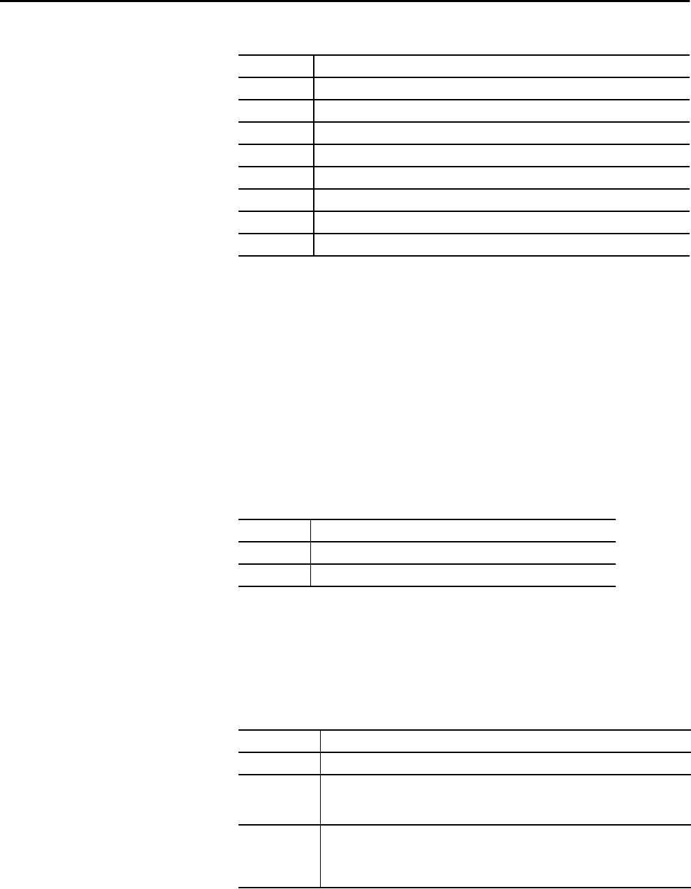
194 Rockwell Automation Publication 1756-UM001P-EN-P - May 2017
Appendix A Troubleshoot the Module
1756-L7x Controller
Status Indicators
The status indicators are below the status display on the controller. They
indicate the state of the controller as described in these tables.
RUN Indicator
Use the mode switch on the front of the controller or use the Controller Status
menu in the Logix Designer application to change the controller mode that is
shown by the RUN indicator.
FORCE Indicator
The Force indicator shows if I/O forces are enabled on the controller.
#FE22 Invalid Connection Type
#FE23 Invalid Unicast Allowed
#FF00 No Connection Instance
#FF01 Path Too Long
#FF04 Invalid State
#FF08 Invalid Path
#FF0B Invalid Config
#FF0E No Connection Allowed
Table 59 - I/O Fault Messages (Continued)
Code Message
Table 60 - RUN Indicator
State Description
Off The controller is in Program or Test mode.
Steady green The controller is in Run mode.
Table 61 - FORCE Indicator
State Description
Off No tags contain I/O force values.
Solid amber I/O forces are active (enabled) though I/O force values and can be configured.
Use caution if you install (add) a force. If you install (add) a force, it immediately
takes effect.
Flashing amber One or more input or output addresses have been forced to an On or Off state, but the forces
have not been enabled.
Use caution if you enable I/O forces. If you enable I/O forces, all existing I/O forces
also take effect.
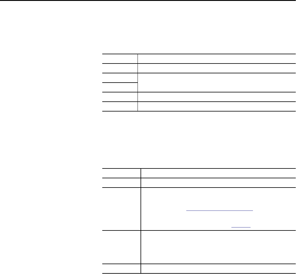
Rockwell Automation Publication 1756-UM001P-EN-P - May 2017 195
Troubleshoot the Module Appendix A
SD Indicator
The SD indicator shows if the SD card is in use.
OK Indicator
The OK indicator shows the state of the controller.
Table 62 - SD Indicator
State Description
Off No activity is occurring with the SD card.
Flashing green The controller is reading from or writing to the SD card.
Do not remove the SD card while the controller is reading or writing.
Solid green
Flashing red The SD card does not have a valid file system.
Solid red The controller does not recognize the SD card.
Table 63 - OK Indicator
State Description
Off No power is applied to the controller.
Flashing red Either of the following is true:
• It is a new controller, out of the box, and it requires a firmware upgrade. If a firmware
upgrade is required, the status display indicates Firmware Installation Required. To
upgrade firmware, see Upgrade Controller Firmware on page 50.
• It is a previously used or in-use controller and a major fault has occurred. For details
about major recoverable and nonrecoverable faults, see the Logix5000 Major, Minor, and
I/O Fault Codes Programming Manual, publication
1756-PM014
.
Solid red One of the following is true:
• The controller is completing power-up diagnostics.
• The charge of the capacitor in the ESM is being discharged upon powerdown.
• The controller is powered, but is inoperable.
• The controller is loading a project to nonvolatile memory.
Solid green The controller is operating normally.
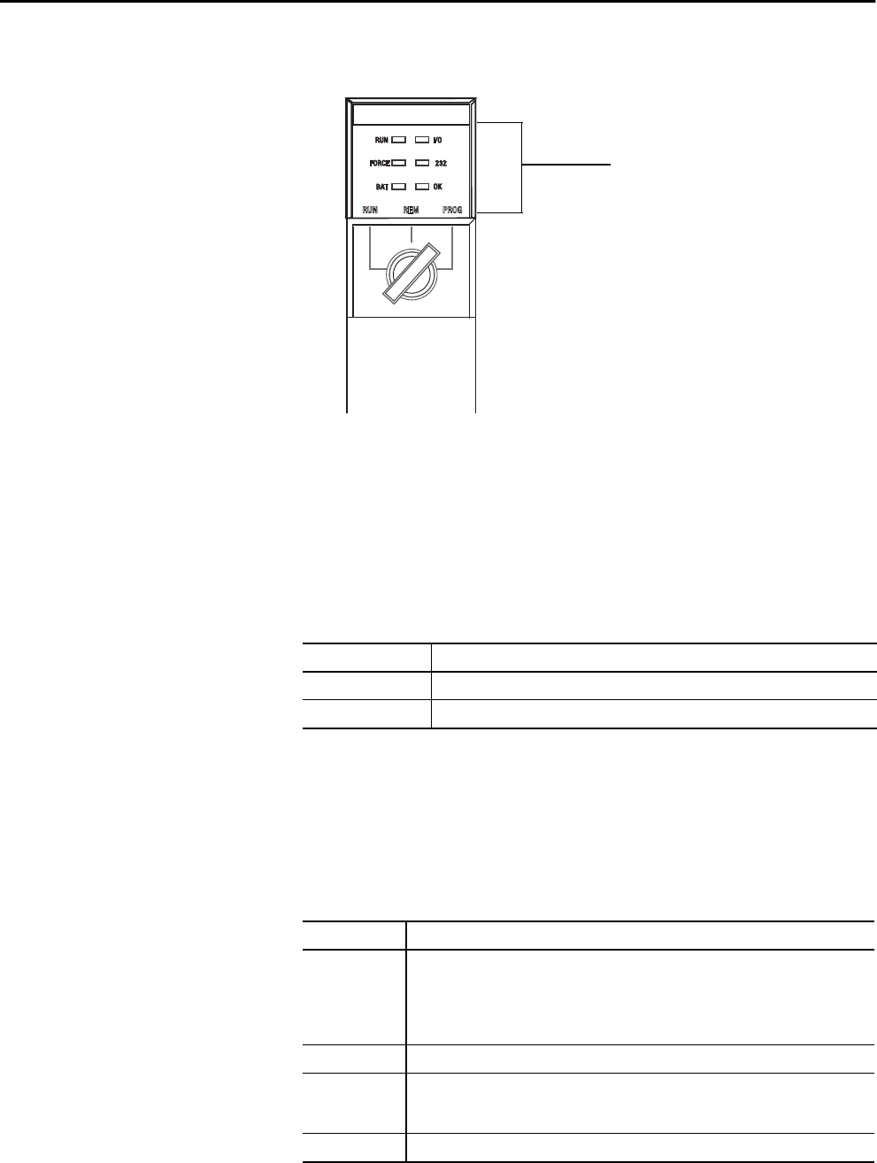
196 Rockwell Automation Publication 1756-UM001P-EN-P - May 2017
Appendix A Troubleshoot the Module
1756-L6x Status Indicators The 1756-L6x controllers have status indicators on the front of the controller
that show the state of the controller.
RUN Indicator
Use the mode switch on the front of the controller or use the Controller Status
menu in the Logix Designer application to change the controller mode that is
shown by the RUN indicator.
I/O Indicator
The I/O indicator shows the status of I/O modules in the project of the
controller.
Table 64 - RUN Indicator
State Description
Off The controller is in Program or Test mode.
Steady green The controller is in Run mode.
Table 65 - I/O Indicator
State Description
Off Either of the following is true:
• There are no devices are in the I/O configuration of the controller. If needed, add the
required devices to the I/O configuration of the controller.
• The controller does not contain a project (controller memory is empty). If prepared,
download the project to the controller.
Solid green The controller is communicating with the devices in its I/O configuration.
Flashing green One or more devices in the I/O configuration of the controller are not responding. For more
information, go online with the Logix Designer application to check the I/O configuration of
the controller.
Flashing red A chassis fault exists. Troubleshoot the chassis and replace it if necessary.
Status Indicators
Rockwell Automation Publication 1756-UM001P-EN-P - May 2017 197
Troubleshoot the Module Appendix A
FORCE Indicator
The FORCE indicator shows if I/O forces are active or enabled.
RS232 Indicator
The RS232 indicator shows if the serial port is in use.
BAT Indicator
The BAT indicator shows the charge of the battery and if the program is being
saved.
Table 66 - FORCE Indicator
State Description
Off Either of the following is true:
• No tags contain I/O force values.
• I/O forces are inactive (disabled).
Steady amber I/O forces are active (enabled) though I/O force values and can be configured.
Use caution if you install (add) a force. If you install (add) a force, it immediately takes
effect.
Flashing amber One or more input or output addresses have been forced to an On or Off state, but the forces have
not been enabled.
Use caution if you enable I/O forces. If you enable I/O forces, all existing I/O forces also
take effect.
Table 67 - RS232 Status Indicator
State Description
Off There is no serial connection activity.
Flashing green There is serial connection activity.
Table 68 - BAT Indicator
State Controller
Series
Description
Off N/A The controller is able to support memory.
Solid green A The series A controllers do not use this state.
B The series B controller is conducting a save of the program to internal-
nonvolatile memory during a controller power down.
Solid red N/A Either of the following is true:
• A battery is not installed.
• The battery is 95% discharged and requires replacement.
If the indicator is solid red before a power down, the indicator remains red while
the controller is completing a program save to internal-nonvolatile memory.
198 Rockwell Automation Publication 1756-UM001P-EN-P - May 2017
Appendix A Troubleshoot the Module
OK Indicator
The OK indicator shows the state of the controller.
Table 69 - OK Indicator
State Description
Off No power is applied to the controller.
Flashing red Either of the following is true:
• It is a new controller, out of the box, and it requires a firmware upgrade.
• It is a previously used or in-use controller and a major fault has occurred.
• The controller is experiencing a nonrecoverable, major fault.
Steady red • A nonrecoverable major fault occurred and the program was cleared from memory.
• The controller is powered up, in diagnostics mode.
• The controller is powered, but inoperable.
Steady green The controller is operating normally.
Flashing green The controller is storing or loading a project to or from nonvolatile memory.
If using a CompactFlash card, leave the card in the controller until the OK status indicator
turns solid green.

Rockwell Automation Publication 1756-UM001P-EN-P - May 2017 199
Index
Numerics
1747-KY controller key
key 19
1756-BA1
check level 76
controller parts 33
storage 80
1756-BA2
check level 76
controller parts 33
estimate life 78
life after warning 79
storage 80
1756-BATM
battery 77
controller parts 33
1756-CN2
uses 95
1756-CN2R
uses 95
1756-CN2RXT
uses 95
1756-CNB
uses 95
1756-CNBR
uses 95
1756-CP3
controller parts 33
1756-DHRIO
communication via 100
uses
remote I/O 99, 101
1756-DHRIOXT
uses 99, 101
1756-DNB
uses 98
1756-EN2F
uses 91
1756-EN2T
uses 91
1756-EN2TR
uses 91
1756-EN2TRXT
uses 91
1756-EN2TSC
uses 91
1756-EN2TXT
uses 91
1756-EN3TR
uses 91
1756-ENBT
uses 91
1756-ESMCAP
controller parts 19
ESM 28
1756-ESMCAPXT
ESM 28
1756-ESMNRM 28
controller parts 20
ESM 28
1756-ESMNRMXT
ESM 28
1756-ESMNSE
controller parts 20
ESM 28
1756-ESMNSEXT
ESM 28
1756-EWEB
uses 91
1756-IF8H
uses 104
1756-L6x
BAT indicator 197
CPU 86
FORCE indicator 197
I/O indicator 196
installation
battery, install 38
battery, uninstall 38
CompactFlash card, removal 34
into chassis 40
memory options 86
OK indicator 198
RS232
indicator 197
port 105
serial driver 48
serial port 47
1756-L72EROM 9, 11
1756-L73EROM 9, 11
1756-L7x
CPU 86
double data rate (DDR) 43, 92
FORCE indicator 194
installation
ESM, uninstall 26
into chassis 21
key 22
SD card, install 23
SD card, removal 25
memory options 86
OK indicator 195
parts
included 19
SD indicator 195
status display 186
status indicators 194, 196
1756-L7xXT
extreme temperature controller 28
1756-N2 126
1756-N2XT 126
1756-RIO
uses 101
1784-SD1 20
load from 71
SD card 19
store to 68

200 Rockwell Automation Publication 1756-UM001P-EN-P - May 2017
Index
1784-SD2
controller parts 20
load from 71
store to 68
1788-CN2DN
uses 98
1788-CN2FFR
uses 103
1788-EN2DNR
uses 98
1788-EN2FFR
uses 103
A
add
distributed I/O 132
local I/O 126
remote I/O 128
Add-On Instructions
in project 159
application
elements 147
networks and 89
Armor ControlLogix controller
1756-L72EROM 9, 11
1756-L73EROM 9, 11
Armor ControlLogix controllers 9
ASCII 111
AutoFlash
upgrade 57
axis
obtain information 144
B
BAT indicator
1756-L6x 197
battery
1756-BA2
estimate 78
life after warning 79
catalog number 33
check if low 76
install 38
life and use 77
replacement 76
schedule 76
storage 80
uninstall 38
broadcast
messages 114
C
cache
message options 120
messages
about 120
calculate
connection use 121
change
equipment phase 173
chassis
ControlLogix
list 126
insert controller 21, 40
communication
Data Highway Plus 99, 100
DH-485 network 110
Foundation Fieldbus 102
HART 104
network options 85
path
set 60
universal remote I/O 101
CompactFlash card
installation 34
load from 71
other tasks 73
removal 34
store to 68
comparison
PhaseManager 174
configure
motion 144
serial driver 48
system overhead time slice 166
connect
DH-485 network 110
connection
calculate use 121
DeviceNet
network 98
EtherNet/IP 92
network 92
example 123
local 121
message, required 120
produce/consume
data and 118
required 119
remote 122
scheduled
ControlNet 96
unscheduled
ControlNet 96

Rockwell Automation Publication 1756-UM001P-EN-P - May 2017 201
Index
considerations
redundancy 178
consume
data 118
continuous task 150
ControlFLASH software 52
controller
1756-L6x
battery, install 38
battery, uninstall 38
CompactFlash card, installation 34
CompactFlash card, removal 34
insert into chassis 40
serial driver 48
1756-L7x
communication options 85
ESM, uninstall 26
insert into chassis 21
key, insert 22
SD card, install 23
SD card, removal 25
status display 186
status indicators 194, 196
battery
check 76
communication path
set 60
connections
calculate 121
CPU resources 86
design system with 84
download 61
estimate
battery life 78
firmware 50
obtain 52
go online 61
memory options 86
monitor
connections 161, 162
parts included 20
program 151
routine 154
tags 155
tasks 148
upload 63
controller parts
1756-BA1 33
1756-BA2 33
1756-BATM 33
1756-CP3 33
1756-ESMCAP 19
1756-ESMNRM 20
1756-ESMNSE 20
1784-SD2 20
battery 33
energy storage module
catalog number 19, 20
catalog number ESM. See energy stor-
age module.
SAMTEC RSP-119350 20
serial cable 33
USB cable 20
ControlLogix
chassis
list 126
design system 84
I/O
remote 127
selection 125
redundancy
about 175
remote I/O
local 125
slot filler 126
ControlLogix-XT
chassis
list 126
ControlNet
module capability 94
module features 94
module list 95
network 93
redundancy system and 180
scheduled connection
scheduled connection 96
unscheduled connection
unscheduled connection 96
CPU
controller 86
D
Data Highway Plus network 99
design
system 84
develop
applications 147
motion applications 143
DeviceNet
connection use 98
module
memory 98
network 96
software for 98
DF1
master 106
point to point 107
radio modem 107
slave 110
DH-485 network
example configuration 110
overview 110
display
1756-L7x 186
distributed
I/O 131
add 132
double data rate (DDR)
1756-L7x 43, 92
download
project 61

202 Rockwell Automation Publication 1756-UM001P-EN-P - May 2017
Index
E
electronic keying
about 87
electrostatic discharge 41
elements
control application 147
enhanced redundancy. See redundancy.
equipment phase
instructions 174
error
script file 55
ESM 28
1756-ESMCAP 28
1756-ESMCAPXT 28
1756-ESMNRMXT 28
1756-ESMNSE 28
1756-ESMNSEXT 28
uninstall 26
EtherNet/IP
add while online 140
connections 92
module features 91
network 90
redundancy system and 180
software for 92
event task 150
example configuration
DH-485 network 110
extreme temperature controller
1756-L7xXT 28
F
fault code
use GSV to get 163
fault handler
execute at I/O fault 164
fault messages 188
I/O 191
features 85
controller
communication 85
programming 85
filler slot
slot filler 126
firmware
controller 50
determine 51
obtain 52
security certificate, error 55
upgrade
AutoFlash, use 57
FORCE indicator
1756-L6x 197
1756-L7x 194
Foundation Fieldbus 102
G
general status messages 186
GSV
fault code 163
monitor
connection 163
H
HART. See Highway Addressable Remote
Transducer.
Highway Addressable Remote Transducer
104
hold-up time
ESM WallClockTime 75
I
I/O
connection error 164
ControlLogix
remote 127
selection 125
determine data update 141
distributed 131
fault codes 191
reconfigure 134
remote 127
I/O configuration
add
distributed I/O 132
local I/O 126
remote I/O 128
while online 136
I/O indicator
1756-L6x 196
indicator 194
BAT
1756-L6x 197
FORCE
1756-L6x 197
1756-L7x 194
I/O
1756-L6x 196
OK
1756-L6x 198
1756-L7x 195
RS232
1756-L6x 197
SD
1756-L7x 195

Rockwell Automation Publication 1756-UM001P-EN-P - May 2017 203
Index
install
1756-L6x
battery 38
CompactFlash card 34
insert into chassis 40
1756-L7x
insert into chassis 21
key, insert 22
SD card 23
battery 38
CompactFlash card 34
SD card 23
instruction
ASCII 112
motion 145
IP address swapping 180
K
key
1747-KY controller key 19
insert 22
L
load
from memory card 71
local
connection 121
I/O
add 126
remote I/O 125
Logix Designer application
Add-On Instructions 159
program 151
routine 154
tags 155
tasks 148
M
memory
DeviceNet module 98
options 86
memory card
load from 71
other tasks 73
store to 68
message
about 120
broadcast over serial 114
cache 120
determine if 120
fault 188
reconfigure I/O module 134
status display 186
Modbus network 116
mode
serial port 106
module
ControlNet 94, 95
EtherNet/IP 91
motion
about 144
application 143
instructions 145
program 145
MVI56-HART
uses 104
N
network
application and 89
controller options 85
ControlNet 93
ControlNet redundancy 180
Data Highway Plus 100
Data Highway Plus DH+. See Data Highway
Plus.
DeviceNet 96
EtherNet/IP 90
EtherNet/IP redundancy 180
Foundation Fieldbus 102
HART 104
universal remote I/O 101
nonvolatile memory 86
O
obtain
axis information 144
firmware 52
OK indicator
1756-L6x 198
1756-L7x 195
online
add
EtherNet/IP 140
to I/O configuration 136
go 61
options
memory 86
P
path
set
communication 60
periodic task 150
PhaseManager
about 169
change states 173
comparison 174
equipment phase instructions 174
state model 171
system requirements 171
terminology 169
transition 172
port
communication 85
prevent electrostatic discharge 41
priority
task 151

204 Rockwell Automation Publication 1756-UM001P-EN-P - May 2017
Index
produce
data 118
produce/consume
connections
required 118
data 118
program
in project 151
scheduled 153
system overhead time slice 165
unscheduled 153
programming languages 158
project
Add-On Instructions 159
download 61
elements 147
go online 61
program 151
routine 154
tags 155
tasks 148
upload 63
protocol
ASCII 111
DF1
master 106
point to point 107
radio modem 107
slave 110
Modbus network 116
serial port 106
R
receive
messages 120
redundancy
about 175
build system 179
considerations 178
ControlNet network 180
EtherNet/IP network 180
scan time 181
system requirements 177
remote
connection 122
I/O 127
remote I/O
add 128
ControlLogix
local 125
universal 101
remove
1756-L6x
CompactFlash card 34
1756-L7x
SD card 25
CompactFlash card 34
SD card 25
replace
battery
schedule 76
required
connections
messages 119, 120
requirement
PhaseManager
system 171
redundancy 177
RIO. See universal remote I/O
routine
in project 154
RS232
DF1 device driver 48
indicator
1756-L6x 197
RSWho
set
path 60
S
SAMTEC RSP-119350
controller parts 20
scan time
redundancy and 181
scheduled
program 153
script file
error 55
SD card
1784-SD1 19
install 23
load from 71
other tasks 73
removal 25
store to 68
SD indicator
1756-L7x 195
security certificate
error 55
selection
I/O 125
send
messages 120
serial
broadcast 114
cable
catalog number 33
DH-485 network configuration 110
driver 48
Modbus network 116
serial port
1756-L6x 47
ASCII 111
DF1
master 106
point to point 107
radio modem 107
slave 110
mode 106
protocols 106
service communication 165

Rockwell Automation Publication 1756-UM001P-EN-P - May 2017 205
Index
set up
serial driver 48
software
DeviceNet and 98
EtherNet/IP and 92
required
USB 44
specifications 13
standard redundancy. See redundancy.
state model
overview 171
status
battery 76
display
1756-L7x 186
fault messages 188
indicators
1756-L7x 194, 196
messages
display 186
monitor
connections 161, 162
storage
battery 80
store
to memory card 68
swapping IP address 180
system 85
system overhead time slice 165
configure 166
system requirements
PhaseManager 171
redundancy 177
T
tag
consume 118
in project 155
produce 118
task
continuous 150
event 150
in project 148
periodic 150
priority 151
time slice 165
transition
PhaseManager 172
type
USB 44
U
uninstall
1756-L6x
battery 38
1756-L7x
ESM 26
battery 38
ESM 26
universal remote I/O 101
communicate via 102
unscheduled
program 153
update
determine frequency 141
upgrade
firmware
AutoFlash, use 57
upload
project 63
USB
cable
catalog number 20
software required 44
type 44

206 Rockwell Automation Publication 1756-UM001P-EN-P - May 2017
Index
Notes:
Publication 1756-UM001P-EN-P - May 2017
Supersedes Publication 1756-UM001O-EN-P - October 2014 Copyright © 2017 Rockwell Automation, Inc. All rights reserved. Printed in the U.S.A.
Rockwell Automation Support
Use the following resources to access support information.
Documentation Feedback
Your comments will help us serve your documentation needs better. If you have any suggestions on how to improve this document, complete the
How Are We Doing? form at http://literature.rockwellautomation.com/idc/groups/literature/documents/du/ra-du002_-en-e.pdf.
Technical Support Center Knowledgebase Articles, How-to Videos, FAQs, Chat, User
Forums, and Product Notification Updates. https://rockwellautomation.custhelp.com/
Local Technical Support Phone Numbers Locate the phone number for your country. http://www.rockwellautomation.com/global/support/get-support-now.page
Direct Dial Codes Find the Direct Dial Code for your product. Use the code to
route your call directly to a technical support engineer. http://www.rockwellautomation.com/global/support/direct-dial.page
Literature Library Installation Instructions, Manuals, Brochures, and
Technical Data. http://www.rockwellautomation.com/global/literature-library/overview.page
Product Compatibility and Download
Center (PCDC)
Get help determining how products interact, check
features and capabilities, and find associated firmware. http://www.rockwellautomation.com/global/support/pcdc.page
.
Rockwell Otomasyon Ticaret A.Ş., Kar Plaza İş Merkezi E Blok Kat:6 34752 İçerenköy, İstanbul, Tel: +90 (216) 5698400
Rockwell Automation maintains current product environmental information on its website at http://www.rockwellautomation.com/rockwellautomation/about-us/sustainability-ethics/product-environmental-compliance.page.
Allen-Bradley, ArmorBlock, ArmorBlock MaXum, ArmorPOINT, Compact I/O, CompactLogix, ControlFLASH, ControlLogix, ControlLogix-XT, Data Highway Plus, DH+, FactoryTalk, FLEX, FLEX Ex, FlexLogix, GuardLogix, Integrated
Architecture, Kinetix, Logix5000, MessageView, MicroLogix, PanelView, PhaseManager, PLC-5, POINT I/O, PowerFlex, RediSTATION, Rockwell Automation, Rockwell Software, RSBizWare, RSFieldbus, RSLinx, RSLogix 5000, RSNetWorx,
RSView, Series 9000, SLC, Stratix, Studio 5000, and Studio 5000 Logix Designer are trademarks of Rockwell Automation.
ControlNet, DeviceNet, and EtherNet/IP are trademarks of ODVA, Inc.
Trademarks not belonging to Rockwell Automation are property of their respective companies.

ControlLogix System User Manual
