ETC442_e240805 SV60584 184906 An 01 En PID Temperaturregler ETC442
User Manual: SV60584
Open the PDF directly: View PDF ![]() .
.
Page Count: 4
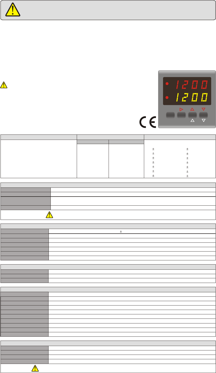
ENDA ETC442 PID TEMPERATURE CONTROLLER
TECHNICAL SPECIFICATIONS
* 48 x 48mm.
* Selectable sensor type.
* Input offset feature.
* Automatic calculation of PID parameters (SELF TUNE).
* Configurable Heat/Cool control.
* Input offset feature
* Adjustable main output during sensor failure.
* Parameter access protection on 3 levels.
* Change over automatically as actuators between 0-100%
* Programming just by using keypad.
TEMPERATURE CONTROLLER
ENDA
HEAT
PV
SV
ALR
SET
HSET ASET
ETC442 °C
Read this document carefully before using this device. The guarantee will be expired by
damaging of the device if you don't attend to the directions in the user manual. Also we don't
accept any compansations for personal injury, material damage or capital disadvantages.
Thank you for choosing ENDA ETC442 temperature controller.
,
Sensor type Temperature range
J (Fe-CuNi) Thermocouple
K (NiCr-Ni) Thermocouple
T (Cu-CuNi) Thermocouple
S (Pt10Rh-Pt) Thermocouple
R (Pt13Rh-Pt) Thermocouple
EN 60584
EN 60584
EN 60584
EN 60584
EN 60584
0... 600
0...1200
0... 400
0...1600
0...1600
°C
°C
°C
°C
°C
Accuracy
0,2% (of full scale)
0,2% ( full scale)of
1 digit
1 digit
0,2% ( full scale)of 1 digit
0,2% ( full scale)of 1 digit
0,2% ( full scale)of 1 digit
+32... +1112
+32... +2192
+32... +752
+32... +2912
+32... +2912
°F
°F
°F
°F
°F
Pt 100 Resistance Thermometer
Pt 100 Resistance Thermometer
EN 60751
EN 60751
-200...600
-99.9...300.0
°C
°C
0,2% ( full scale)of 1 digit
0,2% ( full scale)of 1 digit
-328... +1112
-99.9...+543.0
°F
°F*
°C °F
ELECTRICAL CHARACTERISTICS
Supply 230V AC +10% -20%, 50/60Hz or 24V AC 10%, 50/60Hz
Power consumption Max. 5VA
2.5mm² screw-terminal connections
Wiring
Line resistance
Data retention
EMC
Safety requirements
EN 61326-1: 1997, A1: 1998, A2: 2001 (Performance criterion B for standard EN 61000-4-3)
EEPROM (> 10 years)
EN 61010-1: 2001 (Pollution degree 2, overvoltage category II)
For thermocouple max.100 for 3 wired Pt 100 max. 20WW,
HOUSING
Housing type Suitable for flush-panel mounting according to DIN 43 700.
Dimensions W48xH48xD87mm
Weight Approx. 250g (incl. packaging)
Self extinguishing plastics.
Enclosure material
OUTPUTS
HEAT
Relay : 250V AC, 2A (for resistive load), or 12V DC 20mA logic outputNO+NC,
Mechanical 30.000.000 operation; Electrical 300.000 operation
Relay : 250V AC, 2A ( for resistive load), can programmed as NC function.NO,
ALARM
Life expectancy for relay
CONTROL
Control type Single set-point and alarm control
On-Off / P, PI, PD, PID (selectable)
Control algorithm
A/D converter Better than 15 bits
Sampling time
Proportional band
Derivative time
Integral time
Control period
Hysteresiz
Actuator function (P.Err.)
400ms
Adjustable between 0% and 100%. If Pb=0%, ON/OFF control is selected.
Adjustable between 0.0 and 100.0 minutes
Adjustable between 0.00 and 25.00 minutes
Adjustable between 4 and 250 seconds
Adjustable between 1 and 50°C (122°F)
Change over automatically as actuators between 0-100% power by sensor defect
ENVIRONMENTAL CONDITIONS
Height Max. 2000m
80% up to 31 decreasing linearly 50% at 40 .
Ambient/storage temperature
Max. relative humidity
0 ... +50 /
-25... +70°C, (without condense)
°C
°C °C
Rated pollution degree According to EN 60529 Front panel : IP60
Rare panel : IP20
Do not use the device in locations subject to corrosive and flammable gases.
Enter PID parameters of the system if they are known at the beginning.
Otherwise, Self-Tune should be activated.
english
While cleaning the device, don`t use solvents (thinner, benzine, acid etc.) or corrosive materials
* Display restricted
up to date: 240805, modification reserved and can be change any time previous notice !
1/4
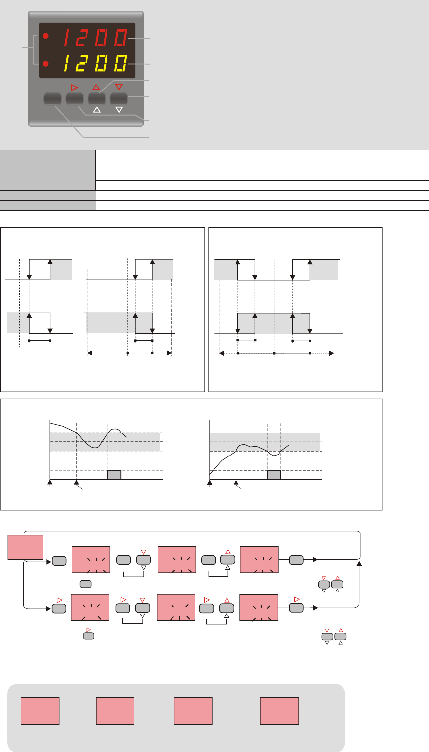
TERMS
PV display :7mm
SV display :7mm
ENDA
TEMPERATURE CONTROLLER
HEAT
PV
SV
ALR
SET
HSET ASET
°C
( 7 )
4 digit seven segment yellow LED
4 digit seven segment red LED
Microswitch
2 red LEDs for HEAT and ALARM outputs
MODIFICATION OF HEAT AND ALARM SET POINTS
( 2 ) SV display
Character heights
( 3 ),( 4 ),( 5 ),( 6 ) Keypad
( 7 ) State indicator
ALARM OUTPUT TYPES
H.SEt
150
H.SEt
150
- - - -
- - - -
PFA
150
PFA
150
PSC
150
PSC
150
A.SEt
250
A.SEt
250
H.SEt
150
H.SEt
150
A.SEt
250
A.SEt
250
A.SEt
249
A.SEt
249
First, press and hold key until the massage H.Set appears on the display. Then, the value is adjusted by using keys.
First, press and hold key until the massage A.Set appears on the display. Then, the value is adjusted by using keys.
SET
HSET
SET
HSET
SET
HSET
SET
HSET
ASET ASET ASET
When H.SEt is released, it
returns to normal operation.
When A.SEt is released, it
returns to normal operation.
130
150
130
150
PV
PV
PV PV PV PV
PV
PV
PVPV
SV
SV
SV SV SV SV
H.SEt
149
H.SEt
149
PV
SV SV
SV
SV
SV
Error Messages
ASET
SET
HSET
ASET
NOTE: The maximum of H.SEt is the value of uPL. parameter and the minimum of it is the value of LoL. parameter.
If independent alarm is selected, A.SEt value can be adjusted between the limits of the full scale.
If deviation alarm is selected, A.SEt value can be adjusted between -300 and +300.
If band alarm is selected, A.SEt value can be adjusted between 0 and +300.
Temperature value is
higher than the end
of the scale
Temperature value is
lower than the beginning
of the scale
Temperature sensor
is broken or
over temperature
Pt 100 or a sensor
line is short circuited
( 1 ) PV display
150150 150150
( 1 ) Process value during normal operation
Mnemonic parameter code during programming
( 2 ) Set point during normal operation.
Data value during programming
( 4 ) Decrement key during normal operation
If only this key is pressed in normal operation, software version number is seen.
Parameter selection during programming
( 3 ) Increment key during normal operation and programming
Parameter selection key during programming
( 5 ) Alarm set key during normal operation
Menu selection key during programming
( 6 ) Heat (main) set key during normal operation
Parameter selection key during programming
2/4
Independent Alarm
A.tyP.=IndE Deviation Alarm
A.tyP.= dE.
Band Alarm
A.tyP.= Band
Band Alarm With Inhibition
A.tyP.= bAn.I.
A.StA.= HI
A.StA.= boHI
A.StA.= Lo
A.StA.= bIHI
ASV
SV SV
SV
SV+ASV
SV+ASV
SV-ASV
OFF OFF
OFF
OFF OFF
OFF
-300
300
+300
300
ON ON
ON
ON ON
ON
ON ON
OFF OFF
Beginning
of procedure
SV =Set point of heat output ASV = Set point of alarm output (ASV min: 0 max: 300 )
(IfinP = Pt.0, ASV min = -30.0
ASV max = +30.0) (IfinP = Pt.0, ASV min = 0.0
ASV max = +30.0)
SV = Set point of Heat output ASV = Set point of alarm output
(ASV min = -300, ASV max = +300)
ASV min = beginning of scale
ASV max = end of scale SV = Set point of heat output ASV = Set point of alarm output
(ASV min = 0, max = 300 )
Band alarm is possible Band alarm is possible
Beginning
of procedure
SV SV
SV+ASV SV+ASV
SV-ASV SV-ASV
HyS.A. HyS.A.
HyS.A.
HyS.A.
By the diagrams are shown only switching examples for
positive ASV-Parameters !
A.tyP.
ýndE.
A.tyP.
ýndE.
A.StA.
Hý.
A.StA.
Hý.
A.SAF.
oFF
A.SAF.
oFF
HyS.A.
2
HyS.A.
2
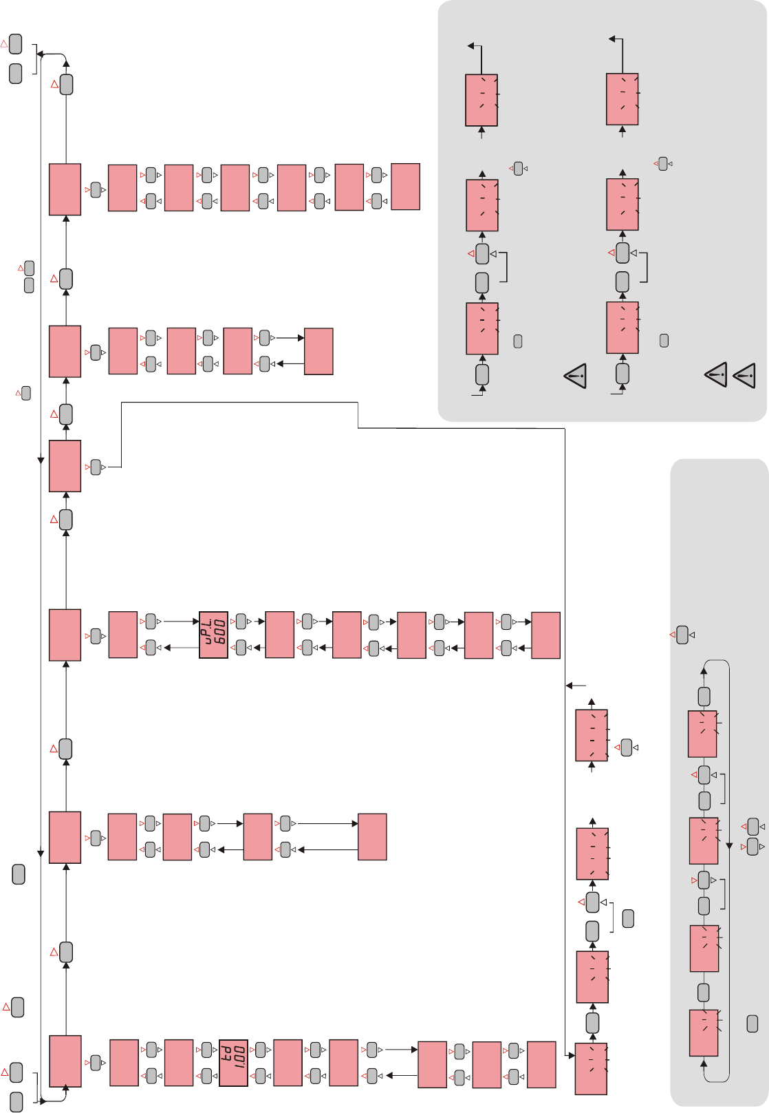
ALr.ALr. ConF.ConF. S.tun.S.tun. CAL.CAL. SECU.SECU.
ASET ASET ASETASET
ASET
P.rES. = The ratio of output power at the set
point.
Adjustable between 0% and 100%.
If this parameter is set to 0, the output power
becomes 0 at the set point. If it is adjusted to 50%
output power becomes 50% at the set point. Using
this parameter the energy requirements of the
system is adjusted at the set point. So the set point
can be achieved by minumum fluctuations and in
the shortest time.
HyS.H. = Hysteresis of the heat output.
Adjustable between 1 and 50 °C/F.
This parameter is only to seen by seen.Pb = 0
H.StA. = Configuration of the heat output.
H.StA. = HEAt means heating control.
H.StA. = cooL means cooling control.
ti = Integral time.
Adjustable between 0.0 and 100.0 minutes.
If ti = 0.0, integral effect is not used.
Setting Pb = 0 this parameter is not seen.
td = Derivative time.
Adjustable between 0.00 and 25.00 minutes.
If td = 0.00, derivation effect is not used.
Setting Pb = 0 this parameter is not seen.
Ct = Control period.
Adjustable between 4 and 250 seconds.
Setting Pb = 0 this parameter is not seen.
P.Err. = Actuator function. This parameter is used to adjust the main output
during a sensor failure. Adjustable between 0% and 100%.
If this parameter is adjusted to a value closer to the energy requirements of the
system at the set point, process temperature is prevented to rise or drop to
dangerous levels.
A.SAF. = The security state of alarm
output during a sensor failure.
If A.SAF.= on , the alarm output is
energised during the sensor failure.
If A.SAF.= oFF, the alarm output is not
energised during the sensor failure.
Pb = Proportional band.
Adjustable between 0% and 100%
Setting Pb = 0% On-Off control is
selected.
HyS.A .= Hysteresis of the alarm
output.
Adjustable between 1 and 50°C.
A.tyP. = Function of alarm output.
Four kinds of functions can be selected.
indE.= Independent
dE. = Deviation
bAnd = Band
bAn.I. = Band alarm with inhibition.
A.StA .= The state of alarm output.
If independent or deviation alarm is
selected, the alarm output can be Lo.
and Hi... For Lo. alarm output is
energised below the alarm set point. For
Hi. alarm output is energised above the
alarm set point. If band alarm is
seleceted, this parameter can be bIHI
or boHI. bIHI means alarm is
activated outside the band.
ýnP.
FE.cn.
ýnP.
FE.cn.
Lo.L.
0
Lo.L.
0
oFFS.
0
oFFS.
0
InP. = Type of sensor and scale.
Pt = Pt 100 -200 to +600°C
Pt.0 = Pt 100 -99.0 to 300.0°C
FE.cn. = J (Iron vs. Copper-Nickel) 0 to +600°C
nc.nA. = K (Nickel-Cr.vs. Nickel-Alum.) 0 to +1200°C
c.cn. = T (Copper vs. Copper-Nickel) 0 to +400°C
P10.r. = S (Platinum-10%Rhodium vs. Pt.) 0...+1600°C
P13.r. = R (Platinum-13%Rhodium vs. Pt.) 0...+1600°C
Note : If the selected sensor type is changed, the value of
the UPL., Lol., A.UP.L., A.Lo.L. parameters changes
automatically.
uPL. = Set point upper limit.
The minimum value is the value of LoL
parameter.
If InP. or UnIt. parameters are changed, the
maximum value of the UPL. parameter changes to
the maximum scale value of the selected sensor
type.
S.cod.= Calibration menu.
access code
It should be 555.
rt.CA. = The environment
temperature is calibrated by
this parameter. It is not
displayed if input type is
tC.CA. = In this case, the
calibration of thermocouple
input can be made.
(See Note 1 below)
Pt.CA. = In this case, the
calibration of Pt 100 input can
be made.
(See Note 2 below)
LoL. = Set point lower limit.
The maximum value is the value of uPL.
parameter.
If InP. or UnIt. parameters are changed, the
minimum value of the Lo.L. parameter changes to
the minimum scale value of the selected sensor
type.
oFFS. = Offset value.
Offset value is added to the measurement value.
Adjusted between -99 and +99°C.
The normal value is 0.
S.cod.
0
S.cod.
0
rt.CA.
25.0
rt.CA.
25.0
tC.CA.
run
tC.CA.
run
Pt.CA.
run
Pt.CA.
run
S.cod.
0
S.cod.
0
A.HEA.
P.yES
A.HEA.
P.yES
A.ALr.
P.yES
A.ALr.
P.yES
A.Con.
P.yES
A.Con.
P.yES
A.CAL.
no
A.CAL.
no
A.tun.
yES
A.tun.
yES
Before starting calibration procedure, 50.000mV referance voltage must be applied to the
thermocouple inputs.
tC.CA.
run
tC.CA.
run
tC.CA.
CAL.
tC.CA.
CAL.
When holding key the message "run" flashes. In this case if key is pressed, calibration for TC input
starts. Then the messages C.Str, a for digit number and Cal are seen in sequence on the lower display. After 5
seconds End message is seen. If the four digit number is 4999 or 5000 or 5001, it means TC calibration was
successful. Otherwise calibration procedure should be repeated.
When holding key the message "run" flashes. In this case if key is pressed, calibration for Pt 100
input starts. The messages C.Str, a for digit number and Cal are seen in sequence on the lower display. After
5 seconds End message is seen. If the four digit number is 3895 or 3896 or 3897, this means Pt 100
calibration was successful. Otherwise, Calibration procedure should be repeated.
SET
HSET
SET
HSET
SET
HSET
SET
HSET
press and hold
NOTE 1
NOTE 2
5 seconds
later
Before starting calibration procedure, make a connection between terminal 1 and 2. Then connect a
212.02ohm referance resistor should be connected between terminal 2 and terminal 3 or apply 300 C
from Pt-100 calibrator.
Pt.CA.
run
Pt.CA.
run
Pt.CA.
CAL.
Pt.CA.
CAL.
SET
HSET
SET
HSET
Press and hold
5 seconds
later
ASET
if key is pressed while holding key, the programming mode is enabled.
HyS.H.
6
HyS.H.
6
HyS.H.
5
HyS.H.
5
HyS.H.
6
HyS.H.
6
If key is pressed and held 0.6 seconds,
the value of the selected parameter changes rapidly. If
waited enough, the value increases 100 at each step. After
1 second following the release of the key, initial condition is
returned. The same procedure is valid for the decrement
key.
SET
HSET
SET
HSET
SET
HSET
Modification of Parameter
When holding key, the value of parameter flashes and using keys the requested value can be adjusted.
Values on the displays are default values.
tC.CA.
End
tC.CA.
End
tC.CA.
End
tC.CA.
End
HEAtHEAt
Pb
4
Pb
4
tý
4.0
tý
4.0
Ct
20
Ct
20
P.rES.
0
P.rES.
0
HyS.H.
2
HyS.H.
2
H.StA.
HEAt
H.StA.
HEAt
P.Err.
0
P.Err.
0
ASET
S.cod. = Security menu access
code.
It should be 666.
A.HEA .= Parameters of heat menu
access level code.
nonE = Not visible
P.yES = Visible and modification can
be done.
P. no = Visible and modified.
A.ALr.= Parameters of alarm
menu access level code.
nonE = Not visible
P.yES = Visible and modification
can be done.
P. no = Visible and not modified.
A.Con.= ConF.Parameters of
configuration menu access level
code.
nonE = Not visible.
P.yES = Visible and modification
can be done.
P. no = Visible and not modified.
A.tun.= S.tun. self tune menu.
no = Not vsible
yES = Self tune procedure can be
activated.
A.CAL.= Calibration menu.
no = Not visible
yES = Calibration can be done.
Returns to the normal
operation mode.
Returns to the normal
operation mode
SET
HSET
SET
HSET
SET
HSET
ASET ASET
SET
HSET
SET
HSET
HyS.H.
6
HyS.H.
6
Entering from the programme mode to the run mode:
If no key is pressed within 20 seconds during programming mode, the data is stored automatically and the normal mode is entered.
Alternatively, the same function occurs first pressing key and then pressing keys together.
SET
HSET
ASET
ASET
Before starting sef-tune
procedure, be sure A.tun
parameter is YES
in theSECU menu.
°
Unýt.
°C
Unýt.
a.UP.L.
600
a.UP.L.
600
A.Lo.L..
0
A.Lo.L..
0
UnIt = The temperature unit.
Selectable as °C or °F.
Note : If the temperature unit is changed, the
value of the UPL., Lol., A.UP.L., A.Lo.L.
parameters changes automatically.
A.UP.L. = Alarm value upper limit.
The minimum value is the value of A.Lo.L.
parameter.
If InP. or UnIt. parameters are changed, the
maximum value of the A.UP.L. parameter changes
to the maximum scale value of the selected sensor
type.
A.Lo.L. = Alarm value lower limit.
If InP. or UnIt. parameters are changed, the
minimum value of the A.Lo.L. parameter changes to
the minimum scale value of the selected sensor
type. The maximum value is the value of A.UP.L.
Parameter.
S.Str.
run
S.Str.
run
S.Str.
S.tun.
S.Str.
S.tun.
25
S.tun.
25
S.tun.
SET
HSET
SET
HSET
press and hold
5 sseconds
later
Press any
key to disactive the self-tune
procedure.
S.Str.
run
S.Str.
run
For activating Self-tune procedure, press and hold key until flashing of the run message. Then if key is pressed, Self-tune procedure begins and the measurement value is
indicated in the above display.
SET
HSET
The message S.tun. flashes until the end of the Self-tune procedure. If ýt is succeeded, A.tun. parameter is automatically becomes "no" and S.tun. menu is canceled. When Self-tune
procedure begins, the measurement value should be lower than the set point at least 5% of the full scale. If the measurement value is closer to a set point than this rate, self-tune is not
be able to started and the message Err. is indicated on the lower display.
3/4
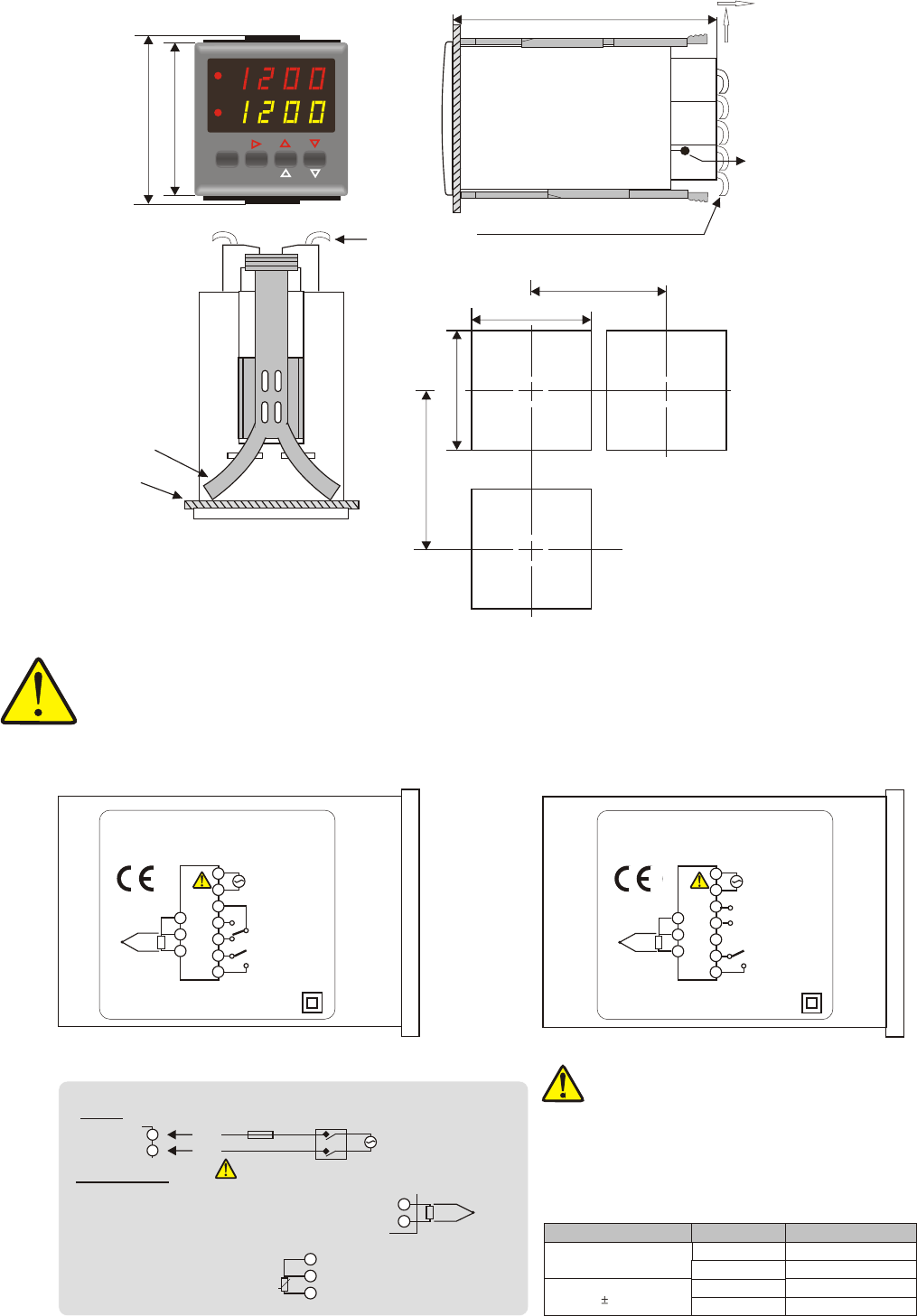
Panel cut-out
Connection
cables
51mm
60mm
54mm
48mm
ENDA
HEAT
ALR
HSET
ETC442
SET
TEMPERATURE CONTROLLER
ASET
PV
SV
°C
Panel
Flush mounting
adaptor
DIMENSIONS
SENSOR INPUT :
For J-K-T-S-R type thermocouple :
Use suitable compansation cables. Don't use
jointed cables. Pay attention to the polarities of the
thermocouple cables as shown in the figure right
TC
-
+
-
+
For resistans thermometer :
When 2 wired Pt 100 is used,
terminals 1 and 2 must be
short circuited.
3
4
4
5
5
Pt 100
45 mm
+0.6
45 mm
+0.6
Supply Order code
HEAT Output
230V AC +10% -20% ETC442
Relay
24V AC 10%
ETC442-SSR
ETC442-24
ETC442-24-SSR
Logic output
Relay
Logic output
Note 1) While panel mounting, additional distance required
for connection cables should be considered.
2) Panel thickness should be maximum 10mm.
3) It is free space (80mm) at backside to take apart the
instrument from panel
ATTENTION ! / CONNECTION DIAGRAM
ENDA ETC 442 is intended for installation in control panels. Make sure that the device is used only for intented purpose. During an installation in a
panel, all of the cables that are connected to the device must be free of energy. The device must be installed so that is protected against
inadmisable humidity, vibrations, severe soiling and make sure that the operation temperature is not exceeded. All input and output lines that are
not connected to the supply network must be laid out as shielded and twisted cables.These cables should not be close to the power cables or
components. The shielding must be grounded on the instrument side. The electrical connections must be carried on by a qualified staff and must be
according to the relevant locally applicable regulations.
Temperature
compansation sensor
Depth
87mm
Terminal Connection ETC442
-
+
ENDA INDUSTRIAL ELECTRONICS
ETC442 PID TEMPERATURE CONTROLLER
SN: XXXXXXXXX
3
4
5
HEAT
ALARM
AC 250V 2A
RESISTIVE LOAD
AC 250V 2A
RESISTIVE LOAD
230V AC +10% -20%
50/60Hz 5VA
TC Pt 100
13
14
8
9
10
11
12
-
+
ENDA INDUSTRIAL ELECTRONICS
ETC442.SSR PID TEMPERATURE CONTROLLER
SN: XXXXXXXXX
3
4
5
HEAT
ALARM
LOGIC OUT
12V DC 20mA
AC 250V 2A
RESISTIVE LOAD
230V AC +10 % -20%
50/60Hz 5VA
TC Pt 100
13
14
8
9
10
11
12
-
+
Terminal Connection ETC442-SSR
Logic output of the instrument ETC442-SSR is not
electrically insulatedfrom the internal circuits. Therefore,
when using a grounding thermocouple, do not connect
the logic output terminals to the ground.
Note :
1)Cables for supply must be IEC60799 or IEC60245
conform.
2)Main switch should be with in easy reach and should be
indicated !
230V AC Supply
Main switch
Cable size : 1,5mm²
Fuse
F 100 mA 250V AC
N
L
Fuse must be
connected !
184-253V AC
50/60Hz 5VA
Supply :
NOTE :
9
8
- Push up the flush-mounting
clamp asshown in the figure
left.
- Then, pull out the clamp in
direction 2.
1
2
For removing mounting clamps:
4/4
If necessary use for the load separate fuse !
E-mail : info@suran-gmbh.de
Internet : www.suran-gmbh.de
Tel.: +49 (0)7451 / 625 617
Fax: +49 (0)7451 / 625 0650
SURAN Industrieelektronik
Im Mitteldorf 26 / D-72160 Horb a.N
