2005B Magnetics Ferrite Catalog Uncut
User Manual: 2005B-Magnetics-Ferrite-Catalog-uncut Igor's of metalworking and electrical manuals
Open the PDF directly: View PDF ![]() .
.
Page Count: 190 [warning: Documents this large are best viewed by clicking the View PDF Link!]

Ferrite Cores

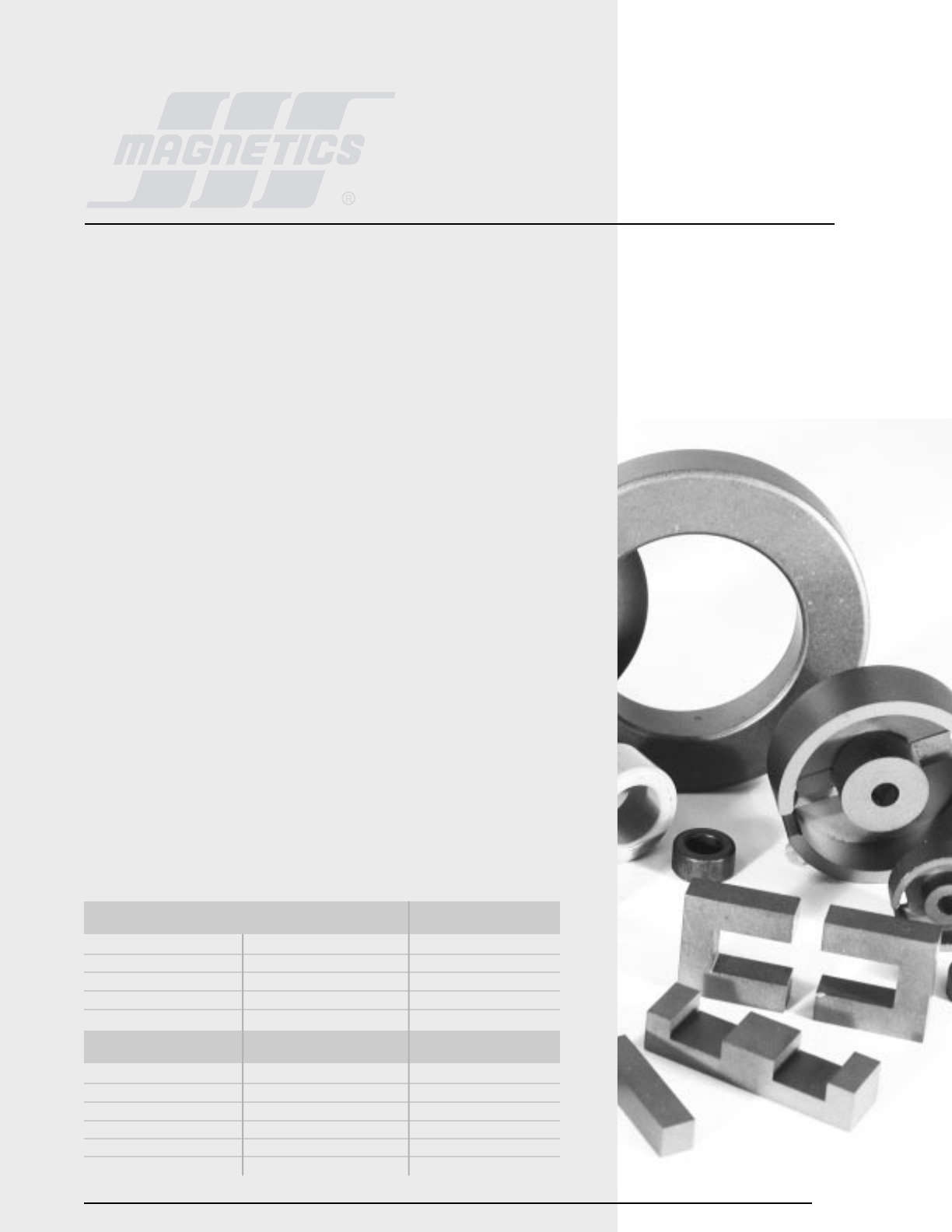
Magnetics®offers
the confidence of
over fifty years of
expertise in the
research, design,
manufacture and
support of high
quality magnetic
materials and
components.
About Magnetics
A major supplier of the highest performance materials
in the industry including; MPP, High Flux, Kool Mµ®,
power ferrites, high permeability ferrites and strip
wound cores, Magnetics products set the standard for
providing consistent and reliable electrical properties for
a comprehensive range of core materials and
geometries. Magnetics is the best choice for a variety
of applications ranging from simple chokes and
transformers used in telephone equipment to
sophisticated devices for aerospace electronics.
Magnetics backs its products with unsurpassed technical
expertise and customer service. Magnetics’ Application
Engineering staff offers the experience necessary to
assist the designer from the initial design phase through
prototype approval. The knowledgable Sales staff is
available to help with all of your customer service
needs. This support, combined with a global presence
via a worldwide distribution network, including a Hong
Kong distribution center, makes Magnetics a premier
supplier to the international electronics industry.
CONTACT MAGNETICS
P.O. Box 11422
Pittsburgh, PA 15238-0422
Phone: 412-696-1300 or 1-800-245-3984
Fax: 412-696-0333
email: magnetics@spang.com
web: www.mag-inc.com

Index
PART NUMBER INDEX
Arranged by Part Number........................................ iii
Arranged by Part Type.............................................iv
Order Information....................................................v
Section 1
INTRODUCTION
What are Ferrites?................................................1.1
Application Areas..................................................1.2
Part Number Identification..............................1.4-1.7
Gapped Core Tolerance Data..........................1.8-1.11
Section 2
MEASUREMENT INFORMATION
Section 3
MATERIALS
Introduction.........................................................3.1
Material Characteristics..................................3.2-3.9
Core Loss Information........................................ 3.10
B vs. H Curves.................................................. 3.11
Ferrite Blocks....................................................3.12
Section 4
POWER DESIGN
Introduction.........................................................4.1
General Core Selection.................................. 4.2-4.3
Transformer Core Selection.............................4.4-4.9
Inductor Core Selection................................4.9-4.14
Core Selector Charts.................................4.15-4.18
DC Bias Data.................................................... 4.19
Section 5
LOW LEVEL DESIGN
Introduction.........................................................5.1
Pot Core Design Advantages...................................5.2
Pot Core Design Notes...................................5.3-5.5
Assembly Notes............................................5.6-5.7
Wire Tables..................................................5.8-5.9
Plastics Information.................................. 5.10-5.11
Section 6
POT CORES
Introduction........................................................ 6.1
Pot Core Data..............................................6.2-6.5
Pot Core Hardware.....................................6.6-6.16
Section 7
RS/DS CORES
Introduction..........................................................7.1
RS/DS Core Data..........................................7.2-7.7
RS/DS Core Hardware................................7.8-7.12
Section 8
RM CORES
Introduction..........................................................8.1
RM Core Data...............................................8.2-8.9
RM Core Hardware...................................8.10-8.14
Section 9
EP CORES
Introduction.........................................................9.1
EP Core Data................................................9.2-9.3
EP Core Hardware.........................................9.4-9.9
Section 10
PQ CORES
Introduction.......................................................10.1
PQ Core Data...........................................10.2-10.3
PQ Core Hardware....................................10.4-10.6
Section 11
E, I, U CORES
Introduction.......................................................11.1
E, I, U Core Data......................................11.2-11.9
E, I, U Core Hardware..........................11.10-11.17
Planar E, I Core Data............................11.18-11.21
Planar E, I Core Hardware.....................11.21-11.23
EEM, EFD Core Data.............................11.24-11.25
EEM, EFD Core Hardware......................11.26-11.30
Section 12
EC, ETD, EER, ER CORES
Introduction.......................................................12.1
EC, ETD, EER, ER Core Data........................12.2-12.3
EC, ETD, EER, ER Core Hardware...............12.4-12.14
Section 13
TOROIDS
Introduction..............................................13.1-13.3
Toroid Core Data....................................13.4-13.12
Toroid Hardware..................................13.13-13.15
Section 14
GENERAL INFORMATION
Definitions...............................................14.2-14.3
References........................................................14.4
Other Products from Magnetics.............................14.5 ii
Index

iii MAGNETICS
Part Number Index
ARRANGED BY PART NUMBER
40200 TC 13.4
40301 TC 13.4
40302 PC 6.2
40401 TC 13.4
40402 TC 13.4
40502 TC 13.4
40503 TC 13.4
40506 PC 6.2
40507 PC 6.2
40601 TC 13.4
40603 TC 13.4
40704 PC 6.2
40705 TC 13.4
40707 EP 9.2
*40903 PC 6.2
40904 EC 11.2
40905 PC 6.2
40906 ER 12.2
40907 TC 13.4
41003 TC 13.4
41005 TC 13.4
41010 EP 9.2
41106 UC-IC 11.2
41107 PC 6.2
41110 RM 8.2
41203 EC 11.2
41205 EC 11.2
41206 TC 13.4
41208 EC 11.2
*41209 EC 11.2
41303 TC 13.4
41305 TC 13.4
41306 TC 13.4
*41309 EEM 11.24
41313 EP 9.2
41406 TC 13.6
41407 TC 13.6
41408 PC 6.2
S-41408 RS 7.2
*41425 EC 11.18
*41434 EC 11.18
41435 TC 13.6
41450 TC 13.6
*41500 RM 8.2
*41505 RM 8.2
41506 TC 13.6
41510 RM 8.2
41515 EFD 11.24
41605 TC 13.6
41707 EC 11.2
*41709 EC 11.24
41717 EP 9.2
*41805 EC 11.18
41808 EC 11.2
41809 TC 13.6
41810 EC 11.2
41811 PC 6.4
41812 RM6-R 8.2
41912 RM6-S 8.4
42016 PQ 10.2
42020 PQ 10.2
42106 TC 13.6
*42107 EC 11.18
42109 TC 13.6
*42110 EC 11.14
42120 EP 9.2
42206 TC 13.6
42207 TC 13.6
42211 EC 11.2
42212 TC 13.6
42213 PC 6.4
*42216 EC 11.18
42220 UC 11.2
*42309 RM 8.4
S-42311 RS 7.2
D-42311 DS 7.2
42316 RM 8.4
S-42318 RS 7.2
D-42318 DS 7.2
42507 TC 13.6
42508 TC 13.6
42510 EC 11.4
42512 UC 11.4
42515 EC-IC 11.4
42515 UC-IC 11.4
42516 IC 11.4
42520 EC 11.4
42523 EFD 11.24
42530 EC 11.4
42530 UC 11.4
*42610 PQ 10.2
42614 PQ 10.2
42616 PC 6.4
S-42616 RS 7.2
D-42616 DS 7.2
42620 PQ 10.2
42625 PQ 10.2
*42809 RM 8.4
42810 EC 11.4
42819 RM 8.4
42908 TC 13.6
42915 TC 13.6
43007 EC 11.4
43009 EC 11.4
43013 EC 11.6
43019 PC 6.4
S-43019 RS 7.4
D-43019 DS 7.4
43113 TC 13.8
43205 TC 13.8
*43208 EC-IC 11.18
*43214 PQ 10.2
43220 PQ 10.2
43230 PQ 10.2
43434 ETD 12.4
43515 EC 11.6
43517 EC 12.2
43520 EC 11.6
43521 EER 12.2
43524 EC 11.6
43535 PQ 10.2
43610 TC 13.8
43615 TC 13.8
*43618 EC-IC 11.18
43622 PC 6.4
S-43622 RS 7.4
D-43622 DS 7.4
43723 RM 8.4
43806 TC 13.8
*43808 EC-IC 11.20
43813 TC 13.8
43825 TC 13.8
43939 ETD 12.4
*44008 EC-IC 11.20
44011 EC 11.6
44016 EC 11.6
44020 EC-IC 11.6
44022 EC 11.6
44040 PQ 10.2
44119 EC 12.1
44119 UC 11.6
44121 UC 11.6
44125 UC 11.6
44130 UC 11.8
44216 EER 12.4
44229 PC 6.4
S-44229 RS 7.4
D-44229 DS 7.4
*44308 EC-IC 11.20
*44310 EC-IC 11.20
44317 EC 11.8
44416 TC 13.8
44444 ETD 12.4
44529 PC 6.4
44715 TC 13.8
44721 EC 11.8
44916 TC 13.8
44920 TC 13.8
44924 EC 11.8
44925 TC 13.8
44932 TC 13.8
44949 ETD 12.4
45021 EC 11.8
45032 ETD 12.4
45224 EC 12.2
45528 EC 11.8
45530 EC 11.8
45724 EC 11.8
*45810 EC-IC 11.20
45959 ETD 12.4
46016 EC 11.8
46113 TC 13.8
46326 TC 13.8
*46409 EC 11.20
*46410 EC-IC 11.20
47035 EC 12.1
47054 ETD 12.4
47228 EC 11.8
47313 TC 13.8
47325 TC 13.8
48020 EC 11.8
48613 TC 13.8
49925 IC 11.8
49925 UC 11.8
49928 EC 11.8
*49938 EC 11.20
PLANAR CORES are available in a number of parts as indicated with an * in the index. Note that most cores can
be pressed as planar types upon request. Check with the factory for cores that may already have an assigned planar
part number or for any other parts for which you may have an interest.
PAGE
TYPE
PART NO. PART NO. TYPE PAGE PART NO. TYPE PAGE PART NO. TYPE PAGE PART NO. TYPE PAGE

ARRANGED BY PART TYPE
PART NO. PAGE
PART NO. PAGE
PART NO. PAGE
PART NO. TYPE
TYPE
PAGE
PART NO. PAGE
PART NO. PAGE
40302 6.2
40506 6.2
40507 6.2
40704 6.2
*40903 6.2
40905 6.2
41107 6.2
41408 6.2
41811 6.4
42213 6.4
42616 6.4
43019 6.4
43622 6.4
44229 6.4
44529 6.4
40707 EP7 9.2
41010 EP10 9.2
41313 EP13 9.2
41717 EP17 9.2
42120 EP20 9.2
43520 11.6
43524 11.6
44011 Metric E40 11.6
44016 11.6
44020 DIN 42/15 11.6
44022 DIN 42/20 11.6
44924 11.8
45021 Metric E50 11.8
45528 DIN 55/21 11.8
45530 DIN 55/25 11.8
46016 Metric E60 11.8
47228 11.8
48020 Metric E80 11.8
49928 E-100 11.8
40904 11.2
41205 11.2
41208 11.2
41209 11.2
41810 11.2
42211 11.2
42515 (E&I) 11.4
42520 11.4
42530 11.4
42810 11.4
43007 11.4
43013 11.6
42311 7.2
42318 7.2
42616 7.2
43019 7.4
43622 7.4
44229 7.4
41203 E2829 11.2
41707 E3233 11.2
41808 EI187 11.2
42510 E2425 11.4
43009 E2627 11.4
43515 EI375 11.6
44317 EI21 11.8
44721 EI625 11.8
45724 EI75 11.8
41408 7.2
42311 7.2
42318 7.2
42616 7.2
43019 7.4
43622 7.4
44229 7.4
Part Number Index
iv
mag-inc.com
PC (POT) CORES EP CORES
OTHER E CORES
PQ CORES
LAMINATION SIZE E CORES
RS (ROUND-SLAB) CORES
DS (DOUBLE-SLAB) CORES
PART NO. TYPE PAGE
PART NO. TYPE PAGE
EEM, EFD CORES
*41309 EEM12.7 11.24
41515 EFD15 11.24
*41709 11.24
42523 EFD25 11.24
43517 EC35 12.2
44119 EC41 12.1
45224 EC52 12.2
47035 EC70 12.1
41305 13.4
41306 13.4
41406 13.6
41407 13.6
41435 13.6
41450 13.6
41506 13.6
41605 13.6
41809 13.6
42106 13.6
42109 13.6
42206 13.6
42207 13.6
42212 13.6
42507 13.6
42508 13.6
42908 13.6
42915 13.6
43113 13.8
43205 13.8
43610 13.8
43615 13.8
43806 13.8
43813 13.8
43825 13.8
44416 13.8
44715 13.8
44916 13.8
44920 13.8
44925 13.8
44932 13.8
46113 13.8
46326 13.8
47313 13.8
47325 13.8
48613 13.8
PART NO. TYPE PAGE
EC CORES
PART NO. TYPE PAGE
ETD, EER CORES
43434 ETD34 12.4
43521 EER35L 12.2
43939 ETD39 12.4
44216 EER42 12.4
44444 ETD44 12.4
44949 ETD49 12.4
45032 12.4
45959 ETD59 12.4
47054 12.4
PART NO. TYPE PAGE
ER CORES
PART NO. TYPE PAGE
PART NO. TYPE
TYPE
PAGE
41110 RM4 8.2
*41500 RM 8.2
*41505 RM 8.2
41510 RM5 8.2
41812 RM6-R 8.2
41912 RM6-S 8.2
*42309 RM 8.4
42316 RM8 8.4
*42809 RM 8.4
42819 RM10 8.4
43723 RM12 8.4
RM CORES
PART NO. TYPE PAGE
OTHER E CORES CONTINUED
PART NO. TYPE PAGE
41106 (U&I) 11.2
42220 11.2
42512 11.4
42515 (U&I) 11.4
42516 11.4
42530 11.4
44119 11.6
44121 11.6
44125 11.6
44130 11.8
49925 (U&I) 11.8
U CORES
PART NO. TYPE PAGE
41425 11.18
41434 (E&I) 11.18
41805 (E&I) 11.18
42107 11.18
42216 (E&I) 11.18
43208 (E&I) 11.18
43618 (E&I) 11.18
43808 (E&I) 11.18
44008 (E&I) 11.20
44308 (E&I) 11.20
44310 (E&I) 11.20
45810 (E&I) 11.20
46409 (E) 11.20
46410 (E&I) 11.20
49938 11.20
PLANAR E CORES
TC (TOROID) CORES
CONTINUED
*PLANAR CORES
Contact Sales Department for newest parts. For sizes not listed here, contact the Magnetics Sales Department.
42016 PQ20/16 10.2
42020 PQ20/20 10.2
*42610 PQ26/10 10.2
42614 PQ26/14 10.2
42620 PQ26/20 10.2
42625 PQ26/25 10.2
*43214 PQ32/14 10.2
43220 PQ32/20 10.2
43230 PQ32/30 10.2
43535 PQ35/35 10.2
44040 PQ40/40 10.2
40906 (ER9.5) 12.6
TC (TOROID) CORES
PART NO. TYPE PAGE
40200 13.4
40301 13.4
40401 13.4
40402 13.4
40502 13.4
40503 13.4
40601 13.4
40603 13.4
40705 13.4
40907 13.4
41003 13.4
41005 13.4
41206 13.4
41303 13.4

vMAGNETICS
Order Information
WARRANTY
All standard parts are guaranteed to be free from defects in material and
workmanship, and are warranted to meet the Magnetics published
specification. No other warranty, expressed or implied, is made by
Magnetics. All special parts manufactured to a customer’s specification are
guaranteed only to the extent agreed upon, in writing, between Magnetics
and the user.
Magnetics will repair or replace units under the following
conditions:
1. The buyer must notify Magnetics, Pittsburgh, PA 15238 in writing,
within 30 days of the receipt of material, that he requests
authorization to return the parts. A description of the complaint must
be included.
2. Transportation charges must be prepaid.
3. Magnetics determines to its satisfaction that the parts are defective,
and the defect is not due to misuse, accident or improper application.
Magnetics liability shall in no event exceed the cost of repair or
replacement of its parts, if, within 90 days from date of shipment, they
have been proven to be defective in workmanship or material at the time of
shipment. No allowance will be made for repairs or replacements made by
others without written authorization from Magnetics.
Under no conditions shall Magnetics have any liability whatever for the loss
of anticipated profits, interruption of operations, or for special, incidental or
consequential damages.
ORDERING
When ordering, please use Magnetics part numbers, or specify material,
size, and ALvalue. Magnetics customer service representatives and
applications engineers are available to help you.
PACKING UNIT
A packing unit is the quantity in a standard full package for a particular part.
Special consideration, such as expedited deliveries, is given when ordering
stocked standard sized packing units. Contact the factory for details.
UL RECOGNITION
Magnetics is a UL-recognized molder in the QMMY2 fabricated parts program.
Many bobbins shown in this catalog are covered. Contact Magnetics for
details on specific parts.
WHAT ARE FERRITES?
Ferrites are dense, homogeneous ceramic structures made by mixing iron oxide (Fe2O3) with
oxides or carbonates of one or more metals such as manganese, zinc, nickel, or magnesium. They
are pressed, then fired in a kiln up to 2000˚ F, and machined as needed to meet various
operational requirements.
ADVANTAGES OF FERRITES
Ferrites have a paramount advantage over other types of magnetic materials: high electrical
resistivity and resultant low eddy current losses over a wide frequency range. Additional
characteristics such as high permeability and time/temperature stability have expanded ferrite
uses into quality filter circuits, high frequency transformers, wide band transformers, adjustable
inductors, delay lines, and other high frequency electronic circuitry. As the high frequency
performance of other circuit components continues to be improved, ferrites are routinely designed
into magnetic circuits for both low level and power applications. For the most favorable
combination of low cost, high Q, high stability, and lowest volume, ferrites are the best core
material choice for frequencies from 10 KHz to 50 MHz. Ferrites offer an unmatched flexibility in
magnetic and mechanical parameters.
FERRITE ADVANTAGES
•LOW COST
•LARGE SELECTION OF MATERIALS
•SHAPE VERSATILITY
•ECONOMICAL ASSEMBLY
•TEMPERATURE AND TIME STABILITY
•HIGH RESISTIVITY
•WIDE FREQUENCY RANGE (10KHz TO 50 MHz)
•HIGH Q/SMALL PACKAGE
MAGNETICS®FERRITES
Magnetics’ ferrite cores are manufactured for a wide variety of applications. Magnetics has
developed and produces the leading MnZn ferrite materials for power transformers, power
inductors, wideband transformers, common mode chokes, and many other applications. In addition
to offering the leading materials, other advantages of ferrites from Magnetics include: the full
range of standard planar E and I cores; rapid prototyping capability for new development; the
widest range of toroid sizes in power and high permeability materials; standard gapping to precise
inductance or mechanical dimension; wide range of coil former and assembly hardware available;
and superior toroid coatings available in several options.
Section 1
Introduction
1.1

Introduction
Properties
1. 2 MAGNETICS
MECHANICAL DATA UNITS
Above properties are averages measured on a range of commercially available MnZn ferrite materials.
TYPICAL MECHANICAL AND THERMAL
PROPERTIES OF FERRITE MATERIALS
Bulk Density 4.85 gm/cm3Coefficient of Linear Expansion 10.5X10⁻⁶ ˚C-1
Tensile Strength 5.0, 7.0X10³kgf.mm-2,lbs.in-2 Specific Heat (25˚) 1100, .26 J.kg-1˚C-1,cal.g-1.˚C-1
Compressive Strength 45, 63X103kgf.mm-2,lbs.in-2 Thermal Conductivity (25-85˚C) 3500-4300 µW.mm-1.˚C-1
Youngs Modulus 12.4X103,1.8X107kgf.mm-2,lbs.in-2 35-43 mW.cm-1.˚C-1
Hardness (Knoop) 650 Typical .0083-.010 cal.s-1.cm-1.˚C-1
Resistivity 102-103ohm-cm
THERMAL DATA UNITS

Introduction
Common Mode Chokes Very high µ. J, W, H Toroids
Differential Inductors Low losses and high F, P, R Pot cores, EP cores, E-cores,
temperature stability. RM cores, Planar cores
Power Transformers High µ and low losses at high flux F, P, R Ungapped pot cores, E, U & I cores,
densities and temperatures. toroids, EP cores, RS cores,
High saturation. PQ cores, Planar cores
Power Inductors Low losses at high flux densities and F, P, R Pot cores, E cores, PQ cores,
temperatures. High saturation. RM cores, Planar cores
Converter and Inverter Transformers Low losses, high saturation. F, P, R Toroids, E, U, & I cores, pot cores,
RS cores, Planar cores
Pulse Transformers High µ, low loss, high Vt product. J, W, H Toroids
Broadband Transformers Low loss, high µ. J, W, H Pot cores, toroids, E, U & I cores,
RM, EP cores
Narrow Band Transformers Moderate Q, high µ, high stability. F Pot cores, toroids
Telecom Inductors Low losses and high temperature stability. F, P, R Pot cores, EP cores, E cores,
RM cores, Planar cores
Noise Filters Very high µ. J, W, H Toroids
Machining and Prototyping High µ, low losses, high saturation. J, R Ferrite blocks for machined parts
1. 3
mag-inc.com
APPLICATIONS DESIRED PROPERTIES AVAILABLE SHAPES
Applications
FERRITE APPLICATION AREAS
PREFERRED
MATERIALS
1. 4 MAGNETICS
Part Number Identification
Ungapped Cores
and Toroids
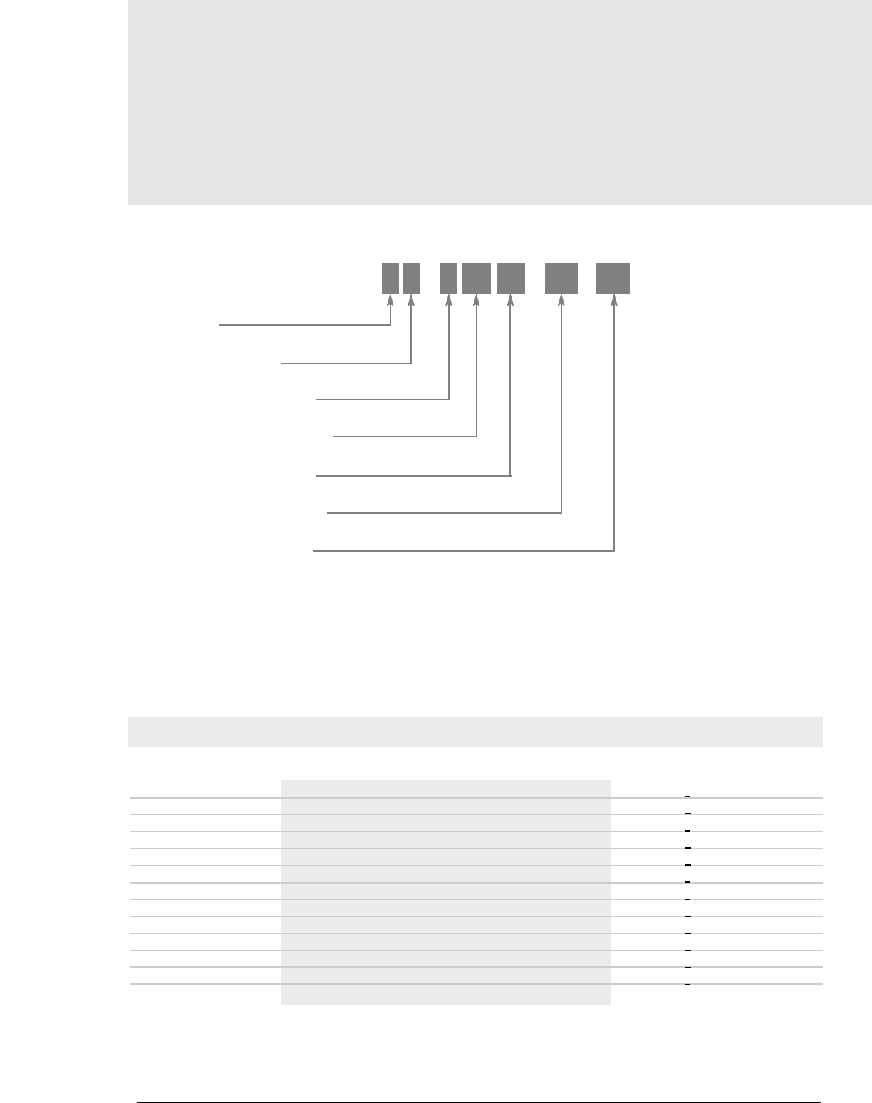
1. TYPICAL PART NUMBER
COATING/SHAPE CODE
(SEE NOTE 2)
FERRITE CORE MATERIAL
USED FOR ALL FERRITE TYPES
APPROXIMATE DIAMETER IN MM
APPROXIMATE HEIGHT IN MM
GEOMETRY CODE (SEE NOTE 3)
SPECIAL SPECIFICATION CODE
(SEE NOTE 4)
S P 4 30 19 UG XX
2. COATING/SHAPE CODE
For some cores, a designation letter precedes the material code.
CPlanar E-core with clip recesses CR45810EC
DDS core with solid centerpost DF42311UG
FPlanar E-core option: no clip recesses FR45810EC
HDS core with a center hole HP41408UG
NRM core with solid centerpost NP41510UG
PEP core PJ41313UG
RRM core with a center hole RG41510UG
SRS core SD41408UG
VNylon toroid coating VJ42206TC
XBlack coating (contact factory) XW41003TC
YParylene toroid coating YA40603TC
ZPolyester/Epoxy toroid coating ZJ42915TC
ONo meaning (e.g.OP-41808-EC is the same as P-41808-EC)
COATING/SHAPE CODE
CODE MEANING EXAMPLE
1. 5
mag-inc.com
Part Number Identification
4. SPECIAL SPECIFICATION CODE
A variety of features over and above the standard specifications are
available. For details, see the section on page 1.6, “Special
Specification Codes.”
5. UNIT OF MEASURE
POT, RS, DS, RM, PQ, and EP cores are ordered in sets. One set is a pair
of two pieces. One set usually is ordered for each transformer, inductor,
or device to be built.
E-, U-, and I-Cores are ordered in individual pieces. Two pieces usually
are ordered for each transformer, inductor, or device to be built.
Toroids are ordered in individual pieces.
HARDWARE
Accessory hardware is offered for nearly all of the cores shown in this
catalog. Available items are shown together with the appropriate cores.
Magnetics is a UL-recognized molder in the QMMY2 fabricated parts
program. Many bobbins shown in this catalog are covered. Contact the
factory for details on specific parts.
The part number and material are shown with the drawing for each bobbin.
Every bobbin is provided in the material defined by the part number,
whether the bobbin is covered in the UL QMMY2 program or not.
3. GEOMETRY CODE
For standard ungapped cores, a two letter code indicates the geometry.
Ungapped Cores
and Toroids
EC All E-cores, including ETD, EC, EER, EEM, EFD, OP44317EC Piece
planar and lamination size.
IC I-Core OJ42516IC Piece
TC Toroid ZJ42915TC Piece
UC U-Core OJ41106UC Piece
UG POT, RS, DS, RM, PQ, EP DF42311UG Set
GEOMETRY CODE
CODE GEOMETRY EXAMPLE UNIT OF
MEASURE
1. 6 MAGNETICS
Gapped Cores
Part Number Identification
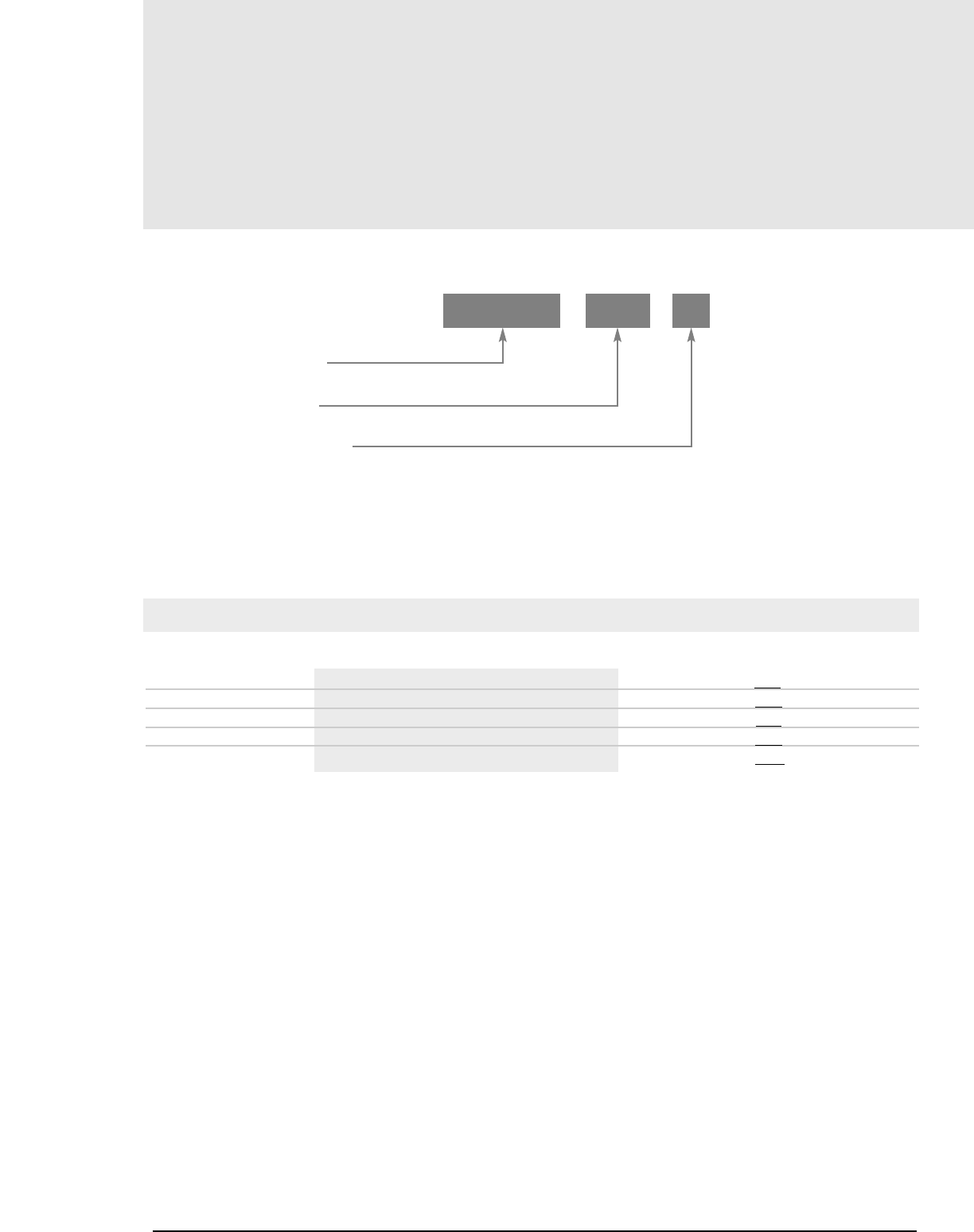
1. TYPICAL PART NUMBER
SAME AS FOR UNGAPPED CORES
AND TOROIDS(PAGE 1.3)
GAP CODE (SEE NOTE 2)
SPECIAL SPECIFICATION CODE
OP44317 A450 XX
2. GAP CODE
The letter indicates the type of gap and a three-digit number defines
the value.
A_ _ _ AL(if < 1000) DF42311A275 (AL= 275)
X_ _ _ ALif 1000 or greater (add 1000 to code) OP44721X250 (AL= 1250)
F_ _ _ ALif < 100, non-integer (divide code by10) OR42510F807 (AL= 80.7)
G_ _ _ Depth of grind in mils (1000ths of an inch) OF44317G079 (Gap = 0.079”)
M_ _ _ Depth of grind, mm (divide code by 10) OF43019M015 (Gap = 1.5mm)
GAP CODE
CODE MEANING EXAMPLE
ALis inductance factor, mH/1000 Turns, or nH/T2(see page 14.2 for
definitions, page 2.1 for measurement setup.) See the chart on pages 1.8-
1.11 for tolerances. The standard gap codes do not apply to U-Cores,
toroids, I-Cores, or some E-I combinations.
3. UNIT OF MEASURE
See Note 5 on page 1.5. For parts ordered in pieces (E-Cores), the depth
of grind is given for each piece. For parts ordered in sets, the depth of
grind is given as a total for the set, and may be UG/G or G/G (see the
chart on page 1.8 to determine which is standard.)
When ordering E-cores gapped to an ALvalue it is critical to understand
whether the standard is UG/G or G/G. See Note 1 on page 1.9.
4. SPECIAL REQUIREMENTS
Many non-standard features are available, including gap values and
tolerances that are different from those shown on the tables in this catalog.
The next section on this page, “Special Specification Codes” explains how
part numbers are defined for non-standard requirements.
For assistance with any special requirements, Magnetics customer service
representatives and applications engineers are available to help you.

1.7
mag-inc.com
Special Specification Codes
Part Number Identification
SPECIAL SPECIFICATION CODES
For special customer requirements, a detailed product specification is
written. This special specification is referenced to a unique two-character
part number suffix. The resulting part number is reserved for the exclusive
use of the originating customer and any sub-contractors that the originating
customer designates.
Special specifications can be written to meet a wide variety of
requirements, including:
• CUSTOM PACKAGING
• CUSTOM MARKING
• NON-STANDARD TOLERANCES
• NON-STANDARD UNITS OF MEASURE
• CUSTOM ELECTRICAL PERFORMANCE
• MODIFIED HEIGHTS
• SPECIAL TESTING
• MANY OTHER NEEDS
For five common requirements, a standard letter code is used in the suffix
location:
NS Not stamped; the standard part marking is omitted. DF42311UGNS
CC Color coded; see page 13.1 for the color index. ZP42915TCCC
EI E-core gapped to an ALvalue when mated CR42216A160EI
with the standard I-core. AL= 160±3% with
CR42216IC
SPECIAL SPECIFICATION CODE
CODE MEANING EXAMPLE

Gapped Cores
1. 8 MAGNETICS
Depth of Grind
Tolerance Ranges
Either the ALor the depth of grind (not both) is controlled during production
of gapped cores. Part numbering for gapped cores is explained on page 1.6.
Codes A, X and F define ALvalues. Codes G and M define depths of grind.
In most applications, defining the gap with the ALresults in inductors with the
least variation. Electrical measurement is inherently more precise, and
compensation is made for variability in material permeability and core geometry.
For deep gaps, however, better consistency often results when the depth of
grind is specified. In such cases, variation in the finished inductor is
dominated by the variation in the windings, especially if the number of
turns is low.
“Ungapped to gap combination” means an asymmetrical gap; the entire
gap is taken from one piece, and the other piece is ungapped. “Gap to gap
combination” means the gap is symmetrical; half of the total gap is ground
into each piece.
GAP TOLERANCE GAP TOLERANCE
*The bobbin depth for the set is the 2D dimension, or 2 times the D dimension.
INCHES MILLIMETERS
For shapes: POT, RS, DS, RM, PQ, and EP Cores.
0.001”–0.038” ±0.0005” Ungapped to gap combination. 0.1mm–0.9mm ±0.03mm
0.039”–0.076” ±0.001” Ungapped to gap combination 1.0mm–1.9mm ±0.04mm
(Except if the gap is more than 10% of the minimum bobbin
depth for the set*. Then gap-to-gap combination.)
0.077”–0.114” ±0.002” Gap to gap combination 2.0mm–2.9mm ±0.07mm
(Except if the gap is less than 10% of the minimum bobbin
depth for the set*. Then ungapped-to-gap combination.)
0.115”–0.152” ±0.002” Gap to gap combination. 3.0mm–3.8mm ±0.07mm
0.153”–0.228” ±0.004” Gap to gap combination. 3.9mm–5.0mm ±0.12mm
GAP TOLERANCE GAP TOLERANCE
INCHES MILLIMETERS
0.001”–0.038” ±0.0005” 0.1mm–0.9mm ±0.03mm
0.039”–0.076” ±0.001” 1.0mm–1.9mm ±0.04mm
0.077”–0.152” ±0.002” 2.0mm–3.8mm ±0.07mm
0.153”–0.228” ±0.004” 3.9mm–5.0mm ±0.12mm
For E-Cores: Lamination Size, EFD, EEM, EC,
ETD, ER, EER, Planar E, and other E-Cores.
E-cores are sold as pieces, not sets. To make an
ungapped/gapped set, use one piece of each. For example, use
OR41808G050 with OR41808EC for an asymmetrical gap of
0.050” ± 001”. For the same gap, but symmetric, use two
pieces of OR41808G025.
For more information about gapped cores and using them, please see
pages 4.13-4.19. For tolerance requirements other than those shown
below, please contact the factory.
Gapped Cores
1. 9
mag-inc.com
Gapping for AL
1. UNIT OF MEASURE
When specifying and ordering E-Cores gapped to an AL, it is important to
note which cores are produced in gap-to-gap combination, because two
gapped pieces are assembled to achieve the AL. Alternatively, for E-Cores
provided ungapped-to-gap, an ungapped piece must be used with the
gapped part to achieve the AL. POT, RS, DS, RM, PQ, and EP cores are
sold as sets whether the combination is G/G or UG/G.
2. SIGNIFICANT FIGURES
ALtesting and limits are calculated to three significant digits, based on
the nominal value. For example, AL= 99±3% is interpreted as 96.0
Minimum, 99.0 Nominal, and 102.0 Maximum.
3. CORRELATION
Magnetics tests gapped ALvalues with full bobbins, usually 100 turns,
or 250 turns for deep gaps. The drive level is low (5 Gauss) and the
frequency is set low enough to avoid resonance effects. Measured
inductance in an application may vary significantly from the theoretical
value due to low turns, low bobbin fill, leakage effects, resonance
effects, or elevated drive levels.
It is important for the user to verify the correlation between the test of
the core and the specific test being applied to the inductor or
transformer. Planar E Cores, planar RM, and planar PQ cores are
especially susceptible to correlation discrepancies.
PC (POT) CORES
FOUND IN SECTION 6
UNGAPPED TO GAP COMBINATION
±3% ±5% ±7% ±10%
GAP TO GAP
±3%
40704 25-35 36-62 63-95 96-125 126-175
40905 25-48 49-87 88-135 136-180 181-240
41107 25-75 76-135 136-220 221-285 286-399
41408 71-113 114-210 211-307 308-417 418-574
41811 96-174 175-326 ≤523 ≤712 ≤988
42213 113-204 205-482 ≤779 ≤1060 ≤1459
42616 139-249 250-695 ≤1125 ≤1543 ≤1999
43019 170-304 305-1015 ≤1642 ≤1999
43622 222-399 400-1494 ≤1999
44229 169-389 390-1965 ≤1999
44529 172-549 550-1999
RS (ROUND-SLAB) CORES
FOUND IN SECTION 7
UNGAPPED TO GAP COMBINATION
±3% ±5% ±7% ±10%
GAP TO GAP
±3%
41408 25-177 ≤283 ≤385 ≤530
42311 25-39 40-347 ≤708 ≤963 ≤1325
42318 25-39 40-452 ≤731 ≤994 ≤1378
42616 25-39 40-622 ≤998 ≤1369 ≤1884
43019 25-62 63-918 ≤1485 ≤1999
43622 40-62 63-1286 ≤1999
44229 40-62 63-1732 ≤1999
Charts show type of combination and the guaranteed tolerance for
corresponding ALranges. For special tolerances, or for AL = 2000 or higher,
contact the factory.
Ranges indicated are the tolerances for standard gapped cores.
For ± 5%, ± 7%, and ± 10%, the maximum ALfor each tolerance is shown.
Standard cores are manufactured to the smallest allowed tolerance.
1.10 MAGNETICS
Gapped Cores
Gapping for AL
DS (DOUBLE-SLAB) CORES
FOUND IN SECTION 7
UNGAPPED TO GAP COMBINATION
±3% ±5% ±7% ±10%
GAP TO GAP
±3%
42311 109-195 196-386 ≤625 ≤850 ≤1170
42318 78-135 136-441 ≤706 ≤961 ≤1332
42616 117-205 206-580 ≤930 ≤1276 ≤1756
43019 149-264 265-873 ≤1412 ≤1922 ≤1999
43622 170-300 301-1111 ≤1797 ≤1999
44229 179-315 316-1543 ≤1999
RM CORES
FOUND IN SECTION 8
UNGAPPED TO GAP COMBINATION
±3% ±5% ±7% ±10%
GAP TO GAP
±3%
41110 25-50 51-55 ≤75 ≤170 ≤250
41510 56-99 100-162 ≤258 ≤352 ≤484
41812 69-120 121-238 ≤381 ≤519 ≤714
41912 69-120 121-238 ≤381 ≤519 ≤714
42316 84-150 151-395 ≤633 ≤862 ≤1195
42819 126-200 201-625 ≤1002 ≤1374 ≤1892
43723 145-250 251-977 ≤1580 ≤1999
EP CORES
FOUND IN SECTION 9
UNGAPPED TO GAP COMBINATION
±3% ±5% ±7% ±10%
GAP TO GAP
±3%
40707 25-63 64-75 ≤125 ≤160
41010 25-55 56-75 ≤125 ≤160
41313 25-75 76-110 ≤175 ≤275 ≤315
41717 25-100 101-175 ≤275 ≤400 ≤630
42120 25-180 181-450 ≤630 ≤850 ≤1250
PQ CORES
FOUND IN SECTION 10
UNGAPPED TO GAP COMBINATION
±3% ±5% ±7% ±10%
GAP TO GAP
±3%
42016 60-184 185-467 ≤755 ≤1027 ≤1425
42020 50-139 140-467 ≤754 ≤1026 ≤1422
42610 200-396 397-777 ≤1258 ≤1728 ≤1999
42614 103-334 335-645 ≤1044 ≤1421 ≤1972
42620 95-296 297-888 ≤1436 ≤1955 ≤1999
42625 77-234 235-880 ≤1423 ≤1936 ≤1999
43214 127-416 417-548 ≤885 ≤1207 ≤1661
43220 128-409 410-846 ≤1369 ≤1878 ≤1999
43230 84-241 242-808 ≤1305 ≤1775 ≤1999
43535 89-255 256-980 ≤1575 ≤1999
44040 83-230 231-1006 ≤1625 ≤1999
LAMINATION SIZE E-CORES
FOUND IN SECTION 11
UNGAPPED TO GAP COMBINATION
±3% ±5% ±7% ±10%
GAP TO GAP
±3%
41203 16-27 28-55 ≤86 ≤117 ≤160
41707 22-37 38-89 ≤140 ≤190 ≤259
41808 27-42 43-121 ≤192 ≤258 ≤355
42510 37-61 62-200 ≤318 ≤432 ≤595
43009 55-91 92-222 ≤353 ≤475 ≤653
43515 54-87 88-429 ≤687 ≤934 ≤1284
44317 81-136 137-762 ≤1222 ≤1676 ≤1999
44721 107-180 181-1188 ≤1920 ≤1999
45724 129-218 219-1732 ≤1999
EFD, EEM CORES
FOUND IN SECTION 11
UNGAPPED TO GAP COMBINATION
±3% ±5% ±7% ±10%
GAP TO GAP
±3%
41309 17-28 29-64 ≤100 ≤135 ≤184
41515 19-30 31-81 ≤127 ≤172 ≤236
41709 21-34 35-107 ≤169 ≤230 ≤313
42110 15-25 26-92 ≤145 ≤195 ≤268
42523 41-66 67-296 ≤475 ≤646 ≤888
Charts show type of combination and the guaranteed tolerance for
corresponding ALranges. For special tolerances, or for AL = 2000 or higher,
contact the factory.
Ranges indicated are the tolerances for standard gapped cores.
For ± 5%, ± 7%, and ± 10%, the maximum ALfor each tolerance is shown.
Standard cores are manufactured to the smallest allowed tolerance.
OTHER E-CORES
FOUND IN SECTION 11
UNGAPPED TO GAP COMBINATION
±3% ±5% ±7% ±10%
GAP TO GAP
±3%
41205 28-47 48-107 ≤170 ≤229 ≤316
41208 19-30 31-78 ≤123 ≤166 ≤228
41810 44-74 75-235 ≤376 ≤512 ≤704
42211 26-42 43-148 ≤236 ≤320 ≤440
42515 28-43 44-210 ≤333 ≤452 ≤616
42520 107-190 191-397 ≤643 ≤874 ≤1202
42530 45-72 73-409 ≤655 ≤891 ≤1225
42810 84-146 147-490 ≤786 ≤1069 ≤1483
43007 42-67 68-307 ≤491 ≤668 ≤919
43013 71-121 122-552 ≤885 ≤1204 ≤1669
43520 65-111 112-461 ≤738 ≤1003 ≤1380
43524 41-62 63-439 ≤698 ≤949 ≤1305
44011 59-95 96-642 ≤1029 ≤1400 ≤1940
44016 52-83 84-545 ≤872 ≤1185 ≤1629
44020 78-126 127-916 ≤1480 ≤1999
44022 94-156 157-1187 ≤1903 ≤1999
44924 100-165 166-1276 ≤1999
45021 99-167 168-1127 ≤1807 ≤1999
45528 113-186 187-1736 ≤1999
45530 129-215 216-1999
46016 102-129 130-1231 ≤1989 ≤1999
47228 120-199 200-1823 ≤1999
48020 99-158 159-1922 ≤1999
PLANAR E-CORES*
FOUND IN SECTION 11
UNGAPPED TO GAP COMBINATION
±3% ±5% ±7% ±10%
GAP TO GAP
±3%
41425 19-37 38-76 ≤122 ≤166 ≤228
41434 17-31 32-77 ≤123 ≤167 ≤230
41805 18-32 33-205 ≤329 ≤448 ≤617
42107 35-66 67-188 ≤304 ≤414 ≤569
42216 78-141 142-405 ≤656 ≤892 ≤1239
43208 118-216 217-643 ≤1040 ≤1427 ≤1964
43618 119-222 223-673 ≤1088 ≤1491 ≤1999
43808 173-315 316-956 ≤1547 ≤1999
44008 106-189 190-507 ≤821 ≤1116 ≤1548
44308 201-367 368-1130 ≤1828 ≤1999
44310 169-305 306-1130 ≤1828 ≤1999
45810 266-481 482-1496 ≤1999
46409 413-768 769-1999
46410 379-701 702-1999
49938 336-594 595-1999
* These tolerances also apply to Planar E-I combinations.
ETD, EER CORES
FOUND IN SECTION 12
UNGAPPED TO GAP COMBINATION
±3% ±5% ±7% ±10%
GAP TO GAP
±3%
40906 15-30 31-52 53-80 81-105 106-142
43434 55-88 89-500 ≤806 ≤1095 ≤1507
43521 54-86 87-566 ≤913 ≤1241 ≤1707
43939 95-156 157-641 ≤1028 ≤1398 ≤1935
44216 71-117 118-876 ≤1415 ≤1925 ≤1999
44444 73-117 118-881 ≤1423 ≤1935 ≤1999
44949 81-130 131-1075 ≤1736 ≤1999
45032 62-99 100-807 ≤1304 ≤1773 ≤1999
45959 51-118 119-1822 ≤1999
47054 83-126 127-1681 ≤1999
EC CORES
FOUND IN SECTION 12
UNGAPPED TO GAP COMBINATION
±3% ±5% ±7% ±10%
GAP TO GAP
±3%
43517 49-79 80-438 ≤702 ≤954 ≤1312
44119 61-98 99-627 ≤1004 ≤1365 ≤1891
45224 76-123 124-911 ≤1471 ≤1999
47035 83-135 136-1403 ≤1999
Charts show type of combination and the guaranteed tolerance for
corresponding ALranges. For special tolerances, or for AL = 2000 or higher,
contact the factory.
Ranges indicated are the tolerances for standard gapped cores.
For ± 5%, ± 7%, and ± 10%, the maximum ALfor each tolerance is shown.
Standard cores are manufactured to the smallest allowed tolerance.
Gapped Cores
1.11
mag-inc.com
Gapping for AL

1.12 MAGNETICS
Introduction
Notes
EQUIPMENT
The test data included in this catalog was primarily obtained using bridges such as a Hewlett-
Packard 419A impedance analyzer. The HP 4192A was used for permeability and loss factor data
from 10kHz to 1MHz. A Wayne-Kerr 3245 inductance analyzer was used for DC bias to 100kHz.
Also, for Permeability vs. Temperature, Permeability vs. Frequency, and Disaccommodation, an HP
4192A was coupled with a computer controlled temperature cabinet and an HP 9836 computer.
Core loss up to and including 100kHz is measured using a 11401 Tektronix oscilloscope connect-
ed to an HP Vectra computer. This is a fully automated system. Other measurements include core
loss using a Tektronix 7854 digital oscilloscope and an HP 9836 computer to measure losses at
500kHz to 1MHz. This test setup is also used to obtain B-H loops in the 1kHz to 100kHz ranges.
High level readings such as Permeability vs. Flux Density were measured on a General Radio 1632-
A incremental bridge.
Q measurements were made on a Boonton 260A Q-meter.
MEASUREMENT
For initial permeability and inductance measurements, excitation levels are kept at values insuring
flux densities below 10 gauss.
Temperature measurements normally are obtained between -30° and 70°C but additional temper-
atures to - 65° and 260°C are used to indicate trends and changes in materials properties outside
the normal guaranteed range. Inductance measurements for disaccommodation are made at 10
and 100 minutes after the test core has been demagnetized. Disaccommodation Factor is calcu-
lated mathematically.
Test bobbins are carefully layer wound with magnet wire or litz wire whose size is chosen so that
the calculated number of turns completely fills the bobbin.
Before core halves are assembled, the mating surfaces should be clean and free from dust. After
aligning the two core halves, pressure indicated in the table below should be applied. Magnetics
clamping hardware will handle these pressures.
Section 2
Measurement
Information
2.1
STANDARD POT CORES RM CORES
RS CORES PQ CORES EP CORES
40704 4 lbs. 42213 15 lbs. 41110 5 lbs.
40905 5 lbs. 42616 20 lbs. 41510, 41912 7 lbs.
41107 7 lbs. 43019 20 lbs. 41812 7 lbs.
41408 7 lbs. 43622 30 lbs. 42316 15 lbs.
41811 12 lbs. 44229 35 lbs. 42819 20 lbs.
41408 7 lbs. 42016, 42020 15 lbs. 40707 6 lbs.
42311, 42318 15 lbs. 42620, 42020 20 lbs. 41010 7 lbs.
42616 20 lbs. 43220, 42330 30 lbs. 41313 7 lbs.
43019 20 lbs. 43535 30 lbs. 41717 13 lbs.
43629 30 lbs. 44040 35 lbs. 42020 15 lbs.
44229 35 lbs.

Measurement
VOLTAGE BREAKDOWN MEASUREMENT
Core finishes (toroids) are tested for voltage breakdown by inserting the
core between two weighted wire mesh pads. Force is adjusted to produce a
uniform pressure of 10psi, simulating winding pressure. The test condition
to guarantee minimum breakdown (see 13.2) is a 60 Hertz r.m.s. voltage
equal to 1.25 times the minimum.
CONVERSION TABLE
MULTIPLY TO OBTAIN
NUMBER OF BY NUMBER OF
oersteds 79.5 ampere-turns/m
oersteds 0.795 ampere-turns/cm
gausses 10-4 teslas (webers/m2)
gausses 0.10 milliTeslas
in26.452 cm2
circular mils 5.07 x 10⁻⁶ cm2
mWatts/cm30.094 watts/lb.
CALIBRATION
All measurement equipment is periodically checked against our NSB trace-
able standards. These standards include an EDC 2902 DC voltage standard,
an EDC 3200 AC/DC current calibrator, a Fluke 5200A AC calibrator, and
various resistance, capacitive, and Q standards.
PHYSICAL MEASUREMENTS
Specific “+” or “-“ tolerances on part dimensions indicated as “normal” in
this catalog can be provided if needed. If a dimension is listed as “typical”,
it is the same as nominal except it covers a plurality.
RESEARCH AND DEVELOPMENT
Magnetics Technology has a continuing program aimed at improving
existing products and introducing new materials and geometries. Technology
efforts and concentrated programming have made Magnetics a leader in many
other magnetic materials, in addition to having a steady growth in ferrites.
Technology also provides technical data which may not be regularly available.
2.2 MAGNETICS
MATERIALS
Magnetics has developed and produces leading MnZn ferrite materials for a variety of applications.
POWER MATERIALS
Three low loss materials are engineered for optimum frequency and temperature performance in
power applications. Magnetics’ R, P and F materials provide superior saturation, high temperature
performance, low losses and product consistency.
SHAPES: E cores, Planar E cores, ETD, EC, U cores, I cores, PQ, Planar PQ, RM, Toroids (2mm to
86mm), Pot cores, RS (round-slab), DS (double slab), EP, Special Shapes.
APPLICATIONS: Telecomm Power Supplies, Computer Power Supplies, Commercial Power Supplies,
Consumer Power Supplies, Automotive, DC-DC Converters, Telecomm Data Interfaces, Impedance
Matching Transformers, Handheld Devices, High power control (gate drive), Computer Servers,
Distributed Power (DC-DC), EMI Filters, Aerospace, Medical.
HIGH PERMEABILITY MATERIALS
Three high permeablility materials (5000µJ material, 10000µW material and 15000µ
H material) are engineered for optimum frequency and impedance performance in signal, choke
and filter applications. These Magnetics’ materials provide superior loss factor, frequency
response, temperature performance, and product consistency.
SHAPES: Toroids (2 mm to 86 mm), E cores, U cores, RM, Pot cores, RS (round-slab), DS (double
slab), EP, Special Shapes.
APPLICATIONS: Common Mode Chokes, EMI Filters, Other Filters, Current Sensors, Telecomm Data
Interfaces, Impedance matching interfaces, Handheld devices, Spike Suppression, Gate Drive
Transformers.
SPECIAL MATERIALS
A number of special materials are engineered for specific performance results, including frequency
response, temperature factor, Curie temperature, permeability across temperature for GFCI and
telecomm performance, and loss factor. Magnetics’ special materials provide outstanding
performance, customization options and superior product consistency.
SHAPES: E cores, Planar E cores, ETD, EC, U cores, I cores, PQ, Planar PQ, RM, Toroids (2mm to
86mm), Pot cores, RS (round-slab), DS (double slab), EP
, Special Shapes.
APPLICATIONS: EMI Filters, Current sensors, Chokes, Tuned Filters, Data interfaces, Special
temperature requirements, Other Special Requirements.
Contact Magnetics’ Application Engineering for additional information.
3.1
Section 3
Materials
EMI/RFI FILTERS &
BROADBAND TRANSFORMERS
INDUCTORS & POWER TRANSFORMERS
3.2 MAGNETICS
Materials
Characteristics
RP F JWH
Initial Permeability µi— 2,300 ± 25% 2,500 ± 25% 3,000 ± 20% 5,000 ± 20% 10,000 ± 30% 15,000 ± 30%
Maximum Usable Frequency
(50% roll-off) f MHz <1.5 <1.2 <1.3 <1 <0.25 <0.15
Relative Loss Factor tan d
µiac 10-6 <8 (100kHz) <20 (100kHz) <7 (10kHz) <15 (10kHz)
*Curie Temperature Tc˚C >230 >230 >250 >140 >125 >120
* Relative Temp. Factor /˚C 10-6/˚C
-30˚C to +20˚C
+20˚C to 70˚C
* Flux Density BmG 5,000 5,000 4,900 4,300 4,300 4,200
@ 1,194 A/m (15 Oe) mT 500 500 490 430 430 420
* Remanence BrG 1,100 1,100 1,200 1,000 800 800
mT 110 110 120 100 80 80
* Coercivity Hc 0e 0.18 0.18 0.2 0.1 0.04 0.04
A/m 14 14 16 833
Disaccommodation Factor DF10-6 <3 <3 <2.5
* Resistivity rΩ-m 6 5 2 1 0.15 0.1
* Density dg/cm34.8 4.8 4.8 4.8 4.8 4.9
Power Loss (PL) 25kHz @25˚C 130 120 90
Sine Wave, in mW/cm3200mT @60˚C 85 90 160
(typical) (2,000G) @100˚C 70 95 240
@120˚C 85 130
100kHz @25˚C 140 125 100
100mT @60˚C 100 90 180
(1,000G) @100˚C 70 125 225
@120˚C 90 165
500kHz @25˚C 375 300
50mT @60˚C 300 250
(500G) @100˚C 250 275
@120˚C 300 350
700kHz @25˚C
50mT @60˚C
(500G) @100˚C
@120˚C
Available In: Pot Cores X X X X X
RS Cores X X X X X
DS Cores X X X X X
RM Cores XXXXX
EP Cores XXXXX
E, U Cores X X X X X
EC, ETD Cores XXX
PQ Cores X X X
Toroids X X X X X X
Blocks X
Note: These characteristics are typical for a 42206 size (0.870” O.D.) toroid. Specific core data will usually differ from these numbers due to the influence of geometry and size.
Characteristics with a * are typical.
3.3
mag-inc.com
Materials
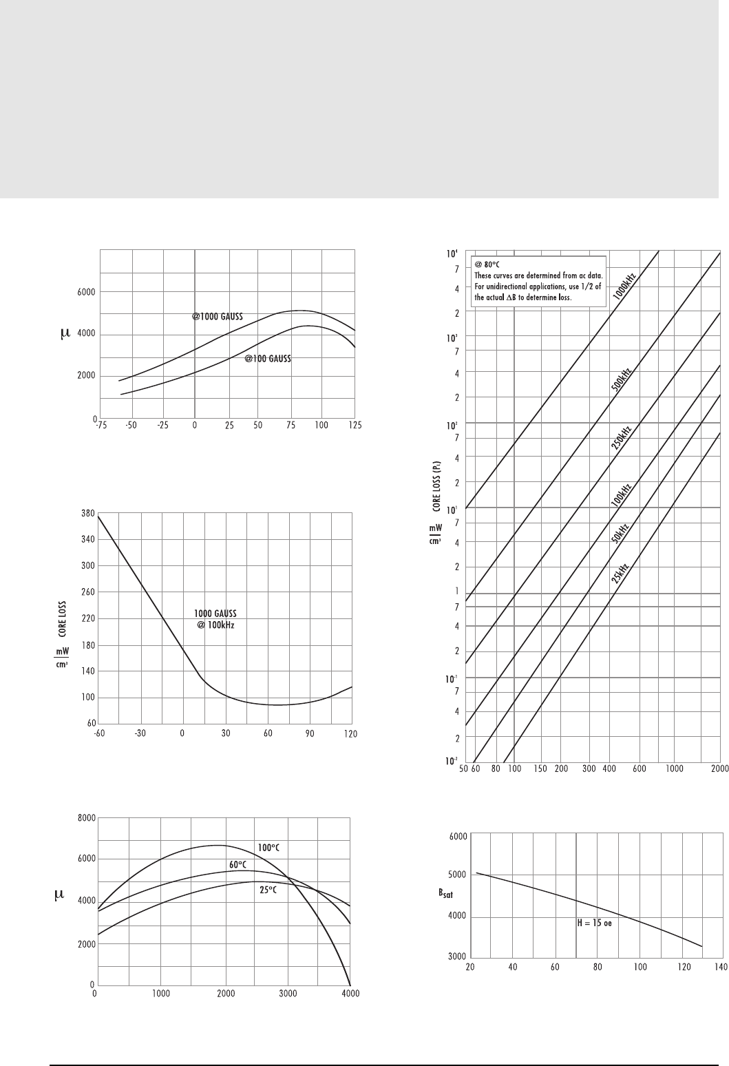
Material Curves
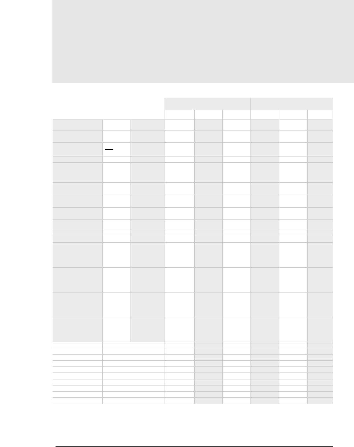
Frequency Response Curves
Frequency (kHz)
80 200 300 400 600 2000
µ
100 1000
GRAPH 1 - FREQUENCY RESPONSE CURVES
FREQUENCY (kHz)
GRAPH 2 - FREQUENCY RESPONSE CURVES
FREQUENCY (kHz)
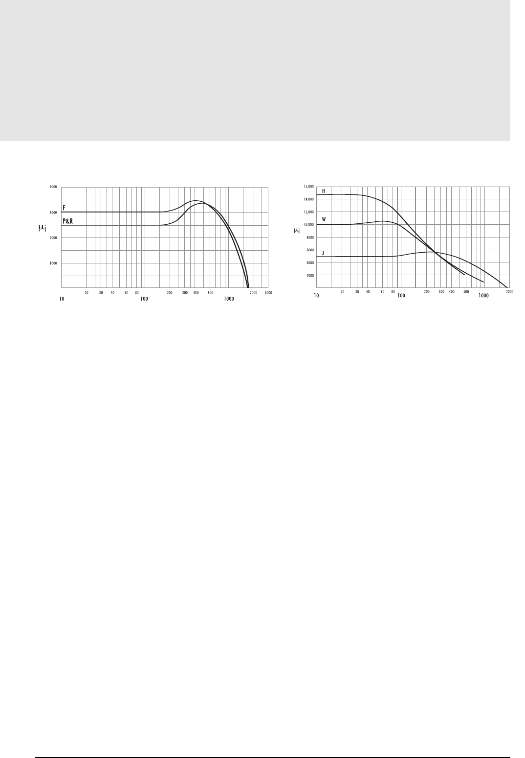
CORE LOSS vs. DENSITY
FLUX DENSITY GAUSS
80 100 150 200 300 400 600 1000 2000
@ 100ºC
These curves are determined from ac data. For unidirectional
applications, use 1/2 of the actual ∆B to determine loss.
1000kHz
500kHz
250kHz
100kHz
50kHz
25kHz
Mat_R_Perm_vs_Fluxden.eps
FLUX DENSITY vs. TEMPERATURE
TEMPERATURE (ºC)
6000
14012010080604020
5000
4000
3000
H = 15oe
3.4 MAGNETICS
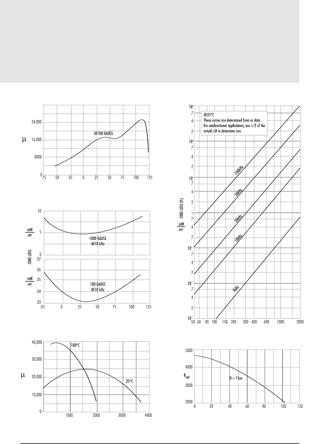
R Material
Saturation Flux Density - gausses 5,000 (at 15 oersted, 25˚C) (500 mT)
Coercive Force - oersted . . . . . . . . . . . . . . . . . 0.18 (14A/m)
Curie Temperature . . . . . . . . . . . . . . . . . . . . . . . . . . . 230˚C
NOTE: The core loss curves are developed from empirical data.
For best results and highest accuracy, use them. The formula on page 3.10
yields a fair approximation and can be useful in computer programs.
PERMEABILITY vs. TEMPERATURE
TEMPERATURE (ºC)
6000
4000
2000
-75 -75 100 125-50 -50-25 -250
0
@1000 GAUSS
@100 GAUSS
µ
PERMEABILITY vs. TEMPERATURE
TEMPERATURE (ºC)
6000
4000
2000
-75 -75 100 125-50 -50-25 -250
0
@1000 GAUSS
@100 GAUSS
µ
PERMEABILITY vs. TEMPERATURE
TEMPERATURE (ºC)
6000
4000
2000
-75 -75 100 125-50 -50-25 -250
0
@1000 GAUSS
@100 GAUSS
µ
PERMEABILITY vs. TEMPERATURE
TEMPERATURE (ºC)
6000
4000
2000
-75 -75 100 125-50 -50-25 -250
0
@1000 GAUSS
@100 GAUSS
µ
PERMEABILITY vs. TEMPERATURE
TEMPERATURE (ºC)
6000
4000
2000
-75 -75 100 125-50 -50-25 -250
0
@1000 GAUSS
@100 GAUSS
µ
PERMEABILITY vs. TEMPERATURE
TEMPERATURE (ºC)
6000
4000
2000
-75 -75 100 125-50 -50-25 -250
0
@1000 GAUSS
@100 GAUSS
µ
PERMEABILITY vs. TEMPERATURE
TEMPERATURE (ºC)
6000
4000
2000
-75 -75 100 125-50 -50-25 -250
0
@1000 GAUSS
@100 GAUSS
µ
PERMEABILITY vs. TEMPERATURE
TEMPERATURE (ºC)
6000
4000
2000
-75 -75 100 125-50 -50-25 -250
0
@1000 GAUSS
@100 GAUSS
µ
PERMEABILITY vs. TEMPERATURE
TEMPERATURE (ºC)
6000
4000
2000
-75 -75 100 125-50 -50-25 -250
0
@1000 GAUSS
@100 GAUSS
µ
PERMEABILITY vs. TEMPERATURE
TEMPERATURE (ºC)
6000
4000
2000
-75 -75 100 125-50 -50-25 -250
0
@1000 GAUSS
@100 GAUSS
µ
PERMEABILITY vs. TEMPERATURE
TEMPERATURE (ºC)
6000
4000
2000
-75 -75 100 125-50 -50-25 -250
0
@1000 GAUSS
@100 GAUSS
µ
PERMEABILITY vs. TEMPERATURE
TEMPERATURE (ºC)
6000
4000
2000
-75 -75 100 125-50 -50-25 -250
0
@1000 GAUSS
@100 GAUSS
µ
PERMEABILITY vs. TEMPERATURE
TEMPERATURE (ºC)
6000
4000
2000
-75 -75 100 125-50 -50-25 -250
0
@1000 GAUSS
@100 GAUSS
µ
PERMEABILITY vs. TEMPERATURE
TEMPERATURE (ºC)
6000
4000
2000
-75 -75 100 125-50 -50-25 -250
0
@1000 GAUSS
@100 GAUSS
µ
PERMEABILITY vs. TEMPERATURE
TEMPERATURE (ºC)
6000
4000
2000
-75 -75 100 125-50 -50-25 -250
0
@1000 GAUSS
@100 GAUSS
µ
PERMEABILITY vs. TEMPERATURE
TEMPERATURE (ºC)
6000
4000
2000
-75 -75 100 125-50 -50-25 -250
0
@1000 GAUSS
@100 GAUSS
µ
PERMEABILITY vs. TEMPERATURE
TEMPERATURE (ºC)
6000
4000
2000
-75 -75 100 125-50 -50-25 -250
0
@1000 GAUSS
@100 GAUSS
µ
PERMEABILITY vs. TEMPERATURE
TEMPERATURE (ºC)
6000
4000
2000
-75 -75 100 125-50 -50-25 -250
0
@1000 GAUSS
@100 GAUSS
µ
PERMEABILITY vs. TEMPERATURE
TEMPERATURE (ºC)
6000
4000
2000
-75 -75 100 125-50 -50-25 -250
0
@1000 GAUSS
@100 GAUSS
µ
PERMEABILITY vs. TEMPERATURE
TEMPERATURE (ºC)
6000
4000
2000
-75 -75 100 125-50 -50-25 -250
0
@1000 GAUSS
@100 GAUSS
µ
PERMEABILITY vs. TEMPERATURE
TEMPERATURE (ºC)
6000
4000
2000
-75 -75 100 125-50 -50-25 -250
0
@1000 GAUSS
@100 GAUSS
µ
PERMEABILITY vs. TEMPERATURE
TEMPERATURE (ºC)
6000
4000
2000
-75 -75 100 125-50 -50-25 -250
0
@1000 GAUSS
@100 GAUSS
µ
PERMEABILITY vs. TEMPERATURE
TEMPERATURE (ºC)
6000
4000
2000
-75 -75 100 125-50 -50-25 -250
0
@1000 GAUSS
@100 GAUSS
µ
PERMEABILITY vs. TEMPERATURE
TEMPERATURE (ºC)
6000
4000
2000
-75 -75 100 125-50 -50-25 -250
0
@1000 GAUSS
@100 GAUSS
µ
PERMEABILITY vs. TEMPERATURE
TEMPERATURE (ºC)
6000
4000
2000
-75 -75 100 125-50 -50-25 -250
0
@1000 GAUSS
@100 GAUSS
µ
PERMEABILITY vs. TEMPERATURE
TEMPERATURE (ºC)
6000
4000
2000
-75 -75 100 125-50 -50-25 -250
0
@1000 GAUSS
@100 GAUSS
µ
PERMEABILITY vs. TEMPERATURE
TEMPERATURE (ºC)
6000
4000
2000
-75 -75 100 125-50 -50-25 -250
0
@1000 GAUSS
@100 GAUSS
µ
PERMEABILITY vs. TEMPERATURE
TEMPERATURE (ºC)
6000
4000
2000
-75 -75 100 125-50 -50-25 -250
0
@1000 GAUSS
@100 GAUSS
µ
PERMEABILITY vs. TEMPERATURE
TEMPERATURE (ºC)
6000
4000
2000
-75 -75 100 125-50 -50-25 -250
0
@1000 GAUSS
@100 GAUSS
µ
PERMEABILITY vs. TEMPERATURE
TEMPERATURE (ºC)
6000
4000
2000
-75 -75 100 125-50 -50-25 -250
0
@1000 GAUSS
@100 GAUSS
µ
PERMEABILITY vs. TEMPERATURE
TEMPERATURE (ºC)
6000
4000
2000
-75 -75 100 125-50 -50-25 -250
0
@1000 GAUSS
@100 GAUSS
µ
PERMEABILITY vs. TEMPERATURE
TEMPERATURE (ºC)
6000
4000
2000
-75 -75 100 125-50 -50-25 -250
0
@1000 GAUSS
@100 GAUSS
µ
PERMEABILITY vs. TEMPERATURE
TEMPERATURE (ºC)
6000
4000
2000
-75 -75 100 125-50 -50-25 -250
0
@1000 GAUSS
@100 GAUSS
µ
PERMEABILITY vs. TEMPERATURE
TEMPERATURE (ºC)
6000
4000
2000
-75 -75 100 125-50 -50-25 -250
0
@1000 GAUSS
@100 GAUSS
µ
PERMEABILITY vs. TEMPERATURE
TEMPERATURE (ºC)
6000
4000
2000
-75 -75 100 125-50 -50-25 -250
0
@1000 GAUSS
@100 GAUSS
µ
PERMEABILITY vs. TEMPERATURE
TEMPERATURE (ºC)
6000
4000
2000
-75 -75 100 125-50 -50-25 -250
0
@1000 GAUSS
@100 GAUSS
µ
PERMEABILITY vs. TEMPERATURE
TEMPERATURE (ºC)
6000
4000
2000
-75 -75 100 125-50 -50-25 -250
0
@1000 GAUSS
@100 GAUSS
µ
PERMEABILITY vs. TEMPERATURE
TEMPERATURE (ºC)
6000
4000
2000
-75 -75 100 125-50 -50-25 -250
0
@1000 GAUSS
@100 GAUSS
µ
PERMEABILITY vs. TEMPERATURE
TEMPERATURE (ºC)
6000
4000
2000
-75 -75 100 125-50 -50-25 -250
0
@1000 GAUSS
@100 GAUSS
µ
PERMEABILITY vs. TEMPERATURE
TEMPERATURE (ºC)
6000
4000
2000
-75 -75 100 125-50 -50-25 -250
0
@1000 GAUSS
@100 GAUSS
µ
PERMEABILITY vs. TEMPERATURE
TEMPERATURE (ºC)
6000
4000
2000
-75 -75 100 125-50 -50-25 -250
0
@1000 GAUSS
@100 GAUSS
µ
PERMEABILITY vs. TEMPERATURE
TEMPERATURE (ºC)
6000
4000
2000
-75 -75 100 125-50 -50-25 -250
0
@1000 GAUSS
@100 GAUSS
µ
PERMEABILITY vs. TEMPERATURE
TEMPERATURE (ºC)
6000
4000
2000
-75 -75 100 125-50 -50-25 -250
0
@1000 GAUSS
@100 GAUSS
µ
PERMEABILITY vs. TEMPERATURE
TEMPERATURE (ºC)
6000
4000
2000
-75 -75 100 125-50 -50-25 -250
0
@1000 GAUSS
@100 GAUSS
µ
PERMEABILITY vs. TEMPERATURE
TEMPERATURE (ºC)
6000
4000
2000
-75 -75 100 125-50 -50-25 -250
0
@1000 GAUSS
@100 GAUSS
µ
PERMEABILITY vs. TEMPERATURE
TEMPERATURE (ºC)
6000
4000
2000
-75 -75 100 125-50 -50-25 -250
0
@1000 GAUSS
@100 GAUSS
µ
PERMEABILITY vs. TEMPERATURE
TEMPERATURE (ºC)
6000
4000
2000
-75 -75 100 125-50 -50-25 -250
0
@1000 GAUSS
@100 GAUSS
µ
PERMEABILITY vs. TEMPERATURE
TEMPERATURE (ºC)
6000
4000
2000
-75 -75 100 125-50 -50-25 -250
0
@1000 GAUSS
@100 GAUSS
µ
PERMEABILITY vs. TEMPERATURE
TEMPERATURE (ºC)
6000
4000
2000
-75 -75 100 125-50 -50-25 -250
0
@1000 GAUSS
@100 GAUSS
µ
PERMEABILITY vs. TEMPERATURE
TEMPERATURE (ºC)
6000
4000
2000
-75 -75 100 125-50 -50-25 -250
0
@1000 GAUSS
@100 GAUSS
µ
PERMEABILITY vs. TEMPERATURE
TEMPERATURE (ºC)
6000
4000
2000
-75 -75 100 125-50 -50-25 -250
0
@1000 GAUSS
@100 GAUSS
µ
PERMEABILITY vs. TEMPERATURE
TEMPERATURE (ºC)
6000
4000
2000
-75 -75 100 125-50 -50-25 -250
0
@1000 GAUSS
@100 GAUSS
µ
PERMEABILITY vs. TEMPERATURE
TEMPERATURE (ºC)
6000
4000
2000
-75 -75 100 125-50 -50-25 -250
0
@1000 GAUSS
@100 GAUSS
µ
PERMEABILITY vs. TEMPERATURE
TEMPERATURE (ºC)
6000
4000
2000
-75 -75 100 125-50 -50-25 -250
0
@1000 GAUSS
@100 GAUSS
µ
PERMEABILITY vs. TEMPERATURE
TEMPERATURE (ºC)
6000
4000
2000
-75 -75 100 125-50 -50-25 -250
0
@1000 GAUSS
@100 GAUSS
µ
PERMEABILITY vs. TEMPERATURE
TEMPERATURE (ºC)
6000
4000
2000
-75 -75 100 125-50 -50-25 -250
0
@1000 GAUSS
@100 GAUSS
µ
PERMEABILITY vs. TEMPERATURE
TEMPERATURE (ºC)
6000
4000
2000
-75 -75 100 125-50 -50-25 -250
0
@1000 GAUSS
@100 GAUSS
µ
PERMEABILITY vs. TEMPERATURE
TEMPERATURE (ºC)
6000
4000
2000
-75 -75 100 125-50 -50-25 -250
0
@1000 GAUSS
@100 GAUSS
µ
PERMEABILITY vs. TEMPERATURE
TEMPERATURE (ºC)
6000
4000
2000
-75 -75 100 125-50 -50-25 -250
0
@1000 GAUSS
@100 GAUSS
µ
PERMEABILITY vs. TEMPERATURE
TEMPERATURE (ºC)
6000
4000
2000
-75 -75 100 125-50 -50-25 -250
0
@1000 GAUSS
@100 GAUSS
µ
PERMEABILITY vs. TEMPERATURE
TEMPERATURE (ºC)
6000
4000
2000
-75 -75 100 125-50 -50-25 -250
0
@1000 GAUSS
@100 GAUSS
µ
PERMEABILITY vs. TEMPERATURE
TEMPERATURE (ºC)
6000
4000
2000
-75 -75 100 125-50 -50-25 -250
0
@1000 GAUSS
@100 GAUSS
µ
PERMEABILITY vs. TEMPERATURE
TEMPERATURE (ºC)
6000
4000
2000
-75 -75 100 125-50 -50-25 -250
0
@1000 GAUSS
@100 GAUSS
µ
PERMEABILITY vs. TEMPERATURE
TEMPERATURE (ºC)
6000
4000
2000
-75 -75 100 125-50 -50-25 -250
0
@1000 GAUSS
@100 GAUSS
µ
PERMEABILITY vs. TEMPERATURE
TEMPERATURE (ºC)
6000
4000
2000
-75 -75 100 125-50 -50-25 -250
0
@1000 GAUSS
@100 GAUSS
µ
PERMEABILITY vs. TEMPERATURE
TEMPERATURE (ºC)
6000
4000
2000
-75 -75 100 125-50 -50-25 -250
0
@1000 GAUSS
@100 GAUSS
µ
PERMEABILITY vs. TEMPERATURE
TEMPERATURE (ºC)
6000
4000
2000
-75 -75 100 125-50 -50-25 -250
0
@1000 GAUSS
@100 GAUSS
µ
PERMEABILITY vs. TEMPERATURE
TEMPERATURE (ºC)
6000
4000
2000
-75 -75 100 125-50 -50-25 -250
0
@1000 GAUSS
@100 GAUSS
µ
PERMEABILITY vs. TEMPERATURE
TEMPERATURE (ºC)
6000
4000
2000
-75 -75 100 125-50 -50-25 -250
0
@1000 GAUSS
@100 GAUSS
µ
PERMEABILITY vs. TEMPERATURE
TEMPERATURE (ºC)
6000
4000
2000
-75 -75 100 125-50 -50-25 -250
0
@1000 GAUSS
@100 GAUSS
µ
PERMEABILITY vs. TEMPERATURE
TEMPERATURE (ºC)
6000
4000
2000
-75 -75 100 125-50 -50-25 -250
0
@1000 GAUSS
@100 GAUSS
µ
PERMEABILITY vs. TEMPERATURE
TEMPERATURE (ºC)
6000
4000
2000
-75 -75 100 125-50 -50-25 -250
0
@1000 GAUSS
@100 GAUSS
µ
PERMEABILITY vs. TEMPERATURE
TEMPERATURE (ºC)
6000
4000
2000
-75 -75 100 125-50 -50-25 -250
0
@1000 GAUSS
@100 GAUSS
µ
PERMEABILITY vs. TEMPERATURE
TEMPERATURE (ºC)
6000
4000
2000
-75 -75 100 125-50 -50-25 -250
0
@1000 GAUSS
@100 GAUSS
µ
PERMEABILITY vs. TEMPERATURE
TEMPERATURE (ºC)
6000
4000
2000
-75 -75 100 125-50 -50-25 -250
0
@1000 GAUSS
@100 GAUSS
µ
PERMEABILITY vs. TEMPERATURE
TEMPERATURE (ºC)
6000
4000
2000
-75 -75 100 125-50 -50-25 -250
0
@1000 GAUSS
@100 GAUSS
µ
PERMEABILITY vs. TEMPERATURE
TEMPERATURE (ºC)
6000
4000
2000
-75 -75 100 125-50 -50-25 -250
0
@1000 GAUSS
@100 GAUSS
µ
PERMEABILITY vs. TEMPERATURE
TEMPERATURE (ºC)
6000
4000
2000
-75 -75 100 125-50 -50-25 -250
0
@1000 GAUSS
@100 GAUSS
µ
PERMEABILITY vs. TEMPERATURE
TEMPERATURE (ºC)
6000
4000
2000
-75 -75 100 125-50 -50-25 -250
0
@1000 GAUSS
@100 GAUSS
µ
PERMEABILITY vs. TEMPERATURE
TEMPERATURE (ºC)
6000
4000
2000
-75 -75 100 125-50 -50-25 -250
0
@1000 GAUSS
@100 GAUSS
µ
PERMEABILITY vs. TEMPERATURE
TEMPERATURE (ºC)
6000
4000
2000
-75 -75 100 125-50 -50-25 -250
0
@1000 GAUSS
@100 GAUSS
µ
PERMEABILITY vs. TEMPERATURE
TEMPERATURE (ºC)
6000
4000
2000
-75 -75 100 125-50 -50-25 -250
0
@1000 GAUSS
@100 GAUSS
µ
PERMEABILITY vs. TEMPERATURE
TEMPERATURE (ºC)
6000
4000
2000
-75 -75 100 125-50 -50-25 -250
0
@1000 GAUSS
@100 GAUSS
µ
PERMEABILITY vs. TEMPERATURE
TEMPERATURE (ºC)
6000
4000
2000
-75 -75 100 125-50 -50-25 -250
0
@1000 GAUSS
@100 GAUSS
µ
PERMEABILITY vs. TEMPERATURE
TEMPERATURE (ºC)
6000
4000
2000
-75 -75 100 125-50 -50-25 -250
0
@1000 GAUSS
@100 GAUSS
µ
PERMEABILITY vs. TEMPERATURE
TEMPERATURE (ºC)
6000
4000
2000
-75 -75 100 125-50 -50-25 -250
0
@1000 GAUSS
@100 GAUSS
µ
PERMEABILITY vs. TEMPERATURE
TEMPERATURE (ºC)
6000
4000
2000
-75 -75 100 125-50 -50-25 -250
0
@1000 GAUSS
@100 GAUSS
µ
PERMEABILITY vs. TEMPERATURE
TEMPERATURE (ºC)
6000
4000
2000
-75 -75 100 125-50 -50-25 -250
0
@1000 GAUSS
@100 GAUSS
µ
PERMEABILITY vs. TEMPERATURE
TEMPERATURE (ºC)
6000
4000
2000
-75 -75 100 125-50 -50-25 -250
0
@1000 GAUSS
@100 GAUSS
µ
PERMEABILITY vs. TEMPERATURE
TEMPERATURE (ºC)
6000
4000
2000
-75 -75 100 125-50 -50-25 -250
0
@1000 GAUSS
@100 GAUSS
µ
PERMEABILITY vs. TEMPERATURE
TEMPERATURE (ºC)
6000
4000
2000
-75 -75 100 125-50 -50-25 -250
0
@1000 GAUSS
@100 GAUSS
µ
PERMEABILITY vs. TEMPERATURE
TEMPERATURE (ºC)
6000
4000
2000
-75 -75 100 125-50 -50-25 -250
0
@1000 GAUSS
@100 GAUSS
µ
PERMEABILITY vs. TEMPERATURE
TEMPERATURE (ºC)
6000
4000
2000
-75 -75 100 125-50 -50-25 -250
0
@1000 GAUSS
@100 GAUSS
µ
PERMEABILITY vs. TEMPERATURE
TEMPERATURE (ºC)
6000
4000
2000
-75 -75 100 125-50 -50-25 -250
0
@1000 GAUSS
@100 GAUSS
µ
PERMEABILITY vs. TEMPERATURE
TEMPERATURE (ºC)
6000
4000
2000
-75 -75 100 125-50 -50-25 -250
0
@1000 GAUSS
@100 GAUSS
µ
PERMEABILITY vs. TEMPERATURE
TEMPERATURE (ºC)
6000
4000
2000
-75 -75 100 125-50 -50-25 -250
0
@1000 GAUSS
@100 GAUSS
µ
PERMEABILITY vs. TEMPERATURE
TEMPERATURE (ºC)
6000
4000
2000
-75 -75 100 125-50 -50-25 -250
0
@1000 GAUSS
@100 GAUSS
µ
Mat_R_Coreloss_vs_Temp.eps
See Page 3.11 for B-H Data
µi2,300 ±25%
PERMEABILITY vs. TEMPERATURE
TEMPERATURE ˚C
CORE LOSS vs. TEMPERATURE
TEMPERATURE ˚C
PERMEABILITY vs. FLUX DENSITY
FLUX DENSITY GAUSS
CORE LOSS vs. FLUX DENSITY
FLUX DENSITY GAUSS
FLUX DENSITY vs. TEMPERATURE
TEMPERATURE ˚C
FLUX DENSITY GAUSS
µi2,500 ±25%
3.5
mag-inc.com
P Material
Saturation Flux Density - gausses 5,000 (at 15 oersted, 25˚C) (500 mT)
Coercive Force - oersted. . . . . . . . . . . . . . . . . . . . . . . . . . . 0.18 (14A/m)
Curie Temperature. . . . . . . . . . . . . . . . . . . . . . . . . . . . . . . 230˚C
NOTE: The core loss curves are developed from empirical data.
For best results and highest accuracy, use them. The formula on page 3.10
yields a fair approximation and can be useful in computer programs.
CORE LOSS vs. FLUX DENSITY
FLUX DENSITY GAUSS
150 200 300 400 1000 2000
1000kHz
500kHz
250kHz
100kHz
50kHz
25kHz
These curves are determined from ac data.
For unidirectional applications, use 1/2 of
B to determine loss
Mat_P_Core_vs_Fluxden.eps
Mat_P_Perm_vs_Fluxden.eps
H = 15 oe
FLUX DENSITY vs. TEMPERATURE
TEMPERATURE (ºC)
60 80 100 120 130
Mat_P_Fluxden_vs_Temp.eps
Mat_P_Core_vs_Temp.eps
See Page 3.11 for B-H Data
PERMEABILITY vs. TEMPERATURE
TEMPERATURE ˚C
CORE LOSS vs. TEMPERATURE
TEMPERATURE ˚C
PERMEABILITY vs. FLUX DENSITY
FLUX DENSITY GAUSS
CORE LOSS vs. FLUX DENSITY
FLUX DENSITY GAUSS
FLUX DENSITY vs. TEMPERATURE
TEMPERATURE ˚C
3.6 MAGNETICS
F Material
CORE LOSS vs. FLUX DENSITY
FLUX DENSITY GAUSS
60 80 100 150 200 300 400 600 1000 2000
1000kHz
500kHz
250kHz
100kHz
50kHz
25kHz
10kHz
5kHz
1kHz
@ 25ºC
These curves are determined from ac data.
For unidirectional applications, use 1/2 of
the actual ∆B to determine loss.
Mat_F_CoreLoss_vs_Temp.eps
µ
Mat_F_Perm_vs_Fluxden.eps
FLUX DENSITY vs TEMPERATURE
TEMPERATURE (ºC)
12010080604020
H = 15 oe
µi3,000 ±20%
Saturation Flux Density - gausses 4,900 (at 15 oersted, 25˚C) (490 mT)
Coercive Force - oersted . . . . . . . . . . . . . . . . . . 0.20 (16A/m)
Curie Temperature. . . . . . . . . . . . . . . . . . . . . . . . . . . . . 250˚C
NOTE: The core loss curves are developed from empirical data.
For best results and highest accuracy, use them. The formula on page 3.10
yields a fair approximation and can be useful in computer programs.
µ
See Page 3.11 for B-H Data
PERMEABILITY vs. TEMPERATURE
TEMPERATURE ˚C
CORE LOSS vs. TEMPERATURE
TEMPERATURE ˚C
PERMEABILITY vs. FLUX DENSITY
FLUX DENSITY GAUSS
CORE LOSS vs. FLUX DENSITY
FLUX DENSITY GAUSS
FLUX DENSITY vs. TEMPERATURE
TEMPERATURE ˚C
3.7
mag-inc.com
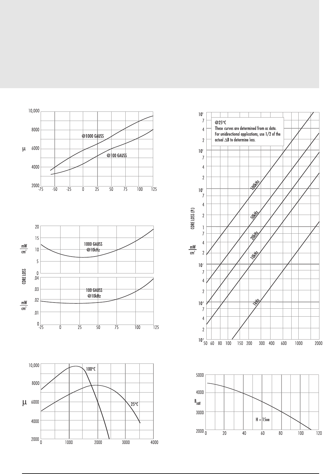
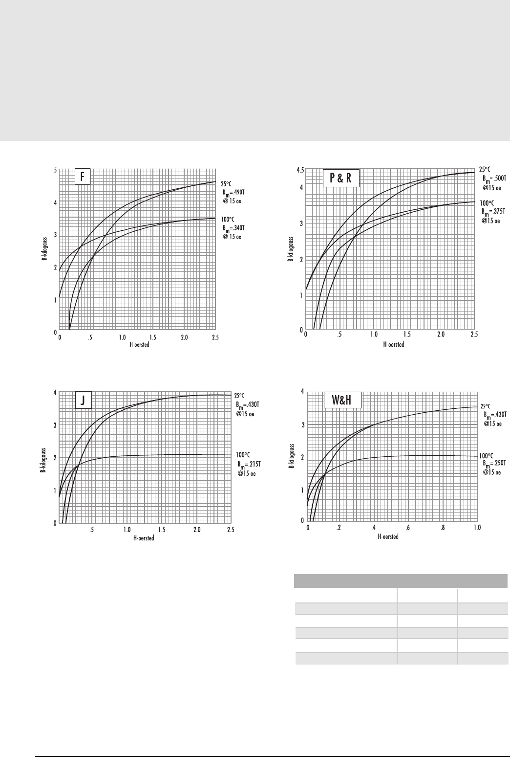
J Material
µi5,000 ±20%
Saturation Flux Density - gausses 4,300 (at 15 oersted, 25˚C) (430 mT)
Coercive Force - oersted. . . . . . . . . . . . . . . . . . . . . . . . . . . 0.1 (8A/m)
Curie Temperature. . . . . . . . . . . . . . . . . . . . . . . . . . . . . . . 140˚C
Disaccomadation Factor. . . . . . . . . . . . . . . . . . . . . . . . . . . <3.0 x 10⁻⁶
NOTE: The core loss curves are developed from empirical data.
For best results and highest accuracy, use them. The formula on page 3.10
yields a fair approximation and can be useful in computer programs.
300 400 600 1000 2000
FLUX DENSITY GAUSS
CORE LOSS vs. FLUX DENSITY
100kHz
50kHz
20kHz
10kHz
1kHz
These Curves are determined from ac data.
For unidirectional applications, use 1/2 of the
Mat_J_Coreloss_vs_Fluxden.eps
Mat_J_Coreloss_vs_Temp.eps
Mat_J_Perm_vs_Fluxden.eps
FLUX DENSITY vs. TEMPERATURE
TEMPERATURE (ºC)
120100806040
H = 15oe
Mat_J_Fluxden_vs_Temp.eps
See Page 3.11 for B-H Data
PERMEABILITY vs. TEMPERATURE
TEMPERATURE ˚C
CORE LOSS vs. TEMPERATURE
TEMPERATURE ˚C
PERMEABILITY vs. FLUX DENSITY
FLUX DENSITY GAUSS
CORE LOSS vs. FLUX DENSITY
FLUX DENSITY GAUSS
FLUX DENSITY vs. TEMPERATURE
TEMPERATURE ˚C
MAGNETICS
CORE LOSS vs. FLUX DENSITY
FLUX DENSITY GAUSS
20001000600400300200
100kHz
50kHz
20kHz
10kHz
1kHz
These curves are determined from ac data.
For unidirectional applications, use 1/2 of the
B to determine loss.
Mat_W_Coreloss_
Mat_W_Coreloss_vs_Temp.eps
Mat_W_Perm_vs_Fluxden.eps
FLUX DENSITY vs. TEMPERATURE
TEMPERATURE (ºC)
12010080604020
H = 15 oe
Saturation Flux Density - gausses 4,300 (at 15 oersted, 25˚C) (430 mT)
Coercive Force - oersted. . . . . . . . . . . . . . . . . . . . 0.04 (3A/m)
Curie Temperature . . . . . . . . . . . . . . . . . . . . . . . . . . . . . 125˚C
Disaccomadation factor. . . . . . . . . . . . . . . . . . . . . . . <3 x 10⁻⁶
NOTE: The core loss curves are developed from empirical data.
For best results and highest accuracy, use them. The formula on page 3.10
yields a fair approximation and can be useful in computer programs.
3.8 See Page 3.11 for B-H Data
PERMEABILITY vs. TEMPERATURE
TEMPERATURE ˚C
CORE LOSS vs. TEMPERATURE
TEMPERATURE ˚C
PERMEABILITY vs. FLUX DENSITY
FLUX DENSITY GAUSS
CORE LOSS vs. FLUX DENSITY
FLUX DENSITY GAUSS
FLUX DENSITY vs. TEMPERATURE
TEMPERATURE ˚C
µi10,000 ±30%
at 10kHz
W Material
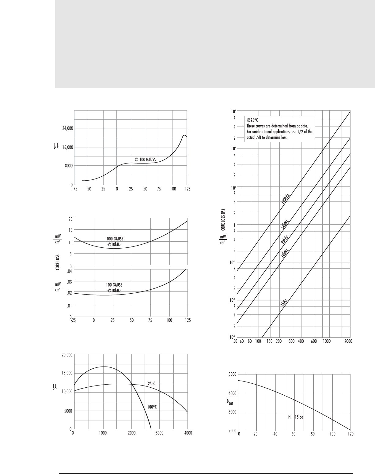
3.9
mag-inc.com
H Material
µi15,000 ±30%
at 10 kHz
Saturation Flux Density - gausses 4,200 (at 15 oersted, 25˚C) (420 mT)
Coercive Force - oersted. . . . . . . . . . . . . . . . . . . . . . . . . . . 0.04 (3A/m)
Curie Temperature. . . . . . . . . . . . . . . . . . . . . . . . . . . . . . . 120˚C
Disaccomadation Factor. . . . . . . . . . . . . . . . . . . . . . . . . . . <2.5 x 10⁻⁶ Typical
NOTE: The core loss curves are developed from empirical data.
For best results and highest accuracy, use them. The formula on page 3.10
yields a fair approximation and can be useful in computer programs.
100kHz
50kHz
20kHz
10kHz
1kHz
CORE LOSS vs. FLUX DENSITY
FLUX DENSITY GAUSS
20001000600400300200150
These curves are determined from ac data.
For unidirectional applications, use 1/2 of the
B to determine loss.
Mat_H_Coreloss_vs_Fluxden.eps
Mat_H_Coreloss_vs_Temp.eps
Mat_H_Perm_vs_Fluxden.eps
FLUX DENSITY vs. TEMPERATURE
1201008060
H = 15oe
Mat_H_Fluxden_vs_Temp.eps
See Page 3.11 for B-H Data
PERMEABILITY vs. TEMPERATURE
TEMPERATURE ˚C
CORE LOSS vs. TEMPERATURE
TEMPERATURE ˚C
PERMEABILITY vs. FLUX DENSITY
FLUX DENSITY GAUSS
CORE LOSS vs. FLUX DENSITY
FLUX DENSITY GAUSS
FLUX DENSITY vs. TEMPERATURE
TEMPERATURE ˚C

R Material f<100 kHz 0.074 1.43 2.85
100 kHz ≤f<500 kHz 0.036 1.64 2.68
f≥500 kHz 0.014 1.84 2.28
P Material f<100 kHz 0.158 1.36 2.86
100 kHz≤f<500 kHz 0.0434 1.63 2.62
f≥500 kHz 7.36*10-7 3.47 2.54
F Material f<10 kHz 0.790 1.06 2.85
10 kHz≤f<100 kHz 0.0717 1.72 2.66
100 kHz≤f<500 kHz 0.0573 1.66 2.68
f≥500 kHz 0.0126 1.88 2.29
J Material f≤20 kHz 0.245 1.39 2.50
f>20 kHz 0.00458 2.42 2.50
W Material f≤20 kHz 0.300 1.26 2.60
f>20 kHz 0.00382 2.32 2.62
H Material f≤20 kHz 0.148 1.50 2.25
f>20 kHz 0.135 1.62 2.15
a c d
3.1 0 MAGNETICS
Materials
Core Loss Equation
Included on pages Pages 3.4-3.9 are material characteristics for the vari-
ous Magnetics power and inductor materials. For computer programming
purposes, the core loss curves can be represented by the equation below.
The factors indicated in the chart are split into discrete frequency ranges,
so that the equation offers a close approximation to the core loss curves on
the above pages.
CORE LOSS EQUATION: PL= afcBd
P is in mW/cm3
B is in kG
f is in kHz
FACTORS APPLIED TO THE ABOVE FORMULA
3.11
mag-inc.com
Materials
B vs. H Curves (dc)
Mat_BHCurves_F.eps
MULTIPLY NUMBER OF BY TO OBTAIN
Oersteds 79.5 A/m
Oersteds 0.795 A/cm
Gausses 0.100 milli Teslas
Gausses 10-4 Teslas
Teslas 104Gausses
CONVERSION TABLE
1.0.8.6.4
H-oersted
100ºC
25ºC
Bm=.430T
@15 oe
Bm=.250T
@15 oe
Mat_BHCurves_W&H.eps
2.52.01.51.0
H-oersted
25ºC
100ºC
Bm–.500T
@15 oe
Bm–.375T
@15 oe
Mat_BHCurves_J.eps
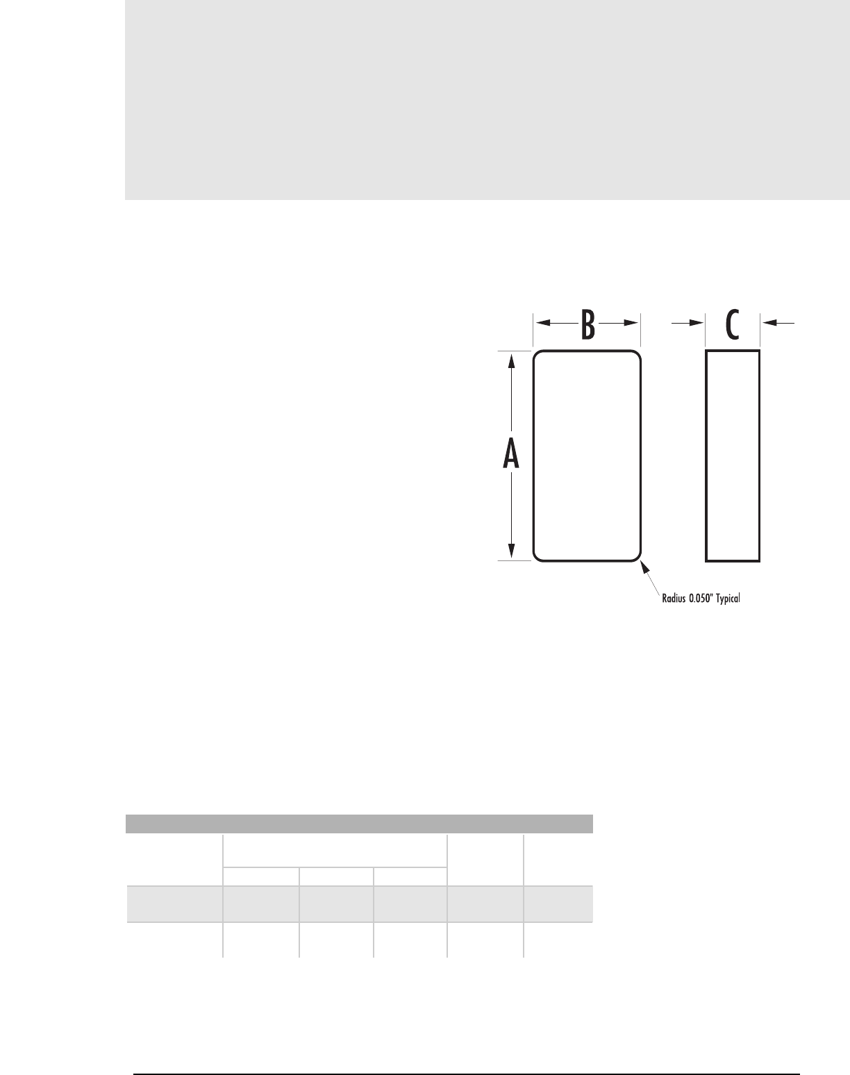
Dimensions (inches) Wt. Vol.
A B C (gms) (cm3)
J42500FB 2.50 1.00 0.50 98.3 20.5
J46213FB 2.45 1.95 0.50 188 39.2
R42500FB 2.50 1.00 0.50 98.3 20.5
R46213FB 2.45 1.95 0.50 188 39.2
STANDARD BLOCKS and HOW TO ORDER
3.12 MAGNETICS
Materials
FEATURES OF MAGENTICS FERRITE BLOCKS
• LOW POROSITY
• EXTREME HARDNESS
• UNIFORM PHYSICAL PROPERTIES
• HIGH DENSITY
• EASE OF MACHINING
Ferrites can be pressed in block form and then machined into intricate shapes. Where
large sizes are required, it is possible to assemble them from two or more smaller
machined or pressed sections; the variety of sizes and shapes becomes limitless.
Without sacrificing magnetic properties, many manufacturing operations can be
performed on ferrites, providing strict dimensional or mechanical tolerances:
Surface grinding
Cutting, slicing, slotting
ID and OD machining
Hole drilling
Special machining
Assembly of smaller parts
MATERIAL SELECTION
J material offers high permeability, see page 3.7.
R material is suitable for power applications, see page 3.4.
B C
A
Radius .050" Typical
Mat_BlockFeature.eps
PART NUMBER
Ferrite Blocks
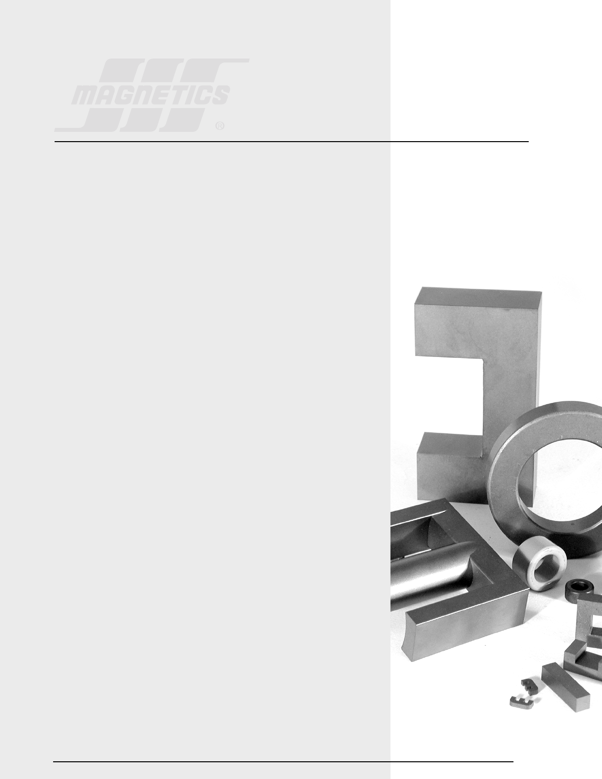
Ferrite is an ideal core material for transformers, inverters and inductors in the frequency range 20
kHz to 3 MHz, due to the combination of low core cost and low core losses.
Ferrite is an excellent material for high frequency (20 kHz to 3 MHz) inverter power supplies.
Ferrites may be used in the saturating mode for low power, low frequency operation (<50 watts
and 10 kHz). For high power operation a two transformer design, using a tape wound core as the
saturating core and a ferrite core as the output transformer, offers maximum performance. The two
transformer design offers high efficiency excellent frequency stability, and low switching losses.
Ferrite cores may also be used in fly-back transformer designs, which offer low core cost, low circuit cost
and high voltage capability. Powder cores (MPP, High Flux, Kool Mµ®) offer soft saturation, higher Bmax
and better temperature stability and may be the best choice in some flyback applications or inductors.
High frequency power supplies, both inverters and converters, offer lower cost, and lower weight
and volume than conventional 60 hertz and 400 hertz power sources.
Many cores in this section are standard types commonly used in the industry. If a suitable size for
your application is not listed, Magnetics will be happy to review your needs, and, if necessary,
quote tooling where quantities warrant.
Cores are available gapped to avoid saturation under dc bias conditions. J and W materials are
available with lapped surfaces.
Bobbins for many cores are available from Magnetics. VDE requirements have been taken into account in
bobbin designs for EC, PQ and metric E Cores. Many bobbins are also available commercially.
4.1
Section 4
Power
Design

4.2 MAGNETICS
General Core Selection
CORE MATERIALS
F, P, and R materials, offering the lowest core losses and highest saturation flux density,
are most suitable for high power/high temperature operation. P material core losses
decrease with temperature up to 70˚C; R material losses decrease up to 100˚C.
J and W materials offer high impedance for broad transformers, and are
also suitable for low-level power transformers.
FERRITE
POWER MATERIALS SUMMARY
FPR JW+
µi (20 gauss) 25˚C 3,000 2,500 2,300 5,000 10,000
µp (2000 gauss) 100˚C 4,600 6,500 6,500 5,500 12,000
Saturation 25˚C 4,900 5,000 5,000 4,300 4,300
Flux Density
(BmGauss) 100˚C 3,700 3,900 3,700 2,500 2,500
Core Loss (mw/cm3) 25˚C 100 125 140
(Typical) 60˚C 180 80* 100
@100 kHz, 1000 Gauss 100˚C 225 125 70
*@80˚C +@10kHz
CORE GEOMETRIES
POT CORES
Pot Cores, when assembled, nearly surround the wound bobbin. This aids in
shielding the coil from pickup of EMI from outside sources. The pot core
dimensions all follow IEC standards so that there is interchangeability
between manufacturers. Both plain and printed circuit bobbins are
available, as are mounting and assembly hardware. Because of its design,
the pot core is a more expensive core than other shapes of a comparable
size. Pot cores for high power applications are not readily available.
DOUBLE SLAB AND RM CORES
Slab-sided solid center post cores resemble pot cores, but have a section cut
off on either side of the skirt. Large openings allow large size wires to be
accommodated and assist in removing heat from the assembly. RM cores
are also similar to pot cores, but are designed to minimize board space,
providing at least a 40% savings in mounting area. Printed circuit or plain
bobbins are available. Simple one piece clamps allow simple assembly. Low
profile is possible. The solid center post generates less core loss and this
minimizes heat buildup
.
EP CORES
EP Cores are round center-post cubical shapes which enclose the coil completely
except for the printed circuit board terminals. The particular shape
minimizes the effect of air gaps formed at mating surfaces in the magnetic
path and provides a larger volume ratio to total space used. Shielding
is excellent.
PQ CORES
PQ cores are designed especially for switched mode power supplies. The
design provides an optimized ratio of volume to winding area and surface
area. As a result, both maximum inductance and winding area are possible
with a minimum core size. The cores thus provide maximum power output
with a minimum assembled transformer weight and volume, in addition to
taking up a minimum amount of area on the printed circuit board. Assembly
with printed circuit bobbins and one piece clamps is simplified. This efficient
design provides a more uniform cross-sectional area; thus cores tend to operate
with fewer hot spots than with other designs.
E CORES
E cores are less expensive than pot cores, and have the advantages of simple bobbin
winding plus easy assembly. Gang winding is possible for the bobbins used
with these cores. E cores do not, however, offer self-shielding. Lamination
size E shapes are available to fit commercially available bobbins previously
designed to fit the strip stampings of standard lamination sizes. Metric and
DIN sizes are also available. E cores can be pressed to different thickness,
providing a selection of cross-sectional areas. Bobbins for these different
cross sectional areas are often available commercially.
E cores can be mounted in different directions, and if desired, provide a low-
profile. Printed circuit bobbins are available for low-profile mounting. E
cores are popular shapes due to their lower cost, ease of assembly and
winding, and the ready availability of a variety of hardware.
PLANAR E CORES
Planar E cores are offered in all of the IEC standard sizes, as well as a num-
ber of other sizes. Magnetics R material is perfectly suited to planar
designs due to its low AC core losses and minimum losses at 100°C. Planar
designs typically have low turns counts and favorable thermal dissipation
compared with conventional ferrite transformers, and as a consequence the
optimum designs for space and efficiency result in higher flux densities. In
those designs, the performance advantage of R material is especially sig-
nificant.
The leg length and window height (B and D dimensions) are adjustable for
specific applications without new tooling. This permits the designer to
adjust the final core specification to exactly accommodate the planar con-
ductor stack height, with no wasted space. Clips and clip slots are avail-
Materials and Geometries

POT DOUBLE SLAB, EP PQ E EC, ETD, TOROIDS
CORES RM CORES CORES CORES CORES EER CORES
See Catalog Section 6 7-8 9 10 11 12 13
Core Cost High High Medium High Low Medium Very Low
Bobbin Cost Low Low High High Low Medium None
Winding Cost Low Low Low Low Low Low High
Winding Flexibility Good Good Good Good Excellent Excellent Fair
Assembly Simple Simple Simple Simple Simple Medium None
Mounting Flexibility** Good Good Good Fair Good Fair Poor
Heat Dissipation Poor Good Poor Good Excellent Good Good
Shielding Excellent Good Excellent Fair Poor Poor Good
** Hardware is required for clamping core halves together and mounting assembled core on a circuit board or chassis.
4.3
General Core Selection
able in many cases, which is especially useful for prototyping. I-cores are
also offered standard, permitting further flexibility in design. E-I planar
combinations are useful to allow practical face bonding in high volume
assembly, and for making gapped inductor cores where fringing losses must
be carefully considered due to the planar construction.
EC, ETD AND EER CORES
These shapes are a cross between E cores and pot cores. Like E cores, they
provide a wide opening on each side. This gives adequate space for the
large size wires required for low output voltage switched mode power
supplies. It also allows for a flow of air which keeps the assembly cooler.
The center post is round, like that of the pot core. One of the advantages
of the round center post is that the winding has a shorter path length
around it (11% shorter) than the wire around a square center post with an
equal area. This reduces the losses of the windings by 11% and enables the
core to handle a higher output power. The round center post also eliminates
the sharp bend in the wire that occurs with winding on a square center post.
TOROIDS
Toroids are economical to manufacture; hence, they are least costly of all comparable
core shapes. Since no bobbin is required, accessory and assembly costs are nil.
Winding is done on toroidal winding machines. Shielding is relatively good.
SUMMARY
Ferrite geometries offer a wide selection in shapes and sizes. When choosing a core
for power applications, parameters shown in Table 1 should be evaluated.
TABLE 1: FERRITE CORE COMPARATIVE GEOMETRY CONSIDERATIONS
mag-inc.com
Materials and Geometries
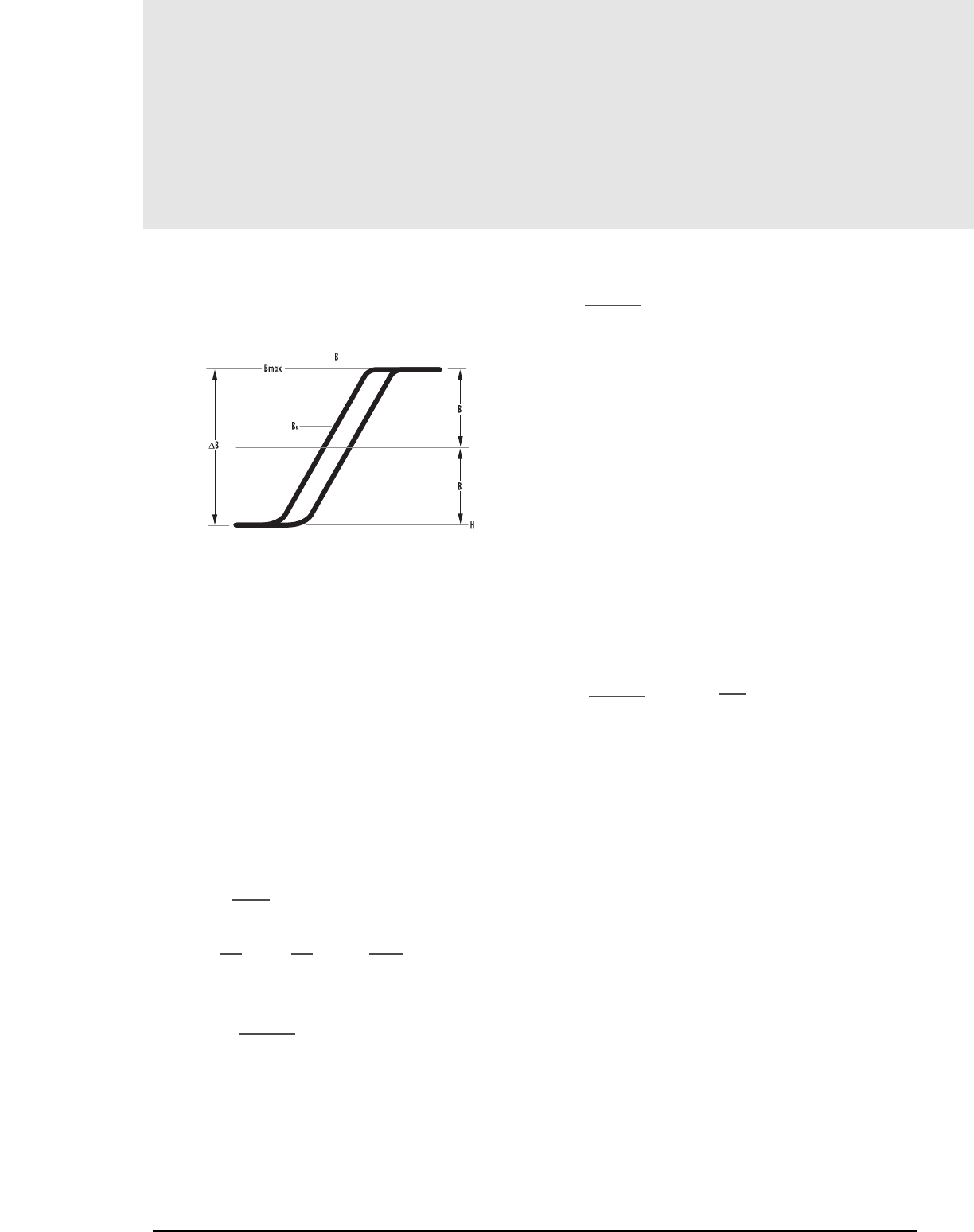
4.4MAGNETICS
TRANSFORMER CORE SIZE SELECTION
The power handling capacity on a transformer core can be determined by its
WaAc product, where Wa is the available core window area, and Ac is the
effective core cross-sectional area.
The WaAc/power-output relationship is obtained by starting with Faraday’s Law:
E=4B Ac Nf x 10-8 (square wave) (1)
E=4.44 BAc Nf x 10-8 (sine wave) (1a)
Where: E=applied voltage (rms) K=winding factor
B=flux density in gauss I=current (rms)
Ac=core area in cm2Pi=input power
N=number of turns Po=output power
f=frequency in Hz e=transformer efficiency
Aw=wire area in cm2
Wa=window area in cm2:
Core window for toroids
Bobbin window for other cores
C=current capacity in cm2/amp
Solving (1) for NAc
NAc= E x 108(2)
4Bf
The winding factor
K= NAw thus N= KWa and NAc= KWaAc (3)
Wa Aw Aw
Combining (2) and (3) and solving for WaAc:
WaAc= E Aw x 108, where WaAc=cm4(4)
4B fK
In addition:
C=Aw/l or Aw=IC e= Po/ PiPi=El
Thus:
E Aw=EIC= PiC= PoC/e
Substituting for EAw in (4), we obtain:
WaAc= PoC x 108
4eB fK
Assuming the following operational conditions:
C= 4.05 x 10⁻³cm2/Amp (square wave) and
2.53 x 10⁻³cm2/Amp (sine wave) for toroids
C= 5.07 x 10⁻³cm2/Amp (square wave) and
3.55 x 10⁻³cm2/Amp (sine wave) for pot cores and
E-U-I cores.
e= 90% for transformers
e= 80% for inverters (including circuit losses)
K=0.30 for pot cores and E-U-I cores (primary side only)
K=0.20 for toroids (primary side only)
With larger wire sizes, and/or higher voltages, these K factors may not be obtainable.
To minimize both wire losses and core size, the window area must be full.
NOTE: For Wire Tables and turns/bobbin data, refer to pgs 5.8.
We obtain the basic relationship between output power and the WaAc product:
WaAc = k’P0x 108, Where k’=C
Bf 4eK
For square wave operation
k’= .00633 for toroids, k’= .00528 for pot cores, k’= .00528 for E-U-I cores
A core selection chart (Table 3) using WaAc can be found on page 4.7. In
addition a A core selection procedure which varies by topology can also be
found on page 4.8. This procedure is based on the book “Switching Power
Supply Design” by A.I. Pressman. While the formula above allows WaAc to be
adjusted based on selected core geometry, the Pressman approach uses topolo-
gy as the key consideration and allows the designer to specify current density.
GENERAL INFORMATION
An ideal transformer is one that offers minimum core loss while requiring
the least amount of space. The core loss of a given core is directly effect-
ed by the flux density and the frequency. Frequency is the most important
characteristic concerning a transformer. Faraday’s Law illustrates that as
frequency increases, the flux density decreases proportionately. Core loss-
es decrease more when the flux density drops than when frequency rises.
For example, if a transformer were run at 250 kHz and 2 kG on R materi-
al at 100°C, the core losses would be approximately 400 mW/cm3. If the
frequency were doubled and all other parameters untouched, by virtue of
Faraday’s law, the flux density would become 1kG and the resulting core
losses would be approximately 300mW/cm3.
Typical ferrite power transformers are core loss limited in the range of 50-
200mW/cm3. Planar designs can be run more aggressively, up to 600
mW/cm3, due to better power dissipation and less copper in the windings.
Transformer Core Selection
FIGURE 1
General Formulas
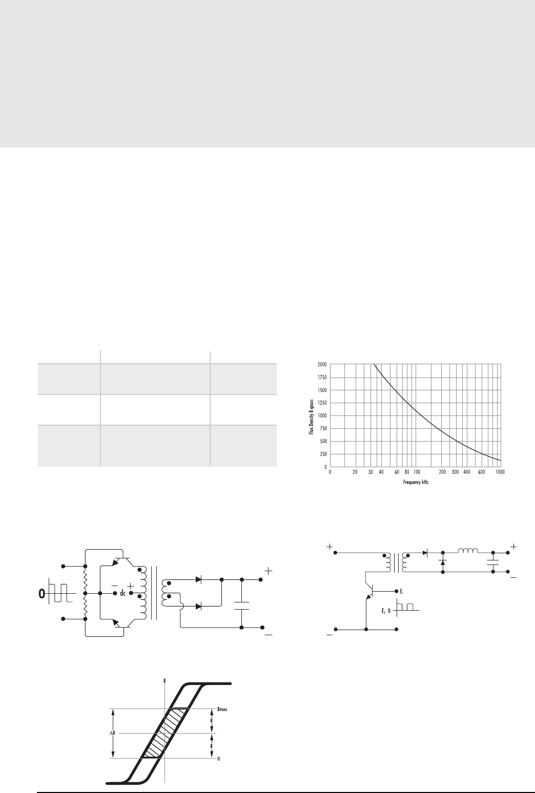
4.5
Transformer Core Selection
CIRCUIT TYPES
Some general comments on the different circuits are:
The push-pull circuit is efficient because it makes bi-directional use of a
transformer core, providing an output with low ripple. However, circuitry is
more complex, and the transformer core saturation can cause transistor failure
if power transistors have unequal switching characteristics.
Feed forward circuits are low in cost, using only one transistor. Ripple is low
because relatively steady state current flows in the transformer whether the
transistor is ON or OFF. The flyback circuit is simple and inexpensive. In
addition, EMI problems are less. However, the transformer is larger and
ripple is higher.
TABLE 2 CIRCUIT TYPE SUMMARY
CIRCUIT ADVANTAGES DISADVANTAGES
Push-pull Medium to high power More components
Efficient core use
Ripple and noise low
Feed forward Medium power Core use inefficient
Low cost
Ripple and noise low
Flyback Lowest cost Ripple and noise high
Few components Regulation poor
Output power limited
(< 100 watts)
PUSH-PULL CIRCUIT
A typical push-pull circuit is shown in Figure 2A. The input signal is the output of an IC
network, or clock, which switches the transistors alternately ON and OFF. High frequency
square waves on the transistor output are subsequently rectified, producing dc.
FIGURE 2A – TYPICAL PUSH-PULL SPS CIRCUIT
FIGURE 2B – HYSTERESIS LOOP OF MAGNETIC
CORE IN PUSH-PULL CIRCUIT
For ferrite transformers, at 20 kHz, it is common practice to apply equation (4)
using a flux density (B) level of ±2 kG maximum. This is illustrated by the
shaded area of the Hysteresis Loop in Figure 2B. This B level is chosen because
the limiting factor in selecting a core at this frequency is core loss. At 20 kHz, if
the transformer is designed for a flux density close to saturation (as done for
lower frequency designs), the core will develop an excessive temperature rise.
Therefore, the lower operating flux density of 2 kG will usually limit the core
losses, thus allowing a modest temperature rise in the core.
Above 20 kHz, core losses increase. To operate the SPS at higher frequencies, it
is necessary to operate the core flux levels lower than ±2 kg. Figure 3 shows
the reduction in flux levels for MAGNETICS “P” ferrite material necessary to
maintain constant 100mW/cm3core losses at various frequencies, with a
maximum temperature rise of 25˚C.
FIGURE 3
FEED FORWARD CIRCUIT
FIGURE 4A – TYPICAL FEED FORWARD SPS CIRCUIT
In the feed forward circuit shown in Figure 4A, the transformer operates in
the first quadrant of the Hysteresis Loop. (Fig 4B). Unipolar pulses applied
to the semiconductor device cause the transformer core to be driven from
its BRvalue toward saturation. When the pulses are reduced to zero, the
core returns to its BRvalue. In order to maintain a high efficiency, the
primary inductance is kept high to reduce magnetizing current and lower
wire losses. This means the core should have a zero or minimal air gap.
mag-inc.com
Specific Circuit Examples
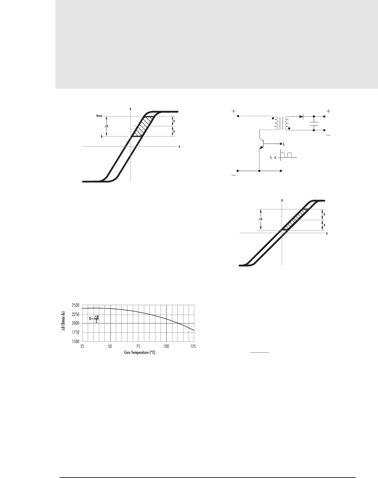
4.6MAGNETICS
Transformer Core Selection
FIGURE 4B
HYSTERESIS LOOP OF MAGNETIC CORE IN FEED FORWARD CIRCUIT
For ferrites used in this circuit, ∆B (or B max-BR) is typically 2400 gauss or
B (as applied to Equation 4) is ±1200 gauss as shown in Figure 4B. In the
push-pull circuit, it was recommended that the peak flux density in the core
should not exceed B = ±2000 gauss in order to keep core losses small.
Because of the constraints of the Hysteresis Loop, the core in the feed
forward circuit should not exceed a peak value of B = ±1200 gauss.
Core selection for a feed forward circuit is similar to the push-pull circuit
except that B for Equation 4 is now limited to ±1200 gauss.
If the transformer operating temperature is above 75˚, the value of B will be further
reduced. Figure 5 shows the variation of ∆B with temperature. Therefore the
recommended ∆B value of 2400 (B= ±1200) gauss has to be reduced, the
amount depending on the final projected temperature rise of the device.
FIGURE 5
The value of ∆B remains virtually unchanged over a large frequency range
above 20 kHz. However, at some frequency, the adjusted value of B, as
shown in Figure 3, will become less than the B determined by the above
temperature considerations (Figure 5). Above this frequency, the B used to
select a core will be the value obtained form Figure 3.
FLYBACK CIRCUIT
A typical schematic is shown in Figure 6A. Unipolar pulses cause dc to flow through
the core winding, moving the flux in the core from BRtowards saturation (Fig. 6B).
When the pulses go to zero the flux travels back to BRas in the feed forward design.
However, the difference between the feed forward and the flyback circuit is that the
flyback requires the transformer to act as an energy storage device as well as to
perform the usual transformer functions. Therefore, to be an effective energy storage
unit, the core must not saturate and is usually a gapped structure.
FIGURE 6A
TYPICAL FLYBACK REGULATOR CIRCUIT
FIGURE 6B
HYSTERESIS LOOP OF MAGNETIC CORE IN FLYBACK CIRCUIT
In most designs, the air gap is large; therefore, BRis small as noted on the
Hysteresis Loop in Figure 6B and can be considered zero. The maximum flux
density available is approximately 3600. This means ∆B is 3600 or B =
±1800 gauss. Core selection for this circuit can be done using Equation 4. The
B value in Equation 4 is ±1800 gauss at 20 kHz and is used until a higher
frequency (Figure 3) dictates a lower B required.
GENERAL FORMULA – CORE SELECTION FOR DIFFERENT TOPOLOGIES
The following formula has been gained from derivations in Chapter 7 of A.I.
Pressman’s book “Switching Power Supply Design” (see Reference No. 13, pg 14.4.)
WaAc = PoDcma
KtBmaxf
WaAc = Product of window area and core area (cm4)
Po = Power Out (watts)
Dcma = Current Density (cir. mils/amp)
Bmax = Flux Density (gauss)
f= Frequency (hertz)
Kt= Topology constant (for a space factor of 0.4):
Forward converter = .0005 Push-Pull = .001
Half-bridge = .0014 Full-bridge = .0014
Flyback = .00033 (single winding)
Flyback = .00025 (multiple winding)
For individual cores, WaAc is listed in this catalog under “Magnetic Data.” Choice
of Bmax at various frequencies, Dcma and alternative transformer temperature rise
calculation schemes are also discussed in Chapter 7 of the Pressman book.
Specific Circuit Examples
4.7
Transformer Core Selection
WaAc*(cm4) PC RS,DS,HS RM, EP RM SOLID PQ EE LAM EE,EEM,EFD EE,EI PLANAR UU, UI ETD, EER EC TC
See Section 6 7 8/9 8 10 11 11 11 11 12 12 13
0.001 40704 41309 (EE) 40601
0.002 40905 40707 (EP) 40904 40603
40906
0.004
0.007 41107 41110(RM) 40705
0.010 41408 41010(EP) 41203 41106 (UI) 41003
(RS,DS) 41005
0.020 41408 41510(RM) 41510 41205 41208 41106(UU) 40907
41313(EP) 41209 41303
41515
41707
0.040 41812(RM) 41812 41709 41206
42110 41305
0.070 41811 42311 41717(EP) 42610 41808 41306
(RS,DS,HS) 41605
0.100 42213 42318 42316(RM) 42316 42016 41810 42216(EE)
(HS) 42614 42510
0.200 42616 42318 42819(RM) 42020 42211 43618(EI) 42515 41809
(RS,DS) 42120(EP) 42620 42810 43208(EI) (UI) 42206
42616 43214 43009
(RS,DS,HS) 42523
0.400 43019 42819 42625 42520 42515 43618(EE) 42207
(RS,DS,HS) 43007 43208(EE)
0.700 43019 43723(RM) 43220 43515 43013 42220(UU) 43517 42507
42512(UU)
42515(UU)
1.00 43622 43622 43723 43230 44317 43520 44308(EI) 42530(UU) 44119 43434 42908
(RS,DS,HS) 43524 43521(EER)
44011
2.00 44229 44229 43535 44721 44020 44308(EE) 44119(UU) 45224 43939 43610
44529 (RS,DS,HS) 44924 45810(EI) 44121(UU) 44216(EER) 43615
44444 43813
45032
4.00 44040 45724 44022 46410(EI) 44125(UU) 44949 44416
45021 44130(UU)
7.00 45528 45810(EE)
46016 46409(EE)
10.00 45530 46410(EE) 47035 44916
47228 44925
46113
20.00 48020 47054 47313
47325
40.00 49938(EE) 48613
100 49928 49925(UU)
49925(UI)
*Bobbin window and core area product. For bobbins other than those in this catalog, WaAc may need to be recalculated.
mag-inc.com
TABLE 3 – FERRITE CORE SELECTION BY AREA PRODUCT DISTRIBUTION
Area Product Distribution (WaAc*)
Transformer Core Selection
WATTAGE LOW-PROFILE
@F= @F= @F= @F= POT-RS-RM DS EP PQ PLANAR EC-ETD TC
20KHZ 50KHZ 100KHZ 250KHZ CORES CORES CORES CORES E-CORES CORES U CORES TOROIDS
See Section 6/7/8 7 9 10 11 11 12 13
2 3 4 7 41408-PC 41313 41707 41709 41206
42107 41303
42110
5 8 11 21 41811-PC 42311 41717 41808 42610-PQ 41306
42311-RS 42216-EC 41605
42809-RM
12 18 27 53 42316-RM 42016 41810, 42211 42614-PQ
13 20 30 59 42510
15 22 32 62 42213-PC
18 28 43 84 42318-RS 42318 42020 43618-E, I 42106
19 30 48 94 42616 42120 43208-E, I 41809
44008-E, I
26 42 58 113 42810, 42520 42206
28 45 65 127 42819-RM 42515 42109
30 49 70 137 42616-PC 42620 42207
33 53 80 156 43019 43618-EC
40 61 95 185 43019-RS 43007 44008-EC 43205
42 70 100 195 42625 43208-EC
48 75 110 215 43013 4,221,242,507
60 100 150 293 43019-PC 43220 42530, 43009 43517 (EC35)
43723-RM 43515 (E375)
70 110 170 332 43622 44308-E, I 43434 (ETD34) 42908
105 160 235 460 44011 (E40)
110 190 250 480 43622-PC 43230
120 195 270 525 44119 (EC41)
130 205 290 570 43524, 43520 43521 43806
140 215 340 663 44317 (E21) 42915, 43113
150 240 380 741 44308-EC 43939 (ETD39)
190 300 470 917 44229 43610
200 310 500 975 44721 (E625) 45032
220 350 530 1,034 43535 43813
230 350 550 1,073 44020 (42/15) 44216
260 400 600 1,170 43615
280 430 650 1,268 44229-PC 45021 (E50) 45224 (EC52)
44924
300 450 700 1,365 44529-PC 44022 (42/20) 45810-EC 44444 (ETD44)
340 550 850 1,658 44040
360 580 870 1,697 43825
410 650 1,000 1,950 45724 (E75) 46410-E, I 44949 (ETD49) 44416
550 800 1,300 2,535 45528 (55/21)
46016 (E60) 45810-EC 44715
650 1,000 1,600 3,120 44916
44920
700 1,100 1,800 3,510 45530 (55/25) 46409-EC
850 1,300 1,900 3,705 46410-EC 44925
900 1,500 2,000 3,900 47035 (EC70)
1,000 1,600 2,500 4,875 45959 (ETD59) 46113
1,000 1,700 2,700 5,265 47228
1,400 2,500 3,200 6,240 44932
1,600 2,600 3,700 7,215 47313
2,000 3,000 4,600 8,970 48020 47054
2,800 4,200 6,500 12,675 49938-EC 48613
11,700 19,000 26,500 51,500 49925 (U)
TABLE 4 – FERRITE CORE SELECTION LISTED BY TYPICAL POWER HANDLING CAPABILITIES (WATTS)
(F, P AND R MATERIALS) (FOR PUSH-PULL SQUARE WAVE OPERATIONS, SEE NOTES BELOW)
Above is for push-pull converter. De-rate by a factor of 3 or 4 for flyback. De-rate by a factor of 2 for feed-forward converter.
NOTE: Assuming Core Loss to be Approximately 100mW/cm3,
B Levels Used in this Chart are:@ 20kHz-2000 gauss @ 50kHz-1300 gauss @ 100kHz-900 gauss @ 250kHz-700 gauss.
SEE PAGE 4.7 — Area Product Distribution
MAGNETICS
4.8
Typical Power Handling
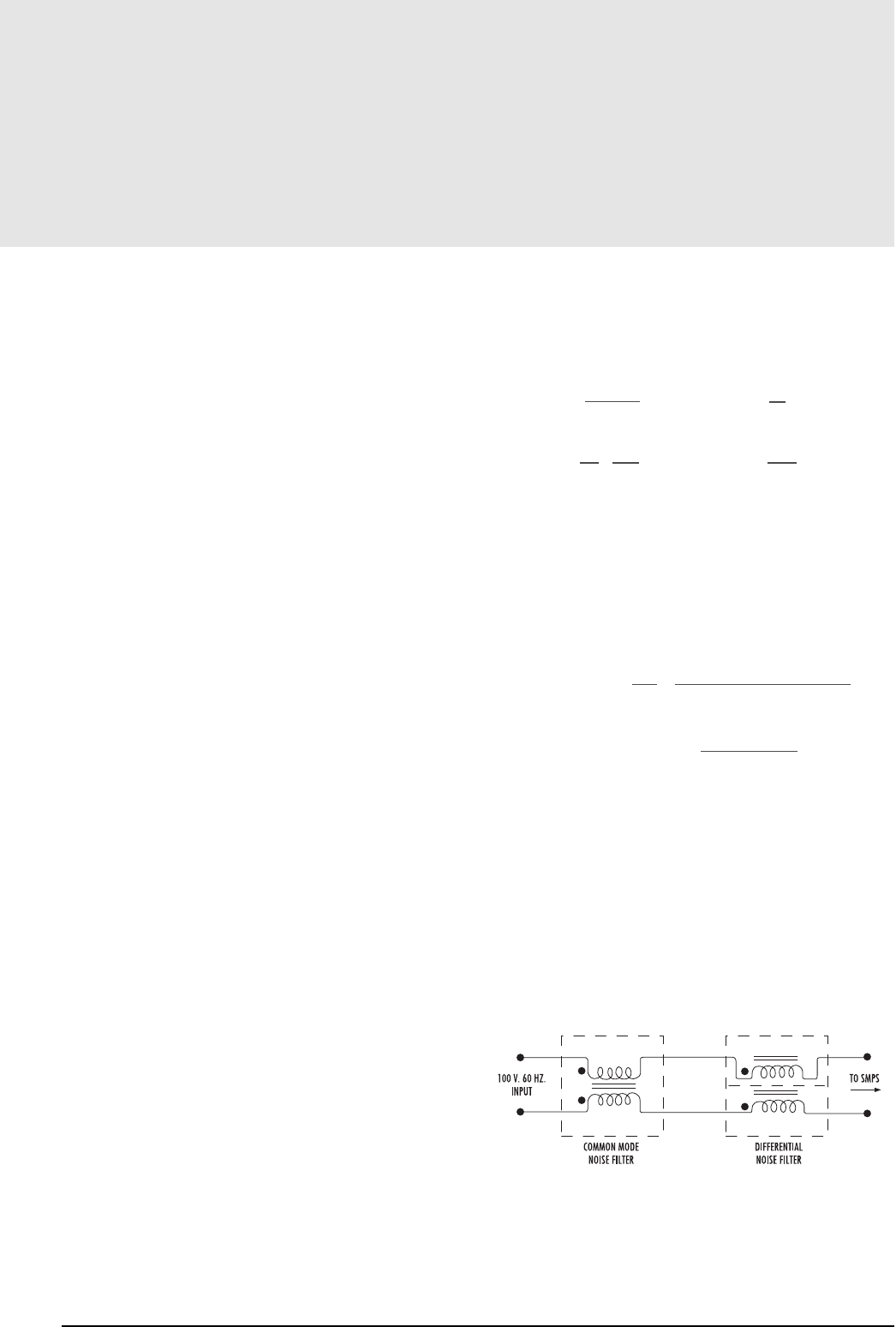
4.9
Transformer Core Selection
TEMPERATURE CONSIDERATIONS
The power handling ability of a ferrite transformer is limited by either the saturation
of the core material or, more commonly, the temperature rise. Core material
saturation is the limiting factor when the operating frequency is below 20kHz.
Above this frequency temperature rise becomes the limitation.
Temperature rise is important for overall circuit reliability. Staying below a given
temperature insures that wire insulation is valid, that nearby active components do not
go beyond their rated temperature, and overall temperature requirements are met.
Temperature rise is also very important for the core material point of view.
As core temperature rises, core losses can rise and the maximum saturation flux
density decreases. Thermal runaway can occur causing the core to heat up to its
Curie temperature resulting in a loss of all magnetic properties and catastrophic
failure. Newer ferrite power materials, like P and R material, attempt to
mitigate this problem by being
tailored to have decreasing losses to temperature of
70˚C and 100˚C respectively.
CORE LOSS—One of the two major factors effecting temperature rise is core
loss. In a transformer, core loss is a function of the voltage applied across the
primary winding. In an inductor core, it is a function of the varying current
applied through the inductor. In either case the operating flux density level, or B
level, needs to be determined to estimate the core loss. With the frequency and
B level known, core loss can be estimated from the material core loss curves. A
material loss density of 100mw/cm3is a common operating point generating
about a 40˚C temperature rise. Operating at levels of 200 or 300 mw/cm3can
also be achieved, although forced air or heat sinks may need to be used.
WINDING CONSIDERATIONS—Copper loss is the second major contributor
to temperature rise. Wire tables can be used as a guide to estimate an
approximate wire size but final wire size is dependent on how hot the designer
allows the wire to get. Magnet wire is commonly used and high frequency copper loss
needs to be considered. Skin effects causes current to flow primarily on the
surface of the wire. To combat this, multiple strands of magnet wire, which
have a greater surface area compared to a single heavier gauge, are used.
Stranded wire is also easier to wind particularly on toroids. Other wire alternatives,
which increase surface areas, are foil and litz wire. Foil winding allows a very
high current density. Foil should not be used in a core structure with significant
air gap since excessive eddy currents would be present in the foil. Litz wire is
very fine wire bundled together. It is similar to stranded wire except the wire is
woven to allow each strand to alternate between the outside and the inside of the
bundle over a given length.
CORE GEOMETRY—The core shape also affects temperature and those
that dissipate heat well are desirable. E core shapes dissipate heat well.
Toroids, along with power shapes like the PQ, are satisfactory. Older
telecommunication shapes, such as pot cores or RM cores, do a poor job of
dissipating heat but do offer shielding advantages. Newer shapes, such as
planar cores, offer a large flat surface ideal for attachment of a heat sink.
TRANSFORMER EQUATIONS
Once a core is chosen, the calculation of primary and secondary turns and
wire size is readily accomplished.
Np = Vpx 108Ns = VsNp
4BAf Vp
lp= Pin = Pout ls=Pout
Pin eEin Eout
KWa = NpAwp = NsAws
Where
Awp = primary wire area Aws = secondary wire area
Assume K = 0.40 for toroids; 0.60 for pot cores and E-U-I cores
Assume NpAwp = 1.1 NsAws to allow for losses and feedback winding
efficiency e = Pout =Pout
Ein Pout + wire losses + core losses
Voltage Regulations (%) = Rs+ (Ns/Np)2Rpx 100
Rload
INDUCTOR CORE SELECTION
EMI FILTERS
Switch Mode Power Supplies (SMPS) normally generate excessive high frequency
noise which can affect electronic equipment like computers, instruments and
motor controls connected to these same power lines. An EMI Noise Filter inserted
between the power line and the SMPS eliminates this type of interference
(Figure 8). A differential noise filter and a common mode noise can be in series,
or in many cases, the common mode filter is used alone.
FIGURE 8
mag-inc.com
Considerations
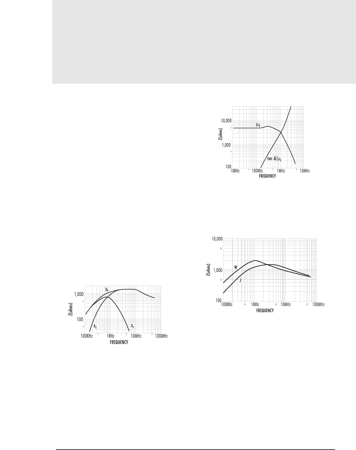
4.10 MAGNETICS
Inductor Core Selection
INDUCTOR CORE SELECTION CONT...
COMMON MODE FILTER
In a CMN filter, each winding of the inductor is connected in series with one of
the input power lines. The connections and phasing of the inductor windings are
such that flux created by one winding cancels the flux of the second winding. The
insertion impedance of the inductor to the input power line is thus zero, except
for small losses in the leakage reactance and the dc resistance of the windings.
Because of the opposing fluxes, the input current needed to power the SMPS
therefore will pass through the filter without any appreciable power loss.
Common mode noise is defined as unwanted high frequency current that
appears in one or both input power lines and returns to the noise source
through the ground of the inductor. This current sees the full impedance of either
one or both windings of the CMN inductor because it is not canceled by a return
current. Common mode noise voltages are thus attenuated in the windings of the
inductor, keeping the input power lines free from the unwanted noise.
CHOOSING THE INDUCTOR MATERIAL
A SMPS normally operates above 20kHz. Unwanted noises generated in these
supplies are at frequencies higher than 20kHz, often between 100kHz and
50MHz. The most appropriate and cost effective ferrite for the inductor is one
offering the highest impedance in the frequency band of the unwanted noise.
Identifying this material is difficult when viewing common parameters such as
permeability and loss factor. Figure 9 shows a graph of impedance Ztvs.
frequency for a ferrite toroid, J42206TC wound with 10 turns.
FIGURE 9
The wound unit reaches its highest impedance between 1 and 10MHz.
The series inductive reactance Xsand series resistance Rs(functions of
the permeability and loss factor of the material) together generate the total
impedance Zt.
Figure 10 shows permeability and loss factor of the ferrite material in
Figure 9 as a function of frequency. The falling off of permeability above
750kHz causes the inductive reactance to fall. Loss factor, increasing with
frequency, cause the resistance to dominate the source of impedance at high
frequencies.
Additional detailed brochures and inductors design software for this application are available from Magnetics.
FIGURE 10
Figure 11 shows total impedance vs. frequency for two different materials.
J material has a high total impedance over the range of 1 to 20MHz. It is
most widely used for common mode filter chokes. Under 1MHz, W material
has 20-50% more impedance than J. It is often used in place of J when low
frequency noise if the major problem. For filter requirements specified at
frequencies above and below 2MHz, either J or W is preferred.
FIGURE 11
CORE SHAPE
Toroids are most popular for a CMN filter as they are inexpensive and have
low leakage flux. A toroid must be wound by hand (or individually on a
toroid winding machine). Normally a non-metallic divider is placed between
the two windings, and the wound unit is epoxied to a printed circuit header
for attaching to a pc board.
An E core with its accessories is more expensive than a toroid, but assembly
into a finished unit is less costly. Winding E core bobbins is relatively inexpensive.
Bobbins with dividers for separating the two windings are available for pc
board mounting.
E cores have more leakage inductance, useful for differential filtering in a
common mode filter. E cores can be gapped to increase the leakage inductance,
providing a unit that will absorb both the common mode and differential
unwanted noise.
Inductor Design
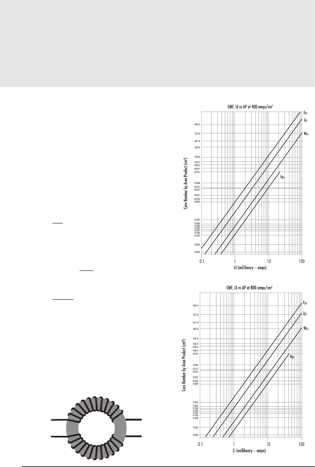
CORE SELECTION
The following is a design procedure for a toroidal, single-layer common mode inductor,
see Figure 12. To minimize winding capacitance and prevent core saturation due to
asymmetrical windings, a single layer design is often used. This procedure assumes a mini-
mum of thirty degrees of free spacing between the two opposing windings.
The basic parameters needed for common mode inductor design are current (I), impedance
(Zs), and frequency (f). The current determines the wire size. A conservative current density of
400 amps/cm2does not significantly heat up the wire. A more aggressive 800 amps/cm2
may cause the wire to run hot. Selection graphs for both levels are presented.
The impedance of the inductor is normally specified as a minimum at a given frequency.
This frequency is usually low enough to allow the assumption that the inductive reactance,
Xs, provides the impedance, see Figure 9. Subsequently, the inductance, Lscan be
calculated from:
Ls =Xs
2πf (1)
With the inductance and current known, Figures 13 and 14 can be used to select a core
size based on the LIproduct, where L is the inductance in mH and Iis the current in
amps. The wire size (AWG) is then calculated using the following equation based on
the current density (Cd) of 400 or 800 amps/cm2:
AWG = -4.31x In 1.889I(2)
Cd
The number of turns is determined from the core’s ALvalue as follows:
N= LSx 1061
/2 (3)
AL
DESIGN EXAMPLE
An impedance of 100Ωis required at 10kHz with a current of 3 amps. Calculating the
inductance from equation 1, Ls= 1.59 mH.
With an LIproduct of 4.77 at 800 amps/cm2, Figure 14 yields the core size for
chosen material. In this example, W material is selected to give high impedance up to
1MHz, see Figure 11. Figure 14 yields the core W41809TC. Page 13.6 lists the core
sizes and AL values. Using an ALof 12,200 mH/1,000 turns, equation 3 yields
N = 12 turns per side. Using 800 amps/cm2, equation 2 yields AWG = 21.
FIGURE 12: COMMON MODE INDUCTOR WINDING ARRANGEMENT
( )
( )
FIG. 14: CORE SELECTION AT 800 amps/cm2
FIG. 13: CORE SELECTION AT 400 amps/cm2
4.11
Inductor Core Selection
mag-inc.com
Inductor Design
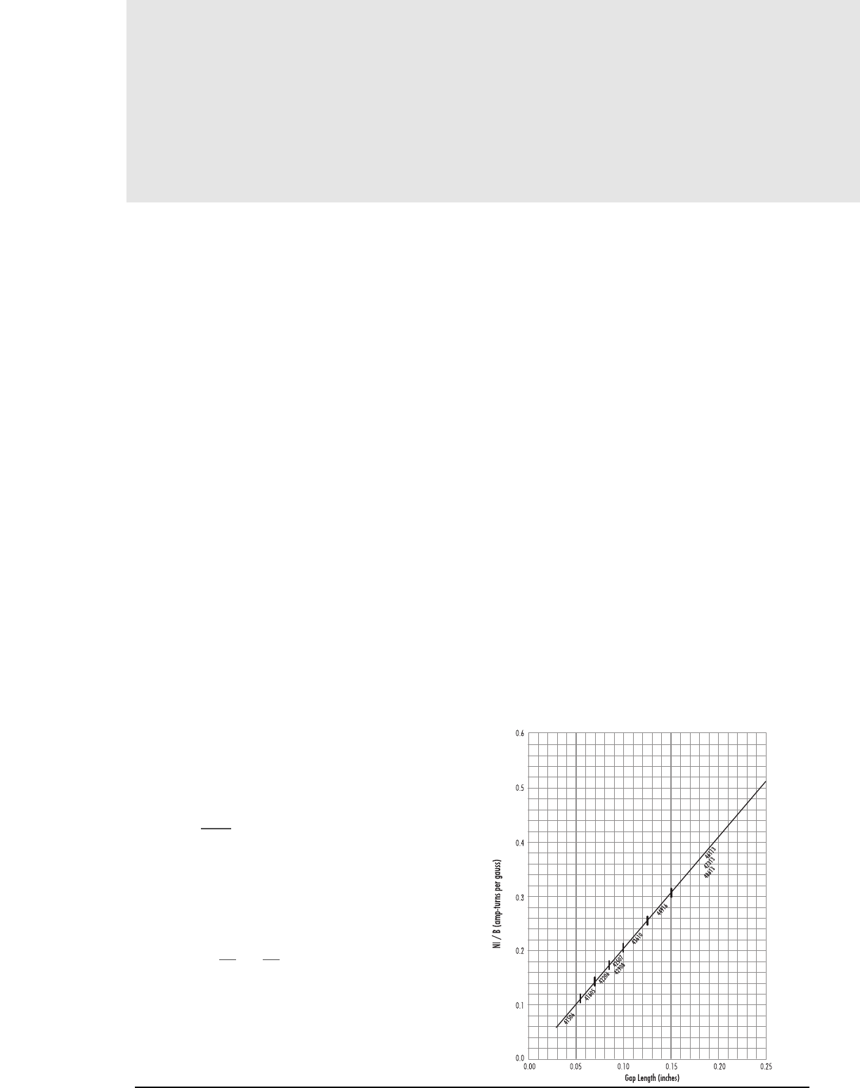
4.12MAGNETICS
Inductor Core Selection
HALL EFFECT DEVICES
Edwin H. Hall observed the “Hall Effect” phenomenon at John Hopkins University
in 1897. He monitored the current flowing from top to bottom in a thin
rectangular strip of gold foil by measuring the voltages at the geometric center
of the left edge and the right edge of the strip. When no magnetic field was
present, the voltages were identical. When a magnetic field was present
perpendicular to the strip, there was a small voltage difference of a predictable
polarity and magnitude. The creation of the transverse electric field, which is
perpendicular to both the magnetic field and the current flow, is called the Hall
Effect or Hall Voltage.
In metals the effect is small, but in semiconductors, considerable Hall voltages can be
developed. Designers should consider using Hall sensors in many applications where
mechanical or optical sensors have traditionally been used. To monitor ac or dc current
flow in a wire, the wire is wrapped around a slotted ferromagnetic core, creating an
electromagnet. The strength of the resulting magnetic field is used by the Hall sensor,
inserted in the air gap, to measure the magnitude and direction of current flowing in
the wire.
CORE SELECTION
In all cases, the effective permeability of a gapped core will be a function of the size
of the air gap and the initial permeability of the core material. Once the gap becomes
greater than a few thousandths of an inch, the effective permeability is determined
essentially by the air gap.
ANALYTICAL METHOD
1. Determine the flux operating extremes based on either the ∆V/∆B of the circuit
(volts/gauss), or the maximum flux sensitivity (gauss) of the sensor (as provided
by the sensor data sheet).
2. Choose a core based on the maximum or minimum dimension requirements to
allow windings, and based on the core cross-section dimensions. The cross-section
dimensions should be at least twice the gap length to ensure a relatively
homogeneous flux distribution bridging the gap.
3. Calculate the maximum required µefor the core:
µe=ble(1)
.4πNI
where B = flux density (gauss)
le = path length (cm)
N= turns
I= current (amps peak)
4. Calculate the minimum required gap length (inches):
lg= le 1 — 1 (0.3937) (2)
µe µi
where lg=gap length (inches)
le= path length (cm)
µe= effective permeability
µi= initial permeability
5. If the minimum required gap is greater than the sensor thickness,
ensure that the cross-section dimensions (length and width) are at least
twice the gap length. If not, choose a larger core and recalculate the
new gap length.
GRAPHICAL METHOD
1. Calculate NI/B (amp turns per gauss), knowing the flux operating extremes of
∆V/∆B or the maximum B sensitivity of the sensor.
2. Using Figure 15, follow the NI/B value from the vertical axis to the diagonal line
to choose a ferrite core size. Drop down from the diagonal line to the horizontal
axis to determine the gap length. The core sizes indicated on the selector chart take
into account gap length versus cross-section dimensions in order to maintain an
even flux distribution across the gap under maximum current.
TOROID GAPPING
Ferrite cores are a ferromagnetic ceramic material. As such, they exhibit
a very high hardness characteristic, they are very brittle, and they do not conduct heat very
efficiently. Machining a slot into one side of a ferrite toroid can be a difficult process.
Special techniques must be used to prevent chipping, cracking, or breaking of the cores.
Diamond bonded-tool machining is the preferred method of cutting ferrite. The bonded
diamond particle size should be approximately 100 to 170 mesh (150 to 90 µm). The
peripheral speed of the cutting wheel should be 5,000 to 6,000 feet/minute (1,500
to 1,800 meters/minute). The depth of the cut may be as deep as 1” (25 mm), but
in order to minimize residual stress, the cut should be limited to a maximum of 0.250”
(6 mm) per pass, the smaller the better. During all cutting, the wheel and core should
be flooded with ample amounts of coolant water to provide a lubricant as well as
remove heat buildup that would cause thermal stress cracking of the core.
( )
Inductor Design
GAPPED TOROID SELECTOR CHART
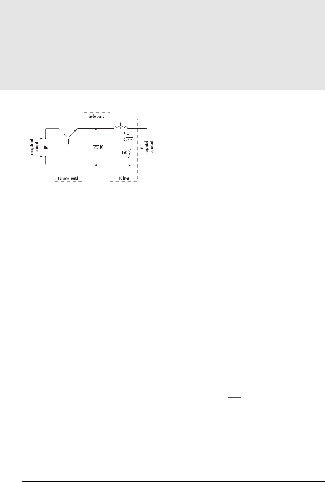
INDUCTOR CORE SIZE SELECTION (USING CORE
SELECTOR CHARTS) DESCRIPTION
A typical regulator circuit consists of three parts: transistor switch, diode
clamp, and an LC filter. An unregulated dc voltage is applied to the transistor
switch which usually operates at a frequency of 1 to 50 kilohertz. When the
switch is ON, the input voltage, Ein, is applied to the LC filter, thus causing current
through the inductor to increase; excess energy is stored in the inductor and capacitor
to maintain output power during the OFF time of the switch. Regulation is obtained
by adjusting the ON time, ton, of the transistor switch, using a feedback system
from the output. The result is regulated dc output, expressed as:
Eout = Ein ton f(1)
COMPONENT SELECTION
The switching system consists of a transistor and a feedback from the
output of the regulator. Transistor selection involves two factors – (1) voltage
ratings should be greater than the maximum input voltage, and (2) the
frequency cut-off characteristics must be high compared to the actual switching
frequency to insure efficient operation. The feedback circuits usually include
operational amplifiers and comparators. Requirements for the diode clamp
are identical to those of the transistor. The design of the LC filter stage is
easily achieved. Given (1) maximum and minimum input voltage, (2)
required output, (3) maximum allowable ripple voltage, (4) maximum and
minimum load currents, and (5) the desired switching frequency, the values
for the inductance and capacitance can be obtained. First, off-time (toff) of the
transistor is calculated.
toff= (1 - Eout/Ein max) /f (2)
When Ein decreases to its minimum value,
fmin = (1 - Eout/Ein min) /toff (3)
With these values, the required L and C can be calculated.
Allowing the peak to peak ripple current (∆i) through the inductor to be given by
∆i = 2 lo min (4)
the inductance is calculated using
L = Eout toff / ∆i (5)
The value calculated for (∆i) is somewhat arbitrary and can be adjusted to
obtain a practical value for the inductance.The minimum capacitance is given by
C = ∆i /8f min ∆eo(6)
Finally, the maximum ESR of the capacitor is
ESR max = ∆eo/∆i (7)
INDUCTOR DESIGN
Ferrite E cores and pot cores offer the advantages of decreased cost and low core
losses at high frequencies. For switching regulators, F or P materials are recommended
because of their temperature and dc bias characteristics. By adding air gaps to these
ferrite shapes, the cores can be used efficiently while avoiding saturation.
These core selection procedures simplify the design of inductors for switching
regulator applications. One can determine the smallest core size, assuming a winding
factor of 50% and wire current carrying capacity of 500 circular mils per ampere.
Only two parameters of the two design applications must be known:
(a) Inductance required with dc bias
(b) dc current
1. Compute the product of LI2where:
L= inductance required with dc bias (millihenries)
I= maximum dc output current - Iomax + ∆i
2. Locate the LI2value on the Ferrite Core Selector charts on pgs
4.15–4.18. Follow this coordinate in the intersection with the first core
size curve. Read the maximum nominal inductance, AL, on the Y-axis.
This represents the smallest core size and maximum ALat which
saturation will be avoided.
3. Any core size line that intersects the LI2coordinate represents a workable
core for the inductor of the core’s ALvalue is less than the maximum
value obtained on the chart.
4. Required inductance L, core size, and core nominal inductance (AL) are
known. Calculate the number of turns using
N = 103 L
AL
where L is in millihenries
5. Choose the wire size from the wire table on pg 5.8 using 500 circular
mils per amp.
√
4.13
Inductor Core Selection
mag-inc.com
Inductor Design
FIG. 15: HALL EFFECT DEVICE, CORE SELECTOR CHART

4.14 MAGNETICS
Inductor Core Selection
EXAMPLE
Choose a core for a switching regulator with the following requirements:
Eo=5 volts
∆eo=0.50 volts
Io max =6 amps
Io min =1 amp
Ein min =25 volts
Ein max =35 volts
f =20 KHz
1. Calculate the off-time and minimum switching, fmin, of the transistor
switch using equations 2 and 3.
toff = (1 – 5/35)/20,000 = 4.3 x 10⁻⁵ seconds and
fmin = (1 – 5/25)/4.3 x 10-5 seconds = 18,700 Hz.
2. Let the maximum ripple current, ∆i, through the inductor be
∆i = 2(1) = 2 amperes by equation 4.
3. Calculate L using equation 5.
L = 5(4.3 x 10⁻⁵)/2 = 0.107 millihenries
4. Calculate C and ESR max using equations 6 and 7.
C = 2/8 (18,700) (0.50) = 26.7 µ farads
and ESR max = 0.50/2 = .25 ohms
5. The product of LI2= (0.107) (8)2= 6.9 millijoules
6. Due to the many shapes available in ferrites, there can be several choices
for the selection. Any core size that the LI2 coordinate intersects can be
used if the maximum ALis not exceeded.
Following the LI2coordinate, the choices are:
(a) 45224 EC 52 core, AL315
(b) 44229 solid center post core, AL315
(c) 43622 pot core, AL400
(d) 43230 PQ core, AL250
7. Given the AL, the number of turns needed for the required inductance is:
ALTurns
250 21
315 19
400 17
8. Use #14 wire
Note: MAGNETICS®Molypermalloy and Kool Mu®powder cores have a distributed
air gap structure, making them ideal for switching regulator applications. Their dc
bias characteristics allow them to be used at high drive levels without saturating.
Information is available in Magnetics Powder Core Catalog and Brochure SR-IA,
“Inductor Design in Switching Regulators.”
FOR REFERENCES, SEE PAGE 14.4
Inductor Design
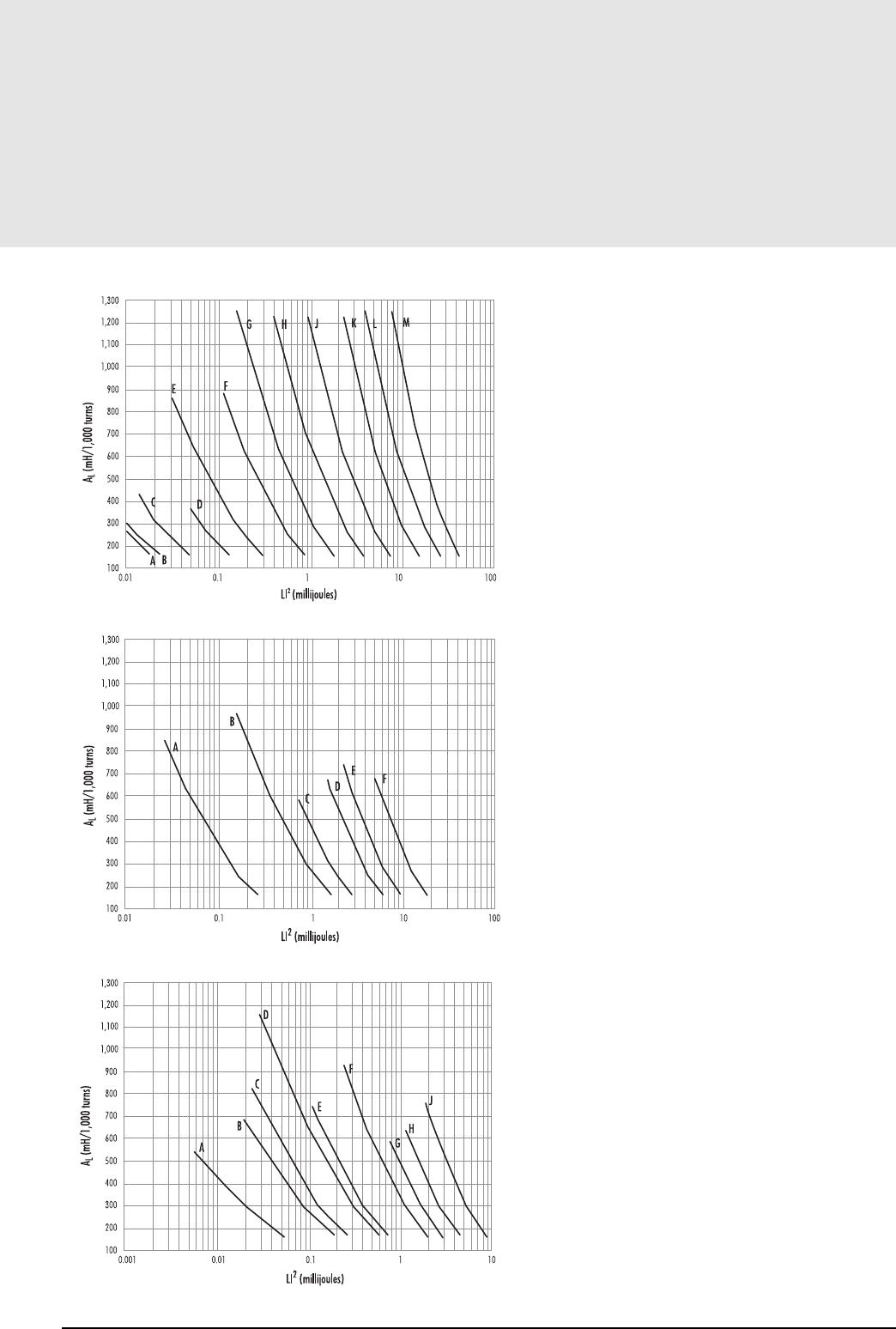
4.15
These vertical mount accessories are designed to accommodate a variety of toroidal core
sizes on to printed circuit board or other assemblies.
(Check factory for new parts not shown here)
Selector Charts
A — 40903
B — 40704
C — 40905
D — 41107
E — 41408
F — 41811
G — 42213
H — 42616
J — 43019
K — 43622
L — 44229
M — 44529
A — 41408 (RS)
B — 42311 (DS, RS)
42318 (DS, RS)
C — 42616 (DS)
D — 43019 (DS, RS)
E — 43622 (DS)
F — 44229 (DS)
A — 40707 (EP7)
41010 (EP10)
41110 (RM4)
B — 41313 (EP13)
C — 41510 (RM5)
D — 41717 (EP17)
E — 41812 (RM6)
F — 42316 (RM8)
G — 42120 (EP20)
H — 42809 (RM10 PLANAR)
42819 (RM10)
J — N43723 (RM12)
Core Selection
mag-inc.com
PC (POT) CORES
RS (ROUND-SLAB) & DS (DOUBLE-SLAB) CORES
RM AND EP CORES
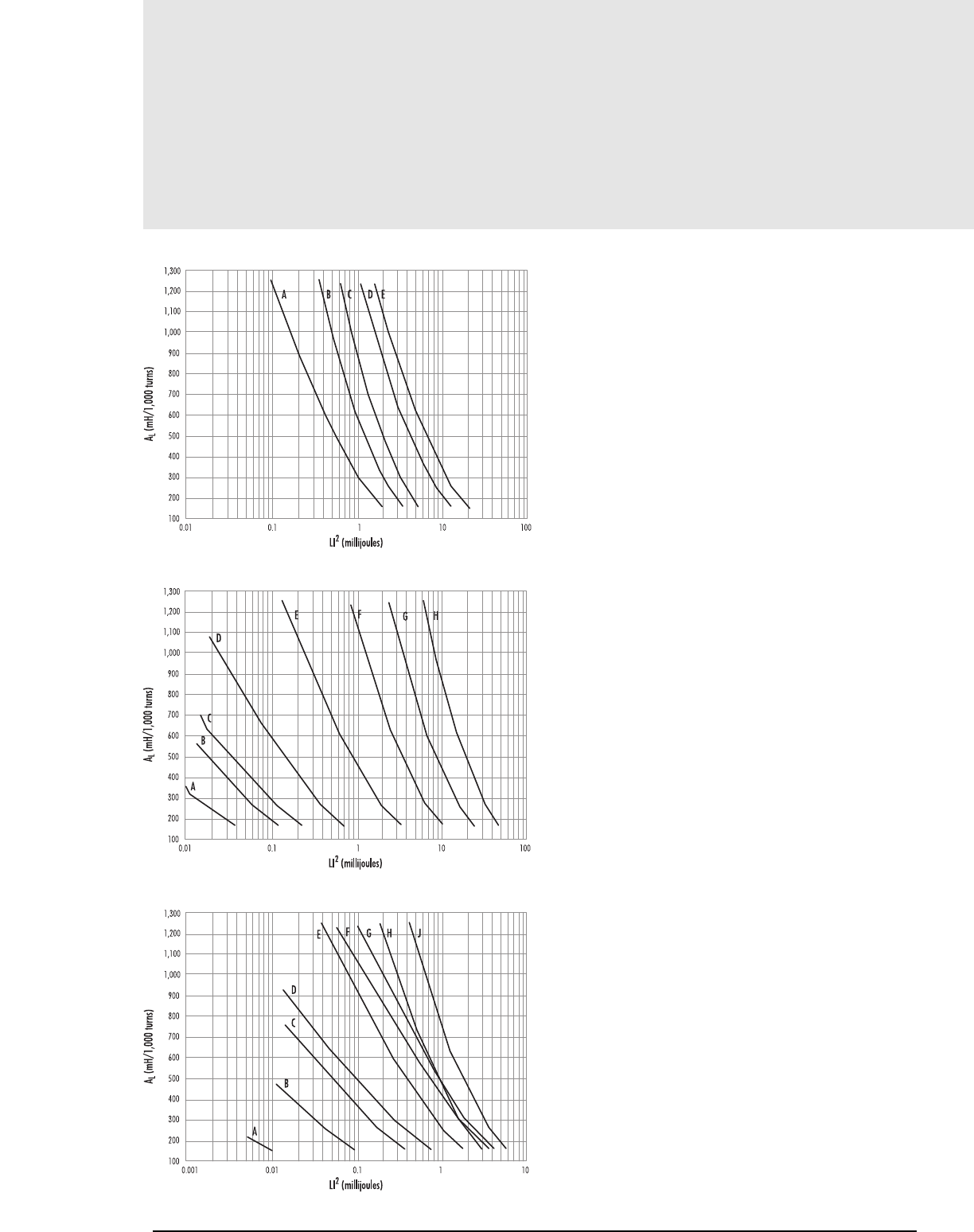
4.16 MAGNETICS
Selector Charts
A — 42016
42020
B — 42614
C — 42610
42620
42625
43214
D — 43220
43230
E — 43535
44040
A — 41203 (EE)
B — 41707 (EE)
C — 41808 (EE)
D — 42510 (EE)
E — 43009 (EE)
43515 (EE)
F — 44317 (EE)
G — 44721 (EE)
H — 45724 (EE)
A — 40904 (EE)
B — 41208 (EE)
41209 (EE)
C — 41205 (EE)
42211 (EE)
D — 42515 (EE)
E — 41810 (EE)
43007 (EE)
F — 43524 (EE)
G — 42530 (EE)
43520 (EE)
H — 42520 (EE)
J — 42810 (EE)
43013 (EE)
Core Selection
PQ CORES
LAMINATION SIZE E CORES
E CORES
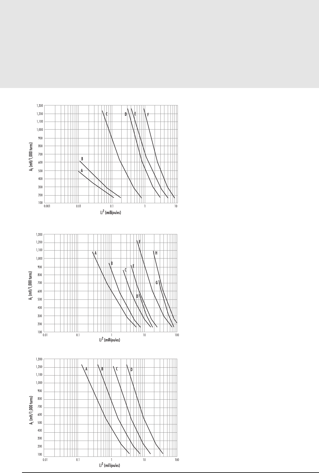
4.17
Core Selection
Selector Charts
A — 42110 (EE)
B — 41709 (EE)
C — 41805 (EE, EI)
D — 42216 (EE, EI)
E — 44008 (EE, EI)
F — 43208 (EE, EI)
43618 (EE, EI)
A — 44016 (EE)
B — 44011 (EE)
C — 44020 (EE)
D — 44308 (EE, EI)
E — 44022 (EE)
44924 (EE)
45021 (EE)
46016 (EE)
F — 45528 (EE)
45530 (EE)
47228 (EE)
48020 (EE)
G — 46410 (EE)
H — 49938 (EE, EI)
A — 43517
B — 44119
C — 45224
D — 47035
mag-inc.com
E, EI CORES
E, EI CORES
EC CORES
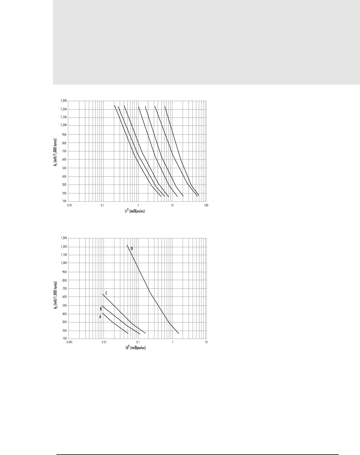
4.18MAGNETICS
Selector Charts
A — 43434 (ETD34)
B — 43521 (EER35L)
C — 43939 (ETD39)
D — 44216 (EER42)
44444 (ETD44)
E — 44949 (ETD49)
F — 47054
G — 45959 (ETD59)
A — 41309 (EEM12.7)
40906 (ER 9.5)
B — 42110
41515 (EFD15)
C — 41709
D — 42523 (EFD25)
ABC D E F G
1300
10 10010.10.01
1200
1100
1000
900
800
700
600
500
400
300
200
100
LI2 (millijoules)
AL (mH/1000 turns)
ETD and EER Cores
dc_bias_etd_eer.eps
1300
1010.10.010.001
1200
1100
1000
900
800
700
600
500
400
300
200
100
LI2 (millijoules)
AL (mH/1000 turns)
dc_bias_eem_efd_er.eps
EEM, EFD, and ER Cores
A
B
C
D
Core Selection
ETD AND EER CORES
EEM, EFD, AND ER CORES
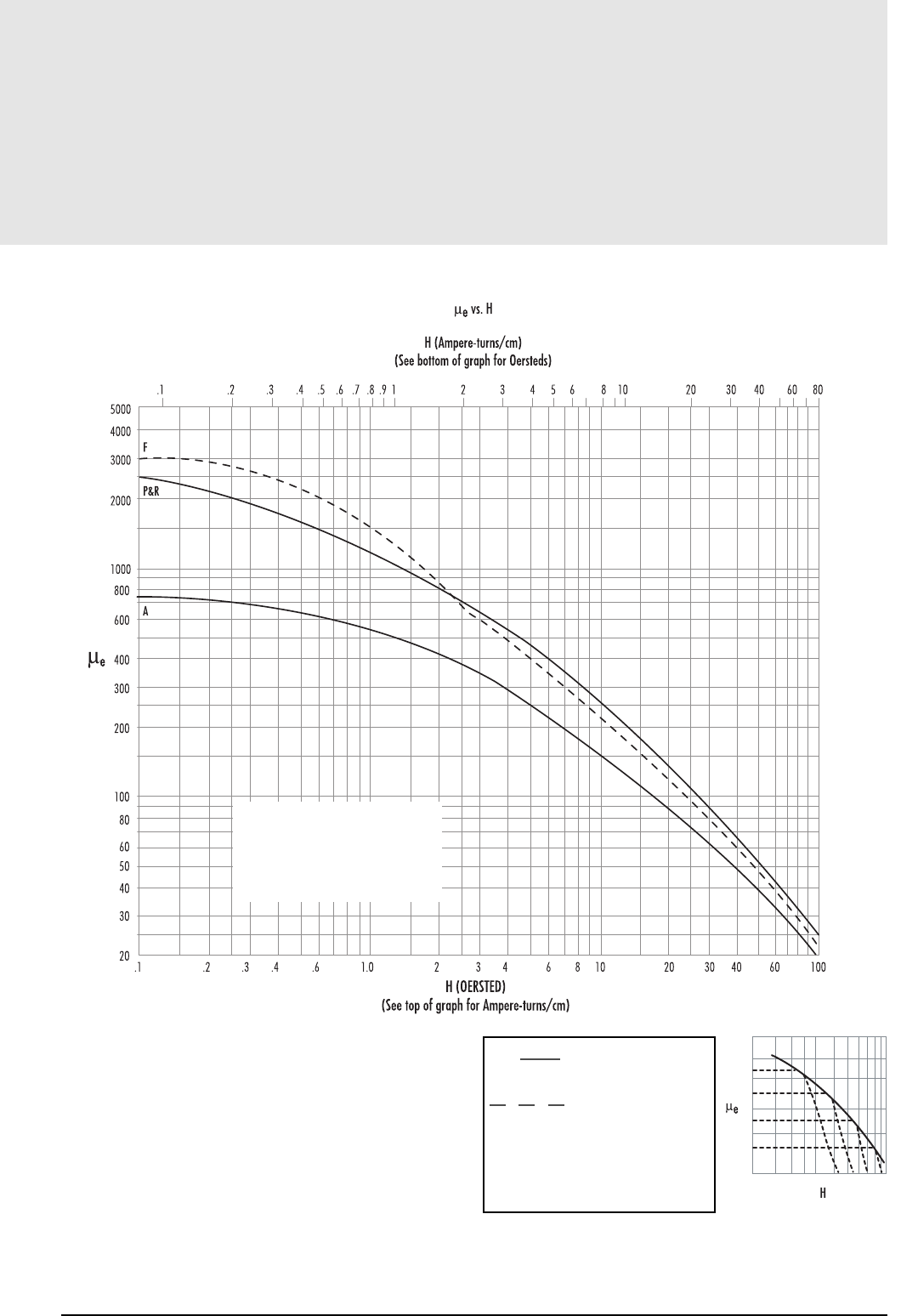
4.19
Gapped Applications
DC Bias Data
5000
F
P&R
A
4000
3000
2000
1000
800
600
400
300
200
100
80
60
50
40
30
20 .1
.1 .2 .3 .4 .5 .6 .7 .8 .9 1 2 3 4 5 6 8 10 20 30 40 60 80
.2 .3 .4 .6 1.0 2 3 4 6 8 10 20 30 40 60 100
µe vs.H
H (Ampere-turns/cm)
(See bottom of graph for Oersteds)
H (OERSTED)
(See top of graph for Ampere-turns/cm)
EFFECTIVE PERMEABILITY
µe
Gap_dc_bias.eps
NI = 0.80 x H x le
Where
NI = maximum allowable ampere-turns
H = DC Bias level
le= core path length (cm)
The above curves represent the locus of points up to which effective
permeability remains constant. They show the maximum
allowable DC
bias, in ampere-turns, without a reduction in inductance. Beyond this
level, inductance drops rapidly.
Example: How many ampere-turns can be supported by an
R42213A315 pot core without a reduction in inductance value?
l
e= 3.12 cm µe= 125
Maximum allowable H = 25 Oersted (from the graph above)
NI (maximum) = 0.80 x H x le= 62.4 ampere-turns
OR (Using top scale, maximum allowable H = 20 A-T/cm.)
NI (maximum) = A-T/cm x le
= 20 x 3.12
= 62.4 A-T
H
µe
Gap_dc_bias(little).eps
DC BIAS DATA — FOR GAPPED APPLICATIONS
mag-inc.com
µeAL•le
4πAe
11lg
µeµile
Ae= effective cross sectional area (cm2)
AL= inductance/1,000 turns (mH)
µi= initial permeability
lg= gap length (cm)
=
=
+
Effective Permeability

4.20 MAGNETICS
Notes
The information contained in this section is primarily concerned with the design of linear inductors
for high frequency LC tuned circuits using ferrite pot cores. Magnetics has arranged the data in this
section for ease in (1) determining the optimum core for these LC circuits and (2) ordering the
items necessary for any particular Pot Core assembly.
Featured are magnetic data, temperature characteristics, core dimensions, accessories, and other
important design criteria. Standard Q curves are available on special request, contact Magnetics
Application Engineering.
The data presented in this section are compiled mainly for selecting cores for high Q resonant LC
circuits. However, much of this information can also be used to design pot cores into many other
applications, including high frequency transformers, chokes, and other magnetic circuit elements.
POT CORE ASSEMBLY
A ferrite pot core assembly includes the following items:
1. TWO MATCHED POT CORE HALVES
2. BOBBIN ON WHICH THE COILS ARE WOUND
3. TUNING ASSEMBLY
4. A CLAMP FOR HOLDING THE CORE HALVES TOGETHER
The pot core shape provides a convenient means of adjusting the ferrite structure to meet the spe-
cific requirements of the inductor. Both high circuit Q and good temperature stability of inductance
can be obtained with these cores. The self-shielded pot core isolates the winding from stray mag-
netic fields or effects from other surrounding circuit elements.
The effective permeability (µe) is adjusted by grinding a small air gap in the center post of the pot
core. For transformers and some inductors, no ground air gap is introduced, and the effective per-
meability is maximized. The effective permeability of the pot core will always be less than the
material initial permeability (µi) because of the small air gap at the mating surfaces of the pot
core halves. For other inductors where stability of inductance, Q, and temperature coefficient must
be closely specified, a controlled air gap is carefully ground into the center post of one or both of
the pot core halves. When fitted together, the total air gap then will determine the effective per-
meability and control the magnetic characteristics of the pot core. Finer adjustment of the effec-
tive permeability (gapped pot core inductance) can be accomplished by moving a ferrite cylinder
or rod into the air gap through a hole in the center post.
Magnetics ferrites are available in various initial permeabilities (µi) which for filter applications
cover frequency ranges into the megahertz region. Magnetics produces a wide variety of pot core
sizes which include fourteen (14) international standard sizes*. These range from 5 x 6 mm to
45 x 29 mm, these dimensions representing OD and height of a pair. Each pot core half is tested
and matched with another half to produce a core with an inductance tolerance of ± 3% for most
centerpost ground parts.
5.1
Section 5
Pot Cores
Low Level
Applications
*IEC Publication No. 133 (1961).

Pot Core Design
5.2 MAGNETICS
Advantages of
Pot Core Assemblies
ADVANTAGES OF POT CORE ASSEMBLIES
• SELF-SHIELDING
Because the wound coil is enclosed within the ferrite core, self-shielding
prevents stray magnetic fields from entering or leaving the structure.
• COMPACTNESS
Self-shielding permits more compact arrangement of circuit components,
especially on printed circuit boards.
• MECHANICAL CONVENIENCE
Ferrite pot cores are easy to assemble, mount, and wire to the circuit.
• LOW COST
As compared to other core materials, ferrites are easier to make in
unusual configurations (such as pot cores), resulting in a lower cost
component. In addition, winding a pot core is usually quick and inex-
pensive because coils can be pre-wound on bobbins. When other costs of
assembly, mounting, wiring, and adjustment are added, the total cost is
often less than with other core materials or shapes.
• ADJUSTABILITY
Final adjustment is accomplished by moving a threaded core in and out
of the centerpost, and adjustment in the field is relatively easy as com-
pared to any other type of construction.
• IMPROVED TEMPERATURE STABILITY AND Q
Air gaps inserted between the mating surfaces of the centerposts provide
good temperature stability and high Q.
• WIDE CORE SELECTION
Many combinations of materials, physical sizes, and inductances offer
the design engineer a large number of choices in core selection.
• LOW LOSSES AND LOW DISTORTION
Since ferrites have high resistivities, eddy current losses are extremely
low over the applicable frequency range and can be neglected.
Hysteresis losses can be kept low with proper selection of material, core
size, and excitation level.
SPECIAL ADVANTAGES OF MAGNETICS POT CORE ASSEMBLIES
• UNIQUE ONE PIECE CLAMP
Provides simple assembly of the two core halves. Easy bending action
allows insertion of the core assembly into the clamp, and spring tension
holds the assembly rigidly and permanently in place. Rivet, screw, or cir-
cuit board tab mounting is available.
• CHOICE OF LINEAR OR FLAT TEMPERATURE CHARACTERISTICS
Provides a close match to corresponding capacitors.
• CONSISTENCY AND UNIFORMITY
Modern equipment with closely controlled manufacturing processes pro-
duce ferrite pot cores that are magnetically uniform, not only within one
lot but from lot to lot.

Pot Core Design
5.3
mag-inc.com
Important Considerations
The selection of a pot core for use in LC resonant circuits and high fre-
quency inductors requires a careful analysis of the design, including the fol-
lowing:
• OPERATING FREQUENCY.
• INDUCTANCE OF THE WOUND POT CORE ASSEMBLY.
• TEMPERATURE COEFFICIENT OF THE INDUCTOR.
• Q OF THE INDUCTOR OVER THE FREQUENCY RANGE.
• DIMENSIONAL LIMITATIONS OF THE COIL ASSEMBLY.
• MAXIMUM CURRENT FLOWING THROUGH THE COIL.
• LONG TERM STABILITY.
The important characteristics which strongly influence the above require-
ments are:
1. Relative loss factor - . This factor reflects the relative losses in
the core and varies with different ferrite materials and changes in operat-
ing frequency. When selecting the proper material, it is best to choose the
one giving the lowest over the range of operating frequencies. In this
way, the highest circuit Q can be expected. In a situation where the
curves may cross over or coincide at various frequencies, each ferrite mate-
rial should be considered in view of all circuit parameters of importance,
including size, temperature coefficient, and disaccommodation, as well as
Q. With this analysis, little doubt is left concerning the optimum selection
of a proper core material.
2. Inductance factor (AL). The selection of this parameter is based on a log-
arithmic progressive series of values obtained by dividing a logarithmic
decade into 5 equal parts (International Standardization Organization R5
series of preferred numbers). Since the (AL) values for the various core
sizes are standard, they may be graphed or charted for ease of determin-
ing the required turns (N) to give the value of inductance needed. Pot
cores with various (AL) values are obtained by grinding closely-con-
trolled air gaps in the centerposts of the cores. Small gaps are processed
by gapping one core half. For larger gaps, both halves are gapped.
3. Temperature Coefficient (TCe). The temperature coefficient of the pot
core is important in LC tuned circuits and filters when attempting to stabi-
lize the resonant frequency over a wide range of temperatures. This tem-
perature coefficient (TCe) is determined by the properties of the ferrite
material and the amount of air gap introduced. Ferrite materials have been
designed to produce gapped pot core temperature coefficients that balance
the opposite temperature characteristics of polystyrene capacitors, or match
similar flat temperature coefficients of silvered mica capacitors. Therefore,
careful selection of both capacitors and pot cores with regard to tempera-
ture coefficient will insure the optimum temperature stability.
4. Quality Factor (Q)*. The quality factor is a measure of the effects of the
various losses on circuit performance. From the designer’s point of view,
these losses should include core losses, copper losses, and winding capaci-
tive losses. Therefore, Q will be affected greatly by the number and place-
ment of the turns on the bobbin, and the type and size of wire used. At
higher frequencies, litz wire would reduce the eddy current losses in the
windings and produce a higher Q than solid wire. Q data include the effects
of winding and capacitive losses, which, if removed, would produce signif-
icantly higher calculated Q values. Consequently, the Q curves represent
more realistically the actual Q values that would be obtained from circuit
designs.
5. Dimensional Limitations. Many circuit designs contain dimensional and
weight limitations which restrict the size of the inductor and the mounting
techniques used. Sometimes, minimum weight or volume is sacrificed to
obtain better circuit performance.
6. Current Carrying Capacity. Inductive circuits containing ferrite pot cores
are normally operated at extremely low levels of AC excitation to insure the
best possible performance. However, the current flowing in the coil may be
much higher than anticipated due to superimposed DC currents, or unex-
pected surges of AC. Therefore, the selection of the wire size used in an
inductor design is influenced by both of these factors. Wire data is pre-
sented in this catalog as a guide in considering these operating conditions.
- Refer to Tables 5 and 6, page 5.10.
7. Long Term Stability (DFe). In critical inductive designs, especially reso-
nant circuits, the designer must be concerned with long term drift in reso-
nant frequency. This stability drift (or decrease in inductance), known as
disaccommodation, can be calculated for each pot core size and inductance
factor (AL). It occurs at a logarithmic rate, and the long term change of
inductance may be calculated from the formula:
where is the decrease in inductance between the times t1and t2, DFe
is the Effective Disaccommodation Coefficient of the core selected, and t1is
the elapsed time between manufacture of the core (stamped on shipping
container) and its assembly into the circuit, while t2is the time from man-
ufacture of the core to the end of the expected life of the device.
Disaccommodation starts immediately after the core is manufactured as it
cools through its Curie Temperature. At any later time as the core is demag-
netized, or thermally or mechanically shocked, the inductance may increase
to its original value and disaccommodation begins again. Therefore, con-
sideration must be given to increases in inductance due to magnetic, ther-
mal or physical shock, as well as decreases in inductance due to time. If no
extreme conditioning is expected during the equipment life, changes in
inductance will be small, because most of the change occurs during the first
few months after manufacture of the core.
*Q curves referred to here are available on special request. Contact
Magnetics Applications Engineering.
1
µiQ
1
µiQ1
µiQ
∆L = DFe x log t2
L t1
∆L
L

5.4 MAGNETICS
Pot Core Design
Important Considerations
LIMITS ON EXCITATION
Inductors designed using pot cores are usually identified as linear magnet-
ic components because they are operated within the range of negligible
change of effective permeability with excitation. To calculate suggested
maximum AC excitation levels, use the following formula:
4.44 for sine wave
4.0 for square wave
where B = 200 gausses, the suggested conservative limit.
N = turns on pot core
f = operating frequency in hertz.
Ae= effective area of the pot core in cm2.
Because superimposed DC current also affects linearity of inductance in pot
cores, consideration for DC currents must also be given. The equation
shown above must be modified to include effect of DC bias. The combined
equation now becomes:
where B = 200 gausses, the suggested conservative limit.
Idc = bias current in amperes.
See pages 4.15 - 4.19 for DC bias data on Magnetics power ferrites.
B = Erms x 108
4.44 AeNf
B = Erms x 108 + Nldc AL
(combined) 4.44 AeNf 10Ae

5.5
mag-inc.com
Pot Core Design
Notes

5.6 MAGNETICS
Pot Core Design
Magnetics ferrite pot cores can be assembled with or without clamping
hardware or tuning devices.
Mounting clamps are available for the 40905, 41107, 41408, 41811,
42213, 42616, 43019, 43622, and 44229 pot core sizes. These clamps
normally eliminate the need to cement the pot core halves together. The
mating surfaces of the pot core must be cleaned to remove moisture,
grease, dust, or other foreign particles, before clamping or cementing.
If the cementing method is chosen, a small amount of cement is placed on
the mating surface of the pot core skirt, being careful to keep the center-
post free of all cement. The pot core halves are brought together and rotat-
ed together under slight pressure to distribute the cement evenly around
the skirt. The halves are separated and the wound bobbin is set in place. A
small amount of cement is now placed on the exposed flange of the bob-
bin to bond it in the pot core assembly and thus insure no movement. The
other core half is replaced, the centerpost holes and wire aperture aligned,
and the unit clamped together in a pressure jig. Permanent bonding is
accomplished by curing the cement at elevated temperatures according to
the manufacturer’s recommendations. After curing, storage for a minimum
of 24 hours, and heat cycling between room temperature and 70°C may be
required before final testing or tuning is completed.
The tuning adjusters can be inserted into the pot core immediately after the
cemented core halves have been cured and the assembly can then be heat
cycled. Some adjusters require insertion of the base into the centerpost
hole prior to assembly of the pot core into the clamp when a clamp is used
for mounting pg 5.8. The adjuster is usually made in two parts - the plas-
tic base with a threaded hole, and a ferrite cylinder imbedded in a plastic
screw. The base is pressed into the centerpost of the pot core, and the plas-
tic screw is turned into the base until the ferrite cylinder enters the air gap.
Tuning is completed when the inductance of the pot core assembly reaches
the proper value. If this initial adjustment is expected to be the final one,
cementing is recommended to prevent accidental detuning. If precise induc-
tance values are expected, final tuning should not be completed earlier
than 24 hours after the pot core assembly has been cured or clamped.
“TB-P” bases, which are polypropylene, may be etched in order to roughen
the adhering surface and improve the bonding that is achieved.
Plastic screw drivers are available upon request for use in final tuning.
Tuning assemblies are available for most standard size pot cores. Contact
Magnetics Application Engineering for details.
Assembly Notes
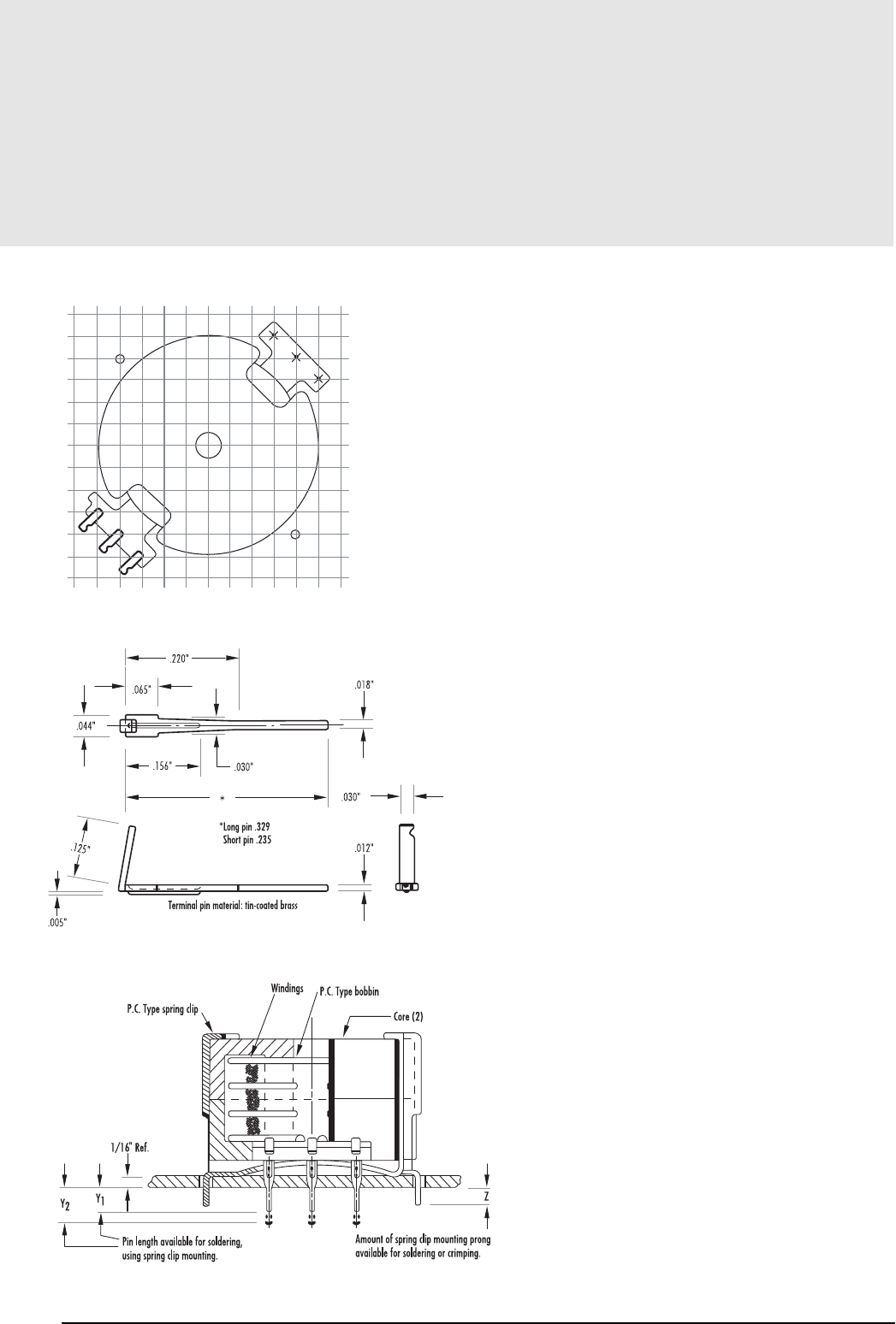
5.7
mag-inc.com
Pot Core Design
Assembly Notes
FIGURE 1
FIGURE 2
FIGURE 3
PRINTED CIRCUIT BOBBINS AND MOUNTING HARDWARE
Many sizes in the standard pot cores can be supplied with printed circuit
board bobbins. The grid pattern (Figure 1) illustrates the location of 6 pin
type bobbins. The soldering pins are arranged to fit a grid of 0.1 “, and
they will also fit printed circuit boards with 2.50 mm grids. The pin
length is sufficient for a board thickness up to .187”. Terminal pin details
are illustrated in Figure 2. The board holes should be .046” + .003” in
diameter (#56 drill). The bobbin should be cemented to the lower pot
core half.
For some core types, printed circuit board mounting clamps are also avail-
able. A cross section of a completed core assembly using clamps is shown
in Figure 3. When clamps are not available, the pot core halves must be
cemented together.
Printed circuit board hardware for EP, RM and RS cores is described in the
sections covering these core types.
PRINTED CIRCUIT BOBBINS SOLDERING INSTRUCTIONS
1. A solder pot should be used to solder the leads to the terminals.
Preferred solder is 63/37 tin/lead eutectic. The solder temperature
should be between 275°-300°C. Lower or higher temperatures will
both damage the bobbin. Modern soldering techniques commonly use
temperatures in excess of the softening points of all thermoplastic bob-
bin materials. Extreme care is required to prevent loosening of the ter-
minals during soldering.
2. Insulation should be removed from the ends of the wire before solder-
ing. This is especially important when litz wire is used. The preferred
method is by burning.
3. Dip wound terminals into liquid soldering flux. A rosin based flux in alco-
hol solution should be used. Allow flux to air dry.
4. The bobbin should be immersed only far enough to cover the terminals.
5. The part should be immersed in the solder for 2-4 seconds, depending
on the size of the wire used.

WIRE SIZE WIRE AREA (MAX.)* HEAVY TURNS** RESISTANCE CURRENT CAPACITY (MA)
AWG Circular Mils cm2103per in2per cm2Ohms/1000’ @750 Cir. Mil/amp @500 Cir. Mil/amp
10 11,470 58.13 89 13.8 .9987 13,840 20,768
11 9,158 46.42 112 17.4 1.261 10,968 16,452
12 7,310 37.05 140 21.7 1.588 8,705 13,058
13 5,852 29.66 176 27.3 2.001 6,912 10,368
14 4,679 23.72 220 34.1 2.524 5,479 8,220
15 3,758 19.05 260 40.3 3.181 4,347 6,520
16 3,003 15.22 330 51.2 4.020 3,441 5,160
17 2,421 12.27 410 63.6 5.054 2,736 4,100
18 1,936 9.812 510 79.1 6.386 2,165 3,250
19 1,560 7.907 635 98.4 8.046 1,719 2,580
20 1,246 6.315 800 124 10.13 1,365 2,050
21 1,005 5.094 1,000 155 12.77 1,083 1,630
22 807 4.090 1,200 186 16.20 853 1,280
23 650 3.294 1,500 232 20.30 681 1,020
24 524 2.656 1,900 294 25.67 539 808
25 424 2.149 2,400 372 32.37 427 641
26 342 1.733 3,000 465 41.0 338 506
27 272 1.379 3,600 558 51.4 259 403
28 219 1.110 4,700 728 65.3 212 318
29 180 0.9123 5,600 868 81.2 171 255
30 144 0.7298 7,000 1,085 104 133 200
31 117 0.5930 8,500 1,317 131 106 158
32 96.0 0.4866 10,500 1,628 162 85 128
33 77.4 0.3923 13,000 2,015 206 67 101
34 60.8 0.3082 16,000 2,480 261 53 79
35 49.0 0.2484 20,000 3,100 331 42 63
36 39.7 0.2012 25,000 3,876 415 33 50
37 32.5 0.1647 32,000 4,961 512 27 41
38 26.0 0.1318 37,000 5,736 648 21 32
39 20.2 0.1024 50,000 7,752 847 16 25
40 16.0 0.0811 65,000 10,077 1,080 13 19
41 13.0 0.0659 80,000 12,403 1,320 11 16
42 10.2 0.0517 100,000 15,504 1,660 8.5 13
43 8.40 0.0426 125,000 19,380 2,140 6.5 10
44 7.30 0.037 150,000 23,256 2,590 5.5 8
45 5.30 0.0269 185,000 28,682 3,348 4.1 6.2
5.8
Wire Tables
TABLE 5 - MAGNET WIRE
Wire Tables

5.9
mag-inc.com
Wire Tables
TABLE 6 - LITZ WIRE
5/44 28,000 4,341
6/44 25,000 3,876
7/44 22,000 3,410
12/44 13,000 2,016
20/44 7,400 1,147
30/44 4,000 620
40/44 3,000 465
50/44 2,300 356
60/44 1,900 294
LITZ TURNS***
Wire Size per in2per cm2LITZ TURNS***
Wire Size per in2per cm2
72/44 1,500 232
80/44 1,400 217
90/44 1,200 186
100/44 1,100 170
120/44 900 140
150/44 700 108
180/44 500 77
360/44 250 38
*Areas are for maximum wire area plus maximum insulation buildup.
**Based on a typical machine layer wound coil.
*** Based on a typical layer wound coil.
Wire Tables
5.10
ASTM
Test D792 D570 D638 D638 D790 D790 D256 D696 D648 D149 D150 D150 D257 D495 UL94
Rynite
FR-515 1.53 0.07 15.5 23 8.5 1.2 H 1.7 210 670 3.1 0.004 1015 67 V-O 30 E69578 250
Rynite 1.67 0.05 22 32 1.5 1.6 H 1.4 224 650 3.8 0.011 1015 117 V-O 33 E69578, 270
FR-530 E69939,
E81777
Delrin 1.42 0.25 19.5 29 1.4 1.6 A 2.3 1.63 550 3.8 HB 16 E66288R
Delrin 1.42 0.25 10 4.5 4.2 1.3 10.4 130 500 3.7 0.005 1015 220 HB E66288 175
900
Zytel 1011.14 1.2 12 23 0.41 1.0 B 4.0 232 480 3.9 0.02 1013 HB 28 E41938 250
Zytel 1.56 0.6 22.8 11.9 1.9 B 2.2 241 437 3.6 0.009 1014 103 V-O E41938 250
FR-50
Zytel 1.38 18 9.0 2.0 249 530 3.7 135 HB E41938 255
70G33L
RTP 1.66 0.6 21 16 33 15.0 2.0 3.4 232 475 3.8 0.015 1014 V-O E84658 248
205FR
LNP 1.46 0.6 31 42 16.0 2.60 260 HB E45195 260
RF1008
Technyl 1.38 0.75 19.6 29.7 2.5 250 1014 V-O 32 E44716
A20-V25
Crastin 1.45 7.5 11.7 3.9 0.8 B 179 560 3.1 0.002 1016 V-0 30 E69578(M) 240
S660FR
E4008 1.70 0.02 21.7 20.1 17.7 2.0 4.5 1013 130 V-O 48 E54705(M) 330
Rogers 1.75 0.07 12 23- 22 1.2 B 1.9 232 500 4.5 0.019 1013 180 V-O 40 E20305 400
RX630 28
Rogers 1.75 0.07 12 23- 22 1.2 B 1.9 232 500 4.5 0.019 1013 180 V-O 40 E123472 400
RX660B 28
Vyncolite 1.75 0.07 12 23- 22 1.2 B 1.9 232 500 4.5 0.019 1013 180 V-0 40 E63312(M) 400
X-611 28
Fiberite 1.79 9.5 17.5 23 0.6 B 1.9 229 400 4.6 0.026 2x10¹³ 180 V-O 42.1 E46372
4017F @1MHz @1MHz
PM9630 1.82 27 1.5 249 305 1011 80 V-O E41429
T3733J 1.41 0.40 8 11 42 170 300 1012 V-1 E59481(S)
*A-105˚C, B-130˚C, H-180˚C
Plastics Information
Specific Gravity
Water Absorption, 24h 73˚F (%)
Tensile Strength (103psi)
Tensile Modulus (103psi)
Flexural Strength (103psi)
Flexural Modulus (105psi)
Izod Impact, Notched (ft.-lb/in)
Temperature Class*
Coefficient of expansion (10-5 in/in˚C)
Deflection Temperature 264 psi (˚C)
Dielectric Strength (v/mil)
Dielectric Constant (@1kHz)
Dissipation Factor (@1kHz)
Vol. Resistivity
@73˚F, 50% RH (ohm-cm)
Arc Resistance (Sec)
Flammability
Oxygen Index (%O2)
UL Card No.
Max solder temperature (˚C)
MAGNETICS

5.11
mag-inc.com
This document reports typical data as compiled from various suppliers’ lit-
erature. Magnetics assumes no responsibility for the use of the information
presented herein and hereby disclaims all liability in regard to use.
Modern soldering techniques commonly use temperatures in excess of the
softening points of all thermoplastic bobbin materials. These typically run
from 400˚C - 600˚C. Extreme care is required to prevent loosening of the
terminals during soldering.
Crastin-DuPont, Wilmington, DE
Delrin-DuPont, Wilmington, DE
Rynite-DuPont, Wilmington, DE
Zytel DuPont, Wilmington, DE
Rogers RX630-Rogers Corporation, Manchester, CT
Rogers RX660B-Rogers Corporation, Manchester, CT
PM9360-Sumitomo Chemical Company. Ltd., Tokyo, Japan
E-4008-Sumitomo Chemical Company. Ltd., Tokyo, Japan
Fiberite-ICI Inc., Winona, MN
LNP-LNP engineering Plastics, Exton,PA
RTP-RTP Company, Winona, MN
Technyl-Nytech, Lyon, France
T373J-Chang Chun Plastics Co. Ltd., Taipei, Taiwan
Vyncolite RX611-31-Vynckier S.A., Belgium
Magnetics is a UL-recognized molder in the QMMY2 fabricated parts pro-
gram. Many bobbins shown in this catalog are covered. Contact Magnetics
for details on specific parts.
Plastics Information
THERMOPLASTIC MATERIALS
NAME TYPE
Rynite FR-515 Thermoplastic Polyester (PET)
Rynite FR-530 Thermoplastic Polyester (PET)
Delrin, Delrin 900 Acetal Resin
LNP RF1008 6/6 Nylon, 40 % glass-filled
Zytel 70633L 6/6 Nylon, 33% glass-filled
RTP 205FR 6/6 Nylon, 30% glass-filled
Zytel 101 6/6 Nylon, 30% glass-filled
Technyl A20-V25 6/6 Nylon, 25% glass-filled
Zytel FR-50 6/6 Nylon, 25% glass-filled
Crastin S660FR PBT
E-4008 Thermoplastic LCP
THERMOSET PHENOLIC
MATERIALS
Rogers RX360 Fiberlite 4017F
Rogers RX660B PM9630
Vyncolyte X-611 T373J

5.12
Notes
MAGNETICS
POT CORES
The pot core shape is a convenient means of adjusting the ferrite structure to meet the specific
requirements of an application. Both high circuit Q and good temperature stability of inductance
can be obtained with these cores. Pot cores, when assembled, nearly surround the wound bobbin.
This self-shielded geometry isolates the winding from stray magnetic fields or effects from other
surrounding circuit elements.
Both plain and printed circuit bobbins are available, as are mounting and assembly hardware.
Typical applications for pot cores include; differential inductors, power transformers, power
inductors, converter and inverter transformers, filters, both broadband and narrow transformers
and telecom inductors.
Magnetics produces a wide variety of sizes, which include fourteen (14) international standard
sizes. Standard pot cores are ungapped, but any practical gap is also available (see page1.8-1.11)
HOW TO ORDER
Section 6
Pot Cores
6.1
STANDARD POT CORE
FERRITE CORE MATERIAL
USED FOR ALL FERRITE TYPES
APPROXIMATE DIAMETER IN MM
APPROXIMATE HEIGHT IN MM
GEOMETRY CODE/GAP CODE
(SEE PAGE 1.6)
SPECIAL SPECIFICATION CODE
O P 4 14 08 UG XX
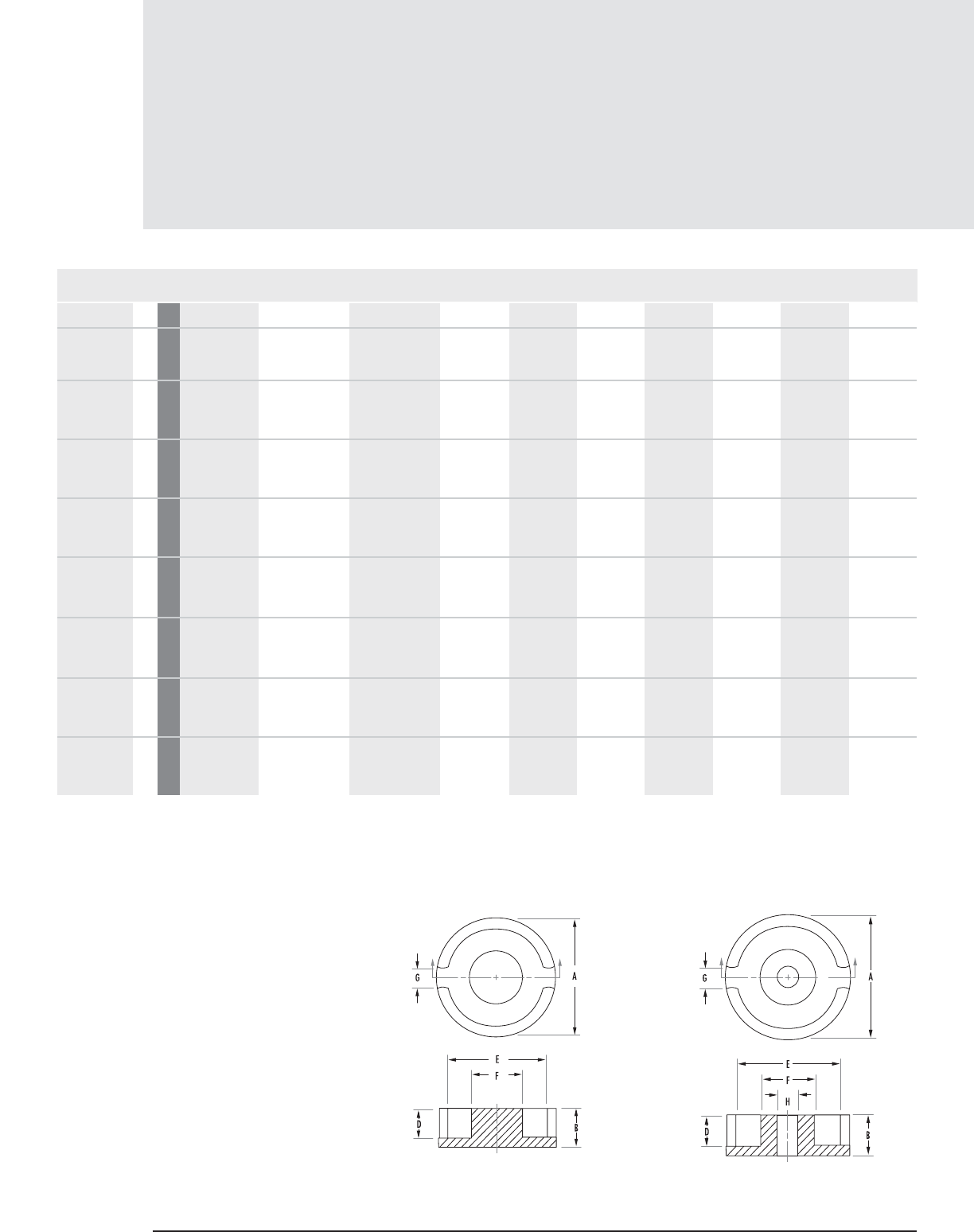
Pot Core
Data (ungapped)
6.2 MAGNETICS
MECHANICAL DIMENSIONS
PART FIG. A B 2B C D 2D E F G H
0_40302UG 1 mm 3.940 ± .080 .953 ± .050 1.910 ± .100 - .445 min .889 min 2.92 min 1.45 max .813 ± .100 -
in .155 ± .003 .0375 ± .002 .075 ± .004 - .0175 min .035 min .115 min .057 max .032 ± .004 -
0_40506UG 1 mm 4.570 ± .127 2.03 ± .050 4.06 ± .100 - 1.340 min 2.690 min 3.680 min 2.200 max 1.30 ± .100 -
in .180 ± .005 .080 ± .002 .160 ± .004 - .053 min .106 min .145 min .087 max .051 ± 004 -
0_40507UG 2 mm 5.720 ± .080 1.620 ± .050 3.250 ± .100 - 1.090 min 2.180 min 4.490 min 2.490 max 1.50 ± .100 .991 ± .050
in .225 ± .003 .064 ± .002 .128 ± .004 - .043 min .086 min .177 min .098 max .059 ± .004 .039 ± .002
0_40704UG 3 mm 7.240 ± .150 2.080 ± .050 4.160 ± .100 4.720 nom 1.400 min 2.790 min 5.740 min 3.000 max 1.520 min 1.09 ± .050
in .285 ± .006 .082 ± .002 .164 ± .004 .186 nom .055 min .110 min .226 min .118 max .060 min .043 ± .002
0_40903UG 3 mm 9.14 ± .15 1.524 ± .000,-.120 3.05 ± .120 6.6 nom .749 min 1.50 min 7.49 min 3.88 max 1.78 min 2.01 ± .05
in .360 ± .006 .060 ± .000,-.005 .120 ± .005 .260 nom .0295 min .059 min .295 min .153 max .070 min .079 ± .05
0_40905UG 3 mm 9.140 ± .150 2.690+.000,-.120 5.26 ± .120 6.600 nom 1.800 min 3.61 min 7.490 min 3.880 max 1.780 min 2.010 ± .050
in .360 ± .006 .106+.000, -.005 .207 ± .005 .260 nom .071 min .142 min .295 min .153 max .070 min .079 ± .002
0_41107UG 4 mm 11.100 ± .200 3.250 ± .050 6.500 ± .100 6.80 2.21 4.42 9.0 4.700 22 2.1 ± 0.1
in .437 ± .008 .128 ± .003 .256 ± .006 .297 nom .087 min .174 min .354 min .185 max .070 min .081 ± .002
0_41408UG 4 mm 14.3 +.000,-.500 4.2 ± .050 8.4 ± .100 9.500 nom 2.80 min 5.6 min 11.600 min 6.0 max 2.70 min 3.00 +.010, -.000
in .553 ± .010 .167 +.000, -.005 .334+.000, -.011 .376 nom .110 min .220 min .457 min .236 max .120 min .122 ± .003
Any practical gap available. See pages 1.8-1.11
To order, add material code to part number.
FIGURE 1 FIGURE 2
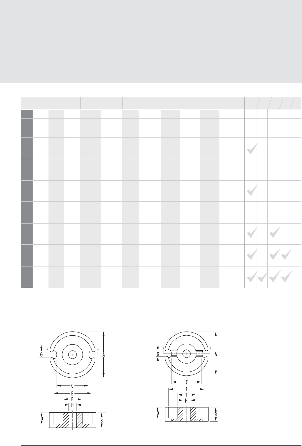
6.3
mag-inc.com
Pot Core
Data (ungapped)
POWER MATERIALS MAGNETIC DATA
HIGH PERMEABILITY
MATERIALS
RPF* J W
le(mm) Ae(mm2)A MIN (mm2)Ve(mm3)CORE WEIGHT
(grams per set) WaAc
Nom 350 -
Nom 500 606 -
Nom 775 930 -
Min 620 675 1,200 1,580 3,000
Min 865 940 1,670 2,200 4,150
Min 760 825 1,365 2,045 4,220
Min 1,150 1,250 1,667 2,925 5,750
Min 1,540 1,680 2,800 3,805 6,300
4.29 2.1 1.5 9.0 0.076 -
Note: +/- 35% for Ind. specs
8.88 4.1 3.6 36.0 0.210 -
Note: +40%/-30% for Ind. specs
7.75 4.4 3.9 34.0 0.200 -
Note: +40%/-30% for Ind. specs
9.9 7.0 5.9 69.0 0.500 -
Note: +40%/-30% for F
6.24 6.1 - 38.0 0.1843 -
12.5 10.1 8.0 126.0 1.000 0.003
15.5 16.2 13.2 251 1.800 0.00815
19.8 25.1 19.8 495 3.200 0.024
AVAILABLE HARDWARE
AL(mH/1000T)
FIGURE 3 FIGURE 4
* F material nominal ± 25% except where noted
** See page 5.6 for tuning assembly information
STANDARD BOBBIN
PRINTED CIRCUIT BOBBIN
MOUNTING CLAMP
SURFACE MOUNT HEADER
TUNING ASSEMBLY**
Pot Cores
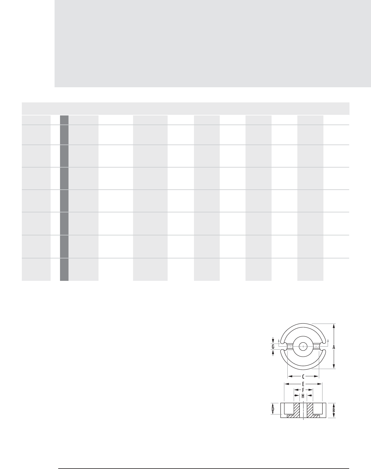
Pot Core
Data (ungapped)
6.4 MAGNETICS
Any practical gap available. See pages 1.8-1.11
FIGURE 4
MECHANICAL DIMENSIONS
PART FIG. A B 2B C D 2D E F G H
0_41811UG 4 mm 18.0 ± .4 5.33 ± .05 10.6 ± .1 13.4 ± .3 3.7 ± .1 7.4 ± .2 15.15 ± .25 7.45 ± .15 3.8 ± 0.6 3.100 ± .1
0_42213UG 4 mm 21.600 ± .380 6.7 ± .1 13.4 ± .2 15.0 nom 4.59 min 9.200 min 17.900 min 9.400 max 2.990 min 4.550 ± .100
in .851 ± .015 .264 ± .004 .528 ± .008 .590 nom .181 min .362 min .705 min .370 max .118 min .179 ± .004
0_42616UG 4 mm 25.5 ± .5 8.05 ± .1 16.1 ± .2 18.0 ± .4 5.5 + .2, -0 11.0 + 4, -0 21.6 ± .4 11.3 ± .2 3.8 ± .6 5.5 ± .1
0_43019UG 4 mm 30.0 ±.5 9.45 ± .05 18.9 ± .1 20.5 ± .5 6.5 ± .1 13 ± .2 25.4 ± .4 13.3 ± .2 4.3 ± .6 5.5 ± .1
0_43622UG 4 mm 35.6 ±.6 10.95 ± .05 21.9 ± .1 26.2 ± .6 7.4 ± .1 14.8 ± .2 30.4 ± .5 15.9 ± .3 4.9 ± .6 5.55 ± .15
0_44229UG 4 mm 42.400 ± .710 14.800 ± .200 29.600 ± .410 32.000 nom 10.200 min 20.400 min 35.600 min 17.700 max 4.490 min 5.5600 ± .100
in 1.669 ± .028 .582 ± .008 1.164 ± .016 1.260 nom .402 min .804 min 1.402 min .697 max .177 min .219 ± .004
0_44529UG 4 mm 45.000 ± .900 14.600 ± .100 29.200 ± .200 32.990 ± .510 9.400 min 18.800 min 36.500 min 20.700 max 4.490 min 5.560 ± .130
in 1.772 ± .035 .575 ± .004 1.150 ± .008 1.299 ± .020 .370 min .740 min 1.438 min .814 max .177 min .219 ± .005
To order, add material code to part number.

Pot Core
Data (ungapped)
6.5
mag-inc.com
* F material nominal ± 25%
** See page 5.6 for tuning assembly information
POWER MATERIALS MAGNETIC DATA
HIGH PERMEABILITY
MATERIALS
RPF* J W
le(mm) Ae(mm2)A MIN (mm2)Ve(mm3)CORE WEIGHT
(grams per set) WaAc
Min 2,300 2,500 4,000 5,625 8,400
Min 3,030 3,300 4,900 6,825 11,200
Min 3,910 4,250 6,350 8,775 14,000
Min 5,010 5,450 8,100 10,200 18,750
Min 6,530 7,100 10,200 13,125 24,500
Min 6,900 7,500 12,000 15,000 28,000
Min 9,660 10,500 14,300 18,750 35,000
25.8 43.3 36.0 1120 7.3 0.073
31.2 63.9 50.9 2000 13.0 0.187
37.6 93.9 77.4 35.30 20.0 0.392
45.2 137.0 116.0 6190 34.0 0.737
53.2 202.0 172.0 10700 57.0 1.53
68.5 266.0 213.0 18200 104.0 3.69
67.2 360.0 299.0 24200 149.6 3.85
STANDARD BOBBIN
PRINTED CIRCUIT BOBBIN
MOUNTING CLAMP
SURFACE MOUNT HEADER
TUNING ASSEMBLY**
AL(mH/1000T)
AVAILABLE HARDWARE
Pot Cores
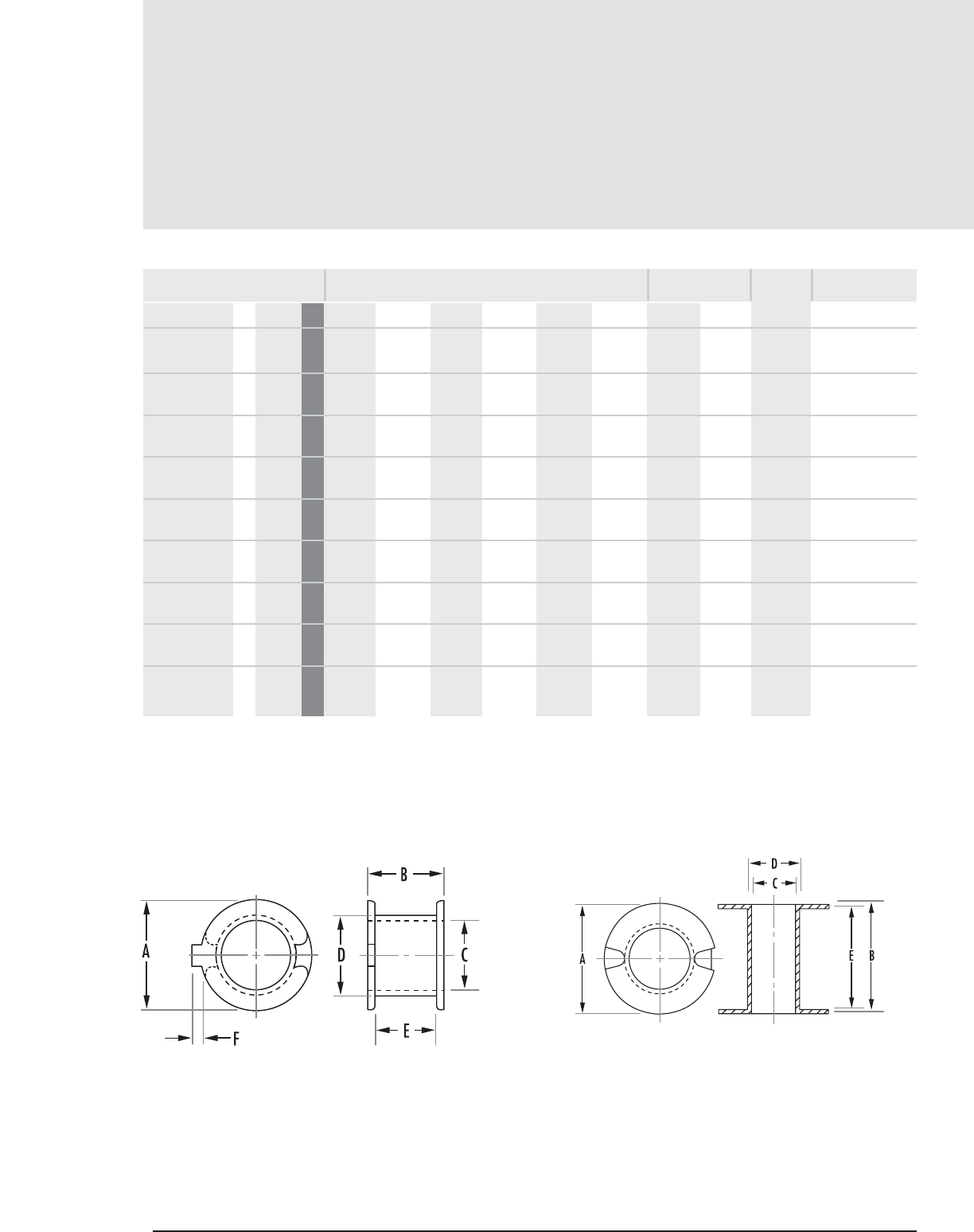
Bobbins
Pot Core Hardware
6.6 MAGNETICS
FIGURE 1 FIGURE 2
MECHANICAL DIMENSIONS
PART FIG. A MAX B MAX C MIN D MAX E NOM F NOM
NOMINAL WINDING
AREA PER SECTION AVERAGE
LENGTH OF
TURN FT
MATERIAL
00B050601 1 40506 mm 3.657 2.540 2.260 2.667 2.006 0.355 0.00150 0.0097 0.0322 Thermoplastic
in 0.144 0.100 0.089 0.105 0.079 0.014 polyester (PET)
00B070401 2 40704 mm 5.740 2.743 3.048 3.657 2.082 - 0.00380 0.0250 0.0479 Glass-filled nylon
in 0.226 0.108 0.120 0.144 0.082 -
00B090501 3 40905 mm 7.416 3.530 3.962 5.181 2.540 - 0.00470 0.0300 0.0633 Delrin
in 0.292 0.139 0.156 0.204 0.100 -
00B090501FR 3 40905 mm 7.416 3.530 3.962 5.181 2.540 - 0.00470 0.0300 0.0633 Crastin S660FR
in 0.292 0.139 0.156 0.204 0.100 -
00B110701 3 41107 mm 8.915 4.318 4.775 5.994 3.327 - 0.00785 0.0500 0.0751 Delrin
in 0.351 0.170 0.188 0.236 0.131 -
00B110702 3 41107 mm 8.915 4.318 4.775 5.994 1.447 - 0.00342 0.0220 0.0751 Delrin
2 Section in 0.351 0.170 0.188 0.236 0.057 -
00B140801 3 41408 mm 11.53 5.511 6.070 7.289 4.521 - 0.01530 0.0980 0.0953 Delrin
in 0.454 0.217 0.239 0.287 0.178 -
00B140802 3 41408 mm 11.53 5.511 6.070 7.289 2.032 - 0.00688 0.0440 0.0953 Delrin
2 Section in 0.454 0.217 0.239 0.287 0.080 -
00B140802FR 3 41408 mm 11.53 5.511 6.070 7.289 2.032 - 0.00688 0.0440 0.0953 Crastin S660FR
2 Section in 0.454 0.217 0.239 0.287 0.080 -
in2cm2
CORE SIZE
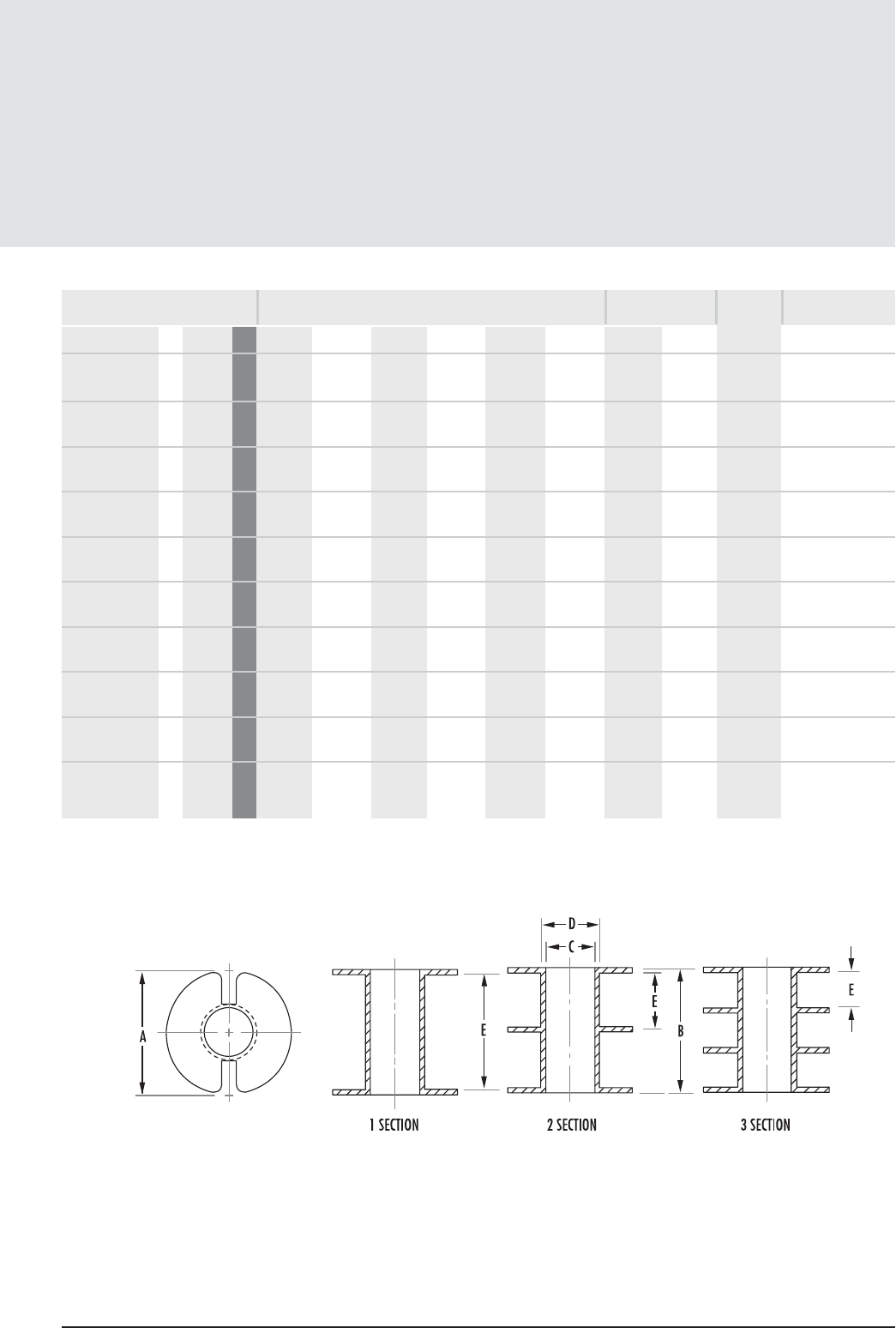
Bobbins
Pot Core Hardware
6.7
mag-inc.com
FIGURE 3
MECHANICAL DIMENSIONS
PART FIG. A MAX B MAX C MIN D MAX E NOM F NOM
00B181101 3 41811 mm 14.909 7.137 7.670 8.89 6.096 - 0.02645 0.1700 0.120 Delrin
in 0.587 0.281 0.302 0.350 0.240 -
00B181101FR 3 41811 mm 14.909 7.137 7.670 8.89 6.096 - 0.02645 0.1700 0.120 Crastin S660FR
in 0.587 0.281 0.302 0.350 0.240 -
00B181102 3 41811 mm 14.909 7.137 7.670 8.89 2.819 - 0.01315 0.0840 0.120 Delrin
2 Section in 0.587 0.281 0.302 0.350 0.111 -
00B181102FR 3 41811 mm 14.909 7.137 7.670 8.89 2.819 - 0.01315 0.0840 0.120 Crastin S660FR
in 0.587 0.281 0.302 0.350 0.111 -
00B181103 3 41811 mm 14.909 7.137 7.670 8.89 1.727 - 0.00755 0.0490 0.120 Delrin
3 Section in 0.587 0.281 0.302 0.350 0.068 -
00B221301 3 42213 mm 17.830 9.118 9.474 10.693 8.128 - 0.04530 0.2920 0.145 Delrin
in 0.702 0.359 0.373 0.421 0.320 -
00B221301FR 3 42213 mm 17.830 9.118 9.474 10.693 8.128 - 0.04530 0.2920 0.145 Crastin S660FR
in 0.702 0.359 0.373 0.421 0.320 -
00B221302 3 42213 mm 17.830 9.118 9.474 10.693 3.835 - 0.02140 0.1380 0.145 Delrin
2 Section in 0.702 0.359 0.373 0.421 0.151 -
00B221302FR 3 42213 mm 17.830 9.118 9.474 10.693 3.835 - 0.02140 0.1380 0.145 Crastin S660FR
2 Section in 0.702 0.359 0.373 0.421 0.151 -
00B221303 3 42213 mm 17.830 9.118 9.474 10.693 2.413 - 0.01350 0.0870 0.145 Delrin
3 Section in 0.702 0.359 0.373 0.421 0.095 -
NOMINAL WINDING
AREA PER SECTION AVERAGE
LENGTH OF
TURN FT
MATERIAL
in2cm2
CORE SIZE
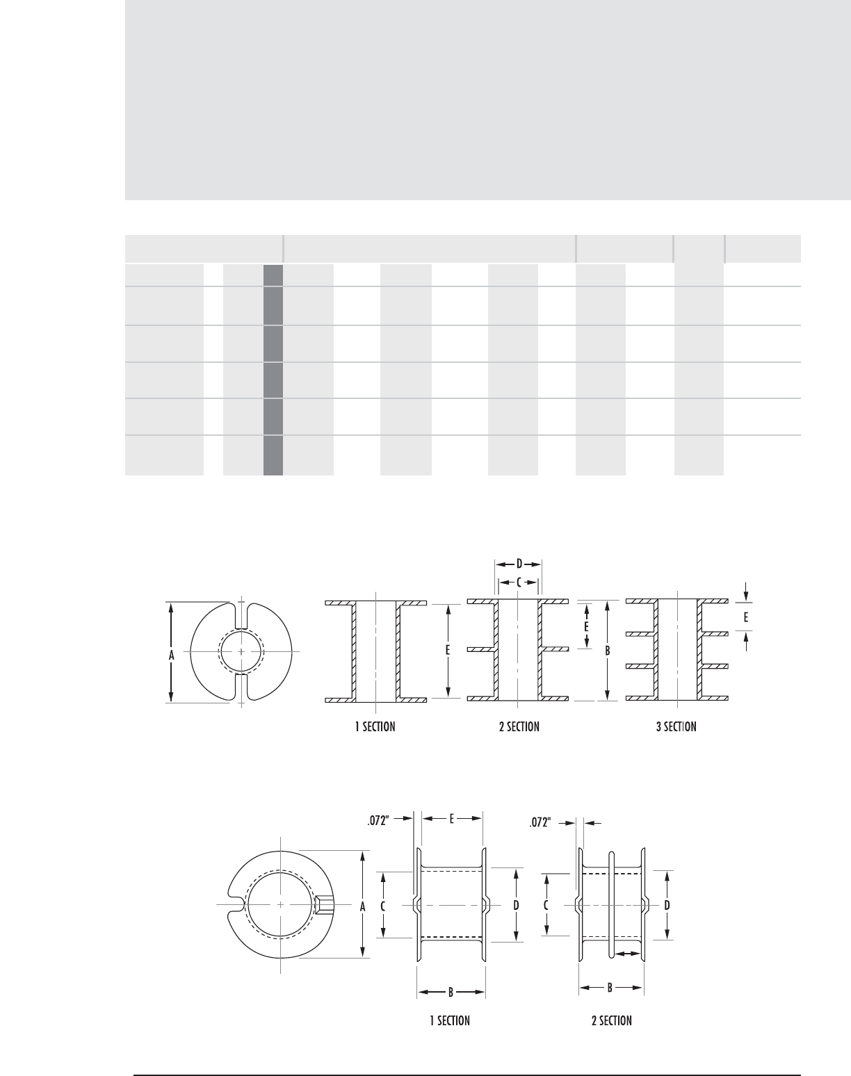
Pot Core Hardware
6.8 MAGNETICS
Bobbins (con’t)
MECHANICAL DIMENSIONS
PART FIG. A MAX B MAX C MIN D MAX E NOM F NOM
00B261601 3 42616 mm 21.132 10.922 11.557 12.776 9.931 - 0.06530 0.4210 0.173 Delrin
in 0.832 0.430 0.455 0.503 0.391 -
00B261601FR 3 42616 mm 21.132 10.922 11.557 12.776 9.931 - 0.06530 0.4210 0.173 Crastin S660FR
in 0.832 0.430 0.455 0.503 0.391 -
00B261602 3 42616 mm 21.132 10.922 11.557 12.776 4.749 - 0.03140 0.2020 0.173 Delrin
2 Section in 0.832 0.430 0.455 0.503 0.187 -
00B261603 3 42616 mm 21.132 10.922 11.557 12.776 3.022 - 0.01990 0.1280 0.173 Delrin
3 Section in 0.832 0.430 0.455 0.503 0.119 -
00B261603FR 3 42616 mm 21.132 10.922 11.557 12.776 3.022 - 0.01990 0.1280 0.173 Crastin S660FR
3 Section in 0.832 0.430 0.455 0.503 0.119 -
FIGURE 3
FIGURE 4
CORE SIZE
NOMINAL WINDING
AREA PER SECTION AVERAGE
LENGTH OF
TURN FT
MATERIAL
in2cm2
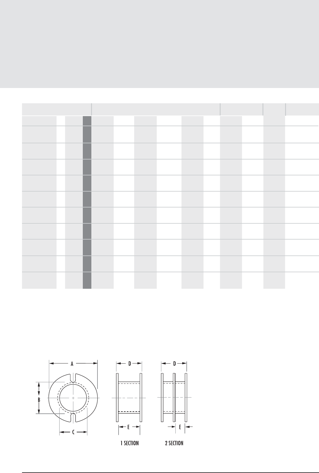
Pot Core Hardware
6.9
mag-inc.com
Bobbins (con’t)
MECHANICAL DIMENSIONS
PART FIG. A MAX B MAX C MIN D MAX E NOM F NOM
00B301901 3 43019 mm 24.917 12.928 13.563 15.036 11.684 - 0.08400 0.5420 0.204 Delrin
in 0.981 0.509 0.534 0.592 0.460 -
00B301902 3 43019 mm 24.917 12.928 13.563 15.036 5.562 - 0.03940 0.2540 0.204 Delrin
2 Section in 0.981 0.509 0.534 0.592 0.219 -
00B301903 3 43019 mm 24.917 12.928 13.563 15.036 3.505 - 0.02460 0.1590 0.204 Delrin
3 Section in 0.981 0.509 0.534 0.592 0.138 -
00B362201 3 43622 mm 29.768 14.478 16.230 18.059 12.979 - 0.11700 0.7550 0.244 Delrin
in 1.172 0.570 0.639 0.711 0.511 -
00B362202 3 43622 mm 29.768 14.478 16.230 18.059 6.146 - 0.05540 0.3570 0.244 Delrin
2 Section in 1.172 0.570 0.639 0.711 0.242 -
00B362203 3 43622 mm 29.768 14.478 16.230 18.059 3.860 - 0.03480 0.2250 0.244 Delrin
3 Section in 1.172 0.570 0.639 0.711 0.152 -
00B422901 4 44229 mm 35.407 20.015 17.983 19.710 17.805 - 0.21500 1.3900 0.282 Delrin
in 1.394 0.788 0.708 0.776 0.701 -
00B422902 4 44229 mm 35.407 20.015 17.983 19.710 8.407 - 0.09700 0.6300 0.282 Delrin
2 Section in 1.394 0.788 0.708 0.776 0.331 -
00B452901 5 44529 mm 36.068 22.86 20.878 18.592 16.256 - 0.16700 1.0700 0.308 Glass-filled nylon
in 1.420 0.900 0.822 0.732 0.640 -
00B452902 5 44529 mm 36.068 22.86 20.878 18.592 7.620 - 0.07800 0.5000 0.308 Glass-filled nylon
2 Section in 1.420 0.900 0.822 0.732 0.300 -
FIGURE 5
NOMINAL WINDING
AREA PER SECTION AVERAGE
LENGTH OF
TURN FT
MATERIAL
in2cm2
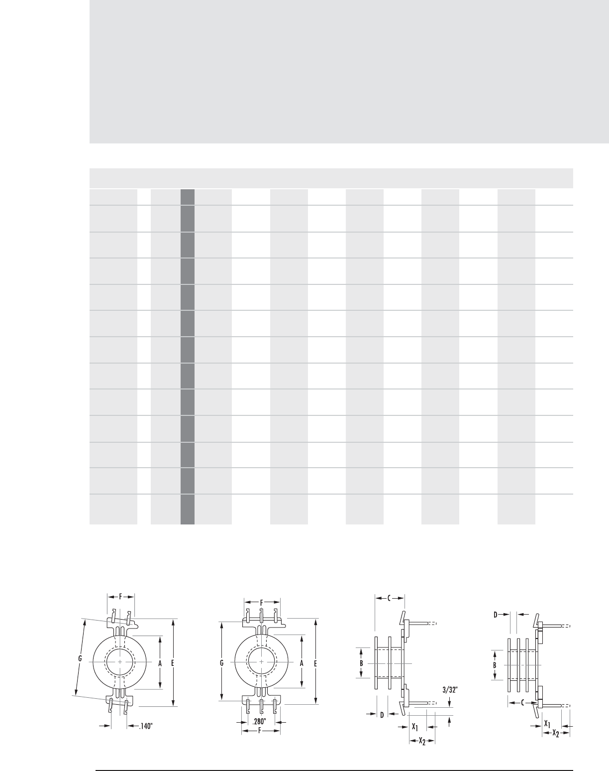
Pot Core Hardware
6.10 MAGNETICS
Printed Circuit Bobbins
MECHANICAL DIMENSIONS
PART FIG. A MAX B MAX C MAX D NOM E MAX F MAX G NOM H X1NOM X2NOM
PCB140811 1A 41408 mm 11.506 7.112 5.410 4.445 18.999 5.892 16.205 - 4.749 -
in 0.453 0.280 0.213 0.175 0.748 0.232 0.638 - 0.187 -
PCB140821 1A 41408 mm 11.506 7.112 5.410 4.445 18.999 5.892 16.205 - - 7.137
in 0.453 0.280 0.213 0.175 0.748 0.232 0.638 - - 0.281
PCB140812 1A 41408 mm 11.506 7.112 5.410 2.032 18.999 5.892 16.205 - 4.749 -
2 Section in 0.453 0.280 0.213 0.080 0.748 0.232 0.638 - 0.187 -
PCB140822 1A 41408 mm 11.506 7.112 5.410 2.032 18.999 5.892 16.205 - - 7.137
2 Section in 0.453 0.280 0.213 0.080 0.748 0.232 0.638 - - 0.281
PCB1408S1 2A 41408 mm 11.506 7.112 5.410 4.445 18.999 10.668 16.205 - - 7.137
in 0.453 0.280 0.213 0.175 0.748 0.420 0.638 - - 0.281
PCB181111 2B 41811 mm 14.808 8.813 7.035 6.045 23.799 10.210 21.539 - 4.749 -
in 0.583 0.347 0.277 0.238 0.937 0.402 0.848 - 0.187 -
PCB181121 2B 41811 mm 14.808 8.813 7.035 6.045 23.799 10.210 21.539 - - 7.137
in 0.583 0.347 0.277 0.238 0.937 0.402 0.848 - - 0.281
PCB181112 2B 41811 mm 14.808 8.813 7.035 2.794 23.799 10.210 21.539 - 4.749 -
2 Section in 0.583 0.347 0.277 0.110 0.937 0.402 0.848 - 0.187 -
PCB181122 2B 41811 mm 14.808 8.813 7.035 2.794 23.799 10.210 21.539 - - 7.137
2 Section in 0.583 0.347 0.277 0.110 0.937 0.402 0.848 - - 0.281
PCB221311 2B 42213 mm 17.805 10.693 8.991 7.797 27.203 10.210 25.146 - 4.749 -
in 0.701 0.421 0.354 0.307 1.071 0.402 0.990 - 0.187 -
PCB221321 2B 42213 mm 17.805 10.693 8.991 7.797 27.203 10.210 25.146 - - 7.137
in 0.701 0.421 0.354 0.307 1.071 0.402 0.990 - - 0.281
PCB221312 2B 42213 mm 17.805 10.693 8.991 3.683 27.203 10.210 25.146 - 4.749 -
2 Section in 0.701 0.421 0.354 0.145 1.071 0.402 0.990 - 0.187 -
FIGURE 1 FIGURE AFIGURE 2 FIGURE B
CORE SIZE

Pot Core Hardware
6.11
mag-inc.com
Printed Circuit Bobbins
Y2NOM Y2NOM
MECHANICAL DIMENSIONS
PART FIG.
PCB140811 1A 41408 mm 1.549 3.937 0.013 0.084 0.095 Glass-filled nylon Tin coated brass
in 0.061 0.155
PCB140821 1A 41408 mm 1.549 3.937 0.013 0.084 0.095 Glass-filled nylon Tin coated brass
in 0.061 0.155
PCB140812 1A 41408 mm 1.549 3.937 0.006 0.039 0.095 Glass-filled nylon Tin coated brass
2 Section in 0.061 0.155
PCB140822 1A 41408 mm 1.549 3.937 0.006 0.039 0.095 Glass-filled nylon Tin coated brass
2 Section in 0.061 0.155
PCB1408S1 2A 41408 mm 1.549 3.937 0.013 0.084 0.095 Glass-filled nylon Tin coated brass
in 0.061 0.155
PCB181111 2B 41811 mm 1.447 3.835 0.024 0.151 0.121 Glass-filled nylon Tin coated brass
in 0.057 0.151
PCB181121 2B 41811 mm 1.447 3.835 0.024 0.151 0.121 Glass-filled nylon Tin coated brass
in 0.057 0.151
PCB181112 2B 41811 mm 1.447 3.835 0.010 0.064 0.121 Glass-filled nylon Tin coated brass
2 Section in 0.057 0.151
PCB181122 2B 41811 mm 1.447 3.835 0.010 0.064 0.121 Glass-filled nylon Tin coated brass
2 Section in 0.057 0.151
PCB221311 2B 42213 mm 0.584 2.971 0.043 0.280 0.144 Glass-filled nylon Tin coated brass
in 0.023 0.117
PCB221321 2B 42213 mm 0.584 2.971 0.043 0.280 0.144 Glass-filled nylon Tin coated brass
in 0.023 0.117
PCB221312 2B 42213 mm 0.584 2.971 0.020 0.130 0.144 Glass-filled nylon Tin coated brass
2 Section in 0.023 0.117
FIGURE 3
BOBBIN
MATERIAL PIN
MATERIAL
NOTES: If short pin (X1) is desired, part number is -11 or
-12. If long pin (X2) is desired, part number is -21 or -22.
Y-Pin length available under board for soldering, using spring
clip mounting (on 1/16” board).
Y1NOM
CORE SIZE
NOMINAL WINDING
AREA PER SECTION AVERAGE
LENGTH OF
TURN FT
in2cm2
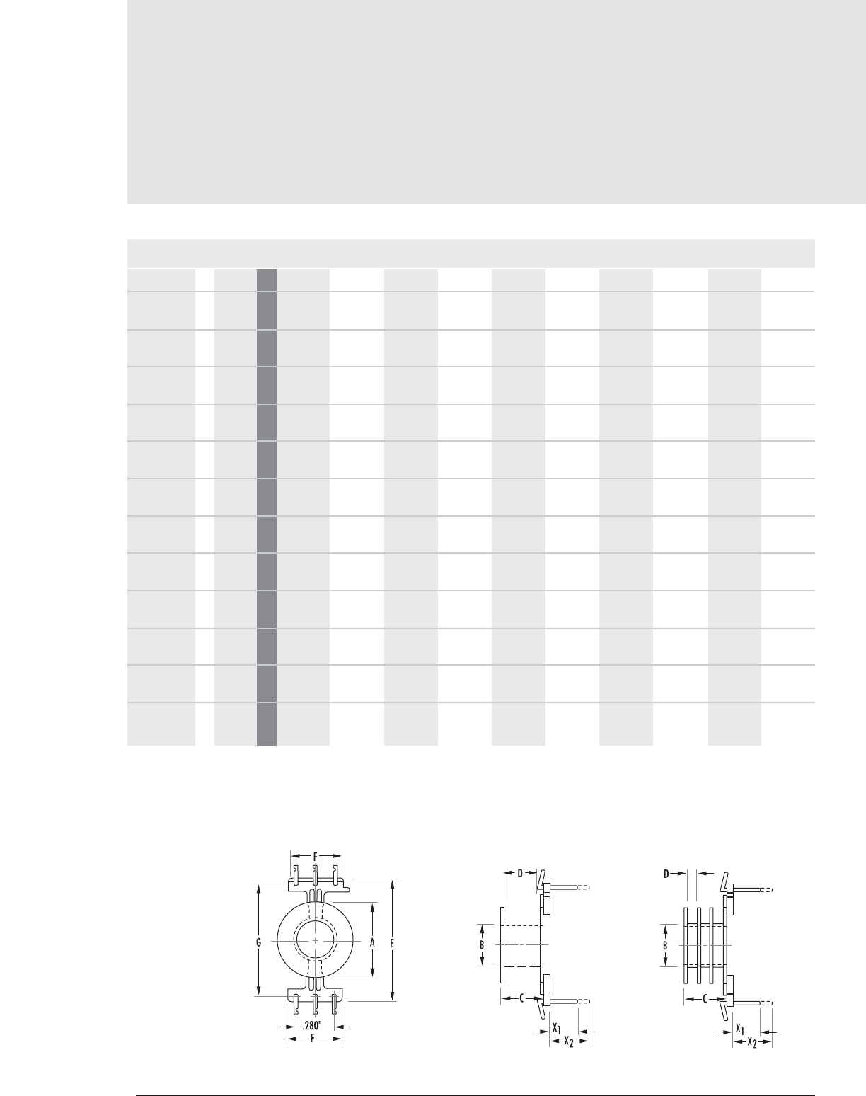
Pot Core Hardware
6.12 MAGNETICS
Printed Circuit Bobbins (con’t)
MECHANICAL DIMENSIONS
PART FIG. A MAX B MAX C MAX D NOM E MAX F MAX G NOM H X1NOM X2NOM
PCB221322 2B 42213 mm 17.805 10.693 8.991 3.683 27.203 10.210 25.146 - - 7.137
2 Section in 0.701 0.421 0.354 0.145 1.071 0.402 0.990 - - 0.281
PCB221313 2B 42213 mm 17.805 10.693 8.991 2.311 27.203 10.210 25.146 - 4.749 -
3 Section in 0.701 0.421 0.354 0.091 1.071 0.402 0.990 - 0.187 -
PCB221323 2B 42213 mm 17.805 10.693 8.991 2.311 27.203 10.210 25.146 - - 7.137
3 Section in 0.701 0.421 0.354 0.091 1.071 0.402 0.990 - - 0.281
PCB261611 2B 42616 mm 20.904 12.801 10.795 9.601 30.683 10.210 28.727 - 4.749 -
in 0.823 0.504 0.425 0.378 1.208 0.402 1.131 - 0.187 -
PCB261621 2B 42616 mm 20.904 12.801 10.795 9.601 30.683 10.210 28.727 - - 7.137
in 0.823 0.504 0.425 0.378 1.208 0.402 1.131 - - 0.281
PCB261612 2B 42616 mm 20.904 12.801 10.795 4.572 30.683 10.210 28.727 - 4.749 -
2 Section in 0.823 0.504 0.425 0.180 1.208 0.402 1.131 - 0.187 -
PCB261622 2B 42616 mm 20.904 12.801 10.795 4.572 30.683 10.210 28.727 - - 7.137
2 Section in 0.823 0.504 0.425 0.180 1.208 0.402 1.131 - - 0.281
PCB261613 2B 42616 mm 20.904 12.801 10.795 2.895 30.683 10.210 28.727 - 4.749 -
3 Section in 0.823 0.504 0.425 0.114 1.208 0.402 1.131 - 0.187 -
PCB261623 2B 42616 mm 20.904 12.801 10.795 2.895 30.683 10.210 28.727 - - 7.137
3 Section in 0.823 0.504 0.425 0.114 1.208 0.402 1.131 - - 0.281
PCB301911 2B 43019 mm 24.942 14.884 12.877 11.684 38.150 10.210 35.915 - 4.749 -
in 0.982 0.586 0.507 0.460 1.502 0.402 1.414 - 0.187 -
PCB301921 2A 43019 mm 24.942 14.884 12.877 11.684 38.150 10.210 35.915 - - 7.137
in 0.982 0.586 0.507 0.460 1.502 0.402 1.414 - - 0.281
PCB362211 3 43622 mm 29.845 18.034 16.179 12.852 14.478 5.588 29.210 40.64 - -
in 1.175 0.710 0.637 0.506 0.570 0.220 1.150 1.600 - -
FIGURE 2 FIGURE A FIGURE B
CORE SIZE
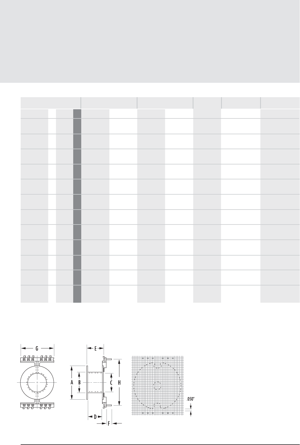
Printed Circuit Bobbins (con’t)
Pot Core Hardware
6.13
mag-inc.com
Y2NOM Y2NOM
MECHANICAL DIMENSIONS
PART FIG.
PCB221322 2B 42213 mm 0.584 2.971 0.020 0.130 0.144 Glass-filled nylon Tin coated brass
2 Section in 0.023 0.117
PCB221313 2B 42213 mm 0.584 2.971 0.013 0.080 0.144 Glass-filled nylon Tin coated brass
3 Section in 0.023 0.117
PCB221323 2B 42213 mm 0.584 2.971 0.013 0.080 0.144 Glass-filled nylon Tin coated brass
3 Section in 0.023 0.117
PCB261611 2B 42616 mm 1.066 3.454 0.060 0.390 0.174 Glass-filled nylon Tin coated brass
in 0.042 0.136
PCB261621 2B 42616 mm 1.066 3.454 0.060 0.390 0.174 Glass-filled nylon Tin coated brass
in 0.042 0.136
PCB261612 2B 42616 mm 1.066 3.454 0.028 0.190 0.174 Glass-filled nylon Tin coated brass
2 Section in 0.042 0.136
PCB261622 2B 42616 mm 1.066 3.454 0.028 0.190 0.174 Glass-filled nylon Tin coated brass
2 Section in 0.042 0.136
PCB261613 2B 42616 mm 1.066 3.454 0.018 0.120 0.174 Glass-filled nylon Tin coated brass
3 Section in 0.042 0.136
PCB261623 2B 42616 mm 1.066 3.454 0.018 0.120 0.174 Glass-filled nylon Tin coated brass
3 Section in 0.042 0.136
PCB301911 2B 43019 mm 0.431 2.819 0.090 0.580 1.970 Glass-filled nylon Tin coated brass
in 0.017 0.111
PCB301921 2B 43019 mm 0.431 2.819 0.090 0.580 1.970 Glass-filled nylon Tin coated brass
2 Section in 0.017 0.111
PCB362211 3 43622 mm --0.117 0.755 0.244 Glass-filled nylon Tin coated
in -- Phosphor Bronze
NOTES: If short pin (X1) is desired, part number is -11 or
-12. If long pin (X2) is desired, part number is -21 or -22.
Y-Pin length available under board for soldering, using spring
clip mounting (on 1/16” board).
FIGURE 3
Y1NOM
CORE SIZE
BOBBIN
MATERIAL PIN
MATERIAL
NOMINAL WINDING
AREA PER SECTION AVERAGE
LENGTH OF
TURN FT
in2cm2
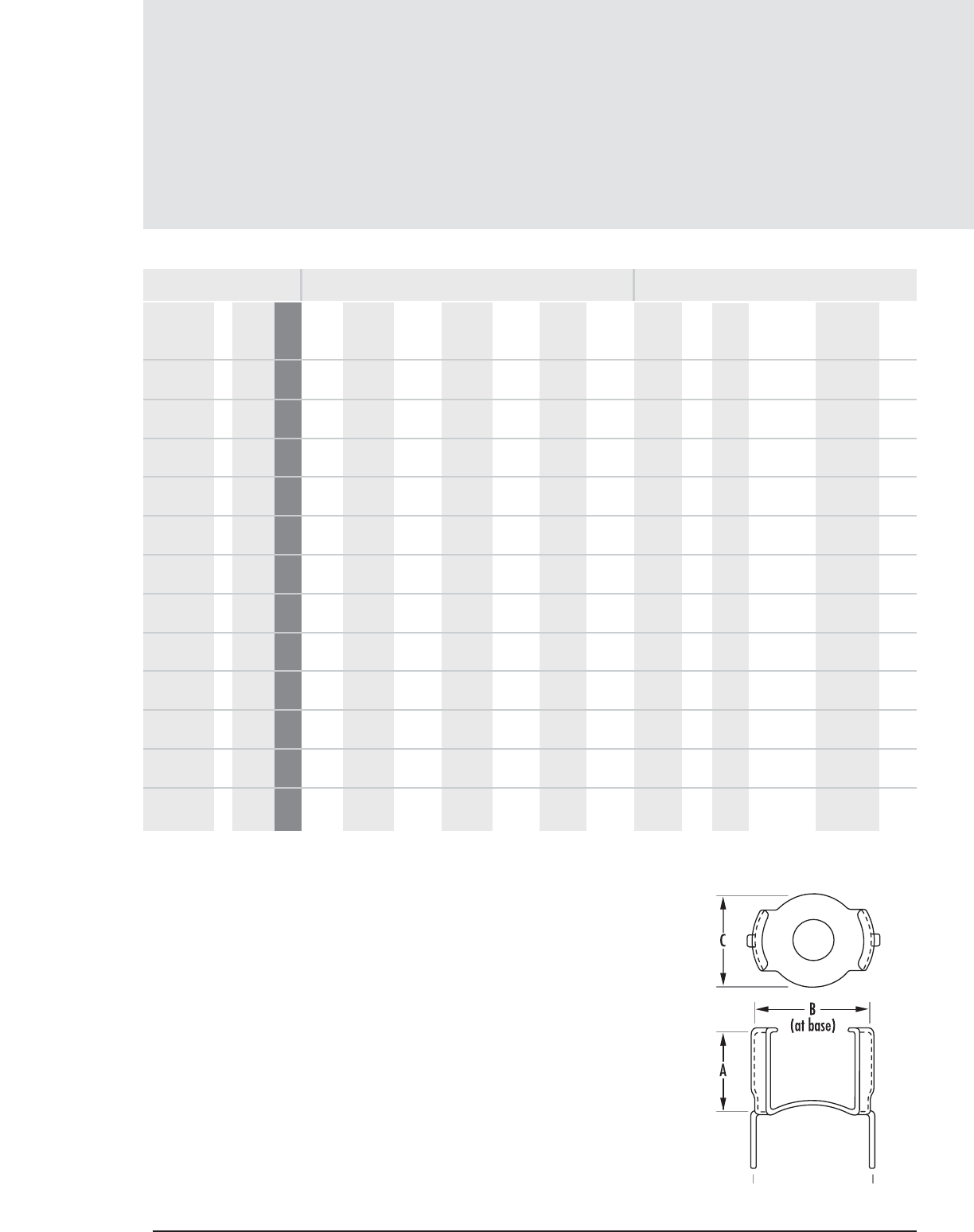
MECHANICAL DIMENSIONS
PART D±.020"*FIG. A NOM B NOM C NOM TAB DIMENSIONS
LENGTH WIDTH
F NOM
00C090511 1 40905 mm 5.689 9.499 8.001 10.008 4.394 1.016 Phosphor .009"
in 0.224 0.374 0.315 0.394 0.173 0.040 Bronze
00C110711 1 41107 mm 6.985 11.480 9.194 12.497 5.003 1.193 Phosphor .010"
in 0.275 0.452 0.362 0.492 0.197 0.047 Bronze
00C140811 2 41408 mm 9.652 14.478 13.208 13.208 3.962 2.159 Spring 0.011" 00W140815 .540 ± .008" .015"
in 0.380 0.570 0.520 0.520 0.156 0.085 Steel
00C1408RS 3 41408 mm 8.89 13.97 8.001 Stainless 00W140815 .540 ± .008" .015"
in 0.35 0.55 0.315 Steel
00C181111 3 41811 mm 11.684 18.542 16.764 16.510 3.962 2.032 Spring .020" 00W181118 .700 ± .008" .020"
2in 0.460 0.730 0.660 0.650 0.156 0.080 Steel
00C221314 4 42213 mm 14.859 22.250 20.828 27.940 33.020 Spring .014" #4-40 00W221324 .840 ± .008" .025"
in 0.585 0.876 0.820 1.100 1.300 Steel
0PC221314 5 42213 mm 14.859 22.250 20.828 21.488 3.581 Spring .014" 00W221324 .840 ± .008" .025"
in 0.585 0.876 0.820 0.846 0.141 Steel
00C261614 4 42616 mm 16.637 26.289 21.082 32.817 38.405 Spring .014" #4-40
in 0.655 1.035 0.830 1.292 1.512 Steel
0PC261614 7 42616 mm 16.637 26.289 21.082 24.638 5.080 Spring .014" #4-40
in 0.655 1.035 0.830 0.970 0.200 Steel
00C301917 4 43019 mm 20.320 30.734 28.575 38.608 44.196 Spring .017" #6-32
in 0.800 1.210 1.125 1.520 1.740 Steel
00C362217 6 43622 mm 23.241 36.322 21.590 44.450 50.038 Spring #6-32
in 0.915 1.430 0.850 1.750 1.970 Steel
00C422917 6 44229 mm 56.388 50.800 43.180 25.400 6.604 Spring #6-32
in 1.233 1.700 1.000 2.000 2.220 Steel
The C090511, C110711, C140811and C1408RS have a D dimension tolerance of ± .010"
Mounting Clamps are made to allow for tuning adjusters. If these adjusters are not used a polypropylene
washer must be inserted to take up extra space. The part number and dimension of available washers
are detailed above.
*
**
Mounting Clamps
Pot Core Hardware
-
-
-
-
-
-
-
-
-
-
-
-
-
-
-
-
-
-
-
-
-
-
-
-
-
-
-
-
-
-
-
-
-
-
-
-
-
-
-
-
-
-
-
-
-
-
-
-
-
-
-
-
-
-
-
-
-
-
-
-
-
-
-
-
-
-
-
-
-
-
-
-
-
-
6.14 MAGNETICS
FIGURE 1
MATERIAL
MACHINE SCREW
IMPRESSIONS
WASHER
DIMENSIONS
MATERIAL
THICKNESS
WASHER**
WASHER
THICKNESS
CORE
SIZE
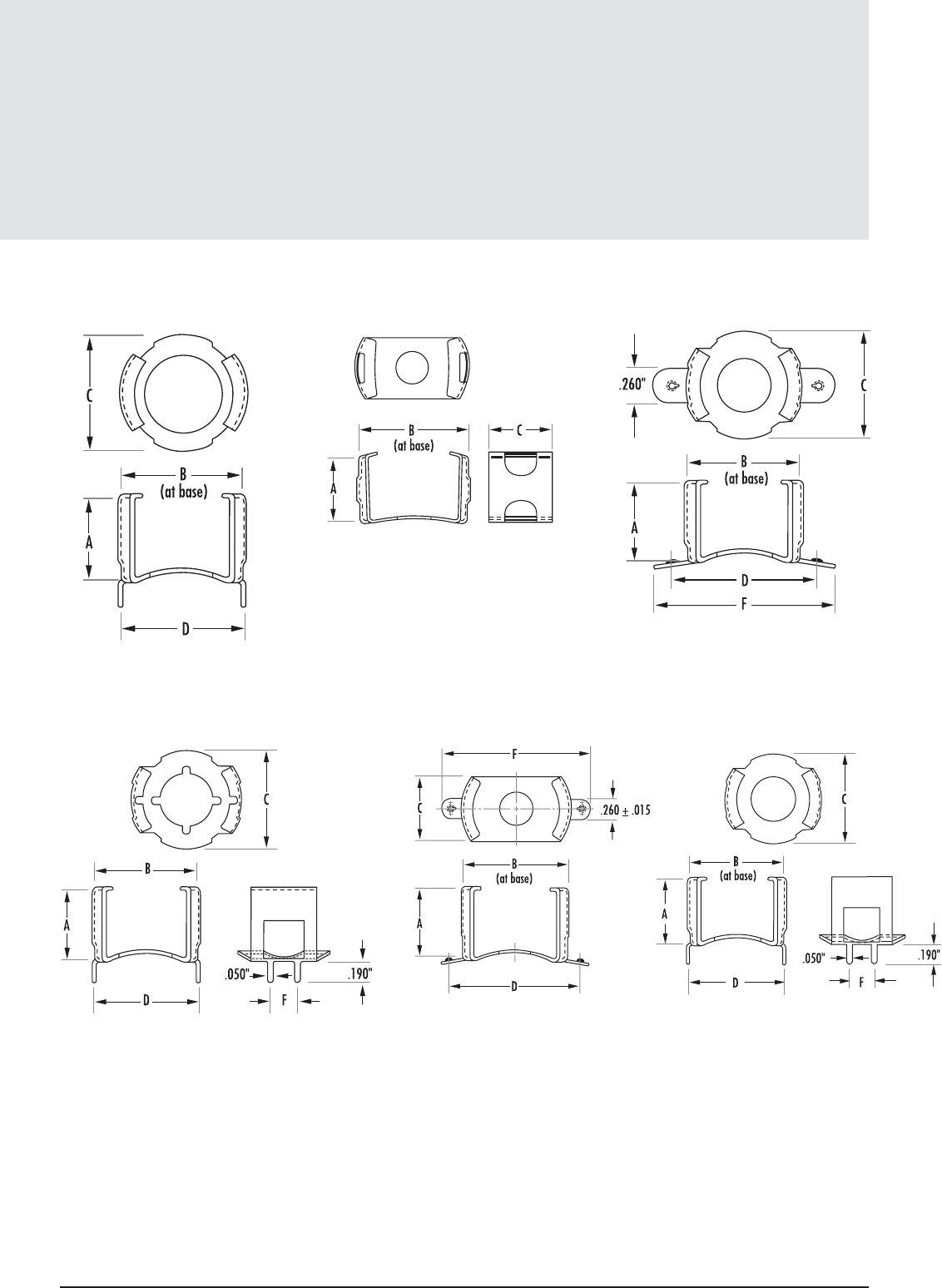
FIGURE 4
FIGURE 2
FIGURE 5
FIGURE 3
FIGURE 6 FIGURE 7
Mounting Clamps
Pot Core Hardware
6.15
mag-inc.com
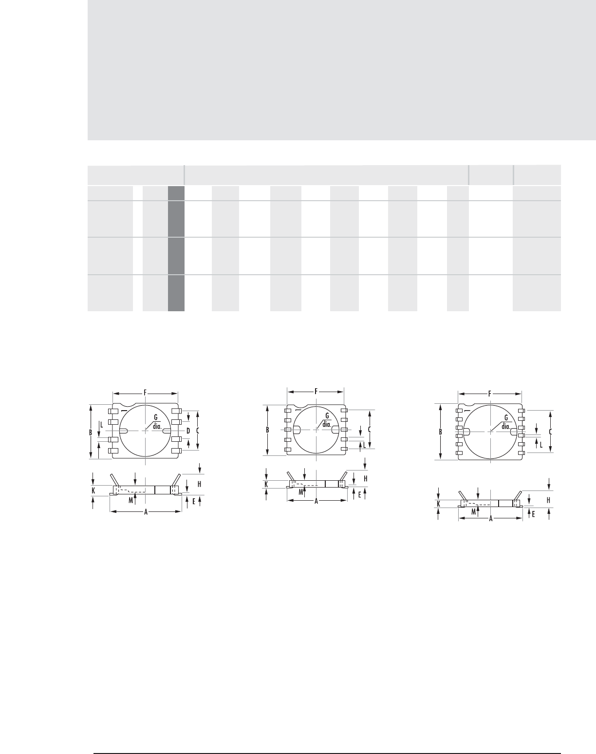
MECHANICAL DIMENSIONS
PART D TYPFIG. A MAX
FIGURE 1 FIGURE 2 FIGURE 3
B MAX C TYP E NOM F MAX G MIN K MAX L NOM M MIN
BOBBIN
MATERIAL
PIN
MATERIAL
SMH11078A 1 41107 mm 16.967 12.751 8.992 3.988 0.483 15.240 11.354 2.134 0.991 1.270 Thermoset Tin coated
in 0.668 0.502 0.354 0.157 0.019 0.600 0.465 0.084 0.039 0.050 plastic phosphor bronze
SMH1408TA 2 41408 mm 19.990 15.748 11.989 - 0.483 18.263 14.351 2.134 0.991 1.270 Thermoset Tin coated
in 0.787 0.620 0.472 - 0.019 0.719 0.565 0.084 0.039 0.050 plastic phosphor bronze
SMH1811LA 3 41811 mm 24.181 19.761 14.732 - 0.483 22.454 18.339 2.134 0.991 1.270 Thermoset Tin coated
in 0.952 0.778 0.580 - 0.019 0.884 0.722 0.084 0.039 0.050 plastic phosphor bronze
Surface Mount Headers
Pot Core Hardware
6.16 MAGNETICS
CORE
SIZE
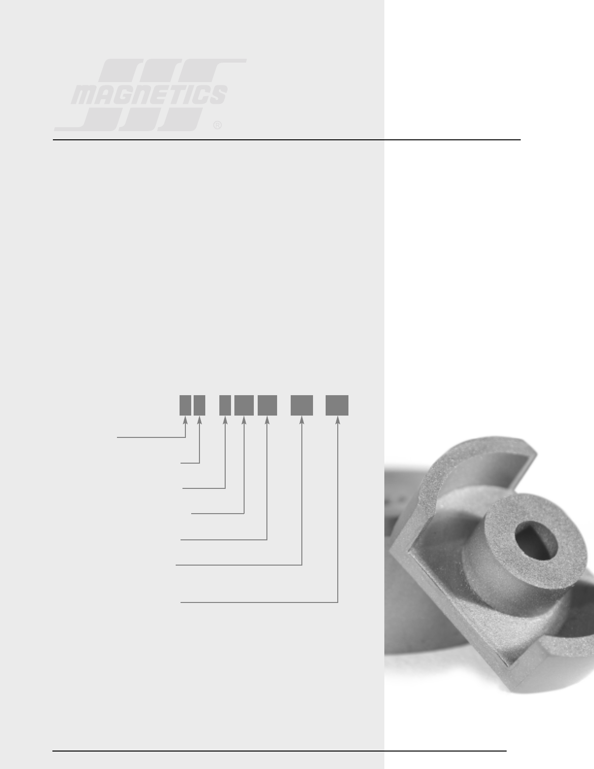
Section 7
RS/DS
Cores
7.1
RS/DS CORES
Slab cores are modified pot cores with the sides removed. The slabs can be paired with one round
half of a standard pot core (RS combination) or two slabs can be paired together for a double slab
(DS combination).
Available in seven sizes, the RS geometry offers all the advantages of pot cores for filter
applications, plus many additional features for power applications.
DS cores, available in six sizes, accommodate large size wire and assist in removing heat from the
assembly.
Both plain and printed circuit bobbins are available for both types of cores.
Typical applications for RS/DS combinations include; low and medium power transformers,
switched-mode power supplies, and converter and inverter transformers.
HOW TO ORDER
*SHAPE CODES
D – DS Core with solid centerpost
H – DS Core with center hole
S – RS Core
SHAPE CODE*
FERRITE CORE MATERIAL
USED FOR ALL FERRITE TYPES
APPROXIMATE DIAMETER IN MM
APPROXIMATE HEIGHT IN MM
GEOMETRY CODE/GAP CODE
(SEE PAGE 1.5 - 1.6)
SPECIAL SPECIFICATION CODE
S P 4 30 19 UG XX
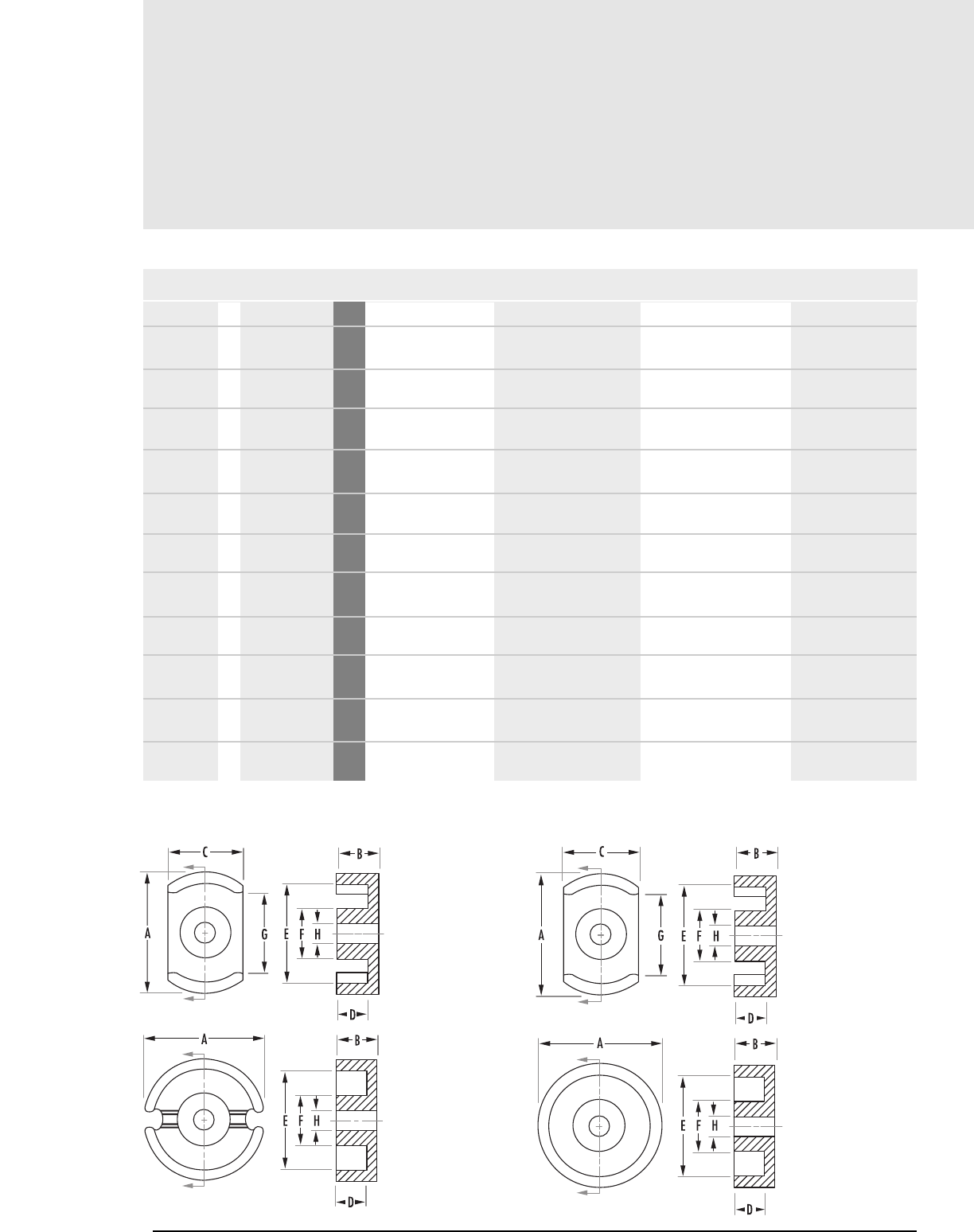
RS/DS
Core Data (ungapped)
7.2 MAGNETICS
MECHANICAL DIMENSIONS
PART FIG. COMBINATION A B 2B C
H_41408UG 1DS mm
with center hole in
S_41408UG 1 RS mm
in
D_42311UG 3 DS mm
in
H_42311UG 4 DS mm
with center hole in
S_42311UG 2 RS mm
in
D_42318UG 3DS mm
in
H_42318UG 4 DS mm
with center hole in
S_42318UG 2 RS mm
in
D_42616UG 3 DS mm
in
H_42616UG 4DS mm
with center hole in
S_42616UG 1 RS mm
in
14 ± .250 4.24 + .000, -.130 8.48 + .000, -.280 9.4 ± .150
.553 ± .010 .167 + .000, -.005 .334 + .000, -.011 .370 ± .006
14 ± .250 4.24 + .000, -.130 8.48 + .000, -.280 9.4 ± .150
.553 ± .010 .167 + .000, -.005 .334 + .000, -.011 .370 ± .006
22.86 ± .460 5.54 ± .130 11.080 ± .260 15.24 ± .250
.900 ± .018 .218 ± .005 .436 ± .010 .600 ± .010
22.86 ± .460 5.54 ± .130 11.080 ± .260 15.24 ± .250
.900 ± .018 .218 ± .005 .436 ± .010 .600 ± .010
22.9 ± .460 5.54 ± .130 11.08 ± .250 15.2 ± .250
.900 ± .018 .218 ± .005 .436 ± .010 .600 ± .010
22.860 ± .460 9.00 ± .180 18.00 ± .360 15.24 ± .250
.900 ±.018 .355 ± .007 .710 ± .014 .600 ± .010
22.860 ±.460 9.00 ±.180 18.00 ± .360 15.24 ± .250
.900 ± .018 .355 ± .007 .710 ± .014 .600 ± .010
22.900 ± .460 9.00 ± .180 18.00 ± .360 15.20 ± .250
.900 ± .018 .355 ± .007 .710 ± .014 .600 ± .010
25.500 ± .510 8.05 ± .100 16.10 ± .200 17.09 nom
1.004 ± .020 .317 ± .004 .634 ± .008 .673 nom
25.500 ±.510 8.05 ±.100 16.10 ±.200 17.09 nom
1.004 ± .020 .317 ± .004 .634 ± .008 .673 nom
25.500 ± .510 8.05 ± .100 16.10 ± .200 17.09 nom
1.004 ± .020 .317 ± .004 .634 ± .008 .673 nom
RS/DS Cores
To order, add material code to part number.
FIGURE 1 FIGURE 2
Any practical gap available. See page 1.8 - 1.11
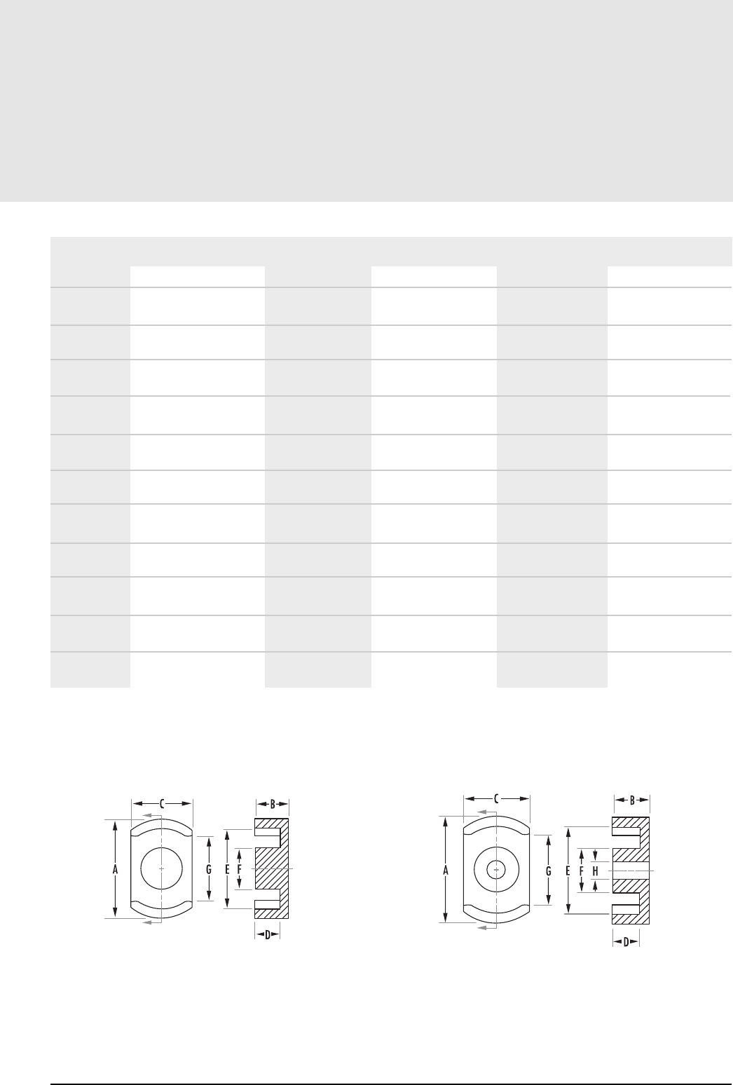
7.3
mag-inc.com
RS/DS
Core Data (ungapped)
MECHANICAL DIMENSIONS
D MIN 2D MIN E MIN F MAX G MIN H
2.800 5.580 11.600 5.990 7.600 3.10 ± .076
0.110 0.220 0.457 0.236 0.300 .122 ± .003
2.800 5.580 11.600 5.990 7.600 3.10 ± .076
0.110 0.220 0.457 0.236 0.300 .122 ± .003
3.630 7.260 17.930 9.900 13.210 -
0.143 0.286 0.706 0.390 0.520 -
3.630 7.260 17.930 9.900 13.210 -
0.143 0.286 0.706 0.390 0.520 -
3.630 7.260 17.940 9.900 13.200 5.08 ± .10
0.143 0.286 0.706 0.390 0.520 .200 ± .004
6.930 13.860 17.93 9.900 13.200 -
0.273 0.546 0.706 0.390 0.520 -
6.930 13.860 17.93 9.900 13.200 -
0.273 0.546 0.706 0.390 0.520 -
6.930 13.870 17.94 9.900 13.200 5.08 ± .100
0.273 0.546 0.706 0.390 0.520 .200 ± .004
5.510 11.020 21.21 11.480 15.500 -
0.217 0.434 0.835 0.452 0.610 -
5.510 11.020 21.21 11.480 15.500 -
.217 0.434 0.835 0.452 0.610 -
5.510 11.020 21.21 11.480 15.500 5.56 ± .100
.217 .434 .835 .452 .610 .219 ± .004
RS/DS Cores
FIGURE 3 FIGURE 4
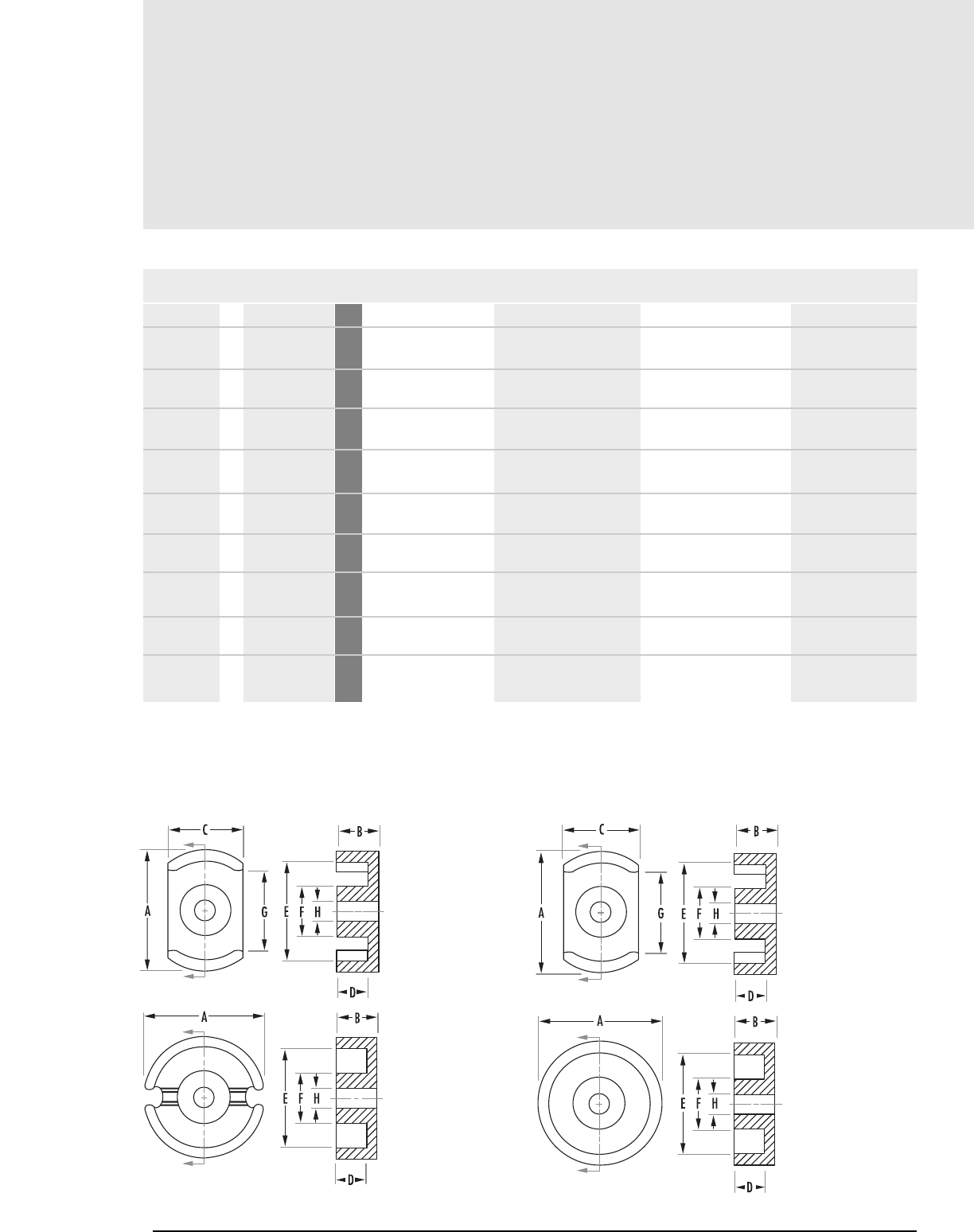
RS/DS
Core Data (ungapped)
7.4 MAGNETICS
MECHANICAL DIMENSIONS
PART FIG. COMBINATION A B 2B C
D_43019UG 3 DS mm
in
H_43019UG 4 DS mm
with center hole in
S_43019UG 1 RS mm
in
D_43622UG 3 DS mm
in
H_43622UG 4 DS mm
with center hole in
S_43622UG 1 RS mm
in
*
D_44229
UG 3 DS mm
in
H_44229UG 4 DS mm
with center hole in
S_44229UG 1 RS mm
in
30.00 ± .051 9.4 ± .100 18.800 ± .200 20.32 ± .250
1.181 ± .020 .370 ± .004 .740 ± .008 .800 ± .010
30.00 ± .510 9.4 ± .100 18.800 ± .200 20.32 ± .250
1.181 ± .020 .370 ± .004 .740 ± .008 .800 ± .010
30.00 ± .510 9.400 ± .100 18.70 ± .200 20.32 ± .250
1.181 ± .020 .370 ± .004 .740 ± .008 .800 ± .010
35.61 ± .510 10.87 ± .130 21.7 ± .250 23.85 nom
1.402 ± .020 .428 ± .005 .856 ± .010 .939 nom
35.61 ± .510 10.87 ± .130 21.7 ± .250 23.85 nom
1.402 ± .020 .428 ± .005 .856 ± .010 .939 nom
35.61 ± .510 10.87 ± .130 21.7 ± .250 23.85 nom
1.402 ±.020 .428 ± .005 .856 ± .010 .939 nom
42.4 ±.710 14.8 ±.200 29.6 ± .400 28.40 nom
1.669 ± .028 .582 ± .008 1.164 ± .016 1.118 nom
42.4 ± .710 14.8 ± .200 29.6 ± .400 28.40 nom
1.669 ± .028 .582 ± .008 1.164 ± .016 1.118 nom
42.4 ± .710 14.8 ± .200 29.6 ± .400 28.40 nom
1.669 ± .028 .582 ± .008 1.164 ± .016 1.118 nom
RS/DS Cores
*This core has a .198” x .043 wire slot (not shown in figure)
FIGURE 1 FIGURE 2
Any practical gap available. See page 1.8 - 1.11
To order, add material code to part number.
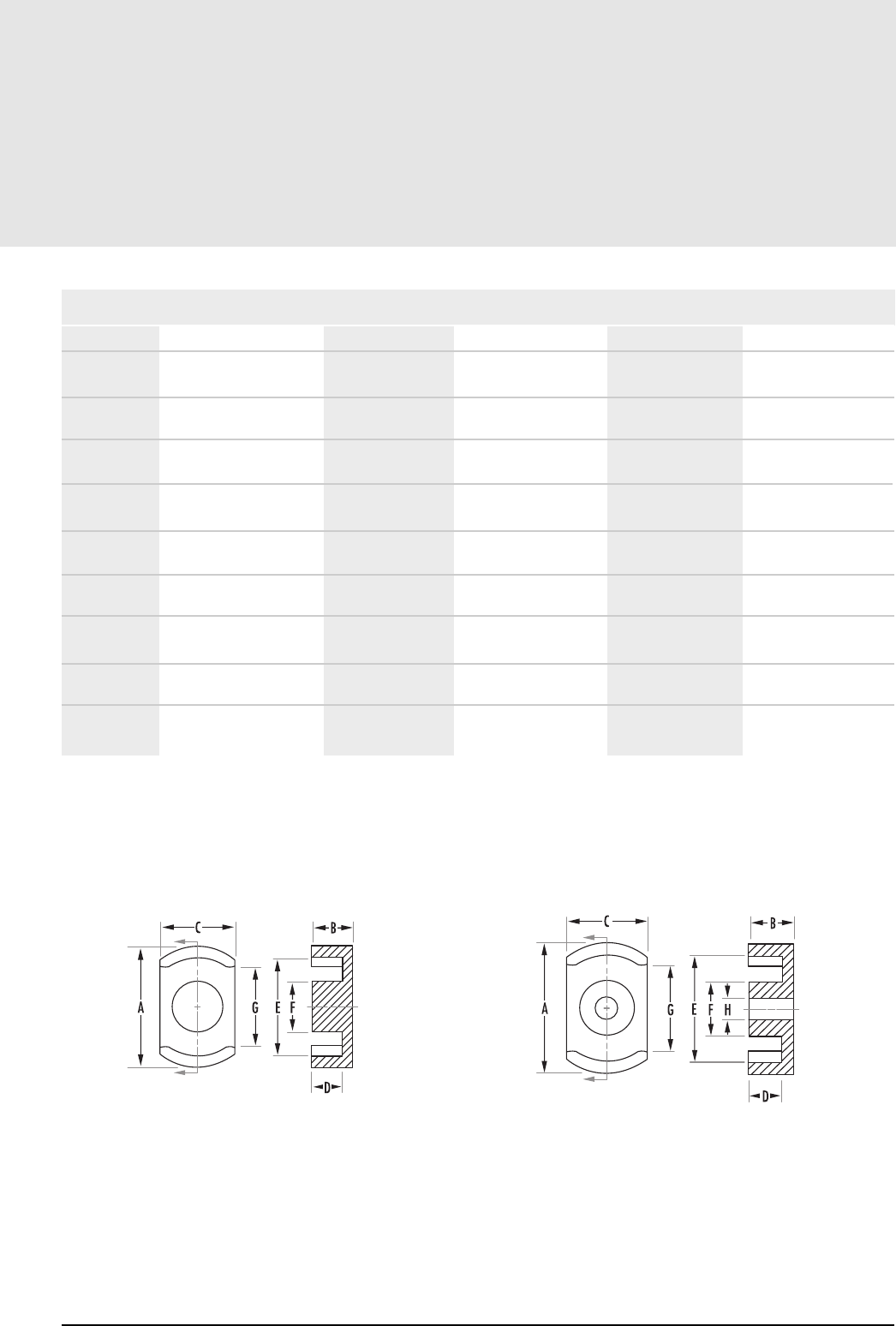
7.5
mag-inc.com
RS/DS
Core Data (ungapped)
MECHANICAL DIMENSIONS
D MIN 2D MIN E MIN F MAX G MIN H
6.500 13.000 25.000 13.510 15.490 -
.256 .512 .984 .532 .610 -
6.500 13.000 25.000 13.510 15.490 5.56 ± .10
.256 .512 .984 .532 .610 .219 ± .004
6.500 13.000 25.000 13.500 15.500 -
.256 .512 .984 .532 .610 -
7.29 14.580 29.85 16.100 20.300 -
.287 .574 1.177 .634 .800 -
7.29 14.580 29.85 16.100 20.300 5.56 ± .10
.287 .574 1.177 .634 .800 .219 ± .004
7.29 14.580 29.85 16.100 20.300 -
.287 .574 1.177 .634 .800 -
10.21 20.420 35.61 17.700 25.000 -
.402 .804 1.402 .697 .985 -
10.21 20.420 35.61 17.700 25.000 5.56 ± .10
.402 .804 1.402 .697 .985 .219 ± .004
10.21 20.420 35.61 17.700 25.000 -
.402 .804 1.402 .697 .985 -
RS/DS Cores
FIGURE 3 FIGURE 4
RS/DS
Core Data (ungapped)
7.6 MAGNETICS
POWER MATERIALS
AL(mH/1000T)
HIGH PERMEABILITY MATERIALS
PART COMBINATION R P F* J W H
H_41408UG DS
with center hole Min
S_41408UG RS
Min
D_42311UG DS
Min
H_42311UG DS
with center hole Min
S_42311UG RS
Min
D_42318UG DS
Min
H_42318UG DS
with center hole Min
S_42318UG RS
Min
D_42616UG DS
Min
H_42616UG DS
with center hole Min
1,150 1,250 1,990 3,080 4,930 -
1,320 1,435 2,274 3,375 5,350 -
2,580 2,810 4,460 6,300 11,245 16,800
2,400 2,595 4,170 5,890 9,815 -
2,950 3,210 5,200 6,300 11,250 -
2,180 2,370 3,800 4,760 7,000 10,500
1,950 2,115 3,350 4,000 7,000 -
2,300 2,500 4,000 4,800 8,400 -
2,870 3,120 5,000 6,070 9,100 -
- 2,880 4,600 6,080 9,100 -
RS/DS Cores
Any practical gap available. See page 1.8 - 1.11
To order, add material code to part number.
* F material nominal ±25%
S_42616UG RS
Min
D_43019UG DS
Min
H_43019UG DS
with center hole Min
S_43019UG RS
Min
D_43622UG DS
Min
H_43622UG DS
with center hole Min
S_43622UG RS
Min
D_44229UG DS
Min
H_44229UG DS
with center hole Min
S_44229UG RS
Min
3,270 3,550 5,300 6,700 11,000 -
3,330 3,620 5,800 7,120 10,500 -
3,170 3,450 5,525 7,130 10,500 -
4,150 4,520 6,700 8,360 13,000 -
4,020 4,370 7,000 8,700 12,600 -
- 4,050 6,520 8,700 12,600 -
5,230 5,685 8,600 11,200 18,600 -
4,830 5,250 8,400 9,220 13,300 -
- 5,000 8,100 9,220 13,300 -
5,440 5,910 10,200 12,200 - -

7.7
mag-inc.com
RS/DS
Core Data (ungapped)
MAGNETIC DATA
le(mm) Ae(mm2)A MIN (mm2)Ve(mm3)WaAc
MOUNTING CLAMP
RS/DS Cores
20.6 21.0 019.2 433.0 - -
20.2 23.0 19.2 460.0 2.85 0.019
26.8 51.2 37.8 1,370.0 10.00 0.081
27.0 48.2 37.8 1,300.0 - -
26.5 58.0 37.8 1,540.0 11.65 0.092
39.9 58.0 40.7 2,310.0 13.0 0.213
40.1 53.4 40.7 2,130.0 - -
38.6 60.0 40.7 2,320.0 17.40 0.221
38.9 77.0 62.7 3,000.0 15.00 0.283
39.0 72.1 62.7 2,810.0 --
38.3 82.6 62.7 3,180.0 20.00 .392
46.2 117.0 96.0 5,410.0 22.00 0.601
46.1 111.0 96.0 5,110.0 - -
45.6 123.0 96.0 5,610.0 30.95 0.632
52.8 149.0 125.0 7,870.0 37.00 1.15
53.1 146.0 125.0 7,750.0 - -
53.0 174.0 125.0 9,220.0 57.00 1.53
71.7 209.0 178.0 14,990.0 78.00 2.91
71.7 203.0 178.0 14,560.0 - -
70.1 234.5 178.0 16,400.0 104.00 3.69
CORE WEIGHT
(grams per set)
STANDARD BOBBIN
PRINTED CIRCUIT BOBBIN
AVAILABLE HARDWARE
Bobbins
7.8 MAGNETICS
RS/DS Core Hardware
MECHANICAL DIMENSIONS MATERIAL
NOMINAL WINDING
AREA PER SECTION
in2cm2
AVERAGE
LENGTH
OF
TURN FT
A MAX B MAX D MIN E NOM
C MIN
21.132 10.922 11.557 12.776 9.931
0.832 0.430 0.455 0.503 0.391
21.132 10.922 11.557 12.776 9.931
0.832 0.430 0.455 0.503 0.391
21.132 10.922 11.557 12.776 4.749
0.832 0.430 0.455 0.503 0.187
21.132 10.922 11.557 12.776 3.022
0.832 0.430 0.455 0.503 0.119
21.132 10.922 11.557 12.776 3.022
0.832 0.430 0.455 0.503 0.119
24.917 12.928 13.563 15.036 11.684
0.981 0.509 0.534 0.592 0.460
24.917 12.928 13.563 15.036 5.562
0.981 0.509 0.534 0.592 0.219
24.917 12.928 13.563 15.036 3.505
0.981 0.509 0.534 0.592 0.138
29.768 14.478 16.230 18.059 12.979
1.1721 0.570 0.639 0.711 0.511
29.768 14.478 16.230 18.059 6.146
1.172 0.570 0.639 0.711 0.242
29.768 14.478 16.230 18.059 3.860
1.172 0.570 0.639 0.711 0.152
35.407 20.015 17.983 19.710 17.805
1.394 0.788 0.708 0.776 0.701
35.407 20.01 17.983 19.710 8.407
1.394 0.788 0.708 0.776 0.331
0.06530 0.4210 0.173 Delrin
0.06530 0.4210 0.173 Crastin S660FR
0.03140 0.2020 0.173 Delrin
0.01990 0.1280 0.173 Delrin
0.01990 0.1280 0.173 Crastin S660FR
0.0840 0.542 0.204 Delrin
0.0394 0.254 0.204 Delrin
0.02460 0.159 0.204 Delrin
0.11700 0.755 0.244 Delrin 500
0.05540 0.357 0.244 Delrin 500
0.34800 0.225 0.244 Delrin 500
0.21500 1.3900 0.282 Delrin
0.09700 0.6300 0.282 Delrin
00B261601 42616 1 mm
in
00B261601FR 42616 1 mm
2 Section in
00B261602 42616 1 mm
3 Section in
00B261603 42616 1 mm
3 Section in
00B261603FR 42616 1 mm
3 Section in
00B301901 43019 1mm
in
00B301902 43019 1 mm
2 Section in
00B301903 43019 1 mm
3 Section in
00B362201 43622 1mm
in
00B362202 43622 1 mm
2 Section in
00B362203 43622 1 mm
3 Section in
00B422901 44229 2 mm
in
00B422902 44229 2mm
2 Section in
PART FIG.CORE
SIZE
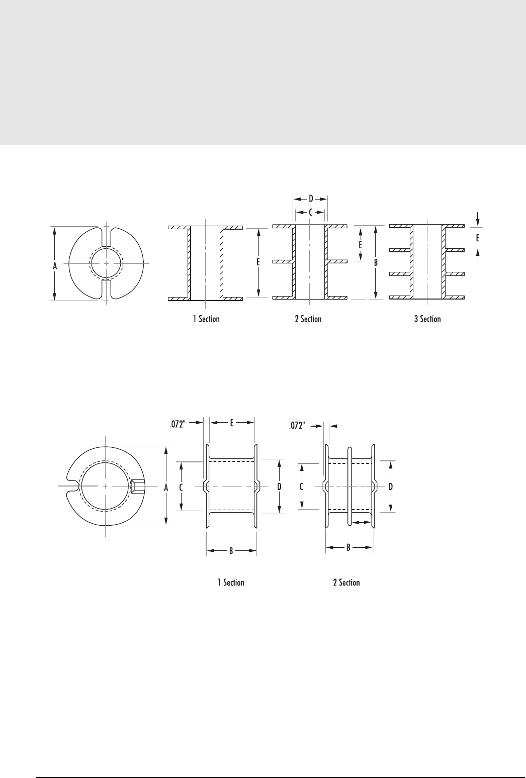
BOBBIN FIGURE 1
BOBBIN FIGURE 2
7.9
mag-inc.com
Bobbins
RS/DS Core Hardware
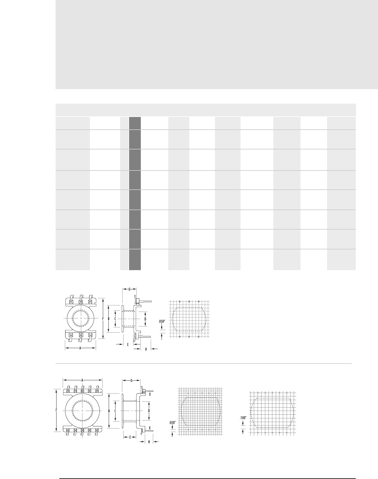
Printed Circuit Bobbins
7.10 MAGNETICS
RS/DS Core Hardware
MECHANICAL DIMENSIONS
A MAX B MAX D MIN E NOM F MAX G MAX H NOM
C MAX
12.776 ref 11.532 7.290 6.071 4.064 16.586 ref 5.486 4.775
0.503 ref 0.454 0.287 0.239 0.160 .653 ref 0.216 0.188
19.812 17.780 11.430 10.033 5.156 23.241 6.858 5.588
0.780 0.700 0.450 0.395 0.203 0.915 0.270 0.220
23.114 17.78 11.404 10.033 11.887 22.86 13.665 5.537
0.910 0.700 0.449 0.395 0.468 0.900 0.538 0.218
25.527 28.194 12.878 11.557 8.890 21.133 10.922 5.588
1.005 1.110 0.507 0.455 0.350 0.832 0.430 0.220
28.194 24.765 14.935 13.563 10.744 30.099 12.776 4.775
1.110 0.975 0.588 0.534 0.423 1.185 0.503 0.188
35.687 38.862 19.558 16.231 12.446 29.769 14.478 4.953
1.405 1.530 0.770 0.639 0.490 1.172 0.570 0.195
43.307 43.688 19.710 17.831 17.907 35.484 20.320 4.826
1.705 1.720 0.776 0.702 0.705 1.397 0.800 0.190
PCB4140861 41408 1 mm
in
PCB2311T1 42311 2 mm
in
PCB2318T1 42318 2 mm
in
PCB2616TA 42616 3 mm
in
PCB3019T1 43019 2 mm
in
PCB3622L1 43622 4mm
in
PCB4229L1 44229 5 mm
in
PART FIG.CORE SIZE
FIGURE 1
FIGURE 2
PCB2311T1 and PCB2318T1 have no standoff at X
41408
42311 & 42318 43019
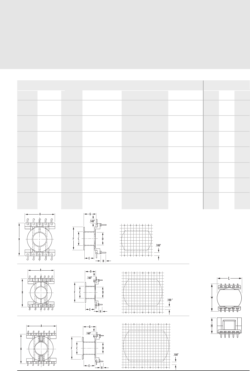
7.11
magnetics.com
Printed Circuit Bobbins
RS/DS Core Hardware
NOMINAL WINDING
AREA PER SECTION
in2cm2
AVERAGE
LENGTH
OF TURN
FT
BOBBIN
MATERIAL PIN
MATERIAL PIN
DIMENSIONS
Length Width Height
0.013 0.086 0.095 Glass-filled nylon Tin coated Phosphor bronze .042" x .015" .565 .850 .375
0.025 0.159 0.143 Glass-filled nylon Tin coated Phosphor bronze .042" x .015" .925 1.030 .450
0.057 0.368 0.143 Glass-filled Nylon Tin coated Phosphor bronze .042" x .015" .925 1.030 .735
0.057 0.368 0.174 Rynite FR530 Tin-lead plated brass .045" x .015" 1.030 1.500 .740
0.080 0.514 0.206 Glass-filled nylon Tin coated Phosphor bronze .042" x .015" 1.215 1.330 .775
0.120 0.774 0.246 Rynite FR530 Tin-lead plated brass .060" x .020" 1.425 1.950 .975
0.217 1.390 0.284 Rynite FR530 Tin-lead plated brass .060" x .020" 1.715 2.150 1.275
FIGURE 3
FIGURE 6
FIGURE 4
FIGURE 5
42616
43622
44229
BOARD CLEARANCE (in.)*
*reference figure 6 for board clearance
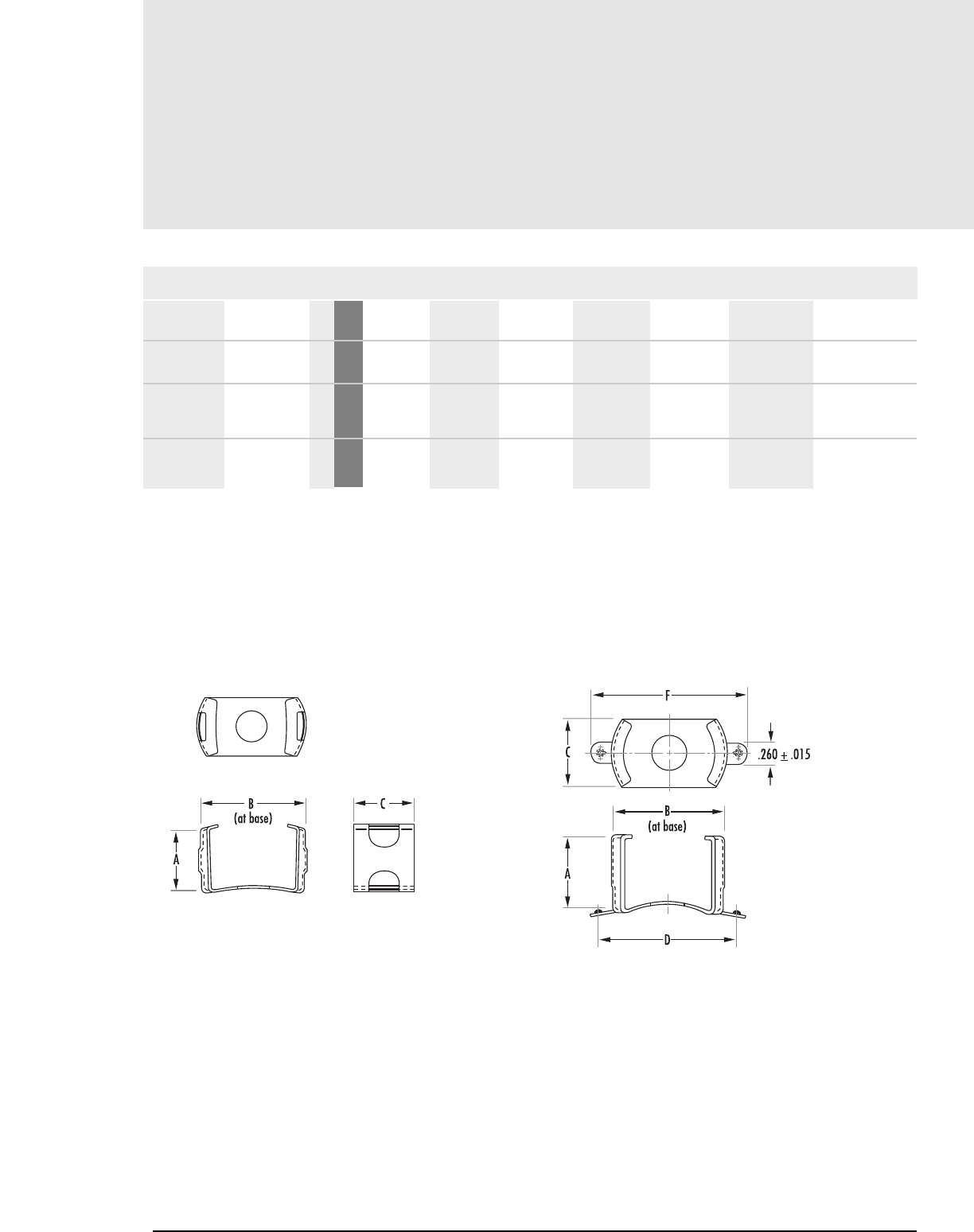
FIGURE 1
MECHANICAL DIMENSIONS
A NOM B NOM D ± .020" F NOM
C NOM MATERIAL MACHINE SCREW
IMPRESSIONS
8.89 13.97 8.001 - - Stainless Steel -
0.35 0.55 0.315 - - -
23.241 36.322 21.590 44.450 50.038 Spring Steel #6-32
0.915 1.430 0.850 1.750 1.970
31.064 43.180 25.40 50.80 56.388 Spring Steel #6-32
1.223 1.700 1.00 2.000 2.220
00C1408RS 41408 1 mm
in
00C362217 43622 2 mm
in
00C422917 44229 2 mm
in
PART FIG.CORE SIZE
FIGURE 2
Mounting Clamps
7.12 MAGNETICS
RS/DS Core Hardware
Clamps are not available for the PCB2311T1 ot PCB2318T1.
Cores may be cemented or bolted (with non-magnetic materials) to mounting surface.
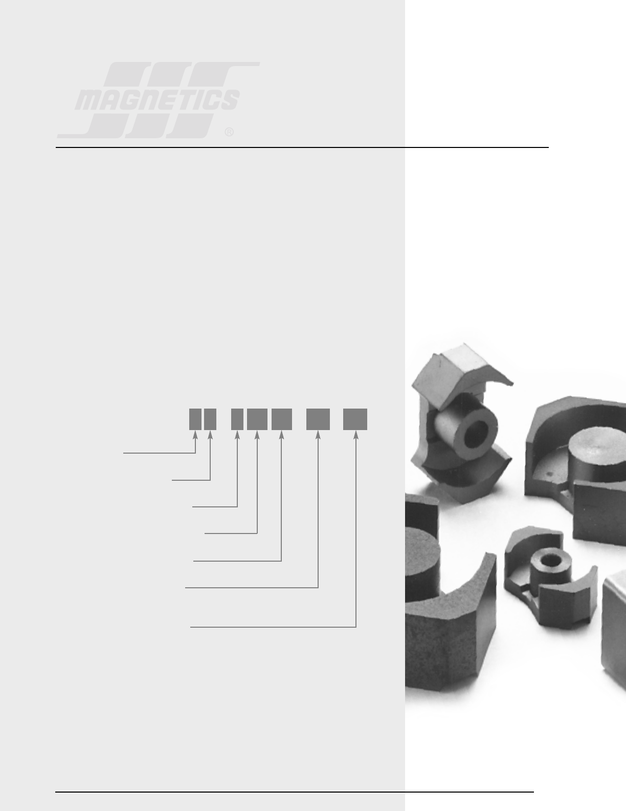
Section 8
RM Cores
8.1
RM CORES
RM Cores are square-designed cores that offer all the magnetic and mechanical advantages of pot
cores, plus the added feature of maximizing magnetic performance while minimizing PC board
space.
Easy to assemble and adaptable to automation, completed units provide at least 40% savings in
mounting area compared to a similar size pot core assembly.
RM cores are available in seven standard sizes. Three of the sizes are also available as low profile
cores.
Printed circuit bobbins or plain bobbins are available.
Typical applications include differential inductors, power inductors, filter inductors, telecom
inductors and broadband transformers.
HOW TO ORDER
SHAPE CODE*
FERRITE CORE MATERIAL
USED FOR ALL FERRITE TYPES
APPROXIMATE DIAMETER IN MM
APPROXIMATE HEIGHT IN MM
GEOMETRY CODE/GAP CODE
(SEE PAGE 1.5)
SPECIAL SPECIFICATION CODE
R P 4 15 10 UG XX
*SHAPE CODES
N – RM Core with solid centerpost
R – RM Core with center hole
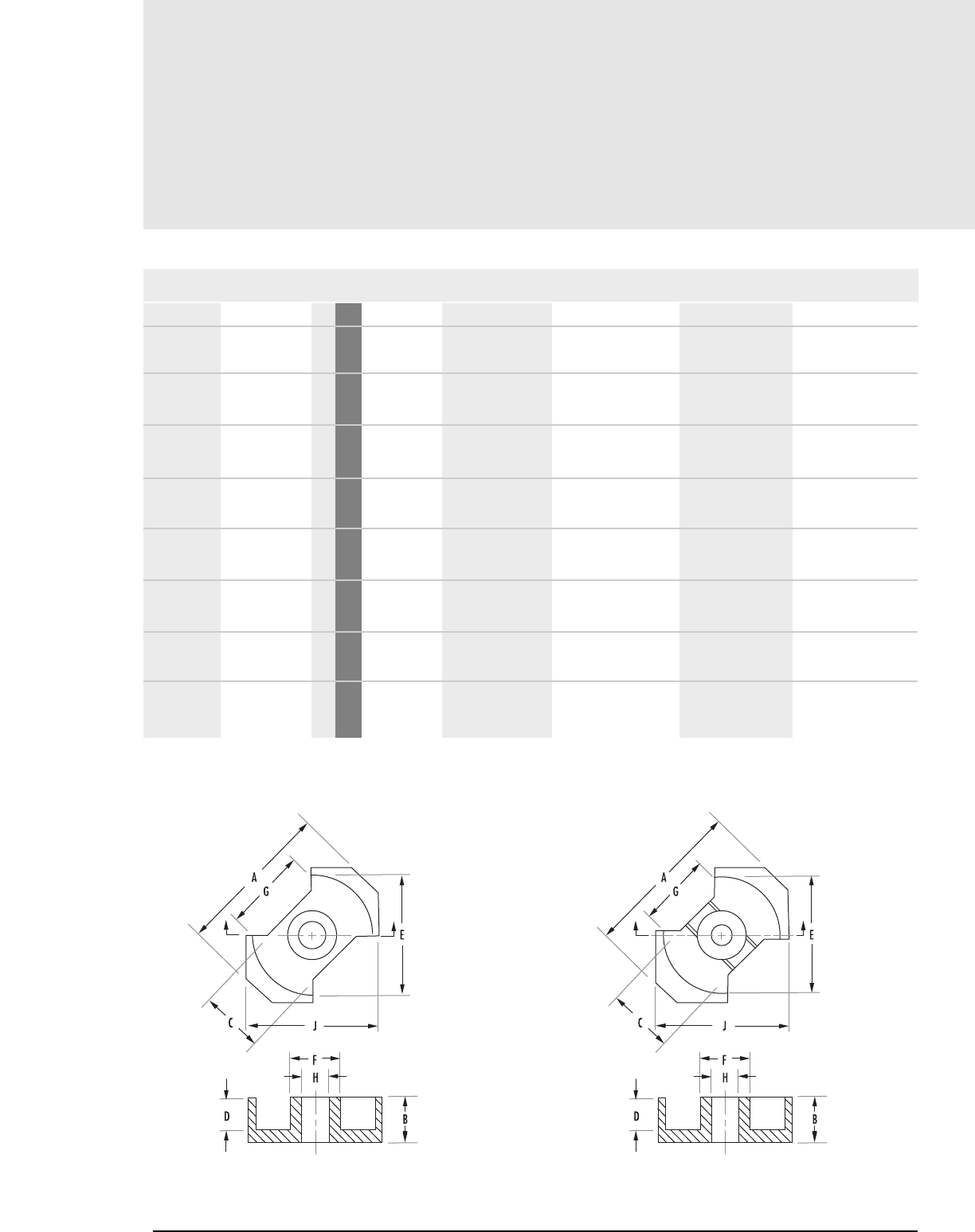
RM
Core Data (ungapped)
8.2 MAGNETICS
MECHANICAL DIMENSIONS
PART FIG.CORE TYPE A MAX B 2B C D
R_41110UG RM4 1mm
in
R_41500UG RM5/low profile 2mm
in
R_41505UG RM5/low profile 2mm
in
R_41510UG RM5 2mm
in
N_41510UG RM5 2mm
No center hole in
R_41812UG RM6-R 3mm
in
N_41812UG RM6-R 3mm
no center hole in
R_41912UG RM6-S 4mm
in
11.8 5.20 ± .050 10.400 4.45 nom 3.61 ± .100
0.465 .205 ± .002 .410 ± .004 0.175 nom .142 ± .004
14.9 2.160 ± .050 4.320 ± .100 6.6 nom .760 ± .100
0.587 .085 ± .002 .170 ± .004 0.260 nom .030 ± .004
14.9 2.490 ± .050 4.980 ± .100 6.6 nom .585 ± .100
0.587 .098 ± .002 .196 ± .004 0.260 nom .023 ± .004
14.9 5.200 ±.050 10.400 ± .100 6.6 nom 3.250 ± .100
0.587 .205 ± .002 .410 ± .004 0.260 nom .128 ± .004
14.9 5.200 ± .050 10.400 ± .100 6.6 nom 3.250 ± .100
0.587 .205 ± .002 .410 ± .004 0.260 nom .128 ± .004
18.3 6.200 ± .050 12.400 ± .100 7.400 nom 4.100 ± .100
0.720 .244 ± .002 .488 ± .004 0.292 nom .161 ± .004
18.3 6.200 ±.050 12.400 ± .100 7.400 nom 4.100 ± .100
0.720 .244 ± .002 .488 ± .004 0.292 nom .161 ± .004
18.3 6.200 ± .050 12.400 ± .100 8.200 nom 4.100 ± .100
0.720 .244 ± .002 .488 ± .004 0.323 nom .161 ± .004
RM Cores
Any practical gap available. See page 1.8 - 1.11
To order, add material code to part number.
FIGURE 1 FIGURE 2
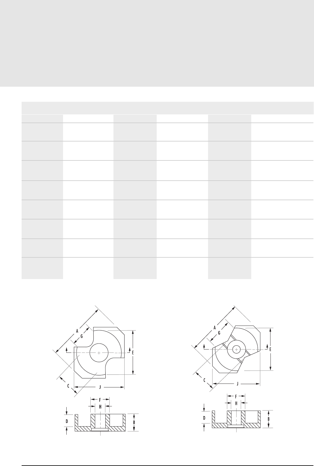
8.3
mag-inc.com
RM
Core Data (ungapped)
MECHANICAL DIMENSIONS
2D E F G H J
7.21 ± .200 8.15 ± .200 3.800 ± .10 5.79 ref 2.05 ± .05 9.600 ± .200
.284 ± .008 .321 ± .008 .150 ± .004 0.228 ref 0.081 ± .002 .378 ± .008
1.520 ± .200 10.400 ± .200 4.800 ± .100 6.71 nom 2.050 ± .050 12.050 ± .250
.060 ± .008 0.409 ± .008 .189 ± .004 0.264 nom .081 ± .002 .474 ± .010
1.170 ± .200 10.400 ± .200 4.800 ± .100 6.71 nom 2.050 ± .050 12.050 ± .250
.046 ± .008 0.409 ± .008 .189 ± .004 0.264 nom .081 ± .002 .474 ± .010
6.520 ±.200 10.400 ± .200 4.800 ± .100 6.71 nom 2.050 ± .050 12.050 ± .250
.256 ± .008 0.409 ± .008 .189 ± .004 0.264 nom .081 ± .002 .474 ± .010
6.520 ± .200 10.400 ± .200 4.800 ± .100 6.71 nom - 12.050 ± .250
.256 ± .008 0.409 ± .008 .189 ± .004 0.264 nom - .474 ± .010
8.200 ± .200 12.650 ± .250 6.250 ± .150 5.850 nom 3.050 ± .050 14.400 ± .300
0.323 ± .008 .498 ± .010 .246 ± .006 0.250 nom .120 ± .002 .567 ± .012
8.200 ±.200 12.650 ±.250 6.250 ± .150 5.850 nom - 14.400 ± .300
0.323 ± .008 .498 ± .010 .246 ± .006 0.230 nom - .567 ± .012
8.200 ± .200 12.650 ± .250 6.250 ± .150 9.000 nom 3.050 ± .050 14.400 ± .300
0.323 ± .008 .498 ± .010 .246 ± .006 0.355 nom .120 ± .002 .567 ± .012
RM Cores
FIGURE 3 FIGURE 4
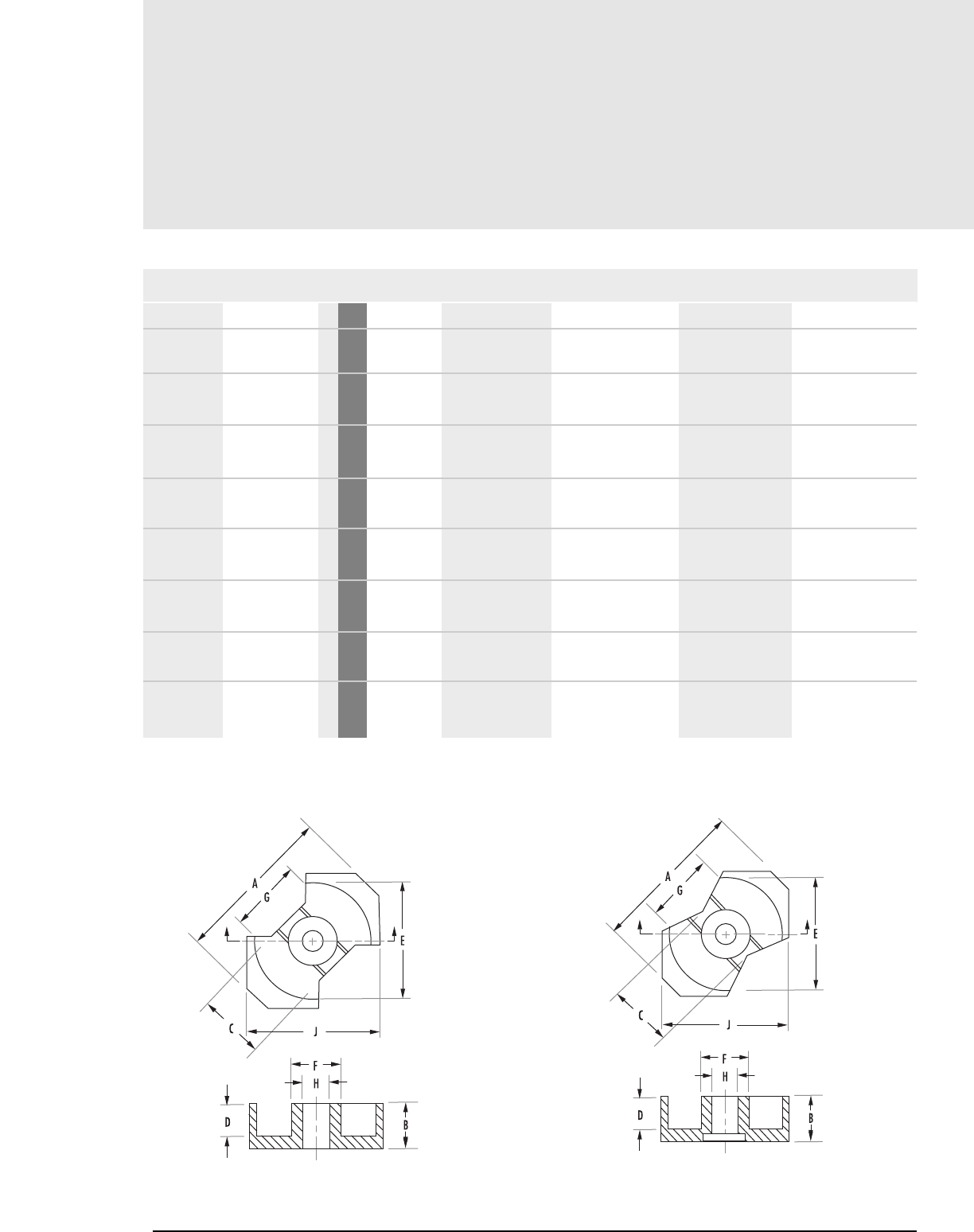
RM
Core Data (ungapped)
8.4 MAGNETICS
MECHANICAL DIMENSIONS
PART FIG.CORE TYPE A MAX B 2B C D
N_41912UG RM6-S 4mm
no center hole in
N_42309UG RM8/low profile 2mm
no center hole in
R_42316UG RM8 2mm
in
N_42316UG RM8 2mm
no center hole
N_42809UG RM10/low profile 2mm
no center hole in
R_42819UG RM10 2mm
in
N_42819UG RM10 2mm
no center hole in
N_43723UG RM12 4mm
in
18.30 6.200 ± .050 12.400 ± .100 8.200 nom 4.100 ± .100
0.720 .244 ± .002 .488 ± .004 .323 nom .161 ± .004
23.20 7.87 ± .050 15.74 ± .100 10.800 1.270 ± .130
0.913 .155 ± .002 .310 ± .004 0.425 .050 ± .005
23.20 8.200 ± .050 16.400 ± .100 10.800 5.530 ± .130
0.913 .323 ± .002 .646 ± .004 0.425 .218 ± .005
23.2 8.2 ± .05 16.4 ± .1 11.0+0 -.5 5.5 ± .1
28.50 4.750 ± .050 9.500 ± .100 13.200 ± .250 1.900 ± .150
1.122 .187 ±.002 .374 ± .004 .520 ± .010 .074 ± .006
28.50 9.300 ± .050 18.600 ± .100 13.200 ± .250 6.400 ± .150
1.122 .366 ± .002 .732 ± .004 .520 ± .010 .250 ± .006
28.50 9.300 ± .050 18.600 ± .100 13.200 ± .250 6.400 ± .150
1.122 .366 ± .002 .732 ± .004 .520 ± .010 .250 ± .006
37.40 11.700 ± .050 23.500 ± .100 16 nom 8.55 ± .150
1.472 .462 ± .002 .924 ± .004 .626 nom .337 ± .006
RM Cores
Any practical gap available. See page 1.8 - 1.11
To order, add material code to part number.
FIGURE 2 FIGURE 4

8.5
mag-inc.com
RM
Core Data (ungapped)
MECHANICAL DIMENSIONS
2D EFG H J
8.200 ± .200 12.650 ± .250 6.250 ± .150 9.000 nom - 14.400 ± .300
0.323 ± .008 .498 ± .010 .246 ± .006 0.355 nom - .567 ± .012
2.54 ± .250 17.350 ± .350 8.400 ± .150 11.700 nom - 19.300 ± .400
.100 ± .010 .683 ± .014 .331 ± .006 0.460 nom - .760 ±.016
11.050 ± .250 17.350 ± .350 8.400 ± .150 11.700 nom 4.500 ± .100 19.300 ± .400
.435 ± .010 .683 ± .014 .331 ± .006 0.415 nom 0.177 ± .004 .760 ±.016
11.0 17.0 +.6 - 0 8.55+0 - .3 - - 19.7+0 - .8
3.800 ± .300 21.650 ± .450 10.700 ± .200 11.400 nom - 24.15 ± .550
.148 ±.012 .852 ±.018 .421 ± .008 0.450 nom - .951 ± .022
12.700 ± .300 21.650 ± .450 10.700 ± .200 11.400 nom 5.563 ± .100 24.15 ± .550
.500 ±.012 .852 ± .018 .421 ± .008 0.450 nom 0.219 ± .005 .951 ± .022
12.700 ± .300 21.650 ± .450 10.700 ± .200 11.400 nom - 24.15 ± .550
.500 ± .012 .852 ± .018 .421 ± .008 0.450 nom - .951 ± .022
17.100 ± .300 25.500 ± .500 12.55 ± .250 15.200 nom - 29.25 ± .550
.673 ± .012 1.004 ± .020 .494 ± .010 0.600 nom - 1.152 ± .022
RM Cores
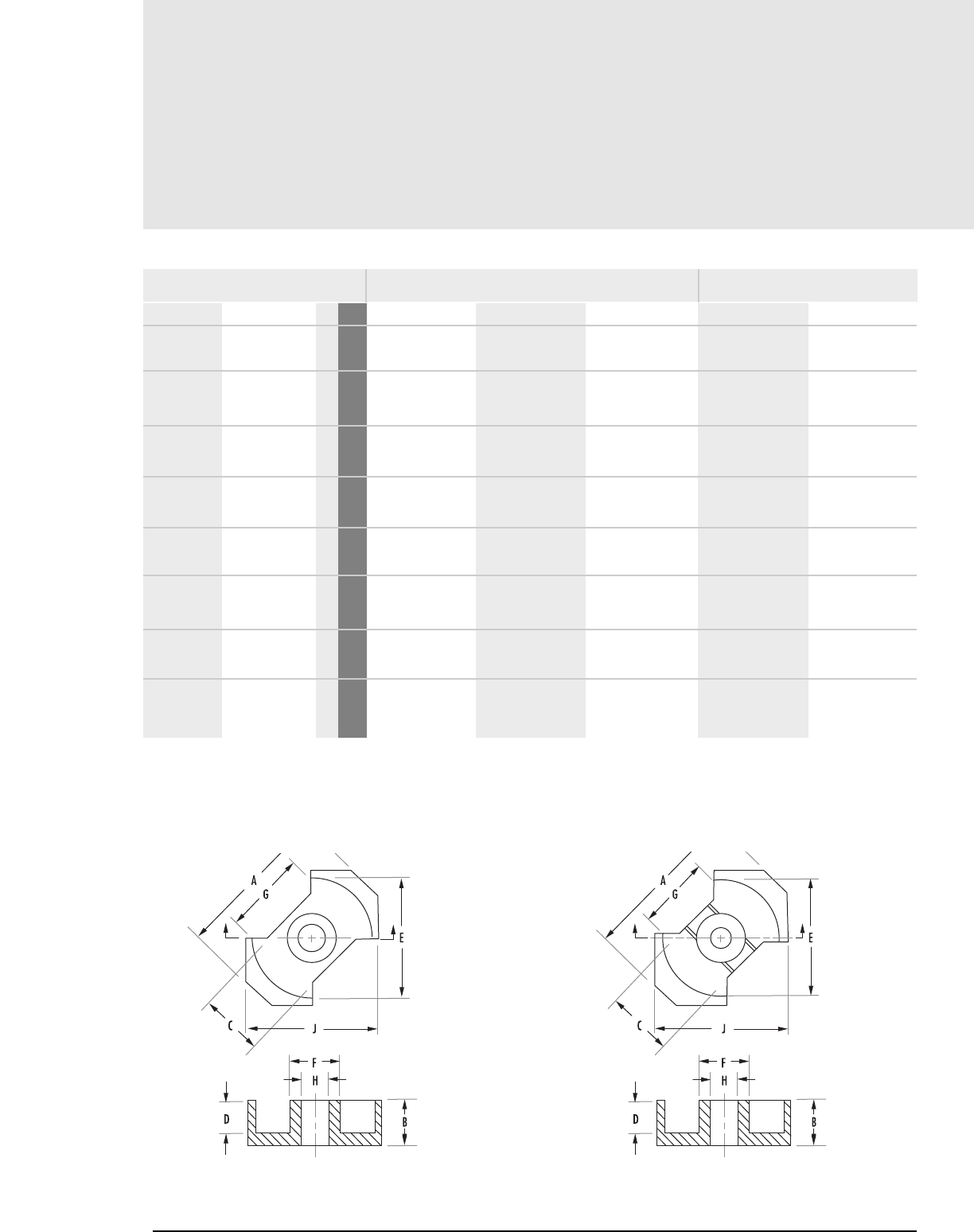
RM
Core Data (ungapped)
8.6 MAGNETICS
POWER MATERIALS
RPF*JW
690 750 1,200 1,480 2,100
1,950 2,030 3,380 5,250 -
2,290 2,390 3,980 6,180 -
1,290 1,400 2,100 3,100 4,200
1,290 1,400 2,100 3,100 4,200
1,640 1,750 2,800 4,480 5,400
1,790 1,950 3,080 5,030 6,020
1,490 1,620 2,600 4,040 5,400
RM Cores
R_41110UG RM4 1
Min
R_41500UG RM5/low profile 2
Min
R_41505UG RM5/low profile 2
Min
R_41510UG RM5 2
Min
N_41510UG RM5 2
Min
R_41812UG RM6-R 3
Min
N_41812UG RM6-R 3
no center hole Min
R_41912UG RM6-S 4
Min
PART FIG.CORE TYPE
AL(mH/1000T)
To order, add material code to part number.
* F material nominal ±25%
FIGURE 1 FIGURE 2
Any practical gap available. See page 1.8 - 1.11
HIGH PERMEABILITY MATERIALS
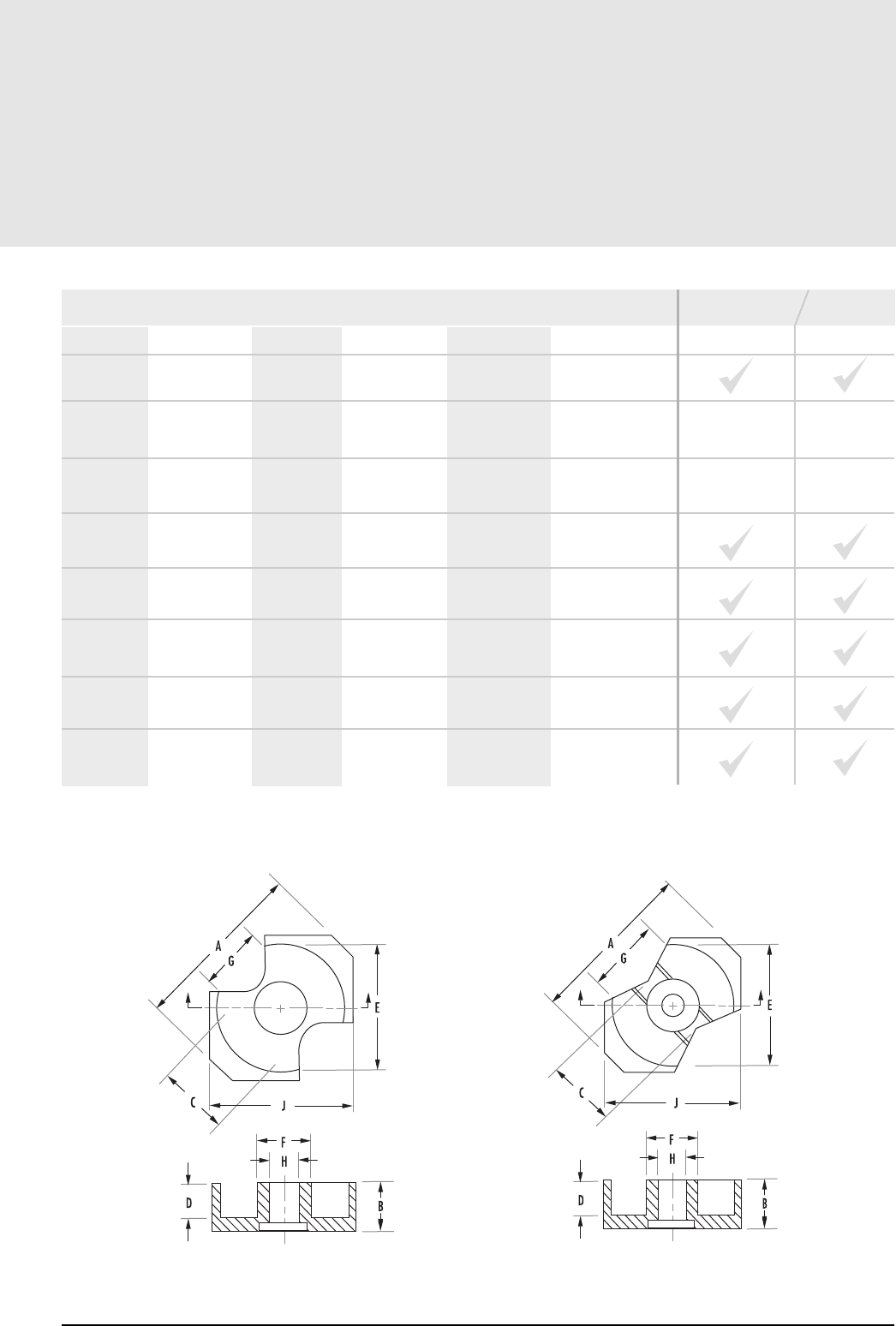
8.7
mag-inc.com
RM
Core Data (ungapped)
MAGNETIC DATA
AVAILABLE HARDWARE
Ie(mm) Ae(mm2)A MIN (mm2)Ve(mm3)WaAc
PRINTED CIRCUIT BOBBIN
MOUNTING CLAMP
RM Cores
20.60 10.8 7.9 222.0 1.600 0.0080
11.8 18.3 15.0 217.0 1.052 -
12.0 21.9 14.8 262.0 1.271 -
21.40 21.0 13.9 449.0 3.000 0.2030
22.40 22.8 18.1 510.0 3.300 0.0219
25.60 32.0 22.6 819.0 5.100 0.0507
27.10 38.0 31.0 1,030.0 5.400 0.0507
27.00 31.0 22.6 837.0 4.800 0.0507
FIGURE 3 FIGURE 4
CORE WEIGHT
(grams per set)
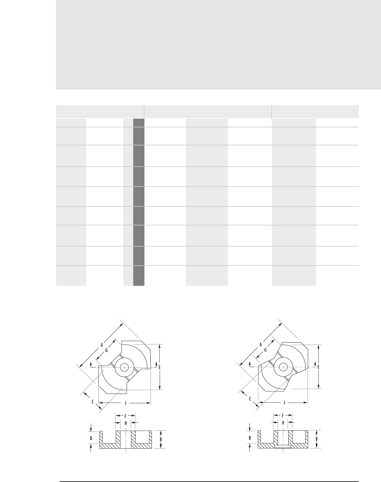
RM
Core Data (ungapped)
8.8 MAGNETICS
POWER MATERIALS HIGH PERMEABILITY MATERIALS
RPF*J W
1,660 1,800 2,880 4,500 6,020
3,490 3,790 6,400 10,300 14,700
1,760 1,920 3,500 5,220 7,420
2,025 2,200 3,700 6,000 8,540
4,710 5,120 8,520 11,600 17,400
2,700 2,950 5,210 6,690 10,000
3,035 3,300 5,500 7,490 11,200
3,450 3,750 6,000 8,850 15,820
RM Cores
N_41912UG RM6-S 4
no center hole Min
N_42309UG RM8/low profile 5
no center hole Min
R_42316UG RM8 5
Min
N_42316UG RM8 5
no center hole Min
N_42809UG RM10/low profile 2
no center hole Min
R_42819UG RM10 2
Min
N_42819UG RM10 2
no center hole Min
N_43723UG RM12 4
Min
PART FIG.CORE TYPE
To order, add material code to part number.
* F material nominal ±25%
FIGURE 2 FIGURE 4
AL(mH/1000T)
Any practical gap available. See page 1.8 - 1.11
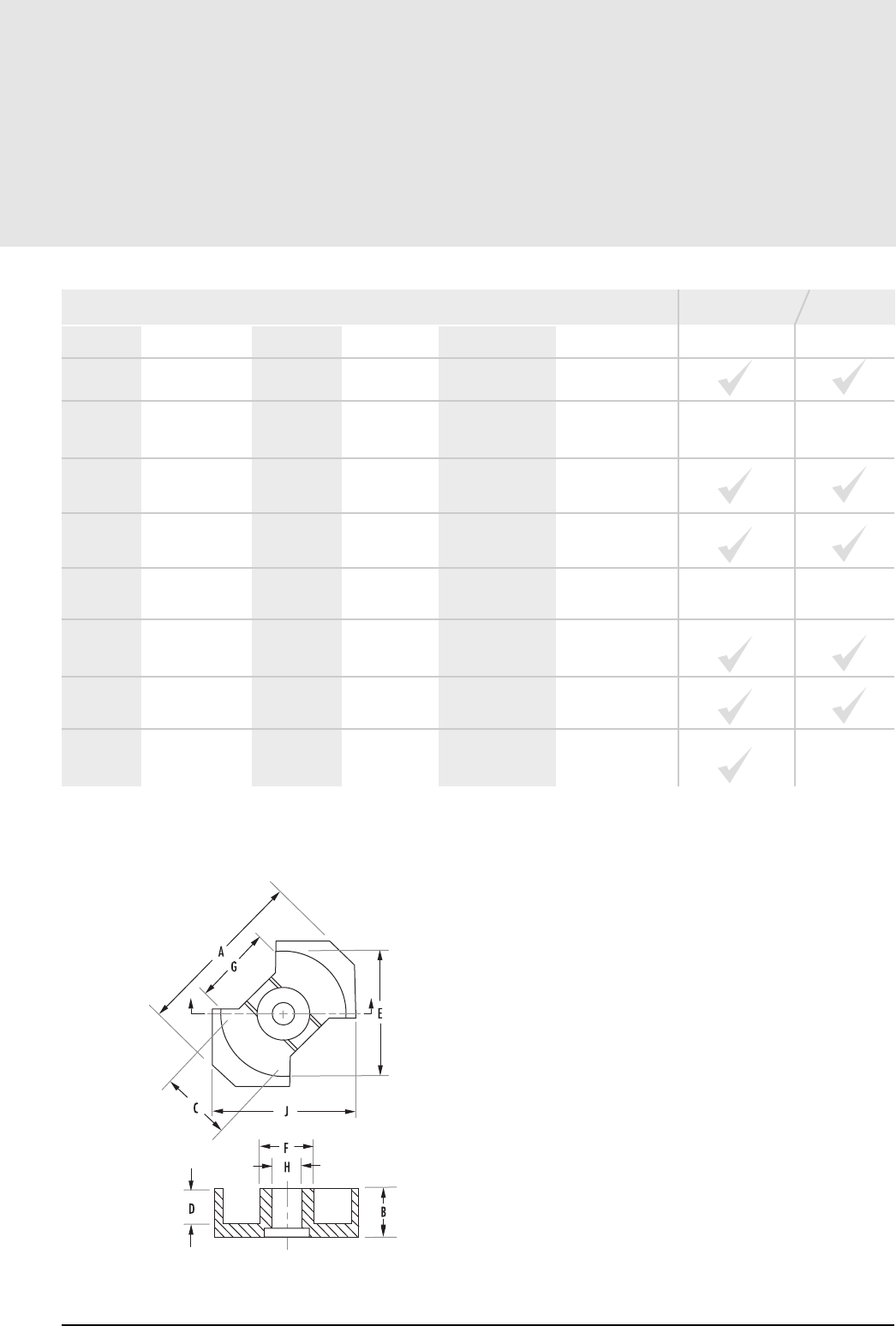
8.9
mag-inc.com
RM
Core Data (ungapped)
MAGNETIC DATA
Ie(mm) Ae(mm2) A MIN (mm2)V
e(mm3)WaAc
RM Cores
28.60 36.6 31.0 1,050 5.1 0.0507
20.8 60.5 55.5 1,260 6.111 -
35.50 52.0 36.9 1,850 10.4 0.1520
38.4 63.0 55.4 2,440 13.0 0.1520
26.1 90.1 82.9 2,360 11.446 -
41.70 8.3 61.8 3,460 20.0 0.4410
44.00 98.0 90.0 4,310 23.0 0.4410
56.60 146.0 125.0 8,340 42.0 1.0240
FIGURE 5
AVAILABLE HARDWARE
PRINTED CIRCUIT BOBBIN
MOUNTING CLAMP
CORE WEIGHT
(grams per set)
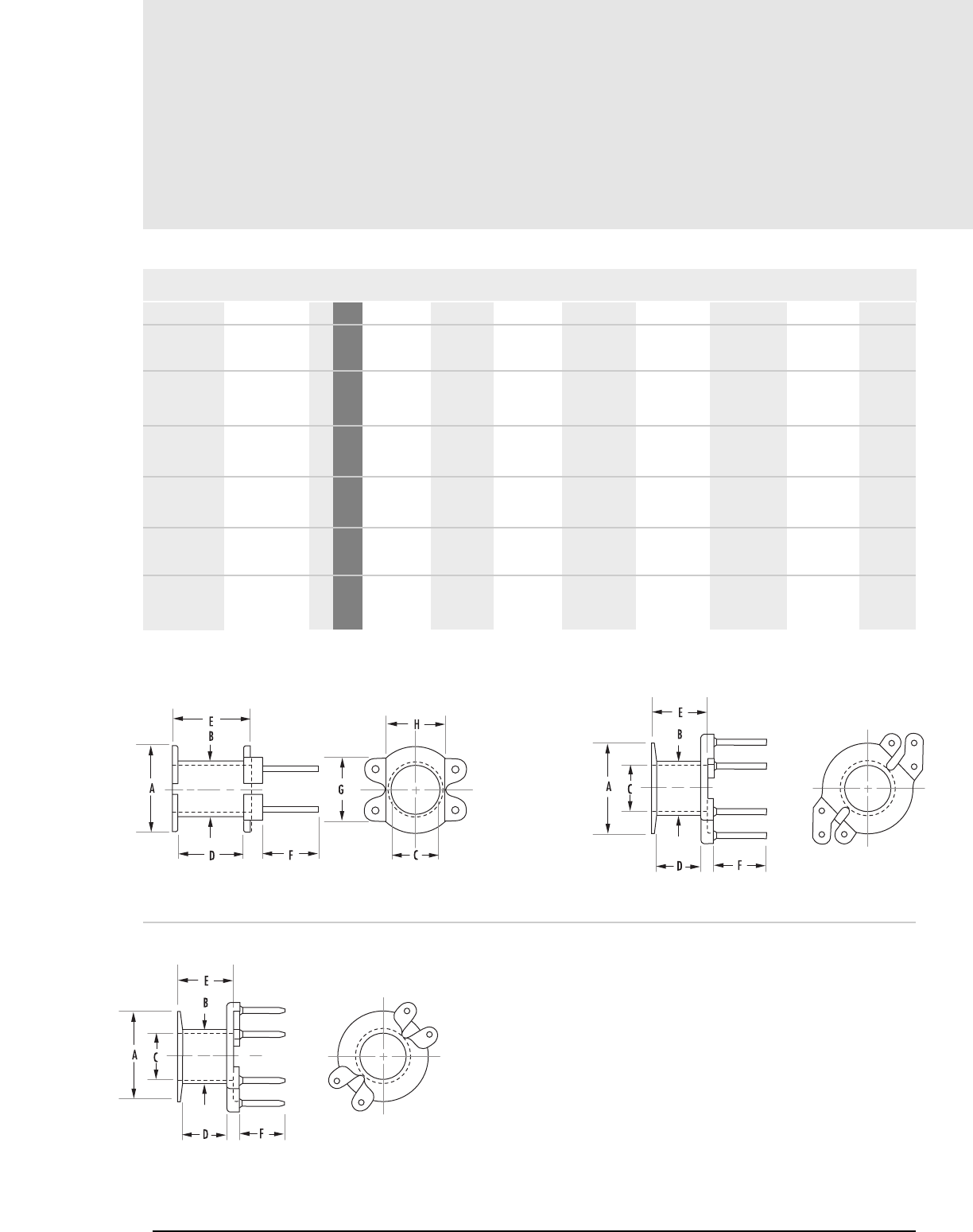
Printed Circuit Bobbins
8.10 MAGNETICS
MECHANICAL DIMENSIONS
A MAX B MAX C MIN D NOM E MAX F NOM G NOM H NOM
7.899 4.902 3.937 5.740 6.807 4.496 5.740 5.258
0.311 0.193 0.155 0.226 0.268 0.177 0.226 0.207
10.109 5.944 4.978 5.080 6.096 5.004 - -
0.398 0.234 0.196 0.200 0.240 0.197 - -
10.109 5.944 4.978 5.080 6.096 5.004 - -
0.398 0.234 0.196 0.200 0.240 0.197 - -
10.109 6.045 4.978 4.928 6.147 4.572 - -
0.398 0.238 0.196 0.194 0.242 0.180 - -
10.109 6.045 4.978 4.928 6.147 4.572 - -
0.398 0.238 0.196 0.194 0.242 0.180 - -
12.294 7.391 6.502 6.706 7.899 4.496 0.762 -
0.484 0.291 0.256 0.264 0.311 0.177 0.030 -
RM Core Hardware
PCB11104A 41110 1mm
in
PCB115104A 41510 2mm
in
PCB115104B 41510 2mm
2 section in
PCB151061 41510 3 mm
in
PCB151081 41510 4 mm
in
PCB181241 41812/41912 5 mm
in
PART FIG.CORE SIZE
FIGURE 1 FIGURE 2
FIGURE 3
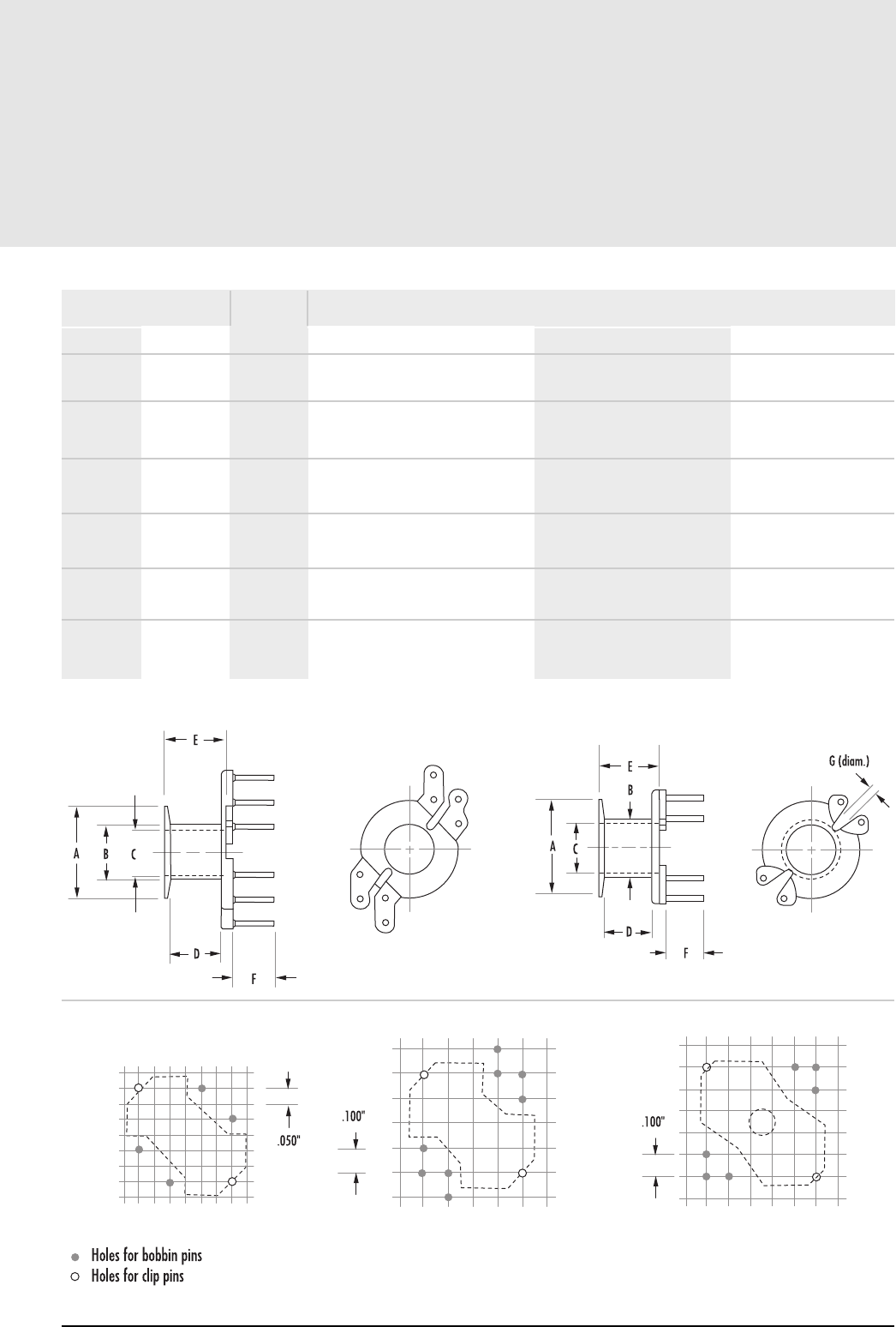
8.11
mag-inc.com
Printed Circuit Bobbins
NOMINAL WINDING
AREA PER SECTION PIN MATERIAL
in2cm2
AVERAGE
LENGTH OF
TURN FT
BOBBIN MATERIAL PIN DIAMETER
RM Core Hardware
0.012 0.077 0.065 Glass-filled nylon Tin coated Phosphor bronze 0.021"
0.015 0.096 0.082 Thermoset Phenolic Tin coated Phosphor bronze .022"
0.015 0.096 0.082 Thermoset Phenolic Tin coated Phosphor bronze 0.022"
0.015 0.096 0.082 Thermoset Phenolic Tin coated Phosphor Bronze 0.021"
0.015 0.096 0.082 Thermoset Phenolic Tin coated Phosphor Bronze 0.019"
0.025 0.160 0.098 Thermoset Phenolic Tin coated Phosphor Bronze .020" square/round
PIN LAYOUTS
41110 41510 41812
41912
FIGURE 4 FIGURE 5
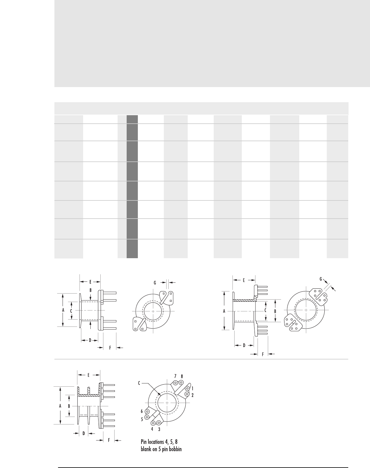
Printed Circuit Bobbins
8.12 MAGNETICS
MECHANICAL DIMENSIONS
A MAX B MAX C MIN D NOM E MAX F NOM G NOM H NOM
12.294 7.391 6.502 6.706 7.899 4.496 0.762 -
0.484 0.291 0.256 0.264 0.311 0.177 0.028 -
16.891 9.957 8.687 9.042 10.592 5.486 - -
0.665 0.392 0.342 0.356 0.417 0.216 - -
16.891 9.957 8.687 4.242 10.592 5.486 - -
0.665 0.392 0.342 0.167 0.417 0.216 - -
16.891 9.957 8.687 9.042 10.592 5.486 - -
0.665 0.392 0.342 0.356 0.417 0.216 - -
16.891 9.957 8.687 4.242 10.592 5.486 - -
0.665 0.392 0.342 0.167 0.417 0.216 - -
21.006 12.243 11.100 10.592 12.192 5.207 1.295 -
0.827 0.492 0.437 0.417 0.480 0.205 0.051 -
24.790 14.503 13.005 14.681 16.459 6.096 1.219 -
0.976 0.571 0.512 0.578 0.648 0.240 min 0.048 -
RM Core Hardware
PCB181261 41812/41912 6 mm
in
PCB231651 42316 7 mm
in
PCB231652 42316 7 mm
2 section in
PCB231681 42316 7 mm
in
PCB231682 42316 7 mm
2 section in
PCB2819L1 42819 8 mm
in
PCB3723L1 43723 9 mm
in
PART FIG.CORE SIZE
FIGURE 6
FIGURE 7
FIGURE 8
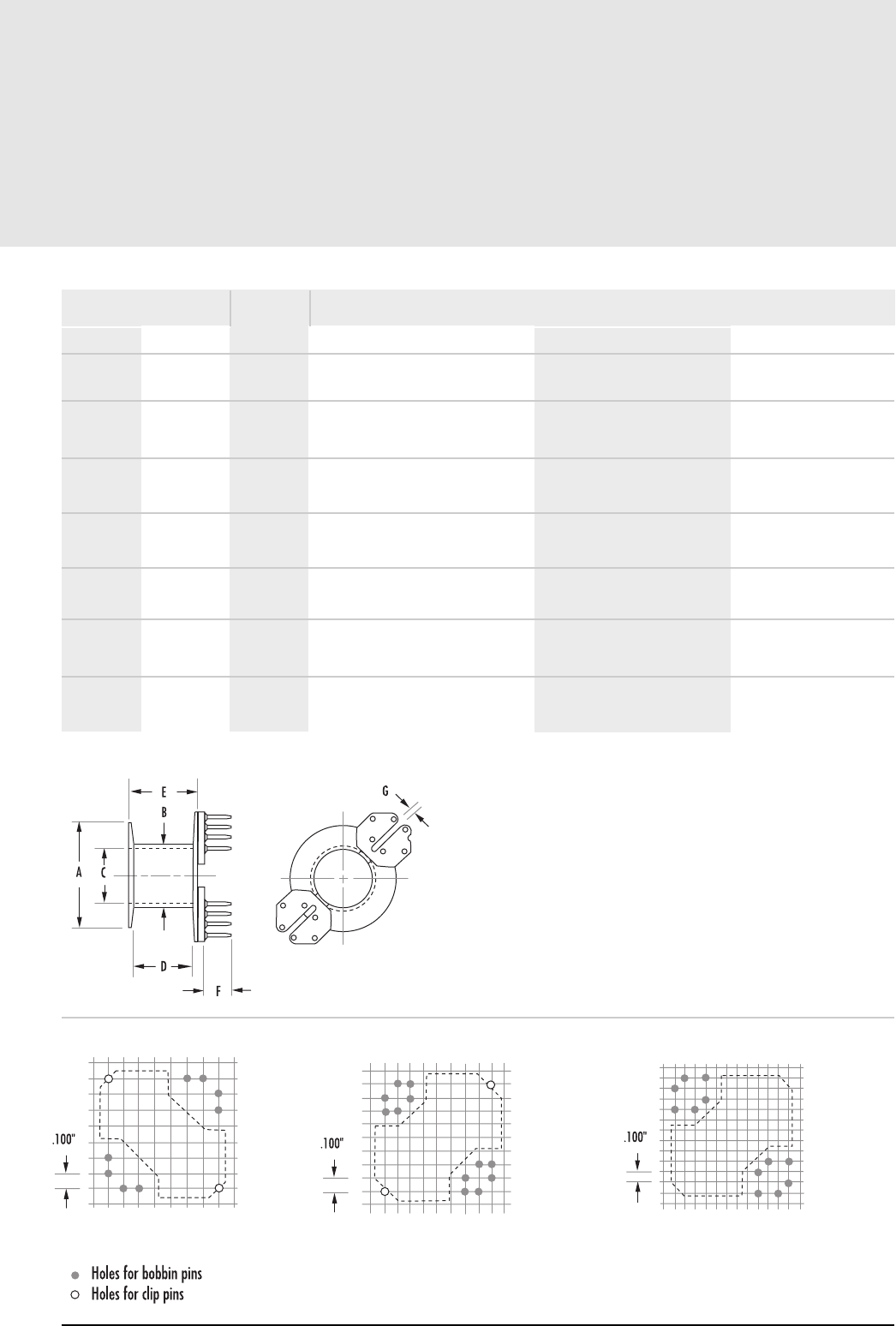
8.13
mag-inc.com
Printed Circuit Bobbins
NOMINAL WINDING
AREA PER SECTION PIN MATERIAL
in2cm2
AVERAGE
LENGTH OF
TURN FT
BOBBIN MATERIAL PIN DIAMETER
RM Core Hardware
0.025 0.160 0.098 Thermoset Phenolic Tin coated Phosphor Bronze .020" square/round
0.046 0.300 0.138 Thermoset Phenolic Tin coated Phosphor Bronze .026"
0.022 0.142 0.138 Thermoset Phenolic Tin coated Phosphor Bronze .026"
0.046 0.300 0.138 Thermoset Phenolic Tin coated Phosphor Bronze .026"
0.022 0.142 0.138 Thermoset Phenolic Tin coated Phosphor Bronze .026"
0.070 0.452 0.172 Thermoset Phenolic Tin coated Phosphor Bronze .024"
0.113 0.730 0.200 Thermoset Phenolic Tin coated Phosphor Bronze .033"
FIGURE 9
42316 42819 43723
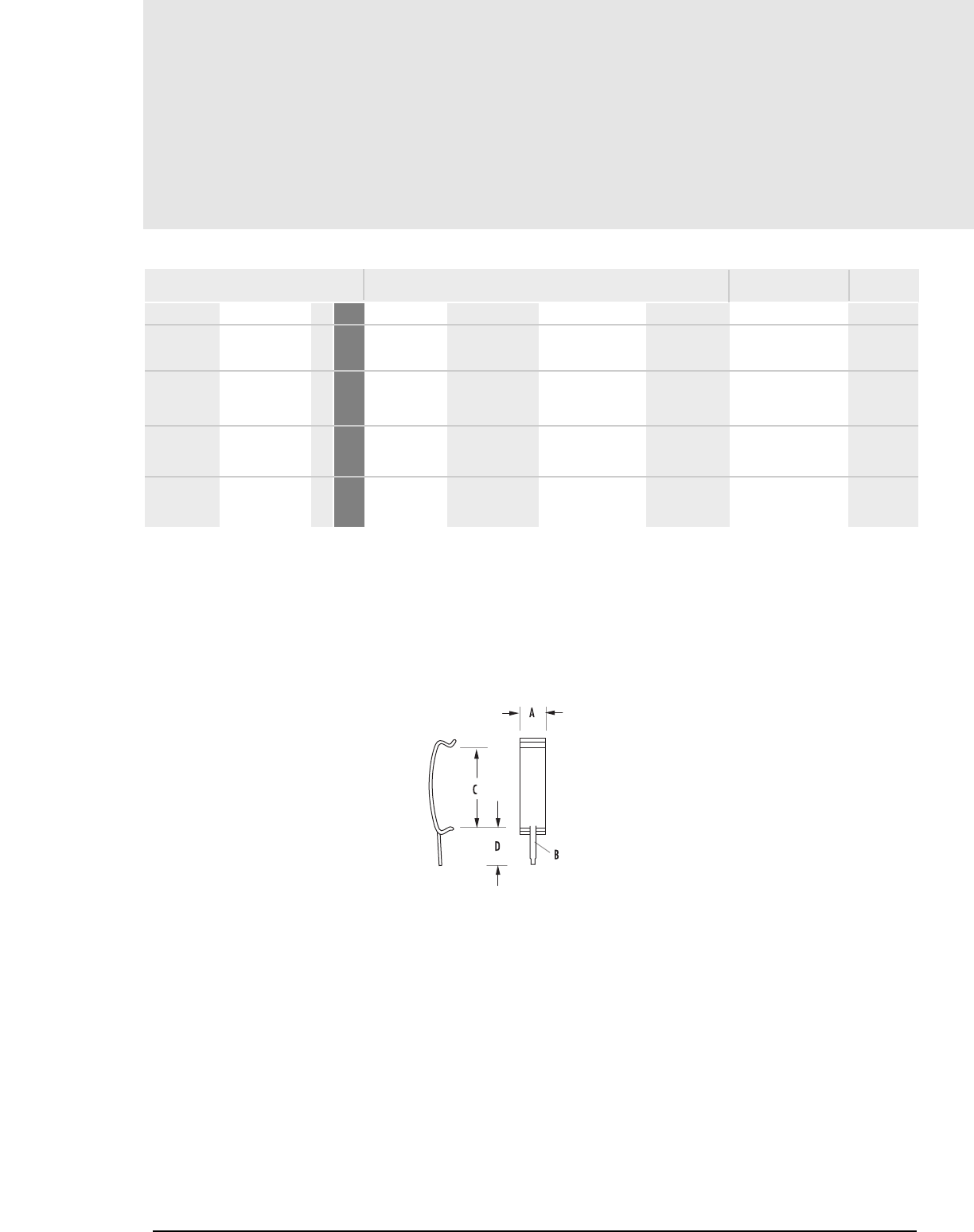
FIGURE 1
MECHANICAL DIMENSIONS
A NOM B NOM
2.083 .686 x .305 8.382 4.343 Spring Steel 0.012"
0.082 .027 x .012 0.330 0.171
2.591 .711 x .381 9.855 4.343 Spring Steel 0.015"
0.102 .028 x .015 0.388 0.171
4.496 .711 x .356 13.589 4.597 Spring Steel 0.014"
0.177 .028 x .014 0.535 0.181
4.496 .711 x .406 15.545 5.055 Spring Steel 0.016"
0.177 .028 x .016 0.612 0.199
00C111012 41110/41510 1mm
in
00C181211 41812/41912 1mm
in
00C231615 42316 1mm
in
00C281916 42819 1 mm
in
PART FIG.CORE SIZE
8.14 MAGNETICS
MATERIAL MATERIAL
THICKNESS
RM
Mounting Clamps
RM Core Hardware
Two mounting clamps are required per core set.
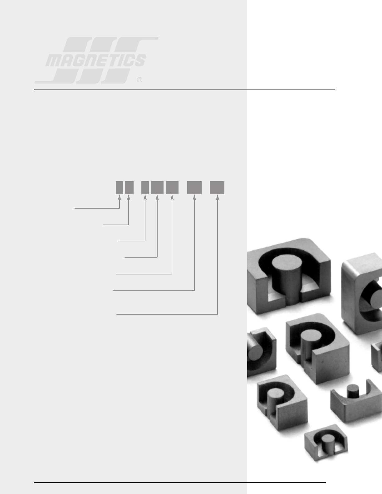
Section 9
EP Cores
9.1
EP CORES
EP cores are round center-post cubical shapes which enclose the coil completely except for the
printed circuit board terminals. This particular shape minimizes the effect of air gaps formed at
mating surfaces in the magnetic path and provides a larger volume ratio to total space used.
EP cores provide excellent shielding.
Typical applications for EP cores include differential and telecom inductors and power transformers.
HOW TO ORDER
*SHAPE CODES: P – EP core
SHAPE CODE*
FERRITE CORE MATERIAL
USED FOR ALL FERRITE TYPES
APPROXIMATE DIAMETER IN MM
APPROXIMATE HEIGHT IN MM
GEOMETRY CODE/GAP CODE
(SEE PAGE 1.5)
SPECIAL SPECIFICATION CODE
P W 4 10 10 UG XX
EP
Core Data (ungapped)
9.2 MAGNETICS
MECHANICAL DIMENSIONS
PART FIG.CORE TYPE A MAX B 2B C
P_40707UG EP7 1 mm
in
P_41010UG EP10 2 mm
in
P_41313UG EP13 3 mm
in
P_41717UG EP17 1 mm
in
P_42120UG EP20 2mm
P_40707UG EP7 1
Min
P_41010UG EP10 2
Min
P_41313UG EP13 3
Min
P_41717UG EP17 1
Min
P_42120UG EP20 2
Min
9.20 ± .200 3.700 ± .050 7.400 ± .100 6.35 ± .150
.362 ± .008 .146 ± .002 .292 ± .004 .250 ± .006
11.500 ± .300 5.150 ± .100 10.300 ± .008 7.60 ± .200
.453 ± .012 .202 ± .004 .404 ± .008 .301 ± .008
12.500 ± .280 6.450 ± .076 12.900 ± .150 8.800 ± .200
4.92 ± .011 .253 ± .003 .506 ± .006 .346 ± .008
17.980 ±.510 8.40 ± .100 16.80 ± .200 11.00 ± .250
.708 ± .020 .331 ± .004 .662 ± .008 .433 ± .010
24.0 ± .5 10.7 ± .1 21.4 ± .2 15 ± .35
810 880 1,240 1,930 3,600
780 850 1,200 1,850 3,360
1,150 1,250 2,000 2,800 5,000
1,790 1,950 3,100 4,400 8,000
3,170 3,450 5,000 7,200 13,500
EP Cores
HIGH PERMEABILITY MATERIALSPOWER MATERIALS
RPF* WJ
FIGURE 1 FIGURE 2 FIGURE 3
Any practical gap is available. See page 1.8-1.11
To order, add material code to part number.
AL (mH/1,000T)
PARTCORE TYPE FIG.
* F material nominal ±25%

9.3
mag-inc.com
EP
Core Data (ungapped)
MECHANICAL DIMENSIONS
D MIN 2D MIN E MIN F MAX K
EP Cores
MAGNETIC DATA
CORE WEIGHT
(grams per set)
2.500 5.000 7.200 3.400 1.70 ± .100
0.098 0.196 0.283 0.134 .067 ± .004
3.600 7.200 9.2 3.450 1.850 ± .100
0.142 0.284 0.362 0.136 .073 ± .004
4.500 8.990 9.72 4.520 2.36 ± .130
0.177 0.354 0.383 0.178 .093 ± .005
5.55 11.10 11.6 5.88 3.30 ± .200
0.22 0.440 0.457 0.230 .128 ± .007
7.05 14.1 16.1 9.05 4.5 ± .2
le(mm) Ae(mm2) A MIN (mm2)V
e(mm3) WaAc (cm4)
15.70 10.3 7.8 162 1.4 0.0039
19.2 11.3 78.0 217 2.8 0.0100
24.2 19.5 14.0 472 5.1 0.0300
29.50 33.7 25.5 999 11.6 0.0810
41.1 78.7 60.8 3,230 27.6 0.2480
SURFACE MOUNT BOBBIN
PRINTED CIRCUIT BOBBIN
MOUNTING CLAMP
AVAILABLE HARDWARE
Printed Circuit Bobbins
9.4 MAGNETICS
MECHANICAL DIMENSIONS
A REF B REF C MAX D MIN E NOM F NOM G NOM H REF J MAX K REF L REF
9.144 7.391 7.112 3.429 3.505 4.496 3.734 4.572 4.724 2.515 5.055
0.360 0.291 0.280 0.135 0.138 0.175 0.147 0.180 0.186 0.099 0.199
10.998 10.998 8.992 3.556 5.588 4.902 3.404 5.385 7.112 2.489 7.493
0.433 0.433 0.354 0.140 0.220 0.193 0.134 0.212 0.280 0.098 0.295
13.157 13.411 9.703 4.572 7.772 5.791 5.334 6.147 8.941 2.489 10.084
0.518 0.528 0.382 0.180 0.306 0.228 0.210 0.242 0.352 0.098 0.397
18.999 18.999 11.455 5.994 9.474 7.112 4.699 7.493 11.100 - -
0.748 0.748 0.451 0.236 0.373 0.280 0.185 0.295 0.437
24.689 21.514 16.078 9.093 12.344 10.211 5.004 8.306 13.894 - -
0.972 0.847 0.633 0.358 0.486 0.402 0.197 0.327 0.547
EP Core Hardware
PCB07076B 40707 1 mm
in
PCB10108A 41010 2 mm
in
PCB1313TA 41313 3 mm
in
PCB17178A 41717 4 mm
in
PCB2120TA 42120 5 mm
in
PART FIG.CORE SIZE
FIGURE 1 FIGURE 2
FIGURE 4
FIGURE 3
9.5
mag-inc.com
Printed Circuit Bobbins
NOMINAL WINDING
AREA PER SECTION PIN MATERIAL
AVERAGE
LENGTH OF
TURN FT
BOBBIN MATERIAL PIN DIAMETER BOARD CLEARANCE (in.)*
Length Width Height
EP Core Hardware
0.007 0.044 0.059 Phenolic Tin coated Phosphor Bronze 0.016" square with clamp 0.4850 0.3850 0.4100
no clamp 0.375 0.300 0.390
0.018 0.114 0.070 Phenolic Tin coated Phosphor Bronze .026" with clamp 0.5500 0.5100 0.4700
no clamp 0.470 0.440 0.450
0.021 0.138 0.078 Phenolic Tin coated Phosphor Bronze 0.020" square with clamp 0.6250 0.6250 0.5450
no clamp 0.535 0.545 0.515
0.029 0.188 0.094 Phenolic Tin coated Phosphor Bronze 0.026" with clamp 0.8400 0.8000 0.6400
no clamp 0.760 0.760 0.625
0.051 0.332 0.134 Thermoset Phenolic Tin coated Phosphor Bronze 0.026" with clamp 1.0800 1.0000 0.8150
no clamp .995 .875 .755
*reference figure 6 for board clearance
FIGURE 5 FIGURE 6
PIN LAYOUTS
in2cm2
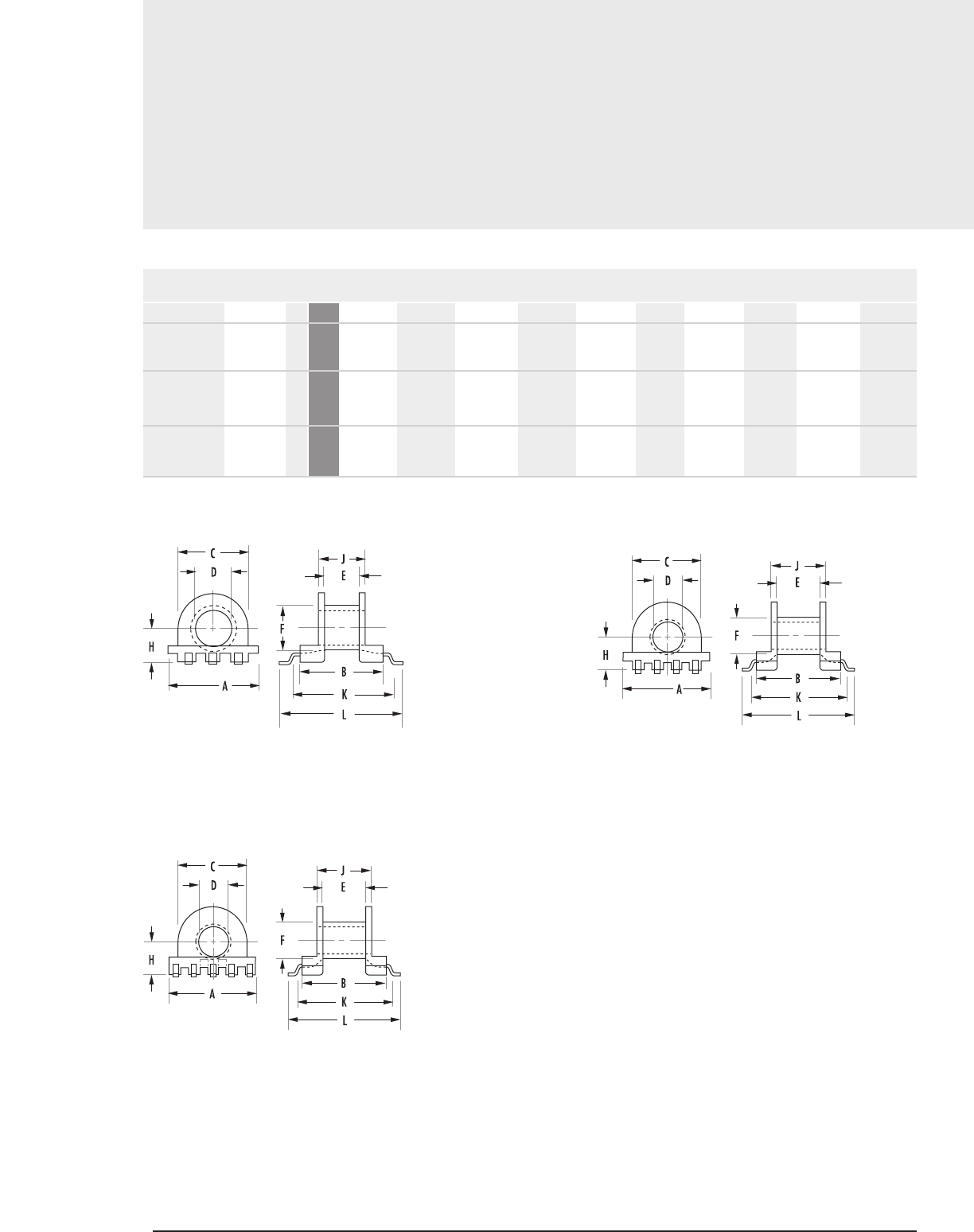
Surface Mount Bobbins
9.6 MAGNETICS
EP Core Hardware
MECHANICAL DIMENSIONS
A REF B REF C MAX D MIN E NOM F NOM H REF J MAX K REF L REF
9.195 8.585 7.112 3.404 3.607 4.496 3.505 4.902 10.592 12.700
0.362 0.338 0.280 0.134 0.142 0.177 0.138 0.193 0.417 0.500
11.506 10.490 9.093 3.505 5.791 4.801 4.496 7.112 12.497 14.605
0.453 0.413 0.358 0.138 0.228 0.189 0.177 0.280 0.492 0.575
12.802 13.005 9.601 4.496 7.595 5.791 5.258 8.788 15.392 16.993
0.504 0.512 0.378 0.177 0.299 0.228 0.207 0.346 0.606 0.669
SMB07076A 40707 1 mm
in
SMB10108A 41010 2 mm
in
SMB1313TA 41313 3 mm
in
PART FIG.CORE SIZE
FIGURE 1 FIGURE 2
FIGURE 3

9.7
mag-inc.com
EP Core Hardware
Surface Mount Bobbins
NOMINAL WINDING
AREA PER SECTION PIN THICKNESS
in2cm2
AVERAGE LENGTH OF TURN FT BOBBIN MATERIAL
0.007 0.044 0.059 L.C.P. 0.012"
0.019 0.120 0.070 L.C.P. 0.012"
0.021 0.138 0.078 L.C.P. 0.012"

Mounting Clamps
9.8 MAGNETICS
EP Core Hardware
MECHANICAL DIMENSIONS (NOMINAL)
A B C D E F G H MATERIAL
MATERIAL
THICKNESS
9.601 12.167 4.978 3.988 2.083 5.893 0.406 - Nickel Silver 0.016"
0.378 0.4790 0.196 0.157 0.082 0.232 0.016 -
10.389 7.188 4.978 - - - - - Nickel Silver 0.012"
0.409 0.2830 0.196 - - - - -
16.510 12.141 6.401 4.953 2.591 9.525 2.489 1.016 Phosphor Bronze 0.015"
0.650 0.4780 0.252 0.195 0.102 0.375 0.098 0.040
13.005 8.590 6.502 - - - - - Phosphor Bronze 0.012"
0.512 0.3382 0.256 - - - - -
16.510 13.0048 7.518 3.988 2.591 11.684 2.997 1.219 Nickel Silver 0.016"
0.650 0.5120 0.296 0.157 0.102 0.460 0.118 0.048
14.072 12.649 7.518 - - - - - Nickel Silver 0.014"
0.554 0.4980 0.296 - - - - -
19.990 18.593 8.992 5.004 5.004 15.596 5.004 0.991 Phosphor Bronze 0.016"
0.787 0.7320 0.354 0.197 0.197 0.614 0.197 0.039
19.177 16.586 8.992 - - - - - Phosphor Bronze 0.012"
0.755 0.6530 0.354 - - - - -
22.276 24.613 11.989 3.505 4.572 17.602 2.540 0.991 Nickel Silver 0.016"
0.877 0.9690 0.472 0.138 0.180 0.693 0.100 0.039
24.994 21.488 11.989 - - - - - Nickel Silver 0.016"
0.984 0.8460 0.472 - - - - -
0AC070716 40707 2 mm
YOKE in
0BC070712 40707 1 mm
CLAMP in
00C10102A 41010 3 mm
in
YOKE/ 41010 1 mm
CLAMP in
0AC131316 41313 4 mm
YOKE in
0BC131314 41313 1 mm
CLAMP in
00C17172A 41717 5 mm
in
YOKE/ 41717 1 mm
CLAMP in
0AC212016 42120 6 mm
YOKE in
0BC212016 42120 1 mm
CLAMP in
Yoke and Clamp are required for assembly.
Part numbers OOC10102A & 00C17172A are
for yoke/clamp set.
PART FIG.
CORE SIZE
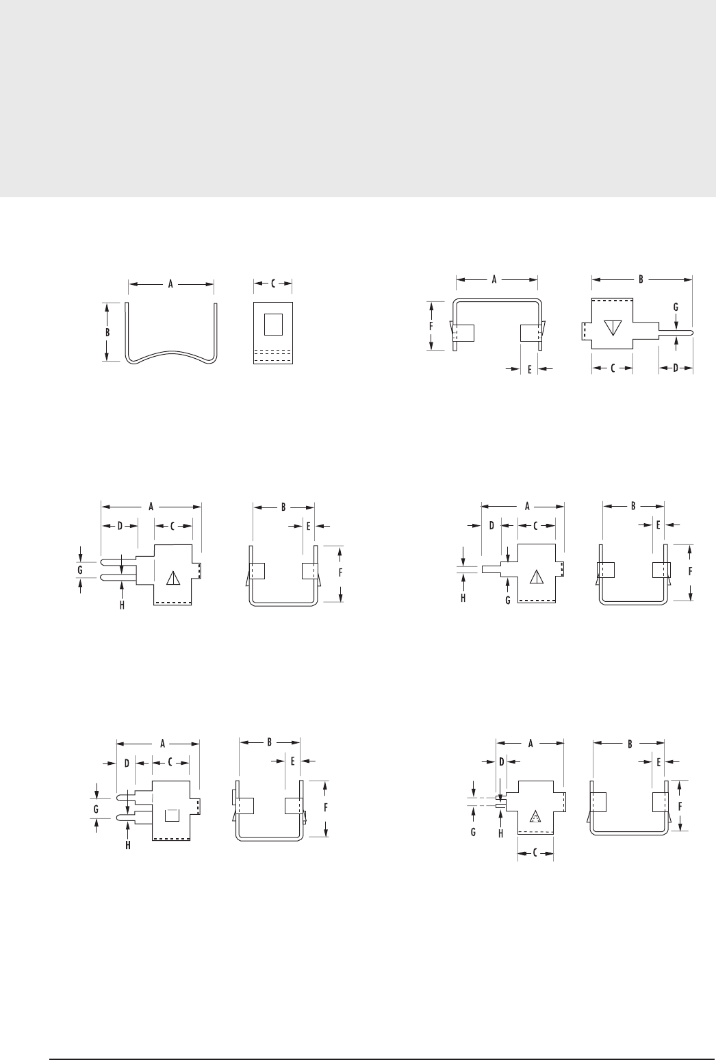
Mounting Clamps
9.9
mag-inc.com
EP Core Hardware
FIGURE 1 FIGURE 2
FIGURE 6
FIGURE 3 FIGURE 4
FIGURE 5

Notes
9.10 MAGNETICS
Section 10
PQ Cores
10.1
PQ CORES
PQ cores are designed specifically for switched mode power supplies. This design provides an
optimized ratio of volume to winding area and surface area. As a result, both maximum inductance
and winding area are possible with a minimum core size. The cores provide maximum power output
with minimum assembled transformer weight and volume, in addition to taking up a minimum
amount of area on the printed circuit board.
Assembly with printed circuit bobbins and one piece clamps is simplified. This efficient design
provides a more uniform cross-sectional area; thus cores tend to operate with fewer hot spots than
with other designs.
Typical applications include power transformers and power inductors.
HOW TO ORDER
STANDARD CORE
FERRITE CORE MATERIAL
USED FOR ALL FERRITE TYPES
APPROXIMATE DIAMETER IN MM
APPROXIMATE HEIGHT IN MM
GEOMETRY CODE/GAP CODE
(SEE PAGE 1.5)
SPECIAL SPECIFICATION CODE
O P 4 20 16 UG XX
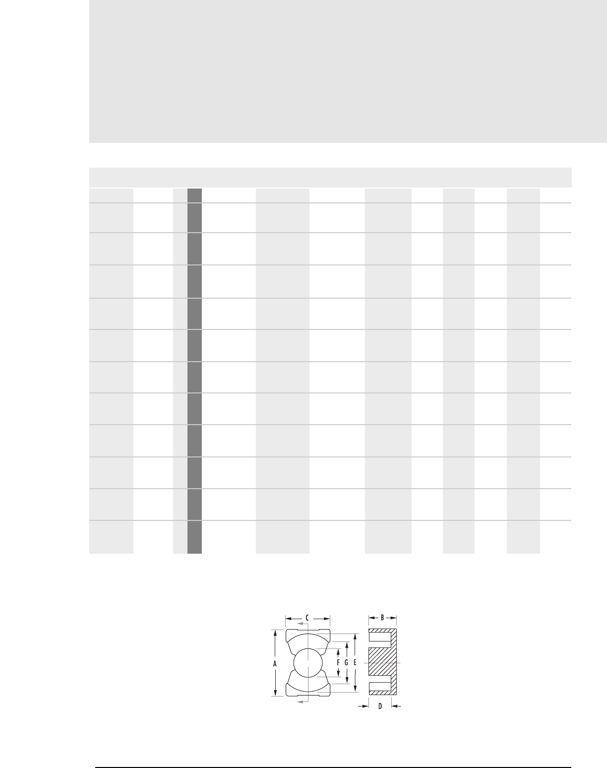
PQ
Core Data (ungapped)
MAGNETICS
MECHANICAL DIMENSIONS
PART CORE TYPE A B 2B C D MIN 2D MIN E MIN F MAX G MIN
0_42016UG PQ 20/16 1 mm
in
0_42020UG PQ 20/20 1 mm
0_42610UG 1 mm
in
0_42614UG 1 mm
in
0_42620UG PQ 26/20 1 mm
in
0_42625UG PQ 26/25 1 mm
0_43214UG 1 mm
in
0_43220UG PQ 32/20 1 mm
in
0_43230UG PQ 32/30 1mm
0_43535UG PQ 35/35 1 mm
0_44040UG PQ 40/40 1mm
21.3 ± .400 8.100 ± .100 16.200 ± .200 14.00 ± .400 5.000 10.000 17.600 9.000 12
0.837 ± .016 .319 ± .004 .638 ± .008 .551 ± .016 0.197 0.394 0.693 0.356 0.472
21.3 ± .4 10.1 ± .1 20.2 ± .2 14. ± .4 7.0 14.0 17.6 9.0 12
27.2 ± .450 5.100 ± .100 10.200 ± .200 19.00 ± .450 1.200 2.390 22.05 12.200 15.50
1.073 ± .018 .200 ± .004 .400 ± .008 .748 ± .018 0.047 0.094 0.868 0.480 0.610
27.200 ±.450 5.94 ± .100 11.90 ± .200 19.00 ± .450 3.400 6.700 22.05 12.200 15.50
1.073 ± .018 .234 ± .004 .468 ± .008 .748 ± .018 0.132 0.264 0.868 0.480 0.610
27.300 ± .460 10.100 ± .130 20.200 ± .250 19.00 ± .450 5.600 11.200 22.05 12.200 15.50
1.073 ± .018 .397 ± .005 .794 ± .010 .748 ± .018 0.220 0.440 0.868 0.480 0.610
27.3 ± .46 12.35 ± .125 24.7 ± .25 19.0 ± .45 7.9 15.8 22.04 12.2 15.5
33.00 ±.500 5.940 ±.100 11.900 ± .200 22.00 ± .500 3.4 6.700 27 13.750 19
1.300 ± .020 .234 ± .004 .468 ± .008 .866 ± .020 0.132 0.264 1.063 0.540 0.748
33.00 ± .500 10.300 ± .130 20.500 ± .250 22.0 ± .500 5.6 11.200 27 13.750 19
1.300 ± .020 .405 ± .005 .810 ± .010 .866 ± .020 0.22 0.440 1.063 0.540 0.748
33.0 ± .5 15.15 ± .125 30.3 ± .25 22.0 ± .5 10.5 21.0 27.0 13.75 19.0
36.1 ± .6 17.4 ± .13 34.7 ± .25 26.0 ± .5 12.2 24.7 31.5 14.65 23.5
41.5 ± .9 19.9 ± .15 39.8 ± .3 28.0 ± .6 14.35 29.1 36.4 15.2 28
PQ Cores
10.2
FIGURE 1
Any practical gap is available. See page 1.8-1.11
To order, add material code to part number.
FIG.
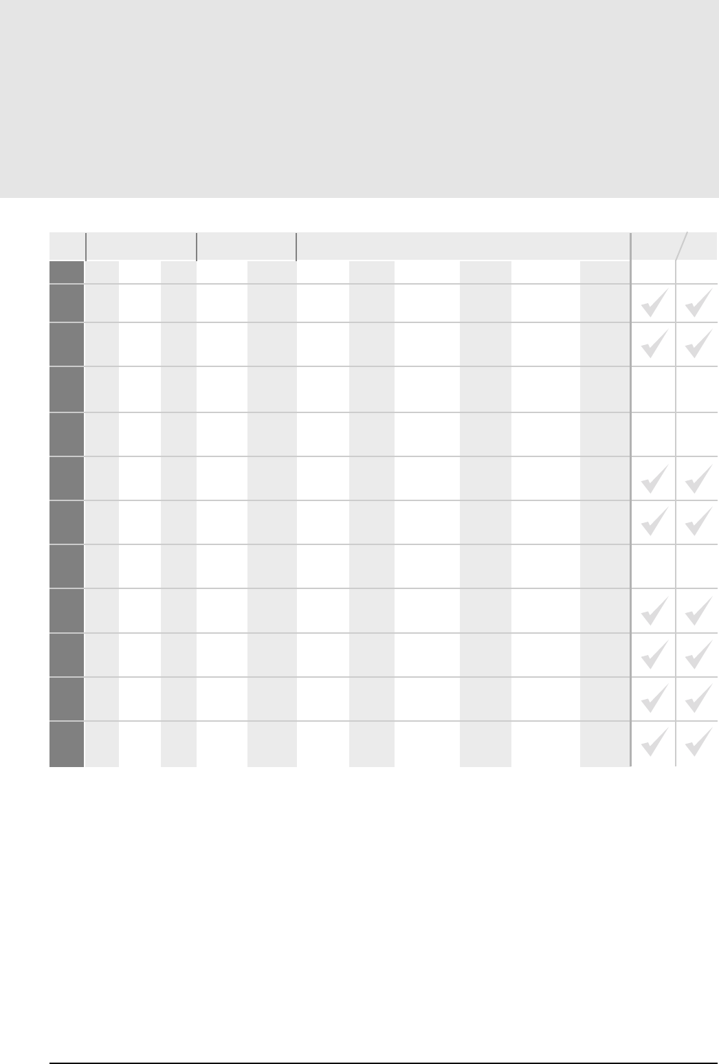
10.3
mag-inc.com
PQ
Core Data (ungapped)
POWER MATERIALS MAGNETIC DATA
RF*PJWl
e(mm) Ae(mm2)A MIN (mm2)V
e(mm3)CORE WEIGHT
(grams per set) WaAc
(cm4)
PQ Cores
Min 2,690 2,930 4,690 4,100 7,630 37.6 61.9 59.1 2,330.0 13.000 0.1570
Min 2,210 2,410 3,860 3,380 6,320 45.7 62.6 59.1 2,850.0 15.000 0.2380
Min 5,800 6,310 — — — 29.40 105.0 93.8 3,090.0 15.000 0.0960
Min 4,210 4,585 7,335 6,420 12,000 33.30 86.4 70.9 2,880.0 14.000 0.1720
Min 4,170 4,540 7,270 6,350 11,800 45.00 121.0 109.0 5,470.0 31.000 0.3950
Min 3,450 3,750 6,010 5,250 9,800 54.3 120.0 108.0 6,530.0 36.000 0.5930
Min 5,150 5,600 8,960 8,000 14,000 34.40 109.0 092.0 3,750.0 21.000 0.3000
Min 4,980 5,410 8,660 7,580 14,100 55.9 169.0 142.0 9,440.0 42.000 0.8010
Min 3,500 3,810 6,100 5,360 9,940 74.7 167.0 142.0 12,500.0 55.000 1.6000
Min 3,610 3,930 6,300 5,510 10,300 86.1 190.0 162.0 16,300.0 73.000 3.1200
Min 3,200 3,480 5,580 4,880 9,100 102.0 201.0 175.0 20,500.0 95.000 5.0000
*F material nominal ±25%
PRINTED CIRCUIT BOBBIN
MOUNTING CLAMP
AVAILABLE
HARDWARE
HIGH PERMEABILITY
MATERIALS
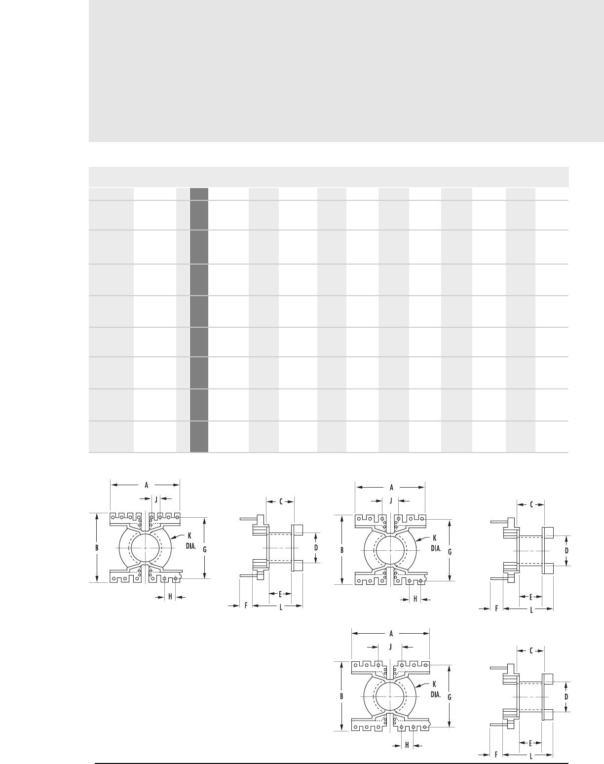
Printed Circuit Bobbins
10.4 MAGNETICS
MECHANICAL DIMENSIONS (NOMINAL UNLESS NOTED)
A B C MAX D E F G H J K L
22.885 22.936 9.881 10.871 7.976 4.496 20.320 3.810 2.540 17.221 16.332
0.901 0.903 0.389 0.428 0.314 0.290 0.800 0.150 0.100 0.678 0.643
22.885 22.936 13.843 10.871 11.938 7.366 20.320 3.810 2.540 17.221 20.295
0.901 0.903 0.545 0.428 0.470 0.290 0.800 0.150 0.100 0.678 0.799
26.492 29.312 10.998 14.199 8.992 7.366 25.400 3.810 7.620 21.590 21.641
1.043 1.154 0.433 0.559 0.354 0.290 1.000 0.150 0.300 0.850 0.852
26.492 29.312 15.748 14.199 13.589 7.366 25.400 3.810 7.620 21.590 26.238
1.043 1.154 0.620 0.559 0.535 0.290 1.000 0.150 0.300 0.850 1.033
32.004 33.985 10.998 15.900 8.788 6.350 30.480 5.080 7.620 26.594 22.835
1.260 1.338 0.433 0.626 0.346 0.250 1.200 0.200 0.300 1.047 0.899
32.004 33.985 20.701 15.900 18.593 6.350 30.480 5.080 7.620 26.594 32.639
1.260 1.338 0.815 0.626 0.732 0.250 1.200 0.200 0.300 1.047 1.285
35.001 38.989 24.460 16.789 22.301 6.350 35.560 5.080 10.160 31.090 37.160
1.378 1.535 0.963 0.661 0.878 0.250 1.400 0.200 0.400 1.224 1.463
40.005 42.012 28.804 17.399 26.797 6.350 38.100 5.080 15.240 35.992 42.164
1.575 1.654 1.134 0.685 1.055 0.25 1.5 0.200 0.600 1.417 1.660
PQ Core Hardware
PCB2016FB 42016 1 mm
in
PCB2020FB 42020 1 mm
in
PCB2620LA 42620 2 mm
in
PCB2625LA 42625 2 mm
in
PCB3220LA 43220 2 mm
in
PCB3230LA 43230 2 mm
in
PCB3535LA 43535 2 mm
in
PCB404012 44040 3 mm
in
PART FIG.CORE SIZE
FIGURE 1 FIGURE 2
FIGURE 3
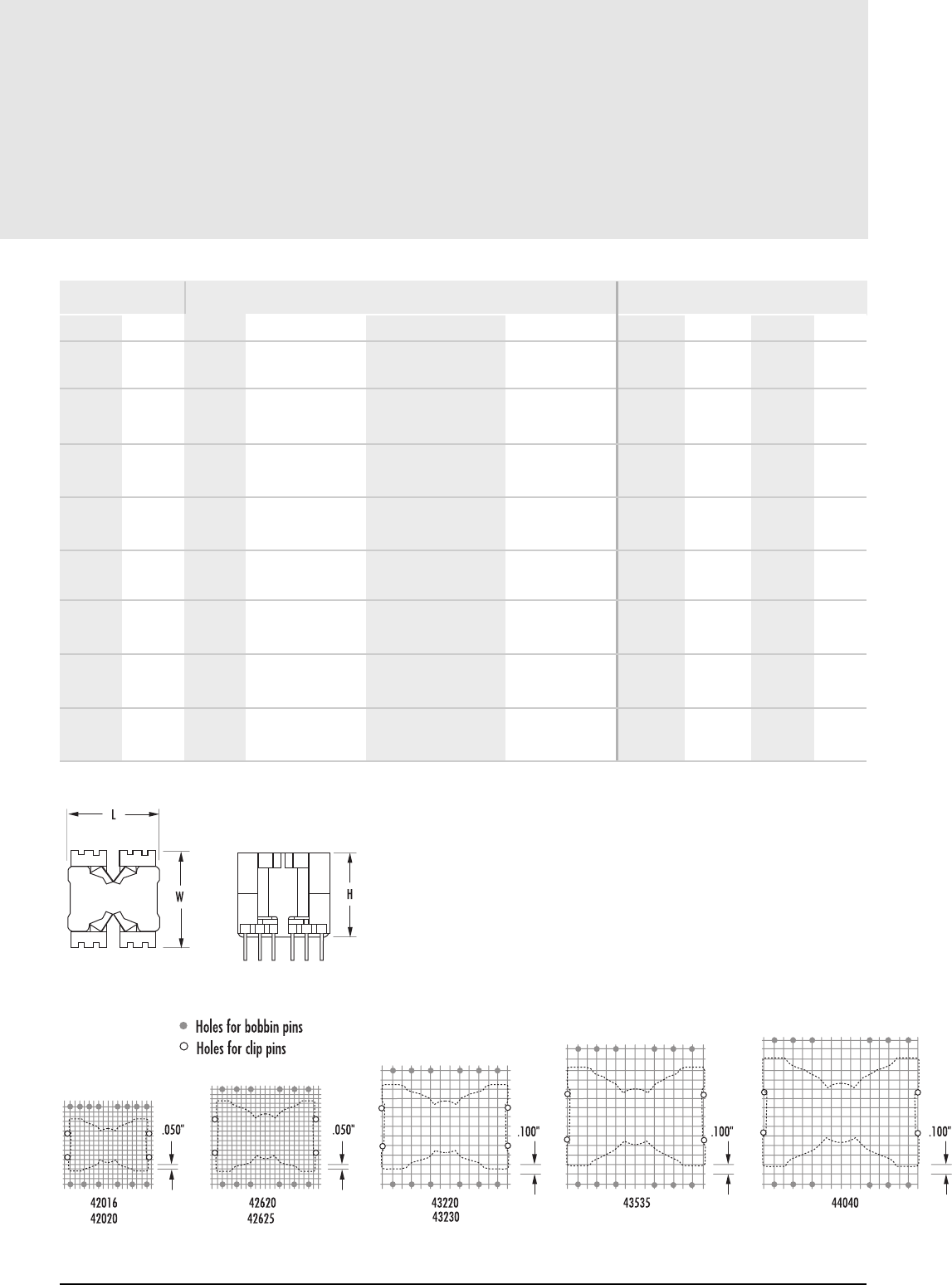
10.5
mag-inc.com
Printed Circuit Bobbins
NOMINAL WINDING
AREA PER SECTION PIN MATERIAL
in2cm2
AVERAGE
LENGTH OF
TURN FT
BOBBIN MATERIAL PIN DIAMETER BOARD CLEARANCE (in.)*
Length Width Heighth
PQ Core Hardware
0.040 0.256 0.144 Rynite Tin plated Brass .024" no clamp 0.915 0.915 0.700
with clamp 0.930 0.915 0.830
0.060 0.384 0.144 Rynite Tin plated Brass .024" no clamp 0.915 0.915 0.850
with clamp 0.930 0.915 0.985
0.050 0.332 0.184 Rynite Tin plated Brass .036" no clamp 1.100 1.170 0.910
with clamp 1.115 1.170 1.000
0.078 0.502 0.184 Rynite Tin plated Brass .036" no clamp 1.100 1.170 1.015
with clamp 1.115 1.170 1.180
0.073 0.470 0.220 Rynite Tin plated Brass .036" no clamp 1.340 1.350 0.950
with clamp 1.355 1.350 1.030
0.154 0.994 0.220 Rynite Tin plated Brass .036" no clamp 1.340 1.350 1.335
with clamp 1.355 1.350 1.415
0.247 1.590 0.247 Rynite Tin plated Brass .036" no clamp 1.470 1.550 1.515
with clamp 1.470 1.550 1.585
0.386 2.490 0.275 Rynite Tin plated Brass .036" no clamp 1.700 1.675 1.725
with clamp 1.700 1.675 1.775
*reference figure 4 for board clearance
FIGURE 4
PIN LAYOUTS
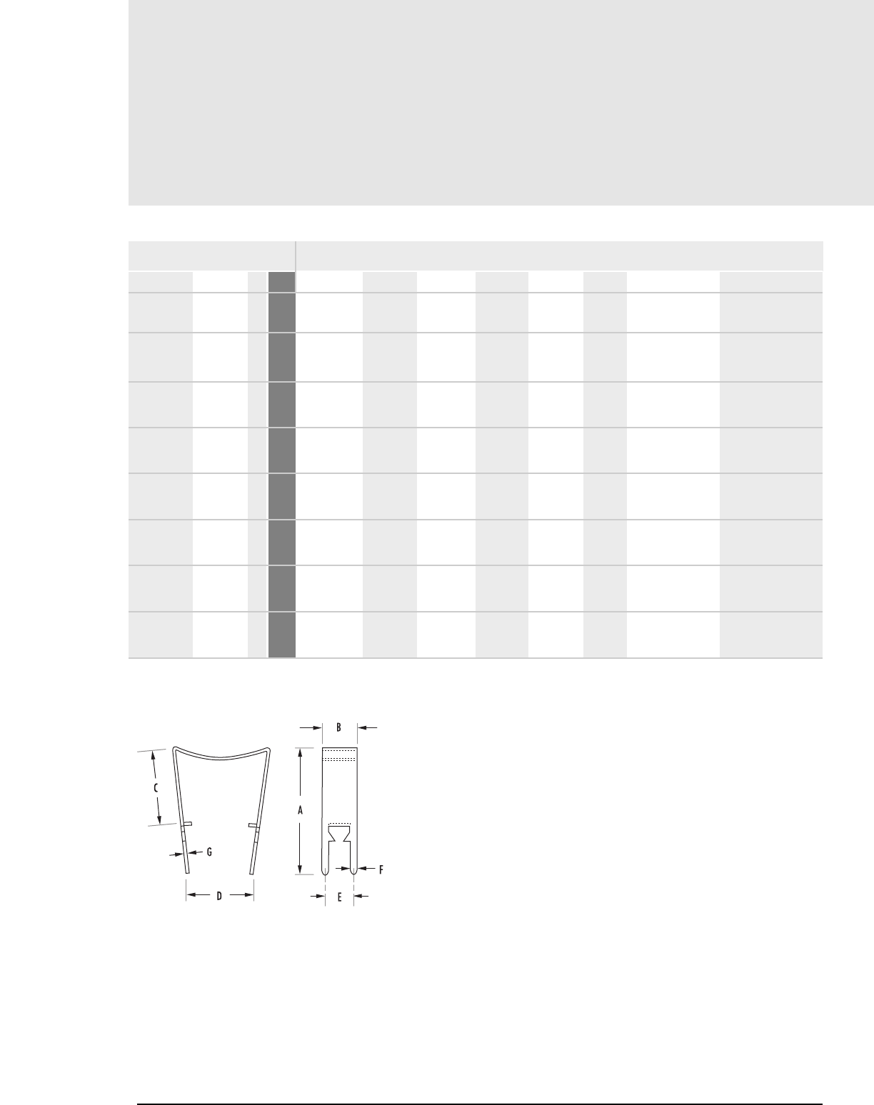
Mounting Clamps
10.6 MAGNETICS
PQ Core Hardware
MECHANICAL DIMENSIONS
A±.020 B±.003 C±.010 D REF E NOM F NOM MATERIAL MATERIAL THICKNESS
29.007 7.899 17.501 14.986 6.401 1.499 Nickel Silver 0.012"
1.142 0.3110 0.689 0.590 0.252 0.059
32.995 7.899 21.488 14.986 6.401 1.499 Nickel Silver 0.012"
1.299 0.3110 0.846 0.590 0.252 0.059
32.995 10.490 21.488 21.006 8.992 1.499 Nickel Silver 0.012"
1.299 0.4130 0.846 0.827 0.354 0.059
37.490 10.490 26.111 21.006 8.992 1.499 Nickel Silver 0.012"
1.476 0.4130 1.028 0.827 0.354 0.059
36.500 12.2936 21.996 27.000 10.592 1.702 Nickel Silver 0.017"
1.437 0.4840 0.866 1.063 0.417 0.067
46.507 12.294 31.801 27.000 10.592 1.702 Nickel Silver 0.017"
1.831 0.4840 1.252 1.063 0.417 0.067
50.495 12.700 36.195 29.997 11.303 1.702 Nickel Silver 0.017"
1.988 0.5000 1.425 1.181 0.445 0.067
55.499 13.487 41.199 35.001 11.786 1.702 Nickel Silver 0.017"
2.185 0.5310 1.622 1.378 0.464 0.067
00C201612 42016 1 mm
in
00C202012 42020 1 mm
in
00C262012 42620 1 mm
in
00C262512 42625 1 mm
in
00C322017 43220 1 mm
in
00C323017 43230 1 mm
in
00C353517 43535 1 mm
in
00C404017 44040 1 mm
in
PART FIG.
CORE SIZE
FIGURE 1
E, I, U CORES
E cores are less expensive than pot cores, and have the advantage of simple bobbin winding plus easy assembly.
E cores do not, however, offer self-shielding. Lamination size E cores are available to fit commercially offered
bobbins previously designed to fit the strip stampings of standard lamination sizes. Metric and DIN sizes are also
available. E cores can be pressed to different thicknesses, providing a selection of cross-sectional areas. Bobbins
for these different cross sections are often available commercially.
E cores can be mounted in different directions and, if desired, provide a low profile. Printed circuit bobbins are
available for low profile mounting. Typical applications for E cores include differential, power and telecom
inductors, as well as, broadband, power, converter and inverter transformers.
U cores, which offer a larger window/cross-sectional area, provide more power handling capability than E cores
of the same size. Typical applications are similar to E cores.
HOW TO ORDER
SHAPE CODE
0 – Standard
C – Planar E core with clip recesses
F – Planar E core option: no clip recesses
GEOMETRY CODE
EC – All E cores including ETD, EC, ER, EER, EEM, EFD, planar and lamination sizes
IC – I cores
UC – U cores
GAP CODE – see page 1.5
Note – Standard gap codes do not apply to U cores, I cores and some EI combinations.
Cores are sold per piece (for sets multiply by 2). Gapped pieces are normally packed separately from ungapped
pieces. If desired in sets, this must be specified.
Section 11
E, I, U Cores
11.1
SHAPE CODE
FERRITE CORE MATERIAL
USED FOR ALL FERRITE TYPES
APPROXIMATE DIAMETER IN MM
APPROXIMATE HEIGHT IN MM
GEOMETRY CODE/GAP CODE
(SEE PAGE 1.5)
SPECIAL SPECIFICATION CODE
CR 41434ECXX
E, I, U Core Data
(ungapped)
11. 2 MAGNETICS
E, I, U Cores
FIGURE 1 FIGURE 2
Any practical gap available. See pages 1.8-1.11
To order, add material code to part number.
MECHANICAL DIMENSIONS
PART CORE TYPE A B C D MIN E MIN F L M S T
0_40904EC E core 2mm 8.86 ± .38 4.06 ± .25 1.91 ± .12 2.03 4.85 1.91 ± .12 1.91 ± .25 1.57 ± .25 - -
in .349 ± .015 0.160 ± .010 0.075 ± .005 0.08 0.191 .075 ± .005 .075 ± .010 .062 ± .010 - -
0_41106IC I core 3mm 10.8 ± .20 1.83 ± .12 6.3 ± .12 - - - - - - -
in .427 ± .008 0.072 ± .005 .248 ± .005 - - - - - - -
0_41106UC U core 4mm 10.8 ± .20 4.19 ± .12 6.3 ± .12 2.11 7.19 - 1.83 ± .12 - - -
in 0.427 ± .008 .165 ± .005 .248 ± .005 0.083 .283 ref - .072 ± .005 - - -
0_41203EC Lam E2829 1mm 12.700 ± .25 5.690 ± .18 3.180 ± .12 3.960 9.190 3.180 ± .08 1.570 3.050 - -
in .500 ± .010 .224 ± .007 0.125 ± .005 0.156 0.362 .125 ± .003 0.062 nom 0.120 min - -
0_41205EC Lam E2829 1mm 12.700 ± .25 5.690 ± .18 6.350 ± .12 3.960 9.270 3.180 ± .08 1.570 3.180 ± .12 - -
Double stack in .500 ± .010 .224 ± .007 .250 ± .005 0.156 0.365 1.25 ± .003 .062 ref .125 ± .005 - -
0_41208EC E core 1mm 12.300 ± .25 7.750 ± .25 4.320 ± .12 5.460 7.850 2.670 ± .08 2.160 ± .13 2.670 - -
in .485 ± .010 .305 ± .010 .170 ± .005 0.215 0.309 .105 ± .003 0.085 ± .005 .105 ref -
0_41209EC EE12.5 1mm 12.400 ± .30 7.390 ± .10 4.850 ± .15 4.800 9.140 2.390 ± .10 1.510 ± .10 3.490 ± .15 - -
in .488 ± .012 .291 ± .004 .191 ± .006 0.189 0.360 .094 ± .004 .0595 ± .004 0.1375± .006 - -
0_41707EC Lam E3233 2mm 16.800 ± .38 7.110 ± .18 3.560± .12 3.940 10.400 3.560 ± .12 2.790 3.630 - -
in .660 ± .015 0.280 ± .007 .140 ± .005 0.155 0.411 0.140 ± .005 0.110 nom 0.143 min - -
0_41808EC Lam EI187 1mm 19.1 ± .4 8.1 ± .13 4.7 ± .13 5.54 13.92 4.57 min 2.39 4.82 ref - -
0_41810EC Lam EI187 1mm 19.300 ± .30 8.100 ± .18 9.530 ± .12 5.590 14.000 4.760 ± .08 2.380 4.890 - -
Double stack in .760 ± .012 .3188 ± .007 .375 ± .005 0.220 0.552 .1875 ± .003 .09375 ref .1925± .005 - -
0_42211EC E core 1mm 22.000 ± .41 11.200 ± .13 5.740 ± .25 7.490 17.100 4.290 ± .20 2.300 6.550 - -
in 0.866 ± .016 0.442 ± .005 .226 ± .010 0.295 0.673 .169 ± .008 .0905 nom .258 nom - -
0_42220UC U core 4mm 22.100 ± .38 20.600 ± .38 6.270 ± .18 13.980 9.500 ± .38 - 6.270 ± .18 - - -
in 0.869 ± .015 .810 ± .015 .247 ± .007 0.550 .375 ± .015 - .247 ± .007 - - -
FIG.
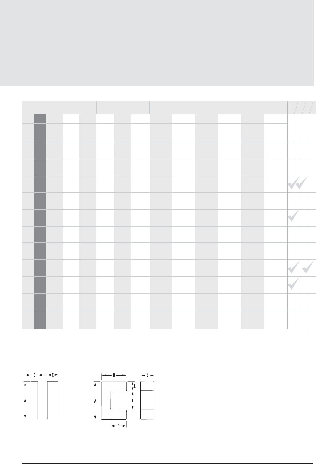
11 . 3
mag-inc.com
E, I, U Core Data
(ungapped)
E, I, U Cores
FIGURE 3 FIGURE 4
AL(mH/1000T)
* F material nominal ± 25%
POWER MATERIALS MAGNETIC DATA
HIGH PERMEABILITY
MATERIALS
RPF*JWHl
e(mm) Ae(mm2)A MIN (mm2)V
e(mm3)CORE WEIGHT
(grams per set) WaAc (cm4)
E-E
Min 370 405 650 780 - -
U-I
Min 710 770 1,150 1,580 - -
U-U
Min 770 840 1,010 1,330 - -
E-E
Min 440 480 770 1,025 - -
E-E
Min 1,100 1,200 1,950 2,475 3,705 -
E-E
Min 630 685 1,100 1,200 1,820 -
E-E
Min 660 710 1,150 1,240 1,900 -
E-E
Min 760 825 1,300 1,425 2,240 -
E-E
Min 865 940 1,500 1,875 3,220 -
E-E
Min 1,725 1,875 3,000 3,750 7,420 -
E-E
Min 920 1,000 1,610 1,890 3,500 5,250
U-U
Min 670 730 1,360 1,580 2,400 -
15.4 5.1 3.6 78.0 0.5 0.0020
24.6 11.5 11.5 283.0 1.5 0.0100
29.2 12.0 12.0 350.0 1.8 0.0250
27.70 10.1 10.0 279.0 1.300 0.0170
27.70 20.2 20.0 558.0 2.600 0.0330
32.10 14.5 11.5 464.0 2.500 0.0280
30.6 14.4 11.6 440.0 4.200 0.0390
30.4 16.6 12.6 505.0 3.000 0.0310
39.9 22.6 22.1 900.0 4.400 0.0760
40.1 45.5 45.4 1820.0 8.500 0.1560
51.10 28.3 24.6 1450.0 8.200 0.2120
95.80 39.7 39.7 4130.0 19.000 0.9100
STANDARD BOBBIN
SURFACE MOUNT BOBBIN
PRINTED CIRCUIT BOBBIN
MOUNTING CLAMP
AVAILABLE
HARDWARE
COMB.
E, I, U Core Data
(ungapped)
11. 4 MAGNETICS
E, I, U Cores
MECHANICAL DIMENSIONS
PART CORE TYPE A B C D MIN E MIN F L M S T
0_42510EC Lam E2425 1mm 25.4 ± .6 9.65 ± .2 6.35 ± .25 6.4 18.8 6.35 ± .25 3.02 6.1 min - -
0_42512UC U core 4mm 25.400 ± .51 12.900 ±.38 12.700 ±.38 6.350 12.800 - 6.300 - - -
in 1.000 ± .020 .510 ± .015 .500 ± .015 0.250 .504 ref - .248 ± .005 - - -
0_42515EC Lam EL2425 1mm 25.400± .38 15.900 ± .25 6.350 ± .25 12.600 18.800 6.350 ± .12 3.120 ± .12 6.400 ± .25 - -
in 1.000 ± .015 .625 ± .010 .250 ± .010 0.495 0.740 .250 ± .005 .123 ± .005 .252 ± .010 - -
0_42515IC I core 3mm 26.400± .38 3.180 ± .12 7.370 ± .25 - - - - - - -
in 1.040 ± .015 .125 ± .005 .290 ± .010 - - - - - - -
0_42515UC U core 4mm 25.400 ± .51 15.900 6.350 ± .12 9.270 12.700 - 6.350 ± .12 - - -
in 1.000 ± .020 .625 ref .250 ± .005 0.365 .500 ref - .250 ± .005 - - -
0_42516IC I core 3mm 25.400 ± .51 6.350 ± .12 6.350 ± .12 - - - - - - -
in 1.000 ± .020 .250 ± .005 .250 ± .005 - - - - - - -
0_42520EC Lam E2425 1mm 25.150 ±.38 9.530 ± .18 12.700± .25 6.250 18.800 6.100 ± .12 3.020 6.220 - -
Double stack in .990 ± .015 .375 ± .007 .500 ± .010 0.246 0.741 .240 ± .005 .119 nom .245 min - -
0_42530EC EL2425 1mm 25.400 ± .38 15.900 ±.25 12.700 ± .25 12.600 18.800 6.350 ± .12 3.120 ± .12 6.400 ± .25 - -
Double stack in 1.000 ± .015 .625 ± .010 .500 ± .010 0.495 0.742 .250 ± .005 .123 ± .005 .252 ± .010 - -
0_42530UC U core 4mm 25.400 ± .51 15.900 12.700±.25 9.270 12.700 - 6.350 ± .12 - - -
in 1.000 ± .020 .625 ref .500 ± .010 0.365 .500 ref - .250 ± .005 - - -
0_42810EC E core 1mm 28.000± .63 10.500 ±.12 11.200 ± .38 5.440 18.500 7.700 ± .25 4.340 ± .25 5.800 - -
in 1.102 ± .025 .415 ± .005 0.440 ± .015 0.214 0.730 .303 ± .010 .171 ± .010 .2285 ref - -
0_43007EC DIN 30/7 1mm 30.8 ± 1.4 15.01 ± .2 7.3 + 0, -.5 9.7 19.5 7.2 + 0, -.5 5.01 ref 6.46 - -
0_43009EC Lam E2627 1mm 30.480± .38 13.4 ± .25 9.400 ± .12 8.830 21.410 9.400 ± .13 4.290 6.000 - -
in 1.200 ± .015 .5275 ± .010 .370 ± .005 0.3475 0.843 .370 ± .005 0.169 nom 0.236 min - -
Any practical gap available. See pages 1.8-1.11
FIGURE 1 FIGURE 3
To order, add material code to part number.
FIG.
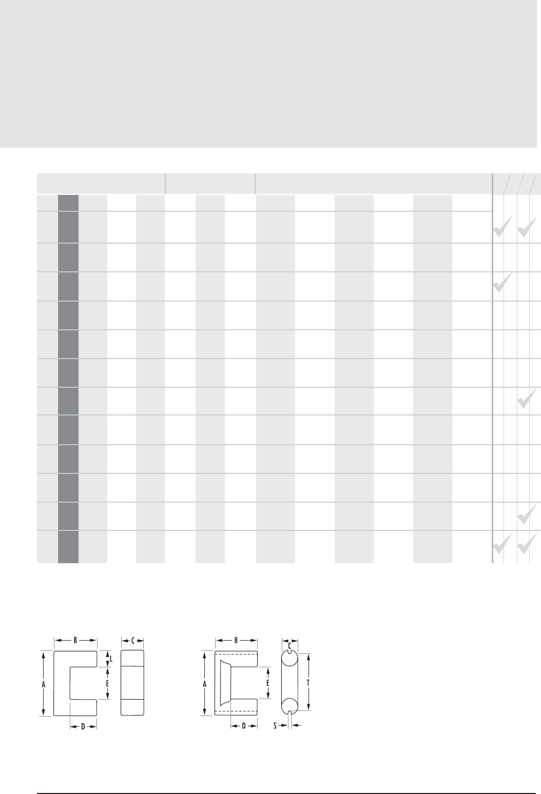
E, I, U Core Data
(ungapped)
11. 5
mag-inc.com
E, I, U Cores
AL(mH/1000T)
FIGURE 5FIGURE 4
* F material nominal ± 25%
POWER MATERIALS MAGNETIC DATA
HIGH PERMEABILITY
MATERIALS
RPF*JWHl
e(mm) Ae(mm2)A MIN (mm2)V
e(mm3)CORE WEIGHT
(grams per set) WaAc (cm4)
E-E
Min 1325 1440 2300 2775 4635 -
U-U
Min 1430 1550 2480 3300 - -
E-E
Min 865 940 1500 1800 3080 -
E-I
Min 1320 1435 2290 2750 4690 -
U-U
Min 830 1000 1600 1880 2730 -
U-I
Min 1020 1110 1770 2180 - -
E-E
Min 2650 2880 4600 5500 10360 -
E-E
Min 1730 1880 3000 3600 6160 -
U-U
Min 1570 1710 2740 3650 - -
E-E
Min 3155 3430 5500 6000 12600 -
E-E
Min 1545 1680 2700 2850 5740 -
E-E
Min 2170 2360 3780 4420 8500 -
49.0 39.5 37.0 1930 9.500 0.1620
68.9 80.0 80.0 4170 29.000 0.6700
73.5 40.1 39.7 2950.0 15.000 0.4210
48.10 40.1 39.7 1930.0 10.000 0.2100
83.40 40.4 40.4 3370.0 17.000 0.6300
64.3 40.4 40.4 2600.0 13.000 0.3200
48.0 78.4 76.8 3760 19.000 0.4000
73.50 80.2 79.4 5900.0 30.000 0.8420
83.40 80.8 80.8 6740.0 34.000 1.2700
47.70 96.7 86.0 4610.0 23.000 0.3470
67.0 60.0 49.0 4000 20.000 0.5000
62.40 83.6 80.7 5220.0 26.000 0.7400
STANDARD BOBBIN
SURFACE MOUNT BOBBIN
PRINTED CIRCUIT BOBBIN
MOUNTING CLAMP
AVAILABLE
HARDWARE
COMB.
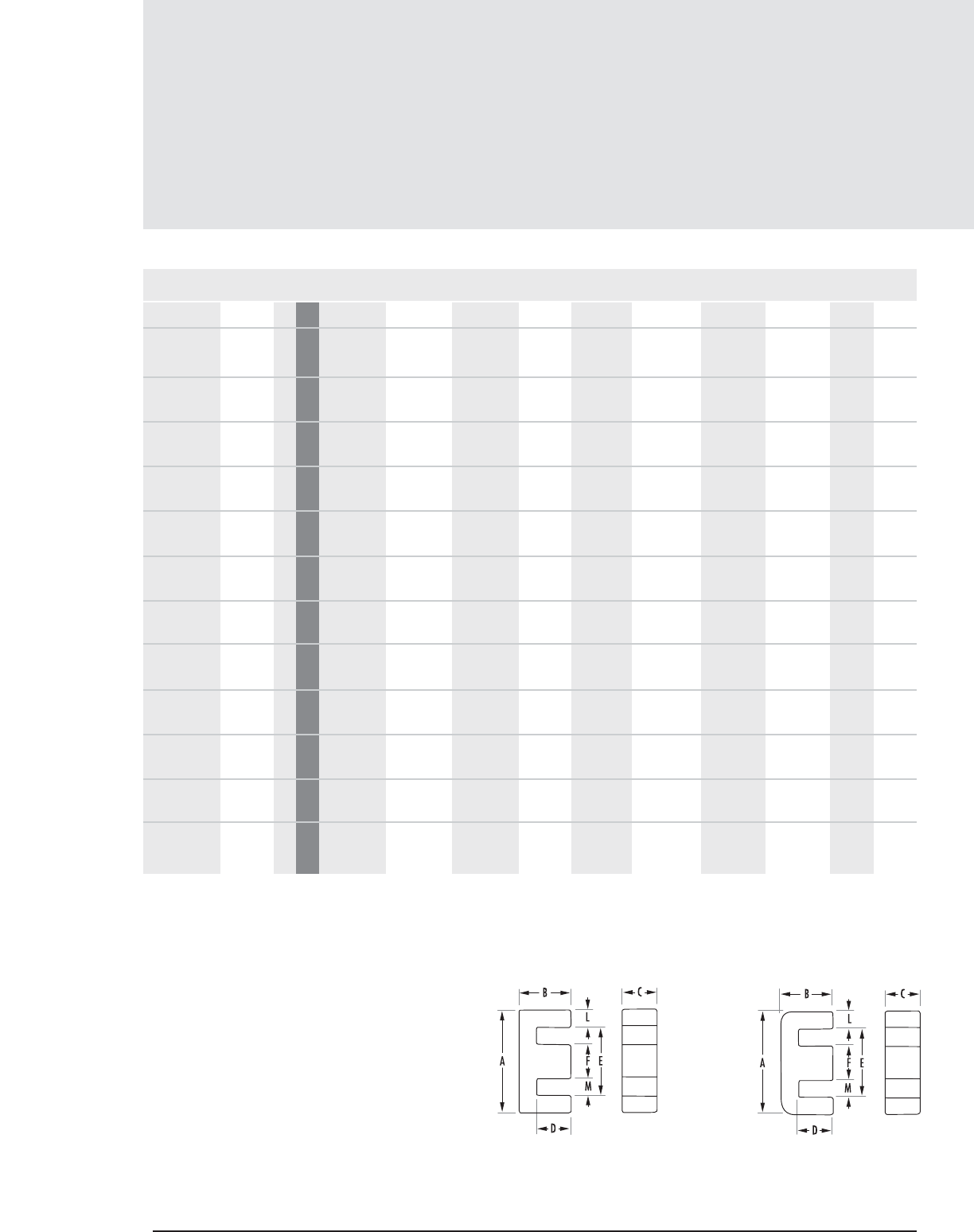
E, I, U Core Data
(ungapped)
11 . 6 MAGNETICS
MECHANICAL DIMENSIONS
PART CORE TYPE A B C D MIN E MIN F L M S T
0_43013EC Metric E30A 1mm 30.000± .51 13.160 ± .15 10.690±.30 8.000 19.700 10.690± .30 5.000 ± .15 4.650 ± .12 - -
in 1.181 ±.020 .518 ± .006 .421 ± .012 0.315 0.776 .421 ± .012 .197 ± .006 .183 ± .005 - -
0_43515EC Lam EI375 2mm 34.3 ± .6 14.1 ±.15 9.3 ± .25 9.67 25.5 9.32 ± .2 4.45 7.87 - -
0_43520EC E core 1mm 34.900 ±.38 20.620± .25 9.530 ± .18 15.600 25.100 9.530 ± .25 4.750 ± .25 7.950 - -
in 1.375 ± .015 .812 ± .010 .375 ± .007 0.615 0.990 .375 ± .010 .187 ± .010 .313 nom - -
0_43524EC EL375 1mm 34.540 ± .38 23.800 ± .18 9.350 ± .18 18.740 25.300 9.350 ± .20 4.450 ± .08 7.870 - -
in 1.360 ± .015 .9375 ± .007 .368 ± .007 0.738 0.998 .368 ± .008 .175 ± .003 .310 min - -
0_44011EC Metric E40 1mm 40.010 ±.51 17.000 ±.30 10.690±.30 10.000 27.600 10.690 ±.30 5.990 ± .25 8.860 - -
in 1.575 ± .020 .669 ± .012 .421 ± .012 0.394 1.087 0.421 ± .012 .236 ± .010 .341 nom - -
0_44016EC E core 1mm 42.800 ± .64 21.100 ± .18 9.000 ± .25 15.000 30.400 11.900 ± .25 5.940 ± .13 9.540 ± .25 - -
in 1.687 ± .025 .830 ± .007 .354 ± .010 0.587 1.195 .468 ± .010 .234 ± .005 .3755 ± .010 - -
0_44020EC DIN 42/15 1mm 43.0 + 0, -1.7 21.0 ± .2 15.2 + 0, -.6 14.8 29.5 12.2 + 0, -.5 6.75 ref 8.65 ref - -
0_44020IC I core 3mm 42.800 ± .64 5.920 ± .12 15.400 ± .25 - - - - - - -
in 1.687 ± .025 .233 ± .005 .608 ± .010 - - - - - - -
0_44022EC DIN 42/20 1mm 43.0 + 0, -1.7 21.0 ± .2 20.000 +0,-8 14.8 29.5 12.2 + 0, -.5 6.75 ref 8.65 ref - -
0_44119UC U core 5mm 41.960 ±.41 20.900 ±.12 11.700± .25 13.400 19.100 ±.64 - - - 3.180 35.300
in 1.652 ± .016 .826 ± .005 .460 ± .010 0.528 .750 ± .025 - - - .125 nom 1.39 ref
0_44121UC U core 5mm 41.960 ±.41 20.600 ±.12 11.700 ± .25 10.900 19.100 ±.64 - - - 3.180 35.300
in 1.652 ± .016 .812 ± .005 .460 ± .010 0.429 .750 ± .025 - - - .125 nom 1.39 ref
0_44125UC U core 5mm 41.960 ± .41 25.400 ± .12 11.700± .25 15.700 19.100 ±.64 - - - 3.180 35.300
in 1.652 ± .016 1.000 ± .005 .460 ± .010 0.617 .750 ± .025 - - - .125 nom 1.39 ref
E, I, U Cores
Any practical gap available. See pages 1.8-1.11
FIGURE 1 FIGURE 2
To order, add material code to part number.
FIG.
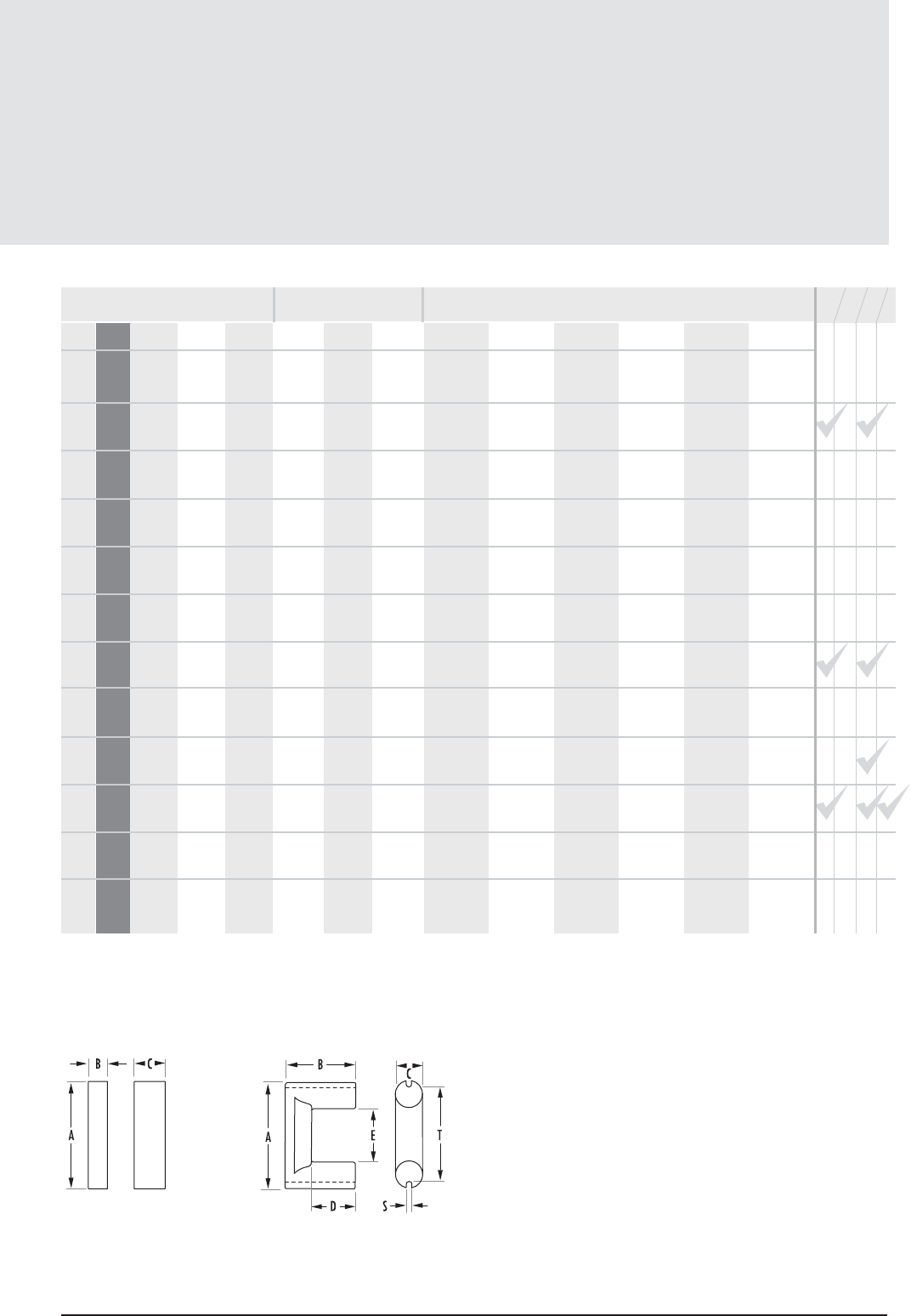
E, I, U Core Data
(ungapped)
11.7
mag-inc.com
E, I, U Cores
POWER MATERIALS MAGNETIC DATA
HIGH PERMEABILITY
MATERIALS
RPF*JWHl
e(mm) Ae(mm2)A MIN (mm2)V
e(mm3)CORE WEIGHT
(grams per set) WaAc (cm4)
E-E
Min 3070 3340 5340 6200 12000 -
E-E
Min 2000 2180 3500 4360 7990 -
E-E
Min 1460 1590 2555 3180 6440 -
E-E
Min 1320 1435 2300 2984 4230 -
E-E
Min 3000 3260 5200 5470 11550 -
E-E
Min 2000 2180 3495 4235 7905 -
E-E
Min 3450 3750 6000 7275 13580 -
E-I
Min 4690 5100 8150 9500 15500 -
E-E
Min 4150 4510 7600 7960 18200 -
U-U
Min 1220 1330 2130 2830 4000 -
U-U
Min 1410 1535 2465 3290 4600 -
U-U
Min 1200 1310 2105 2800 3920 -
57.80 109.0 107.0 6330.0 32.000 0.6500
69.30 80.7 80.7 5590 33.000 0.8560
94.30 90.6 90.5 8540.0 42.000 1.6800
107.00 85.8 83.1 9180.0 46.000 1.6600
76.70 127.0 114.0 9780.0 49.000 1.3900
98.40 107.0 106.0 10500.0 52.000 2.0800
97.0 178.0 175.0 17300 87.000 3.5500
68.0 183.0 183.0 12400.0 60.000 1.7800
97 233 233 22700 114.000 4.5900
121.20 91.1 80.5 11000.0 54.000 2.8600
113.40 98.8 98.8 11100.0 55.000 3.0900
132.80 98.8 98.8 13000.0 64.000 4.4400
STANDARD BOBBIN
SURFACE MOUNT BOBBIN
PRINTED CIRCUIT BOBBIN
MOUNTING CLAMP
AVAILABLE
HARDWARE
AL(mH/1000T)
FIGURE 3 FIGURE 5
COMB.
* F material nominal ±25%
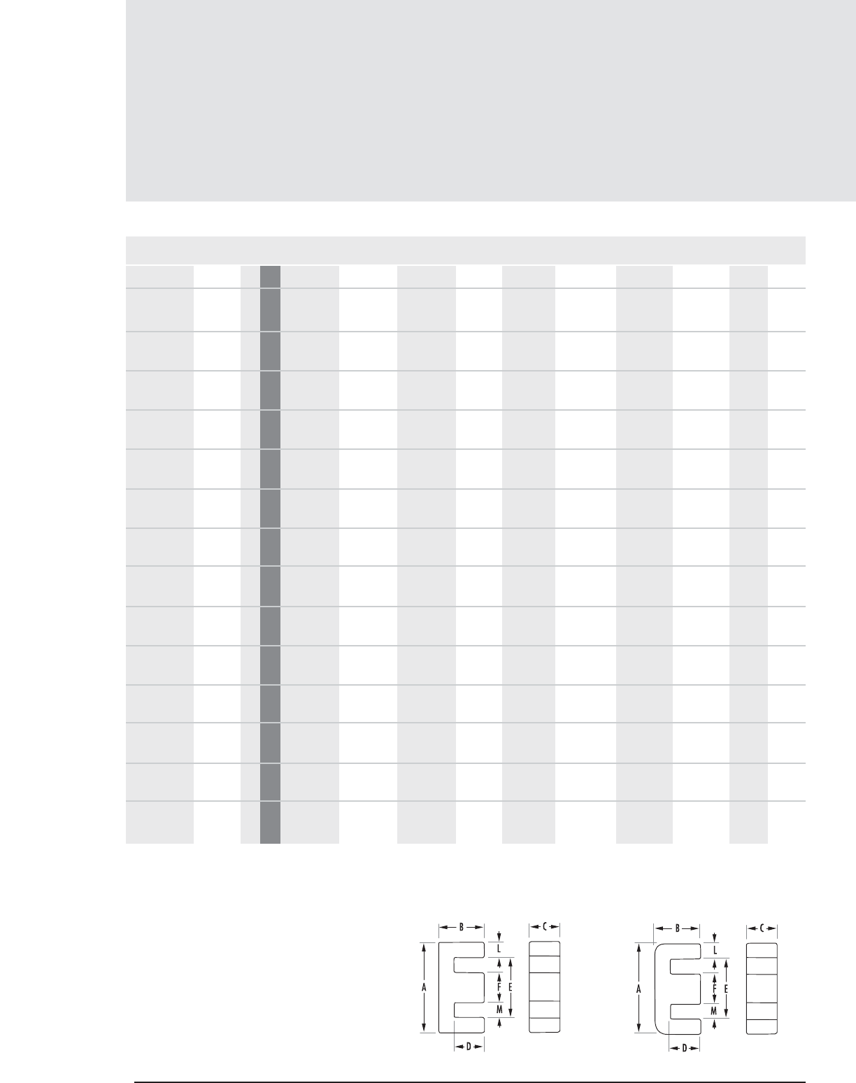
E, I, U Core Data
(ungapped)
11. 8 MAGNETICS
FIGURE 1 FIGURE 2
Any practical gap available. See pages 1.8-1.11
E, I, U Cores
MECHANICAL DIMENSIONS
PART CORE TYPE A B C D MIN E MIN F L M S T
0_44130UC U core 5mm 41.960 ± .41 30.500±.30 11.700 ± .25 20.800 19.100 ± .64 3.180 35.300
in 1.652 ± .016 1.200 ± .012 .460 ± .010 0.817 .750 ± .025 .125 nom 1.39 ref
0_44317EC Lam EI21 2mm 40.6 ± .65 16.6 ± .20 12.4 ± .3 10.4 28.6 12.45 ± .25 6.05 7.87
0_44721EC Lam EI625 2mm 46.9 ± .8 19.6 ± .2 15.6 ± .25 12.1 32.4 ± .65 15.6 ±.25 7.54 7.87
0_44924EC EL10 1mm 49.070 ± .64 23.8 ±.25 15.620 ± .43 15.100 31.600 15.620 ± .25 9.140 ± .12 7.870
in 1.932 ± .025 .936 ± .010 .615 ± .017 0.594 1.246 .615 ± .010 .366 ± .005 .310 min
0_45021EC Metric E50 1mm 49.500 ± .64 21.300 ± .30 14.600 ±.38 12.500 34.500 14.600 ± .38 7.370 ± .25 10.1 ± .30
in 1.95 ± .025 .839 ± .012 .575 ± .015 0.492 1.359 .575 ± .015 .290 ± .010 .3975 ± .012
0_45528EC DIN 55/21 1mm 56.2 + 0, -.21 27.5 ± .3 21 + 0, -.8 18.500 37.500 17.2 + 0, -.5 9.35 ref 10.15 ref
0_45530EC DIN 55/25 1mm 54.900 ± .64 27.600± .38 24.610 ± .38 18.500 37.500 15.620 ± .38 8.380 ± .38 10.700 ±.38
in 2.16 ± .025 1.085 ± .015 0.969 ± .015 0.730 1.476 .660 ± .015 .330 ± .015 .420 ± .015
0_45724EC Lam EI75 2mm 56.1 ± 1.0 23.6 ± .25 18.8 ± .25 14.6 ± .13 38.1 18.8 ± .25 9.02 9.4
0_46016EC Metric E60 2mm 59.990 ± .78 22.300 ± .30 15.620 ±.38 13.800 44.000 15.620 ± .38 7.700 ± .25 14.490 ± .25
in 2.362 ± .031 .878 ± .012 .615 ± .015 0.543 1.732 .615 ± .015 .303 ± .010 .5705 ± .010
0_47228EC F11 1mm 72.400 ± .76 27.900±.33 19.000 ± .33 17.800 52.600 19.000 ± .38 9.530 ± .38 16.900
in 2.85 ± .030 1.100 ± .013 .750 ± .013 0.700 2.072 .750 ± .015 .375 ± .015 .665 min
0_48020EC Metric E80 1mm 80.0 ± 1.6 38.1±.30 19.8 ± .4 27.9 59.1 19.8 ± .4 9.9 19.45 min
0_49925IC I100/25/25 3mm 101.6 ±1.5 25.4 ±.4 25.4 ±.6
0_49925UC U/100/57/2 5 4mm 101.6 ± 1.5 57.1 ± .4 25.4 ±.6 30.95 50.7 25.4 ±.8
0_49928EC E-100 2mm 100.300 ±2.03 59.400 ±.51 27.500 ± .51 46.900 ± .38 72.000 27.500 ± .51 13.700 ± .38 22.700 ± .51
in 3.948 ± .080 2.340 ± .020 1.082 ± .02 1.845±.015 2.834 min 1.082 ± .020 .541 ± .015 .892 ± .020
-- -
-
-
-
-
-
-
-
--
-
-
-
-
-
-
-
-
-
-
-
-
-
-
-
-
-
-
-
-
-
-
-
-
-
-
-
-
-
-
-
-
-
-
-
-
-
-
-
-
-
-
-
To order, add material code to part number.
FIG.
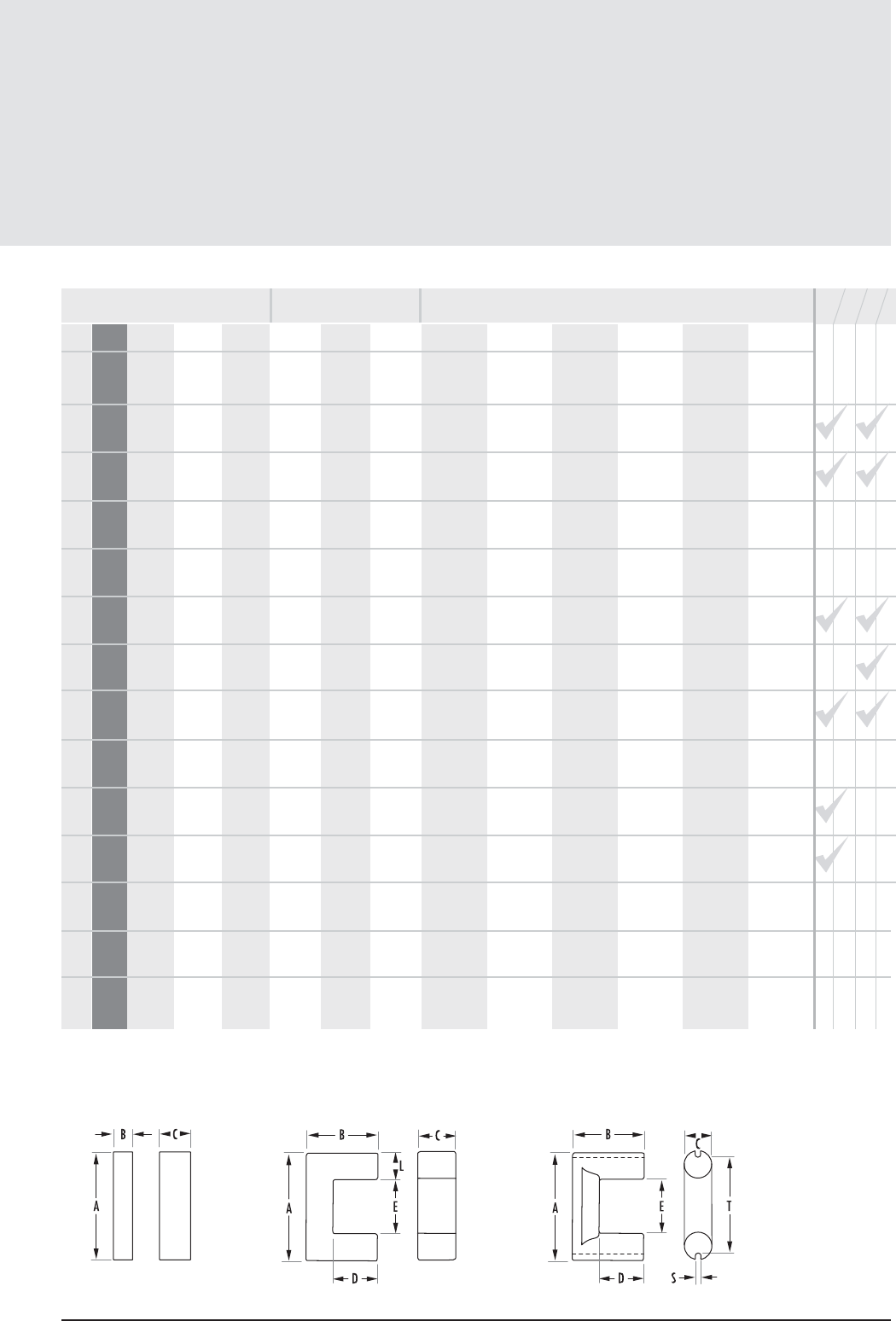
E, I, U Core Data
(ungapped)
11. 9
mag-inc.com
FIGURE 3 FIGURE 4 FIGURE 5
E, I, U Cores
POWER MATERIALS MAGNETIC DATA
HIGH PERMEABILITY
MATERIALS
RPF*JWHl
e(mm) Ae(mm2)A MIN (mm2)Ve(mm3)CORE WEIGHT
(grams per set) WaAc (cm4)
U-U
Min 1050 1140 1830 2440 3420 -
E-E
Min 2925 3180 5900 7350 13720 -
E-E
Min 4020 4370 8300 10600 19810 -
E-E
Min 4030 4380 7010 8180 - -
E-E
Min 4600 5000 8000 8010 - -
E-E
Min 4720 5130 8220 9375 - -
E-E
Min 5640 6130 9800 11190 - -
E-E
Min 6070 6600 10400 10610 18000 -
E-E
Min 4300 4680 6590 7445 - -
E-E
Min 4470 4860 7780 8885 - -
E-E
Min 3505 3810 6000 6940 - -
U-I
Min 4280 4650 7440 - - -
U-U
Min 3400 3650 5900 - - -
E-E
Min 4670 5080 8120 - - -
152.80 98.8 98.8 15100 75 5.8800
77.0 149.0 142.0 11500 57 1.4800
88.9 234.0 226.0 20800 103 2.7700
104.00 257.0 244.0 26700 132 3.9600
92.90 225.0 213.0 20900 108 4.0000
124 353 345 44000 212 9.9100
123.00 417.0 413.0 51400 255 11.8000
107.00 337.0 337.0 36000 179 6.3400
110.00 248.0 240.0 27200 135 7.1600
137.00 368.0 363.0 50300 264 14.8000
184 392 392 72300 357 30.8000
245.0 645.0 645.0 158000 324 102.0000
308.00 645.0 645.0 199000 975 168.0000
274.00 738.0 692.0 202000 - 156.0000
STANDARD BOBBIN
SURFACE MOUNT BOBBIN
PRINTED CIRCUIT BOBBIN
MOUNTING CLAMP
AVAILABLE
HARDWARE
COMB.
AL(mH/1000T)
* F material nominal ± 25%
11.10 MAGNETICS
Bobbins
MECHANICAL DIMENSIONS
PART CORE SIZE A MAX B MAX C MAX D MAX E MIN F NOM
MATERIAL
00B120301 41203EC 1 mm 9.2964 - 7.874 4.5212 3.302 6.6294 0.02400 0.1580 0.089 Nylon*
in 0.366 - 0.310 0.178 0.13 0.261
00B120801 41208EC 3 mm 7.8232 9.525 10.668 4.50 9.58 2.870 0.02900 0.19 0.09 Glass filled
in 0.308 0.375 0.420 0.177 min 0.377 nom 0.113 min Nylon**
00B180801 41808EC 1 mm 13.843 - 11.049 6.477 4.953 9.525 0.05300 0.3420 0.131 Nylon*
in 0.545 - 0.435 0.255 0.195 0.375
00B18100A 41810EC 4 mm 13.716 18.415 10.922 9.7028 9.1694 4.953 0.04900 0.316 0.164 Glass filled
in 0.540 0.725 0.43 0.382 min 0.361 nom 0.195 min Nylon*
00B251001 42510EC 1 mm 18.4912 - 12.3444 8.4074 6.6294 10.3124 0.07900 0.510 0.184 Nylon*
in 0.728 - 0.486 0.331 0.261 0.406
00B251501 42515EC 5 mm 15.0876 15.0876 22.098 6.35 20.574 6.35 0.111 0.716 0.149 Glass filled
in 0.594 0.594 0.870 0.250 min 0.810 nom 0.250 min Nylon
00B300901 43009EC 2 mm 21.336 24.892 17.526 11.4808 9.6012 15.6464 0.13000 0.8390 0.226 Nylon*
in 0.840 0.980 0.690 0.452 0.378 0.616
00B351501 43515EC 1 mm 24.8412 - 18.923 11.9888 9.906 17.145 0.17500 1.130 0.236 Nylon*
in 0.978 - 0.745 0.472 0.390 0.675
00B402001 44020EC 6 mm 29.845 35.052 16.129 12.319 26.162 29.21 0.321 2.07 0.32 Glass filled
in 1.175 1.380 0.635 min 0.485 min 1.030 nom 1.150 Nylon*
00B431701 44317EC 1 mm 28.0162 - 20.4724 14.605 12.827 18.9484 0.19500 1.260 0.277 Nylon*
in 1.103 - 0.806 0.575 0.505 0.746
00B472101 44721EC 1 mm 31.1912 - 23.5712 18.415 16.129 21.3868 0.21800 1.410 0.320 Nylon*
in 1.228 - 0.928 0.725 0.635 0.842
00B552801 45528EC 6 mm 36.576 42.037 21.209 17.399 36.576 33.528 0.438 2.830 0.400 Glass filled
in 1.440 1.655 0.835 min 0.685 min 1.440 1.320 Nylon
00B572401 45724EC 1 mm 37.846 - 28.575 21.59 19.1262 26.543 0.332 2.14 0.388 Nylon*
in 1.49 - 1.125 0.850 0.753 1.045
00B722801 47228EC 7 mm 51.0794 51.0794 19.7612 19.7612 34.4678 30.4038 0.632 4.08 0.49 Zytel 50
in 2.011 2.011 0.778 min 0.778 min 1.357 1.197
00B802001 48020EC 7 mm 57.5818 57.5818 20.5486 20.5486 55.118 51.054 1.25 8.06 0.542 Zytel 50
in 2.267 2.267 0.809 min 0.809 min 2.17 2.01
E, I, U Hardware
NOMINAL WINDING
AREA PER SECTION
AVERAGE
LENGTH OF
TURN FT
in2cm2
* UL 94 HB rated
** UL 94 V-O rated
FIG.
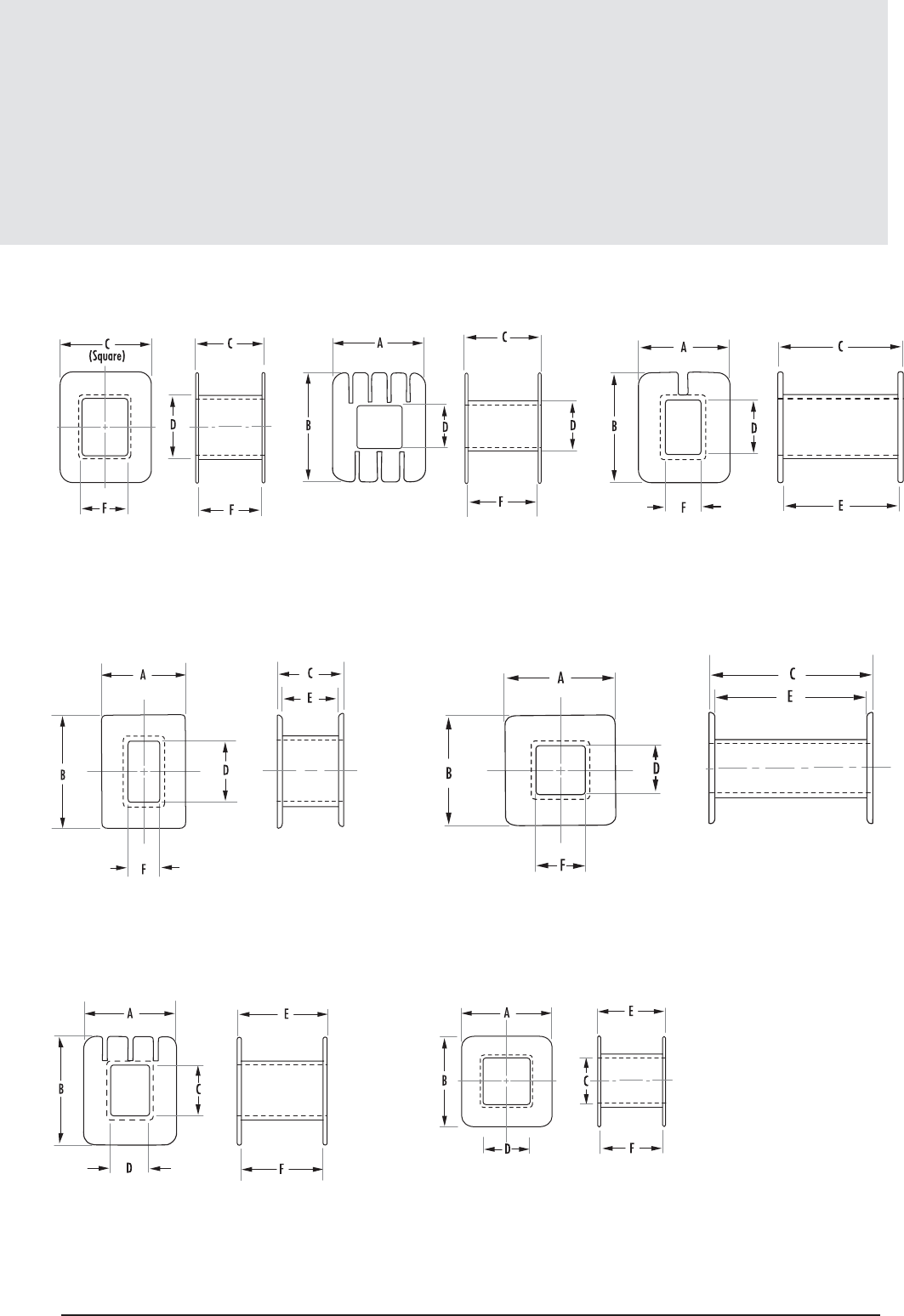
11.11
mag-inc.com
Bobbins
FIGURE 1
FIGURE 4
FIGURE 6
FIGURE 5
FIGURE 7
FIGURE 2 FIGURE 3
E, I, U Hardware
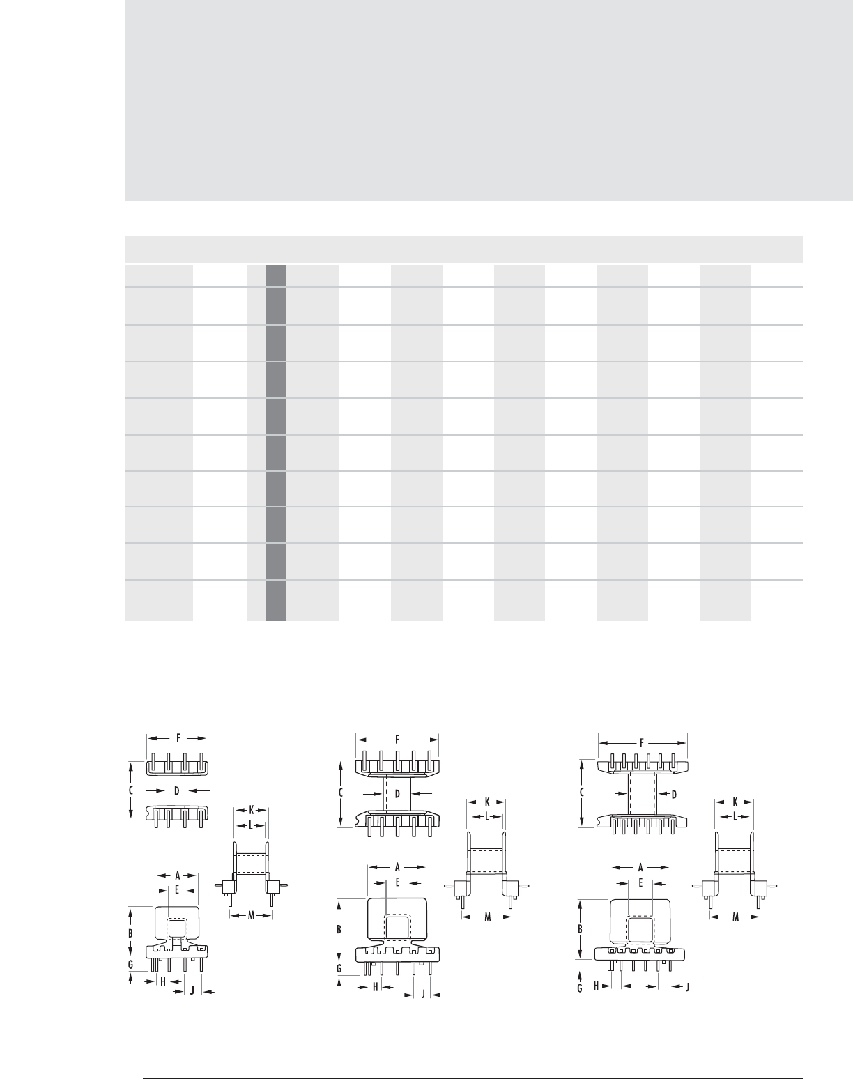
11.12 MAGNETICS
Printed Circuit Bobbins
MECHANICAL DIMENSIONS
PART CORE SIZE A MAX B MAX C MAX D MAX E MIN F MAX G MIN H NOM J NOM K MAX
PCB180881 41808EC 1 mm 13.843 16.129 17.399 7.315 4.953 19.177 4.191 3.810 5.080 11.049
in 0.545 0.635 0.685 0.288 0.195 0.755 0.165 0.150 0.200 0.435
PCB180882 41808EC 1 mm 13.843 16.129 17.399 7.315 4.953 19.177 4.191 3.810 5.080 11.049
2 Section in 0.545 0.635 0.685 0.288 0.195 0.755 0.165 0.150 0.200 0.435
PCB2510T1 42510EC 2 mm 18.669 20.371 20.955 8.890 6.629 26.289 4.191 3.810 5.080 12.319
in 0.735 0.802 0.825 0.350 0.261 1.035 0.165 0.150 0.200 0.485
PCB2510T2 42510EC 2 mm 18.669 20.371 20.955 8.890 6.629 26.289 4.191 3.810 5.080 12.319
2 Section in 0.735 0.802 0.825 0.350 0.261 1.035 0.165 0.150 0.200 0.485
PCB2520TA 42520EC 5 mm 26.289 21.209 13.335 6.680 18.542 27.940 12.369 10.668 15.748 3.429
in 1.035 0.835 0.525 min 0.263 min .730 nom 1.100 nom .487 max 0.420 0.620 .135 nom
PCB3007T1 43007EC 6 mm 24.003 32.080 7.442 7.442 18.796 18.796 19.050 17.272 25.400 3.048
in 0.945 1.263 0.293 min 0.293 min 0.740 nom 0.740 nom 0.750 max 0.680 1.000 0.120
PCB3009LA 43009EC 4 mm 21.387 26.035 30.734 12.192 9.652 33.909 5.080 5.080 - 17.145
in 0.842 1.025 1.210 0.480 0.380 1.335 0.200 0.200 - 0.675
PCB3515L1 43515EC 3 mm 25.146 25.527 27.483 12.014 9.677 37.465 4.191 3.810 5.080 18.593
in 0.990 1.005 1.082 0.473 0.381 1.475 0.165 0.150 0.200 0.732
PCB3515L2 43515EC 3 mm 25.146 25.527 27.483 12.014 9.677 37.465 4.191 3.810 5.080 18.593
2 Section in 0.990 1.005 1.082 0.473 0.381 1.475 0.165 0.150 0.200 0.732
E, I, U Hardware
FIGURE 1 FIGURE 2 FIGURE 3
FIG.
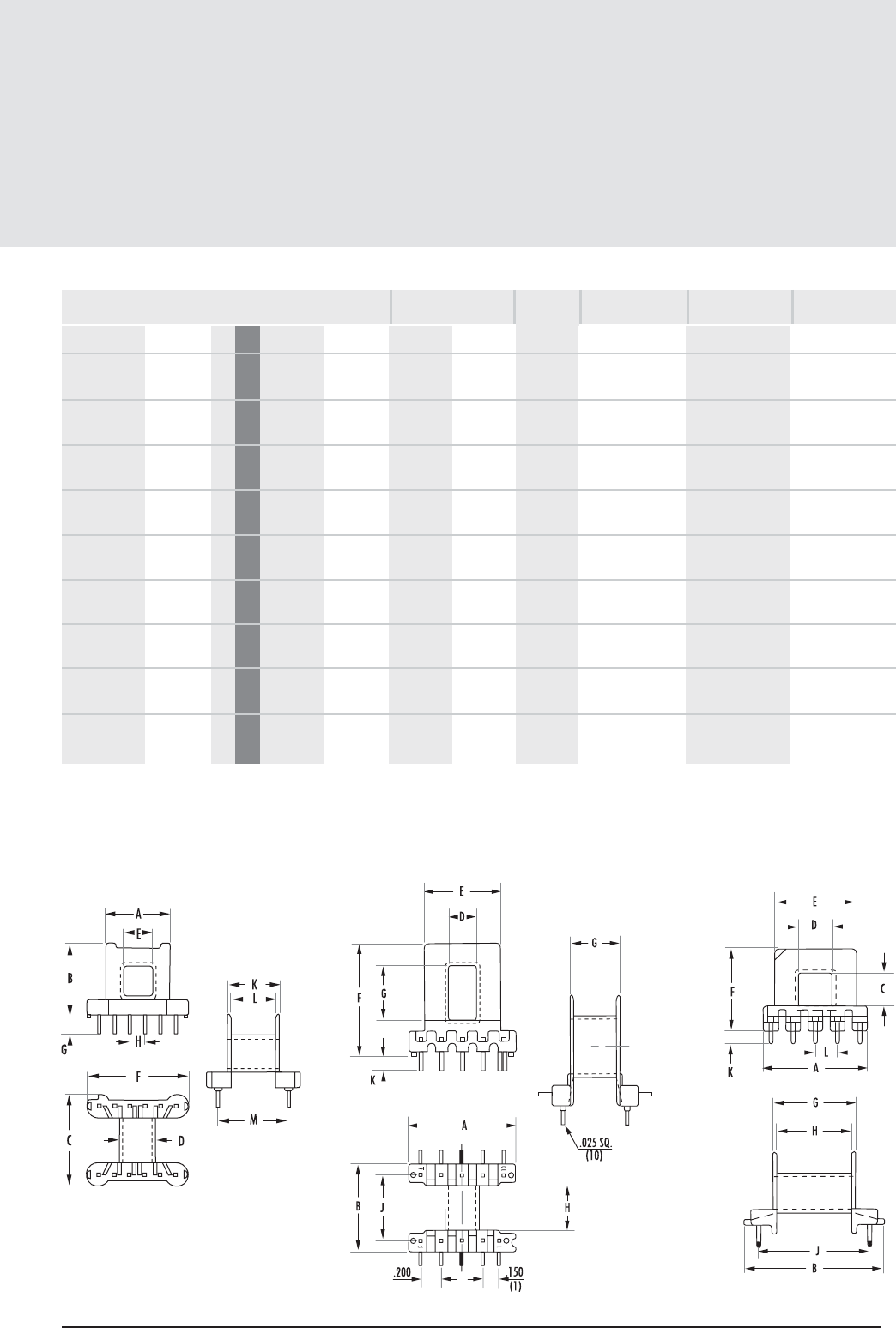
11.13
mag-inc.com
Printed Circuit Bobbins
MECHANICAL DIMENSIONS
PART CORE SIZE L NOM M NOM
PCB180881 41808EC 1 mm 9.322 13.081 0.049 0.316 0.133 Glass filled Nylon* Phosphor Bronze .025" square
in 0.367 0.515
PCB180882 41808EC 1 mm 9.322 13.081 0.049 0.316 0.133 Glass filled Nylon* Phosphor Bronze .025" square
2 Section in 0.367 0.515
PCB2510T1 42510EC 2 mm 10.262 15.621 0.063 0.406 0.178 Glass filled Nylon* Phosphor Bronze .025" square
in 0.404 0.615
PCB2510T2 42510EC 2 mm 10.262 15.621 0.063 0.406 0.178 Glass filled Nylon* Phosphor Bronze .025" square
2 Section in 0.404 0.615
PCB2520TA 42520EC 5 mm --0.098 0.630 0.225 PET Polyester .025" square
in --
PCB3007T1 43007EC 6 mm 5.080 - 0.129 0.833 0.180 Thermoset Phenolic .030"
in 0.200 -
PCB3009LA 43009EC 4 mm 14.732 22.860 0.111 0.714 0.218 DAP** Alloy 510 tin plated .036" square
in 0.580 0.900
PCB3515L1 43515EC 3 mm 16.510 21.895 0.147 0.948 0.241 Glass filled Nylon* Phosphor Bronze .025" square
in 0.650 0.862
PCB3515L2 43515EC 3 mm 16.510 21.895 0.147 0.948 0.241 Glass filled Nylon Phosphor Bronze .025" square
2 Section in 0.650 0.862
NOMINAL WINDING
AREA PER SECTION
in2cm2
E, I, U Hardware
FIGURE 4 FIGURE 5 FIGURE 6
* UL 94 HB rated
** UL 94 V-O rated
FIG.
PIN
MATERIAL PIN
DIAMETER
BOBBIN
MATERIAL
AVERAGE
LENGTH OF
TURN FT
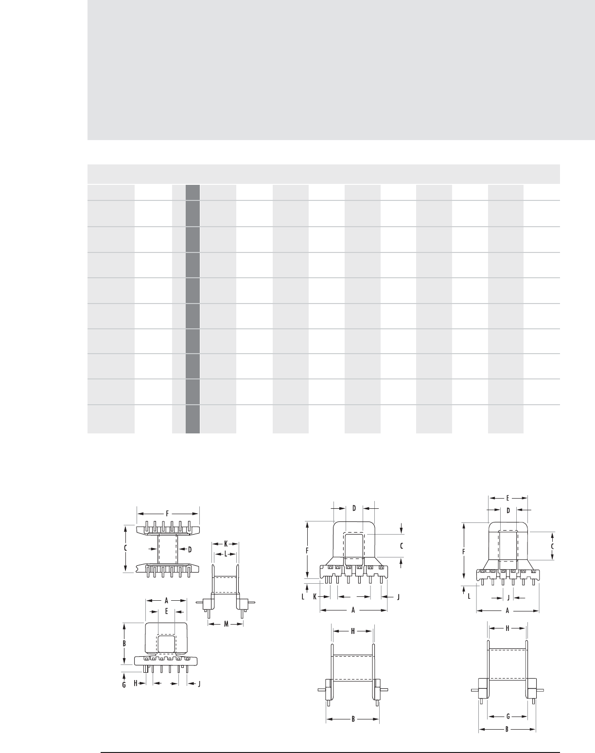
11.14 MAGNETICS
Printed Circuit Bobbins (con’t)
MECHANICAL DIMENSIONS
PART CORE SIZE A MAX B MAX C MAX D MAX E MIN F MAX G MIN H NOM J NOM K MAX
PCB4020L1 44020EC 7 mm 46.609 37.313 15.748 12.167 28.524 38.735 29.718 27.686 7.620 5.080
in 1.835 1.469 0.620 min .479 min 1.123 nom 1.525 nom 1.170 nom 1.090 0.300 0.200nom
PCB4022L1 44022EC 8 mm 46.609 42.393 20.447 12.167 28.448 42.428 29.718 27.432 7.620 -
in 1.835 1.669 .805 min .479 min 1.120 nom 1.670 nom 1.170 nom 1.080 0.300 -
PCB4317L1 44317EC 3 mm 28.067 28.829 29.210 15.265 12.827 41.402 4.318 5.080 6.350 20.320
in 1.105 1.135 1.15 0.601 0.505 1.63 0.17 0.200 0.250 0.800
PCB4317L2 44317EC 3 mm 28.067 28.829 29.210 15.265 12.827 41.402 4.318 5.080 6.350 20.32
2 Section in 1.105 1.135 1.15 0.601 0.505 1.63 0.17 0.200 0.250 0.800
PCB4721L1 44721EC 3 mm 31.369 32.131 32.893 18.415 16.129 44.577 4.445 5.080 7.620 23.49
in 1.235 1.265 1.295 0.725 0.635 1.755 0.175 0.200 0.300 0.925
PCB4721L2 44721EC 3 mm 31.369 32.131 32.893 18.415 16.129 44.577 4.445 5.080 7.620 23.495
2 Section in 1.235 1.265 1.295 0.725 0.635 1.755 0.175 0.200 0.300 0.925
PCB5528WA 45528EC 9 mm 54.991 51.181 21.133 17.120 37.033 50.292 36.068 35.560 45.720 4.064
in 2.165 2.015 0.832 min 0.674 min 1.458 nom 1.98 nom 1.42 nom 1.400 1.800 0.160
PCB5530FA 45530EC 10 mm 37.160 40.157 27.737 min 17.551 min 37.008 49.403 35.611 33.401 40.005 4.496
in 1.463 1.581 1.092 0.691 1.457 nom 1.945 nom 1.402 1.315 1.575 0.177
PCB5724L1†45724EC 3 mm 37.719 39.243 38.227 21.514 19.279 44.577 4.394 5.080 7.620 28.321
in 1.485 1.545 1.505 0.847 0.759 1.755 0.173 0.200 0.300 1.115
E, I, U Hardware
† This bobbin has no standoff
FIGURE 7 FIGURE 8
FIGURE 3
FIG.
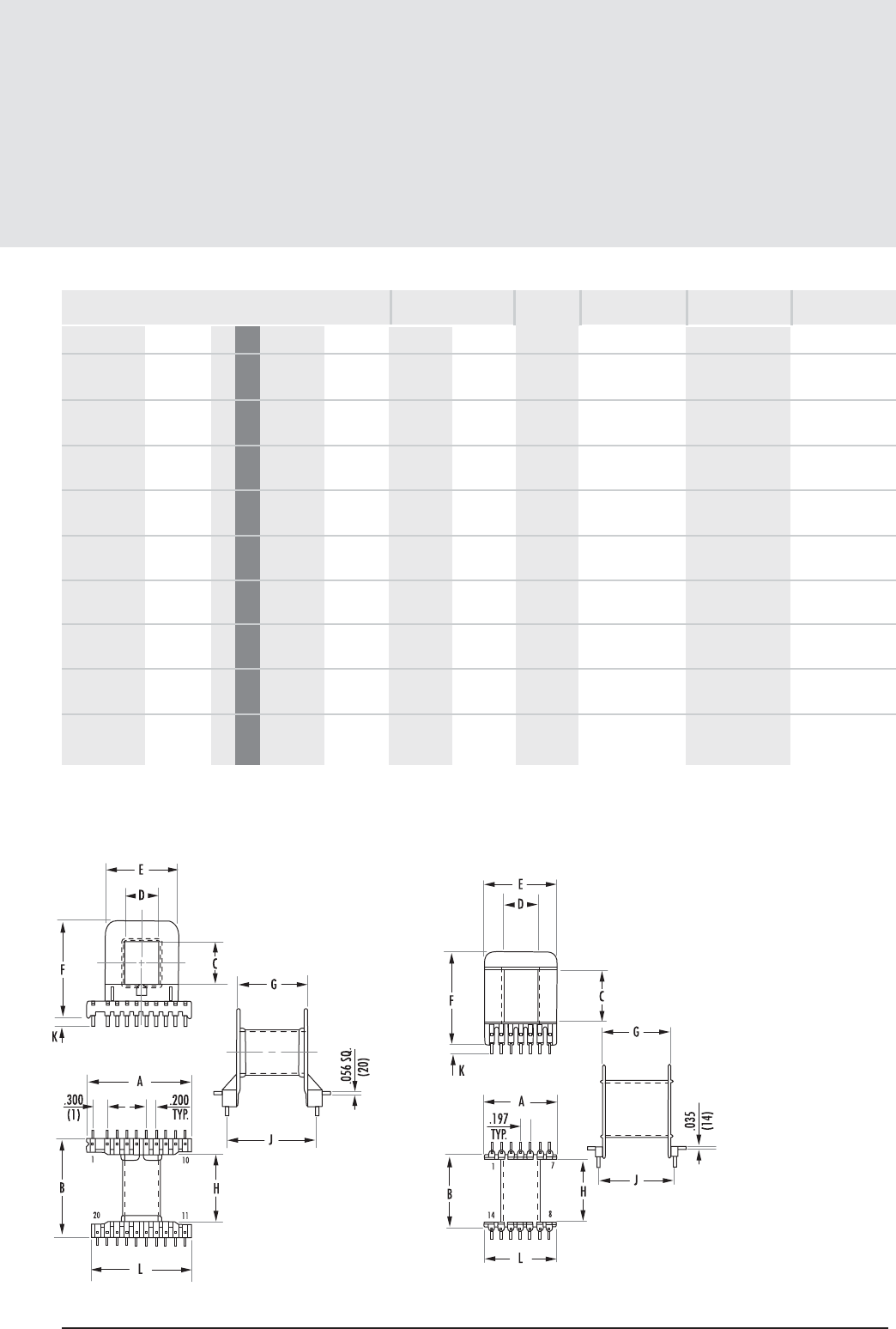
11.15
mag-inc.com
Printed Circuit Bobbins (con’t)
E, I, U Hardware
MECHANICAL DIMENSIONS
PART CORE SIZE L NOM M NOM
PCB4020L1 44020EC 7 mm 3.810 - 0.300 1.940 0.300 Rynite FR-530** .036" square
in 0.150 -
PCB4022L1 44022EC 8 mm 4.572 - 0.300 1.940 0.335 Rynite FR-530** .036" square
in 0.180 -
PCB4317L1 44317EC 3 mm 18.110 24.130 0.156 1.010 0.281 Rynite Phosphor Bronze .025" square
in 0.713 0.950
PCB4317L2 44317EC 3 mm 18.110 24.130 0.156 1.010 0.281 Rynite Phosphor Bronze .025" square
2 Section in 0.713 0.950
PCB4721L1 44721EC 3 mm 21.082 27.940 0.185 1.193 0.325 Glass filled Nylon* Phosphor Bronze .025 " square
in 0.830 1.100
PCB4721L2 44721EC 3 mm 21.082 27.940 0.185 1.193 0.325 Glass filled Nylon* Phosphor Bronze .025 " square
2 Section in 0.830 1.100
PCB5528WA 45528EC 9 mm 52.070 - 0.468 3.020 0.352 Glass filled Nylon** .036" square
in 2.050 -
PCB5530FA 45530EC 10 mm 37.008 - 0.448 2.890 0.439 Glass filled Nylon** .035"
in 1.457 -
PCB5724L1†45724EC 3 mm 26.162 33.020 0.293 1.890 0.386 Glass filled Nylon* .035" square
in 1.030 1.300
FIGURE 9 FIGURE 10
† This bobbin has no standoff * UL 94 HB rated ** UL 94 V-O rated.
FIG.
NOMINAL WINDING
AREA PER SECTION
in2cm2
PIN
MATERIAL PIN
DIAMETER
BOBBIN
MATERIAL
AVERAGE
LENGTH OF
TURN FT
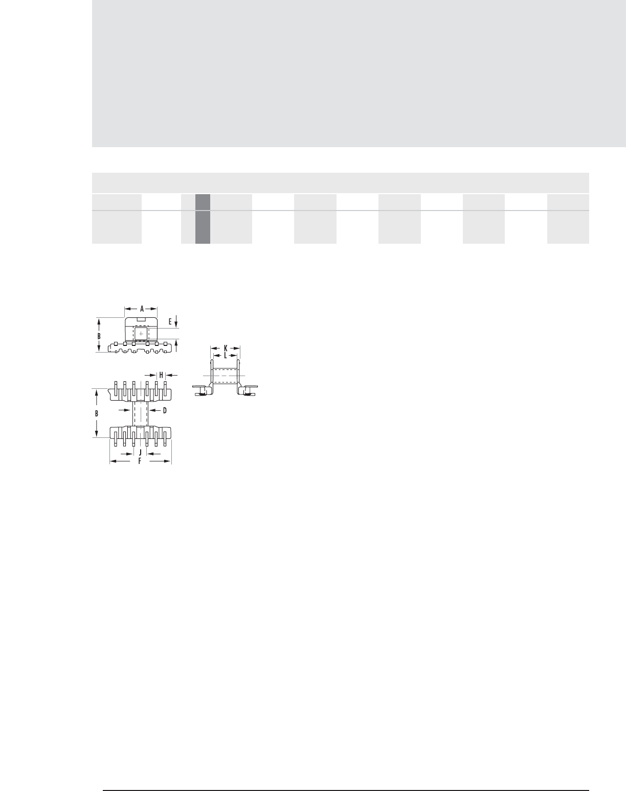
11.16 MAGNETICS
Surface Mount Bobbins
MECHANICAL DIMENSIONS
PART CORE SIZE A MAX B MAX C MAX D MAX E MIN F MAX G MIN H NOM J NOM
E, I, U Hardware
FIGURE 1
SMB1203LA 41203EC 1 mm 9.119 10.490 14.072 4.496 3.302 17.221 - 2.540 3.810
in 0.359 0.413 0.554 0.177 0.130 0.678 - 0.100 0.150
FIG.

MECHANICAL DIMENSIONS
PART CORE SIZE K MAX L NOM
11.17
mag-inc.com
Surface Mount Bobbins
E, I, U Hardware
SMB1203LA 41203EC 1 mm 7.925 6.909 Phosphor
in 0.312 0.272 0.025 0.162 0.087 LCP** Bronze .020” square
** UL 94 V-O rated
FIG.
NOMINAL WINDING
AREA PER SECTION PIN
MATERIAL PIN
DIAMETER
BOBBIN
MATERIAL
AVERAGE
LENGTH OF
TURN FT
in2cm2
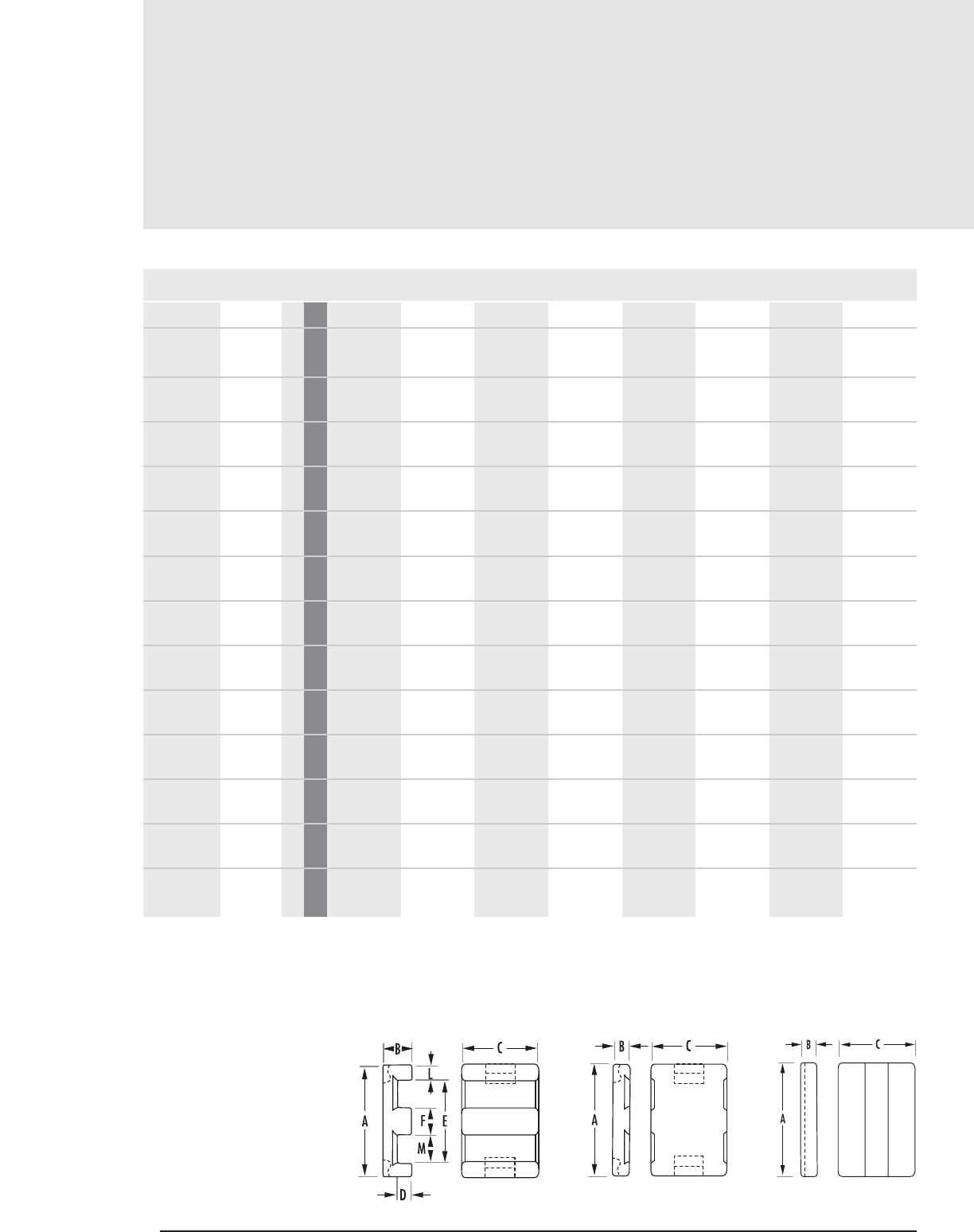
Planar E, I Cores
11.18 MAGNETICS
Planar Core Data
(ungapped)
MECHANICAL DIMENSIONS
PART CORE TYPE A B C D MIN E MIN F L M
0_41425EC 6 mm 14 ± .30 2.5 ± .10 5 ± .15 0.9 10.5 3 ± .10 1.5 4
in 0.551 ± .012 .098 ± .004 .197 ± .006 0.035 0.414 .118 ± .004 .059 ref .1575 ref
C_41434EC* E14 1mm 14 ± .30 3.5 ± .10 5 ± .15 1.91 10.5 3 ± .10 1.5 4
in .555 ± .012 0.138 ± .004 .197 ± .006 0.075 0.414 .118 ± .004 .059 ref .1575 ref
C_41434IC I14 3mm 14 ± .30 1.8 ± .05 5 ± .15
in .551 ± .012 .071 ± .002 .197 ± .006
C_41805EC* E18 1mm 18 ± .35 4 ± .1 10 ± .20 2 ± .1 13.7 4 ± .1 2.0 ref 5.0 ref
C_41805IC I18 3mm 18 ± .41 2.39 ± .10 10 ± .20
in .709 ± .016 .094 ± .004 .394 ± .008
0_42107EC 6 mm 21.8 ± .43 3.91 ± .08 7.8 ± .51 1.52 16.5 5 ± .20 2.5 ± .12 5.89 ± .25
in .858 ± .017 .154 ± .003 .307 ± .020 0.06 0.649 .197 ± .008 .0985 ± .005 .232 ± .010
C_42216EC* E22 1mm 21.8 ± .400 5.72 ± .12 15.8 ± .30 3.05 16.1 5.08 ± .12 2.54 ref 5.7 ref
in .850 ± .010 .225 ± .005 .625 ± .010 0.12 0.632 .200 ± .005 .100 ± .005 .225 ± .012
C_42216IC I22 3mm 21.8 ± .400 2.95 ± .10 15.9 ± .25
in .850 ± .010 .116 ± .004 .625 ± .010
F_43208EC E32 1mm 31.75 ± .640 6.35 ± .130 20.32 ± .41 2.98 24.9 6.35 ± .130 3.18 9.27
in 1.250 ± .020 .250 ± .008 .800 ± .016 0.12 0.98 .250 ± .005 .125 ref .365 min
F_43208IC I32 2mm 31.75 ± .64 3.18 ± .13 20.32 ± .41
in 1.250 ± .020 .125 ± .005 .800 ± .016
0_43618EC 7 mm 35.56 ± .51 6.35 ± .12 17.8 ± .38 2.41 27.2 7.62 ± .18 3.81 ± .12 10.16 ± .25
in 1.400 ± .020 .250 ± .005 .700 ± .015 0.095 1.070 .300 ± .007 .150 ± .005 .400 ± .010
0_43618IC 8 mm 36.58 ± .51 3.81 ± .25 18.29 ± .38
in 1.440 ± .020 .150 ± .010 .720 ± .015
F_43808EC E38 1mm 38.1 ± .76 8.26 ± .13 25.4 ± .51 4.32 30.2 7.62 ± .15 3.81 11.43
in 1.500 ± .030 .325 ± .005 1.000 ± .020 0.170 1.190 .300 ± .008 .150 ref .450 ref
Any practical gap available. See pages 1.8-1.11
To order, add material code to part number.
* All E-cores available with clamp recesses are also available without. NOTE: Clamps are available for the EI combination of parts 41434, 41805 and 42216 only.
FIGURE 1 FIGURE 2 FIGURE 3
FIG.
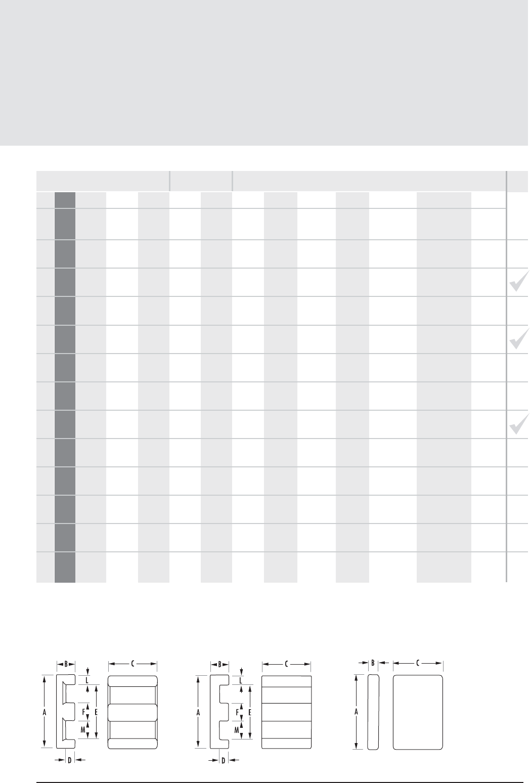
11.19
mag-inc.com
Planar Core Data
(ungapped)
COMB.
POWER MATERIALS MAGNETIC DATA
HIGH PERMEABILITY
MATERIALS
RPF*JWl
e(mm) Ae(mm2)A MIN (mm2)Ve(mm3)CORE WEIGHT
(grams per set) WaAc (cm4)AVAILABLE
HARDWARE
Min 1240 1350 2150 2650 4260
Min 1000 1080 1730 2140 3420
Min 1330 1450 2320 2880 -
Min 2520 2740 4380 5470 -
Min 3000 3260 5210 6450 -
Min 2190 2380 3810 4350 8260
Min 3590 3905 6250 8640 13300
Min 4467 4858 7776 10750 -
Min 5025 5465 8744 10930 -
Min 5930 6446 10313 12892 -
Min 5170 5640 9020 - -
Min 5870 6400 10250 12760 21600
Min 5900 6430 10300 - -
16.7 14.7 14.7 244 1.2 0.064 0.0090
14.7 14.7 244.0
20.7 14.66 14.66 303.9 1.5 0.128 0.019
1.47 14.7 30.4
16.7 14.7 14.7 245.0 1.2 0.064 0.009
24.2 40.1 39.9 972 4.9 0.16 0.064
20.3 39.5 35.9 830 4.1 0.08 0.032
25.7 37.1 36.0 960.0 4.2 0.15 0.056
32.3 76.0 73.n
26.1 80.4 72.5 2100 10.4 0.15 0.12
41.4 130.0 130.0 5380 26 0.51 0.66
35.1 130.0 130.0 4560 22 0.25 0.33
42.4 135.0 135.0 5750.0 28 0.412 0.556
37.4 135.0 135.0 5060.0 25 0.206 0.278
52.4 194.0 194.0 10200 50.9 0.813 1.56
MOUNTING CLAMP
AL(mH/1000T)
Planar E, I Cores
* F material nominal ± 25%
FIGURE 6 FIGURE 7 FIGURE 8
E-E
E-E
E-I
E-E
E-I
E-E
E-E
E-I
E-E
E-I
E-E
E-I
E-E
BOBBIN WINDOW
AREA (cm2)
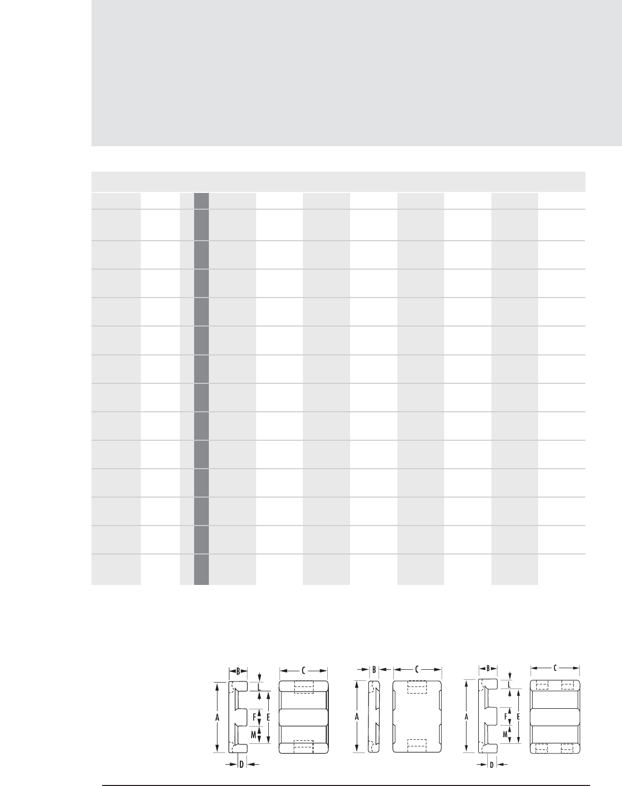
Planar E, I Cores
11. 20 MAGNETICS
Planar Core Data
(ungapped)
MECHANICAL DIMENSIONS
PART CORE TYPE A B C D MIN E MIN F L M
F_43808IC I38 2mm 38.1 ± .76 3.81 ± .13 25.4 ± .51
in 1.500 ± .030 .150 ± .005 1.000 ± .020
0_44008EC 7 mm 40.64 ± .51 8.51 ± .25 10.7 ± .25 3.56 29.8 10.16 ± .12 5.08 ± .12 10.16
in 1.600 ± .020 .335 ± .010 .421 ± .010 0.140 1.175 .400 ± .005 .200 ± .005 .400 nom
0_44008IC 8 mm 40.64 ± .51 4.45 ± .25 10.7 ± .25
in 1.600 ± .020 .175 ± .010 .421 ± .010
0_44308EC 7 mm 43.2 ± .9 8.51 ± .25 27.9 ±.6 4.19 34.7 8.1 ± .2 4.06 ref 13.46 ref
0_44308IC 8 mm 43.2 ± .9 4.1 ± .13 27.9 ± .6
F_44310EC E43 1mm 43.18 ± .51 9.53 ± .12 27.9 ± .38 5.33 34.4 8.13 ± .25 4.06 ± .25 13.46 ± .25
in 1.700 ± .020 0.375 ± .005 1.100 ± .015 0.21 1.355 .320 ± .010 .160 ± .010 .530 ± .010
F_44310IC I43 2mm 43.18 ± .51 4.06 ± .12 27.9 ± .38
in 1.700 ± .020 .160 ± .005 1.100 ± .015
C_45810EC* E58 4mm 58.42 ± 1.17 10.54 ± .20 38.1 ± .78 6.35 50.39 8.1 ± .20 3.66 21.5 ± .25
in 2.300 ± .046 .415 ± .008 1.500 ± .031 0.25 1.984 .319 ± .008 .144 ref .8465 ± .010
C_45810IC I58 5mm 58.42 ± 1.17 4.04 ± .12 38.1 ± .78
in 2.300 ± .046 .159 ± .005 1.500 ± .031
0_46409EC 7 mm 64 ± .76 9.65 ± .12 50.8 ± .64 4.45 52.8 10.16 ± .18 5.08 ± .12 21.8 ± .25
in 2.520 ± .030 .380 ± .005 2.000 ± .025 0.175 2.08 .400 ± .007 .200 ± .005 .860 ± .010
C_46410EC* E64 4mm 64 ± .76 10.2 ± .10 50.8 ± .81 5.03 53.16 10.16 ± .18 5.08 ± .12 21.8 ± .25
in 2.520 ± .030 .402 ± .004 2.000 ± .032 0.198 2.093 .400 ± .007 .200 ± .005 .860 ± .010
C_46410IC I64 5mm 64 ± .76 5.08 ± .12 50.8 ± .81
in 2.520 ± .030 .200 ± .005 2.000 ± .032
0_49938EC E102 7mm 102 ± 1.52 20.3 ± .25 37.5 ± .56 12.9 85 14 ± .25 8 ± .25 35.9 ± .51
in 4.016 ± .060 .800 ± .010 1.476 ± .022 0.507 3.346 .551 ± .010 .315 ± .010 1.415 ± .020
Any practical gap available. See pages 1.8-1.11
To order, add material code to part number.
* All E-cores available with clip recesses are also available without. NOTE: Clips are available for the EI combination of parts 41434, 41805 and 42216 only.
FIGURE 4FIGURE 1 FIGURE 2
FIG.
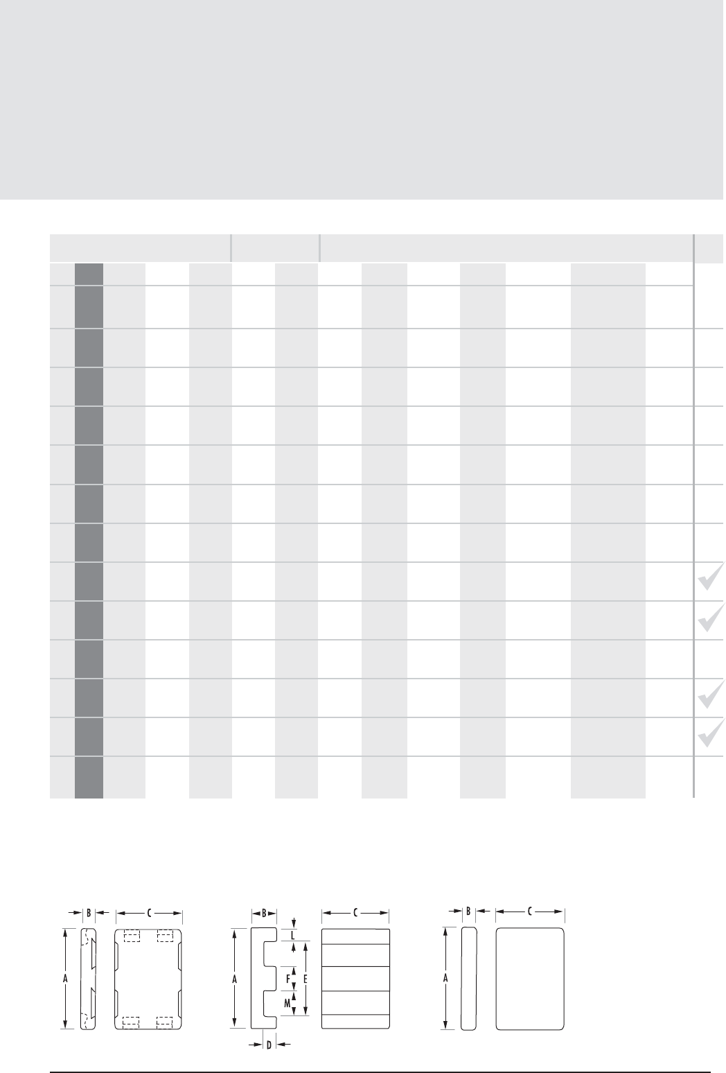
11. 21
mag-inc.com
Planar Core Data
(ungapped)
AL(mH/1000T)
FIGURE 5 FIGURE 7 FIGURE 8
COMB.
POWER MATERIALS MAGNETIC DATA
HIGH PERMEABILITY
MATERIALS
RPF*JWl
e(mm) Ae(mm2)A MIN (mm2)Ve(mm3)CORE WEIGHT
(grams per set) WaAc (cm4)AVAILABLE
HARDWARE
Min 7100 7730 12400 - -
Min 3150 3430 5488 6860 -
Min 3690 4013 6421 8026 -
Min 6420 6982 11172 13966 -
Min 7600 8261 13200 16400 -
Min 6000 6530 10450 13000 22800
Min 7350 8000 12800 15900 27900
Min 6030 6550 10500 12100 -
Min 7210 7840 12500 14500 -
Min 11500 12500 20000 22000 38500
Min 11100 12100 19400 21200 37200
Min 12800 13900 22200 24100 42200
Min 6330 6880 11000 - -
43.7 194.0 194.0 8460 42.5 0.406 0.78
51.9 101.0 95.1 5220.0 26 0.66 0.667
43.8 99.5 95.1 4360.0 21 0.33 0.328
57.5 227.0 227.0 13100.0 64 0.96 2.18
50.4 229.0 229.0 11500 54 0.48 1.09
61.5 227.0 227.0 14000.0 70.6 1.18 2.68
50.6 227.0 227.0 11500.0 58 0.588 1.34
81.2 301.0 279.0 24600.0 125 2.5 7.53
68.3 303.0 279.0 20700.0 105 1.25 3.79
77.4 516.0 516.0 40000.0 200 1.78 9.18
80.2 516.0 516.0 41400.0 195 2.02 10.4
69.9 516.0 516.0 36100.0 170 1.01 5.21
148.0 540.0 525.0 79800.0 400 8.5 46
MOUNTING CLAMP
E-I
E-E
E-I
E-E
E-I
E-E
E-I
E-E
E-I
E-E
E-E
E-I
E-E
BOBBIN WINDOW
AREA (cm2)
Planar E, I Cores
* F material nominal ± 25%
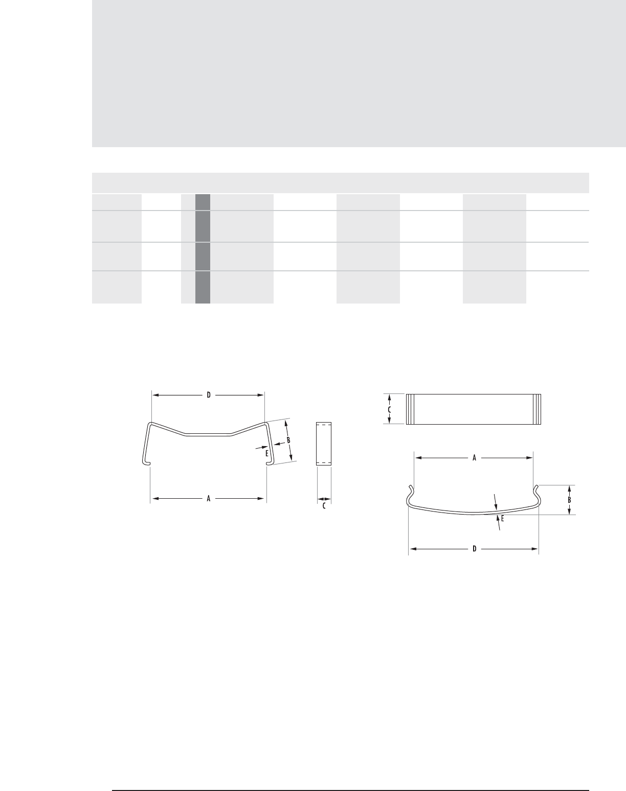
Planar Hardware
11.22 MAGNETICS
FIGURE 1 FIGURE 2
Clamps
MECHANICAL DIMENSIONS
PART CORE SIZE A B C D E MATERIAL
00C143420 41434EC/IC 1 mm 14 5.4 2.21 13.59 0.3048 Stainless Steel
in .551 ± .020 .2126 ± .004 0.087 .535 ± .015 0.012
00C180520 41805EC/IC 1 mm 18.01 6.61 2.2098 17.6 0.4064 Stainless Steel
in 0.709 ± .008 .260 ± .004 0.087 .693 ± .020 0.016
00C221620 42216EC/IC 3 mm 22.2 8.74 2.4892 21.4122 0.4064 Stainless Steel
in 0.874 ± .008 .3425 ± .004 0.098 0.843 0.016
FIG.
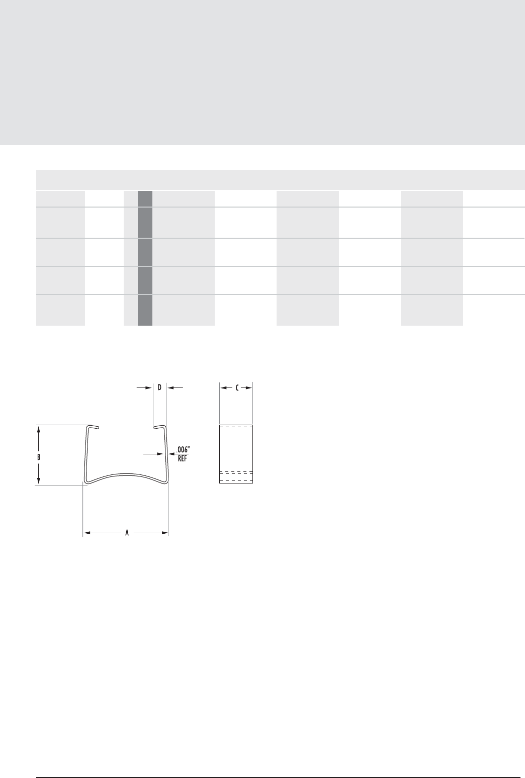
FIGURE 3
MECHANICAL DIMENSIONS
PART CORE SIZE A B C D E MATERIAL
00C581001 45810EC/EC 2 mm 18.24 4.57 4.5 19.87 0.381 Stainless Spring Steel
in .718 ± .006 .180 ref .177 ± .004 .782 ± .006 .015 ± .001
00C581002 45810EC/IC 2 mm 11.61 4.5 13.23 0.381 Stainless Spring Steel
in .457 ± .006 0.177 .521 ± .006 .015 ± .001
00C641001 46410EC/EC 2 mm 17.58 4.57 4.5 9.2 0.381 Stainless Spring Steel
in .692 ± .006 .180 ref .177 ± .004 .756 ± .006 .015 ± .001
00C641002 46410EC/IC 2 mm 11.86 4.57 4.5 13.72 0.381 Stainless Spring Steel
in .467 ± .006 .180 ref .177 ± .004 .540 ± .006 .015 ± .001
11.23
mag-inc.com
Clamps
Planar Hardware
FIG.

EEM/EFD Cores
11.24MAGNETICS
EEM/EFD Core Data
(ungapped)
MECHANICAL DIMENSIONS
PART CORE TYPE A B C D MIN E MIN F K L M
0_41309EC EEM 12.7 2mm 12.8 ± .25 6.86 ± .15 3.3 ± .15 4.42 9.22 6 ± .10 1.85 ± .10 1.68 ± .08 1.7 ± .15
in .502 ± .010 .270 ± .006 .130 ± .006 0.174 0.363 .236 ± .004 .073 ± .004 .066 ± .003 .067 ± .006
0_41515EC EFD 15 3mm 15.5 ± .4 7.5 ± .15 4.65 ± .15 5.25 10.65 5.3 ± .15 2.4 ± .10
0_41709EC 1 mm 17.8 ± .30 9.4 ± .12 4.32 ± .25 6.73 12.3 7.11 ± .18 2.54 ± .18 2.54 ± .18 2.79 ± .18
in .700 ± .012 .370 ± .005 .170 ± .010 0.265 0.485 .280 ± .007 .100 ± .007 0.100 ± .007 .110 ± .007
0_42523EC EFD 25 4mm 25 ± .66 12.5 ± .15 9.1 ± .20 9.1 18.1 11.4 ± .20 5.2 ± .15 3.15 ± .20 3.65 ± .20
in .984 ± .026 .492 ± .006 .358 ± .008 0.358 0.712 .448 ± .008 .205 ± .006 .124 ± .008 .144 ± .008
Any practical gap available. See pages 1.8-1.11
To order, add material code to part number.
FIG.
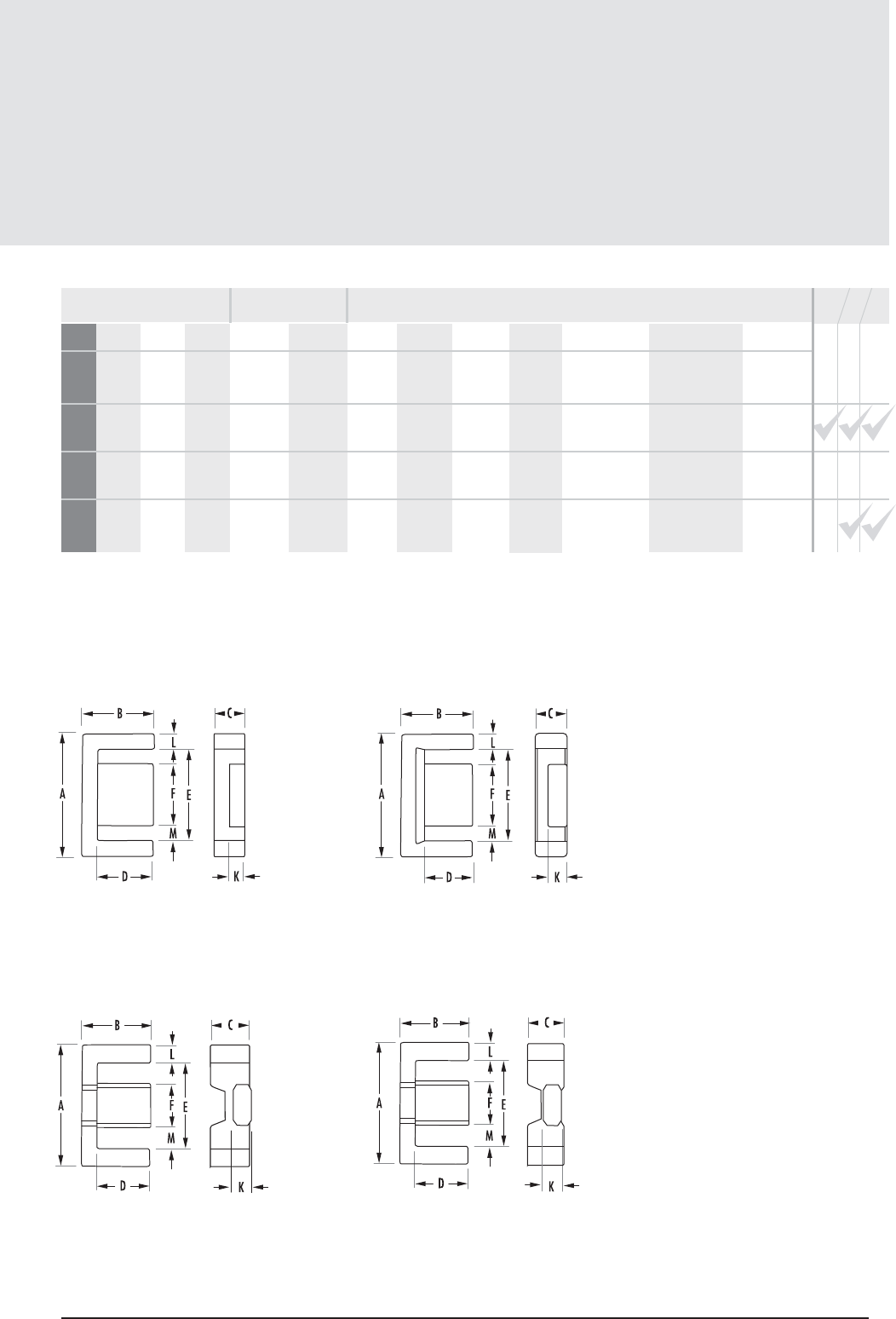
EEM/EFD Core Data
(ungapped)
POWER MATERIALS MAGNETIC DATA
HIGH PERMEABILITY
MATERIALS
RPF* J Wl
e(mm) Ae(mm2)AMIN(mm2)V
e(mm3)CORE WEIGHT
(grams per set) WaAc (cm4)
Nom
Min 600 650 1000 1080 -
Nom
Min 670 730 1170 1450 2150
Nom
Min 740 800 1280 1600 -
Nom
Min 1570 1710 2730 3380 5820
28.5 11.7 11.1 330.0 1.6 0.124 0.015
34.0 15.0 12.2 510.0 2.8 0.167 0.025
41.5 20.1 18.1 834.0 4.1 0.27 0.054
57.0 58.0 55.0 3300.0 16.2 0.402 0.233
SURFACE MOUNT BOBBIN
PRINTED CIRCUIT BOBBIN
MOUNTING CLAMP
AVAILABLE
HARDWARE
11.25
mag-inc.com
FIGURE 1
FIGURE 3 FIGURE 4
FIGURE 2
AL(mH/1000T)
BOBBIN WINDOW
AREA (cm2)
* F material nominal ± 25%
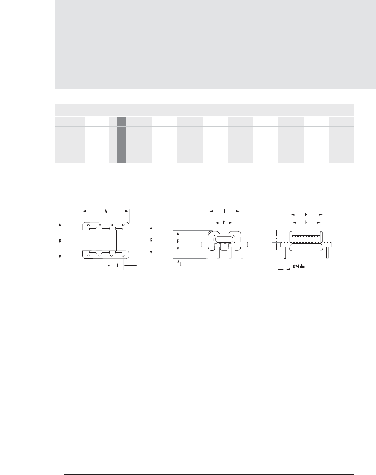
EEM/EFD Hardware
11. 2 6 MAGNETICS
Printed Circuit Bobbins
MECHANICAL DIMENSIONS
PART CORE SIZE A NOM B NOM C MIN D MIN E MAX F NOM G MAX H NOM J TYP
PCB15158A 41515EC 1 mm 14.986 16.3068 2.4892 5.4356 10.5918 8.509 10.5918 9.1948 3.7592
in 0.590 0.642 0.098 0.214 0.417 0.335 0.417 0.358 0.148
PCB2523TA 42523EC 2 mm 24.9936 25.8572 5.3848 11.6078 18.1102 13.208 18.0086 16.6878 5.0038
in 0.984 1.018 0.212 0.457 0.713 0.520 0.709 0.657 0.197
FIGURE 1
FIG.
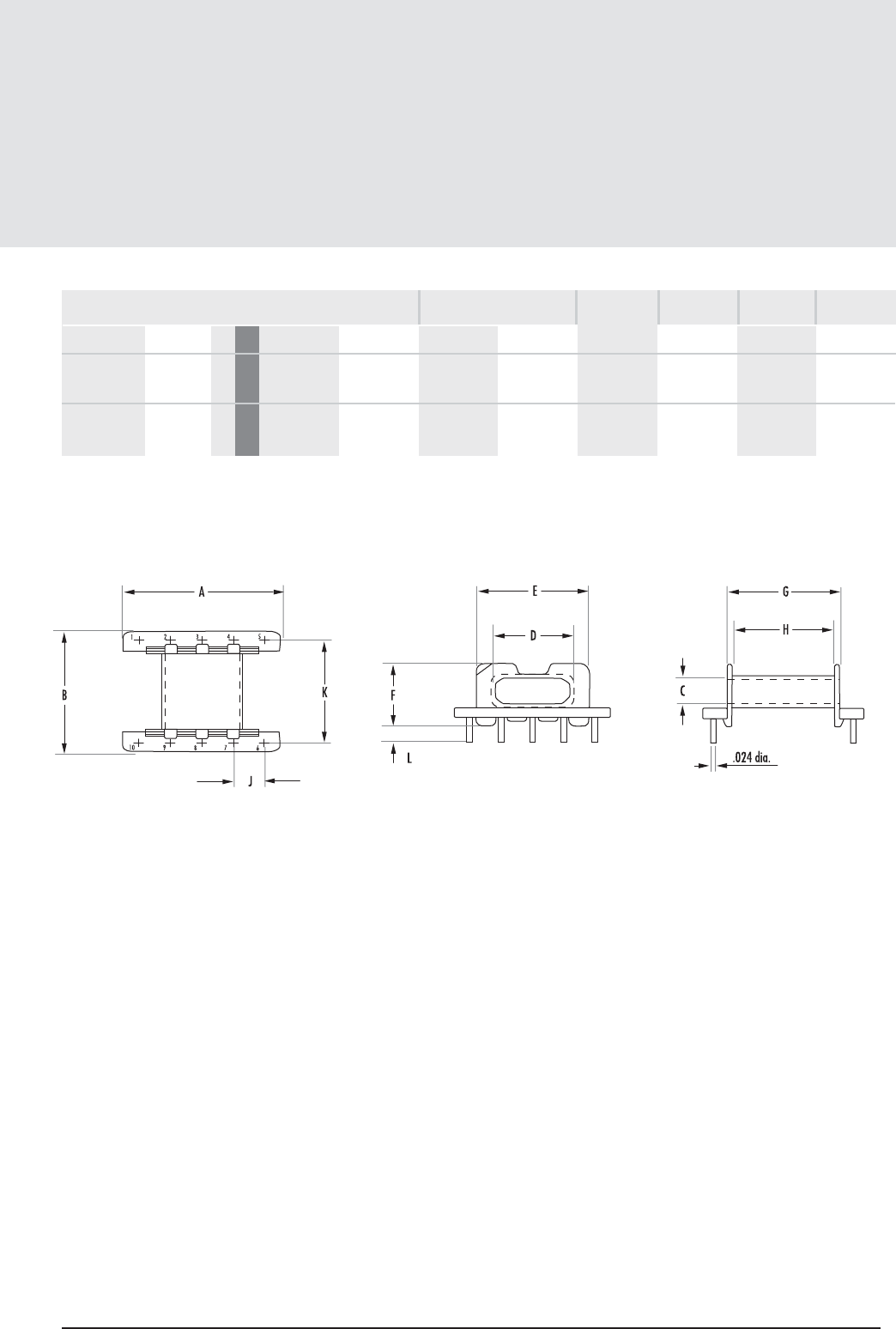
MECHANICAL DIMENSIONS
PART CORE SIZE
Printed Circuit Bobbins
11. 2 7
mag-inc.com
FIGURE 2
K NOM L±.012”
EEM/EFD Hardware
* UL 94 V-O rated
FIG.
NOMINAL WINDING
AREA PER SECTION PIN
MATERIAL PIN
DIAMETER
BOBBIN
MATERIAL
in2cm2
AVERAGE
LENGTH OF
TURN FT
PCB15158A 41515EC 1 mm 13.7414 3.5052 0.026 0.169 0.118 Phenolic* CP Wire .024”
in 0.541 0.138
PCB2523TA 42523EC 2 mm 22.5044 3.5052 0.065 0.412 0.196 Phenolic* CP Wire .024”
in 0.886 0.138
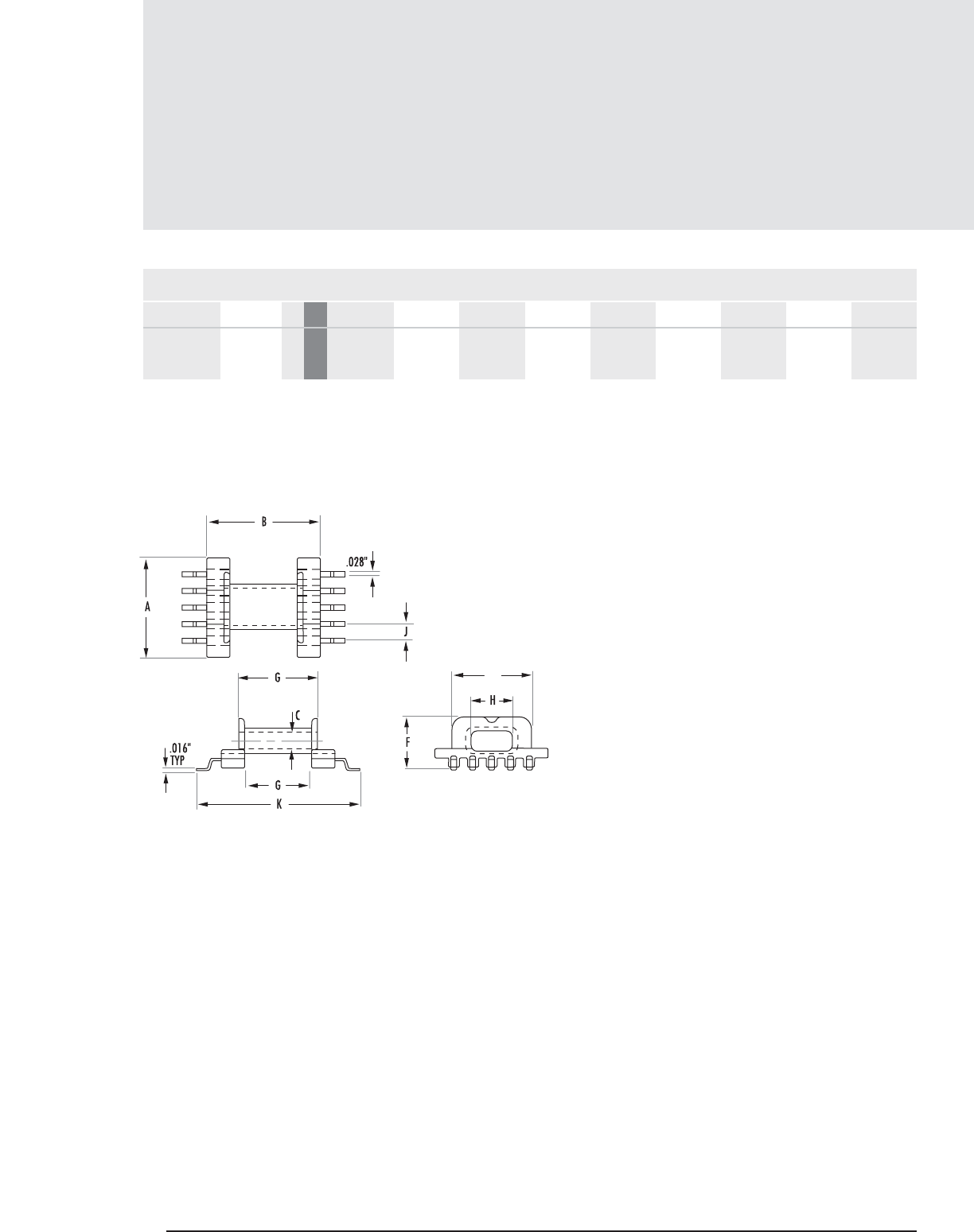
EEM/EFD Hardware
11. 2 8 MAGNETICS
Surface Mount Bobbins
FIGURE 1
MECHANICAL DIMENSIONS
PART CORE SIZE A NOM B NOM C MIN D MIN E MAX F NOM G MAX H NOM J TYP
SMB1515TA 41515EC 1 mm 14.986 14.986 2.4892 5.3848 10.6934 7.493 10.4902 8.89 2.4892
in 0.590 0.590 0.098 0.212 0.421 0.295 0.413 0.350 0.098
FIG.

Surface Mount Bobbins
11.29
mag-inc.com
EEM/EFD Hardware
MECHANICAL DIMENSIONS
PART CORE SIZE K NOM
SMB1515TA 41515EC 1 mm 21.59 0.027 0.175 0.12 L.C.P.* Nickel .016"
in 0.850 Bronze
* UL 94 V-O rated
FIG.
NOMINAL WINDING
AREA PER SECTION PIN
MATERIAL PIN
DIAMETER
BOBBIN
MATERIAL
in2cm2
AVERAGE
LENGTH OF
TURN FT
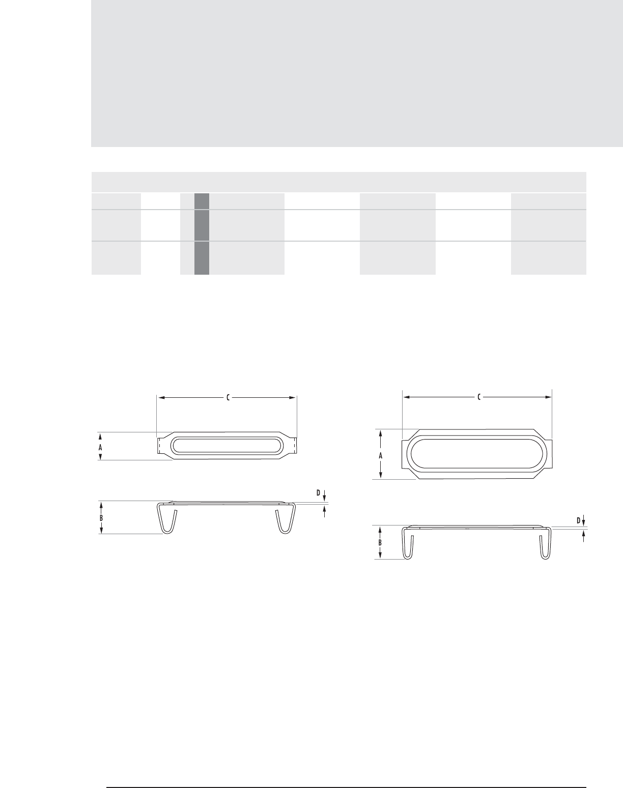
EEM/EFD Hardware
11.30 MAGNETICS
Clamps
MECHANICAL DIMENSIONS
PART CORE SIZE A B C D MATERIAL
00C15151A* 41515EC 1 mm 4.4958 5.207 18.796 0.254 Stainless Steel
in 0.177 0.205 0.740 0.010
00C25231A* 42523EC 2 mm 8.001 5.3848 29.0068 0.3048 Stainless Steel
in 0.315 0.212 1.142 0.012
*Two clamps required per core set
FIGURE 1 FIGURE 2
FIG.
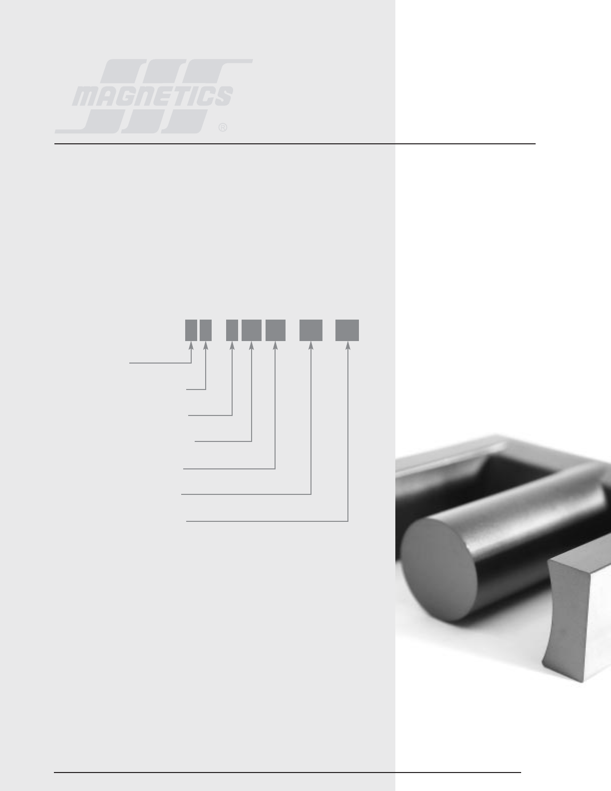
EC, ETD, EER AND ER CORES
EC, ETD and EER cores are a cross between E cores and pot cores. Like E cores they provide a wide opening on
each side. This gives adequate space for the large size wire required for low output voltage switched mode power
supplies. It also allows for a flow of air which keeps the assembly cooler.
The center posts of these cores are round, like that of the pot core. One of the advantages of the round center post
is that the winding has a shorter path length (11% shorter) than the wire around a square center post with an equal
area. This reduces the losses of the windings by 11% and enables the core to handle a higher output power. The
round center post also eliminates the sharp bend in the wire that occurs with winding on a square center post. The
most common application is switched mode power supplies.
HOW TO ORDER
GEOMETRY CODE
EC – All E cores including ETD, EC, ER, EER, EEM, EFD, planar and lamination sizes.
Section 12
EC,ETD,EER
and ER Cores
12.1
STANDARD CORE
FERRITE CORE MATERIAL TYPE
USED FOR ALL FERRITE TYPES
APPROXIMATE DIAMETER IN MM
APPROXIMATE HEIGHT IN MM
GEOMETRY CODE/GAP CODE
SPECIAL SPECIFICATION CODE
OR 43434 EC XX
mag-inc.com
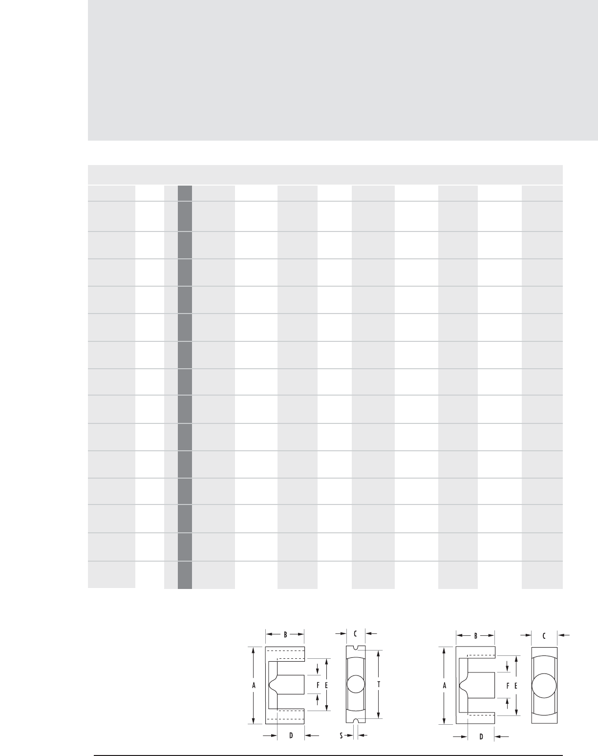
EC, ETD, EER and ER
Core Data (ungapped)
12 . 2 MAGNETICS
MECHANICAL DIMENSIONS
PART A B C D MIN E F G S T
0_40906EC ER 9.5 3 mm 9.5 + 0, -.3 2.45 ± .05 5 + 0, -.2 1.6 7.5 + .25,-0 3.50 + 0, -.2 7.21 ±.10 - -
0_43434EC ETD 34 2 mm 35.0 +.0,-1.6 17.3 ± .20 11.1 + 0, -.6 11.8 27 max 11.1 + 0, -.6 - - -
0_43517EC EC 35 1 mm 34.5 ± .8 17.3 ± .15 9.5 ± .30 11.9 22.75 ± .55 9.5 ± .30 - 2.75 ± .25 28.5 ± .8
0_43521EC EER 35L 2 mm 35 ± .65 20.70 ± .20 11.30 ± .35 14.40 26.15 ± .55 11.30 ± .25 - - -
in 1.378 ± .020 .815 ± .008 .445 ± .010 0.567 1.028 ± .020 .445 ± .010 - - -
0_43939EC ETD 39 2 mm 40.0 + 0, - 1.8 19.8 ± .20 12.8 + 0, -.6 14.2 29.3 +1.6,-0 12.8 + 0, -.6 - - -
0_44119EC EC41 1 mm 40.6 ± 1.0 19.5 ± .15 11.6 ± .3 13.5 27 + .8, -.7 11.6 ± .3 - 3.25 ± .25 33.6 ± 1.0
0_44216EC EER 42 2 mm 42.10 ± .81 21.60 ± .20 14.70 ± .30 15.60 31 ± .58 14.70 ± .30 -
in 1.659 ± .032 .850 ± .008 .579 ± .012 0.614 1.220 ± .023 .579 ± .012 - - -
0_44444EC ETD 44 2 mm 45 + .0, -.2 22.30 ± .20 15.2 + .0, -.6 16.10 32.5+ 1.6,-0 15.2 + 0, -.6 - - -
in 1.732 ± .040 .878 ± .008 .583 ± .015 0.635 1.311 ± .032 .583 ± .015 - - -
0_44949EC ETD 49 2 mm 49.8 +0,-2.2 24.7 ± .20 16.7 + 0, -.6 17.7 36.1 + 0,-1.8 16.7 + 0, -.6 -
0_45032EC 2 mm 49.80 ± .76 15.90 ± .25 13.20 ± .38 9.50 39.10 ± .51 14.50 ± .25 -
in 1.960 ± .030 .625 ± .010 .520 ± .015 0.373 1.540 ± .020 .570 ± .010 - - -
0_45224EC EC52 1 mm 52.2 ± 1.3 24.2 ± .15 13.4 ± .35 11.9 33 ± .9 13.4 ± .35 - 3.75 ± .25 44 ±1.3
0_45959EC ETD 59 2 mm 59.80 ± 1.30 31 ± .20 21.65 ± .45 22.10 44.70 ± 1.09 21.65 ± .45 - - -
in 2.354 ± .051 1.220 ± .008 .852 ± .018 0.87 1.760 ± .043 .852 ± .018 - - -
0_47035EC EC70 1 mm 70 ± 1.52 34.50 ± .15 16.38 ±.38 22.30 44.50 ± 1.14 16.38 ± .38 - 4.75 ± .250 59.6 ± .15
in 2.756 ± .060 1.358 ± .006 .645 ± .015 0.879 1.752 ± .045 .645 ± .015 - .187 ± .010 2.346 ± .060
0_47054EC 2 mm 68.58 ± 1.52 54 ± .38 20 ± .38 41.80 54.10 ± 1.27 20 ± .38 - - -
in 2.700 ± .060 2.125 ± .015 .787 ± .015 1.647 2.130 ± .050 .787 ± .015 - - -
FIGURE 1 FIGURE 2
Any practical gap available. See pages 1.8-1.11
To order, add material code to part number.
EC, ETD, EER, ER Cores
FIG.
CORE
TYPE
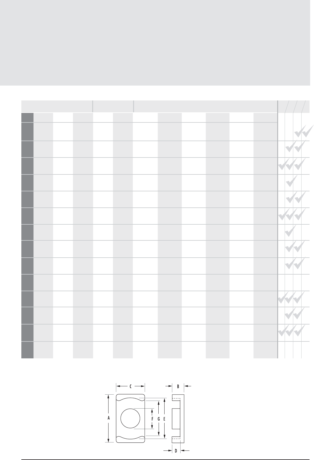
12.3
mag-inc.com
EC, ETD, EER and ER
Core Data (ungapped)
POWER MATERIALS HIGH PERMEABILITY
MATERIALS MAGNETIC DATA
RPF*JWl
e(mm) Ae(mm2)A MIN (mm2)Ve(mm3)CORE WEIGHT
(grams per set)
14.2 8.47 7.6 120 0.6 .0026
Min 730 790 1270 1550 2520
78.6 97.1 91.6 7640 40 1.2100
Min 2030 2200 3600 - -
77.4 84.3 71.0 6530 36 0.833
Min 1660 1800 3000 - -
90.8 107.0 100.0 9710 49 1.91
Min 2020 2220 3550 - -
92.2 125.0 123.0 11500 60 2.21
Min 2230 2420 4050 - -
89.3 121.0 106.0 10800 52 1.67
Min 2210 2400 3700 - -
98.7 175.0 166.0 17300 106 3.55
Min 2880 3130 5000 - -
103 173 172.0 17800 94 3.75
Min 2750 3000 4950 - -
114.0 211 209 24000 124 5.83
Min 3070 3330 5400 - -
84.7 161.0 156.0 13640 66 2.75
Min 3010 3270 5230 7160 -
105.0 180.0 141.0 18800 111 3.87
Min 2900 3150 5040 - -
139.0 368.0 368.0 51200 248 13.7
Min 4310 4680 7500 9320 -
141.0 281.0 211.0 39600 253 13.4
Min 3310 3600 5760 - -
231.0 339.0 314.0 78600 396 34
Min 2440 2650 4240 - -
STANDARD BOBBIN
PRINTED CIRCUIT BOBBIN
MOUNTING CLAMP
SURFACE MOUNT BOBBIN
AVAILABLE
HARDWARE
FIGURE 3
AL(mH/1000T)
* F material nominal ± 25%
EC, ETD, EER, ER Cores
WaAc (cm4)
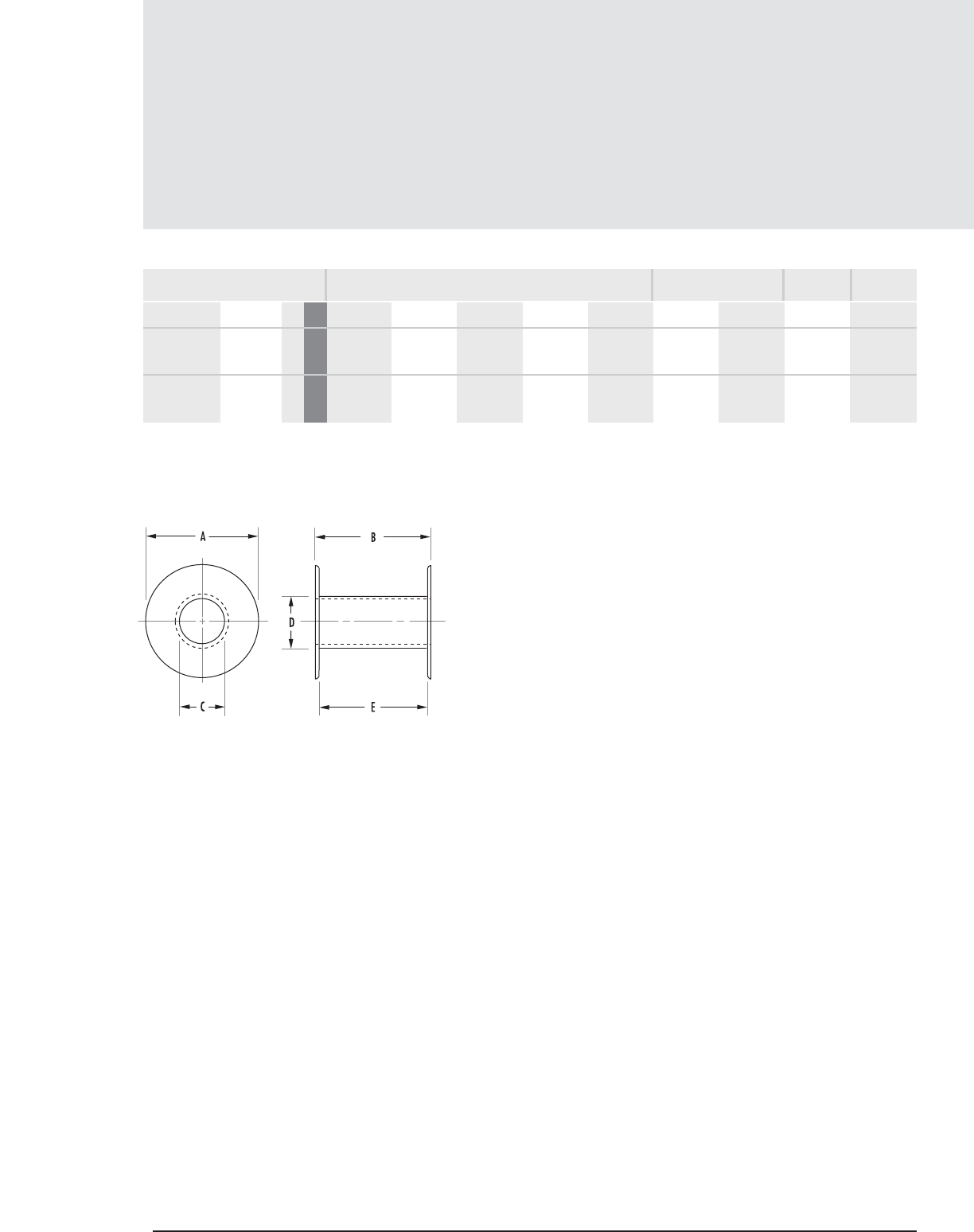
Bobbins
12 . 4 MAGNETICS
MECHANICAL DIMENSIONS
PART CORE SIZE A MAX B MAX C MAX D MAX E NOM
MATERIAL
00B351701 43517EC 1 mm 21.9456 23.5712 9.8806 11.6586 21.7932 0.173 1.12 0.172 Glass filled
in 0.864 0.928 0.389 0.459 0.858 Nylon*
00B411901 44119EC 1 mm 26.035 26.7462 12.065 14.097 24.6126 0.225 1.45 0.205 Glass filled
in 1.025 1.053 0.475 0.555 0.969 Nylon*
NOMINAL WINDING
AREA PER SECTION AVG. LENGTH
OF TURN FT
in2cm2
EC, ETD, EER, ER Hardware
FIGURE 1
FIG.

Bobbins
12.5
mag-inc.com
MECHANICAL DIMENSIONS
PART CORE TYPE A MAX B MAX C MAX D MAX E NOM
00B522401 45224EC 1 mm 31.75 30.734 13.766 15.595 28.346 0.352 2.27 0.242 Glass filled
in 1.250 1.210 0.542 0.614 1.116 Nylon*
00B703501 47035EC 1 mm 42.799 44.323 16.916 19.481 41.605 0.748 4.82 .319 Glass filled
in 1.685 1.745 0.666 0.767 1.638 Nylon*
EC, ETD, EER, ER Hardware
* UL 94 HB rated
FIG.
MATERIAL
NOMINAL WINDING
AREA PER SECTION AVG. LENGTH
OF TURN FT
in2cm2
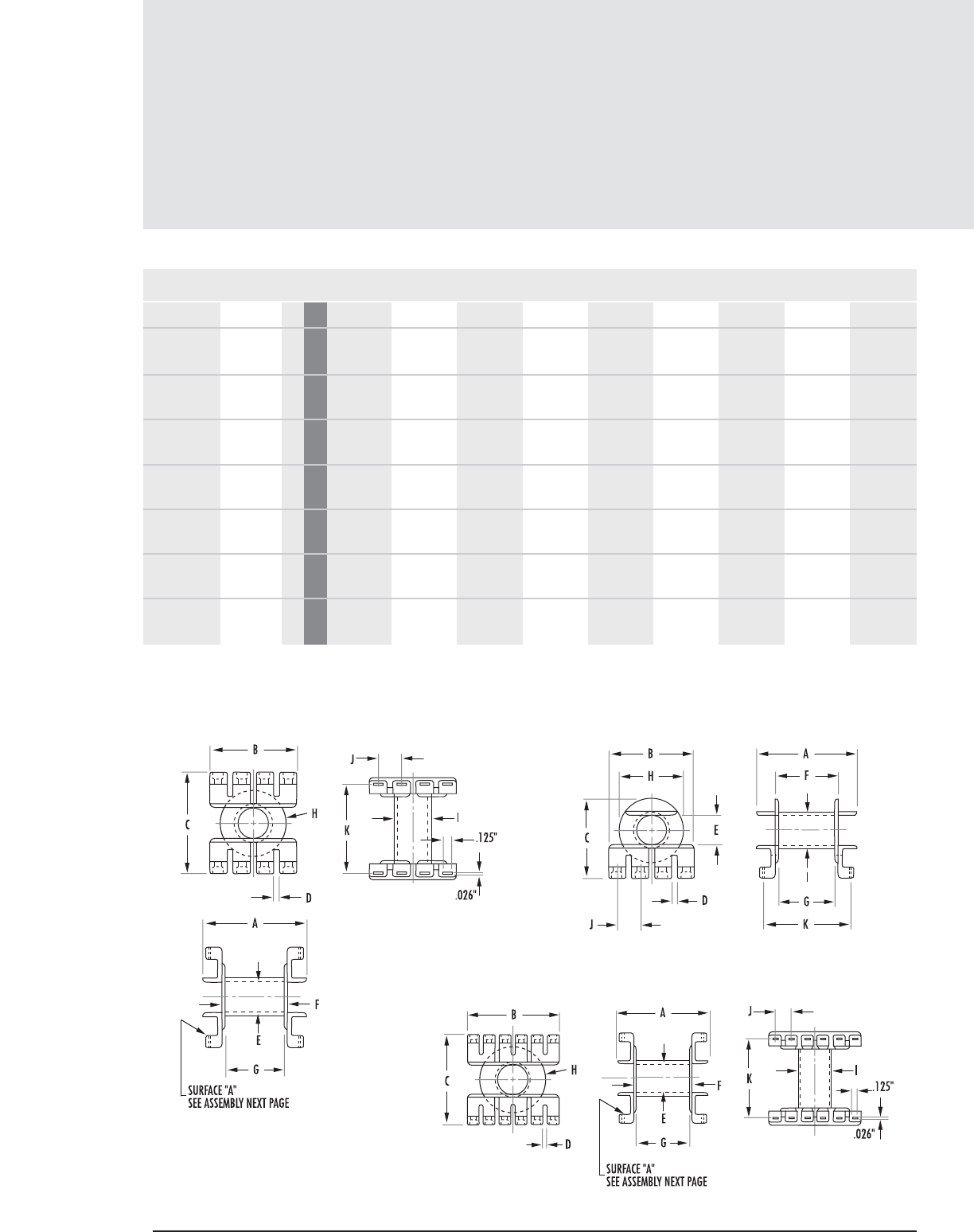
Printed Circuit Bobbins
12 . 6 MAGNETICS
EC, ETD, EER, ER Hardware
MECHANICAL DIMENSIONS
PART CORE SIZE A MAX B MAX C MAX D NOM E NOM F MAX G NOM H NOM I NOM
PCB3434FA 43434EC 5 mm 40.513 21.488 nom 13.8938 11.01 min 25.5016 26.01 ref 5.08 35.20 min -
in 1.595 .846 nom 0.547 .437 min 1.004 1.024 ref 0.200 1.386 min -
PCB351701 43517EC 1 mm 34.1122 28.8036 31.6484 2.032 10.0076 23.749 21.4884 21.6408 12.192
in 1.343 1.134 1.246 0.080 0.394 0.935 0.846 0.852 0.480
PCH351701 43517EC 3 mm 34.163 29.0068 26.6954 2.032 10.0076 23.622 21.4884 21.6408 12.192
in 1.345 1.142 1.051 0.08 0.394 0.930 0.846 0.852 0.480
PCB3521LA 43521EC 10 mm 29.21 nom 26.162 nom 14.1732 11.6586 min 25.4 39.8272 ref 4.826 29.21 min -
in 1.15 nom 1.03 nom 0.558 0.459 min 1.00 1.568 ref 0.190 1.15 min -
PCB3939SA 43939EC 6 mm 44.2976 26.1874 nom 15.2908 12.7 min 30.2006 32.791 ref 5.588 40.1066 min -
in 1.744 1.031 nom 0.602 0.500 min 1.189 1.291 ref 0.220 1.579 min -
PCB411901 44119EC 1 mm 38.6334 28.6258 36.5506 2.032 12.0904 26.9494 24.511 25.654 14.097
in 1.521 1.127 1.439 0.080 0.476 1.061 0.965 1.010 0.555
PCH411901 44119EC 3 mm 38.6588 28.9052 31.1912 2.032 12.0904 26.8224 24.511 25.654 14.097
in 1.522 1.138 1.228 0.080 0.476 1.056 0.965 1.010 0.555
FIGURE 3
FIGURE 2
FIGURE 1
FIG.†
† Figures 7-12 found on pages 12.8-12.9
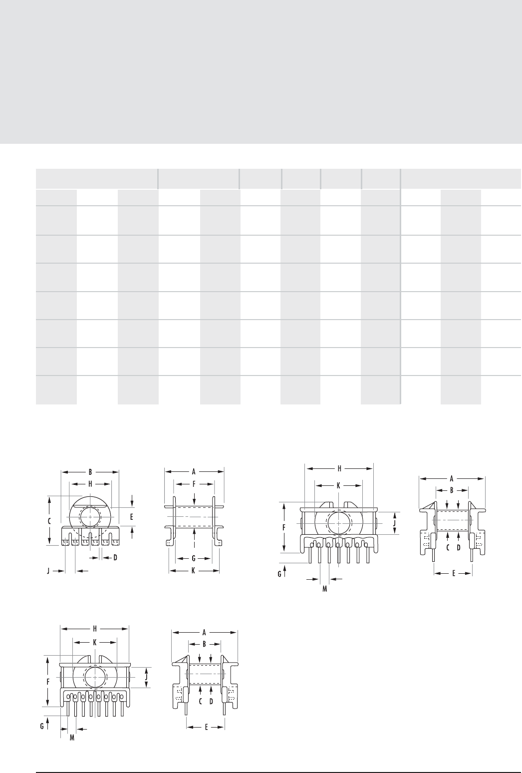
Printed Circuit Bobbins
12.7
mag-inc.com
EC, ETD, EER, ER Hardware
MECHANICAL DIMENSIONS
J NOM K MAX M NOM L W H
BOBBIN
MATERIAL PIN
MATERIAL PIN
DIAMETER BOARD CLEARANCE (in)†
11.30 min 25.2984 5.0038 0.19000 1.23 0.200 Phenolic* 1.675 1.575 1.350
.445 min 0.996 0.197
7.62 30.48 - 0.150 0.970 0.164 Glass Filled - - -
0.300 1.200 - Nylon**
7.62 30.48 - 0.15 0.97 0.164 Glass Filled - - -
0.300 1.200 - Nylon**
12.7 25.5016 5.08 0.230 1.48 0.20 Rynite CP Wire .031" - - -
0.500 1.004 0.200 FR530**
13.0048 min 28.9052 5.0038 0.270 1.740 0.220 Phenolic* 1.900 1.800 1.475
0.512 min 1.138 0.197
7.62 33.02 - 0.21 1.35 0.197 Glass Filled - - -
0.300 1.300 - Nylon**
7.62 33.02 - 0.21 1.35 0.197 Glass Filled - - -
0.300 1.300 - Nylon**
FIGURE 5
FIGURE 4
FIGURE 6
* UL 94 V-1 rated **UL 94 V-O rated
† Reference figure 12 for board clearance
NOMINAL WINDING
AREA PER SECTION AVG. LENGTH
OF TURN FT
in2cm2
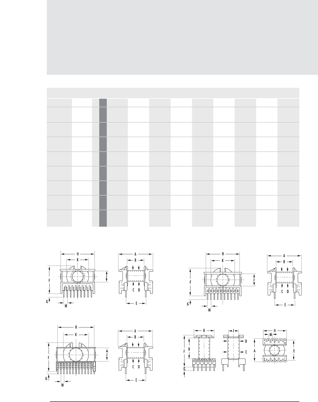
Printed Circuit Bobbins (con’t)
12 . 8 MAGNETICS
EC, ETD, EER, ER Hardware
MECHANICAL DIMENSIONS
PART CORE SIZE A MAX B MAX C MAX D NOM E NOM F MAX G NOM H NOM I NOM
PCB4216FA 44216EC 11 mm 30.988 27.305 nom 17.983 15.392 min 24.993 45.593 5.08 39.878 -
in 1.220 1.075 nom 0.708 0.606 min 0.984 1.795 0.200 1.570 -
PCB4444WA 44444EC 7 mm 51.308 29.997 nom 17.805 15.189 min 35.712 39.700 ref 5.08 45.135 min -
in 2.02 1.181 nom 0.701 0.598 min 1.406 1.563 ref 0.200 1.777 min -
PCB4949WA 44949EC 8 mm 53.797 33.0962 nom 19.507 16.484 min 40.386 40.690 ref 5.08 49.504 min -
in 2.118 1.303 nom 0.768 0.649 min 1.590 1.602 ref 0.2 1.949 min -
PCB522401 45224EC 2 mm 44.526 44.018 41.630 2.032 13.944 30.708 28.2956 31.445 16.205
in 1.753 1.733 1.639 0.080 0.549 1.209 1.114 1.238 0.638
PCH522401 45224EC 4 mm 44.551 44.094 36.499 2.032 13.944 30.708 28.2956 31.445 16.205
in 1.754 1.736 1.437 0.08 0.549 1.209 1.114 1.238 0.638
PCB5959AA 45959EC 9 mm 66.04 41.376 nom 24.866 22.352 min 50.8 48.514 ref 4.191 61.341 min -
in 2.600 1.629 nom 0.979 0.88 min 2 1.91 ref 0.165 2.415 min -
PCB703501 47035EC 2 mm 57.937 56.794 51.816 4.4958 17.145 44.2722 41.4528 42.443 19.507
in 2.281 2.236 2.040 0.177 0.675 1.743 1.632 1.671 0.768
PCH703501 47035EC 4 mm 57.937 56.896 47.117 4.4958 17.145 44.2722 41.4528 42.545 19.507
in 2.281 2.24 1.855 0.177 0.675 1.743 1.632 1.675 0.768
FIGURE 7
FIGURE 9
FIGURE 8
FIGURE 10
† Figures 1-6 found on pages 12.6-12.7
FIG.†
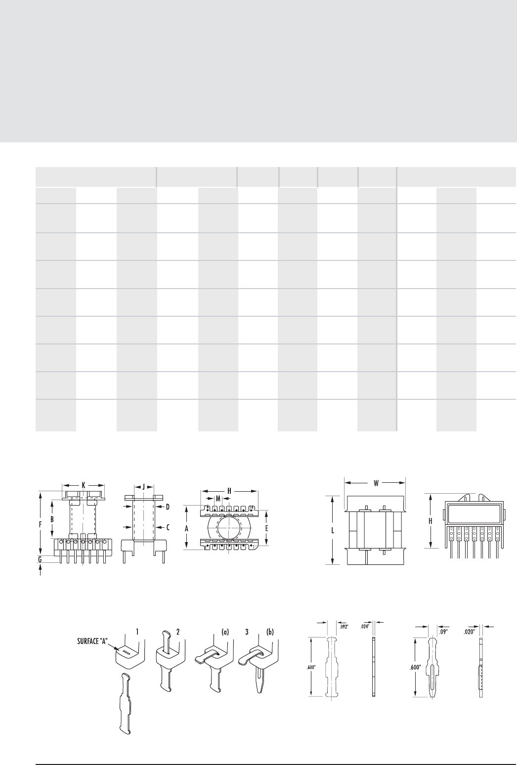
Printed Circuit Bobbins (con’t)
12.9
mag-inc.com
EC, ETD, EER, ER Hardware
FIGURE 11 FIGURE 12
TERMINAL ASSEMBLY
* UL 94 V-1 rated **UL 94 V-O rated. † Reference figure 12 for board clearance
NOTE: Terminals are not normally inserted but shipped separately in strip form. See above Terminal Assembly.
Printed Circuit Terminal
PNEC02000
General Purpose Terminal
PNEC01000
MECHANICAL DIMENSIONS
J NOM K MAX M NOM L W H
BOBBIN
MATERIAL PIN
MATERIAL PIN
DIAMETER BOARD CLEARANCE (in)†
15.6972 30.48 ref 5.0038 0.488 3.15 0.30 Rynite CP Wire .039" - - -
0.618 1.20 ref 0.197 FR530**
15.3924 min 32.512 5.0038 0.33 2.13 0.25 Phenolic* 2.075 2.000 1.580
0.606 min 1.280 0.197
16.891 min 35.5092 5.0038 0.420 2.71 0.28 Phenolic* 2.275 2.175 1.680
0.665 min 1.398 0.197
7.62 38.1 - 0.33 2.13 0.239 Glass Filled - - -
0.300 1.500 - Nylon**
7.62 38.1 - 0.33 2.13 0.239 Glass Filled - - -
0.300 1.500 - Nylon**
22.352 min 43.18 5.08 0.58 3.72 0.35 Rynite 2.845 2.635 1.940
0.88 min 1.700 0.200 FR530L**
10.16 50.8 - 0.74 4.77 0.312 Glass Filled - - -
0.400 2.000 - Nylon**
10.16 50.8 - 0.74 4.77 0.312 Glass Filled - - -
0.400 2.000 - Nylon**
NOMINAL WINDING
AREA PER SECTION AVG. LENGTH
OF TURN FT
in2cm2
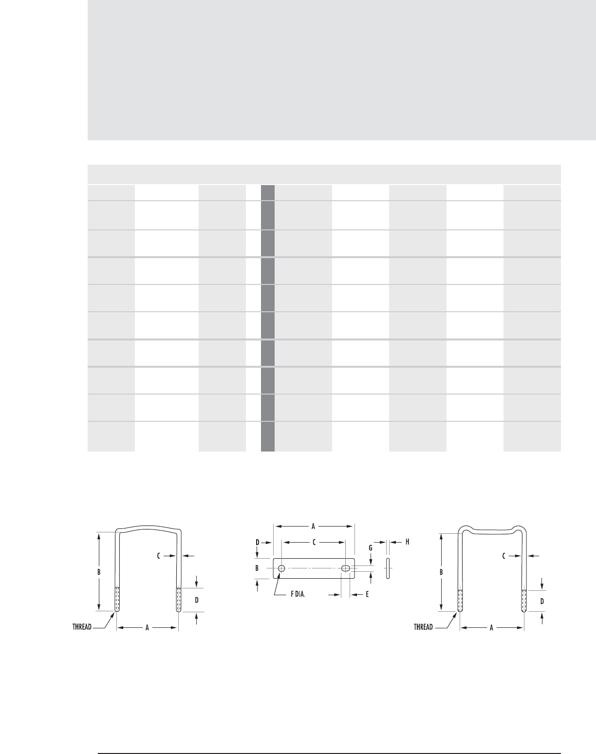
Mounting Clamps
EC, ETD, EER, ER Hardware
12 .10 MAGNETICS
MECHANICAL DIMENSIONS
PART ITEM FIG.CORE SIZE A B C D E
00C09061A Clamp 40906EC 7mm 10.007 5.384 3.988 13.97 -
in 0.394 .212 .157 .055 -
00C343416 Clamp 43434EC 4mm 22.8854 10.8458 39.624 - -
(2 required per set) in 0.901 0.427 1.56 - -
0AC351717 U Bolt 3mm 32.385 42.164 2.1082 12.7 -
in 1.275 1.66 0.083 0.500 -
0BC351740 Plate 43517EC 2mm 39.37 9.525 31.5976 3.8862 4.445
in 1.55 0.375 1.244 0.153 0.175
0CC351700 Nut - ------
(2 required)
00C393916 Clamp 43939EC mm 25.3238 12.5476 44.704 - -
(2 required per set) in 0.997 0.494 1.76 - -
0AC411919 U Bolt 1mm 38.100 46.99 2.3622 12.7 -
in 1.500 1.850 0.093 0.500 -
0BC411940 Plate 44119EC 2mm 46.736 11.1252 37.211 4.7752 4.699
in 1.840 0.438 1.465 0.188 0.185
0CC411900 Nut - ------
(2 required)
FIGURE 1 FIGURE 3FIGURE 2
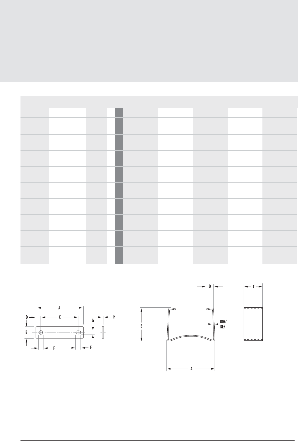
Mounting Clamps
EC, ETD, EER, ER Hardware
12 .11
mag-inc.com
FIGURE 4 FIGURE 7
MECHANICAL DIMENSIONS
PART ITEM FIG.CORE SIZE F G H THREAD MATERIAL
00C09061A Clamp 40906EC 7mm -----
in ---
00C343416 Clamp 43434EC 4mm ----Stainless Steel
(2 required per set) in ---
0AC351717 U Bolt 3mm ---#3-48-2A Brass
in ---
0BC351740 Plate 43517EC 2mm 2.6416 2.6416 1.016 Aluminum
in 0.104 0.104 0.040
0CC351700 Nut - ---- -
(2 required)
00C393916 Clamp 43939EC mm ----Stainless Steel
(2 required per set) in ---
0AC411919 U Bolt 1mm ---#4-40-2A Brass
in ---
0BC411940 Plate 44119EC 2mm 3.048 3.048 1.016 Aluminum
in 0.120 0.120 0.040
0CC411900 Nut - ---- -
(2 required)
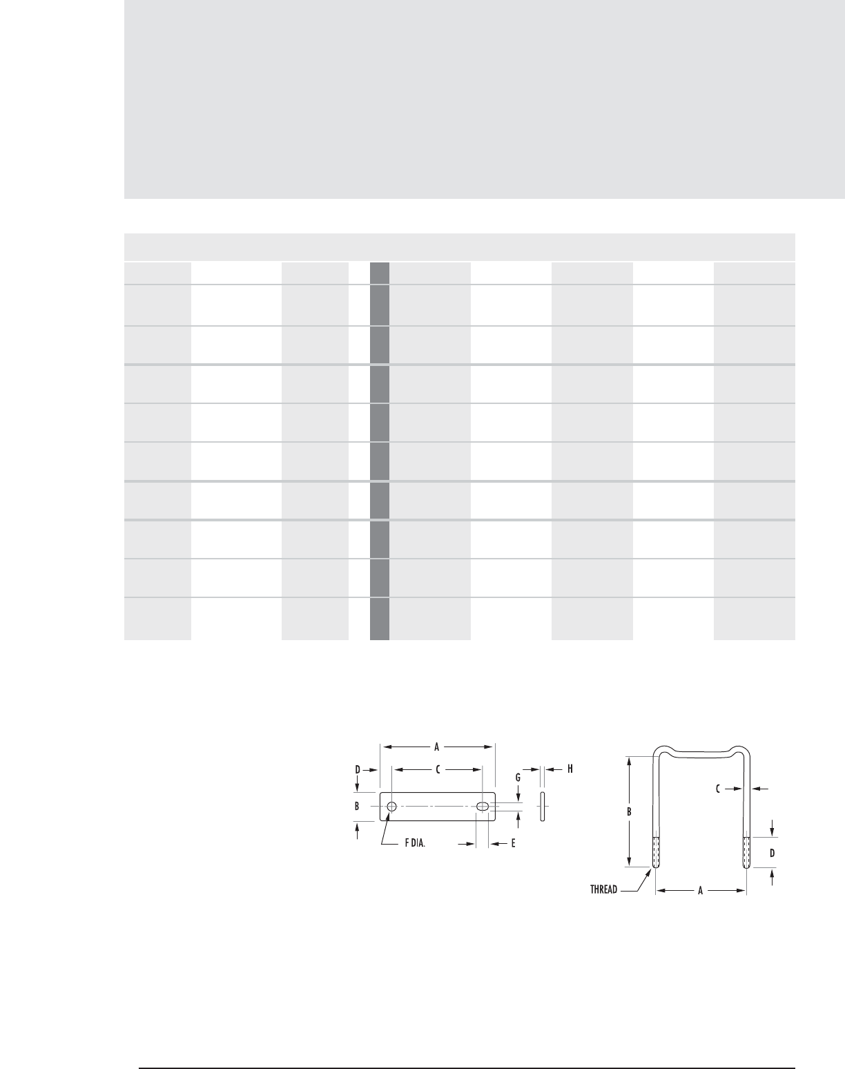
Mounting Clamps (con’t)
12 .12 MAGNETICS
EC, ETD, EER, ER Hardware
MECHANICAL DIMENSIONS
PART ITEM FIG.CORE SIZE A B C D E
00C444416 Clamp 44444EC 4mm 28.6766 14.9098 49.657 - -
(2 required per set) in 1.129 0.587 1.955 - -
00C494916 Clamp 44949EC 4mm 30.8864 16.383 54.61 - -
(2 required per set) in 1.216 0.645 2.15 - -
0AC522423 U Bolt 3mm 48.895 57.15 2.921 15.24 -
in 1.925 2.25 0.115 0.600 -
0BC522440 Plate 45224EC 2mm 59.69 12.70 48.1076 5.9182 5.715
in 2.350 0.500 1.894 0.233 0.225
0CC522400 Nut - ------
(2 required)
00C595916 Clamp 45959EC 5mm 12.9032 22.098 65.405 - -
(2 required per set) in 0.508 0.87 2.575 - -
0AC703531 U Bolt 3mm 65.405 78.74 2.921 15.24 -
in 2.575 3.100 0.115 0.600 -
0BC703540 Plate 47035EC 4mm 76.962 15.875 64.6938 6.2738 5.715
in 3.03 0.625 2.547 0.247 0.225
00C522400 Nut - --- -- -
FIGURE 3FIGURE 2
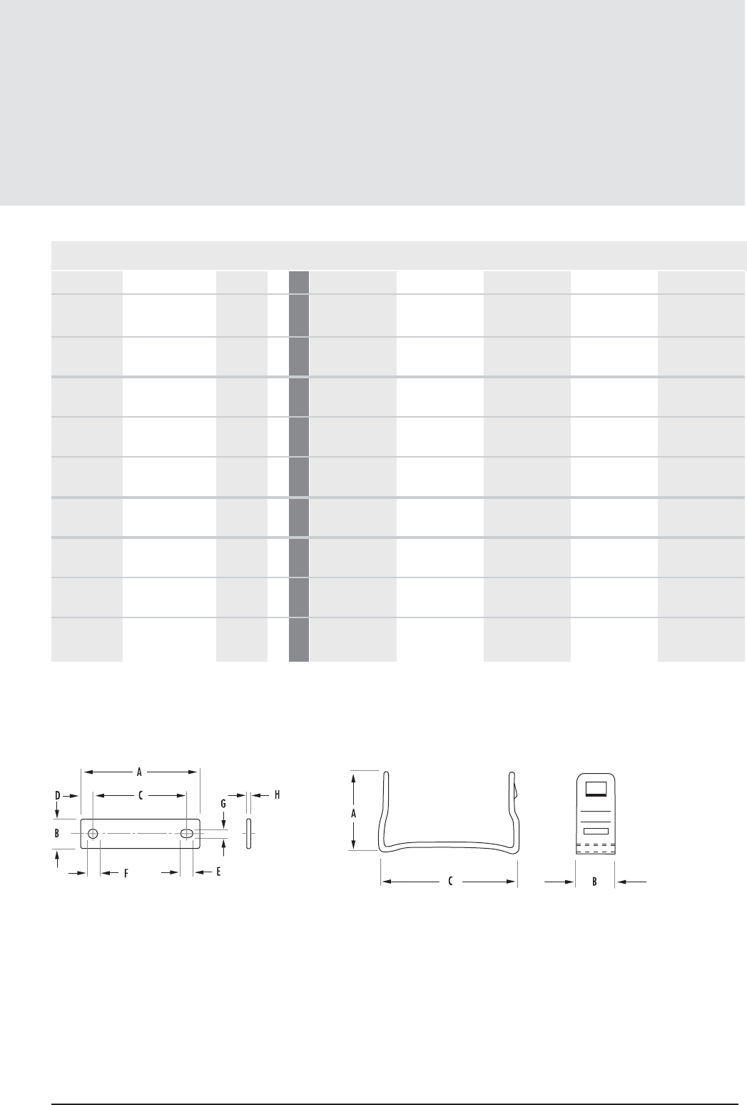
Mounting Clamps (con’t)
12 .13
mag-inc.com
EC, ETD, EER, ER Hardware
MECHANICAL DIMENSIONS
PART ITEM FIG.CORE SIZE F G H THREAD MATERIAL
00C444416 Clamp 44444EC 4mm ----Stainless Steel
(2 required per set) in ---
00C494916 Clamp 44949EC 4mm ----Stainless Steel
(2 required per set) in ---
0AC522423 U Bolt 3mm ---#6-32-2A Brass
in ---
0BC522440 Plate 45224EC 2mm 3.6576 3.6576 1.016 - Aluminum
in 0.144 0.144 0.040
0CC522400 Nut - ------
(2 required)
00C595916 Clamp 45959EC 5mm ----Stainless Steel
(2 required per set) in ---
0AC703531 U Bolt 3mm ---#6-32-2A Brass
in ---
0BC703540 Plate 47035EC 4mm 5.715 3.6576 1.016 - Aluminum
in 0.225 0.144 0.04
00C522400 Nut - ---- --
FIGURE 4 FIGURE 5
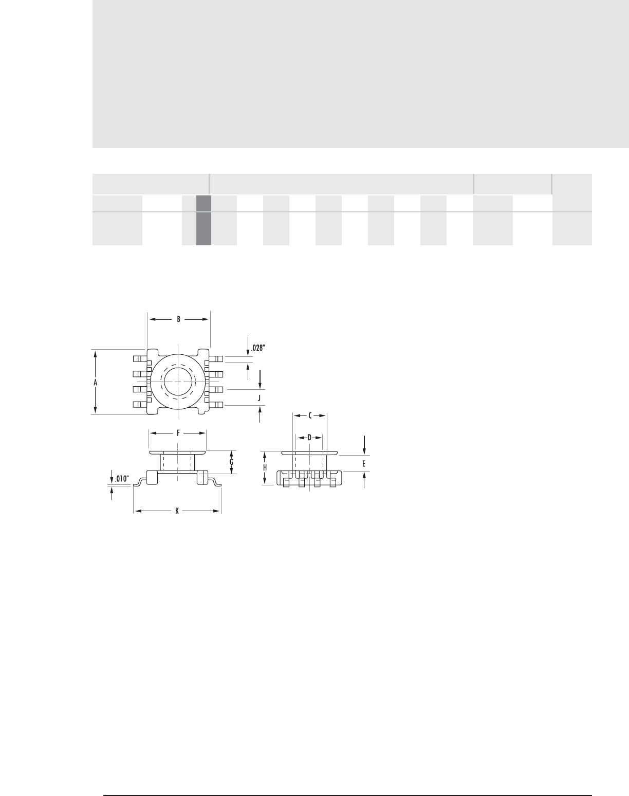
12 .14 MAGNETICS
Surface Mount Bobbin
EC, ETD, EER, ER Hardware
MECHANICAL DIMENSIONS
PART CORE SIZE A NOM B NOM C MAX D MIN E NOM F MAX G MAX H NOM J TYP K NOM
SMB09068A 40906EC 1mm 8.509 8.102 4.55 3.505 2.159 7.391 2.997 4.292 2.006 11.557 .0047 .030 .06
in .335 .319 .179 .138 .085 .291 .118 1.69 .079 .455
FIGURE 1
NOMINAL WINDING
AREA PER SECTION AVERAGE
LENGTH OF
TURN FT
in2cm2
FIG.
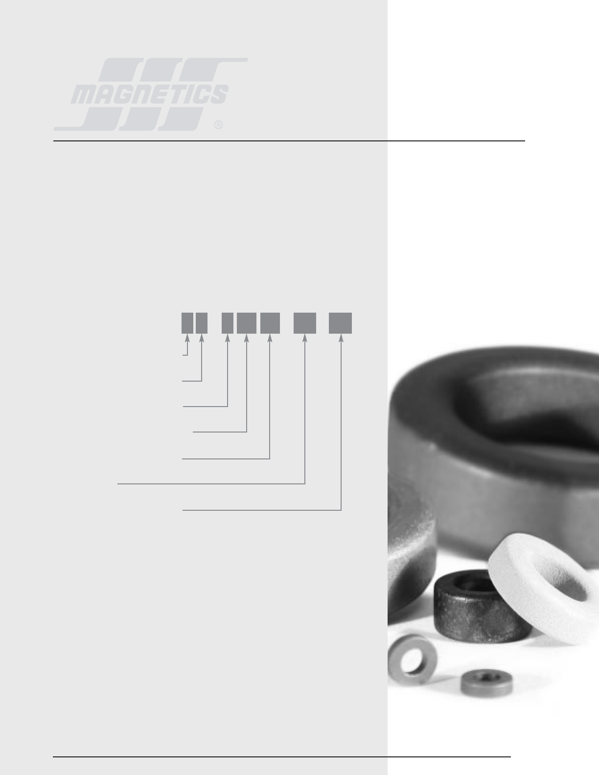
Section 13
Toroids
13.1
TOROIDS
Ferrite toroids offer high magnetic efficiency as there is no air gap, and the cross sectional area is uniform.
Available in many sizes (O.D.s from 0.100" to 3.375") and materials (permeabilities ranging from 750 to
15,000), this section lists common sizes. For additional sizes contact Magnetics Sales.
Typical applications for high permeability toroids (J, W, and H materials) include common mode chokes,
broadband transformers, pulse transformers and current transformers. R, P and F material toroids are excellent
choices for high frequency transformers. Special sizes in J material are available for Ground Fault Interrupter
applications.
HOW TO ORDER
COATING CODE (SEE PG 13.2)
FERRITE CORE MATERIAL TYPE
USED FOR ALL FERRITE TYPES
APPROXIMATE DIAMETER IN MM
APPROXIMATE HEIGHT IN MM
TOROID CORE
SPECIAL SPECIFICATION CODE
O J 4 22 06 TC XX
*COATING CODES
0 – Bare core
V – Nylon coating
Y – Parylene C®
Z – Polyester/Epoxy coating
*SPECIAL SPECIFICATION CODES
CC – Color Coded
*See page 13.2 – 13.3 for discussion of coating and other special requirements.

13 . 2 MAGNETICS
Toroids
COATINGS
In order to increase winding ease and improve voltage breakdown, toroids are available
coated. There are three categories of coatings available; Parylene, Nylon and Polyester/Epoxy.
Parylene C®is a vacuum-deposited material which has a uniform coating (including
edges) with a thickness of .0005" to .002", a smooth winding surface, and good
moisture resistance to organic solvents and acid bases. The electrical characteristics
are superior to other coatings. To specify Parylene use "Y" as the coating code when ordering.
Parylene C®is available for cores with O.D.s up to .500". The continuous maximum
rating is 130° C. Note that minimum inductance is 5% lower than listed for Parylene
coated cores.
Parylene C® offers a minimum voltage breakdown of 600 volts wire to wire.
Nylon coating (V designation) provides good adhesion, a smooth winding surface and
excellent resistance to moisture and organic solvents. Typically, Nylon coating is .004”
to .008” thick.
Available in the 12.7 mm to 29 mm size range, Nylon is a good finish for continuous
operation from -65° C to +155° C. Nylon coating offers a minimum voltage breakdown
of 1000 volts (wire to wire).
Polyester/Epoxy coating (Z designation) meets the same general visual requirements,
standard dimensional and voltage breakdown guarantees as Nylon. Polyester/Epoxy
is rated to 200° C continuous operation. Coating thickness with Polyester/Epoxy is
typically less than with Nylon, although the guaranteed limits are the same.
The size range for Polyester/Epoxy is from 9.5 mm to 86 mm.
NOTE: H material (15,000µ) is not available in Nylon coating.

13.3
mag-inc.com
Toroids
SPECIAL SPECIFICATION CODES
COLOR CODING
Toroids (as well as other cores) can be marked with a color code to help differentiate
different materials. When ordering add "CC" as the special specification code.
MATERIAL ASSIGNED COLOR CODES
RBlue
PGreen
FWhite
JRed
WYellow
HPurple
HIGH VOLTAGE
Voltage breakdown, higher than the standard guarantees, can be provided.
Dimensional tolerances are relaxed to allow for the added coating. Contact Magnetics
Application Engineering for specifications.

Toroid Core Data
13 . 4 MAGNETICS
MECHANICAL DIMENSIONS POWER MATERIALS
PART A (OD) B (ID) C (HGT.) R
2300
µ
±25% P
2500
µ
±25% F
3000
µ
±20%
HIGH PERMEABILITY MATERIALS
J
5000
µ
±20% W
10,000
µ
±30% H
15,000
µ
±30%
40200TC mm 2.54 1.27 1.27 400 454 525 875 1,750 2,625
in 0.100 0.050 0.050
40301TC mm 3.51 1.83 1.27 380 410 495 825 1,650 2,475
in 0.138 0.072 0.050
40502TC mm 3.94 2.24 1.27 340 368 440 735 1,470 2,205
in 0.155 0.088 0.050
40503TC mm 3.94 2.24 2.54 670 716 885 1,475 2,950 4,425
in 0.155 0.088 0.100
40401TC mm 4.83 2.29 1.27 440 474 570 950 1,900 2,850
in 0.190 0.090 0.050
40402TC mm 4.83 2.29 2.54 870 948 1,140 1,900 3,800 5,700
in 0.190 0.090 0.100
40601TC mm 5.84 3.05 1.52 450 488 585 980 1,960 2,940
in 0.230 0.120 0.060
40603TC mm 5.84 3.05 3.18 940 1,020 1,225 2,040 4,080 6,120
in 0.230 0.120 0.125
40705TC mm 7.62 3.18 4.78 1,920 2,088 2,505 4,175 8,350 12,500
in 0.300 0.125 0.188
40907TC mm 9.53 5.59 7.11 1,730 1,884 2,260 3,765 7,530 11,300
in 0.375 0.220 0.280
41003TC mm 9.53 4.75 3.18 1,000 1,095 1,314 2,196 4,392 6,590
in 0.375 0.187 0.125
41005TC mm 9.53 4.75 4.78 1,510 1,650 1,980 3,308 6,616 9,920
in 0.375 0.187 0.188
41206TC mm 12.7 5.16 6.35 2,600 2,820 3,384 5,640 11,280 16,900
in 0.500 0.203 0.250
41303TC mm 12.7 8.14 3.15 680 745 894 1,488 2,976 4,460
in 0.500 0.312 0.125
41305TC mm 12.7 8.14 5.08 1,090 1,190 1,430 2,380 4,760 7,140
in 0.500 0.312 0.200
41306TC mm 12.7 8.14 6.35 1,360 1,485 1,782 2,968 5,936 8,900
in 0.500 0.312 0.250
Toroids
AL(mH/1000T)
∆ALvalues based on testing at 5 gauss in a de-gaussed state.
For the cores listed here, dimensional tolerances for bare and coated cores are on pages 13.10-13.12.
Page 3.12 also lists guidelines for dimensional tolerances of all toroids.
Other core heights are available upon special request.
To order, add coating and material code.

13.5
mag-inc.com
Toroid Core Data
MAGNETIC DATA
le(mm) Ae(mm2)Ve(mm3)WaAc (cm4)
40200TC 5.53 .77 4.3 0.013 .03 Y
40301TC 7.65 1.03 7.87 0.026 .04 Y
40502TC 9.2 1.05 9.7 0.039 .05 Y
40503TC 9.2 2.10 19.4 0.039 .10 Y
40401TC 10.21 1.54 15.7 0.041 .09 Y
40402TC 10.21 3.08 31.4 0.041 .17 Y
40601TC 13.0 2.0 26.7 0.073 .14 Y
40603TC 13.0 4.3 56.0 0.073 .30 Y
40705TC 15 9.9 149.0 0.079 .90 Y
40907TC 22.7 13.7 310.0 0.245 1.6 0.033 Y, Z
41003TC 20.7 7.3 151.0 0.177 .82 Y, Z
41005TC 20.7 10.9 227.0 0.177 1.2 0.019 Y, Z
41206TC 24.6 22.1 554.0 0.209 3.3 0.046 Y, Z
41303TC 31.7 7.1 224.0 0.493 1.2 0.035 Y, Z
41305TC 31.7 11.4 361.0 0.493 1.9 0.058 V, Y, Z
41306TC 31.7 14.2 451.2 0.493 2.4 0.072 V, Y, Z
Toroids
WINDOW
AREA (cm2)
PART
AVAIL. COATINGS
CORE WEIGHT
(g)
13 . 6 MAGNETICS
Toroid Core Data (con’t)
Toroids
∆ALvalues based on testing at 5 gauss in a de-gaussed state.
For the cores listed here, dimensional tolerances for bare and coated cores are on pages 13.10-13.12.
Page 13.12 also lists guidelines for dimensional tolerances of all toroids.
Other core heights are available upon special request.
MECHANICAL DIMENSIONS POWER MATERIALS
PART A (OD) B (ID) C (HGT.) R
2300
µ
±25% P
2500
µ
±25% F
3000
µ
±20%
41406TC mm 12.7 7.14 6.35 1,660 1,805 2,166 3,612 7,224 10,800
in 0.500 0.281 0.250
41407TC mm 12.7 7.14 4.78 1,240 1,356 1,630 2,715 5,430 8,140
in 0.500 0.281 0.188
41506TC mm 13.2 7.37 3.96 1,020 1,111 1,334 2,295 4,590 6,880
in 0.520 0.290 0.156
41435TC mm 13.6 7.01 3.51 1,040 1,130 1,350 2,260 4,520 6,780
in 0.535 0.276 0.138
41450TC mm 14.0 8.99 5.00 990 1,080 1,290 2,160 4,320 6,480
in 0.551 0.354 0.197
41605TC mm 15.9 8.89 4.70 1,260 1,375 1,650 2,760 5,520 8,280
in 0.625 0.350 0.185
41809TC mm 18.4 9.75 10.3 2,810 3,050 3,660 6,115 12,200 18,300
in 0.726 0.384 0.404
42106TC mm 20.6 12.7 6.35 1,380 1,500 1,680 2,800 5,600 8,400
in 0.810 0.500 0.250
42109TC mm 20.6 12.7 8.89 1,930 2,100 2,520 4,200 8,400 12,600
in 0.810 0.500 0.350
42206TC mm 22.1 13.7 6.35 1,380 1,510 1,812 3,020 6,040 9,060
in 0.870 0.540 0.250
42207TC mm 22.1 13.7 7.90 1,720 1,875 2,250 3,700 7,400 11,100
in 0.870 0.540 0.312
42212TC mm 22.1 13.7 12.44 2,770 3,020 3,624 6,040 12,080 18,100
in 0.870 0.540 0.500
42507TC mm 25.34 15.45 7.66 1,800 1,958 2,348 3,913 7,825 11,700
in 1.000 0.610 0.312
42508TC mm 25.34 15.45 10.0 2,220 2,420 2,900 4,830 9,660 14,490
in 1.000 0.610 0.394
42908TC mm 29.0 19.0 7.50 1,450 1,585 1,902 3,170 6,340 9,510
in 1.142 0.748 0.295
42915TC mm 29.0 19.0 15.2 2,960 3,222 3,868 6,447 12,894 19,300
in 1.142 0.748 0.600
AL(mH/1000T)
HIGH PERMEABILITY MATERIALS
J
5000
µ
±20% W
10,000
µ
±30% H
15,000
µ
±30%
To order, add coating and material code.

mag-inc.com
Toroid Core Data (con’t)
Toroids
MAGNETIC DATA
le(mm) Ae(mm2)V
e(mm3)WaAc (cm4)
41406TC 29.5 16.9 498.0 0.400 2.7 0.064 V, Y, Z
41407TC 29.5 12.6 373.0 0.400 1.9 0.050 V, Y, Z
41506TC 30.6 10.9 332.0 0.426 1.9 0.046 V, Z
41435TC 30.1 10.8 326.0 0.386 1.8 0.042 V, Z
41450TC 35.0 12.0 421.0 0.636 2.2 0.076 V, Z
41605TC 36.8 15.3 562.0 0.620 2.8 0.094 V, Z
41809TC 41.4 40.3 1670.0 0.746 9.9 0.301 V, Z
42106TC 50.0 23.1 1150.0 1.27 5.4 0.293 V, Z
42109TC 50.0 32.6 1630.0 1.27 8.1 0.414 V, Z
42206TC 54.1 26.2 1417.0 1.48 6.4 0.370 V, Z
42207TC 54.2 32.5 1763.0 1.48 8.5 0.466 V, Z
42212TC 54.2 51.3 2776 1.48 13.5 0.756 V, Z
42507TC 61.5 37.1 2284 1.89 11.6 0.707 V, Z
42508TC 61.5 48.45 2981.0 1.89 14.9 0.898 V, Z
42908TC 73.2 37 2704.0 2.84 12.9 1.02 V, Z
42915TC 73.2 74.9 5481.0 2.84 27.6 2.10 Z
AVAIL. COATINGS
WINDOW
AREA (cm2)
13 .7
CORE WEIGHT
(g)
Toroid Core Data (con’t)
13 . 8 MAGNETICS
Toroids
∆ALvalues based on testing at 5 gauss in a de-gaussed state.
For the cores listed here, dimensional tolerances for bare and coated cores are on pages 13.10-13.12.
Page 13.12 also lists guidelines for dimensional tolerances of all toroids.
Other core heights are available upon special request.
MECHANICAL DIMENSIONS POWER MATERIALS
SIZE A (OD) B (ID) C (HGT.) R
2300
µ
±25% P
2500
µ
±25% F
3000
µ
±20%
43113TC mm 30.83 19.06 12.74 2,850 3,100 3,720 6,200 12,400 -
in 1.220 0.748 0.512
43205TC mm 32.0 15.0 4.50 1,480 1,610 1,930 3,220 6,440 -
in 1.260 0.591 0.177
43610TC mm 36.0 23.0 10.0 2,030 2,210 2,726 4,543 9,085 -
in 1.417 0.906 0.394
43615TC mm 36.0 23.0 14.6 3,100 3,366 4,040 6,736 13,400 -
in 1.417 0.906 0.590
43806TC mm 38.1 19.0 6.11 2,020 2,200 2,640 4,400 8,800 -
in 1.500 0.750 0.250
43813TC mm 38.1 19.0 12.45 3,850 4,185 5,020 8,365 16,700 -
in 1.500 0.750 0.500
43825TC mm 38.1 19.0 25.4 8,060 8,762 10,040 16,730 33,400 -
in 1.500 0.750 1.000
44416TC mm 44.5 19.0 15.9 5,360 5,830 7,000 11,600 23,200 -
in 1.750 0.750 0.625
44715TC mm 46.9 27.0 15.0 3,700 4,030 4,840 8,075 16,100 -
in 1.846 1.063 0.591
44916TC mm 49.1 33.8 15.6 2,710 2,950 3,540 5,900 11,800 -
in 1.932 1.332 0.625
44920TC mm 49.1 31.8 15.9 2,790 3,032 3,640 6,065 12,130 -
in 1.932 1.252 0.625
44925TC mm 49.1 31.8 19.0 3,420 3,718 4,460 7,435 14,870 -
in 1.932 1.252 0.750
44932TC mm 49.1 33.8 31.8 5,430 5,900 7,080 11,800 23,600 -
in 1.932 1.332 1.250
46113TC mm 61.0 35.6 12.7 3,140 3,491 4,107 6,845 13,690 -
in 2.400 1.400 0.500
46326TC mm 63.0 38.0 24.5 5,770 6,270 7,530 12,500 25,100 -
in 2.480 1.496 0.984
47313TC mm 73.7 38.9 12.5 3,700 4,024 4,880 8,140 16,280 -
in 2.900 1.530 0.500
47325TC mm 3.66 38.860 25.40 7,400 8,050 9,760 16,280 32,560 -
in 2.900 1.530 1.000
48613TC mm 85.7 55.5 12.7 2,510 2,726 3,310 5,520 11,040 -
in 3.375 2.187 0.500
AL(mH/1000T)
HIGH PERMEABILITY MATERIALS
J
5000
µ
±20% W
10,000
µ
±30% H
15,000
µ
±30%
To order, add coating and material code.

Toroid Core Data (con’t)
13.9
mag-inc.com
Toroids
MAGNETIC DATA
le(mm) Ae(mm2)V
e(mm3)WaAc (cm4)
43113TC 75.4 73.6 5547 2.83 29.3 2.11 Z
43205TC 67.2 34.5 2320.0 1.77 12.9 0.611 Z
43610TC 89.7 62.6 5616 4.15 29.4 2.61 Z
43615TC 89.6 93.3 8366 4.15 44.0 3.93 Z
43806TC 82.9 56.1 4644 2.85 26.4 1.62 Z
43813TC 83.0 114.2 9462 2.85 51.7 3.27 Z
43825TC 83.0 231.0 19200.0 2.85 103.4 6.58 Z
44416TC 88.7 187.0 16600.0 2.85 80.8 5.33 Z
44715TC 110.0 142.0 15700.0 5.72 84 8.12 Z
44916TC 127 118 15010 8.99 75.3 10.4 Z
44920TC 123.0 119.0 14700.0 7.94 74.6 9.45 Z
44925TC 123.0 146.0 18000.0 7.94 91.0 11.6 Z
44932TC 127.0 236.0 30000.0 8.99 150.6 21.2 Z
46113TC 145.0 156.0 22500.0 9.93 117.3 15.5 Z
46326TC 152.0 300 45598 11.3 231 34.4 Z
47313TC 165.0 210 34771 11.9 177 25.2 Z
47325TC 165.0 424.0 71000.0 11.9 354 50.4 Z
48613TC 215.0 187.0 40200.0 24.2 203 45.2 Z
AVAIL. COATINGS
WINDOW
AREA (cm2)CORE WEIGHT
(g)
Bare Core Limiting Dimensions
13 .10 MAGNETICS
Toroids
R, P, F MATERIALS W AND H MATERIALS
PART O.D.
MAX I.D.
MIN HGT.
MAX O.D.
MAX I.D.
MIN HGT.
MAX
40200TC mm 2.75 1.06 1.45 2.75 1.06 1.45
in 0.108 0.042 0.057 0.108 0.042 0.057
40301TC mm 3.71 1.62 1.45 3.71 1.62 1.45
in 0.146 0.064 0.057 0.146 0.064 0.057
40502TC mm 4.14 2.03 1.45 4.14 2.03 1.45
in 0.163 0.080 0.057 0.163 0.080 .057
40503TC mm 4.14 2.03 2.80 4.14 2.03 2.80
in 0.163 0.080 0.110 0.163 0.080 0.110
40401TC mm 5.03 2.08 1.45 5.03 2.08 1.45
in 0.198 0.082 0.057 0.198 0.082 0.057
40402TC mm 5.03 2.08 2.80 5.03 2.08 2.80
in 0.198 0.082 0.110 0.198 0.082 0.110
40601TC mm 6.13 2.76 1.71 6.13 2.76 1.71
in 0.241 0.109 0.067 0.241 0.109 0.067
40603TC mm 6.13 2.76 3.43 6.13 2.76 3.43
in 0.241 0.109 0.135 0.241 0.109 0.135
40705TC mm 7.88 2.92 4.91 8.01 2.79 5.03
in 0.310 0.115 0.193 0.315 0.110 0.198
40907TC mm 9.78 5.33 7.29 9.91 5.20 7.40
in 0.385 0.210 0.287 0.390 0.205 0.291
41003TC mm 9.78 4.49 3.31 9.91 4.36 3.43
in 0.385 0.177 0.130 0.390 0.172 0.135
41005TC mm 9.78 4.49 4.91 9.91 4.36 5.03
in 0.385 0.177 0.193 0.390 0.172 0.198
41206TC mm 12.96 4.90 6.53 13.09 4.77 6.63
in 0.510 0.193 0.257 0.515 0.188 0.261
41303TC mm 12.96 7.67 3.31 13.09 7.54 3.43
in 0.510 0.302 0.130 0.515 0.297 0.135
41305TC mm 12.96 7.67 5.26 13.09 7.54 5.36
in 0.510 0.302 0.207 0.515 0.297 0.211
41306TC mm 12.96 7.67 6.53 13.09 7.54 6.63
in 0.510 0.302 0.257 0.515 0.297 0.261
41406TC mm 12.96 6.88 6.53 13.09 6.75 6.63
in 0.510 0.271 0.257 0.515 0.266 0.261
41407TC mm 12.96 6.88 4.91 13.09 6.75 5.03
in 0.510 0.271 0.193 0.515 0.266 0.198
41506TC mm 13.47 7.11 4.09 13.59 6.98 4.22
in 0.530 0.280 0.161 0.535 0.275 0.166
41435TC mm 13.85 6.75 3.64 13.97 6.62 3.76
in 0.545 0.266 0.143 0.550 0.261 0.148
41450TC mm 14.25 8.73 5.14 14.38 8.61 5.26
in 0.561 0.344 0.202 0.566 0.339 0.207
41605TC mm 16.26 8.50 4.83 16.46 8.30 4.96
in 0.640 0.335 0.190 0.648 0.327 0.195
41809TC mm 18.83 9.37 10.52 19.03 9.16 10.65
in 0.741 0.369 0.414 0.749 0.361 0.419
42106TC mm 20.96 12.31 6.53 21.16 12.11 6.63
in 0.825 0.485 0.257 0.833 0.477 0.261
42109TC mm 20.96 12.31 9.15 21.16 12.11 9.28
in 0.825 0.485 0.360 0.833 0.477 0.365
R, P, F MATERIALS W AND H MATERIALS
PART O.D.
MAX I.D.
MIN HGT.
MAX O.D.
MAX I.D.
MIN HGT.
MAX
42206TC mm 22.48 13.33 6.53 22.69 13.13 6.63
in 0.885 0.525 0.257 0.893 0.517 0.261
42207TC mm 22.48 13.33 8.18 22.69 13.13 8.31
in 0.885 0.525 0.322 0.893 0.517 0.327
42212TC mm 22.48 13.33 12.96 22.69 13.13 13.09
in 0.885 0.525 0.510 0.893 0.517 0.515
42507TC mm 25.91 14.98 8.18 26.17 14.73 8.31
in 1.020 0.590 0.322 1.030 0.580 0.327
42508TC mm 25.91 14.98 10.27 26.17 14.73 10.39
in 1.020 0.590 0.404 1.030 0.580 0.409
42908TC mm 29.52 18.49 7.68 29.77 18.23 7.78
in 1.162 0.728 0.302 1.172 0.718 0.306
42915TC mm 29.52 18.49 15.63 29.77 18.23 15.83
in 1.162 0.728 0.615 1.172 0.718 0.623
43113TC mm 31.50 18.49 13.26 31.75 18.23 13.39
in 1.240 0.728 0.522 1.250 0.718 0.527
43205TC mm 32.52 14.50 4.63 32.77 14.24 4.70
in 1.280 0.571 0.182 1.290 0.561 0.185
43610TC mm 36.50 22.50 10.27 36.76 22.25 10.39
in 1.437 0.886 0.404 1.447 0.876 0.409
43615TC mm 36.50 22.50 15.24 36.76 22.25 15.37
in 1.437 0.886 0.600 1.447 0.876 0.605
43806TC mm 38.87 18.28 6.53 39.25 17.90 6.63
in 1.530 0.720 0.257 1.545 0.705 0.261
43813TC mm 38.87 18.28 12.96 39.25 17.90 13.09
in 1.530 0.720 0.510 1.545 0.705 0.5155
43825TC mm 38.87 18.28 25.91 39.25 17.90 26.17
in 1.530 0.720 1.020 1.545 0.705 1.030
44416TC mm 45.22 18.28 16.26 45.60 17.90 16.46
in 1.780 0.720 0.640 1.795 0.705 0.648
44715TC mm 47.65 26.23 15.27 48.04 25.85 15.40
in 1.876 1.033 0.601 1.891 1.018 0.606
44916TC mm 49.84 33.07 16.26 50.22 32.69 16.46
in 1.962 1.302 0.640 1.977 1.287 0.648
44920TC mm 49.84 31.03 16.26 50.22 30.65 16.46
in 1.962 1.222 0.640 1.977 1.207 0.648
44925TC mm 49.84 31.03 19.44 50.22 30.65 19.64
in 1.962 1.222 0.765 1.977 1.207 0.773
44932TC mm 49.84 33.07 32.26 50.22 32.69 32.52
in 1.962 1.302 1.270 1.977 1.287 1.280
46113TC mm 61.85 34.67 12.96 62.31 34.21 13.09
in 2.435 1.365 0.510 2.453 1.347 0.515
46326TC mm 63.89 37.10 25.38 64.34 36.65 25.58
in 2.515 1.461 0.999 2.533 1.443 1.007
47313TC mm 74.68 37.84 12.96 75.19 37.33 13.29
in 2.940 1.490 0.510 2.960 1.470 0.523
47325TC mm 74.68 37.84 25.91 95.19 37.33 26.54
in 2.940 1.490 1.020 2.96 1.470 1.045
48613TC mm 87.00 54.28 12.96 87.63 53.64 13.29
in 3.425 2.137 0.510 3.450 2.112 0.523
V and Z Coated Limiting Dimensions
13 .11
mag-inc.com
Toroids
R, P, F MATERIALS W AND H MATERIALS
PART O.D.
MAX I.D.
MIN HGT.
MAX O.D.
MAX I.D.
MIN HGT.
MAX
40907TC mm 10.16 4.95 7.68 10.29 4.82 7.78
in 0.400 0.195 0.302 0.405 0.190 0.306
41003TC mm 10.16 4.11 3.69 10.29 3.98 3.81
in 0.400 0.162 0.145 0.405 0.157 0.150
41005TC mm 10.16 4.11 5.29 10.29 3.98 5.41
in 0.400 0.162 0.208 0.405 0.157 0.213
41206TC mm 13.34 4.52 6.91 13.47 4.39 7.01
in 0.525 0.178 0.272 0.530 0.173 0.276
41303TC mm 13.34 7.29 3.69 13.47 7.16 3.81
in 0.525 0.287 0.145 0.530 0.282 0.150
41305TC mm 13.34 7.29 5.64 13.47 7.16 5.75
in 0.525 0.287 0.222 0.530 0.282 0.226
41306TC mm 13.34 7.29 6.91 13.47 7.16 7.01
in 0.525 0.287 0.272 0.530 0.282 0.276
41406TC mm 13.34 6.50 6.91 13.47 6.37 7.01
in 0.525 0.256 0.272 0.530 0.251 0.276
41407TC mm 13.34 6.50 5.29 13.47 6.37 5.41
in 0.525 0.256 0.208 0.530 0.251 0.213
41506TC mm 13.84 6.73 4.47 13.97 6.60 4.60
in 0.545 0.265 0.176 0.550 0.260 0.181
41435TC mm 14.23 6.37 4.02 14.36 6.24 4.14
in 0.560 0.251 0.158 0.565 0.246 0.163
41450TC mm 14.64 8.35 5.52 14.76 8.23 5.64
in 0.576 0.329 0.217 0.581 .0324 .0222
41605TC mm 16.64 8.12 5.21 16.84 7.92 5.34
in 0.655 0.320 0.205 0.663 0.312 0.210
41809TC mm 19.21 8.99 10.90 19.41 8.78 11.03
in 0.756 0.354 0.429 0.764 0.346 0.434
42106TC mm 21.34 11.93 6.91 21.54 11.73 7.01
in 0.840 0.470 0.272 0.848 0.462 0.276
42109TC mm 21.34 11.93 9.53 21.54 11.73 9.66
in 0.840 0.470 0.375 0.848 0.462 0.380
42206TC mm 22.86 12.95 6.91 23.07 12.75 7.01
in 0.900 0.510 0.272 0.908 0.502 0.276
42207TC mm 22.86 12.95 8.56 23.07 12.75 8.69
in 0.900 0.510 0.337 0.908 0.502 0.342
42212TC mm 22.86 12.95 13.34 23.07 12.75 13.47
in 0.900 0.510 0.525 0.908 0.502 0.530
42507TC mm 26.29 14.60 8.56 26.55 14.35 8.69
in 1.035 0.575 0.337 1.045 0.565 0.342
42508TC mm 26.29 14.60 10.65 26.55 14.35 10.77
in 1.035 0.575 0.419 1.045 0.565 0.424
R, P, F MATERIALS W AND H MATERIALS
PART O.D.
MAX I.D.
MIN HGT.
MAX O.D.
MAX I.D.
MIN HGT.
MAX
42908TC mm 29.90 18.11 8.06 30.15 17.85 8.16
in 1.177 0.713 0.317 1.187 0.703 0.321
42915TC mm 29.90 18.11 16.01 30.15 17.85 16.21
in 1.177 0.713 0.630 1.187 0.703 0.638
43113TC mm 31.88 18.11 13.64 32.14 17.85 13.77
in 1.255 0.713 0.537 1.265 0.703 0.542
43205TC mm 32.90 14.12 5.01 33.15 13.86 5.08
in 1.295 0.556 0.197 1.305 0.546 0.200
43610TC mm 36.89 22.12 10.65 37.14 21.86 10.77
in 1.452 0.871 0.419 1.462 0.861 0.424
43615TC mm 36.89 22.12 15.63 37.14 21.86 15.75
in 1.452 0.871 0.615 1.462 0.861 0.620
43806TC mm 39.25 17.90 6.91 39.63 17.52 7.01
in 1.545 0.705 0.272 1.560 0.690 0.276
43813TC mm 39.25 17.90 13.34 39.63 17.52 13.47
in 1.545 0.705 0.525 1.560 0.690 0.530
43825TC mm 39.25 17.90 26.29 39.63 17.52 26.55
in 1.545 0.705 1.035 1.560 0.690 1.045
44416TC mm 45.60 17.90 16.64 45.98 17.52 16.85
in 1.795 0.705 0.655 1.810 0.690 0.663
44715TC mm 48.04 25.85 15.65 48.42 25.47 15.78
in 1.891 1.018 0.616 1.906 1.003 0.621
44916TC mm 50.22 32.69 16.64 50.60 32.30 16.85
in 1.977 1.287 0.655 1.992 1.272 0.663
44920TC mm 50.22 30.65 16.64 50.60 30.27 16.85
in 1.977 1.207 0.655 1.992 1.192 0.663
44925TC mm 50.22 30.65 19.82 50.60 30.27 20.02
in 1.977 1.207 0.780 1.992 1.192 0.788
44932TC mm 50.22 32.69 32.64 50.60 32.30 32.90
in 1.977 1.287 1.285 1.992 1.272 1.295
46113TC mm 62.23 34.29 13.34 62.69 33.83 13.47
in 2.450 1.350 0.525 2.468 1.332 0.530
46326TC mm 64.27 36.72 25.76 64.72 36.27 25.96
in 2.530 1.446 1.014 2.548 1.428 1.0225
47313TC mm 75.06 37.46 13.34 75.57 36.95 13.67
in 2.955 1.475 0.525 2.975 1.455 0.538
47325TC mm 75.06 37.46 26.289 75.565 36.957 26.924
in 2.955 1.475 1.035 2.975 1.455 1.060
48613TC mm 87.38 53.89 13.34 88.02 53.26 13.67
in 3.440 2.122 0.525 3.465 2.097 0.538
13 .12 MAGNETICS
Y Coated Limiting Dimensions
and Dimensional Tolerance Guidelines
Toroids
R, P, F MATERIALS
DIMENSIONAL TOLERANCE GUIDELINES
W AND H MATERIALS
PART O.D.
MAX I.D.
MIN HGT.
MAX O.D.
MAX I.D.
MIN HGT.
MAX
40200TC mm 2.82 0.99 1.53 2.82 0.99 0.53
in 0.111 0.039 0.060 0.111 0.039 0.060
40301TC mm 3.79 1.54 1.53 3.79 1.54 1.53
in 0.149 0.061 0.060 0.149 0.061 0.060
40502TC mm 4.22 1.95 1.53 4.22 1.95 1.53
in 0.166 0.077 0.060 0.166 0.077 0.060
40503TC mm 4.22 1.95 2.87 4.22 1.95 2.87
in 0.166 0.077 0.113 0.166 0.077 0.113
40401TC mm 5.11 2.00 1.53 5.11 2.00 1.53
in 0.201 0.079 0.060 0.201 0.079 0.060
40402TC mm 5.11 2.00 2.87 5.11 2.00 2.87
in 0.201 0.079 0.113 0.201 0.079 0.113
40601TC mm 6.20 2.69 1.78 6.20 2.69 1.78
in 0.244 0.106 0.070 0.244 0.106 0.070
40603TC mm 6.20 2.69 3.51 6.20 2.69 3.51
in 0.244 0.106 0.138 0.244 0.106 0.138
40705TC mm 7.95 2.84 4.98 8.08 2.71 5.11
in 0.313 0.112 0.196 0.318 0.107 0.201
R, P, F MATERIALS W AND H MATERIALS
PART O.D.
MAX I.D.
MIN HGT.
MAX O.D.
MAX I.D.
MIN HGT.
MAX
40907TC mm 9.86 5.25 7.37 9.99 5.13 7.47
in 0.388 0.207 0.290 0.393 0.202 0.294
41003TC mm 9.86 4.42 3.38 9.99 4.29 3.51
in 0.388 0.174 0.133 0.393 0.169 0.138
41005TC mm 9.86 4.42 4.98 9.99 4.29 5.11
in 0.388 0.174 0.196 0.393 0.169 0.201
41206TC mm 13.03 4.82 6.61 13.16 4.69 6.71
in 0.513 0.190 0.260 0.518 0.185 0.264
41303TC mm 13.03 7.59 3.38 13.16 7.46 3.51
in 0.513 0.299 0.133 0.518 0.294 0.138
41305TC mm 13.03 7.59 5.34 13.16 7.46 5.44
in 0.513 0.299 0.210 0.518 0.294 0.214
41306TC mm 13.03 7.59 6.61 13.16 7.46 6.71
in 0.513 0.299 0.260 0.518 0.294 0.264
41406TC mm 13.03 6.80 6.61 13.16 6.68 6.71
in 0.513 0.268 0.260 0.518 0.263 0.264
41407TC mm 13.03 6.80 4.98 13.16 6.68 5.11
in 0.513 0.268 0.196 0.518 0.263 0.201
OD AND ID TOLERANCES
CORE OD’S R, P, F
MATERIALS W & H
MATERIALS
Up to .099" ±.005" ±.005"
.100" – .199” ±.008" ±.008"
.200" – .299" ±.011" ±.011"
.300" – .599" ±.010" ±.015"
.600" – .999" ±.015" ±.023"
1.000" – 1.499" ±.020" ±.030"
1.500" – 1.999" ±.030" ±.045"
2.000” – 2.499” ±.035" ±.053"
2.500" – 2.999" ±.040" ±.060"
3.000" – 3.500" ±.050" ±.075"
HEIGHT TOLERANCES (1) (2)
CORE HEIGHTS R, P, F
MATERIALS W & H
MATERIALS
Up to .099" ±.003" ±.007"
.100" – .199” ±.005" ±.010"
.200" – .299" ±.007" ±.011"
.300" – .599" ±.010" ±.015"
.600" – .999" ±.015" ±.023"
1.000" – 1.499" ±.020" ±.030"
1.500" – 1.999" ±.030" ±.045"
(1) For W and H material cores 2.8” and larger in OD,
add 50% to height tolerance
(2) For cores <.300” OD, use W & H column
COATING SIZE LIMITS
Parylene (Y) 41406 and smaller (Minimum inductance 5% lower than listed). Grey (Z) 40907 and larger.
FOR COATED CORES
Allow .003” for Y finish. Allow .015” for V and Z finish. Allow .030” for voltages above 1000 up to 4000.
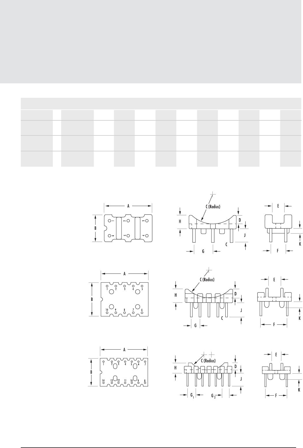
13 .13
mag-inc.com
Toroid Mounts
Toroid Hardware
DIMENSIONS (IN.)
PART A NOMFIG B NOM C REF D NOM E REF F TYP G TYP H NOM J REF K REF
FOR CORE O.D
TVB22066A 1 0.500”-0.870” 0.748 0.425 0.472 0.138 0.189 0.236 0.295 0.216 0.216 0.079
(6 pins)
TVB2908TA 2 0.810”-1.25” 1.063 0.748 0.630 0.197 0.276 0.590 0.197 0.295 0.320 0.138
(10 pins)
TVB3610FA 3 1.142”-1.500” 1.409 0.819 0.433 0.197 0.276 0.630 G10.248 0.299 0.384 0.177
(14 pins) G20.197
These vertical mount accessories are designed to accommodate a variety of toroidal core sizes on to printed circuit board or other assemblies.
(Contact Magnetics Application Engineering for new parts not shown here)
All parts
Material: Phenolic
UL 94 VO rated
Pin Material: CP Wire
Pin Diameter: .039”
FIGURE 1
For use with P/N’s 41206TC –
42212TC
FIGURE 2
For use with P/N’s 42507TC –
43113TC
FIGURE 3
For use with P/N’s 42908TC –
43825TC
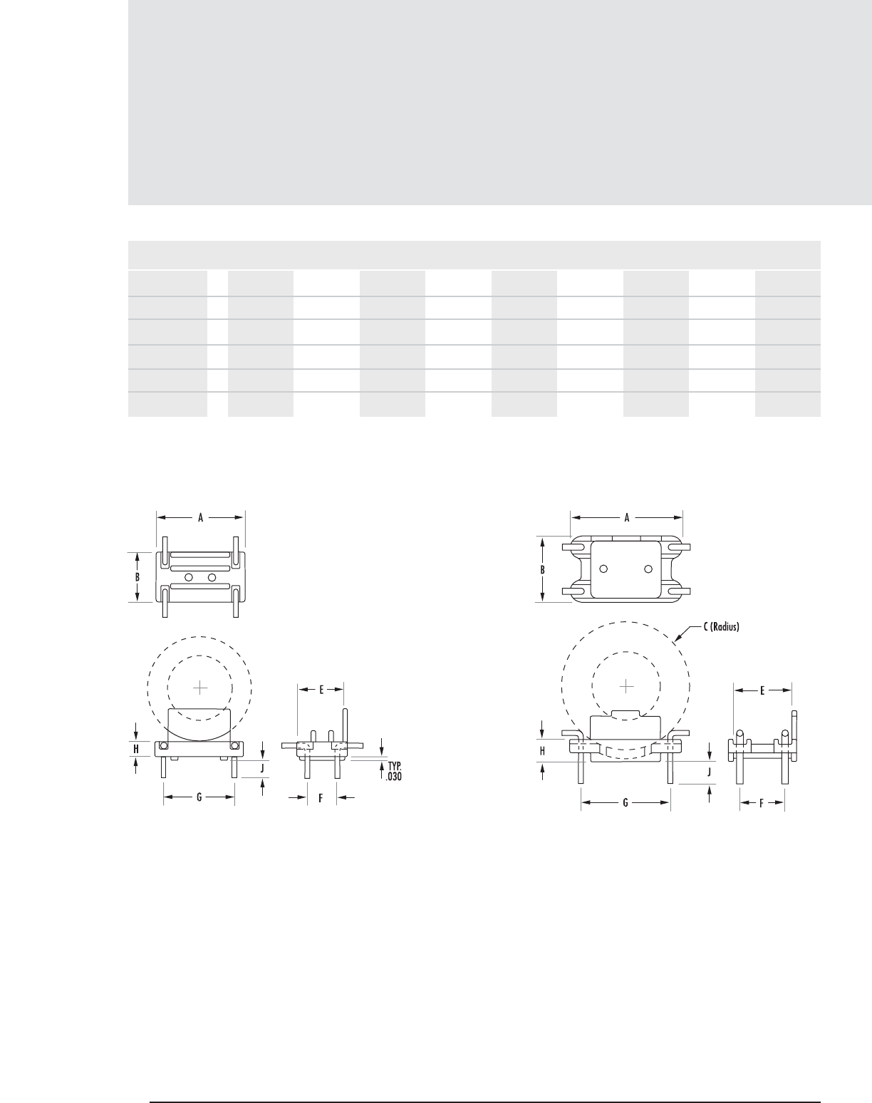
13.14 MAGNETICS
Toroid Mounts (con’t)
Toroid Hardware
DIMENSIONS (IN.) (NOM.)
PART FIG ABCEFGHJFOR CORE O.D.
TVH22064A 1 0.750 0.425 - 0.385 0.250 0.600 0.125 0.150 0.5" – 1.00"
TVH25074A 2 1.000 0.600 0.600 0.510 0.400 0.800 0.200 0.200 0.81" – 1.14"
TVH38134A 2 1.100 0.800 0.800 0.710 0.600 0.900 0.200 0.200 1.25" – 1.50"
TVH49164A 2 1.400 0.900 1.270 0.810 0.700 1.20 0.200 0.200 1.5" – 2.5"
TVH61134A 2 1.700 1.100 1.400 1.010 0.900 1.500 0.200 0.200 1.9" - 2.8"
FIGURE 1 FIGURE 2
Material: Nylon
UL 94 VO rated
Pin Material: CP Wire
Pin Diameter: .040”
Material: Nylon
UL 94 VO rated
Pin Material: CP Wire
Pin Diameter: .050”
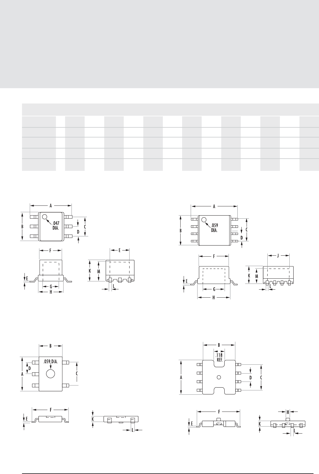
13 .15
mag-inc.com
Toroid Cups and Headers
Toroid Hardware
SURFACE MOUNT HEADERS Several surface mount headers are available. See page 6.16 for sizes and dimensions.
DIMENSIONS (IN.)
PART FIG A MAX B MAX C NOM D TYP E NOM F MAX G MIN H NOM J MIN K MAX L NOM M MIN
SMC03016A 1 0.431 0.303 0.200 0.100 0.010 0.232 0.161 0.264 0.197 0.228 0.028 0.189 <0.155
SMC06018A 2 0.636 0.409 0.300 0.100 0.012 0.409 0.301 0.449 0.301 0.240 0.024 0.205 <0.250
SMH05025A 3 0.240 0.161 0.157 0.079 0.010. 0.250 - - - 0.043 0.024 - <0.200
SMH07058A 4 0.398 0.378 0.295 0.098 0.010 0.494 - - - 0.063 0.024 - <0.310
FIGURE 1 FIGURE 2
FIGURE 3 FIGURE 4
Material: L.C.P.
UL 94 VO rated
Pin Material: Phosphor Bronze
Material: Phenolic
UL 94 VO rated
Pin Material: Phosphor Bronze
Material: Phenolic
UL 94 VO rated
Pin Material: Phosphor Bronze
Material: L.C.P.
UL 94 VO rated
Pin Material: Phosphor Bronze
FOR CORE
O.D.

13.16 MAGNETICS
Notes
Toroids
14.1
Section 14
General
Information
14.2MAGNETICS
Definitions
µ — Permeability—The ratio of magnetic flux density in gausses to magnetic field strength in oersteds.
µ=
B
H
µi — Initial Permeability—The value of the permeability at very low magnetic field strengths.
µi= lim B
HÞO H
µe — Effective Permeability—If a magnetic circuit is not homogeneous (i.e., contains an air gap), the effective permeability is
the permeability of a hypothetical homogeneous (ungapped) structure of the same shape, dimensions, and reluctance, that
would give the inductance equivalent to the gapped structure.
ALmillihenries per Inductance factor—In a wound core, the inductance per unit turn when L is in henries. More often, when L is expressed
1,000 turns in millihenries, ALis the inductance as measured using a thousand turn coil. When calculating for other turns, use:
or nanohenries/turn2L (mH) = ALn2/1,0002.
TC /˚C Temperature Coefficient—The relative change in permeability per ˚C when measured at two different temperatures.
TC = µ2– µ1
µ2(T2–T1)
TF /˚C Temperature Factor—The temperature coefficient of a material per unit of permeability.
TF = TC
µi
TCe/˚C Effective Temperature Coefficient—The actual temperature coefficient of a magnetic structure whose material permeability
has been reduced to µeby gapping.
TCe= TF x µe
DA —Disaccommodation—The relative decrease in permeability of a magnetic material with time after magnetic
conditioning (demagnetization).
DA = ∆µlog t2t1 = time from demagnetization to 1st measurement
µ1t1t2 = time from demagnetization to 2nd measurement
For each decade of time, when t2= 10t1 DA = ∆µ
µi
DF — Disaccommodation Factor—The disaccommodation of a material per unit of permeability.
DF = DA
µi
SYMBOL UNITS DEFINITION
Definitions
mag-inc.com
DFe— Effective Disaccommodation Coefficient—The actual disaccommodation of a magnetic circuit whose material permeability
has been reduced to µe by gapping.
DFe= DF x µe
Q — Q Factor—The efficiency of an inductor, that is the ratio of series inductive reactance to loss resistance.
Q = qLS
RS
tand—Loss angle—Deviation from ideal phase angle (90˚) due to losses.
tand= RS = 1
qLS Q
tand— Relative loss factor—Losses per unit of permeability. Figure of merit of a material.
µitand= 1
µiµiQ
Ch/gausses Hysteresis coefficient—The coefficient in the Legg** equation which separates the hysteresis losses from the eddy
current and residual losses. RS= ChB + Cef + Cr
µifLS
This coefficient can be evaluated by noting the variation of series resistance with B.
Ch/gausses Relative Hysteresis Factor. This hysteresis coefficient normalized to unit permeability so that it is strictly a material property.
µi2
Ch(e) /gausses Effective Hysteresis Coefficient—The actual hysteresis loss in a magnetic structure whose permeability has been reduced
to µeby gapping. Ch(e) = Chx µe2
µi2
Bgausses Flux density—The magnetic flux in maxwells per cm2of cross sectional area.
Bmax gausses The flux density at high field strengths (normally 25 oersteds).
Teslas 104gausses = 1 Tesla
H oersteds Field strength—The externally applied magnetizing field in oersteds.
Hc oersteds Coercive force—The reverse magnetic field needed to reduce a magnetically saturated structure from remanence
to zero magnetic induction.
amp-turns/m 1oersted = 79.5 amp-turns/m
L henries Inductance—The magnetic flux linkages in maxwells-turns per ampere of magnetizing current.
L= –N df
di
lecm Effective magnetic path length—In a structure containing a non-uniform cross section, the effective magnetic path
length is that length of a similar structure with uniform cross section which is equivalent to the first for purposes of
magnetic calculations.
Aecm2Effective cross-sectional area—In a structure containing a non-uniform cross section, the effective magnetic cross section is
the area of a structure with uniform cross section which is equivalent to the first for purposes of magnetic calculations.
Vecm3Effective magnetic volume.
Tc˚C Curie Temperature—Temperature at which a ferromagnetic material loses its ferromagnetism and becomes
paramagnetic (µeapproaches 1).
**V.E. Legg, Magnetic Measurements at Low Flux Densities Using the Alternating Current Bridge, Bell System Technical Journal, 15, 39 (1936)
SYMBOL UNITS DEFINITION
14.3

14.4 MAGNETICS
References
1.* Handbook of Modern Ferromagnetic Materials
Alex Goldman
Klywer Academic Publishers, Norwell, MA 02061
2.* Magnetic Core Selection for Transformers & Inductors,
Colonel Wm. T. McLyman
Marcel Dekker, 270 Madison Avenue, New York, NY 10016-0602
3.* Transformer and Inductor Design Handbook (second edition)
Colonel Wm. T. McLyman
270 Madison Avenue, New York, NY 10016-0602
4.* Fundamentals of Power Electronics
Robert Erickson
Chapman and Hall, New York, NY 10003
5.* Introduction to Power Electronics
Daniel Hart
Prentice-Hall, Upper Saddle River, NJ 07458
6.* Resonant Power Converters
Marian Kazimierczok
John Wiley & Sons, Inc., New York, NY 10158
7.* Power Switching Coverters
Simon Ang
Marcel Dekker, 270 Madison Avenue, New York, NY 10016
8.* Designing Magnetic Components for High Frequency DC-DC Converters
Colonel W.T. McLyman
Kg Magnetics, Idyllwild, CA 92549
9.* Elements of Power Electronics
Philip Krein
Oxford University Press, Cary, NC 27513
10.* Modern DC-DC Switchmode Power Converter Circuits (reprint)
Severns & Bloom, e/j Bloom associates inc.
11.* Switchmode Power Conversion
K. Kit Sum
Marcel Dekker, 270 Madison Avenue, New York, NY 10016-0602
12.* Applications of Magnetism, J.K. Watson, (self-published).
13.* Switching Power Supply Design (second edition)
A.I. Pressman
McGraw-Hill Publishing Co., 1221 Avenue of Americas, New York, NY 10020
14.* EMI Filter Design
R. Ozenbaugh
Marcel Dekker, 270 Madison Avenue, New York, NY 10016-0602
15.* Handbook of Switch Mode Power Supply Design
K. Billings
McGraw-Hill Publishing Co., 1221 Avenue of Americas, New York, NY 10020
16.* Handbook of Transformer Applications (second edition)
W. Flanagan
McGraw-Hill Publishing Co., 1221 Avenue of Americas, New York, NY 10020
17.* Practical Switching Power Supply Design,
Marty Brown
Academic Press Inc., San Diego, CA 92101
18. Modern Ferrite Technology
Alex Goldman
Van Nostrand Reinhold, 115 Fifth Avenue, New York, NY 10003
19. Power Line Filter Design for Switch-Mode Power Supplies
Mark J. Nave
EMC Services, P.O. Box 2504, Huntsville, AL, Telephone 205-461-0241
20.* Solid-State Power Conversion Handbook
R. Tarter
John Wiley & Sons Inc., 605 Third Avenue, New York, NY 10158
21.* Power Electronics: Converters, Applications & Design (second edition)
N. Mohan et. al.
John Wiley & Sons Inc., 605 Third Avenue, New York, NY 10158
22.* Power Supply Cookbook
Marty Brown
Butterworth - Heinemann, 313 Washington Street, Newton, MA 02158
23.* Designing Magnetic Components for High Frequency DC-DC Converters
Colonel Wm. T. McLyman
KG Magnetics Inc., P.O. Box 3703, 26504 Crestview Dr.,
Idyllwild, CA 92549, Telephone 909-659-4548
24.* Pulse Width Modulated DC-DC Converters
Keng Wu
Chapman and Hall, New York, NY 10003
25.* Power Electronics-Principles & Applications
Joseph Vithayathil
McGraw Hill Inc., 1221 Avenue of Americas, New York, NY 10020
26. MMPA Publications of Soft Ferrites
PC 110 Pot Core Standard
UEI 310 U, E and I Core Standard
FTC 410 Toroid Standard
Soft Ferrites, A User’s Guide
Available from: Magnetic Materials Producers Association,
8 South Michigan Avenue, Suite 1000, Chicago, IL 60603,
Telephone 312-456-5590, Fax 312-580-0165
*Available from: e/j Bloom associates inc.,
115 Duran Drive, San Rafael, CA 94903-2317
Phone (415) 492-8443 Fax (415) 492-1239
email ejbloom@compuserve.com http://www.ejbloom.com
ADDITIONAL MAGNETICS FERRITE LITERATURE
CG-01 - A Critical Comparison of Ferrites with other Magnetic Materials
FC-S1 - Ferrite Material Selection Guide
FC-S2 - EMI-RFI Filter, Common Mode Filter - Material Selection
FC-S3 - Qcurves for Ferrite Cores
FC-S4 - Step Gap E-Core Swing Chokes
FC-S7 - Curve Fit Equations for Ferrite Materials
FC-S8 - Designing with Ferrite Planar Cores
CG-2 - Material Selection Charts for Frequency, Temperature, Geometry, Stability
PS-01 - Cores for SMPS
CG-03 - Cores for Flybacks
HED-01 - Cores for Hall Effect Devices

14.5
mag-inc.com
Other Products
Other Products
from Magnetics
POWDER CORES
Powder cores are excellent as low loss inductors for switched-mode power
supplies, switching regulators and noise filters. Most core types can be
shipped immediately from stock.
Molypermalloy powder cores (MPP) are available in ten permeabilities
ranging from 14 through 550, and have guaranteed inductance limits of
±8%. Insulation on the cores is a high dielectric strength finish not affect-
ed by normal potting compounds and waxes. Thirty sizes include I.D.s
from 0.070” (1.78 mm) to 1.938” (49.2 mm) and O.D.s from 0.140”
(3.56 mm) to 3.063” (77.8 mm). Standard cores include either tem-
perature stabilized (as wide as -65° C at 125° C for stable operation) or
standard stabilization.
High Flux powder cores have a much higher energy storage capacity than
MPP cores and are available in six permeabilities from 26µ through 160µ.
High Flux cores a re available in sizes identical to MPP cores.
Kool Mµ® powder cores have a higher energy storage capacity than MPP
cores and are available in five permeabilities from 26µ through 125µ.
Kool Mµtoroids are available in sizes identical to MPP cores, and this
material is also available in a number of E-core sizes. Permeability for
Kool MµE-cores is from 26 to 90 and sizes are tooled ranging from the
EF 12.6 to the Metric E80 size.
MPP THINZ® are extremely low height (<1 mm) self-shielded power
inductor cores, allowing finished inductor heights in the 1.5 mm to 2mm
range. THINZ come in 5 sizes with O.D.s ranging from 0.120” through
0.310” and four permeabilities: 125µ, 160µ, 200µ and 250µ.
For further information view Powder Cores Design Manual at
www.mag-inc.com.
STRIP WOUND CORES
Tape wound cores are made from high permeability alloys of nickel-iron,
grain oriented silicon-iron. The alloys are known as Orthonol®, Alloy 48,
Square Permalloy 80, Supermalloy and Magnesil® . Cores are available
in more than 50 standard sizes. For a wide range of frequency applica-
tions, materials are produced in thicknesses from 1/2 mil(0.013 mm)
through 14 mils (0.356 mm). Cases are robust nylon boxes, rated for
200° C continuous operation and 2000 voltage minimum breakdown.
Applications include: magnetic amplifiers, reactors, regulators, static mag-
netic devices and current transformers.
For further information view the Tape Wound Core Design Manual at
www.mag-inc.com.
Miniature Tape Wound Bobbin Cores are manufactured from Permalloy 80
and Orthonol ultra-thin tape (0.000125” to 0.001” thick). They are
available in widths from 0.031” to 0.250” (wider on special request).
Wound on non-magnetic stainless steel bobbins, core diameters are avail-
able down to 0.050”, with flux capacities as low as several maxwells.
Magnetics’ sophisticated pulse test equipment reproduces most test pro-
grams and can measure accurately in the millivolt-microsecond region.
Applications include: magnetometers, flux gates, oscillators, inverters and
magnetic amplifiers.
For further information view the Bobbin Core Design Manual at www.mag-
inc.com.
RAPID PROTOTYPING SERVICE
Magnetics' world-class materials offer unique and powerful advantages to
almost any application. An even greater competitive edge can be gained
through innovations in new core shapes and custom geometries, and
Magnetics is poised to help. Our Rapid Prototyping Service can quickly
make a wide variety of core shapes in ferrite, MPP, High Flux, or Kool
Mu®. The time between receipt of your drawing and delivery of the parts
to you is usually less than 10 days. This quick turnaround time results in
a shorter design period, which gets your product to market faster. Plus,
our application engineers may be able to provide design assistance that
could lead to a lower piece price. To learn more about how our Rapid
Prototyping Service can help you shorten your design cycle, contact a
Magnetics Application Engineer.

14.6 MAGNETICS
General Information
Notes

www.mag-inc.com
Visit MAGNETICS’ website for a wealth of easy to access
information on soft magnetic cores and materials…
All product specifications for MAGNETICS’ ferrite cores, powder
cores and strip wound cores can be found quickly by using the
menu driven product locator.
MAGNETICS’ Digital Library contains all of the company’s
technical bulletins, white papers and design manuals, which can
be viewed on-screen or downloaded.
The Software section of the website provides access to the
MAGNETICS’ software design aids for designing Common Mode
Filters, Current Transformers, Inductors and MagAmps.
Contact information for MAGNETICS’ global distribution network,
including access to STOCKCHECK, an easy way to check
distributor inventory via the web.
CONTACT MAGNETICS
P.O. Box 11422
Pittsburgh, PA 15238-0422
Phone: 412-696-1300 or 1-800-245-3984
Fax: 412-696-0333
email: magnetics@spang.com
web: www.mag-inc.com
©2005 MAGNETICS
P.O. Box 11422
Pittsburgh, PA 15238-0422
Phone: 1.800.245.3984
Fax: 412.696.0333
www.mag-inc.com magnetics@spang.com
