Polaris Outlaw 500 2006 2007 Service Manual
User Manual: 2006 - 2007 Polaris Outlaw 500 Service Manual
Open the PDF directly: View PDF ![]() .
.
Page Count: 202 [warning: Documents this large are best viewed by clicking the View PDF Link!]
- 2006-2007 POLARIS OUTLAW 500 SERVICE MANUAL
- TABLE
- GENERAL INFORMATION
- MAINTENANCE
- ENGINE
- Specifications
- General Engine Service
- Piston Identification
- Compression Test
- Coolant Temperature Sensor (Thermistor)
- Cooling System
- Radiator Cap / System Pressure Test
- Cooling System Specifications
- Accessible Components
- Engine Removal
- Engine Installation Notes
- Crankshaft Straightening
- ES50PL Engine Lubrication
- Oil Pressure Test
- Oil Pump Priming Procedure
- Oil Flow - ES50PL
- ES50PL Oil Flow Chart
- ES50PL Engine Exploded Views
- Upper Engine Disassembly
- Lower Engine Disassembly
- Crankcase Disassembly and Inspection
- Starter Drive Gears Removal and Inspection
- Flywheel / One-Way Starter Clutch Removal and Inspection
- Crankshaft Nut Removal
- Clutch Cover / Clutch Removal and Inspection
- Shifter Component Removal and Inspection
- Oil Pump Removal and Inspection
- Crankshaft Drive and Cam Gear Removal
- Cam Chain / Tensioner Blade Removal
- Crankcase Separation
- Crankcase Inspection
- Crankcase Bearing Inspection / Removal / Installation
- Transmission and Crankshaft Service
- Engine Reassembly
- Cylinder Head Service
- Cylinder Service
- Water Pump Service
- Troubleshooting
- FUEL SYSTEM / CARBURETION
- BODY / STEERING / SUSPENSION
- General Information
- Body Assembly
- Body Component Removal
- Steering Assembly Exploded View
- Steering Knuckle
- Ball Joint Service
- Front Hub
- Front Suspension Exploded View
- Front A-arm Replacement
- Rear Suspension Exploded View
- Rear A-arm Replacement
- Rear Housing
- Rear Bearing Carrier
- Rear Drive (CV) Joint
- Decals
- Front Shock Exploded View
- Rear Shock Exploded View
- RydeFX™ Shock Service
- BRAKES
- ELECTRICAL
- General Information
- Lighting and Controls
- Neutral / Reverse Position Indicator Switch Test
- Headlight Lamp Replacement
- Headlamp Switch Test
- Headlight Housing Replacement
- Headlight Adjustment
- Taillight / Brakelight Lamp Replacement
- Brake Light Switch Tests
- Clutch Switch Test
- Indicator Lamp Replacement
- Tether Switch Test (Accessory Option)
- Electronic Throttle Control (ETC) Switch
- ETC Operation Test
- Ignition System
- Cooling System
- Charging System
- Battery Service
- Starting System
- INDEX
- WIRE DIAGRAM (Main)
- WIRE DIAGRAM (Breakouts)

Fix it like a Pro

1
GENERAL INFORMATION
2
MAINTENANCE
3
ENGINE
4
FUEL SYSTEM
5
BODY / STEERING / SUSPENSION
6
BRAKES
7
ELECTRICAL
8
WIRE DIAGRAMS

GENERAL INFORMATION
1.1
CHAPTER 1
GENERAL INFORMATION 1
VEHICLE IDENTIFICATION . . . . . . . . . . . . . . . . . . . . . . . . . . . . . . . . . . . . . . . . . . . . . . . 1.2
MODEL IDENTIFICATION . . . . . . . . . . . . . . . . . . . . . . . . . . . . . . . . . . . . . . . . . . . . . . . . 1.2
ENGINE DESIGNATION NUMBER . . . . . . . . . . . . . . . . . . . . . . . . . . . . . . . . . . . . . . . . . 1.2
VIN IDENTIFICATION . . . . . . . . . . . . . . . . . . . . . . . . . . . . . . . . . . . . . . . . . . . . . . . . . . . 1.2
UNIT SERIAL NUMBER (VIN) LOCATION . . . . . . . . . . . . . . . . . . . . . . . . . . . . . . . . . . . 1.2
ENGINE SERIAL NUMBER LOCATION . . . . . . . . . . . . . . . . . . . . . . . . . . . . . . . . . . . . . 1.2
VEHICLE INFORMATION . . . . . . . . . . . . . . . . . . . . . . . . . . . . . . . . . . . . . . . . . . . . . . . . . 1.2
PAINT CODES . . . . . . . . . . . . . . . . . . . . . . . . . . . . . . . . . . . . . . . . . . . . . . . . . . . . . . . . . 1.2
REPLACEMENT KEYS . . . . . . . . . . . . . . . . . . . . . . . . . . . . . . . . . . . . . . . . . . . . . . . . . . 1.2
PUBLICATION NUMBERS. . . . . . . . . . . . . . . . . . . . . . . . . . . . . . . . . . . . . . . . . . . . . . . . 1.3
STANDARD TORQUE SPECIFICATIONS. . . . . . . . . . . . . . . . . . . . . . . . . . . . . . . . . . . . 1.3
SPECIFICATIONS. . . . . . . . . . . . . . . . . . . . . . . . . . . . . . . . . . . . . . . . . . . . . . . . . . . . . . . 1.4
2006-2007 OUTLAW 500. . . . . . . . . . . . . . . . . . . . . . . . . . . . . . . . . . . . . . . . . . . . . . . . . 1.5
SPECIAL TOOLS . . . . . . . . . . . . . . . . . . . . . . . . . . . . . . . . . . . . . . . . . . . . . . . . . . . . . . . 1.6
‘WHERE USED’ TABLE . . . . . . . . . . . . . . . . . . . . . . . . . . . . . . . . . . . . . . . . . . . . . . . . . . 1.6
SPECIAL TOOL LISTING. . . . . . . . . . . . . . . . . . . . . . . . . . . . . . . . . . . . . . . . . . . . . . . . . 1.7
MISC. NUMBERS / CHARTS . . . . . . . . . . . . . . . . . . . . . . . . . . . . . . . . . . . . . . . . . . . . . 1.10
SAE TAP / DRILL SIZES . . . . . . . . . . . . . . . . . . . . . . . . . . . . . . . . . . . . . . . . . . . . . . . . 1.10
METRIC TAP / DRILL SIZES . . . . . . . . . . . . . . . . . . . . . . . . . . . . . . . . . . . . . . . . . . . . . 1.10
DECIMAL EQUIVALENTS . . . . . . . . . . . . . . . . . . . . . . . . . . . . . . . . . . . . . . . . . . . . . . . 1.10
COVERSION TABLE . . . . . . . . . . . . . . . . . . . . . . . . . . . . . . . . . . . . . . . . . . . . . . . . . . . 1.11
GLOSSARY OF TERMS. . . . . . . . . . . . . . . . . . . . . . . . . . . . . . . . . . . . . . . . . . . . . . . . . 1.12
1.2
GENERAL INFORMATION
VEHICLE IDENTIFICATION
Model Identification
The machine model number must be used with any
correspondence regarding warranty or service.
Engine Designation Number
ES50PLE - Single, Water Cooled, Electric Start, 5-Speed
Manual, DOHC 4 Stroke.
VIN Identification
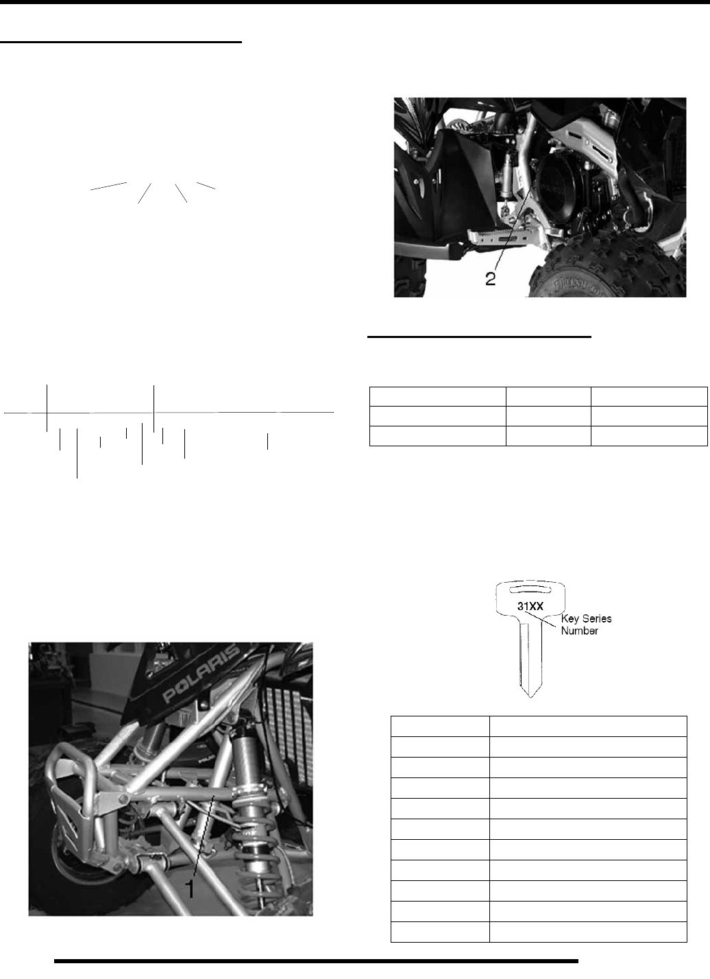
Unit Serial Number (VIN) Location
Whenever corresponding with Polaris about a particular issue,
the machine model number and serial number are important for
vehicle identification. The machine serial number is stamped on
the left side of the frame tube. (1)
Engine Serial Number Location
This information can be found on the clutch housing on the right
side of engine. (2)
VEHICLE INFORMATION
Paint Codes
Replacement Keys
Replacement keys can be made from the original key. To
identify which series the key is, take the first two digits on the
original key and refer to the chart to the right for the proper part
number. Should both keys become lost, replacement of the
ignition switch assembly is necessary.
}
Machine Model Number Identification
}
}
}
A 07 GP 50 AA
Year Designation
Basic Chassis Designation Engine Designation
Emissions & Model Option
}
1 2 3 4 5 6 7 8 9 10 11 12 13 14 15 16 17
World
Mfg. ID
Engine
4 X A G P 5 0 A * 7 P 0 0 0 0 0 0
Vehicle Descriptor Vehicle Identifier
Emissions
}
Check Digit*
Model
Year
Body
Style Plant No*
Individual Serial Number
* -This could be either a number or a letter
Powertrain
PAINTED PART COLOR POLARIS
Frame Cloud Silver P-385
Frame Matte Black P-458
SERIES # PART NUMBER
20 4010278
21 4010278
22 4010321
23 4010321
27 4010321
28 4010321
31 4110141
32 4110148
67 4010278
68 4010278
RepairPro Service Manual
1.3
GENERAL INFORMATION
1
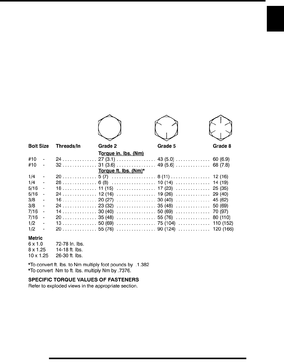
Standard Torque Specifications
The following torque specifications are to be used as a general guideline.
FOR SPECIFIC TORQUE VALUES OF FASTENERS, refer to exploded views in the appropriate section. There are exceptions
in the steering, suspension, and engine sections.
1.4
GENERAL INFORMATION
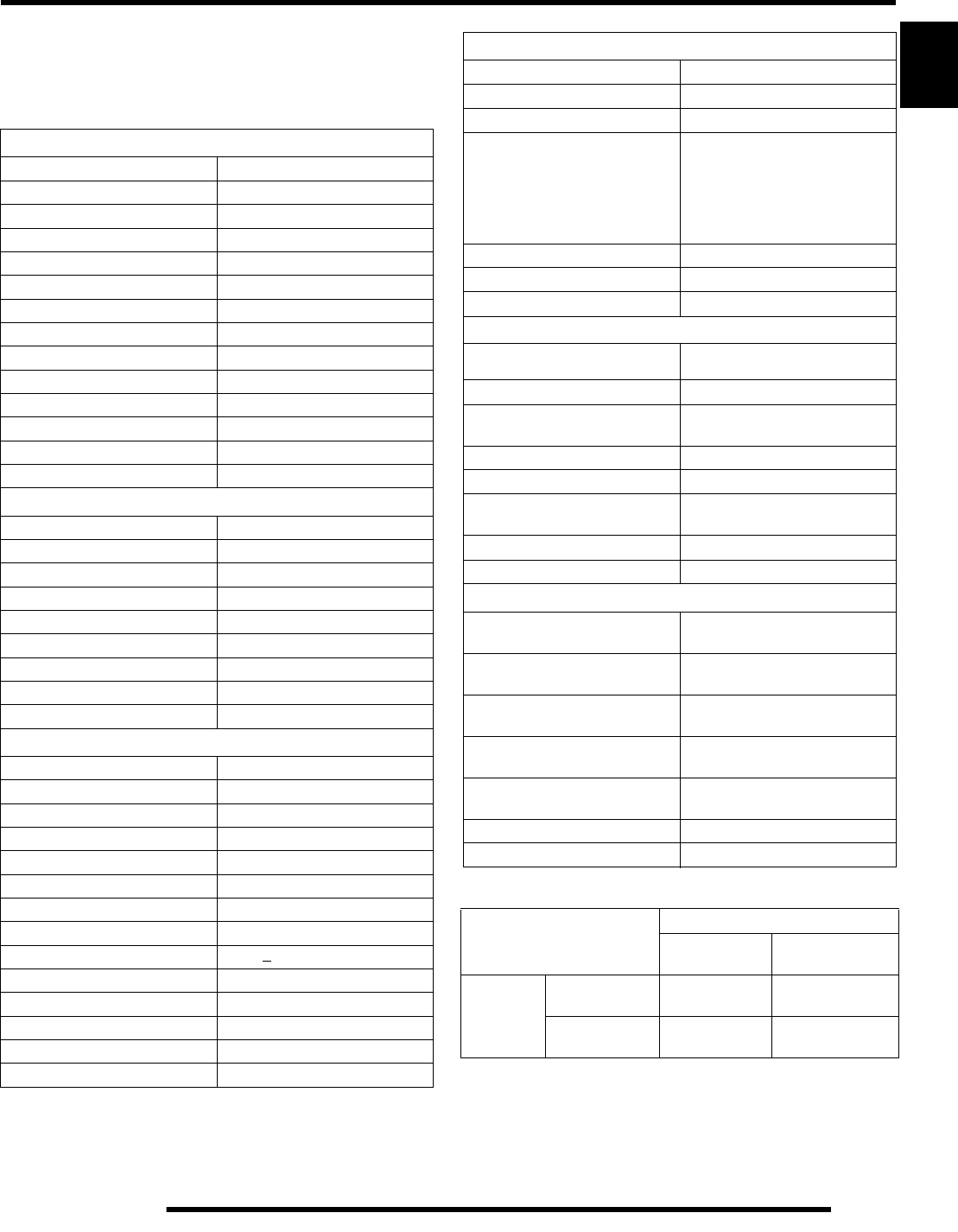
SPECIFICATIONS
MODEL: 2006- 2007 OUTLAW 500
MODEL NUMBER: A06(07)GP50AA,AB
ENGINE MODEL: ES500PLE041
Category Dimension
Length 71.5 in. / 182 cm
Width 47.5 in. / 121 cm
Height 45 in. / 114 cm
Minimum Turing Radius 67 in. / 170 cm
Wheel Base 51 in. / 130 cm
Ground Clearance 11.5 in. / 29 cm
Dry Weight 439 lbs. / 199 kg
Gross Vehicle Weight 645 lbs. / 292 kg
Oil Capacity 2 qts. / 1.9 ltr
Coolant Capacity 2.25 qts. / 2.1 ltr
Fuel Capacity 3.25 gal. / 12.3 ltr
RepairPro Service Manual
1.5
GENERAL INFORMATION
1
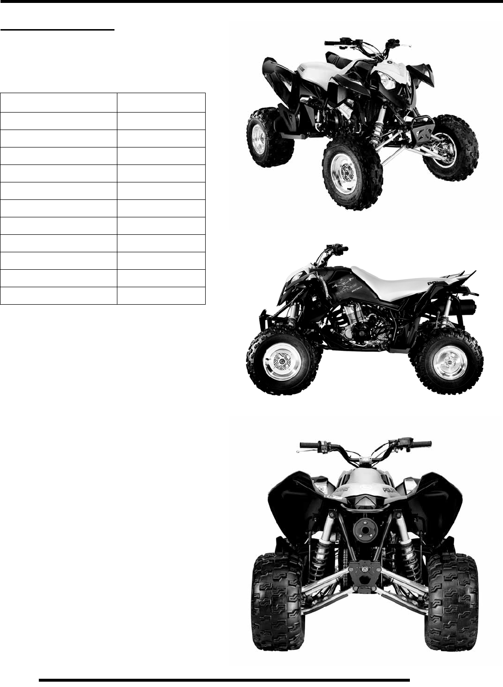
2006 - 2007 OUTLAW 500
MODEL NUMBER: A06(07)GP50AA,AB
ENGINE MODEL: ES500PLE041
JETTING CHART
Engine
Platform Fuji DOHC 4 stroke
Engine Model Number ES500PLE041
Engine Displacement 499cc
Number of Cylinders 1
Bore & Stroke (mm) 99.2 x 64.6 mm
Compression Ratio 10.8:1
Compression Pressure 130 psi
Engine Idle Speed 1600 Rpm
Cooling System Liquid
Thermostat Opening Temperature 160°F (71°C)
Overheat Warning High Temp Light
Lubrication Pressurized Dry Sump
Oil Requirements PS-4 Synthetic
Exhaust System 2 to 1 canister style
Carburetion
Carburetor model Mikuni BSR 42mm
Main Jet 145
Pilot Jet 37.5
Jet Needle 6GL68-40-2
Needle Jet O-0
Pilot Screw 2.5 Turns Out (Reference Only)
Float Height 13 mm (0.51")
Fuel Delivery Fuel Pump
Fuel Requirement 87 Octane (minimum)
Electrical
Alternator Output 200 w @ 3000 RPM
Voltage Regulator 3-Phase
Lights : Main Headlights Dual Beam 35 watts / 35 watts
Tail LED
Brake 26.9 watts
Neutral / Hot / Reverse 1 watt (ea.)
Ignition System DC/CDI Ignition
RPM Limit 9100 ± 100 / Reverse 5000 ± 100
Ignition Timing 30o + 3o BTDC @ 3500 RPM
Spark plug / Gap NGK DCPR8E/ .035 in./ 0.9 mm
Battery / Model / Amp Hr Maintenance-Free 9 Amp Hr
Circuit Breakers (Amps) Main-15 / Fan-10 / Ignition-5
Starting Electric - Standard
Instrument Cluster N/A
Drivetrain
Transmission Type Manual 5 speed
Main Sprocket - # Tooth 14
Rear Sprocket - # Tooth 38
Gear Ratio : 1st
2nd
3rd
4th
5th
Rev
2.43
1.61
1.29
1.09
0.92
2.07
Chain Size / Deflection 520 O-ring / 1/4-3/8” (6-8mm)
Clutch Type Wet Multi Plate
Clutch Lever Freeplay 1/8” – 3/16” / 3.1 – 4.7 mm
Steering / Suspension
Front Suspension
Style / Shock Dual A-arm / RydeFX™ Shock
Front Travel 10 in. / 25.4 cm
Rear Suspension
Style / Shock
Independent A-Arm / RydeFX™
Compression Adjustable Shock
Rear Travel 11 in. / 27.94 cm
Ground Clearance 11.5 in. / 29 cm
Shock Preload Adjustment
Front and Rear
Threaded shock adjustment
with Spanner Wrench
Turning Radius 67 in. / 170 cm
Toe Out 0 - 1/16 in / .0 - .159 mm
Wheels / Brakes
Front
Wheel Size / Offset / Bolt Pattern 10x5 / 28.3mm - 4/156
Rear
Wheel Size / Offset / Bolt Pattern 9x8 / 58.8mm - 4/110
Front Tire
Make / Model / Size Dunlop / Radial / 21x7-10
Rear Tire
Make / Model / Size Dunlop / Radial / 20x10-9
Recommended Air Pressure
F / R
5 psi Front
5 psi Rear
Brake - Front Hydraulic Disc
Brake - Rear Hydraulic Disc
Altitude
AMBIENT TEMPERATURE
Below 40o F
Below 5o C +40o F + Above
+5o C + Above
Meters
(Feet)
0-1800
(0-6000) 150 145
above 1800
(above 6000) 142.5 137.5

1.6
GENERAL INFORMATION
SPECIAL TOOLS
‘Where Used’ Table
*Special Tools can be ordered through a Polaris Dealer or SPX Corporation (1-800-328-6657).
PART NUMBER TOOL DESCRIPTION CHAPTER TOOL USED IN
8712100 or 8712500 Tachometer 2,7
2200634 Valve Seat Reconditioning Kit 3
PU-45257 Valve Spring Compressor 3
PA-46075 Flywheel Puller 3
PA-46087 Crankcase Separator 3
2870390 Piston Support Block 3
2872105 Water Pump Mechanical Seal Puller 3
PA-45958 Cam Chain Tensioner Assembly Tool 3
PA-46076 MAG End Crankshaft Nut Remover/Installer 3
PA-46077 MAG End Crankshaft Installer 3
2871283 Crankshaft/Water Pump Seal Install Kit 3
5131135 Water Pump Install Kit 3
PA-46502 Valve Spring Compressor 3
2870975 Mity Vac™ Pressure Test Tool 3,4
2872314 Carburetor Float Adjustment Tool 4
PS-45259 Gas Fill Tool 5
PS-45261 IFP Positioning / Extraction Tool 5
PA-48282 Rear Hub Tool 5
PV-43568 Fluke™ 77 Digital Multimeter 7
2870630 Timing Light 7
RepairPro Service Manual
1.7
GENERAL INFORMATION
1
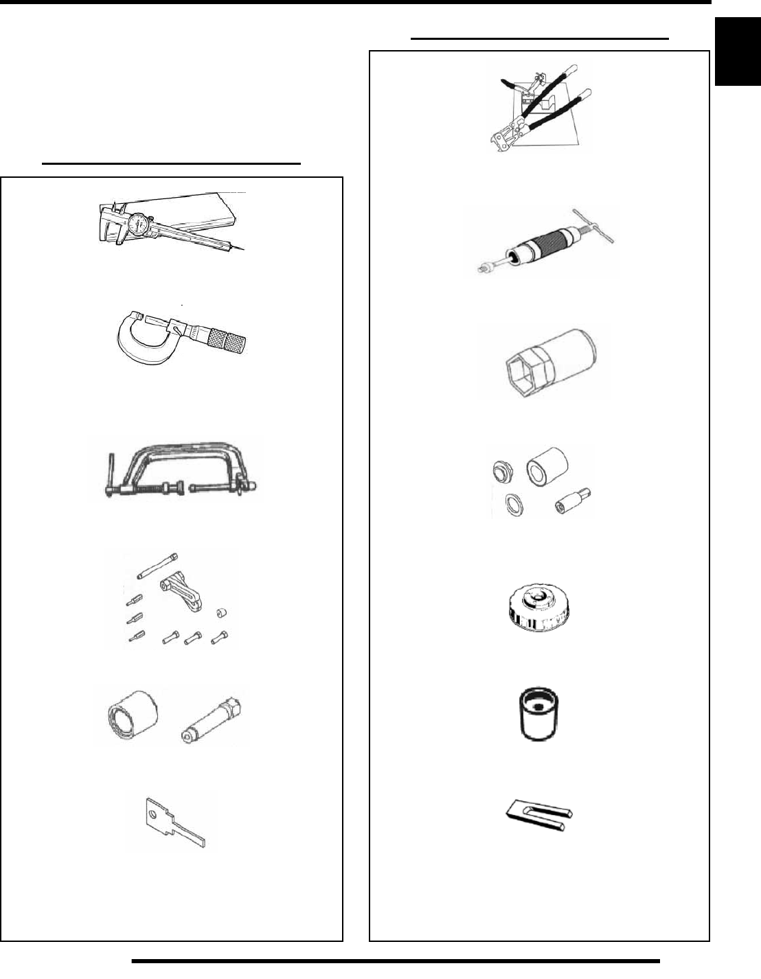
Special Tool Listing
Special Tools may be required while servicing your machine.
Some of the tools listed are mandatory and other tools may be
substituted with a similar tool, if available. Tools shown may not
apply to a particular vehicle. Polaris recommends the use of
Polaris special tools when servicing any Polaris product.
Standard Tools and Engine Tools
PU-45432 - Caliper or A Basic Caliper
Basic Micrometer
PA-46502 - Valve Spring Compressor
PA-46087 - Crankcase Separator
PA-46075 - Flywheel Puller
PA-45958 - Cam Chain Tensioner Tool
Standard Tools and Engine Tools
2870569 - Crankshaft True Kit
2870386 - Piston Pin Puller
PA-46076 Mag End Crank Nut Remover/Install
PA-46077 - Mag End Crankshaft Installer
PV-43527 Oil Filter Wrench
5131135 - Water Pump Install Tool
2870390 - Piston Support Block
1.8
GENERAL INFORMATION
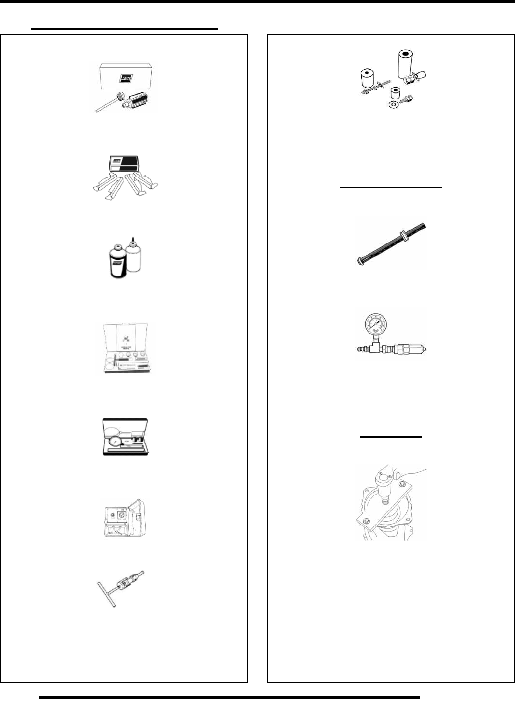
Standard Tools and Engine Tools
2870303 - Hone Kit
2870305 - Stone Replacement Kit
2870588 - Hone Oil (12 OZ.)
2200634 - Valve Seat Reconditioning Kit
2870459 - Dial Indicator
PV-35667-A - Cylinder Leak down Tester
2872105 - Water Pump Seal Puller
2871283 - Crank/Water Pump Seal Install Kit
Suspension Tools
PS-45261 - Shock IFP Positioning / Extraction Tool
PS-45259 - Gas Fill Tool
Final Drive
PA-48282 Rear Hub Tool
RepairPro Service Manual
1.9
GENERAL INFORMATION
1
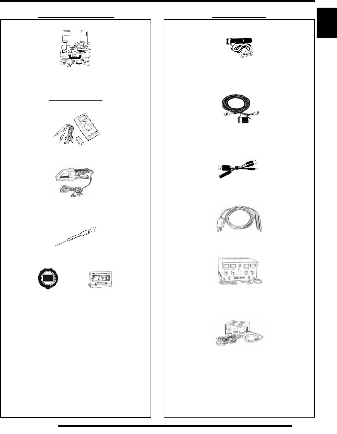
Fuel & Brake Systems
2870975 - Mity Vac™
Electrical Tools
PV-43568 - Fluke™ 77 Multimeter
PV-39617 - Current Clamp
2870836 - Battery Hydrometer
8712500 - PV-39951-A -
Tachometer Tachometer
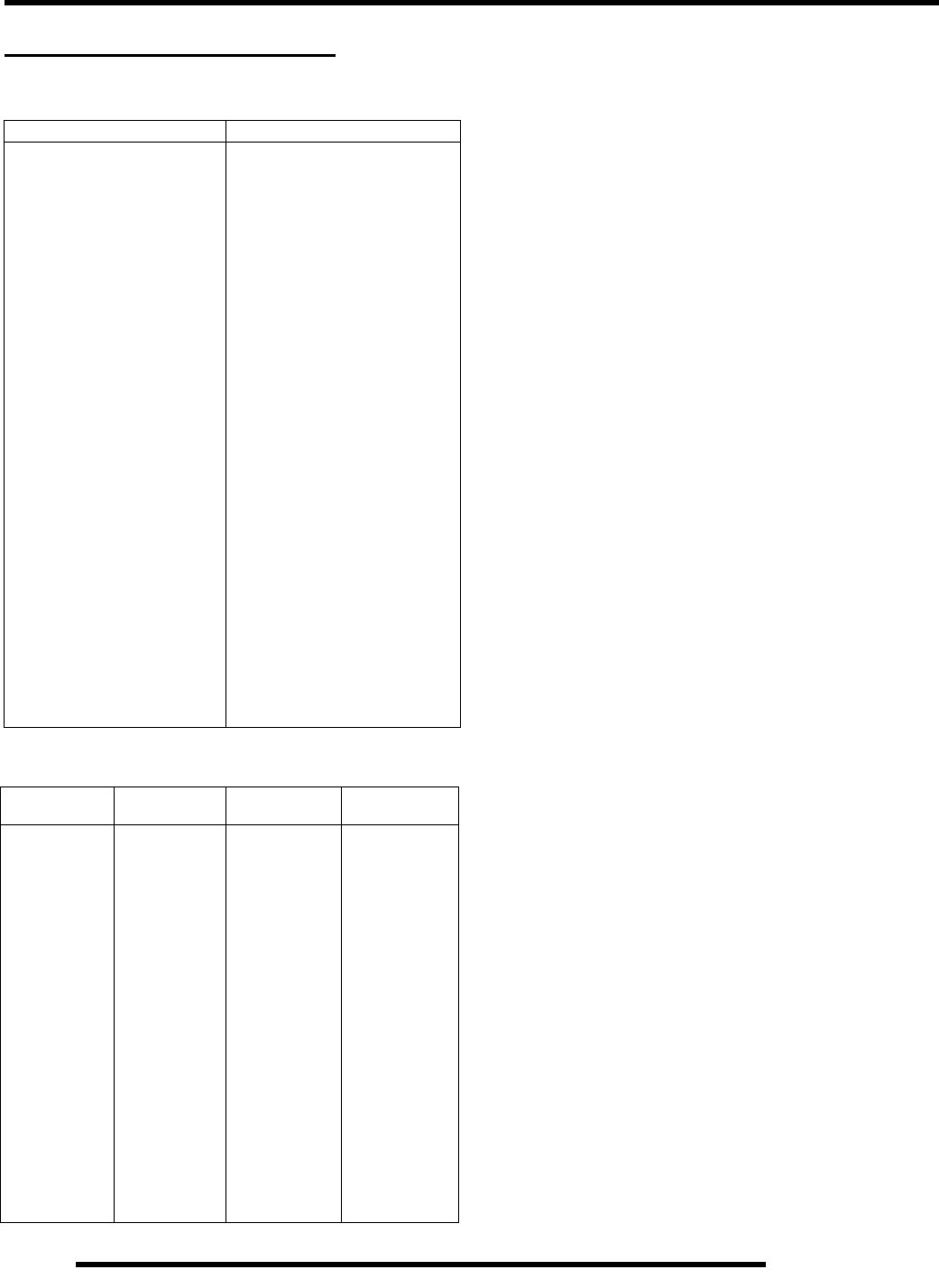
Electrical Tools
2870630 - Timing Light
2871745 - Static Timing Light Harness
2460761 - Hall Sensor Probe Harness
PV-39991 - Peak Reading Adapter
PV-37453 - Christie™ Se-Sulfating
Multi-Battery Charger
PV-63070 - Christie™ Multi-Battery Charger
1.10
GENERAL INFORMATION
MISC. NUMBERS / CHARTS
SAE Tap / Drill Sizes
Metric Tap / Drill Sizes
Decimal Equivalents
1/64 . . . . . . . . . . . . . . . . . .0156
1/32 . . . . . . . . . . . . . .0312. . . 1 mm= .0394"
3/64 . . . . . . . . . . . . . . . . . .0469
1/16 . . . . . . . . . . . . . .0625
5/64 . . . . . . . . . . . . . . . . . .0781. . . 2 mm = .0787"
3/32 . . . . . . . . . . . . . .0938
7/64 . . . . . . . . . . . . . . . . . .1094. . . 3 mm =.1181"
1/8 . . . . . . . .1250
9/64 . . . . . . . . . . . . . . . . . .1406
5/32 . . . . . . . . . . . . . .1563. . . 4 mm = .1575"
11/64 . . . . . . . . . . . . . . . . . .1719
3/16 . . . . . . . . . . . . . .1875. . . 5mm= .1969"
13/64 . . . . . . . . . . . . . . . . . .2031
7/32 . . . . . . . . . . . . . .2188
15/64 . . . . . . . . . . . . . . . . . .2344. . . 6 mm = .2362"
1/4 . . . . . . . .25
17/64 . . . . . . . . . . . . . . . . . .2656. . . 7 mm = .2756"
9/32 . . . . . . . . . . . . . .2813
19/64 . . . . . . . . . . . . . . . . . .2969
5/16 . . . . . . . . . . . . . .3125. . . 8mm= .3150"
21/64 . . . . . . . . . . . . . . . . . .3281
11/32 . . . . . . . . . . . . .3438. . . 9 mm = .3543"
23/64 . . . . . . . . . . . . . . . . . .3594
3/8 . . . . . . . .375
25/64 . . . . . . . . . . . . . . . . . .3906. . . 10 mm = .3937"
13/32 . . . . . . . . . . . . . . . . . .4063
27/64 . . . . . . . . . . . . . . . . . .4219. . . 11 mm =.4331"
7/16 . . . . . . . . . . . . . .4375
29/64 . . . . . . . . . . . . . . . . . .4531
15/32 . . . . . . . . . . . . .4688. . . 12 mm = .4724"
31/64 . . . . . . . . . . . . . . . . . .4844
1/2 . . . . . . . .5. . . . . . . . . . . . 13mm = .5118"
33/64 . . . . . . . . . . . . . . . . . .5156
17/32 . . . . . . . . . . . . .5313
35/64 . . . . . . . . . . . . . . . . . .5469. . . 14 mm = .5512"
9/16 . . . . . . . . . . . . . .5625
37/64 . . . . . . . . . . . . . . . . . .5781. . . 15 mm = .5906"
19/32 . . . . . . . . . . . . .5938
39/64 . . . . . . . . . . . . . . . . . .6094
5/8 . . . . . . . .625. . . . . . . . . . 16mm=. 6299"
41/64 . . . . . . . . . . . . . . . . . .6406
21/32 . . . . . . . . . . . . .6563. . . 17 mm =.6693"
43/64 . . . . . . . . . . . . . . . . . .6719
11/16 . . . . . . . . . . . . .6875
45/64 . . . . . . . . . . . . . . . . . .7031. . . 18 mm = .7087"
23/32 . . . . . . . . . . . . .7188
47/64 . . . . . . . . . . . . . . . . . .7344. . . 19 mm = .7480"
3/4 . . . . . . . .75
49/64 . . . . . . . . . . . . . . . . . .7656
25/32 . . . . . . . . . . . . .7813. . . 20 mm = .7874"
51/64 . . . . . . . . . . . . . . . . . .7969
13/16 . . . . . . . . . . . . .8125. . . 21 mm =.8268"
53/64 . . . . . . . . . .
. . . . . . . .8281
27/32 . . . . . . . . . . . . .8438
55/64 . . . . . . . . . . . . . . . . . .8594. . . 22 mm = .8661"
7/8 . . . . . . . .875
57/64 . . . . . . . . . . . . . . . . . .8906. . . 23 mm = .9055"
29/32 . . . . . . . . . . . . .9063
59/64 . . . . . . . . . . . . . . . . . .9219
15/16 . . . . . . . . . . . . .9375. . . 24 mm = .9449"
61/64 . . . . . . . . . . . . . . . . . .9531
31/32 . . . . . . . . . . . . .9688. . . 25 mm = .9843"
63/64 . . . . . . . . . . . . . . . . . .9844
1 . . . . . . . . . . 1.0
Thread Size/ Drill Size Thread Size / Drill Size
#0-80 3/64 1/2-13 27/64
#1-64 53 1/2-20 29/64
#1-72 53 9/16-12 31/64
#2-56 51 9/16-18 33/64
#2-64 50 5/8-11 17/32
#3-48 5/64 5/8-18 37/64
#3-56 45 3/4-10 21/32
#4-40 43 3/4-16 11/16
#4-48 42 7/8-9 49/64
#5-40 38 7/8-14 13/16
#5-44 37 1-8 7/8
#6-32 36 1-12 59/64
#6-40 33 1 1/8-7 63/64
#8-32 29 1 1/8-12 1 3/64
#8-36 29 1 1/4-7 1 7/64
#10-24 24 1 1/4-12 1 11/64
#10-32 21 1 1/2-6 1 11/32
#12-24 17 1 1/2-12 1 27/64
#12-28 4.6mm 1 3/4-5 1 9/16
1/4-20 71 3/4-12 1 43/64
1/4-28 32-4 1/2 1 25/32
5/16-18 F2-12 1 59/64
5/16-24 I2 1/4-4 1/2 2 1/32
3/8-16 O2 1/2-4 2 1/4
3/8-24 Q2 3/4-4 2 1/2
7/16-14 U3-4 2 3/4
7/16-20 25/64
Tap Size Drill Size Decimal
Equivalent Nearest
Fraction
3x.50 #39 0.0995 3/32
3x.60 3/32 0.0937 3/32
4x.70 #30 0.1285 1/8
4x.75 1/8 0.125 1/8
5x.80 #19 0.166 11/64
5x.90 #20 0.161 5/32
6x1.00 #9 0.196 13/64
7x1.00 16/64 0.234 15/64
8x1.00 J0.277 9/32
8x1.25 17/64 0.265 17/64
9x1.00 5/16 0.3125 5/16
9x1.25 5/16 0.3125 5/16
10x1.25 11/32 0.3437 11/32
10x1.50 R0.339 11/32
11 x 1.50 3/8 0.375 3/8
12x1.50 13/32 0.406 13/32
12x1.75 13/32 0.406 13/32
RepairPro Service Manual

1.11
GENERAL INFORMATION
1
Coversion Table
°C to °F: 9 (°C + 40)+ 5 - 40 = °F
°F to °C: 5 (°F + 40) + 9 - 40 = °C
Unit of Measure Multiplied by Converts to
ft. lbs. x 12 = in. lbs.
in. lbs. x .0833 = ft. lbs.
ft. lbs. x 1.356 = Nm
in. lbs. x.0115 = kg-m
Nm x .7376 = ft. lbs.
kg-m x 7.233 = ft. lbs.
kg-m x 86.796 = in. lbs.
kg-m x 9.807 = Nm
in. x 25.4 =mm
mm x .03937 = in.
in. x 2.54 = cm
mile (mi.) x 1.6 = km
km x .6214 = mile (mi.)
Ounces (oz.) x 28.35 = Grams (g)
Fluid Ounces (fl. oz.) x 29.57 = Cubic Centimeters (cc)
Cubic Centimeters (cc) x .03381 = Fluid Ounces (fl. oz.)
Grams (g) x 0.035 = Ounces (oz.)
lb. x .454 = kg
kg x 2.2046 = lb.
Cubic inches (cu. in) x 16.387 = Cubic centimeters (cc)
Cubic centimeters (cc) x 0.061 = Cubic inches (cu. in)
Imperial pints (Imp pt.) x 0.568 = Liters (l)
Liters (l) x 1.76 = Imperial pints (Imp pt.)
Imperial quarts (Imp qt.) x 1.137 = Liters (l)
Liters (l) x 0.88 = Imperial quarts (Imp qt.)
Imperial quarts (Imp qt.) x 1.201 = US quarts (US qt.)
US quarts (US qt.) x 0.833 = Imperial quarts (Imp qt.)
US quarts (US qt.) x 0.946 = Liters (l)
Liters (l) x 1.057 = US quarts (US qt.)
US gallons (US gal) x 3.785 =Liters (l)
Liters (l) x 0.264 = US gallons (US gal)
Pounds - force per square inch (psi) x 6.895 = Kilo pascals (kPa)
Kilo pascals (kPa) x 0.145 = Pounds - force per square inch (psi)
Kilo pascals (kPa) x 0.01 = Kilograms - force per square cm
Kilograms - force per square cm x 98.1 = Kilo pascals (kPa)
ð(3.14)xR2xH (height) = Cylinder Volume

1.12
GENERAL INFORMATION
Glossary of Terms
ABDC: After bottom dead center.
ACV: Alternating current voltage.
Alternator: Electrical generator producing voltage alternating current.
ATDC: After top dead center.
BBDC: Before bottom dead center.
BDC: Bottom dead center.
BTDC: Before top dead center.
CC: Cubic centimeters.
Center Distance: Distance between center of crankshaft and center of driven clutch shaft.
Chain Pitch: Distance between chain link pins (No. 35 = 3/8" or 1 cm). Polaris measures chain length in number of pitches.
CI: Cubic inches.
Clutch Buttons: Plastic bushings which aid rotation of the movable sheave in the drive and driven clutch.
Clutch Offset: Drive and driven clutches are offset so that drive belt will stay nearly straight as it moves along the clutch face.
Clutch Weights: Three levers in the drive clutch which relative to their weight, profile and engine RPM cause the drive clutch to close and grip the
drive belt.
Crankshaft Run-Out: Run-out or "bend" of crankshaft measured with a dial indicator while crankshaft is supported between centers on V blocks or
resting in crankcase. Measure at various points especially at PTO.
DCV: Direct current voltage.
Dial Bore Gauge: A cylinder measuring instrument which uses a dial indicator. Good for showing taper and out-of-round in the cylinder bore.
Electrical Open: Open circuit. An electrical circuit which isn't complete.
Electrical Short: Short circuit. An electrical circuit which is completed before the current reaches the intended load. (i.e. a bare wire touching the
chassis).
End Seals: Rubber seals at each end of the crankshaft.
Engagement RPM: Engine RPM at which the drive clutch engages to make contact with the drive belt.
ft.: Foot/feet.
Foot Pound: Ft. lb. A force of one pound at the end of a lever one foot in length, applied in a rotational direction.
g: Gram. Unit of weight in the metric system.
gal.: Gallon.
ID: Inside diameter.
in.: Inch/inches.
Inch Pound: In. lb. 12 in. lbs. = 1 ft. lb.
kg/cm2: Kilograms per square centimeter.
kg-m: Kilogram meters.
Kilogram/meter: A force of one kilogram at the end of a lever one meter in length, applied in a rotational direction.
l or ltr: Liter.
lbs/in2: Pounds per square inch.
Left or Right Side: Always referred to based on normal operating position of the driver.
m: Meter/meters.
Mag: Magneto.
Magnetic Induction: As a conductor (coil) is moved through a magnetic field, a voltage will be generated in the windings. Mechanical energy is
converted to electrical energy in the stator.
mi.: Mile/miles.
mm: Millimeter. Unit of length in the metric system. 1 mm = approximately .040".
Nm: Newton meters.
OD: Outside diameter.
Ohm: The unit of electrical resistance opposing current flow.
oz.: Ounce/ounces.
Piston Clearance: Total distance between piston and cylinder wall.
psi.: Pounds per square inch.
PTO: Power take off.
PVT: Polaris Variable Transmission (Drive Clutch System)
qt.: Quart/quarts.
Regulator: Voltage regulator. Regulates battery charging system output at approx. 14.5 DCV as engine RPM increases.
Reservoir Tank: The fill tank in the liquid cooling system.
Resistance: In the mechanical sense, friction or load. In the electrical sense, ohms, resulting in energy conversion to heat.
RPM: Revolutions per minute.
Seized Piston: Galling of the sides of a piston. Usually there is a transfer of aluminum from the piston onto the cylinder wall.
Possible causes: 1) improper lubrication; 2) excessive temperatures; 3) insufficient piston clearance; 4) stuck piston rings.
Stator Plate: The plate mounted under the flywheel supporting the battery charging coils.
TDC: Top dead center. Piston's most outward travel from crankshaft.
Volt: The unit of measure for electrical pressure of electromotive force. Measured by a voltmeter in parallel with the circuit.
Watt: Unit of electrical power. Watts = amperes x volts.
WOT: Wide open throttle.
RepairPro Service Manual

MAINTENANCE
2.1
CHAPTER 2
MAINTENANCE 2
PERIODIC MAINTENANCE CHART. . . . . . . . . . . . . . . . . . . . . . . . . . . . . . . . . . . . . . . . . 2.3
PERIODIC MAINTENANCE OVERVIEW. . . . . . . . . . . . . . . . . . . . . . . . . . . . . . . . . . . . . 2.3
MAINTENANCE CHART KEY . . . . . . . . . . . . . . . . . . . . . . . . . . . . . . . . . . . . . . . . . . . . . 2.3
PRE-RIDE MAINTENANCE INTERVAL. . . . . . . . . . . . . . . . . . . . . . . . . . . . . . . . . . . . . . 2.4
RECOMMENDED PRE-RIDE FLUID LEVEL CHECKS . . . . . . . . . . . . . . . . . . . . . . . . . . 2.4
0 - 50 HOUR MAINTENANCE INTERVAL . . . . . . . . . . . . . . . . . . . . . . . . . . . . . . . . . . . . 2.5
50 - 100 HOUR MAINTENANCE INTERVAL . . . . . . . . . . . . . . . . . . . . . . . . . . . . . . . . . . 2.6
100 - 300 HOUR MAINTENANCE INTERVAL . . . . . . . . . . . . . . . . . . . . . . . . . . . . . . . . . 2.7
MAINTENANCE REFERENCES . . . . . . . . . . . . . . . . . . . . . . . . . . . . . . . . . . . . . . . . . . . 2.8
LUBRICANTS AND SERVICE PRODUCTS . . . . . . . . . . . . . . . . . . . . . . . . . . . . . . . . . . . 2.9
POLARIS LUBRICANTS, MAINTENANCE AND SERVICE PRODUCTS . . . . . . . . . . . . 2.9
GENERAL VEHICLE INSPECTION AND MAINTENANCE. . . . . . . . . . . . . . . . . . . . . . . 2.10
PRE-RIDE / DAILY INSPECTION . . . . . . . . . . . . . . . . . . . . . . . . . . . . . . . . . . . . . . . . . 2.10
FRAME, NUTS, BOLTS, AND FASTENERS . . . . . . . . . . . . . . . . . . . . . . . . . . . . . . . . . 2.10
FUEL SYSTEM AND AIR INTAKE . . . . . . . . . . . . . . . . . . . . . . . . . . . . . . . . . . . . . . . . . 2.10
FUEL SYSTEM. . . . . . . . . . . . . . . . . . . . . . . . . . . . . . . . . . . . . . . . . . . . . . . . . . . . . . . . 2.10
FUEL LINES . . . . . . . . . . . . . . . . . . . . . . . . . . . . . . . . . . . . . . . . . . . . . . . . . . . . . . . . . . 2.10
VENT LINES. . . . . . . . . . . . . . . . . . . . . . . . . . . . . . . . . . . . . . . . . . . . . . . . . . . . . . . . . . 2.11
FUEL VALVE . . . . . . . . . . . . . . . . . . . . . . . . . . . . . . . . . . . . . . . . . . . . . . . . . . . . . . . . . 2.11
CARBURETOR DRAINING . . . . . . . . . . . . . . . . . . . . . . . . . . . . . . . . . . . . . . . . . . . . . . 2.11
CARBURETOR PILOT SCREW ADJUSTMENT . . . . . . . . . . . . . . . . . . . . . . . . . . . . . . 2.12
IDLE SPEED ADJUSTMENT . . . . . . . . . . . . . . . . . . . . . . . . . . . . . . . . . . . . . . . . . . . . . 2.12
THROTTLE INSPECTION . . . . . . . . . . . . . . . . . . . . . . . . . . . . . . . . . . . . . . . . . . . . . . . 2.12
THROTTLE CABLE / ELECTRONIC THROTTLE CONTROL (ETC) ADJUSTMENT . . 2.13
CHOKE ADJUSTMENT . . . . . . . . . . . . . . . . . . . . . . . . . . . . . . . . . . . . . . . . . . . . . . . . . 2.13
AIR FILTER AND PRE-FILTER SERVICE . . . . . . . . . . . . . . . . . . . . . . . . . . . . . . . . . . . 2.13
AIR BOX DRAIN TUBE. . . . . . . . . . . . . . . . . . . . . . . . . . . . . . . . . . . . . . . . . . . . . . . . . . 2.14
CRANKCASE BREATHER FILTER INSPECTION. . . . . . . . . . . . . . . . . . . . . . . . . . . . . 2.14
ENGINE AND TRANSMISSION . . . . . . . . . . . . . . . . . . . . . . . . . . . . . . . . . . . . . . . . . . . 2.14
ENGINE OIL LEVEL CHECK . . . . . . . . . . . . . . . . . . . . . . . . . . . . . . . . . . . . . . . . . . . . . 2.14
ENGINE OIL AND FILTER SERVICE. . . . . . . . . . . . . . . . . . . . . . . . . . . . . . . . . . . . . . . 2.15
OIL PUMP PRIMING PROCEDURE . . . . . . . . . . . . . . . . . . . . . . . . . . . . . . . . . . . . . . . 2.16
COMPRESSION TEST. . . . . . . . . . . . . . . . . . . . . . . . . . . . . . . . . . . . . . . . . . . . . . . . . . 2.16
EXHAUST PIPE / SPARK ARRESTOR . . . . . . . . . . . . . . . . . . . . . . . . . . . . . . . . . . . . . 2.16
ENGINE MOUNT LOCATIONS . . . . . . . . . . . . . . . . . . . . . . . . . . . . . . . . . . . . . . . . . . . 2.17
LIQUID COOLING SYSTEM . . . . . . . . . . . . . . . . . . . . . . . . . . . . . . . . . . . . . . . . . . . . . . 2.17
COOLING SYSTEM OVERVIEW . . . . . . . . . . . . . . . . . . . . . . . . . . . . . . . . . . . . . . . . . . 2.17
COOLANT STRENGTH / TYPE . . . . . . . . . . . . . . . . . . . . . . . . . . . . . . . . . . . . . . . . . . . 2.18
COOLING SYSTEM HOSES . . . . . . . . . . . . . . . . . . . . . . . . . . . . . . . . . . . . . . . . . . . . . 2.18
RADIATOR . . . . . . . . . . . . . . . . . . . . . . . . . . . . . . . . . . . . . . . . . . . . . . . . . . . . . . . . . . . 2.18
RECOVERY BOTTLE COOLANT LEVEL INSPECTION . . . . . . . . . . . . . . . . . . . . . . . . 2.18
COOLING SYSTEM PRESSURE TEST. . . . . . . . . . . . . . . . . . . . . . . . . . . . . . . . . . . . . 2.19
RADIATOR SCREEN REMOVAL. . . . . . . . . . . . . . . . . . . . . . . . . . . . . . . . . . . . . . . . . . 2.19
FINAL DRIVE. . . . . . . . . . . . . . . . . . . . . . . . . . . . . . . . . . . . . . . . . . . . . . . . . . . . . . . . . . 2.19
CLUTCH ADJUSTMENT . . . . . . . . . . . . . . . . . . . . . . . . . . . . . . . . . . . . . . . . . . . . . . . . 2.19
REVERSE LOCK-OUT LEVER INSPECTION AND CABLE ADJUSTMENT. . . . . . . . . 2.19
SPROCKET INSPECTION . . . . . . . . . . . . . . . . . . . . . . . . . . . . . . . . . . . . . . . . . . . . . . . 2.19
DRIVE CHAIN INSPECTION / REPLACEMENT . . . . . . . . . . . . . . . . . . . . . . . . . . . . . . 2.20
DRIVE CHAIN TENSION . . . . . . . . . . . . . . . . . . . . . . . . . . . . . . . . . . . . . . . . . . . . . . . . 2.20
DRIVE CHAIN ADJUSTMENT . . . . . . . . . . . . . . . . . . . . . . . . . . . . . . . . . . . . . . . . . . . . 2.21
REAR DRIVESHAFT BOOT INSPECTION . . . . . . . . . . . . . . . . . . . . . . . . . . . . . . . . . . 2.21
REAR DRIVESHAFT BOOT “PRESSURE EQUALIZING”. . . . . . . . . . . . . . . . . . . . . . . 2.22

2.2
MAINTENANCE
ELECTRICAL AND IGNITION SYSTEM . . . . . . . . . . . . . . . . . . . . . . . . . . . . . . . . . . . . . 2.22
BATTERY MAINTENANCE . . . . . . . . . . . . . . . . . . . . . . . . . . . . . . . . . . . . . . . . . . . . . . 2.22
BATTERY INSPECTION / REMOVAL . . . . . . . . . . . . . . . . . . . . . . . . . . . . . . . . . . . . . . 2.23
BATTERY TERMINALS / BOLTS. . . . . . . . . . . . . . . . . . . . . . . . . . . . . . . . . . . . . . . . . . 2.23
OFF SEASON STORAGE . . . . . . . . . . . . . . . . . . . . . . . . . . . . . . . . . . . . . . . . . . . . . . . 2.23
ENGINE- TO- FRAME GROUND. . . . . . . . . . . . . . . . . . . . . . . . . . . . . . . . . . . . . . . . . . 2.23
CHARGING PROCEDURE . . . . . . . . . . . . . . . . . . . . . . . . . . . . . . . . . . . . . . . . . . . . . . 2.23
SPARK PLUG INSPECTION . . . . . . . . . . . . . . . . . . . . . . . . . . . . . . . . . . . . . . . . . . . . . 2.24
IGNITION TIMING . . . . . . . . . . . . . . . . . . . . . . . . . . . . . . . . . . . . . . . . . . . . . . . . . . . . . 2.24
STEERING AND SUSPENSION . . . . . . . . . . . . . . . . . . . . . . . . . . . . . . . . . . . . . . . . . . . 2.24
STEERING . . . . . . . . . . . . . . . . . . . . . . . . . . . . . . . . . . . . . . . . . . . . . . . . . . . . . . . . . . . 2.24
CONTROLS . . . . . . . . . . . . . . . . . . . . . . . . . . . . . . . . . . . . . . . . . . . . . . . . . . . . . . . . . . 2.25
WHEEL ALIGNMENT. . . . . . . . . . . . . . . . . . . . . . . . . . . . . . . . . . . . . . . . . . . . . . . . . . . 2.25
STEERING INSPECTION / TIE ROD ENDS AND HUBS . . . . . . . . . . . . . . . . . . . . . . . 2.26
TOE ALIGNMENT ADJUSTMENT . . . . . . . . . . . . . . . . . . . . . . . . . . . . . . . . . . . . . . . . . 2.27
CAMBER AND CASTER . . . . . . . . . . . . . . . . . . . . . . . . . . . . . . . . . . . . . . . . . . . . . . . . 2.27
SUSPENSION SPRING PRELOAD ADJUSTMENT . . . . . . . . . . . . . . . . . . . . . . . . . . . 2.27
REAR SHOCK COMPRESSION ADJUSTMENT. . . . . . . . . . . . . . . . . . . . . . . . . . . . . . 2.29
BRAKE SYSTEM. . . . . . . . . . . . . . . . . . . . . . . . . . . . . . . . . . . . . . . . . . . . . . . . . . . . . . . 2.29
BRAKE SYSTEM INSPECTION. . . . . . . . . . . . . . . . . . . . . . . . . . . . . . . . . . . . . . . . . . . 2.29
HOSE / FITTING INSPECTION . . . . . . . . . . . . . . . . . . . . . . . . . . . . . . . . . . . . . . . . . . . 2.30
BRAKE PAD INSPECTION . . . . . . . . . . . . . . . . . . . . . . . . . . . . . . . . . . . . . . . . . . . . . . 2.30
BRAKE TESTING. . . . . . . . . . . . . . . . . . . . . . . . . . . . . . . . . . . . . . . . . . . . . . . . . . . . . . 2.30
WHEELS AND TIRES . . . . . . . . . . . . . . . . . . . . . . . . . . . . . . . . . . . . . . . . . . . . . . . . . . . 2.30
WHEELS. . . . . . . . . . . . . . . . . . . . . . . . . . . . . . . . . . . . . . . . . . . . . . . . . . . . . . . . . . . . . 2.30
WHEEL, HUB, AND SPINDLE TORQUE TABLE. . . . . . . . . . . . . . . . . . . . . . . . . . . . . . 2.30
WHEEL REMOVAL: FRONT OR REAR. . . . . . . . . . . . . . . . . . . . . . . . . . . . . . . . . . . . . 2.30
TIRE PRESSURE. . . . . . . . . . . . . . . . . . . . . . . . . . . . . . . . . . . . . . . . . . . . . . . . . . . . . . 2.31
TIRE INSPECTION. . . . . . . . . . . . . . . . . . . . . . . . . . . . . . . . . . . . . . . . . . . . . . . . . . . . . 2.31
RepairPro Service Manual

2.3
MAINTENANCE
2
PERIODIC MAINTENANCE CHART
Periodic Maintenance Overview
Careful periodic maintenance will help keep your vehicle in the safest, most reliable condition. Inspection, adjustment and
lubrication of important components are explained in the periodic maintenance chart.
Inspect, clean, lubricate, adjust and replace parts as necessary. When inspection reveals the need for replacement parts, use
genuine Polaris parts available from your Polaris dealer.
NOTE: Service and adjustments are critical. If you’re not familiar with safe service and adjustment
procedures, have a qualified dealer perform these operations.
Maintenance intervals in the following chart are based upon average riding conditions and an average vehicle speed of approximately
10 miles per hour. Vehicles subjected to severe use must be inspected and serviced more frequently.
Severe Use Definition
• Frequent immersion in mud, water or sand
• Racing or race-style high RPM use
• Prolonged low speed, heavy load operation
• Extended idle
• Short trip cold weather operation
Pay special attention to the oil level. A rise in oil level during cold weather can indicate contaminants collecting in the oil sump or
crankcase. Change oil immediately if the oil level begins to rise. Monitor the oil level, and if it continues to rise, discontinue use
and determine the cause or see your dealer.
Maintenance Chart Key
The following symbols denote potential items to be aware of during maintenance:
= CAUTION: Due to the nature of these adjustments, it is recommended this service be performed by an
authorized Polaris dealer.
= SEVERE USE ITEM --If vehicle is subjected to severe use, decrease interval by 50%
(Severe Use is defined as frequent vehicle immersion in mud, water or sand, racing or race-style high rpm
use, prolonged low speed - heavy load operation or extended idle. More preventative maintenance is required
under these conditions. Fluid changes, cable, chain and chassis lubrication are required more frequently. For
engine oil, short trip cold weather riding also constitutes severe use. Pay special attention to oil level. A rising
oil level in cold weather can indicate contaminants collecting in the oil sump or crankcase. Change oil imme-
diately and monitor level. If oil level begins to rise, discontinue use and determine cause.)
E= Emission Control System Service (California).
NOTE: Inspection may reveal the need for replacement parts. Always use genuine Polaris parts.
WARNING
Improperly performing the procedures marked could result in component failure and lead to serious injury or death.
Have an authorized Polaris dealer perform these services.

2.4
MAINTENANCE
Pre-Ride Maintenance Interval
Periodic Maintenance Chart
Perform these procedures more often for vehicles subjected to severe use.
E Emission Control System Service ( California)
Have an authorized Polaris dealer perform these services.
Recommended Pre-Ride Fluid Level Checks
NOTE: Quick Reference Lubricants and maintenance product part numbers are listed on page 2.9
Item
Maintenance Interval
(whichever comes first) Remarks
Hours Calendar Miles
(KM)
Steering - Pre-Ride -
Make adjustments as needed.
Front / Rear Suspension - Pre-Ride -
Tires - Pre-Ride -
Brake Fluid Level - Pre-Ride -
Brake Lever Travel - Pre-Ride -
Brake Systems - Pre-Ride -
Wheels / Fasteners - Pre-Ride -
Frame Fasteners - Pre-Ride -
EEngine / Trans Oil Level - Pre-Ride -
Drive Chain - Pre-Ride -
Throttle - Pre-Ride - Check operation
Clutch - Pre-Ride - Check operation and adjustment
Engine Stop Switch - Pre-Ride - Check operation
EAir Filter / Pre-Filter - Pre-Ride - Inspect; clean often
EAir Box Sediment Tube - Pre-Ride - Drain deposits when visible
Coolant - Pre-Ride - Check level daily,
change coolant every 2 years
Head Lamp / Tail Lamp - Pre-Ride - Check operation;
apply dielectric grease if replacing
A-arm Ball Joint -Pre-Ride Check freeplay daily; have dealer replace if
wheel moves excessively
Rear Shaft Assembly -Pre-Ride
Post-Ride -Check pre-ride for tears, punctures, leaking.
Check post-ride for bulging / ballooning.
Replace if damaged. Burp if bulging.
ITEM TYPE NOTES SEE PAGES
Engine / Trans Oil Polaris PS-4 Synthetic Engine Oil Add to proper level on dipstick 2.14
Coolant / Level
Polaris Premium 60/40 Pre–mixed
Antifreeze/Coolant or a 50/50
mixture high quality antifreeze/
coolant and distilled water
Allow engine and cooling system to cool completely
and check level in radiator. Fill to top of filler neck. If
reservoir was empty or extremely low, fill radiator
before filling reservoir tank to full line
2.18
Brake Fluid Polaris DOT 3 or DOT 4 Brake Fluid Fill to indicated level inside reservoir.
Use the sight glass to ensure the proper fluid level. 2.29
RepairPro Service Manual

2.5
MAINTENANCE
2
0 - 50 Hour Maintenance Interval
Periodic Maintenance Chart
Perform these procedures more often for vehicles subjected to severe use.
E Emission Control System Service (California)
Have an authorized Polaris dealer perform these services.
Item
Maintenance Interval
(whichever comes first) Remarks
Hours Calendar Miles
(KM)
EAir Filter,
Main Element - Weekly - Inspect; replace as needed
EEngine / Trans Oil
Change (Break-In) 1 H - - Perform a break-in oil change at 1 hour or 1
tank of gas
EEngine / Trans
Oil Change 10 H - 100 (160) Check pre-ride level
EOil Filter Change 10 H - 100 (160) Replace with oil change
Brake Pad Wear 10 H Monthly 100 (160) Inspect periodically
Battery 20 H Monthly 200 (320) Check terminals; clean; test
EEngine Breather
Filter (in air box) 20 H Monthly 200 (320) Inspect; replace if necessary
Valve Lash 50 H - - Check clearance. Re-shim only if out of
specification.
General
Lubrication 50 H 3M 500 (800) Lubricate all grease fittings, pivots, cables,
etc.
Drive Chain 50 H 6M 500 (800) Inspect daily;
adjust and lubricate as needed
Front / Rear Suspension 50 H 6M 500 (800) Inspect; tighten fasteners; grease
(especially after washing or driving in high
water levels) See page 2.6
Carburetor Float Bowl 50 H 6M 500 (800) Drain bowl periodically and prior to storage
EThrottle Cable / ETC
Switch 50 H 6M 500 (800) Inspect; adjust; lubricate;
replace if necessary
EChoke Cable 50 H 6M 500 (800) Inspect; adjust; lubricate;
replace if necessary
Clutch cable 50 H 6 M 500 (800) Inspect, lubricate, adjust
ECarburetor Air Intake /
Flange 50 H 6M 500 (800) Inspect ducts for proper sealing / air leaks
Cooling System 50 H 6M 500 (800) Inspect coolant strength seasonally;
pressure test system yearly
Steering 50 H 6 M 500 (800) Lubricate
2.6
MAINTENANCE
50 - 100 Hour Maintenance Interval
Periodic Maintenance Chart
Perform these procedures more often for vehicles subjected to severe use.
E Emission Control System Service (California)
Have an authorized Polaris dealer perform these services.
Item Maintenance Interval
(whichever comes first) Remarks
Hours Calendar Miles
(Km)
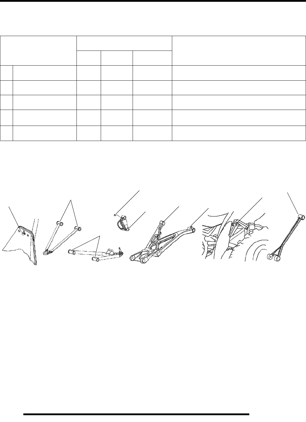
Upper Steering Post (A) 50 H 3 M 500 (800) Inspect; tighten fasteners; grease after washing
ATV or driving in water
Front A-arms (B) 50 H 3 M 500 (800) Inspect; tighten fasteners; grease (also after
washing ATV or driving in water)
Rear Control Arm
Bushings (C) 50 H 3 M 500 (800) Inspect; tighten fasteners; grease (also after
washing ATV or driving in water)
EStabilizer Bar (D) 50 H 6 M 500 (800) Grease
ERear Control Arm
Needle Bearings (E) 100 H 12 M 1000 (1600) Disassemble, clean, inspect bearings and seals,
grease, reassemble
ABC
EEC
DE
B
RepairPro Service Manual

2.7
MAINTENANCE
2
100 - 300 Hour Maintenance Interval
Periodic Maintenance Chart
Perform these procedures more often for vehicles subjected to severe use.
E Emission Control System Service (California)
Have an authorized Polaris dealer perform these services.
Item
Maintenance Interval
(whichever comes first) Remarks
Hours Calendar Miles
(Km)
EOil Tank Vent Hose 100 H 12M 1000 (1600) Inspect routing, condition
EFuel System 100 H 12M 1000 (1600) Check for leaks at tank cap, lines, fuel valve,
filter, pump, carburetor.
Replace lines every two years
EFuel filter 100 H 12 M 1000 (1600) Replace yearly
Coolant System
Pressure Test 100 H 12 M 1000 (1600) Pressure test system annually
Radiator 100 H 12M 1000 (1600) Inspect; clean external surfaces;
change coolant every 2 years
Cooling Hoses 100 H 12M 1000 (1600) Inspect for leaks
Engine Mounts 100 H 12M 1000 (1600) Inspect
Exhaust Pipe 100 H 12M 1000 (1600) Inspect
ESpark Plug 100 H 12M 1000 (1600) Inspect; replace as needed
EIgnition Timing - 12M - Inspect
Wiring 100 H 12M 1000 (1600) Inspect for wear, routing, security; apply
dielectric grease to connectors subjected to
water, mud, etc.
Clutch Plates 100 H 12M 1000 (1600) Inspect; replace worn parts
Brake Fluid 200 H 24M 2000 (3200) Change every two years
Front Wheel Bearings 300 H 36M 3000 (4800) Inspect; replace as needed
Spark Arrestor 300 H 36M 3000 (4800) Clean out as required
EIdle Speed -Adjust as needed
Toe Adjustment -Inspect periodically;
adjust when parts are replaced
Headlight Aim -Adjust as needed
2.8
MAINTENANCE
Maintenance References
* More often under severe use, such as operation in mud, water, sand or under severe loads.
** Every 10 hours of operation (refer to Maintenance Schedule for additional information). Change more often in extremely dirty
conditions such as continuous operation in water, mud or sand, continuous hot, cold, or short trip cold weather operation.
NOTE: Excessive clutch plate residue will accelerate oil change intervals.
*** Every 24 months or 200 hours of operation (refer to Maintenance Schedule for additional information).
More often under severe conditions such as continuous operation in water, mud or sand.
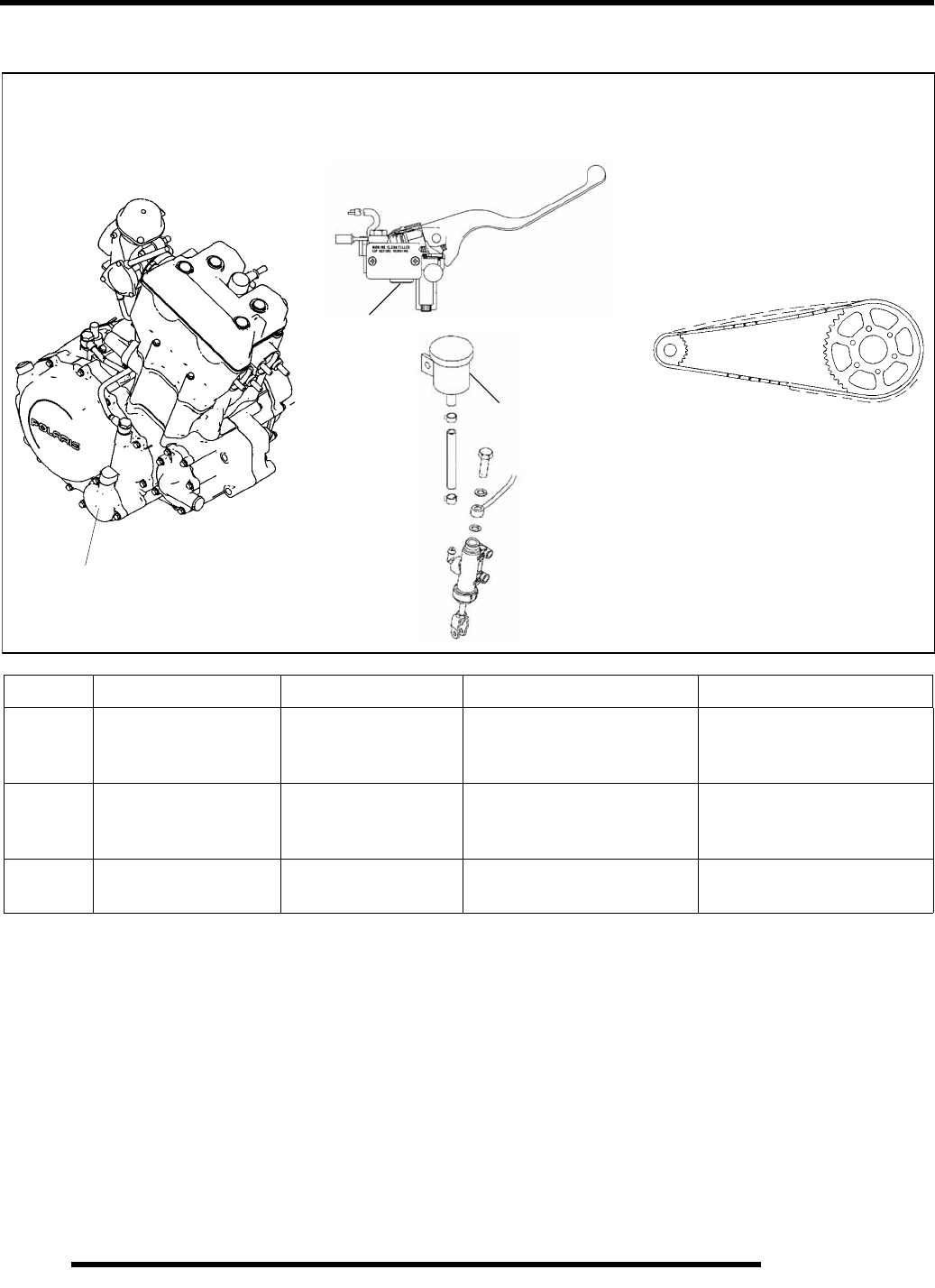
III. # Item Lube Rec. Method Frequency*
1. Engine Oil /
Transmission Polaris PS-4 Synthetic Check dipstick and add to
proper level.
Perform break–in oil / filter
change at one hour; change oil
every 10hrs / 100mi. **
2. Brake Fluid Polaris DOT 3 or DOT 4
Brake Fluid
Fill master cylinder reservoirs
to indicated level inside
reservoir.
As required. Change fluid every
2 years or 200 hours. ***
3. Drive Chain Polaris Chain Lube Apply to chain link plates and
rollers. As required *
1. Engine Oil and Filter
3. Rear Drive Chain
2. Brake Fluid
(Right hand and Foot
Brake Master Cylinder)
Oil Filter Location
Sight
Glass
Fill to Indicated
Level
RepairPro Service Manual

2.9
MAINTENANCE
2
LUBRICANTS AND SERVICE PRODUCTS
Polaris Lubricants, Maintenance and Service Products
PART NO. DESCRIPTION
ENGINE LUBRICANT
2874414 Engine Oil (Quart) PS 4 Synthetic (4-Cycle)
2874415 Engine Oil (Gallon) PS 4 Synthetic (4-Cycle)
GREASE / SPECIALIZED LUBRICANTS
2871322 Premium All Season Grease (3 oz. cartridge)
2871423 Premium All Season Grease (14 oz. cartridge)
2876006 Rear Shaft Grease
2871460 Starter Drive Grease
2871312 Grease Gun Kit
2871329 Dielectric Grease
2872073 Chain Lube (Aerosol)
COOLANT
2871323 60/40 Coolant (Gallon)
2871534 60/40 Coolant (Quart)
ADDITIVES / SEALANTS / THREAD LOCKING AGENTS / MISC.
2870791 Fogging Oil (12 oz. Aerosol)
2871326 Premium Carbon Clean (12 oz.)
2870652 Fuel Stabilizer (16 oz.)
2870585 Loctite™ Primer N, Aerosol, 25 g
2870990 DOT 3 Brake Fluid
2872189 DOT 4 Brake Fluid
2871956 Loctite™ Thread Sealant 565 (50 ml.)
2871949 Loctite™ Threadlock 242 (50 ml.)
2871950 Loctite™ Threadlock 242 (6 ml.)
2871951 Loctite™ Threadlock 262 (50 ml.)
2871952 Loctite™ Threadlock 262 (6 ml.)
2871953 Loctite™ Threadlock 271 (6 ml.)
2871954 Loctite™ Threadlock 271 (36 ml.)
2870584 Loctite™ RC 680–Retaining Compound (10 ml.)
2870587 Loctite™ 518 Gasket Eliminator / Flange Sealant (50 ml.)
2871957 Black RTV Silicone Sealer (3 oz. tube)
2871958 Black RTV Silicone Sealer (11 oz. cartridge)
8560054 Silicone Sealer (14 oz. cartridge)
2871557 Crankcase Sealant, 3–Bond 1215
2872893 Engine Degreaser
2.10
MAINTENANCE
GENERAL VEHICLE INSPECTION
AND MAINTENANCE
Pre-Ride / Daily Inspection
Perform the following pre-ride inspection daily, and when
servicing the vehicle at each scheduled maintenance.
• Tires – check condition and pressures
• Chain - Check tension, lubricate, adjust as needed
• Fuel and oil tanks – fill both tanks to their proper level;
Do not overfill oil tank
• All brakes – check operation and adjustment (includes
auxiliary brake
• Throttle – check for free operation
• Headlight/Taillight/Brakelight – check operation of all
indicator lights and switches
• Engine stop switch – check for proper function
• Wheels – check for loose wheel nuts and axle nuts;
check to be sure axle nuts are secured by cotter pins
• Air cleaner element – check for dirt or water; clean or
replace
• Steering – check for free operation, noting any unusual
looseness in any area
• Loose parts – visually inspect vehicle for any damaged
or loose nuts, bolts or fasteners
• Engine coolant – check for proper level at the recovery
bottle
Frame, Nuts, Bolts, and Fasteners
Periodically inspect the torque of all fasteners in accordance
with the maintenance schedule. Check that all cotter pins are in
place. Refer to specific fastener torques listed in each chapter.
FUEL SYSTEM AND AIR INTAKE
Fuel System
• Always stop the engine and refuel outdoors or in a well
ventilated area.
• Do not smoke or allow open flames or sparks in or near
the area where refueling is performed or where gasoline
is stored.
• Do not overfill the tank. Do not fill the tank neck.
• If you get gasoline in your eyes or if you swallow
gasoline, seek medical attention immediately.
• If you spill gasoline on your skin or clothing,
immediately wash it off with soap and water and
change clothing.
• Never start the engine or let it run in an enclosed area.
Engine exhaust fumes are poisonous and can result in
loss of consciousness or death in a short period of time.
• Never drain the float bowl when the engine is hot.
Severe burns may result.
Fuel Lines
1. Check fuel lines for signs of wear, deterioration, damage,
or leakage. Replace if necessary.
2. Be sure fuel lines are routed properly and secured with
cable ties.
WARNING
Gasoline is extremely flammable and
explosive under certain conditions.
CAUTION
Make sure lines are not kinked or pinched.
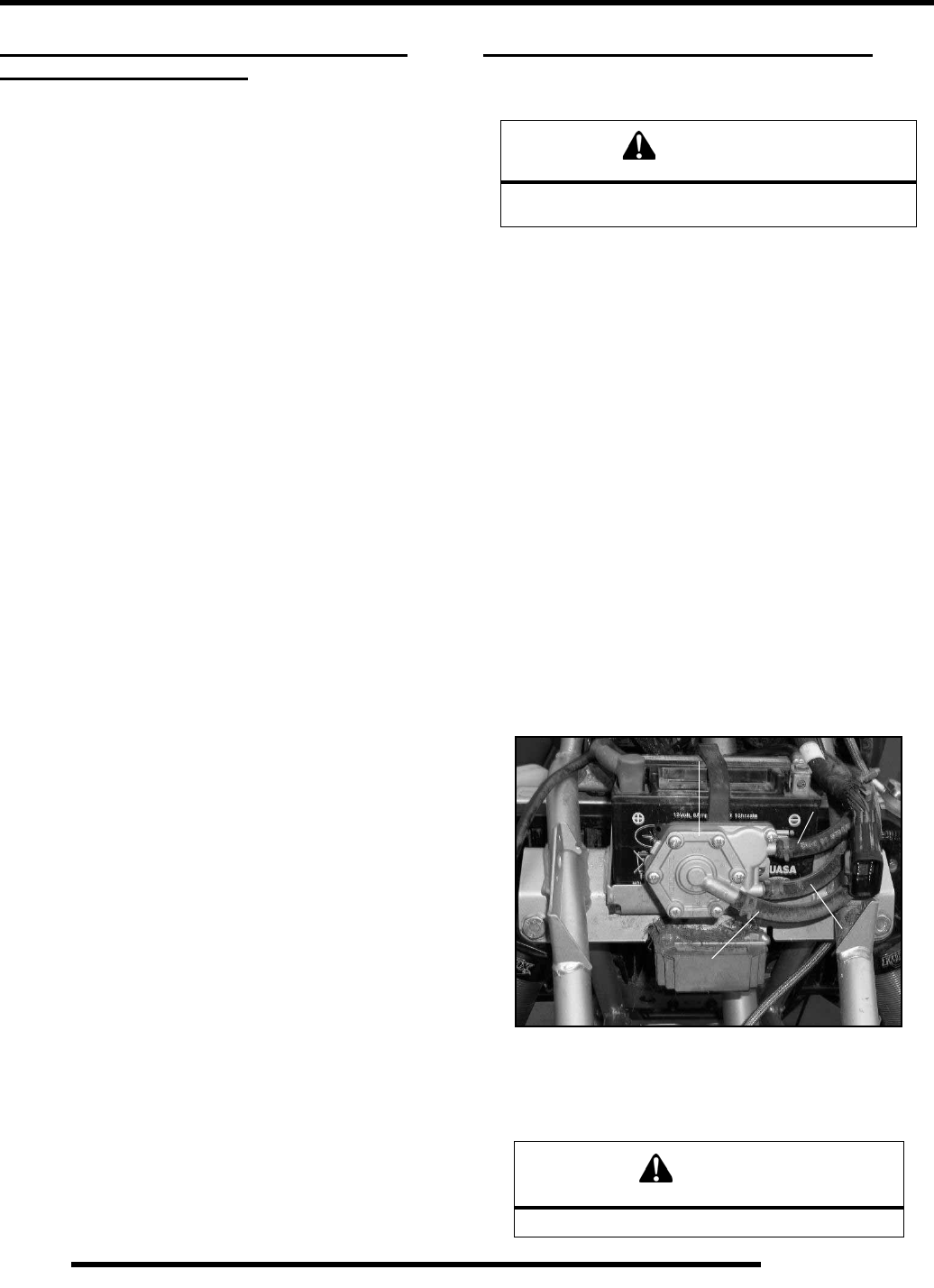
Fuel Pump
Pulse Line
Fuel Outlet
Fuel Inlet
RepairPro Service Manual
2.11
MAINTENANCE
2
3. Replace all fuel lines every two years.
Vent Lines
Check engine, fuel tank, oil tank, and carburetor vent lines for
signs of wear, deterioration, damage, or leakage. Replace every
two years.
Be sure vent lines are routed properly and secured with cable
ties.
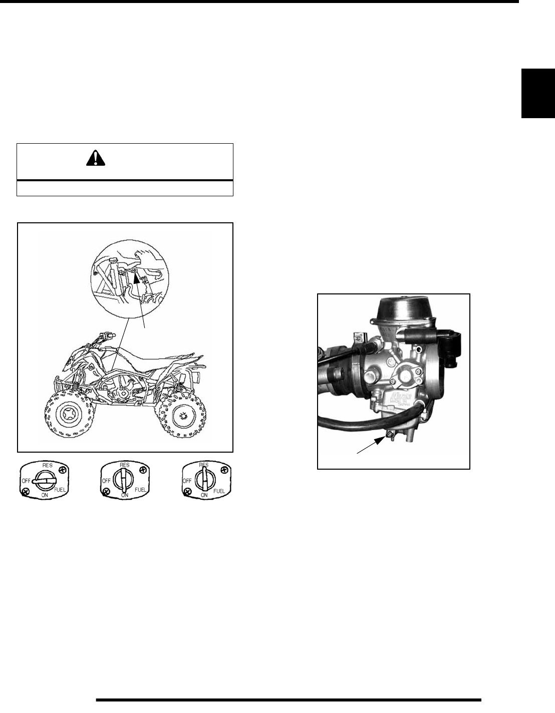
Fuel Valve
The fuel system strains the fuel through screens located in the
fuel valve. There is no fuel filter to service. To service the fuel
valve:
1. Shut off fuel supply at fuel valve. Remove line clamps and
fuel lines from the tank.
2. Remove the tank and drain remainder of fuel into a
appropriate container.
3. Remove fuel valve by loosening the screws holding the
valve to the tank.
4. Inspect the valve for damage or debris. Replace the valve
if problems are found.
5. Reverse the procedures to install the fuel valve.
6. Turn valve on, start engine and inspect for leaks.
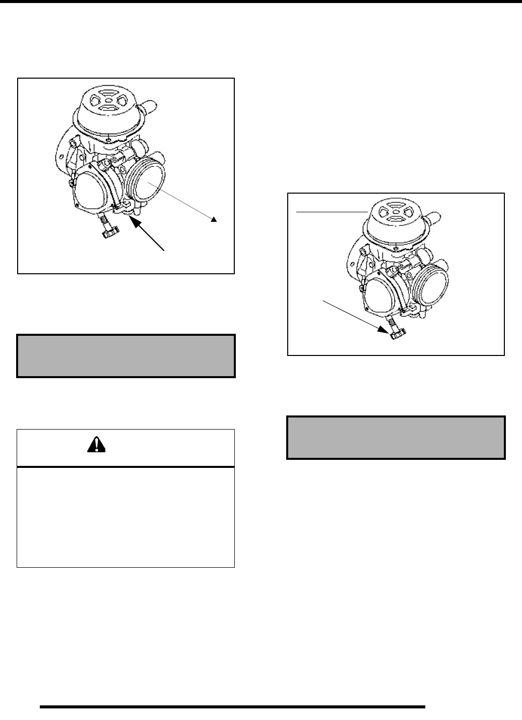
Carburetor Draining
The carburetor float bowl should be drained periodically, or
before extended periods of storage, to remove moisture or
sediment from the bowl.
NOTE: The bowl drain screw is located on the
bottom left side of the float bowl.
1. Turn fuel valve to the “Off” position.
2. Place a clean container beneath the bowl drain spigot or
bowl drain hose.
3. Turn drain screw out two turns and allow fuel in the float
bowl and fuel line to drain completely.
4. Inspect the drained fuel for water or sediment.
5. Tighten drain screw.
6. Turn fuel valve to “On”.
7. Start machine and check for leaks.
NOTE: All tubes attached to the carburetor must be
checked for pinching or blockage, as this will effect
engine performance.
CAUTION
Make sure lines are not kinked or pinched
Fuel Valve
Drain Screw
2.12
MAINTENANCE
Carburetor Pilot Screw Adjustment
NOTE: The pilot screw is covered by a brass welsh
plug per EPA requirements. Removal will be
required to perform these procedures.
1. Start the engine and warm it up to operating temperature
(about 10 minutes).
2. With engine off, turn pilot screw in (clockwise) until lightly
seated. Turn screw out the specified number of turns.
NOTE: Do not tighten the pilot screw forcefully
against the seat or the screw and/or seat will be
permanently damaged.
3. Connect an accurate tachometer that will read in increments
of + or - 50 RPM such as the PET 2100DX (PN
8712100DX) or the PET 2500 (PN 8712500). Start engine.
4. Set idle speed to 1600 RPM.
5. Slowly turn mixture screw clockwise using the pilot screw
or an appropriate sized screwdriver until engine begins to
miss.
6. Slowly turn mixture screw counterclockwise until idle
speed increases to maximum RPM. Continue turning
counterclockwise until idle RPM begins to drop.
7. Center the pilot screw between the points in Step 5 and 6.
8. Readjust idle speed to specification.
NOTE: Always check throttle cable freeplay after
adjusting idle speed and adjust if necessary.
Idle Speed Adjustment
NOTE: Adjusting the idle speed effects throttle
cable freeplay and electronic throttle control (ETC)
adjustment. Always check throttle cable freeplay
after adjusting idle speed and adjust if necessary.
1. Start engine and warm it up thoroughly.
2. Adjust idle speed by turning the idle adjustment screw in
(clockwise) to increase or out (counterclockwise) to
decrease RPM.
Throttle Inspection
Check for smooth throttle opening and closing in all handlebar
positions. Throttle lever operation should be smooth and lever
must return freely without binding.
1. Place the gear selector in neutral.
2. Set parking brake.
3. Start the engine and let it idle.
4. Turn handlebars from full right to full left. If idle speed
increases at any point in the turning range, inspect throttle
cable routing and condition. Adjust cable tension as needed
until lock-to-lock turning can be accomplished with no rise
in engine rpm.
5. Replace the throttle cable if worn, kinked, or damaged.
6. Inspect ETC cover seal and switch cavity by removing the
cover. Verify that no dirt, water or mud is present.
Pilot Screw Initial Setting:
Outlaw 500 - 2.5 Turns Out
CAUTION
The pilot screw is calibrated at the factory to meet
EPA / CARB regulations for air quality standards
and is sealed with a brass plug to prevent
tampering. Removal of the tamper proof plug is
not permitted. For service purposes, cleaning of
the pilot circuit can be done only by a certified
repair shop to ensure air quality standards
are not exceeded.
Pilot Screw Location
FRONT
(Engine Side)
Idle Speed
1600 ± 100 RPM
Idle Screw
BSR Carburetor
RepairPro Service Manual
2.13
MAINTENANCE
2
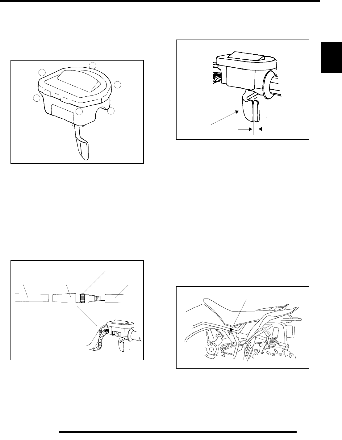
To remove the ETC cover:
1. Use a medium flat blade screwdriver and insert blade into
the pocket of the cover starting on the #1 position
2. Twist screwdriver slightly while lifting on the cover to
release snap.
3. Repeat procedure at the other five locations as shown.
NOTE: Do not attempt to remove cover until all latch
points are released.
Throttle Cable / Electronic Throttle Control
(ETC) Adjustment
1. Slide boot off throttle cable adjuster and jam nut.
2. Place shift selector in neutral and set parking brake.
3. Start engine and set idle to 1600 RPM.
NOTE: Be sure the engine is at operating
temperature. See Idle Speed Adjustment.
4. Loosen lock nut on in–line cable adjuster.
5. Turn adjuster until 1/16” to 1/8” (1-2mm) freeplay is
achieved at thumb lever. After making adjustments,
quickly actuate the thumb lever several times and reverify
freeplay.
6. Tighten lock nut securely and slide boot completely in
place to ensure a water–tight seal.
7. Turn handlebars from left to right through the entire turning
range. If idle speed increases, check for proper cable
routing. If cable is routed properly and in good condition,
repeat adjustment procedure.
Choke Adjustment
If the choke knob does not stay out when pulled, adjust the choke
tension by tightening (clockwise) the jam nut under the rubber
boot between the choke knob and nut. Firmly grasp the rubber
boot and tighten until the choke slides freely but stays out when
pulled.
Verify free play of 1/16-3/16” (1.6-4.76 mm) and smooth
operation of choke cable.
If smooth choke operation is not obtainable, inspect choke cable
for kinks or sharp bends in routing.
Air Filter and Pre-filter Service
It is recommended that the air filter and pre-filter be inspected
frequently. When riding in extremely dusty conditions,
replacement is required more often.
5
6
4
32
1
Boot Adjuster Sleeve
Lock Nut
Boot
1/16”-1/8”
Direction of Travel
Freeplay
(1-2mm)
Choke
2.14
MAINTENANCE
The pre filter should be cleaned before each ride using the
following procedure:
1. Unlatch and remove the seat.
2. Release the two air box cover clips (A) and rotate the cover
rearward to remove it.
3. Remove the air filter retaining screw (B).
4. Loosen the filter clamp (C).
5. Remove the main air filter (D).
6. Remove the pre-filter (E) from the main filter element.
7. Remove the breather filter (F).
Cleaning:
8. Wash the pre-filter (E) and breather filter (F) in soapy
water, then rinse and let dry.
9. Wash the main filter element (D) without removing it from
the internal filter cage. Rinse and let dry. When dry, apply
a commercially available foam filter oil thoroughly on the
element.
Installation:
10. Check the hoses for cracks, deterioration, abrasion, or
leaks. Replace as needed.
11. Reinstall crankcase breather filter, pre-filter and air filter
into air box. Install the air filter retaining screw.
12. Reinstall the air box cover and secure the cover with the two
clips.
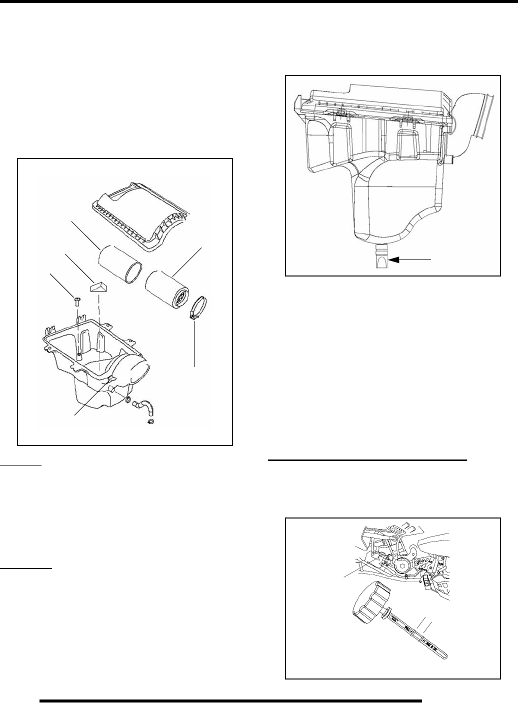
Air Box Drain Tube
Periodically check the air box drain tube located on the bottom
side of the air box. Be sure the drain tube is not obstructed by
mud or sand. Whenever deposits are visible, clean out the tube.
NOTE: The drain tube will require more frequent
inspection if the vehicle is operated in severe
conditions.
Crankcase Breather Filter Inspection
Outlaw ATV engines are equipped with a crankcase breather
filter in the air box. The filter is similar in appearance to a small
foam block, and is visible on the left side (See Illustration to the
left, Reference F).
The air breather filter should be inspected or replaced whenever
the air filter is inspected.
ENGINE AND TRANSMISSION
Engine Oil Level Check
Check the oil level before each use of the vehicle. The dipstick
is located on the left side of the ATV.
A
B
C
D
E
FDrain Tube
Dipstick
Location
Oil Level
Marks
RepairPro Service Manual
2.15
MAINTENANCE
2
1. Position the ATV on a level surface.
2. Start the engine and let it idle for one minute.
3. Stop the engine and remove the dipstick. Wipe it dry with
a clean cloth.
4. Reinstall the dipstick completely.
NOTE: The dipstick must be screwed completely in
to keep the angle and depth of the stick consistent.
5. Remove the dipstick and check the oil level. Maintain the
oil level in the safe range, between the full and add marks.
Do not overfill.
6. Reinstall the dipstick.
Engine Oil and Filter Service
IMPORTANT: Polaris PS-4 Engine Oil is
recommended for use in the Predator. PS-4 was
specifically designed for the Predator’s engine and
clutching system. Other oils do not contain the
needed additives to prolong engine life and provide
proper lubrication to the Predator clutch and
transmission components.
1. Place the vehicle on a level surface.
2. Clean the area around the oil tank and crankcase drain plugs
with clean shop towels.
3. Run the engine for two to three minutes until warm, then
stop the engine.
4. Place a drain pan beneath the oil tank and remove the drain
plug (1).
5. Allow the oil to drain completely.
6. Replace the sealing washer and reinstall the plug. Torque
to 14 ft. lbs. (19 Nm).
NOTE: The sealing surfaces on drain plugs, oil tank
and crankcase should be clean and free of burrs,
nicks or scratches.
7. Place a drain pan beneath the crankcase and remove the
drain plug (2).
8. Allow the oil to drain completely.
9. Replace the sealing washer and reinstall the plug. Torque
to 14 ft. lbs. (19 Nm).
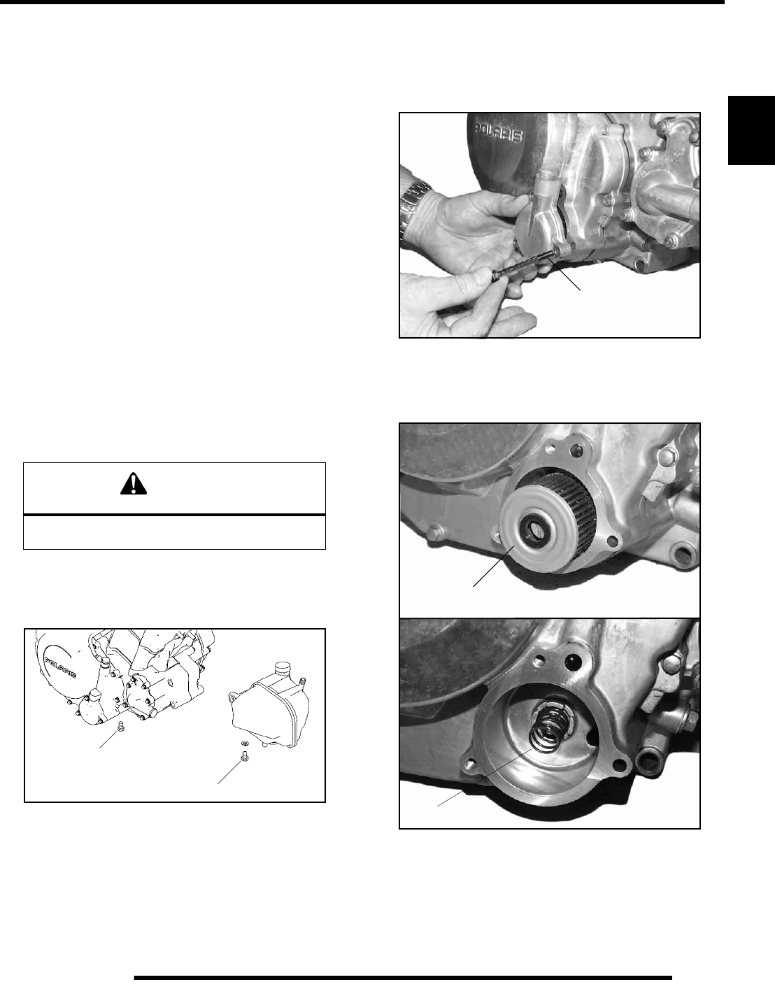
10. Place shop towels beneath the oil filter cover.
11. Remove the three cover bolts and remove the cover.
NOTE: A spring located behind the filter may pop
out as the filter is removed. The spring must be
reinstalled with the new filter.
12. Pull out the oil filter.
13. Using a clean dry cloth, clean the filter sealing surfaces.
WARNING
Hot oil can cause serious burns to the skin.
Do not allow hot oil to contact skin.
1
214 ft. lbs. (19 Nm)
72–78 in. lbs.
(8–9 Nm)
Oil Filter
Spring
2.16
MAINTENANCE
14. Replace the gasket in the cover.
15. Lubricate the gasket on the new filter with a film of fresh
engine oil.
16. Reinstall the spring and install the new filter with the open
end facing outward.
17. Install the cover and torque the bolts to 72–78 in. lbs. (8–
9 Nm).
NOTE: The long bolt must be placed in the forward
hole.
18. Remove the dipstick and fill the oil tank with 2.25 quarts
(1.9 l) of Polaris PS-4 Engine Oil (PN 2874414).
19. Place gear selector in neutral and set parking brake.
20. Start the engine and let it idle for one to two minutes. Stop
the engine and inspect for leaks.
21. Re–check the oil level on the dipstick and add oil as
necessary to bring the level to the upper mark on the
dipstick.
22. Dispose of used filter and oil properly.
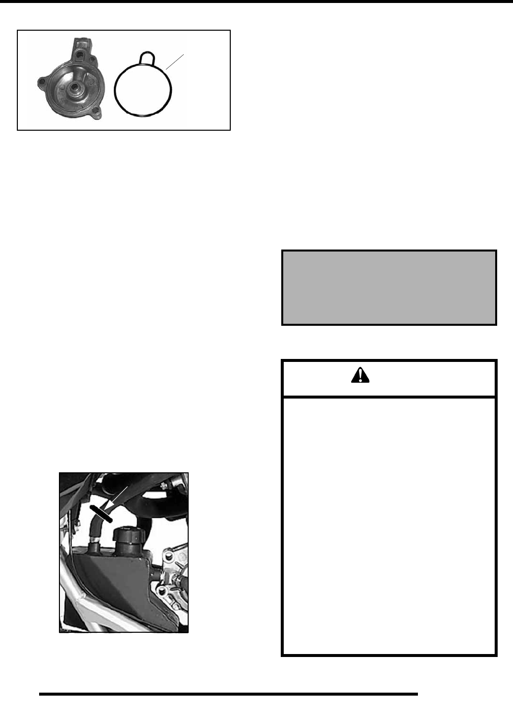
Oil Pump Priming Procedure
NOTE: The oil pump priming procedure should be
performed as a safeguard against loss of pump
prime when repairing oil tank, lines or engine.
1. Clamp or pinch off vent line approximately 2″ from oil
tank (P), between the end of oil tank vent fitting and the
vent line.
2. Run engine for 5-10 seconds at IDLE.
3. Shut off engine. Remove the vent line clamp. The oil pump
should now be properly primed and ready for field
operation.
NOTE: If the system is primed properly you should
hear some air release. If you do not, the system has
not primed. Repeat the process if necessary.
Compression Test
NOTE: This engine has built-in decompression
components. Compression readings will vary in
proportion to cranking speed during the test.
Average compression (measured) is about 85-90 psi
@ 400 RPM during a compression test.
A cylinder leakdown test is the best indication of engine
condition. Follow manufacturer’s instructions to perform a
cylinder leakage test. (Never use high pressure leakage testers,
as crankshaft seals may dislodge and leak).
Exhaust Pipe / Spark Arrestor
Gasket
P
Cylinder Compression w / decompression
Standard: 85-90 PSI @ 400 RPM
Cylinder Leakdown
Service Limit: 10%
(Inspect for cause if leakage exceeds 10%)
WARNING
• Do not perform clean out immediately after
the engine has been run, as the exhaust
system becomes very hot. Serious burns
could result from contact with exhaust
components.
• To reduce fire hazard, make sure that there
are no combustible materials in the area when
purging the spark arrestor.
• Wear eye protection.
• Do not stand behind or in front of the vehicle
while purging the carbon from the spark
arrestor.
• Never run the engine in an enclosed area.
Exhaust contains poisonous carbon monoxide
gas.
• Do not go under the machine while it is
inclined. Set the hand brake and block the
wheels to prevent roll back.
Failure to follow these warnings could result in
serious personal injury or death.
RepairPro Service Manual
2.17
MAINTENANCE
2
Periodically clean the spark arrestor to remove accumulated
carbon.
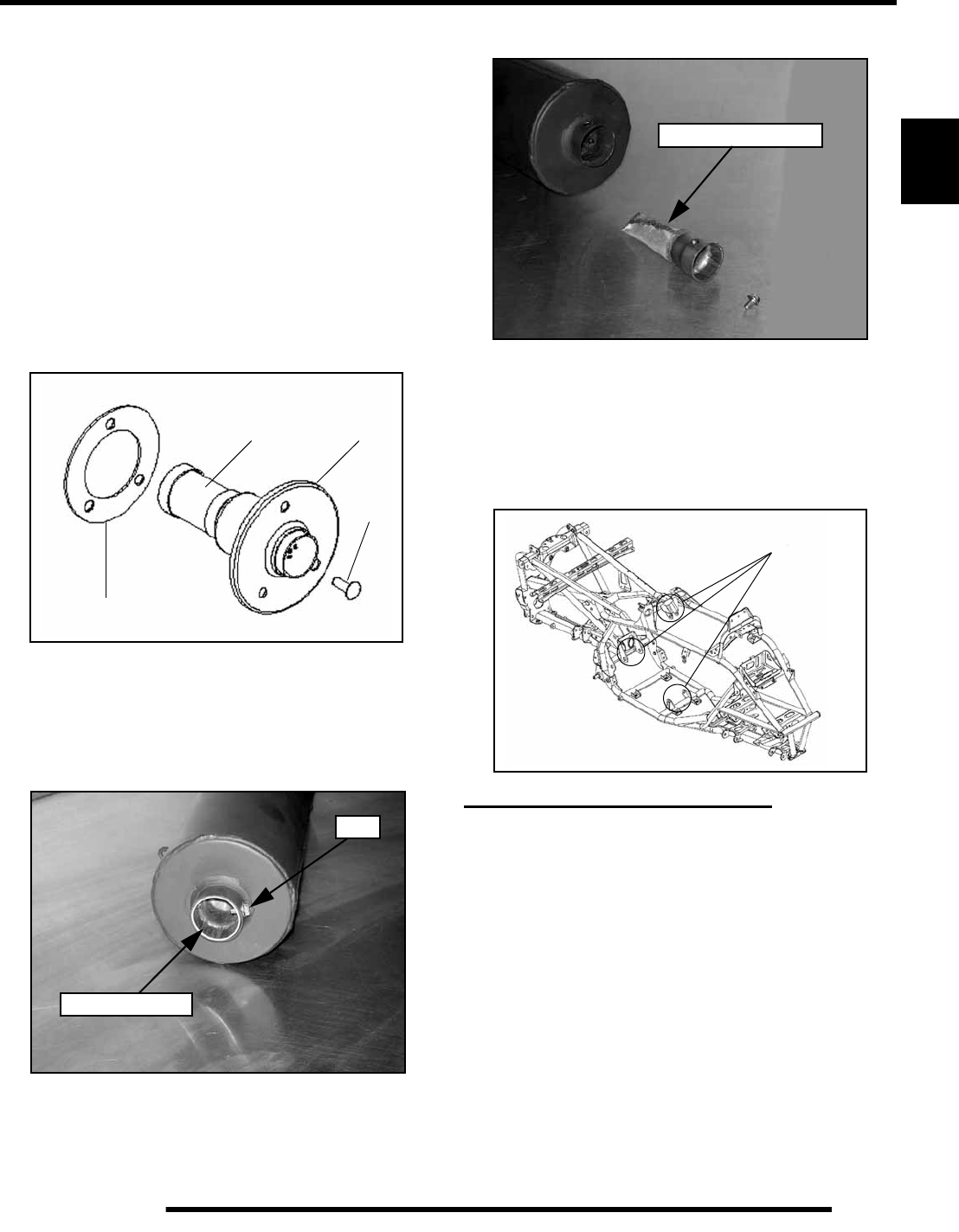
Verify which type of spark arrestor your ATV is equipped with
and follow the appropriate cleaning procedure below: (A) or (B)
Procedure A - End Cap Spark Arrestor
1. Remove the three screws (1) and remove the arrestor (2)
from the end of the muffler.
2. Use a non-synthetic brush to clean the arrestor screen (3).
A synthetic brush may melt if components are warm.
If necessary, blow debris from screen with compressed air.
3. Inspect the screen for wear and damage. Replace the
arrestor is damage is found.
4. Remove and inspect the gasket (4). Replace if worn or
damaged.
5. Reinstall the gasket and arrestor.
6. Torque screws to 50 in. lbs. (5.6 Nm).
Procedure B - Set Screw Type Spark Arrestor
1. Remove the bolt and remove the arrestor from the end of
the muffler.
2. Use a non-synthetic brush to clean the arrestor screen.
A synthetic brush may melt if components are warm.
If necessary, blow debris from screen with compressed air.
3. Inspect the screen for wear and damage. Replace the
arrestor is damage is found.
4. Reinstall the arrestor and torque the bolt to 7 ft. lbs.
(9.5 Nm)
Engine Mount Locations
Inspect engine mounts and frame for cracks or damage.
Check engine fasteners and ensure they are tight.
LIQUID COOLING SYSTEM
Cooling System Overview
The engine coolant level is maintained by the recovery
system.The recovery system components are the recovery
bottle, radiator filler neck, radiator pressure cap and connecting
hose.
As coolant operating temperature increases, the expanding
(heated) excess coolant is forced out of the radiator past the
pressure cap and into the recovery bottle. As engine coolant
temperature decreases the contracting (cooled) coolant is drawn
back up from the tank past the pressure cap and into the radiator.
• Some coolant level drop on new machines is normal as
the system is purging itself of trapped air. Observe
coolant levels often during the break–in period.
1
2
3
4
Spark Arrestor
Bolt
Inspect the screen
Engine Mounting Locations
2.18
MAINTENANCE
• Overheating of engine could occur if air is not fully
purged from system.
• Polaris Premium 60/40 anti-freeze is premixed and
ready to use. Do not dilute with water.
Coolant Strength / Type
Test the strength of the coolant using an antifreeze hydrometer.
• A 50/50 or 60/40 mixture of antifreeze and distilled
water will provide the optimum cooling, corrosion
protection, and antifreeze protection.
• Do not use tap water. Tap water contains minerals and
impurities which build up in the system. Do not add
straight antifreeze or straight water to the system.
Straight water or antifreeze may cause the system to
freeze, corrode, or overheat.
Cooling System Hoses
Inspect all hoses for cracks, deterioration, abrasion or leaks.
Replace if necessary.
1. Check tightness of all hose clamps.
2. Do not over–tighten hose clamps at radiator or radiator
fitting may distort, causing a restriction or leak. Radiator
hose clamp torque is 36 in.lbs. (4 Nm).
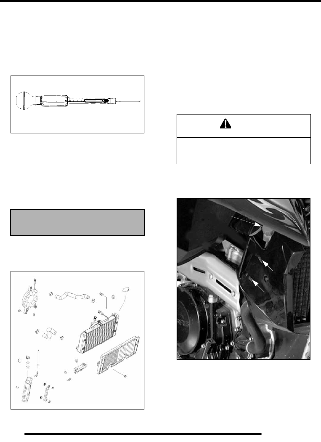
Radiator
1. Check radiator external air flow passages for restrictions or
damage.
2. Carefully straighten any bent radiator fins.
3. Remove any obstructions with compressed air or low
pressure water.
Recovery Bottle Coolant Level Inspection
The recovery bottle, is located on the right side of the vehicle
under the front fender. The fluid level must be maintained
between the FULL (A) and ADD (B) marks on the side panel
(when the fluid is cool).
If coolant is not between the FULL and ADD marks, perform the
following steps:
1. Remove reservoir cap. Verify the breather foam is in place
and the inner splash cap vent hole is clear and open.
Polaris 60/40 Anti-Freeze / Coolant
(PN 2871323)
Antifreeze Hydrometer WARNING
Never remove the radiator pressure cap when the
engine is warm or hot. Escaping stream and fluid can
cause severe burns. The engine must be allowed to
cool before removing the pressure cap.
Recovery Bottle
A
B
RepairPro Service Manual
2.19
MAINTENANCE
2
2. Fill reservoir to upper mark with Polaris Premium 60/40
Anti Freeze / Coolant (PN 2871323) or a mixture of
antifreeze and distilled water as required for freeze
protection in your area.
3. Reinstall cap.
NOTE: If overheating is evident, allow system to
cool completely and check coolant level in the
radiator. Inspect for signs of trapped air in system.
Cooling System Pressure Test
See Chapter 3 for testing procedures.
Radiator Screen Removal
1. Remove the 4 screws retaining the radiator screen for
access to the radiator fins when cleaning.
FINAL DRIVE
Clutch Adjustment
1. Measure clutch lever freeplay between the perch and the
lever (A). This distance should be 1/8” – 3/16” (3.1 mm –
4.7 mm)
2. If adjustment is required, slide the clutch perch pivot boot
down the clutch cable to access the clutch adjustment screw
(B) and lock ring (C).
3. Loosen the lock ring and turn the screw in (clockwise) to
increase lever travel. Turn the screw out
(counterclockwise) to decrease lever travel. Tighten the
lock ring.
4. Squeeze the lever fully and release. Slightly squeeze the
lever again until a slight resistance is felt. Measure the
freeplay again. If necessary, repeat the adjustment
procedure until proper freeplay is attained.
5. Replace the clutch perch pivot boot over the screw and lock
ring.
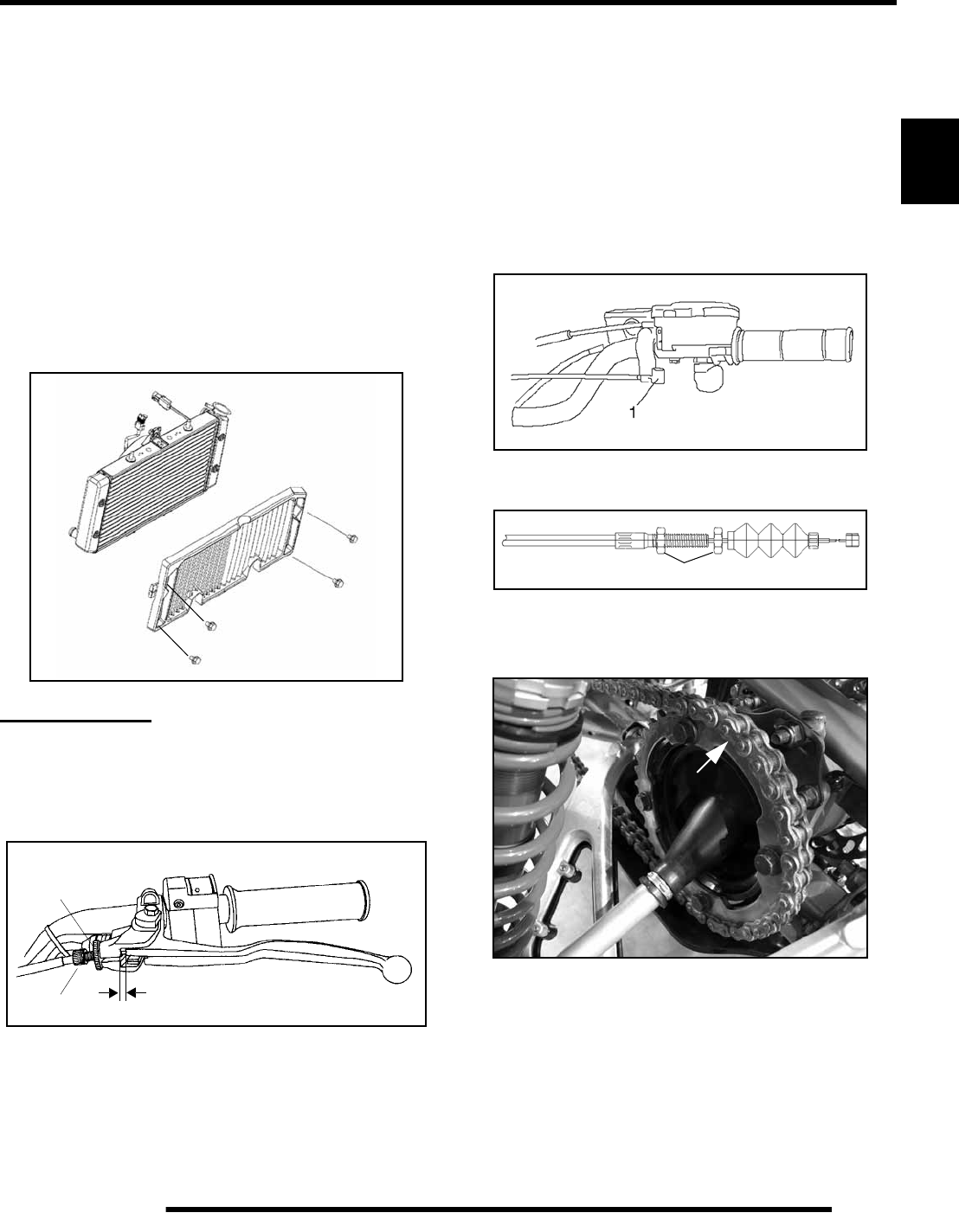
Reverse Lock-Out Lever Inspection and
Cable Adjustment
Check for smooth lever operation and ensure that the lever
returns freely without binding (1).
Adjust the reverse cable freeplay to .08”-.12” by adjusting the
cable jam nuts (2).
Sprocket Inspection
Inspect the sprocket for worn, broken or bent teeth.
To check for wear, pull upward on the chain at the area indicated
(arrow). Replace sprocket if chain movement exceeds 1/4”
(.6 cm).
A
B
C
CLUTCH LEVER FREEPLAY
2
2.20
MAINTENANCE
Drive Chain Inspection / Replacement
Inspect the drive chain for missing or damaged O–Rings, link
plates, or rollers. Do not wash the chain with a high pressure
washer, gasoline or solvents; do not use a wire brush to clean the
chain as damage to the O–Rings may occur. Clean chain with
hot soapy water and a soft bristled nylon brush.
Polaris ATV drive chains are equipped with O–ring sealed
permanently greased pins and rollers.The sprockets and outer
rollers require periodic lubrication. Lubricate the chain with
Polaris Chain Lubricant (PN 2872073).
Never allow battery acid to contact the drive chain.
The chain must be replaced when it reaches 3% elongation.
1. Stretch the chain tightly in a straight line.
2. Measure the length of 21 pitches (pins) from pin center to
pin center, and compare to the specification. Replace the
chain if the length exceeds the wear limit.
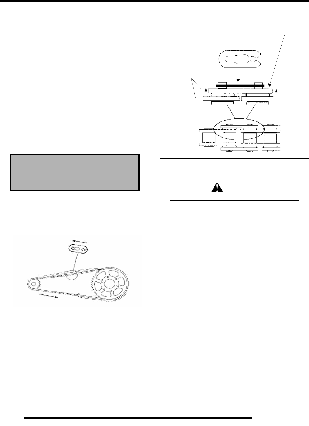
3. When replacing or reinstalling drive chain, install the
closed end of the splice link clip as shown, with the closed
end leading in forward operation. There should be a .003-
.005″ (.076-.127 mm) gap between the side plate of the
chain and the splice link clip. See illustrations below.
Drive Chain Tension
BREAK-IN: It is extremely important to maintain proper chain
tension to ensure the best possible chain life. There is a chain
break–in period of approximately 100 miles or two (2) tanks of
fuel. During this time chain tension should be watched very
closely and loads to the chain should be kept light.
CHECKING CHAIN TENSION:
Check the amount of chain slack by moving the vehicle slightly
forward to remove slack at the top side of the chain. At the
center point of the top side of the chain there should be 1/4” - 3/
8” (6-9 mm) deflection.
NOTE: The chain has a press-on master link. A
chain tool must be used if it’s necessary to remove
the chain for service.
Drive Chain Wear Limit, 21 Pitch Length:
Std: 12.5″(32 cm)
Wear Limit: 12.875” (32.7 cm)
Proper Spacelink Clip Opening Position
.003 - .005″
(.076- .127 mm)
Gap after installation
CAUTION
Never adjust or operate the vehicle with the rear drive
chain too loose or too tight. Severe damage to the
transmission and drive components can result.
Master Link
Do not press
plate in too far
If a gap is noticed between the outside edge
of the master link and plate, back the plate out
and close the gap.
RepairPro Service Manual
2.21
MAINTENANCE
2
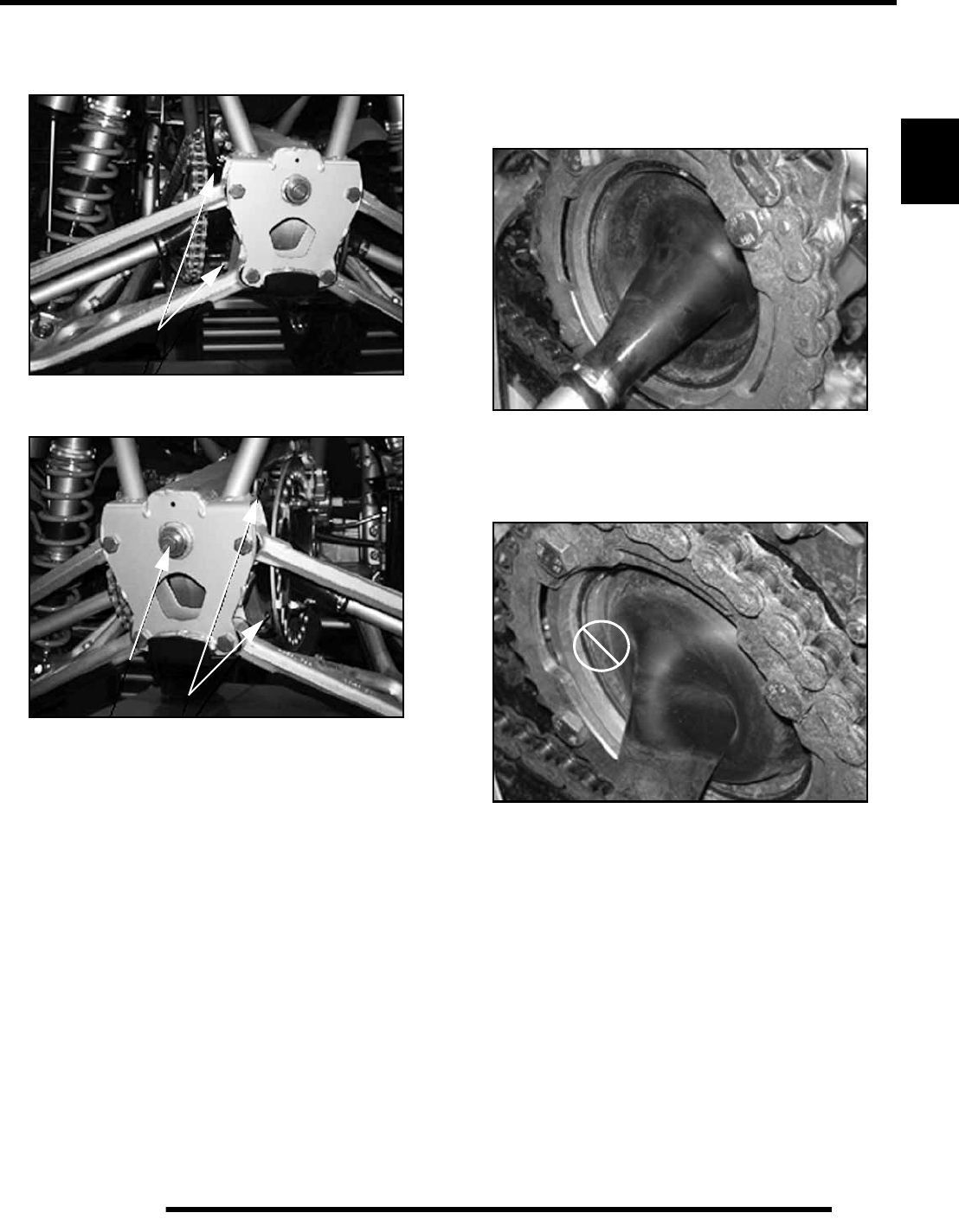
Drive Chain Adjustment
1. Loosen the upper and lower pivot mounting bolts (1).
2. Thread the chain adjusting bolt (2) inward or outward to
adjust chain slack to the proper dimension.
3. Torque the pivot mounting bolts to 30 ft. lbs. (41 Nm).
4. Torque the chain adjusting bolt to 20 ft. lbs. (27 Nm).
Rear Driveshaft Boot Inspection
Before Operating
Inspect the boots before operating the vehicle. If a boot is torn,
punctured or leaking fluid, replacement is required.
After Operating
Inspect the boots after operating the vehicle. If a boot is bulging
or ballooned, perform the boot “burping” procedure.
1
2
1
OK
2.22
MAINTENANCE
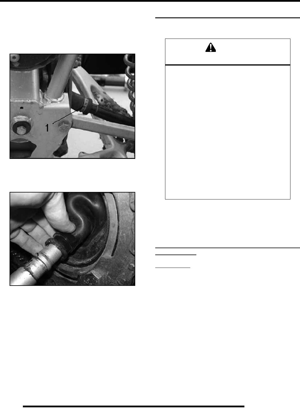
Rear Driveshaft Boot “Pressure Equalizing”
1. Using a needle nose pliers or boot clamp removal tool,
remove the small boot clamp (1) from the inboard boot.
NOTE: Do not use any tools that may damage the
boot.
2. Slide the free end of the boot two inches toward the center
of the vehicle and lift the boot away from the shaft to allow
excess air to escape.
3. Wipe excess grease from the shaft before returning the boot
to the boot groove. Use caution not to allow excess air back
into the system when reinstalling the boot.
4. Reinstall the boot clamp.
ELECTRICAL AND IGNITION SYSTEM
Battery Maintenance
The battery is located under the front cab at the front of the ATV.
NOTE: The Outlaw battery is a Low Maintenance
design and construction. Before placing the battery
into service, check the battery condition and charge
accordingly.
Use of Conventional Lead-Acid batteries is not
recommended.
New Batteries: Batteries must be fully charged before use or
battery life will be reduced by 10–30% of full potential.
Charge battery for 3-5 hours at a current equivalent of 1/10 of
the battery’s rated amp/hour capacity (i.e. 9 amp hr x.10 =.9
amp charging). Do not use the alternator to charge a new bat-
tery.
Maintenance-Free batteries are sealed at the factory. The use of
lead-calcium instead of lead-antimony allows the battery acid to
be fully absorbed by the plates. Therefore, a Maintenance-Free
battery case is opaque and the sealing caps are not removable,
since there is no need to check electrolyte level.
IMPORTANT: Never attempt to add electrolyte or
water to a Maintenance-Free battery. Doing so will
damage the case and shorten the life of the battery.
WARNING
Battery electrolyte is poisonous. It contains
sulfuric acid. Serious burns can result from
contact with skin, eyes or clothing. Antidote:
External: Flush with water.
Internal: Drink large quantities of water or milk.
Follow with milk of magnesia, beaten egg, or
vegetable oil. Call physician immediately.
Eyes: Flush with water for 15 minutes and get
prompt medical attention.
Batteries produce explosive gases. Keep
sparks, flame, cigarettes, etc. away. Ventilate
when charging or using in an enclosed space.
Always shield eyes when working near
batteries. KEEP OUT OF REACH OF
CHILDREN.
RepairPro Service Manual
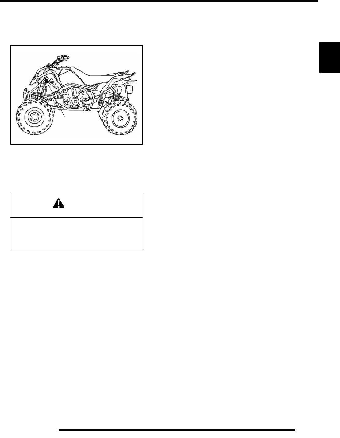
2.23
MAINTENANCE
2
Battery Inspection / Removal
The battery is located under the front cab at the front of the ATV.
Removal of the front cab assembly is required to access the
battery. Refer to “Chapter 5” for front cab removal.
To remove the battery:
1. Remove the front cab.
2. Disconnect holder strap.
3. Disconnect battery negative (–) (black) cable first,
followed by the positive (+) (red) cables.
4. Remove the battery.
5. Clean battery cables and terminals with a stiff wire brush.
Corrosion can be removed using a solution of one cup water
and one tablespoon baking soda. Rinse well with clean
water and dry thoroughly. Test battery for condition and
charge accordingly.
6. If required, charge battery at 1/10 of its amp/hour rating.
Example: 1/10 of 14 amp battery = 1.4 amp
7. Reinstall battery, attaching positive (+) (red) cable first and
then the negative (–) (black) cable.
8. Coat terminals and bolt threads with Dielectric Grease (PN
2871329).
9. Reinstall battery cover, holder strap and front cab.
Battery Terminals / Bolts
Ensure battery terminals are clean of corrosion. Use Polaris
corrosion resistant Dielectric Grease (PN 2871329) on battery
bolts.
Off Season Storage
To prevent battery damage during extended periods of non–use,
the following basic battery maintenance items must be
performed:
• Remove the battery from the machine and wash the
case and battery tray with a mild solution of baking
soda and water. Rinse with fresh water after cleaning.
NOTE: Do not get any of the baking soda into the
battery or the acid will be neutralized.
• Using a wire brush or knife, remove any corrosion from
the cables and terminals.
•Never add water to a sealed maintenance free
battery.
• Charge at a rate no greater than 1/10 of the battery’s
amp/hr capacity until the open circuit voltage is 12.9V
or greater.
• Store the battery either in the machine with the cables
disconnected, or store in a cool place.
Engine- To- Frame Ground
Inspect engine–to–frame ground cable connection. Be sure it is
clean and tight.
Charging Procedure
NOTE: Remote charging terminals have been
provided to allow for battery charging without
removal of the front cab.
1. Attach the Positive battery charging cable to the Red
Charge Terminal (A); which is directly connected to the
positive battery terminal. It is located just above the front
right shock mount.
2. Attach the Negative battery charging cable to the free end
of the Black Cable (B) under the right front cab (which is
directly connected to the negative battery terminal).
CAUTION
To reduce the chance of sparks: Whenever
removing the battery, disconnect the
negative (black) cable first. When reinstalling
the battery, install the negative cable last.
Battery
Location
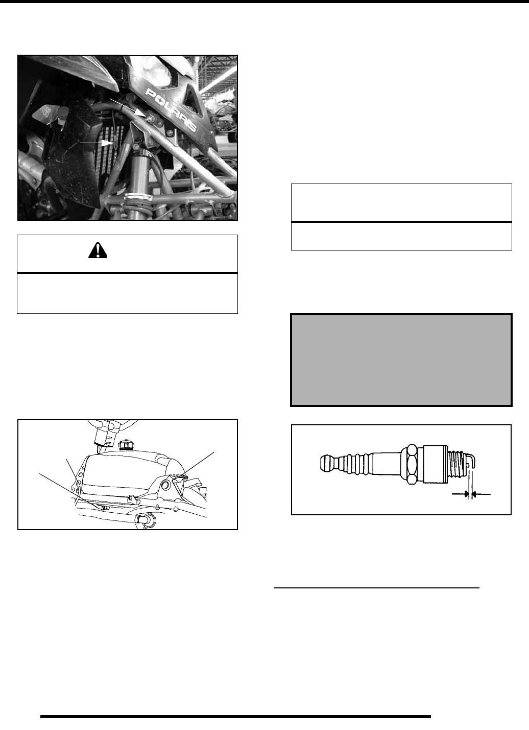
2.24
MAINTENANCE
3. Charge with a charging output no larger than 1/10 of the
battery's amp/hr rating. Charge as needed to raise the open
circuit voltage to 12.9 V or greater.
Spark Plug Inspection
Spark Plug Removal and Replacement
1. Turn the fuel valve to OFF.
2. Remove the side panels and front cab.
3. Move the fuel valve hose clamp forward and gently remove
the hose (1) from the fuel valve fitting on the gas tank.
4. Remove the vent hose (2) from the instrument panel, taking
note of the hose routing for reinstallation.
5. Remove the tank mounting bolt (3) at the rear of the gas
tank.
6. Move the tank rearward and upward over the engine.
Slowly remove the tank, being careful not to catch any
hoses, wires or other components. Place the tank on a stable
surface or work bench to protect the valve from
contamination or damage.
7. Remove spark plug high tension lead. Clean plug area so
no dirt and debris can fall into engine when plug is
removed.
8. Remove spark plug. and inspect electrodes for wear and
carbon buildup. The insulator tip should be a light tan color,
indicating good combustion. Look for a sharp outer
electrode edge with no rounding or erosion.
9. If needed, clean spark plug with electrical contact cleaner
or a glass bead spark plug cleaner only.
NOTE: Wire brushes or coated abrasives should not
be used.
10. Measure gap with a wire gauge. Refer to specifications for
proper spark plug type and gap. Adjust gap if necessary by
bending the side electrode carefully.
11. If necessary, replace spark plug with proper type.
12. Apply a small amount of anti–seize compound to the spark
plug threads.
13. Install spark plug and torque to specification. Reverse steps
as needed for reassembly.
Ignition Timing
Timing is non-adjustable. Refer to Chapter 7 for ignition timing
inspection.
STEERING AND SUSPENSION
Steering
The steering components should be checked periodically for
loose fasteners, worn tie rod ends, ball joints, and damage. Also
check to make sure all cotter pins are in place. If cotter pins are
removed, they must not be re–used. Always use new cotter pins.
WARNING
To avoid the possibility of explosion or sparks,
connect positive (red) cable first and negative
(black) cable last.
A
B
1
23
CAUTION
Severe engine damage may occur if the
incorrect spark plug is used.
Recommended Spark Plug:
NGK DCPR8E
Spark Plug Torque:
14 Ft. Lbs. (19 Nm)
Spark Plug Gap
.035″ (0.9mm)
RepairPro Service Manual
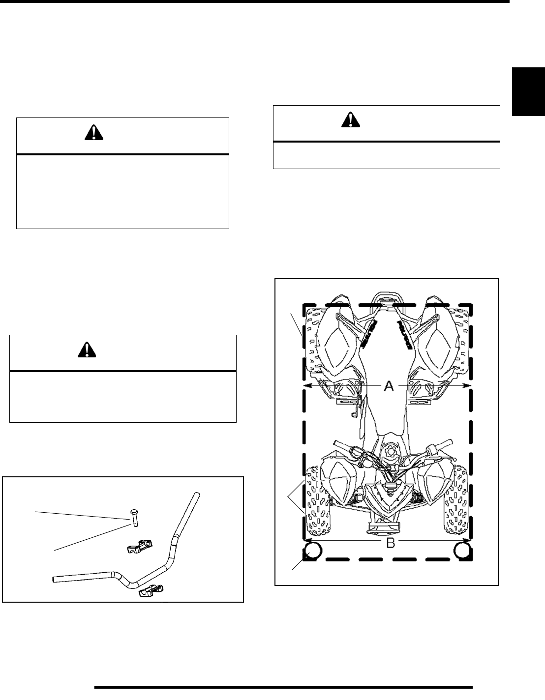
2.25
MAINTENANCE
2
Replace any worn or damaged steering components. Steering
should move freely through entire range of travel without
binding. Check routing of all cables, hoses, and wiring to be sure
the steering mechanism is not restricted or limited.
NOTE: Whenever steering components are
replaced, check front end alignment. Use only
genuine Polaris parts.
Controls
Check controls for proper operation, positioning and
adjustment.
Handlebars
If desired, the handlebars can be adjusted for rider preference.
1. Loosen the four bolts and adjust the handlebar to the
desired height. Be sure the handlebars do not contact the
gas tank or any other part of the machine when turned fully
to the left or right.
2. Torque the rear two bolts to 11 ft. lbs. (15 Nm), then torque
the front two bolts. A gap of up to 1/8” will remain at the
rear bolts.
Wheel Alignment
One of two methods can be used to measure toe alignment. The
string method and the chalk method. If adjustment is required,
refer to following for procedure.
METHOD 1: USING A STRAIGHTEDGE OR STRING
1. Position the vehicle on a level surface.
NOTE: Always measure toe alignment on a flat
ground surface.
2. Place the handlebars in a straight-ahead position. Use tie
straps to secure the handlebars to the rear grab bar so they
can’t move.
3. Place stands (1) in front of the vehicle, perpendicular to the
rear tires. See illustration below.
4. Tie an elastic string (2) around the stands, making sure the
string just touches the side surface of the rear tires on each
side of the vehicle and goes around the stands in front of
the vehicle.
WARNING
Due to the critical nature of the procedures outlined in
this chapter, Polaris recommends steering component
repair and adjustment be performed by an authorized
Polaris MSD certified technician when replacing
worn or damaged steering parts.
Use only genuine Polaris replacement parts.
WARNING
Improper adjustment of the handlebars or incorrect
torquing of the adjuster lock bolts can cause limited
steering of the handle bars, which could result in
loss of control and serious injury or death.
1
11 ft. lbs.
(15 Nm)
WARNING
Severe injury or death can result from improper toe
alignment and adjustment.
2
3
1
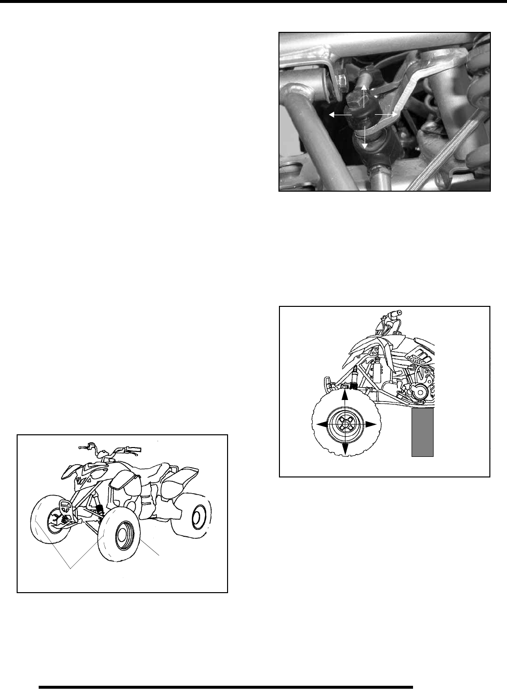
2.26
MAINTENANCE
5. Measure the distance between the string in front of the rear
tires (A) and in front of the front tires (B). If the two
measurements are not equal, adjust the string position until
the measurements are equal.
6. Measure the distance from the string to the rim at the front
and rear of the front rim (3). The difference between these
two measurements should be between 0” and 1/16” toe out.
METHOD 2: USING A CHALK LINE
1. Place machine on a smooth level surface.
2. Set handlebars in a straight ahead position and secure
handlebars in this position. NOTE: The steering post arm
“frog” can be used as an indicator of whether the handlebars
are straight. The frog should be centered with equal
clearance between the steering stops.
3. Place a chalk mark on the center line of the front tires as
close to the hub/axle center line as possible, or measure to
a specific distance from the floor. NOTE: It is important
that the height of both marks be equally positioned in order
to get an accurate measurement.
4. Measure the distance between the marks and record the
measurement. Call this measurement “A”.
5. Rotate the tires 180o by moving vehicle forward or
backward. Position chalk marks even with the hub/axle
centerline or the specified floor measurement.
6. Again measure the distance between the marks and record.
Call this measurement “B”. Subtract measurement “B”
from measurement “A”. The difference between
measurements “A” and “B” is the vehicle toe alignment.
The recommended vehicle toe tolerance is 0 to 1/16” (0
to.0625 cm) toe out. This means the measurement at the
front of the tire (A) is 0 to 1/16” (0 to.0625 cm) wider than
the measurement at the rear (B).
Steering Inspection / Tie Rod Ends and Hubs
• To check for play in the tie rod end, grasp the steering
tie rod, pull in all directions feeling for movement.
• Repeat inspection for inner tie rod end on steering post.
• Elevate front end of machine so front wheels are off the
ground. Check for any looseness in front hub / wheel
assembly by grasping the tire firmly at top and bottom
first, and then at front and rear. Try to move the wheel
and hub by pushing inward and pulling outward.
• If abnormal movement is detected, inspect the hub and
wheel assembly to determine the cause (possible loose
wheel nuts or loose front hub components).
• Refer to the Body/Suspension Chapter 5 or Final Drive
Chapter for service procedures.
Chalk Line
Chalk Line Measurement ‘A’
Measurement ‘B’
Check for Loose Wheel or Hub
RepairPro Service Manual
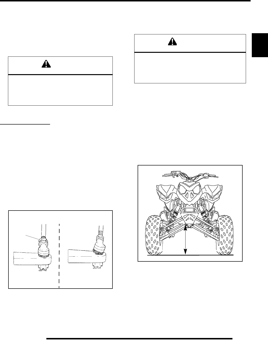
2.27
MAINTENANCE
2
Toe Alignment Adjustment
If toe alignment is incorrect, measure the distance between
vehicle center and each wheel. This will tell you which tie rod
needs adjusting.
NOTE: Be sure handlebars are straight ahead before
determining which tie rod(s) need adjustment.
To adjust toe alignment:
• Hold tie rod end to keep it from rotating.
• Loosen jam nuts at both ends of the tie rod.
• Shorten or lengthen the tie rod until alignment is as
required to achieve the proper toe setting as specified in
Method 1 or Method 2.
•IMPORTANT: When tightening the tie rod end jam
nuts, the rod ends must be held parallel to prevent rod
end damage and premature wear. Damage may not be
immediately apparent if done incorrectly.
• After alignment is complete, torque jam nuts to
specification.
Camber and Caster
The camber and caster are non–adjustable.
Suspension Spring Preload Adjustment
The front suspension preload may be adjusted to suit different
conditions and operator weight.
Front Suspension Set-Up
1. Position the vehicle on a level surface.
2. Stop the engine.
3. Elevate the front of the vehicle by placing a suitable stand
under the frame.
NOTE: The tires should be barely touching the
ground and the suspension should be at full
rebound.
4. Measure the distance from the ground to the bottom of the
lower front bumper bolt. Note this measurement for later
use.
5. Remove the support stand and have a rider sit comfortably
on the seat with hands on the handlebars.
6. Place the transmission in neutral and slowly roll the
machine forward and backward at least ten feet (3 m)
without lifting or pushing down on the suspension.
7. Turn the handlebars fully to the left and right.
8. With the rider still on the vehicle, repeat the measurement
performed in step 4.
CAUTION
During tie rod adjustment, it is very important that
the following precautions be taken when
tightening tie rod end jam nuts.
If the rod end is positioned incorrectly it will not
pivot, and may break.
Hold Rod End Level While Nut Is Tightened
Correct Tie Rod End Incorrect Tie Rod End
12–14 ft. lbs.
(16–19 Nm)
WARNING
Uneven adjustment may cause poor handling of the
ATV, which could result in an accident and serious
injury or death. Always adjust both the left and right
spring preloads equally or have your Polaris
dealer perform the adjustments.
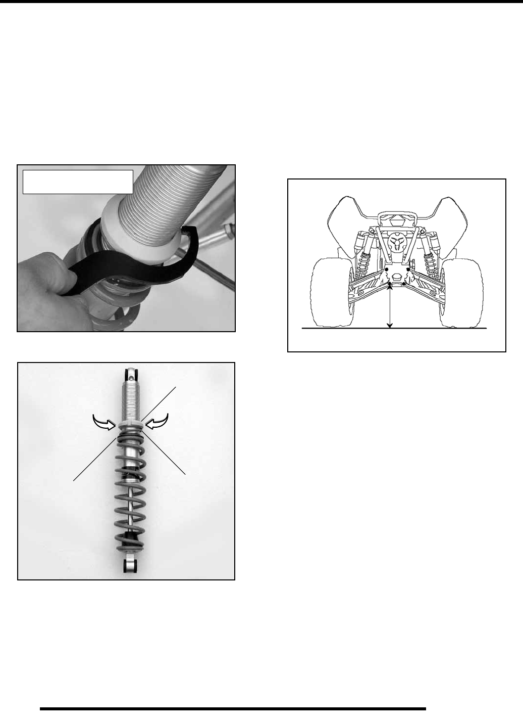
2.28
MAINTENANCE
9. Subtract the step 8 measurement from the step 4
measurement. The difference should be between 3.75 and
4 inches (9.5 - 10.2 cm).
10. If the number is less than 3.75 inches (9.5 cm), decrease the
front spring preload and repeat all steps (See “Front Spring
Preload Adjustment”). If the number is higher than 4 inches
(10.2 cm), increase spring preload and repeat all steps.
Front Spring Preload Adjustment
1. Raise and safely support the front of the ATV off the
ground to allow the suspension to fully extend.
2. Turn the adjusting ring (1) clockwise to increase preload or
counter-clockwise to decrease preload.
Rear Suspension Set-Up
1. Position the vehicle on a level surface.
2. Stop the engine.
3. Elevate the rear of the vehicle by placing a suitable stand
under the frame.
NOTE: The tires should be barely touching the
ground and the suspension should be at full
rebound.
4. Measure the distance from the ground to the bottom of the
rear lower control arm pivot bolt. Note this measurement
for later use.
5. Remove the support stand and have a rider sit comfortably
on the seat with hands on the handlebars.
6. Place the transmission in neutral and slowly roll the
machine forward and backward at least ten feet (3 m)
without lifting or pushing down on the suspension.
7. Turn the handlebars fully to the left and right.
8. With the rider still on the vehicle, repeat the measurement
performed in step 4.
9. Subtract the step 8 measurement from the step 4
measurement. The difference should be between 4 and 4.25
inches (10.2 - 10.8 cm).
10. If the number is less than 4 inches (10.2 cm), decrease the
rear spring preload on both shocks and repeat all steps. (See
“Rear Spring Preload adjustment”) If the number is higher
than 4.25 inches (10.8 cm), increase spring preload and
repeat all steps.
Rear Spring Preload Adjustment
• The rear suspension spring preload and shock
compression damping may be adjusted to suit different
riding conditions and operator weight.
1. Raise and safety support the rear of the ATV off the ground
to allow the suspension to fully extend.
Preload adjustment tool
is included in tool kit
Figure 2-27
Spring
Spacer
1
Ride-In
Spring
Increase
Preload
Decrease
Preload
RepairPro Service Manual
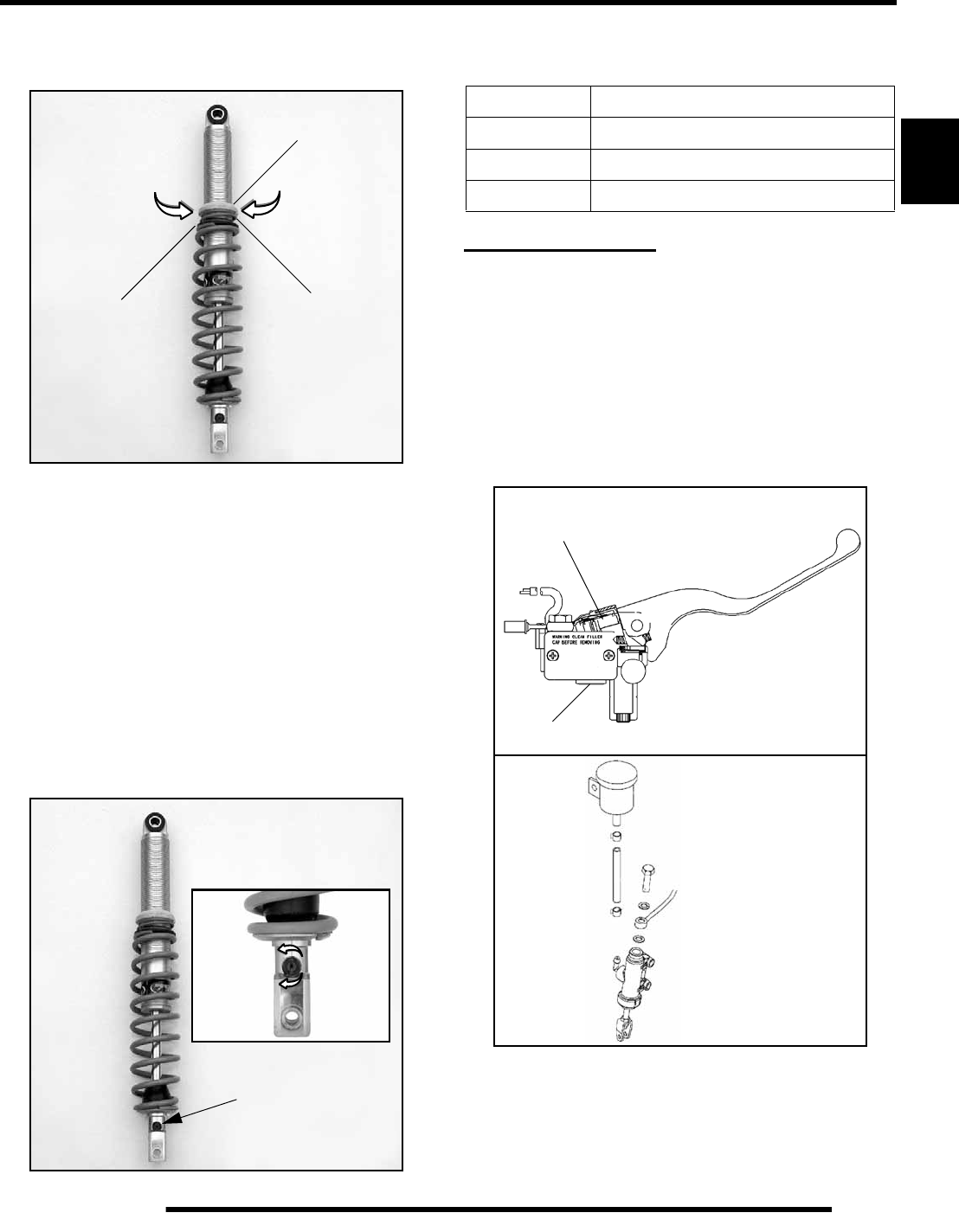
2.29
MAINTENANCE
2
2. Turn the adjusting ring (1) clockwise to increase preload or
counter-clockwise to decrease preload. See Figure 2-27 on
previous page.
Rear Shock Compression Adjustment
The compression damping adjustment is located on the bottom
of each rear shock.
Use a flat blade screwdriver to make adjustments. There are 7
positions of compression adjustment.
The softest adjustment is position #1. To obtain position #1,
turn the adjuster counter-clockwise until it stops.
The firmest adjustment is position #7. To obtain position #7,
start from position #1 and turn the adjuster clockwise 6 clicks.
The factory setting is position #4 or 3 clicks clockwise from
position #1.
BRAKE SYSTEM
Brake System Inspection
The following checks are recommended to keep the brake
system in good operating condition. Service life of brake system
components depends on operating conditions. Inspect brakes in
accordance with the maintenance schedule and before each ride.
• Keep fluid level in the master cylinder reservoir to the
indicated level inside reservoir.
• Use Polaris DOT 3 or DOT 4 Brake Fluid
• Check brake system for fluid leaks.
• Check brake for excessive travel or spongy feel.
• Check friction pads for wear, damage or looseness.
1
Spring
Spacer
Ride-In
Spring
Increase
Preload
Decrease
Preload
Compression Adjustment
Location
7 Positions
Position 1 - Full Counter-Clockwise.
Position 7 - 6 Clicks Clockwise from
Position 1.
Softest - 1
Firmest - 7
Factory - 4
Use a
screwdriver
to adjust
Rear Compression Adjustments
Setting Compression Damping
Softest Position #1 - Full Counter-Clockwise
Factory Position #4 - 3 Clicks from #1
Firmest Position #7 - 6 Clicks from #1
Sight
Glass
Parking Brake
Lock
Front Master Cylinder
Rear Master Cylinder
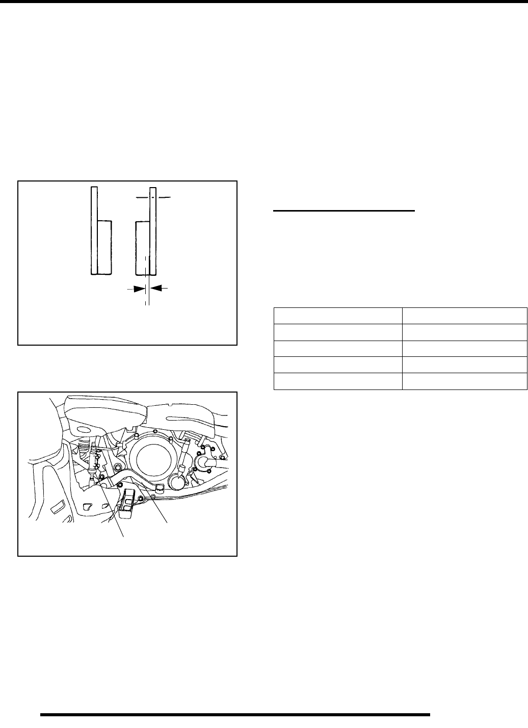
2.30
MAINTENANCE
• Check surface condition of the disc.
• Inspect thickness of brake pad friction material.
Hose / Fitting Inspection
Check brake system hoses and fittings for cracks, deterioration,
abrasion, and leaks.Tighten any loose fittings and replace any
worn or damaged parts.
Brake Pad Inspection
Pads should be changed when the friction material is worn to
3/64” (.1 cm), or about the thickness of a U.S. dime.
Brake Testing
The foot brake should be checked for proper function.
When applied, the brake power should be sufficient enough to
stop the wheels under most conditions.
If brake operation is poor, two things must be examined:
Free Play:
Free play of the brake pedal should be 1/8″ – 1/4″ (3.2 – 6.35
mm).
If free play is excessive, inspect pedal (1), linkage, and master
cylinder (2) for wear or damage and replace any parts as needed.
Bleeding:
If free play is correct and brake pedal travel is still excessive, air
may be trapped somewhere in the system. Bleed the hydraulic
auxiliary brake system in a conventional manner, following the
procedure outlined in the Brake Chapter.
WHEELS AND TIRES
Wheels
Inspect all wheels for runout or damage. Check wheel nuts and
ensure they are tight. Do not over tighten the wheel nuts.
Wheel, Hub, and Spindle Torque Table
Wheel Removal: Front or Rear
Wheel Removal
1. Stop the engine, place the transmission in gear and lock the
parking brake.
2. Loosen the wheel nuts slightly.
3. Elevate the side of the vehicle by placing a suitable stand
under the footrest frame.
4. Remove the wheel nuts and remove the wheel.
Wheel Installation
1. With the transmission in gear and the parking brake
locked, place the wheel in the correct position on the wheel
hub. Be sure the valve stem is toward the outside and
rotation arrows on the tire point toward forward rotation.
2. Attach the wheel nuts and finger tighten them.
3. Lower the vehicle to the ground.
3/64” (.1cm)
Minimum Thickness
1
2
Item Specification
Front Wheel Nuts 30-35 Ft. Lbs. (41-47 Nm)
Rear Wheel Nuts 30-35 Ft. Lbs. (41-47 Nm)
Front Spindle Nut 40 Ft. Lbs. (55 Nm)
Rear Hub Retaining Nut 90 Ft. Lbs. (108 Nm)
RepairPro Service Manual
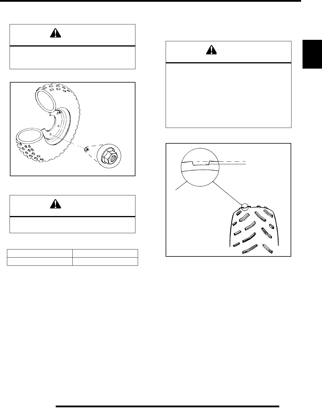
2.31
MAINTENANCE
2
4. Securely tighten the wheel nuts to the proper torque listed
in the table.
Tire Pressure
Tire Inspection
• Improper tire inflation may affect ATV
maneuverability.
• When replacing a tire always use original equipment
size and type.
• The use of non–standard size or type tires may affect
ATV handling.
Tire Tread Depth
Always replace tires when tread depth is worn to 1/8″ (3 mm)
or less.
CAUTION
Improperly installed wheels could affect vehicle
handling and tire wear. On vehicles with flange wheel
nuts, make sure flat of nut goes onto wheel.
CAUTION
Maintain proper tire pressure. Refer to the warning
tire pressure decal applied to the vehicle.
Tire Pressure (PSI - Cold)
Front Rear
55
Flat side against wheel
WARNING
Operating your ATV with worn tires, improperly
inflated tires, non - standard tires or improperly
installed tires will affect vehicle handling and could
cause an accident resulting in serious injury or death.
Maintain proper tire pressure as described on the ATV
decal and in the owner’s manual.
Always use original equipment size and type
when replacing tires.
Make sure the wheels are installed properly.
1/8″ (.3 cm)

NOTES
MAINTENANCE
2.32
RepairPro Service Manual

3.1
CHAPTER 3
ENGINE
3
ENGINE
SPECIFICATIONS. . . . . . . . . . . . . . . . . . . . . . . . . . . . . . . . . . . . . . . . . . . . . . . . . . . . . . . 3.3
TORQUE SPECIFICATIONS . . . . . . . . . . . . . . . . . . . . . . . . . . . . . . . . . . . . . . . . . . . . . . 3.3
ES50PL ENGINE SERVICE DATA. . . . . . . . . . . . . . . . . . . . . . . . . . . . . . . . . . . . . . . . . . 3.4
ES50PL ENGINE SERVICE DATA. . . . . . . . . . . . . . . . . . . . . . . . . . . . . . . . . . . . . . . . . . 3.5
SPECIAL TOOLS . . . . . . . . . . . . . . . . . . . . . . . . . . . . . . . . . . . . . . . . . . . . . . . . . . . . . . . 3.6
ENGINE FASTENER TORQUE PATTERNS . . . . . . . . . . . . . . . . . . . . . . . . . . . . . . . . . . 3.6
GENERAL ENGINE SERVICE . . . . . . . . . . . . . . . . . . . . . . . . . . . . . . . . . . . . . . . . . . . . . 3.6
PISTON IDENTIFICATION. . . . . . . . . . . . . . . . . . . . . . . . . . . . . . . . . . . . . . . . . . . . . . . . 3.6
COMPRESSION TEST. . . . . . . . . . . . . . . . . . . . . . . . . . . . . . . . . . . . . . . . . . . . . . . . . . . 3.6
COOLANT TEMPERATURE SENSOR (THERMISTOR). . . . . . . . . . . . . . . . . . . . . . . . . 3.7
COOLING SYSTEM . . . . . . . . . . . . . . . . . . . . . . . . . . . . . . . . . . . . . . . . . . . . . . . . . . . . . 3.7
RADIATOR CAP / SYSTEM PRESSURE TEST . . . . . . . . . . . . . . . . . . . . . . . . . . . . . . . 3.7
COOLING SYSTEM SPECIFICATIONS. . . . . . . . . . . . . . . . . . . . . . . . . . . . . . . . . . . . . . 3.7
ACCESSIBLE COMPONENTS. . . . . . . . . . . . . . . . . . . . . . . . . . . . . . . . . . . . . . . . . . . . . 3.8
ENGINE REMOVAL . . . . . . . . . . . . . . . . . . . . . . . . . . . . . . . . . . . . . . . . . . . . . . . . . . . . . 3.8
ENGINE INSTALLATION NOTES . . . . . . . . . . . . . . . . . . . . . . . . . . . . . . . . . . . . . . . . . . 3.9
CRANKSHAFT STRAIGHTENING. . . . . . . . . . . . . . . . . . . . . . . . . . . . . . . . . . . . . . . . . 3.10
ES50PL ENGINE LUBRICATION. . . . . . . . . . . . . . . . . . . . . . . . . . . . . . . . . . . . . . . . . . 3.10
OIL PRESSURE TEST. . . . . . . . . . . . . . . . . . . . . . . . . . . . . . . . . . . . . . . . . . . . . . . . . . 3.10
OIL PUMP PRIMING PROCEDURE . . . . . . . . . . . . . . . . . . . . . . . . . . . . . . . . . . . . . . . 3.11
OIL FLOW - ES50PL . . . . . . . . . . . . . . . . . . . . . . . . . . . . . . . . . . . . . . . . . . . . . . . . . . . 3.11
ES50PL OIL FLOW CHART . . . . . . . . . . . . . . . . . . . . . . . . . . . . . . . . . . . . . . . . . . . . . . 3.12
ES50PL ENGINE EXPLODED VIEWS. . . . . . . . . . . . . . . . . . . . . . . . . . . . . . . . . . . . . . 3.13
UPPER ENGINE DISASSEMBLY . . . . . . . . . . . . . . . . . . . . . . . . . . . . . . . . . . . . . . . . . . 3.14
DISASSEMBLY. . . . . . . . . . . . . . . . . . . . . . . . . . . . . . . . . . . . . . . . . . . . . . . . . . . . . . . . 3.14
CAM CHAIN TENSIONER REMOVAL . . . . . . . . . . . . . . . . . . . . . . . . . . . . . . . . . . . . . . 3.14
CAM CHAIN TENSIONER INSPECTION AND REASSEMBLY. . . . . . . . . . . . . . . . . . . 3.14
CAMSHAFT REMOVAL . . . . . . . . . . . . . . . . . . . . . . . . . . . . . . . . . . . . . . . . . . . . . . . . . 3.15
AUTOMATIC COMPRESSION RELEASE INSPECTION . . . . . . . . . . . . . . . . . . . . . . . 3.15
CAMSHAFT INSPECTION . . . . . . . . . . . . . . . . . . . . . . . . . . . . . . . . . . . . . . . . . . . . . . . 3.16
CYLINDER HEAD REMOVAL . . . . . . . . . . . . . . . . . . . . . . . . . . . . . . . . . . . . . . . . . . . . 3.16
CYLINDER AND PISTON REMOVAL . . . . . . . . . . . . . . . . . . . . . . . . . . . . . . . . . . . . . . 3.17
PISTON REMOVAL . . . . . . . . . . . . . . . . . . . . . . . . . . . . . . . . . . . . . . . . . . . . . . . . . . . . 3.17
PISTON AND ROD INSPECTION . . . . . . . . . . . . . . . . . . . . . . . . . . . . . . . . . . . . . . . . . 3.18
LOWER ENGINE DISASSEMBLY. . . . . . . . . . . . . . . . . . . . . . . . . . . . . . . . . . . . . . . . . . 3.19
CRANKCASE DISASSEMBLY AND INSPECTION . . . . . . . . . . . . . . . . . . . . . . . . . . . . 3.19
STARTER DRIVE GEARS REMOVAL AND INSPECTION . . . . . . . . . . . . . . . . . . . . . . 3.19
FLYWHEEL / ONE-WAY STARTER CLUTCH REMOVAL AND INSPECTION. . . . . . . 3.19
CRANKSHAFT NUT REMOVAL. . . . . . . . . . . . . . . . . . . . . . . . . . . . . . . . . . . . . . . . . . . 3.20
CLUTCH COVER / CLUTCH REMOVAL AND INSPECTION . . . . . . . . . . . . . . . . . . . . 3.20
SHIFTER COMPONENT REMOVAL AND INSPECTION . . . . . . . . . . . . . . . . . . . . . . . 3.22
OIL PUMP REMOVAL AND INSPECTION. . . . . . . . . . . . . . . . . . . . . . . . . . . . . . . . . . . 3.23
CRANKSHAFT DRIVE AND CAM GEAR REMOVAL . . . . . . . . . . . . . . . . . . . . . . . . . . 3.23
CAM CHAIN / TENSIONER BLADE REMOVAL . . . . . . . . . . . . . . . . . . . . . . . . . . . . . . 3.24
CRANKCASE SEPARATION . . . . . . . . . . . . . . . . . . . . . . . . . . . . . . . . . . . . . . . . . . . . . 3.24
CRANKCASE INSPECTION. . . . . . . . . . . . . . . . . . . . . . . . . . . . . . . . . . . . . . . . . . . . . . 3.25
CRANKCASE BEARING INSPECTION / REMOVAL / INSTALLATION . . . . . . . . . . . . 3.25
TRANSMISSION AND CRANKSHAFT SERVICE. . . . . . . . . . . . . . . . . . . . . . . . . . . . . . 3.26
TRANSMISSION REMOVAL AND INSPECTION . . . . . . . . . . . . . . . . . . . . . . . . . . . . . 3.26
TRANSMISSION MAIN SHAFT DISASSEMBLY / ASSEMBLY. . . . . . . . . . . . . . . . . . . 3.26
TRANSMISSION REASSEMBLY . . . . . . . . . . . . . . . . . . . . . . . . . . . . . . . . . . . . . . . . . . 3.27
CRANKSHAFT REMOVAL / INSTALLATION . . . . . . . . . . . . . . . . . . . . . . . . . . . . . . . . 3.29
CRANKSHAFT INSPECTION. . . . . . . . . . . . . . . . . . . . . . . . . . . . . . . . . . . . . . . . . . . . . 3.29

3.2
ENGINE
ENGINE REASSEMBLY . . . . . . . . . . . . . . . . . . . . . . . . . . . . . . . . . . . . . . . . . . . . . . . . . 3.30
CRANKCASE REASSEMBLY . . . . . . . . . . . . . . . . . . . . . . . . . . . . . . . . . . . . . . . . . . . . 3.30
PISTON INSTALLATION . . . . . . . . . . . . . . . . . . . . . . . . . . . . . . . . . . . . . . . . . . . . . . . . 3.31
PISTON RING INSTALLATION . . . . . . . . . . . . . . . . . . . . . . . . . . . . . . . . . . . . . . . . . . . 3.31
CYLINDER INSTALLATION. . . . . . . . . . . . . . . . . . . . . . . . . . . . . . . . . . . . . . . . . . . . . . 3.32
CAM CHAIN INSTALLATION. . . . . . . . . . . . . . . . . . . . . . . . . . . . . . . . . . . . . . . . . . . . . 3.32
CAMSHAFT TIMING . . . . . . . . . . . . . . . . . . . . . . . . . . . . . . . . . . . . . . . . . . . . . . . . . . . 3.32
PRIMARY DRIVE GEAR INSTALLATION . . . . . . . . . . . . . . . . . . . . . . . . . . . . . . . . . . . 3.33
OUTLAW CAM TIMING EXPLODED VIEW. . . . . . . . . . . . . . . . . . . . . . . . . . . . . . . . . . 3.34
CYLINDER HEAD SERVICE. . . . . . . . . . . . . . . . . . . . . . . . . . . . . . . . . . . . . . . . . . . . . . 3.35
CYLINDER HEAD INSPECTION . . . . . . . . . . . . . . . . . . . . . . . . . . . . . . . . . . . . . . . . . . 3.35
CYLINDER HEAD WARP. . . . . . . . . . . . . . . . . . . . . . . . . . . . . . . . . . . . . . . . . . . . . . . . 3.35
CYLINDER HEAD DISASSEMBLY . . . . . . . . . . . . . . . . . . . . . . . . . . . . . . . . . . . . . . . . 3.35
CYLINDER HEAD VALVE GUIDE / VALVE SEAT INSPECTION . . . . . . . . . . . . . . . . . 3.36
VALVE GUIDE REMOVAL / INSTALLATION / REAM . . . . . . . . . . . . . . . . . . . . . . . . . . 3.36
VALVE SEAT RECONDITIONING . . . . . . . . . . . . . . . . . . . . . . . . . . . . . . . . . . . . . . . . . 3.37
VALVE INSPECTION . . . . . . . . . . . . . . . . . . . . . . . . . . . . . . . . . . . . . . . . . . . . . . . . . . . 3.39
ES50PL ADJUSTING PAD SELECTION MATRIX. . . . . . . . . . . . . . . . . . . . . . . . . . . . . 3.40
CYLINDER HEAD ASSEMBLY . . . . . . . . . . . . . . . . . . . . . . . . . . . . . . . . . . . . . . . . . . . 3.41
CYLINDER HEAD INSTALLATION . . . . . . . . . . . . . . . . . . . . . . . . . . . . . . . . . . . . . . . . 3.42
CYLINDER SERVICE . . . . . . . . . . . . . . . . . . . . . . . . . . . . . . . . . . . . . . . . . . . . . . . . . . . 3.42
CYLINDER INSPECTION. . . . . . . . . . . . . . . . . . . . . . . . . . . . . . . . . . . . . . . . . . . . . . . . 3.42
PISTON–TO–CYLINDER CLEARANCE . . . . . . . . . . . . . . . . . . . . . . . . . . . . . . . . . . . . 3.43
CYLINDER HONE SELECTION AND HONING PROCEDURE. . . . . . . . . . . . . . . . . . . 3.43
HONING TO DEGLAZE . . . . . . . . . . . . . . . . . . . . . . . . . . . . . . . . . . . . . . . . . . . . . . . . . 3.43
PISTON RING INSTALLED GAP . . . . . . . . . . . . . . . . . . . . . . . . . . . . . . . . . . . . . . . . . . 3.44
WATER PUMP SERVICE . . . . . . . . . . . . . . . . . . . . . . . . . . . . . . . . . . . . . . . . . . . . . . . . 3.44
OIL SEAL / MECHANICAL SEAL REMOVAL (ENGINE DISASSEMBLED) . . . . . . . . . 3.44
WATER PUMP MECHANICAL SEAL INSTALLATION . . . . . . . . . . . . . . . . . . . . . . . . . 3.44
MECHANICAL SEAL REMOVAL AND INSTALLATION (ENGINE ASSEMBLED) . . . . 3.45
TROUBLESHOOTING. . . . . . . . . . . . . . . . . . . . . . . . . . . . . . . . . . . . . . . . . . . . . . . . . . . 3.46
ENGINE . . . . . . . . . . . . . . . . . . . . . . . . . . . . . . . . . . . . . . . . . . . . . . . . . . . . . . . . . . . . .3.46
SPARK PLUG FOULING . . . . . . . . . . . . . . . . . . . . . . . . . . . . . . . . . . . . . . . . . . . . . . . . 3.48
COOLING SYSTEM . . . . . . . . . . . . . . . . . . . . . . . . . . . . . . . . . . . . . . . . . . . . . . . . . . . . 3.48
RepairPro Service Manual

3.3
ENGINE
3
SPECIFICATIONS
Torque Specifications
ES50PL
Fastener Thread ES50PL: Ft. Lbs. (Nm)
Blind Plug (Crankcase) 1/8 PT 6.6–11.1 (9–15 Nm)
Blind Plug (Oil Filter Cover) 1/4 PT 12.5–17 (17–23 Nm)
Bearing Stop Plates 6mm 8.1–9.6 (11–13 Nm)
Camshaft Chain Tensioner Blade Bolt 8mm 10–12.2 (13.5–16.5 Nm)
Camshaft Chain Tensioner 6mm 6.6–8.1 (9–11 Nm)
Camshaft Chain Tensioner Cap 6mm 6.6–8.1 (9–11 Nm)
Camshaft Support 8mm 6.6–7.5 (9–10 Nm)
Carburetor Adaptor 8mm 11.8–14.8 (16–20 Nm)
Crankcase Cover 8mm 6.6–8.1 (9–11 Nm)
Crankshaft Nut (Primary Drive Sprocket) 18mm 81–96 (110–130 Nm)
Crankshaft Nut (Ball Bearing at Crankshaft) 32mm 66–81 (90–110 Nm)
Cylinder Base / Head Bolts 11mm
6mm Refer to Page 3.42
6–8 (9–11 Nm)
Clutch Basket Nut 18mm 66–81 (90–110 Nm)
Clutch Cover 6mm 6.6–8.1 (9–11 Nm)
Drive Sprocket and Sprocket Cover 6mm 6.6–8.1 (9–11 Nm)
Flywheel (Apply engine oil to threads) 14mm 111–125 (150–170 Nm)
Neutral Indicator Switch 5mm 2.2–3.7 (3–5 Nm)
Oil Delivery Pipe 12mm 11.1–15.5 (15–21 Nm)
Oil Drain Bolt (Crankcase) 14mm 14–17 (19–23 Nm)
Oil Filter Cover Housing and Oil Pump Case 6mm 6.6–8.1 (9–11 Nm)
Oil Hose Fittings 8mm 8.1–10.3 (11-14 Nm)
One Way Valve Plug 11mm 11.1–15.5 (15-21 Nm)
One Way Clutch Screws 6mm 9.6–11.1 (13–15 Nm)
Pulser Coil (Apply PN2871557 to threads) 5mm 1.8–2.6 (2.5–3.5 Nm)
Pressure Plate Screws 6mm 6.6–8.1 (9–11 Nm)
Shift Cam 6mm 5.9–7.4 (8–10 Nm)
Shift Lever 6mm 6.6–8.1 (9–11 Nm)
Shift Detent Arm (Apply PN 2871557 to threads) 6mm 6.6–8.1 (9–11 Nm)
Stator Housing Cover 6mm 6.6–8.1 (9–11 Nm)
Stator Plate 5mm 4.1–5.8 (5.5–6.5 Nm)
Starter Motor 6mm 6.6–8.1 (9–11 Nm)
Spark Plug 12mm 11.1–14.8 (15–20 Nm)
Timing Cover Plug (Center) 32mm 7.4–8.8 (10–12 Nm)
Timing Cover Plug (Timing window) 14mm 2–4 (3–5 Nm)
Thermo Cover 6mm 5.2–6.6 (7–9 Nm)
Thermo Switch 3/8 NPT 23.6–28 (32–38 Nm)
Valve Cover 6mm 6.6–8.1 (9–11 Nm)
Water Pump Impeller 6mm 6.6–8.1 (9–11 Nm)
Water Pump Housing Cover 6mm 6.6–8.1 (9–11 Nm)
Radiator Thermistor -- 8 ±12 in.lbs. (0.8 ± 1.36 Nm)
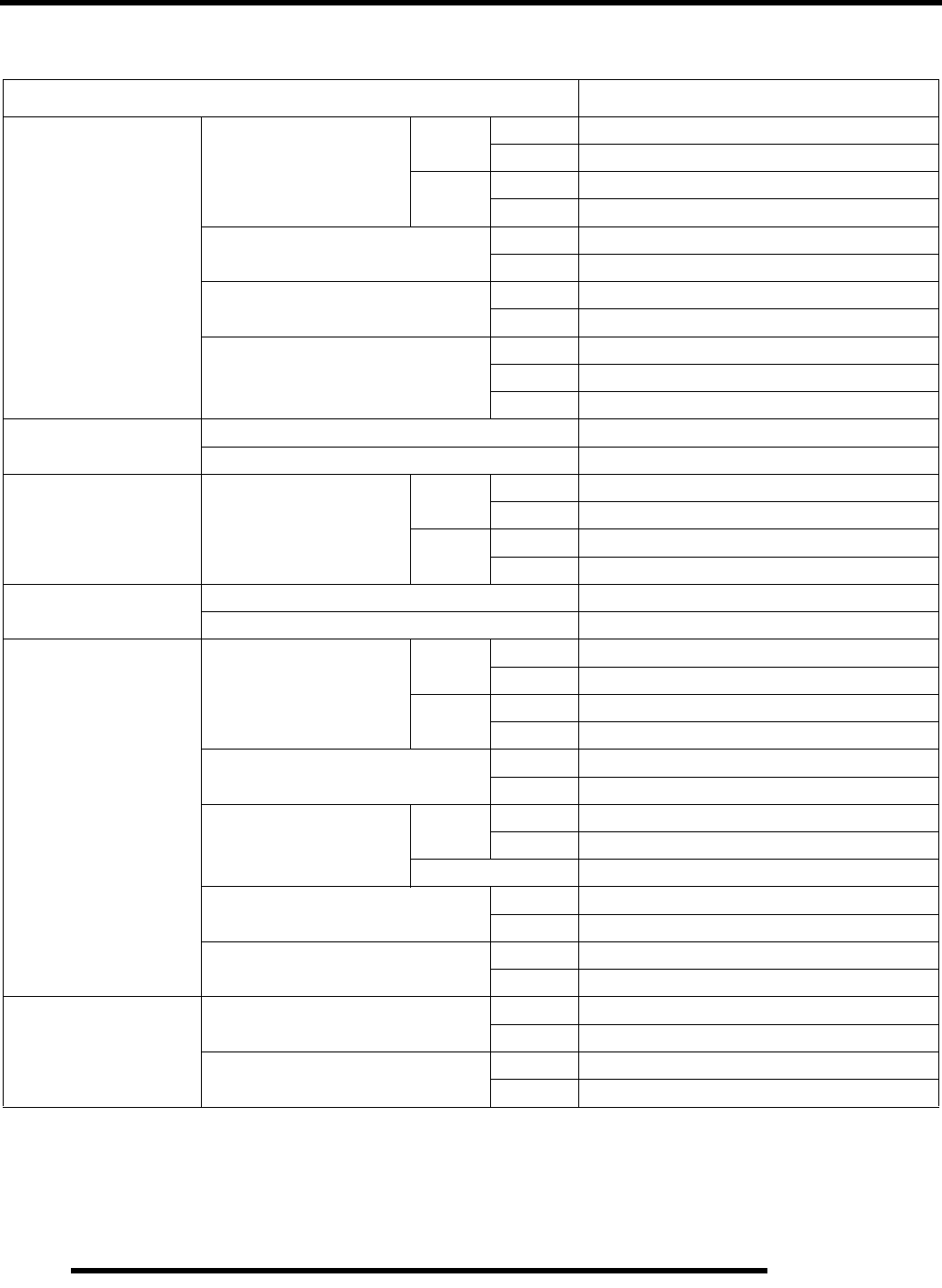
3.4
ENGINE
ES50PL Engine Service Data
Cylinder Head / Valve ES50PL
Camshaft
Cam lobe height
In Std 1.667–1.671” (42.35–42.45 mm)
Limit 1.655” (42.05 mm)
Ex Std 1.667–1.671” (42.35–42.45 mm)
Limit 1.655” (42.05 mm)
Camshaft journal OD Mag .9821–.9828” (24.946–24.963 mm)
PTO .8652–.8655” (21.976–21.985 mm)
Camshaft journal bore ID Mag .9842–.9851” (25.000–25.021 mm)
PTO .8657–.8661” (21.990–22.000 mm)
Camshaft Oil clearance
Mag .0014–.0029” (.037–.075 mm)
PTO .0001–.0009” (.005–.024 mm)
Limit .004” (.10 mm)
Cylinder Head Surface warpage limit .0020” (.05 mm)
Standard height 4.975” (126.4 mm)
Valve Seat Contacting width
**Measure valve stem
height
In Std 1.5255” (38.75 mm)
Limit 1.5425” (39.18 mm)
Ex Std 1.5255” (38.75 mm)
Limit 1.5377” (39.06 mm)
Valve Guide Inner diameter .2362- .2367” (6.0- 6.012 mm)
Protrusion above head .535- .551” (13.6- 14.0 mm)
Valve
Margin thickness
In Std .039” (1.0 mm)
Limit .031” (.8 mm)
Ex Std .039” (1.0 mm)
Limit .031” (.8 mm)
Stem diameter In .2343–.2348” (5.950–5.965 mm)
Ex .2341–.2346” (5.945–5.960 mm)
Stem oil clearance Std In .0014–.0024” (.035–.062 mm)
Ex .0016–.0026” (.040–.067 mm)
Limit .0059” (.15 mm)
Overall length In 4.031” (102.4 mm)
Ex 4.059” (103.1 mm)
Valve Lash In .006” (.15 mm) +/- .0019” (.05 mm)
Ex .010” (.27 mm) +/- .0019” (.05 mm)
Valve Spring
Overall length
Limit = -.079” (-2.0 mm)
Inner 1.575” (40.0 mm)
Outer 1.650” (41.9 mm)
Squareness Inner .067-” (1.7 mm)
Outer .071” (1.8 mm)
RepairPro Service Manual
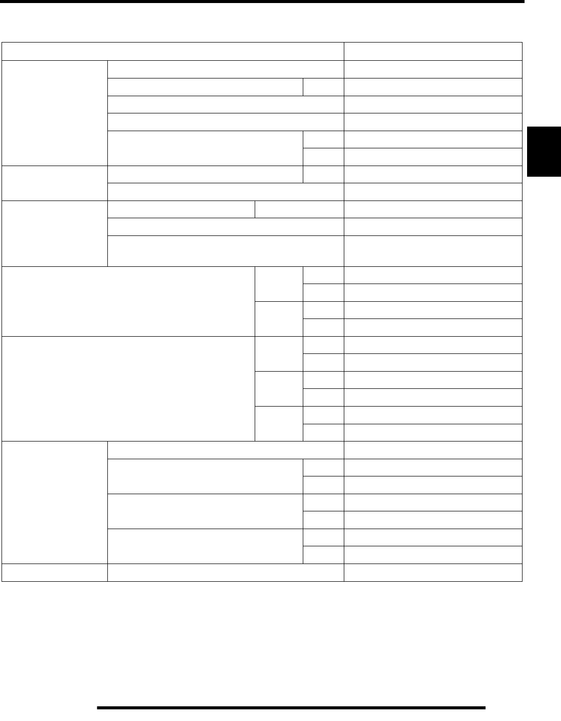
3.5
ENGINE
3
ES50PL Engine Service Data
KEY – Std: Standard; OS: Oversize; ID: Inner Diameter; OD: Outer Diameter; Mag: Magneto Side; PTO: Power Take Off Side.
Cylinder / Piston / Connecting Rod / Crankshaft ES50PL
Cylinder
Surface warpage limit (mating with cylinder head) .002” (.05 mm)
Cylinder bore Std 3.9055–3.9062” (99.20–99.22 mm)
Taper limit .002” (.05 mm)
Out of round limit .002” (.05 mm)
Piston clearance Std .0018- .0025” (.046- .065 mm)
Limit .0039” (.10 mm)
Piston Outer diameter Std 3.9037- 3.904” (99.155- 99.170 mm)
Piston Pin Bore Standard I.D. .9055- .9057” (23.001- 23.007 mm)
Piston Pin
Outer diameter Std .9053- .9055” (23.001 - 23.007 mm)
Piston pin to pin bore clearance .0002- .0004” (.001- .0011 mm)
Degree of fit Piston Pin must be a push (by hand)
fit at 68o F(20o C)
Piston Ring to ring groove clearance
Top
Ring
Std .0012–.0028” (.030–.070 mm)
Limit .0059” (.15 mm)
Second
Ring
Std .0012–.0028” (.030–.070 mm)
Limit .0059” (.15 mm)
Piston Ring installed gap
Top
Ring
Std .008–.012” (.20–.30 mm)
Limit .027” (.7 mm)
Second
Ring
Std .014–.019” (.35–.50 mm)
Limit .031” (.8 mm)
Oil Ring Std .004–.019” (.10–.50 mm)
Limit .039” (1.0 mm)
Connecting Rod
Connecting rod small end ID .9058- .9063” (23.007- 23.020 mm)
Connecting rod small end radial
clearance
Std .0003- .0009” (.007- .024 mm)
Limit .0020” (.05 mm)
Connecting rod big end side clearance Std .0035- .0196” (.09- .50 mm)
Limit .0255” (.65 mm)
Connecting rod big end
radial clearance
Std .0004- .0015” (.011- .038 mm)
Limit Same as standard
Crankshaft Crankshaft runout limit .0024” (.06 mm)
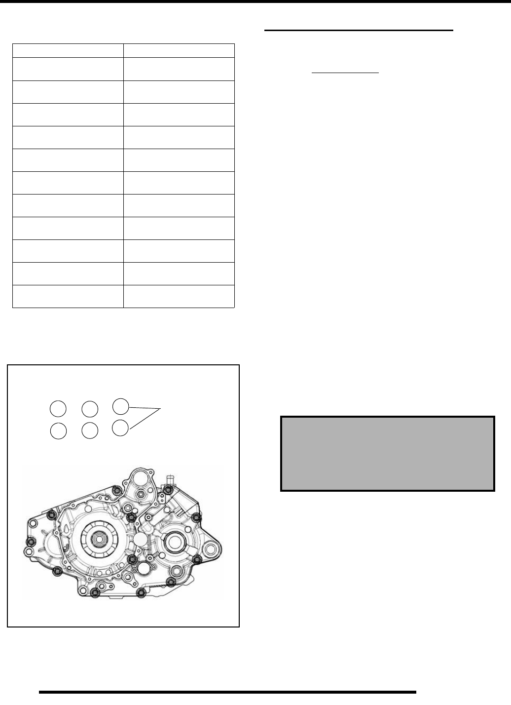
3.6
ENGINE
Special Tools
Engine Fastener Torque Patterns
Tighten cylinder head, cylinder base, and crankcase fasteners
following the sequence outlined below.
GENERAL ENGINE SERVICE
Piston Identification
The piston may or may not have an identification mark for
piston placement. If the piston has an identification mark, follow
the directions for piston placement below. If the piston does not
have an identification mark, the direction for placement of the
piston does not matter.
NOTE: Note the directional and identification marks
when viewing the pistons from the top. Identifying
marks such as “F”, “J”, “X“or Q must always be
positioned to the flywheel side of the engine. Other
marks are used for identification as to diameter,
length and design. Four stroke engine rings are a
rectangular profile. See text for oil control ring rail
installation. Use the information below to identify
pistons and rings:
Compression Test
NOTE: This engine has built-in decompression
components. Compression readings will vary in
proportion to cranking speed during the test.
Average compression (measured) is about 85-90 psi
@ 400 RPM during a compression test.
A cylinder leakdown test is the best indication of engine
condition. Follow manufacturer’s instructions to perform a
cylinder leakage test. Never use high pressure leakage testers,
as crankshaft seals may dislodge and leak.
PART NUMBER TOOL DESCRIPTION
2872105 Water Pump Mechanical
Seal Puller
2200634 Valve Seat Reconditioning
Kit
2870390 Piston Support Block
PA-45958 Cam Chain Tensioner
Assembly Tool
PA-46075 Flywheel Puller
PA- 46076 MAG End Crankshaft Nut
Remover/Installer
PA-46087 Crankcase Separator
PA-46077 MAG End Crankshaft
Installer
2871283 Crankshaft/Water Pump
Seal Install Kit
5131135 Water Pump Install Kit
PA-46502 Valve Spring Compressor
Cylinder Head & Cylinder Base
325
146
8 mm
1
2
3
4
5
67
8
9
10
11
12
13
Cylinder Compression w / decompression
Standard: 85-90 PSI @ 400 RPM
Cylinder Leakdown
Service Limit: 10%
(Inspect for cause if leakage exceeds 10%)
RepairPro Service Manual
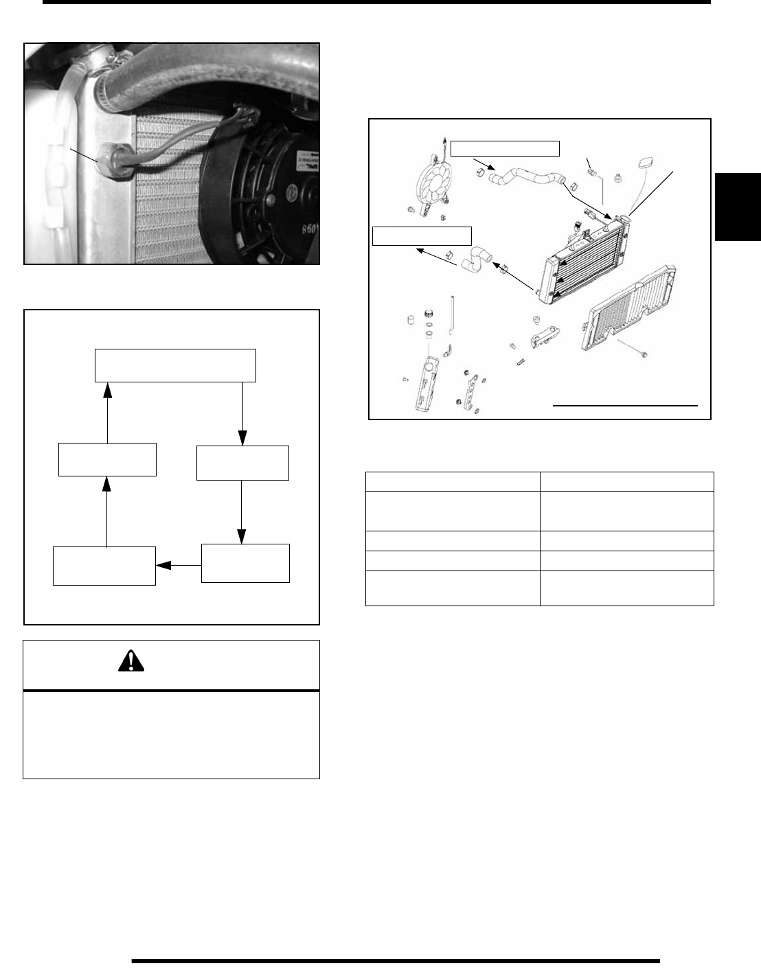
3.7
ENGINE
3
Coolant Temperature Sensor (Thermistor)
Cooling System
Radiator Cap / System Pressure Test
1. Remove recovery bottle hose from coolant filler neck.
2. Connect a Mity Vac™ (PN 2870975) to radiator and
pressurize system to 10 PSI. The system must retain 10 lbs
of pressure for five minutes or longer. If pressure loss is
evident within five minutes, check radiator, all cooling
system hoses and clamps, or water pump seal.
Radiator Cap Pressure Test
1. Remove radiator cap and test using a cap tester
(commercially available).
2. The radiator cap relief pressure is 13 psi. for all models.
Replace if cap releases at less than 13 psi.
Cooling System Specifications
Recommended Coolant Type
Use only high quality antifreeze/coolant mixed with distilled
water in a 50/50 or 60/40 ratio, depending on freeze protection
required in your area.
IMPORTANT: Using tap water in the cooling system
will lead to a buildup of deposits which may restrict
coolant flow and reduce heat dissipation, resulting in
possible engine damage. Polaris Premium 60/40
Antifreeze / Coolant (PN 2871323) is recommended for
use in all cooling systems and comes pre–mixed,
ready to use.
WARNING
Never remove radiator cap when engine is
warm or hot. The cooling system is under
pressure and serious burns may result.
Allow the engine and cooling system to cool
before servicing.
8-12 in. lbs.
(.9-1.3 Nm)
Radiator
Water Pump
Cylinder
Cylinder
Thermostat
FLOW
Head
Description Temperature
Fan Switch (Off)
Fan Switch (On) 150o F (65o C) ± 8o
180o F (82o C) ± 7o
Hot Light On 221o F (105o C)
System Capacity 2.25 Quarts (2.1 L)
Radiator Cap Relief
Pressure 13 PSI
Coolant Flow Diagram
From Thermostat Sensor
To Water Pump
Pressure test
here with cap
in place

3.8
ENGINE
Accessible Components
The following components can be serviced or removed with
the engine installed in the frame:
• Flywheel
• Alternator/Stator
• Starter Motor/Starter Drive
• Water Pump / Water Pump Mechanical Seal*
*Mechanical Water Pump Seal Removal Tool (PN 2872105) is
required to replace mechanical seal with engine in frame.
The following components require engine removal for
service:
• Counterbalance Shaft or Bearing(s)
• Connecting Rod
•Crankshaft
• Crankshaft Main Bearings
• Cylinder Head
• Cylinder
• Piston/RIngs
• Camshaft
•Cams
• Cam Chain and Sprockets
•Transmission Gears and Bearings
Engine Removal
1. Thoroughly clean the ATV engine and chassis.
2. Clean work area.
3. Support the ATV with jackstands under the footrests at a
height sufficient to raise the rear wheels off the floor at least
5 inches (12.7 cm).
4. Drain coolant and engine oil.
5. Remove the following components:
•Seat
• Side Panels
• Front Cab (Refer to Chapter 5)
• Fuel Tank (Refer to Chapter 4)
•RH footwell (Refer to Chapter 5)
6. Disconnect battery cables, starting with the negative (–)
cable first.
7. Remove air intake duct.
8. Remove carburetor. Caution: Fuel will leak if carb is
turned upside down. In most instances, the carburetor will
not have to be disconnected from the throttle cable, choke
cable and fuel line for engine removal. Insert a shop towel
into the carburetor flange to prevent dirt from entering the
intake of the engine.
9. Disconnect all electrical connections to the engine (coolant
sensor, neutral switch, plug wire, starter cable, ground
cable). Remove the magneto side cover, leaving the
electrical components attached, and secure out of the way.
10. Remove clutch and reverse cable linkage and secure out of
the way.
11. Remove fasteners from exhaust pipe and remove header
pipe.
12. Remove oil tank and hoses as an assembly. Disconnect vent
line and secure out of the way.
13. Loosen chain, disconnect and remove. An acceptable
alternative is to remove the transmission drive sprocket and
roll chain off.
14. Remove all engine mount nuts and engine mount plates,
starting at the rear with the combination engine / swing arm
pivot mount first. Using a suitable tool, push the bolt out
far enough to loosen the engine, but not drop the swing arm
pivot. Use a jack under the bearing carrier to relieve tension
from the pivot bolt for easier removal and installation.
15. With an assistant helping you, remove the engine by tilting
forward and turning to exit through left side of frame.
To reinstall the engine, reverse the procedures. Refer to engine
installation notes on Page 3.9.
RepairPro Service Manual
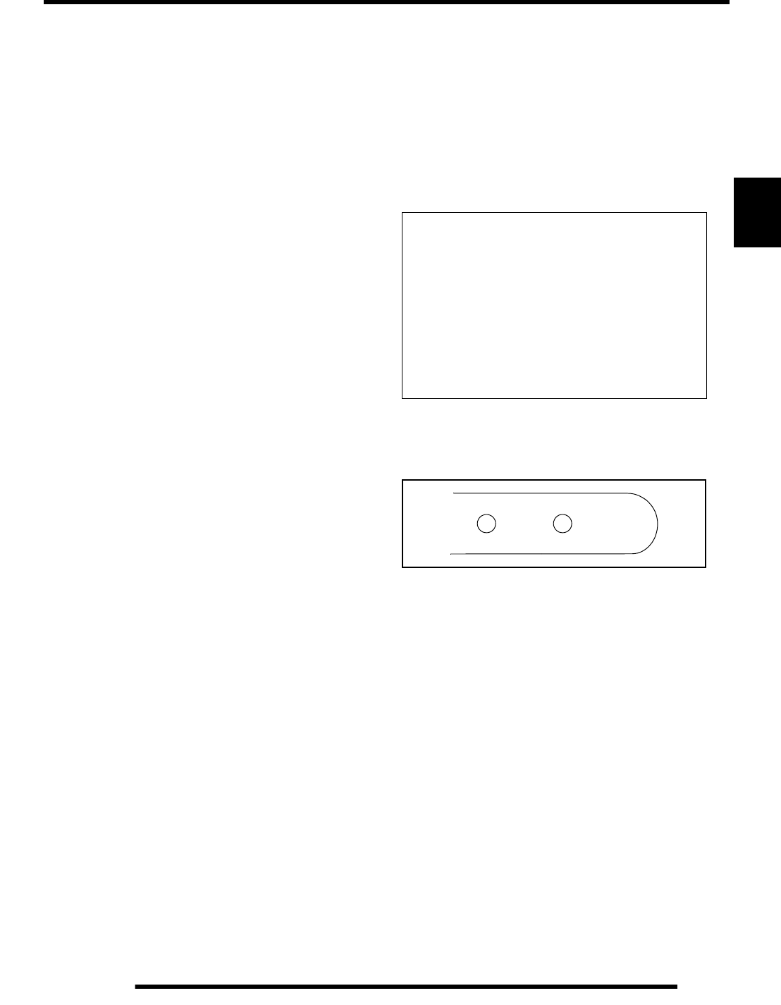
3.9
ENGINE
3
Engine Installation Notes
After the engine is installed in the frame, review this checklist
and perform all steps that apply:
General Items
•Torque Rear Engine Lower Mount to 90 ft. lbs.
(122 Nm)
• Torque Front Engine Lower Mount to 27 ft. lbs.
(33 Nm)
• Torque Top Engine Mount to 22 ft. lbs. (30 Nm)
• Install previously removed components using new
gaskets, seals, and fasteners where applicable.
• Perform checks on fluid levels, controls, and all
important areas on the vehicle as outlined in the daily
pre–ride inspection checklist (refer to Chapter 2 or the
Owner’s Manual).
• Verify clutch and lever freeplay according to
procedures in Chapter 2.
•Adjust chain tension according to procedures in
Chapter 2.
Exhaust
•Replace exhaust gaskets. Seal connections with high
temp silicone sealant if applicable.
•Verify all fasteners are in good condition and torqued
properly.
Bleed Cooling System
NOTE: Refer to Page 3.7 for hose routing. Bleeding
generally is necessary after repairs to purge any air
that may remain in the system during filling.
1. Remove radiator cap and slowly add coolant to the bottom
of filler neck.
2. Fill coolant reservoir tank to full mark.
3. Install radiator cap half-way and gently squeeze coolant
hoses to force any trapped air out of system.
4. Again, remove radiator cap and slowly add coolant to the
bottom of fill neck if required.
5. Start engine and observe coolant level in the radiator. Allow
air to purge and top off as necessary. Reinstall radiator cap
and bring engine to operating temperature. After engine is
cool, check level in reservoir tank and add coolant if
necessary.
NOTE: Should the reservoir tank become empty, it
will be necessary to refill at the radiator and repeat
the bleeding procedure.
Engine Break In Period
The break in period for a Polaris ATV engine is defined as the
first ten hours of operation, or the time it takes to use two full
tanks of gasoline. No single action on your part is as important
as a proper break in period. Careful treatment of a new engine
will result in more efficient performance and longer life for the
engine. Perform the following procedures carefully.
New and rebuilt engines require a break-in oil change at 1 hour
of engine run time.
1. Fill fuel tank with unleaded fuel which has a minimum
pump octane number of 87= (R+ M)/2.
2. Check oil reservoir level indicated on dipstick. Add oil if
necessary.
3. Drive slowly at first to gradually bring engine up to
operating temperature.
4. Vary throttle positions. Do not operate at sustained idle or
sustained high speed.
5. Perform regular checks on fluid levels, controls and all
important areas on the vehicle.
6. Pull only light loads during initial break in.
7. Change break in oil and filter at 1 hour or 100 miles.
OIL RECOMMENDATION
Polaris PS-4 All Season synthetic oil is specially
formulated for use with wet-clutch transmissions.
Never substitute or mix oil brands. Serious engine
damage and voiding of warranty can result.
For new or rebuilt engines, do not operate at full
throttle or high speeds for extended periods during the
first three hours of use. Excessive heat can build up
and cause damage to close fitted engine parts.
SAFE ADD 8 OZ
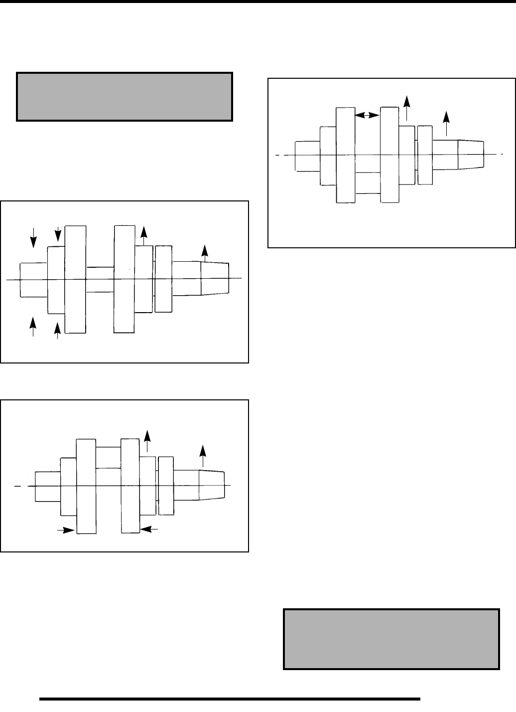
3.10
ENGINE
Crankshaft Straightening
Lubricate the bearings and clamp the crankshaft securely in the
crankshaft alignment fixture. Refer to the illustrations below.
NOTE: The rod pin position in relation to the dial
indicator position tells you what action is required to
straighten the shaft.
1. To correct a situation like the one shown in the illustration,
strike the shaft at point A with a brass hammer.
2. To correct a situation like the one shown in the illustration,
squeeze the crankshaft at points A. (Use tool from
alignment kit).
3. If the crank rod pin location is 180o from the dial indicator
(opposite that shown), it will be necessary to spread the
crankshaft at position A as shown in the illustration below.
When rebuilding and straightening a crankshaft, runout
must be as close to zero as possible.
NOTE: Maximum allowable runout is .0024”.
ES50PL Engine Lubrication
Oil Type:
Polaris PS-4 Synthetic (PN 2874414)
Capacity:
Approximately 2.25 U.S. Quarts (2.1L)
Filter:
(PN 3088036)
Drain Plug / Screen Fitting:
14.8 - 17 ft. lbs. (20-23 Nm)
(If fitting is removed, follow oil pump priming procedure).
Oil Pressure Specification:
20 PSI @ 5500 RPM, Polaris PS-4 Synthetic
(Engine Hot)
Oil Pressure Test
1. Remove blind plug on front right oil filter cover.
2. Insert a 1/8 NPT oil pressure gauge adaptor and attach the
gauge.
3. Start engine and allow it to reach operating temperature,
monitoring gauge indicator.
NOTE: Use only Polaris PS-4 Synthetic Engine
Lubricant (PN 2874414).
Crankshaft Alignment Fixture
(PN 2870569)
HIGH .004 (.1 mm)
HIGH .004 (.1 mm)
A
B
SUPPORT CRANKSHAFT HERE
HIGH .002 (.05 mm)
HIGH .005 (.13 mm)
AA
Oil Pressure at 5500 RPM (Engine Hot):
Standard: 20 PSI
Minimum: 12 PSI
AA
HIGH .002 (.05 mm)
HIGH .005 (.13 mm)
RepairPro Service Manual
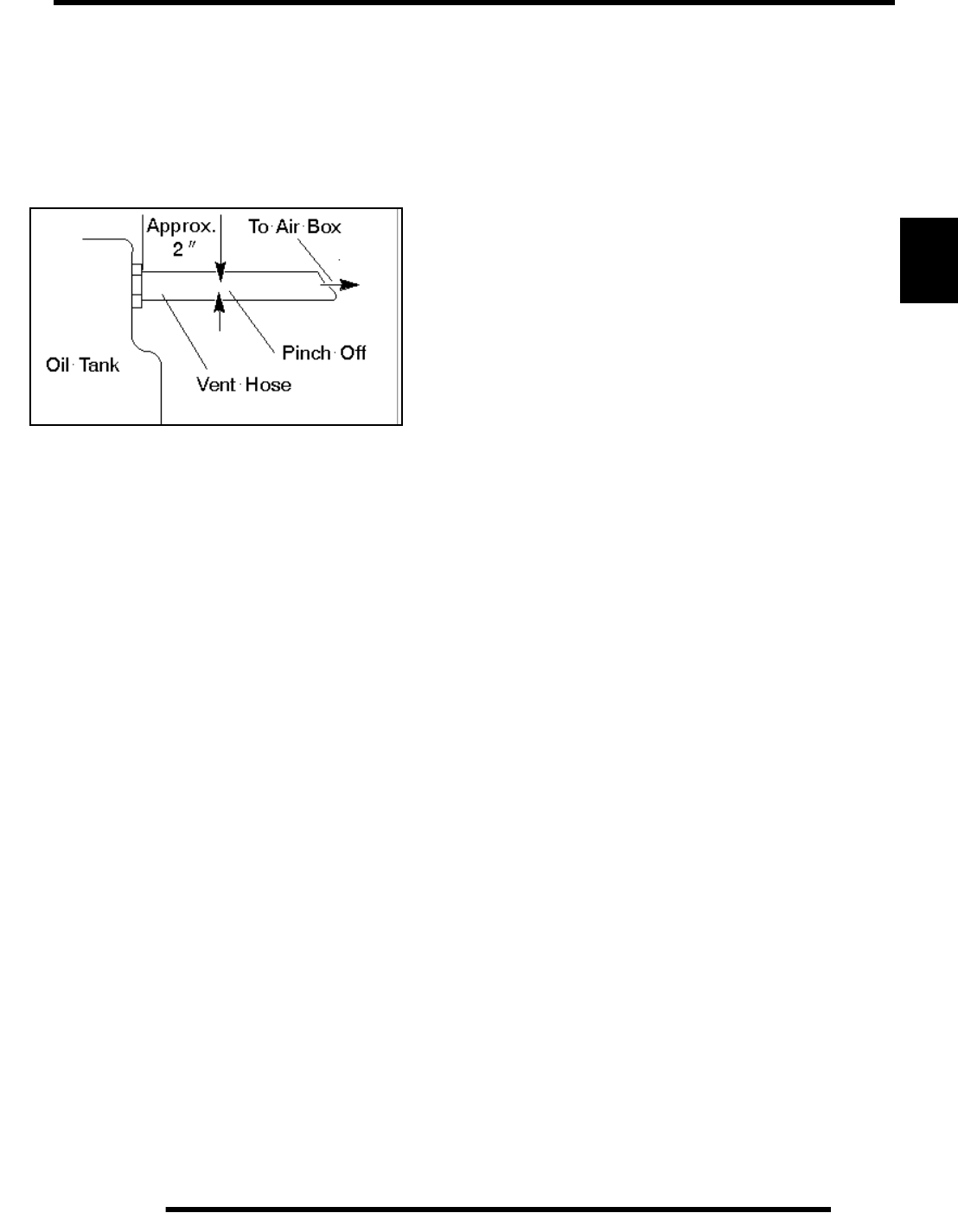
3.11
ENGINE
3
Oil Pump Priming Procedure
NOTE: The oil pump priming procedure should be
performed as a safeguard against loss of pump
prime when repairing oil tank, lines or engine.
1. Clamp or pinch off vent line approximately 2” from oil
tank, between the end of oil tank vent fitting and the vent
line.
2. Run engine for 5-10 seconds at IDLE.
IMPORTANT: Do not raise rpm or run for more than 10
seconds. Damage to tank may result.
3. Shut off engine. Remove the vent line clamp. The oil pump
should now be properly primed and ready for field
operation.
NOTE: If the system is primed properly you should
hear some air release. If you do not, the system has
not primed. Repeat the process if necessary.
Oil Flow - ES50PL
The chart on Page 3.12 describes the flow of oil through the
ES50PL engine. Beginning at the oil tank, the oil flows through
a screen fitting in the bottom of the tank and into the oil supply
hose. The feed side of the oil pump draws oil through the hose
and into the crankcase oil gallery, pulling the oil through another
passage to the one way valve. When the engine is off, the one
way valve closes to prevent oil in the tank from draining into the
crankcase. Oil is then pumped to the oil filter. If the oil filter is
obstructed, a bypass valve contained in the filter allows oil to
bypass the filter element.
At this point, the oil is diverted in three directions. Oil is
supplied to the crankshaft through a PTO side oil passage,
lubricating the crank bearings, crank pin, piston, cylinder and
connecting rod bearings. A delivery pipe supplies oil to the top
of the cylinder head and the transmission main shaft. Oil is
delivered though the pipe and enters the camshaft through the
cam support oil gallery. The camshaft journals are lubricated
through holes in the camshaft. Oil lubricates the cam chain
sprockets and cam lobes via an oil jet, which drains to the
crankcase.
Another oil path flows from the delivery pipe to the transmission
main shaft. Here it passes through the oil gallery to lubricate the
transmission gears, clutch and bearings.
Residual oil from the lubrication of the crankshaft and
connecting rod indirectly lubricates the cylinder wall, piston,
rings, connecting rod small end bearing, piston pin, oil/water
pump drive gears, cam chain, drive sprocket, and Magneto end
crankshaft main bearing.
A one–way valve is located on the right front (PTO) side of the
crankcase. This valve prevents oil in the tank from draining into
the engine crankcase when the engine is off. The valve
mechanism consists of a plunger, return spring, guide plug, and
sealing washer. When the engine is running, oil pressure lifts the
plunger off the seat, allowing oil flow. When the engine is off,
spring pressure forces the plunger against the oil passage seat,
preventing oil flow from the tank to the sump. The one–way
valve requires very little maintenance. If engine oil drains into
the crankcase when the engine is off, inspect the valve sealing
surface for debris or damage. Inspect the return spring for
distortion or damage.
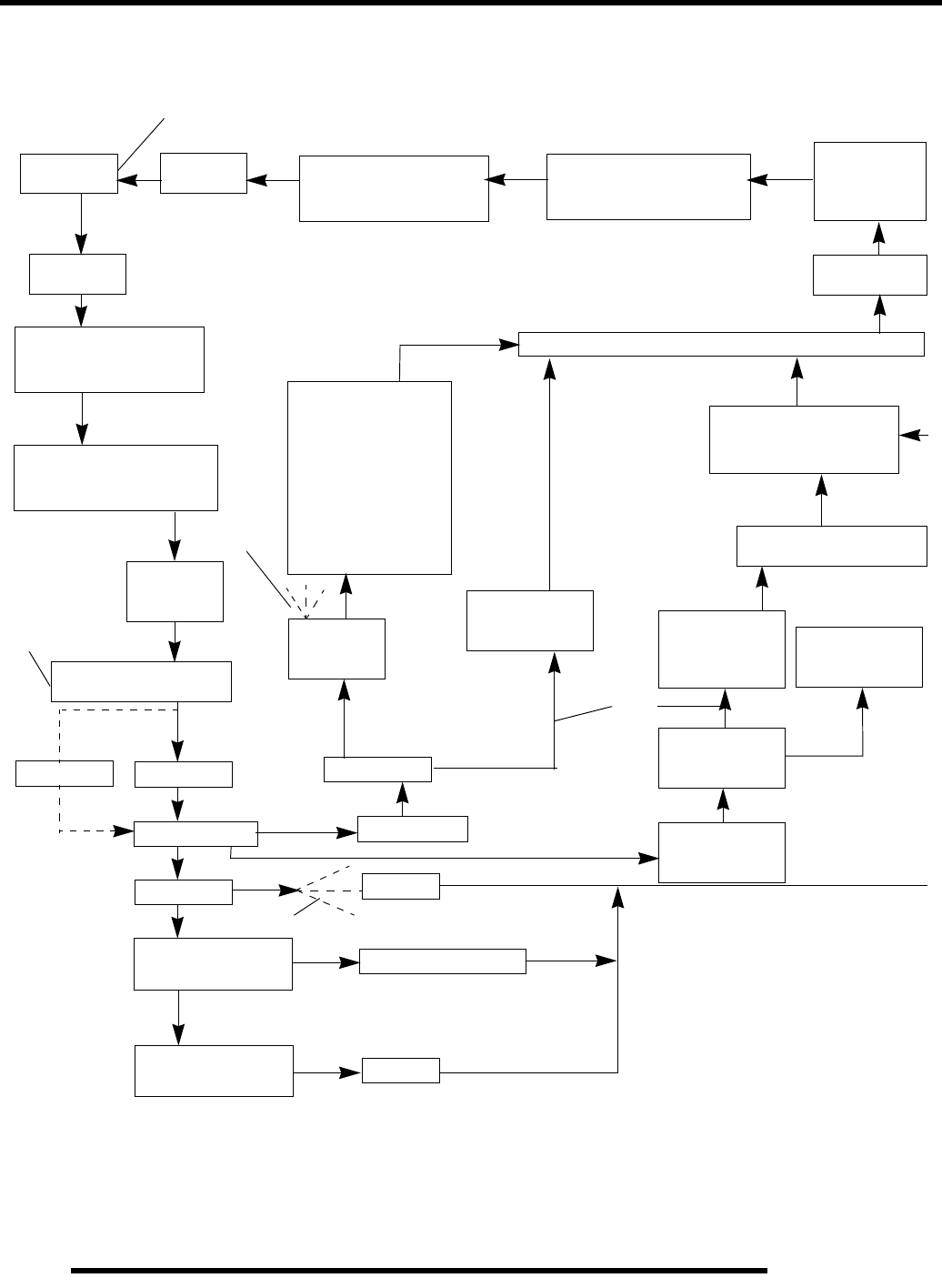
3.12
ENGINE
ES50PL Oil Flow Chart
Oil Tank Oil Hose Crankcase (Mag Side)
Oil Gallery
Crankcase (Clutch Side)
Oil Gallery
Oil Pump
(Scavenging)
Oil Hose Oil Strainer
Crankcase (Mag Side)
Oil Gallery
Crankcase (Clutch Side)
Oil Gallery
Oil Pump
(Feed)
One Way Valve
Bypass Oil Filter
Delivery Pipe
Oil Shaft
Transmission
Main Shaft
Transmission
Counter Shaft
Crankcase
Cylinder
Piston
Connecting Rod
(Small End)
Large End
Bearing
Crank Pin
Crankshaft
Gears
Gears & Clutch
Gears
Ball Bearing
(Mag Side)
Cam Chain
Cam & Crank Sprocket
Chain Room
Cam Lobe
Valve Lifter Cam Shaft
Journal
Cam Support
Oil Gallery
Cylinder Head
Oil Gallery
Prevents oil from
draining into
crankcase with
engine off
Indirect
Lubrication
Indirect
Lubrication
Oil Jet
Top of Oil Tank
RepairPro Service Manual
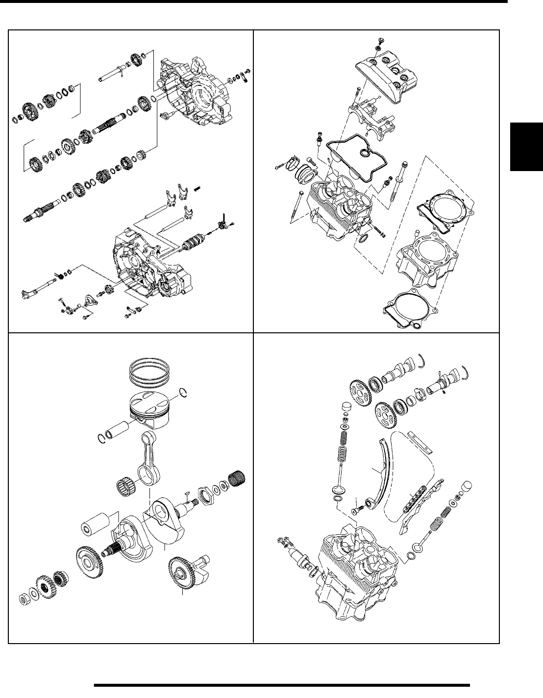
3.13
ENGINE
3
ES50PL Engine Exploded Views
Crankshaft and Piston
Cylinder / Cylinder Head
Valve Train
Crankcase / Transmission
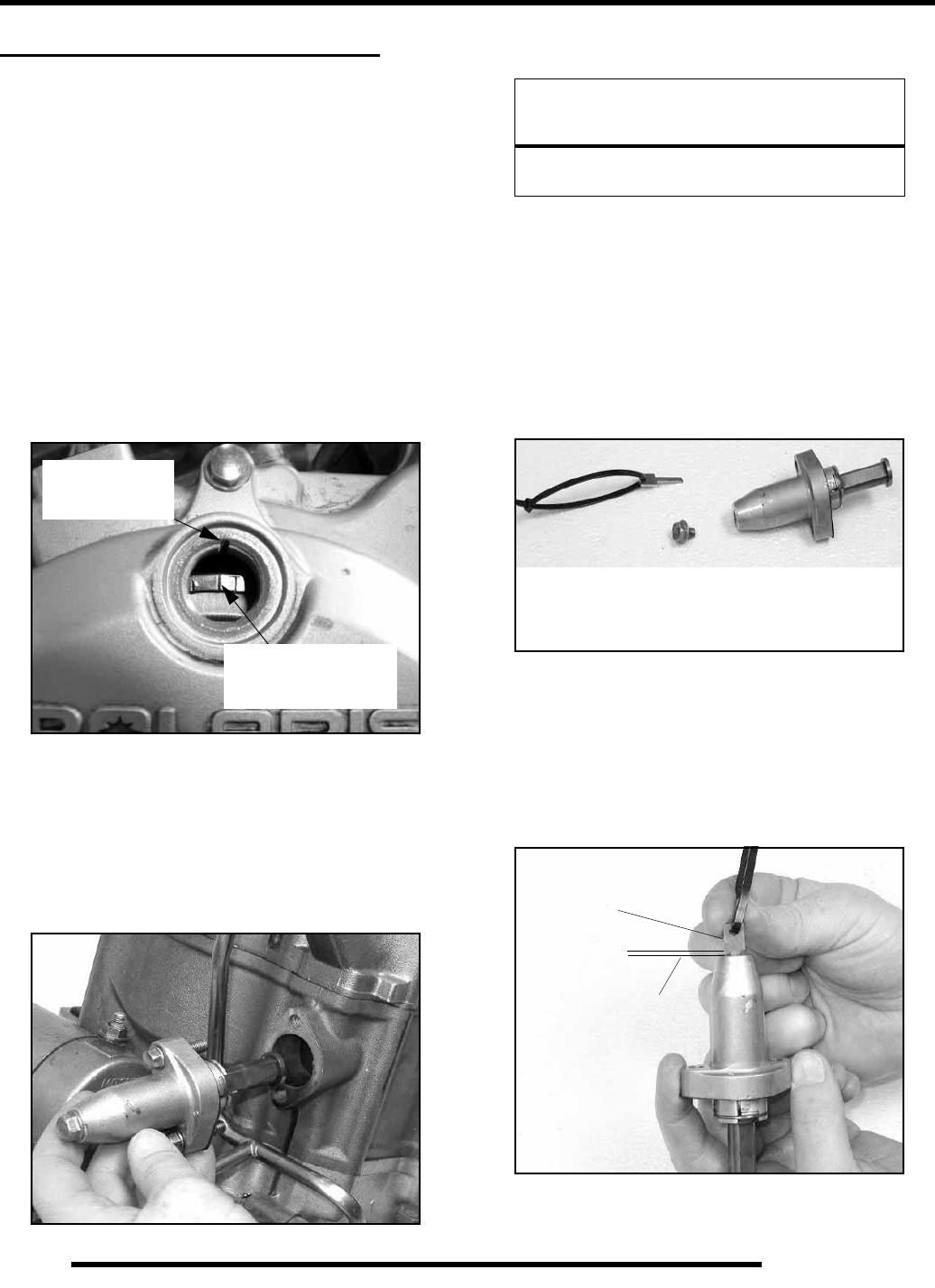
3.14
ENGINE
UPPER ENGINE DISASSEMBLY
Disassembly
REFER TO PAGE 3.8-3.9 FOR ENGINE
REMOVAL / INSTALLATION NOTES
Cam Chain Tensioner Removal
1. Remove ignition timing inspection plug from recoil
housing.
To position crankshaft at Top Dead Center (TDC) on the
compression stroke:
2. Rotate engine slowly in the direction of rotation watching
intake valves open and start to close.
3. Continue to rotate engine slowly, watching for the camshaft
sprocket marks and the indicator mark in the timing
inspection hole.
4. Align the indicator mark on flywheel with the indent in the
inspection hole and the cam sprocket marks (facing
upward) aligned with the dots at the 12 o’clock and 9
o’clock positions.
NOTE: The cam lobes should be laying flat and the
valves have clearance at this point.
5. Remove the two 8 x 25 mm cam chain tensioner flange
bolts.
6. If tensioner remains in place, tap lightly on tensioner body
with a soft face hammer and remove tensioner.
7. For installation, retract the plunger using the special tool
and reverse the installation procedures using a new gasket.
Tighten bolts to specification. (Page 3.3)
Cam Chain Tensioner Inspection and
Reassembly
NOTE: The cam tensioner assembly is not a
serviceable item. Replace assembly if problems are
found. Spring tension may be relieved using the
special tool prior to removal, but is not necessary.
1. When removed, the cam chain tensioner plunger should be
extended outward to the end of its travel. Verify and
inspect the plunger for wear or damage.
2. Push on the plunger. The plunger should not move in and
out of the tensioner body.
3. To release the plunger tension and prepare for reassembly,
remove the 10mm plug and insert the Cam Chain Tensioner
Tool (PA-45958), lodging the tip of the tool into the spring
TDC Line
(Left of the “T”)
TDC
Case Mark
CAUTION
The assembly is under spring tension.
Maintain inward pressure while removing.
A- Tool PN PA-45958
B- 10mm tensioner cap
A
B
Tool PA-45958
IMPORTANT
Maintain Clearance
while rotating tool
RepairPro Service Manual
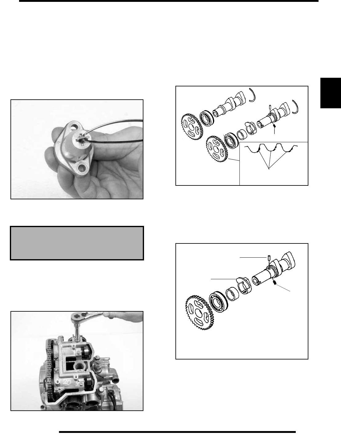
3.15
ENGINE
3
4. To retract the plunger, rotate the special tool clockwise
while holding the tensioner stationary. You may also hold
the special tool stationary and rotate the tensioner assembly
counterclockwise if desired.
IMPORTANT: Do not grind edges of key flange into
tensioner to prevent damage to the tool or locking
guides during plunger retraction.
5. Once retraction is complete, lock the tool into the tensioner
guides. This holds the spring and plunger in place for
reassembly. Use caution not to disturb the tool during
tensioner installation.
6. Reinstall the tensioner assembly, torquing the bolts to
specification (Page 3.3). Remove the special tool and
replace the tensioner cap.
Camshaft Removal
1. Remove the valve cover.
2. Remove the tensioner assembly.
3. Remove the 8 bolts securing the cam tower assembly and
remove the cover.
4. To free the cam assembly, lift one cam assembly and
slightly rotate it while removing the chain from the cam
gear. Repeat this procedure for the other cam.
NOTE: Do not allow cam chain to drop into the
engine if no other disassembly is being performed.
5. Use a device to secure the cam chain, such as mechanic’s
wire or nylon line, to prevent it from falling into the engine.
6. Inspect cam sprocket teeth for wear or damage. If damage
is found, replace the camshaft assembly.
Automatic Compression Release Inspection
NOTE: The automatic compression release
mechanism cannot be serviced. The components are
not replaceable. Replace the camshaft as an
assembly if any part of the compression release is
worn or damaged.
1. Check release cam (A) for smooth operation throughout
the entire range of movement. The spring (B) should hold
the cam against the stop. In this position, the actuator (C)
will be held outward in the compression release mode.
2. Inspect lobe on end of release cam for wear. Replace cam
assembly if necessary.
Tensioner Bolt Torque
6.6- 8.1 ft lbs (9- 11 Nm)
Inspect for Areas of Tooth
Wear or Damage
Note: Cam and compression release are
an assembly and not serviceable.
A
B
C
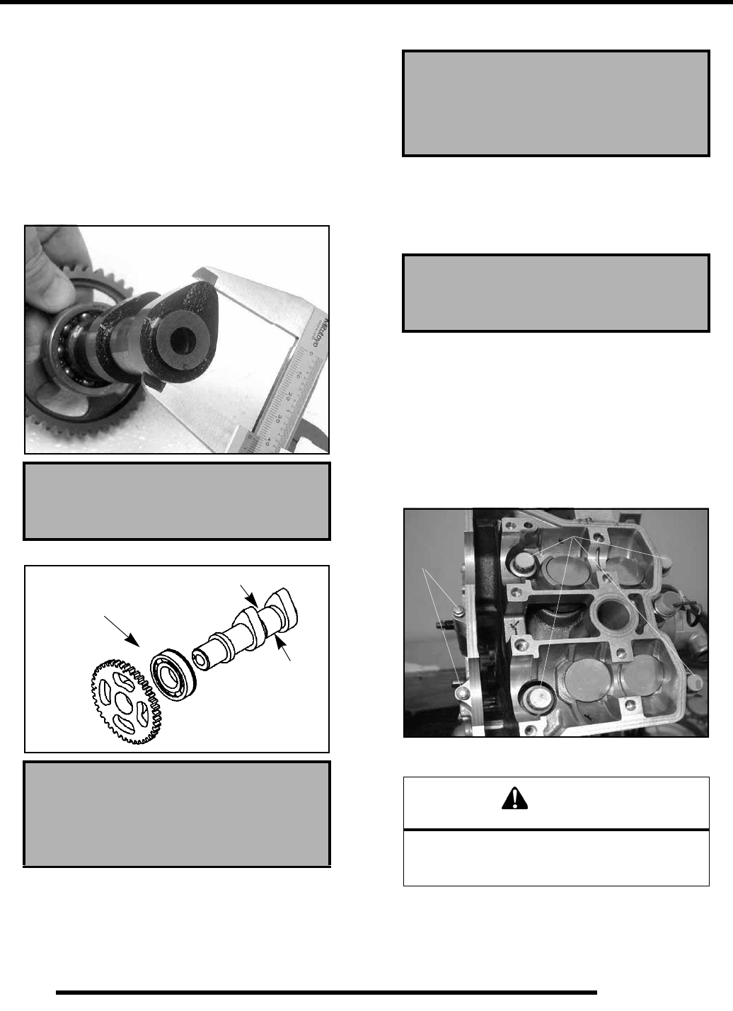
3.16
ENGINE
Camshaft Inspection
1. Visually inspect each cam lobe for wear, chafing or
damage.
NOTE: Camshafts, gears and bearings are not
serviceable. Replace camshaft as an assembly if
problems are found.
2. Inspect the cam bearings for excess play or noise during
rotation.
3. Measure height of each cam lobe using a micrometer.
Compare to specifications.
4. Measure camshaft journal outside diameter (O.D.)
5. Measure ID of camshaft journal bore.
NOTE: Replace camshaft as an assembly if
damaged or if any part is worn past the service limit.
6. Calculate oil clearance by subtracting journal OD from
journal bore ID. Compare to specifications.
NOTE: Replace cylinder head if camshaft journal
bore is damaged or worn excessively.
Cylinder Head Removal
1. Remove the cam shafts.
2. Remove the two 8mm flange bolts (A) from cylinder head.
3. Loosen each of the four cylinder head bolts (B) with a
14mm 12-point socket, turning evenly 1/8 turn each time
in a criss–cross pattern until loose.
4. Remove bolts (B) and tap cylinder head lightly with a soft-
face hammer until loose.
5. Remove cylinder head and head gasket.
Camshaft Lobe Height
Limit: 1.6555ð (42.05 mm)
Camshaft Journal O.D.:
Mag End: .9821- .9828ð
(24.946- 24.963 mm)
Check for wear
or roughness
Journal O.D.
Camshaft Journal I.D.:
Mag End: .9842- .9851ð
(25.00- 25.021 mm)
Camshaft Oil Clearance
Limit: .0039ð (.10 mm)
CAUTION
Tap only in reinforced areas or on thick parts of
cylinder head casting to avoid
damaging the head.
A
B
RepairPro Service Manual
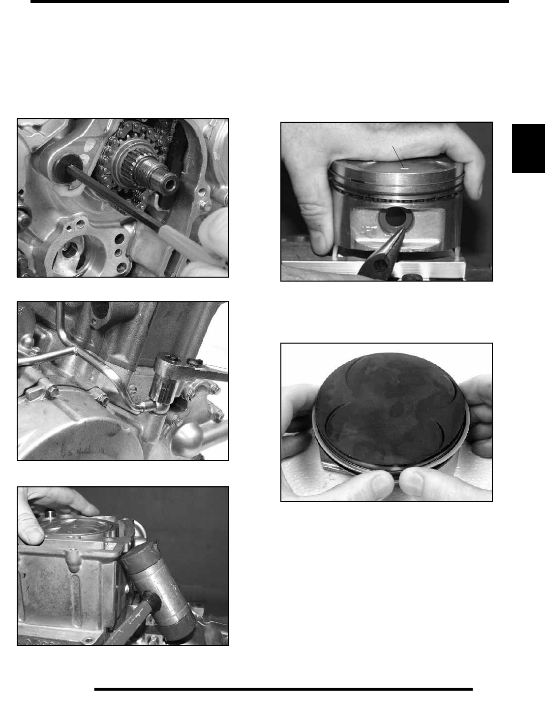
3.17
ENGINE
3
Cylinder and Piston Removal
NOTE: Follow engine disassembly procedures to
remove valve cover, camshafts and cylinder head.
Removal of clutch basket is required for this
procedure.
1. Using a 9/32” (7mm) Allen wrench, remove the rear cam
chain tensioner blade from the cylinder.
2. Loosen the 3 oil pipe banjo bolts, remove the bolts and
sealing washers. Remove the pipes.
3. Tap cylinder lightly with a plastic hammer in reinforced
areas until loose.
4. Rock cylinder forward and backward and lift it from the
crankcase, exposing the piston and connecting rod. Support
piston with Piston Support Block (PN 2870390).
5. Remove dowel pins from crankcase.
Piston Removal
1. Remove circlip. Note piston directional aid that is pointing
toward the left (stator) side of engine.
2. Remove piston circlip and push piston pin out of piston. If
necessary, heat the crown of the piston slightly with a
propane torch to aid removal.
IMPORTANT: Do not apply heat to the piston rings.
The ring may lose radial tension.
3. Remove top compression ring:
*Using a piston ring pliers: Carefully expand ring and lift
it off the piston.
*By hand: Placing both thumbs as shown, spread the ring
open and push up on the opposite side. Take care to not
scratch the ring lands.
IMPORTANT: Do not expand the ring more than the
amount necessary to remove it from the piston, or the
ring may break.
Directional Aid
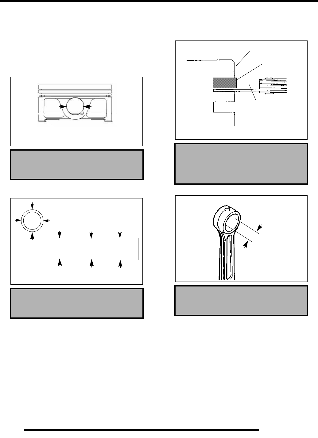
3.18
ENGINE
4. Repeat procedure for second ring.
5. The oil control ring is a three piece design consisting of a
top and bottom steel rail and center expander section.
Remove the top rail first followed by the bottom rail, then
remove the expander. For installation, refer to Page 3.31.
Piston and Rod Inspection
1. Measure piston pin bore.
2. Measure piston pin O.D. Replace piston and/or piston pin
if out of tolerance.
3. Measure piston ring to groove clearance by placing the ring
in the ring land and measuring with a thickness gauge.
Replace piston and rings if ring–to–groove clearance
exceeds service limits.
4. Measure connecting rod small end ID.
Piston Pin Bore:
.9055- .9057″ (23.001- 23.007 mm)
Piston Pin O.D.
.9053- .9065″ (22.994- 23 mm)
Piston Pin Bore
Piston Pin Measurement Locations
Piston Ring-to-Groove Clearance
Top Ring Limit: .0059″ (.15 mm)
Second Ring Limit: .0059″ (.15 mm)
Small End I.D. :
Std: .9058- .9063″ (23.007- 23.020 mm)
Piston
Ring
Feeler Gauge
RepairPro Service Manual
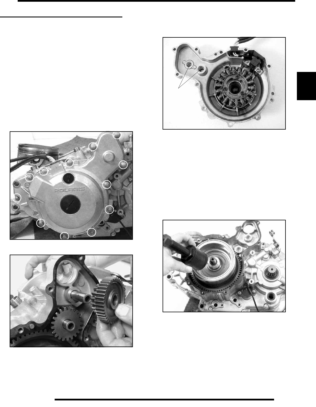
3.19
ENGINE
3
LOWER ENGINE DISASSEMBLY
Crankcase Disassembly and Inspection
NOTE: The starter motor, starter drive gears,
flywheel, stator, cam chain and sprockets can be
serviced with the engine in the frame.
NOTE: Crankcase and transmission components
cannot be serviced in the frame. Upper engine
components, with the exception of the starter and
stator removal, must be disassembled prior to
performing these procedures.
Starter Drive Gears Removal and Inspection
1. Remove the starter.
2. Remove the 12 bolts holding the stator cover assembly.
3. Inspect the drive gears and shafts for wear or damage and
replace if necessary.
4. Measure the OD of the starter drive shafts on both ends and
record. Measure in two directions 90° apart to determine if
components are out of round. Replace if components are
worn or damaged.
5. Measure the ID of the bushing in the stator housing (A) and
the crankcase and record. Measure in two directions 90°
apart to determine if cover is out of round. Replace cover
if clearance is determined to be excessive.
6. Inspect gear teeth on starter drive gears. Replace gears if
gear teeth are cracked, worn, or broken.
7. Installation: Reverse the removal procedures and install
with a new gasket. Do not use sealant. Torque the bolts in
a criss-cross pattern to 80–97 in. lbs. (9–11 Nm).
Flywheel / One-Way Starter Clutch
Removal and Inspection
1. Remove flywheel nut and washer.
2. Install Flywheel Puller (PA-46075) and remove flywheel.
IMPORTANT: Thread the puller onto the flywheel fully
or flywheel threads may be damaged.
A
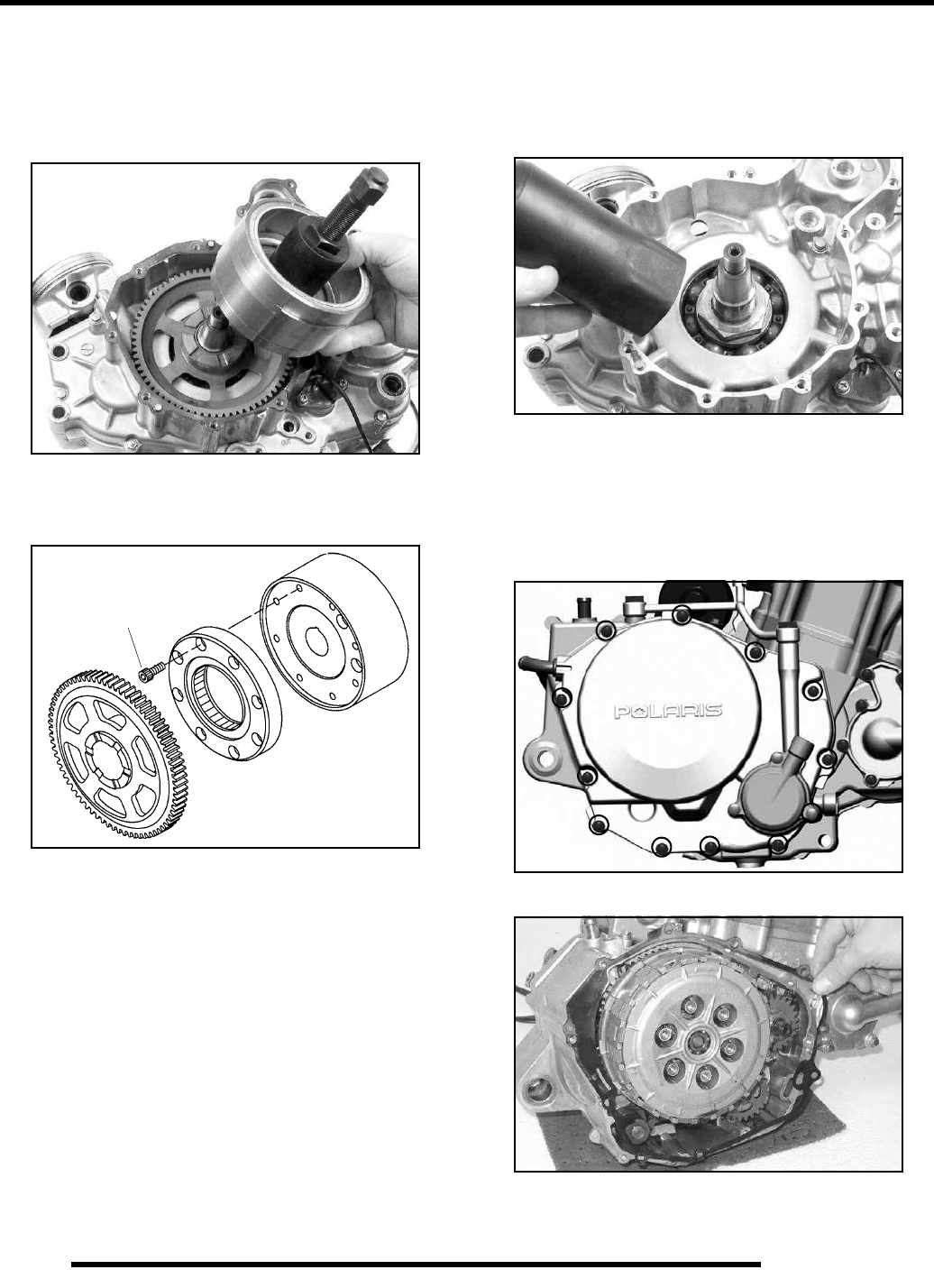
3.20
ENGINE
3. Removing the flywheel exposes the starter drive main gear
and one way clutch, which is mounted on the flywheel.
Inspect the main gear and bearing for wear, broken teeth or
other damage. Inspect the one-way clutch for wear or
damage to the rollers, springs, etc. Replace one-way
assembly if excessive wear or damage is found.
4. To replace the one-way starter clutch, remove the 8 screws
(A) holding the assembly to the flywheel. Reinstall the
screws and torque to 155-133 in. lbs. (13-15 Nm) in a criss-
cross pattern.
5. Installation: For installation of flywheel and starter gears,
reverse the removal procedures. When installing the
flywheel, apply engine oil to the crankshaft threads and
torque the flywheel nut to 111-125 ft. lbs. (150-170 Nm).
Crankshaft Nut Removal
1. Remove the stator-side crankshaft nut using MAG End
Crankshaft Nut Remover/Installer (PN PA-46076) while
using a suitable holding fixture to keep the crankshaft from
turning.
2. To reinstall, use a suitable holding fixture and MAG End
Crankshaft Nut Remover/Installer (PN PA-46076) to
torque the nut to 66-81 ft. lbs. (90–110 Nm).
Clutch Cover / Clutch Removal and
Inspection
1. Remove the 12 screws holding the clutch cover.
2. Remove the gasket. Clean the gasket surfaces prior to
reassembly.
A
PA-46076
RepairPro Service Manual
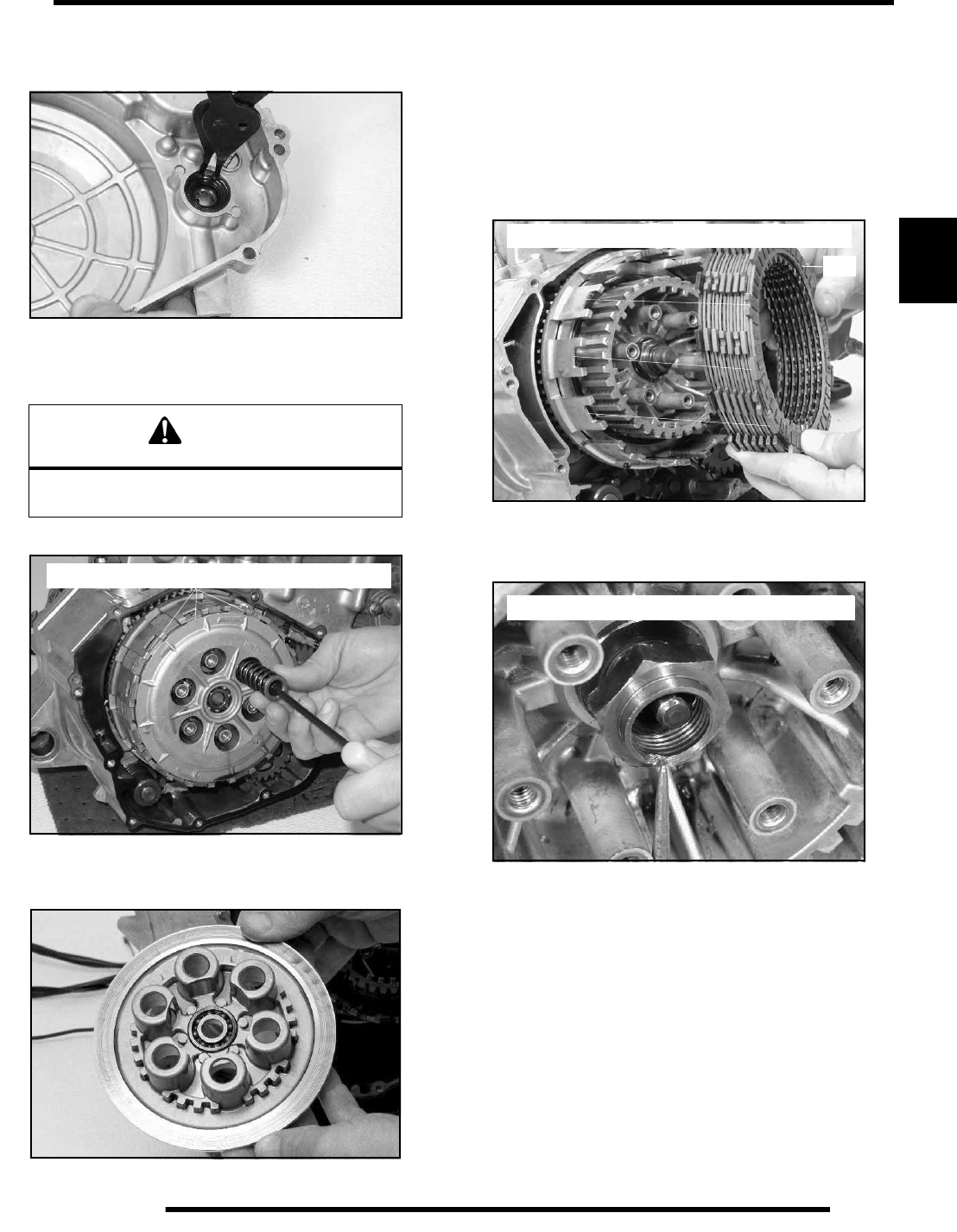
3.21
ENGINE
3
3. Inspect or replace the crankshaft oil seal anytime the clutch
cover is removed for service. Install with the seal lip
pointed in toward the cover.
4. Remove the 6 screws holding the clutch pressure plate.
NOTE: The top clutch plate should rest in the
towers.
5. Remove and inspect the clutch pressure plate for wear,
cracks, etc. Check bearing for wear and smooth rotation.
Replace either component if found to be damaged or worn.
6. Remove the clutch plates and friction discs, keeping them
in order. Inspect the pressure plates for wear and warpage.
Inspect the friction plates for wear or damage to friction
material. If either are damaged or worn excessively, replace
the components as a set.
NOTE: Replace clutch pack if measured thickness
of friction material is less than .110” (2.8mm). The
top plate has slightly different friction pads and
should always be installed on top.
7. To remove the clutch basket, remove the plunger from the
center of the clutch and de-stake the nut to avoid damaging
the threads upon removal.
8. Installation: Reverse the procedures. Using a new nut,
torque the clutch basket retaining nut to 66-81 ft. lbs. (90-
110 Nm). Stake the nut at the flat on the transmission shaft.
Install the clutch plates in order of removal. Reinsert the
plunger into the shaft. Reinstall the cover, pressure plate
screws and springs. Torque the screws to 80–97 in. lbs.
(9–11 Nm).
CAUTION
Assembly is under spring pressure. Wear safety
glasses during removal.
NOTE: Top Clutch Plate Aligns In Basket Towers
NOTE: Top Clutch Plate Aligns In Basket Towers
Top
NOTE: Nut is staked on flat of transmission shaft
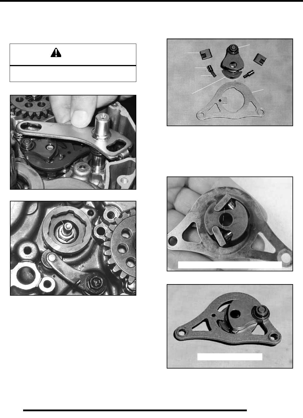
3.22
ENGINE
Shifter Component Removal and Inspection
1. With the clutch basket removed, remove the shift shaft
assembly (A), guide plate (D), pawl assembly (B), and
stopper arm / detent spring assembly (C).
2. Remove the shift cam by loosening the shifter pin bolt (E).
3. Inspect the ratcher pawls (F), pawl plungers (G), plunger
springs (H), shifter collar (J), shifter drum (K) and guide
plate (L) for wear or damage. Replace if wear or damage
is evident.
4. Installation: Reverse the procedures, paying close attention
to the orientation of the ratcher pawls (F) during
installation, as the surface must be flat when the pawls are
installed correctly. The guide plat (L) should be installed
with the “dot” facing upward. Torque the guide plate bolts,
the detent spring assembly bolt and the shifter pin bolt (E)
to 80–97 in. lbs. (9–11 Nm).
CAUTION
Stopper arm (C) is under spring pressure.
Use care during removal.
A
B
C
D
E
F
G
H
J
K
L
L
Correct for installation - Flat Surface
Correct for installation
RepairPro Service Manual
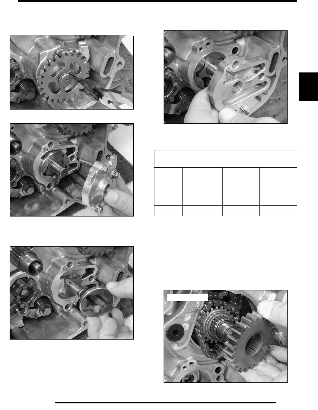
3.23
ENGINE
3
Oil Pump Removal and Inspection
1. Remove the circlip holding the oil pump gear and remove
the gear.
2. Remove the 3 bolts holding the oil pump cover. Inspect the
inside of the cover for wear or scoring.
3. Remove the outer pump rotor assembly. Inspect for signs
of scoring or excess wear.
NOTE: Cross pins for the pump rotors are loose and
may become lost. Keep pins in a secure location.
4. Remove the inner pump chamber and pump rotor assembly.
Inspect these components for wear or scoring.
NOTE: Dowel pins for the inner pump body are
loose and may become lost. Keep pins in a secure
location.
5. Replace any component that is found to be damaged or
worn.
6. Installation: Reverse the procedures. Use assembly lube or
clean engine oil to coat the parts before assembly. Tighten
the cover bolts to 80–97 in. lbs.(9–11 Nm). Verify the pump
turns freely during and after torquing bolts.
Crankshaft Drive and Cam Gear Removal
1. Remove the crankshaft nut, washer and drive gear. Note
and white-mark the double spline on both gears and shaft
for ease of reassembly.
OIL PUMP CLEARANCE
Limits are same as Standard
Body Feed / Scavenge .006-.008” .15 - .21mm
Rotor Tip Feed / Scavenge Less than .006” Less than
.15 mm
Rotor Side Feed .0007-.003” .02 - .08mm
Scavenge .002-.006” .05 - .16mm
Double Spline
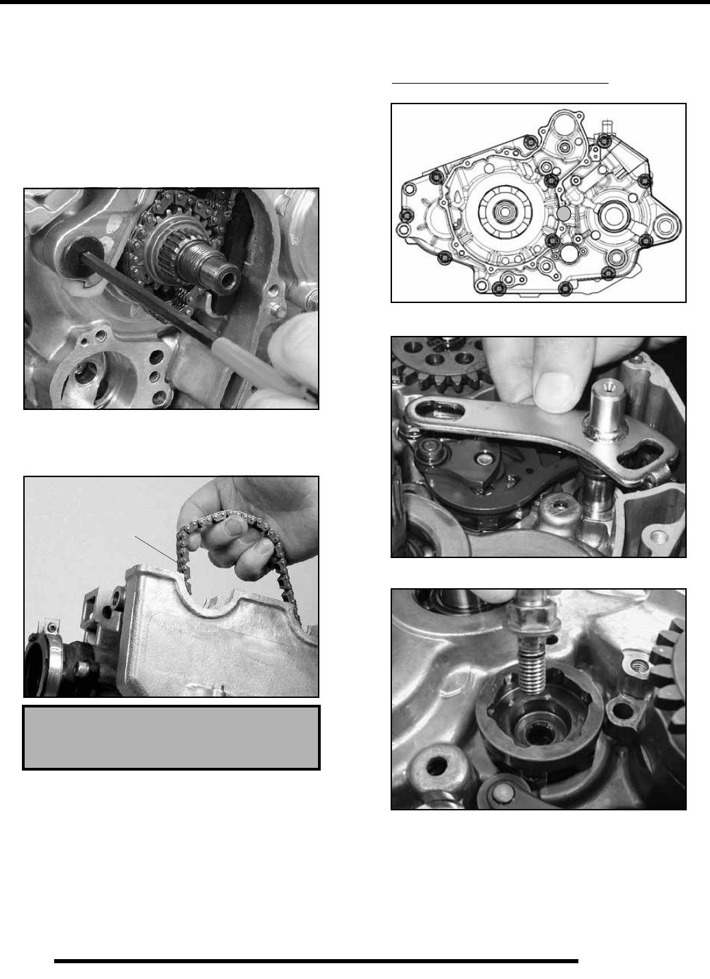
3.24
ENGINE
2. Remove the cam gear and thrustwasher from the crankshaft
for inspection. Replace if damage or excessive wear is
present to the gear teeth or splines.
3. Installation: Reverse the procedures and torque nut to 81–
96 ft. lbs. (110–130 Nm).
Cam Chain / Tensioner Blade Removal
1. Remove bolt (A) securing tensioner pivot blade to
crankcase . Inspect for cracks, wear, or damage.
2. Remove cam chain (B). Inspect chain for wear, missing
rollers or damage. Stretch chain tight on a flat surface and
apply a 10 lb. (4.53 kg) load. Measure length of a 20 pitch
(pin) section of chain. Replace if worn past service limit.
3. Installation: Reverse the procedures and torque the pivot
blade bolt to 10–12.2 ft. lbs. (13.5–16.5 Nm).
4. See Page 3.32 for Cam Timing.
Crankcase Separation
1. Remove the 13 flange bolts. 12 from the magneto side and
1 from the clutch side of the crankcase evenly in a criss–
cross pattern.
2. Remove the shifter assembly and shift cog that is attached
to the shift drum (Items A-E).
Chain Service Limit:
5.407” (13.7 cm)
A
B
A
B
C
D
E
RepairPro Service Manual
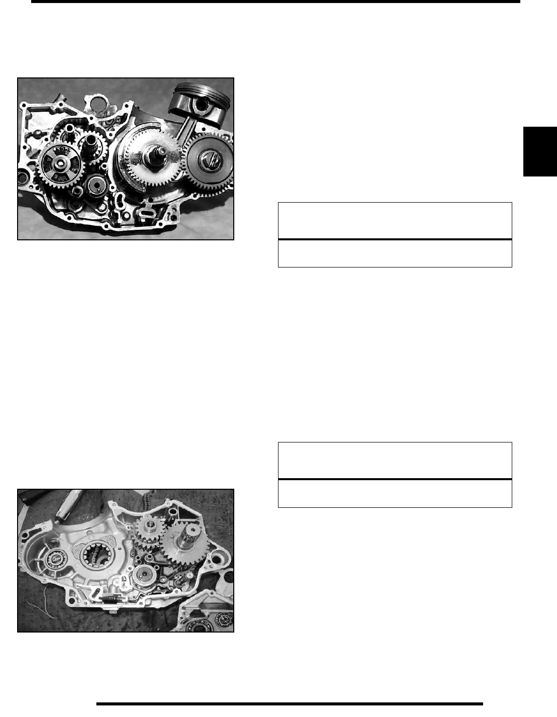
3.25
ENGINE
3
3. Separate crankcase by tapping with a soft faced hammer in
reinforced areas. Watch the gap along the crankcase mating
surface, making sure to separate the crankcase evenly. It
may also be necessary to tap the clutch side of the
crankshaft lightly to help separate the crankcase.
4. The crankshaft is designed to slip out of the PTO side upon
disassembly. Once the crankcase halves are split apart,
orientate the components into the stator side of the
crankcase containing the crankshaft, balancer, oil gallery,
the transmission gears and shift components for ease of
service and reassembly.
Crankcase Inspection
1. Remove all traces of gasket sealer from the crankcase
mating surfaces. Inspect the surfaces closely for nicks,
burrs or damage.
2. Check the oil pump and oil passage mating surfaces to be
sure they are clean and not damaged. Verify the oil pump
screen is clean.
Crankcase Bearing Inspection / Removal /
Installation
1. Inspect the crankshaft main bearings, balancer shaft
bearings, output shaft, and pump shaft bearings.
NOTE: Due to extremely close tolerances and
minimal wear, the bearings must be inspected
visually, and by feel. Look for signs of discoloration,
scoring or galling. Turn the inner race of each
bearing. The bearings should turn smoothly and
quietly. The outer race of each bearing should fit
tightly in the crankcase. The inner race should be
firm with minimal side to side movement and no
detectable up and down movement.
Bearing Removal:
NOTE: To ease bearing removal, warm the bearing
area, but not the bearing itself, until hot to the touch
to expand the bearing cavity.
1. Support the crankcase and drive or press the main bearings
out of each crankcase.
2. To remove balancer shaft bearings and pump shaft bearing,
use a blind-hole bearing puller.
NOTE: Bearings are stressed during the removal
process and should not be re–used!
Bearing Installation:
NOTE: For ease of bearing installation, warm the
crankcase until hot to the touch to expand the
bearing cavity. Place the bearings in a freezer. This
shrinks the bearing outer diameter slightly.
1. Install the bearings so the numbers are visible.
2. Drive or press new bearings into the crankcases, using the
proper driver.
IMPORTANT: Press only on outer race of bearing to
prevent bearing damage.
CAUTION
Wear the appropriate safety equipment during the
heating and removal process.
CAUTION
Wear the appropriate safety equipment during the
heating and installation process.
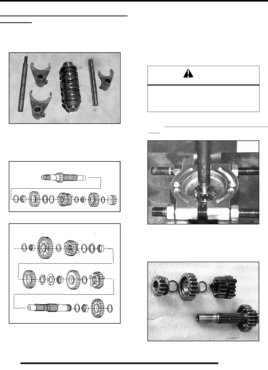
3.26
ENGINE
TRANSMISSION AND CRANKSHAFT
SERVICE
Transmission Removal and Inspection
1. Remove the shift fork tubes, spring, shift forks, and shift
drum from the transmission assembly.
2. Remove the main and output transmission shaft assemblies
and disassemble, keeping the parts in order for ease of
reassembly. Inspect the shift forks, shift drum, shift dogs,
gear teeth and shaft splines for damage. If the mating
surfaces on any of the components are found to be rounded,
worn, or otherwise damaged, they must be replaced.
3. Inspect the shaft support bearings in the crankcase halves.
Replace if any roughness or wear is felt. See page 3.25 for
crankcase bearing inspection / removal.
4. To reassemble, reverse the procedures using the photos for
reference.
Transmission Main Shaft Disassembly /
Assembly
1. Attach a bearing splitter to the reverse gear ONLY as
shown. DO NOT apply a load to 4th gear, as damage will
result. Place the assembly into a hydraulic press and using
a suitable driver, press off the gear.
2. Remove the parts from the shaft, keeping them in order for
ease of reassembly. Inspect all the main shaft components
for signs of damage or wear. If the mating or rolling
surfaces on any of the components are found to be rounded,
worn, or otherwise damaged or rough, they must be
replaced.
Main Shaft Assembly
Output Shaft Assembly
CAUTION
These procedures require the use of a heat
source and hydraulic press to remove and install
components. Wear the proper protective and
safety gear to prevent injury.
RepairPro Service Manual
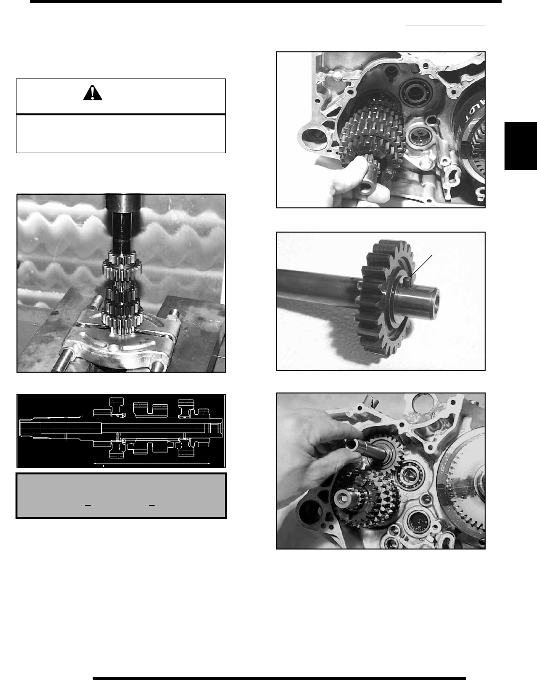
3.27
ENGINE
3
3. To reassemble the main shaft, install the components in the
order removed.
4. Before pressing the reverse gear onto the main shaft, heat
the reverse gear in an oil bath if desired. This will expand
and ease pressing of the gear to the specified dimension.
5. Support the mainshaft as shown with flat blocks. Press
ONLY on the reverse gear until the total width of the gear
set measures 120.4 ± .2mm (4.74 ± .008″) as shown.
Transmission Reassembly
NOTE: Installation of the transmission assemblies
can be facilitated by constantly rocking or moving
them to reduce binding during assembly.
NOTE: Do not to allow transmission parts to fall
from their assemblies during installation. Parts that
are out of alignment will cause improper casehalf
mating, resulting in transmission binding. Use of
assembly lube to “stick” parts together for ease of
installation is recommended.
1. Insert the output shaft assembly, minus the outer gear into
the stator side casehalve. Do not insert outer gear or shift
fork pins at this time.
2. Insert the reverse gear shaft assembly. Verify the alignment
pin (A) has seated into the casehalf.
CAUTION
This procedure requires the use of a heat source and
hydraulic press to install components. Wear the
proper protective and safety gear to prevent injury.
Main Shaft Gear Set Width
120.4 + .2 mm (4.74 + .008″)
A
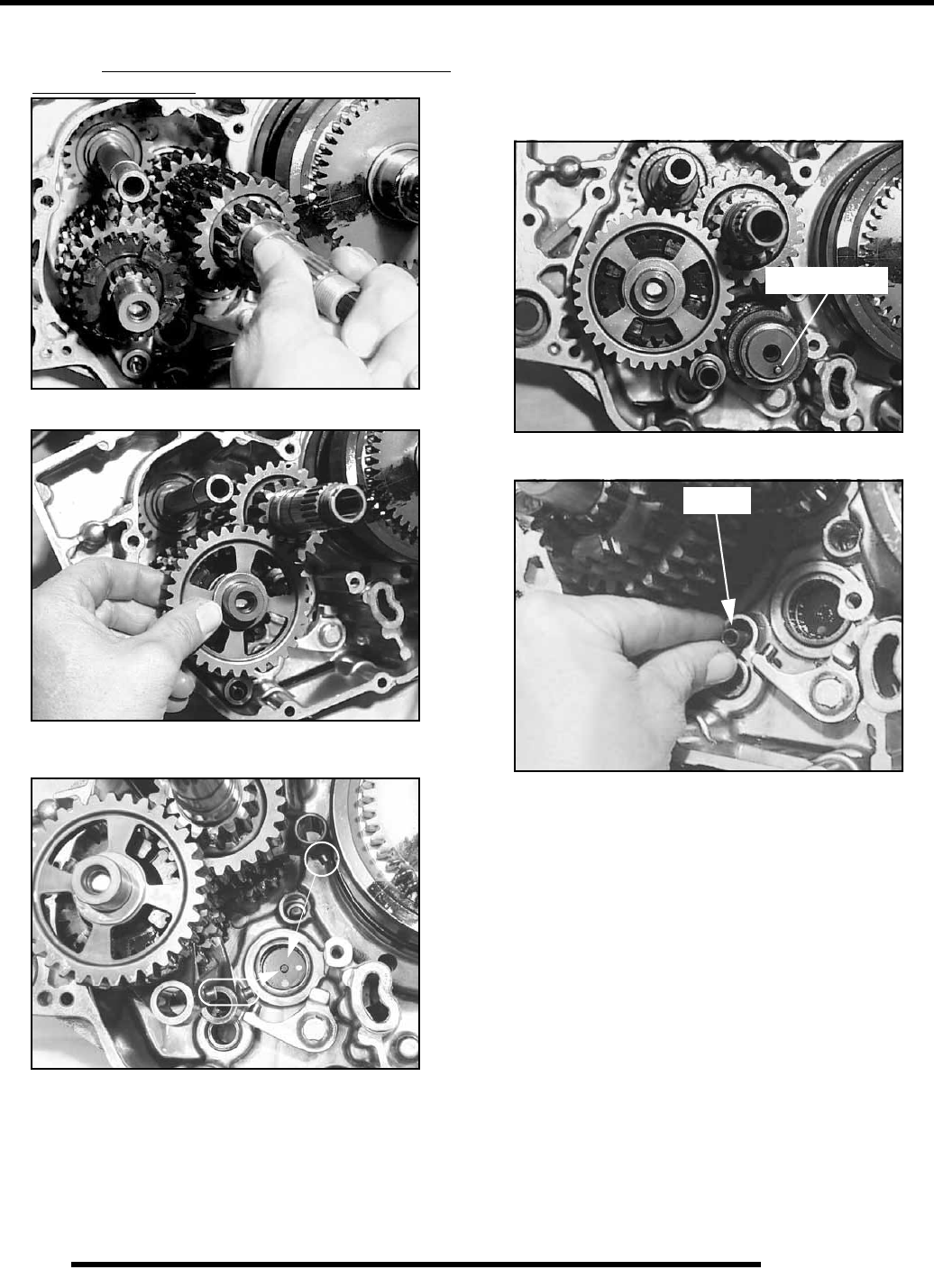
3.28
ENGINE
3. Install the main shaft assembly. The outer gear can now be
installed. Verify the shallow side of the outer gear is facing
out during installation.
4. Install the shift forks. Verify that each fork pin is pointed
toward the shift drum.
5. Insert and rotate the shift drum so the alignment pin is
approximately at the 5 o’clock position. Insert the fork pins
into their respective cam followers, installing each fork
shaft as they are assembled. Lifting of forks and gears will
be required to align pins into the shift drum.
NOTE: The output fork shaft contains a spring that
must be inserted before assembly. See Photo.
Pin Position
Spring
RepairPro Service Manual
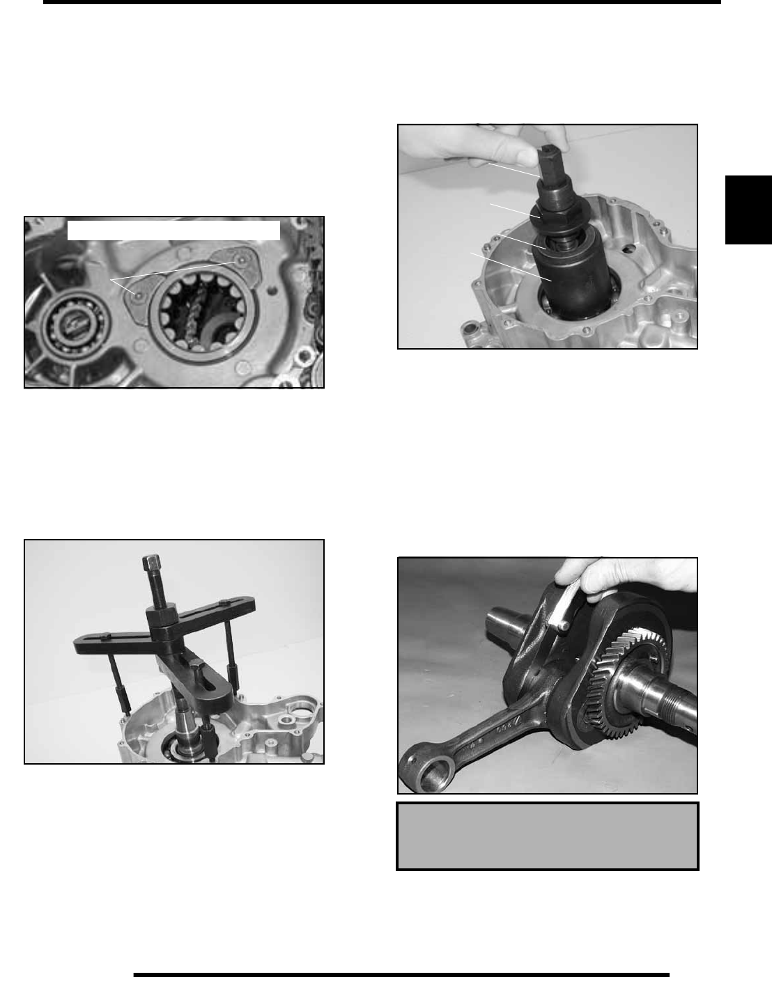
3.29
ENGINE
3
Crankshaft Removal / Installation
To remove crankshaft:
1. Remove the crankshaft retaining nut using Crankshaft Nut
Remover / Installer (PA-46076).
2. Remove the crankshaft bearing retainer screws using a
impact driver at location (A).
NOTE: Screw threads contain locking agent.
Heating of screws is required for removal. Use
caution and wear the proper safety equipment while
performing this procedure.
3. Support the stator side crankcase in a stand to press the
crankshaft out. Use care not to damage the crankcase
mating surface or connecting rod. Applying heat to the
crankcase bearing area to ease removal is acceptable.
4. Attach Crankcase Separator (PA-46087) to the casehalve.
Turn the inner shaft clockwise while holding the outer shaft
to press the crankshaft and bearing as an assembly out of
the case.
To install crankshaft:
5. Press the bearing into the crankcase at the outer edges with
an appropriate driver. Insert the bearing retainers and new
screws, which have a pre-applied locking agent. Torque the
screws to 8.1–9.6 ft. lbs. (11–13 Nm).
6. Using MAG End Crankshaft Installer (PA-46077), draw
the crankshaft into the bearing assembly by sliding the
collar and thrustwasher over the crankshaft end, threading
the inner puller onto the crankshaft end. Turn the outer nut
clockwise while holding the inner to pull the crankshaft into
the bearing.
Crankshaft Inspection
NOTE: Larger than standard readings indicate
excessive wear.
NOTE: Crankshaft components are press-fit and are
serviceable.
1. Inspect the crankshaft connecting rod bearing journal for
scoring and abnormal wear.
2. Use a feeler gauge to measure the connecting rod big end
side clearance.
PTO side shown for clarity
A
PA-46087 Verify that all bolts are
fully threaded to avoid
damage to the case
Connecting Rod Big End Side Clearance:
Limit: .0256″ (.65 mm)
Inner Puller
Outer Puller
Thrust Washer
Collar
PA-46077
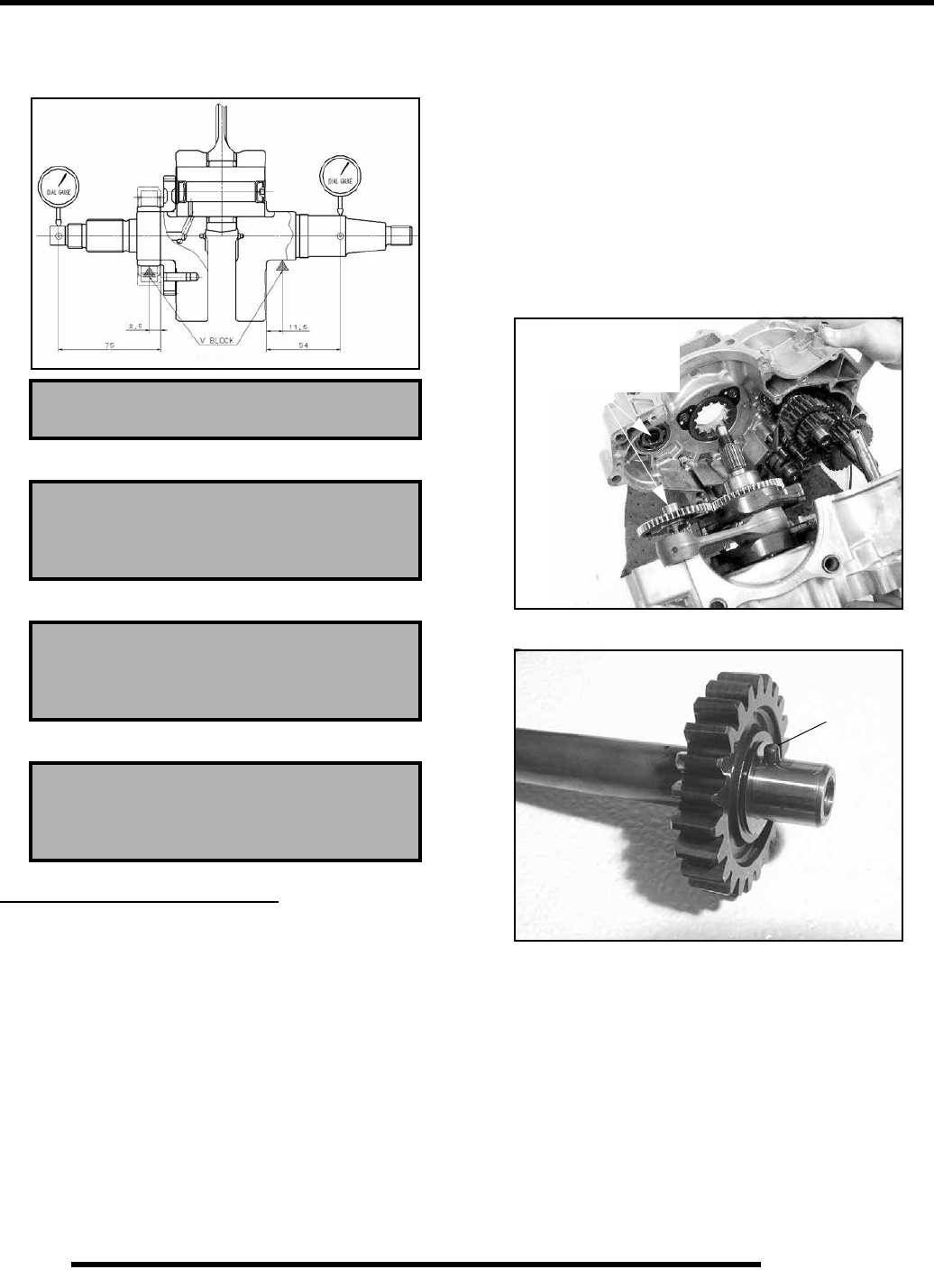
3.30
ENGINE
3. Place the crankshaft in a truing stand or V–blocks and
measure the runout on both ends with a dial indicator. See
Crankshaft Straightening on Page 3.10.
4. Measure the connecting rod big end radial clearance.
5. Measure the connecting rod small end radial clearance.
6. Measure the connecting rod small end I.D.
ENGINE REASSEMBLY
Crankcase Reassembly
1. Apply a thin layer of Crankcase Sealer (PN 2871557) to all
sealing surfaces of the PTO case half, being careful not to
over apply, as excessive sealant may clog oil passages or
drip into the crankcase. Allow the sealer to set for a few
minutes before assembling the two halves together.
2. Align the crankshaft and balancer timing marks and insert
the components into the stator-side case halve. Then install
the oil tube and transmission assemblies.
3. Reassemble the crankcase halves. This is best
accomplished with the stator side casehalve settled in a
suitable fixture that allows it to lay flat. This allows easier
installation without parts falling out of position. Make sure
the oil gallery tube is oriented correctly and the balancer
shaft groove aligns with the water pump shaft. Refer to
photos.
NOTE: Some light tapping with a soft faced mallet
may be required to bring the casehalves together. If
for any reason the cases fail to mate, DO NOT
FORCE. Reverify the transmission assemblies are
fully seated in their respective case half and are not
binding.
4. Reinstall the (12) stator side and (1) clutch side flange bolts,
tightening in a criss-cross pattern. Stop occasionally and
check that all rotating assemblies turn freely. Torque the
flange bolts to 80–97 in. lbs. (9–11 Nm).
Max Runout: .0012″ (.03 mm)
Big End Radial Clearance:
Limit: .0004- .0015″ (.011- .038 mm)
Small End Radial Clearance:
Limit: .0020″ (.05 mm)
Small End I.D. :
Std: .9058- .9063″ (23.007- 23.020 mm)
Align balancer
shaft and water
pump shaft grooves
Pin
Verify pin is aligned with notch in case
RepairPro Service Manual
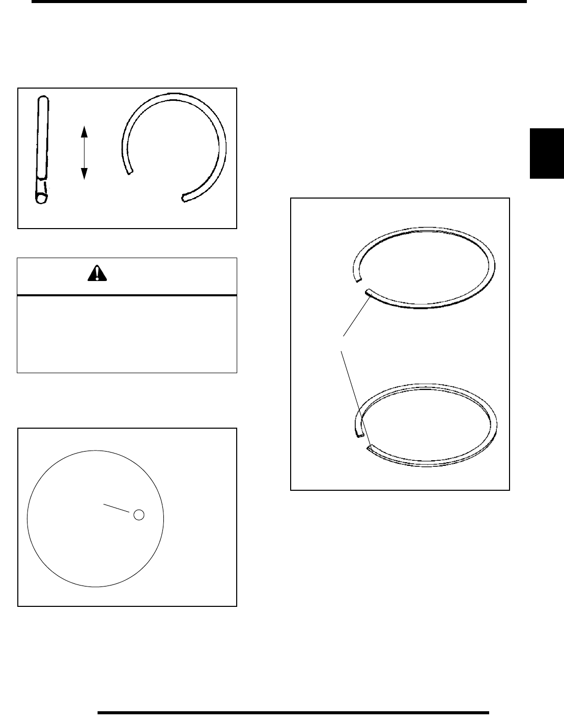
3.31
ENGINE
3
Piston Installation
1. Clean the gasket surfaces on the cylinder and crankcase.
Remove all traces of old gasket material.
2. Make sure the cylinder mounting bolt holes are clean and
free of debris.
3. Install a new circlip on one side of the piston with the end
gap facing up or down.
4. Apply clean engine oil to the piston rings, ring lands, piston
pin bore, piston pin, and piston skirt. Lubricate the
connecting rod (both ends), balancer drive gear, and
crankshaft main bearing area.
5. Install the piston on the connecting rod with the
identification mark facing the stator end of the crankshaft.
The piston pin should be a push fit in the piston.
6. Install the other circlip with the gap facing up or down. (see
Caution with Step 3 above). Push the piston pin in both
directions to make sure the clips are properly seated in the
groove.
Piston Ring Installation
NOTE: Apply clean engine oil to all ring surfaces
and ring lands. Always check piston ring installed
gap before rings are installed on piston. If the piston
has been in service, clean any accumulated carbon
from the ring grooves and oil control ring holes.
1. Place the oil control ring expander in oil ring groove with
the end gap facing forward. The expander has no up or
down marking and can be installed either way. The ends
should butt squarely together and must not overlap. Install
the bottom and top rails.
2. Install the second ring with the mark facing up.
3. Install the top ring with the mark facing up.
4. Check to make sure the rings rotate freely in the groove
when compressed.
5. Orientate the rings for installation by rotating until the end-
gaps are 120 degrees apart.
CAUTION
Circlips become deformed during the removal
process. Do not re–use old circlips. Do not
compress the new clip more than necessary
upon installation to prevent loss of radial tension.
Severe engine damage may result if circlips are
re–used or deformed during installation.
Gap should face up or down
Identification Mark
Stator Side
Top Side of Piston
Ring Profile
Top - Chrome
Install with mark facing up
Second - Cast
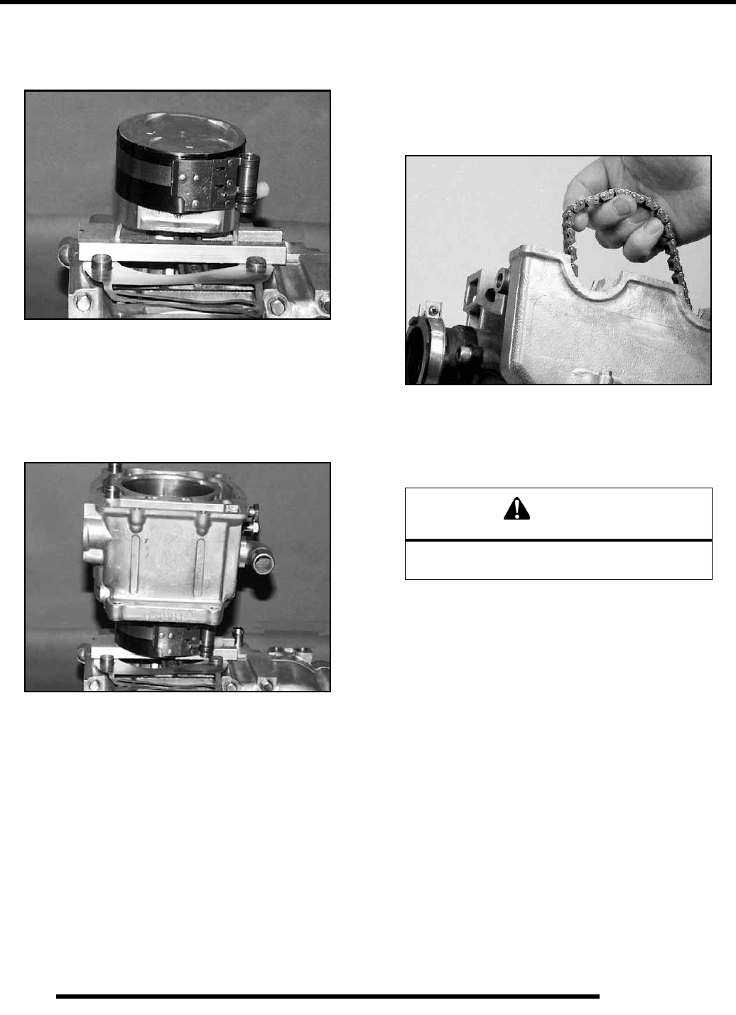
3.32
ENGINE
Cylinder Installation
1. Place the dowel pins in the crankcase and install a new
cylinder base gasket.
2. Position the Piston Support Block (P/N 2870390) beneath
the piston skirt to support the piston during cylinder
installation.
3. Apply clean engine oil to the ring compressor and install
the compressor according to the manufacturer’s
instructions.
IMPORTANT: Verify all ring end gaps are correctly
located.
4. Apply clean engine oil liberally to the cylinder bore and
tapered area of the sleeve. Install the cylinder with a slight
rocking motion until the rings are captive in the sleeve.
5. Remove the ring compressor and support block.
6. Push the cylinder downward until fully seated on the base
gasket.
7. Rotate the crankshaft and position the piston at TDC.
NOTE: If cam chain is installed, hold it up while
rotating the engine to avoid damage to the chain,
drive sprocket teeth, or tensioner blade.
Cam Chain Installation
NOTE: The camshafts, crankshaft sprocket and
clutch basket must be removed to perform this
procedure.
1. Install the cam chain by dropping it down through the
chain room and over the crankshaft sprocket.
2. Use a suitable device to hold the chain in place to keep it
from dropping through the chain room, such as wire or a
hammer handle.
Camshaft Timing
IMPORTANT: CAMSHAFT TIMING NOTE
The Top Dead Center (TDC) mark is used to time the
camshaft to the crankshaft. Follow the procedures
outlined. Refer to the diagram.
1. Apply engine oil or assembly lube to the camshaft main
journals, cam lobes and the automatic compression release
mechanism.
2. Install the crankshaft cam sprocket onto the shaft. Note the
double spline for ease of installation. The alignment mark
should face outward.
PN 2870390
CAUTION
Serious engine damage will result if the camshaft
is not properly timed to the crankshaft.
RepairPro Service Manual
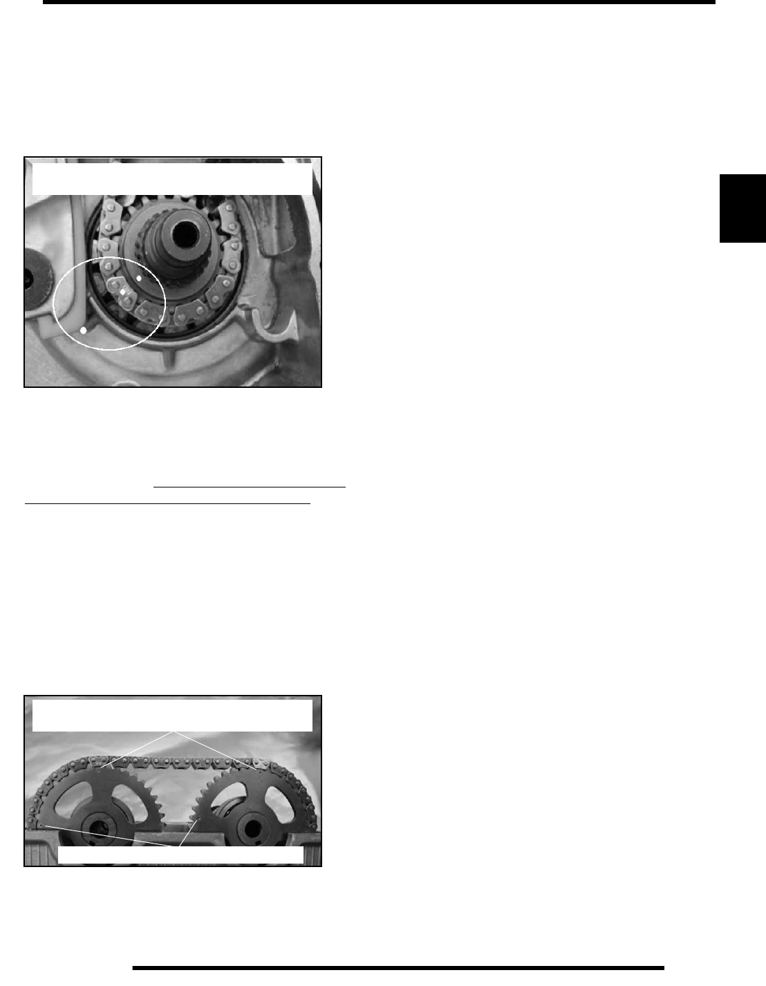
3.33
ENGINE
3
3. If not already at Top Dead Center, Loosely hold the cam
chain and rotate the crankshaft until the crankshaft cam
sprocket timing mark is aligned with the Top Dead Center
(TDC) mark on the crankcase (see photo). Position the
chain for correct timing by aligning the bottom cam timing
mark with the brass colored bottom chain link. Keep
tension on the chain so as to not lose chain alignment at the
crankshaft sprocket during cam installation.
4. Install the camshafts one at a time. First, install the exhaust
cam by looping the chain over the cam gear. At the same
time, position the cam chain for correct timing by aligning
the brass colored chain link with the 12 o’clock dot on the
cam sprocket. The sprocket secondary mark should be at
the 9 o’clock position. Keep tension on the chain so as to
not lose chain alignment at the crankshaft sprocket.
5. Next, install the intake cam, positioning the upper cam
chain for correct timing by aligning the remaining brass
colored chain link with the 12 o’clock dot on the cam
sprocket. Timing is in phase when all three brass colored
cam chain links align with all three sprocket timing marks
and the secondary cam gear marks are at approximately the
9 o’clock position, with the exhaust cam timing mark
slightly advanced. Refer to the diagram on Page 3.34.
NOTE: Failure to align marks in this fashion will
cause valve-to-piston interference, resulting in
engine damage.
6. Re-check all cam timing marks to verify proper cam timing,
and install the cam tower. Tighten the bolts evenly in a
criss-cross pattern to specification. Do not rotate engine
until the tensioner has been installed to avoid chain slip
and loss of timing reference.
7. Install the tensioner assembly. (raefer to Page 3.14). Verify
timing by rotating the crankshaft two full revolutions (720
degrees), checking for valve-to-piston interference which
would indicate a problem with cam timing. If interference
is noted, immediately stop rotation and reverify cam
timing.
NOTE: Rotating the engine during verification will
cause the timing alignment marks to rotate out of
phase, and will take as many as 20 revolutions to
come back into phase. To maintain alignment of the
marks if needed, rotate the engine backward the
same number of turns as forward.
8. With timing procedure completed, install the primary drive
sprocket, washer and nut onto the crankshaft. Torque to
specification.
Primary Drive Gear Installation
1. Install the cam sprocket with alignment mark outward.
2. With chain in place and cam timing having been performed,
install the primary drive sprocket, washer and nut onto the
crankshaft. Torque to 81–96 ft. lbs. (110–130 Nm).
Align Brass Colored Link and Sprocket
Mark with Top Dead Center (TDC) Mark
Align Brass Colored Link and Sprocket
Mark with Top Dead Center (TDC) Mark
Note exhaust cam is slightly advanced

3.34
ENGINE
Outlaw Cam Timing Exploded View
RepairPro Service Manual
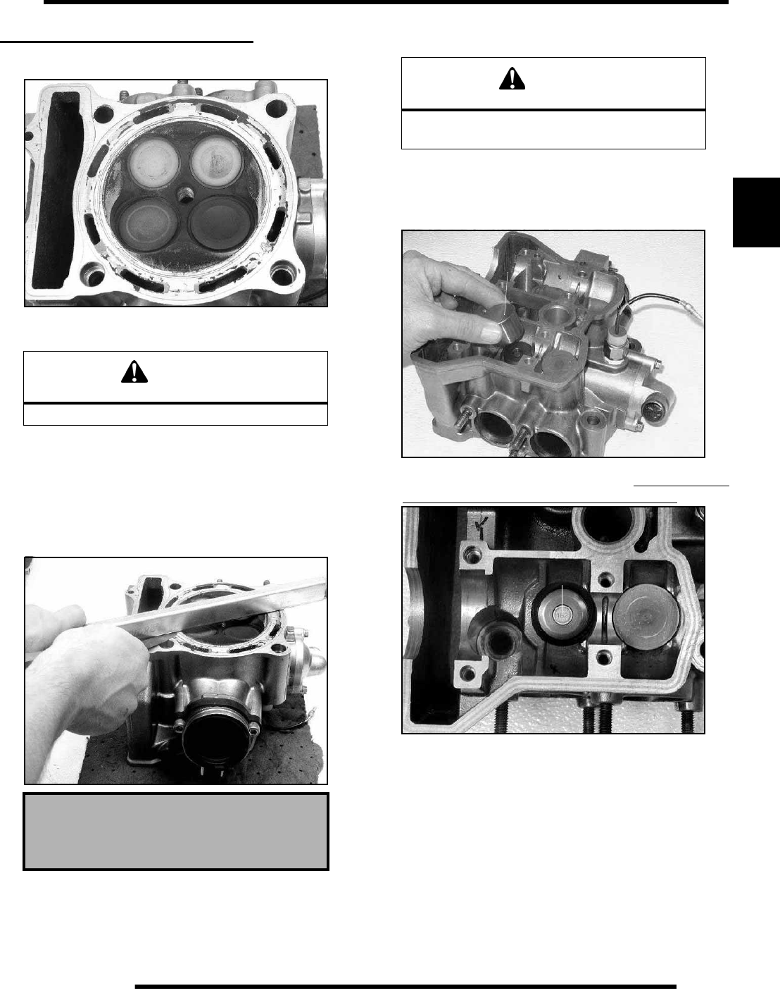
3.35
ENGINE
3
CYLINDER HEAD SERVICE
Cylinder Head Inspection
1. Thoroughly clean cylinder head surface to remove all
traces of gasket material and carbon.
Cylinder Head Warp
1. Lay a straight edge across the surface of the cylinder head
at several different points and measure warp by inserting a
feeler gauge between the straight edge and the cylinder
head surface. If measurement exceeds the service limit,
replace the cylinder head.
Cylinder Head Disassembly
1. Remove the valve buckets (A).
NOTE: Keep all parts in order with respect to their
location in the cylinder head. Use care not to mar or
damage the buckets upon removal.
2. Under each bucket is a valve shim (B). Record and keep
these shims oriented to each valve disassembled.
3. Using Valve Spring Compressor (A) (PA-46502),
compress the valve springs and remove the split keepers.
CAUTION
Use care not to damage sealing surface.
Cylinder Head Warp Limit:
.002″ (.05 mm)
WARNING
Wear eye protection during cylinder head
disassembly and reassembly.
A
B
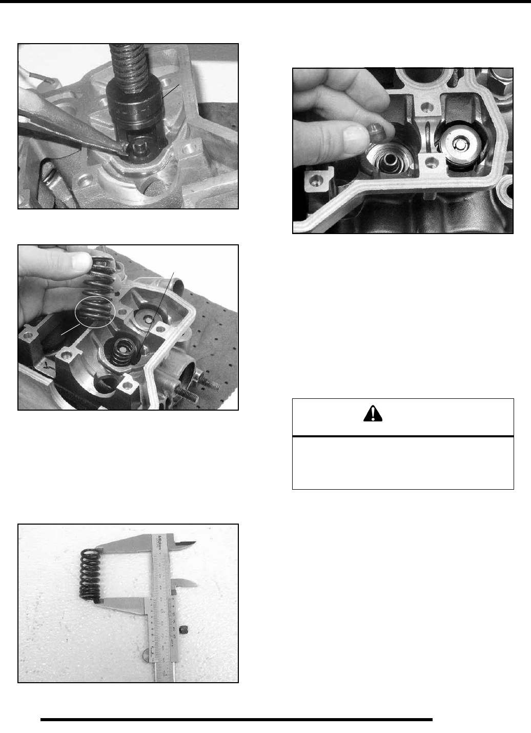
3.36
ENGINE
NOTE: To prevent loss of tension, do not compress
the valve springs more than necessary.
4. Remove spring retainer, inner and outer springs and spring
washer.
NOTE: The valve springs should be positioned with
the tightly wound coils against the cylinder head (B).
5. Push valve out, keeping it in order for reassembly in the
same guide.
6. Measure free length of the inner and outer springs with a
Vernier caliper. Check springs for squareness. Compare to
specifications. Replace inner and outer springs as a set if
either measurement is out of specification.
7. Remove the valve seals.
NOTE: Replace seals whenever the cylinder head is
disassembled. Hardened, cracked or worn valve
seals will cause excessive oil consumption and
carbon buildup.
Cylinder Head Valve Guide / Valve Seat
Inspection
Inspect valve seats in cylinder head for pitting, burnt spots,
roughness, and uneven surface. If any of the described
conditions exist, the valve seat must be reconditioned. If the
valve seat is cracked the cylinder head must be replaced.
NOTE: Servicing the valve guides and valve seats
requires special tools and a thorough knowledge of
reconditioning techniques. Follow the instructions
provided in the cylinder head service tool kit.
Valve Guide Removal / Installation / Ream
1. Remove all carbon deposits from the combustion chamber,
valve seat and valve guide area before attempting to
remove valve guides.
IMPORTANT: Carbon deposits are extremely
abrasive and may damage the valve guide bore when
guides are removed.
2. Place new valve guides in a freezer for at least 15 minutes
while heating cylinder head.
3. Heat cylinder head in an oven or use a hot plate to bring
cylinder head temperature to 212° F (100° C).
A
B
Spring Washer Located
Below Assembly
Inner 1.575” (40.0 mm)
Outer 1.650” (41.9 mm)
CAUTION
Wear the proper safety equipment when
performing cylinder head service. Valve guide
replacement will require heating of the cylinder
head. Wear safety gloves to prevent burns.
RepairPro Service Manual
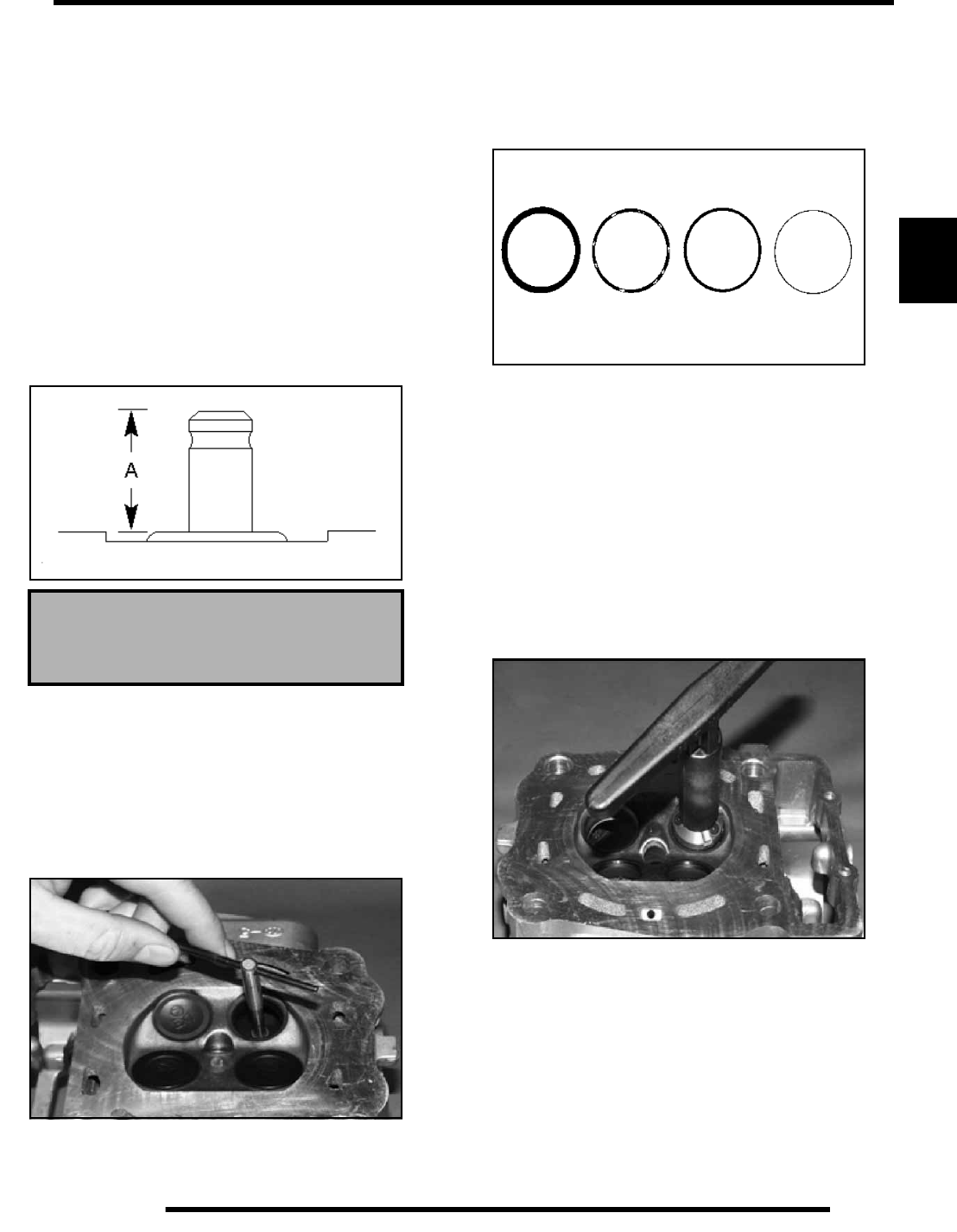
3.37
ENGINE
3
IMPORTANT: Do not use a torch to heat cylinder head
or warpage may result from uneven heating. Head
temperature can be checked with a pyrometer or a
welding temperature stick.
4. When thoroughly heated, place cylinder head on blocks of
wood which will allow the old guides to be removed.
5. Using valve guide driver, drive guides out of the cylinder
head from the combustion chamber side. Be careful not to
damage guide bore or valve seat when removing guides.
6. Place cylinder head on cylinder head table.
NOTE: Be sure cylinder head is still at 212° F (100°
C) before installing new guides.
7. Place a new guide in the valve guide installation tool and
press guide in to proper depth. Check height of each guide
above the cylinder head (A).
NOTE: The guide can also be inserted to the proper
depth using a driver. Inspect the guide closely for
cracks or damage if a driver is used.
8. Allow the cylinder head to cool to room temperature. Apply
cutting oil to the reamer. Guides should be reamed from the
valve spring side of the cylinder head. Ream each guide to
size by turning the reamer clockwise continually. Continue
to rotate reamer clockwise during removal of the tool.
9. Clean guides thoroughly with hot soapy water and a nylon
brush. Rinse and dry with compressed air. Apply clean
engine oil to guides.
Valve Seat Reconditioning
1. Follow the manufacturers instructions provided with the
Valve Seat Reconditioning Kit (P/N 2200634). Abrasive
stone seat reconditioning equipment can also be used.
Keep all valves in order with their respective seat.
NOTE: Valve seat width and point of contact on the
valve face is very important for proper sealing. The
valve must contact the valve seat over the entire
circumference of the seat, and the seat must be the
proper width all the way around. If the seat is
uneven, compression leakage will result. If the seat
is too wide, seat pressure is reduced, causing
carbon accumulation and possible compression
loss. If the seat is too narrow, heat transfer from
valve to seat is reduced and the valve may overheat
and warp, resulting in burnt valves.
2. Install pilot into valve guide.
3. Apply cutting oil to valve seat and cutter.
4. Place 46° cutter on the pilot and make a light cut.
5. Inspect the cut area of the seat:
• If the contact area is less than 75% of the circumference
of the seat, rotate the pilot 180° and make another light
cut.
• If the cutter now contacts the uncut portion of the seat,
check the pilot. Look for burrs, nicks, or runout. If the
pilot is bent it must be replaced.
Valve Guide Height:
.689- .709” (17.5 - 18.0 mm)
Valve Guide Installed Height
Valve Seat Wear Patterns
Too
Wide Uneven Good Too
Narrow
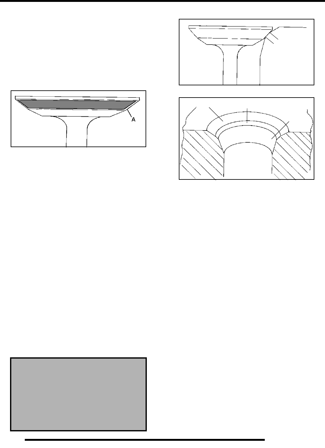
3.38
ENGINE
• If the contact area of the cutter is in the same place, the
valve guide is distorted from improper installation and
must be replaced. Be sure the cylinder head is at the
proper temperature and replace the guide.
• If the contact area of the initial cut is greater than 75%,
continue to cut the seat until all pits are removed and a
new seat surface is evident.
NOTE: Remove only the amount of material
necessary to repair the seat surface.
6. To check the contact area of the seat on the valve face, apply
a thin coating of Prussian Blue™ paste to the valve seat. If
using an interference angle (46°) apply black permanent
marker to the entire valve face (A).
7. Insert valve into guide and tap valve lightly into place a few
times.
8. Remove valve and check where the Prussian Blue™
indicates seat contact on the valve face. The valve seat
should contact the middle of the valve face or slightly
above, and must be the proper width (refer to the wear limits
for proper seat width).
• If the indicated seat contact is at the top edge of the
valve face and contacts the margin area it is too high on
the valve face. Use the 30° cutter to lower the valve
seat.
• If too low use the 60° or 75° cutter to raise the seat.
When contact area is centered on the valve face,
measure seat width.
• If the seat is too wide or uneven, use both top and
bottom cutters to narrow the seat.
• If the seat is too narrow, widen using the 45° cutter and
re–check contact point on the valve face and seat width
after each cut.
NOTE: When using an interference angle, the seat
contact point on the valve will be very narrow, and is
a normal condition. Look for an even and continuous
contact point on the black marker, all the way
around the valve face.
9. Clean all filings from the area with hot soapy water, rinse,
and dry with compressed air.
10. Lubricate the valve guides with clean engine oil, and apply
oil or water based lapping compound to the face of the
valve.
NOTE: Lapping is not required with an interference
angle.
11. Insert the valve into its respective guide and lap using a
lapping tool or a section of fuel line connected to the valve
stem.
12. Rotate the valve rapidly back and forth until the cut sounds
smooth. Lift the valve slightly off of the seat, rotate 1/4 turn,
and repeat the lapping process. Do this four to five times
until the valve is fully seated, and repeat process for the
other valve(s).
13. Clean cylinder head, valves, and camshaft oil supply
passages thoroughly.
Valve Seat Width:
Intake Std: .028” (.7 mm)
Limit: .055” (1.4 mm)
Exhaust Std: .039” (1.0 mm)
Limit: .071” (1.8 mm)
Seat Contact
Width
Seat 45o or 46o
Top 30o Bottom 60o
or 75o
RepairPro Service Manual
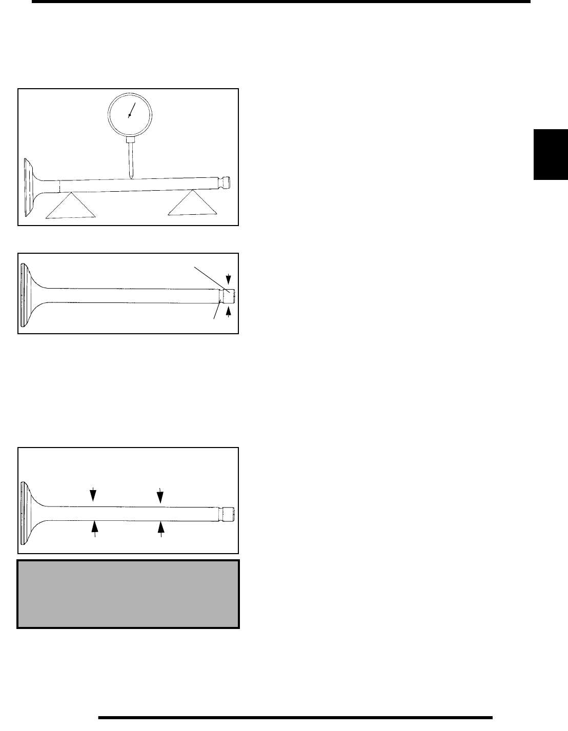
3.39
ENGINE
3
Valve Inspection
1. Remove all carbon from valve with a soft wire wheel.
2. Check valve face for runout, pitting, and burned spots. To
check for bent valve stems, mount the valve in “V” blocks
and use a dial indicator.
3. Check end of valve stem for flaring, pitting, wear or damage
(A).
4. Inspect split keeper groove for wear or flaring of the keeper
seat area (B).
NOTE: The valves cannot be re–faced or end
ground. Valves must be replaced if worn, bent, or
damaged.
5. Measure diameter of valve stem with a micrometer in three
places and in two different directions (six measurements
total). Compare to specifications.
Valve Stem Diameter:
Intake: .2343- .2348″ (5.950- 5.965 mm)
Exhaust: .2341- .2346″ (5.945- 5.960 mm)
A
B
Measure valve stem in
several places
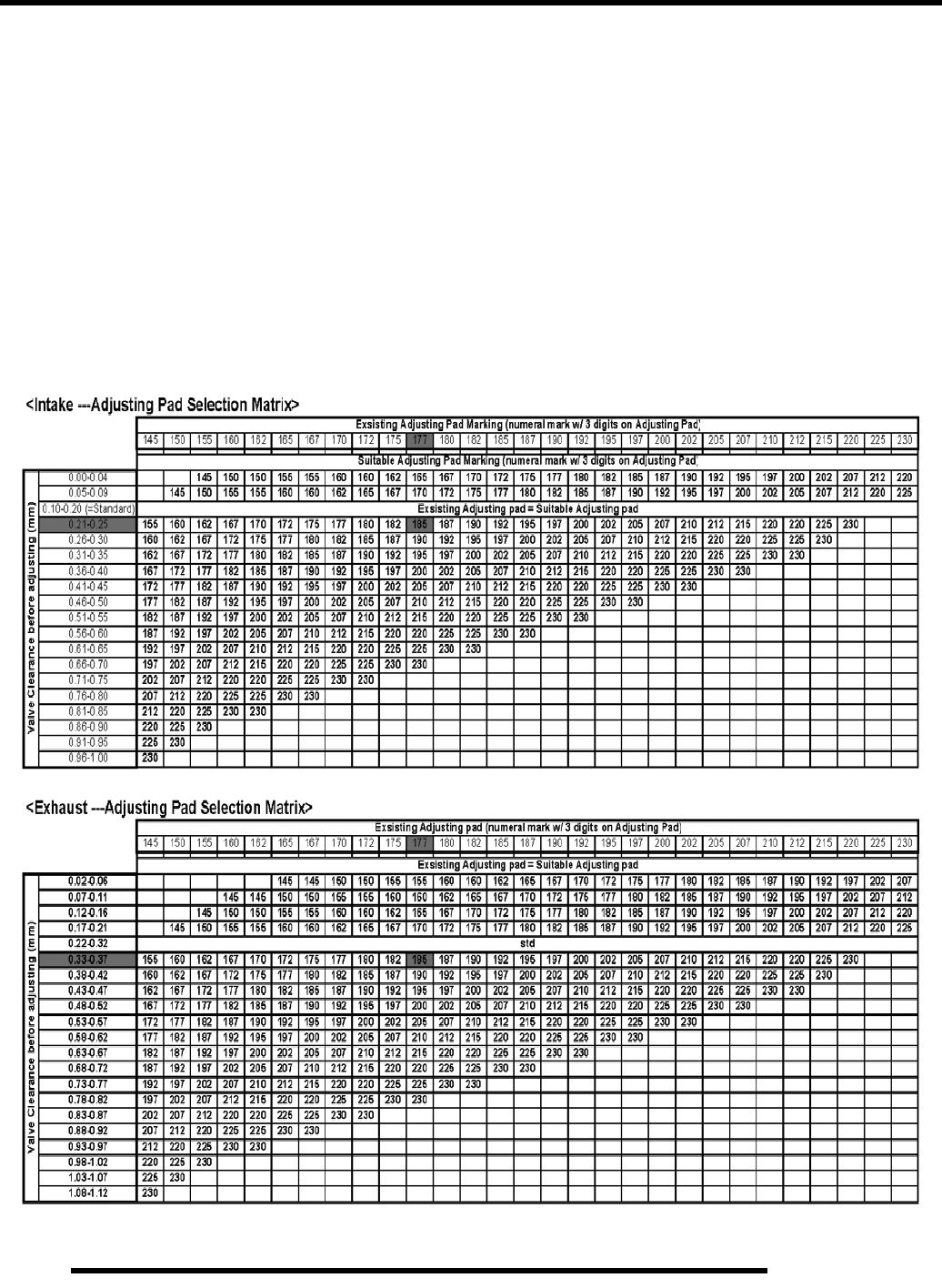
3.40
ENGINE
ES50PL Adjusting Pad Selection Matrix
1. Measure valve clearance at TDC (Compression Stroke) using thickness gauge with original adjusting pad installed.
2. Reference the measurement and the 3 digits marked on the existing adjusting pad on the matrix below.
3. Select a suitable adjusting pad from the matrix below and replace existing pad.
4. Measure and confirm that valve clearance is within the standard values.
5. If valve clearance is not within standard, reverify step#1 and repeat procedures again.
Example:
Intake- Valve clearance before adjusting: 0.23mm(.009”)
Existing adjusting pad mark: 177
From “Intake Adjusting Pad Selection Matrix”, a suitable adjusting pad would be 185
Exhaust- Valve clearance before adjusting: 0.35mm(.0137”)
Existing adjusting pad mark: 177
From “Intake Adjusting Pad Selection Matrix”, a suitable adjusting pad would be 185
RepairPro Service Manual
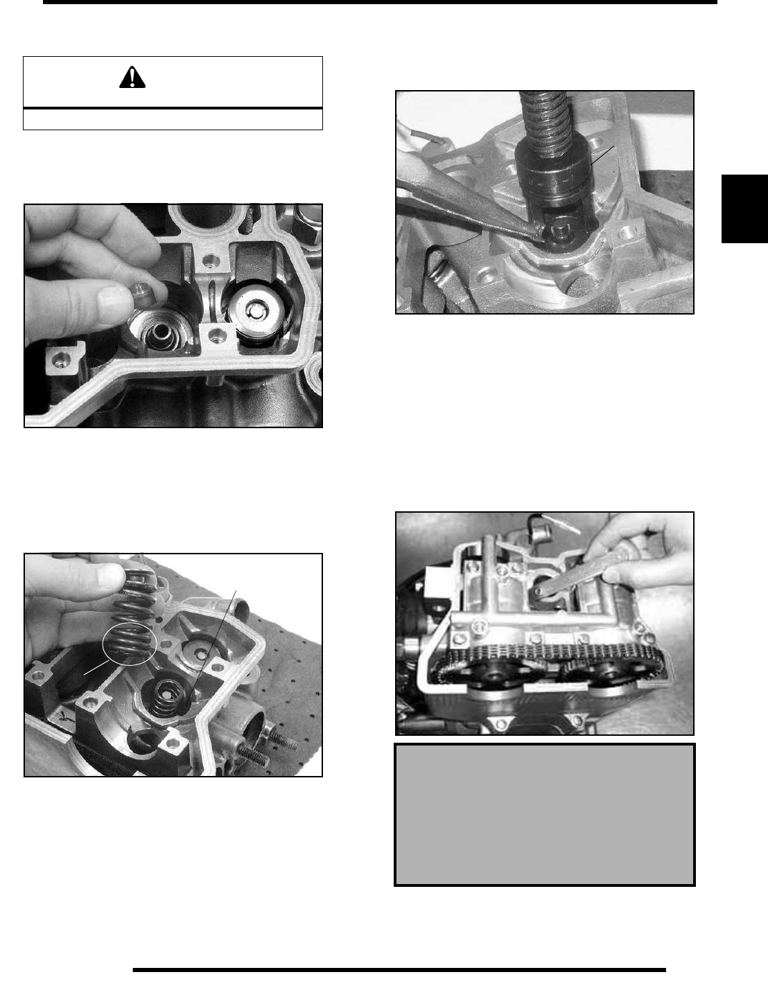
3.41
ENGINE
3
Cylinder Head Assembly
NOTE: Assemble the valves one at a time to
maintain proper order.
1. Install new valve seals on valve guides.
2. Apply engine oil to valve guides and seats.
3. Coat valve stem with assembly lube.
4. Install valve carefully with a rotating motion to avoid
damaging valve seal.
5. Install spring washers. Dip valve springs and retainer in
clean engine oil and install springs with closely spaced coils
(B) toward the cylinder head.
6. Place spring retainer on and install valve spring compressor
(A). Compress springs only enough to allow split keeper
installation and prevent loss of spring tension. Install split
keepers with the gap even on both sides.
7. Repeat procedure for remaining valves.
8. When all valves are installed, tap lightly with soft faced
hammer on the end of the valves to seat the keepers.
9. Install the shims and buckets for each valve in the order they
were removed.
10. Check valve clearance with engine at Top Dead Center
(TDC).
NOTE: Repairs such as valve grinding or valve
replacement will require re-shimming for proper
valve clearance. Use the chart provided on page 3.40
to determine the appropriate shim thickness.
CAUTION
Wear eye protection during assembly.
B
Spring Washer Located
Below Assembly
Valve Clearance (Engine Cold):
Intake: .006″ (.15 mm)
Exhaust: .010” (.27 mm)
+/- .0019″ (.05 mm)
A
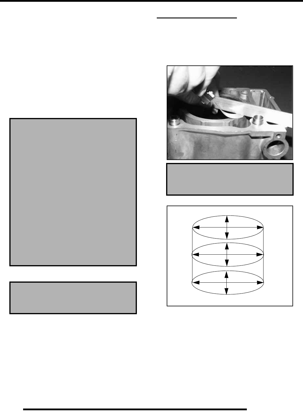
3.42
ENGINE
Cylinder Head Installation
Clean the gasket surfaces on the cylinder head and cylinder.
Remove all traces of old gasket material.
Refer to disassembly photos.
1. Install the cam chain tensioner guides. Be sure bottom end
of guide is located properly in crankcase.
2. Install the two dowels and a new cylinder head gasket.
3. Place the cylinder head on the cylinder. Apply a film of
engine oil to the cylinder head bolt threads and washers, and
hand tighten the bolts.
The following procedure must be used to torque the cylinder
head properly:
4. Install the two 6 mm bolts and torque to specification.
CYLINDER SERVICE
Cylinder Inspection
1. Remove all gasket material from the cylinder sealing
surfaces.
2. Inspect the top of the cylinder for warp using a straight edge
and feeler gauge.
3. Inspect cylinder for wear, scratches, or damage.
4. Inspect cylinder for taper and out of round with a
telescoping gauge or a dial bore gauge. Measure in two
different directions, front to back and side to side, on three
different levels (1/2” down from top, in the middle, and
1/2” up from bottom).
**TORQUE ALL BOLTS EVENLY IN A
CRISS-CROSS PATTERN
1. Torque bolts to 22 ft. lbs. (30 Nm)
2. Torque bolts to 51 ft. lbs. (70 Nm)
Leave at this torque for 1 minute to allow
gaskets to seat for proper sealing.
3. Loosen bolts evenly 360o (1 turn)
4. Torque bolts to 29 ft. lbs. (35 Nm)
5. From this point, tighten bolts evenly 90o
(1/4 turn)
6. Finally, tighten another 90o (1/4 turn)
7. Install two 6 mm bolts and torque to 6 ft.
lbs. (8 Nm)
Cylinder 6 mm Bolt Torque:
6 ft. lbs. (8 Nm)
Cylinder Warp
.002″ (.05 mm)
1/2” Down From Top of Cylinder
1/2” Up From Bottom
X
X
X
Y
Y
Y
RepairPro Service Manual
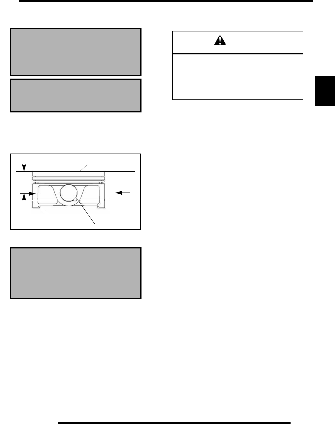
3.43
ENGINE
3
5. Record measurements. If cylinder is tapered or out of round
beyond specification, the cylinder must be replaced.
Piston–to–Cylinder Clearance
1. Measure piston outside diameter at a point 40 mm down
from the top of the piston at a right angle to the direction
of the piston pin.
2. Subtract this measurement from the maximum cylinder
measurement obtained previously in Step 5.
Cylinder Hone Selection and Honing
Procedure
Cylinders may be wet or dry honed depending upon the hone
manufacturer’s recommendations. Wet honing removes more
material faster and leaves a more distinct pattern in the bore.
IMPORTANT: Clean the Cylinder After Honing
It is very important that the cylinder be thoroughly cleaned after
honing to remove all grit material. Wash the cylinder in a
solvent, then in hot, soapy water. Use electrical contact cleaner
if necessary to clean these areas. Rinse thoroughly, dry with
compressed air, and oil the bore immediately with Polaris 4
Cycle Lubricant to prevent the formation of surface rust.
Honing To Deglaze
A finished cylinder should have a cross–hatch pattern to ensure
piston ring seating and to aid in the retention of the fuel/oil
mixture during initial break in. Hone cylinder according to hone
manufacturer’s instructions, or these guidelines:
• Use a motor speed of approximately 300–500 RPM, run
the hone in and out of the cylinder rapidly until cutting
tension decreases. Remember to keep the hone drive
shaft centered (or cylinder centered on arbor) and to
bring the stones approximately 1/2” (1.3 cm) above and
below the bore at the end of each stroke.
• Release the hone at regular intervals and inspect the
bore to determine if it has been sufficiently deglazed,
and to check for correct cross-hatch.
NOTE: Do not allow cylinder to heat up during
honing.
• After honing has been completed, inspect cylinder for
thinning or peeling.
Cylinder Taper
Limit: .002″ (.05 mm) Max.
Cylinder Out of Round
Limit: .002″ (.05 mm) Max.
Standard Bore Size:
3.9055- 3.9062″ (99.20- 99.22 mm)
Piston to Cylinder Clearance:
Std: .0018- .0025″ (.046- .065 mm)
Piston O.D.:
Std: 3.9037- 3.9040″ (99.155- 99.170 mm)
Piston
Piston Pin
CAUTION
A hone which will straighten as well as remove
material from the cylinder is very important.
Using a common spring loaded glaze breaker for
honing is not advised for nicasil cylinders.
Polaris recommends using a rigid hone
or arbor honing machine.
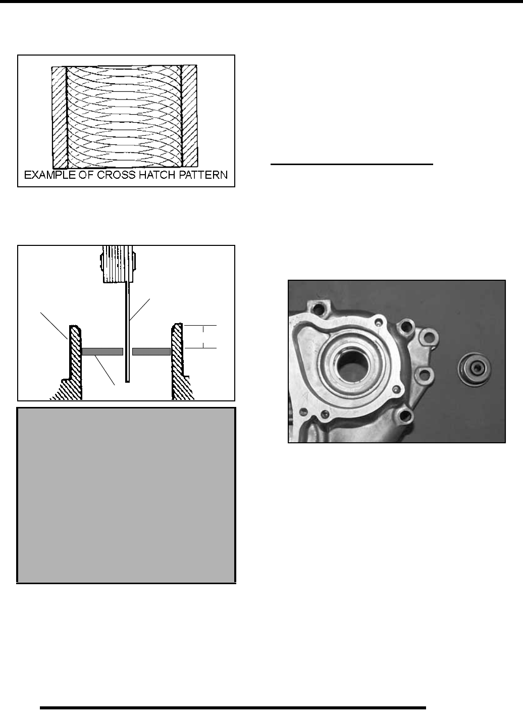
3.44
ENGINE
If cylinder wear or damage is excessive, it will be necessary to
replace the cylinder. Hone only enough to deglaze the outer
layer of the cylinder bore.
Piston Ring Installed Gap
1. Place each piston ring inside cylinder using piston to push
ring squarely into place.
2. Measure installed gap with a feeler gauge at both the top
and bottom of the cylinder.
NOTE: A difference in end gap indicates cylinder
taper. The cylinder should be measured for
excessive taper and out of round.
3. If the bottom installed gap measurement exceeds the
service limit, replace the rings. If ring gap is below
specified limit, file ring ends until the gap is within the
specified range.
NOTE: Always check piston ring installed gap after
re–boring a cylinder or when installing new rings. A
re–bored cylinder should always be scrubbed
thoroughly with hot soapy water, rinsed, and dried
completely. Wipe cylinder bore with oil immediately
to prevent rust.
WATER PUMP SERVICE
Oil Seal / Mechanical Seal Removal
(Engine Disassembled)
NOTE: The water pump mechanical seal can be
removed without removing the engine. Refer to
Water Pump Mechanical Seal Installation.
Replace the water pump mechanical seal whenever the
crankcase is disassembled.
1. Remove the pump shaft bearings from the PTO (right
hand) side crankcase.
2. Drive the water pump mechanical seal out of the crankcase
from inside to outside.
NOTE: The new mechanical seal must be installed
using special tools. See Mechanical Seal Installation.
Water Pump Mechanical Seal Installation
1. Clean the seal cavity to remove all traces of old sealer.
2. Place a new mechanical seal in the seal drive collar, and
install on the pump shaft.
3. Screw the guide onto the end of the pump shaft.
4. Install the washer and nut and tighten to draw seal into place
until fully seated.
5. Remove the guide adaptor using the additional nut as a jam
nut if necessary.
Piston Ring Installed Gap
Top Ring
Std: .008- .012″ (.20- .30 mm)
Limit: .027” (.7 mm)
Second Ring
Std: .014- .019″ (.35- .50 mm)
Limit: .031” (.8 mm)
Oil Ring
Std: .004- .019″ (.10- .50 mm)
Limit: .039” (1.0 mm)
Piston Ring
Cylinder Feeler Gauge
25-50 mm
RepairPro Service Manual
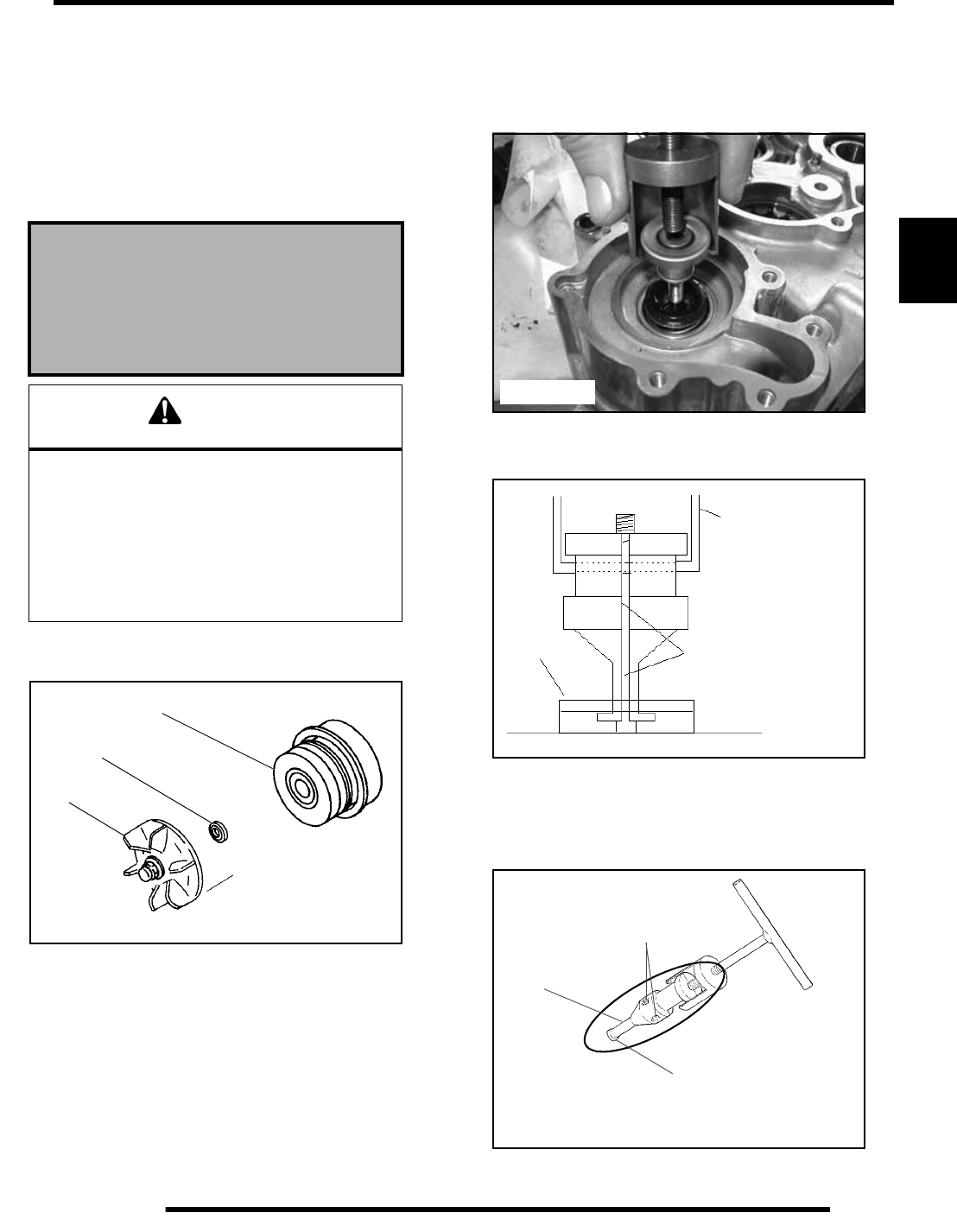
3.45
ENGINE
3
Mechanical Seal Removal and Installation
(Engine Assembled)
The Water Pump Mechanical Seal Puller allows a technician to
replace the seal on ES50PL engines without removing the
engine and splitting the cases.
NOTE: This removal process dismantles the seal,
making it unusable for reinstallation.
1. After the coolant has been drained, remove the water pump
cover, impeller and the sealing washer.
2. Slide the main puller body over the outer portion of the
mechanical seal as shown in (Figure 3-45)and turn T–
Handle clockwise until it contacts water pump shaft.
Continue rotating until outer portion of mechanical seal is
separated from the metal seal body.
3. Insert the puller legs between the water pump drive shaft
and the remaining portion of the mechanical seal. Attach
the puller legs to the main puller body. (Figure 3-46)
4. Ensure that the split between the puller legs are fully
supported by the main body of the tool (Figure 3-46).
5. Tighten the hex socket screws on the puller legs sufficiently
so the lip of the puller legs will grasp the mechanical seal
(Figure 3-47).
Water Pump Mechanical Seal
Puller: (PN 2872105)
Replacement T-Handle:
(PN 2872106)
CAUTION
Improper or careless use of this tool or procedure
can result in a bent water pump shaft.Pump shaft
replacement requires engine removal and
crankcase separation. Use caution while
performing this procedure. Make sure the puller
is parallel to the shaft at all times.
Do not place side loads on the water pump shaft
or strike the puller or shaft in any way.
Mechanical Seal
Sealing Washer
Impeller
III 2
Figure 3-45
Main Puller Body
Position the split
90° to opening
on main puller body
Seal
Figure 3-46
Puller Legs
Hex Socket Screws
Lip must grasp inside of mechanical seal.
Figure 3-47
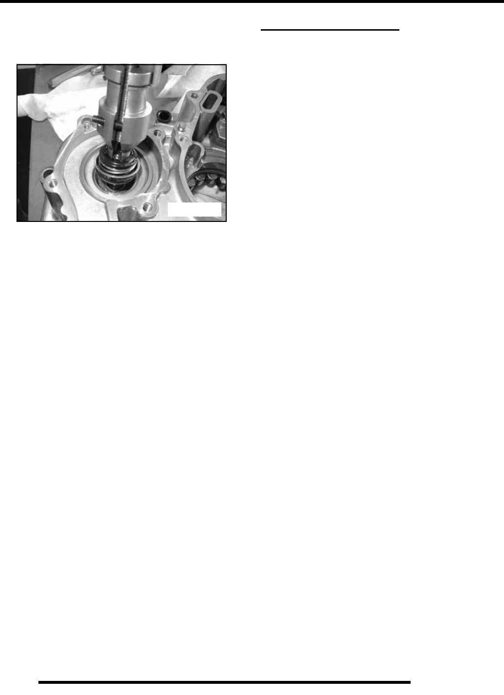
3.46
ENGINE
6. Turn the puller T–Handle clockwise until it contacts the
water pump shaft. Continue rotating until the remaining
portion of mechanical seal has been removed from the case.
(Figure 3-48)
7. Water Pump Install Kit (PN 5131135) is required to install
the new mechanical seal. This tool is available separately
as well as included in Crankshaft / Water Pump Seal
Installation Kit (PN 2871283).
TROUBLESHOOTING
Engine
Engine Turns Over But Fails to Start
•No fuel
• Dirt in fuel line or filter
• Fuel will not pass through fuel valve
• Fuel pump inoperative/restricted
• Tank vent plugged
• Carb starter circuit
• Engine flooded
• Low compression (high cylinder leakage)
• No spark (Spark plug fouled)
Engine Does Not Turn Over
• Dead battery
• Starter motor does not turn
• Engine seized, rusted, or mechanical failure
Engine Runs But Will Not Idle
• Restricted carburetor pilot system
• Carburetor misadjusted
• Choke not adjusted properly
• Low compression
• Crankcase breather restricted
Figure 3-48
RepairPro Service Manual

3.47
ENGINE
3
Engine Idles But Will Not Rev Up
• Spark plug fouled/weak spark
• Broken throttle cable
• Obstruction in air intake
• Air box removed (reinstall all intake components)
• Incorrect or restricted carburetor jetting
• ETC switch limiting speed
• Reverse speed limiter limiting speed
• Carburetor vacuum slide sticking/diaphragm damaged
• Incorrect ignition timing
• Restricted exhaust system
Engine Has Low Power
• Spark plug fouled
• Cylinder, piston, ring, or valve wear or damage (check
compression)
• PVT not operating properly
• Restricted exhaust muffler
• Carburetor vacuum slide sticking/diaphragm damaged
• Dirty carburetor
Piston Failure – Scoring
• Lack of lubrication
• Dirt entering engine through cracks in air filter or ducts
• Engine oil dirty or contaminated
Excessive Smoke and Carbon Buildup
• Excessive piston–to–cylinder clearance
• Wet sumping
• Worn rings, piston, or cylinder
• Worn valve guides or seals
• Restricted breather
• Air filter dirty or contaminated
Low Compression
• Decompressor stuck
• Cylinder head gasket leak
• No valve clearance or incorrectly adjusted
• Cylinder or piston worn
• Piston rings worn, leaking, broken, or sticking
• Bent valve or stuck valve
• Valve spring broken or weak
• Valve not seating properly (bent or carbon accumulated
on sealing surface)
• Rocker arm sticking
Backfiring
• ETC or speed limiter system malfunction
• Fouled spark plug or incorrect plug or plug gap
• Carburetion faulty – lean condition
• Exhaust system air leaks
• Ignition system faulty:
Spark plug cap cracked / broken
Ignition coil faulty
Ignition or kill switch circuit faulty
Ignition timing incorrect
Sheared flywheel key
• Poor connections in ignition system
• System wiring wet
• Valve sticking
• Air leaks in intake
• Lean condition

3.48
ENGINE
Spark Plug Fouling
• Spark plug cap loose or faulty
• Choke cable adjustment or plunger/cable sticking
• Foreign material on choke plunger seat or plunger
• Incorrect spark plug heat range or gap
• Carburetor inlet needle and seat worn
• Jet needle and/or needle jet worn or improperly
adjusted
• Excessive carburetor vibration (loose or missing needle
jet locating pins)
• Loose jets in carburetor or calibration incorrect for
altitude/temperature
• Incorrect float level setting
• PVT system calibrated incorrectly or components worn
or adjusted incorrectly
• Fuel quality poor (old) or octane too high
• Low compression
• Restricted exhaust
• Weak ignition (loose coil ground, faulty coil, stator, or
ETC switch)
• ETC switch adjusted incorrectly
• Restricted air filter (main or pre–cleaner) or breather
system
• Improperly assembled air intake system
• Restricted engine breather system
• Oil contaminated with fuel
•Restricted oil tank vent
Cooling System
Overheating
• Low coolant level
• Air in cooling system
• Wrong type of coolant
• Faulty pressure cap or system leaks
• Restricted system (mud or debris in radiator fins or
restriction to air flow, passages blocked in radiator,
lines, pump, or water jacket)
• Lean mixture (restricted jets, vents, fuel pump or fuel
valve)
• Fuel pump output weak
• Restricted radiator (internally or cooling fins)
• Water pump failure
• Cooling system restriction
• Cooling fan inoperative or turning too slowly (perform
current draw test)
• Ignition timing misadjusted
• Low oil level
• Spark plug incorrect heat range
• Faulty hot light circuit
• Thermostat stuck closed or not opening completely
Temperature Too Low
• Thermostat stuck open
Leak at Water Pump Weep Hole
• Faulty water pump mechanical seal (coolant leak)
•Faulty pump shaft oil seal (oil leak)
RepairPro Service Manual

FUEL SYSTEM / CARBURETION
4.1
CHAPTER 4
FUEL SYSTEM / CARBURETION
4
FUEL SYSTEM AND CARBURETION . . . . . . . . . . . . . . . . . . . . . . . . . . . . . . . . . . . . . . . 4.2
BSR 42 CARBURETOR EXPLODED VIEW. . . . . . . . . . . . . . . . . . . . . . . . . . . . . . . . . . . 4.2
FUEL TANK ASSEMBLY . . . . . . . . . . . . . . . . . . . . . . . . . . . . . . . . . . . . . . . . . . . . . . . . . 4.3
SPECIAL TOOLS . . . . . . . . . . . . . . . . . . . . . . . . . . . . . . . . . . . . . . . . . . . . . . . . . . . . . . . 4.4
JETTING GUIDELINES . . . . . . . . . . . . . . . . . . . . . . . . . . . . . . . . . . . . . . . . . . . . . . . . . . 4.4
CARBURETOR JETTING. . . . . . . . . . . . . . . . . . . . . . . . . . . . . . . . . . . . . . . . . . . . . . . . . 4.4
MIKUNI JET PART NUMBERS . . . . . . . . . . . . . . . . . . . . . . . . . . . . . . . . . . . . . . . . . . . . 4.4
CV CARBURETOR SYSTEM . . . . . . . . . . . . . . . . . . . . . . . . . . . . . . . . . . . . . . . . . . . . . . 4.5
CARBURETOR FUNCTION . . . . . . . . . . . . . . . . . . . . . . . . . . . . . . . . . . . . . . . . . . . . . . . 4.5
VENT SYSTEMS – CV CARBURETOR. . . . . . . . . . . . . . . . . . . . . . . . . . . . . . . . . . . . . . 4.5
MIKUNI CV CARBURETOR OPERATION. . . . . . . . . . . . . . . . . . . . . . . . . . . . . . . . . . . . 4.5
PILOT (IDLE AND SLOW) SYSTEM . . . . . . . . . . . . . . . . . . . . . . . . . . . . . . . . . . . . . . . . 4.6
STARTER SYSTEM (CHOKE OR ENRICHMENT) . . . . . . . . . . . . . . . . . . . . . . . . . . . . . 4.7
FLOAT SYSTEM. . . . . . . . . . . . . . . . . . . . . . . . . . . . . . . . . . . . . . . . . . . . . . . . . . . . . . . . 4.7
MAIN SYSTEM . . . . . . . . . . . . . . . . . . . . . . . . . . . . . . . . . . . . . . . . . . . . . . . . . . . . . . . . . 4.8
PILOT SCREW . . . . . . . . . . . . . . . . . . . . . . . . . . . . . . . . . . . . . . . . . . . . . . . . . . . . . . . . . 4.8
CARBURETOR DISASSEMBLY . . . . . . . . . . . . . . . . . . . . . . . . . . . . . . . . . . . . . . . . . . . 4.9
CARBURETOR CLEANING . . . . . . . . . . . . . . . . . . . . . . . . . . . . . . . . . . . . . . . . . . . . . . 4.10
CARBURETOR INSPECTION . . . . . . . . . . . . . . . . . . . . . . . . . . . . . . . . . . . . . . . . . . . . 4.10
CARBURETOR ASSEMBLY . . . . . . . . . . . . . . . . . . . . . . . . . . . . . . . . . . . . . . . . . . . . . 4.11
FLOAT HEIGHT ADJUSTMENT. . . . . . . . . . . . . . . . . . . . . . . . . . . . . . . . . . . . . . . . . . . 4.11
FUEL DELIVERY. . . . . . . . . . . . . . . . . . . . . . . . . . . . . . . . . . . . . . . . . . . . . . . . . . . . . . . 4.12
NEEDLE AND SEAT LEAK TEST . . . . . . . . . . . . . . . . . . . . . . . . . . . . . . . . . . . . . . . . . 4.12
FUEL LEVEL TEST . . . . . . . . . . . . . . . . . . . . . . . . . . . . . . . . . . . . . . . . . . . . . . . . . . . . 4.12
FUEL PUMP . . . . . . . . . . . . . . . . . . . . . . . . . . . . . . . . . . . . . . . . . . . . . . . . . . . . . . . . . . 4.13
FUEL PUMP DISASSEMBLY. . . . . . . . . . . . . . . . . . . . . . . . . . . . . . . . . . . . . . . . . . . . . 4.13
FUEL PUMP INSPECTION / ASSEMBLY . . . . . . . . . . . . . . . . . . . . . . . . . . . . . . . . . . . 4.13
TROUBLESHOOTING. . . . . . . . . . . . . . . . . . . . . . . . . . . . . . . . . . . . . . . . . . . . . . . . . . . 4.13
FUEL STARVATION / LEAN MIXTURE . . . . . . . . . . . . . . . . . . . . . . . . . . . . . . . . . . . . . 4.13
RICH MIXTURE . . . . . . . . . . . . . . . . . . . . . . . . . . . . . . . . . . . . . . . . . . . . . . . . . . . . . . . 4.14
POOR IDLE / IDLE TOO HIGH. . . . . . . . . . . . . . . . . . . . . . . . . . . . . . . . . . . . . . . . . . . . 4.14
IDLE TOO LOW . . . . . . . . . . . . . . . . . . . . . . . . . . . . . . . . . . . . . . . . . . . . . . . . . . . . . . . 4.14
ERRATIC IDLE . . . . . . . . . . . . . . . . . . . . . . . . . . . . . . . . . . . . . . . . . . . . . . . . . . . . . . . . 4.14
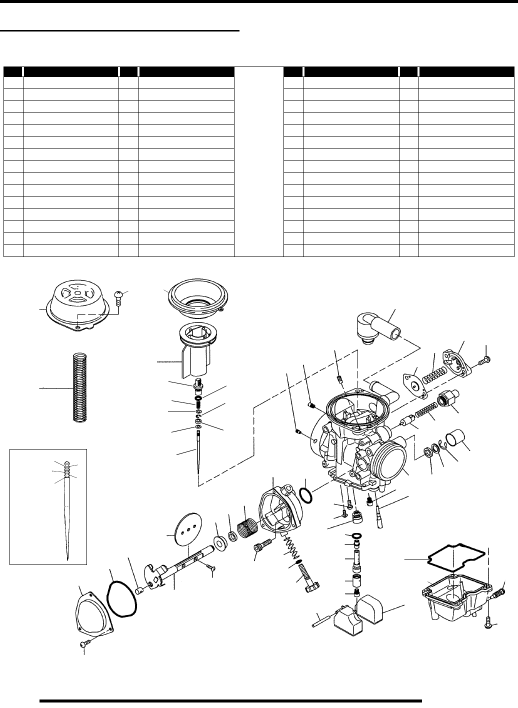
4.2
FUEL SYSTEM / CARBURETION
FUEL SYSTEM AND CARBURETION
BSR 42 Carburetor Exploded View
Ref Description Ref Description Ref Description Ref Description
1 Cover, Diaphragm 16 Guide, Cable 31 A-Float 46 Asm., Plunger
2 Spring 17 O-ring 32 Jet, Main 47 Spring
3 Diaphragm 18 Cover 33 Ring 48 Holder, Guide
4 Valve, Piston 19 Screw 34Holder, Jet 49Screw
5 Holder 20 A-Shaft, Throttle 35 Jet, Needle 50 Cover
6 Spring 21 Screw 36 O-ring 51 Spring
7 Washer 22 Bolt 37 Needle Guide 52 Asm., Diaphragm
8 Washer 23 Spring, Idle Adjust 38 Screw 53 Filter
9 Jet, Needle 24 O-ring 39 Screw 54 Jet, Pilot Air 2 (1.3)
10 O-ring 25 Screw, Adjust 40 Jet, Pilot 55 Jet, Pilot Air 1 (110)
11 Case 26 Pin, Float 41 Jet, Starter (42.5) 56 Jet, Main Air (120)
12 Spring 27 O-ring 42 Asm., Carburetor 57 Ring
13 Seal 28 Body, Float 43 Packing 58 E-ring
14 Ring 29 Screw 44 E-ring 59 O-ring
15 Valve, Throttle (105) 30 Screw 45 Cap 60 Screw
Refer to Page 4.4 for Optional Jet Part Numbers
Jet Needle
“E” Clip
Position
12
34
5
1
60
2
3
4
19
18
17
16
15
14 13
12
11 10
20
21
22
23
24
25
26
32
33
34
35
36
37
38
39
40
41 42 13
43 44
45
31
28
27
29
30
46
47 48
49
50
51
52
53
54
55
56
5
6
7
8
9
57
58
59
RepairPro Service Manual
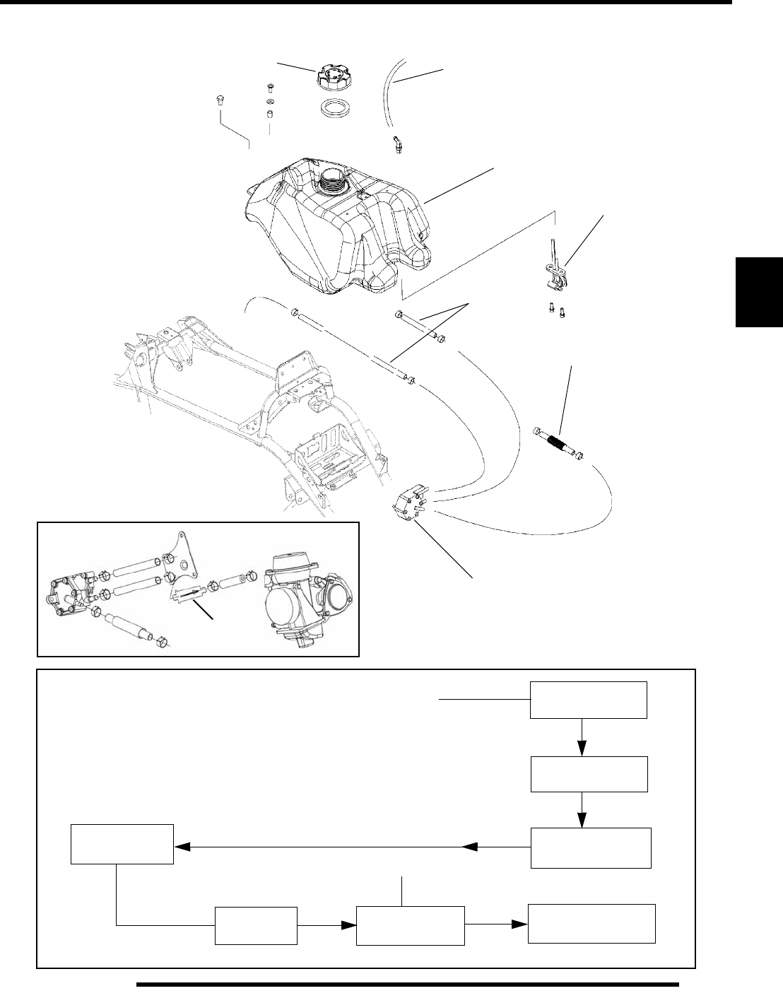
4.3
FUEL SYSTEM / CARBURETION
4
Fuel Tank Assembly
Vent Line
Fuel Tank
Fuel Valve
Fuel Lines
Impulse Line
Fuel Pump
Tank Cap
In-Line
Filter
FUEL FLOW Fuel Tank Vent Fuel Tank
Fuel Screens
Fuel Valve
(Filter in Pickup)
*Fuel Pump
Carburetor Engine
Carburetor Vent
* Located on upper frame
In-Line Filter
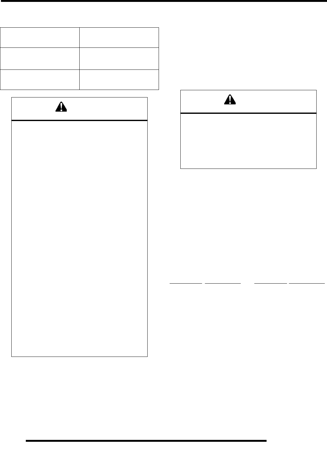
4.4
FUEL SYSTEM / CARBURETION
Special Tools
Jetting Guidelines
Changes in altitude and temperature affect air density, which is
essentially the amount of oxygen available for combustion. In
low elevations and cold temperatures, the air is more dense and
has more oxygen. In higher elevations and higher temperatures,
the air is less dense with reduced oxygen.
Polaris ATV carburetors are calibrated for an altitude of 0–6000
ft. (0–1800 meters) and ambient temperatures above +40o F
(+26o C). Carburetors must be re–calibrated if operated outside
this temperature and/or altitude range. The jetting installed in
production is not intended for all altitudes and/or temperatures.
In addition, air screw / pilot screw adjustments may be required
to suit operating conditions.
Carburetor Jetting
IMPORTANT: The following guidelines must be
followed when establishing a main jet setting:
1. Select the lowest anticipated temperature at which the
machine will be operated.
2. Determine the lowest approximate altitude at which the
machine will be operated.
3. Select the correct main jet from the specifications chart in
Chapter 1.
Mikuni Jet Part Numbers
Main Jets Pilot Jets
Jet Number Part Number Jet Number Part Number
130 3131537 25 3131538
132.5 3131536 27.5 3131539
135 3131535 30 3131540
137.5 3131534 32.5 3131541
140 3131522 35 3131542
142.5 3131523 37.5 3131543
145 3131524 40 3131544
147.5 3131525 42.5 3131545
152.5 3131526 47.5 3131546
155 3131527 50 3131547
157.5 3131528 52.5 3131548
160 3131529 55 3131549
162.5 3131530 57.5 3131550
165 3131531 60 3131551
167.5 3131532 65 3131552
170 3131533 70 3131553
PART NUMBER TOOL
DESCRIPTION
2870975 Mity VacTM Pressure Test
Tool
2872314 Carburetor Float
Adjustment Tool
WARNING
Gasoline is extremely flammable and
explosive under certain conditions.
Always stop the engine and refuel
outdoors or in a well ventilated area.
Do not overfill the tank. The tank is at full
capacity when the fuel reaches the bottom
of the filler neck. Leave room for
expansion of fuel.
Never start the engine or let it run in an
enclosed area. Gasoline powered engine
exhaust fumes are poisonous and can
cause loss of consciousness and death in
a short time.
Never drain the float bowl when the
engine is hot. Severe burns may result.
Do not smoke or allow open flames or
sparks in or near the area where refueling
is performed or where gasoline is stored.
If you get gasoline in your eyes or if you
should swallow gasoline, seek medical
attention immediately.
If you spill gasoline on your skin or
clothing, immediately wash with soap and
water and change clothing.
CAUTION
A main jet that is too small will cause a lean
operating condition resulting in
serious engine damage.
Select the correct main jet carefully for
elevation and temperature according to the
charts in the specifications section or in the
Owner’s Manual for each particular model.
RepairPro Service Manual
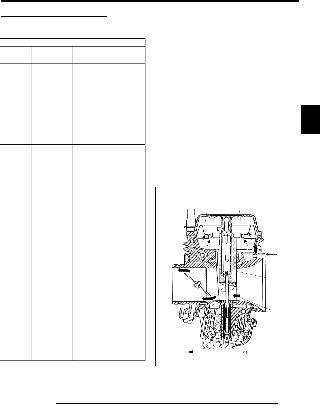
4.5
FUEL SYSTEM / CARBURETION
4
CV CARBURETOR SYSTEM
Carburetor Function
Vent Systems – CV Carburetor
The carburetor float bowl vent lines supply atmospheric
pressure to the float bowl. The lines must be free of kinks,
restrictions and be properly routed. This allows fuel to flow in
the proper amount and prevents contaminants from entering the
carburetor.
Mikuni CV Carburetor Operation
The constant velocity carburetor incorporates a mechanically
operated throttle plate and a vacuum controlled slide valve
(vacuum slide). The venturi cross–sectional area in the
carburetor bore is increased or decreased automatically by the
vacuum slide, which moves according to the amount of
negative pressure (less than atmospheric) present in the
venturi.
A diaphragm attached to the top of the vacuum slide is sealed to
the slide and to the carburetor body forming two chambers. The
chamber above the diaphragm is connected to the venturi area
by a drilled orifice in the center of the vacuum slide. The
chamber below the diaphragm is vented to atmospheric pressure
by a passage on the air box side of the carburetor. A spring,
installed in the center of the vacuum slide, dampens the slide
movement and assists the return of the slide.
Carburetor Component Function
System Main
Components Main
Function Main
Affect
Float System
(Level Control)
Inlet Pipe, Needle
and Seat, Float,
Float Pin
Maintains specified
fuel level in float
chamber
(carburetor float
bowl).
All systems; all
throttle ranges
Venting
Passages in
carburetor; vent
lines to frame.
Supplies
atmospheric
pressure to float
chamber.
All systems; all
throttle ranges.
Starter
(Choke /
Enrichment)
Choke Lever, Cable,
Plunger, Return
Spring, Carb
Passages (Starter
Jet, Starter Bleed
Pipe).
Supplies additional
fuel air mixture
necessary for cold
starting.
All throttle
ranges.
Greatest effect
at low throttle
settings and
idle.
Pilot
(Idle System)
Pilot Jet / Passage-
ways, Pilot–Mixture
Screw with Spring
Washer and Sealing
O–Ring, By-pass
Ports (Behind
Throttle Plate), Pilot
Air Jet, Pilot Outlet,
Throttle Plate.
Primarily supplies
fuel at idle and low
throttle positions.
Mainly idle to
1/4 throttle.
Minimal effect
after 1/2
throttle.
Main System
Main Jet, Main Air
Jet, Main Air
Passage, Needle
Jet, Jet Needle,
Vacuum Slide,
Throttle Plate.
Supplies fuel at
mid–range and high
throttle settings.
1/4 to full
throttle.
Throttle Plate
Diaphragm Low Pressure
From Venturi
Atmospheric
Pressure
Air inlet
Atmospheric
Vacuum
Slide
Venturi
= Air Flow = Low pressure
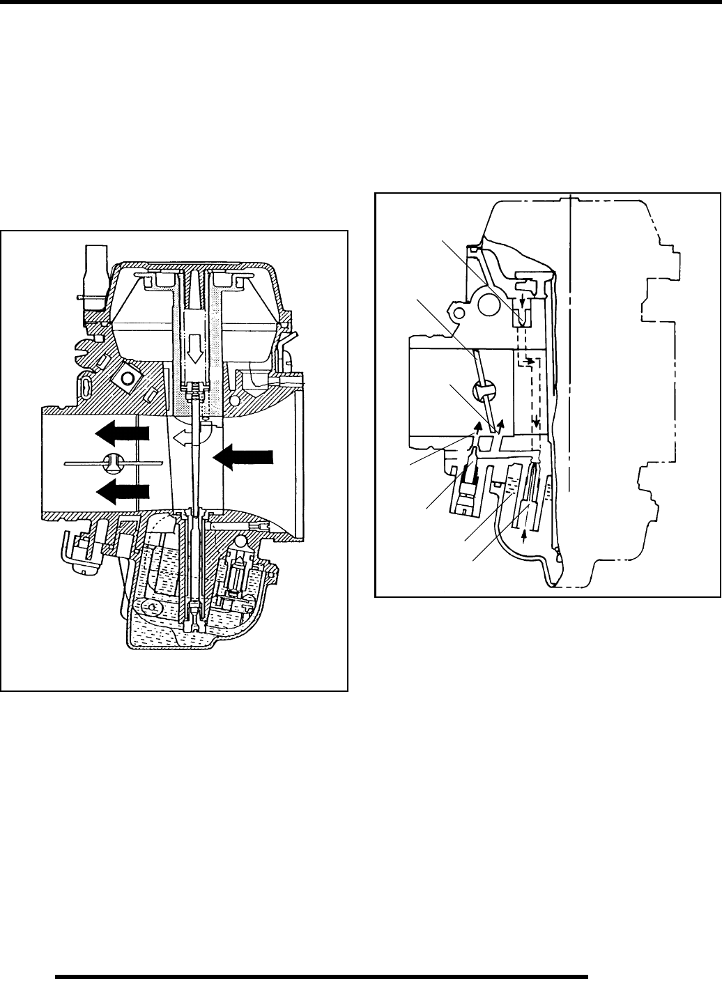
4.6
FUEL SYSTEM / CARBURETION
Mikuni CV Carburetor Operation, Continued.....
When the throttle plate is opened and engine speed begins to
increase, the pressure in the venturi, and therefore in the
chamber above the diaphragm, becomes significantly lower
than atmospheric. Atmospheric pressure in the chamber below
the diaphragm forces the diaphragm upward, raising the slide
against spring pressure. When the pressure above and below the
diaphragm are nearly equal, the slide moves downward under
spring pressure. Raising or lowering the slide increases or
decreases the cross sectional area in the venturi, and therefore
the air velocity in the venturi is kept relatively constant. This
provides improved fuel atomization and optimum fuel/air ratio.
Pilot (Idle and Slow) System
This system supplies fuel during engine operation with throttle
valve closed (1) or slightly opened. The fuel from float chamber
(2) is metered by pilot jet (3) where it mixes with air coming in
through pilot air jet (4). The mixture then goes up through pilot
passage to pilot screw (5). A part of the mixture is discharged
into the main bore out of bypass ports (6). The remainder is then
metered by pilot screw and discharged into the main bore
through pilot outlet (7).
Note: Diagrams are for explanation of theory only, and are not true
representations of Mikini BST carburetor.
4
1
6
7
5
2
3
RepairPro Service Manual
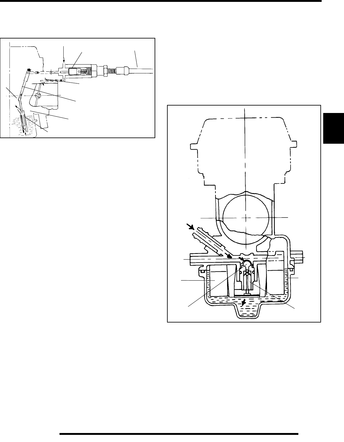
4.7
FUEL SYSTEM / CARBURETION
4
Starter System (Choke or Enrichment)
When the choke cable (1) is activated, the starter plunger (5) is
lifted off the seat.
Fuel is drawn into the starter circuit from the float chamber (2)
through the starter jet (3). Starter jet meters this fuel, which then
flows into starter pipe (4) and mixes with the air (7) coming from
the float chamber. The mixture, rich in fuel content, reaches
starter plunger and mixes again with the air coming through a
passage (8) extending from underneath the diaphragm. The rich
fuel/air mixture for starting is discharged through starter outlet
(6) in the main bore.
Float System
Fuel enters the float chamber (3) by means of the inlet pipe and
passage, through a screen on the back of the inlet needle seat (4),
and around the inlet needle (2). As the fuel fills the float
chamber, the float (1) rises and forces the inlet needle against the
seat, shutting off the orifice in the seat. When fuel level is up in
float chamber, floats are up and needle valve remains pushed up
against valve seat. Under this condition, no fuel enters the float
chamber. As the fuel level falls, floats go down and needle valve
unseats itself to allow fuel into the chamber. In this manner, the
needle valve releases and shuts off fuel alternately to maintain
a constant fuel level inside the float chamber.
1
2
3
4
5
6
7
8
Inlet
Pipe
1
2
3
4
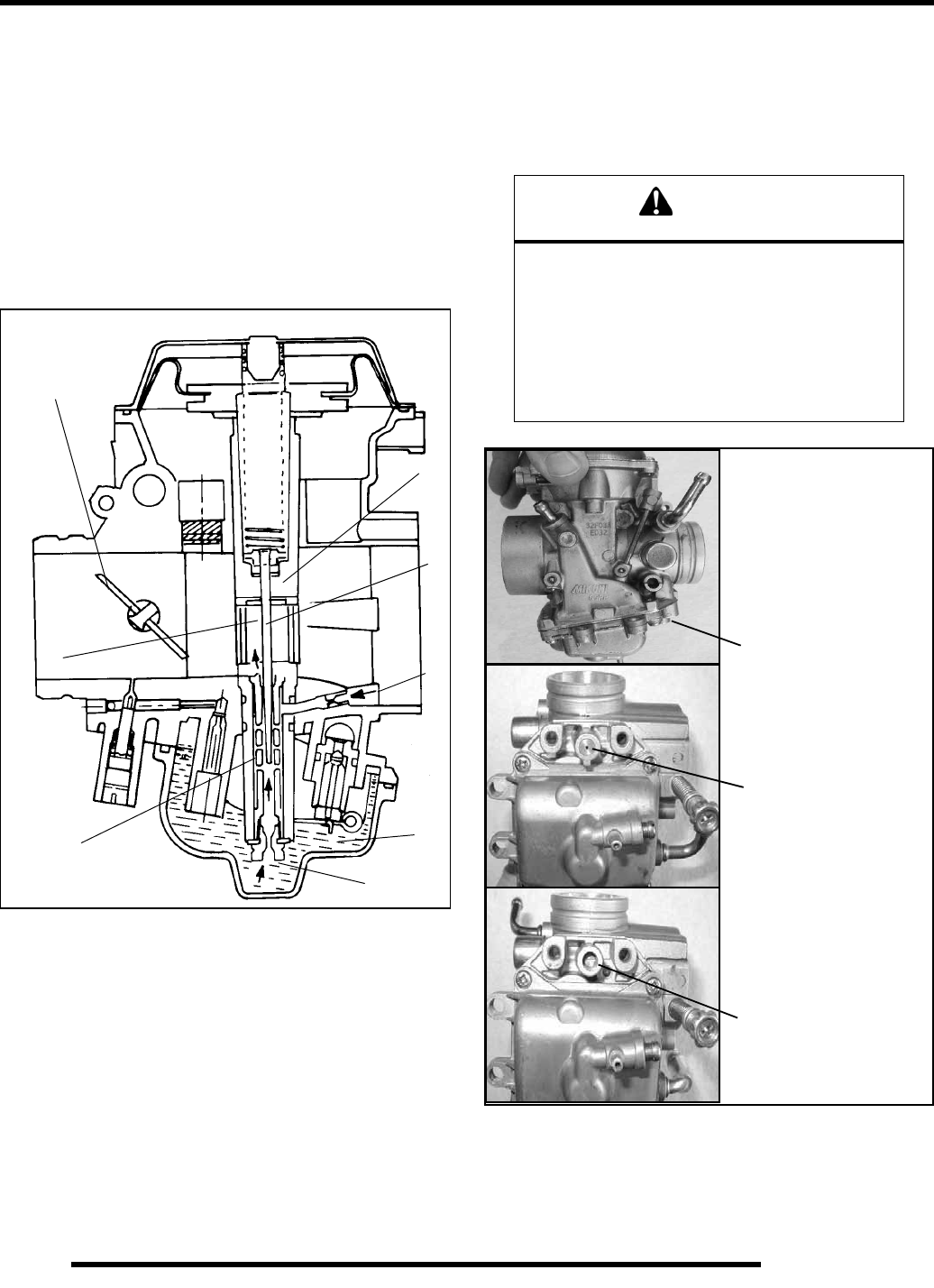
4.8
FUEL SYSTEM / CARBURETION
Main System
As throttle valve (1) is opened, engine speed rises, and this
increases negative pressure in the venturi. Consequently the
vacuum slide (2) moves upward. The fuel in float chamber (3)
is metered by main jet (4), and the metered fuel enters needle jet
(5), in which it mixes with the air admitted through main air jet
(6) to form an emulsion. The emulsified fuel then passes through
the clearance between needle jet (5) and jet needle (7), and is
discharged into the venturi (A). Mixture proportioning is
accomplished in needle jet (5); the clearance through which the
emulsified fuel must flow is determined ultimately by throttle
position and vacuum slide height.
Pilot Screw
The pilot system supplies fuel during engine operation with the
throttle valve closed or slightly opened. The fuel/air mixture is
metered by pilot screw and discharged into the main bore
through the pilot outlet.
1
2
3
4
5
6
7
A
CAUTION
The pilot screw is calibrated at the factory to meet
EPA / CARB regulations for air quality standards
and is sealed with a brass plug to prevent
tampering. Removal of the tamper proof plug is
not permitted. For service purposes, cleaning of
the pilot circuit can be done only by a certified
repair shop to ensure air quality standards
are not exceeded.
Pilot Screw Location
Brass Plug Installed
Brass Plug Removed
RepairPro Service Manual
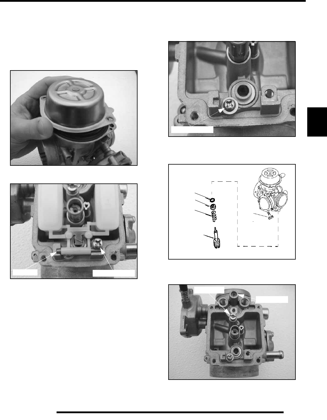
4.9
FUEL SYSTEM / CARBURETION
4
Carburetor Disassembly
Use the following disassembly, assembly, and inspection
techniques to service a CV carburetor.
1. Remove carburetor diaphragm chamber cover with a
ratchet style screwdriver. DO NOT use an impact driver to
remove the screws or carburetor may be permanently
damaged.
2. Remove float bowl. Remove the float pin screw. Then the
float and float pin can be removed.
3. Remove inlet needle seat retaining screw along with plate,
and carefully remove needle seat.
NOTE: Do not use a pliers to remove the seat or
permanent damage may occur.
4. Remove the pilot mixture screw, spring, flat washer, and O–
Ring. If an anti–tamper plug is installed over the pilot screw
cavity, it must be removed for access.
NOTE: The starter jet is removable. Upon
disassembly, place the parts in a container for safe
keeping.
Float Pin Remove Screw
Remove Screw
O-Ring
Washer
Spring
Pilot Screw
Pilot Screw
Starter Jet

4.10
FUEL SYSTEM / CARBURETION
Carburetor Cleaning
1. Thoroughly clean the carburetor body, jets, and all
passages with carburetor cleaner or electrical contact
cleaner.
2. If the carburetor is extremely dirty or contaminated with
fuel residue and varnish, soak for short periods only in
carburetor cleaner, and rinse in hot water.
3. Replace the jets if they have a buildup of fuel residue or
bacterial growth that cannot be removed. Even a small
amount of residue will reduce the flow characteristics of the
jet.
4. Verify all passages and jets are unobstructed by spraying
electrical contact cleaner through the passages.
IMPORTANT: Do not use wire or welding tip cleaners
as the orifice size may be altered.
5. Use low pressure air to dry carburetor body and all
components.
Carburetor Inspection
1. Inspect jet needle and needle jet for wear. Look for
discoloration, shiny spots, or an area that looks different
than the rest of the needle. The middle to upper portion of
the needle contacts the needle jet and is the most likely
wear point. If jet needle shows signs of wear replace both
the needle and needle jet to prevent a rich condition.
TIP: A worn needle jet is difficult to spot. To check, slide
a slightly larger new jet needle into the needle jet and hold
it to a light source. Light will be visible between the needle
and needle jet if it is worn.
2. Inspect the inlet needle tapered surface for any sign of wear
or damage. Be sure the spring loaded pin is free moving and
returns freely when pushed. The inlet needle and seat
should be pressure tested after assembly.
WARNING
Protect eyes from contact with cleaner. Take
appropriate safety measures during these
procedures. Safety glasses and chemical
resistant gloves are required. Should you get
cleaner in your eyes or if you swallow cleaner,
seek medical attention immediately.
Carburetor cleaners can be extremely caustic.
Extended periods of soaking can loosen the
adhesive sealer on the passage drill–way plugs.
Do not soak rubber or plastic components (such
as the vacuum slide diaphragm, needle seat
screen, or O–Rings in caustic cleaning
solutions. Irreparable damage may occur. Do
not use agitator-type carburetor cleaning
equipment. Rubber parts must be cleaned with
mild detergent and hot water only.
Jet Needle
Inspect this area
Needle Jet
Good Condition Worn, Deposits
Seat
Needle
Wear areas
RepairPro Service Manual
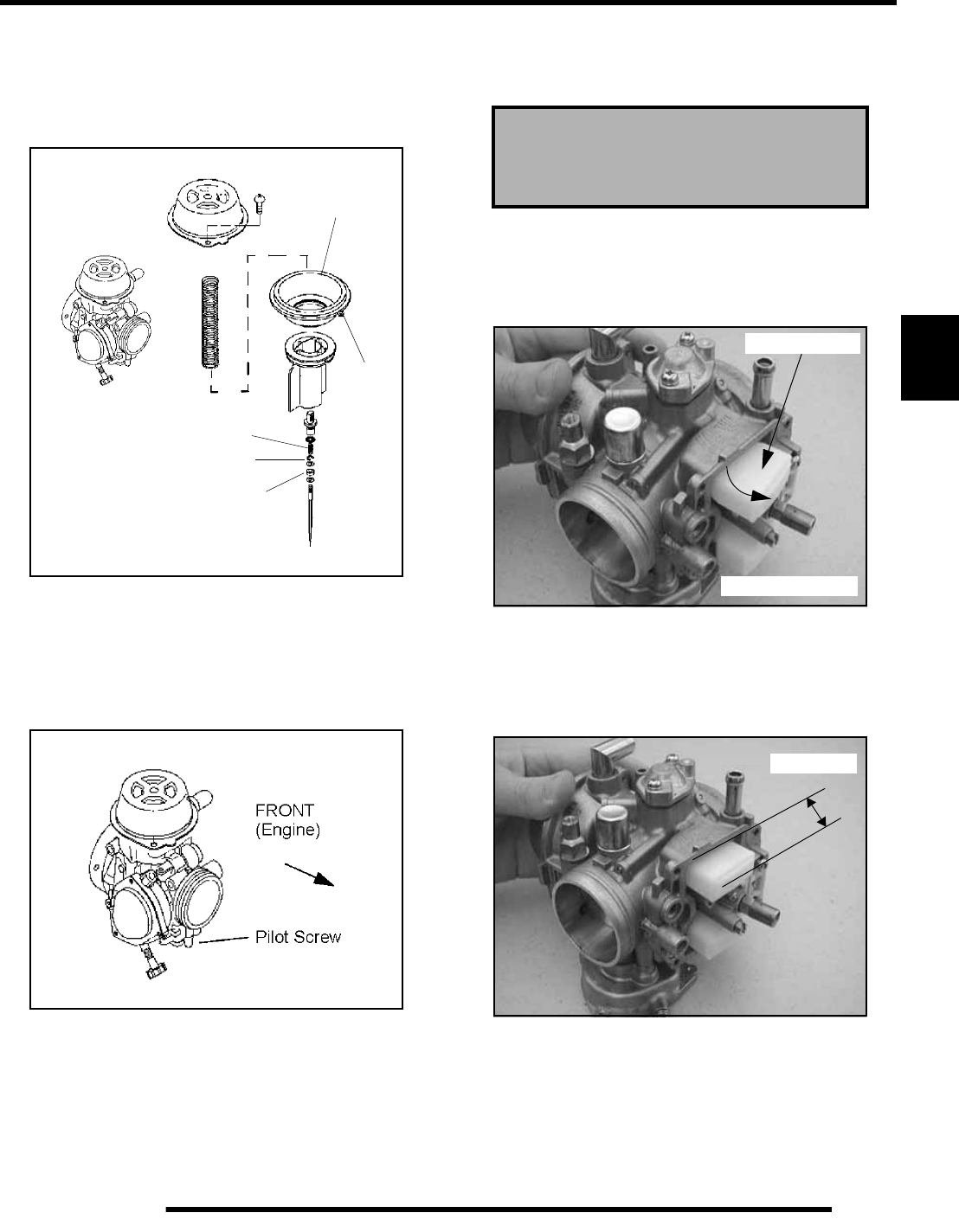
4.11
FUEL SYSTEM / CARBURETION
4
Carburetor Assembly
Inspect the diaphragm (A) for holes, deterioration, or damage.
Make sure the diaphragm is pliable but not swollen. The
diaphragm should fit properly in the carburetor body. Replace
diaphragm assembly if diaphragm is damaged.
1. Replace parts in proper order. The spring seat (B) is
stepped and must be placed on TOP of “E” Clip (C).
Spacer washer (D) must be installed below the E–Clip.
Refer to parts manual for more information.
2. Be sure the tab (E) on outer edge of diaphragm is positioned
properly in the carburetor body.
3. Install the pilot mixture screw, spring, washer, and O–ring
as an assembly. Lubricate the O–Ring with oil or light
grease before installation.
IMPORTANT: Do not damage the O–ring during
installation. Turn the screw in until it lightly contacts
the seat. Then back it out the specified number of
turns.
NOTE: The final pilot (idle) mixture must be adjusted
with the engine running. Refer to Chapter 2 for
procedure.
Float Height Adjustment
1. Place the throttle side of the carburetor on a level surface
to remove weight from float arm. In this position, the float
tongue will rest slightly outward.
2. With the carburetor still resting on the level surface, use one
hand to slightly tilt the carburetor back. The float will then
fall into the correct position, with the float tongue resting
lightly on the inlet needle valve pin without compressing
the spring. The bottom of the float should be parallel with
the float bowl mating surface.
A
B
C
D
E
Pilot Screw Base Setting
(Set at Factory)
Factory Specification: 2.5 Turns Out
Float Outward
Carburetor Level
Float parallel with float
bowl mating surface
13-14 mm
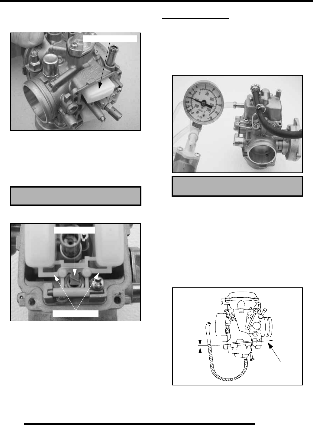
4.12
FUEL SYSTEM / CARBURETION
3. If the float is past parallel with the mating surface, the
carburetor has been tilted back too far and the float tongue
is likely compressing the needle valve pin.
4. Measure the height from the float bowl mating surface to
the top of step of the float as shown in Illustration 2. Both
sides of float should be parallel to each other. The
measurement should be made at the mid–point on top of the
float using Float Adjustment Tool (PN 2872314) or a
vernier caliper. When measuring the height, be sure the
inlet needle valve spring is not compressed.
5. If adjustment is necessary, bend the tongue slightly. Be sure
float measurement is even on left and right side.
FUEL DELIVERY
Needle and Seat Leak Test
1. Install the float bowl. Invert the carburetor and install a
Mity–Vac™ (PN 2870975) to the fuel inlet fitting. Apply
5 PSI pressure to inlet fitting. The needle and seat should
hold pressure indefinitely. If not, inspect needle and seat
and seat O–ring.
Fuel Level test
A fuel level test can be performed on some models if the drain
hose fitting is accessible. Be sure to re–attach the bowl drain
hose after performing the test. A fuel level test allows you to
observe the height of the fuel in the float bowl without removing
the carburetor. The fuel level can be observed with the engine
either running or shut off, however, engine must run briefly to
allow fuel level to stabilize.
1. Attach a clear line to drain fitting. Be sure line fits tightly
on fitting. Position hose along side of carburetor as shown.
Float Bowl Height: 13-14 mm
Float too far inward
Bend to adjust
Float arms even
Mity VacTM (PN 2870975)
Bowl Mating
Surface
1.5 mm
.060 in.
RepairPro Service Manual
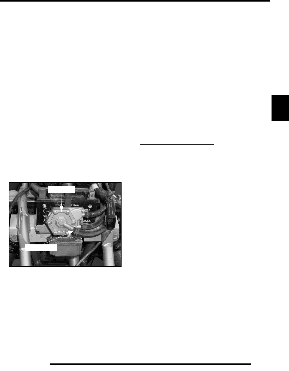
4.13
FUEL SYSTEM / CARBURETION
4
2. Open bowl drain screw by turning counterclockwise
approximately two turns. Start and run engine for 3 to 5
seconds to allow fuel level to stabilize in the line. If level
is out of specification, remove carburetor and inspect inlet
needle and seat, float height, passages, etc.
NOTE: If a line was removed to perform this
procedure, it must be replaced.
Fuel Pump
This 500cc is equipped with a pressure regulated fuel pump
(1–3 PSI). The pump is located in the front fender cavity of the
machine.
To test the fuel pump:
1. Turn fuel off.
2. Remove the front cab to access the fuel pump if needed.
3. Disconnect impulse line from pump.
4. Connect Mity–Vac™ (PN 2870975) to the impulse line
fitting on the pump.
5. Apply 5 inches (Hg) vacuum to the pump fitting. The
diaphragm should hold vacuum indefinitely.
If fuel is present in the impulse line or vacuum chamber of the
pump, the diaphragm is ruptured. The pump diaphragms must
be replaced.
Fuel Pump Disassembly
1. Remove the screws from the pump diaphragm cover. Note
the location of the two longer screws.
2. Remove the diaphragm cover gasket, diaphragm, and valve
body gasket.
3. Remove the outlet check valve cover, diaphragm, and
gasket.
Fuel Pump Inspection / Assembly
1. Inspect inlet and outlet check valves for cracks, warpage or
damage. Inspect the diaphragms for cracks, holes or
swelling.
2. To clean the valves or pump body, remove the set screw and
washer. Remove the valve and wash with soap and water.
Carburetor cleaner may be used to clean the pump body
when the check valves are removed.
IMPORTANT: Some carburetor cleaners are very
caustic and should not be used to clean the non–
metal parts of the fuel pump.
3. Check the sealing surfaces of the pump body and covers.
Carefully remove all traces of old gasket and check the
surfaces for damage. Replace diaphragms and gaskets as a
set.
4. Reassemble the pump in the reverse order of disassembly.
Tighten all screws evenly.
TROUBLESHOOTING
Fuel Starvation / Lean Mixture
Symptoms: Hard start or no start, bog, backfire, popping
through intake / exhaust, hesitation, detonation, low power,
spark plug erosion, engine runs hot, surging, high idle, idle
speed erratic.
• No fuel in tank
• Restricted tank vent, or routed improperly
• Fuel lines or fuel valve restricted
• Fuel filter plugged
• Carburetor vent line(s) restricted
• Plugged or restricted inlet needle and seat screen or
inlet passage
• Clogged jets or passages
• Float stuck, holding inlet needle closed or inlet needle
stuck
• Float level too low
• Fuel pump inoperative
• Air leak at impulse line
• Restricted impulse line (kinked, pinched)
• Intake air leak (throttle shaft, intake ducts, airbox or air
cleaner cover)
Impulse Line
Fuel Pump

4.14
FUEL SYSTEM / CARBURETION
• Ruptured vacuum slide diaphragm, vacuum slide stuck
closed or sticky
• Improper spring
• Jet needle position incorrect
• Incorrect pilot screw adjustment
Rich Mixture
Symptoms: Fouls spark plugs, black, sooty exhaust smoke,
rough idle, poor fuel economy, engine runs rough/ misses, poor
performance, bog, engine loads up, backfire.
• Air intake restricted (inspect intake duct)
• Air filter dirty/plugged
• Choke plunger sticking, incorrectly adjusted choke
• Choke cable binding or improperly routed
• Incorrect pilot air/fuel screw adjustment
• Faulty inlet needle and seat
• Faulty inlet needle seat O–Ring
• Float level too high
• Poor fuel quality (old fuel)
• Loose jets
• Worn jet needle/needle jet or other carburetor parts
• Dirty carburetor (air bleed passages or jets)
• Weak or damaged vacuum piston return spring
• Fouled spark plug
Poor Idle / Idle Too High
• Idle adjusted improperly / idle mixture screw damaged
• Sticky vacuum slide
• Throttle cable sticking, improperly adjusted, routed
incorrectly
• Choke cable sticking, improperly adjusted, routed
incorrectly
• Plugged or restricted idle jet
Idle Too Low
• Choke cable bending or incorrectly adjusted
• Idle speed set incorrectly
• Idle mixture screw adjusted incorrectly or damaged
• Belt dragging
• Ignition timing incorrect
• Worn jet needle/needle jet
• Plugged or restricted idle jet
Erratic Idle
• Choke cable bending or incorrectly adjusted
• Throttle cable incorrectly adjusted
• Air leaks, dirty carburetor passages (pilot circuit)
• Pilot mixture screw damaged or adjusted incorrectly
• Tight valves
• Ignition timing incorrect
• Belt dragging
• Dirty air cleaner
•Engine worn
• Spark plug fouled
• Idle speed set incorrectly (speed limiter)
• Worn jet needle/needle jet
• Plugged or restricted idle jet
RepairPro Service Manual

BODY / STEERING / SUSPENSION
5.1
CHAPTER 5
BODY / STEERING / SUSPENSION
5
GENERAL INFORMATION . . . . . . . . . . . . . . . . . . . . . . . . . . . . . . . . . . . . . . . . . . . . . . . . 5.3
TORQUE SPECIFICATIONS . . . . . . . . . . . . . . . . . . . . . . . . . . . . . . . . . . . . . . . . . . . . . . 5.3
SPECIAL TOOLS . . . . . . . . . . . . . . . . . . . . . . . . . . . . . . . . . . . . . . . . . . . . . . . . . . . . . . . 5.3
BODY ASSEMBLY . . . . . . . . . . . . . . . . . . . . . . . . . . . . . . . . . . . . . . . . . . . . . . . . . . . . . . 5.4
EXPLODED VIEW . . . . . . . . . . . . . . . . . . . . . . . . . . . . . . . . . . . . . . . . . . . . . . . . . . . . . . 5.4
BODY COMPONENT REMOVAL . . . . . . . . . . . . . . . . . . . . . . . . . . . . . . . . . . . . . . . . . . . 5.5
SEAT / SIDE PANEL . . . . . . . . . . . . . . . . . . . . . . . . . . . . . . . . . . . . . . . . . . . . . . . . . . . . 5.5
FRONT CAB . . . . . . . . . . . . . . . . . . . . . . . . . . . . . . . . . . . . . . . . . . . . . . . . . . . . . . . . . . . 5.5
TANK COVER. . . . . . . . . . . . . . . . . . . . . . . . . . . . . . . . . . . . . . . . . . . . . . . . . . . . . . . . . . 5.5
HEEL POCKET. . . . . . . . . . . . . . . . . . . . . . . . . . . . . . . . . . . . . . . . . . . . . . . . . . . . . . . . . 5.6
REAR CAB . . . . . . . . . . . . . . . . . . . . . . . . . . . . . . . . . . . . . . . . . . . . . . . . . . . . . . . . . . . .5.6
STEERING ASSEMBLY EXPLODED VIEW . . . . . . . . . . . . . . . . . . . . . . . . . . . . . . . . . . . 5.7
STEERING KNUCKLE. . . . . . . . . . . . . . . . . . . . . . . . . . . . . . . . . . . . . . . . . . . . . . . . . . . . 5.8
REMOVAL . . . . . . . . . . . . . . . . . . . . . . . . . . . . . . . . . . . . . . . . . . . . . . . . . . . . . . . . . . . .5.8
INSTALLATION . . . . . . . . . . . . . . . . . . . . . . . . . . . . . . . . . . . . . . . . . . . . . . . . . . . . . . . . 5.8
BALL JOINT SERVICE . . . . . . . . . . . . . . . . . . . . . . . . . . . . . . . . . . . . . . . . . . . . . . . . . . . 5.8
REMOVAL . . . . . . . . . . . . . . . . . . . . . . . . . . . . . . . . . . . . . . . . . . . . . . . . . . . . . . . . . . . .5.8
INSTALLATION . . . . . . . . . . . . . . . . . . . . . . . . . . . . . . . . . . . . . . . . . . . . . . . . . . . . . . . . 5.9
FRONT HUB . . . . . . . . . . . . . . . . . . . . . . . . . . . . . . . . . . . . . . . . . . . . . . . . . . . . . . . . . . 5.10
EXPLODED VIEW . . . . . . . . . . . . . . . . . . . . . . . . . . . . . . . . . . . . . . . . . . . . . . . . . . . . . 5.10
HUB REMOVAL . . . . . . . . . . . . . . . . . . . . . . . . . . . . . . . . . . . . . . . . . . . . . . . . . . . . . . . 5.11
HUB DISASSEMBLY . . . . . . . . . . . . . . . . . . . . . . . . . . . . . . . . . . . . . . . . . . . . . . . . . . . 5.12
HUB ASSEMBLY . . . . . . . . . . . . . . . . . . . . . . . . . . . . . . . . . . . . . . . . . . . . . . . . . . . . . . 5.12
HUB INSTALLATION . . . . . . . . . . . . . . . . . . . . . . . . . . . . . . . . . . . . . . . . . . . . . . . . . . . 5.13
FRONT SUSPENSION EXPLODED VIEW . . . . . . . . . . . . . . . . . . . . . . . . . . . . . . . . . . . 5.14
FRONT A-ARM REPLACEMENT . . . . . . . . . . . . . . . . . . . . . . . . . . . . . . . . . . . . . . . . . . 5.15
A-ARM REMOVAL AND INSPECTION . . . . . . . . . . . . . . . . . . . . . . . . . . . . . . . . . . . . . 5.15
A-ARM INSTALLATION . . . . . . . . . . . . . . . . . . . . . . . . . . . . . . . . . . . . . . . . . . . . . . . . . 5.15
REAR SUSPENSION EXPLODED VIEW . . . . . . . . . . . . . . . . . . . . . . . . . . . . . . . . . . . . 5.16
REAR A-ARM REPLACEMENT . . . . . . . . . . . . . . . . . . . . . . . . . . . . . . . . . . . . . . . . . . . 5.17
A-ARM REMOVAL . . . . . . . . . . . . . . . . . . . . . . . . . . . . . . . . . . . . . . . . . . . . . . . . . . . . . 5.17
A-ARM INSPECTION . . . . . . . . . . . . . . . . . . . . . . . . . . . . . . . . . . . . . . . . . . . . . . . . . . . 5.17
A-ARM INSTALLATION . . . . . . . . . . . . . . . . . . . . . . . . . . . . . . . . . . . . . . . . . . . . . . . . . 5.18
REAR HOUSING . . . . . . . . . . . . . . . . . . . . . . . . . . . . . . . . . . . . . . . . . . . . . . . . . . . . . . . 5.19
EXPLODED VIEW . . . . . . . . . . . . . . . . . . . . . . . . . . . . . . . . . . . . . . . . . . . . . . . . . . . . . 5.19
HOUSING REMOVAL. . . . . . . . . . . . . . . . . . . . . . . . . . . . . . . . . . . . . . . . . . . . . . . . . . . 5.20
HOUSING DISASSEMBLY / SERVICE . . . . . . . . . . . . . . . . . . . . . . . . . . . . . . . . . . . . . 5.21
ASSEMBLY . . . . . . . . . . . . . . . . . . . . . . . . . . . . . . . . . . . . . . . . . . . . . . . . . . . . . . . . . . 5.23
INSTALLATION . . . . . . . . . . . . . . . . . . . . . . . . . . . . . . . . . . . . . . . . . . . . . . . . . . . . . . . 5.24
REAR BEARING CARRIER. . . . . . . . . . . . . . . . . . . . . . . . . . . . . . . . . . . . . . . . . . . . . . . 5.25
CARRIER REMOVAL . . . . . . . . . . . . . . . . . . . . . . . . . . . . . . . . . . . . . . . . . . . . . . . . . . . 5.25
CARRIER DISASSEMBLY / INSPECTION . . . . . . . . . . . . . . . . . . . . . . . . . . . . . . . . . . 5.25
CARRIER ASSEMBLY . . . . . . . . . . . . . . . . . . . . . . . . . . . . . . . . . . . . . . . . . . . . . . . . . . 5.26
CARRIER INSTALLATION. . . . . . . . . . . . . . . . . . . . . . . . . . . . . . . . . . . . . . . . . . . . . . . 5.27
REAR DRIVE (CV) JOINT . . . . . . . . . . . . . . . . . . . . . . . . . . . . . . . . . . . . . . . . . . . . . . . . 5.28
CV JOINT REMOVAL. . . . . . . . . . . . . . . . . . . . . . . . . . . . . . . . . . . . . . . . . . . . . . . . . . . 5.28
CV JOINT SERVICE. . . . . . . . . . . . . . . . . . . . . . . . . . . . . . . . . . . . . . . . . . . . . . . . . . . . 5.28
CV BOOT REPLACEMENT . . . . . . . . . . . . . . . . . . . . . . . . . . . . . . . . . . . . . . . . . . . . . . 5.29
CV JOINT INSTALLATION. . . . . . . . . . . . . . . . . . . . . . . . . . . . . . . . . . . . . . . . . . . . . . . 5.30
DECALS . . . . . . . . . . . . . . . . . . . . . . . . . . . . . . . . . . . . . . . . . . . . . . . . . . . . . . . . . . . . . 5.31
REPLACEMENT. . . . . . . . . . . . . . . . . . . . . . . . . . . . . . . . . . . . . . . . . . . . . . . . . . . . . . . 5.31

5.2
BODY / STEERING / SUSPENSION
FRONT SHOCK EXPLODED VIEW . . . . . . . . . . . . . . . . . . . . . . . . . . . . . . . . . . . . . . . . 5.32
RYDE FX™ FRONT SHOCK . . . . . . . . . . . . . . . . . . . . . . . . . . . . . . . . . . . . . . . . . . . . . 5.32
REAR SHOCK EXPLODED VIEW . . . . . . . . . . . . . . . . . . . . . . . . . . . . . . . . . . . . . . . . . 5.33
RYDE FX™ REAR SHOCK (COMPRESSION ADJUSTABLE) . . . . . . . . . . . . . . . . . . . 5.33
RYDE FX™ SHOCK SERVICE. . . . . . . . . . . . . . . . . . . . . . . . . . . . . . . . . . . . . . . . . . . . 5.34
SHOCK SPECIFICATION CHART. . . . . . . . . . . . . . . . . . . . . . . . . . . . . . . . . . . . . . . . . 5.34
PISTON ORIENTATION. . . . . . . . . . . . . . . . . . . . . . . . . . . . . . . . . . . . . . . . . . . . . . . . . 5.34
RYDE FX™ SHOCK REBUILD PROCEDURE . . . . . . . . . . . . . . . . . . . . . . . . . . . . . . . 5.35
RepairPro Service Manual
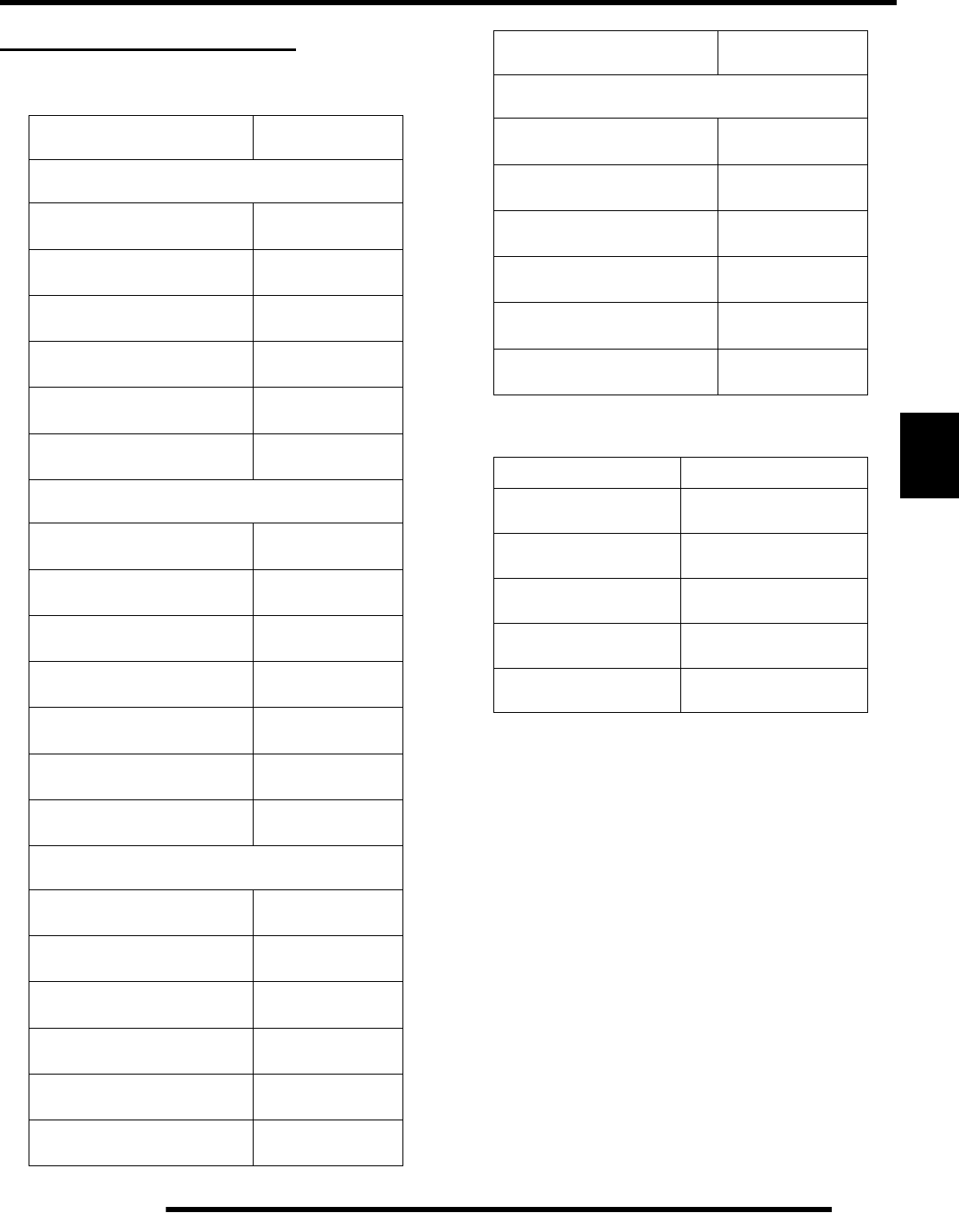
5.3
BODY / STEERING / SUSPENSION
5
GENERAL INFORMATION
Torque Specifications
Special Tools
COMPONENT TORQUE VALUE
FRONT SUSPENSION
Front A–Arm Attaching Bolts 33 ft. lbs.
(45 Nm)
Front A–Arm Ball Joint
Stud Nut 40 ft. lbs.
(54 Nm)
Front Spindle Nut 40 ft. lbs.
(54 Nm)
Tie Rod End Jam Nut 15 ft. lbs.
(20 Nm)
Tie Rod End Attaching Nut 33 ft. lbs.
(45 Nm)
Shock Bolts
(top & bottom) 33 ft. lbs.
(45 Nm)
STEERING
Master Cylinder Mount Bolts 45–55 in. lbs.
(5.2–6.3 Nm)
Handlebar Adjuster Block 9 ft. lbs.
(12 Nm)
Steering Post Nut 35 ft.lbs.
(47 Nm)
Steering Post Bushing Nuts 17 ft. lbs.
(23 Nm)
Steering Post Retainer Nuts 17 ft. lbs.
(23 Nm)
Centerlink - Steering Post Arm 33 ft. lbs.
(45 Nm)
Centerlink - Idler Arm 33 ft. lbs.
(45 Nm)
REAR SUSPENSION
Rear A–Arm Attaching Bolts 33 ft. lbs.
(45 Nm)
Rear Hub Nut 90 ft. lbs.
(122 Nm)
Rear Hub Carrier Bolts 30 ft. lbs.
(41 Nm)
Upper Torsion Bar Bolts 33 ft. lbs.
(45 Nm)
Shock Bolts
(top & bottom) 33 ft. lbs.
(45 Nm)
Torsion Bar Pivot
Plate Bolts 9 ft. lbs.
(12 Nm)
COMPONENT TORQUE VALUE
SERVICEABLE COMPONENTS
Rear Pivot Housing
Mounting Bolts 30 ft. lbs.
(41 Nm)
Rear Sprocket Bolts 26 ft. lbs.
(35 Nm)
Brake Disc
Caliper Mounting Bolts 18 ft. lbs.
(25 Nm)
Wheel Nuts 25 ft. lbs.
(34 Nm)
Rear Pivot Housing
Mount Plate 17 ft. lbs.
(23 Nm)
Foot Peg 33 ft. lbs.
(45 Nm)
PART NUMBER TOOL DESCRIPTION
PA - 48282 Rear Drive Hub Removal /
Installation Tool
2870871 Ball Joint Replacement
Tool
PS-45259 Gas Fill Tool
PS-45261 IFP Positioning /
Extraction Tool
PA-48282 Rear Hub Tool
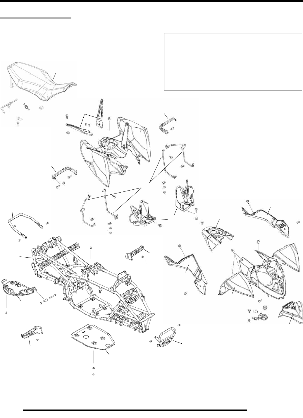
5.4
BODY / STEERING / SUSPENSION
BODY ASSEMBLY
Exploded View
A. Seat
B. Seat Release Latch
C. Rear Cab
D. Side Panel
E. Front Cover
F. Front Cab
G. Heel Pocket
H. Heel Support
I. Grab Bar
J. Fuel Tank Cover
K. Frame
L. Foot Peg
M. Rock Guard
N. Front Bumper
O. Rear Cab Support
A
BC
D
E
F
G
H
I
J
KL
M
N
O
D
L
M
O
O
RepairPro Service Manual
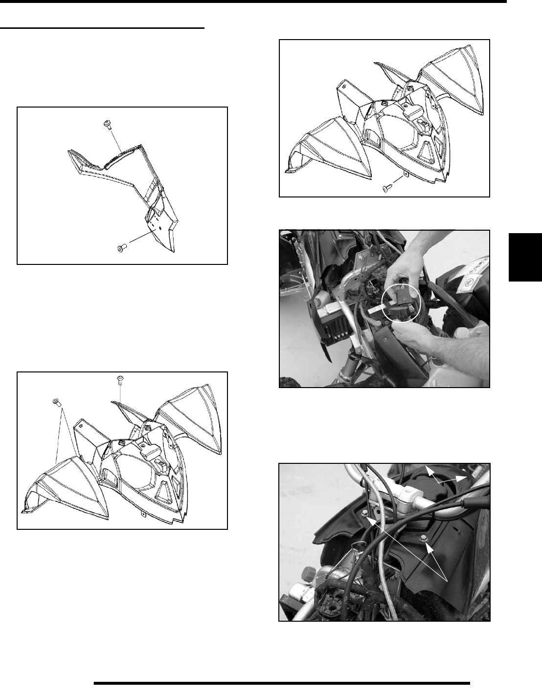
5.5
BODY / STEERING / SUSPENSION
5
BODY COMPONENT REMOVAL
Seat / Side Panel
1. Remove the seat by lifting up on the releasing latch and
slide the seat towards the rear of the ATV.
2. Remove the 2 torx head screws from the side panel.
3. Carefully unhook the locking tabs at the rear portion of the
side panel and then slide the panel towards the rear of the
ATV to completely disengage the side panel locking tabs
4. Reverse the removal steps to reinstall the side panel.
Front Cab
1. Remove the 4 torx head screws and the 2 (6mm) bolts
holding the rear portion of the front cab.
2. Remove the 2 torx head screws holding the lower front
portion of the front cab.
3. Disconnect the 16 pin connector to completely remove the
front cab assembly.
4. Reverse the removal steps to reinstall the front cab.
Tank Cover
1. Remove the 4 (6mm) bolts (A) retaining the fuel tank
cover.
A
A
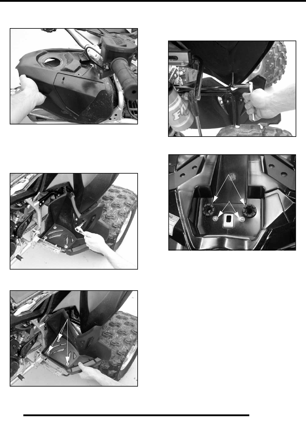
5.6
BODY / STEERING / SUSPENSION
2. Remove the fuel tank cap to allow the cover to be removed.
Once removed reinstall the fuel tank cap.
3. Reverse the removal steps to reinstall the tank cover.
Heel Pocket
1. Remove the 2 bolts from the upper portion of the heel
pocket.
2. Remove the 3 screws (A) from the lower portion and
remove the heel pocket.
3. Reverse the removal steps to reinstall the heel pocket.
Rear Cab
1. Remove the 2 bolts from the lower portion of the rear cab
on each side as shown below.
2. Push both seat grommets (C) through the rear cab, remove
screws (D) and completely remove the rear cab.
3. Reverse the removal steps to reinstall the rear cab. It may
be necessary to lubricate the rubber grommets to aid the
reassembly.
A
C
D
RepairPro Service Manual
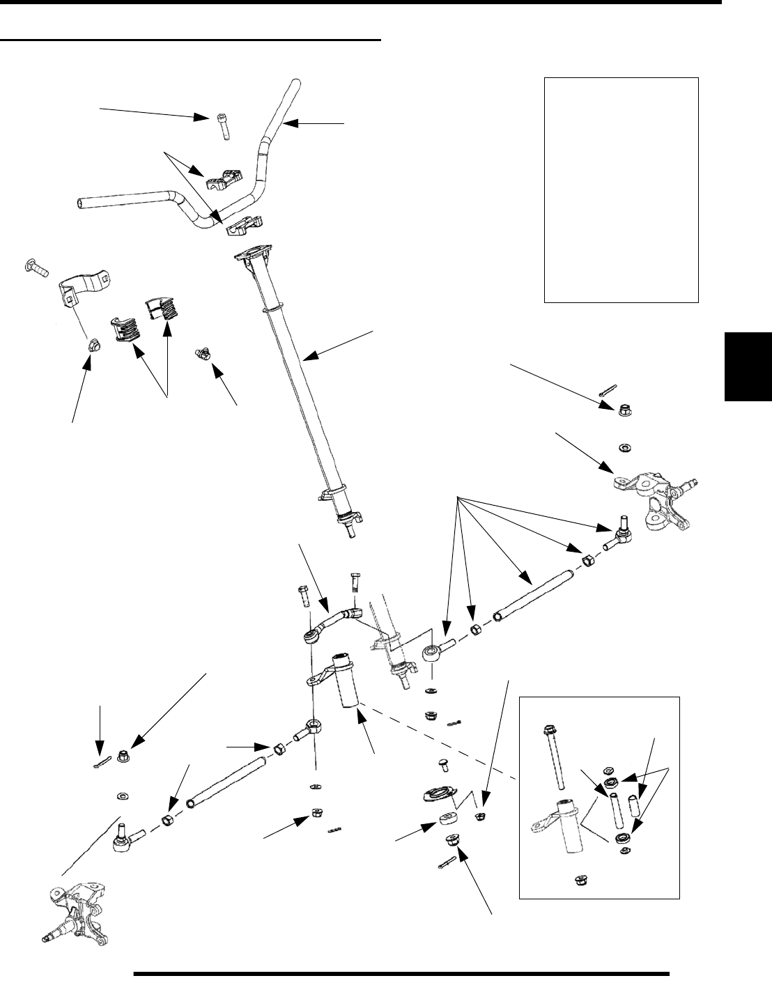
5.7
BODY / STEERING / SUSPENSION
5
STEERING ASSEMBLY EXPLODED VIEW
NOTE: APPLY ANTI-SEIZE COMPOUND
ONTO SPINDLE BEFORE HUB INSTALLATION
A. Handlebar
B. Block Clamps
C. Steering Bushings
D. Steering Post
E. Zerk Fitting
F. Cotter Pin
G. Tie Rod Assembly
H. Sealed Ball Bearing
I. Ball Bearings
J. Foam Spacer
K. Tube Spacer
L. Steering Knuckle
A
B
D
E
C
F
G
H
I
J
K
L
M. Centerlink Asm.
M
N. Steering Idler Asm.
N
9 ft. lbs
(12 Nm)
35 ft. lbs. (47 Nm)
17 ft. lbs.
(23 Nm)
17 ft. lbs.
(23 Nm)
33 ft. lbs.
(45 Nm)
33 ft. lbs.
(45 Nm)
33 ft. lbs.
(45 Nm)
15 ft. lbs.
(20 Nm)
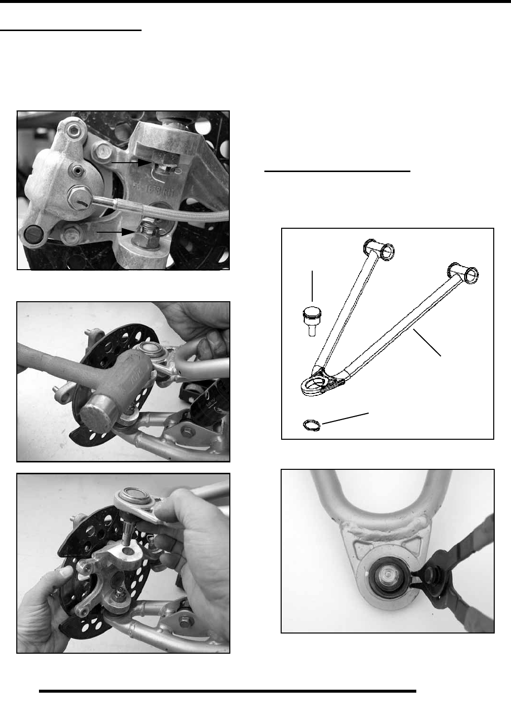
5.8
BODY / STEERING / SUSPENSION
STEERING KNUCKLE
Removal
1. Follow the steps in the “FRONT HUB REMOVAL”
section to remove the hub, if needed.
2. Remove the upper and lower ball joint cotter keys and castle
nuts.
3. Carefully tap on the upper A-arm near the top ball joint
while lifting up on the upper A-arm.
4. Tap down on the lower A-arm to move the lower ball joint
from the steering hub.
Installation
1. Before installation check the condition of the ball joints.
Joints should move freely and have no axial play.
2. Place the upper and lower A-arms into the steering hub.
3. Install the castle nuts onto the upper and lower A-arms.
Torque the nuts to 35 ft.lbs. (47 Nm).
4. Install new cotter pins into the castle nuts and ball joints.
BALL JOINT SERVICE
Removal
1. The A-arm must be removed to perform this procedure,
Refer to “A-ARM REPLACEMENT” on Page 5.13.
2. Remove the retaining ring from the ball joint.
Retaining Ring
Upper A-arm
Ball Joint
Upper A-arm Shown
RepairPro Service Manual
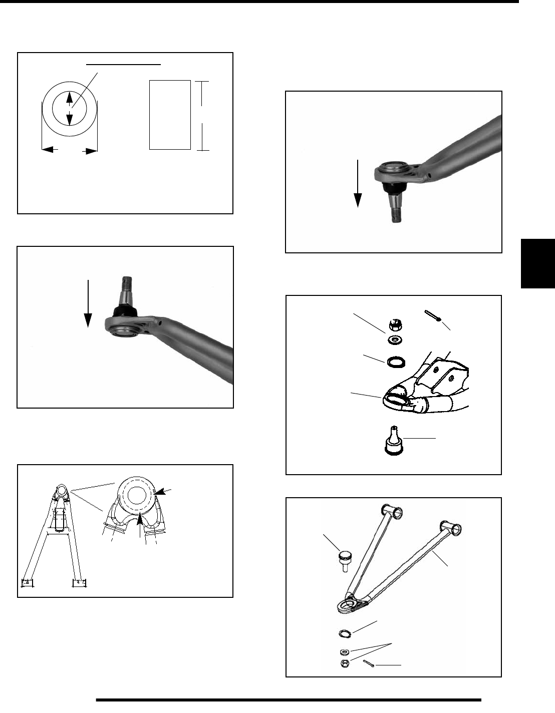
5.9
BODY / STEERING / SUSPENSION
5
3. A driver must be used for the removal of the ball joints. Use
the dimensions below to fabricate or locate the correct size
driver to use in the following process.
4. Use a press and correct size driver to remove the ball joint
from the A-arm.
NOTE: The driver must fit the inside diameter of the
A-arm. This will allow the ball joint to be properly
pressed out of the A-arm without damaging the A-
arm.
Installation
1. Place the A-arm in the correct position for ball joint
installation. Face the A-arm end flat on top of the driver.
Carefully drive the ball joint into place until the ball joint
is properly installed.
2. After the new ball joint is installed into the A-arm, install
a NEW retaining ring. Upon A-arm installation onto the
steering hub, install a NEW cotter key.
1.75 in
(4.45 cm)
1.375 in.
(3.49 cm)
3 in.
(7.62 cm)
* Outside diameter of driver cannot be any larger than
1.75 in. Inside diameter cannot be any smaller than
1.375 in. Driver must be 3 in. or taller.
Driver Dimensions
Press out of the A-arm
in this direction
Upper A-arm Shown
Correct
Driver Placement
The driver must fit the inside
diameter of the A-arm end.
Lower A-arm Shown
Press into the A-arm
in this direction
Upper A-arm Shown
NEW Cotter Key
Nut & Washer
NEW
Retaining Ring
Lower A-arm
Ball Joint
Nut & Washer
NEW
Retaining Ring
Upper A - arm
NEW Cotter Key
Ball Joint
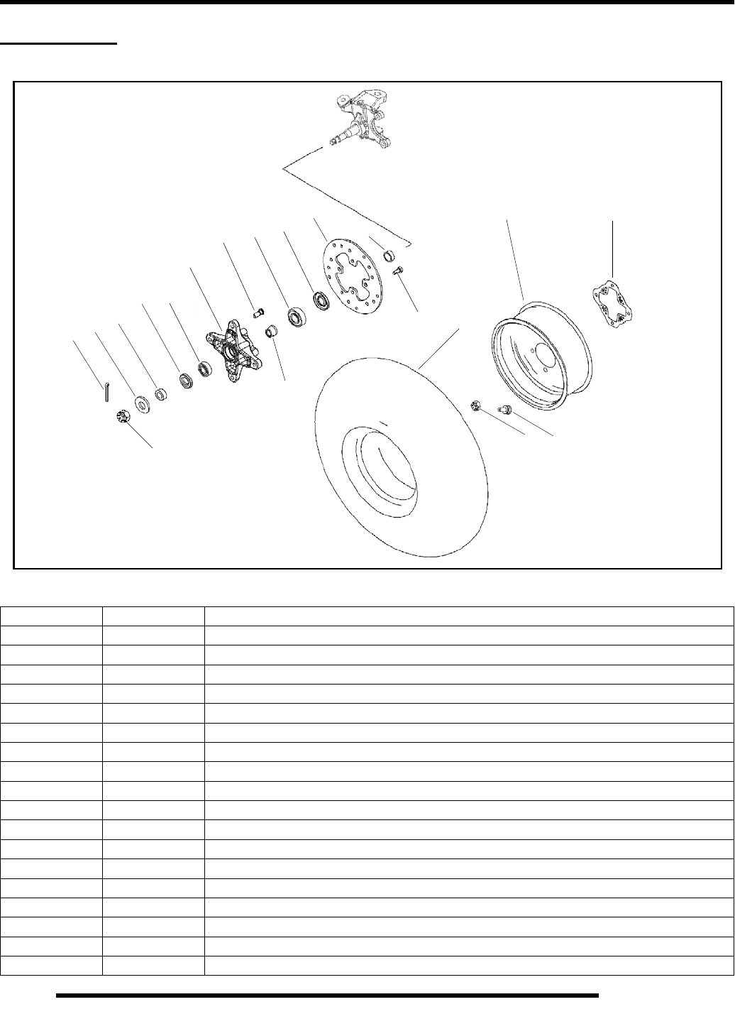
5.10
BODY / STEERING / SUSPENSION
FRONT HUB
Exploded View
Ref. Qty. Description
1. 2 Nut, Castle
2. 2 Pin, Cotter
3. 2 Washer
4. 2 Spacer, Outer
5. 2 Seal
6. 2 Bearing, Ball, Sealed
7. 2 Hub, Wheel, Front, Indy Red
8. 8 Stud
9. 2 Spacer, Tapered
10. 2 Bearing, Ball
11. 2 Seal
12. 2 Disc, Brake
13. 2 Spacer, Inner
14. 8 Bolt
15. 2 Rim, Front
16. 2 Valve, Rim
17. 8 Nut, Flange
18. 2 Tire, Front, 21x7–10
19. 2 Guard, Disc, Outer
14
13
12
11
10
9
8
7
6
5
4
3
2
1
15 19
18
17 16
RepairPro Service Manual
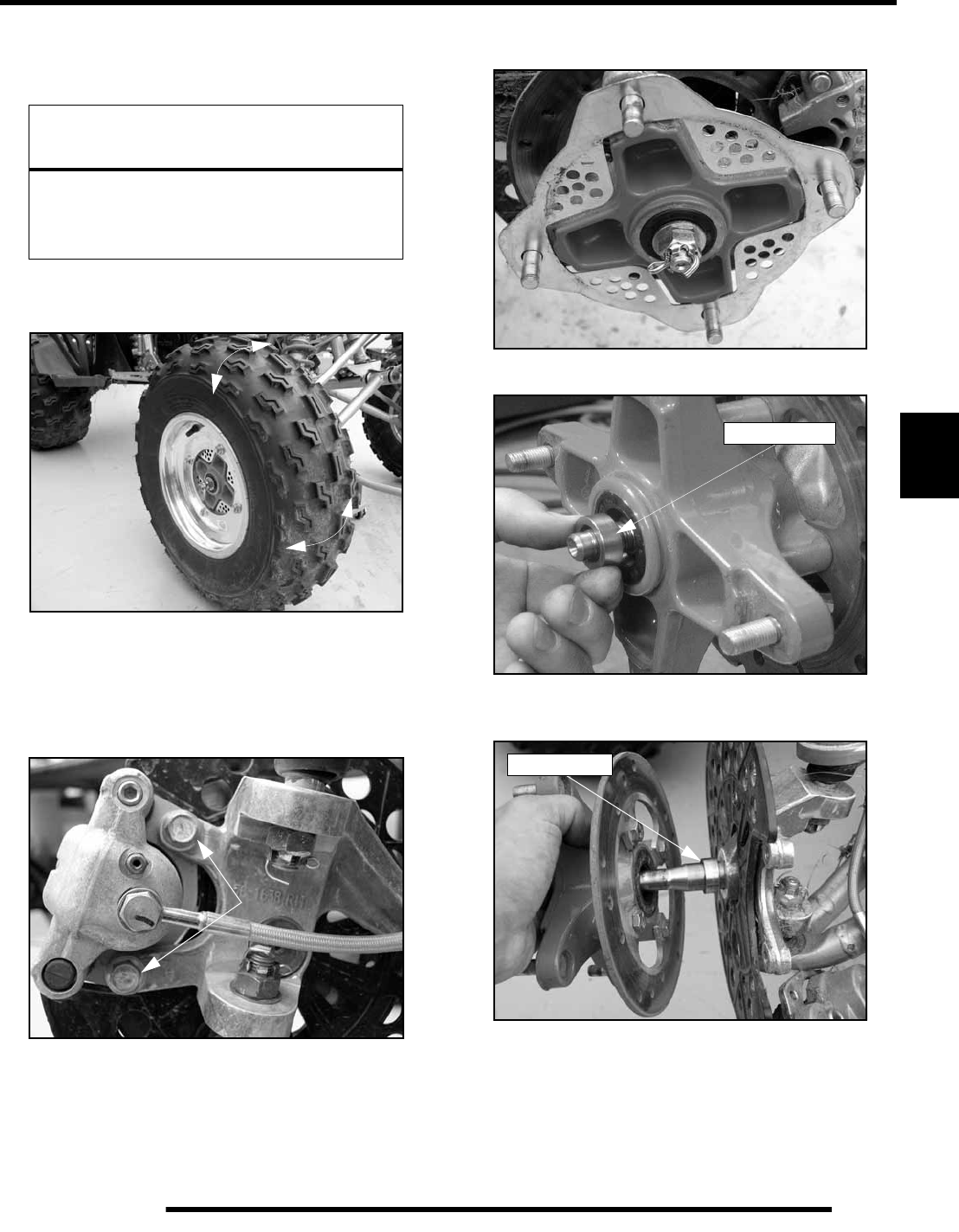
5.11
BODY / STEERING / SUSPENSION
5
Hub Removal
1. Elevate front end of ATV and safely support machine
under footrest / frame area.
2. Check bearings for side play by grasping tire / wheel firmly
(top and bottom, side to side) and checking for movement.
It should rotate smoothly without binding or rough spots.
3. Remove wheel nuts and wheel.
4. Remove the two brake caliper bolts and the brake caliper.
Use mechanic’s wire or other suitable material to support
the caliper assembly. Do not allow caliper assembly to
hang by the brake line!
5. Remove outer brake disc guard, cotter pin, front spindle
nut, and washer.
6. Remove the outer spacer from the spindle. Inspect outer
spacer for wear, replace if needed.
7. Remove the hub from the spindle. Remove the inner spacer
from the spindle. Inspect the inner spacer for wear, replace
if needed.
8. Rotate each bearing inside the hub by hand and check for
smooth rotation. Visually inspect bearing for moisture, dirt,
or corrosion. Replace bearing if moisture, dirt, corrosion,
or roughness is evident.
CAUTION
Serious injury may result if machine tips or falls.
Be sure machine is secure before beginning this
service procedure. Wear eye protection when
removing bearings and seals.
Brake Caliper
Bolts
Outer Spacer
Inner Spacer
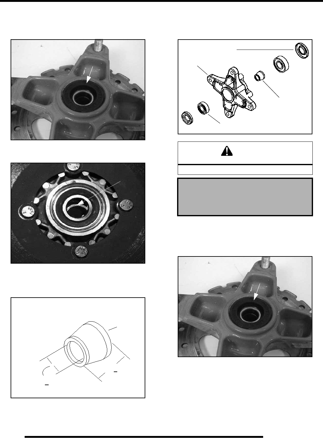
5.12
BODY / STEERING / SUSPENSION
Hub Disassembly
1. Place a shop towel on hub to protect surface. Carefully pry
seal out of hub.
2. Using a brass drift, tap bearing spacer to one side to expose
inner bearing race. Drive bearing out using a drift through
opposite side of hub and discard.
3. Remove spacer. Drive other bearing out and discard.
4. Clean hub and spacer thoroughly.
5. Inspect spacer for wear or damage. Measure the tapered
spacer for wear, replace as needed.
Hub Assembly
1. Drive or press one new bearing into hub using a bearing
driver.
2. Coat bearing spacer with grease and install into hub. Drive
or press the other bearing into hub until seated against
spacer.
3. Install seal into hub (with numbers facing out) until flush
with end of seal bore.
Seal
Tap Spacer to
the side
Tapered Spacer
.774 + .005
.797 + .005
CAUTION
Do not drive on the inner race of the bearing.
Premium All- Season Grease
(PN 2871322) (3 oz. Tube)
(PN 2871423) (14 oz. Tube)
Seals (2)
Hub
Tapered Spacer
Bearings (2)
Seal
RepairPro Service Manual
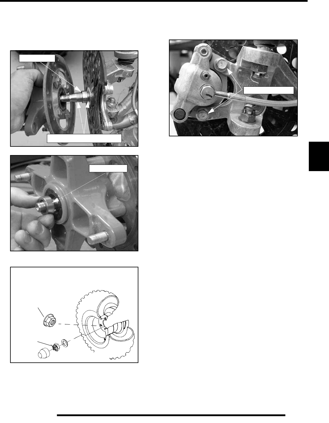
5.13
BODY / STEERING / SUSPENSION
5
Hub Installation
1. Apply anti-seize compound to spindle area, this will aid in
easier removal of the wheel in the future.
2. Inspect spindle and bearing surface for wear or damage.
Install the inner spacer.
3. Install hub on spindle. Install the outer spacer.
4. Install the washer and spindle nut. Torque the spindle nut
to 40 ft. lbs. (54 Nm).
5. Install a new cotter pin. Tighten nut slightly if necessary to
align cotter pin holes.
6. Bend both ends of cotter pin around end of spindle in
different directions.
7. Rotate hub. It should rotate smoothly without binding,
rough spots or side play.
8. Install brake caliper. Tighten bolts to 18 ft.lbs. (24 Nm).
9. Install the brake disc guard.
10. Install the wheel and four wheel nuts finger tight. Lower the
ATV and torque the wheel nuts to 30-35 ft. lbs.
(41-47 Nm).
Inner Spacer
Apply anti-seize compound
Outer Spacer
Front Wheel Torque
Front Wheel Nuts (4)
30-35 ft. lbs.
(41-47 Nm)
Front Spindle Nut
40 ft. lbs. (54 Nm)
18 ft. lbs. (24 Nm)
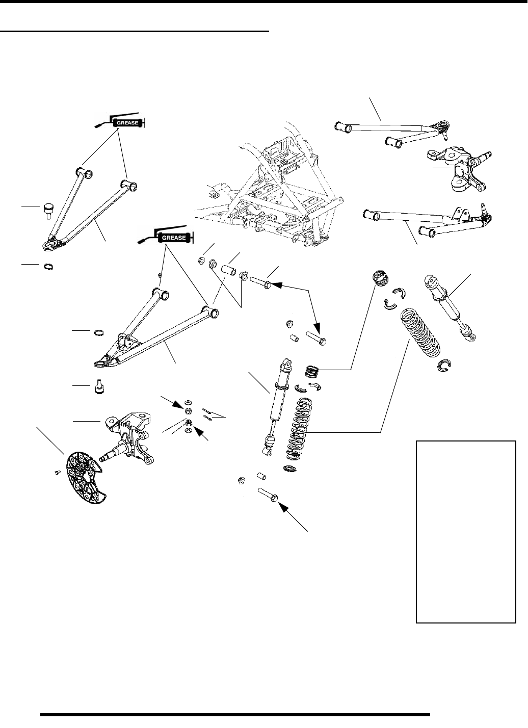
5.14
BODY / STEERING / SUSPENSION
FRONT SUSPENSION EXPLODED VIEW
Use new cotter pins upon reassembly.
open end toward rear of machine.
A
B
C
C
D
D
E
F
G
H
I
J
J
L
L
K
M
A
B
I
Install with
A. Springs
B. IFP Shock
C. Upper A-Arm
D. Lower A-Arm
E. A-Arm Shaft
F. Bushings
G. Bolt
H. Flange Nut
I. Steering Knuckle
J. Ball Joints
K. Cotter Pins
L. Retainer Rings
M. Inner Disc Guard
33 ft. lbs.
(45 Nm)
40 ft. lbs.
(54 Nm)
33 ft. lbs.
(45 Nm)
40 ft. lbs.
(54 Nm)
RepairPro Service Manual
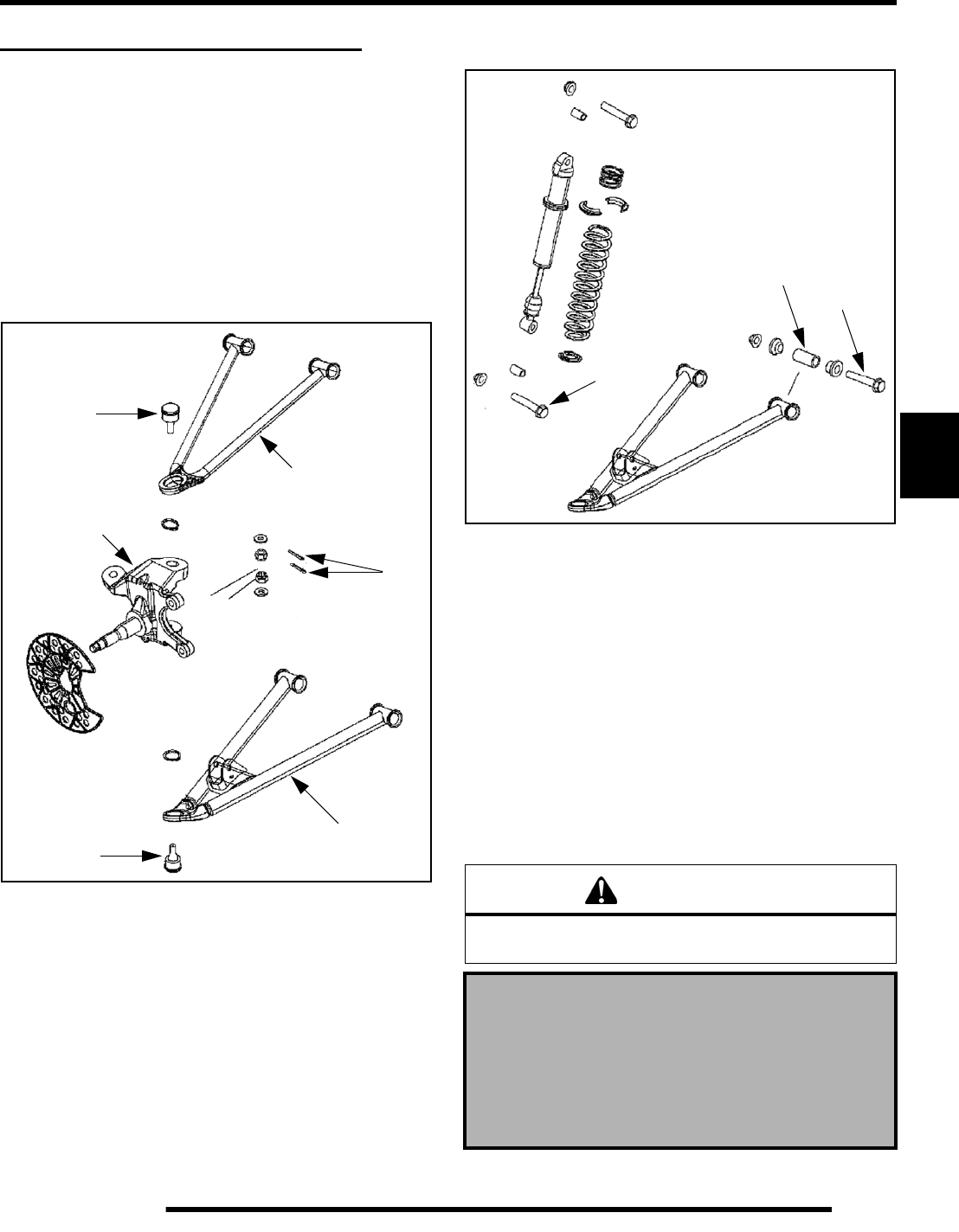
5.15
BODY / STEERING / SUSPENSION
5
FRONT A-ARM REPLACEMENT
A-arm Removal and Inspection
1. Elevate and safely support vehicle. Remove the front
wheel(s).
2. Remove the upper and lower ball joint cotter pins (A) from
the ball joint studs (B & C) at wheel end of A–arm. Remove
the ball joint nuts until the nuts are flush with end of the ball
joints studs.
3. Push up on the upper A-arm (D) to remove the A-arm from
the steering knuckle (E). Push down on the lower A-arm (F)
to remove the A-arm from the steering knuckle (E).
4. Remove the lower shock bolt (G) from the lower A-arm and
remove the shock from the A-arm.
5. Loosen two bolts on the A–arm tubes (H) (upper and lower
A-arms) until A–arm can be removed.
6. Examine A–arm shafts (I). Replace if worn. Discard
hardware.
A-arm Installation
1. Insert A–arm shaft (I) into the new A–arm (D & F).
2. Install new A–arm assembly onto vehicle frame (upper and
lower). Torque bolts to 33 ft. lbs. (45 Nm).
3. Attach upper A-arm (D) and lower A–arm (F) to steering
knuckle (E). Attach shock with bolts (G). Tighten all
fasteners to 33 ft. lbs. (45 Nm). If ball joint cotter pin holes
are not aligned, tighten nut slightly to align. Install a new
cotter pin with open ends toward rear of machine (upper and
lower). Bend ends in opposite directions around nut.
4. Locate grease fittings at the end of each A–arm tube and
pump A–arm ends full of grease.
A
B
C
D
E
F
WARNING
Upon A–arm installation completion, test vehicle at low
speeds before putting into regular service.
A-arm Attaching Bolt Torque:
Ball Joint Stud Nut Torque:
Front Shock Bolt Torque:
33 ft. lbs. (45 Nm)
G
H
I
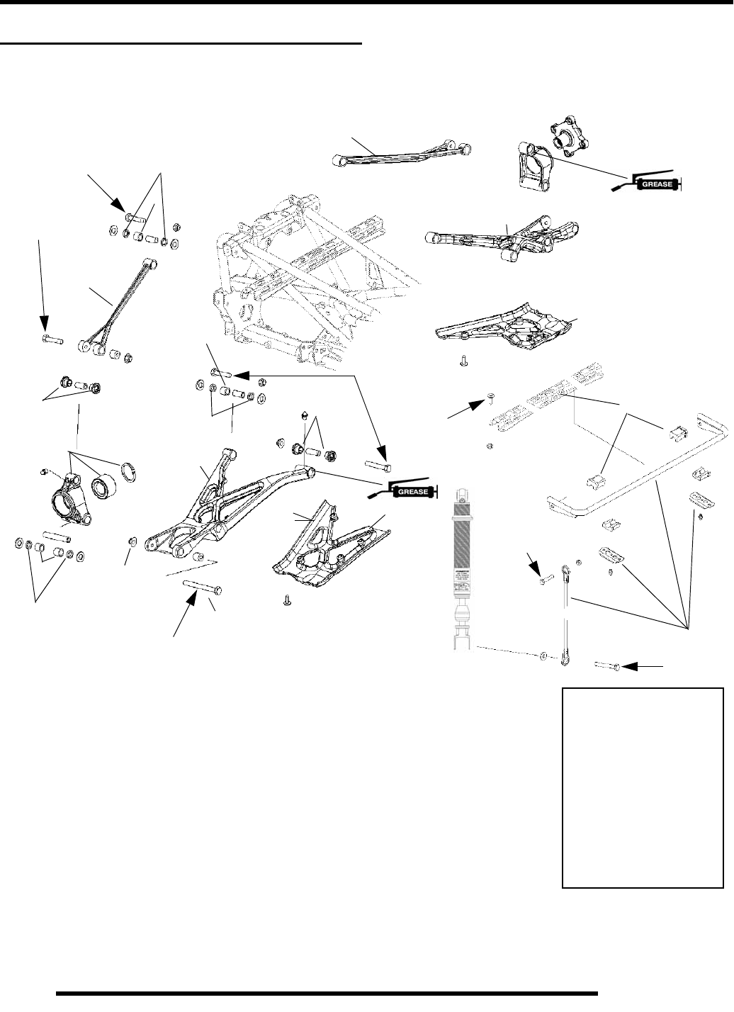
5.16
BODY / STEERING / SUSPENSION
REAR SUSPENSION EXPLODED VIEW
B
C
D
E
G
H
J
K
A
B
A. Hub Carrier Assembly
B. Torsion Bar Assembly
C. Upper A-Arm
D. Lower A-Arm
E. Guard
F. Bushings
G. Bolt
H. Flange Nut
I. Needle Bearing
J. Bearing Seals
E
D
I
F
C
F
I
I
J
J
J
33 ft. lbs.
(45 Nm)
30 ft. lbs.
(41 Nm)
30 ft. lbs.
(41 Nm)
33 ft. lbs.
(45 Nm)
33 ft. lbs.
(45 Nm)
33 ft. lbs.
(45 Nm)
9 ft. lbs.
(12 Nm)
RepairPro Service Manual
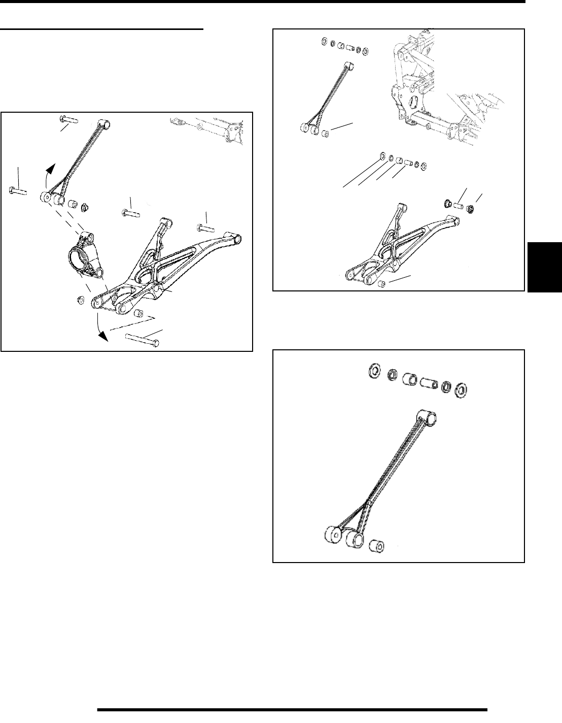
5.17
BODY / STEERING / SUSPENSION
5
REAR A-ARM REPLACEMENT
A-arm Removal
1. Elevate and safely support vehicle. Remove the rear
wheel(s).
2. Loosen the upper and lower hub carrier bolts at the wheel
end of A–arms (A)(C).
3. Remove the lower shock bolt from the lower A-arm hole
(B) and remove the shock from the A-arm.
4. Remove bolt (A) on the lower A–arm tube and pry the hub
carrier up and away from the A-arm.
5. Remove bolt (C) on the upper A–arm tube and pry the hub
carrier down and away from the A-arm.
6. Remove remaining bolts (D) from A-arms and remove A-
arms from frame.
7. Examine A–arm shafts (E), needle bearings (F), seals (G),
thrust washers (H) and bushings (I). Replace if worn or
damaged.
NOTE: Rear A-arm mounts contain needle bearings
A-arm Inspection
1. Disassemble, clean and inspect the upper A-arm bushings
and shaft. Replace components as required.
C
A
B
D
D
D
G
H
I
E
F
G
HI
E
E
E
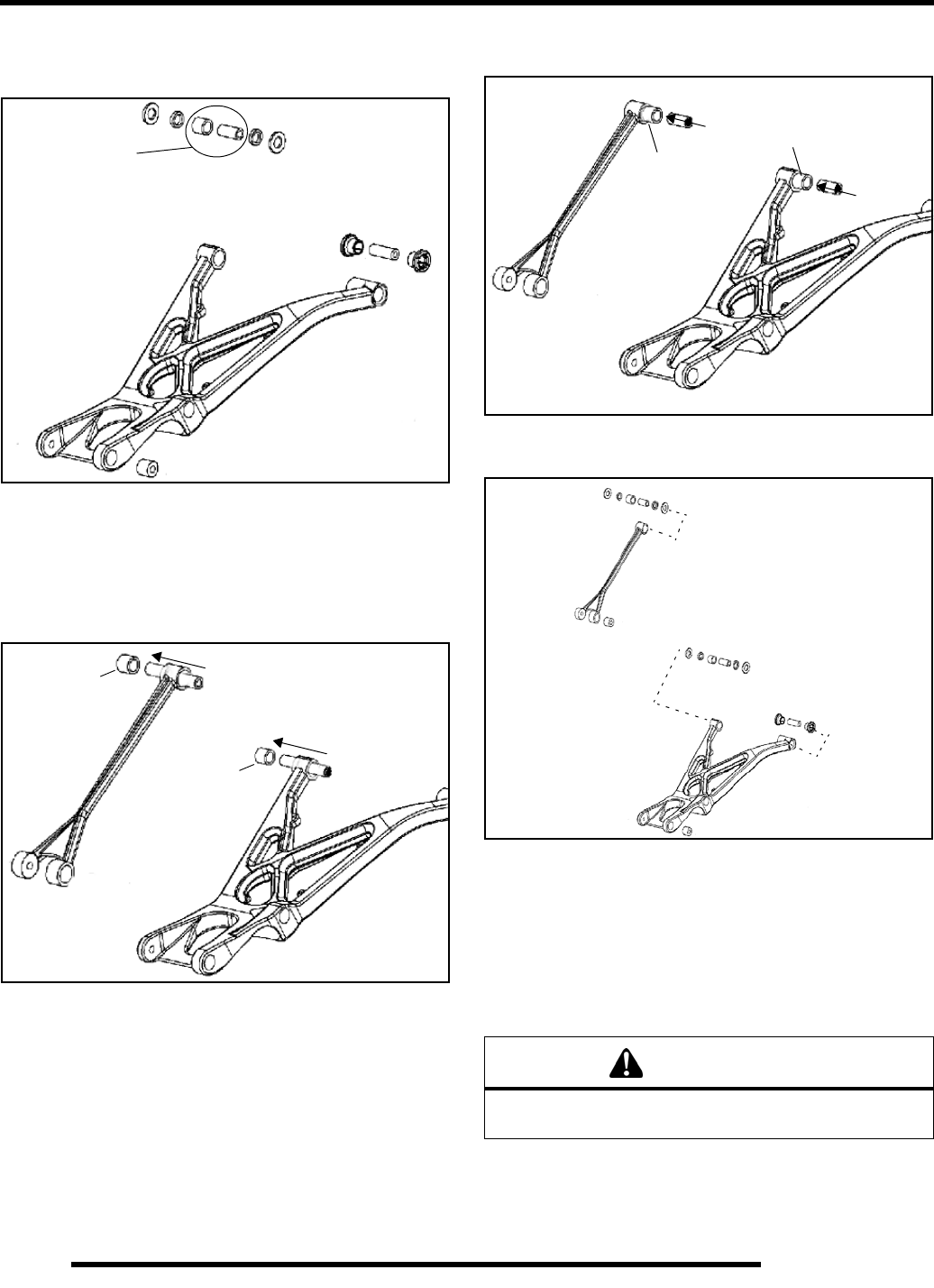
5.18
BODY / STEERING / SUSPENSION
2. Disassemble, clean and inspect the lower A-arm thrust
washers, needle bearing, seals and shaft. Replace
components as required.
3. Inspect needle bearing performance by rotating the shaft
inside the bearing (circled). If replacement is required,
press the bearings out from opposite sides using a drift
punch or other suitable tool.
4. Press needle bearings (A) from the A-arms using a drift
punch or other suitable tool. Do not re-use bearings once
they have been removed.
5. Press new needle bearings (A) into the A-arms, centering
bearing in the bore. Press only on the outside diameter of
the bearing. Verify that an equal amount of space remains
on each side to allow for seal installation.
NOTE: Apply grease to the inside of the needle
bearings before inserting shaft.
6. Insert A–arm shafts, seals and thrust washers into the A–
arm mounting bores.
A-arm Installation
1. Install A–arm assemblies onto vehicle frame (upper and
lower). Torque bolts to 33 ft. lbs. (45 Nm).
2. Attach upper A-arm and lower A–arm to hub carrier. (E).
Tighten both fasteners to 33 ft. lbs. (45 Nm).
3. Locate grease fittings at the upper and lower A-arm
bushings and pump full of grease.
Inspect
A
A
WARNING
Upon A–arm installation completion, test vehicle at low
speeds before putting into regular service.
A
A
RepairPro Service Manual
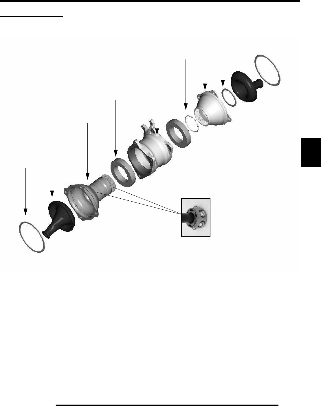
5.19
BODY / STEERING / SUSPENSION
5
REAR HOUSING
Exploded View
A. CV Boot Retaining Ring
B. Inner CV Boot
C. Sprocket Hub
D. Bearing (2)
E. Rear Axle Housing
F. O-Ring
G. Rear Brake Disc Hub
H. Brake Hub Retaining Ring
A
B
C
D
E
F
H
G
I
D
A
B
CV Ball/Cage Assembly
Individual Parts Not Available - Order Hub Assembly
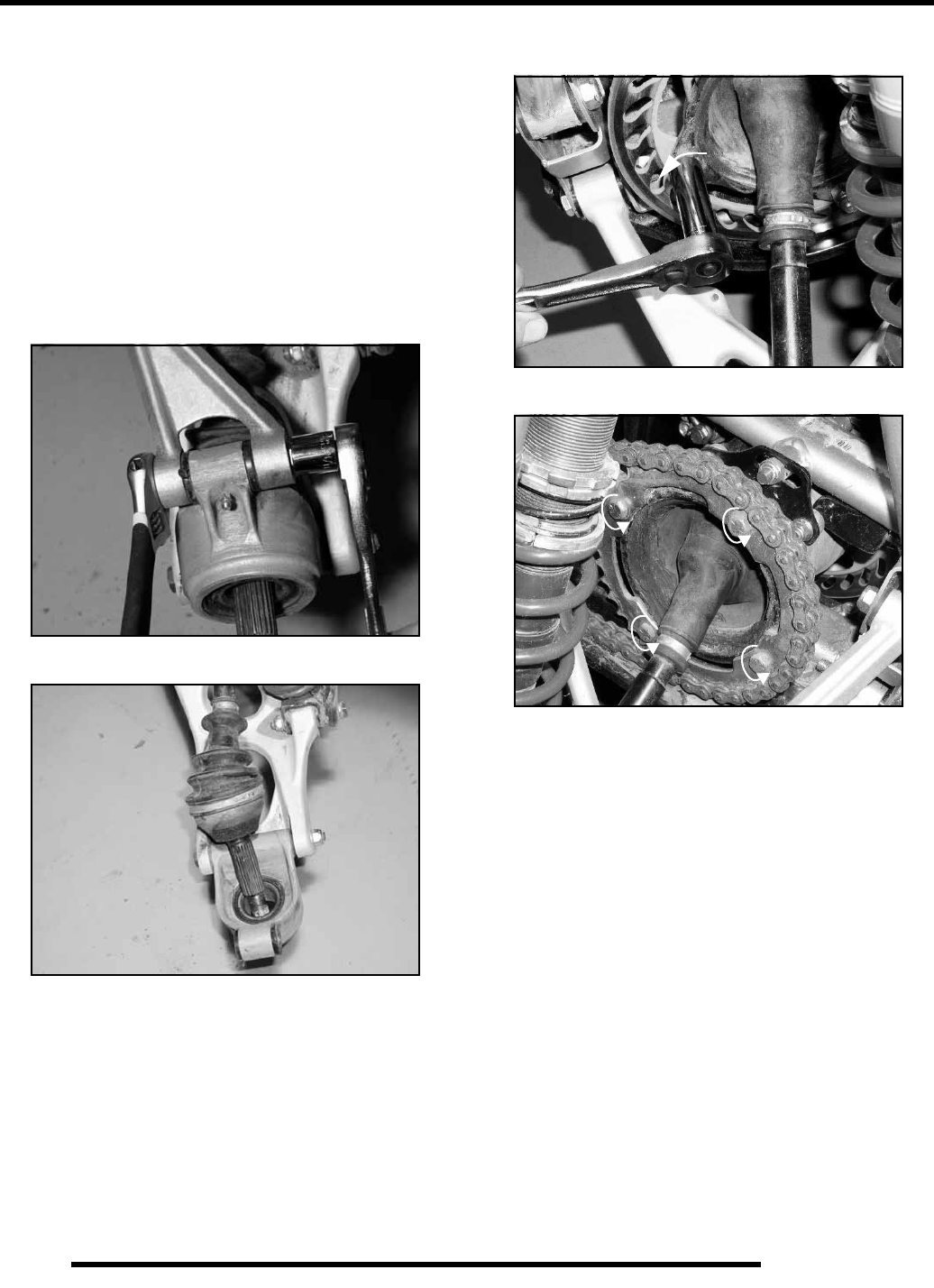
5.20
BODY / STEERING / SUSPENSION
Housing Removal
1. With ATV on the ground, loosen wheel nuts and hub nuts.
2. Safely lift and support the rear of the ATV under the main
frame.
3. Remove both rear wheels and hubs.
4. Loosen rear housing mounting bolts and chain adjustment.
5. Remove drive chain.
6. Remove rear caliper and secure out of the way.
NOTE: Do not allow the caliper to hang by the brake
line. Brake line damage may result.
7. Remove both upper carrier bolts and secure upper a-arms
out of the way.
8. Tilt each hub carrier outward while pulling rear CV shaft
end from carrier assembly.
9. Remove brake disc and drive sprocket from rear housing.
This provides the necessary clearance for housing removal.
10. Remove rear housing mounting bolts and chain adjustment
components.
11. Lift and rotate rear housing and angle out of the ATV frame,
exiting the frame from either side.
NOTE: Removal of rear shock may be necessary to
gain adequate clearance for rear housing removal.
A
RepairPro Service Manual
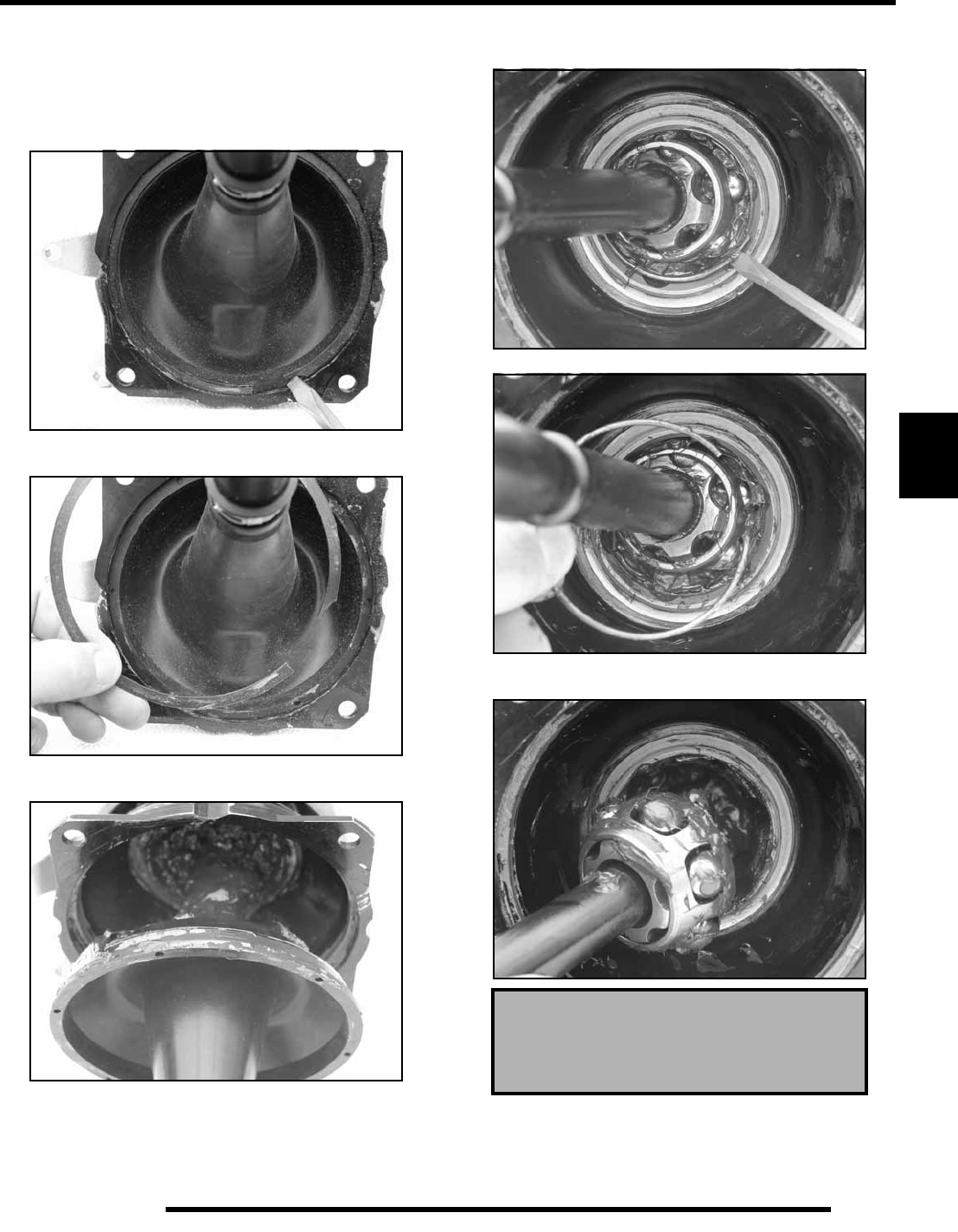
5.21
BODY / STEERING / SUSPENSION
5
Housing Disassembly / Service
1. Place housing in a suitable holding fixture.
2. Remove both boot clamps from their locations.
3. Using a flat blade screwdriver, carefully pry the retaining
ring from each boot.
4. Remove the retaining rings from both inner boots of the rear
housing.
5. Remove both inner boots by pulling outward on boot. A
blunt prying tool may be required to break the sealing area.
NOTE: Inner CV boots are sealed to housing. Use
caution during removal. Boot damage may result.
6. Using a flat blade screwdriver, carefully pry the retaining
rings from both CV ball cages.
7. Remove the CV ball cage retaining rings from the housing.
8. Remove the inner CV joints and shaft assemblies from the
carrier housing.
NOTE: Inner CV joint parts are not
replaceable. Order new hub assembly if
damaged beyond serviceable condition.
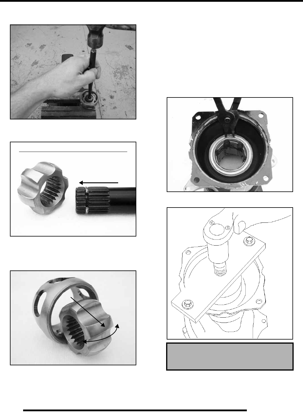
5.22
BODY / STEERING / SUSPENSION
9. To disassemble the inner CV joint, place the CV end on a
vise and use a punch to tap the driveshaft out.
IMPORTANT: Note the orientation of the parts for
reassembly. Inner CV joint parts are not replaceable.
Replace hub assembly if joints are damaged
10. The inner CV joint can be disassembled by rotating the
inner joint approximately 180 degrees and pulling out.
Clean and inspect the joint and rollers for cracks or rough
surfaces. Replace the hub assembly if damage is found.
11. To reassemble the inner CV joint, use special Hi Temp CV
joint grease to allow the rollers to “stick” to the cage. Insert
the rollers into the outer cage, then insert the inner joint
sideways 180 degrees into the cage assembly and turn the
inner joint to capture the rollers. The chamfered end should
be facing toward the drive shaft.
12. Using a soft faced hammer, tap the drive shaft into the
chamfered end of the inner CV assembly until it locks in
place. Lubricate the inner CV assembly liberally with joint
grease before housing reassembly.
13. Before pressing the brake and sprocket hubs apart, remove
the sprocket hub snap ring.
14. Using Special Tool PN PA-48282, press the rear hub
assembly apart to access the carrier bearings.
NOTE: Drive shaft inserts into chamfered end
180
°
Rear Hub Tool
PA - 48282
Brake Hub Assembly
RepairPro Service Manual
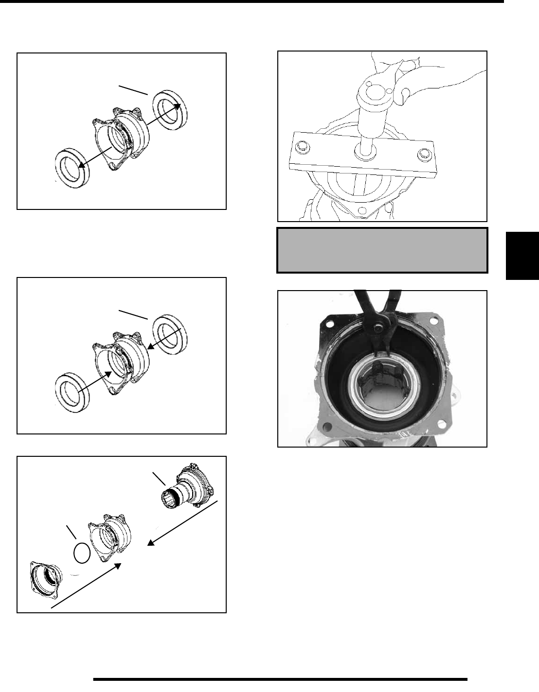
5.23
BODY / STEERING / SUSPENSION
5
15. Using a suitable holding fixture, press or tap the carrier
bearings out the opposite end of each housing.
NOTE: Do not reuse the bearings if removed.
Assembly
1. Using a suitable holding fixture, press or tap the carrier
bearings into the housing.
NOTE: Do not reuse the bearings if removed.
2. Apply sealant to the sprocket hub splines before assembly.
3. Using Special Tool PN PA-48282, press the rear hub
assembly together. Verify o-ring is seated properly during
reassembly.
4. Install the sprocket hub snap ring.
Bearing
Bearing
O-ring
Sprocket Hub Assembly
Rear Hub Tool
PA - 48282
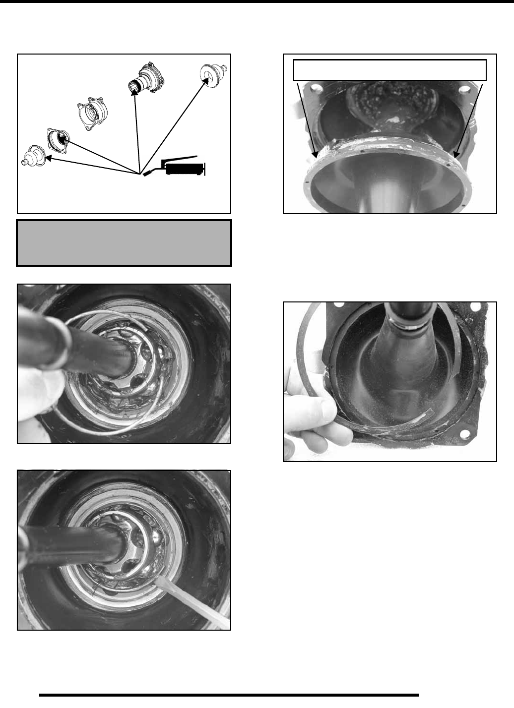
5.24
BODY / STEERING / SUSPENSION
5. Pack the housing assembly and inner boots with a total of
8.75 oz. of Hi-Temperature CV joint grease. Distribute
grease evenly.
6. Install the inner CV ball cage and retaining rings.
7. Ensure the retaining ring is seated properly in the rear
housing groove.
8. Clean and apply a thin coat of sealant to both the boot and
sealing surface before installing inner boots. Install
retaining rings.
9. Install boot clamps.
NOTE: Before tightening boot clamp on inboard
joints, make sure any air pressure which may have
built up in joint boot has been released using the
boot ‘burping’ process. The air should be released
after the plunging joint has been centered properly.
Tighten boot clamps using boot clamp pliers.
Installation
1. Reverse the steps described in the Removal/ Disassembly
procedure.
2. Attach the rear housing mounting bolts, chain adjustment
components and brackets. Torque brackets to 17 ft.lbs. (23
Nm). Do not tighten chain adjustment or housing bolts
until chain adjustment has been completed.
3. Attach the brake disc and drive sprocket to rear housing.
4. Install and torque the brake disc bolts to 18 ft.lbs. (25 Nm).
5. Install and torque the drive sprocket bolts to 26 ft.lbs. (35
Nm).
6. Install each rear CV shaft end into hub carrier from and
attach the upper a-arm to the hub carrier.
Rear Housing Hi-Temp CV Grease
Capacity: 8.75 oz. (248.05 grams)
8.75 oz. (248.05 grams)
NOTE: Use Special Hi-Temp CV Grease
CV GREASE
Apply sealant before assembly
RepairPro Service Manual
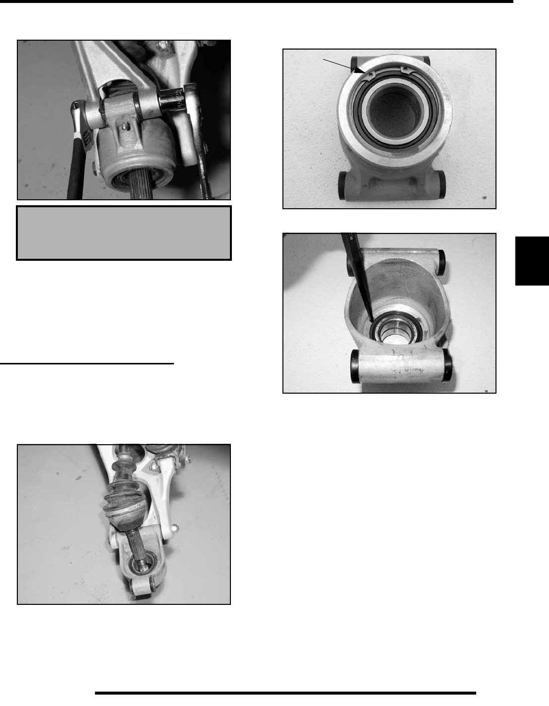
5.25
BODY / STEERING / SUSPENSION
5
7. Insert and torque the a-arm mount bolts to 30 ft.lbs. (41
Nm).
8. Follow chain adjustment procedures.
9. Torque remaining rear housing fasteners to 30 ft.lbs. (41
Nm) after completion of chain adjustment.
10. Install rear hubs, cone washer and nut. Verify cone washer
domed side faces outward. Torque hub nut to 90 ft.lbs. (122
Nm) and install cotter pin.
REAR BEARING CARRIER
Carrier Removal
1. Remove rear wheel and hub.
2. Remove upper carrier bolt and secure upper A-arm out of
the way. Tip hub carrier outward and remove shaft end from
carrier. Remove lower carrier bolt.
Carrier Disassembly / Inspection
1. Remove outer snap ring.
2. From the back side, tap on the outer bearing race with a drift
punch in the reliefs as shown.
NOTE: Drive bearing out evenly by tapping on outer
race only. Once bearing is at bottom of casting,
support casting on outer edges so bearing can be
removed.
3. Inspect bearing.
NOTE: Due to extremely close tolerances and
minimal wear, the bearings must be inspected
visually, and by feel. While rotating bearings by
hand, inspect for rough spots, discoloration, or
corrosion. The bearings should turn smoothly and
quietly, with no detectable up and down movement
and minimal movement sideways between inner and
outer race.
4. Inspect bearing housing for scratches, wear or damage.
Replace housing if damaged.
Carrier Bolt Torque:
30 ft.lbs. (41 Nm)
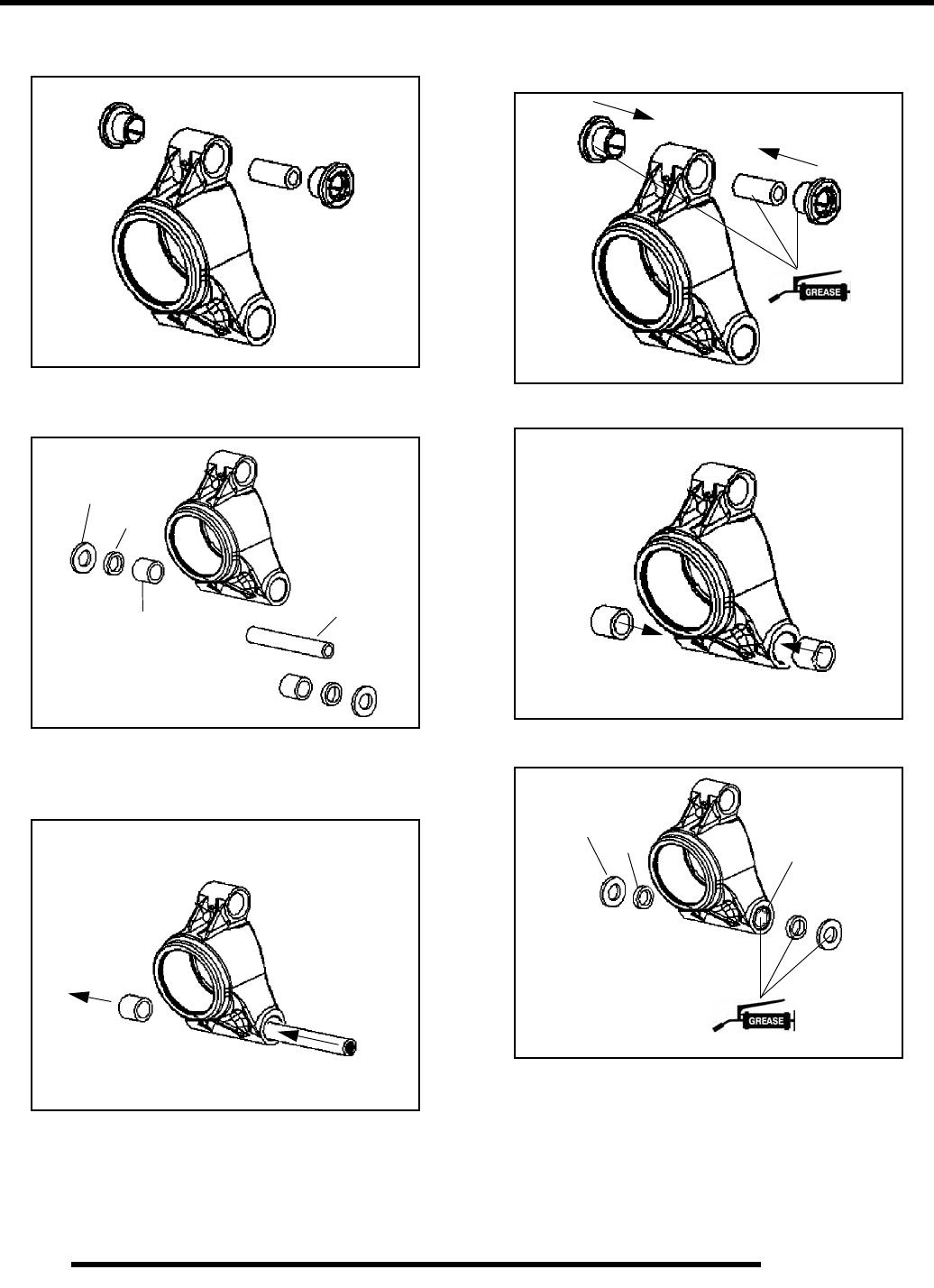
5.26
BODY / STEERING / SUSPENSION
5. Disassemble, clean and inspect the upper A-arm bushings
and shaft. Replace components as required.
6. Disassemble, clean and inspect the lower A-arm thrust
washers, needle bearing, seals and shaft. Replace
components as required.
7. Inspect needle bearing performance by rotating the shaft
inside the bearing. If replacement is required, press the
bearings out from opposite sides using a drift punch or other
suitable tool.
Carrier Assembly
1. Assemble and install the upper A-arm bushings and shaft.
2. Install needle bearings by pressing the bearings into the
housing using a suitable tool.
3. Apply grease and install the shaft. Install the lower A-arm
seals.
Seal
Needle Bearing Shaft
Thrust
Washer
Bearing Removal
Bearing Installation
Seal
Thrust
Washer
Shaft
RepairPro Service Manual
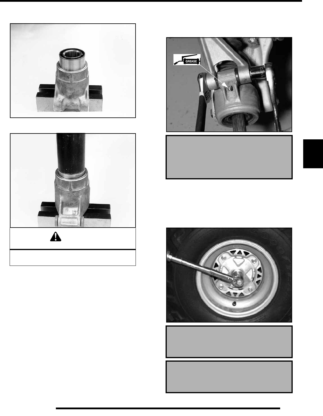
5.27
BODY / STEERING / SUSPENSION
5
4. Support bottom of bearing carrier housing and start bearing
in housing
5. Press bearing into place until outer race bottoms on
housing.
6. Install snap ring into groove.
Carrier Installation
1. Insert bearing carrier on drive shaft.
2. Align bottom of carrier housing and lower control arm.
Grease and slide lower control arm bushings into place,
securing corner housing.
3. Install both lower control arm bolts.
4. Lift bearing carrier until top aligns with upper control arm.
Install and torque upper control arm bolt and torque to
specification. Torque lower control arm bolts to
specification. Apply grease to zerk.
5. Pull drive shaft outward and install hub onto driveshaft
splines.
6. Install cone washer domed side facing outward.
7. Install retainer nut, wheel and wheel nuts.
8. Remove jackstand and torque hub nut and wheel nuts to
specification.
CAUTION
Use an arbor press only on the outer race.
Bearing damage may occur.
Lower Control Arm Bolt Torque:
33 ft. lbs. (45 Nm)
Upper Control Arm Bolt Torque:
33 ft. lbs. (45 Nm)
Hub Nut Torque:
90 ft.lbs. (122Nm).
Wheel Nut Torque:
30-35 ft.lbs. (41-47 Nm).
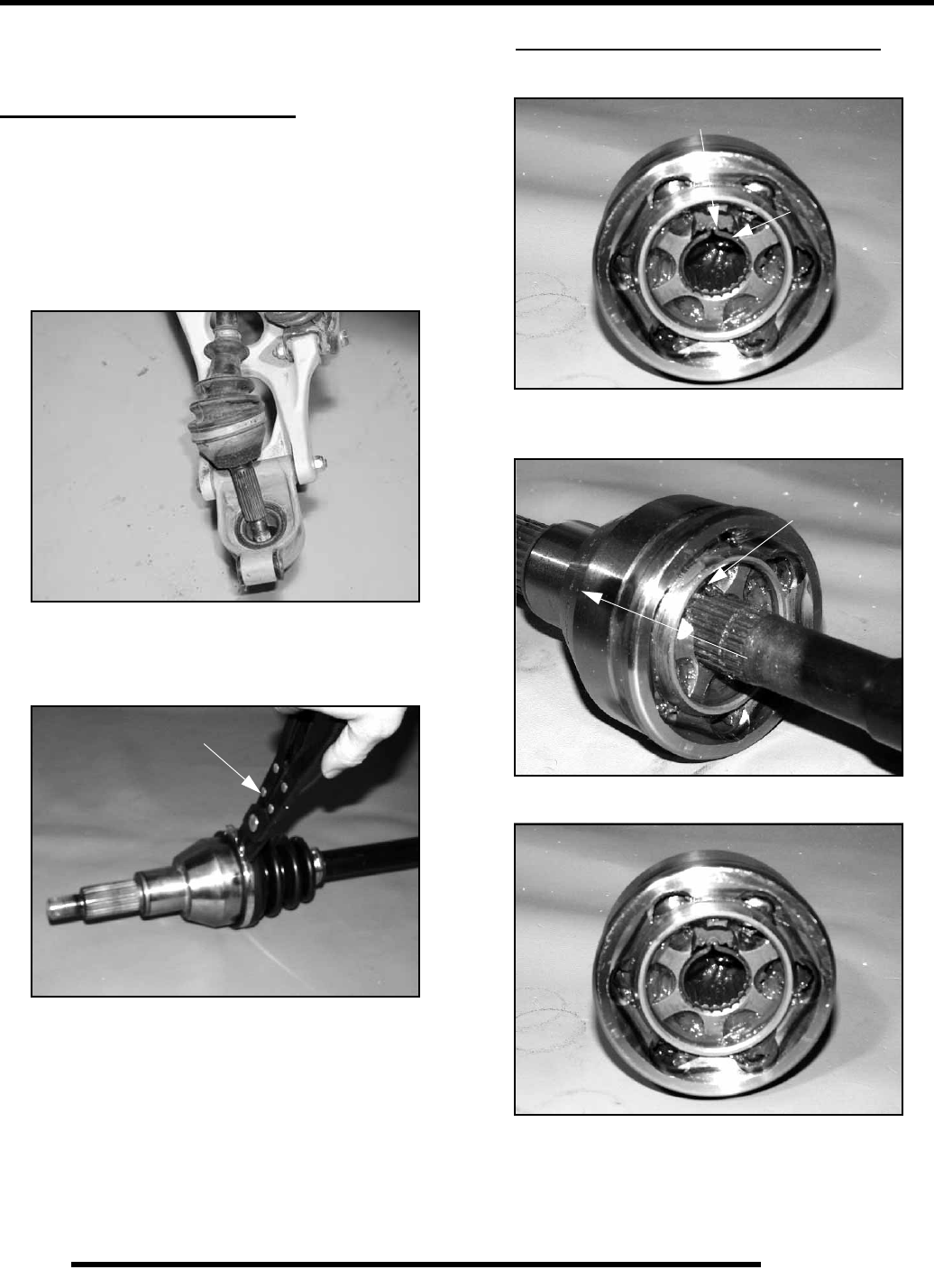
5.28
BODY / STEERING / SUSPENSION
9. Install a new cotter pin. Tighten nut slightly to align holes
if required.
REAR DRIVE (CV) JOINT
CV Joint Removal
1. Remove rear wheel and hub.
2. Remove upper carrier bolt and secure upper A-arm out of
the way. Tip hub carrier outward and remove shaft end from
carrier.
NOTE: CV joint service can be performed with
driveshaft attached to rear carrier housing.
CV Joint Service
1. Remove clamps from rubber boot(s) using the CV Boot
Clamp Pliers (PN 8700226) (A).
2. Photo below is shown without shaft for clarity. Wipe
grease away from recess in CV joint inner hub and locate
snap ring
3. Open the snap ring using a snap ring pliers or small needle
nose pliers. Tap CV housing off shaft with a soft faced
hammer while holding snap ring open.
4. Place a new snap ring in the groove of the CV joint inner
hub, with tabs facing the shaft as shown.
A
Snap Ring
Snap Ring Located in Recessed Area
Spread ends of snap ring
to remove joint from shaft
Tap CV housing
off shaft
RepairPro Service Manual
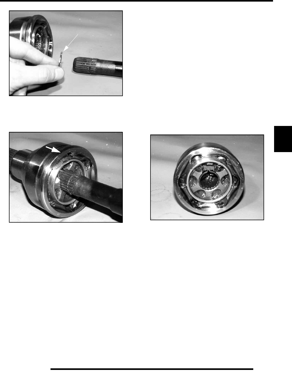
5.29
BODY / STEERING / SUSPENSION
5
5. Refit CV joint on interconnecting shaft by tapping with a
plastic hammer on the joint housing. Take care not to
damage threads on the outboard CV joint. The joint is fully
assembled when the snap ring is located in the groove on
the interconnecting shaft.
6. Install and tighten large boot clamp with boot clamp pliers.
7. Remove excess grease from the CV joint's external surfaces
and position joint boot over housing, making sure boot is
seated in groove. Position clamp over boot end and make
sure clamp tabs are located in slots.
NOTE: NOTE: Before tightening boot clamp on
inboard joint, make sure any air pressure which may
have built up in joint boot has been released. The air
should be released after the plunging joint has been
centered properly. Tighten boot clamp using boot
clamp pliers.
CV Boot Replacement
1. Remove CV joint from end of shaft.
2. Remove boot from shaft.
NOTE: When replacing a damaged boot, check the
grease for contamination by rubbing it between two
fingers. A gritty feel indicates contamination. If the
grease is not contaminated, the boot can be
replaced without cleaning the CV joint. Use the
recommended amount of grease for boot
replacement only (see below). Proceed to Boot
Installation.
3. Thoroughly clean and dry the CV joint and inspect ball
tracks and cages for wear, cracks or other damage.
NOTE: Shiny areas in ball tracks and on the cage
spheres are normal. Do not replace CV joints
because parts have polished surfaces. Replace CV
joint only if components are cracked, broken, worn
or otherwise unserviceable.
4. Add the recommended amount of grease for CV joint
cleaning to the joint as required. Be sure grease penetrates
all parts of the joint.
5. Refit CV joint on interconnecting shaft by tapping with a
plastic hammer on the joint housing. Take care not to
damage threads on the outboard CV joint. The joint is fully
assembled when the snap ring is located in the groove on
the interconnecting shaft.
6. Add grease through large end of boot.
7. Install a new boot onto the axle shaft and fill the CV joint
and boot with the correct type and amount of grease.
Tabs face shaft
Tap joint onto shaft
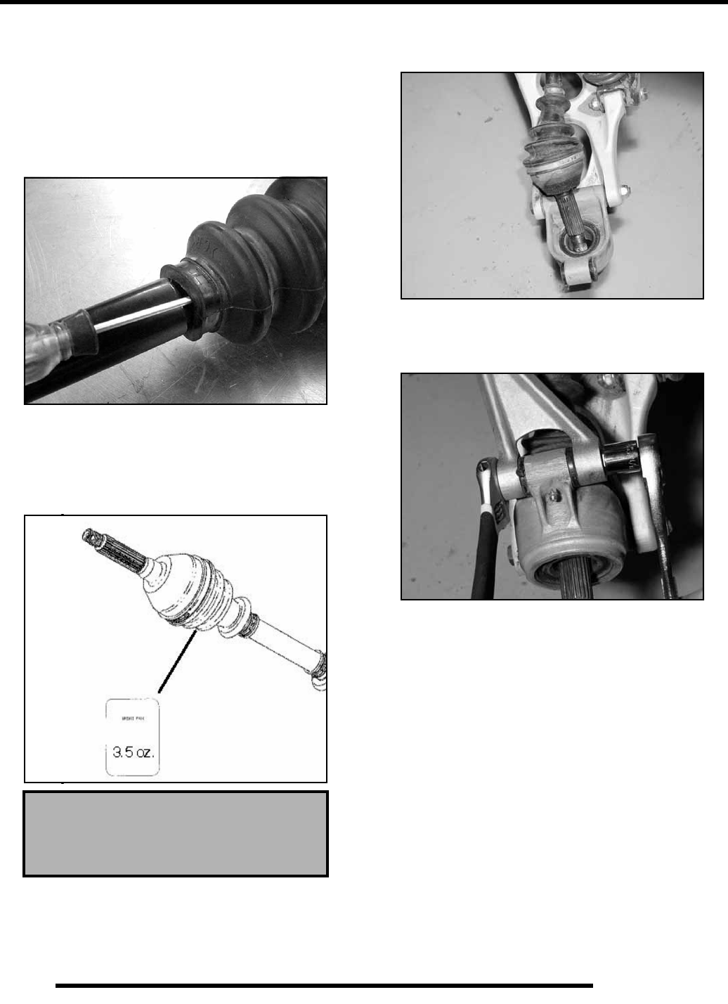
5.30
BODY / STEERING / SUSPENSION
8. While pulling out on the CV shaft, fully extend the CV joint
and slide a straight O-ring pick or a small slotted screw
driver between the small end of the boot and the shaft. This
will allow the air pressure to equalize in the CV boot in the
position that the joint will spend most of its life. Before you
remove your instrument, be sure the small end of the boot
is in its correct location on the axle. CARE MUST BE
TAKEN TO AVOID DAMAGE TO THE NEWLY
INSTALLED BOOT.
9. Install the small clamp on the boot.
10. Be sure to use only the Constant Velocity Joint grease
supplied with boot service kit. IF CV JOINT WAS
CLEANED, add the required amount of grease to the joint
in addition to the grease pack supplied with boot kit.
NOTE: CV Joint Grease Capacity:
CV Joint Installation
1. Slide shaft assembly into bearing carrier hub.
2. Apply anti-seize compound to splines of shaft.
3. Install a new lock ring and install the shaft.
4. Lift bearing carrier into place and install bolt to upper
control arm. Torque bolt to 33 ft. lbs. (45 Nm).
5. Install hub, flat washer, domed washer (domed side out)
and nut. Torque center hub nut to 90 ft. lbs. (122 Nm).
Install new cotter pin and hub cap.
CV Joint Grease
Outboard Joints - 3.5 oz. (99.2 grams)
each
Boot Capacity -
30 Grams
RepairPro Service Manual
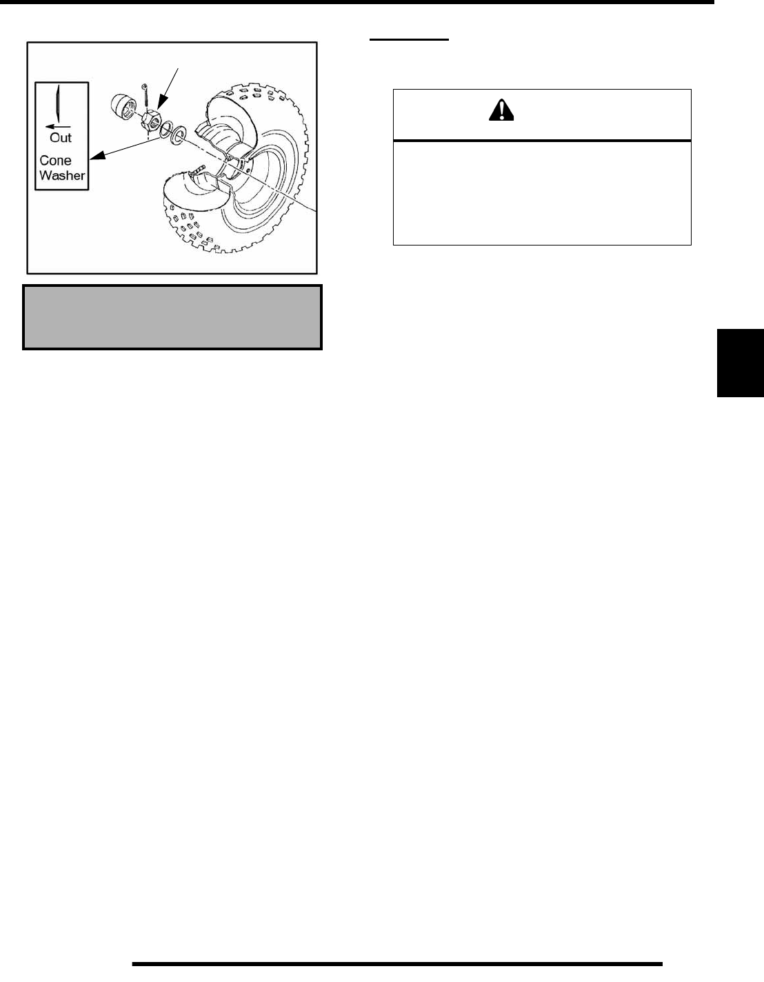
5.31
BODY / STEERING / SUSPENSION
5
6. Install rear wheel and torque wheel nuts to specification. DECALS
Replacement
The side panels, front and rear fender cabs are plastic
polyethylene material. Therefore, they must be “flame treated”
prior to installing a decal to ensure good adhesion. A bonus of
the flame treating procedure is it can be used to reduce or
eliminate the whitish stress marks that are sometimes left after
a fender or cab is bent, flexed, or damaged.
To flame treat the decal area:
1. Pass the flame of a propane torch back and forth quickly
over the area where the decal is to be applied until the
surface appears slightly glossy. This should occur after just
a few seconds of flame treating. Do not hold the torch too
close to the surface (2-3 inches from the flame tip is
recommended). Keep the torch moving to prevent damage.
2. Apply the decal on one edge first. Slowly lay down
remainder of the decal while rubbing lightly over the decal
surface to eliminate any air bubbles during the application.
Refer to Chapter 2 for
Wheel Nut Torque.
90 ft.lbs. (122 Nm)
WARNING
The following procedure involves the use of an
open flame. Perform this procedure in a well
ventilated area, away from gasoline or
other flammable materials.
Be sure the area to be flame treated is clean and
free of gasoline or flammable residue.
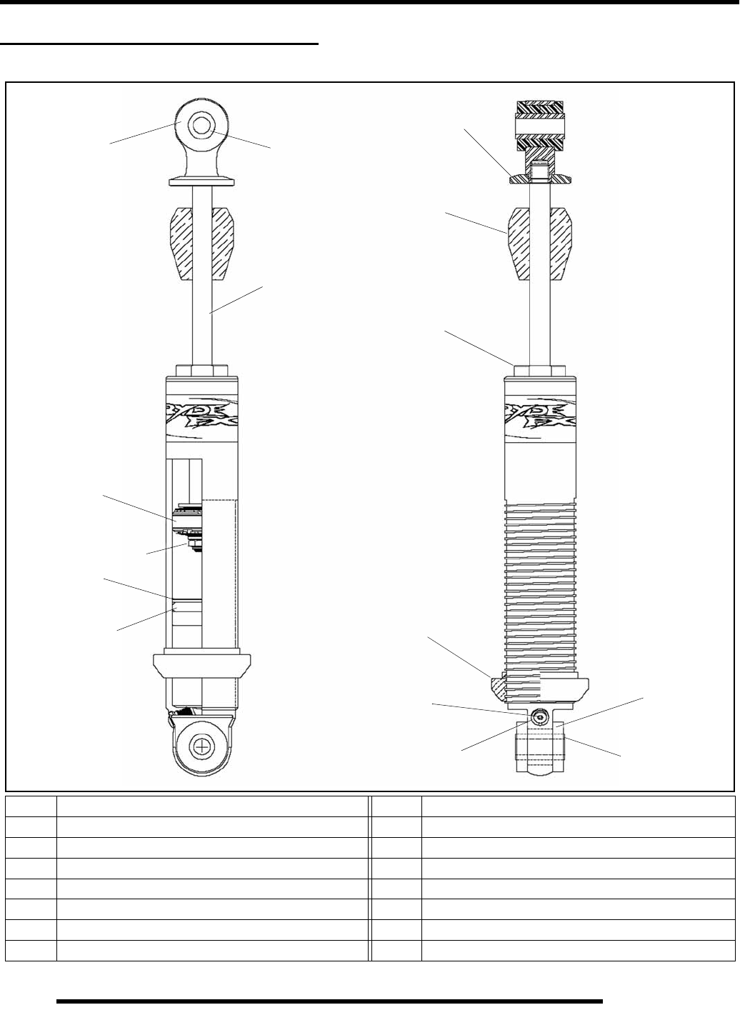
5.32
BODY / STEERING / SUSPENSION
FRONT SHOCK EXPLODED VIEW
RydeFX™ FRONT SHOCK
Ref. Description Ref. Description
1. Bushing 8. Nut
2. Sleeve 9. IFP
3. Spring Retainer Nut 10. IFP O-Ring
4. Compression Bumper 11. Cylinder Head Asm
5. Upper Mount 12. Pressure Valve
6. Shaft 13. Valve Screw
7. Piston / Wear Band / Top-Out & Bottom-Out Washers
12
3
4
5
6
7
8
10
11
12
13
9
1
2
RepairPro Service Manual
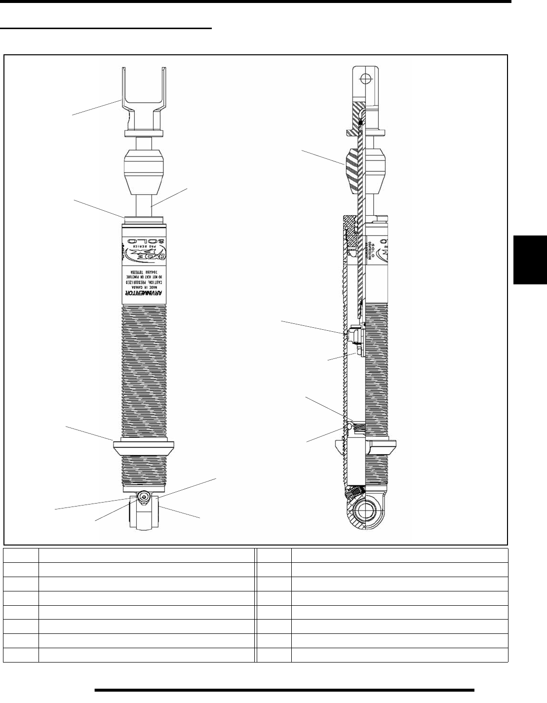
5.33
BODY / STEERING / SUSPENSION
5
REAR SHOCK EXPLODED VIEW
RydeFX™ REAR SHOCK (Compression Adjustable)
Ref. Description Ref. Description
1. Bushing 8. Nut
2. Sleeve 9. IFP
3. Spring Retainer Nut 10. IFP O-Ring
4. Compression Bumper 11. Cylinder Head Asm
5. Upper Mount 12. Pressure Valve
6. Shaft 13. Valve Screw
7. Piston / Wear Band / Top-Out & Bottom-Out Washers
5
2
4
6
11
8
10
9
12 13
3
1
7
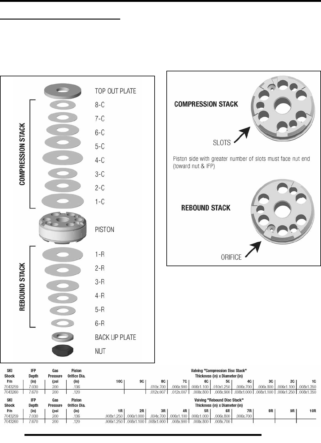
5.34
BODY / STEERING / SUSPENSION
RYDE FX™ SHOCK SERVICE
Shock Specification Chart
Shown below is an example of how valving stacks are arranged.
NOTE: Direction of the valve piston before
disassembly. The side with the greater number of
slots should face the IFP (nut end of the shaft).
Changing oil on RydeFX™ Shocks is recommended annually
and should NOT be performed during end of season storage
preparation.
For competition use, shocks should be disassembled and
serviced more frequently.
Piston Orientation
NOTE: Orifice must be drilled to required size on
replacement valve pistons.
RepairPro Service Manual
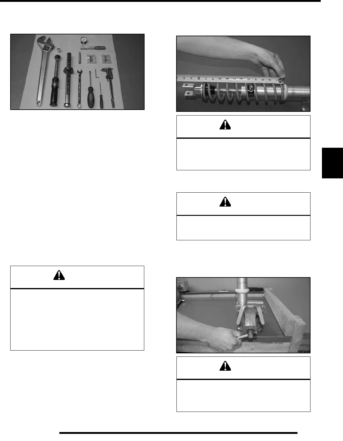
5.35
BODY / STEERING / SUSPENSION
5
RydeFX™ Shock Rebuild Procedure
Required Tools
• RydeFX Gas Charge Tool (Inflation Needle)
• RydeFX I.F.P Extraction / Locator Tool
• Adjustable Wrench
• 5/64” Hex Key
• Slotted Head Screwdriver
• Torque Wrench
• Vernier Caliper or Micrometer
• Rod Thimble
• Rod Blocks
• Pic Tool
• Shock Spring Compressor
• Nitrogen Regulator
DISASSEMBLY
1. Remove the shock from the vehicle.
2. If shock incorporates a spring; remove spring and collateral
retainers.
NOTE: Before unscrewing pre-load springs,
measure the compressed length of the installed
spring and mark position for reinstallation.
3. Wash the shock body in parts cleaner; then dry with
compressed air to remove sand and dirt.
4. Remove bearing, sleeve and/or bushings from lower shock
mount eyelet. Secure the lower mount of the shock in a
vise. The use of soft jaws is recommend to prevent damage
or marks to the shock.
WARNING
Before servicing a gas shock it is important that
all the gas pressure be discharged from the unit.
Refer to the instructions listed below for the
proper procedure of discharging the gas
pressure from a shock. Protective eye wear
should be worn to avoid risk of injury while
servicing RydeFX™ gas charged
mono-tube shocks.
CAUTION
When removing the spring from a shock that
utilizes a fixed lower retainer; the use of a proper
spring compressor should be used to avoid
risk of bodily injury.
WARNING
When using compressed air to dry components,
protective eye wear should be worn to
avoid risk of injury.
CAUTION
It is important that the gas shock be retained in
the vise by the lower mount. Any other method
of securing the shock body during these
procedures may deform the shock body cylinder.
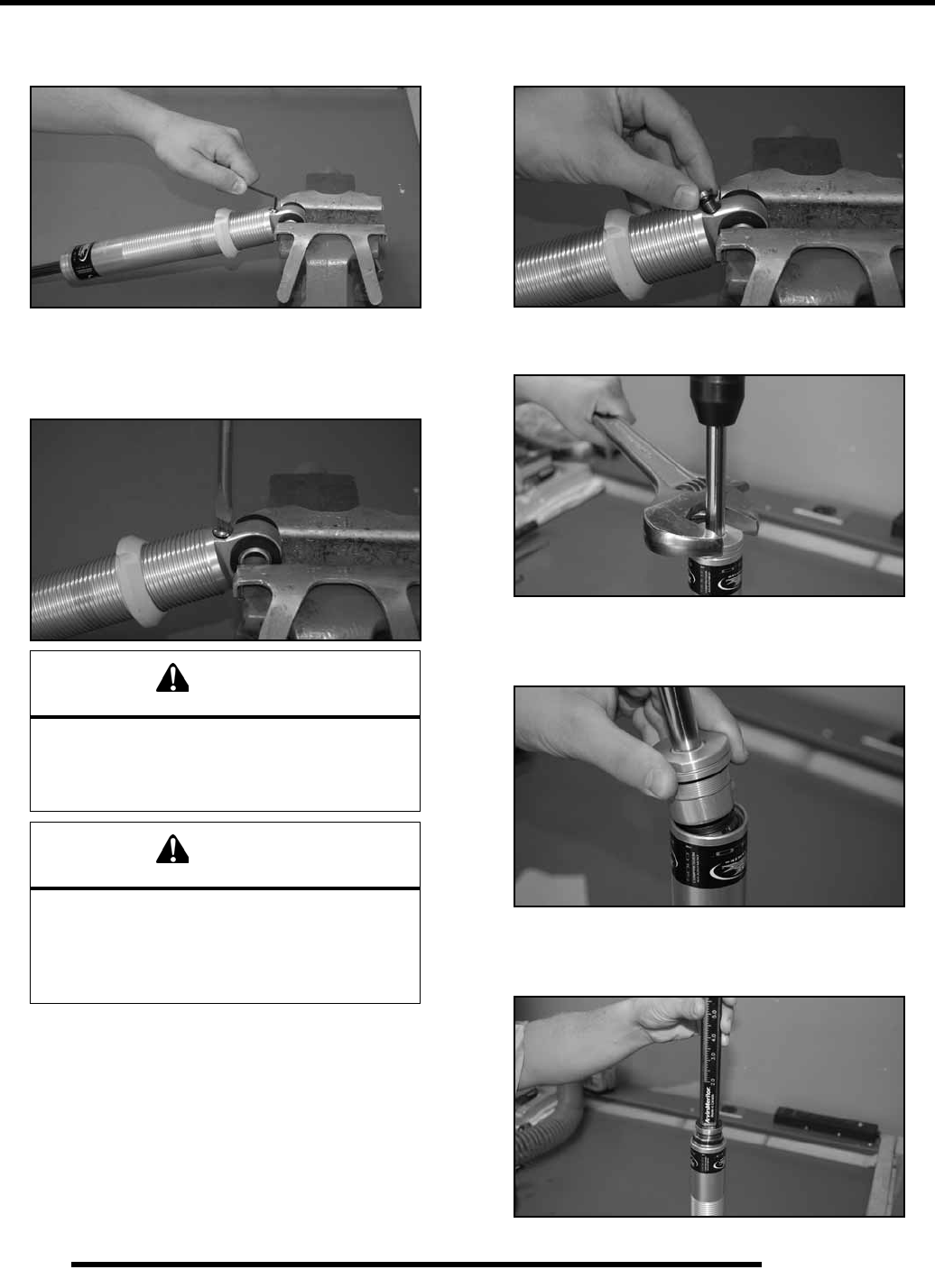
5.36
BODY / STEERING / SUSPENSION
5. Remove the small button head screw from the pressure
valve assembly.
6. Using a slotted screwdriver, loosen the pressure valve
assembly counter-clockwise two full revolutions allowing
the gas pressure to fully escape past the pressure valve
assembly O-ring.
7. Remove the pressure valve assembly from the lower end
mount. Account for an O-ring.
8. With an adjustable wrench, loosen and remove cylinder
head assembly.
9. Pour the oil out of the shock body. Discard old oil into an
approved storage container and dispose appropriately.
Never reuse damper oil during shock rebuild.
10. Using the I.F.P extraction tool, thread the tool into the I.F.P
and pull upwards, removing the I.F.P from the shock body.
Account for wear band and an O-ring.
WARNING
Nitrogen gas is under extreme pressure. Use
caution when releasing nitrogen gas from
shock. Protective eye wear should be worn to
avoid risk of injury.
CAUTION
Allow all the gas pressure to escape before
proceeding with the removal of the pressure
valve assembly. Pressurized gas and shock oil
could eject the valve assembly from the cylinder
resulting in bodily injury.
RepairPro Service Manual
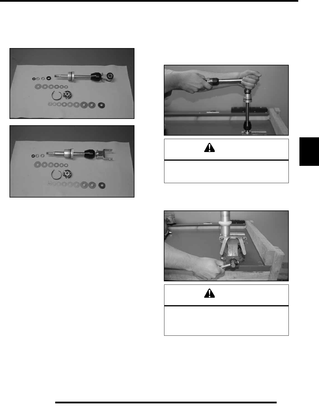
5.37
BODY / STEERING / SUSPENSION
5
11. Clean the inside of the shock body using clean parts-
cleaning solvent and blow dry using compressed air.
12. Place the shock piston rod upper mount in bench vise, begin
piston and valve removal. Arrange parts removed in the
sequence of disassembly.
Items to inspect:
• Piston rod for straightness, nicks or burrs.
• Cylinder Head Assembly / DU Bearing - clean, inspect,
or replace.
• Inside of shock body for scratches, burrs or excessive
wear.
• Teflon piston and I.F.P wear band for cuts, chipped or
nicked edges, or excessive wear.
• O-rings for nicks, cuts, or cracks.
• Cap and rod seals for nicks, cuts or cracks.
• Valve discs for kinks or waves.
• Compression bumpers for chipping, cracking or being
missing.
Should any of these items be in question replacement is
recommended.
ASSEMBLY
1. Place the piston rod upper mount into the vise.
Reassemble damper rod assembly in the reverse order of
disassembly. Pay special attention to the order of the
Rebound and Compression disc (shim) stacks, ensuring
that they are in the same order prior to disassembly.
Tighten the lock nut to15-20 ft. lbs. (20-27 Nm) of torque.
2. Secure the shock body by its lower mount in vise. The use
of soft jaws is recommended to prevent damage or marks
to the shock.
Front Shock Part# 7043259
Rear Shock Part# 7043260
CAUTION
DO NOT OVER-TORQUE.
If excessive torque is applied, damage to the
piston and valves will occur.
CAUTION
It is important that the gas shock be retained in
the vice by the lower mount. Any other method
of securing the shock body during these
procedures may deform the shock body cylinder.
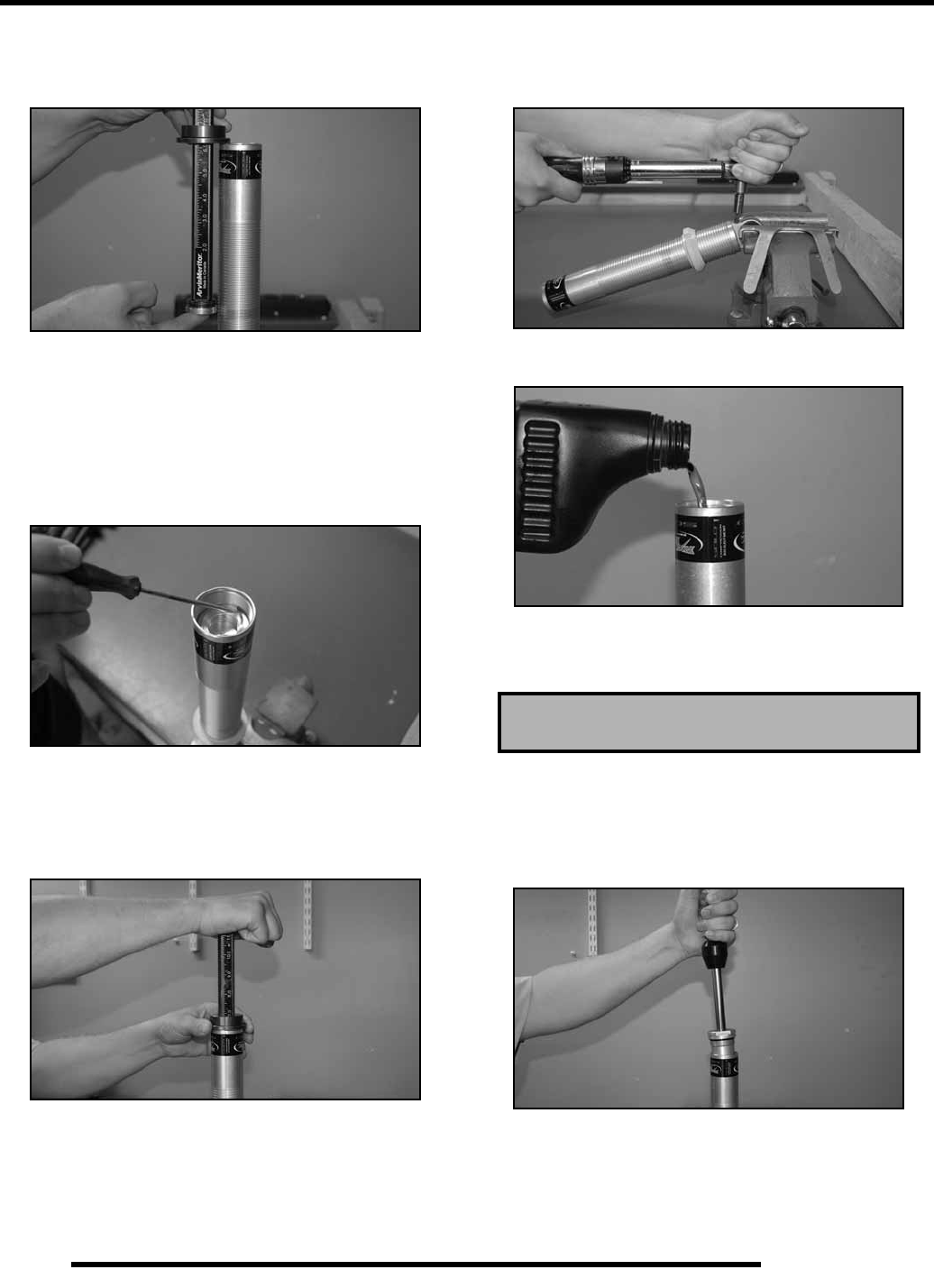
5.38
BODY / STEERING / SUSPENSION
3. Thread the positioning head onto the I.F.P locator tool and
adjust the top of the value indicator to the appropriate
measurement.
NOTE: Depending on which shock absorber is being
worked on, adjust the piston location tool to the
specified depth indicated in the shock specification
chart, located on the bottom of Page 5.34.
4. Apply a thin film of oil onto the floating wear band and O-
ring and install the floating piston into the top of the shock
body, positioning it below the counterbore.
5. Using the tool as a handle, push the floating piston down
into the shock body, being careful not to damage I.F.P wear
band and O-ring, until the value indicator knob comes in
contact with the shock body. The piston should now be
located correctly.
6. Apply a light film of grease to the pressure valve port
counterbore through 360º, where the pressure valve
assembly O-ring meets.
7. Screw the pressure valve assembly into the valve port by
hand with a slotted head screwdriver. Tighten to 100-110
in. lbs. (11-12 Nm) of torque.
8. Fill the shock body with shock oil to the bottom of the
threads within the cylinder.
NOTE: After filling the shock body with oil, allow a
couple of minutes for all air bubbles to rise to the
top.
9. With the cylinder head assembly pushed down against the
piston, carefully, insert the piston rod and assembly into the
cylinder; Slightly oscillating the piston rod to allow piston
to enter shock body bore. A light coating of oil on the piston
wear band will ease installation.
10. Slowly push the piston rod and assembly into shock body
until the cylinder head assembly bottoms on the cylinder
counterbore. Slight up and down movement may be
required to allow all air to pass through piston assembly.
Polaris Gas Shock Oil - P/N 2870995
RepairPro Service Manual
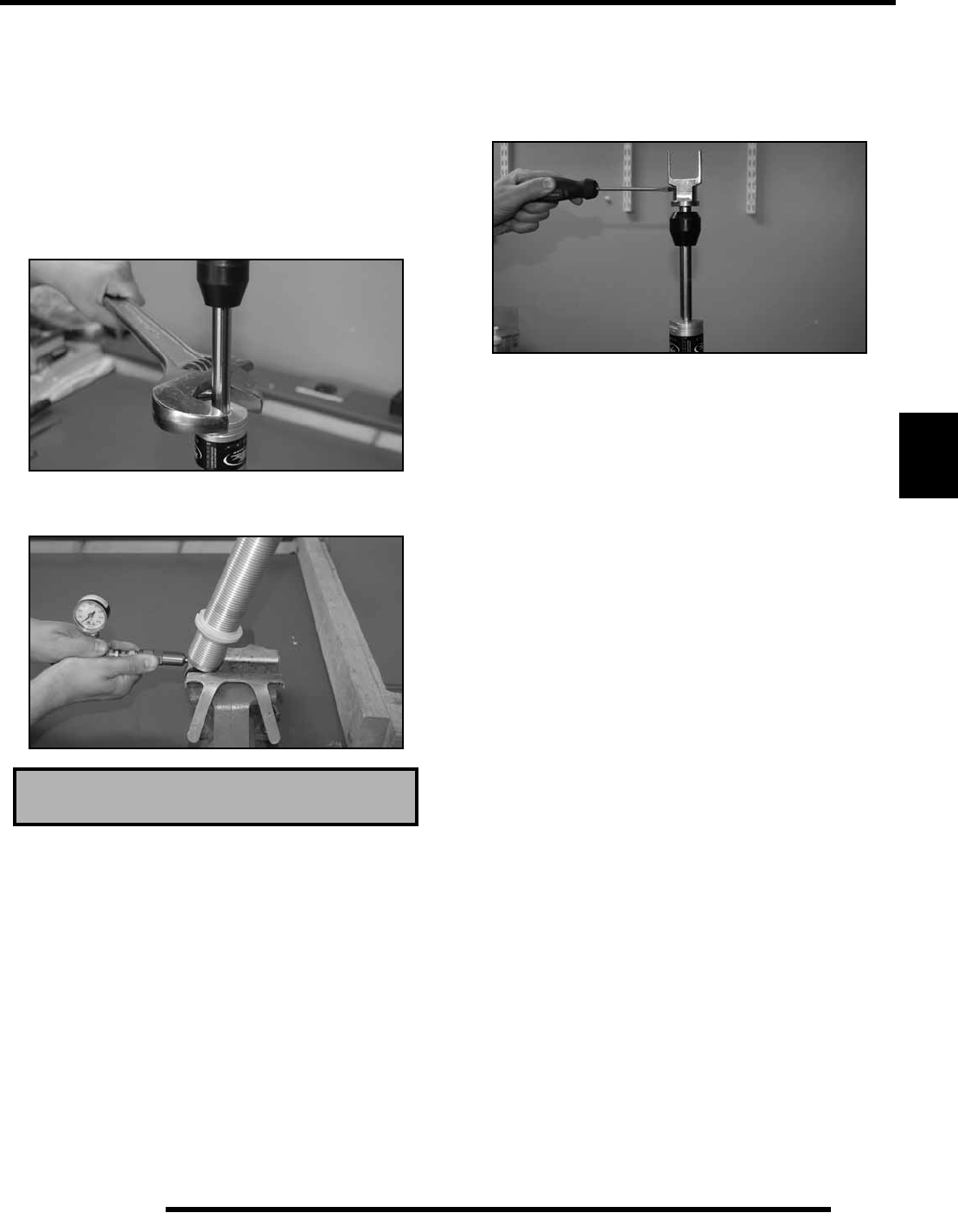
5.39
BODY / STEERING / SUSPENSION
5
NOTE: During installation, some shock oil will
overflow. Wrap a shop cloth around shock body to
catch possible oil overflow.
NOTE: Fast installation of the piston rod and
assembly may displace the floating piston from its
original position. This must not occur if the damper
is expected to perform as designed
11. Using an adjustable wrench tighten cylinder head securely
into the shock cylinder.
12. Pressurize the shock through the pressure valve with
nitrogen gas to the specified pressure.
NOTE: After being compressed, the piston rod
should fully extend from the shock body once the
shock has been pressurized.
13. Using a flat head screw driver, turn the compression
adjusting cam clockwise to ensure there is positive
engagement of the internal adjusting rod with the surface
of the adjusting cam. Only applicable for the rear shock
absorber P/N: 7043260.
14. Install the small button head screw in the pressure valve
assembly and tighten securely.
15. Reinstall sleeve and bushings in lower shock mount.
Nitrogen Gas Pressure - 200 psi

NOTES
BODY / STEERING / SUSPENSION
5.40
RepairPro Service Manual

BRAKES
6.1
CHAPTER 6
BRAKES
6
BRAKE SPECIFICATIONS . . . . . . . . . . . . . . . . . . . . . . . . . . . . . . . . . . . . . . . . . . . . . . . . 6.2
GENERAL SPECIFICATIONS . . . . . . . . . . . . . . . . . . . . . . . . . . . . . . . . . . . . . . . . . . . . . 6.2
TORQUE SPECIFICATIONS . . . . . . . . . . . . . . . . . . . . . . . . . . . . . . . . . . . . . . . . . . . . . . 6.2
SPECIAL TOOLS . . . . . . . . . . . . . . . . . . . . . . . . . . . . . . . . . . . . . . . . . . . . . . . . . . . . . . . 6.2
BRAKE CALIPER EXPLODED VIEWS . . . . . . . . . . . . . . . . . . . . . . . . . . . . . . . . . . . . . . . 6.3
REAR BRAKE CALIPER ASSEMBLY . . . . . . . . . . . . . . . . . . . . . . . . . . . . . . . . . . . . . . . 6.3
FRONT BRAKE CALIPER ASSEMBLY . . . . . . . . . . . . . . . . . . . . . . . . . . . . . . . . . . . . . . 6.3
BRAKE SYSTEM OVERVIEW. . . . . . . . . . . . . . . . . . . . . . . . . . . . . . . . . . . . . . . . . . . . . . 6.4
FRONT BRAKE SYSTEM - EXPLODED VIEW . . . . . . . . . . . . . . . . . . . . . . . . . . . . . . . . 6.4
REAR BRAKE SYSTEM - EXPLODED VIEW . . . . . . . . . . . . . . . . . . . . . . . . . . . . . . . . . 6.5
SERVICE NOTES. . . . . . . . . . . . . . . . . . . . . . . . . . . . . . . . . . . . . . . . . . . . . . . . . . . . . . . 6.6
BRAKE NOISE TROUBLESHOOTING . . . . . . . . . . . . . . . . . . . . . . . . . . . . . . . . . . . . . . 6.6
HYDRAULIC SYSTEM OPERATION . . . . . . . . . . . . . . . . . . . . . . . . . . . . . . . . . . . . . . . . 6.7
BRAKE FLUID REPLACEMENT AND BLEEDING PROCEDURE. . . . . . . . . . . . . . . . . . 6.8
MASTER CYLINDER. . . . . . . . . . . . . . . . . . . . . . . . . . . . . . . . . . . . . . . . . . . . . . . . . . . . 6.10
REMOVAL . . . . . . . . . . . . . . . . . . . . . . . . . . . . . . . . . . . . . . . . . . . . . . . . . . . . . . . . . . . 6.10
INSTALLATION . . . . . . . . . . . . . . . . . . . . . . . . . . . . . . . . . . . . . . . . . . . . . . . . . . . . . . . 6.11
FRONT CALIPER SERVICE . . . . . . . . . . . . . . . . . . . . . . . . . . . . . . . . . . . . . . . . . . . . . . 6.12
CALIPER REMOVAL AND DISASSEMBLY. . . . . . . . . . . . . . . . . . . . . . . . . . . . . . . . . . 6.12
CALIPER INSPECTION . . . . . . . . . . . . . . . . . . . . . . . . . . . . . . . . . . . . . . . . . . . . . . . . . 6.13
CALIPER REASSEMBLY . . . . . . . . . . . . . . . . . . . . . . . . . . . . . . . . . . . . . . . . . . . . . . . . 6.14
CALIPER INSTALLATION . . . . . . . . . . . . . . . . . . . . . . . . . . . . . . . . . . . . . . . . . . . . . . . 6.14
FRONT BRAKE PADS. . . . . . . . . . . . . . . . . . . . . . . . . . . . . . . . . . . . . . . . . . . . . . . . . . . 6.15
PAD REMOVAL . . . . . . . . . . . . . . . . . . . . . . . . . . . . . . . . . . . . . . . . . . . . . . . . . . . . . . . 6.15
PAD ASSEMBLY . . . . . . . . . . . . . . . . . . . . . . . . . . . . . . . . . . . . . . . . . . . . . . . . . . . . . . 6.16
BRAKE BURNISHING PROCEDURE . . . . . . . . . . . . . . . . . . . . . . . . . . . . . . . . . . . . . . 6.16
FRONT BRAKE DISC . . . . . . . . . . . . . . . . . . . . . . . . . . . . . . . . . . . . . . . . . . . . . . . . . . . 6.17
DISC INSPECTION . . . . . . . . . . . . . . . . . . . . . . . . . . . . . . . . . . . . . . . . . . . . . . . . . . . . 6.17
DISC REMOVAL / REPLACEMENT. . . . . . . . . . . . . . . . . . . . . . . . . . . . . . . . . . . . . . . . 6.17
REAR CALIPER SERVICE . . . . . . . . . . . . . . . . . . . . . . . . . . . . . . . . . . . . . . . . . . . . . . . 6.18
CALIPER REMOVAL . . . . . . . . . . . . . . . . . . . . . . . . . . . . . . . . . . . . . . . . . . . . . . . . . . . 6.18
CALIPER DISASSEMBLY . . . . . . . . . . . . . . . . . . . . . . . . . . . . . . . . . . . . . . . . . . . . . . . 6.18
CALIPER INSPECTION . . . . . . . . . . . . . . . . . . . . . . . . . . . . . . . . . . . . . . . . . . . . . . . . . 6.19
CALIPER ASSEMBLY . . . . . . . . . . . . . . . . . . . . . . . . . . . . . . . . . . . . . . . . . . . . . . . . . . 6.19
REAR BRAKE PAD . . . . . . . . . . . . . . . . . . . . . . . . . . . . . . . . . . . . . . . . . . . . . . . . . . . . . 6.20
PAD REMOVAL . . . . . . . . . . . . . . . . . . . . . . . . . . . . . . . . . . . . . . . . . . . . . . . . . . . . . . . 6.20
PAD INSTALLATION . . . . . . . . . . . . . . . . . . . . . . . . . . . . . . . . . . . . . . . . . . . . . . . . . . . 6.21
REAR BRAKE DISC . . . . . . . . . . . . . . . . . . . . . . . . . . . . . . . . . . . . . . . . . . . . . . . . . . . . 6.22
DISC INSPECTION . . . . . . . . . . . . . . . . . . . . . . . . . . . . . . . . . . . . . . . . . . . . . . . . . . . . 6.22
DISC REMOVAL. . . . . . . . . . . . . . . . . . . . . . . . . . . . . . . . . . . . . . . . . . . . . . . . . . . . . . . 6.23
DISC REPLACEMENT . . . . . . . . . . . . . . . . . . . . . . . . . . . . . . . . . . . . . . . . . . . . . . . . . . 6.23
TROUBLESHOOTING. . . . . . . . . . . . . . . . . . . . . . . . . . . . . . . . . . . . . . . . . . . . . . . . . . . 6.24
BRAKES SQUEAL . . . . . . . . . . . . . . . . . . . . . . . . . . . . . . . . . . . . . . . . . . . . . . . . . . . . . 6.24
POOR BRAKE PERFORMANCE . . . . . . . . . . . . . . . . . . . . . . . . . . . . . . . . . . . . . . . . . . 6.24
LEVER VIBRATION . . . . . . . . . . . . . . . . . . . . . . . . . . . . . . . . . . . . . . . . . . . . . . . . . . . . 6.24
BRAKES LOCK. . . . . . . . . . . . . . . . . . . . . . . . . . . . . . . . . . . . . . . . . . . . . . . . . . . . . . . . 6.24

6.2
BRAKES
BRAKE SPECIFICATIONS
General Specifications
Torque Specifications
NOTE: Refer to the tightening procedures in this chapter when torquing the bolts. Some special procedures
are used when torquing certain bolts and fasteners.
Special Tools
FRONT BRAKE CALIPER
Item Standard Service Limit
Brake Pad Thickness .298″ / 7.6 mm .180″ / 4.6 mm
Brake Disc Thickness .158” / 4.013 mm .140″ / 3.556 mm
Brake Disc Thickness Variance
Between Measurements – .002″ / .051 mm
Brake Disc Runout – .010″ / .254 mm
RH Handle Bar Master Cylinder I.D. – .551” / 14 mm
REAR BRAKE CALIPER
Item Standard Service Limit
Brake Pad Thickness .298″ / 7.6 mm .180″ / 4.6 mm
Brake Disc Thickness .158” / 4.013 mm .140″ / 3.556 mm
Brake Disc Thickness Variance
Between Measurements – .002″ / .051 mm
Brake Disc Runout – .010″ / .254 mm
Master Cylinder I.D. – Aux. Rear .500” / 12.7 mm
ITEM TORQUE
(ft. lbs. except where noted) TORQUE
(Nm)
Front Caliper Mounting Bolts 18 24
Rear Caliper Mounting Bolts 18 24
Rear Master Cylinder Mounting Bolts 8 11
Front Master Cylinder Reservoir Cover Bolts 11 (in. lbs.) 1.24
Brake Line Banjo Bolts 15 20
Brake Disc Mounting Bolts 18 24
Wheel Mounting Nuts 25 34
Front Master Cylinder Clamp Bolts 85 (in. lbs.) 9.6
Rear Caliper Bleed Screws 27 (in. lbs.) 3.1
Front Caliper Bleed Screws 47 (in. lbs.) 5.3
Rear Caliper Slide Bolts 33 45
Rear Caliper Anvil Bolts 16-18 22-24
Rear Hub Nut 90 122
Upper A-arm Bolt 30 41
Part Number Tool Description
2870975 Mity Vac™
RepairPro Service Manual
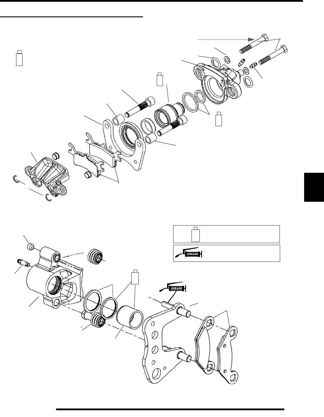
6.3
BRAKES
6
BRAKE CALIPER EXPLODED VIEWS
Rear Brake Caliper Assembly
Front Brake Caliper Assembly
A. Anvil Bolts
B. Bleed Screws
C. Washers
D. O-rings
E. Rear Housing
F. Seals
G. Piston
H. Slide Pins
I. Bushings
J. Seal
K. Bracket
L. Pad
M. Front Housing
N. Retaining Clips
Apply Polaris DOT 3 or DOT 4 brake fluid
to component.
A
B
C
D
E
F
G
H
I
J
K
L
M
N
33 ft.lbs.
(45 Nm) 27 in lbs.
(3.1 Nm)
16-18 ft.lbs.
(22-24 Nm)
A. Socket Set Screw
B. Bleeder Screw
C. Caliper Assy.
D. Boot
E. Square O-ring
F. Piston
G. Caliper Mount
H. Brake Pads
A
B
C
D
E
F
GH
Apply Polaris All Purpose
Grease
Apply Polaris DOT 3 or DOT 4
Brake Fluid to Component
47 in lbs.
(5.3 Nm)
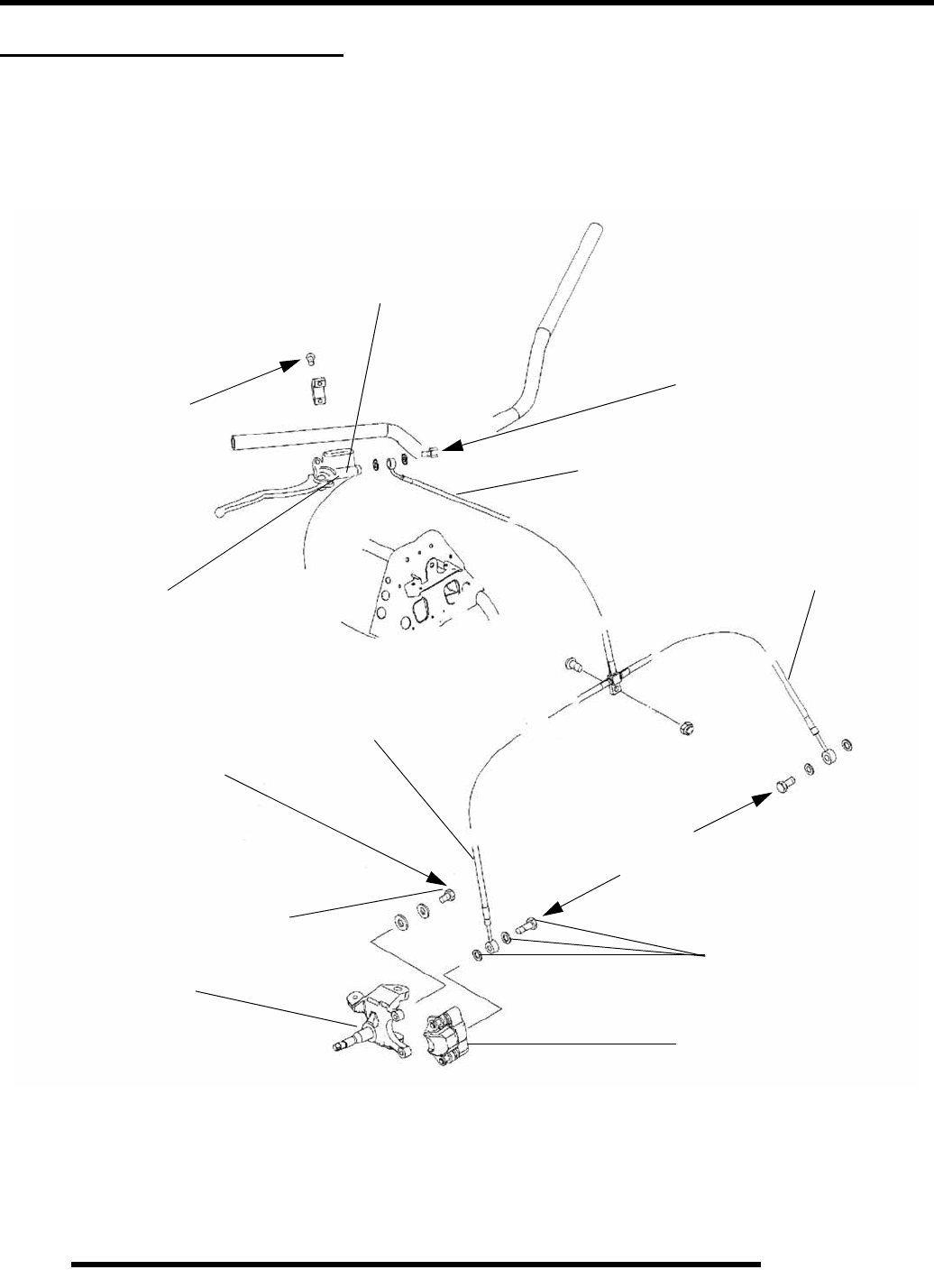
6.4
BRAKES
BRAKE SYSTEM OVERVIEW
Front Brake System - Exploded View
A. Master Cylinder
B. Brake Line
C. Mechanical Brake Switch
D. Wheel Hub
E. Banjo Bolt & Washers
F. Caliper
G. Caliper Mount Bolt
A
B
B
B
C
D
E
F
G
15 ft. lbs.
18 ft. lbs.
85 in. lbs.
(9.6 Nm)
(24 Nm)
(20 Nm)
15 ft. lbs.
(20 Nm)
RepairPro Service Manual
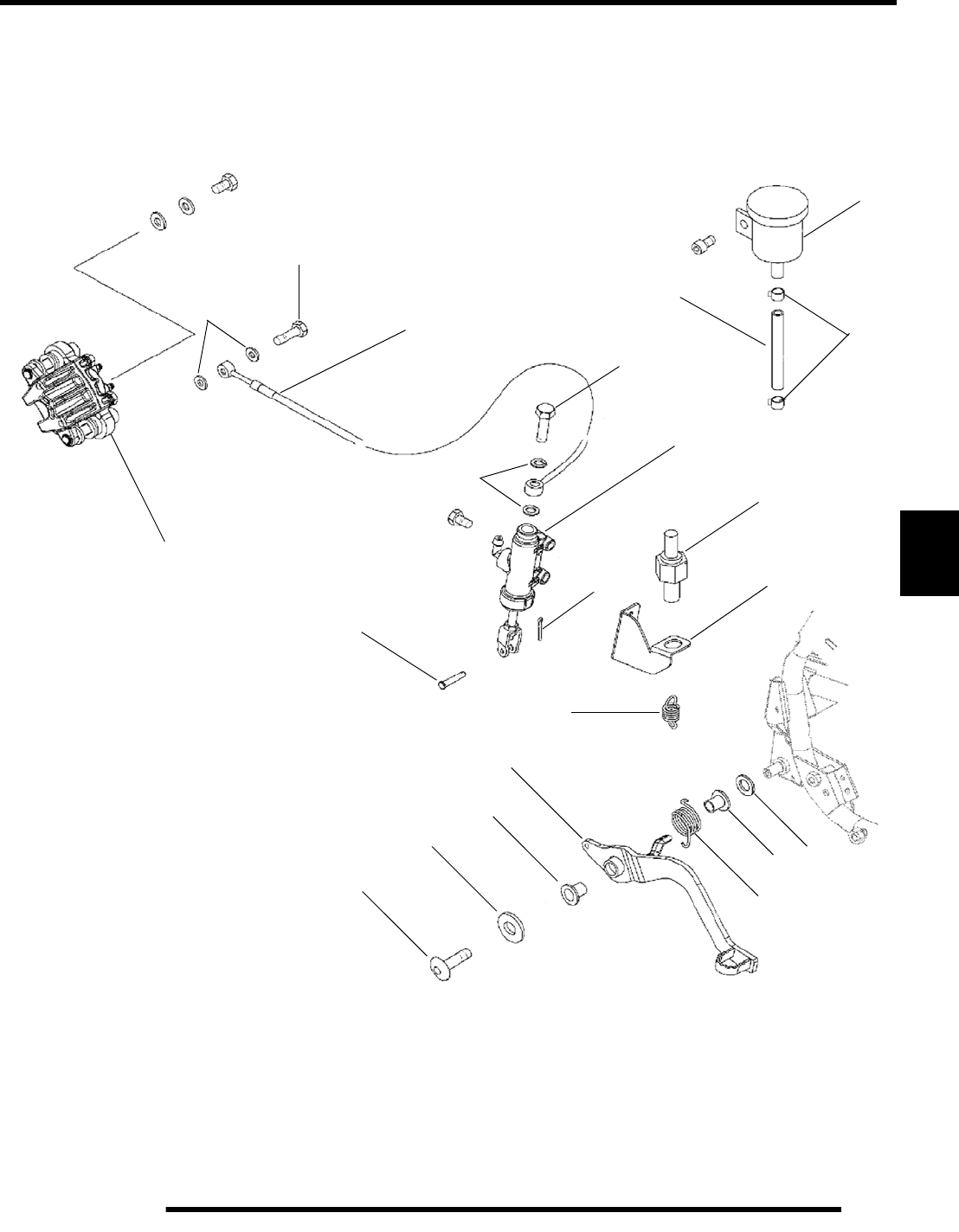
6.5
BRAKES
6
Rear Brake System - Exploded View
A. Caliper
B. Sealing Washer
C. Banjo Bolt
D. Brake Line
E. Clevis Pin
F. Master Cylinder Asm.
G. Cotter Pin
H. Rear Brake Reservoir
I. Hose Clamp
J. Reservoir Hose
K. Brake Switch
L. Brake Switch Bracket
M. Switch Spring
N. Washer
O. Bushing
A
B
C
B
C
D
E
F
G
H
I
J
K
L
M
N
O
P
Q
P. Torsion Spring
Q. Foot Brake
O
R
R. Large Washer
S. Screw
S
15 ft. lbs.
(20 Nm)
15 ft. lbs.
(20 Nm)
18 ft. lbs.
(24 Nm)
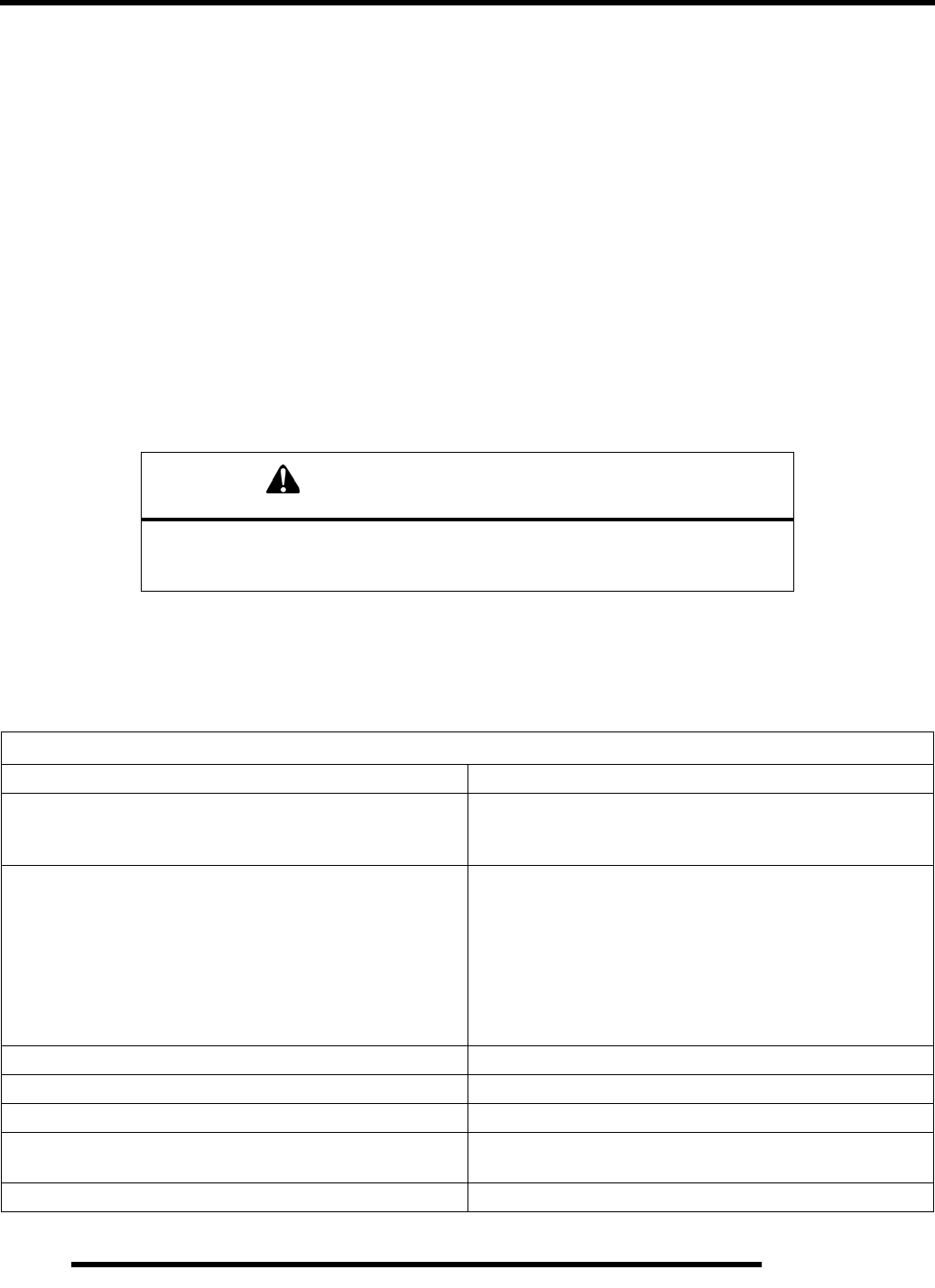
6.6
BRAKES
Service Notes
Disc brake systems are light weight, low maintenance, and perform well in the conditions ATVs routinely encounter. There are a
few things to remember when replacing disc brake pads or performing brake system service to ensure proper system function and
maximum pad service life.
• Optional pads are available to suit conditions in your area. Select a pad to fit riding style and environment
• Do not over-fill the master cylinder fluid reservoirs.
• Make sure the brake levers return freely and completely.
• Check and adjust master cylinder reservoir fluid levels after pad service.
• Make sure atmospheric vent on reservoirs are unobstructed.
• Test for brake drag after any brake system service and investigate cause if brake drag is evident.
• Make sure caliper moves freely on guide pins.
• Inspect caliper piston seals for foreign material that could prevent caliper pistons from returning freely.
• Perform a brake burnishing procedure after installing new pads to maximize service life.
Brake Noise Troubleshooting
Dirt or dust buildup on the brake pads and disc is the most common cause of brake noise (squeal caused by vibration). If cleaning
does not reduce the occurrence of brake noise, check the backing of each pad for worn spots allowing metal to metal contact. See
table below:
CAUTION
Use only DOT 3 or DOT 4 brake fluid as an assembly aid for all procedures
described in this chapter to prevent brake system contamination.
DO NOT USE LUBRICANTS OF ANY KIND FOR ASSEMBLY.
Brake Noise Troubleshooting
Possible Cause Remedy
Dirt, dust, or imbedded material on pads or disc Spray disc and pads with a non–flammable aerosol brake
cleaner only! Remove pads and/or disc hub to clean imbedded
material from disc or pads.
Pad(s) dragging on disc (noise or premature pad wear)
Improper adjustment
Insufficient lever or pedal clearance
Master cylinder reservoir overfilled
Master cylinder compensating port restricted
Master cylinder piston not returning completely
Caliper piston(s) not returning
Operator error (riding the brake / park brake applied)
Adjust pad stop (front calipers)
Check position of controls & switches
Set to proper level
Clean compensating port
Inspect. Repair as necessary
Clean piston(s) seal
Educate operator
Loose wheel hub or bearings Check wheel and hub for abnormal movement
Brake disc warped or excessively worn Replace disc
Brake disc misaligned or loose Inspect and repair as necessary
Noise is from other source (chain, axle, hub, disc or wheel) If noise does not change when brake is applied check other
sources. Inspect and repair as necessary
Wrong pad for conditions Change to a softer or harder pad
RepairPro Service Manual
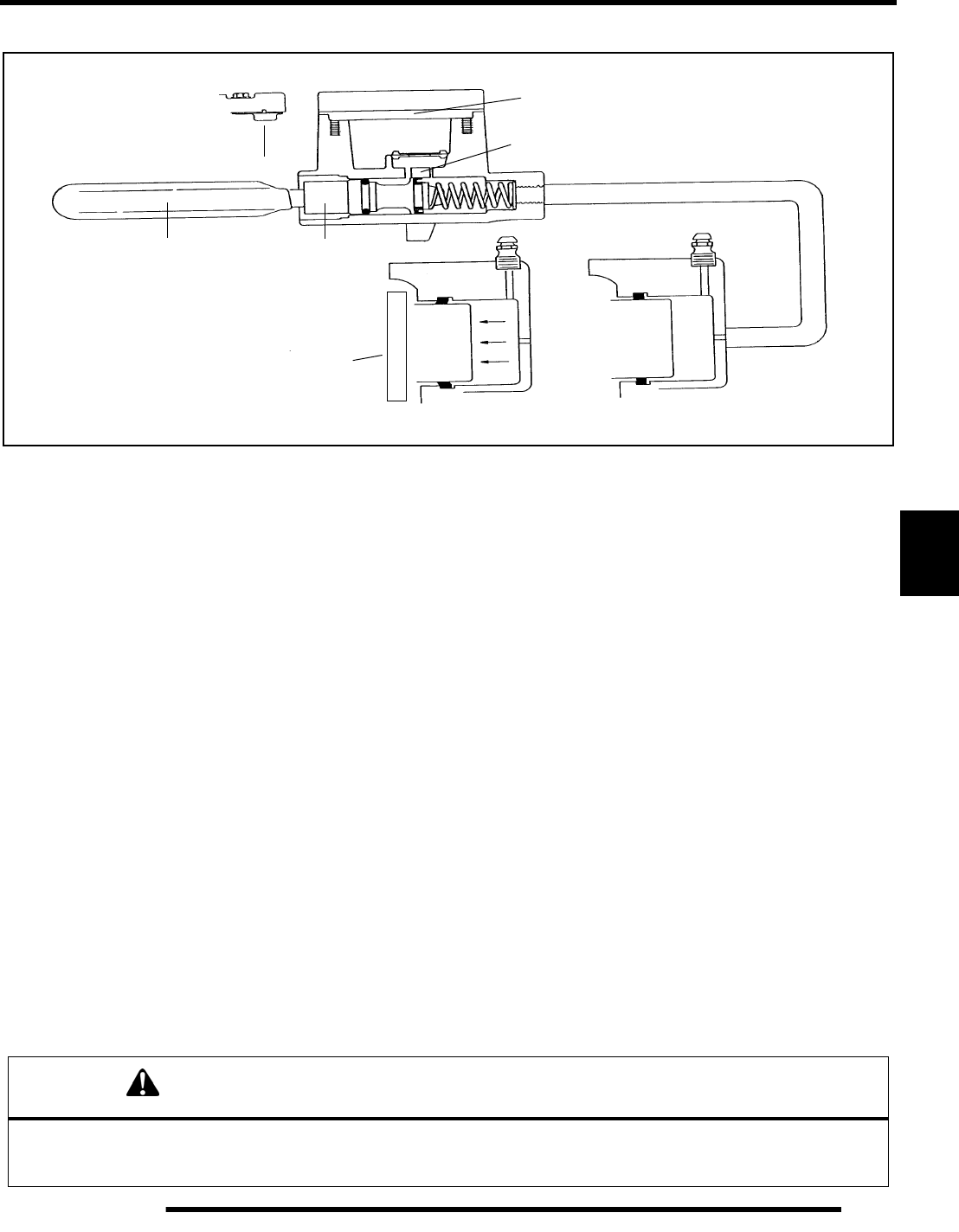
6.7
BRAKES
6
Hydraulic System Operation
The Polaris brake system consists of the following components or assemblies: brake lever; master cylinder; hydraulic hose; brake
calipers (slave cylinder); brake pads; and brake discs, which are secured to the drive line.
When the hand activated brake lever (A) is applied it contacts a piston (B) within the master cylinder. As the master cylinder piston
moves inward it closes a small opening (compensating port) (C) within the cylinder and starts to build pressure within the brake
system. As the pressure within the system is increased, the piston (D) located in the brake caliper moves outward and applies pressure
to the moveable brake pad. This pad contacts the brake disc and moves the caliper in its floating bracket, pulling the stationary side
pad into the brake disc. The resulting friction reduces brake disc and vehicle speed. As the lever pressure is increased, the braking
affect is also increased.
The friction applied to the brake pads will cause the pads to wear. As these pads wear, the piston within the caliper moves further
outward and becomes self adjusting. Fluid from the reservoir fills the additional area created when the caliper piston moves outward.
Brake fluid level is critical to proper system operation. Too little fluid will allow air to enter the system and cause the brakes to feel
spongy. Too much fluid could cause brakes to drag due to fluid expansion.
Located within the master cylinder is the compensating port (C) which is opened and closed by the master cylinder piston assembly.
The port is open when the lever is released and the master cylinder piston is outward. As the temperature within the hydraulic system
changes, this port compensates for fluid expansion (heated fluid) or contraction (cooled fluid). During system service, be sure this
port is open. Due to the high temperatures created within the system during heavy braking, it is very important that the master cylinder
reservoir have adequate space to allow for fluid expansion. Never overfill the reservoir! Fill to 1/4” – 5/16” (.64 – .80 cm) from top
of the cylinder.
This system also incorporates a diaphragm (E) as part of the cover gasket; and a vent port (F) located between the gasket and the
cover. The combination diaphragm and vent allow for the air above the fluid to equalize pressure as the fluid expands or contracts.
Make sure the vent is open and allowed to function. If the reservoir is over filled or the diaphragm vent is plugged the expanding
fluid may build pressure in the brake system leading to brake failure.
When servicing Polaris ATV brake systems use only Polaris DOT 3 or DOT 4 Approved High Temperature Brake Fluid.
WARNING
Once a bottle is opened, use what is necessary and discard the rest in accordance with local laws. Do not store or use a partial
bottle of brake fluid. Brake fluid is hygroscopic, meaning it rapidly absorbs moisture. This causes the boiling temperature of
the brake fluid to drop, which can lead to brake fade and possible loss of control.
Typical Hydraulic Brake System
AB
C
D
E
F
G
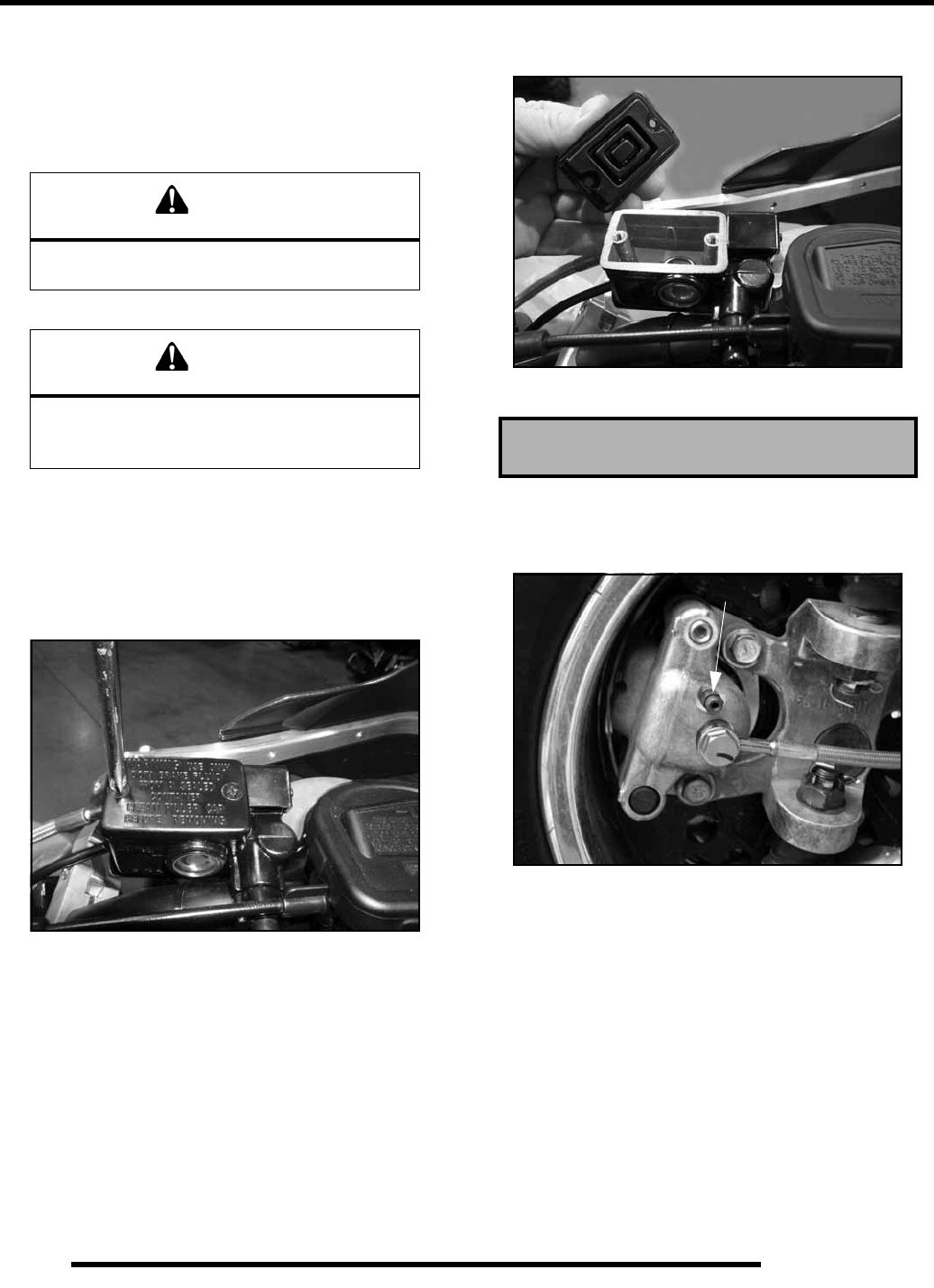
6.8
BRAKES
Brake Fluid Replacement and
Bleeding Procedure
NOTE: When bleeding the brakes or replacing the
fluid always start with the caliper farthest from the
master cylinder.
NOTE: This procedure should be used to change
fluid or bleed brakes during regular maintenance.
Front Brake Caliper Bleeding
1. Clean reservoir cover thoroughly.
2. Remove screws, cover, and diaphragm from master
cylinder reservoir.
3. Inspect vent slots in the cover and remove any debris or
blockage.
4. If changing fluid, remove old fluid from reservoir with a
Mity Vac™ (PN 2870975) or similar tool.
NOTE: Do not remove brake lever when reservoir
fluid level is low.
5. Add brake fluid to the upper level mark on reservoir.
6. Begin bleeding procedure with either front caliper. Install
a box end wrench on the caliper bleeder screw. Attach a
clean, clear hose to fitting and place the other end in a clean
container. Be sure the hose fits tightly on fitting.
NOTE: Fluid may be forced from compensation port
when brake lever is pumped. Place diaphragm in
reservoir to prevent spills. Do not install cover.
7. Slowly pump brake lever until pressure builds and holds.
8. While maintaining lever pressure, open bleeder screw.
Close bleeder screw and release brake lever.
NOTE: Do not release lever before bleeder screw is
tight or air may be drawn into caliper.
CAUTION
Always wear safety glasses during
these procedures.
CAUTION
Brake fluid will damage finished surfaces.
Do not allow brake fluid to come in contact
with finished surfaces. Polaris DOT 3 or DOT 4 Brake Fluid
Bleeder Screw
RepairPro Service Manual
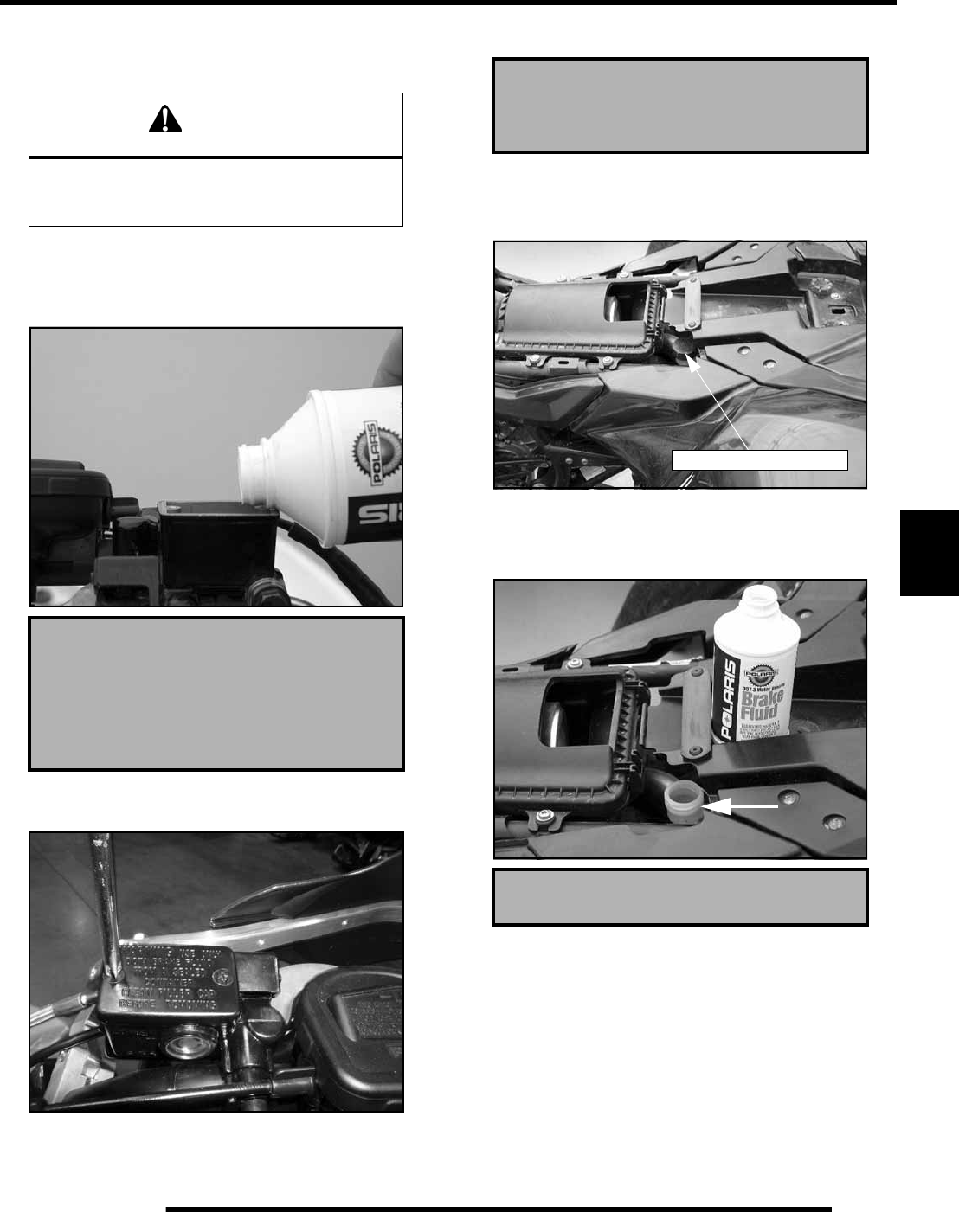
6.9
BRAKES
6
9. Repeat procedure until clean fluid appears in bleeder hose
and all air has been purged. Add fluid as necessary to
maintain level in reservoir.
10. Tighten bleeder screw securely and remove bleeder hose.
Torque bleeder screw to 47 in. lbs. (5.3 Nm).
11. Repeat procedure Steps 5-9 for the remaining front caliper.
12. Add brake fluid to the proper level
13. Install diaphragm, cover, and screws. Torque the screws to
11 in.lbs. (1.2 Nm).
Rear Brake Caliper Bleeding
1. Clean rear brake fluid reservoir cover thoroughly.
2. Remove the cap and diaphragm from the reservoir.
3. If changing fluid, remove old fluid from reservoir with a
Mity Vac™ (PN 2870975) or similar tool.
4. Using a funnel, add brake fluid to the MAX level mark on
reservoir.
CAUTION
Maintain at least 1/2” (1.27 cm) of brake fluid in
the reservoir to prevent air from entering
the master cylinder.
Master Cylinder Fuild Level:
Add to MAX level inside reservoir.
Sight glass must look dark, if sight glass
is clear, fluid level is too low
Reservoir Cover Torque
11 in. lbs. (1.2 Nm)
Polaris DOT 3 or DOT 4 Brake Fluid
Rear Brake Reservoir
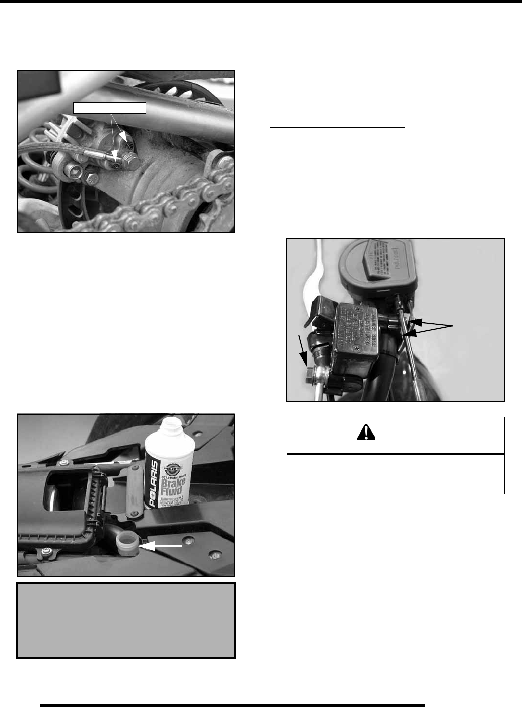
6.10
BRAKES
5. Install a box end wrench on the upper rear caliper bleeder
screw. Attach a clean, clear hose to fitting and place the
other end in a clean container. Be sure the hose fits tightly
on fitting.
6. Slowly pump foot brake lever until pressure builds and
holds.
7. While maintaining lever pressure, open bleeder screw.
Close bleeder screw and release brake lever.
NOTE: Do not release lever before bleeder screw is
tight or air may be drawn into caliper.
8. Repeat procedure until clean fluid appears in bleeder hose
and all air has been purged. Add fluid as necessary to
maintain level in reservoir.
9. Tighten bleeder screw securely and remove bleeder hose.
Torque bleeder screw to 27 in. lbs. (3.1 Nm).
10. Using a funnel, add brake fluid to the MAX level mark on
reservoir.
11. Field test machine at low speed before putting into service.
Check for proper braking action and lever reserve. With
lever firmly applied, lever reserve should be no less than
1/2” (1.3 cm) from handlebar.
12. Check brake system for fluid leaks and inspect all hoses and
lines for wear or abrasion. Replace hose if wear or abrasion
is found.
MASTER CYLINDER
Removal
1. Clean master cylinder and reservoir assembly. Make sure
you have a clean work area to disassemble brake
components.
2. Place a shop towel under brake line connection at master
cylinder. Loosen banjo bolt (A); remove bolt and sealing
washers.
3. Loosen the master cylinder clamp bolts (B) on the
handlebar side of the master cylinder.
Rear Reservoir Fuild Level:
Add to MAX level shown on the outside
of the rear reservoir.
Bleeder Screws
CAUTION
Brake fluid will damage finished surfaces.
Do not allow brake fluid to come in contact
with finished surfaces.
AB
RepairPro Service Manual
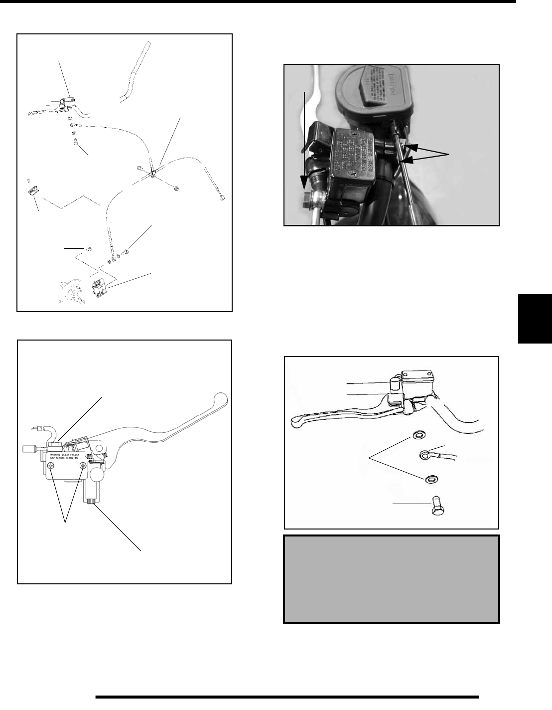
6.11
BRAKES
6
4. Remove master cylinder from handlebars. Installation
1. Install master cylinder on handlebars. Torque mounting
bolts to 85 in. lbs. (9.6 Nm). Torque the top bolt first.
NOTE: To speed up the brake bleeding procedure
the master cylinder can be purged of air before
brake line is attached. Fill with DOT 3 or DOT 4 Brake
Fluid and pump lever slowly two to three times with
finger over the outlet end to purge master cylinder of
air.
2. Place new sealing washers on each side of banjo brake line.
Install the brake line into the master cylinder. Torque the
brake switch bolt to 15 ft.lbs. (20 Nm).
Master Cylinder
Front Brake Line
Caliper
Banjo Bolt
Banjo Bolt
Retainer
Caliper
Mount Bolt
15 ft. lbs.
(20 Nm)
15 ft. lbs.
(20 Nm)
18 ft. lbs.
(24 Nm)
Master Cylinder Assembly
Cover Screws
Clamp Bolts
85 in. lbs. (9.6 Nm)
11 in. lbs. (1.24 Nm)
Banjo Bolt
15 ft. lbs. (20 Nm)
Master Cylinder Mounting Clamp
Bolt Torque: 85 in. lbs. (9.6 Nm)
Banjo Bolt Torque:
15 ft. lbs. (20 Nm)
15 ft. lbs.
85 in. lbs.
(20 Nm)
(9.6 Nm)
Brake Line
Sealing Washers
Torque to 15 ft. lbs.
(20 Nm)
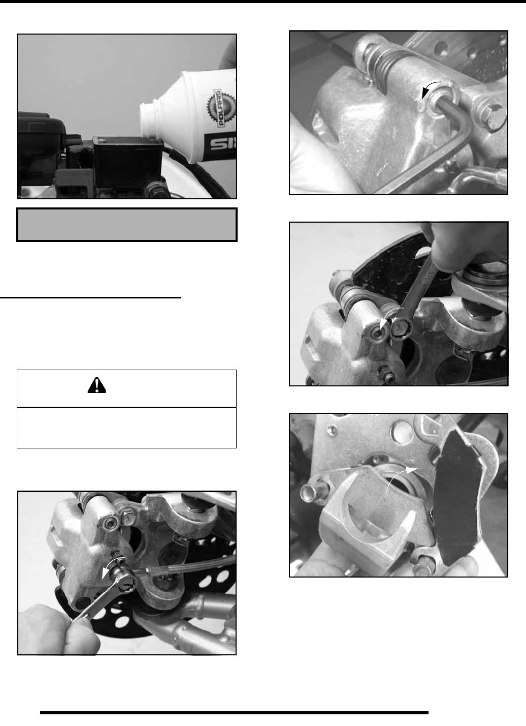
6.12
BRAKES
3. Fill reservoir with DOT 3 or DOT 4 Brake Fluid.
4. Follow bleeding procedure. Check all connections for leaks
and repair if necessary.
FRONT CALIPER SERVICE
Caliper Removal and Disassembly
1. Clean caliper area before removal.
2. Elevate and support front of machine. Remove the front
wheel.
3. Using a line wrench, loosen and remove brake line to
caliper. Place a container under caliper to catch fluid
draining from brake line.
4. Loosen pad adjuster screw 2-3 turns.
5. Remove the upper and lower caliper mounting bolts and
remove the caliper assembly from the caliper mount.
6. Push upper pad retainer pin inward and slip brake pads past
edge.
Polaris DOT 3 or DOT 4 Brake Fluid
CAUTION
Use care when supporting vehicle so that it
does not tip or fall.
Severe injury may occur if machine tips or falls.
RepairPro Service Manual
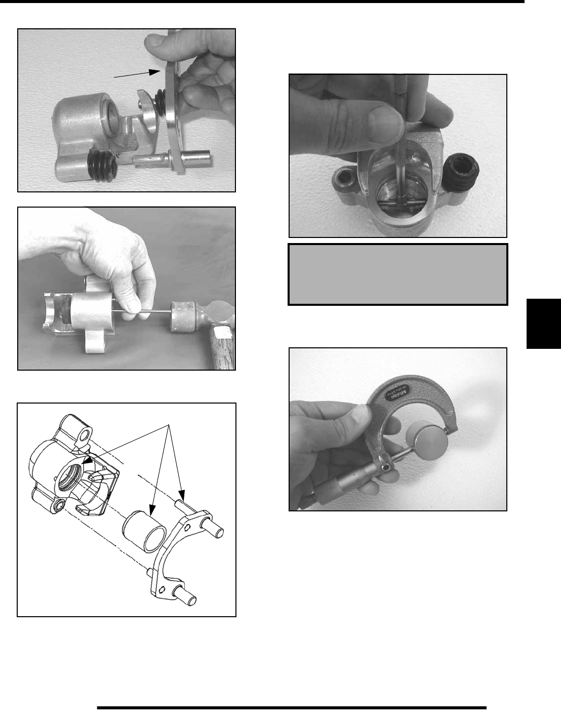
6.13
BRAKES
6
7. Remove mounting bracket, pin assembly and dust boot.
8. Remove dust seal and piston seal.
9. Clean the caliper body, piston, and retaining bracket with
brake cleaner or alcohol.
NOTE: Be sure to clean seal grooves in caliper
body.
Caliper Inspection
1. Inspect caliper body for nicks, scratches or wear. Measure
bore size and compare to specifications. Replace if damage
is evident or if worn beyond service limit.
2. Inspect piston for nicks, scratches, wear or damage.
Measure diameter and replace if damaged or worn beyond
service limit.
3. Inspect the brake disc and pads as outlined for brake pad
replacement in this section. See “Brake Pad Inspection”
earlier in this chapter.
Clean Components
Caliper Piston Bore I.D.:
Std:. 1.188” (30.2 mm)
Service Limit: 1.193” (30.30 mm)
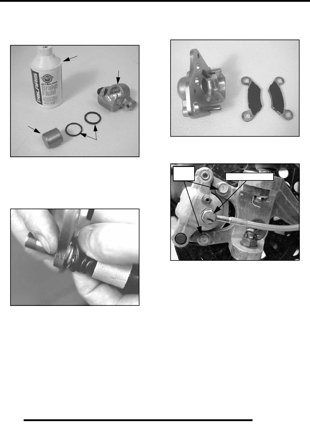
6.14
BRAKES
Caliper Reassembly
1. Install new O-rings (A) in the caliper body (B). Be sure
groove is clean and free of residue or brakes may drag
upon assembly.
2. Coat piston with clean Polaris DOT 3 or DOT 4 Brake Fluid
(C). Install piston (D) with a twisting motion while pushing
inward. Piston should slide in and out of bore smoothly,
with light resistance.
3. Lubricate the mounting bracket pins with Polaris Premium
All Season Grease (PN 2871423), and install the rubber
dust seal boots.
4. Compress the mounting bracket and make sure the dust
seals are fully seated. Install the brake pads. Clean the disc
and pads with brake parts cleaner or denatured alcohol to
remove any dirt, oil or grease.
Caliper Installation
1. Install caliper and torque mounting bolts.
2. Install brake line and tighten securely with a line wrench.
Torque the banjo brake lines to the proper torque
specification.
3. Install the adjuster screw and turn until stationary pad
contacts disc, then back off 1/2 turn.
4. Perform brake bleeding procedure as outlined earlier in this
chapter.
5. Install wheels and torque wheel nuts to specification.
A
B
C
D
15 ft.lbs. (20 Nm)
18 ft. lbs
(24 Nm)
RepairPro Service Manual
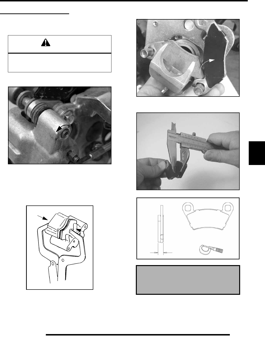
6.15
BRAKES
6
FRONT BRAKE PADS
Pad Removal
1. Elevate and support front of ATV.
2. Remove the front wheel. Loosen pad adjuster screw 2-3
turns.
3. Remove caliper from mounting bracket.
NOTE: When removing caliper, use care not to
damage brake line. Support caliper so to avoid
kinking or bending brake line.
4. Push caliper piston into caliper bore slowly using a
C-clamp or locking pliers with pads installed.
NOTE: Brake fluid will be forced through
compensating port into master cylinder fluid
reservoir when piston is pushed back into caliper.
Remove excess fluid from reservoir as required.
5. Push mounting bracket inward and slip outer brake pad
past edge. Remove inner pad.
6. Measure the thickness of the pad material. Replace pads if
worn beyond the service limit.
CAUTION
Use care when supporting vehicle so that it
does not tip or fall.
Severe injury may occur if machine tips or falls.
Front Brake Pad Thickness
New : .298”/ 7.6 mm
Service Limit: .180” / 4.6 mm
Measure Pad
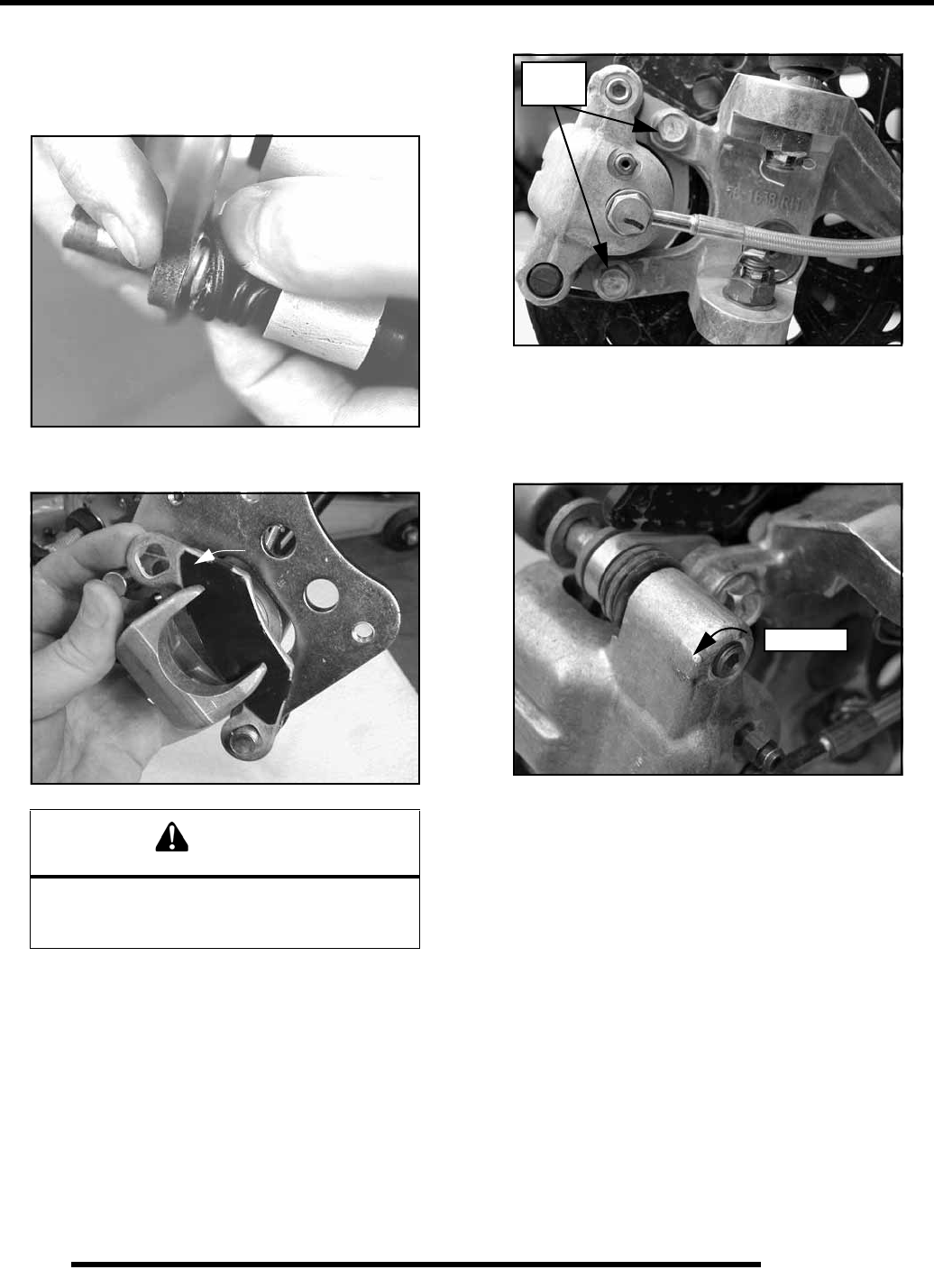
6.16
BRAKES
Pad Assembly
1. Lubricate mounting bracket pins with a light film of
Polaris Premium All Season Grease (PN 2871423), and
install rubber dust boots.
2. Compress mounting bracket and make sure dust boots are
fully seated. Install pads with friction material facing each
other.
3. Install caliper on spindle hub and torque mounting bolts.
4. Slowly pump the brake lever until pressure has been built
up. Maintain at least 1/2, (12.7 mm) of brake fluid in the
reservoir to prevent air from entering the brake system.
5. Install the adjuster screw and turn clockwise until
stationary pad contacts disc, then back off 1/2 turn
(counterclockwise).
6. Verify fluid level in reservoir is up to MAX line inside
reservoir and install reservoir cap.
7. Install wheels and torque wheel nuts.
NOTE: Front Wheel Nut Torque: Refer to Torque
Table at beginning of chapter.
Brake Burnishing Procedure
It is required that a burnishing procedure be performed after
installation of new brake pads to extend service life and reduce
noise.
Start machine and slowly increase speed to 30 mph. Gradually
apply brakes to stop machine. Allow pads and disc to cool
sufficiently during the procedure. Do not allow pads or disc to
become hot or warping may result. Repeat this procedure 10
times.
WARNING
If brake pads are contaminated with grease, oil, or
liquid soaked do not use the pads.
Use only new, clean pads.
18 ft. lbs
(24 Nm)
1/2 Turn
RepairPro Service Manual
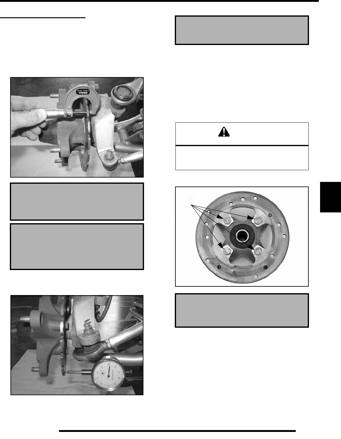
6.17
BRAKES
6
FRONT BRAKE DISC
Disc Inspection
1. Visually inspect the brake disc for nicks, scratches, or
damage.
2. Measure the disc thickness at 8 different points around the
pad contact surface using a 0–1” micrometer. Replace disc
if worn beyond service limit.
3. Mount dial indicator as shown to measure disc runout.
Slowly rotate the disc and read total runout on the dial
indicator. Replace the disc if runout exceeds specifications.
Disc Removal / Replacement
1. Apply heat to the hub in the area of the brake disc
mounting bolts to soften the bolt locking agent.
2. Remove bolts and disc.
3. Clean mating surface of disc and hub.
4. Install disc on hub.
5. Install new bolts and tighten to specified torque.
Brake Disc Thickness
New: .158” (4.013 mm)
Service Limit: .140” / 3.556 mm)
Brake Disc Thickness Variance
Service Limit: .002” (.051 mm)
(difference between measurements)
Brake Disc Runout
Service Limit .010” (.254 mm)
CAUTION
Always use new brake disc mounting bolts.
The bolts have a pre–applied locking agent
which is destroyed upon removal.
Front Brake Disc Mounting Bolt Torque
18 ft. lbs. (24 Nm)
18 ft. lbs.
(24 Nm)
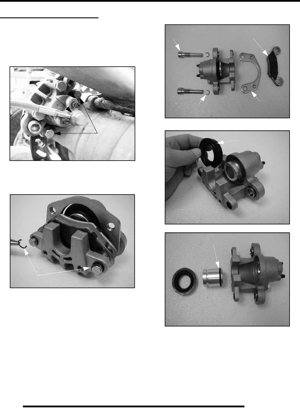
6.18
BRAKES
REAR CALIPER SERVICE
Caliper Removal
1. Clean caliper area before removal.
2. Using a flare nut wrench, remove the brake line (A). Place
a container to catch brake fluid draining from brake line.
3. Remove the caliper mounting bolts (B) and remove the
caliper assembly from the caliper mount.
Caliper Disassembly
1. Remove the c-clips (A) from the caliper sliding bolts.
2. Remove the caliper slide bolts (B), mounting bracket (C),
and brake pads (D).
3. Remove the outside dust boot (E).
4. Remove the piston and seal (F).
A
B
A
B
AC
D
E
F
RepairPro Service Manual
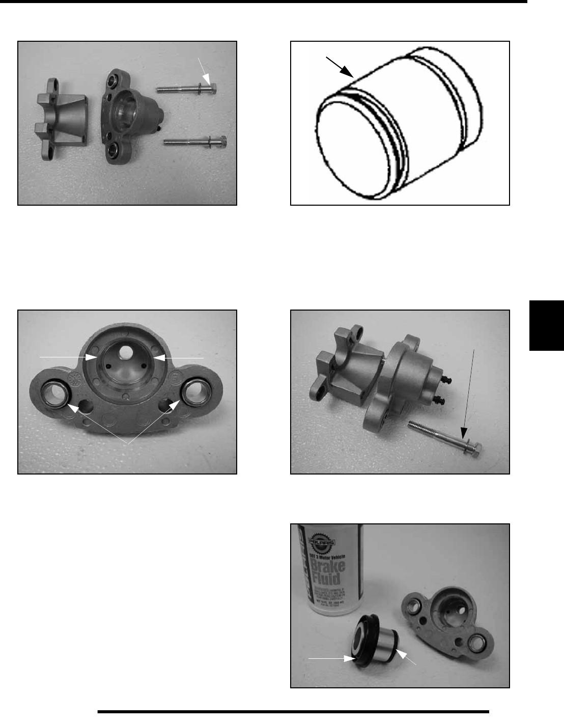
6.19
BRAKES
6
5. Remove the caliper body bolts (G). Pull the caliper bodies
apart (if necessary).
6. Clean the caliper body, piston, and retaining bracket with
brake cleaner or alcohol.
Caliper Inspection
1. Inspect caliper body bore and o-rings for nicks, scratches
or wear. Measure bore for roundness. Replace if damage is
evident.
NOTE: Be sure to clean seal grooves in caliper
body.
2. Inspect piston for nicks, scratches, wear or damage.
Replace if damaged or worn.
3. Inspect the brake disc and pads as outlined for brake pad
replacement this section.
Caliper Assembly
1. Reassemble the two caliper halves if previously
disassembled. Torque the caliper body bolts to 18 ft.lbs.
(24 Nm).
2. Install new O–ring (A) in the caliper body. Install the dust
boot over the caliper and seat the dust boot into caliper
groove. Be sure groove is clean and free of residue or brakes
may drag.
G
O-rings
Inspect Piston
18 ft.-lb.
(24Nm)
BA
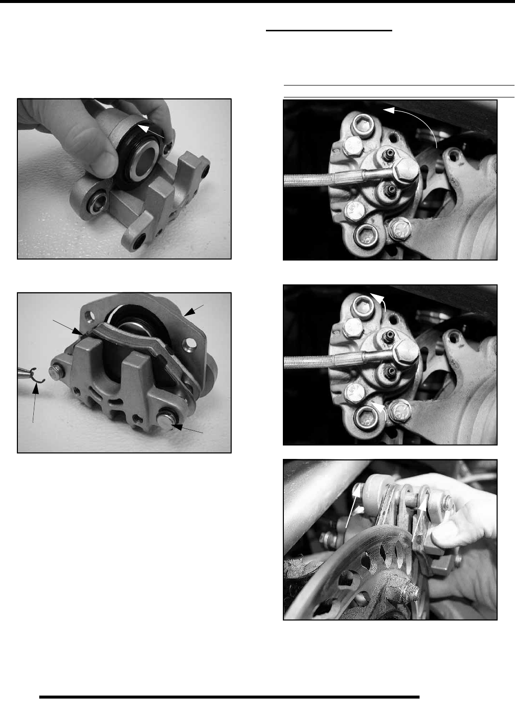
6.20
BRAKES
3. Coat piston and inside of caliper body with clean DOT 3
or DOT 4 Brake Fluid. Install piston with a twisting motion
while pushing inward. Piston should slide in and out of bore
smoothly, with light resistance. NOTE: Be sure that the O-
ring does not bind when installing the piston.
4. Seat the dust boot securely onto the caliper body.
5. Install the caliper mount (C), brake pads (D), caliper slide
bolts (E), and c-clips (F).
6. Torque the caliper slide bolts (E) to 33 ft.lbs. (45 Nm).
REAR BRAKE PAD
Pad Removal
1. Loosen both bolts and remove the rear brake mount bolt.
Tip the caliper and re-torque the remaining brake mount
bolt. This will allow access to the upper caliper slide bolt.
2. Loosen the caliper slide bolts with an Allen wrench before
you remove the brake caliper.
3. Remove caliper mounting bolts and lift caliper off of disc.
NOTE: When removing caliper, be careful not to
damage brake line. Support caliper so as not to kink
or bend brake line.
D
C
E
F
RepairPro Service Manual
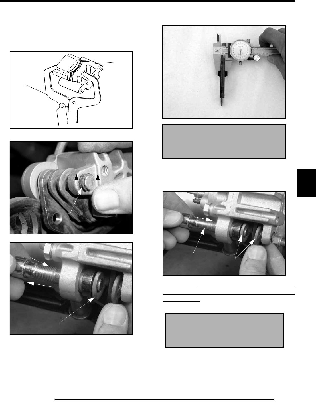
6.21
BRAKES
6
4. With pads installed, push caliper piston into caliper bore
(A) slowly using a C–clamp (B) or locking pliers.
NOTE: Brake fluid will be forced through
compensating port into master cylinder fluid
reservoir when piston is pushed back into caliper.
Remove excess fluid from reservoir as required.
5. Remove the c-clips (C) on the ends of the caliper slide bolt.
6. Remove caliper slide bolts (D) and brake pads (E).
7. Measure the thickness of the pad material. Replace pads if
worn beyond the service limit.
Pad Installation
1. Install new pads (A) in caliper body. Slide the caliper slide
bolts (B) into the caliper and hand-tighten.
2. Install the caliper assembly over the brake disc and onto the
caliper mount. Tip the caliper forward and install only the
forward bolt. This will allow both slide bolts to be torqued
to specification. TIP: Use a block or wedge to keep the
caliper stationary while tightening the slide bolts.
A
B
C
D
E
Brake Pad Thickness
New: .298” / 7.6 mm
Service Limit: .180” / 4.6 mm
Brake Caliper Mounting Bolt
Torque:
18 ft. lbs. (24 Nm)
A
B
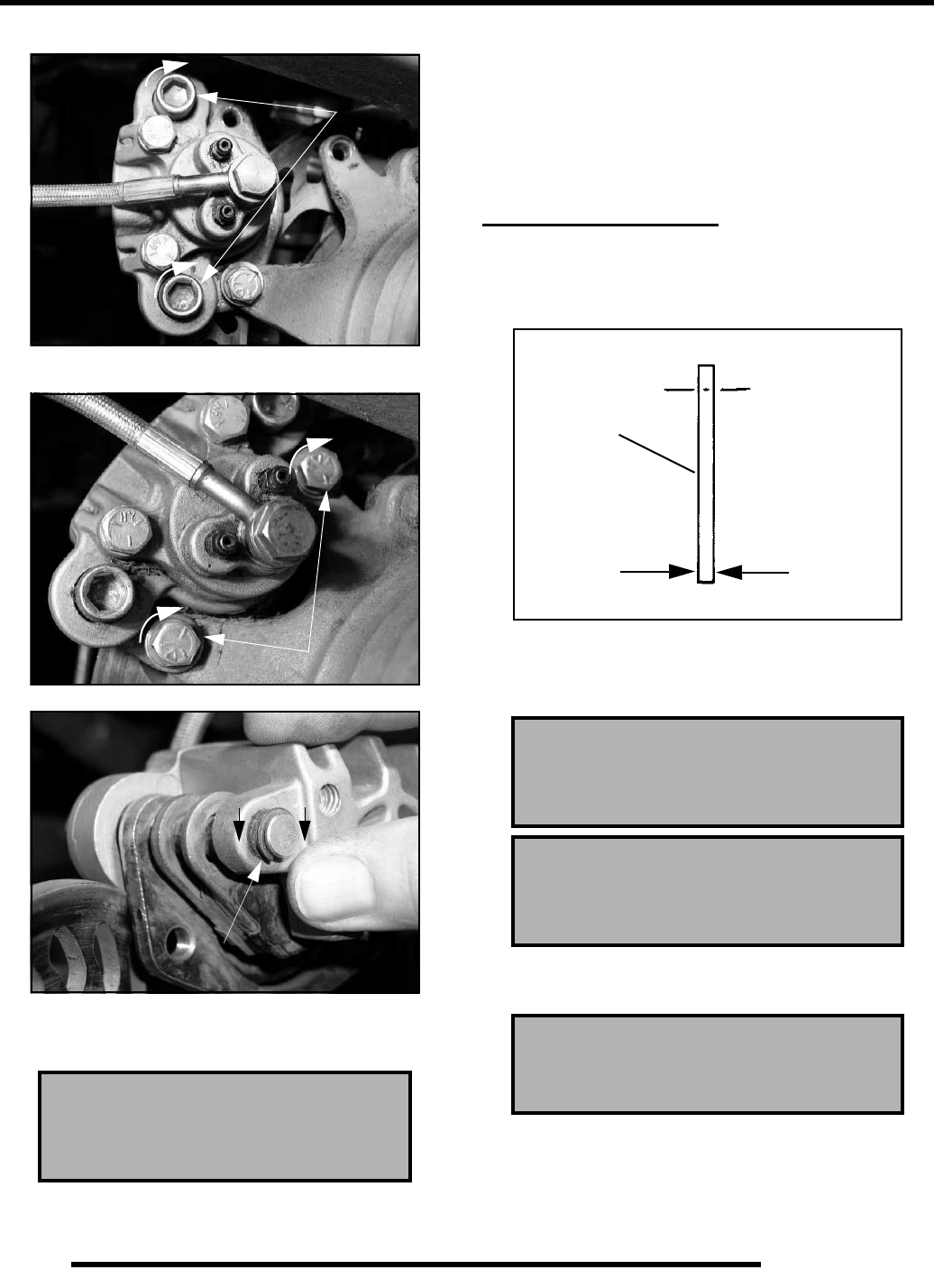
6.22
BRAKES
3. Torque the caliper slide bolts to 33 ft.lbs. (45 Nm).
4. Install the caliper mounting bolts and torque both bolts to
18 ft. lbs. (24 Nm).
5. Install the c-clips (C) onto the ends of the caliper slide bolts.
6. Slowly pump the brake levers until pressure has been built
up. Maintain at least 1/2” (12.7 mm) of brake fluid in the
reservoir to prevent air from entering the master cylinder.
NOTE: BRAKE BURNISHING: It is recommended
that a burnishing procedure be performed after
installation of new brake pads to extend service life
and reduce noise. Start machine and slowly increase
speed to 30 mph. Gradually apply brakes to stop
machine. Repeat this procedure 10 times, allowing
brakes to cool sufficiently after each run.
REAR BRAKE DISC
Disc Inspection
1. Visually inspect disc for scoring, scratches, or gouges.
Replace the disc if any deep scratches are evident.
2. Use a 0–1” micrometer and measure disc thickness at 8
different points around perimeter of disc. Replace disc if
worn beyond service limit.
3. Mount dial indicator and measure disc runout. Replace the
disc if runout exceeds specifications.
Auxiliary Brake Master Cylinder
Fluid Level
Between MIN and MAX lines
33 ft.-lb.
(45Nm)
18 ft. lbs. (24 Nm)
C
Brake Disc Thickness
New: .158” (4.013 mm)
Service Limit: .140” / 3.556 mm
Brake Disc Thickness Variance
Service Limit: .002” (.051 mm)
(difference between measurements)
Brake Disc Runout
Service Limit: .010” (.25 mm)
Measure
Thickness
Rear Brake
Disc
RepairPro Service Manual
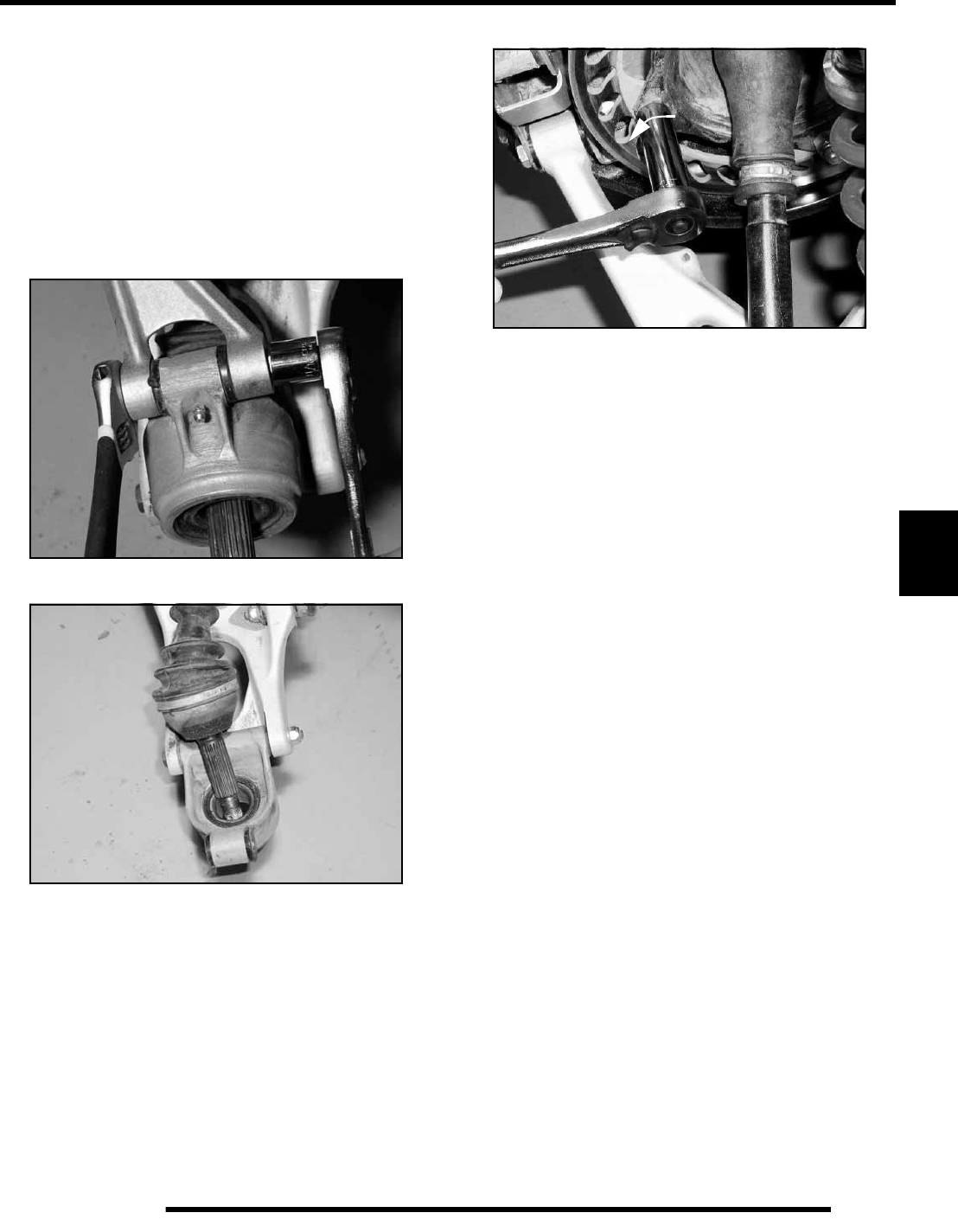
6.23
BRAKES
6
Disc Removal
1. With ATV on the ground, loosen wheel nuts and hub nuts.
2. Safely lift and support the rear of the ATV under the main
frame.
3. Remove right rear wheel and hub.
4. Remove rear caliper and secure out of the way.
NOTE: Do not allow the caliper to hang by the brake
line. Brake line damage may result.
5. Remove right upper carrier bolt and secure upper a-arm out
of the way.
6. Tilt right hub carrier outward while pulling rear CV shaft
end from carrier assembly.
7. Remove brake disc mounting bolts (4).
8. Lift and rotate disc, slipping it over the hub assembly and
off the driveshaft, exiting the frame from the side.
Disc Replacement
1. Install disc, slipping it over the over the drive shaft and hub
assembly. Disc mounting holes will be on the inside face
of the hub assembly for correct installation.
2. Install brake disc mounting bolts. Torque mounting bolts to
18 ft.lbs. (24 Nm).
3. Install CV shaft into hub carrier.
4. Install upper a-arm, bolt and nut on to hub carrier. Torque
mounting bolt to 30 ft.lbs. (40.6 Nm).
5. Install wheel hub, domed washer and nut (dome of washer
facing out). Torque to 90 ft.lbs. (122 Nm). Install cotter pin.

6.24
BRAKES
TROUBLESHOOTING
Brakes Squeal
• Dirty/contaminated friction pads
• Improper alignment
• Worn disc
• Worn disc splines
• Glazed brake pads
Poor Brake Performance
• Air in system
• Water in system (brake fluid contaminated)
• Caliper/disc misaligned
• Caliper dirty or damaged
• Brake line damaged or lining ruptured
• Worn disc and/or friction pads
• Incorrectly adjusted lever
• Incorrectly adjusted stationary pad
• Worn or damaged master cylinder or components
• Improper clearance between lever and switch
Lever Vibration
• Disc damaged
• Disc worn (runout or thickness variance exceeds
service limit)
• Caliper overheats (Brakes Drag)
• Compensating port plugged
• Pad clearance set incorrectly
• Auxiliary brake pedal incorrectly adjusted
• Brake lever or pedal binding or unable to return fully
• Parking brake left on
• Residue build up under caliper seals
• Operator riding brakes
Brakes Lock
• Alignment of caliper to disc
• Fluid overfill of the reservoir
• Stuck caliper piston
RepairPro Service Manual

ELECTRICAL
7.1
CHAPTER 7
ELECTRICAL
7
GENERAL INFORMATION . . . . . . . . . . . . . . . . . . . . . . . . . . . . . . . . . . . . . . . . . . . . . . . . 7.2
SPECIAL TOOLS . . . . . . . . . . . . . . . . . . . . . . . . . . . . . . . . . . . . . . . . . . . . . . . . . . . . . . . . . . . . . . . . 7.2
ELECTRICAL SERVICE NOTES . . . . . . . . . . . . . . . . . . . . . . . . . . . . . . . . . . . . . . . . . . . . . . . . . . . . 7.2
TIMING CHECK PROCEDURE . . . . . . . . . . . . . . . . . . . . . . . . . . . . . . . . . . . . . . . . . . . . . . . . . . . . .7.2
LIGHTING AND CONTROLS . . . . . . . . . . . . . . . . . . . . . . . . . . . . . . . . . . . . . . . . . . . . . . 7.3
NEUTRAL / REVERSE POSITION INDICATOR SWITCH TEST . . . . . . . . . . . . . . . . . . . . . . . . . . . 7.3
HEADLIGHT LAMP REPLACEMENT . . . . . . . . . . . . . . . . . . . . . . . . . . . . . . . . . . . . . . . . . . . . . . . . 7.3
HEADLAMP SWITCH TEST. . . . . . . . . . . . . . . . . . . . . . . . . . . . . . . . . . . . . . . . . . . . . . . . . . . . . . . . 7.3
HEADLIGHT HOUSING REPLACEMENT . . . . . . . . . . . . . . . . . . . . . . . . . . . . . . . . . . . . . . . . . . . . . 7.3
HEADLIGHT ADJUSTMENT . . . . . . . . . . . . . . . . . . . . . . . . . . . . . . . . . . . . . . . . . . . . . . . . . . . . . . . 7.4
TAILLIGHT / BRAKELIGHT LAMP REPLACEMENT. . . . . . . . . . . . . . . . . . . . . . . . . . . . . . . . . . . . . 7.4
BRAKE LIGHT SWITCH TESTS . . . . . . . . . . . . . . . . . . . . . . . . . . . . . . . . . . . . . . . . . . . . . . . . . . . .7.5
CLUTCH SWITCH TEST . . . . . . . . . . . . . . . . . . . . . . . . . . . . . . . . . . . . . . . . . . . . . . . . . . . . . . . . . . 7.5
INDICATOR LAMP REPLACEMENT . . . . . . . . . . . . . . . . . . . . . . . . . . . . . . . . . . . . . . . . . . . . . . . . . 7.5
TETHER SWITCH TEST (ACCESSORY OPTION) . . . . . . . . . . . . . . . . . . . . . . . . . . . . . . . . . . . . . . 7.6
ELECTRONIC THROTTLE CONTROL (ETC) SWITCH . . . . . . . . . . . . . . . . . . . . . . . . . . . . . . . . . . 7.6
ETC OPERATION TEST . . . . . . . . . . . . . . . . . . . . . . . . . . . . . . . . . . . . . . . . . . . . . . . . . . . . . . . . . . 7.6
IGNITION SYSTEM. . . . . . . . . . . . . . . . . . . . . . . . . . . . . . . . . . . . . . . . . . . . . . . . . . . . . . 7.7
IGNITION SYSTEM TROUBLESHOOTING. . . . . . . . . . . . . . . . . . . . . . . . . . . . . . . . . . . . . . . . . . . . 7.7
CIRCUIT BREAKERS. . . . . . . . . . . . . . . . . . . . . . . . . . . . . . . . . . . . . . . . . . . . . . . . . . . . . . . . . . . . . 7.7
CRANKING OUTPUT TESTS . . . . . . . . . . . . . . . . . . . . . . . . . . . . . . . . . . . . . . . . . . . . . . . . . . . . . .7.7
FLYWHEEL IDENTIFICATION. . . . . . . . . . . . . . . . . . . . . . . . . . . . . . . . . . . . . . . . . . . . . . . . . . . . . . 7.8
DC / CDI IGNITION . . . . . . . . . . . . . . . . . . . . . . . . . . . . . . . . . . . . . . . . . . . . . . . . . . . . . . . . . . . . . . 7.8
IGNITION SYSTEM TESTING . . . . . . . . . . . . . . . . . . . . . . . . . . . . . . . . . . . . . . . . . . . . . . . . . . . . . . 7.9
COMPONENTS OF DC / CDI IGNITION . . . . . . . . . . . . . . . . . . . . . . . . . . . . . . . . . . . . . . . . . . . . . 7.10
COOLING SYSTEM . . . . . . . . . . . . . . . . . . . . . . . . . . . . . . . . . . . . . . . . . . . . . . . . . . . . 7.11
FAN CONTROL CIRCUIT OPERATION / TESTING . . . . . . . . . . . . . . . . . . . . . . . . . . . . . . . . . . . . 7.11
COOLANT TEMPERATURE SENSOR TEST (HOT LIGHT) . . . . . . . . . . . . . . . . . . . . . . . . . . . . . . 7.11
FAN CONTROL SWITCH BYPASS TEST . . . . . . . . . . . . . . . . . . . . . . . . . . . . . . . . . . . . . . . . . . . . 7.11
COOLANT FAN CONTROL SWITCH OPERATION TEST . . . . . . . . . . . . . . . . . . . . . . . . . . . . . . . 7.12
FAN MOTOR CURRENT DRAW . . . . . . . . . . . . . . . . . . . . . . . . . . . . . . . . . . . . . . . . . . . . . . . . . . . 7.12
CHARGING SYSTEM . . . . . . . . . . . . . . . . . . . . . . . . . . . . . . . . . . . . . . . . . . . . . . . . . . . 7.12
CURRENT DRAW – KEY OFF. . . . . . . . . . . . . . . . . . . . . . . . . . . . . . . . . . . . . . . . . . . . . . . . . . . . . 7.12
CHARGING SYSTEM “BREAK EVEN” TEST . . . . . . . . . . . . . . . . . . . . . . . . . . . . . . . . . . . . . . . . . 7.13
ALTERNATOR TESTS (CHARGING SYSTEM) . . . . . . . . . . . . . . . . . . . . . . . . . . . . . . . . . . . . . . . 7.13
CHARGING SYSTEM TESTING FLOW CHART . . . . . . . . . . . . . . . . . . . . . . . . . . . . . . . . . . . . . . . 7.14
BATTERY SERVICE . . . . . . . . . . . . . . . . . . . . . . . . . . . . . . . . . . . . . . . . . . . . . . . . . . . . 7.15
BATTERY MAINTENANCE . . . . . . . . . . . . . . . . . . . . . . . . . . . . . . . . . . . . . . . . . . . . . . . . . . . . . . . 7.15
BATTERY INSPECTION / REMOVAL . . . . . . . . . . . . . . . . . . . . . . . . . . . . . . . . . . . . . . . . . . . . . . . 7.15
BATTERY TERMINALS / BOLTS. . . . . . . . . . . . . . . . . . . . . . . . . . . . . . . . . . . . . . . . . . . . . . . . . . . 7.16
BATTERY TESTING. . . . . . . . . . . . . . . . . . . . . . . . . . . . . . . . . . . . . . . . . . . . . . . . . . . . . . . . . . . . . 7.16
OCV – OPEN CIRCUIT VOLTAGE TEST . . . . . . . . . . . . . . . . . . . . . . . . . . . . . . . . . . . . . . . . . . . . 7.16
LOAD TEST . . . . . . . . . . . . . . . . . . . . . . . . . . . . . . . . . . . . . . . . . . . . . . . . . . . . . . . . . . . . . . . . . . . 7.16
OFF SEASON STORAGE . . . . . . . . . . . . . . . . . . . . . . . . . . . . . . . . . . . . . . . . . . . . . . . . . . . . . . . . 7.16
CHARGING PROCEDURE . . . . . . . . . . . . . . . . . . . . . . . . . . . . . . . . . . . . . . . . . . . . . . . . . . . . . . .7.17
STARTING SYSTEM. . . . . . . . . . . . . . . . . . . . . . . . . . . . . . . . . . . . . . . . . . . . . . . . . . . . 7.17
STARTER SYSTEM TROUBLESHOOTING . . . . . . . . . . . . . . . . . . . . . . . . . . . . . . . . . . . . . . . . . . 7.17
CLUTCH SWITCH TEST . . . . . . . . . . . . . . . . . . . . . . . . . . . . . . . . . . . . . . . . . . . . . . . . . . . . . . . . . 7.18
NEUTRAL START DIODE TEST . . . . . . . . . . . . . . . . . . . . . . . . . . . . . . . . . . . . . . . . . . . . . . . . . . . 7.18
STARTER VOLTAGE DROP TESTING. . . . . . . . . . . . . . . . . . . . . . . . . . . . . . . . . . . . . . . . . . . . . . 7.18
STARTER MOTOR DISASSEMBLY . . . . . . . . . . . . . . . . . . . . . . . . . . . . . . . . . . . . . . . . . . . . . . . . 7.18
BRUSH INSPECTION / REPLACEMENT . . . . . . . . . . . . . . . . . . . . . . . . . . . . . . . . . . . . . . . . . . . . 7.19
ARMATURE TESTING. . . . . . . . . . . . . . . . . . . . . . . . . . . . . . . . . . . . . . . . . . . . . . . . . . . . . . . . . . . 7.19
STARTER REASSEMBLY . . . . . . . . . . . . . . . . . . . . . . . . . . . . . . . . . . . . . . . . . . . . . . . . . . . . . . . . 7.20
STARTER ONE-WAY CLUTCH INSPECTION . . . . . . . . . . . . . . . . . . . . . . . . . . . . . . . . . . . . . . . . 7.20
STARTER SYSTEM TESTING FLOW CHART . . . . . . . . . . . . . . . . . . . . . . . . . . . . . . . . . . . . . . . . 7.21
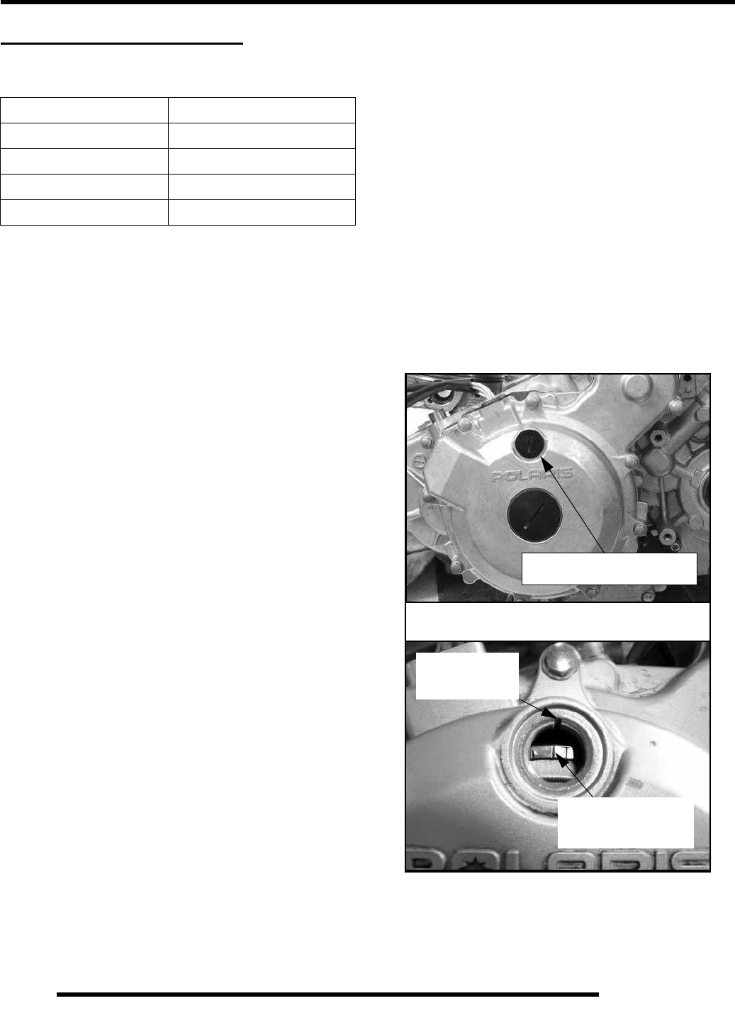
7.2
ELECTRICAL
GENERAL INFORMATION
Special Tools
Electrical Service Notes
Keep the following notes in mind when diagnosing an electrical
problem.
• Refer to wiring diagram for stator and electrical
component resistance specifications.
• When measuring resistance of a component that has a
resistance value under 10 Ohms, remember to subtract
meter lead resistance from the reading. Connect the
leads together and record the resistance. The resistance
of the component is equal to tested value minus the lead
resistance.
• Become familiar with the operation of your meter. Be
sure leads are in the proper jack for the test being
performed (i.e. 10A jack for current readings). Refer to
the Owner’s Manual included with your meter for more
information.
• Voltage, amperage, and resistance values included in
this manual are obtained with a Fluke™ 77 Digital
Multimeter (PV-43568). This meter is used for when
diagnosing electrical problems. Readings obtained with
other meters may differ.
• Pay attention to the prefix on the multimeter reading (K,
M, etc.) and the position of the decimal point.
• For resistance readings, isolate the component to be
tested. Disconnect it from the wiring harness or power
supply.
•Ignition timing is non-adjustable.
Timing Check Procedure
1. The ignition timing inspection hole is located in the starter
/ magneto housing. Remove the check plug.
NOTE: Do not allow the engine to warm up. The
timing may retard approximately 2° when the engine
is warm.
The ignition timing marks are stamped on the outer diameter of
the flywheel. Ignition timing must be inspected with the engine
at room temperature (68° F / 20° C) to obtain the most accurate
reading.
2. With the transmission in neutral, start the engine and set
engine speed to 3500 ± 50 RPM.
3. Direct the timing light at the ignition timing check hole and
check the ignition timing.
If the ignition timing is not within the specified range, test
ignition components for proper function.
Ignition timing is non-adjustable.
PART NUMBER TOOL DESCRIPTION
PV-43568 Fluke™ 77 Digital Multimeter
2870630 Timing Light
2870836 Battery Hydrometer
2871745 Static Timing Light Harness
Ignition Timing: Max 30o @ 3500 RPM
Timing Inspection Hole
TDC Line
(Left of the “T”)
TDC
Case Mark
RepairPro Service Manual
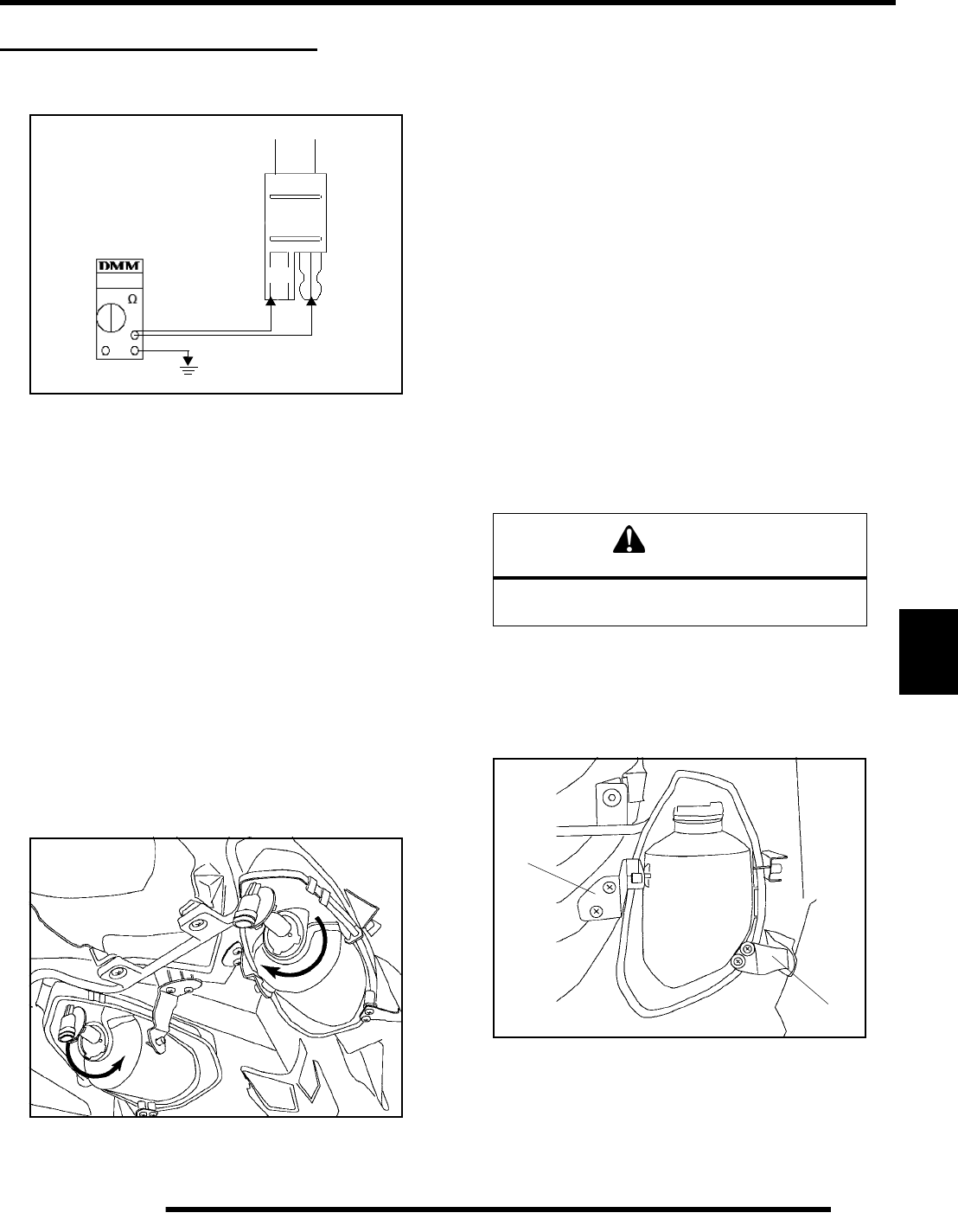
7.3
ELECTRICAL
7
LIGHTING AND CONTROLS
Neutral / Reverse
Position Indicator Switch Test
1. Shift the transmission into 1st gear. The ohm meter should
show no continuity or OL when testing at points A and B.
2. Check for continuity at test points A and B while in reverse
and neutral. You should have continuity on one of the wires
for each test at points A and B.
NOTE: If there is no continuity at either of the wire
connections with the transmission in neutral or
reverse, remove the switch and inspect the shift
drum contact pin and spring for proper function. If
no problems are found, inspect the wiring, bulb, and
harness connection.
Headlight Lamp Replacement
1. Remove the wire harness connector from the back of the
headlight.
2. On the left headlamp, grasp the bulb housing and turn it
counterclockwise and pull outward (1) to remove the bulb.
On the right headlamp, turn the bulb housing clockwise and
pull outward (2) to remove the bulb.
3. Apply dielectric grease to the light bulb socket before
installing the new bulb. Install the replacement bulb into
headlight housing and rotate firmly.
NOTE: The bulb must be positioned so the harness
installs into the lamp at the outer side.
4. Reinstall the connector to the back of the headlight.
Headlamp Switch Test
Probe the headlamp plug wires (Brown and Yellow) at back of
connector. Turn headlights on. Test for battery voltage across the
connections.
• Low Beam - Brown and Yellow
• High Beam - Brown and Green
If no current is found, test for bad connections, switches, or
broken wiring. Refer to the wire diagram for harness routing and
connections.
Headlight Housing Replacement
1. Remove the wire harness connector from the headlights.
2. Remove the front cab. Position the cab upside down on a
soft protective surface to prevent scratching.
3. Remove the small adjuster bracket (1) and install it on the
new lamp.
4. Remove the large pivot bracket (2) and remove the
headlamp.
5. Install the new headlamp by inserting the outboard pivot
pin in the hole of the mounting tab on the cab.
AB
RED
BLK
1
2
CAUTION
Do not service while headlight is hot. Serious
burns may result. Protect lamp during install.
1
2
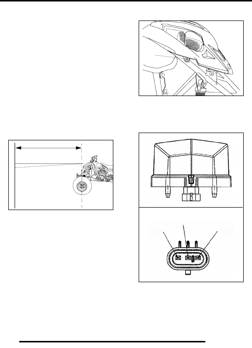
7.4
ELECTRICAL
6. Install the adjuster bracket onto the inboard pivot pin of the
headlamp.
7. Adjust for approximately 1/16” clearance between the
bracket and the edge of the headlight. Tighten the mounting
screws.
IMPORTANT: Be sure the bracket is 90 degrees to the
pivot pin so the lamp can move freely.
8. Install the adjusting screw, leaving it loose so the headlight
can be adjusted.
9. Reinstall the front cab and connect the wire harness to the
headlamp.
10. Adjust the lamps as needed, then tighten the adjuster screw.
Headlight Adjustment
The headlight beam can be adjusted to varied positions by using
the following procedures:
1. Place the vehicle on a level surface with the headlight
approximately 25’ (7.6 m) from a wall.
2. Measure the distance from the floor to the center of the
headlight and make a mark on the wall at the same height
3. Start the engine and turn the headlight switch to high beam.
4. Observe headlight aim. The most intense part of the
headlight beam should be aimed 2” (5.1 cm) below the
mark placed on the wall in Step 2.
NOTE: Rider weight must be included on the seat.
On machines with separate low beam lights, the
drop should be 8” (20.3 cm) in 25’ from the center of
the low beam lamp.
5. Loosen the pivot screw (1) and adjust the beam to the
desired position.
6. Tighten the screw and torque to 27 in. lbs. (3 Nm).
Taillight / Brakelight Lamp Replacement
If the taillight / brakelight does not work the LED lamp
assembly may need to be replaced.
1. From the rear of the taillight remove two screws holding
the assembly in place.
2. Remove the assembly and replace it with the recommended
lamp. Apply dielectric grease (PN 2871329) to the new
contacts.
3. Reinstall the assembly as in step 1.
4. Test the taillight / brakelight to see it is working.
25’ (7.6m)
Lamp Center Height
2” (5.1cm)
1
Pinout Detail
BRAKE
TAIL
GROUND
RepairPro Service Manual
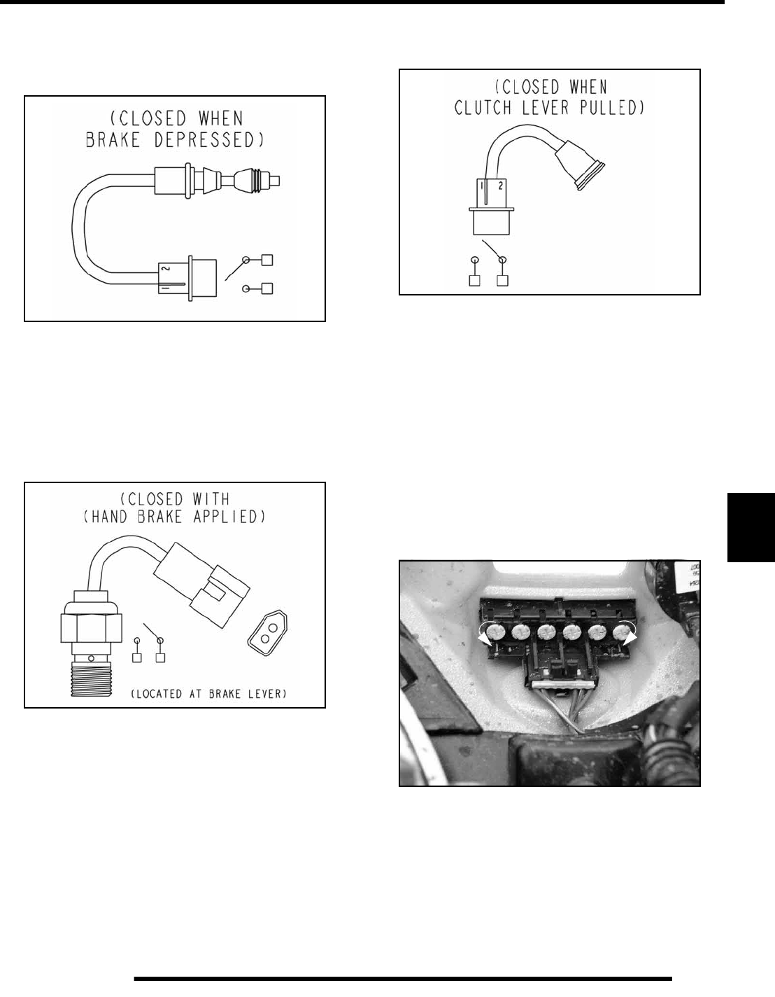
7.5
ELECTRICAL
7
Brake Light Switch Tests
Foot Brake Switch
1. Disconnect wire harness from switch.
2. Connect an ohmmeter across switch contacts. The circuit
should have an open line or infinity reading.
3. Apply foot brake and check for continuity between switch
contacts. Replace switch if there is no continuity or greater
than .5 ohms resistance when the brake is applied with
slight pressure.
Hand Brake Switch
1. Disconnect wire harness from switch.
2. Connect an ohmmeter across switch contacts. The circuit
should have an open line or infinity reading.
3. Apply front brake lever and check for continuity between
switch contacts. Replace switch if there is no continuity or
greater than .5 ohms resistance when the brake is applied
with slight pressure.
Clutch Switch Test
1. Disconnect wire harness from switch.
2. Connect an ohmmeter across switch contacts. The circuit
should have an open line or infinity reading.
3. Apply the clutch lever and check for continuity between
switch contacts. Replace switch if there is no continuity or
greater than .5 ohms resistance when the lever is applied
with slight pressure.
Indicator Lamp Replacement
1. Gain access to the lamps by disconnecting the front cab
harness and removing the fasteners that attach the front cab
to the ATV.
2. Disconnect wire harness connector at indicator panel.
Remove indicator lamp from the panel by turning the
holder 1/4 turn with a screw driver (A).
3. Push a new lamp into holder assembly and insert into the
indicator panel. Turn holder 1/4 turn to lock in place (B).
Reconnect wiring and reattach the cab assembly.
AB
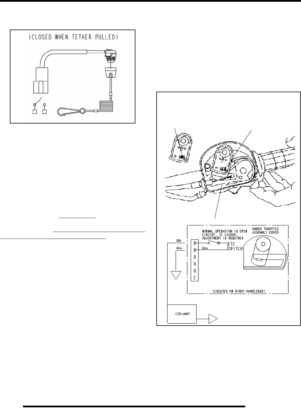
7.6
ELECTRICAL
Tether Switch Test (Accessory Option)
1. Disconnect wire harness from switch.
2. Connect an ohmmeter across switch contacts. The circuit
should have an open line or infinity reading.
3. Pull tether boot from switch and check for continuity
between switch contacts. Replace switch if there is no
continuity or greater than .5 ohms resistance.
Electronic Throttle Control (ETC) Switch
The Electronic Throttle Control (ETC) system is designed to
stop the engine of an ATV in the event of a mechanical problem
with the throttle mechanism. The ETC switch is mounted
independently of the throttle actuator lever inside the throttle
block assembly. This is a normally closed switch, and is held in
the open position (contacts are separated (as shown below)) by
throttle cable tension. The contacts are “open” during normal
operation regardless of throttle lever position. In the event of a
mechanical problem in the throttle mechanism (cable tension is
lost), the switch contacts close, connecting the CDI black wire
to ground, which prevents ignition spark. This is the same as
turning the key or engine stop switch “OFF”.
Test the ETC switch at the harness connector.
NOTE: Adjust throttle cable freeplay (ETC switch)
and make sure throttle mechanism is functioning
properly before testing the switch. Refer to
Maintenance Chapter 2 for cable adjustment
procedure.
ETC Operation Test
Remove throttle block cover by carefully releasing all tabs
around edge of cover.
Place transmission in neutral and apply parking brake.
Start engine and open throttle lever slightly until engine RPM is
just above idle speed.
Hold throttle cable with fingers at point “A” as shown below and
release throttle lever. If the ETC system is functioning properly,
the engine will lose spark and stop.
Electronic Throttle Control (ETC) Switch
(Composite Throttle Housing)
ETC switch contacts
are closed in a fault
condition (throttle cable
slack)
Switch contacts are open
during normal operation
A
RepairPro Service Manual
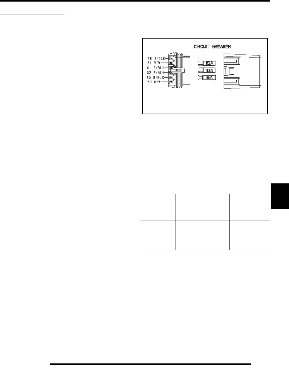
7.7
ELECTRICAL
7
IGNITION SYSTEM
Ignition System Troubleshooting
No Spark, Weak or Intermittent Spark
• No 12 volt power or ground to CDI
• Spark plug gap incorrect
• Fouled spark plug
• Faulty spark plug cap or poor connection to high
tension lead
• Related wiring loose, disconnected, shorted, or
corroded
• Engine Stop switch or ignition switch faulty
• ETC switch misadjusted or faulty
• Poor ignition coil ground (e.g. coil mount loose or
corroded)
• Faulty stator (measure resistance of all ignition related
windings)
• Incorrect wiring (inspect color coding in connectors
etc)
• Faulty ignition coil winding (measure resistance of
primary and secondary)
• Worn magneto (RH) end Crankshaft bearings
• Sheared flywheel key
• Flywheel loose or damaged
• Excessive crankshaft runout on magneto (RH)
end – should not exceed .005”
•Faulty CDI module
Circuit Breakers
The circuit breaker panel is located underneath the front cab.
Access can be gained by removing the cover. Removal of front
cab may be required for better access.
Cranking Output Tests
The following tests will measure the amount of output directly
from each component.
Test output from the CDI and pulse (trigger) coil and compare
to the table. The following measurements are obtained when
cranking the engine with the electric starter and with the spark
plug installed. The starter system must be in good condition and
the battery fully charged.
200 Watt 4 Stroke DC/CDI Ignition
Test Connect
Meter Wires To:
Reading
(Without Peak
Reading Volt
meter)
Pulse (Trigger) White / Red and White 1.4 - 2.0 DCV
CDI Output White / Blue and Ground 200 - 400 DCV
15 Amp - System Main
10 Amp - Fan
5 Amp - CDI
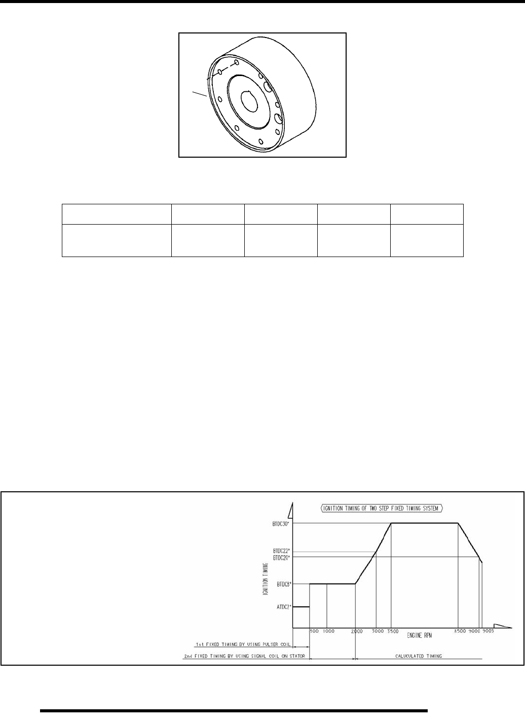
7.8
ELECTRICAL
Flywheel Identification
Flywheel Identification Stamp Location
The flywheel can be identified by the casting marks in location A. Refer to “I.D.” location in chart below.
DC / CDI Ignition
Some of the advantages of DC ignition are:
• Stronger, more consistent spark at low rpm for better performance
• Easier starts
• Simpler component design for ease trouble shooting and maintenance
Operation Overview:
The DC/CDI system relies on battery power for ignition function. Instead of generating DC voltage via magnetic induction, a 12
volt DC current is supplied directly to the CDI unit from the battery.
At the CDI, the supplied 12 volt DC current charges an internal capacitor to build up the initial ignition charge. A small AC signal
from the Pulse coil closes a thyristor (located in the CDI) at a point pre-determined in the crankshaft rotation by magnets on the
flywheel’s outer diameter. This signal releases the electrical charge which saturates the coil for ignition. DC/CDI systems have the
ability to ignite with as little as 6 volts of power.
Engine Application Type Stamp Comment I.D. Stamp
ES50PL External
Trigger IJ09 DC / CDI
Ignition K1805
A
NOTE: DC/CDI systems and components
are not interchangeable
with any other system.
Typical Timing Pattern Shown
RepairPro Service Manual
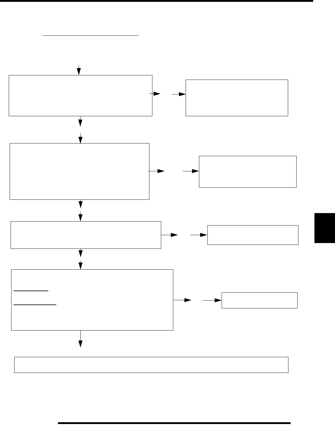
7.9
ELECTRICAL
7
Ignition System Testing
Whenever troubleshooting an electrical problem you should first check all terminal connections to be sure they are clean and tight.
Also be sure that colors match when wires are connected. Use the following pages as a guide for troubleshooting. The resistance
values are also given on the specification pages.
Condition: No spark or intermittent spark.
Verify 12 Volt DC power is present on the red wire to CDI. Replace Spark Plug.
Disconnect the black wire from the 4 wire connector
Disconnect the pulse (trigger) coil connector from
the CDI module. Measure the resistance of the
trigger coil. Check reverse signal coil. Refer to the
exploded view or the wiring schematic for meter
connections and specifications.
Compare results to the specifications.
Is it within specification?
Check coil ground connection between engine and coil
mount using an ohmmeter. The coil mount should
have good continuity to ground on the engine (0 - .3 Ω).
Disconnect and check the secondary coil.
Primary Side - Primary wire tab to engine ground
(on coil mount or engine): .3 to .5 Ohms
Secondary Side High Tension wire to engine ground
Cap installed - 11,300Ω
Cap removed - 6300Ω
Are these values within specs?
If all of the above tests are within specifications, and all grounds, connections, and wire color coding
have been inspected, perform voltage output tests on following page or replace the CDI module.
-Test the ignition switch, engine stop
switch, and speed limiter circuit for
short to ground.
- Check connectors for moisture,
wire color matching or corrosion.
Inspect connectors, wiring and
grounds to the component in ques-
tion. Replace the component if a
wiring problem cannot be found.
Clean coil mounting area.
Repair ground wire connections.
Replace the ignition coil.
No
Yes
Yes
Yes
Yes
No
No
No
ground path (brown) for operation.
from the kill system. Verify the CDI has a good
attached to the CDI module to isolate the ignition
Does it have spark?
Resistance values should be:
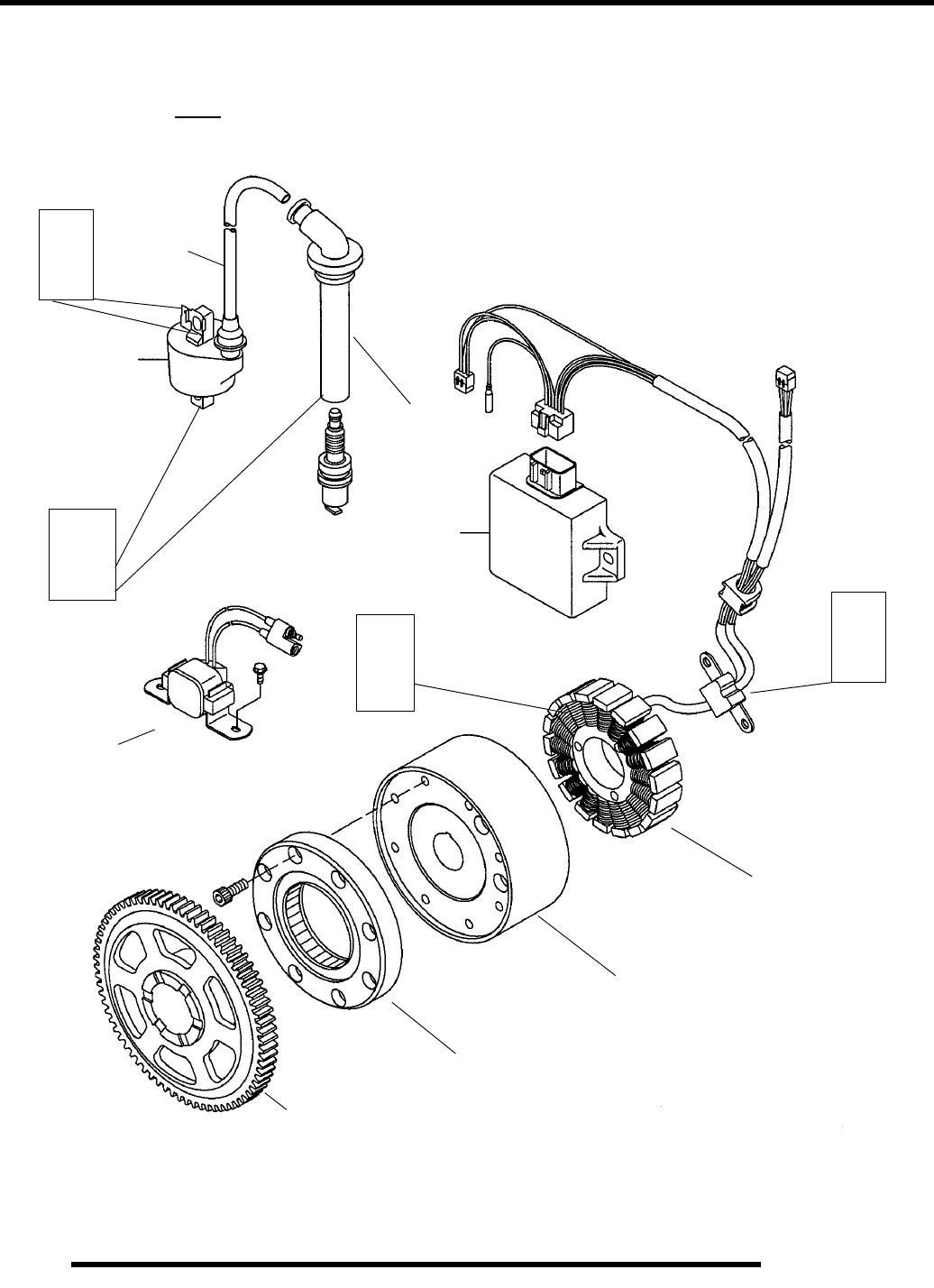
7.10
ELECTRICAL
Components of DC / CDI Ignition
Note: DC/CDI components are not compatible with any other type of ignition.
Refer To Wiring Diagrams For Specified Stator Coil Resistance
Stator
Refer to Page 7.8 for
Flywheel identification.
One way starter clutch
Starter Drive gear
Ω
Meter
190Ω
Pulse Coil (Trigger)
Air Gap: .016 - .030”
(.4 - .75mm)
Reverse Signal Coil
(Located in stator)
Starter
Solenoid
CDI Box
Resistor
Cap
Ω
Meter
11.3kΩ
Ignition Coil
High Tension
Ω
Meter
.3 Ω
Ignition Kill Wire
(Black)
12 Volt DC
Supply Wire
(Red)
Primary
Ω
.089Ω
Meter
Lead
Secondary
Resistance
Resistance
RepairPro Service Manual
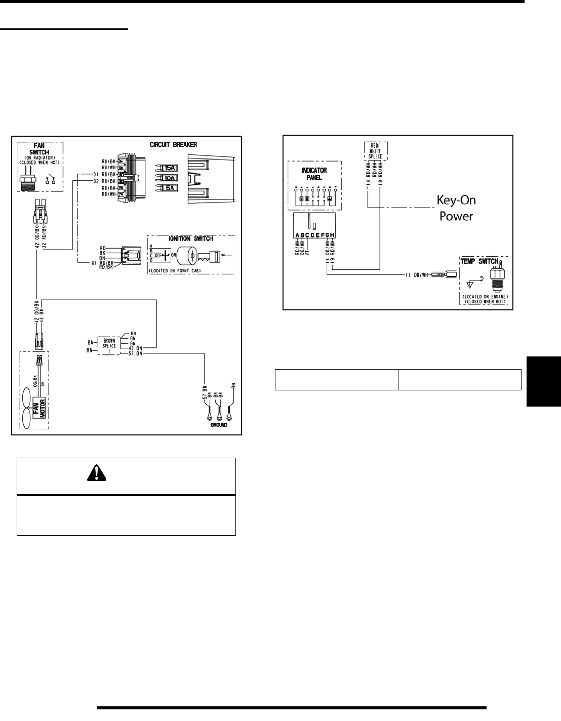
7.11
ELECTRICAL
7
COOLING SYSTEM
Fan Control Circuit Operation / Testing
The fan switch is located on the radiator. Power is supplied to the
fan switch via the Red / Black wire when the ignition key is
“ON”. When the fan switch reaches the specified temperature,
it becomes conductive and sends power to the fan motor through
to the Orange / Black wire. The ground path for the fan motor
is through the Brown harness wire.
The fan switch may not function or operation may be delayed if
coolant level is low or if air is trapped in the cooling system.
Verify the cooling system is full and purged of air. Refer to
Maintenance Chapter 2 for cooling system information.
Coolant Temperature Sensor Test (Hot Light)
With the ignition switch (and engine stop switch) “ON”, power
is delivered to the hot light via the Red / White wire.
The Blue / White wire (ground) out of the light socket is
connected to the coolant temperature switch on the cylinder
head. In normal operating conditions, the temperature switch is
non–conductive (open). If engine coolant reaches the specified
temperature, the switch becomes conductive completing the
ground path for the light.
With engine cold, disconnect lead and measure resistance of
sensor between connector terminal and ground. There should be
no continuity or very high resistance (mega-ohms).
Fan Control Switch Bypass Test
1. Disconnect harness from fan switch on radiator.
2. Place a jumper wire between the Red / Blk and Org / Blk
wires in the connector.
3. With the parking brake on, turn the ignition key (and engine
stop switch) “ON”. The fan should start running.
4. If the fan runs with the jumper wire installed, check the fan
control switch and connector terminals. If the fan does not
run or runs slowly with the jumper wire installed, check the
fan motor wiring, ground, and motor condition (refer to Fan
Motor Current Draw). Repair or replace as necessary.
CAUTION
Keep hands away from fan blades during this
procedure. Serious personal
injury could result.
Hot Light On 221o F (105o C)
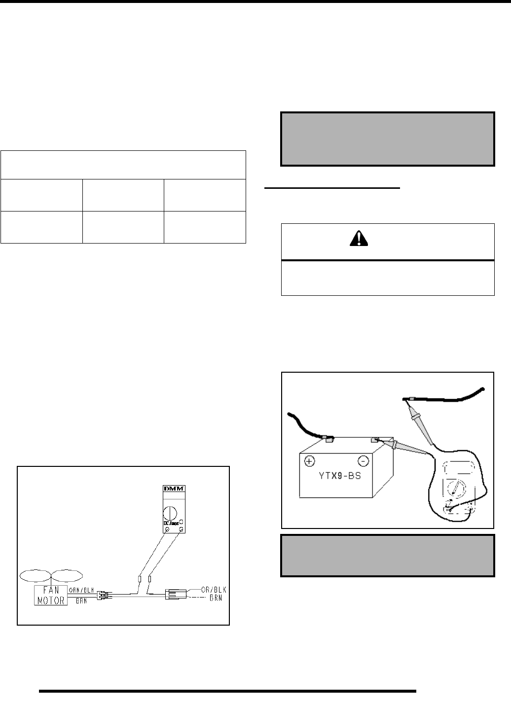
7.12
ELECTRICAL
Coolant Fan Control Switch Operation Test
1. Place switch in a liquid bath and submerse it to the base of
the threads. Do not allow threads to contact container or an
inaccurate reading will result.
2. Heat the liquid slowly and monitor the temperature with a
thermometer or Fluke™ meter pyrometer. The switch
should be closed (conductive) at the “ON” temperature
indicated in the chart, and stay conductive until the “OFF”
temperature is reached.
Fan Motor Current Draw
A current draw test will provide a good indication of fan motor
condition. A worn or damaged fan motor will draw more
current, which causes a reduction in blade speed and reduced
cooling.
1. Turn key off. Disconnect harness from fan switch on
radiator.
2. Place a jumper wire between the Red / Blk and Org / Blk
wires in the fan switch connector.
3. Disconnect the fan and place a jumper wire between the
brown wires in the connectors. This will provide a ground
path to the fan. Use caution as to not damage the wire
terminals.
4. Place a DC ammeter in series as shown in the Illustration.
Verify fan blade is free to rotate.
5. Turn ignition key and engine stop switch to “RUN”
position. Read the current draw on ammeter with fan
running.
6. During start-up, the amperage should peak then decline
rapidly. If the motor continues to draw more amperage than
the fan circuit breaker rating during start-up, replace the
motor.
7. If the fan motor draws more than 6.5 Amps during continual
running, check for debris blocking the fan, or replace the
motor.
CHARGING SYSTEM
Current Draw – Key Off
Connect an ammeter in series with the negative battery cable.
Check for current draw with the key off. If the draw is excessive,
loads should be disconnected from the system one by one until
the draw is eliminated. Check component wiring as well as the
component for partial shorts to ground to eliminate the draw.
Refer To Parts Manual For Fan Switch Application
Fan Switch Type Continuity
(On) No Continuity
(Off)
Off / On
Thermistor 180o F (82o C) ±
3oF
150o F (65o C)
± 8oF
Connect ammeter leads to
each service tool terminal
Connect BRN Wires
Fan Motor Current Draw:
Less Than 6.5 Amps
CAUTION
Do not connect or disconnect the battery cable
or ammeter with the engine running.
Damage will occur to electrical components.
Current Draw - Key Off:
Maximum of .01 DCA (10mA)
Current Draw Inspection
Key Off
RepairPro Service Manual
7.13
ELECTRICAL
7
Charging System “Break Even” Test
The “break even” point of the charging system is the point at
which the alternator overcomes all system loads (lights, etc.)
and begins to charge the battery. Depending on battery condition
and system load, the break even point may vary slightly. The
battery should be fully charged before performing this test.
1. Connect a tachometer to the engine.
2. Using an inductive amperage metering device, (set to DC
amps) connect to the negative battery cable.
3. With engine off and the key, kill switch, and lights in the
“ON” position, the ammeter should read negative amps
(battery discharge). Reverse meter lead if a positive reading
is indicated.
4. Shift transmission into Park and start the engine. With the
engine running at idle, observe meter readings.
5. Increase engine RPM while observing ammeter and
tachometer.
6. Note RPM at which the battery starts to charge (ammeter
indication is positive).
7. With lights and other electrical loads off, the “break even”
point should occur at approximately 1500 RPM or lower.
8. With the engine running, turn the lights on and engage
parking brake lock to keep brake light on.
9. Repeat test, observing ammeter and tachometer. With
lights on, charging should occur at or below 2000 RPM.
Alternator Tests (Charging System)
Three tests can be performed using a multimeter to determine
the condition of the stator (alternator).
TEST 1: Resistance Value of Each Stator Leg
1. Measure the resistance value of each of the three stator
legs: Y1 to Y2, Y1 to Y3, and Y2 to Y3. Each should
measure 0.49 ohms.
NOTE: If there are any significant variations in ohms
readings between the three legs; it is an indication
that one of the three stator legs may be weak or
failed.
TEST 2: Resistance Value of Stator Leg to Ground
1. Measure the resistance value of each of the stator legs to
ground: Y1 to Ground, Y2 to Ground, Y3 to Ground.
NOTE: Any measurement other than Infinity (open)
will indicate a failed or shorted stator leg.
TEST 3: Measure AC Voltage Output of Each Stator
Leg at Charging RPM with a Voltmeter set to Volts AC.
1. Set the voltmeter to read AC Voltage.
2. Start the engine and let it idle.
3. Separately test each ’leg’ of the stator by connecting the
meter leads to the wires leading from the alternator (Y1 to
Y2, Y1 to Y3, Y2 to Y3). Alternator Output Readings
should be no less than 30-40V AC above 2000 RPM on
each ’leg’.
NOTE: If stator leg AC output varies significantly
from the specified value, the stator may need to be
replaced.
CAUTION
Do not allow the battery cables to become
disconnected with the engine running.
Follow the steps below as outlined to reduce
the chance of damage to electrical
WARNING
Never start the engine with an ammeter
connected in series. Damage to the meter or
meter fuse will result. Do not run test for
extended period of time. Do not run test with
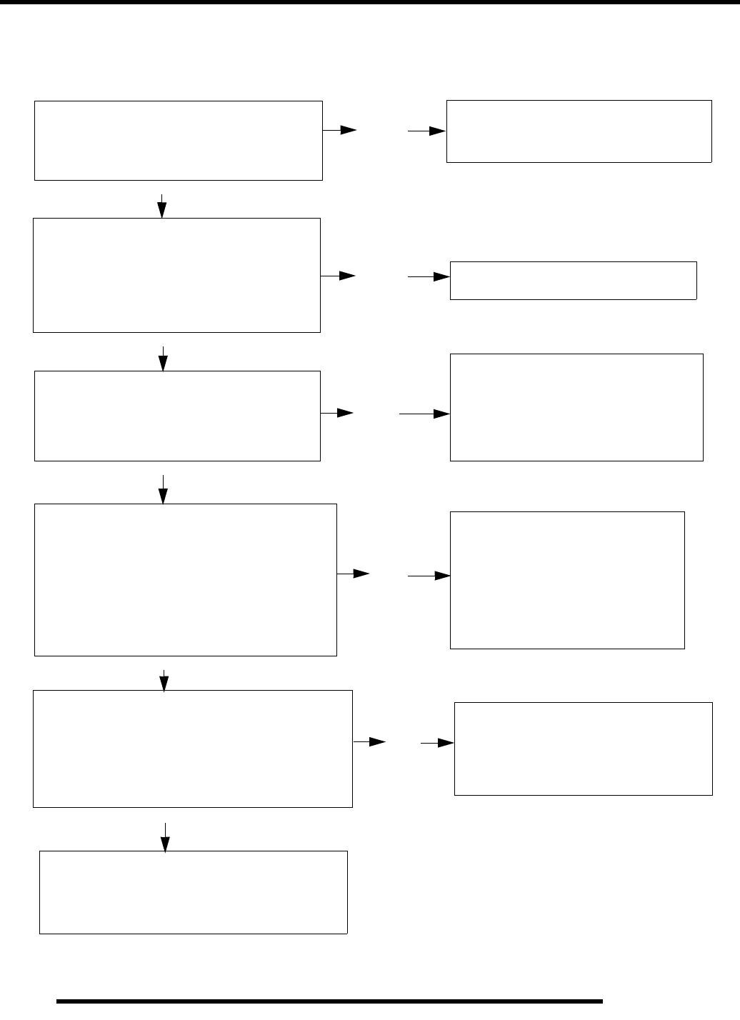
7.14
ELECTRICAL
Charging System Testing Flow Chart
Whenever charging system problems are suspected, proceed with the following system check.
Using a multitester set on D.C. volts, mea-
sure the battery open circuit voltage (See
page 7.12). It should be 12.5 volts or more.
Is it?
Meter Setting: DC Volts
With the transmission in neutral, start the
engine and increase RPM to between 3000
and 4000. Read battery voltage with the
multitester. Readings should increase to be-
tween 13.0 and 14.6 V D.C. Are they?
Meter Setting: DC Amps
Perform system “Break Even Amperage”
test outlined on Page 7.13.
Does charging occur as specified?
Ohm stator (Y) wires. If failed, replace, if good,
continue with alternator output test.
Meter Setting: AC Volts
Disconnect the Yellow wires from the regu-
lator/rectifier. Using a multitester, perform
an Alternator Output Test. See
test procedure on Page 7.13 for procedure.
Does output meet specification?
Meter Setting: DC Volts
Reconnect the alternator wires. Note: Red
wire must be connected to harness. Battery
voltage must be present on red wire terminal
on harness side of voltage regulator connector.
Is it?
If all of the previous tests indicate a good
condition, but the charging voltage does
not rise above battery voltage at the
connector or wire harness, replace the
voltage regulator.
Yes
No
No
Yes
Yes
Remove the battery and properly ser-
vice. Reinstall the fully charged battery
or a fully charged shop battery.
No
Check Key off Current Draw.
Yes
Check for owner modification, and
discuss operating habits. The battery
will continually discharge if operated
below the “Break Even” RPM. Con-
tinued problems would call for battery
inspection.
Yes
Inspect the wiring harness be-
tween the panel and the stator for
damage. If no damage is found,
remove the recoil and flywheel.
Inspect the flywheel magnets, sta-
tor coils and stator wire harness
for damage. Repair or replace
any damaged components.
No
Check regulator/rectifier connections
and ground, battery connections, cir-
cuit breaker and connecting wires.
Repair or replace faulty wiring or
components.
No
RepairPro Service Manual
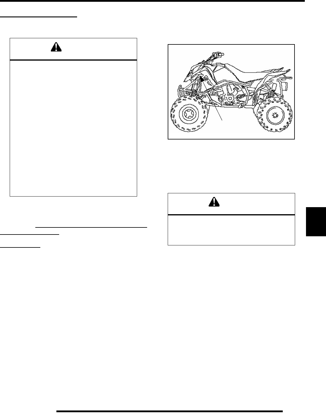
7.15
ELECTRICAL
7
BATTERY SERVICE
Battery Maintenance
All Outlaw ATV batteries are Maintenance-Free design
and construction. Before placing the battery into
service, check the battery condition and charge
accordingly. Use of Conventional Lead-Acid batteries
is not recommended.
New Batteries: Batteries must be fully charged before
use or battery life will be reduced by 10–30% of full
potential. Charge battery for 3-5 hours at a current
equivalent of 1/10 of the battery’s rated amp/hour
capacity (i.e. 9 amp hr x .10 = .9 amp charging). Do not
use the alternator to charge a new battery.
Maintenance-Free batteries are sealed at the factory.
The use of lead-calcium instead of lead-antimony
allows the battery acid to be fully absorbed by the
plates. Therefore, a Maintenance-Free battery case is
opaque and the sealing caps are not removable, since
there is no need to check electrolyte level.
NEVER attempt to add electrolyte or water to a
Maintenance-Free battery. Doing so will damage the
case and shorten the life of the battery.
Battery Inspection / Removal
The battery is located under the front cab at the front of the ATV.
Removal of the front cab assembly is required to access the
battery. Refer to Chapter 5 for front cab removal.
To remove the battery:
1. Remove the front cab.
2. Disconnect holder strap.
3. Disconnect battery negative (–) (black) cable first,
followed by the positive (+) (red) cables.
4. Remove the battery.
5. Clean battery cables and terminals with a stiff wire brush.
Corrosion can be removed using a solution of one cup water
and one tablespoon baking soda. Rinse well with clean
water and dry thoroughly. Test battery for condition and
charge accordingly.
6. Reinstall battery, attaching positive (+) (red) cable first and
then the negative (–) (black) cable.
7. Coat terminals and bolt threads with Dielectric Grease (PN
2871329).
8. Reinstall the holder strap.
9. Reinstall the battery caps.
10. Charge battery at 1/10 of its amp/hour rating. Example: 1/
10 of 14 amp battery = 1.4 amp
11. Reinstall the battery after testing.
WARNING
Battery electrolyte is poisonous. It contains
sulfuric acid. Serious burns can result from
contact with skin, eyes or clothing. Antidote:
External: Flush with water.
Internal: Drink large quantities of water or milk.
Follow with milk of magnesia, beaten egg, or
vegetable oil. Call physician immediately.
Eyes: Flush with water for 15 minutes and get
prompt medical attention.
Batteries produce explosive gases. Keep
sparks, flame, cigarettes etc. away. Ventilate
when charging or using in an enclosed space.
Always shield eyes when working near
batteries. KEEP OUT OF REACH OF
CHILDREN.
CAUTION
To reduce the chance of sparks: Whenever
removing the battery, disconnect the
negative (black) cable first. When reinstalling
the battery, install the negative cable last.
Battery
Location
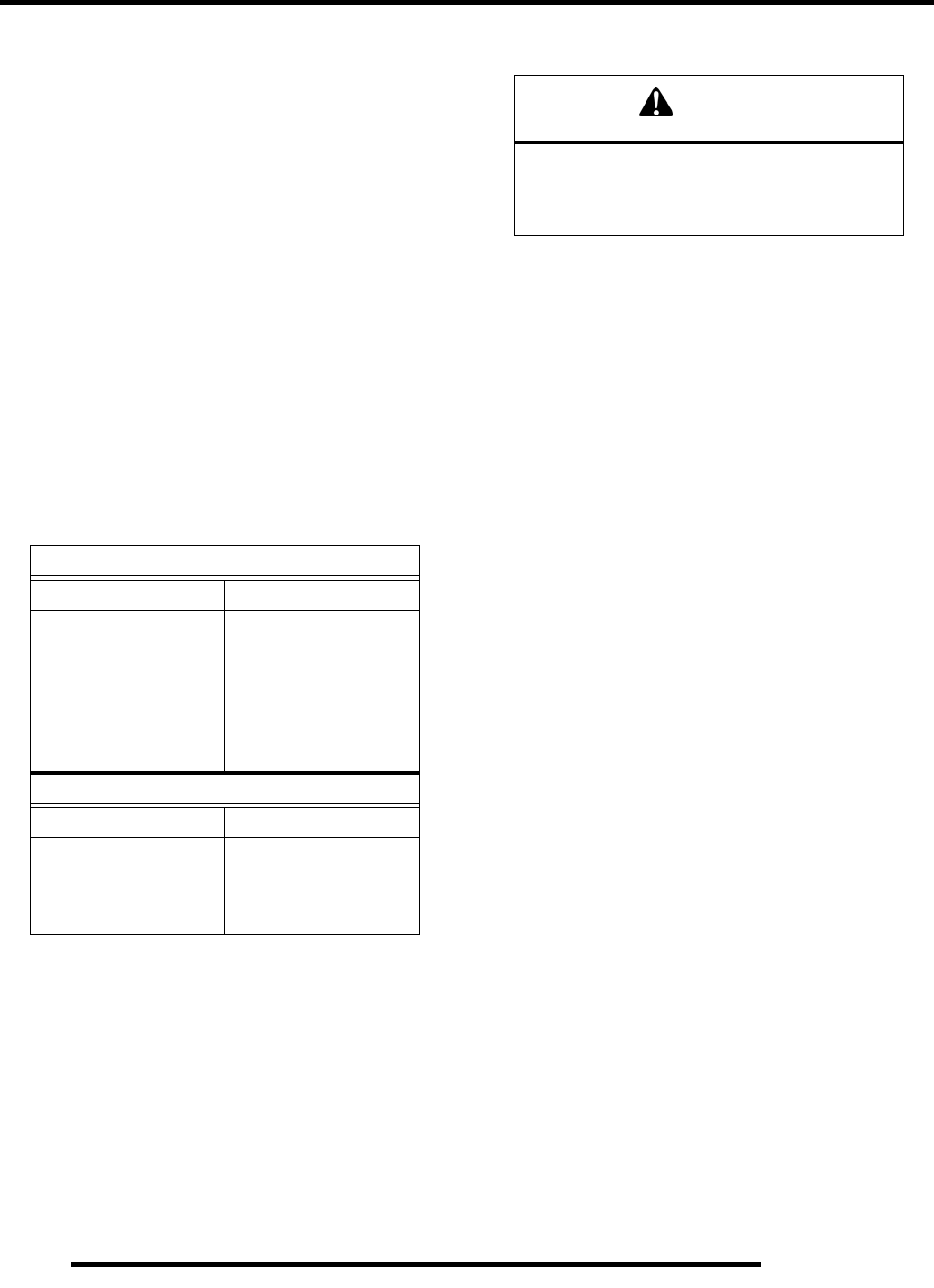
7.16
ELECTRICAL
Battery Terminals / Bolts
Use Polaris corrosion resistant Dielectric Grease (PN 2871329)
on battery bolts.
Battery Testing
Whenever a service complaint is related to either the starting
or charging systems, the battery should be checked first.
Following are tests which can easily be made on a maintenance-
free battery to determine its condition: The OCV Test and Load
Test.
OCV – Open Circuit Voltage Test
Battery voltage should be checked with a digital multitester.
Readings of 12.6 volts or less require further battery testing
and charging. See charts and Load Test.
To perform an open circuit voltage test, set the digital meter to
DC volts and place the tester leads on each battery terminal.
Minimum voltage should be 12.4 to 12.7 VDC for a known good
battery.
Load Test
NOTE: This test can only be performed on machines
with electric starters. This test cannot be performed
with an engine or starting system that is not working
properly.
A battery may indicate a full charge condition in the OCV test
and the specific gravity test, but still may not have the storage
capacity necessary to properly function in the electrical system.
For this reason, a battery capacity or load test should be
conducted whenever poor battery performance is encountered.
To perform this test, hook a multi-tester to the battery in the
same manner as was done in the OCV test. The reading should
be 12.6 volts or greater. Engage the starter and observe the
battery voltage while cranking the engine. Continue the test for
15 seconds. During cranking the observed voltage should not
drop below 9.5 volts. If the beginning voltage is 12.6 volts or
higher and the cranking voltage drops below 9.5 volts during the
test, replace the battery and re-test. Continued low cranking
voltage with a known good battery may indicate excess current
draw from one or more of the starting components.
Off Season Storage
To prevent battery damage during extended periods of non–use,
the following basic battery maintenance items must be
performed:
• Remove the battery from the machine and wash the
case and battery tray with a mild solution of baking
soda and water. Rinse with lots of fresh water after
cleaning.
NOTE: Do not get any of the baking soda into the
battery or the acid will be neutralized.
• Using a wire brush or knife, remove any corrosion from
the cables and terminals.
•Never add water to a sealed maintenance free
battery.
• Charge at a rate no greater than 1/10 of the battery’s
amp/hr capacity until the open circuit voltage is 12.9 V
or greater.
•Store the battery either in the machine with the cables
disconnected, or store in a cool place.
OPEN CIRCUIT VOLTAGE
State of Charge Maintenance Free
100% Charged 12.6 V
75% Charged 12.4 V
50% Charged 12.1 V
25% Charged 11.9 V
0% Charged less than 11.9 V
Self Discharge vs. Temperature
Temperature Days to 0% Charged
104 F 300
77 F 600
32 F 950
CAUTION
To prevent shock or component damage,
remove spark plug high tension leads and
connect securely to engine ground
before proceeding.
RepairPro Service Manual
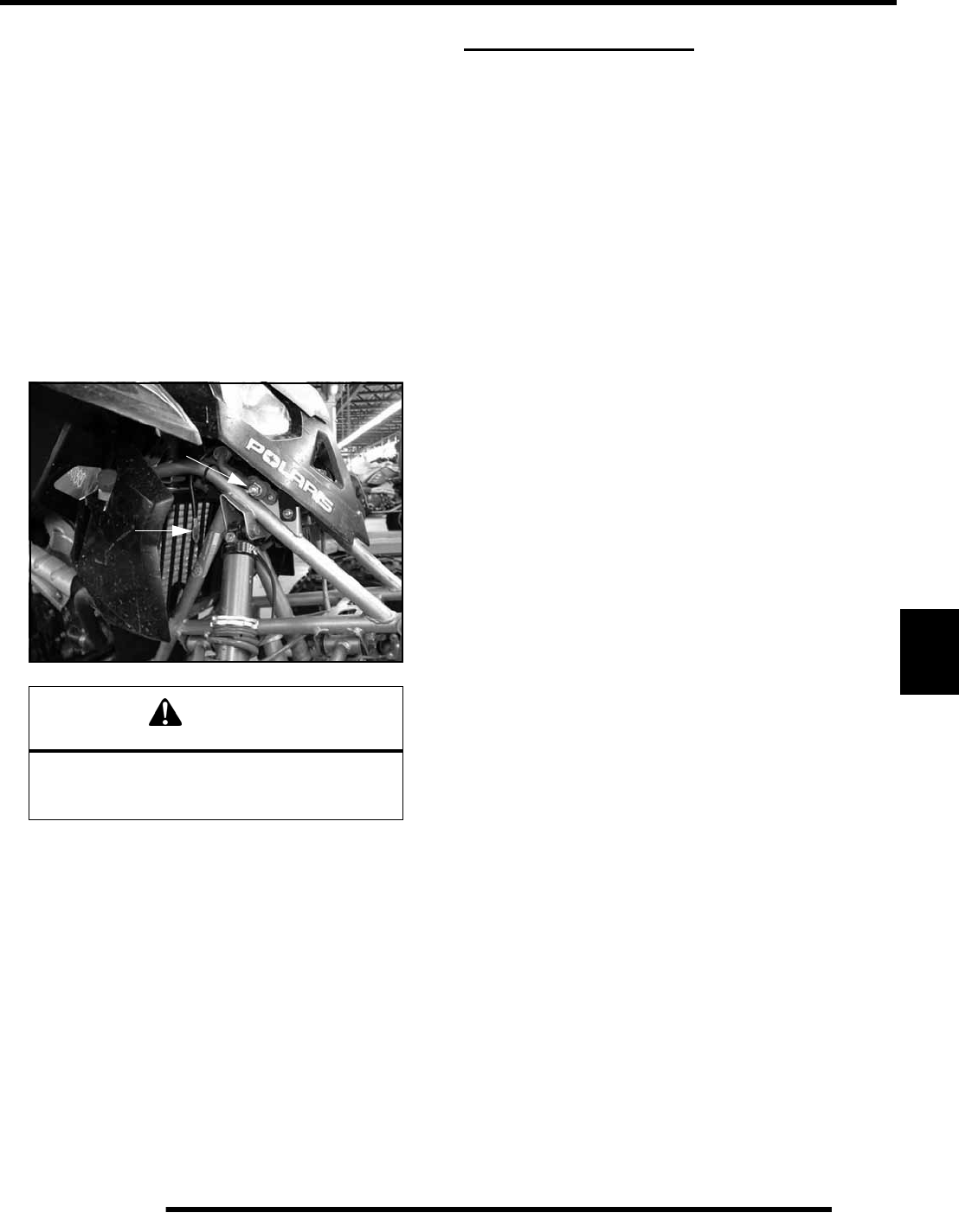
7.17
ELECTRICAL
7
Charging Procedure
NOTE: Remote charging terminals have been
provided to allow for battery charging without
removal of the front cab.
1. Attach the Positive battery charging cable to the Red
Charge Terminal (A); which is directly connected to the
positive battery terminal. It is located just above the front
right shock mount.
2. Attach the Negative battery charging cable to the free end
of the Black Cable (B) under the right front cab (which is
directly connected to the negative battery terminal).
3. Charge with a charging output no larger than 1/10 of the
battery's amp/hr rating. Charge as needed to raise the open
circuit voltage to 12.9 V or greater.
STARTING SYSTEM
Starter System Troubleshooting
Starter Motor Does Not Turn
• Battery discharged. Low specific gravity
• Loose or faulty battery cables or corroded connections
(see Voltage Drop Tests)
• Related wiring loose, disconnected, or corroded
• Poor ground connections at battery cable, starter motor
or starter solenoid (see Voltage Drop Tests)
• Faulty key switch
• Faulty kill switch
• Faulty neutral diode
• Faulty clutch switch
• Faulty starter solenoid or starter motor
• Engine problem – seized or binding (Can engine be
rotated easily ?)
•NOTE: The Outlaw will not push start or key start if
the battery is disconnected or completely dead.
Starter Motor Turns Over Slowly
• Battery discharged
• Excessive circuit resistance – poor connections (see
Voltage Drop Test)
• Engine problem – seized or binding (Can engine be
rotated easily?)
• Faulty or worn brushes in starter motor
• Automatic compression release inoperative
Starter Motor Turns – Engine Does Not Rotate
• Faulty starter drive/one way clutch
• Faulty starter drive gears or starter motor gear
• Faulty flywheel gear or loose flywheel
• Possible engine damage
WARNING
To avoid the possibility of explosion or sparks,
connect positive (red) cable first and negative
(black) cable last.
A
B
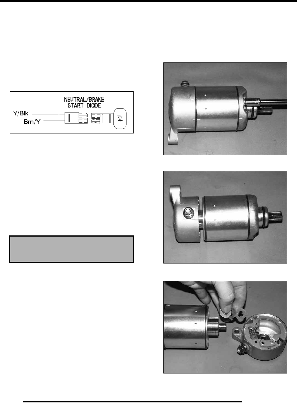
7.18
ELECTRICAL
Clutch Switch Test
Refer to “Clutch Switch Test” under the “Lighting and
Controls” section of this chapter. Problems with the clutch
switch will cause the starter circuit to not operate.
Neutral Start Diode Test
1. Disconnect diode from harness.
2. Using an ohm meter, test for continuity each way. The diode
should only read continuity one direction if it is working
properly.
3. Should the diode test good and there is still a problem,
check the clutch switch, wiring, and harness connections.
Starter Voltage Drop Testing
A Voltage Drop Test tests for bad connections. When
performing the procedure, you are testing the amount of voltage
drop through the connection. A poor or corroded connection
will appear as a high voltage reading.
Voltage shown on the meter when testing connections should
not exceed .1 VDC per connection or component.
To perform the test, place the meter on DC volts and place the
meter leads across the connection to be tested.
Starter Motor Disassembly
Use only electrical contact cleaner to clean starter motor parts.
Some solvents may leave a residue or damage internal parts and
insulation.
1. Note the alignment marks on both ends of the starter motor
casing. These marks must align during reassembly.
2. Remove the two bolts, washers, and sealing O–Rings.
Inspect O–Rings and replace if damaged.
3. Remove brush terminal end of housing while holding other
two sections together.
4. Remove shims from armature shaft.
NOTE: All shims must be replaced during reassembly.
Voltage should not exceed
.1 DC volts per connection
RepairPro Service Manual
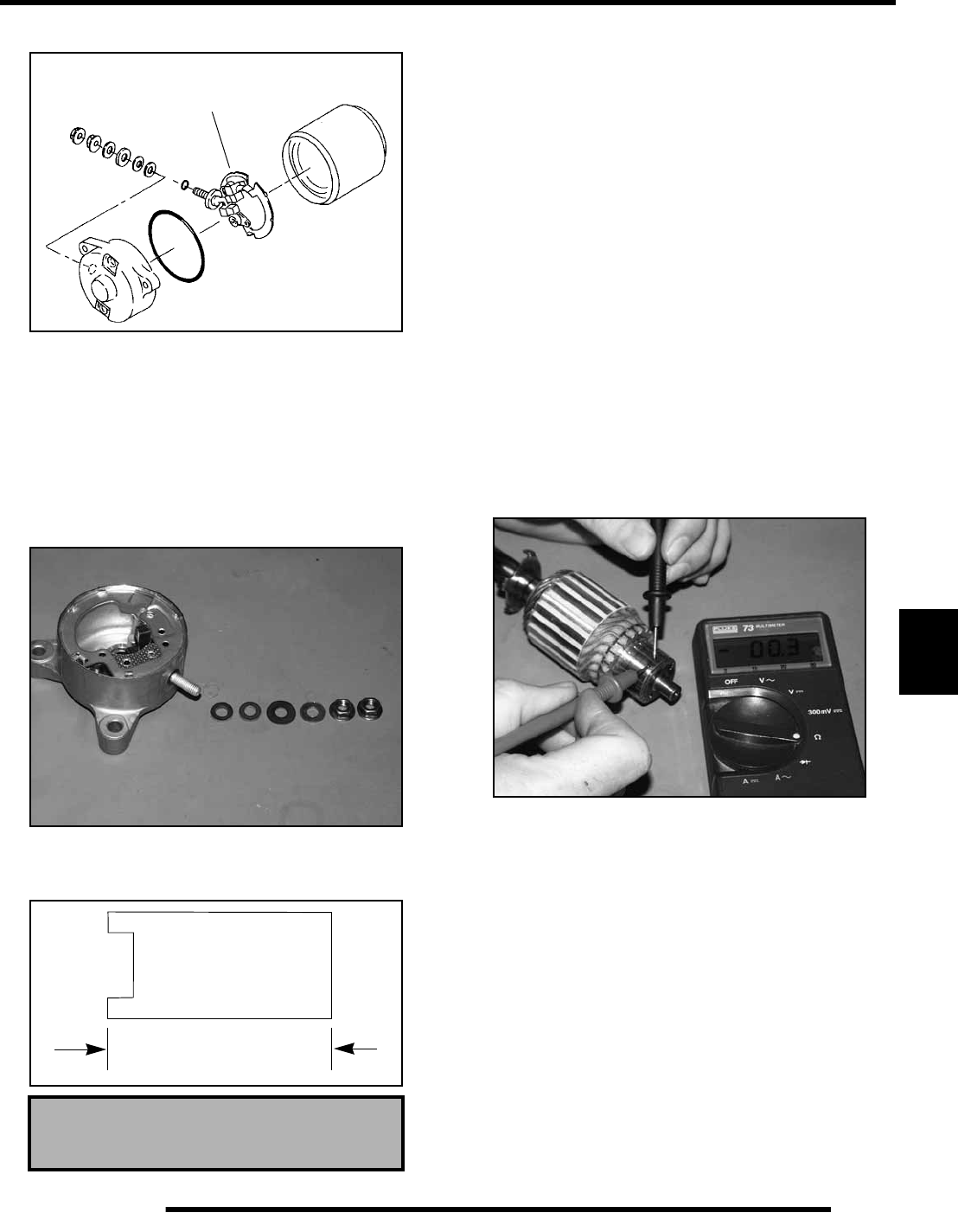
7.19
ELECTRICAL
7
Brush Inspection / Replacement
1. Using a digital multi-tester, measure the resistance
between the cable terminal and the insulated brush. The
reading should be .3 ohms or less.
2. Measure the resistance between the cable terminal and
brush housing. Make sure the brush is not touching the case.
The reading should be infinite.
3. Remove nut, flat washer, large phenolic washer, two small
phenolic washers, and O–Ring from brush terminal. Inspect
the O–Ring and replace if damaged.
4. Remove brush plate and brushes. Measure length of
brushes and replace if worn past the service limit. Replace
springs if they are discolored or have inadequate tension.
5. Inspect surface of commutator for wear or discoloration.
See Steps 3–6 of armature testing on Page 7.20.
6. Install a new carbon brush assembly in the brush housing.
NOTE: Be sure that the terminal bolt insulating
washer is properly seated in the housing, and the
tab on the brush plate engages the notch in the
brush plate housing.
7. Place a wrap of electrical tape on the threads of the terminal
bolt to prevent O–Ring damage during reinstallation.
8. Install the O–Ring over the bolt. Make sure the O–ring is
fully seated.
9. Remove the electrical tape and reinstall the two small
phenolic washers, the large phenolic washer, flat washer,
and nut.
Armature Testing
1. Remove armature from starter casing. Note order of shims
on drive end for reassembly.
2. Inspect surface of commutator. Replace if excessively
worn or damaged.
Brush Length Service Limit:
5/16” (.8 cm)
Brush Set
5/16” (.8 cm)
Brush length
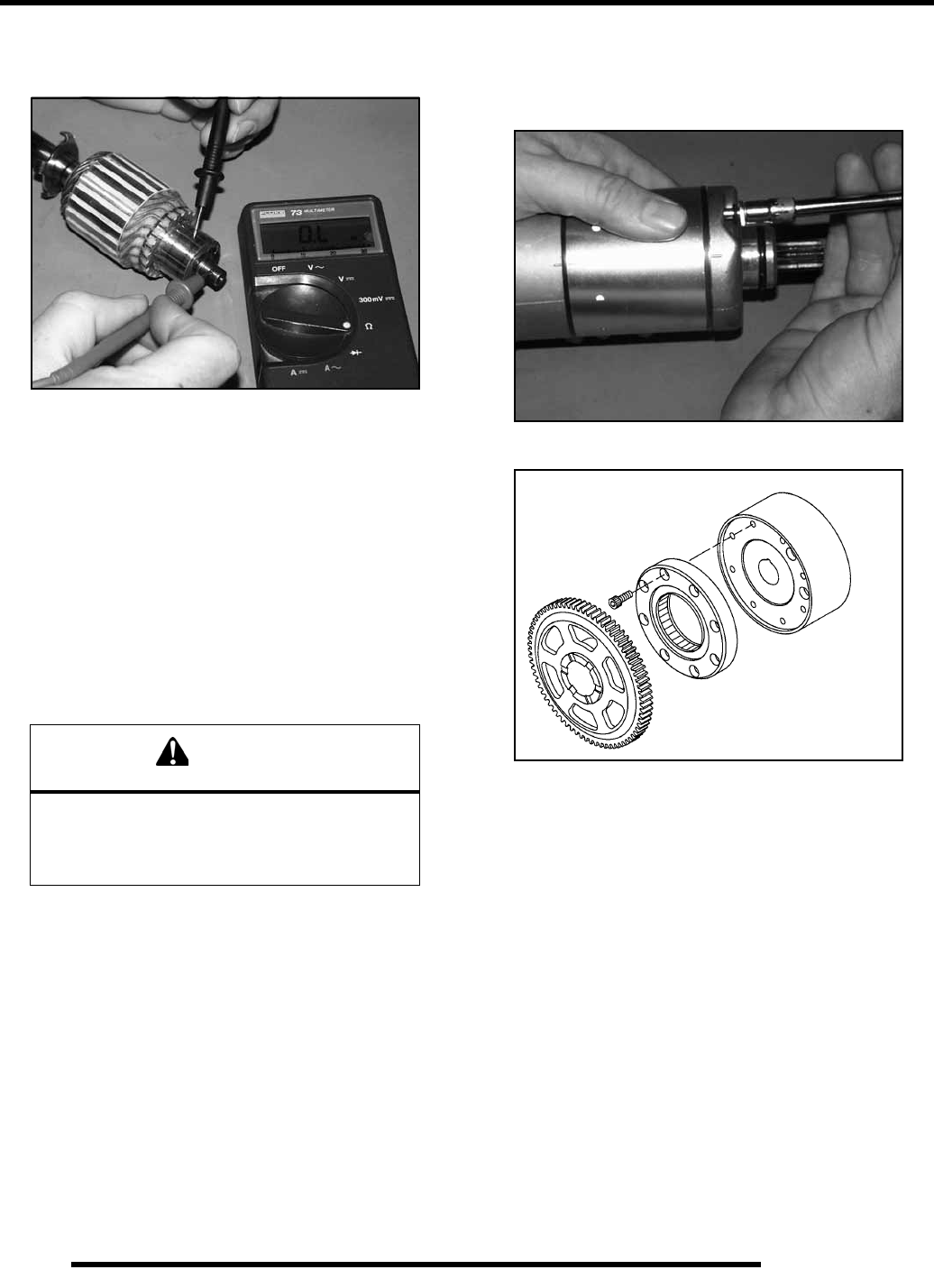
7.20
ELECTRICAL
3. Using a digital multitester, measure the resistance between
each of the commutator segments. The reading should be
.3 ohms or less.
4. Measure the resistance between each commutator segment
and the armature shaft. The reading should be infinite (no
continuity).
5. Check commutator bars for discoloration. Bars discolored
in pairs indicate shorted coils, requiring replacement of the
starter motor.
6. Place armature in a growler. Turn growler on and position
a hacksaw blade or feeler gauge lengthwise 1/8” (.3 cm)
above armature coil laminates. Rotate armature 360o. If
hacksaw blade is drawn to armature on any pole, the
armature is shorted and must be replaced.
Starter Reassembly
1. Inspect permanent magnets in starter housing. Make sure
they are not cracked or separated from housing.
2. Reinstall starter motor housing bolts. Make sure O–Rings
are in good condition and seated in groove.
3. Place armature in field magnet casing.
4. Place shims on drive end of armature shaft with phenolic
washer outermost on shaft. Engage tabs of stationary
washer in drive end housing, holding it in place with a light
film of grease.
5. Install case sealing O–Ring. Make sure O–Ring is in good
condition and not twisted on the case. Lubricate needle
bearing and oil seal with a light film of grease, and install
housing, aligning marks.
6. Install O–Ring on other end of field magnet casing. Make
sure it is in good condition and not twisted on the case.
7. Align casing marks and install housing, pushing back
brushes while installing shaft in bushing.
Starter One-Way Clutch Inspection
1. Inspect the drive gear teeth, bearings and thrust surfaces
for excessive wear or damage.
2. Inspect the one way drive clutch rollers and springs for
excessive wear or damage.
3. Proper function can be determined by rotating the drive
gear counterclockwise, which will engage the one-way
clutch rollers and turn the flywheel. During engine rotation,
there should be no chattering or hanging of the drive gear
and one-way clutch. Should this occur, replace one or both
components and retest. Refer to Chapter 3 for the proper
torque specifications and assembly procedures.
CAUTION
Use care when handling starter housing. Do not
drop or strike the housing as magnet damage is
possible. If magnets are damaged,
starter must be replaced.
Flywheel
One - way Clutch
Drive Gear
RepairPro Service Manual
7.21
ELECTRICAL
7
Starter System Testing Flow Chart
Condition: Starter fails to turn motor.
NOTE: Make sure engine crankshaft is free to turn before proceeding with dynamic testing of starter system.
A digital multitester must be used for this test.
With the tester on the VDC position, place the tes-
ter’s black lead on the battery negative and the red
lead on the battery positive.
Reading should be 12.5 VDC or greater.
Disconnect White/Red engagement coil wire from
the starter solenoid. Connect tester black wire to
battery ground. Connect red tester lead to White/
Red harness wire at solenoid.Turn on ignition
switch and depress the starter button.Tester
should read battery voltage.
No
Yes
Remove battery and properly service.
Install fully charged shop battery to conti-
nue test.
Check voltage on both sides of circuit break-
er, ignition switch/engine stop switch and
starter button. The voltage on both sides
should be the same. NOTE: The ignition
switch must be on and the engine switch
turned to “RUN”. Check the clutch and neu-
tral safety start circuits, as they supply the
ground path for solenoid operation. Replace
the defective component(s) or wiring.
No
Test starter solenoid coil by connecting an ohmmeter between the solenoid
red wire and the solenoid mounting plate. Resistance should be 3.4Ω.
Check solenoid ground path by measuring resistance between mounting
plate and battery negative terminal (-).
Reconnect the solenoid. Connect the tester black
lead to the battery positive and the red lead to the
solenoid end of the battery-to-solenoid wire.Depr-
ess starter button. Reading should be less than
.1 V D.C.
Voltage Drop Testing
See Page 7.16 for information
Connect the black tester lead to solenoid end of
battery-to-solenoid cable. Connect red tester lead
to solenoid end of solenoid-to-starter cable. Depre-
ss starter button. Reading should be less than
.1 V D.C.
Yes
Connect the black tester lead to solenoid end of
the solenoid-to-starter cable. Connect red tester
lead to the starter end of the same cable. Depress
the starter button. The reading should be less than
Yes
Yes
.1 V D.C.
If all of these indicate a good condition, yet the starter still fails to turn, the
starter must be removed for static testing and inspection.
Yes
Clean the battery-to-solenoid cable ends or
replace the cables.
No
Replace the starter solenoid.
No
Clean the solenoid-to-starter cable ends or
replace the cable.
No

NOTES
ELECTRICAL
7.22
RepairPro Service Manual

IX.1
IX
A
A-Arm Replacement . . . . . . . . . . . . . . . . . . . . . . . . . . . . 5.10
A-Arm, Front Installation . . . . . . . . . . . . . . . . . . . . . . . . 5.15
A-Arm, Front Removal and Inspection . . . . . . . . . . . . . 5.15
A-Arm, Rear Inspection . . . . . . . . . . . . . . . . . . . . . . . . . 5.17
A-Arm, Rear Installation . . . . . . . . . . . . . . . . . . . . . . . . 5.18
A-Arm, Rear Removal . . . . . . . . . . . . . . . . . . . . . . . . . . 5.17
Air Filter Service . . . . . . . . . . . . . . . . . . . . . . . . . . . . . . 2.13
Alternator Output Test . . . . . . . . . . . . . . . . . . . . . . . . . . 7.13
Anti-Freeze / Coolant . . . . . . . . . . . . . . . . . . . . . . . . . . . 2.18
Auxiliary Brake, Master Cylinder Fluid Level . . . . . . . . 6.22
B
Ball Joint, Removal and Installation . . . . . . . . . . . . . . . . . 5.8
Battery Charging . . . . . . . . . . . . . . . . . . . . . . . . . . 2.23, 7.17
Battery Location . . . . . . . . . . . . . . . . . . . . . . . . . . . . . . . 7.15
Battery Maintenance . . . . . . . . . . . . . . . . . . . . . . . 2.22, 7.15
Battery Removal . . . . . . . . . . . . . . . . . . . . . . . . . . . . . . . 2.23
Battery Service . . . . . . . . . . . . . . . . . . . . . . .2.23, 7.15, 7.16
Battery Storage . . . . . . . . . . . . . . . . . . . . . . . . . . . . . . . . 2.23
Battery Terminal Bolts . . . . . . . . . . . . . . . . . . . . . . . . . . 7.16
Battery Testing . . . . . . . . . . . . . . . . . . . . . . . . . . . . . . . . 7.16
Battery, Off Season Storage . . . . . . . . . . . . . . . . . . . . . . 7.16
Body Exploded View . . . . . . . . . . . . . . . . . . . . . . . . . . . . 5.4
Boot Burping, Rear Driveshaft . . . . . . . . . . . . . . . . . . . . 2.22
Boot Inspection, Rear Driveshaft . . . . . . . . . . . . . . . . . . 2.21
Brake Burnishing . . . . . . . . . . . . . . . . . . . . . . . . . . . . . . 6.16
Brake Caliper Assembly, Front . . . . . . . . . . . . . . . . . . . 6.14
Brake Caliper Exploded View . . . . . . . . . . . . . . . . . . . . . 6.3
Brake Caliper Inspection, Front . . . . . . . . . . . . . . . . . . . 6.13
Brake Caliper Installation, Front . . . . . . . . . . . . . . . . . . 6.14
Brake Caliper Removal, Front . . . . . . . . . . . . . . . . . . . . 6.12
Brake Caliper, Rear . . . . . . . . . . . . . . . . . . . . . . . . . . . . 6.18
Brake Caliper, Rear Mounting Bolt Torque . . . . . . . . . . 6.21
Brake Caliper, Rear Removal . . . . . . . . . . . . . . . . . . . . . 6.18
Brake Caliper, Rear, Assembly . . . . . . . . . . . . . . . . . . . 6.19
Brake Caliper, Rear, Disassembly . . . . . . . . . . . . . . . . . 6.18
Brake Caliper, Rear, Inspection . . . . . . . . . . . . . . . . . . . 6.19
Brake Disc Runout, Front . . . . . . . . . . . . . . . . . . . . . . . . 6.17
Brake Disc Runout, Rear . . . . . . . . . . . . . . . . . . . . . . . . 6.22
Brake Disc Thickness, Front . . . . . . . . . . . . . . . . . . . . . 6.17
Brake Disc Thickness, Rear . . . . . . . . . . . . . . . . . . . . . . 6.22
Brake Disc, Front . . . . . . . . . . . . . . . . . . . . . . . . . . . . . . 6.17
Brake Disc, Inspection . . . . . . . . . . . . . . . . . . . . . . . . . . 6.17
Brake Disc, Inspection, Rear . . . . . . . . . . . . . . . . . . . . . 6.22
Brake Disc, Mounting Bolt Torque . . . . . . . . . . . . . . . . 6.17
Brake Disc, Rear . . . . . . . . . . . . . . . . . . . . . . . . . . . . . . . 6.22
Brake Disc, Removal, Rear . . . . . . . . . . . . . . . . . . . . . . 6.23
Brake Disc, Replacement / Service . . . . . . . . . . . . . . . . 6.17
Brake Disc, Replacement, Rear . . . . . . . . . . . . . . . . . . . 6.23
Brake Front Pad Assembly . . . . . . . . . . . . . . . . . . . . . . . 6.16
Brake Lamp, Replacement . . . . . . . . . . . . . . . . . . . . . . . . 7.4
Brake Light Switch Testing . . . . . . . . . . . . . . . . . . . . . . . 7.5
Brake Pad Assembly, Front . . . . . . . . . . . . . . . . . . . . . . 6.16
Brake Pad Thickness, Front . . . . . . . . . . . . . . . . . . . . . . 6.15
Brake Pad Thickness, Rear . . . . . . . . . . . . . . . . . . . . . . . 6.21
Brake Pads, Front . . . . . . . . . . . . . . . . . . . . . . . . . . . . . .6.15
Brake Pads, Rear . . . . . . . . . . . . . . . . . . . . . . . . . . . . . . .6.20
Brake Pads, Rear Installation . . . . . . . . . . . . . . . . . . . . .6.21
Brake Pads, Rear Removal . . . . . . . . . . . . . . . . . . . . . . .6.20
Brake Pads, Removal, Front . . . . . . . . . . . . . . . . . . . . . .6.15
Brake Switch, Testing . . . . . . . . . . . . . . . . . . . . . . . . . . . .7.5
Brake System . . . . . . . . . . . . . . . . . . . . . . . . . . . . . . . . . . .6.4
Brake System, Service Notes . . . . . . . . . . . . . . . . . . . . . .6.6
Brakelight Lamp Replacement . . . . . . . . . . . . . . . . . . . . .7.4
Brakes, Fluid Replacement and Bleeding Procedure . . . .6.8
Brakes, Hydraulic System Operation . . . . . . . . . . . . . . . .6.7
Brakes, Inspection and Maintenance . . . . . . . . . . . . . . . .2.29
C
Cam Timing Exploded View . . . . . . . . . . . . . . . . . . . . . .3.34
Carburetor Draining . . . . . . . . . . . . . . . . . . . . . . . . . . . .2.11
Carburetor Exploded View . . . . . . . . . . . . . . . . . . . . . . . .4.2
Carburetor Pilot Screw . . . . . . . . . . . . . . . . . . . . . . . . . .2.12
Carburetor, Assembly . . . . . . . . . . . . . . . . . . . . . . . . . . .4.11
Carburetor, Disassembly . . . . . . . . . . . . . . . . . . . . . . . . . .4.9
Carburetor, Float Bowl Level Test . . . . . . . . . . . . . . . . .4.12
Carburetor, Float Height Adjustment . . . . . . . . . . . . . . .4.11
Carburetor, Function and Operation . . . . . . . . . . . . . . . . .4.5
Carburetor, Jetting . . . . . . . . . . . . . . . . . . . . . . . . . . . . . . .4.4
Carburetor, Needle and Seat Leak Test . . . . . . . . . . . . . .4.12
Carburetor, Pilot Screw Adjustment . . . . . . . . . . . . . . . . .4.8
Carburetor, Troubleshooting . . . . . . . . . . . . . . . . . . . . . .4.13
Chain Adjustment . . . . . . . . . . . . . . . . . . . . . . . . . . . . . .2.21
Chain Tension . . . . . . . . . . . . . . . . . . . . . . . . . . . . . . . . .2.20
Chain, Inspection and Replacement . . . . . . . . . . . . . . . .2.20
Charging System Break Even Test . . . . . . . . . . . . . . . . .7.13
Charging System Flow Chart . . . . . . . . . . . . . . . . . . . . .7.14
Charging System Testing . . . . . . . . . . . . . . . . . . . . . . . .7.14
Charging System, Alternator Tests . . . . . . . . . . . . . . . . .7.13
Charging System, Break Even Test . . . . . . . . . . . . . . . . .7.13
Charging System, Current Draw-Key Off . . . . . . . . . . . .7.12
Charging System, Exploded View . . . . . . . . . . . . . . . . .7.10
Choke Adjustment . . . . . . . . . . . . . . . . . . . . . . . . . . . . . .2.13
Circuit Breakers . . . . . . . . . . . . . . . . . . . . . . . . . . . . . . . . .7.7
Clutch Adjustment . . . . . . . . . . . . . . . . . . . . . . . . . . . . . .2.19
Clutch Switch Test . . . . . . . . . . . . . . . . . . . . . . . . . . . . .7.18
Clutch Switch, Test . . . . . . . . . . . . . . . . . . . . . . . . . . . . . .7.5
Compression Test . . . . . . . . . . . . . . . . . . . . . . . . . . 2.16, 3.6
Conversion Table . . . . . . . . . . . . . . . . . . . . . . . . . . . . . .1.11
Coolant Temp. Sensor Test . . . . . . . . . . . . . . . . . . . . . . .7.11
Cooling System . . . . . . . . . . . . . . . . . . . . . . . . . . . . . . . .2.17
Cooling System Pressure Test . . . . . . . . . . . . . . . . . . . . . .3.7
Cooling System, Recovery Level Inspection . . . . . . . . .2.18
Cooling, Fan Control Operation . . . . . . . . . . . . . . . . . . .7.11
Cooling, Temperature Sensor Operation/Test . . . . . . . . .7.11
Crankcase Bearing Inspection . . . . . . . . . . . . . . . . . . . . .3.29
Crankcase Bearing Installation . . . . . . . . . . . . . . . . . . . .3.25
Crankcase Breather Inspection . . . . . . . . . . . . . . . . . . . .2.14
Cranking Output Test . . . . . . . . . . . . . . . . . . . . . . . . . . . .7.7
Crankshaft Removal/Inspection . . . . . . . . . . . . . . . . . . .3.29
Crankshaft Straightening . . . . . . . . . . . . . . . . . . . . . . . . .3.10

IX.2
Current Draw . . . . . . . . . . . . . . . . . . . . . . . . . . . . . . . . . .7.12
CV Joint, Boot Replacement . . . . . . . . . . . . . . . . . . . . . .5.29
CV Joint, Installation . . . . . . . . . . . . . . . . . . . . . . . . . . . .5.30
CV Joint, Rear Removal . . . . . . . . . . . . . . . . . . . . . . . . .5.28
CV Joint, Rear Service . . . . . . . . . . . . . . . . . . . . . . . . . .5.28
Cylinder Head Inspection . . . . . . . . . . . . . . . . . . . . . . . .3.35
Cylinder Leakdown Test . . . . . . . . . . . . . . . . . . . . . . . . .2.16
D
Decals, Replacement . . . . . . . . . . . . . . . . . . . . . . . . . . . .5.31
Decimal Equivalent Size Charts . . . . . . . . . . . . . . . . . . .1.10
Drain Tube, Air Box . . . . . . . . . . . . . . . . . . . . . . . . . . . .2.14
E
E.T.C. Adjustment . . . . . . . . . . . . . . . . . . . . . . . . . . . . . .2.13
Electrical Service Notes . . . . . . . . . . . . . . . . . . . . . . . . . .7.2
Electrical Special tools . . . . . . . . . . . . . . . . . . . . . . . . . . .7.2
Engine Accessible Components . . . . . . . . . . . . . . . . . . . .3.8
Engine Bottom End Disassembly . . . . . . . . 3.17, 3.18, 3.29
Engine Break in Period . . . . . . . . . . . . . . . . . . . . . . . . . . .3.9
Engine Designation Number . . . . . . . . . . . . . . . . . . . . . . .1.2
Engine Exploded Views . . . . . . . . . . . . . . . . . . . . . . . . .3.13
Engine Installation . . . . . . . . . . . . . . . . . . . . . . . . . . . . . . .3.9
Engine Installation Notes . . . . . . . . . . . . . . . . . . . . . . . . .3.9
Engine Lubrication . . . . . . . . . . . . . . . . . . . . . . . . . . . . .3.10
Engine Mounts . . . . . . . . . . . . . . . . . . . . . . . . . . . . . . . .2.17
Engine Oil Specifications . . . . . . . . . . . . . . . . . . . . . . . .3.10
Engine Removal . . . . . . . . . . . . . . . . . . . . . . . . . . . . . . . .3.8
Engine Serial Number Location . . . . . . . . . . . . . . . . . . . .1.2
ETC Operation Test . . . . . . . . . . . . . . . . . . . . . . . . . . . . .7.6
ETC Switch Testing . . . . . . . . . . . . . . . . . . . . . . . . . . . . .7.6
ETC Switch, Operation and Testing . . . . . . . . . . . . . . . . .7.6
Exhaust, Maintenance . . . . . . . . . . . . . . . . . . . . . . . . . . .2.16
F
Fan Control Bypass Test . . . . . . . . . . . . . . . . . . . . . . . . .7.11
Fan Control Operation . . . . . . . . . . . . . . . . . . . . . . . . . . .7.11
Fan Control Switch Test . . . . . . . . . . . . . . . . . . . . . . . . .7.12
Fan Motor Current Draw . . . . . . . . . . . . . . . . . . . . . . . . .7.12
Fan Motor Current Draw Test . . . . . . . . . . . . . . . . . . . . .7.12
Front Brake Caliper Assembly . . . . . . . . . . . . . . . . . . . . .6.3
Front Brake System, Exploded View . . . . . . . . . . . . . . . .6.4
Front Cab, Remove and Install . . . . . . . . . . . . . . . . . . . . .5.5
Front Caliper, Piston Bore I.D. . . . . . . . . . . . . . . . . . . . .6.13
Front Hub Removal . . . . . . . . . . . . . . . . . . . . . . . . . . . . .5.11
Front Hub, Assembly . . . . . . . . . . . . . . . . . . . . . . . . . . .5.12
Front Hub, Disassembly . . . . . . . . . . . . . . . . . . . . . . . . .5.12
Front Hub, Exploded View . . . . . . . . . . . . . . . . . . . . . . .5.10
Front Hub, Installation . . . . . . . . . . . . . . . . . . . . . . . . . .5.13
Front Hub, Removal . . . . . . . . . . . . . . . . . . . . . . . . . . . .5.11
Front Suspension, Exploded View . . . . . . . . . . . . . . . . .5.14
Fuel Line Inspection . . . . . . . . . . . . . . . . . . . . . . . . . . . .2.10
Fuel Pump, Assembly . . . . . . . . . . . . . . . . . . . . . . . . . . .4.13
Fuel Pump, Disassembly . . . . . . . . . . . . . . . . . . . . . . . . .4.13
Fuel Pump, Tests . . . . . . . . . . . . . . . . . . . . . . . . . . . . . . .4.13
Fuel System Inspection . . . . . . . . . . . . . . . . . . . . . . . . . .2.10
Fuel System, Troubleshooting . . . . . . . . . . . . . . . . . . . . .4.13
Fuel Tank Assembly, Exploded View . . . . . . . . . . . . . . . 4.3
Fuel Valve . . . . . . . . . . . . . . . . . . . . . . . . . . . . . . . . . . . 2.11
Fuses, See Circuit Breakers . . . . . . . . . . . . . . . . . . . . . . . 7.7
G
Gear Position Switch Test . . . . . . . . . . . . . . . . . . . . . . . . 7.3
Glossary of Terms . . . . . . . . . . . . . . . . . . . . . . . . . . . . . 1.12
H
Headlamp Removal . . . . . . . . . . . . . . . . . . . . . . . . . . . . . 7.3
Headlamp Service . . . . . . . . . . . . . . . . . . . . . . . . . . . . . . 7.3
Headlamp Switch Test . . . . . . . . . . . . . . . . . . . . . . . . . . . 7.3
Headlamp Switch Testing . . . . . . . . . . . . . . . . . . . . . . . . 7.3
Headlight Adjustment . . . . . . . . . . . . . . . . . . . . . . . . . . . 7.4
Headlight Housing, Replacement . . . . . . . . . . . . . . . . . . 7.3
Headlight Lamp Replacement . . . . . . . . . . . . . . . . . . . . . 7.3
Heel Pocket, Remove and Install . . . . . . . . . . . . . . . . . . . 5.6
Hub Carrier, Assembly . . . . . . . . . . . . . . . . . . . . . . . . . 5.26
Hub Carrier, Disassembly . . . . . . . . . . . . . . . . . . . . . . . 5.25
Hub Carrier, Installation . . . . . . . . . . . . . . . . . . . . . . . . 5.27
Hub Carrier, Removal . . . . . . . . . . . . . . . . . . . . . . . . . . 5.25
I
Idle Speed Adjustment . . . . . . . . . . . . . . . . . . . . . . . . . . 2.12
Ignition System Components . . . . . . . . . . . . . . . . . . . . . 7.10
Ignition System Testing . . . . . . . . . . . . . . . . . . . . . . . . . . 7.9
Ignition, Cranking Output Test . . . . . . . . . . . . . . . . . . . . 7.7
Ignition, DC/CDI Ignition Operation . . . . . . . . . . . . . . . . 7.8
Ignition, Exploded View . . . . . . . . . . . . . . . . . . . . . . . . 7.10
Ignition, Testing Flow Chart . . . . . . . . . . . . . . . . . . . . . . 7.9
Ignition, Timing Check Procedure . . . . . . . . . . . . . . . . . . 7.2
Indicator Lamp Replacement . . . . . . . . . . . . . . . . . .7.5, 7.18
Indicator Lamp, Replacement . . . . . . . . . . . . . . . . . . . . . 7.5
J
Jet Part Numbers, Mikuni . . . . . . . . . . . . . . . . . . . . . . . . 4.4
Jetting Guidelines . . . . . . . . . . . . . . . . . . . . . . . . . . . . . . . 4.4
L
Load Test . . . . . . . . . . . . . . . . . . . . . . . . . . . . . . . . . . . . 7.16
M
Maintenance Chart . . . . . . . . . . . . . . . . . . . . . . . . . . . . . . 2.3
Maintenance Products . . . . . . . . . . . . . . . . . . . . . . . . . . . 2.9
Maintenance References . . . . . . . . . . . . . . . . . . . . . . . . . 2.8
Master Cylinder, Installation . . . . . . . . . . . . . . . . . . . . . 6.11
Master Cylinder, Removal . . . . . . . . . . . . . . . . . . . . . . . 6.10
N
Neutral / Reverse Switch Test . . . . . . . . . . . . . . . . . . . . . 7.3
Neutral Start Diode . . . . . . . . . . . . . . . . . . . . . . . . . . . . 7.18
O
Oil and Filter Change . . . . . . . . . . . . . . . . . . . . . . . . . . . 2.15
Oil Flow . . . . . . . . . . . . . . . . . . . . . . . . . . . . . . . . . . . . . 3.11
Oil Flow Diagram . . . . . . . . . . . . . . . . . . . . . . . . . . . . . 3.12
Oil Level, Inspection . . . . . . . . . . . . . . . . . . . . . . . . . . . 2.14
Oil Pressure Test . . . . . . . . . . . . . . . . . . . . . . . . . . . . . . 3.10
Oil Pressure Testing . . . . . . . . . . . . . . . . . . . . . . . . . . . . 3.10
Oil Pump Priming . . . . . . . . . . . . . . . . . . . . . . . . . . . . . 3.11
RepairPro Service Manual

IX.3
IX
Oil Pump Priming Procedure . . . . . . . . . . . . . . . . . . . . . 2.16
P
Paint Codes . . . . . . . . . . . . . . . . . . . . . . . . . . . . . . . . . . . . 1.2
Periodic Maintenance Chart . . . . . . . . . . . . . . . . . . . . . . . 2.3
Piston Identification . . . . . . . . . . . . . . . . . . . . . . . . . . . . . 3.6
Piston Removal . . . . . . . . . . . . . . . . . . . . . . . . . . . . . . . . 3.17
Piston Ring Installed Gap . . . . . . . . . . . . . . . . . . . . . . . . 3.44
Piston to Cylinder Clearance . . . . . . . . . . . . . . . . . . . . . 3.43
Piston/Rod Inspection . . . . . . . . . . . . . . . . . . . . . . . . . . . 3.18
Pre-Ride / Daily Inspection . . . . . . . . . . . . . . . . . . . . . . 2.10
Pre-Ride Inspection . . . . . . . . . . . . . . . . . . . . . . . . . . . . . 2.4
Publication Numbers . . . . . . . . . . . . . . . . . . . . . . . . . . . . 1.3
R
Radiator Cap Pressure Test . . . . . . . . . . . . . . . . . . . . . . . . 3.7
Radiator, Inspection . . . . . . . . . . . . . . . . . . . . . . . . . . . . 2.18
Rear Brake Caliper Assembly . . . . . . . . . . . . . . . . . . . . . 6.3
Rear Brake System, Exploded View . . . . . . . . . . . . . . . . 6.5
Rear Cab, Remove and Install . . . . . . . . . . . . . . . . . . . . . 5.6
Rear Housing, Assembly . . . . . . . . . . . . . . . . . . . . . . . . 5.23
Rear Housing, Disassembly . . . . . . . . . . . . . . . . . . . . . . 5.21
Rear Housing, Exploded View . . . . . . . . . . . . . . . . . . . . 5.19
Rear Housing, Installation . . . . . . . . . . . . . . . . . . . . . . . 5.24
Rear Housing, Removal . . . . . . . . . . . . . . . . . . . . . . . . . 5.20
Rear Suspension, Exploded View . . . . . . . . . . . . . . . . . 5.16
Replacement Keys . . . . . . . . . . . . . . . . . . . . . . . . . . . . . . 1.2
Reverse Lock-Out Lever . . . . . . . . . . . . . . . . . . . . . . . . 2.19
S
Serial Number (VIN) Location . . . . . . . . . . . . . . . . . . . . . 1.2
Shock Compression Adjustment, Rear . . . . . . . . . . . . . . 2.29
Shock, Front, Exploded View . . . . . . . . . . . . . . . . . . . . . 5.32
Shock, Piston Orientation . . . . . . . . . . . . . . . . . . . . . . . . 5.34
Shock, Rear, Exploded View . . . . . . . . . . . . . . . . . . . . . 5.33
Shocks, Front / Rear Standard Valving . . . . . . . . . . . . . 5.34
Shocks, RydeFX Service Procedure . . . . . . . . . . . . . . . . 5.35
Side Panel, Remove and Install . . . . . . . . . . . . . . . . . . . . 5.5
Sparkplug, Inspection and Torque . . . . . . . . . . . . . . . . . 2.24
Special Tool, Rear Housing . . . . . . . . . . . . . . . . . . . . . . 5.22
Special Tools . . . . . . . . . . . . . . . . . . . . . . . . . . .1.6, 3.6, 4.4
Special Tools, Brakes . . . . . . . . . . . . . . . . . . . . . . . . . . . . 6.2
Special Tools, Detailed Listing . . . . . . . . . . . . . . . . . . . . 1.7
Special Tools, Electrical . . . . . . . . . . . . . . . . . . . . . . . . . . 7.2
Special Tools, Engine . . . . . . . . . . . . . . . . . . . . . . . . . . . . 3.6
Special Tools, Fuel System . . . . . . . . . . . . . . . . . . . . . . . 4.4
Special Tools, Suspension . . . . . . . . . . . . . . . . . . . . . . . . 5.3
Specification, A-Arm Fastener Torque . . . . . . . . . . . . . 5.15
Specification, Brake Lever Freeplay . . . . . . . . . . . . . . . 2.30
Specification, Brake Pad Thickness . . . . . . . . . . . . . . . . 2.30
Specification, Cam Shaft . . . . . . . . . . . . . . . . . . . . . . . . 3.16
Specification, Chain Wear Limit . . . . . . . . . . . . . . . . . . 2.20
Specification, Crankshaft Nut Torque . . . . . . . . . . . . . . 3.20
Specification, CV Joint Grease Amount . . . . . . . . . . . . . 5.30
Specification, Cylinder Head Torque . . . . . . . . . . . . . . . 3.42
Specification, Cylinder Taper . . . . . . . . . . . . . . . . . . . . . 3.43
Specification, Cylinder Warp . . . . . . . . . . . . . . . . . . . . . 3.42
Specification, Drive Chain Wear Limit . . . . . . . . . . . . . .2.20
Specification, Float Height . . . . . . . . . . . . . . . . . . . . . . .4.12
Specification, Flywheel Nut Torque . . . . . . . . . . . . . . . .3.20
Specification, Handle Bar Fastener Torque . . . . . . . . . .2.25
Specification, Hub Carrier Fastener Torque . . . . . 5.25, 5.27
Specification, Hub Nut Torque . . . . . . . . . . . . . . . . . . . .5.27
Specification, Idle Speed RPM . . . . . . . . . . . . . . . . . . . .2.12
Specification, Oil Filter Cover Bolt Torque . . . . . . . . . .2.16
Specification, Oil Pressure . . . . . . . . . . . . . . . . . . . . . . .3.10
Specification, Oil Tank Drain Plug Torque . . . . . . . . . .2.15
Specification, Pilot Screw Setting . . . . . . . . . . . . . . . . . .2.12
Specification, Piston Ring Installed Gap . . . . . . . . . . . . .3.44
Specification, Radiator Cap Pressure . . . . . . . . . . . . . . . .3.7
Specification, Spark Plug . . . . . . . . . . . . . . . . . . . . . . . .2.24
Specification, Sparkplug Gap . . . . . . . . . . . . . . . . . . . . .2.24
Specification, Sparkplug Torque . . . . . . . . . . . . . . . . . . .2.24
Specification, Tensioner Bolt Torque . . . . . . . . . . . . . . .3.15
Specification, Thermistor Torque . . . . . . . . . . . . . . . . . . .3.7
Specification, Throttle Lever Freeplay . . . . . . . . . . . . . .2.13
Specification, Tire Pressure . . . . . . . . . . . . . . . . . . . . . . .2.31
Specification, Tire Wear . . . . . . . . . . . . . . . . . . . . . . . . .2.31
Specification, Valve Clearance . . . . . . . . . . . . . . . . . . . .3.41
Specification, Valve Guide Installed Height . . . . . . . . . .3.37
Specification, Valve Seat . . . . . . . . . . . . . . . . . . . . . . . .3.38
Specification, Valve Spring Height . . . . . . . . . . . . . . . . .3.36
Specification, Valve Stem . . . . . . . . . . . . . . . . . . . . . . . .3.39
Specification, Wheel and Hub Torque . . . . . . . . . . . . . .2.30
Specification, Wheel Nut Torque . . . . . . . . . . . . . . . . . .5.27
Specifications, Brakes . . . . . . . . . . . . . . . . . . . . . . . . . . . .6.2
Specifications, Brakes Torque . . . . . . . . . . . . . . . . . . . . . .6.2
Specifications, Cooling System . . . . . . . . . . . . . . . . . . . . .3.7
Specifications, Detailed . . . . . . . . . . . . . . . . . . . . . . . . . . .1.5
Specifications, Engine Fastener Torques . . . . . . . . . . . . .3.3
Specifications, ES50PL Engine Data . . . . . . . . . . . . . . . .3.4
Specifications, Front Suspension Fastener Torque . . . . . .5.3
Specifications, General . . . . . . . . . . . . . . . . . . . . . . . . . . .1.4
Specifications, Piston and Rod . . . . . . . . . . . . . . . . . . . .3.17
Specifications, Rear Suspension Fastener Torque . . . . . .5.3
Specifications, Steering Component Fastener Torque . . .5.3
Sprocket Inspection, Rear . . . . . . . . . . . . . . . . . . . . . . . .2.19
Starter Armature Testing . . . . . . . . . . . . . . . . . . . . . . . . .7.19
Starter Assembly . . . . . . . . . . . . . . . . . . . . . . . . . . . . . . .7.20
Starter Brushes, Inspection and Replacement . . . . . . . . .7.19
Starter Disassembly . . . . . . . . . . . . . . . . . . . . . . . . . . . . .7.18
Starter Motor Armature Testing . . . . . . . . . . . . . . . . . . .7.19
Starter Motor Brush Inspection/Replacement . . . . . . . . .7.19
Starter One-Way Clutch Inspection . . . . . . . . . . . . . . . .7.20
Starter Reassembly . . . . . . . . . . . . . . . . . . . . . . . . . . . . .7.20
Starter System Flow Chart . . . . . . . . . . . . . . . . . . . . . . .7.21
Starter System Test . . . . . . . . . . . . . . . . . . . . . . . . . . . . .7.21
Starter Voltage Drop Test . . . . . . . . . . . . . . . . . . . . . . . .7.18
Starting Clutch . . . . . . . . . . . . . . . . . . . . . . . . . . . . . . . . .3.20
Starting System Troubleshooting . . . . . . . . . . . . . . . . . .7.17
Steering Assembly, Exploded View . . . . . . . . . . . . . . . . .5.7
Steering Inspection . . . . . . . . . . . . . . . . . . . . . . . . . . . . .2.26

IX.4
Steering Knuckle, Removal and Installation . . . . . . . . . . .5.8
Steering, Alignment . . . . . . . . . . . . . . . . . . . . . . . . . . . .2.24
Steering, Toe Alignment . . . . . . . . . . . . . . . . . . . . . . . . .2.27
Suspension, Spring Preload Adjustment . . . . . . . . . . . . .2.27
T
Tail Lamp, Replacement . . . . . . . . . . . . . . . . . . . . . . . . . .7.4
Taillight Lamp Replacement . . . . . . . . . . . . . . . . . . . . . . .7.4
Tank Cover, Remove and Install . . . . . . . . . . . . . . . . . . . .5.5
Tap / Drill Sizes, Metric . . . . . . . . . . . . . . . . . . . . . . . . .1.10
Tap / Drill Sizes, SAE . . . . . . . . . . . . . . . . . . . . . . . . . . .1.10
Temperature Sensor Operation/Test . . . . . . . . . . . . . . . .7.11
Tether Switch . . . . . . . . . . . . . . . . . . . . . . . . . . . . . . . . . .7.6
Tether Switch, Testing . . . . . . . . . . . . . . . . . . . . . . . . . . .7.6
Throttle Inspection . . . . . . . . . . . . . . . . . . . . . . . . . . . . .2.12
Timing Check Procedure . . . . . . . . . . . . . . . . . . . . . . . . . .7.2
Tire Inspection . . . . . . . . . . . . . . . . . . . . . . . . . . . . . . . . .2.31
Toe Alignment . . . . . . . . . . . . . . . . . . . . . . . . . . . . . . . . .2.27
Torque Patterns, Engine . . . . . . . . . . . . . . . . . . . . . . . . . .3.6
Torque Specifications, Standard . . . . . . . . . . . . . . . . . . . .1.3
Transmission Removal . . . . . . . . . . . . . . . . . . . . . . . . . .3.26
Troubleshooting, Brake Noise . . . . . . . . . . . . . . . . . . . . . .6.6
Troubleshooting, Brake System . . . . . . . . . . . . . . . . . . .6.24
Troubleshooting, Cooling . . . . . . . . . . . . . . . . . . . . . . . .3.48
Troubleshooting, Engine . . . . . . . . . . . . . . . . . . . . . . . . .3.46
Troubleshooting, Ignition System . . . . . . . . . . . . . . . . . . .7.7
Troubleshooting, Spark Plug Fouling . . . . . . . . . . . . . . .3.48
Troubleshooting, Starter System . . . . . . . . . . . . . . . . . . .7.17
U
Unit Model Number Identification . . . . . . . . . . . . . . . . . .1.2
V
Valve Shim Adjustment Matrix . . . . . . . . . . . . . . . . . . .3.40
Vehicle Identification . . . . . . . . . . . . . . . . . . . . . . . . . . . .1.2
Vehicle Identification Number (VIN) . . . . . . . . . . . . . . . .1.2
Voltage Drop Test . . . . . . . . . . . . . . . . . . . . . . . . . . . . . .7.18
W
Water Pump . . . . . . . . . . . . . . . . . . . . . . . . . . . . . . . . . . .3.44
Water Pump Seal Removal and Installation . . . . . . . . . .3.45
Water Pump Shaft Oil Seal . . . . . . . . . . . . . . . . . . . . . . .3.44
Wheel Alignment . . . . . . . . . . . . . . . . . . . . . . . . . . . . . .2.25
Wheel Removal, Front or Rear . . . . . . . . . . . . . . . . . . . .2.30
RepairPro Service Manual
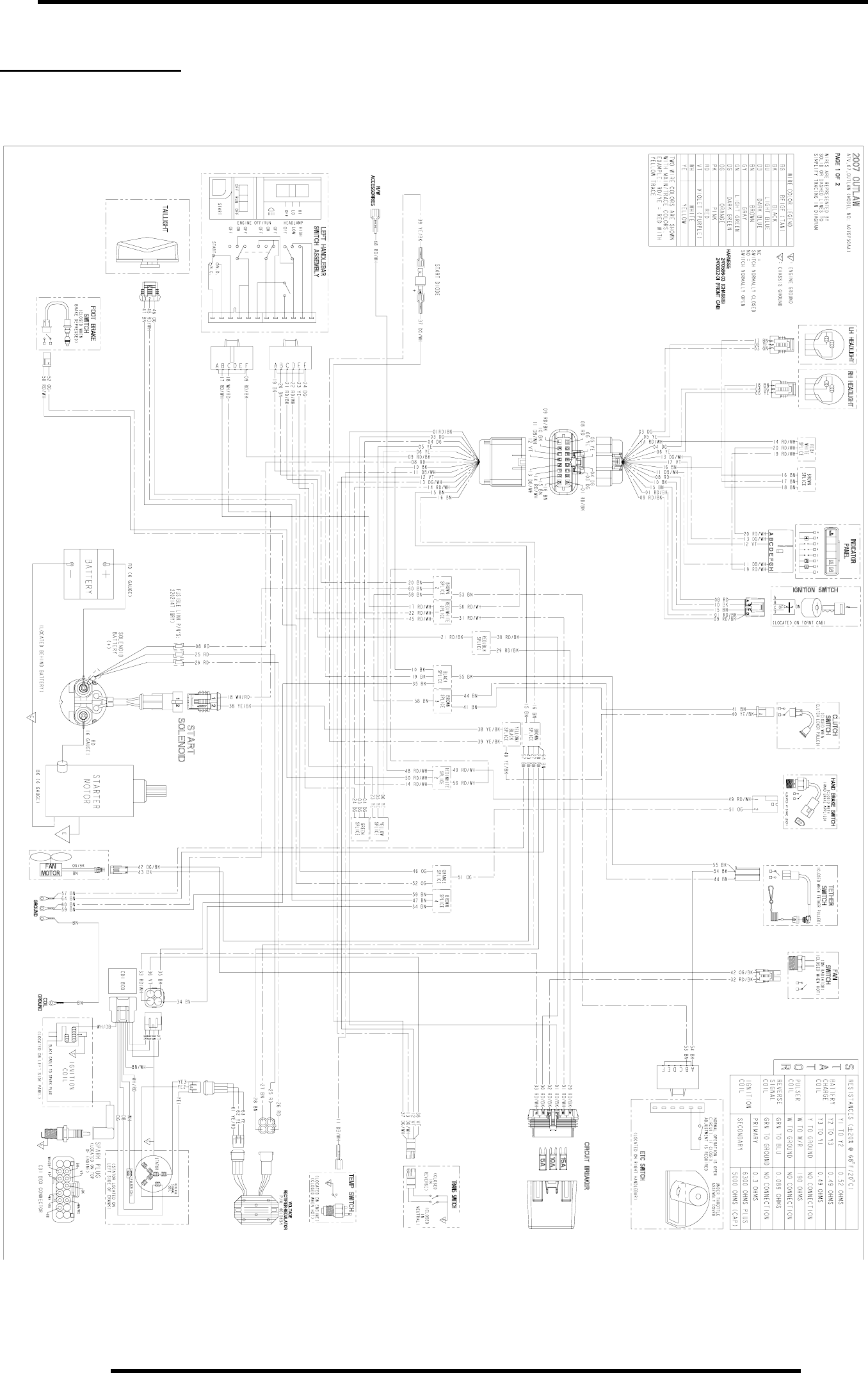
8.1
WIRE DIAGRAM
OUTLAW 500
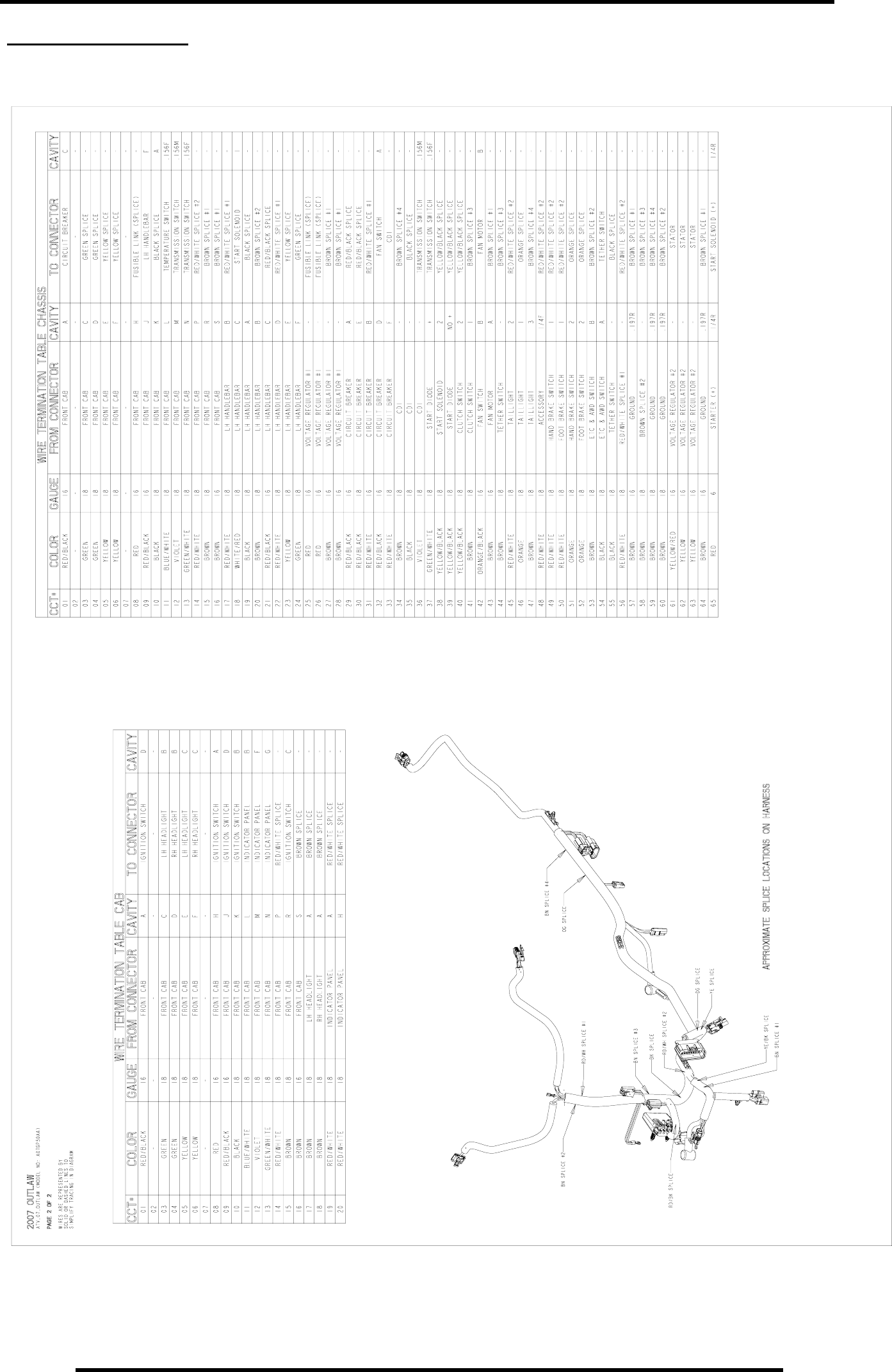
8.2
WIRE DIAGRAM
OUTLAW 500
RepairPro Service Manual
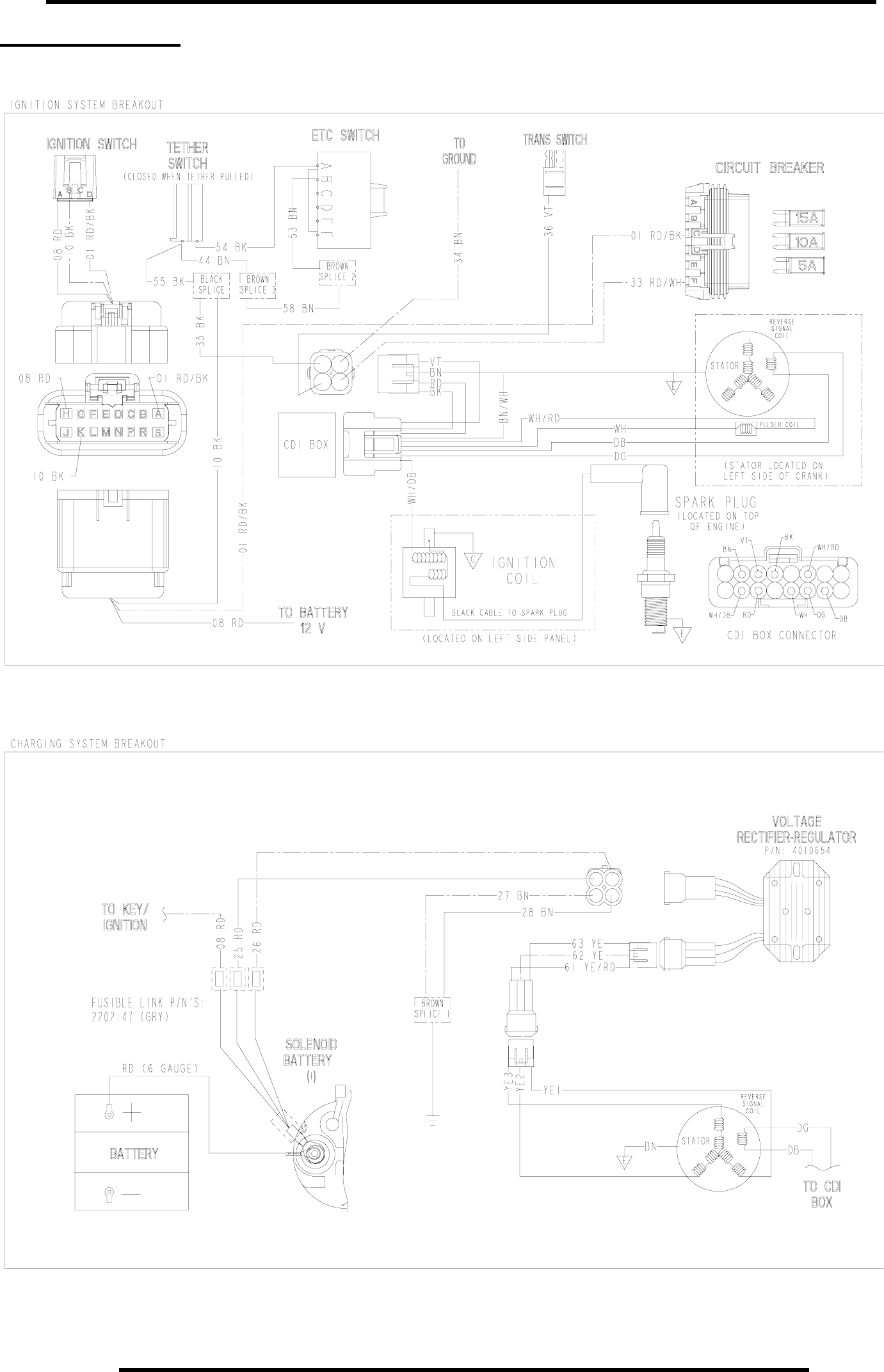
8.3
WIRE DIAGRAM
OUTLAW 500
