2006 ST1300/A ST1300 SETUP
User Manual: 2006 ST1300/A
Open the PDF directly: View PDF ![]() .
.
Page Count: 28

Set-up and pre-delivery service
must be performed by an authorized
Honda motorcycle dealer.
2006 ST1300/A
SET-UP
INSTRUCTIONS
©2006 American Honda Motor Co., Inc. - All Rights Reserved MPD 11396 (0601)
Issued: January 2006
©2006 American Honda Motor Co., Inc. - All Rights Reserved i
IMPORTANCE OF PROPER SET-UP AND PRE-DELIVERY SERVICE
FOR YOUR CUSTOMER'S SAFETY
Proper set-up and pre-delivery service are essential to rider safety and the reliability of the
machine. Any error or oversight made by the technician assembling and servicing a new machine
can result in faulty operation, damage to the machine, or injury to the rider.
FOR YOUR SAFETY
Some of the most important safety precautions are given below. However, we cannot warn you
of every conceivable hazard that can arise in performing set-up and pre-delivery service. Only
you can decide whether or not you should perform a given task.
IMPORTANT SAFETY PRECAUTIONS
Make sure you have a clear understanding of all basic shop safety practices and that you are
wearing appropriate clothing and safety equipment. When performing the set-up or pre-delivery
service, be especially careful of the following:
• Read the instructions before you begin, and make sure you have the tools and skills required to
perform the tasks safely.
• To prevent the machine from falling on you, park it on a firm, level surface, using the proper
stand(s) to provide firm support.
Make sure the engine is off before you begin any servicing procedures. This will help eliminate
several potential hazards:
• Carbon monoxide poisoning from engine exhaust—be sure there is adequate ventilation
whenever you run the engine.
• Burns from hot parts—let the engine and exhaust system cool before touching.
• Injury from moving parts—do not run the engine unless the instruction tells you to do so. Even
then, keep your hands, fingers, and clothing away.
To reduce the possibility of a fire or explosion, be careful when working around gasoline or
batteries. Use only a nonflammable solvent, not gasoline, to clean parts. Keep all cigarettes,
sparks and flames away from the battery and all fuel-related parts.
WARNING
Improper set-up or pre-delivery service can
create an unsafe condition that can cause
your customer to be seriously hurt or killed.
Follow the procedures and precautions in
this manual and the service manual carefully.
WARNING
Failure to properly follow instructions and
precautions can cause you to be seriously
hurt or killed.
Follow the procedures and precautions in this
manual carefully.
ii ©2006 American Honda Motor Co., Inc. - All Rights Reserved
2006 ST1300/A
How To Use This Manual
Follow the complete sequence of steps as shown. Do not short-cut any steps. The sequence has
been established to ensure the unit is properly assembled.
The individual steps are composed of three components:
• Sub-heading—The large sub-headings are a brief description of the step. They are intended
to be used by the experienced technician, one who only needs a brief reminder of the
set-up sequence.
• Descriptive text—The descriptive text explains in detail what is to be done during that step.
This explanation is intended as a guide for the technician needing additional information.
• Photographs/Line art—The photographs or line art support both the sub-headings and the
detailed text.
Modifications and Accessories
Modifications that you may have made, or should make in the future, to any Honda product, shall
be deemed by our company to have been performed at your sole risk and responsibility, and
without our company's or the manufacturer's approval, or consent, implied or expressed. We
further disclaim any and all liability, obligation, or responsibility for any defects of modified parts
or of the modified product, and for any claims, demands, or causes of action for damage to
property or for personal injuries resulting from the modification of said Honda product.
Indicates the set-up section Indicates the pre-delivery section
Torque Table
ITEM SIZE TORQUE
Reflector nut 6 mm 12 N·m (1.2 kgf·m, 9 lbf·ft)
Front fender bolt 6 mm 12 N·m (1.2 kgf·m, 9 lbf·ft)
Front axle bolt -------- 79 N·m (8.1 kgf·m, 58 lbf·ft)
Pinch bolt 8 mm 22 N·m (2.2 kgf·m, 16 lbf·ft)
Caliper bolt 8 mm 31 N·m (3.2 kgf·m, 23 lbf·ft)
Mirror bolt 6 mm 12 N·m (1.2 kgf·m, 9 lbf·ft)
Windscreen bolt 6 mm 12 N·m (1.2 kgf·m, 9 lbf·ft)
Windscreen cover screws 4 mm 1.0 N·m (0.1 kgf·m, 0.7 lbf·ft)
Handlebar cover 6 mm 1.2 N·m (0.12 kgf·m, 0.9
lbf·ft)
Engine guard cover 6 mm 9.0 N·m (0.9 kgf·m, 6.6 lbf·ft)
Oil filler cap -------- 12 N·m (1.2 kgf·m, 9 lbf·ft)
©2006 American Honda Motor Co., Inc. - All Rights Reserved 1
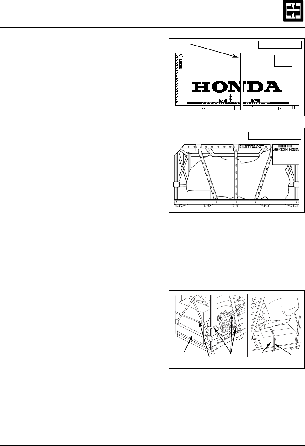
1.Remove the carton cover.
The ST1300/A is crated in one of two ways.
You may receive either one.
Covered crate:
Cut the strap and remove the carton cover.
Remove the inner cardboard frame cover.
Uncovered crate:
When stacking crates, protect the motorcycle
from falling objects and bad weather.
2.Check for damage.
Check the unit for hidden damage.
If you find damage, follow the instructions on
the Delivery and Damage Claims Guidelines
wall chart (Reorder No. S0477) before
proceeding.
3.Remove the side braces, wheel, loose
parts cartons, and crate frame.
Remove the ties securing the front wheel and
loose parts cartons.
STRAP COVERED CRATE
UNCOVERED CRATE
TIES TIE
TIE
PARTS
CARTON PARTS
CARTON
2006 ST1300/A
2©2006 American Honda Motor Co., Inc. - All Rights Reserved
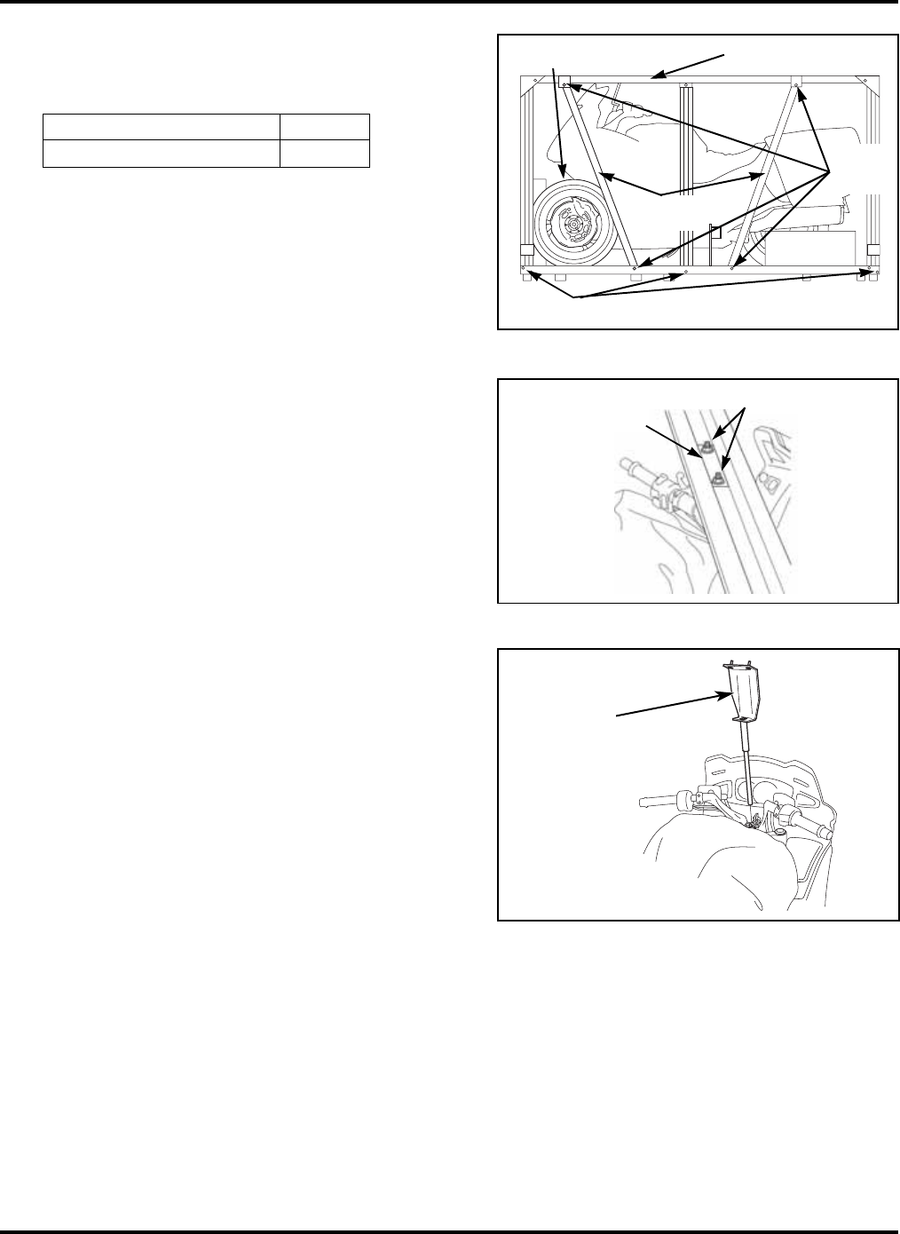
3.Remove the side braces, wheel,
loose parts cartons, and crate
frame (cont.).
Remove the bolts and side braces, being
careful not to damage the front wheel.
Remove the loose parts cartons.
Keep the You and Your Motorcycle Riding
Tips & Practice Guide and hand deliver to the
customer at the time of delivery.
Remove the nuts, plate, and bolts.
Using two people, carefully remove the
crate frame, being careful not to damage
the motorcycle.
Remove the front shipping brace, being
careful not to damage the motorcycle.
PARTS QTY
Riding Tips & Practice Guide 1 SIDE
BRACE
BOLTS
SIDE
BRACES
FRONT WHEEL CRATE FRAME
FRAME BOLTS
PLATE NUTS AND BOLTS
FRONT
SHIPPING
BRACE
©2006 American Honda Motor Co., Inc. - All Rights Reserved 3
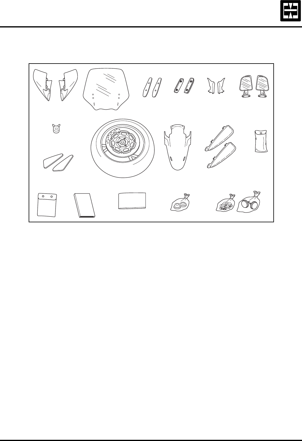
4.Loose Parts Information.
Unpack the remaining loose parts and check them against this illustration.
* Optional parts. Hand the knee pads to the customer at the time of delivery or install if the
customer wants them installed (see step 15).
DESCRIPTION QTY PART NUMBER STEP
1. Right mirror cover 1 88111-MCS-G00ZJ 8
Left mirror cover 1 88121-MCS-G00ZJ 8
2. Windscreen 1 64150-MCS-G00 9
3. Windscreen cover 2 64151-MCS-G00 9
4. Right windscreen bracket cover 1 64183-MCS-G00 9
Left windscreen bracket cover 1 64188-MCS-G00 9
5. Right mirror cover rubber 1 88112-MCS-G00 8
Left mirror cover rubber 1 88122-MCS-G00 8
6. Right rear view mirror 1 88110-MCS-G01 8
Left rear view mirror 1 88120-MCS-G01 8
7. Handlebar cover 1 53115-MCS-G00ZA 10
8. Right knee grip pad* 1 17506-MCS-G01 15
Left knee grip pad* 1 17507-MCS-G01 15
9. Front wheel assembly 1 ------------------------ 7
10. Front fender 1 61100-MCS-G00ZH 6
11. Right engine guard cover 1 64260-MCS-G01 14
Left engine guard cover 1 64265-MCS-G01 14
(Continued on next page.)
1. 2. 3.
11.
5.
7.
8.
4.
9. 10.
6.
12.
13.
14.
17.
15. 16.

2006 ST1300/A
4©2006 American Honda Motor Co., Inc. - All Rights Reserved
4.Loose parts information (cont.).
** If missing, order from Helm Inc.
*** If missing, order from Resolve Corp.
Missing Parts or Shipping Damage
Identify missing parts by referring to the Loose Parts Information section. Order the parts
using normal parts ordering procedures. Claims for missing loose parts or those damaged
during transit should be submitted to American Honda, not the carrier. After completing
repairs, submit a Transportation Claim via iN. For complete details, please refer to the
Warranty Policy and Procedures Manual.
DESCRIPTION QTY PART NUMBER STEP
12. Tool kit 1 ------------------------ 12
13. Owner’s Manual bag 1 83642-MN5-000 12
14. Owner’s Manual 1 31MCS630** 12
15. You and Your Motorcycle
Riding Tips & Practice Guide 1 G0045*** 3
16. Right front wheel side collar 1 44311-MCS-G00 7
Left front wheel side collar 1 44312-MCS-G00 7
17. Attaching parts:
Front fender:
Rubber washer 2 18325-MBV-000 6
Pan screw 6 x 20 mm 2 90138-MCS-G00 6
Socket bolt 6 x 18 mm 2 96600-06018-00 6
Flange bolt 6 x 16 mm 2 96001-06016-07 6
Front reflector 2 33742-HB9-641 6
Front reflector stay 2 33742-MCS-L00 6
Flange nut 6 mm 2 94050-06000 6
Mirrors:
Flange bolt 6 x 20 mm 4 96001-06020-00 8
Hose clip 4 95002-02100 8
Windscreen:
Plastic retainer 4 64509-MK4-000 9
Collar, side cover 4 61104-435-000 9
Flange bolt 6 x 18 mm 4 96001-06018-07 9
Pan screw 4 x 25 mm 4 90126-MCS-G00 9
Adjuster rubber 2 64175-MCS-G00 9
Handlebar cover:
Special screw 4 x 6.5 mm 2 90136-MCS-G00 10
Engine guard covers:
Pan screw 6 x 11 mm 2 90106-KY2-701 14
©2006 American Honda Motor Co., Inc. - All Rights Reserved 5
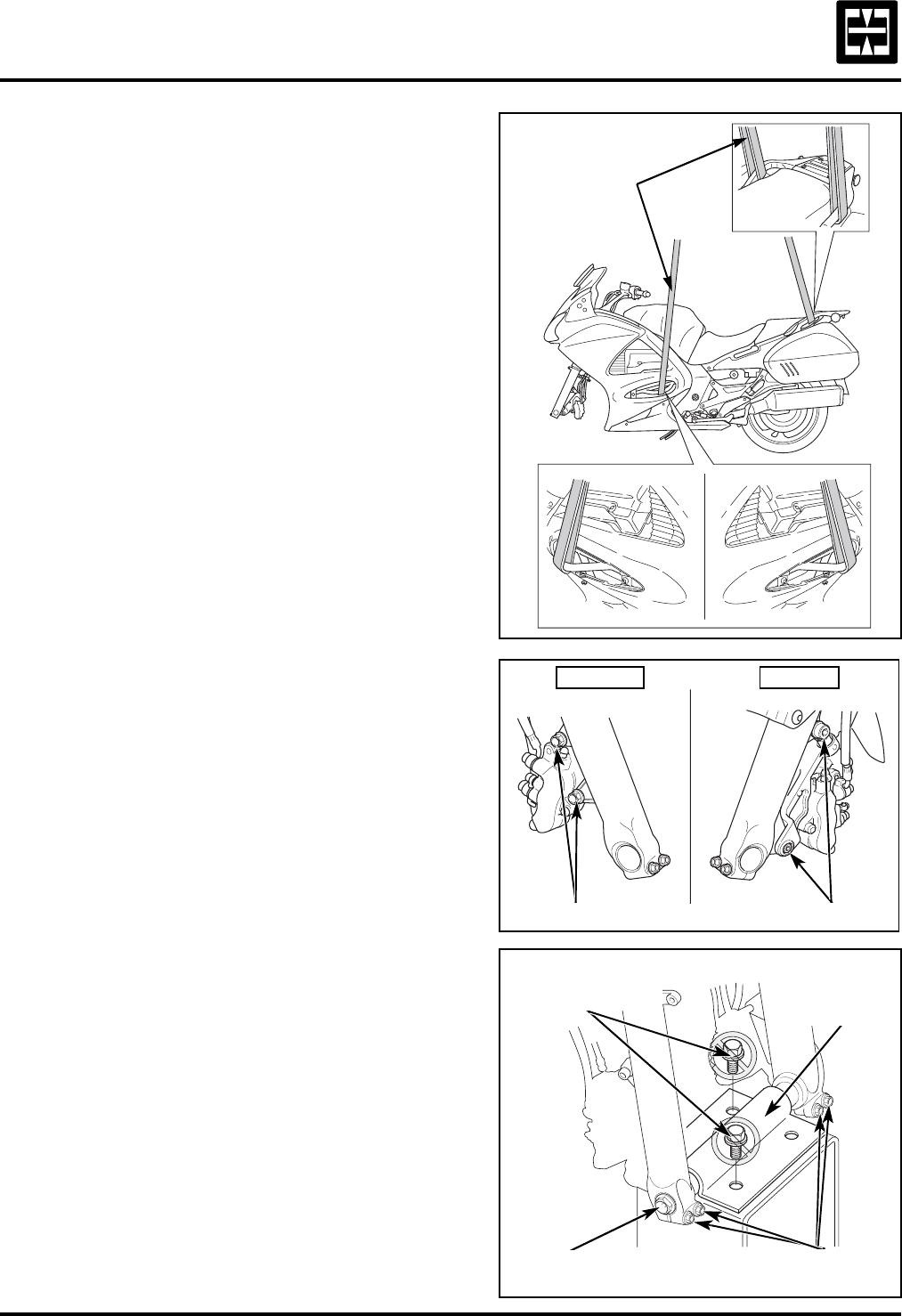
5.Remove the motorcycle from the
crate base.
Install lifting slings on the engine guards and
grab rails as shown.
If necessary, use a spreader board to prevent
the slings from damaging the motorcycle.
Lift the slings just enough to remove
the slack.
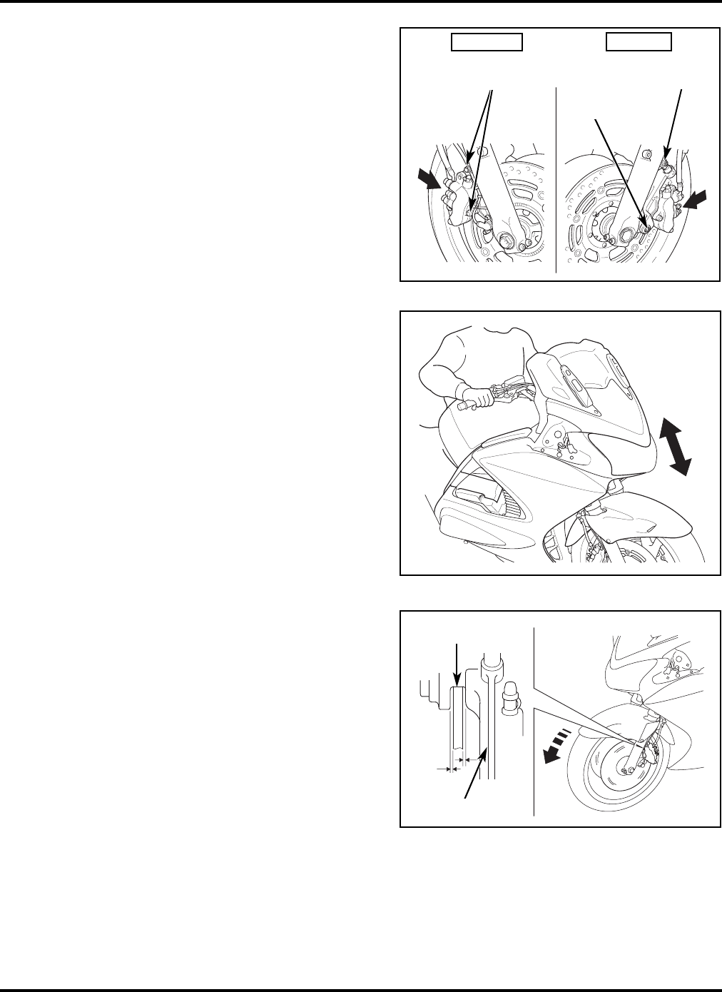
Loosen the caliper bolts, axle bolt, and axle
pinch bolts. Remove the washer bolts, and
lower shipping bracket from the crate base.
Discard the washer bolts.
SLINGS
RIGHT SIDE LEFT SIDE
CALIPER BOLTS CALIPER BOLTS
AXLE BOLT PINCH BOLTS
LOWER
SHIPPING
BRACKET
WASHER BOLTS
(discard)
2006 ST1300/A
6©2006 American Honda Motor Co., Inc. - All Rights Reserved
5.Remove the motorcycle from the crate
base (cont.).
Remove the shipping braces, nuts, and
protective covering from the foot pegs on
both sides of the motorcycle.
Lift the motorcycle free from the crate base
and remove the base.
On a firm, level surface, lower the centerstand
and lower the motorcycle until it is resting on
its rear wheel and centerstand.
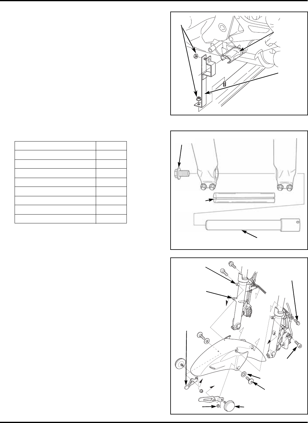
6.Install the front fender.
Remove the axle bolt.
Remove the axle protective covering and the
axle shaft.
Position the reflector stays on the inside of
the front fender by aligning them with the
projections on the front fender. Install the
reflector stays with two 6 x 20 mm pan
screws and rubber washers.
Secure the reflectors to the stays with two
6 mm nuts.
Torque the nuts.
Torque: 12 N·m (1.2 kgf·m, 9 lbf·ft)
Position the front fender between the fork
legs and attach it to the fork stays with two
6 x 18 mm socket bolts. Secure the brake
hose stays with two 6 x 16 mm flange bolts.
Torque the bolts.
Torque: 12 N·m (1.2 kgf·m, 9 lbf·ft)
PARTS QTY
Front fender 1
Rubber washer 2
Pan screw 6 x 20 mm 2
Socket bolt 6 x 18 mm 2
Flange bolt 6 x 16 mm 2
Front reflector 2
Front reflector stay 2
Flange nut 6 mm 2
PROTECTIVE
COVERING
(discard)
SHIPPING
BRACE
NUTS
AXLE
BOLT
AXLE SHAFT
PROTECTIVE
COVERING
(discard)
FORK STAY
LOWER
REFLECTOR
6 mm NUT
REFLECTOR
STAY
RUBBER WASHER
FORK STAY
UPPER
6 x 18 mm
SOCKET BOLT
6 x 20 mm
FLANGE BOLT
6 x 16 mm
FLANGE
BOLT
©2006 American Honda Motor Co., Inc. - All Rights Reserved 7
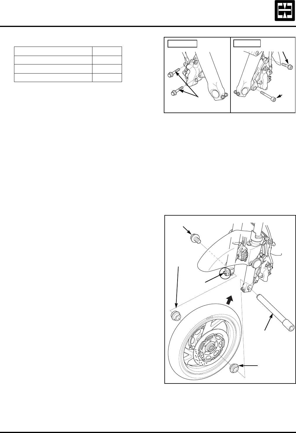
7.Install the front wheel.
Clean both sides of the front and rear brake
discs with a clean shop towel and Pro Honda
Brake Cleaner or equivalent.
Remove the caliper mounting bolts. Be
careful not to get dust and dirt on the ends of
the mounting bolts.
Support both calipers with a piece of wire,
or similar method, so they do not hang from
the brake hoses. Be careful not to twist the
brake hoses.
Do not operate the brake lever or pedal after
the brake calipers are removed.
Note that the shoulders on each wheel collar
are different sizes. It is important to install
them with the correct sides facing the wheel.
Install the 16.5 mm left-side collar with the
10 mm deep shoulder side facing the wheel.
Install the 27.5 mm right-side collar with the
34 mm outside diameter shoulder facing
the wheel.
Position the front wheel between the
fork legs.
Slide the axle shaft through the left fork leg,
the 16.5 mm left-side collar, front wheel,
27.5 mm right-side collar, and right fork leg.
Push in on the axle shaft so the left end of the
axle shaft is flush with the surface of the left
fork leg.
While holding the axle, install and tighten the
axle bolt to the specified torque.
Torque: 79 N·m (8.1 kgf·m, 58 lbf·ft)
Tighten the right axle pinch bolts to the
specified torque.
Torque: 22 N·m (2.2 kgf·m, 16 lbf·ft)
PARTS QTY
Front wheel assembly 1
Right front wheel side collar 1
Left front wheel side collar 1
RIGHT SIDE LEFT SIDE
8 x 4 5 m m
CALIPER
BOLT
CALIPER
BOLTS
CALIPER
BOLT
AXLE BOLT
PINCH
BOLTS
27.5 mm
RIGHT SIDE
COLLAR
AXLE
SHAFT
16.5 mm
LEFT SIDE
COLLAR
2006 ST1300/A
8©2006 American Honda Motor Co., Inc. - All Rights Reserved
7.Install the front wheel (cont.).
Reinstall the right and left front brake
calipers, being careful not to damage the
front wheel and related components.
Install the caliper bolts and tighten to the
specified torque.
Torque: 31 N·m (3.2 kgf·m, 23 lbf·ft)
Operate the front brake and pump the forks
several times to seat the axle.
Check the brake operation by applying the
brake lever and pedal.
Check the wheel for free rotation after the
brake is released. If the brake drags or the
wheel does not rotate freely, recheck the
wheel and brake caliper installation.
Visually check the position of the brake disc in
relation to the brake caliper; it should be
centered. If not, recheck the wheel and brake
caliper installation.
CALIPER
BOLT
8 x 45 mm
CALIPER
BOLT
CALIPER
BOLTS
RIGHT SIDE LEFT SIDE
DISC
CALIPER BRACKET
©2006 American Honda Motor Co., Inc. - All Rights Reserved 9
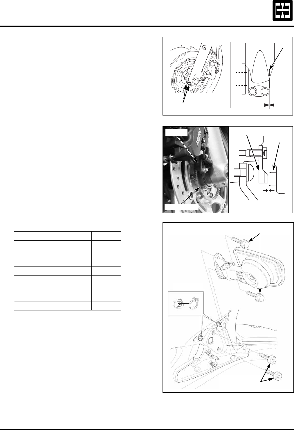
7.Install the front wheel (cont.).
Make sure the axle end is flush with the front
fork leg outer surface as shown.
Tighten the left axle pinch bolts to the
specified torque.
Torque: 22 N·m (2.2 kgf·m, 16 lbf·ft)
On the ST1300A, verify the clearance between
the ABS front pulser ring and sensor.
Clearance specification:
0.4 - 1.2 mm (0.02 - 0.05 in)
If outside the clearance specification range,
recheck the wheel installation.
8.Install the mirrors.
Remove and discard the shipping bolts.
Install the right and left rear view mirrors
using two 6 x 20 mm flange bolts on
each side.
Torque the bolts.
Torque: 12 N·m (1.2 kgf·m, 9 lbf·ft)
Install the two hose clips as shown.
PARTS QTY
Right mirror cover 1
Left mirror cover 1
Right mirror cover rubber 1
Left mirror cover rubber 1
Right rear view mirror 1
Left rear view mirror 1
Flange bolt 6 x 20 mm 4
Hose clip 4
PINCH BOLTS
AXLE
0.4 - 1.2 mm (0.02 - 0.05 in)
PULSER RING
SENSOR
PULSER RING
SENSOR
6 x 20 mm FLANGE BOLTS
HOSE CLIPS
SHIPPING BOLTS
(discard)
2006 ST1300/A
10 ©2006 American Honda Motor Co., Inc. - All Rights Reserved
8.Install the mirrors (cont.).
Align the retaining tabs, located on the ends
of the mirror cover rubber, with the indent-
ations on the fairing.
Push the end of the retainer strap into the
hole in the body.
Connect the wiring harness terminals color-
to-color: right side wires are colored light
blue and white, left side wires are colored
orange and white.
Carefully install the mirror covers by pressing
the cover prongs into the grommets on the
bracket, and mirror bracket ends into the
cover as shown.
MIRROR COVER
RETAINER
STRAP
TERMINALS
HOLE
MIRROR
COVER
RUBBER
MIRROR COVER
©2006 American Honda Motor Co., Inc. - All Rights Reserved 11
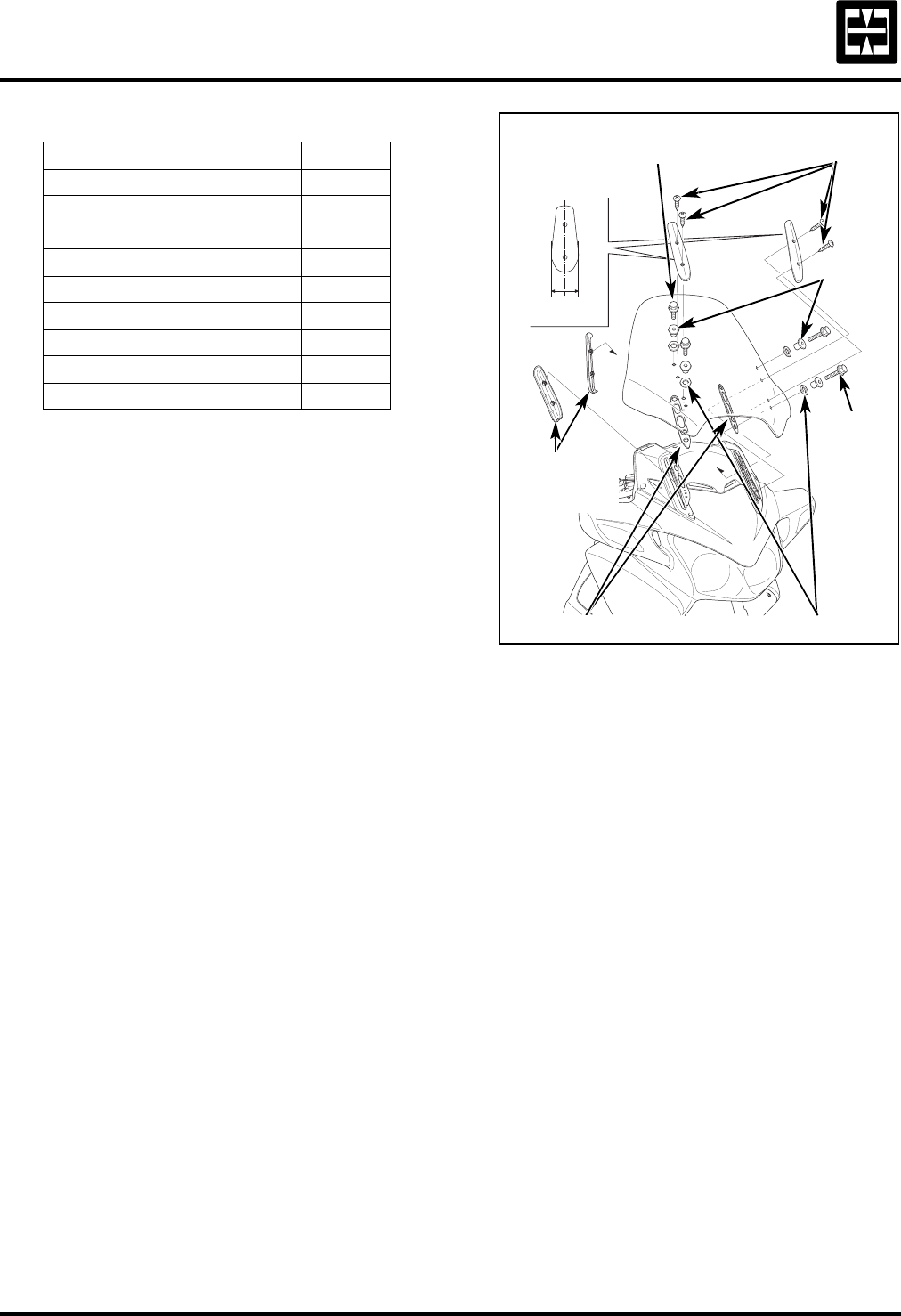
9.Install the windscreen.
Note that the windscreen adjusters are
installed as shown, however, they can be
reinstalled according to rider preference.
To install the windscreen, use two people
to carefully install the following parts in the
order indicated below:
•Windscreen bracket covers
•Adjuster rubbers
•Windscreen
•Plastic retainer
•Side cover collars
•6 x 18 mm flange bolts
Torque the bolts.
Torque: 12 N·m (1.2 kgf·m, 9 lbf·ft)
Then, install the following:
•Windscreen covers
•4 x 25 mm pan screws
Torque the pan screws.
Torque: 1.0 N·m (0.1 kgf·m, 0.7 lbf·ft)
PARTS QTY
Windscreen 1
Windscreen cover 2
Right windscreen bracket cover 1
Left windscreen bracket cover 1
Plastic retainer 4
Side cover collar 4
Flange bolt 6 x 18 mm 4
Pan screw 4 x 25 mm 4
Adjuster rubber 2
WINDSCREEN
BRACKET
COVERS
6 x 18 mm
FLANGE BOLT 4 x 25 mm
PAN SCREWS
SIDE
COVER
COLLARS
6 x 18 mm
FLANGE
BOLT
PLASTIC RETAINERS
ADJUSTER RUBBERS
WINDSCREEN
COVER
2006 ST1300/A
12 ©2006 American Honda Motor Co., Inc. - All Rights Reserved
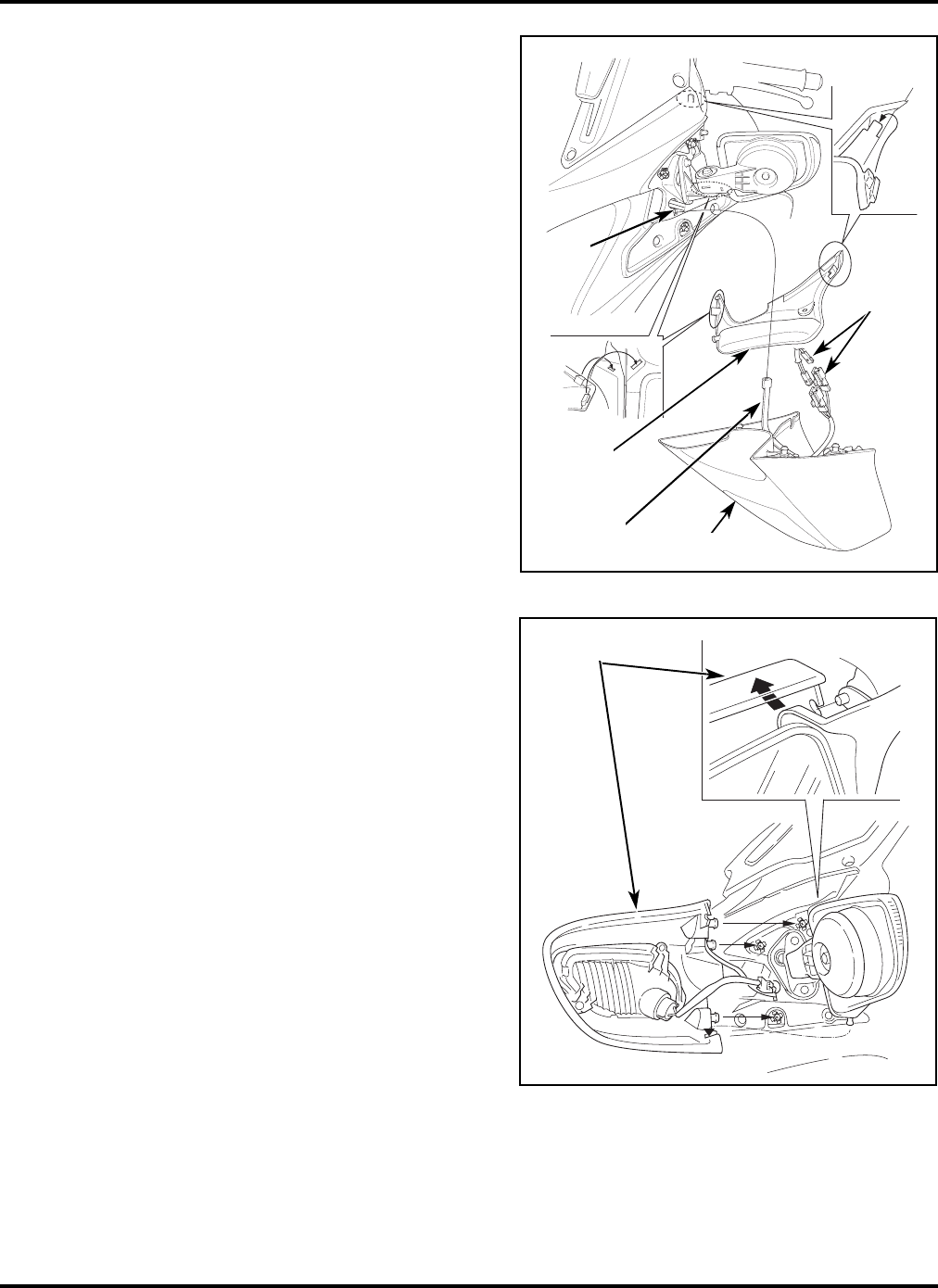
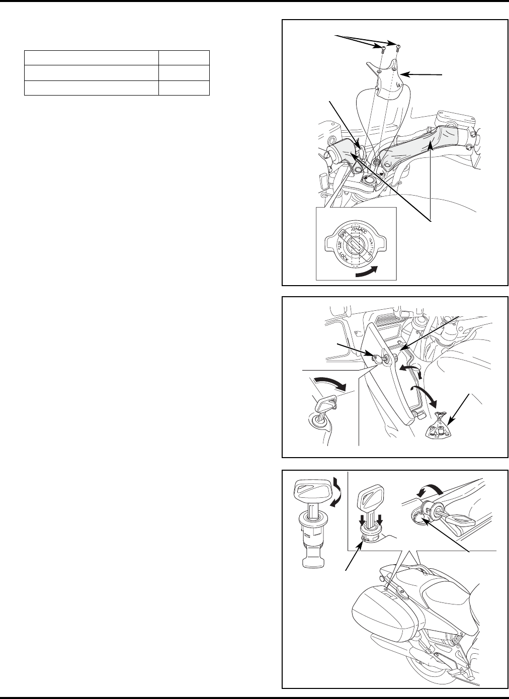
10. Install the handlebar cover and saddlebag
lever lock.
Remove the ignition key from the ignition.
Remove the protective tape.
Attach the handlebar cover using two
4 x 6.5 mm special screws.
Torque the screws.
Torque: 1.2 N·m (0.12 kgf·m, 0.9 lbf·ft)
Open the left fairing pocket with the
ignition key.
Take out the saddlebag lever locks from the
left fairing pocket.
Insert the ignition key into the saddlebag
lever lock and turn it clockwise to the position
shown.
Push in on the saddlebag lever lock while
aligning it with the cutout in the saddlebag
as shown.
PARTS QTY
Handlebar cover 1
Special screw 4 x 6.5 mm 2 IGNITION
KEY
4 x 6.5 mm SPECIAL SCREWS
HANDLEBAR
COVER
PROTECTIVE
TAPE
IGNITION
KEY
FAIRING POCKET
SADDLEBAG
LEVER LOCKS
CUTOUT
SADDLEBAG
LEVER LOCK
©2006 American Honda Motor Co., Inc. - All Rights Reserved 13
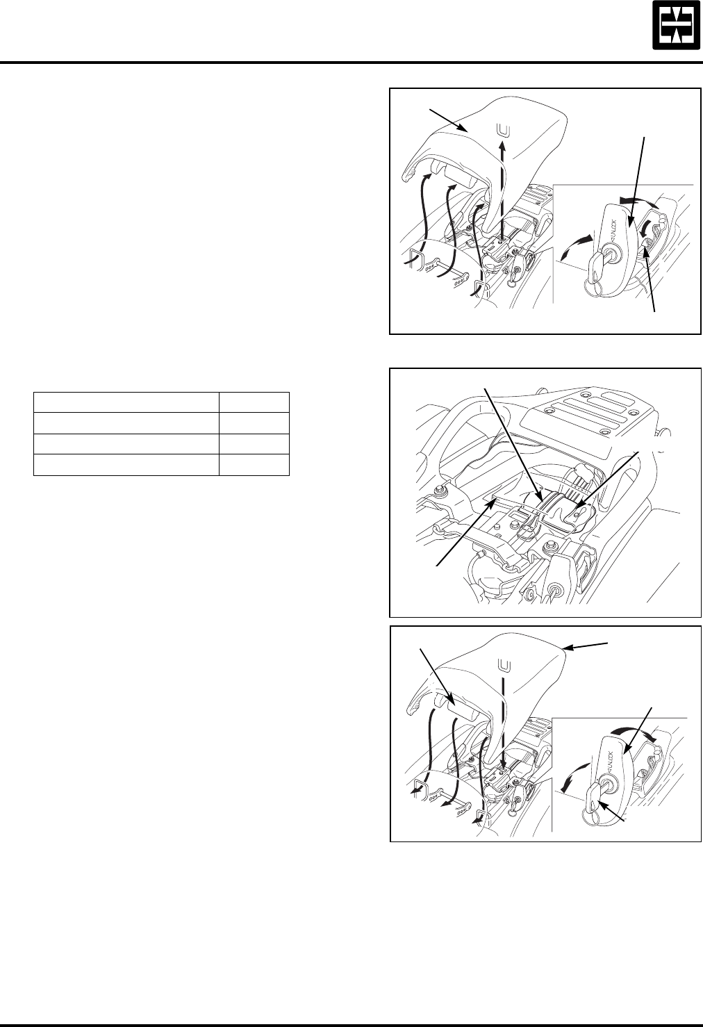
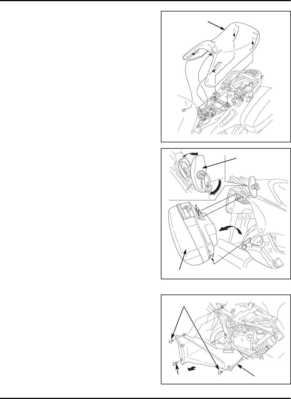
11.Remove the rear seat.
Insert the ignition key and turn it clockwise to
open the latch lever.
Pull the rear seat back and up while
depressing the seat opener.
12.Store the tool kit and Owner’s Manual.
Place the tool kit under the rear seat and
secure it with the tool band.
Place the Owner’s Manual into its bag and
place it on top of the tool kit.
13.Install the rear seat.
Note: If the pre-delivery steps will be
completed directly after set-up, leave the rear
seat off until after step 17.
Insert the prong into the recess under the
frame cross member, then push down on the
rear of the rear seat.
Close the latch lever and turn the ignition
key counterclockwise.
Be sure the seat is locked securely in position.
Place the ignition key into the ignition.
PARTS QTY
Tool kit 1
Owner’s Manual bag 1
Owner’s Manual 1
REAR SEAT
LATCH LEVER
SEAT OPENER
TOOL KIT
TOOL BAND
OWNER’S
MANUAL
AND BAG
IGNITION
KEY
REAR SEAT
LATCH LEVER
PRONG
2006 ST1300/A
14 ©2006 American Honda Motor Co., Inc. - All Rights Reserved
14.Install the engine guard covers.
Install the engine guard covers and secure
them with a 6 x 11 mm pan screw.
Torque the screws.
Torque: 9.0 N·m (0.9 kgf·m, 6.6 lbf·ft)
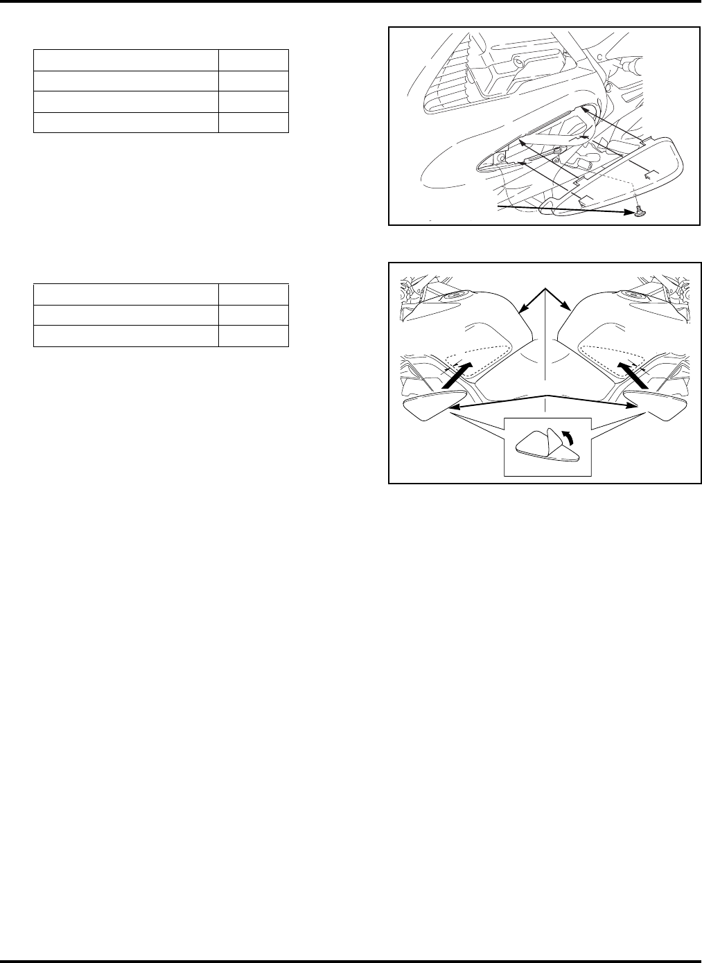
15.Install the fuel tank knee grip pads.
Install the optional knee pads if the customer
requests them to be installed.
If the unit has not been sold, store the pads in
the right saddlebag.
Clean the mating surfaces of the fuel tank
with a clean shop towel and isopropyl alcohol
or equivalent.
Peel off the backing sheets and attach the
pads to the sides of the fuel tank 30 mm
(1-13/16 in) from the lower front edges of the
tank, as shown in the illustration.
If the ambient temperature is 77°F or below,
warm the mating surfaces of the tank and
the pad’s adhesive side with a hair dryer
before attaching.
After attaching the pads, press down firmly
over the entire area of the pad to ensure
maximum adhesion.
Avoid washing the motorcycle or riding in
wet conditions for 24 hours after attaching
the pads.
PARTS QTY
Right engine guard cover 1
Left engine guard cover 1
Pan screw 6 x 11 mm 2
PARTS QTY
Right knee grip pad 1
Left knee grip pad 1
6 x 11 mm
PAN SCREW
30 mm
(1-13/16 in)
30 mm
(1-13/16
FUEL TANK
KNEE GRIP PADS
©2006 American Honda Motor Co., Inc. - All Rights Reserved 15
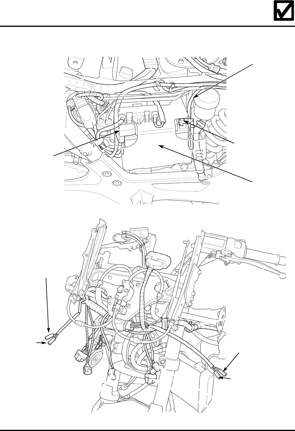
16.Verify the proper routing of the cables, hoses, and wire harnesses.
LEFT TURN
SIGNAL 2P
(ORANGE)
CONNECTOR
RIGHT
RUNNING
LIGHT
CONNECTOR
LEFT RUNNING LIGHT
CONNECTOR
RIGHT TURN
SIGNAL 2P
(SKY BLUE)
CONNECTOR
POSITIVE (+)
BATTERY TERMINAL
BATTERY BOX
NEGATIVE (-)
BATTERY TERMINAL
NEGATIVE (-) CABLE
2006 ST1300/A
16 ©2006 American Honda Motor Co., Inc. - All Rights Reserved
17.Service and install the battery.
Service the battery only if the unit is sold or
will be used as a demonstrator.
Remove the seats:
If the rear seat is installed, follow the
instructions for seat removal in step 11.
Remove the front seat by pulling it back
and up.
Remove the right saddlebag:
Insert the ignition key and turn it clockwise to
open the latch lever.
Remove the right side saddlebag by lifting up
and pulling it out.
Close the latch lever.
Remove the right side cover:
Remove the screws and the right side cover.
FRONT SEAT
LATCH LEVER
SADDLEBAG
5 mm SCREW
5 mm SCREWS
SIDE COVER
©2006 American Honda Motor Co., Inc. - All Rights Reserved 17
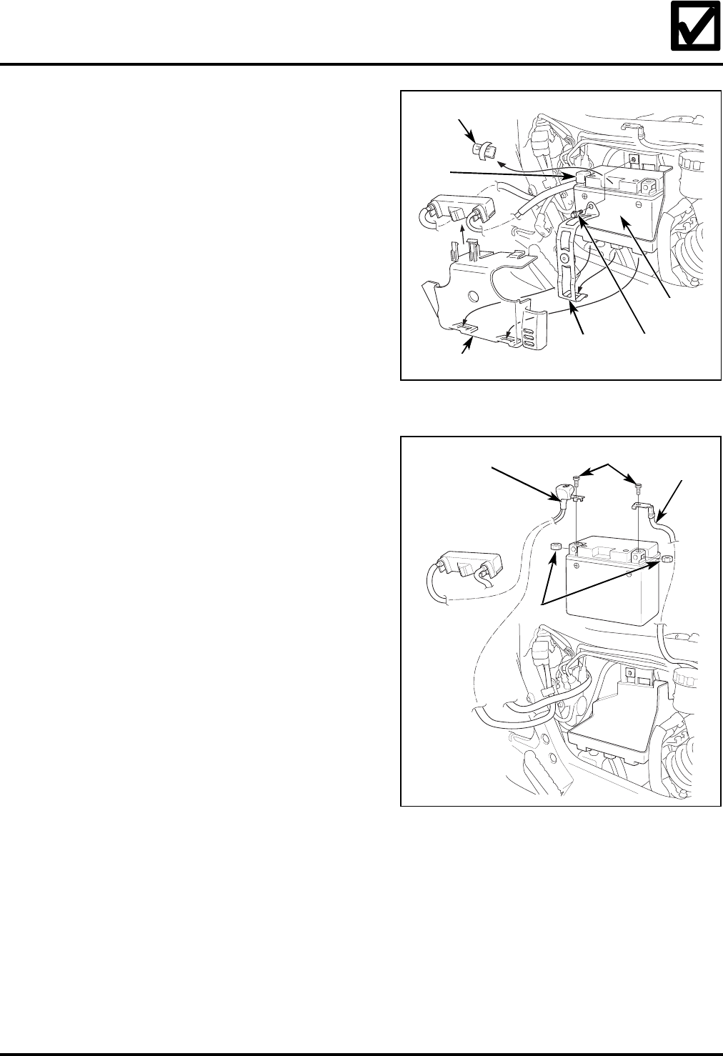
17.Service and install the battery (cont.).
Remove the battery cover.
Remove the battery holder by removing
the bolt.
Pull the battery out of the battery box.
Remove the cap and the packed battery nuts
and bolts.
The battery in this motorcycle is a pre-
charged, maintenance-free type. The
electrolyte has been added at the factory.
Follow the instructions included in Service
Letter #48.
Make sure the ignition switch is in the
OFF position.
Lower the battery into the battery box.
Connect the positive (+) battery cable to
the positive (+) battery terminal. Then
connect the negative (-) battery cable to the
negative (-) battery terminal using the special
bolts and nuts.
Tighten the bolts securely.
Coat both terminals with clean dielectric
grease and pull the red cover over the
positive terminal.
Allowing the positive (+) cable to rest on any
metal parts could wear through the insulation
and cause a short circuit. Do not allow the
positive (+) cable to contact any metal parts.
Verify the correct battery cable routing by
referring to step 16.
Reinstall the battery holder, bolts, battery
cover, and side cover in the reverse order
of removal.
CAP
BATTERY
BOLT
BATTERY
HOLDER
BATTERY COVER
NUTS AND BOLTS
BOLTS
POSITIVE (+)
CABLE
NEGATIVE
(-) CABLE
NUTS
2006 ST1300/A
18 ©2006 American Honda Motor Co., Inc. - All Rights Reserved
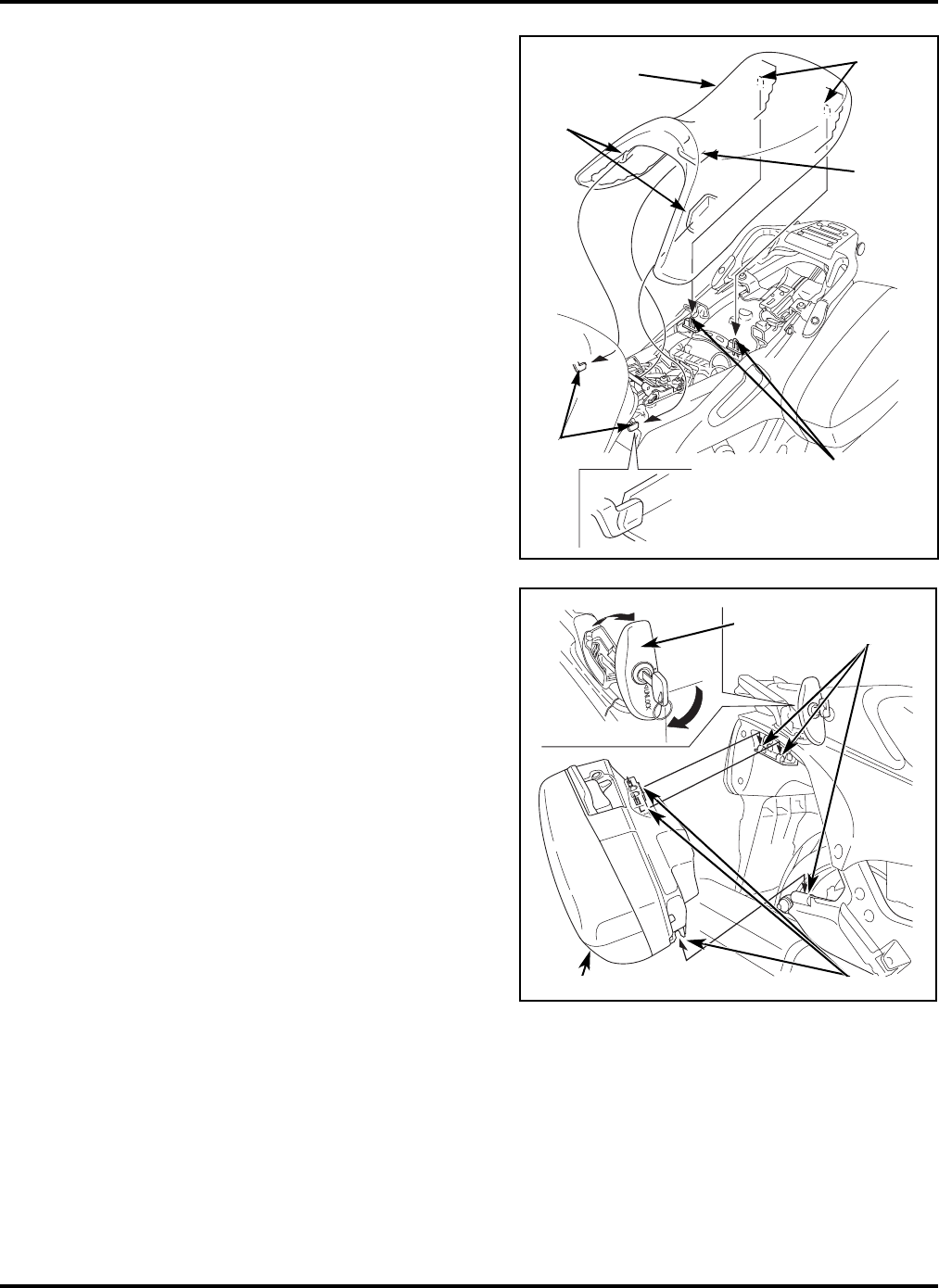
17.Service and install the battery (cont.).
Reinstall the front seat:
Insert the seat prong under the tank and align
the two recesses with the prongs at the rear
of the tank. Make sure that the seat adjust-
ment guides align with the holes in the seat
and push down on the rear of the seat to
secure it into position.
Reinstall the rear seat:
Reinstall the rear seat by following the
instructions in step 13.
Install the right saddlebag:
Use the ignition key to open the latch lever.
Position the three slots of the saddlebag
on the three hooking points on the
motorcycle as shown. Check that the
saddlebag engages securely.
Close the latch lever and lock it with the
ignition key.
Remove the ignition key and place it in the
ignition switch in the OFF position.
FRONT SEAT HOLES
PRONG
RECESSES
PRONGS SEAT ADJUSTMENT
GUIDES
LATCH
LEVER HOOKING
POINTS
SLOTS
SADDLEBAG
©2006 American Honda Motor Co., Inc. - All Rights Reserved 19
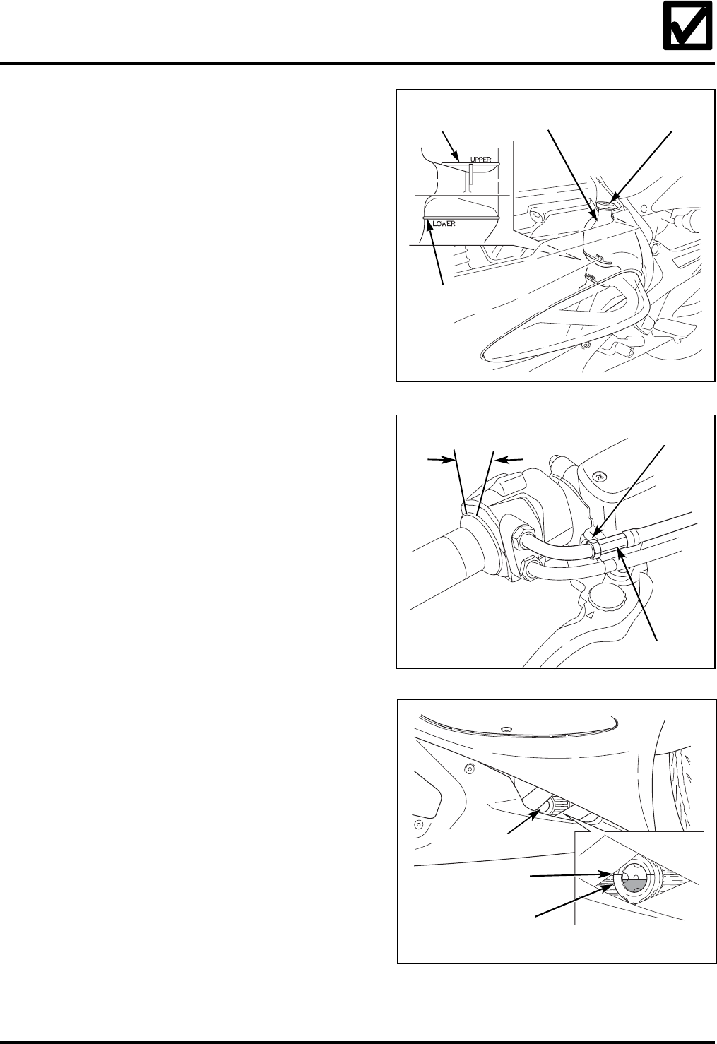
18.Check the coolant level.
Check the coolant level at the coolant reserve
tank. If the level is low, remove the coolant
reserve tank cap and add Pro Honda HP
coolant or a 1:1 mixture of a high-quality
ethylene glycol anti-freeze containing
corrosion inhibitors and distilled water to
restore the level to the UPPER mark. Do not
spill coolant on painted or plastic surfaces as
it can damage the finish.
19.Verify the throttle freeplay.
Operate the throttle to confirm that it moves
smoothly and returns automatically from any
open position to the fully closed position in all
steering positions.
Confirm the throttle grip freeplay:
Throttle freeplay:
2 – 6 mm (1/16 – 1/4 in)
Make adjustments at the throttle grip
adjuster by loosening the lock nut and
turning the adjuster. Tighten the lock nut
after adjustment.
20.Check the oil level.
Before starting the engine, remove the anti-
rust coating from the engine and exhaust
system using a mild detergent and water.
Rinse with clean water.
Support the motorcycle in an upright position
on a firm, level surface.
Check that the oil level is between the
upper and lower level marks in the
inspection window.
RESERVE
TANK
UPPER
LEVEL MARK
LOWER
LEVEL MARK
RESERVE
TANK CAP
2 – 6 mm (1/16 – 1/4 in)
ADJUSTER
LOCK NUT
UPPER LEVEL MARK
LOWER LEVEL MARK
INSPECTION WINDOW
2006 ST1300/A
20 ©2006 American Honda Motor Co., Inc. - All Rights Reserved
20.Check the oil level (cont.).
If the oil level is below the lower level mark,
remove the right cylinder head over-head
cover and oil filler cap, and add the recom-
mended oil until it is visible in the inspection
window. Replace the oil filler cap.
Start the engine and let it idle for 3 – 5
minutes. Make sure the low oil pressure
indicator goes off. If the indicator remains on,
stop the engine and troubleshoot the cause.
Stop the engine and wait 2 – 3 minutes. Check
the oil level using the above procedure and, if
necessary, add the recommended oil until it
reaches the upper level mark. Do not add oil
above the upper level mark.
•Oil recommendation: Pro Honda GN4 or
HP4 (without molybdenum additives) 4-
stroke oil or equivalent motor oil
•Viscosity: SAE 10W-40
•Classification: SG or higher. Do not use oils
labeled as energy conserving on the circular
API service label.
•JASO 4T Service Classification: MA
•Crankcase capacity (after draining): 3.6
Liters (3.8 US Quarts)
Reinstall the oil filler cap and right cylinder
head over-head cover.
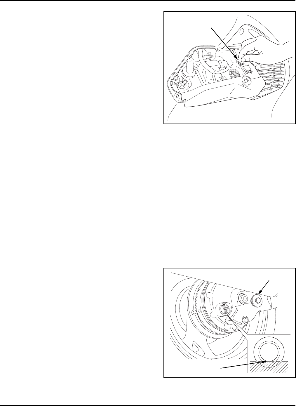
21.Check the final drive oil level.
Place the motorcycle on its centerstand on a
firm, level surface.
Remove the oil filler cap and check the oil
level, it should be flush with the lower edge of
the oil filler hole. If the level is low, check for
oil leaks. Add the recommended oil through
the oil filler hole until it reaches the lower
edge of the opening.
Recommended oil: Pro Honda Shaft Drive Oil
or equivalent SAE 80 hypoid gear oil
Reinstall and torque the oil filler cap.
Torque: 12 N·m (1.2 kgf·m, 9 lbf·ft)
FILLER CAP
OIL FILLER CAP
LOWER EDGE
©2006 American Honda Motor Co., Inc. - All Rights Reserved 21
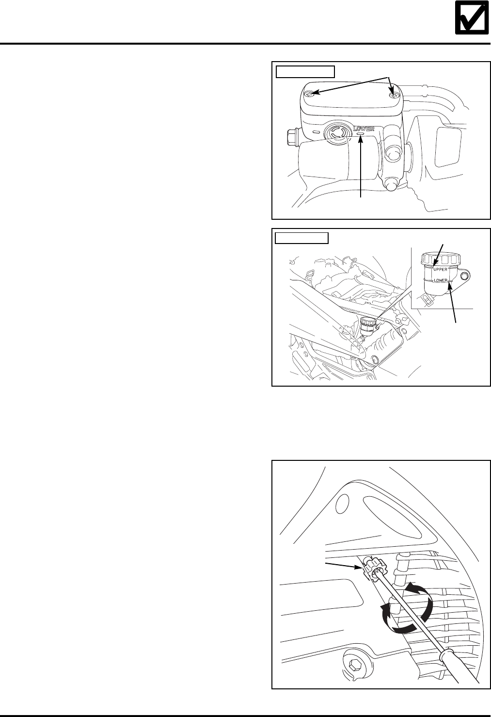
22.Check the front and rear brake reservoir
fluid levels.
Turn the handlebar so the front brake
reservoir is level and check the fluid level.
Support the motorcycle in an upright position
on a firm, level surface and check the rear
brake fluid level.
If the fluid level is low in either reservoir,
remove the screws, reservoir cover, and
diaphragm or cap.
Add Pro Honda DOT 4 brake fluid or
equivalent from a sealed container to bring
the level up to the upper level mark.
Reinstall the cap or the diaphragm, cover,
and screws.
Operate the hand lever and foot pedal. If the
free play is excessive or the brake feels
spongy and the reservoir fluid level is correct,
bleed the system.
23.Check the idle speed.
Start the engine and warm it up to its normal
operating temperature.
Place the motorcycle on its centerstand on a
firm, level surface.
Connect a tachometer to the engine
according to the manufacturer’s instructions.
Verify the idle speed (rpm).
Idle speed: l,000 ± 100 rpm
If an adjustment is needed, turn the
throttle stop screw to set the idle speed
using a screwdriver.
Stop the engine and remove the tachometer.
FRONT BRAKE
LOWER LEVEL MARK
SCREWS
REAR BRAKE UPPER LEVEL MARK
LOWER
LEVEL MARK
INCREASE
DECREASE
THROTTLE
STOP
SCREW

2006 ST1300/A
22 ©2006 American Honda Motor Co., Inc. - All Rights Reserved
24.Check the tire pressure.
Front and rear: 42 psi.
25.Check the clutch lever and sidestand
ignition cut-off switches.
When the transmission is in gear, the starter
should not work unless the clutch lever is
pulled in and the sidestand is up.
Position the motorcycle securely with the rear
wheel raised off the ground.
Clutch lever ignition cut-off switch test:
Shift the transmission into gear.
Raise the sidestand and without pulling the
clutch lever in, turn on the ignition, set the
engine stop switch to the RUN position, and
press the starter button.
If the engine starts, there is a problem with
the clutch lever ignition cut-off switch.
Troubleshoot the cause.
Sidestand ignition cut-off switch test:
Shift the transmission into gear.
Lower the sidestand and pull the clutch lever
in. Turn on the ignition, set the engine stop
switch to the RUN position, and press the
starter button.
If the engine starts, there is a problem with
the sidestand ignition cut-off switch.
Troubleshoot the cause.
©2006 American Honda Motor Co., Inc. - All Rights Reserved 23
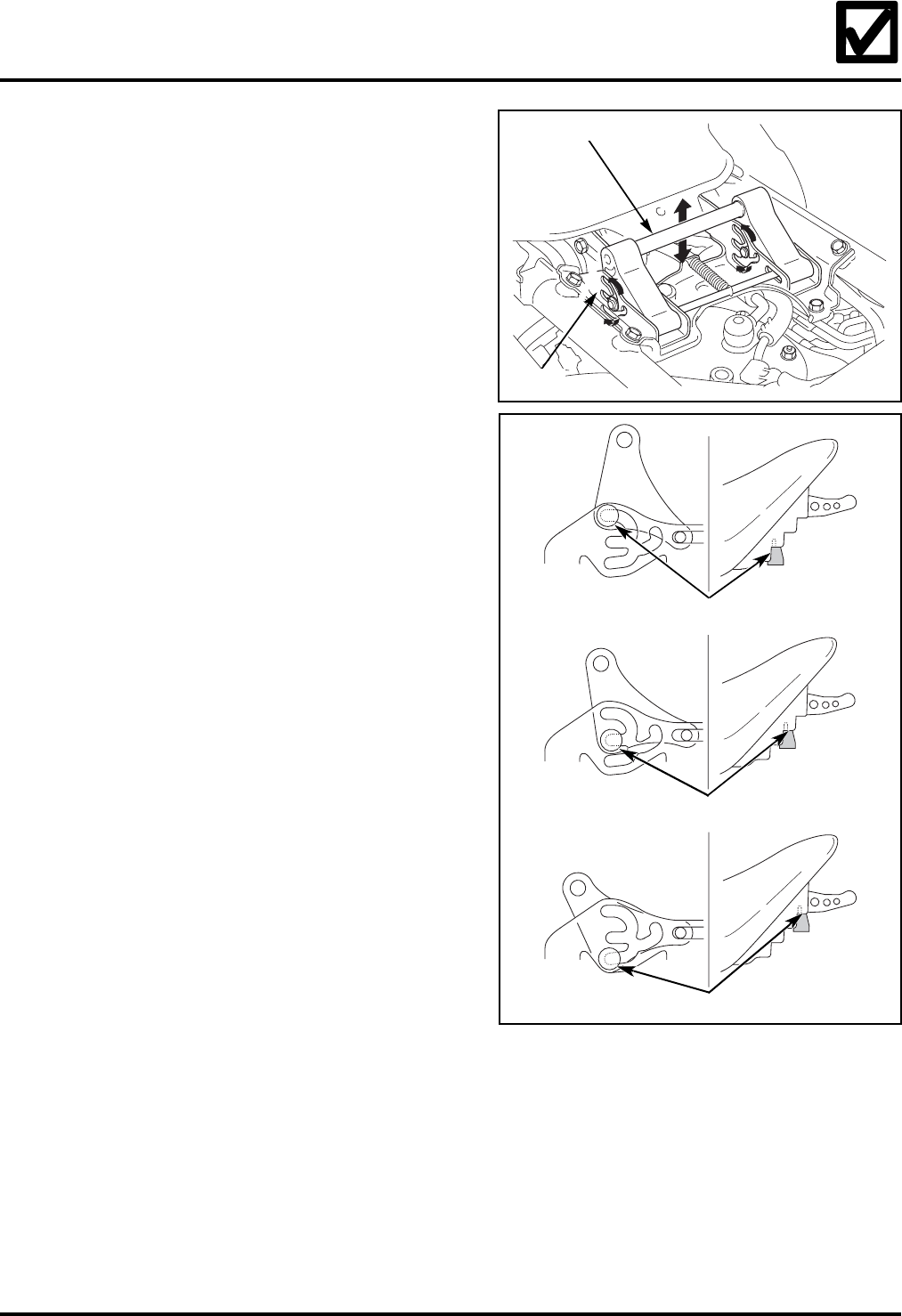
26.Adjust the front seat height.
The front seat height of the ST1300/A can be
adjusted for rider preference.
Remove the rear seat by referring to the
instructions in step 11.
Remove the front seat by following the
instructions in step 17.
Move the seat height adjuster into one of the
three positions on the guide as shown.
Be sure to align the holes in the rear of the
front seat with the adjuster when installing
the seat.
Reinstall the front seat by referring to the
instructions in step 17.
Reinstall the rear seat by following the
instructions in step 13.
27.Complete the Set-up/Pre-delivery form.
Complete an On-Road Motorcycle Set-up/Pre-
delivery Checklist (Reorder No. S0299, also
available on iN) by checking the boxes
confirming the steps were done.
MIDDLE POSITION
LOW POSITION
HIGH POSITION
GUIDE
SEAT HEIGHT ADJUSTER
2006 ST1300/A
24 ©2006 American Honda Motor Co., Inc. - All Rights Reserved
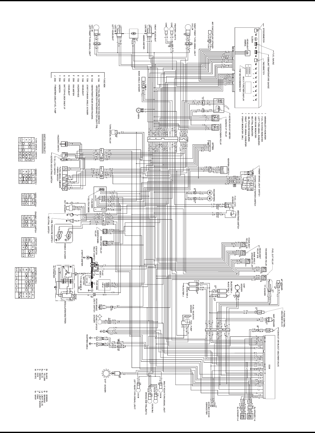
Wiring Diagram - ST1300
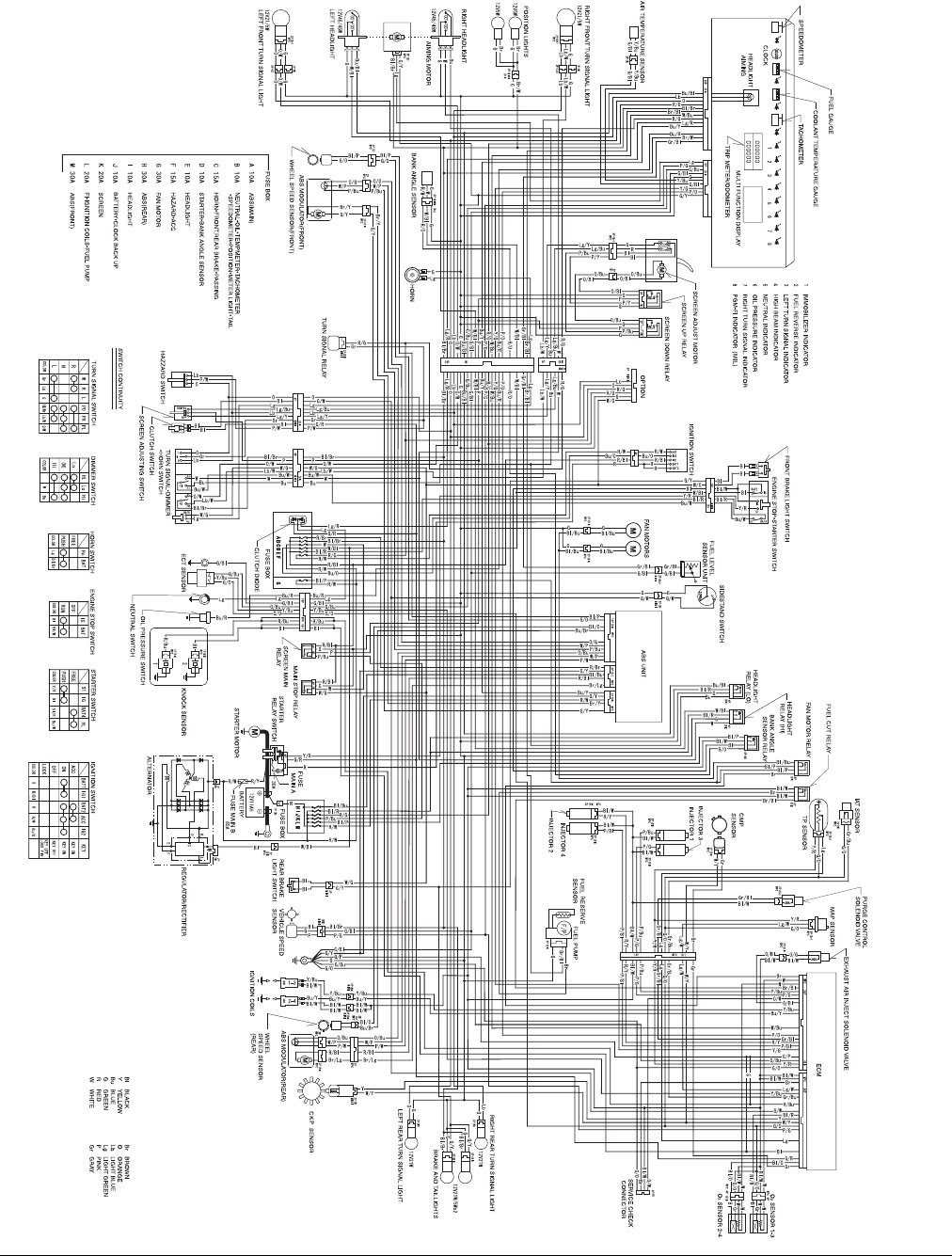
©2006 American Honda Motor Co., Inc. - All Rights Reserved 25
Wiring Diagram - ST1300A
