TL SG3109 200796032223
200796032223 200796032223 200796032223 software resources static.tp-link.com 3:
200796032223 200796032223 200796032223 software_r static.tp-link.com 3:
User Manual: TL-SG3109
Open the PDF directly: View PDF ![]() .
.
Page Count: 54
- Package contents
- Section 1: Introduction
- Section 2. Device Description
- Section 3. Mounting Device
- Section 4. Starting and Configuring the Device

Rev: 1.0
71035592
TP-LINK TECHNOLOGIES CO., LTD.
E-mail: support@tp-link.com
Website: http://www.tp-link.com
Add: 3/F., Building R1-B, Hi-tech Industrial Park, Shennan Rd., Shenzhen, P.R.China

Installation Guide
48+4G Gigabit Managed Switch
TL-SL3452
Rev: 1.0
TL-SL3428
24+4G Gigabit Managed Switch
TL-SG3109
9-port Gigabit Managed Switch

COPYRIGHT & TRADEMARKS
Specifications are subject to change without notice. is a
registered trademark of TP-LINK Technologies Co., Ltd. Other brands and
product names are trademarks or registered trademarks of their respective
holders.
No part of the specifications may be reproduced in any form or by any
means or used to make any derivative such as translation, transformation, or
adaptation without permission from TP-LINK Technologies Co., Ltd. Copyright
© 2006 TP-LINK Technologies Co., Ltd. All rights reserved.
FCC STATEMENT
This equipment has been tested and found to comply with the limits for a
class A digital device, pursuant to part 15 of the FCC Rules. These limits are
designed to provide reasonable protection against harmful interference in a
residential installation.
This equipment generates, uses and can radiate radio frequency energy
and, if not installed and used in accordance with the instructions, may cause
harmful interference to radio communications. However, there is no guarantee
that interference will not occur in a particular installation. If this equipment
does cause harmful interference to radio or television reception, which can be
determined by turning the equipment off and on, the user is encouraged to try
to correct the interference by one or more of the following measures:
Reorient or relocate the receiving antenna.
Increase the separation between the equipment and receiver.
Connect the equipment into an outlet on a circuit different from that to

which the receiver is connected.
Consult the dealer or an experienced radio/TV technician for help.
This device complies with Part 15 of the FCC Rules. Operation is subject to
the following two conditions:
1) This device may not cause harmful interference.
2) This device must accept any interference received, including interference
that may cause undesired operation.
EC DECLARATION OF CONFORMITY (EUROPE)
In compliance with the EMC Directive 89/336/EEC, Low Voltage Directive
73/23/EEC, this product meets the requirements of the following standards:
EN55022
EN55024
EN60950
SAFETY NOTICES
Cautions
Do not use this product near water, for example, in a wet basement or near a
swimming pool.
Avoid using this product during an electrical storm. There may be a remote
risk of electric shock from lightning.
TABLE OF CONTENTS
Package contents .................................................................................1
Section 1: Introduction ........................................................................2
1.1 Intended Audience ........................................................................................2
1.2 Agreement .....................................................................................................2
1.3 Guide Overview .............................................................................................2
Section 2. Device Description ............................................................3
2.1 Features.........................................................................................................3
2.2 TP-Link TL-SG3109 Description ..................................................................4
2.3 TP-Link TL-SL3428 Description ...................................................................6
2.4 TP-Link TL-SL3452 Description ...................................................................8
2.5 Back Panel ..................................................................................................10
2.6 Device Hardware Interfaces .......................................................................10
2.6.1 RJ-45 Base-T Fast Ethernet Ports ..........................................................10
2.6.2 SFP Port ................................................................................................... 11
2.6.3 RS-232 DB-9 Console Port .....................................................................12
2.7 Cable, Port, and Pinout Information ...........................................................12
2.7.1 Pin Explain For RJ-45 Connector ...........................................................12
2.7.2 SFP Connector .........................................................................................14
2.8 Physical Dimensions ...................................................................................14
Section 3. Mounting Device ..............................................................15
3.1 Preparing for Installation .............................................................................15
3.1.1 Installation Precautions ............................................................................15
3.1.2 Site Requirements ...................................................................................16
3.1.3 Unpacking ................................................................................................16
3.1.3.1 Package Contents ................................................................................16
3.1.3.2 Unpacking Essentials ...........................................................................17
3.2 Installing the Device ....................................................................................17
3.2.1 Desktop or Shelf Installation ....................................................................18
3.2.2 Rack Installation .......................................................................................18
3.3 Connecting the Device ................................................................................20
3.3.1 Connecting the Switch to a Terminal .......................................................20
3.3.2 AC Power Connection .............................................................................21
Section 4. Starting and Configuring the Device ............................22
4.1 Conguring the Terminal .............................................................................22
4.2 Installation Procedure .................................................................................23
4.2.1 Device Port Default Settings ....................................................................24
4.3 Booting the Device ......................................................................................24
4.4 Conguration Overview ..............................................................................26
4.4.1 Initial Conguration ..................................................................................27
4.4.1.1 Static IP Address and Subnet Mask ....................................................28
4.4.1.2 Assigning Static IP Addresses on a default VLAN ..............................29
4.4.1.3 User Name .............................................................................................30
4.4.1.4 SNMP Community Strings ...................................................................31
4.5 Advanced Conguration .............................................................................33
4.5.1 Receiving an IP Address from a DHCP Server ......................................34
4.5.2 Receiving an IP Address from a BOOTP Server ....................................35
4.5.3 Security Management and Password Conguration .............................36
4.5.3.1 Conguring Security Passwords Introduction .....................................37
4.5.3.2 Conguring an Initial Console Password .............................................37
4.5.3.3 Conguring an Initial Telnet Password .................................................38
4.5.3.4 Conguring an Initial SSH password ...................................................38
4.5.3.5 Conguring an Initial HTTP Password .................................................39
4.5.3.6 Conguring an initial HTTPS Password ..............................................39
4.6 Startup Procedures .....................................................................................39
4.6.1 Software Download [Option 1] ................................................................41
4.6.1.1 Software Download through TFTP Server ..........................................42
4.6.2 Erasing the Flash File [Option 2] .............................................................46
4.6.3 Password Recovery [Option 3] ................................................................46
4.6.4 Enter Diagnostic Mode [Option4] ............................................................47
4.6.5 Set Terminal Baud-Rate [Option5] ..........................................................47

1
Gigabit Managed Switch Family Installation Guide
TL-SG3109/TL-SL3428/TL-SL3452
Package contents
The following contents should be found in your box:
The device
An AC power cable
Console cable with DB-9 connector
This "Installation Guide", the "Embedded Web System User Guide" and
documentation CD
Two mounting brackets and other ttings
Note:
If any of the listed contents are damaged or missing, please contact the
retailer from whom you purchased the TL-SG3109/TL-SL3428/TL-SL3452
Gigabit Managed Switch for assistance.

2
Gigabit Managed Switch Family Installation Guide
TL-SG3109/TL-SL3428/TL-SL3452
Section 1: Introduction
Thanks for choosing the TL-SG3109/TL-SL3428/TL-SL3452 Gigabit Managed
Switch Family! The switch family provides a friendly management interface
and excellent performance.
1.1 Intended Audience
This guide is intended for network administrators familiar with IT concepts and
network terminology.
1.2 Agreement
Due to the similarity in function of the TL-SG3109/TL-SL3428/TL-SL3452
Gigabit Managed Switch Family, this installation guide will illustrate the general
usage of this switch family. The “switch” referred in this guide indicates the TL-
SG3109/TL-SL3428/TL-SL3452 Gigabit Managed Switch Family.
1.3 Guide Overview
This installation guide is divided into the following sections to provide concise
information for conguring, and managing the TP-Link device:
Section 1: Introduction.
Section 2: Device Description -- Provides an overview about the switch family.
Section 3: Mounting Device -- Describes the mounting procedure of the switch.
Section 4: Starting and Conguring the Device -- Describes the initial device
conguration.

3
Gigabit Managed Switch Family Installation Guide
TL-SG3109/TL-SL3428/TL-SL3452
Section 2. Device Description
The TP-Link devices offer switching systems that combine versatility with ease
of management. Management can be performed through an Embedded Web
System (EWS) or for the more advanced users, a Command Line Interface
(CLI) system. The device configuration is performed via a DB-9 RS-232
interface.
There are a range of devices which offer variable solutions for specific
requirements. The offering includes the following devices:
10/100/1000 devices (GE devices)
TP-Link TL-SG3109 — 8 10/100/1000Base-TX ports and 1 SFP
10/100 devices (FE devices)
TP-Link TL-SL3428 — 24 10/100Base-TX ports and 4 Giga ports(2 x
Copper and 2 x SFP)
TP-Link TL-SL3452 — 48 10/100Base-TX ports and 4 Giga ports (2 x
Copper and 2 x SFP)
2.1 Features
Compliant with IEEE802.3, IEEE802.3u, IEEE802.3ab and IEEE802.3z
Standards.
IEEE 802.3x ow control for full-duplex
Back pressure ow control for half-duplex
Store-and-Forward switching method
(0/24/48) 10/100BASE-TX Fast Ethernet ports (Auto MDI/MDI-X support)
(8/2/2) 1000BASE-T Gigabit Ethernet ports (Auto MDI/MDI-X support)
(1/2/2) SFP ports
Support N-Way adaptive mode

4
Gigabit Managed Switch Family Installation Guide
TL-SG3109/TL-SL3428/TL-SL3452
Support up 200 meters of Cat. 5 cables at the transmission speed of 10M
Support MAC address table of 8K entries
Support MAC address learning and aging time
Support management through Embedded Web System (EWS) which can
be accessed via WEB browser
Support management through Command Line Interface (CLI) which can
be
Accessed via a DB-9 RS-232 interface.
Support GARP VLAN Registration Protocol (GVRP)
Support 802.1Q VLAN
Support strom control
Support management ACL, system IP address management,
management access control, management interface ltering, port security
by number of MACs, guest VLAN and single/multiple host.
Support port monitor
Support STP, RSTP, MSTP
Support Link Aggregation Group (LAG)
Support QoS
Support static multicast groups and IGMP snooping.
Support RMON
Support DNS, RADIUS, TACACS+, multilingual, logging le, SNTP, SNMP
v1, v2 and v3
Support manual port control
Support Virtual Cable Test (VCT) diagnostics
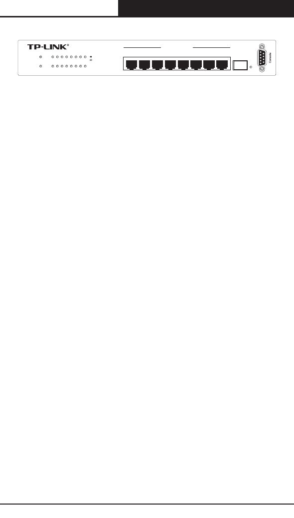
2.2 TP-Link TL-SG3109 Description
The following gure illustrates the TL-SG3109 front panel.
5
Gigabit Managed Switch Family Installation Guide
TL-SG3109/TL-SL3428/TL-SL3452
1 3 5 7
2 4 6 8
SFP
1 2 345 6 7 8
TL-SG3109
10/100/1000Mbps 1000Mb ps
Power
Syst em
Link
Act
10 00 M
Link/Act
9-port Gigab it Manage d Switch
Figure 2-1: TL-SG3109 Front Panel
The TL-SG3109 device front panel is congured as follows:
8 1000Base-T Copper port — Copper RJ-45 Gigabit port designated on
the device as ports 1-8.
1 1000Base-FX SFP port — Fiber Gigabit ports designated on the device
as ports SFP.
RS-232 DB-9 Console port — An asynchronous serial console port
supporting the RS-232 electrical specication. The port is used to connect
the device to the console managing the device.
The front panel also contains the following:
System LEDs — Indicates system hardware status.
10/100/1000 Base-T Port LEDs — Indicates the 10/100/1000 Base-T port
status. Each port has two LEDs.
SFP Port LED — Indicates the SFP port status. The port has one LED on
the right side of the port.
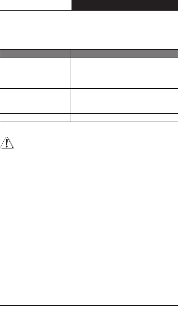
TL-SG3109 LEDs
The LED indications are described in the following table:
6
Gigabit Managed Switch Family Installation Guide
TL-SG3109/TL-SL3428/TL-SL3452
Port
LED Indication
Description
8 Giga Port
LEDs
Top LED
• Off — No 10/100/1000Mbps link is established on the port.
• Solid Green — A valid link is established on the port.
• Flashing Green — Packet transmission or reception is
occurring on the port.
Bottom LED
• Off — No link or a valid 10/100Mbps link is established
on the port.
• Solid Green — A valid 1000Mbps link is established on
the port.
SFP Port SFP Link/
ACT LED
• Off — No link is established on the port.
• Solid Green — A valid link is established on the port.
• Flashing Green — Packet transmission or reception is
occurring on the port.
System
LEDs
Power
• Solid Red — Power is supplied to the switch and is
operating normally.
• Off — Power is disconnected.
System
•
Flashing Green — Power On Self Test (POST) has passed
successfully and the device is operating normally.
• Solid Green — POST failure. A problem has been
discovered during the POST.
Table 1: TL-SG3109 Port LED Indications
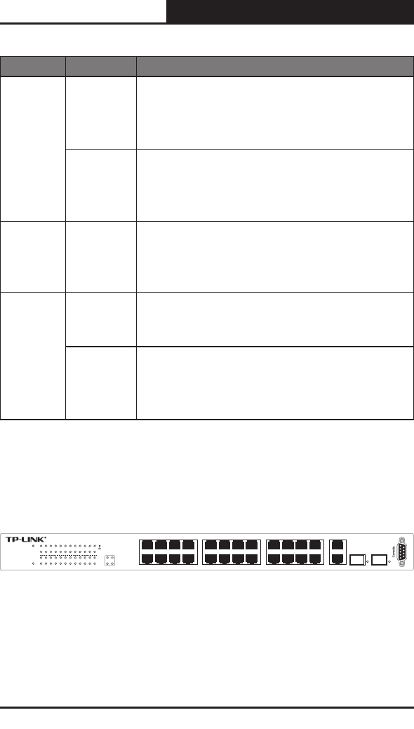
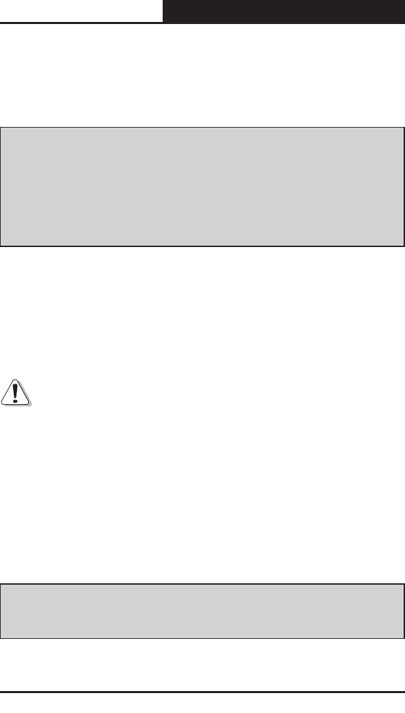
2.3 TP-Link TL-SL3428 Description
The following gure illustrates the TL-SL3428 front panel.
10 12 14 16
24 6 8
911 13 15
13 5 7 17 19 21 23 GIGA 1
GIGA 2
18 20 22 24
SFP 1 SFP 2
Pow er
1000Mbps
2 4 6 8 10 12 14 16 18 20 22 24
1 3 5 7 911 13 15 17 19 21 23
Lin k/A ct
Link/ Act Lin k/Act
Syste m
Link
Act
100Mbps
24+ 4G G iga bit Swi tchMan aged
TL-SL3428
GIGA1 GIGA2
Figure 2-2: TL-SL3428 Front Panel
The TL-SL3428 device front panel is congured as follows:
24 Fast Ethernet ports — RJ-45 ports designated as 10/100Base-T. The
RJ-45 ports are designated as ports Ports1-24.

7
Gigabit Managed Switch Family Installation Guide
TL-SG3109/TL-SL3428/TL-SL3452
2 1000Base-T Copper port — Copper RJ-45 Gigabit port designated on
the device as ports GIGA1 and GIGA2.
2 1000Base-FX SFP port — Fiber Gigabit ports designated on the device
as ports SFP1 and SFP2.
RS-232 DB-9 Console port — An asynchronous serial console port
supporting the RS-232 electrical specication. The port is used to connect
the device to the console managing the device.
The front panel also contains the following:
System LEDs — Indicates system hardware status.
10/100 Base-T Port LEDs — Indicates the 10/100 Base-T port status.
Each port has two LEDs all grouped together on the left side of the device.
Giga Port LEDs — Indicates the Giga port status. Each port has two LEDs
on the left side of the device.
SFP Port LEDs — Indicates the SFP port status. Each port has one LED
on the right side of the port.
TL-SL3428 LEDs
The LED indications are described in the following table:
Port
LED Indication
Description
24 10/100M
Ports
Top LED
• Off — No link is established on the port.
• Solid Green — A link is established on the port.
• Flashing Green — Packet transmission or reception is
occurring on the port.
Bottom LED
• Off — No 100Mbps link is established on the port.
• Solid Green — A valid 100Mbps link is established on
the port.
8
Gigabit Managed Switch Family Installation Guide
TL-SG3109/TL-SL3428/TL-SL3452
Giga Port
LEDs
Top LED
•
Off — No 10/100/1000Mbps link is established on the port.
• Solid Green — A valid link is established on the port.
• Flashing Green — Packet transmission or reception is
occurring on the port.
Bottom LED
• Off — No 1000Mbps link is established on the port.
• Solid Green — A valid 1000Mbps link is established on
the port.
2-SFP Port SFP Link/
ACT LED
• Off — No link is established on the port.
• Solid Green — A valid link is established on the port.
• Flashing Green — Packet transmission or reception is
occurring on the port.
System
LEDs
Power
• Solid Red — Power is supplied to the switch and is
operating normally.
• Off — Power is disconnected.
System
•
Flashing Green — Power On Self Test (POST) has passed
successfully and the device is operating normally
.
• Solid Green — POST failure. A problem has been
discovered during the POST.
Table 2: TL-SL3428 Port LED Indications
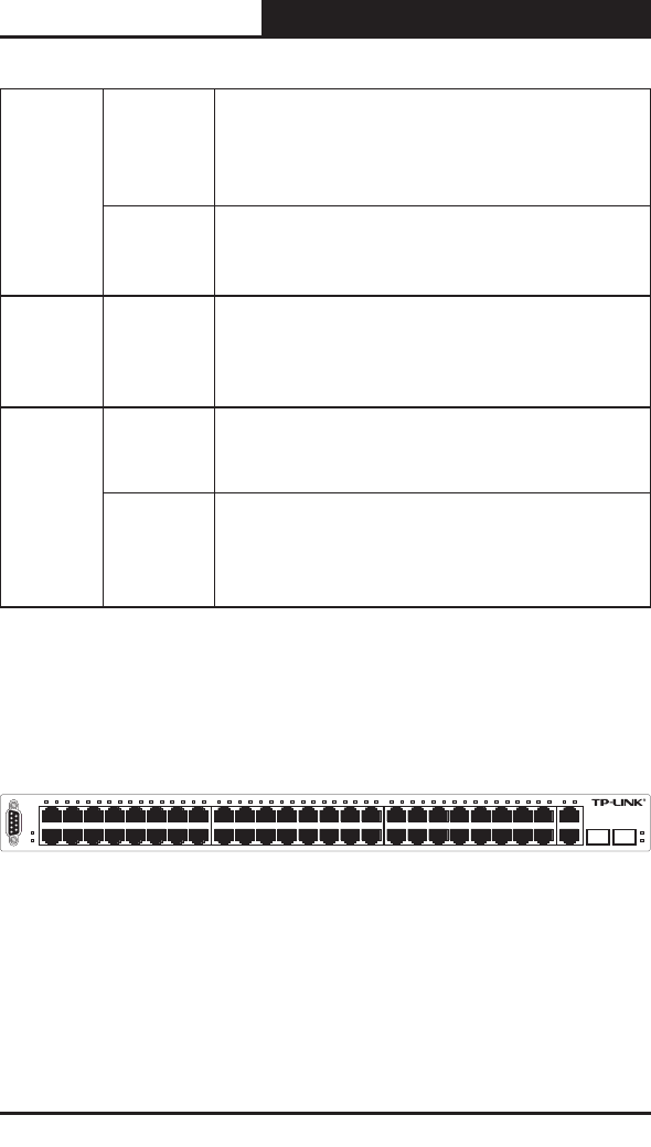
2.4 TP-Link TL-SL3452 Description
The following gure illustrates the TL-SL3452 front panel.
Console
TL-S L3 45 2
SFP 1
SFP 2
29 30 31 32 33 34 35 36 37 38 39 40 41 42 43 44 45 46 47 482 4 6 8 10 12 14 16 18 20 22 24 25 26 27 281 3 57 9 11 13 15 17 19 21 23 GIGA1 GIGA2
2 4 6 8 10 12 14 16 18 20 22 24 26 28 30 32 34 36 38 40 42 44 46 48
47
33 35 37 39 41 43 45
13 5 7 9 11 13 15 17 27 29 312519 21 23
GIGA1
GIGA2
SFP 1 SFP 2
Link/Act
48+4G Gigabit Managed Switch
Powe r
System
Figure 2-3: TL-SL3452 Front Panel
The TL-SL3452 device front panel is congured as follows:
48 Fast Ethernet ports — RJ-45 ports designated as 10/100Base-T.
The RJ-45 ports are designated as ports Ports1-48. The top row of ports
are designated odd numbers, and the bottom row are designated even

9
Gigabit Managed Switch Family Installation Guide
TL-SG3109/TL-SL3428/TL-SL3452
numbers.
2 1000Base-T Copper port — Copper RJ-45 Gigabit port designated on
the device as ports GIGA1 and GIGA2.
2 1000Base-FX SFP port — Fiber Gigabit ports designated on the device
as ports SFP1 and SFP2.
RS-232 DB-9 Console port — An asynchronous serial console port
supporting the RS-232 electrical specication. The port is used to connect
the device to the console managing the device.
The front panel also contains the following:
System LEDs — Indicates system hardware status.
10/100 Base-T Port LEDs — Indicates the 10/100 Base-T port status.
Each port has one LED above the port.
Giga Port LEDs — Indicates the Giga port status. Each port has one LED
above the port.
SFP Port LEDs — Indicates the SFP port status. Each port has one LED
on the right side of the port.
TL-SL3452 LEDs
The LED indications are described in the following table:
Port
LED Indication
Description
48 10/100M
Ports
Top LED
• Off — No link is established on the port.
• Solid Green — A valid link is established on the port.
• Flashing Green — Packet transmission or reception is
occurring on the port .
Giga Port
LEDs Top LED
•
Off — No 10/100/1000Mbps link is established on the port.
• Solid Green — A valid link is established on the port.
• Flashing Green — Packet transmission or reception is
occurring on the port.

10
Gigabit Managed Switch Family Installation Guide
TL-SG3109/TL-SL3428/TL-SL3452
2-SFP Port SFP Link/
ACT LED
• Off — No link is established on the port.
• Solid Green — A valid link is established on the port.
• Flashing Green — Packet transmission or reception is
occurring on the port.
System
LEDs
Power
• Solid Red — Power is supplied to the switch and is
operating normally.
• Off — Power is disconnected.
System
•
Flashing Green — Power On Self Test (POST) has passed
successfully and the device is
operating normally
.
• Solid Green — POST failure. A problem has been
discovered during the POST.
Table 3: TL-SL3452 Port LED Indications
2.5 Back Panel
The following gure illustrates the devices back panel.
Figure 2-4: TL-SG3109 Back Panel
Figure 2-5: TL-SL3428/TL-SL3452 Back Panel
The device back panel is congured as follows:
Power Connector — AC power supply interface.
2.6 Device Hardware Interfaces
2.6.1 RJ-45 Base-T Fast Ethernet Ports
RJ-45 ports are auto-sensing ports. When inserting a cable into an RJ-45 port,

11
Gigabit Managed Switch Family Installation Guide
TL-SG3109/TL-SL3428/TL-SL3452
the switch automatically ascertains the maximum speed (10 or 100 or 1000
Mbps) and duplex mode (half- or full-duplex) of the attached device. All ports
support only unshielded twisted-pair (UTP) cable terminated with an 8-pin
RJ-45 plug.
To simplify the procedure for attaching devices, all RJ-45 ports support Auto
Uplink. This technology allows attaching devices to the RJ-45 ports with either
straight-through or crossover cables. When inserting a cable into the switch’s
RJ-45 port, the switch automatically:
Senses whether the cable is a straight-through or crossover cable.
Determines whether the link to the attached device requires a “normal”
connection (such as when connecting the port to a PC) or an “uplink”
connection (such as when connecting the port to a router, switch, or hub).
Configures the RJ-45 port to enable communications with the attached
device, without requiring user intervention. In this way, the Auto Uplink
technology compensates for setting uplink connections, while eliminating
concern about whether to use crossover or straight-through cables when
attaching devices.
2.6.2 SFP Port
The GBIC module bays accommodate standard SFP GBIC modules, such as
the TL-SM311LM or TL-SM311LS from TP-LINK, allowing ber connections
on the network.
The SFP GBIC bay accommodates a standard SFP GBIC module. Small
Form Factor Pluggable (SFP) Optical Transceivers are integrated duplex data
links for bi-directional communication over multimode optical ber, designed
for high-speed Fibre Channel data links. The SFP port is designated as
1000Base-FX.
12
Gigabit Managed Switch Family Installation Guide
TL-SG3109/TL-SL3428/TL-SL3452
2.6.3 RS-232 DB-9 Console Port
The DB-9 port is an asynchronous serial console port supporting the RS-232
electrical specification. The port is used to connect the device to a console
managing the device. This interface conguration is as follows:
Eight data bits.
One stop bit.
No parity.
Baud rate is 38400 (default). Possible values of baud rate are 2400, 4800,
9600, 19200, 38400.
2.7 Cable, Port, and Pinout Information
This section describes the devices physical interfaces and provides
information about cable connections. Stations are connected to the device
ports through the physical interface ports on the front panel. For each station,
the appropriate mode (Half/Full Duplex, Auto) is set.
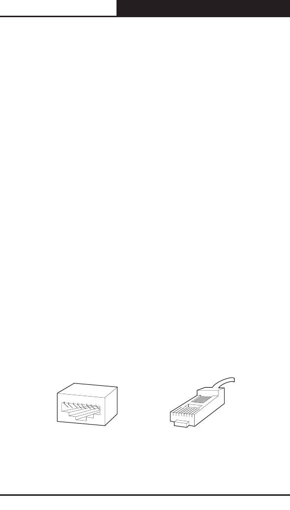
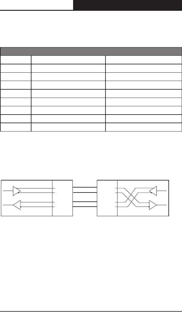
2.7.1 Pin Explain For RJ-45 Connector
The switching port can connect to stations wired in standard RJ-45 Ethernet
station mode using straight cables. Transmission devices connected to each
other use crossed cables. The following gure illustrates the pin allocation:
87654321
1 2 3 4 5 6 7 8
Figure 2-6 RJ-45 connector
13
Gigabit Managed Switch Family Installation Guide
TL-SG3109/TL-SL3428/TL-SL3452
The following shows the way to make the cable use to connect switch to
network adapter, and cable use to connect switch to switch/hub/bridge.
Pin signal allocation for RJ-45 connector
Pin MDI-II MDI-X
1 TX+ (send) RX+ (receive)
2 TX- (send) RX- (receive)
3 RX+ (receive) TX+ (send)
4 No use No use
5 No use No use
6 RX- (receive) TX- (send)
7 No use No use
8 No use No use
Table 4: RJ-45 Pin Connections for 10/100/1000 Base-T
Straight cable: use to connect switch (uplink port) or network adapter to switch/
hub/other device (normal port).
1 TX+
2 TX-
3 RX+
6 RX-
RX+ 1
RX- 2
TX+ 3
TX- 6
MDI-II MDI-X
Figure 2-7 straight cable
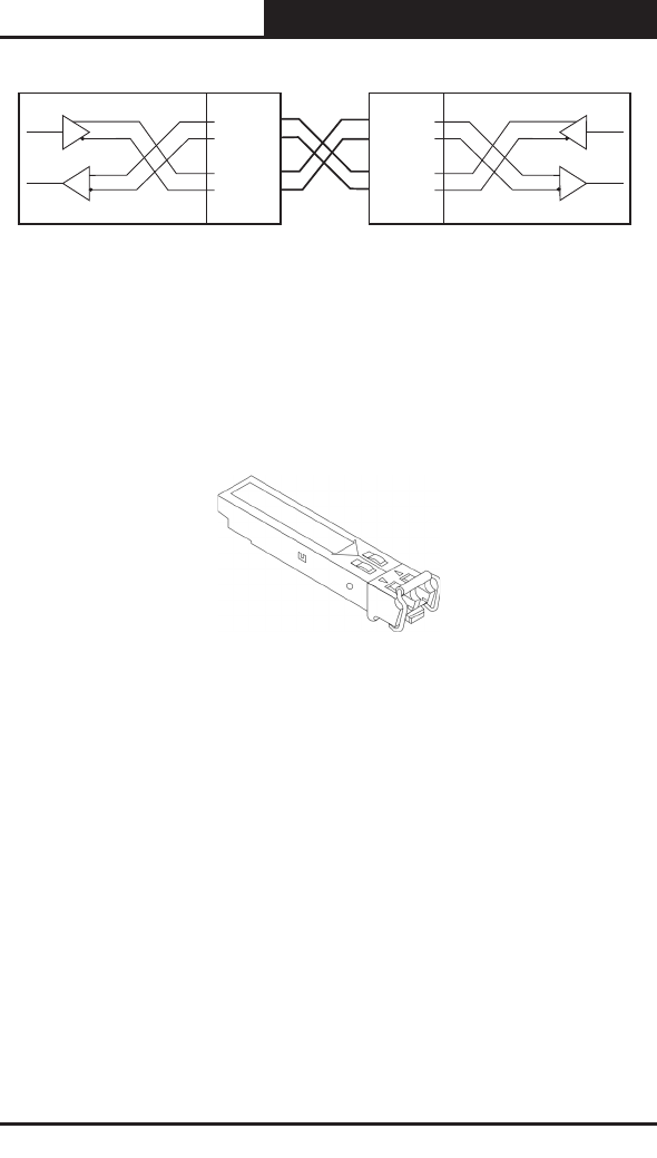
Crossed cable: use to connect switch (normal port) to switch/hub/other
device(normal port).
14
Gigabit Managed Switch Family Installation Guide
TL-SG3109/TL-SL3428/TL-SL3452
1 RX+
2 RX-
3 TX+
6 TX-
RX+ 1
RX- 2
TX+ 3
TX- 6
MDI-XMDI-X
Figure 2-8 crossed cable
2.7.2 SFP Connector
The following figure illustrates an SFP connector which is entered into the
device SFP port.
2.8 Physical Dimensions
The TL-SG3109 device has the following physical dimensions:
Width: 294mm (11.57 inch)
Depth: 180mm (7.09 inch)
Height: 44mm (1.73 inch)
The TL-SL3428 and TL-SL3452 described in this Installation Guide have the
following physical dimensions:
Width: 440 mm (17.32 inch)
Depth: 430mm (16.93 inch)
Height: 45 mm (1.77 inch)

15
Gigabit Managed Switch Family Installation Guide
TL-SG3109/TL-SL3428/TL-SL3452
Section 3. Mounting Device
3.1 Preparing for Installation
3.1.1 Installation Precautions
Warnings
The surface on which the switch is placed should be adequately secured
to prevent it from becoming unstable and/or falling over.
Ensure the power source circuits are properly grounded.
Observe and follow service markings. Do not service any product except
as explained in your system documentation. Opening or removing
covers marked with a triangular symbol with a lighting bolt may cause
electrical shock. These components are to be serviced by trained service
technicians only.
Ensure the power cable, extension cable, and/or plug is not damaged.
Ensure the product is not exposed to water.
Ensure the device is not exposed to radiators and/or heat sources.
Do not push foreign objects into the device, as it may cause a fire or
electric shock.
Use the device only with approved equipment.
Allow the product to cool before removing covers or touching internal
equipment.
Ensure the switch does not overload the power circuits, wiring, and over-
current protection. To determine the possibility of overloading the supply
circuits, add together the ampere ratings of all devices installed on the
same circuit as the device being installed. Compare this total with the
rating limit for the circuit. The maximum ampere ratings are usually printed
on the switch, near their AC power connectors.

16
Gigabit Managed Switch Family Installation Guide
TL-SG3109/TL-SL3428/TL-SL3452
Cautions
Ensure the air ow around the front, sides, and back of the switch is not
restricted.
Ensure the cooling vents are not blocked.
Do not install the switch in an environment where the operating ambient
temperature might exceed 40ºC (104ºF).
3.1.2 Site Requirements
The device is placed on a table-top. Before installing the unit, verify that the
location chosen for installation meets the following site requirements.
General — Ensure that the power supply is correctly installed.
Power — The unit is installed within 1.5 m (5 feet) of a grounded, easily
accessible outlet 100-240 VAC, 50-60 Hz.
Clearance — There is adequate frontal clearance for operator access.
Allow clearance for cabling, power connections and ventilation.
Cabling — The cabling is routed to avoid sources of electrical noise such
as radio transmitters, broadcast amplifiers, power lines and fluorescent
lighting xtures.
Ambient Requirements — The ambient unit operating temperature
range is 0 to 40ºC (32 to 104ºF) at a relative humidity of up to 95%, non-
condensing. Verify that water or moisture cannot enter the device casing.
3.1.3 Unpacking
3.1.3.1 Package Contents
While unpacking Cedar device, ensure that the following items are included:
The device
An AC power cable

17
Gigabit Managed Switch Family Installation Guide
TL-SG3109/TL-SL3428/TL-SL3452
Console cable with DB-9 connector
This "Installation Guide", the "Embedded Web System User Guide" and
documentation CD
Two mounting brackets and other ttings
3.1.3.2 Unpacking Essentials
Note
Before unpacking the device, inspect the package and report any evidence of
damage immediately.
To unpack the device perform the following:
1. It is recommended to put on an ESD wrist strap and attach the ESD clip
to a metal surface to act as ground. An ESD strap is not supplied with the
device.
2. Place the container on a clean at surface and cut all straps securing the
container.
3. Open the container.
4. Carefully remove the device from the container and place it on a secure
and clean surface.
5. Remove all packing material.
6. Inspect the product for damage. Report any damage immediately.
3.2 Installing the Device
The device can be installed on a at surface or mounted in a rack. This section
includes the following topics:
Desktop or Shelf Installation
Rack Installation

18
Gigabit Managed Switch Family Installation Guide
TL-SG3109/TL-SL3428/TL-SL3452
3.2.1 Desktop or Shelf Installation
When installing the switch on a desktop or shelf, the rubber feet included with
the device should rst be attached. Attach these cushioning feet on the bottom
at each corner of the device.
Ensure the surface is be able to support the weight of the device and the
device cables.
To install the device on a surface, perform the following:
1. Attach the rubber feet on the bottom of the device.
2. Set device down on a at surface, while leaving 2 inches on each side and
5 inches at the back.
3. Ensure that the device has proper ventilation by allowing adequate space
for ventilation between the device and the objects around the device.
3.2.2 Rack Installation
The device can be mounted in an EIA standard-sized, 19-inch rack, which can
be placed in a wiring closet with other equipment. To install, the device the
mounting brackets must rst be attached on the devices’s sides.
Note
Disconnect all cables from the unit before mounting the device in a rack or
cabinet.
When mounting multiple devices into a rack, mount the devices from the
bottom up.
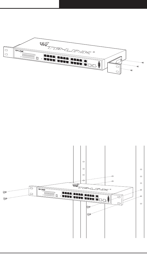
To install the device in a rack, perform the following:
1. Place the supplied rack-mounting bracket on one side of the device
ensuring the mounting holes on the device line up to the mounting holes
19
Gigabit Managed Switch Family Installation Guide
TL-SG3109/TL-SL3428/TL-SL3452
on the rack mounting bracket. The following figure illustrates where to
mount the brackets.
10121416
2468
9111315
135717192123
GIGA1
GIGA2
18202224
SFP1SFP2
RESET
Power
1000Mbps
24681012141618202224
1357911131517192123
Link/Act
Link/ActLink/Act
System
Link
Act
100Mbps
24+4GGigabitSwitch
Managed
TL-SL3428
GIGA1GIGA2
Console
Figure 3-1: Attaching the Mounting Brackets
2. Insert the supplied screws into the rack mounting holes and tighten with a
screwdriver.
3. Repeat the process for the rack-mounting bracket on the other side of the
device.
4. Insert the unit into the 19-inch rack ensuring the rack-mounting holes on
the device line up to the mounting hole on the rack. The following gure
illustrates lining up and mounting the device in the rack.
10121416
2468
9111315
135717192123
GIGA1
GIGA2
18202224
SFP1SFP2
RESET
Power
1000Mbps
24681012141618202224
1357911131517192123
Link/Act
Link/ActLink/Act
System
Link
Act
100Mbps
24+4GGigabitSwitch
Managed
TL-SL3428
GIGA1GIGA2
Console
Figure 3-2: Mounting Device in a Rack

20
Gigabit Managed Switch Family Installation Guide
TL-SG3109/TL-SL3428/TL-SL3452
5. Secure the unit to the rack with the rack screws (not provided). Fasten the
lower pair of screws before the upper pair of screws. This ensures that the
weight of the unit is evenly distributed during installation. Ensure that the
ventilation holes are not obstructed.
3.3 Connecting the Device
This section describes how to connect the device, and includes the following
sections:
Connecting the Switch to a Terminal
AC Power Connection
3.3.1 Connecting the Switch to a Terminal
The device is connected to a terminal through an console port on the front
panel, which enables a connection to a terminal desktop system running
terminal emulation software for monitoring and conguring the device.
The terminal must be a VT100 compatible terminal or a desktop or portable
system with a serial port and running VT100 terminal emulation software.
To connect a terminal to the device Console port, perform the following:
1. Connect a cable to the terminal running VT100 terminal emulation software.
2. Ensure that the terminal emulation software is set as follows:
a) Select the appropriate port to connect to the device.
b) Set the data rate to 38400 baud.
c) Set the data format to 8 data bits, 1 stop bit, and no parity.
d) Set ow control to none.
e) Under Properties, select VT100 for Emulation mode.
f) Select Terminal keys for Function, Arrow and Ctrl keys. Ensure that the

21
Gigabit Managed Switch Family Installation Guide
TL-SG3109/TL-SL3428/TL-SL3452
setting is for Terminal keys (not Windows keys).
Note
When using HyperTerminal with Microsoft® Windows 2000, ensure that you
have Windows 2000 Service Pack 2 or later installed. With Windows® 2000
Service Pack 2, the arrow keys function properly in HyperTerminal’s VT100
emulation. Go to www.microsoft.com for information on Windows 2000 service
packs.
3. Connect the cable to the console port on the device front panel.
3.3.2 AC Power Connection
To connect the power supply perform the following:
1. Using a 5-foot (1.5 m) standard power cable with safety ground connected,
connect the power cable to the AC main socket located on the back panel.
2. Connect the power cable to a grounded AC outlet.
3. Conrm that the device is connected and operating by checking that the
Power Supply LED on the front panel is green.

22
Gigabit Managed Switch Family Installation Guide
TL-SG3109/TL-SL3428/TL-SL3452
Section 4. Starting and Conguring the Device
This section describes the initial device configuration and includes the
following topics:
Conguring the Terminal
Installation Procedure
Booting the Device
Conguration Overview
Advanced Conguration
Startup Procedures
4.1 Conguring the Terminal
After completing all external connections, connect a terminal to the device to
monitor the boot and other procedures.
To configure the device, the terminal must be running terminal emulation
software.
Ensure that the terminal emulation software is congured as follows:
1. Connect the Chassis serial port to the switch module. The baud rate
automatically boots up at 38400.
2. Set the data format to 8 data bits, 1 stop bit, and no parity.
3. Set Flow Control to none.
4. Under Properties, select VT100 for Emulation mode.
5. Select Terminal keys for Function, Arrow, and Ctrl keys. Ensure that the
setting is for Terminal keys (not Windows keys).
Note
When using HyperTerminal with Microsoft® Windows 2000, make sure that
23
Gigabit Managed Switch Family Installation Guide
TL-SG3109/TL-SL3428/TL-SL3452
Windows® 2000 Service Pack 2 or later is installed. With Windows 2000
Service Pack 2, the arrow keys function properly in HyperTerminal’s VT100
emulation. Go to www.microsoft.com for information on Windows 2000 service
packs.
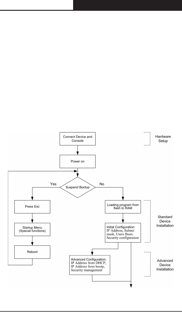
4.2 Installation Procedure
The order of installation and configuration procedures is illustrated in the
following gure. For the initial conguration, the standard device conguration
is performed.
Performing other functions is described later in this section.
24
Gigabit Managed Switch Family Installation Guide
TL-SG3109/TL-SL3428/TL-SL3452
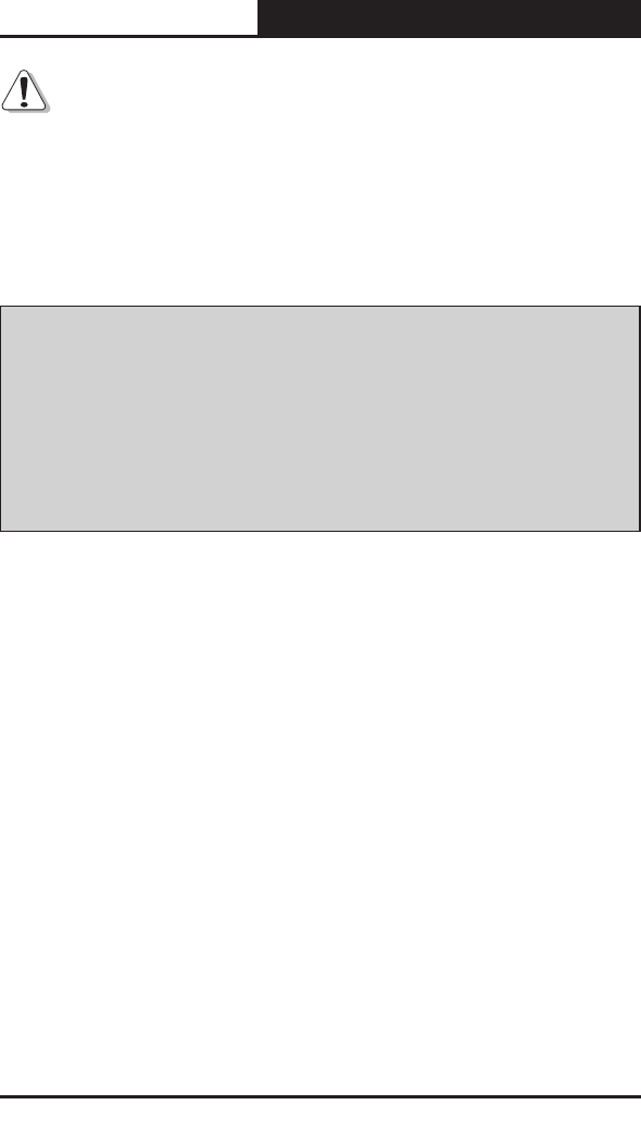
4.2.1 Device Port Default Settings
The following table describes the device port default settings.
Function
Default Settings
Port speed and mode
• 100Mbps Auto-negotiation for 10/100 Base-TX
Ports
• 1000Mbps Auto-negotiation for 10/100/1000
Base-TX Ports
Port forwarding state Enabled
Head of line blocking prevention On (Enabled)
Flow Control Off
Back Pressure Off
Table 5: Port Default Setting
Note
These default settings can be modied once the device is installed.
4.3 Booting the Device
The assumed bootup information is as follows:
The device is delivered with an empty conguration.
To boot the device, perform the following steps:
1. Ensure that the device port console is connected to a VT100 terminal
device or VT100 terminal emulator.
2. Connect the device to the AC receptacle.
3. Activate the AC power receptacle (if required).
The device goes through Power On Self Test (POST). POST runs every time
the device is initialized and checks hardware components to determine if

25
Gigabit Managed Switch Family Installation Guide
TL-SG3109/TL-SL3428/TL-SL3452
the device is fully operational before completely booting. If a critical problem
is detected, the program flow stops. If POST passes successfully, a valid
executable image is loaded into RAM.
POST messages are displayed on the terminal and indicate test success or
failure.
As the device boots, the bootup test rst counts the device memory availability
and then continues to boot. The following screen is an example of the
displayed POST:
------ Performing the Power-On Self Test (POST) ------
UART Channel Loopback Test.............................PASS
Testing the System SDRAM.................................PASS
Boot1 Checksum Test............................................PASS
Boot2 Checksum Test............................................PASS
Flash Image Validation Test.................................PASS
BOOT Software Version 1.0.0.04 Built 29-Nov-2005 11:56:12
TPLink Switch based on 88E6218 with ARM946E-S.
32MByte SDRAM. I-Cache 8 KB. D-Cache 8 KB. Cache Enabled.
Autoboot in 2 seconds - press RETURN or Esc. to abort and enter prom.
Preparing to decompress...
The boot process runs for approximately 60 seconds.
The auto-boot message displayed at the end of POST (see the last lines)

26
Gigabit Managed Switch Family Installation Guide
TL-SG3109/TL-SL3428/TL-SL3452
indicates that no problems were encountered during boot.
During boot, the Startup menu can be used to run special procedures. To
enter the Startup menu, press <Esc> or <Enter> within the rst two seconds
after the auto-boot message is displayed.
If the system boot process is not interrupted by pressing <Esc> or <Enter>,
the process continues decompressing and loading the code into RAM. The
code starts running from RAM and the list of numbered system ports.
After the device boots successfully, a system prompt is displayed (console>)
which is used to congure the device. However, before conguring the device,
ensure that the latest software version is installed on the device. If it is not the
latest version, download and install the latest version. For more information on
downloading the latest version, see Software Download [Option 1].
4.4 Conguration Overview
Before assigning a static IP address to the device, obtain the following
information:
A specic IP address that has been allocated to the device in order for it to
be congured.
Default route.
Network mask for the network.
There are two conguration types:
Initial Configuration — Consists of configuration functions with basic
security considerations.
Advanced Conguration — Consists of dynamic IP conguration and more
advanced security considerations.

27
Gigabit Managed Switch Family Installation Guide
TL-SG3109/TL-SL3428/TL-SL3452
Note
After making any conguration changes, the new conguration must be saved
before rebooting. To save the conguration, enter:
console# copy running-config startup-config
4.4.1 Initial Conguration
Initial configuration, which starts after the device has booted successfully,
includes static IP address and subnet mask configuration, and setting user
name and privilege level to allow remote management. If the device is to be
managed from an SNMP-based management station, SNMP community
strings must also be congured. The following congurations are completed:
The initial simple conguration uses the following assumptions:
The device was never congured before, and is in the same state as when
it was received.
The device booted successfully.
The Serial connection is established and the console prompt is displayed
on the screen of a VT100 terminal device. (Press the <Enter> key several
times to verify that the prompt displays correctly.)
The device is not congured with a default user name and password.
The initial device configuration is through the Serial port. After the initial
configuration, the device can then be managed either from the already
connected Serial port or remotely through an interface dened during the initial
conguration.
The initial conguration consists of the following:

28
Gigabit Managed Switch Family Installation Guide
TL-SG3109/TL-SL3428/TL-SL3452
Setting a user name and password with the highest privilege level of 15.
Conguring the static IP address and the default gateway.
Conguring the SNMP read/write community string.
Assigning the IP address allocated by the DHCP server.
Before applying the initial conguration procedure to the device, the following
information must be obtained from the network administrator:
The IP address to be assigned to a VLAN through which the device is
managed.
The IP subnet mask for the network.
The default gateway IP address.
The SNMP community.
4.4.1.1 Static IP Address and Subnet Mask
IP interfaces can be congured on each port of the device. After entering the
conguration command, it is recommended to check if a port was congured
with the IP address by entering the show ip interface command.
The commands to congure the device are port specic.
To manage the switch from a remote network, a static route must be
congured, which is an IP address to where packets are sent when no entries
are found in the device tables. The congured IP address must belong to the
same subnet as one of the device IP interfaces.
To configure a static route, enter the command at the system prompt as
shown in the following conguration example, where 100.1.1.1 is the specic
management station, the IP address is dened on VLAN 1, and the default

29
Gigabit Managed Switch Family Installation Guide
TL-SG3109/TL-SL3428/TL-SL3452
gateway is dened as 100.1.1.10. Note that by default, all ports are members
of VLAN 1, which is the default VLAN.
console# configure
console(config)# interface vlan 1
console(config-if)# ip address 100.1.1.1 255.255.255.0
console(config-if)# exit
console# ip default-gateway 100.1.1.10
Conrm that the IP address has been correctly congured as follows:
console# show ip interface
Proxy ARP is disabled
IP Address I/F Type
----------------- ----------- -----------------
100.1.1.1/24 vlan 1 static
4.4.1.2 Assigning Static IP Addresses on a default VLAN
This example uses the following assumptions:
The IP address to be assigned to the VLAN interface is 192.168.1.123
The IP subnet mask for the network is 255.255.255.0
The IP address of the default route is 192.168.1.1
The read/write SNMP community string is "private"
console> enable
console# configure
console(config)# username admin password admin level 15
console(config)# interface VLAN 1
console (config-if) # ip address 192.168.1.123 255.255.255.0
console (config-if) # exit
console (config) # ip default-gateway 192.168.1.1
console (config) # snmp-server community private rw
console(config)# exit
console#
30
Gigabit Managed Switch Family Installation Guide
TL-SG3109/TL-SL3428/TL-SL3452
Verifying the IP and Default Gateway Addresses
Ensure that the IP address and the default gateway were properly assigned by
executing the following command and examining its output:
Gateway IP Address Activity status
----------------------------------------------------------
---- ---
192.168.1.1 Active
IP address Interface Type
------------------- ---------------- --------
192.168.1.123/24 VLAN 1 Static
4.4.1.3 User Name
A user name is used to manage the device remotely, for example through
SSH, Telnet, or the Web interface. To gain complete administrative (super-user)
control over the device, the highest privilege (15) must be specied.
Note
Only the administrator (super-user) with the highest privilege level (15) is
allowed to manage the device through the Web browser interface.
For more information about the privilege level, see the CLI Reference Guide.
The congured user name is entered as a login name for remote management
sessions. To congure user name and privilege level, enter the command at
the system prompt as shown in the conguration example:
console> enable
console# configure
console(config)# username admin password admin level 15

31
Gigabit Managed Switch Family Installation Guide
TL-SG3109/TL-SL3428/TL-SL3452
4.4.1.4 SNMP Community Strings
Simple Network Management Protocol (SNMP) provides a method for
managing network devices. Devices supporting SNMP run a local software
(agent). The SNMP agents maintain a list of variables, used to manage the
device. The variables are dened in the Management Information Base (MIB).
The MIB presents the variables controlled by the agent. The SNMP agent
denes the MIB specication format, as well as the format used to access the
information over the network.
Access rights to the SNMP agents are controlled by access strings and SNMP
community strings.
The device is SNMP-compliant, and contain an SNMP agent that support a
set of standard and private MIB variables. Developers of management stations
require the exact structure of the MIB tree and receive the complete private
MIBs information before being able to manage the MIBs.
All parameters are manageable from any SNMP management platform,
except the SNMP management station IP address and community (community
name and access rights). The SNMP management access to the switch is
disabled if no community strings exist.
Note
The device switch is delivered with no community strings congured.
The community-string, community-access, and IP address can be congured
through the local terminal during the initial conguration procedure.
The SNMP conguration options are:

32
Gigabit Managed Switch Family Installation Guide
TL-SG3109/TL-SL3428/TL-SL3452
Community string
– Access rights options: ro (read only), rw (read-and-write) or su (super).
– An option to configure IP address or not: If an IP address is not
configured, it means that all community members having the same
community name are granted the same access rights.
Common practice is to use two community strings for the switch one (public
community) with read-only access and the other (private community) with
read-write access. The public string allows authorized management stations
to retrieve MIB objects, while the private string allows authorized management
stations to retrieve and modify MIB objects.
During initial configuration, it is recommended to configure the device
according to the network administrator requirements, in accordance with
using an SNMP-based management station. During the initial configuration
procedure the community-string, community-access, and IP address can be
set through the local terminal.
The SNMP conguration options are:
Community string.
– Read Only—Indicates that the community members can view
conguration information, but cannot change any information.
– Read/Write — Indicates that the community members can view and
modify conguration information.
– Super — Indicates that the community members have administration
access.
Configurable IP address. If IP address is not configured, all community
members with the same community name are granted the same access
rights.

33
Gigabit Managed Switch Family Installation Guide
TL-SG3109/TL-SL3428/TL-SL3452
To congure SNMP station IP address and community string(s) perform the
following:
1. At the console prompt, enter the command Enable. The prompt is displayed as
#.
2. Enter the command congure and press <Enter>.
3. In the conguration mode, enter the SNMP conguration command with
the parameters including community name (private), community access
right (read and write) and IP address, as shown in the following example:
console# configure
console(config)# snmp-server community private rw 11.1.1.2
console(config)# end
console# show snmp
Community-String Community-Access IP address
-------------------------------- ----------------------------------- -----------------------
private readWrite 11.1.1.2
Traps are enabled.
Authentication-failure trap is enabled.
Trap-Rec-Address Trap-Rec-Community Version
-------------------------------- ---------------------------------- ----------------------
System
Contact:
System Location:
This completes the initial conguration of the device from a local terminal. The
congured parameters enable further device conguration from any remote
location.
4.5 Advanced Conguration
This section provides information about dynamic allocation of IP addresses
and security management based on the authentication, authorization, and

34
Gigabit Managed Switch Family Installation Guide
TL-SG3109/TL-SL3428/TL-SL3452
accounting (AAA) mechanism, and includes the following topics:
Receiving an IP Address from a DHCP Server
Receiving an IP Address from a BOOTP Server
Security Management and Password Conguration
When conguring or receiving IP addresses through DHCP and BOOTP, the
conguration received from these servers includes the IP address, and may
include a subnet mask and default gateway.
4.5.1 Receiving an IP Address from a DHCP Server
When using the DHCP protocol to retrieve an IP address, the device acts as
a DHCP client. To receive an IP address from a DHCP server, perform the
following steps:
1. Select and connect any port to a DHCP server or to a subnet that has a
DHCP server on it, in order to retrieve the IP address.
2. Enter the following commands to use the selected port for receiving the IP
address. In the following example, the commands are based on the port
type used for conguration.
console# configure
console(config)# interface vlan 1
console(config-if)# ip address dhcp hostname admin-host
console(config-if)# exit
console(config)#
3. To verify the IP address, enter the show ip interface command at the
system prompt as shown in the following example.

35
Gigabit Managed Switch Family Installation Guide
TL-SG3109/TL-SL3428/TL-SL3452
console# show ip interface
IP Address I/F Type
-------------------- --------------- --------------
100.1.1.1/24 vlan 1 dynamic
Note
The device configuration does not have to be deleted to retrieve an IP
address for the DHCP server.
When copying configuration files, avoid using a configuration file that
contains an instruction to enable DHCP on an interface that connects to
the same DHCP server, or to one with an identical conguration.As a result
of the copying conguration, the switch retrieves the new conguration le
and boots from it. The device then enables DHCP as instructed in the new
conguration le, and the DHCP instructs it to reload the same le.
4.5.2 Receiving an IP Address from a BOOTP Server
The standard BOOTP protocol is supported and enables the switch to
automatically download its IP host conguration from any standard BOOTP
server in the network. In this case, the device acts as a BOOTP client.
To receive an IP address from a BOOTP server:
1. Select and connect any port to a BOOTP server or subnet containing such
a server.
2. At the system prompt, enter the delete startup conguration command to
delete the startup conguration from ash.
The device reboots with no conguration and in 60 seconds starts sending
BOOTP requests. The device receives the IP address automatically.
36
Gigabit Managed Switch Family Installation Guide
TL-SG3109/TL-SL3428/TL-SL3452
Note
When the device reboot begins, any input at the ASCII terminal or keyboard
automatically cancels the BOOTP process before completion, and the device
does not receive an IP address from the BOOTP server.
The following example illustrates the process:
console> enable
console# delete startup-config
Startup file was deleted
console# reload
You haven’t saved your changes. Are you sure you want to continue (Y/N)[N]?
This command will reset the whole system and disconnect your current
session. Do you want to continue (Y/N)[N]?
***************************************************
***************** SYSTEM RESET *****************
***************************************************
3. To verify the IP address, enter the show ip interface command. The
device is now congured with an IP address.
4.5.3 Security Management and Password Conguration
System security is handled through the AAA (Authentication, Authorization,
and Accounting) mechanism that manages user access rights, privileges, and
management methods. AAA uses both local and remote user databases. Data
encryption is handled through the SSH mechanism.
The system is delivered with no default password congured; all passwords
are user-defined. If a user-defined password is lost, a password recovery
procedure can be invoked from the Startup menu. The procedure is applicable
for the local terminal only and allows a one-time access to the device from the
local terminal with no password entered.

37
Gigabit Managed Switch Family Installation Guide
TL-SG3109/TL-SL3428/TL-SL3452
4.5.3.1 Conguring Security Passwords Introduction
The security passwords can be congured for the following services:
Console
Telnet
SSH
HTTP
HTTPS
Note
Passwords are user-dened.
When creating a user name, the default priority is "1," which allows
access but not conguration rights. A priority of "15" must be set to enable
access and conguration rights to the device. Although user names can
be assigned privilege level 15 without a password, it is recommended to
always assign a password. If there is no specified password, privileged
users can access the Web interface with any password.
4.5.3.2 Conguring an Initial Console Password
To congure an initial console password, enter the following commands:
console(config)# aaa authentication login default line
console(config)# aaa authentication enable default line
console(config)# line console
console(config-line)# login authentication default
console(config-line)# enable authentication default
console(config-line)# password george
When initially logging on to a device through a console session, enter george
at the password prompt.

38
Gigabit Managed Switch Family Installation Guide
TL-SG3109/TL-SL3428/TL-SL3452
When changing a device mode to enable, enter george at the password
prompt.
4.5.3.3 Conguring an Initial Telnet Password
To congure an initial Telnet password, enter the following commands:
console(config)# aaa authentication login default line
console(config)# aaa authentication enable default line
console(config)# line telnet
console(config-line)# login authentication default
console(config-line)# enable authentication default
console(config-line)# password bob
When initially logging onto a device through a Telnet session, enter bob at the
password prompt.
When changing a device mode to enable, enter bob.
4.5.3.4 Conguring an Initial SSH password
To congure an initial SSH password, enter the following commands:
console(config)# aaa authentication login default line
console(config)# aaa authentication enable default line
console(config)# line ssh
console(config-line)# login authentication default
console(config-line)# enable authentication default
console(config-line)# password jones
When initially logging onto a device through a SSH session, enter jones at the
password prompt.
When changing a device mode to enable, enter jones.
39
Gigabit Managed Switch Family Installation Guide
TL-SG3109/TL-SL3428/TL-SL3452
4.5.3.5 Conguring an Initial HTTP Password
To congure an initial HTTP password, enter the following commands:
console(config)# ip http authentication local
console(config)# username admin password user1 level 15
4.5.3.6 Conguring an initial HTTPS Password
To congure an initial HTTPS password, enter the following commands:
console(config)# ip https authentication local
console(config)# username admin password user1 level 15
Enter the following commands once when configuring to use a console, a
Telnet, or an SSH session to use an HTTPS session.
In the Web browser enable SSL 2.0 or greater for the content of the page to
appear.
console(config)# crypto certificate 2 generate key_generate
console(config)# ip https server
When initially enabling an http or https session, enter admin for user name
and user1 for password.
Note
HTTP and HTTPS services require level 15 access and connect directly to the
conguration level access.
4.6 Startup Procedures

40
Gigabit Managed Switch Family Installation Guide
TL-SG3109/TL-SL3428/TL-SL3452
The procedures called from the Startup menu cover software download, ash
handling, and password recovery. The diagnostics procedures are for use by
technical support personnel only and are not disclosed in this document.
The Startup menu can be entered when booting the device. A user input must
be entered immediately after the POST test.
To enter the Startup menu:
1. Turn the power on and watch for the auto-boot message.
------ Performing the Power-On Self Test (POST) ------
UART Channel Loopback Test.............................PASS
Testing the System SDRAM.................................PASS
Boot1 Checksum Test............................................PASS
Boot2 Checksum Test............................................PASS
Flash Image Validation Test.................................PASS
BOOT Software Version 1.0.0.04 Built 29-Nov-2005 11:56:12
TPLink Switch based on 88E6218 with ARM946E-S.
32MByte SDRAM. I-Cache 8 KB. D-Cache 8 KB. Cache Enabled.
Autoboot in 2 seconds - press RETURN or Esc. to abort and enter prom.
2. When the auto-boot message appears, press <Enter> to display the
Startup menu.
41
Gigabit Managed Switch Family Installation Guide
TL-SG3109/TL-SL3428/TL-SL3452
[1] Download Software
[2] Erase Flash File
[3] Password Recovery Procedure
[4] Enter Diagnostic Mode
[5] Set Terminal Baud-Rate
[6] Back
Enter your choice or press 'ESC' to exit:
The Startup menu procedures can be performed using the ASCII terminal or
Windows HyperTerminal. The following sections describe the available Startup
menu options.
Note
When selecting an option from the Startup menu, time must be taken into
account. If no selection is made within 35 seconds (default), the device times
out. This default value can be changed through the CLI.
Only technical support personnel can use Diagnostics Mode. For this reason,
Diagnostics Mode is not described in this guide.
4.6.1 Software Download [Option 1]
The software download procedure is performed when a new version must be
downloaded to replace corrupted les, or when the system software must be
upgraded. To download software from the Startup menu:
1. From the Startup menu, press [1]. The following prompt appears:
Downloading code using XMODEM
2. When using HyperTerminal, click Transfer on the HyperTerminal Menu
Bar.

42
Gigabit Managed Switch Family Installation Guide
TL-SG3109/TL-SL3428/TL-SL3452
3. In the Filename eld, enter the le path for the le to be downloaded.
4. Ensure that the Xmodem protocol is selected in the Protocol eld.
5. Press Send. The software is downloaded.
Note
After software download, the device reboots automatically.
Software can also be downloaded through a TFTP.
4.6.1.1 Software Download through TFTP Server
This section contains instructions for downloading device software (system
and boot images) through a TFTP server. The TFTP server must be
congured before beginning to download the software. This section contains
the following topics:
System Image Download
Boot Image Download
System Image Download
The device boots and runs when decompressing the system image from the
ash memory area where a copy of the system image is stored. When a new
image is downloaded, it is saved in the area allocated for the other system
image copy.
On the next boot, the device decompresses and runs the currently active
system image unless otherwise directed.
To download a system image through the TFTP server:
1. Ensure that an IP address is congured on one of the device ports and
pings can be sent to the TFTP server.

43
Gigabit Managed Switch Family Installation Guide
TL-SG3109/TL-SL3428/TL-SL3452
2. Make sure that the le to be downloaded is saved on the TFTP server (the
arc le).
3. Enter show version to verify which software version is currently running
on the device. The following is an example of the information that appears:
console# show version
SW version 1.0.0.30 ( date 16-Jul-2006 time 09:19:44 )
Boot version 1.0.0.04 ( date 29-Nov-2005 time 11:56:12 )
HW version 01.00.00
4. Enter show bootvar to verify which system image is currently active. The
following is an example of the information that appears:
console# sh bootvar
Images currently available on the FLASH
Image-1 active (selected for next boot)
Image-2 not active
console#
5. Enter copy tftp://{tftp address}/{file name} image to copy a new
system image to the device. When the new image is downloaded, it is
saved in the area allocated for the other copy of system image (image-2,
as given in the example). The following is an example of the information
that appears:
console# copy tftp://176.215.31.3/file1.ros image
!!!!!!!!!!!!!!!!!!!!!!!!!!!!!!!!!!!!!!!!!!!!!!!!!!!!!!!!!!!!!!!!!!!!!!!!!!!!!!!!!!!!!!!!!
!!!!!!!!!!!!!!!!!!!!!!!!!!!!!!!!!!!!!!!!!!!
Copy: 3172288 bytes copied in 00:01:48 [hh:mm:ss]
Exclamation points indicate that a copying process is in progress. Each
symbol (!) corresponds to 512 bytes transferred successfully. A period
indicates that the copying process timed out. Many periods in a row

44
Gigabit Managed Switch Family Installation Guide
TL-SG3109/TL-SL3428/TL-SL3452
indicate that the copying process failed.
6. Enter the reload command. The following message is displayed:
console# reload
This command will reset the whole system and disconnect your current
session. Do you want to continue (Y/N) [N]?
7. Enter y. The device reboots.
Boot Image Download
Loading a new boot image from the TFTP server and programming it into the
ash updates the boot image. The boot image is loaded when the device is
powered on. A user has no control over the boot image copies.
To download a boot image through the TFTP server:
1. Ensure that an IP address is congured on one of the device ports and
pings can be sent to the TFTP server.
2. Ensure that the le to be downloaded is saved on the TFTP server (the rfb
le).
3. Enter show version to verify which software version is currently running
on the device. The following is an example of the information that appears:
console# show version
SW version 1.0.0.30 ( date 16-Jul-2006 time 09:19:44 )
Boot version 1.0.0.04 ( date 29-Nov-2005 time 11:56:12 )
HW version 01.00.00
4. Enter copy tftp://{tftp address}/{file name} boot to copy the boot image
to the device. The following is an example of the information that appears:

45
Gigabit Managed Switch Family Installation Guide
TL-SG3109/TL-SL3428/TL-SL3452
console# copy tftp://176.215.31.3/332448-10018.rfb boot
!!!!!!!!!!!!!!!!!!!!!!!!!!!!!!!!!!!!!!!!!!!!!!!!!!!!!!!!!!!!!!!!!!!!!!!!!!!!!!!!!!!!!!!!!
!!!!!!!!!!!!!!!!!!!!!!!!!!!!!!!!!!!!!!!!!!!
Copy: 2739187 bytes copied in 00:01:13 [hh:mm:ss]
5. Enter the reload command. The following message is displayed:
console# reload
This command will reset the whole system and disconnect your current
session. Do you want to continue (Y/N) [N]?
6. Enter y. The device reboots.
This section contains instructions for downloading device software (system
and boot images) using XModem, which is a data transfer protocol for
updating backup conguration les.
To download a boot le using XModem:
1. Enter the command copy xmodem: boot.
The device is ready to receive the file via the XModem protocol and
displays text similar to the following:
console# copy xmodem: boot
Please download program using XMODEM.
console#
2. Specify the path of the source le within 20 seconds.
If the path is not specied within 20 seconds, the command times out.
To download a software image le using XModem:
1. Enter the command console# copy xmodem: image.

46
Gigabit Managed Switch Family Installation Guide
TL-SG3109/TL-SL3428/TL-SL3452
The switch is ready to receive the le via the XModem protocol.
2. Specify the path of the source le to begin the transfer process.
The following is an example of the information that appears:
console# copy xmodem: image
Please download program using XMODEM
4.6.2 Erasing the Flash File [Option 2]
In some cases, the device conguration must be erased. If the conguration
is erased, all parameters configured via CLI, EWS, or SNMP must be
recongured.
To erase the device conguration:
1. From the Startup menu, press [2] within two seconds to erase the ash
le. The following message is displayed:
Warning! About to erase a Flash file.
Are you sure (Y/N)? y
2. Press Y. The following message is displayed.
Write Flash file name (Up to 8 characters, Enter for none.):config
File config (if present) will be erased after system initialization
======== Press Enter To Continue ========
3. Enter config as the name of the ash le. The conguration is erased and
the device reboots.
4. Repeat the initial device conguration.
4.6.3 Password Recovery [Option 3]

47
Gigabit Managed Switch Family Installation Guide
TL-SG3109/TL-SL3428/TL-SL3452
If a password is lost, you can perform the password recovery procedure from
the Startup menu. The password recovery procedure enables entry to the
device one time without a password.
To recover a lost password for the local terminal only:
1. From the Startup menu, type [3] and press <Enter>. The password is
deleted.
Note
To ensure device security, recongure passwords for applicable management
methods.
4.6.4 Enter Diagnostic Mode [Option4]
For Technical Support only.
4.6.5 Set Terminal Baud-Rate [Option5]
To set the terminal baud-rate:
1. From the Startup menu, type [5] and press <Enter>.
2. Enter your choice or press <ESC> to exit.
3. Press <Enter>. The baud-rate is set.
