2008 Kawasaki KVF 750 Brute Force Service Manual
User Manual: 2008 Kawasaki KVF 750 Brute Force Service Manual
Open the PDF directly: View PDF ![]() .
.
Page Count: 594 [warning: Documents this large are best viewed by clicking the View PDF Link!]
- tables
- LIST OF ABBREVIATIONS
- COUNTRY AND AREA CODES
- Units of Mass:
- Units of Volume:
- Units of Force:
- Units of Length:
- Units of Torque:
- Units of Pressure:
- Units of Speed:
- Units of Power:
- Basic Torque for General Fasteners of Engine Parts
- Basic Torque for General Fasteners of Frame Parts
- Throttle Lever Free Play
- Idle Speed
- Water and Coolant Mixture Ratio (when shipping)
- Valve Clearance (when cold)
- Valve Clearance (when cold)
- Belt Width
- Belt Deflection
- Spacers
- Actuator Lever Guide Shoe
- Engine Oil
- Tire Tread Depth
- Standard Tire
- Differential Control Lever Lock Position Length
- Front Final Gear Case Oil
- Rear Final Gear Case Oil
- Pad Lining Thickness
- Rear Brake Lever Free Play
- Brake Pedal Free Play
- Spark Plug Gap
- Brake Light Timing
- Terminal Names
- Sample Diagnosis Sheet
- Engine Doesn't Start, Starting Difficulty
- Poor Running at Low Speed
- Poor Running or No Power at High Speed:
- Connections:
- Throttle Sensor Input Voltage
- Input Voltage at Sensor
- Wiring Connection
- Throttle Sensor Output Voltage
- Idle Speed
- Output Voltage at Sensor
- Wiring Connection
- Throttle Sensor Resistance
- Inlet Air Pressure Sensor Input Voltage
- Input Voltage at ECU
- Inlet Air Pressure Sensor Output Voltage
- Inlet Air Pressure Sensor Output Voltage
- Inlet Air Temperature Sensor Output Voltage
- Output Voltage at ECU
- Inlet Air Temperature Sensor Resistance
- Water Temperature Sensor Output Voltage
- Speed Sensor Input Voltage
- Input Voltage at Sensor
- Speed Sensor Output Voltage
- Output Voltage at Sensor
- Vehicle-down Sensor Power Source Voltage
- Input Voltage at Sensor
- Vehicle-down Sensor Output Voltage
- Output Voltage at Sensor
- Ignition Coil Input Voltage at ECU
- Injector Power Source Voltage
- Power Source Voltage at Injector
- Injector Output Voltage
- Output Voltage at Injector
- Injector Wiring Inspection
- Injector Resistance
- Injector Fuel Line Maximum Pressure
- ECU Grounding Inspection
- ECU Power Source Inspection
- Fuel Pressure (Idling)
- Amount of Fuel Flow
- Pump Operating Voltage at Pump
- Operating Voltage at Pump Connector
- Engine Vacuum Synchronization Vacuum
- Throttle Sensor Output Voltage
- Connections:
- Standard Resistence:
- Radiator Cap Relief Pressure
- Thermostat Valve Opening Temperature
- Rocker Arm Inside Diameter
- Rocker Shaft Diameter
- Cam Height
- Camshaft Bearing Clearance ( 18)
- Camshaft Bearing Clearance ( 22)
- Camshaft Journal Diameter ( 18)
- Camshaft Journal Diameter ( 22)
- Cylinder Compression (Usable Range)
- Cylinder Head Warp
- Valve/Valve Guide Clearance (Wobble Method)
- Valve Seating Surface Outside Diameter
- Valve Seating Surface Width
- Special Tools - Valve Seat Cutters:
- Cylinder Inside Diameter
- Piston Diameter
- Piston/Cylinder Clearance
- Piston Ring/Groove Clearance
- Piston Ring Groove Width
- Piston Ring Thickness
- Piston Ring End Gap
- Actuator Lever Assembly Installation Length
- Measurement Length [E]
- Actuator Lever Assemblies
- Cover Bushing Inside Diameter [A]
- Sheave Bushing Inside Diameter [A]
- Spring Free Length [A]
- Shoe Side Clearance
- Drive Pulley Installation Length [A]
- Measurement Length [D]
- Drive Pulley Covers
- Sheave Bushing Inside Diameter
- Spring Free Length [A]
- Oil Pressure
- Connecting Rod Bend
- Connecting Rod Twist
- Connecting Rod Big End Side Clearance
- Connecting Rod Big End Bearing, Insert/Crankpin Clearance
- Crankpin Diameter
- Crankpin Diameter Marks
- Connecting Rod Big End Inside Diameter Marks
- Big End Bearing Insert Selection
- Crankshaft Runout
- Crankshaft Main Journal Diameter
- Crankcase Main Bearing Bore Diameter
- Shift Fork Ear Thickness
- Shifter Groove Width
- Toe-in of Front Wheels
- Maximum Tire Air Pressure (to seat beads when cold)
- Tire Air Pressure (when cold)
- Drive Bevel Gear Shims for Tooth Contact Adjustment
- Driven Bevel Gear Shims for Backlash Adjustment
- Output Bevel Gear Backlash
- Standard Length of Assembling:
- Standard Length of Assembling
- Front Final Gear Case Coupling Bushing Inside Diameter [B]
- LSD Clutch Torque (When variable differential control lever is r
- LSD Clutch Torque (When variable differential control lever is p
- 1. Pinion Gear Shims for Backlash Adjustment
- 2. Ring Gear Right Shims for Tooth Contact Adjustment
- 3. Ring Gear Left Shims for Tooth Contact Adjustment
- Front Final Bevel Gear Backlash
- Standard Length of Assembling:
- Standard Length of Assembling:
- 6. Pinion Gear Shims for Backlash Adjustment
- 7. Ring Gear Shims for Tooth Contact Adjustment
- 8. Ring Gear Shims for Tooth Contact Adjustment
- Rear Final Bevel Gear Backlash
- Recommended Disc Brake Fluid
- Disc Thickness
- Disc Runout
- Spring Action
- Spring Action
- Tie-rod Length
- Kawasaki-recommended chargers:
- Battery Terminal Voltage
- Terminal Voltage: 11.5 ∼ less than 12.8 V
- Terminal Voltage: less than 11.5 V
- Regulator/Rectifier Output Voltage
- Alternator Output Voltage
- Stator Coil Resistance @20°C (68°F)
- Regulator/Rectifier Resistance (Unit: kΩ)
- Ignition Coil Arcing Distance
- Ignition Coil Winding Resistance
- Ignition Coil Primary Peak Voltage
- Crankshaft Sensor Resistance
- Connections:
- Crankshaft Sensor Peak Voltage
- Ignition Timing
- Starter Motor Brush Length
- Testing Relay
- Radiator Fan Motor Lead Connections:
- Failure Indication Pattern and Failure Part
- Malfunction Mode
- Actuator Internal Resistance
- Actuator Internal Resistance
- Controller Power Supply Voltage
- Speed Sensor Output Voltage
- Controller Output Voltage (at 2WD/4WD Shift Switch OFF, 4WD)
- Controller Output Voltage (at 2WD/4WD Shift Switch ON, 2WD)
- Controller Output Voltage (to Actuators)
- Controller Output Voltage (to speed sensor)
- Controller Output Voltage (to 2WD/4WD shift switch)
- Controller Output Voltage (to engine brake actuator)
- Controller Output Voltage (to 2WD/4WD actuator)
- Forward/Reverse Detecting Sensor Resistance
- Fuel Level Sensor Resistance
- Water Temperature Sensor Resistance
- Testing Relay
- toc
- EMISSION CONTROL INFORMATION
- PLEASE DO NOT TAMPER WITH NOISE CONTROL SYSTEM (US MODEL only)
- Foreword
- General Information
- Before starting to perform an inspection service or carry out a
- Battery Ground
- Edges of Parts
- Solvent
- Cleaning Vehicle before Disassembly
- Arrangement and Cleaning of Removed Parts
- Storage of Removed Parts
- Inspection
- Replacement Parts
- Assembly Order
- Tightening Sequence
- Tightening Torque
- Force
- Gasket, O-ring
- Liquid Gasket, Locking Agent
- Press
- Ball Bearing and Needle Bearing
- Oil Seal, Grease Seal
- Circlips, Cotter Pins
- Lubrication
- Direction of Engine Rotation
- Electrical Wires
- Instrument
- KVF750D8F Left Side View
- KVF750D8F Right Side View
- Frame Number
- Engine Number
- Prefixes for Units:
- Units of Temperature
- Before starting to perform an inspection service or carry out a
- Periodic Maintenance
- The scheduled maintenance must be done in accordance with this c
- The following tables list the tightening torque for the major fa
- Oil Filter Wrench:
- Fuel System
- Throttle Lever Free Play Inspection
- Throttle Lever Free Play Adjustment
- Idle Speed Inspection
- Idle Speed Adjustment
- Air Cleaner Element Cleaning and Inspection
- Air Cleaner Draining
- Fuel Hose Inspection (fuel leak, damage, installation condition)
- Fuel Hose Replacement
- Cooling System
- Engine Top End
- Converter System
- Engine Lubrication System
- Wheels/Tires
- Final Drive
- Brakes
- Front Brake Pad Wear Inspection
- Front Brake Hoses and Connections Inspection
- Front Brake Hose Replacement
- Front Brake Fluid Level Inspection
- Front Brake Fluid Change
- Front Brake Master Cylinder Piston Assembly and Dust Cover Repla
- Front Brake Caliper Fluid Seal Replacement
- Front Brake Caliper Dust Seal and Friction Boot Replacement
- Rear Brake Plates Replacement
- Rear Brake Lever Free Play Inspection
- Rear Brake Pedal Free Play Inspection
- Rear Brake Lever and Pedal Free Play Adjustment
- Steering
- Electrical System
- Joint Boots Inspection
- General Lubrication
- Bolts and Nuts Tightening
- Fuel System (DFI)
- DFI System
- DFI System Wiring Diagram
- FI Indicator Light (LCD) [A]
- Vacuum Gauge Adapter:
- DFI Servicing Precautions
- Outline
- NOTE
- Self-diagnosis Outline
- Throttle Sensor Removal/Adjustment
- CAUTION
- Inlet Air Temperature Sensor Removal/Installation
- Water Temperature Sensor Removal/Installation
- Start the engine and switch the diagnosis mode to Dealer 1 mode
- Speed Sensor Removal
- Vehicle-down Sensor Removal
- Fuel Pump Relay Removal
- Ignition Coil ##1: Ignition Coil for Front Cylinder (Service Code
- Fuel Injector Removal
- Inspection Flow Chart
- CAUTION
- Fuel Pressure Inspection
- Fuel Pump Removal
- Throttle Lever Free Play Inspection
- Idle Speed Inspection
- ISC Valve Removal
- Air Cleaner Element Removal
- Fuel Tank Removal
- Cooling System
- Engine Top End
- Outside Circlip Pliers:
- Camshaft Chain Tensioner Removal
- Rocker Case Removal
- Camshaft Removal
- Cylinder Compression Measurement
- Valve Clearance Inspection
- Cylinder Removal
- This vehicle is equipped with a spark arrester approved for off-
- Converter System
- Engine Lubrication System
- Engine Removal/Installation
- Crankshaft/Transmission
- Outside Circlip Pliers:
- Crankcase Disassembly
- Crankshaft Removal
- Crankshaft Installation
- Connecting Rod Removal
- Connecting Rod Installation
- Crankshaft/Connecting Rod Cleaning
- Connecting Rod Bend Inspection
- Connecting Rod Twist Inspection
- Connecting Rod Big End Side Clearance Inspection
- Connecting Rod Big End Bearing/Crankpin Wear Inspection
- Crankshaft Runout Inspection
- Crankshaft Main Bearing/Journal Wear Inspection
- Shift Lever Removal
- Ball and Needle Bearing Replacement
- Wheels/Tires
- Final Drive
- Dummy Page
- Bearing Puller:
- Output Drive Bevel Gear Removal
- Special Tool -
- Output Drive Bevel Gear Installation
- Output Drive Bevel Gear Disassembly
- Output Drive Bevel Gear Assembly
- Output Driven Bevel Gear Removal
- Output Driven Bevel Gear Installation
- Output Driven Bevel Gear Disassembly
- Output Driven Bevel Gear Assembly
- Output Bevel Gears Adjustment
- Output Bevel Gear (Backlash-related Parts)
- Front Propeller Shaft Removal
- Front Axle Removal
- Front Final Gear Case Oil Level Inspection
- Torque -
- Front Final Gear Case Oil Change
- Variable Differential Control Lever Play Inspection
- Variable Differential Control Lever Play Adjustment
- Variable Differential Control Lever Removal
- Variable Differential Control Lever Installation
- Variable Differential Control Cable Installation
- Variable Differential Control Cable Lubrication
- Variable Differential Control Cable Inspection
- Front Final Gear Case Removal
- Front Final Gear Case Installation
- Front Final Gear Case Disassembly
- Front Final Gear Case Coupling Inspection
- Front Final Gear Case Assembly
- Oil Seal Installation
- Ring Gear Disassembly
- Ring Gear Assembly
- LSD Clutch Torque Inspection
- Pinion Gear Unit Disassembly
- Pinion Gear Unit Assembly
- Front Final Bevel Gear Adjustment
- Front Final Gear Case (Backlash-related Parts)
- Correct Tooth Contact Pattern: No adjustment is required.
- Incorrect Tooth Contact Patterns (Example 1)
- Incorrect Tooth Contact Patterns (Example 2)
- Rear Propeller Shaft Removal
- Rear Axle Removal
- Rear Final Gear Case Oil Level Inspection
- Torque -
- Rear Final Gear Case Oil Change
- Rear Final Gear Case Removal
- Rear Final Gear Case Installation
- Rear Final Gear Case Disassembly
- Rear Final Gear Case Right Cover Assembly
- Rear Final Gear Case Front Cover Assembly
- Rear Final Gear Case Assembly
- Rear Final Bevel Gear Adjustment
- Rear Final Gear Case (Backlash-related Parts)
- Ball or Needle Bearing Inspection
- Brakes
- Suspension
- Inside Circlip Pliers:
- Front Shock Absorber Preload Adjustment
- Front Suspension Arm Removal
- Steering
- Inside Circlip Pliers:
- Steering Stem Removal
- Steering Inspection
- Handlebar Removal
- Frame
- Seat Removal
- Front Carrier Removal
- Front Fender Removal
- Middle Cover Removal
- Front Guard Removal
- Left Footboard Removal
- Trailer Hitch Bracket Removal
- Electrical System
- Light/Dimmer Switch [A]
- Dummy Page
- Timing Light:
- There are a number of important precautions that should be taken
- Wiring Inspection
- Battery Removal
- Alternator Cover Removal
- Special Tool -
- Alternator Cover Installation
- Alternator Rotor Removal
- Alternator Rotor Installation
- Alternator Stator Removal
- Alternator Stator Installation
- Regulator/Rectifier Output Voltage Inspection
- Alternator Inspection
- Regulator/Rectifier Removal
- Regulator/Rectifier Installation
- Regulator/Rectifier Inspection
- Charging System Circuit
- WARNING
- Spark Plug Removal
- Spark Plug Installation
- Spark Plug Cleaning/Inspection
- Spark Plug Gap Inspection
- Ignition Coil Removal
- Ignition Coil Installation
- Ignition Coil Inspection
- Ignition Coil Primary Peak Voltage Inspection
- Crankshaft Sensor Removal
- Crankshaft Sensor Installation
- Crankshaft Sensor Inspection
- Crankshaft Sensor Peak Voltage Inspection
- Alternator Rotor Inspection
- Ignition Timing Test
- Ignition System Troubleshooting
- Ignition System Circuit
- Starter Motor Removal
- Headlight Beam Vertical Adjustment
- Radiator Fan Motor Inspection
- Multifunction Meter Unit Removal
- 2WD/4WD Actuator Removal
- If the drive belt failure detection system activated by abnormal
- Fuel Level Sensor Inspection
- Special Tool -
- Fuel Level Sensor Circuit
- Relay Inspection
- Fuse Removal
- Appendix
- NOTE
- Engine Doesn't Start, Starting Difficulty:
- Poor Running at Low Speed:
- Poor Running or No Power at High Speed:
- Overheating:
- Over Cooling:
- Converter Operation Faulty:
- Gear Shifting Faulty:
- Abnormal Engine Noise:
- Abnormal Drive Train Noise:
- Abnormal Frame Noise:
- Exhaust Smokes Excessively:
- Handling and/or Stability Unsatisfactory
- Brake Doesn't Hold
- Kawasaki Engine Brake Control and Selectable 2WD/4WD System Malf
- Battery Discharged:
- Battery Overcharged:
- NOTE
- EMISSION CONTROL INFORMATION

BRUTE FORCE 750 4×4i
KVF750 4×4
All Terrain Vehicle
Service Manual
This quick reference guide will assist
you in locating a desired topic or pro-
cedure.
•Bend the pages back to match the
black tab of the desired chapter num-
ber with the black tab on the edge at
each table of contents page.
•Refer to the sectional table of contents
for the exact pages to locate the spe-
cific topic required.
Quick Reference Guide
General Information 1 j
Periodic Maintenance 2 j
Fuel System (DFI) 3 j
Cooling System 4 j
Engine Top End 5 j
Converter System 6 j
Engine Lubrication System 7 j
Engine Removal/Installation 8 j
Crankshaft/Transmission 9 j
Wheels/Tires 10 j
Final Drive 11 j
Brakes 12 j
Suspension 13 j
Steering 14 j
Frame 15 j
Electrical System 16 j
Appendix 17 j

BRUTE FORCE 750 4×4i
KVF750 4×4
All Terrain Vehicle
Service Manual
All rights reserved. No parts of this publication may be reproduced, stored in a retrieval system, or
transmitted in any form or by any means, electronic mechanical photocopying, recording or otherwise,
without the prior written permission of Quality Assurance Division/Consumer Products & Machinery
Company/Kawasaki Heavy Industries, Ltd., Japan.
No liability can be accepted for any inaccuracies or omissions in this publication, although every possible
care has been taken to make it as complete and accurate as possible.
The right is reserved to make changes at any time without prior notice and without incurring an obligation
to make such changes to products manufactured previously. See your dealer for the latest information on
product improvements incorporated after this publication.
All information contained in this publication is based on the latest product information available at the time
of publication. Illustrations and photographs in this publication are intended for reference use only and may
not depict actual model component parts.
© 2007 Kawasaki Heavy Industries, Ltd. First Edition (1) : Jul. 20, 2007 (M)
LIST OF ABBREVIATIONS
Aampere(s) lb pounds(s)
ABDC after bottom dead center mmeter(s)
AC alternating current min minute(s)
ATDC after top dead center Nnewton(s)
BBDC before bottom dead center Pa pascal(s)
BDC bottom dead center PS horsepower
BTDC before top dead center psi pound(s) per square inch
°C degree(s) Celcius rrevolution
DC direct current rpm revolution(s) per minute
F farad(s) TDC top dead center
°F degree(s) Fahrenheit TIR total indicator reading
ft foot, feet Vvolt(s)
ggram(s) Wwatt(s)
hhour(s) Ωohm(s)
Lliter(s)
COUNTRY AND AREA CODES
CA Canada EUR Europe
US United States

EMISSION CONTROL INFORMATION
To protect the environment in which we all live, Kawasaki has incorporated crankcase emission
(1) and exhaust emission (2) control systems in compliance with applicable regulations of the
United States Environmental Protection Agency and California Air Resources Board.
Additionally, Kawasaki has incorporated an evaporative emission control system (3) in compli-
ance with applicable regulations of the United States Environmental Protection Agency.
1. Crankcase Emission Control System
A sealed-type crankcase emission control system is used to eliminate blow-by gases. The blow-by
gases are led to the breather chamber through the crankcase. Then, it is led to the air cleaner. Oil is
separated from the gases while passing through the inside of the breather chamber from the crankcase,
and then returned back to the bottom of crankcase.
2. Exhaust Emission Control System
This system reduces the amount of pollutants discharged into the atmosphere by the exhaust of this
vehicle. The fuel, ignition and exhaust systems of this vehicle have been carefully designed and con-
structed to ensure an efficient engine with low exhaust pollutant levels.
A maintenance free ignition system provides the most favorable ignition timing and helps maintain a
thorough combustion process within the engine which contributes to a reduction of exhaust pollutants
entering the atmosphere.
The Clean Air Act, which is the Federal law covering motor vehicle pollution, contains what is com-
monly referred to as the Act’s "tampering provisions."
"Sec. 203(a) The following acts and the causing thereof are prohibited...
3. Evaporative Emission Control System
The evaporative emission control system for this vehicle consists of low permeation fuel hoses and a
fuel tank.
(3)(A) for any person to remove or render inoperative any device or element of design installed
on or in a motor vehicle or motor vehicle engine in compliance with regulations under this
title prior to its sale and delivery to the ultimate purchaser, or for any manufacturer or dealer
knowingly to remove or render inoperative any such device or element of design after such
sale and delivery to the ultimate purchaser.
(3)(B) for any person engaged in the business of repairing, servicing, selling, leasing, or trading
motor vehicles or motor vehicle engines, or who operates a fleet of motor vehicles know-
ingly to remove or render inoperative any device or element of design installed on or in a
motor vehicle or motor vehicle engine in compliance with regulations under this title follow-
ing its sale and delivery to the ultimate purchaser..."
NOTE
○The phrase "remove or render inoperative any device or element of design" has been generally
interpreted as follows:
1. Tampering does not include the temporary removal or rendering inoperative of de-
vices or elements of design in order to perform maintenance.
2. Tampering could include:
a.Maladjustment of vehicle components such that the emission standards are ex-
ceeded.
b.Use of replacement parts or accessories which adversely affect the performance
or durability of the vehicle.
c.Addition of components or accessories that result in the vehicle exceeding the stan-
dards.
d.Permanently removing, disconnecting, or rendering inoperative any component or
element of design of the emission control systems.
WE RECOMMEND THAT ALL DEALERS OBSERVE THESE PROVISIONS OF FEDERAL LAW,
THE VIOLATION OF WHICH IS PUNISHABLE BY CIVIL PENALTIES NOT EXCEEDING
$10,000 PER VIOLATION.

PLEASE DO NOT TAMPER WITH NOISE CONTROL SYSTEM
(US MODEL only)
TAMPERING WITH EMISSION CONTROL SYSTEM PROHIBITED:
Federal regulations and California State law prohibit the following acts or the causing thereof:
(1) the removal or rendering inoperative by any person other than for purposes of maintenance,
repair, or replacement, of any device or element of design incorporated into any new vehicle for
the purposes of emission control prior to its sale or delivery to the ultimate purchaser or while it
is in use, or (2) the use of the vehicle after such device or element of design has been removed
or rendered inoperative by any person.
Do not tamper with the original emission related parts:
•Throttle body or internal parts
•Spark plugs
•Magneto ignition system
•Fuel pump/Fuel injectors
•Air cleaner element
•Electronic control unit (ECU)
TAMPERING WITH NOISE CONTROL SYSTEM PROHIBITED:
Federal law prohibits the following acts or the causing thereof: (1) the removal or rendering
inoperative by any person other than for purposes of maintenance, repair, or replacement, of any
device or element of design incorporated into any new vehicle for the purpose of noise control
prior to its sale or delivery to the ultimate purchaser or while it is in use, or (2) the use of the
vehicle after such device or element of design has been removed or rendered inoperative by
any person.
Among those acts presumed to constitute tampering are the acts listed below:
*Replacement of the original exhaust system or muffler with a component not in compliance
with Federal regulations.
*Removal of the muffler or any internal portion of the muffler.
*Removal of the air cleaner housing or air cleaner housing cover.
*Modifications to the muffler or air intake system by cutting, drilling, or other means if such
modifications result in increased noise levels.
*Modification to the air cleaner element.
Foreword
This manual is designed primarily for use by
trained mechanics in a properly equipped shop.
However, it contains enough detail and basic in-
formation to make it useful to the owner who de-
sires to perform his own basic maintenance and
repair work. A basic knowledge of mechanics,
the proper use of tools, and workshop proce-
dures must be understood in order to carry out
maintenance and repair satisfactorily. When-
ever the owner has insufficient experience or
doubts his ability to do the work, all adjust-
ments, maintenance, and repair should be car-
ried out only by qualified mechanics.
In order to perform the work efficiently and
to avoid costly mistakes, read the text, thor-
oughly familiarize yourself with the procedures
before starting work, and then do the work care-
fully in a clean area. Whenever special tools or
equipment are specified, do not use makeshift
tools or equipment. Precision measurements
can only be made if the proper instruments are
used, and the use of substitute tools may ad-
versely affect safe operation.
For the duration of the warranty period,
we recommend that all repairs and scheduled
maintenance be performed in accordance with
this service manual. Any owner maintenance or
repair procedure not performed in accordance
with this manual may void the warranty.
To get the longest life out of your vehicle:
•Follow the Periodic Maintenance Chart in the
Service Manual.
•Be alert for problems and non-scheduled
maintenance.
•Use proper tools and genuine Kawasaki Vehi-
cle parts. Special tools, gauges, and testers
that are necessary when servicing Kawasaki
vehicles are introduced by the Service Man-
ual. Genuine parts provided as spare parts
are listed in the Parts Catalog.
•Follow the procedures in this manual care-
fully. Don’t take shortcuts.
•Remember to keep complete records of main-
tenance and repair with dates and any new
parts installed.
How to Use This Manual
In this manual, the product is divided into
its major systems and these systems make up
the manual’s chapters. The Quick Reference
Guide shows you all of the product’s system
and assists in locating their chapters. Each
chapter in turn has its own comprehensive Ta-
ble of Contents.
For example, if you want ignition coil informa-
tion, use the Quick Reference Guide to locate
the Electrical System chapter. Then, use the
Table of Contents on the first page of the chap-
ter to find the Ignition Coil section.
Whenever you see these WARNING and
CAUTION symbols, heed their instructions!
Always follow safe operating and maintenance
practices.
WARNING
This warning symbol identifies special
instructions or procedures which, if not
correctly followed, could result in per-
sonal injury, or loss of life.
CAUTION
This caution symbol identifies special
instructions or procedures which, if not
strictly observed, could result in dam-
age to or destruction of equipment.
This manual contains four more symbols (in
addition to WARNING and CAUTION) which will
help you distinguish different types of informa-
tion.
NOTE
○This note symbol indicates points of par-
ticular interest for more efficient and con-
venient operation.
•Indicates a procedural step or work to be
done.
○Indicates a procedural sub-step or how to do
the work of the procedural step it follows. It
also precedes the text of a NOTE.
Indicates a conditional step or what action to
take based on the results of the test or inspec-
tion in the procedural step or sub-step it fol-
lows.
In most chapters an exploded view illustration
of the system components follows the Table of
Contents. In these illustrations you will find the
instructions indicating which parts require spec-
ified tightening torque, oil, grease or a locking
agent during assembly.

GENERAL INFORMATION 1-1
1
General Information
Table of Contents
Before Servicing ..................................................................................................................... 1-2
Model Identification................................................................................................................. 1-7
General Specifications............................................................................................................ 1-9
Unit Conversion Table ............................................................................................................ 1-12
1-2 GENERAL INFORMATION
Before Servicing
Before starting to perform an inspection service or carry out a disassembly and reassembly oper-
ation on a vehicle, read the precautions given below. To facilitate actual operations, notes, illustra-
tions, photographs, cautions, and detailed descriptions have been included in each chapter wherever
necessary. This section explains the items that require particular attention during the removal and
reinstallation or disassembly and reassembly of general parts.
Especially note the following:
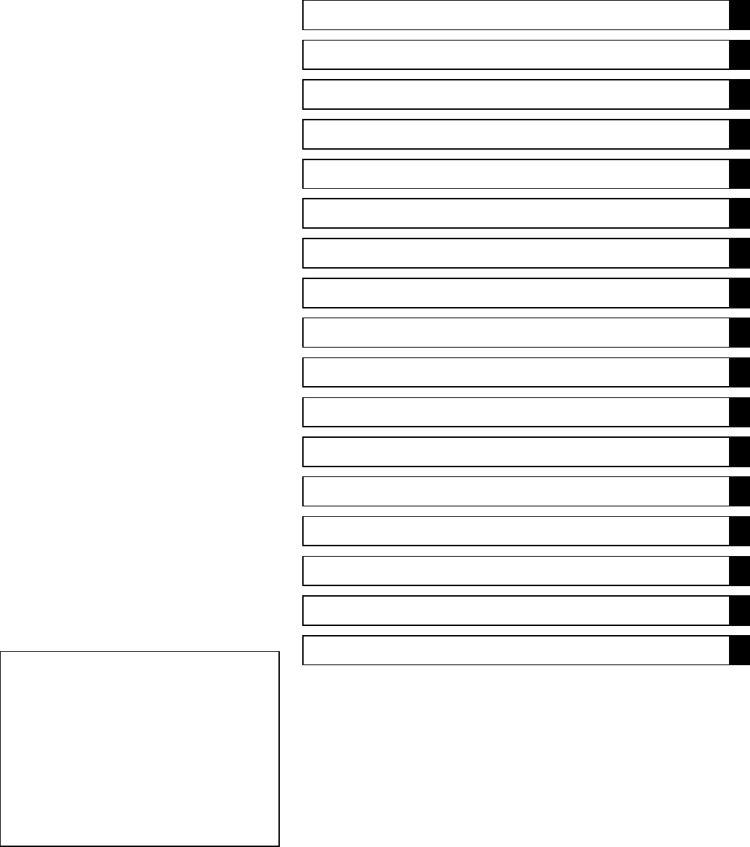
Battery Ground
Before completing any service on the vehicle, disconnect
the battery wires from the battery to prevent the engine from
accidentally turning over. Disconnect the ground wire (–)
first and then the positive (+). When completed with the
service, first connect the positive (+) wire to the positive
(+) terminal of the battery then the negative (–) wire to the
negative terminal.
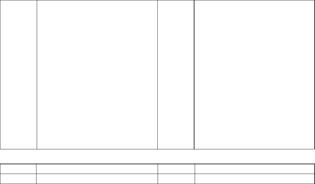
Edges of Parts
Lift large or heavy parts wearing gloves to prevent injury
from possible sharp edges on the parts.
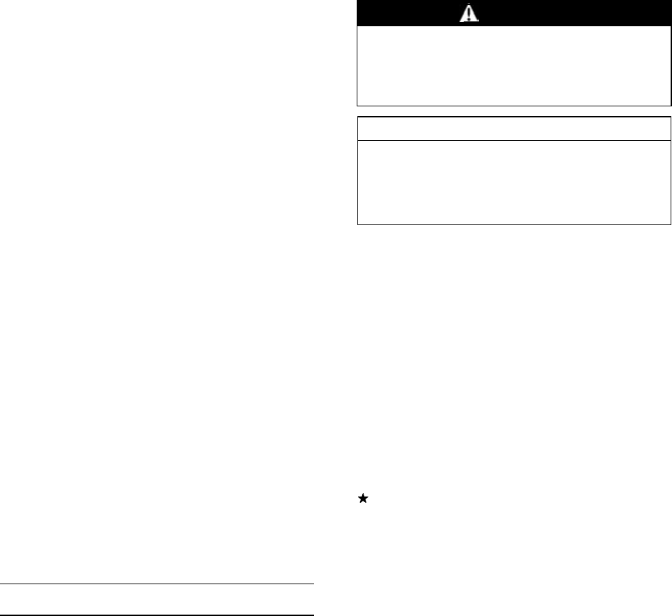
Solvent
Use a high-flush point solvent when cleaning parts. High
-flush point solvent should be used according to directions
of the solvent manufacturer.
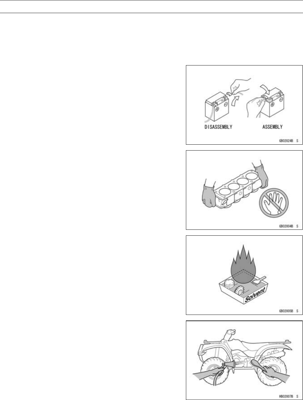
Cleaning Vehicle before Disassembly
Clean the vehicle thoroughly before disassembly. Dirt or
other foreign materials entering into sealed areas during ve-
hicle disassembly can cause excessive wear and decrease
performance of the vehicle.
GENERAL INFORMATION 1-3
Before Servicing
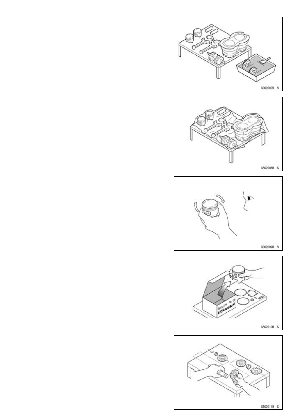
Arrangement and Cleaning of Removed Parts
Disassembled parts are easy to confuse. Arrange the
parts according to the order the parts were disassembled
and clean the parts in order prior to assembly.
Storage of Removed Parts
After all the parts including subassembly parts have been
cleaned, store the parts in a clean area. Put a clean cloth
or plastic sheet over the parts to protect from any foreign
materials that may collect before re-assembly.
Inspection
Reuse of worn or damaged parts may lead to serious ac-
cident. Visually inspect removed parts for corrosion, discol-
oration, or other damage. Refer to the appropriate sections
of this manual for service limits on individual parts. Replace
the parts if any damage has been found or if the part is be-
yond its service limit.
Replacement Parts
Replacement Parts must be KAWASAKI genuine or
recommended by KAWASAKI. Gaskets, O-rings, Oil seals,
Grease seals, circlips or cotter pins must be replaced with
new ones whenever disassembled.
Assembly Order
In most cases assembly order is the reverse of disassem-
bly, however, if assembly order is provided in this Service
Manual, follow the procedures given.
1-4 GENERAL INFORMATION
Before Servicing
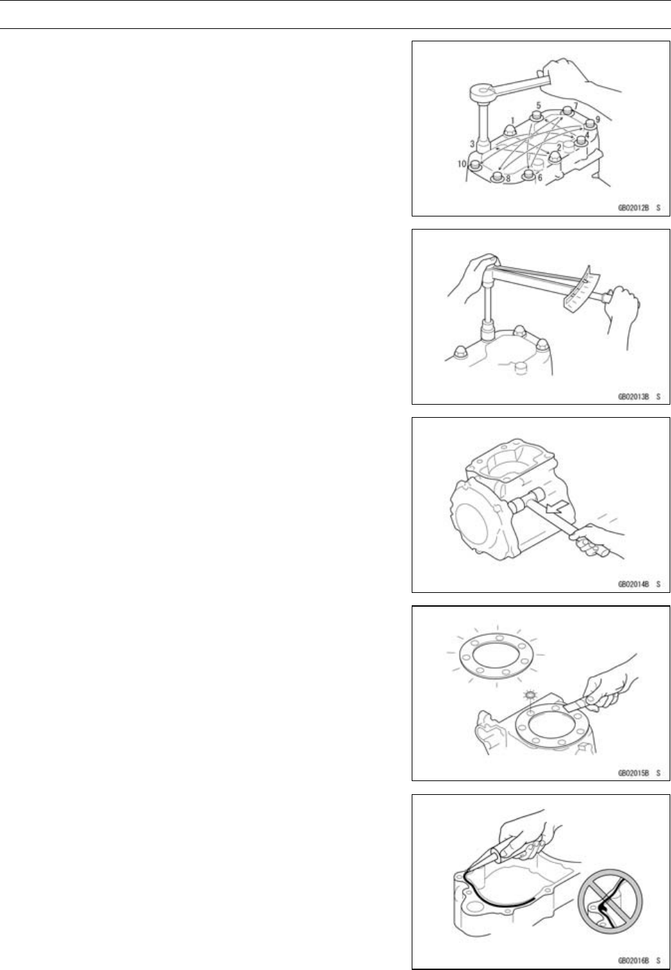
Tightening Sequence
Generally, when installing a part with several bolts, nuts,
or screws, start them all in their holes and tighten them to
a snug fit. Then tighten them according to the specified se-
quence to prevent case warpage or deformation which can
lead to malfunction. Conversely when loosening the bolts,
nuts, or screws, first loosen all of them by about a quar-
ter turn and then remove them. If the specified tightening
sequence is not indicated, tighten the fasteners alternating
diagonally.
Tightening Torque
Incorrect torque applied to a bolt, nut, or screw may
lead to serious damage. Tighten fasteners to the specified
torque using a good quality torque wrench.
Often, the tightening sequence is followed twice initial
tightening and final tightening with torque wrench.
Force
Use common sense during disassembly and assembly,
excessive force can cause expensive or hard to repair dam-
age. When necessary, remove screws that have a non
-permanent locking agent applied using an impact driver.
Use a plastic-faced mallet whenever tapping is necessary.
Gasket, O-ring
Hardening, shrinkage, or damage of both gaskets
and O-rings after disassembly can reduce sealing per-
formance. Remove old gaskets and clean the sealing
surfaces thoroughly so that no gasket material or other
material remains. Install new gaskets and replace used
O-rings when re-assembling.
Liquid Gasket, Locking Agent
For applications that require Liquid Gasket or a
Non-Permanent Locking Agent, clean the surfaces so
that no oil residue remains before applying liquid gasket
or locking agent. Do not apply them excessively. Exces-
sive application can clog oil passages and cause serious
damage.
GENERAL INFORMATION 1-5
Before Servicing
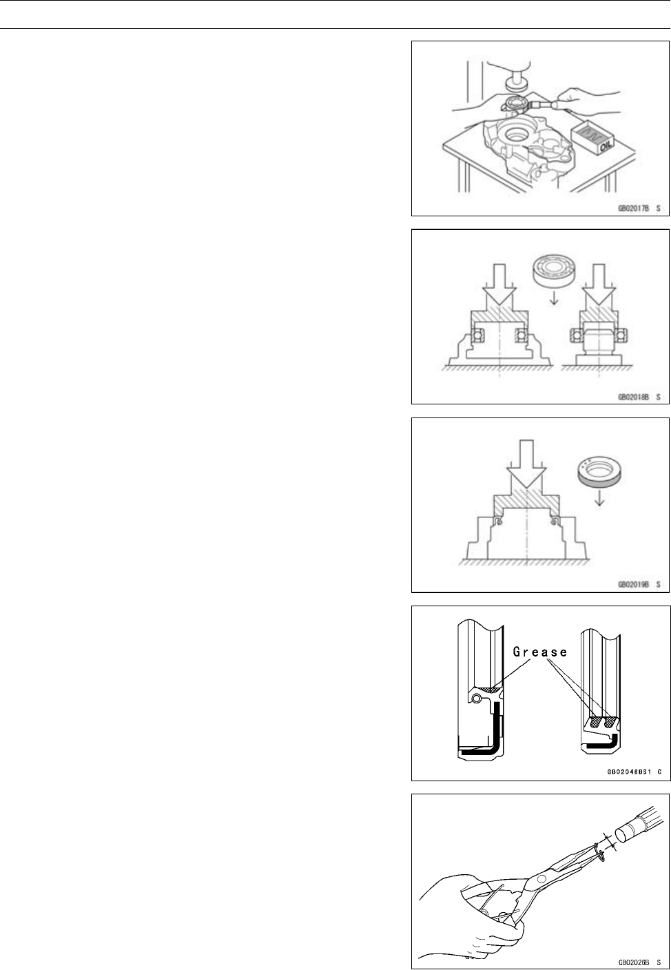
Press
For items such as bearings or oil seals that must be
pressed into place, apply small amount of oil to the con-
tact area. Be sure to maintain proper alignment and use
smooth movements when installing.
Ball Bearing and Needle Bearing
Do not remove pressed ball or needle unless removal is
absolutely necessary. Replace with new ones whenever
removed. Press bearings with the manufacturer and size
marks facing out. Press the bearing into place by putting
pressure on the correct bearing race as shown.
Pressing the incorrect race can cause pressure between
the inner and outer race and result in bearing damage.
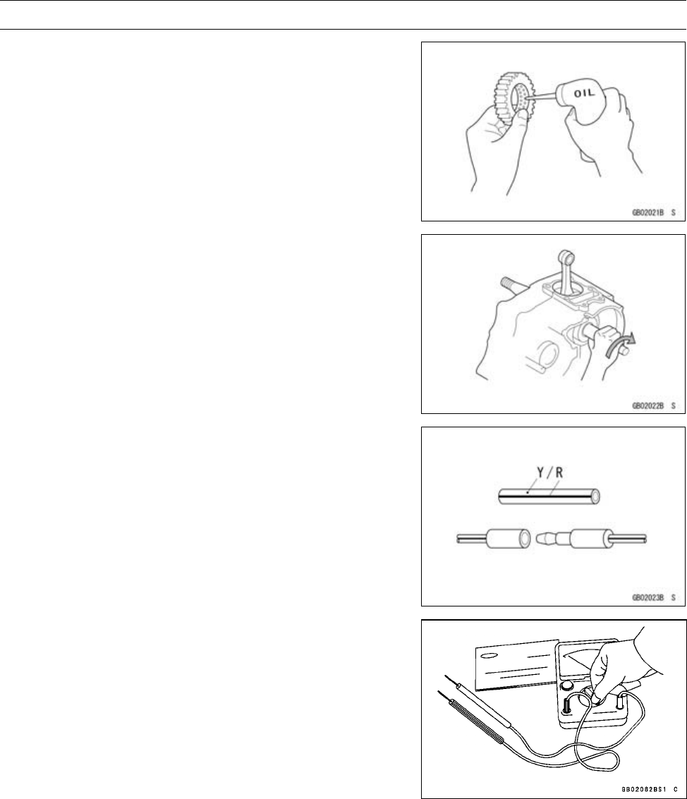
Oil Seal, Grease Seal
Do not remove pressed oil or grease seals unless removal
is necessary. Replace with new ones whenever removed.
Press new oil seals with manufacture and size marks facing
out. Make sure the seal is aligned properly when installing.
Apply specified grease to the lip of seal before installing
the seal.
Circlips, Cotter Pins
Replace circlips or cotter pins that were removed with new
ones. Take care not to open the clip excessively when in-
stalling to prevent deformation.
1-6 GENERAL INFORMATION
Before Servicing
Lubrication
It is important to lubricate rotating or sliding parts during
assembly to minimize wear during initial operation. Lubri-
cation points are called out throughout this manual, apply
the specific oil or grease as specified.
Direction of Engine Rotation
When rotating the crankshaft by hand, the free play
amount of rotating direction will affect the adjustment. Ro-
tate the crankshaft to positive direction (clockwise viewed
from output side).
Electrical Wires
A two-color wire is identified first by the primary color and
then the stripe color. Unless instructed otherwise, electrical
wires must be connected to those of the same color.
Instrument
Use a meter that has enough accuracy for an accurate
measurement. Read the manufacture’s instructions thor-
oughly before using the meter. Incorrect values may lead
to improper adjustments.

GENERAL INFORMATION 1-7
Model Identification
KVF750D8F Left Side View
KVF750D8F Right Side View
The KVF750E is a camouflage-surface-treated model and identical to the KVF750D, the base
model, in every other aspect: controls, features, and specifications.
The KVF750F is identical to the KVF750D in every other aspect, that is, controls, features, and
specifications.
1-8 GENERAL INFORMATION
Model Identification
Frame Number
[A] Frame Number
[B] Left Front Axle
Engine Number
[A] Engine Number
[B] Torque Converter Cover

GENERAL INFORMATION 1-9
General Specifications
Items KVF750D8F, E8F, F8F
Dimensions
Overall Length 2 195 mm (86.42 in.)
Overall Width 1 166 mm (45.90 in.)
Overall Height 1 233 mm (48.54 in.)
Wheelbase 1 284 mm (50.55 in.)
Ground Clearance: 247 mm (9.72 in.)
Seat Height 903 mm (35.6 in.)
Dry Mass 274.5 kg (605.3 lb), (EUR) 275 kg (606 lb)
Curb Mass:
Front 148.5 kg (327.4 lb), (EUR) 149 kg (328 lb)
Rear 147 kg (324 lb)
Fuel Tank Capacity 19 L (5.0 US gal)
Performance
Minimum Turning Radius 3.2 m (10.5 ft)
Engine
Type 4-stroke, SOHC, V2-cylinders
Cooling System Liquid-cooled
Bore and Stroke 85 × 66 mm (3.35 × 2.60 in.)
Displacement 749 cm3(45.7 cu in.)
Compression Ratio 8.8 : 1
Maximum Horsepower 37.1 kW (50.9 PS) @6 500 r/min (rpm),
(CA), (US) – – –
Maximum Torque 59.4 N·m (6.2 kgf·m, 45 ft·lb) @4 500 r/min (rpm)
(CA), (US) – – –
Carburetion System FI (Fuel Injection) Mikuni 36 × 2
Starting System Electric Starter
Ignition System Battery and Coil (transistorized)
Timing Advance Electronically advanced (digital)
Ignition Timing 10° BTDC @1 100 r/min (rpm)
Spark Plug NGK CR7E
Cylinder Numbering Method Front to rear, 1-2
Firing Order 1-2
Valve Timing:
Inlet:
Open 20° BTDC
Close 44° ABDC
Duration 244°
Exhaust:
Open 44° BBDC
Close 20° ATDC
Duration 244°
Lubrication System Forced lubrication (wet sump)

1-10 GENERAL INFORMATION
General Specifications
Items KVF750D8F, E8F, F8F
Engine oil:
Type API SF or SG
API SH, SJ or SL with JASO MA
Viscosity SAE 10W-40
Capacity 2.6 L (2.7 US qt)
Drive Train
Primary Reduction System:
Type Belt converter
Reduction Ratio 3.122 ∼0.635
Transmission:
Type 2-speed and reverse
Gear Ratios:
Forward:
High 3.098 (30/26 × 29/18 × 20/12)
Low 4.833 (36/20 × 29/18 × 20/12)
Reverse 4.028 (16/12 × 18/16 × 29/18 × 20/12)
Final Drive System:
Type Shaft 2WD/4WD
Reduction Ratio 4.375 (35/8)
Overall Drive Ratio:
Forward:
High 42.32 ∼8.61
Low 66.02 ∼13.43
Reverse 55.01 ∼11.19
Front Final Gear Case Oil:
Type API SF or SG
API SH, SJ or SL with JASO MA
Viscosity SAE10W-40
Capacity 0.40 L (0.42 US qt)
Rear Final Gear Case Oil:
Type MOBIL FLUID 424, CITGO TRANSGARD TRACTOR HYDRAULIC
FLUID, or EXXON HYDRAUL 560
Capacity 0.72 L (0.76 US qt)
Frame
Type Double tubular
Caster (Rake Angle) 2.0°
Camber 0.6°
King Pin Angle 10.5°
Trail 12 mm (0.47 in.)
Tread:
Front 930 mm (36.6 in.)
Rear 895 mm (35.2 in.)

GENERAL INFORMATION 1-11
General Specifications
Items KVF750D8F, E8F, F8F
Rim Size:
Front 12 × 6.0
Rear 12 × 7.5
Front tire:
Type Tubeless
Size AT25 × 8-12
Rear tire:
Type Tubeless
Size AT25 × 10-2
Suspension:
Front:
Type Double Wishbone
Wheel Travel 171 mm (6.73 in.)
Rear:
Type Double Wishbone
Wheel Travel 200 mm (7.87 in.)
Brake:
Front Disc × 2
Rear Enclosed wet multi-plate
Parking Brake Enclosed wet multi-plate
Electrical Equipment
Battery 12 V 12 Ah
Headlight:
Type Semi-sealed beam
Bulb 12 V 40/40 W × 2
Tail/brake Light:
Bulb 12 V 5/21 W
Reverse Light:
Bulb (EUR) 12 V 10 W
Alternator:
Type Three - phase AC
Rated Output 24.3 A, 14 V @6 000 r/min (rpm)
Specifications subject to change without notice, and may not apply to every country.
EUR: Europe Model
US: United States Model
1-12 GENERAL INFORMATION
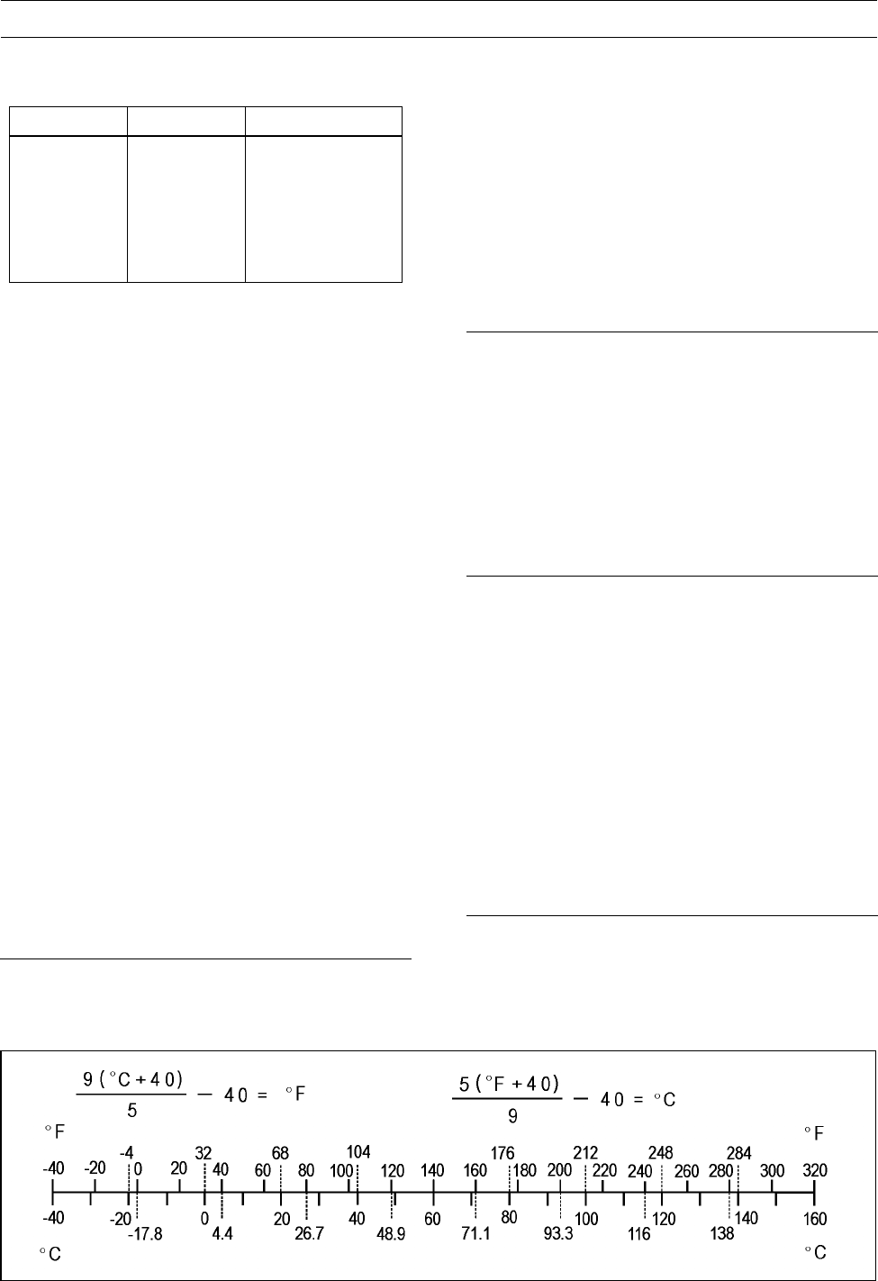
Unit Conversion Table
Prefixes for Units:
Prefix Symbol Power
mega M× 1 000 000
kilo k× 1 000
centi c×0.01
milli m× 0.001
micro µ× 0.000001
Units of Mass:
kg × 2.205 = lb
g × 0.03527 = oz
Units of Volume:
L × 0.2642 = gal (US)
L × 0.2200 = gal (imp)
L×1.057=
qt (US)
L × 0.8799 = qt (imp)
L × 2.113 = pint (US)
L × 1.816 = pint (imp)
mL × 0.03381 = oz (US)
mL × 0.02816 = oz (imp)
mL × 0.06102 = cu in
Units of Force:
N × 0.1020 = kg
N × 0.2248 = lb
kg × 9.807 = N
kg × 2.205 = lb
Units of Length:
km × 0.6214 = mile
m × 3.281 = ft
mm × 0.03937 = in
Units of Torque:
N·m × 0.1020 = kgf·m
N·m × 0.7376 = ft·lb
N·m × 8.851 = in·lb
kgf·m × 9.807 = N·m
kgf·m × 7.233 = ft·lb
kgf·m × 86.80 = in·lb
Units of Pressure:
kPa × 0.01020 = kgf/cm²
kPa × 0.1450 = psi
kPa × 0.7501 = cmHg
kgf/cm² × 98.07 = kPa
kgf/cm² × 14.22 = psi
cmHg × 1.333 = kPa
Units of Speed:
km/h × 0.6214 = mph
Units of Power:
kW × 1.360 = PS
kW × 1.341 = HP
PS × 0.7355 = kW
PS × 0.9863 = HP
Units of Temperature

PERIODIC MAINTENANCE 2-1
2
Periodic Maintenance
Table of Contents
Periodic Maintenance Chart ................................................................................................... 2-3
Torque and Locking Agent...................................................................................................... 2-5
Specifications ......................................................................................................................... 2-11
Special Tools .......................................................................................................................... 2-13
Periodic Maintenance Procedures.......................................................................................... 2-14
Fuel System......................................................................................................................... 2-14
Throttle Lever Free Play Inspection.................................................................................. 2-14
Throttle Lever Free Play Adjustment ................................................................................ 2-14
Idle Speed Inspection ....................................................................................................... 2-15
Idle Speed Adjustment...................................................................................................... 2-15
Air Cleaner Element Cleaning and Inspection .................................................................. 2-16
Air Cleaner Draining.......................................................................................................... 2-16
Fuel Hose Inspection (fuel leak, damage, installation condition)...................................... 2-17
Fuel Hose Replacement ................................................................................................... 2-17
Cooling System.................................................................................................................... 2-18
Radiator Cleaning ............................................................................................................. 2-18
Water Hoses and Connections Inspection........................................................................ 2-19
Coolant Change................................................................................................................ 2-19
Engine Top End ................................................................................................................... 2-22
Valve Clearance Inspection .............................................................................................. 2-22
Valve Clearance Adjustment............................................................................................. 2-23
Spark Arrester Cleaning.................................................................................................... 2-23
Converter System ................................................................................................................ 2-24
Converter Drive Belt Wear Inspection............................................................................... 2-24
Converter Drive Belt Deflection Inspection ....................................................................... 2-25
Converter Drive Belt Deflection Adjustment...................................................................... 2-26
Actuator Lever (Engine Brake Control Lever) Assembly Inspection ................................. 2-27
Engine Lubrication System.................................................................................................. 2-27
Engine Oil Change............................................................................................................ 2-27
Oil Filter Replacement ...................................................................................................... 2-27
Wheels/Tires........................................................................................................................ 2-28
Tire Inspection ..................................................................................................................2-28
Final Drive............................................................................................................................ 2-28
Variable Differential Control Lever Play Inspection........................................................... 2-28
Variable Differential Control Lever Play Adjustment ......................................................... 2-29
Front Final Gear Case Oil Change ................................................................................... 2-29
Rear Final Gear Case Oil Change.................................................................................... 2-30
Universal Joint Lubrication................................................................................................ 2-31
Brakes.................................................................................................................................. 2-31
Front Brake Pad Wear Inspection..................................................................................... 2-31
Front Brake Hoses and Connections Inspection............................................................... 2-31
Front Brake Hose Replacement........................................................................................ 2-32
Front Brake Fluid Level Inspection ................................................................................... 2-32
Front Brake Fluid Change................................................................................................. 2-33
Front Brake Master Cylinder Piston Assembly and Dust Cover Replacement ................. 2-33
Front Brake Caliper Fluid Seal Replacement.................................................................... 2-34
Front Brake Caliper Dust Seal and Friction Boot Replacement........................................ 2-34
Rear Brake Plates Replacement....................................................................................... 2-34
Rear Brake Lever Free Play Inspection............................................................................ 2-34
Rear Brake Pedal Free Play Inspection............................................................................ 2-34

2-2 PERIODIC MAINTENANCE
Rear Brake Lever and Pedal Free Play Adjustment ......................................................... 2-35
Steering ............................................................................................................................... 2-35
Steering Inspection ........................................................................................................... 2-35
Electrical System ................................................................................................................. 2-36
Spark Plug Cleaning/Inspection........................................................................................ 2-36
Spark Plug Gap Inspection ............................................................................................... 2-36
Rear Brake Light Switch Inspection .................................................................................. 2-36
Rear Brake Light Timing Adjustment ................................................................................ 2-36
Converter Drive Belt Failure Detection System Inspection............................................... 2-37
Joint Boots Inspection.......................................................................................................... 2-39
Front Axle/Steering Knuckle Joint Boots Inspection ......................................................... 2-39
Front Propeller Shaft Joint Boots Inspection..................................................................... 2-39
Tie-rod End Boots Inspection............................................................................................ 2-39
Rear Propeller Shaft Joint Boots Inspection ..................................................................... 2-39
Rear Axle/Stabilizer Joint Boots Inspection ...................................................................... 2-39
General Lubrication ............................................................................................................. 2-40
Lubrication ........................................................................................................................ 2-40
Bolts and Nuts Tightening.................................................................................................... 2-41
Tightness Inspection ......................................................................................................... 2-41
PERIODIC MAINTENANCE 2-3
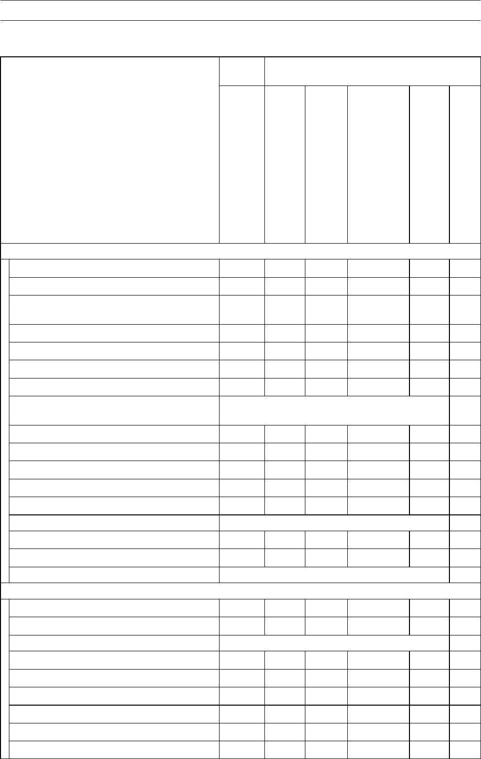
Periodic Maintenance Chart
The scheduled maintenance must be done in accordance with this chart to keep the vehicle in good
running condition. The initial maintenance is vitally important and must not be neglected.
FREQUENCY First
Service Regular Service
OPERATION
After 10
hrs. or
100 km
(60 mi.)
of use
Every
10
days or
200 km
(120
mi.) of
use
Every
30
days or
600 km
(360
mi.) of
use
Every 90
days, 1
700 km (1
100 mi.)
of use or
when belt
indicator
light turns
on (100
hrs of use)
whichever
comes first
Every
year of
use
See
page
ENGINE
Converter drive belt wear-inspect* •2-24
Converter drive belt deflection- inspect* •2-25
Converter drive belt failure detection
system function-inspect* •2-37
Engine brake control lever-inspect* •2-27
Air cleaner-inspect* • • 2-16
Throttle lever play-inspect • • 2-14
Idle speed-inspect •2-15
Valve clearance-inspect First 1 700 km (1 100 mile); thereafter
every 3 400 km (2 200 mile) 2-22
Engine oil-change* • • 2-27
Oil filter-replace* • • 2-27
Spark plug-clean and gap • • 2-36
Spark arrester-clean •2-23
Fuel hoses and connections-inspect •2-17
Fuel hose-replace 4 years 2-17
Radiator-clean* • • 2-18
Radiator hoses and connections-inspect* • • 2-19
Coolant-change* 2 years 2-19
CHASSIS
Joint boots-inspect* • • 2-39
Rear brake pedal and lever play-inspect* • • 2-34
Rear brake plates-replace* every 10 000 km (6 000 mi.) 2-34
Bolts and nuts-tighten • • 2-41
Front brake pad wear-inspect* • • 2-31
Brake light switch-inspect* • • 2-36
Steering-inspect • • 2-35
Differential control lever play-inspect • • 2-28
Tire wear-inspect* •2-28
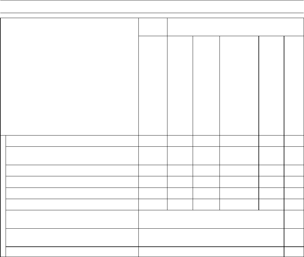
2-4 PERIODIC MAINTENANCE
Periodic Maintenance Chart
FREQUENCY First
Service Regular Service
OPERATION
After 10
hrs. or
100 km
(60 mi.)
of use
Every
10
days or
200 km
(120
mi.) of
use
Every
30
days or
600 km
(360
mi.) of
use
Every 90
days, 1
700 km (1
100 mi.)
of use or
when belt
indicator
light turns
on (100
hrs of use)
whichever
comes first
Every
year of
use
See
page
Front and rear final gear case oil-change • • 2-29
Rear propeller shaft universal joint
lubrication-perform* •2-31
General lubrication-perform* •2-40
Front brake fluid level-inspect • • 2-32
Front brake fluid-change •2-33
Front brake hoses and connections-inspect •2-31
Front brake master cylinder piston
assembly and dust cover-replace 2 years 2-33
Front brake caliper fluid seal and dust
seal-replace 2 years 2-34
Front brake hose-replace 4 years 2-32
*: Service more frequently when operated in mud, dust, or other harsh riding conditions, or when
carrying heavy loads or pulling a trailer.
•: Clean, adjust, lubricate, torque, or replace parts as necessary.

PERIODIC MAINTENANCE 2-5
Torque and Locking Agent
The following tables list the tightening torque for the major fasteners, and the parts requiring use of
a non-permanent locking agent or liquid gasket.
Letters used in the “Remarks” column mean:
L: Apply a non-permanent locking agent.
LB: Apply a non-permanent locking agent (Three Bond TB2471, Blue).
Lh: Left-hand Threads
MO: Apply molybdenum disulfide oil (mixture of the engine oil and molybdenum disulfide grease in
a weight ratio: 10 : 1).
R: Replacement Parts
S: Follow the specific tightening sequence.
SS: Apply silicone sealant (Kawasaki Bond: 56019-120).
St: Stake the fasteners to prevent loosening.
Torque
Fastener N·m kgf·m ft·lb Remarks
Fuel System
Air Cleaner Housing Bolts 8.8 0.90 78 in·lb
ISC Valve Mounting Bolts 8.8 0.90 78 in·lb
Water Temperature Sensor 12 1.2 106 in·lb
Air Cleaner Element Holder Screw 3.5 0.36 31 in·lb
Air Cleaner Element Holder Tapping Screw 1.5 0.15 13 in·lb
Inlet Air Pressure Sensor Mounting Screw 5.0 0.51 44 in·lb
Delivery Pipe Mounting Screws 5.0 0.51 44 in·lb
Fuel Pump Bolts 4.0 0.41 35 in·lb
Fuel Tank Mounting Bolts 9.8 1.0 87 in·lb
Throttle Lever Limiter Screw 3.6 0.37 32 in·lb
Throttle Lever Limiter Nut 3.6 0.37 32 in·lb
Throttle Case Assembly Screws 3.6 0.37 32 in·lb
Cooling System
Radiator Mounting Bolts 8.8 0.90 78 in·lb
Radiator Screen Mounting Bolts 4.0 0.40 35 in·lb
Radiator Fan Assembly Bolts 4.9 0.50 43 in·lb
Thermostat Housing Cover Bolts 8.8 0.90 78 in·lb
Water Pump Cover Bolts 8.8 0.90 78 in·lb
Coolant Drain Bolt 8.8 0.90 78 in·lb
Water Pump Impeller 7.8 0.80 69 in·lb
Water Pipe Joint Bolt 8.8 0.90 78 in·lb
Reserve Tank Mounting Screws 4.0 0.40 35 in·lb L
Engine Top End
Rocker Case Bolts 55 mm (2.2 in.) 8.8 0.90 78 in·lb S
Rocker Case Bolts 130 mm (5.1 in.) 9.8 1.0 87 in·lb S
Rocker Case Bolts 30 mm (1.2 in.) 9.8 1.0 87 in·lb S
Rocker Case Bolts 25 mm (1.0 in.) 9.8 1.0 87 in·lb S
Cylinder Head Bolts (M10), first torque 25 2.5 18 S, MO
Cylinder Head Bolts (M10), final torque 49 5.0 36 S
Cylinder Head Bolts (M6) 9.8 1.0 87 in·lb
Valve Adjusting Cap Bolts 8.8 0.90 78 in·lb

2-6 PERIODIC MAINTENANCE
Torque and Locking Agent
Torque
Fastener N·m kgf·m ft·lb Remarks
Rocker Shaft Bolts 22 2.2 16
Valve Adjusting Screw Locknuts 12 1.2 106 in·lb
Camshaft Chain Tensioner Mounting Bolts 8.8 0.90 78 in·lb
Camshaft Chain Tensioner Cap Bolts 22 2.2 16
Position Plate Bolts 8.8 0.90 78 in·lb
Intermediate Shaft Chain Guide Bolts 8.8 0.90 78 in·lb EO
Intermediate Shaft Chain Tensioner Bolts 8.8 0.90 78 in·lb
Camshaft Sprocket Bolts 12 1.2 106 in·lb L
Cylinder Bolts 40 mm (1.6 in.) 9.8 1.0 87 in·lb
Cylinder Bolts 30 mm (1.2 in.) 9.8 1.0 87 in·lb
Front Cylinder Camshaft Chain Guide Bolt 20 2.0 15
Rear Cylinder Camshaft Chain Guide Bolt 20 2.0 15
Exhaust Pipe Cover Bolts 8.8 0.90 78 in·lb
Exhaust Pipe Holder Nuts 17 1.7 12
Muffler Clamp Bolt 8.8 0.90 78 in·lb
Muffler Mounting Nuts 20 2.0 14
Muffler Mounting Locknuts 31 3.2 23
Muffler Cover Bolts 8.8 0.90 78 in·lb
Converter System
Drive Pulley Bolt 93 9.5 68 R, Lh
Driven Pulley Nut 93 9.5 68
Drive Pulley Cover Bolt 13 1.3 115 in·lb
Ramp Weight Nuts 6.9 0.70 61 in·lb
Spider 275 28 203 Lh
Torque Converter Cover Bolts 8.8 0.90 78 in·lb S
Engine Brake Actuator Mounting Bolts 8.8 0.90 78 in·lb S
Engine Lubrication System
Oil Filter 17.5 1.8 13 R
Oil Pressure Switch 15 1.5 11 SS
Oil Pipe Bolts 8.8 0.90 78 in·lb
Engine Oil Drain Bolt 20 2.0 15
Oil Pressure Relief Valve 15 1.5 11 L
Oil Pump Cover Bolts 8.8 0.90 78 in·lb
Oil Pump Chain Guide Bolts 8.8 0.90 78 in·lb
Oil Pump Drive Chain Tensioner Bolt 25 2.5 18
Oil Filter Mounting Bolts 25 2.5 18 L(15mm)
Engine Removal/Installation
Engine Mounting Bracket Bolts 72 7.3 53 L
Engine Mounting Bolt 72 7.3 53 L
Engine Mounting Nut 100 10 74
Crankshaft/Transmission
Connecting Rod Big End Cap Nuts 34.3 3.5 25 MO
Engine Oil Drain Bolt 20 2.0 15

PERIODIC MAINTENANCE 2-7
Torque and Locking Agent
Torque
Fastener N·m kgf·m ft·lb Remarks
Crankcase Bolts (M8) 75 mm (2.95 in.) 20 2.0 15 S
Crankcase Bolts (M8) 110 mm (4.33 in.) 20 2.0 15 S
Crankcase Bolt (M8) 110 mm (4.33 in.) 20 2.0 15 S, L
Crankcase Bolts (M6) 40 mm (1.57 in.) 9.8 1.0 87 in·lb
Crankcase Bolts (M6) 65 mm (2.56 in.) 9.8 1.0 87 in·lb
Bearing Position Plate Screws 4.9 0.50 43 in·lb L
Rear Cylinder Camshaft Chain Guide Bolt 20 2.0 15
Grip Holder Nut 9.8 1.0 87 in·lb
Shift Lever Assembly Bracket Bolts 19.6 2.0 14
Tie-rod End Front Locknut 9.8 1.0 87 in·lb Lh
Tie-Rod End Rear Locknut 9.8 1.0 87 in·lb
Tie-rod End Nut 19.6 2.0 14
Shift Lever Assembly Nut 19.6 2.0 14
Shift Lever Clamp Bolt 13.5 1.4 119 in·lb
Tie-rod End Bolt 9.8 1.0 87 in·lb
Shift Shaft Positioning Bolt 25 2.5 18
Shift Shaft Spring Bolt 25 2.5 18 L
Shift Shaft Cover Bolts 8.8 0.90 78 in·lb
Tie-rod End Locknut 19.6 2.0 14
Neutral Position Switch 15 1.5 11
ReversePositionSwitch 15 1.5 11
Shift Lever Guide Mounting Nut 19.6 2.0 14
Wheel/Tires
Tie-rod Locknuts 37 3.8 27
Wheel Nuts (First Torque) 15 1.5 11 S
Wheel Nuts (Final Torque) 76 7.7 56 S
Front Axle Nuts 197 20 145
Rear Axle Nuts 265 27 195
Final Drive
(Output Bevel Gears)
Output Driven Bevel Gear Housing Bolts 26 2.7 20
Output Drive Bevel Gear Housing Bolts 26 2.7 20
Bearing Holder 137 14 101 L
Bevel Gear Holder Nut 157 16 116 L
Bearing Holder 120 12 88 L
Output Shaft Holder Nut 157 16 116 L
Rotor Mounting Bolts 12 1.2 106 in·lb
Output Drive Bevel Gear Cover Bolts 8.8 0.90 78 in·lb
Forward/Reverse Detecting Sensor Mounting Bolt 15 1.5 11
(Front Final Gear Case)
Variable Differential Control Shift Shaft Lever Bolt 8.8 0.90 78 in·lb
Front Final Gear Case Left Cover Bolts (M6) 9.8 1.0 87 in·lb L(4),S
Ring Gear Bolts 57 5.8 42 LB

2-8 PERIODIC MAINTENANCE
Torque and Locking Agent
Torque
Fastener N·m kgf·m ft·lb Remarks
Front Final Gear Case Center Cover Bolts (M6) 9.8 1.0 87 in·lb L
Front Final Gear Case Center Cover Bolts (M8) 24 2.4 17 L
Front Final Gear Case Oil Filler Cap 29 3.0 22
Pinion Gear Bearing Holder Nut 127 13 94 St
Pinion Gear Bearing Holder 137 14 101 L
Front Final Gear Case Coupling Nut 25 2.5 18
Front Final Gear Case Oil Drain Bolt 15 1.5 11
2WD/4WD Actuator Mounting Bolts 9.8 1.0 87 in·lb L, S
Variable Differential Control Cable Locknut 17 1.7 12
Variable Differential Control Lever Bolt 3.4 0.35 30 in·lb L
Front Final Gear Case Nuts 59 6.0 43
(Rear Final Gear Case)
Rear Final Gear Case Front Cover Bolts 24 2.4 18
Rear Final Gear Case Gasket Screws 1.25 0.13 11 in·lb L
Pinion Gear Bearing Holder Nut 157 16 116 L
Pinion Gear Bearing Holder 137 14 101 L
Rear Final Gear Case Right Cover Bolts (M12) 95 9.7 70 L
Rear Final Gear Case Right Cover Bolts (M10) 49 5.0 36 L
Rear Final Gear Case Right Cover Bolts (M8) 24 2.4 18 L
Rear Final Gear Case Oil Filler Cap 29 3.0 22
Rear Final Gear Case Oil Drain Bolt 15 1.5 11
Rear Final Gear Case Bracket Bolts 59 6.0 44
Rear Final Gear Case Nuts 91 9.3 67
Brakes
Reservoir Cap Screws 1.5 0.15 13 in·lb
Front Brake Lever Pivot Bolt 5.9 0.60 52 in·lb
Front Brake Lever Pivot Bolt Locknut 5.9 0.60 52 in·lb
Front Brake Master Cylinder Clamp Bolts 8.8 0.90 78 in·lb S
Front Bake Hose Banjo Bolt 34 3.5 25
Front Brake Caliper Mounting Bolts 25 2.5 18
Bleed Valves 7.8 0.80 69 in·lb
Front Brake Disc Mounting Bolts 37 3.8 27 L
Front Brake Caliper Holder Shaft 17 1.7 12 Si
Front Brake Pad Mounting Bolts 17 1.7 12
Front Brake Light Switch Mounting Screw 1.2 0.12 11 in·lb
Rear (Parking) Brake Lever Pivot Bolt 2.2 0.22 19 in·lb
Rear (Parking) Brake Lever Pivot Nut 3.4 0.35 30 in·lb
Rear Brake Lock Lever Pivot Screw 2.2 0.22 19 in·lb L
Variable Differential Control Lever Bolt 3.4 0.35 30 in·lb L
Rear Final Gear Case Gasket Screws 1.25 0.13 12 in·lb L
Suspension
Front Shock Absorber Mounting Nuts 34 3.5 25
Front Suspension Arm Pivot Nuts 42 4.3 31

PERIODIC MAINTENANCE 2-9
Torque and Locking Agent
Torque
Fastener N·m kgf·m ft·lb Remarks
Steering Knuckle Joint Nuts 29 3.0 21
Rear Shock Absorber Mounting Nuts 34 3.5 25
Stabilizer Holder Bolts 22 2.2 16
Stabilizer Joint Nuts 46 4.7 34
Rear Suspension Arm Pivot Nuts 46 4.7 34
Rear Knuckle Mounting Nuts 46 4.7 34
Steering
Handlebar Holder Bolts 29 3.0 21 S
Steering Stem Clamp Bolts 25 2.5 18
Tie-rod End Nuts 42 4.3 31
Tie-rod Locknuts 37 3.8 27
Steering Stem Bearing Joint Bolts 22 2.2 16 L
Steering Stem Bottom End Nut 62 6.3 46
Steering Knuckle Joint Nuts 29 3.0 21
Front Brake Master Cylinder Clamp Bolts 8.8 0.90 78 in·lb S
Left Handlebar Switch Housing Screws 3.5 0.36 31 in·lb
Frame
Front Guard Bolts 46 4.7 34
Front Carrier Bolts, L = 50 mm (2.0 in.) 32 3.3 24 L
Front Carrier Bolts, L = 70 mm (2.8 in.) 32 3.3 24 L
Front Carrier Bracket Bolts 32 3.3 24 L
Rear Carrier Bolts, L = 14 mm (0.55 in.) 54 5.5 40 L
Rear Carrier Bolts, L = 41 mm (1.6 in.) 54 5.5 40 L
Rear Carrier Bracket Bolts 46 4.7 34
Footboard Bracket Bolts 46 4.7 34
Hitch Bracket Bolts 82 8.3 60 L
Rear Final Gear Case Mounting Bracket Bolts 59 6.0 44 L
Electrical System
Starter Motor Mounting Bolts 8.8 0.90 78 in·lb
Starter Motor Cable Mounting Nut 6.8 0.69 60 in·lb
Starter Motor Terminal Locknut 11 1.1 97 in·lb
Starter Motor Through Bolts 5.0 0.51 44 in·lb
Starter Motor Clutch Bolts 34 3.5 25 L
Alternator Stator Bolts 13.5 1.4 119 in·lb
Crankshaft Sensor Mounting Bolts 5.9 0.60 52 in·lb
Alternator Cover Plugs 17.5 1.8 13
Alternator Rotor Bolt 127 13 94
Alternator Cover Bolts 8.8 0.90 78 in·lb
Alternator Outer Cover Bolts 5.9 0.60 52 in·lb
Harness Clamp Bolt 8.8 0.90 78 in·lb
Spark Plugs 13 1.3 115 in·lb
2WD/4WD Actuator Mounting Bolts 9.8 1.0 87 in·lb L, S
Engine Brake Actuator Mounting Bolts 8.8 0.90 78 in·lb S
2-10 PERIODIC MAINTENANCE
Torque and Locking Agent
Torque
Fastener N·m kgf·m ft·lb Remarks
Forward/Reverse Detecting Sensor Mounting Bolt 15 1.5 11
Speed Sensor Mounting Bolt 8.8 0.90 78 in·lb
Neutral Position Switch 15 1.5 11
ReversePositionSwitch 15 1.5 11
Ignition Coil Mounting Bolts 5.9 0.60 52 in·lb
Ignition Coil Bracket Mounting Bolts 5.9 0.60 52 in·lb
Oil Pressure Switch 15 1.5 11 SS
Oil Pressure Switch Terminal Bolt 1.5 0.15 13 in·lb
Regulator/Rectifier Mounting Bolts 8.8 0.90 78 in·lb
Tail/Brake Light Lens Screws 1.0 0.10 88 in·lb
The tables below, relating tightening torque to thread diameter, lists the basic torque for the bolts
and nuts. Use this table for only the bolts and nuts which do not require a specific torque value. All of
the values are for use with dry solvent-cleaned threads.
Basic Torque for General Fasteners of Engine Parts
Torque
Threads dia.
mm (in.) Mark of bolt head N·m kgf·m ft·lb
5 (0.20) 4T 2.2 ∼2.6 0.22 ∼0.27 19 ∼23 in·lb
6 (0.24) 9T 12 ∼15 1.2 ∼1.5 104 ∼130 in·lb
6 (0.24) 7T 7.8 ∼9.8 0.8 ∼1.0 69 ∼87 in·lb
6 (0.24) 4T 3.9 ∼4.9 0.4 ∼0.5 35 ∼43 in·lb
8 (0.31) 7T 18 ∼22 1.8 ∼2.2 13 ∼16
8 (0.31) 4T 10 ∼14 1.0 ∼1.4 87 ∼122 in·lb
10 (0.39) 7T 39 ∼44 4.0 ∼4.5 29 ∼33
10 (0.39) 4T 20 ∼24 2.0 ∼2.4 14 ∼17
Basic Torque for General Fasteners of Frame Parts
Torque
Threads dia. mm (in.) N·m kgf·m ft·lb
5 (0.20) 3.4 ∼4.9 0.35 ∼0.5 30 ∼43 in·lb
6 (0.24) 5.9 ∼7.8 0.6 ∼0.8 52 ∼69 in·lb
8 (0.31) 14 ∼19 1.4 ∼1.9 10.0 ∼13.5
10 (0.39) 25 ∼34 2.6 ∼3.5 19 ∼25
12 (0.47) 44 ∼61 4.5 ∼6.2 33 ∼45
14 (0.55) 73 ∼98 7.4 ∼10.0 54 ∼72
16 (0.63) 115 ∼155 11.5 ∼16.0 83 ∼115
18 (0.71) 165 ∼225 17.0 ∼23.0 125 ∼165
20 (0.79) 225 ∼325 23.0 ∼33.0 165 ∼240

PERIODIC MAINTENANCE 2-11
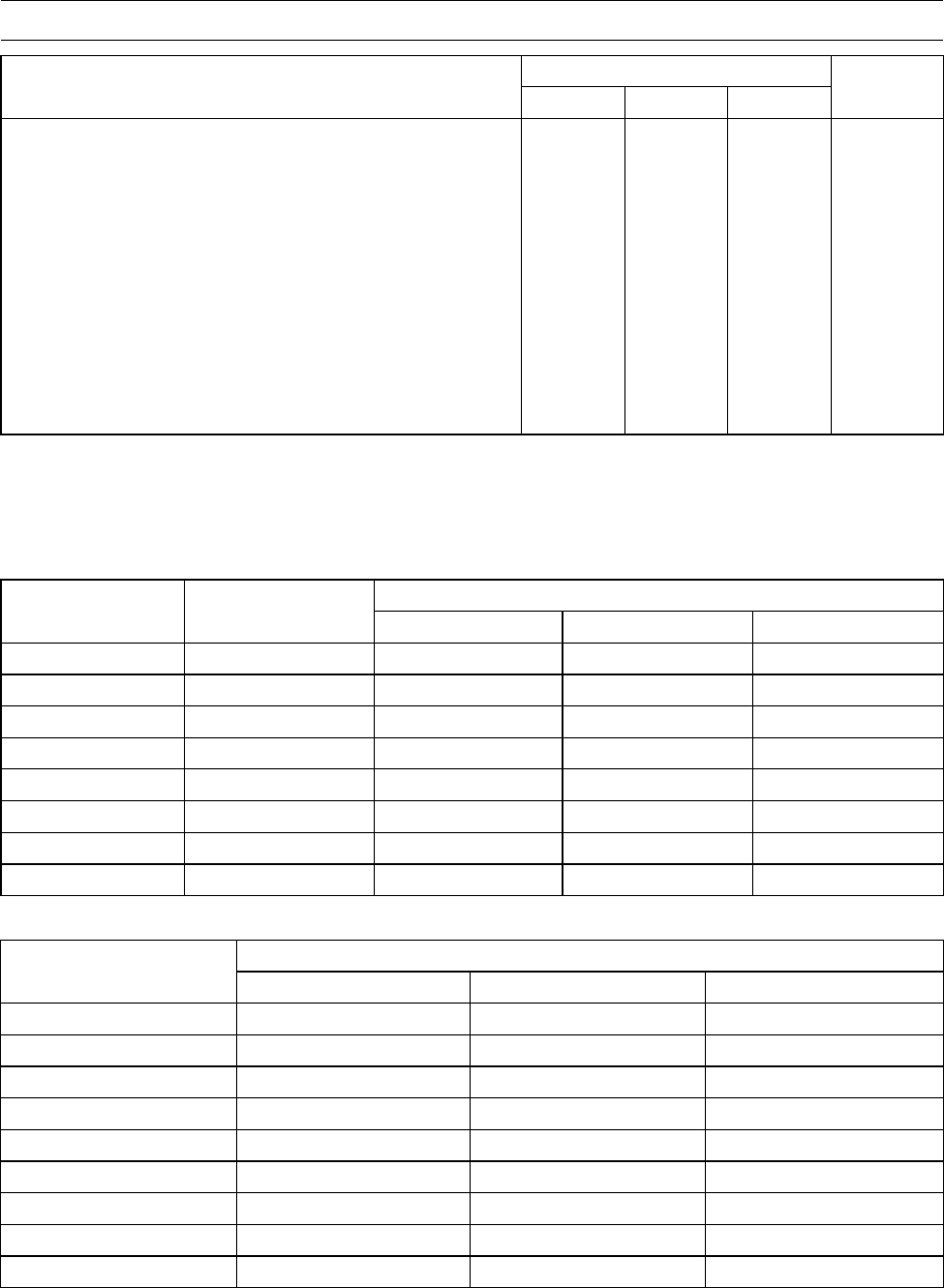
Specifications
Item Standard Service Limit
Fuel System
Throttle Lever Free Play 2∼3mm(0.08∼0.12 in.) –––
Idle Speed 1 100 ±50 r/min (rpm) –––
Air Cleaner Element Oil High-quality foam air filter oil –––
Cooling System
Coolant:
Type (Recommended) Permanent type antifreeze –––
Color Green –––
Mixed Ratio Soft water 50%, Coolant 50% –––
Freezing Point −35°C (−31°F) –––
Total Amount 2.2 L (2.3 US qt.) –––
Engine Top End
Valve Clearance:
Exhaust 0.20 ∼0.25 mm (0.0079 ∼0.0098 in.) –––
Inlet 0.10 ∼0.15 mm (0.0039 ∼0.0059 in.) –––
Converter System
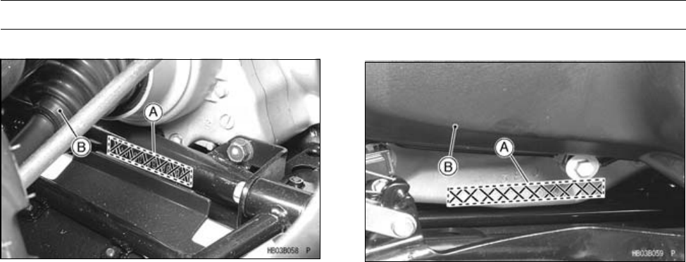
Belt Width 29.7 ∼30.3 mm (1.17 ∼1.19 in.) 28.0 mm (1.10 in.)
Belt Deflection 22 ∼27 mm (0.87 ∼1.06 in.) –––
Actuator Lever Guide Shoe Wear ––– 6 mm (0.24 in.)
Engine Lubrication System
Engine Oil:
Type API SF or SG –––
API SH, SJ or SL with JASO MA –––
Viscosity SAE10W-40 –––
Capacity 2.1 L (2.2 US qt)
(When filter is not removed)
–––
2.2 L (2.3 US qt)
(When filter is removed)
–––
2.6 L (2.7 US qt)
(When engine is completely dry)
–––
Wheels/Tires
Tire Tread Depth:
Front 13.0 mm (0.51 in.) 3 mm (0.12 in.)
Rear 14.5 mm (0.57 in.) 4 mm (0.16 in.)
Standard tire:
Front AT 25 × 8-12 –––
DUNLOP, KT191, Tubeless –––
Rear AT 25 × 10-12 –––
DUNLOP, KT195, Tubeless –––

2-12 PERIODIC MAINTENANCE
Specifications
Item Standard Service Limit
Final Drive
Front Final Gear Case:
Gear Case Oil:
Type API SF or SG –––
API SH, SJ or SL with JASO MA –––
Viscosity SAE 10W-40 –––
Oil Level Filler opening bottom –––
Capacity 0.40 L (0.42 US qt) –––
Rear Final Gear Case:
Gear Case Oil:
Type MOBIL Fluid 424, CITGO
TRANSGARD TRACTOR HYDRAULIC
FLUID, or EXXON HYDRAUL 560
–––
Oil Level Filler opening bottom –––
Capacity 0.72 L (0.76 US qt) –––
Brakes
Front Brake Fluid:
Type DOT 3 or DOT 4 –––
Front Disc Brake:
Pad Lining Thickness 4 mm (0.16 in.) 1 mm (0.04 in.)
Rear Brake Lever, Pedal and
Cables:
Rear Brake Lever Free Play 1∼2mm(0.04∼0.08 in.) –––
Brake Pedal Free Play 15 ∼25 mm (0.6 ∼1.0 in.) –––
Electrical System
Spark Plug Gap 0.7 ∼0.8 mm (0.028 ∼0.032 in.) –––
Rear Brake Light Switch Timing ON after 10 mm (0.4 in.) of pedal travel –––
PERIODIC MAINTENANCE 2-13
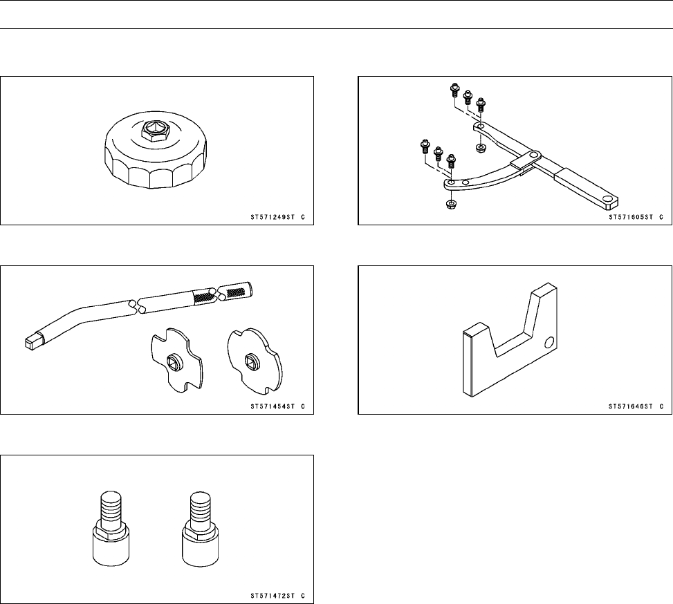
Special Tools
Oil Filter Wrench:
57001-1249
Filler Cap Driver:
57001-1454
Pulley Holder Attachment:
57001-1472
Flywheel & Pulley Holder:
57001-1605
Belt Measuring Gauge:
57001-1646
2-14 PERIODIC MAINTENANCE
Periodic Maintenance Procedures
Fuel System
Throttle Lever Free Play Inspection
•Check that the throttle lever [A] moves smoothly from full
open to close, and the throttle closes quickly and com-
pletely in all steering positions by the return spring.
If the throttle lever does not return properly, check the
throttle cable routing, lever free play, and cable damage.
Then lubricate the throttle cable.
•Run the engine at the idle speed, and turn the handlebar
all the way to the right and left to ensure that the idle speed
does not change.
If the idle speed increases, check the throttle lever free
play and the cable routing.
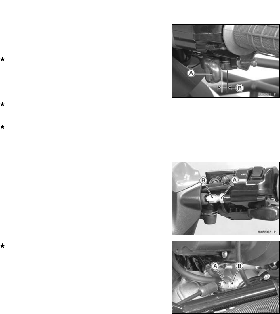
•Stop the engine and check the throttle lever free play [B].
If the free play is not within the specified range, adjust the
cable.
Throttle Lever Free Play
Standard: 2 ∼3 mm (0.08 ∼0.12 in.)
Throttle Lever Free Play Adjustment
•Slide the rubber cover off the adjuster at the throttle case.
•Loosen the locknut [A] and turn the throttle cable upper
adjuster [B] until the cable has proper amount of play.
•Tighten the locknut and reinstall the rubber cover.
If the free play cannot be adjusted by using the upper
cable adjuster, remove the left side cover (see Left Side
Cover Removal in the Frame chapter) and then use the
cable adjusting nut [A] and locknut [B] at the lower end of
the throttle cable and make the necessary free play.
PERIODIC MAINTENANCE 2-15
Periodic Maintenance Procedures
Idle Speed Inspection
•Start the engine and warm it up thoroughly.
•With the engine idling, turn the handlebar to both sides to
check for any changes in the idle speed.
If handlebar movement changes the idle speed, the throt-
tle cable may be improperly adjusted, incorrectly routed,
or damaged. Be sure to correct any of these conditions
before riding.
WARNING
Operation with improperly adjusted, incorrectly
routed, or damaged cables could result in an un-
safe riding condition.
•Check idle speed with a suitable tachometer.
If the idle speed is out of the specified range, adjust it (see
Idle Speed Adjustment).
Idle Speed
Standard: 1 100 ±50 r/min (rpm)
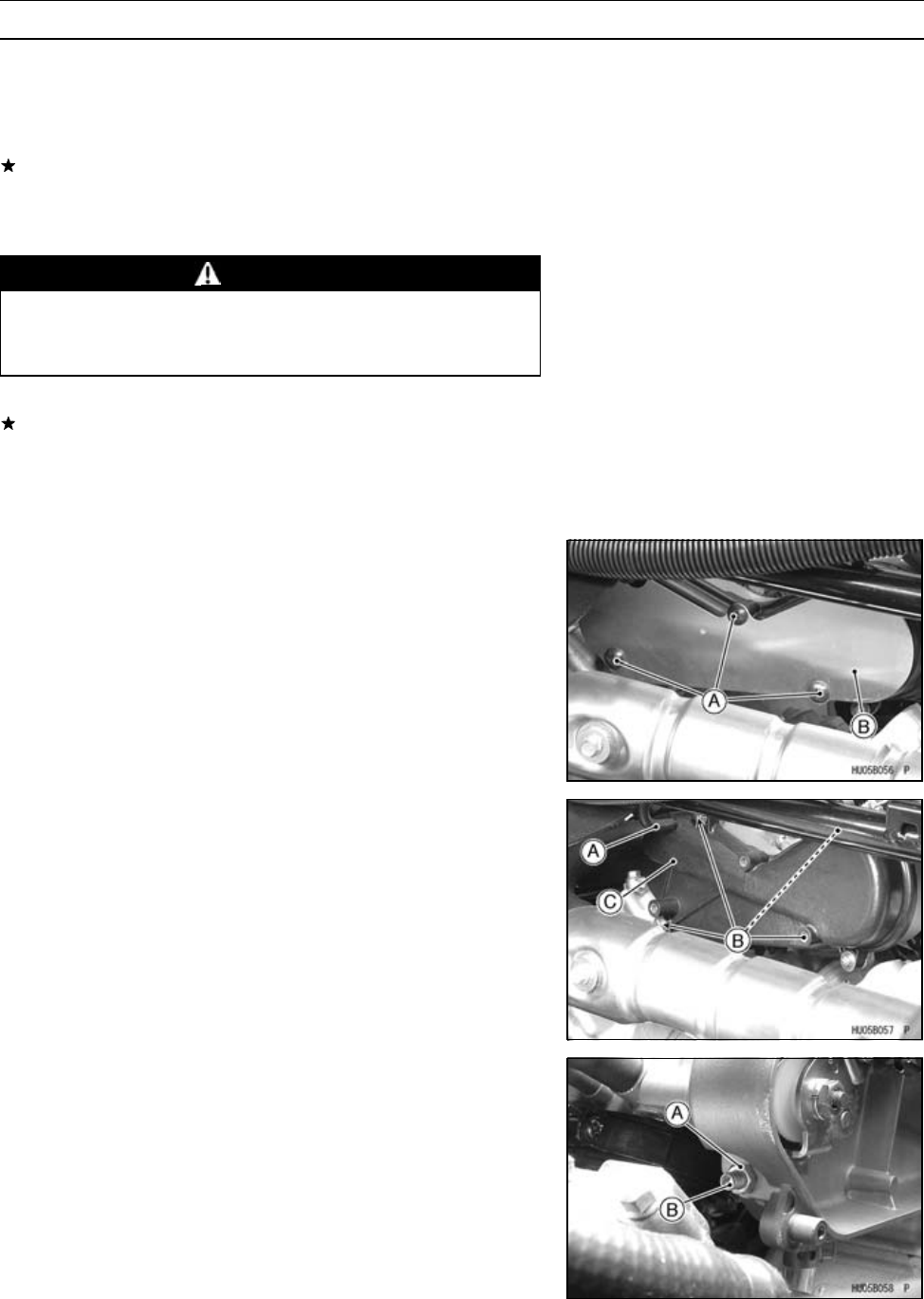
Idle Speed Adjustment
•Start the engine and warm it up thoroughly.
•Remove:
Screws [A]
Heat Guard Plate [B]
•Disconnect:
Hose [A]
•Remove:
Screws [B] and Washers
Throttle Link Cover [C]
•Loosen the locknut [A].
•Turn the idle adjusting screw [B] until the idle speed is
correct.
○Open and close the throttle a few times to make sure that
the idle speed is within the specified range.
•Tighten the locknut.
•Install the removed parts.
2-16 PERIODIC MAINTENANCE
Periodic Maintenance Procedures
Air Cleaner Element Cleaning and Inspection
NOTE
○In dusty areas, the element should be cleaned more
frequently than the recommended interval.
○After riding through rain or muddy terrains, the element
should be cleaned immediately.
○Also, if there is a break in the element material or any
other damage to the element, replace the element with
a new one.
WARNING
Clean the element in a well-ventilated area, and
take care that there are no sparks or flame any-
where near the working area; this includes any
appliance with a pilot light. Because of the danger
of highly flammable liquids, do not use gasoline or
a low-flash point solvent to clean the foam element.
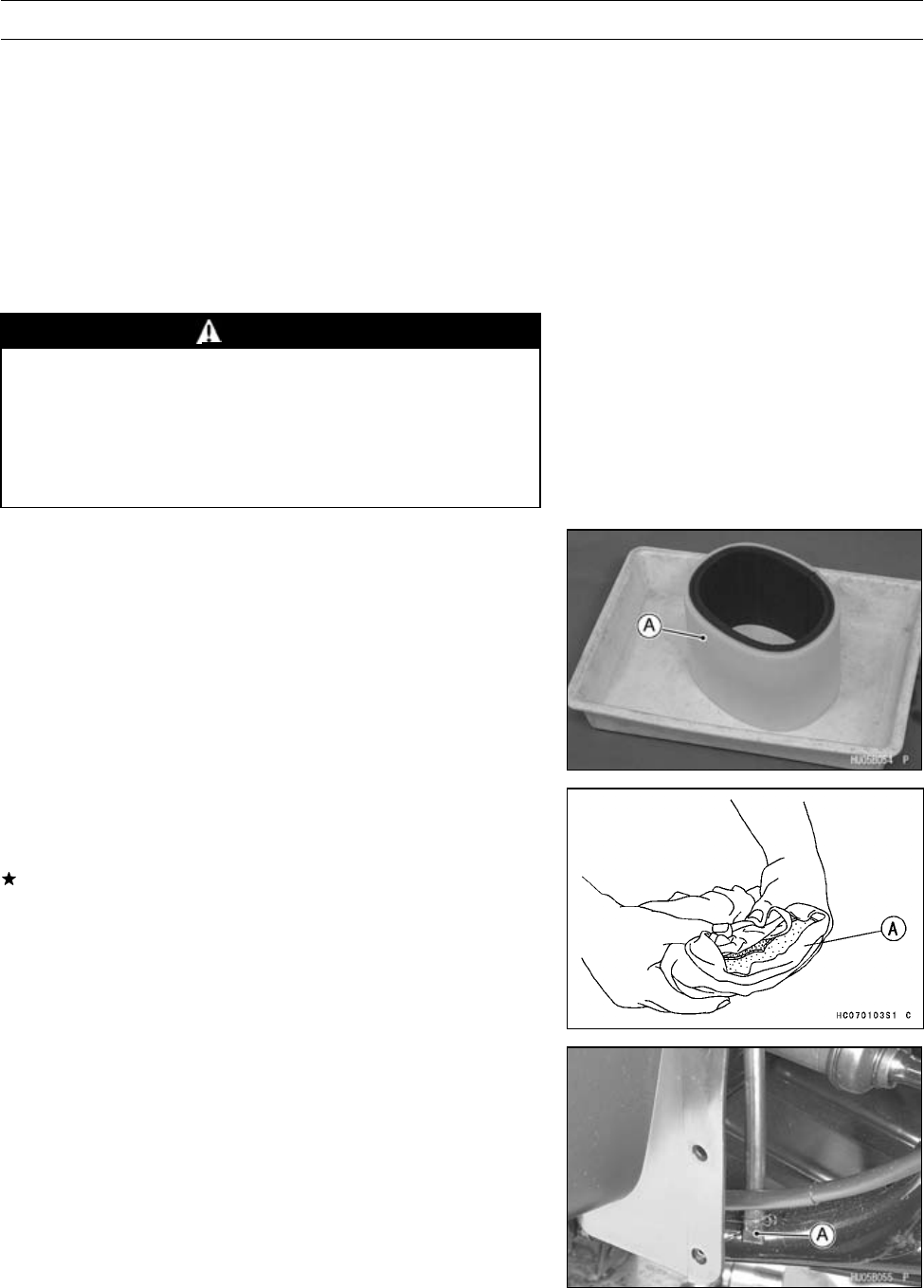
•Remove the air cleaner element (see Air Cleaner Element
Removal in the Fuel System (DFI) chapter).
•Clean the element [A] in a bath of high-flash point solvent.
•Squeeze it dry in a clean towel [A]. Do not wring the ele-
ment or blow it dry; the element can be damaged.
•Inspect the element for damage.
If it is torn, punctured, or hardened, replace it.
•After cleaning, saturate the element with a high-quality
foam-air-filter oil, squeeze out the excess oil, then wrap
it in a clean rag and squeeze it as dry as possible. Be
careful not to tear the element.
Air Cleaner Draining
•If any water or oil accumulates in the tube, drain it by
taking off the tube plug [A]. After draining, be sure to install
the tube plug and clamp firmly.
PERIODIC MAINTENANCE 2-17
Periodic Maintenance Procedures
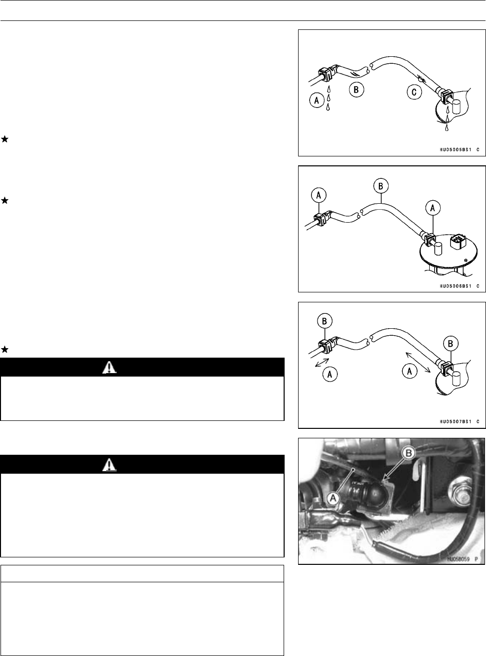
Fuel Hose Inspection (fuel leak, damage,
installation condition)
○The fuel hose is designed to be used throughout the vehi-
cle’s life without any maintenance. However, if the vehicle
is not properly handled, the high pressure inside the fuel
line can cause fuel to leak [A] or the hose to burst. Re-
move the fuel tank (see Fuel Tank Removal in the Fuel
System (DFI) chapter) and check the fuel hose.
Replace the fuel hose if any fraying, cracks [B] or bulges
[C] are noticed.
•Check that the hoses are routed according to Cable, Wire,
and Hose Routing section in the Appendix chapter.
Replace the hose if it has been sharply bent or kinked.
Hose Joints [A]
Fuel Hose [B]
•Check that the hose joints are securely connected.
○Push and pull [A] the hose joint [B] back and forth more
than two times, and make sure it is locked.
If it does not locked, reinstall the hose joint.
WARNING
Make sure the hose joint is installed correctly on the
delivery pipe by sliding the joint, or the fuel could
leak.
Fuel Hose Replacement
WARNING
Gasoline is extremely flammable and can be ex-
plosive under certain conditions. Turn the ignition
switch OFF. Do not smoke. Make sure the area is
well ventilated and free from any source of flame
or sparks; this includes any appliance with a pilot
light.
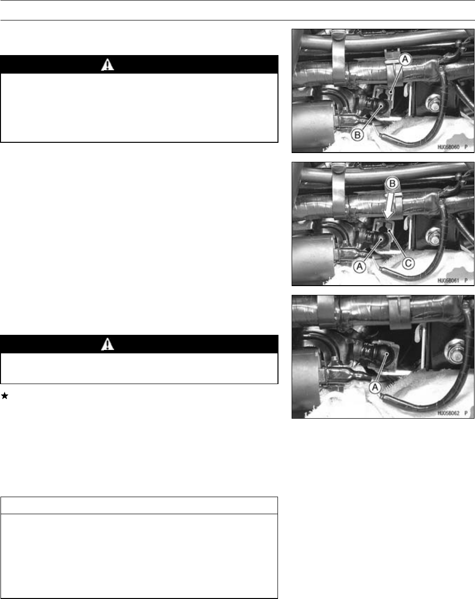
CAUTION
When removing and installing the fuel hose joint,
do not apply strong force to the outlet pipe on the
fuel pump and delivery pipe on the throttle body
assy. The fuel pump pipe made from resin could
be damaged.
•Disconnect the fuel hose from the fuel pump (see Fuel
Pump Removal in the Fuel System (DFI) chapter).
•Be sure to place a piece of cloth around the fuel hose joint.
•Insert a minus screwdriver [A] into the slit [B] on the joint
lock.
2-18 PERIODIC MAINTENANCE
Periodic Maintenance Procedures
•Twist the screwdriver to disconnect the joint lock [A].
•Pull the fuel hose joint [B] out of the delivery pipe.
WARNING
Be prepared for fuel spillage; any spilled fuel must
be completely wiped up immediately.
When the fuel hose is disconnected, fuel spills out
from the hose and the pipe. Cover the hose connec-
tion with a clean shop towel to prevent fuel spillage.
•Install the new fuel hose.
•Insert the fuel hose joint [A] straight onto the delivery pipe
until the hose joint clicks.
•Push [B] the joint lock [C].
•Push and pull the fuel hose joint [A] back and forth more
than two times and make sure it is locked and doesn’t
come off.
WARNING
Make sure the fuel hose joint is installed correctly
on the delivery pipe or the fuel could leak.
If it comes off, reinstall the hose joint.
•Run the fuel hose correctly (see Cable, Wire and Hose
Routing section in the Appendix chapter).
•Install the removed parts (see appropriate chapters).
•Start the engine and check the fuel hose for leaks.
Cooling System
Radiator Cleaning
CAUTION
Clean the radiator screen and the radiator in ac-
cordance with the Periodic Maintenance Chart.
In dusty areas, they should be cleaned more fre-
quently than the recommended interval. After
riding through muddy terrains, the radiator screen
and the radiator should be cleaned immediately.
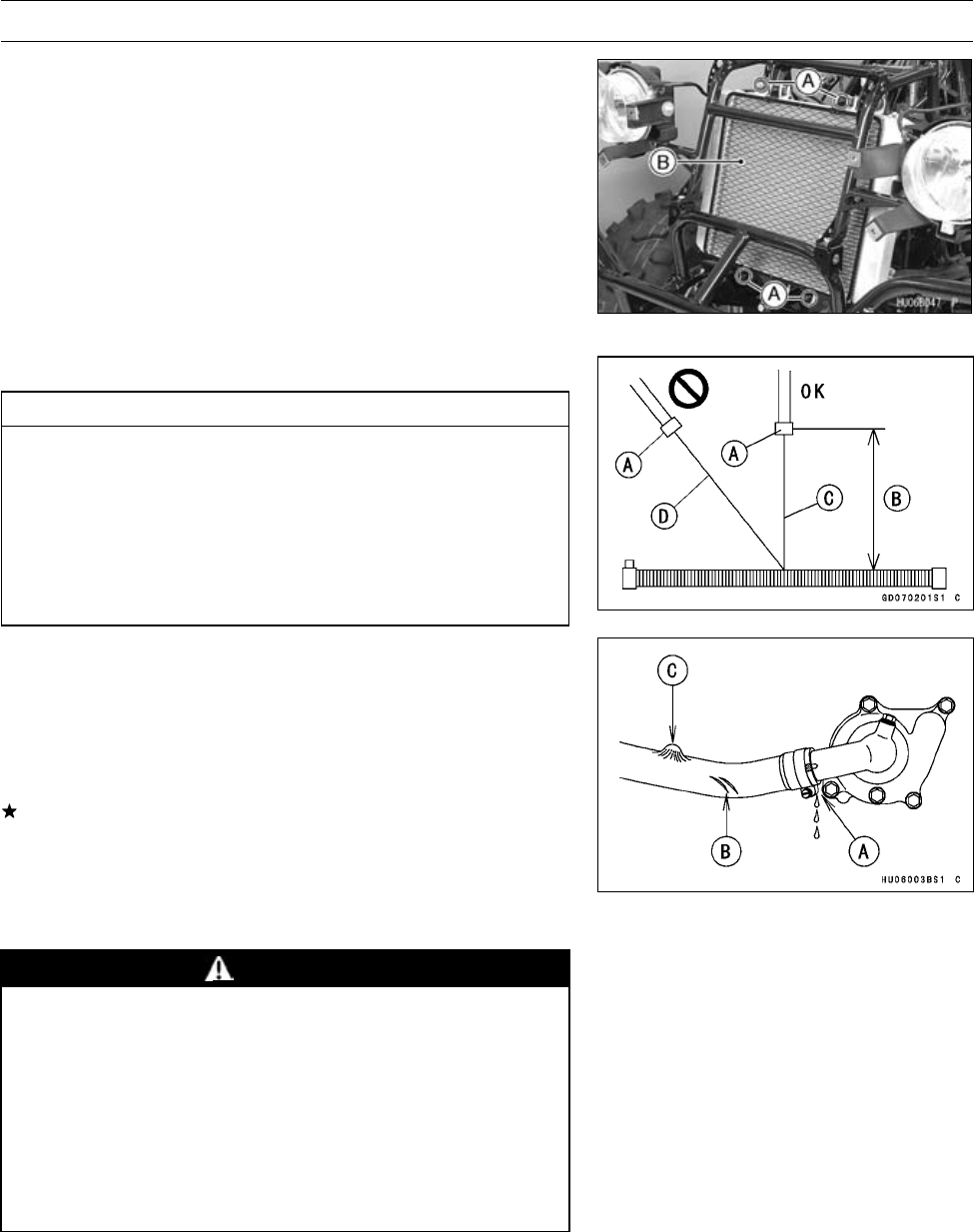
PERIODIC MAINTENANCE 2-19
Periodic Maintenance Procedures
•Remove:
Front Guard Cover (see Front Guard Removal in the
Frame chapter)
Front Fender (see Front Fender Removal in the Frame
chapter)
Headlight Cover (see Headlight Cover Removal in the
Frame chapter)
Radiator Screen Mounting Screws [A]
Radiator Screen [B]
•Clean the radiator screen in a bath of tap water, and then
dry it with compressed air or by shaking it.
•Clean the radiator.
CAUTION
When cleaning the radiator with steam cleaner, be
careful of the following to prevent radiator damage.
Keep the steam gun [A] away more than 0.5 m (20
in.) [B] from the radiator core.
Hold the steam gun perpendicular [C] (not oblique
[D]) to the core surface.
Run the steam gun following the core fin direction.
Water Hoses and Connections Inspection
○The high pressure inside the water hose can cause
coolant to leak [A] or the hose to burst if the line is not
properly maintained. Visually inspect the hoses for signs
of deterioration. Squeeze the hoses. A hose should not
be hard and brittle, nor should it be soft or swollen.
Replace the hose if any fraying, cracks [B] or bulges [C]
are noticed.
•Check that the hoses are securely connected and clamps
are tightened correctly.
Coolant Change
WARNING
To avoid burns, do not remove the radiator cap or
try to change the coolant when the engine is still
hot. Wait until it cools down.
Coolant on tires will make them slippery and can
cause an accident and injury. Immediately wash
away any coolant that spills on the frame, engine,
or wheels.
Since coolant is harmful to the human body, do not
use for drinking.
•Remove:
Radiator Cover (see Radiator Cover Removal in the
Frame chapter)
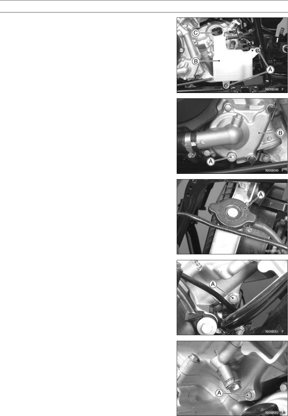
2-20 PERIODIC MAINTENANCE
Periodic Maintenance Procedures
•Remove:
Reserve Tank Screws [A]
Reserve Tank [B] with Hose
•Remove the reserve tank cap [C], and pour the coolant
into a container.
•Place a container under the drain bolt [A] at the bottom of
the water pump cover [B], then remove the drain plug.
•Remove the radiator cap [A] in two steps. First turn the
cap counterclockwise to the first step. Then push and turn
it further in the same direction and remove the cap.
•The coolant will drain from the radiator and engine.
•Place a container under the drain bolt [A] at the front cylin-
der, then remove the drain bolt.
•Place a container under the drain bolt [A] at the rear cylin-
der, then remove the drain bolt.
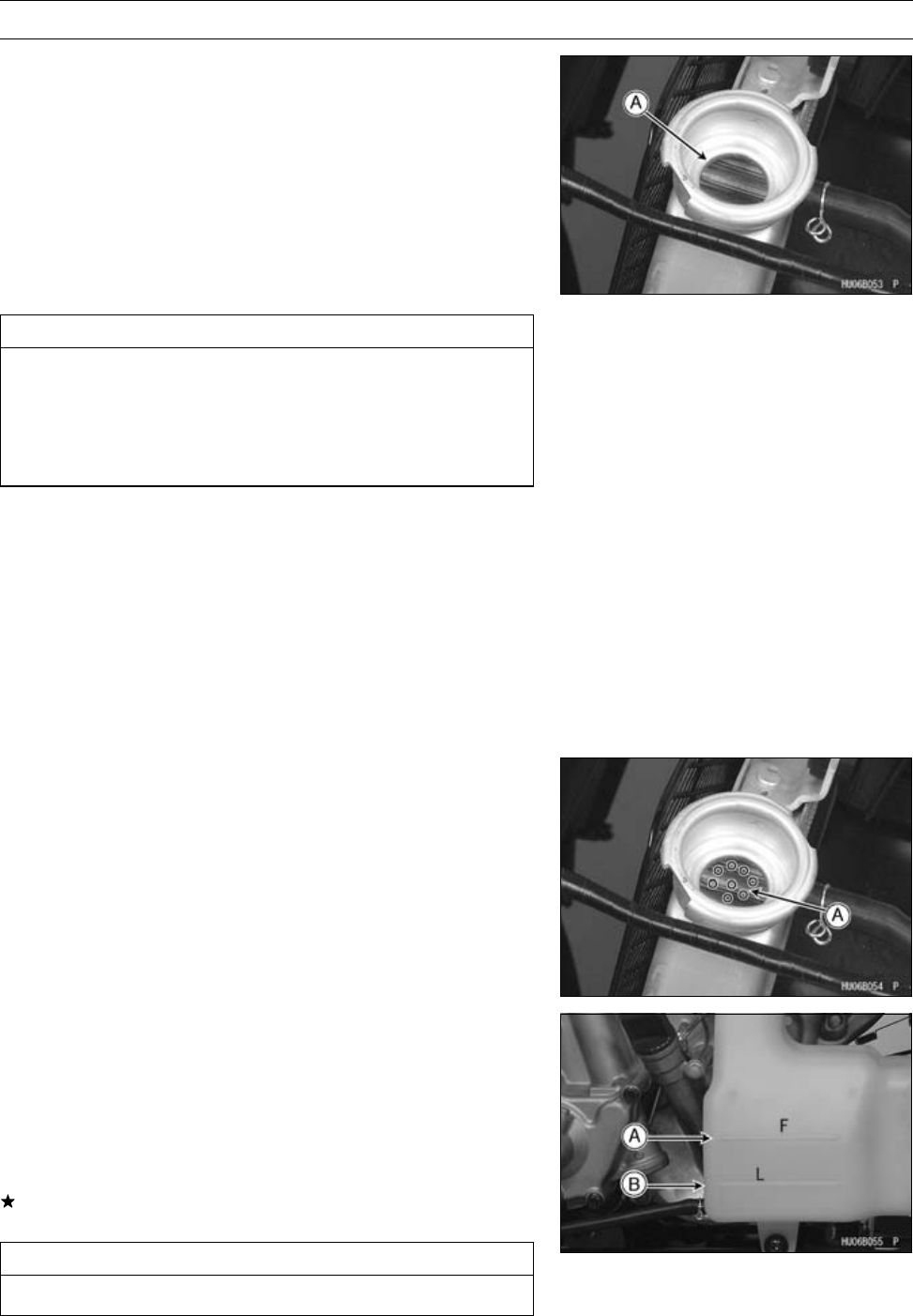
PERIODIC MAINTENANCE 2-21
Periodic Maintenance Procedures
•Tighten:
Torque - Coolant Drain Bolt: 8.8 N·m (0.90 kgf·m, 78 in·lb)
•Support the vehicle on a stand or the jack so that the front
wheels are off the ground. This makes air bleeding easier.
•Fill the radiator up to the radiator filler neck [A] with
coolant.
NOTE
○Pour in the coolant slowly so that the air in the engine
and radiator can escape.
CAUTION
Soft or distilled water must be used with the an-
tifreeze in the cooling system.
If hard water is used in the system, it causes scale
accumulation in the water passages, considerably
reducing the efficiency of the cooling system.
Water and Coolant Mixture Ratio (when shipping)
Soft Water: 50%
Coolant: 50%
Freezing Point: −35°C (−31°F)
Total Amount: 2.2 L (2.3 US qt)
NOTE
○Choose a suitable mixture ratio by referring to the
coolant manufacturer’s directions.
•Bleed the air from the cooling system as follows.
○Start the engine with the radiator cap removed and run it
until no more air bubbles [A] can be seen in the coolant.
○Tap the radiator hoses to force any air bubbles caught
inside.
○Stop the engine and add coolant up to the radiator filler
neck.
•Install the radiator cap.
•Remove the reserve tank cap.
•Fill the reserve tank up to the F mark [A] with coolant and
install the cap.
•Start the engine, warm it up thoroughly until the radiator
fan turns on and then stop the engine.
•Check the coolant level in the reserve tank after the en-
gine cools down.
If the coolant level is lower than the low level line [B], add
coolant to the full level line.
CAUTION
Do not add more coolant above the full level line.
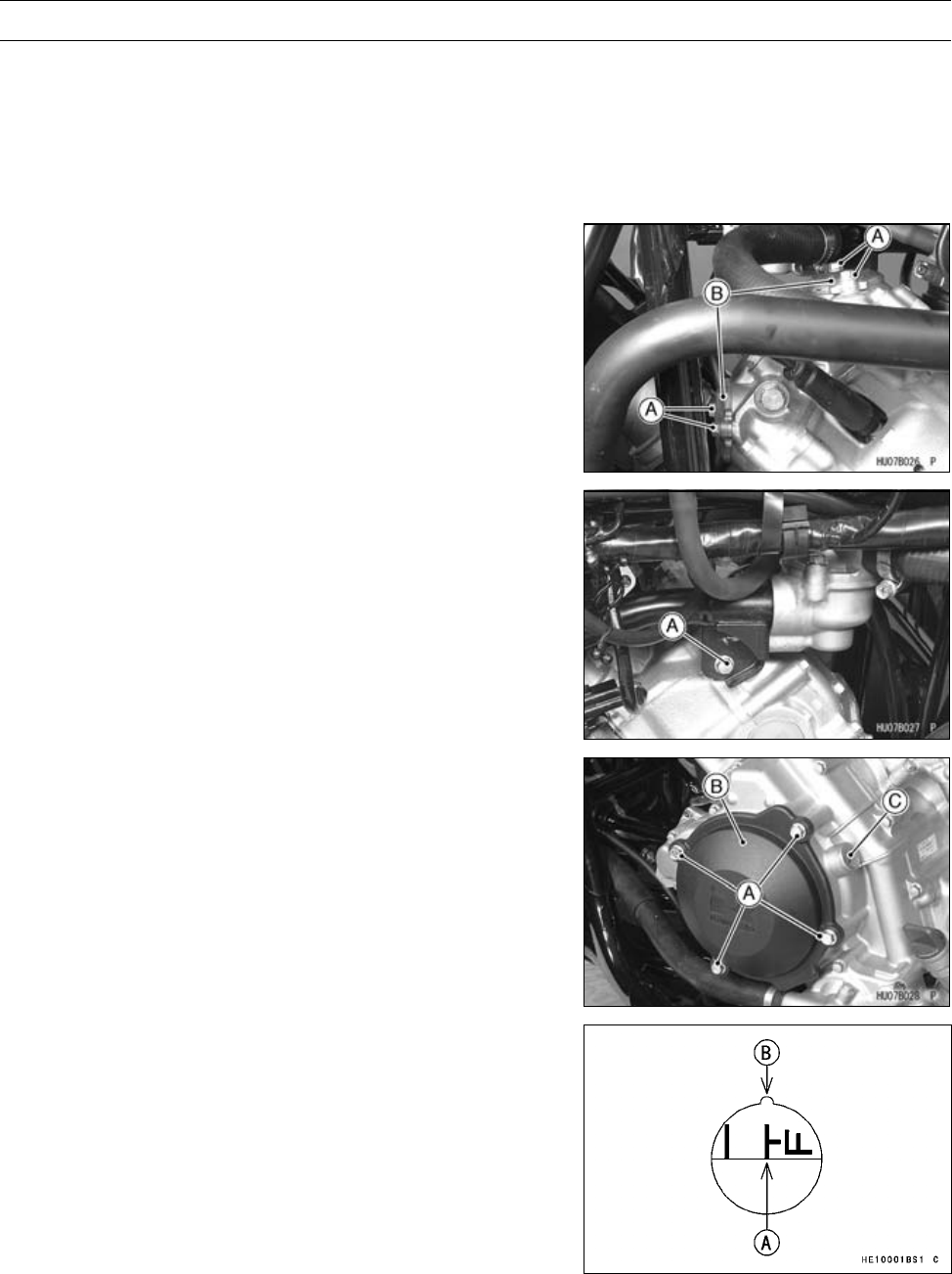
2-22 PERIODIC MAINTENANCE
Periodic Maintenance Procedures
Engine Top End
Valve Clearance Inspection
NOTE
○Check the valve clearance only when the engine is cold
(at room temperature).
•Remove:
Front Fender (see Front Fender Removal in the Frame
chapter)
Battery Case
Valve Adjusting Cap Bolts [A]
Valve Adjusting Caps [B]
•Remove the right water pipe bolt [A], if necessary.
•Remove:
Bolts [A]
Alternator Outer Cover [B]
•Removethetiminginspectionplug[C].
Special Tool - Filler Cap Driver [B]: 57001-1454
•Turn the crankshaft counterclockwise withawrenchon
the alternator rotor bolt until “T-F” mark [A] on the alter-
nator rotor aligns with the notch [B] as shown: the end of
the compression stroke in the front cylinder head.
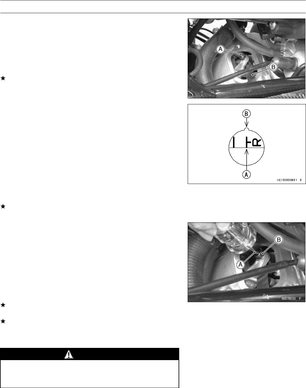
PERIODIC MAINTENANCE 2-23
Periodic Maintenance Procedures
•Measure the clearance for all four valves, one at a time
between the end of the valve stem and the adjusting
screw [A] with the thickness gauge [B].
Valve Clearance (when cold)
Exhaust 0.20 ∼0.25 mm (0.0079 ∼0.0098 in.)
Inlet 0.10 ∼0.15 mm (0.0039 ∼0.0059 in.)
If the valve clearance is not correct, adjust it (see Valve
Clearance Adjustment).
•Then, turn the crankshaft counterclockwise with a
wrench on the alternator rotor bolt until “T-R” mark [A] on
the alternator rotor aligns with the notch [B] as shown:
the end of the compression stroke in the rear cylinder
head.
•Measure the clearance for all four valves, one at a time
between the end of the valve stem and the adjusting
screw with the thickness gauge.
Valve Clearance (when cold)
Exhaust 0.20 ∼0.25 mm (0.0079 ∼0.0098 in.)
Inlet 0.10 ∼0.15 mm (0.0039 ∼0.0059 in.)
If the valve clearance is not correct, adjust it (see Valve
Clearance Adjustment).
Valve Clearance Adjustment
•Remove the valve adjusting caps.
•Loosen the locknut and turn the adjusting screw until the
clearance is correct.
•Hold the adjusting screw [A] from turning and tighten the
locknut [B].
Torque - Valve Adjusting Screw Locknuts: 12 N·m (1.2
kgf·m, 106 in·lb)
•Recheck the clearance.
If the clearance is incorrect, repeat the adjustment proce-
dure.
If the clearance is correct, perform the adjustment proce-
dure on the other valve.
Spark Arrester Cleaning
WARNING
To avoid burns, wear gloves while cleaning the
spark arrester. Since the engine must be run dur-
ing this procedure, the muffler will become hot.
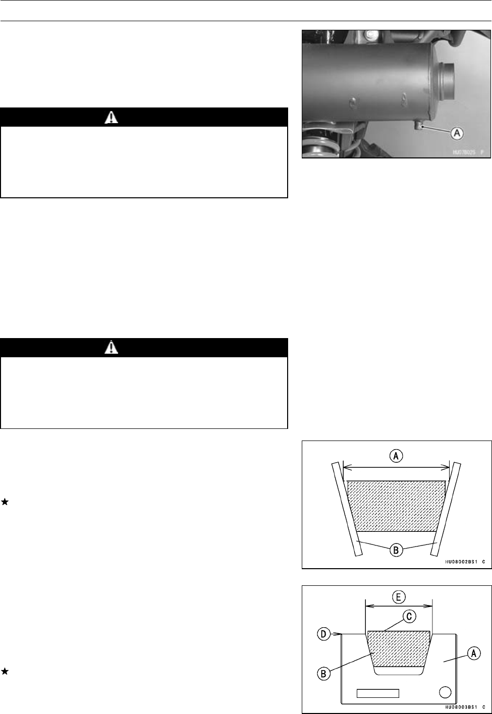
2-24 PERIODIC MAINTENANCE
Periodic Maintenance Procedures
•Remove the drain plug [A] on the muffler.
•In an open area away from combustible materials, start
the engine with the transmission in neutral.
•Raise and lower engine speed while tapping on the muf-
fler with a rubber mallet until carbon particles are purged
from the muffler.
WARNING
Do not run the engine in a closed area. Exhaust
gases contain carbon monoxide; a colorless, odor-
less, poisonous gas. Breathing exhaust gas leads
to carbon monoxide poisoning, asphyxiation, and
death.
•Stop the engine.
•Install the drain plug.
Converter System
Converter Drive Belt Wear Inspection
Inspection of the drive belt is required at least every 90
days of vehicle use (average 12 mile/day) not to exceed 1
700 km (1 100 mile) or belt indicator light turn on (100 hours
of use) counted by the hour meter. More frequent inspection
is necessary if the vehicle is subjected to hard usage.
WARNING
Neglect, abuse, or failure to maintain the transmis-
sion can result in a severely worn or damaged drive
belt locking up the transmission and wheels. This
can cause the operator to lose control and have an
accident resulting in injury or death.
•Remove the torque converter cover (see Torque Con-
verter Cover in the Converter System chapter).
•Measure the width [A] of the belt at several locations with
a pair of suitable straightedges [B] as shown.
If any measurements exceed the service limit, replace the
belt.
Belt Width
Standard: 29.7 ∼30.3 mm (1.17 ∼1.19 in.)
Service Limit: 28.0 mm (1.10 in.)
NOTE
○Use the belt measuring gauge [A] in order to make easy
to inspect the drive belt width.
Special Tool - Belt Measuring Gauge: 57001-1646
•Fit the drive belt [B] into the belt measuring gauge.
If the upper surface [C] of the belt lowers than the upper
surface [D] of the gauge, replace the belt.
[E] 28 mm (1.10 in.)
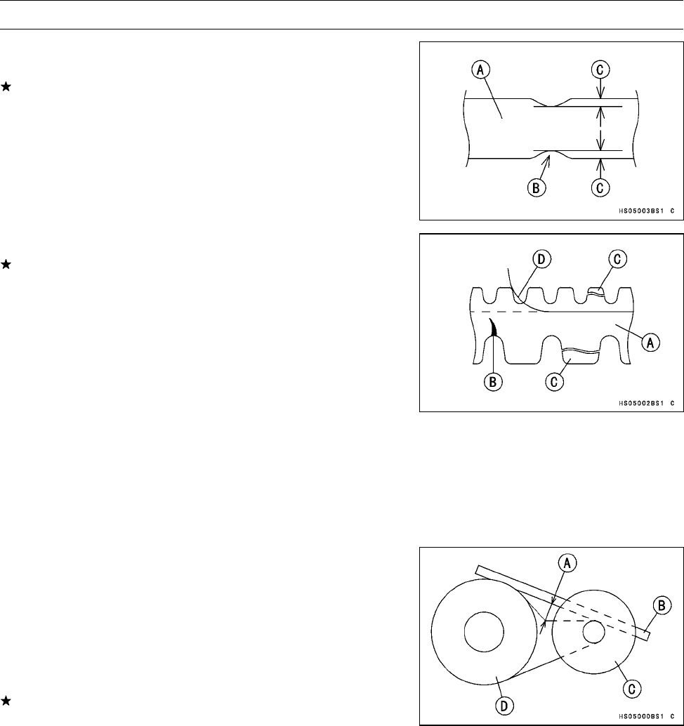
PERIODIC MAINTENANCE 2-25
Periodic Maintenance Procedures
•Check the belt [A] for abnormal wear [B].
○Measure the width [C] of the belt at abnormal wear point.
If any measurements exceed 0.5 mm (0.02 in.), replace
the belt.
○When using the belt of large abnormal wear, the drive belt
failure detection switch could be activated.
•Check the belt for cracks, breaks, or peeling.
If necessary, replace the belt with a new one.
Belt [A]
Crack [B]
Broken [C]
Peeling [D]
NOTE
○Whenever the belt is replaced, inspect the drive and the
driven pulleys.
Converter Drive Belt Deflection Inspection
•Remove the torque converter cover (see Torque Con-
verter Cover Removal in the Converter System chapter).
•Put the transmission in neutral and rotate the driven pulley
by hand to make sure the belt is shifted all the way to the
top of the driven pulley.
•Measure the belt deflection [A] as shown:
○Place a straightedge [B] on top of the belt between the
drive pulley [C] and the driven pulley [D].
○Use a ruler to push the belt away from the straightedge.
Push hard, but with no more force than 59 N (6 kgf, 13 lb).
Belt Deflection
Standard: 22 ∼27 mm (0.87 ∼1.06 in.)
If the belt deflection is not within the specified range, ad-
just the deflection by adding or removing spacers on the
fixed sheave of the driven pulley.
•When adjusting the deflection, less is better than more.
Less deflection will maintain better performance for more
time as the belt width decreases by normal wear, which
causes the deflection to increase with usage.
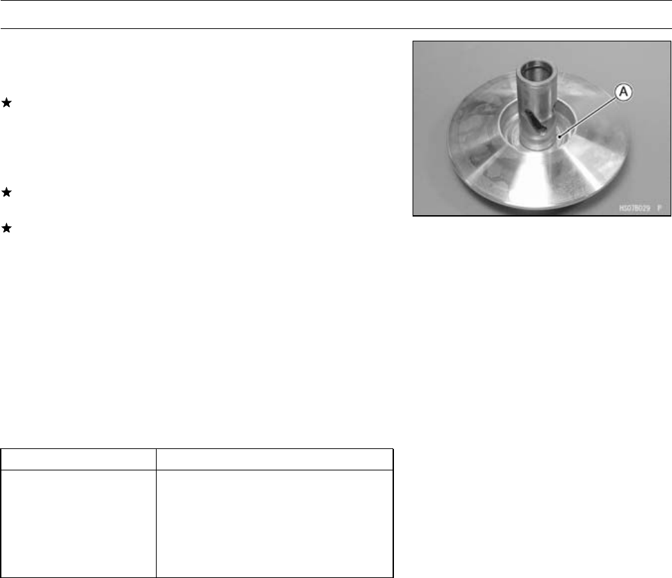
2-26 PERIODIC MAINTENANCE
Periodic Maintenance Procedures
Converter Drive Belt Deflection Adjustment
•Disassemble the driven pulley (see Driven Pulley Disas-
sembly in the Converter System chapter).
If the belt deflection is more than 27 mm (1.06 in.), remove
the spacers to decrease it.
○The rule-of-thumb is: 0.1 mm (0.004 in.) change in spacer
thickness equals about 1.3 mm (0.051 in.) change in belt
deflection.
If the adjustment cannot be done within the specified
range even if the shim is removed, replace the drive belt.
If the belt deflection is less than 22 mm (0.87 in.), add the
spacers [A] to increase it.
○The rule-of-thumb is: 0.1 mm (0.004 in.) change in spacer
thickness equals about 1.6 mm (0.063 in.) change in belt
deflection.
NOTE
○When using the plural spacers, install the thick spacer
to the movable sheave side and thin spacer to the fixed
sheave side.
Spacers
Part No. Thickness
92026-0034 0.3 mm (0.012 in.)
92026-1569 0.6 mm (0.024 in.)
92026-1617 0.8 mm (0.032 in.)
92026-1565 1.0 mm (0.039 in.)
92026-1570 1.4 mm (0.055 in.)
•Assemble the driven pulley (see Driven Pulley Assembly
in the Converter System chapter).
•With the transmission in neutral, rotate the driven pulley
to allow the belt to return to the top of the sheaves before
measuring the belt deflection.
•Measure the belt deflection again and repeat the above
procedures until it is within the standard range.
•Using the flywheel & pulley holder and pulley holder at-
tachment, tighten the driven pulley nut.
Special Tools - Flywheel & Pulley Holder: 57001-1605
Pulley Holder Attachment: 57001-1472
Torque - Driven Pulley Nut: 93 N·m (9.5 kgf·m, 69 ft·lb)
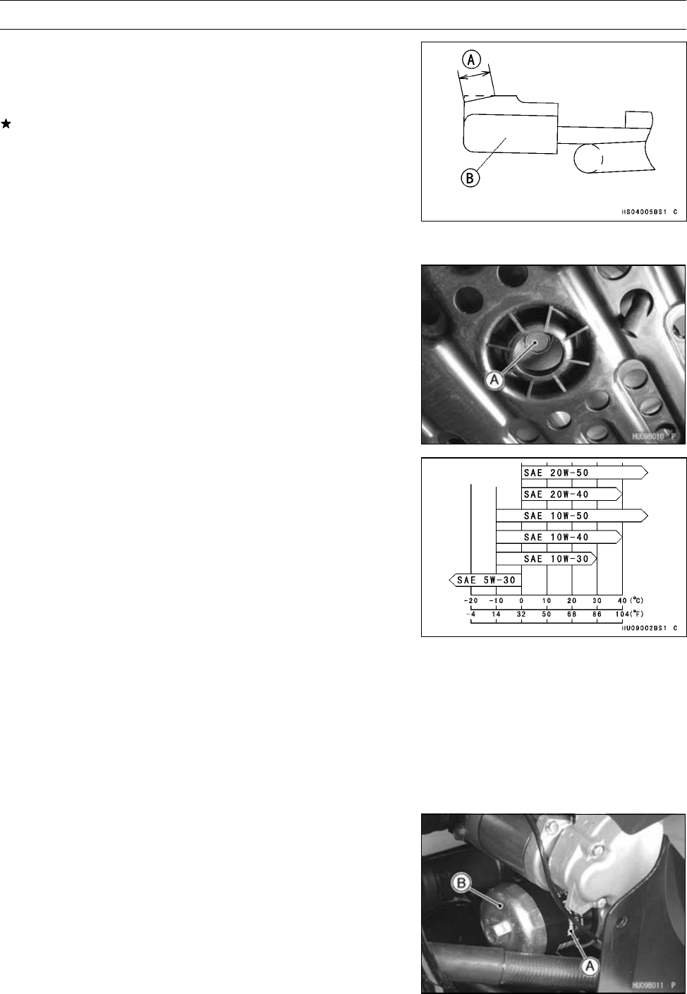
PERIODIC MAINTENANCE 2-27
Periodic Maintenance Procedures
Actuator Lever (Engine Brake Control Lever)
Assembly Inspection
•Measure the width [A] of the plastic guide shoe [B] of the
actuator lever assembly.
If the guide contact area width is greater than the service
limit, replace the actuator lever assembly.
Actuator Lever Guide Shoe
Service Limit: 6 mm (0.24 in.)
Engine Lubrication System
Engine Oil Change
•Support the vehicle so that it is level, both side to side and
front to rear after warming up the engine.
•Remove the engine oil drain bolt [A] to drain the oil.
○The oil in the filter can be drained by removing the filter
(see Oil Filter Change).
•Replace the oil drain bolt gasket with a new one.
•Tighten:
Torque - Engine Oil Drain Bolt: 20 N·m (2.0 kgf·m, 14 ft·lb)
•Pour in the specified type and amount of oil.
Engine Oil
Type: API SF or SG
API SH, SJ or SL with JASO MA
Viscosity: SAE 10W-40
Amount: 2.1 L (2.2 US qt)
(When filter is not removed)
2.2 L (2.3 US qt)
(When filter is removed)
2.6 L (2.7 US qt)
(When engine is completely dry)
NOTE
○Although 10W-40 engine oil is the recommended oil
for most conditions, the oil viscosity may need to be
changed to accommodate atmospheric conditions in
your riding area.
Oil Filter Replacement
•Drain the engine oil.
•Remove the oil filter [A] with the oil filter wrench [B].
Special Tool - Oil Filter Wrench: 57001-1249
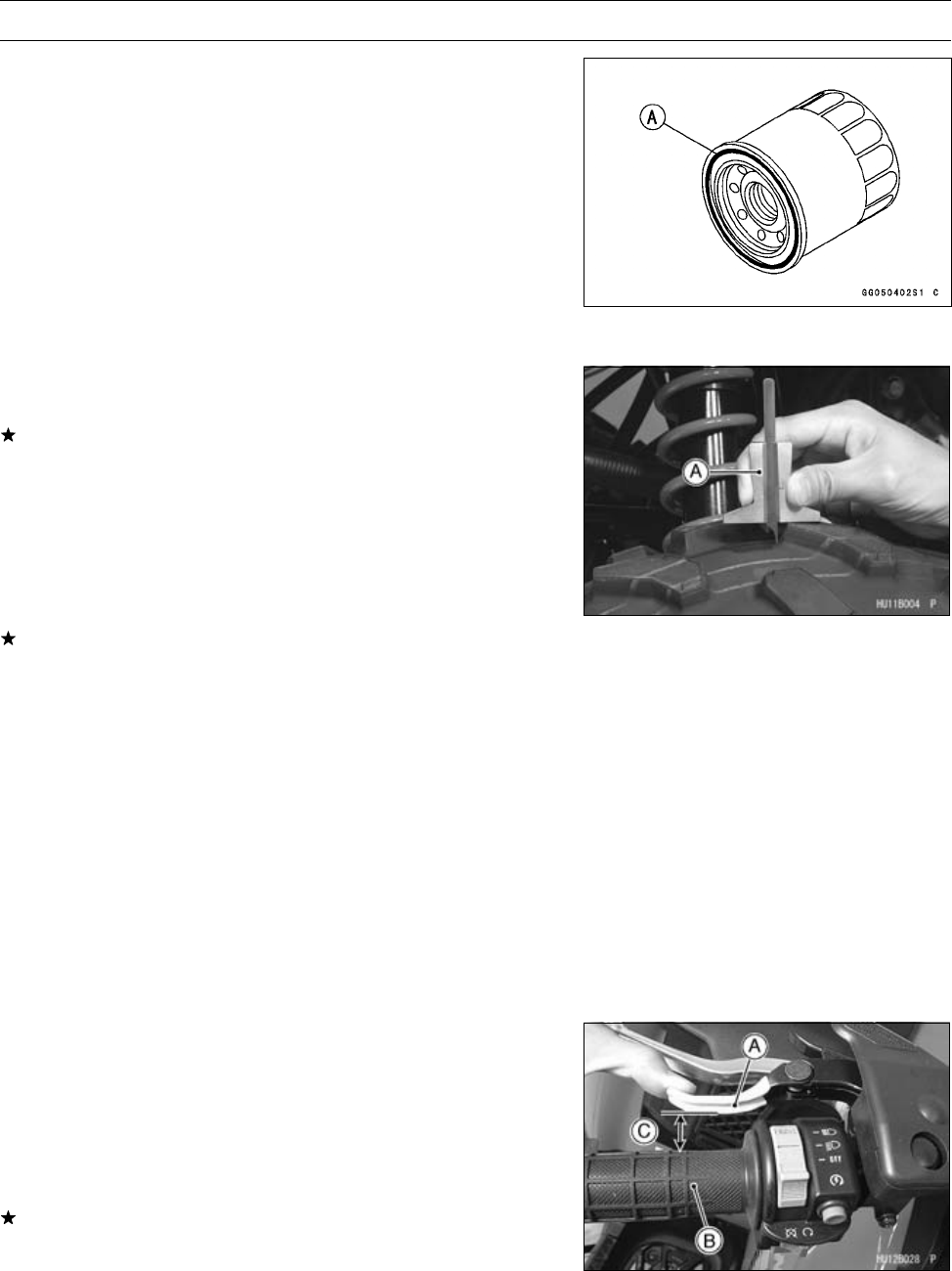
2-28 PERIODIC MAINTENANCE
Periodic Maintenance Procedures
•Replace the filter with a new one.
•When installing the oil filter, be careful of the following.
○Apply oil to the gasket [A] before installation.
○Tighten the filter with the oil filter wrench.
Special Tool - Oil Filter Wrench: 57001-1249
Torque - Oil Filter: 17.5 N·m (1.8 kgf·m, 13 ft·lb)
○Pour in the specified type and amount of oil.
Wheels/Tires
Tire Inspection
•Examine the tire for damage and wear.
If the tire is cut or cracked, replace it.
○Lumps or high spots on the tread or sidewalls indicate
internal damage requiring tire replacement.
○Remove any foreign objects from the tread. After re-
moval, check for leaks with a soap and water solution.
•Measure the tread depth at the center of the tread with a
depth gauge [A]. Since the tire may wear unevenly, take
measurements at several places.
If any measurements are less than the service limit, re-
place the tire.
Tire Tread Depth
Service Limit:
Front 3 mm (0.12 in.)
Rear 4 mm (0.16 in.)
Standard Tire
Front: AT 25 × 8 - 12
DUNLOP, KT191, Tubeless
Rear: AT 25 × 10 - 12
DUNLOP, KT195, Tubeless
Final Drive
Variable Differential Control Lever Play Inspection
•Pull the variable differential control lever [A] towards the
handlebar grip [B] with a spring scale until it reads 30 N
(3 kgf, 7 lb) of force.
○The differential control in the front final gear case must be
locked, then the clearance [C] between the control lever
and grip should be 20 mm (0.8 in.).
If the clearance is not the specified length, adjust the ca-
ble.
Differential Control Lever Lock Position Length
Standard: 20 mm (0.8 in.)
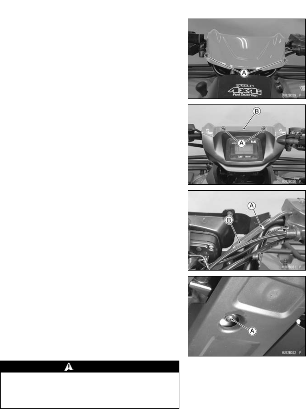
PERIODIC MAINTENANCE 2-29
Periodic Maintenance Procedures
Variable Differential Control Lever Play
Adjustment
•Remove:
Handlebar Cover Screws [A]
•Remove:
Handlebar Cover Screws [A]
Handlebar Cover Front [B]
•Loosen the locknut [A] of the differential control cable.
•Turn the adjuster [B] until the cable has proper amount of
play.
•Tighten the locknut securely.
Front Final Gear Case Oil Change
•Warm up the oil by running the vehicle so that the oil will
pick up any sediment and drain easily. Then stop the
vehicle.
•Park the vehicle so that it is level, both side-to-side and
front-to-rear.
•Remove the right side cover (see Right Side Cover Re-
moval in the Frame chapter).
•Place an oil pan beneath the front final gear case and
remove the oil drain bolt [A].
WARNING
When draining or filling the final gear case, be care-
ful that no oil gets on the tire or rim. Clean off any
oil that inadvertently gets on them with a high-flash
point solvent.
•After the oil has completely drained out, install the oil drain
bolt with a new aluminum gasket, and tighten it.
Torque - Front Final Gear Case Oil Drain Bolt: 15 N·m (1.5
kgf·m, 11 ft·lb)
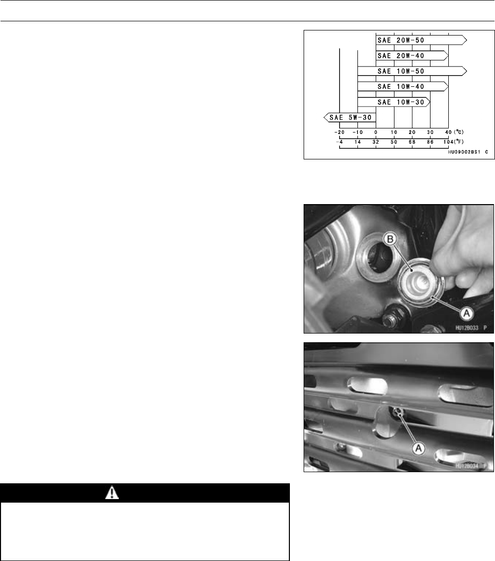
2-30 PERIODIC MAINTENANCE
Periodic Maintenance Procedures
•Fill the gear case up to the bottom of filler opening with
the oil specified below.
Front Final Gear Case Oil
Type: API SF or SG
API SH, SJ or SL with JASO MA
Viscosity: SAE 10W-40
Capacity: 0.40 L (0.42 US qt)
NOTE
○Depending on the atmospheric temperature of your rid-
ing area, the engine oil viscosity should be changed ac-
cordingtothechart.
•Be sure the O-ring [A] is in place, and tighten the filler cap
[B].
○Apply grease to the O-ring.
Torque - Front Final Gear Case Oil Filler Cap: 29 N·m (3.0
kgf·m, 22 ft·lb)
Rear Final Gear Case Oil Change
•Warm up the oil by running the vehicle so that the oil will
pick up any sediment and drain easily. Then stop the
vehicle.
•Park the vehicle so that it is level, both side-to-side and
front-to-rear.
•Place an oil pan beneath the rear final gear case and
remove the oil drain bolt [A].
WARNING
When draining or filling the final gear case, be care-
ful that no oil gets on the tire or rim because oil will
deteriorate the tire. Clean off any oil that inadver-
tently gets on them with a high-flash point solvent.
•After the oil has completely drained out, install the oil drain
plug with a new aluminum gasket.
Torque - Rear Final Gear Case Oil Drain Bolt: 15 N·m (1.5
kgf·m, 11 ft·lb)
•Fill the final gear case up to the bottom of filler opening
with the oil specified below.
Rear Final Gear Case Oil
Type: MOBIL FLUID 424, CITGO TRANSGARD
TRACTOR HYDRAULIC FLUID or EXXON
HYDRAUL 560
Capacity: 0.72 L (0.76 US qt)
○Do not use mixing the above oils.
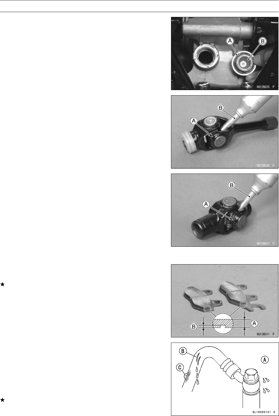
PERIODIC MAINTENANCE 2-31
Periodic Maintenance Procedures
•Be sure the O-ring [A] is in place, and tighten the filler cap
[B].
○Apply grease to the O-ring.
Torque - Rear Final Gear Case Oil Filler Cap: 29 N·m (3.0
kgf·m, 22 ft·lb)
Universal Joint Lubrication
•Remove:
Rear Propeller Shaft (see Rear Propeller Shaft Removal
in the Final Drive chapter)
•Force grease into the grease nipples [A] until the grease
comes out from the nipple, and wipe off any excess
grease.
[B] Grease Gun
Brakes
Front Brake Pad Wear Inspection
•Check the lining thickness [A] of the pads in each caliper.
If the lining thickness of either pad is less than the service
limit [B], replace both pads in the caliper as a set.
Pad Lining Thickness
Standard: 4 mm (0.16 in.)
Service Limit: 1 mm (0.04 in.)
Front Brake Hoses and Connections Inspection
•Inspect the brake hose and fittings for deterioration,
cracks and signs of leakage.
○The high pressure inside the brake line can cause fluid to
leak [A] or the hose to burst if the line is not properly main-
tained. Bend and twist the rubber hose while examining
it.
Replace the hose if any cracks [B] or bulges [C] are no-
ticed.
•Tighten any loose fittings.
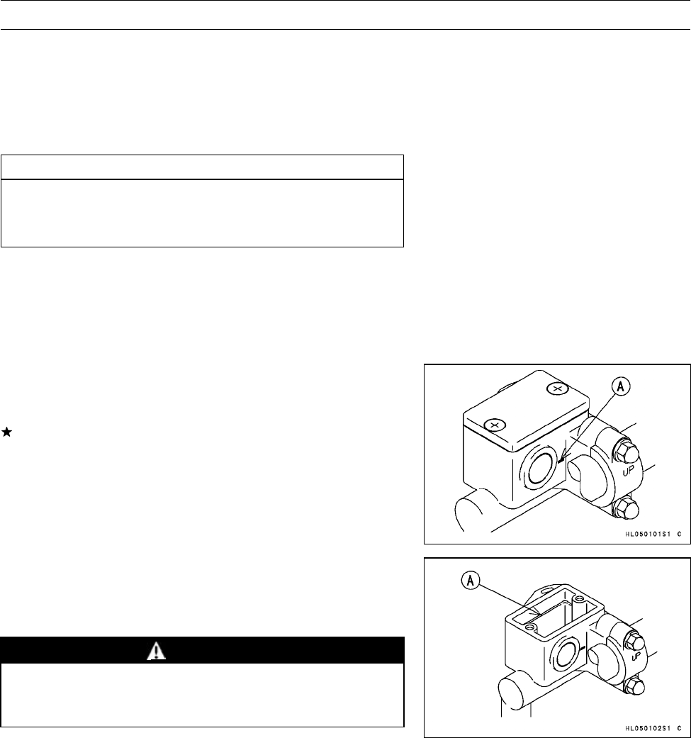
2-32 PERIODIC MAINTENANCE
Periodic Maintenance Procedures
Front Brake Hose Replacement
•Pump the brake fluid out of the line as explained in the
Brake Fluid Change.
•Remove the banjo bolts at both ends of the brake hose,
and pull the hose off the vehicle.
•Immediately wipe up any brake fluid that spills.
CAUTION
Brake fluid quickly ruins painted surfaces; any
spilled fluid should be completely washed away
immediately.
•Use a new flat washer for each side of the hose fittings.
•Install the new brake hose in its place, and tighten the
banjo bolts.
Torque - Brake Hose Banjo Bolts: 34 N·m (3.5 kgf·m, 25
ft·lb)
Front Brake Fluid Level Inspection
•Position the reservoir horizontal, and check that the fluid
level in the reservoir is higher than the lower level line [A].
If the fluid level is lower than the lower level line, check
for fluid leakage of the brake line, and add the fluid as
follows:
○Remove the reservoir cap, and fill the reservoir to the up-
per level line [A] in the reservoir with the same type and
brand of the fluid that is already in the reservoir. And then
install the reservoir cap.
WARNING
Change the fluid in the brake line completely if the
fluid must be refilled but the type and brand of the
fluid that is already in the reservoir are unidentified.
•Tighten:
Torque - Reservoir Cap Screws: 1.5 N·m (0.15 kgf·m, 13
in·lb)
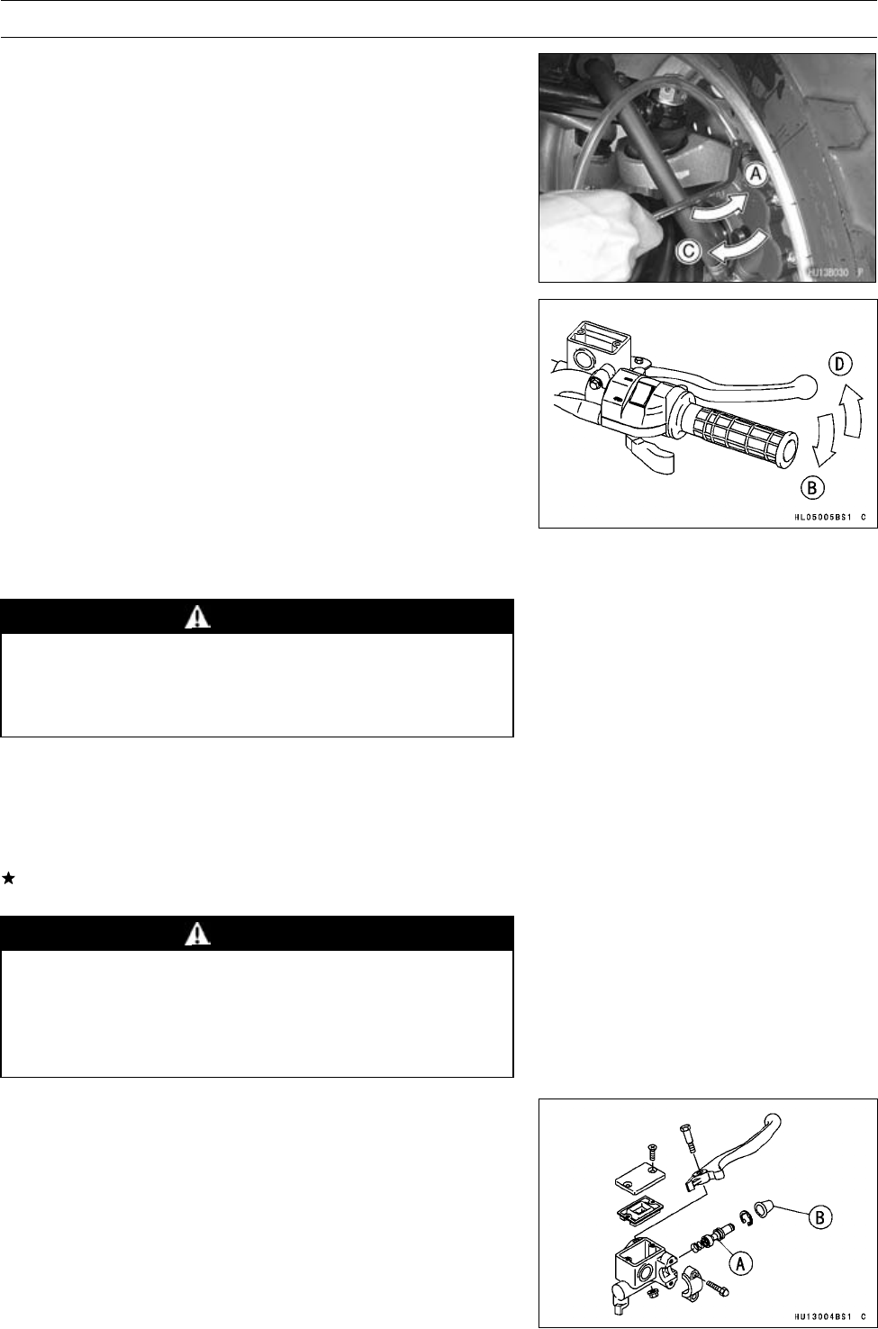
PERIODIC MAINTENANCE 2-33
Periodic Maintenance Procedures
Front Brake Fluid Change
•Remove the reservoir cap and the rubber cap on the bleed
valve.
•Attach a clear plastic hose to the bleed valve on the
caliper, and run the other end of the hose into a con-
tainer.
•Fill the reservoir with new brake fluid.
•Change the brake fluid as follows:
○Open the bleed valve [A].
○Apply the brake lever and hold it [B].
○Close the bleed valve [C].
○Release the brake lever [D].
•Check the fluid level in the reservoir often, replenishing it
as necessary.
NOTE
○If the fluid in the reservoir runs completely out any time
during fluid changing, air will enter the line, and the sys-
tem must be bled.
•Repeat this operation until fresh brake fluid comes out into
the plastic hose or the color of the fluid changes.
WARNING
Do not mix two brands of fluid. Change the brake
fluid in the brake line completely if the brake fluid
must be refilled but the type and brand of the brake
fluid that is already in the reservoir are not known.
•Tighten:
Torque - Bleed Valves: 7.8 N·m (0.80 kgf·m, 69 in·lb)
•Apply the brake lever forcefully for a few seconds, and
check for fluid leakage around the fittings.
If necessary, bleed the air from the brake line (see Brake
Line Air Bleeding section in the Brakes chapter).
WARNING
If the brake lever has a soft or “spongy feeling”
when it is applied, there might be air in the brake
line or the brake may be defective. Since it is dan-
gerous to operate the vehicle under such condi-
tions, bleed the air from the brake line immediately.
Front Brake Master Cylinder Piston Assembly and
Dust Cover Replacement
•Disassemble the master cylinder (see Front Brake Master
Cylinder Disassembly in the Brakes chapter).
•Replace the piston assembly [A] and dust cover [B] under
following condition:
a)Primary and secondary cups are worn, damaged, soft-
ened (rotted) or swollen.
b)Fluid leakage is noted at the brake lever,
c)Dust cover is broken or swollen.
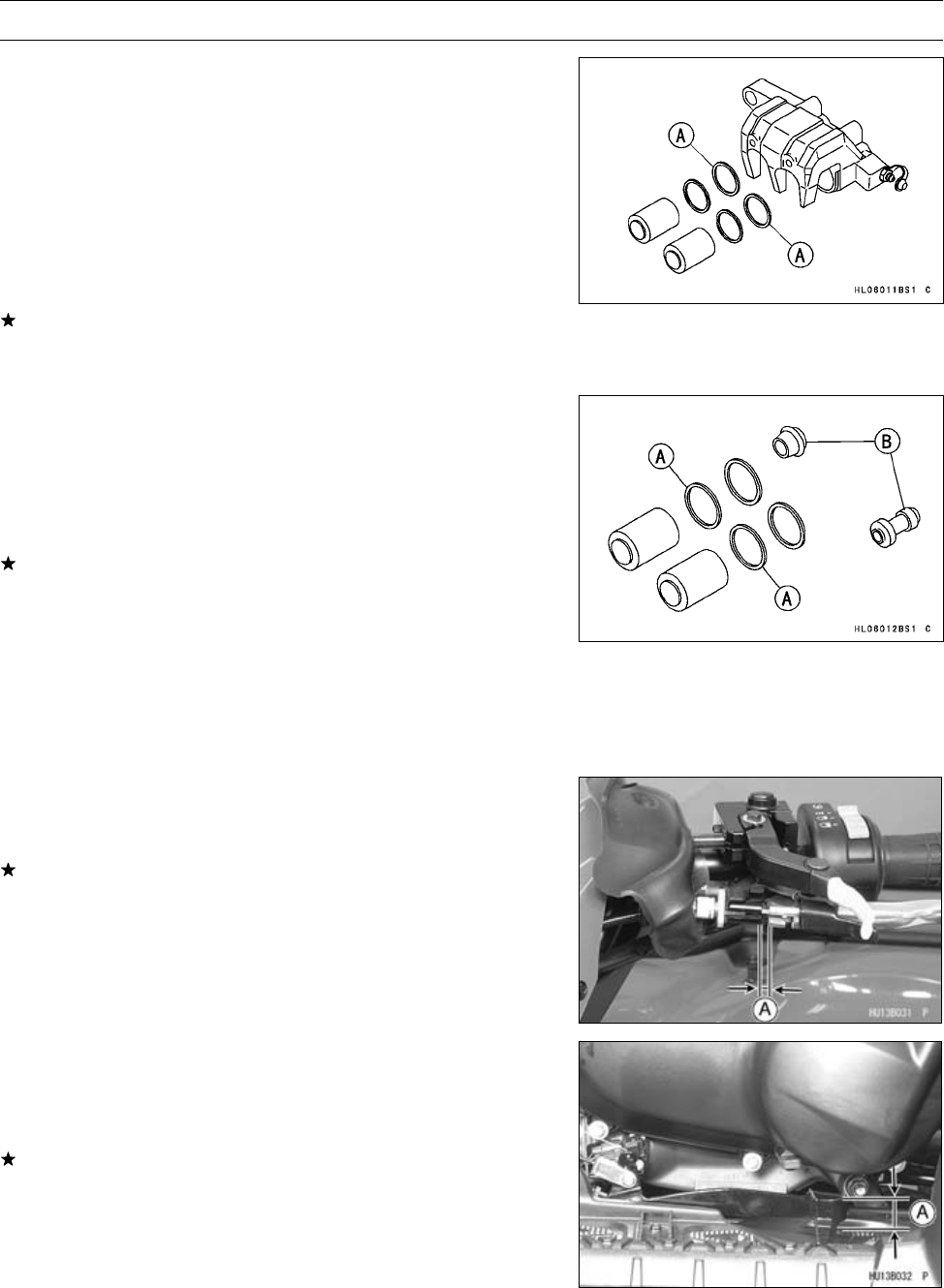
2-34 PERIODIC MAINTENANCE
Periodic Maintenance Procedures
Front Brake Caliper Fluid Seal Replacement
The fluid seals [A] around the piston maintain the proper
pad/disc clearance. If the seals are not satisfactory, pad
wear will increase, and constant pad drag on the disc will
raise brake and brake fluid temperature.
•Replace the fluid seals in accordance with the Periodic
Maintenance Chart or under any of the following condi-
tions: (a) fluid leakage around the pad; (b) brakes over-
heat; (c) there is a large difference in inner and outer pad
wear; (d) the seal is stuck to the piston.
If the fluid seal is replaced, replace the dust seal as well.
Also, replace all seals every other time the pads are
changed.
Front Brake Caliper Dust Seal and Friction Boot
Replacement
•Replace the dust seals [A] in accordance with the Peri-
odic Maintenance Chart or check that the dust seals and
rubber boots [B] are not cracked, worn swollen, or other-
wise damaged.
If they show any damage, replace them.
Rear Brake Plates Replacement
•Replace the steel plates and friction plates in accordance
with the specified interval (see Rear Final Gear Case sec-
tion in the Final Drive chapter).
Rear Brake Lever Free Play Inspection
•Check the rear brake lever free play [A].
○Pull the rear brake lever lightly until the brake is applied.
If the play is incorrect, adjust it.
Rear Brake Lever Free Play
Standard: 1 ∼2 mm (0.04 ∼0.08 in.)
Rear Brake Pedal Free Play Inspection
•Check the brake pedal free play [A].
○Depress the brake pedal lightly by hand until the brake is
applied.
If the free play is incorrect, adjust it.
Brake Pedal Free Play
Standard: 15 ∼25 mm (0.6 ∼1.0 in.)
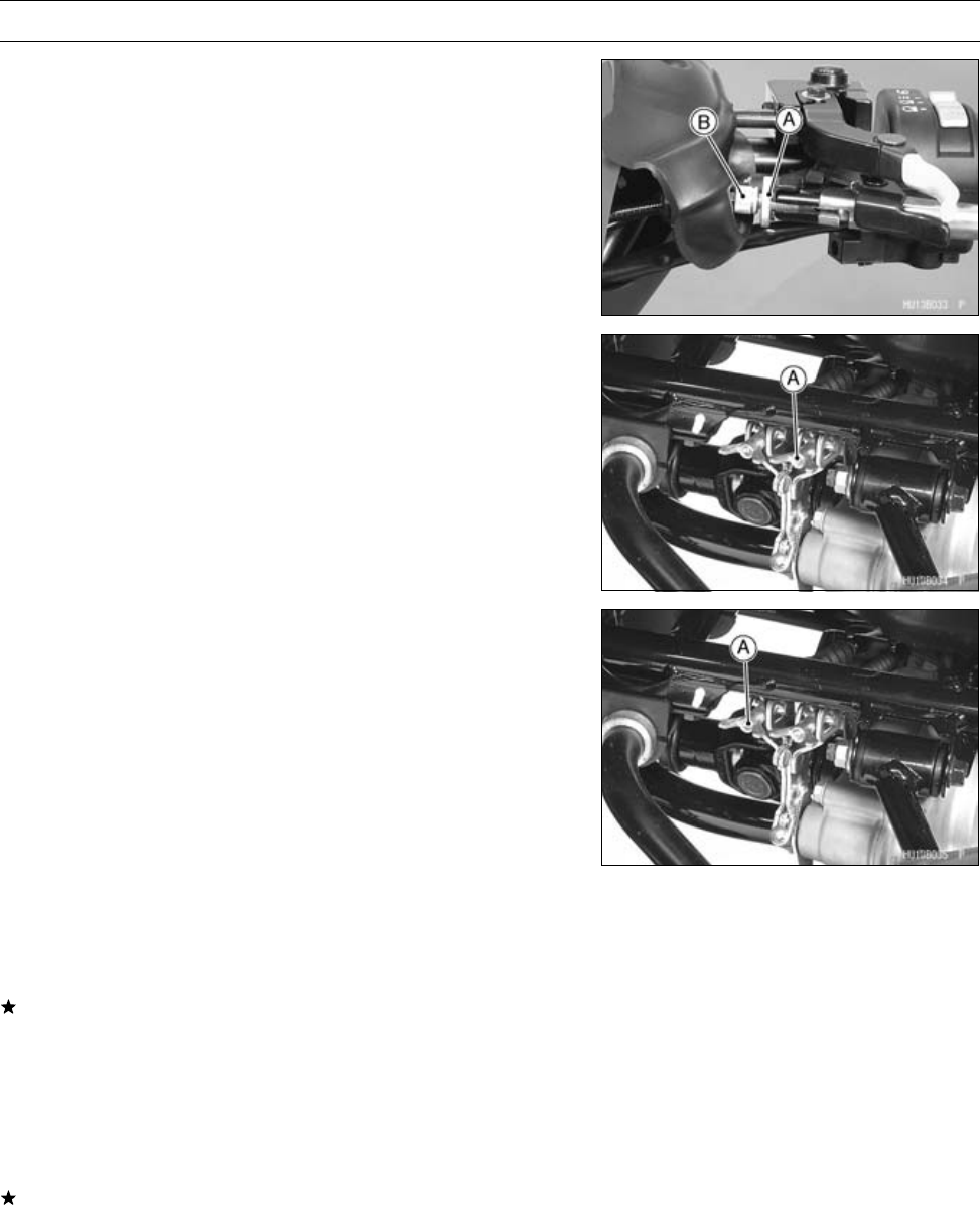
PERIODIC MAINTENANCE 2-35
Periodic Maintenance Procedures
Rear Brake Lever and Pedal Free Play Adjustment
NOTE
○Since the rear brake lever and pedal free play adjust-
ments affect each other, make them at the same time.
Rear Brake Lever
•Loosen the knurled locknut [A] and turn the adjuster [B]
at the rear brake lever in as far as it will go.
•Tighten the locknut.
•Turn the brake lever adjuster [A] at the rear end of the
brake cable until the rear brake lever has the correct
amount of play.
Rear Brake Pedal
•Turn the brake pedal adjuster [A] at the rear end of the
brake cable until the brake pedal has the correct amount
of play.
•Operate the pedal a few times to see that it returns to its
rest position immediately upon release.
•Rotate the rear wheels to check for brake drag.
•Check braking effectiveness.
If there is any doubt as to the conditions of the brake,
check the brake parts for wear or damage.
Steering
Steering Inspection
•Turn the handlebar left and right, and check the steering
action.
If the steering action is not smooth, or if the steering binds
or catches before the stop, lubricate the steering stem
bearing.
NOTE
○The cables and wires will have some effect on the steer-
ing action which must be taken into account.
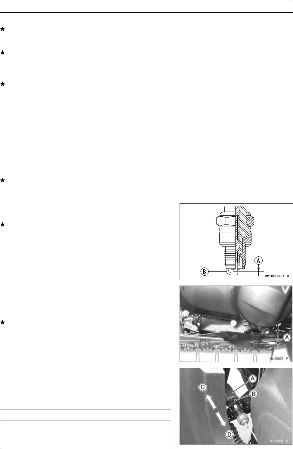
2-36 PERIODIC MAINTENANCE
Periodic Maintenance Procedures
•Check the steering action again.
If steering stem bearing lubrication does not remedy the
problem, inspect the steering stem for straightness, steer-
ing stem clamps, and tie-rod bearings.
If you feel looseness, or if the steering rattles as it turns,
check the tightness of the steering bolts and nuts.
•Tighten loose bolts and nuts to the specified torque (see
Steering chapter), and check the steering action again.
If the steering action does not change by tightening the
bolts and nuts, inspect the steering stem clamps, steer-
ing stem bearings, tie-rod bearings, and steering knuckle
joints.
Electrical System
Spark Plug Cleaning/Inspection
•Remove the spark plug (see Spark Plug Removal in the
Electrical System chapter).
•Clean the spark plug, preferably in a sandblasting device,
and then clean off any abrasive particles. The plug may
also be cleaned using a wire brush or other suitable tool.
If the spark plug electrodes are corroded or damaged,
or if the insulator is cracked, replace the plug. Use the
standard spark plug or its equivalent.
Spark Plug Gap Inspection
•Measure the gap [A] with a wire-type thickness gauge.
If the gap is incorrect, carefully bend the side electrode
[B] with a suitable tool to obtain the correct gap.
Spark Plug Gap
0.7 ∼0.8 mm (0.028 ∼0.032 in.)
Rear Brake Light Switch Inspection
•Turn on the ignition switch.
•Check the operation of the rear brake light switch by de-
pressing the brake pedal.
If it does not as specified, adjust the brake light timing.
Brake Light Timing
Standard: On after about 10 mm (0.4 in.) of pedal
travel [A]
Rear Brake Light Timing Adjustment
•Adjust the brake light switch [A] up or down. To change
the switch position, turn the adjusting nut [B].
Light sooner as the body rises [C]
Light later as the body lowers [D]
CAUTION
To avoid damaging the electrical connections in-
side the switch, be sure that the switch body does
not turn during adjustment.

PERIODIC MAINTENANCE 2-37
Periodic Maintenance Procedures
Converter Drive Belt Failure Detection System
Inspection
•Remove:
Seat (see Seat Removal in the Frame chapter)
•Check the drive belt failure detection system according to
following chart in the next page.
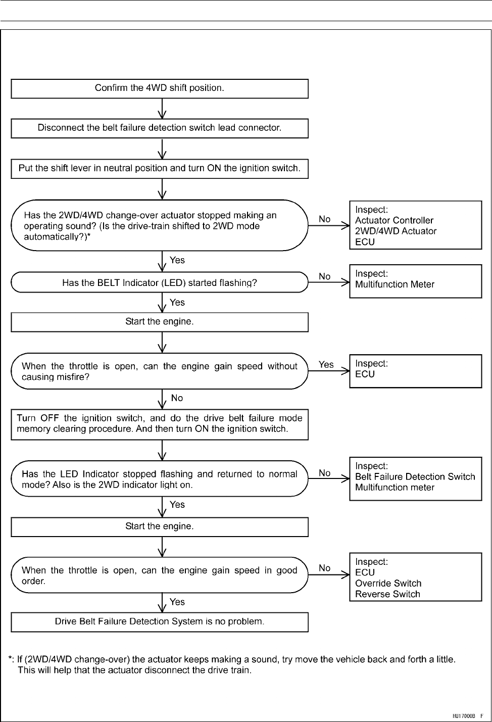
2-38 PERIODIC MAINTENANCE
Periodic Maintenance Procedures
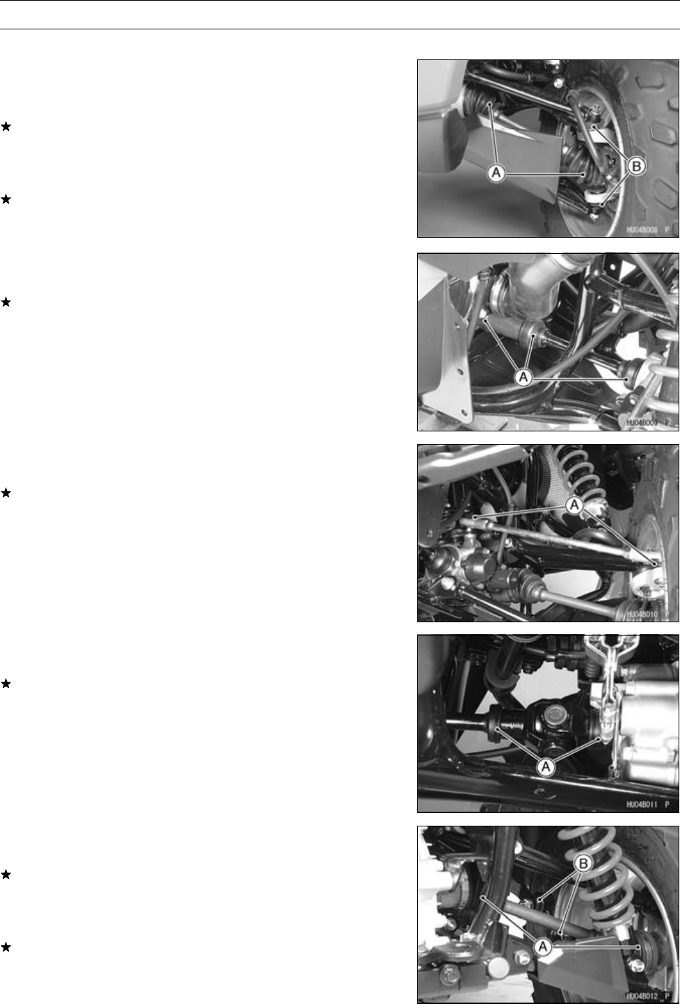
PERIODIC MAINTENANCE 2-39
Periodic Maintenance Procedures
Joint Boots Inspection
Front Axle/Steering Knuckle Joint Boots
Inspection
•Visually inspect the front axle joint boots [A].
If the joint boot is torn, worn, deteriorated, or leaks grease,
replace the joint boot or front axle assembly (see Front
Axle Joint Boot Replacement in the Final Drive chapter).
•Visually inspect the knuckle joint boots [B].
If the joint boot is torn, worn, deteriorated, or leaks grease,
replace the knuckle (see Steering Knuckle section in the
Steering chapter).
Front Propeller Shaft Joint Boots Inspection
•Visually inspect the boots [A] of the front propeller shaft.
If damage, tear or deterioration is found, replace the boots
(see Front Propeller Shaft section in the Final Drive chap-
ter).
Tie-rod End Boots Inspection
•Visually inspect the tie-rod end boots [A] of the tie-rods.
If the boot is torn, worn, deteriorated, or leaks grease,
replace the tie-rod end (see Tie-Rod End Removal in the
Steering chapter).
Rear Propeller Shaft Joint Boots Inspection
•Visually inspect the boots [A] of the rear propeller shaft.
If the joint boot is torn, worn, or deteriorated, replace the
joint boot and check the propeller shaft (see Rear Pro-
peller Shaft section in the Final Drive chapter).
Rear Axle/Stabilizer Joint Boots Inspection
•Visually inspect the rear axle joint boots [A].
If the joint boot is torn, worn, deteriorated, or leaks grease,
replace the joint boot or rear axle assembly (see Rear
Axle Joint Boot Replacement in the Final Drive chapter).
•Visually inspect the stabilizer joint boots [B].
If the joint boot is torn, worn, deteriorated, or leaks grease,
replace the stabilizer joint (see Stabilizer Removal in the
Suspension chapter).
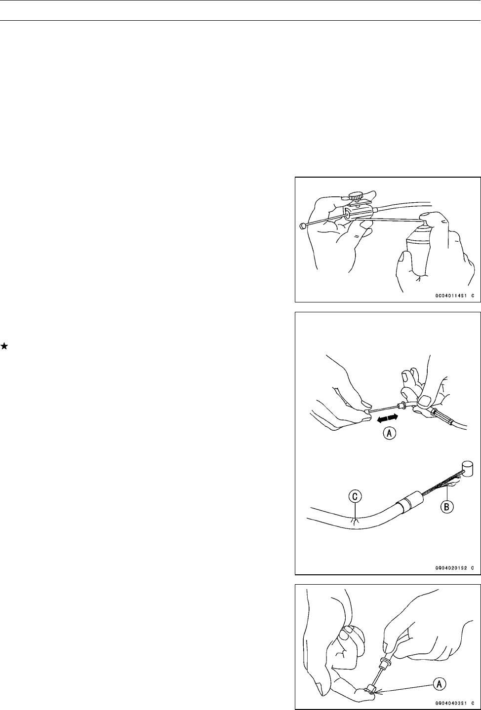
2-40 PERIODIC MAINTENANCE
Periodic Maintenance Procedures
General Lubrication
Lubrication
•Before lubricating each part, clean off any rusty spots with
rust remover and wipe off any grease, oil, dirt, or grime.
•Lubricate the points listed below with indicated lubricant.
NOTE
○Whenever the vehicle has been operated under
wet or rainy conditions, or especially after using a
high-pressure spray water, perform the general lubri-
cation.
Cables: Lubricate with Cable Lubricant
Rear Brake Inner Cable
Throttle Inner Cable
Variable Differential Control Inner Cable
•Lubricate the cables by seeping the oil between the cable
and housing.
○The cable may be lubricated by using a pressure cable
luber with an aerosol cable lubricant.
•With the cable disconnected at the both ends, the cable
should move freely [A] within the cable housing.
If cable movement is not free after lubricating, if the cable
is frayed [B], or if the cable housing is kinked [C], replace
the cable.
Points: Lubricate with Grease.
Throttle Inner Cable Upper End [A]
Brake Cable Upper End
Variable Differential Control Cable Ends

PERIODIC MAINTENANCE 2-41
Periodic Maintenance Procedures
Slide Points: Lubricate with Grease.
Brake Lever
Brake Pedal Pivot Shaft
Throttle Lever Shaft
Bolts and Nuts Tightening
Tightness Inspection
•Check the tightness of the bolts and nuts listed here in
accordance with the Periodic Maintenance Chart. Also,
check to see that each cotter pin is in place and in good
condition.
If there are loose fasteners, retorque them to the speci-
fied torque following the specified tightening sequence.
Refer to the appropriate chapter for torque specifications.
If torque specifications are not listed in the appropriate
chapter, see the Basic Torque Table (see Torque and
Locking Agent). For each fastener, first loosen it by 1/2
turn, then tighten it.
If cotter pins are damaged, replace them with new ones.
Bolts, Nuts, and Fasteners to be checked
Wheels:
Front Axle Nuts and Cotter Pins
Rear Axle Nuts and Cotter Pins
Wheel Nuts
Brakes:
Front Brake Master Cylinder Clamp Bolts
Brake Lever Pivot Bolt
Brake Lever Pivot Bolt Locknut
Front Brake Caliper Mounting Bolts
Brake Pedal Cotter Pin
Steering/Suspension:
Handlebar Holder Bolts
Steering Stem Clamp Bolts
Steering Stem Bearing Joint Bolts
Tie-rod End Nuts and Cotter Pins
Tie-rod Locknuts
Shock Absorber Mounting Nuts
Front Suspension Arm Pivot Nuts
Rear Suspension Arm Pivot Nuts
Steering Knuckle Joint Nuts and Cotter Pins
Engine:
Engine Mounting Bolts
Engine Mounting Bracket Bolts
Exhaust Pipe Holder Nuts
Muffler Mounting Nuts
Muffler Clamp Bolt
Final Drive:
Rear Final Gear Case Bracket Bolts
Others:
Footboard Mounting Bolts
Throttle Case Screws
Carrier Bolts

FUEL SYSTEM (DFI) 3-1
3
Fuel System (DFI)
Table of Contents
Exploded View........................................................................................................................ 3-4
DFI System............................................................................................................................. 3-8
DFI Parts Location.................................................................................................................. 3-13
Specifications ......................................................................................................................... 3-15
Special Tools and Sealant ...................................................................................................... 3-17
DFI Servicing Precautions...................................................................................................... 3-19
DFI Servicing Precautions ................................................................................................ 3-19
Troubleshooting the DFI System ............................................................................................ 3-21
Outline............................................................................................................................... 3-21
Inquiries to Rider............................................................................................................... 3-25
DFI System Troubleshooting Guide ....................................................................................... 3-28
Self-Diagnosis ........................................................................................................................ 3-35
Self-diagnosis Outline ....................................................................................................... 3-35
Self-diagnosis Procedures ................................................................................................ 3-35
How to Read Service Codes............................................................................................. 3-38
How to Erase Service Codes ............................................................................................ 3-38
Service Code Table........................................................................................................... 3-39
Backups ............................................................................................................................ 3-40
Throttle Sensor (Service Code 11) ......................................................................................... 3-42
Throttle Sensor Removal/Adjustment ............................................................................... 3-42
Throttle Sensor Input Voltage Inspection.......................................................................... 3-42
Throttle Sensor Output Voltage Inspection ....................................................................... 3-43
Throttle Sensor Resistance Inspection ............................................................................. 3-44
Inlet Air Pressure Sensor (Service Code 12).......................................................................... 3-46
Inlet Air Pressure Sensor Removal................................................................................... 3-46
Inlet Air Pressure Sensor Installation................................................................................ 3-46
Inlet Air Pressure Sensor Input Voltage Inspection........................................................... 3-46
Inlet Air Pressure Sensor Output Voltage Inspection........................................................ 3-47
Inlet Air Temperature Sensor (Service Code 13).................................................................... 3-51
Inlet Air Temperature Sensor Removal/Installation........................................................... 3-51
Inlet Air Temperature Sensor Output Voltage Inspection.................................................. 3-51
Inlet Air Temperature Sensor Resistance Inspection ........................................................ 3-52
Water Temperature Sensor (Service Code 14) ...................................................................... 3-53
Water Temperature Sensor Removal/Installation ............................................................. 3-53
Water Temperature Sensor Output Voltage Inspection..................................................... 3-54
Water Temperature Sensor Resistance Inspection........................................................... 3-54
Crankshaft Sensor (Service Code 21).................................................................................... 3-56
Crankshaft Sensor Removal/Installation........................................................................... 3-56
Crankshaft Sensor Inspection........................................................................................... 3-56
Speed Sensor (Service Code 24)........................................................................................... 3-57
Speed Sensor Removal .................................................................................................... 3-57
Speed Sensor Installation ................................................................................................. 3-57
Speed Sensor Inspection.................................................................................................. 3-57
Input Voltage Inspection.................................................................................................... 3-57
Output Voltage Inspection................................................................................................. 3-58
Vehicle-down Sensor (Service Code 31)................................................................................ 3-60
Vehicle-down Sensor Removal ......................................................................................... 3-60
Vehicle-down Sensor Installation...................................................................................... 3-60
Vehicle-down Sensor Inspection....................................................................................... 3-60
Fuel Pump Relay (Service Code 46)...................................................................................... 3-63

3-2 FUEL SYSTEM (DFI)
Fuel Pump Relay Removal ............................................................................................... 3-63
Fuel Pump Relay Inspection ............................................................................................. 3-63
Ignition Coils (#1, #2: Service Code 51, 52)........................................................................... 3-65
Ignition Coil Removal/Installation...................................................................................... 3-65
Input Voltage Inspection.................................................................................................... 3-65
Fuel Injectors ......................................................................................................................... 3-66
Fuel Injector Removal ....................................................................................................... 3-66
Fuel Injector Installation .................................................................................................... 3-66
Audible Inspection............................................................................................................. 3-67
Fuel Injector Power Source Voltage Inspection ................................................................ 3-67
Fuel Injector Output Voltage Inspection............................................................................ 3-68
Injector Signal Test............................................................................................................ 3-69
Injector Resistance Inspection .......................................................................................... 3-69
Injector Unit Test ............................................................................................................... 3-70
Injector Fuel Line Inspection ............................................................................................. 3-70
FI Indicator Light (LCD) .......................................................................................................... 3-72
Light Inspection.................................................................................................................3-73
ECU........................................................................................................................................ 3-74
ECU Removal ................................................................................................................... 3-74
ECU Installation ................................................................................................................ 3-74
ECU Power Supply Inspection.......................................................................................... 3-74
Fuel Line................................................................................................................................. 3-76
Fuel Pressure Inspection .................................................................................................. 3-76
Fuel Flow Rate Inspection ................................................................................................ 3-77
Fuel Pump .............................................................................................................................. 3-79
Fuel Pump Removal ......................................................................................................... 3-79
Fuel Pump Installation ...................................................................................................... 3-80
Fuel Pump Operation Inspection ...................................................................................... 3-81
Fuel Pump Operating Voltage Inspection ......................................................................... 3-81
Pressure Regulator Removal............................................................................................ 3-82
Pump Screen, Fuel Filter Cleaning ................................................................................... 3-82
Throttle Lever and Cable........................................................................................................ 3-84
Throttle Lever Free Play Inspection.................................................................................. 3-84
Throttle Lever Free Play Adjustment ................................................................................ 3-84
Throttle Case Removal/Disassembly................................................................................ 3-84
Throttle Case Assembly/Installation.................................................................................. 3-84
Throttle Cable Installation ................................................................................................. 3-85
Throttle Case Inspection ................................................................................................... 3-85
Throttle Cable Lubrication and Inspection ........................................................................ 3-85
Throttle Body Assy ................................................................................................................. 3-86
Idle Speed Inspection ....................................................................................................... 3-86
Throttle Body Assy Removal............................................................................................. 3-86
Throttle Body Assy Installation.......................................................................................... 3-87
Throttle Body Assy Disassembly ...................................................................................... 3-88
Throttle Body Assy Assembly ........................................................................................... 3-89
Engine Vacuum Synchronization Inspection..................................................................... 3-89
Engine Vacuum Synchronization Adjustment ................................................................... 3-89
ISC Valve................................................................................................................................ 3-91
ISC Valve Removal ........................................................................................................... 3-91
ISC Valve Installation ........................................................................................................ 3-91
ISC Valve Inspection......................................................................................................... 3-91
Air Cleaner.............................................................................................................................. 3-92
Air Cleaner Element Removal........................................................................................... 3-92
Air Cleaner Element Installation........................................................................................ 3-92
Air Cleaner Element Cleaning and Inspection .................................................................. 3-92
Air Cleaner Housing Removal........................................................................................... 3-92
Air Cleaner Housing Installation........................................................................................ 3-94

FUEL SYSTEM (DFI) 3-3
Fuel Tank ................................................................................................................................ 3-95
Fuel Tank Removal ........................................................................................................... 3-95
Fuel Tank Installation ........................................................................................................ 3-96
Fuel Tank Cleaning ........................................................................................................... 3-97
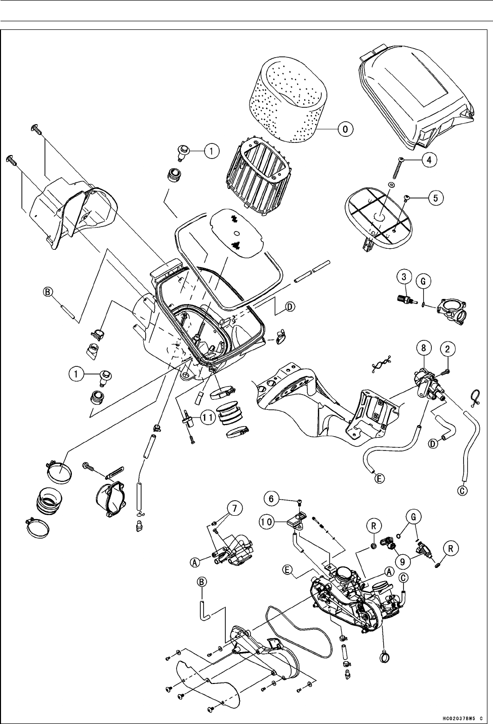
3-4 FUEL SYSTEM (DFI)
Exploded View

FUEL SYSTEM (DFI) 3-5
Exploded View
Torque
No. Fastener N·m kgf·m ft·lb Remarks
1Air Cleaner Housing Bolts 8.8 0.90 78 in·lb
2ISC Valve Mounting Bolts 8.8 0.90 78 in·lb
3Water Temperature Sensor 12 1.2 106 in·lb
4Air Cleaner Element Holder Screw 3.5 0.36 31 in·lb
5Air Cleaner Element Holder Tapping Screw 1.5 0.15 13 in·lb
6Inlet Air Pressure Sensor Mounting Screw 5.0 0.51 44 in·lb
7Delivery Pipe Mounting Screws 5.0 0.51 44 in·lb
8. ISC Valve
9. Fuel Injectors
10. Inlet Air Pressure Sensor
11. Inlet Air Temperature Sensor
G: Apply grease.
O: Apply high-quality foam air filter oil.
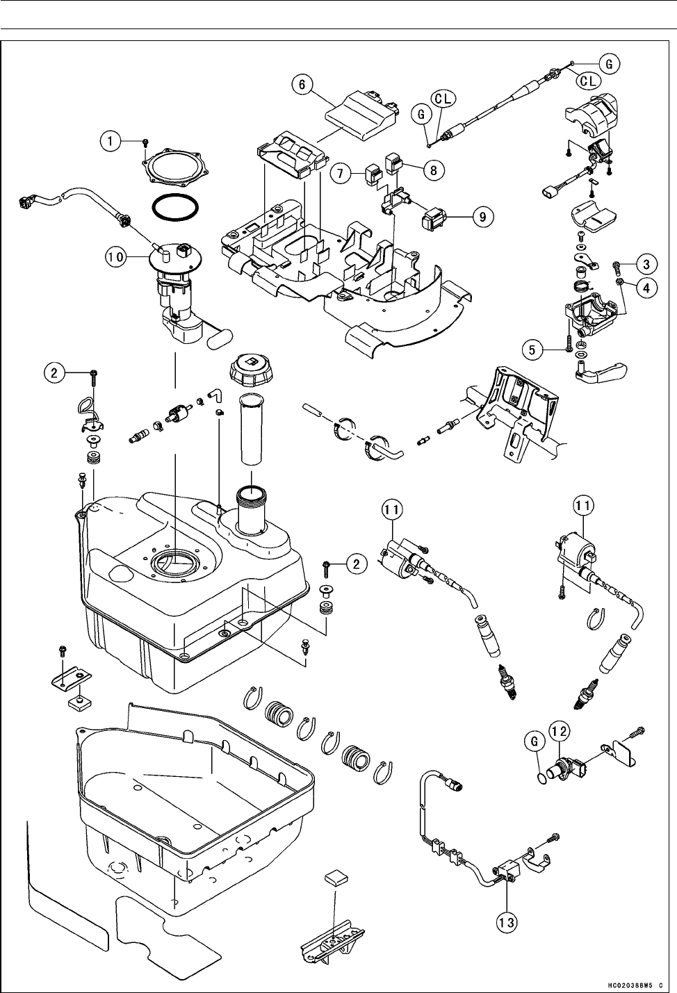
3-6 FUEL SYSTEM (DFI)
Exploded View

FUEL SYSTEM (DFI) 3-7
Exploded View
Torque
No. Fastener N·m kgf·m ft·lb Remarks
1Fuel Pump Bolts 4.0 0.41 35 in·lb
2Fuel Tank Mounting Bolts 9.8 1.0 87 in·lb
3Throttle Lever Limiter Screw 3.6 0.37 32 in·lb
4Throttle Lever Limiter Nut 3.6 0.37 32 in·lb
5Throttle Case Assembly Screws 3.6 0.37 32 in·lb
6. ECU (Electronic Control Unit)
7. Fuel Pump Relay
8. Radiator Fan Relay
9. Vehicle-down Sensor
10. Fuel Pump
11. Ignition Coils
12. Speed Sensor
13. CrankShaft Sensor
G: Apply grease.
CL: Apply cable lubricant.
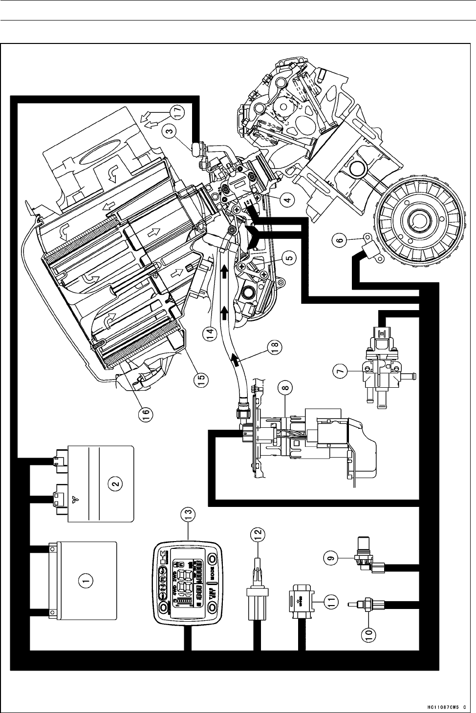
3-8 FUEL SYSTEM (DFI)
DFI System
DFI System

FUEL SYSTEM (DFI) 3-9
DFI System
1. Battery 12 V 12 Ah
2. ECU (Electronic Control Unit)
3. Inlet Air Pressure Sensor
4. Throttle Sensor
5. Injectors
6. Crankshaft Sensor
7. ISC Valve
8. Fuel Pump
9. Speed Sensor
10. Water Temperature Sensor
11. Vehicle-down Sensor
12. Inlet Air Temperature Sensor
13. Multifunction Meter
14. Delivery Pipe
15. Air Cleaner Housing
16. Air Cleaner Element
17. Air Flow
18. Fuel Flow
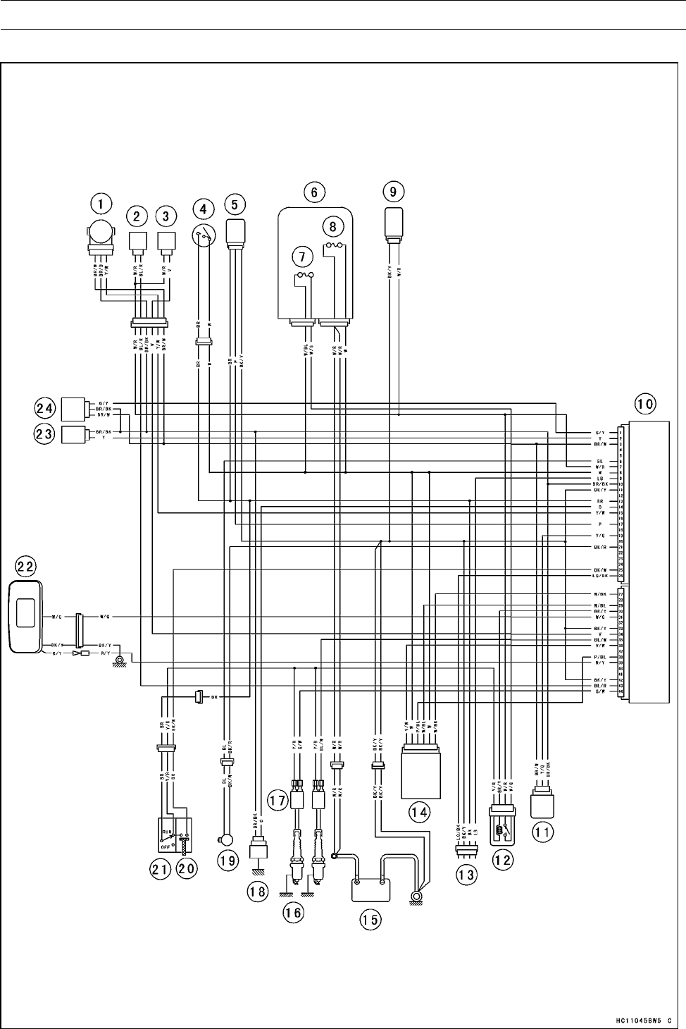
3-10 FUEL SYSTEM (DFI)
DFI System
DFI System Wiring Diagram

FUEL SYSTEM (DFI) 3-11
DFI System
Part Name
1. Throttle Sensor
2. Fuel Injector #1
3. Fuel Injector #2
4. Ignition Switch
5. Speed Sensor
6. Fuse Box
7. Fuel Pump Fuse 10 A
8. Main Fuse 30 A
9. Fuel Pump
10. ECU (Electronic Control Unit)
11. Vehicle-down Sensor
12. Fuel Pump Relay
13. Kawasaki Diagnostic System Connector
14. ISC Valve
15. Battery 12 V 12 Ah
16. Spark Plugs
17. Ignition Coils
18. Water Temperature Sensor
19. Crankshaft Sensor
20. Starter Button
21. Engine Stop Switch
22. Multifunction Meter
23. Inlet Air Temperature Sensor
24. Inlet Air Pressure Sensor
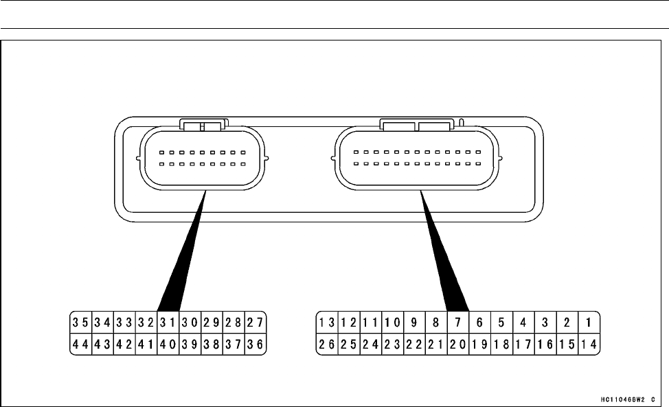
3-12 FUEL SYSTEM (DFI)
DFI System
Terminal Names
1. Inlet Air Pressure Sensor Signal
2. Inlet Air Temperature Sensor Signal
3. Power Supply to Sensors
4. Reverse Switch Signal
5. Reverse Power Assist Switch Signal
6. Crankshaft Sensor (–) Signal
7. Battery Monitor
8. Power Supply to ECU (from Battery)
9. External Communication Line (KDS)
10. Ground for Sensors
11. Ground for Control System
12. Unused
13. Ignition Switch Signal
14. Water Temperature Sensor Signal
15. Throttle Sensor Signal
16. Unused
17. Speed Sensor Signal
18. Signal Neutral Switch Signal
19. Vehicle-down Sensor Signal
20. Unused
21. Crankshaft Sensor (+) Signal
22. Drive Belt Failure Detecting Switch Signal
23. Communication Line B
24. Communication Line A
25. Starter Button Signal
26. Diagnosis Terminal
27. ISC Valve Signal #4
28. Drive Belt Failure Detecting Reset
29. ISC Valve Signal #2
30. Fuel Pump Relay Signal
31. Water Temperature Warning Indicator
(LCD) Signal
32. Radiator Fan Relay Signal
33. Ground for Engine
34. Injector #2 Signal
35. Ignition Coil #2 Signal
36. ISC Valve Signal #1
37. 2WD/4WD Shift Switch Signal
38. ISC Valve Signal #3
39. FI Indicator (LCD) Signal
40. Drive Belt Check Indicator Light (LED) Sig-
nal
41. Unused
42. Ground for Engine
43. Injector #1 Signal
44. Ignition Coil #1 Signal
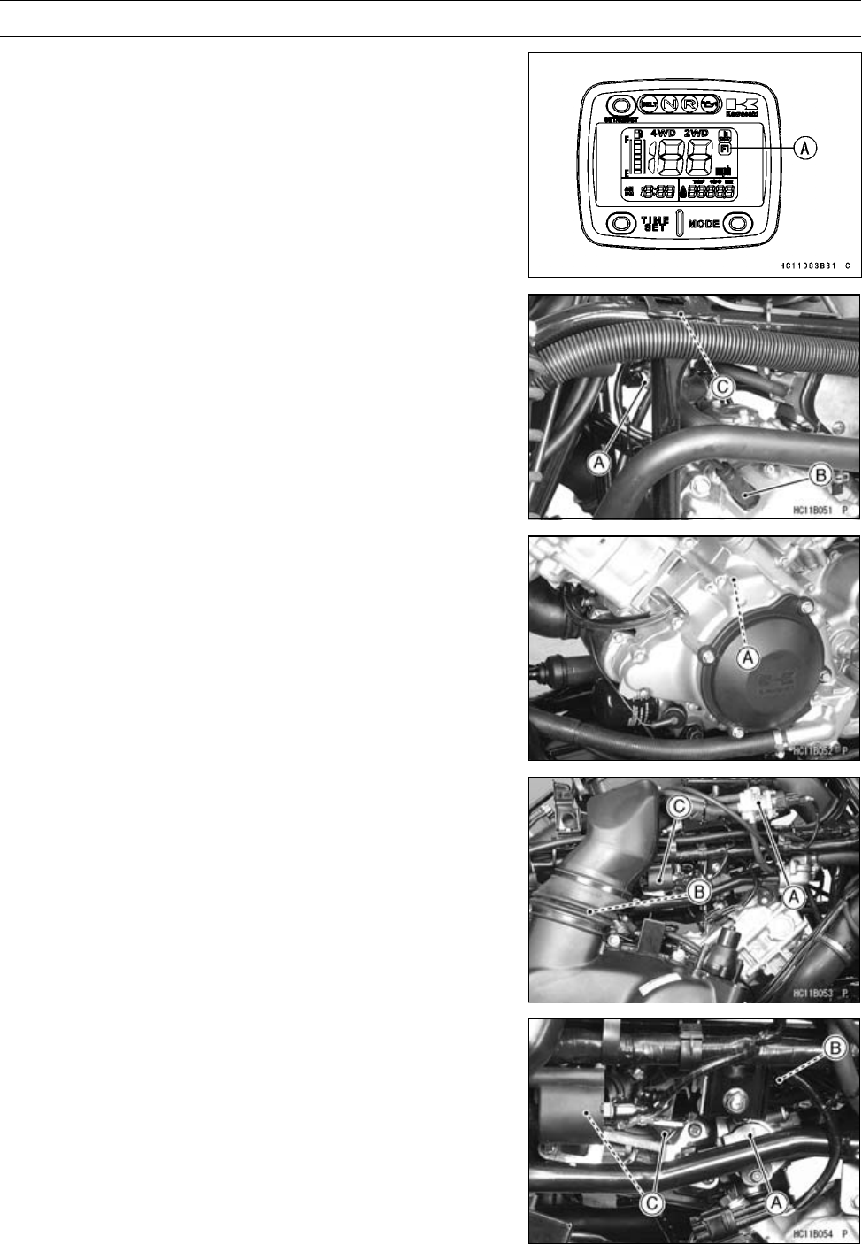
FUEL SYSTEM (DFI) 3-13
DFI Parts Location
FI Indicator Light (LCD) [A]
Water Temperature Sensor [A]
Spark Plug (Front) [B]
Ignition Coil (Front) [C]
Crankshaft Sensor [A]
ISC Valve [A]
Spark Plug (Rear) [B]
Ignition Coil (Rear) [C]
Throttle Sensor [A]
Inlet Air Pressure Sensor [B]
Fuel Injectors [C]
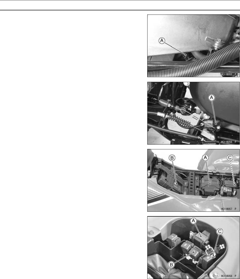
3-14 FUEL SYSTEM (DFI)
DFI Parts Location
Inlet Air Temperature Sensor [A]
Speed Sensor [A]
ECU (Electronic Control Unit) [A]
Battery 12V 12Ah [B]
Fuel Pump [C]
Vehicle-down Sensor [A]
Fuel Pump Relay [B]
Kawasaki Diagnostic System Connector [C]

FUEL SYSTEM (DFI) 3-15
Specifications
Item Standard
Digital Fuel Injection System
Idle Speed 1 100 ±50 r/min (rpm)
Throttle Body Assy:
Type Two barrel type
Bore 38 mm (1.50 in.)
ECU (Electronic Control Unit):
Make Mitsubishi Electric
Type Digital memory type, with built in IC igniter, sealed
with resin
Usable Engine Speed 100 ∼8 700 r/min (rpm)
Fuel Pressure (High Pressure Line):
With Engine Idling 294 kPa (3.0 kgf/cm², 43 psi) with fuel pump running
Fuel Pump:
Type In-tank friction pump
Discharge 50 mL (1.7 US oz.) or more for 3 seconds
Fuel Injectors:
Type INP-250
Nozzle Type One spray type with 4 holes
Resistance About 11.7 ∼12.3 Ωat 20°C (68°F)
Throttle Sensor: Non-adjustable and non-removable
Input Voltage DC 4.75 ∼5.25 V between BR/W and BR/BK leads
Output Voltage at Idle Throttle Opening DC 1.00 ∼1.24 V between Y/W and BR/BK leads
Output Voltage at Full Throttle Opening DC 4.0∼4.4 V between Y/W and BR/BK leads
Resistance 4∼6kΩ
Inlet Air Pressure Sensor:
Input Voltage DC 4.75 ∼5.25 V between BR/W and BR/BK leads
Output Voltage DC 3.80 ∼4.20 V at standard atmospheric pressure
(see this text for details)
Inlet Air Temperature Sensor:
Resistance 5.4 ∼6.6 kΩat 0°C (32°F)
0.29 ∼0.39 kΩat 80°C (176°F)
Output Voltage at ECU About 2.26 ∼2.50 V at 25°C (77°F)
Water Temperature Sensor:
Resistance see Electrical System chapter
Output Voltage at ECU About 2.24 ∼2.48 V at 25°C (77°F)
Vehicle-down Sensor:
Detection Method Magnetic flux detection method
Detection Angle more than 15 ∼35° for each bank
Output Voltage with the sensor tilted 15 ∼35° or more: 0.4 ∼1.4 V
with sensor arrow mark pointed up: 3.7 ∼4.4 V
ISC Valve:
Resistance 28.8 ∼31.2 Ωat 20° (68°F)
Engine Vacuum 29.6 ±1.3 kPa (222 ±9.8 mmHg) at Idle Speed

3-16 FUEL SYSTEM (DFI)
Specifications
Item Standard
Speed Sensor:
Input Voltage Battery Voltage at ignition Switch ON
Output Voltage less than CD 0.8 Vor over than DC 4.8 V at ignition
Switch ON and 0 km/h
Throttle Lever and Cable
Throttle Lever Free Play 2∼3 mm (0.08 ∼0.12 in.)
Air Cleaner
Air Cleaner Element Oil High quality form air filter oil
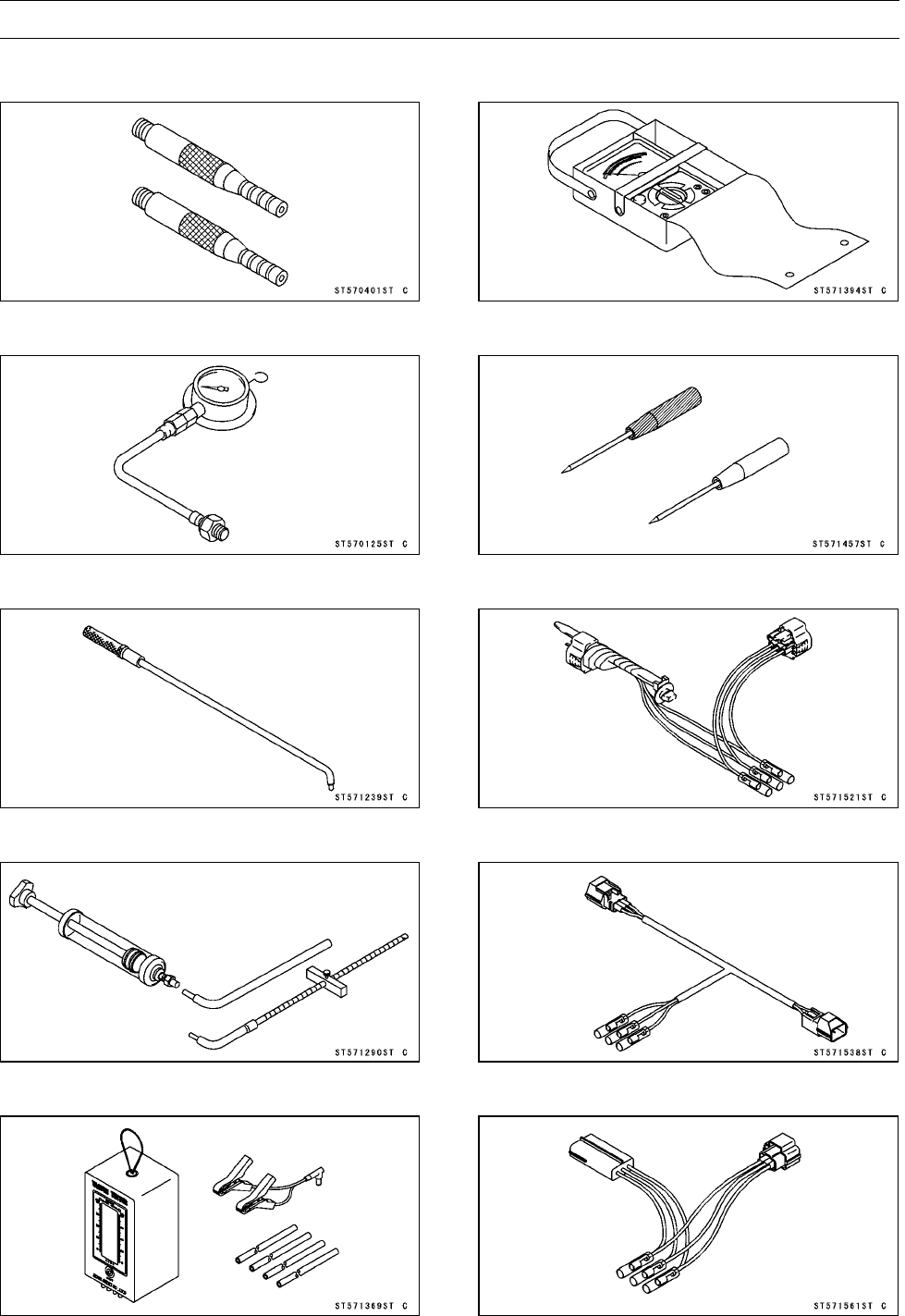
FUEL SYSTEM (DFI) 3-17
Special Tools and Sealant
Vacuum Gauge Adapter:
57001-401
Oil Pressure Gauge, 5 kgf/cm²:
57001-125
Pilot Screw Adjuster, A:
57001-1239
Fork Oil Level Gauge:
57001-1290
Vacuum Gauge:
57001-1369
Hand Tester:
57001-1394
Needle Adapter Set:
57001-1457
Throttle Sensor Setting Adapter:
57001-1521
Throttle Sensor Setting Adapter:
57001-1538
Sensor Harness Adapter:
57001-1561
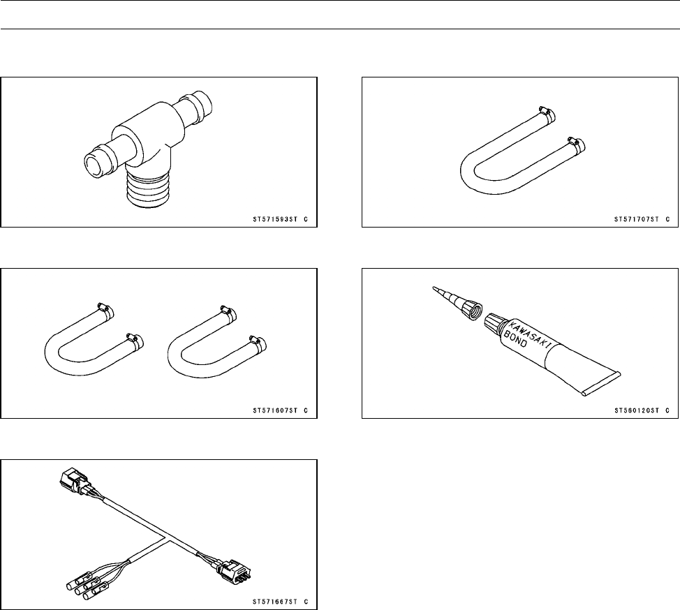
3-18 FUEL SYSTEM (DFI)
Special Tools and Sealant
Fuel Pressure Gauge Adapter:
57001-1593
Fuel Hose:
57001-1607
Speed Sensor Measuring Adapter:
57001-1667
Fuel Hose L = 550:
57001-1707
Kawasaki Bond (Silicone Sealant):
56019-120
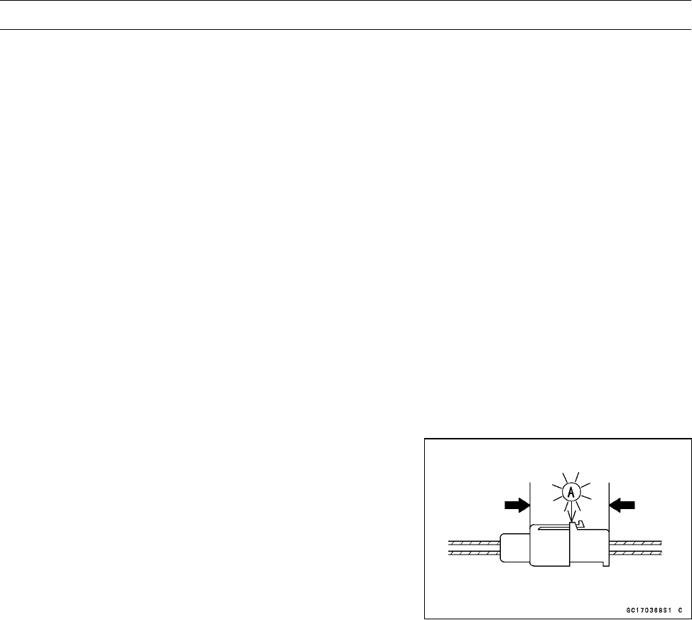
FUEL SYSTEM (DFI) 3-19
DFI Servicing Precautions
DFI Servicing Precautions
There are a number of important precautions that should
be followed servicing the DFI system.
○This DFI system is designed to be used with a 12 V sealed
battery as its power source. Do not use any other battery
except for a 12 V sealed battery as a power source.
○Do not reverse the battery cable connections. This will
damage the ECU.
○To prevent damage to the DFI parts, do not disconnect the
battery cables or any other electrical connections when
the ignition switch is on or while the engine is running.
○Take care not to short the cables that are directly con-
nected to the battery positive (+) terminal to the chassis
ground.
○When charging, remove the battery from the vehicle. This
is to prevent ECU damage by excessive voltage.
○Do not turn the ignition switch ON while any of the DFI
electrical connectors are disconnected. The ECU memo-
rizes service codes.
○Do not spray water on the electrical parts, DFI parts, con-
nectors, leads, and wiring.
○Whenever the DFI electrical connections are to be dis-
connected, first turn off the ignition switch, and disconnect
the battery (–) terminal. Do not pull the lead, only the con-
nector. Conversely, make sure that all the DFI electrical
connections are firmly reconnected before starting the en-
gine.
○Connect these connectors until they click [A].
○If a transceiver is installed on the vehicle, make sure that
the operation of the DFI system is not influenced by elec-
tric wave radiated from the antenna. Check operation of
the system with the engine at idle. Locate the antenna as
far as possible away from the ECU.
○When any fuel hose is disconnected, fuel may spout out
by residual pressure in the fuel line. Cover the hose joint
with a piece of clean cloth to prevent fuel spillage.
○When any fuel hose is disconnected, do not turn on the
ignition switch. Otherwise, the fuel pump will operate and
fuel will spout from the fuel hose.
○Do not operate the fuel pump if the pump is completely
dry. This is to prevent pump seizure.
○Before removing the fuel system parts, blow the outer sur-
faces of these parts clean with compressed air.
○To prevent corrosion and deposits in the fuel system, do
not add to fuel any fuel antifreeze chemicals.
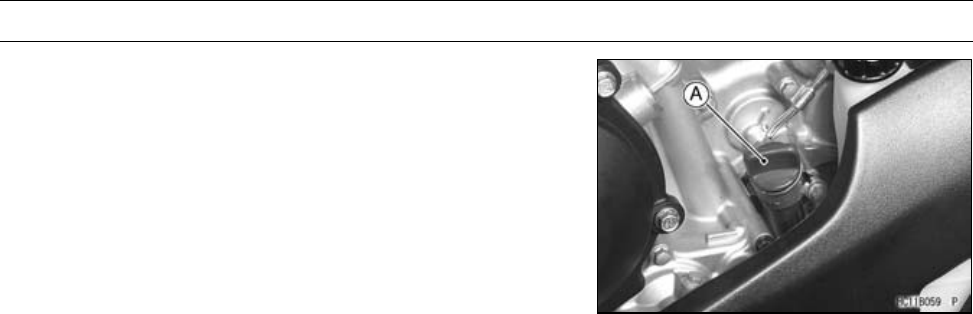
3-20 FUEL SYSTEM (DFI)
DFI Servicing Precautions
○To maintain the correct fuel/air mixture (F/A), there must
be no inlet air leaks in the DFI system. Be sure to install
the oil filler plug [A] after filling the engine oil.
Clutch Cover [B]
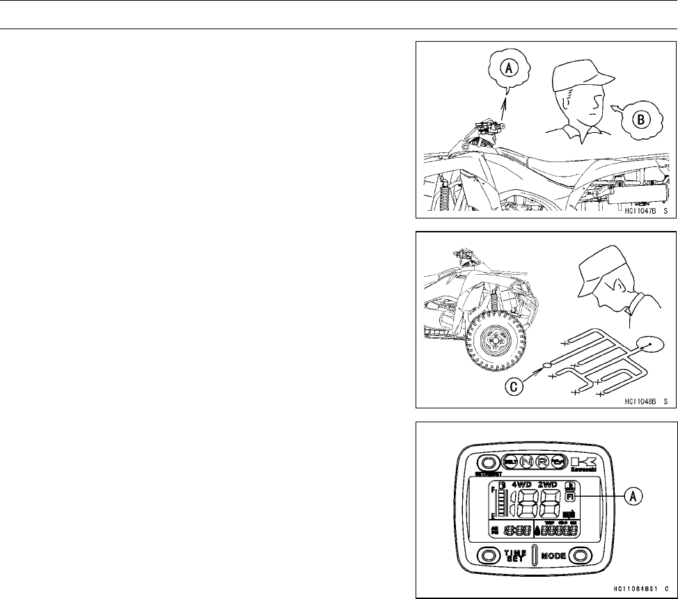
FUEL SYSTEM (DFI) 3-21
Troubleshooting the DFI System
Outline
When an abnormality in the DFI system occurs, the FI
indicator light (LCD) goes on to alert the rider on the meter
panel. In addition, the condition of the problem is stored in
the memory of the ECU (electronic control unit). With the
engine stopped and turned in the self-diagnosis mode, the
service code [A] is indicated by the number of times the FI
indicator light (LCD) blinks.
When due to a malfunction, the FI indicator light (LCD) re-
mains lit, ask the rider about the conditions [B] under which
the problem occurred and try to determine the cause [C].
First, conduct a self-diagnosis inspection and then a
non-self-diagnosis inspection. The non-self-diagnosis
items are not indicated by the FI indicator light (LCD). Don’t
rely solely on the DFI self-diagnosis function, use common
sense.
Even when the DFI system is operating normally, the FI
indicator light (LCD) [A] may light up under strong electrical
interference. No repair needed. Turn the ignition switch
OFF to stop the indicator light.
When the FI indicator light (LCD) goes on and the vehicle
is brought in for repair, check the service codes.
When the repair has been done, the light doesn’t go on.
But the service codes stored in memory are not erased to
preserve the problem history, and the light can display the
codes in the self-diagnosis mode. The problem history is
referred when solving unstable problems.
When the vehicle is down, the vehicle-down sensor is
turned OFF and the ECU shuts off the fuel injector and igni-
tion system. The FI indicator light (LCD) blinks but the ser-
vice code cannot be displayed. The ignition switch is left
ON. If the starter button is pushed, the electric starter turns
but the engine doesn’t start. To start the engine again, raise
the vehicle, turn the ignition switch OFF, and then ON. The
vehicle-down sensor is turned ON and the light goes OFF.
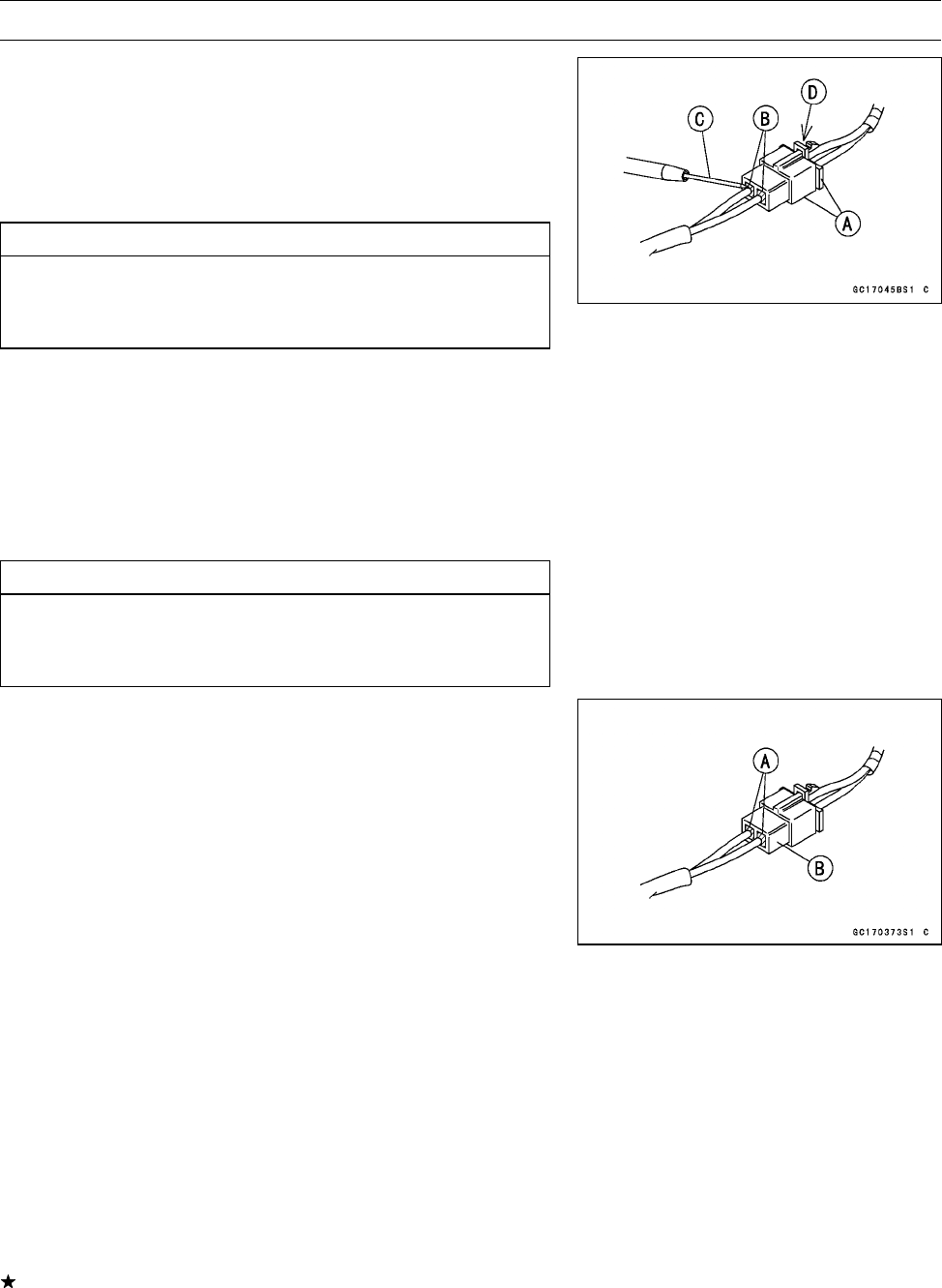
3-22 FUEL SYSTEM (DFI)
Troubleshooting the DFI System
○The DFI part connectors [A] have seals [B], including the
ECU.
•Join the connector and insert the needle adapters [C]
inside the seals [B] from behind the connector until the
adapter reaches the terminal.
Special Tool - Needle Adapter Set: 57001-1457
CAUTION
Insert the needle adapter straight along the terminal
in the connector to prevent short-circuit between
terminals.
•Make sure that measuring points are correct in the con-
nector, noting the position of the lock [D] and the lead
color before measurement. Do not reverse connections
of the hand tester or a digital meter.
•Be careful not to short-circuit the leads of the DFI or elec-
trical system parts by contact between adapters.
•Turn the ignition switch ON and measure the voltage with
the connector joined.
CAUTION
Incorrect, reverse connection or short circuit by
needle adapters could damage the DFI or electrical
system parts.
○After measurement, remove the needle adapters and ap-
ply silicone sealant to the seals [A] of the connector [B]
for waterproofing.
Sealant - Kawasaki Bond (Silicone Sealant): 56019-120
•Always check battery condition before replacing the DFI
parts. A fully charged battery is a must for conducting
accurate tests of the DFI system.
•Trouble may involve one or in some cases all items.
Never replace a defective part without determining what
CAUSED the problem. If the problem was caused by
some other item or items, they too must be repaired or
replaced, or the new replacement part will soon fail again.
•Measure coil winding resistance when the DFI part is cold
(at room temperature).
•Make sure all connectors in the circuit are clean and tight,
and examine wires for signs of burning, fraying, short,
etc. Deteriorated wires and bad connections can cause
reappearance of problems and unstable operation of the
DFI system.
If any wiring is deteriorated, replace the wiring.
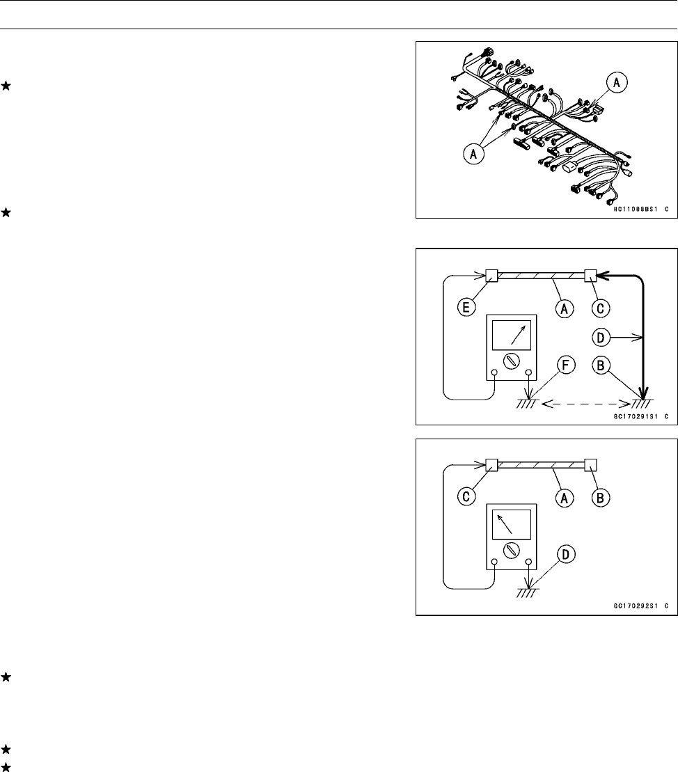
FUEL SYSTEM (DFI) 3-23
Troubleshooting the DFI System
•Pull each connector [A] apart and inspect it for corrosion,
dirt, and damage.
If the connector is corroded or dirty, clean it carefully. If it
is damaged, replace it. Connect the connectors securely.
•Check the wiring for continuity.
○Use the wiring diagram to find the ends of the lead which
is suspected of being a problem.
○Connect the hand tester between the ends of the leads.
○Set the tester to the × 1 Ωrange, and read the tester.
If the tester does not read 0 Ω, the lead is defective. Re-
place the lead or the main harness or the sub harness.
○If both ends of a harness [A] are far apart, ground [B] the
one end [C], using a jumper lead [D] and check the con-
tinuity between the end [E] and the ground [F]. This en-
ables to check a long harness for continuity. If the harness
is open, repair or replace the harness.
○When checking a harness [A] for short circuit, open one
end [B] and check the continuity between the other end
[C] and ground [D]. If there is continuity, the harness has
a short circuit to ground, and it must be repaired or re-
placed.
•Narrow down suspicious locations by repeating the con-
tinuity tests from the ECU connectors.
If no abnormality is found in the wiring or connectors, the
DFI parts are the next likely suspects. Check the part,
starting with input and output voltages. However, there is
no way to check the ECU itself.
If an abnormality is found, replace the affected DFI part.
If no abnormality is found in the wiring, connectors, and
DFI parts, replace the ECU.
○Lead Color Codes:
BK: Black
BL: Blue
BR: Brown
CH: Chocolate
DG: Dark Green
G: Green
GY: Gray
LB: Light Blue
LG: Light Green
O: Orange
P: Pink
PU: Purple
R: Red
W: White
Y: Yellow
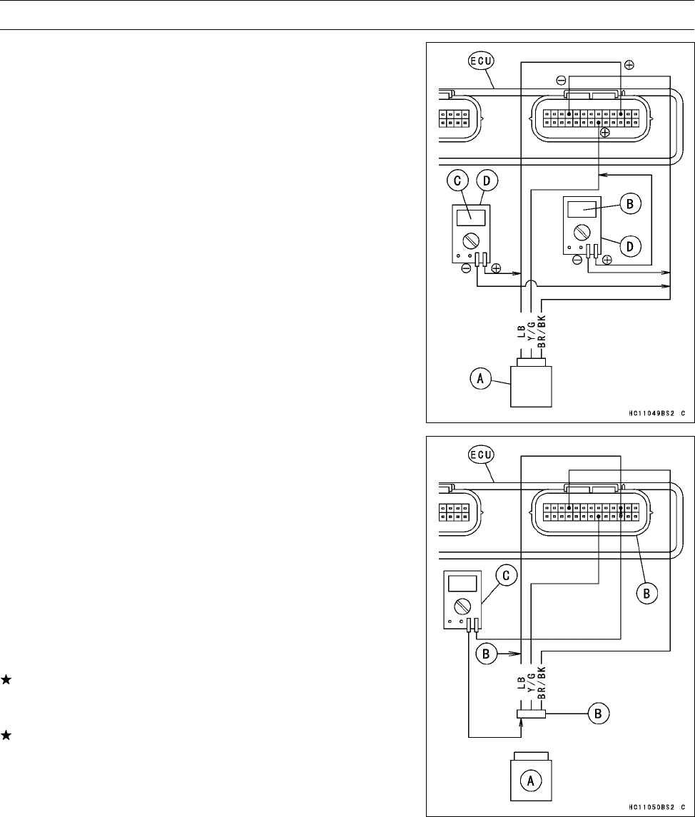
3-24 FUEL SYSTEM (DFI)
Troubleshooting the DFI System
○There are two ways to inspect the DFI system. One is
voltage Check Method and the other is Resistance Check
Method.
(Voltage Check Method)
○This method is conducted by measuring the input voltage
[B] to a sensor [A] first, and then the output voltage [C]
from the sensor.
○Sometimes this method can detect a fault of the ECU.
•Refer to each sensor inspection section for detail in this
chapter.
•Use a fully charged battery and a digital meter [D] which
can be read two decimal places voltage or resistance.
(Resistance Check Method)
○This method is simple. No need for a fully charged battery
and the needle adapter. Just do the following especially
when a sensor [A] is suspect.
•Turn the ignition switch OFF and disconnect the connec-
tors.
•Inspect the sensor resistance, using a digital meter (see
each sensor inspection).
•Inspect the wiring and connectors [B] for continuity, using
the hand tester [C] (analog tester) rather than a digital
meter.
Special Tool - Hand Tester: 57001-1394
If the sensor, the wiring and connections are good, inspect
the ECU for its ground and power supply (see ECU Power
Supply Inspection).
If the ground and power supply are good, the ECU is sus-
pect. Replace the ECU.
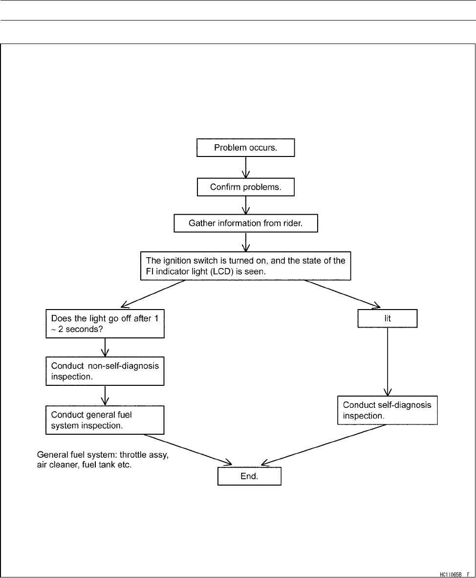
FUEL SYSTEM (DFI) 3-25
Troubleshooting the DFI System
DFI Diagnosis Flow Chart
Inquiries to Rider
○Each rider reacts to problems in different ways, so it is important to confirm what kind of symptoms
the rider has encountered.
○Try to find out exactly what problem occurred under exactly what conditions by asking the rider;
knowing this information may help you reproduce the problem.
○The following sample diagnosis sheet will help prevent you from overlooking any areas, and will
help you decide if it is a DFI system problem, or a general engine problem.

3-26 FUEL SYSTEM (DFI)
Troubleshooting the DFI System
Sample Diagnosis Sheet
Rider name: Registration No. (license plate No.):
Year of initial registration: Model:
Engine No.: Frame No.:
Date problem occurred: Mileage:
Environment when problem occurred.
Weather □fine, □cloudy,□rain, □snow, □always, □other:
Temperature □hot, □warm, □cold, □very cold, □always
Problem
frequency
□chronic, □often, □once
Road □street, □mountain road (□uphill, □downhill), □bumpy, □pebble
Altitude □normal, □high (about 1 000 m or more)
Vehicle conditions when problem occurred.
□light up immediately after ignition switch ON, and goes off after 1 ∼2 seconds
(normal)
□lights blinks immediately after ignition switch ON, and stays on (DFI problem)
□lights up immediately after ignition switch ON, but goes off after about 10 seconds
(DFI problem)
□unlights (light, ECU or its wiring fault)
FI indicator
light (LCD)
□sometimes lights up (probably wiring fault)
□starter motor not rotating
□starter motor rotating but engine doesn’t turn over
□starter motor and engine don’t turn over
□no fuel flow (□no fuel in tank, □no fuel pump sound)
□engine flooded (do not crank engine with throttle opened, which promotes engine
flooding)
□no spark
Starting
difficulty
□other
□right after starting
□when opening throttle lever
□when closing throttle lever
□when moving off
□when stopping the vehicle
□when cruising
Engine stops
□other
□very low idle speed, □very high idle speed, □rough idle speed
□battery voltage is low (charge the battery)
□spark plug loose (tighten it)
□spark plug dirty, broken, or gap maladjusted (remedy it)
□backfiring
□afterfiring
□hesitation when acceleration
□engine oil viscosity too high
□brake dragging
□engine overheating
Poor running
at low speed
□clutch slipping

FUEL SYSTEM (DFI) 3-27
Troubleshooting the DFI System
□other
□spark plug loose (tighten it)
□spark plug dirty, broken, or gap maladjusted (remedy it)
□spark plug incorrect (replace it)
□knocking (fuel poor quality or incorrect)
□brake dragging
□clutch slipping
□engine overheating
□engine oil level too high
□engine oil viscosity too high
Poor running
or no power at
high speed
□other

3-28 FUEL SYSTEM (DFI)
DFI System Troubleshooting Guide
NOTE
○This is not an exhaustive list, giving every possible cause for each problem listed. It is meant
simply as a rough guide to assist the troubleshooting for some of the more common difficulties.
○The ECU may be involved in the DFI electrical and ignition system troubles. If these parts and
circuits are checked out good, be sure to check the ECU for ground and power supply. If the
ground and power supply are checked good, replace the ECU.
Engine Doesn’t Start, Starting Difficulty
Symptoms or possible Causes Actions (chapter)
Starter motor not rotating:
Ignition and engine stop switches not ON Turn both switches ON.
Starter lockout switch or neutral switch trouble Inspect (see chapter 16).
Starter motor trouble Inspect (see chapter 16).
Battery voltage lowInspect and charge (see chapter 16).
Starter relays not contacting or operating Inspect the starter relay (see chapter 16).
Starter button not contacting Inspect and replace (see chapter 16).
Starter system wiring open or shorted Inspect the wiring (see chapter 16).
Ignition switch trouble Inspect and replace (see chapter 16).
Engine stop switch trouble Inspect and repair or replace (see chapter 16).
Main 30A fuse blown Inspect and replace (see chapter 16).
Starter motor rotating but engine doesn’t
turn over:
Starter clutch trouble Inspect (see chapter 16).
Starter idle gear trouble Inspect (see chapter 16).
Engine won’t turn over:
Valve seizure Inspect and replace (see chapter 5).
Cylinder, piston seizure Inspect and replace (see chapter 5).
Camshaft seizure Inspect and replace (see chapter 5).
Connecting rod small end seizure Inspect and replace (see chapter 9).
Connecting rod big end seizure Inspect and replace (see chapter 9).
Crankshaft seizure Inspect and replace (see chapter 9).
Transmission gear or bearing seizure Inspect and replace (see chapter 9).
No fuel flow:
No or little fuel in tank Supply fuel (see Owner’s Manual).
Fuel pump not rotating Inspect (see chapter 3).
Fuel injector trouble Inspect and replace (see chapter 3).
Fuel tank air vent obstructed Inspect and repair (see chapter 3).
Fuel filter or pump screen clogged Inspect and replace fuel pump (see chapter 3).
Fuel pressure regulator clogged Inspect and replace fuel pump (see chapter 3).
Fuel line clogged Inspect and repair (see chapter 3).
Engine flooded:
Spark plug dirty, broken or gap maladjusted Replace (see chapter 2).
Starting technique faulty When flooded, don’t crank engine with throttle
fully opened.
No spark or spark weak:
Ignition and engine stop switches not ON Turn both switches ON .

FUEL SYSTEM (DFI) 3-29
DFI System Troubleshooting Guide
Symptoms or possible Causes Actions (chapter)
Brake lever or pedal not pulled in and gear not
in neutral
Pull the brake lever or pedal in.
Vehicle-down sensor coming off Reinstall (see chapter 3).
Vehicle-down sensor trouble Inspect (see chapter 3).
ECU ground or power supply trouble Inspect (see chapter 3).
Battery voltage low Inspect and charge (see chapter 16).
Spark plug dirty, broken or gap maladjusted Replace (see chapter 2).
Ignition coil trouble Inspect ignition coil (see chapter 16).
Ignition coil shorted or not in good contact Reinstall or inspect ignition coil (see chapter 16).
Spark plug incorrect Replace it with the correct plug (see chapter 16).
IC igniter in ECU trouble Inspect (see chapter 16).
Crankshaft sensor trouble Inspect (see chapter 16).
Ignition coil trouble Inspect (see chapter 16).
Ignition switch shorted Inspect and replace (see chapter 16).
Engine stop switch shorted Inspect and repair or replace (see chapter 2).
Starter system wiring shorted or open Inspect and repair or replace (see chapter 16).
Main 30A fuse blown Inspect and replace (see chapter 16).
Fuel/air mixture incorrect:
Air cleaner clogged, poorly sealed or missing Clean or reinstall (see chapter 3).
Leak from oil filler cap, crankcase breather hose
or air cleaner drain plug
Inspect and repair or replace (see chapter 3).
Water or foreign matter in fuel Change fuel. Inspect and clean fuel system (see
chapter 3).
Fuel pressure regulator trouble Inspect fuel pressure and replace fuel pump (see
chapter 3).
Throttle sensor trouble Inspect (see chapter 3).
Fuel pressure may be low Inspect (see chapter 3).
Fuel pump trouble Inspect (see chapter 3).
Fuel injector trouble Inspect (see chapter 3).
Inlet air pressure sensor trouble Inspect (see chapter 3).
Inlet air temperature sensor trouble Inspect (see chapter 3).
Water temperature sensor trouble Inspect (see chapter 3).
ISC valve trouble Inspect (see chapter 3).
Crankshaft sensor trouble Inspect (see chapter 3).
Compression low:
Spark plug loose Reinstall (see chapter 16).
Cylinder head not sufficiently tightened down Tighten (see chapter 5).
Cylinder, piston worn Inspect and replace (see chapter 5).
Piston ring bad (worn, weak, broken or sticking) Inspect and replace (see chapter 5).
Piston ring/groove clearance excessive Inspect and replace (see chapter 5).
Cylinder head gasket damaged Replace (see chapter 5).
Cylinder head warped Inspect and replace (see chapter 5).
No valve clearance Adjust (see chapter 2).
Valve guide worn Inspect and replace (see chapter 5).

3-30 FUEL SYSTEM (DFI)
DFI System Troubleshooting Guide
Symptoms or possible Causes Actions (chapter)
Valvespringbrokenorweak Inspect and replace (see chapter 5).
Valve not seating properly (valve bent, worn or
carbon accumulating on seating surface)
Inspect and repair or replace (see chapter 5).
Poor Running at Low Speed
Symptoms or Possible Causes Actions (chapter)
Spark weak:
Battery voltage low Inspect and charge (see chapter 16).
Spark plug dirty, broken or gap maladjusted Replace (see chapter 2).
Ignition coil trouble Inspect the ignition coil (see chapter 16).
Ignition coil shorted or not in good contact Reinstall or inspect ignition coil (see chapter 16).
Spark plug incorrect Replace it with the correct plug (see chapter 16).
IC igniter in ECU trouble Inspect (see chapter 16).
Crankshaft sensor trouble Inspect (see chapter 16).
Ignition coil trouble Inspect (see chapter 16).
Fuel/air mixture incorrect:
Little fuel in tank Supply fuel (see Owner’s Manual).
Air cleaner clogged, poorly sealed, or missing Clean element or inspect sealing (see chapter
2, 3).
Air cleaner duct loose Reinstall (see chapter 3).
Air cleaner O-ring damaged Replace (see chapter 3).
Fuel tank air vent obstructed Inspect and repair (see chapter 3).
Throttle body assy loose Reinstall (see chapter 3).
Fuel filter or pump screen clogged Inspect and replace fuel pump (see chapter 3).
Fuel pressure regulator clogged Inspect fuel pressure and replace fuel pump (see
chapter 3).
Fuel line clogged Inspect and repair (see chapter 3).
Inlet air pressure sensor trouble Inspect (see chapter 3).
Inlet air temperature sensor trouble Inspect (see chapter 3).
Unstable (rough) idling:
ISC valve trouble Inspect (see chapter 3).
Fuel injector trouble Inspect (see chapter 3).
Throttle sensor trouble Inspect (see chapter 3).
Crankshaft sensor trouble Inspect (see chapter 3).
Throttle valves not synchronizing Inspect (see chapter 2).
Inlet air temperature sensor trouble Inspect (see chapter 3).
Water temperature sensor trouble Inspect (see chapter 3).
Fuel pressure too low or too high Inspect (see chapter 3).
Battery voltage low Inspect and charge (see chapter 16).
Incorrect idle speed:
Water temperature sensor trouble Inspect (see chapter 3).
Throttle sensor trouble Inspect (see chapter 3).
ISC valve trouble Inspect (see chapter 3).
Engine stalls easily:
Fuel pump trouble Inspect (see chapter 3).

FUEL SYSTEM (DFI) 3-31
DFI System Troubleshooting Guide
Symptoms or Possible Causes Actions (chapter)
Fuel injector trouble Inspect (see chapter 3).
Throttle sensor trouble Inspect (see chapter 3).
Fuel pressure too low or too high Inspect (see chapter 3).
Inlet air pressure sensor trouble Inspect (see chapter 3).
Water temperature sensor trouble Inspect (see chapter 3).
Inlet air temperature sensor trouble Inspect (see chapter 3).
Fuel line clogged Inspect and repair (see chapter 3).
Fuel pressure too low or too high Inspect (see chapter 3).
Fuel pressure regulator trouble Inspect fuel pressure and replace fuel pump (see
chapter 3).
Crankshaft sensor trouble Inspect (see chapter 16).
Ignition coil trouble Inspect (see chapter 16).
Compression Low:
Spark plug loose Reinstall (see chapter 16).
Cylinder head not sufficiently tightened down Tighten (see chapter 5).
No valve clearance Adjust (see chapter 2).
Cylinder, piston worn Inspect and replace (see chapter 5).
Piston ring bad (worn, weak, broken or sticking ) Inspect and replace (see chapter 5).
Piston ring/groove clearance excessive Inspect and replace (see chapter 5).
Cylinder head gasket damaged Replace (see chapter 5).
Cylinder head warped Inspect and replace (see chapter 5).
Valve guide worn or stem seal damaged Inspect and replace (see chapter 5).
Valvespringbrokenorweak Inspect and replace (see chapter 5).
Valve not seating properly (valve bent, worn or
carbon accumulating on seating surface)
Inspect and repair or replace (see chapter 5).
Camshaft cam worn Inspect and replace (see chapter 5).
Hesitation:
Too low fuel pressure Inspect (see chapter 3).
Clogged fuel line Inspect and repair (see chapter 3).
Cracked or obstructed inlet air pressure sensor
hose
Inspect and repair or replace (see chapter 3).
Fuel pump trouble Inspect (see chapter 3).
Fuel injector trouble Inspect (see chapter 3).
Inlet air temperature sensor trouble Inspect (see chapter 3).
Throttle sensor trouble Inspect (see chapter 3).
Water temperature sensor trouble Inspect (see chapter 3).
Inlet air pressure sensor trouble Inspect (see chapter 3).
Loose injector connectors Remedy (see chapter 3).
Crankshaft sensor trouble Inspect or replace (see chapter 16).
Ignition coil trouble Inspect or replace (see chapter 16).
Loose terminal of battery (–) cable or engine
ground lead
Inspect and repair (see chapter 16).
Delay of ignition timing Inspect crankshaft sensor and IC igniter in ECU
(see chapter 16).
Poor acceleration:

3-32 FUEL SYSTEM (DFI)
DFI System Troubleshooting Guide
Symptoms or Possible Causes Actions (chapter)
Too low fuel pressure Inspect (see chapter 3).
Water or foreign matter in fuel Change fuel. Inspect and clean fuel system (see
chapter 3).
Clogged fuel filter or pump screen Inspect and replace fuel pump (see chapter 3).
Fuel pump trouble Inspect (see chapter 3).
Fuel injector trouble Inspect (see chapter 3).
Inlet air temperature sensor trouble Inspect (see chapter 3).
Water temperature sensor trouble Inspect (see chapter 3).
Ignition coil trouble Inspect and replace (see chapter 16).
Engine oil level to high Repair (see chapter 7).
Spark plug dirty, broken or gap maladjusted Replace (see chapter 2).
Stumble:
Too low fuel pressure Inspect (see chapter 3).
Fuel injector trouble Inspect (see chapter 3).
Throttle sensor malfunction Inspect (see chapter 3).
Water temperature sensor trouble Inspect (see chapter 3).
Inlet air pressure sensor trouble Inspect (see chapter 3).
Surge:
Unstable fuel pressure Fuel pressure regulator trouble (Inspect and
replace fuel pump) or kinked fuel line (Inspect
and repair fuel line) (see chapter 3).
Fuel injector trouble Inspect (see chapter 3).
Water temperature sensor trouble Inspect (see chapter 3).
Backfiring when deceleration:
Spark plug dirty, broken or gap maladjusted Replace (see chapter 2).
Too low fuel pressure Inspect (see chapter 3).
Fuel pump trouble Inspect (see chapter 3).
Throttle sensor trouble Inspect (see chapter 3).
Inlet air temperature sensor trouble Inspect (see chapter 3).
Water temperature sensor trouble Inspect (see chapter 3).
Inlet air pressure sensor trouble Inspect (see chapter 3).
After fire:
Crankshaft sensor trouble Inspect (see chapter 16).
Spark plug burned or gap maladjusted Replace (see chapter 2).
Inlet air temperature sensor trouble Inspect (see chapter 3).
Water temperature sensor trouble Inspect (see chapter 3).
Inlet air pressure sensor trouble Inspect (see chapter 3).
Fuel injector trouble Inspect (see chapter 3).
Run-on (dieseling):
Ignition switch trouble Inspect and replace (see chapter 16).
Engine stop switch trouble Inspect and repair or replace (see chapter 2).
Fuel injector trouble Inspect (see chapter 3).
Loose terminal of battery (–) cable or ECU
ground lead
Inspect and repair (see chapter 16).
Carbon accumulating on valve seating surface Repair (see chapter 5).

FUEL SYSTEM (DFI) 3-33
DFI System Troubleshooting Guide
Symptoms or Possible Causes Actions (chapter)
Engine overheating (see Overheating of Troubleshooting Guide, see
chapter 17)
Other:
Engine oil viscosity too high Change (see chapter 2).
Brake dragging Inspect caliper fluid seal damage or clogging
of master cylinder relief and supply ports (see
chapter 12).
Engine overheating (see Overheating of Troubleshooting Guide, see
chapter 17)
Intermittent any DFI fault and its recovery Check that DFI connectors are clean and tight,
and examine wires for signs of burning or fraying
(see chapter 3).
Poor Running or No Power at High Speed:
Symptoms or Possible Causes Actions (chapter)
Firing incorrect:
Spark plug dirty, broken or maladjusted Replace (see chapter 2).
Ignition coil trouble Inspect ignition coil (see chapter 16).
Ignition coil shorted or not in good contact Reinstall or inspect ignition coil (see chapter 16).
Spark plug incorrect Replace it with the correct plug (see chapter 16).
IC igniter in ECU trouble Inspect (see chapter 16).
Crankshaft sensor trouble Inspect (see chapter 16).
Ignition coil trouble Inspect (see chapter 16).
Fuel/air mixture incorrect:
Air cleaner clogged, poorly sealed, or missing Clean element or inspect sealing (see chapter 3).
Air cleaner duct loose Reinstall (see chapter 3).
Air cleaner O-ring damaged Replace (see chapter 3).
Water or foreign matter in fuel Change fuel. Inspect and clean fuel system (see
chapter 3).
Throttle body assy loose Reinstall (see chapter 3).
Fuel tank air vent obstructed Inspect and repair (see chapter 3).
Fuel line clogged Inspect and repair (see chapter 3).
Fuel pump operates intermittently and often DFI
fuse blows.
Pump bearings may wear. Replace the pump
(see chapter 3).
Fuel pump trouble Inspect (see chapter 3).
Inlet air temperature sensor trouble Inspect (see chapter 3).
Throttle sensor trouble Inspect (see chapter 3).
Inlet air pressure sensor trouble Inspect (see chapter 3).
Cracked or obstructed inlet air pressure sensor
hose
Inspect and repair or replace (see chapter 3).
Injector clogged Visually inspect and replace (see chapter 3).
Compression low:
Spark plug loose Reinstall (see chapter 16).
Cylinder head not sufficiently tightened down Tighten (see chapter 5).
No valve clearance Adjust (see chapter 2).
Cylinder, piston worn Inspect and replace (see chapter 5).

3-34 FUEL SYSTEM (DFI)
DFI System Troubleshooting Guide
Symptoms or Possible Causes Actions (chapter)
Piston ring bad (worn, weak, broken or sticking) Inspect and replace (see chapter 5).
Piston ring/groove clearance excessive Inspect and replace (see chapter 5).
Cylinder head gasket damaged Replace (see chapter 5) .
Cylinder head warped Inspect and replace (see chapter 5).
Valvespringbrokenorweak Inspect and replace (see chapter 5).
Valve not seating properly (valve bent , worn or
carbon accumulating on the seating surface)
Inspect and repair or replace (see chapter 5).
Knocking:
Carbon built up in combustion chamber Repair (see chapter 5).
Fuel poor quality or incorrect (Use the gasoline
recommended in the Owner’s Manual)
Change fuel (see chapter 3).
Spark plug incorrect Replace it with the correct plug (see chapter 16).
Ignition coil trouble Inspect (see chapter 16).
IC igniter in ECU trouble Inspect (see chapter 16).
Inlet air temperature sensor trouble Inspect (see chapter 3).
Miscellaneous:
Throttle valve won’t fully open Inspect throttle cable and lever linkage (see
chapter 3).
Brake dragging Inspect caliper fluid seal damage or clogging
of master cylinder relief and supply ports (see
chapter 12).
Engine overheating - Water temperature sensor
or crankshaft sensor trouble
(see Overheating of Troubleshooting Guide in
chapter 17).
Engine oil level too high Repair (see chapter 7).
Engine oil viscosity too high Change (see chapter 2).
Camshaft cam worn Inspect and replace (see chapter 5).
Exhaust Smokes Excessively:
(White smokes)
Piston oil ring worn Inspect and replace (see chapter 5).
Cylinder worn Inspect and replace (see chapter 5).
Valve oil seal damaged Replace (see chapter 5).
Valve guideworn Replace the guide (see chapter 5).
Engine oil level too high Repair (see chapter 7).
(Black smoke)
Air cleaner clogged Clean (see chapter 3).
Toohighfuelpressure Inspect (see chapter 3).
Injector stuck open Inspect (see chapter 3).
Water temperature sensor trouble Inspect and replace (see chapter 3).
Inlet air temperature sensor trouble Inspect and replace (see chapter 3).
(Brown smoke)
Air cleaner duct loose Reinstall (see chapter 3).
Air cleaner O-ring damaged Replace (see chapter 3).
Too low fuel pressure Inspect fuel line and fuel pump (see chapter 3).
Water temperature sensor trouble Inspect and replace (see chapter 3).
Inlet air temperature sensor trouble Inspect and replace (see chapter 3).
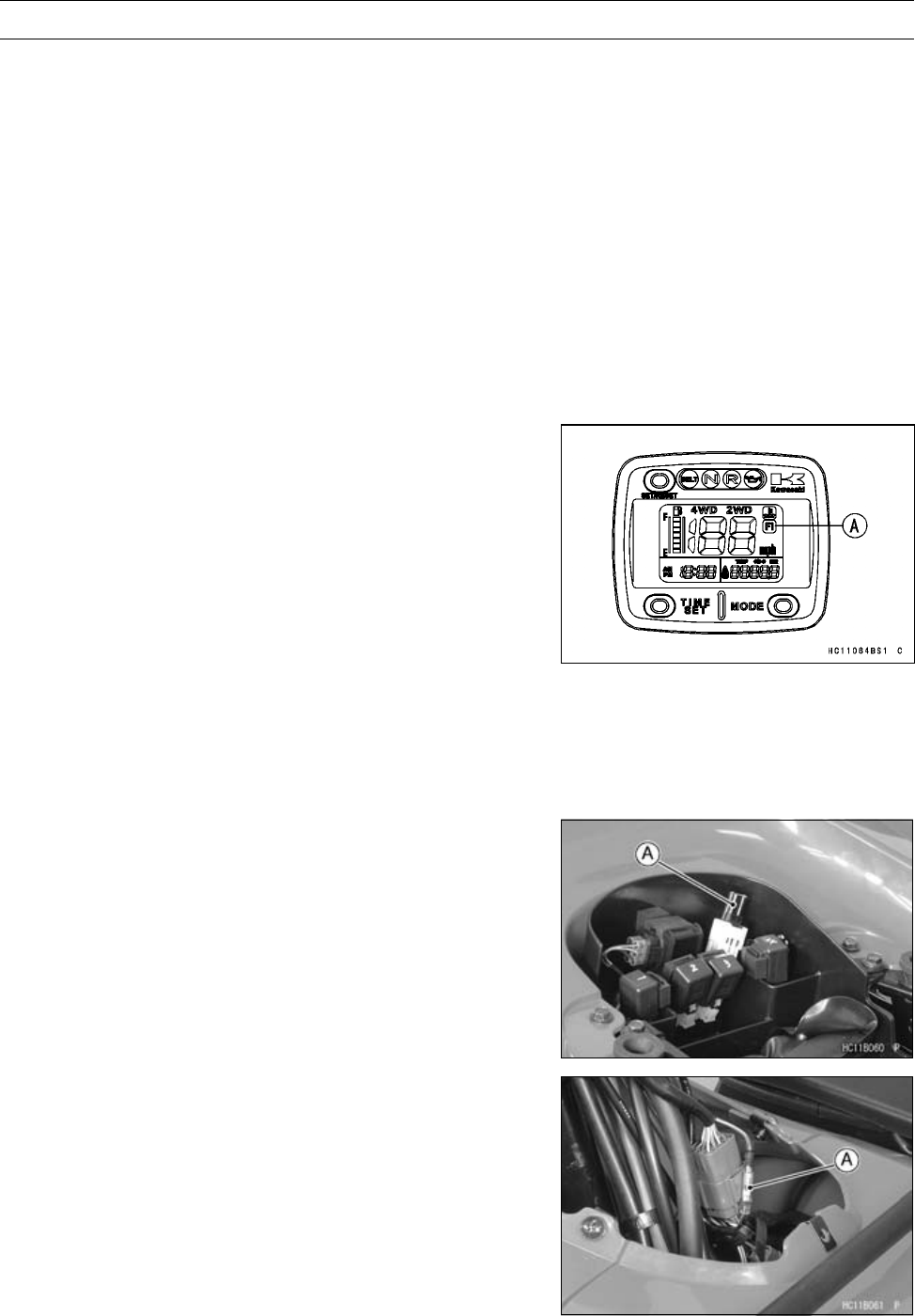
FUEL SYSTEM (DFI) 3-35
Self-Diagnosis
Self-diagnosis Outline
The self-diagnosis system has two modes and can be
switched to another mode by grounding the self-diagnosis
terminal.
User Mode
The ECU notifies the rider of troubles in DFI system and
ignition system by flashing the FI indicator when DFI system
and ignition system parts are faulty, and initiates fail-safe
function. In case of serious troubles, the ECU stops the
injection/ignition/starter motor operation.
Dealer Mode
The ECU generate service code(s) to show the prob-
lem(s) which the DFI system, and ignition system have at
the moment of diagnosis.
Self-diagnosis Procedures
○When a problem occurs with the DFI system and ignition
system, the FI indicator light (LCD) [A] flashes.
NOTE
○Use a fully charged battery when conducting
self-diagnosis.
○Keep the self-diagnosis terminal grounded during self
-diagnosis, with an auxiliary lead.
•Remove: (see Upper Cover Removal in the Frame chap-
ter).
Seat (see Seat Removal in the Frame chapter)
Middle Cover (see Middle Cover Removal in the Frame
chapter)
•Remove the connector cap [A].
•Disconnect the FI indicator light (LCD) connector [A]
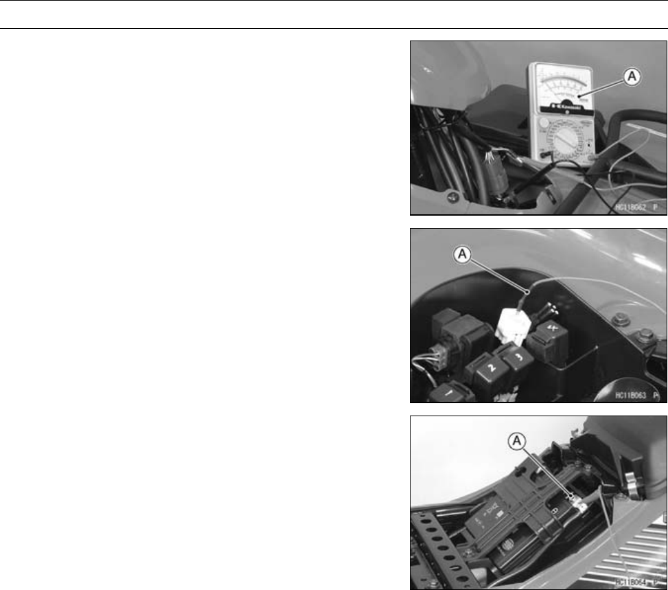
3-36 FUEL SYSTEM (DFI)
Self-Diagnosis
•Connect the hand tester [A] as shown.
•Set the tester to 5 mA range.
Special Tool - Hand Tester: 57001-1394
Connections:
Adapter Hand Tester
Meter Side ←Red →(+)
Main Harness
Side ←Black →(–)
•Ground the self-diagnosis terminal to the battery (–) ter-
minal or battery (–) lead connector, using a wire.
•Turn on the ignition switch.
•Connect an auxiliary lead [A] to the LG/BK terminal for
grounding.
•To enter the self-diagnosis dealer mode, ground the self
-diagnosis indicator terminal [A] to the battery (–) termi-
nal for more than 2 seconds, and then keep it grounded
continuously.
○Count the flicks of the hand tester to read the service
code. Keep the auxiliary lead ground until you finish read-
ing the service code.
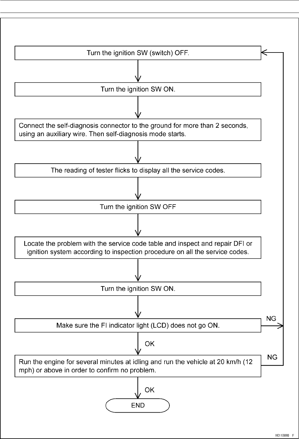
FUEL SYSTEM (DFI) 3-37
Self-Diagnosis
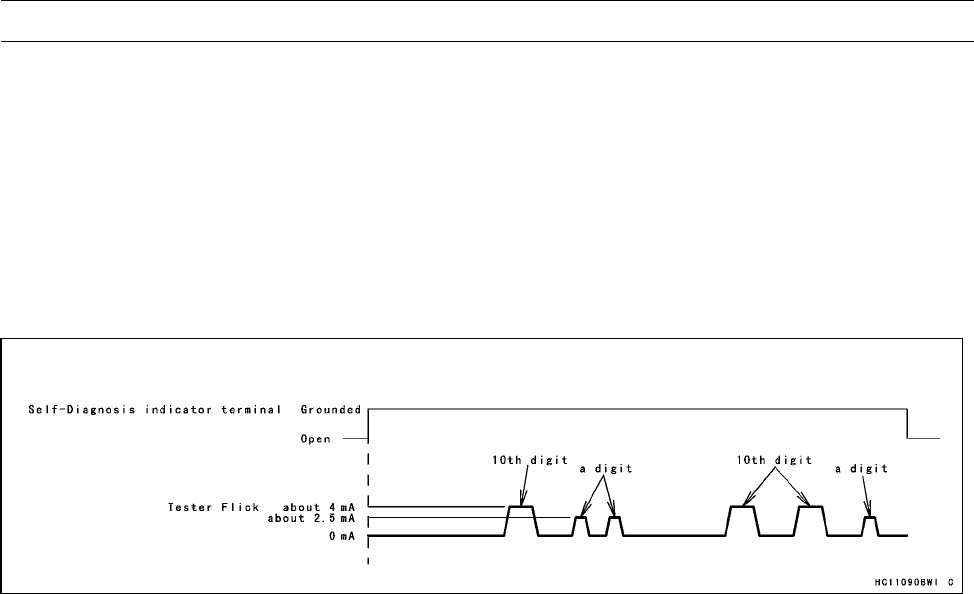
3-38 FUEL SYSTEM (DFI)
Self-Diagnosis
How to Read Service Codes
○Service codes are shown by a series of long and short flicks of the tester as shown below.
○Read 10th digit and unit digit as the tester flicks.
○When there are a number of problems, all the service codes can be stored and the display will
begin starting from the lowest number service code in the numerical order. Then after completing
all codes, the display is repeated until the self-diagnosis indicator terminal is open.
○If there is no problem, no code and unlight.
○For example, if two problems occurred in the order of 21, 12, the service codes are displayed from
the lowest number in the order listed.
(12 →21) →(12 →21) →···(repeated)
○If the problem is with the following parts, the ECU cannot memorize these problems, the tester
doesn’t flick, and no service codes can be displayed.
FI Indicator Light (LCD)
Fuel Pump
ECU Main Relay
ECU Power Source Wiring and Ground Wiring (see ECU Inspection)
Fuel Injectors
ISC Valve
How to Erase Service Codes
○Even if the ignition switch is turned OFF, the battery or the ECU are disconnected or the problem is
solved, all service codes remain in the ECU.
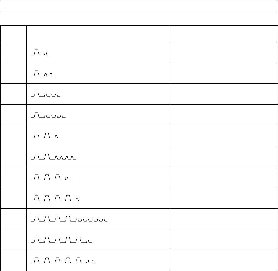
FUEL SYSTEM (DFI) 3-39
Self-Diagnosis
Service Code Table
Service
Code Flicks of Tester Problems
11 Throttle sensor malfunction, wiring
open or short
12 Inlet air pressure sensor malfunction,
wiring open or short
13 Inlet air temperature sensor
malfunction, wiring open or short
14 Water temperature sensor
malfunction, wiring open or short
21 Crankshaft sensor malfunction, wiring
open or short
24 Speed sensor malfunction, wiring
open or short
31 Vehicle-down sensor, malfunction,
wiring open or short
41 Injector malfunction, wiring open or
short
46 Fuel pump relay malfunction, relay
is stuck
51 Ignition coil #1 malfunction, wiring
open or short
52 Ignition coil #2 malfunction, wiring
open or short
Notes:
○The ECU may be involved in these problems. If all the parts and circuits are checked out good, be
sure to check the ECU for ground and power supply. If the ground and power supply are checked
out good, replace the ECU.
○When no service code is displayed, the electrical parts of the DFI system has no fault, and the
mechanical parts of the DFI system and the engine are suspect.

3-40 FUEL SYSTEM (DFI)
Self-Diagnosis
Backups
○The ECU takes the following measures to prevent engine damage when the DFI or the ignition
system parts have troubles.
Service
Codes Parts Output Signal Usable
Range or Criteria Backups by ECU
11 Throttle
Sensor
Throttle Sensor Output
Voltage
0.2 ∼4.8 V
If the throttle sensor system fails (the signal is
out of the usable range, wiring short or open),
the ECU locks ignition timing into the ignition
timing at opened throttle position and sets the
DFI in the D-J method.
Also, the throttle sensor system and inlet air
pressure sensor fails, the ECU locks ignition
timing into the ignition timing at opened throttle
position and sets the DFI in the α-N method.
12
Inlet Air
Pressure
Sensor
Inlet Air Pressure Sensor
Output Voltage
0.2 ∼4.8 V
If the inlet air pressure sensor system fails (the
signal Pv is out of the usable range, wiring
short or open), the ECU sets the DFI in the α
-Nmethod.
13
Inlet Air
Temperature
Sensor
Inlet Air Temperature
Sensor Output Voltage
0.2 ∼4.6 V
If the inlet air temperature sensor fails (the
signal is out of the usable range, wiring short
or open), the ECU sets Ta at 30°C.
14
Water
Temperature
Sensor
Water Temperature
Sensor Output Voltage
0.2 ∼4.6 V
If the water temperature sensor system fails
(the signal is out of the usable range, wiring
short or open), the ECU sets Tw at 80°C.
21 Crankshaft
Sensor
Crankshaft sensor must
send 22 signals (output
signal) to the ECU at the
one cranking.
If crankshaft sensor does not generate signals,
the engine stops by itself.
24 Speed Sensor
Speed sensor must send
20 signals (output signal)
to the ECU at the one
rotation of the output
driven bevel gear.
If the speed sensor system fails (no signal,
wiring short or open), the speedometer shows
0.
31 Vehicle-down
Sensor
Vehicle-down Sensor
Output Voltage
Vd = 0.2 ∼4.6 V
If the vehicle-down sensor system has failures
(the output voltage Vd is more than usable
range, wiring open), the ECU shuts off the fuel
pump.
46 Fuel Pump
Relay
When the relay ON
condition, battery monitor
voltage 5 V or more
If the relay fails, battery monitor voltage 12 V.
51 Ignition Coil #1
The ignition coil primary
winding must send
signals (output voltage)
continuously to the ECU.
If the ignition primary winding #1 has failures
(no signal, wiring short or open), the ECU
shuts off the injector #1 to stop fuel to the
cylinder #1, though the engine keeps running.
52 Ignition Coil #2
The ignition coil primary
winding must send
signals (output voltage)
continuously to the ECU.
If the ignition primary winding #2 has failures
(no signal, wiring short or open), the ECU
shuts off the injector #2 to stop fuel to the
cylinder #2, though the engine keeps running.
Note:
(1) D-J Method and α- N Method: When the engine load is light like at idling or low speed, the ECU
determines the injection quantity by calculating from the throttle vacuum (inlet air pressure sensor
output voltage) and engine speed (crankshaft sensor output voltage). This method is called D-J
method (low-speed mode). As the engine speed increases, and the engine load turns middle to

FUEL SYSTEM (DFI) 3-41
Self-Diagnosis
heavy, the ECU determines the injection quantity by calculating from the throttle opening (throttle
sensor output voltage) and the engine speed. This method is called α- N method (high-speed
mode).
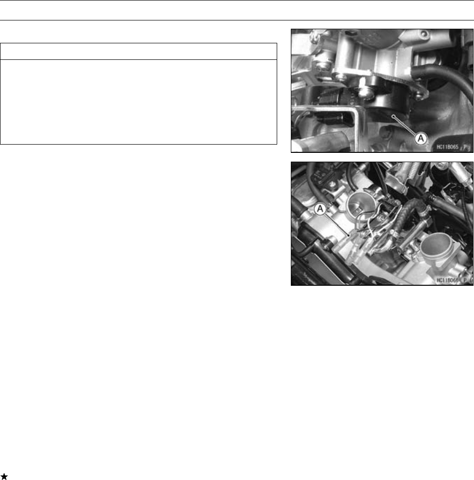
3-42 FUEL SYSTEM (DFI)
Throttle Sensor (Service Code 11)
Throttle Sensor Removal/Adjustment
CAUTION
Do not remove or adjust the throttle sensor [A]
since it has been adjusted and set with precision
at the factory.
Never drop the throttle body assy, especially on a
hard surface. Such a shock to the sensor can dam-
age it.
Throttle Sensor Input Voltage Inspection
NOTE
○Be sure the battery is fully charged.
•Turn the ignition switch OFF.
•Disconnect the throttle sensor connector with the needle
nose pliers and connect the harness adapter [A] between
these connectors.
○In this photo, the air cleaner has been removed for clarity.
Special Tool - Throttle Sensor Setting Adapter: 57001
-1521
•Connect a digital meter to the harness adapter lead.
Throttle Sensor Input Voltage
Connections to Adapter
Meter (+) →BL (sensor BR/W) lead
Meter (–) →BK/BL (sensor BR/W) lead
•Measure the input voltage with the engine stopped and
with the connector joined.
•Turn the ignition switch ON.
Input Voltage at Sensor
Standard: DC 4.75 ∼5.25 V
•Turn the ignition switch OFF.
If the input voltage is normal, check the output voltage.
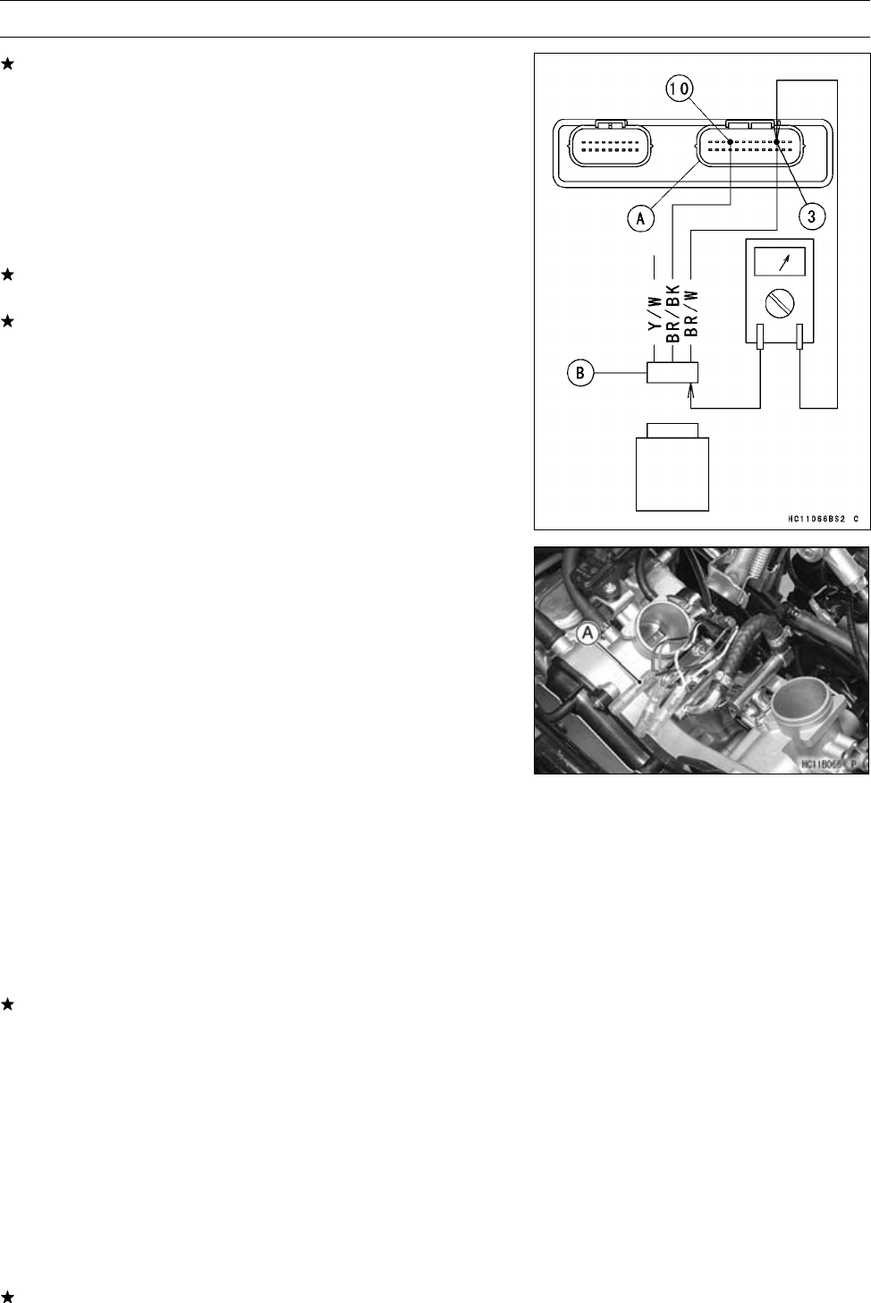
FUEL SYSTEM (DFI) 3-43
Throttle Sensor (Service Code 11)
If the input voltage is less than the standard, remove the
ECU and check the wiring between these connectors.
○Disconnect the ECU and sensor connectors.
Wiring Connection
ECU Connector [A] ←→
Throttle Sensor Connector [B]
BR/W lead (ECU terminal 3)
BR/BK lead (ECU terminal 10)
If the wiring is good, check the ECU for its ground and
power supply (see ECU Power Supply Inspection).
If the ground and power supply are good, replace the ECU
(see ECU Removal/Installation).
Throttle Sensor Output Voltage Inspection
•Measure the output voltage at the throttle sensor in the
same way as input voltage inspection, Note the following.
○Disconnect the throttle sensor connector and connect the
harness adapter [A] between these connectors.
○In this photo, the air cleaner has been removed for clarity.
Special Tool - Throttle Sensor Setting Adapter: 57001
-1521
Throttle Sensor Output Voltage
Connections to Adapter
Meter (+) →Y/W (sensor Y/W) lead
Meter (–) →BK/BL (sensor BR/BK) lead
•Start the engine and warm it up thoroughly.
•Check idle speed to ensure the throttle opening is correct.
Idle Speed
Standard: 1 100 ±50 r/min (rpm)
If the idle speed is out of the specified range, adjust it
(see Idle Speed Inspection in the Periodic Maintenance
chapter).
•Turn the ignition switch OFF.
•Measure the output voltage with the engine stopped, and
with the connector joined.
•Turn the ignition switch ON.
Output Voltage at Sensor
Standard: DC 1.00 ∼1.24 V (at idle throttle opening)
DC 4.0 ∼4.4 V (at full throttle opening)
•Turn the ignition switch OFF.
If the output voltage is out of the standard, inspect the
throttle sensor resistance (see Throttle Sensor Resis-
tance Inspection).
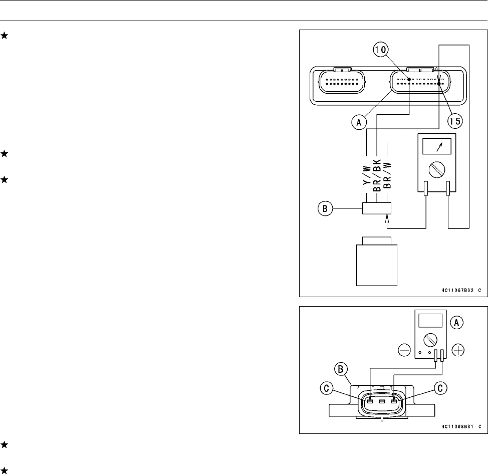
3-44 FUEL SYSTEM (DFI)
Throttle Sensor (Service Code 11)
If the output voltage is normal, check the wiring for conti-
nuity.
○Disconnect the ECU and sensor connectors.
Wiring Connection
ECU Connector [A] ←→
Throttle Sensor Connector [B]
Y/W lead (ECU terminal 15)
BR/BK lead (ECU terminal 10)
If the wiring is good, check the ECU for its ground and
power supply (see ECU Power Supply Inspection).
If the ground and power supply are good, replace the ECU
(see ECU Removal/Installation).
Throttle Sensor Resistance Inspection
•Turn the ignition switch OFF.
•Disconnect the throttle sensor connector.
•Connect a digital meter [A] to the throttle sensor connector
[B].
•Measure the throttle sensor resistance.
Throttle Sensor Resistance
Connections: BR/W lead [C] ←→ BR/BK lead [D]
Standard: 4 ∼6kΩ
If the reading is out of the range, replace the throttle body
assy.
If the reading is within the range, but the problem still
exists, replace the ECU (see ECU Removal/Installation).
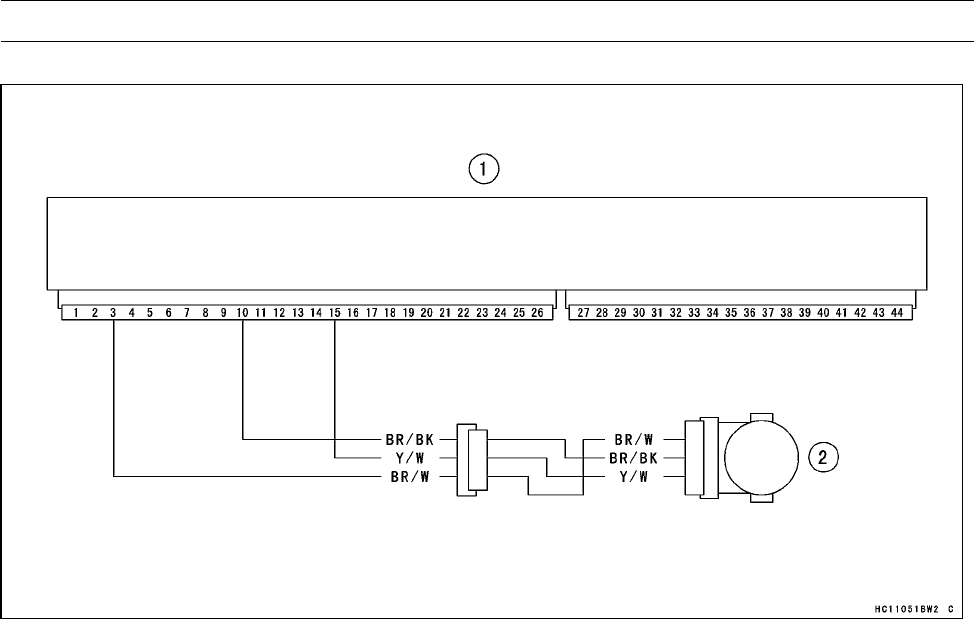
FUEL SYSTEM (DFI) 3-45
Throttle Sensor (Service Code 11)
Throttle Sensor Circuit
1. ECU (Electronic Control Unit)
2. Throttle Sensor
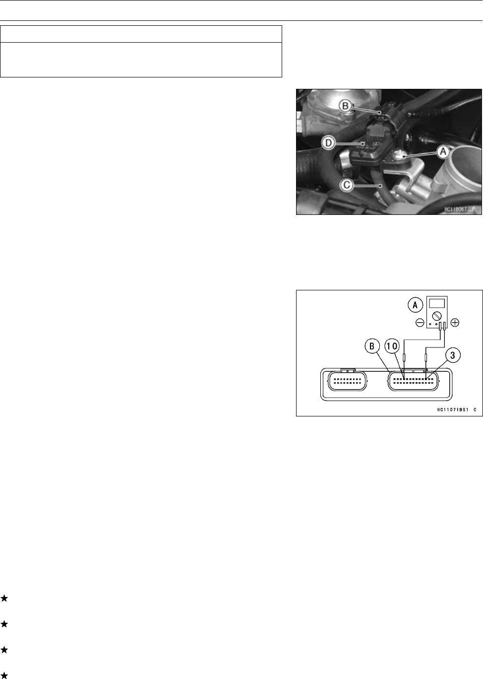
3-46 FUEL SYSTEM (DFI)
Inlet Air Pressure Sensor (Service Code 12)
CAUTION
Never drop the sensor, especially on a hard surface.
Such a shock to the part can damage it.
Inlet Air Pressure Sensor Removal
•Remove:
Air Cleaner (see Air Cleaner Housing Removal)
Screw [A]
•Disconnect the inlet air pressure sensor connector [B] and
the vacuum hose [C].
•Remove the inlet air pressure sensor [D].
Inlet Air Pressure Sensor Installation
•Installation is the reverse of removal.
Torque - Inlet Air Pressure Sensor Mounting Screw: 5.0
N·m (0.51 kgf·m, 44 in·lb)
Inlet Air Pressure Sensor Input Voltage Inspection
NOTE
○Be sure the battery is fully charged.
○The inspection is the same as “Input Voltage Inspection”
of the throttle sensor.
•Turn the ignition switch OFF.
•Remove the ECU (see ECU Removal).
○Do not disconnect the ECU connectors.
•Connect a digital meter [A] to the connector [B] with the
needle adapter set.
Special Tool - Needle Adapter Set: 57001-1457
Inlet Air Pressure Sensor Input Voltage
Connections to ECU Connector
Meter (+) →BR/W lead (terminal 3)
Meter (–) →BR/BK lead (terminal 10)
•Measure the input voltage with the engine stopped, and
with the connectors joined.
•Turn the ignition switch ON.
Input Voltage at ECU
Standard: DC 4.75 ∼5.25 V
If the reading is within the standard range, check the out-
put voltage.
If the reading is less than the standard range, remove the
ECU and check the wiring between these connectors.
If the wiring is good, check the ECU for its ground and
power supply (see ECU Power Supply Inspection).
If the ground and power supply are good, replace the ECU
(see ECU Removal/Installation).
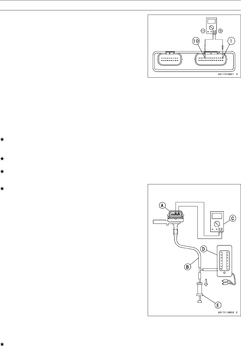
FUEL SYSTEM (DFI) 3-47
Inlet Air Pressure Sensor (Service Code 12)
Inlet Air Pressure Sensor Output Voltage
Inspection
NOTE
○The output voltage changes according to the local at-
mospheric pressure.
•Measure the output voltage at the ECU in the same way
as input voltage inspection. Note the following.
Special Tool - Needle Adapter Set: 57001-1457
Inlet Air Pressure Sensor Output Voltage
Connections to ECU Connector
Meter (+) →G/Y lead (terminal 1)
Meter (–) →BR/BK lead (terminal 10)
Usable Range: DC 3.80 ∼4.20 V at the standard
atmospheric pressure (101.32 kPa, 76
cmHg abs.)
•Turn the ignition switch OFF.
If the output voltage is within the usable range, check the
ECU for its ground, and power supply (see ECU Power
Supply Inspection).
If the ground and power supply are good, replace the ECU
(see ECU Removal/Installation).
If the output voltage is out of the usable range, check the
wiring.
If the wiring is good, check the sensor for various vacuum.
•Remove the inlet air pressure sensor [A] and disconnect
the vacuum hose from the sensor.
•Connect an auxiliary hose [B] to the inlet air pressure sen-
sor.
•Temporarily install the inlet air pressure sensor.
•Connect a digital meter [C], vacuum gauge [D], the fork
oil level gauge [E] and the harness adapter to the inlet air
pressure sensor.
Special Tools - Fork Oil Level Gauge: 57001-1290
Sensor Harness Adapter: 57001-1561
Inlet Air Pressure Sensor Output Voltage
Connections to Adapter
Meter (+) →G/W (sensor G/Y) lead
Meter (–) →BK (sensor BR/BK) lead
•Turn the ignition switch ON.
•Measure the output voltage from various vacuum readings, while pulling the handle of the fork oil
level gauge.
If the output voltage for various vacuum is normal, check the ECU for its ground, and power supply
(see ECU Power Supply Inspection).
•Check the output voltage, using the following formula and chart.

3-48 FUEL SYSTEM (DFI)
Inlet Air Pressure Sensor (Service Code 12)
Suppose:
Pg: Vacuum Pressure (gauge) to Sensor
Pl: Local Atmospheric Pressure (absolute) measured by a barometer
Pv: Vacuum Pressure (absolute) to Sensor
Vv: Sensor Output Voltage (V)
then
Pv = Pl – Pg
For example, suppose the following data is obtained:
Pg = 8 cmHg (Vacuum gauge reading)
Pl = 70 cmHg (Varometer reading)
Vv = 3.2 V (Digital meter reading)
then
Pv=70–8=62cmHg(Abs.)
Plot this Pv (62 cmHg) at a point [1] on the chart and draw a vertical line through the point. Then, you
can get the usable range [2] of the sensor output voltage.
Usable range = 3.04 ∼3.49 V
Plot Vv (3.2 V) on the vertical line. →Point [3].
Results: In the chart, Vv is within the usable range and the sensor is normal.
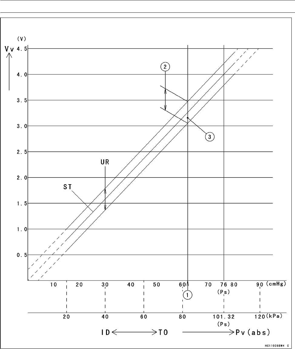
FUEL SYSTEM (DFI) 3-49
Inlet Air Pressure Sensor (Service Code 12)
ID: Idling
Ps: Standard Atmospheric Pressure (Absolute)
Pv: Throttle Vacuum Pressure (Absolute)
ST: Standard of Sensor Output Voltage (V)
TO: Throttle Full Open
UR: Usable Range of Sensor Output Voltage (V)
Vv: Inlet Air Pressure Sensor Output Voltage (V) (Digital Meter Reading)
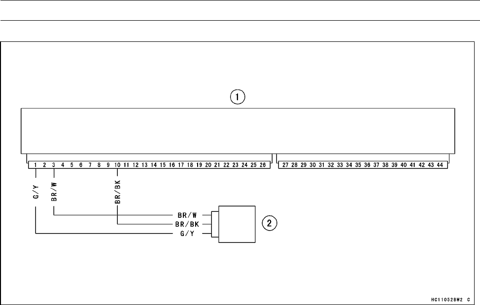
3-50 FUEL SYSTEM (DFI)
Inlet Air Pressure Sensor (Service Code 12)
Inlet Air Pressure Sensor Circuit
1. ECU (Electronic Control Unit)
2. Inlet Air Pressure Sensor
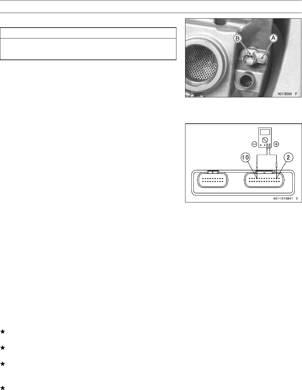
FUEL SYSTEM (DFI) 3-51
Inlet Air Temperature Sensor (Service Code 13)
Inlet Air Temperature Sensor Removal/Installation
CAUTION
Never drop the sensor, especially on a hard surface.
Such a shock to the sensor can damage it.
•Remove the air cleaner (see Air Cleaner Housing Re-
moval).
•Remove the screw [A].
•Pull out the inlet air temperature sensor [B].
•Put the inlet air temperature sensor into the air cleaner
housing.
•Tighten the screw securely.
Inlet Air Temperature Sensor Output Voltage
Inspection
NOTE
○Be sure the battery is fully charged.
○The output voltage changes according to the inlet air
temperature.
•Remove the ECU (see ECU Removal).
○Do not disconnect the ECU connectors.
•Connect a digital meter to the ECU connector, using nee-
dle adapter set.
Special Tool - Needle Adapter Set: 57001-1457
Inlet Air Temperature Sensor Output Voltage
Connections to ECU Connector
Meter (+) →Y lead (terminal 2)
Meter (–) →BR/BK lead (terminal 10)
•Measure the output voltage with the engine stopped and
the connector joined.
•Turn the ignition switch ON.
Output Voltage at ECU
Standard: About 2.26 ∼2.50 V at inlet air temperature
25°C (77°F)
•Turn the ignition switch OFF.
If the output voltage is out of the standard, check the
wiring.
If the wiring is good, check the sensor resistance (see
Inlet Air Temperature Sensor Resistance).
If the output voltage is within the standard, check the ECU
for its ground, and power supply (see ECU Power Supply
Inspection).
If the ground and power supply are good, replace the ECU
(see ECU Removal/Installation).
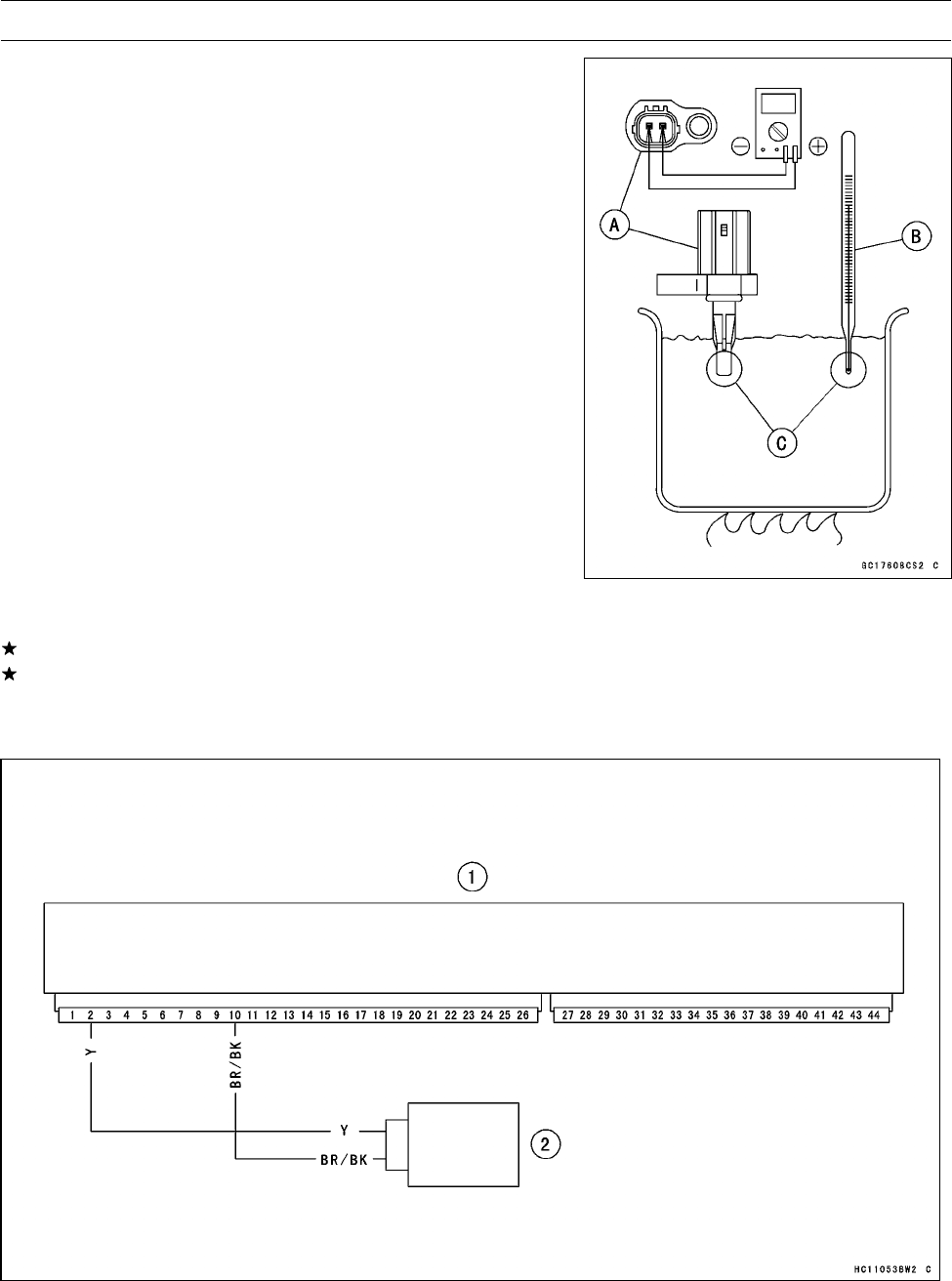
3-52 FUEL SYSTEM (DFI)
Inlet Air Temperature Sensor (Service Code 13)
Inlet Air Temperature Sensor Resistance
Inspection
•Remove the inlet air temperature sensor (see Inlet Air
Temperature Sensor Removal/Installation).
•Suspend the sensor [A] in a container of machine oil so
that the heat-sensitive portion is submerged.
•Suspend a thermometer [B] with the heat-sensitive por-
tions [C] located in almost the same depth with the sen-
sor.
NOTE
○The sensor and thermometer must not touch the con-
tainer side or bottom.
•Place the container over a source of heat and gradually
raise the temperature of the oil while stirring the oil gently
for even temperature.
•Using a digital meter, measure the internal resistance
of the sensor across the terminals at the temperatures
shown in the following.
Inlet Air Temperature Sensor Resistance
Standard: 5.4 ∼6.6 kΩat 0°C (32°F)
0.29 ∼0.39 kΩat 80°C (176°F)
If the measurement is out of the range, replace the sensor.
If the measurement is within the specified, replace the
ECU (see ECU Removal/Installation).
Inlet Air Temperature Sensor Circuit
1. ECU (Electronic Control Unit)
2. Inlet Air Temperature Sensor
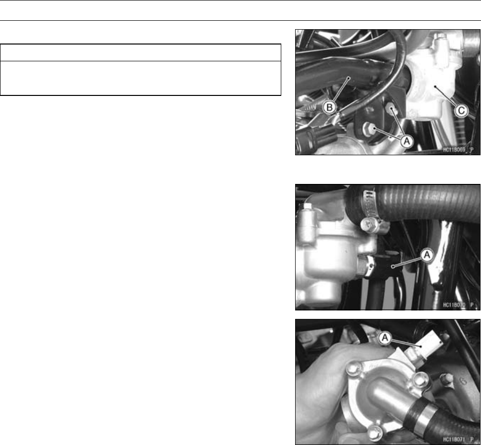
FUEL SYSTEM (DFI) 3-53
Water Temperature Sensor (Service Code 14)
Water Temperature Sensor Removal/Installation
CAUTION
Never drop the sensor, especially on a hard surface.
Such a shock to the sensor can damage it.
•Drain the coolant (see Coolant Change in the Periodic
Maintenance chapter).
•Remove:
Bolts [A]
•Disconnect the water pipe [B] from the thermostat housing
[C].
•Disconnect the sensor connector [A].
•Remove the water temperature sensor [A].
•Apply grease to new O-ring on the water temperature sen-
sor.
•Install the water temperature sensor.
•Fill the engine with coolant and bleed the air from the cool-
ing system (see Coolant Change in the Periodic Mainte-
nance chapter).
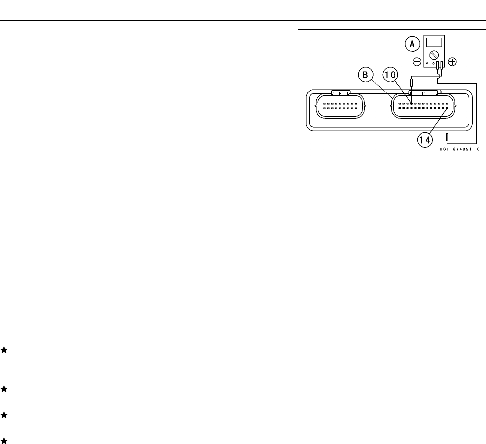
3-54 FUEL SYSTEM (DFI)
Water Temperature Sensor (Service Code 14)
Water Temperature Sensor Output Voltage
Inspection
NOTE
○Be sure the battery is fully charged.
○The output voltage changes according to the coolant
temperature in the engine.
•Remove the ECU (see ECU Removal).
○Do not disconnect the connectors.
•Connect a digital meter [A] to the ECU connector [B] with
the needle adapter set.
Special Tool - Needle Adapter Set: 57001-1457
Water Temperature Sensor Output Voltage
Connections to ECU Connector
Meter (+) →O lead (terminal 14)
Meter (–) →BR/BK lead (terminal 10)
•Measure the output voltage with the engine stopped and
the connector joined.
•Turn the ignition switch ON.
Output Voltage at ECU
Standard: About 2.24 ∼2.48 V at 25°C (77°F)
•Turn the ignition switch OFF.
If the output voltage is within the standard, check the ECU
for its ground, and power supply (see ECU Power Supply
Inspection).
If the ground and power supply are good, replace the ECU
(see ECU Removal/Installation).
If the output voltage is out of the standard, check the
wiring.
If the wiring is good, check the water temperature sensor
resistance (see Water Temperature Sensor Resistance
Inspection in the Electrical System chapter).
Water Temperature Sensor Resistance Inspection
•Refer to the Water Temperature Sensor Inspection in the
Electrical System chapter.
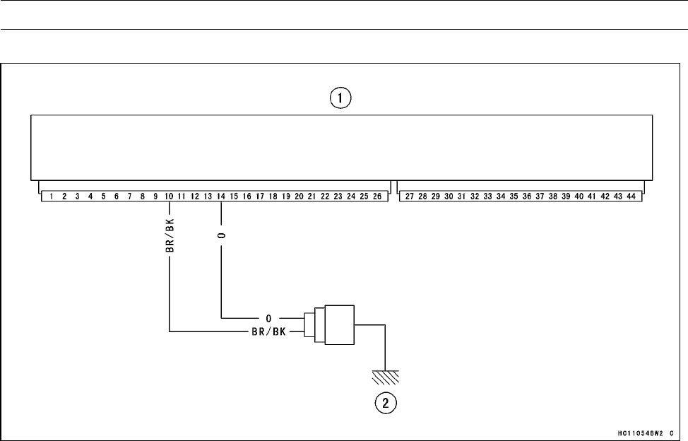
FUEL SYSTEM (DFI) 3-55
Water Temperature Sensor (Service Code 14)
Water Temperature Sensor Circuit
1. ECU (Electronic Control Unit)
2. Water Temperature Sensor
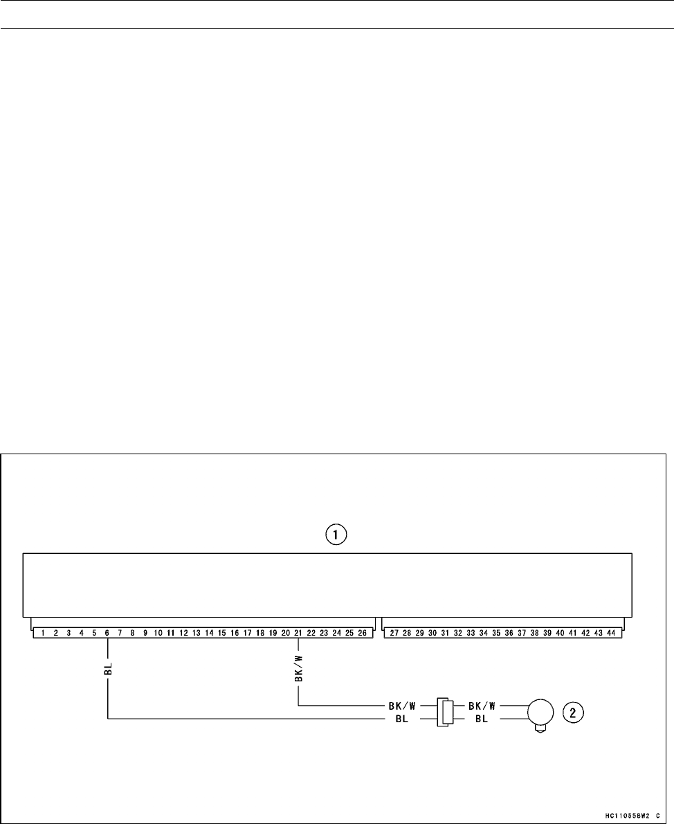
3-56 FUEL SYSTEM (DFI)
Crankshaft Sensor (Service Code 21)
Start the engine and switch the diagnosis mode to Dealer
1 mode to know all the problem that the DFI system has at
the time of self-diagnosis. If the engine cannot be started,
the self-diagnosis system does not detect dynamic condi-
tion of the crankshaft sensor. In this case, turn off the igni-
tion switch and turn it on again to enter the Dealer 2 mode.
In this mode, the system tells all the troubles which the DFI
system had in both static and dynamic conditions.
Crankshaft Sensor Removal/Installation
•Refer to the Crankshaft Sensor Removal/Installation in
the Electrical System chapter.
Crankshaft Sensor Inspection
○The crankshaft sensor has no power source, and when
the engine stops, the crankshaft sensor generates no sig-
nals.
•Cranking the engine and measure the peak voltage of the
crankshaft sensor (see Crankshaft Sensor Inspection in
the Electrical System) in order to check the sensor.
•Check the wiring for continuity, using the following dia-
gram.
Crankshaft Sensor Circuit
1. ECU (Electronic Control Unit)
2. Crankshaft Sensor
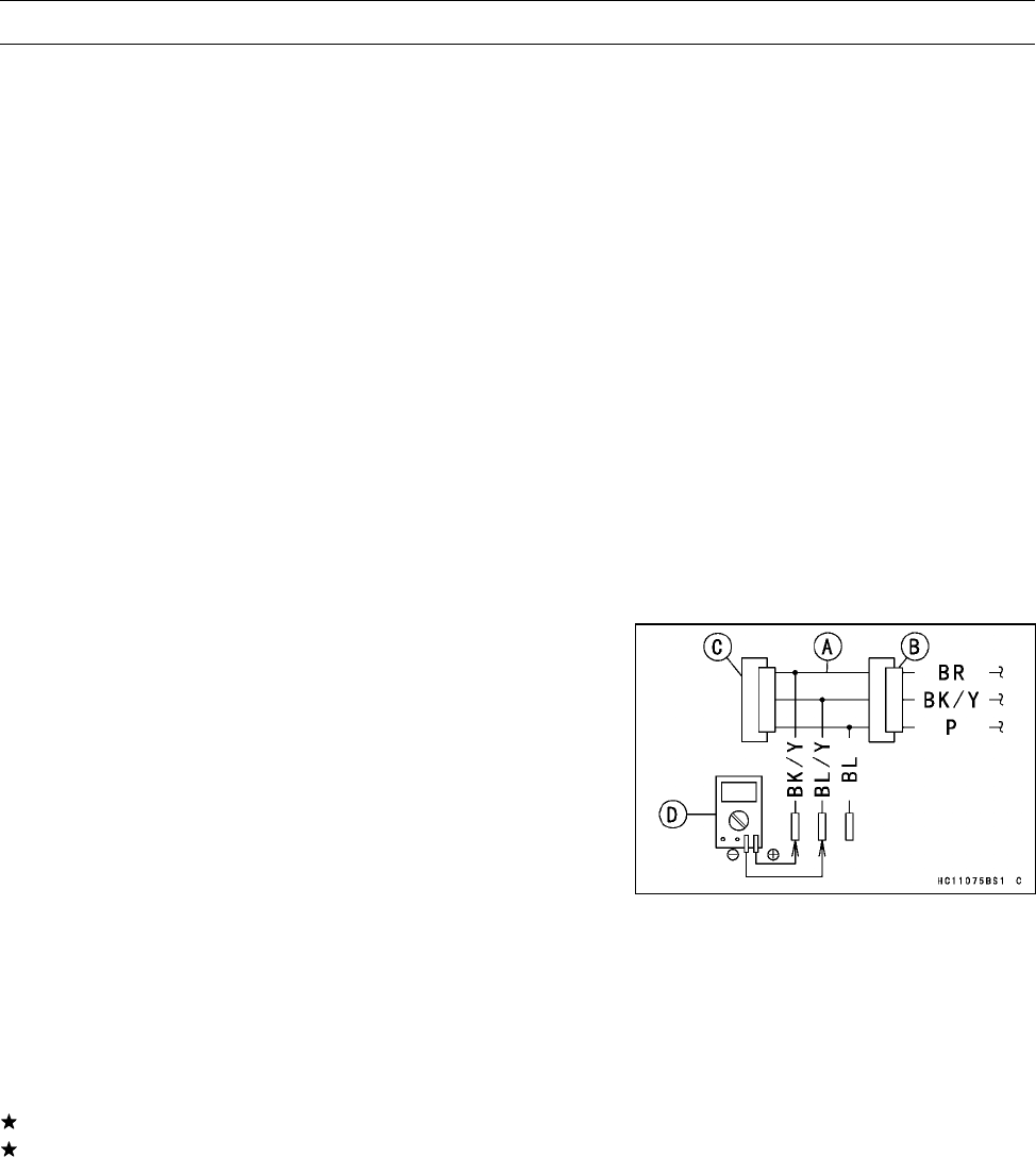
FUEL SYSTEM (DFI) 3-57
Speed Sensor (Service Code 24)
Speed Sensor Removal
•Refer to the Speed Sensor Removal in the Electrical Sys-
tem chapter.
Speed Sensor Installation
•Refer to the Speed Sensor Installation in the Electrical
System chapter.
Speed Sensor Inspection
•Refer to the Speed Sensor Inspection in the Electrical
System chapter.
Input Voltage Inspection
•Remove:
Right Footboard (see Right Footboard Removal in the
Flame chapter)
NOTE
○Be sure the battery is fully charged.
•Turn the ignition switch OFF.
•Disconnect the speed sensor connector.
•Connect the measuring adapter [A] between the harness
connector [B] and speed sensor connector [C].
Special Tool - Speed Sensor Measuring Adapter: 57001
-1667
•Connect a digital meter [D] to the measuring adapter lead
connectors.
Speed Sensor Input Voltage
Connections to Adapter
Meter (+) →BK/Y (sensor BR) lead
Meter (−)→BL/Y (sensor BK/Y) lead
•Measure the input voltage with the engine stopped, and
with the connectors joined.
•Turn the ignition switch ON.
Input Voltage at Sensor
Standard: Battery Voltage
If the reading is out of the range, check the wiring.
If the reading is good, check the output voltage.
•Turn the ignition switch OFF.
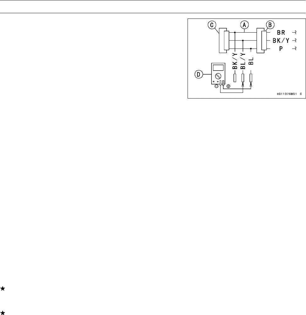
3-58 FUEL SYSTEM (DFI)
Speed Sensor (Service Code 24)
Output Voltage Inspection
•Before this inspection, inspect the input voltage (see Input
Voltage Inspection in the Speed Sensor section).
NOTE
○Be sure the battery is fully charged.
•Turn the ignition switch OFF.
•Using the jack, raise the rear wheel off the ground.
Special Tool - Jack: 57001-1238
•Remove the speed sensor (see Speed Sensor Removal
in the Electrical System chapter).
•Connect the measuring adapter [A] between the harness
connector [B] and speed sensor connector [C].
Special Tool - Speed Sensor Measuring Adapter: 57001
-1667
•Reinstall the speed sensor with the measuring adapter
connected.
•Connect a digital meter [D] to the measuring adapter lead
connectors.
Speed Sensor Output Voltage
Connections to Adapter
Meter (+) →BL (sensor P) lead
Meter (–) →BL/Y (sensor BK/Y) lead
•Measure the output voltage with the engine stopped, and
with the connectors joined.
•Turn the ignition switch ON.
Output Voltage at Sensor
Standard: less than DC 0.8 V or over than DC 4.8 V
•Rotate the rear wheel by hand, confirm the output voltage
will be raise or lower.
If the reading is out of the range, replace the speed sensor
(see Switch and Sensors section in the Electrical System
chapter) and check the wiring to ECU (see next diagram).
If the reading, speed sensor and wiring are good, replace
the ECU (see ECU section).
•Turn the ignition switch OFF.
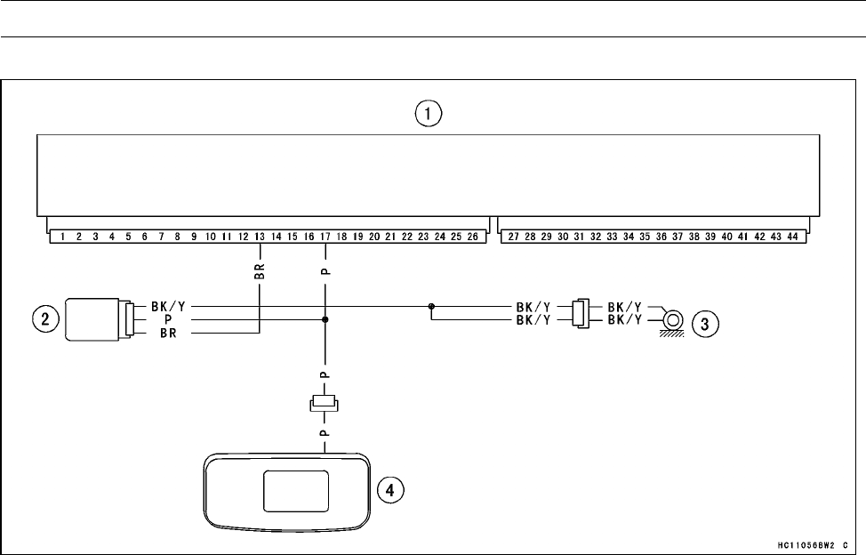
FUEL SYSTEM (DFI) 3-59
Speed Sensor (Service Code 24)
Speed Sensor Circuit
1. ECU (Electronic Control Unit)
2. Speed Sensor
3. Engine Ground
4. Multifunction Meter
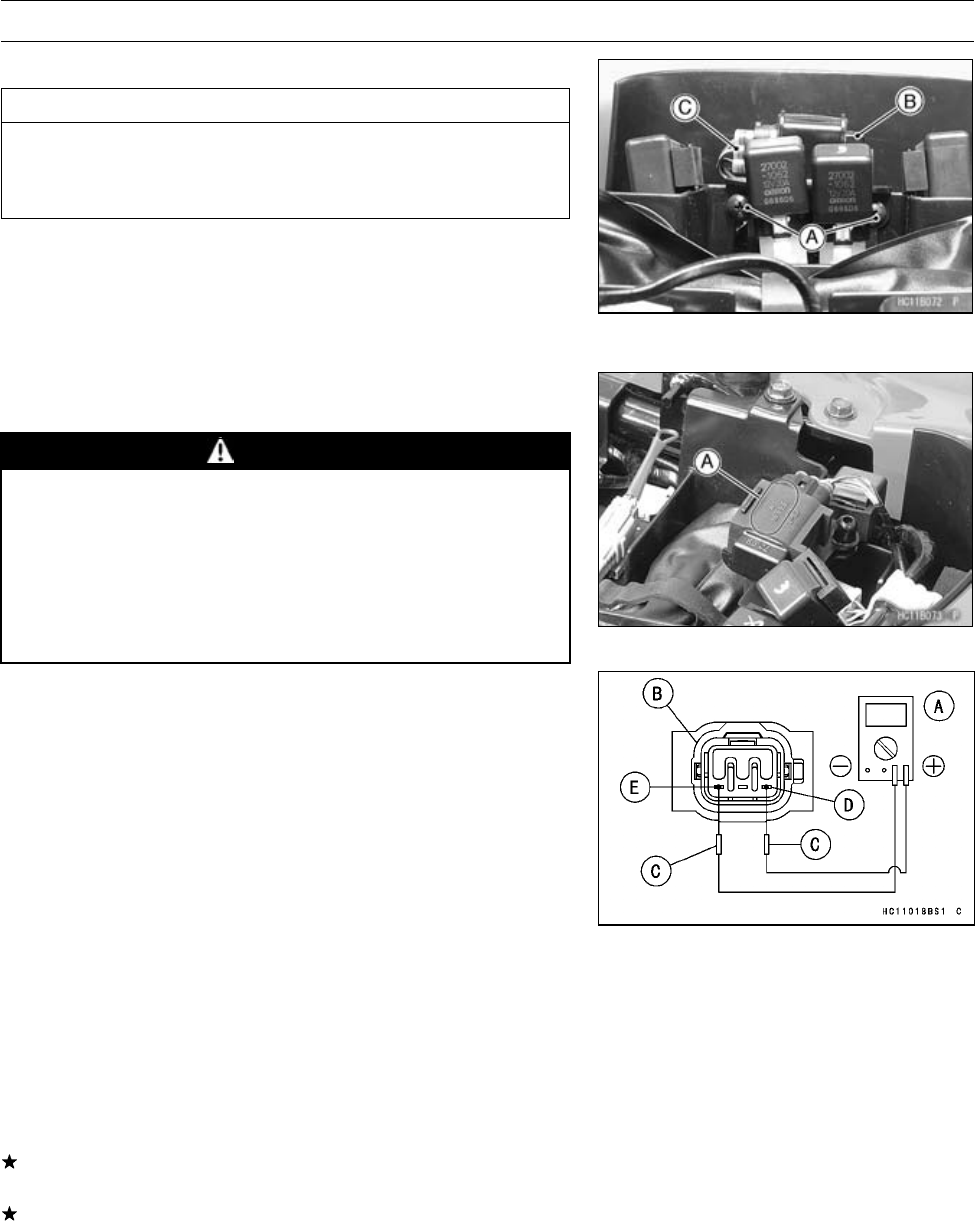
3-60 FUEL SYSTEM (DFI)
Vehicle-down Sensor (Service Code 31)
Vehicle-down Sensor Removal
CAUTION
Never drop the vehicle-down sensor, especially on
a hard surface. Such a shock to the sensor can
damage it.
•Remove:
Seat (see Seat Removal in the Frame chapter)
Screws [A]
Vehicle-down Sensor [B]
Connector [C]
Vehicle-down Sensor Installation
•The UPPER mark [A] of the sensor should face upward.
WARNING
Incorrect installation of the vehicle-down sensor
could cause sudden loss of engine power. The
rider could lose balance during certain riding situ-
ations like leaning over in a turn with the potential
for an accident resulting in injury or death. Ensure
that the vehicle-down sensor is held in place by the
sensor brackets.
Vehicle-down Sensor Inspection
NOTE
○Be sure the battery is fully charged.
•Connect a digital meter [A] to the connector [B] of the
vehicle-down sensor with the needle adapter set [C].
Special Tool - Needle Adapter Set: 57001-1457
Vehicle-down Sensor Power Source Voltage
Connections to Sensor Connector
Meter (+) →LB lead [D]
Meter (–) →BR/W lead [E]
•Turn the ignition switch ON, and measure the power
source voltage with the connector joined.
Input Voltage at Sensor
Standard: DC 4.75 ∼5.25 V
•Turn the ignition switch OFF.
If the reading of input voltage is less than the standard,
check the ECU for its ground, power supply and wiring.
If the power source is normal, check the output voltage.
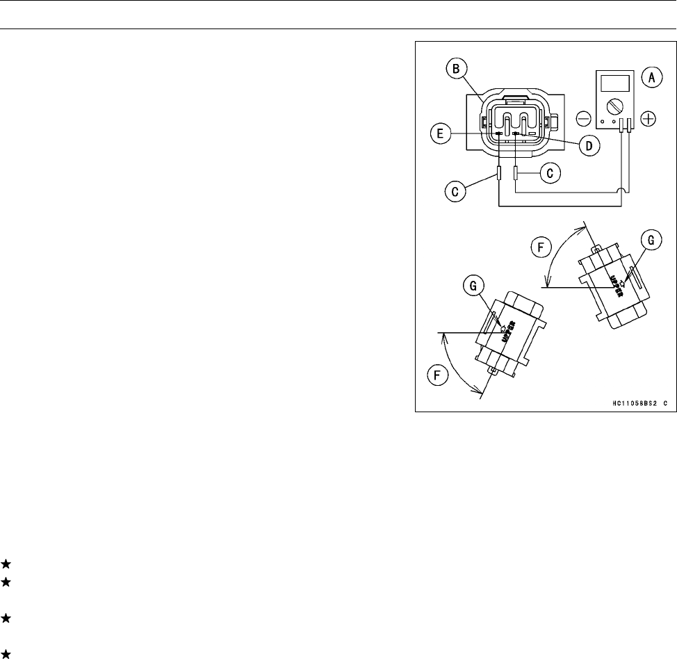
FUEL SYSTEM (DFI) 3-61
Vehicle-down Sensor (Service Code 31)
•Remove the vehicle-down sensor (see Vehicle-down
Sensor Removal).
○Do not disconnect the sensor connector.
•Connect a digital meter [A] to the connector [B] with nee-
dle adapter set [C].
Special Tool - Needle Adapter Set: 57001-1457
Vehicle-down Sensor Output Voltage
Connections to Sensor Connector
Meter (+) →Y/G lead [D]
Meter (–) →BR/BK lead [E]
•Hold the sensor vertically.
•Turn the ignition switch ON, and measure the output volt-
age with the connector joined.
○Tilt the sensor 55∼75° or more [F] right or left, then hold
the sensor almost vertical with the arrow mark [G] pointed
up, and measure the output voltage.
Output Voltage at Sensor
Standard: with sensor tilted 55∼75° or more right or
left: 3.7 ∼4.4 V
with sensor arrow mark pointed up: 0.4 ∼
1.4 V
NOTE
○If you need to test again, turn the ignition switch OFF,
and then ON.
•Turn the ignition switch OFF.
If the output voltage is normal, check the wiring.
If the wiring is good, check the ECU for its ground and
power supply (see ECU Power Supply Inspection).
If the ground and power supply are good, replace the ECU
(see ECU Removal/Installation).
If the output voltage is out of the specified, replace the
vehicle-down sensor.
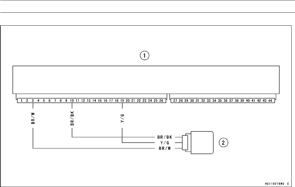
3-62 FUEL SYSTEM (DFI)
Vehicle-down Sensor (Service Code 31)
Vehicle-down Sensor Circuit
1. ECU (Electronic Control Unit)
2. Vehicle-down Sensor
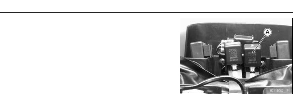
FUEL SYSTEM (DFI) 3-63
Fuel Pump Relay (Service Code 46)
Fuel Pump Relay Removal
•Remove:
Seat (see Seat Removal in the Frame chapter)
Fuel Pump Relay [A]
Fuel Pump Relay Inspection
•Refer to the Relay Inspection in the Electrical System
chapter.
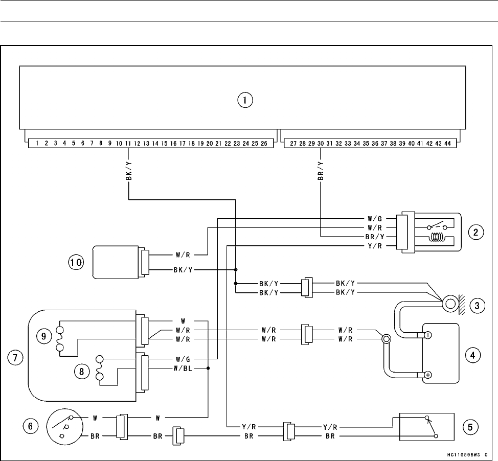
3-64 FUEL SYSTEM (DFI)
Fuel Pump Relay (Service Code 46)
Fuel Pump Relay Circuit
1. ECU (Electronic Control Unit)
2. Fuel Pump Relay
3. Engine Ground Terminal
4. Battery 12 V 12 Ah
5. Engine Stop Switch
6. Ignition Switch
7. Fuel Box
8. Fuel Pump Fuse 10 A
9. Main Fuse 30 A
10. Fuel Pump
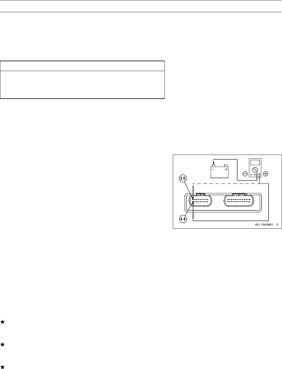
FUEL SYSTEM (DFI) 3-65
Ignition Coils (#1, #2: Service Code 51, 52)
Ignition Coil #1: Ignition Coil for Front Cylinder (Service
Code 51)
Ignition Coil #2: Ignition Coil for Rear Cylinder (Service
Code 52)
Ignition Coil Removal/Installation
CAUTION
Never drop the ignition coils, especially on a hard
surface. Such a shock to the ignition coil can dam-
age it.
•Refer to the Ignition Coil Removal and Installation in the
Electrical System chapter.
Input Voltage Inspection
NOTE
○Be sure the battery is fully charged.
•Turn the ignition switch OFF.
•Remove the ECU (see ECU Removal). Do not disconnect
the ECU connector.
•Connect a digital voltmeter as shown, using two needle
adapters.
Special Tool - Needle Adapter Set: 57001-1457
○Measure the input voltage to each primary winding of the
ignition coils with the engine stopped, and with the con-
nectors joined.
•Turn the ignition switch ON.
Ignition Coil Input Voltage at ECU
Connections for Ignition Coil #1
Meter (+) →G/W lead (terminal 44)
Meter (–) →Battery (–) Terminal
Connections for Ignition Coil #2
Meter (+) →BL/W lead (terminal 35)
Meter (–) →Battery (–) Terminal
Standard: Battery Voltage (12.8 V or more)
If the reading is out of the standard, check the ECU for
its ground and power supply (see ECU Power Supply In-
spection).
If the reading is good, remove the fuel tank and check the
wiring between the ECU and the primary lead terminals
at the ignition coils.
If the wiring is good, crank the engine, and check the peak
voltage of the ignition coils (see Ignition Coil Primary Peak
Voltage Inspection in the Electrical System chapter) in or-
der to check the primary coils.
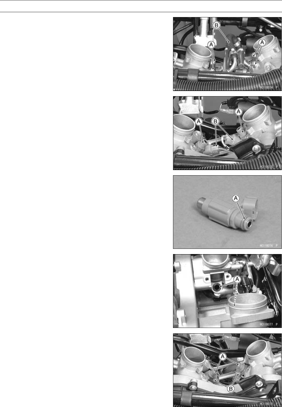
3-66 FUEL SYSTEM (DFI)
Fuel Injectors
Fuel Injector Removal
•Remove:
Air cleaner (see Air cleaner Housing Removal)
Screw [A]
Fuel Hose (from the Delivery Pipe)
Delivery Pipe [B]
•Remove:
Fuel Injectors [A]
Connectors [B]
Fuel Injector Installation
•Replace the O-rings [A] and seals [B] with a new one.
○Before installation, blow away dirt or dust from the deliv-
ery pipe by applying compressed air.
•Apply grease to the O-ring of the injectors.
•Install the injector [A] to the throttle body assy so that the
connector [B] faces downward.
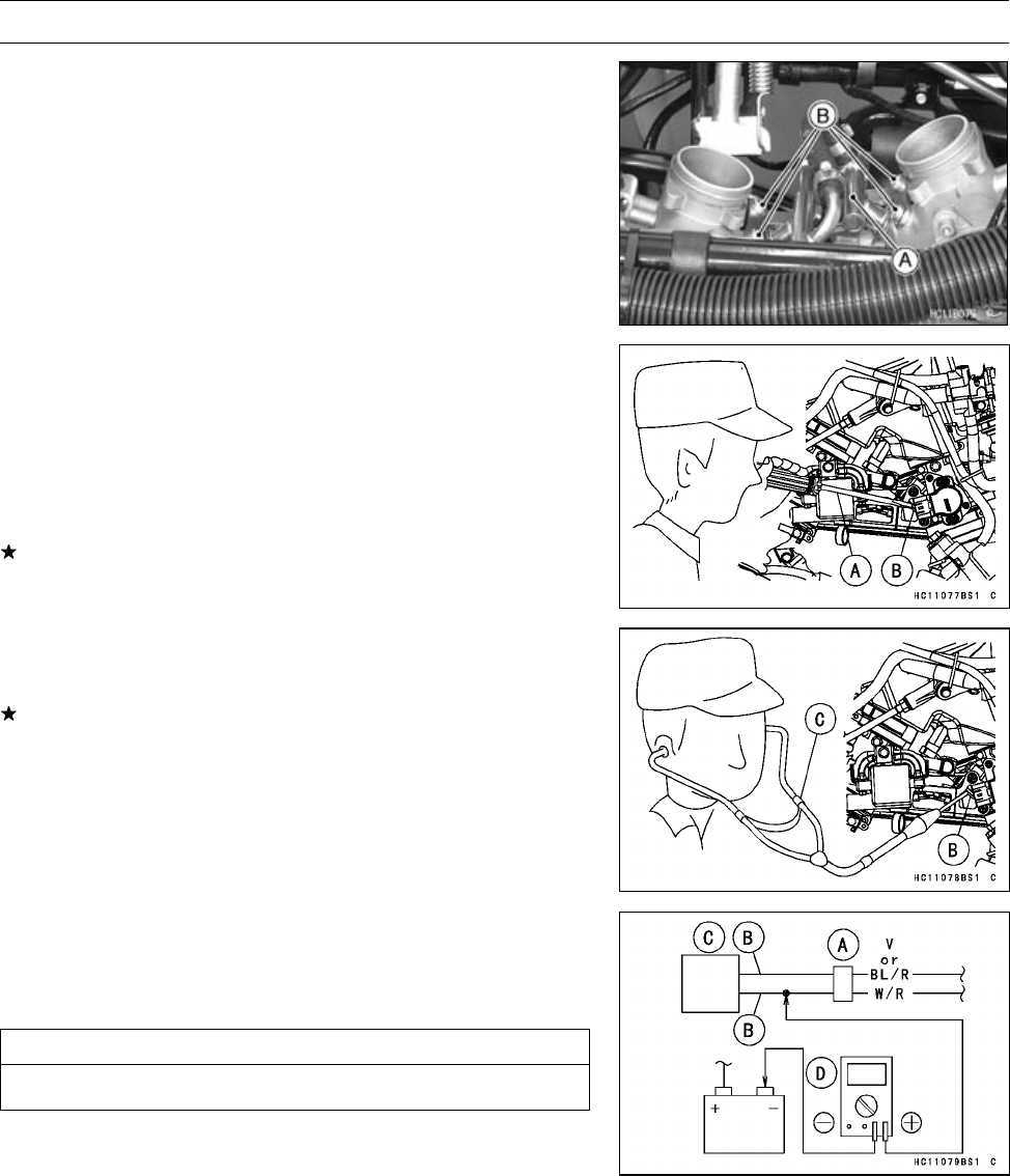
FUEL SYSTEM (DFI) 3-67
Fuel Injectors
•Install the delivery pipe [A] on the throttle body assy.
•Tighten:
Torque - Delivery Pipe Mounting Screws [B]: 5.0 N·m (0.51
kgf·m, 44 in·lb)
Audible Inspection
•Start the engine.
•Apply the tip of a screwdriver [A] to the injector [B]. Put
the grip end onto your ear, and listen whether the injector
is clicking or not.
○A sound scope [C] can also be used.
•Dothesamefortheotherinjectors.
If all the injectors click at a regular intervals, the injec-
tors are good. The trouble may be related to the fuel line,
requiring fuel pressure inspection (see Fuel Pressure In-
spection).
○The click interval becomes shorter as the engine speed
rises.
If any injector(s) doesn’t click, the DFI circuit or the injector
is suspect. Perform “Fuel Injector Power Source Voltage
Inspection”, first.
Fuel Injector Power Source Voltage Inspection
•Disconnect the injector connector [A] and connect the in-
sulated auxiliary leads [B] between injector [C] and injec-
tor connector.
CAUTION
Do not short each terminals.
•Connect a digital meter [D] as shown.
Injector Power Source Voltage
Connections to injector
Meter (+) →W/R lead
Meter (–) →Battery (–) Terminal
•Measure the power source voltage with the engine
stopped, and with the connector joined.
•Turn the engine stop switch to run position.
•Turn the ignition switch ON.
Power Source Voltage at Injector
Standard: Battery Voltage for 3 second, and then 0 V
•Turn the ignition switch OFF.
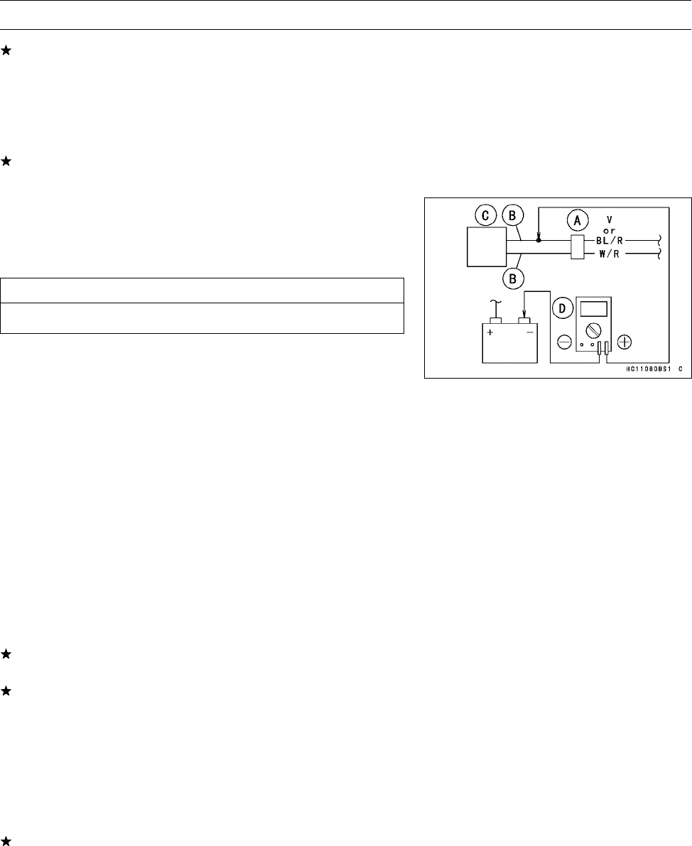
3-68 FUEL SYSTEM (DFI)
Fuel Injectors
If the meter doesn’t read as specified, check the following.
Main Fuse 30 A (see Fuse Inspection in the Electrical
System chapter)
Fuel Pump Relay (see Relay Circuit Inspection in the
Electrical System chapter)
Power Source Wiring (see wiring diagram below)
If the power source voltage is normal, check the output
voltage of the injectors.
Fuel Injector Output Voltage Inspection
•Disconnect the injector connector [A] and connect the in-
sulated auxiliary leads [B] between injector [C] and injec-
tor connector.
CAUTION
Do not short each terminals.
•Connect a digital meter [D] as shown.
Injector Output Voltage
Connections to injector (#1)
Meter (+) →BL/R lead
Meter (–) →Battery (–) Terminal
Connections to injector (#2)
Meter (+) →V lead
Meter (–) →Battery (–) Terminal
•Turn the engine stop switch to run position.
•Turn the ignition switch ON.
Output Voltage at Injector
Standard: Battery Voltage for 3 second, and then 0 V
•Turn the ignition switch OFF.
If the output voltage is normal, perform “Injector Signal
Test” .
If the output voltage is out of the standard, remove the
ECU (see ECU Removal/Installation), and check the in-
jector wiring for continuity.
Injector Wiring Inspection
ECU Connector Injector Connectors
Terminal 43 →Injector (#1) Terminal (BL/R)
Terminal 34 Injector (#2) Terminal (V)
If the wiring is good, inspect the resistance of the injectors
(see Injector Resistance Inspection).
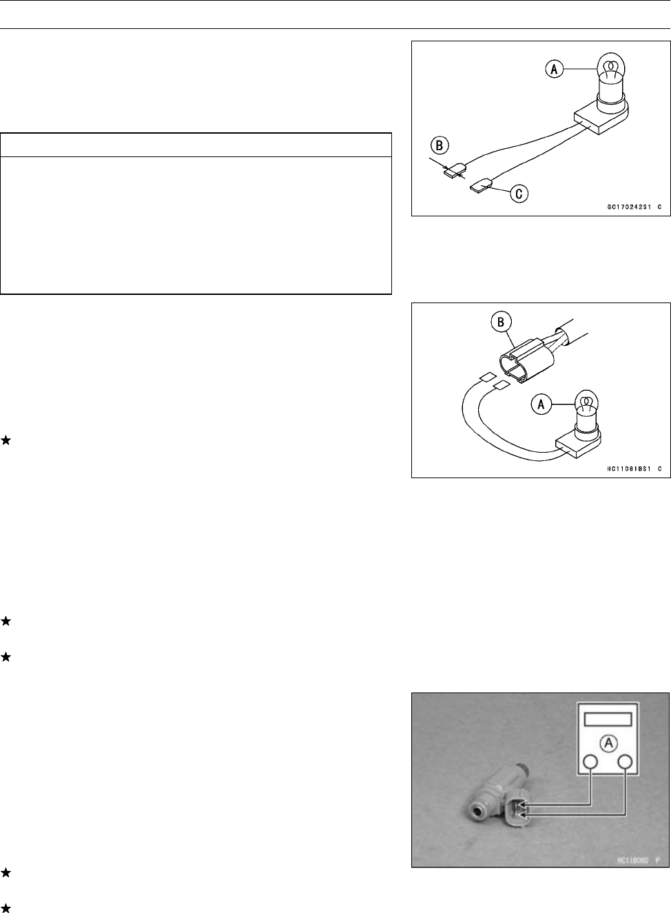
FUEL SYSTEM (DFI) 3-69
Fuel Injectors
Injector Signal Test
•Prepare two test light sets with terminals as shown.
Rating of Bulb [A]: 12 V × (3 ∼3.4) W
Terminal Width [B]: 1.8 mm (0.071 in.)
Terminal Thickness [C]: 0.8 mm (0.031 in.)
CAUTION
Do not use larger terminals than specified above.
A larger terminal could damage the injector main
harness connector, leading to harness repair or re-
placement.
Be sure to connect bulbs in series. The bulb works
as a current limiter to protect the solenoid in the
injector from excessive current.
•Remove:
Fuel Injector (see Fuel Injector Removal)
•Connect each test light set [A] to the injector harness con-
nector [B].
•Turn the ignition switch ON.
•While cranking the engine with the starter motor, watch
the test lights.
If the test lights flicker at regular intervals, the injector
circuit in the ECU, and the wiring are good. Perform the
“Injector Resistance Inspection”.
○Injector signals can be also confirmed by connecting the
hand tester (× AC 10 V ) instead of the test light set to the
injector main harness connector. Crank the engine with
the starter motor, and check to see if the hand oscillates
at regular intervals.
Special Tool - Hand Tester: 57001-1394
If the test light doesn’t flicker (or the tester needle doesn’t
oscillates), check the wiring and connectors again.
If the wiring is good, replace the ECU (see ECU Re-
moval/Installation).
Injector Resistance Inspection
•Remove:
Fuel Injector (see Fuel Injector Removal)
•Measure the injector resistance with the hand tester [A].
Special Tool - Hand Tester: 57001-1394
Injector Resistance
Connections to Injector Connector
Standard: About 11.7 ∼12.3 Ωat 20°C (68°F)
If the reading is out of the range, perform the “Injector Unit
Test” .
If the reading is normal, perform the “Injector Unit Test”
for confirmation.
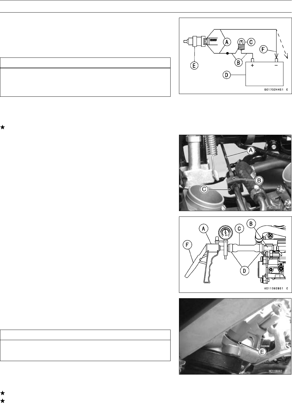
3-70 FUEL SYSTEM (DFI)
Fuel Injectors
Injector Unit Test
•Use two leads [A] and the same test light set [B] as in
“Injector Signal Test”.
Rating of Bulb [C]: 12 V × (3 ∼3.4) W
12 V Battery [D]
CAUTION
Be sure to connect the bulb in series. The bulb
works as a current limiter to protect the solenoid
in the injector from excessive current.
•Connect the test light set to the injector [E] as shown.
•Open and connect [F] the end of the lead to the battery
(–) terminal repeatedly. The injector should click.
If the injector does not click, replace the injector.
Injector Fuel Line Inspection
•Remove the air cleaner (see Air Cleaner Housing Re-
moval).
•Be sure to place a piece of cloth around the fuel hose joint
and the delivery pipe.
•Insert a minus screwdriver [A] into the slit on the joint lock
[B].
•Turn the driver to disconnect the joint lock.
•Pull the fuel hose joint [C] out of the delivery pipe.
•Check the injector fuel line for leakage as follows.
○Connect a commercially available vacuum/pressure
pump [A] to the nipple of the delivery pipe [B] with a
high-pressure fuel hose [C] (both ends connected with
the clamps [D]) as shown.
Torque - Fuel Hose Clamp Screws: 1.5 N·m (0.15 kgf·m, 13
in·lb)
○Apply soap and water solution to the areas [E] as shown.
○Watching the pressure gauge, squeeze the pump lever
[F], and build up the pressure until the pressure reaches
the maximum pressure.
Injector Fuel Line Maximum Pressure
Standard: 300 kPa (3.06 kgf/cm², 43.5 psi)
CAUTION
During pressure testing, do not exceed the maxi-
mum pressure for which the system is designed.
•Watch the gauge for at least 6 seconds.
If the pressure holds steady, the system is good.
If the pressure drops at once or if bubbles are found in
the area, the line is leaking. Replace the delivery pipe,
injectors and related parts.
○Repeat the leak test, and check the fuel line for no leak-
age.
•Run the hoses correctly (see Cable, Wire, and Hose Rout-
ing section in the Appendix chapter).
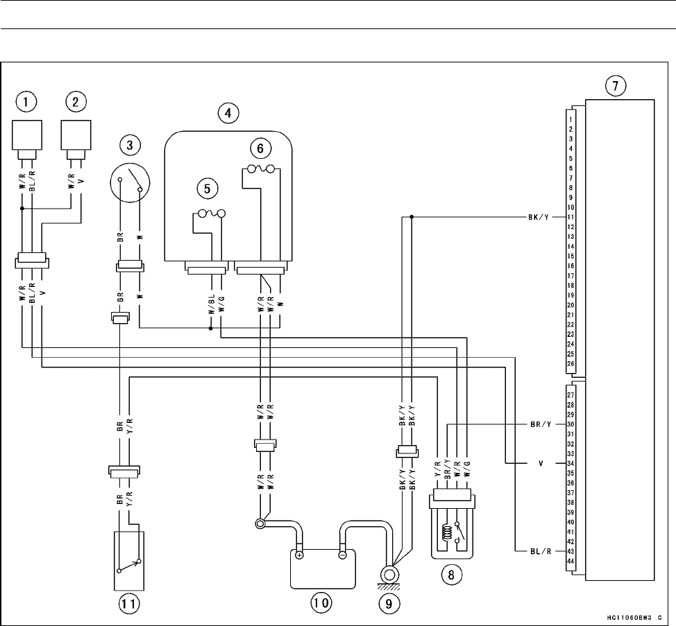
FUEL SYSTEM (DFI) 3-71
Fuel Injectors
Fuel Injector Circuit
1. Fuel Injector #1
2. Fuel Injector #2
3. Ignition Switch
4. Fuse Box
5. Fuel Pump Fuse 10 A
6. Main Fuse 30 A
7. ECU (Electronic Control Unit)
8. Fuel Pump Relay
9. Engine Ground Terminal
10. Battery 12 V 12 Ah
11. Engine Stop Switch
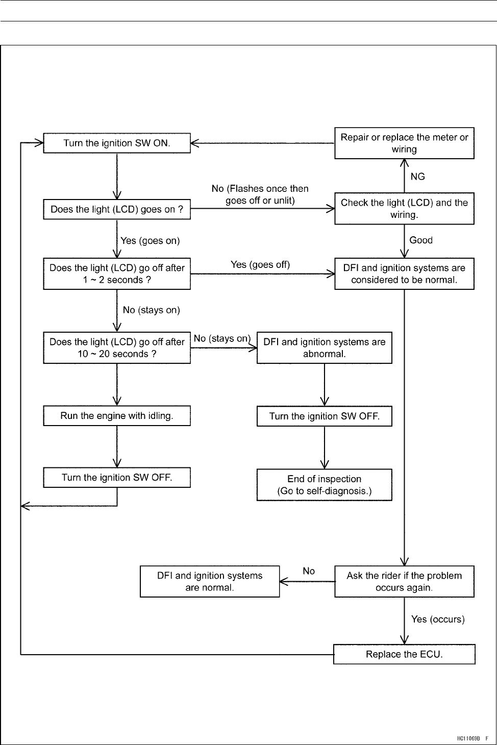
3-72 FUEL SYSTEM (DFI)
FI Indicator Light (LCD)
Inspection Flow Chart
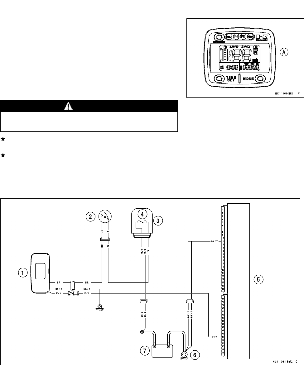
FUEL SYSTEM (DFI) 3-73
FI Indicator Light (LCD)
Light Inspection
○The FI indicator light (LCD) [A] goes ON when the ignition
switch is turned ON and the FI indicator light (LCD) goes
OFF when the engine oil pressure is high enough (the
engine is running). This is to ensure that the FI indicator
light (LCD) has not burned out and the DFI system and
the ignition system function properly.
•Refer to the Multifunction Meter Unit Inspection in the
Electrical System chapter for FI indicator light (LCD) In-
spection.
WARNING
This inspection may produce sparks. Keep the bat-
tery and the meter unit away from the fuel tank.
If the FI indicator light (LCD) is abnormal, replace the me-
ter unit.
If the FI indicator light (LCD) is normal, the wiring or ECU
has trouble. Check the wiring (see next diagram). If the
wiring is good, check the ECU for its ground and power
supply (see ECU Power Supply Inspection).
FI Indicator Light (LCD) Circuit
1. Multifunction Meter
2. Ignition Switch
3. Fuse Box
4. Main Fuse 30 A
5. ECU (Electronic Control Unit)
6. Engine Ground Terminal
7. Battery 12 V 12 Ah
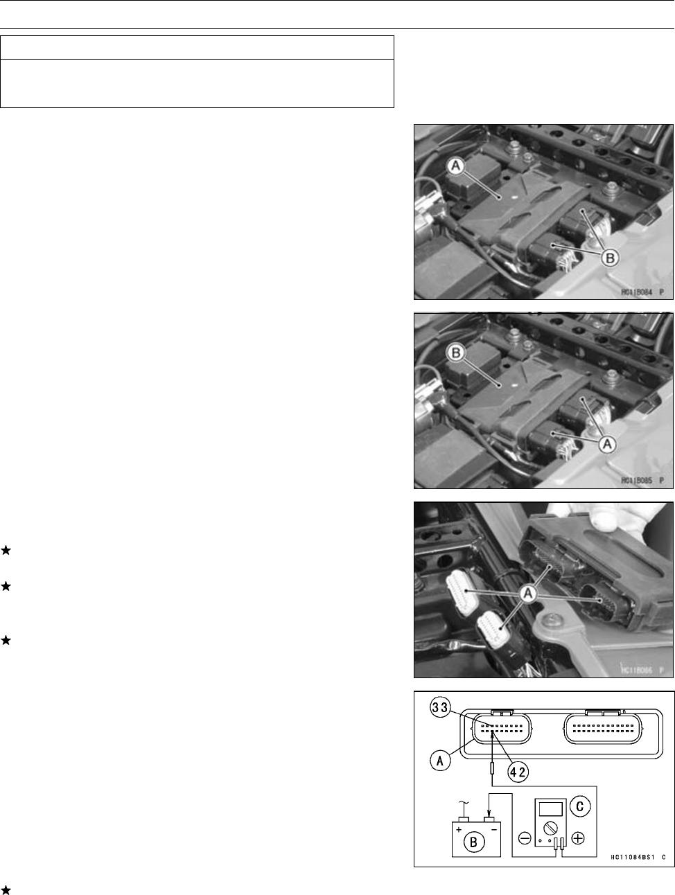
3-74 FUEL SYSTEM (DFI)
ECU
CAUTION
Never drop the ECU, especially on a hard surface.
Such a shock to the ECU can damage it.
ECU Removal
•Remove:
Seat (see Seat Removal in the Frame chapter)
ECU [A]
•Disconnect the ECU connectors [B].
ECU Installation
•Connect the ECU connectors [A] to the ECU [B].
•Install the ECU to the electrical parts case.
ECU Power Supply Inspection
•Visually inspect the terminals [A] of the ECU connectors.
If the connector is clogged with mud or dust, blow it off
with compressed air.
Replace the main harness if the terminals of the main
harness connectors are cracked, bent, or otherwise dam-
aged.
Replace the ECU if the terminals of the ECU connectors
are cracked, bent, or otherwise damaged.
•With the ECU connector [A] connected, check the follow-
ing ground lead for continuity with the ignition switch OFF,
using a digital meter and needle adapter set.
Battery [B]
Digital Meter [C]
Special Tool - Needle Adapter Set: 57001-1457
ECU Grounding Inspection
33 or 42 (BK/Y) Terminal ←→ Battery (–) Terminal: 0 Ω
Engine Ground ←→ Battery (–) Terminal: 0 Ω
If no continuity, check the connector, the engine ground
lead, or main harness, and repair or replace them if nec-
essary.
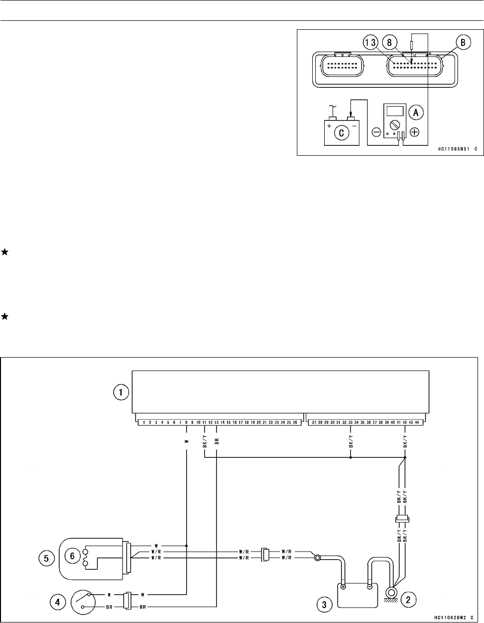
FUEL SYSTEM (DFI) 3-75
ECU
•Check the ECU power source voltage with a digital meter
[A].
○Position the terminal in accordance with terminal numbers
of ECU connector [B] in this chapter figure.
Battery [C]
ECU Power Source Inspection
Meter Connections:
Between Terminal 8 (W) and Battery (–) Terminal
Between Terminal 13 (BR) and Battery (–) Terminal
Ignition Switch OFF:
Terminal 8 (W): 0 V
Terminal 13 (BR): Battery Voltage
Ignition Switch ON:
Both: Battery Voltage
If the meter does not read as specified, check the follow-
ing.
Main Fuse 30 A (see Fuse Inspection in the Electrical
System chapter)
Power Source Wiring (see wiring diagram in this section)
If the fuse, reply and wiring are good, replace the ECU
(see ECU Removal/Installation).
ECU Power Source Circuit
1. ECU (Electronic Control Unit)
2. Engine Ground Terminal
3. Battery 12 V 12 Ah
4. Ignition Switch
5. Fuse Box
6. Main Fuse 30 A
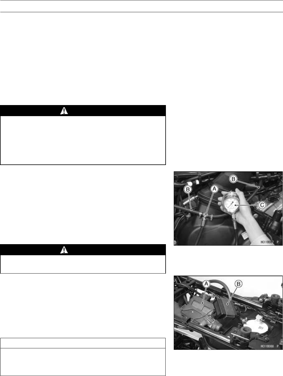
3-76 FUEL SYSTEM (DFI)
Fuel Line
Fuel Pressure Inspection
NOTE
○This inspection can determine which trouble the DFI
system has, mechanical or electrical trouble.
○It is preferable to measure the fuel pressure while run-
ning the vehicle just when trouble occurred in order to
know symptom well.
○Be sure the battery is fully charged.
•Remove the fuel hose (see Fuel Hose Replacement in the
Periodic Maintenance chapter).
WARNING
Be prepared for fuel spillage; any spilled fuel must
be completely wiped up immediately.
When the fuel hose is disconnected, fuel spills out
from the hose and the pipe because of residual
pressure. Cover the hose connection with a piece
of clean cloth to prevent fuel spillage.
•Install the fuel pressure gauge adapter [A] and fuel hoses
(Special Tools) [B] between the fuel pump outlet pipe and
the delivery pipe.
•Connect the pressure gauge [C] to the fuel pressure
gauge adapter.
Special Tools - Oil Pressure Gauge, 5 kgf/cm²: 57001-125
Fuel Pressure Gauge Adapter: 57001-1593
Fuel Hose: 57001-1607
Fuel Hose L = 550: 57001-1707
WARNING
Do not try to start the engine with the fuel hoses
disconnected.
•Temporarily, install the ECU [A] and actuator controller
[B].
•Turn the ignition switch ON. The fuel pump will turn for 3
seconds, and then stop.
NOTE
○Turn the ignition switch ON and inspect the fuel line
leakage after installing the special tools.
CAUTION
Do not drive the fuel pump without the fuel in the
fuel tank. If the fuel pump is driven without the fuel,
it may be damaged.
•Start the engine, and let it idle.
•Measure the fuel pressure with the engine idling.
Fuel Pressure (Idling)
Standard: 294 kPa (3.0 kgf/cm², 43 psi)
FUEL SYSTEM (DFI) 3-77
Fuel Line
NOTE
○The gauge needle will fluctuate. Read the pressure at
the average of the maximum and minimum indications.
If the fuel pressure is much lower than specified, the fuel
pressure regulator in the fuel pump have been clogged or
stuck. Replace the fuel pump (see Fuel Pump section).
If the fuel pressure is much lower than specified, check
the following.
Fuel Line Leakage
Amount of Fuel Flow (see Fuel Flow Rate Inspection)
If the fuel pressure is much lower than specified, and if
inspection above checks out good, replace the throttle
body assy, or the fuel pump and measure the fuel pres-
sure again (see appropriate sections).
•Remove the fuel pressure gauge, hoses and adapter.
•Install the removed parts.
Fuel Flow Rate Inspection
NOTE
○Be sure the battery is fully charged.
WARNING
Gasoline is extremely flammable and can be explo-
sive under certain conditions. Make sure the area
is well-ventilated and free from any source of flame
or sparks; this includes any appliance with a pilot
light. Do not smoke. Turn the ignition switch OFF.
Be prepared for fuel spillage; any spilled fuel must
be completely wiped up immediately.
•Turn the ignition switch, and engine stop switch OFF.
•Wait until the engine cools down.
•Prepare a fuel hose (Special Tool: 57001-1607) and a
measuring cylinder.
Special Tool - Fuel Hose: 57001-1607
•Remove the fuel hose (see Fuel Hose Replacement in the
Periodic Maintenance chapter).
WARNING
Be prepared for fuel spillage; any spilled fuel must
be completely wiped up immediately.
When the fuel hose is disconnected, fuel spills out
from the hose and the pipe because of residual
pressure. Cover the hose connection with a piece
of clean cloth to prevent fuel spillage.
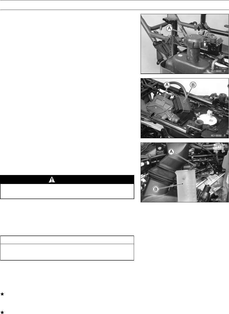
3-78 FUEL SYSTEM (DFI)
Fuel Line
•Open the fuel tank cap [A] to lower the pressure in the
tank.
•Temporarily, install the ECU [A] and actuator controller
[B].
•Connect the prepared fuel hose [A] to the fuel pump outlet
pipe.
•Secure the fuel hose with a clamp.
•Run the other side of the fuel hose into the measuring
cylinder [B].
WARNING
Wipe off spilled out fuel immediately.
Be sure to hold the measuring cylinder vertical.
•Close the fuel tank cap.
•With the engine stopped, turn the ignition switch ON. The
fuel pump should operate for 3 seconds, and then should
stop. Repeat this several times until the fuel hose is filled
with fuel.
CAUTION
Do not drive the fuel pump without the fuel in the
fuel tank.
•Measure the discharge for 3 seconds.
○Repeat this operation several times.
Amount of Fuel Flow
Standard: 50 mL (1.7 US oz.) or more for 3 seconds
If the fuel flow is much less than the specified, check the
battery condition (see Charging Condition Inspection in
the Electrical System chapter).
If the battery is good, replace the fuel pump (see Fuel
Pump Removal/Installation).
•After inspection, connect the fuel hose (see Fuel Tank
Installation).
•Start the engine and check for fuel leakage.
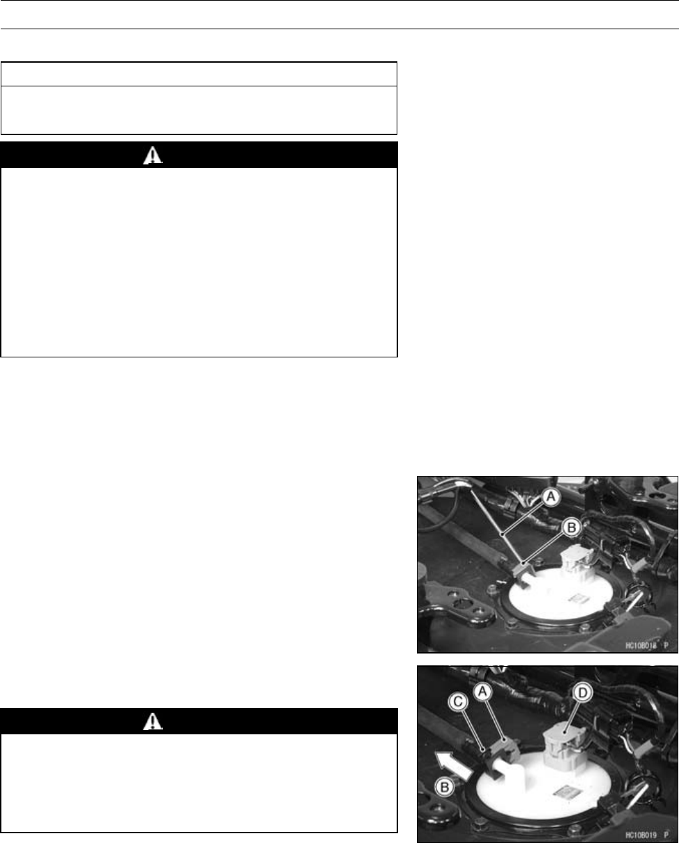
FUEL SYSTEM (DFI) 3-79
Fuel Pump
Fuel Pump Removal
CAUTION
Never drop the fuel pump, especially on a hard sur-
face. Such a shock to the pump can damage it.
WARNING
Gasoline is extremely flammable and can be explo-
sive under certain conditions. Make sure the area
is well-ventilated and free from any source of flame
or sparks; this includes any appliance with a pilot
light. Do not smoke. Turn the ignition switch OFF.
Disconnect the battery (–) terminal.
To make fuel spillage minimum, draw the fuel out
from the fuel tank when the engine is cold. Be
prepared for fuel spillage; any spilled fuel must be
completely wiped up immediately.
•Remove the electrical parts case (see Electrical Parts
Case Removal in Frame chapter).
○Be careful of fuel spillage from the fuel tank since fuel still
remains in the fuel tank and fuel pump. Plug the fuel pipe
of the fuel tank.
•Be sure to place a piece cloth around the fuel hose joint.
•Insert a minus screwdriver [A] into the slit on the joint lock
[B].
•Twist the screwdriver to disconnect the joint lock [A].
•Pull [B] the fuel hose joint [C] out of the fuel pump.
WARNING
Be prepared for fuel spillage; any spilled fuel must
be completely wiped up immediately.
When the fuel hose is disconnected, fuel spills out
from the hose and the pipe. Cover the hose connec-
tion with a clean shop towel to prevent fuel spillage.
•Disconnect:
Fuel Pump Connector [D]
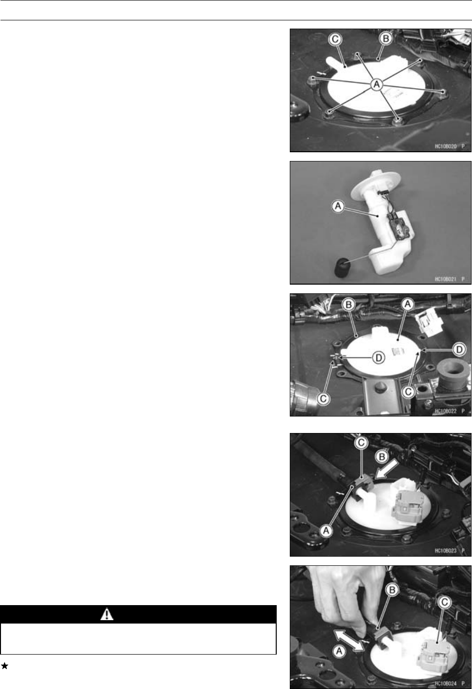
3-80 FUEL SYSTEM (DFI)
Fuel Pump
•Remove:
Fuel Pump Bolts [A]
Plate [B]
Fuel Pump [C]
O-ring
Fuel Pump Installation
•Remove dirt or dust from the fuel pump [A] by lightly ap-
plying compressed air.
•Install:
Fuel Pump [A]
O-ring
•Install the plate [B] so that fit the projections [C] and hel-
lows [D] of the fuel pump and plate.
•Tighten the fuel pump bolts to a snug fit, tighten them
alternating diagonally.
Torque - Fuel Pump Bolts: 4.0 N·m (0.41 kgf·m, 35 in·lb)
•Tighten the pump bolts again alternating diagonally to
check the tightness.
•Install the fuel hose.
•Insert the fuel hose joint [A] straight onto the fuel pump
until the hose joint clicks.
•Push [B] the joint lock [C].
•Push and pull [A] the fuel hose joint [B] back and forth
more than two times and make sure it is locked and
doesn’t come off.
WARNING
Make sure the fuel hose joint is installed correctly
on the fuel pump or the fuel could leak.
If it comes off, reinstall the hose joint.
•Connect:
Fuel Pump Connector [C]
•Run the fuel hose correctly (see Cable, Wire and Hose
Routing section in the Appendix chapter).
•Install the removed parts (see appropriate chapters).
•Start the engine and check the fuel hose for leaks.
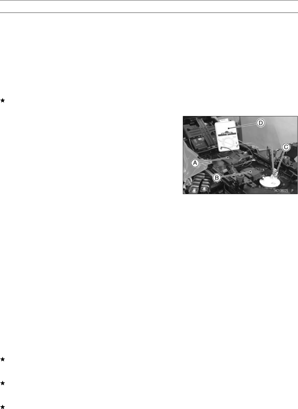
FUEL SYSTEM (DFI) 3-81
Fuel Pump
Fuel Pump Operation Inspection
NOTE
○Be sure the battery is fully charged.
○Just listen to the pump sound in the fuel tank to confirm
pump operation.
•Turn the ignition switch ON and make sure that the fuel
pump operates (make light sounds) for 3 seconds, and
then stops.
•Turn the ignition switch OFF.
If the pump does not work as described above, inspect
the operating voltage.
Fuel Pump Operating Voltage Inspection
NOTE
○Be sure the battery is fully charged.
•Turn the ignition switch OFF.
•Remove:
Electrical Parts Case (see Electrical Parts Case Re-
moval in the Frame chapter)
•Temporary connect the ECU [A] and actuator controller
[B].
•Open the fuel pump connector cap [C].
•Connect the hand tester [D] (× DC 25 V) to the fuel pump
connector with needle adapter set.
Special Tools - Hand Tester: 57001-1394
Needle Adapter Set: 57001-1457
Pump Operating Voltage at Pump
Connections to Pump Connectors
Tester (+) →W/R Lead
Tester (–) →BK/Y Lead
•Measure the operating voltage with the engine stopped,
and with the connector joined.
•Turn the engine stop switch to run position.
•Turn the ignition switch ON.
○The tester needle should indicate battery voltage for 3
seconds, and then 0 V.
Operating Voltage at Pump Connector
Standard: Battery Voltage for 3 seconds, and then 0 V
If the reading stays on battery voltage, and never shows
0 V. Check the ECU for its ground and power supply (see
ECU Power Supply Inspection) and fuel pump relay.
If the voltage is in specification, but the pump doesn’t
work, replace the pump (see Fuel Pump Removal/Instal-
lation).
If there is still no battery voltage, check the pump relay
(see Relay Inspection in the Electrical System chapter).
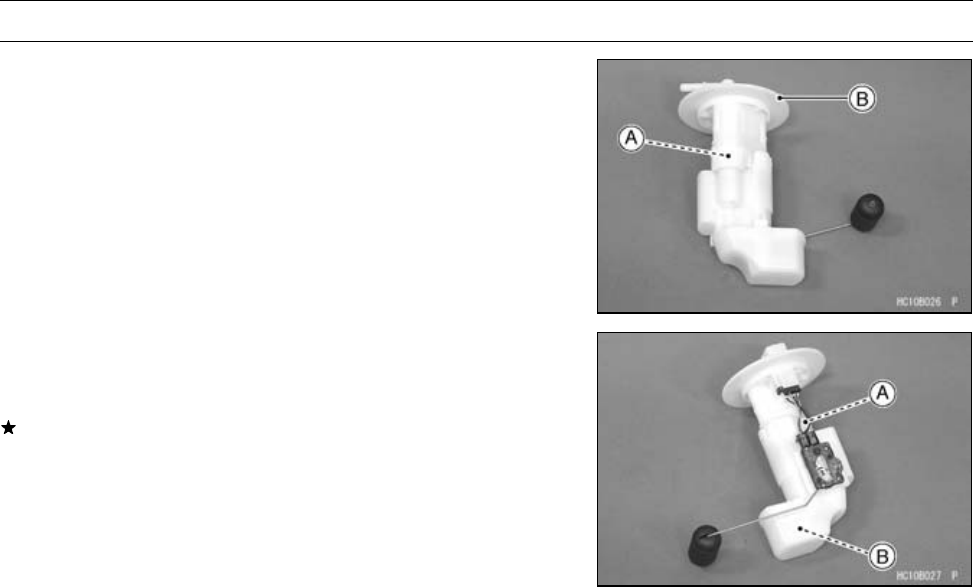
3-82 FUEL SYSTEM (DFI)
Fuel Pump
Pressure Regulator Removal
○The pressure regulator [A] is built into the fuel pump [B]
and cannot be removed.
Pump Screen, Fuel Filter Cleaning
○The pump screen [A] and fuel filter [B] are built into the
pump and cannot be cleaned or checked.
If the fuel filter is suspected of clogging or being damaged,
replace it with the fuel pump.
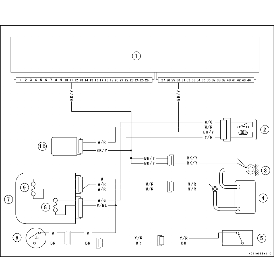
FUEL SYSTEM (DFI) 3-83
Fuel Pump
Fuel Pump Circuit
1. ECU (Electronic Control Unit)
2. Fuel Pump Relay
3. Engine Ground Terminal
4. Battery 12 V 12 Ah
5. Engine Stop Switch
6. Ignition Switch
7. Fuse Box
8. Fuel Pump Fuse 10 A
9. Main Fuse 30 A
10. Fuel Pump
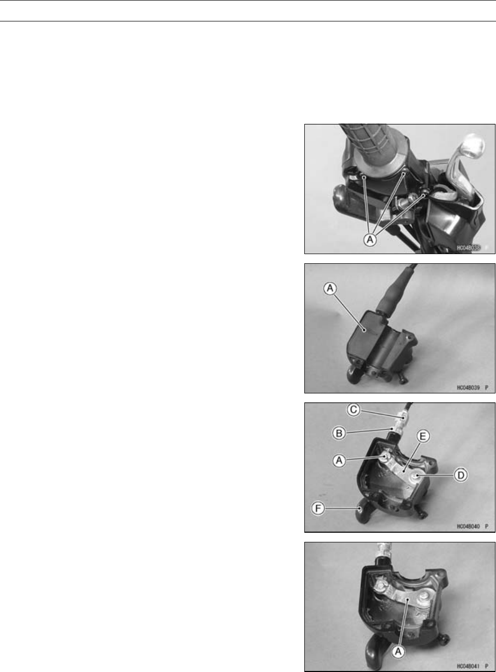
3-84 FUEL SYSTEM (DFI)
Throttle Lever and Cable
Throttle Lever Free Play Inspection
•Refer to the Throttle Lever Free Play Inspection in the
Periodic Maintenance chapter.
Throttle Lever Free Play Adjustment
•Refer to the Throttle Lever Free Play Adjustment in the
Periodic Maintenance chapter.
Throttle Case Removal/Disassembly
•Remove the throttle case screws [A] and pull the case
open.
•Slide the cable adjuster dust cover out of place.
•Remove the rubber cover [A].
•Pull the cable tip [A] out of the throttle lever catch with the
throttle lever opened.
•Loosen the locknut [B] and unscrew the adjuster [C].
•Disassemble the throttle case as follows:
○Remove the throttle lever screw [D], lockwasher, and flat
washer, and lift the throttle lever [E] and return spring from
the case.
○Pull the throttle control lever [F] out of the case.
Throttle Case Assembly/Installation
•Lubricate the throttle case and cable before assembly/in-
stallation.
•Be certain that the return spring is correctly installed on
the throttle lever [A].
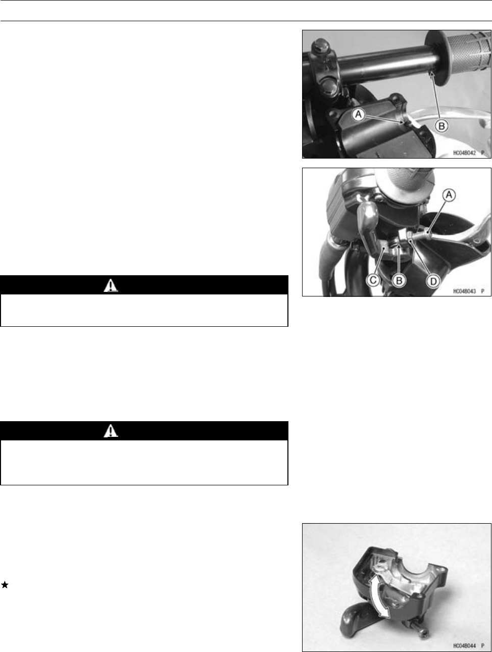
FUEL SYSTEM (DFI) 3-85
Throttle Lever and Cable
•Install the throttle case so that the projection [A] fit to the
hole [B] of the handlebar.
•Swing the throttle control lever so that the carburetor throt-
tle valve is fully open. Turn the throttle limiter screw [A]
until it is spaced about 1 mm (0.04 in.) [B] away from the
throttle lever stop [C]. Tighten the locknut [D].
NOTE
○Refer to the Owner’s Manual for the function of the throt-
tle limiter and adjustment procedure of it.
WARNING
Operation with an improperly assembled throttle
case could result in an unsafe riding condition.
•Check the throttle lever free play (see Throttle Lever Free
Play Inspection in the Periodic Maintenance chapter).
Throttle Cable Installation
•Lubricate the throttle cable before installation.
•Route the cable correctly according to the Cable, Wire,
and Hose Routing in the Appendix chapter.
WARNING
Operation with an improperly adjusted, incorrectly
routed, or damaged cable could result in an unsafe
riding condition.
•Check the throttle cable (see Throttle Lever Free Play In-
spection in the Periodic Maintenance chapter).
Throttle Case Inspection
•With the throttle cable disconnected from the throttle
lever, the lever should move freely and return smoothly
by spring.
If the lever is heavy, disassemble the throttle case, clean
and lubricate the throttle case.
•Examine the lever and case for cracks. Replace the case
assembly if it is cracked.
Throttle Cable Lubrication and Inspection
•Whenever the throttle cable is removed or in accordance
with the Periodic Maintenance Chart in the Periodic Main-
tenance chapter, lubricate the cable .
•Refer to the General Lubrication in the Periodic Mainte-
nance chapter.
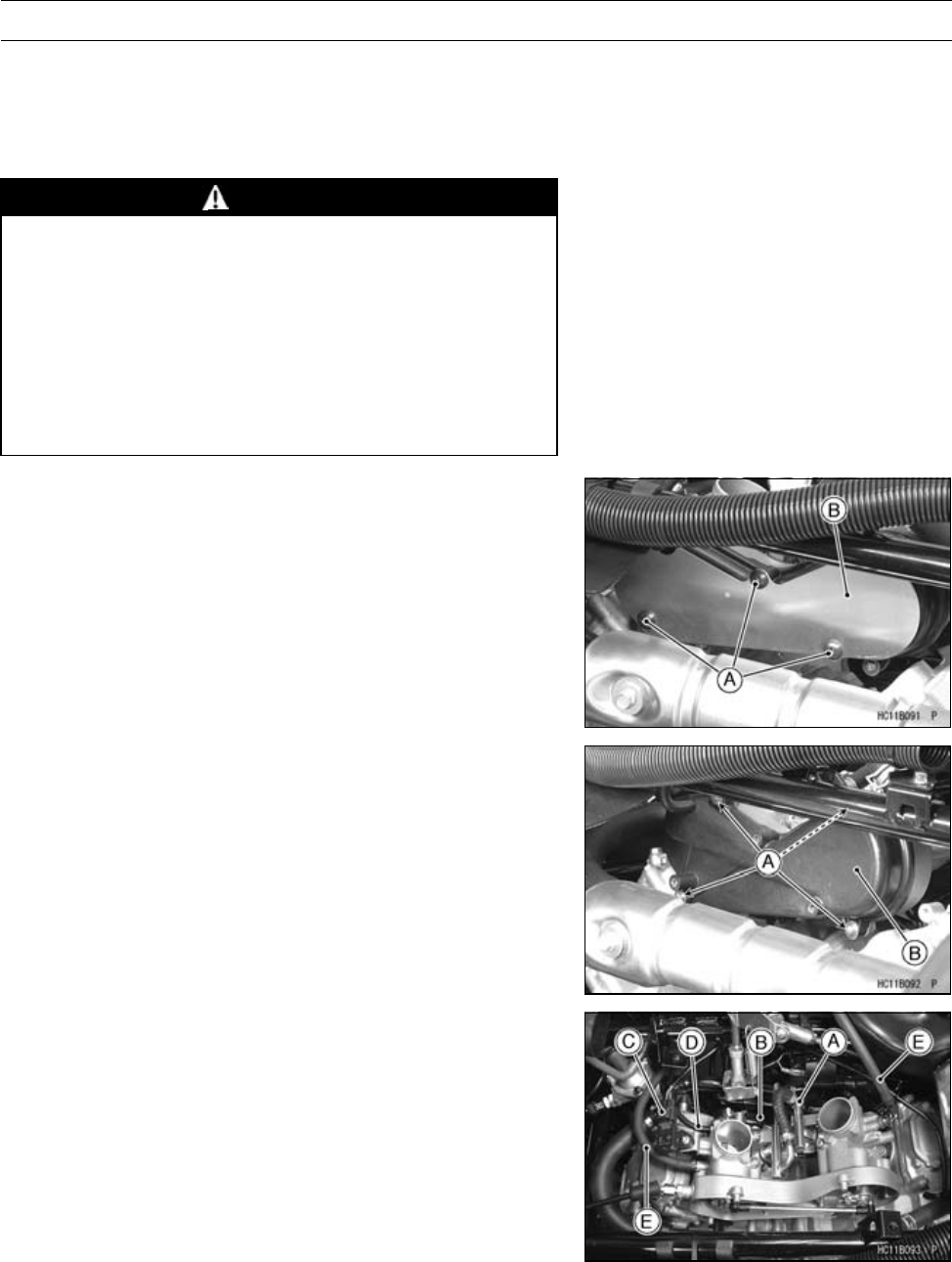
3-86 FUEL SYSTEM (DFI)
Throttle Body Assy
Idle Speed Inspection
•Refer to the Idle Speed Inspection in the Periodic Main-
tenance chapter.
Throttle Body Assy Removal
WARNING
Gasoline is extremely flammable and can be ex-
plosive under certain conditions. Turn the ignition
switch OFF. Disconnect the battery (–) cable ter-
minal. Do not smoke. Make sure the area is
well-ventilated and free from any source of flame
or sparks; this includes any appliance with a pilot
light.
Be prepared for fuel spillage: any spilled fuel must
be completely wiped up immediately.
•Remove:
Air Cleaner (see Air Cleaner Housing Removal)
Fuel Hose (see Fuel Hose Replacement in the Periodic
Maintenance chapter)
Screws [A]
Heat Guard Plate [B]
•Remove:
Screws [A]
Throttle Link Case Cover [B]
•Remove:
Delivery Pipe [A] (see Fuel Injection Removal)
Throttle Sensor Connector [B]
Inlet Air Pressure Sensor Connector [C]
Vacuum Hose [D]
ISC Valve Hoses [E]
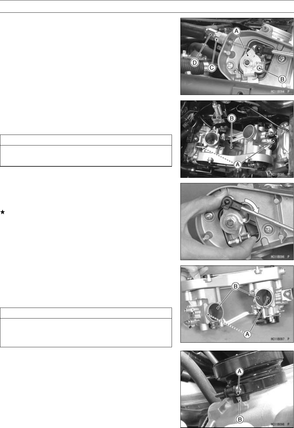
FUEL SYSTEM (DFI) 3-87
Throttle Body Assy
•Turn the throttle pully [A] clockwise to remove the throttle
cable tip [B].
•Loosen the locknut [C] and adjusting nut [D] fully to re-
move the throttle cable from the throttle body assy.
•Loosen the clamp screws [A] fully.
•Remove the throttle body assembly [B].
•After removing the throttle body assy, stuff pieces of lint
-free, clean cloths into the throttle body assy holders.
CAUTION
If dirt gets into the engine, excessive engine wear
and possible engine damage will occur.
Throttle Body Assy Installation
•Turn the throttle pulley to check that the throttle valve
move smoothly and return by spring force.
If the throttle valve do not move smoothly, replace the
throttle body.
•Open the butterfly valves [A], and wipe any carbon off
the throttle bores [B] around the valve, using a piece of
lint-free cloth penetrated with a high-flash point solvent.
•Blow away dirt or dust from the throttle body by applying
compressed air.
CAUTION
Do not immerse the throttle body in a high-flash
point solvent for cleaning. This could damage the
throttle sensor on the throttle body.
•Be sure to groove [A] of the throttle body holder fits on the
projection [B] of the cylinder head.
•Install the throttle body assy.
•Tighten the throttle body holder clamp screw securely.
•Run the leads and hoses as shown in the Cable, Wire,
and Hose Routing section of the Appendix chapter.
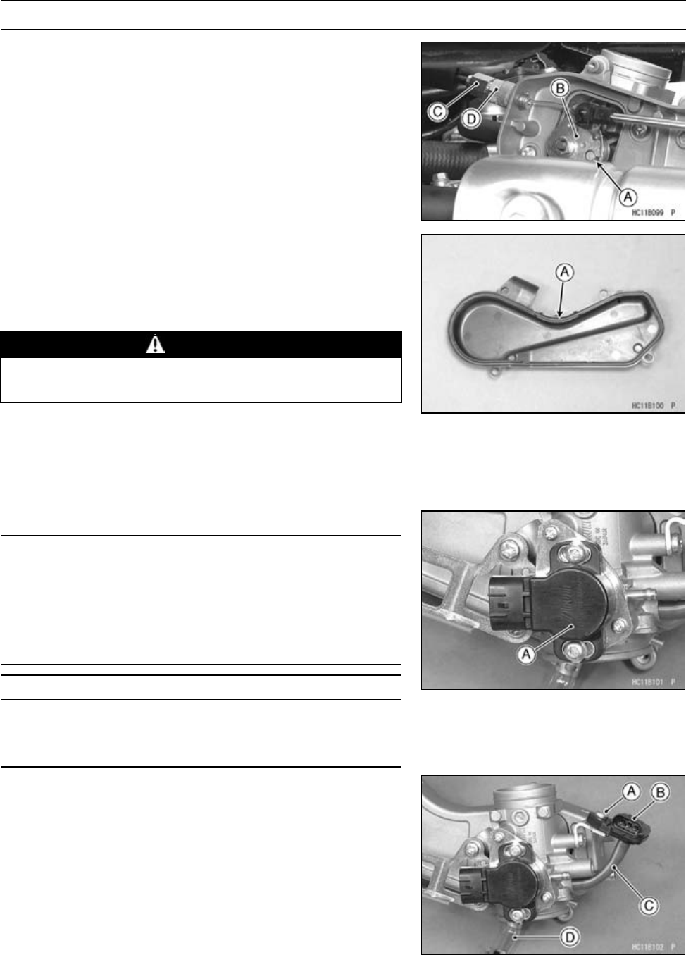
3-88 FUEL SYSTEM (DFI)
Throttle Body Assy
•Apply a thin coating of grease to the throttle cable lower
end.
•Fit the throttle cable lower end [A] into the throttle pulley
[B].
•Tighten the adjusting nut [C] and locknut [D].
•Be sure to install the seal [A] on the throttle link case
cover.
•Install the removed parts.
•Check the throttle lever free play (see Throttle Lever Free
Play Inspection in the Periodic Maintenance chapter).
WARNING
Operation with an incorrectly routed cable could re-
sult in an unsafe riding condition.
•Adjust:
Throttle Lever Free Play (see Throttle Lever Free Play
Inspection in the Periodic Maintenance chapter)
Idle Speed (see Idle Speed Adjustment in the Periodic
Maintenance chapter)
Throttle Body Assy Disassembly
CAUTION
Do not remove, disassemble or adjust the throttle
sensor [A] and throttle body assy, because they are
adjusted or set at the manufacturer. Adjustment of
these parts could result in poor performance, re-
quiring replacement of the throttle body assy.
CAUTION
Never drop the throttle body assy , especially on a
hard surface. Such a shock to the body assy can
damage it.
•Remove:
Throttle Body Assy (see Throttle Body Assy Removal)
Screw [A]
Inlet Air Pressure Sensor [B]
Vacuum Hose [C]
•Remove the drain tube [D], if necessary.
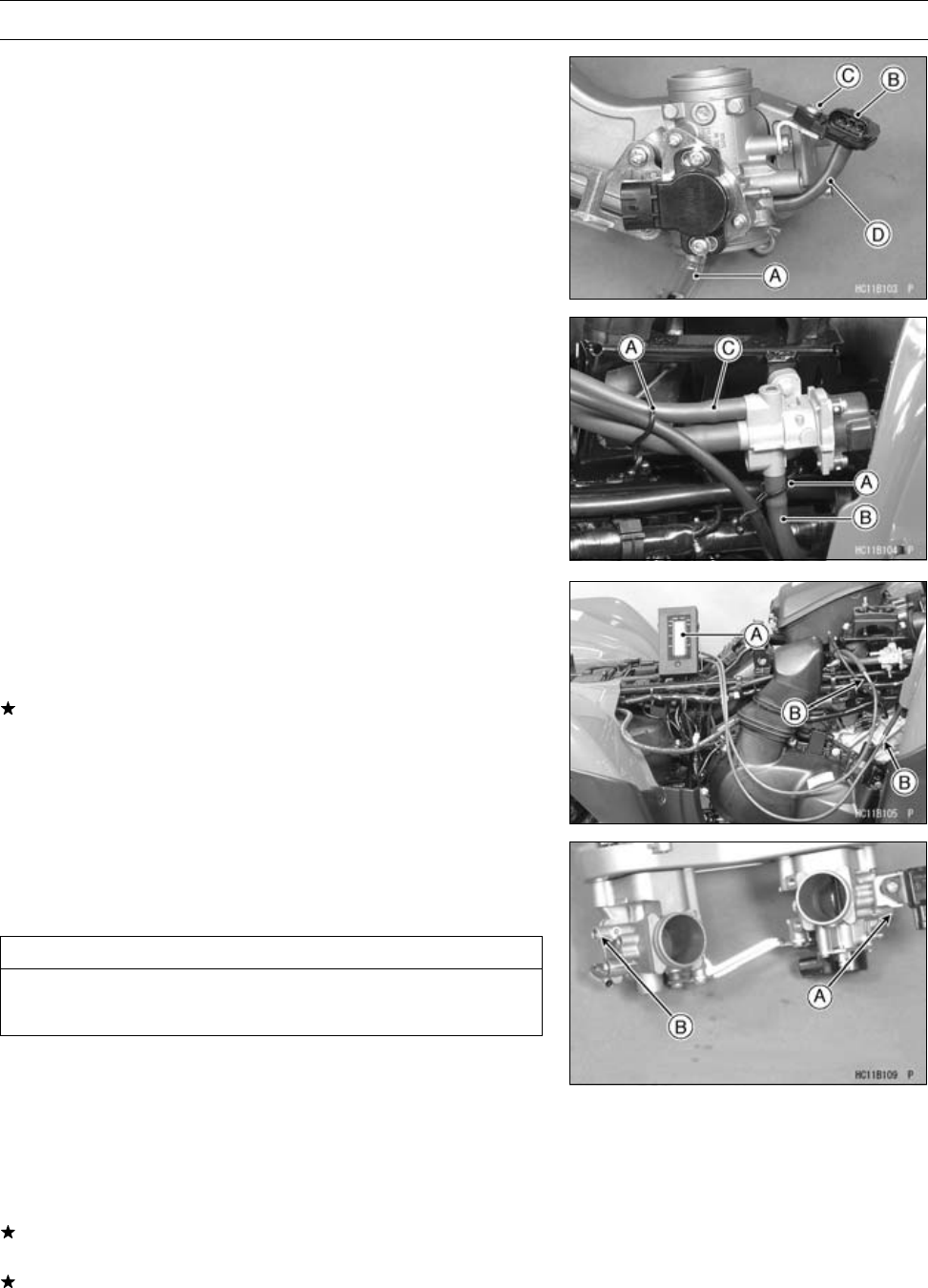
FUEL SYSTEM (DFI) 3-89
Throttle Body Assy
Throttle Body Assy Assembly
•Install the drain tube [A], if removed
•Install the inlet air pressure sensor [B]
•Tighten:
Torque - Inlet Air Pressure Sensor Mounting Screw [C]: 5.0
N·m (0.51 kgf·m, 44 in·lb)
•Connect the vacuum hose [D].
Engine Vacuum Synchronization Inspection
•Remove:
Side Covers (see Left and Right Side Cover Removal in
the Frame chapter)
Throttle Link Case Cover
•Check idle speed.
•Remove:
Clamps [A]
ISC Valve Tube (Front) [B]
ISC Valve Tube (Rear) [C]
•Connect the vacuum gauge [A] as shown.
Special Tools - Vacuum Gauge: 57001-1369
Vacuum Gauge Adapter [B]: 57001-401
•Start the engine and read the intake vacuum when idling.
If the vacuum is out of the specified range, adjust it.
Engine Vacuum Synchronization Vacuum
Standard: 29.6 ±1.3 kPa (222 ±9.8 mmHg) at Idle Speed
Engine Vacuum Synchronization Adjustment
•Turn in the bypass screws until it seats fully but not tightly.
Special Tool - Pilot Screw Adjuster, A: 57001-1239
CAUTION
Do not over tighten them. They could be damaged,
requiring replacement.
•Turn out the bypass screw of the higher vacuum between
#1 [A] and #2 [B] to the lower vacuum.
○In this photo, the throttle body has been removed for clar-
ity.
•Open and close the throttle valves after each measure-
ment and adjust the idle speed as necessary.
•Inspect the vacuums as before.
If both vacuums are within the specification, finish the en-
gine vacuum synchronization.
If any vacuum can not be adjusted within the specification,
remove the bypass screws #1, #2 and clean them.
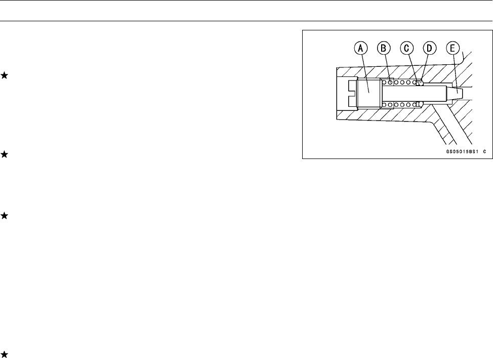
3-90 FUEL SYSTEM (DFI)
Throttle Body Assy
•Remove the bypass screw [A], spring [B], washer [C] and
O-ring [D].
○Check the bypass screw and its hole for carbon deposits.
If any carbon accumulates, wipe the carbon off the bypass
screw and the hole, using a cotton pad penetrated with a
high-flash point solvent.
○Replace the O-ring with a new one.
○Check the tapered portion [E] of the bypass screw for
wear or damage.
If the bypass screw is worn or damaged, replace it.
•Turn in the bypass screw until it seats fully but not tightly.
•Repeat the same procedure for other bypass screw.
•Repeat the synchronization.
If the vacuums are correct, check the output voltage of
the throttle sensor (see Throttle Sensor Output Voltage
Inspection in the Fuel System (DFI) chapter).
Throttle Sensor Output Voltage
Connections to ECU
Meter (+) →Y/W lead (ECU terminal 15)
Meter (–) →BR/BK lead (ECU terminal 10)
Standard:
1.00 ∼1.24 V DC (at idle throttle opening)
If the output voltage is out of the range, check the throttle
input voltage (see Throttle Sensor Input Voltage Inspec-
tion in the Fuel System (DFI) chapter).
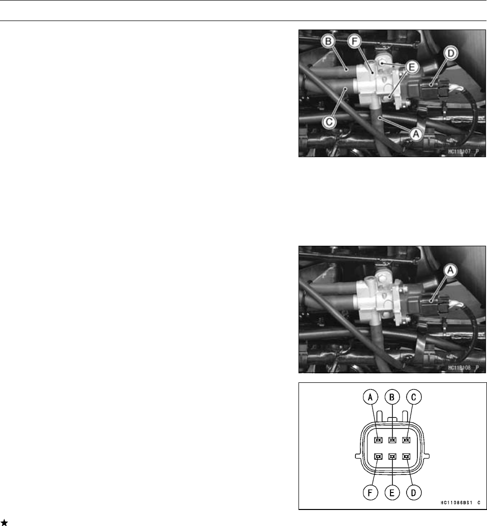
FUEL SYSTEM (DFI) 3-91
ISC Valve
ISC Valve Removal
•Remove:
Front Fender (see Front Fender Removal in the Frame
chapter)
ISC Valve Tube (Front) [A]
ISC Valve Tube (Rear) [B]
ISC Valve Tube (Primary) [C]
Connector [D]
Bolts [E]
ISC Valve [F]
ISC Valve Installation
•Install the ISC valve.
•Tighten:
Torque - ISC Valve Mounting Bolts: 8.8 N·m (0.90 kgf·m, 78
in·lb)
ISC Valve Inspection
•Remove:
Front Fender (see Front Fender Removal in the Frame
chapter)
ISC Valve Connector [A]
•Connect the hand tester to the following pair of terminals.
Special Tool - Hand Tester: 57001-1394
•Set the hand tester to the 10 Ωrange.
Connections:
Terminal A-B, Terminal B-C
Terminal D-E, Terminal E-F
Standard Resistence:
28.8 ∼31.2 Ωat 20°C(68°F)
If the tester does not read as specified, replace the ISC
valve.
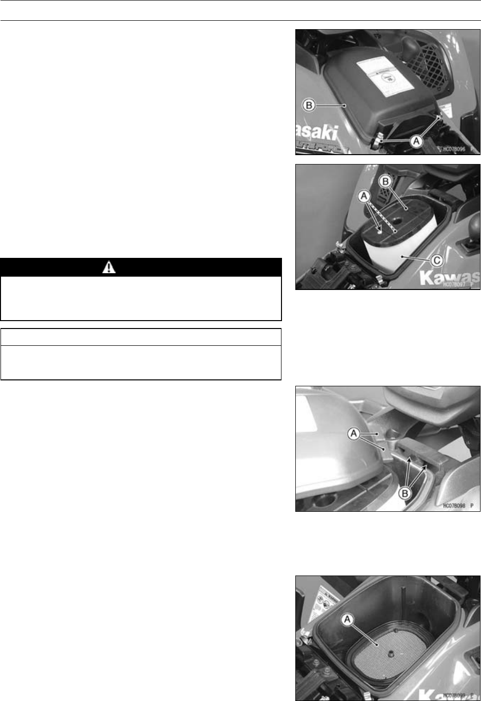
3-92 FUEL SYSTEM (DFI)
Air Cleaner
Air Cleaner Element Removal
•Remove:
Seat (see Seat Removal in the Frame chapter)
Clips [A]
Air Cleaner Housing Cap [B]
•Remove:
Element Holder Screws [A]
Element Holder [B]
Element [C]
•After removing the element, stuff pieces of lint-free, clean
cloth into the air cleaner ducts to keep dirt out of the throt-
tle body assy and engine.
WARNING
If dirt or dust is allowed to pass through into the
carburetors, the throttle may become stuck, possi-
bly causing an accident.
CAUTION
If dirt gets through into the engine, excessive en-
gine wear and possibly engine damage will occur.
Air Cleaner Element Installation
•Install:
Element
Element Holder
•Tighten:
Torque - Air Cleaner Element Holder Screw: 3.5 N·m (0.36
kgf·m, 31 in·lb)
Air Cleaner Element Holder Tapping Screw: 1.5
N·m (0.15 kgf·m, 13 in·lb)
•Fit the tangs [A] of the housing cap into the guides [B].
Air Cleaner Element Cleaning and Inspection
•Refer to the Air Cleaner Element Cleaning and Inspection
in the Periodic Maintenance chapter.
Air Cleaner Housing Removal
•Remove:
Air Cleaner Element (see Air Cleaner Element Removal)
Spark Arrester [A]
Side Covers (see Left and Right Side Cover Removal in
the Frame chapter)
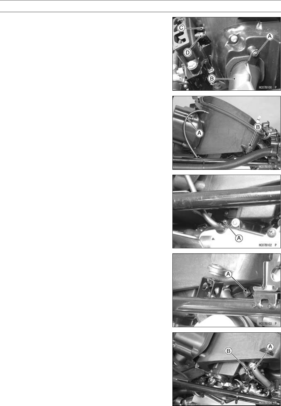
FUEL SYSTEM (DFI) 3-93
Air Cleaner
•Remove:
Screw [A]
Air Intake Duct [B]
Tube [C]
ISC Valve Inlet Tube [D]
•Remove:
Tube [A]
Air Cleaner Housing Bolts [B] (both side)
•Loosen the clamp screw [A].
•Loosen the clamp screw [A].
•While pulling up the air cleaner housing, remove the
breathe hose [A] and inlet air temperature sensor con-
nector [B].
•Remove the air cleaner housing.
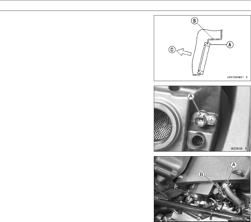
3-94 FUEL SYSTEM (DFI)
Air Cleaner
Air Cleaner Housing Installation
•Install:
Dust Seal [A]
Air Cleaner Housing Cover [B]
[C] Inside
•Be sure to the inlet air temperature sensor [A] is installed.
•Install:
Clamp [A] and Breather Hose
Inlet Air Temperature Sensor Connector [B]
•Install the air cleaner housing and joint duct on the throttle
body assy.
•Fit the joint duct on the fitting of the throttle body assy
securely and tighten the clamp screws.
•Tighten the air cleaner housing bolts.
•Install the removed hoses.
•Install:
Spark Arrester
Element Holder
Element (see Air Cleaner Element Installation)
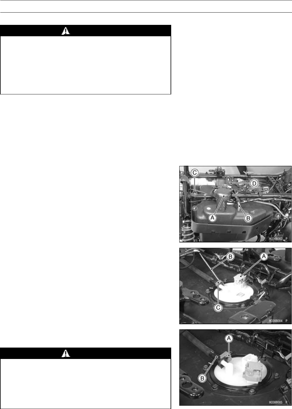
FUEL SYSTEM (DFI) 3-95
Fuel Tank
Fuel Tank Removal
WARNING
Gasoline is extremely flammable and can be explo-
sive under certain conditions. Make sure the area
is well-ventilated and free from any source of flame
or sparks; this includes any appliance with a pilot
light. Do not smoke. Turn the ignition switch OFF.
Be prepared for fuel spillage; any spilled fuel must
be completely wiped up immediately.
•Turn the ignition switch and engine stop switch OFF.
•Wait until the engine cools down.
•Disconnect the battery (–) cable terminal (see Battery Re-
moval in the Electrical System chapter).
•Remove:
Electrical Parts Case (see Electrical Parts Case Re-
moval in the Frame chapter)
•Open the fuel tank cap [A] to lower the pressure in the
tank.
○During tank removal, keep the tank cap open to release
pressure in the tank. This makes fuel spillage less.
•Remove:
Storage Case (Optional Part)
Check Valve Hose [B]
Bolts [C]
Fuel Tank Bracket [D]
•Disconnect:
Fuel Pump Lead Connector [A]
•Be sure to place a piece of cloth around the fuel hose joint.
•Insert a minus screwdriver [B] into the slit on the joint lock
[C].
•Twist the driver to disconnect the joint lock [A].
•Pull the fuel hose joint [B] out of the outlet pipe.
WARNING
Be prepared for fuel spillage; any spilled fuel must
be completely wiped up immediately.
When the fuel hose is disconnected, fuel spills out
from the hose and the pipe because of residual
pressure. Cover the hose connection with a piece
of clean cloth to prevent fuel spillage.
•Close the fuel tank cap.
•Remove the fuel tank together with the tank case from the
vehicle right side.
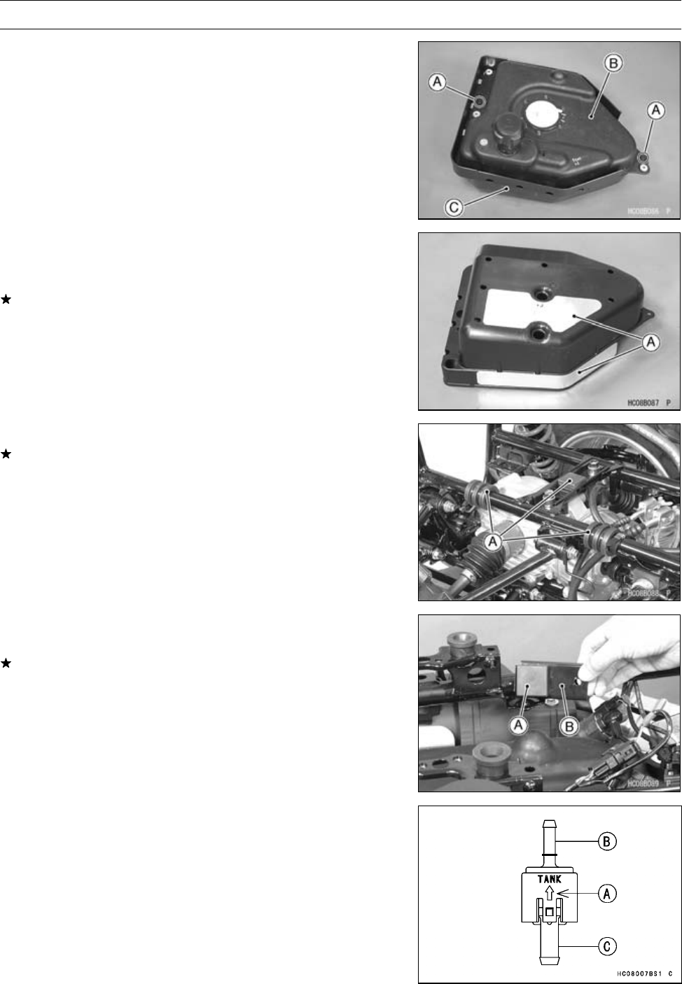
3-96 FUEL SYSTEM (DFI)
Fuel Tank
•Remove the quick rivets [A] to speparate the fuel tank [B]
and tank case [C].
Fuel Tank Installation
•Note the above WARNING (see Fuel Tank Removal)
•Check the insulators [A] on the tank case.
If the insulators are damaged or deteriorated, replace
them.
•Check the rubber dampers [A] on the frame as shown.
If the dampers are damaged or deteriorated, replace
them.
•Install the fuel tank with case, and tighten the bolts.
•Check the damper [A] on the damper bracket [B].
If the damper is damaged or deteriorated, replace it.
•Tighten the damper bracket bolt.
•Install the check valve so that the arrow [A] faces fuel tank.
[B] Black Color
[C] Blue Color
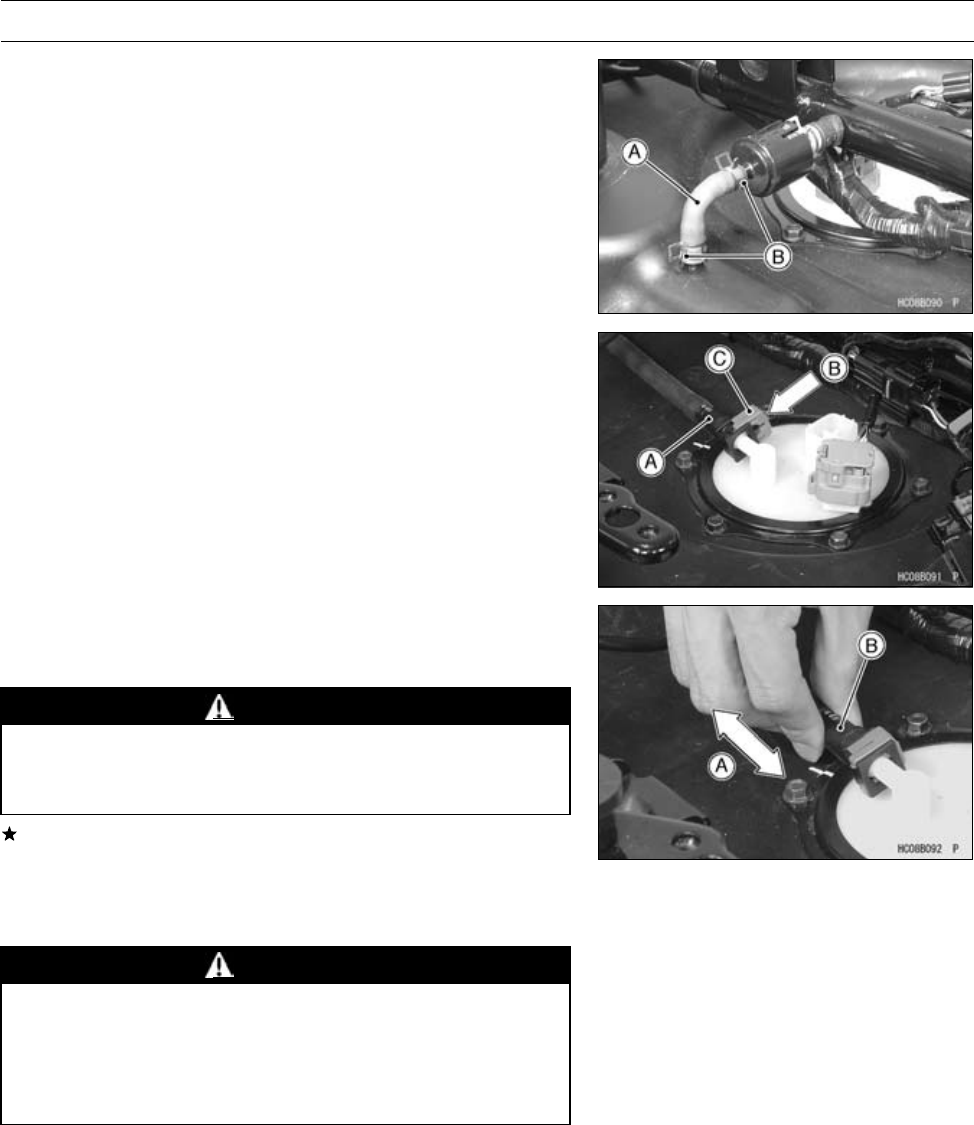
FUEL SYSTEM (DFI) 3-97
Fuel Tank
•Install:
Hose [A]
Clamps [B]
•Insert the fuel hose joint [A] straight onto the delivery pipe
until the hose joint clicks.
•Push [B] the joint lock [C] .
•Push and pull [A] the hose joint [B] back and forth more
than two times and make sure it is locked and doesn’t
come off.
WARNING
Make sure the hose joint is installed correctly on the
delivery pipe by sliding the joint, or the fuel could
leak.
If it comes off, reinstall the hose joint.
•Connect the fuel pump connector and the battery (–) cable
terminal.
Fuel Tank Cleaning
WARNING
Clean the tank in a well-ventilated area, and take
care that there are no sparks or flame anywhere
near the working area. Because of the danger or
highly flammable liquids, do not use gasoline or
low-flash point solvents to clean the tank.
•Remove:
Fuel Tank (see Fuel Tank Removal)
Fuel Pump (see Fuel Pump Removal)
•Remove the fuel pump inlet hose and the fuel pump (see
Fuel Pump Removal).
•Pour some high-flash point solvent into the fuel tank and
shake the tank to remove dirt and fuel deposits.
•Draw the solvent out of the fuel tank.
•Dry the tank with compressed air.
•Install the fuel pump (see Fuel Pump Installation).
•Install the fuel tank (see Fuel Tank Installation).

COOLING SYSTEM 4-1
4
Cooling System
Table of Contents
Exploded View........................................................................................................................ 4-2
Coolant Flow Chart................................................................................................................. 4-4
Specifications ......................................................................................................................... 4-6
Special Tools .......................................................................................................................... 4-7
Coolant ................................................................................................................................... 4-8
Coolant Deterioration Inspection....................................................................................... 4-8
Coolant Level Inspection................................................................................................... 4-8
Coolant Draining ............................................................................................................... 4-8
Coolant Filling ................................................................................................................... 4-8
Pressure Testing ............................................................................................................... 4-9
Water Pump............................................................................................................................ 4-10
Water Pump Cover Removal ............................................................................................ 4-10
Water Pump Cover Installation ......................................................................................... 4-10
Water Pump Impeller Removal ......................................................................................... 4-10
Water Pump Impeller Installation ...................................................................................... 4-10
Water Pump Impeller Inspection....................................................................................... 4-11
Water Pump Leakage Inspection...................................................................................... 4-11
Mechanical Seal Replacement ......................................................................................... 4-11
Radiator.................................................................................................................................. 4-13
Radiator Removal ............................................................................................................. 4-13
Radiator Installation .......................................................................................................... 4-14
Radiator Fan Removal ...................................................................................................... 4-14
Radiator Fan Installation ................................................................................................... 4-15
Radiator Inspection ........................................................................................................... 4-15
Radiator Cleaning ............................................................................................................. 4-15
Radiator Cap Inspection ................................................................................................... 4-15
Thermostat ............................................................................................................................. 4-17
Thermostat Removal......................................................................................................... 4-17
Thermostat Installation...................................................................................................... 4-17
Thermostat Inspection ...................................................................................................... 4-18
Water Temperature Sensor .................................................................................................... 4-19
Water Temperature Sensor Removal/Installation ............................................................. 4-19
Water Temperature Sensor Inspection ............................................................................. 4-19
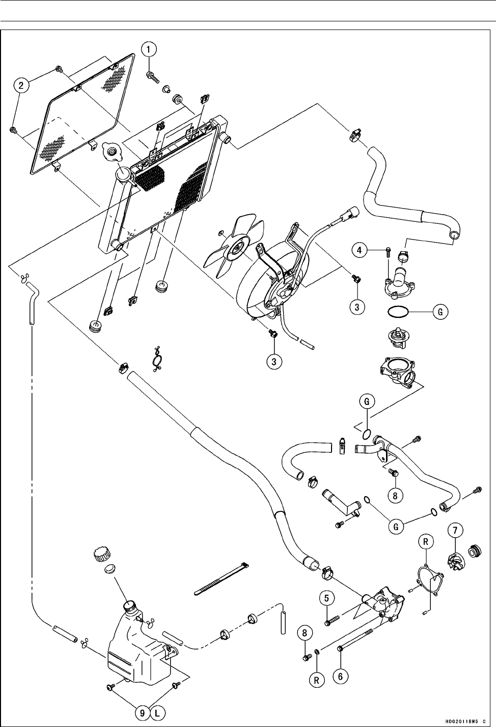
4-2 COOLING SYSTEM
Exploded View

COOLING SYSTEM 4-3
Exploded View
Torque
No. Fastener N·m kgf·m ft·lb Remarks
1Radiator Mounting Bolts 8.8 0.90 78 in·lb
2Radiator Screen Mounting Bolts 4.0 0.40 35 in·lb
3Radiator Fan Assembly Bolts 4.9 0.50 43 in·lb
4Thermostat Housing Cover Bolts 8.8 0.90 78 in·lb
5Water Pump Cover Bolts 8.8 0.90 78 in·lb
6Coolant Drain Bolt 8.8 0.90 78 in·lb
7Water Pump Impeller 7.8 0.80 69 in·lb
8Water Pipe Joint Bolt 8.8 0.90 78 in·lb
9Reserve Tank Mounting Screws 4.0 0.40 35 in·lb L
G: Apply grease.
L: Apply a non-permanent locking agent.
R: Replacement Parts

4-4 COOLING SYSTEM
Coolant Flow Chart
Permanent type antifreeze is used as a coolant to protect the cooling system from rust and corrosion.
When the engine starts, the water pump (coupled with the oil pump) turns and the coolant circulates.
The thermostat is a wax pellet type which opens or closes with coolant temperature changes. The
thermostat continuously changes its valve opening to keep the coolant temperature at the proper
level. When coolant temperature is below 67°C (153°F), the thermostat closes so that the coolant
flow is restricted through the air bleeder hole, causing the engine to warm up more quickly. When
coolant temperature is more than 69.5 ∼72.5°C (157 ∼162°F), the thermostat opens and the coolant
flows. When the coolant temperature goes up beyond 100°C (212°F), the radiator fan relay conducts
to operate the radiator fan. The radiator fan draws air through the radiator core when there is not
sufficient air flow such as at low speeds. This increases up the cooling action of the radiator. When
the temperature is below 90°C (194°F), the fan relay opens and the radiator fan stops.
In this way, this system controls the engine temperature within narrow limits where the engine op-
erates most efficiently even if the engine load varies.
The system is pressurized by the radiator cap to suppress boiling and the resultant air bubbles
which can cause engine overheating. As the engine warms up, the coolant in the radiator and the
water jacket expands. The excess coolant flows through the radiator cap and hose to the reserve tank
to be stored there temporarily. Conversely, as the engine cools down, the coolant in the radiator and
the water jacket contract, and the stored coolant flows back to the radiator from the reserve tank.
The radiator cap has two valves. One is a pressure valve which holds the pressure in the system
when the engine is running. When the pressure exceeds 93 ∼123 kPa (0.95 ∼1.25 kgf/cm², 14 ∼18
psi), the pressure valve opens and releases the pressure to the reserve tank. As soon as pressure
escapes, the valve closes, and keeps the pressure at 93 ∼123 kPa (0.95 ∼1.25 kgf/cm², 14 ∼18 psi).
When the engine cools down, another small valve (vacuum valve) in the cap opens. As the coolant
cools, the coolant contracts to form a vacuum in the system. The vacuum valve opens and allows the
coolant from the reserve tank to enter the radiator.
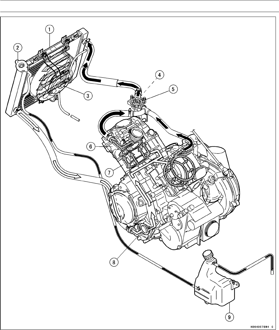
COOLING SYSTEM 4-5
Coolant Flow Chart
1. Radiator
2. Radiator Cap
3. Radiator Fan
4. Water Temperature Switch
5. Thermostat
6. Cylinder
7. Cylinder Head
8. Water Pump
9. Reserve Tank
Black Painted Arrow: Hot Coolant
White Painted Arrow: Cold Coolant

4-6 COOLING SYSTEM
Specifications
Item Standard Service Limit
Coolant Provided when Shipping
Type Permanent type of antifreeze (soft water
and ethylene glycol plus corrosion and rust
inhibitor chemicals for aluminum engines and
radiators)
–––
Color Green –––
Mixed Ratio Soft water 50%, coolant 50% –––
Freezing Point −35°C (−31°F) –––
Total Amount 2.2 L (2.3 US qt) (reserve tank full level
including radiator and engine) –––
Radiator Cap
Relief Pressure 93 ∼123 kPa (0.95 ∼1.25 kgf/cm², 14 ∼18 psi) –––
Thermostat
Valve Opening Temperature 69.5 ∼72.5°C (157 ∼162°F) –––
Valve Full Opening Lift 8 mm (0.3 in.) or more @85°C (185°F) –––
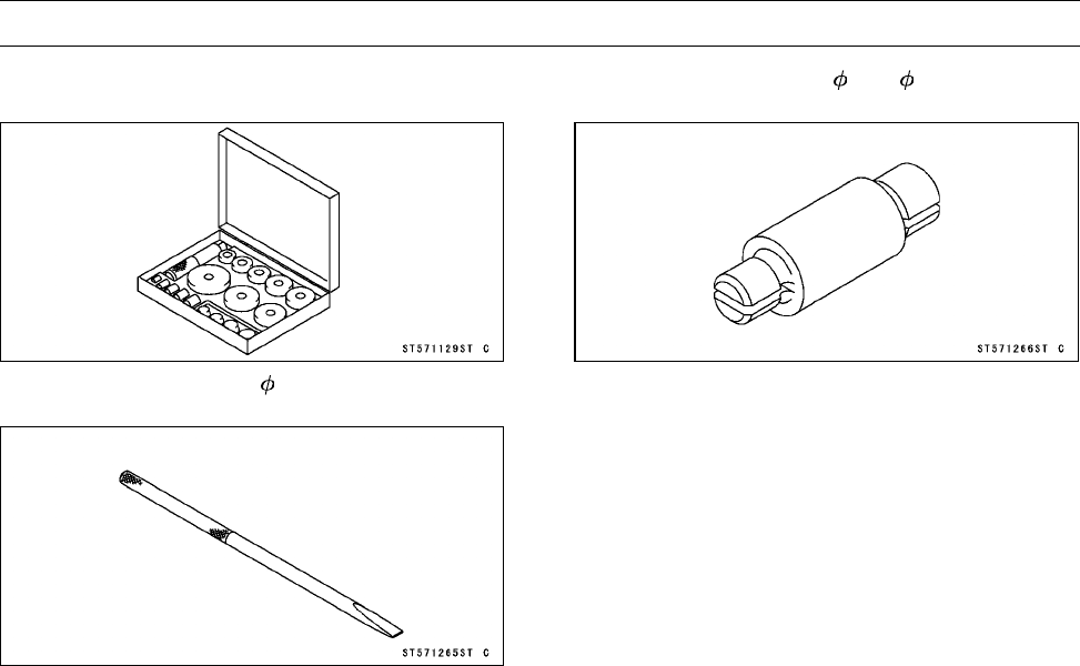
COOLING SYSTEM 4-7
Special Tools
Bearing Driver Set:
57001-1129
Bearing Remover Shaft, 9:
57001-1265
Bearing Remover Head, 10 × 12:
57001-1266
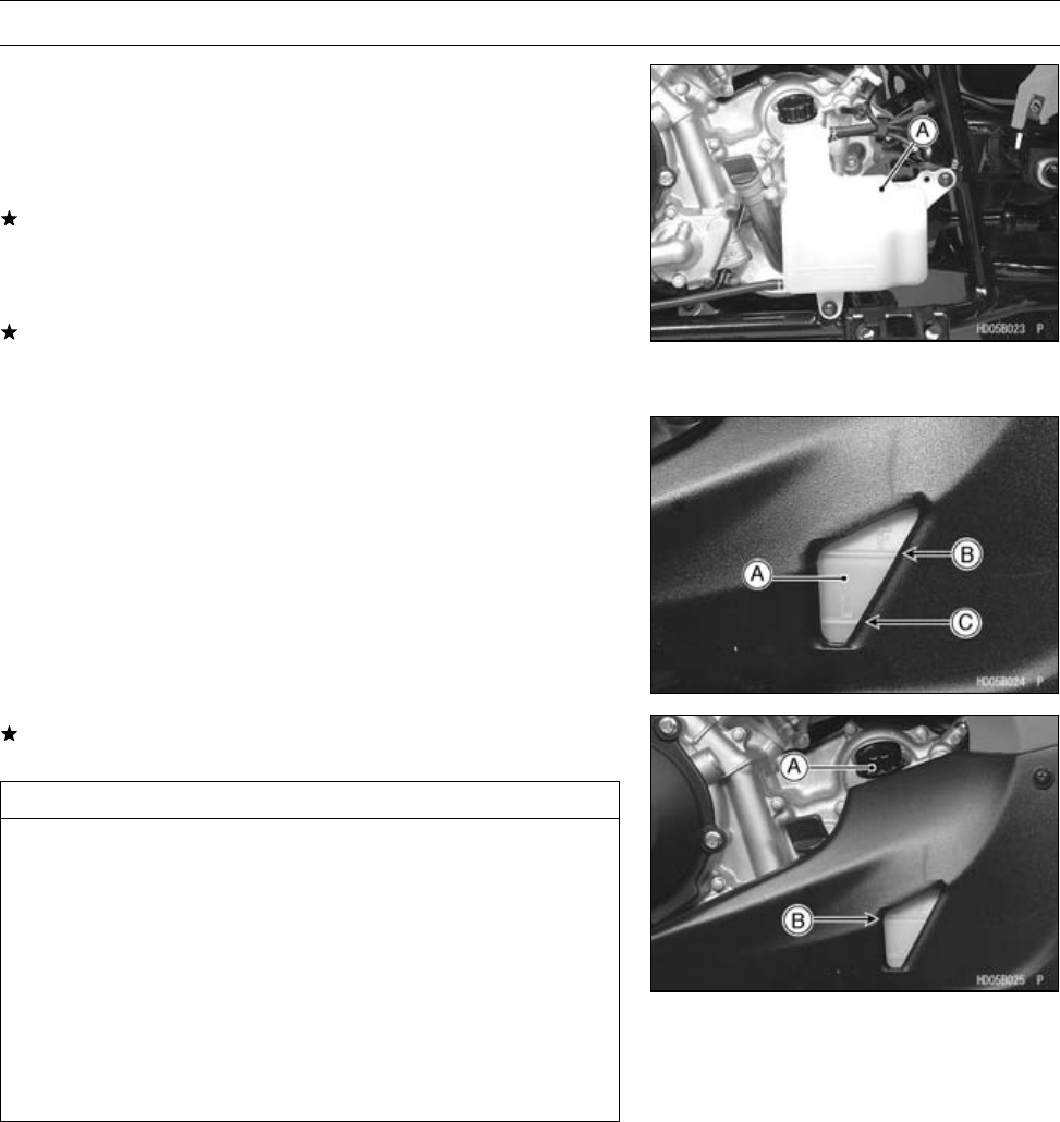
4-8 COOLING SYSTEM
Coolant
Coolant Deterioration Inspection
•Remove:
Left Footboard (see Left Footboard Removal in the
Frame chapter)
•Visually inspect the coolant in the reserve tank [A].
If whitish cotton-like wafts are observed, aluminum parts
in the cooling system are corroded. If the coolant is
brown, iron or steel parts are rusting. In either case, flush
the cooling system.
If the coolant gives off an abnormal smell, check for cool-
ing system leak. It may be caused by exhaust gas leaking
into the cooling system.
Coolant Level Inspection
NOTE
○Check the level when the engine is cold (room or ambi-
ent temperature).
•Check the coolant level in the reserve tank with the vehi-
cle held perpendicularly.
Reserve Tank [A]
F(full)Mark[B]
L(low)Mark[C]
If the coolant level is lower than the L mark, remove the
reserve tank cap [A], then add coolant to the F mark [B].
CAUTION
For refilling, add the specified mixture of coolant
and soft water. Adding water alone dilutes the
coolant and degrades its anticorrosion properties.
The diluted coolant can attach the aluminum engine
parts. In an emergency, soft water can be added.
But the diluted coolant must be returned to the cor-
rect mixture ratio within a few days.
If coolant must be added often, or the reserve tank
has run completely dry; there is probably leakage
in the cooling system. Check the system for leaks.
Coolant Draining
•Refer to the Coolant Change in the Periodic Maintenance
chapter.
Coolant Filling
•Refer to the Coolant Change in the Periodic Maintenance
chapter.
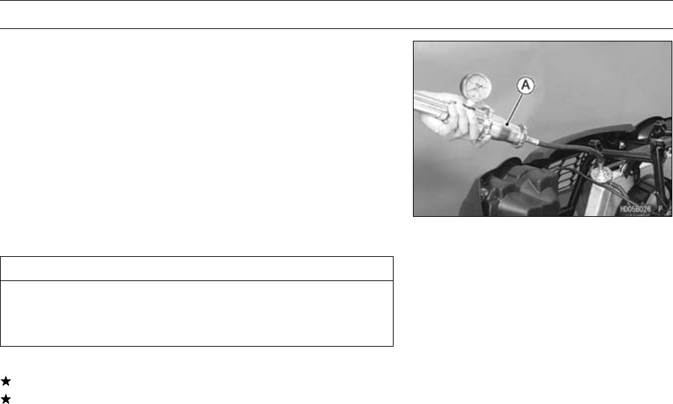
COOLING SYSTEM 4-9
Coolant
Pressure Testing
•Remove:
Front Fender (see Front Fender Removal in the Frame
chapter)
•Remove the radiator cap, and install a cooling system
pressure tester [A] on the radiator filler neck.
NOTE
○Wet the cap sealing surfaces with water or coolant to
prevent pressure leakage.
•Build up pressure in the system carefully until the pres-
sure reaches 123 kPa (1.25 kgf/cm², 18 psi).
CAUTION
During pressure testing, do not exceed the pres-
sure for which the system is designed. The maxi-
mum pressure is 123 kPa (1.25 kgf/cm², 18 psi).
•Watch the gauge for at least 6 seconds.
If the pressure holds steady, the system is alright.
If the pressure drops soon, check for leaks.
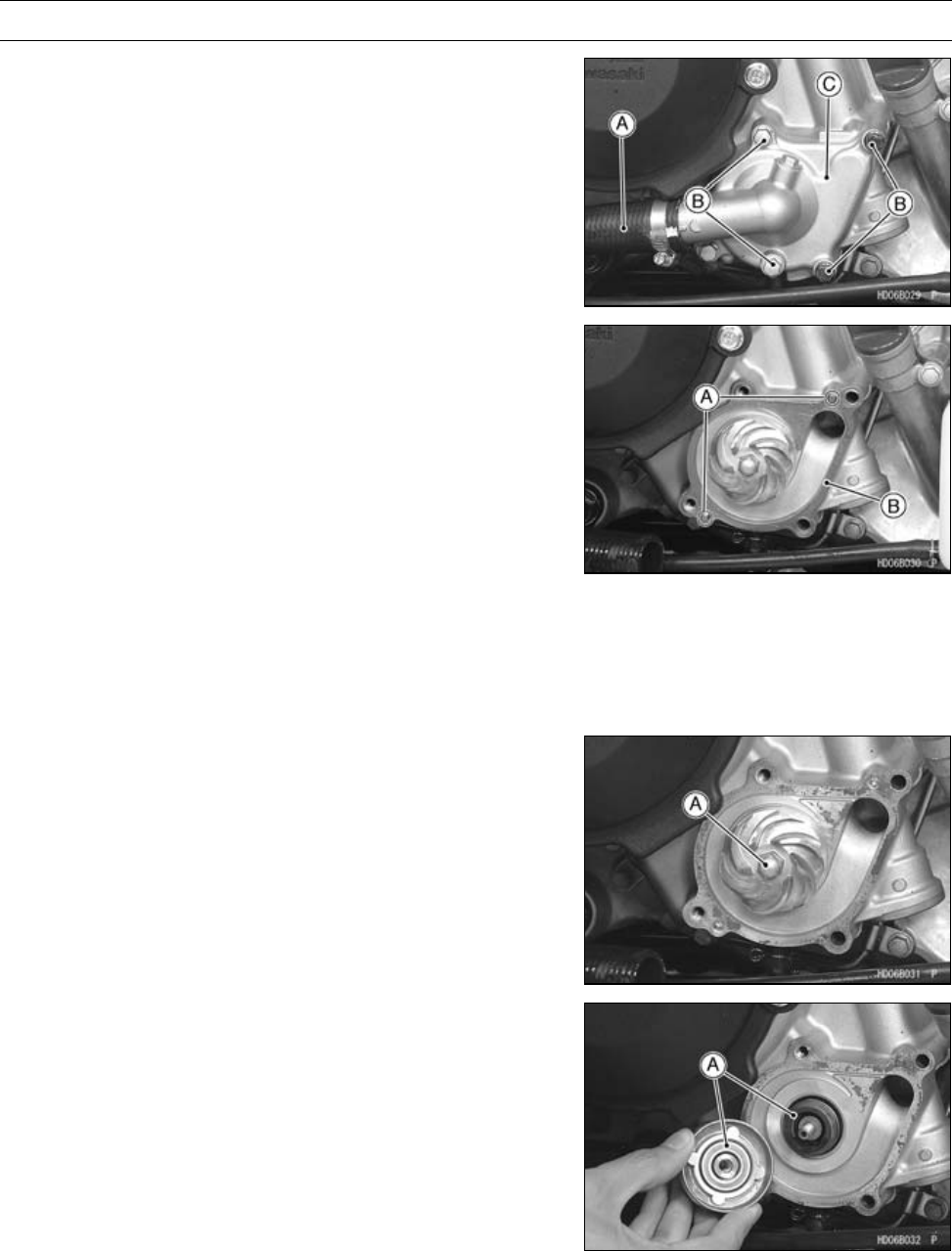
4-10 COOLING SYSTEM
Water Pump
Water Pump Cover Removal
•Drain the coolant (see Coolant Change in the Periodic
Maintenance chapter).
•Remove:
Radiator Hose [A]
Water Pump Cover Bolts [B]
Water Pump Cover [C]
Water Pump Cover Installation
•Install:
KnockPins[A]
New Gasket [B]
•Tighten:
Torque - Water Pump Cover Bolts: 8.8 N·m (0.90 kgf·m, 78
in·lb)
Water Pump Impeller Removal
•Drain the coolant (see Coolant Change in the Periodic
Maintenance chpater).
•Remove:
Water Pump Cover (see Water Pump Cover Removal)
•Loosen the water pump impeller [A] counterclockwise.
WaterPumpImpellerInstallation
•Apply a small amount of coolant on the sliding surface [A]
of the mechanical seal and the sealing seat.
•Install the impeller on the water pump shaft and tighten
the impeller.
Torque - Water Pump Impeller: 7.8 N·m (0.80 kgf·m, 69 in·lb)
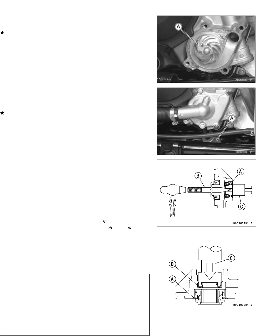
COOLING SYSTEM 4-11
Water Pump
Water Pump Impeller Inspection
•Visually inspect the impeller [A].
If the surface is corroded or the blades are damaged, re-
place the impeller.
Water Pump Leakage Inspection
•Check the drainage catch tank [A] at the bottom of the
water pump body for coolant leakage.
If there is a coolant leak, the mechanical seal in the pump
could be damaged. Replace the mechanical seal with a
new one (see Mechanical Seal Replacement).
Mechanical Seal Replacement
•Remove:
Water Pump Impeller (see Water Pump Impeller Re-
moval)
Alternator Cover (see Alternator Cover Removal in the
Electrical System chapter)
•Take the bearing [A] out of the alternator cover, using the
bearing remover.
Special Tools - Bearing Remover Shaft, 9 [B]: 57001-1265
Bearing Remover Head, 10 × 12 [C]:
57001-1266
•Press out the mechanical seal [A] and oil seal [B] from
the inside of the alternator cover with the bearing driver
set [C].
Special Tool - Bearing Driver Set: 57001-1129
CAUTION
If either the mechanical seal, oil seal, or the ball
bearing is removed, make sure to replace all of them
simultaneously with a new one.
Be careful not to block the inspection hole with
the oil seal. If the inspection hole is blocked, the
coolant may pass through the oil seal and flow into
the crankcase.
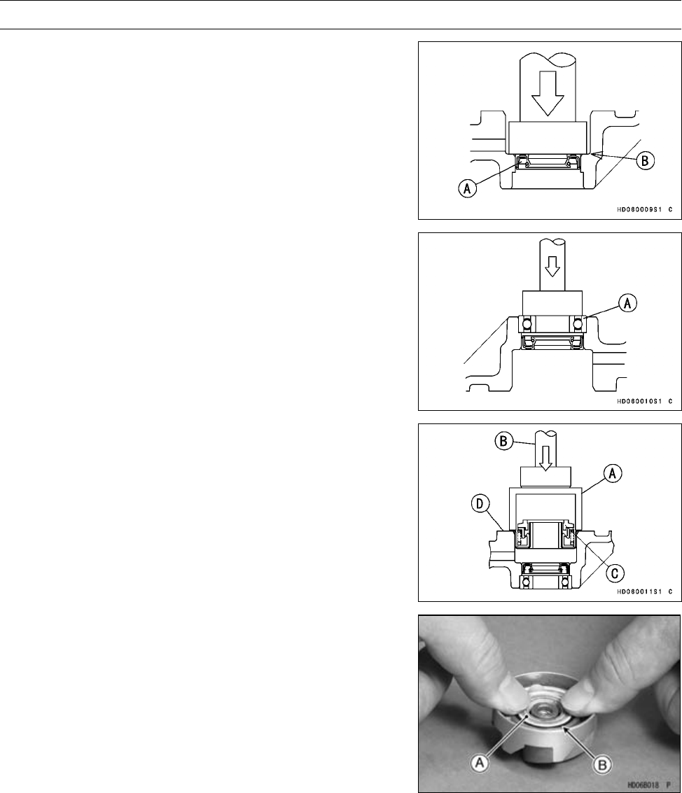
4-12 COOLING SYSTEM
Water Pump
•Apply heat-resistance grease on the oil seal lip.
•From outside the alternator cover, press and insert the oil
seal [A] so that its surface is flush with the step portion of
the cover as shown [B].
Special Tool - Bearing Driver Set: 57001-1129
•From inside the alternator cover, press and insert the ball
bearing [A] until it is bottomed.
Special Tool - Bearing Driver Set: 57001-1129
•Using a suitable socket [A] and the bearing driver [B],
press and insert a new mechanical seal [C] until its flange
stops at the step [D] of the hole.
Special Tool - Bearing Driver Set: 57001-1129
•Clean the sliding surface of a new mechanical seal with
a high flash-point solvent, and apply a little coolant to the
sliding surface to give the mechanical seal initial lubrica-
tion.
•Apply coolant to the surfaces of the rubber seal and seal-
ing seat [A], and press the rubber seal [B] and sealing
seat into the impeller by hand until the seat bottoms out.
•Tighten the water pump impeller by turning it clockwise.
Torque - Water Pump Impeller: 7.8 N·m (0.80 kgf·m, 69 in·lb)
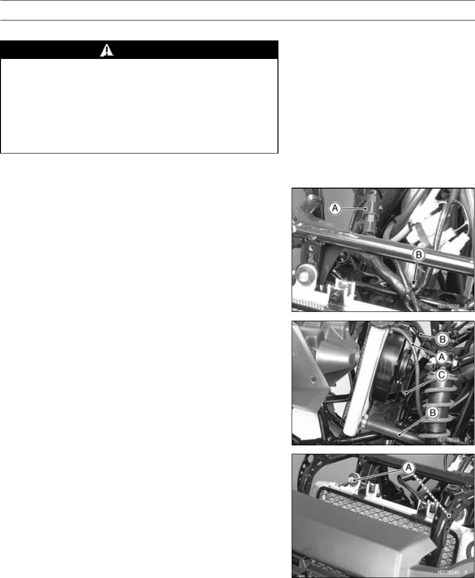
COOLING SYSTEM 4-13
Radiator
Radiator Removal
WARNING
The radiator fan is connected directly to the bat-
tery. The radiator fan may start even if the ignition
switch is off. NEVER TOUCH THE RADIATOR FAN
UNTIL THE RADIATOR FAN CONNECTOR IS DIS-
CONNECTED. TOUCHING THE FAN BEFORE THE
CONNECTOR IS DISCONNECTED COULD CAUSE
INJURY FROM THE FAN BLADES.
•Drain the coolant (see Coolant Change in the Periodic
Maintenance chapter).
•Remove:
Radiator Cover (see Radiator Cover Removal in the
Frame chapter)
Radiator Fan Motor Lead Connector [A]
•Cut the band [B].
•Remove:
Reserve Tank Hose [A]
Radiator Hoses [B]
Fan Motor Breather Hose [C]
•Remove:
Radiator Mounting Bolts [A]
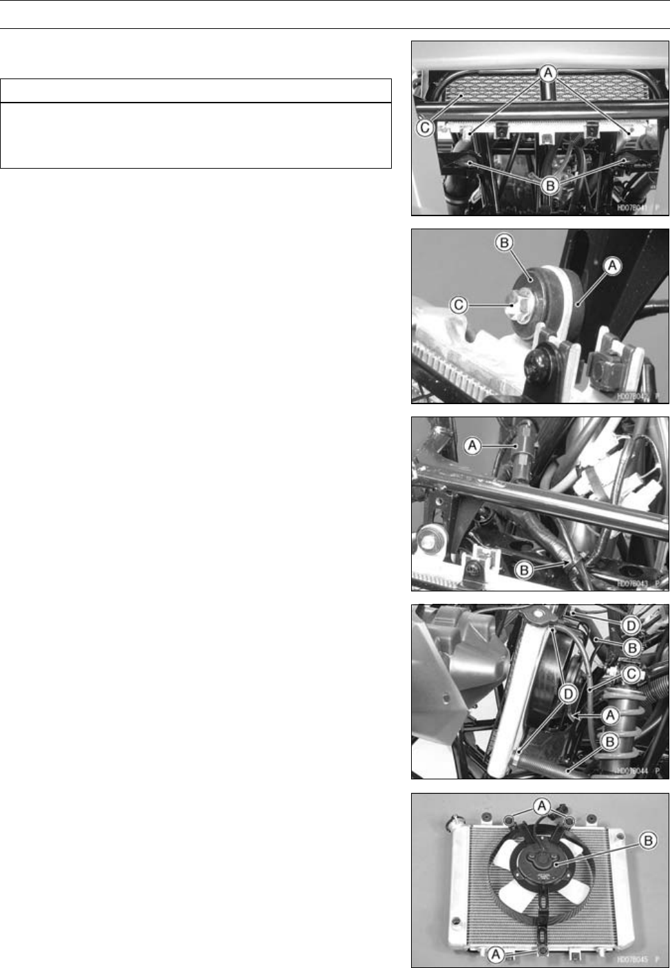
4-14 COOLING SYSTEM
Radiator
•Pull the projections [A] out of from the dampers [B], and
remove the radiator [C].
CAUTION
Do not touch the radiator core. This could damage
the radiator fins, resulting in loss of cooling effi-
ciency.
Radiator Installation
•Insert the projections of the radiator in the dampers.
•Install:
Dampers [A]
Collars [B]
•Tighten:
Torque - Radiator Mounting Bolts [C]: 8.8 N·m (0.90 kgf·m,
78 in·lb)
•Connect:
Radiator Fan Motor Lead Connector [A]
•Fix the fan motor lead and main harness with a band [B].
•Install the fan motor breather hose [A].
NOTE
○Do not apply lubricant at fitting hose region.
•Install:
Radiator Hoses [B]
Reserve Tank Hose [C]
Clamps [D]
•Run the hoses according to the Cable, Wire, and Hose
Routing section in the Appendix chapter.
Radiator Fan Removal
•Remove:
Radiator (see Radiator Removal)
Radiator Fan Assembly Bolts [A]
Fan Assembly [B]
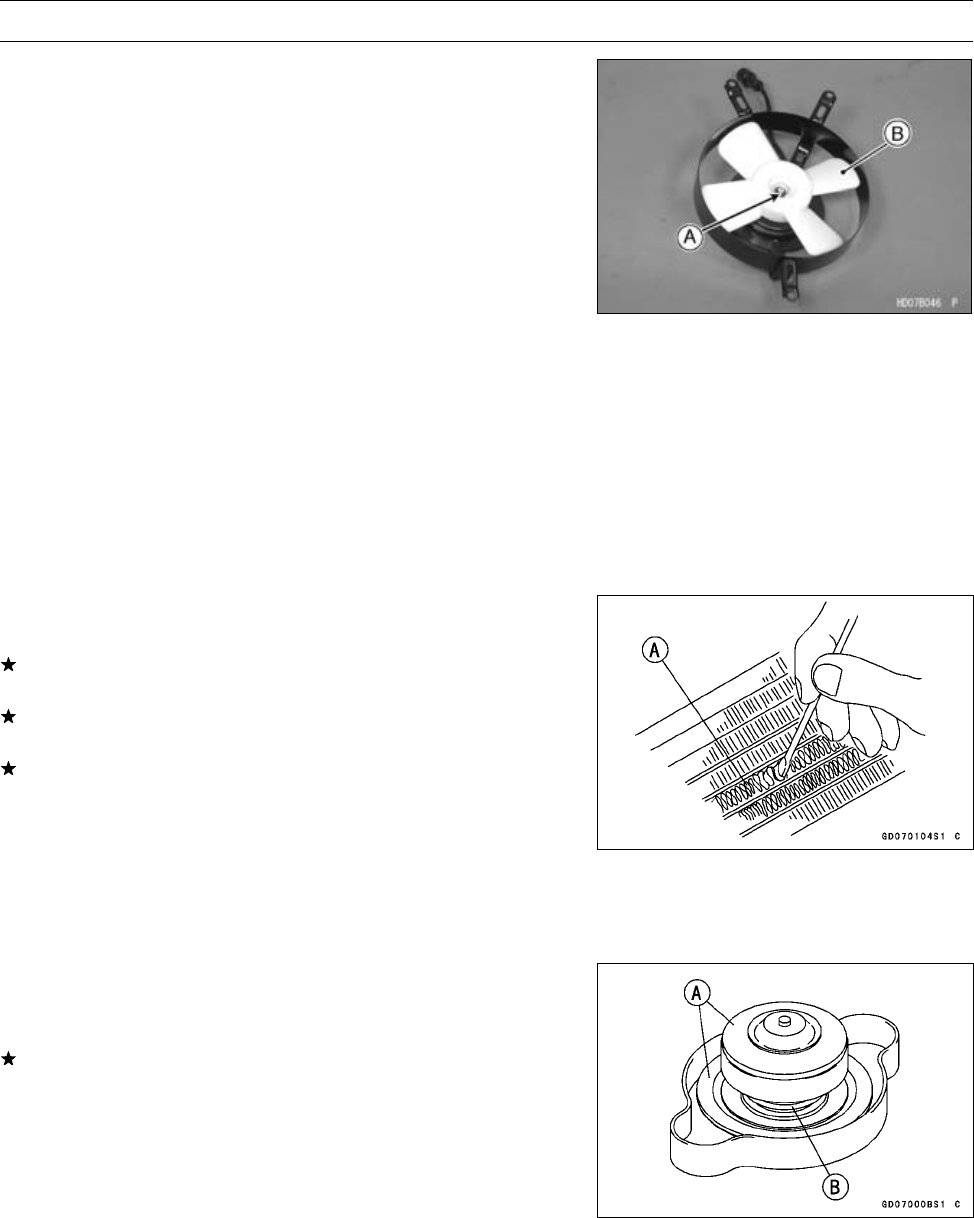
COOLING SYSTEM 4-15
Radiator
•Remove:
Radiator Fan Mounting Nut [A]
Radiator Fan [B]
Radiator Fan Installation
•Install:
Radiator Fan
Radiator Fan Mounting Nut
•Install:
Radiator Fan Assembly
•Tighten:
Torque - Radiator Fan Assembly Bolts: 4.9 N·m (0.50 kgf·m,
43 in·lb)
Radiator Inspection
•Check the radiator core.
If there are obstructions to air flow, remove the radiator
and remove obstructions.
If the corrugated fins [A] are deformed, carefully
straighten them.
If the air passages of the radiator core are blocked more
than 20% by unremovable obstructions or irreparably de-
formed fins, replace the radiator with a new one.
Radiator Cleaning
•Refer to the Radiator Cleaning in the Periodic Mainte-
nance chapter.
Radiator Cap Inspection
•Check the condition of the top and bottom valve seals of
the radiator cap.
If any one of them shows visible damage, replace the cap.
Top and Bottom Valve Seals [A]
Valve Spring [B]
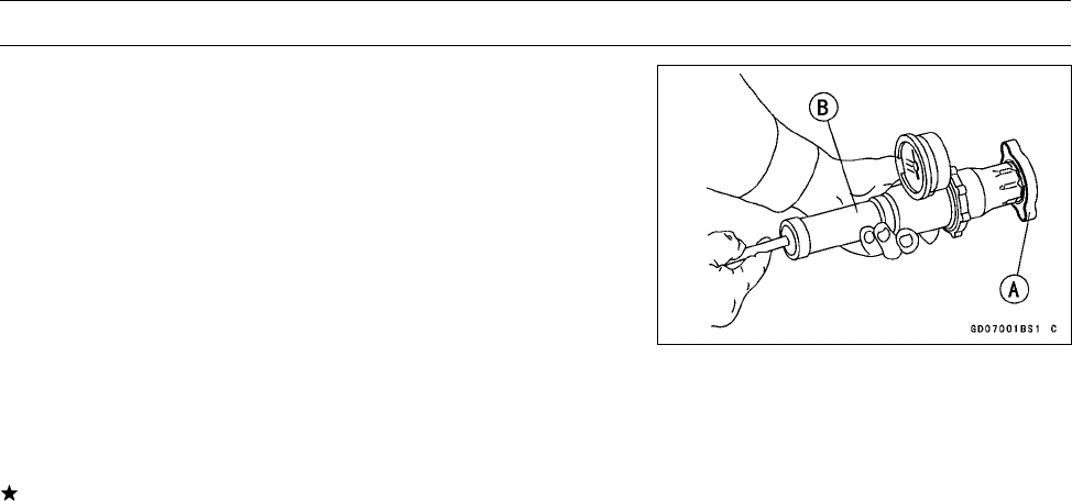
4-16 COOLING SYSTEM
Radiator
•Install the cap [A] on a cooling system pressure tester [B].
NOTE
○Wet the cap sealing surfaces with water or coolant to
prevent pressure leakage.
•Watching the pressure gauge, slowly pump the pressure
tester to build up the pressure. The relief valve opens,
indicated by the gauge hand flicks downward.
○The relief valve must open within the relief pressure range
in the table below and the gauge hand must remain within
the specified range at least 6 second.
Radiator Cap Relief Pressure
Standard: 93 ∼123 kPa (0.95 ∼1.25 kgf/cm², 14 ∼18
psi)
If the cap cannot hold the specified pressure, or if it holds
too much pressure, replace it with a new one.
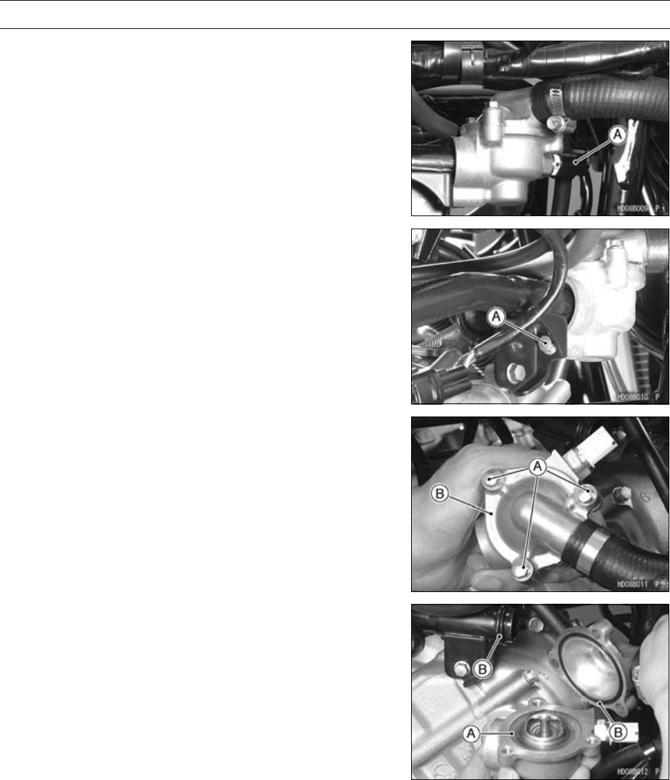
COOLING SYSTEM 4-17
Thermostat
Thermostat Removal
•Drain the coolant (see Coolant Change in the Periodic
Maintenance chapter).
•Remove:
Front Fender (see Front Fender Removal in the Frame
chapter)
Water Temperature Sensor Connector [A]
•Remove:
Water Pipe Bolt [A]
•Remove:
Thermostat Housing Cover Bolts [A]
Thermostat Housing Cover [B]
Thermostat
Thermostat Installation
•Install:
Thermostat [A]
•Be sure to install the O-rings [B] on the housing cover and
water pipe.
•Tighten:
Torque - Thermostat Housing Cover Bolts: 8.8 N·m (0.90
kgf·m, 78 in·lb)
Water Pipe Joint Bolt: 8.8 N·m (0.90 kgf·m, 78
in·lb)
•Add coolant (see Coolant Change in the Periodic Mainte-
nance chapter).
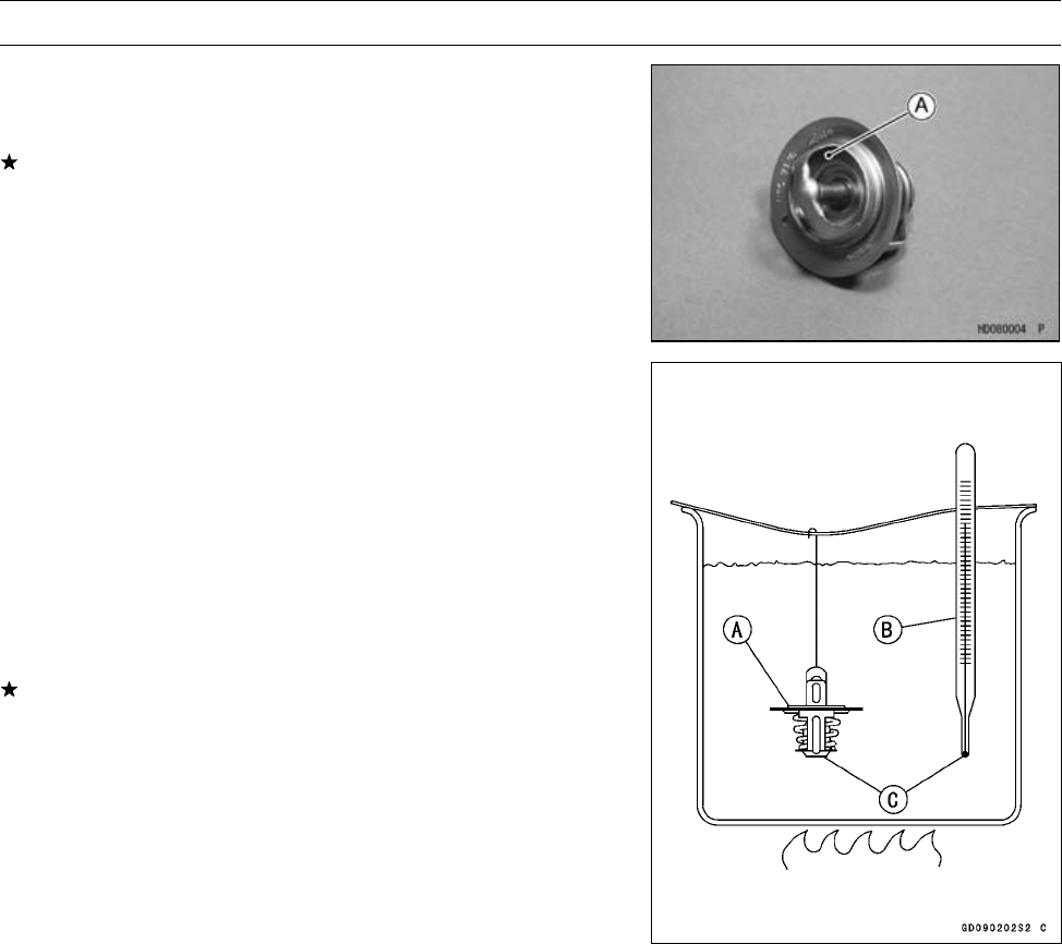
4-18 COOLING SYSTEM
Thermostat
Thermostat Inspection
•Remove the thermostat, and inspect the thermostat valve
[A] at room temperature.
If the valve is open, replace the valve with a new one.
•To check valve opening temperature, suspend the ther-
mostat [A] and an accurate thermometer [B] in a container
of water with the heat-sensitive portions [C] in almost the
same depth.
NOTE
○The thermostat must be completely submerged and the
thermostat and thermometer must not touch the con-
tainer sides or bottom.
•Gradually raise the temperature of the water while stirring
the water gently for even temperature.
If the measurement is out of the specified range, replace
the thermostat.
Thermostat Valve Opening Temperature
69.5 ∼72.5°C (157 ∼162°F)

COOLING SYSTEM 4-19
Water Temperature Sensor
Water Temperature Sensor Removal/Installation
CAUTION
The water temperature sensor should never be al-
lowed to fall on a hard surface. Such a shock to
water temperature sensor can damage it.
•Refer to the Water Temperature Sensor Removal/Instal-
lation in the Fuel System (DFI) chapter.
Water Temperature Sensor Inspection
•Refer to the Water Temperature Sensor Inspection in the
Electrical System chapter.

ENGINE TOP END 5-1
5
Engine Top End
Table of Contents
Exploded View................................... 5-2
Specifications .................................... 5-8
Special Tools and Sealant ................. 5-10
Camshaft Chain Tensioner ................ 5-12
Camshaft Chain Tensioner
Removal .................................... 5-12
Camshaft Chain Tensioner
Installation ................................. 5-13
Rocker Case...................................... 5-14
Rocker Case Removal ................. 5-14
Rocker Case Installation .............. 5-15
Rocker Arm Removal................... 5-16
Rocker Arm Installation................ 5-17
Rocker Arm Inspection................. 5-17
Rocker Shaft Diameter
Measurement ............................ 5-18
Camshaft ........................................... 5-19
Camshaft Removal ...................... 5-19
Camshaft Installation ................... 5-19
Camshaft Assembly ..................... 5-20
Cam Wear Inspection .................. 5-20
Camshaft Bearing Wear
Inspection.................................. 5-21
KACR Inspection.......................... 5-22
KACR Removal............................ 5-22
KACR Installation......................... 5-23
Camshaft Chain Removal ............ 5-23
Camshaft Chain Installation ......... 5-24
Camshaft Chain Guide Wear
Inspection.................................. 5-27
Cylinder Head.................................... 5-28
Cylinder Compression
Measurement ............................ 5-28
Cylinder Head Removal ............... 5-29
Cylinder Head Installation ............ 5-29
Cylinder Head Cleaning ............... 5-30
Cylinder Head Warp Inspection ... 5-30
Valves ................................................ 5-31
Valve Clearance Inspection ......... 5-31
Valve Clearance Adjustment........ 5-31
Valve Removal ............................. 5-31
Valve Installation .......................... 5-31
Valve Guide Removal .................. 5-31
Valve Guide Installation ............... 5-32
Valve-to-Guide Clearance
Measurement ............................ 5-32
Valve Seat Inspection .................. 5-33
Valve Seat Repair (Valve
Lapping) .................................... 5-33
Cylinder and Piston ........................... 5-38
Cylinder Removal......................... 5-38
Piston Removal............................ 5-38
Cylinder, Piston Installation.......... 5-38
Cylinder Wear Inspection............. 5-40
Piston Wear Inspection ................ 5-40
Piston/Cylinder Clearance
Inspection.................................. 5-40
Piston Ring, Piston Ring Groove
Wear Inspection ........................ 5-41
Piston Ring Groove Width
Inspection.................................. 5-41
Piston Ring Thickness Inspection 5-41
Piston Ring End Gap Inspection .. 5-42
Exhaust System................................. 5-43
Spark Arrester Cleaning............... 5-43
Muffler and Exhaust Pipe
Removal .................................... 5-43
Muffler and Exhaust Pipe
Installation ................................. 5-44
Exhaust System Inspection.......... 5-45
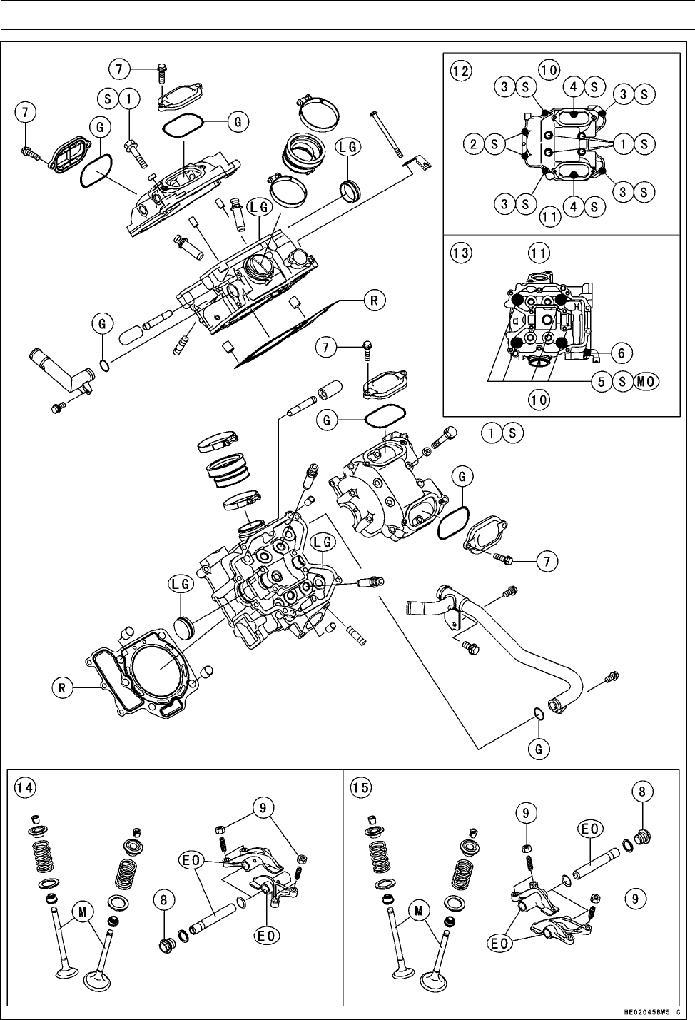
5-2 ENGINE TOP END
Exploded View

ENGINE TOP END 5-3
Exploded View
Torque
No. Fastener N·m kgf·m ft·lb Remarks
1Rocker Case Bolts 55 mm (2.2 in.) 8.8 0.90 78 in·lb S
2Rocker Case Bolts 130 mm (5.1 in.) 9.8 1.0 87 in·lb S
3Rocker Case Bolts 30 mm (1.2 in.) 9.8 1.0 87 in·lb S
4Rocker Case Bolts 25 mm (1.0 in.) 9.8 1.0 87 in·lb S
5Cylinder Head Bolts (M10), First Torque 25 2.5 18
5Cylinder Head Bolts (M10), Final Torque 49 5.0 36 S, MO
6Cylinder Head Bolts (M6) 9.8 1.0 87 in·lb
7Valve Adjusting Cap Bolts 8.8 0.90 78 in·lb
8Rocker Shaft Bolts 22 2.2 16
9Valve Adjusting Screw Locknuts 12 1.2 106 in·lb
10. Inlet
11. Exhaust
12. Rocker Case
13. Cylinder Head
14. Front
15. Rear
EO: Apply engine oil.
G: Apply grease.
LG: Apply liquid gasket (Kawasaki Bond: 92104-1063).
M: Apply molybdenum disulfide grease.
MO: Apply molybdenum disulfide oil (mixture of the engine oil and molybdenum disulfide grease in
a weight ratio: 10 : 1).
R: Replacement Parts
S: Follow the specific tightening sequence.
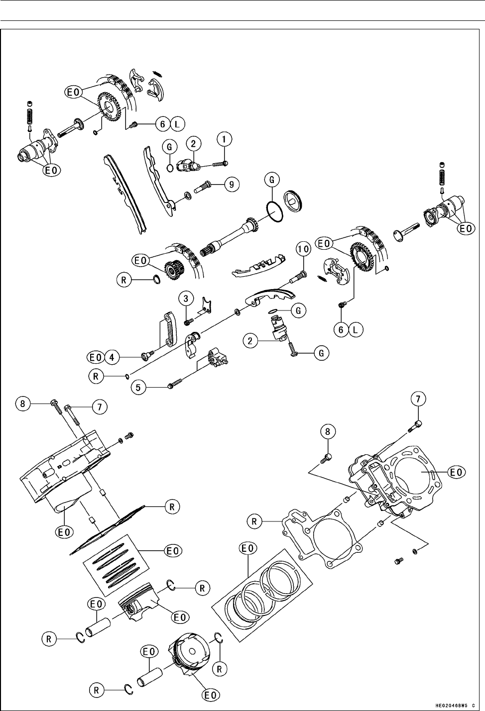
5-4 ENGINE TOP END
Exploded View

ENGINE TOP END 5-5
Exploded View
Torque
No. Fastener N·m kgf·m ft·lb Remarks
1Camshaft Chain Tensioner Mounting Bolts 8.8 0.90 78 in·lb
2Camshaft Chain Tensioner Cap Bolts 22 2.2 16
3Position Plate Bolts 8.8 0.90 78 in·lb
4Intermediate Shaft Chain Guide Bolts 8.8 0.90 78 in·lb EO
5Intermediate Shaft Chain Tensioner Bolts 8.8 0.90 78 in·lb
6Camshaft Sprocket Bolts 12 1.2 106 in·lb L
7Cylinder Bolts 40 mm (1.6 in.) 9.8 1.0 87 in·lb
8Cylinder Bolts 30 mm (1.2 in.) 9.8 1.0 87 in·lb
9Front Cylinder Camshaft Chain Guide Bolt 20 2.0 15
10 Rear Cylinder Camshaft Chain Guide Bolt 20 2.0 15
EO: Apply engine oil.
G: Apply grease.
L: Apply a non-permanent locking agent.
R: Replacement Parts
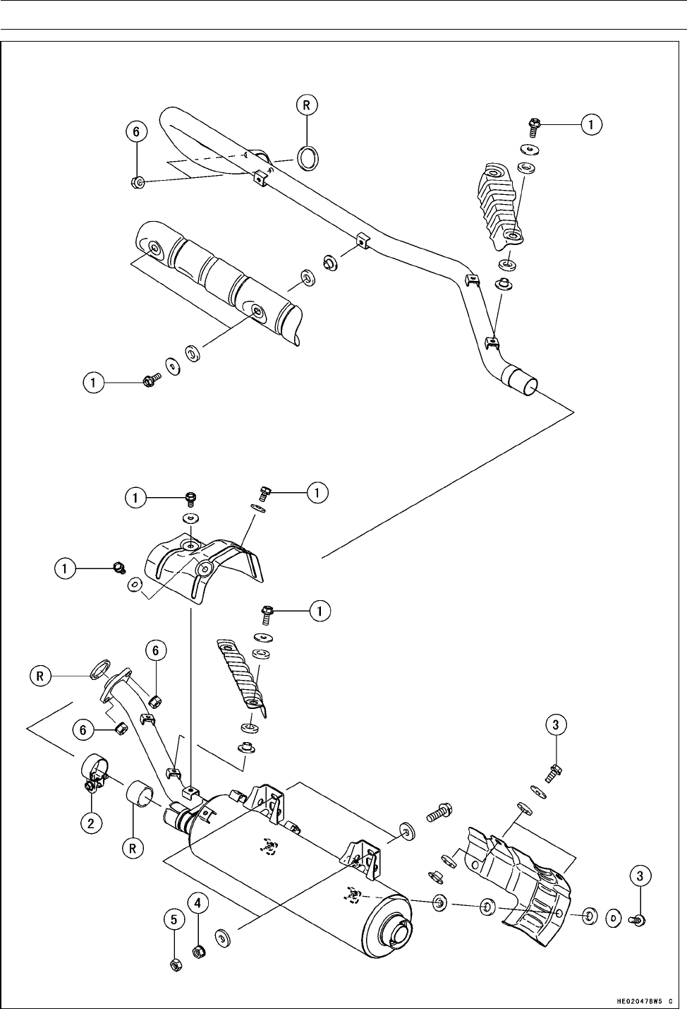
5-6 ENGINE TOP END
Exploded View

ENGINE TOP END 5-7
Exploded View
Torque
No. Fastener N·m kgf·m ft·lb Remarks
1Exhaust Pipe Cover Bolts 8.8 0.90 78 in·lb
2Muffler Clamp Bolt 8.8 0.90 78 in·lb
3Muffler Cover Bolts 8.8 0.90 78 in·lb
4Muffler Mounting Nuts 19.6 2.0 14
5Muffler Mounting Locknuts 31.4 3.2 23
6Exhaust Pipe Holder Nuts 17 1.7 12
R: Replacement Parts

5-8 ENGINE TOP END
Specifications
Item Standard Service Limit
Rocker Case
Rocker Arm Inside Diameter 12.000 ∼12.018 mm (0.4724 ∼0.4731 in.) 12.05 mm (0.474 in.)
Rocker Shaft Diameter 11.983 ∼11.994 mm (0.4718 ∼0.4722 in.) 11.96 mm (0.471 in.)
Camshafts
Cam Height:
Exhaust 35.363 ∼35.477 mm (1.3922 ∼1.3967 in.) 35.26 mm (1.388 in.)
Inlet 35.622 ∼35.736 mm (1.4024 ∼1.4069 in.) 35.52 mm (1.398 in.)
Camshaft Bearing Clearance:
18 0.016 ∼0.052 mm (0.0006 ∼0.0020 in.) 0.14 mm (0.0055 in.)
22 0.020 ∼0.062 mm (0.0008 ∼0.0024 in.) 0.15 mm (0.0059 in.)
Camshaft Journal Diameter:
18 17.966 ∼17.984 mm (0.7073 ∼0.7080 in.) 17.94 mm (0.706 in.)
22 21.959 ∼21.980 mm (0.8645 ∼0.8653 in.) 21.93 mm (0.863 in.)
Camshaft Bearing Inside
Diameter:
18 18.000 ∼18.018 mm (0.7087 ∼0.7094 in.) 18.08 mm (0.712 in.)
22 22.000 ∼22.021 mm (0.8661 ∼0.8670 in.) 22.08 mm (0.870 in.)
Camshaft runout TIR 0.02 mm (0.0008 in.) or less TIR 0.1 mm (0.0039 in.)
KACR (Kawasaki Automatic
Compression Release):
KACR Operating Engine
Speed
760 ±30 r/min (rpm) –––
Cylinder Head
Cylinder Compression
(Usable Range)
Electric Starter 251 ∼456 kPa (2.56 ∼4.65 kgf/cm², 36 ∼
66 psi) @380 r/min (rpm)
–––
Cylinder head warp ––– 0.05 mm (0.002 in.)
Valve
Valve Clearance:
Exhaust 0.20 ∼0.25 mm (0.0079 ∼0.0098 in.) –––
Inlet 0.10 ∼0.15 mm (0.0039 ∼0.0059 in.) –––
Valve Head Thickness:
Exhaust 0.8 mm (0.031 in.) 0.4 mm (0.016 in.)
Inlet 0.5 mm (0.020 in.) 0.3 mm (0.012 in.)
Valve Stem Bend ––– TIR 0.05 mm (0.002 in.)
Valve Stem Diameter:
Exhaust 4.955 ∼4.970 mm (0.1951 ∼0.1957 in.) 4.94 mm (0.1945 in.)
Inlet 4.975 ∼4.990 mm (0.1959 ∼0.1965 in.) 4.96 mm (0.1953 in.)
Valve Guide Inside Diameter:
Exhaust 5.000 ∼5.012 mm (0.1969 ∼0.1973 in.) 5.08 mm (0.20 in.)
Inlet 5.000 ∼5.012 mm (0.1969 ∼0.1973 in.) 5.08 mm (0.20 in.)

ENGINE TOP END 5-9
Specifications
Item Standard Service Limit
Valve/Valve Guide Clearance
(Wobble Method):
Exhaust 0.09 ∼0.17 mm (0.0035 ∼0.0067 in.) 0.37 mm (0.0146 in.)
Inlet 0.03 ∼0.11 mm (0.0012 ∼0.0043 in.) 0.31 mm (0.0122 in.)
Valve Seat Cutting Angle 45°, 32°, 60° –––
Valve Seating Surface:
Outside Diameter:
Exhaust 25.2 ∼25.4 mm (0.992 ∼1.000 in.) –––
Inlet 29.4 ∼29.6 mm (1.157 ∼1.165 in.) –––
Width:
Exhaust 0.5 ∼1.0 mm (0.02 ∼0.04 in.) –––
Inlet 0.5 ∼1.0 mm (0.02 ∼0.04 in.) –––
Valve Spring Free Length:
Exhaust 41.3 mm (1.626 in.) 39.5 mm (1.555 in.)
Inlet 41.3 mm (1.626 in.) 39.5 mm (1.555 in.)
Cylinder, Piston
Cylinder Inside Diameter 84.994 ∼85.006 mm (3.3462 ∼3.3467 in.) 85.10 mm (3.350 in.)
Piston Diameter 84.964 ∼84.979 mm (3.3450 ∼3.3456 in.) 84.81 mm (3.3390 in.)
Piston/Cylinder Clearance 0.015 ∼0.042 mm (0.0006 ∼0.0017 in.) –––
Piston Ring/Groove
Clearance:
Top 0.04 ∼0.08 mm (0.0016 ∼0.0032 in.) 0.18 mm (0.0071 in.)
Second 0.03 ∼0.07 mm (0.0012 ∼0.0028 in.) 0.17 mm (0.0067 in.)
Piston Ring Groove Width:
Top 1.03 ∼1.05 mm (0.0405 ∼0.0413 in.) 1.13 mm (0.0445 in.)
Second 1.02 ∼1.04 mm (0.0402 ∼0.0409 in.) 1.12 mm (0.0441 in.)
Piston Ring Thickness:
Top 0.97 ∼0.99 mm (0.0382 ∼0.0390 in.) 0.90 mm (0.035 in.)
Second 0.97 ∼0.99 mm (0.0382 ∼0.0390 in.) 0.90 mm (0.035 in.)
Piston Ring End Gap:
Top 0.20 ∼0.30 mm (0.0079 ∼0.0118 in.) 0.60 mm (0.0236 in.)
Second 0.30 ∼0.45 mm (0.0118 ∼0.0177 in.) 0.75 mm (0.0295 in.)
Oil 0.20 ∼0.70 mm (0.0079 ∼0.0276 in.) 1.00 mm (0.0394 in.)
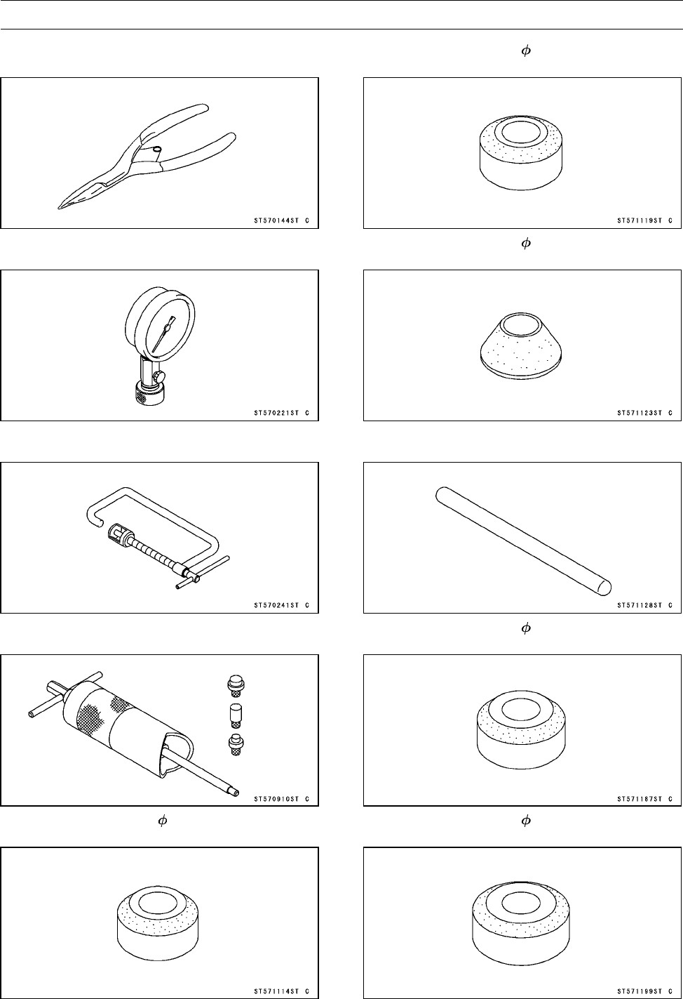
5-10 ENGINE TOP END
Special Tools and Sealant
Outside Circlip Pliers:
57001-144
Compression Gauge, 20 kgf/cm²:
57001-221
Valve Spring Compressor Assembly:
57001-241
Piston Pin Puller Assembly:
57001-910
Valve Seat Cutter, 45° - 27.5:
57001-1114
Valve Seat Cutter, 32° - 28:
57001-1119
Valve Seat Cutter, 60° - 30:
57001-1123
Valve Seat Cutter Holder Bar:
57001-1128
Valve Seat Cutter, 45° - 30:
57001-1187
Valve Seat Cutter, 32° - 33:
57001-1199
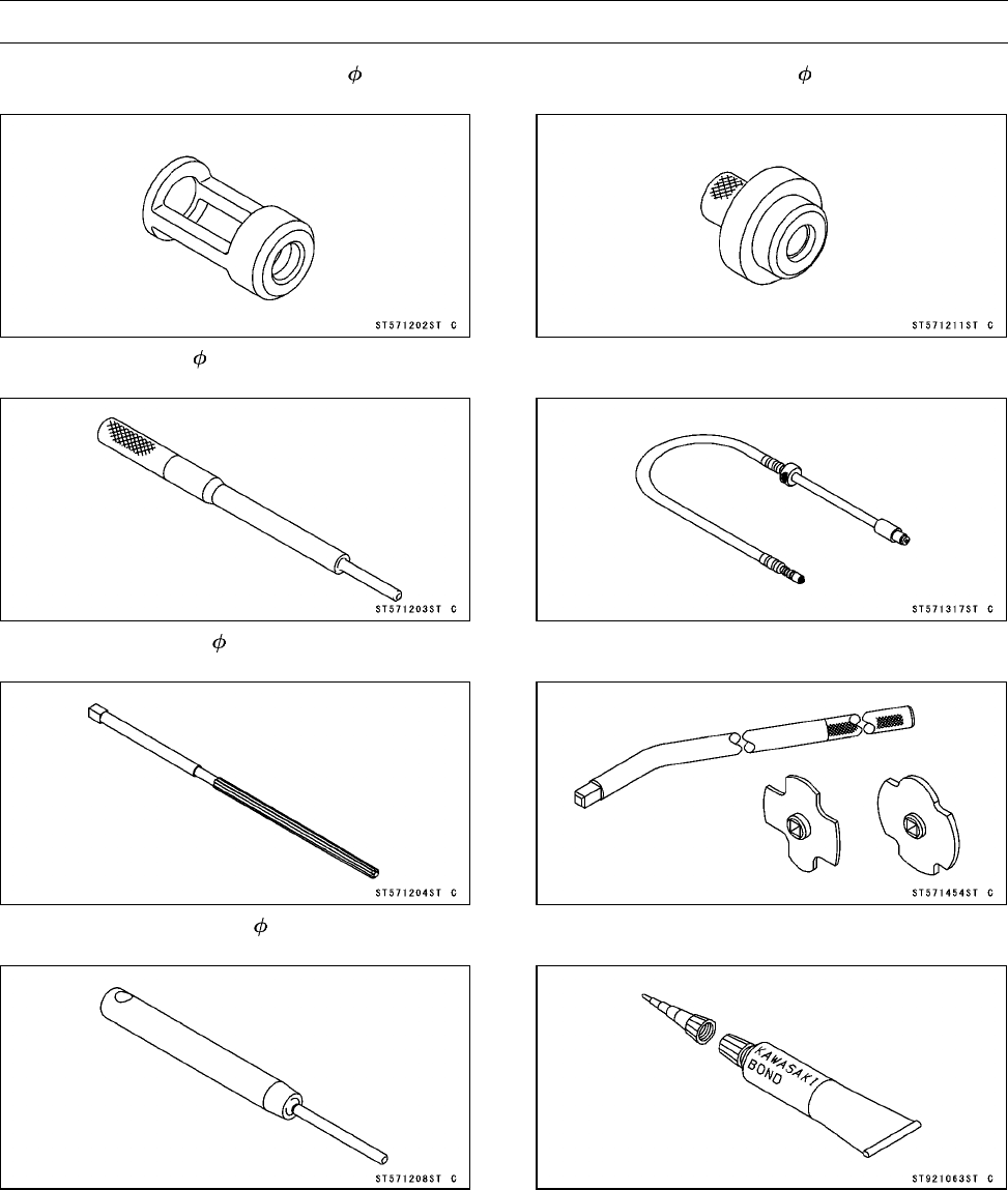
ENGINE TOP END 5-11
Special Tools and Sealant
Valve Spring Compressor Adapter, 22:
57001-1202
Valve Guide Arbor, 5:
57001-1203
Valve Guide Reamer, 5:
57001-1204
Valve Seat Cutter Holder, 5:
57001-1208
Piston Pin Puller Adapter, 14:
57001-1211
Compression Gauge Adapter, M10 × 1.0:
57001-1317
Filler Cap Driver:
57001-1454
Kawasaki Bond (Liquid Gasket - Gray):
92104-1063
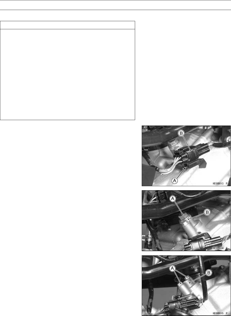
5-12 ENGINE TOP END
Camshaft Chain Tensioner
Camshaft Chain Tensioner Removal
CAUTION
This is a non-return type cam chain tensioner. The
push rod does not return to its original position
once it moves out to take up cam chain slack. Ob-
serve all the rules listed below:
When removing the tensioner, do not take out the
mounting bolts only partway. Retightening the
mounting bolts from this position could damage
the tensioner and the camshaft chain. Once the
bolts are loosened, the tensioner must be removed
and reset as described in “Camshaft Chain Ten-
sioner Installation”.
Do not turn over the crankshaft while the tensioner
is removed. This could upset the cam chain timing,
and damage the valves.
Front Cylinder
•For front cylinder, push down the stopper [A] to clear the
connector [B].
•Remove:
Cap Bolt [A]
Washer [B]
Pin and Spring
•Remove:
Tensioner Mounting Bolts [A]
Camshaft Chain Tensioner [B]
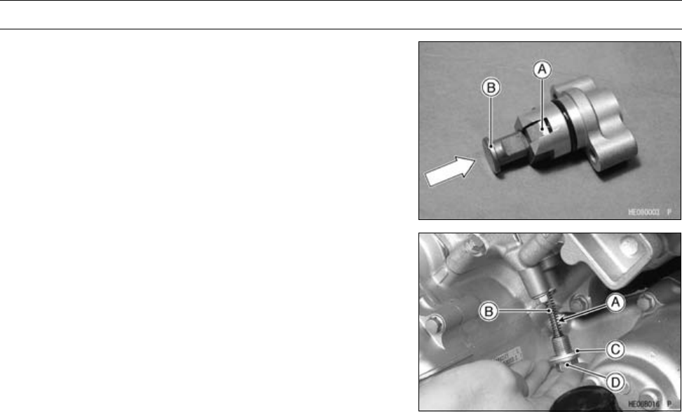
ENGINE TOP END 5-13
Camshaft Chain Tensioner
Camshaft Chain Tensioner Installation
•Push the stopper [A] to release the ratchet and push the
push rod [B] into the tensioner body.
•Tighten:
Torque - Camshaft Chain Tensioner Mounting Bolts: 8.8
N·m (0.90 kgf·m, 78 in·lb)
•Install:
Pin [A] and Spring [B]
Washer [C] and Chain Tensioner Cap Bolt [D]
•Tighten:
Torque - Camshaft Chain Tensioner Cap Bolt: 22 N·m (2.2
kgf·m, 16 ft·lb)
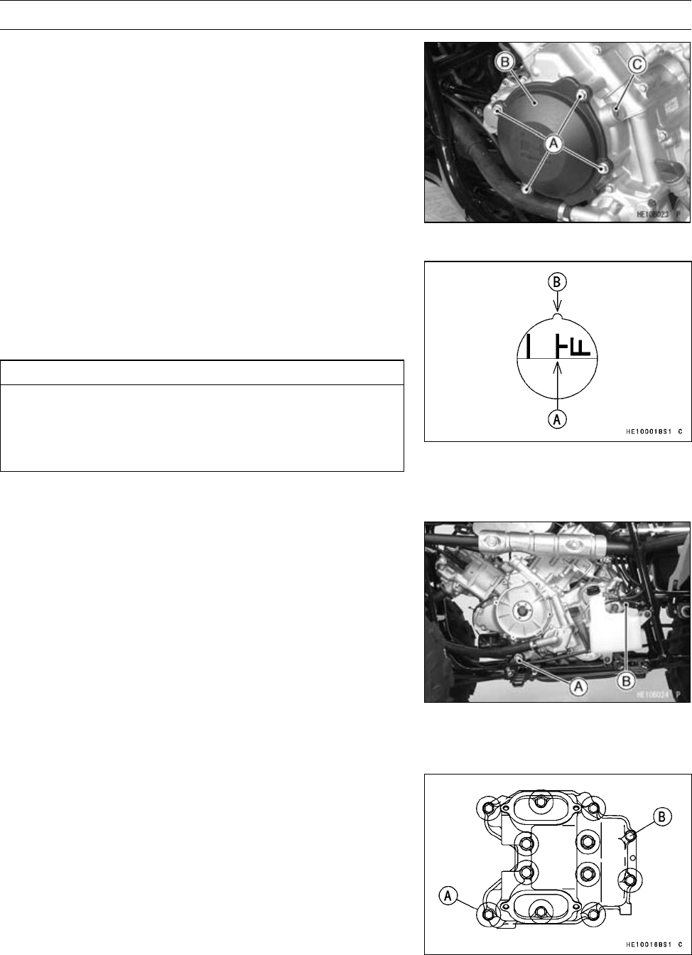
5-14 ENGINE TOP END
Rocker Case
Rocker Case Removal
Front Rocker Case
•Remove:
Front Fender (see Front Fender Removal in the Frame
chapter)
Alternator Outer Cover Bolts [A]
Alternator Outer Cover [B]
Timing Inspection Plug [C]
Special Tool - Filler Cap Driver: 57001-1454
•Remove:
Valve Adjusting Caps
•Using a wrench on the alternator bolt, turn the crankshaft
counterclockwise until “T-F” mark [A] is aligned with the
notch [B] in the inspection window, and the cam lobes
are pointing away from the rocker arms: the end of the
compression stroke.
CAUTION
Be sure to position the crankshaft at TDC of the
end of the compression stroke when removing or
installing the rocker case. The rocker arms could
bend the valves.
•Drain the coolant (see Coolant Change section in the Pe-
riodic maintenance chapter).
•Remove:
Thermostat and Left Water Pipe (see Thermostat Re-
moval in the Cooling System chapter)
Front and Rear Propeller Shafts (see Front and Rear
Propeller Shaft Removal in the Final Drive chapter)
Air Cleaner Housing Mounting Bolts
Front Camshaft Chain Tensioner (see Camshaft Chain
Tensioner Removal)
Rear Muffler (see Muffler and Exhaust Pipe Removal)
Converter Rubber Ducts (Inlet and Outlet)
Front Engine Mounting Bolt [A] and Nut
•Loosen:
Rear Engine Mounting Bolt [B]
•Remove:
Rocker Case Bolts [A]
•Loosen:
Rocker Case Bolt [B]
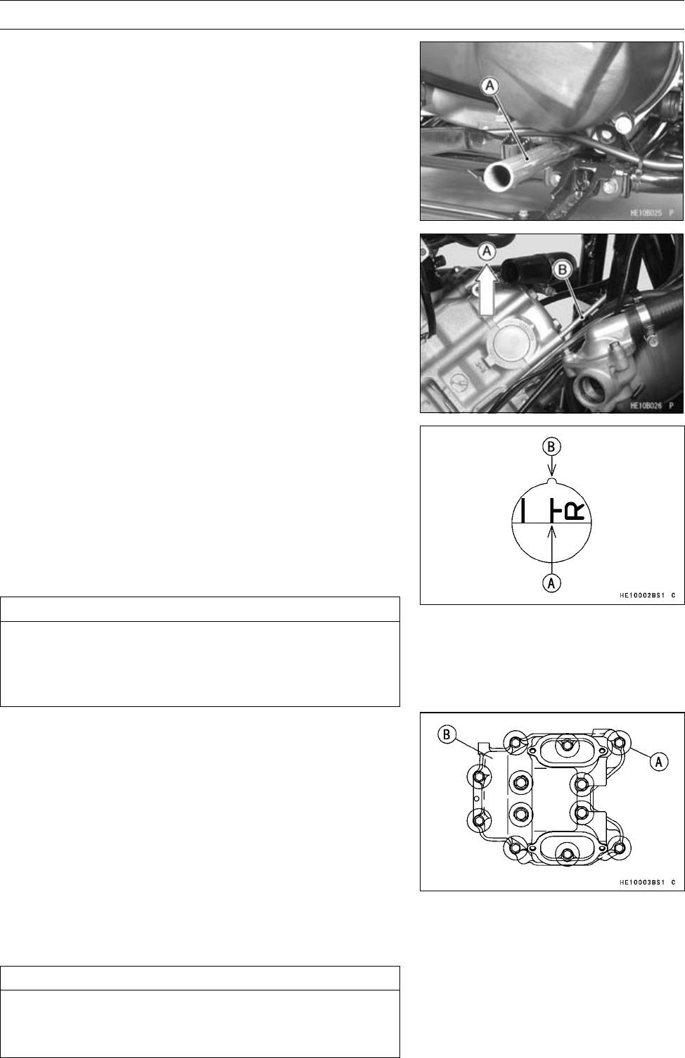
ENGINE TOP END 5-15
Rocker Case
•Insert a suitable bar [A] under the front of the engine.
•Lift [A] the front of the engine to remove the bolt [B] of the
front right side on the rocker case.
•Lift the rocker case to clear of the dowel pins in the cylin-
der head and slide the rocker case out of the frame.
Rear Rocker Case
•Remove:
Front Rocker Case
Battery Case
•Using a wrench on the alternator bolt, turn the crankshaft
counterclockwise (270°) until “T-R” mark [A] is aligned
with the notch [B] in the inspection window, and the cam
lobes are pointing away from the rocker arms: the end of
the compression stroke.
CAUTION
Be sure to position the crankshaft at TDC of the
end of the compression stroke when removing or
installing the rocker case. The rocker arms could
bend the valves.
•Remove:
Rear Camshaft Chain Tensioner (see Camshaft Chain
Tensioner Removal)
Rocker Case Bolts [A]
Rear Rocker Case [B]
•Lift the rocker case to clear of the dowel pins in the cylin-
der head and slide the rocker case out of the frame.
Rocker Case Installation
•Check that the crankshaft is positioned at TDC and at the
end of the compression stroke.
CAUTION
Be sure to position the crankshaft is at TDC of the
end of the compression stroke. The rocker arms
could bend the valves.
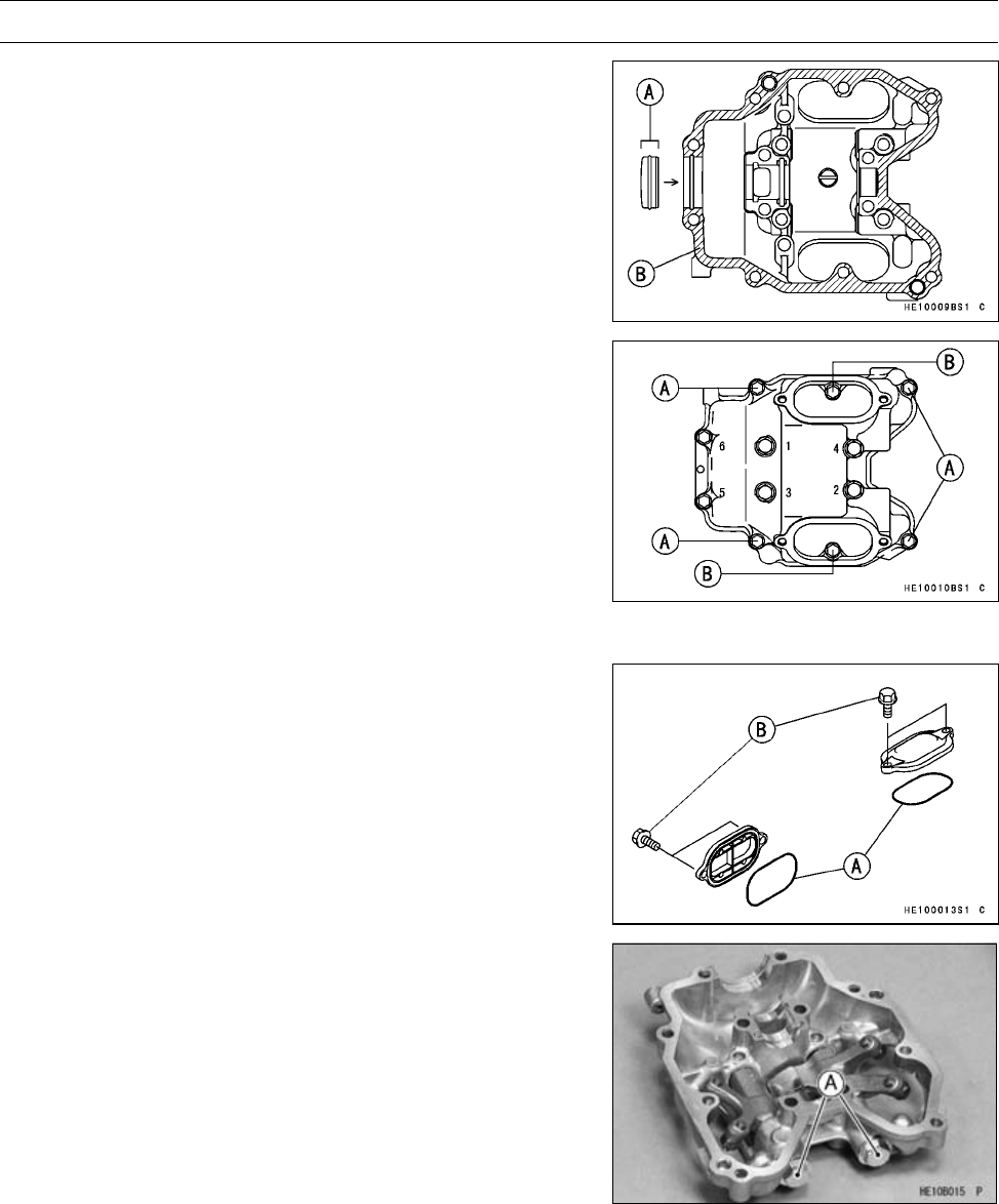
5-16 ENGINE TOP END
Rocker Case
•Apply silicone sealant to the outer surface of the cap [A]
and the cylinder head upper surface [B] as shown.
Sealant - Kawasaki Bond (Liquid Gasket - Gray): 92104
-1063
•Tighten the rocker case bolts following the tightening se-
quence shown.
Torque - Rocker Case Bolts: 8.8 N·m (0.90 kgf·m, 78 in·lb)
[1,2,3,4]L=55mm(2.2in.) withwashers
Rocker Case Bolts: 9.8 N·m (1.0 kgf·m, 87 in·lb)
[5, 6] L = 130 mm (5.1 in.)
[A]L=30mm(1.2in.)
[B]L=25mm(1.0in.)
○Lift the front of the engine to install the bolt of the front
right side on the front rocker case.
•Check the valve clearance and adjust it if necessary.
•Apply grease to the O-ring [A].
•Tighten:
Torque - Valve Adjusting Cap Bolts [B]: 8.8 N·m (0.90 kgf·m,
78 in·lb)
Rocker Arm Removal
•Remove:
Rocker Case (see Rocker Case Removal)
Rocker Shaft Bolts [A]
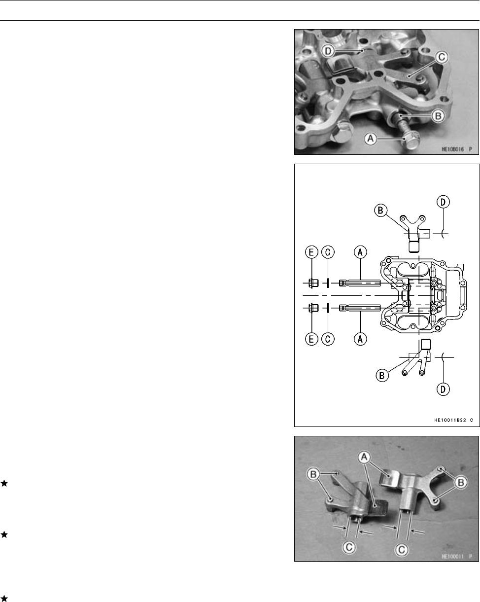
ENGINE TOP END 5-17
Rocker Case
•Using a M8 bolt [A], remove the rocker shaft [B].
•Remove:
Rocker Arm [C]
Washers [D]
○Mark and record the rocker arm location so it can be in-
stalled in the original position.
○The rocker arms come off with the rocker shafts.
Rocker Arm Installation
•Apply engine oil:
Rocker Shafts [A]
Hole in Rocker Arms [B]
•Replace the copper washers [C] with new ones.
•Install:
Wave Washers [D] (as shown)
Rocker Arms (as shown)
Rocker Shafts and Copper Washers
•Tighten:
Torque - Rocker Shaft Bolts [E]: 22 N·m (2.2 kgf·m, 16 ft·lb)
Rocker Arm Inspection
•Inspect the area [A] on the rocker arm where the cam
rubs.
If the rocker arm is scored, discolored or otherwise dam-
aged, replace it. Also inspect the camshaft lobes.
•Inspect the end of the valve clearance adjusting screws
[B] where it contacts the valve stem.
If the end of the adjusting screw is mushroomed or dam-
aged in any way, or if the screw will not turn smoothly,
replace it. Also inspect the end of the valve stem.
•Measure the inside diameter [C] of the rocker arm with a
dial bore gauge.
If the rocker arm inside diameter is larger than the service
limit, replace it. Also check the rocker shaft diameter (see
Rocker Shaft Diameter Measurement).
Rocker Arm Inside Diameter
Standard: 12.000 ∼12.018 mm (0.4724 ∼0.4731 in.)
Service Limit: 12.05 mm (0.474 in.)
5-18 ENGINE TOP END
Rocker Case
Rocker Shaft Diameter Measurement
•Measure the diameter [A] of the rocker shaft where the
rocker arm pivots on it with a micrometer.
If the rocker shaft diameter is smaller than the service
limit, replace it. Also check the rocker arm inside diameter
(see Rocker Arm Inspection).
Rocker Shaft Diameter
Standard: 11.983 ∼11.994 mm (0.4718 ∼0.4722 in.)
Service Limit: 11.96 mm (0.471 in.)
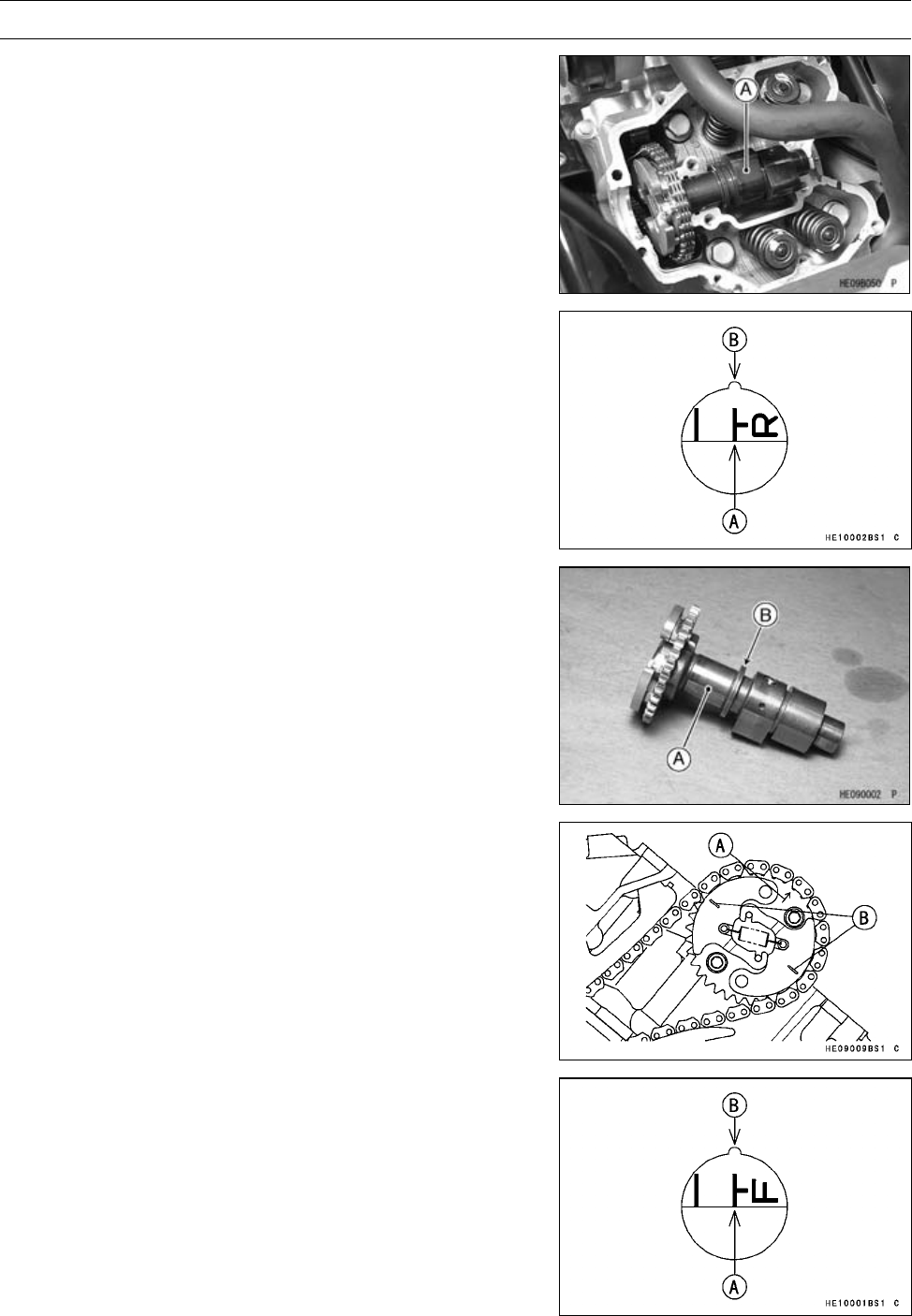
ENGINE TOP END 5-19
Camshaft
Camshaft Removal
•Remove:
Camshaft Chain Tensioners (see Camshaft Chain Ten-
sioner Removal)
Rocker Cases (see Rocker Case Removal)
Camshafts [A]
•Support the chain using a suitable tool.
Camshaft Installation
•Using a wrench on the alternator bolt, turn the crankshaft
clockwise until “T-R” mark [A] is aligned with the notch
[B] in the inspection window.
•The rear camshaft [A] has a groove [B].
•First, install the rear camshaft.
•Face the arrow [A] of the rear camshaft sprocket upward
(left side view).
•Engage the rear camshaft chain with the rear camshaft
sprocket.
•Align the marks [B] on the weights with the rear cylinder
head upper surface.
•Using a wrench on the alternator bolt, turn the crankshaft
clockwise 270°.
○Align the “T-F” mark [A] with the notch [B] in the inspection
window.
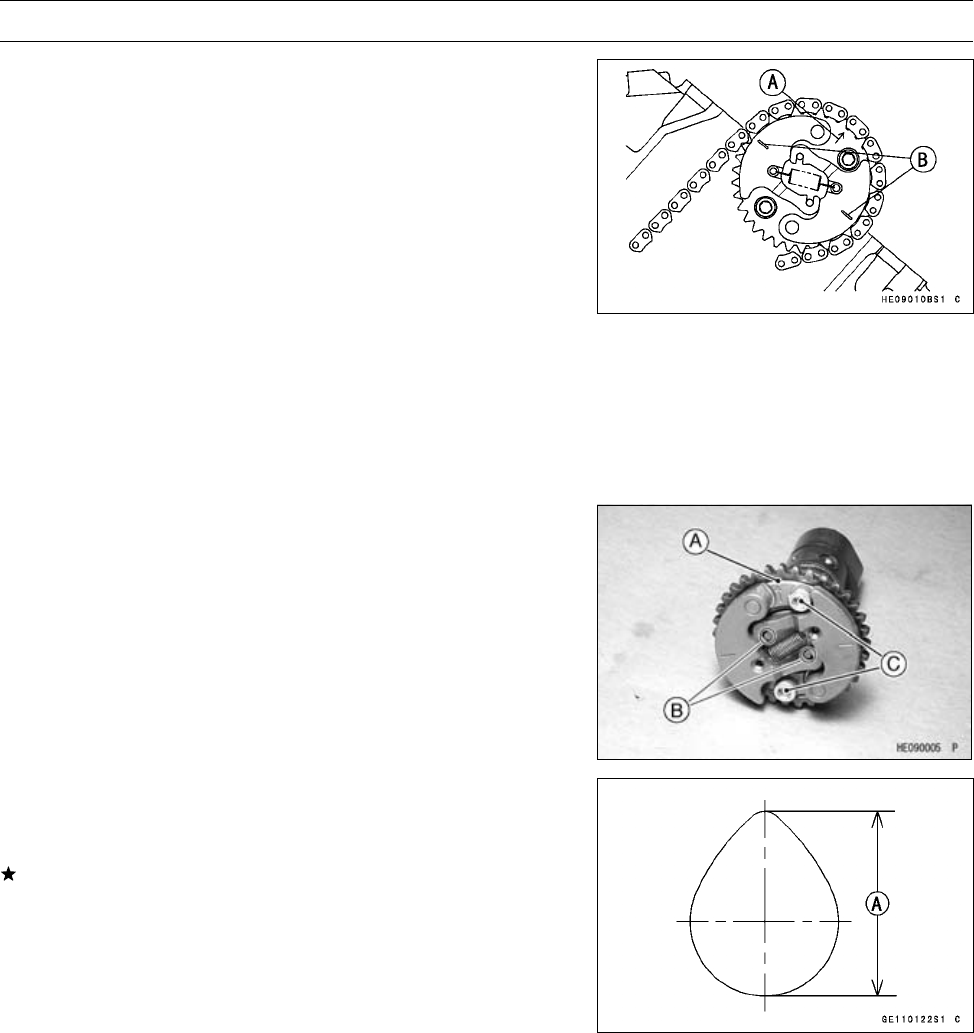
5-20 ENGINE TOP END
Camshaft
•Face the arrow [A] of the front camshaft sprocket upward
(right side view).
•Engage the front camshaft chain with the front camshaft
sprocket.
•Align the marks [B] on the weights with the front cylinder
head upper surface.
•Install:
Rocker Cases (see Rocker Case Installation)
Camshaft Chain Tensioners (see Camshaft Chain Ten-
sioner Installation)
•Check the valve clearance (see Valve Clearance Inspec-
tion).
Camshaft Assembly
•Install the KACR unit [A] (sprocket) on the camshaft so
that the unit fits onto the camshaft pins [B].
•Apply a non-permanent locking agent to the camshaft
sprocket bolts [C].
•Tighten:
Torque - Camshaft Sprocket Bolts: 12 N·m (1.2 kgf·m, 106
in·lb)
Cam Wear Inspection
•Remove the camshaft.
•Measure the height [A] of the cam with a micrometer.
If the cams are worn past the service limit, replace the
camshaft.
Cam Height
Standard:
Exhaust 35.363 ∼35.477 mm (1.3922 ∼1.3967 in.)
Inlet 35.622 ∼35.736 mm (1.4024 ∼1.4069 in.)
Service Limit:
Exhaust 35.26 mm (1.388 in.)
Inlet 35.52 mm (1.398 in.)
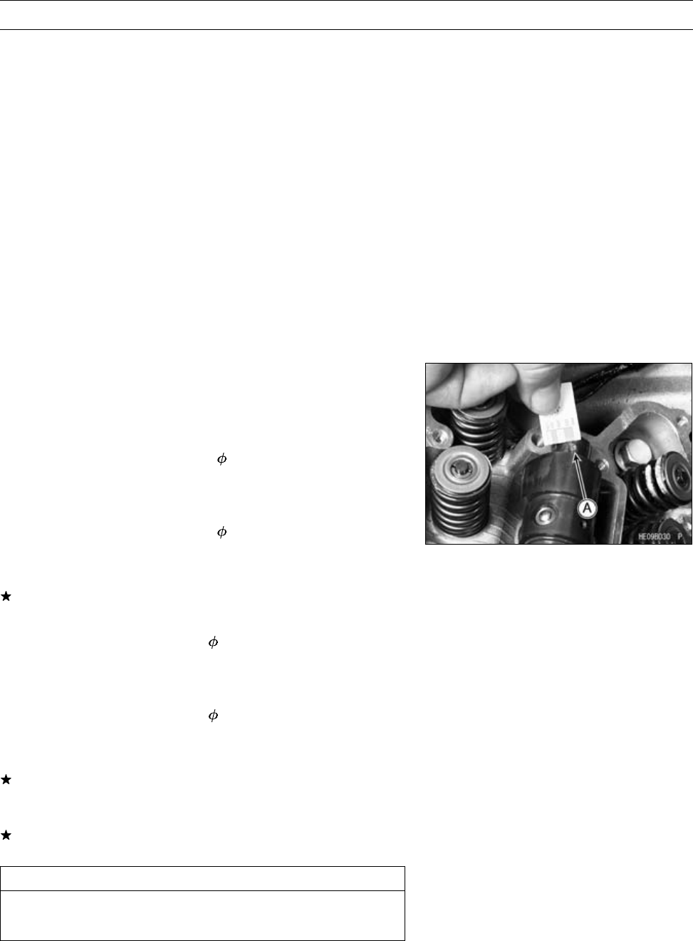
ENGINE TOP END 5-21
Camshaft
Camshaft Bearing Wear Inspection
○The journal wear is measured using plastigage (press
gauge), which is inserted into the clearance to be mea-
sured. The plastigage indicates the clearance by the
amount it is compressed and widened when the parts are
assembled.
•Cut strips of plastigage to journal width. Place a strip on
each journal parallel to the camshaft with the camshaft
installed in the correct position so that the plastigage will
be compressed between the journal and rocker case.
•Install the rocker case, tightening the bolts in the correct
sequence to the specified torque (see Rocker Case In-
stallation).
NOTE
○Do not turn the camshaft when the plastigage is be-
tween the journal and rocker case.
•Remove the rocker case and measure the plastigage
width [A] to determine the clearance between the journal
and the rocker case. Measure the widest portion of the
plastigage.
Camshaft Bearing Clearance ( 18)
Standard: 0.016 ∼0.052 mm (0.0006 ∼0.0020 in.)
Service Limit: 0.14 mm (0.0055 in.)
Camshaft Bearing Clearance ( 22)
Standard: 0.020 ∼0.062 mm (0.0008 ∼0.0024 in.)
Service Limit: 0.15 mm (0.0059 in.)
If any clearance exceeds the service limit, measure the
diameter of the camshaft journal.
Camshaft Journal Diameter ( 18)
Standard: 17.966 ∼17.984 mm (0.7073 ∼0.7080 in.)
Service Limit: 17.94 mm (0.706 in.)
Camshaft Journal Diameter ( 22)
Standard: 21.959 ∼21.980 mm (0.8645 ∼0.8653 in.)
Service Limit: 21.93 mm (0.863 in.)
If the camshaft journal diameter is less than the service
limit, replace the camshaft with a new one and measure
the clearance again.
If the clearance still remains out of the limit, replace the
cylinder head and the rocker case.
CAUTION
The cylinder head and rocker case are machined as
a set, and must be replaced as a set.
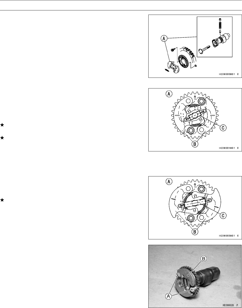
5-22 ENGINE TOP END
Camshaft
KACR Inspection
The Kawasaki Automatic Compression Release (KACR)
momentarily opens the exhaust valves on the compression
stroke at very low speeds. This allows some of the com-
pression pressure to escape, making it easy to turn over
the engine during starting.
Due to the simplicity of the mechanism, no periodic main-
tenance is needed. There are only two symptoms of prob-
lems with the KACR mechanism [A]: compression is not re-
leased during starting, and compression is released during
running.
(1) If compression is not released during starting, the
weights are not returning to their rest position.
•Remove the camshaft (see Camshaft Removal).
•Remove the KACR unit.
•Visually inspect the spring.
If damaged, deformed, or missing, replace the spring.
•Remove the spring and move the weights back and forth.
If the weights do not move smoothly, replace the KACR
unit. Also inspect the exhaust rocker arm for any damage,
and replace the rocker arm if necessary.
[A] Rest Position (compression is released)
[B] Weights
[C] Spring
(2) If compression is released while the engine is running,
the weights are not swinging out.
•Remove the spring and move the weights back and forth.
If the weights do not move easily from the retracted po-
sition, replace the KACR unit. Also inspect the exhaust
rocker arm for any damage, and replace the rocker arm if
necessary.
[A] Running Position (compression is not released)
[B] Weights
[C] Spring
KACR Removal
•Remove:
Camshaft (see Camshaft Removal)
Camshaft Sprocket Bolts [A]
KACR Unit [B]
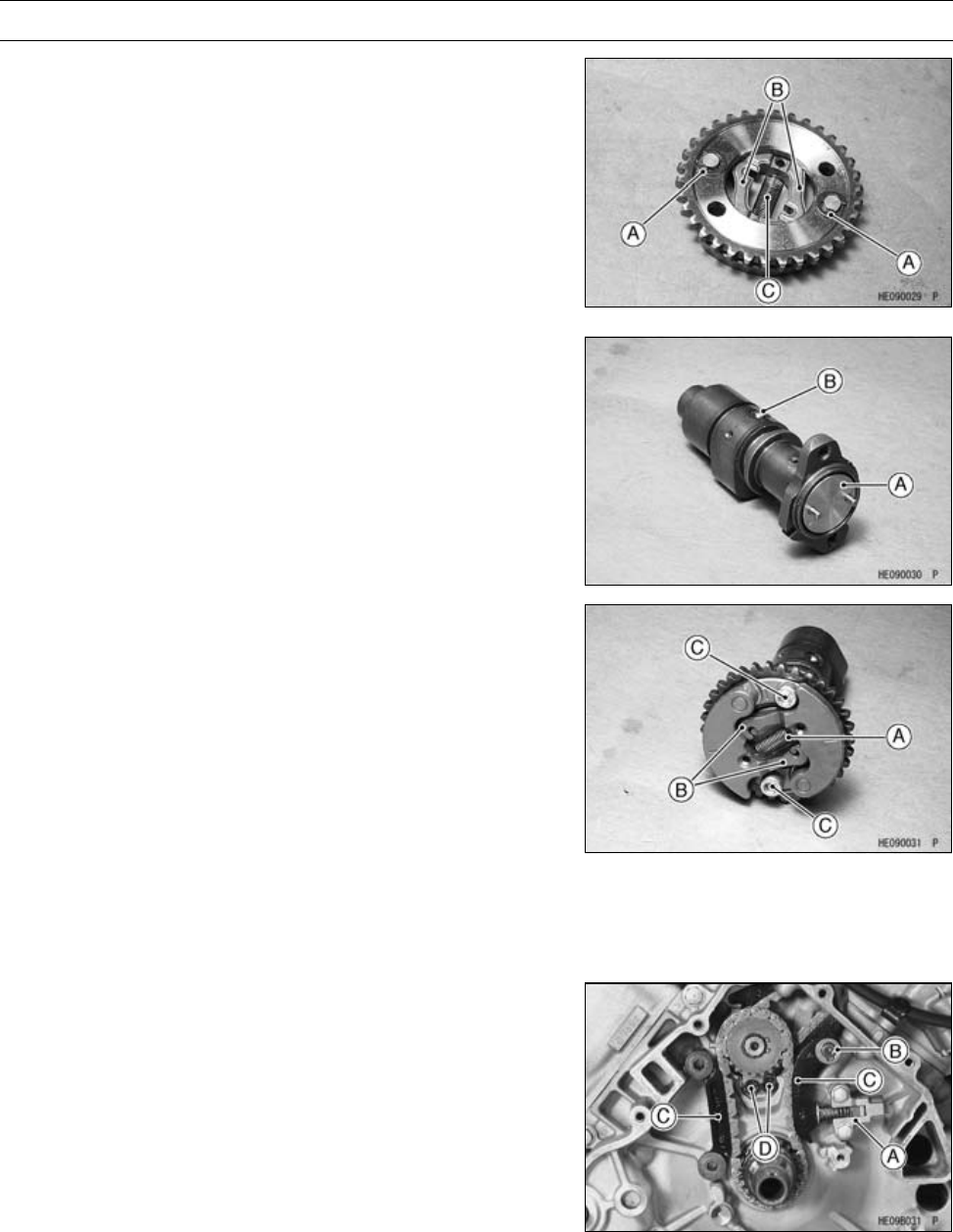
ENGINE TOP END 5-23
Camshaft
•Remove:
Circlips [A]
Weights [B]
Spring [C]
NOTE
○Do not remove the shaft [A] and pin [B].
○If the parts are removed, they cannot be reinstalled.
KACR Installation
•Install:
Weights
Circlips
Spring [A]
○Hook the spring from the outside with the open side of the
hook inwards.
•Install:
KACR Unit
•Hook the arms [B] on the pins.
•Apply a non-permanent locking agent to the camshaft
sprocket bolts [C] and tighten them.
Torque - Camshaft Sprocket Bolts: 12 N·m (1.2 kgf·m, 106
in·lb)
Camshaft Chain Removal
•Remove (left side view):
Rear and Front Camshafts (see Camshaft Removal)
Alternator Rotor (see Alternator Rotor Removal in the
Electrical System chapter)
Oil Pump (see Oil Pump Removal in the Engine Lubri-
cation System chapter)
Intermediate Shaft Chain Tensioner [A]
Circlip [B] and Washer
Special Tool - Outside Circlip Pliers: 57001-144
•Remove:
Intermediate Shaft Chain Guides [C]
Position Plate Bolts [D] and Position Plate
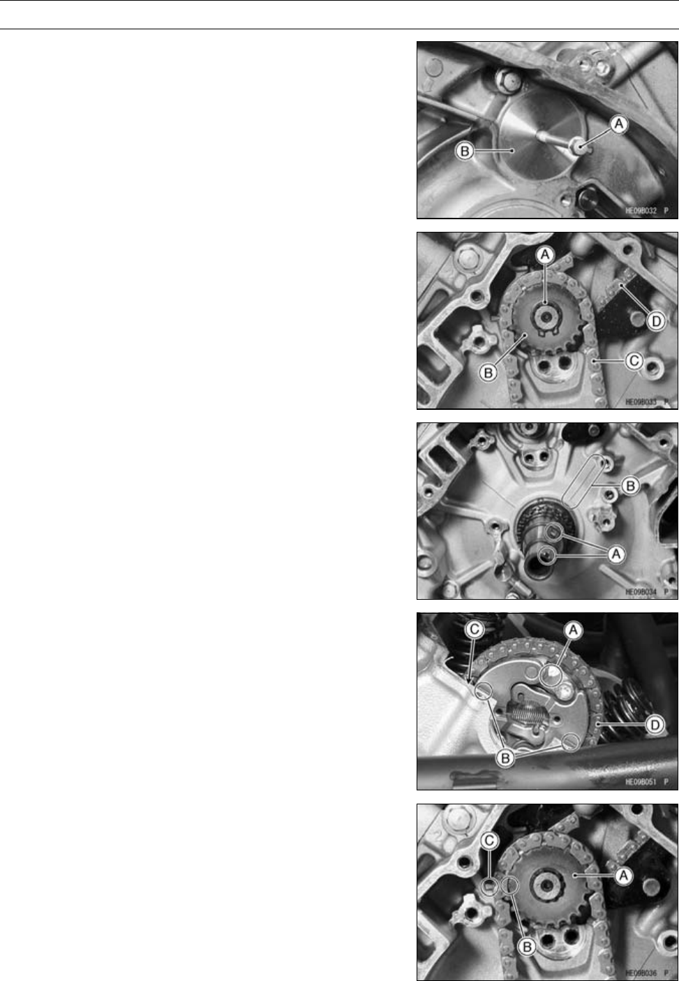
5-24 ENGINE TOP END
Camshaft
•Remove (right side view):
Torque Converter Cover (see Torque Converter Cover
Removal in the Converter System chapter)
•Using a M6 bolt [A], pull out the cover [B].
•Remove (left side view):
Circlip [A]
Special Tool - Outside Circlip Pliers: 57001-144
•Remove:
Intermediate Shaft Sprocket [B]
Intermediate Shaft Drive Chain [C]
Rear Camshaft Chain [D]
Front Camshaft Chain (right side)
Camshaft Chain Installation
Rear Camshaft Chain
•Align the key grooves [A] on the crankshaft with the em-
bossed line [B] on the crankcase (left side view).
•Face the arrow [A] of the rear camshaft sprocket upward.
•Align the marks [B] on the weights with the rear cylinder
head upper surface [C].
•Place the rear camshaft chain [D] onto the rear camshaft
sprocket.
•Engage the camshaft and intermediate shaft chains on
the intermediate shaft sprocket [A] and insert the inter-
mediate shaft (left side view).
•Align the punch marks [B] on the sprocket with the em-
bossed mark [C] on the crankcase.
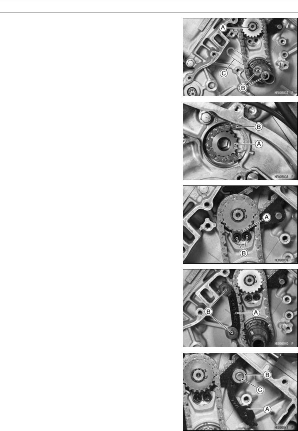
ENGINE TOP END 5-25
Camshaft
Front Camshaft Chain
•Install the circlip [A].
Special Tool - Outside Circlip Pliers: 57001-144
•Rotate the crankshaft clockwise 270°.
•Align the key grooves [B] on the crankshaft with the em-
bossed line [C] on the crankcase.
•Move the intermediate shaft [A] to the left side of the en-
gine.
•Engage the front camshaft chain [B] with the sprocket on
the intermediate shaft.
•Install (left side view):
Position Plate [A]
•Tighten:
Torque - Position Plate Bolts [B]: 8.8 N·m (0.90 kgf·m, 78
in·lb)
•Install:
Intermediate Shaft Chain Guide [A] (front)
•Tighten:
Torque - Intermediate Shaft Chain Guide Bolts [B]: 8.8 N·m
(0.90 kgf·m, 78 in·lb)
•Install:
Intermediate Shaft Chain Guide [A] (Rear)
Washer [B]
Circlip [C]
Special Tool - Outside Circlip Pliers: 57001-144
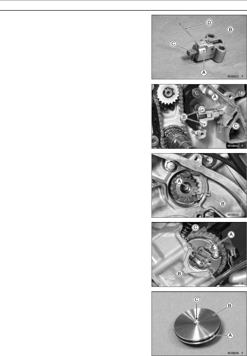
5-26 ENGINE TOP END
Camshaft
•Install the intermediate shaft chain tensioner [A] as fol-
lows:
•Release the stopper [B] and push the push rod [C] into
the tensioner body.
•Insertawire[D]intotherodholetoholdtherodinplace.
•Install:
Intermediate Shaft Chain Tensioner [A]
•Tighten:
Torque - Intermediate Shaft Chain Tensioner Bolts [B]: 8.8
N·m (0.90 kgf·m, 78 in·lb)
•Remove the wire [C] to free the push rod.
•Confirm that the punch mark [A] on the intermediate shaft
sprocket (Right Side) is aligned with the embossed mark
[B] on the crankcase.
•Face the arrow mark [A] upward.
•Align the marks [B] on the weights with the front cylinder
head upper surface [C].
•Place the front camshaft chain on the front camshaft
sprocket.
•Apply grease to the O-ring [A] and install the cover [B] into
the right side of the crankcase so that the tapped hole [C]
faces outward.

ENGINE TOP END 5-27
Camshaft
•Install:
Rocker Cases (see Rocker Case Installation)
Camshaft Chain Tensioners (see Camshaft Chain Ten-
sioner Installation)
•Check the valve clearances (see Valve Clearance Inspec-
tion).
Camshaft Chain Guide Wear Inspection
•Visually inspect the rubber on the guides.
If the rubber is damaged, cut, or is missing pieces, replace
the guide.
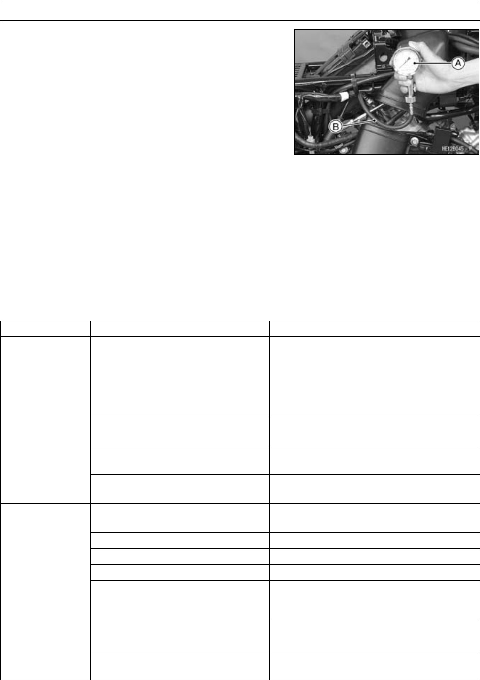
5-28 ENGINE TOP END
Cylinder Head
Cylinder Compression Measurement
NOTE
○Use the battery which is fully charged.
•Warm up the engine thoroughly, and stop the engine.
•Remove the spark plug (see Spark Plug Removal in the
Electrical System chapter).
•Attach the compression gauge [A] and adapter [B] firmly
into the spark plug hole.
Special Tools - Compression Gauge, 20 kgf/cm²: 57001-221
Compression Gauge Adapter, M10 × 1.0:
57001-1317
•Hold the throttle wide open and crank the engine with the
electric starter or the recoil starter several times.
When the gauge stops rising, stop cranking and read the
gauge.
Cylinder Compression (Usable Range)
Electric Starter: 251 ∼456 kPa (2.56 ∼4.65 kgf/cm², 36
∼66 psi) @380 r/min (rpm)
The following table should be consulted if the obtainable compression reading is not within the us-
able range.
Problem Diagnosis Remedy (Action)
Carbon accumulation on piston,
cylinder head, and in combustion
chamber possibly due to damaged
valve stem oil seal and/or damaged
piston oil rings (This may be
indicated by white exhaust smoke).
Remove the carbon deposits and replace
damaged parts if necessary.
Incorrect cylinder head gasket
thickness.
Replace the gasket with a standard part.
Damaged or missing compression
release cam spring
Replace the spring.
Cylinder
compression
is higher than
usable range
Compression release weights do
not move smoothly.
Replace the compression release unit.
Gas leakage around cylinder head Replace damaged gasket and check
cylinder head warp.
Bad condition of valve seating Repair if necessary.
Incorrect valve clearance. Adjust the valve clearance.
Incorrect piston/cylinder clearance Replace the piston and/or cylinder
Piston seizure. Inspect the cylinder and liner and
replace/repair the cylinder and/or piston
as necessary.
Bad condition of piston ring and/or
piston ring grooves
Replace the piston and/or the piston rings.
Cylinder
compression is
lower than usable
range
Compression release weights do
not move smoothly
Replace the compression release unit
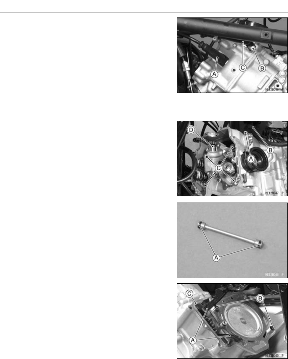
ENGINE TOP END 5-29
Cylinder Head
Cylinder Head Removal
•Drain the coolant (see Coolant Change in the Periodic
Maintenance chapter).
•Remove:
Throttle Body (see Throttle Body Removal in the Fuel
System (DFI) chapter)
Exhaust Pipe (see Muffler and Exhaust Pipe Removal)
Thermostat (see Thermostat Removal in the Cooling
System chapter)
Camshaft (see Camshaft Removal)
Spark Plug Cap [A]
Water Pipe Bolt [B]
Left Water Pipe [C]
•Remove:
Cylinder Head Bolt (M6) [A]
Bracket [B] (Front only)
Cylinder Head Bolts (M10) [C] and Washers
Cylinder Head [D] and Gasket
○For front cylinder head removal, lift up the front of the
engine with a suitable bar to remove the two cylinder head
bolts.
○For rear cylinder head removal, push the engine right
ward to remove the right side cylinder head bolts.
Cylinder Head Installation
•Apply oil to the O-rings [A] on the oil pipe, and insert the
pipe.
•Install:
Camshaft Chain Guides [A]
Dowel Pins [B]
New Cylinder Head Gasket [C]
•Tighten:
Torque - Front Cylinder Camshaft Chain Guide Bolt: 20
N·m (2.0 kgf·m, 15 ft·lb)
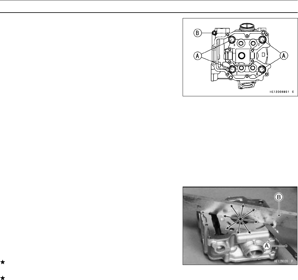
5-30 ENGINE TOP END
Cylinder Head
•Apply molybdenum disulfide oil to the threads and seating
surface of the cylinder head bolts and both sides of the
washers.
•Tighten the cylinder head bolts [A] following the tightening
sequence as shown.
First Torque - Cylinder Head Bolts (M10): 25 N·m (2.5
kgf·m, 18 ft·lb)
Final Torque - Cylinder Head Bolts (M10): 49 N·m (5.0
kgf·m, 36 ft·lb)
•Tighten the cylinder head bolts (M6) [B].
Torque - Cylinder Head Bolts (M6): 9.8 N·m (1.0 kgf·m, 87
in·lb)
Cylinder Head Cleaning
•Remove the cylinder head (see Cylinder Head Removal).
•Scrape the carbon out of the combustion chamber and
exhaust port with a suitable tool.
•Wash the head with a high-flash point solvent.
•Blow out any particles which may obstruct the oil passage
in the cylinder head using compressed air.
Cylinder Head Warp Inspection
•Clean the cylinder head (see Cylinder Head Cleaning).
•Lay a straightedge across the lower surface of the cylinder
head.
•Use a thickness gauge [A] to measure the space between
the straightedge [B] and the head at several locations.
Cylinder Head Warp
Service Limit: 0.05 mm (0.002 in.)
If the cylinder head is warped more than the service limit,
replace it.
If the cylinder head is warped less than the service limit,
repair the head by lapping the lower surface with emery
paper secured to a surface plate (first No. 200, then No.
400).
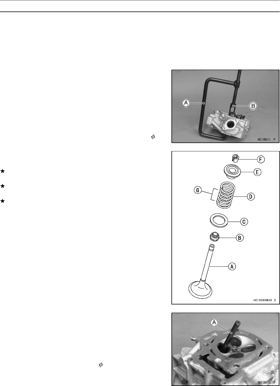
ENGINE TOP END 5-31
Valves
Valve Clearance Inspection
•Refer to the Valve Clearance Inspection in the Periodic
Maintenance chapter.
Valve Clearance Adjustment
•Refer to the Valve Clearance Adjustment in the Periodic
Maintenance chapter.
Valve Removal
•Remove the cylinder head (see Cylinder Head Removal).
○Mark and record the valve location so it can be installed
in the original position.
•Using the valve spring compressor assembly, remove the
valve.
Special Tools - Valve Spring Compressor Assembly: 57001
-241 [A]
Valve Spring Compressor Adapter, 22:
57001-1202 [B]
Valve Installation
•Replace the valve stem oil seal.
If a new valve is to be used, check the valve-to-guide
clearance (see Valve-to-Guide Clearance Measurement).
If there is too little clearance, ream the valve guide (see
Valve Guide Installation).
If there is too much clearance, install a new valve guide
(see Valve Guide Removal and Valve Guide Installation).
•Check the valve seat (see Valve Seat Inspection).
•Apply a thin coat of molybdenum disulfide grease to the
valve stem.
•Install each spring so that the closed coil end faces down-
wards.
○The green paint on the spring faces upwards.
Valve Stem [A]
Oil Seal [B]
Spring Seat [C]
Spring [D]
Retainer [E]
Split Keepers [F]
Closed Coil End [G]
Valve Guide Removal
•Remove:
Valve (see Valve Removal)
Valve Stem Oil Seal
•Hammer lightly on the valve guide arbor [A] to remove the
guide from the top of the head.
Special Tool - Valve Guide Arbor, 5: 57001-1203
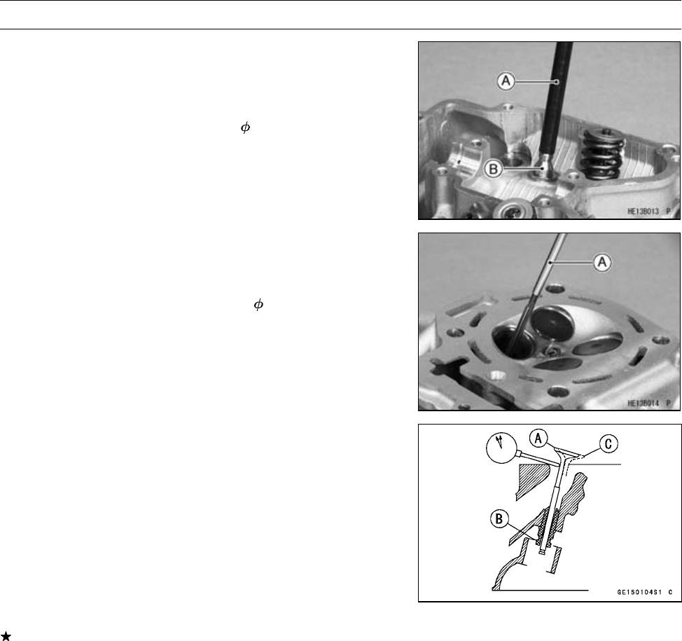
5-32 ENGINE TOP END
Valves
Valve Guide Installation
•Lightly oil the valve guide outer surface.
•Using the valve guide arbor [A], drive the valve guide [B]
until its flange touches the cylinder head.
Special Tool - Valve Guide Arbor, 5: 57001-1203
•Ream the valve guide with the valve guide reamer [A] , it
may be necessary to ream the guide even if the old guide
is reused.
Special Tool - Valve Guide Reamer, 5: 57001-1204
Valve-to-Guide Clearance Measurement
If a small bore gauge is not available, inspect the valve
guide wear by measuring the valve to valve guide clearance
with the wobble method as indicated below.
•Insert a new valve [A] into the guide [B] and set a dial
gauge against the stem perpendicular to it as close as
possible to the cylinder head mating surface.
•Move [C] the stem back and forth to measure valve/valve
guide clearance.
•Repeat the measurement in a direction at a right angle to
the first.
If the reading exceeds the service limit, replace the guide.
NOTE
○The reading is not actual valve/valve guide clearance
because the measuring point is above the guide.
Valve/Valve Guide Clearance (Wobble Method)
Standard:
Exhaust 0.09 ∼0.17 mm (0.0035 ∼0.0067 in.)
Inlet 0.03 ∼0.11 mm (0.0012 ∼0.0043 in.)
Service Limit:
Exhaust 0.37 mm (0.0146 in.)
Inlet 0.31 mm (0.0122 in.)
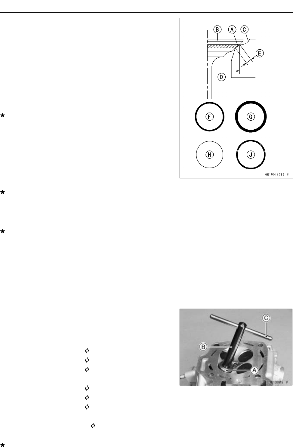
ENGINE TOP END 5-33
Valves
Valve Seat Inspection
•Remove the valve (see Valve Removal).
•Check the valve seating surface [A] between the valve [B]
and valve seat [C].
○Coat the valve seat with machinist’s dye.
○Push the valve into the guide.
○Rotate the valve against the seat with a lapping tool.
○Pull the valve out, and check the seating pattern on the
valve head. It must be the correct width and even all the
way around.
•Measure the outside diameter [D] of the seating pattern
on the valve seat.
If the outside diameter of the valve seating pattern is too
large or too small, repair the seat (see Valve Seat Repair).
Valve Seating Surface Outside Diameter
Exhaust: 25.2 ∼25.4 mm (0.992 ∼1.000 in.)
Inlet: 29.4 ∼29.6 mm (1.157 ∼1.165 in.)
NOTE
○The valve stem and guide must be in good condition, or
this check will not be valid.
If the valve seating pattern is not correct, repair the seat
(see Valve Seat Repair).
•Measure the seat width [E] of the portion where there is
no build-up carbon (white portion) of the valve seat with
vernier calipers.
If the width is too wide, too narrow or uneven, repair the
seat (see Valve Seat Repair).
[F] Good
[G] Too Wide
[H] Too Narrow
[J] Uneven
Valve Seating Surface Width
Exhaust: 0.5 ∼1.0 mm (0.02 ∼0.04 in.)
Inlet: 0.5 ∼1.0 mm (0.02 ∼0.04 in.)
Valve Seat Repair (Valve Lapping)
•Using the valve seat cutters [A], repair the valve seat.
Special Tools - Valve Seat Cutters:
Exhaust Valves:
Valve Seat Cutter, 45° - 27.5: 57001-1114
Valve Seat Cutter, 32° - 28: 57001-1119
Valve Seat Cutter, 60° - 30: 57001-1123
Inlet Valves:
Valve Seat Cutter, 45° - 30: 57001-1187
Valve Seat Cutter, 32° - 33: 57001-1199
Valve Seat Cutter, 60° - 30: 57001-1123
Holder and Bar:
Valve Seat Cutter Holder, 5: 57001-1208 [B]
Valve Seat Cutter Holder Bar: 57001-1128 [C]
If the manufacturer’s instructions are not available, use
the following procedure.
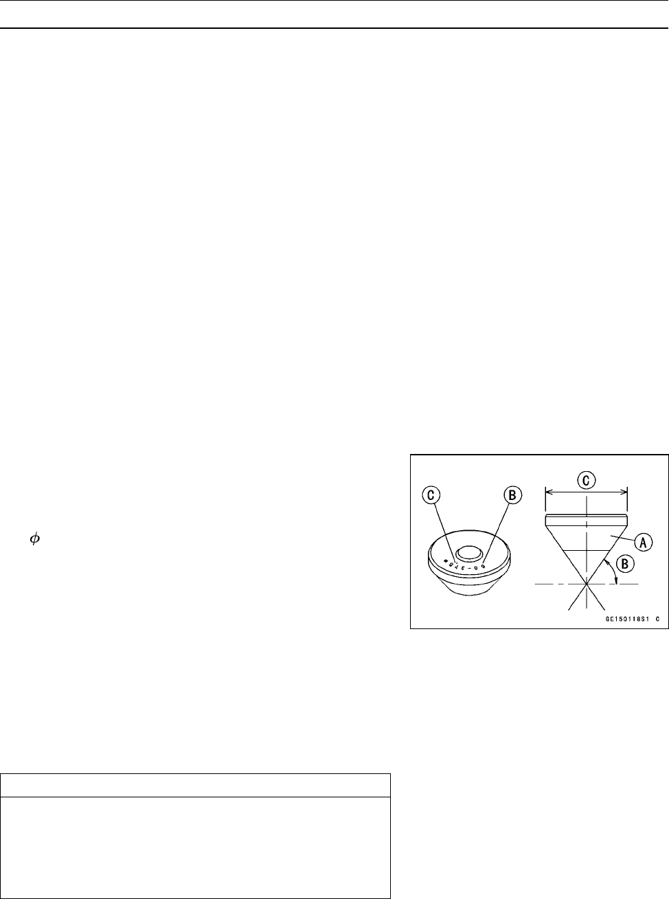
5-34 ENGINE TOP END
Valves
Seat Cutter Operation Care
1. This valve seat cutter is developed to grind the valve
seat for repair. Therefore the cutter must not be used
for other purposes than seat repair.
2. Do not drop or shock the valve seat cutter, or the dia-
mond particles may fall off.
3. Do not fail to apply engine oil to the valve seat cutter
before grinding the seat surface. Also wash off ground
particles sticking to the cutter with washing oil.
NOTE
○Do not use a wire brush to remove the metal particles
from the cutter. It will take off the diamond particles.
4. Setting the valve seat cutter holder in position, operate
the cutter in one hand. Do not apply too much force to
the diamond portion.
NOTE
○Prior to grinding, apply engine oil to the cutter and dur-
ing the operation, wash off any ground particles sticking
to the cutter with washing oil.
5. After use, wash it with washing oil and apply thin layer
of engine oil before storing.
Marks Stamped on the Cutter
The marks stamped on the back of the cutter [A] represent
the following.
60° ........................... Cutter angle [B]
37.5 ....................... Outer diameter of cutter [C]
Operating Procedures
•Clean the seat area carefully.
•Coat the seat with machinist’s dye.
•Fit a 45° cutter into the holder and slide it into the valve
guide.
•Press down lightly on the handle and turn it right or left.
Grind the seating surface only until it is smooth.
CAUTION
Do not grind the seat too much. Overgrinding will
reduce valve clearance by sinking the valve into the
head. If the valve sinks too far into the head, it will
be impossible to adjust the clearance, and the cylin-
der head must be replaced.
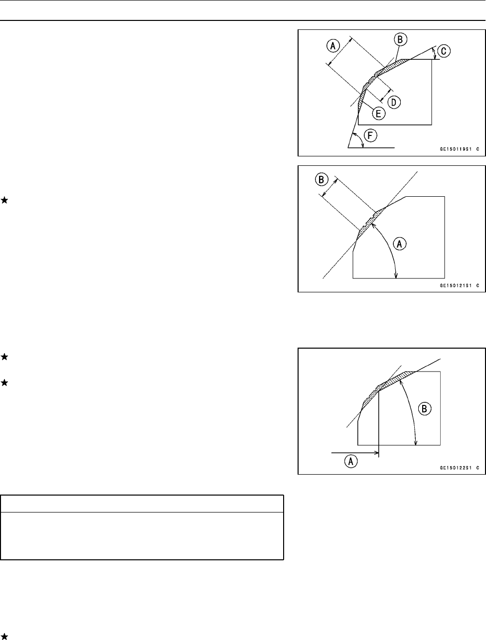
ENGINE TOP END 5-35
Valves
Widened Width [A] of engagement by machining with
45° cutter
Ground Volume [B] by 32° cutter
32° [C]
Correct Width [D]
Ground Volume [E] by 60° cutter
60° [F]
•Measure the outside diameter of the seating surface with
vernier calipers.
If the outside diameter of the seating surface is too small,
repeat the 45° grind [A] until the diameter is within the
specified range.
Original Seating Surface [B]
NOTE
○Remove all pittings of flaws from 45° ground surface.
○After grinding with 45° cutter, apply thin coat of machin-
ist’s dye to seating surface. This makes seating surface
distinct and 32° and 60° grinding operation easier.
○When the valve guide is replaced, be sure to grind with
45° cutter for centering and good contact.
If the outside diameter (O.D.) [A] of the seating surface is
too large, make the 32° grind described below.
If the outside diameter of the seating surface is within the
specified range, measure the seat width as described be-
low.
•Grind the seat at a 32° angle [B] until the seat O.D. is
within the specified range.
○To make the 32° grind, fit a 32° cutter into the holder, and
slide it into the valve guide.
Turn the holder one turn at a time while pressing down very
lightly. Check the seat after each turn.
CAUTION
The 32° cutter removes material very quickly.
Check the seat outside diameter frequently to pre-
vent overgrinding.
After making the 32° grind, return to the seat O.D. mea-
surement step above.
•To measure the seat width, use vernier calipers to mea-
sure the width of the 45° angle portion of the seat at sev-
eral places around the seat.
If the seat width is too narrow, repeat the 45° grind until
the seat is slightly too wide, and then return to the seat
O.D. measurement step above.
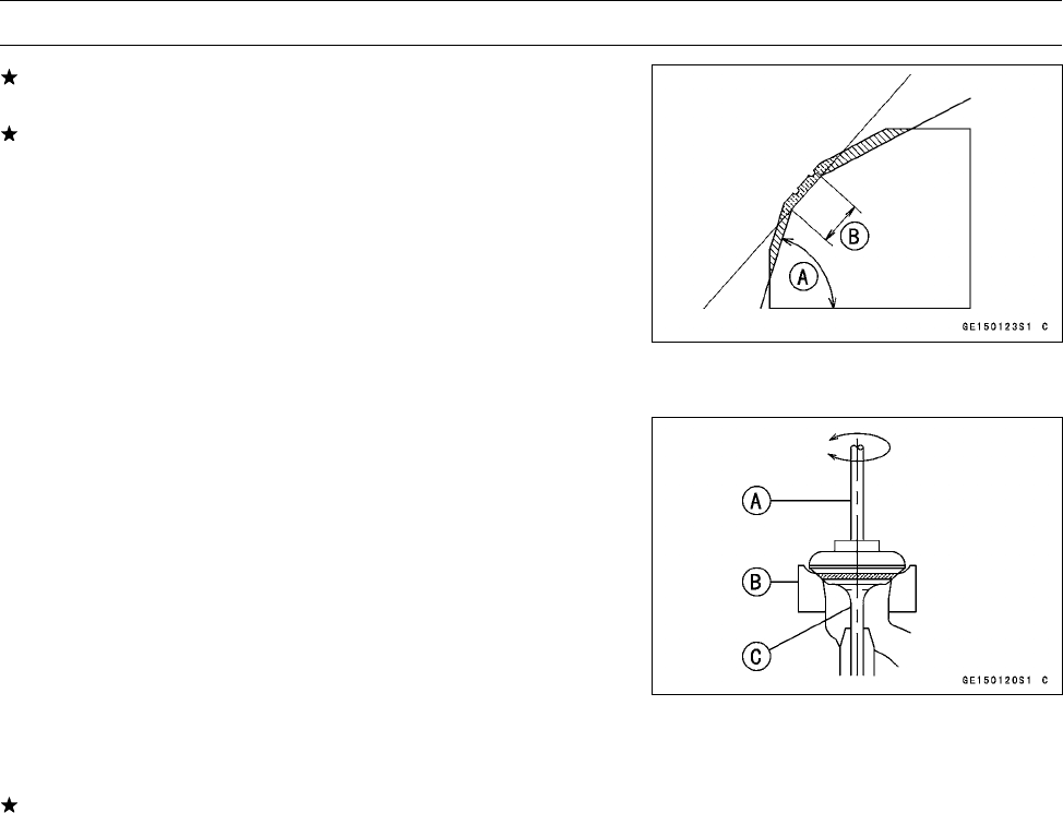
5-36 ENGINE TOP END
Valves
If the seat width is too wide, make the 60° [A] grind de-
scribed below.
If the seat width is within the specified range, lap the valve
to the seat as described below.
•Grind the seat at a 60° angle until the seat width is within
the specified range.
○To make the 60° grind, fit 60° cutter into the holder, and
slide it into the valve guide.
○Turn the holder, while pressing down lightly.
○After making the 60° grind, return to the seat width mea-
surement step above.
Correct Width [B]
•Lap the valve to the seat, once the seat width and O.D.
are within the ranges specified above.
○Put a little coarse grinding compound on the face of the
valve in a number of places around the valve head.
○Spin the valve against the seat until the grinding com-
pound produces a smooth, matched surface on both the
seat and the valve.
○Repeat the process with a fine grinding compound.
[A] Lapper
[B] Valve Seat
[C] Valve
•The seating area should be marked about in the middle
of the valve face.
If the seat area is not in the right place on the valve, check
to be sure the valve is the correct part. If it is, it may have
been refaced too much; replace it.
•Be sure to remove all grinding compound before assem-
bly.
•When the engine is assembled, be sure to adjust the valve
clearance (see Valve Clearance Adjustment in the Peri-
odic Maintenance chapter).
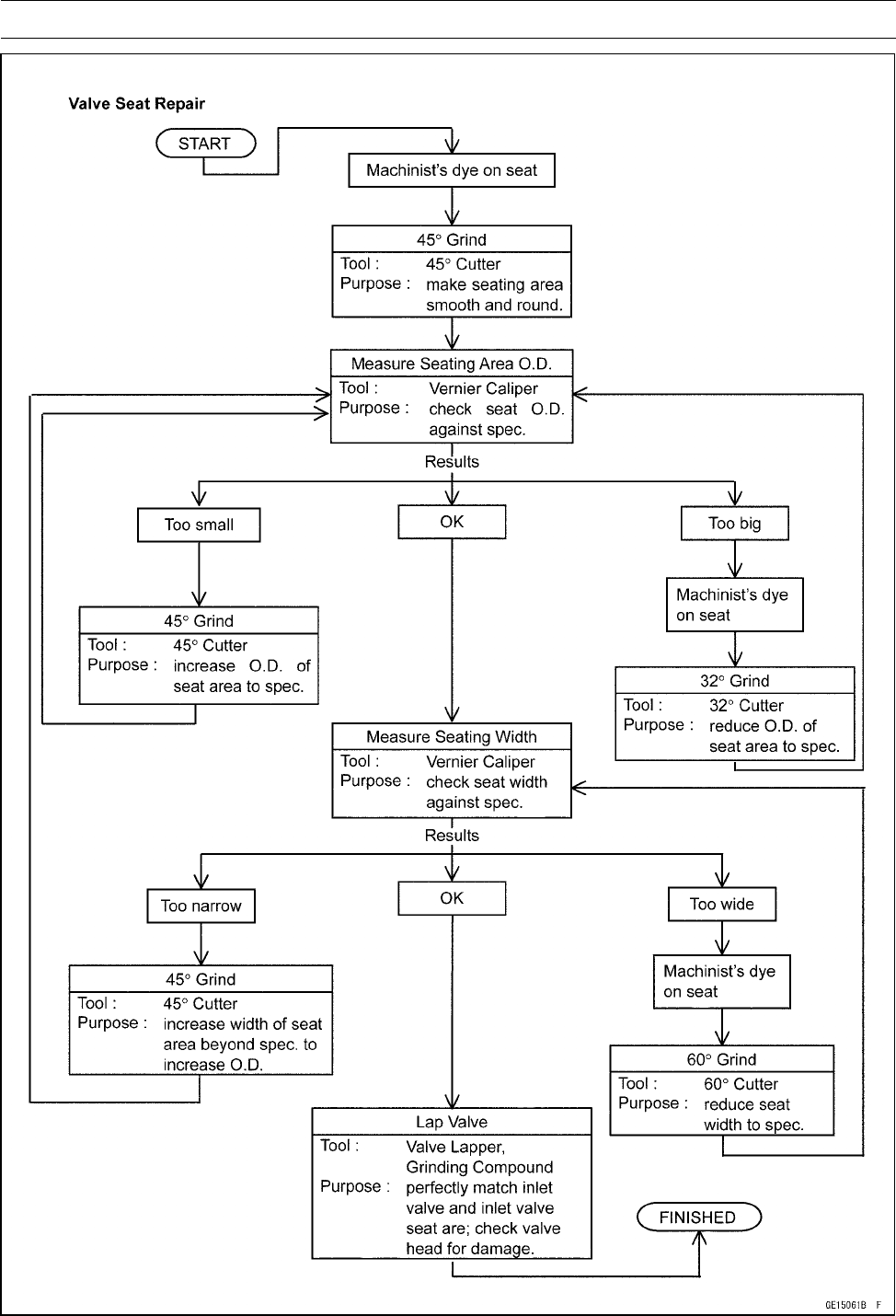
ENGINE TOP END 5-37
Valves
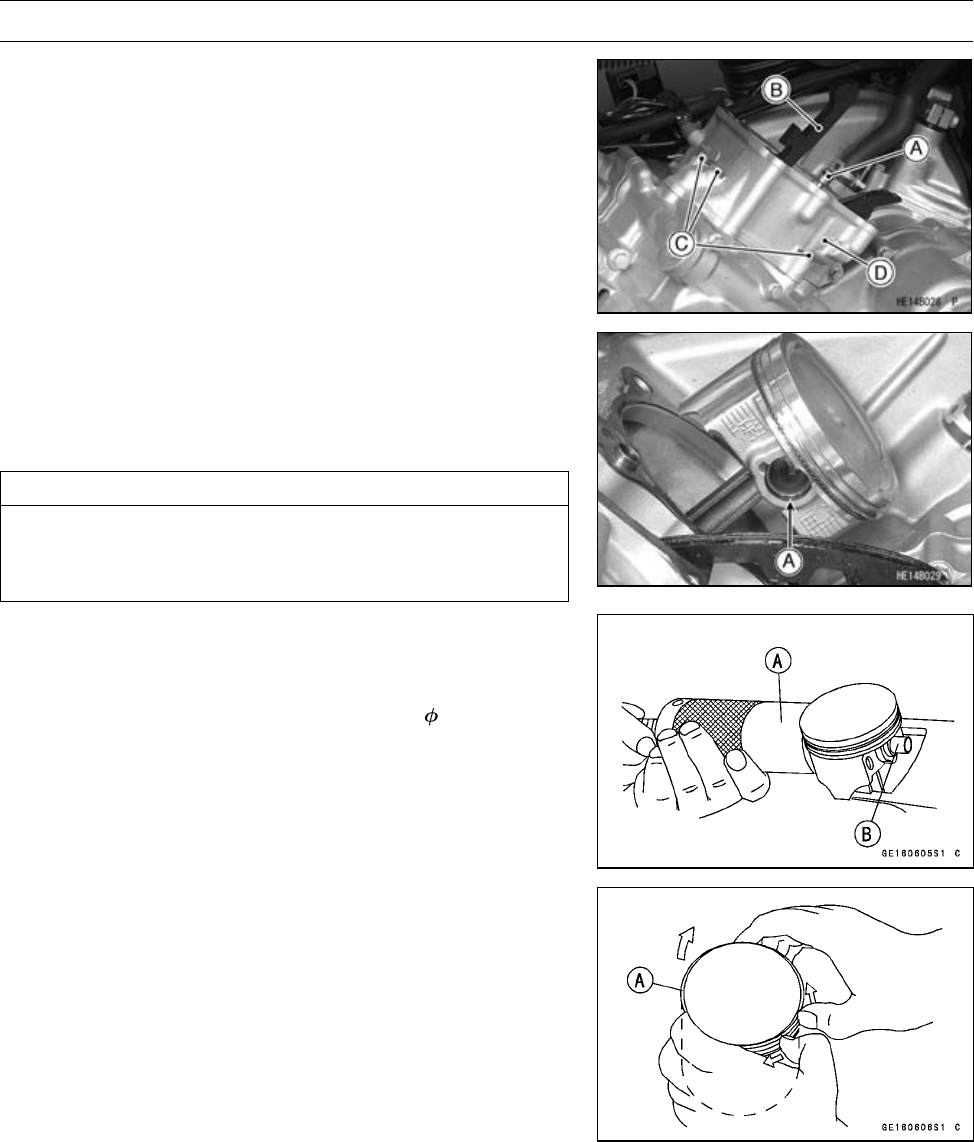
5-38 ENGINE TOP END
Cylinder and Piston
Cylinder Removal
•Remove:
Cylinder Head (see Cylinder Head Removal)
Oil Pipe [A]
Chain Guide [B]
Cylinder Bolts [C]
Cylinder [D]
Cylinder Base Gasket
Piston Removal
•Remove the cylinder block (see Cylinder Removal).
•Place a piece of clean cloth under the piston and remove
the piston pin snap rings [A] from the outside of each pis-
ton.
CAUTION
Do not reuse snap rings, as removal weakens and
deforms them. They could fall out and score the
cylinder wall.
•Using the piston pin puller assembly (special tool), re-
move the piston pins.
Special Tools - Piston Pin Puller Assembly [A]: 57001-910
Piston Pin Puller Adapter, 14 [B]: 57001
-1211
•Remove the piston.
•Carefully spread the ring opening with your thumbs and
then push up on the opposite side of the ring [A] to remove
it.
•Remove the 3-piece oil ring with your thumbs in the same
manner.
Cylinder, Piston Installation
NOTE
○If a new piston or cylinder is used, check piston to cylin-
der clearance (see Piston/Cylinder Clearance), and use
new piston rings.
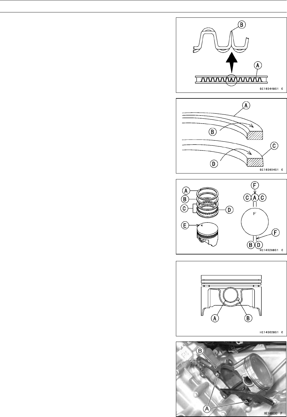
ENGINE TOP END 5-39
Cylinder and Piston
NOTE
○The oil ring rails have no “top” or “bottom”.
•Install the oil ring expander [A] in the bottom piston ring
groove so the ends [B] butt together.
•Install the oil ring steel rails, one above the expander and
one below it.
○Spread the rail with your thumbs, but only enough to fit
the rail over the piston.
○Release the rail into the bottom piston ring groove.
•Do not mix up the top ring and second ring.
•Install the top ring [A] so that the “R”mark[B]facesup.
•Install the second ring [C] so that the “RN”mark[D]faces
up.
•The piston ring openings must be positioned as shown in
the figure. The openings of the oil ring steel rails do not
align.
Top Rin g [ A ]
Second Ring [B]
Oil Ring Steel Rails [C]
Oil Ring Expander [D]
F mark [E] must be faced toward Front Side for front and
rear pistons
Opening Positions [F]
•Fit a new piston pin snap ring into the side of the piston
so that the ring opening [A] does not coincide with the slit
[B] of the piston pin hole.
○When installing the piston pin snap ring, compress it only
enough to install it and no more.
•Apply engine oil to the cylinder bore and, piston skirt.
•Install:
Dowel Pins [A]
New Cylinder Base Gasket [B]
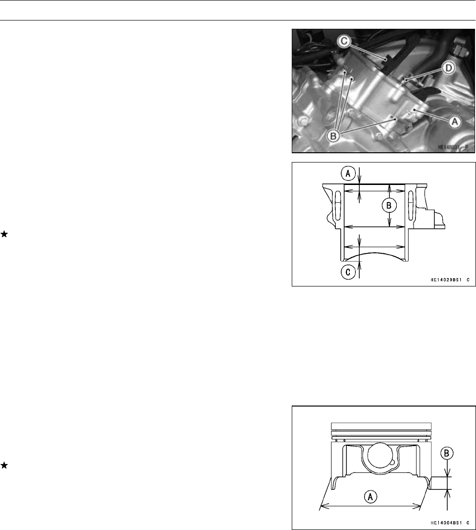
5-40 ENGINE TOP END
Cylinder and Piston
•Install:
Cylinder [A]
•Tighten:
Torque - Cylinder Bolts [B]: 9.8 N·m (1.0 kgf·m, 87 in·lb)
•Install:
Chain Guide [C]
•Apply oil to the O-ring on the oil pipe [D], and insert the
pipe.
Cylinder Wear Inspection
•Since there is a difference in cylinder wear in different di-
rections, take a side-to-side and a front-to-back measure-
ment at each of the three locations (total of six measure-
ments) shown in the figure.
If any of the cylinder inside diameter measurements ex-
ceeds the service limit, replace the cylinder.
10 mm (0.4 in.) [A]
60 mm (2.4 in.) [B]
20 mm (0.8 in.) [C]
Cylinder Inside Diameter
Standard: 84.994 ∼85.006 mm (3.3462 ∼3.3467
in.), and less than 0.01 mm (0.0004
in.) difference between any two
measurements.
Service Limit: 85.10 mm (3.350 in.), or more than 0.05
mm (0.0020 in.) difference between any
two measurements.
Piston Wear Inspection
•Measure the outside diameter [A] of each piston 18 mm
(0.71 in.) [B] up from the bottom of the piston at a right
angle to the direction of the piston pin.
If the measurement is under service limit, replace the pis-
ton.
Piston Diameter
Standard: 84.964 ∼84.979 mm (3.3450 ∼3.3456 in.)
Service Limit: 84.81 mm (3.3390 in.)
Piston/Cylinder Clearance Inspection
•Subtract the piston diameter from the cylinder inside di-
ameter to get the piston/cylinder clearance.
Piston/Cylinder Clearance
Standard: 0.015 ∼0.042 mm (0.0006 ∼0.0017 in.)
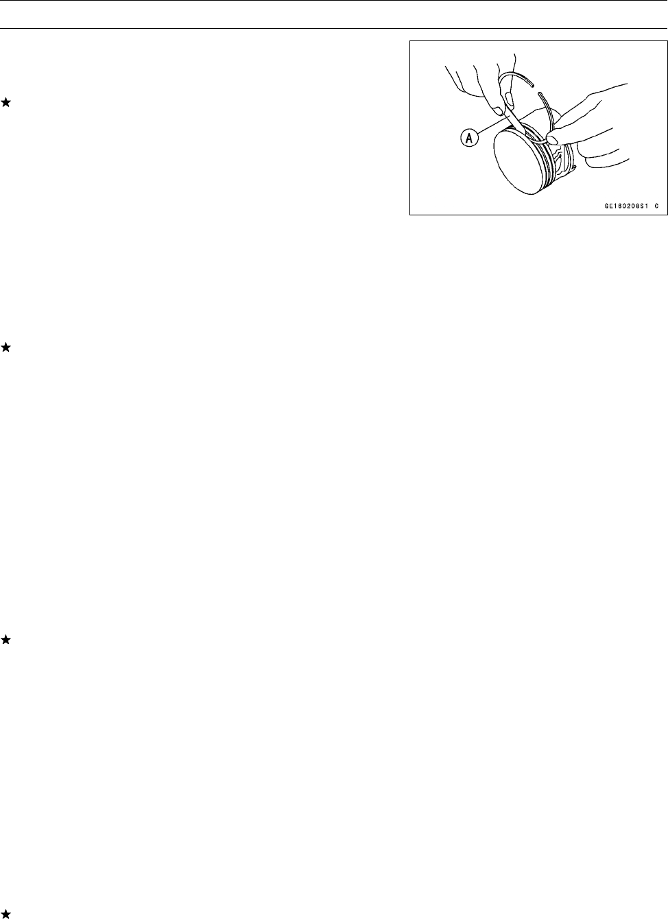
ENGINE TOP END 5-41
Cylinder and Piston
Piston Ring, Piston Ring Groove Wear Inspection
•Check for uneven groove wear by inspecting the ring seat-
ing.
The rings should fit perfectly parallel to groove surfaces.
If not, replace the piston and all the piston rings.
•With the piston rings in their grooves, make several mea-
surements with a thickness gauge [A] to determine piston
ring/groove clearance.
Piston Ring/Groove Clearance
Standard:
Top 0.04 ∼0.08 mm (0.0016 ∼0.0032 in.)
Second 0.03 ∼0.07 mm (0.0012 ∼0.0028 in.)
Service Limit:
Top 0.18 mm (0.0071 in.)
Second 0.17 mm (0.0067 in.)
If the piston ring/groove clearance is greater than the ser-
vice limit, measure the ring thickness and groove width as
follows to decide whether to replace the rings, the piston
or both.
Piston Ring Groove Width Inspection
•Measure the piston ring groove width.
○Use a vernier caliper at several points around the piston.
Piston Ring Groove Width
Standard:
Top 1.03 ∼1.05 mm (0.0405 ∼0.0413 in.)
Second 1.02 ∼1.04 mm (0.0402 ∼0.0409 in.)
Service Limit:
Top 1.13 mm (0.0445 in.)
Second 1.12 mm (0.0441 in.)
If the width of any of the two grooves is wider than the
service limit at any point, replace the piston.
Piston Ring Thickness Inspection
•Measure the piston ring thickness.
○Use a micrometer to measure at several points around
the ring.
Piston Ring Thickness
Standard:
Top 0.97 ∼0.99 mm (0.0382 ∼0.0390 in.)
Second 0.97 ∼0.99 mm (0.0382 ∼0.0390 in.)
Service Limit:
Top 0.90 mm (0.035 in.)
Second 0.90 mm (0.035 in.)
If any of the measurements is less than the service limit
on either of the rings, replace all the rings.
NOTE
○When using new rings in a used piston, check for un-
even groove wear. The rings should fit perfectly parallel
to the groove sides. If not, replace the piston.
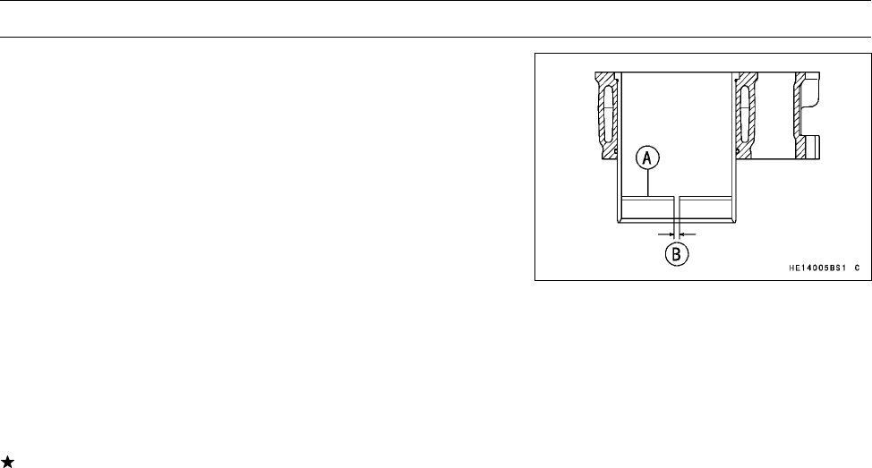
5-42 ENGINE TOP END
Cylinder and Piston
Piston Ring End Gap Inspection
•Place the piston ring [A] inside the cylinder, using the pis-
ton to locate the ring squarely in place. Set it close to the
bottom of the cylinder, where cylinder wear is low.
•Measure the gap [B] between the ends of the ring with a
thickness gauge.
Piston Ring End Gap
Standard:
Top 0.20 ∼0.30 mm (0.0079 ∼0.0118 in.)
Second 0.30 ∼0.45 mm (0.0118 ∼0.0177 in.)
Oil 0.20 ∼0.70 mm (0.0079 ∼0.0276 in.)
Service Limit:
Top 0.60 mm (0.0236 in.)
Second 0.75 mm (0.0295 in.)
Oil 1.00 mm (0.0394 in.)
If the end gap of either ring is greater than the service
limit, replace all the rings.
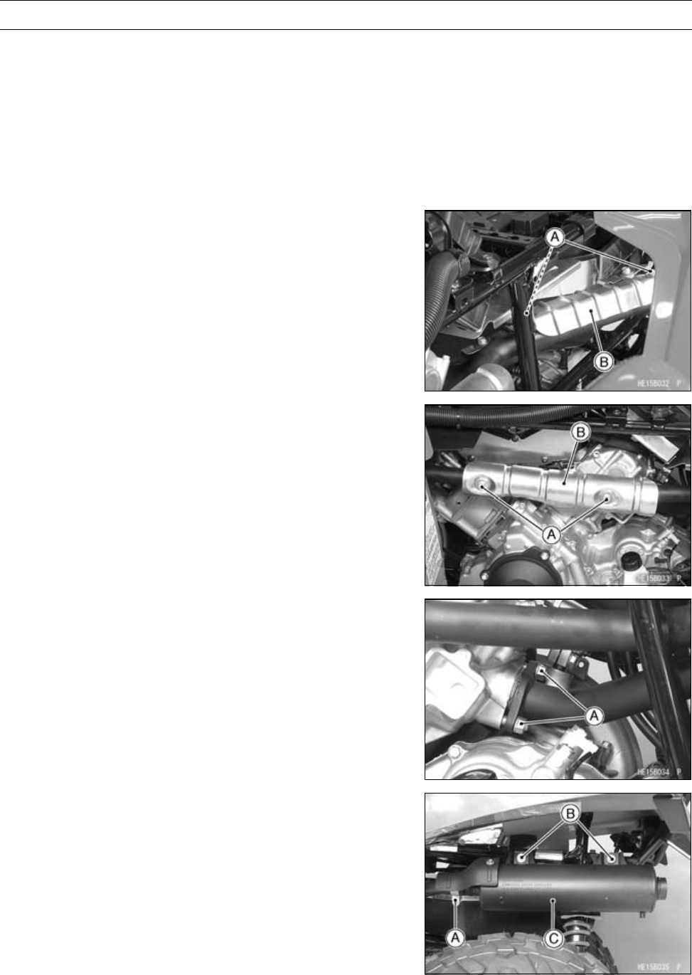
ENGINE TOP END 5-43
Exhaust System
This vehicle is equipped with a spark arrester approved
for off-road use by the United States Forest Service. It must
be properly maintained to ensure its efficiency. In accor-
dance with the Periodic Maintenance Chart, clean the spark
arrester.
Spark Arrester Cleaning
•Refer to the Spark Arrester Cleaning in the Periodic Main-
tenance chapter.
Muffler and Exhaust Pipe Removal
•Remove:
Front Fender (see Front Fender Removal in the Frame
chapter)
Bolts [A]
Middle Front Exhaust Pipe Cover [B]
•Remove:
Bolts [A]
Front Exhaust Pipe Cover [B]
•Remove:
Rear Exhaust Pipe Nuts [A]
•Remove:
Muffler Clamp Bolt [A]
Muffler Mounting Nuts [B], Washers and Bolts
Muffler Body [C]
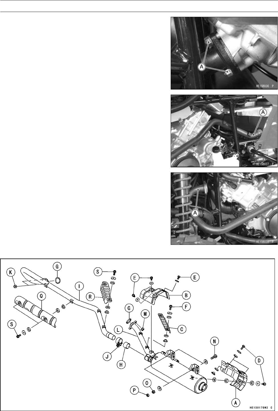
5-44 ENGINE TOP END
Exhaust System
•Remove:
Front Exhaust Pipe Nuts [A]
•Move the front exhaust pipe rear end [A] under the fuel
tank.
•Move the front exhaust pipe front end [A] as shown.
•Turn the front exhaust pipe front end to install the front
exhaust pipe.
Muffler and Exhaust Pipe Installation

ENGINE TOP END 5-45
Exhaust System
•If the muffler cover [A], rear and middle exhaust pipe cov-
ers [B] [C] are removed, tighten them.
Torque - Muffler Cover Bolts [D]: 8.8 N·m (0.90 kgf·m, 78
in·lb)
Rear Exhaust Pipe Cover Bolts [E]: 8.8 N·m (0.90
kgf·m, 78 in·lb)
Middle Exhaust Pipe Cover Bolts [F]: 8.8 N·m (0.90
kgf·m, 78 in·lb)
•Replace the exhaust pipe gaskets [G] and clamp gasket
[H] with new ones.
•Install (But do not tighten the following nuts and bolts.):
Front Exhaust Pipe [I], Clamp [J] and Nuts [K]
Rear Exhaust Pipe [L] and Nuts [M]
Muffler Mounting Bolts [N] and Washers
•Tighten:
Torque - Exhaust Pipe Holder Nuts: 17 N·m (1.7 kgf·m, 13
ft·lb)
•Tighten the muffler mounting nuts [O] (flange nut) and
then the locknuts [P].
○Hold the nut while tightening the locknuts.
Torque - Muffler Mounting Nuts: 19.6 N·m (2.0 kgf·m, 14
ft·lb)
Muffler Mounting Locknuts: 31.4 N·m (3.2 kgf·m,
23 in·lb)
Muffler Clamp Bolts: 8.8 N·m (0.90 kgf·m, 78 in·lb)
•Install:
Front Exhaust Pipe Front Cover [Q]
Front Exhaust Pipe Rear Cover [R]
Torque - Front Exhaust Pipe Cover Bolts [S]: 8.8 N·m (0.90
kgf·m, 78 in·lb)
Exhaust System Inspection
•Before removing the exhaust system, check for signs of
leakage at the exhaust pipe gasket in the cylinder head
and at the muffler clamp.
If there are signs of leakage around the exhaust pipe gas-
ket, it should be replaced. If the muffler-to-exhaust pipe
joint leaks, tighten the clamp.
•Remove the exhaust pipe and muffler (see Muffler and
Exhaust Pipe Removal).
•Inspect the gasket for damage and signs of leakage.
If the gasket is damaged or has been leaking, replace it.
•Check the exhaust pipe and muffler for dents, cracks, rust
and holes.
If the exhaust pipe or muffler is damaged or has holes, it
should be replaced for best performance and least noise.

CONVERTER SYSTEM 6-1
6
Converter System
Table of Contents
Exploded View........................................................................................................................ 6-2
Specifications ......................................................................................................................... 6-6
Special Tools .......................................................................................................................... 6-7
Torque Converter Cover ......................................................................................................... 6-9
Torque Converter Cover Removal .................................................................................... 6-9
Torque Converter Cover Installation ................................................................................. 6-10
Torque Converter Cover Disassembly .............................................................................. 6-10
Actuator Lever (Engine Brake Control Lever) Assembly Inspection ................................. 6-11
Torque Converter Cover Assembly ................................................................................... 6-11
Drive Belt................................................................................................................................ 6-13
Drive Belt Removal ........................................................................................................... 6-13
Drive Belt Installation ........................................................................................................ 6-13
Drive Belt Deflection Inspection........................................................................................ 6-13
Drive Belt Deflection Adjustment ...................................................................................... 6-13
Drive Belt Inspection ......................................................................................................... 6-13
Drive Pulley ............................................................................................................................ 6-14
Drive Pulley Removal........................................................................................................ 6-14
Drive Pulley Disassembly ................................................................................................. 6-14
Drive Pulley Inspection ..................................................................................................... 6-16
Spider Shoe Side Clearance Inspection/Adjustment ........................................................ 6-17
Drive Pulley Assembly ...................................................................................................... 6-18
Drive Pulley Installation..................................................................................................... 6-19
Driven Pulley .......................................................................................................................... 6-22
Driven Pulley Removal...................................................................................................... 6-22
Driven Pulley Disassembly ............................................................................................... 6-22
Driven Pulley Inspection ................................................................................................... 6-23
Driven Pulley Assembly .................................................................................................... 6-24
Driven Pulley Installation................................................................................................... 6-26
High Altitude Setting Information............................................................................................ 6-28
Specifications.................................................................................................................... 6-28
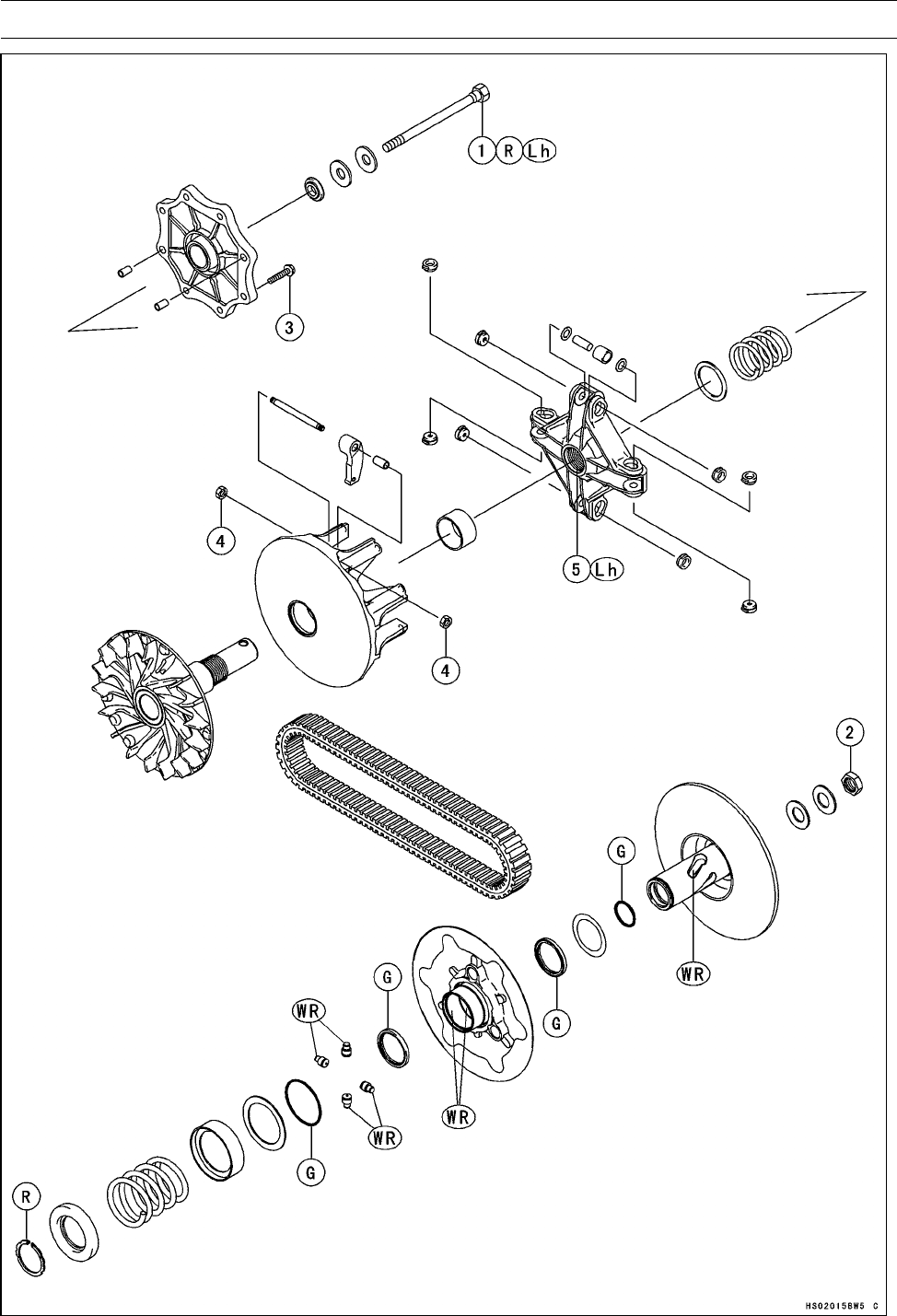
6-2 CONVERTER SYSTEM
Exploded View

CONVERTER SYSTEM 6-3
Exploded View
Torque
No. Fastener N·m kgf·m ft·lb Remarks
1Drive Pulley Bolt 93 9.5 68 R, Lh
2Driven Pulley Nut 93 9.5 68
3Drive Pulley Cover Bolts 13 1.3 115 in·lb
4Ramp Weight Nuts 6.9 0.70 61 in·lb
5Spider 275 28 203 Lh
G: Apply grease.
Lh: Left-hand Threads
R: Replacement Parts
WR: Apply grease (WR500-No.2 KYODO YUSHI, POWER LITE WR #2 KYODO YUSHI, or SERAN
-HV TOTAL FINA).
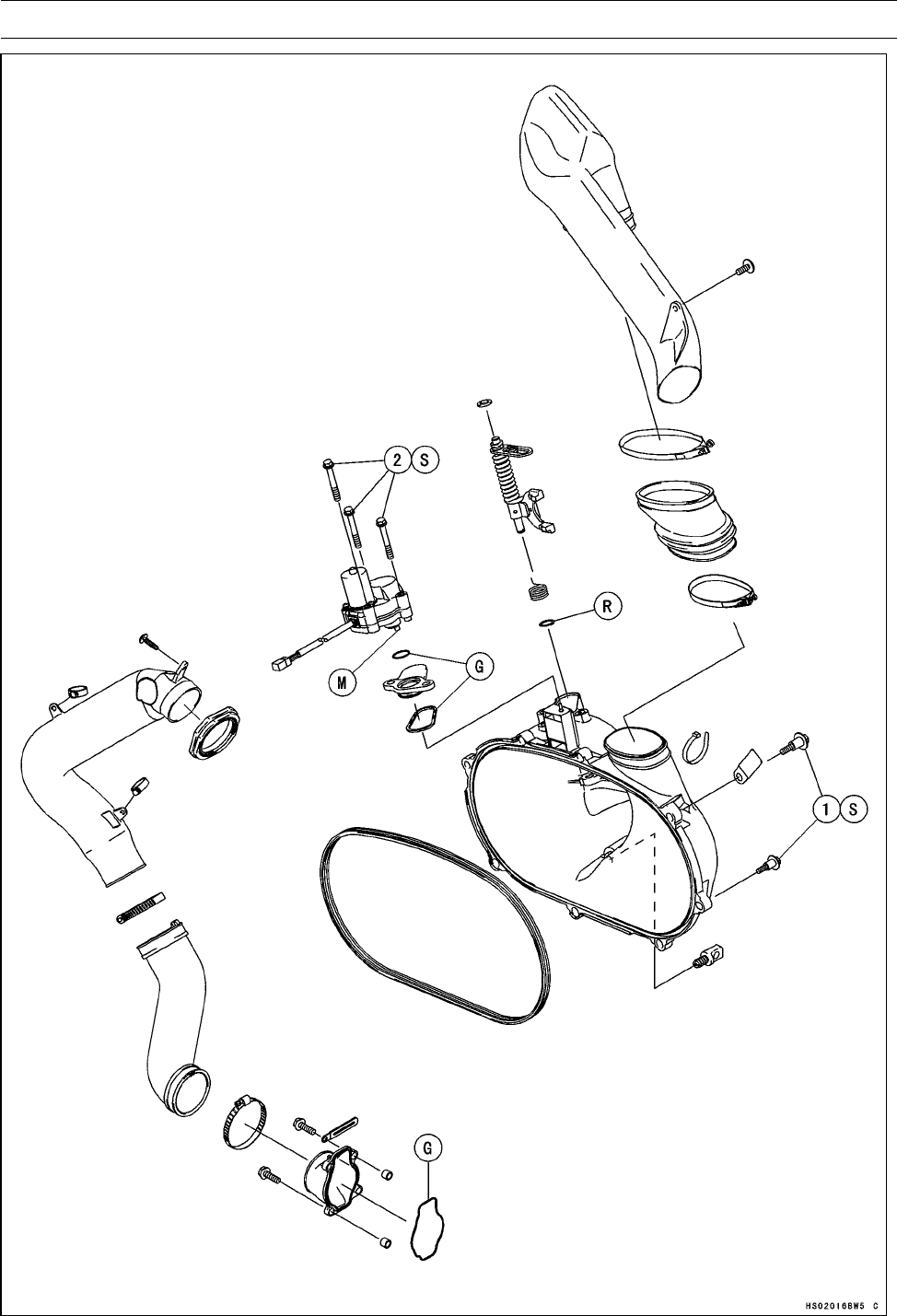
6-4 CONVERTER SYSTEM
Exploded View

CONVERTER SYSTEM 6-5
Exploded View
Torque
No. Fastener N·m kgf·m ft·lb Remarks
1Torque Converter Cover Bolts 8.8 0.90 78 in·lb S
2Engine Brake Actuator Mounting Bolts 8.8 0.90 78 in·lb S
G: Apply grease.
M: Apply molybdenum disulfide grease.
R: Replacement Part
S: Follow the specific tightening sequence.

6-6 CONVERTER SYSTEM
Specifications
Item Standard Service Limit
Torque Converter
Actuator Lever Guide Shoe ––– 6 mm (0.24 in.)
Drive Belt
Belt Width 29.7 ∼30.3 mm (1.17 ∼1.19 in.) 28.0 mm (1.10 in.)
Belt Deflection 22 ∼27 mm (0.87 ∼1.06 in.) –––
Drive Pulley
Shoe Side Clearance Up to 0.20 mm (0.008 in.) (in the text) –––
Cover Bushing Inside Diameter 27.985 ∼28.085 mm (1.1018 ∼1.1057 in.) 28.12 mm (1.107 in.)
Sheave Bushing Inside
Diameter
37.985 ∼38.085 mm (1.4955 ∼1.4994 in.) 38.12 mm (1.501 in.)
Spring Free Length 59.5 mm (2.34 in.) –––
Driven Pulley
Sheave Bushing Inside
Diameter
40.000 ∼40.039 mm (1.5748 ∼1.5763 in.) 40.07 mm (1.578 in.)
Spring Free Length 75.1 mm (2.96 in.) –––
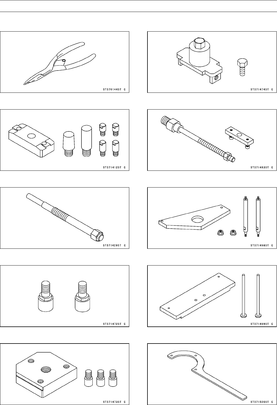
CONVERTER SYSTEM 6-7
Special Tools
Outside Circlip Pliers:
57001-144
Drive & Driven Pulley Holder:
57001-1412
Drive Pulley Puller Bolt:
57001-1429
Pulley Holder Attachment:
57001-1472
Drive & Driven Pulley Holder:
57001-1473
Drive Pulley Wrench:
57001-1474
Spring Holder Set:
57001-1483
Drive Pulley Measurement Tool:
57001-1498
Actuator Lever Measurement Tool:
57001-1499
Drive Pulley Holder:
57001-1520
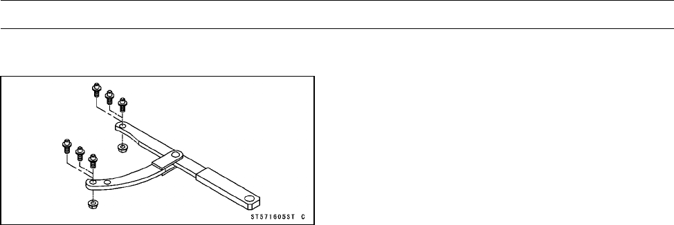
6-8 CONVERTER SYSTEM
Special Tools
Flywheel & Pulley Holder:
57001-1605
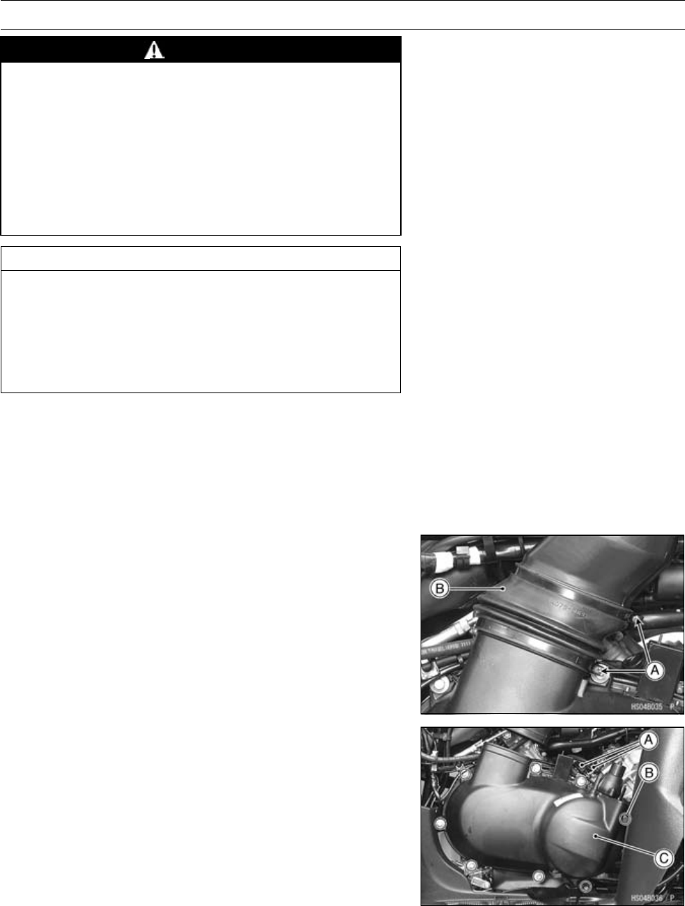
CONVERTER SYSTEM 6-9
Torque Converter Cover
WARNING
Excessive imbalance or operating rpm could cause
torque converter pulley failure resulting in severe
injury or death. The pulleys of the belt drive torque
converter are precision balanced components de-
signed to operate within certain rpm limits. Disas-
sembly/assembly and servicing procedures of the
pulley assemblies must be followed closely. Modi-
fications to the engine or pulleys that increase rpm
may cause failure.
CAUTION
Do not turn the ignition switch OFF position from
ON position, while the torque converter cover is re-
moved.
If it is done, the learning control of Kawasaki Engine
Brake Control system works and the engine brake
actuator works an error operation.
NOTE
○If the drive belt failure detection system is activated by
abnormal belt, the drive belt failure detection switch is
damaged. Make sure to replace the torque converter
cover (see Torque Converter Cover Removal/Installa-
tion).
Torque Converter Cover Removal
•Confirm that the ignition switch is in OFF position.
•Remove:
Right Side Cover (see Right Side Cover Removal in the
Frame chapter)
Clamp Screws [A] and Clamps
Rubber Air Duct [B]
•Remove:
Actuator Lead Connector and Drive Belt Failure Detec-
tion Switch Lead Connector [A]
Torque Converter Cover Bolts [B]
Torque Converter Cover [C]
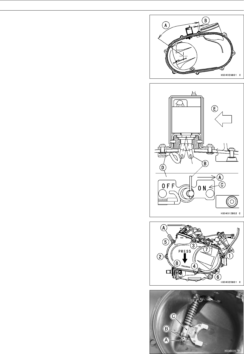
6-10 CONVERTER SYSTEM
Torque Converter Cover
Torque Converter Cover Installation
•Check the actuator lever assembly installation length (see
Torque Converter Cover Assembly).
•Fit the trim seal into the converter cover.
○Set the trim seal juncture in the area [A] when insert the
trim seal in the cover.
[B] 10 mm (0.39 in.)
•Check:
Drive Belt Failure Detection Switch (see Switch Inspec-
tion section in Electric System chapter)
•Set [A] the switch lever [B] to the ON mark side [C].
[D] Converter Cover
[E] Front
NOTE
○The failure detection system is activated when the
switch is in the ON position. This is the normal running
mode. Engine rpm is limited when the switch is in the
OFF position.
•Tighten (loosely):
#3 Bolt
#1 and #2 Bolts
•Press the cover downward and tighten the cover bolts
following the tightening sequence as shown.
Torque - Torque Converter Cover Bolts: 8.8 N·m (0.90
kgf·m, 78 in·lb)
[A] Clamp
Torque Converter Cover Disassembly
•Remove:
Torque Converter Cover (see Torque Converter Cover
Removal)
Engine Brake Actuator (see Engine Brake Actuator Re-
moval in the Electrical System chapter)
Circlip [A]
Spring [B]
Actuator Lever Assembly [C]
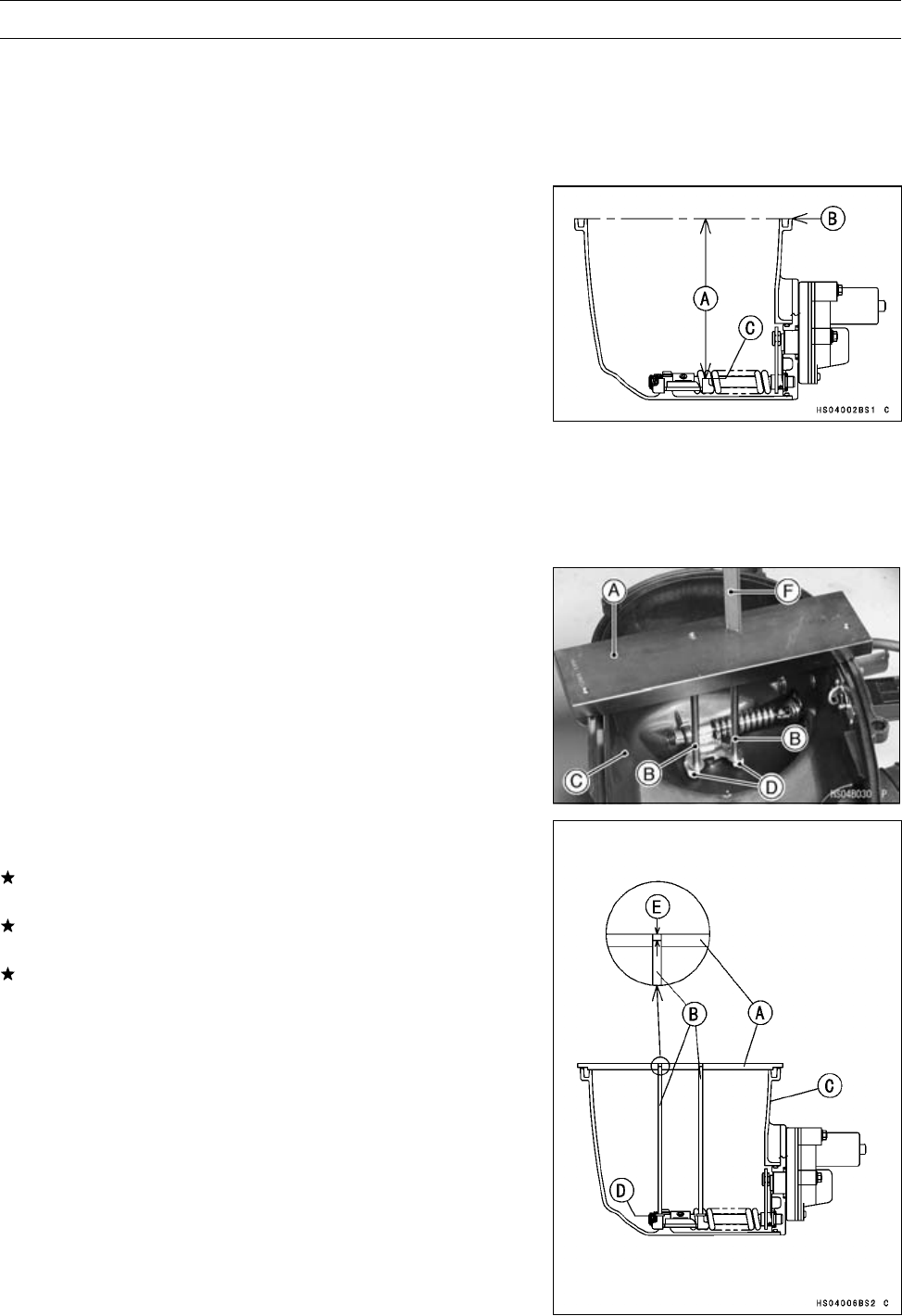
CONVERTER SYSTEM 6-11
Torque Converter Cover
Actuator Lever (Engine Brake Control Lever)
Assembly Inspection
•Refer to the Actuator Lever (Engine Brake Control Lever)
Assembly Inspection in the Periodic Maintenance chap-
ter.
Torque Converter Cover Assembly
•Install:
New Circlip
Spring
Actuator Lever Assembly
Engine Brake Actuator (see Engine Brake Actuator In-
stallation in the Electrical System chapter)
Torque - Engine Brake Actuator Mounting Bolts: 8.8 N·m
(0.90 kgf·m, 78 in·lb)
•Measure the installation length [A] of the actuator lever
assembly between the cover end [B] and resin tips [C] on
the actuator lever assembly as follows:
Actuator Lever Assembly Installation Length
Standard: 149.33 ∼150.47 mm (5.879 ∼5.924 in.)
○Remove the trim seal.
○Install the actuator lever measurement tool (plate [A] and
rods [B]) on the torque converter cover [C] and tighten the
two cover bolts.
Special Tool - Actuator Lever Measurement Tool: 57001
-1499
○Set the rod ends on the resin tips [D].
○Measure the recess length [E] between the plate and rods
with Vernier calipers [F] or depth gauge.
Measurement Length [E]
Standard: 1.33 ∼2.47 mm (0.052 ∼0.097 in.)
If the measurement is less than 1.33 mm (0.052 in.), use
the actuator lever assembly (13236-0046) of yellow paint.
If the measurement is more than 2.47 mm (0.097 in.), use
the actuator lever assembly (13236-0047) of green paint.
If the length is not within the specified length after the
actuator lever assembly is replaced, replace the torque
converter cover, and install the actuator lever assembly
(13236-0048).
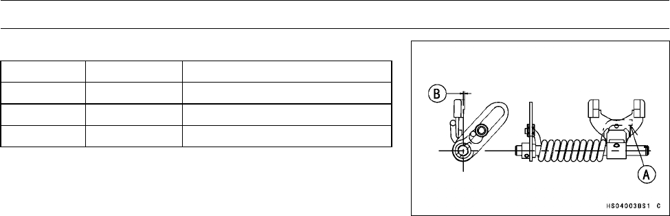
6-12 CONVERTER SYSTEM
Torque Converter Cover
Actuator Lever Assemblies
Part Number Paint Color [A] Length [B]
13236-0046 Yellow 0.4 ±0.1 mm (0.016 ±0.004 in.)
13236-0048 None 1.0 ±0.1 mm (0.039 ±0.004 in.)
13236-0047 Green 1.6 ±0.1 mm (0.063 ±0.004 in.)
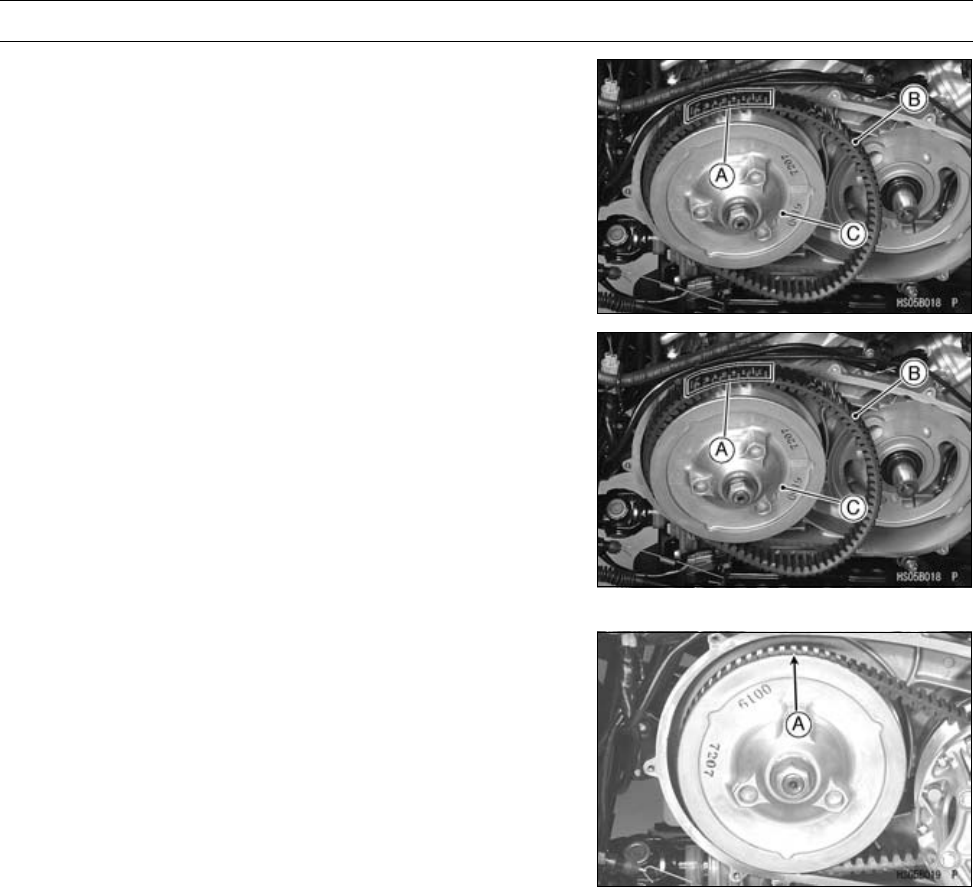
CONVERTER SYSTEM 6-13
Drive Belt
Drive Belt Removal
•Remove the drive pulley (see Drive Pulley Removal).
NOTE
○Before removing, observe the direction the belt’s printed
information [A] (such as manufacturer’s name) is facing
so that it may be reinstalled on the pulleys to rotate in
the same direction as originally installed.
•Lift the drive belt [B] off the driven pulley [C].
Drive Belt Installation
NOTE
○Be sure the printed information faces the same direc-
tion so the belt rotates in the same direction as origi-
nally installed. When installing a new belt, install it so
the printed information [A] can be read from beside the
vehicle.
•Installation is basically the reverse of removal.
•Loop the belt [B] over the driven pulley [C].
•Install the drive pulley (see Drive Pulley Installation).
•Put the transmission in neutral, and rotate the driven pul-
ley to allow the belt to return to the top [A] of the sheaves,
before measuring belt deflection.
Drive Belt Deflection Inspection
•Refer to the Drive Belt Deflection Inspection in the Peri-
odic Maintenance chapter.
Drive Belt Deflection Adjustment
•Refer to the Drive Belt Deflection Adjustment in the Peri-
odic Maintenance chapter.
Drive Belt Inspection
•Refer to the Drive Belt Inspection in the Periodic Mainte-
nance chapter.
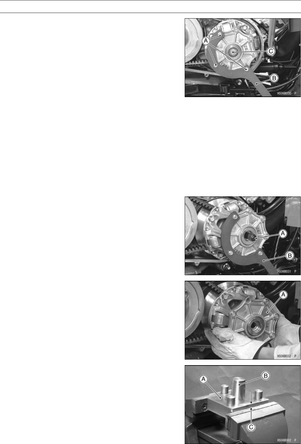
6-14 CONVERTER SYSTEM
Drive Pulley
Drive Pulley Removal
•Remove:
Torque Converter Cover (see Torque Converter Cover
Removal)
Right Footboard (see Right Footboard Removal in the
Frame chapter)
•Remove the three cover bolts [A] and install the drive pul-
ley holder [B].
Special Tool - Drive Pulley Holder: 57001-1520
•Tighten the three cover bolts:
Torque - Drive Pulley Cover Bolts: 13 N·m (1.3 kgf·m, 113
in·lb)
•Loosen the drive pulley bolt [C] (left-hand threads), hold-
ing the drive pulley with the drive pulley holder.
NOTE
○The drive pulley bolt has left-hand threads. Turn the
wrench clockwise for loosening.
•Remove the drive pulley bolt, two washers, and the
stepped washer, but do not remove the drive pulley
holder yet.
•Screw the drive pulley puller bolt [A] clockwise, while
holding the drive pulley with the drive pulley holder [B].
Special Tools - Drive Pulley Puller Bolt: 57001-1429
Drive Pulley Holder: 57001-1520
•Remove the puller bolt and pulley holder.
○Remove the drive pulley [A] from the crankshaft as shown.
Drive Pulley Disassembly
•Hold the drive & driven pulley holder (57001-1473) [A] and
the tapered guide of the holder (57001-1412) [B] in a vise
so that the upper surface on the holder is 7 mm (0.28 in.)
[C] above the vise.
Special Tools - Drive & Driven Pulley Holder: 57001-1473
Drive & Driven Pulley Holder: 57001-1412
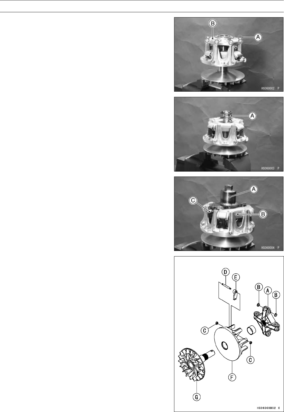
CONVERTER SYSTEM 6-15
Drive Pulley
•Set the pulley onto the pulley holder.
•Remove:
Drive Pulley Cover Bolts [A]
Drive Pulley Cover [B]
•Remove:
Spring [A]
Spacer
•Put the drive pulley wrench [A] on the spider [B] and
tighten the bolt [C].
Special Tool - Drive Pulley Wrench: 57001-1474
•Turn the wrench clockwise and remove the spider with the
movable sheave.
NOTE
○The spider has left-hand threads. Turn the wrench
clockwise for loosening.
•Remove:
Spider [A]
Shoes [B]
Nuts [C]
Ramp Weight Pin [D]
Ramp Weight [E]
Movable Sheave [F]
Fixed Sheave [G]
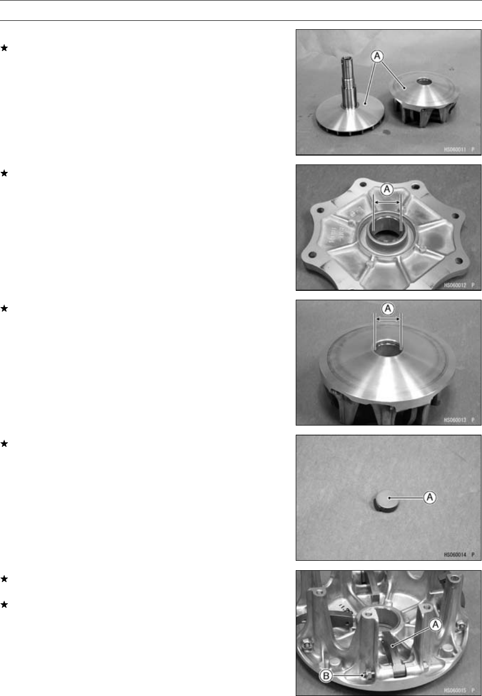
6-16 CONVERTER SYSTEM
Drive Pulley
DrivePulleyInspection
If the sheave surfaces [A] appear damaged, replace the
sheaves.
If the cover bushing is damaged or worn, replace the drive
pulley cover.
Cover Bushing Inside Diameter [A]
Standard: 27.985 ∼28.085 mm (1.1018 ∼1.1057 in.)
Service Limit: 28.12 mm (1.107 in.)
If the sheave bushing is damaged or worn, replace it.
Sheave Bushing Inside Diameter [A]
Standard: 37.985 ∼38.085 mm (1.4955 ∼1.4994 in.)
Service Limit: 38.12 mm (1.501 in.)
If the spider shoes [A] are damaged, replace them.
•Check the spider shoe side clearance (see Spider Shoe
Side Clearance Inspection).
If the ramp weights [A] in the movable sheave are dam-
aged or worn, replace them.
If the pins [B] are damaged or worn, replace them.
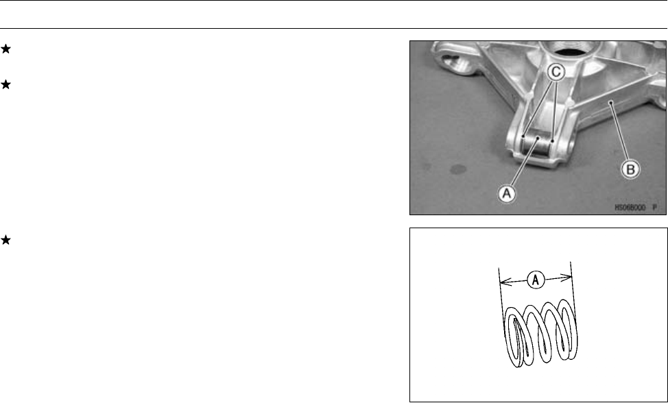
CONVERTER SYSTEM 6-17
Drive Pulley
If the rollers [A] are damaged or worn, replace the spider
[B].
If the washers [C] are damaged or worn, replace the spi-
der.
If the spring is worn or damaged, replace the spring.
Spring Free Length [A]
Standard: 59.5 mm (2.34 in.)
Spider Shoe Side Clearance Inspection/Adjust-
ment
•Remove:
Drive Pulley (see Drive Pulley Removal)
Drive Pulley Cover and Spring (see Drive Pulley Disas-
sembly)
•Temporarily install the following parts on the movable
sheave.
Dowel Pins (2)
Drive Pulley Cover
Two Bolts (at dowel pins)
○Do not install the spring.
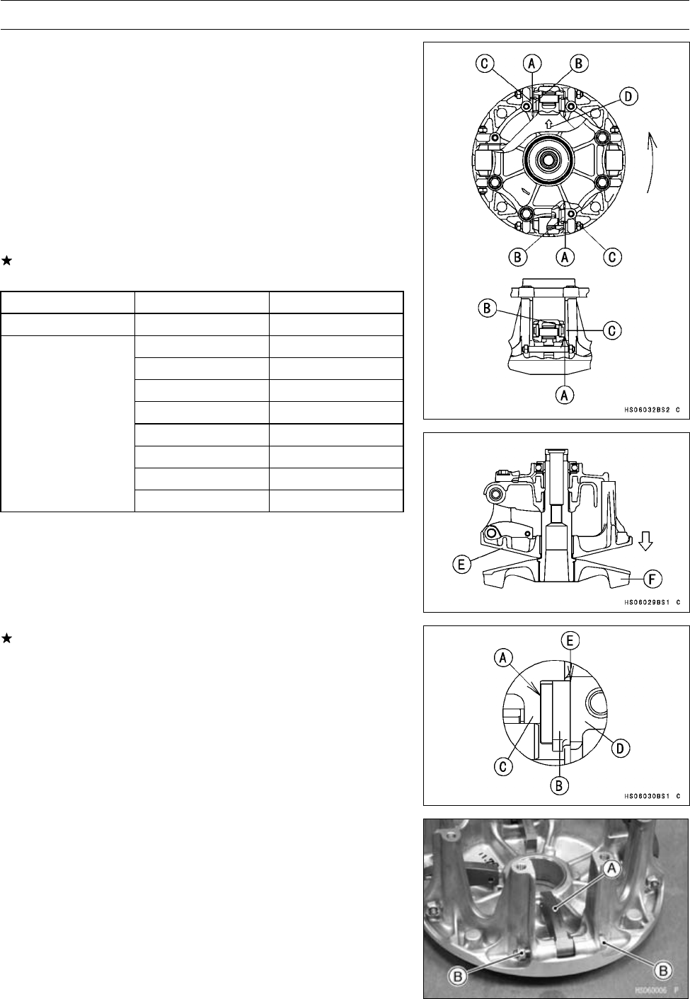
6-18 CONVERTER SYSTEM
Drive Pulley
•Turn the movable sheave counterclockwise.
•Measure the resulting clearance [A] between the shoe [B]
and the post [C] on the movable sheave at two positions
as shown.
[D] Arrow Mark
Shoe Side Clearance
Standard: up to 0.20 mm (0.008 in.), and there must
be kept a clearance which the movable
sheave [E] moves smoothly until it
touchesthefixedsheave[F]withitsown
weight.
If the clearance is not the specified range, adjust it using
the following shoes.
Part Number Thickness
Standard Shoe 49048-1090 7.5 mm (0.295 in.)
49048-1087 7.2 mm (0.283 in.)
49048-1088 7.3 mm (0.287 in.)
49048-1089 7.4 mm (0.291 in.)
49048-1091 7.6 mm (0.299 in.)
49048-1092 7.7 mm (0.303 in.)
49048-1093 7.8 mm (0.307 in.)
49048-1094 7.9 mm (0.311 in.)
Adjustment Shoes
49048-1095 8.0 mm (0.315 in.)
If the clearance is not the specified range after the above
shoes are replaced, use the spacer [A] (92026-0038) of
the option part.
[B] Shoe
[C] Spider
[D] Post
[E] Clearance
Drive Pulley Assembly
•Install the ramp weight [A] as shown.
•Tighten:
Torque - Ramp Weight Nuts [B]: 6.9 N·m (0.70 kgf·m, 61
in·lb)
•Check that the ramp weights swing smoothly.
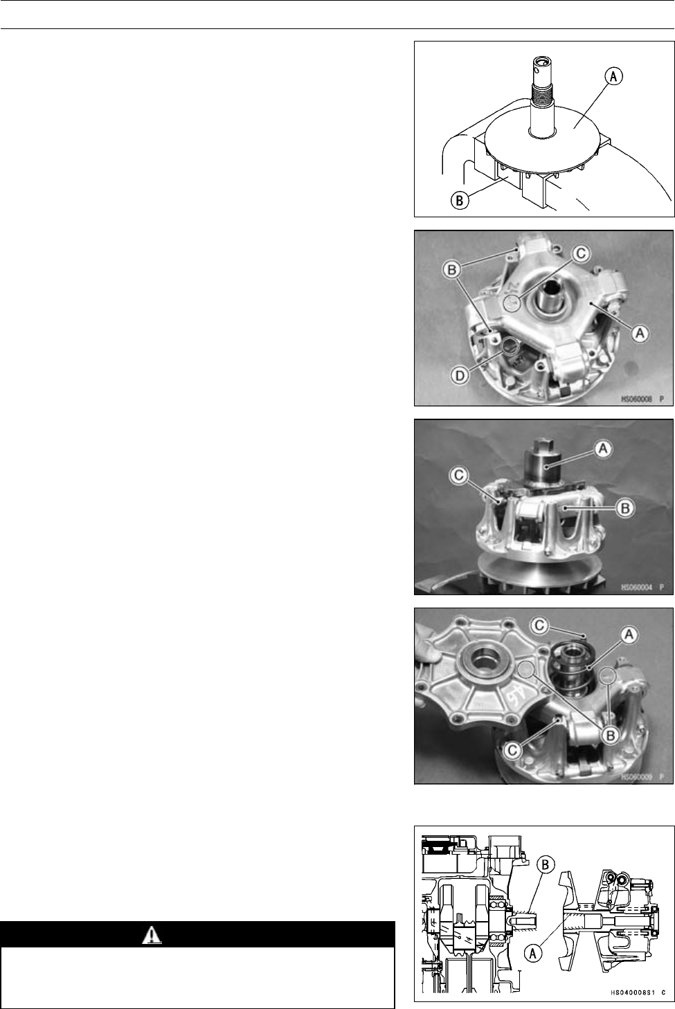
CONVERTER SYSTEM 6-19
Drive Pulley
•Hold the fixed sheave [A] with the drive pulley holder [B]
in a vise.
Special Tool - Drive & Driven Pulley Holder: 57001-1473
•Clean the threads of the fixed sheave and spider.
•Install:
Movable Sheave
Spider [A] and Shoes [B]
○Align the arrow [C] on the spider with the arrow [D] on the
movable sheave.
○Insert the shoes so that the rubber side (black, small di-
ameter) faces inward.
•Put the drive pulley wrench [A] on the spider [B] and
tighten the bolt [C].
Special Tool - Drive Pulley Wrench: 57001-1474
•Turn the wrench counterclockwise for tightening.
Torque - Spider (left-hand threads): 275 N·m (28 kgf·m, 203
ft·lb)
•Remove the drive pulley wrench.
•Install the spacer.
•Put the spring [A] in the groove of the spider.
•Align the arrows [B] on the drive pulley cover and spider.
•Install:
Dowel Pins [C]
Drive Pulley Cover
•Tighten:
Torque - Drive Pulley Cover Bolts: 13 N·m (1.3 kgf·m, 115
in·lb)
•Clean the surface of the sheaves with an oil-less cleaning
fluid.
Drive Pulley Installation
•Clean the following portions with an oil-less cleaning fluid
such as trichloroethylene or acetone.
Fixed Sheave Tapered Portion [A]
Crankshaft Tapered Portion [B]
WARNING
These cleaning fluids are usually highly flammable
and harmful if breathed for prolonged periods. Be
sure to heed the fluid manufacturer’s warnings.
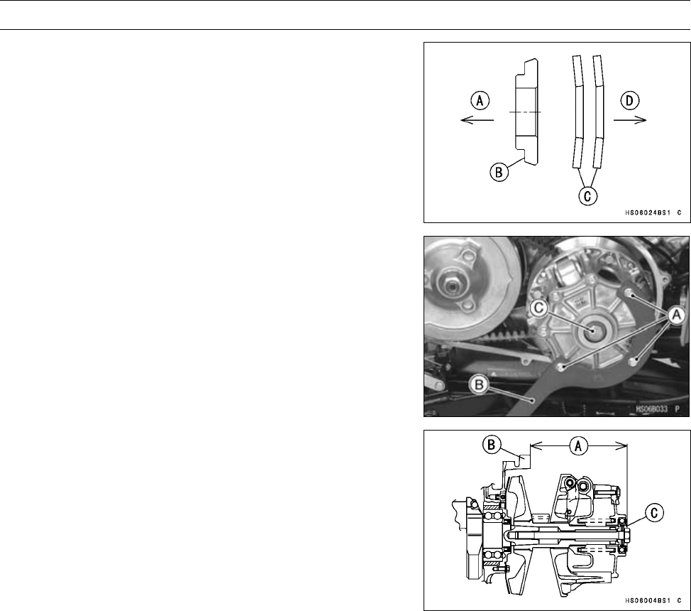
6-20 CONVERTER SYSTEM
Drive Pulley
•Install the drive pulley, stepped waster and two washers
on the drive pulley bolt as shown.
Crankcase Side [A]
Stepped Washer [B]
Two Washers [C]
Bolt Head Side [D]
•Remove the three cover bolts [A] and install the drive pul-
ley holder [B].
Special Tool - Drive Pulley Holder: 57001-1620
•Tighten:
Torque - Drive Pulley Cover Bolts: 13 N·m (1.3 kgf·m, 115
in·lb)
Drive Pulley Bolt [C] (new, left-hand threads): 93
N·m (9.5 kgf·m, 68 ft·lb)
•Remove the drive pulley holder and install three drive pul-
ley cover bolts to the specified torque.
•Adjust the installation length [A] of the drive pulley be-
tween the surface of the crankcase [B] and the collar [C]
on the drive pulley as followings.
Drive Pulley Installation Length [A]
Standard: 149.85 ∼150.95 mm (5.900 ∼5.943 in.)
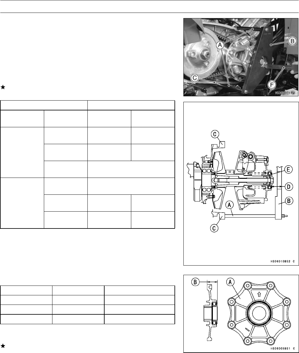
CONVERTER SYSTEM 6-21
Drive Pulley
○Install the drive pulley measurement tool (legs [A] and
plate [B]) on the crankcase [C].
Special Tool - Drive Pulley Measurement Tool: 57001-1498
○Measure the length [D] between the plate and collar [E]
with vernier calipers [F] or a depth gauge.
Measurement Length [D]
Standard: 14.55 ∼15.65 mm (0.573 ∼0.616 in.)
If the measurement is not within the specified range, ad-
just it according to following table.
Status Quo Replacement Part
Measurement
Length
Paint Color
of Cover
Replace Part
(Part Number)
Paint Color
of Cover
Blue Pulley Cover
(14041-1161) No Paint
No Paint Pulley Cover
(14041-1159) Red
less than
14.55 mm
(0.573 in.)
Red Drive Pulley Assembly
(49093-0022)
Blue Drive Pulley Assembly
(49093-0022)
No Paint Pulley Cover
(14041-1160) Blue
more than
15.65 mm
(0.616 in.)
Red Pulley Cover
(14041-1161) No Paint
Drive Pulley Covers
Part Number Paint Color [A] Length [B]
14041-1159 Red 24.0 mm (0.945 in.)
14041-1160 Blue 25.4 mm (1.000 in.)
14041-1161 No Paint 24.7 mm (0.972 in.)
•Measure the length again, after the drive pulley cover is
replaces.
If the length is not within the specified length, replace the
drive pulley assembly.
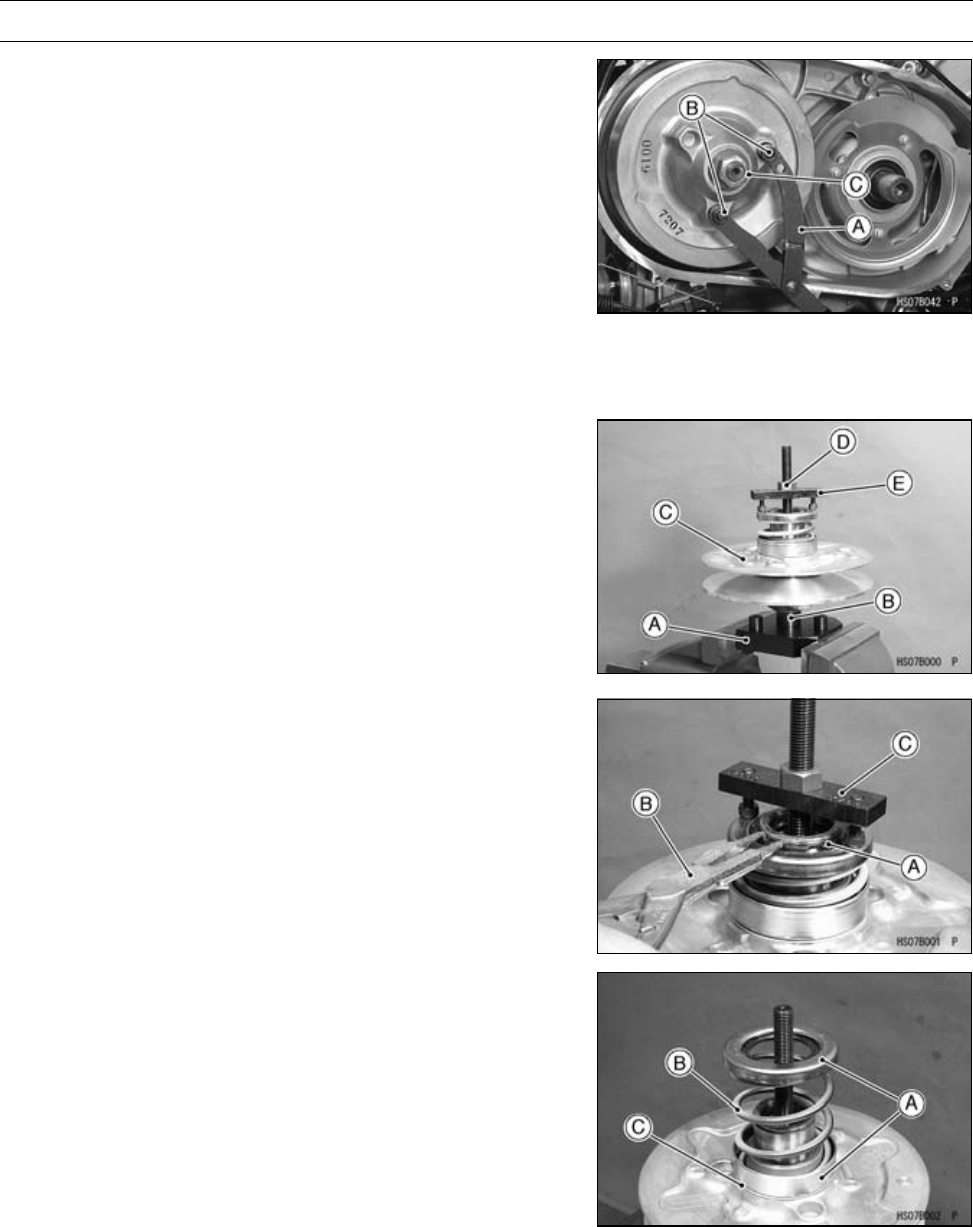
6-22 CONVERTER SYSTEM
Driven Pulley
Driven Pulley Removal
•Remove:
Torque Converter Cover (see Torque Converter Cover
Removal)
Drive Pulley (see Drive Pulley Removal)
DriveBelt(seeDriveBeltRemoval)
•Using the flywheel & pulley holder [A] and attachments
[B], remove the driven pulley nut [C] and washers. (Nut
has R/H threads.)
Special Tools - Flywheel & Pulley Holder: 57001-1605
Pulley Holder Attachment: 57001-1472
•Remove:
Driven Pulley
Driven Pulley Disassembly
•Hold the drive & driven pulley holder [A] in a vise.
Special Tool - Drive & Driven Pulley Holder: 57001-1473
•Screw the guide bar [B] into the holder.
Special Tool - Spring Holder Set: 57001-1483
•Put the driven pulley [C] on the guide bar.
•Tighten the nut [D], and compress the spring with the
spring holder [E].
Special Tool - Spring Holder Set: 57001-1483
•Remove the circlip [A] with circlip pliers [B].
Special Tool - Circlip Pliers: 57001-144
•Remove the nut and spring holder [C].
•Remove:
Spring Seats [A]
Spring [B]
Thrust Plate [C]
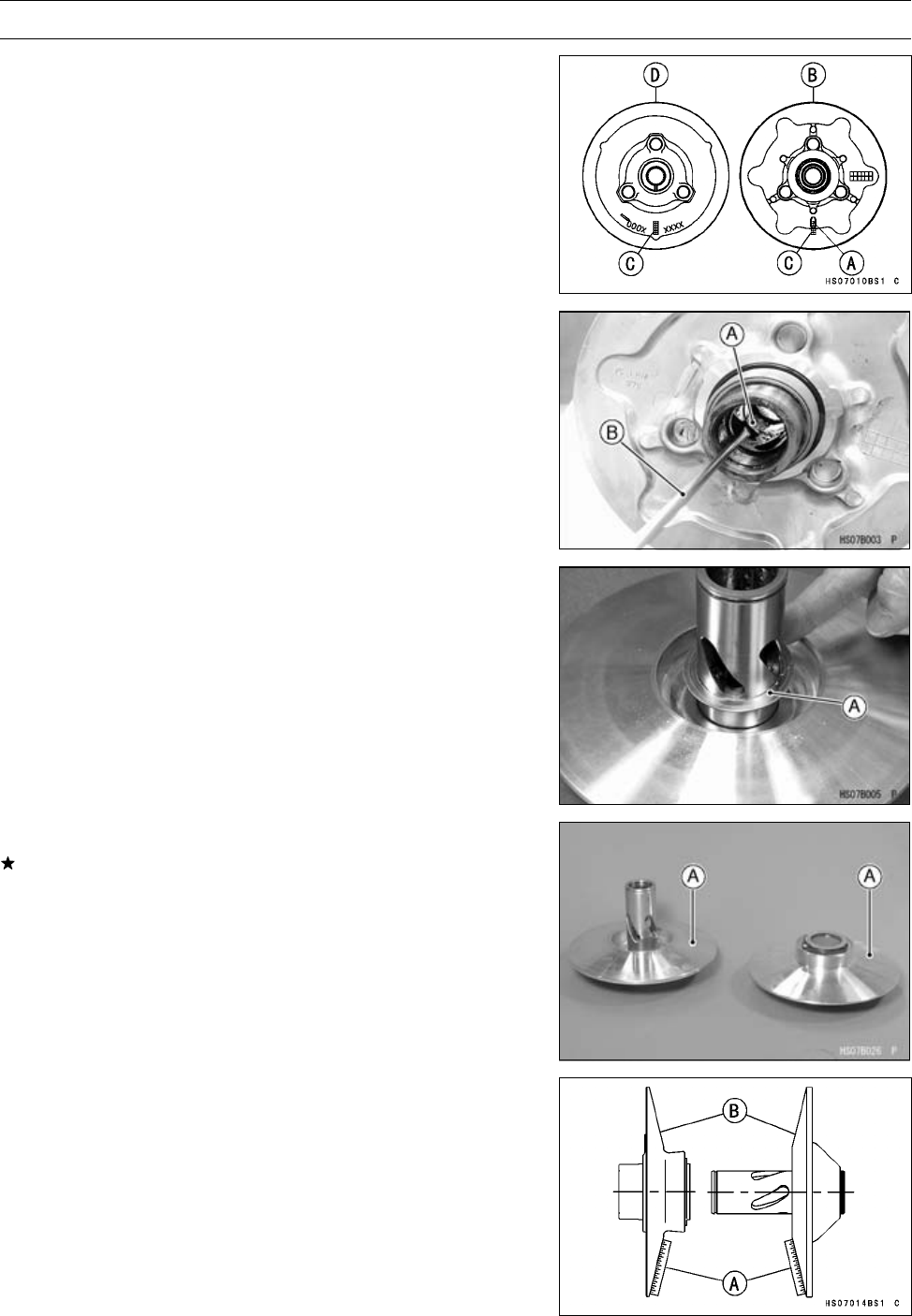
CONVERTER SYSTEM 6-23
Driven Pulley
•Confirm the paint mark “0” [A] on the movable sheave [B]
in alignment with the point [C] on the fixed sheave [D] for
phase fit of the sheaves.
•Wipe off the molybdenum disulfide grease.
•Remove the four pins [A] with a thin standard tip screw-
driver [B].
•Remove the movable sheave from the fixed sheave.
•Remove:
Spacer(s) [A] (for Drive Belt Deflection Adjustment)
Driven Pulley Inspection
If the sheave surfaces [A] appear damaged, replace the
sheaves.
•Replace the sheave with uneven wear on the belt con-
tacting surfaces.
[A] Straight Edge
[B] Sheave Surface
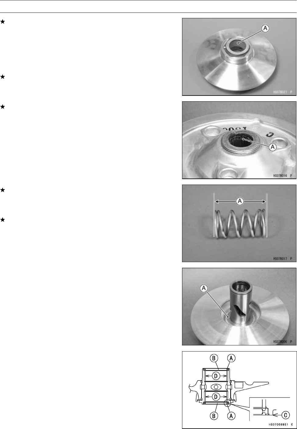
6-24 CONVERTER SYSTEM
Driven Pulley
If the sheave bushings [A] are damaged or worn, replace
the movable sheave.
Sheave Bushing Inside Diameter
Standard: 40.000 ∼40.039 mm (1.5748 ∼1.5763 in.)
Service Limit: 40.07 mm (1.578 in.)
•Inspect seals for damage.
If seals are damaged, replace the movable sheave.
If the splines [A] are damaged or worn, replace the fixed
sheave.
If the spring is damaged or worn, replace the spring.
Spring Free Length [A]
Standard: 75.1 mm (2.96 in.)
If the spring coils are distorted, replace the spring.
Driven Pulley Assembly
•Clean off any grease or dirt on the movable and fixed
sheaves, and dry them with a clean cloth.
•Install:
Spacers [A] (see Converter Drive Belt Deflection Adjust-
ment in the Periodic Maintenance chapter)
•Apply grease to the oil seal lips [A].
•Press the oil seals [B] in the movable sheave assembly
so that the oil seal surface is flush [C] with the sleeve end.
•Apply [D] grease (WR500-No.2 (KYODO YUSHI),
POWER LITE WR #2 (KYODO YUSHI), or SERAN-HV
(TOTAL FINA)) to the inner surfaces of the busings.
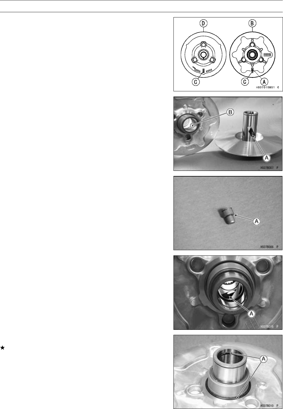
CONVERTER SYSTEM 6-25
Driven Pulley
•Align the paint mark “0” [A] on the movable sheave [B]
with the point [C] on the fixed sheave [D] for phase fit of
the sheaves.
○In that case the opening [A] and hole [B] will be matched
easily.
•Apply grease (WR500-No.2 (KYODO YUSHI), POWER
LITE WR #2 (KYODO YUSHI), or SERAN-HV (TOTAL
FINA)) to the seating surface [A] of the pins, and insert
them into the holes in the movable sheave.
•Draw the movable sheave onto the fixed sheave, and ap-
ply grease of 1 g (0.035 oz) to all openings [A].
Grease - WR500-No.2 (KYODO YUSHI) or
POWERLITEWR#2(KYODOYUSHI)or
SERAN-HV (TOTAL FINA)
NOTE
○Do not heap up the grease out of the openings.
•Check that the O-rings [A] are in good condition.
If any of the O-rings are damaged, replace them.
•Apply grease to the O-rings.
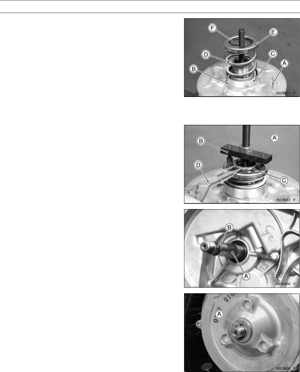
6-26 CONVERTER SYSTEM
Driven Pulley
•Hold the drive & driven pulley holder in a vise.
Special Tool - Drive & Driven Pulley Holder: 57001-1473
•Screw the guide bar into the holder.
Special Tool - Spring Holder Set: 57001-1483
•Put the driven pulley [A] onto the guide bar.
•Put the thrust plate [B] so that the alloy side (gray) faces
the movable sheave.
•Install:
Spring Seat [C]: 18.5 mm (0.728 in.)
Spring [D]
Spring Seat [E]: 9.3 mm (0.366 in.)
Circlip [F]
•Tighten the nut [A], and compress the spring with the
spring holder [B].
Special Tool - Spring Holder Set: 57001-1483
•Install a new circlip [C] with circlip pliers [D].
Special Tool - Circlip Pliers: 57001-144
•Remove the driven pulley from the spring holder set.
•Clean the surface of the sheaves with an oil-less cleaning
fluid.
Driven Pulley Installation
•Clean the transmission driven shaft [A].
•Install:
Driven Pulley
NOTE
○When engaging the spline on the driven pulley with
the spline [B] on the shaft, do not damage the pulley’s
spline. If any damage occurs, remove it with a file.
•Clean the threads of the driven shaft and driven pulley
ends to open the air vent passage. Wipe off any extra
grease.
○Wipe off any protruding grease [A].
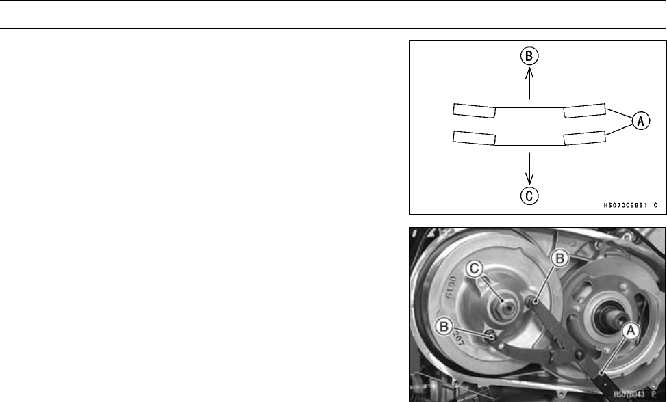
CONVERTER SYSTEM 6-27
Driven Pulley
•Install two washers [A] on the shaft as shown.
Crankcase Side [B]
Bolt Head Side [C]
•Using the flywheel & pulley holder [A] and attachments
[B], tighten the driven pulley nut [C].
Special Tools - Flywheel & Pulley Holder: 57001-1605
Pulley Holder Attachment: 57001-1472
Torque - Driven Pulley Nut: 93 N·m (9.5 kgf·m, 68 ft·lb)

6-28 CONVERTER SYSTEM
High Altitude Setting Information
Specifications
Altitude Drive Pulley
m (ft) Ramp Weights Spring Spacer (qty)
(1)0∼2 000
(0 ∼6 500)
P/No. 39152-0019
(STD, X1)
P/No. 92026-1603
t = 1 mm (0.04 in.)
2 000 ∼3 200
(6 500 ∼10 400)
P/No. 39152-0028
(X1H)
P/No. 92026-1603
t = 1 mm (0.04 in.)
(2)
X1, X1H: Identification Marks
qty: quantity
•Refer to the Drive Pulley section for the parts replacement.

ENGINE LUBRICATION SYSTEM 7-1
7
Engine Lubrication System
Table of Contents
Exploded View........................................................................................................................ 7-2
Specifications ......................................................................................................................... 7-4
Special Tools & Sealant.......................................................................................................... 7-5
Engine Oil Flow Chart............................................................................................................. 7-6
Engine Oil and Oil Filter.......................................................................................................... 7-7
Oil Level Inspection........................................................................................................... 7-7
Engine Oil Change............................................................................................................ 7-7
Oil Filter Change ............................................................................................................... 7-7
Oil Screen Removal .......................................................................................................... 7-7
Oil Screen Cleaning .......................................................................................................... 7-8
Oil Pressure Measurement ............................................................................................... 7-8
Oil Pressure Switch ................................................................................................................ 7-9
Oil Pressure Switch Removal ........................................................................................... 7-9
Oil Pressure Switch Installation ........................................................................................ 7-9
Oil Pressure Relief Valve........................................................................................................ 7-10
Oil Pressure Relief Valve Removal ................................................................................... 7-10
Oil Pressure Relief Valve Installation ................................................................................ 7-10
Oil Pressure Relief Valve Inspection................................................................................. 7-10
Oil Pump................................................................................................................................. 7-11
Oil Pump Removal ............................................................................................................ 7-11
Oil Pump Installation ......................................................................................................... 7-11
Oil Pipe ................................................................................................................................... 7-13
Oil Pipe Removal .............................................................................................................. 7-13
Oil Pipe Installation ........................................................................................................... 7-14
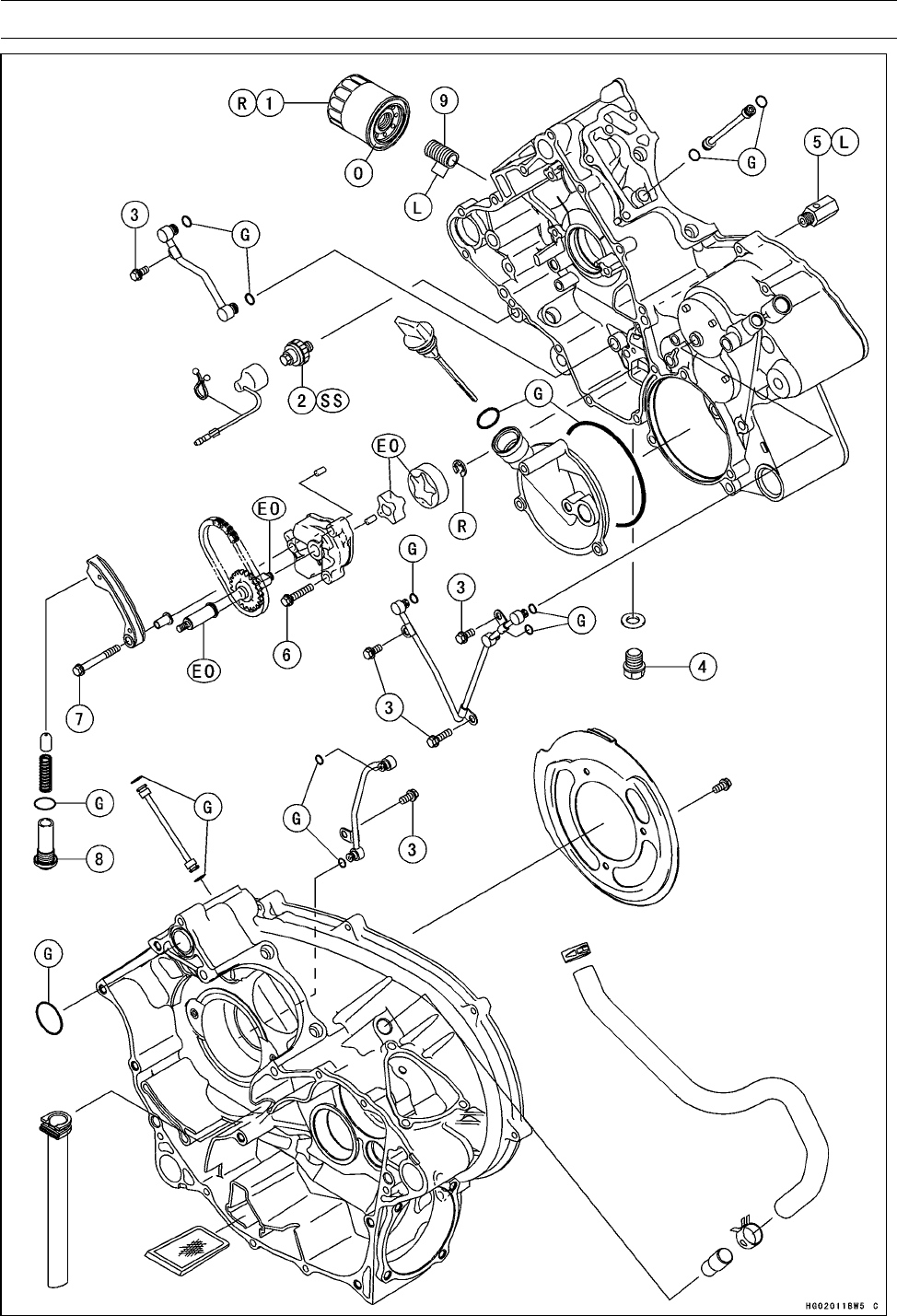
7-2 ENGINE LUBRICATION SYSTEM
Exploded View

ENGINE LUBRICATION SYSTEM 7-3
Exploded View
Torque
No. Fastener N·m kgf·m ft·lb Remarks
1Oil Filter 17.5 1.8 13 R
2Oil Pressure Switch 15 1.5 11 SS
3Oil Pipe Bolts 8.8 0.90 78 in·lb
4Engine Oil Drain Bolt 20 2.0 15
5Oil Pressure Relief Valve 15 1.5 11 L
6Oil Pump Cover Bolts 8.8 0.90 78 in·lb
7Oil Pump Chain Guide Bolts 8.8 0.90 78 in·lb
8Oil Pump Drive Chain Tensioner Bolt 25 2.5 18
9Oil Filter Mounting Bolt 25 2.5 18 L (15 mm)
G: Apply grease.
L: Apply a non-permanent locking agent.
O: Apply engine oil.
R: Replacement Parts
SS: Apply silicone sealant (Kawasaki Bond: 56019-120).
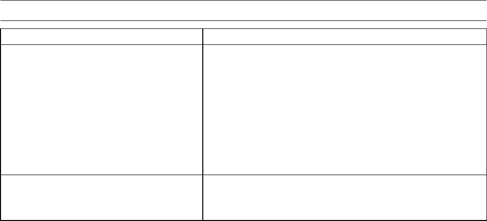
7-4 ENGINE LUBRICATION SYSTEM
Specifications
Item Standard
Engine Oil
Type API SF or SG
API SH, SJ or SL with JASO MA
Viscosity SAE 10W-40
Capacity 2.1 L (2.2 US qt) (when filter is not removed)
2.2 L (2.3 US qt) (when filter is removed)
2.6 L (2.7 US qt) (when engine is completely dry)
Oil Level (after warm-up or driving) Between upper and lower level lines
Oil Pressure Measurement
Oil Pressure @4 000 r/min (rpm), Oil
Temperature 120°C (248°F)
430 kPa (4.4 kgf/cm², 62.6 psi)
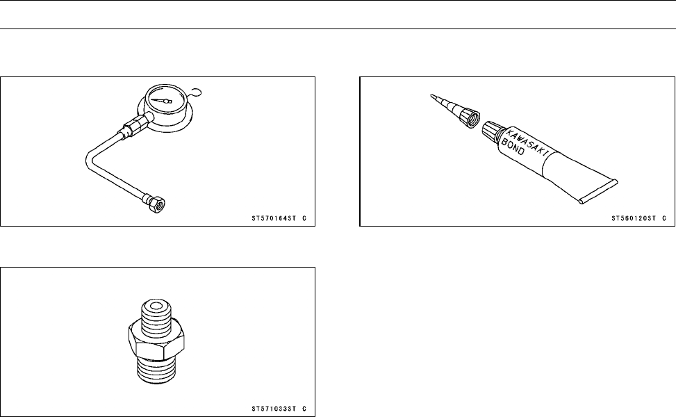
ENGINE LUBRICATION SYSTEM 7-5
Special Tools & Sealant
Oil Pressure Gauge, 10 kgf/cm²:
57001-164
Oil Pressure Gauge Adapter, PT 1/8:
57001-1033
Kawasaki Bond (Silicone Sealant):
56019-120
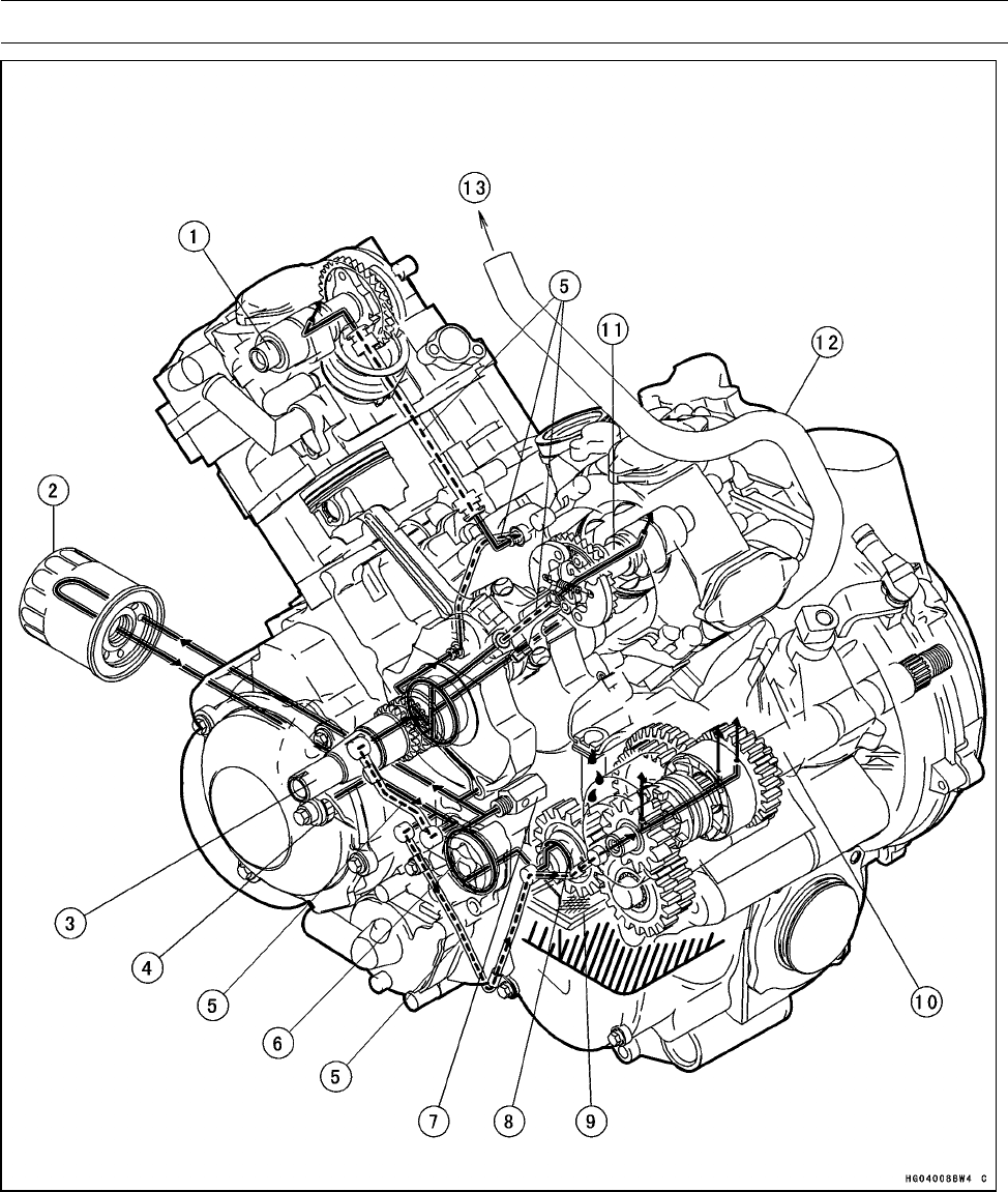
7-6 ENGINE LUBRICATION SYSTEM
Engine Oil Flow Chart
1. Front Camshaft
2. Oil Filter
3. Crankshaft
4. Oil Pressure Switch
5. Oil Pipes
6. Oil Pump
7. Relief Valve
8. Transmission Idle Shaft
9. Oil Screen
10. Transmission Driven Shaft
11. Rear Camshaft
12. Breather Hose
13. To Air Cleaner
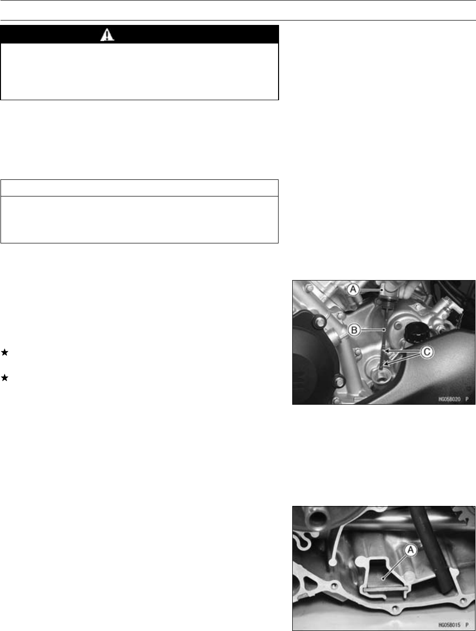
ENGINE LUBRICATION SYSTEM 7-7
Engine Oil and Oil Filter
WARNING
Vehicle operation with insufficient, deteriorated,
or contaminated engine oil will cause accelerated
wear and may result in engine or transmission
seizure, accident, and injury.
Oil Level Inspection
•Park the vehicle so that it is level, both side-to-side and
front-to-rear.
•If the oil has just been changed, start the engine, and run
it for several minutes to fill the oil filter.
CAUTION
Allow the engine to idle for several minutes so that
oil may reach all parts of the engine. Racing a "dry"
engine may cause severe damage.
•Stop the engine and wait several minutes for all the oil to
drain back to the sump.
•Unscrew the oil filler cap [A], wipe its dipstick [B] dry, and
tighten it into the filler opening.
•Unscrew the oil filler cap and check the oil level. The oil
level should be between the upper (H) and lower (L) level
lines [C].
If the level is too high, suck the excess oil out the filler
hole with a syringe or other suitable device.
If the level is too low, add oil through the filler hole. Use
the same type and make of oil that is already in the engine.
Engine Oil Change
•Refer to the Engine Oil Change in the Periodic Mainte-
nance chapter.
Oil Filter Change
•Refer to the Oil Filter Change in the Periodic Maintenance
chapter.
Oil Screen Removal
•Split the crankcase (see Crankcase Disassembly in the
Crankshaft/Transmission chapter).
•Pull the oil screen [A] out of the crankcase.
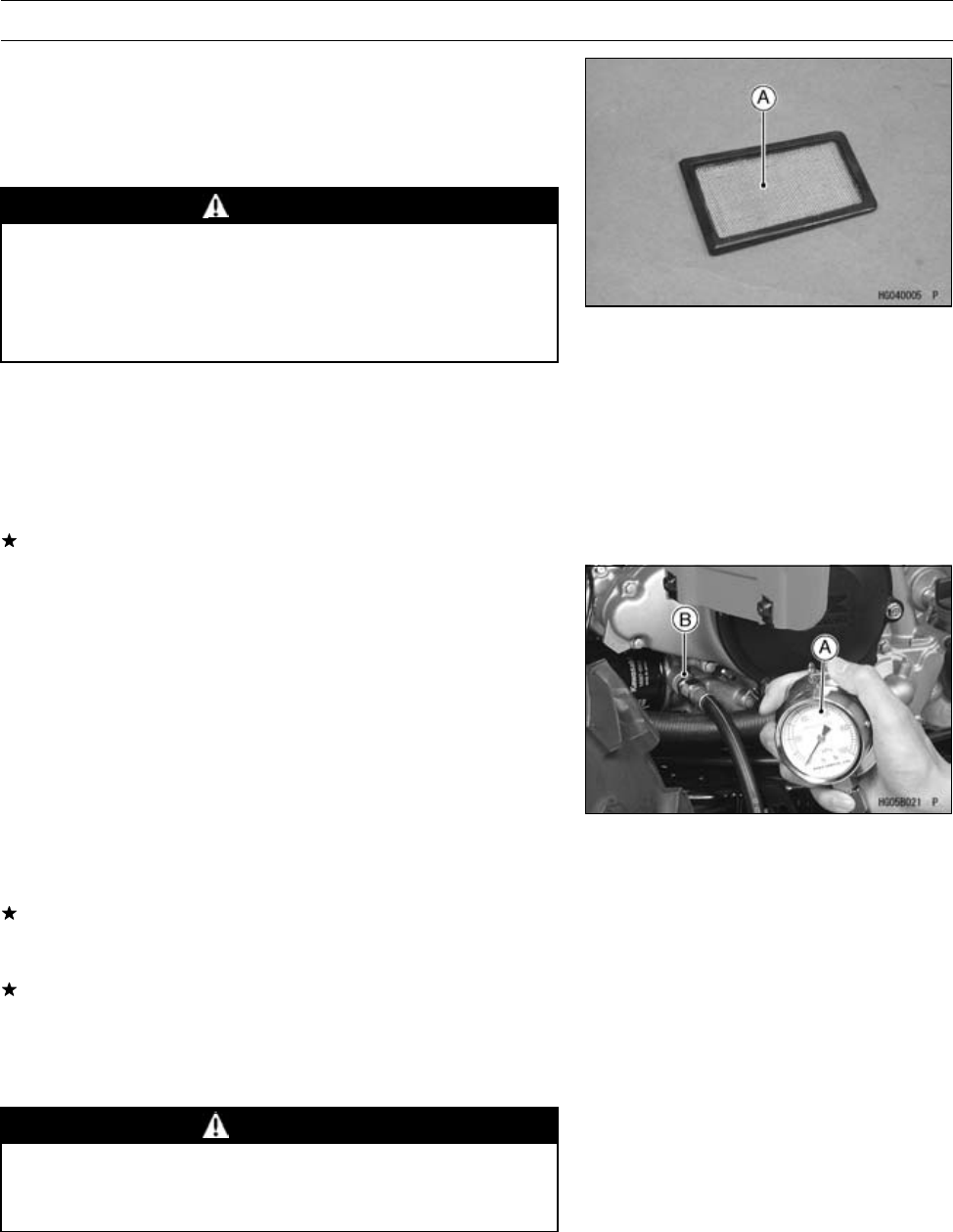
7-8 ENGINE LUBRICATION SYSTEM
Engine Oil and Oil Filter
Oil Screen Cleaning
•Clean the oil screen [A] thoroughly whenever it is removed
for any reason.
•Clean the oil screen with a high-flash point solvent and
remove any particles stuck to it.
WARNING
Clean the screen in a well-ventilated area, and take
care that there is no spark or flame anywhere near
the working area. Because of the danger of highly
flammable liquids, do not use gasoline or low-flash
point solvents.
NOTE
○While cleaning the screen, check for any metal particles
that might indicate internal engine damage.
•Check the screen carefully for any damage, holes, broken
wires, or gasket pulling off.
If the screen is damaged, replace it.
Oil Pressure Measurement
NOTE
○Measure the oil pressure after the engine is warmed up.
•Remove the oil pressure switch.
•Attach the oil pressure gauge [A] and adapter [B].
Special Tools - Oil Pressure Gauge, 10 kgf/cm²: 57001-164
Oil Pressure Gauge Adapter, PT 1/8: 57001
-1033
Oil Pressure
Standard: 430 kPa (4.4 kgf/cm², 62.6 psi) @4 000
r/min (rpm), 120°C (248°F) of oil temp.
If the oil pressure is much lower than the standard, inspect
the relief valve, oil pump, and/or crankshaft bearing insert
wear.
If the oil pressure is much higher than the standard, in-
spect the oil filter, oil screen, and other areas of the lubri-
cation system for clogging.
•Stop the engine.
•Remove the oil pressure gauge and adapter.
WARNING
Take care against burns from hot engine oil that
will drain through the oil passage when the gauge
adapter is removed.
•Install the oil pressure switch (see Oil Pressure Switch
Installation).
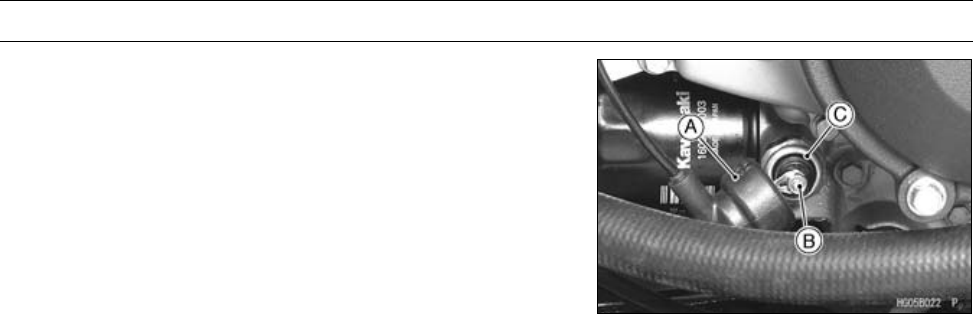
ENGINE LUBRICATION SYSTEM 7-9
Oil Pressure Switch
Oil Pressure Switch Removal
•Drain:
Engine Oil (see Engine Oil Change in the Periodic Main-
tenance chapter)
•Remove:
Switch Cover [A]
Switch Lead Terminal [B]
OilPressureSwitch[C]
Oil Pressure Switch Installation
•Apply silicone sealant to the threads of the oil pressure
switch, and tighten it.
Sealant - Kawasaki Bond (Silicone Sealant): 56019-120
Torque - Oil Pressure Switch: 15 N·m (1.5 kgf·m, 11 ft·lb)
•Tighten the terminal bolt securely.
•Apply grease to the terminal, and install the switch cover.
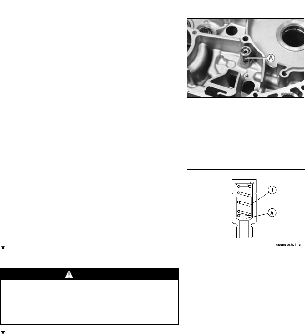
7-10 ENGINE LUBRICATION SYSTEM
Oil Pressure Relief Valve
Oil Pressure Relief Valve Removal
•Split the crankcase (see Crankcase Disassembly in the
Crankshaft/Transmission chapter).
•Remove the oil pressure relief valve [A].
Oil Pressure Relief Valve Installation
•See crankcase assembly (see Crankcase Assembly in
the Crankshaft/Transmission chapter).
•Apply a non-permanent locking agent to the threads of oil
pressure relief valve, and tighten it.
Torque - Oil Pressure Relief Valve: 15 N·m (1.5 kgf·m, 11
ft·lb)
Oil Pressure Relief Valve Inspection
•Remove the relief valve.
•Using a wooden stick, push the inner valve to make sure
that the valve [A] moves smoothly and that it returns to its
original position by the force of the spring [B].
NOTE
○The relief valve cannot be disassembled and it must be
inspected in the assembled state.
If the valve movement is not smooth, wash the relief valve
with high-flash point solvent, and use compressed air to
remove any foreign particles from it.
WARNING
Clean the oil pressure relief valve in a well
-ventilated area, and take care that there is no
spark or flame anywhere near the working area.
Because of the danger of highly flammable liquids,
do not use gasoline or low-flash point solvents.
If the valve does not move smoothly even after washing
it, replace the relief valve. The oil pressure relief valve
is precision made with no allowance for replacement of
individual parts.
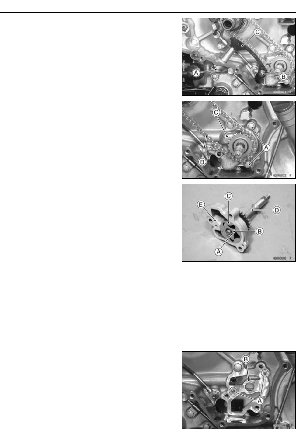
ENGINE LUBRICATION SYSTEM 7-11
Oil Pump
Oil Pump Removal
•Remove:
Alternator Rotor (see Alternator Rotor Removal in the
Electrical System chapter)
Oil Pump Drive Chain Tensioner Bolt [A]
Starter Motor Clutch Gear
Chain Guide Bolt [B] and Collar
Chain Guide [C]
•Remove:
Oil Pump Bolts [A]
Oil Pump Drive Chain [B] together with Oil Pump Assem-
bly [C]
•Remove:
Circlip [A]
Inner Rotor [B]
Outer Rotor [C]
Oil Pump Drive Shaft [D]
Oil Pump Cover [E]
Oil Pump Installation
•Apply engine oil:
Oil Pump Drive Shaft
Inner and Outer Rotors
•Install:
Oil Pump Drive Shaft
Oil Pump Cover
Inner Rotor
Outer Rotor
New Circlip
•Check to see that the dowel pins [A] are in place.
•Apply engine oil to the oil pump hole [B].
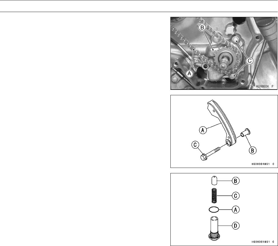
7-12 ENGINE LUBRICATION SYSTEM
Oil Pump
•Install the oil pump drive chain [A] with the oil pump as-
sembly [B].
•Tighten:
Torque - Oil Pump Cover Bolts [C]: 8.8 N·m (0.90 kgf·m, 78
in·lb)
•Install:
Chain Guide [A] and Collar [B]
•Tighten:
Torque - Oil Pump Drive Chain Guide Bolt [C]: 8.8 N·m (0.90
kgf·m, 78 in·lb)
•Apply grease to the O-ring [A].
•Install:
Pin [B]
Spring [C]
O-ring
Oil Pump Drive Chain Tensioner Bolt [D]
•Tighten:
Torque - Oil Pump Drive Chain Tensioner Bolt: 25 N·m (2.5
kgf·m, 18 ft·lb)
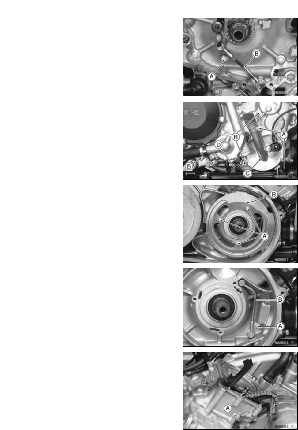
ENGINE LUBRICATION SYSTEM 7-13
Oil Pipe
Oil Pipe Removal
Engine Left Side Oil Pipe (Engine Inside)
•Remove:
Oil Pump (see Oil Pump Removal)
Oil Pipe Bolt [A]
Oil Pipe [B]
Engine Left Side Oil Pipe (Engine Outside)
•Drain the engine oil (see Engine Oil Change in the Peri-
odic Maintenance chapter).
•Remove:
Output Drive Bevel Gear Cover Bolts [A]
Oil Pipe Bolts [B]
•Remove the bevel gear cover [C] to remove the oil pipe
[D].
Engine Right Side Oil Pipe
•Remove:
Drive Pulley (see Drive Pulley Removal in the Converter
System chapter)
Drive Pulley Inner Plate Bolts [A]
Drive Pulley Inner Plate [B]
•Remove:
Oil Pipe Bolt [A]
Oil Pipe [B]
Engine Inside Oil Pipe
•Remove:
Cylinder Head (see Cylinder Head Removal in the En-
gine Top End chapter)
Oil Pipe [A]
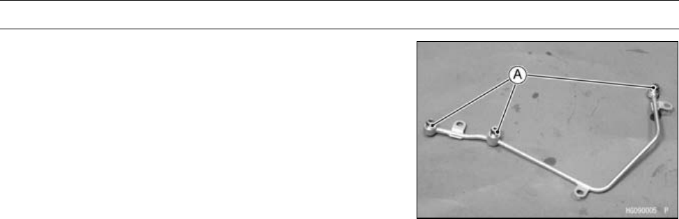
7-14 ENGINE LUBRICATION SYSTEM
Oil Pipe
Oil Pipe Installation
•Replace the O-ring [A] with new ones.
•Apply engine oil to the O-rings before installation.
•Tighten:
Torque - Oil Pipe Bolts: 8.8 N·m (0.90 kgf·m, 78 in·lb)

ENGINE REMOVAL/INSTALLATION 8-1
8
Engine Removal/Installation
Table of Contents
Exploded View........................................................................................................................ 8-2
Engine Removal/Installation................................................................................................... 8-4
Engine Removal................................................................................................................ 8-4
Engine Installation............................................................................................................. 8-6
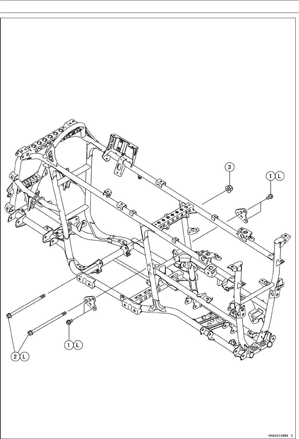
8-2 ENGINE REMOVAL/INSTALLATION
Exploded View

ENGINE REMOVAL/INSTALLATION 8-3
Exploded View
Torque
No. Fastener N·m kgf·m ft·lb Remarks
1Engine Mounting Bracket Bolts 72 7.3 53 L
2Engine Mounting Bolts 72 7.3 53 L
3Engine Mounting Nut 100 10 74
L: Apply a non-permanent locking agent.
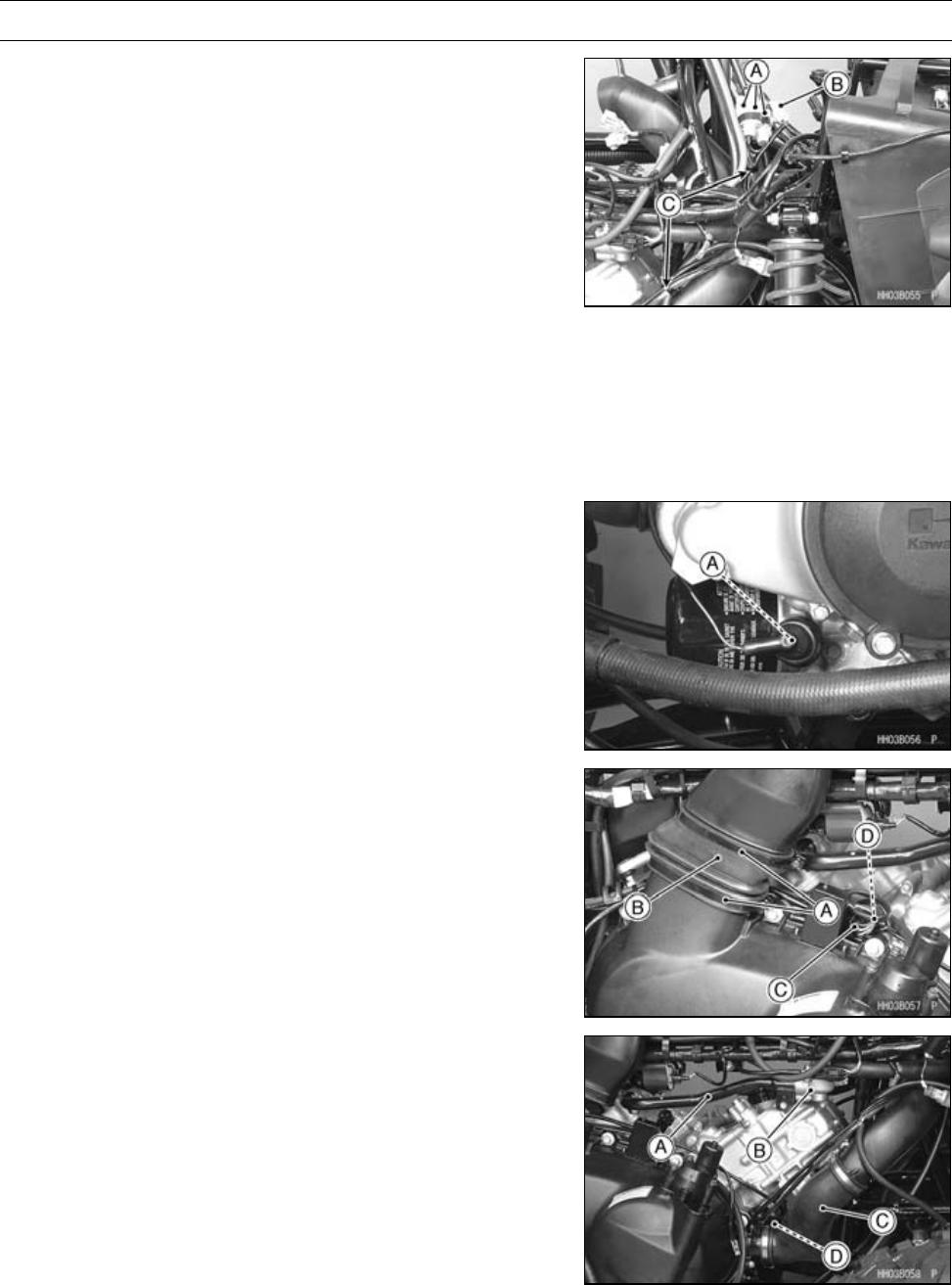
8-4 ENGINE REMOVAL/INSTALLATION
Engine Removal/Installation
Engine Removal
•Remove:
Engine Oil (drain) (see Engine Oil Change in the Periodic
Maintenance chapter)
Coolant (drain) (see Coolant Change in the Periodic
Maintenance chapter)
Muffler and Exhaust Pipe (see Muffler and Exhaust Pipe
Removal in the Engine Top End chapter)
Throttle Body (see Throttle Body in the Fuel System
(DFI) chapter)
Speed Sensor (see Speed Sensor Removal in the Elec-
trical System chapter)
Front Propeller Shaft (see Front Propeller Shaft Re-
moval in the Final Drive chapter)
Alternator Lead Connectors [A]
Crankshaft Sensor Lead Connector [B]
Clamps [C]
•Remove:
Oil Pressure Switch Terminal [A]
•Remove:
Rubber Duct Clamps [A]
Rubber Duct [B]
Engine Brake Actuator Lead Connector [C]
Drive Belt Failure Detection Switch Lead Connector [D]
•Remove:
Water Pipe [A]
Thermostat Housing [B]
Air Rubber Duct [C]
Starter Motor Cable Nut [D] (see Front Propeller Shaft
Removal in the Final Drive chapter)
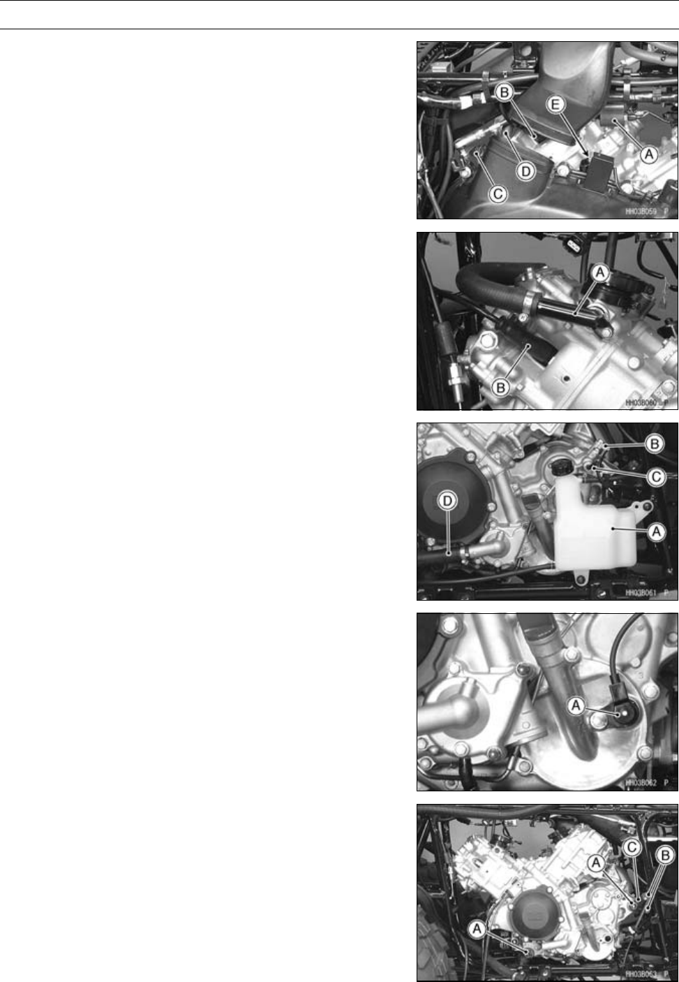
ENGINE REMOVAL/INSTALLATION 8-5
Engine Removal/Installation
•Remove:
Ignition Coil [A] (rear)
Spark Plug Cap [B]
Shift Shaft Lever [C]
Breather Hose [D]
Engine Ground Terminal [E]
•Remove:
Water Pipe [A]
Spark Plug Cap [B]
•Remove:
Coolant Reserve Tank [A]
Neutral Switch Lead Connector [B]
Reverse Switch Lead Connector [C]
Water Hose [D]
•Remove:
Forward/Reverse Detecting Sensor [A]
•Remove:
Engine Mounting Bolts [A]
Engine Mounting Bracket Bolts [B] (both side)
Engine Mounting Bracket [C]
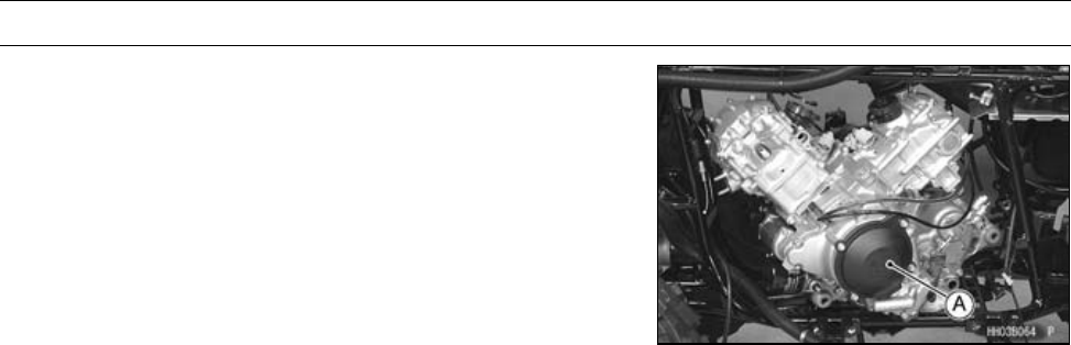
8-6 ENGINE REMOVAL/INSTALLATION
Engine Removal/Installation
•Remove the engine [A] as shown.
Engine Installation
•Apply a non-permanent locking agent to the engine
mounting bolts and engine mounting bracket bolts.
•Install:
Engine
Engine Bracket and Bolts
Engine Mounting Bolts (temporary)
•Tighten:
Torque - Engine Mounting Bracket Bolts: 72 N·m (7.3
kgf·m, 53 ft·lb)
Engine Mounting Bolts: 72 N·m (7.3 kgf·m, 53 ft·lb)
Engine Mounting Nut: 100 N·m (10 kgf·m, 74 ft·lb)

CRANKSHAFT/TRANSMISSION 9-1
9
Crankshaft/Transmission
Table of Contents
Exploded View........................................................................................................................ 9-2
Specifications ......................................................................................................................... 9-6
Special Tools and Sealant ...................................................................................................... 9-8
Crankcase .............................................................................................................................. 9-9
Crankcase Disassembly ................................................................................................... 9-9
Crankcase Assembly ........................................................................................................ 9-10
Crankshaft/Connection Rod ................................................................................................... 9-13
Crankshaft Removal ......................................................................................................... 9-13
Crankshaft Installation ...................................................................................................... 9-13
Connecting Rod Removal ................................................................................................. 9-13
Connecting Rod Installation.............................................................................................. 9-13
Crankshaft/Connecting Rod Cleaning............................................................................... 9-14
Connecting Rod Bend Inspection ..................................................................................... 9-14
Connecting Rod Twist Inspection...................................................................................... 9-14
Connecting Rod Big End Side Clearance Inspection........................................................ 9-15
Connecting Rod Big End Bearing/Crankpin Wear Inspection........................................... 9-15
Crankshaft Runout Inspection........................................................................................... 9-17
Crankshaft Main Bearing/Journal Wear Inspection........................................................... 9-17
Transmission .......................................................................................................................... 9-18
Shift Lever Removal.......................................................................................................... 9-18
Shift Lever Installation....................................................................................................... 9-19
Transmission Removal ..................................................................................................... 9-21
Transmission Installation .................................................................................................. 9-22
Shift Fork Bending Inspection ........................................................................................... 9-24
Shift Fork/Gear and Shifter Groove Wear Inspection ....................................................... 9-24
Transmission and Shift Mechanism Inspection................................................................. 9-25
Ball Bearing, Needle Bearing, and Oil Seal............................................................................ 9-27
Ball and Needle Bearing Replacement............................................................................. 9-27
Ball and Needle Bearing Wear Inspection ........................................................................ 9-27
Oil Seal Inspection ............................................................................................................ 9-27
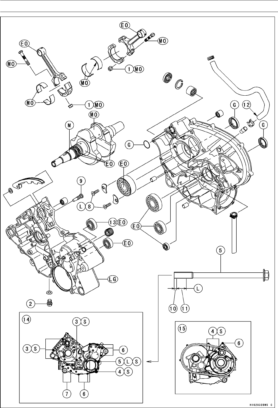
9-2 CRANKSHAFT/TRANSMISSION
Exploded View

CRANKSHAFT/TRANSMISSION 9-3
Exploded View
Torque
No. Fastener N·m kgf·m ft·lb Remarks
1Connecting Rod Big End Cap Nuts 34.3 3.5 25 MO
2Engine Oil Drain Bolt 20 2.0 15
3Crankcase Bolts (M8) 75 mm (2.95 in.) 20 2.0 15 S
4Crankcase Bolts (M8) 110 mm (4.33 in.) 20 2.0 15 S
5Crankcase Bolt (M8) 110 mm (4.33 in.) 20 2.0 15 S, L
6Crankcase Bolts (M6) 40 mm (1.57 in.) 9.8 1.0 87 in·lb
7Crankcase Bolts (M6) 65 mm (2.56 in.) 9.8 1.0 87 in·lb
8Bearing Position Plate Screws 4.9 0.50 43 in·lb L
9Rear Cylinder Camshaft Chain Guide Bolt 20 2.0 15
10. Do not apply a non-permanent locking agent to this area (2 ∼3 mm, 0.08 ∼0.12 in.)
11. About 12 mm (0.47 in.)
12. White Mark: Face the mark backwards and align it with the crankcase mark.
13. Face the seal of the bearing to the left side (outward).
14. Left Crankcase
15. Right Crankcase
EO: Apply engine oil.
G: Apply grease.
L: Apply a non-permanent locking agent.
LG: Apply liquid gasket (Kawasaki Bond: 92104-1063).
M: Apply molybdenum disulfide grease.
MO: Apply molybdenum disulfide oil (mixture of the engine oil and molybdenum disulfide grease in
a weight ratio: 10 : 1).
S: Follow the specific tightening sequence.
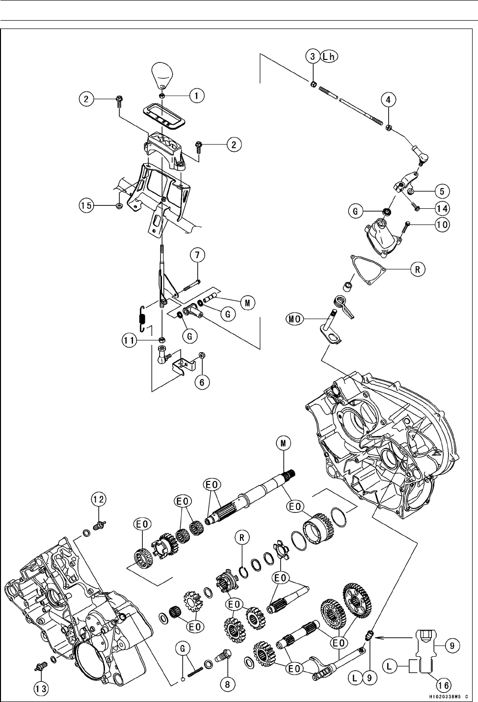
9-4 CRANKSHAFT/TRANSMISSION
Exploded View

CRANKSHAFT/TRANSMISSION 9-5
Exploded View
Torque
No. Fastener N·m kgf·m ft·lb Remarks
1Grip Holder Nut 9.8 1.0 87 in·lb
2Shift Lever Guide Mounting Bolts 19.6 2.0 14
3Tie-rod End Front Locknut 9.8 1.0 87 in·lb Lh
4Tie-rod End Rear Locknut 9.8 1.0 87 in·lb
5Tie-rod End Nut 19.6 2.0 14
6Shift Lever Assembly Nut 19.6 2.0 14
7Tie-rod End Bolt 9.8 1.0 87 in·lb
8Shift Shaft Positioning Bolt 25 2.5 18
9Shift Shaft Spring Bolt 25 2.5 18 L
10 Shift Shaft Cover Bolts 8.8 0.90 78 in·lb
11 Tie-rod End Locknut 19.6 2.0 14
12 Neutral Position Switch 15 1.5 11
13 Reverse Position Switch 15 1.5 11
14 Shift Lever Clamp Bolt 13.5 1.4 119 in·lb
15 Shift Lever Guide Mounting Nut 19.6 2.0 14
16. Do not apply a non-permanent locking agent to this end.
EO: Apply engine oil.
G: Apply grease.
L: Apply a non-permanent locking agent.
Lh: Left-hand Threads
M: Apply molybdenum disulfide grease.
MO: Apply molybdenum disulfide oil (mixture of the engine oil and molybdenum disulfide grease in
a weight ratio: 10 : 1).
R: Replacement Part
9-6 CRANKSHAFT/TRANSMISSION
Specifications
Item Standard Service Limit
Crankshaft, Connecting Rods
Connecting Rod Bend ––– TIR 0.2/100 mm
(0.008/3.94 in.)
Connecting Rod Twist ––– TIR 0.2/100 mm
(0.008/3.94 in.)
Connecting Rod Big End Side Clearance 0.16 ∼0.46 mm
(0.0063 ∼0.0181 in.)
0.7 mm
(0.028 in.)
Connecting Rod Big End Bearing Insert/Crankpin
Clearance
0.028 ∼0.052 mm
(0.0011 ∼0.0020 in.)
0.09 mm
(0.0035 in.)
Crankpin Diameter: 39.984 ∼40.000 mm
(1.5742 ∼1.5748 in.)
39.97 mm
(1.5736 in.)
Marking:
None 39.984 ∼39.992 mm
(1.5742 ∼1.57448 in.)
–––
○39.993 ∼40.000 mm
(1.57452 ∼1.5748 in.)
–––
Connecting Rod Big End Inside Diameter: 43.000 ∼43.016 mm
(1.6929 ∼1.6935 in.)
–––
Marking:
None 43.000 ∼43.008 mm
(1.6929 ∼1.6932 in.)
–––
○43.009 ∼43.016 mm
(1.6933 ∼1.6935 in.)
–––
Connecting Rod Big End Bearing Insert Thickness:
Brown 1.482 ∼1.486 mm
(0.05835 ∼0.05850 in.)
–––
Yellow 1.486 ∼1.490 mm
(0.05850 ∼0.05866 in.)
–––
Green 1.490 ∼1.494 mm
(0.05866 ∼0.05882 in.)
–––
Connecting Rod Big End Bearing Insert Selection:
Bearing Insert
Con-rodBigEndBore
Diameter Marking
Crankpin Diameter
Marking Size Color Part Number
None ○Brown 92028-1963
None None
○ ○ Yellow 92028-1962
○None Green 92028-1961
Crankshaft Runout TIR 0.04 mm (0.0016 in.)
or less
TIR 0.10 mm
(0.0039 in.)
Crankshaft Main Journal Diameter 41.984 ∼42.000 mm
(1.6529 ∼1.6535 in.)
41.96 mm
(1.652 in.)
Crankshaft Main Bearing Bore Diameter 42.025 ∼42.041 mm
(1.6545 ∼1.6552 in.)
42.08 mm
(1.657 in.)

CRANKSHAFT/TRANSMISSION 9-7
Specifications
Item Standard Service Limit
Transmission
Shift Fork Ear Thickness 5.9 ∼6.0 mm
(0.232 ∼0.236 in.)
5.8 mm
(0.23 in.)
Shift Groove Width 6.05 ∼6.15 mm
(0.238 ∼0.242 in.)
6.25 mm
(0.246 in.)
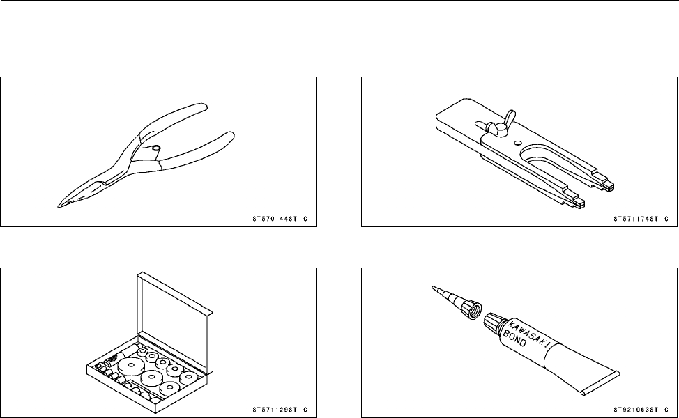
9-8 CRANKSHAFT/TRANSMISSION
Special Tools and Sealant
Outside Circlip Pliers:
57001-144
Bearing Driver Set:
57001-1129
Crankshaft Jig:
57001-1174
Kawasaki Bond (Liquid Gasket - Gray):
92104-1063
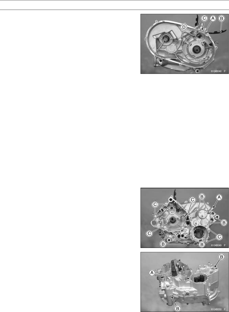
CRANKSHAFT/TRANSMISSION 9-9
Crankcase
Crankcase Disassembly
•Remove:
Engine (see Engine Removal in the Engine Removal/In-
stallation chapter)
Starter Motor (see Starter Motor Removal in the Electri-
cal System chapter)
Oil Filter
Cylinder Blocks and Pistons (see Cylinder and Piston
Removal in the Engine Top End chapter)
Intermediate Shaft and Chains (see Camshaft Chain Re-
moval in the Engine Top End chapter)
Drive Pulley (see Drive Pulley Removal in the Converter
system chapter)
Driven Pulley (see Driven Pulley Removal in the Con-
verter system chapter)
Engine Right Side Oil Pipe (see Oil Pipe Removal in the
Engine Lubrication System chapter)
Output Drive Bevel Gear (see Output Drive Bevel Gear
removal in the Final Drive chapter)
Output Driven Bevel Gear (see Output Driven Bevel
Gear removal in the Final Drive chapter)
Shift Shaft Cover (see Transmission Removal)
Shift Shaft (see Transmission Removal)
Shift Shaft Spring Bolt (see Transmission Removal)
Bolt [A]
Chain Guide [B]
Right Crankcase Bolt (M6) [C]
Right Crankcase Bolts (M8) [D]
•Remove:
Shift Shaft Positioning Bolt [A], Washer, Spring, and
Steel Ball
Left Crankcase Bolts (M6) [B]
Left Crankcase Bolts (M8) [C]
•Wrap the teeth on the sprockets [A] by taping for protect-
ing the bushing in the crankcase.
•Using the pry points [B], split the crankcase halves.
•Lift off the left crankcase half.
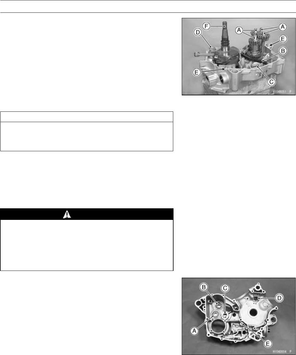
9-10 CRANKSHAFT/TRANSMISSION
Crankcase
•Remove the following parts from the right crankcase half.
Transmission Shafts and Shift Rod [A] (see Transmis-
sion Removal)
Oil Tube [B]
Oil Screen [C]
O-ring [D]
Dowel Pins [E]
Crankshaft [F] (see Crankshaft Removal)
Oil Pressure Relief Valve (see Oil Pressure Relief Valve
Removal in the Engine Lubrication System chapter)
Crankcase Assembly
CAUTION
The right and left crankcase halves are machined at
the factory in the assembled state, so the crankcase
halves must be replaced as a set.
NOTE
○Be certain that all parts are cleaned thoroughly before
assembly.
○Blow through all oil passages with compressed air to
clear any blockage in the crankcase halves and crank-
shaft.
WARNING
Clean the engine parts in a well-ventilated area, and
take care that there are no sparks or flame any-
where near the working area; this includes any ap-
pliance with a pilot light. Do not use gasoline or
low-flash point solvents to clean parts. A fire or ex-
plosion could result.
•Press and insert the new ball bearings until they are bot-
tomed.
Special Tool - Bearing Driver Set: 57001-1129
[A] Ball Bearing
[B] Ball Bearing (sealed side towards crankcase)
•Press and insert the new needle bearings so that the
bearing surfaces are flush with the end of the hole.
[C] Needle Bearing
[D] Needle Bearing (Insert it from outside.)
•Apply engine oil to the bearings.
•Install:
Oil Pressure Relief Valve [E] (see Oil Pressure Relief
Valve Installation in the Engine Lubrication System
chapter)
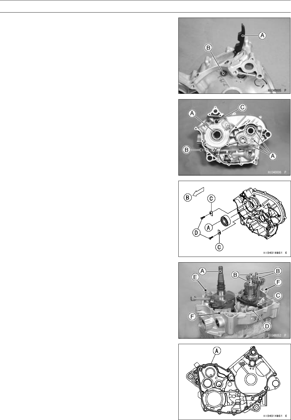
CRANKSHAFT/TRANSMISSION 9-11
Crankcase
•Install:
Rear Cylinder Camshaft Chain Guide [A]
•Tighten:
Torque - Rear Cylinder Camshaft Chain Guide Bolt [B]: 20
N·m (2.0 kgf·m, 15 ft·lb)
•Press and insert the new ball bearings [A] until they are
bottomed.
Special Tool - Bearing Driver Set: 57001-1129
•Press and insert the new needle bearings so that the
bearing surfaces are flush with the end of the hole.
[B] Needle Bearing
[C] Needle Bearing (Insert it from outside.)
•Apply engine oil to the bearings.
•Install the ball bearing [A] so that the stepped side faces
outside [B].
•Install:
Bearing Position Plates [C]
•Apply a non-permanent locking agent to the bearing po-
sition plate screws [D].
•Tighten:
Torque - Bearing Position Plate Screws: 4.9 N·m (0.50
kgf·m, 43 in·lb)
•Be sure the following parts are in place in the right
crankcase half.
Crankshaft [A]
Transmission Shafts and Shift Rod [B] (see Transmis-
sion Installation)
Oil Tube [C]
Oil Screen [D]
O-ring (Apply Grease) [E]
Dowel Pins [F]
•Apply liquid gasket [A] to mating surface of the left
crankcase half.
Sealant - Kawasaki Bond: 92104-1063 (Liquid Gasket -
Gray)
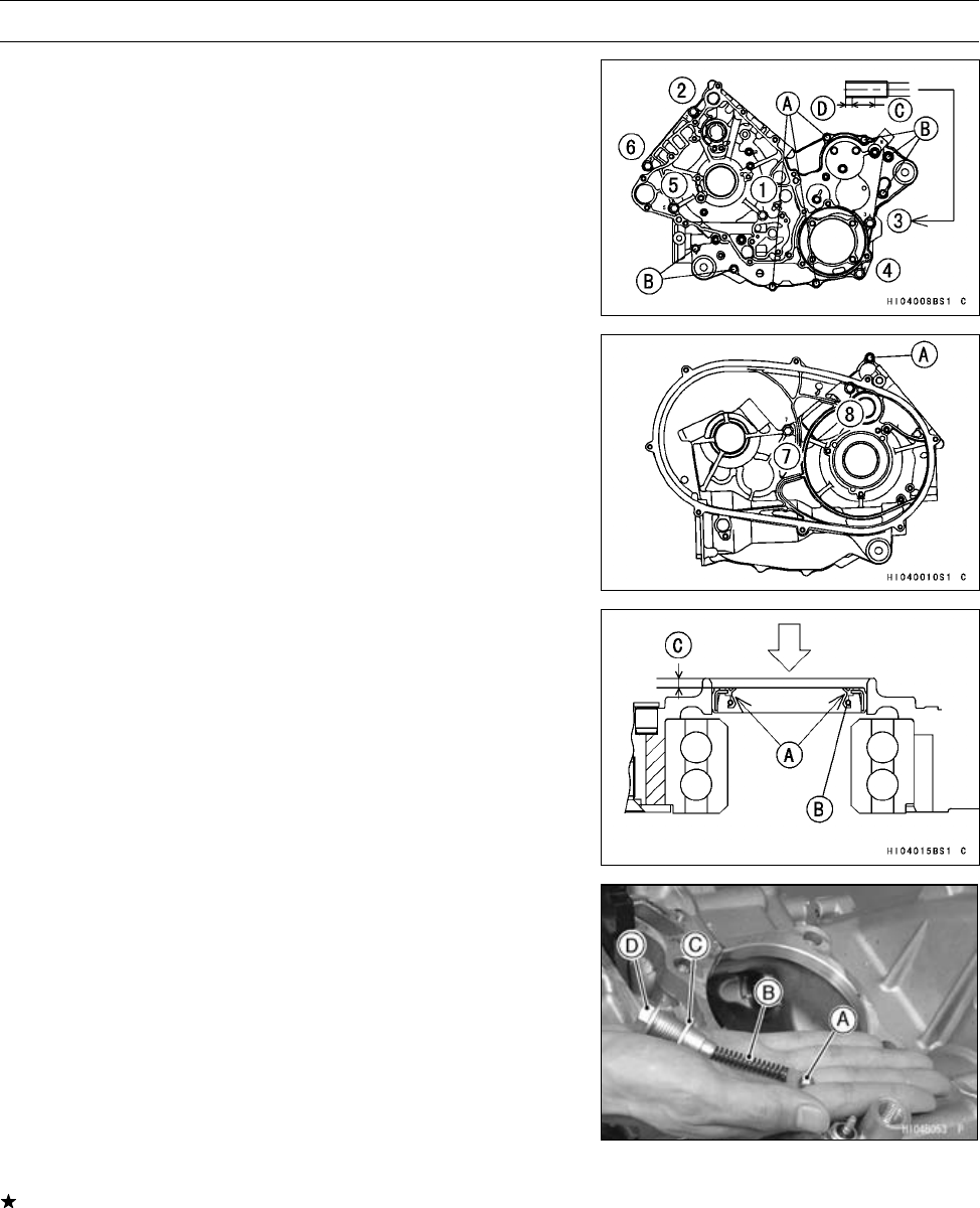
9-12 CRANKSHAFT/TRANSMISSION
Crankcase
•Apply a non-permanent locking agent to the area [C] (12
mm, 0.47 in.) except for the tip [D] (2 ∼3 mm, 0.08 ∼0.12
in.).
Left Crankcase Bolt (M8) [3]
•Tighten the right and left crankcase bolts (M8) following
the tightening sequence [1 ∼8].
Torque - Crankcase Bolts (M8): 20 N·m (2.0 kgf·m, 15 ft·lb)
[1,2,5,6]L=75mm(2.95in.)
[3,4,7,8]L=110mm(4.33in.)
•Tighten:
Torque - Crankcase Bolts (M6): 9.8 N·m (1.0 kgf·m, 87 in·lb)
[A] L = 40 mm (1.57 in.)
[B] L = 65 mm (2.56 in.)
•Grease the lip [A] of the oil seal [B] and press the seal 3
mm (0.12 in.) [C] inwards from the end of the boss.
•Apply grease to the steel ball [A] and spring [B].
•Install:
Steel Ball
Spring
Washer [C]
Shift Shaft Positioning Bolt [D]
•Tighten:
Torque - Shift Shaft Positioning Bolt: 25 N·m (2.5 kgf·m, 18
ft·lb)
•Check:
Crankshaft and driven shaft turn freely.
If any of the shafts do not turn freely, split the crankcase
to locate the problem.
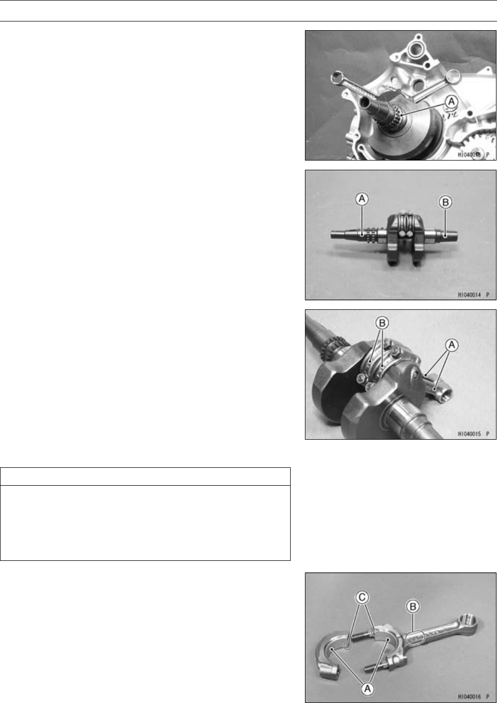
CRANKSHAFT/TRANSMISSION 9-13
Crankshaft/Connection Rod
Crankshaft Removal
•Split the crankcase (see Crankcase Disassembly).
•Remove the crankshaft [A] from the crankcase using a
press.
Crankshaft Installation
•The left shaft [A] of the crankshaft is longer than the right
shaft [B].
•Apply engine oil to the both main journals.
•Insert the right crankshaft tapered end (the shorter end)
into the right crankcase using a press and two crankshaft
jigs.
Special Tools - Crankshaft Jig: 57001-1174 × 2
Connecting Rod Removal
•Remove the crankshaft (see Crankshaft Removal).
•Remove the connecting rods [A] from the crankshaft.
NOTE
○Mark and record the locations of the connecting rods
and their big end caps [B] so that they can be installed
in their original positions.
○Remove the connecting rod big end nuts, and take off the
rod and cap with the bearing inserts.
Connecting Rod Installation
CAUTION
If the connecting rods, bearing inserts, or crank-
shaft are replaced with new ones, select the bearing
insert and check clearance with a plastigage before
assembling the engine to be sure the correct bear-
ing inserts are installed.
•Apply molybdenum disulfide oil:
Inner Surface [A] of Bearing Inserts
•Face the “OUT” marks [B] of both connecting rods to-
wards the outsides of the crankshaft.
•Fit the connecting rod cap so that the grooves [C] of the
cap and connecting rod are on the same side.
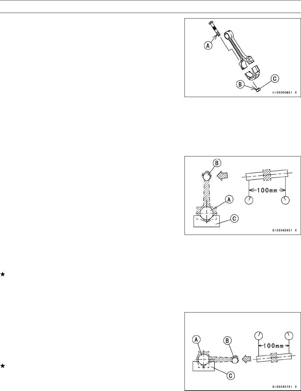
9-14 CRANKSHAFT/TRANSMISSION
Crankshaft/Connection Rod
•Apply molybdenum disulfide oil:
Threads [A] of Connecting Rod Big End Cap Bolts
Seating Surface [B] of Connecting Rod Big End Cap
Nuts [C]
•Tighten:
Torque - Connecting Rod Big End Cap Nuts: 34.3 N·m (3.5
kgf·m, 25 ft·lb)
Crankshaft/Connecting Rod Cleaning
•After removing the connecting rods from the crankshaft,
clean them with a high flash-point solvent.
•Blow the crankshaft oil passages with compressed air to
remove any foreign particles or residue that may have
accumulated in the passages.
Connecting Rod Bend Inspection
•Remove the connecting rod big end bearing inserts, and
reinstall the connecting rod big end cap.
•Select an arbor [A] of the same diameter as the connect-
ing rod big end, and insert the arbor through the connect-
ing rod big end.
•Select an arbor of the same diameter as the piston pin
and at least 100 mm (3.94 in.) long, and insert the arbor
[B] through the connecting rod small end.
•On a surface plate, set the big-end arbor on a V block [C].
•With the connecting rod held vertically, use a height
gauge to measure the difference in the height of the
arbor above the surface plate over a 100 mm (3.94 in.)
length to determine the amount of connecting rod bend.
If connecting rod bend exceeds the service limit, the con-
necting rod must be replaced.
Connecting Rod Bend
Service Limit: TIR 0.2/100 mm (0.008/3.94 in.)
Connecting Rod Twist Inspection
•With the big-end arbor [A] still on the V block [C], hold the
connecting rod horizontally and measure the amount that
the arbor [B] varies from being parallel with the surface
plate over a 100 mm (3.94 in.) length of the arbor to de-
termine the amount of connecting rod twist.
If connecting rod twist exceeds the service limit, the con-
necting rod must be replaced.
Connecting Rod Twist
Service Limit: TIR 0.2/100 mm (0.008/3.94 in.)
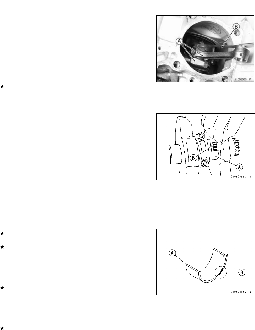
CRANKSHAFT/TRANSMISSION 9-15
Crankshaft/Connection Rod
Connecting Rod Big End Side Clearance
Inspection
•Measure the side clearance of the connecting rod big end
[A].
○Insert a thickness gauge [B] between the big end and ei-
ther crank web to determine clearance.
Connecting Rod Big End Side Clearance
Standard: 0.16 ∼0.46 mm (0.0063 ∼0.0181 in.)
Service Limit: 0.7 mm (0.028 in.)
If the clearance exceeds the service limit, replace the con-
necting rod with new one and then check clearance again.
If clearance is too large after connecting rod replacement,
the crankshaft also must be replaced.
Connecting Rod Big End Bearing/Crankpin Wear
Inspection
•Measure the bearing insert/crankpin [A] clearance with
plastigage [B].
○Tighten the big end cap nuts to the specified torque.
Torque - Connecting Rod Big End Cap Nuts: 34.3 N·m (3.5
kgf·m, 25 ft·lb)
NOTE
○Do not move the connecting rod and crankshaft during
clearance measurement.
Connecting Rod Big End Bearing, Insert/Crankpin
Clearance
Standard: 0.028 ∼0.052 mm (0.0011 ∼0.0020 in.)
Service Limit: 0.09 mm (0.0035 in.)
If the clearance is within the standard, no bearing insert
replacement is required.
If the clearance is between 0.052 mm (0.0020 in.) and
the service limit 0.09 mm (0.0035 in.), replace the bear-
ing inserts [A] with inserts painted green [B]. Check in-
sert/crankpin clearance with plastigage. The clearance
may exceed the standard slightly, but it must not be less
than the minimum in order to avoid bearing seizure.
If the clearance exceeds the service limit, measure the
diameter of the crankpin.
Crankpin Diameter
Standard: 39.984 ∼40.000 mm (1.5742 ∼1.5748 in.)
Service Limit: 39.97 mm (1.5736 in.)
If the crankpin has worn past the service limit, replace the
crankshaft with a new one.
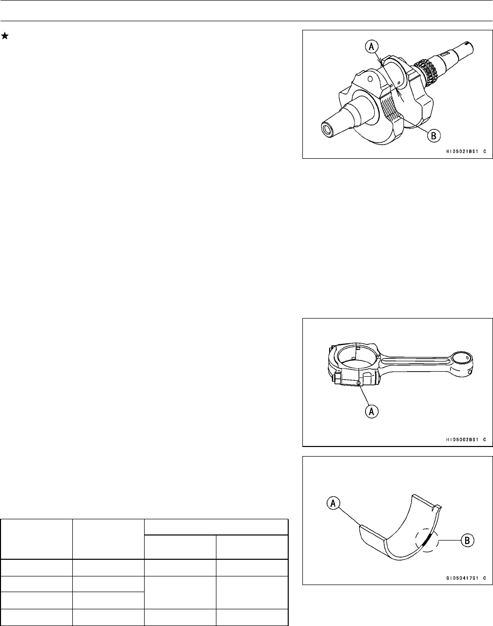
9-16 CRANKSHAFT/TRANSMISSION
Crankshaft/Connection Rod
If the measured crankpin diameter [A] is not less than
the service limit, but does not coincide with the original
diameter marking on the crankshaft, make a new mark
on it.
Crankpin Diameter Marks
None: 39.984 ∼39.992 mm (1.5742 ∼1.57448 in.)
○:39.993 ∼40.000 mm (1.57452 ∼1.5748 in.)
Crankpin Diameter Mark [B]: “○” mark or no mark
•Measure the connection rod big end inside diameter, and
mark each connecting rod big end in accordance with the
inside diameter.
•Tighten the big end nuts to the specified torque.
Torque - Connecting Rod Big End Cap Nuts: 34.3 N·m (3.5
kgf·m, 25 ft·lb)
NOTE
○The mark already on the big end should almost coincide
with the measurement because of little wear.
Connecting Rod Big End Inside Diameter Marks
None: 43.000 ∼43.008 mm (1.6929 ∼1.6932 in.)
○:43.009 ∼43.016 mm (1.6933 ∼1.6935 in.)
Diameter Mark [A]: “○”ornomark
•Select the proper bearing insert [A] in accordance with the
combination of the connecting rod and crankshaft coding.
Size Color [B]
Big End Bearing Insert Selection
Bearing Insert
Con-rod Big
End Bore
Diameter Mark
Crankpin
Diameter Mark Size Color Part Number
None ○Brown 92028-1963
None None
○ ○ Yellow 92028-1962
○None Green 92028-1961
•Install the new inserts in the connecting rod and check
insert/crankpin clearance with the plastigage.
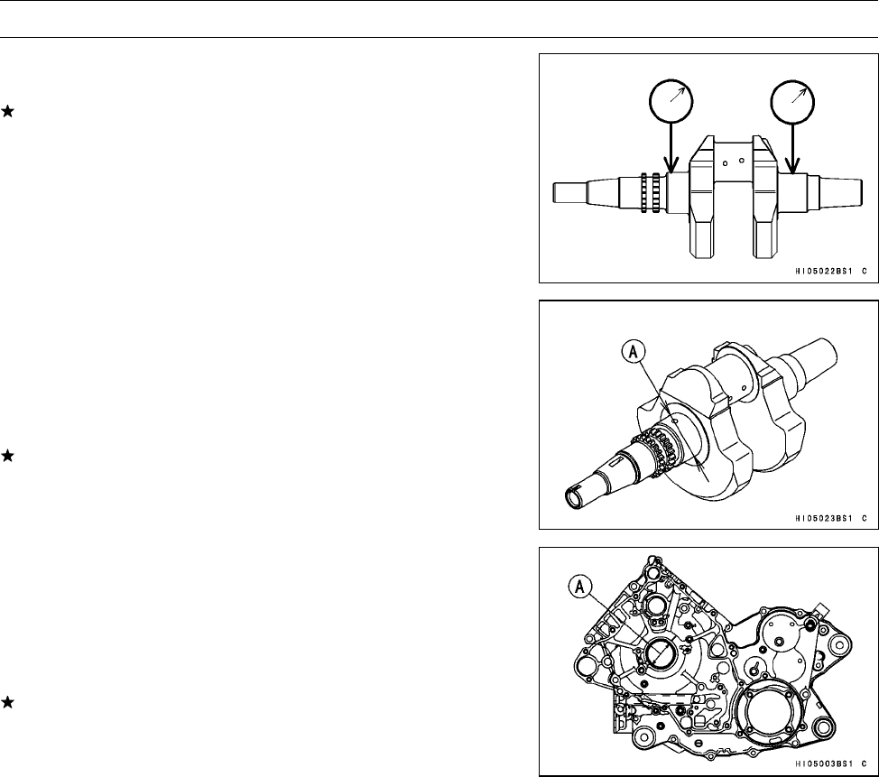
CRANKSHAFT/TRANSMISSION 9-17
Crankshaft/Connection Rod
Crankshaft Runout Inspection
•Measure the crankshaft runout.
If the measurement exceeds the service limit, replace the
crankshaft.
Crankshaft Runout
Standard: TIR 0.04 mm (0.0016 in.) or less
Service Limit: TIR 0.10 mm (0.0039 in.)
Crankshaft Main Bearing/Journal Wear Inspection
•Measure the diameter [A] of the crankshaft main journal.
Crankshaft Main Journal Diameter
Standard: 41.984 ∼42.000 mm (1.6529 ∼1.6535 in.)
Service Limit: 41.96 mm (1.652 in.)
If any journal has worn past the service limit, replace the
crankshaft with a new one.
•Measure the main bearing bore diameter [A] in the
crankcase halves.
Crankcase Main Bearing Bore Diameter
Standard: 42.025 ∼42.041 mm (1.6545 ∼1.6552 in.)
Service Limit: 42.08 mm (1.6567 in.)
If there is any signs of seizure, damage, or excessive
wear, replace the crankcase halves as a set.
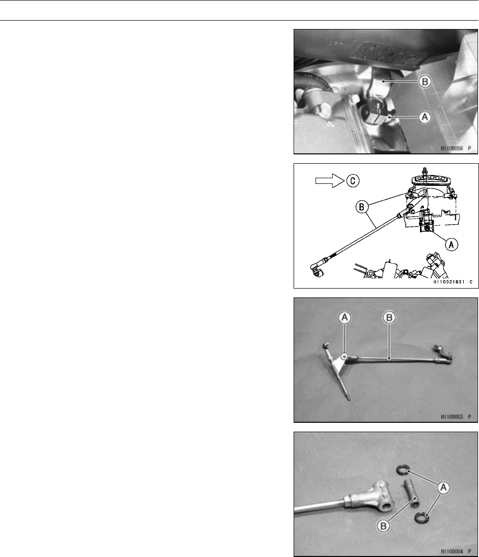
9-18 CRANKSHAFT/TRANSMISSION
Transmission
Shift Lever Removal
•Set the shift lever in the neutral position.
•Remove:
Right Side Cover (see Right Side Cover Removal in the
Frame chapter)
Shift Shaft Lever Bolt [A]
•Remove the shift shaft lever [B] from the shift shaft.
•Remove:
Nut [A]
Shift Lever Assembly [B]
Front [C]
•Remove:
Tie-rod End Bolt [A]
Tie-rod [B]
•Remove:
Oil Seals [A]
Collar [B]
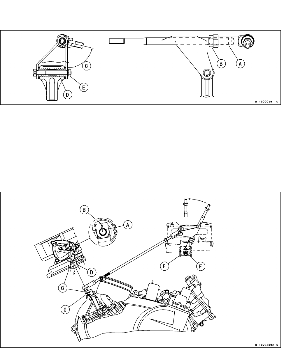
CRANKSHAFT/TRANSMISSION 9-19
Transmission
Shift Lever Installation
•Twist the tie-rod end [A] and tie-rod end locknut [B] to
bottom of the screw and then turn back to dimension with
77° ±10° [C] as shown.
•Tighten the locknut against the tie-rod end:
Torque - Tie-rod End Locknut: 19.6 N·m (2.0 kgf·m, 14 ft·lb)
•Apply molybdenum disulfide grease:
Outside of Tie-rod End Collar [D]
•Apply grease to the oil seals, and install them.
•Tighten:
Torque - Tie-rod End Bolt [E]: 9.8 N·m (1.0 kgf·m, 87 in·lb)
•Align the mark [A] on the shaft end with the slit [B] of the
shift shaft lever.
•Position the shift shaft lever end [C] on the boss-center
[D] of the crankcase.
•Install:
Bracket [E]
Shift Lever Assembly Nut [F]
•Tighten:
Torque - Shift Lever Assembly Nut: 20 N·m (2.0 kgf·m, 14
ft·lb)
Tie-rodEndNut[G]:19.6N·m(2.0kgf·m,14ft·lb)
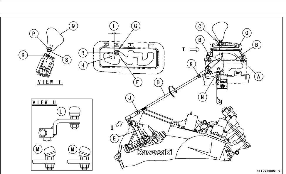
9-20 CRANKSHAFT/TRANSMISSION
Transmission
•Install:
Guide [A]
•Tighten:
Torque - Shift Lever Guide Mounting Bolts [B]: 19.6 N·m
(2.0 kgf·m, 14 ft·lb)
•Set the lever assembly in the neutral position [C] while
turning the tie-rod [D].
NOTE
○Do not turn the shift shaft [E] when setting the lever
assembly on neutral position.
○Turn the tie-rod counterclockwise until the rod [F] of the
shift lever assembly contacts with the neutral position [G]
of the guide [H]. At that time, the clearance [I] between
the rod and guide is 0 mm.
○Move the rod [F] to right side and check it returns to left
side automatically.
•Tighten:
Torque - Tie-rod End Rear Locknut [J]: 9.8 N·m (1.0 kgf·m,
87 in·lb)
•Holding the rear tie-rod end, and tighten the front locknut
[K].
Torque - Tie-rod End Front Locknut: 9.8 N·m (1.0 kgf·m, 87
in·lb)
NOTE
○The front locknut has left-hand threads.
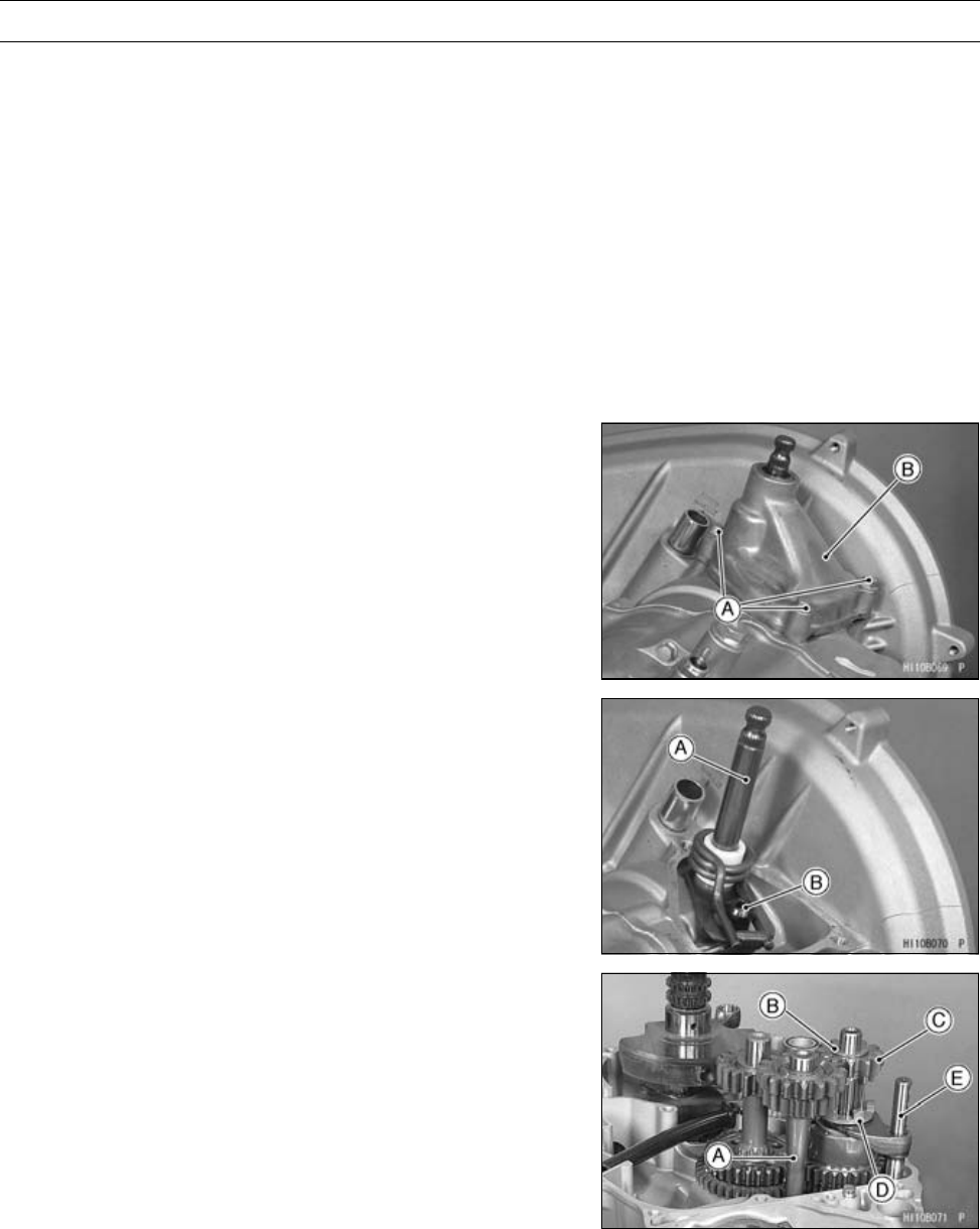
CRANKSHAFT/TRANSMISSION 9-21
Transmission
○Do not lean the tie-rod rear end after tightening the front
locknut.
Right [L]
Wrong [M]
•Check that the shift lever moves from right to left automat-
ically.
•Install:
Spring [N]
Trim Seal [O]
•Align the mark [P] of the grip [Q] with the projection [R] on
the guide.
•Tighten:
Torque - Grip Holder Nut [S]: 9.8 N·m (1.0 kgf·m, 87 in·lb)
Transmission Removal
•Remove:
Shift Shaft Cover Bolts [A]
Shift Shaft Cover [B]
•While opening the shift shaft spring end, remove the shift
shaft [A].
Special Tool - Outside Circlip Pliers: 57001-144
•Remove:
Shift Shaft Spring Bolt [B]
•Split the crankcase (see Crankcase Disassembly).
•Remove:
ReverseIdleShaft[A]
Spacer [B]
Reverse Drive Gear [C], Needle Bearing, and Spacer
Shifter [D]
Shift Rod [E]
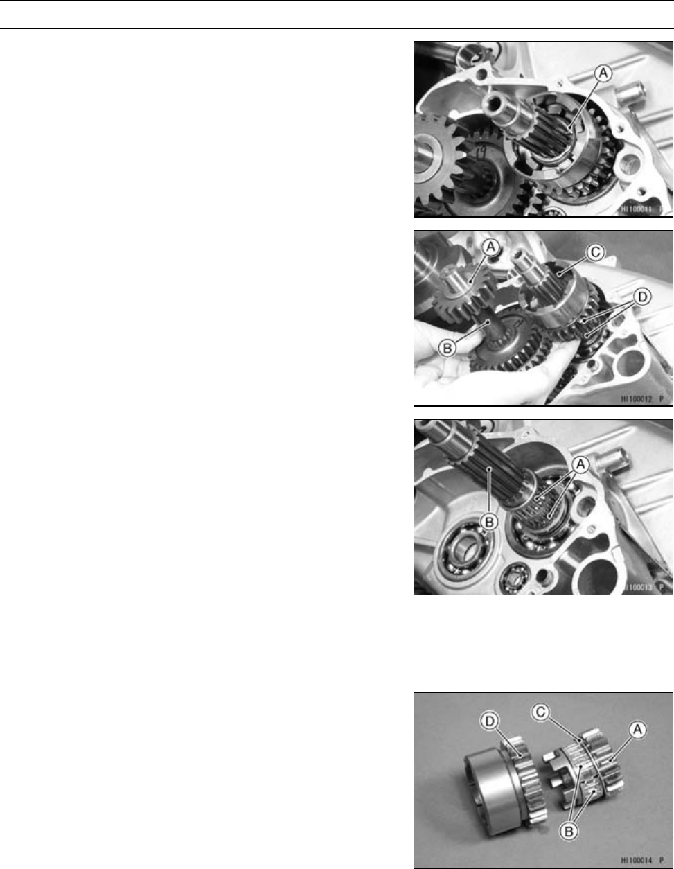
9-22 CRANKSHAFT/TRANSMISSION
Transmission
•Remove:
Circlip [A]
Special Tool - Outside Circlip Pliers: 57001-144
•Remove:
Spacer [A]
Idle Gear Assembly [B]
Washers and Spacer [C]
Low and High Gears [D]
•Remove:
Needle Bearings [A]
•Remove the driven shaft [B] from the crankcase using a
press.
Transmission Installation
•Insert the driven shaft in the crankcase until it is bottomed
using a press.
•Apply engine oil to the needle bearings and install them.
•Install the following parts on the low gear [A].
Needle Bearings [B]
Spacer [C] (P/No. 92026-1599, 48.2 × 54.3 × 1.0)
High Gear [D]
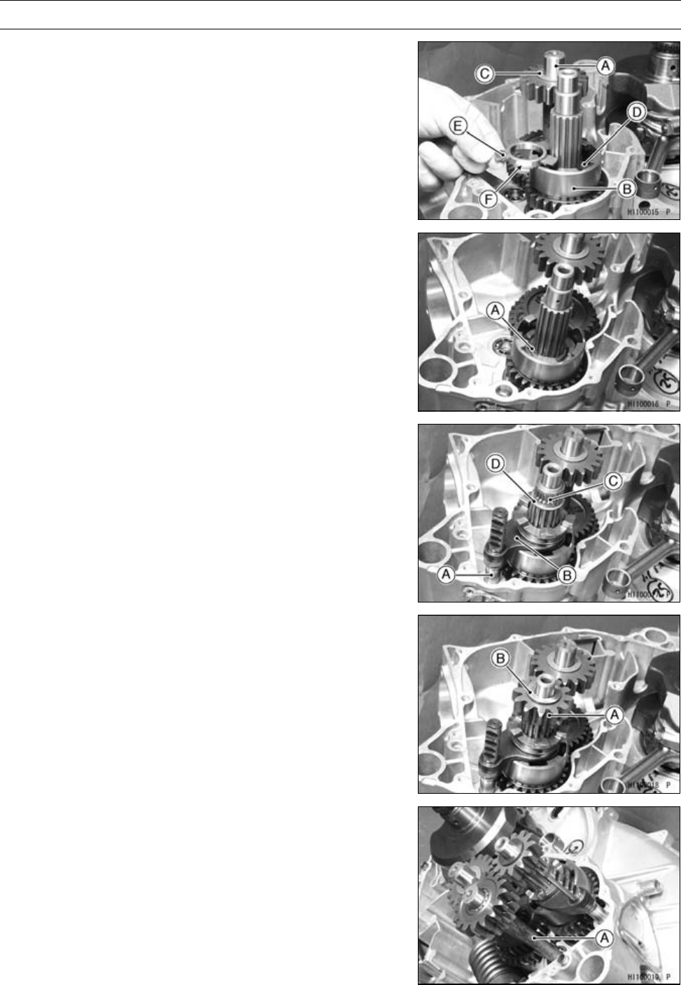
CRANKSHAFT/TRANSMISSION 9-23
Transmission
•Install:
Idle Shaft [A] with Gear Assembly [B]
Spacer [C]
Spacer [D] (P/No. 92026-1599, 48.2 × 54.3 × 1.0)
•Apply engine oil to the inner surface of the spacer [E].
•Install the spacer [E] so that the stepped side [F] faces
outward.
•Install:
Spacer
Toothed Washer [A]
Circlip
Special Tool - Outside Circlip Pliers: 57001-144
•Apply engine oil:
Shift Rod [A] and Shift Fork Ear [B]
Needle Bearing [C]
•Install:
Shift Rod with Shift Fork
Spacer [D]
Needle Bearing
•Install:
Reverse Drive Gear [A]
Spacer [B]
•Install:
ReverseIdleShaft[A]
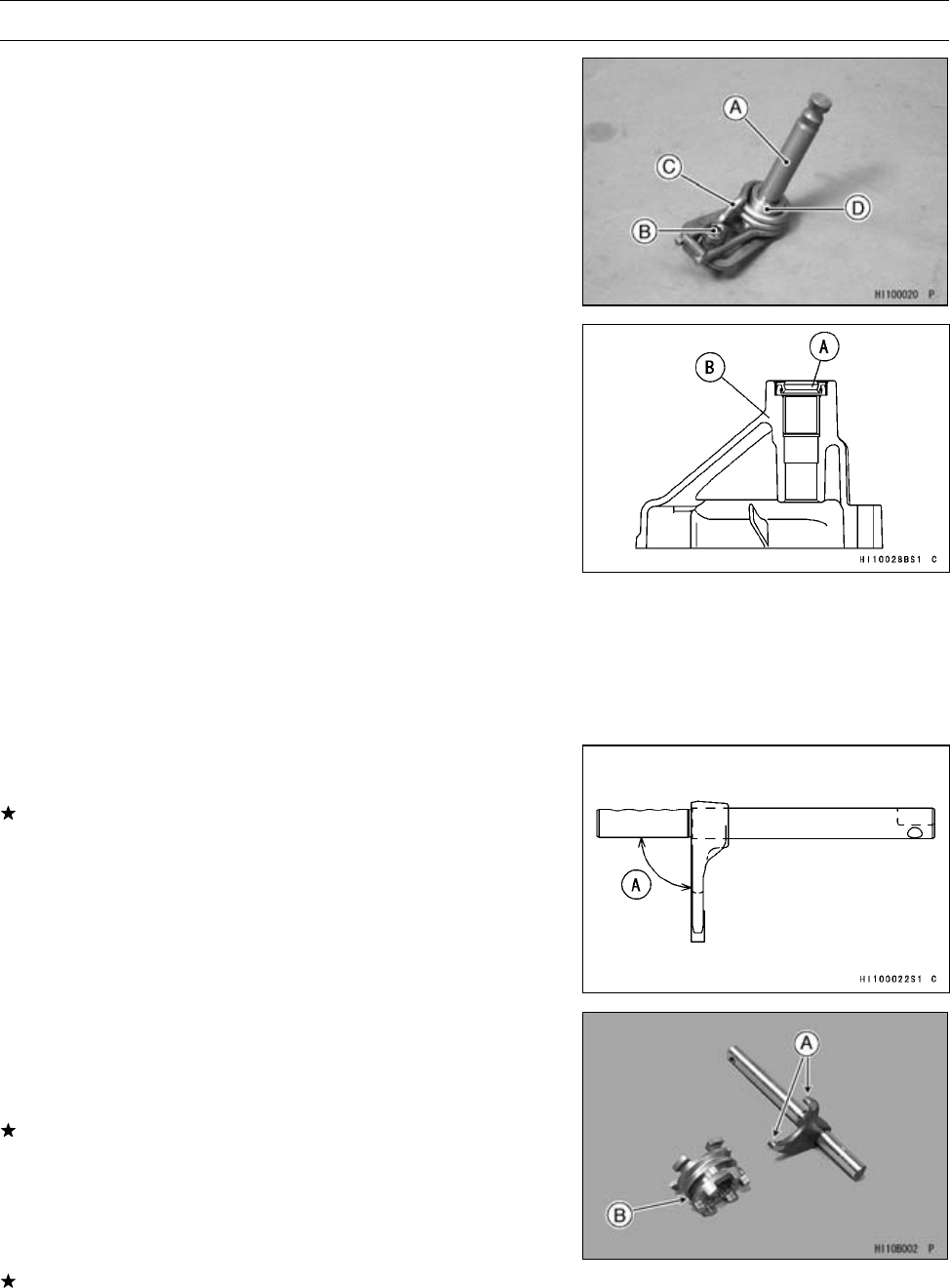
9-24 CRANKSHAFT/TRANSMISSION
Transmission
•Apply molybdenum disulfide oil to the shift shaft [A].
•Install:
Shift Shaft Spring Bolt [B]
Spring [C]
Guide [D]
•Apply a non-permanent locking agent:
Shift Shaft Spring Bolt
•Tighten:
Torque - Shift Shaft Spring Bolt: 25 N·m (2.5 kgf·m, 18 ft·lb)
•When an oil seal [A] is installed in the shift shaft cover [B],
press and insert the oil seal so that its surface is flush with
the end of the hole.
•Install:
Shift Shaft Cover
•Tighten:
Torque - Shift Shaft Cover Bolts: 8.8 N·m (0.90 kgf·m, 78
in·lb)
Shift Fork Bending Inspection
•Visually inspect the shift fork.
If the fork is bent, replace the shift rod with a new one.
A bent fork could cause difficulty in shifting, or allow the
transmission to jump out of gear when under power.
[A] 90°
Shift Fork/Gear and Shifter Groove Wear
Inspection
•Measure the thickness of the shift fork ears [A], and mea-
sure the width [B] of the shifter groove.
If the thickness of a shift fork ear is less than the service
limit, the shift rod must be replaced.
Shift Fork Ear Thickness
Standard: 5.9 ∼6.0 mm (0.232 ∼0.236 in.)
Service Limit: 5.8 mm (0.23 in.)
If the groove is worn over the service limit, the shifter must
be replaced.
Shifter Groove Width
Standard: 6.05 ∼6.15 mm (0.238 ∼0.242 in.)
Service Limit: 6.25 mm (0.246 in.)
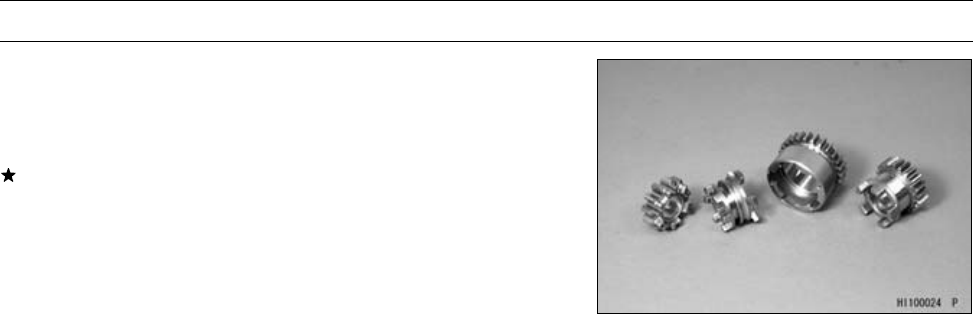
CRANKSHAFT/TRANSMISSION 9-25
Transmission
Transmission and Shift Mechanism Inspection
•Visually inspect:
Gears
Dogs of Gear and Shifter
If they are damaged or worn excessively, replace them.
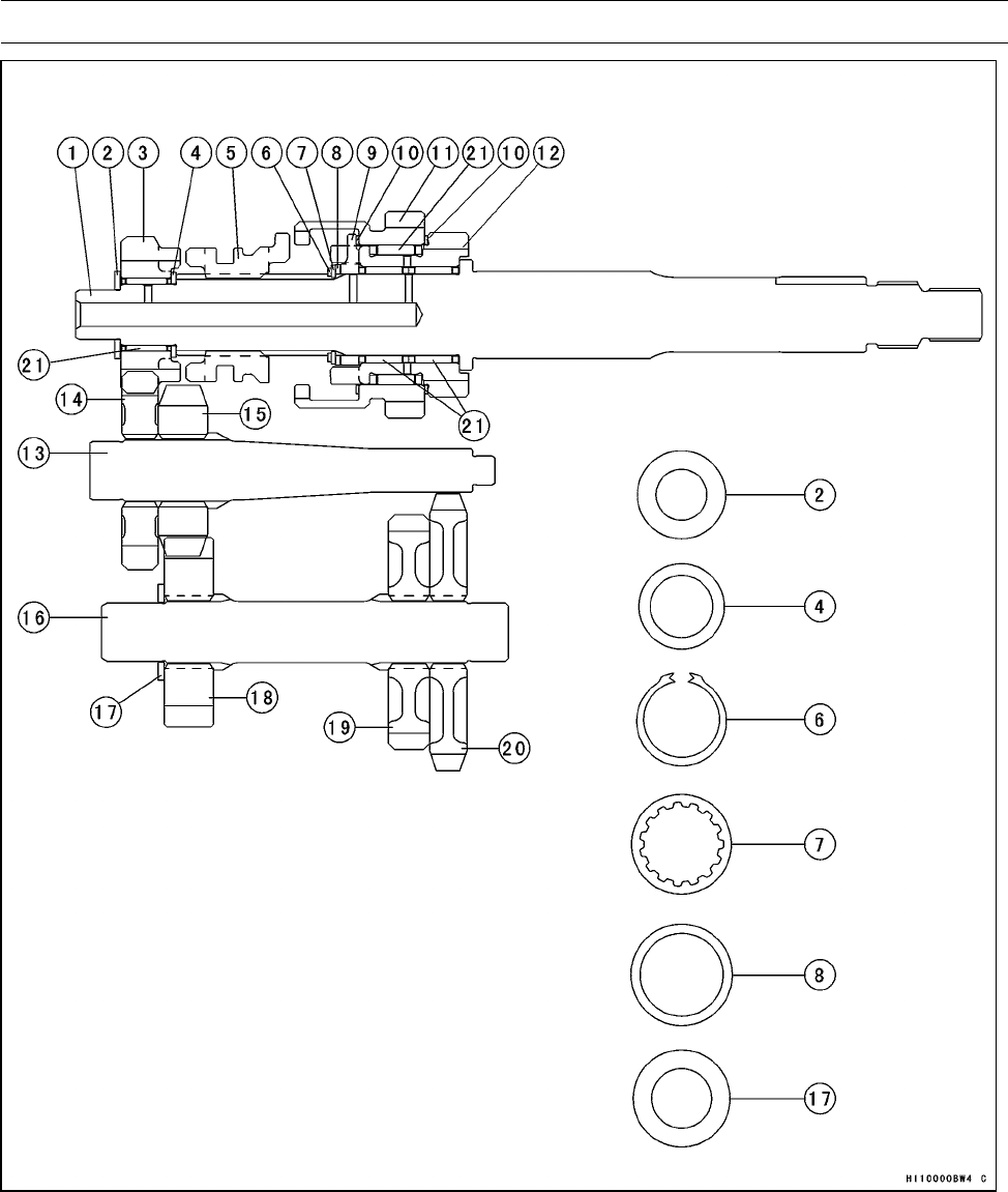
9-26 CRANKSHAFT/TRANSMISSION
Transmission
1. Driven Shaft
2. Spacer (17.3 × 30 × 2.0)
3. Reverse Gear (12T)
4. Spacer (21.2 × 29 × 1.6)
5. Shifter
6. Circlip
7. Toothed Washer (t = 1.5)
8. Spacer (28.2 × 34.5 × 1.6)
9. Spacer (Hi and Low)
10. Spacer (48.2 × 54.3 × 1.0)
11. Drive Hi Gear (26T)
12. Drive Low Gear (20T)
13.ReverseIdleShaft
14. Reverse Driven Gear (16T)
15. Reverse Driven Output Gear (16T)
16. Idle Shaft
17. Spacer (20.3 × 33 × 2.0)
18. Drive Output Gear (18T)
19. Driven Hi Gear (30T)
20. Driven Low Gear (36T)
21. Needle Bearing
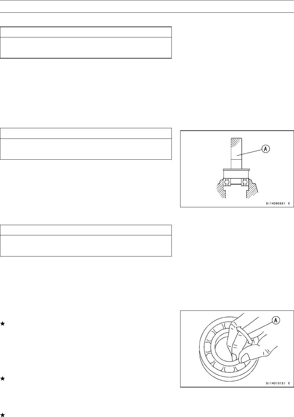
CRANKSHAFT/TRANSMISSION 9-27
Ball Bearing, Needle Bearing, and Oil Seal
Ball and Needle Bearing Replacement
CAUTION
Do not remove the ball or needle bearings unless it
is necessary. Removal may damage them.
•Using a press or puller, remove the ball bearing and/or
three needle bearings.
NOTE
○In the absence of the above mentioned tools, satisfac-
tory results may be obtained by heating the case to ap-
proximately 93°C (200°F) max., and tapping the bearing
in or out.
CAUTION
Do not heat the case with a torch. This will warp the
case. Soak the case in oil and heat the oil.
•Using a press and the bearing driver set [A], install the
new ball bearing until it stops at the bottom of its housing.
○Three new needle bearings must be pressed into the
crankcase so that the end is flush with the end of the
hole.
Special Tool - Bearing Driver Set: 57001-1129
Ball and Needle Bearing Wear Inspection
CAUTION
Do not remove the bearings for inspection. Re-
moval may damage them.
•Check the ball bearings.
○Since the ball bearings are made to extremely close toler-
ances, the wear must be judged by feel rather than mea-
surement. Clean each bearing in a high-flash point sol-
vent, dry it (do not spin the bearing while it is dry), and oil
it with engine oil.
○Spin [A] the bearing by hand to check its condition.
If the bearing is noisy, does not spin smoothly, or has any
rough spots, replace it.
•Check the needle bearings.
○The rollers in a needle bearing normally wear very little,
and wear is difficult to measure. Instead of measuring,
inspect the bearing for abrasion, color change, or other
damage.
If there is any doubt as to the condition of a needle bear-
ing, replace it.
Oil Seal Inspection
•Inspect the oil seals.
Replace it if the lips are misshapen, discolored (indicating
that the rubber has deteriorated), hardened or otherwise
damaged.

WHEELS/TIRES 10-1
10
Wheels/Tires
Table of Contents
Exploded View........................................................................................................................ 10-2
Specifications ......................................................................................................................... 10-4
Special Tool ............................................................................................................................ 10-5
Wheel Alignment .................................................................................................................... 10-6
Steering Centering Inspection........................................................................................... 10-6
Steering Centering Adjustment ......................................................................................... 10-6
Toe-in Inspection............................................................................................................... 10-7
Toe-in Adjustment ............................................................................................................. 10-7
Wheels (Rims) ........................................................................................................................ 10-9
Wheel Removal................................................................................................................. 10-9
Wheel Installation.............................................................................................................. 10-9
Wheel (Rim) Inspection..................................................................................................... 10-10
Wheel (Rim) Replacement................................................................................................ 10-10
Tires........................................................................................................................................ 10-11
Tire Removal.....................................................................................................................10-11
Tire Installation.................................................................................................................. 10-11
Tire Inspection .................................................................................................................. 10-12
Front Hub................................................................................................................................ 10-13
Front Hub Removal........................................................................................................... 10-13
Front Hub Installation........................................................................................................ 10-13
Front Hub Disassembly/Assembly .................................................................................... 10-14
Rear Hub ................................................................................................................................ 10-15
Rear Hub Removal ........................................................................................................... 10-15
Rear Hub Installation ........................................................................................................ 10-15
Rear Hub Disassembly/Assembly..................................................................................... 10-16
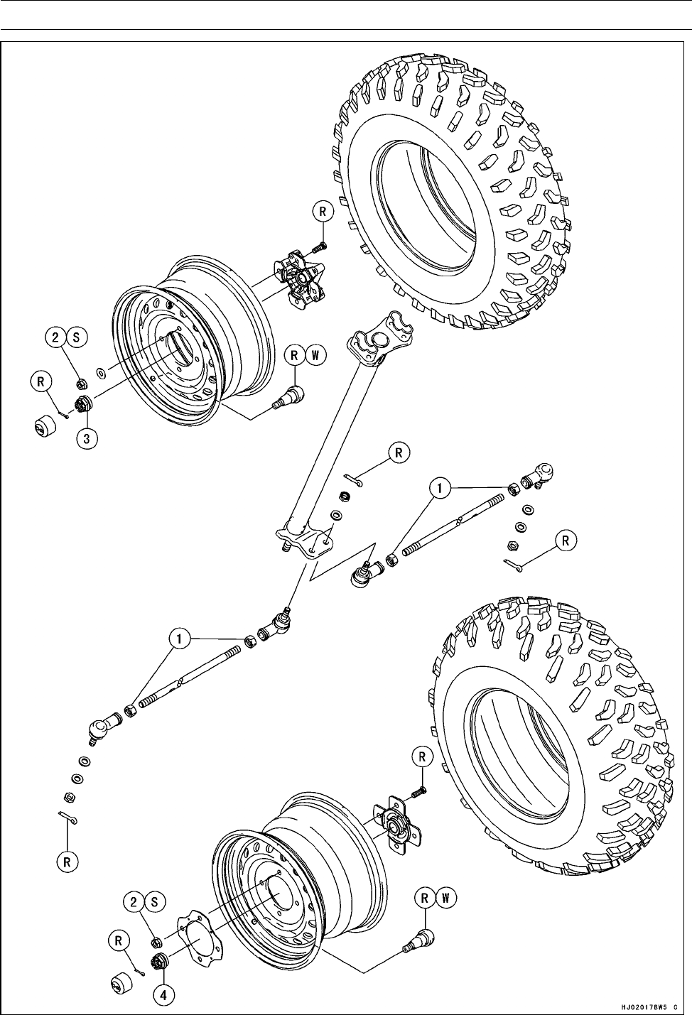
10-2 WHEELS/TIRES
Exploded View

WHEELS/TIRES 10-3
Exploded View
Torque
No. Fastener N·m kgf·m ft·lb Remarks
1Tie-rod Locknuts 37 3.8 27
2Wheel Nuts (First Torque) 15 1.5 11 S
2Wheel Nuts (Final Torque) 76 7.7 56 S
3Front Axle Nuts 197 20 145
4 Rear Axle Nuts 265 27 195
R: Replacement Parts
S: Follow the specific tightening sequence.
W: Apply water or soap and water solution.

10-4 WHEELS/TIRES
Specifications
Item Standard Service Limit
Wheel Alignment
Toe-in of front wheels: –10 ∼10 mm (–0.39 ∼0.39 in.) at 1G –––
Wheels (Rims)
Rim Size:
Front 12 × 6.0 –––
Rear 12 × 7.5 –––
Tires
Standard tire:
Front AT 25 × 8-12 –––
DUNLOP, KT191, Tubeless
Rear AT 25 × 10-12 –––
DUNLOP, KT195, Tubeless
Tire air pressure (when cold):
Front 35 kPa (0.35 kgf/cm², 5.0 psi) –––
Rear 35 kPa (0.35 kgf/cm², 5.0 psi) –––
Maximum tire air pressure 250 kPa (2.5 kgf/cm², 36 psi) –––
(to seat beads, when cold)
Tire tread depth:
Front 13.0 mm (0.51 in.) 3 mm (0.12 in.)
Rear 14.5 mm (0.57 in.) 4 mm (0.16 in.)
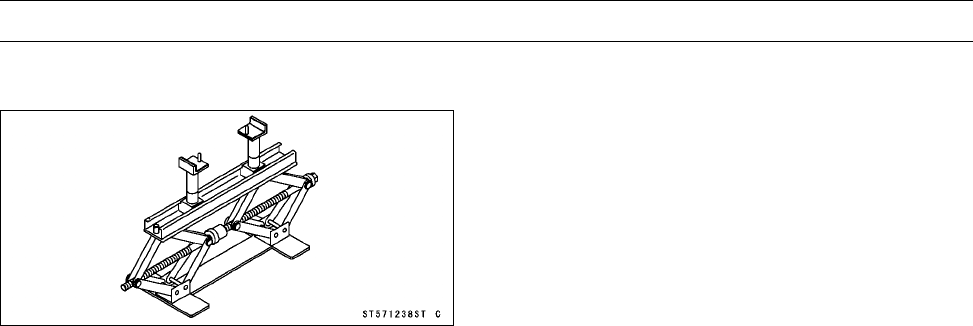
WHEELS/TIRES 10-5
Special Tool
Jack:
57001-1238
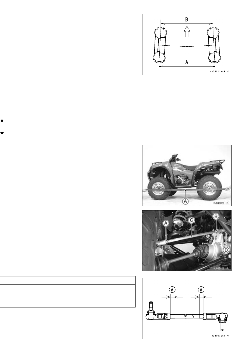
10-6 WHEELS/TIRES
Wheel Alignment
Toe-in is the difference between the distance of front and
the one of rear at the axle height position in the front wheels.
When there is toe-in, the distance A (Rear) is the greater
than B (Front) as shown.
The purpose of toe-in is to prevent the front wheels from
getting out of parallel at any time, and to prevent any slip-
ping or scuffing action between the tires and the ground. If
toe-in is incorrect, the front wheels will be dragged along
the ground, scuffing and wearing the tread knobs.
Caster and camber are build-in and require no adjust-
ment.
A (Rear ) – B (Front) = Amount of Toe-in
(Distance A and B are measured at axle height with the
vehicle sitting on the ground, or at 1G.)
Steering Centering Inspection
•Test ride the vehicle.
If the handlebar is straight when the vehicle is traveling in
a straight line, go on to the Toe-in Inspection procedure.
Otherwise, go on to the Steering Centering Adjustment
procedure.
Steering Centering Adjustment
•Hold a straightedge [A] against the rear wheel rim on one
side at axle height.
•With the handlebar straight ahead, loosen the locknuts
[A] [B] and turn the tie-rod [C] until the front wheel on that
side is parallel to the straightedge.
NOTE
○The locknut [B] near the L mark [D] on the tie-rod has
left-hand threads. Turn the wrench clockwise for loos-
ening.
CAUTION
Adjust the tie-rod so that the visible thread length
[A] is even on both ends of the tie-rod, or the
threads could be damaged.
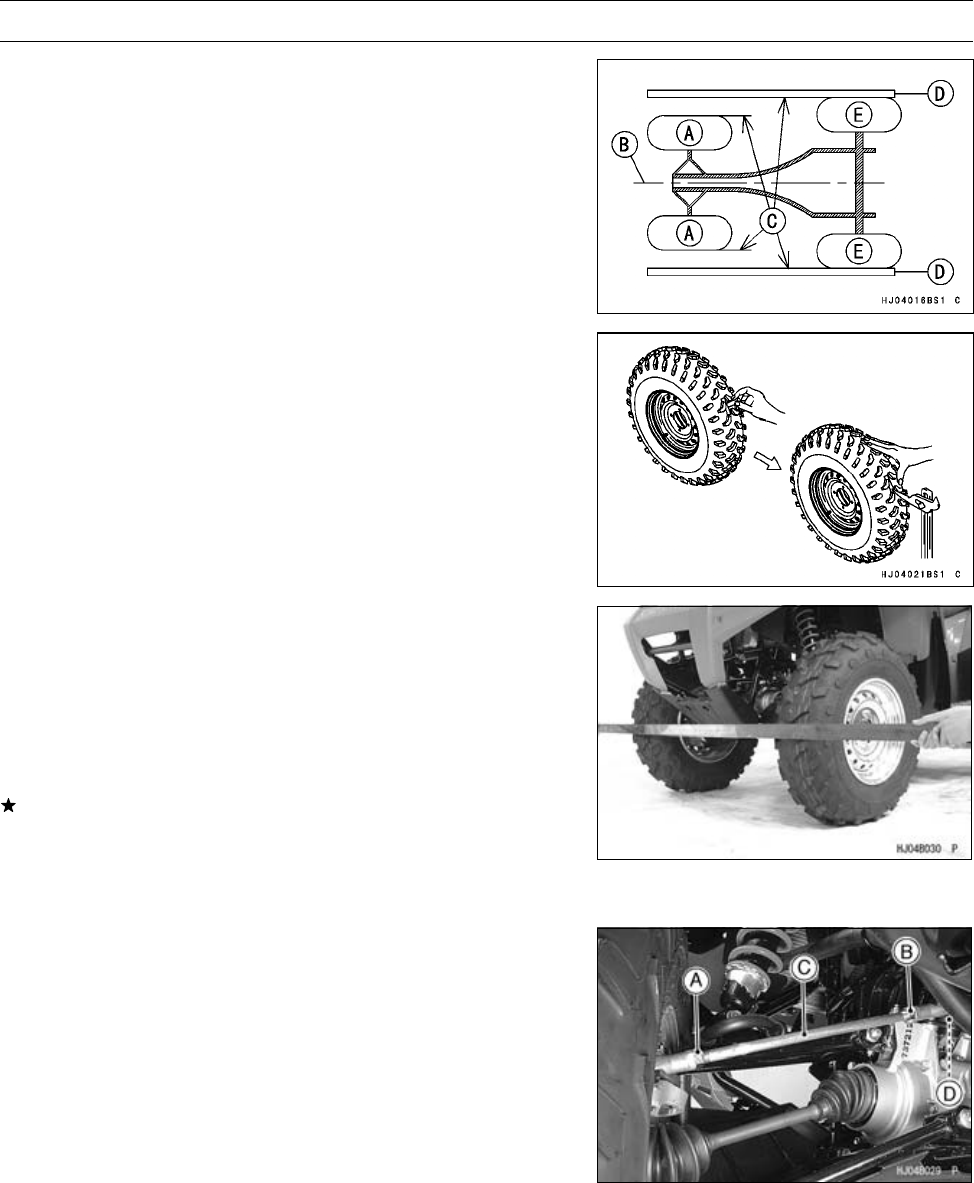
WHEELS/TIRES 10-7
Wheel Alignment
•Repeat the straightedge procedure on the other side of
the vehicle. Now the front wheels are parallel to each
other and to the center line of the vehicle.
Front Wheel [A]
Vehicle Center Line [B]
Parallel each other [C]
Straightedges [D]
Rear Wheels [E]
•Go on to the Toe-in Inspection procedure.
Toe-in Inspection
•Apply a heavy coat of chalk or a paint line near the center
of the front tires.
•Using a needle nose scriber, make a thin mark near the
center of the chalk coating while turning the wheel.
•With the front wheels on the ground, set the handlebar
straight ahead.
•At the level of the axle height, measure the distance be-
tween the scribed or painted lines for both front and rear
of the front tires.
•Subtract the measurement of the front from the measure-
ment of the rear to get the toe-in.
If the toe-in is not in the specified range, go on to the
Toe-in Adjustment procedure.
Toe-in of Front Wheels
Standard: –10 ∼10 mm (–0.39 ∼0.39 in.) at 1G
Toe-in Adjustment
•Loosen the locknuts [A] [B] and turn the tie-rod [C] the
same number of turns on both sides to achieve the spec-
ified toe-in.
NOTE
○The locknut [B] near the L mark [D] on the tie-rod has
left-hand threads. Turn the locknut clockwise for loos-
ening.
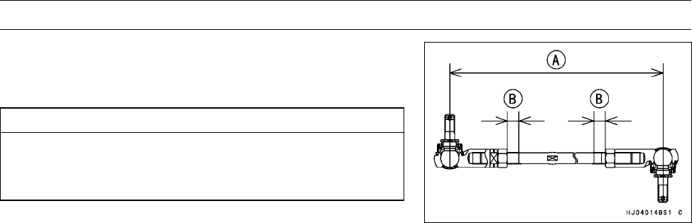
10-8 WHEELS/TIRES
Wheel Alignment
NOTE
○The toe-in will be near the specified value, if the tie-rod
length [A] is 388.5 mm (15.30 in.) on each tie-rod.
CAUTION
Adjust the tie-rod length so that the visible thread
length [B] is even on both ends of the tie-rod. Un-
even thread length could cause tie-rod damage.
•Check the toe-in.
•Tighten:
Torque - Tie-rod Locknuts: 37 N·m (3.8 kgf·m, 27 ft·lb)
•Test ride the vehicle.
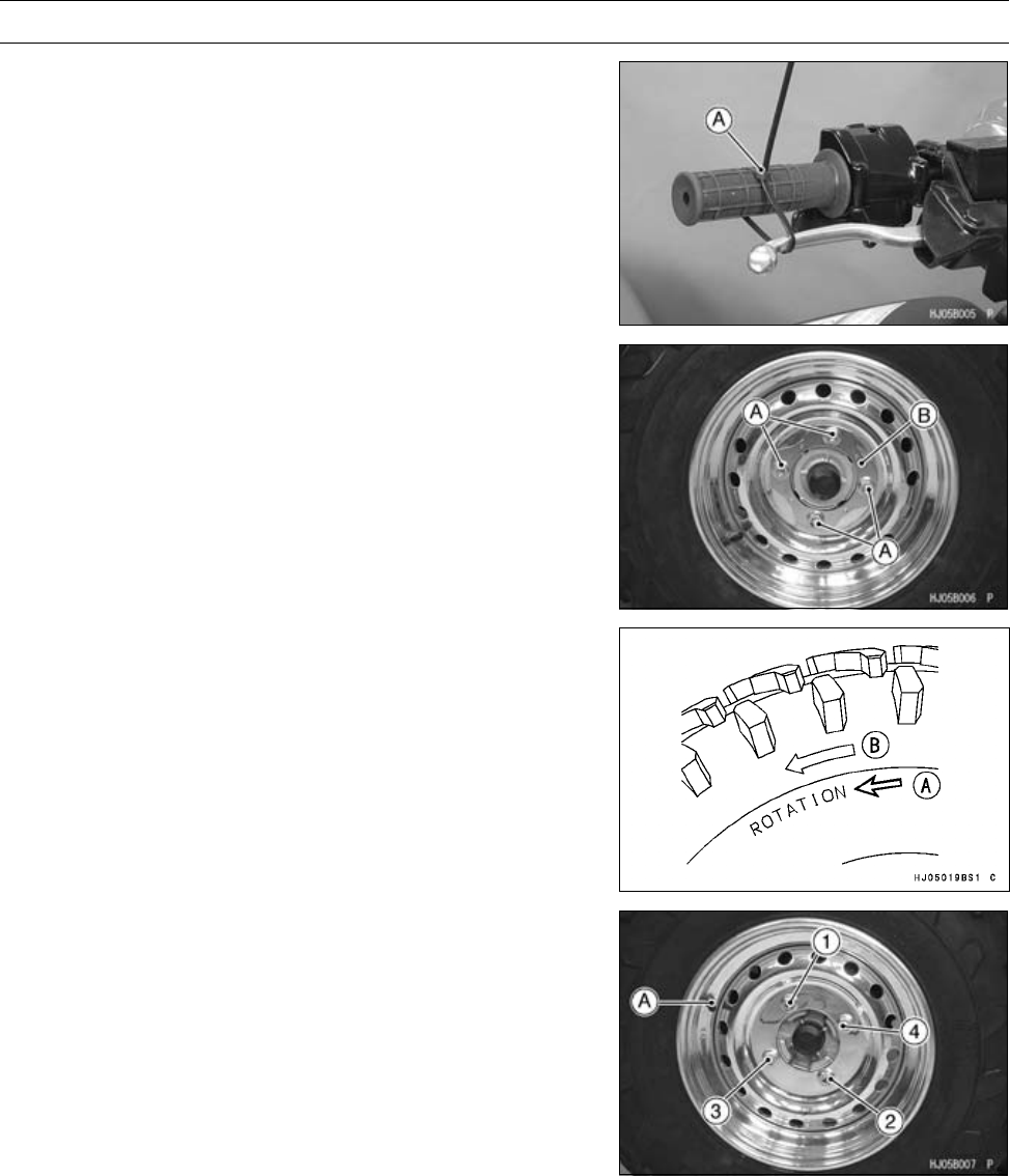
WHEELS/TIRES 10-9
Wheels (Rims)
Wheel Removal
•Squeeze the brake lever slowly and hold it with a band
[A].
•Loosen the wheel nuts [A].
•Support the vehicle on a stand or a jack so that the wheels
are off the ground.
Special Tool - Jack: 57001-1238
•Remove:
Wheel Nuts
Washers (Front Wheel)
Plate [B] (Rear Wheel)
Wheel
Wheel Installation
•Check the tire rotation mark [A] on the tire, and install the
wheel accordingly.
NOTE
○The direction of the tire rotation [B] is shown by an arrow
on the tire sidewall.
•Position the wheel so that the air valve [A] is toward the
outside of the vehicle.
•Wipe dry the surface of the rim.
•Wipe dry the nuts, washers (Front Wheel) and plate (Rear
Wheel).
•First tighten the wheel nuts in a criss-cross pattern.
First Torque - Wheel Nuts: 15 N·m (1.5 kgf·m, 11 ft·lb)
•Finally tighten the wheel nuts in a criss-cross pattern.
Final Torque - Wheel Nuts: 76 N·m (7.7 kgf·m, 56 ft·lb)
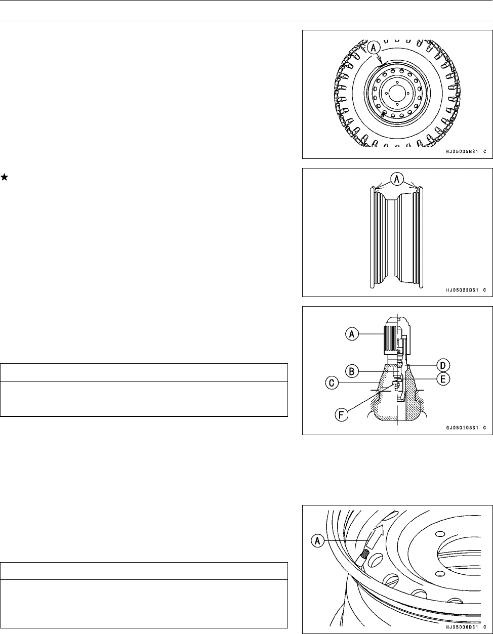
10-10 WHEELS/TIRES
Wheels (Rims)
Wheel (Rim) Inspection
•Examine both sides of the rim for dents [A]. If the rim is
dented, replace it.
If the tire is removed, inspect the air sealing surfaces [A]
of the rim for scratches or nicks. Smooth the sealing sur-
faceswithfineemeryclothifnecessary.
Wheel (Rim) Replacement
•Remove the wheel (see Wheel Removal).
•Disassemble the tire from the rim (see Tire Removal).
○Remove the air valve and discard it.
CAUTION
Replace the air valve whenever the tire is replaced.
Do not reuse the air valve.
Plastic Cap [A]
ValveCore[B]
Stem Seal [C]
Valve Stem [D]
Valve Seat [E]
Valve Opened [F]
•Install a new air valve in the new rim.
○Remove the valve cap, lubricate the stem with a soap and
water solution, and pull [A] the stem through the rim from
the inside out until it snaps into place.
CAUTION
Do not use engine oil or petroleum distillates to lu-
bricate the stem because they will deteriorate the
rubber.
•Mount the tire on the new rim (see Tire Installation).
•Install the wheel (see Wheel Installation).
•Install the air valve cap.
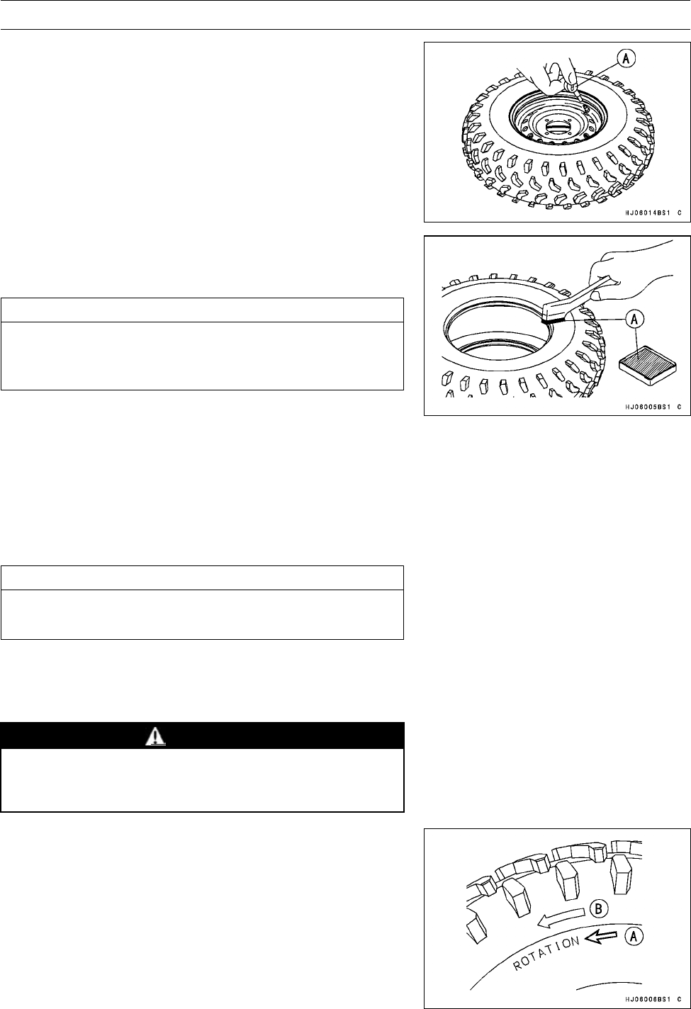
WHEELS/TIRES 10-11
Tires
Tire Removal
•Remove the wheel.
•Unscrew the valve core to deflate the tire.
○Use a proper valve core tool [A].
•Lubricate the tire beads and rim flanges on both sides of
the wheel with a soap and water solution, or water [A].
This helps the tire beads slip off the rim flanges.
CAUTION
Do not lubricate the tire beads and rim flanges with
engine oil or petroleum distillates because they will
deteriorate the tire.
•Removethetirefromtherimusingasuitablecommer-
cially available tire changer.
NOTE
○The tires cannot be removed with hand tools because
they fit the rims tightly.
Tire Installation
•Inspect the rim (see Wheel (Rim) Inspection).
•Replace the air valve with a new one.
CAUTION
Replace the air valve with whenever the tire is re-
placed. Do not reuse the air valve.
•Check the tire for wear and damage (see Tire Inspection
in the Periodic Maintenance chapter).
•Lubricate the tire beads and rim flanges with a soap and
water solution, or water.
WARNING
Do not use the lubricant other than a water and soap
solution, or water to lubricate the tire beads and rim
because it may cause tire separation.
•Check the tire rotation mark [A] on the tire, and install the
tire on the rim accordingly.
○The tires should be installed on the rims so that each air
valve is toward the outside of the vehicle.
NOTE
○The direction of the tire rotation [B] is shown by an arrow
on the tire sidewall.
•Install the tire on the rim using a suitable commercially
available tire changer.
•Lubricate the tire beads again and center the tire on the
rim.
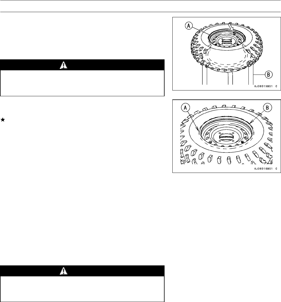
10-12 WHEELS/TIRES
Tires
•Support the wheel rim [A] on a suitable stand [B] to pre-
vent the tire from slipping off.
•Inflate the tire until the tire beads seat on the rim.
Maximum Tire Air Pressure (to seat beads when cold)
Front and Rear 250 kPa (2.5 kgf/cm², 36 psi)
WARNING
Do not inflate the tire to more than the maximum tire
air pressure. Overinflation can explode the tire with
possibility of injury and loss of life.
•Check to see that rim lines [A] on both sides of the tire are
parallel with the rim flanges [B].
If the rim lines and the rim flanges are not parallel, deflate
the tire, lubricate the sealing surfaces again, and reinflate
the tire.
•After the beads are properly seated, check for air leaks.
○Apply a soap and water solution around the tire bead and
check for bubbles.
•Deflate the tire to the specified pressure.
•Check the tire pressure using an air pressure gauge.
NOTE
○Kawasaki provides the air pressure gauge (P/N 52005
-1082) with the owner’s tool kit.
Tire Air Pressure (when cold)
Front 35 kPa (0.35 kgf/cm², 5.0 psi)
Rear 35 kPa (0.35 kgf/cm², 5.0 psi)
•Install the air valve cap.
•Install the wheel (see Wheel Installation).
•Wipe off the soap and water solution on the tire and dry
the tire before operation.
WARNING
Do not operate the vehicle with the water and soap
still around the tire beads. They will cause tire sep-
aration, and a hazardous condition may result.
Tire Inspection
•Refer to the Tire Inspection in the Periodic Maintenance
chapter.
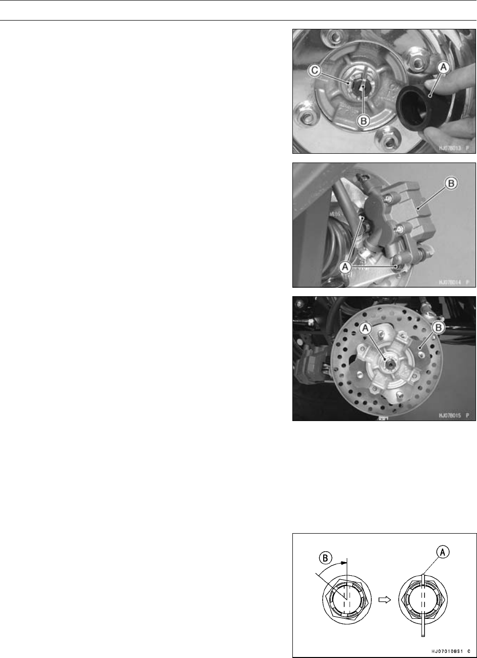
WHEELS/TIRES 10-13
Front Hub
Front Hub Removal
•Remove:
Cap [A]
Cotter Pin [B] (cut)
•Loosen the axle nut [C].
•Remove the front wheel (see Wheel Removal).
•Remove the caliper by taking off the mounting bolts [A],
and let the caliper [B] hang free.
•Remove the axle nut [A], and pull off the front hub [B]
together with the brake disc.
•Separate the brake disc from the front hub (see Front
Brake Disc Removal in the Brakes chapter).
Front Hub Installation
•Install the front brake disc (see Front Brake Disc Installa-
tion in the Brakes chapter).
•Wipe dry the spline portion of the hub.
•Wipe dry the threads and seating surface of the nuts.
•Tighten:
Torque - Front Axle Nuts: 197 N·m (20 kgf·m, 145 ft·lb)
•Insert a new cotter pin [A].
NOTE
○When inserting the cotter pin, if the slots in the nut do
not align with the cotter pin hole in the axle shaft, tighten
the nut clockwise [B] up to next alignment.
○It should be within 30 degree.
○Loosen once and tighten again when the slot goes past
the nearest hole.
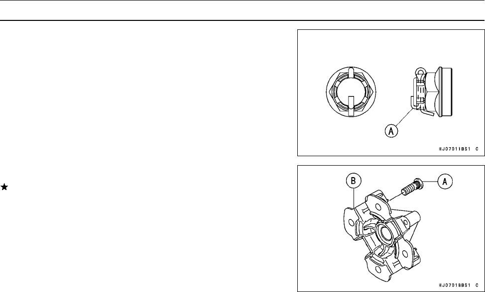
10-14 WHEELS/TIRES
Front Hub
•Bend the cotter pin [A] over the nut.
Front Hub Disassembly/Assembly
If any hub bolt [A] is damaged, replace the hub [B] and
bolts as a unit.
•Remove the hub bolt from the hub using a press.
•Press the hub bolt using a press.
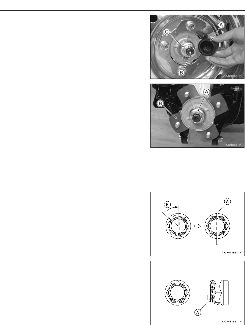
WHEELS/TIRES 10-15
Rear Hub
Rear Hub Removal
•Remove:
Cap [A]
Cotter Pin [B]
•Loosen the axle nut [C].
•Remove:
Wheel (see Wheel Removal)
Axle Nut [A]
Rear Hub [B]
Rear Hub Installation
•Wipe dry the spline portion of the hub.
•Wipe dry the threads and seating surface of the nuts.
•Tighten:
Torque - Rear Axle Nuts: 265 N·m (27 kgf·m, 195 ft·lb)
•Insert a new cotter pin [A].
NOTE
○When inserting the cotter pin, if the slots in the nut do
not align with the cotter pin hole in the axle shaft, tighten
the nut clockwise [B] up to next alignment.
○It should be within 30 degree.
○Loosen once and tighten again when the slot goes past
the nearest hole.
•Bend the cotter pin [A] over the nut.
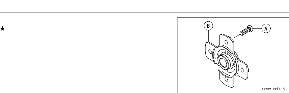
10-16 WHEELS/TIRES
Rear Hub
Rear Hub Disassembly/Assembly
If any hub bolt [A] is damaged, replace the hub [B] and
bolts as a unit.
•Remove the hub bolt from the hub using a press.
•Press the hub bolt using a press.

FINAL DRIVE 11-1
11
Final Drive
Table of Contents
Exploded View........................................................................................................................ 11-3
Specifications ......................................................................................................................... 11-10
Special Tools .......................................................................................................................... 11-11
Output Bevel Gears ................................................................................................................ 11-14
Output Drive Bevel Gear Removal.................................................................................... 11-14
Output Drive Bevel Gear Installation................................................................................. 11-14
Output Drive Bevel Gear Disassembly ............................................................................. 11-15
Output Drive Bevel Gear Assembly .................................................................................. 11-17
Output Driven Bevel Gear Removal.................................................................................. 11-17
Output Driven Bevel Gear Installation............................................................................... 11-18
Output Driven Bevel Gear Disassembly ........................................................................... 11-18
Output Driven Bevel Gear Assembly ................................................................................ 11-19
Output Bevel Gears Adjustment ....................................................................................... 11-20
Bevel Gears Inspection..................................................................................................... 11-24
Front Propeller Shaft .............................................................................................................. 11-25
Front Propeller Shaft Removal.......................................................................................... 11-25
Front Propeller Shaft Installation....................................................................................... 11-25
Front Axle ............................................................................................................................... 11-26
Front Axle Removal .......................................................................................................... 11-26
Front Axle Installation ....................................................................................................... 11-26
Front Axle Joint Boot Inspection ....................................................................................... 11-26
Front Axle Joint Boot Replacement .................................................................................. 11-26
Front Final Gear Case............................................................................................................ 11-33
Front Final Gear Case Oil Level Inspection...................................................................... 11-33
Front Final Gear Case Oil Change ................................................................................... 11-33
Variable Differential Control Lever Play Inspection........................................................... 11-33
Variable Differential Control Lever Play Adjustment ......................................................... 11-33
Variable Differential Control Lever Removal ..................................................................... 11-33
Variable Differential Control Lever Installation .................................................................. 11-34
Variable Differential Control Cable Installation.................................................................. 11-34
Variable Differential Control Cable Lubrication ................................................................. 11-34
Variable Differential Control Cable Inspection .................................................................. 11-35
Front Final Gear Case Removal ....................................................................................... 11-35
Front Final Gear Case Installation .................................................................................... 11-36
Front Final Gear Case Disassembly ................................................................................. 11-37
Front Final Gear Case Coupling Inspection...................................................................... 11-39
Front Final Gear Case Assembly...................................................................................... 11-39
Oil Seal Installation ........................................................................................................... 11-43
Ring Gear Disassembly .................................................................................................... 11-44
Ring Gear Assembly ......................................................................................................... 11-44
LSD Clutch Torque Inspection .......................................................................................... 11-45
Pinion Gear Unit Disassembly .......................................................................................... 11-45
Pinion Gear Unit Assembly ............................................................................................... 11-46
Front Final Bevel Gear Adjustment................................................................................... 11-46
Bevel Gear Inspection....................................................................................................... 11-50
Differential Gear Inspection .............................................................................................. 11-50
Rear Propeller Shaft............................................................................................................... 11-52
Rear Propeller Shaft Removal .......................................................................................... 11-52
Rear Propeller Shaft Installation ....................................................................................... 11-52
Rear Propeller Shaft Joint Boot Inspection....................................................................... 11-53

11-2 FINAL DRIVE
Rear Propeller Shaft Inspection........................................................................................ 11-53
Rear Axle................................................................................................................................ 11-54
Rear Axle Removal ........................................................................................................... 11-54
Rear Axle Installation ........................................................................................................ 11-54
Rear Axle Joint Boot Inspection........................................................................................ 11-54
Rear Axle Joint Boot Replacement ................................................................................... 11-55
Rear Final Gear Case............................................................................................................. 11-61
Rear Final Gear Case Oil Level Inspection....................................................................... 11-61
Rear Final Gear Case Oil Change .................................................................................... 11-61
Rear Final Gear Case Removal........................................................................................ 11-61
Rear Final Gear Case Installation..................................................................................... 11-63
Rear Final Gear Case Disassembly.................................................................................. 11-63
Rear Final Gear Case Right Cover Assembly .................................................................. 11-66
Rear Final Gear Case Front Cover Assembly .................................................................. 11-66
Rear Final Gear Case Assembly ...................................................................................... 11-66
Rear Final Bevel Gear Adjustment ................................................................................... 11-69
Pinion Gear Unit Disassembly .......................................................................................... 11-73
Pinion Gear Unit Assembly ............................................................................................... 11-73
Bearing and Oil Seal............................................................................................................... 11-74
Ball or Needle Bearing Inspection..................................................................................... 11-74
Oil Seal Inspection............................................................................................................ 11-75

FINAL DRIVE 11-3
Exploded View
Dummy Page
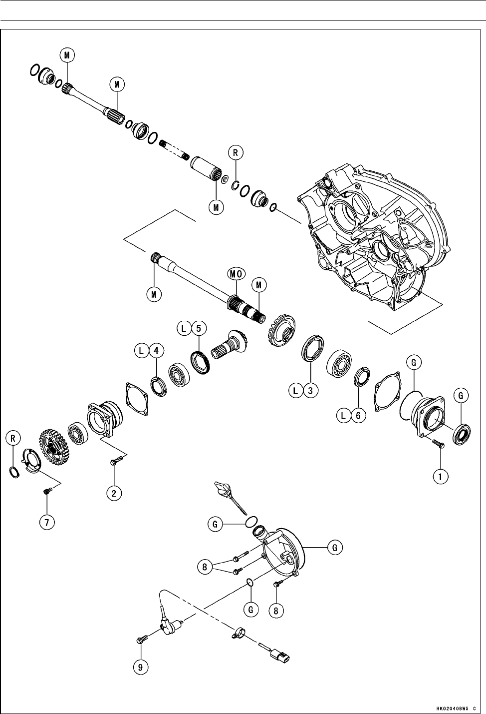
11-4 FINAL DRIVE
Exploded View

FINAL DRIVE 11-5
Exploded View
Torque
No. Fastener N·m kgf·m ft·lb Remarks
1Output Driven Bevel Gear Housing Bolts 26 2.6 20
2Output Drive Bevel Gear Housing Bolts 26 2.6 20
3Bearing Holder 137 14 101 L
4Bevel Gear Holder Nut 157 16 116 L
5Bearing Holder 120 12 88 L
6Output Shaft Holder Nut 157 16 116 L
7Rotor Mounting Bolts 12 1.2 106 in·lb
8Output Drive Bevel Gear Cover Bolts 8.8 0.90 78 in·lb
9Forward/Reverse Detecting Sensor Mounting Bolt 15 1.5 11
G: Apply grease.
L: Apply a non-permanent locking agent.
M: Apply molybdenum disulfide grease.
MO: Apply molybdenum disulfide oil (mixture of the engine oil and molybdenum disulfide grease in
a weight ratio: 10 : 1).
R: Replacement Parts
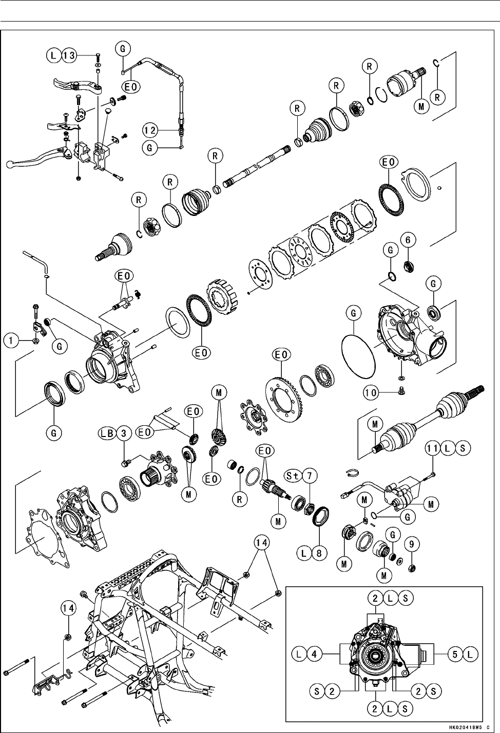
11-6 FINAL DRIVE
Exploded View

FINAL DRIVE 11-7
Exploded View
Torque
No. Fastener N·m kgf·m ft·lb Remarks
1Variable Differential Control Shift Shaft Lever Bolt 8.8 0.90 78 in·lb
2Front Final Gear Case Left Cover Bolts (M6) 9.8 1.0 87 in·lb L(4),S
3Ring Gear Bolts 57 5.8 42 LB
4Front Final Gear Case Center Cover Bolts (M6) 9.8 1.0 87 in·lb L
5Front Final Gear Case Center Cover Bolts (M8) 24 2.4 17 L
6Front Final Gear Case Oil Filler Cap 29 3.0 22
7Pinion Gear Bearing Holder Nut 127 13 94 St
8Pinion Gear Bearing Holder 137 14 101 L
9Front Final Gear Case Coupling Nut 25 2.5 18
10 Front Final Gear Case Oil Drain Bolt 15 1.5 11
11 2WD/4WD Actuator Mounting Bolts 9.8 1.0 87 in·lb L, S
12 Variable Differential Control Cable Locknut 16 1.6 12
13 Variable Differential Control Lever Bolt 3.4 0.35 30 in·lb L
14 Front Final Gear Case Nuts 59 6.0 44
EO: Apply engine oil.
G: Apply grease.
L: Apply a non-permanent locking agent.
LB: Apply a non-permanent locking agent (Three Bond TB2471 Blue).
M: Apply molybdenum disulfide grease.
R: Replacement Parts
S: Follow the specific tightening sequence.
St: Stake the fasteners to prevent loosening.
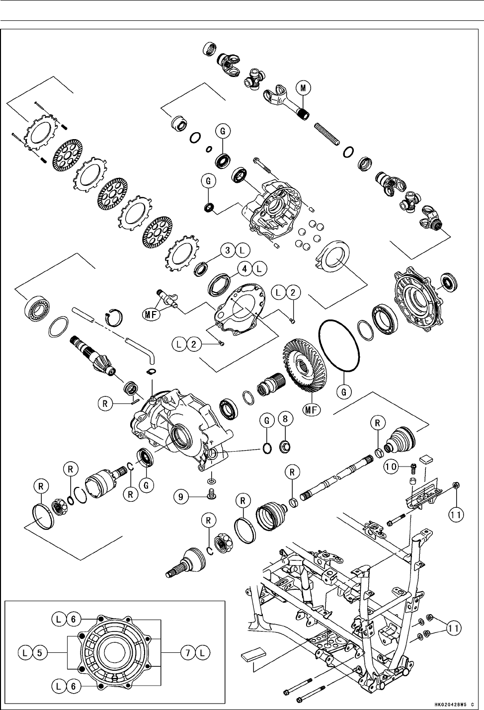
11-8 FINAL DRIVE
Exploded View

FINAL DRIVE 11-9
Exploded View
Torque
No. Fastener N·m kgf·m ft·lb Remarks
1Rear Final Gear Case Front Cover Bolts 24 2.4 18
2Rear Final Gear Case Gasket Screws 1.25 0.13 11 in·lb L
3Pinion Gear Bearing Holder Nut 157 16 116 L
4Pinion Gear Bearing Holder 137 14 101 L
5Rear Final Gear Case Right Cover Bolts (M12) 95 9.7 70 L
6Rear Final Gear Case Right Cover Bolts (M10) 49 5.0 36 L
7Rear Final Gear Case Right Cover Bolts (M8) 24 2.4 18 L
8Rear Final Gear Case Oil Filler Cap 29 3.0 21
9Rear Final Gear Case Oil Drain Bolt 15 1.5 11
10 Rear Final Gear Case Bracket Bolts 59 6.0 44
11 Rear Final Gear Case Nuts 91 9.3 67
G: Apply grease.
L: Apply a non-permanent locking agent.
M: Apply molybdenum disulfide grease.
MF: Apply gear oil (MOBIL FLUID 424) or equivalent oil.
R: Replacement Parts
S: Follow the specific tightening sequence.

11-10 FINAL DRIVE
Specifications
Item Standard Service Limit
Output Bevel Gear Case
Output Bevel Gear Backlash 0.05 ∼0.11 mm (0.0020 ∼0.0043 in.) –––
(at output drive shaft spline)
Front Final Gear Case
Gear Case Oil (same engine oil):
Type API SF or SG –––
API SH, SJ or SL with JASO MA –––
Viscosity SAE 10W-40 –––
Oil Level Filler opening bottom –––
Capacity 0.40 L (0.42 US qt) –––
Coupling Bushing Inside Diameter 13.000 ∼13.018 mm (0.5118 ∼0.5125 in.) 13.048 mm
(0.5137 in.)
LSD Clutch Torque:
(when variable differential control
lever is released.)
15 ∼20 N·m (1.5 ∼2.0 kgf·m, 11 ∼14 ft·lb) –––
(when variable differential control
lever is pulled in.)
157 N·m (16 kgf·m, 116 ft·lb) or more –––
Bevel Gear Backlash 0.10 ∼0.20 mm (0.004 ∼0.008 in.) –––
(at pinion gear spline)
Rear Final Gear Case
Gear Case Oil:
Type MOBIL Fluid 424 or CITGO TRANSGARD
TRACTOR HYDRAULIC FLUID
–––
Oil Level Filler opening bottom –––
Capacity 0.72 L (0.76 US qt) –––
Rear Final Bevel Gear Backlash 0.04 ∼0.17 mm (0.002 ∼0.007 in.) –––
(at pinion gear spline)
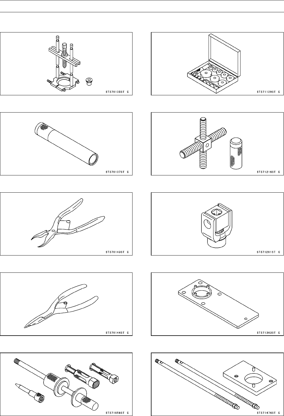
FINAL DRIVE 11-11
Special Tools
Bearing Puller:
57001-135
Steering Stem Bearing Driver:
57001-137
Inside Circlip Pliers:
57001-143
Outside Circlip Pliers:
57001-144
Oil Seal & Bearing Remover:
57001-1058
Bearing Driver Set:
57001-1129
Rotor Puller, M16/M18/M20/M22 × 1.5:
57001-1216
Pinion Gear Holder, m1.0:
57001-1281
Socket Wrench:
57001-1363
Holder & Guide Arbor:
57001-1476
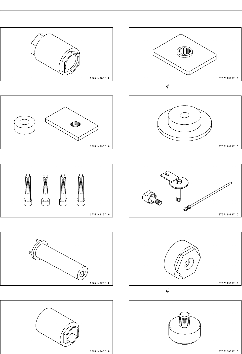
11-12 FINAL DRIVE
Special Tools
Socket Wrench, Hex 50:
57001-1478
Output Shaft Holder & Spacer, m1.25:
57001-1479
Nut Holding Bolts:
57001-1481
Socket Wench:
57001-1482
Socket Wrench, Hex 41:
57001-1484
Pinion Gear Holder, m1.0:
57001-1485
Bearing Driver, 54.3:
57001-1488
Gear Holder & Socket Wrench, Hex 24:
57001-1489
Hexagon Wench, Hex 41:
57001-1491
OilSealDriver, 18.5:
57001-1505
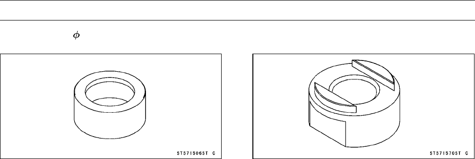
FINAL DRIVE 11-13
Special Tools
OilSealDriver, 70:
57001-1506
Output Shaft Holder:
57001-1570
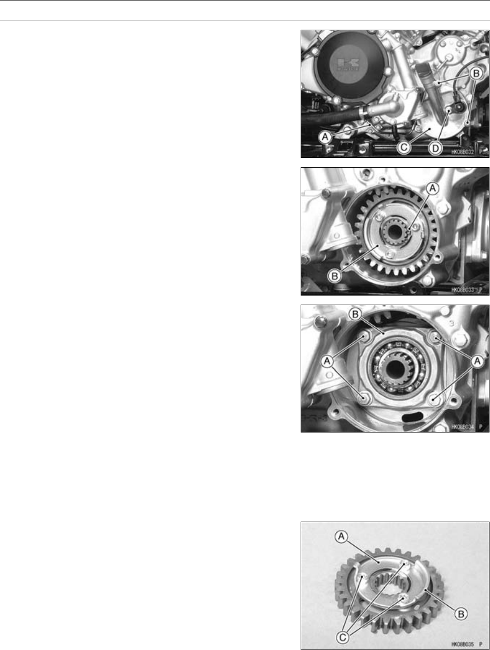
11-14 FINAL DRIVE
Output Bevel Gears
Output Drive Bevel Gear Removal
•Remove:
Oil Pipe [A] (Engine Left and Outside, see Oil Pipe Re-
moval in the Engine Lubrication System chapter)
Output Drive Bevel Gear Cover Bolts [B]
Output Drive Bevel Gear Cover [C]
Forward/Reverse Detecting Sensor Mounting Bolt [D]
•Remove:
Circlip [A]
Special Tool - Outside Circlip Pliers: 57001-144
•Remove:
Output Drive Idle Gear [B]
•Remove:
Output Drive Bevel Gear Housing Bolts [A]
Output Drive Bevel Gear Housing [B]
Output Drive Bevel Gear Installation
•Install the output drive bevel gear housing.
•Tighten:
Torque - Output Drive Bevel Gear Housing Bolts: 26 N·m
(2.6 kgf·m, 20 ft·lb)
•Install the rotor [A] so that the projections [B] face out-
ward.
•Tighten:
Torque - Rotor Mounting Bolts [C]: 12 N·m (1.2 kgf·m, 106
in·lb)
•Install:
Output Drive Idle Gear
New Circlip
Special Tool - Outside Circlip Pliers: 57001-144
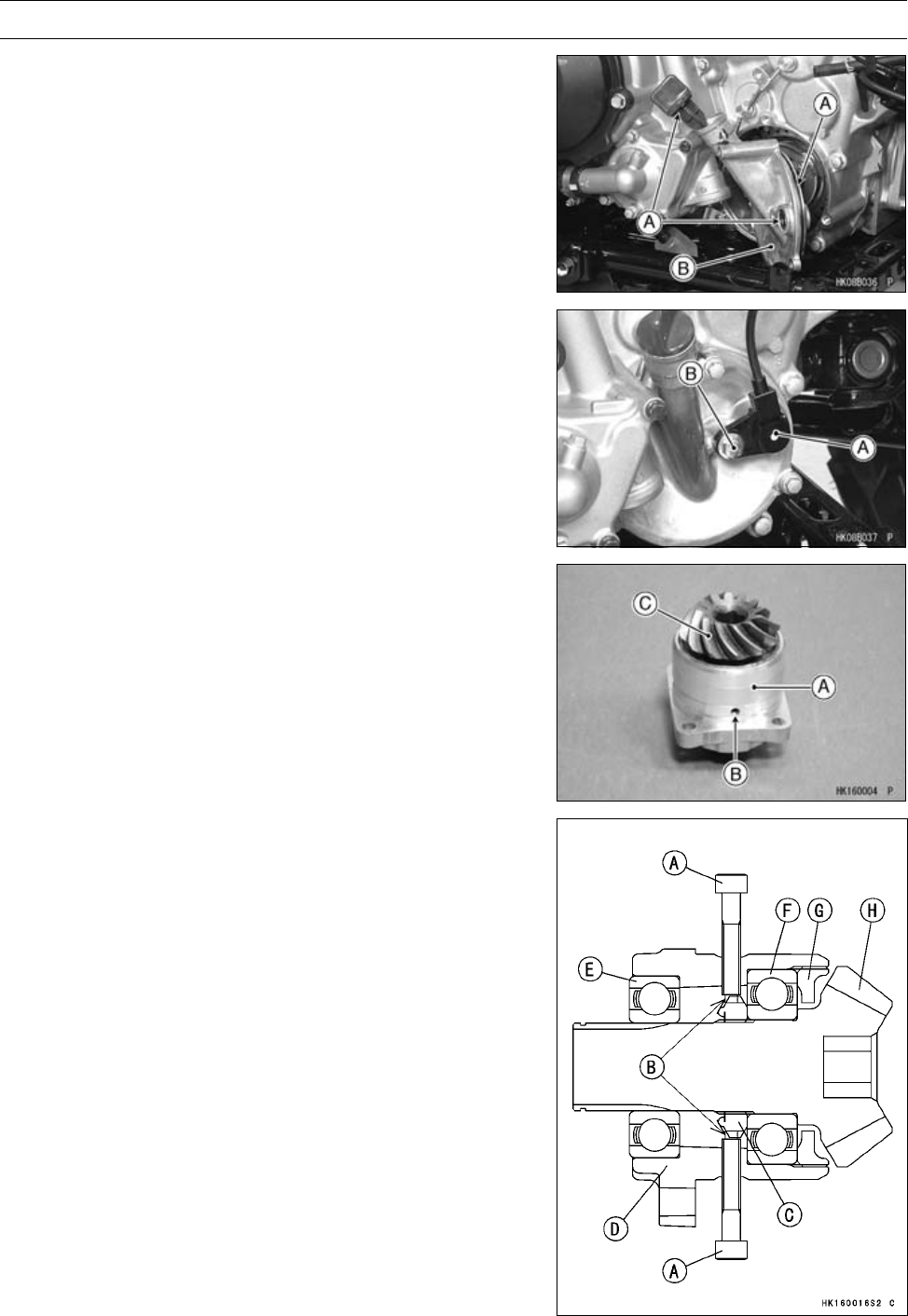
FINAL DRIVE 11-15
Output Bevel Gears
•Apply grease:
O-rings [A]
•Install:
Output Drive Bevel Gear Cover [B]
Oil Pipe (see Oil Pipe Installation in the Engine Luburi-
cation chapter)
•Tighten:
Torque - Output Drive Bevel Gear Cover Bolts: 8.8 N·m
(0.90 kgf·m, 78 in·lb)
•Install:
Forward/Reverse Detecting Sensor [A]
•Tighten:
Torque - Forward/Reverse Detecting Sensor Mounting Bolt
[B]: 15 N·m (1.5 kgf·m, 11 ft·lb)
Output Drive Bevel Gear Disassembly
•Remove:
Output Drive Bevel Gear Housing [A] (see Output Drive
Bevel Gear Removal)
•Look through the hole [B] in the housing.
•Turn the bevel gear [C] until the groove of the output drive
bevel gear holder nut is seen.
•Tighten the nut holding bolts [A] (4) securely into the
grooves [B] of the bevel gear holder nut [C] in the output
drive bevel gear housing.
Special Tool - Nut Holding Bolts: 57001-1481
[D] Output Drive Bevel Gear Housing
[E] Outer Ball Bearing
[F] Inner Ball Bearing
[G] Bearing Holder
[H] Output Drive Bevel Gear
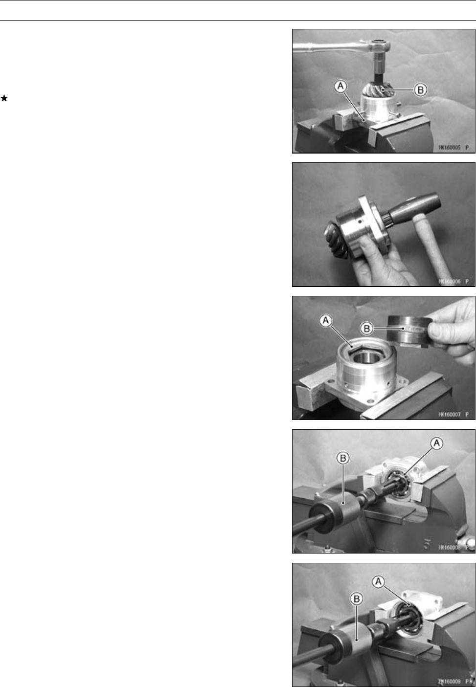
11-16 FINAL DRIVE
Output Bevel Gears
•Hold the output drive bevel gear housing [A] in a vise.
•Loosen the bevel gear [B] using an Allen wrench about
four rotations.
•Remove one nut holding bolt, and look at through the
hole.
If the groove of the bevel gear holder nut is not seen,
loosen the other three bolts.
•Drive the gear shaft end using a copper mallet until the
grooves of the bearing holder nut can be seen again.
•Retighten the nut holding bolts (4) securely into the
groove of the bevel gear holder nut in the output drive
bevel gear housing.
Special Tool - Nut Holding Bolts: 57001-1481
•Repeat the above procedure, and remove the bevel gear
from the housing.
•Remove the bearing holder [A] using the hexagon wrench
[B].
Special Tool - Hexagon Wrench, Hex 41: 57001-1491
○If it is difficult to break free the holder, apply the heat to it
to softer the locking agent.
•Remove:
Outer Ball Bearing [A]
Special Tool - Oil Seal & Bearing Remover [B]: 57001-1058
•Remove:
Output Drive Bevel Gear Holder Nut
Inner Ball Bearing [A]
Special Tool - Oil Seal & Bearing Remover [B]: 57001-1058
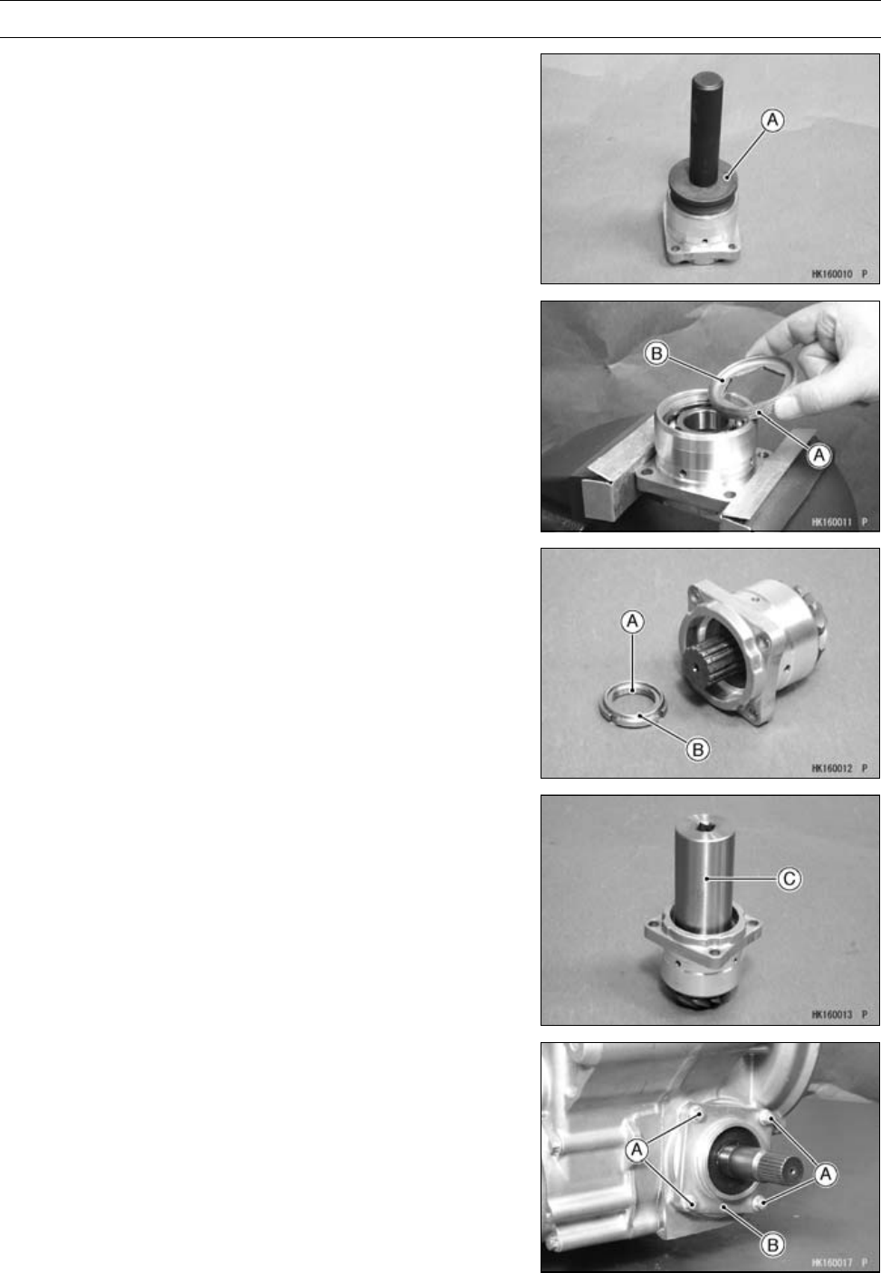
FINAL DRIVE 11-17
Output Bevel Gears
Output Drive Bevel Gear Assembly
•Press the new inner ball bearing until it is bottomed.
Special Tool - Bearing Driver Set [A]: 57001-1129
•Apply a non-permanent locking agent to the threads of
the bearing holder [A] and tighten it so that the deep side
[B] faces outward.
Torque - Bearing Holder: 120 N·m (12 kgf·m, 88 ft·lb)
•Press the output drive bevel gear until it is bottomed.
•Apply a non-permanent locking agent to the threads of
the bevel gear holder nut [A] and tighten it so that the
projection side [B] faces outward.
Special Tool - Socket Wrench: 57001-1482 [C]
Torque - Bevel Gear Holder Nut: 157 N·m (16 kgf·m, 116
ft·lb)
•Press the new outer ball bearing until it is bottomed.
Output Driven Bevel Gear Removal
•Remove:
Engine (see Engine Removal in the Engine Removal/In-
stallation chapter)
Output Driven Bevel Gear Housing Bolts [A]
Output Driven Bevel Gear Housing [B]
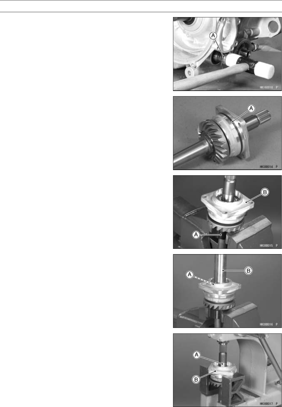
11-18 FINAL DRIVE
Output Bevel Gears
•Tap lightly the front end [A] of the output driven bevel gear
shaft using a plastic mallet.
○The output driven bevel gear shaft assembly comes off
with the housing.
Output Driven Bevel Gear Installation
•Apply grease:
O-ring [A]
•Install the output driven bevel gear shaft assembly.
•Tighten:
Torque - Output Driven Bevel Gear Housing Bolts: 26 N·m
(2.6 kgf·m, 20 ft·lb)
Output Driven Bevel Gear Disassembly
•Remove:
Output Driven Bevel Gear Housing Assembly (see Out-
put Driven Bevel Gear Removal)
Oil Seal
•Hold the output shaft holder [A] in a vise, and set the
housing assembly [B] on the holder.
Special Tool - Output Shaft Holder: 57001-1570
•Remove:
Output Shaft Holder Nut [A]
Special Tool - Socket Wrench [B]: 57001-1482
•Remove the output shaft [A] from the housing [B] using a
press.
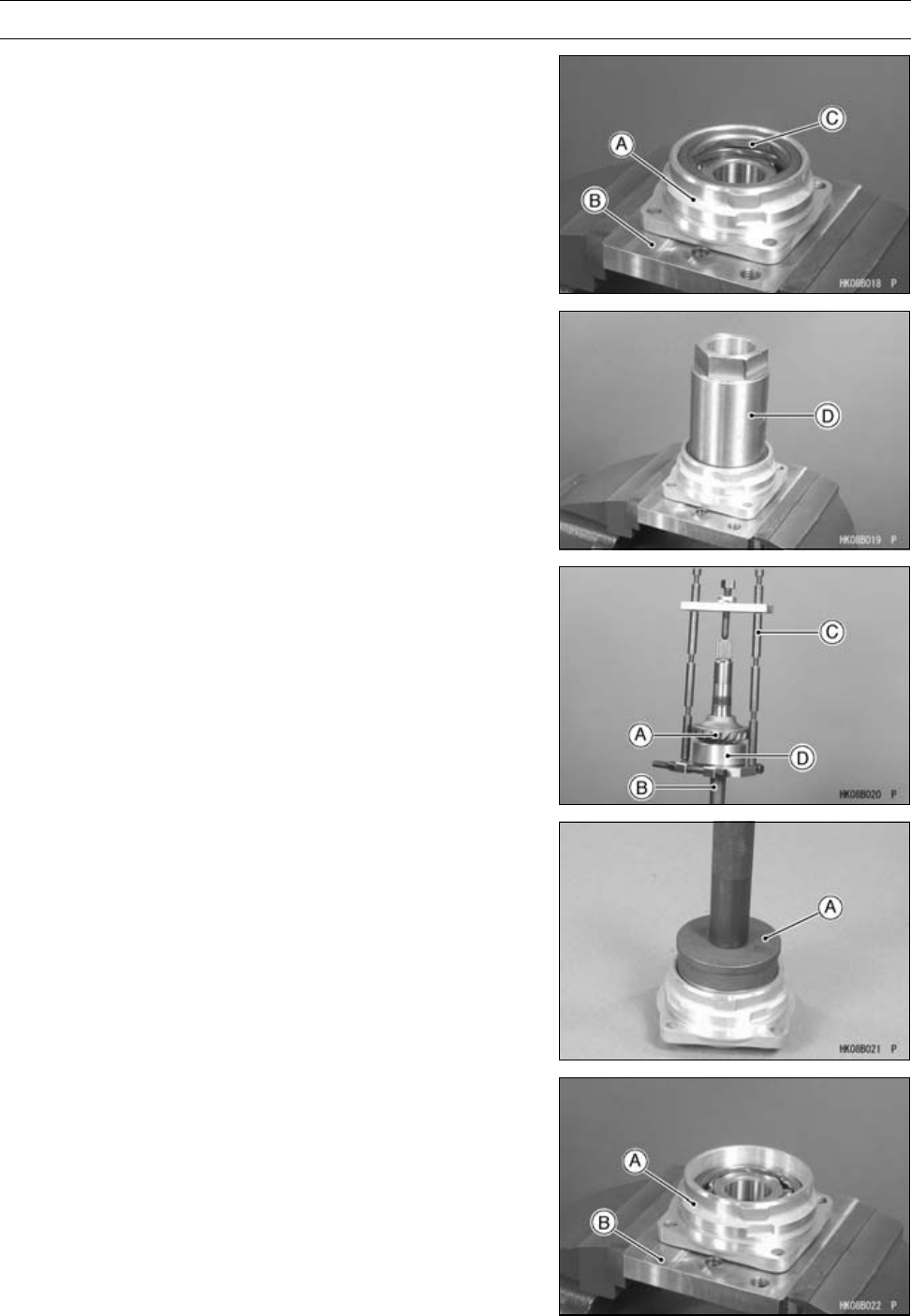
FINAL DRIVE 11-19
Output Bevel Gears
•Hold the housing assembly [A] with the holder [B] in a
vise.
Special Tool - Holder & Guide Arbor: 57001-1476
•Remove:
Bearing Holder [C]
Special Tool - Socket Wrench, Hex 50 [D]: 57001-1478
○If the holder seems too difficult to break free, apply heat
to softer the locking agent.
•Remove:
Ball Bearing
Special Tool - Oil Seal & Bearing Remover: 57001-1058
•Remove the output driven bevel gear [A] from the output
shaft [B] using the bearing puller [C] and spacer [D].
Special Tools - Bearing Puller: 57001-135
Output Shaft Holder & Spacer, m1.25: 57001
-1479
Output Driven Bevel Gear Assembly
•Press the new ball bearing until it is bottomed.
Special Tool - Bearing Driver Set [A]: 57001-1129
•Hold the housing assembly [A] with the holder [B] in a
vise.
Special Tool - Holder & Guide Arbor: 57001-1476
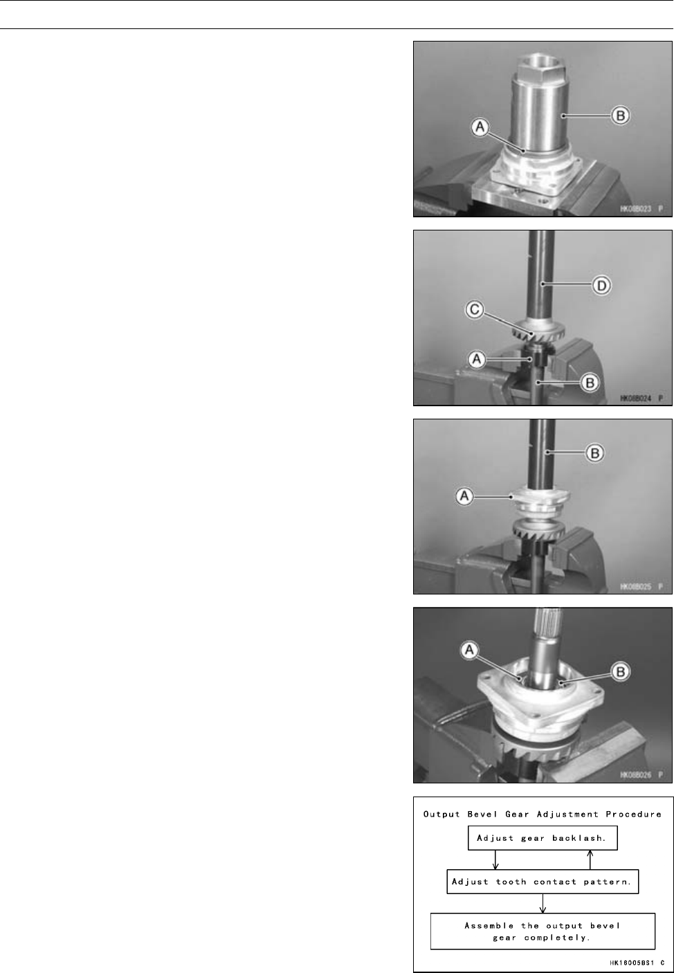
11-20 FINAL DRIVE
Output Bevel Gears
•Apply a non-permanent locking agent to the threads of
the bearing holder [A] and tighten it.
Special Tool - Socket Wrench, Hex 50 [B]: 57001-1478
Torque - Bearing Holder: 137 N·m (14 kgf·m, 101 ft·lb)
•Hold the output shaft holder [A] in a vise, and set the
output shaft [B] on the holder.
Special Tool - Output Shaft Holder: 57001-1570
•Press the output driven bevel gear [C] using the steering
stem bearing driver [D] until it is bottomed.
Special Tool - Steering Stem Bearing Driver: 57001-137
•Press the housing assembly [A] using the steering stem
bearing driver [B] until it is bottomed.
Special Tool - Steering Stem Bearing Driver: 57001-137
•Apply a non-permanent locking agent to the threads of
the output shaft holder nut [A] and tighten it so that the
projection side [B] faces outward.
Special Tool - Socket Wrench: 57001-1482
Torque - Output Shaft Holder Nut: 157 N·m (16 kgf·m, 116
ft·lb)
•Apply grease to the oil seal and press it so that it is flush
with the end surface of the housing.
Output Bevel Gears Adjustment
The backlash and tooth contact pattern of the bevel
gears must be correct to prevent the gears from making
noise and being damaged.
When replacing any one of the backlash-related parts, be
sure to check and adjust the backlash and tooth contact.
First adjust the backlash, and then tooth contact by replac-
ing shims.
These two adjustments are of critical importance and
must be carried out in the correct sequence, using the
procedures shown.
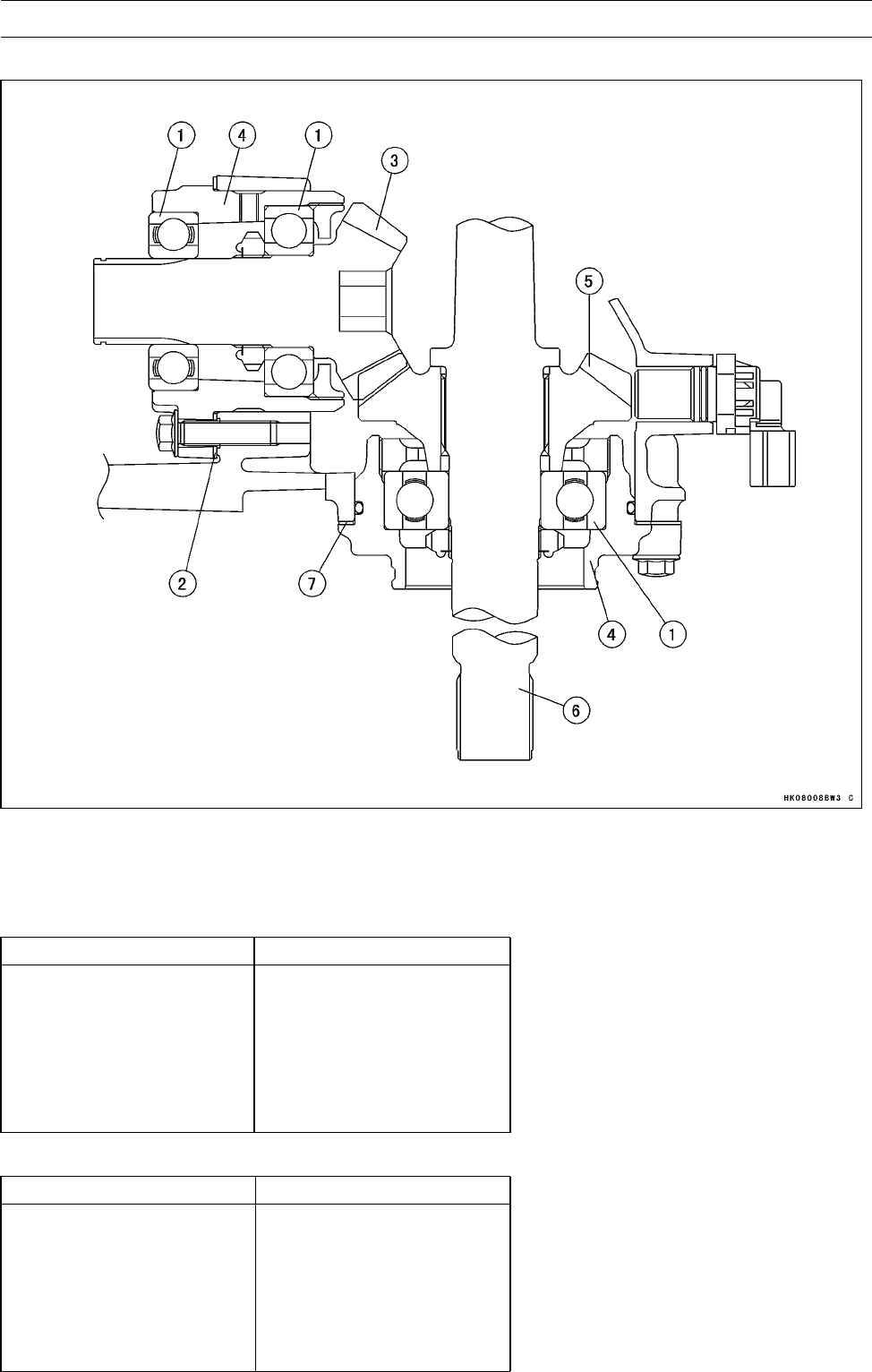
FINAL DRIVE 11-21
Output Bevel Gears
Output Bevel Gear (Backlash-related Parts)
1. Ball Bearings
2. Drive Bevel Gear Shims
3. Output Drive Bevel Gear
4. Bearing Housings
5. Output Driven Bevel Gear
6. Output Driven Shaft
7. Driven Bevel Gear Shims
Drive Bevel Gear Shims for Tooth Contact Adjustment
Thickness Part Number
0.15 mm (0.006 in.) 92180-1311
0.2 mm (0.008 in.) 92180-1312
0.5 mm (0.020 in.) 92180-1313
0.8 mm (0.031 in.) 92180-1314
1.0 mm (0.039 in.) 92180-1351
1.2 mm (0.047 in.) 92180-1352
Driven Bevel Gear Shims for Backlash Adjustment
Thickness Part Number
0.15 mm (0.006 in.) 92180-1307
0.2 mm (0.008 in.) 92180-1308
0.5 mm (0.020 in.) 92180-1309
0.8 mm (0.031 in.) 92180-1310
1.0 mm (0.039 in.) 92180-1349
1.2 mm (0.047 in.) 92180-1350
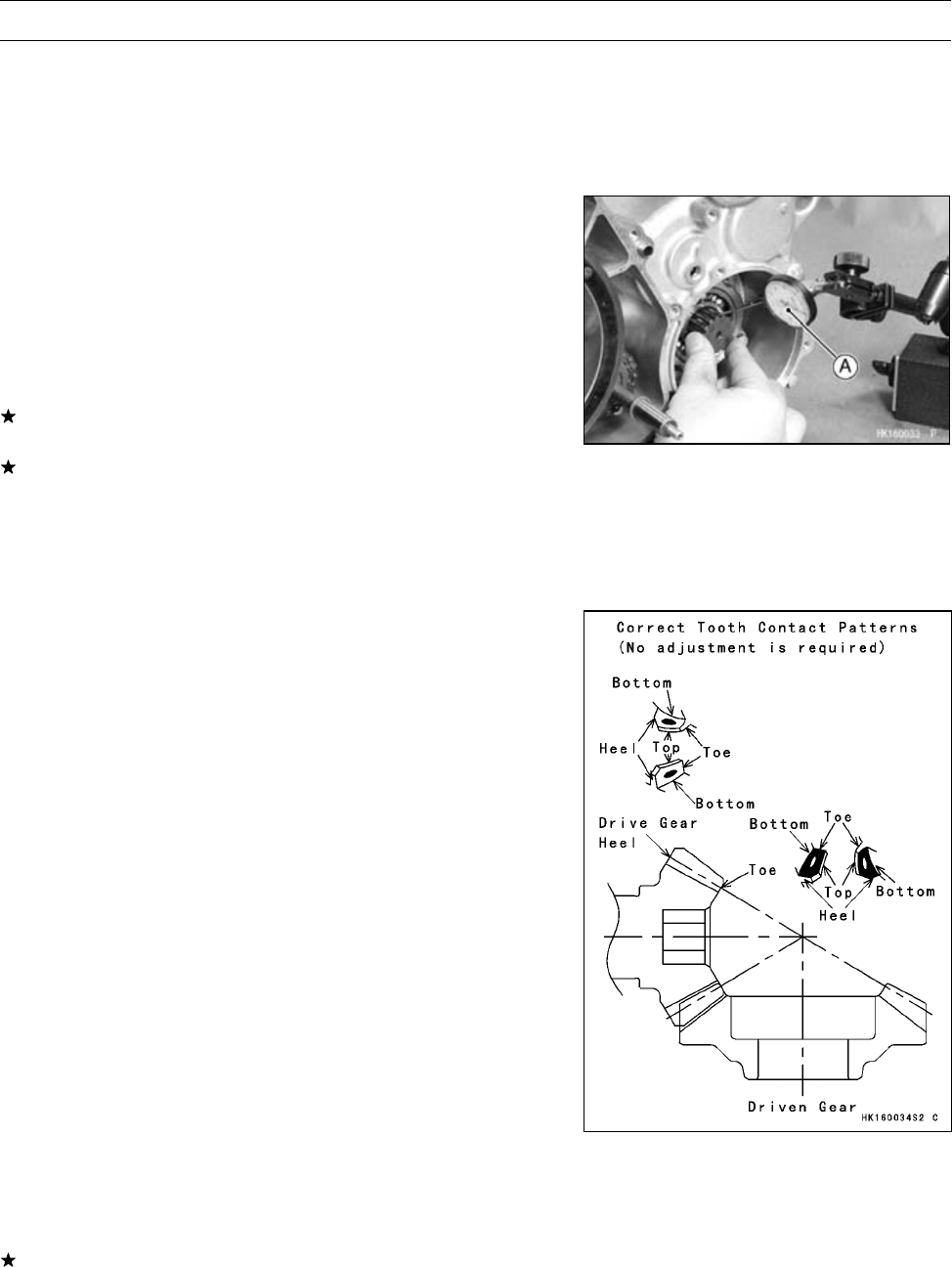
11-22 FINAL DRIVE
Output Bevel Gears
Bevel Gear Backlash Adjustment
○The amount of backlash is influenced by driven bevel gear
position more than by drive bevel gear position.
•Remove the output drive idle gear (see Output Drive
Bevel Gear Removal).
•Set up a dial gauge [A] against the output drive shaft
spline groove to check gear backlash.
○To measure the backlash, turn the shaft clockwise and
counterclockwise slightly so as not to move the mate gear.
A rod can be inserted through the lower hole of the hous-
ing and into contact with driven gear. This may help to
hold it still. The difference between the highest and low-
est gauge reading is the amount of backlash.
If the backlash is not within the limit, replace the shim(s)
at the driven bevel gear.
Change the thickness a little at a time.
•Recheck the backlash, and readjust as necessary.
Output Bevel Gear Backlash
Standard: 0.05 ∼0.11 mm (0.0020 ∼0.0043 in.) (at
output drive shaft spline)
Tooth Contact Adjustment
○Tooth contact location is influenced by drive gear position
more than by driven gear position.
•Clean any dirt and oil off the bevel gear teeth.
•Apply checking compound to 4 or 5 teeth on the output
driven bevel gear.
NOTE
○Apply checking compound to the teeth in a thin, even
coat with a fairly stiff paint brush. If painted too thickly,
the exact tooth pattern may not appear.
○The checking compound must be smooth and firm with
the consistency of tooth paste.
○Special compounds are available from automotive sup-
ply stores for the purpose of checking differential gear
tooth patterns and contact. Use this for checking the
bevel gears.
•Turn the output driven shaft for 3 or 4 turns in the drive
and reverse (coast) directions, while creating a drag on
the drive bevel gear shaft.
•Check the drive pattern and coast pattern of the bevel
gear teeth. The tooth contact patterns of both drive and
coast sides should be centrally located between the top
and bottom of the tooth, and a little closer to the toe of the
tooth.
If the tooth contact pattern is incorrect, replace the shim(s)
at the drive bevel gear and shim(s) at the driven bevel
gear, following the examples shown. Then erase the tooth
contact patterns, and check them again. Also check the
backlash every time the shims are replaced. Repeat the
shim change procedure as necessary.
NOTE
○If the backlash is out of the standard range after chang-
ing shims, correct the backlash before checking the
tooth contact pattern.
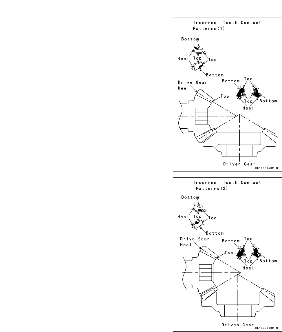
FINAL DRIVE 11-23
Output Bevel Gears
Example 1: Decrease the thickness of the drive bevel gear
shim(s) by 0.1 mm (0.004 in.), and/or increase the thickness
of the driven bevel gear shim(s) by 0.1 mm (0.004 in.) to
correct the pattern shown below. Repeat in 0.1 mm (0.004
in.) steps if necessary.
Example 2: Increase the thickness of the drive bevel gear
shim(s) by 0.1 mm (0.004 in.), and/or decrease the thick-
ness of the driven bevel gear shim(s) by 0.1 mm (0.004
in.) to correct the pattern shown below. Repeat in 0.1 mm
(0.004 in.) steps if necessary.
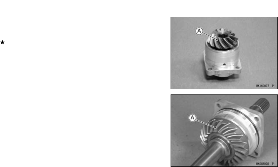
11-24 FINAL DRIVE
Output Bevel Gears
Bevel Gears Inspection
•Visually check the bevel gears [A] for scoring, chipping,
or other damage.
Replace the bevel gears as a set if either gear is dam-
aged.
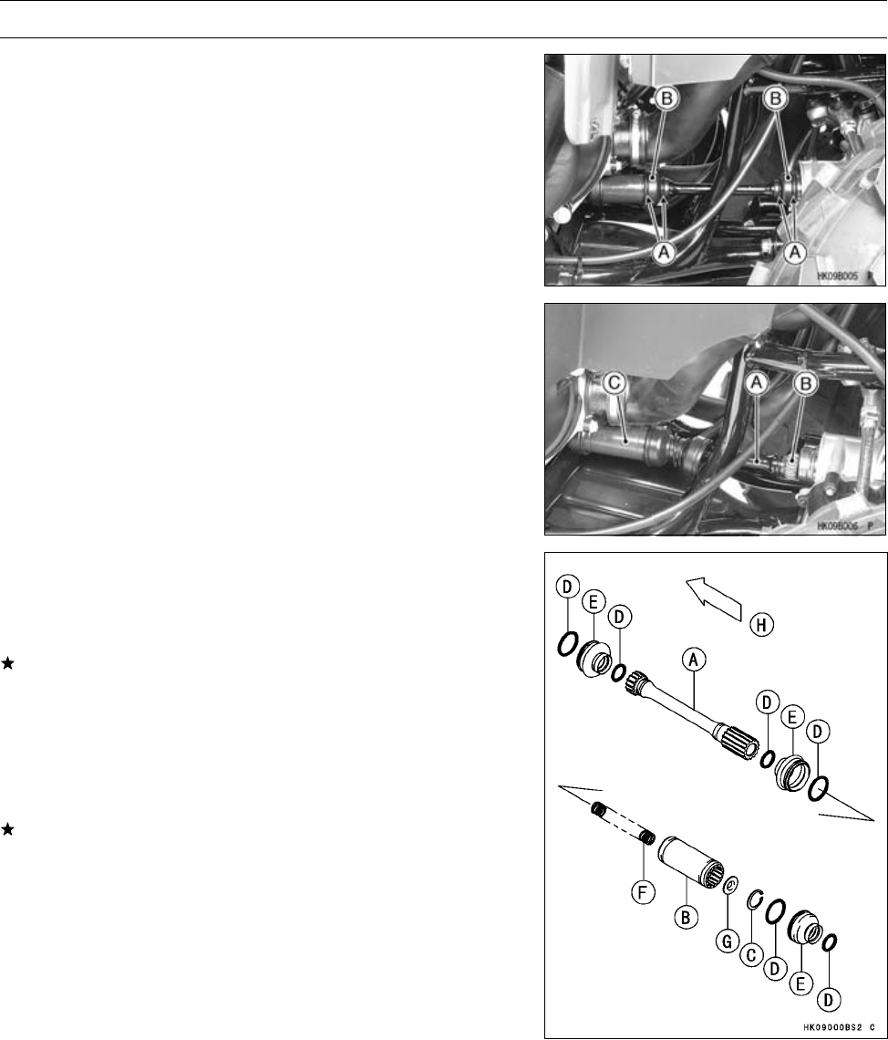
FINAL DRIVE 11-25
Front Propeller Shaft
Front Propeller Shaft Removal
•Slip the O-ring clamps [A] off the grooves on the small
rubber boots [B], and then pull the boot.
•Push the front propeller shaft [A] rearward, and remove
the front end [B] from the front final gear case.
•Push the coupling [C] forward, and remove the rear end
from the front final gear case.
Front Propeller Shaft Installation
•Wipe off any old grease on the splines of the propeller
shaft [A] and the coupling [B].
•Inspect the splines of the propeller shaft and the coupling.
If the splines are twisted or damaged in any way, replace
the parts as needed.
•Apply molybdenum disulfide grease to all splines.
•Replace the circlip [C] with a new one, if it is removed.
•Wipe off any old grease on the splines of the shafts in the
engine and front final gear case.
•Inspect the O-rings on those shafts for damage.
If any doubt exists, replace the O-rings with new ones.
•Apply molybdenum disulfide grease to the splines of the
shafts on the output bevel gear and front final gear case.
•First install the rear end, and then install the front end.
•Slip the two O-ring clamps into the groove on the small
rubber boot.
O-rings [D]
Boots [E]
Spring [F]
Spring Seat [G]
Front [H]
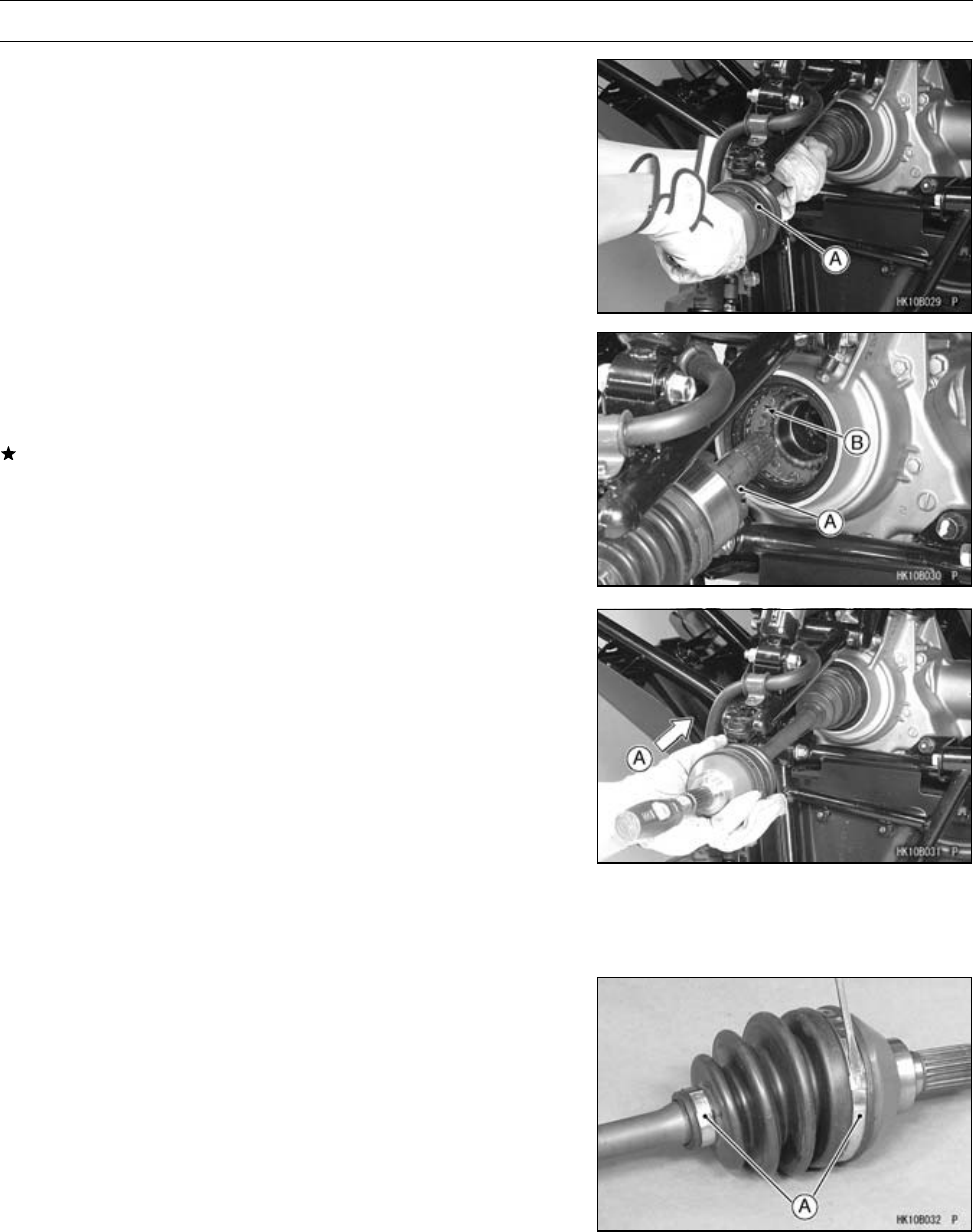
11-26 FINAL DRIVE
Front Axle
Front Axle Removal
•Drain the front final gear case oil (see Front Final Gear
Case Oil Change in the Periodic Maintenance chapter).
•Remove:
Front Wheel (see Wheel Removal in the Wheels/Tires
chapter)
Steering Knuckle (see Steering Knuckle Removal in the
Steering chapter)
•Pull the front axle [A] in a straight line out of the front final
gear case.
Front Axle Installation
•Wipe the old grease off the splines of the axle and the
gear case oil seal.
•Visually inspect the splines of the axle.
If they are badly worn or chipped, replace the axle with a
new one.
•Apply molybdenum disulfide grease to the axle splines.
•Apply grease to the gear case oil seal.
•Insert the left axle so that the teeth [A] fit in the grooves
[B].
•Tap [A] the end of the front axle lightly and install the front
axle.
NOTE
○The axle shaft must not come off easily.
Front Axle Joint Boot Inspection
•Refer to the Front Axle Joint Boot Inspection in the Peri-
odic Maintenance chapter.
Front Axle Joint Boot Replacement
Outboard Joint Boot Removal
•Remove:
Front Axle (see Front Axle Removal)
Boot Bands [A]
•Scrap the removed boot bands.
•Slide the joint boot toward the inboard joint.
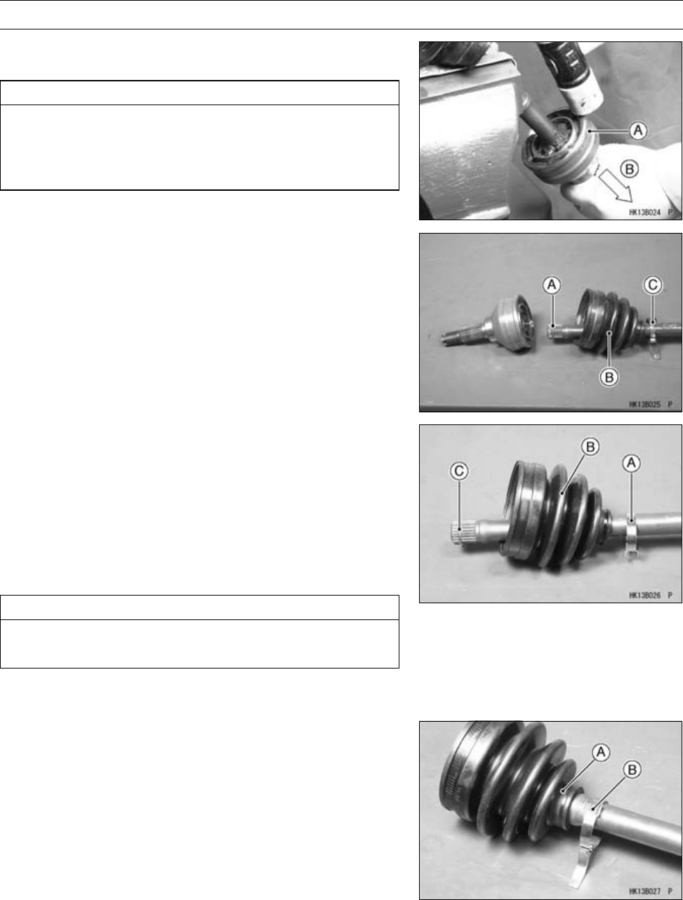
FINAL DRIVE 11-27
Front Axle
•Tap the bearing housing [A] straight [B] with a plastic ham-
mer to separate it from the shaft.
CAUTION
Do not tap on the cage. Be careful not get hurt when
the housing comes out. If the splined portion of
shaft cracked or damaged during disassembling of
outboard joint, do not reuse the shaft.
•Remove:
Circlip [A]
Boot [B]
Small Band [C]
Outboard Joint Boot Installation
•Cleantheaxleshaftbywipingofftheusedgreaseonit.
•Wind the tape on the splines of the axle shaft in order to
protect the joint boot.
•Install:
New Small Band [A]
New Boot [B]
○Apply the special grease slightly on the inside of the new
boot small diameter, and install the boot on the axle shaft.
CAUTION
Only the special grease that is included with the
boot kit can be applied to the boots.
•Install:
New Circlip [C]
•Apply the special grease slightly on the part [A] of the
band installation in order to make easy to install the boot
band.
•Tighten the small boot band [B].
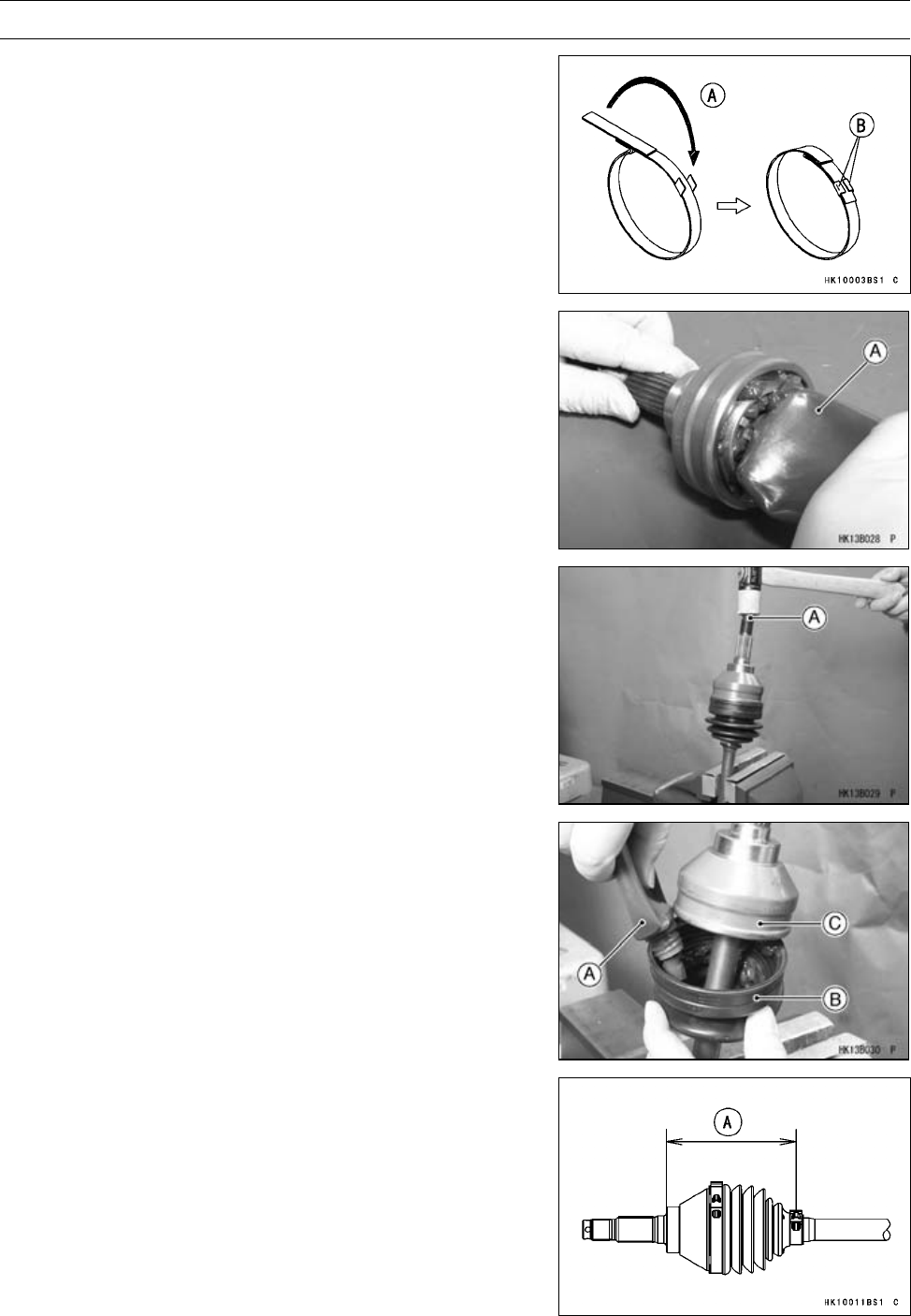
11-28 FINAL DRIVE
Front Axle
○Tighten the boot band [A] and bend the tangs [B] securely
to hold down the end of the band.
•Place the special grease tube nozzle in the bore of the
housing and squeeze the tube [A] until the grease comes
out from the joint bearing.
•Tap the shaft end [A] straight with a plastic hammer until
it is locked by the circlip.
•Squeeze all of the special grease [A] into the new boot
[B], and slide the boot onto the outboard joint [C].
•Compress the axle assembly to the specified length while
relieving the air pressure inside the inboard boot.
•Hold the axle at this setting.
Standard Length of Assembling:
Right Front Axle: 108.7 mm (4.28 in.) [A]
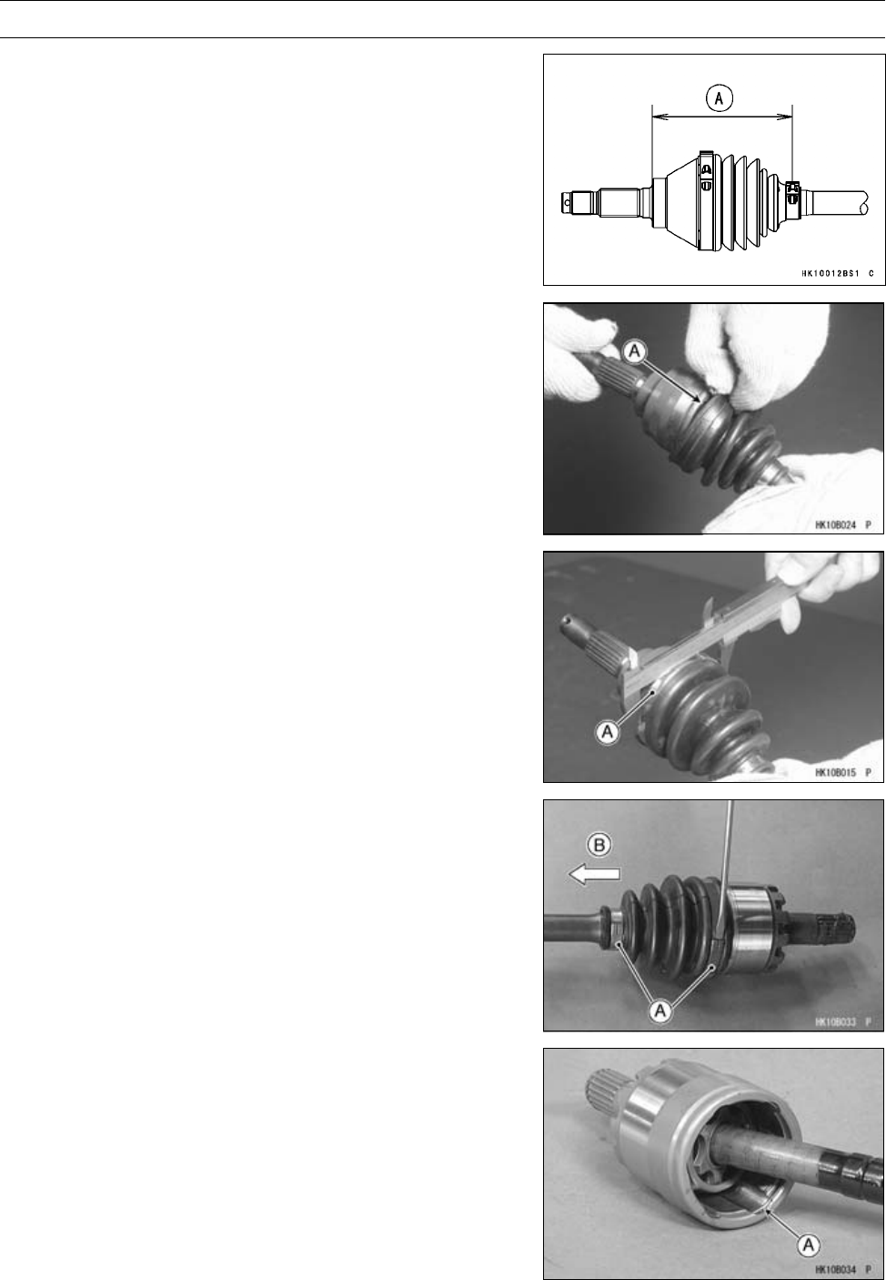
FINAL DRIVE 11-29
Front Axle
Left Front Axle: 108.7 mm (4.28 in.) [A]
•Open the edge [A] of the boot in order to equalize the air
pressures.
•Tighten the large band [A] and bend the tangs securely to
hold down the end of the band.
Maximum Outside Diameter of Band: 80 mm (3.15 in.)
(After tightening the outside diameter)
Inboard Joint Boot Removal
•Remove:
Front Axle (see Front Axle Removal)
Boot Bands [A]
•Scrap the removed boot bands.
•Slide the joint boot toward the outboard joint [B].
•Remove the retaining ring [A].
•Separate to the axle shaft.
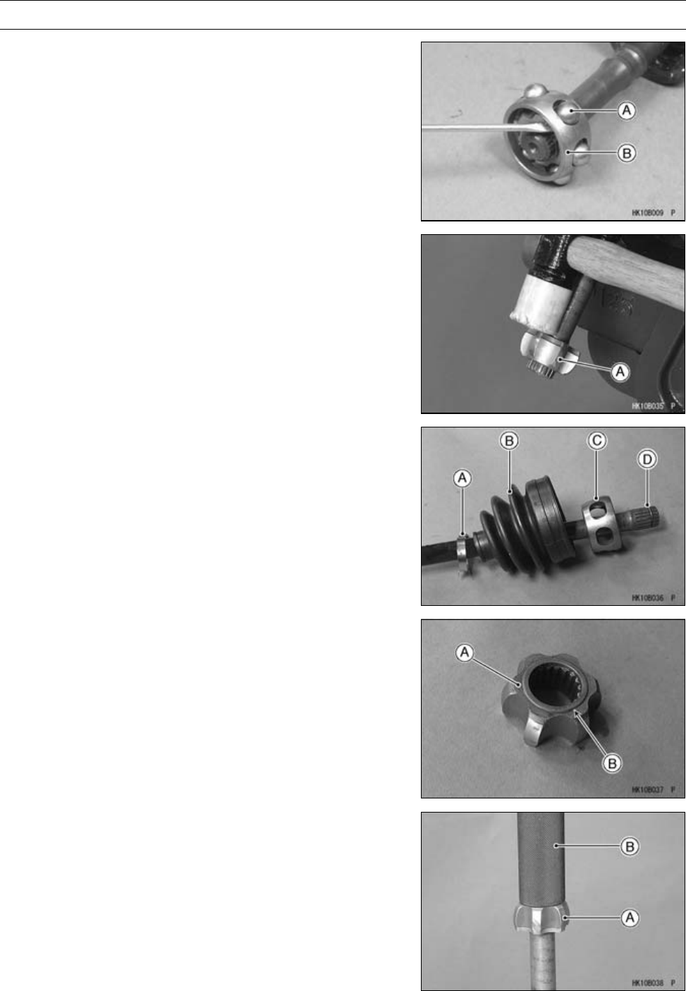
11-30 FINAL DRIVE
Front Axle
•Remove the steel balls [A].
•Slide the cage [B] toward the center of the axle.
•Tap the inner race [A] straight with a plastic hammer until
it is locked by the circlip.
•Remove the inboard joint boot.
Inboard Joint Boot Installation
•Wind the tape on the splines of the axle shaft in order to
protect the joint boot.
•Install:
New Small Band [A]
New Inboard Joint Boot [B]
Cage [C]
Circlip [D]
•Install the inner race [A] so that the stepped side [B] faces
front final gear case.
•Press the inner race [A] using the rotor puller [B] (57001
-1216) until it is bottomed.
Special Tool - Rotor Puller, M16/M18/M20/M22 × 1.5: 57001
-1216

FINAL DRIVE 11-31
Front Axle
•Slide the cage [A] on the inner race and install the steel
balls [B].
•Apply the special grease [A] to the steel balls and cage.
•Squeeze about half a tube (30 grams) of the special
grease [A] into the bearing cup [B].
•Insert the balls and cage assembly [A] in the bearing cup
[B] strongly.
•Install the new retaining ring [A] so that the opening [B] is
aligned with one of the projections [C].
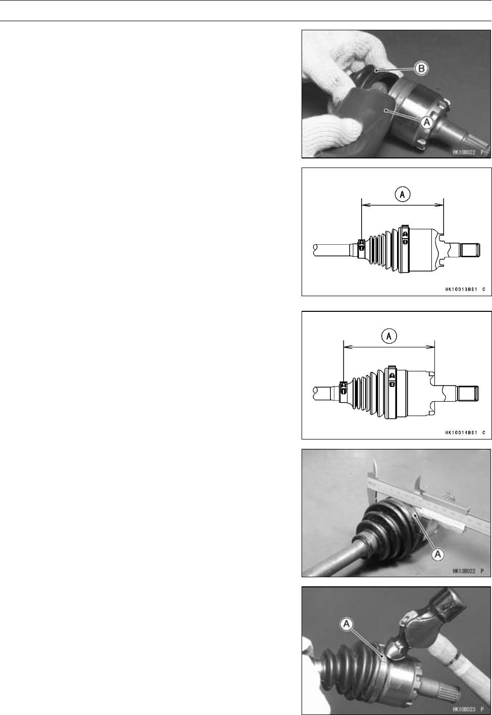
11-32 FINAL DRIVE
Front Axle
•Tighten the small band.
•Squeeze the remaining special grease [A] into the inboard
joint boot [B].
•Compress the axle assembly to the specified length while
relieving the air pressure inside the inboard boot.
•Hold the axle at this setting.
Standard Length of Assembling
Right Front Axle: 127 mm (5.00 in.) [A]
Left Front Axle: 127 mm (5.00 in.) [A]
•Open the edge of the boot in order to eqalize the air pres-
sures.
•Tighten the large band [A] and bend the tangs securely to
hold down the end of the band.
Maximum Outside Diameter of Band: 77.2 mm (3.04 in.)
(After tightening the outside diameter)
•While the band is held at the diameter above, tap down
the tangs [A] of the clamp.
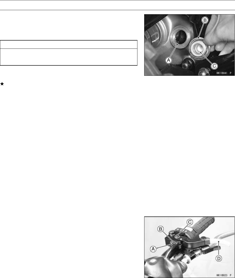
FINAL DRIVE 11-33
Front Final Gear Case
Front Final Gear Case Oil Level Inspection
•Park the vehicle so that it is level, both side-to-side and
front-to-rear.
•Remove the filler cap.
CAUTION
Be careful not to allow any dirt or foreign materials
to enter the gear case.
•Check the oil level. The oil level should come to the bot-
tom of the filler opening [A].
If it is insufficient, first check the front final gear case for
oil leakage, remedy it if necessary, and add oil through
the filler opening. Use the same type and brand of oil that
is already in the final gear case.
•Be sure the O-ring [B] is in place, and tighten the filler cap
[C].
○Apply grease to the O-ring.
Torque - Front Final Gear Case Oil Filler Cap: 29 N·m (3.0
kgf·m, 22 ft·lb)
Front Final Gear Case Oil Change
•Refer to the Front Final Gear Case Oil Change in the Pe-
riodic Maintenance chapter.
Variable Differential Control Lever Play Inspection
•Refer to the Variable Differential Control Lever Play In-
spection in the Periodic Maintenance chapter.
Variable Differential Control Lever Play
Adjustment
•Refer to the Variable Differential Control Lever Play Ad-
justment in the Periodic Maintenance chapter.
Variable Differential Control Lever Removal
•Remove:
Handlebar Cover
Plate Bolt [A]
Cable Stopper Plate [B]
Variable Differential Control Lever Bolt [C], Washer and
Collar
Variable Differential Control Lever [D]
Variable Differential Control Cable Upper End
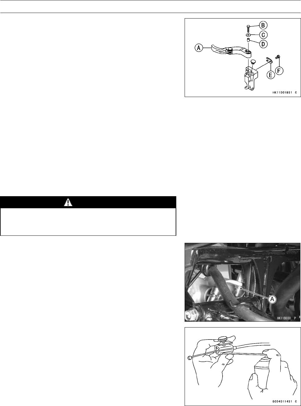
11-34 FINAL DRIVE
Front Final Gear Case
Variable Differential Control Lever Installation
•Install:
Variable Differential Control Cable Upper End
Variable Differential Control Lever [A]
•Apply a non-permanent locking agent to the variable dif-
ferential control lever bolt [B] and tighten it.
Torque - Variable Differential Control Lever Bolt: 3.4 N·m
(0.35 kgf·m, 30 in·lb)
•Install:
Variable Differential Control Lever Bolt, Washer [C] and
Collar [D]
Cable Stopper Plate [E]
Plate Bolt [F]
•Check the variable differential control lever play (see Vari-
able Differential Control Lever Play Inspection in the Pe-
riodic Maintenance chapter).
Variable Differential Control Cable Installation
•Lubrication the variable differential control cable before
installation.
•Route the cable correctly according to the Cable, Wire,
and Hose Routing in the Appendix chapter.
WARNING
Operation with an improperly adjusted, incorrectly
routed, or damaged cable could result in an unsafe
operating condition.
•Tighten:
Torque - Variable Differential Control Cable Locknut [A]: 16
N·m (1.6 kgf·m, 12 ft·lb)
•Check the variable differential control lever play (see Vari-
able Differential Control Lever Play Inspection in the Pe-
riodic Maintenance chapter).
Variable Differential Control Cable Lubrication
Whenever the variable differential control cable is re-
moved, lubricate the cable as follows:
•Apply a small amount of multi-purpose grease to the cable
(both ends).
•Lubricate the cable with a penetrating aerosol cable lubri-
cant through the pressure cable luber.
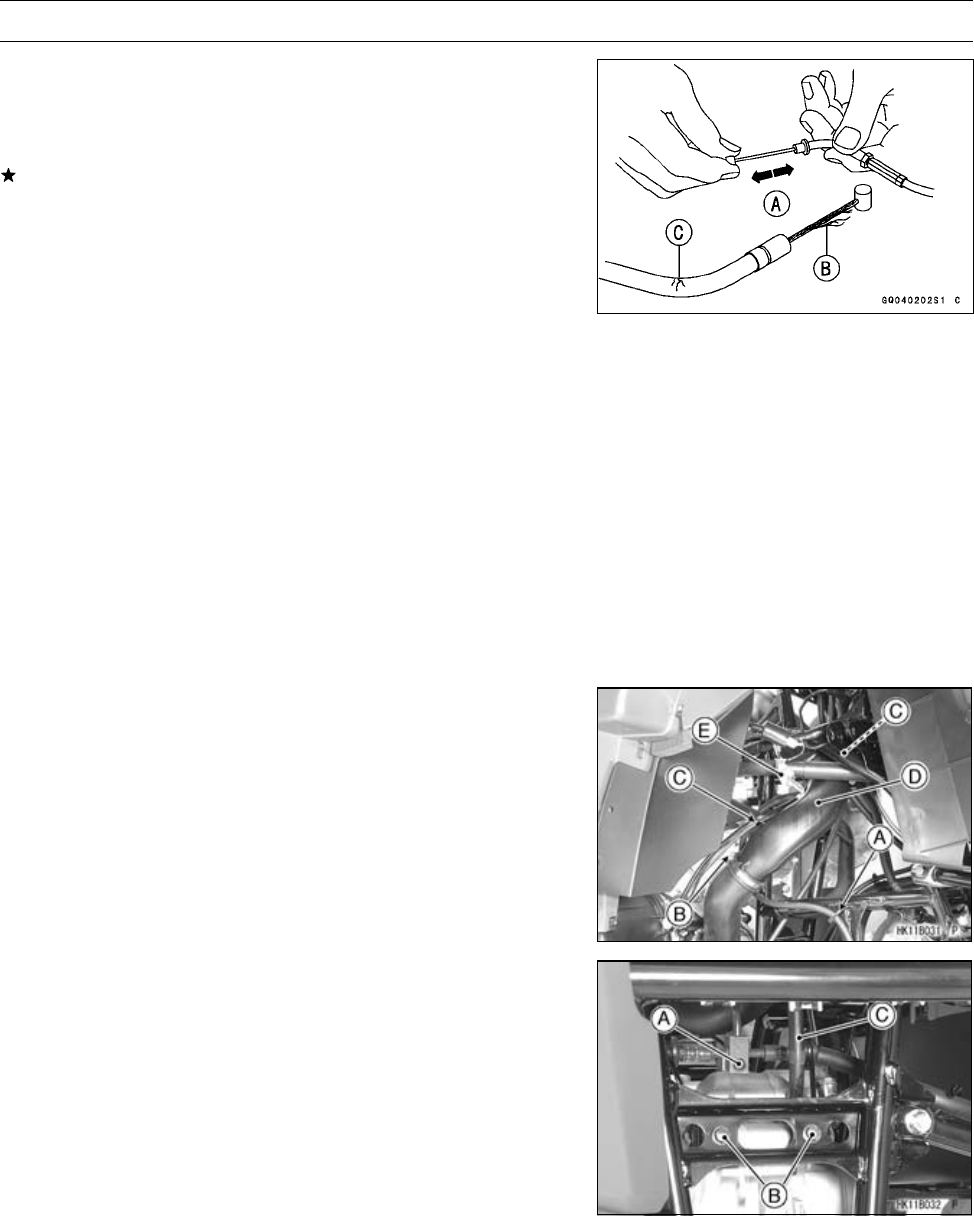
FINAL DRIVE 11-35
Front Final Gear Case
Variable Differential Control Cable Inspection
•With the variable differential control cable disconnected at
both ends, the cable should move freely within the cable
housing.
If the cable does not move freely [A] after lubricating, if the
cable is frayed [B], or if the housing is kinked [C], replace
the cable.
Front Final Gear Case Removal
•Drain the gear case oil (see Front Final Gear Case Oil
Change in the Periodic Maintenance chapter).
•Remove:
Steering Stem (see Steering Stem Removal in the Steer-
ing chapter)
Front Axles (see Front Axle Removal)
Right Upper Suspension Arm (see Front Suspension
Arm Removal in the Suspension chapter)
Right Front Shock Absorber (see Front Shock Absorber
Removal in the Suspension chapter)
Front Propeller Shaft (see Front Propeller Shaft Re-
moval)
•Cut the band [A].
•Loosen the clamp screw [B].
•Remove:
Clamps [C]
Air Duct [D]
Actuator Lead Connector [E] (disconnect)
•Remove:
Brake Hose Joint Bolt [A]
Bracket Bolts [B]
Vent Hose [C]
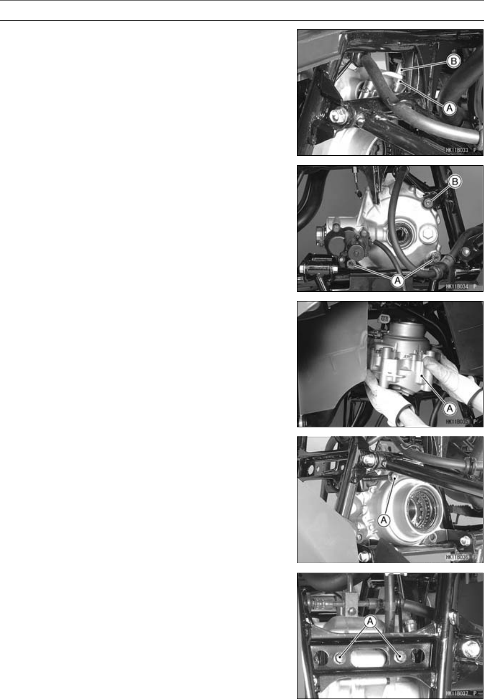
11-36 FINAL DRIVE
Front Final Gear Case
•Loosen the variable differential control cable locknut [A]
and adjusting nut [B], and clear the cable lower end from
the variable differential control lever.
•Remove:
Front Final Gear Case Lower Bolts and Nuts [A]
•Remove the front final gear case upper nut [B].
•Lift up the rear portion of the front final gear case, and
remove the upper bolt.
•Remove the rear final gear case [A] as shown.
Front Final Gear Case Installation
○Install the gear case bolts from the vehicle left side.
•Insert the upper front final gear case bolt [A] first.
•Tighten the bracket bolts [A].
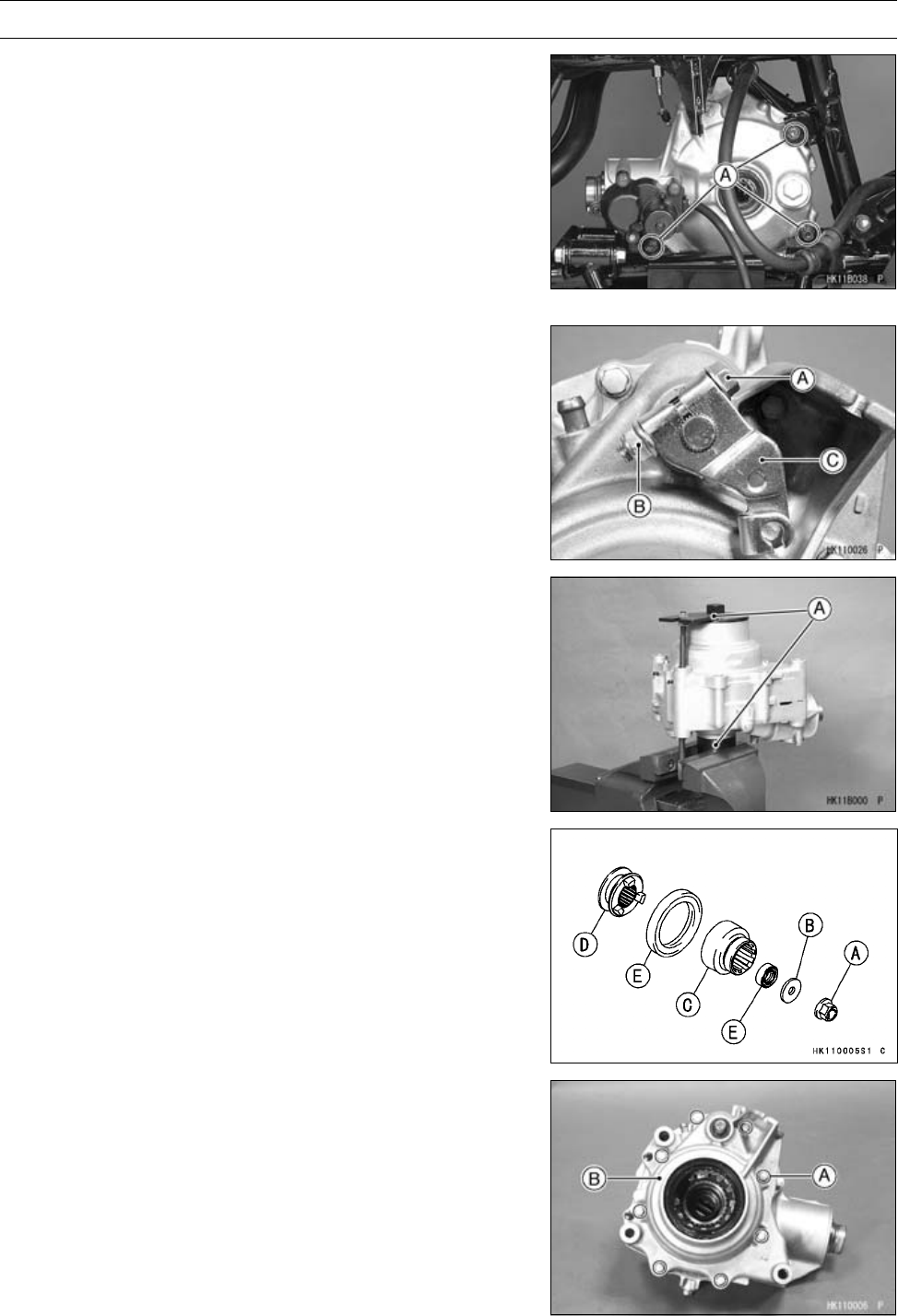
FINAL DRIVE 11-37
Front Final Gear Case
•Insert the lower front final gear case bolts.
•Tighten:
Torque - Front Final Gear Case Nuts [A]: 59 N·m (6.0 kgf·m,
44 ft·lb)
•Install the removed parts.
Torque - Front Final Gear Case Oil Drain Plug: 15 N·m (1.5
kgf·m, 11 ft·lb)
•Fill the front final gear case with the specified oil (see
Front Final Gear Case Oil Change in the Periodic Main-
tenance chapter).
Front Final Gear Case Disassembly
•Remove:
Front Final Gear Case (see Front Final Gear Case Re-
moval)
Variable Differential Control Shift Shaft Lever Bolt [A]
and Nut [B]
Variable Differential Control Shift Shaft Lever [C]
2WD/4WD Actuator (see 2WD/4WD Actuator Removal
in the Electrical System chapter)
•Hold the front final gear case with the gear holder & socket
wrench [A] in a vise.
Special Tool - Gear Holder & Socket Wrench, Hex 24:
57001-1489
•Remove:
Front Final Gear Case Coupling Nut [A]
Washer [B]
Front Final Gear Case Coupling [C]
Shifter [D]
Oil Seals [E]
•Remove:
Front Final Gear Case Left Cover Bolts [A]
Front Final Gear Case Left Cover [B]
Variable Differential Control Shift Shaft
Spring
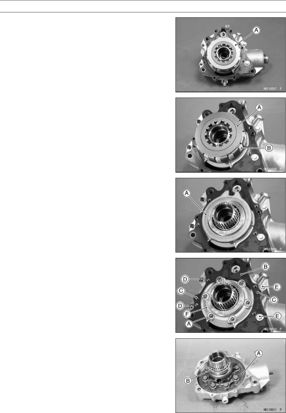
11-38 FINAL DRIVE
Front Final Gear Case
•Remove:
Outer Disc [A]
Needle Bearing
•Remove:
Housing [A] and Differential Disc Assembly [B]
Inner Disc
Needle Bearing
•Remove:
Cam Plate [A]
•Remove:
Steel Balls [A]
Gasket [B]
Dowel Pins [C]
Front Final Gear Case Center Cover Bolts (M6) [D]
Front Final Gear Case Center Cover Bolts (M8) [E]
Front Final Gear Case Center Cover [F]
•Remove:
Ring Gear Assembly [A]
Shim(s) [B]
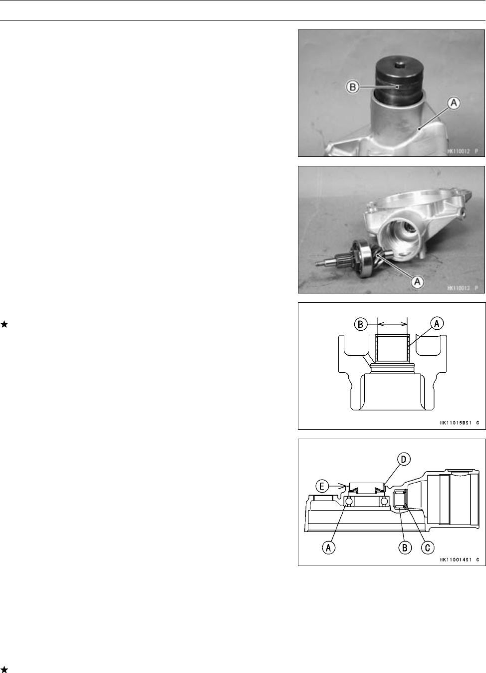
FINAL DRIVE 11-39
Front Final Gear Case
•Hold the front final gear case right cover [A] in a vise, and
remove the bearing holder using the socket wrench [B].
Special Tool - Socket Wrench, Hex 41: 57001-1484
○If the holder seems too difficult to break free, apply heat
to softer the locking agent.
•Remove:
Pinion Gear Bearing Holder
•Remove:
Pinion Gear Unit [A]
Shim(s)
Front Final Gear Case Coupling Inspection
If the coupling bushing [A] is damaged or worn, replace
the front final gear case coupling.
Front Final Gear Case Coupling Bushing Inside Diameter
[B]
Standard: 13.000 ∼13.018 mm (0.5118 ∼0.5125 in.)
Service Limit: 13.048 mm (0.5137 in.)
Front Final Gear Case Assembly
•Install:
Ball Bearing [A]
Needle Bearing [B]
○Press the ball bearing and needle bearing until they are
bottomed.
•Install:
Circlip [C]
Special Tool - Inside Circlip Pliers: 57001-143
•Install:
Oil Seal [D]
○Insert the oil seal so that the rubber surface is flush [E]
with the end of hole.
○Apply grease to the oil seal lip.
•Visually check the pinion gear and ring gear for scoring,
chipping, or other damage.
Replace the bevel gear as a set if either gear is damaged
since they are lapped as a set in the factory to get the best
tooth contact.
•Insert the pinion gear in the front final gear case right
cover.
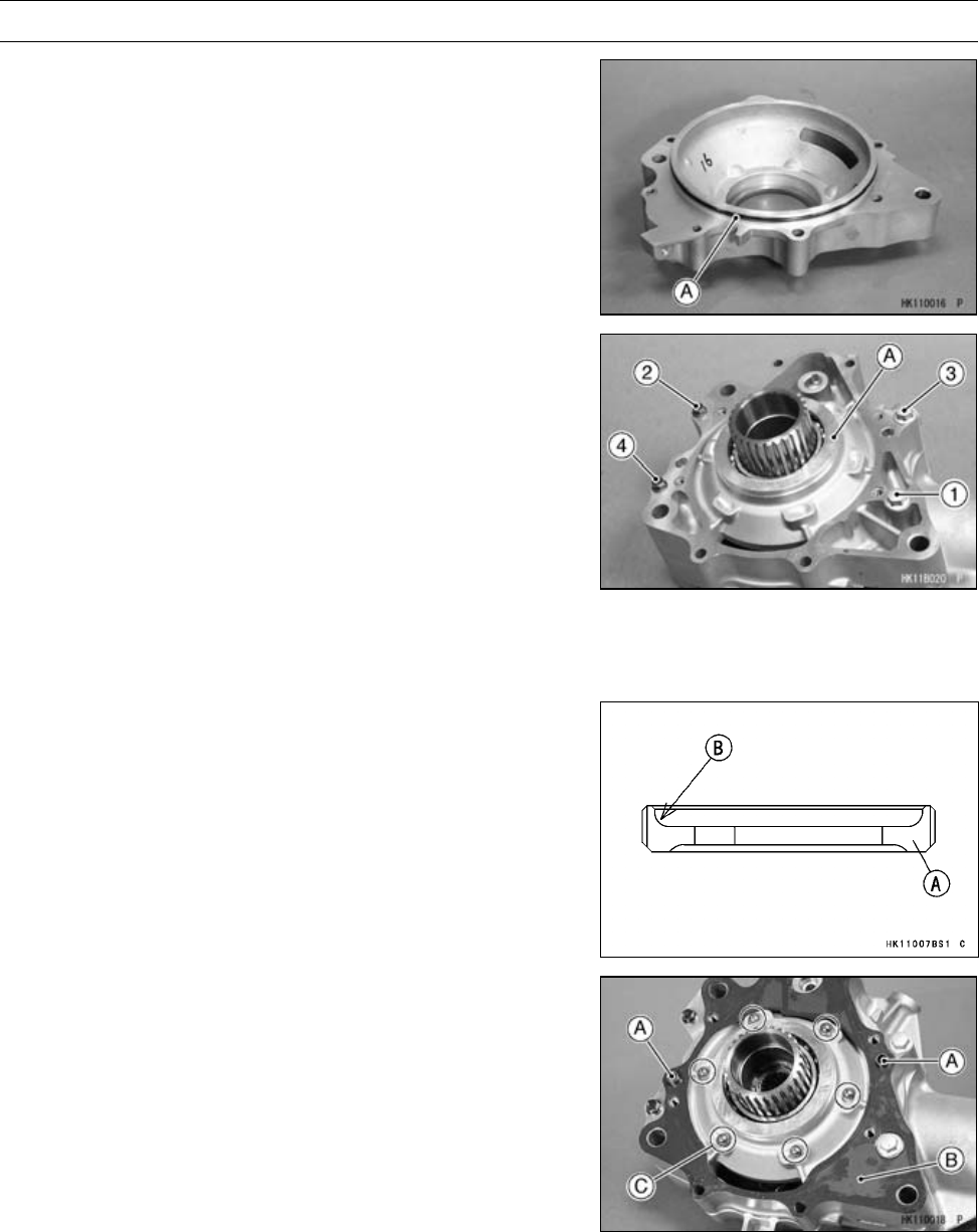
11-40 FINAL DRIVE
Front Final Gear Case
•Install:
Ring Gear Assembly
•Apply grease to the O-ring [A] on the front final gear case
center cover.
•Install:
Front Final Gear Case Center Cover [A]
•Tighten the cover bolts following the tightening sequence
as shown.
Torque - Front Final Gear Case Center Cover Bolts (M8)
[1,3]: 24N·m(2.4kgf·m,17ft·lb)
Front Final Gear Case Center Cover Bolts (M6)
[2, 4]: 9.8 N·m (1.0 kgf·m, 87 in·lb)
•Adjust the gear backlash and tooth contact pattern (see
Front Final Bevel Gear Adjustment).
•Apply a non-permanent locking agent to the cover bolts,
and tighten them to the specified torque in the tightening
sequence [1 ∼4].
•Apply a non-permanent locking agent to the pinion gear
bearing holder [A], and tighten it so that the deep recess
[B] faces outward.
Special Tool - Socket Wrench, Hex 41: 57001-1484
Torque - Pinion Gear Bearing Holder: 137 N·m (14 kgf·m,
101 ft·lb)
•Install:
Dowel Pins [A]
New Gasket [B]
Steel Balls [C]
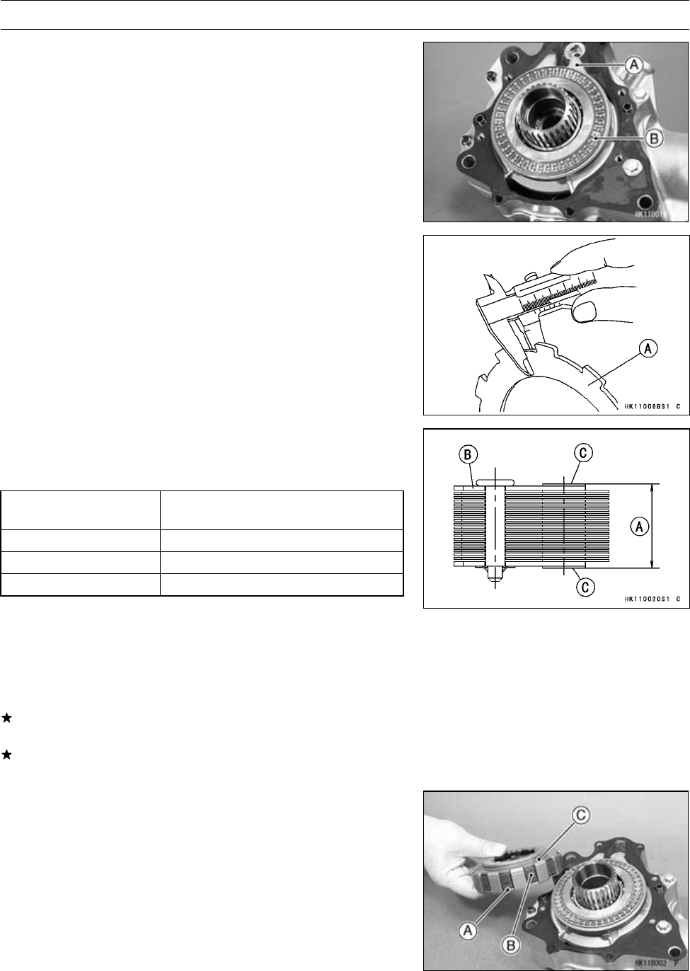
FINAL DRIVE 11-41
Front Final Gear Case
•Install:
Cam Lever [A]
Needle Bearing [B]
•Apply engine oil to the needle bearing.
•Check the wear of the disc assembly as follows.
○Measure the thickness of the inner disc [A].
•Select the width [A] of the disc assembly [B] in accordance
with the thickness of the inner disc, refer to the below
table.
Thickness of Inner
Disc Assembly Width [A] of Disc Assembly
2.4 mm (0.0945 in.) 16.7 ∼17.3 mm (0.6675 ∼0.6811 in.)
1.8 mm (0.0709 in.) 17.31 ∼17.9 mm (0.6815 ∼0.7047 in.)
1.2 mm (0.0472 in.) 17.91 ∼18.5 mm (0.7051 ∼0.7283 in.)
○Measure the width of the disc assembly at three locations,
and calculate average for three points.
NOTE
○Be careful not to damage the facing surface [C] on the
outer plates.
If the width is within the specified range, install the inner
disc and disc assembly.
If the width is not within the specified range, replace the
disc assembly.
•Install:
Inner Disc [A]
Disc Assembly [B] and Housing [C]
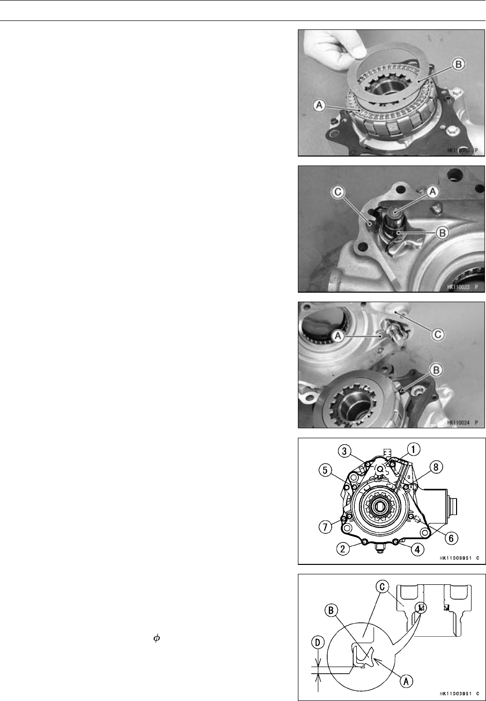
11-42 FINAL DRIVE
Front Final Gear Case
•Apply engine oil to the needle bearing [A].
•Install:
Needle Bearing
Outer Disc [B]
•Apply engine oil to the variable front differential control
shift shaft [A].
•Install the shaft and spring [B] in the front final gear case
left cover [C] as shown.
•Turn the shaft counterclockwise and insert the tab [A] of
the shift shaft into the groove [B] of the cam plate.
•Install:
Front Final Gear Case Left Cover [C]
•Apply a non-permanent locking agent to the cover bolts [1
∼4], and tighten them following the tightening sequence
as shown.
Torque - Front Final Gear Case Left Cover Bolts (M6)
[1 ∼8]: 9.8 N·m (1.0 kgf·m, 87 ft·lb)
[1 ∼4] L = 60 mm (2.4 in.)
[5 ∼8] L = 30 mm (1.2 in.)
•Apply grease to the oil seal lip [A].
•Press the oil seal [B] in the coupling [C] to the specified
position as shown.
[D] 1 mm (0.04 in.)
Special Tools - Oil Seal Driver, 18.5: 57001-1505
Driver Holder: 57001-1132
NOTE
○57001-1132 is included in Bearing Driver Set, 57001
-1129.
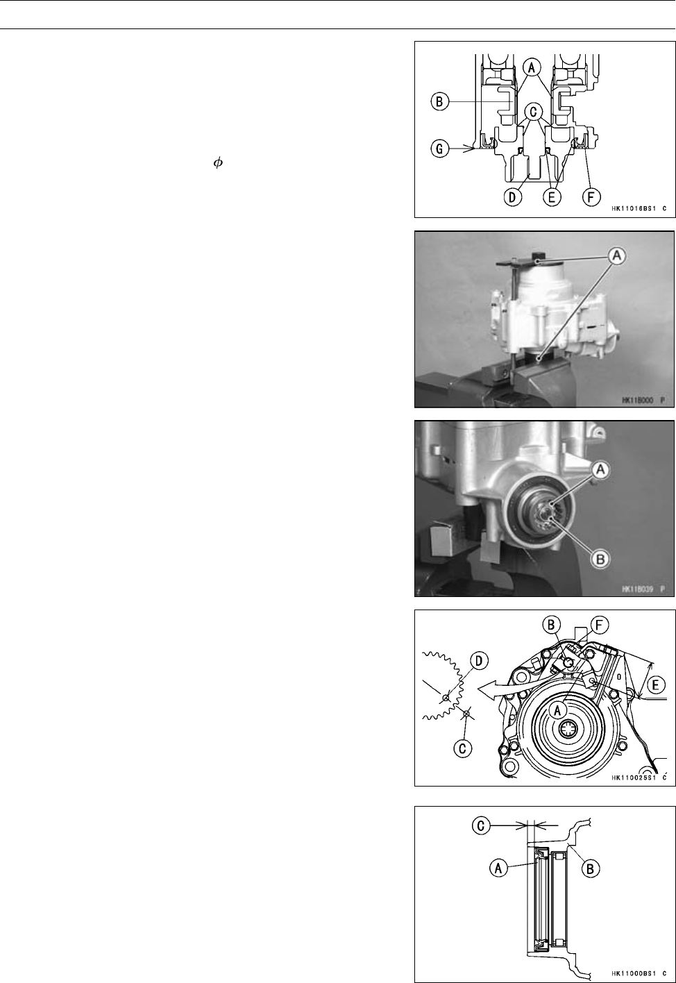
FINAL DRIVE 11-43
Front Final Gear Case
•Apply molybdenum disulfide grease to the spline [A] of
the shifter [B] and inner surface [C] of the coupling.
•Install the shifter and coupling on the pinion gear shaft [D].
•Apply grease to the oil seal lip [E].
•Press the oil seal [F] in the front final gear case so that
the oil seal surface is flush [G] with the case end.
Special Tool - Oil Seal Driver, 70: 57001-1506
•Hold the front final gear case with the gear holder & socket
wrench [A] in a vise.
Special Tool - Gear Holder & Socket Wrench, Hex 24:
57001-1489
•Install:
Washer [A]
•Tighten:
Torque - Front Final Gear Case Coupling Nut [B]: 25 N·m
(2.5 kgf·m, 18 ft·lb)
•Install the variable differential control shift shaft lever
[A] on the shift shaft [B] so that the punch mark [C] on
the lever aligns with the punch mark [D] on the shaft as
shown.
[E] 45.8 ∼50.4 mm (1.80 ∼1.98 in.)
•Tighten:
Torque - Variable Differential Control Shift Shaft Lever Bolt
[F]: 8.8 N·m (0.90 kgf·m, 78 in·lb)
2WD/4WD Actuator Mounting Bolts: 9.8 N·m (1.0
kgf·m, 87 in·lb)
Oil Seal Installation
•Press the oil seal [A] in the front final gear case left cover
[B] to the dimension as shown.
[C] 4.6 ∼5.6 mm (0.18 ∼0.22 in.)
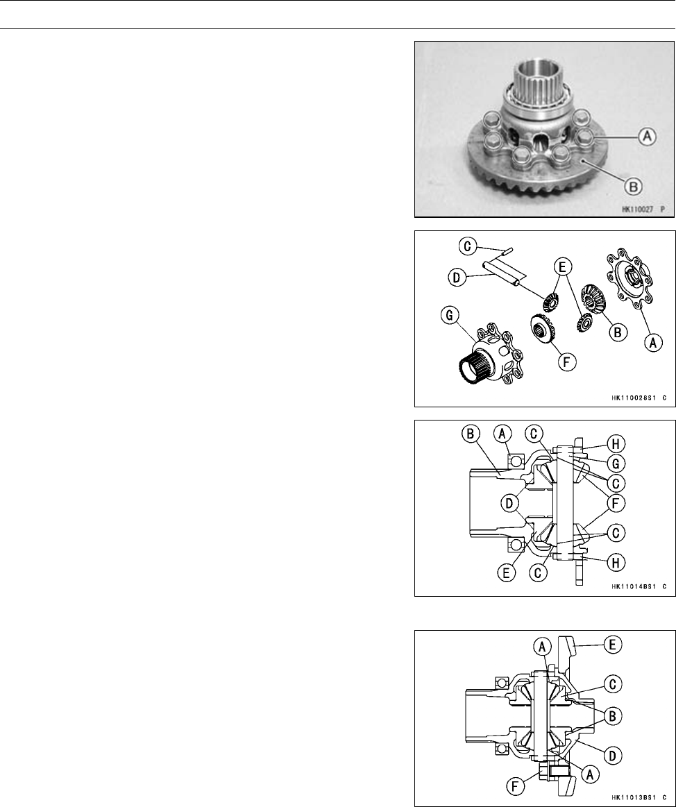
11-44 FINAL DRIVE
Front Final Gear Case
Ring Gear Disassembly
•Remove:
Ring Gear Assembly (see Front Final Gear Case Disas-
sembly)
Ring Gear Bolts [A]
Ring Gear [B]
•Remove:
Differential Gear Case Cover [A]
Right Side Gear (16T) [B]
Pins [C]
Spider Gear Shaft [D]
Spider Gears (10T) [E]
Left Side Gear (16T) [F]
Left Differential Gear Case [G]
Ring Gear Assembly
•Press the bearing [A] on the left differential gear case [B]
until it is bottomed.
•Apply engine oil [C] to the spider gears and the spider
gear shaft.
•Apply molybdenum disulfide grease [D] to the left side
gear (16T) [E].
•Install:
Left Side Gear (16T)
Spider Gears (10T) [F]
Spider Gear Shaft [G] and Pins [H]
•Apply engine oil [A] to the spider gears.
•Apply molybdenum disulfide grease [B] to the right side
gear (16T) [C].
•Install:
Right Side Gear (16T)
Differential Gear Case Cover [D]
Ring Gear [E]
•Apply a non-permanent locking agent (Three Bond:
TB2471 Blue) to the ring gear bolts [F], and tighten them.
Torque - Ring Gear Bolts: 57 N·m (5.8 kgf·m, 42 ft·lb)
NOTE
○Keep the ring gear assembly at more than 20°C (68°F)
for six hours after tightening the bolts.
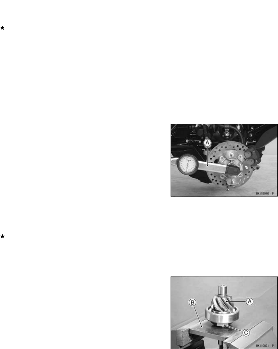
FINAL DRIVE 11-45
Front Final Gear Case
LSD Clutch Torque Inspection
If the vehicle has the following symptoms, check the LSD
(Limited Slip Differential) clutch torque.
-The handlebar is hard to turn.
-The front final gear case overheats.
-Abnormal noises come from the front final gear case
when rounding a curve.
•Ensure 2WD mode.
•Support the vehicle so that the front wheels are off the
ground.
•Remove:
One Front Wheel (see Wheel Removal in the
Wheels/Tires chapter)
Front Axle Nut Cotter Pin
•Secure the other-side front wheel from rotating.
•Measure the clutch torque using a torque wrench [A]. Turn
the wrench evenly.
○The clutch torque is the mean torque reading during about
a quarter turn of the wrench.
LSD Clutch Torque
(When variable differential control lever
is released.)
Standard: 15 ∼20 N·m (1.5 ∼2.0 kgf·m, 11 ∼14 ft·lb)
LSD Clutch Torque
(When variable differential control lever
is pulled in.)
Standard: 157 N·m (16 kgf·m, 116 ft·lb) or more
If the clutch torque is out of the specified range, check the
width of the disc assembly (see Front Final Gear Case
Assembly).
NOTE
○The correct type of oil must be installed.
Pinion Gear Unit Disassembly
•Remove:
Pinion Gear Unit (see Front Final Gear Case Disassem-
bly)
•Pry open the staking of the pinion gear bearing holder nut
with a small chisel.
•Hold the pinion gear unit [A] with the pinion gear holder
[B] in a vise, and remove the pinion gear bearing holder
nut [C].
Special Tool - Pinion Gear Holder, m1.0: 57001-1485
•Remove the ball bearing only if required.
Special Tool - Bearing Puller: 57001-135
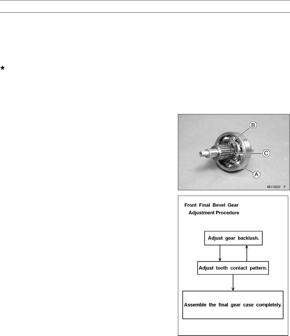
11-46 FINAL DRIVE
Front Final Gear Case
Pinion Gear Unit Assembly
○The pinion gear and ring gear are lapped as a set in the
factory to get the best tooth contact. They must be re-
placed as a set.
•Visually inspect the bearing for abrasion, color change, or
other damage.
If there is any doubt as to the condition of a bearing, re-
place the bearing.
•Be sure to check and adjust the bevel gear backlash and
tooth contact, when any of the backlash-related parts are
replaced (see Front Final Bevel Gear Adjustment).
•Press the bearing on the pinion gear until it is bottomed.
•Install the pinion gear bearing holder nut [A] so that the
projection [B] faces outward.
•Tighten:
Special Tool - Pinion Gear Holder, m1.0: 57001-1485
Torque - Pinion Gear Bearing Holder Nut: 127 N·m (13
kgf·m, 94 ft·lb)
•Stake [C] the nut with a punch at three positions to secure
it.
Front Final Bevel Gear Adjustment
The backlash (distance one gear will move back and forth
without moving the mate gear) and tooth contact pattern
of the bevel gears must be correct to prevent the gears from
making noise and being damaged.
Above two adjustments are of critical importance and
must be carried out following the correct sequence and
method.
•When any one of the backlash-related parts are replaced,
check and adjust the bevel gear backlash, and tooth con-
tact by replacing shims.
○The amount of backlash is influenced by the ring gear
position more than by the pinion gear position.
○Tooth contact location is influenced by the pinion gear po-
sition more than by the ring gear position.
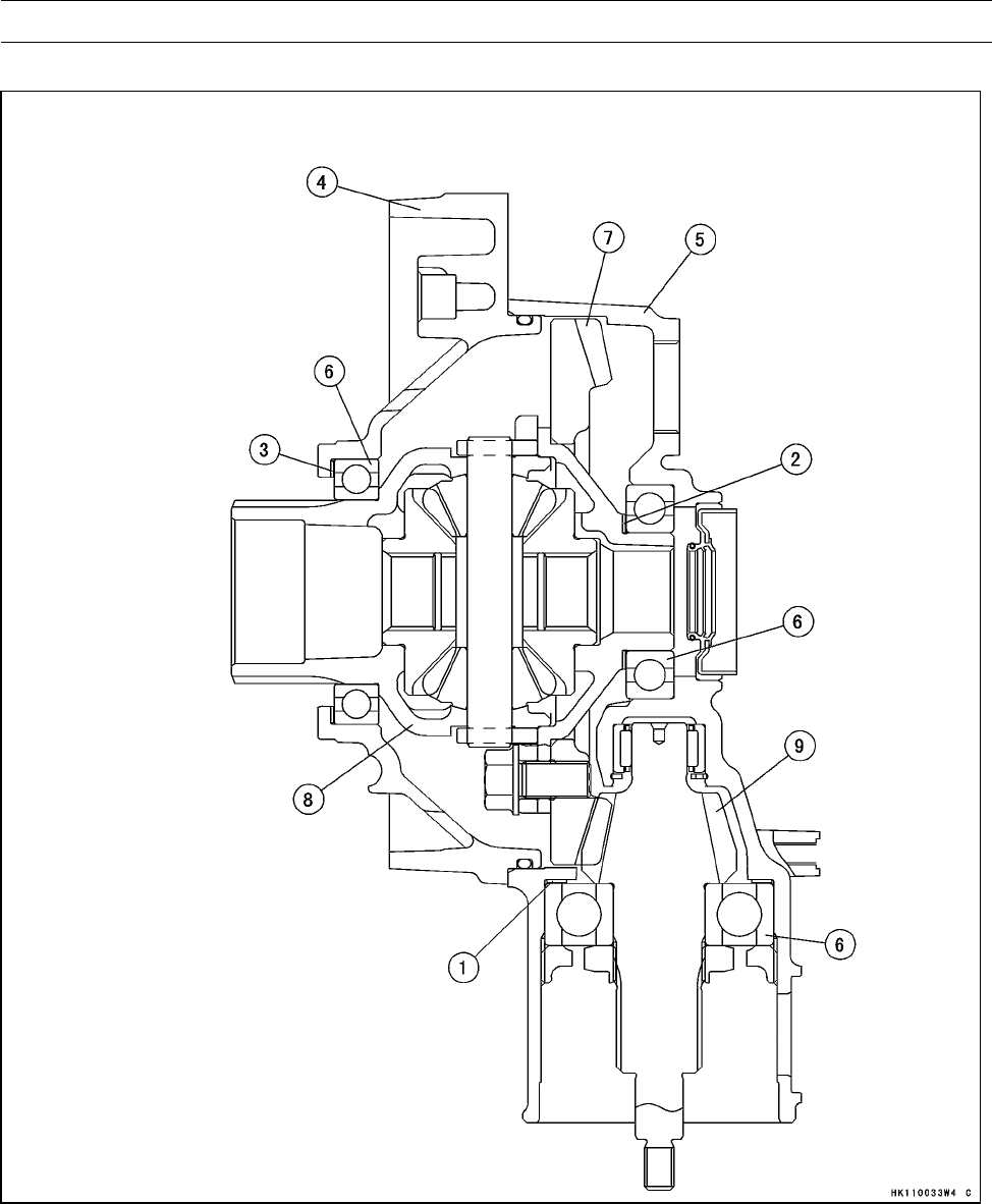
FINAL DRIVE 11-47
Front Final Gear Case
Front Final Gear Case (Backlash-related Parts)
1. Pinion Gear Shim(s)
2. Ring Gear Right Shim(s)
3. Ring Gear Left Shim(s)
4. Front Final Gear Case Center Cover
5. Front Final Gear Case Right Cover
6. Ball Bearings
7. Ring Gear
8. Ring Gear Assembly
9. Pinion Gear

11-48 FINAL DRIVE
Front Final Gear Case
1. Pinion Gear Shims for Backlash Adjustment
Thickness Part Number
0.15 mm (0.006 in.) 92180-1408
0.2 mm (0.008 in.) 92180-1409
0.5 mm (0.020 in.) 92180-1410
0.7 mm (0.028 in.) 92180-1411
0.8 mm (0.031 in.) 92180-1412
0.9 mm (0.035 in.) 92180-1413
1.0 mm (0.039 in.) 92180-1414
1.1 mm (0.043 in.) 92180-1415
1.2 mm (0.047 in.) 92180-1416
2. Ring Gear Right Shims for Tooth Contact Adjustment
Thickness Parts Number
0.15 mm (0.006 in.) 92180-1399
0.2 mm (0.008 in.) 92180-1400
0.5 mm (0.020 in.) 92180-1401
0.7 mm (0.028 in.) 92180-1402
0.8 mm (0.031 in.) 92180-1403
0.9 mm (0.035 in.) 92180-1404
1.0 mm (0.039 in.) 92180-1405
1.1 mm (0.043 in.) 92180-1406
1.2 mm (0.047 in.) 92180-1407
3. Ring Gear Left Shims for Tooth Contact Adjustment
Thickness Parts Number
0.15 mm (0.006 in.) 92180-1390
0.2 mm (0.008 in.) 92180-1391
0.5 mm (0.020 in.) 92180-1392
0.7 mm (0.028 in.) 92180-1393
0.8 mm (0.031 in.) 92180-1394
0.9 mm (0.035 in.) 92180-1395
1.0 mm (0.039 in.) 92180-1396
1.1 mm (0.043 in.) 92180-1397
1.2 mm (0.047 in.) 92180-1398
Backlash Adjustment
•Check and adjust the gear backlash when any of the
backlash-related parts are replaced with new ones.
•Clean any dirt and oil off the bevel gear teeth.
•Assemble the front final gear case (see Front Final Gear
Case Assembly).
○It is not necessary to install the variable front differential
control unit.
○Check the backlash during tightening of the front final gear
case center cover bolts and stop tightening them imme-
diately if the backlash disappears. Then, change the ring
gear shim to a thicker one.
•Temporarily, install the right front axle in the gear case
and hold it in a vise so that the ring gear is lower than the
pinion gear.
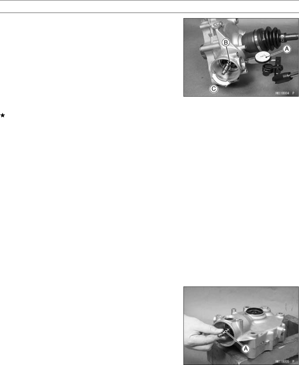
FINAL DRIVE 11-49
Front Final Gear Case
•Mount a dial gauge [A] so that the tip of the gauge is
against the splined portion [B] of the pinion gear shaft.
•To measure the backlash, move the pinion gear shaft
back and forth [C] while holding the front axle steady.
The difference between the highest and the lowest gauge
reading is the amount of backlash.
○Measure backlash at three locations equally spaced on
the splines.
Front Final Bevel Gear Backlash
Standard: 0.10 ∼0.20 mm (0.004 ∼0.008 in.) (at
pinion gear spline)
If the backlash is not within the limit, replace the pinion
gear shims. To increase backlash, increase the thickness
of the shim(s). To decrease backlash, decrease the thick-
ness of the shim(s).
○Change the thickness a little at a time.
•Recheck the backlash, and readjust as necessary.
Tooth Contact Adjustment
•Clean any dirt and oil off the bevel gear teeth.
•Apply checking compound to 4 or 5 teeth on the pinion
gear.
NOTE
○Apply checking compound to the teeth in a thin, even
coat with a fairly stiff paint brush. If painted too thickly,
the exact tooth pattern may not appear.
○The checking compound must be smooth and firm, with
the consistency of tooth paste.
○Special compounds are available from automotive sup-
ply stores for the purpose of checking differential gear
tooth patterns and contact. Use one of these for check-
ing the bevel gears.
•Assemble the front final gear case (see Front Final Gear
Case Assembly).
○It is not necessary to install the variable front differential
control unit.
•Turn the pinion gear shaft [A] for one revolution in the
drive and reverse (coast) direction, while creating a drag
on the ring gear.
•Remove the ring gear and pinion gear unit to check the
drive pattern and coast pattern of the bevel gear teeth.
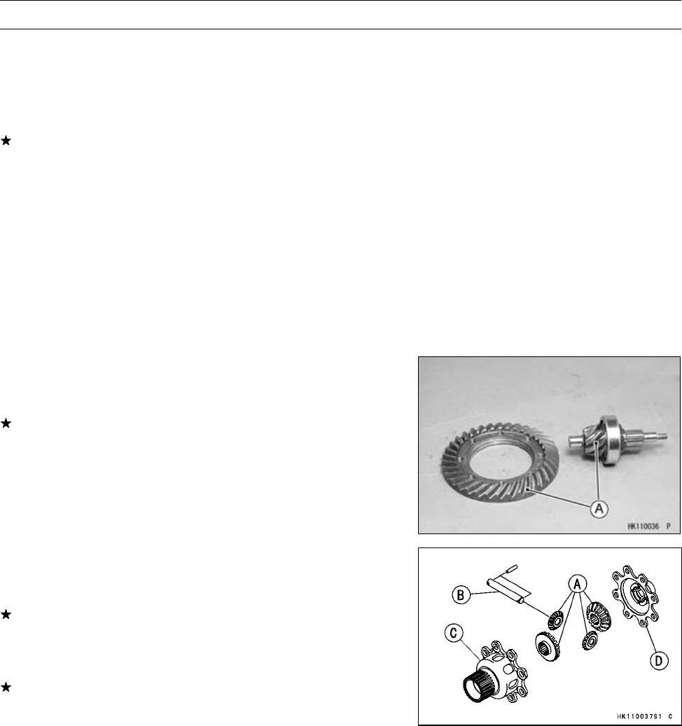
11-50 FINAL DRIVE
Front Final Gear Case
○The tooth contact patterns of both (drive and coast) sides
should be centrally located between the top and bottom
of the tooth. The drive pattern can be a little closer to the
toe and the coast pattern can be a somewhat longer and
closer to the toe.
If the tooth contact pattern is incorrect, replace the ring
gear shim(s), following the examples shown.
•Then erase the tooth contact patterns and check them
again. Also check the backlash every time the shim(s)
are replaced. Repeat the shim change procedure as nec-
essary.
NOTE
○If the backlash is out of the standard range after
changing the ring gear shim(s), change the pinion gear
shim(s) to correct the backlash before checking the
tooth contact pattern.
Bevel Gear Inspection
•Visually check the bevel gears [A] for scoring, chipping,
or other damage.
Replace the bevel gears as a set if either gear is dam-
aged.
Differential Gear Inspection
•Visually check the differential gears [A] for scoring, chip-
ping, or other damage.
Replace the differential gears as a set if either gear is
damaged.
•Also, inspect the differential gear shaft [B], gear case [C],
and cover [D] where the differential gears rub.
If they are scored, discolored, or otherwise damaged, re-
place them as a set.
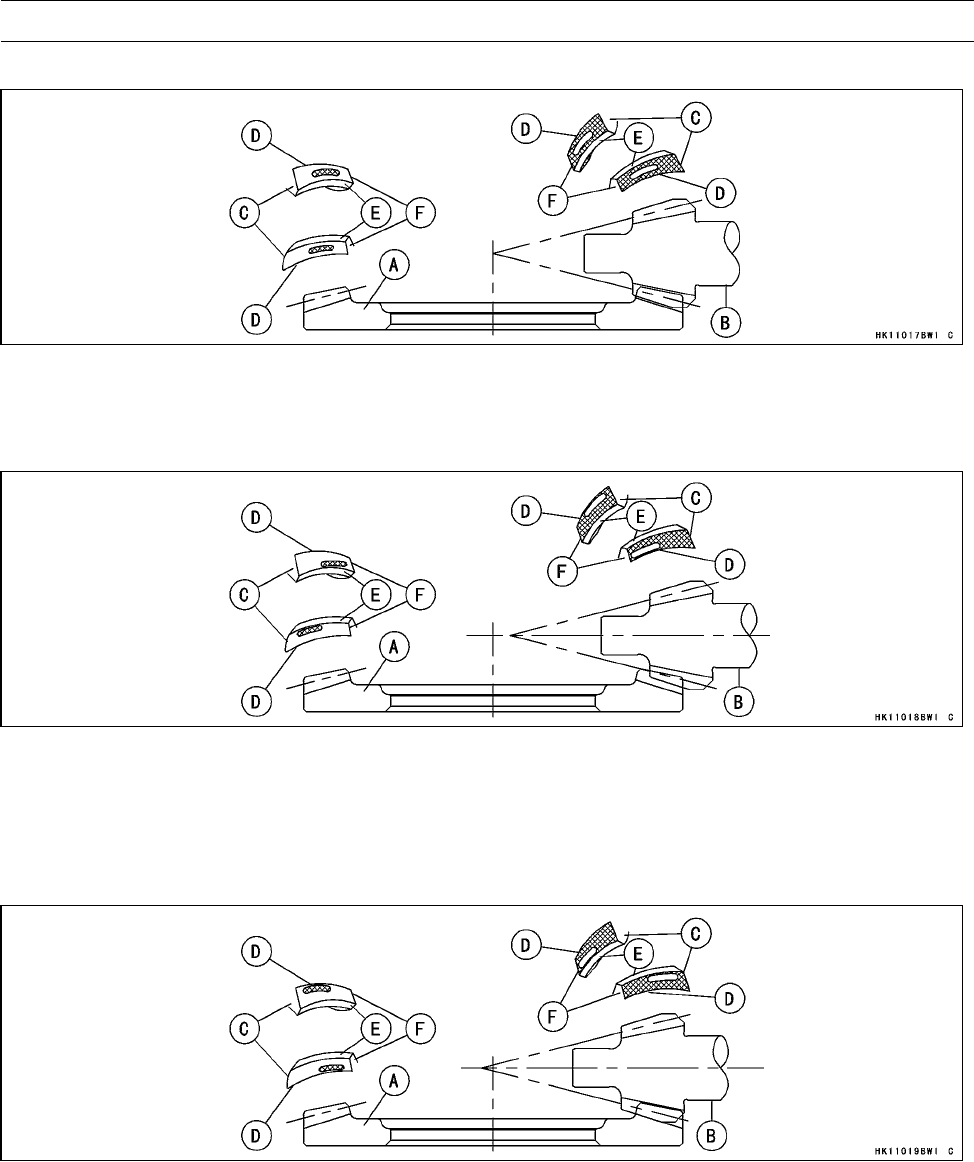
FINAL DRIVE 11-51
Front Final Gear Case
Correct Tooth Contact Pattern: No adjustment is required.
A. Ring Gear
B. Pinion Gear
C. Heel
D. Bottom
E. Top
F. Toe
Incorrect Tooth Contact Patterns (Example 1)
○Decrease the thickness of the pinion gear shim(s) by 0.1 mm (0.004 in.) to correct the pattern
shown above. Repeat in 0.1 mm (0.004 in.) steps if necessary.
A. Ring Gear
B. Pinion Gear
C. Heel
D. Bottom
E. Top
F. Toe
Incorrect Tooth Contact Patterns (Example 2)
○Increase the thickness of the pinion gear shim(s) by 0.1 mm (0.004 in.) to correct the pattern shown
above. Repeat in 0.1 mm (0.004 in.) steps if necessary.
A. Ring Gear
B. Pinion Gear
C. Heel
D. Bottom
E. Top
F. Toe
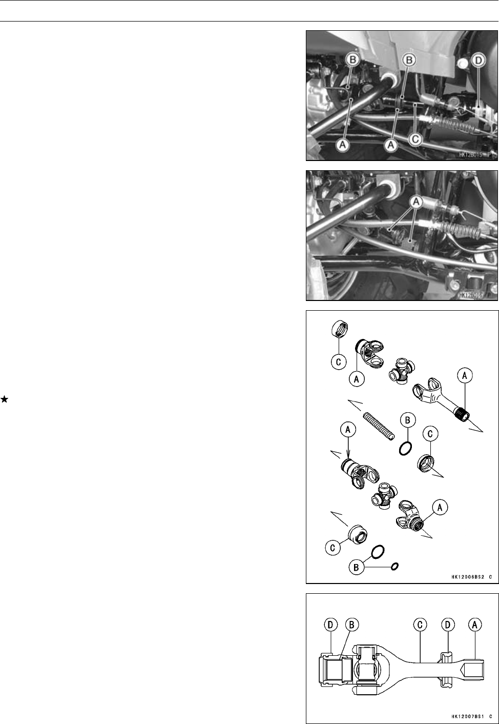
11-52 FINAL DRIVE
Rear Propeller Shaft
Rear Propeller Shaft Removal
•Remove:
Footboard (see Left and Right Footboard Removal in the
Frame chapter)
•Slip the O-ring clamps [A] off the grooves on the rubber
boots [B].
•Slide the rubber boot.
•Push the front universal joint [C] rearward, and remove
the front end [D] from the engine.
•Remove the rear propeller shaft [A] from the vehicle.
Rear Propeller Shaft Installation
•Wipe off any old grease:
Splines [A] of Propeller Shaft and Universal Joint
Output Shaft of Engine
Pinion Gear of Rear Final Gear Case
•Inspect O-rings [B] and boots [C] for damage.
If any doubt exists, replace it with a new one.
•Apply molybdenum disulfide grease to the spline [A] and
inside [B] of propeller shaft [C].
•Install:
Boots [D]
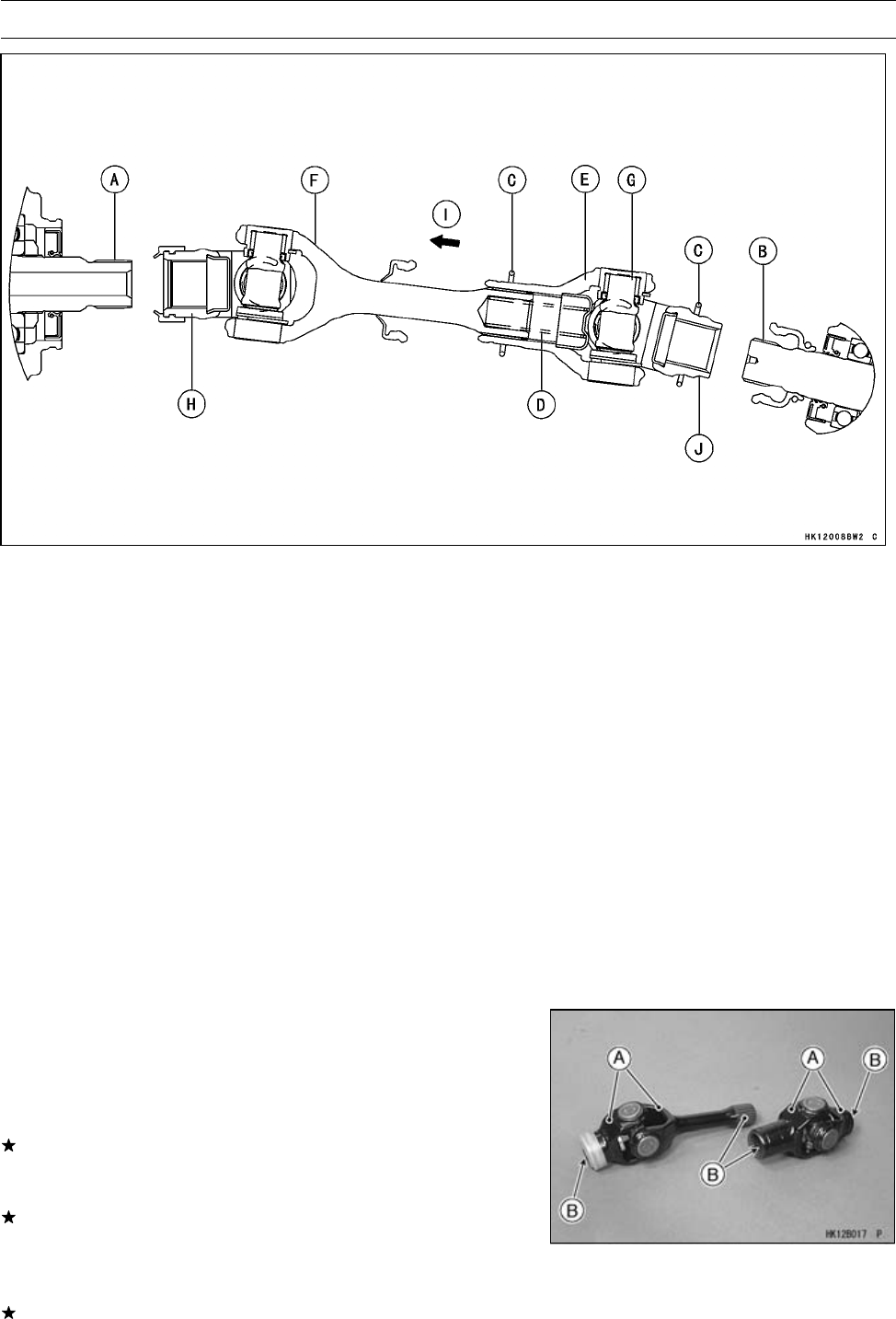
FINAL DRIVE 11-53
Rear Propeller Shaft
•Apply molybdenum disulfide grease:
Spline [A] on Output Shaft of Engine
Spline [B] on Pinion Gear of Rear Final Gear Case
•Install:
O-rings [C]
Spring [D]
Rear Universal Joint [E]
•Align the front universal joint yoke [F] with the rear univer-
sal joint yoke [G] as shown.
•Install the front end [H] of the propeller shaft.
•Push the rear universal joint forward [I], and install the
rear end [J] of the rear universal joint on the pinion gear
of rear final gear case.
•Install the rubber boots and fit the O-rings in the groove
of the boots.
Rear Propeller Shaft Joint Boot Inspection
•Refer to the Rear Propeller Shaft Joint Boot Inspection in
the Periodic Maintenance chapter.
Rear Propeller Shaft Inspection
•Remove the rear propeller shaft (see Rear Propeller Shaft
Removal).
•Check that the universal joints [A] work smoothly without
rattling or sticking.
If it does rattle or stick, the universal joint is damaged.
Replace the propeller shaft with a new one.
•Visually inspect the splines [B] on the propeller shaft.
If they are badly worn, chipped, or loose, replace the pro-
peller shaft.
•Also, inspect the splines on the rear end of the output
shaft and the pinion gear in the final gear case.
If splines are badly worn, chipped, or loose, replace the
output shaft and the pinion gear.
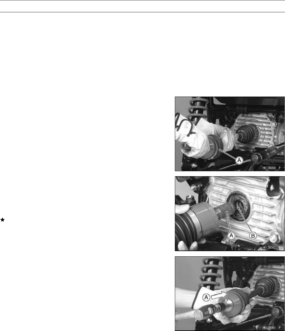
11-54 FINAL DRIVE
Rear Axle
Rear Axle Removal
•Drain the rear final gear case oil (see Rear Final Gear
Case Oil Change in the Periodic Maintenance chapter).
•Remove:
Rear Wheels (see Wheel Removal in the Wheels/Tires
chapter)
Rear Knuckle (see Rear Suspension Arm Removal in
the Suspension chapter)
Upper Suspension Arm (see Rear Suspension Arm Re-
moval in the Suspension chapter)
•Pull the rear axle [A] in a straight line out of the rear final
gear case.
Rear Axle Installation
•Wipe off any old grease:
Splines[A]ofAxle
Gear Case Oil Seal [B]
•Visually inspect the splines of the axle.
If they are badly worn or chipped, replace the axle with a
new one.
•Apply molybdenum disulfide grease to the axle splines.
•Apply grease top the gear case oil seal.
•Tap [A] the end of the rear axle straight and install the rear
axle.
NOTE
○The axle shaft must not come off easily.
Rear Axle Joint Boot Inspection
•Refer to the Axle Joint Boot Inspection in the Periodic
Maintenance chapter.
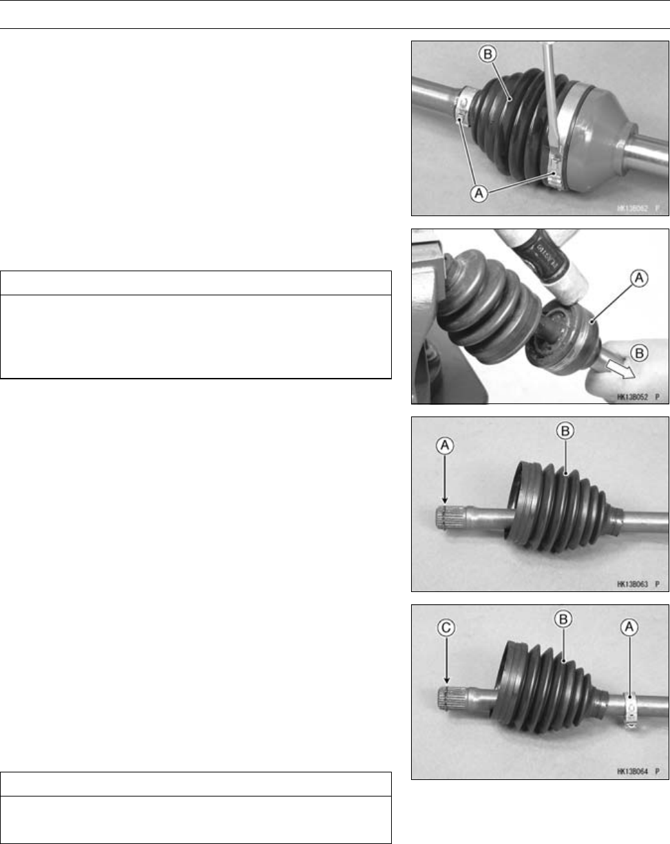
FINAL DRIVE 11-55
Rear Axle
Rear Axle Joint Boot Replacement
Outboard Joint Boot Removal
•Remove:
Rear Axle (see Rear Axle Removal)
•Tap the joint portion of the bands [A] with a suitable tool.
•Scrap the removed boot bands.
•Slide the joint boot [B] toward the inboard joint.
•Tap the bearing housing [A] straight [B] with a plastic ham-
mer to separate it from the shaft.
CAUTION
Do not tap on the cage. Be careful not get hurt when
the housing comes out. If the splined portion of
shaft cracked or damaged during disassembling of
outboard joint, do not reuse the shaft.
•Remove:
Circlip [A]
Boot [B]
Outboard Joint Boot Installation
•Cleantheaxleshaftbywipingofftheusedgreaseonit.
•Wind the tape on the splines of the axle shaft in order to
protect the joint boot.
•Install:
New Small Band [A]
New Boot [B]
○Apply the special grease slightly on the inside of the new
boot small diameter, and install the boot on the axle shaft.
CAUTION
Only the special grease that is included with the
boot kit can be applied to the boots.
•Install:
New Circlip [C]
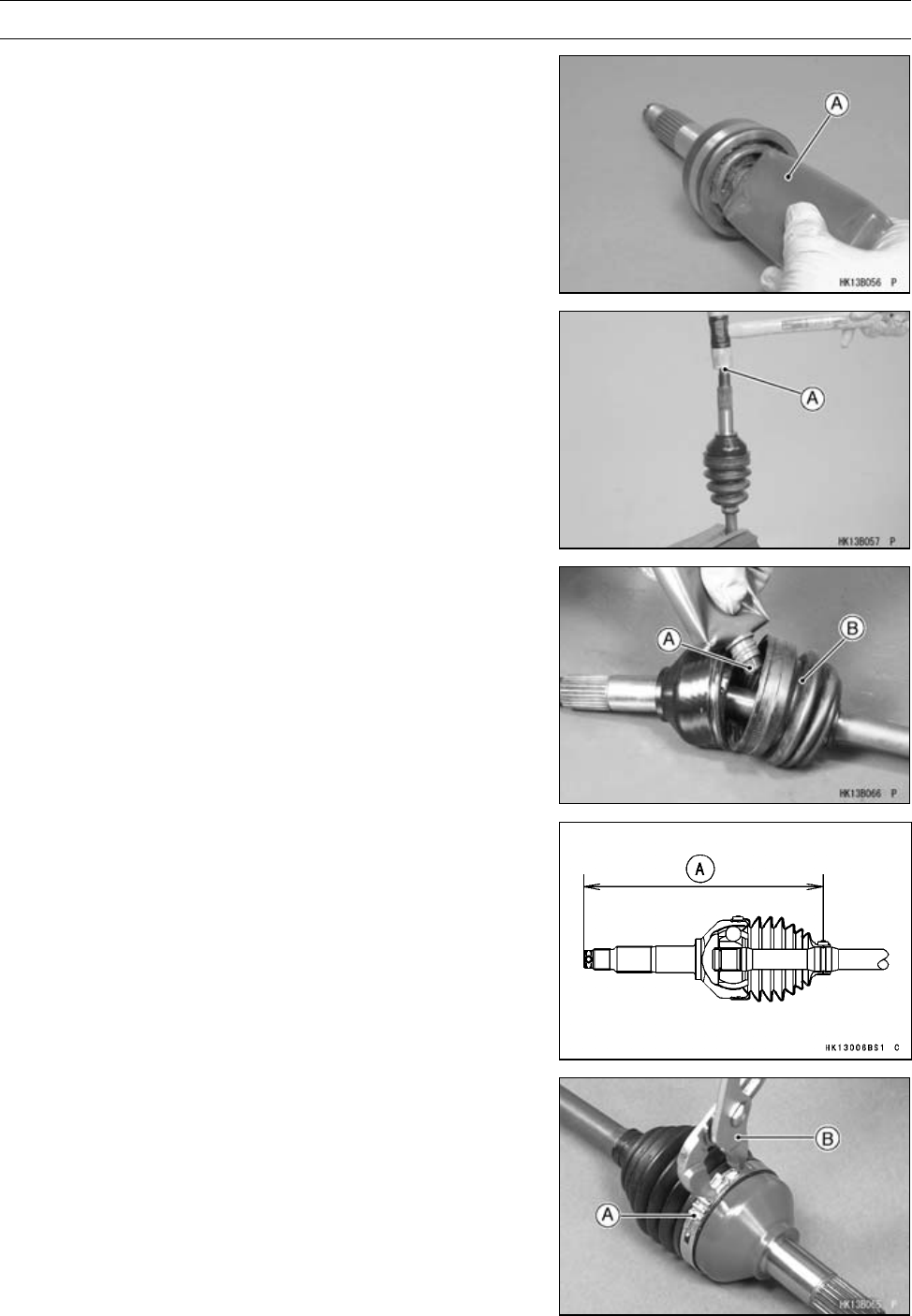
11-56 FINAL DRIVE
Rear Axle
•Place the special grease tube nozzle in the bore of the
housing and squeeze the tube [A] until the grease comes
out from the joint bearing.
•Tap the shaft end [A] straight with a plastic hammer until
it is locked by the circlip.
•Squeeze all of the special grease [A] into the new boot
[B].
•Compress the axle assembly to the specified length while
relieving the air pressure inside the inboard boot.
•Hold the axle at this setting.
Standard Length of Assembling:
Outboard: 224.82 mm (8.850 in.) [A]
•Pinch the boot bands [A] with a suitable tool [B] to install
it.
○Compress the suitable tool with a vice, if necessary.
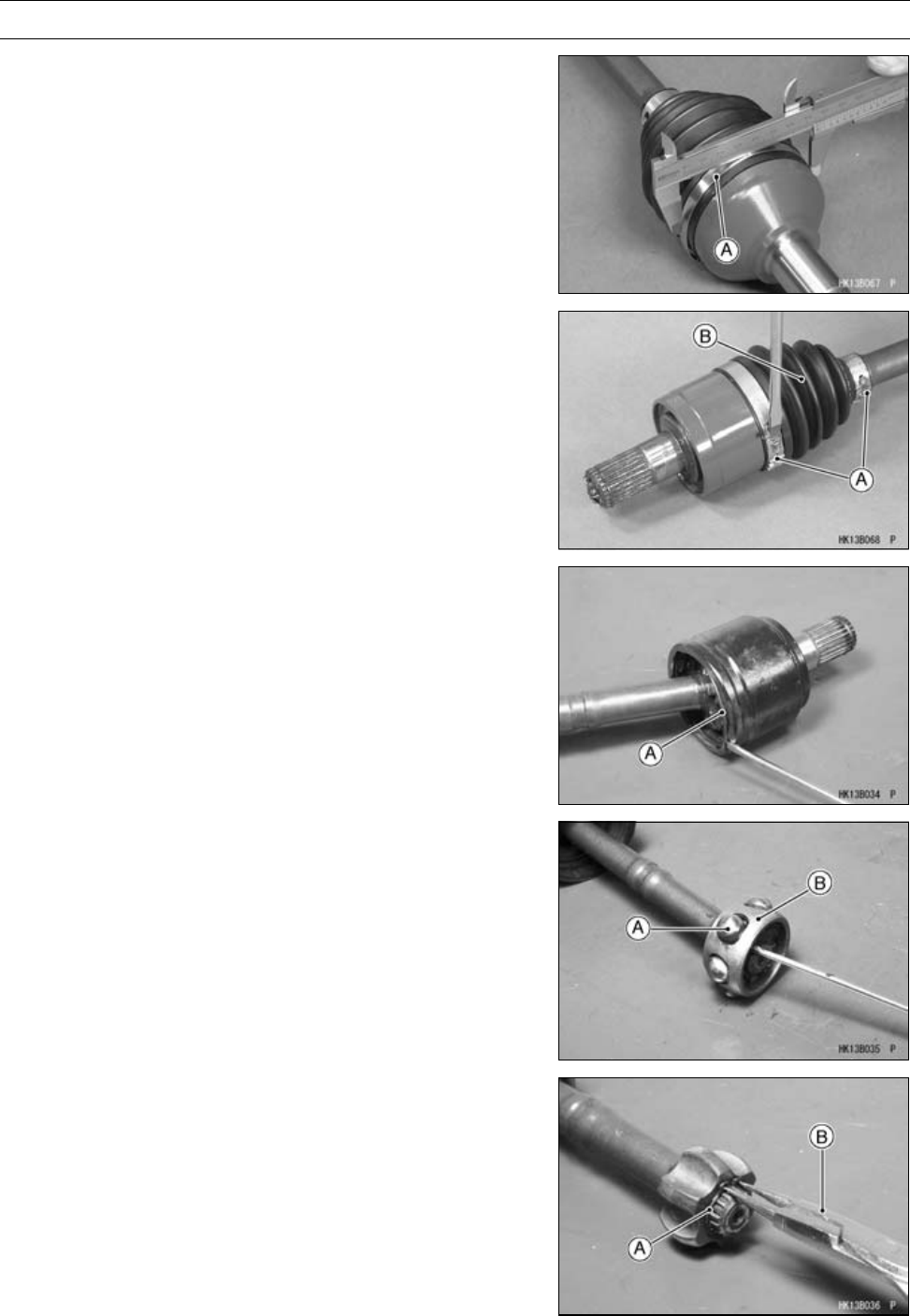
FINAL DRIVE 11-57
Rear Axle
•Be sure outside diameter of the band [A] is less than the
maximum diameter.
Maximum Outside Diameter of Band: 82.9 mm (3.26 in.)
Inboard Joint Boot Removal
•Remove:
Rear Axle (see Rear Axle Removal)
•Tap the joint portion of the bands [A] with a suitable tool.
•Scrap the removed boot bands.
•Slide the joint boot [B] toward the outboard joint.
•Remove the retaining ring [A].
•Separate the bearing cup from the axle shaft.
•Remove the steel balls [A].
•Slide the cage [B] toward the outboard joint.
•Remove:
Circlip [A]
Special Tool - Outside Circlip Pliers [B]: 57001-144
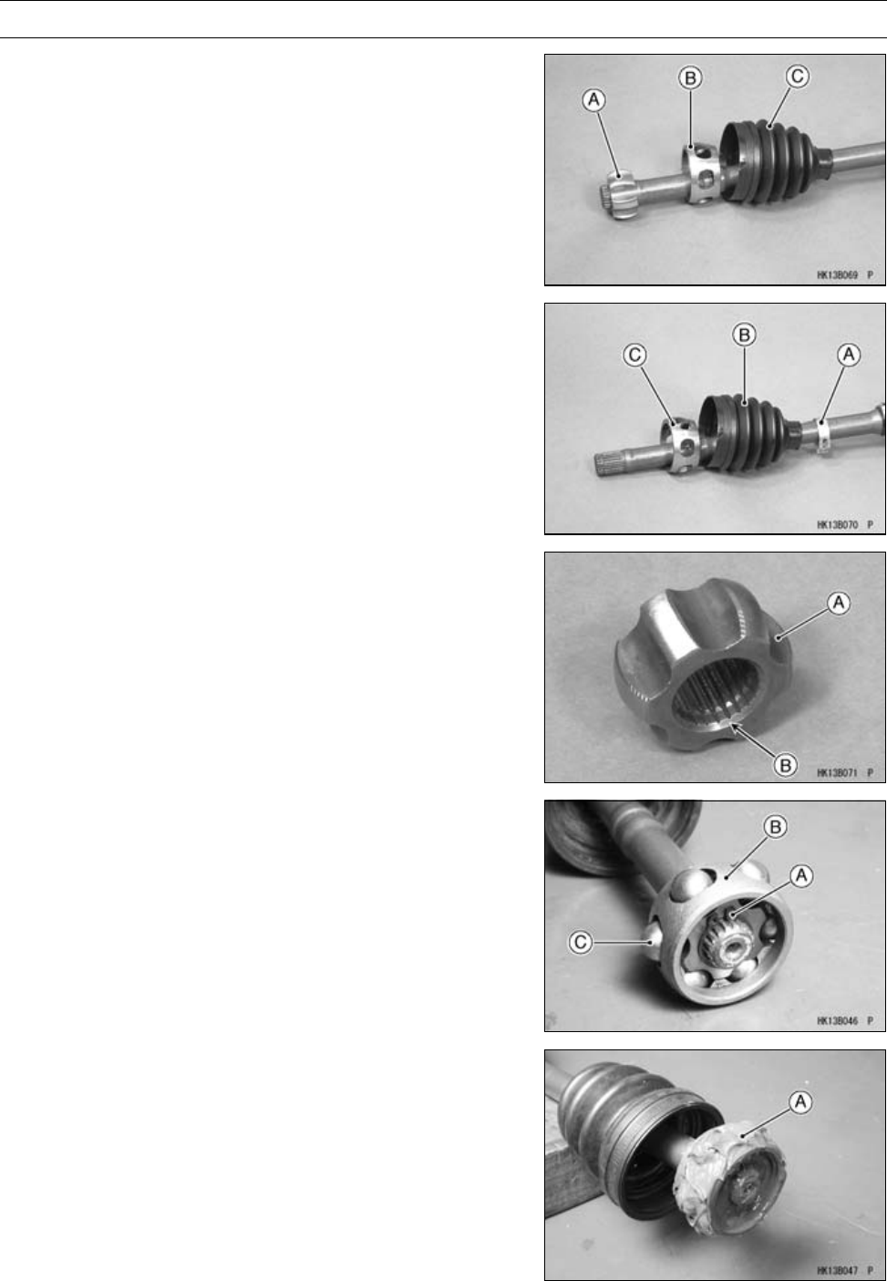
11-58 FINAL DRIVE
Rear Axle
•Remove:
Inner Race [A]
Cage [B]
Inboard Joint Boot [C]
Inboard Joint Boot Installation
•Install:
New Small Band [A]
New Inboard Joint Boot [B]
Cage [C]
•Install the inner race [A] so that the tapered side [B] faces
outboard joint.
•Install:
Circlip [A]
Special Tool - Outside Circlip Pliers: 57001-144
•Slide the cage [B] on the inner race and install the steel
balls [C].
•Apply the special grease [A] to the steel balls and cage.
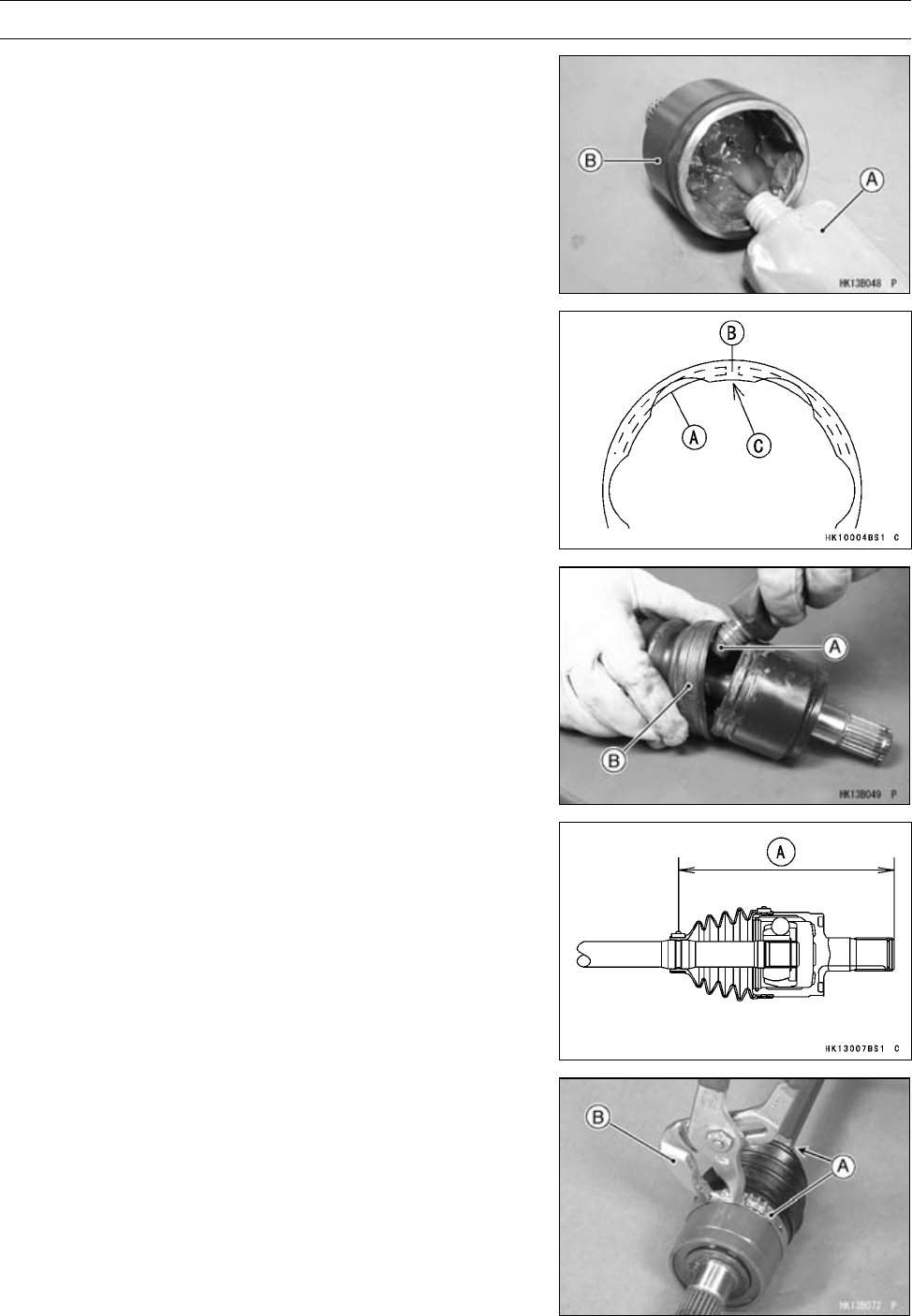
FINAL DRIVE 11-59
Rear Axle
•Squeeze about half a tube (30 grams) of the special
grease [A] into the bearing cup [B].
•Insert the balls and cage assembly in the bearing cup
strongly.
•Install the new retaining ring [A] so that the opening [B] is
aligned with one of the projections [C].
•Squeeze the remaining special grease [A] into the inboard
joint boot [B].
•Compress the axle assembly to the specified length while
relieving the air pressure inside the inboard boot.
•Hold the axle at this setting.
Standard Length of Assembling:
Inboard: 162.2 mm (6.386 in.) [A]
•Pinch the boot bands [A] with a suitable tool [B] to install
them.
○Compress the suitable tool with a vice, if necessary.
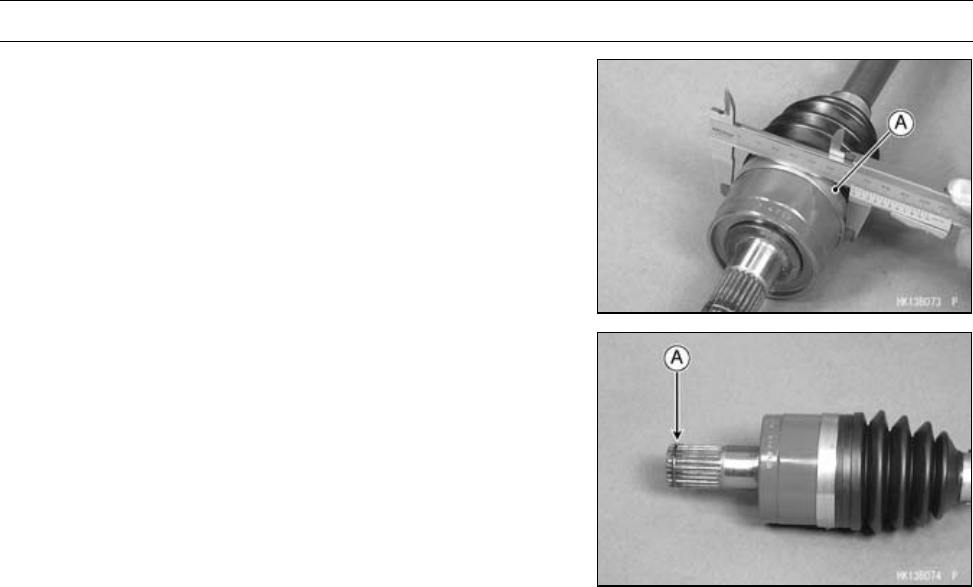
11-60 FINAL DRIVE
Rear Axle
•Be sure the outside diameter of the band [A] is less than
the maximum diameter.
Maximum Outside Diameter of Band: 73.4 mm (2.89 in.)
•Install the new circlip [A] to the shaft of the bearing cup.
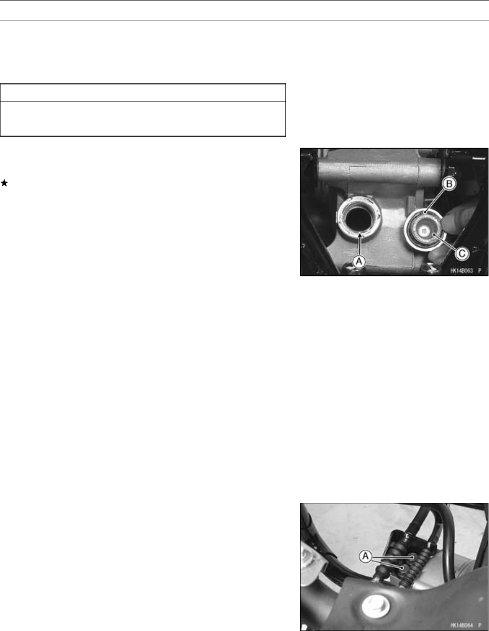
FINAL DRIVE 11-61
Rear Final Gear Case
Rear Final Gear Case Oil Level Inspection
•Park the vehicle so that it is level, both side-to-side and
front-to-rear.
•Remove the filler cap.
CAUTION
Be careful not to allow any dirt or foreign materials
to enter the gear case.
•Check the oil level. The oil level should come to the bot-
tom of the filler opening [A].
If it is insufficient, first check the rear final gear case for oil
leakage, remedy it if necessary, and add oil through the
filler opening. Use the same type and brand of oil that is
already in the final gear case.
•Apply grease to the O-ring [B].
•Be sure the O-ring is in place.
Torque - Rear Final Gear Case Oil Filler Cap [C]: 29 N·m (3.0
kgf·m, 21 ft·lb)
Rear Final Gear Case Oil Change
•Refer to the Rear Final Gear Case Oil Change in the Pe-
riodic Maintenance chapter.
Rear Final Gear Case Removal
•Remove:
Rear Fender (see Rear Fender Removal in the Frame
chapter)
Fuel Tank (see Fuel Tank Removal in the Fuel System
(DFI) chapter)
Rear Wheels (see Wheel Removal in the Wheels/Tires
chapter)
Rear Propeller Shaft (Rear Propeller Shaft Removal)
Rear Axles (see Rear Axle Removal)
Stabilizer (see Stabilizer Removal in the Suspension
chapter)
•Remove:
Brake Cable Bracket Bolts [A]
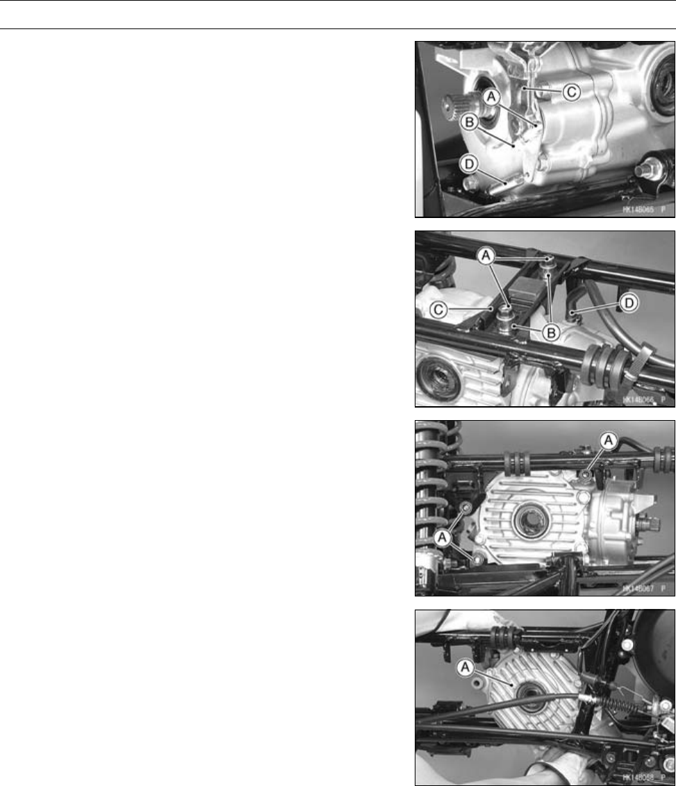
11-62 FINAL DRIVE
Rear Final Gear Case
•Remove:
Bolts [A] and Nut [B]
Brake Cam Lever [C]
Spring [D]
•Remove:
Bracket Bolts [A]
Collars [B]
Bracket [C]
Vent Hose [D]
•Remove:
Rear Final Gear Case Bolts and Nuts [A]
•Remove the rear final gear case [A] as shown.
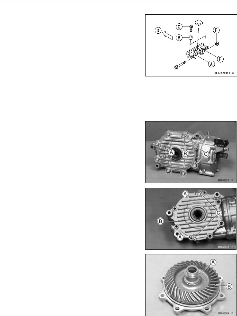
FINAL DRIVE 11-63
Rear Final Gear Case
Rear Final Gear Case Installation
•Install:
Rear Final Gear Case
Bracket [A]
Collars [B]
Bracket Bolts [C]
[D] Front
[E] Hole
Washers (rear side)
•Tighten:
Torque - Rear Final Gear Case Nuts [F]: 91 N·m (9.3 kgf·m,
67 ft·lb)
Rear Final Gear Case Bracket Bolts: 59 N·m (6.0
kgf·m, 44 ft·lb)
•Install:
Removed Parts (see applicable chapters)
Rear Final Gear Case Disassembly
•Remove:
Rear Final Gear Case (see Rear Final Gear Case Re-
moval)
Rear Final Gear Case Right Cover Bolts (M8) [A]
Rear Final Gear Case Right Cover Bolts (M10) [B]
Rear Final Gear Case Right Cover Bolts (M12) [C]
•Using the pry points [A], remove the rear final gear case
right cover [B].
[C] Arrow Marks
•Remove:
Shim(s) [A]
Ring Gear [B]
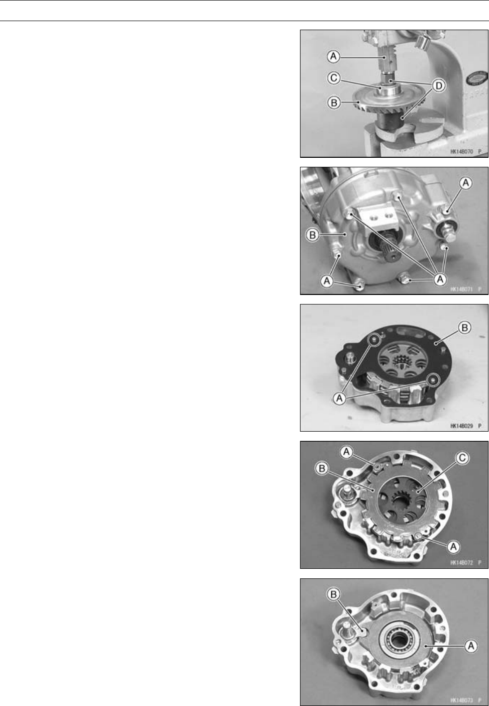
11-64 FINAL DRIVE
Rear Final Gear Case
•Using a press [A], sparate the ring gear [B] and coupling
[C].
[D] Suitable Tools
•Remove:
Rear Final Gear Case Front Cover Bolts [A]
Rear Final Gear Case Front Cover Assembly [B]
•Remove:
Gasket Screws [A]
Gasket [B]
•Remove:
Set Pins [A] with Steel Plates [B], Friction plates [C] and
spring
•Remove:
Brake Cam Plate [A]
Brake Camshaft [B]
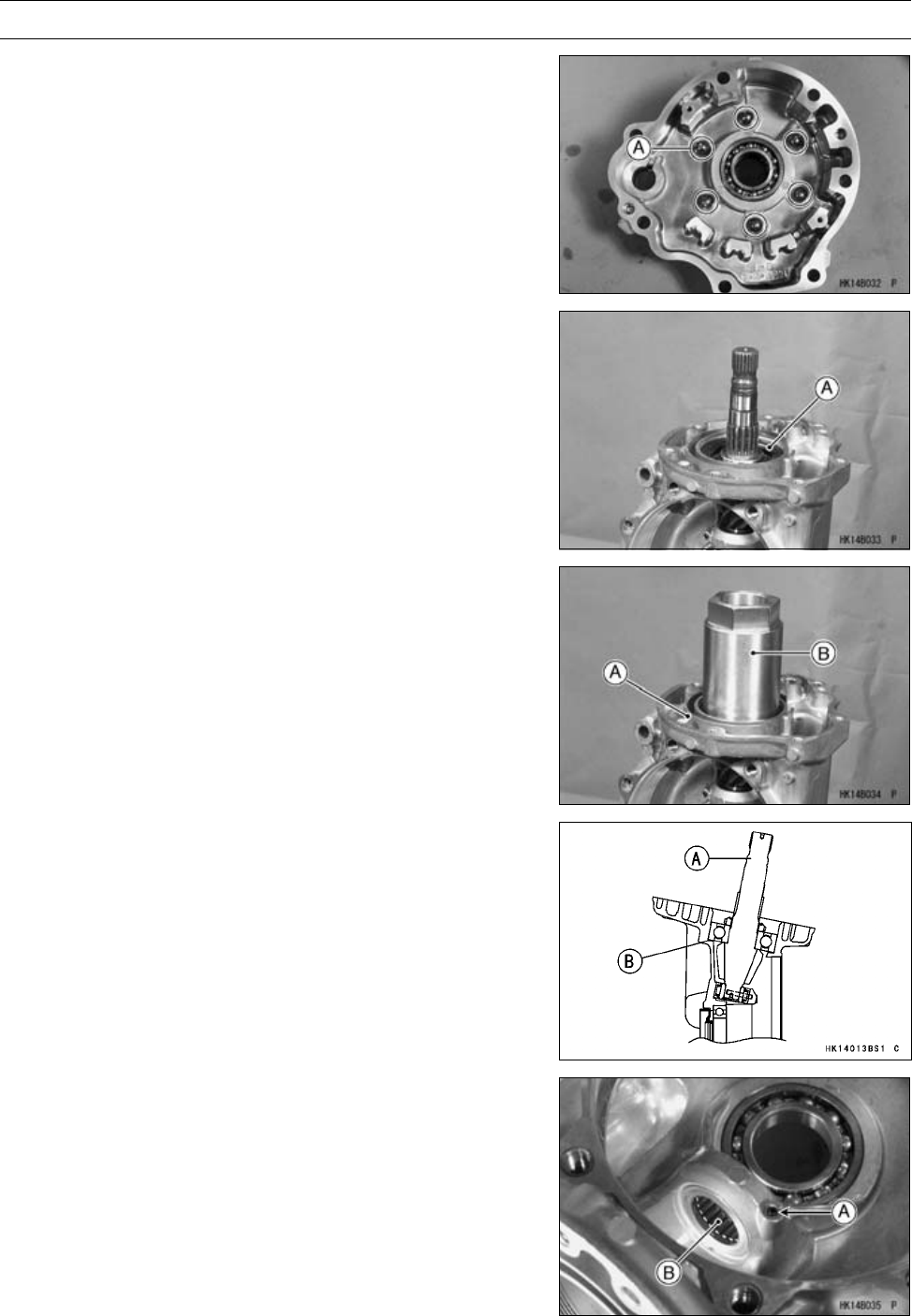
FINAL DRIVE 11-65
Rear Final Gear Case
•Remove:
Steel Balls [A]
•Remove:
Pinion Gear Bearing Holder [A]
○Hold the rear final gear case [A] in a vise, and remove the
bearing holder using the socket wrench [B].
Special Tool - Socket Wrench, Hex 50: 57001-1478
○If it is difficult to break free the holder, apply the heat to it
to softer the locking agent.
•Remove:
Pinion Gear Unit [A]
Shim(s) [B]
•Drill out the spring pin [A] with a drill bit of 3 mm (0.12 in.)
diameter and remove it.
•Remove the needle bearing [B].
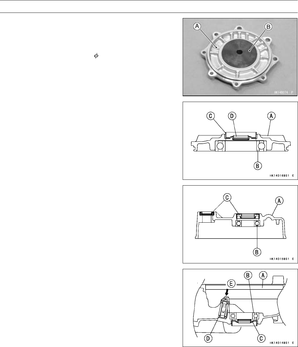
11-66 FINAL DRIVE
Rear Final Gear Case
Rear Final Gear Case Right Cover Assembly
[A] Rear Final Gear Case Right Cover
•Press:
Ball Bearing (until bottomed)
Special Tool - Bearing Driver, 54.3 [B]: 57001-1488
[A] Rear Final Gear Case Right Cover
[B] Ball Bearing
•Press:
Oil Seal [C] (until bottomed)
Special Tool - Bearing Driver Set: 57001-1129
•Apply Grease:
Oil Seal Lips [D]
Rear Final Gear Case Front Cover Assembly
[A] Rear Final Gear Case Front Cover
•Press:
Ball Bearing [B] (until bottomed)
Special Tool - Bearing Driver Set: 57001-1129
•Press the faces of the oil seals [C] are flush with the ends
of the housing.
•Apply Grease:
Oil Seal Lips
Rear Final Gear Case Assembly
[A] Rear Final Gear Case
•Press:
Ball Bearing [B] (until bottomed)
Oil Seal [C] (until bottomed)
Special Tool - Bearing Driver Set: 57001-1129
•Apply Grease:
Oil Seal Lip
•Press the face of the needle bearing [D] so that its surface
is flush with the end of the housing.
•Insert the spring pin [E].
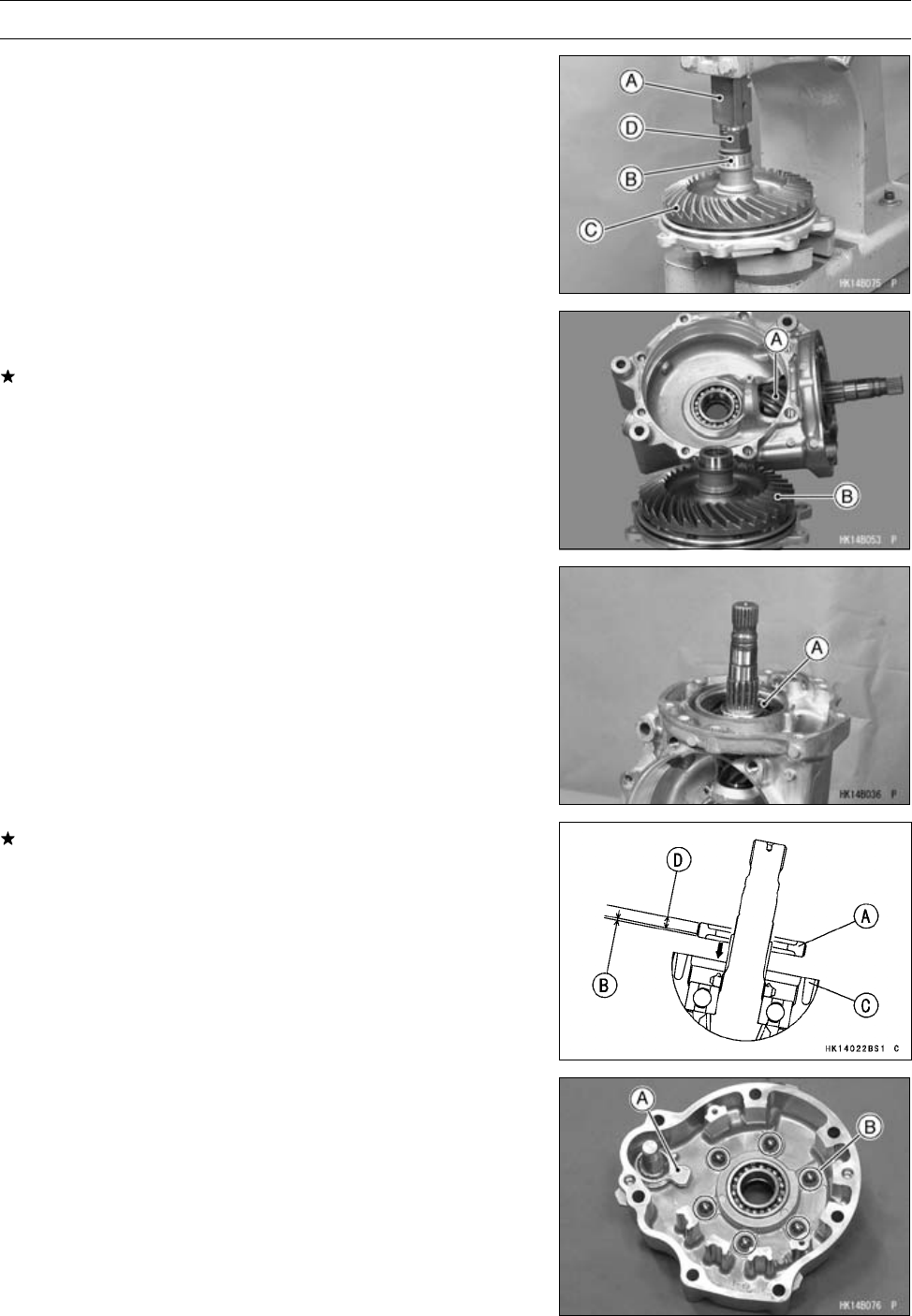
FINAL DRIVE 11-67
Rear Final Gear Case
•Using a press [A], press the coupling [B] to the ring gear
[C] until it bottom out.
[D] Suitable Tool
•Visually check the pinion gear [A] and ring gear [B] for
scoring, chipping, or other damage.
Replace the bevel gear as a set if either gear is damaged
since they are lapped as a set in the factory to get the best
tooth contact.
•Be sure to check and adjust the bevel gear backlash and
tooth contact when any of the backlash-related parts are
replaced (see Rear Final Bevel Gear Adjustment).
•Insert the shim(s) and pinion gear unit [A].
•Apply a non-permanent locking agent to the pinion gear
bearing holder, and tighten it.
Special Tool - Socket Wrench, Hex 50: 57001-1478
Torque - Pinion Gear Bearing Holder: 137 N·m (14 kgf·m,
101 ft·lb)
When installing a new pinion gear bearing holder [A], in-
stall the holder so that the no coating area [B] (one pitch
thread) faces gear case [C].
[D] Locking Agent Coating Area
•Install:
Brake Camshaft [A]
Steel Balls [B]
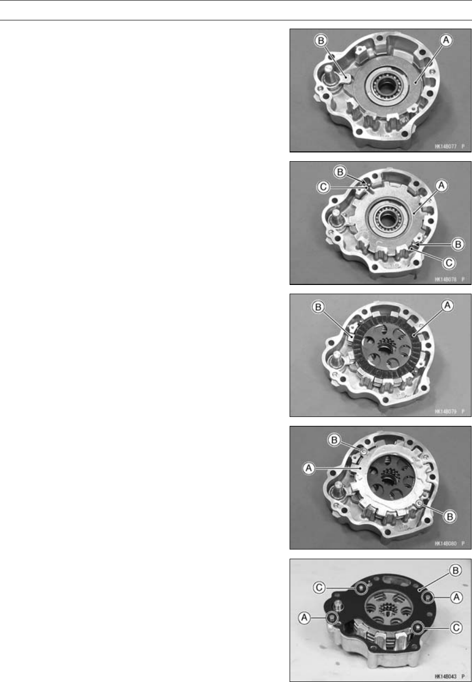
11-68 FINAL DRIVE
Rear Final Gear Case
•Install:
Brake Cam Plate [A]
○Fit the cam plate and brake camshaft [B] as shown.
•Install:
Steel Plate [A] (P/No. 41080-1483, two holes)
Set Pins [B] and Springs [C]
•Install (alternately):
Friction Plates [A]
Steel Plates [B](P/No. 41080-1484, without holes)
•Install:
Steel Plate [A] (P/No. 41080-1483, two holes)
○Insert the pins [B] into the holes of steel plate.
•Install:
Dowel Pins [A]
New Gasket [B]
•Apply a non-permanent locking agent to the rear final gear
case gasket screws.
•Tighten:
Torque - Rear Final Gear Case Gasket Screws [C]: 1.25 N·m
(0.13 kgf·m, 11 in·lb)
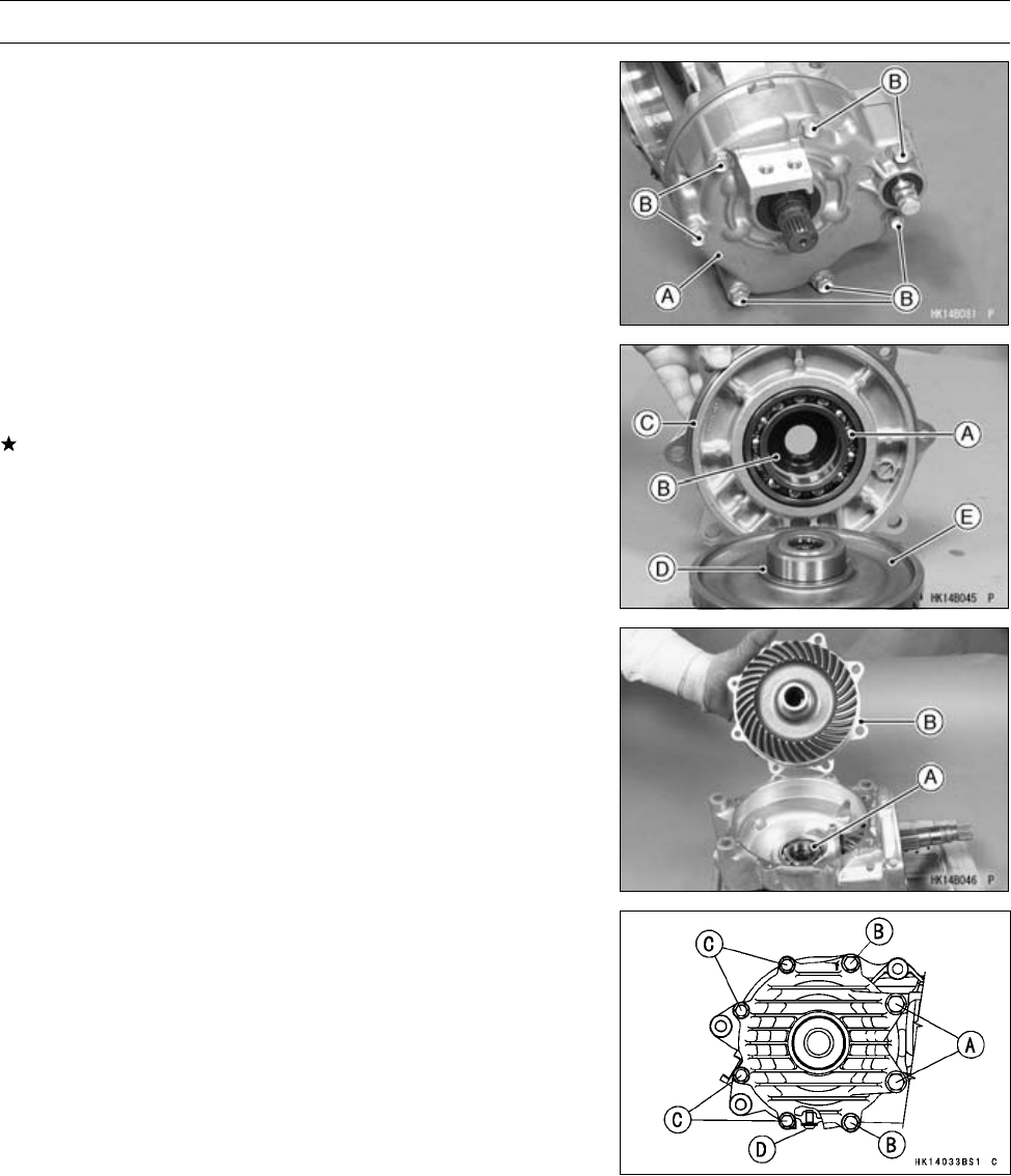
FINAL DRIVE 11-69
Rear Final Gear Case
•Install:
Rear Final Gear Case Front Cover [A]
•Tighten:
Torque - Rear Final Gear Case Front Cover Bolts [B]: 24
N·m (2.4 kgf·m, 18 ft·lb)
•Inspect:
Ball Bearing [A] (see Bearing and Oil Seal section)
Oil Seal [B] (see Bearing and Oil Seal section)
If they are damaged, replace them.
•Apply grease to the oil seal lips and O-ring [C].
•Install:
Shim [D]
Ring Gear [E]
•Install:
Shim [A]
Rear Final Gear Case Right Cover [B]
•Apply a non-permanent locking agent to the rear final gear
case right cover bolts.
•Tighten:
Torque - Rear Final Gear Case Right Cover Bolts (M12) [A]:
95 N·m (9.7 kgf·m, 70 ft·lb)
Rear Final Gear Case Right Cover Bolts (M10) [B]:
49 N·m (5.0 kgf·m, 36 ft·lb)
Rear Final Gear Case Right Cover Bolts (M8) [C]:
24 N·m (2.4 kgf·m, 18 ft·lb)
Rear Final Gear Case Oil Drain Plug [D]: 15 N·m
(1.5 kgf·m, 11 ft·lb)
Rear Final Bevel Gear Adjustment
○The backlash and tooth contact pattern of the bevel
gears must be adjust to prevent the gears from making
noise and being damaged.
•After replacing any of the backlash-related parts, be sure
to check and adjust the backlash and tooth contact of the
bevel gears. First, adjust backlash, and then tooth con-
tact by replacing shims.
○The amount of backlash is influenced by the ring gear
position more than by the pinion gear position.
○Tooth contact locations is influenced by the pinion gear
position more than by the ring gear position.
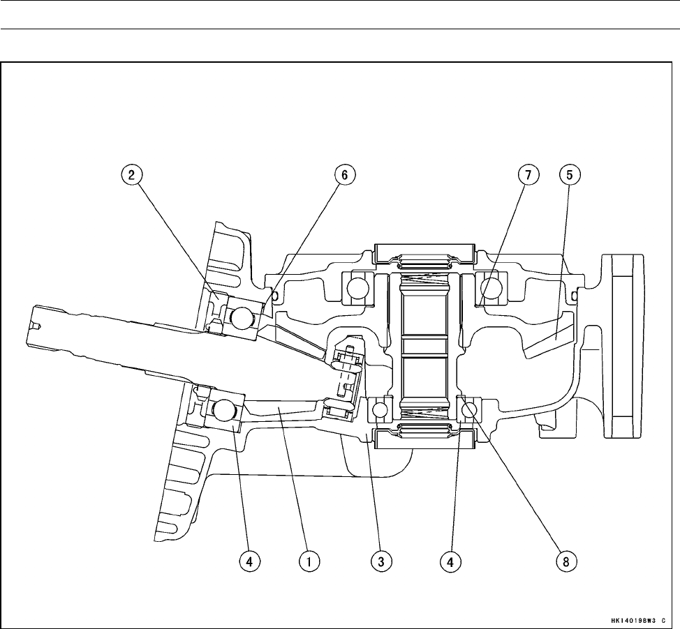
11-70 FINAL DRIVE
Rear Final Gear Case
Rear Final Gear Case (Backlash-related Parts)
1. Pinion Gear
2. Pinion Gear Bearing Holder
3. Gear Case Right Cover
4. Ball Bearings
5. Ring Gear
6. Pinion Gear Shim(s)
7. Ring Gear Shim(s)
8. Ring Gear Shim(s)
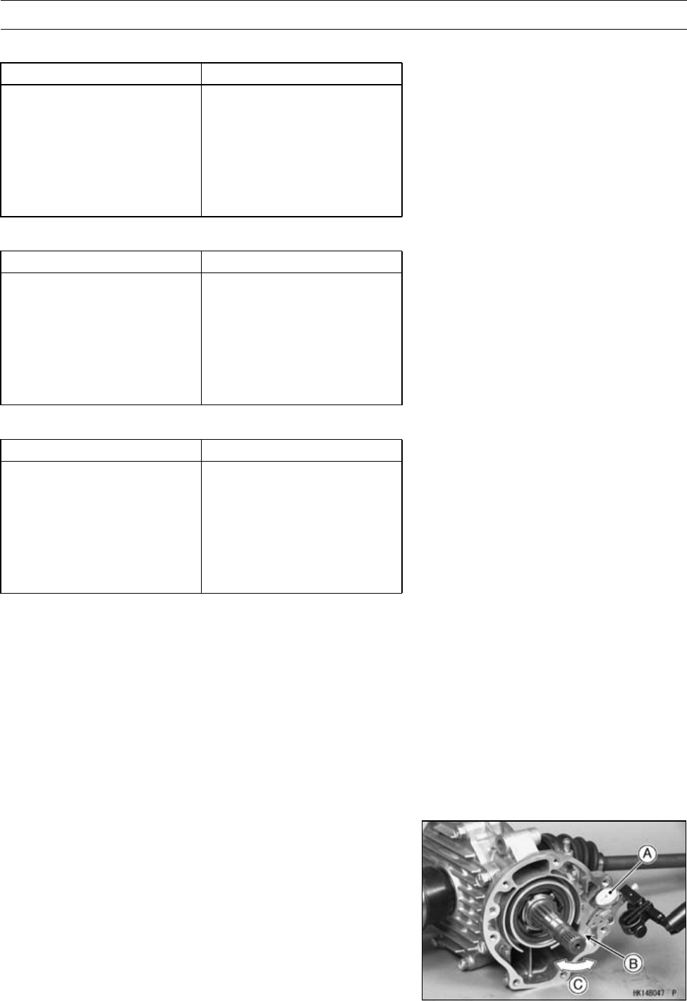
FINAL DRIVE 11-71
Rear Final Gear Case
6. Pinion Gear Shims for Backlash Adjustment
Thickness Part Number
0.15 mm (0.006 in.) 92180-1423
0.2 mm (0.008 in.) 92180-1424
0.5 mm (0.020 in.) 92180-1425
0.8 mm (0.031 in.) 92180-1426
1.0 mm (0.039 in.) 92180-1427
1.2 mm (0.047 in.) 92180-1428
7. Ring Gear Shims for Tooth Contact Adjustment
Thickness Part Number
0.15 mm (0.006 in.) 92180-1417
0.2 mm (0.008 in.) 92180-1418
0.5 mm (0.020 in.) 92180-1419
0.8 mm (0.031 in.) 92180-1420
1.0 mm (0.039 in.) 92180-1421
1.2 mm (0.047 in.) 92180-1422
8. Ring Gear Shims for Tooth Contact Adjustment
Thickness Part Number
0.15 mm (0.006 in.) 92180-0166
0.2 mm (0.008 in.) 92180-0165
0.5 mm (0.020 in.) 92180-0164
0.8 mm (0.031 in.) 92180-0163
1.0 mm (0.039 in.) 92180-0162
1.2 mm (0.047 in.) 92180-0161
Backlash Adjustment
•Clean any dirt and oil off the bevel gear teeth.
•Install the pinion gear assembly with the primary shim 1.0
mm (0.039 in.) thickness.
•Assemble the rear final gear case (see Rear Final Gear
Case Assembly).
○Install the ring gear with the primary shims 1.0 mm (0.039
in.) thickness.
○Check the backlash during tightening the cover bolts, and
stop tightening them immediately if the backlash disap-
pears. Then, change the ring gear shim to a thinner one.
•Temporarily, install the rear axle in the gear case and hold
it with a vise so that the ring gear is lower than the pinion
gear.
•Mount a dial gauge [A] so that the tip of the gauge is
against the splined portion [B] of the pinion gear joint.
•To measure the backlash, move the pinion gear shaft
back and forth [C] while holding the rear axle steady.
The difference between the highest and the lowest gauge
reading is the amount of backlash.
○Measure backlash at three locations equally spaced on
the splines.
Rear Final Bevel Gear Backlash
Standard: 0.04 ∼0.17 mm (0.002 ∼0.007 in.) at
pinion gear spline

11-72 FINAL DRIVE
Rear Final Gear Case
If the backlash is not within the standard, replace the
pinion gear shim(s). To increase backlash, increase the
thickness of the shim(s). To decrease backlash, decrease
the thickness of the shim(s).
Change the thickness a little at a time.
•Recheck the backlash, and readjust as necessary.
Tooth Contact Adjustment
•Clean any dirt and oil off the bevel gear teeth.
•Apply checking compound to 4 or 5 teeth of the pinion
gear.
NOTE
○Apply checking compound to the teeth in a thin, even
coat with a fairly stiff paint brush. If painted too thickly,
the exact tooth pattern may not appear.
○The checking compound must be smooth and firm, with
the consistency of tooth paste.
○Special compounds are available at automotive supply
stores for the purpose of checking gear tooth patterns
and contact. Use one of these for checking the bevel
gears.
•Assemble the rear final gear case (see Rear Final Gear
Case Assembly).
•Turn the pinion gear for one revolution in the drive and
reverse (coast) direction, while creating drag on the ring
gear.
•Remove the ring gear and pinion gear unit to check the
drive pattern and coast pattern of the bevel gear teeth.
○The tooth contact patterns of both (drive and coast) sides
should be centrally located between the top and bottom
of the tooth. The drive pattern can be a little closer to the
toe and the coast pattern can be a somewhat longer and
closer to the toe.
If the tooth contact pattern is incorrect, replace the pinion
gear shim(s), following the examples shown (see Correct
Tooth Contact Pattern in the Front Final Bevel Gear Ad-
justment section).
•Then erase the tooth contact patterns, and check them
again. Also check the backlash every time the shim(s)
are replaced. Repeat the shim change procedure as nec-
essary.
NOTE
○If the backlash is out of the standard range after
changing the pinion gear shim(s), change the ring gear
shim(s) to correct the backlash before checking the
tooth contact pattern.
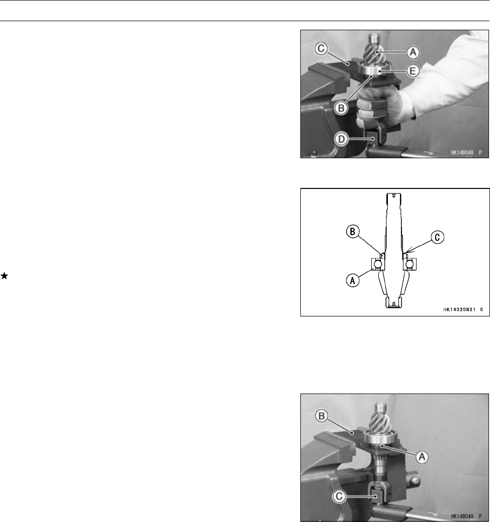
FINAL DRIVE 11-73
Rear Final Gear Case
Pinion Gear Unit Disassembly
•Remove:
Pinion Gear Unit [A] (see Rear Final Gear Case Disas-
sembly)
•Hold the pinion gear bearing holder nut [B] with the socket
wrench [C] in a vise, and loosen the pinion gear shaft
using the pinion gear holder [D].
Special Tools - Socket Wrench: 57001-1363
Pinion Gear Holder, m1.0: 57001-1281
•Remove the ball bearing [E] as necessary.
Special Tool - Bearing Puller: 57001-135
Pinion Gear Unit Assembly
○The pinion gear and ring gear are lapped as a set in the
factory to get the best tooth contact. They must be re-
placed as a set.
•Visually inspect the bearing for abrasion, color change, or
other damage.
If there is any doubt as to the condition of a bearing, re-
place the bearing.
•Be sure to check and adjust the bevel gear backlash and
tooth contact, when any of the backlash-related parts are
replaced (see Front Final Bevel Gear Adjustment).
•Press the bearing [A] on the pinion gear until it is bot-
tomed.
•Install the pinion gear bearing holder nut [B] so that the
projection [C] faces outward.
•Apply a non-permanent locking agent to the pinion gear
bearing holder nut [A], and tighten it.
Special Tools - Socket Wrench [B]: 57001-1363
Pinion Gear Holder, m1.0 [C]: 57001-1281
Torque - Pinion Gear Bearing Holder Nut: 157 N·m (16
kgf·m, 116 ft·lb)
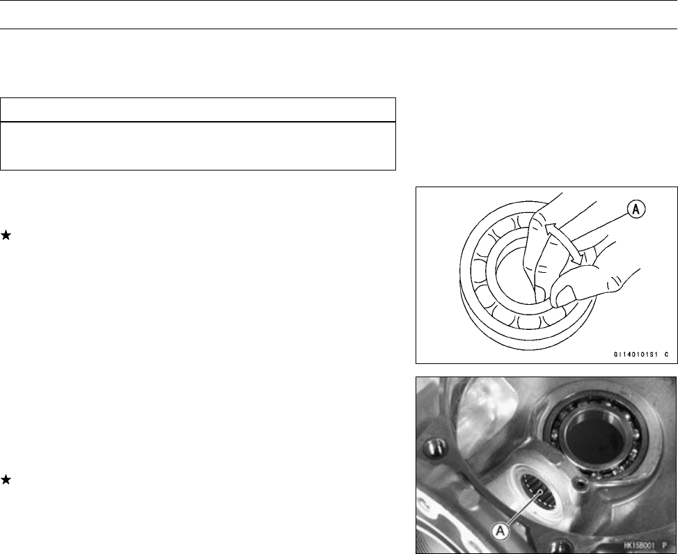
11-74 FINAL DRIVE
Bearing and Oil Seal
Ball or Needle Bearing Inspection
Since the bearings are made to extremely close toler-
ances, the clearance cannot normally be measured.
CAUTION
Do not remove any bearings for inspection except
the right rear axle bearing.
•Turn each bearing in the case or hub back and forth [A]
while checking for plays, roughness, or binding.
If bearing play, roughness, or binding is found, replace
the bearing.
•Check the needle bearings [A].
○The rollers in the needle bearing normally wear very little,
and wear is difficult to measure. Instead of measuring,
inspect the bearing for abrasion, color change, or other
damage.
If the bearing is damaged, replace the bearing.
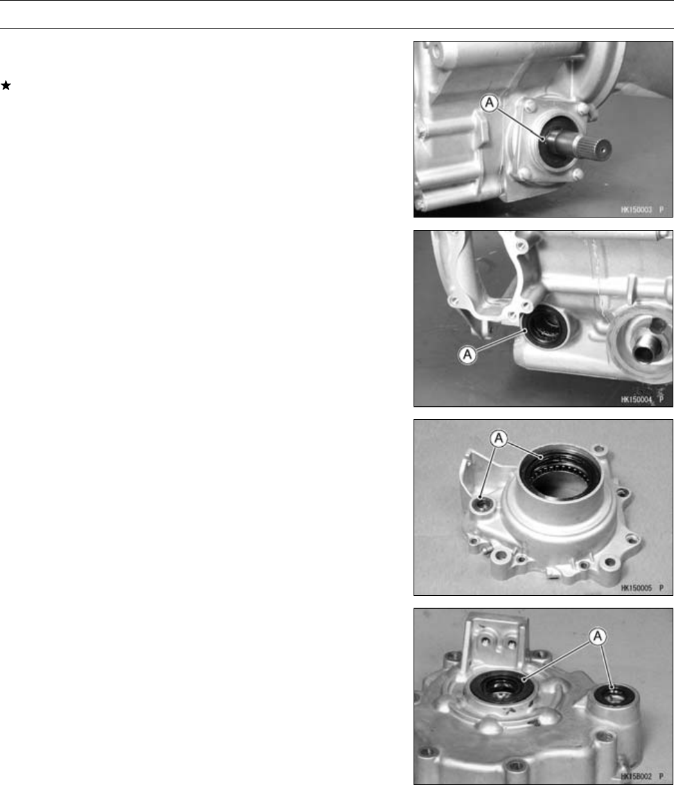
FINAL DRIVE 11-75
Bearing and Oil Seal
Oil Seal Inspection
•Inspect the oil seals [A].
Replace any if the lips are misshapen, discolored (indicat-
ing that the rubber has deteriorated), hardened, or been
otherwise damaged.

BRAKES 12-1
12
Brakes
Table of Contents
Exploded View................................... 12-2
Specifications .................................... 12-6
Special Tool ....................................... 12-7
Brake Fluid ........................................ 12-8
Front Brake Fluid
Recommendation ...................... 12-8
Front Brake Fluid Level
Inspection.................................. 12-8
Front Brake Fluid Change............ 12-8
Front Brake Line Air Bleeding ...... 12-9
Master Cylinder ................................. 12-10
Front Brake Master Cylinder
Removal .................................... 12-10
Front Brake Master Cylinder
Installation ................................. 12-10
Front Brake Master Cylinder
Disassembly.............................. 12-11
Front Brake Master Cylinder
Assembly................................... 12-11
Front Master Cylinder Inspection
(Visual Inspection)..................... 12-12
Calipers ............................................. 12-13
Front Brake Caliper Removal....... 12-13
Front Brake Caliper Installation.... 12-13
Front Brake Caliper Disassembly 12-14
Front Brake Caliper Assembly ..... 12-14
Front Brake Caliper Piston and
Cylinder Damage Inspection ..... 12-15
Front Brake Caliper Holder Shaft
Wear Inspection ........................ 12-15
Brake Pads........................................ 12-16
Front Brake Pad Removal............ 12-16
Front Brake Pad Installation......... 12-16
Front Brake Pad Wear Inspection 12-16
Brake Discs ....................................... 12-17
Front Brake Disc Cleaning ........... 12-17
Front Brake Disc Removal ........... 12-17
Front Brake Disc Installation ........ 12-17
Front Brake Disc Wear Inspection 12-17
Front Brake Disc Runout
Inspection.................................. 12-17
Brake Hoses...................................... 12-18
Front Brake Hose Inspection ....... 12-18
Front Brake Hose Replacement... 12-18
Rear Brake Lever, Pedal and Cables 12-19
Rear Brake Pedal Position
Inspection.................................. 12-19
Rear Brake Pedal Position
Adjustment ................................ 12-19
Rear Brake Lever Free Play
Inspection.................................. 12-19
Rear Brake Pedal Free Play
Inspection.................................. 12-19
Rear Brake Lever and Brake
Pedal Free Play Adjustment...... 12-19
Rear Brake Pedal Removal ......... 12-19
Rear Brake Pedal Installation ...... 12-20
Rear Brake Cable Removal ......... 12-20
Rear Brake Cable Installation ...... 12-21
Rear Brake Cable Lubrication...... 12-21
Internal Wet Brake............................. 12-22
Internal Wet Brake Disassembly.. 12-22
Internal Wet Brake Assembly....... 12-22
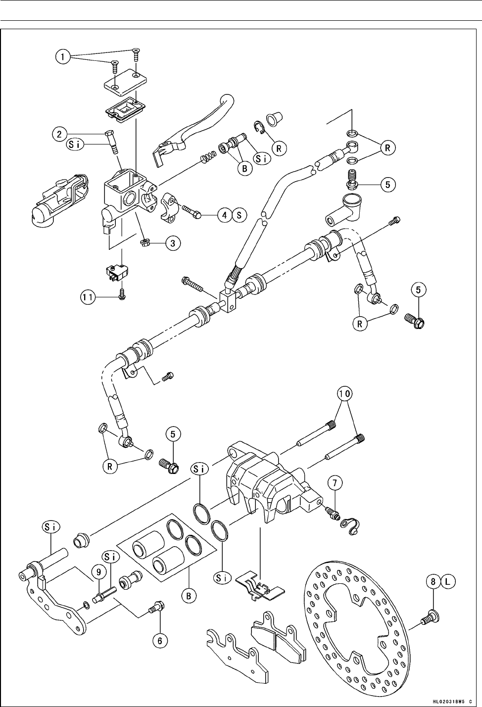
12-2 BRAKES
Exploded View

BRAKES 12-3
Exploded View
Torque
No. Fastener N·m kgf·m ft·lb Remarks
1Reservoir Cap Screws 1.5 0.15 13 in·lb
2Front Brake Lever Pivot Bolt 5.9 0.60 52 in·lb
3Front Brake Lever Pivot Bolt Locknut 5.9 0.60 52 in·lb
4Front Brake Master Cylinder Clamp Bolts 8.8 0.90 78 in·lb S
5Brake Hose Banjo Bolts 34 3.5 25
6Front Brake Caliper Mounting Bolts 25 2.5 18
7Bleed Valves 7.8 0.80 69 in·lb
8Front Brake Disc Mounting Bolts 37 3.8 27 L
9Front Brake Caliper Holder Shafts 17 1.7 12 Si
10 Front Brake Pad Mounting Bolts 17 1.7 12
11 Front Brake Light Switch Mounting Screw 1.2 0.12 11 in·lb
B: Apply brake fluid.
L: Apply a non-permanent locking agent.
R: Replacement Parts
S: Follow the specific tightening sequence.
Si: Apply silicone grease.
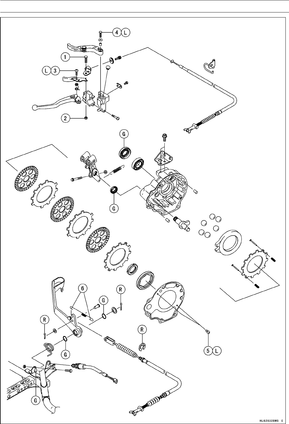
12-4 BRAKES
Exploded View

BRAKES 12-5
Exploded View
Torque
No. Fastener N·m kgf·m ft·lb Remarks
1Rear (Parking) Brake Lever Pivot Bolt 2.2 0.22 19 in·lb
2Rear (Parking) Brake Lever Pivot Nut 3.4 0.35 30 in·lb
3Rear Brake Lock Lever Pivot Screw 2.2 0.22 19 in·lb L
4Variable Differential Control Lever Bolt 3.4 0.35 30 in·lb L
5Rear Final Gear Case Gasket Screws 1.25 0.13 12 in·lb L
6. Bend both hooks after installing the spring.
G: Apply grease.
L: Apply a non-permanent locking agent.
MF: Apply gear oil (MOBILE FLUID 424) or equivalent oil.
O: Apply engine oil.
R: Replacement Parts

12-6 BRAKES
Specifications
Item Standard Service Limit
Brake Fluid
Type DOT 3 or DOT 4 –––
Front Brake
Pad Lining Thickness 4.0 mm (0.16 in.) 1 mm (0.04 in.)
Disc Thickness 3.3 ∼3.7 mm (0.13 ∼0.14 in.) 3 mm (0.12 in.)
Disc Runout TIR 0.4 mm (0.016 in.) or less TIR 0.5 mm (0.020 in.)
Rear Brake Lever, Pedal and Cables
Rear Brake Pedal Position see text –––
Rear Brake Lever Free Play 1∼2 mm (0.04 ∼0.08 in.) –––
Rear Brake Pedal Free Play 15 ∼25 mm (0.6 ∼1.0 in.) –––
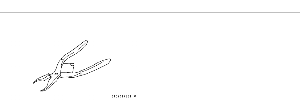
BRAKES 12-7
Special Tool
Inside Circlip Pliers:
57001-143

12-8 BRAKES
Brake Fluid
WARNING
When working with the disc brake, observe the pre-
cautions listed below.
1. Never reuse old brake fluid.
2. Do not use fluid from a container that has been left
unsealed or that has been open for a long time.
3. Do not mix two types and brands of fluid for use in
the brake. This lowers the brake fluid boiling point
and could cause the brake to be ineffective. It may
also cause the rubber brake parts to deteriorate.
4. Don’t leave the reservoir cap off for any length of
time to avoid moisture contamination of the fluid.
5. Don’t change the fluid in the rain or when a strong
wind is blowing.
6. Except for the disc pads and disc, use only disc
brake fluid, isopropyl alcohol, or ethyl alcohol for
cleaning brake parts. Do not use any other fluid for
cleaning these parts. Gasoline, engine oil, or any
other petroleum distillate will cause deterioration of
the rubber parts. Oil spilled on any part will be diffi-
cult to wash off completely and will eventually dete-
riorate the rubber used in the disc brake.
7. When handling the disc pads or disc, be careful that
no disc brake fluid or any oil gets on them. Clean off
any fluid or oil that inadvertently gets on the pads or
disc with a high-flash point solvent. Do not use one
which will leave an oily residue. Replace the pads
with new ones if they cannot be cleaned satisfacto-
rily.
8. Brake fluid quickly ruins painted surfaces; any
spilled fluid should be completely washed away
immediately.
9. If any of the brake line fittings or the bleed valve is
opened at any time, the AIR MUST BE BLED FROM
THEBRAKELINE.
Front Brake Fluid Recommendation
Use extra heavy-duty brake fluid only from a container
marked DOT3 or DOT4.
Recommended Disc Brake Fluid
Type DOT 3 or DOT 4
Front Brake Fluid Level Inspection
•Refer to the Brake Fluid Level Inspection in the Periodic
Maintenance chapter.
Front Brake Fluid Change
•Refer to the Brake Fluid Change in the Periodic Mainte-
nance chapter.
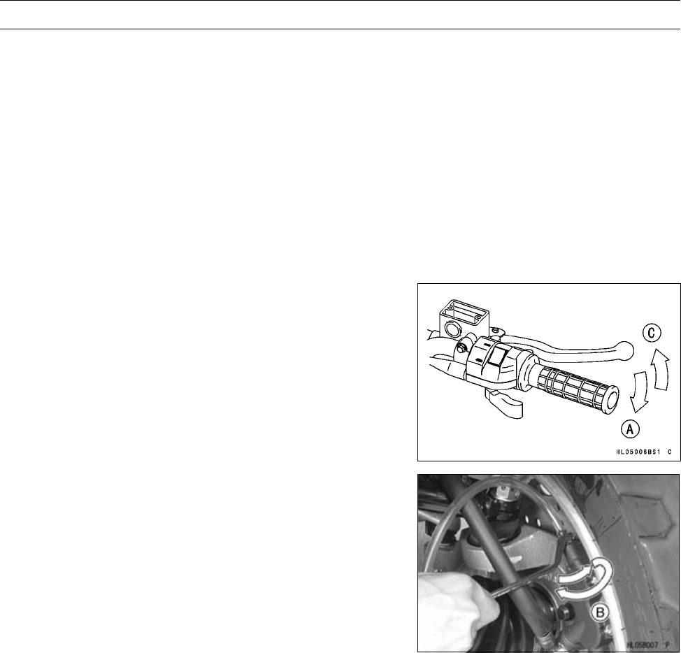
BRAKES 12-9
Brake Fluid
Front Brake Line Air Bleeding
•Bleed the air whenever brake parts are replaced or re-
assembled.
•Remove the reservoir cap and fill the reservoir with new
brake fluid.
•Slowly pump the brake lever several times until no air
bubbles can be seen rising up through the fluid from the
hose at the bottom of the reservoir. This bleeds the air
from the master cylinder and the brake line.
NOTE
○Tap the brake hose lightly going from the caliper to the
reservoir side and bleed the air off at the reservoir.
•Attach a clear plastic hose to the bleed valve on the
caliper, and run the other end of the hose into a con-
tainer.
•Bleed the brake line and the caliper as follows:
○Hold the brake lever applied [A].
○Quickly open and close the valve [B].
○Release the brake lever [C].
•The fluid level must be checked several times during the
bleeding operation and replenished as necessary.
NOTE
○If the fluid in the reservoir runs completely out any time
during bleeding, the bleeding operation must be done
over again from the beginning since air will have en-
tered the line.
○If the brake lever action still feels soft or "spongy", tap
the brake hose from bottom to top and air will rise up to
the top part of the hose. Slowly pump the brake lever
in the same manner as above.
•Tighten:
Torque - Bleed Valves: 7.8 N·m (0.80 kgf·m, 69 in·lb)
Reservoir Cap Screws: 1.5 N·m (0.15 kgf·m, 13
in·lb)
•Apply the brake lever forcefully for a few seconds, and
check for fluid leakage around the fittings.
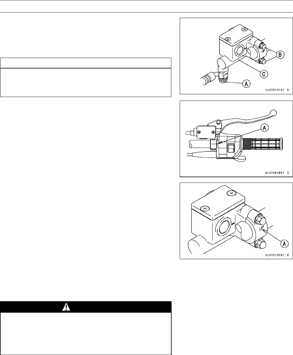
12-10 BRAKES
Master Cylinder
Front Brake Master Cylinder Removal
•Remove:
Brake Hose Banjo Bolt [A]
Master Cylinder Clamp Bolts [B]
Master Cylinder [C]
CAUTION
Brake fluid quickly ruins painted surface; any
spilled fluid should be completely washed away
immediately.
Front Brake Master Cylinder Installation
•Align the punch mark [A] on the handlebar with the mating
surface end of the master cylinder clamp.
•The master cylinder clamp must be installed with the “UP”
mark [A] upwards.
•Tighten the upper clamp bolt first, and then the lower
clamp bolt. There will be a gap at the lower part of the
clamp after tightening.
Torque - Front Brake Master Cylinder Clamp Bolts: 8.8 N·m
(0.90 kgf·m, 78 in·lb)
•Use a new flat washer on each side of the brake hose
fitting, and tighten the banjo bolt.
Torque - Brake Hose Banjo Bolt: 25 N·m (2.5 kgf·m, 18 ft·lb)
•Bleed the brake line after master cylinder installation (see
Front Brake Line Air Bleeding).
•Check the brake for good braking power, no braking brag,
and no fluid leakage.
WARNING
Do not attempt to drive the vehicle until a firm brake
lever can be obtained by pumping the brake lever
until the pads are against each disc. The brakes
will not function on the first application of the lever
if this is not done.
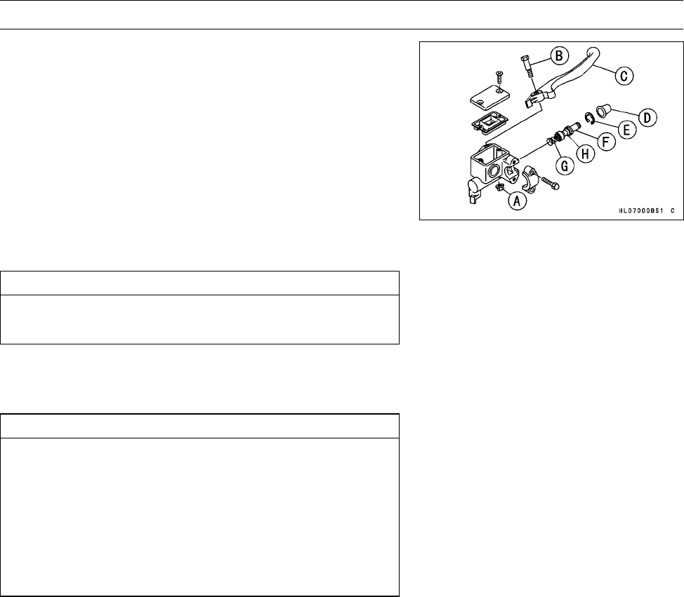
BRAKES 12-11
Master Cylinder
Front Brake Master Cylinder Disassembly
•Remove:
Front Brake Master Cylinder (see Front Brake Master
Cylinder Removal)
Brake Lever Pivot Bolt Locknut [A]
Brake Lever Pivot Bolt [B]
Brake Lever [C]
Dust Cover [D]
Circlip [E]
Piston [F]
Spring [G]
Special Tool - Inside Circlip Pliers: 57001-143
CAUTION
Do not remove the secondary cup [H] from the pis-
ton since removal will damage it.
Front Brake Master Cylinder Assembly
•Before assembly, clean all parts including the master
cylinder with brake fluid or alcohol.
CAUTION
Except for the disc pads and disc, use only disc
brake fluid, isopropyl alcohol, or ethyl alcohol for
cleaning brake parts. Do not use any other fluid for
cleaning these parts. Gasoline, engine oil, or any
other petroleum distillate will cause deterioration of
the rubber parts. Oil spilled on any part will be diffi-
cult to wash off completely, and will eventually de-
teriorate the rubber used in the disc brake.
•Take care not to scratch the piston or the inner wall of the
cylinder.
•Apply brake fluid to the removed parts and to the inner
wall of the cylinder.
•Tighten:
Torque - Front Brake Lever Pivot Bolt: 5.9 N·m (0.60 kgf·m,
52 in·lb)
Front Brake Lever Pivot Bolt Locknut: 5.9 N·m
(0.60 kgf·m, 52 in·lb)
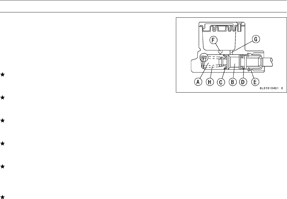
12-12 BRAKES
Master Cylinder
Front Master Cylinder Inspection (Visual
Inspection)
•Disassemble the master cylinder (see Front Brake Master
Cylinder Disassembly).
•Check that there are no scratches, rust or pitting on the
inner wall of the master cylinder [A] and on the outside of
the piston [B].
If the master cylinder or piston shows any damage, re-
place them.
•Inspect the primary [C] and secondary [D] cups.
If a cup is worn, damaged, softened (rotted), or swollen,
the piston assembly should be replaced to renew the
cups.
If fluid leakage is noted at the brake lever, the piston as-
sembly should be replaced to renew the cups.
•Check the dust cover [E] for damage.
If it is damaged, replace it.
•Check that the relief [F] and supply [G] ports are not
plugged.
If the relief port becomes plugged, the brake pads will
drag on the disc. Blow the ports clean with compressed
air.
•Check the piston return spring [H] for any damage.
If the spring is damaged, replace it.
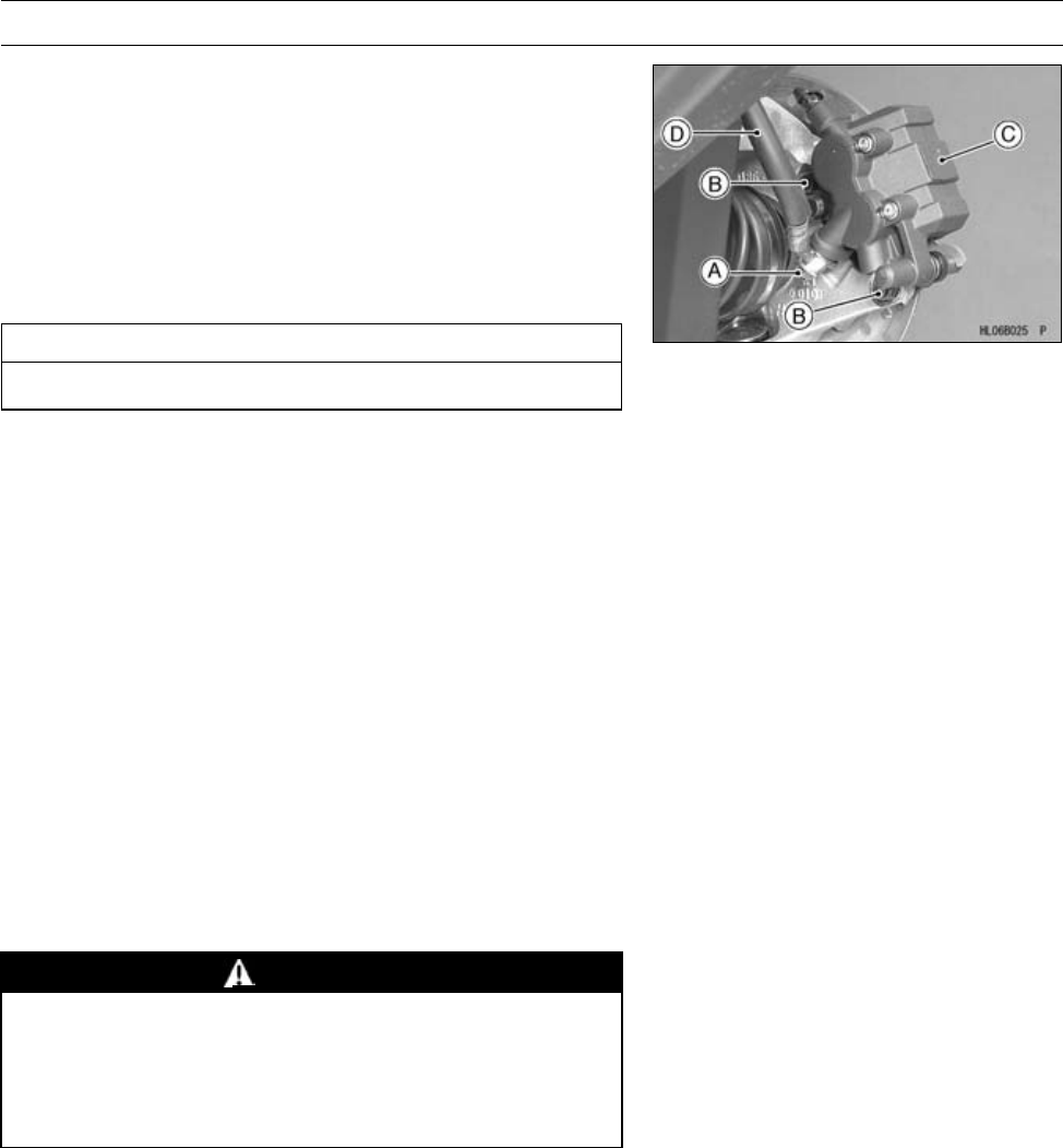
BRAKES 12-13
Calipers
Front Brake Caliper Removal
•Remove the front wheel (see Wheel Removal in the
Wheels/Tires chapter).
•Loosen the banjo bolt [A] at the brake hose lower end,
and tighten it loosely.
•Unscrew the caliper mounting bolts [B], and detach the
caliper [C] from the disc.
•Unscrew the banjo bolt and remove the brake hose [D]
from the caliper.
CAUTION
Immediately wash away any brake fluid that spills.
NOTE
○If the caliper is to be disassembled after removal and if
compressed air is not available, disassemble the caliper
before the brake hose is removed (see Front Brake
Caliper Disassembly).
Front Brake Caliper Installation
•Install the caliper and brake hose lower end.
○Replace the washers that are on each side of hose fitting
with new ones.
•Tighten:
Torque - Front Brake Caliper Mounting Bolts: 25 N·m (2.5
kgf·m, 18 ft·lb)
Brake Hose Banjo Bolt: 25 N·m (2.5 kgf·m, 18 ft·lb)
•Check the fluid level in the brake reservoir.
•Bleed the brake line (see Front Brake Line Air Bleeding).
•Check the brake for good braking power, no brake drag,
and no fluid leakage.
WARNING
Do not attempt to drive the vehicle until a firm brake
lever can be obtained by pumping the brake lever
until the pads are against each disc. The brakes
will not function on the first application of the lever
if this is not done.
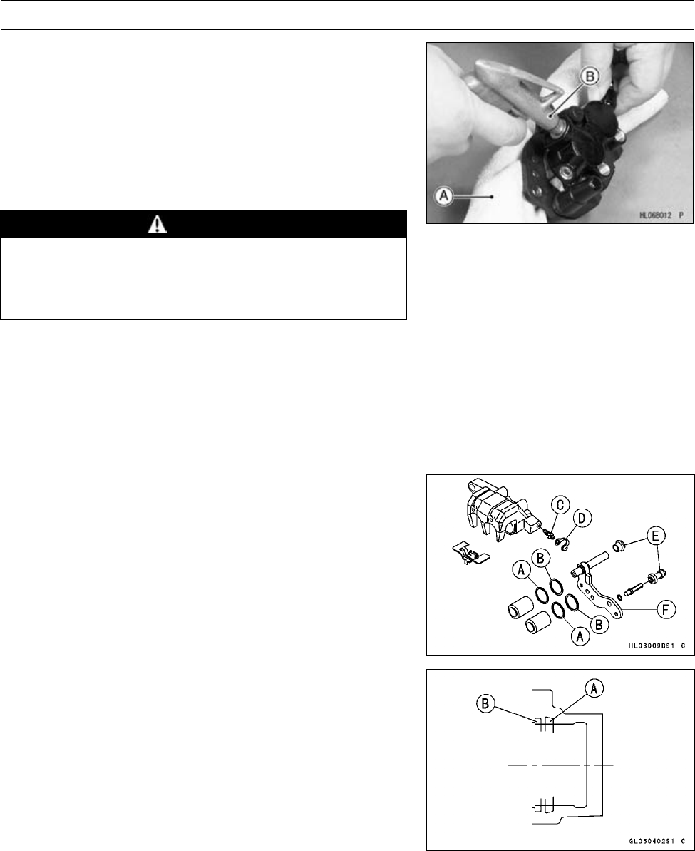
12-14 BRAKES
Calipers
Front Brake Caliper Disassembly
•Remove:
Caliper (see Front Brake Caliper Removal)
Pads (see Front Brake Pad Removal)
Anti-rattle Spring
•Using compressed air, remove the piston.
○Cover the caliper opening with a clean, heavy cloth [A].
○Remove the piston by lightly applying compressed air [B]
to where the brake line fits into the caliper.
WARNING
To avoid serious injury, never place your fingers or
palm inside the caliper opening. If you apply com-
pressed air into the caliper, the piston may crush
your hand or fingers.
NOTE
○If compressed air is not available, do as follows with the
brake hose connected to the caliper.
○Prepare a container for brake fluid.
○Remove the pads (see Front Brake Pad Removal) and
anti-rattle spring.
○Pump the brake lever to remove the caliper piston.
•Remove:
Dust Seals [A]
Fluid Seals [B]
Bleed Valve [C] and Rubber Cap [D]
Boots [E] and Caliper Holder [F]
Front Brake Caliper Assembly
•Replace the fluid seal [A] with a new one.
○Apply brake fluid to the fluid seal, and install it into the
cylinder by hand.
•Replace the dust seal [B] with a new one if it is damaged.
○Apply brake fluid to the dust seal, and install it into the
cylinder by hand.
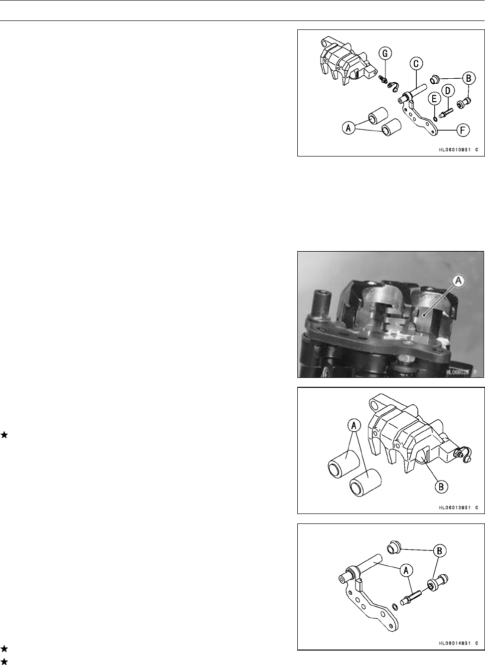
BRAKES 12-15
Calipers
•Apply brake fluid to the outside of the pistons [A], and
push them into the cylinder by hand. Take care that nei-
ther the cylinder nor the piston skirt gets scratched.
•Replace the rubber boots [B] if they are damaged.
•Apply a thin coat of silicone grease to the caliper holder
shafts [C] [D] (Silicone grease is a special high tempera-
ture, water-resistant grease).
•Install:
Wave Washer [E]
•Tighten:
Torque - Front Brake Caliper Holder Shaft [D]: 17 N·m (1.7
kgf·m, 12 ft·lb)
•Install:
Caliper Holder [F]
Bleed Valve [G] and Rubber Cap
Torque - Bleed Valves: 7.8 N·m (0.80 kgf·m, 69 in·lb)
•Install the anti-rattle spring [A] in the caliper as shown.
•Install the pads (see Front Brake Pad Installation).
Front Brake Caliper Piston and Cylinder Damage
Inspection
•Visually inspect the piston [A] and cylinder surfaces [B].
Replace the caliper if the cylinder and piston are badly
scored or rusty.
Front Brake Caliper Holder Shaft Wear Inspection
The caliper body must slide smoothly on the caliper holder
shafts [A]. If the body does not slide smoothly, one pad will
wear more than the other, pad wear will increase, and con-
stant drag on the disc will raise brake and brake fluid tem-
perature.
•Check to see that the caliper holder shafts are not badly
worn or stepped, and that the rubber boots [B] are not
damaged.
If the rubber boot is damaged, replace the rubber boot.
If caliper holder shaft is damaged, replace the caliper
holder shaft and rubber boot as a unit.
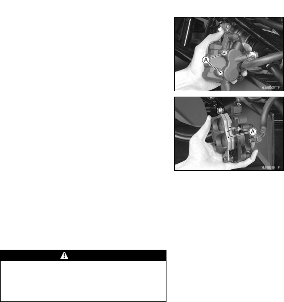
12-16 BRAKES
Brake Pads
Front Brake Pad Removal
•Detach the caliper from the disc (see Front Brake Caliper
Removal).
•Remove:
Pad Mounting Bolts [A]
•Remove:
Brake Pads [A]
Front Brake Pad Installation
•Push the caliper piston in by hand as far as it will go.
•Be sure that the anti-rattle spring is in place.
•Install:
Brake Pads
Pad Mounting Bolts
•Tighten:
Torque - Front Brake Pad Mounting Bolts: 17 N·m (1.7
kgf·m, 12 ft·lb)
WARNING
Do not attempt to drive the vehicle until a firm brake
lever can be obtained by pumping the brake lever
until the pads are against each disc. The brake will
not function on the first application if this is not
done.
Front Brake Pad Wear Inspection
•Refer to the Front Brake Pad Wear Inspection in the Pe-
riodic Maintenance chapter.
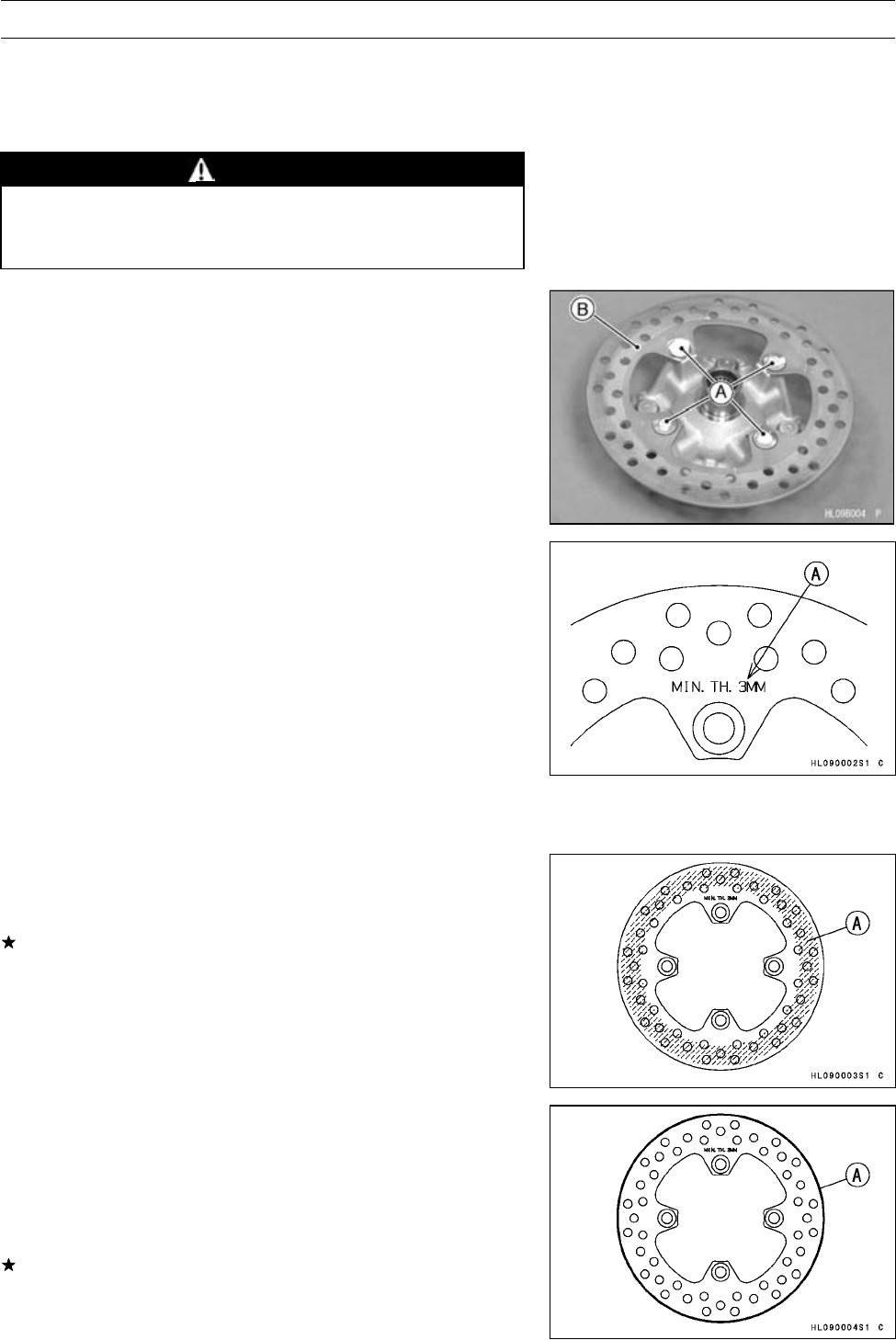
BRAKES 12-17
Brake Discs
Front Brake Disc Cleaning
Poor braking can be caused by oil on a disc. Oil on a disc
must be cleaned off with an oilless cleaning fluid such as
trichloroethylene or acetone.
WARNING
These cleaning fluids are usually highly flammable
and harmful if breathed for prolonged periods. Be
sure to heed the fluid manufacturer’s warnings.
Front Brake Disc Removal
•Remove:
Front Hub (see Front Hub Removal in the Wheels/Tires
chapter)
Brake Disc Mounting Bolts [A]
Brake Disc [B]
Front Brake Disc Installation
•The disc must be installed with the marked side [A] facing
toward the steering knuckle.
•Apply a non-permanent locking agent to the brake disc
mounting bolts.
•Tighten:
Torque - Front Brake Disc Mounting Bolts: 37 N·m (3.8
kgf·m, 27 ft·lb)
•After installing the discs, check the disc runout. Com-
pletely clean off any grease that has gotten on either side
of the disc with a high-flash point solvent. Do not use one
which will leave an oily residue.
Front Brake Disc Wear Inspection
•Measure the thickness of each disc at the point [A] where
it has worn the most.
Replace the disc if it has worn past the service limit.
Disc Thickness
Standard: 3.3 ∼3.7 mm (0.13 ∼0.14 in.)
Service Limit: 3 mm (0.12 in.)
Front Brake Disc Runout Inspection
•Jack up the vehicle so that the wheels are off the ground.
•Remove the front wheels and turn the handlebar fully to
one side.
•Set up a dial gauge against the disc [A], and measure the
disc runout.
If the runout exceeds the service limit, replace the disc.
Disc Runout
Standard: TIR 0.4 mm (0.016 in.) or less
Service Limit: TIR 0.5 mm (0.020 in.)

12-18 BRAKES
Brake Hoses
Front Brake Hose Inspection
•Refer to the Front Brake Hose and Connections Inspec-
tion in the Periodic Maintenance chapter.
Front Brake Hose Replacement
•Refer to the Front Brake Hose Replacement in the Peri-
odic Maintenance chapter.
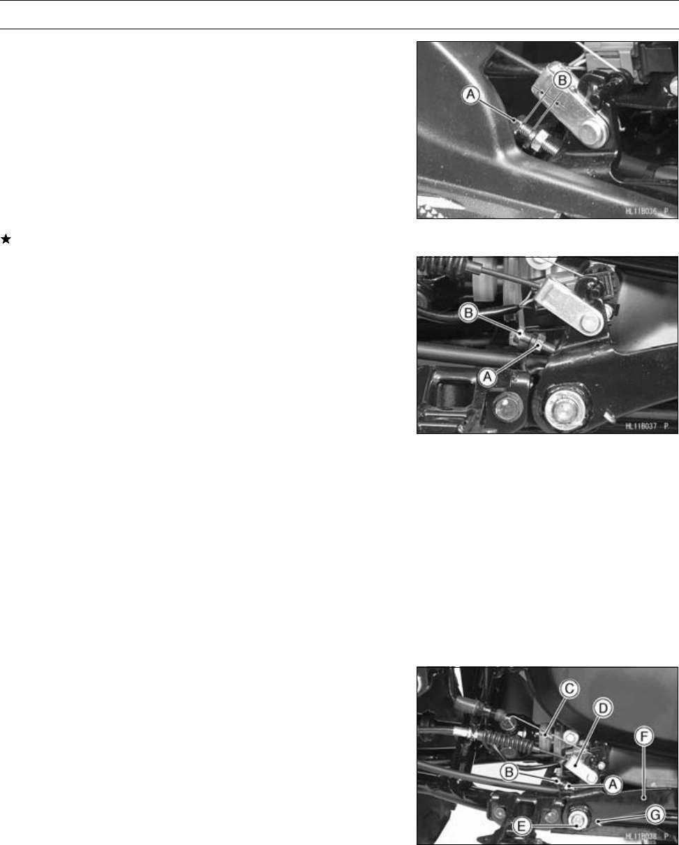
BRAKES 12-19
Rear Brake Lever, Pedal and Cables
Rear Brake Pedal Position Inspection
NOTE
○The position of the brake pedal has been decided by
the position of the adjusting bolt [A].
•Check that the adjusting bolt is in the correct position as
shown.
Adjusting Bolt Position [B]
Standard: 5 ∼6 mm (0.20 ∼0.24 in.) (between Frame
and Adjusting Bolt Head)
If it is incorrect, adjust the adjusting bolt.
Rear Brake Pedal Position Adjustment
•Remove:
Right Footboard (see Right Footboard Removal in the
Frame chapter)
•Loosen the locknut [A], and turn the adjusting bolt [B] until
the brake pedal is correctly positioned.
•Tighten the locknut.
•Check the brake pedal free play (see Rear Brake Pedal
Free Play Inspection in the Periodic Maintenance chap-
ter).
Rear Brake Lever Free Play Inspection
•Refer to the Rear Brake Lever Free Play Inspection in the
Periodic Maintenance chapter.
Rear Brake Pedal Free Play Inspection
•Refer to the Rear Brake Pedal Free Play Inspection in the
Periodic Maintenance chapter.
Rear Brake Lever and Brake Pedal Free Play
Adjustment
•Refer to the Rear Brake Lever and Pedal Free Play Ad-
justment in the Periodic Maintenance chapter.
Rear Brake Pedal Removal
•Remove:
Right Footboard (see Right Footboard Removal in the
Frame chapter)
•Loosen the locknut [A] and the adjusting bolt [B].
•Remove:
BrakeSwitchSpring[C]
Cotter Pin, Washer, Pin and Brake Cable Joint [D]
Cotter Pin and Washer [E]
O-ring and Brake Pedal [F]
Spring [G]
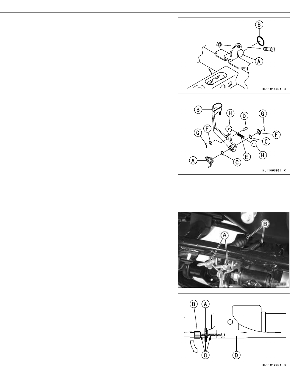
12-20 BRAKES
Rear Brake Lever, Pedal and Cables
Rear Brake Pedal Installation
•Apply grease:
Brake Pedal Pivot [A]
O-ring [B]
•Install:
Spring [A]
Brake Pedal [B]
•Apply grease:
O-rings [C]
•Install:
Brake Cable Joint and Pin [D]
BrakeSwitchSpring[E]
Washers [F]
•Replace the cotter pins [G] with new ones.
•Bend both side hooks [H] of switch spring [E] after in-
stalling the spring.
•Adjust the brake pedal position (see Rear Brake Pedal
Position Adjustment).
Rear Brake Cable Removal
•Unscrew the adjusters [A] at the rear ends of the cables,
and pull the cables out of the joints [B] and cable mounts.
•Loosen the knurled locknut [A] at the rear brake lever and
screw in the adjuster [B].
•Line up the slots [C] in the brake lever, knurled locknut,
and adjuster, and then free the cable from the lever [D].
•Remove the brake lever cable from the frame.
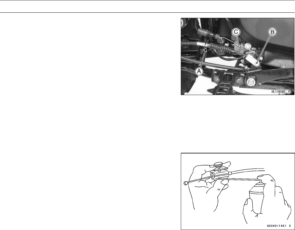
BRAKES 12-21
Rear Brake Lever, Pedal and Cables
•Remove:
Circlip [A]
Cotter Pin, Washer and Pin [B]
Brake Pedal Cable [C]
Rear Brake Cable Installation
•Grease the brake cable front ends.
•Replace the cotter pin with a new one.
•Route the brake cables according to the Cable, Wire, and
Hose Routing section in the Appendix chapter.
•Adjust the rear brake pedal and rear brake lever.
Rear Brake Cable Lubrication
Whenever the brake cable is removed, lubricate the cable
as follows:
•Lubricate the cable with an aerosol cable lubricant
through the pressure cable luber.

12-22 BRAKES
Internal Wet Brake
Internal Wet Brake Disassembly
•Refer to Rear Final Gear Case section in the Final Drive
chapter.
Internal Wet Brake Assembly
•Refer to Rear Final Gear Case section in the Final Drive
chapter.

SUSPENSION 13-1
13
Suspension
Table of Contents
Exploded View........................................................................................................................ 13-2
Specifications ......................................................................................................................... 13-6
Special Tools .......................................................................................................................... 13-7
Shock Absorbers .................................................................................................................... 13-8
Front Shock Absorber Preload Adjustment....................................................................... 13-8
Front Shock Absorber Removal........................................................................................ 13-8
Front Shock Absorber Installation..................................................................................... 13-8
Front Shock Absorber Inspection...................................................................................... 13-9
Front Shock Absorber Scrapping...................................................................................... 13-9
Rear Shock Absorber Preload Adjustment ....................................................................... 13-9
Rear Shock Absorber Removal ........................................................................................ 13-10
Rear Shock Absorber Installation ..................................................................................... 13-10
Rear Shock Absorber Inspection ...................................................................................... 13-10
Rear Shock Absorber Scrapping ...................................................................................... 13-10
Suspension Arms ................................................................................................................... 13-11
Front Suspension Arm Removal ....................................................................................... 13-11
Front Suspension Arm Installation .................................................................................... 13-12
Front Suspension Arm Disassembly................................................................................. 13-12
Front Suspension Arm Assembly...................................................................................... 13-13
Rear Suspension Arm Removal........................................................................................ 13-14
Rear Suspension Arm Installation..................................................................................... 13-15
Rear Suspension Arm Disassembly ................................................................................. 13-15
Rear Suspension Arm Assembly ...................................................................................... 13-16
Stabilizer Removal ............................................................................................................ 13-17
Stabilizer Installation ......................................................................................................... 13-17
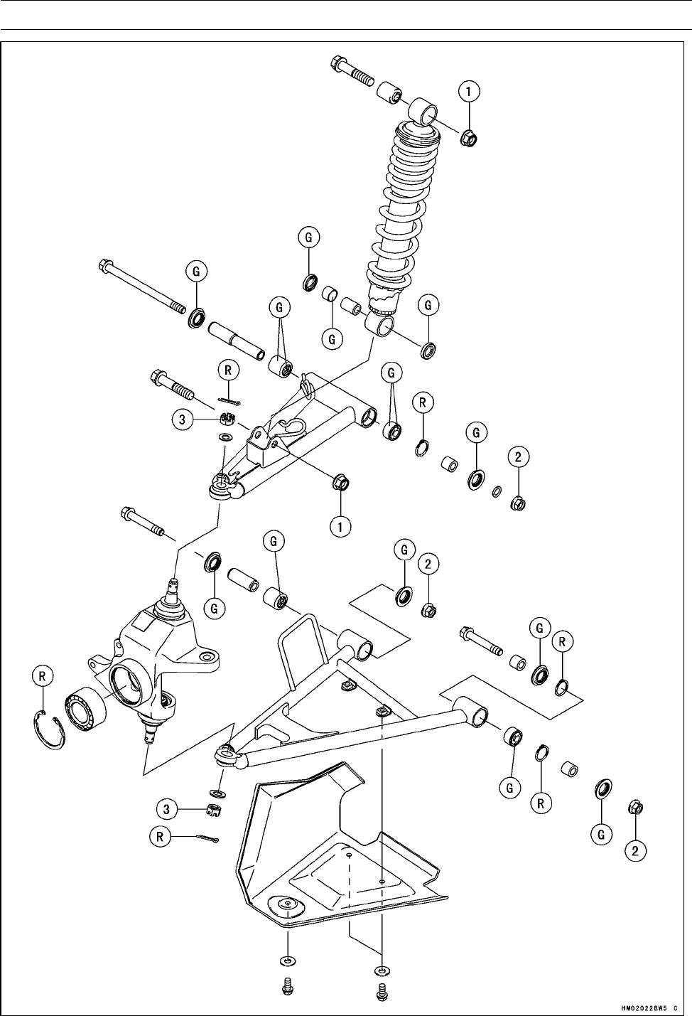
13-2 SUSPENSION
Exploded View

SUSPENSION 13-3
Exploded View
Torque
No. Fastener N·m kgf·m ft·lb Remarks
1Front Shock Absorber Mounting Nuts 34 3.5 25
2Front Suspension Arm Pivot Nuts 42 4.3 31
3Steering Knuckle Joint Nuts 29 3.0 21
G: Apply grease.
R: Replacement Parts
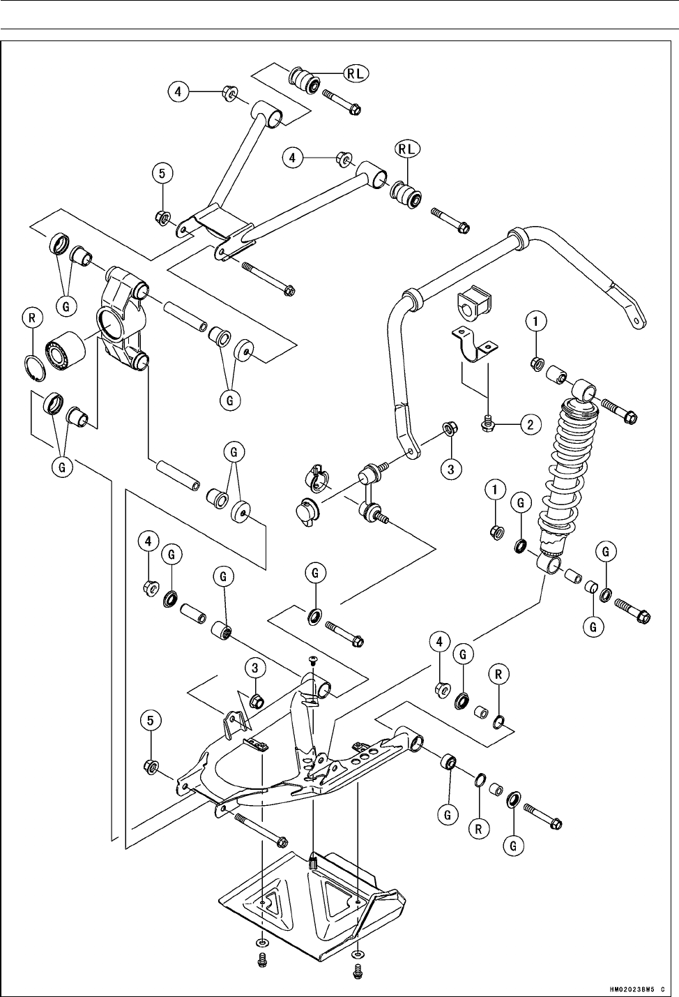
13-4 SUSPENSION
Exploded View

SUSPENSION 13-5
Exploded View
Torque
No. Fastener N·m kgf·m ft·lb Remarks
1Rear Shock Absorber Mounting Nuts 34 3.5 25
2Stabilizer Holder Bolts 22 2.2 16
3Stabilizer Joint Nuts 46 4.7 34
4Rear Suspension Arm Pivot Nuts 46 4.7 34
5Rear Knuckle Mounting Nuts 46 4.7 34
G: Apply grease.
R: Replacement Parts
RL: Apply rubber lubricant.

13-6 SUSPENSION
Specifications
Item Standard Service Limit
Shock Absorbers (Usable Range)
Spring Preload Setting Position:
Front 2nd Step 1∼5
Rear 3rd Step 1∼5
SUSPENSION 13-7
Special Tools
Inside Circlip Pliers:
57001-143
Outside Circlip Pliers:
57001-144
Steering Stem Nut Wrench:
57001-1100
Jack:
57001-1238
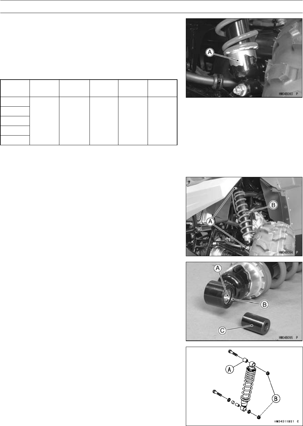
13-8 SUSPENSION
Shock Absorbers
Front Shock Absorber Preload Adjustment
The spring adjusting sleeve [A] on the front shock ab-
sorber has 5 positions so that the spring can be adjusted
for different terrain and loading conditions. If the spring ac-
tion feels too soft or too stiff, adjust it in accordance with the
following table.
Spring Action
Position Spring
Force Setting Load Terr ai n Speed
1Weak Soft Light Smooth Low
2(STD) ↑ ↑ ↑ ↑ ↑
3
4↓ ↓ ↓ ↓ ↓
5Strong Hard Heavy Rough High
•Turn the adjusting sleeve on the front shock absorber to
the desired position with the wrench.
Special Tool - Steering Stem Nut Wrench: 57001-1100
Front Shock Absorber Removal
•Support the vehicle on a stand or a jack so that the front
wheels are off the ground.
Special Tool - Jack: 57001-1238
•While holding the front wheels, remove the lower and up-
per shock absorber mounting bolts [A] and nuts.
•Remove the front shock absorber [B].
Front Shock Absorber Installation
•Apply grease to the inside of bushing [A] and grease seal
lips [B].
•Install:
Collar [C]
•Install:
Bushing [A] (press)
•Tighten:
Torque - Front Shock Absorber Mounting Nuts [B]: 34 N·m
(3.5 kgf·m, 25 ft·lb)
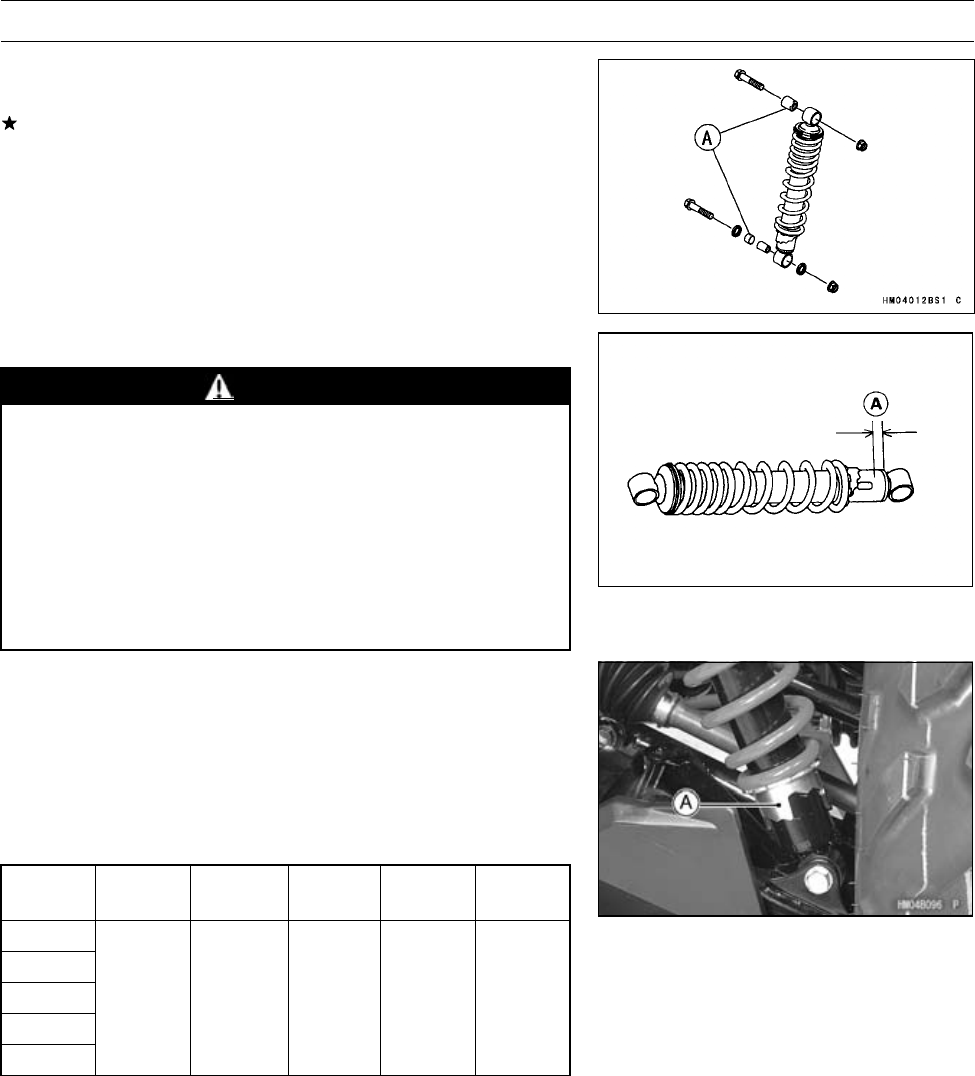
SUSPENSION 13-9
Shock Absorbers
Front Shock Absorber Inspection
•Check the bushings [A] in the upper and lower pivots.
If bushings are worn, cracked, hardened, or otherwise
damaged, replace them.
Front Shock Absorber Scrapping
WARNING
Since the front shock absorber contains nitrogen
gas, do not incinerate or disassemble the front
shock absorber.
Before a front shock absorber is scrapped, drill a
hole at a point about 15 mm (0.59 in.) [A] up from the
bottom of the cylinder to release the nitrogen gas
completely. Wear safety glasses when drilling the
hole, as the gas may blow out bits of drilled metal
when the hole opens.
Rear Shock Absorber Preload Adjustment
The spring adjusting sleeve [A] on the rear shock ab-
sorber has 5 positions so that the spring can be adjusted
for different terrain and loading conditions. If the spring ac-
tion feels too soft or too stiff, adjust it in accordance with the
following table.
Spring Action
Position Spring
Force Setting Load Terrai n Speed
1Weak Soft Light Smooth Low
2↑ ↑ ↑ ↑ ↑
3(STD)
4↓ ↓ ↓ ↓ ↓
5Strong Hard Heavy Rough High
•Remove the axle guard.
•Turn the adjusting sleeve on the rear shock absorber to
the desired position with the wrench.
Special Tool - Steering Stem Nut Wrench: 57001-1100
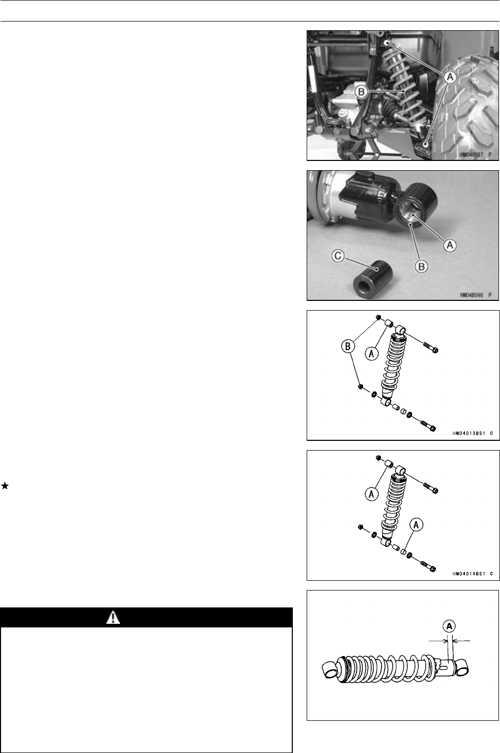
13-10 SUSPENSION
Shock Absorbers
Rear Shock Absorber Removal
•Support the vehicle on a stand or a jack so that the rear
wheels are off the ground.
Special Tool - Jack: 57001-1238
•While holding the rear wheels, remove the lower and up-
per shock absorber mounting bolts [A] and nuts.
•Remove the rear shock absorber [B].
Rear Shock Absorber Installation
•Apply grease to the inside of bushing [A] and grease seal
lips [B].
•Install:
Collar [C]
•Install:
Bushing [A] (press)
•Tighten:
Torque - Rear Shock Absorber Mounting Nuts [B]: 34 N·m
(3.5 kgf·m, 25 ft·lb)
Rear Shock Absorber Inspection
•Check the bushings [A] in the upper and lower pivots.
If bushings are worn, cracked, hardened, or otherwise
damaged, replace them.
Rear Shock Absorber Scrapping
WARNING
Since the rear shock absorber contains nitrogen
gas, do not incinerate or disassemble the rear
shock absorber.
Before a rear shock absorber is scrapped, drill a
hole at a point about 15 mm (0.59 in.) [A] up from the
bottom of the cylinder to release the nitrogen gas
completely. Wear safety glasses when drilling the
hole, as the gas may blow out bits of drilled metal
when the hole opens.
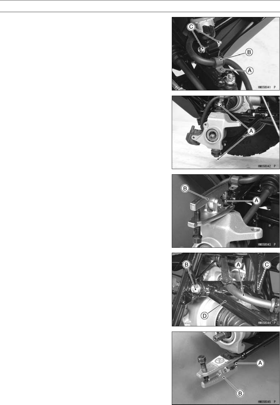
SUSPENSION 13-11
Suspension Arms
Front Suspension Arm Removal
•Remove:
Wheel Hub (see Front Hub Removal in the Wheels/Tires
chapter)
Bolt [A] and Brake Hose Clamp [B]
Front Shock Absorber Mounting Bolt and Nut [C] (lower)
•Remove:
Cotter Pins, Knuckle Joint Nuts [A] and Washers
•Remove the knuckle joint [A] from the lower suspension
arm using a suitable joint remover [B].
•Clear the brake hose [A] from the front upper suspension
arm.
•Remove:
Suspension Arm Pivot Bolt [B] and Nut [C]
Front Upper Suspension Arm [D]
•Remove the knuckle joint [A] from the upper suspension
arm using a suitable joint remover [B].
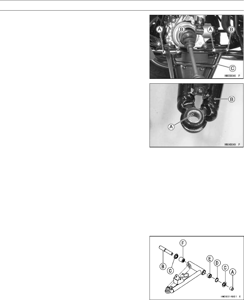
13-12 SUSPENSION
Suspension Arms
•Remove:
Suspension Arm Pivot Bolts [A] and Nuts [B]
Front Lower Suspension Arm [C]
Front Suspension Arm Installation
•Clean the taper surface [A] of the suspension arm [B] and
shank of the knuckle joint.
•Install:
Front Upper Suspension Arm
Front Lower Suspension Arm
Suspension Arm Pivot Bolts and Nuts (temporary)
Steering Knuckle Joint (see Steering Knuckle Installa-
tion in the Steering chapter)
Front Shock Absorber Mounting Bolt and Nut (lower)
•Tighten:
Torque - Front Suspension Arm Pivot Nuts: 42 N·m (4.3
kgf·m, 31 ft·lb)
Steering Knuckle Joint Nuts: 29 N·m (3.0 kgf·m,
21 ft·lb)
Front Shock Absorber Mounting Bolt: 34 N·m (3.5
kgf·m, 25 ft·lb)
•Install:
Brake Hose
Front Wheels (see Wheel Installation in the Wheels/Tires
chapter)
Front Suspension Arm Disassembly
Front Upper Suspension Arm
•Remove:
Collar [A] (rear side)
Sleeve [B] (front side)
Oil Seals [C]
Circlip [D]
Special Tool - Inside Circlip Pliers: 57001-143
•Remove:
Ball Joint Bearing [E] (rear side)
Needle Bearing [F] (front side)
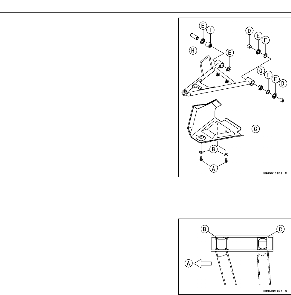
SUSPENSION 13-13
Suspension Arms
Front Lower Suspension Arm
•Remove:
Bolts [A]
Collar [B]
Axle Guard [C]
Collars [D] (rear side)
Oil Seals [E]
Circlips [F]
Special Tool - Inside Circlip Pliers: 57001-143
•Remove:
Ball Joint Bearing [G] (rear side)
Sleeve [H] (front side)
Needle Bearing [I] (front side)
Front Suspension Arm Assembly
•Apply grease:
Ball Joint Bearing
Needle Bearing
•Install the following parts as shown.
Front Upper Suspension Arm
Front [A]
•Press the needle bearing [B] until it is stopped.
•Press the ball joint bearing [C] until it is stopped.
•Install:
New Circlip
Special Tool - Inside Circlip Pliers: 57001-143
•Apply grease:
Oil Seal Lips
•Install:
Sleeve (front side)
Collar (rear side)
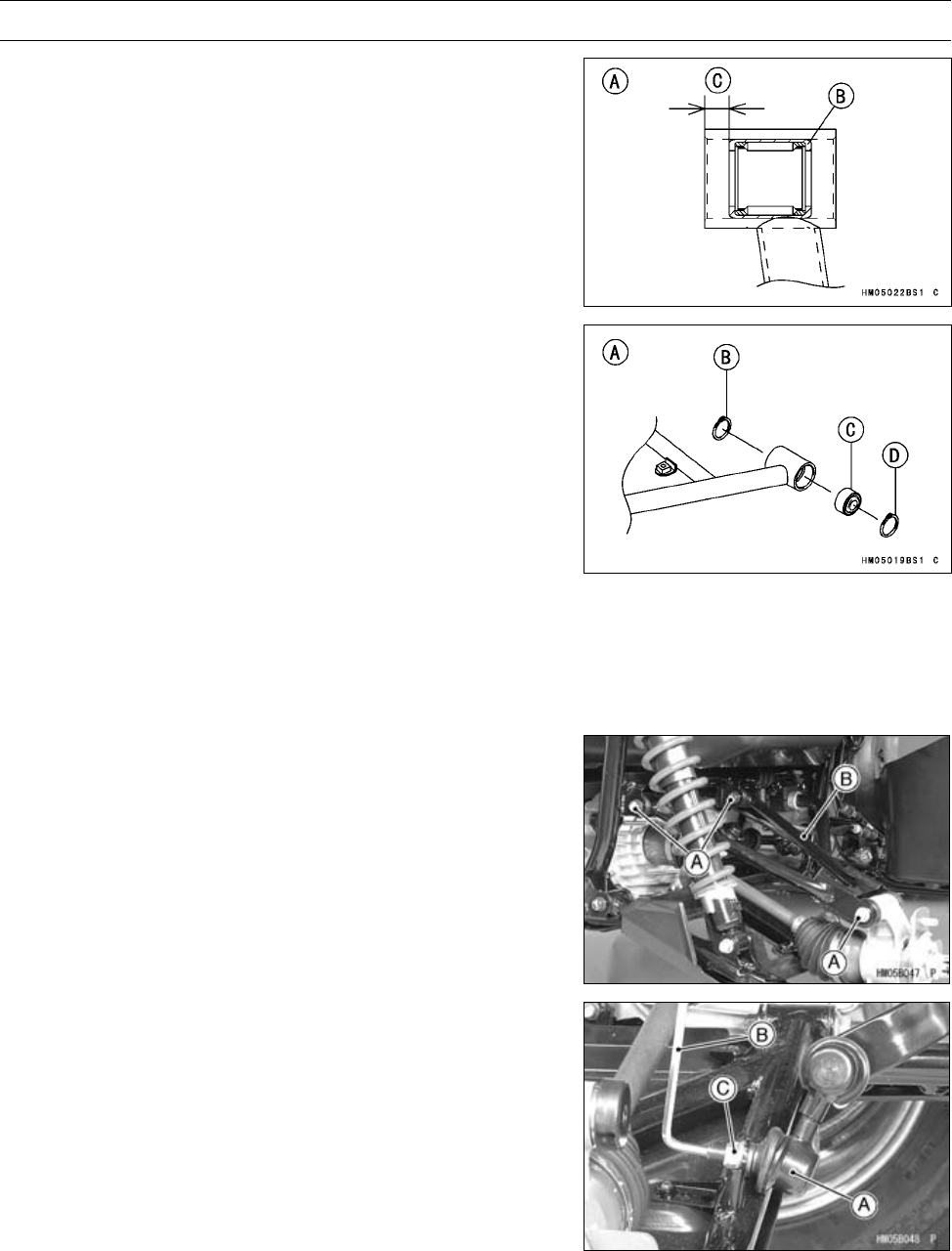
13-14 SUSPENSION
Suspension Arms
•Install the following parts as shown.
Front Lower Suspension Arm
Front Side [A]:
Needle Bearing [B]
7.5 ±0.1 mm (0.295 ±0.004 in.) [C]
Rear Side [A]:
Circlip [B] (front side)
Ball Joint Bearing [C]
Circlip [D] (rear side)
Special Tool - Inside Circlip Pliers: 57001-143
•Apply grease:
Oil Seal Lips
•Install:
Sleeve (front side)
Collars (rear side)
Rear Suspension Arm Removal
•Remove:
Rear Wheels (see Wheel Removal in the Wheels/Tires
chapter)
Suspension Arm Bolts [A] and Nuts
Rear Upper Suspension Arm [B]
•Remove:
Stabilizer Joint [A]
○Hold the joint bolt with an Allen wrench [B], and remove
the nut [C].
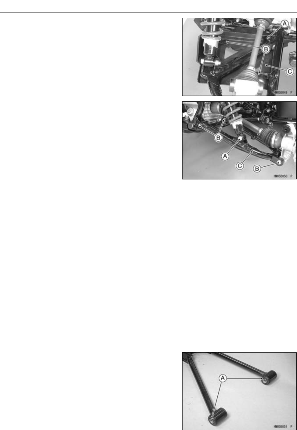
SUSPENSION 13-15
Suspension Arms
•Remove:
Screw [A]
Bolts [B]
Axle Guard [C]
•Remove:
Rear Shock Absorber Mounting Bolt [A] and Nut (lower)
Suspension Arm Bolts and Nuts [B]
Rear Lower Suspension Arm [C]
Rear Suspension Arm Installation
•Install:
Rear Upper Suspension Arm
Rear Lower Suspension Arm
Suspension Arm Pivot Bolts and Nut (temporary)
Rear Shock Absorber Mounting Bolt (lower)
Stabilizer Joint
•Tighten:
Torque - Rear Suspension Arm Pivot Nuts: 46 N·m (4.7
kgf·m, 34 ft·lb)
Rear Shock Absorber Mounting Nuts: 34 N·m (3.5
kgf·m, 25 ft·lb)
Stabilizer Joint Nut: 46 N·m (4.7 kgf·m, 34 ft·lb)
Rear Knuckle Mounting Nuts: 46 N·m (4.7 kgf·m,
34 ft·lb)
○Hold the joint bolt with an Allen wrench, and tighten the
nut.
•Install:
Front Wheels (see Wheel Installation in the Wheels/Tires
chapter)
Rear Suspension Arm Disassembly
Rear Upper Suspension Arm
•Remove out the bushings [A].
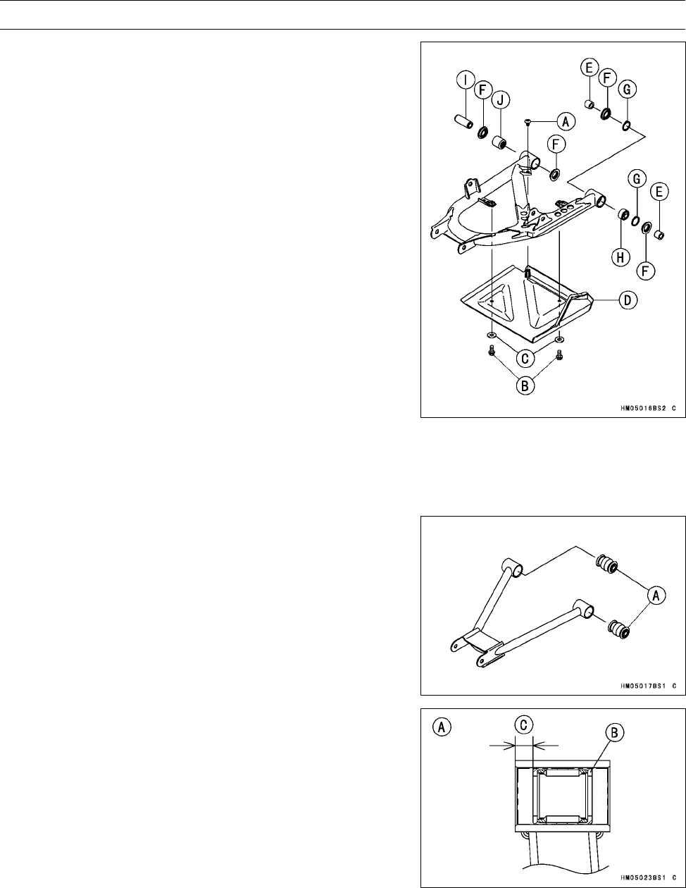
13-16 SUSPENSION
Suspension Arms
Rear Lower Suspension Arm
•Remove:
Screw [A]
Bolts [B]
Collars [C]
Axle Guard [D]
Collars [E] (rear side)
Oil Seals [F]
Circlips [G]
Special Tool - Outside Circlip Pliers: 57001-144
•Remove:
Ball Joint Bearing [H] (rear side)
Sleeve [I] (front side)
Needle Bearing [J] (front side)
Rear Suspension Arm Assembly
•Apply grease:
Ball Joint Bearing
Needle Bearing
Rear Upper Suspension Arm
•Install the bushings [A] using a press.
Rear Lower Suspension Arm
•Install the following parts as shown.
Front Side [A]:
Needle Bearing [B]
7.5 ±0.1 mm (0.295 ±0.004 in.) [C]
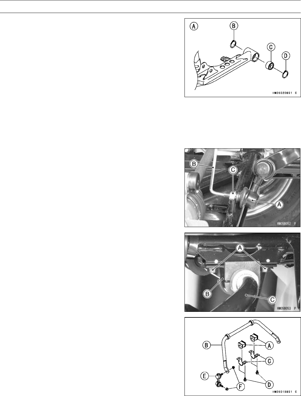
SUSPENSION 13-17
Suspension Arms
Rear Side [A]:
Circlip [B] (front side)
Ball Joint Bearing [C]
Circlip [D] (rear side)
Special Tool - Inside Circlip Pliers: 57001-143
•Apply grease:
Oil Seal Lips
•Install:
Sleeve (front side)
Collars (rear side)
Stabilizer Removal
•Remove:
Rear Wheels (see Wheel Removal in the Wheels/Tires
chapter)
Stabilizer Joint [A]
○Hold the joint bolt with an Allen wrench [B], and remove
the nut [C].
•Remove:
Stabilizer Holder Bolts [A]
Stabilizer Holders [B]
Dampers and Stabilizer [C]
Stabilizer Installation
•Install:
Dampers [A] and Stabilizer [B]
Stabilizer Holders [C] and Bolts
•Tighten:
Torque - Stabilizer Holder Bolts [D]: 22 N·m (2.2 kgf·m, 16
ft·lb)
•Install:
Stabilizer Joints [E]
○Hold the joint bolt with an Allen wrench, and tighten the
nut.
Torque - Stabilizer Joint Nuts [F]: 46 N·m (4.7 kgf·m, 34 ft·lb)
•Install:
Rear Wheels (see Wheel Installation in the Wheels/Tires
chapter)

STEERING 14-1
14
Steering
Table of Contents
Exploded View........................................................................................................................ 14-2
Specifications ......................................................................................................................... 14-4
Special Tools .......................................................................................................................... 14-5
Steering .................................................................................................................................. 14-6
Steering Stem Removal .................................................................................................... 14-6
Steering Stem Installation ................................................................................................. 14-7
Steering Knuckle Removal................................................................................................ 14-8
Steering Knuckle Installation............................................................................................. 14-9
Steering Knuckle Bearing Removal .................................................................................. 14-9
Steering Knuckle Bearing Installation ............................................................................... 14-10
Tie-rod Removal ............................................................................................................... 14-10
Tie-rod Installation ............................................................................................................ 14-10
Tie-rod End Removal ........................................................................................................ 14-11
Tie-rod End Installation ..................................................................................................... 14-11
Steering Maintenance............................................................................................................. 14-12
Steering Inspection ........................................................................................................... 14-12
Steering Stem Straightness Inspection............................................................................. 14-12
Steering Bearing Sleeve Lubrication................................................................................. 14-12
Steering Stem Clamp Inspection ...................................................................................... 14-12
Steering Stem Bearing Inspection .................................................................................... 14-12
Steering Knuckle Bearing Inspection................................................................................ 14-13
Tie-rod End Inspection...................................................................................................... 14-13
Steering Knuckle Joint Inspection..................................................................................... 14-13
Handlebar............................................................................................................................... 14-14
Handlebar Removal .......................................................................................................... 14-14
Handlebar Installation ....................................................................................................... 14-14
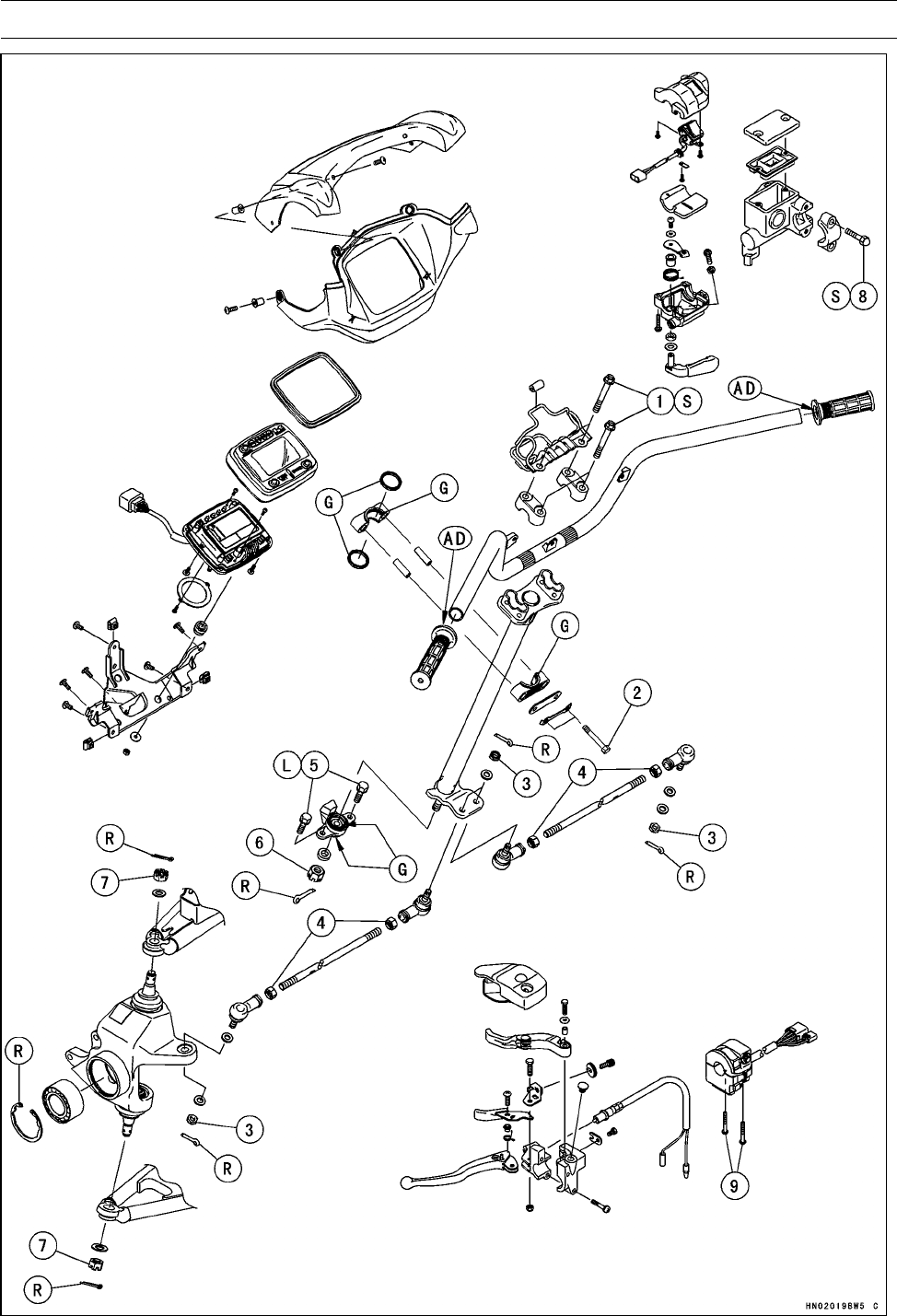
14-2 STEERING
Exploded View

STEERING 14-3
Exploded View
Torque
No. Fastener N·m kgf·m ft·lb Remarks
1Handlebar Holder Bolts 29 3.0 21 S
2Steering Stem Clamp Bolts 25 2.5 18
3Tie-rod End Nuts 42 4.3 31
4Tie-rod Locknuts 37 3.8 27
5Steering Stem Bearing Joint Bolts 22 2.2 16 L
6Steering Stem Bottom End Nut 62 6.3 46
7Steering Knuckle Joint Nuts 29 3.0 21
8Front Brake Master Cylinder Clamp Bolts 8.8 0.90 78 in·lb S
9Left Handlebar Switch Housing Screws 3.5 0.36 31 in·lb
AD: Apply adhesive agent.
G: Apply grease.
L: Apply a non-permanent locking agent.
R: Replacement Parts
S: Follow the specific tightening sequence.

14-4 STEERING
Specifications
Item Standard Service Limit
Tie-rods
Tie-rod Length 388.5 mm (15.30 in.) –––
STEERING 14-5
Special Tools
Inside Circlip Pliers:
57001-143
Bearing Driver Set:
57001-1129
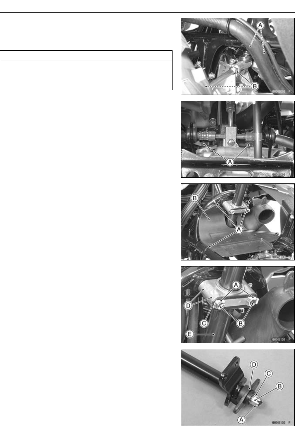
14-6 STEERING
Steering
Steering Stem Removal
•Remove:
Handlebar (see Handlebar Removal)
Cotter Pins and Tie-rod End Nuts [A]
CAUTION
Do not loosen the locknuts [B] at the ends of the
tie-rod adjusting sleeve, or the toe-in of the front
wheels will be changed.
•Remove:
Steering Stem Bearing Joint Bolts [A]
Air Cleaner Housing (see Air Cleaner Housing Removal
in the Fuel System (DFI) chapter)
•Cut the bands [A] to remove the heat guard [B]
•Flatten out the bended washer [A].
•Remove:
Steering Clamp Bolts [B]
Water and Plate [C]
Steering Clamps [D]
Collars
Grease Seals
•Pull the steering stem [E] out of the frame.
•Remove:
Cotter Pin [A]
Steering Stem Bottom End Nut [B]
Collar [C]
Steering Stem Bearing [D]
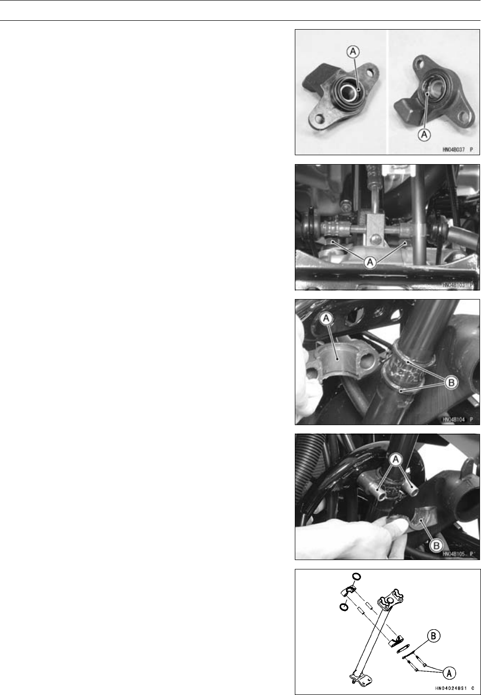
STEERING 14-7
Steering
Steering Stem Installation
•Fill grease up the seal grooves [A] in the steering stem
bearing.
•Install:
Collar
•Tighten:
Torque - Steering Stem Bottom End Nut: 62 N·m (6.3 kgf·m,
46 ft·lb)
•Bend both ends of the cotter pin.
•Apply a non-permanent locking agent to the steering stem
bearing joint bolts [A].
•Tighten:
Torque - Steering Stem Bearing Joint Bolts: 22 N·m (2.2
kgf·m, 16 ft·lb)
•Apply grease to the inside of steering clamp [A].
•Install:
Grease Seals [B]
•Install:
Collars [A]
•Apply above grease to the inside of steering clamp [B].
•Tighten:
Torque - Steering Stem Clamp Bolts [A]: 25 N·m (2.5 kgf·m,
18 ft·lb)
Tie-rod End Nuts: 42 N·m (4.3 kgf·m, 31 ft·lb)
•Bend the tabs of the washer [B] toward the bolt head.
•Inspect the toe-in (see Toe-in Inspection in the
Wheels/Tires chapter).
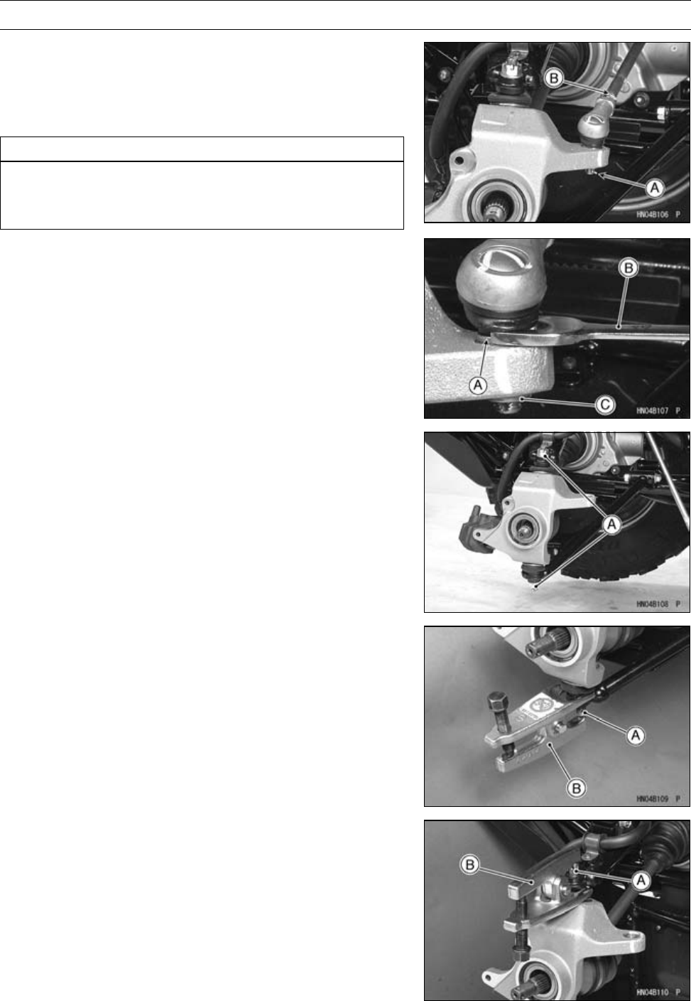
14-8 STEERING
Steering
Steering Knuckle Removal
•Remove:
Front Hub (see Front Hub Removal in the Wheel/Tiers
chapter)
Cotter Pin [A]
CAUTION
Do not loosen the locknuts [B] at the ends of the
tie-rod, or the toe-in of the front wheels will be
changed.
•Holdtheflatsurfaces[A]ofthetie-rodendwithathin
wrench [B], and remove the tie-rod end nut [C] and wash-
ers.
•Tap the tie-rod end shaft lightly and remove the tie-rod
end from the knuckle.
•Remove:
Cotter Pins and Steering Knuckle Joint Nuts [A]
•Remove the knuckle joint [A] from the lower suspension
arm using a suitable joint remover [B].
•Remove the knuckle joint [A] from the upper suspension
arm using a suitable joint remover [B].
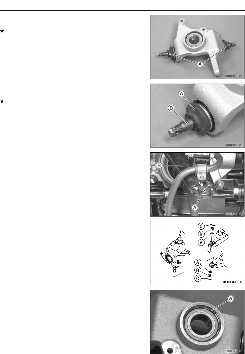
STEERING 14-9
Steering
Steering Knuckle Installation
•Inspect the spherical bearings in the knuckle joints [A].
If roughness, excessive play, or seizure is found, replace
theknucklejoint.
•Check the joint boot [A] is not torn, worn, deteriorated, or
is leaking grease.
If it is found, replace the knuckle joint.
•Clean the shanks [B] of the knuckle joint.
•Clean the taper surface [A] in the front suspension arm
[B].
•Install:
Washers [A] and Knuckle Joint Nuts [B]
•Tighten:
Torque - Steering Knuckle Joint Nuts: 29 N·m (3.0 kgf·m,
21 ft·lb)
Tie-rodEndNuts:42Nm(4.3kgfm,31ftlb)
•Install the new cotter pins [C] and bend its both ends.
Steering Knuckle Bearing Removal
•Remove:
Steering Knuckle (see Steering Knuckle Removal)
Circlip [A]
Special Tool - Inside Circlip Pliers: 57001-143
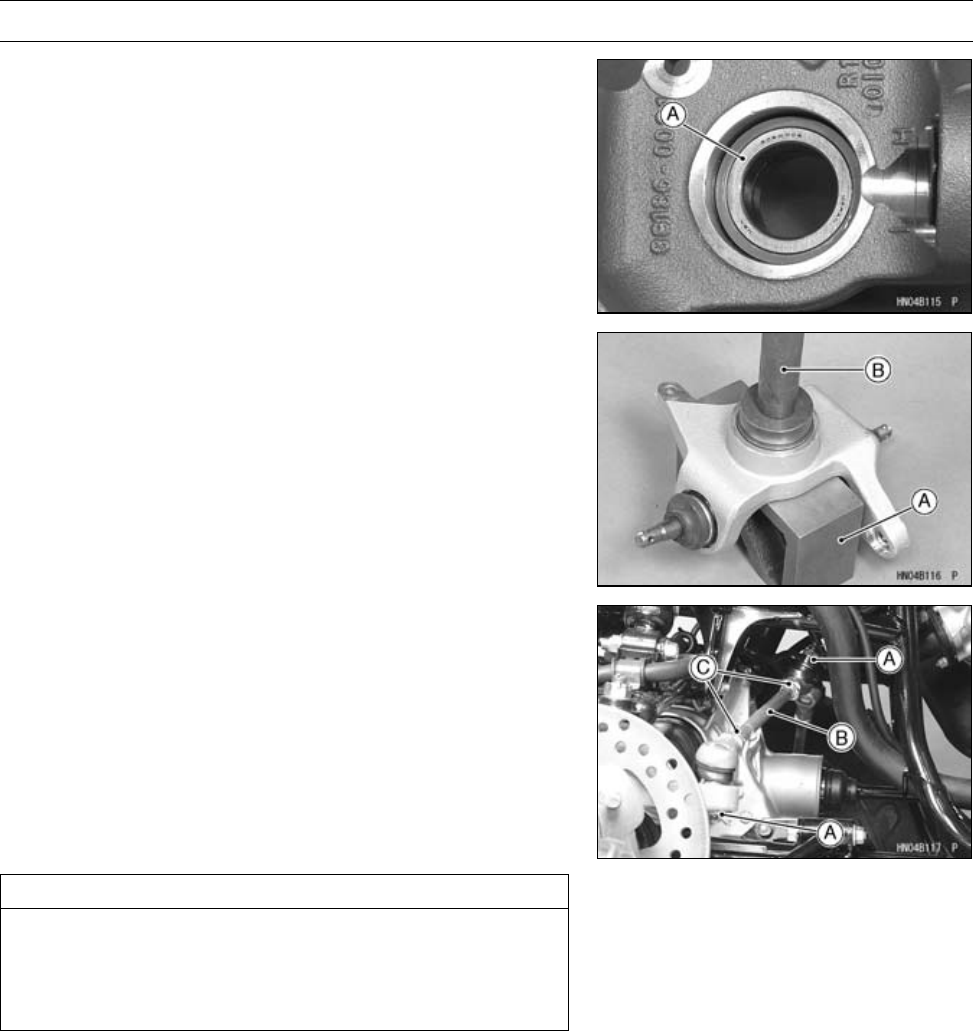
14-10 STEERING
Steering
•Drive the bearing [A] out using a suitable bearing driver
from the bearing driver set.
Special Tool - Bearing Driver Set: 57001-1129
Steering Knuckle Bearing Installation
•The marked side of the bearing faces outward.
•Press in the bearing until it is bottomed.
[A] V Block
Special Tool - Bearing Driver Set [B]: 57001-1129
•Replace the circlip with a new one.
Special Tool - Inside Circlip Pliers: 57001-143
Tie-rod Removal
•Remove:
Front Wheels (see Wheel Removal in the Wheels/Tires
chapter)
Cotter Pins
•Hold the flat surfaces of the tie-rod end with a thin wrench,
and remove the tie-rod nuts [A] and washers (see Steer-
ing Knuckle Removal).
•Remove:
Tie-rod [B]
CAUTION
When removing the tie-rod, be careful not to bend
it. Do not loosen the locknuts [C] at the end of the
tie-rod adjusting sleeve, or the toe-in of the front
wheels will be changed.
Tie-rod Installation
•The right and left tie-rods are identical.
•Tighten:
Torque - Tie-rod End Nuts: 42 N·m (4.3 kgf·m, 31 ft·lb)
•Inspect the toe-in (see Toe-in Inspection in the
Wheels/Tires chapter).
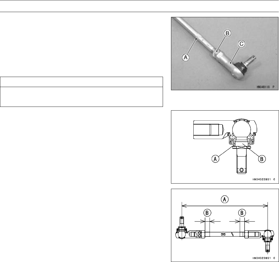
STEERING 14-11
Steering
Tie-rod End Removal
•Removethetie-rod(seeTie-rodRemoval).
•Holding the tie-rod flattened area [A], loosen the locknut
[B] and unscrew the tie-rod end [C].
NOTE
○The locknut near the L mark on the tie-rod has left-hand
threads. Turn the wrench clockwise for loosening.
CAUTION
Do not remove the grease seal. It is packed with
grease.
Tie-rod End Installation
•Check that the boot lip [A] is on the shank [B].
•Install the tie-rod ends so that the tie-rod has the correct
length [A], and both visible thread lengths [B] are equal.
Tie-rod Length
Standard: 388.5 mm (15.30 in.)
•Tighten:
Torque - Tie-rod Locknuts: 37 N·m (3.8 kgf·m, 27 ft·lb)
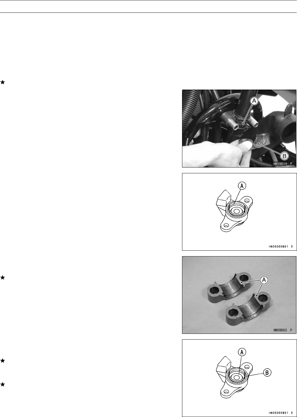
14-12 STEERING
Steering Maintenance
Steering Inspection
•Refer to the Steering Inspection in the Periodic Mainte-
nance chapter.
Steering Stem Straightness Inspection
•Remove the steering stem (see Steering Stem Removal).
•Check the steering stem for straightness.
○Use a straightedge along the stem.
If the steering stem is bent, replace the steering stem.
Steering Bearing Sleeve Lubrication
•Lubricate the steering stem bearings.
○Remove the steering stem (see Steering Stem Removal).
○Wipe all the old grease off the steering stem, bearing
sleeves, and out of the grease seals.
○Apply grease to the steering stem [A] and the inside [B]
of the both clamps.
•Lubricate the steering stem bearing [A].
○Remove the steering stem bearing.
○Pack the grease seal lips with grease.
Steering Stem Clamp Inspection
•Inspect the steering stem clamps [A].
If roughness, excessive play, or seizure is found, replace
both clamps.
Steering Stem Bearing Inspection
•Inspect the spherical bearing [A].
If roughness, excessive play, or seizure is found, replace
the steering stem bearing.
•Inspect the upper and lower grease seals [B].
If damage, wear or deterioration is found, replace the
steering stem bearing.
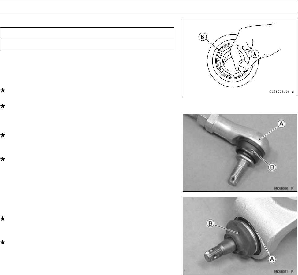
STEERING 14-13
Steering Maintenance
Steering Knuckle Bearing Inspection
CAUTION
Do not remove any bearings for inspection.
•Remove the steering knuckle (see Steering Knuckle Re-
moval).
•Turn [A] the bearing back and forth while checking for
roughness or binding.
If roughness or binding is found, replace the bearing.
•Examine the bearing seal [B] for tears or leakage.
If the seal is torn or is leaking, replace the bearing.
Tie-rod End Inspection
•Inspect each spherical bearing [A].
If roughness, excessive play, or seizure is found, replace
the tie-rod end.
•Inspect each boot [B].
If damage, wear or deterioration is found, replace the tie
-rod end.
Steering Knuckle Joint Inspection
•Inspect each spherical bearing [A].
If roughness, excessive play, or seizure is found, replace
the steering knuckle joint.
•Inspect each boot [B].
If damage, wear or deterioration is found, replace the
steering knuckle joint.
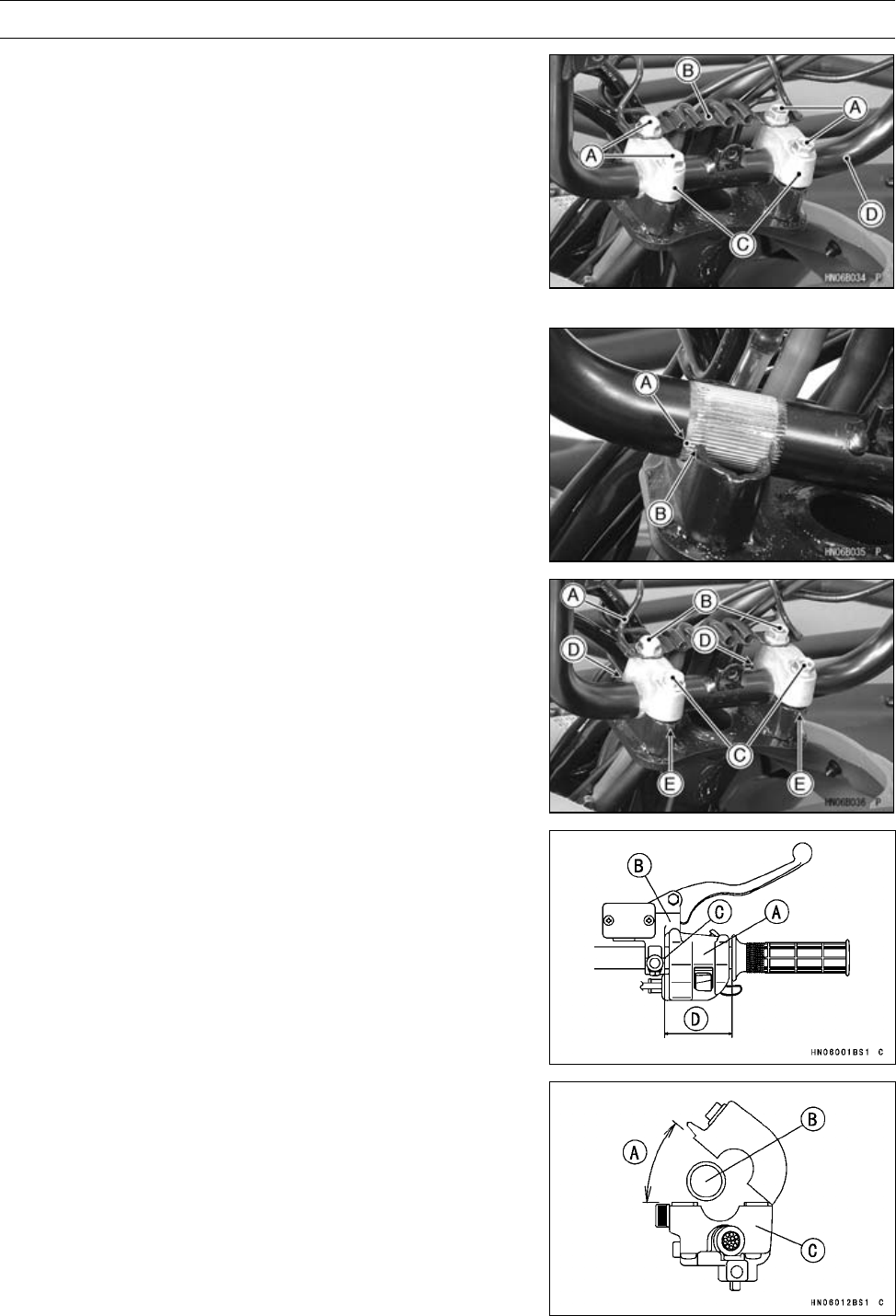
14-14 STEERING
Handlebar
Handlebar Removal
•Remove:
Multifunction Meter Unit (see Multifunction Meter Unit
Removal in the Electrical System chapter)
Throttle Case
Front Brake Master Cylinder
Left-hand Switch Housing
Rear Brake Lever Assembly
Handlebar Holder Bolts [A] and Bracket [B]
Handlebar Holders [C]
Handlebar [D]
Handlebar Installation
•Align the punch mark [A] on the handlebar with the mating
surface end [B] of the steering stem.
•Install the bracket [A].
•Tighten the holder front bolts [B] first and then the rear
bolts [C].
Torque - Handlebar Holder Bolts: 29 N·m (3.0 kgf·m, 21
ft·lb)
○If the holder is correctly installed, there will be no gap [D]
at the front and an even gap [E] at the rear after tightening.
•Install:
Right Switch Housing (Throttle Case) [A]
Front Master Cylinder [B] (see Front Master Cylinder In-
stallation in the Brakes chapter)
Punch Mark [C]
[D] = 70 mm (2.76 in.)
•Install the left switch housing [C] on the handlebar [B] so
that the opening angle is 40° [A] or less.
NOTE
○Do not open the housing more than 40°, the built-in
parts in the housing may be damaged.
•Tighten:
Torque - Left Handlebar Switch Housing Screws: 3.5 N·m
(0.36 kgf·m, 31 in·lb)
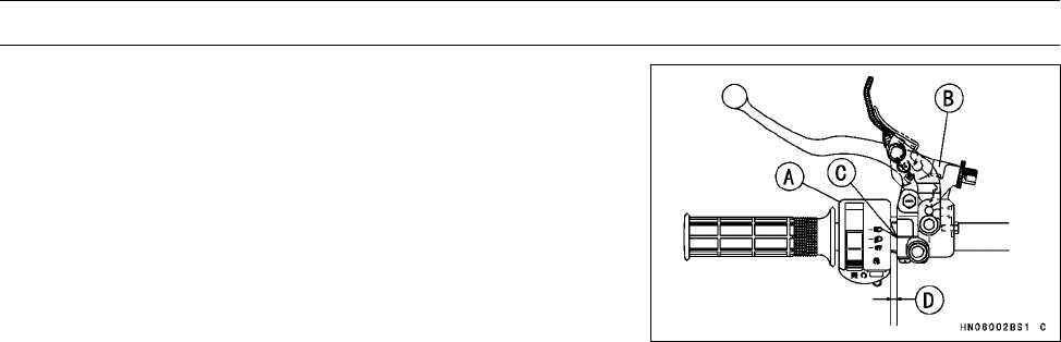
STEERING 14-15
Handlebar
•Install:
Left Switch Housing [A]
Rear Brake Lever Assembly [B]
Punch Mark [C]
[D] = 6 mm (0.24 in.)
○Apply a non-permanent locking agent to the thread of the
variable differential control lever bolt, and tighten it se-
curely.

FRAME 15-1
15
Frame
Table of Contents
Exploded View................................... 15-2
Seat ................................................... 15-8
Seat Removal .............................. 15-8
Seat Installation ........................... 15-8
Carriers.............................................. 15-9
Front Carrier Removal ................. 15-9
Front Carrier Installation .............. 15-9
Front Carrier Bracket Installation . 15-9
Rear Carrier Removal .................. 15-9
Rear Carrier Installation............... 15-10
Rear Carrier Bracket Installation.. 15-10
Fenders ............................................. 15-11
Front Fender Removal ................. 15-11
Front Fender Installation .............. 15-11
Rear Fender Removal.................. 15-11
Rear Fender Installation............... 15-12
Covers ............................................... 15-13
Middle Cover Removal................. 15-13
Middle Cover Installation.............. 15-13
Storage Box Removal .................. 15-13
Storage Case Removal................ 15-14
Storage Case Installation............. 15-14
Left Side Cover Removal ............. 15-14
Left Side Cover Installation .......... 15-15
Right Side Cover Removal........... 15-15
Right Side Cover Installation........ 15-15
Electrical Parts Case Removal .... 15-16
Electrical Parts Case Installation . 15-16
Radiator Cover Removal.............. 15-16
Radiator Cover Installation........... 15-17
Headlight Cover Removal ............ 15-17
Headlight Cover Installation ......... 15-17
Guards............................................... 15-18
Front Guard Removal .................. 15-18
Front Guard Installation ............... 15-18
Front Bottom Guard Removal ...... 15-19
Front Bottom Guard Installation ... 15-19
Engine Bottom Guard Removal ... 15-19
Engine Bottom Guard Installation 15-19
Rear Bottom Guard Removal....... 15-20
Rear Bottom Guard Installation.... 15-20
Flaps and Footboards........................ 15-21
Left Footboard Removal .............. 15-21
Left Footboard Installation ........... 15-21
Right Footboard Removal ............ 15-21
Right Footboard Installation ......... 15-22
Footboard Bracket installation ..... 15-22
Trailer Hitch Bracket .......................... 15-23
Trailer Hitch Bracket Removal ..... 15-23
Trailer Hitch Bracket Installation .. 15-23
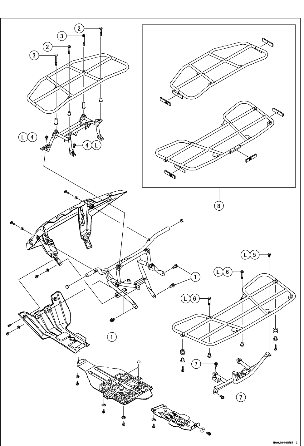
15-2 FRAME
Exploded View

FRAME 15-3
Exploded View
Torque
No. Fastener N·m kgf·m ft·lb Remarks
1Front Guard Bolts 46 4.7 34
2Front Carrier Bolts, L = 50 mm (2.0 in.) 32 3.3 24 L
3Front Carrier Bolts, L = 70 mm (2.8 in.) 32 3.3 24 L
4Front Carrier Bracket Bolts 32 3.3 24 L
5Rear Carrier Bolts, L = 14 mm (0.55 in.) 54 5.5 40 L
6Rear Carrier Bolts, L = 44 mm (1.7 in.) 54 5.5 40 L
7Rear Carrier Bracket Bolts 46 4.7 34
8. CA Model
L: Apply a non-parmanent locking agent.
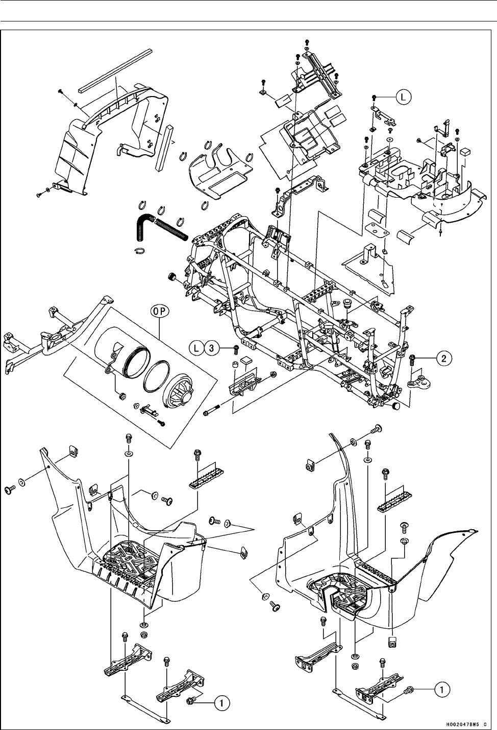
15-4 FRAME
Exploded View

FRAME 15-5
Exploded View
Torque
No. Fastener N·m kgf·m ft·lb Remarks
1Footboard Bracket Bolts 46 4.7 34
2Trailer Hitch Bracket Bolts 82 8.4 60 L
3Rear Final Gear Case Mounting Bracket Bolts 59 6.0 44 L
L: Apply a non-permanent locking agent.
OP: Optional Parts
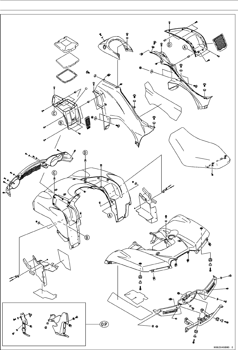
15-6 FRAME
Exploded View

FRAME 15-7
Exploded View
OP: Optional Parts
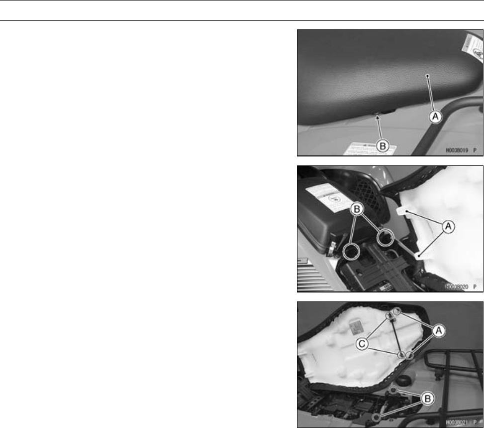
15-8 FRAME
Seat
Seat Removal
•Remove the seat [A] by lifting the latch lever [B] and then
pulling the seat up to the rear.
Seat Installation
•Insert the front seat hooks [A] into the receivers [B] in the
bracket.
•Insert the rear seat hooks [A] into the dampers [B].
•Push the rear part of the seat down to engage the latches
[C].
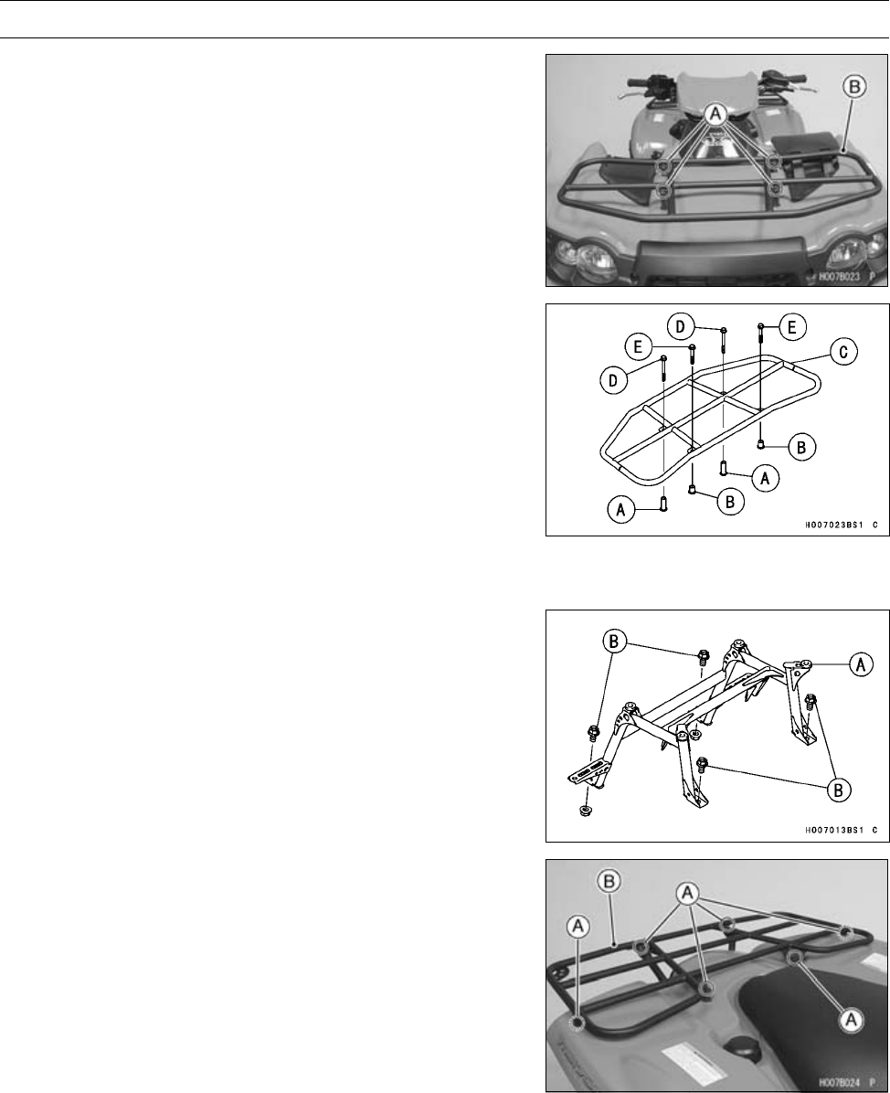
FRAME 15-9
Carriers
Front Carrier Removal
•Remove:
Front Carrier Bolts [A]
Collars
Front Carrier [B]
Front Carrier Installation
•Install:
Long Collars, L = 44.6 mm (1.8 in.) [A]
Short Collars, L = 21.6 mm (0.9 in.) [B]
Front Carrier [C]
•Apply a non-parmanent locking agent to the front carrier
bolts.
•Tighten:
Torque - Front Carrier Bolts [D], L = 70 mm (2.8 in.): 32 N·m
(3.3 kgf·m, 24 ft·lb)
Front Carrier Bolts [E], L = 50 mm (2.0 in.): 32 N·m
(3.3 kgf·m, 24 ft·lb)
Front Carrier Bracket Installation
•Install:
Front Carrier Bracket [A]
•Apply a non-permanent locking agent on the thread of the
front carrier bracket bolts and tighten them with a speci-
fied torque.
Torque - Front Carrier Bracket Bolts [B]: 32 N·m (3.3 kgf·m,
24 ft·lb)
Rear Carrier Removal
•Remove:
Rear Carrier Bolts [A]
Collars
Rear Carrier [B]
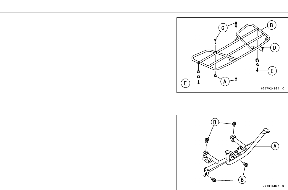
15-10 FRAME
Carriers
Rear Carrier Installation
•Install:
Collar [A]
Rear Carrier [B]
Rear Carrier Bolts, L = 44 mm (1.7 in.) [C]
Rear Carrier Bolts, L = 14 mm (0.55 in.) [D]
Rear Carrier Bolts, L = 25 mm (0.98 in.) [E]
•Apply a non-permanent locking agent on the thread of the
rear carrier bolts [C], [D], and tighten them with a specified
torque.
Torque - Rear Carrier Bolts [C] [D]: 54 N·m (5.5 kgf·m, 40
ft·lb)
Rear Carrier Bracket Installation
•Install:
Rear Carrier Bracket [A]
•Tighten:
Torque - Rear Carrier Bracket Bolts [B]: 46 N·m (4.7 kgf·m,
34 ft·lb)
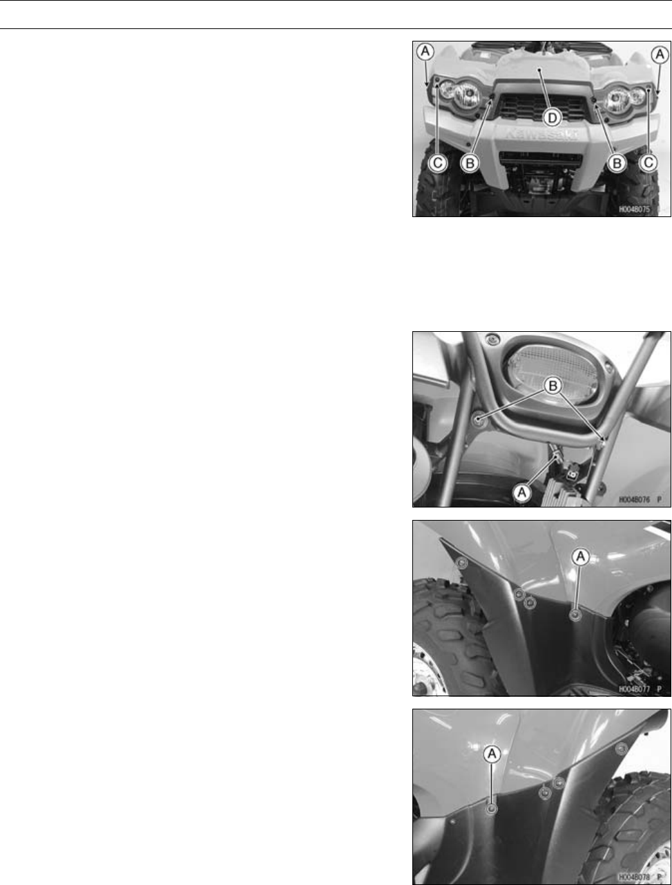
FRAME 15-11
Fenders
Front Fender Removal
•Remove:
Seat (see Seat Removal)
Front Carrier (see Front Carrier Removal)
Footboard (see each Footboard Removal)
Middle Cover (see Middle Cover Removal)
Quick Rivets [A] (both sides)
Bolts [B] and Collars
Bolts [C]
•While pulling the front fender [D] backward, remove it.
Front Fender Installation
•Install:
Front Fender
Screws and Collars
Quick Rivets
Rear Fender Removal
•Remove:
Seat (see Seat Removal)
•Disconnect:
Tail/Brake Light Lead Connector [A]
•Remove:
Bolts [B] and Collars
•Remove:
Seat (see Seat Removal)
Rear Carrier (see Rear Carrier Removal)
Screws [A] and Collars
•Remove:
Screws [A] and Collars
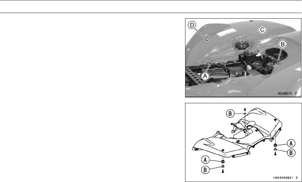
15-12 FRAME
Fenders
•Remove:
Screws [A] and Collars
Bolts [B] and Collars
Fuel Tank Cap [C]
Rear Fender [D]
•Install the fuel tank cap after removing the rear fender.
Rear Fender Installation
•Connect:
Tail/Brake Light Lead Connector
•Install:
Rear Fender
Dampers [A] and Collars [B]
Rear Carrier (see Rear Carrier Installation)
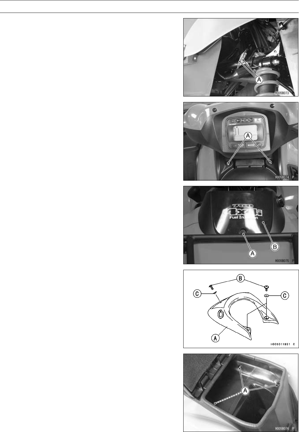
FRAME 15-13
Covers
Middle Cover Removal
•Disconnect:
Power Outlet Lead Connectors [A]
•Remove:
Middle Cover Screws [A] and Collars
•Remove:
Middle Cover Screw [A] and Collar
Middle Cover [B]
Middle Cover Installation
•Connect:
Power Outlet Lead Connectors
•Install:
Middle Cover [A]
Middle Cover Screws [B] and Collars [C]
Storage Box Removal
•Open the lid.
•Remove the screws [A].
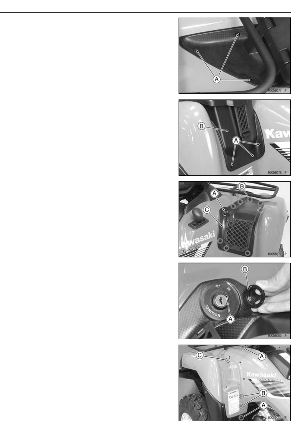
15-14 FRAME
Covers
•Remove:
Screws [A]
•Remove:
Screws [A]
Storage Box [B]
Storage Case Removal
•Remove:
Ignition Switch Nut [A]
Screws [B]
Storage Case [C]
Storage Case Installation
•Install:
Storage Case
Screws
•Fit projection [A] on the ignition switch into the recess in
the storage case.
•Tighten the nut [B] securely.
Left Side Cover Removal
•Remove:
Seat (see Seat Removal)
Middle Cover (see Middle Cover Removal)
Storage Box (see Storage Box Removal)
•Remove:
Screws [A] and Collars
Screws [B], Washers and Nuts
Screws [C]
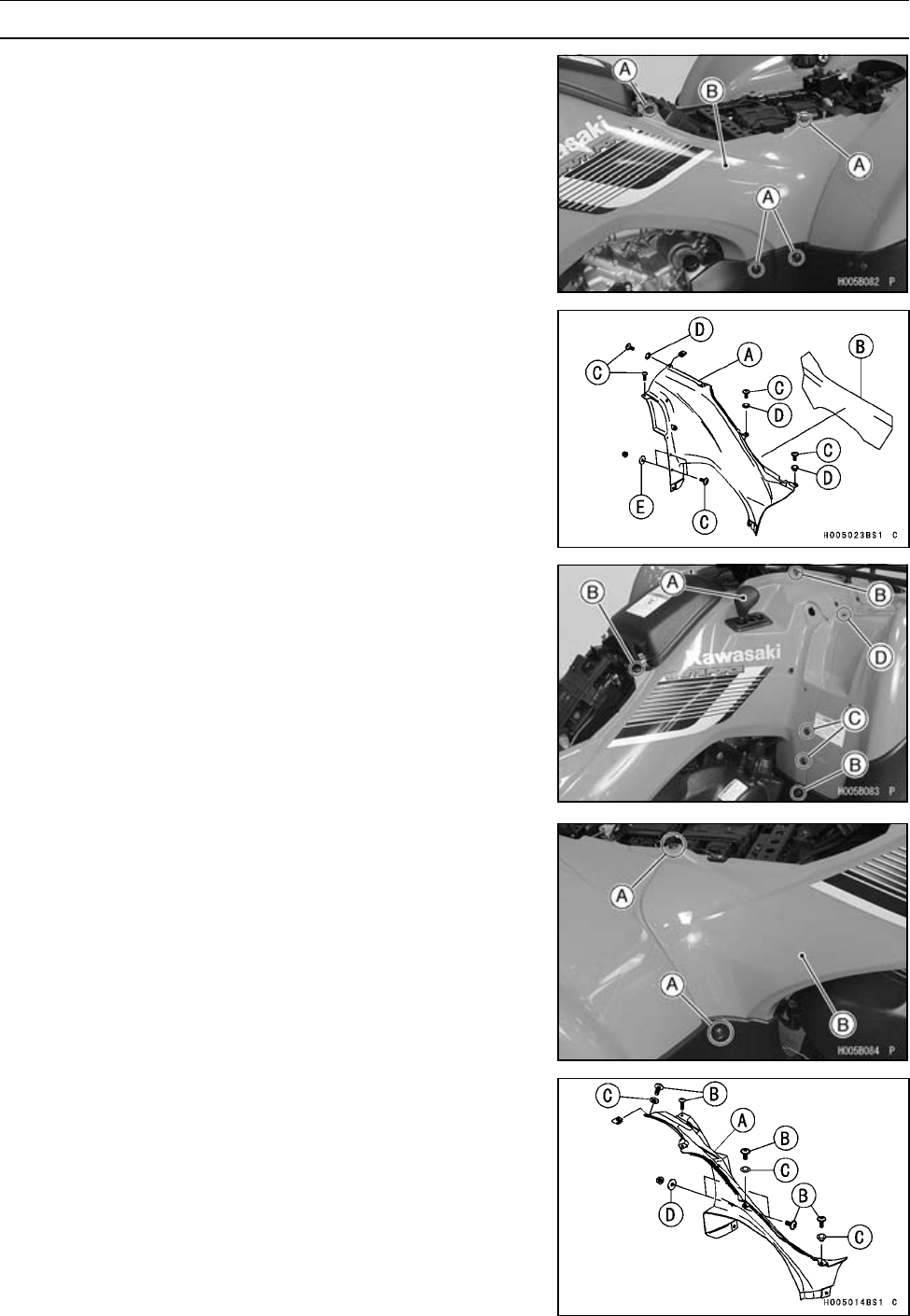
FRAME 15-15
Covers
•Remove:
Screws [A] and Collars
Left Side Cover [B]
Left Side Cover Installation
•Install:
Left Side Cover [A]
Insulator [B]
Screws [C] and Collars [D]
Washers [E]
Storage Case
Right Side Cover Removal
•Remove:
Seat (see Seat Removal)
Middle Cover (see Middle Cover Removal)
Storage Case (see Storage Case Removal)
•Remove:
Shift Knob [A]
Screws [B] and Collars
Screws [C], Washers and Nuts
Screws [D]
•Remove:
Screws [A] and Collars
Right Side Cover [B]
Right Side Cover Installation
•Install:
Right Side Cover [A]
Screws [B] and Collars [C]
Washer [D]
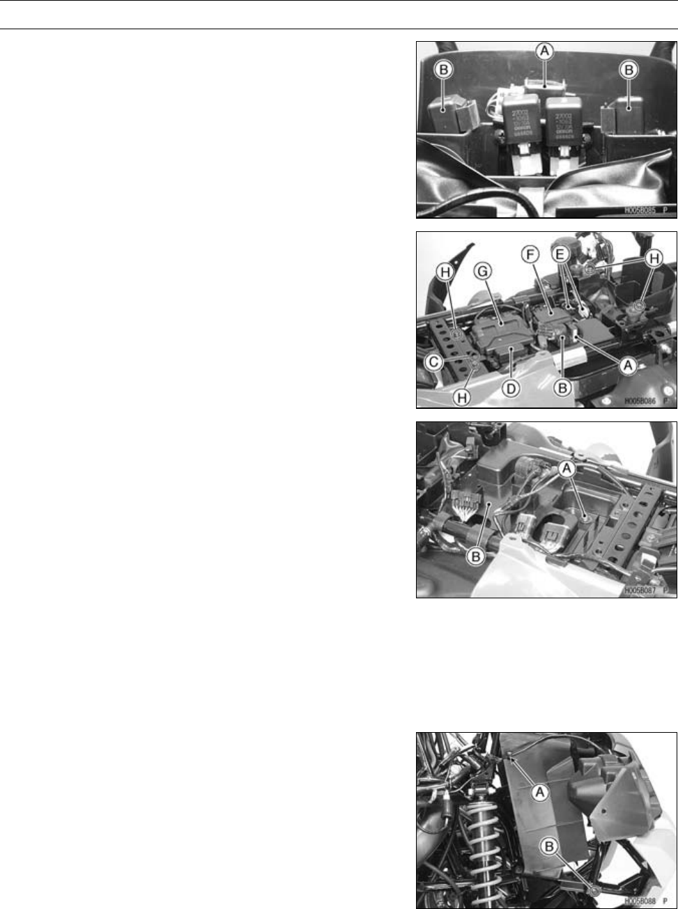
15-16 FRAME
Covers
Electrical Parts Case Removal
•Remove:
Seat (see Seat Removal)
Rear Fender (see Rear Fender Removal)
Vehicle-down Sensor [A] (see Vehicle-down Sensor Re-
moval in the Fuel System (DFI) chapter)
Stater Control Relays [B]
•Remove the following parts from the case.
Radiator Fan Breaker [A]
Starter Relay [B]
Fuse Box Bracket Bolt [C]
Fuse Box [D]
Reset Connectors [E]
Actuator Controller [F]
ECU [G]
Bolts [H]
•Remove:
Screw [A] and Collar
Bolts [B]
Electrical Parts Case [B]
Electrical Parts Case Installation
•Apply a non-parmanent agent to the fuse box bracket bolt.
•Install:
Removed Parts
•Route the electrical parts leads according to the Appendix
chapter.
Radiator Cover Removal
•Remove:
Front Fender (see Front Fender Removal)
Clamps [A] (both sides)
Radiator Cover Screws [B] and collars (both sides)
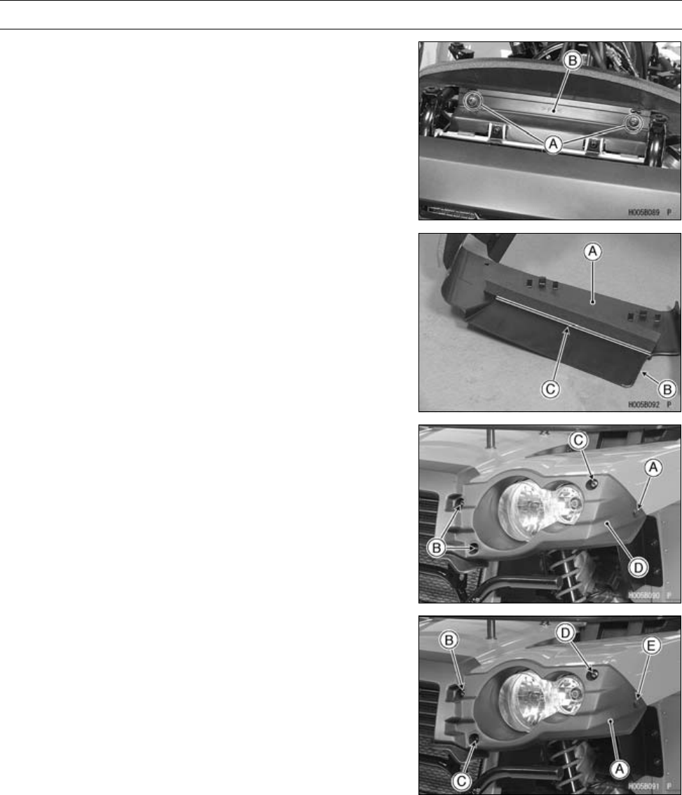
FRAME 15-17
Covers
•Remove:
Radiator Cover Screws [A] and Collars
Radiator Cover [B]
Radiator Cover Installation
•Install the seal [A] so that along it to the bottom [B] and
corner line [C].
•Install:
Radiator Cover Screws and Collars
Headlight Cover Removal
•Remove:
Front Guard Cover (see Front Guard Removal)
Quick Rivets [A] (both sides)
Bolts [B] and Collars (both sides)
Bolts [C] (both side)
Headlight Cover [D]
Headlight Cover Installation
•Install:
Headlight Cover [A]
Bolts and Collars [B] [L = 6 mm (0.24 in.)]
BoltsandCollars[C][L=4mm(0.16in.)]
Bolts [D]
QuickRivets[E]
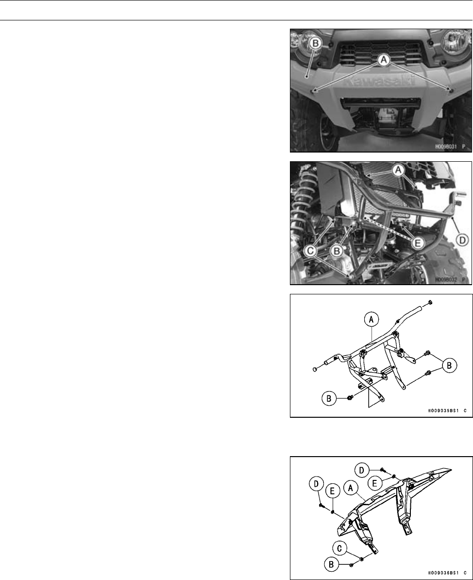
15-18 FRAME
Guards
Front Guard Removal
•Remove:
Front Bottom Guard (see Front Bottom Guard Removal)
Bolts [A] and Collars
Front Guard Cover [B]
•Remove:
Front Carrier Bracket Bolts [A]
Radiator Cover Screws [B] and Collars (both sides)
Front Guard Bolts [C] (both sides)
•Remove the front guard [D] from the radiator bottom stop-
pers [E].
Front Guard Installation
•Insert the radiator bottom stoppers in the grommet in the
front guard.
•Install:
Front Guard [A]
Front Guard Bolts [B]
•Apply a non-parmanent locking agent to the front carrier
bracket bolts.
•Tighten:
Torque - Front Guard Bolts: 46 N·m (4.7 kgf·m, 34 ft·lb)
Front Carrier Bracket Bolts: 32 N·m (3.3 kgf·m, 24
ft·lb)
•Install:
Radiator Cover Screws
Front Guard Cover [A]
Bolts [B] and Collars [C]
Bolts [D] and Collars [E]
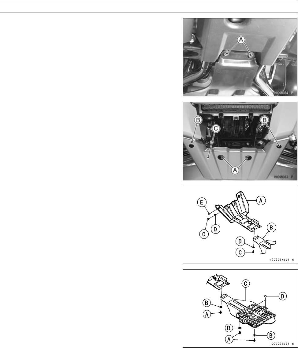
FRAME 15-19
Guards
Front Bottom Guard Removal
•Remove:
Bolts [A] and Collars
•Remove:
Bolts [A] and Collars
QuickRivets[B]
Front Bottom Guard [C]
Front Bottom Guard Installation
•Install the front bottom guard [A] between the frame and
engine bottom guard [B].
•Install:
Bolts [C] and Collars [D]
Engine Bottom Guard Removal
•Remove:
Bolts [A] and Collars [B]
Engine Bottom Guard [C]
Engine Bottom Guard Installation
•Confirm:
Damper [D]
•Install:
Engine Bottom Guard
Bolts and Collars
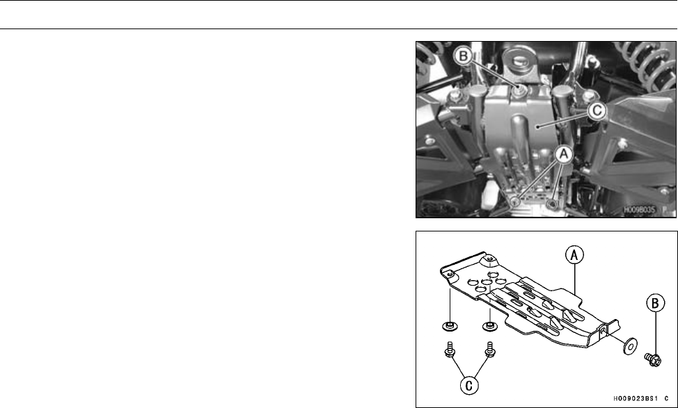
15-20 FRAME
Guards
Rear Bottom Guard Removal
•Remove:
Bolts (M6) [A] and Collars
Bolt (M8) [B] and Collar
Rear Bottom Guard [C]
Rear Bottom Guard Installation
•Install:
Rear Bottom Guard [A]
Bolt (M8) [B] and Collar
Bolts (M6) [C] and Collars
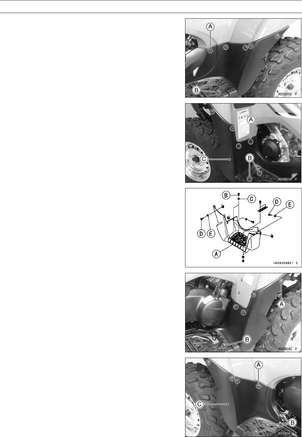
FRAME 15-21
Flaps and Footboards
Left Footboard Removal
•Remove:
Screws [A] and Collars
Bolts [B] and Collars
•Remove:
Screws [A] and Collars
Bolts [B] and Collars
Left Footboard [C]
Left Footboard Installation
•Install:
Left Footboard [A]
Bolts [B] and Collars [C]
Screws [D] and Collars [E]
Right Footboard Removal
•Remove:
Screws [A] and Collars
Bolt [B] and Collar
•Remove:
Screws [A] and Collars
Bolts [B] and Collars
Right Footboard [C]
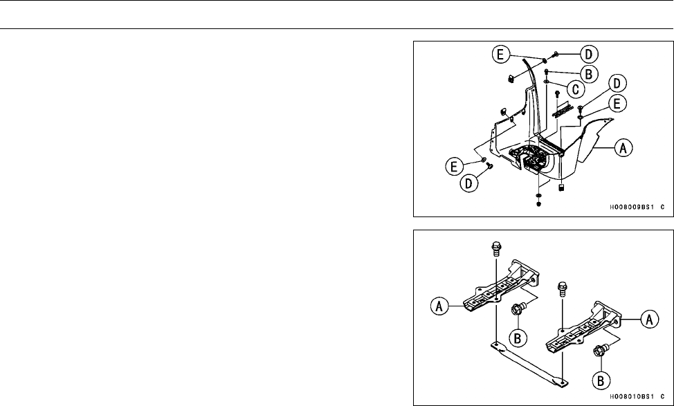
15-22 FRAME
Flaps and Footboards
Right Footboard Installation
•Install:
Right Footboard [A]
Bolts [B] and Collars [C]
Screws [D] and Collars [E]
Footboard Bracket installation
•Install:
Footboard Bracket [A]
•Tighten:
Torque - Footboard Bracket Bolts [B]: 46 N·m (4.7 kgf·m, 34
ft·lb)
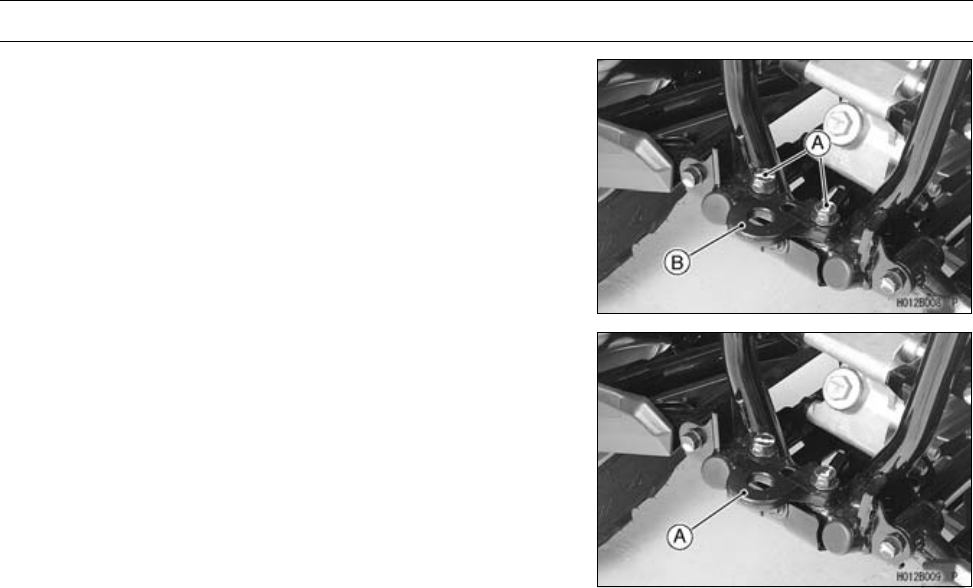
FRAME 15-23
Trailer Hitch Bracket
Trailer Hitch Bracket Removal
•Remove:
Trailer Hitch Bracket Bolts [A]
Trailer Hitch Bracket [B]
Trailer Hitch Bracket Installation
•Install the trailer hitch bracket [A] as shown.
•Apply a non-parmanent locking agent to the trailer hitch
bracket bolts.
•Tighten:
Torque - Trailer Hitch Bracket Bolts: 82 N·m (8.4 kgf·m, 60
ft·lb)

ELECTRICAL SYSTEM 16-1
16
Electrical System
Table of Contents
Parts Location......................................................................................................................... 16-3
Exploded View........................................................................................................................ 16-6
Specifications ......................................................................................................................... 16-12
Wiring Diagram....................................................................................................................... 16-13
Special Tools and Sealant ...................................................................................................... 16-16
Precautions............................................................................................................................. 16-17
Electrical Wiring...................................................................................................................... 16-19
Wiring Inspection .............................................................................................................. 16-19
Battery .................................................................................................................................... 16-20
Battery Removal ............................................................................................................... 16-20
Battery Installation ............................................................................................................ 16-20
Battery Activation .............................................................................................................. 16-20
Precautions ....................................................................................................................... 16-22
Interchange ....................................................................................................................... 16-23
Charging Condition Inspection.......................................................................................... 16-23
Refreshing Charge ........................................................................................................... 16-24
Charging System.................................................................................................................... 16-26
Alternator Cover Removal................................................................................................. 16-26
Alternator Cover Installation.............................................................................................. 16-27
Alternator Rotor Removal ................................................................................................ 16-29
Alternator Rotor Installation .............................................................................................. 16-29
Alternator Stator Removal................................................................................................. 16-30
Alternator Stator Installation.............................................................................................. 16-30
Regulator/Rectifier Output Voltage Inspection .................................................................. 16-30
Alternator Inspection ......................................................................................................... 16-31
Regulator/Rectifier Removal ............................................................................................. 16-32
Regulator/Rectifier Installation .......................................................................................... 16-32
Regulator/Rectifier Inspection........................................................................................... 16-33
Ignition System....................................................................................................................... 16-34
Spark Plug Removal ......................................................................................................... 16-34
Spark Plug Installation ...................................................................................................... 16-35
Spark Plug Cleaning/Inspection........................................................................................ 16-35
Spark Plug Gap Inspection ............................................................................................... 16-35
Ignition Coil Removal ........................................................................................................ 16-35
Ignition Coil Installation ..................................................................................................... 16-36
Ignition Coil Inspection...................................................................................................... 16-37
Ignition Coil Primary Peak Voltage Inspection .................................................................. 16-38
Crankshaft Sensor Removal ............................................................................................. 16-38
Crankshaft Sensor Installation .......................................................................................... 16-39
Crankshaft Sensor Inspection........................................................................................... 16-39
Crankshaft Sensor Peak Voltage Inspection..................................................................... 16-40
Alternator Rotor Inspection ............................................................................................... 16-40
Ignition Timing Test ........................................................................................................... 16-40
Electric Starter System ........................................................................................................... 16-44
Starter Motor Removal...................................................................................................... 16-44
Starter Motor Installation................................................................................................... 16-44
Starter Motor Disassembly................................................................................................ 16-45
Starter Motor Assembly .................................................................................................... 16-46
Brush Inspection ............................................................................................................... 16-48
Commutator Cleaning and Inspection............................................................................... 16-48

16-2 ELECTRICAL SYSTEM
Armature Inspection.......................................................................................................... 16-48
Brush Lead Inspection ...................................................................................................... 16-49
Right-hand End Cover Inspection ..................................................................................... 16-49
Starter Relay Inspection.................................................................................................... 16-49
Starter Control Relay Inspection ....................................................................................... 16-49
Starter Motor Clutch Removal........................................................................................... 16-51
Starter Motor Clutch Installation........................................................................................ 16-51
Starter Motor Clutch Inspection ........................................................................................ 16-51
Torque Limiter Inspection.................................................................................................. 16-52
Lighting System...................................................................................................................... 16-53
Headlight Beam Vertical Adjustment................................................................................. 16-53
Headlight Bulb Replacement ............................................................................................ 16-53
Tail/Brake Light Bulb Replacement ................................................................................... 16-55
Tail/Brake Light Removal .................................................................................................. 16-55
Radiator Fan System.............................................................................................................. 16-57
Radiator Fan Motor Inspection.......................................................................................... 16-57
Radiator Fan Breaker Inspection ...................................................................................... 16-57
Radiator Fan Breaker Installation ..................................................................................... 16-57
Meter ...................................................................................................................................... 16-59
Multifunction Meter Unit Removal ..................................................................................... 16-59
Multifunction Meter Unit Inspection................................................................................... 16-60
Drive Belt Failure Mode Memory Clearing Procedure ...................................................... 16-66
Actuator Control System......................................................................................................... 16-69
2WD/4WD Actuator Removal ........................................................................................... 16-69
2WD/4WD Actuator Installation ........................................................................................ 16-69
Engine Brake Actuator Removal....................................................................................... 16-69
Engine Brake Actuator Installation.................................................................................... 16-70
Actuator Control System Outline....................................................................................... 16-70
Actuator Controller Removal............................................................................................. 16-71
Actuator Controller Installation.......................................................................................... 16-71
Actuator Control System Troubleshooting ........................................................................ 16-72
Drive Belt Failure Detection System....................................................................................... 16-80
Drive Belt Failure Detection System Inspection................................................................ 16-80
Switches and Sensor.............................................................................................................. 16-81
Fuel Level Sensor Inspection............................................................................................ 16-81
Brake Light Switch Adjustment ......................................................................................... 16-82
Water Temperature Sensor Inspection ............................................................................. 16-83
Speed Sensor Removal/Installation.................................................................................. 16-83
Speed Sensor Inspection.................................................................................................. 16-83
Switch Inspection.............................................................................................................. 16-84
Drive Belt Failure Detection Switch Inspection ................................................................. 16-85
Relay ...................................................................................................................................... 16-86
Relay Inspection ............................................................................................................... 16-86
Fuses ..................................................................................................................................... 16-87
Fuse Removal................................................................................................................... 16-87
Fuse Installation................................................................................................................ 16-87
Fuse Inspection................................................................................................................. 16-87
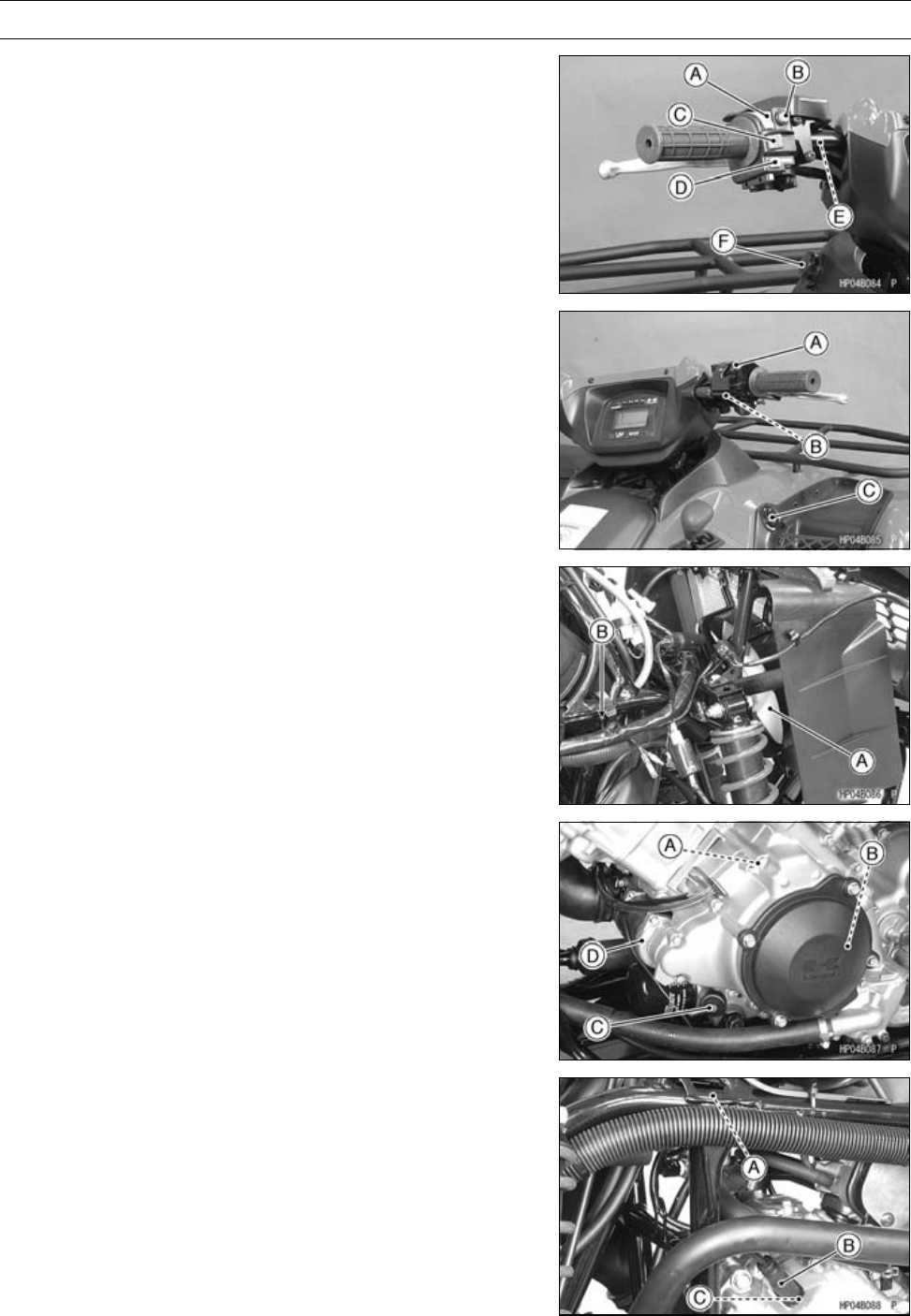
ELECTRICAL SYSTEM 16-3
Parts Location
Light/Dimmer Switch [A]
Starter Button [B]
Engine Stop Switch [C]
Reverse Power Assist Switch (Override) [D]
Rear Brake Light Switch [E]
Power Outlet Connector [F] (120 W)
2WD/4WD Shift Switch [A]
Front Brake Light Switch [B]
Ignition Switch [C]
Radiator Fan [A]
Frame Ground [B]
Crankshaft Sensor [A]
Alternator [B]
Oil Pressure Warning Light Switch [C]
Starter Motor [D]
Ignition Coil (Front) [A]
Spark Plug Cap (Front) [B]
Spark Plug (Front) [C]
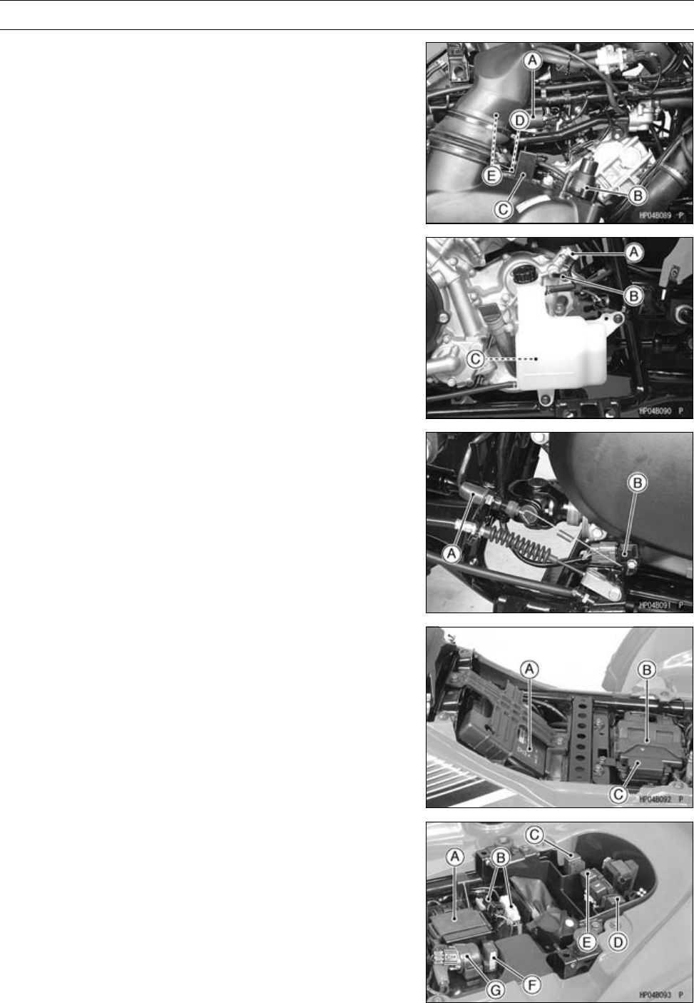
16-4 ELECTRICAL SYSTEM
Parts Location
Ignition Coil (Rear) [A]
Engine Brake Actuator [B]
Drive Belt Failure Detection Switch [C]
Engine Ground [D]
Spark Plug Cap (Rear) [E]
Neutral Position Switch [A]
ReversePositionSwitch[B]
Forward/Reverse Detecting Sensor [C]
Rear Brake Light Switch [A]
Speed Sensor [B]
Battery 12 V 12 Ah[A]
ECU (Electronic Control Unit) [B]
Fuse Box [C]
Actuator Controller [A]
Reset Connectors [B]
Starter Control Relay (Neutral) [C]
Starter Control Relay (Brake) [D]
Radiator Fan Relay [E]
Radiator Fan Breaker [F]
Starter Relay [G]
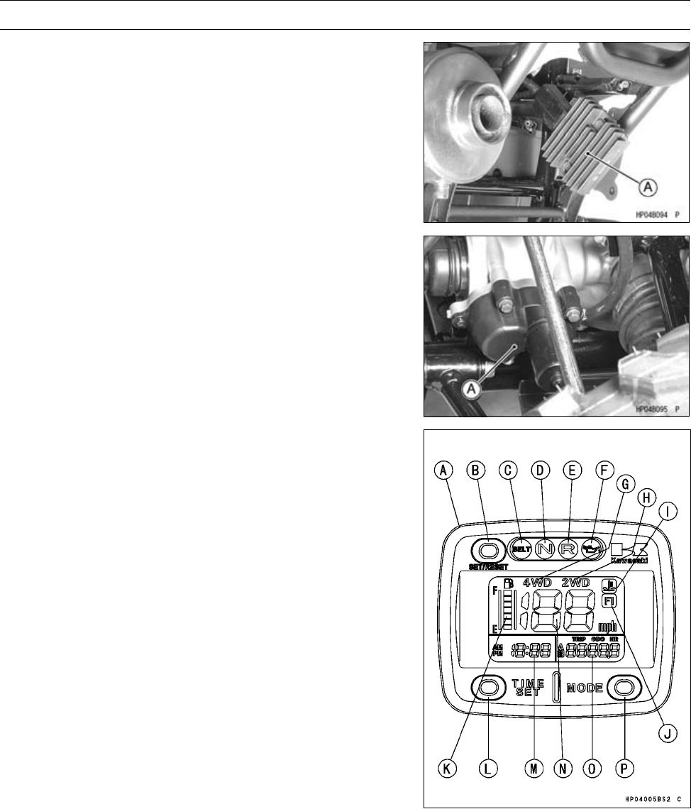
ELECTRICAL SYSTEM 16-5
Parts Location
Regulator/Rectifier [A]
2WD/4WD Actuator [A]
Multifunction Meter [A]
“SET/RESET” Button [B]
Belt Check Indicator Light [C]
Neutral Indicator Light [D]
Reverse Indicator Light [E]
Oil Pressure Warning Indicator Light [F]
“4WD” Indicator Light [G]
“2WD” Indicator Light [H]
Water Temperature Warning Symbol [I]
FI Indicator Light [J]
Fuel Level Gauge [K]
“TIME SET” Button [L]
Clock [M]
Speedometer [N]
Trip Meter/Odometer/Hour Meter [O]
“MODE” Button [P]
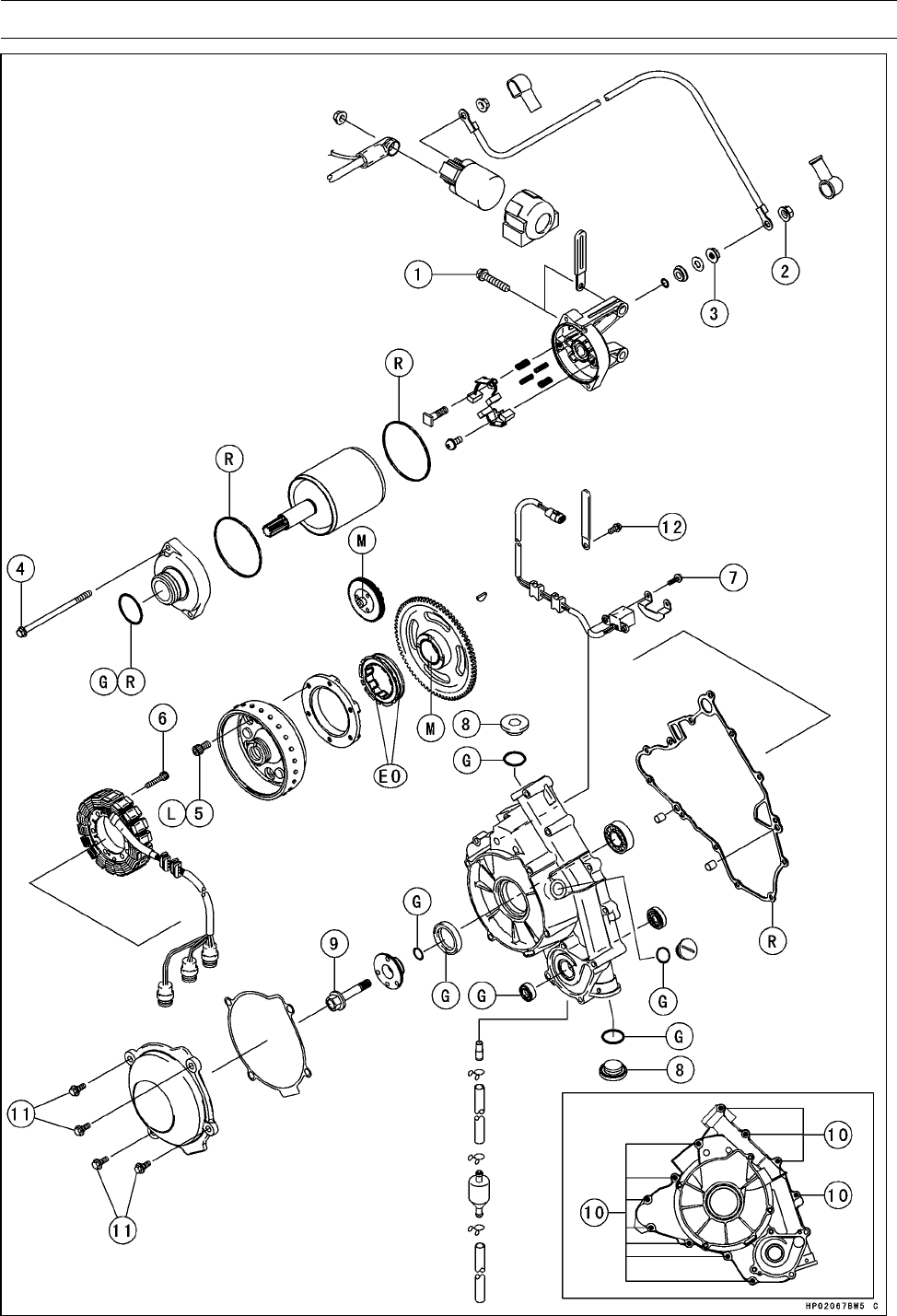
16-6 ELECTRICAL SYSTEM
Exploded View

ELECTRICAL SYSTEM 16-7
Exploded View
Torque
No. Fastener N·m kgf·m ft·lb Remarks
1Starter Motor Mounting Bolts 8.8 0.90 78 in·lb
2Starter Motor Cable Mounting Nut 6.8 0.69 60 in·lb
3Starter Motor Terminal Locknut 11 1.1 97 in·lb
4Starter Motor Through Bolts 5.0 0.51 44 in·lb
5Starter Motor Clutch Bolts 34 3.5 25 L
6Alternator Stator Bolts 13.5 1.4 119 in·lb
7Crankshaft Sensor Mounting Bolts 5.9 0.60 52 in·lb
8Alternator Cover Plugs 17.5 1.8 13
9Alternator Rotor Bolt 127 13 94
10 Alternator Cover Bolts 8.8 0.90 78 in·lb
11 Alternator Outer Cover Bolts 5.9 0.60 52 in·lb L
12 Harness Clamp Bolt 8.8 0.90 78 in·lb
EO: Apply engine oil.
G: Apply grease.
L: Apply a non-permanent locking agent.
M: Apply molybdenum disulfide grease.
R: Replacement Parts
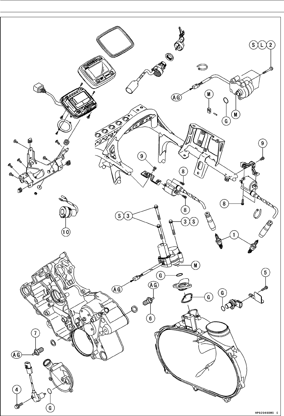
16-8 ELECTRICAL SYSTEM
Exploded View

ELECTRICAL SYSTEM 16-9
Exploded View
Torque
No. Fastener N·m kgf·m ft·lb Remarks
1Spark Plugs 13 1.3 115 in·lb
22WD/4WD Actuator Mounting Bolts 9.8 1.0 87 in·lb L, S
3Engine Brake Actuator Mounting Bolts 8.8 0.90 78 in·lb S
4Forward/Reverse Detecting Sensor Mounting Bolt 14.9 1.5 11
5Speed Sensor Mounting Bolt 8.8 0.90 78 in·lb
6Neutral Position Switch 15 1.5 11
7ReversePositionSwitch 15 1.5 11
8Ignition Coil Mounting Bolts 5.9 0.60 52 in·lb
9Ignition Coil Bracket Mounting Bolts 5.9 0.60 52 in·lb
10. Power Outlet Connector (120 W)
AG: Apply grease (Amoco rykon premium grease No.2 EP Green).
G: Apply grease.
L: Apply a non-permanent locking agent.
M: Apply molybdenum disulfide grease.
S: Follow the specific tightening sequence.
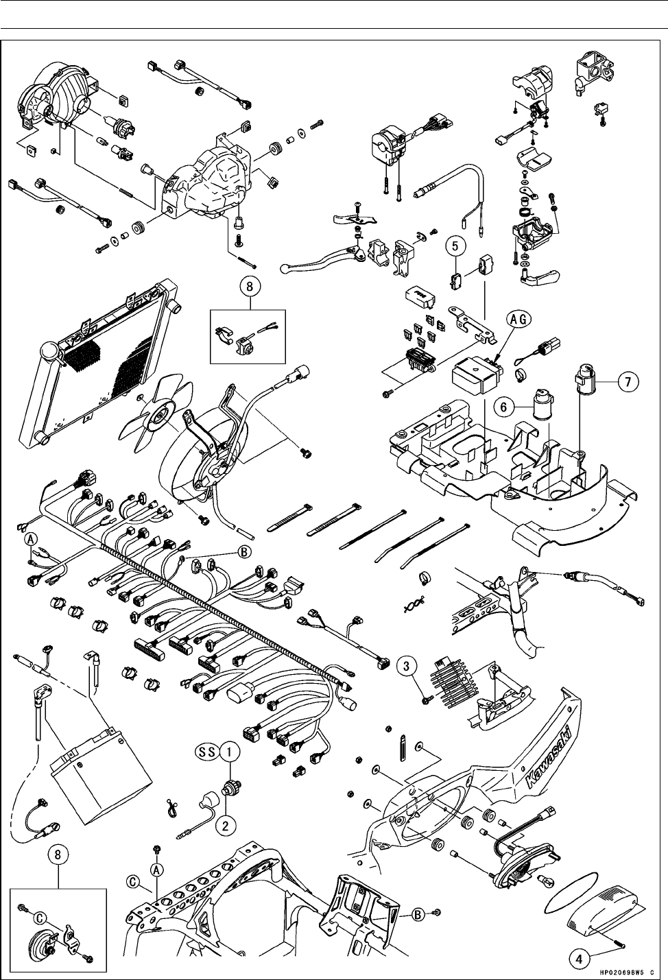
16-10 ELECTRICAL SYSTEM
Exploded View

ELECTRICAL SYSTEM 16-11
Exploded View
Torque
No. Fastener N·m kgf·m ft·lb Remarks
1Oil Pressure Switch 15 1.5 11 SS
2Oil Pressure Switch Terminal Bolt 1.5 0.15 13 in·lb
3Regulator/Rectifier Mounting Bolts 8.8 0.90 78 in·lb
4Tail/Brake Light Lens Screws 1.0 0.10 8.8 in·lb
5. Radiator Fan Breaker
6. Starter Control Relay (Brake)
7. Starter Control Relay (Neutral)
8. Other than US and CA Models
AG: Apply grease (Amoco rykon premium grease No.2 EP Green).
SS: Apply silicone sealant (Kawasaki Bond: 56019-120).

16-12 ELECTRICAL SYSTEM
Specifications
Item Standard Service Limit
Battery
Type Sealed Battery –––
Model Name KMX14-BS –––
Capacity 12 V 12 Ah –––
Voltage 12.8 V or more –––
Charging System
Alternator Type Three-phase AC –––
Charging Voltage 14 ∼15 V –––
(Regulator/Rectifier Output Voltage)
Alternator Output Voltage 54 ∼80 V @4 000 r/min (rpm) –––
Stator Coil Resistance 0.25 ∼0.37 Ω–––
Ignition System
Spark Plug:
Spark Plug Gap 0.7 ∼0.8 mm (0.028 ∼0.031 in.) –––
Spark Plug Cap Resistance 3.75 ∼6.25 kΩ–––
Ignition Coil:
3 Needle Arcing Distance 7 mm (0.28 in.) or more –––
Primary Winding Resistance 2.1 ∼2.5 Ω–––
Secondary Winding Resistance 10 ∼16 kΩ–––
Primary Peak Voltage 130 V or more –––
Crankshaft Sensor Resistance 423 ∼517 Ω–––
Crankshaft Sensor Peak Voltage 2Vormore –––
Electric Starter System
Starter Motor:
Brush Length 12 mm (0.47 in.) 6.5 mm (0.26 in.)
Fuel Level Sensor
Fuel Level Sensor Resistance:
Full Level Position 3Ω–––
Empty Level Position 120 Ω–––
Actuator Control System
Actuator Resistance in the text –––
Forward/Reverse Detecting Sensor
Resistance
1.2 ∼1.6 kΩ–––
Switches
Brake Light Switch Timing ON after 10 mm (0.4 in.) of pedal travel –––
Water Temperature sensor Resistance in the text

ELECTRICAL SYSTEM 16-13
Wiring Diagram
Dummy Page
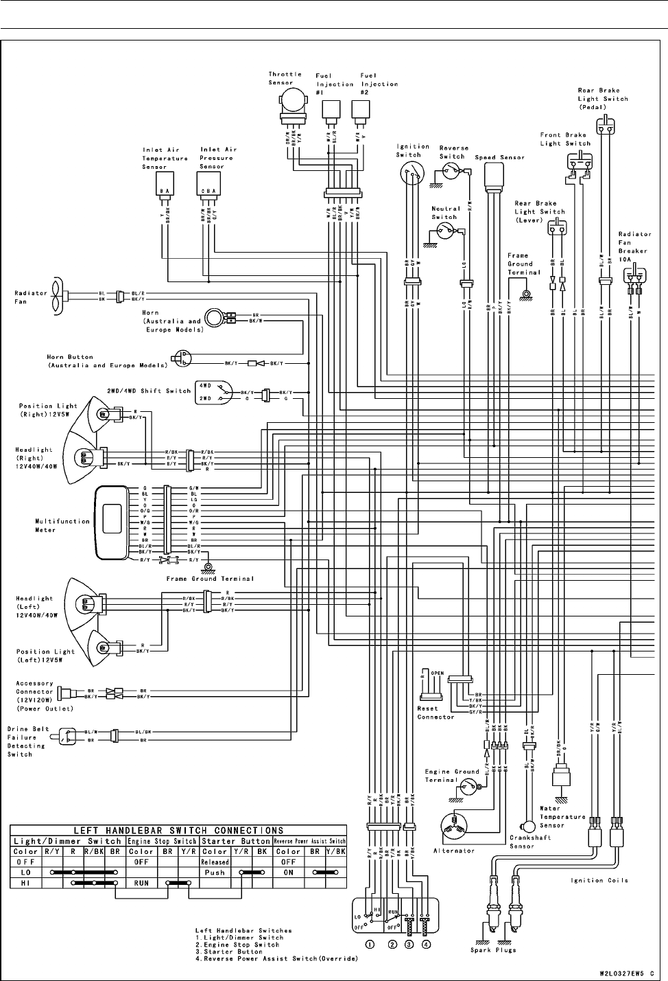
16-14 ELECTRICAL SYSTEM
Wiring Diagram
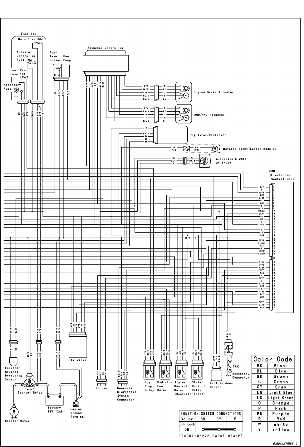
ELECTRICAL SYSTEM 16-15
Wiring Diagram
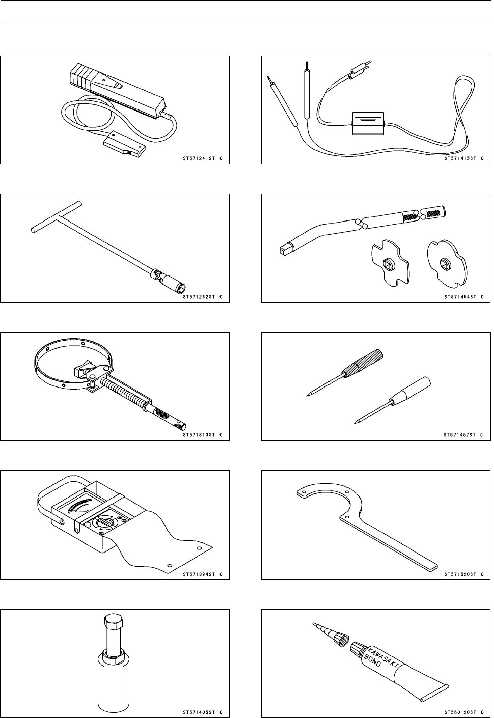
16-16 ELECTRICAL SYSTEM
Special Tools and Sealant
Timing Light:
57001-1241
SparkPlugWrench,Hex16:
57001-1262
Flywheel Holder:
57001-1313
Hand Tester:
57001-1394
Flywheel Puller Assembly, M38 × 1.5/M35 × 1.5:
57001-1405
Peak Voltage Adapter:
57001-1415
Filler Cap Driver:
57001-1454
Needle Adapter Set:
57001-1457
Drive Pulley Holder:
57001-1520
Kawasaki Bond (Silicone Sealant):
56019-120

ELECTRICAL SYSTEM 16-17
Precautions
There are a number of important precautions that should
be taken when servicing electrical systems. Learn and ob-
serve all the rules below.
○Do not reverse the battery lead connections. This will
burn out the diodes in the electrical parts.
○Always check battery condition before condemning other
parts of an electrical system. A fully charged battery is
required for conducting accurate electrical system tests.
○The electrical parts should never be struck sharply, as
with a hammer, or allowed to fall on a hard surface. Such
a shock to the parts can damage them.
○To prevent damaging electrical parts, do not disconnect
the battery leads or any other electrical connections when
the ignition switch is on, or while the engine is running.
○Because of the high current, never keep the starter button
depressed when the starter motor will not turn over, or the
current may burn out the starter motor windings.
○Only use an illumination bulb rated for the voltage or
wattage specified in the wiring diagram, or the handle
cover could be warped by excessive heat radiated from
the bulb.
○Take care not to short the leads that are directly con-
nected to the battery positive (+) terminal to chassis
ground.
○Troubles may involve one or in some cases all items.
Never replace a defective part without determining what
CAUSED the failure. If the failure was caused by some
other item or items, they too must be repaired or replaced,
or the new replacement will soon fail again.
○Make sure all connectors in the circuit are clean and tight,
and examine wires for signs of burning, fraying, etc. De-
fective wires and bad connections will affect electrical sys-
tem operation.
○Measure coil and winding resistance when the part is cold
(at room temperature).
○Color Codes:
BK Black GGreen PPink
BL Blue GY Gray PU Purple
BR Brown LB Light blue R Red
CH Chocolate LG Light green W White
DG Dark green OOrange Y Yellow
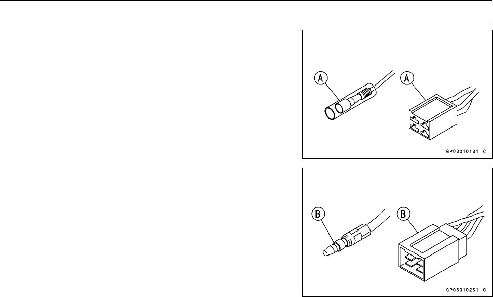
16-18 ELECTRICAL SYSTEM
Precautions
○Electrical Connectors:
Connectors [A]
Connectors [B]
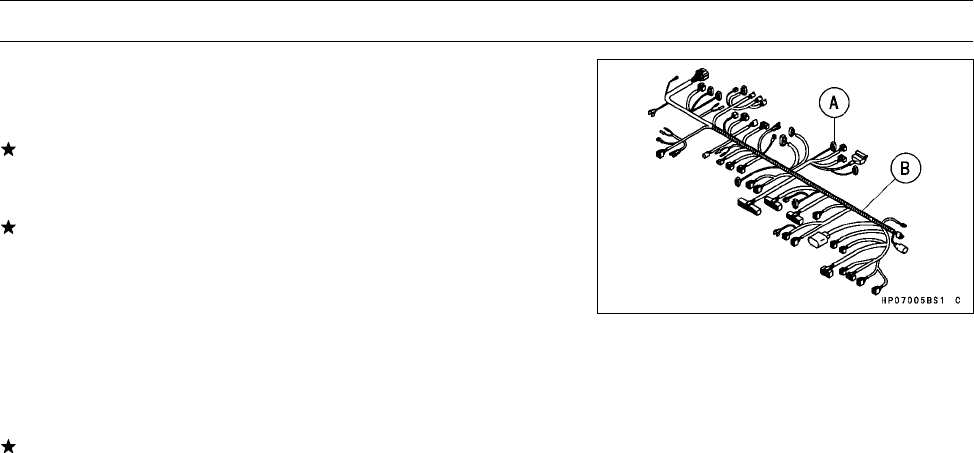
ELECTRICAL SYSTEM 16-19
Electrical Wiring
Wiring Inspection
•Visually inspect the wiring for signs of burning, fraying,
etc.
If any wiring is defective, replace the damaged wiring.
•Pull each connector [A] apart and inspect for corrosion,
dirt, and damage.
If the connector is corroded or dirty, clean it carefully. If it
is damaged, replace it.
•Check the wiring for continuity.
○Use the wiring diagram to find the ends of the lead which
is suspected of being a problem.
○Connect the hand tester between the ends of the leads.
Special Tool - Hand Tester: 57001-1394
○Set the tester to the ×1 Ωrange.
If the tester does not read 0 Ω, the lead is defective. Re-
place the lead or the wiring harness [B] if necessary.
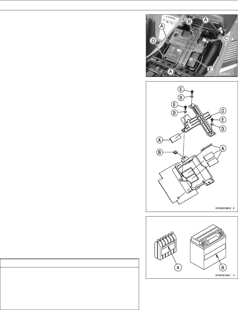
16-20 ELECTRICAL SYSTEM
Battery
Battery Removal
•Turn off the ignition switch.
•Remove:
Seat (see Seat Removal in the Frame chapter)
Battery Holder Bolts [A] and Collars
Battery Holder [B]
•Disconnect the battery negative (–) cable [C] first, and
then the positive (+) cable [D].
•Take out the battery [E].
Battery Installation
•Turn off the ignition switch.
•Install:
Rubber Dampers [A]
Clamp Nut [B]
•Connect the positive cable first and then the negative.
•Put a light coat of grease on the terminals to prevent cor-
rosion.
•Install:
Battery Holder [C]
Collars [D]
Battery Holder Bolts [E]
Battery Activation
Electrolyte Filling
•Make sure that the model name [A] of the electrolyte con-
tainer matches the model name [B] of the battery. These
names must be the same.
Battery Model Name for KVF750D: KMX 14-BS
CAUTION
Be sure to use the electrolyte container with the
same model name as the battery since the elec-
trolyte volume and specific gravity vary with the
battery type. This is to prevent overfilling of the
electrolyte, shorting the battery life, and deteriora-
tion of the battery performance.
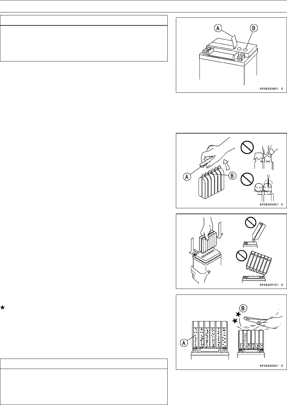
ELECTRICAL SYSTEM 16-21
Battery
CAUTION
Do not remove the aluminum sealing sheet [A] from
the filler ports [B] until just prior to use. Be sure to
use the dedicated electrolyte container for correct
electrolyte volume.
•Place the battery on a level surface.
•Check to see that the sealing sheet has no peeling, tears,
or holes in it.
•Remove the sealing sheet.
NOTE
○The battery is vacuum sealed. If the sealing sheet has
leaked air into the battery, it may require a longer initial
charge.
•Remove the electrolyte container from the vinyl bag.
•Detach the strip of caps [A] from the container and set
aside, these will be used later to seal the battery.
NOTE
○Do not pierce or otherwise open the sealed cells [B] of
the electrolyte container. Do not attempt to separate
individual cells.
•Place the electrolyte container upside down with the six
sealed cells into the filler ports of the battery. Hold the
container level, push down to break the seals of all six
cells. You will see air bubbles rising into each cell as the
ports fill.
NOTE
○Do not tilt the electrolyte container
•Check the electrolyte flow.
If no air bubbles [A] are coming up from the filler ports, or
if the container cells have not emptied completely, tap the
container [B] a few times.
•Keep the container in place for 20 minutes or more. Don’t
remove the container from the battery until it’s empty, the
battery requires all the electrolyte from the container for
proper operation.
CAUTION
Removal of the container before it is completely
empty can shorten the service life of the battery. Do
not remove the electrolyte container until it is com-
pletely empty and 20 minutes have elapsed.
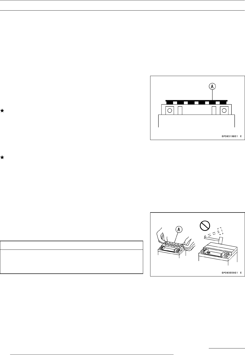
16-22 ELECTRICAL SYSTEM
Battery
•Gently remove the container from the battery.
•Let the battery sit for 30 minutes prior to charging to allow
the electrolyte to permeate into the plates for optimum
performance.
NOTE
○Charging the battery immediately after filling can
shorten service life. Let the battery sit for at least 30
minutes after filling.
Initial Charge
•Place the strip [A] of caps loosely over the filler ports.
•Newly activated sealed batteries require an initial charge.
Standard Charge 1.2 A × 5 ∼10 hours
If using a recommended battery charger, follow the
charger’s instructions for newly activated sealed battery.
Kawasaki-recommended chargers:
Optimate III
Yuasa 1.5 Amp Automatic Charger
Battery Mate 150–9
If the above chargers are not available, use equivalent
one.
NOTE
○Charging rates will vary depending on how long the
battery has been stored, temperature, and the type of
charger used. Let battery sit 30 minutes after initial
charge, then check voltage using a voltmeter. If it is
not at least 12.8 volts, repeat charging cycle.
•After charging is completed, press down firmly with both
hands to seat the strip of caps [A] into the battery (don’t
pound or hammer). When properly installed, the strip of
the caps will be level with the top of the battery.
CAUTION
Once the strip of the caps [A] is installed onto the
battery, never remove the caps, nor add water or
electrolyte to the battery.
NOTE
○To ensure maximum battery life and customer satisfac-
tion, it is recommended the battery be load tested at
three times its amp-hour rating for 15 seconds.
Re-check voltage and if less than 12.8 volts repeat the
charging cycle and load test. If still below 12.8 volts the
battery is defective.
Precautions
1) No need of topping-up
No topping-up is necessary in this battery until it ends its life under normal use. Forcibly prying
off the sealing plug to add water is very dangerous. Never do that.
2) Refreshing charge
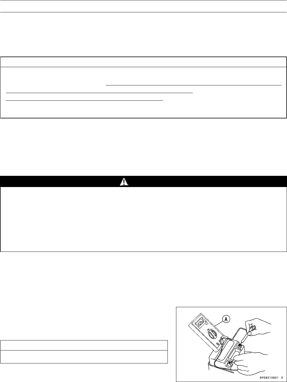
ELECTRICAL SYSTEM 16-23
Battery
If an engine will not start, a horn sounds weak, or lamps are dim, it indicates the battery has been
discharged. Give refresh charge for 5 to 10 hours with charge current shown in the specification
(see Refreshing Charge).
When a fast charge is inevitably required, do it following precisely the maximum charge current
and time conditions indicated on the battery.
CAUTION
This battery is designed to sustain no unusual deterioration if refresh-charged according
to the method specified above. However, the battery’s performance may be reduced no-
ticeably if charged under conditions other than given above.
Never remove the seal caps during refresh charge.
If by chance an excessive amount of gas is generated due to overcharging, the safety valve
operates to keep the battery safe.
3) When you do not use the motorcycle for months
Give a refresh charge before you store the motorcycle and store it with the negative lead re-
moved. Give a refresh charge once a month during storage.
4) Battery life
If the battery will not start the engine even after several refresh charges, the battery has ex-
ceeded its useful life. Replace it. (Provided, however, the vehicle’s starting system has no prob-
lem.)
WARNING
Keep the battery away from sparks and open flames during charging, since the battery
gives off an explosive gas mixture of hydrogen and oxygen. When using a battery charger,
connect the battery to the charger before turning on the charger. This procedure prevents
sparks at the battery terminals which could ignite any battery gases.
No fire should be drawn near the battery, or no terminals should have the tightening loos-
ened.
The electrolyte contains sulfuric acid. Be careful not to have it touch your skin or eyes. If
touched, wash it off with liberal amount of water. Get medical attention if severe.
Interchange
A sealed battery can fully display its performance only when combined with a proper vehicle electri-
cal system. Therefore, replace a sealed battery only on a vehicle which was originally equipped with
a sealed battery.
Be careful, if a sealed battery is installed on a vehicle which had an ordinary battery as original
equipment, the sealed battery’s life will be shortened.
Charging Condition Inspection
Battery charging condition can be checked by measuring
battery terminal voltage.
•Remove the battery (see Battery Removal).
CAUTION
Be sure to disconnect the negative (−) cable first.
•Measure the battery terminal voltage.
NOTE
○Measure with a digital voltmeter [A] which can be read
to one decimal place voltage.
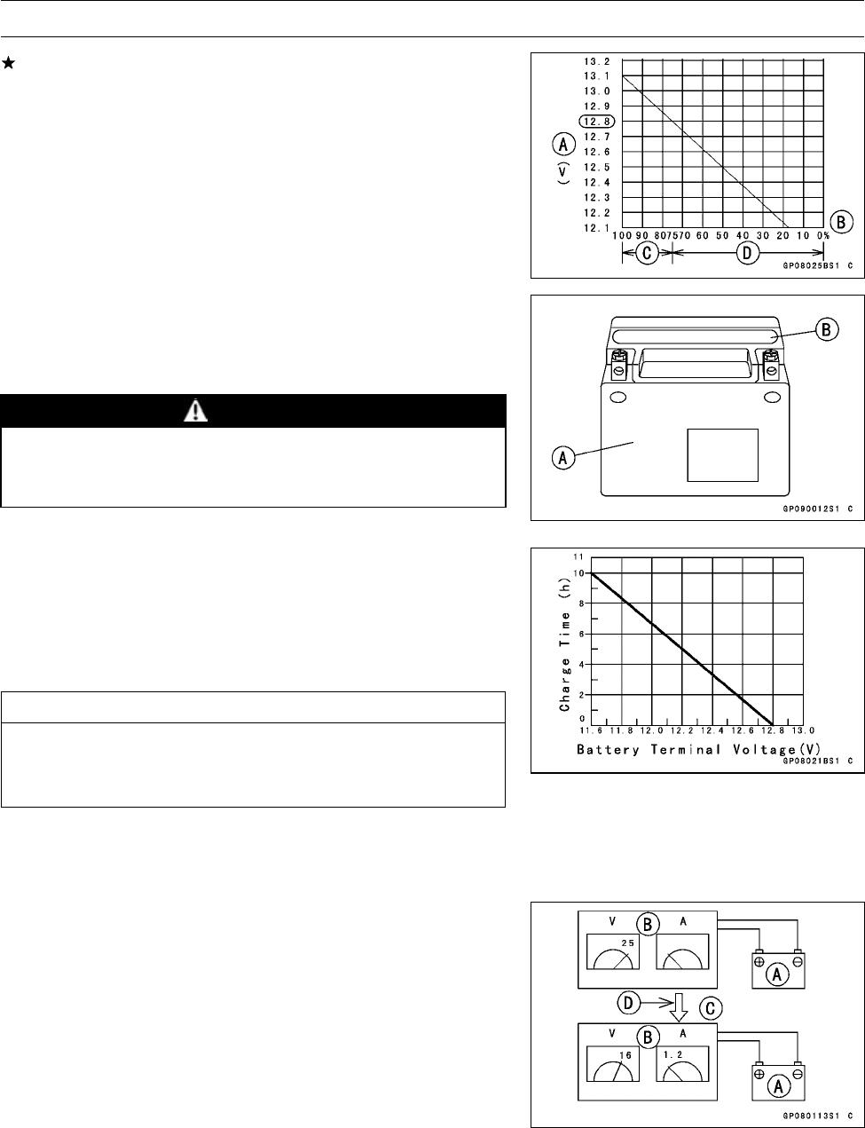
16-24 ELECTRICAL SYSTEM
Battery
If the reading is below the specified, refreshing charge is
required.
Battery Terminal Voltage
Standard: 12.8 V or more
Terminal Voltage (V) [A]
Battery Charge Rate (%) [B]
Good [C]
Refresh charge is required [D]
Refreshing Charge
•Remove the battery [A] (see Battery Removal).
•Refresh-charge by following method according to the bat-
tery terminal voltage.
WARNING
This battery is sealed type. Never remove seal
sheet [B] even at charging. Never add water.
Charge with current and time as stated below.
Terminal Voltage: 11.5 ∼less than 12.8 V
Standard Charge
1.2 A × 5 ∼10 h (see following chart)
Quick Charge
6.0 A × 1.0 h
CAUTION
If possible, do not quick charge. If the quick charge
is done due to unavoidable circumstances, do the
standard charge later on.
Terminal Voltage: less than 11.5 V
Charging Method: 1.2 A × 20 h
NOTE
○Increase the charging voltage to a maximum voltage of
25 V if the battery will not accept current initially. Charge
for no more than 5 minutes at the increased voltage then
check if the battery is drawing current. If the battery will
accept current [D], decrease the voltage and charge by
the standard charging method described on the battery
case. If the battery will not accept current after 5 min-
utes, replace the battery.
Battery [A]
Battery Charger [B]
Standard Value [C]

ELECTRICAL SYSTEM 16-25
Battery
•Determine battery condition after refreshing charge.
○Determine the condition of the battery 30 minutes after
completion of the charge by measuring the terminal volt-
age according to the table below.
Criteria Judgement
12.8 V or higher Good
12.0 ∼12.8 V or lower Charge insufficient →Recharge
12.0 V or lower Unserviceable →Replace
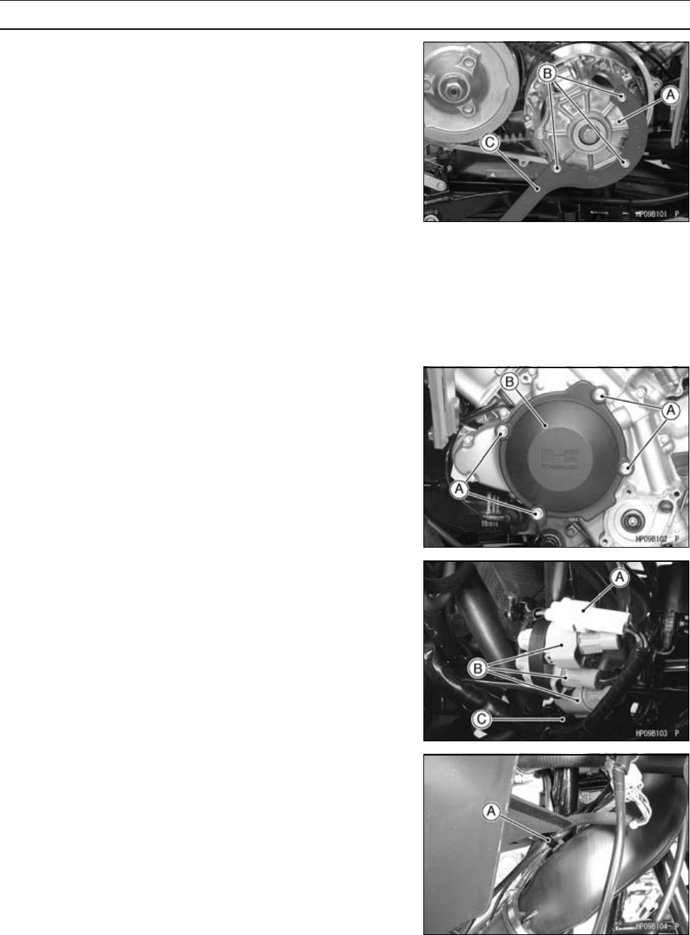
16-26 ELECTRICAL SYSTEM
Charging System
Alternator Cover Removal
•Drain:
Coolant (see Coolant Change in the Periodic Mainte-
nance chapter)
Engine Oil (see Engine Oil Change in the Periodic Main-
tenance chapter)
•Remove:
Water Pump Impeller (see Water Pump Impeller Re-
moval in the Cooling System chapter)
Torque Converter Cover (see Torque Converter Cover
Removal in the Converter System chapter)
Middle Cover (see Middle Cover Removal in the Frame
chapter)
•Remove the three bolts of the drive pulley cover [A].
•Install the drive pulley holder [C], tightening the removed
three bolts [B].
Special Tool - Drive Pulley Holder: 57001-1520
•Remove:
Bolts [A]
Alternator Outer Cover [B]
•Disconnect:
Crankshaft Sensor Connector [A]
Alternator Stator Connectors [B]
•Remove:
Clamp [C]
•Remove:
Clamp [A]
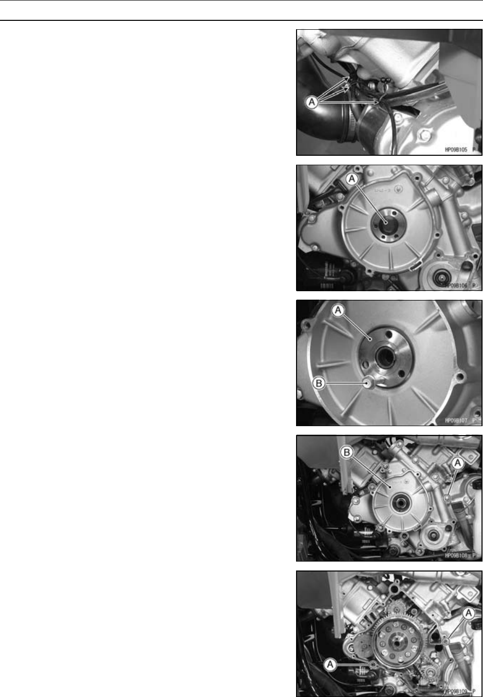
ELECTRICAL SYSTEM 16-27
Charging System
•Open the clamps [A].
•Holding the drive pulley with the drive pulley holder,
loosen the alternator rotor bolt [A].
•Remove:
Alternator Rotor Bolt
•Remove:
Collar [A]
○Install the M6 bolt [B] to the collar, and pull out it.
•Remove:
Alternator and Crankshaft Sensor Lead Connectors (dis-
connect)
Alternator Cover Bolts [A]
Alternator Cover [B]
Alternator Cover Installation
•Be sure all of the old gasket has been removed from the
alternator cover and the left crankcase sealing surfaces.
•Check that the dowel pins [A] are in place, and fit a new
gasket on the crankcase.
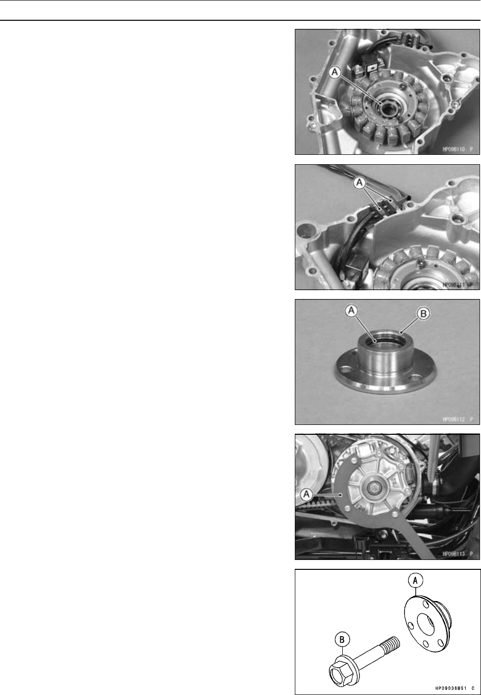
16-28 ELECTRICAL SYSTEM
Charging System
•Check that the bearing [A] is in place.
•Fit the grommets [A] into the notch in the cover.
•Grease the alternator cover oil seal.
•Tighten:
Torque - Alternator Cover Bolts: 8.8 N·m (0.90 kgf·m, 78
in·lb)
•Check that the O-ring [A] in the collar [B] is in good con-
dition.
•Apply grease to the O-ring.
•Install the collar on the alternator cover.
•Hold the drive pulley with the drive pulley holder [A].
Special Tool - Drive Pulley Holder: 57001-1520
•Install the collar [A] to the crankshaft.
•Tighten:
Torque - Alternator Rotor Bolt [B]: 127 N·m (13 kgf·m, 94
ft·lb)
•Install the removed parts (see appropriate chapter).
•Pour:
Coolant (see Coolant Change in the Periodic Mainte-
nance chapter)
Engine Oil (see Engine Oil Change in the Periodic Main-
tenance chapter)
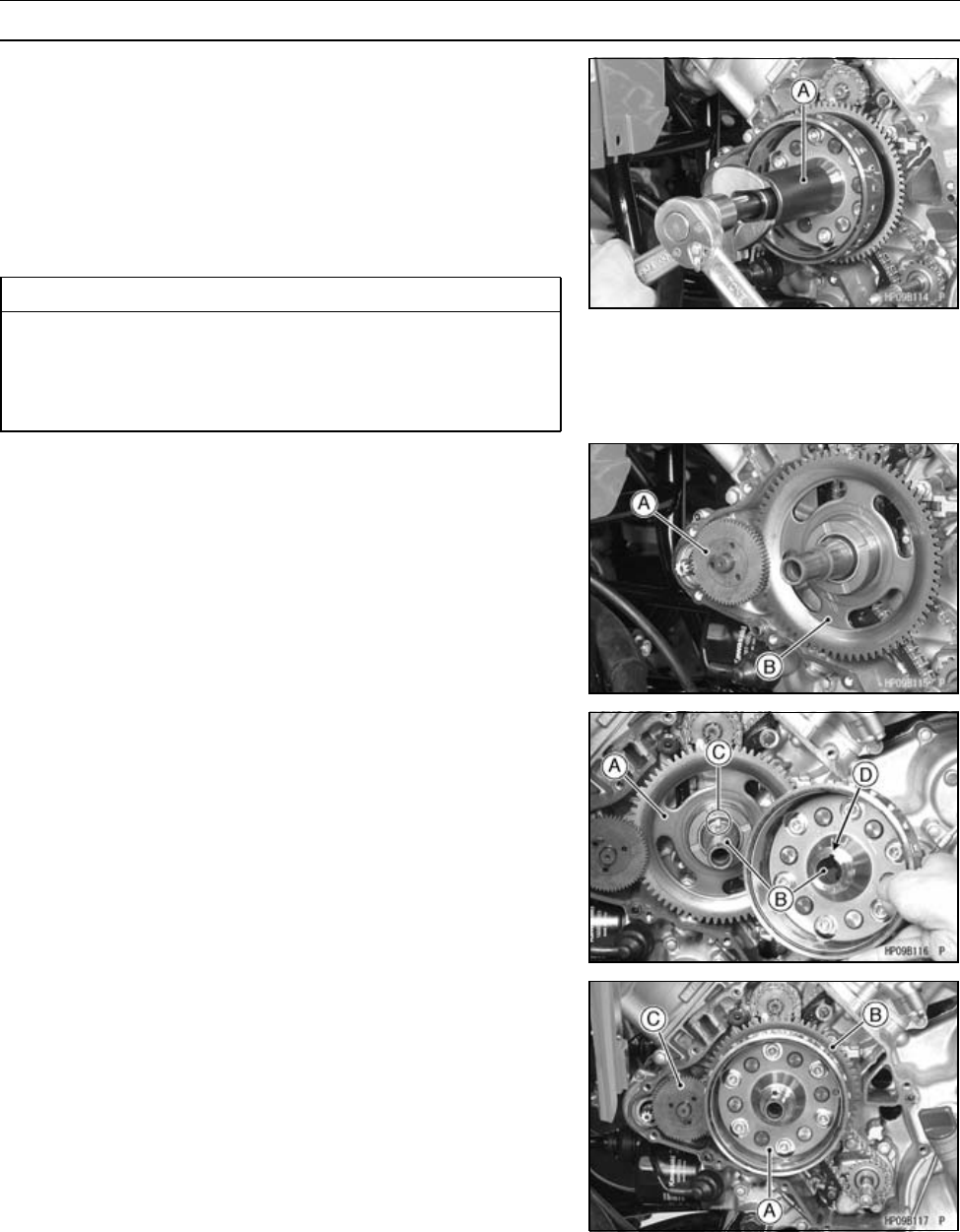
ELECTRICAL SYSTEM 16-29
Charging System
Alternator Rotor Removal
•Remove:
Alternator Cover (see Alternator Cover Removal)
•Screw the flywheel puller [A] onto the alternator rotor.
Special Tool - Flywheel Puller Assembly, M38 × 1.5/M35 ×
1.5: 57001-1405
•Holding the flywheel puller, turn the rotor puller bolt until
the alternator rotor is forced off the end of the crankshaft.
CAUTION
If the rotor is difficult to remove, turn the puller
while tapping the end of the puller. Do not strike
the alternator rotor. Striking the rotor can cause the
magnets to lose magnetism.
•Remove:
Torque Limiter [A]
Starter Clutch Gear [B]
Alternator Rotor Installation
•Install:
Starter Clutch Gear [A]
•Clean [B] the inside of the rotor and the end of the crank-
shaft.
•Fit the rotor onto the crankshaft so that woodruff key [C]
fits in the groove [D] in the hub of the rotor.
•Install the alternator rotor [A] while turning the starter
clutch gear [B] counterclockwise.
•Apply molybdenum disulfide grease to the shaft of the
torque limiter [C].
•Install the torque limiter.
○Pull out the alternator rotor a little, and install the torque
limiter.
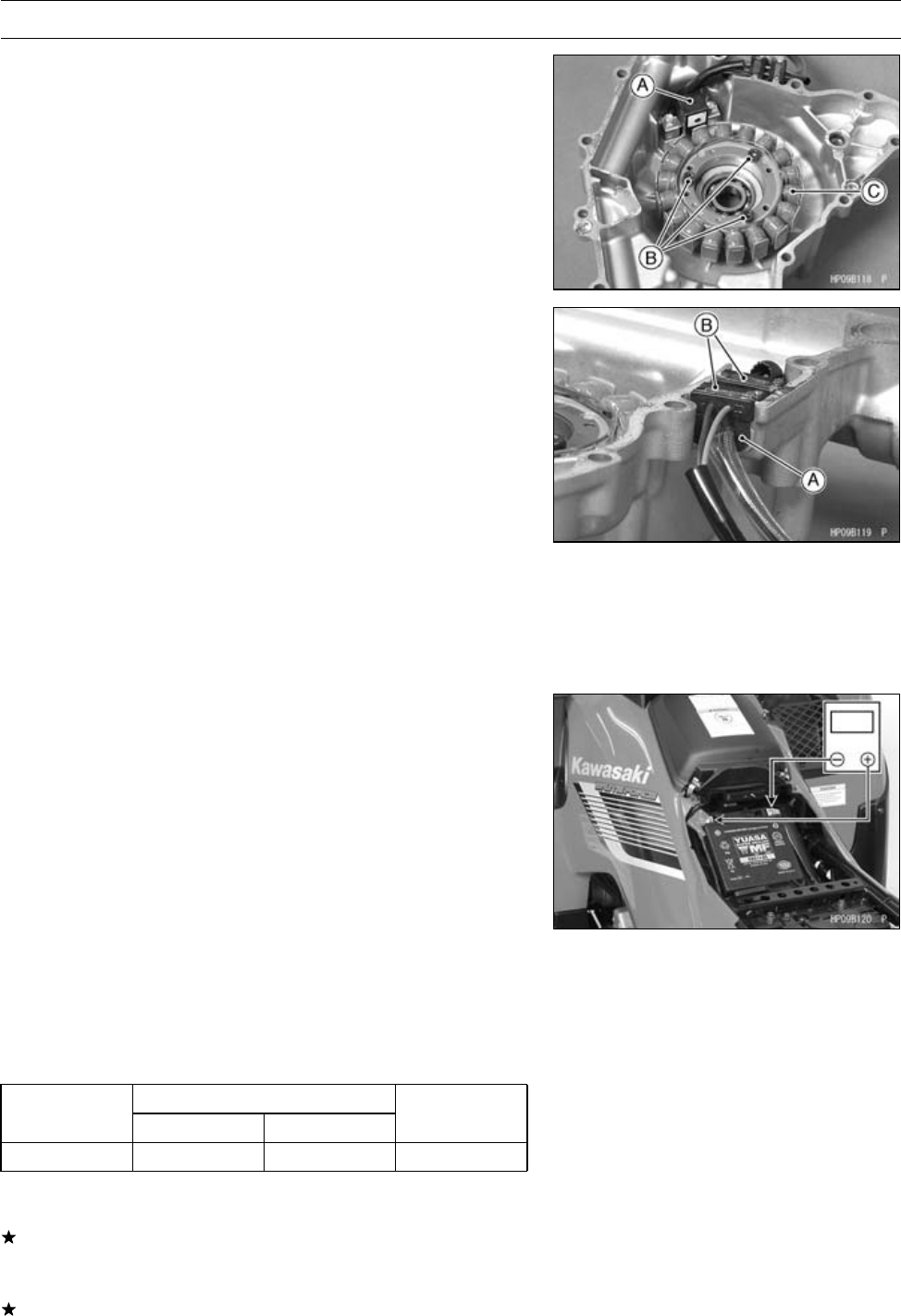
16-30 ELECTRICAL SYSTEM
Charging System
Alternator Stator Removal
•Remove:
Alternator Cover (see Alternator Cover Removal)
Crankshaft Sensor [A] (see Crankshaft Sensor Re-
moval)
Bolts [B] and Alternator Stator [C]
Alternator Stator Installation
•Tighten:
Torque - Alternator Stator Bolts: 13.5 N·m (1.4 kgf·m, 119
in·lb)
•Install:
Crankshaft Sensor (see Crankshaft Sensor Installation)
•Fit the lead grommets into the notch on the alternator
cover.
Grommets [A] for Alternator Leads
Grommets [B] for Crankshaft Sensor Leads
○Run the alternator starter leads under the crankshaft sen-
sor leads.
○Fit the grommet for alternator leads first and then install
the one of crankshaft sensor leads to the notch of the
alternator cover.
Regulator/Rectifier Output Voltage Inspection
•Remove the seat (see Seat Removal in the Frame chap-
ter).
•Check the battery condition (see Battery section).
•Warm up the engine to obtain actual alternator operating
conditions.
•Check that the ignition switch is turned off, and connect a
hand tester to the battery terminals.
Special Tool - Hand Tester: 57001-1394
•Start the engine and note the voltage readings at various
engine speeds with the headlight turned on and then off.
The readings should show nearly battery voltage when
the engine speed is low, and as the engine speed in-
creases, the readings should also increase.
Regulator/Rectifier Output Voltage
Connections
Tes te r Ra ng e Te ste r (+ ) to Te ster ( –) to Reading
25 V DC Battery (+) Battery (–) 14 ∼15 V
•Turn off the ignition switch, and disconnect the hand
tester.
If the regulator/rectifier output voltage is between the val-
ues given in the table, the charging system is working nor-
mally.
If the output voltage is much higher than the values spec-
ified in the table, the regulator/rectifier is defective or the
regulator/rectifier leads are loose or open.
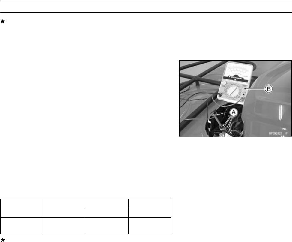
ELECTRICAL SYSTEM 16-31
Charging System
If the battery voltage does not increase as the engine
speed increases, then the regulator/rectifier is defective
or the alternator output is insufficient for the loads. Check
the alternator and regulator/rectifier to determine which
part is defective.
Alternator Inspection
There are three types of alternator failures: short, open,
or loss in rotor magnetism. A short or open in one of the coil
wires will result in either a low output, or no output at all. A
loss in rotor magnetism, which may be caused by dropping
or hitting the alternator, by leaving it near an electromag-
netic field, or just by aging, will result in low output.
•To check the alternator output voltage, perform the follow-
ing procedures.
○Remove the middle cover (see Middle Cover Removal in
the Frame chapter).
○Disconnect the alternator connectors [A].
○Connect a hand tester [B] as shown in the table.
○Start the engine.
○Run it at the rpm given in the table.
○Note the voltage readings (total 3 measurements).
Alternator Output Voltage
Connections Reading
Tester Range Tes te r (+) to Te st er ( –) t o @4 000 rpm
250 V AC One black lead Another black
lead 54 ∼80 V
If the output voltage is within the values in the table, the
alternator is operating correctly, and the regulator/rectifier
is damaged. A much lower reading indicates that the al-
ternator is defective.
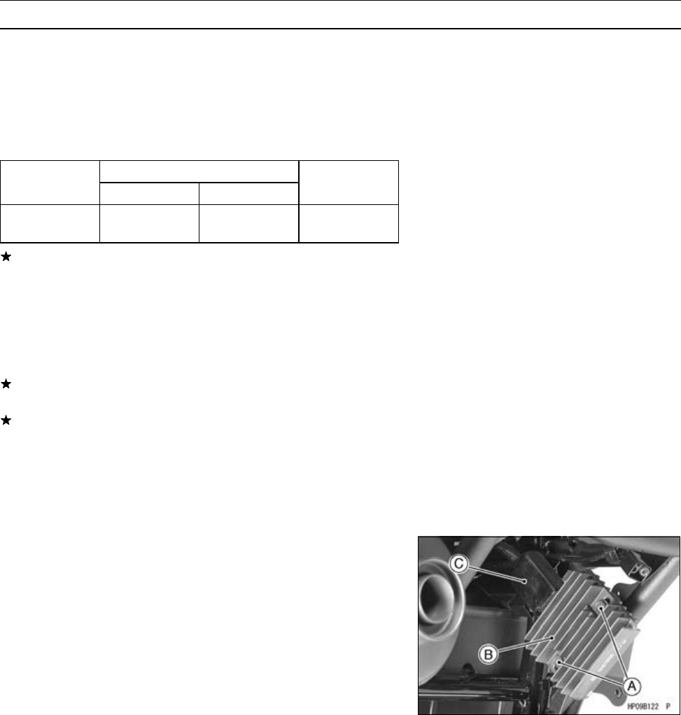
16-32 ELECTRICAL SYSTEM
Charging System
•Check the stator coil resistance as follows:
○Stop the engine.
○Disconnect the alternator connector.
○Connect a hand tester as shown in the table.
○Note the readings (total 3 measurement).
Stator Coil Resistance @20°C (68°F)
Connections
Tester Range Test er ( +) to Tester (– ) to Reading
×1ΩOne black lead Another black
lead 0.25 ∼0.37 Ω
If there is more resistance than shown in the table, or no
reading (infinity) for any two leads, the stator has an open
and must be replaced. Much less resistance means the
stator is shorted and must be replaced.
•Using the highest resistance range of the hand tester,
measure the resistance between each of the black leads
and chassis ground.
Any reading less than infinity (∞) indicates a short, neces-
sitating stator replacement.
If the stator coils have normal resistance, but the voltage
check shows the alternator to be defective; then the rotor
magnetism has probably weakened, and the rotor must
be replaced.
Special Tools - Hand Tester: 57001-1394
Needle Adapter Set: 57001-1457
Regulator/Rectifier Removal
•Remove:
Bolts [A] and Regulator/Rectifier [B]
Connector [C] (disconnect)
Regulator/Rectifier Installation
•Tighten:
Torque - Regulator/Rectifier Mounting Bolts: 8.8 N·m (0.90
kgf·m, 78 in·lb)
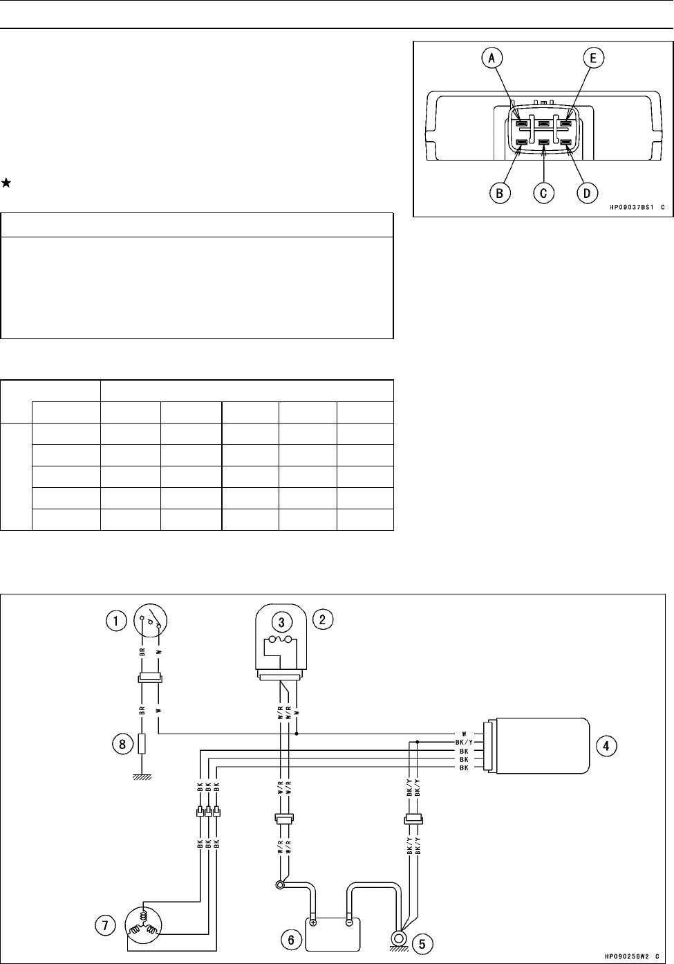
ELECTRICAL SYSTEM 16-33
Charging System
Regulator/Rectifier Inspection
•Remove:
Regulator/Rectifier (see Regulator/Rectifier Removal)
•Set the hand tester to the × 1 kΩrange and make the
measurements shown in the table.
Special Tool - Hand Tester: 57001-1394
•Connect the hand tester to the regulator rectifier.
If the tester readings are not as specified, replace the
regulator/rectifier.
CAUTION
Use only Kawasaki Hand Tester 57001-1394 for this
test. A tester other than the Kawasaki Hand Tester
may show different readings.
If a megger or a meter with a large capacity battery
is used, the regulator/rectifier will be damaged.
Regulator/Rectifier Resistance (Unit: kΩ)
Tester (+) Lead Connection
Term in al A B CD E
A–∞ ∞ ∞ ∞
B 2 ∼26 –∞ ∞ ∞
C2∼26 ∞–∞ ∞
D 2 ∼26 ∞ ∞ –∞
(–)*
E 2 ∼50 2∼26 2∼26 2∼26 –
(−)*: Tester (−) Lead Connection
Charging System Circuit
1. Ignition Switch
2. Fuse Box
3. Main Fuse 30 A
4. Regulator/rectifier
5. Engine Ground Terminal
6. Battery 12 V 12 Ah
7. Alternator
8. Load
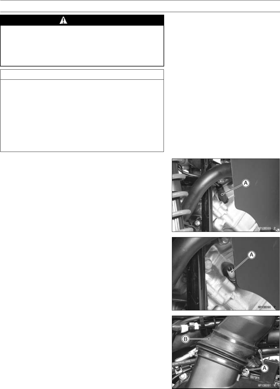
16-34 ELECTRICAL SYSTEM
Ignition System
WARNING
The ignition system produces extremely high volt-
age.
Do not touch the spark plug, ignition coil, or spark
plug lead while the engine is running, or you could
receive a severe electrical shock.
CAUTION
Do not disconnect the battery cables or any other
electrical connections when the ignition switch is
on, or while the engine is running. This is to prevent
igniter damage.
Do not install the battery backwards. The negative
side is grounded. This is to prevent damage to the
diodes and igniter.
Use the standard regulator/rectifier, or the igniter
will be damaged.
Spark Plug Removal
Front Side
•Remove:
Spark Plug Cap [A]
•Using a spark plug wrench, remove the spark plug [B].
Special Tool - Spark Plug Wrench, Hex 16: 57001-1262
Rear Side
•Remove:
Right Side Cover (see Right Side Cover Removal in the
Frame chapter)
Clamp Screws [A] and Clamps
Rubber Air Duct [B]
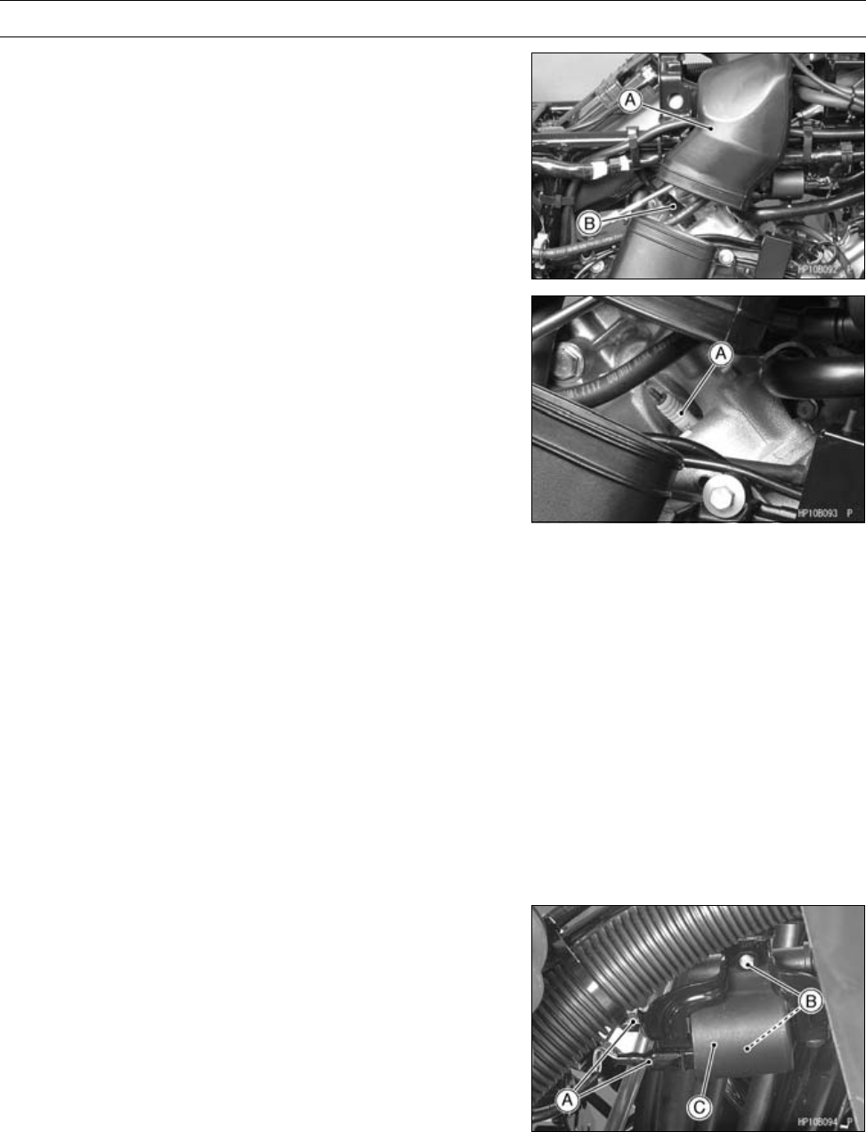
ELECTRICAL SYSTEM 16-35
Ignition System
•While lifting up the air duct [A], remove the spark plug cap
[B].
•Using a spark plug wrench, remove the spark plug [A].
Special Tool - Spark Plug Wrench, Hex 16: 57001-1262
Spark Plug Installation
•Tighten:
Torque - Spark Plugs: 13 N·m (1.3 kgf·m, 115 in·lb)
Special Tool - Spark Plug Wrench, Hex 16: 57001-1262
•Fit the spark plug caps securely.
•Pull up the spark pug caps lightly to make sure of the
installation of the spark plug caps.
Spark Plug Cleaning/Inspection
•Refer to the Spark Plug Cleaning/Inspection in the Peri-
odic Maintenance chapter.
Spark Plug Gap Inspection
•Refer to the Spark Plug Gap Inspection in the Periodic
Maintenance chapter.
Ignition Coil Removal
Front Side
•Remove:
Spark Plug Cap (see Spark Plug Removal)
Primary Lead Connectors [A]
Bolts [B]
Ignition Coil [C]
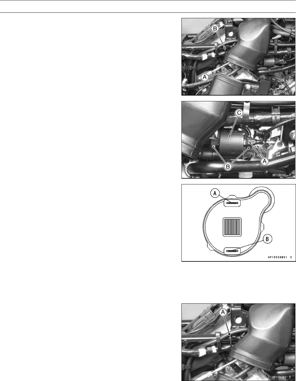
16-36 ELECTRICAL SYSTEM
Ignition System
Rear Side
•Remove:
Right Side Cover (see Right Side Cover Removal in the
Frame chapter)
Rubber Air Duct (see Spark Plug Removal)
Spark Plug Cap [A]
•Cut the band [B].
•Remove:
Primary Lead Connectors [A]
Bolts [B]
Ignition Coil [C]
Ignition Coil Installation
•Install:
Ignition Coil
Torque - Ignition Coil Mounting Bolts: 5.9 N·m (0.60 kgf·m,
52 in·lb)
•Connect the primary leads to the ignition coil terminals as
shown.
Front Side
Y/R Lead →(+) Terminal [A]
G/W Lead →(–) Terminal [B]
Rear Side
Y/R Lead →(+) Terminal [A]
BL/W Lead →(–) Terminal [B]
•For rear ignition coil, fix the ignition coil lead and main
harness with a band [B].
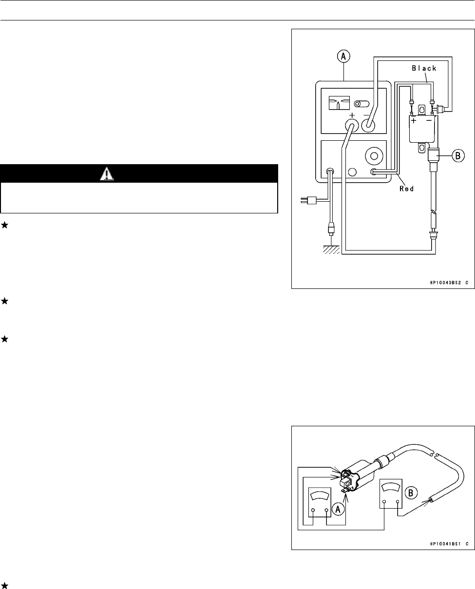
ELECTRICAL SYSTEM 16-37
Ignition System
Ignition Coil Inspection
•Remove the ignition coil.
•Measure the arcing distance with a coil tester [A] to check
the condition of the ignition coil [B].
•Connect the ignition coil (with the spark plug cap left at-
tached at the end of the spark plug lead) to the tester in
the manner prescribed by the manufacturer and measure
thearcingdistance.
Ignition Coil Arcing Distance
7 mm (0.28 in.) or more
WARNING
To avoid extremely high voltage shocks, do not
touch the ignition coil body or leads.
If the distance reading is less than the specified value, the
ignition coil or spark plug cap is defective.
•To determine which part is defective, measure the arcing
distance again with the spark plug cap removed from the
ignition coil. Remove the cap by turning it counterclock-
wise.
If the arcing distance is as before, the trouble is with the
ignition coil. If the arcing distance is normal, the trouble
is with the spark plug cap.
If a coil tester is not available, the coil can be checked for
a broken or badly shorted winding with a hand tester.
Special Tool - Hand Tester: 57001-1394
NOTE
○The hand tester cannot detect layer shorts and shorts
resulting from insulation breakdown under high voltage.
•Measure the primary winding resistance [A] as follows:
○Connect the tester between the coil terminals.
○Set the tester to the × 1 Ωrange.
•Measure the secondary winding resistance [B] as follows:
○Remove the plug cap by turning it counterclockwise.
○Connect the tester between the spark plug lead and ter-
minal.
○Set the tester to the × 1 kΩrange.
Ignition Coil Winding Resistance
Primary Windings: 2.1 ∼2.5 Ω
Secondary Windings: 10 ∼16 kΩ
If the hand tester does not read as specified, replace the
coil.
○To install the plug cap, turn it clockwise.
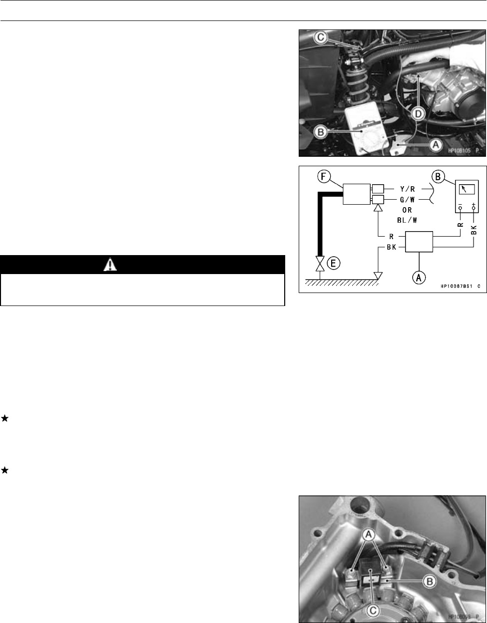
16-38 ELECTRICAL SYSTEM
Ignition System
Ignition Coil Primary Peak Voltage Inspection
NOTE
○Be sure the battery is fully charged.
•Remove the spark plug cap (see Spark Plug Removal),
but do not remove the spark plug.
•Measure the primary peak voltage as follows.
○Connect a commercially peak voltage adapter [A] to the
hand tester [B] (250 V DC range).
Special Tools - Hand Tester: 57001-1394
Peak Voltage Adapter: 57001-1415
Type: KEK-54-9-B
○Insert the peak voltage adapter lead of the G/W (front) or
BL/W (rear) primary lead [C].
○Install a new spark plug [D] into the spark plug cap, and
ground it to the engine.
[E] Ignition Coil
WARNING
To avoid extremely high voltage shocks, do not
touch the spark plugs or tester connections.
•Turn the ignition switch ON, rotate the engine for 4 ∼5
seconds with the transmission in neutral to measure the
primary peak voltage.
•Repeat the measurements 5 times for one ignition coil.
Ignition Coil Primary Peak Voltage
Standard: 130 V or more
•Repeat the test for the other ignition coil.
If the reading is less than the specified value, check the
following.
Ignition Coils (see Ignition Coil Inspection)
Crankshaft Sensor (see Crankshaft Sensor Inspection)
If the ignition coils and crankshaft sensor are normal, see
the Ignition System Troubleshooting chart on page 17-42.
Crankshaft Sensor Removal
•Remove:
Alternator Cover (see Alternator Cover Removal)
Crankshaft Sensor Mounting Bolts [A]
Plate [B]
Crankshaft Sensor [C]
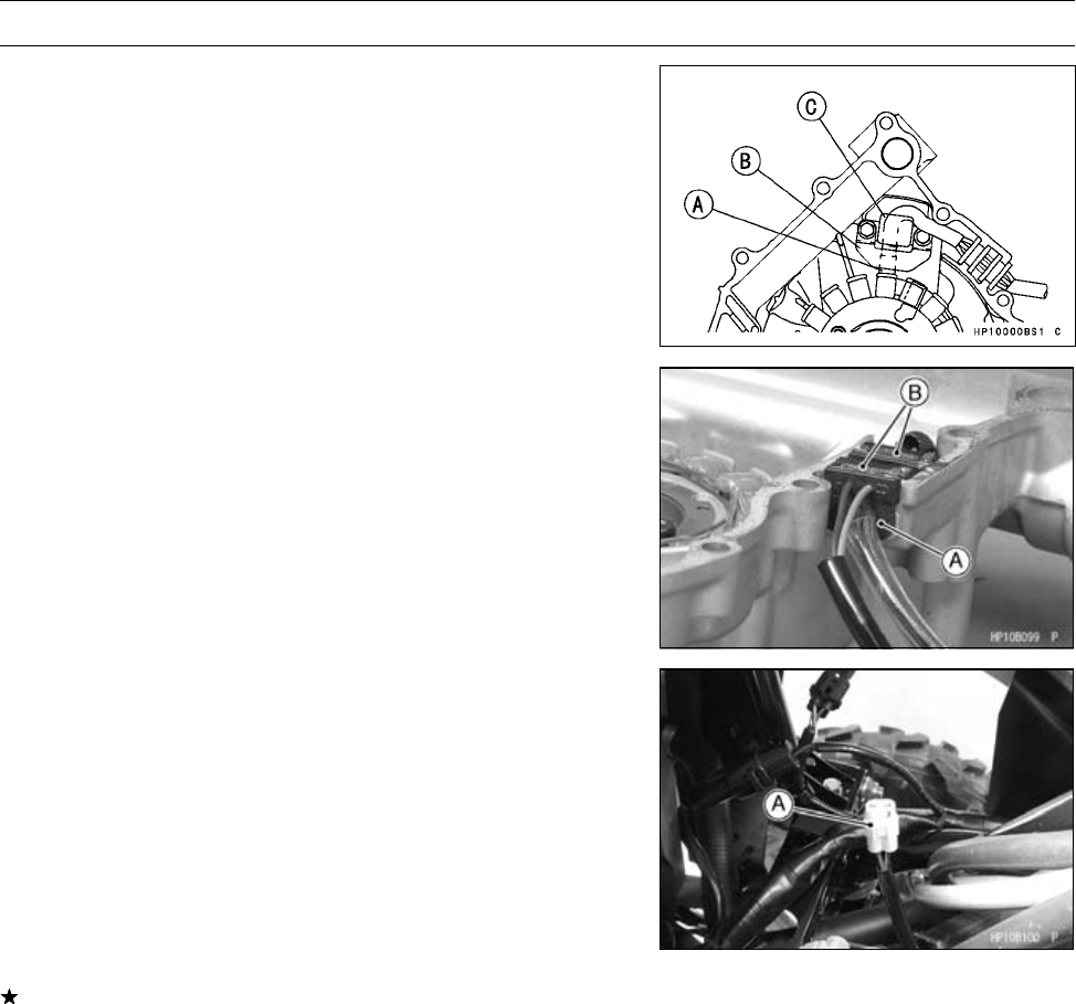
ELECTRICAL SYSTEM 16-39
Ignition System
Crankshaft Sensor Installation
•Install:
Stator Coil Leads [A]
Plate [B]
Crankshaft Sensor [C]
•Tighten:
Torque - Crankshaft Sensor Mounting Bolts: 5.9 N·m (0.60
kgf·m, 52 in·lb)
•Fit the lead grommets into the notch on the alternator
cover.
Grommets [A] for Alternator Leads
Grommets [B] for Crankshaft Sensor Leads
Crankshaft Sensor Inspection
•Remove the middle cover (see Middle Cover Removal in
the Frame chapter).
•Disconnect the crankshaft sensor lead connector [A].
•Measure the crankshaft sensor resistance.
○Connect a hand tester between the BK/W lead and the
BL lead.
○Set the tester to the × 100 Ωrange.
Crankshaft Sensor Resistance
423 ∼517 Ω
If the tester does not read as specified, replace the crank-
shaft sensor.
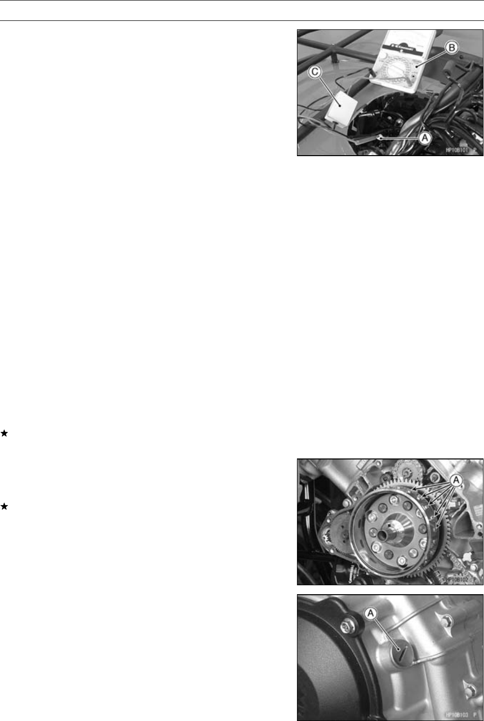
16-40 ELECTRICAL SYSTEM
Ignition System
Crankshaft Sensor Peak Voltage Inspection
NOTE
○Be sure the battery is fully charged.
•Removal the middle cover (see Middle Cover Removal in
the Frame chapter).
•Remove the spark plug caps, but do not remove the spark
plugs.
•Disconnect:
Crankshaft Sensor Lead Connector [A]
•Set the hand tester [B] to the 10 V DC range.
•Connect the peak voltage adapter [C] to the hand tester
and crankshaft sensor leads in the connector.
Special Tools - Hand Tester: 57001-1394
Peak Voltage Adapter: 57001-1415
Type: KEK-54-9-B
Needle Adapter Set: 57001-1457
Connections:
Crankshaft Sensor
Lead Adapter Hand Tester
Black/White ←Red →(+)
Blue ←Black →(–)
•Turn the ignition switch on, and rotate the engine for 4 ∼5
seconds with the transmission gear in neutral to measure
the crankshaft sensor peak voltage.
•Repeat the measurement 5 or more times.
Crankshaft Sensor Peak Voltage
Standard: 2Vormore
If the peak voltage is lower than the standard, inspect the
crankshaft sensor.
Alternator Rotor Inspection
•Check the timing projections [A] for damage such as chip-
ping or grooving.
If the timing projection on the rotor is visibly damaged,
replace the alternator rotor.
Ignition Timing Test
•Remove the ignition timing inspection plug [A].
Special Tool - Filler Cap Driver: 57001-1454
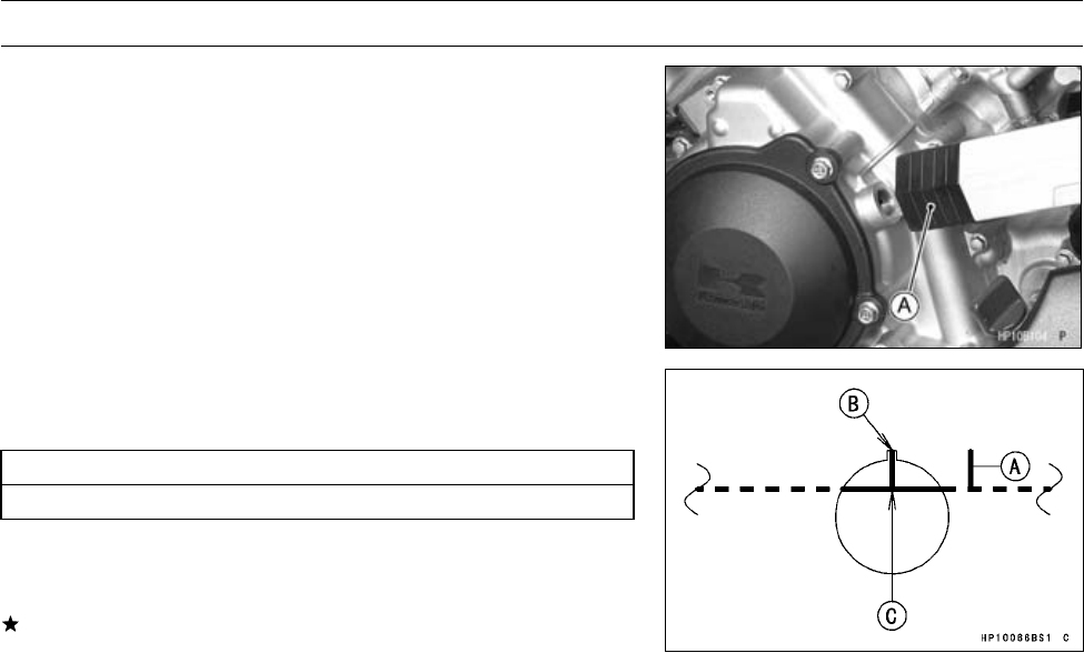
ELECTRICAL SYSTEM 16-41
Ignition System
•Attach a timing light [A] and a tachometer in the manner
prescribed by the manufacturer.
Special Tool - Timing Light: 57001-1241
•Start the engine and aim the timing light at the timing mark
on the alternator rotor.
•Run the engine at the speeds specified and note the align-
ment of the timing marks.
[A] F or R mark
Ignition Timing
Slot [B] aligned with:
Advanced mark [C] on alternator rotor
NOTE
○Do not mix up the timing marks with mark [A].
If the ignition timing is incorrect, replace the ECU and the
crankshaft sensor.
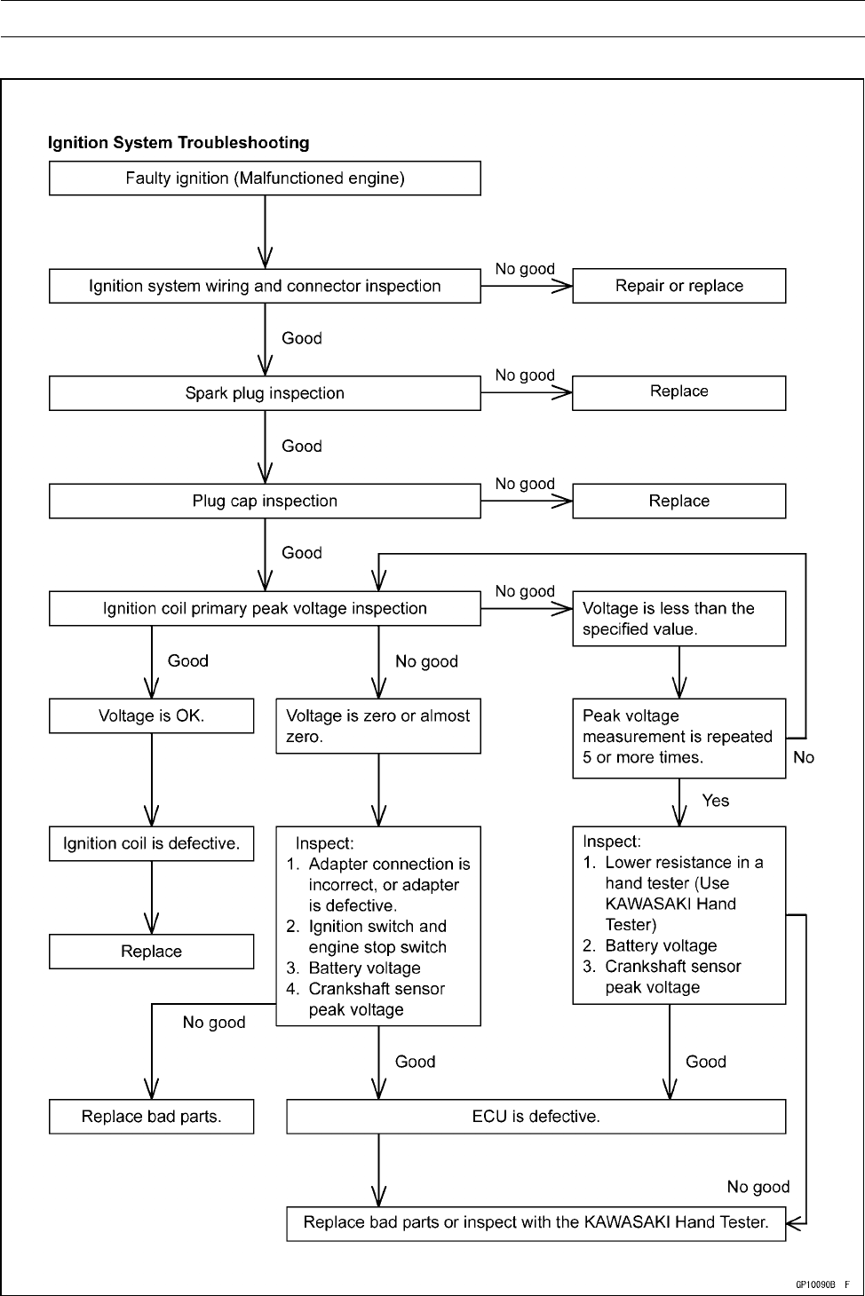
16-42 ELECTRICAL SYSTEM
Ignition System
Ignition System Troubleshooting
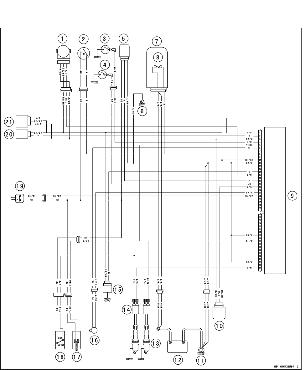
ELECTRICAL SYSTEM 16-43
Ignition System
Ignition System Circuit
1. Throttle Sensor
2. Ignition Switch
3. Reverse Switch
4. Neutral Switch
5. Speed Sensor
6. Frame Ground Terminal
7. Fuse Box
8. Main Fuse 30 A
9. ECU (Electronic Control Unit)
10. Vehicle-down Sensor
11. Engine Ground Terminal
12. Battery 12 V 12 Ah
13. Spark Plugs
14. Ignition Coils
15. Water Temperature Sensor
16. Crankshaft Sensor
17. Reverse Power Assist Switch (Override)
18. Engine Stop Switch
19. Drive Belt Failure Detecting Switch
20. Inlet Air Temperature Sensor
21. Inlet Air Pressure Sensor
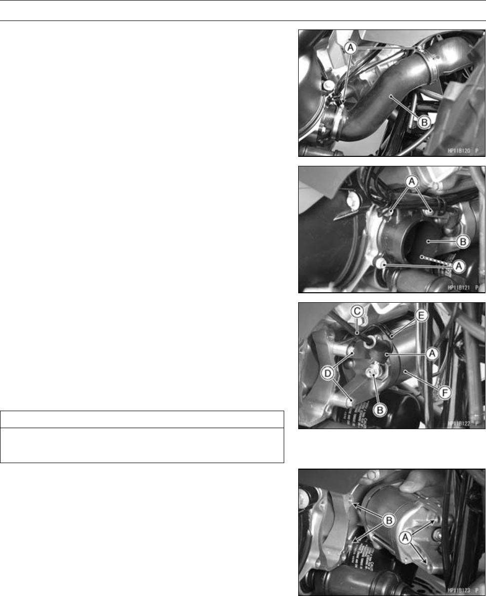
16-44 ELECTRICAL SYSTEM
Electric Starter System
Starter Motor Removal
•Loosen:
Clamp Bolts [A]
•Remove:
Air Intake Rubber Duct [B]
•Remove:
Bolts [A]
JointDuct[B]andCollars
•Slide the rubber boots [A].
•Remove:
Starter Motor Cable
Mounting Nut [B]
Starter Motor Cable [C]
Starter Motor Mounting Bolts [D]
Clamp [E]
Starter Motor [F]
CAUTION
Do not tap the end of the starter motor shaft or the
motor may be damaged.
Starter Motor Installation
•When installing the starter motor, clean the starter mo-
tor lugs [A] and crankcase [B] where the starter motor is
grounded.
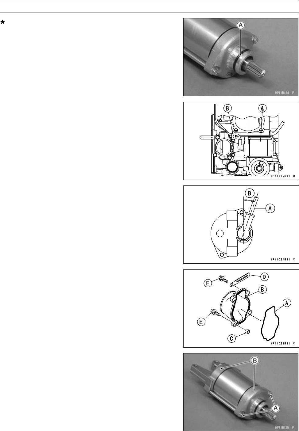
ELECTRICAL SYSTEM 16-45
Electric Starter System
If the O-ring [A] shows wear or damage, or if it is hard-
ened, replace it with a new one.
•Apply a small amount of engine oil to the O-ring.
•Install:
Starter Motor [A]
Clamp [B] (as shown)
•Tighten:
Torque - Starter Motor Mounting Bolts: 8.8 N·m (0.90 kgf·m,
78 in·lb)
•Position the starter motor cable [A] as shown.
About 20° [B]
•Tighten:
Torque - Starter Motor Cable Mounting Nut: 6.8 N·m (0.69
kgf·m, 60 in·lb)
•Slide back the rubber cap to the original position.
•Apply grease to the O-ring [A] in the joint duct [B].
•Install:
JointDuctandCollars[C]
Clamp [D] (as shown)
•Tighten the joint duct bolts [E].
Starter Motor Disassembly
•Remove the starter motor (see Starter Motor Removal).
•Take off the starter motor through bolts [A] and remove
the both end covers [B].
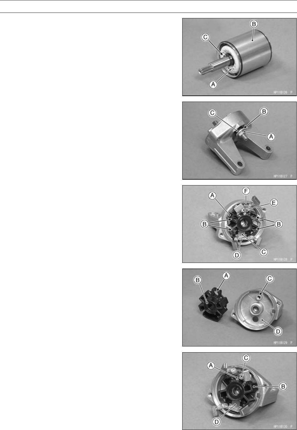
16-46 ELECTRICAL SYSTEM
Electric Starter System
•Pull out the armature [A] out of the yoke [B].
NOTE
○Do not remove the circlip [C] from the shaft.
•Remove:
Starter Motor Terminal Locknut [A]
Washer [B]
Collar [C]
•Pull out the brushes from the brush holder [A].
•Remove:
Brush Springs [B]
Starter Motor Terminal [C]
Positive Brush Assy [D] and O-ring
Screw [E]
Negative Brush Assy [F]
Brush Holder
Starter Motor Assembly
•Align the hole [A] of the brush holder [B] to the boss [C]
of the end cover [D].
•Install the negative brush assy [A] to the brush holder [B].
•Tighten the screw [C] securely.
•Install the positive brush assy [D] to the brush holder.
•Install the starter motor terminal.
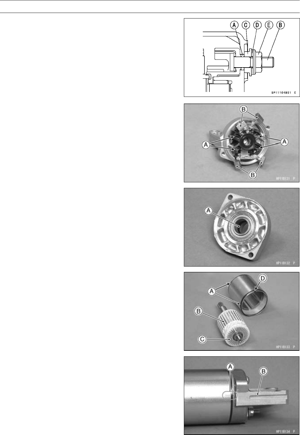
ELECTRICAL SYSTEM 16-47
Electric Starter System
•Replace the O-ring [A] with a new one.
•Install the following parts to the starter motor terminal [B].
O-ring
Collar [C]
Washer [D]
Starter Motor Terminal Locknut [E]
○Install the collar so that stepped side faces outward.
•Tighten:
Torque - Starter Motor Terminal Locknut: 11 N·m (1.1
kgf·m, 97 in·lb)
•Install the brush springs [A].
•Insert the brushes [B] to the brush holder.
•Apply thin coat of grease to the oil seal [A].
•Replace the O-rings [A] with new ones.
•Insert the armature [B] so that commutator side [C] faces
hollow side [D] of the yoke [E].
•Align the marks [A] to assembly the yoke and the end
cover [B] as shown.
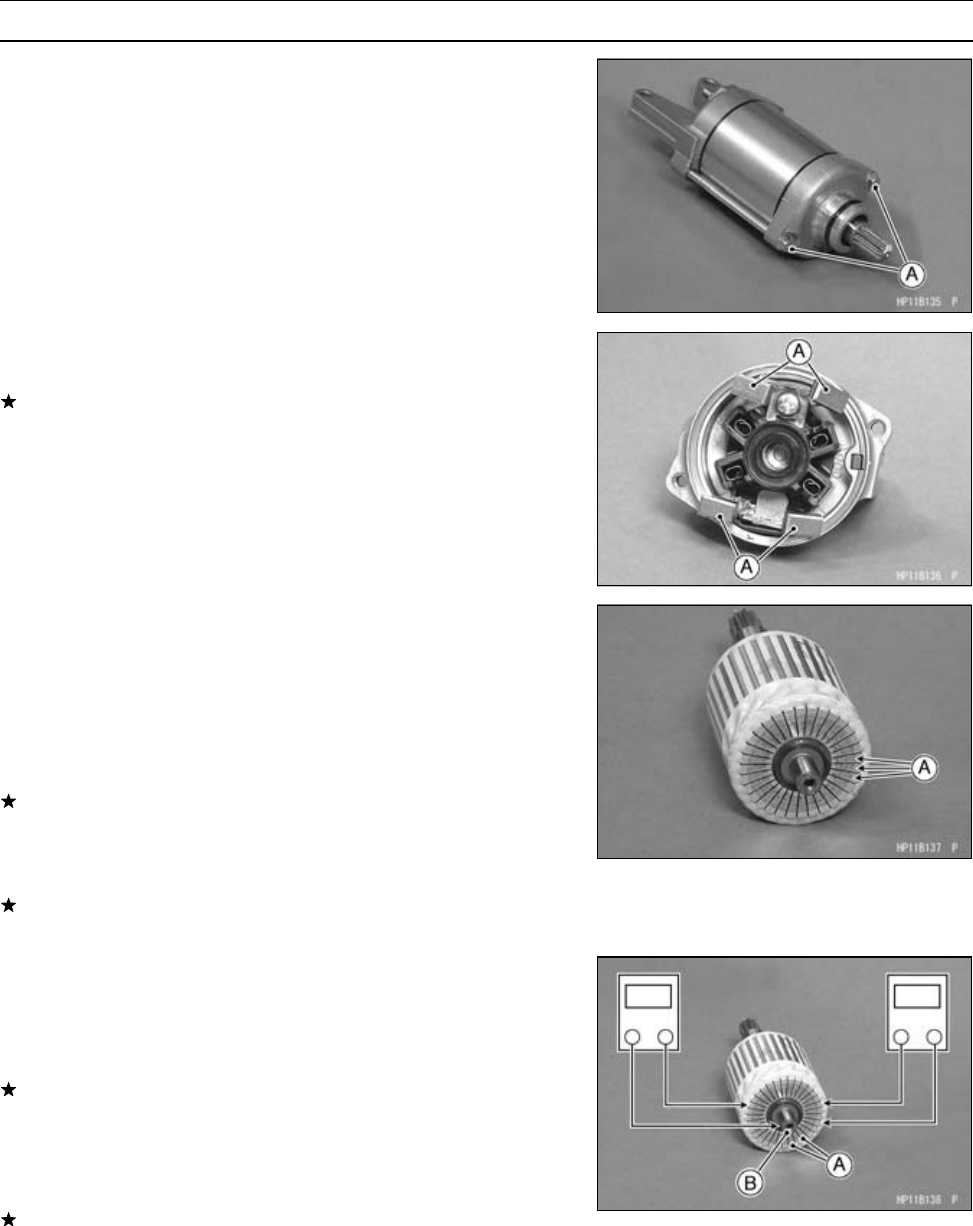
16-48 ELECTRICAL SYSTEM
Electric Starter System
•Tighten:
Torque - Starter Motor Through Bolts [A]: 5.0 N·m (0.51
kgf·m, 44 in·lb)
Brush Inspection
•Measure the length of each brush [A].
If any is worn down to the service limit, replace the brush
assy.
Starter Motor Brush Length
Standard: 12 mm (0.47 in.)
Service Limit: 6.5 mm (0.26 in.)
Commutator Cleaning and Inspection
•Clean the metallic debris off the between commutator
segments [A].
NOTE
○Do not use emery or sand paper on the commutator.
•Check the commutator for damage or abnormal wear.
Replace the starter motor with a new one if there is any
damage or wear.
•Visually inspect the commutator segments for discol-
oration.
Replace the starter motor with a new one if discoloration
is noticed.
Armature Inspection
•Using the × 1 Ωhand tester range, measure the resis-
tance between any two commutator segments [A].
Special Tool - Hand Tester: 57001-1394
If there is a high resistance or no reading (∞) between any
two segments, a winding is open and the starter motor
must be replaced.
•Using the highest hand tester range, measure the resis-
tance between the segments and the shaft [B].
If there is any reading at all, the armature has a short and
the starter motor must be replaced.
NOTE
○Even if the foregoing checks show the armature to be
good, it may be defective in some manner not readily
detectable with the hand tester. If all other starter motor
and starter motor circuit components check good, but
the starter motor still does not turn over or only turns
over weakly, replace the starter motor with a new one.
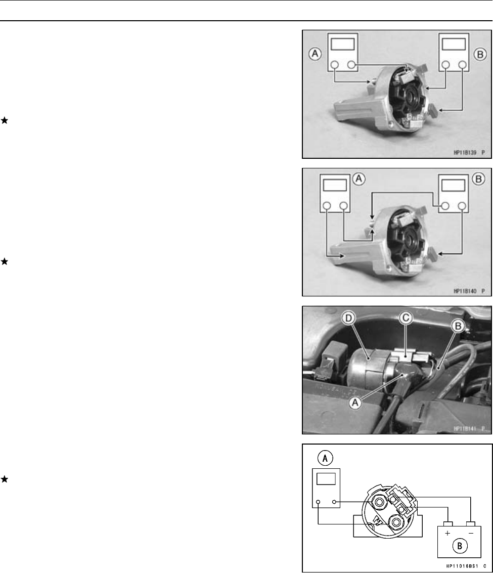
ELECTRICAL SYSTEM 16-49
Electric Starter System
Brush Lead Inspection
•Using the × 1 Ωhand tester range, measure the resis-
tance as shown.
Terminal Bolt and Positive Brushes [A]
Right-hand End Cover and Negative Brushes [B]
Special Tool - Hand Tester: 57001-1394
If there is not close to zero ohms, the brush lead has an
open. Replace the brush plate assy.
Right-hand End Cover Inspection
•Using the highest hand tester range, measure the resis-
tance as shown.
Terminal Bolt and Right-hand End Cover [A]
Terminal Bolt and Negative Brushes [B]
Special Tool - Hand Tester: 57001-1394
If there is any reading, the brush assy and/or terminal bolt
assy have a short. Replace the starter motor.
Starter Relay Inspection
•Remove:
Seat (see Seat Removal in the Frame chapter)
•Disconnect:
Starter Motor Cable [A]
Battery Positive Cable [B]
Connector [C]
•Remove:
Starter Relay [D]
•Connect the hand tester [A] and a 12 V battery [B] to the
starter relay as shown.
If the relay does not work as specified, the relay is defec-
tive. Replace the relay.
Testing Relay
Hand Tester Range: × 1Ωrange
Criteria: When battery is connected ⇒0Ω
When battery is disconnected ⇒∞Ω
Starter Control Relay Inspection
•Refer to the Relay Inspection.
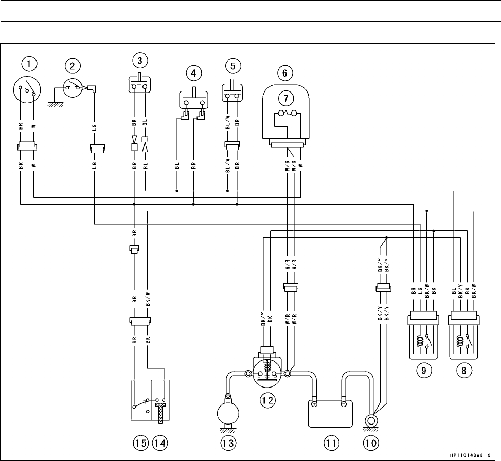
16-50 ELECTRICAL SYSTEM
Electric Starter System
Electric Starter Circuit
1. Ignition Switch
2. Neutral Switch
3. Rear Brake Light Switch (Lever)
4. Front Brake Light Switch
5. Rear Brake Light Switch (Pedal)
6. Fuse Box
7. Main Fuse 30 A
8. Stater Control Relay (Brake)
9. Stater Control Relay (Neutral)
10. Engine Ground Terminal
11. Battery 12 V 12 Ah
12. Starter Relay
13. Starter Motor
14. Starter Button
15. Engine Stop Switch
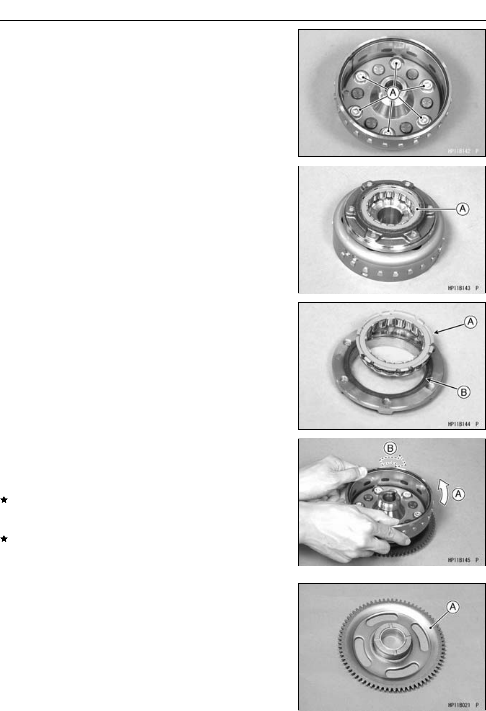
ELECTRICAL SYSTEM 16-51
Electric Starter System
Starter Motor Clutch Removal
•Remove the alternator rotor (see Alternator Rotor Re-
moval).
•Hold the rotor with the flywheel holder and take out the
starter motor clutch bolts [A].
Special Tool - Flywheel Holder: 57001-1313
•Take out the one-way clutch [A].
Starter Motor Clutch Installation
•Install the one-way clutch so that the flange [A] fits on the
recess [B] of the race.
•Apply a non-permanent locking agent to the starter motor
clutch bolts.
•Tighten:
Torque - Starter Motor Clutch Bolts: 34 N·m (3.5 kgf·m, 25
ft·lb)
Starter Motor Clutch Inspection
•Remove:
Alternator Rotor (see Alternator Rotor Removal)
•Fit the starter clutch gear into the starter motor clutch.
If the alternator rotor turns counterclockwise [A] freely
from the starter clutch gear, but not clockwise [B], the
clutch is operating correctly.
If the clutch does not operate correctly, or if it makes
noise, disassemble it and examine each part visually. Re-
place any worn or damaged parts.
NOTE
○Examine the starter clutch gear [A]. Replace it if it is
worn or damaged.
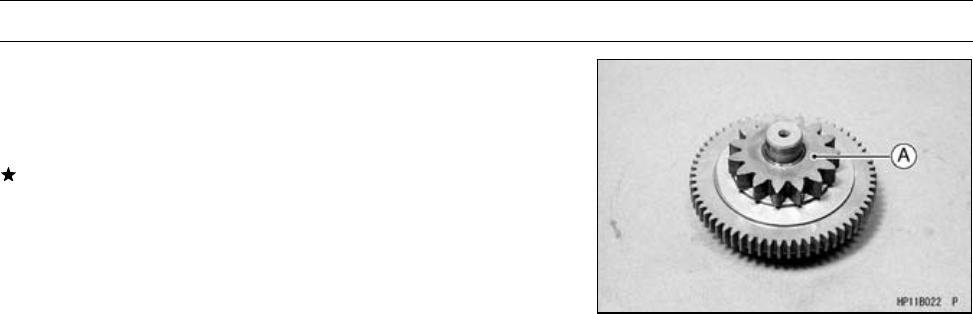
16-52 ELECTRICAL SYSTEM
Electric Starter System
Torque Limiter Inspection
•Remove:
Alternator Rotor (see Alternator Rotor Removal)
•Remove the torque limiter [A] and visually inspect it.
If the limiter has wear, discoloration, or other damage,
replace it as a unit.
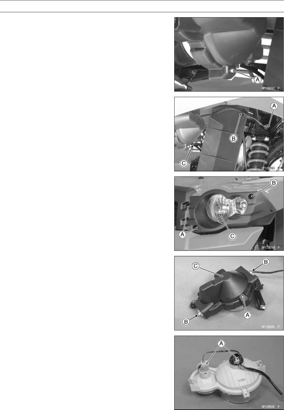
ELECTRICAL SYSTEM 16-53
Lighting System
Headlight Beam Vertical Adjustment
•Turn the adjusting screw [A] on each headlight rim in or
out to adjust the headlight vertically.
NOTE
○On high beam, the brightest point should be slightly be-
low horizontal with the vehicle on its wheels and the
rider seated. Adjust both headlights to the same an-
gle.
Headlight Bulb Replacement
•Remove:
Connector [A]
Clamp [B]
Screw [C]
•Remove:
Headlight Bolts [A] and Collars
Headlight Bolt [B]
Headlight Body [C]
•Remove:
Vertical Adjustment Screw [A], Spring and Nut
Bolts [B]
Headlight Cover [C]
•Disconnect:
Connectors [A]
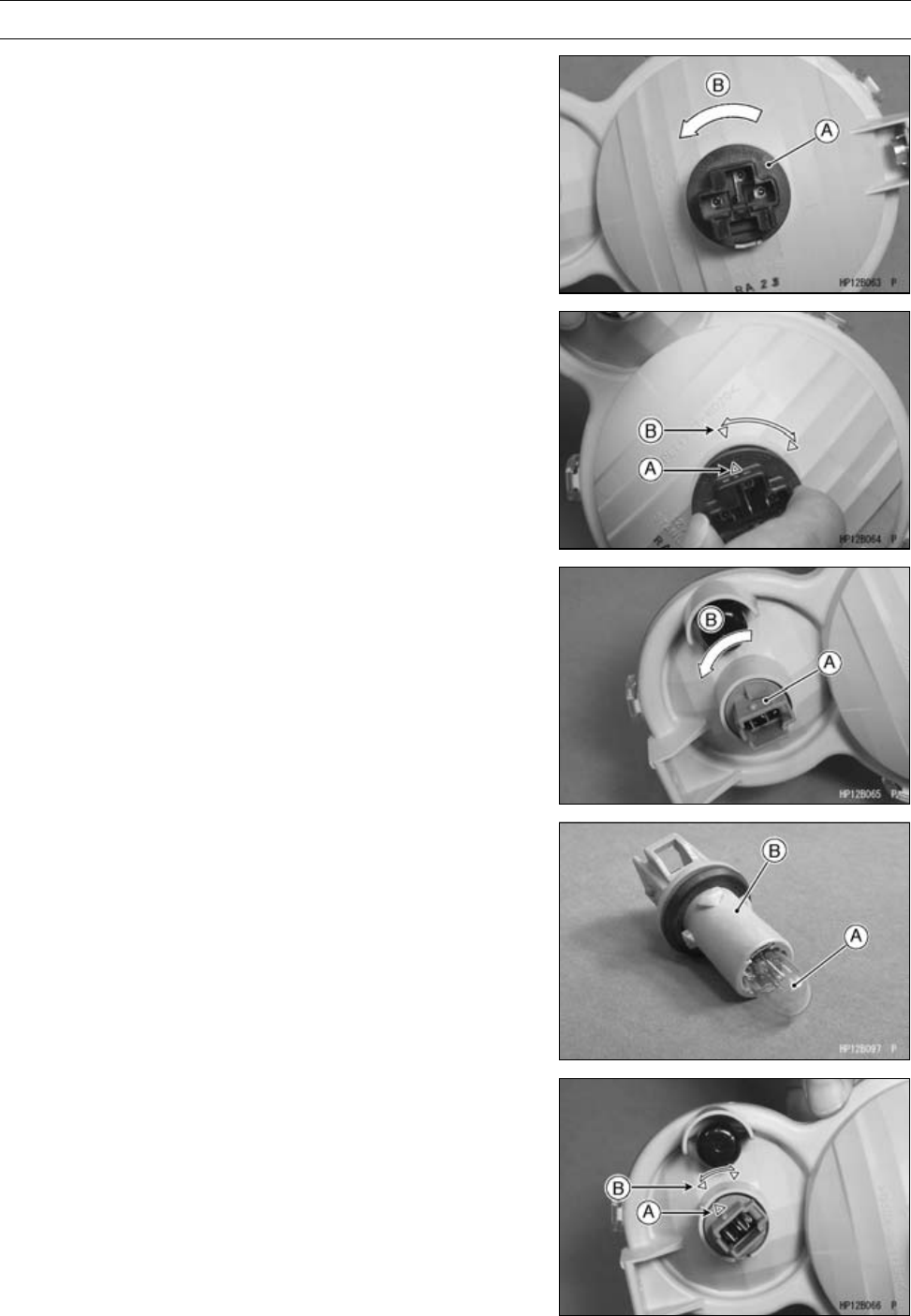
16-54 ELECTRICAL SYSTEM
Lighting System
•Turn the bulb socket [A] counterclockwise [B], and remove
the bulb.
○The headlight bulb can not be removed from the socket.
•Align the mark [A] of a new bulb socket with the mark [B]
of the headlight body.
•Turn the bulb socket clockwise until it is stopped.
•Turn the bulb socket [A] counterclockwise [B], and remove
it.
•Pullthebulb[A]fromthesocket[B].
•Install the new bulb to the socket.
•Align the mark [A] of a new bulb socket with the mark [B]
of the headlight body.
•Turn the bulb socket clockwise until it is stopped.
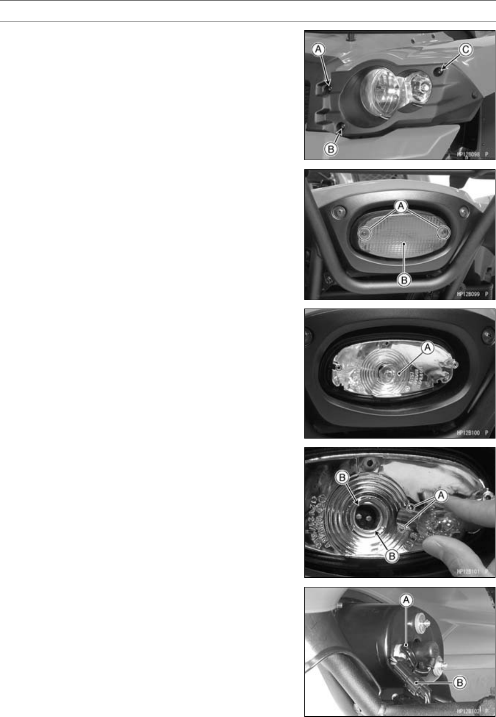
ELECTRICAL SYSTEM 16-55
Lighting System
•Install the removed parts.
[A] Bolt and Collar [L = 6 mm (0.24 in.)]
[B] Bolt and Collar [L = 4 mm (0.16 in.)]
[C] Bolt (only)
Tail/Brake Light Bulb Replacement
•Remove:
Tail/Brake Light Lens Mounting Screws [A]
Tail/Brake Light Lens [B]
•Push the bulb [A] in, turn it counterclockwise, and pull it
out.
•Be sure the socket is clean.
•Insert the new bulb by aligning the pins [A] with the
grooves in the walls of the socket.
•Push the bulb in, turn it clockwise, and release it. It should
lock in position.
•Tighten:
Torque - Tail/Brake Light Lens Screws: 1.0 N·m (0.10 kgf·m,
8.8 in·lb)
Tail/Brake Light Removal
•Open the clamp [A].
•Disconnect:
Taillight Connector [B]
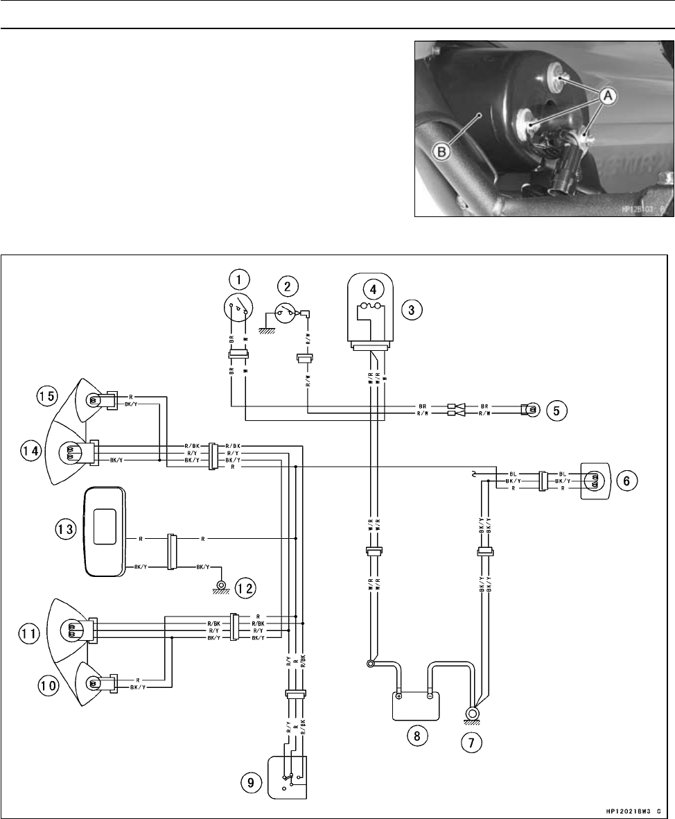
16-56 ELECTRICAL SYSTEM
Lighting System
•Remove:
Tail/Brake Light Mounting Nuts [A]
Tail/Brake Light [B]
Lighting System Circuit
1. Ignition Switch
2. Reverse Switch
3. Fuse Box
4. Main Fuse 30 A
5. Reverse Light (Europe Models)
6. Tail/Brake Lights 12 V 5/21 W
7. Engine Ground Terminal
8. Battery 12 V 12 Ah
9. Light/Dimmer Switch
10. Position Light (Left) 12 V 5 W
11. Headlight (Left) 12 V 40/40 W
12. Frame Ground
13. Multifunction Meter
14. Headlight (Right) 12 V 40/40 W
15. Position Light (Right) 12 V 5 W
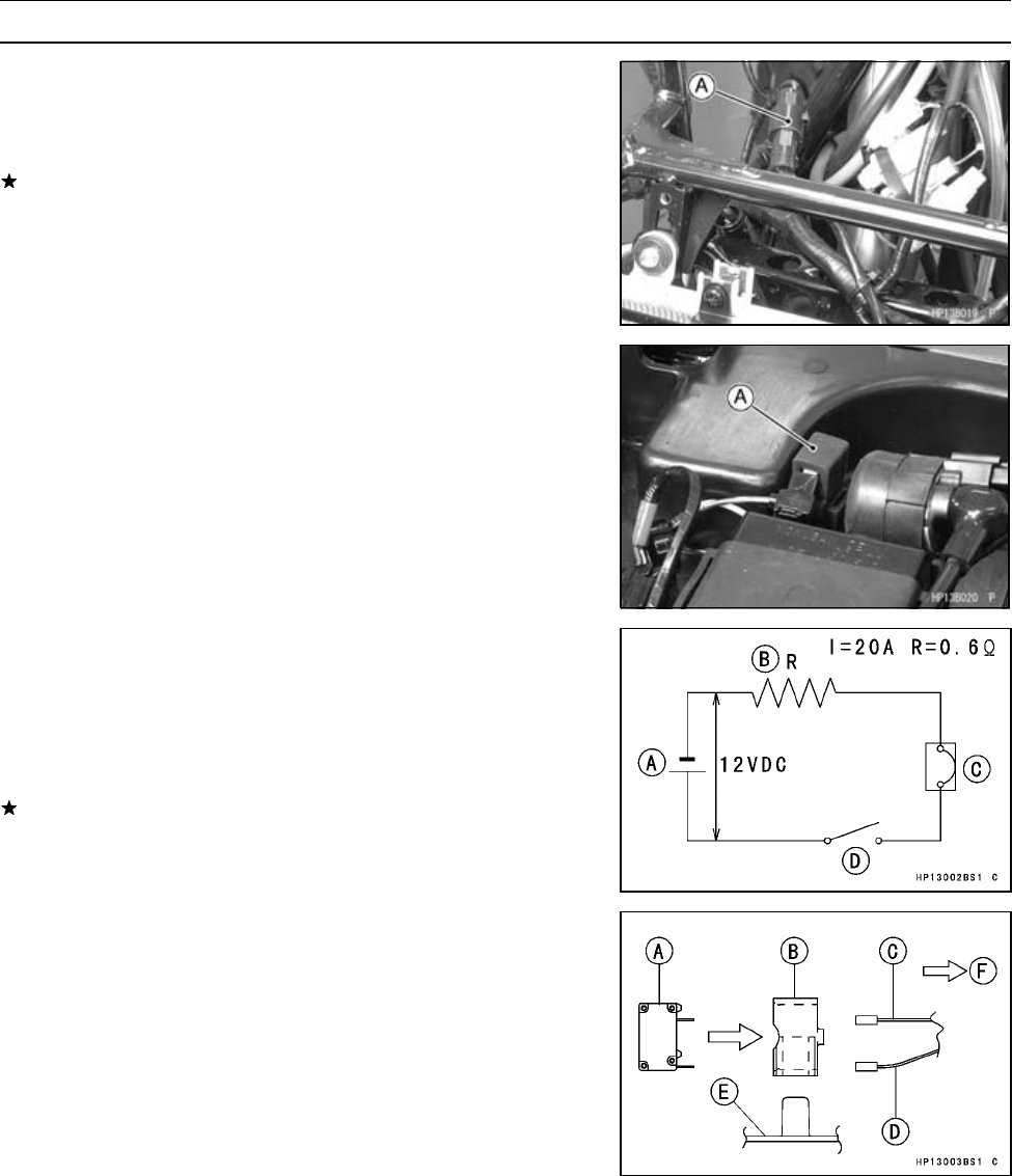
ELECTRICAL SYSTEM 16-57
Radiator Fan System
Radiator Fan Motor Inspection
•Disconnect the connector [A] in the fan lead.
•Using two auxiliary wires, supply battery voltage to the fan
motor.
If the fan does not rotate, the fan motor is defective and
must be replaced.
Radiator Fan Motor Lead Connections:
BL →Battery (+)
BK →Battery (–)
Radiator Fan Breaker Inspection
•Remove:
Seat (see Seat Removal in the Frame chapter)
Radiator Fan Breaker [A]
•Inspect the breaker for operation.
•Connect:
12 V Battery [A]
0.6 ΩResistance [B]
Radiator Fan Breaker [C]
Switch [D]
If the circuit in the breaker will not open within 60 seconds,
replace the breaker.
Radiator Fan Breaker Installation
•Install:
Radiator Fan Breaker [A]
Holder [B]
•Connect:
White Lead [C]
Blue/White Lead [D]
[E] Electrical Parts Case
[F] Right Side
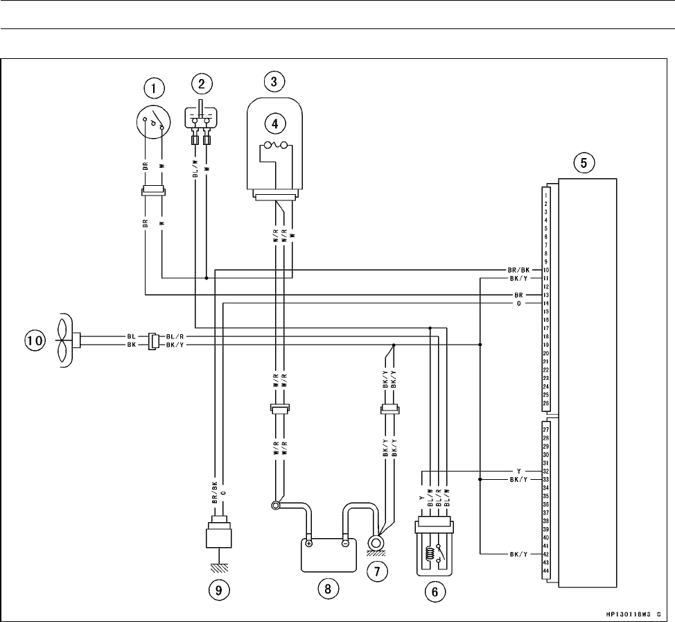
16-58 ELECTRICAL SYSTEM
Radiator Fan System
Radiator Fan Circuit
1. Ignition Switch
2. Radiator Fan Breaker 10 A
3. Fuse Box
4. Main Fuse 30 A
5. ECU (Electronic Control Unit)
6. Radiator Fan Relay
7. Engine Ground Terminal
8. Battery 12 V 12 Ah
9. Water Temperature Sensor
10. Radiator Fan
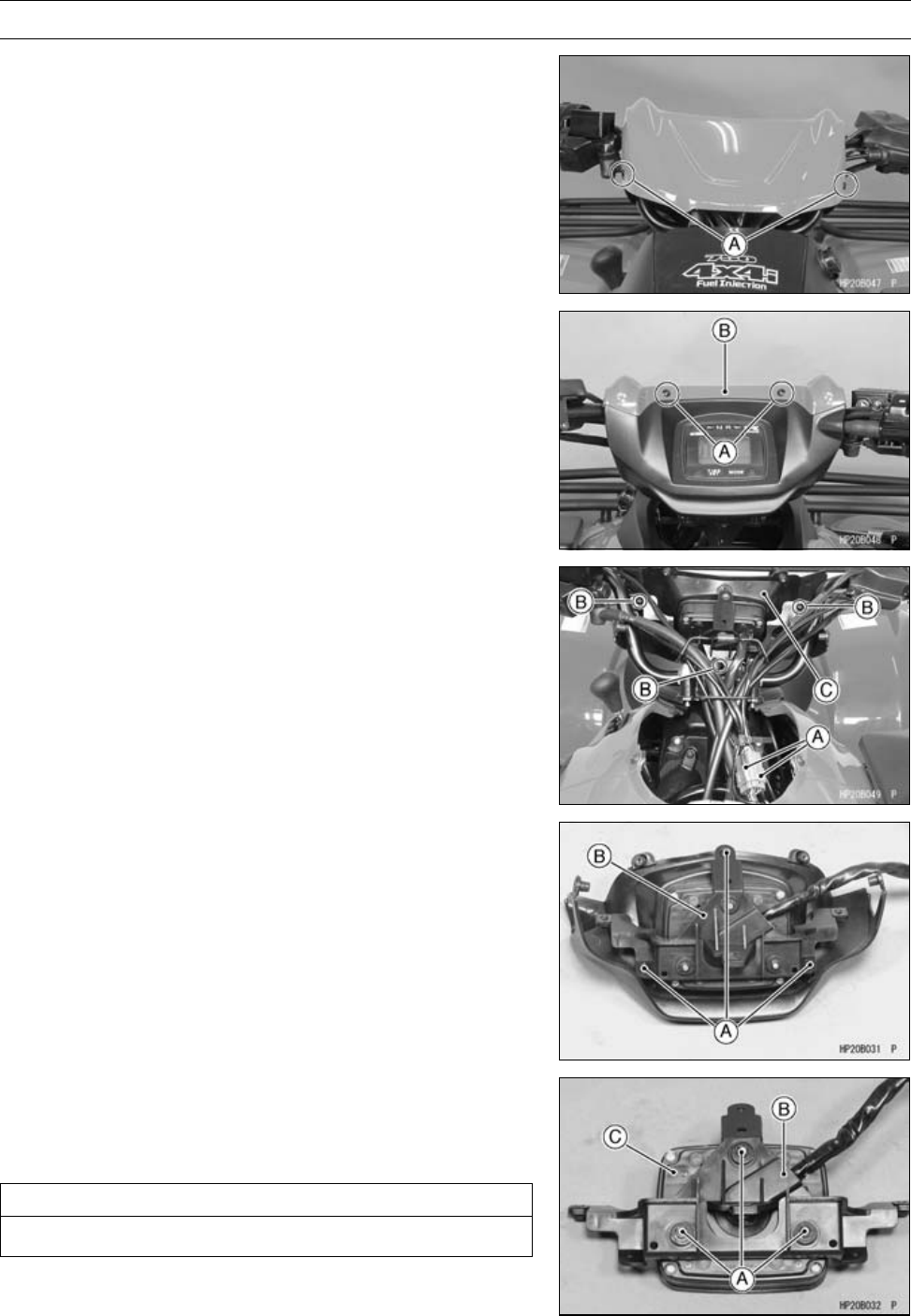
ELECTRICAL SYSTEM 16-59
Meter
Multifunction Meter Unit Removal
•Remove:
Handlebar Cover Screws [A]
•Remove:
Handlebar Cover Screws [A]
Handlebar Cover Front [B]
•Remove:
Meter Unit Lead Connectors [A]
Handlebar Cover Screws [B]
Handlebar Cover Rear [C] with Meter Unit
•Remove:
Bracket Mounting Screws [A]
Meter and Bracket [B]
Upper Damper
•Remove:
Multifunction Meter Mounting Nuts [A] and Washers
Bracket [B]
Multifunction Meter Unit [C]
CAUTION
Do not drop the meter unit.
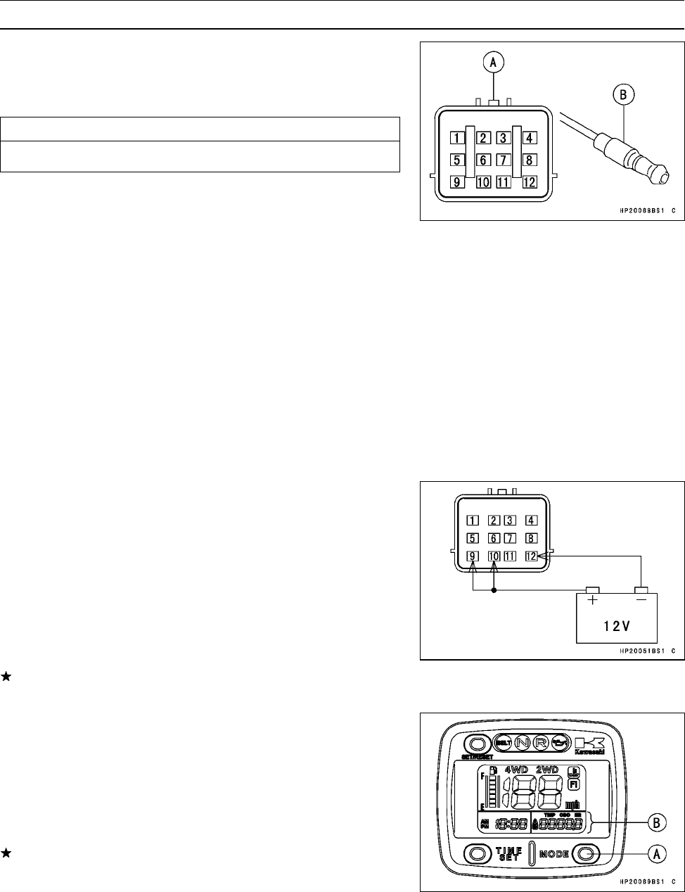
16-60 ELECTRICAL SYSTEM
Meter
Multifunction Meter Unit Inspection
•Remove:
Multifunction Meter Unit (see Multifunction Meter Unit
Removal)
CAUTION
Do not drop the meter unit.
[A] Meter Unit Lead Connector
[B] FI Indicator (LCD) Connector
[1] Speed Sensor Pulse
[2] Belt Indicator Light (LED) (–)
[3] Water Temperature Sensor (–)
[4] 2WD/4WD LCD Indicator (–)
[5] Fuel Gauge (Fuel Indicator LCD Segments)
[6] Meter Illumination (+)
[7] Reverse Indicator Light (LED) (–)
[8] Neutral Indicator Light (LED) (–)
[9] Ignition (+)
[10] Battery (+)
[11] Oil Pressure Warning Indicator Light (LED)
[12] Battery (–)
LED: Light Emitting Diode
LCD: Liquid Crystal Display
Check 1: LCD Segments Check
•Using auxiliary wires, connect a 12 V battery to the meter
unit connector as follows.
•Connect the battery positive (+) terminal to terminal [10].
•Connect the battery negative (–) terminal to terminal [12].
•Connect terminal [9] to the battery (+) terminal.
○When the terminal [9] is connected, all the LCD segments
appear for one second.
○When the terminal [9] is disconnected, all the LCD seg-
ments disappear.
If this display function does not work, replace the meter
unit.
Check 2: MODE and TIME SET Buttons Operation
Check
•Connect the wires in the same manner as Check 1.
•Check that when the MODE button [A] is pushed and
held continuously, the display [B] cycles through the four
modes.
ODO →TRIP A →TRIP B →Hour →ODO
If this display function does not work, replace the meter
unit.
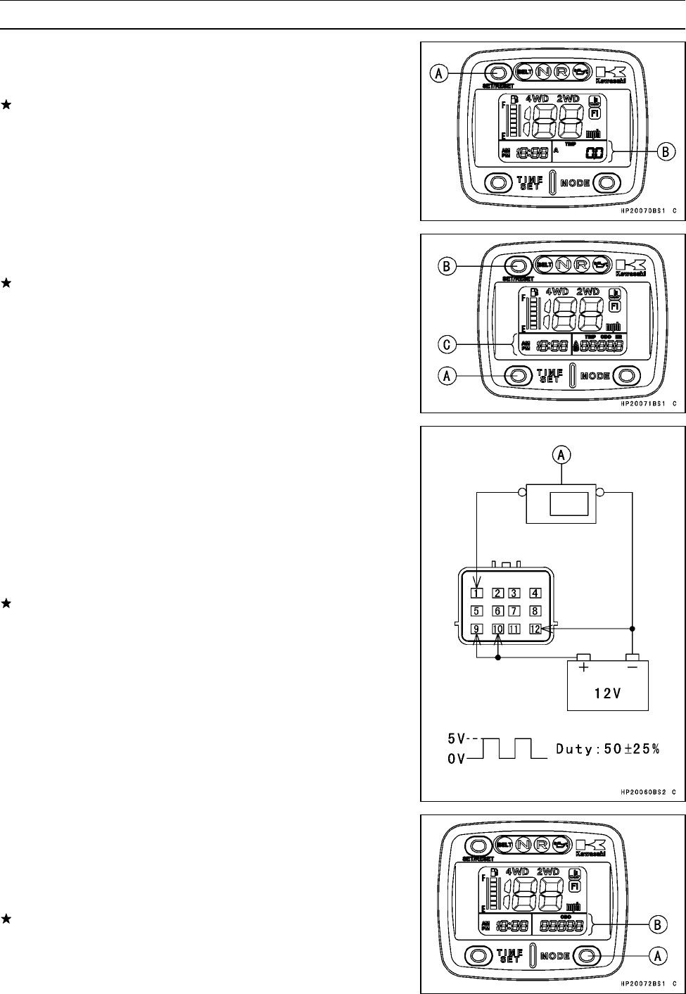
ELECTRICAL SYSTEM 16-61
Meter
•Cycle the meter to TRIP A or TRIP B mode.
•Check that when the SET/RESET button [A] is pushed,
the display turns to 0.0.
If this display function does not indicate 0.0 [B], replace
the meter unit.
•Check that when the TIME SET [A] and SET/RESET [B]
buttons are pushed, the time [C] will reset.
If the meter function does not work, replace the meter unit.
Check 3: Speedometer Check
•Connect the wires in the same manner as Check 1.
•The speed equivalent to the input frequency is indicated in
the oscillator [A], if the square wave is input into terminal
[1].
○Indicates approximately 40 mph if the input frequency is
approximately 789 Hz.
○Indicates approximately 40 km/h if the input frequency is
approximately 526 Hz.
If the meter function does not work, replace the meter unit.
Check 4: Odometer Check
•Connect the wires in the same manner as Check 3.
•Pushing the MODE button [A], cycles the odometer [B].
•Raise the input frequency of the oscillator to see the result
of this inspection.
If the value indicated by the odometer does not work, re-
place the meter unit.
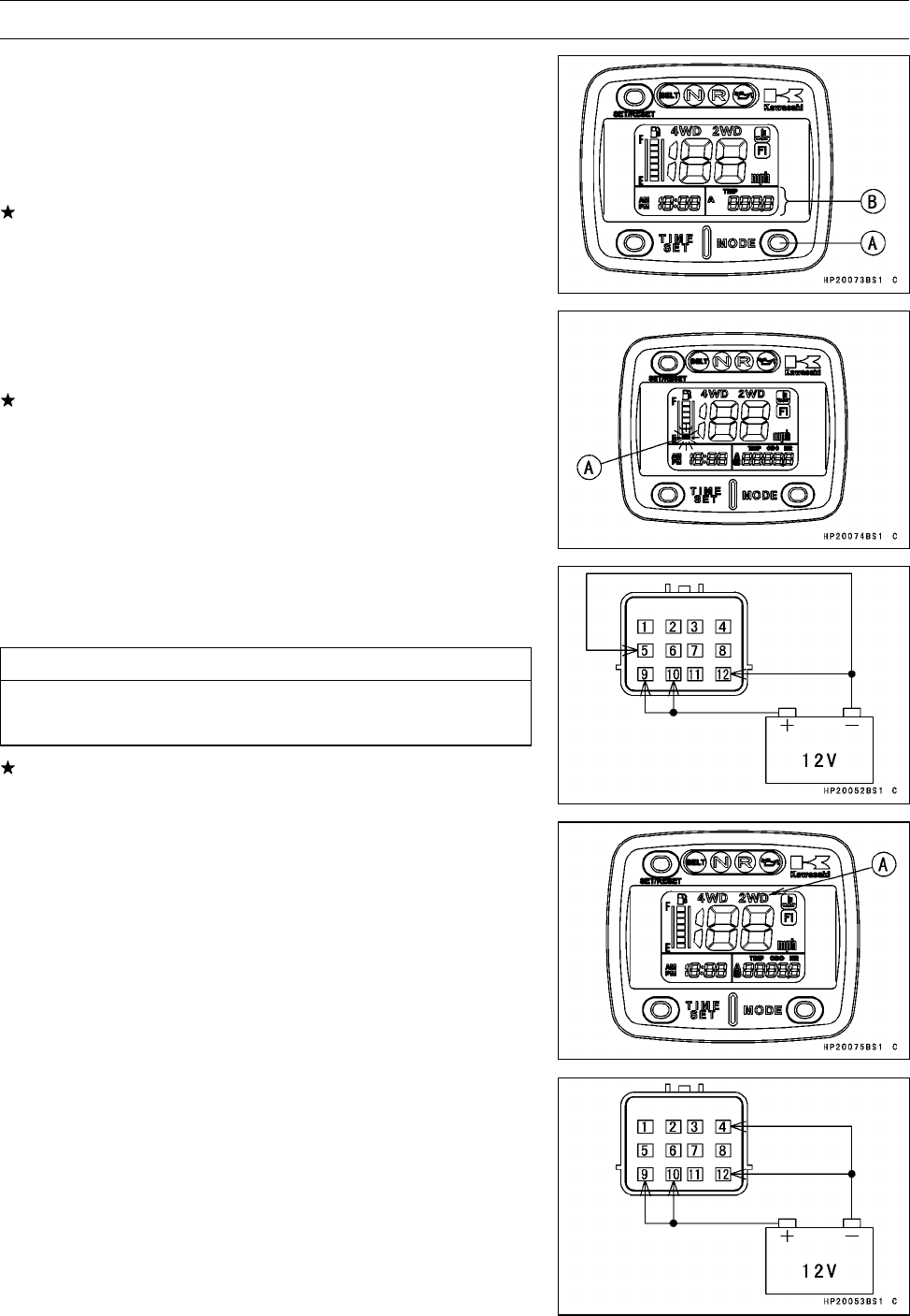
16-62 ELECTRICAL SYSTEM
Meter
Check 5: Trip Meter A/B Check
•Connect the wires in the same manner as Check 3.
•PushingtheMODEbutton[A],cyclesthetripmeterAor
B[B].
•Raise the input frequency of the oscillator to see the result
of this inspection.
If the value indicated by the trip meter A or B does not
increase, replace the meter unit.
Check 6: Fuel Meter Check
•Connect the wires in the same manner as Check 1.
○The first segment (LCD) [A] should flash.
It the segment (LCD) does not flash, replace the meter
unit.
•Connect terminal [5] to the battery (–) terminal.
○When terminal [5] is connected, one segment in the fuel
gauge should appear every 15 seconds.
CAUTION
When all segments appeared, disconnect the termi-
nal [5].
If this display function does not work, replace the meter
unit.
Check 7: 2WD/4WD Indicator Lights Check
•Connect the wires in the same manner as Check 1.
○The 2WD indicator light (LCD) [A] should appear.
•Connect terminal [4] to the battery (–) terminal.
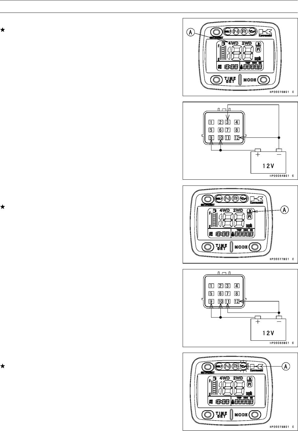
ELECTRICAL SYSTEM 16-63
Meter
○The 4WD indicator light (LCD) [A] should appear.
If this display function does not work, replace the meter
unit.
Check 8: Water Temperature Warning Symbol Check
•Connect the wires in the same manner as Check 1.
•Connect terminal [3] to the battery (–) terminal.
○The water temperature warning symbol (LCD) [A] should
appear.
If this display function does not work, replace the meter
unit.
Check 9: Oil Pressure Warning Light Check
•Connect the wires in the same manner as Check 1.
•Connect terminal [11] to the battery (–) terminal.
○The oil pressure warning light (LED) [A] should flash.
If the LED light does not flash, replace the meter unit.
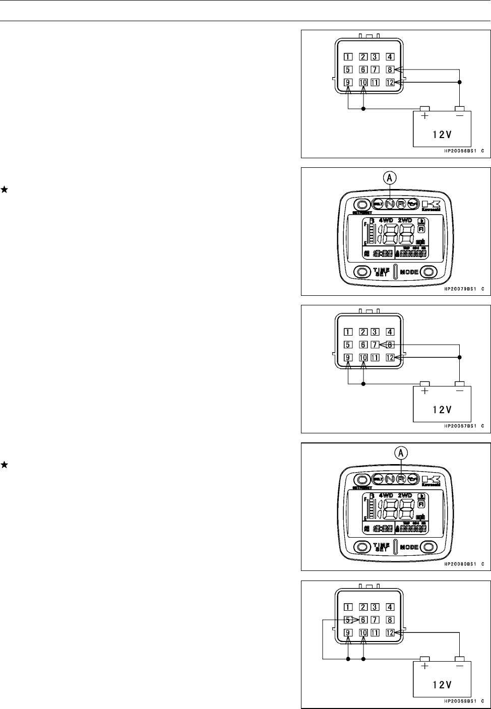
16-64 ELECTRICAL SYSTEM
Meter
Check 10: Neutral Indicator Light Check
•Connect the wires in the same manner as Check 1.
•Connect terminal [8] to the battery (–) terminal.
○The neutral indicator light (LED) [A] should go on.
If the LED light does not go on, replace the meter unit.
Check 11: Reverse Indicator Light Check
•Connect the wires in the same manner as Check 1.
•Connect terminal [7] to the battery (–) terminal.
○The reverse indicator light (LED) [A] should go on.
If the LED light does not go on, replace the meter unit.
Check 12: Meter Illumination Check
•Connect the wires in the same manner as Check 1.
•Connect terminal [6] to battery (+) terminal.
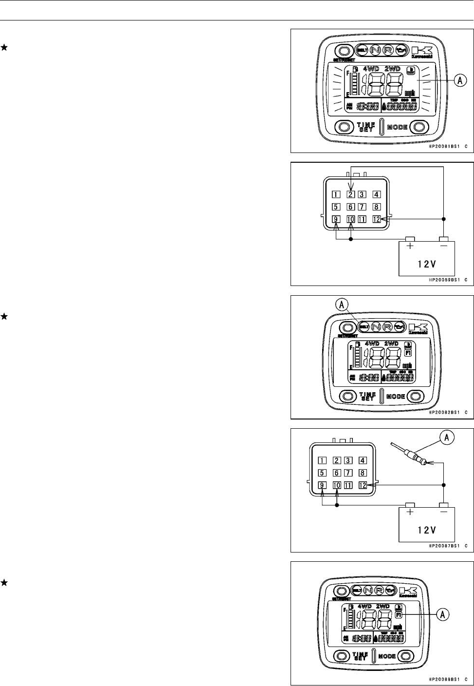
ELECTRICAL SYSTEM 16-65
Meter
○The meter illumination [A] should go on.
If the illumination does not go on, replace the meter unit.
Check 13: Belt Check Indicator Light check
•Connect the wires in the same manner as Check 1.
•Connect terminal [2] to the battery (–) terminal.
○The belt check indicator light (LED) [A] should go on.
It the LED does not go on, replace the meter unit.
Check 14:FI Indicator Light check
•Connect the wires in the same manner as Check 1.
•Connect FI indicator connector [A] to the battery (–) ter-
minal.
○The FI indicator light (LCD) [A] should flash.
It the LCD does not flash, replace the meter unit.
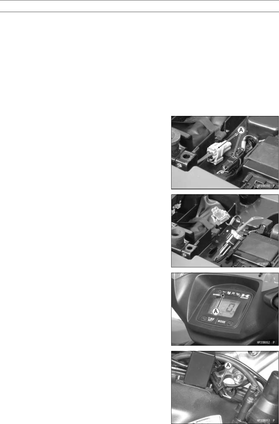
16-66 ELECTRICAL SYSTEM
Meter
Drive Belt Failure Mode Memory Clearing
Procedure
A flashing BELT check indicator LED (Light Emitting
Diode) light means that the drive belt failure detection
system has activated. The belt check indicator light will
illuminate and stay on when activated by the 100 hour belt
check system.
NOTE
○Follow the instruction on page 2-25 of this Service Man-
ual to complete the necessary inspections.
○After completing the inspections, follow these instruc-
tions to clear the system memory and turn off the light.
•Turn off the ignition switch.
•Remove the seat (see Seat Removal in the Frame chap-
ter).
•Disconnect both sets of 4 pin connectors [A] in the elec-
trical parts case.
•Reconnect these 4 pin connectors to their opposite gray
to black and black to gray as shown.
•Turn on the ignition switch.
•Observe the belt check indicator light [A].
○It should be flashing quickly.
•Disconnect the belt switch at the 2 pin connectors [A]
above the torque converter cover.
•Observe the belt check indicator light.
○It should be flashing slowly.
○Let it flash for at least five seconds.
NOTE
○More than five seconds is OK.
•While observing the belt check indicator light, turn off the
ignition switch.
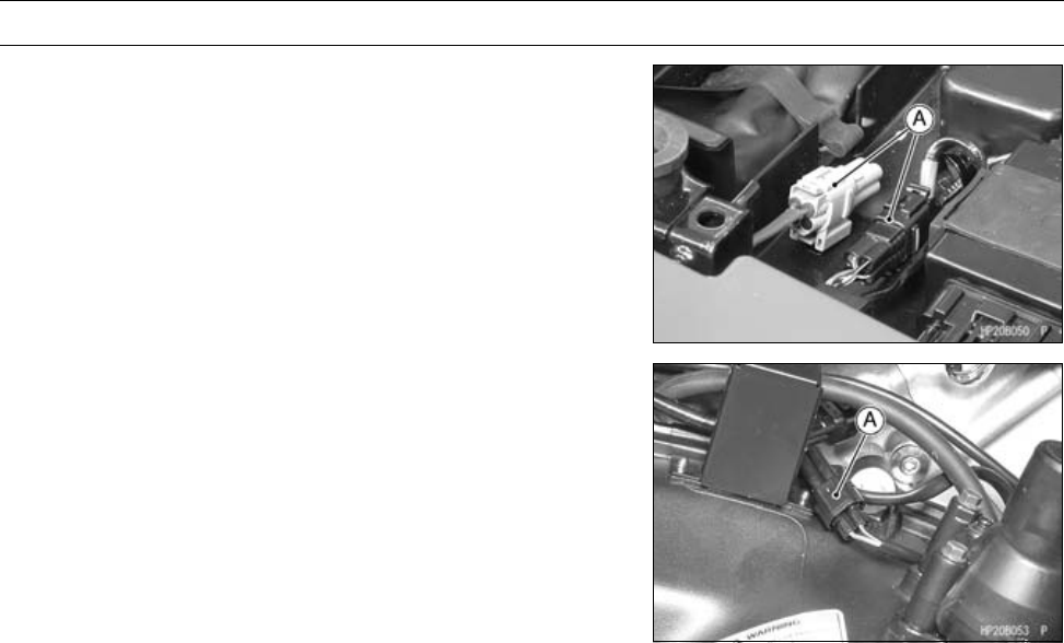
ELECTRICAL SYSTEM 16-67
Meter
•Disconnect the mismatched 4 pin connector sets and re-
connect them normally. (Black to black, gray to gray) [A]
•Connect the belt switch 2 pin connector [A].
•Turn on the ignition switch.
•Confirm that no belt check indicator light is flashing.
•Put the connectors back and bend the clamps.
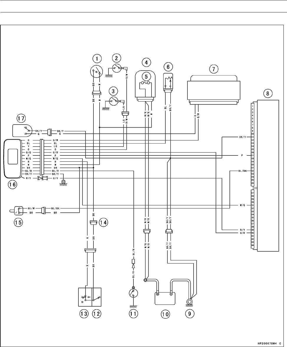
16-68 ELECTRICAL SYSTEM
Meter
Meter Circuit
1. Ignition Switch
2. Reverse Switch
3. Neutral Switch
4. Fuse Box
5. Main Fuse 30 A
6. Fuel Level Sensor
7. Actuator Controller
8. ECU (Electronic Control Unit)
9. Engine Ground Terminal
10. Battery 12 V 12 Ah
11. Oil Pressure Switch
12. Engine Stop Switch
13. Light/Dimmer Switch
14. Reset Connector
15. Drive Belt Failure Detecting Switch
16. Multifunction Meter
17. 2WD/4WD Shift Switch
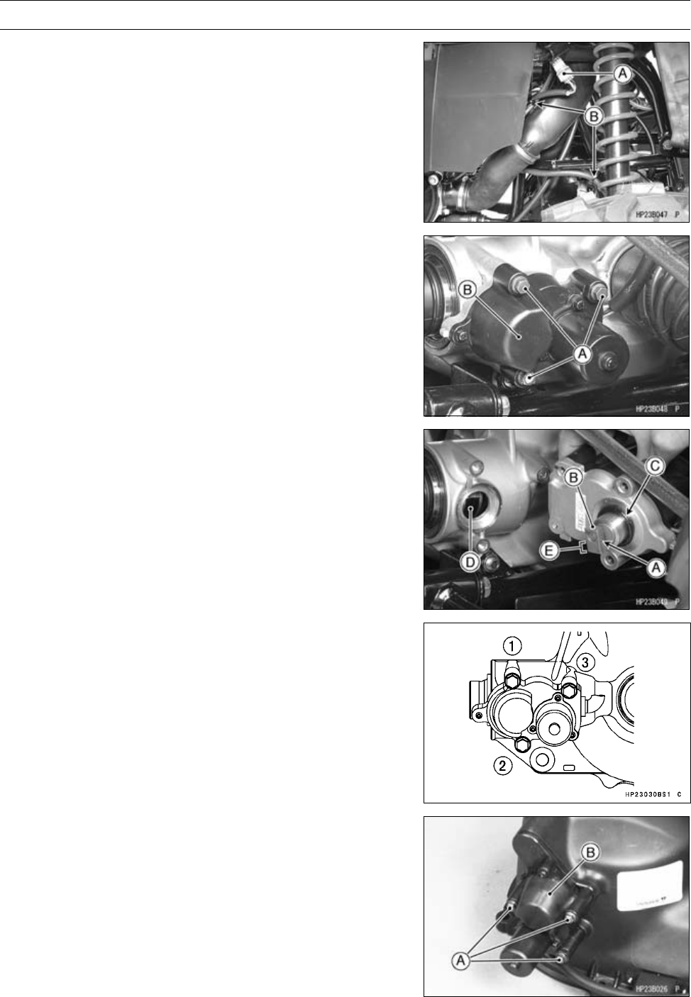
ELECTRICAL SYSTEM 16-69
Actuator Control System
2WD/4WD Actuator Removal
•Drain the front final gear case oil (see Front Final Gear
Case Oil Change in the Periodic Maintenance chapter).
•Remove:
Actuator Lead Connector [A]
Clamps [B]
•Remove:
Actuator Mounting Bolts [A]
Actuator [B]
2WD/4WD Actuator Installation
•When installing the pin [A], apply engine oil to the rod of
the actuator and install the collar [B] on the actuator and
then press the pin.
•Apply grease to the O-ring [C].
•Apply molybdenum disulfide grease to the collar.
•Insert the collar into the groove [D] of the shifter so that
the long side [E] faces downward.
•Apply a non-permanent locking agent to the actuator
mounting bolts, and tighten them following the tightening
sequence [1 ∼3].
Torque - 2WD/4WD Actuator Mounting Bolts: 9.8 N·m (1.0
kgf·m, 87 in·lb)
•Apply grease (Amoco Rykon Premium grease No.2 EP
Green) to the actuator connector, and connect it.
Engine Brake Actuator Removal
•Confirm that the ignition switch is in OFF position.
•Remove:
Torque Converter Cover (see Torque Converter Cover
Removal in the Converter System chapter)
Actuator Mounting Bolts [A]
Actuator [B]
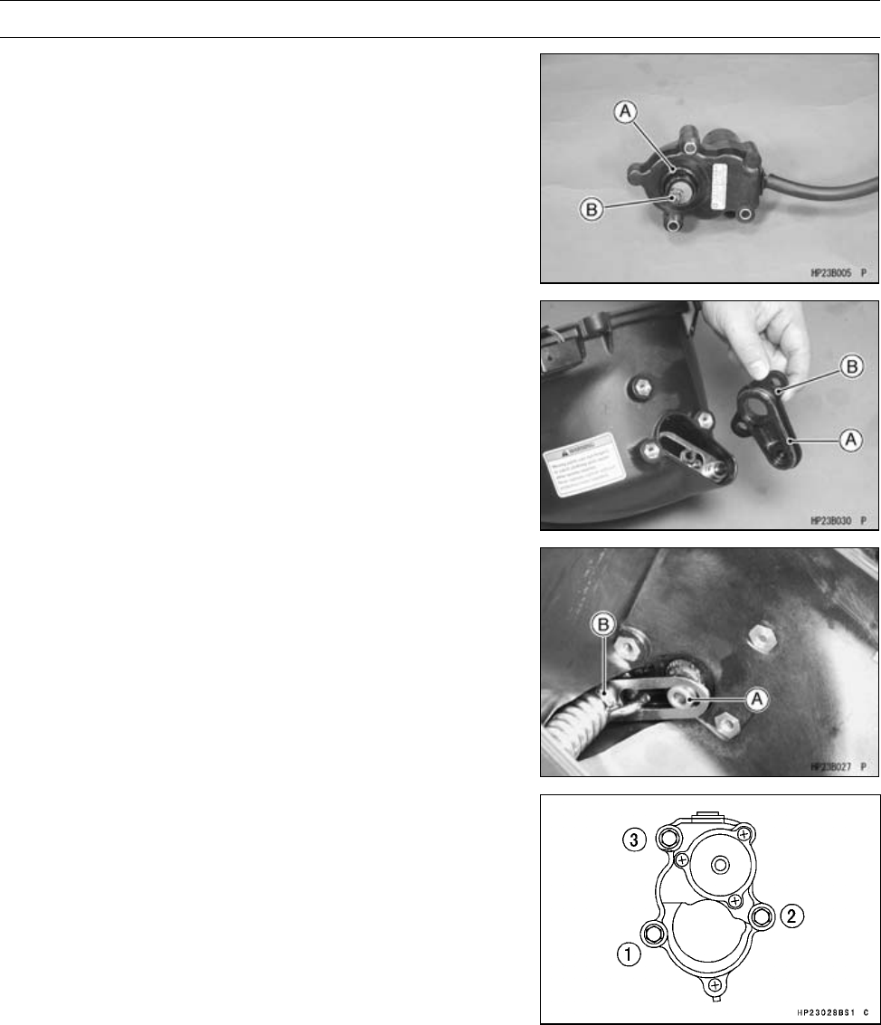
16-70 ELECTRICAL SYSTEM
Actuator Control System
Engine Brake Actuator Installation
•Apply grease and Install:
O-ring [A]
•Apply molybdenum disulfide grease to the pin [B].
•Apply grease to the trim seal [A] and install the cover [B].
•Insert the pin into the collar [A] of the engine brake lever
assembly [B].
•Wipe off any protruding grease.
•Tighten the actuator mounting bolts following the tighten-
ing sequence [1 ∼3].
Torque - Engine Brake Actuator Mounting Bolts: 8.8 N·m
(0.90 kgf·m, 78 in·lb)
•Apply grease (Amoco Rykon Premium grease No.2 EP
Green) to the actuator connector, and connect it.
Actuator Control System Outline
The actuator controller has a microprocessor that detects
vehicle speed, state of the selectable 2WD/4WD shift
switch, ignition switch, and the forward/reverse movement
of the vehicle in order to control the engine brake actuator
and selectable 2WD/4WD actuator.
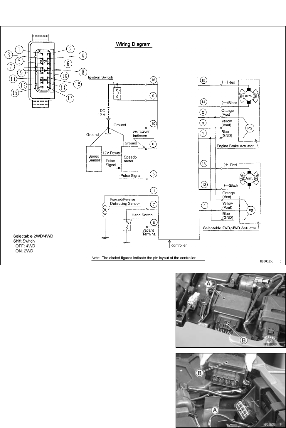
ELECTRICAL SYSTEM 16-71
Actuator Control System
Actuator Control System
Actuator Controller Removal
•Remove:
Seat (see Seat Removal in the Frame chapter)
Actuator Controller [A]
•Disconnect the connector [B].
Actuator Controller Installation
•Apply grease (Amoco Rykon Premium grease No.2 EP
Green) to the connector [A], and connect it to the actuator
controller [B].
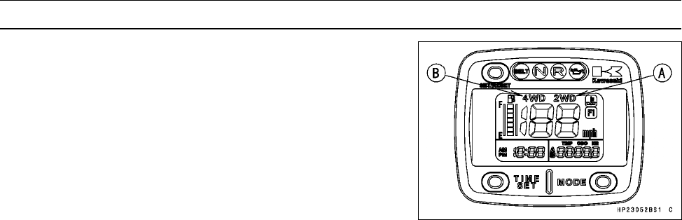
16-72 ELECTRICAL SYSTEM
Actuator Control System
Actuator Control System Troubleshooting
When the actuator fails, the controller enters failure mode
and the indicator light illuminates 2WD and 4WD alternately.
[A] 2WD Indicator Light (LCD)
[B] 4WD Indicator Light (LCD)
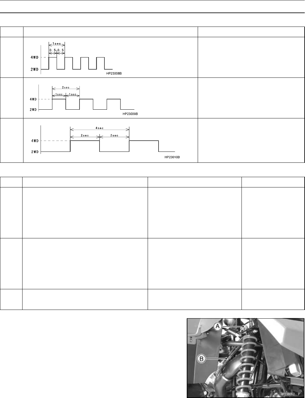
ELECTRICAL SYSTEM 16-73
Actuator Control System
Failure Indication Pattern and Failure Part
No. Failure Indication Pattern Failure Part
1Selectable 2WD/4WD actuator
2Engine brake actuator
3
Both the selectable 2WD/4WD
actuator and the engine brake
actuator
Malfunction Mode
No. Malfunction Mode Probable Faulty Part/Location Check Number
2WD/4WD actuator 1
Controller power supply 3
Speed sensor 4
2WD/4WD shift switch 5
1The 2WD/4WD actuator does not
operate correctly.
Controller 6
Engine brake actuator 2
Controller power supply 3
Speed sensor 4
F/R detecting sensor 7
2The engine brake actuator does not
operate correctly.
Controller 6
Indicator light (LCD) 8
3The 2WD/4WD indicator light does not
switch. Controller 6
Check 1. 2WD/4WD Actuator Inspection
•Remove:
Actuator Lead Connector [A]
Clamp [B]
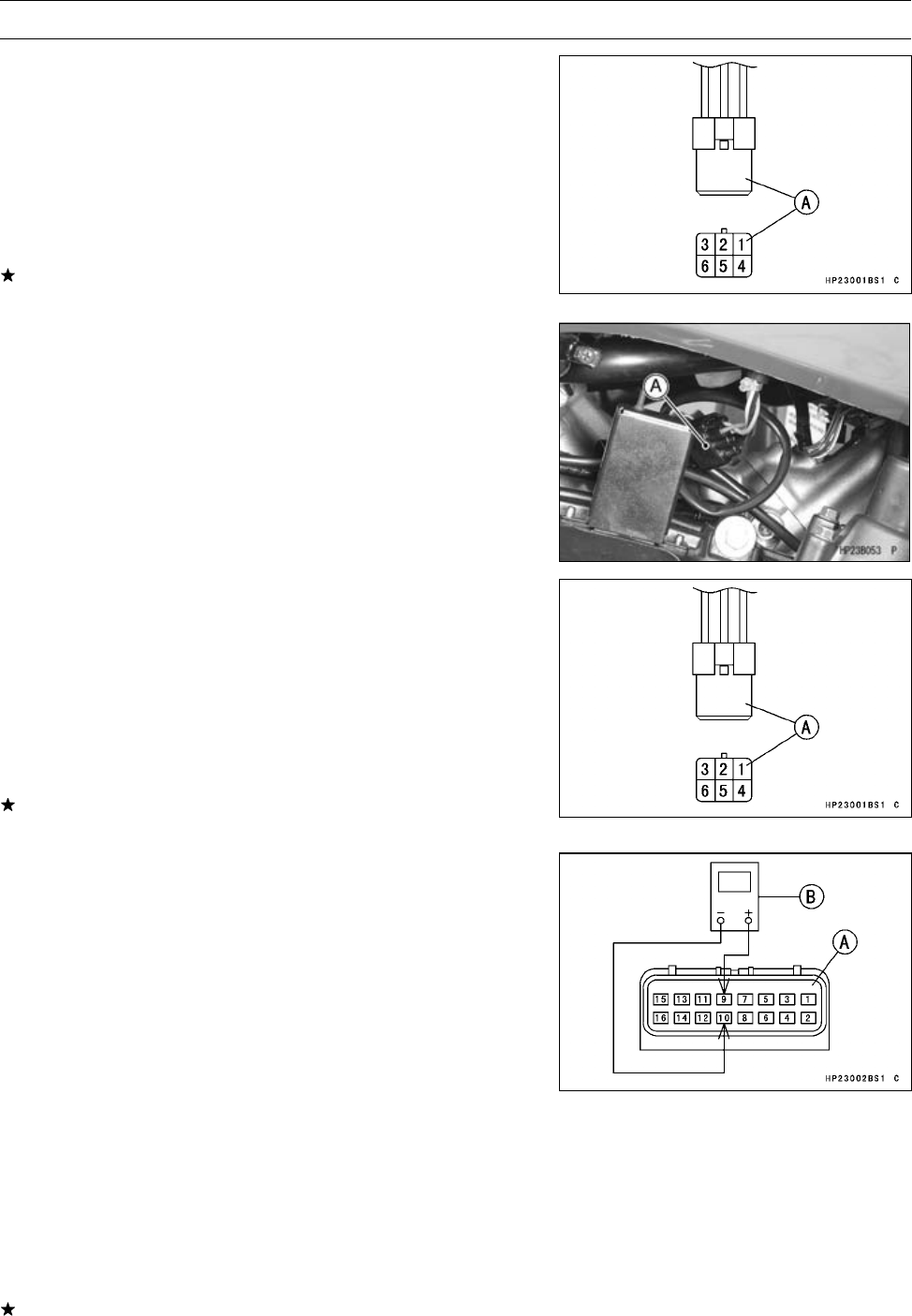
16-74 ELECTRICAL SYSTEM
Actuator Control System
•Measure the resistance between the following terminals
in the actuator lead connector [A].
Special Tool - Hand Tester: 57001-1394
Actuator Internal Resistance
4(Red)-6(Black): 3∼15 Ω
1 (Orange) - 3 (Blue): 3.5 ∼6.5 kΩ
2(Yellow)-3(Blue): 630∼3,720 Ω
If any reading is not within the specified range, replace
the 2WD/4WD actuator.
Check 2. Engine Brake Actuator Inspection
•Remove:
Actuator Lead Connector [A]
•Measure the resistance between the following terminals
in the actuator lead connector [A].
Special Tool - Hand Tester: 57001-1394
Actuator Internal Resistance
4(Red)-6(Black): 3∼15 Ω
1 (Orange) - 3 (Blue): 3.5 ∼6.5 kΩ
2(Yellow)-3(Blue): 630∼5,330 Ω
If any reading is not within the specified range, replace
the engine brake actuator.
Check 3. Controller Power Supply Inspection
NOTE
○Be sure the battery is fully charged.
•Remove:
Seat (see Seat Removal in the Frame chapter)
•Connect:
Controller Connector [A]
Hand Tester [B] (range: DC 25 V)
Test e r ( +) →Connector (BR) Terminal [9]
Test e r ( –) →Connector (BK/Y) Terminal [10]
○Install the needle adapters on the tester leads.
Special Tools - Hand Tester: 57001-1394
Needle Adapter Set: 57001-1457
•Turn ON the ignition switch.
Controller Power Supply Voltage
Standard: near Battery Voltage
If the reading is not battery voltage, check the wiring har-
ness, 30 A fuse, or ignition switch.
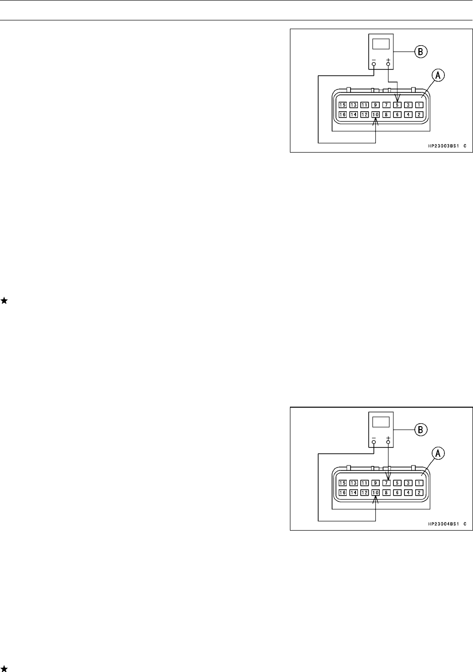
ELECTRICAL SYSTEM 16-75
Actuator Control System
Check 4. Speed Sensor Inspection
NOTE
○Be sure the battery is fully charged.
•Support the vehicle on a stand or a jack so that the wheels
are off the ground.
•Remove:
Seat (see Seat Removal in the Frame chapter)
•Connect:
Controller Connector [A]
Hand Tester [B] (range: DC 25 V)
Test e r (+) →Connector (P) Terminal [5]
Test e r ( –) →Connector (BK/Y) Terminal [10]
○Install the needle adapters on the tester leads.
Special Tools - Hand Tester: 57001-1394
Needle Adapter Set: 57001-1457
•Turn ON the ignition switch.
•Spin a rear wheel, measure the voltage.
Speed Sensor Output Voltage
Standard: repeat from 0 to 5 V
If the reading is not standard, replace the speed sensor.
○When installing a new O-ring on the speed sensor, apply
grease all around the O-ring. Insert the speed sensor to
the fully seated position before tightening the mounting
bolt for the sensor.
NOTE
○If the sensor is not fully seated before tightening the bolt,
the O-ring can be damaged and oil may leak.
Check 5. 2WD/4WD Shift Switch Inspection
NOTE
○Be sure the battery is fully charged.
•Remove:
Seat (see Seat Removal in the Frame chapter)
•Connect:
Controller Connector [A]
Hand Tester [B] (range: DC 10 V)
Test e r (+) →Connector (G) Terminal [7]
Test e r ( –) →Connector (BK/Y) Terminal [10]
○Install the needle adapters on the tester leads.
Special Tools - Hand Tester: 57001-1394
Needle Adapter Set: 57001-1457
•Turn ON the ignition switch.
•Push the switch to the 4WD position.
Controller Output Voltage (at 2WD/4WD Shift Switch OFF,
4WD)
Standard: about 5 V
If the reading is not standard, check the 2WD/4WD shift
switch or actuator controller unit.
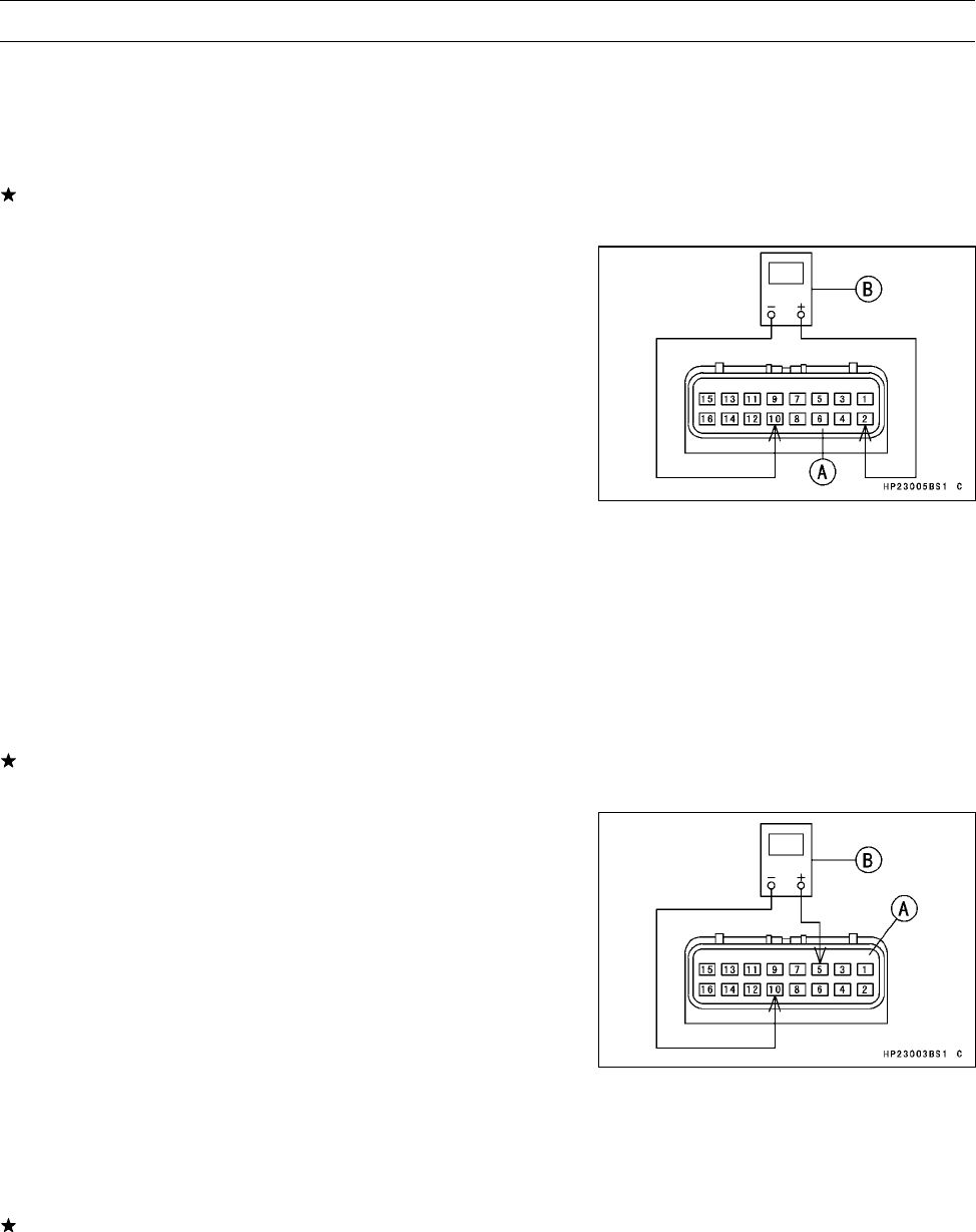
16-76 ELECTRICAL SYSTEM
Actuator Control System
•Push the switch to the 2WD position.
Controller Output Voltage (at 2WD/4WD Shift Switch ON,
2WD)
Standard: 0V
If the reading is not standard, check the 2WD/4WD shift
switch or actuator controller unit.
Check 6. Controller Unit Inspection
NOTE
○Be sure the battery is fully charged.
•Remove:
Seat (see Seat Removal in the Frame chapter)
•Connect:
Controller Connector [A]
Hand Tester [B] (range: DC 10 V)
Test e r ( +) →Connector (O) Terminal [2]
Test e r ( –) →Connector (BK/Y) Terminal [10]
○Install the needle adapters on the tester leads.
Special Tools - Hand Tester: 57001-1394
Needle Adapter Set: 57001-1457
•Turn ON the ignition switch.
•Measure the controller output voltage for the actuators.
Controller Output Voltage (to Actuators)
Standard: 4.8 ±0.2 V
If the reading is not standard, replace the actuator con-
troller unit.
•Disconnect the speed sensor lead connector.
•Connect:
Controller Connector [A]
Hand Tester [B] (range: DC 10 V)
Test e r (+) →Connector (P) Terminal [5]
Test e r ( –) →Connector (BK/Y) Terminal [10]
○Install the needle adapters on the tester leads.
Special Tools - Hand Tester: 57001-1394
Needle Adapter Set: 57001-1457
•Turn ON the ignition switch.
•Measure the controller output voltage for the speed sen-
sor.
Controller Output Voltage (to speed sensor)
Standard: 5 ±0.25 V
If the reading is not standard, replace the actuator con-
troller unit.
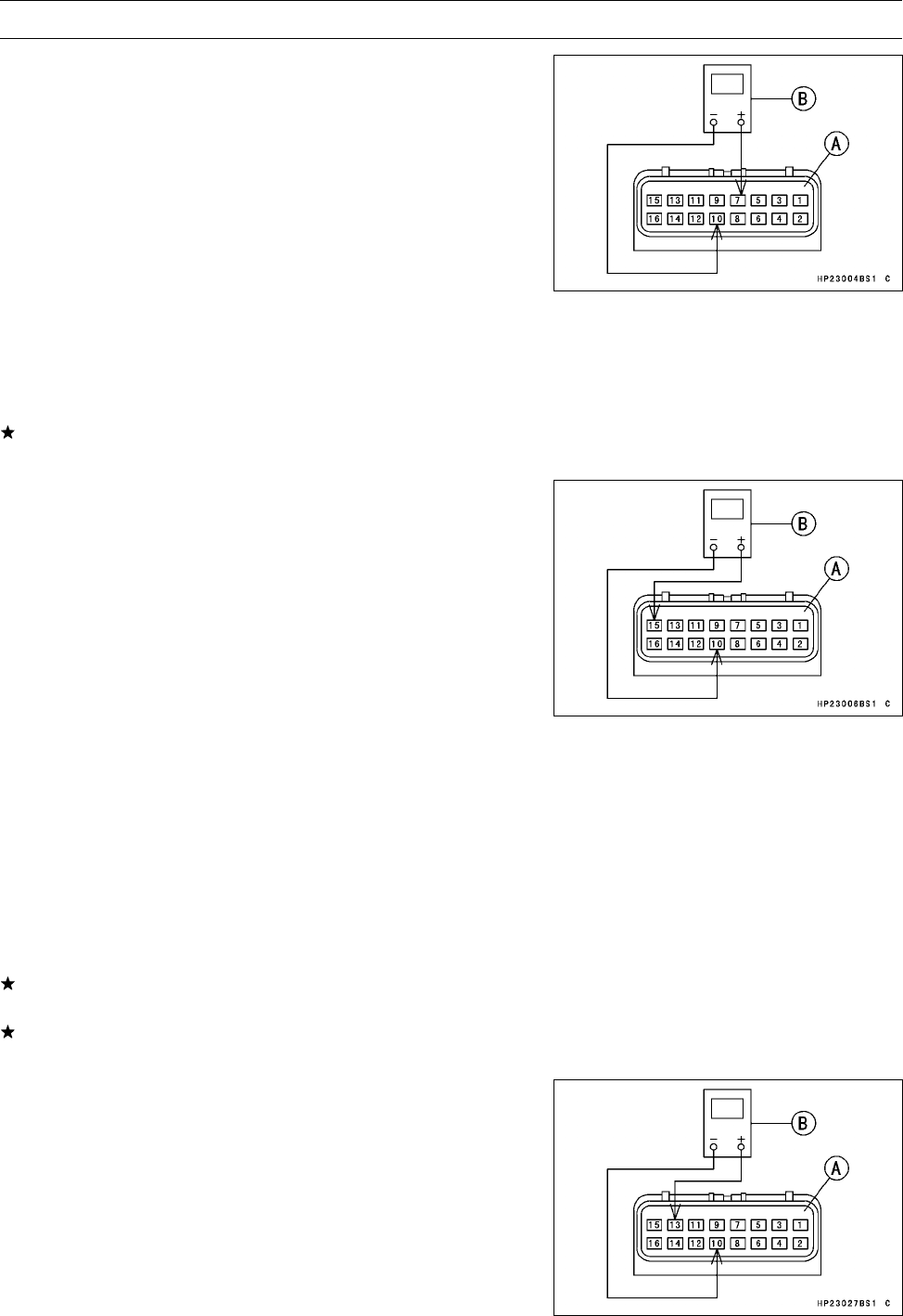
ELECTRICAL SYSTEM 16-77
Actuator Control System
•Disconnect the 2WD/4WD shift switch lead connector.
•Connect:
Controller Connector [A]
Hand Tester [B] (range: DC 10 V)
Test e r (+) →Connector (G) Terminal [7]
Test e r ( –) →Connector (BK/Y) Terminal [10]
○Install the needle adapters on the tester leads.
Special Tools - Hand Tester: 57001-1394
Needle Adapter Set: 57001-1457
•Turn ON the ignition switch.
•Measure the controller output voltage for the 2WD/4WD
shift switch.
Controller Output Voltage (to 2WD/4WD shift switch)
Standard: 5 ±0.25 V
If the reading is not standard, replace the actuator con-
troller unit.
•Support the vehicle on a stand or a jack so that the wheels
are off the ground.
•Connect:
Controller Connector [A]
Hand Tester [B] (range: DC 25 V)
Test e r (+) →Connector (W/R) Terminal [15]
Test e r ( –) →Connector (BK/Y) Terminal [10]
○Install the needle adapters on the tester leads.
Special Tools - Hand Tester: 57001-1394
Needle Adapter Set: 57001-1457
•Turn ON the ignition switch.
•Spin a rear wheel as forward rotation.
•After the wheels stop and one second elapses, turn OFF
the ignition switch.
•After two seconds elapses, measure the controller output
voltage for the engine brake actuator until the actuator
stops.
Controller Output Voltage (to engine brake actuator)
Standard: 5∼12 V
If the reading is not standard, check the forward/reverse
detecting sensor.
If the forward/reverse detecting sensor is normal, replace
the actuator controller unit.
•Support the vehicle on a stand or a jack so that the wheels
are off the ground.
•Run the engine and shift to the 4WD position.
•Stop the engine and turn OFF the ignition switch.
•Connect:
Controller Connector [A]
Hand Tester [B] (range: DC 25 V)
Test e r (+) →Connector (W/Y) Terminal [13]
Test e r ( –) →Connector (BK/Y) Terminal [10]
○Install the needle adapters on the tester leads.
Special Tools - Hand Tester: 57001-1394
Needle Adapter Set: 57001-1457
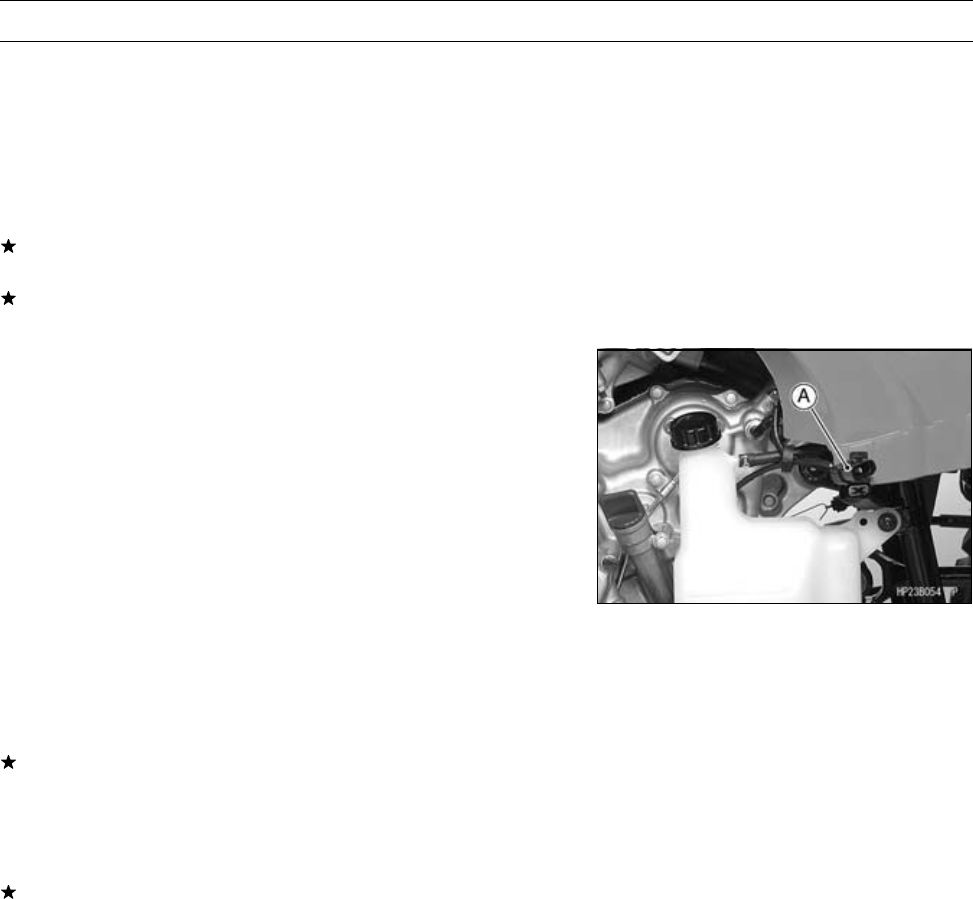
16-78 ELECTRICAL SYSTEM
Actuator Control System
•Turn ON the ignition switch.
•Shift to the 2WD position.
•Measure the controller output voltage for the 2WD/4WD
actuator until the actuator stops.
Controller Output Voltage (to 2WD/4WD actuator)
Standard: 5∼12 V
If the reading is not standard, check the 2WD/4WD shift
switch.
If the 2WD/4WD shift switch is normal, replace the actu-
ator controller unit.
Check 7. Forward/Reverse Detecting Sensor Inspec-
tion
•Remove the left footboard (see Left Footboard Removal
in the Frame chapter).
•Disconnect forward/reverse detecting sensor lead con-
nector [A].
•Measure the forward/reverse detecting sensor resis-
tance.
○Connect the hand tester between the BK lead and the W
lead.
○Set the tester to the × kΩrange.
Special Tool - Hand Tester: 57001-1394
Forward/Reverse Detecting Sensor Resistance
Standard: 1.2 ∼1.6 kΩ
If the reading is not within the specified range, replace the
forward/reverse detecting sensor.
•Using the highest resistance, measure the resistance be-
tween forward/reverse detecting sensor leads and chas-
sis ground.
If the tester reading is less than infinity (∞) indicates a
short, replace the forward/reverse detecting sensor.
Check 8. Indicator Light (LCD) Inspection
•Refer to Check 7: 2WD/4WD Indicator Lights Check in
Multifunction Meter Unit Inspection.
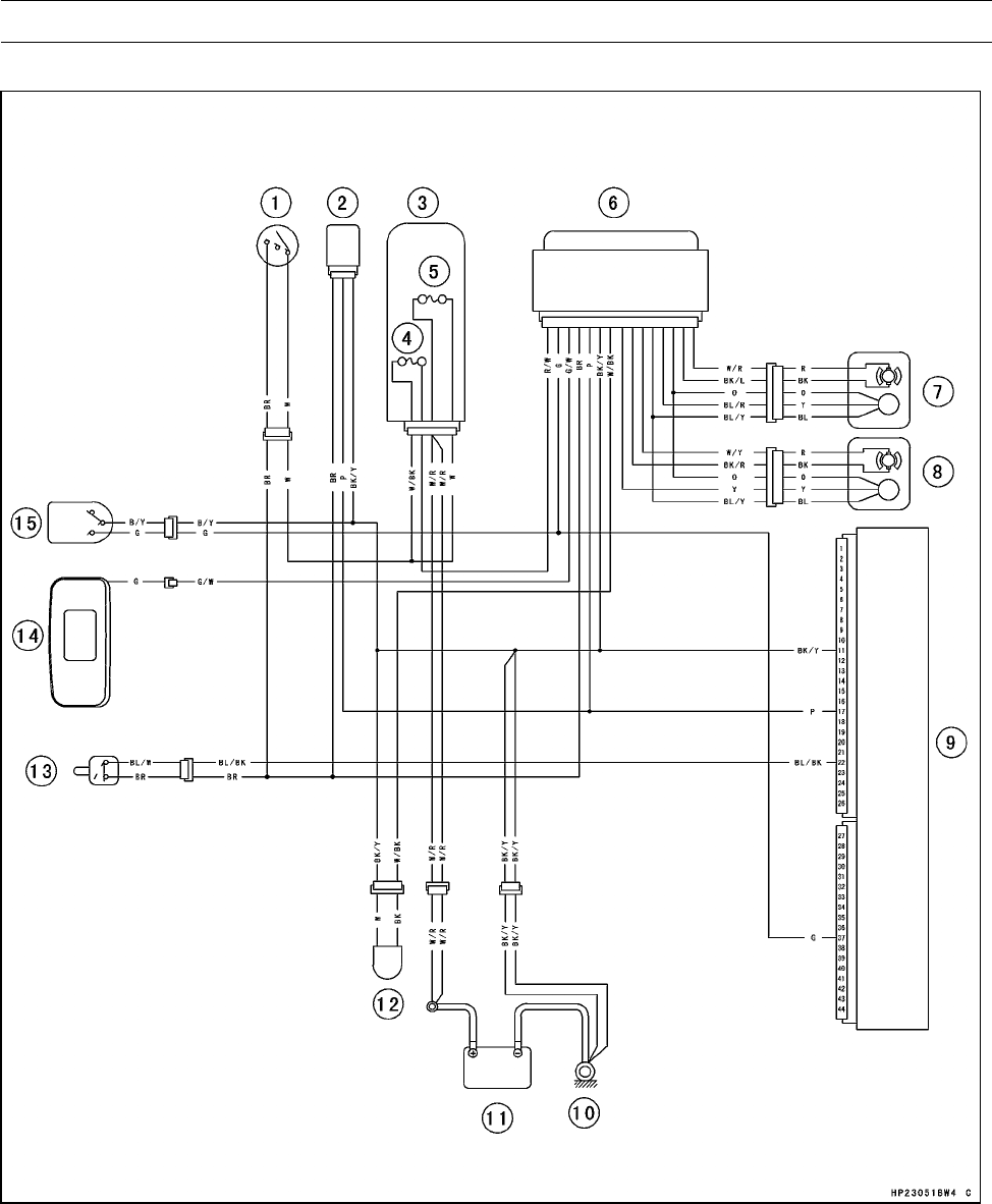
ELECTRICAL SYSTEM 16-79
Actuator Control System
Actuator Control System Circuit
1. Ignition Switch
2. Speed Sensor
3. Fuse Box
4. Actuator Controller Fuse 10 A
5. Main Fuse 30 A
6. Actuator Controller
7. Engine Brake Actuator
8. 2WD/4WD Actuator
9. ECU (Electronic Control Unit)
10. Engine Ground Terminal
11. Battery 12 V 12 Ah
12. Forward/Reverse Detecting Sensor
13. Drive Belt Failure Detecting Switch
14. Multifunction Meter
15. 2WD/4WD Shift Switch
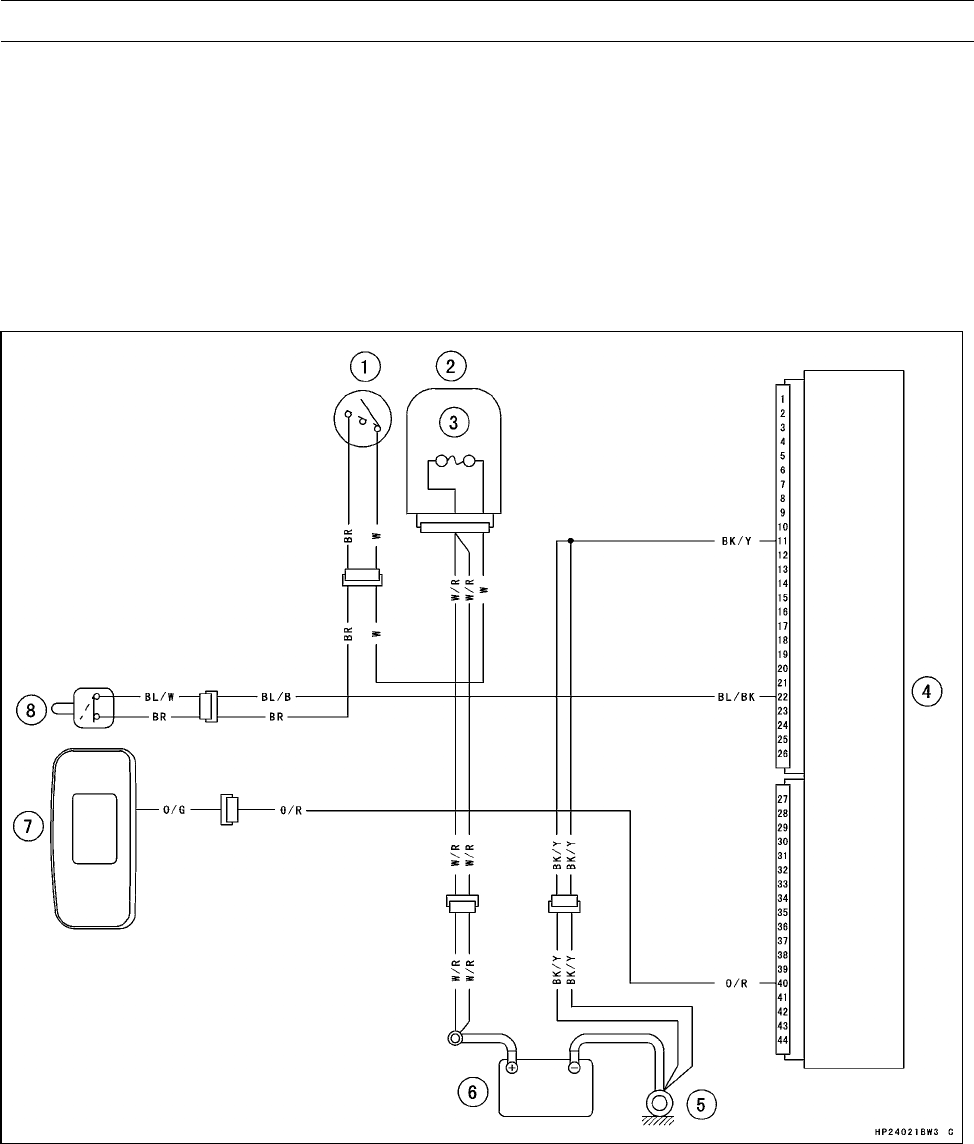
16-80 ELECTRICAL SYSTEM
Drive Belt Failure Detection System
If the drive belt failure detection system activated by ab-
normal belt, the drive belt failure detection switch is dam-
aged. Make sure replace the torque converter cover (see
Torque Converter Cover Removal/Installation in the Con-
verter System chapter).
Drive Belt Failure Detection System Inspection
•Refer to the Drive Belt Failure Detection System Inspec-
tion in the Periodic Maintenance chapter.
Drive Belt Failure Detection System Circuit
1. Ignition Switch
2. Fuse Box
3. Main Fuse 30 A
4. ECU (Electronic Control Unit)
5. Engine Ground Terminal
6. Battery 12 V 12 Ah
7. Multifunction Meter
8. Drive Belt Failure Detecting Switch
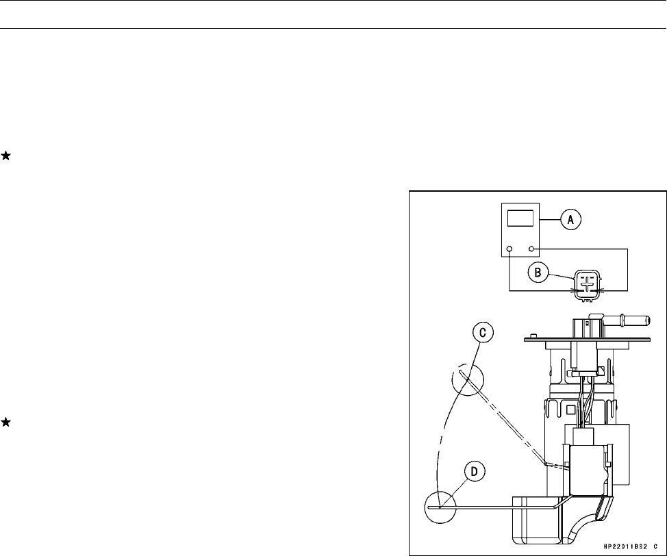
ELECTRICAL SYSTEM 16-81
Switches and Sensor
Fuel Level Sensor Inspection
•Remove:
Fuel Pump (see Fuel Pump Removal in the Fuel System
(DFI) chapter)
•Check that the float moves up and down smoothly without
binding. It should go down under its own weight.
If the float does not move smoothly, replace the fuel pump
assembly.
•Using a hand tester [A], measure the resistance across
the terminals in the fuel pump lead connector [B].
Special Tool - Hand Tester: 57001-1394
NOTE
○In contrast to the normal measuring method, the current
that flows through the gauge when measuring it with a
tester is very low, thus making the measurement easily
affected by the oxidized film of the resistance plate, and
resulting in excessive resistance. Therefore, make sure
to wipe the resistance plate with alcohol before taking a
measurement.
If the readings are not as specified, replace the fuel pump
assembly.
Fuel Level Sensor Resistance
Standard: Full Level Position [C]: 3 Ω
Empty Level Position [D]: 120 Ω
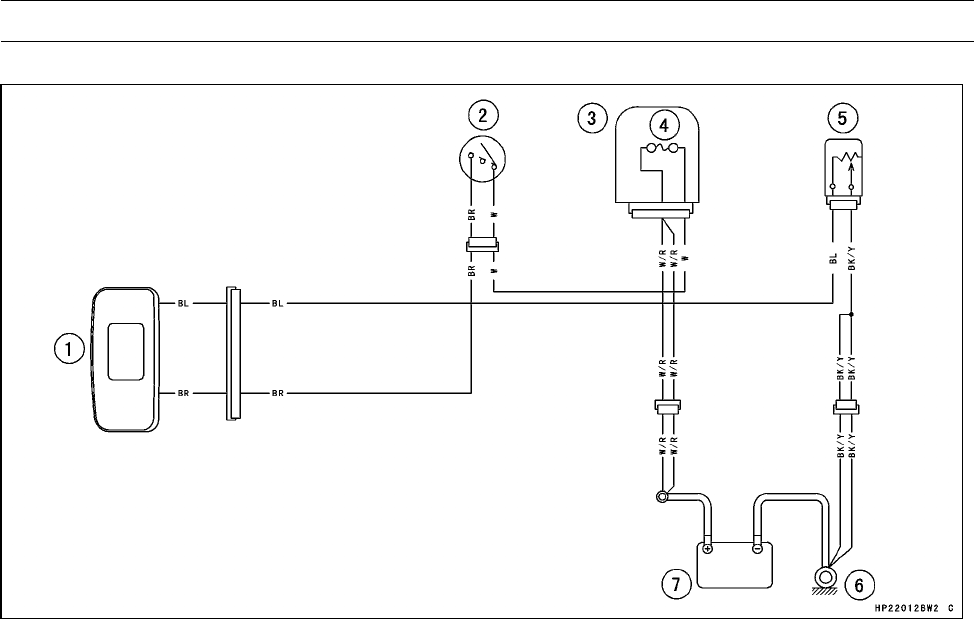
16-82 ELECTRICAL SYSTEM
Switches and Sensor
Fuel Level Sensor Circuit
1. Multifunction Meter
2. Ignition Switch
3. Fuse Box
4. Main Fuse 30 A
5. Fuel Level Sensor
6. Engine Ground Terminal
7. Battery 12 V 12 Ah
Brake Light Switch Adjustment
•Refer to the Brake Light Switch Inspection and Adjust-
ment in the Periodic Maintenance chapter.
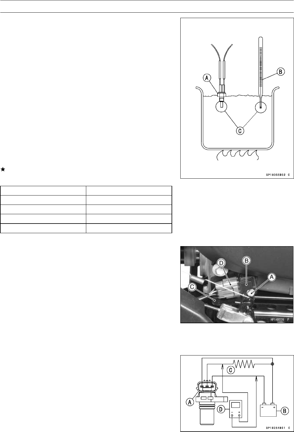
ELECTRICAL SYSTEM 16-83
Switches and Sensor
Water Temperature Sensor Inspection
•Remove the water temperature sensor (see Water Tem-
perature Sensor Removal/Installation in the Fuel System
(DFI) chapter).
•Suspend the sensor [A] in a container of machine oil so
that the heat-sensitive portion and threaded portion are
submerged.
•Suspend an accurate thermometer [B] with heat-sensitive
portions [C] located in almost the same depth.
NOTE
○The sensor and thermometer must not touch the con-
tainer side or bottom.
•Place the container over a source of heat and gradually
raise the temperature of the oil while stirring the oil gently
for even temperature.
•Using the hand tester, measure the internal resistance of
the sensor across the terminal and the body at the tem-
peratures shown in the table.
If the measurement is out of the range, replace the sensor.
Water Temperature Sensor Resistance
Temperature Resistance (kΩ)
−20°C (−4°F) *18.80 ±2.37
0°C (32°F) *(about 6.544)
40°C (104°F) 1.136 ±0.095
100°C (212°F) 0.1553 ±0.0070
*: Reference Information
Speed Sensor Removal/Installation
•Drain the engine oil (see Engine Oil Change in the Peri-
odic Maintenance Chapter).
•Remove:
Bolts [A]
Speed Sensor [B]
Guard [C]
•Disconnect the speed sensor Connector [D].
•Replace the O-ring with a new one.
•Apply grease to the O-ring
•Tighten:
Torque - Speed Sensor Mounting Bolt: 8.8 N·m (0.90 kgf·m,
78 in·lb)
Speed Sensor Inspection
•Remove the speed sensor (see Speed Sensor Removal).
•Connect the speed sensor connector [A] with the battery
[B], 10 kΩresistor [C] and hand tester [D] as shown.
•Set the tester to the DC 25 V range.
Special Tool - Hand Tester: 57001-1394
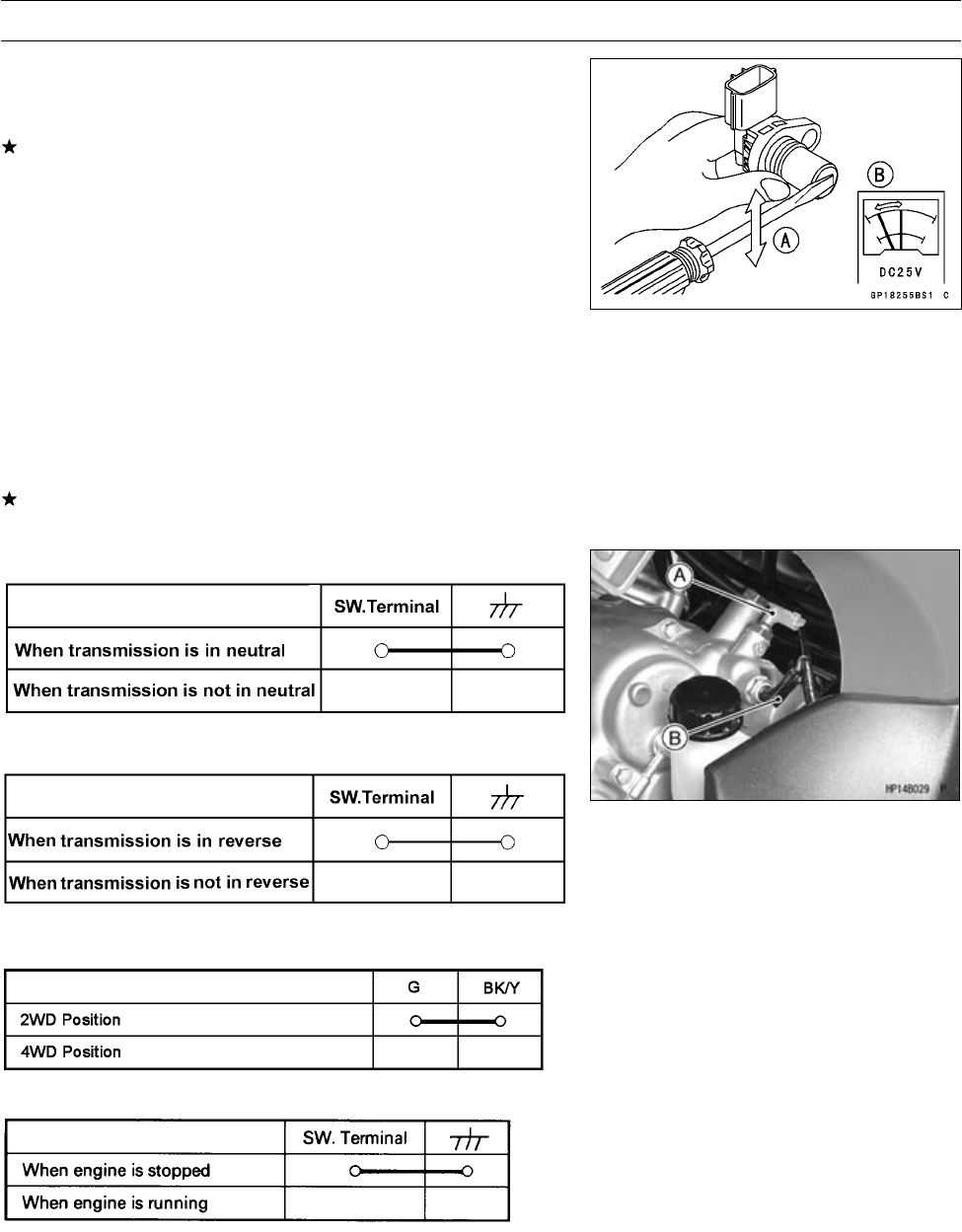
16-84 ELECTRICAL SYSTEM
Switches and Sensor
•Trace [A] each side of the speed sensor surface with the
screw driver.
○Then the tester indicator should flick [B].
If the tester indicator does not flick, replace the speed
sensor.
Switch Inspection
•Using the hand tester, check to see that only the con-
nections shown in the table have continuity (about zero
ohms).
○For the handlebar switches, ignition switch, refer to tables
in the Wiring Diagram.
If the switch has an open or short, repair or replace it with
a new one.
Neutral Switch Connection
[A] Neutral Switch
Reverse Switch Connections
[B] Reverse Switch
2WD/4WD Shift Switch
Oil Pressure Switch Connections*
*: Engine Iubrication system is in good condition
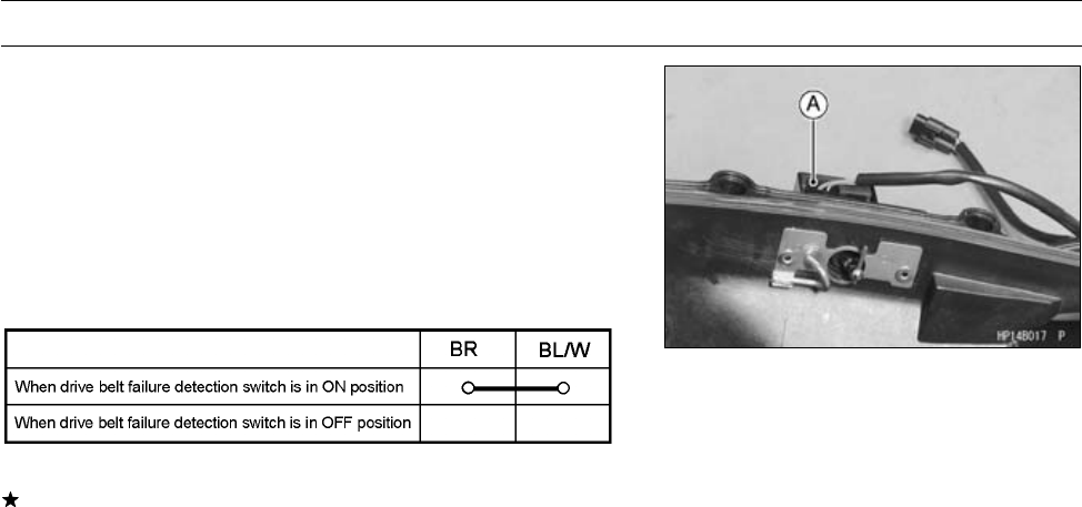
ELECTRICAL SYSTEM 16-85
Switches and Sensor
Drive Belt Failure Detection Switch Inspection
If the drive belt failure detection system is activated by
abnormal belt, the drive belt failure detection switch is dam-
aged. Make sure to replace the torque converter cover (see
Torque Converter Cover Removal/Installation in the Con-
verter System chapter).
•Remove:
Torque Converter Cover (see Torque Converter Cover
Removal in the Converter System chapter)
[A] Drive Belt Failure Detection Switch
If the switch has an open or short, repair or replace it with
a new one.
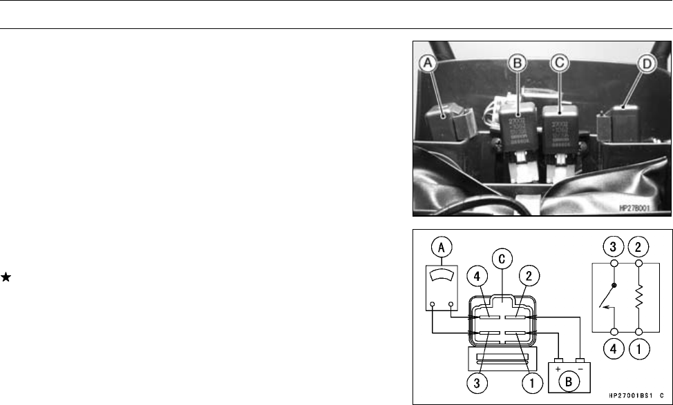
16-86 ELECTRICAL SYSTEM
Relay
Relay Inspection
•Remove:
Seat (see Seat Removal in the Frame chapter)
Starter Control Relay (Neutral) [A]
Radiator Fan Relay [B]
Fuel Pump Relay [C]
Starter Control Relay (Brake) [D]
○The relays are identical.
•Connect the hand tester [A] and a 12 V battery [B] to the
starter circuit relay [C] as shown.
If the relay does not work as specified, the relay is defec-
tive. Replace the relay.
Testing Relay
Hand Tester Range: × 1 Ω
Criteria: When battery is connected ⇒0Ω
When battery is disconnected ⇒∞Ω
Relay Coil Terminals [1] and [2]
Relay Switch Terminals [3] and [4]
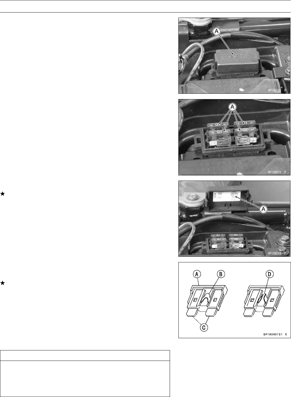
ELECTRICAL SYSTEM 16-87
Fuses
Fuse Removal
•Remove:
Seat (see Seat Removal in the Frame chapter)
Fuse Box Lid [A]
•Pull the fuses [A] straight out of the fuse box with needle
nose pliers.
Fuse Installation
If a fuse fails during operation, inspect the electrical sys-
tem to determine the cause, and then replace it with a
new fuse of proper amperage.
•Install the fuses on the original position as specified on
the fuse box lid [A].
Fuse Inspection
•Inspect the fuse element.
If it is blown out, replace the fuse. Before replacing a
blown fuse, always check the amperage in the affected
circuit. If the amperage is equal to or greater than the
fuse rating, check the wiring and related components for
a short circuit.
Housing [A]
Fuse Element [B]
Terminals [C]
Blown Element [D]
CAUTION
When replacing a fuse, be sure the new fuse
matches the specified fuse rating for that circuit.
Installation of a fuse with a higher rating may cause
damage to wiring and components.

APPENDIX 17-1
17
Appendix
Table of Contents
Troubleshooting Guide ........................................................................................................... 17-2
Cable, Wire, and Hose Routing .............................................................................................. 17-6

17-2 APPENDIX
Troubleshooting Guide
NOTE
○Refer to the Fuel System chapter for most
of DFI trouble shooting guide.
○This is not an exhaustive list, giving every
possible cause for each problem listed. It
is meant simply as a rough guide to assist
the troubleshooting for some of the more
common difficulties.
Engine Doesn’t Start, Starting Difficulty:
Starter motor not rotating:
Neutral switch trouble
Starter motor trouble
Battery voltage low
Relays not contacting or operating
Starter button not contacting
Wiring open or shorted
Ignition switch trouble
Engine stop switch trouble
Fuse blown
Starter motor rotating but engine doesn’t
turn over:
Starter motor clutch trouble
Engine won’t turn over:
Valve seizure
Rocker arm seizure
Cylinder, piston seizure
Crankshaft seizure
Connecting rod small end seizure
Connecting rod big end seizure
Transmission gear or bearing seizure
Camshaft seizure
No fuel flow:
Fuel tank air vent obstructed
Fuel line clogged
Fuel pump damaged or circuit open/short
Engine flooded:
Fuel level too high
Float valve worn or stuck open
Starting technique faulty
(When flooded, crank the engine with the
throttle fully opened to allow more air to
reach the engine.)
Fuel/air mixture incorrect:
Pilot screw and/or idle adjusting screw mal-
adjusted
Air cleaner clogged, poorly sealed, or miss-
ing
No spark; spark weak:
Spark plug dirty, broken, or maladjusted
Spark plug cap or spark plug lead trouble
Spark plug cap not in good contact
Spark plug incorrect
Crankshaft sensor trouble
Ignition coil trouble
Battery voltage low
Ignition or engine stop switch shorted
Wiring shorted or open
Fuse blown
Compression Low:
Spark plug loose
Cylinder head not sufficiently tightened
down
No valve clearance
Cylinder, piston worn
Piston ring bad (worn, weak, broken, or
sticking)
Piston ring/groove clearance excessive
Cylinder head gasket damaged
Cylinder head warped
Valvespringbrokenorweak
Valve not seating properly (valve bent,
worn, or carbon accumulation on the
seating surface)
Compression release (KACR) cam sticks
open (Engine stalls when moving off)
Poor Running at Low Speed:
Spark weak:
Spark plug dirty, broken, or maladjusted
Spark plug cap or spark plug lead trouble
Spark plug cap shorted or not in good con-
tact
Spark plug incorrect
Crankshaft sensor trouble
Ignition coil trouble
Battery voltage low
Fuel/air mixture incorrect:
Pilot screw and/or idle adjusting screw mal-
adjusted
Air cleaner clogged, poorly sealed, or miss-
ing
Fuel level too high or too low
Fuel tank air vent obstructed
Throttle body holder loose
Air cleaner duct loose
Compression low:
Spark plug loose
Cylinder head not sufficiently tightened
down
No valve clearance
Cylinder, piston worn
Piston ring bad (worn, weak, broken, or
sticking)
Piston ring/groove clearance excessive
Cylinder head gasket damaged
Cylinder head warped
Valvespringbrokenorweak
Valve not seating properly (valve bent,
worn, or carbon accumulation on the
seating surface)
Compression release (KACR) cam sticks
open (Engine stalls when moving off)
Other:
Engine oil viscosity too high

APPENDIX 17-3
Troubleshooting Guide
Brake dragging
Front or rear final gear case oil viscosity too
high
Poor Running or No Power at High Speed:
Firing incorrect:
Spark plug dirty, broken, or maladjusted
Spark plug cap or spark plug lead trouble
Spark plug cap shorted or not in good con-
tact
Spark plug incorrect
Crankshaft sensor trouble
Ignition coil trouble
Drive belt failure detection switch activated
Fuel/air mixture incorrect:
Air cleaner clogged, poorly sealed, or miss-
ing
Water or foreign matter in fuel
Throttle body holder loose
Air cleaner duct loose
Fuel tank air vent obstructed
Fuel line clogged
Compression low:
Spark plug loose
Cylinder head not sufficiently tightened
down
No valve clearance
Cylinder, piston worn
Piston rings bad (worn, weak, broken, or
sticking)
Piston ring/groove clearance excessive
Cylinder head gasket damaged
Cylinder head warped
Valve spring broken or weak
Valve not seating properly (valve bent,
worn, or carbon accumulation on the
seating surface.)
Compression release cam (K.A.C.R.) sticks
open (Engine stalls when moving off)
Knocking:
Carbon built up in combustion chamber
Fuel poor quality or incorrect
Spark plug incorrect
Miscellaneous:
Throttle valve won’t fully open
Brake dragging
Overheating
Engine oil level too high
Engine oil viscosity too high
Front or rear final gear case oil viscosity too
high
Overheating:
Firing incorrect:
Spark plug dirty, broken, or maladjusted
Spark plug incorrect
Fuel/air mixture incorrect:
Throttle body holder loose
Air cleaner poorly sealed, or missing
Air cleaner duct loose
Air cleaner clogged
Compression high:
Carbon built up in combustion chamber
Engine load faulty:
Engine oil level too high
Engine oil viscosity too high
Drive train trouble
Brake dragging
Lubrication inadequate:
Engine oil level too low
Engine oil poor quality or incorrect
Front or rear final gear case overheating:
Insufficient oil
Bevel gears maladjusted
LSD clutches in front final gear case malad-
justment
Coolant incorrect:
Coolant level too low
Coolant deteriorated
Thick coolant
Cooling system component incorrect:
Radiator clogged
Thermostat trouble
Radiator cap trouble
Fan motor broken
Fan blade damaged
Water pump not turning
Water pump impeller damaged
Over Cooling:
Cooling system component incorrect:
Thermostat trouble
Converter Operation Faulty:
Belt slipping:
Belt dirty, worn, or wetted
Drive or driven pulley sheave dirty or worn
Drive pulley spring broken or weak
Converter engagement speed too low:
Drive pulley spring broken or weak
Converter engagement speed too high:
Belt dirty or worn
Drive or driven pulley sheave dirty or worn
Drive pulley weight doesn’t move smoothly
Drive pulley movable sheave doesn’t move
smoothly
Drive or driven pulley movable sheave bush
worn
Drive pulley weight or roller worn
Shifting too quickly:
Drive pulley spring weak
Driven pulley spring weak or incorrectly in-
stalled (too loose)
Shifting too slowly:
Belt dirty or worn
Drive or driven pulley sheave dirty or worn
Drive pulley weight doesn’t move smoothly

17-4 APPENDIX
Troubleshooting Guide
Drive pulley movable sheave doesn’t move
smoothly
Drive pulley spring incorrect installed (too
tight)
Driven pulley movable sheave doesn’t
move smoothly
Gear Shifting Faulty:
Doesn’t go into gear:
Shift arm bent or seized
Gear stuck on the shaft
Shift tie-rod maladjusted
Shift tie-rod damaged
Jumps out of gear:
Shifter groove worn
Gear dogs worn
Shift block worn
Shift arm positioning bolt spring weak or
broken
Shift tie-rod maladjusted
Drive shaft, output shaft, and/or gear
splines worn
Overshifts:
Shift arm positioning bolt spring weak or
broken
Shift tie-rod maladjusted
Abnormal Engine Noise:
Knocking:
Carbon built up in combustion chamber
Fuel poor quality or incorrect
Spark plug incorrect
Overheating
Piston Slap:
Cylinder/piston clearance excessive
Cylinder, piston worn
Connecting rod bent
Piston pin, piston holes worn
Valve noise:
Valve clearance incorrect
Valve spring broken or weak
Camshaft bearing worn
Rocker arm worn
Other noise:
Connecting rod small end clearance exces-
sive
Connecting rod big end clearance exces-
sive
Piston ring worn, broken, or stuck
Piston seizure, damage
Cylinder head gasket leaking
Exhaust pipe leaking at cylinder head con-
nection
Crankshaft runout excessive
Engine mounts loose
Crankshaft bearing worn
Camshaft chain tensioner trouble
Camshaft chain, sprocket, guides worn
Loose alternator rotor
Abnormal Drive Train Noise:
Converter noise:
Belt worn
Drive or driven pulley sheave worn
Drive or driven pulley movable sheave bush
worn
Drive or driven pulley mount loose
Driven pulley shoe worn
Drive pulley weight or roller side washer
worn
Drive pulley weight or roller worn
Wear guides worn
Transmission noise:
Bearing worn
Transmission gears worn or chipped
Metal chips jammed in gear teeth
Engine oil insufficient or too thin
Front or rear final gear case noise:
Insufficient lubricant
Incorrect oil (Front final gear case)
Bevel gear bearings worn
Bevel gears worn or chipped
Bevel gears maladjusted
Worn LSD clutch friction plate (Front final
gear case)
Thrust plug maladjusted (Rear final gear
case)
Damaged side gears or pinions (Front final
gear case)
Abnormal Frame Noise:
Shock absorber noise:
Shock absorber damaged
Disc brake noise:
Pad installed incorrectly
Pad surface glazed
Disc warped
Caliper trouble
Rear brake noise:
Foreign matter in hub
Brake not properly adjusted
Other noise:
Bracket, nut bolt, etc. not properly mounted
or tightened
Exhaust Smokes Excessively:
White smoke:
Piston oil ring worn
Cylinder worn
Valve oil seal damaged
Valve guide worn
Cylinder head gasket damaged
Engine oil level too high
Black Smoke:
Air cleaner clogged
Brown smoke:
Air cleaner duct loose
Air cleaner poorly sealed or missing

APPENDIX 17-5
Troubleshooting Guide
Handling and/or Stability Unsatisfactory
Handlebar hard to turn:
Tire air pressure too low
Steering stem bearing damaged
Steering stem bearing lubrication inade-
quate
Steering stem bent
Damaged steering knuckle joint
Damage tie-rod end
LSD clutch maladjusted (front final gear
case)
Noise when turning:
Damaged side gear or pinion (front final
gear case)
Worn LSD clutch friction plates (Front final
gear case)
Handlebar shakes or excessively vibrates:
Tire worn
Wheel rim warped
Rear axle runout excessive
Wheel bearing worn
Handlebar clamp loose
Steering stem clamp bolt loose
Handlebar pulls to one side:
Frame bent
Wheel maladjustment
Suspension arm bent or twisted
Steering stem bent
Front or rear tire air pressure unbalanced
Front shock absorber unbalanced
Shock absorption unsatisfactory:
Too hard:
Tire air pressure too high
Shock absorber maladjusted
Too soft:
Shock absorber oil leaking
Shock absorber spring weak
Tire air pressure too low
Shock absorber maladjusted
Brake Doesn’t Hold
Front brake:
Air in the brake line
Brake fluid leakage
Brake fluid deteriorated
Primary or secondary cup trouble
Master cylinder scratched inside
Pad overworn or worn unevenly
Oil, grease on pads and disc
Disc worn or warped
Brake overheated
Rear Brake:
Brake not properly adjusted
Plates worn
Brake parts worn or damaged
Kawasaki Engine Brake Control and
Selectable 2WD/4WD System Malfunction:
Actuators failed
Speed sensor short or open
Forward/Reverse detecting sensor short or
open
Actuator controller failed
Controller 10A fuse blown
Battery disconnected
Battery Discharged:
Battery faulty (e.g., plates sulphated,
shorted through sedimentation, elec-
trolyte level too low)
Battery leads making poor contact
Load excessive (e.g., bulb of excessive
wattage)
Ignition switch trouble
Regulator/rectifier trouble
Alternator trouble
Wiring faulty
Battery Overcharged:
Regulator/rectifier trouble
Battery trouble
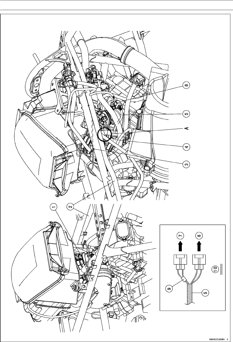
17-6 APPENDIX
Cable, Wire, and Hose Routing

APPENDIX 17-7
Cable, Wire, and Hose Routing
1. Band
2. Main Harness
3. Clamp
4. To Fuel Injectors and Throttle Sensor
5. Fuel Injector Throttle Sensor Subharness
6. Fuel Injector Throttle Sensor Subharness Connector (Clamp the connector to the bracket of the
cylinder head.)
7. To Fuel Injector #1
8. To Fuel Injector #2
9. White Tape
10. Detail A
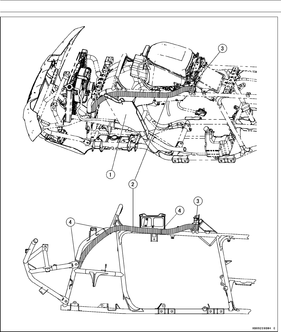
17-8 APPENDIX
Cable, Wire, and Hose Routing
1. Front Fender Inner Cover
2. Tube (for Winch Harness)
3. Band (Pass the band through the hole of the frame bracket.)
4. Bands
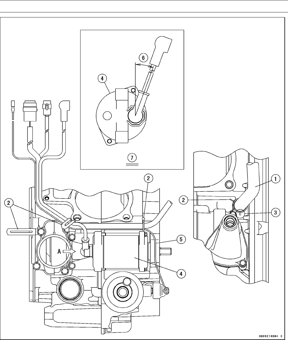
APPENDIX 17-9
Cable, Wire, and Hose Routing
1. Engine Breather Hose
2. Clamps (Install the clamps direction as shown.)
3. Align the white paint of the breather hose with the projection of the crankcase.
4. Starter Motor
5. Run the oil pressure switch lead so that it does not touch the starter motor.
6. About 20°
7. View A
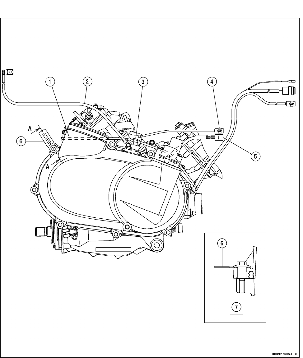
17-10 APPENDIX
Cable, Wire, and Hose Routing
1. Starter Motor Cable
2. Engine Ground Lead (Install the lead so that the flat side of the lower terminal faces toward the
engine.)
3. Install the clamp on the engine ground lead terminal.
4. Drive Belt Failure Detecting Switch Lead Connector
5. Engine Brake Actuator Lead Connector
6. Clamp
7. Section A-A
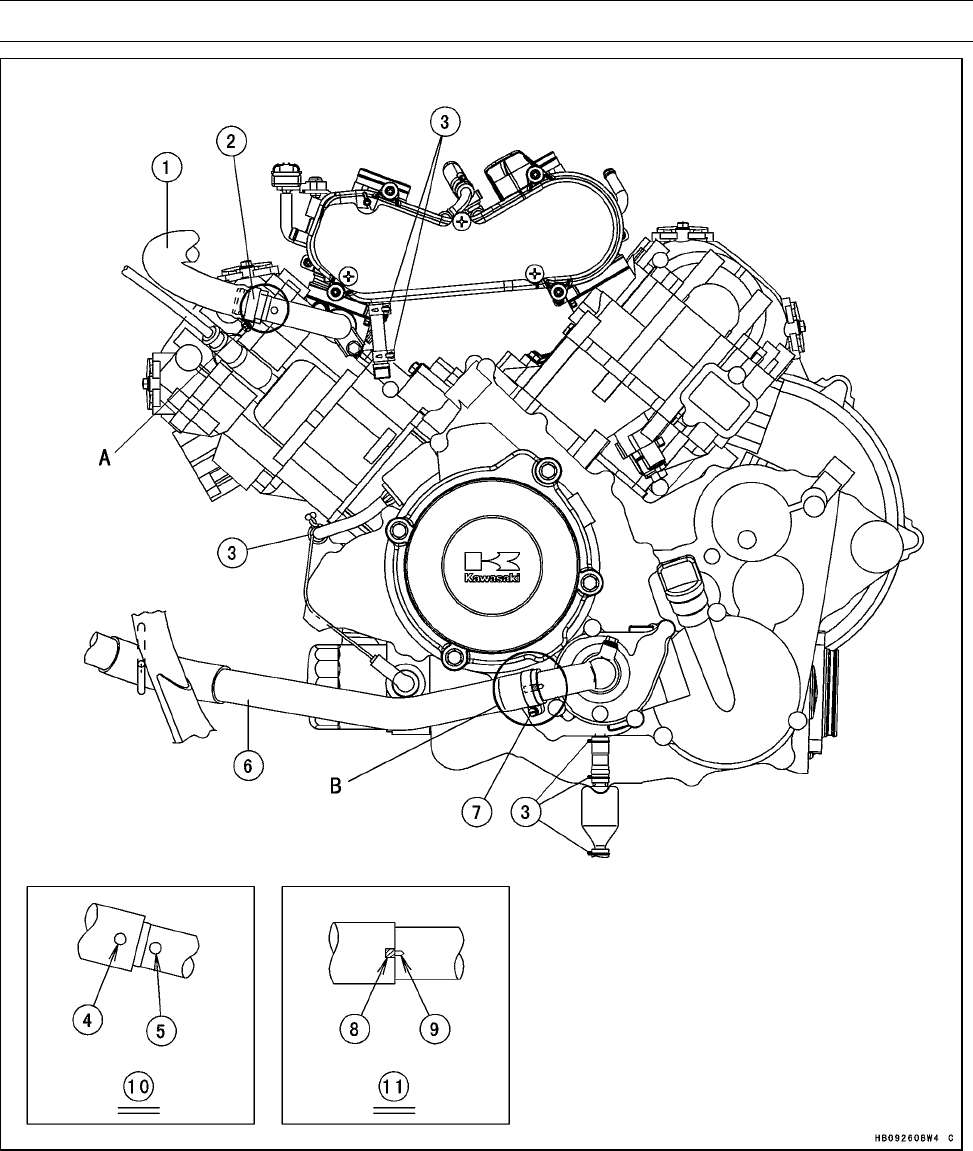
APPENDIX 17-11
Cable, Wire, and Hose Routing
1. Water Hose (Thermostat Housing ∼Front Cylinder Head)
2. Water Hose Clamp
3. Clamps
4. White Paint of Water Hose
5. White Paint of Water Pipe
6. Radiator Hose (Radiator ∼Water Pump)
7. Radiator Hose Clamp
8. White Paint of Radiator Hose
9. Projection of Water Pump Cover
10. Detail A
11. Detail B
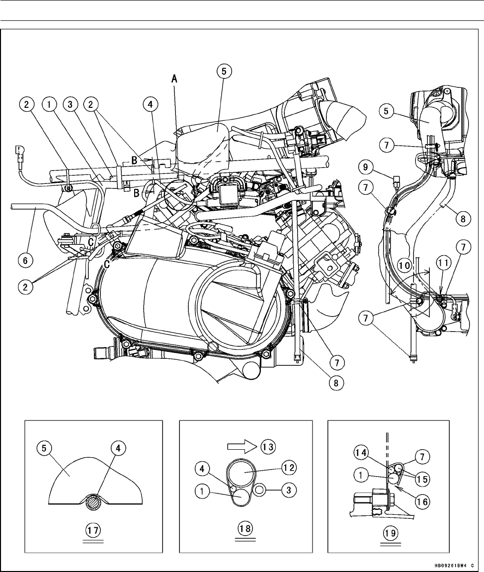
17-12 APPENDIX
Cable, Wire, and Hose Routing
1. Main Harness
2. Bands
3. Rear Final Gear Case Vent Hose
4. Spark Plug Lead of Rear Ignition Coil
(Run the spark plug lead along the con-
cave of the exhaust duct.)
5. Torque Converter Exhaust Duct
6. Fuel Hose
7. Clamp
8. Drain Hose
9. 2WD/4WD Actuator Connector
10. 60°
11. Install the clamp so that it do not touch
the harness. Set the position of the clamp
within 60°.
12. Frame Pipe
13. Outside of Vehicle
14. Starter Motor Cable
15. Engine Ground Lead
16. Bend the clamp so that this position do
not touch.
17. Detail A
18. Section B-B
19. Section C-C
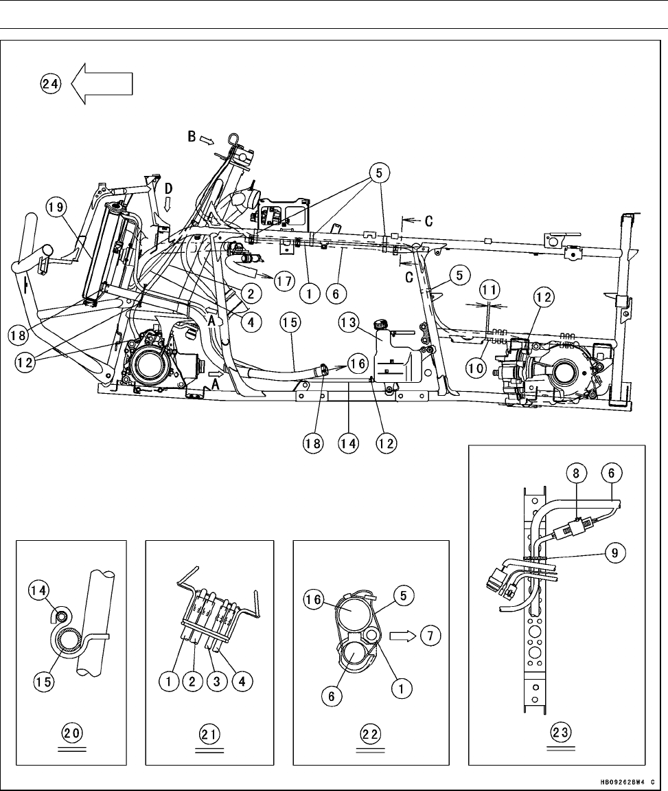
APPENDIX 17-13
Cable, Wire, and Hose Routing
1. Rear Final Gear Case Vent Hose
2. Front Final Gear Case Vent Hose
3. Vacuum Hose
4. Radiator Fan Motor Vent Hose
5. Bands
6. Main Harness
7. Outside of Vehicle
8. Radiator Fan Motor Connector
9. Band (Clamp the main harness and radi-
ator fan motor lead.)
10. Band (Clamp the rear final gear case vent
hose to the right side of the frame.)
11. About 5 mm (0.20 in.)
12. Clamps
13. Reserve Tank
14. Reserve Tank Hose
15. Radiator Hose
16. To Water Pump
17. To Front Cylinder Head
18. Radiator Hose Clamps
19. Radiator
20. View A
21. View B
22. Section C-C
23. View D
24. Front
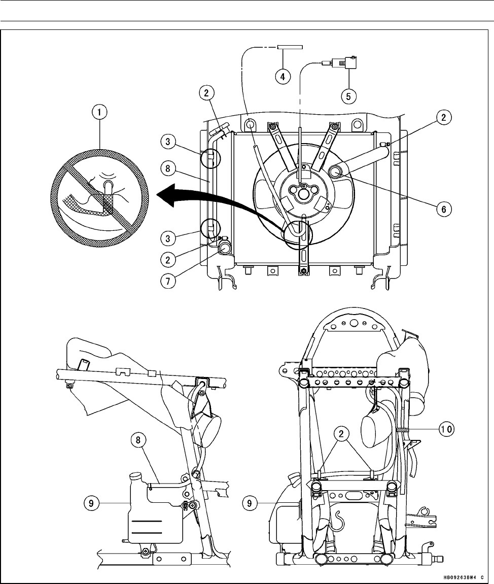
17-14 APPENDIX
Cable, Wire, and Hose Routing
1. Do not crush the radiator fan motor vent hose to pull it.
2. Clamps
3. Clamp the reserve tank hose to the radiator cover.
4. Radiator Fan Motor Vent Hose
5. Radiator Fan Motor Connector
6. To Thermostat Housing
7. To Water Pump
8. Reserve Tank Hose
9. Reserve Tank
10. Band (Clamp the reserve tank hose and rear final gear case vent hose.)
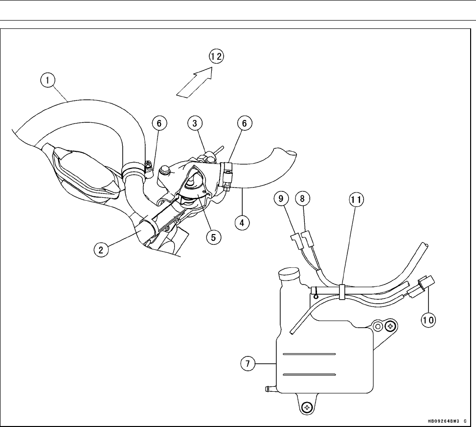
APPENDIX 17-15
Cable, Wire, and Hose Routing
1. Water Hose (Thermostat Housing ∼Front Cylinder Head)
2. Water Pipe (Thermostat Housing ∼Rear Cylinder Head)
3. Water Temperature Sensor
4. Radiator Hose (Thermostat Housing ∼Radiator)
5. Thermostat
6. Clamps
7. Reserve Tank
8. Reverse Switch Lead Connector (R/W Lead)
9. Neutral Switch Lead Connector (LG Lead)
10. Forward/Reverse Detecting Sensor Lead Connector
11. Band
12. Front
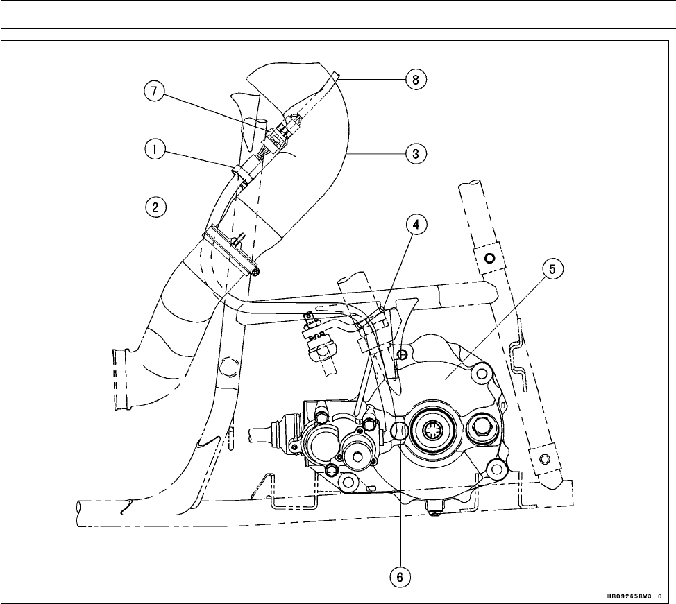
17-16 APPENDIX
Cable, Wire, and Hose Routing
1. Clamp
2. 2WD/4WD Actuator Lead
3. Air Intake Duct
4. Band
5. Front Final Gear Case
6. Run the 2WD/4WD actuator lead so that it do not touch the front final gear case.
7. 2WD/4WD Actuator Lead Connector (Apply grease all around on the top surface of connector
to be waterproof.)
8. Main Harness
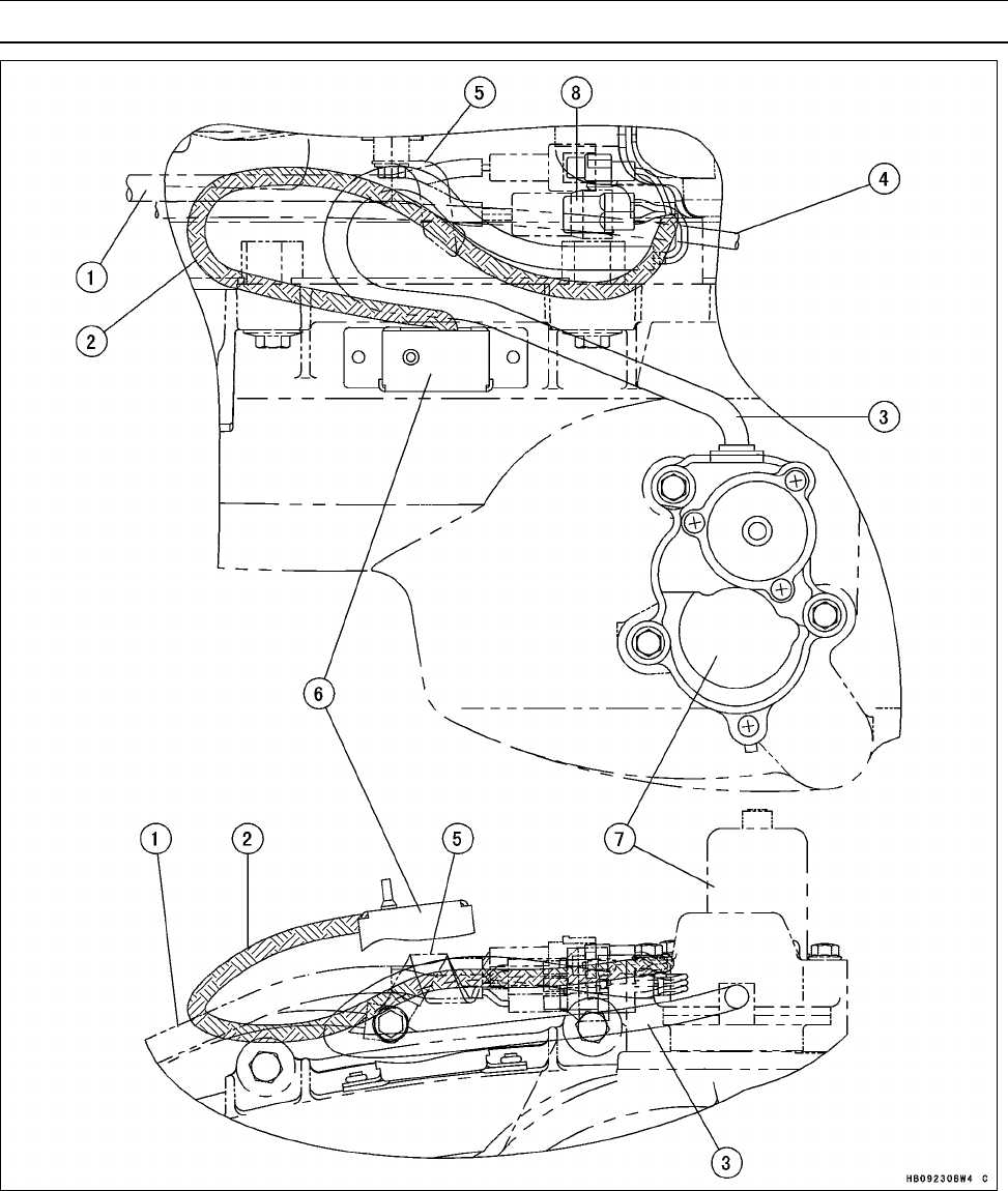
APPENDIX 17-17
Cable, Wire, and Hose Routing
1. Main Harness
2. Drive Belt Failure Detecting Switch Lead
3. Engine Brake Actuator Lead
4. Starter Motor Cable
5. Clamp
6. Drive Belt Failure Detecting Switch
7. Engine Brake Actuator
8. Engine Brake Actuator Lead Connector (Apply grease all around on the top surface of connector
to be waterproof.)
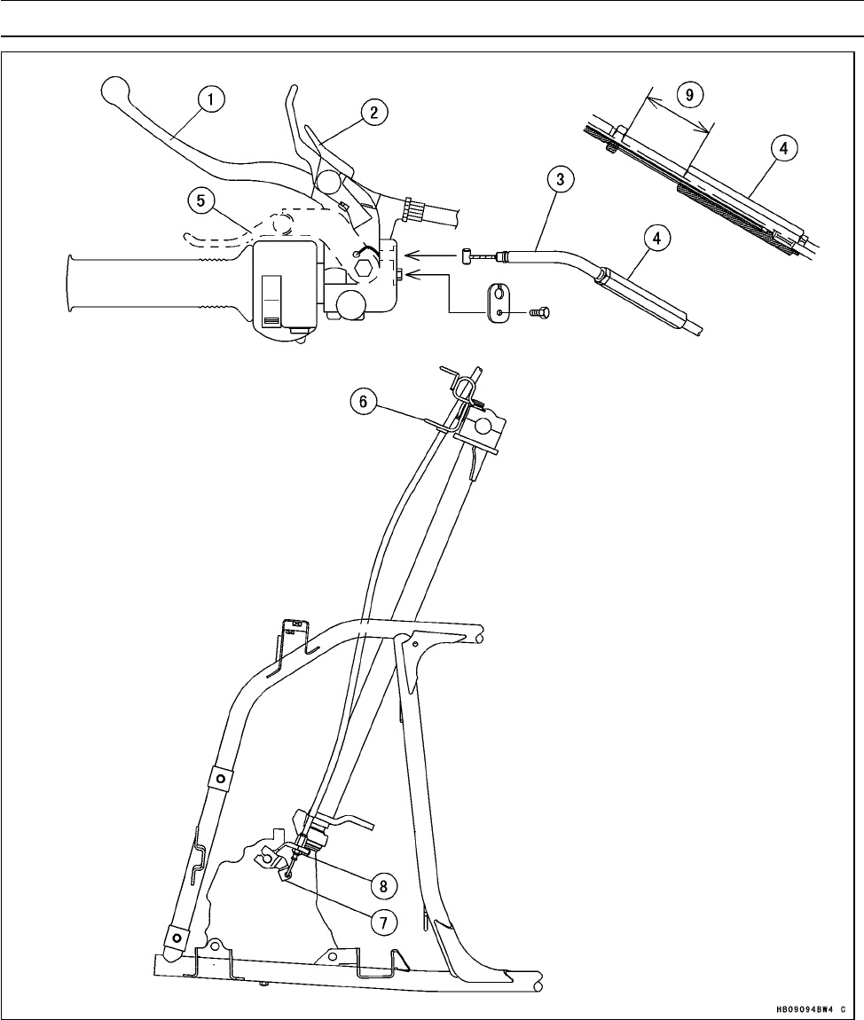
17-18 APPENDIX
Cable, Wire, and Hose Routing
1. Rear Brake Lever
2. Parking Brake Lock Lever
3. Variable Differential Control Cable
4. Cable Adjuster
5. Variable Differential Control Lever
6. Handle Holder Clamp
7. Variable Differential Operating Lever
8. Fit the dust cap.
9. 27 ∼35 mm (1.1 ∼1.4 in.)
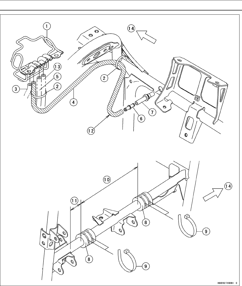
APPENDIX 17-19
Cable, Wire, and Hose Routing
1. Clamp
2. Bands
3. Radiator Fan Motor Vent Hose
4. Vacuum Hose
5. Front Final Gear Case Vent Hose
6. Fitting
7. Tube
8. Dampers
9. Bands
10. 220 mm (8.66 in.)
11. 60 mm (2.36 in.)
12. “L” Formed Side
13. Rear Final Gear Case Vent Hose
14. Front
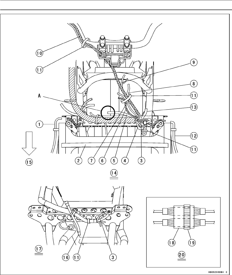
17-20 APPENDIX
Cable, Wire, and Hose Routing
1. Right Headlight Lead
2. Radiator Cover
3. Frame Ground Lead
4. Horn Switch Lead (Australia and Europe
Models)
5. Alternator Lead
6. Rear Brake Light Switch Lead
7. 2WD/4WD Shift Switch Lead
8. Left Handlebar Switch Lead
9. Meter Unit Lead
10. Front Brake Light Switch Lead
11. Bands
12. Left Headlight Lead
13. Front Ignition Coil Primary Lead (Run the
primary lead under the frame.)
14. Top View
15. Front
16. Radiator Fan Motor Lead
17. Front View
18. Alternator Lead Connector
19. Band
20. Detail A
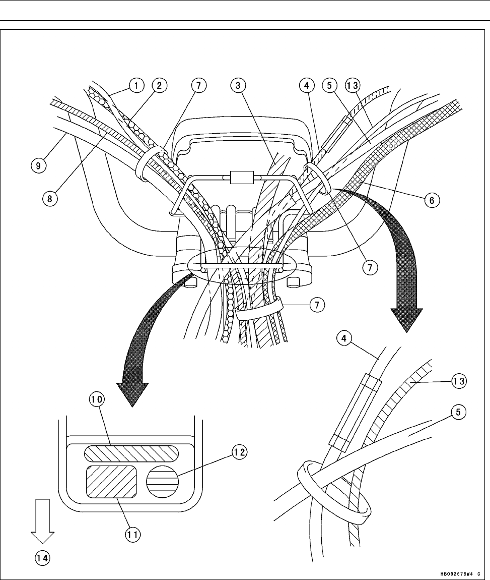
APPENDIX 17-21
Cable, Wire, and Hose Routing
1. Right Handlebar Switch Lead
2. Throttle Cable
3. Meter Unit Lead
4. Variable Differential Control Cable
5. Parking Brake Cable
6. Left Handlebar Switch Lead
7. Bands
8. Front Brake Light Switch Lead
9. Brake Hose
10. Hoses
11. Cables and Brake Hose
12. Leads
13. Rear Brake Light Switch Lead
14. Front
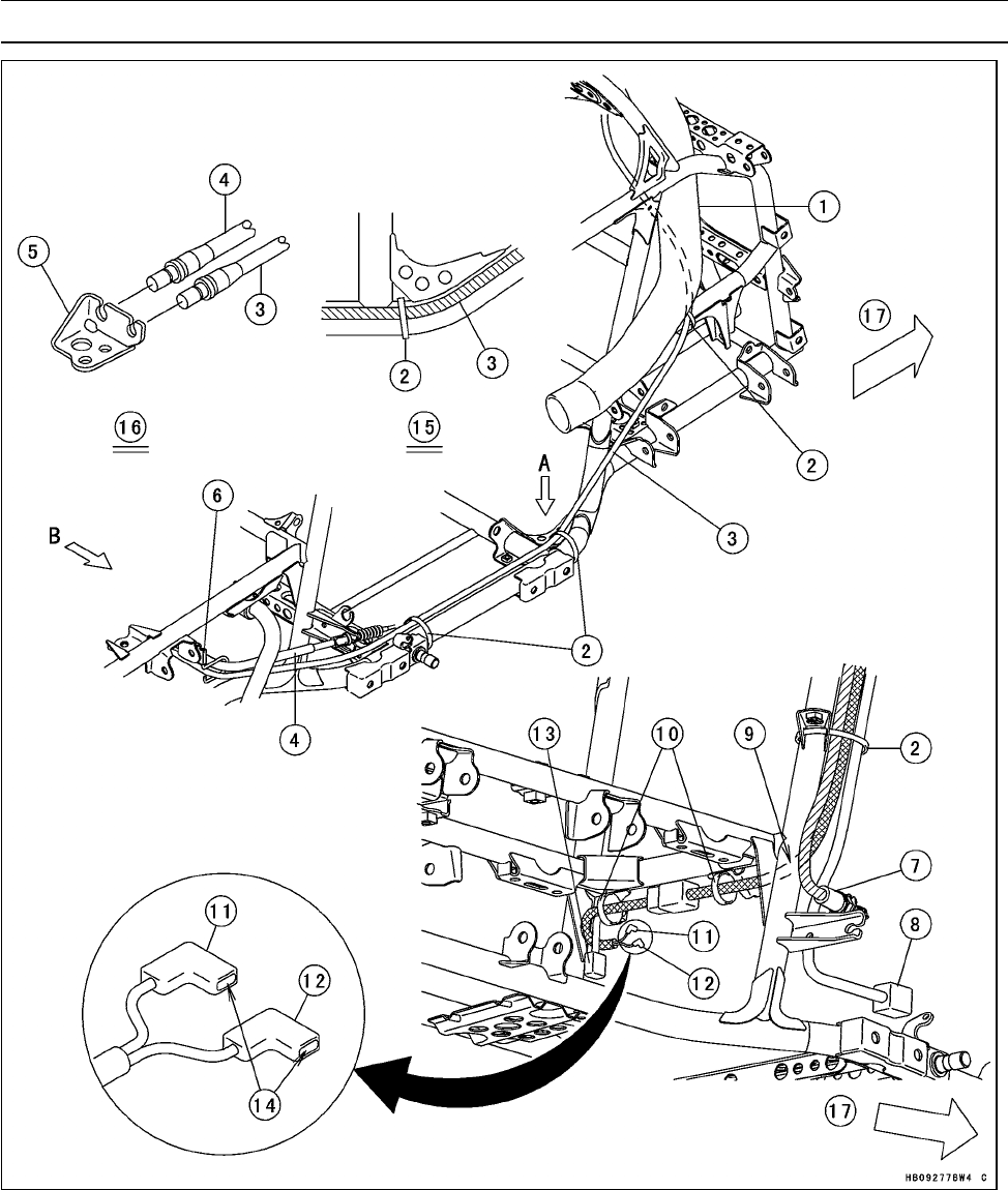
17-22 APPENDIX
Cable, Wire, and Hose Routing
1. Air Intake Duct
2. Bands
3. Parking Brake Cable
4. Rear Brake Cable
5. Bracket
6. Clamp
7. Rear Brake Light Switch
8. Speed Sensor Lead Connector
9. Run the lead front side of frame pipe.
10. Clamps
11. Reverse Switch Lead Connector (BK
Lead)
12. Neutral Switch Lead Connector (W Lead)
13. Forward/Reverse Detecting Sensor Lead
Connector
14. Apply grease (Amoco Rykon Premium
Grease No.2 EP Green)
15. View A
16. View B
17. Front
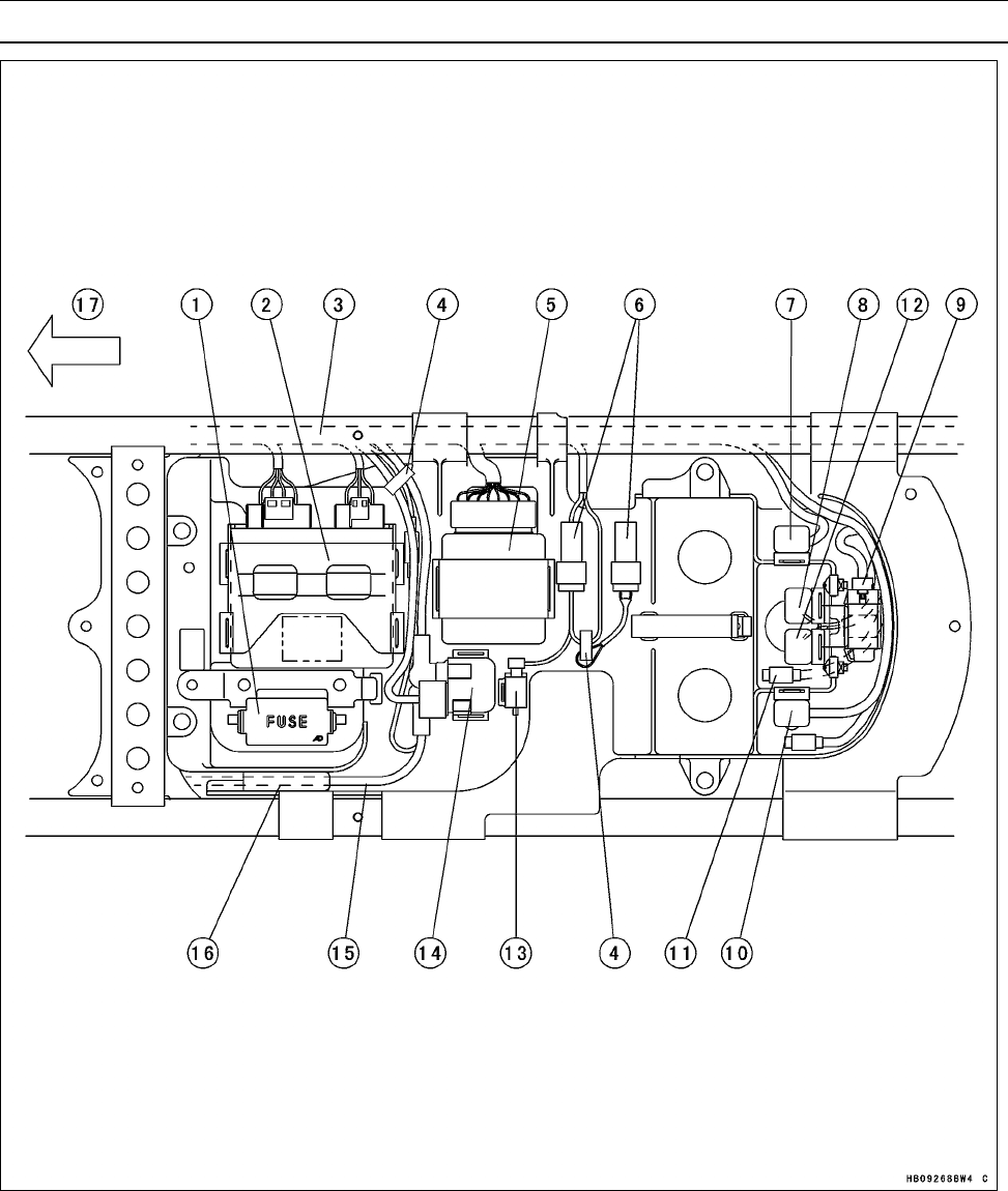
APPENDIX 17-23
Cable, Wire, and Hose Routing
1. Fuse Box
2. ECU
3. Main Harness (Run the main harness un-
der the frame pipe.)
4. Clamps
5. Actuator Controller
6. Reset Connectors (Clamp the connector
to the electrical parts case.)
7. Starter Control Relay (Neutral)
8. Radiator Fan Relay
9. Vehicle-down Sensor
10. Starter Control Relay (Brake)
11. Kawasaki Diagnostic System Connector
(Connector of Gray)
12. Fuel Pump Relay
13. Radiator Fan Breaker
14. Starter Relay
15. Battery (+) Cable
16. Run the battery (+) cable under the elec-
trical parts case.
17. Front
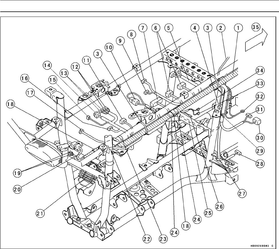
17-24 APPENDIX
Cable, Wire, and Hose Routing
1. Main Harness (Run the main harness un-
der the frame pipe.)
2. Battery (–) Cable
3. Bands
4. To Rear Brake Light Switch
5. To Fuse Box
6. To ECU
7. To Actuator Controller
8. To Starter Circuit Relay
9. To Battery (–) Cable
10. Reset Connector
11. Fuel Pump Lead Connector
12. To Radiator Fan Relay and Fuel Pump
Relay
13. Kawasaki Diagnostic System Connector
14. To Starter Control Relay (Brake)
15. To Vehicle-down Sensor
16. To Starter Control Relay (Neutral)
17. Accessory Connector
18. Clamps
19. To Reverse Light (Europe Model)
20. Tail/Brake Light Lead
21. Regulator/Rectifier
22. Run the regulator/rectifier lead to the in-
side of the frame pipe.
23. Band (Clamp the accessory lead.)
24. White Tapes
25. Run the lead under the frame pipe.
26. Forward/Reverse Detecting Sensor Lead
Connector
27. Clamp (Insert the clamp into the hole of
the frame.)
28. To Speed Sensor
29. Band (Pass the band through the hole of
the frame bracket.)
30. To Engine Brake Actuator
31. To Drive Belt Failure Detecting Switch
32. Engine Ground Terminal
33. Neutral Switch Lead Connector (LG
Lead)
34. Reverse Switch Lead Connector (R/W
Lead)
35. Front
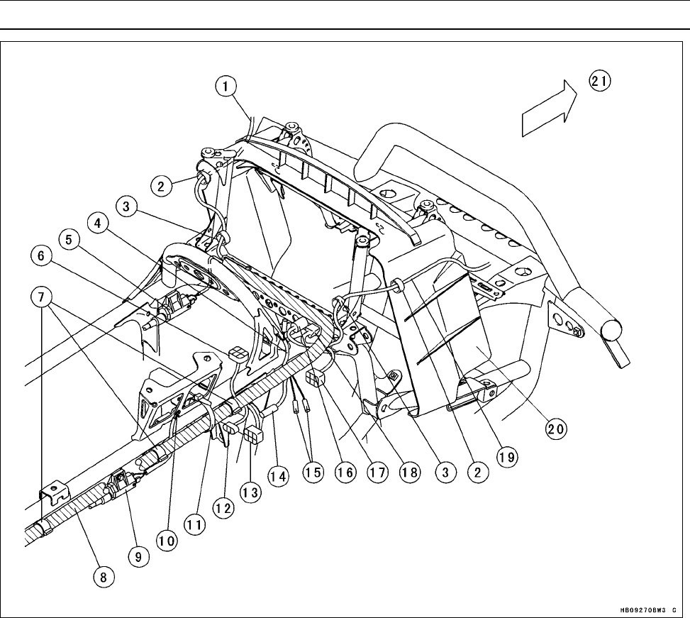
APPENDIX 17-25
Cable, Wire, and Hose Routing
1. To Left Headlight Lead
2. Clamps (Insert the clamp into the hole of
the radiator cover.)
3. Clamps
4. To Power Outlet Connector
5. Front Ignition Coil
6. To ISC Valve
7. Clamps
8. Main Harness (Run the main harness un-
der the frame pipe.)
9. Rear Ignition Coil
10. Frame Ground Terminal
11. Band
12. To Inlet Air Pressure Sensor
13. To Fuel Injector Throttle Sensor Subhar-
ness Connector
14. To Water Temperature Sensor
15. Accessory Connector
16. To Radiator Fan Motor
17. To 2WD/4WD Actuator
18. To Ignition Switch
19. To Right Headlight Lead
20. Radiator Cover
21. Front
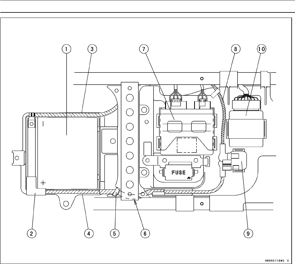
17-26 APPENDIX
Cable, Wire, and Hose Routing
1. Battery
2. Red Cap
3. Battery (–) Cable
4. Battery (+) Cable
5. Clamp (Insert the clamp into the hole of the frame from inside.)
6. Run the battery (+) cable under the frame.
7. ECU
8. Starter Motor Cable
9. Starter Relay
10. Actuator Controller
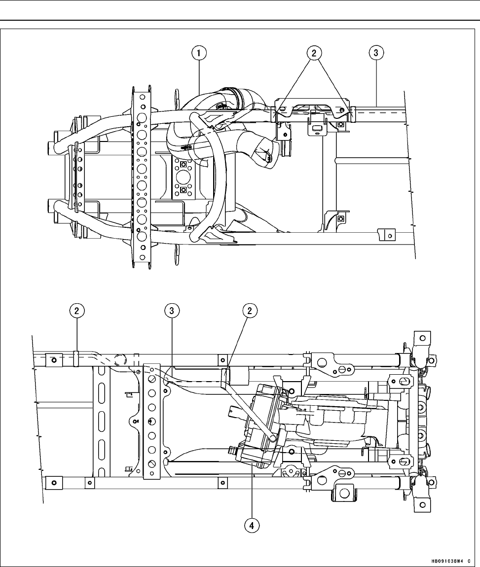
APPENDIX 17-27
Cable, Wire, and Hose Routing
1. Air Intake Duct
2. Bands
3. Rear Final Gear Case Vent Hose
4. Rear Final Gear Case
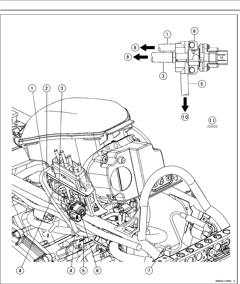
17-28 APPENDIX
Cable, Wire, and Hose Routing
1. ISC Valve Tube (Rear)
2. Tube
3. ISC Valve Tube (Primary)
4. Clamps
5. ISC Valve Tube (Front)
6. ISC Valve
7. Run the spark plug lead of the front ignition coil to the guide of the frame.
8. To Throttle Body #2
9. To Air Cleaner Housing
10. To Throttle Body #1
11. View A
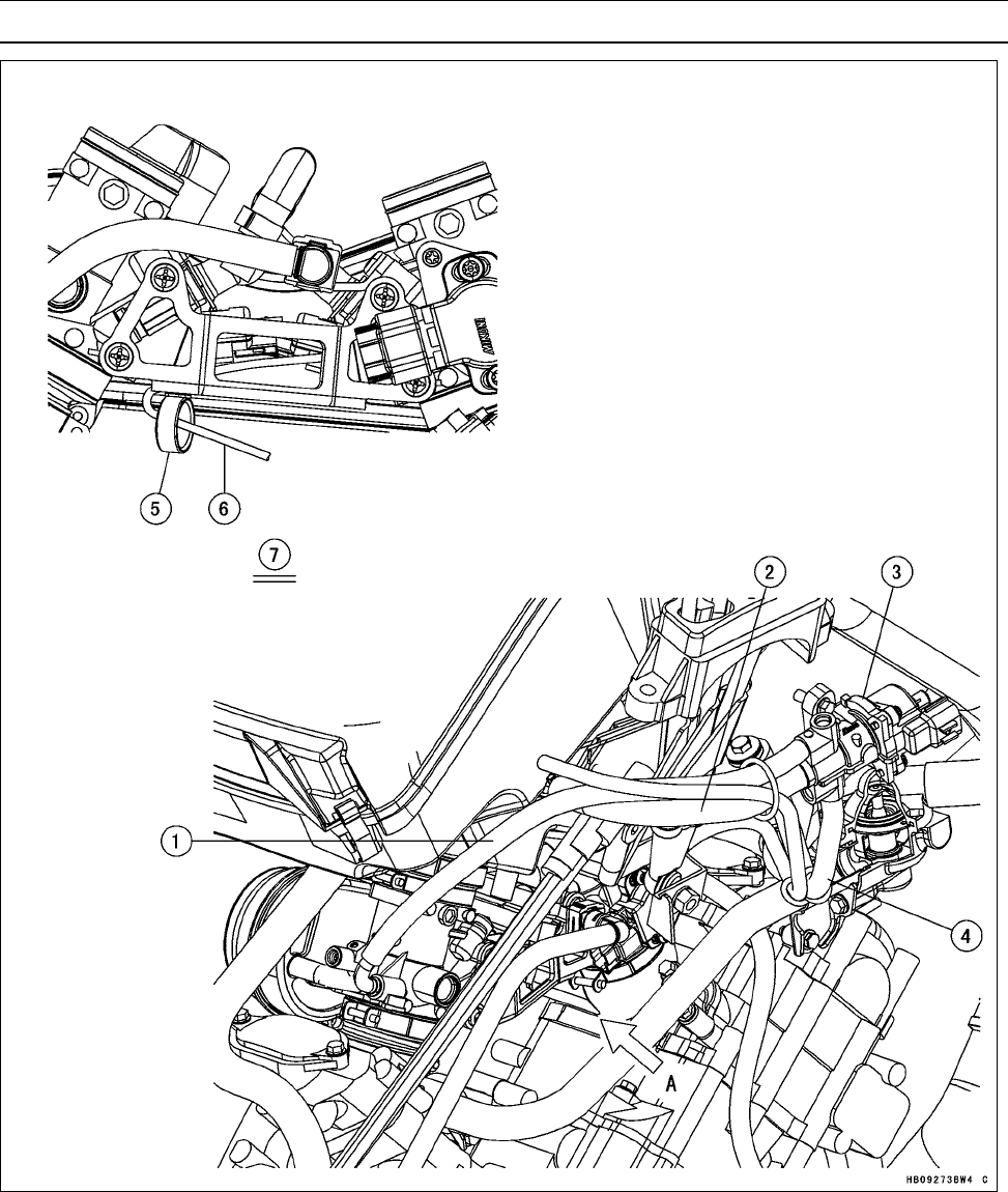
APPENDIX 17-29
Cable, Wire, and Hose Routing
1. ISC Valve Tube (Rear)
2. ISC Valve Tube (Primary)
3. ISC Valve
4. ISC Valve Tube (Front)
5. Clamp
6. Fuel Injector/Throttle Sensor Subharness
7. View A

MODEL APPLICATION
Year Model Beginning Frame No.
2008 KVF750D8F JKAVFDD1□8B500001 or
JKAVF750DDB600001
2008 KVF750E8F JKAVFDE1□8B500001
2008 KVF750E8FA JKAVFDE1□8B500001
2008 KVF750F8F JKAVFDF1□8B500001
□:This digit in the frame number changes from one machine to another.
Part No.99924-1394-01 Printed in Japan
