4D3 28197 10 2008 Yamaha Raptor 250 Sevice Manual
User Manual: 2008 Yamaha Raptor 250 Sevice Manual
Open the PDF directly: View PDF ![]() .
.
Page Count: 311 [warning: Documents this large are best viewed by clicking the View PDF Link!]
SERVICE MANUAL
YFM250RX
4D3-28197-10LIT-11616-21-22
2008

YFM250RX
SERVICE MANUAL
© 2007 by Yamaha Motor
Corporation, U.S.A.
First Edition, July 2007
All rights reserved.
Any reproduction or unauthorized use
without the written permission of
Yamaha Motor Corporation, U.S.A.
is expressly prohibited.
Printed in U.S.A
LIT-11616-21-22
EBS00001

EBS00002
NOTICE
This manual was produced by the Yamaha Motor Company primarily for use by Yamaha dealers and
their qualified mechanics. It is not possible to include all the knowledge of a mechanic in one man-
ual, so it is assumed that anyone who uses this book to perform maintenance and repairs on
Yamaha machine has a basic understanding of the mechanical ideas and the procedures of
machine repair. Repairs attempted by anyone without this knowledge are likely to render the
machine unsafe and unfit for use.
Yamaha Motor Company, Ltd. is continually striving to improve all its models. Modifications and sig-
nificant changes in specifications or procedures will be forwarded to all authorized Yamaha dealers
and will appear in future editions of this manual where applicable.
N
O
TE:
Designs and specifications are subject to change without notice.
EBS00003
IMPORTANT INFORMATION
Particularly important information is distinguished in this manual by the following notations.
The Safety Alert Symbol means ATTENTION! BECOME ALERT! YOUR
SAFETY IS INVOLVED!
Failure to follow WARNING instructions could result in severe injury or death
to the machine operator, a bystander or a person checking or repairing the
machine.
A CAUTION indicates special precautions that must be taken to avoid dam-
age to the machine.
A NOTE provides key information to make procedures easier or clearer.
WARNING
CAUTION:
NOTE:
EBS00004
HOW TO USE THIS MANUAL
MANUAL ORGANIZATION
This manual consists of chapters for the main categories of subjects. (See “symbols”)
1st title : This is the title of the chapter with its symbol in the upper right corner of each page.
2nd title : This title indicates the section of the chapter and only appears on the first page of each
section. It is located in the upper left corner of the page.
3rd title : This title indicates a sub-section that is followed by step-by-step procedures accompa-
nied by corresponding illustrations.
EXPLODED DIAGRAMS
To help identify parts and clarify procedure steps, there are exploded diagrams at the start of each
removal and disassembly section.
1. An easy-to-see exploded diagram is provided for removal and disassembly jobs.
2. Numbers are given in the order of the jobs in the exploded diagram. A number that is enclosed
by a circle indicates a disassembly step.
3. An explanation of jobs and notes is presented in an easy-to-read way by the use of symbol marks
. The meanings of the symbol marks are given on the next page.
4. A job instruction chart accompanies the exploded diagram, providing the order of jobs, names
of parts, notes in jobs, etc.
5. For jobs requiring more information, the step-by-step format supplements are given in addition
to the exploded diagram and the job instruction chart.
GEN
INFO
CHAS
EBS00006
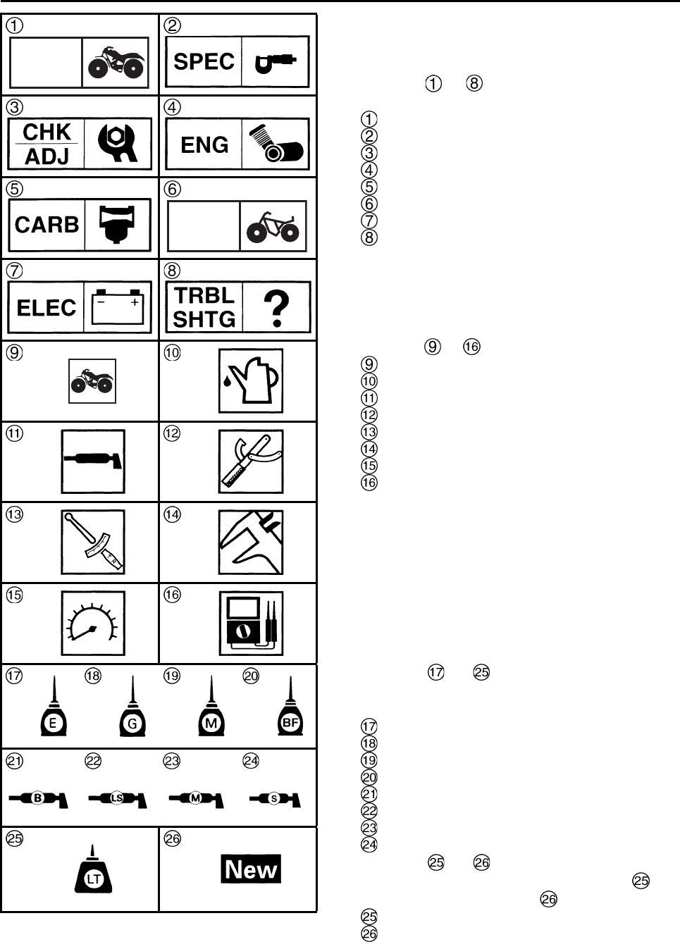
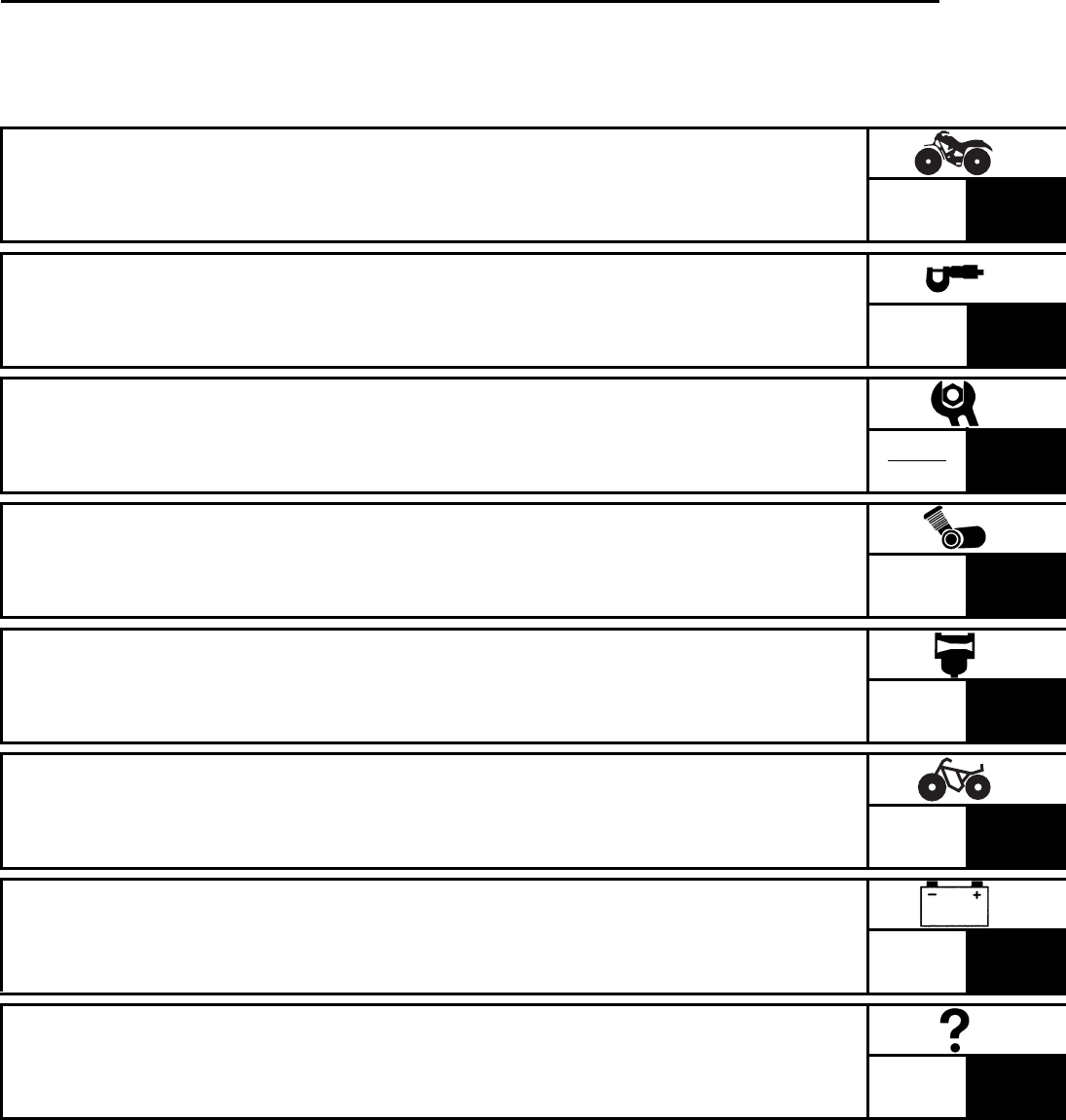
SYMBOLS
The following symbols are not relevant to every
machine.
Symbols to indicate the subject of each
chapter.
General information
Specifications
Periodic checks and adjustments
Engine
Carburetor
Chassis
Electrical
Troubleshooting
Symbols to indicate the following
Serviceable with engine mounted
Filling fluid
Lubricant
Special tool
Torque
Wear limit, clearance
Engine speed
Electrical data (Ω, V, A)
Symbols to in the exploded diagrams
indicate the types of lubricants and lubrication
points.
Apply engine oil
Apply gear oil
Apply molybdenum disulfide oil
Apply brake fluid
Apply wheel bearing grease
Apply lithium-soap-based grease
Apply molybdenum disulfide grease
Apply silicone grease
Symbols to in the exploded diagrams
indicate where to apply a locking agent and
when to install a new part .
Apply the locking agent (LOCTITE®)
Replace

EBS00008 TABLE OF CONTENTS
GENERAL INFORMATION GEN
INFO 1
SPECIFICATIONS SPEC 2
PERIODIC CHECKS AND
ADJUSTMENTS CHK
ADJ 3
ENGINE ENG 4
CARBURETOR CARB 5
CHASSIS CHAS 6
ELECTRICAL ELEC 7
TROUBLESHOOTING TRBL
SHTG 8

CHAPTER 1
GENERAL INFORMATION
MACHINE IDENTIFICATION . . . . . . . . . . . . . . . . . . . . . . . . . . . . . . . . . . 1-1
VEHICLE IDENTIFICATION NUMBER. . . . . . . . . . . . . . . . . . . . . . . . 1-1
MODEL LABEL . . . . . . . . . . . . . . . . . . . . . . . . . . . . . . . . . . . . . . . . . . 1-1
IMPORTANT INFORMATION . . . . . . . . . . . . . . . . . . . . . . . . . . . . . . . . . 1-2
PREPARATION FOR REMOVAL AND DISASSEMBLY . . . . . . . . . . 1-2
REPLACEMENT PARTS . . . . . . . . . . . . . . . . . . . . . . . . . . . . . . . . . . 1-2
GASKETS, OIL SEALS AND O-RINGS . . . . . . . . . . . . . . . . . . . . . . . 1-2
LOCK WASHERS/PLATES AND COTTER PINS . . . . . . . . . . . . . . . 1-2
BEARINGS AND OIL SEALS . . . . . . . . . . . . . . . . . . . . . . . . . . . . . . . 1-3
CIRCLIPS . . . . . . . . . . . . . . . . . . . . . . . . . . . . . . . . . . . . . . . . . . . . . . 1-3
CHECKING THE CONNECTIONS . . . . . . . . . . . . . . . . . . . . . . . . . . . 1-4
SPECIAL TOOLS. . . . . . . . . . . . . . . . . . . . . . . . . . . . . . . . . . . . . . . . . . . 1-5
CHAPTER 2
SPECIFICATIONS
GENERAL SPECIFICATIONS. . . . . . . . . . . . . . . . . . . . . . . . . . . . . . . . . 2-1
ENGINE SPECIFICATIONS. . . . . . . . . . . . . . . . . . . . . . . . . . . . . . . . . . . 2-4
CHASSIS SPECIFICATIONS. . . . . . . . . . . . . . . . . . . . . . . . . . . . . . . . . . 2-11
ELECTRICAL SPECIFICATIONS . . . . . . . . . . . . . . . . . . . . . . . . . . . . . . 2-13
TIGHTENING TORQUES. . . . . . . . . . . . . . . . . . . . . . . . . . . . . . . . . . . . . 2-15
ENGINE TIGHTENING TORQUES . . . . . . . . . . . . . . . . . . . . . . . . . . 2-15
CHASSIS TIGHTENING TORQUES . . . . . . . . . . . . . . . . . . . . . . . . . 2-17
HOW TO USE THE CONVERSION TABLE . . . . . . . . . . . . . . . . . . . . . . 2-19
GENERAL TIGHTENING TORQUE SPECIFICATIONS . . . . . . . . . . . . . 2-19
LUBRICATION POINTS AND LUBRICANT TYPES . . . . . . . . . . . . . . . . 2-20
ENGINE . . . . . . . . . . . . . . . . . . . . . . . . . . . . . . . . . . . . . . . . . . . . . . . 2-20
OIL FLOW DIAGRAMS . . . . . . . . . . . . . . . . . . . . . . . . . . . . . . . . . . . . . . 2-22
CABLE ROUTING . . . . . . . . . . . . . . . . . . . . . . . . . . . . . . . . . . . . . . . . . . 2-25

CHAPTER 3
PERIODIC CHECKS AND ADJUSTMENTS
INTRODUCTION . . . . . . . . . . . . . . . . . . . . . . . . . . . . . . . . . . . . . . . . . . . 3-1
PERIODIC MAINTENANCE CHART FOR THE EMISSION CONTROL
SYSTEM. . . . . . . . . . . . . . . . . . . . . . . . . . . . . . . . . . . . . . . . . . . . . . . . . . 3-1
GENERAL MAINTENANCE AND LUBRICATION CHART . . . . . . . . . . 3-2
SEAT, FENDERS AND FUEL TANK. . . . . . . . . . . . . . . . . . . . . . . . . . . . 3-4
SEAT, FRONT FENDER AND HEADLIGHTS . . . . . . . . . . . . . . . . . . 3-4
FOOT PROTECTORS AND ENGINE SKID PLATE . . . . . . . . . . . . . . 3-5
REAR FENDER AND AIR FILLTER CASE. . . . . . . . . . . . . . . . . . . . . 3-6
FUEL TANK . . . . . . . . . . . . . . . . . . . . . . . . . . . . . . . . . . . . . . . . . . . . 3-8
ENGINE . . . . . . . . . . . . . . . . . . . . . . . . . . . . . . . . . . . . . . . . . . . . . . . . . . 3-9
ADJUSTING THE VALVE CLEARANCE . . . . . . . . . . . . . . . . . . . . . . 3-9
ADJUSTING THE ENGINE IDLING SPEED. . . . . . . . . . . . . . . . . . . . 3-11
ADJUSTING THE THROTTLE LEVER FREE PLAY . . . . . . . . . . . . . 3-12
ADJUSTING THE SPEED LIMITER . . . . . . . . . . . . . . . . . . . . . . . . . . 3-13
CHECKING THE SPARK PLUG . . . . . . . . . . . . . . . . . . . . . . . . . . . . . 3-15
CHECKING THE IGNITION TIMING . . . . . . . . . . . . . . . . . . . . . . . . . 3-16
MEASURING THE COMPRESSION PRESSURE . . . . . . . . . . . . . . . 3-17
CHECKING THE ENGINE OIL LEVEL . . . . . . . . . . . . . . . . . . . . . . . . 3-19
CHANGING THE ENGINE OIL . . . . . . . . . . . . . . . . . . . . . . . . . . . . . . 3-20
ADJUSTING THE CLUTCH CABLE . . . . . . . . . . . . . . . . . . . . . . . . . . 3-22
CLEANING THE AIR FILTER ELEMENT . . . . . . . . . . . . . . . . . . . . . . 3-23
CLEANING THE SPARK ARRESTER . . . . . . . . . . . . . . . . . . . . . . . . 3-25
CHASSIS . . . . . . . . . . . . . . . . . . . . . . . . . . . . . . . . . . . . . . . . . . . . . . . . . 3-26
ADJUSTING THE FRONT BRAKE . . . . . . . . . . . . . . . . . . . . . . . . . . . 3-26
ADJUSTING THE BRAKE LEVER (For adjustment type model) . . . . 3-26
ADJUSTING THE REAR BRAKE . . . . . . . . . . . . . . . . . . . . . . . . . . . . 3-26
ADJUSTING THE PARKING BRAKE . . . . . . . . . . . . . . . . . . . . . . . . . 3-27
CHECKING THE BRAKE FLUID LEVEL . . . . . . . . . . . . . . . . . . . . . . 3-28
CHECKING THE FRONT BRAKE PADS . . . . . . . . . . . . . . . . . . . . . . 3-29
CHECKING THE REAR BRAKE PADS . . . . . . . . . . . . . . . . . . . . . . . 3-30
ADJUSTING THE REAR BRAKE LIGHT SWITCH. . . . . . . . . . . . . . . 3-31
CHECKING THE BRAKE HOSES . . . . . . . . . . . . . . . . . . . . . . . . . . . 3-31
BLEEDING THE HYDRAULIC BRAKE SYSTEM . . . . . . . . . . . . . . . . 3-32
ADJUSTING THE SHIFT PEDAL . . . . . . . . . . . . . . . . . . . . . . . . . . . . 3-34
ADJUSTING THE DRIVE CHAIN SLACK. . . . . . . . . . . . . . . . . . . . . . 3-35
CHECKING THE STEERING SYSTEM . . . . . . . . . . . . . . . . . . . . . . . 3-36
ADJUSTING THE TOE-IN . . . . . . . . . . . . . . . . . . . . . . . . . . . . . . . . . 3-37
CHECKING THE FRONT AND REAR SHOCK ABSORBERS. . . . . . 3-38
ADJUSTING THE FRONT SHOCK ABSORBERS . . . . . . . . . . . . . . . 3-39
ADJUSTING THE REAR SHOCK ABSORBER . . . . . . . . . . . . . . . . . 3-40
CHECKING THE TIRES . . . . . . . . . . . . . . . . . . . . . . . . . . . . . . . . . . . 3-41
CHECKING THE WHEELS. . . . . . . . . . . . . . . . . . . . . . . . . . . . . . . . . 3-43

CHECKING AND LUBRICATING THE CABLES . . . . . . . . . . . . . . . . 3-43
LUBRICATING THE LEVERS AND PEDALS. . . . . . . . . . . . . . . . . . . 3-44
ELECTRICAL SYSTEM . . . . . . . . . . . . . . . . . . . . . . . . . . . . . . . . . . . . . . 3-45
CHECKING AND CHARGING THE BATTERY . . . . . . . . . . . . . . . . . 3-45
CHECKING THE FUSES . . . . . . . . . . . . . . . . . . . . . . . . . . . . . . . . . . 3-52
ADJUSTING THE HEADLIGHT BEAM. . . . . . . . . . . . . . . . . . . . . . . . 3-53
REPLACING A HEADLIGHT BULB . . . . . . . . . . . . . . . . . . . . . . . . . . 3-54
CHAPTER 4
ENGINE
ENGINE REMOVAL. . . . . . . . . . . . . . . . . . . . . . . . . . . . . . . . . . . . . . . . . 4-1
MUFFLER AND EXHAUST PIPE . . . . . . . . . . . . . . . . . . . . . . . . . . . . 4-1
INSTALLING THE EXHAUST PIPE AND MUFFLER . . . . . . . . . . . . . 4-2
LEADS, CABLES AND HOSES . . . . . . . . . . . . . . . . . . . . . . . . . . . . . 4-3
ENGINE MOUNTING BOLTS. . . . . . . . . . . . . . . . . . . . . . . . . . . . . . . 4-5
INSTALLING THE ENGINE . . . . . . . . . . . . . . . . . . . . . . . . . . . . . . . . 4-6
CYLINDER HEAD . . . . . . . . . . . . . . . . . . . . . . . . . . . . . . . . . . . . . . . . . . 4-7
REMOVING THE CYLINDER HEAD . . . . . . . . . . . . . . . . . . . . . . . . . 4-9
CHECKING THE CYLINDER HEAD. . . . . . . . . . . . . . . . . . . . . . . . . . 4-10
CHECKING THE TIMING CHAIN GUIDES . . . . . . . . . . . . . . . . . . . . 4-11
CHECKING THE TIMING CHAIN TENSIONERS. . . . . . . . . . . . . . . . 4-11
INSTALLING THE CYLINDER HEAD. . . . . . . . . . . . . . . . . . . . . . . . . 4-12
ROCKER ARM, CAMSHAFT. . . . . . . . . . . . . . . . . . . . . . . . . . . . . . . . . . 4-15
REMOVING THE ROCKER ARMS AND CAMSHAFT . . . . . . . . . . . . 4-16
CHECKING THE CAMSHAFT . . . . . . . . . . . . . . . . . . . . . . . . . . . . . . 4-17
CHECKING THE ROCKER ARMS AND ROCKER ARM
SHAFTS . . . . . . . . . . . . . . . . . . . . . . . . . . . . . . . . . . . . . . . . . . . . . . . 4-18
INSTALLING THE CAMSHAFT AND ROCKER ARMS . . . . . . . . . . . 4-19
VALVES AND VALVE SPRINGS . . . . . . . . . . . . . . . . . . . . . . . . . . . . . . 4-21
REMOVING THE VALVES . . . . . . . . . . . . . . . . . . . . . . . . . . . . . . . . . 4-22
CHECKING THE VALVES AND VALVE GUIDES . . . . . . . . . . . . . . . 4-23
CHECKING THE VALVE SEATS . . . . . . . . . . . . . . . . . . . . . . . . . . . . 4-25
CHECKING THE VALVE SPRINGS . . . . . . . . . . . . . . . . . . . . . . . . . . 4-28
INSTALLING THE VALVES . . . . . . . . . . . . . . . . . . . . . . . . . . . . . . . . 4-29
CYLINDER AND PISTON . . . . . . . . . . . . . . . . . . . . . . . . . . . . . . . . . . . . 4-31
REMOVING THE PISTON . . . . . . . . . . . . . . . . . . . . . . . . . . . . . . . . . 4-32
CHECKING THE CYLINDER AND PISTON. . . . . . . . . . . . . . . . . . . . 4-32
CHECKING THE PISTON RINGS . . . . . . . . . . . . . . . . . . . . . . . . . . . 4-34
CHECKING THE PISTON PIN . . . . . . . . . . . . . . . . . . . . . . . . . . . . . . 4-36
INSTALLING THE PISTON AND CYLINDER. . . . . . . . . . . . . . . . . . . 4-37
CLUTCH. . . . . . . . . . . . . . . . . . . . . . . . . . . . . . . . . . . . . . . . . . . . . . . . . . 4-39
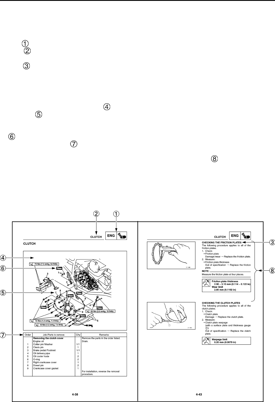
REMOVING THE CLUTCH. . . . . . . . . . . . . . . . . . . . . . . . . . . . . . . . . 4-43
CHECKING THE FRICTION PLATES . . . . . . . . . . . . . . . . . . . . . . . . 4-44

CHECKING THE CLUTCH PLATES . . . . . . . . . . . . . . . . . . . . . . . . . 4-44
CHECKING THE CLUTCH SPRINGS . . . . . . . . . . . . . . . . . . . . . . . . 4-45
CHECKING THE CLUTCH HOUSING . . . . . . . . . . . . . . . . . . . . . . . . 4-45
CHECKING THE CLUTCH BOSS . . . . . . . . . . . . . . . . . . . . . . . . . . . 4-45
CHECKING THE PRESSURE PLATE . . . . . . . . . . . . . . . . . . . . . . . . 4-45
CHECKING THE CLUTCH PUSH RODS . . . . . . . . . . . . . . . . . . . . . . 4-46
CHECKING THE PRIMARY DRIVE GEAR . . . . . . . . . . . . . . . . . . . . 4-46
INSTALLING THE CLUTCH . . . . . . . . . . . . . . . . . . . . . . . . . . . . . . . . 4-46
OIL PUMP AND BLANCER WEIGHT GEAR . . . . . . . . . . . . . . . . . . . . . 4-50
REMOVING THE BALANCER WEIGHT GEAR AND OIL PUMP. . . . 4-53
CHECKING THE OIL PUMP. . . . . . . . . . . . . . . . . . . . . . . . . . . . . . . . 4-53
CHECKING THE BALANCER WEIGHT GEAR . . . . . . . . . . . . . . . . . 4-54
ASSENBLING THE BALANCER DRIVE GEAR . . . . . . . . . . . . . . . . . 4-55
INSTALLING THE OIL PUMP. . . . . . . . . . . . . . . . . . . . . . . . . . . . . . . 4-55
INSTALLING THE BALANCER WEIGHT GEAR . . . . . . . . . . . . . . . . 4-56
SHIFT SHAFT . . . . . . . . . . . . . . . . . . . . . . . . . . . . . . . . . . . . . . . . . . . . . 4-57
CHECKING THE SHIFT SHAFT. . . . . . . . . . . . . . . . . . . . . . . . . . . . . 4-58
CHECKING THE STOPPER LEVER . . . . . . . . . . . . . . . . . . . . . . . . . 4-58
INSTALLING THE SHIFT SHAFT. . . . . . . . . . . . . . . . . . . . . . . . . . . . 4-58
PICKUP COIL ROTOR AND STARTER CLUTCH . . . . . . . . . . . . . . . . . 4-60
REMOVING THE PICKUPCOIL ROTOR . . . . . . . . . . . . . . . . . . . . . . 4-62
CHECKING THE STARTER CLUTCH . . . . . . . . . . . . . . . . . . . . . . . . 4-63
INSTALLING THE PICKUP COIL ROTOR . . . . . . . . . . . . . . . . . . . . . 4-64
CRANKCASE. . . . . . . . . . . . . . . . . . . . . . . . . . . . . . . . . . . . . . . . . . . . . . 4-66
DISASSEMBLING THE CRANKCASE . . . . . . . . . . . . . . . . . . . . . . . . 4-69
CHECKING THE CRANKCASE . . . . . . . . . . . . . . . . . . . . . . . . . . . . . 4-70
ASSEMBLING THE CRANKCASE . . . . . . . . . . . . . . . . . . . . . . . . . . . 4-70
CRANKSHAFT ASSEMBLY . . . . . . . . . . . . . . . . . . . . . . . . . . . . . . . . . . 4-72
REMOVING THE CRANKSHAFT ASSEMBLY. . . . . . . . . . . . . . . . . . 4-73
REMOVING THE PLUNGER SEAL . . . . . . . . . . . . . . . . . . . . . . . . . . 4-73
CHECKING THE CRANKSHAFT AND CONNECTING ROD. . . . . . . 4-73
CHECKING THE TIMING CHAIN, CRANKSHAFT SPROCKET
AND TIMING CHAIN GUIDE . . . . . . . . . . . . . . . . . . . . . . . . . . . . . . . 4-74
INSTALLING THE PLUNGER SEAL . . . . . . . . . . . . . . . . . . . . . . . . . 4-75
INSTALLING THE CRANKSHAFT ASSEMBLY . . . . . . . . . . . . . . . . . 4-75
TRANSMISSION . . . . . . . . . . . . . . . . . . . . . . . . . . . . . . . . . . . . . . . . . . . 4-77
REMOVING THE TRANSMISSION . . . . . . . . . . . . . . . . . . . . . . . . . . 4-80
CHECKING THE SHIFT FORKS . . . . . . . . . . . . . . . . . . . . . . . . . . . . 4-80
CHECKING THE SHIFT DRUM ASSEMBLY . . . . . . . . . . . . . . . . . . . 4-81
CHECKING THE TRANSMISSION. . . . . . . . . . . . . . . . . . . . . . . . . . . 4-81
INSTALLING THE SHIFT FORKS AND SHIFT DRUM
ASSEMBLY. . . . . . . . . . . . . . . . . . . . . . . . . . . . . . . . . . . . . . . . . . . . . 4-82

CHAPTER 5
CARBURETOR
CARBURETOR . . . . . . . . . . . . . . . . . . . . . . . . . . . . . . . . . . . . . . . . . . . . 5-1
CHECKING THE CARBURETOR. . . . . . . . . . . . . . . . . . . . . . . . . . . . 5-4
ASSEMBLING THE CARBURETOR . . . . . . . . . . . . . . . . . . . . . . . . . 5-6
INSTALLING THE CARBURETOR JOINT . . . . . . . . . . . . . . . . . . . . . 5-7
INSTALLING THE CARBURETOR. . . . . . . . . . . . . . . . . . . . . . . . . . . 5-7
CHAPTER 6
CHASSIS
FRONT AND REAR WHEELS. . . . . . . . . . . . . . . . . . . . . . . . . . . . . . . . . 6-1
FRONT WHEELS . . . . . . . . . . . . . . . . . . . . . . . . . . . . . . . . . . . . . . . . 6-1
REAR WHEELS . . . . . . . . . . . . . . . . . . . . . . . . . . . . . . . . . . . . . . . . . 6-3
CHECKING THE WHEELS. . . . . . . . . . . . . . . . . . . . . . . . . . . . . . . . . 6-4
CHECKING THE WHEEL HUBS . . . . . . . . . . . . . . . . . . . . . . . . . . . . 6-4
CHECKING THE BRAKE DISCS . . . . . . . . . . . . . . . . . . . . . . . . . . . . 6-5
INSTALLING THE FRONT WHEEL HUB BEARINGS . . . . . . . . . . . . 6-6
INSTALLING THE FRONT BRAKE DISCS . . . . . . . . . . . . . . . . . . . . 6-6
INSTALLING THE FRONT WHEELS . . . . . . . . . . . . . . . . . . . . . . . . . 6-6
INSTALLING THE WHEEL HUBS . . . . . . . . . . . . . . . . . . . . . . . . . . . 6-7
REAR AXLE AND REAR AXLE HUB . . . . . . . . . . . . . . . . . . . . . . . . . . . 6-8
REMOVING THE REAR AXLE . . . . . . . . . . . . . . . . . . . . . . . . . . . . . . 6-10
CHECKING THE REAR AXLE . . . . . . . . . . . . . . . . . . . . . . . . . . . . . . 6-11
CHECKING THE DRIVEN SPROCKET . . . . . . . . . . . . . . . . . . . . . . . 6-11
CHECKING THE BRAKE DISC . . . . . . . . . . . . . . . . . . . . . . . . . . . . . 6-11
INSTALLING THE DRIVEN SPROCKET . . . . . . . . . . . . . . . . . . . . . . 6-11
INSTALLING THE REAR AXLE . . . . . . . . . . . . . . . . . . . . . . . . . . . . . 6-11
FRONT AND REAR BRAKES . . . . . . . . . . . . . . . . . . . . . . . . . . . . . . . . . 6-13
FRONT BRAKE PADS . . . . . . . . . . . . . . . . . . . . . . . . . . . . . . . . . . . . 6-13
REAR BRAKE PADS . . . . . . . . . . . . . . . . . . . . . . . . . . . . . . . . . . . . . 6-14
REPLACING THE FRONT BRAKE PADS . . . . . . . . . . . . . . . . . . . . . 6-15
REPLACING THE REAR BRAKE PADS . . . . . . . . . . . . . . . . . . . . . . 6-17
FRONT BRAKE MASTER CYLINDER . . . . . . . . . . . . . . . . . . . . . . . . 6-19
REAR BRAKE MASTER CYLINDER . . . . . . . . . . . . . . . . . . . . . . . . . 6-21
CHECKING THE MASTER CYLINDERS . . . . . . . . . . . . . . . . . . . . . . 6-24
ASSEMBLING THE FRONT BRAKE MASTER CYLINDER . . . . . . . 6-25
ASSEMBLING THE REAR BRAKE MASTER CYLINDER . . . . . . . . 6-25
INSTALLING THE FRONT BRAKE MASTER CYLINDER . . . . . . . . . 6-26
INSTALLING THE REAR BRAKE MASTER CYLINDER . . . . . . . . . . 6-28
FRONT BRAKE CALIPERS . . . . . . . . . . . . . . . . . . . . . . . . . . . . . . . . 6-30
REAR BRAKE CALIPER. . . . . . . . . . . . . . . . . . . . . . . . . . . . . . . . . . . 6-32
REMOVING THE PARKING BRAKE CABLE . . . . . . . . . . . . . . . . . . . 6-34
DISASSEMBLING THE FRONT AND REAR BRAKE CALIPERS . . . 6-34
CHECKING THE FRONT AND REAR BRAKE CALIPERS . . . . . . . . 6-35
ASSEMBLING THE FRONT BRAKE CALIPERS . . . . . . . . . . . . . . . . 6-36

ASSEMBLING THE REAR BRAKE CALIPER . . . . . . . . . . . . . . . . . . 6-36
INSTALLING THE FRONT BRAKE CALIPERS . . . . . . . . . . . . . . . . . 6-38
INSTALLING THE REAR BRAKE CALIPER . . . . . . . . . . . . . . . . . . . 6-40
STEERING SYSTEM . . . . . . . . . . . . . . . . . . . . . . . . . . . . . . . . . . . . . . . . 6-42
HANDLEBAR . . . . . . . . . . . . . . . . . . . . . . . . . . . . . . . . . . . . . . . . . . . 6-42
REMOVING THE CLUTCH SWITCH . . . . . . . . . . . . . . . . . . . . . . . . . 6-44
REMOVING THE HANDLEBAR GRIPS . . . . . . . . . . . . . . . . . . . . . . 6-44
CHECKING THE HANDLEBAR . . . . . . . . . . . . . . . . . . . . . . . . . . . . . 6-44
INSTALLING THE HANDLEBAR . . . . . . . . . . . . . . . . . . . . . . . . . . . . 6-45
INSTALLING THE HANDLEBAR GRIPS . . . . . . . . . . . . . . . . . . . . . . 6-45
INSTALLING THE CLUTCH LEVER. . . . . . . . . . . . . . . . . . . . . . . . . . 6-46
INSTALLING THE BRAKE MASTER CYLINDER . . . . . . . . . . . . . . . 6-46
STEERING STEM. . . . . . . . . . . . . . . . . . . . . . . . . . . . . . . . . . . . . . . . 6-47
CHECKING THE STEERING STEM. . . . . . . . . . . . . . . . . . . . . . . . . . 6-48
INSTALLING THE STEERING STEM. . . . . . . . . . . . . . . . . . . . . . . . . 6-48
INSTALLING THE LOCK WASHER . . . . . . . . . . . . . . . . . . . . . . . . . . 6-48
TIE-RODS AND STEERING KNUCKLES. . . . . . . . . . . . . . . . . . . . . . 6-49
REMOVING THE STEERING KNUCKLES. . . . . . . . . . . . . . . . . . . . . 6-50
CHECKING THE TIE-RODS. . . . . . . . . . . . . . . . . . . . . . . . . . . . . . . . 6-50
CHECKING THE STEERING KNUCKLES . . . . . . . . . . . . . . . . . . . . . 6-50
INSTALLING THE TIE-RODS. . . . . . . . . . . . . . . . . . . . . . . . . . . . . . . 6-50
FRONT ARMS AND FRONT SHOCK ABSORBER ASSEMBLIES . . . . 6-51
REMOVING THE FRONT ARMS . . . . . . . . . . . . . . . . . . . . . . . . . . . . 6-53
CHECKING THE FRONT ARMS . . . . . . . . . . . . . . . . . . . . . . . . . . . . 6-53
CHECKING THE FRONT SHOCK ABSORBERS . . . . . . . . . . . . . . . 6-53
CHECKING THE BALL JOINTS . . . . . . . . . . . . . . . . . . . . . . . . . . . . . 6-54
INSTALLING THE FRONT ARMS . . . . . . . . . . . . . . . . . . . . . . . . . . . 6-54
REAR SHOCK ABSORBER, SWINGARM AND DRIVE CHAIN . . . . . . 6-55
HANDLING THE REAR SHOCK ABSORBER . . . . . . . . . . . . . . . . . . 6-57
DISPOSING OF A REAR SHOCK ABSORBER . . . . . . . . . . . . . . . . . 6-57
REMOVING THE REAR SHOCK ABSORBER. . . . . . . . . . . . . . . . . . 6-58
CHECKING THE REAR SHOCK ABSORBER . . . . . . . . . . . . . . . . . . 6-58
REMOVING THE SWINGARM . . . . . . . . . . . . . . . . . . . . . . . . . . . . . . 6-58
CHECKING THE SWINGARM . . . . . . . . . . . . . . . . . . . . . . . . . . . . . . 6-59
CHECKING THE DRIVE CHAIN. . . . . . . . . . . . . . . . . . . . . . . . . . . . . 6-60
INSTALLING THE SWINGARM . . . . . . . . . . . . . . . . . . . . . . . . . . . . . 6-62
INSTALLING THE DRIVE SPROCKET . . . . . . . . . . . . . . . . . . . . . . . 6-62
CHAPTER 7
ELECTRICAL
ELECTRICAL COMPONENTS . . . . . . . . . . . . . . . . . . . . . . . . . . . . . . . . 7-1
CHECKING SWITCH CONTINUITY . . . . . . . . . . . . . . . . . . . . . . . . . . . . 7-2
CHECKING THE SWITCHES . . . . . . . . . . . . . . . . . . . . . . . . . . . . . . . . . 7-3

CHECKING THE BULBS AND BULB SOCKETS. . . . . . . . . . . . . . . . . . 7-5
TYPES OF BULBS . . . . . . . . . . . . . . . . . . . . . . . . . . . . . . . . . . . . . . . 7-5
CHECKING THE CONDITION OF THE BULBS. . . . . . . . . . . . . . . . . 7-5
CHECKING THE CONDITION OF THE BULB SOCKETS . . . . . . . . 7-7
IGNITION SYSTEM . . . . . . . . . . . . . . . . . . . . . . . . . . . . . . . . . . . . . . . . . 7-8
CIRCUIT DIAGRAM . . . . . . . . . . . . . . . . . . . . . . . . . . . . . . . . . . . . . . 7-8
TROUBLESHOOTING . . . . . . . . . . . . . . . . . . . . . . . . . . . . . . . . . . . . 7-9
ELECTRIC STARTING SYSTEM. . . . . . . . . . . . . . . . . . . . . . . . . . . . . . . 7-13
CIRCUIT DIAGRAM . . . . . . . . . . . . . . . . . . . . . . . . . . . . . . . . . . . . . . 7-13
STARTING CIRCUIT CUT-OFF SYSTEM OPERATION . . . . . . . . . . 7-14
TROUBLESHOOTING . . . . . . . . . . . . . . . . . . . . . . . . . . . . . . . . . . . . 7-15
STARTER MOTOR . . . . . . . . . . . . . . . . . . . . . . . . . . . . . . . . . . . . . . . . . 7-19
CHECKING THE STARTER MOTOR. . . . . . . . . . . . . . . . . . . . . . . . . 7-21
ASSEMBLING THE STARTER MOTOR . . . . . . . . . . . . . . . . . . . . . . 7-23
CHARGING SYSTEM . . . . . . . . . . . . . . . . . . . . . . . . . . . . . . . . . . . . . . . 7-24
CIRCUIT DIAGRAM . . . . . . . . . . . . . . . . . . . . . . . . . . . . . . . . . . . . . . 7-24
TROUBLESHOOTING . . . . . . . . . . . . . . . . . . . . . . . . . . . . . . . . . . . . 7-25
LIGHTING SYSTEM. . . . . . . . . . . . . . . . . . . . . . . . . . . . . . . . . . . . . . . . . 7-27
CIRCUIT DIAGRAM . . . . . . . . . . . . . . . . . . . . . . . . . . . . . . . . . . . . . . 7-27
TROUBLESHOOTING . . . . . . . . . . . . . . . . . . . . . . . . . . . . . . . . . . . . 7-28
CHECKING THE LIGHTING SYSTEM . . . . . . . . . . . . . . . . . . . . . . . . 7-29
SIGNAL SYSTEM . . . . . . . . . . . . . . . . . . . . . . . . . . . . . . . . . . . . . . . . . . 7-31
CIRCUIT DIAGRAM . . . . . . . . . . . . . . . . . . . . . . . . . . . . . . . . . . . . . . 7-31
TROUBLESHOOTING . . . . . . . . . . . . . . . . . . . . . . . . . . . . . . . . . . . . 7-32
CHECKING THE SIGNALING SYSTEM. . . . . . . . . . . . . . . . . . . . . . . 7-33
CHAPTER 8
TROUBLESHOOTING
STARTING FAILURE/HARD STARTING . . . . . . . . . . . . . . . . . . . . . . . . 8-1
FUEL SYSTEM . . . . . . . . . . . . . . . . . . . . . . . . . . . . . . . . . . . . . . . . . . 8-1
ELECTRICAL SYSTEM . . . . . . . . . . . . . . . . . . . . . . . . . . . . . . . . . . . 8-1
COMPRESSION SYSTEM . . . . . . . . . . . . . . . . . . . . . . . . . . . . . . . . . 8-2
POOR IDLE SPEED PERFORMANCE . . . . . . . . . . . . . . . . . . . . . . . . . . 8-2
POOR IDLE SPEED PERFORMANCE . . . . . . . . . . . . . . . . . . . . . . . 8-2
POOR MEDIUM AND HIGH-SPEED PERFORMANCE . . . . . . . . . . . . . 8-2
POOR MEDIUM AND HIGH-SPEED PERFORMANCE . . . . . . . . . . . 8-2
FAULTY GEAR SHIFTING . . . . . . . . . . . . . . . . . . . . . . . . . . . . . . . . . . . 8-3
HARD SHIFTING . . . . . . . . . . . . . . . . . . . . . . . . . . . . . . . . . . . . . . . . 8-3
SHIFT PEDAL DOES NOT MOVE . . . . . . . . . . . . . . . . . . . . . . . . . . . 8-3
JUMPS OUT GEAR . . . . . . . . . . . . . . . . . . . . . . . . . . . . . . . . . . . . . . 8-3

CLUTCH SLIPPING/DRAGGING . . . . . . . . . . . . . . . . . . . . . . . . . . . . . . 8-3
CLUTCH SLIPPING . . . . . . . . . . . . . . . . . . . . . . . . . . . . . . . . . . . . . . 8-3
CLUTCH DRAGGING . . . . . . . . . . . . . . . . . . . . . . . . . . . . . . . . . . . . . 8-3
OVERHEATING . . . . . . . . . . . . . . . . . . . . . . . . . . . . . . . . . . . . . . . . . . . . 8-4
OVERHEATING . . . . . . . . . . . . . . . . . . . . . . . . . . . . . . . . . . . . . . . . . 8-4
FAULTY BRAKE . . . . . . . . . . . . . . . . . . . . . . . . . . . . . . . . . . . . . . . . . . . 8-4
POOR BRAKING EFFECT . . . . . . . . . . . . . . . . . . . . . . . . . . . . . . . . . 8-4
SHOCK ABSORBER MALFUNCTION . . . . . . . . . . . . . . . . . . . . . . . . . . 8-4
MALFUNCTION . . . . . . . . . . . . . . . . . . . . . . . . . . . . . . . . . . . . . . . . . 8-4
UNSTABLE HANDLING . . . . . . . . . . . . . . . . . . . . . . . . . . . . . . . . . . . . . 8-5
UNSTABLE HANDLING . . . . . . . . . . . . . . . . . . . . . . . . . . . . . . . . . . . 8-5
LIGHTING SYSTEM. . . . . . . . . . . . . . . . . . . . . . . . . . . . . . . . . . . . . . . . . 8-5
HEADLIGHT DOES NOT COME ON . . . . . . . . . . . . . . . . . . . . . . . . . 8-5
TAIL/BRAKE LIGHT DOES NOT LIGHT . . . . . . . . . . . . . . . . . . . . . . 8-5
BULB BURNT OUT. . . . . . . . . . . . . . . . . . . . . . . . . . . . . . . . . . . . . . . 8-5
TAIL/BRAKE LIGHT BULB BURNT OUT . . . . . . . . . . . . . . . . . . . . . 8-5
GEN
INFO
1-1
EBS00009
GENERAL INFORMATION
MACHINE IDENTIFICATION
EBS00010
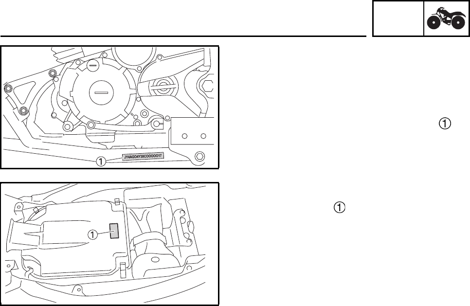
VEHICLE IDENTIFICATION NUMBER
The vehicle identification number is
stamped into the left side of the frame.
EBS00011
MODEL LABEL
The model label is affixed to the air filter
case cover. This information will be needed to
order spare parts.
MACHINE IDENTIFICATION
GEN
INFO
1-2
1
2
3
4
5
6
7
8
EBS00013
IMPORTANT INFORMATION
PREPARATION FOR REMOVAL AND
DISASSEMBLY
1. Before removal and disassembly remove all
dirt, mud, dust and foreign material.
2. Use only the proper tools and cleaning
equipment.
Refer to “SPECIAL TOOLS”.
3. When disassembling always keep mated
parts together. This includes gears, cylin-
ders, pistons and other parts that have
been “mated” through normal wear. Mated
parts must always be reused or replaced as
an assembly.
4. During disassembly, clean all of the parts
and place them in trays in the order of dis-
assembly. This will speed up assembly and
allow for the correct installation of all parts.
5. Keep all parts away from any source of fire.
EBS00014
REPLACEMENT PARTS
1. Use only genuine Yamaha parts for all
replacements. Use oil and grease recom-
mended by Yamaha for all lubrication jobs.
Other brands may be similar in function and
appearance, but inferior in quality.
EBS00015
GASKETS, OIL SEALS AND O-RINGS
1. When overhauling the engine, replace all
gaskets, seals and O-rings. All gasket sur-
faces, oil seal lips and O-rings must be
cleaned.
2. During reassembly properly oil all mating
parts and bearings, and lubricate the oil
seal lips with grease.
EBS00016
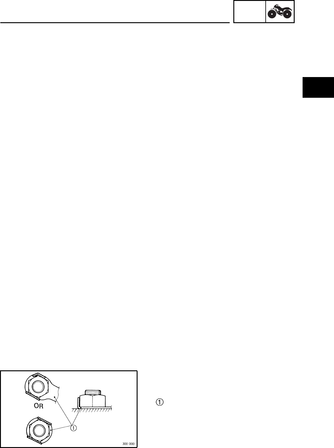
LOCK WASHERS/PLATES AND COTTER
PINS
After removal, replace all lock washers/plates
and cotter pins. After the bolt or nut has
been tightened to specification, bend the lock
tabs along a flat of the bolt or nut.
IMPORTANT INFORMATION
GEN
INFO
1-3
EBS00017
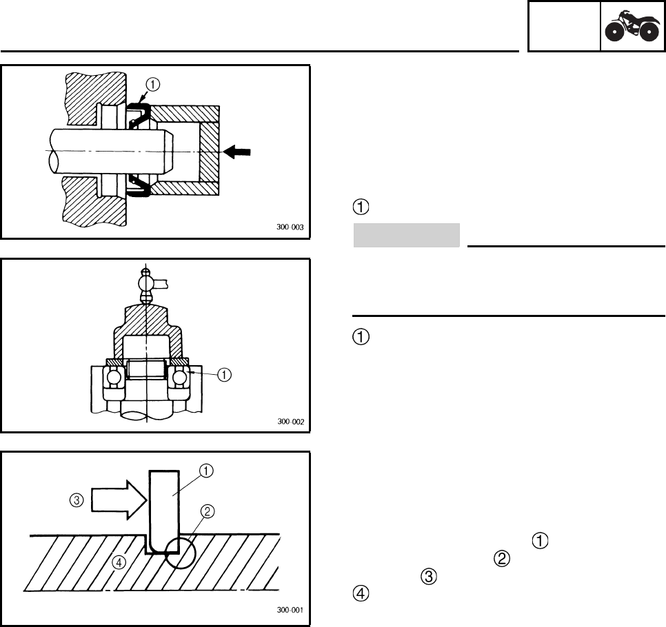
BEARINGS AND OIL SEALS
Install bearings and oil seals so that the manu-
facturer’s marks or numbers are visible. When
installing oil seals, lubricate the oil seal lips
with a light coat of lithium-soap-based grease.
Oil bearings liberally when installing, if appro-
priate.
Oil seal
CAUTION:
Do not spin the bearing with compressed
air because this will damage the bearing
surfaces.
Bearing
EBS00018
CIRCLIPS
Before reassembly, check all circlips carefully
and replace damaged or distorted circlips.
Always replace piston pin clips after one use.
When installing a circlip , make sure the
sharp-edged corner is positioned opposite
the thrust that the circlip receives.
Shaft
IMPORTANT INFORMATION
GEN
INFO
1-4
EBS00019
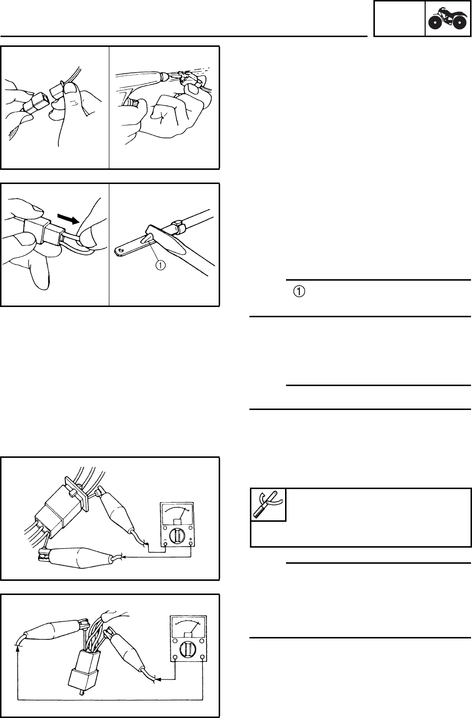
CHECKING THE CONNECTIONS
Check the leads, couplers, and connectors for
stains, rust, moisture, etc.
1. Disconnect:
• lead
• coupler
• connector
2. Check:
• lead
• coupler
• connector
Moisture → Dry with an air blower.
Rust /stains → Connect and disconnect
several times.
3. Check:
• all connections
Loose connection → Connect properly.
N
O
TE:N
O
TE:
If the pin on the terminal is flattened, bend it
up.
4. Connect:
• lead
• coupler
• connector
N
O
TE:N
O
TE:
Make sure all connections are tight.
5. Check:
• continuity (with the pocket tester)
N
O
TE:N
O
TE:
• If there is no continuity, clean the terminals.
• When checking the wire harness, perform
steps (1) to (3).
• As a quick remedy, use a contact revitalizer
available at most part stores.
Pocket tester
YU-03112-C
Analog pocket tester
YU-03112-C
IMPORTANT INFORMATION
GEN
INFO
1-5
EBS00021
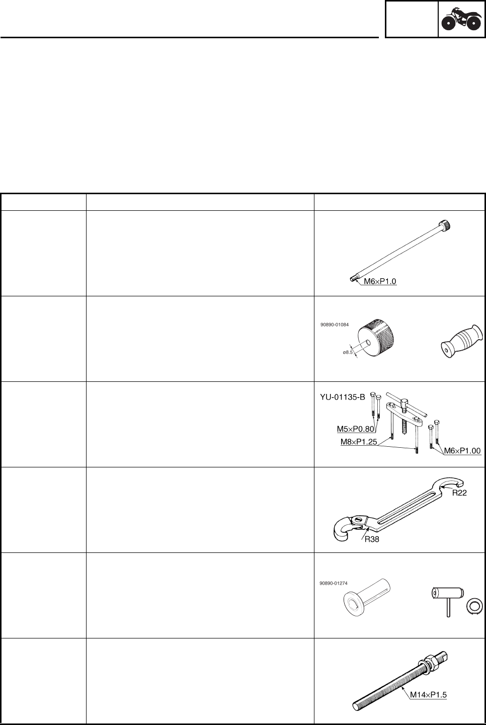
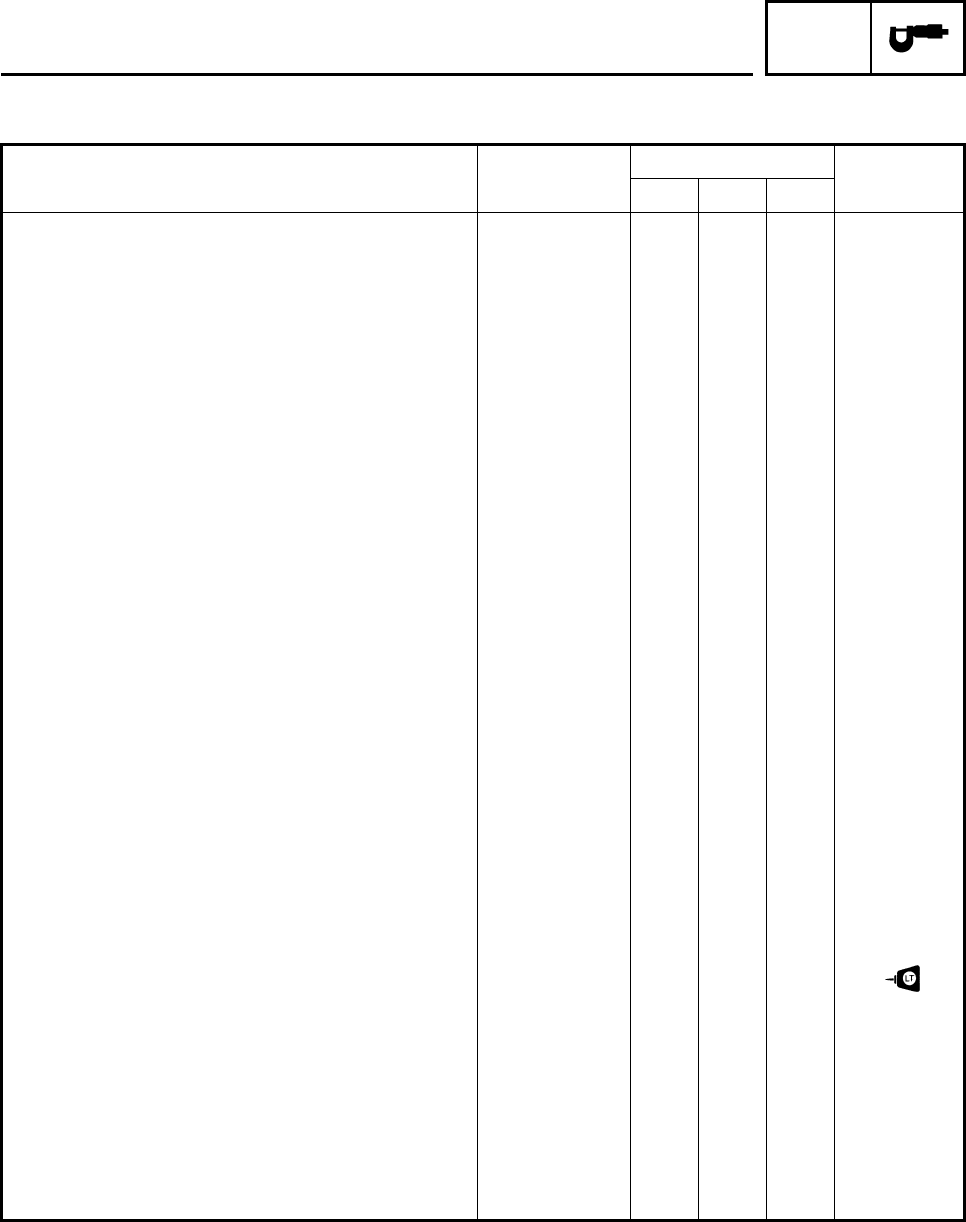
SPECIAL TOOLS
The following special tools are necessary for complete and accurate tune-up and assembly. Use
only the appropriate special tools; this will help prevent damage caused by the use of inappropriate
tools or improvised techniques. Special tools may differ by shape and part number from country to
country. In such a case, two types are provided.
When placing an order, refer to the list provided below to avoid any mistakes.
For US and CAN
P/N. YM-, YU-, YS-, YK-, ACC-
Except for US and CAN
P/N. 90890
Tool No. Tool name/Function Illustration
90890-01083
YU-01083-1
Slide hummer bolt
Slide hummer bolt 6 mm
This tool is used to remove the rocker arm
shaft.
90890-01084
YU-01083-3
Weight
This tool is used to remove the rocker arm
shaft.
90890-01135
YU-01135-B
Crankcase separating tool
Crankcase separator
This tool is used to separate the crankcase.
90890-01268
YU-01268
Ring nut wrench
Spanner wrench
This tool is used to adjusting the front shock
absorbers.
90890-01274
YU-90058
Crankshaft installer pot
Installing pot
These tools are used to install the crankshaft.
90890-01275
YU-90060
Crankshaft installer bolt
Bolt
This tool is used to install the crankshaft.
YU-01083-3
YU-90058/YU-90059
SPECIAL TOOLS
GEN
INFO
1-6
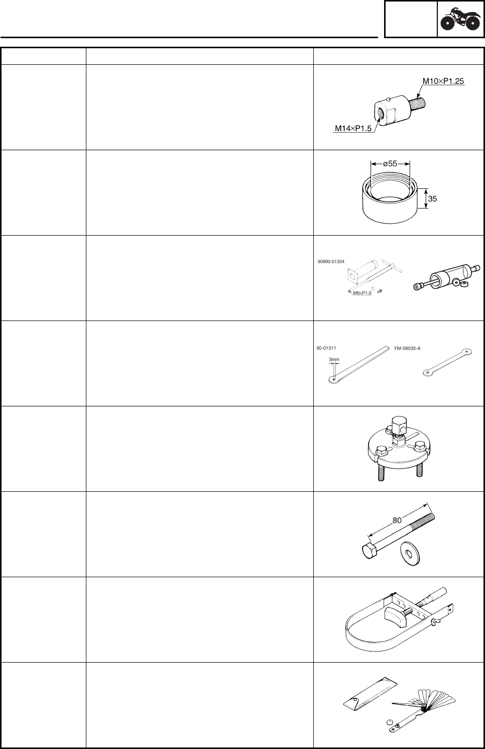
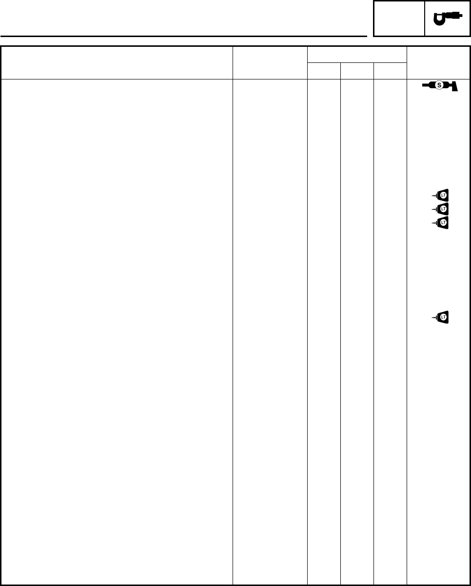
Tool No. Tool name/Function Illustration
Adapter
90890-01383
YU-90062
Adapter (M10)
Adapter #2
This tool is used to install the crankshaft.
90890-01288
Spacer
This tool is used to install the crankshaft.
90890-01304
YU-01304
Piston pin puller set
Piston pin puller
This tool is used to remove the piston pin.
90890-01311
YM-A5970
Tappet adjusting tool
Six piece tappet set
This tool is necessary for adjusting the valve
clearance.
90890-01362
YU-33270-B
Flywheel puller
Heavy duty puller
This tool is used to remove the AC magneto
rotor.
90890-01359
Bolt (M8 × 80 mm)
This tool is used to remove the AC magneto
rotor.
90890-01701
YS-01880-A
Sheave holder
Primary clutch holder
This tool is needed to hold the AC magneto
rotor when loosen or tighten the AC magneto
rotor nut.
90890-03079
YM-34483
Thickness gauge
Narrow gauge set
This tool is used to measure the valve clear-
ance and spark plug gap.
YU-01304
SPECIAL TOOLS
GEN
INFO
1-7
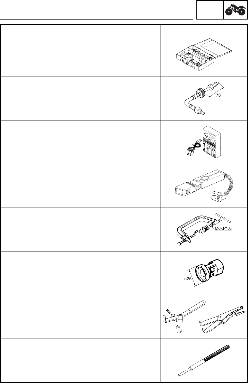
Tool No. Tool name/Function Illustration
90890-03081
YU-33223
Compression gauge
Engine compression tester
This tool is needed to measure the engine
compression.
90890-04082
Extension
This tool is needed to measure engine com-
pression.
90890-03112
YU-03112-C
Pocket tester
Analog pocket tester
This instrument is needed for checking the
electrical system.
90890-03141
YU-03141
Timing light
Inductive clamp timing light
This tool is necessary for checking ignition
timing.
Compressor
90890-04019
YM-04019
Valve spring compressor
This tool is needed to remove and install the
valve assemblies.
90890-01243
YM-01253-1
Valve spring compressor attachment
Valve spring compressor adapter (26 mm)
This tool is needed to remove and install the
valve assemblies.
90890-04086
YM-91042
Universal clutch holder
This tool is needed to hold the clutch carrier
when removing or installing the carrier nut.
90890-04064
YM-04064-A
Valve guide remover (φ6)
Valve guide remover (6.0 mm)
This tool is needed to remove and install the
valve guides.
SPECIAL TOOLS
GEN
INFO
1-8
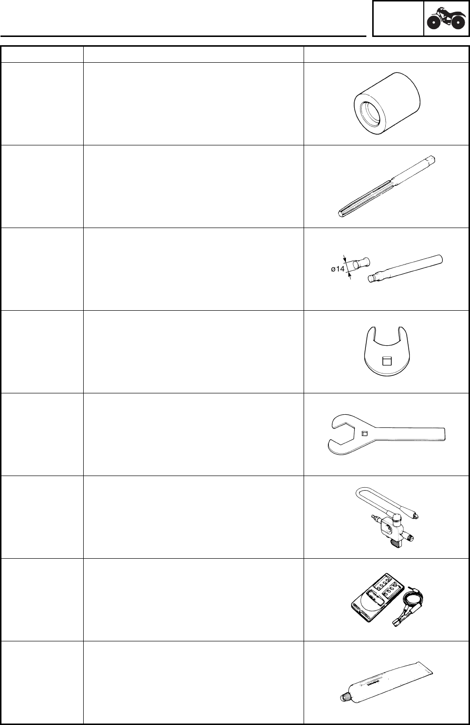
Tool No. Tool name/Function Illustration
90890-04065
YM-04065-A
Valve guide installer (φ6)
Valve guide installer (6.0 mm)
This tool is needed to install the valve guides.
90890-04066
YM-04066
Valve guide reamer (φ6)
Valve guide reamer (6.0 mm)
This tool is needed to rebore the new valve
guides.
90890-04101
YM-A8998
Valve lapper
Valve lapping tool
This tool is needed to remove and install the
valve lifters.
90890-06588
PTT wrench 46
This tool is needed to loosen or tighten the
rear axle nut.
YM-37134
Axle nut wrench (46 mm)
This tool is needed to loosen or tighten the
rear axle nut.
90890-06754
YM-34487
Ignition checker
Opama pet-4000 spark checker
This instrument is necessary for checking the
ignition system components.
90890-06760
YU-39951-B
Digital tachometer
This tool is needed for observing engine rpm.
90890-85505
Yamaha bond No. 1215
(Three Bond No. 1215®)
This bond is used on crankcase mating sur-
faces, etc.
SPECIAL TOOLS
SPEC
2-1
EBS01001
SPECIFICATIONS
GENERAL SPECIFICATIONS
Item Standard
Model code 4D31
4D35
4D39
Dimensions
Overall length 1,625 mm (64.0 in)
Overall width 1,070 mm (42.1 in)
Overall height 1,040 mm (40.9 in)
Seat height 730 mm (28.7 in)
Wheelbase 1,110 mm (43.7 in)
Minimum ground clearance 100 mm (3.94 in)
Minimum turning radius 2,900 mm (114.2 in)
Basic weight
With oil and full fuel tank 150 kg (331 lb)
Engine
Engine type Air-cooled 4-stroke, SOHC
Cylinder arrangement Forward-inclined single cylinder
Displacement 249 cm3 (15.19 cu in)
Bore × stroke 74.0 × 58.0 mm (2.91 × 2.28 in)
Compression ratio 9.5 : 1
Engine idle speed 1,500 ~ 1,600 r/min
Intake vacuum 34 kPa (255 mmHg, 10.0 inHg)
Oil temperature 55 ~ 65 °C
Standard compression pressure (at sea level) 1,100 kPa (11.2 kg/cm2, 160 psi)/720 r/min
Starting system Electric starter
Lubrication system Wet sump
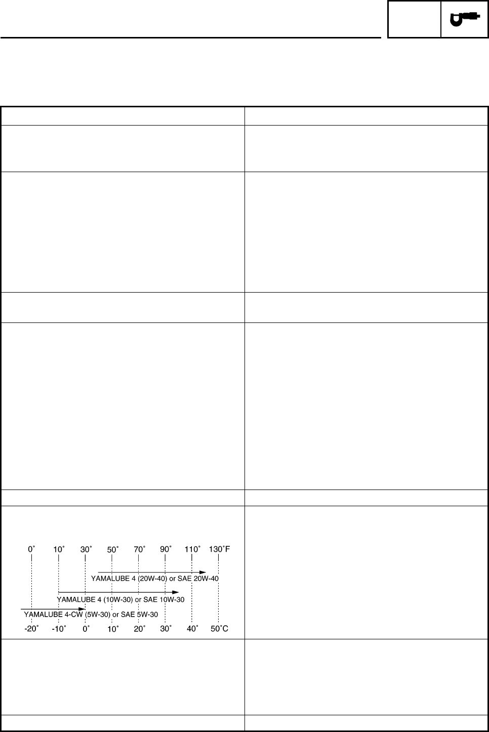
Oil type or grade
Engine oil YAMALUBE4, SAE 5W-30 or SAE 10W-30 or
SAE 20W-40
API service, SG type or higher, JASO standard
MA
Oil capacity
Engine oil
Periodic oil change 1.25 L (1.10 Imp qt, 1.32 US qt)
With oil filter replacement 1.35 L (1.19 Imp qt, 1.43 US qt)
Total amount 1.60 L (1.41 Imp qt, 1.69 US qt)
Air filter Wet type element
GENERAL SPECIFICATIONS

SPEC
2-2
1
2
3
4
5
6
7
8
Item Standard
Fuel
Type Unleaded gasoline only
Fuel tank capacity 9.0 L (1.97 Imp gal, 2.37 US gal)
Fuel reserve amount 1.0 L (0.22 Imp gal, 0.26 US gal)
Carburetor
Type/quantity BSR29 × 1
Manufacturer MIKUNI
Spark plug
Type/manufacturer DR7EA/NGK
Spark plug gap 0.6 ~ 0.7 mm (0.024 ~ 0.028 in)
Clutch type Wet, multiple-disc
Transmission
Primary reduction system Spur gear
Primary reduction ratio 76/22 (3.455)
Secondary reduction system Chain drive
Secondary reduction ratio 38/14 (2.714)
Transmission type Constant mesh, 5-speed
Operation Left foot operation
Gear ratio
1st gear 37/13 (2.846)
2nd gear 33/18 (1.833)
3rd gear 29/21 (1.381)
4th gear 27/24 (1.125)
5th gear 28/29 (0.966)
Chassis
Frame type Steel tube frame
Caster angle 6°
Camber angle –1.5°
Kingpin angle 14.8°
Trail 23.0 mm (0.91 in)
Tread (STD) front 826 mm (32.52 in)
rear 824 mm (32.44 in)
Toe-in (with tires touching the ground) 9 ~ 19 mm (0.35 ~ 0.75 in)
Tire
Type Tubeless
Size front AT20 × 7-10
rear AT19 × 10-9
Manufacturer front DUNLOP
rear DUNLOP
Type front KT201
rear KT205A
Tire pressure (cold tire)
Maximum load* 100 kg (220 lb)
Off-road riding front 27.5 kPa (0.28 kg/cm2, 4.0 psi)
rear 27.5 kPa (0.28 kg/cm2, 4.0 psi)
*Load in total weight of cargo, rider and
accessories
GENERAL SPECIFICATIONS

SPEC
2-3
Item Standard
Brake
Front brake type Dual disc brake
operation Right hand operation
Rear brake type Single disc brake
operation Right foot operation
Suspension
Front suspension Double wishbone
Rear suspension Swingarm
Shock absorber
Front shock absorber Coil spring/oil damper
Rear shock absorber Coil spring/gas-oil damper
Wheel travel
Front wheel travel 190 mm (7.48 in)
Rear wheel travel 200 mm (7.87 in)
Electrical
Ignition system DC-CDI
Generator system AC magneto
Battery type YTZ7S
Battery capacity 12 V 6.0 Ah
Headlight type Krypton bulb
Bulb voltage/wattage × quantity
Headlight 12 V 30 W/30 W × 2
Tail/brake light 12 V 5 W/21 W × 1 (4D31)
12 V 0.5 W/3.9 W × 1 (4D35, 4D39)
Indicator lights
Neutral 12 V 1.7 W × 1
GENERAL SPECIFICATIONS
SPEC
2-4
EBS01002
ENGINE SPECIFICATIONS
Item Standard Limit
Cylinder head
Volume 20.50 ~ 21.50 cm3 (1.25 ~ 1.31 cu.in) • • •
Warp limit • • •0.05 mm
(0.0020 in)
Cylinder
Bore size 74.000 ~ 74.016 mm (2.9134 ~ 2.9140 in) 74.100 mm
(2.9173 in)
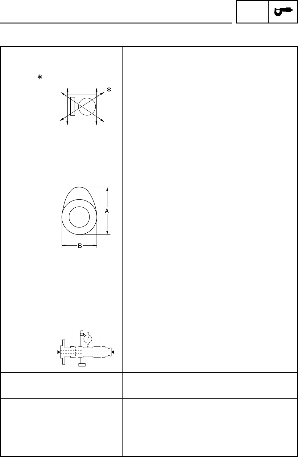
Camshaft
Drive method Chain drive (Right) • • •
Camshaft lobe dimensions
Intake “A” 36.890 ~ 36.990 mm (1.4524 ~ 1.4563 in) 36.790 mm
(1.4484 in)
“B” 30.111 ~ 30.211 mm (1.1855 ~ 1.1894 in) 30.011 mm
(1.1815 in)
Exhaust “A” 36.891 ~ 36.991 mm (1.4524 ~ 1.4563 in) 36.791 mm
(1.4485 in)
“B” 30.092 ~ 30.192 mm (1.1847 ~ 1.1887 in) 29.992 mm
(1.1808 in)
Camshaft runout limit • • •0.03 mm
(0.0012 in)
Timing chain
Timing chain type/No. of links DID SCR-0404 SV/104 • • •
Timing chain adjustment method Automatic • • •
Rocker arm/rocker arm shaft
Rocker arm inside diameter 12.000 ~ 12.018 mm (0.4724 ~ 0.4731 in) 12.036 mm
(0.4739 in)
Rocker arm shaft outside diameter 11.981 ~ 11.991 mm (0.4717 ~ 0.4721 in) 11.950 mm
(0.4705 in)
Rocker-arm-to-rocker-arm-shaft
clearance 0.009 ~ 0.037 mm (0.0004 ~ 0.0015 in) • • •
ENGINE SPECIFICATIONS
SPEC
2-5
Item Standard Limit
Valve, valve seat, valve guide
Valve clearance (cold) IN 0.05 ~ 0.10 mm (0.0020 ~ 0.0039 in) • • •
EX 0.10 ~ 0.15 mm (0.0039 ~ 0.0059 in) • • •
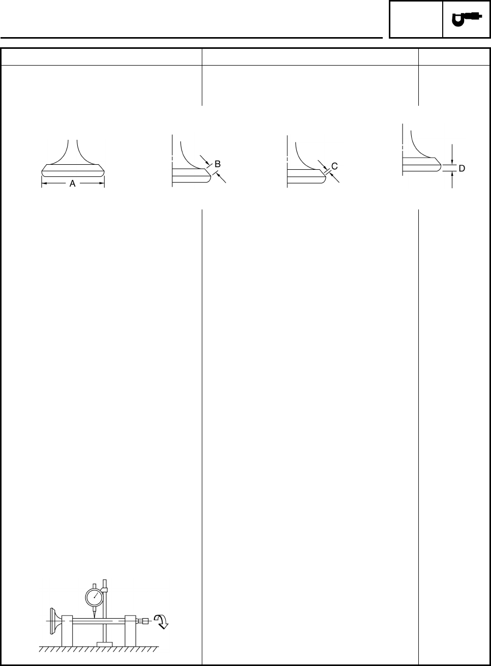
Valve dimensions
“A” head diameter IN 33.90 ~ 34.10 mm (1.3346 ~ 1.3425 in) • • •
EX 28.40 ~ 28.60 mm (1.1181 ~ 1.1260 in) • • •
“B” face width IN 2.26 mm (0.0890 in) • • •
EX 2.26 mm (0.0890 in) • • •
“C” seat width IN 0.90 ~ 1.10 mm (0.0354 ~ 0.0433 in) 1.6 mm
(0.06 in)
EX 0.90 ~ 1.10 mm (0.0354 ~ 0.0433 in) 1.6 mm
(0.06 in)
“D” margin thickness IN 0.80 ~ 1.20 mm (0.0315 ~ 0.0472 in) • • •
EX 0.80 ~ 1.20 mm (0.0315 ~ 0.0472 in) • • •
Stem outside diameter IN 5.975 ~ 5.990 mm (0.2352 ~ 0.2358 in) 5.945 mm
(0.234 in)
EX 5.960 ~ 5.975 mm (0.2346 ~ 0.2352 in) 5.930 mm
(0.233 in)
Guide inside diameter IN 6.000 ~ 6.012 mm (0.2362 ~ 0.2367 in) 6.050 mm
(0.238 in)
EX 6.000 ~ 6.012 mm (0.2362 ~ 0.2367 in) 6.050 mm
(0.238 in)
Stem-to-guide clearance IN 0.010 ~ 0.037 mm (0.0004 ~ 0.0015 in) 0.080 mm
(0.003 in)
EX 0.025 ~ 0.052 mm (0.0010 ~ 0.0020 in) 0.100 mm
(0.004 in)
Valve stem runout • • •0.01 mm
(0.0004 in)
Valve seat width IN 0.90 ~ 1.10 mm (0.0354 ~ 0.0433 in) 1.6 mm
(0.06 in)
EX 0.90 ~ 1.10 mm (0.0354 ~ 0.0433 in) 1.6 mm
(0.06 in)
Head Diameter Face Width Seat Width Margin Thickness
ENGINE SPECIFICATIONS
SPEC
2-6
Item Standard Limit
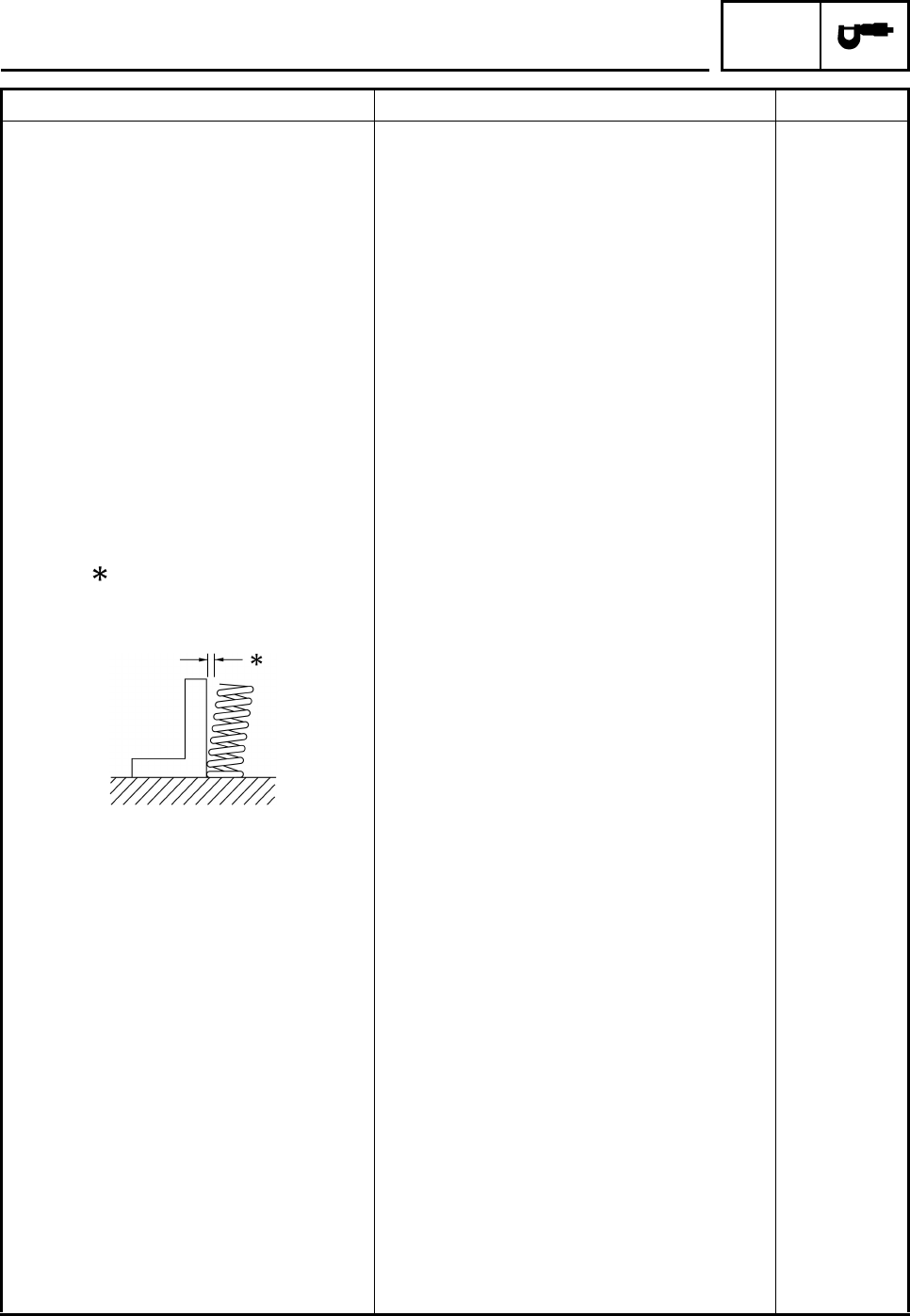
Valve spring
Inner spring
Free length IN 36.17 mm (1.42 in) 34.36 mm
(1.35 in)
EX 36.17 mm (1.42 in) 34.36 mm
(1.35 in)
Installed length
(valve closed) IN 30.50 mm (1.20 in) • • •
EX 30.50 mm (1.20 in) • • •
Spring rate K1 IN 14.70 N/mm (1.50 kg/mm, 83.94 lb/in) • • •
K2 IN 19.00 N/mm (1.94 kg/mm, 108.49 lb/in) • • •
K1 EX 14.70 N/mm (1.50 kg/mm, 83.94 lb/in) • • •
K2 EX 19.00 N/mm (1.94 kg/mm, 108.49 lb/in) • • •
Compressed spring force
(installed) IN 75.00 ~ 91.70 N
(7.65 ~ 9.35 kg, 16.86 ~ 20.62 lb) • • •
EX 75.00 ~ 91.70 N
(7.65 ~ 9.35 kg, 16.86 ~ 20.62 lb) • • •
Tilt limit IN • • • 2.5°/1.60 mm
(2.5°/0.063 in)
EX • • • 2.5°/1.60 mm
(2.5°/0.063 in)
Direction of winding
(top view) IN Counter clockwise • • •
EX Counter clockwise • • •
Outer spring
Free length IN 36.63 mm (1.44 in) 34.80 mm
(1.37 in)
EX 36.63 mm (1.44 in) 34.80 mm
(1.37 in)
Installed length
(valve closed) IN 32.00 mm (1.26 in) • • •
EX 32.00 mm (1.26 in) • • •
Spring rate K1 IN 30.90 N/mm (3.15 kg/mm, 176.44 lb/in) • • •
Spring rate K2 IN 40.80 N/mm (4.16 kg/mm, 232.97 lb/in) • • •
Spring rate K1 EX 30.90 N/mm (3.15 kg/mm, 176.44 lb/in) • • •
Spring rate K2 EX 40.80 N/mm (4.16 kg/mm, 232.97 lb/in) • • •
Compressed spring force
(installed) IN 128.50 ~ 157.90 N
(13.10 ~ 16.10 kg, 28.89 ~ 35.50 lb) • • •
EX 128.50 ~ 157.90 N
(13.10 ~ 16.10 kg, 28.89 ~ 35.50 lb) • • •
ENGINE SPECIFICATIONS
SPEC
2-7
Item Standard Limit
Tilt limit IN • • • 2.5°/1.60 mm
(2.5°/0.063 in)
EX • • • 2.5°/1.60 mm
(2.5°/0.063 in)
Direction of winding
(top view) IN Clockwise • • •
EX Clockwise • • •
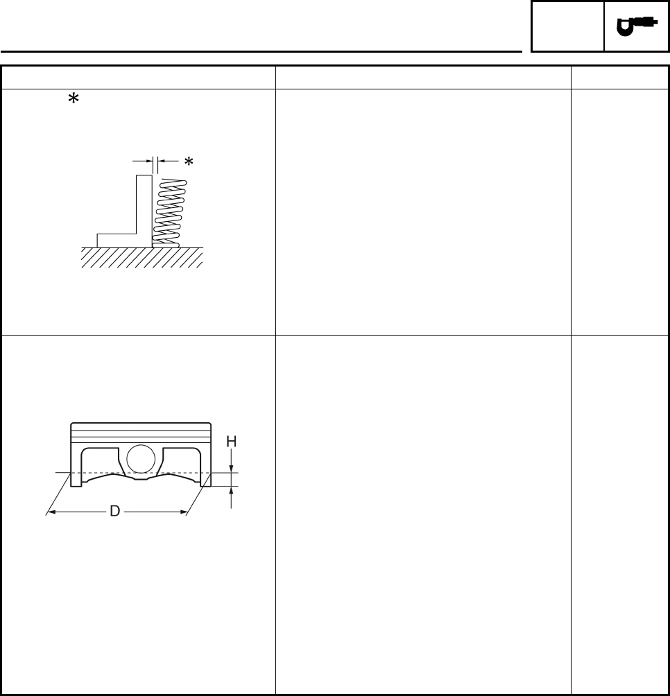
Piston
Piston to cylinder clearance 0.010 ~ 0.025 mm (0.0004 ~ 0.0010 in) 0.15 mm
(0.006 in)
Piston size “D” 73.983 ~ 73.998 mm (2.9127 ~ 2.9133 in) • • •
Measuring point “H” 5.0 mm (0.20 in) • • •
Piston off set 0.25 mm (0.0098 in) • • •
Offset direction Intake side • • •
Piston pin bore inside diameter 17.002 ~ 17.013 mm (0.6694 ~ 0.6698 in) 17.043 mm
(0.6710 in)
Piston pin outside diameter 16.991 ~ 17.000 mm (0.6689 ~ 0.6693 in) 16.971 mm
(0.6681 in)
Piston-pin-to-piston-pin-bore
clearance 0.002 ~ 0.022 mm (0.0001 ~ 0.0009 in) 0.072 mm
(0.0028 in)
ENGINE SPECIFICATIONS
SPEC
2-8
Item Standard Limit
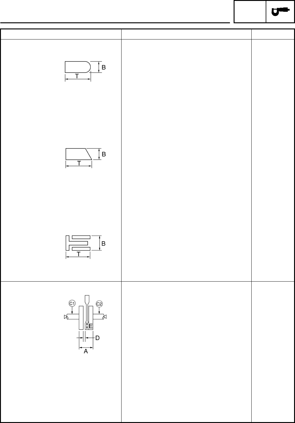
Piston rings
Top ring
Type Barrel • • •
Dimensions (B × T) 0.90 × 2.75 mm (0.035 × 0.108 in) • • •
End gap (installed) 0.19 ~ 0.31 mm (0.007 ~ 0.012 in) 0.56 mm
(0.022 in)
Side clearance 0.030 ~ 0.065 mm (0.0012 ~ 0.0026 in) 0.115 mm
(0.0045 in)
2nd ring
Type Taper • • •
Dimensions (B × T) 0.80 × 2.80 mm (0.031 × 0.110 in) • • •
End gap (installed) 0.30 ~ 0.45 mm (0.012 ~ 0.018 in) 0.80 mm
(0.032 in)
Side clearance 0.020 ~ 0.055 mm (0.0008 ~ 0.0022 in) 0.115 mm
(0.0045 in)
Oil ring
Dimensions (B × T) 1.50 × 2.60 mm (0.059 × 0.102 in) • • •
End gap (installed) 0.10 ~ 0.35 mm (0.004 ~ 0.014 in) • • •
Crankshaft
Crank width “A” 69.25 ~ 69.30 mm (2.726 ~ 2.728 in) • • •
Runout limit C1 • • •0.03 mm
(0.0012 in)
C2 • • •0.03 mm
(0.0012 in)
Big end side clearance “D” 0.350 ~ 0.650 mm (0.0138 ~ 0.0256 in) 0.50 mm
(0.0197 in)
Big end radial clearance “E” 0.010 ~ 0.025 mm (0.0004 ~ 0.0010 in) • • •
ENGINE SPECIFICATIONS

SPEC
2-9
Item Standard Limit
Balancer
Balancer drive method Gear • • •
Clutch
Friction plate 1 (inside dia.: 104.5 ~
105.5 mm)
Thickness 2.9 ~ 3.1 mm (0.114 ~ 0.122 in) 2.8 mm
(0.110 in)
Quantity 4 • • •
Friction plate 2 (inside dia.: 104.5 ~
105.5 mm)
Thickness 2.9 ~ 3.1 mm (0.114 ~ 0.122 in) 2.8 mm
(0.110 in)
Quantity 2 • • •
Clutch plate
Thickness 1.5 ~ 1.7 mm (0.059 ~ 0.067 in) • • •
Quantity 5 • • •
Max. warpage • • • 0.2 mm
(0.0079 in)
Clutch spring
Free length 47.8 mm (1.88 in) 45.4 mm
(1.79 in)
Quantity 5 • • •
Clutch release method Inner push, cam push • • •
Push rod 2 bending limit • • • 0.1 mm
(0.004 in)
Transmission
Main axle runout limit • • •0.06 mm
(0.0024 in)
Drive axle runout limit • • •0.06 mm
(0.0024 in)
Main axle assembly width 102.2 ~ 102.4 mm (4.02 ~ 4.03 in) • • •
Shifter
Shifter type Shift drum and guide bar • • •
Max. shift fork guide bar bending • • •0.05 mm
(0.002 in)
Air filter oil grade Foam air filter oil or equivalent oil • • •
ENGINE SPECIFICATIONS

SPEC
2-10
Item Standard Limit
Carburetor
I. D. mark 4D31 00 • • •
Main jet (M.J) #133.8 • • •
Main air jet (M.A.J) #140 • • •
Jet needle (J.N) 5DH66-1 • • •
Needle jet (N.J) P-0M • • •
Pilot air jet 1 (P.A.J.1) #85 • • •
Pilot air jet 2 (P.A.J.2) #170 • • •
Pilot outlet (P.O) ø0.9 • • •
Pilot jet (P.J) #25 • • •
Bypass 1 (B.P.1) ø0.8 • • •
Bypass 2 (B.P.2) ø0.8 • • •
Bypass 3 (B.P.3) ø0.8 • • •
Valve seat size (V.S) ø2.0 • • •
Starter jet 1 (G.S.1) #55 • • •
Starter jet 2 (G.S.2) #0.5 • • •
Throttle valve size (THV) #100 • • •
Float height (F.H) 13.0 mm (0.51 in) • • •
Oil filter type Wire mesh • • •
Oil pump
Oil pump type Trochoid • • •
Inner-rotor-to-outer-rotor-tip clearance 0.15 mm (0.0059 in) 0.23 mm
(0.0091 in)
Outer-rotor-to-oil-pump-housing
clearance 0.100 ~ 0.151 mm (0.0039 ~ 0.0059 in) 0.22 mm
(0.0087 in)
Oil-pump-housing-to-inner-and-outer-
rotor clearance 0.04 ~ 0.09 mm (0.0016 ~ 0.0035 in) 0.16 mm
(0.0063 in)
Oil pressure (hot) 3.0 kPa, 0.03 kg/cm2, 0.44 psi/1550 r/min • • •
Pressure check location HEAD CYLINDER • • •
ENGINE SPECIFICATIONS

SPEC
2-11
EBS01003
CHASSIS SPECIFICATIONS
Item Standard Limit
Front suspension
Shock absorber travel 90.7 mm (3.57 in) • • •
Spring free length 248.5 mm (9.78 in) • • •
Spring rate 23.0 N/mm (2.34 kg/mm, 131.26 lb/in) • • •
Spring stroke 0.0 ~ 90.7 mm (0.0 ~ 3.57 in) • • •
Optional spring No • • •
Rear suspension
Shock absorber assembly travel 87.0 mm (3.43 in) • • •
Spring free length 240.5 mm (9.47 in) • • •
Spring rate 54.0 N/mm (5.50 kg/mm, 308.18 lb/in) • • •
Stroke 0 ~ 87.0 mm (0 ~ 3.43 in) • • •
Optional spring No • • •
Swingarm
Free play limit radial • • • 1.0 mm
(0.04 in)
axial • • • 1.0 mm
(0.04 in)
Rear axle
Rear axle runout • • • 1.5 mm
(0.06 in)
Front wheel
Type Panel wheel • • •
Rim size 10 × 5.5 AT • • •
Rim material Aluminum • • •
Rim runout limit radial • • • 2.0 mm
(0.08 in)
lateral • • • 2.0 mm
(0.08 in)
Rear wheel
Type Panel wheel • • •
Rim size 9 × 8.5 AT • • •
Rim material Aluminum • • •
Rim runout limit radial • • • 2.0 mm
(0.08 in)
lateral • • • 2.0 mm
(0.08 in)
Drive chain
Type/manufacturer 520V/DAIDO • • •
Link quantity 91 • • •
Drive chain slack 45.0 ~ 55.0 mm (1.77 ~ 2.17 in) • • •
Maximum 15-links section 239.3 mm (9.42 in) • • •
CHASSIS SPECIFICATIONS

SPEC
2-12
Item Standard Limit
Front disc brake
Type Dual • • •
Disc outside diameter × thickness 161.0 × 3.5 mm (6.34 × 0.14 in) 3.0 mm
(0.12 in)
Brake disk maximum deflection 0.15 mm
(0.006 in)
Pad thickness inner 4.4 mm (0.17 in) 1.5 mm
(0.06 in)
Pad thickness outer 4.5 mm (0.18 in) 1.5 mm
(0.06 in)
Master cylinder inside diameter 12.7 mm (0.50 in) • • •
Caliper cylinder inside diameter 27 mm (1.06 in) • • •
Brake fluid type DOT 4 • • •
Rear disc brake
Type Single • • •
Disc outside diameter × thickness 200.0 × 4.0 mm (7.87 × 0.16 in) 3.5 mm
(0.14 in)
Brake disk maximum deflection 0.15 mm
(0.006 in)
Pad thickness inner 4.2 mm (0.17 in) 1.0 mm
(0.04 in)
Pad thickness outer 4.2 mm (0.17 in) 1.0 mm
(0.04 in)
Master cylinder inside diameter 12.7 mm (0.50 in) • • •
Caliper cylinder inside diameter 33.96 mm (1.34 in) • • •
Brake fluid type DOT 4 • • •
Lever and pedal
Brake lever free play 0 mm (0 in) • • •
Brake pedal position (top of the brake
pedal to top of the frame) 40.0 mm (1.57 in) • • •
Parking brake cable end length 64 ~ 68 mm (2.52 ~ 2.68 in) • • •
Clutch lever free play (lever end) 5 ~ 10 mm (0.20 ~ 0.39 in) • • •
Throttle lever free play 2 ~ 4 mm (0.08 ~ 0.16 in) • • •
Speed limiter length Less than 12 mm (0.47 in) • • •
Shift pedal height 15.2 mm (0.60 in) • • •
CHASSIS SPECIFICATIONS

SPEC
2-13
EBS01004
ELECTRICAL SPECIFICATIONS
Item Standard Limit
Voltage 12 V • • •
Ignition system
Ignition timing (B.T.D.C.) 10.0°/1,550 r/min • • •
Advanced timing (B.T.D.C.) 24.4°/5,000 r/min
Advancer type Digital type • • •
CDI
CDI unit model/manufacturer 4D3/YAMAHA • • •
Pickup coil resistance/color 248 ~ 372 Ω at 20°C (68°F) red–white • • •
Ignition coil
Model/manufacturer 2JN/YAMAHA • • •
Minimum ignition spark gap 6.0 mm (0.24 in) • • •
Primary winding resistance 0.18 ~ 0.28 Ω at 20°C (68°F) • • •
Secondary winding resistance 6.32 ~ 9.48 kΩ at 20°C (68°F) • • •
Spark plug cap
Material Resin
Resistance 10.0 kΩ
Charging system
Type AC magneto • • •
Model/manufacturer F5XT/YAMAHA • • •
Nominal output 14 V 190 W at 5,000 r/min • • •
Charging coil resistance/color 0.688 ~ 1.032 Ω at 20°C (68°F)
white–white • • •
Rectifier/regulator
Type Semi conductor-short circuit • • •
Model/manufacturer SH640E-11/SHINDENGEN • • •
No load regulated voltage (DC) 14.1 ~ 14.9 V • • •
Rectifier capacity (DC) 14.0 A • • •
Withstand voltage 200.0 V
Battery
Specific gravity 1.310
Electric starter system
Type Constant mesh type • • •
Starter motor
Model/manufacturer 4D3/YAMAHA • • •
Output 0.40 kW • • •
Armature coil resistance 0.013 ~ 0.015 Ω at 20°C (68°F) • • •
Brush overall length 10.0 mm (0.39 in) 3.5 mm
(0.14 in)
Spring force 5.52 ~ 8.28 N
(563 ~ 844 gf, 19.85 ~ 29.78 oz) • • •
Commutator diameter 22.0 mm (0.87 in) 21.0 mm
(0.83 in)
Mica undercut 1.5 mm (0.06 in) • • •
ELECTRICAL SPECIFICATIONS

SPEC
2-14
Item Standard Limit
Starter relay
Model/manufacturer A4616-051/JIDECO • • •
Amperage rating 180 A • • •
Coil winding resistance 4.18 ~ 4.62 Ω• • •
Headlight relay
Headlight relay
Model/manufacturer G8HN-1C4T-DJ-Y52/OMRON • • •
Coil resistance 94.5 Ω ~ 115.5 Ω• • •
Circuit breaker
Type Fuse • • •
Amperage for individual circuit
Fuse 15 A × 1•
• •
Reserve 15 A × 1•
• •
ELECTRICAL SPECIFICATIONS
SPEC
2-15
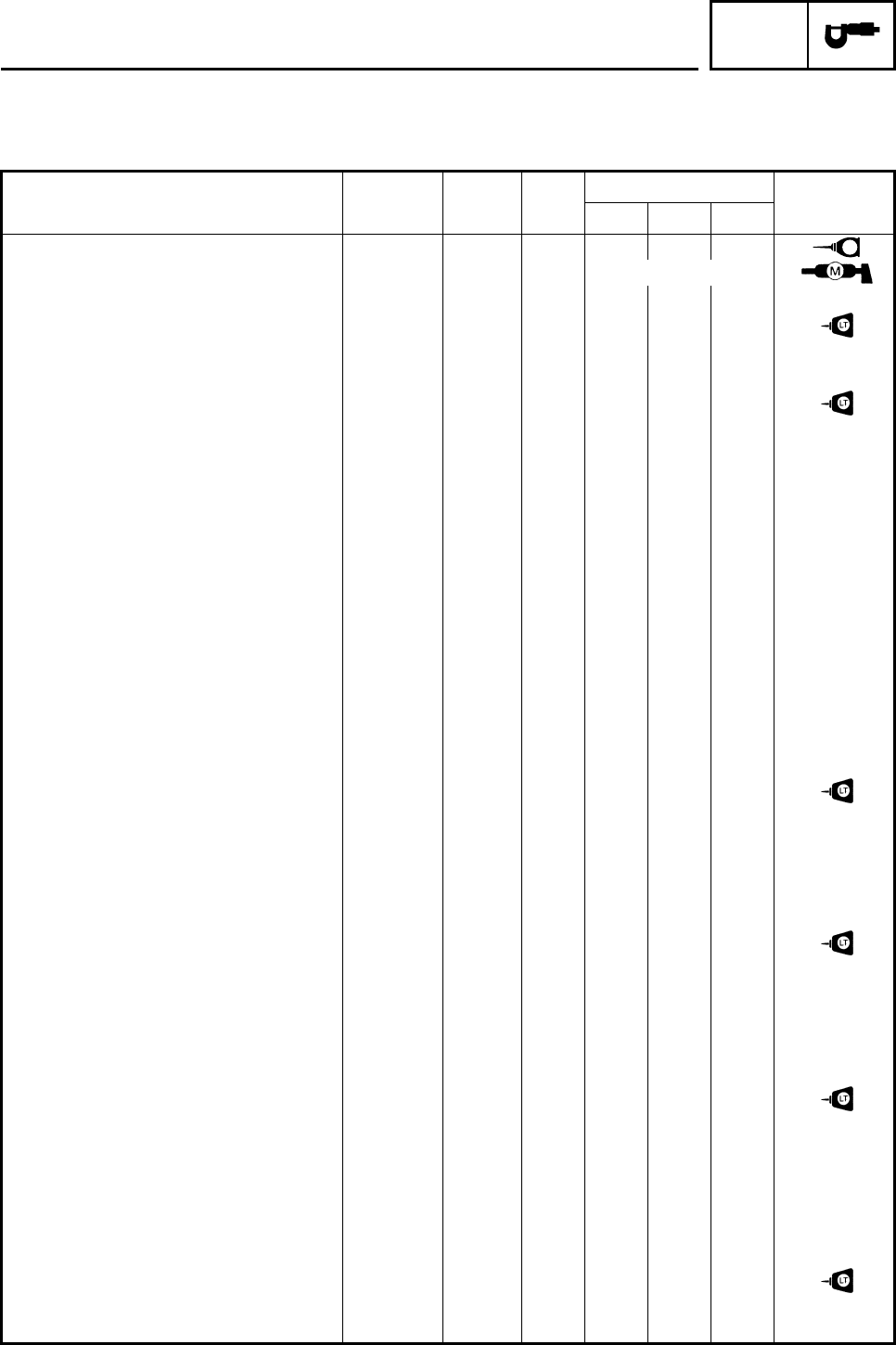
EBS01005
TIGHTENING TORQUES
ENGINE TIGHTENING TORQUES
Part to be tightened Part
name Thread
size Q’ty Tightening torque Remarks
Nm m•kg ft•lb
Cylinder head (upper) Bolt M8 4 24 2.4 18
See NOTE *1
Cylinder head Bolt M8 2 20 2.0 15
Camshaft lock plate Bolt M6 2 8 0.8 5.9
Cylinder head side cover (1 and 2) Bolt M55 2 18 1.8 13
Cylinder head side cover 3 Bolt M6 2 10 1.0 7.4
Cylinder head breather plate Bolt M6 2 10 1.0 7.4
Spark plug — M12 1 18 1.8 13
Cylinder head stud bolt Stud bolt M8 2 15 1.5 11
Oil gallery bolt Bolt M6 1 7 0.7 5.2
Carburetor joint Bolt M6 2 10 1.0 7.4
Plate, 2 Bolt M6 2 12 1.2 8.9
Cylinder Bolt M6 2 10 1.0 7.4
Left crankcase cover Bolt M6 9 10 1.0 7.4
Pickup coil rotor Bolt M10 1 60 6.0 44
Balancer weight gear Nut M12 1 55 5.5 41 Use a lock
washer.
Valve clearance adjusting locknut Nut M6 2 14 1.4 10
Camshaft sprocket Bolt M10 1 60 6.0 44
Timing chain tensioner Bolt M6 2 10 1.0 7.4
Timing chain tensioner cap bolt Bolt M6 1 8 0.8 5.9
Timing chain guide (intake side) Bolt M6 2 8 0.8 5.9
Oil filter element cover Bolt M6 3 10 1.0 7.4
Oil delivery pipe Union
bolt M10 1 20 2.0 15
Oil delivery pipe and cylinder Union
bolt M8 1 17 1.7 13
Oil pump assembly Screw M6 3 6 0.6 4.4
Carburetor joint clamp screw (front) Screw M4 2 4 0.4 3.0
Carburetor joint clamp screw (rear) Screw M4 1 4 0.4 3.0
Exhaust pipe nut Nut M8 2 18 1.8 13
Muffler joint Bolt M8 1 20 2.0 15
Muffler Bolt M8 2 34 3.4 25
Left crankcase cover Bolt M5 1 7 0.7 5.2
Right crankcase cover Bolt M6 13 10 1.0 7.4
Crankcase Bolt M6 12 10 1.0 7.4
Oil drain bolt Bolt M12 1 20 2.0 15
Ground lead, clutch cable holder Bolt M6 1 10 1.0 7.4
Neutral switch lead clamp Bolt M6 1 10 1.0 7.4
Starter idle gear cover Bolt M6 3 10 1.0 7.4
Starter clutch Bolt M8 3 30 3.0 22
Primary drive gear nut Nut M16 1 80 8.0 59 Use a lock
washer.
E
TIGHTENING TORQUES
SPEC
2-16
N
O
TE:
*1: Apply oil to the bearing surface of (upper) cylinder head bolt.
Further, apply molybdenum disulfide grease to thread part.
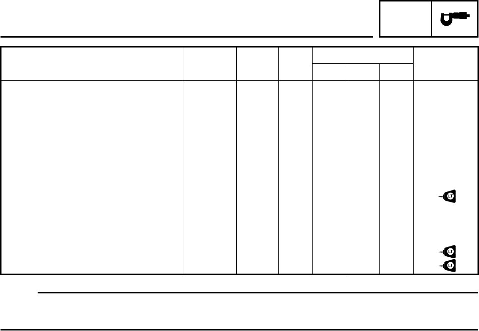
Part to be tightened Part
name Thread
size Q’ty Tightening torque Remarks
Nm m•kg ft•lb
Clutch boss nut Nut M16 1 75 7.5 55 Use a lock
washer.
Clutch spring Screw M6 5 8 0.8 5.9
Push lever adjusting screw locknut Nut M6 1 8 0.8 5.9
Push lever shaft Bolt M8 1 12 1.2 8.9
Chain case cover Bolt M10 2 10 1.0 7.4
Drive sprocket nut Nut M18 1 110 11.0 81 Use a lock
washer.
Stopper lever Bolt M6 1 10 1.0 7.4
Shift pedal Bolt M6 1 10 1.0 7.4
Neutral switch — M10 1 20 2.0 15
Starter motor Bolt M6 2 10 1.0 7.4
Stator coil Bolt M6 3 10 1.0 7.4
Pickup coil Bolt M6 2 10 1.0 7.4
TIGHTENING TORQUES
SPEC
2-17
EBS01006
CHASSIS TIGHTENING TORQUES
Part to be tightened Thread size Tightening torque Remarks
Nm m•kg ft•lb
Engine upper stay and frame M8 33 3.3 24
Engine upper stay and engine M10 66 6.6 49
Engine lower stay and engine M10 40 4.0 30
Engine and frame M10 66 6.6 49
Engine lower stay and frame M8 33 3.3 24
Swingarm pivot shaft and frame M14 100 10 74
Rear shock absorber and frame M12 55 5.5 41
Rear shock absorber locknut M20 42 4.2 31
Rear axle pinch bolt M8 21 2.1 15
Front shock absorber and frame M10 48 4.8 35
Front shock absorber and lower front arm M10 48 4.8 35
Upper front arm and frame M10 45 4.5 33
Lower front arm and frame M10 45 4.5 33
Steering stem and frame M10 35 3.5 26
Steering stem bushing and frame M8 23 2.3 17 Use a lock
washer.
Steering stem and handlebar holder M8 20 2.0 15
Tie-rod end and locknut M10 15 1.5 11
Steering knuckle and front wheel hub M14 70 7.0 52
Steering knuckle and front arm (upper and
lower) M10 25 2.5 18
Steering knuckle and tie-rod ball joint M10 25 2.5 18
Steering stem and tie-rod ball joint M10 25 2.5 18
Fuel tank and fuel cock M6 4 0.4 3.0
Fuel tank and frame M6 7 0.7 5.2
Front wheel and front wheel hub M10 45 4.5 33
Steering knuckle and front brake caliper bracket M8 28 2.8 21
Front brake disc and front wheel hub M8 28 2.8 21
Rear axle and rear wheel hub M14 120 12 89
Rear brake caliper and brake caliper bracket M8 34 3.4 25
Rear wheel and rear wheel hub M10 45 4.5 33
Driven sprocket and sprocket bracket M10 55 5.5 41
Front brake pipe nut M10 19 1.9 14
Front brake master cylinder and handlebar M6 7 0.7 5.2
Clutch lever holder and handlebar M5 4 0.4 3.0
Parking brake assembly and clutch lever holder M6 7 0.7 5.2
TIGHTENING TORQUES
SPEC
2-18
Part to be tightened Thread size Tightening torque Remarks
Nm m•kg ft•lb
Front brake master cylinder and brake lever M6 6 0.6 4.4
Throttle assembly and handlebar M5 4 0.4 3.0
Front brake master cylinder and brake hose M10 27 2.7 20
Brake hose joint and frame M6 10 1.0 7.4
Bleed screw M8 5 0.5 3.7
Front brake pad retaining bolt M10 17 1.7 13
Front brake caliper and brake hose M10 27 2.7 20
Rear brake caliper retaining bolt M8 17 1.7 13
Parking brake case and caliper M8 22 2.2 16
Rear axle ring nut M33 140 14 103
Rear axle ring nut set bolt M6 7 0.7 5.2
Rear brake pad retaining bolt M8 17 1.7 13 Use a lock
washer.
Rear brake caliper and brake hose M10 31 3.1 23
Rear brake master cylinder and frame M8 20 2.0 15
Rear brake master cylinder and brake hose M10 31 3.1 23
Parking brake adjusting bolt and locknut M8 15 1.5 11
Rear brake disc and brake disc bracket M8 28 2.8 21
Rear brake fluid reservoir, cover and bracket M6 7 0.7 5.2
Front bumper and frame M8 31 3.1 23
Front fender stay and frame M6 7 0.7 5.2
Side cover and frame M6 7 0.7 5.2
Rear fender and frame M6 7 0.7 5.2
Rear fender, air filter case and frame M6 7 0.7 5.2
Rear fender and rear fender stay M6 7 0.7 5.2
Front fender stay and front fender M6 7 0.7 5.2
Rear carrier bar and frame M8 31 3.1 23
Footrest and frame M10 73 7.3 54
Foot protector stay foot protector M6 7 0.7 5.2
Foot protector stay foot protector M5 6 0.6 4.4
Foot protector stay and frame M8 17 1.7 13
Foot protector stay and footrest M8 17 1.7 13
Battery cover, air filter case and frame M6 7 0.7 5.2
Headlight and frame M6 7 0.7 5.2
Tail/brake light bracket and air filter case M6 4 0.4 3.0
Drive chain guide roller and frame M8 23 2.3 17
Engine skid plate and frame M6 7 0.7 5.2
TIGHTENING TORQUES
SPEC
2-19
EBS00022
HOW TO USE THE CONVERSION
TABLE
All specification data in this manual are listed
in SI and METRIC UNITS.
Use this table to convert METRIC unit data to
IMPERIAL unit data.
Ex.
CONVERSION TABLE
EBS00023
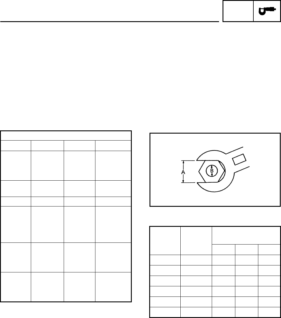
GENERAL TIGHTENING TORQUE
SPECIFICATIONS
This chart specifies tightening torques for
standard fasteners with a standard ISO thread
pitch. Tightening torque specifications for spe-
cial components or assemblies are provided
for each chapter of this manual. To avoid
warpage, tighten multi-fastener assemblies in
a crisscross pattern and progressive stages
until the specified tightening torque is reached.
Unless otherwise specified, tightening torque
specifications require clean, dry threads. Com-
ponents should be at room temperature.
A: Distance between flats
B: Outside thread diameter
METRIC MULTIPLIER IMPERIAL
** mm ×0.03937 = ** in
2 mm ×0.03937 = 0.08 in
METRIC TO IMPERIAL
Metric unit Multiplier Imperial unit
Torque
m•kg
m•kg
cm•kg
cm•kg
7.233
86.794
0.0723
0.8679
ft•lb
in•lb
ft•lb
in•lb
Weight kg
g2.205
0.03527 lb
oz
Speed km/hr 0.6214 mph
Distance
km
m
m
cm
mm
0.6214
3.281
1.094
0.3937
0.03937
mi
ft
yd
in
in
Volume /
Capacity
cc (cm3)
cc (cm3)
lt (liter)
lt (liter)
0.03527
0.06102
0.8799
0.2199
oz (IMP liq.)
cu•in
qt (IMP liq.)
gal (IMP liq.)
Misc.
kg/mm
kg/cm2
Centigrade
(°C)
55.997
14.2234
9/5+32
lb/in
psi (lb/in2)
Fahrenheit
(°F)
A
(nut) B
(bolt)
General tightening
torques
Nm m•kg ft•lb
10 mm 6 mm 6 0.6 4.3
12 mm 8 mm 15 1.5 11
14 mm 10 mm 30 3.0 22
17 mm 12 mm 55 5.5 40
19 mm 14 mm 85 8.5 61
22 mm 16 mm 130 13.0 94
HOW TO USE THE CONVERSION TABLE/
GENERAL TIGHTENING TORQUE SPECIFICATIONS
SPEC
2-20
EBS00024
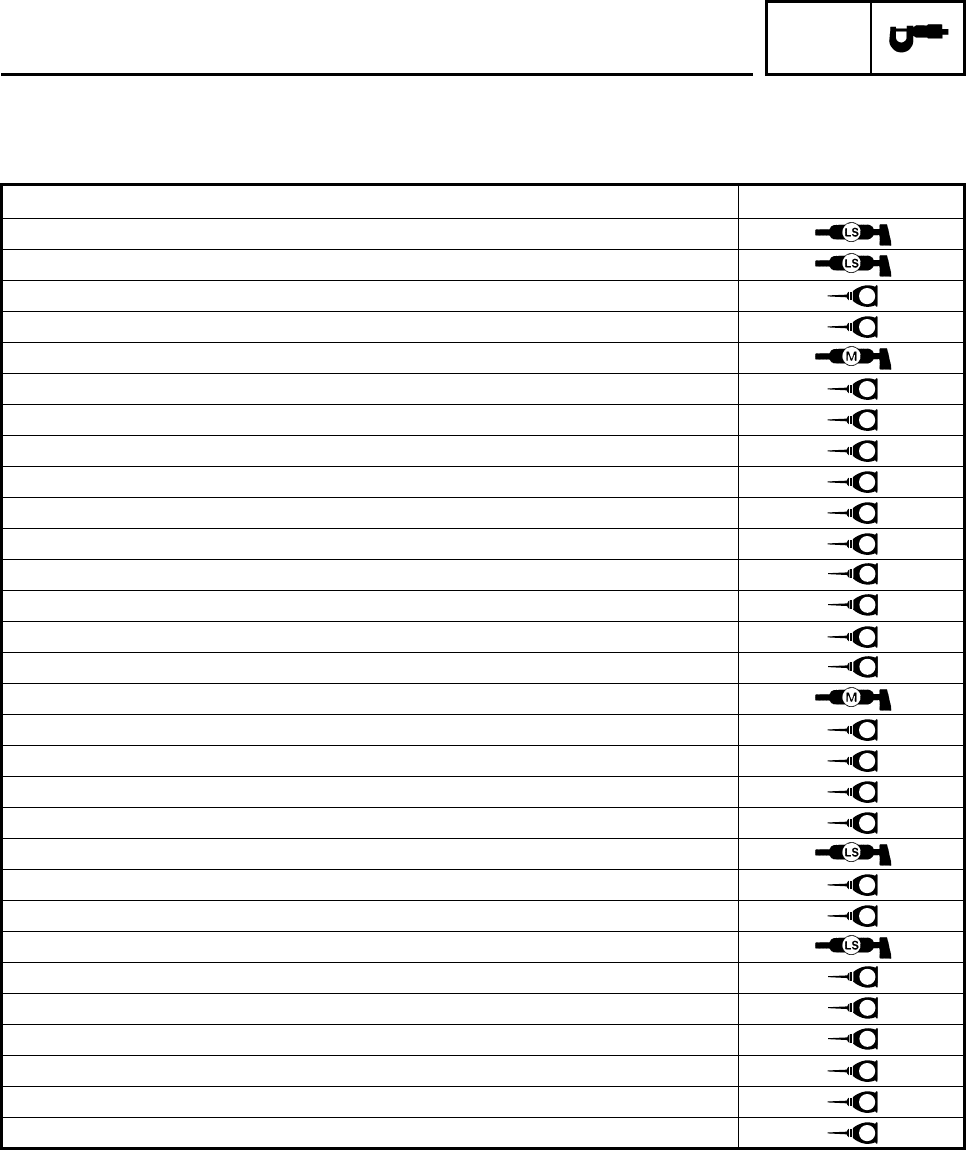
LUBRICATION POINTS AND LUBRICANT TYPES
ENGINE
Lubrication point Lubricant
Oil seal lips
O-rings
Bearings
Cylinder head bolts (bearing surface of bolts)
Cylinder head bolts (thread part)
Cylinder body surface
Crankshaft journals
Connecting rod small end and big end
Piston pin
Piston surface
Boss periphery
Valve stems (intake and exhaust)
Valve stem ends (intake and exhaust)
Rocker arm shafts (intake and exhaust)
Camshaft
Valve rocker arms
Oil pump rotors (inner and outer) and oil pump housing and shaft
Starter idler gears 1
Starter idler gears 2
Starter wheel gear
Push rods
Clutch housing (primary driven gear)
Push lever shaft
Push rod ball
Drive axle
Main axle
Transmission gears (inside and end)
Shift fork guide bar
Shift drum
Shift shaft
E
E
E
E
E
E
E
E
M
M
E
M
E
E
E
E
E
E
M
M
M
E
E
E
LUBRICATION POINTS AND LUBRICANT TYPES
SPEC
2-21
Lubrication point Lubricant
Crankcase mating surfaces
Sealant
(Three Bond No.1215®)
Yamaha bond
No.1215
AC magneto lead grommet (AC magneto cover)
Sealant
(Three Bond No.1215®)
Yamaha bond
No.1215
LUBRICATION POINTS AND LUBRICANT TYPES
SPEC
2-22
EBS00026
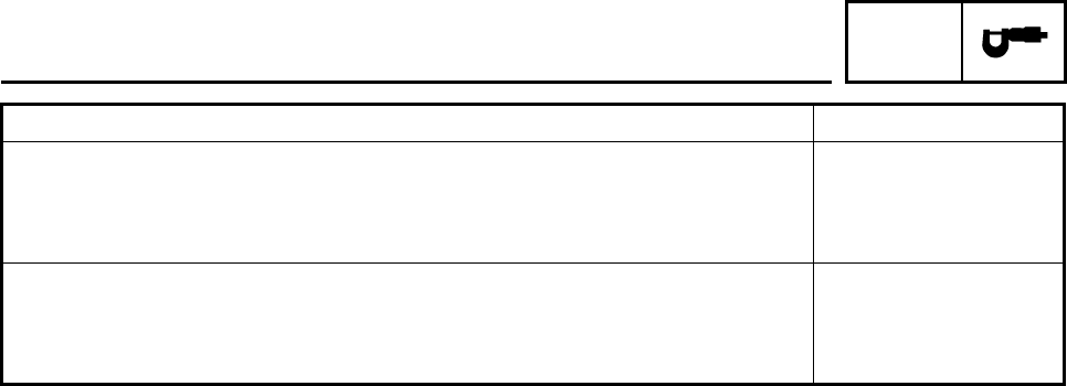
OIL FLOW DIAGRAMS
Camshaft
Oil filter element
Oil pump
Oil strainer
Oil cooler
Drive axle Main axle
Pin,
with hole
Crank
shaft
Oil pump
Oil strainer
Cylinder
head
Cam shaft
Oil pan
Oil filter
OIL FLOW DIAGRAMS
SPEC
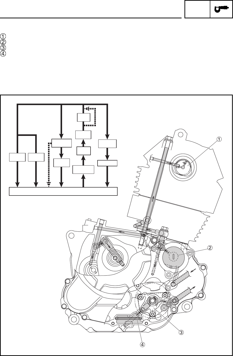
2-23
Camshaft
Drive axle
Main axle
Push lever shaft
Oil pump assembly
Oil strainer
Crankshaft assembly
Oil filter element
OIL FLOW DIAGRAMS
SPEC
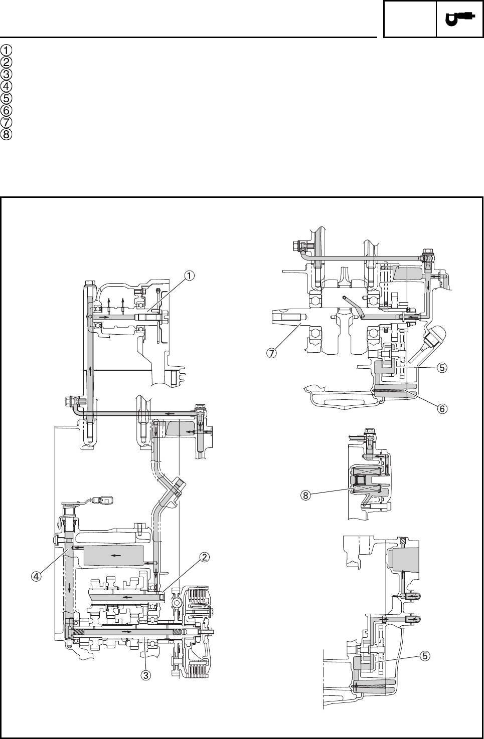
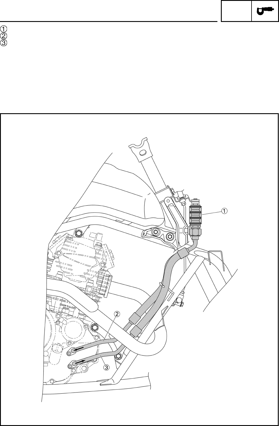
2-24
Oil cooler
Oil hose 1
Oil hose 2
OIL FLOW DIAGRAMS
SPEC
2-25
EBS00028
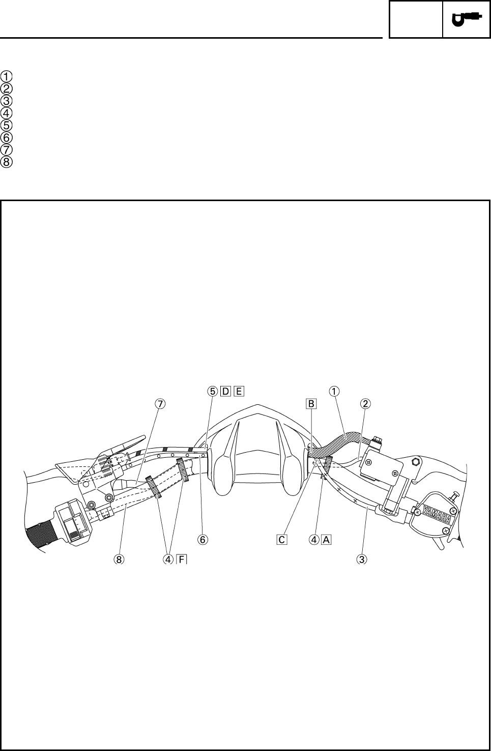
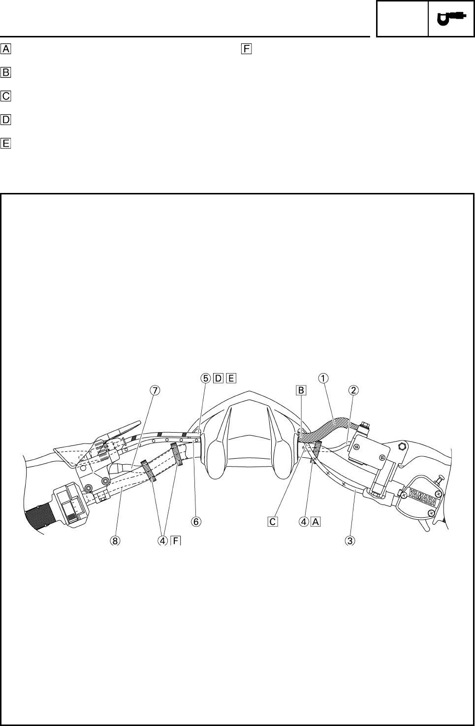
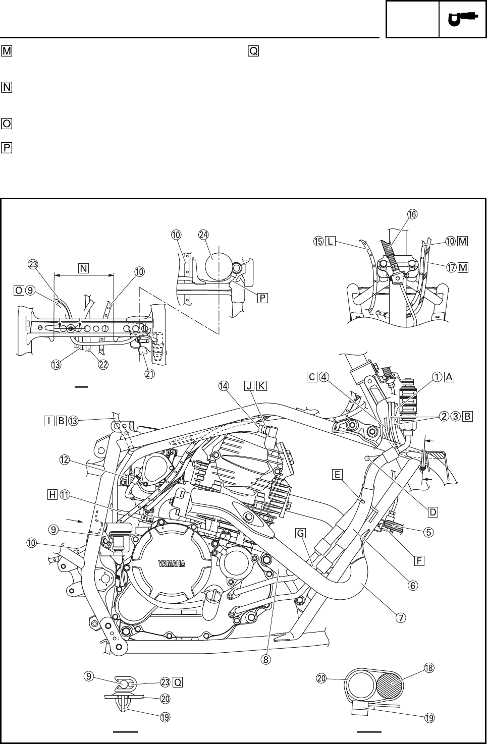
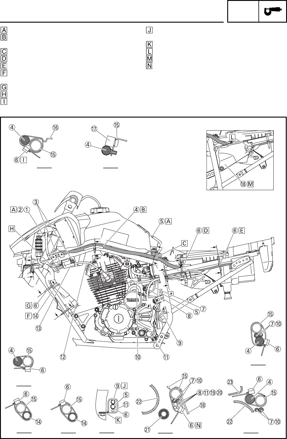
CABLE ROUTING
Front brake hose
Front brake light switch lead
Throttle cable
Plastic band
Clutch cable
Parking brake cable
Clutch switch lead
Handlebar switch lead
CABLE ROUTING
SPEC
2-26
Clamp the front brake light switch lead at the
bends of handlebar.
Route the front brake hose and throttle cable
through the guide of the handlebar protector.
Route the throttle cable under the front brake
hose.
Route the clutch cable and parking brake cable
through the guide of the handlebar protector.
Route the clutch cable in front of the parking brake
cable.
Clamp the clutch switch lead and handlebar switch
lead at the bends of handlebar.
CABLE ROUTING
SPEC
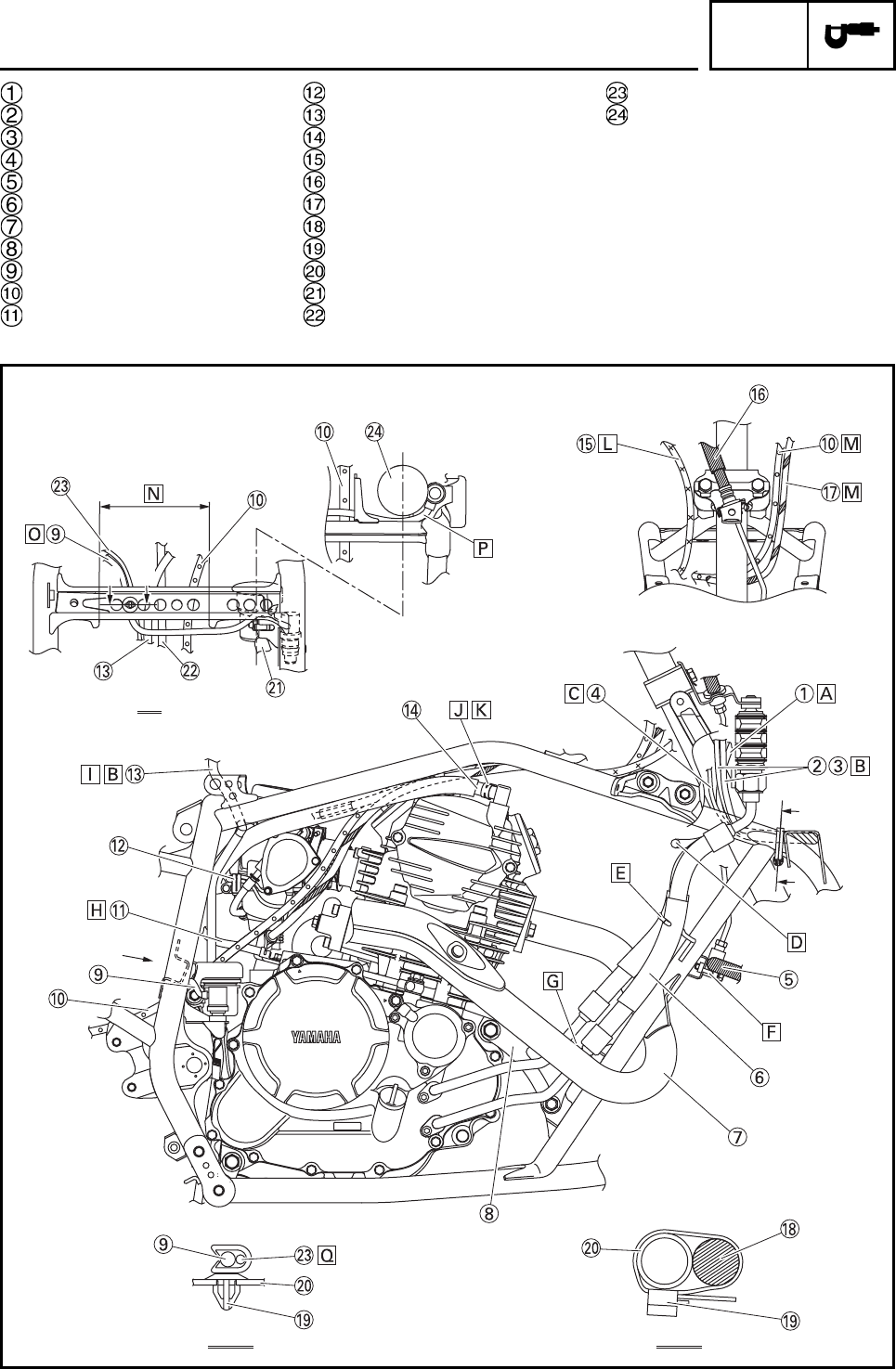
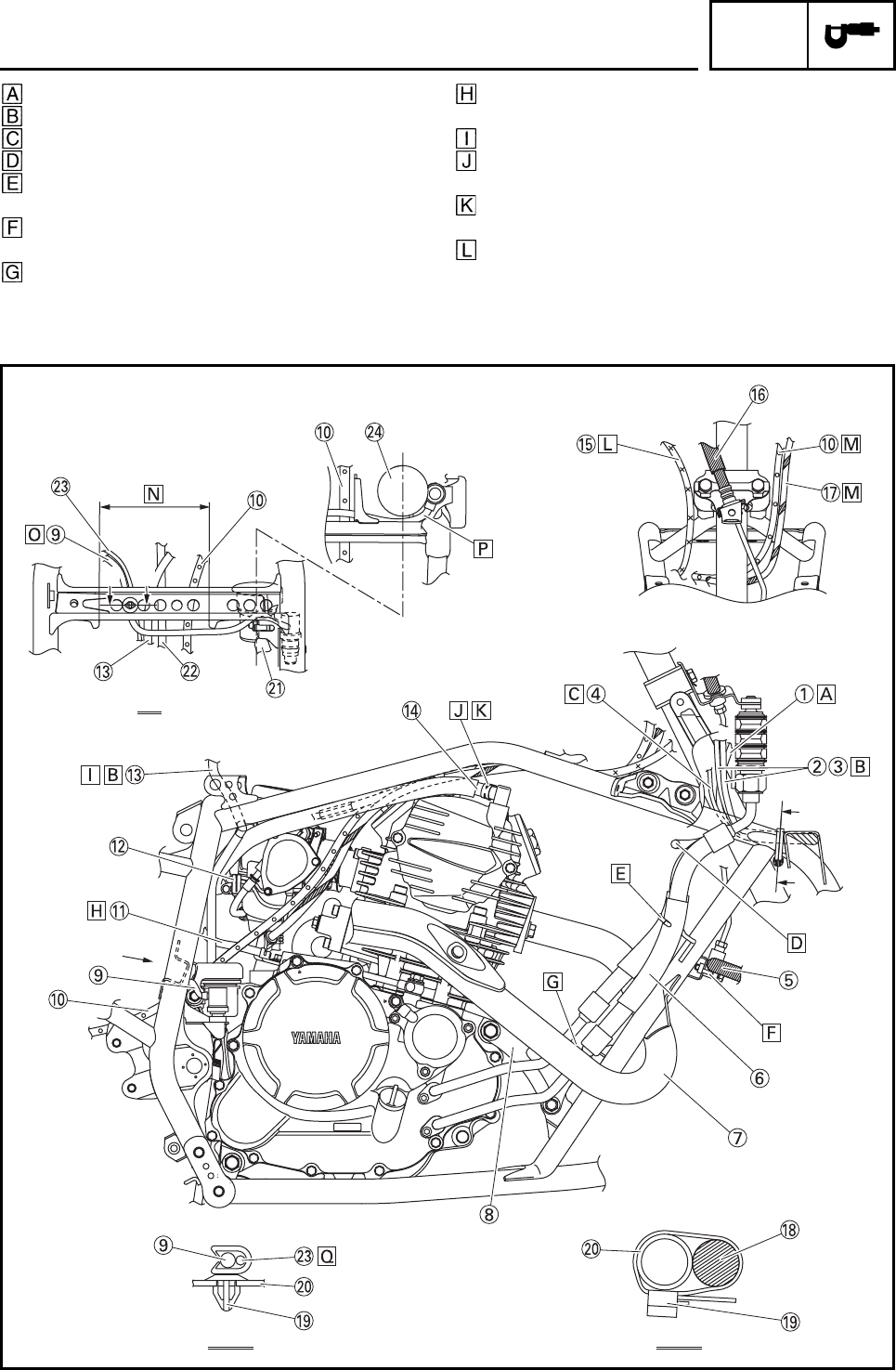
2-27
Indicator light lead
Main switch lead
Coupler joint
Front brake light switch lead
Front brake hose 2
Oil cooler hose 1, 2
Exhaust pipe
Engine bracket
Rear brake light switch lead
Parking brake cable
Battery negative lead
Carburetor warmer lead
Air vent hose
Air filter case breather hose
Throttle cable
Front brake hose 1
Clutch cable
Main harness
Clamp
Frame complete
Rear brake reservoir hose
Carburetor overflow hose
Neutral switch lead
Rear brake reservoir cover
H
H
H-H
F
A-A
F
AA
CABLE ROUTING
SPEC
2-28
To the front panel
To the front fender
To the handlebar
To the right headlight
Make sure to route the oil cooler hoses 1and 2
through the guide wire.
Install the front brake hose 2, making sure to face
the white paint mark forward.
Route the oil cooler hose 1 and 2 between the
exhaust pipe and the engine bracket.
Route the battery negative lead behind the clutch
cable holder.
Route the air vent hose through the bracket.
Make sure that the white paint mark on the air filter
case breather hose
Make sure that the clip end is facing the left side of
the vehicle.
Route the throttle cable under the cross pipe and
left of the steering column as shown in the illustra-
tion.
CABLE ROUTING
H
H
H-H
F
A-A
F
AA
SPEC
2-29
Route the parking brake cable and the clutch cable
under the cross pipe and right of the steering col-
umn as shown in the illustration.
Route the rear brake light switch lead, neutral
switch lead, air vent hose, carburetor overflow
hose and parking brake cable through the bracket.
Route the rear brake light switch lead under the
bracket.
Route the rear brake light switch lead between the
bracket and rear brake reservoir tank.
Route the neutral switch lead and rear brake light
switch lead as shown in the illustration.
H
H
H-H
F
A-A
F
AA
CABLE ROUTING
SPEC
2-30
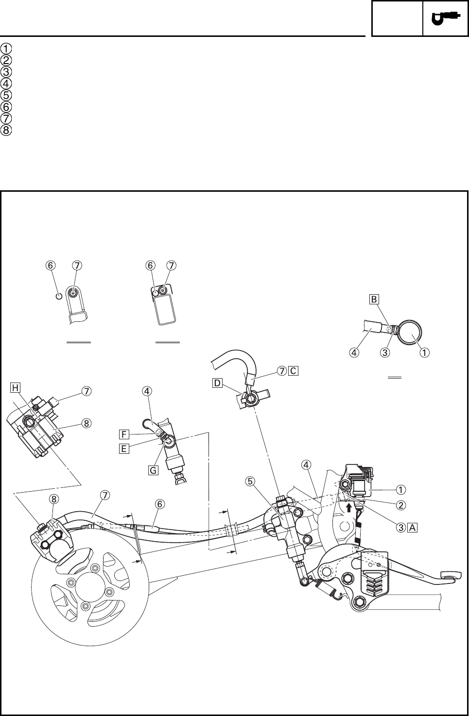
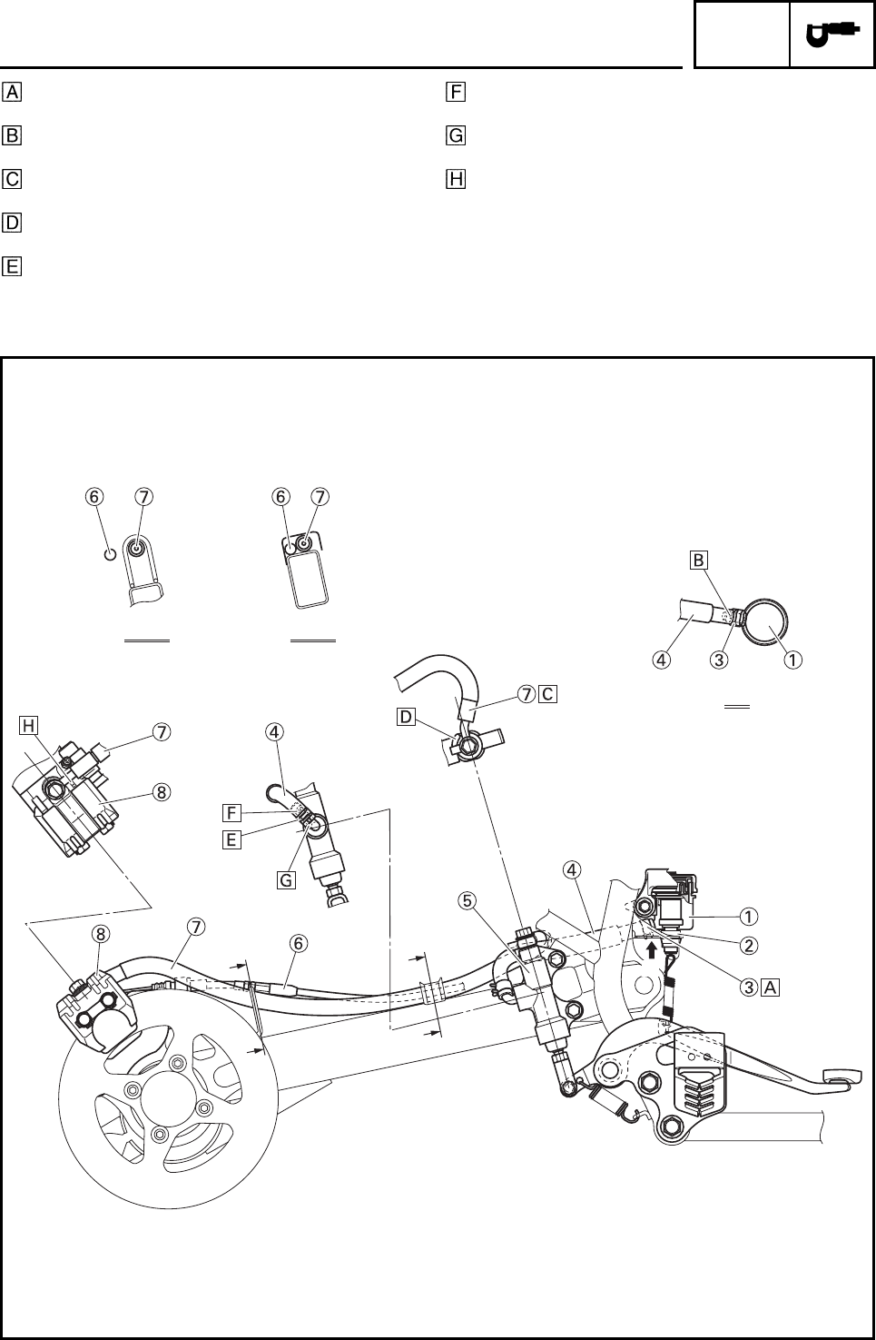
Rear brake reservoir
Rear brake light switch
Clip
Rear brake reservoir hose
Rear brake master cylinder
Parking brake cable
Rear brake hose
Rear brake caliper
E
E
D-D C-C
D
D
C
C
CABLE ROUTING
SPEC
2-31
Make sure that the end of the clip is facing down-
ward.
Set the rear brake reservoir hose with the position-
ing yellow paint mark pointing down.
Install the rear brake hose in the direction shown in
the illustration.
Insert the rear brake hose until it contacts the pro-
jection.
Make sure that the end of the clip is facing out-
ward.
Install the rear brake reservoir hose, making sure
to face the white paint mark outward.
Insert the rear brake reservoir hose until it contacts
the projection.
When installing the rear brake hose, make sure
that the metal part on the rear brake Inlet hose is
touching the stopper of the rear caliper.
E
E
D-D C-C
D
D
C
C
CABLE ROUTING
SPEC
2-32
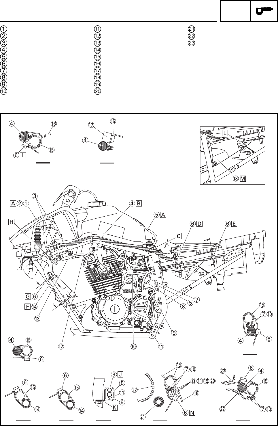
Clutch switch lead
Handlebar switch lead
Bolt
Main harness
Air vent hose
Clamp
Battery negative lead
AC magneto lead
Carburetor overflow hose
Starter motor lead
Neutral switch lead
Ignition coil spark plug lead
Ignition coil
Drain hose
Frame complete
Damper plate
Seat pad
Cover
Rear brake light switch lead
Carburetor warmer lead
Air filter case breather hose
Air filter joint
Air filter case
D
M
D
L-L M-M
E-E
B-B
C-C
D-D
G-G
N-N
I-I
M
E
E
B
N
L
L
N
I
I
BG
G
CC
CABLE ROUTING
SPEC
2-33
To the front fender
Route the wire harness above the guide for the
damper plate.
Fix point for wire harness
Clamp near the hook of the air filter.
Clamp near the edge of the air filter case.
Route the drain hose in front of the left oil cooler
hose.
Clamp on top of the frame bracket.
To the left headlight
Route the clamp through the damper plate hole.
Route the carburetor overflow hose as shown in
the illustration.
Fasten the clamp with the engine.
Route the leads on the upper inside of the cover.
Place the couplers on the inside of the cover.
Route the clamp through the frame bracket.
D
M
D
L-L M-M
E-E
B-B
C-C
D-D
G-G
N-N
I-I
M
E
E
B
N
L
L
N
I
I
BG
G
CC
CABLE ROUTING
SPEC
2-34
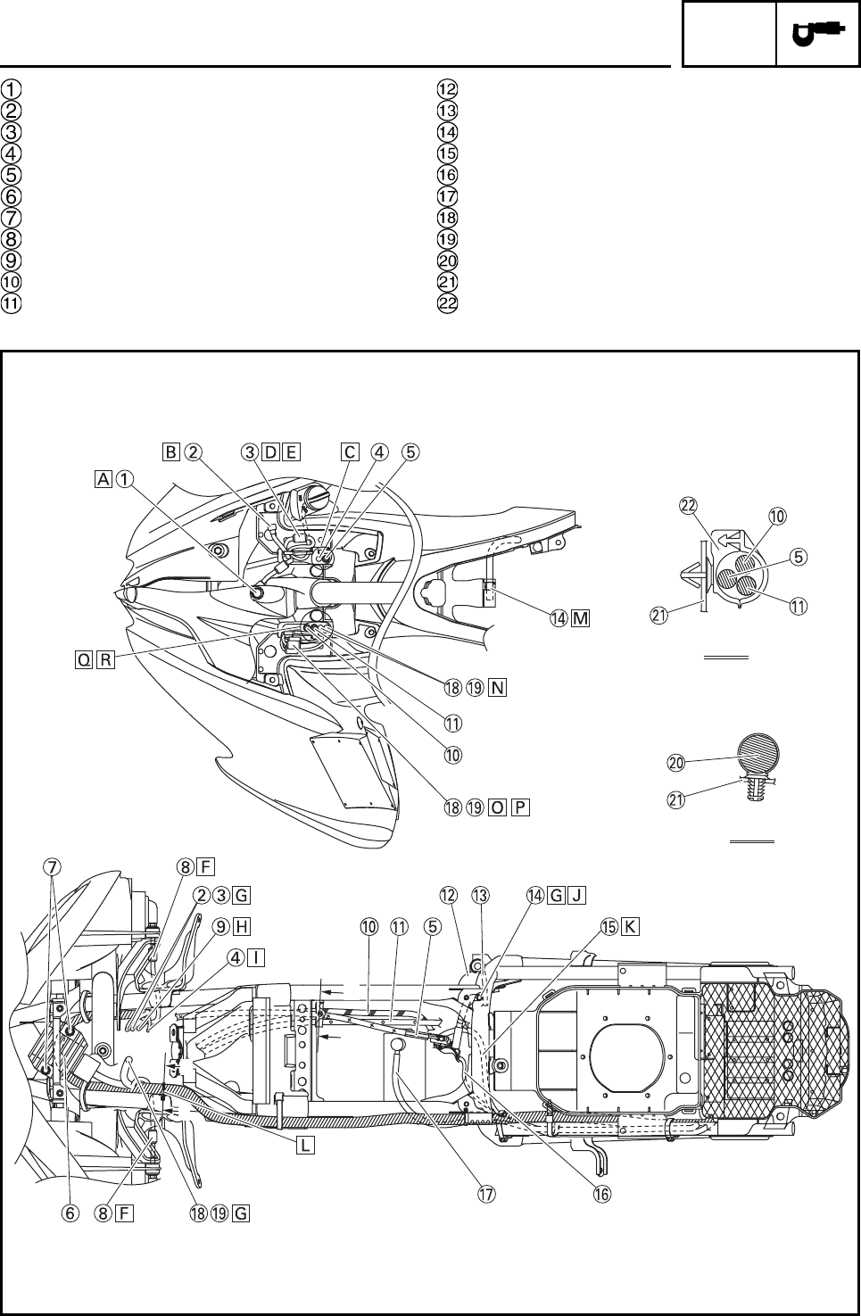
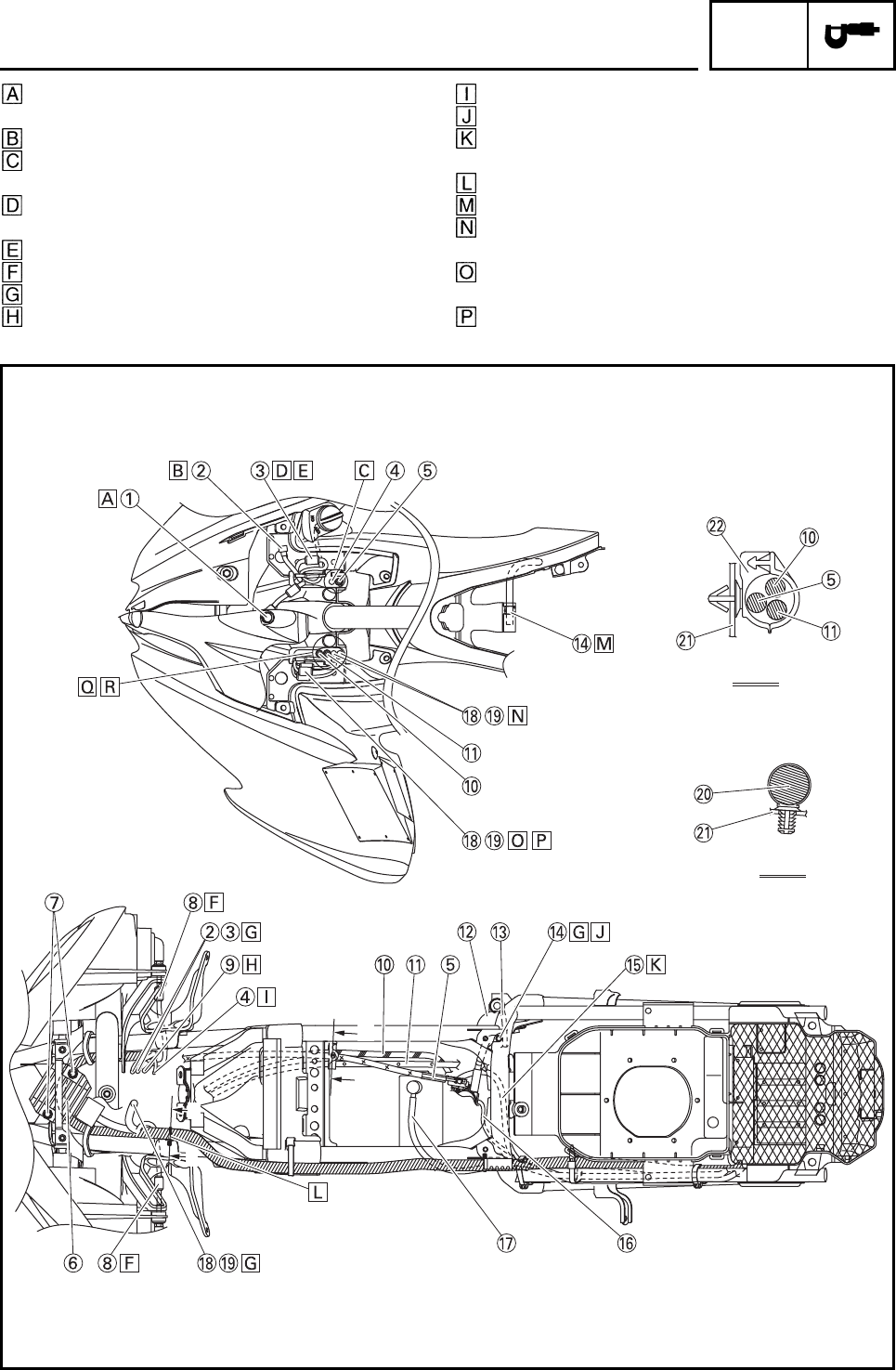
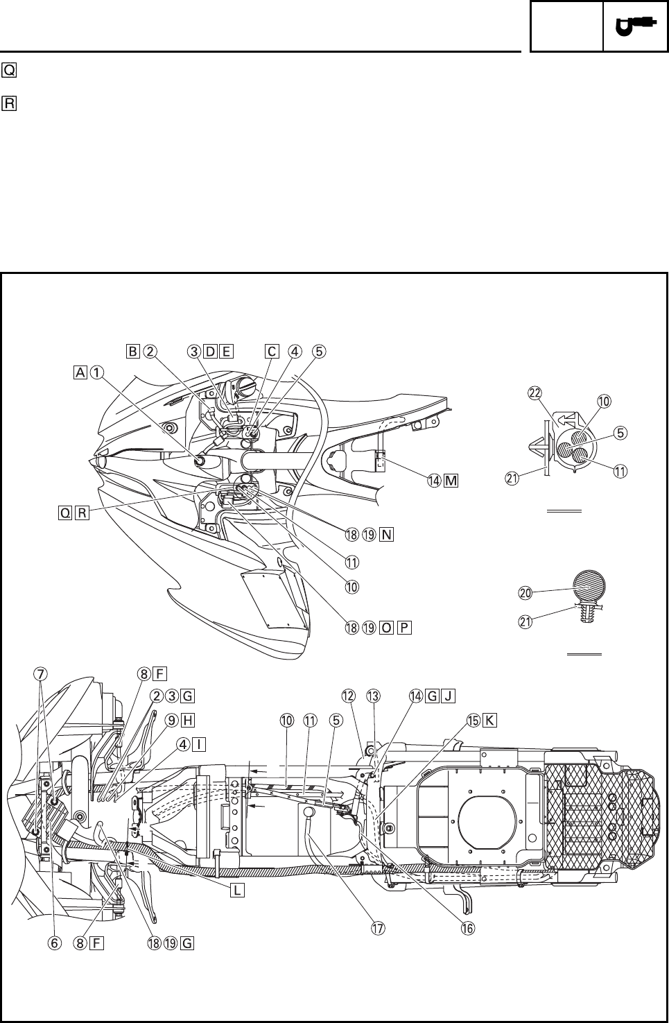
Indicator light
Coupler joint
Main switch lead
Front brake light switch lead
Throttle cable
Regulator
Flange bolt
Headlight lead
Indicator light lead
Clutch cable
Parking brake cable
Rear brake reservoir
Rear brake light switch lead
Air vent hose
Battery negative lead
Carburetor warmer lead
Starter motor lead
Clutch switch lead
Handlebar switch lead
Main harness
Frame complete
Clamp
N
N
J
J
K
K
J-J
K-K
CABLE ROUTING
SPEC
2-35
Install the indicator light as shown in the illustra-
tion.
Place the coupler joint above the front fender.
Route the front brake light switch lead and throttle
cable through the guide.
Connect the main switch lead on top of the front
fender.
Route both leads from the front.
Route the headlight lead under the frame.
To the front fender
To the front panel
To the handlebar
Route the air vent hose through the bracket.
Route the battery negative lead behind the clutch
cable holder.
Fix point for wire harness
Insert the air vent hose into the fender.
Route the clutch switch lead and handlebar switch
lead on the box shaped part.
Connect the clutch switch lead and handlebar
switch lead on top of the front fender.
Route the wire harness from the front.
N
N
J
J
K
K
J-J
K-K
CABLE ROUTING
SPEC
2-36
Route the cables and leads through the guide of
the front fender.
Route the leads behind the clutch and parking
brake cable.
CABLE ROUTING
N
N
J
J
K
K
J-J
K-K
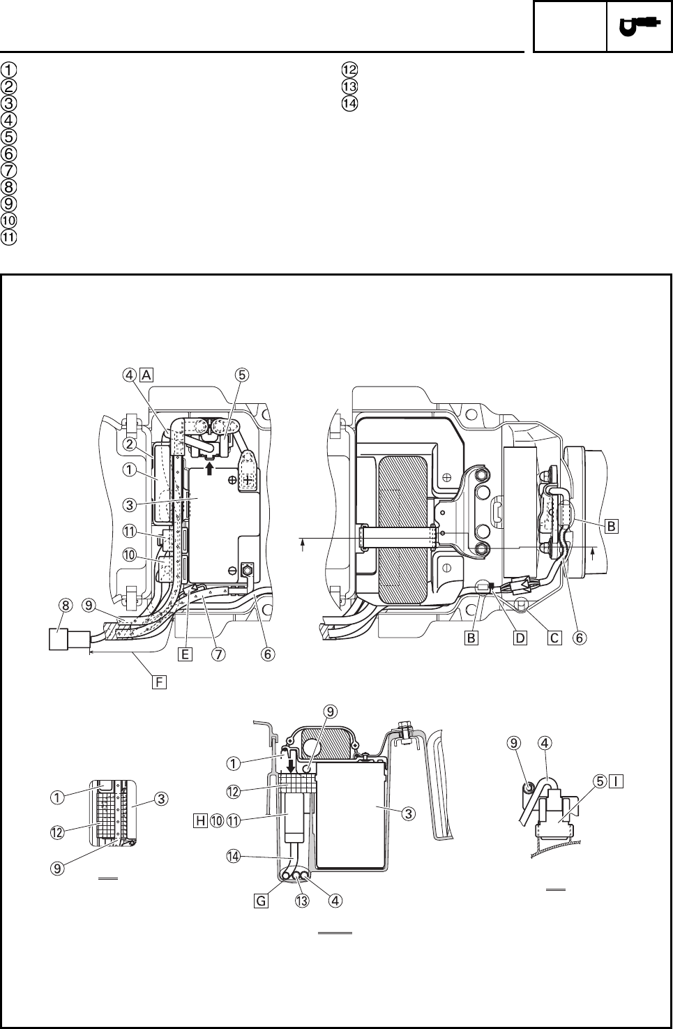
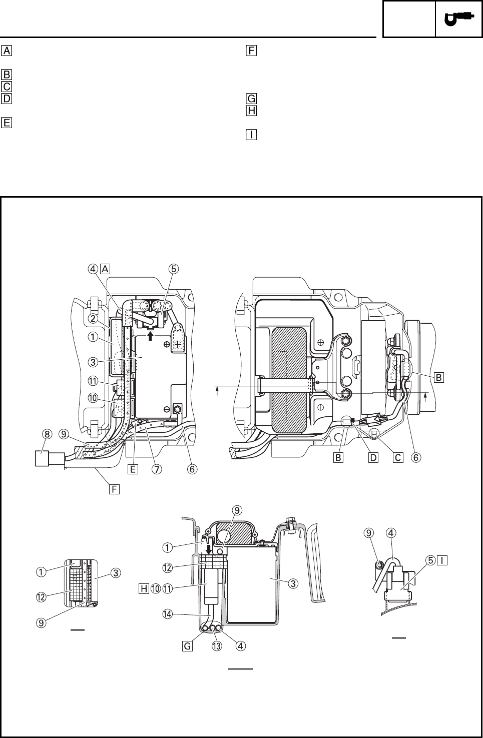
SPEC
2-37
CDI unit
Band
Battery
Starter relay lead
Starter relay
Taillight lead
Battery negative lead
AC magneto coupler
Starter motor lead
Headlight relay
Neutral relay
Damper
CDI unit lead
Relay lead
CABLE ROUTING
J
AA
B
A-A
J
B
SPEC
2-38
Route the starter relay lead under the starter
motor lead.
Clamp the taillight lead.
Do not clamp.
When clamping the wire harness, make sure that
the insulator lock is behind the clamp.
After connecting the battery negative lead, push
the sag in the box.
After connecting the taillight lead and each electric
part, the length between the air filter and AC mag-
neto coupler should be 185 mm (7.28 in) on
straight line.
There is no particular order in placing each lead.
Insert each relay all the way into the rib on the air
filter side.
Insert the starter relay all the way into the rib on
the air filter side.
J
AA
B
A-A
J
B
CABLE ROUTING
CHK
ADJ
3-1
EBS00029 PERIODIC CHECKS AND ADJUSTMENTS
INTRODUCTION
This chapter includes all information necessary to perform recommended checks and adjustments.
These preventive maintenance procedures, if followed, will ensure more reliable machine operation
and a longer service life. The need for costly overhaul work will be greatly reduced. This information
applies to machines already in service as well as to new machines that are being prepared for sale.
All service technicians should be familiar with this entire chapter.
PERIODIC MAINTENANCE CHART FOR THE EMISSION CONTROL
SYSTEM
N
O
TE:
• For ATVs not equipped with an odometer or an hour meter, follow the month maintenance inter-
vals.
• For ATVs equipped with an odometer or an hour meter, follow the km (mi) or hours maintenance
intervals. However, keep in mind that if the ATV isn’t used for a long period of time, the month main-
tenance intervals should be followed.
• Items marked with an asterisk should be performed by a Yamaha dealer as they require special
tools, data and technical skills.
NO. ITEM CHECK OR MAINTENANCE
JOB
Whichever
comes
first
INITIAL EVERY
month136612
km
(mi)
320
(200)
1300
(800)
2500
(1600)
2500
(1600)
5000
(3200)
hours 20 80 160 160 320
1 * Fuel line • Check fuel hoses for cracks or other damage, and replace
if necessary. √√√
2 Spark plug • Check condition and clean, regap, or replace if necessary. √√√√√
3 * Valves • Check valve clearance and adjust if necessary. √√√√
4 * Carburetor • Check starter (choke) operation and correct if necessary.
• Check engine idling speed and adjust if necessary. √√√√
5*
Crankcase breather
system
• Check breather hose for cracks or other damage, and
replace if necessary. √√√
6 * Exhaust system
• Check for leakage and replace gasket(s) if necessary.
• Check for looseness and tighten all screw clamps and
joints if necessary.
√√√
7 Spark arrester • Clean. √√√
INTRODUCTION/PERIODIC MAINTENANCE
CHART FOR THE EMISSION CONTROL SYSTEM

CHK
ADJ
3-2
1
2
3
4
5
6
7
8
GENERAL MAINTENANCE AND LUBRICATION CHART
NO. ITEM CHECK OR MAINTENANCE
JOB
Whichever
comes
first
INITIAL EVERY
month136612
km
(mi)
320
(200)
1300
(800)
2500
(1600)
2500
(1600)
5000
(3200)
hours 20 80 160 160 320
1 Air filter element • Clean and replace if necessary. Every 20 ~ 40 hours (more often in wet or dusty
areas)
2*Clutch • Check operation and adjust if necessary. √√√√
3 * Front brake
• Check operation and correct if necessary.
• Check fluid level and ATV for fluid leakage, and correct if
necessary.
√√√√√
• Replace brake pads. Whenever worn to the limit
4 * Rear brake
• Check operation and correct if necessary.
• Check fluid level and ATV for fluid leakage, and correct if
necessary.
√√√√√
• Replace brake pads. Whenever worn to the limit
5 * Brake hoses
• Check for cracks or other damage, and replace if neces-
sary. √√√√
• Replace. Every 4 years
6 * Parking brake • Check operation and adjust if necessary. √√√√√
7 * Wheels • Check runout and for damage, and replace if necessary. √√√√
8*Tires
• Check tread depth and for damage, and replace if neces-
sary.
• Check air pressure and balance, and correct if necessary.
√√√√
9 * Wheel hub bearings • Check for looseness or damage, and replace if necessary. √√√√
10 * Swingarm pivots
• Check operation and for excessive play, and replace bear-
ings if necessary.
• Lubricate with lithium-soap-based grease.
√√√
11 * Upper and lower arm
pivots • Lubricate with lithium-soap-based grease. √√√
12 Drive chain
• Check chain slack and adjust if necessary.
• Check rear wheel alignment and correct if necessary.
• Clean and lubricate.
√√√√√
13 * Drive chain rollers • Check for wear and replace if necessary. √√√
14 * Chassis fasteners • Make sure that all nuts, bolts, and screws are properly
tightened. √√√√√
15 * Shock absorber assem-
blies
• Check operation and correct if necessary.
• Check for oil leakage and replace if necessary. √√√
16 *
Rear suspension relay
arm and connecting
arm pivoting points
• Check operation and correct if necessary.
• Lubricate with lithium-soap-based grease. √√√√
17 * Steering shaft • Lubricate with lithium-soap-based grease. √√√
18 * Steering system • Check operation and repair or replace if damaged.
• Check toe-in and adjust if necessary. √√√√√
19 * Engine mount • Check for cracks or other damage, and replace if neces-
sary. √√√
20 Engine oil • Change.
• Check ATV for oil leakage, and correct if necessary. √√√√
21 Engine oil filter element • Clean or replace if necessary. √√√
22 * Moving parts and
cables • Lubricate. √√√√
23 * Throttle lever housing
and cable
• Check operation and correct if necessary.
• Check throttle cable free play and adjust if necessary.
• Lubricate throttle lever housing and cable.
√√√√√
24 * Front and rear brake
switches • Check operation and correct if necessary. √√√√√
25 * Lights and switches • Check operation and correct if necessary.
• Adjust headlight beams. √√√√√
GENERAL MAINTENANCE AND LUBRICATION CHART
CHK
ADJ
3-3
N
O
TE:
• The air filter needs more frequent service if you are riding in unusually wet or dusty areas.
• Hydraulic brake service
• Regularly check and, if necessary, correct the brake fluid level.
• Every two years replace the internal components of the brake master cylinders and calipers, and
change the brake fluid.
• Replace the brake hoses every four years and if cracked or damaged.
WARNING
Indicates a potential hazard that could result in serious injury or death.
GENERAL MAINTENANCE AND LUBRICATION CHART
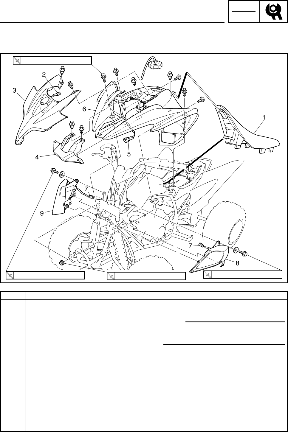
CHK
ADJ
3-4
EBS00033
SEAT, FENDERS AND FUEL TANK
SEAT, FRONT FENDER AND HEADLIGHTS
Order Job/Part Q’ty Remarks
Removing the seat, front fender and
headlights Remove the parts in the order listed.
1 Seat 1 N
O
TE:N
O
TE:
Pull back the seat lock lever, than pull up
on the rear of the seat.
2 Indicator light coupler 1 Disconnect.
3 Front panel 1
4Plate 1
5 Main switch coupler 1 Disconnect.
6 Front fender 1
7 Headlight coupler 2 Disconnect.
8 Left headlight 1
9 Right headlight 1
For installation, reverse the removal
procedure.
7 Nm (0.7 m•kg, 5.2 ft•Ib)
7 Nm (0.7 m•kg, 5.2 ft•Ib) 7 Nm (0.7 m•kg, 5.2 ft•Ib) 7 Nm (0.7 m•kg, 5.2 ft•Ib)
SEAT, FENDERS AND FUEL TANK
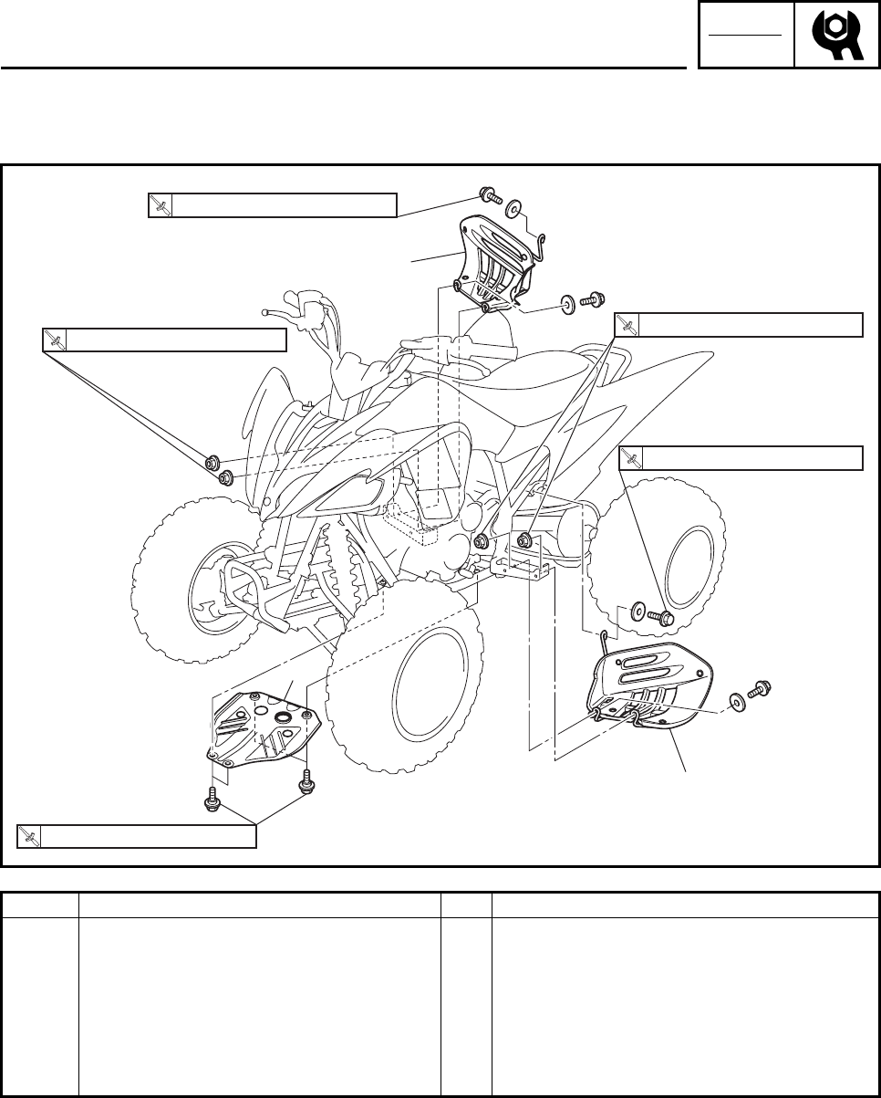
CHK
ADJ
3-5
EBS00034
FOOT PROTECTORS AND ENGINE SKID PLATE
Order Job/Part Q’ty Remarks
Removing the foot protectors and
engine skid plate Remove the parts in the order listed.
1 Left foot protector 1
2 Right foot protector 1
3 Engine skid plate 1
For installation, reverse the removal
procedure.
2
1
3
T
R
.
.
T
R
.
.
T
R
.
.
T
R
.
.
T
R
.
.
17 Nm (1.7 m•kg, 13 ft•Ib)
7 Nm (0.7 m•kg, 5.2 ft•Ib)
17 Nm (1.7 m•kg, 13 ft•Ib) 17 Nm (1.7 m•kg, 13 ft•Ib)
17 Nm (1.7 m•kg, 13 ft•Ib)
SEAT, FENDERS AND FUEL TANK
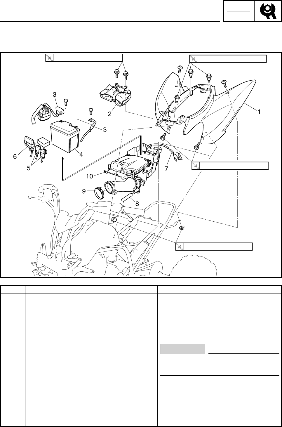
CHK
ADJ
3-6
REAR FENDER AND AIR FILLTER CASE
Order Job/Part Q’ty Remarks
Removing the rear fender and air
fillter case Remove the parts in the order listed.
Seat/front fender Refer to “SEAT, FENDERS AND FUEL
TANK”.
1 Rear fender 1
2 Battery cover 1
3 Battery lead 2 CAUTION:
First disconnect the negative lead,
then disconnect the positive lead.
4 Battery 1
5Relay 2
6 CDI unit 1
7 Tail/brake light lead 1 Disconnect.
8 Air filter case breather hose 1 Disconnect.
9 Clamp 1 Loosen.
7 Nm (0.7 m•kg, 5.2 ft•Ib) 7 Nm (0.7 m•kg, 5.2 ft•Ib)
7 Nm (0.7 m•kg, 5.2 ft•Ib)
7 Nm (0.7 m•kg, 5.2 ft•Ib)
SEAT, FENDERS AND FUEL TANK
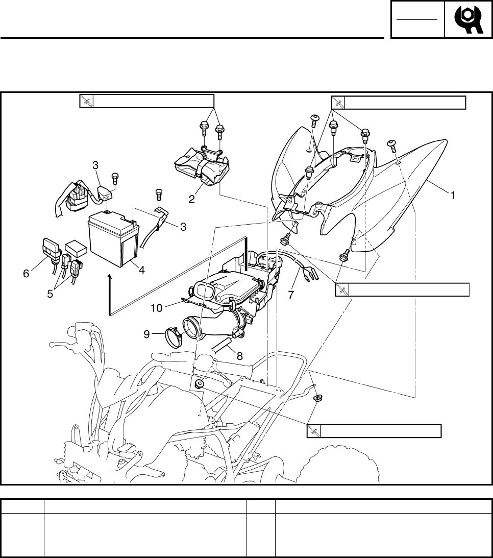
CHK
ADJ
3-7
Order Job/Part Q’ty Remarks
10 Air filter case 1
For installation, reverse the removal
procedure.
7 Nm (0.7 m•kg, 5.2 ft•Ib) 7 Nm (0.7 m•kg, 5.2 ft•Ib)
7 Nm (0.7 m•kg, 5.2 ft•Ib)
7 Nm (0.7 m•kg, 5.2 ft•Ib)
SEAT, FENDERS AND FUEL TANK
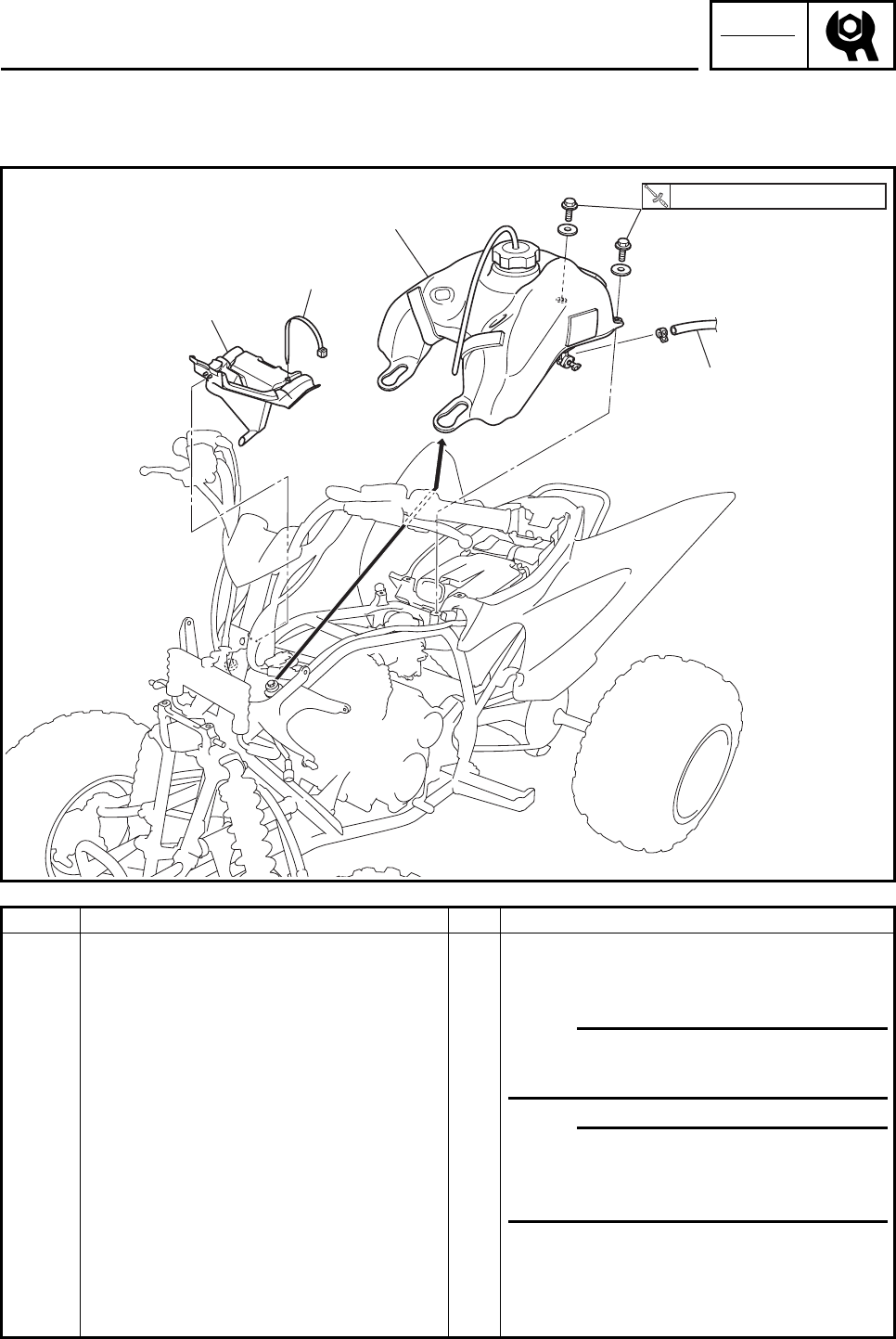
CHK
ADJ
3-8
EBS00042
FUEL TANK
Order Job/Part Q’ty Remarks
Removing the fuel tank Remove the parts in the order listed.
Seat/front fender Refer to “SEAT, FENDERS AND FUEL
TANK”.
1 Fuel hose (fuel cock side) 1 N
O
TE:N
O
TE:
Before disconnecting the fuel hose, turn
the fuel cock to “OFF”.
2 Fuel tank 1 N
O
TE:N
O
TE:
When installing the fuel tank, pass the fuel
tank breather hose through the hole in the
handlebar protector.
3Clamp 1
4 Fuel tank shield 1
For installation, reverse the removal
procedure.
2
1
3
.
4
7 Nm (0.7 m•kg, 5.2 ft•Ib)
SEAT, FENDERS AND FUEL TANK
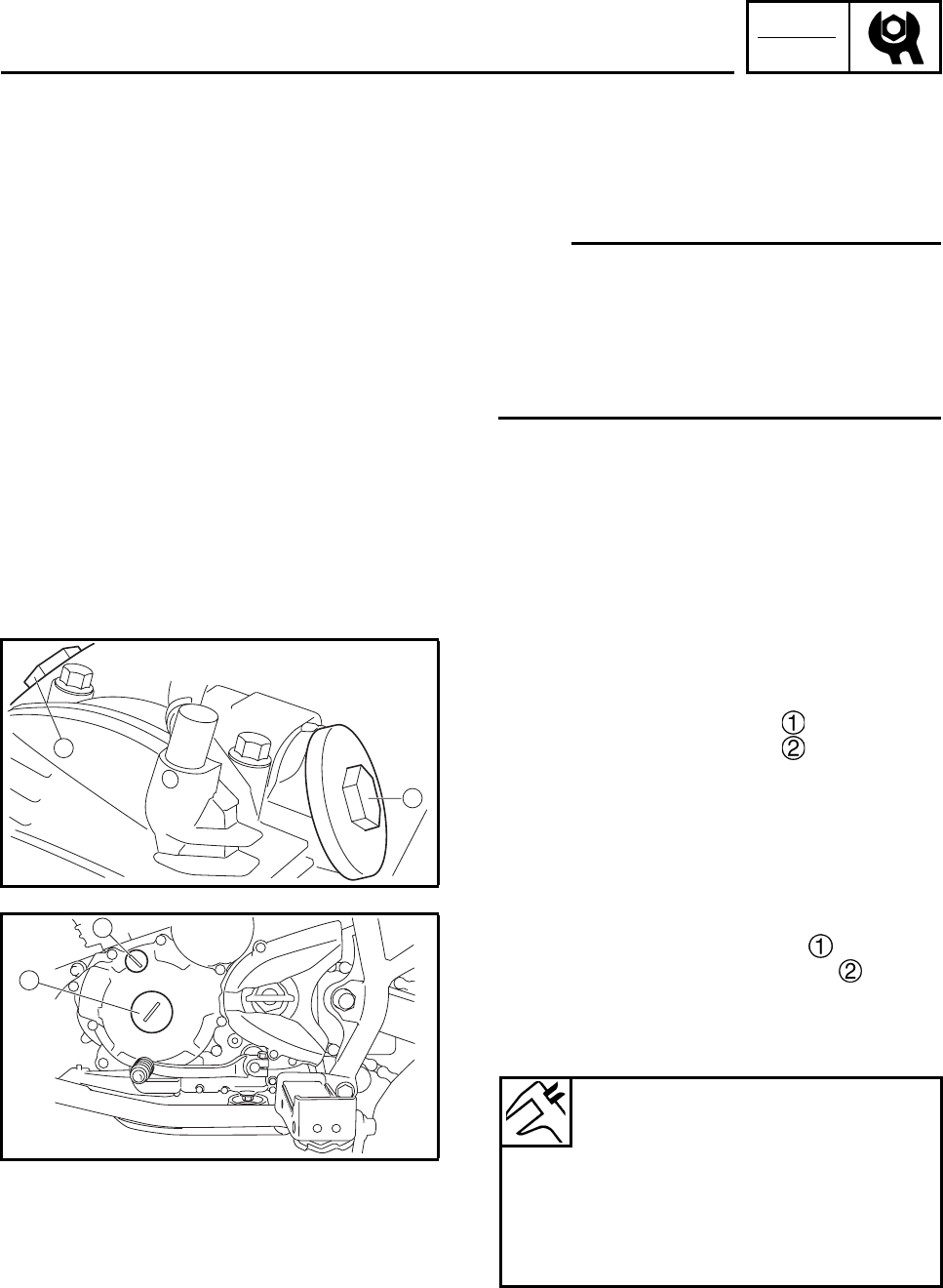
CHK
ADJ
3-9
EAS00048
ENGINE
ADJUSTING THE VALVE CLEARANCE
The following procedure applies to all of the
valves.
N
O
TE:N
O
TE:
• Valve clearance adjustment should be made
on a cold engine, at room temperature.
• When the valve clearance is to be measured
or adjusted, the piston must be at the Top
Dead Center (TDC) on the compression
stroke.
1. Remove:
• seat
• front fender
• fuel tank
Refer to “SEAT, FENDERS AND FUEL
TANK”.
2. Remove:
• spark plug cap
• spark plug
• cylinder head side cover 1
• cylinder head side cover 2
3. Remove:
• timing mark accessing screw
• crankshaft end accessing screw
4. Measure:
• valve clearance
Out of specification → Adjust.
1
2
1
2
Valve clearance (cold)
Intake valve
0.05 ~ 0.10 mm
(0.0020 ~ 0.0039 in)
Exhaust valve
0.10 ~ 0.15 mm
(0.0039 ~ 0.0059 in)
ADJUSTING THE VALVE CLEARANCE
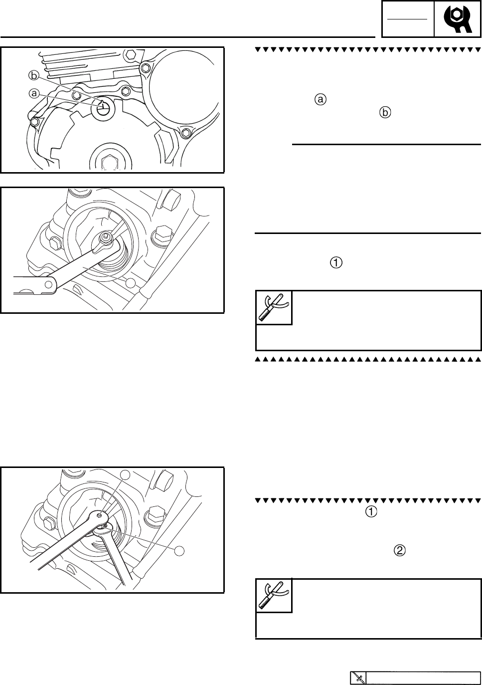
CHK
ADJ
3-10
a. Turn the crankshaft counterclockwise.
b. When the piston is at the Top Dead Center
(TDC) on the compression stroke, align the
“I” mark on the AC magneto rotor with
the stationary pointer on the crankcase
cover.
N
O
TE:N
O
TE:
Top dead center (TDC) is a point where the
mark on the AC magneto rotor and the pointer
on the crankcase cover match, plus at the
same time, the punch mark in the camshaft
sprocket and the pointer on the cylinder head
match.
c. Measure the valve clearance with a thick-
ness gauge .
Out of specification → Adjust.
5. Adjust:
• valve clearance
a. Loosen the locknut .
b. Insert a thickness gauge between the end
of the adjusting screw and the valve stem.
c. Turn the adjusting screw until the speci-
fied valve clearance is obtained.
• Hold the adjusting screw to prevent it from
moving and tighten the locknut to specifica-
tion.
Thickness gauge
90890-03079
Narrow gauge set
YM-34483
1
1
2
Tappet adjusting tool
90890-01311
Six piece tappet set
YM-A5970
14 Nm (1.4 m•kg, 10 ft•lb)
ADJUSTING THE VALVE CLEARANCE
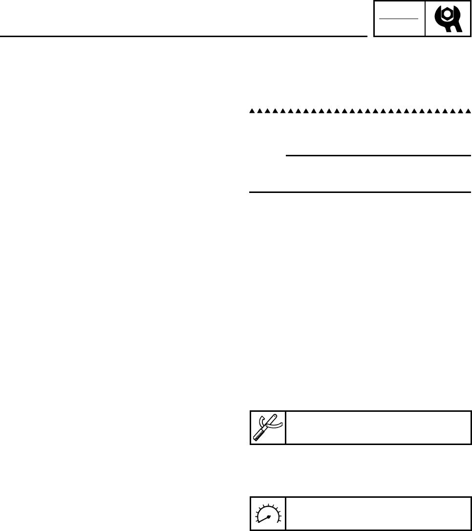
CHK
ADJ
3-11
d. Measure the valve clearance again.
e. If the valve clearance is still out of specifica-
tion, repeat all of the valve clearance
adjustment steps until the specified clear-
ance is obtained.
6. Install:
• all removed parts
N
O
TE:N
O
TE:
For installation, reverse the removal proce-
dure.
EBS00051
ADJUSTING THE ENGINE IDLING SPEED
1. Start the engine and let it warm up for sev-
eral minutes.
2. Attach:
• digital tachometer
(onto the ignition coil spark plug lead)
3. Measure:
• engine idling speed
Out of specification → Adjust.
Digital tachometer
90890-06760, YU-39951-B
Engine idling speed
1,500 ~ 1,600 r/min
ADJUSTING THE VALVE CLEARANCE/
ADJUSTING THE ENGINE IDLING SPEED
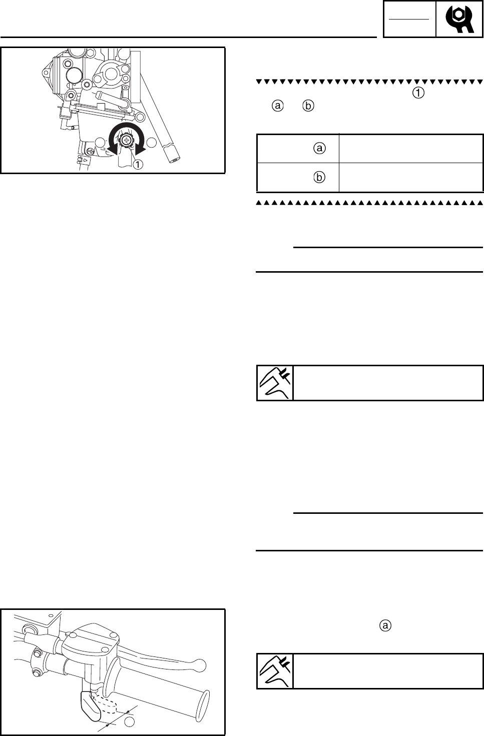
CHK
ADJ
3-12
4. Adjust:
• engine idling speed
a. Turn the throttle stop screw in direction
or until the specified idling speed is
obtained.
5. Remove:
• fuel tank
N
O
TE:N
O
TE:
Slide the fuel tank.
6. Detach:
• digital tachometer
7. Adjust:
• throttle lever free play
Refer to “ADJUSTING THE THROTTLE
LEVER FREE PLAY”.
EBS00052
ADJUSTING THE THROTTLE LEVER FREE
PLAY
N
O
TE:N
O
TE:
Engine idling speed should be adjusted prop-
erly before adjusting the throttle lever free play.
1. Measure:
• throttle lever free play
Out of specification → Adjust.
ab Direction Idling speed becomes
higher.
Direction Idling speed becomes
lower.
Throttle lever free play
2 ~ 4 mm (0.08 ~ 0.16 in)
a
Throttle lever free play
2 ~ 4 mm (0.08 ~ 0.16 in)
ADJUSTING THE ENGINE IDLING SPEED/
ADJUSTING THE THROTTLE LEVER FREE PLAY
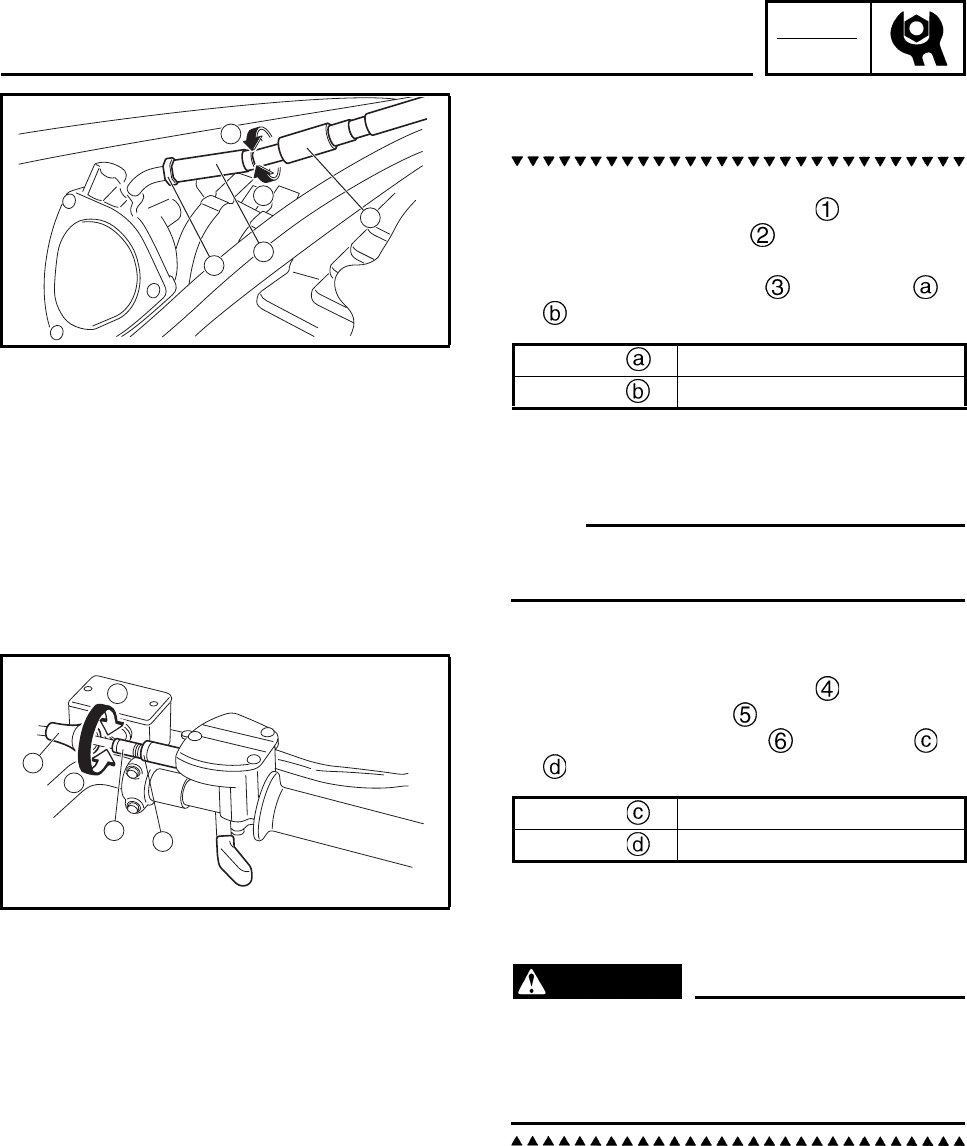
CHK
ADJ
3-13
2. Adjust:
• throttle lever free play
First step:
a. Slide back the rubber cover .
b. Loosen the locknut on the carburetor
side.
c. Turn the adjusting nut in direction or
until the correct free play is obtained.
d. Tighten the locknut.
e. Slide the rubber cover to its original posi-
tion.
N
O
TE:N
O
TE:
If the free play cannot be adjusted here, adjust
it at the throttle lever side of the cable.
Second step:
f. Slide back the rubber cover .
g. Loosen the locknut .
h. Turn the adjusting bolt in direction or
until the correct free play is obtained.
i. Tighten the locknut.
j. Slide the rubber cover to its original posi-
tion.
WARNING
After adjusting the free play, turn the han-
dlebar to the right and left to make sure
that the engine idling speed does not
increase.
EBS00053
ADJUSTING THE SPEED LIMITER
The speed limiter keeps the carburetor throttle
from becoming fully-opened even when the
throttle lever is applied to the maximum posi-
tion. Screwing in the adjusting screw stops the
engine speed from increasing.
1
3
2
b
a
Direction Free play is increased.
Direction Free play is decreased.
c
d
4
65
Direction Free play is increased.
Direction Free play is decreased.
ADJUSTING THE THROTTLE LEVER FREE PLAY/
ADJUSTING THE SPEED LIMITER
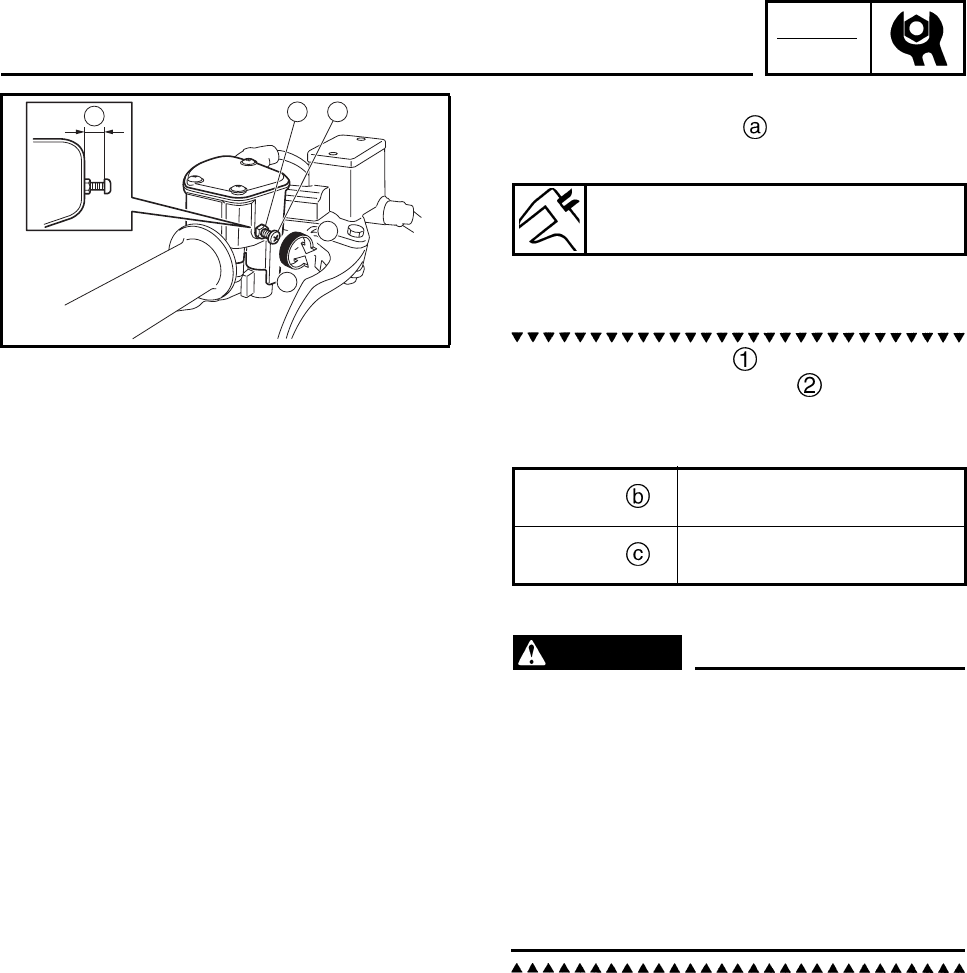
CHK
ADJ
3-14
1. Measure:
• Speed limiter length
Out of specification → Adjust.
2. Adjust:
• speed limiter length
a. Loosen the locknut .
b. Turn the adjusting screw in or out until
the specified speed limiter length is
obtained.
c. Tighten the locknut.
WARNING
• Particularly for a beginner rider, the speed
limiter should be screwed in completely.
Screw it out little by little as their riding
technique improves. Never remove the
speed limiter for a beginning rider.
• For proper throttle lever operation do not
turn out the adjusting screw more than 12
mm (0.47 in). Also, always adjust the throt-
tle lever free play to 2 ~ 4 mm (0.08 ~ 0.16
in).
1 2
b
c
a
Speed limiter length
Less than 12 mm (0.47 in)
Direction Speed limiter length is
decreased.
Direction Speed limiter length is
increased.
ADJUSTING THE SPEED LIMITER
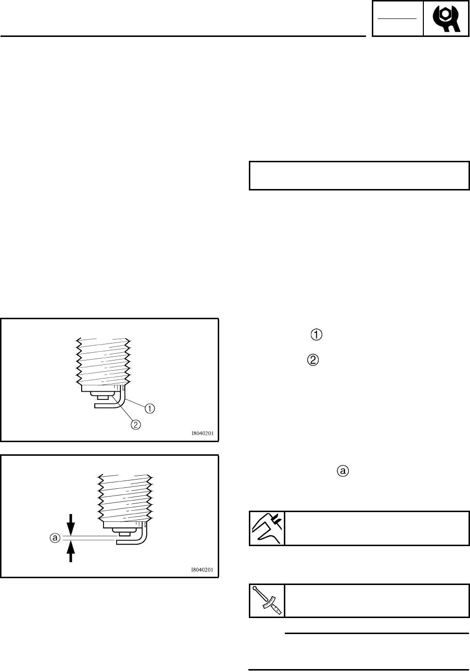
CHK
ADJ
3-15
EBS00057
CHECKING THE SPARK PLUG
1. Disconnect:
• spark plug cap
2. Remove:
• spark plug
3. Check:
• spark plug type
Incorrect → Change.
4. Check:
• electrode
Wear/damage → Replace.
• insulator
Abnormal color → Replace.
Normal color is a medium-to-light tan color.
5. Clean:
• spark plug
(with a spark plug cleaner or wire brush)
6. Measure:
• spark plug gap
Use a wire gauge or thickness gauge.
Out of specification → Regap.
7. Install:
• spark plug
N
O
TE:N
O
TE:
Before installing a spark plug, clean the gasket
surface and plug surface.
8. Install:
• spark plug cap
Standard spark plug
NGK/DR7EA
Spark plug gap
0.6 ~ 0.7 mm (0.024 ~ 0.028 in)
Spark plug
18 Nm (1.8 m•kg, 13 ft•lb)
CHECKING THE SPARK PLUG
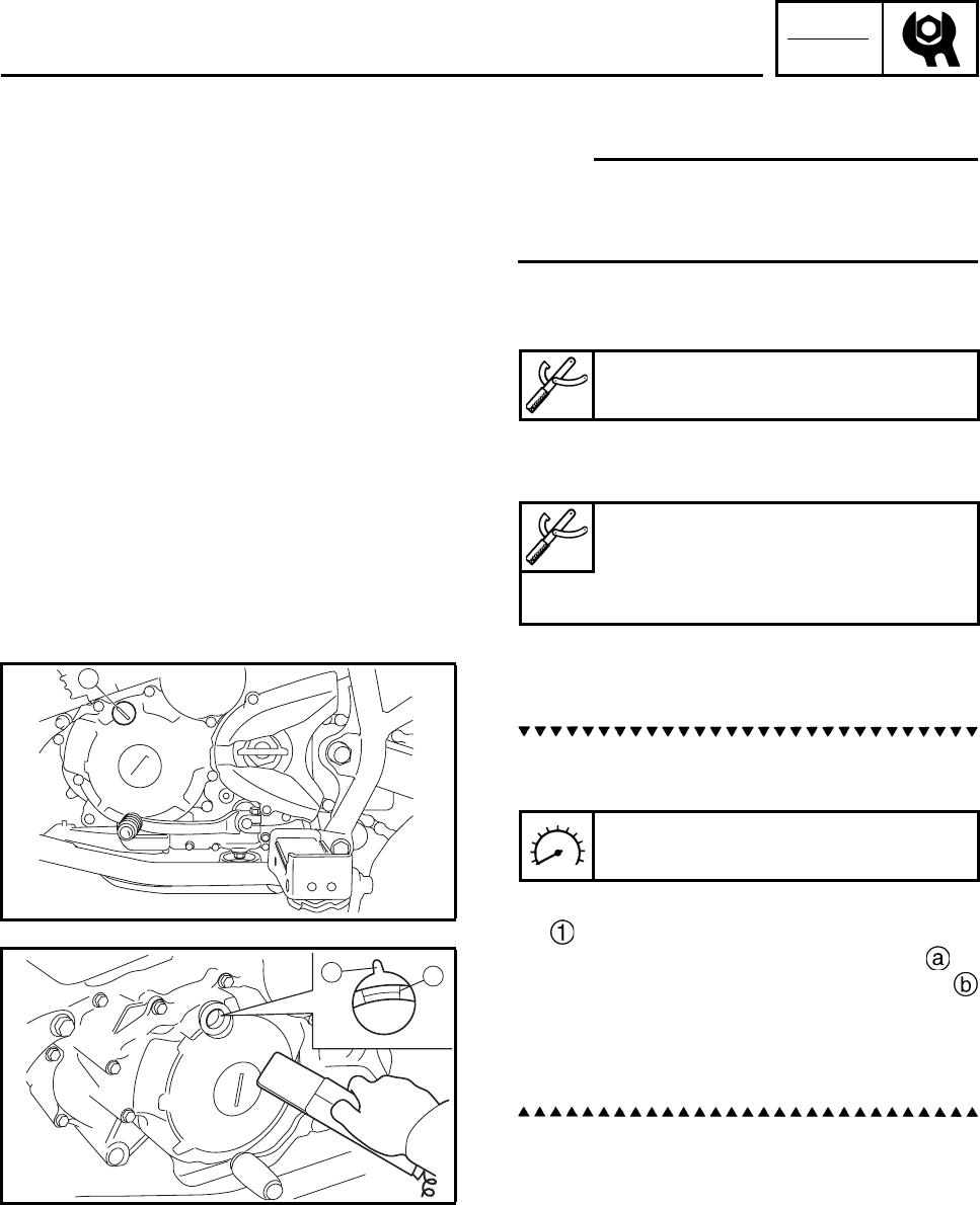
CHK
ADJ
3-16
EBS00058
CHECKING THE IGNITION TIMING
N
O
TE:N
O
TE:
Engine idling speed and throttle cable free play
should be adjusted properly before checking
the ignition timing.
1. Attach:
• digital tachometer
• timing light
(onto the ignition coil spark plug lead)
2. Check:
• ignition timing
a. Warm up the engine and keep it at the
specified speed.
b. Remove the timing mark accessing screw
.
c. Visually check the stationary pointer to
verify it is within the required firing range
indicated on the AC magneto rotor.
Incorrect firing range → Check the pickup
coil assembly.
d. Install the timing mark accessing screw.
3. Detach:
• timing light
• digital tachometer
Digital tachometer
90890-06760, YU-39951-B
Timing light
90890-03141
Inductive clamp timing light
YU-03141
1
Engine speed
1,500 ~ 1,600 r/min
ab
CHECKING THE IGNITION TIMING
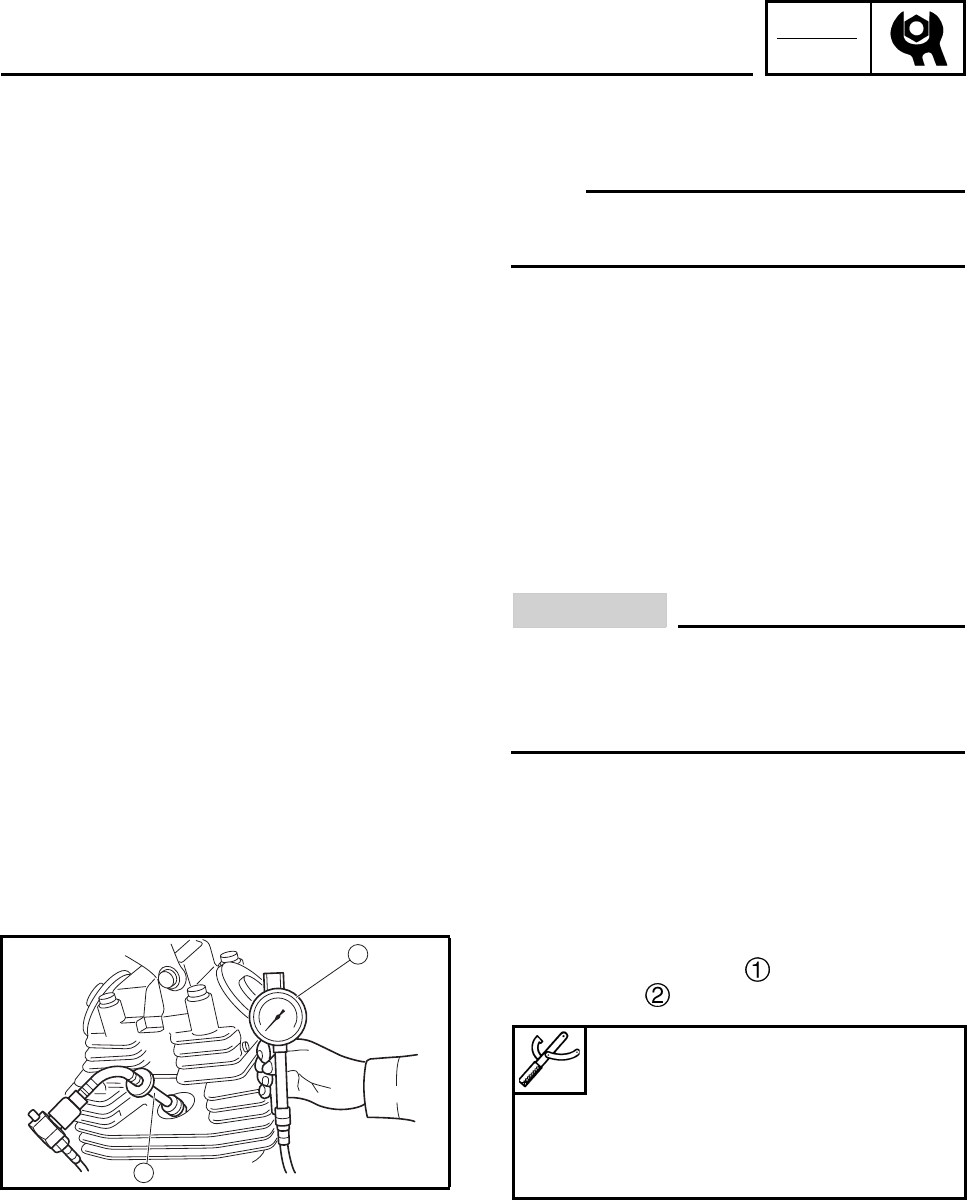
CHK
ADJ
3-17
MEASURING THE COMPRESSION
PRESSURE
The following procedure applies to the cylinder.
N
O
TE:N
O
TE:
Insufficient compression pressure will result in
a loss of performance.
1. Measure:
• Valve clearance
Out of specification → Adjust.
Refer to “ADJUSTING THE VALVE CLEAR-
ANCE”
2. Start the engine, warm it up for several min-
utes, and then turn it off.
3. Disconnect:
• Spark plug cap
4. Remove:
• Spark plug
ECA13340
CAUTION:
Before removing the spark plug, use com-
pressed air to blow away any dirt accumu-
lated in the spark plug wells to prevent it
from falling into the cylinder.
5. Install:
• Compression gauge
• Extension
2
1
Compression gauge
90890-03081
Engine compression tester
YU-33223
Extension
90890-04082
MEASURING THE COMPRESSION PRESSURE
CHK
ADJ
3-18
6. Measure:
• Compression pressure
Out of specification → Refer to steps (c)
and (d).
a. Set the main switch to “ON”.
b. With the throttle wide open, crank the
engine until the reading on the compres-
sion gauge stabilizes.
WARNING
To prevent sparking, ground the spark plug
lead before cranking the engine.
c. If the compression pressure is above the
maximum specification, check the cylinder
head, valve surfaces and piston crown for
carbon deposits.
Carbon deposits → Eliminate.
d. If the compression pressure is below the
minimum specification, pour a teaspoonful
of engine oil into the spark plug bore and
measure again.
Refer to the following table.
Compression pressure (standard)
1,100 kPa/720 r/min
(11.2 kgf/cm2, 160 psi/720 r/min)
Compression pressure
(maximum)
1,300 kPa/720 r/min
(13.3 kgf/cm2, 189 psi/720 r/min)
Compression pressure (minimum)
900 kPa/720 r/min
(9.2 kgf/cm2, 131 psi /720 r/min)
Compression pressure
(with oil applied into the cylinder)
Reading Diagnosis
Higher than without
oil Piston ring(s) wear or
damage → Repair.
Same as without oil
Piston, valves, cylin-
der head gasket or
piston possibly
defective → Repair.
MEASURING THE COMPRESSION PRESSURE
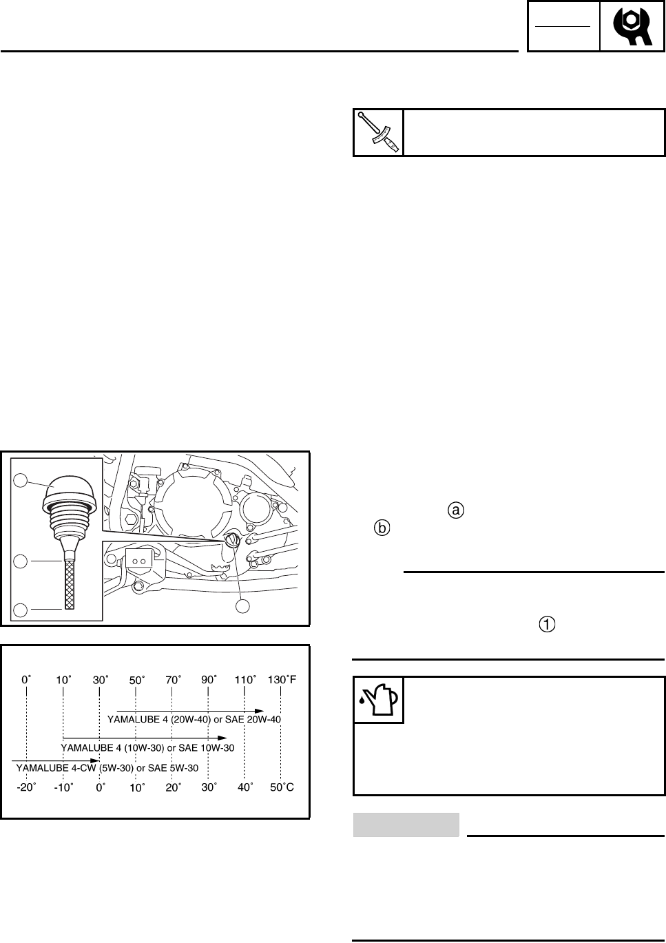
CHK
ADJ
3-19
7. Install:
• Spark plug
8. Connect:
• Spark plug cap
EBS01101
CHECKING THE ENGINE OIL LEVEL
1. Place the machine on a level surface.
2. Start the engine, warm it up several min-
utes, and then turn it off.
3. Check:
• engine oil level
Oil level should be between the minimum
level mark and the maximum level mark
.
Low oil level → Add oil to the proper level.
N
O
TE:N
O
TE:
• Wait a few minutes until the oil settles before
checking the oil level.
• Do not screw the dipstick in when check-
ing the oil level.
CAUTION:
• Do not add any chemical additives.
Engine oil also lubricates the clutch and
additives could cause clutch slippage.
• Do not allow foreign material to enter the
crankcase.
Spark plug
18 Nm (1.8 m•kg, 13 ft•lb)
1
1
a
b
Recommended engine oil type
YAMALUBE 4, SAE 5W-30 or
SAE 10W-30 or SAE 20W-40
Recommended engine oil grade
API service SG type or higher
JASO standard MA
MEASURING THE COMPRESSION PRESSURE/
CHECKING THE ENGINE OIL LEVEL
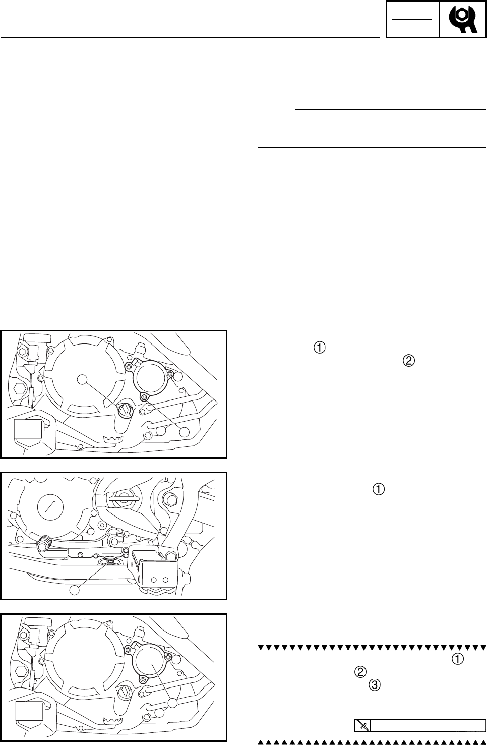
CHK
ADJ
3-20
4. Start the engine, warm it up for several min-
utes, and then turn it off.
5. Check:
• engine oil level
N
O
TE:N
O
TE:
Before checking the engine oil level, wait a few
minutes until the oil has settled.
EBS00067
CHANGING THE ENGINE OIL
1. Place the machine on a level surface.
2. Start the engine, warm it up for several min-
utes, and then turn it off.
3. Place a container under the engine oil drain
bolt.
4. Remove:
• dipstick
• oil filter element drain bolt
5. Remove:
• engine oil drain bolt
(along with the washer)
6. Drain:
• engine oil
(completely from the crankcase)
7. If the oil filter element is also to be
replaced, perform the following procedure.
a. Remove the oil filter element cover and
oil filter element .
b. Install new O-rings .
c. Install the new oil filter element and the oil
filter element cover.
1
2
1
1
10 Nm (1.0 m•kg, 7.4 ft•lb)
CHECKING THE ENGINE OIL LEVEL/
CHANGING THE ENGINE OIL
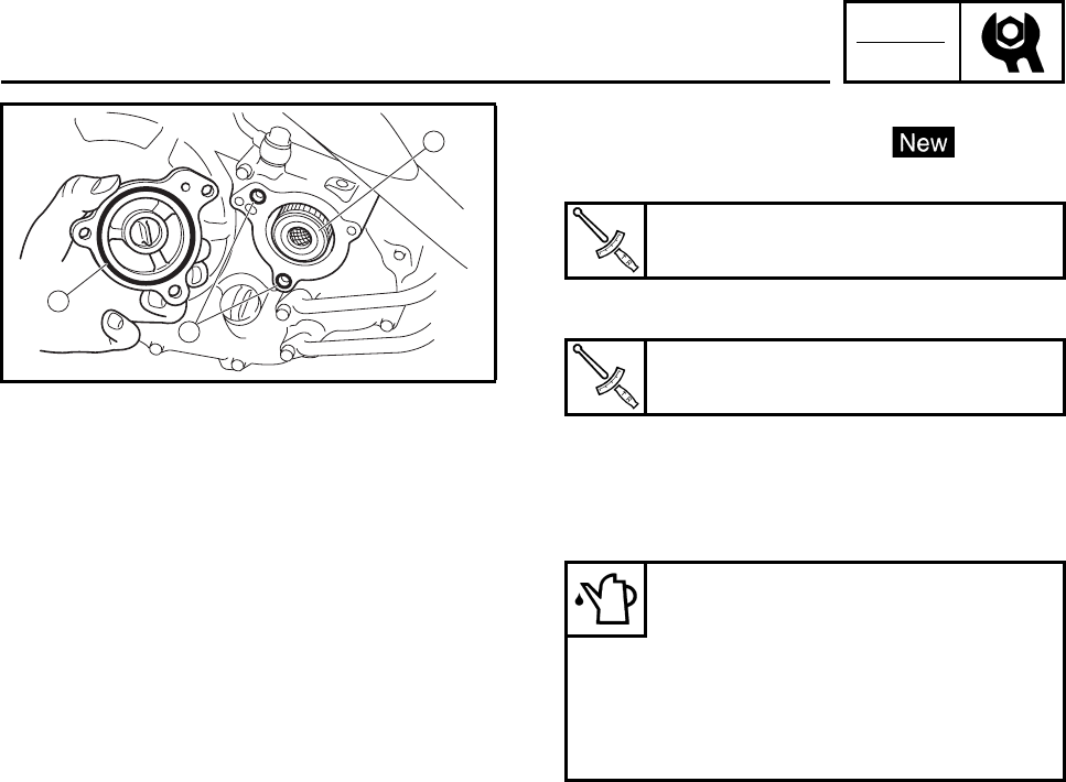
CHK
ADJ
3-21
8. Install:
• engine oil drain bolt gasket
• engine oil drain bolt
• oil filter element drain bolt
9. Fill:
• crankcase
(with the specified amount of the recom-
mended engine oil)
10.Install:
• dipstick
11.Start the engine, warm it up for several min-
utes, and then turn it off.
12.Check:
• engine
(for engine oil leaks)
13.Check:
• engine oil level
Refer to “CHECKING THE ENGINE OIL
LEVEL”.
2
3
3
Engine oil drain bolt
20 Nm (2.0 m•kg, 15 ft•lb)
Oil filter element drain bolt
10 Nm (1.0 m•kg, 7.4 ft•lb)
Periodic oil replacement
1.25 L (1.10 Imp qt, 1.32 US qt)
With oil filter element replacement
1.35 L (1.19 Imp qt, 1.43 US qt)
Engine oil quantity
Total amount
1.60 L (1.41 Imp qt, 1.69 US qt)
CHANGING THE ENGINE OIL
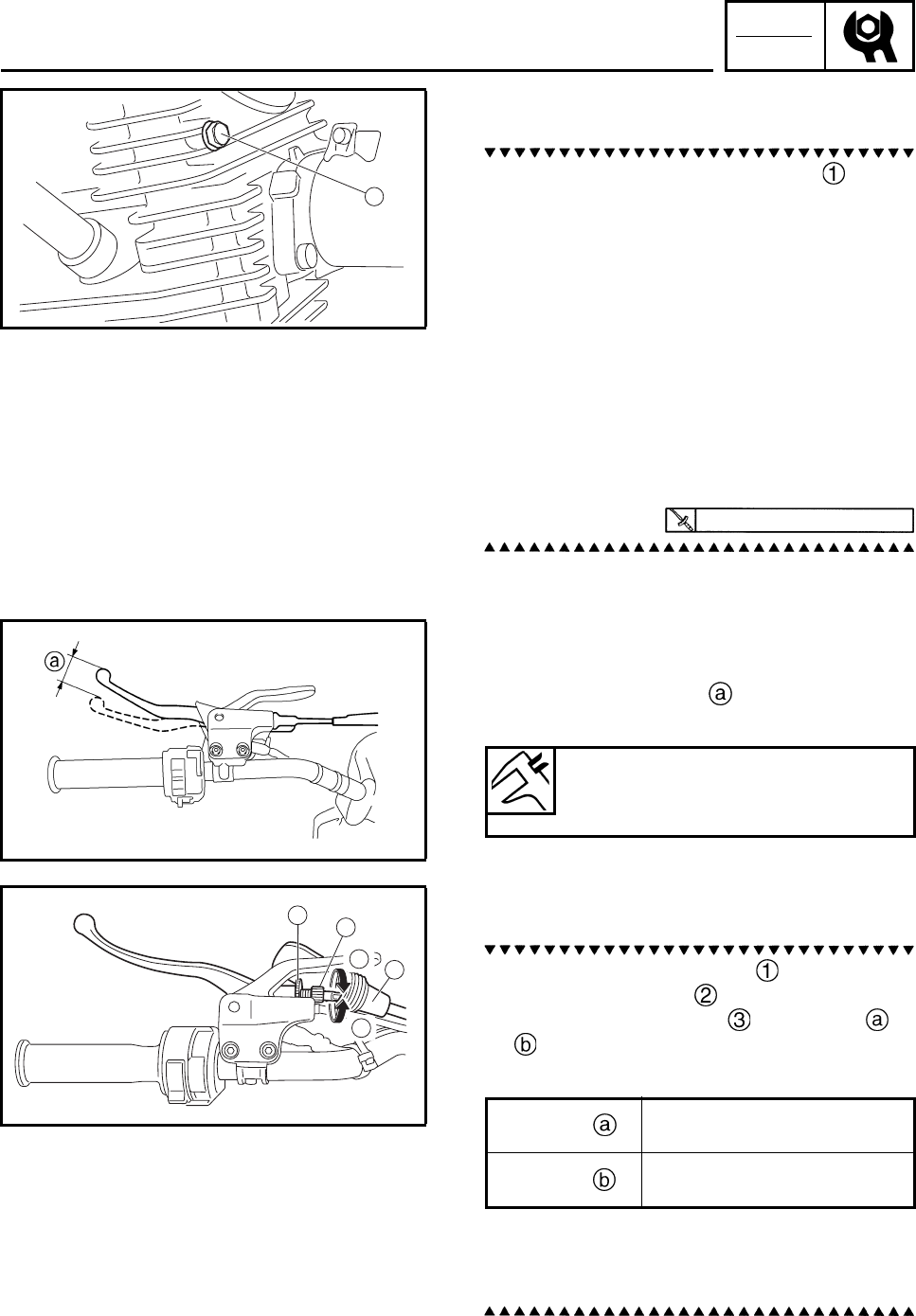
CHK
ADJ
3-22
14.Check:
• engine oil pressure
a. Slightly loosen the oil gallery bolt .
b. Start the engine and keep it idling until
engine oil starts to seep from the oil gallery
bolt. If no engine oil comes out after one
minute, turn the engine off so that it will not
seize.
c. Check the engine oil passages, the oil filter
element and the oil pump for damage or
leakage. Refer to “OIL PUMP AND
BLANCER WEIGHT GEAR” in chapter 4.
d. Start the engine after solving the prob-
lem(s) and check the engine oil pressure
again.
e. Tighten the oil gallery bolt to specification.
EBS00070
ADJUSTING THE CLUTCH CABLE
1. Check:
• clutch lever free play
Out of specification → Adjust.
2. Adjust:
• clutch release lever free play
a. Slide back the lever cover .
b. Loosen the locknut .
c. Turn the adjusting bolt in direction or
until the specified clutch cable free play
is obtained.
d. Tighten the locknut.
e. Slide the rubber cover to its original posi-
tion.
1
7 Nm (0.7 m•kg, 5.2 ft•lb)
Clutch lever free play
(at the clutch lever end)
5 ~ 10 mm (0.20 ~ 0.39 in)
1
b
a
3
2
Direction Clutch cable free play is
increased.
Direction Clutch cable free play is
decreased.
CHANGING THE ENGINE OIL/
ADJUSTING THE CLUTCH CABLE
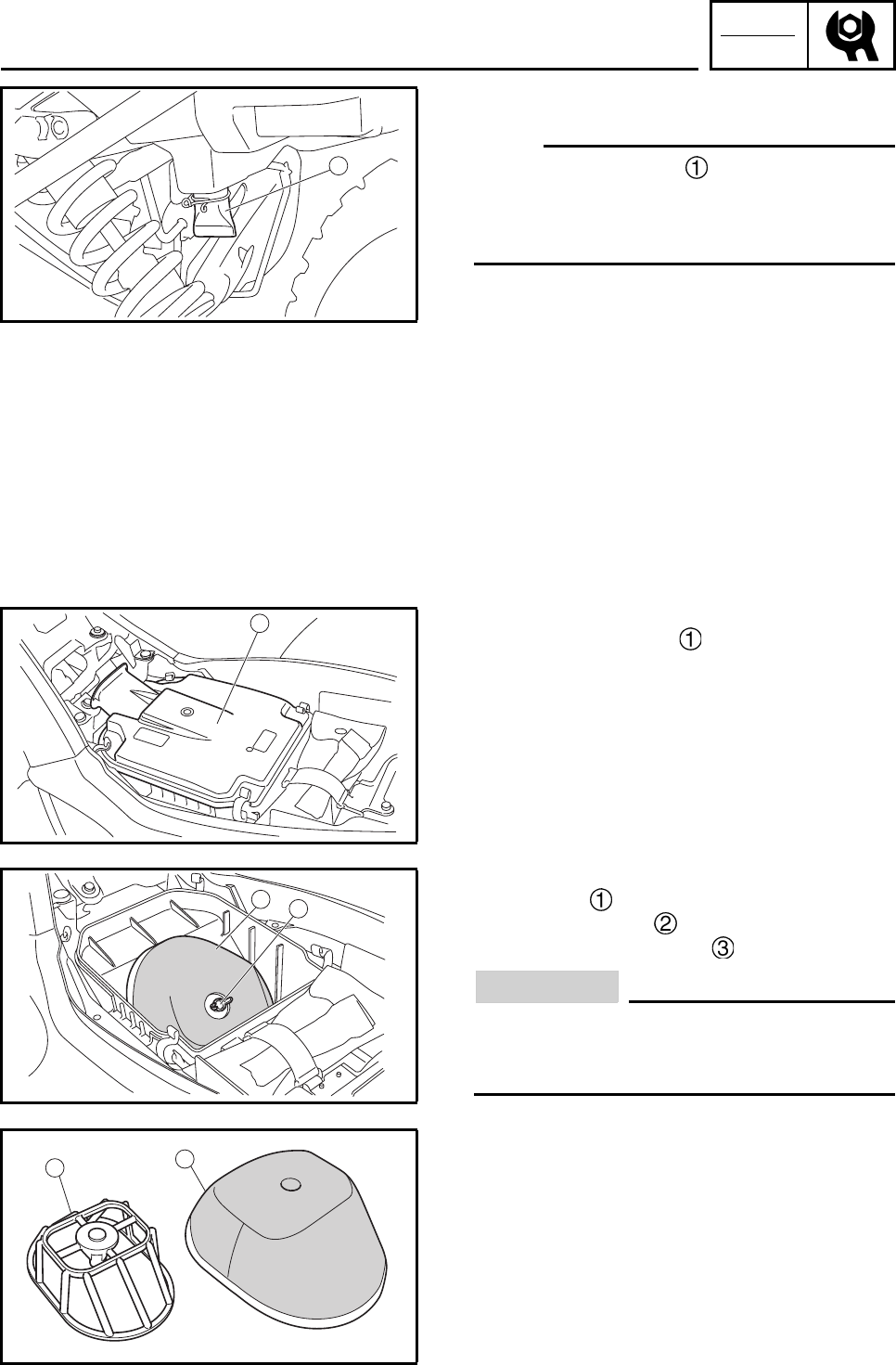
CHK
ADJ
3-23
EBS00073
CLEANING THE AIR FILTER ELEMENT
N
O
TE:N
O
TE:
There is a check hose at the bottom of the
air filter case. If dust and/or water collects in
this hose, clean the air filter element and air fil-
ter case.
1. Remove:
• seat
Refer to “SEAT, FENDERS AND FUEL
TANK”.
2. Remove:
• air filter case cover
3. Remove:
• wing bolt
• air filter element
• air filter element frame
CAUTION:
The engine should never be run without the
air filter; excessive piston and / or cylinder
wear may result.
4. Check:
• air filter element
Damage → Replace.
1
1
1
2
2
3
ADJUSTING THE CLUTCH CABLE/
CLEANING THE AIR FILTER ELEMENT
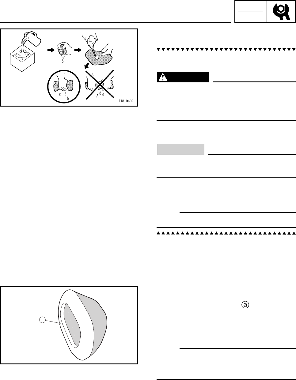
CHK
ADJ
3-24
5. Clean:
• air filter element
a. Wash the element gently, but thoroughly in
solvent.
WARNING
Use a cleaning solvent which is designed
to clean parts only. Never use gasoline or
low flash point solvents as they may cause
a fire or explosion.
b. Squeeze the excess solvent out of the ele-
ment and let it dry.
CAUTION:
Do not twist or wring out the element. This
could damage the foam material.
c. Apply Yamaha foam air filter oil or other
quality foam air filter oil (not spray type).
d. Squeeze out the excess oil.
N
O
TE:N
O
TE:
The element should be wet but not dripping.
6. Install:
• air filter element frame
7. Apply:
• Lithium-soap-based grease
On the matching surface on air filter ele-
ment.
8. Install:
• air filter element
• wing bolt
N
O
TE:N
O
TE:
Make sure its sealing surface matches the
sealing surface of the case so there is no air
leak.
9. Install:
• air filter case cover
10.Install:
• seat
Refer to “SEAT, FENDERS AND FUEL
TANK”.
a
CLEANING THE AIR FILTER ELEMENT
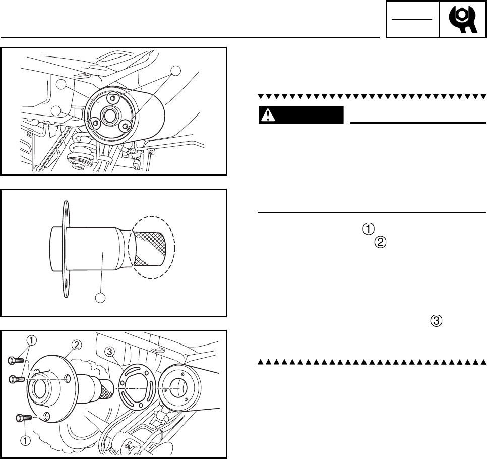
CHK
ADJ
3-25
CLEANING THE SPARK ARRESTER
1. Clean:
• Spark arrester
WARNING
• Select a well-ventilated area free of com-
bustible materials.
• Always let the exhaust system cool before
performing this operation.
• Do not start the engine when removing the
tailpipe from the muffler.
a. Remove the bolts .
b. Remove the tailpipe from the muffler.
c. Tap the tailpipe lightly with a soft-face ham-
mer or suitable tool, then use a wire brush
to remove any carbon deposits from the
spark arrester portion of the tailpipe and the
inner contact surfaces of the muffler.
d. Insert the tailpipe and gasket into the
muffler.
e. Install the bolts and tighten it.
2
1
1
1
2
CLEANING THE AIR FILTER ELEMENT/
CLEANING THE SPARK ARRESTER
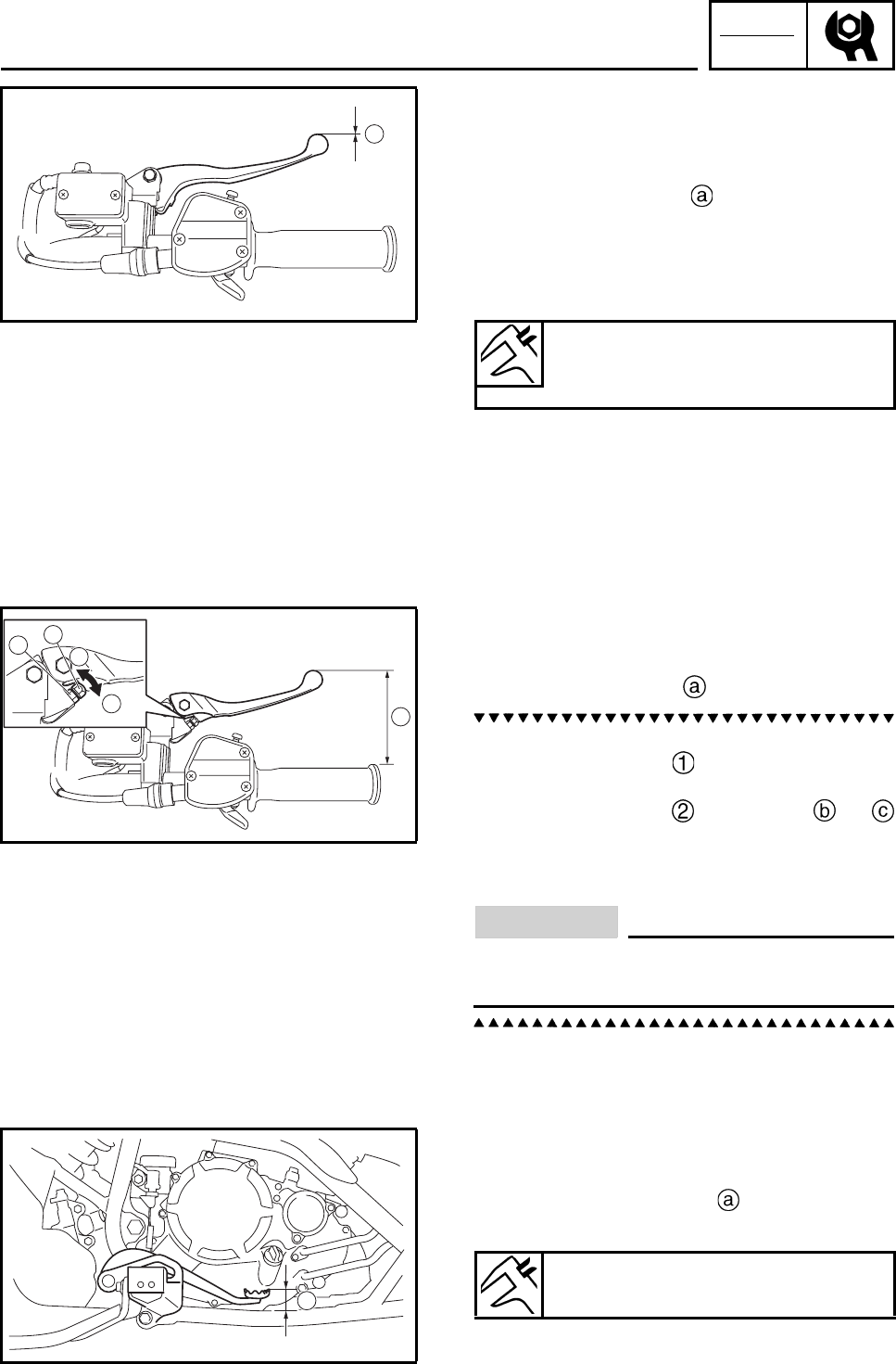
CHK
ADJ
3-26
EBS00080
CHASSIS
ADJUSTING THE FRONT BRAKE
1. Measure:
• brake lever free play
Out of specification → Bleed the front brake
system.
Refer to “BLEEDING THE HYDRAULIC
BRAKE SYSTEM”.
ADJUSTING THE BRAKE LEVER
(For adjustment type model)
1. Adjust:
• brake lever position
a. While pushing the brake lever forward,
loosen the locknut .
b. While pushing the brake lever forward, turn
the adjusting bolt in direction or
until the brake lever is in the desired posi-
tion.
c. Tighten the locknut.
CAUTION:
Be sure to tighten the locknut, as failing to
do so will cause poor brake performance.
EBS00085
ADJUSTING THE REAR BRAKE
1. Measure:
• rear brake pedal height
Out of specification → Adjust.
a
Brake lever free play
(at the end of the brake lever)
0 mm (0 in)
a
b
2
1
a
a
Rear brake pedal height
40.0 mm (1.57 in)
ADJUSTING THE FRONT BRAKE/ADJUSTING THE
BRAKE LEVER/ADJUSTING THE REAR BRAKE
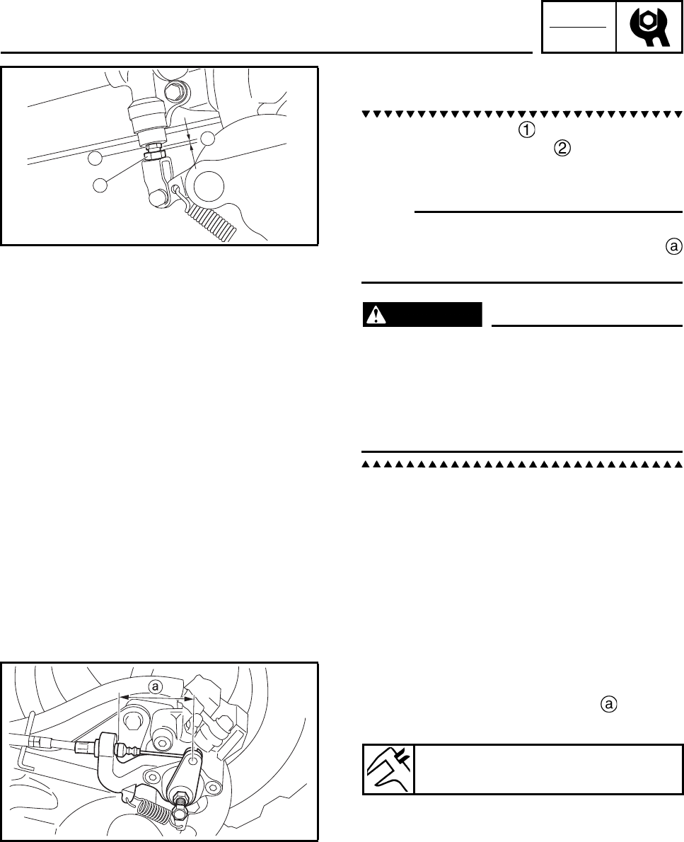
CHK
ADJ
3-27
2. Adjust:
• rear brake pedal height
a. Loosen the locknut .
b. Turn the adjusting bolt until the brake
pedal height is within the specified limits.
c. Tighten the locknut.
N
O
TE:N
O
TE:
When adjusting the brake pedal height make
sure the locknut-to-adjusting bolt clearance
does not exceed 2.2 ~ 3.2 mm (0.09 ~ 0.13 in).
WARNING
After this adjustment is performed, lift the
front and rear wheels off the ground by
placing a block under the engine, and spin
the rear wheels to ensure there is no brake
drag. If any brake drag is noticed, perform
the above steps again.
ADJUSTING THE PARKING BRAKE
1. Check:
• parking brake cable end length
Out of specification → Adjust.
1
2
a
Parking brake cable end length
64 ~ 68 mm (2.52 ~ 2.68 in)
ADJUSTING THE REAR BRAKE/
ADJUSTING THE PARKING BRAKE
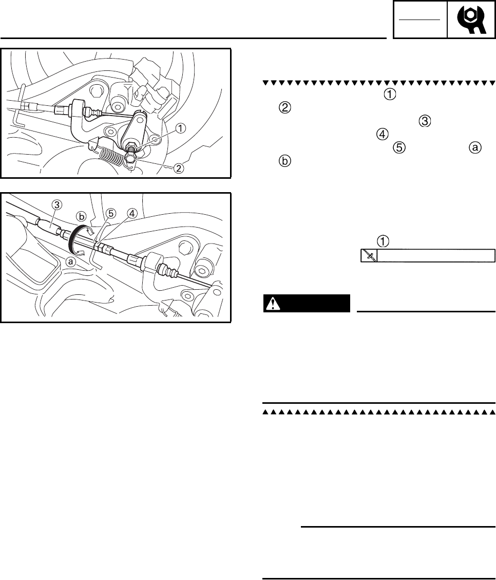
CHK
ADJ
3-28
2. Adjust:
• parking brake cable end length
a. Loosen the locknut and adjusting bolt
.
b. Slide back the rubber cover .
c. Loosen the locknut .
d. Turn the adjusting nut in direction or
until the specified brake cable end
length is obtained.
e. Tighten the locknut.
f. Slowly turn the adjusting bolt clockwise until
resistance is felt.
g. Turn it 1/8 counterclockwise.
h. Tighten the locknut .
i. Slide the rubber cover to its original posi-
tion.
WARNING
After this adjustment is performed, lift the
rear wheels off the ground by placing a
block under the engine, and spin the rear
wheels to ensure there is no brake drag. If
any brake drag is noticed perform the
above steps again.
EBS00087
CHECKING THE BRAKE FLUID LEVEL
1. Place the machine on a level surface.
N
O
TE:N
O
TE:
When checking the brake fluid level, make sure
that the top of the brake master cylinder reser-
voir or brake fluid reservoir is horizontal.
16 Nm (1.6 m•kg, 11 ft•lb)
ADJUSTING THE PARKING BRAKE/
CHECKING THE BRAKE FLUID LEVEL
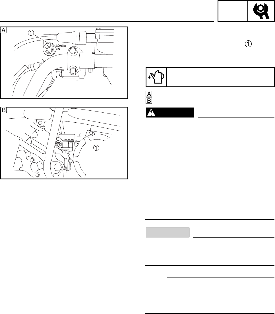
CHK
ADJ
3-29
2. Check:
• brake fluid level
Below the minimum level mark → Add
the recommended brake fluid to the proper
level.
Front brake
Rear brake
WARNING
• Use only the designated brake fluid.
Other brake fluids may cause the rubber
seals to deteriorate, causing leakage and
poor brake performance.
• Refill with the same type of brake fluid that
is already in the system. Mixing brake flu-
ids may result in a harmful chemical reac-
tion, leading to poor brake performance.
• When refilling, be careful that water does
not enter the brake fluid reservoir. Water
will significantly lower the boiling point of
the brake fluid and could cause vapor
lock.
CAUTION:
Brake fluid may damage painted surfaces
and plastic parts. Therefore, always clean
up any spilt brake fluid immediately.
N
O
TE:N
O
TE:
In order to ensure a correct reading of the
brake fluid level, make sure that the top of the
brake master cylinder reservoir or brake fluid
reservoir is horizontal.
EBS00088
CHECKING THE FRONT BRAKE PADS
1. Remove:
• front wheels
Refer to “FRONT AND REAR WHEELS” in
chapter 6.
Recommended brake fluid
DOT 4
CHECKING THE BRAKE FLUID LEVEL/
CHECKING THE FRONT BRAKE PADS
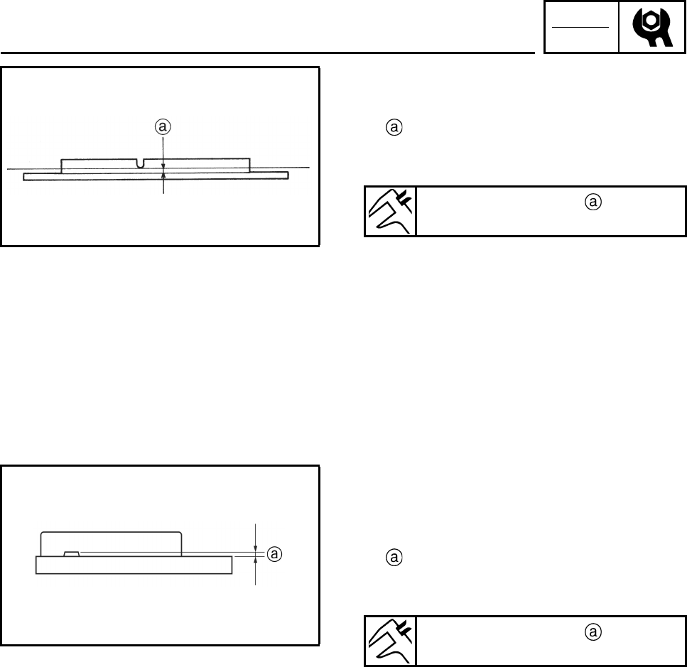
CHK
ADJ
3-30
2. Check:
• brake pads
Wear indicator groove almost disappeared
→ Replace the brake pads as a set.
Refer to “FRONT AND REAR BRAKES” in
chapter 6.
3. Operate the brake lever.
4. Install:
• front wheels
Refer to “FRONT AND REAR WHEELS” in
chapter 6.
EBS00089
CHECKING THE REAR BRAKE PADS
1. Check:
• brake pads
Wear indicators almost touch the brake disc
→ Replace the brake pads as a set.
Refer to “FRONT AND REAR BRAKES” in
chapter 6.
2. Operate the brake pedal.
Brake pad wear limit
1.5 mm (0.06 in)
Brake pad wear limit
1.0 mm (0.04 in)
CHECKING THE FRONT BRAKE PADS/
CHECKING THE REAR BRAKE PADS
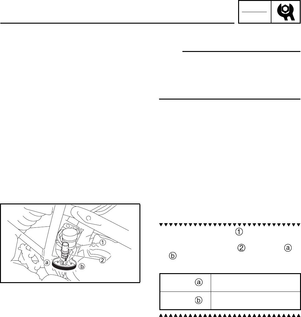
CHK
ADJ
3-31
ADJUSTING THE REAR BRAKE LIGHT
SWITCH
N
O
TE:N
O
TE:
• The rear brake light switch is operated by
movement of the brake pedal.
• The rear brake light switch is properly
adjusted when the brake light comes on just
before the braking effect starts.
1. Check:
• rear brake light operation timing
Incorrect → Adjust.
2. Adjust:
• rear brake light operation timing
a. Hold the main body of the rear brake
light switch so that it does not rotate and
turn the adjusting nut in direction or
until the rear brake light comes on at the
proper time.
EBS00092
CHECKING THE BRAKE HOSES
1. Remove:
• seat
• front fender
Refer to “SEAT, FENDERS AND FUEL
TANK”.
Direction Brake light comes on
sooner.
Direction Brake light comes on
later.
ADJUSTING THE REAR BRAKE LIGHT SWITCH/
CHECKING THE BRAKE HOSES
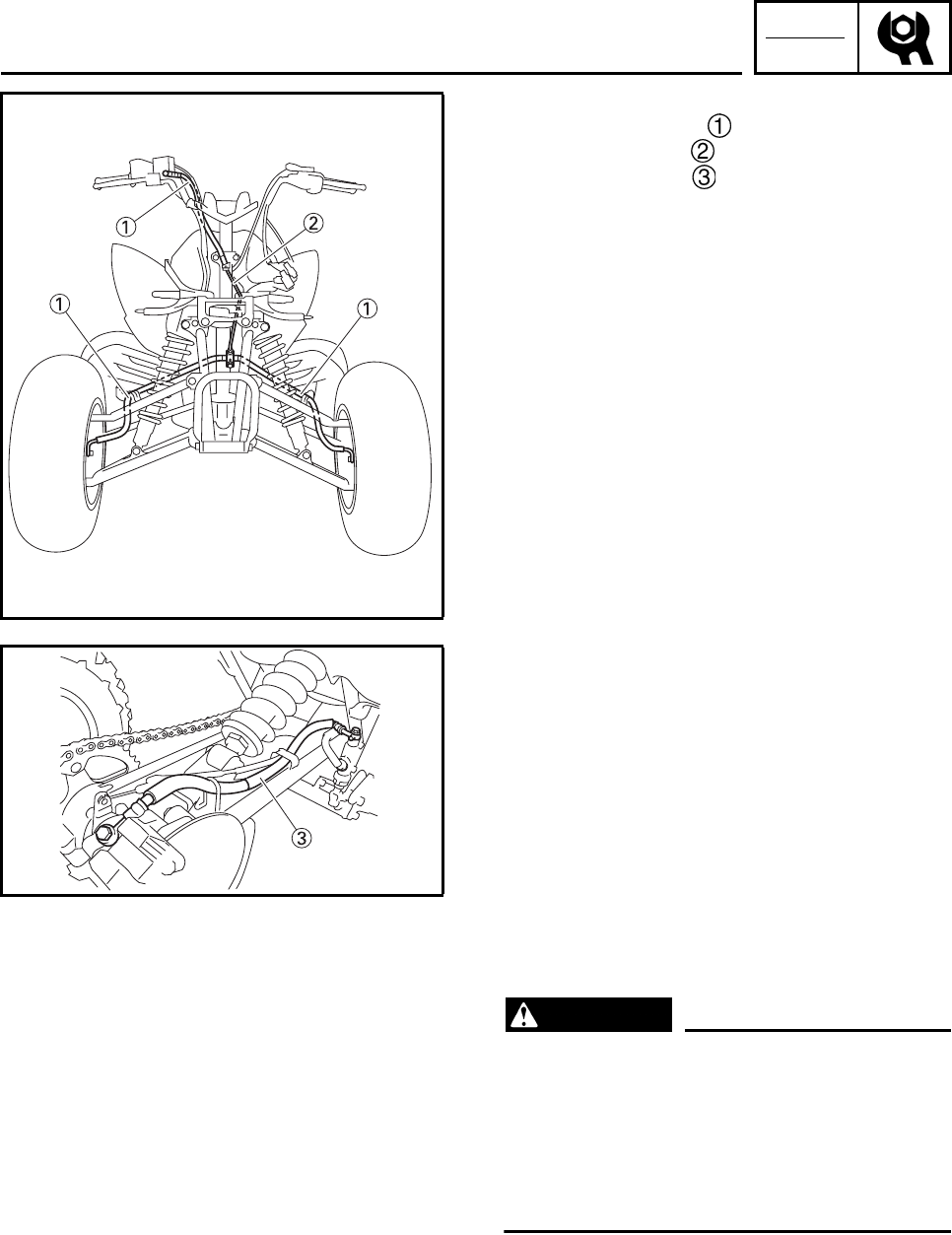
CHK
ADJ
3-32
2. Check:
• front brake hoses
• front brake pipe
• rear brake hose
Cracks/wear/damage → Replace.
3. Check:
• brake hose clamps
Loosen → Tighten.
4. Hold the machine in an upright position and
apply the front or rear brake.
5. Check:
•brake hoses
Apply the brake lever or brake pedal several
times.
Fluid leakage → Replace the hoses or pipe.
Refer to “FRONT AND REAR BRAKES” in
chapter 6.
6. Install:
• front fender
• seat
Refer to “SEAT, FENDERS AND FUEL
TANK”.
EBS00094
BLEEDING THE HYDRAULIC BRAKE
SYSTEM
WARNING
Bleed the hydraulic brake system when-
ever:
• the system is disassembled.
• a brake hose is loosened, disconnected or
replaced.
• the brake fluid level is very low.
• brake operation is faulty.
CHECKING THE BRAKE HOSES/
BLEEDING THE HYDRAULIC BRAKE SYSTEM
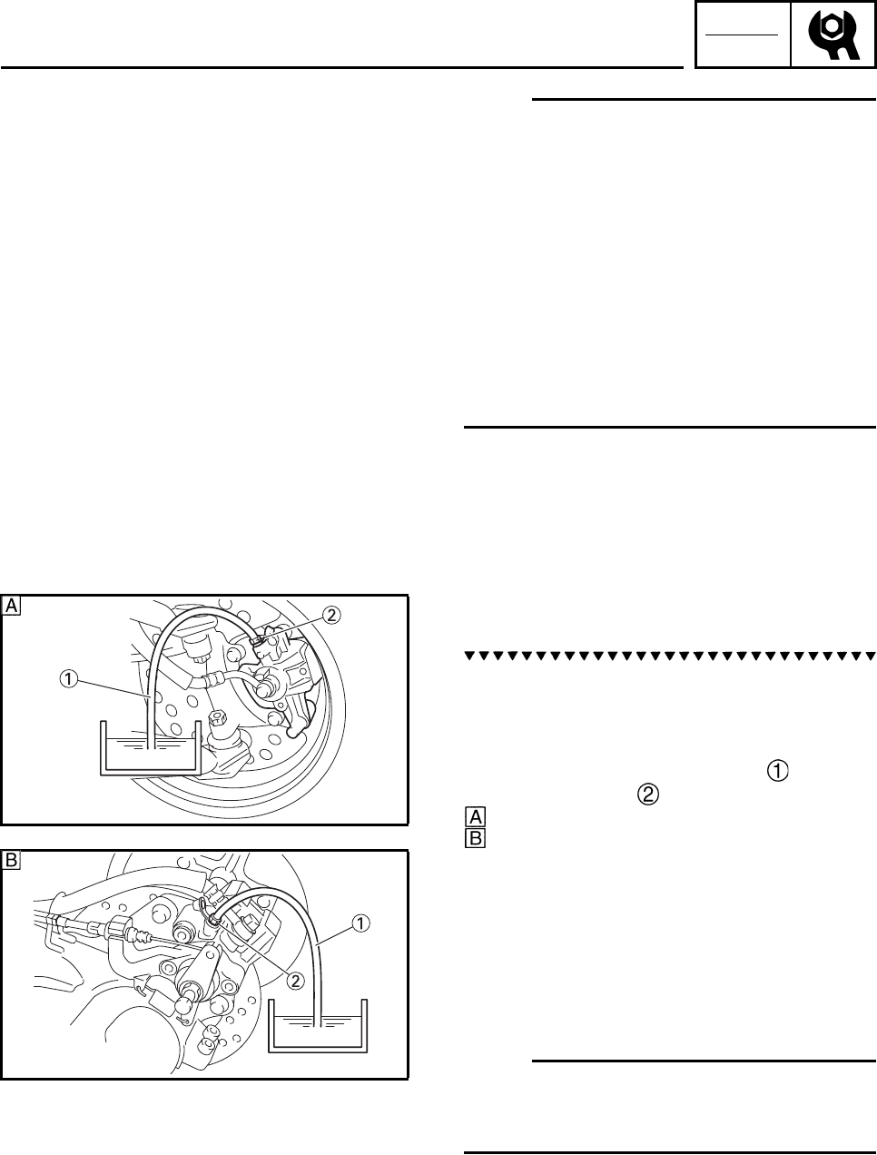
CHK
ADJ
3-33
N
O
TE:N
O
TE:
• Be careful not to spill any brake fluid or allow
the brake master cylinder reservoir or brake
fluid reservoir to overflow.
• When bleeding the hydraulic brake system,
make sure there is always enough brake fluid
before applying the brake. Ignoring this pre-
caution could allow air to enter the hydraulic
brake system, considerably lengthening the
bleeding procedure.
• If bleeding is difficult, it may be necessary to
let the brake fluid settle for a few hours.
Repeat the bleeding procedure when the tiny
bubbles in the hose have disappeared.
1. Bleed:
• hydraulic brake system
a. Fill the brake fluid reservoir to the proper
level with the recommended brake fluid.
b. Install the diaphragm (brake master cylin-
der reservoir or brake fluid reservoir).
c. Connect a clear plastic hose tightly to
the bleed screw .
Front
Rear
d. Place the other end of the hose into a con-
tainer.
e. Slowly apply the brake lever or brake pedal
several times.
f. Fully squeeze the brake lever or fully
depress the brake pedal and hold it in posi-
tion.
g. Loosen the bleed screw.
N
O
TE:N
O
TE:
Loosening the bleed screw will release the
pressure and cause the brake lever to contact
the grip or the brake pedal to fully extend.
h. Tighten the bleed screw and then release
the brake lever or brake pedal.
i. Repeat steps (e) to (h) until all of the air
bubbles have disappeared from the brake
fluid in the plastic hose.
BLEEDING THE HYDRAULIC BRAKE SYSTEM
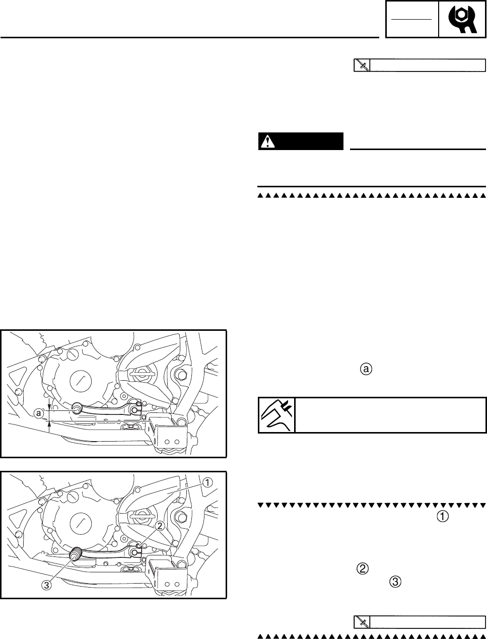
CHK
ADJ
3-34
j. Tighten the bleed screw to specification.
k. Fill the brake fluid reservoir to the proper
level with the recommended brake fluid.
Refer to “CHECKING THE BRAKE FLUID
LEVEL”.
WARNING
After bleeding the hydraulic brake system,
check the brake operation.
EBS00098
ADJUSTING THE SHIFT PEDAL
1. Measure:
• shift pedal height
Out of specification → Adjust.
2. Adjust:
• shift pedal position
a. Remove the drive sprocket cover .
Refer to “REAR SHOCK ABSORBER,
SWINGARM AND DRIVE CHAIN” in chap-
ter 6.
b. Remove the bolt .
c. Remove the shift pedal .
d. Install the shift pedal at the correct height.
e. Tighten the bolt to specification.
5 Nm (0.5 m•kg, 3.7 ft•lb)
Shift pedal height
15.2 mm (0.60 in)
10 Nm (1.0 m•kg, 7.4 ft•lb)
BLEEDING THE HYDRAULIC BRAKE SYSTEM/
ADJUSTING THE SHIFT PEDAL
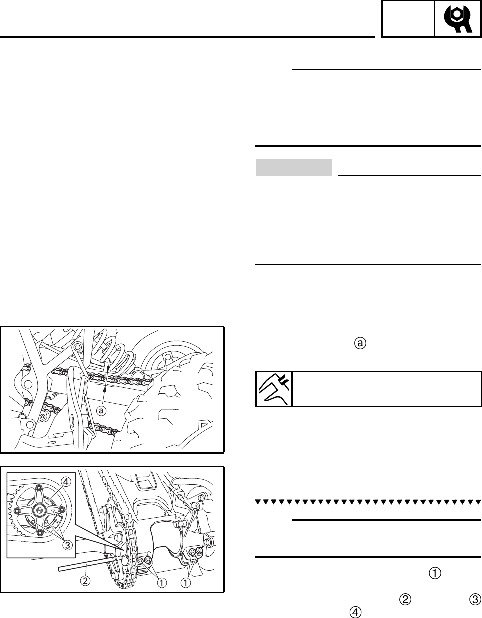
CHK
ADJ
3-35
ADJUSTING THE DRIVE CHAIN SLACK
N
O
TE:N
O
TE:
• Measure the drive chain slack halfway
between the drive axle and the rear axle.
• When checking and adjusting the drive chain
slack, there should be no weight on the vehi-
cle and all tires must be touching the ground.
CAUTION:
A drive chain that is too tight will overload
the engine and other vital parts, and one
that is too loose can skip and damage the
swingarm or cause an accident. Therefore,
keep the drive chain slack within the speci-
fied limits.
1. Measure:
• drive chain slack
Out of specification → Adjust.
2. Adjust:
• drive chain slack
N
O
TE:N
O
TE:
The drive chain slack is adjusted by the rota-
tion of the rear axle hub.
a. Loosen the rear axle pinch bolts .
b. Insert a rod of a diameter of 8 mm (0.31 in)
and length of 10 cm (4 in) in the hole
of rear axle hub .
c. Shift the transmission into the neutral posi-
tion.
d. To loosen the drive chain, push the vehicle
forward and to tighten the drive chain, pull
the vehicle backward.
Drive chain slack
45 ~ 55 mm (1.77 ~ 2.17 in)
ADJUSTING THE DRIVE CHAIN SLACK
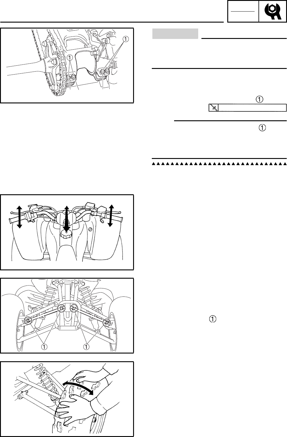
CHK
ADJ
3-36
CAUTION:
Excessive chain slack will overload the
engine and other vital parts; keep the slack
within the specified limits.
e. If the chain slack cannot be adjusted,
replace the sprockets and drive chain as a
set.
f. Tighten the rear axle pinch bolts .
N
O
TE:N
O
TE:
• Tighten the rear axle pinch bolts in the
proper sequence as shown.
• The chain should be cleaned and lubricated
after every use of the vehicle.
EBS00106
CHECKING THE STEERING SYSTEM
1. Place the machine on a level surface.
2. Check:
• steering assembly bushings
Move the handlebar up and down, and/or
back and forth.
Excessive play → Replace the steering
stem bushings.
3. Check:
• tie-rod ends
Turn the handlebar to the left and right until
it stops completely, and then move the han-
dlebar slightly in the opposite direction.
Tie-rod end(s) have vertical play →
Replace the tie-rod end(s).
4. Raise the front end of the machine so that
there is no weight on the front wheels.
5. Check:
• ball joints and/or wheel bearings
Move the wheels laterally back and forth.
Excessive free play → Replace the front
arms (upper and lower) and/or wheel bear-
ings.
12 34
56 78
21 Nm (2.1 m•kg, 15 ft•lb)
ADJUSTING THE DRIVE CHAIN SLACK/
CHECKING THE STEERING SYSTEM
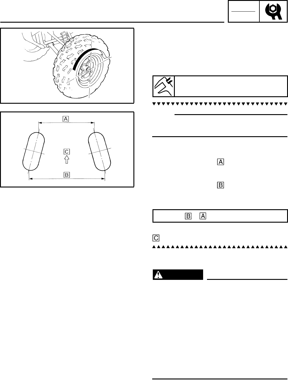
CHK
ADJ
3-37
EBS00108
ADJUSTING THE TOE-IN
1. Place the machine on a level surface.
2. Measure:
• toe-in
Out of specification → Adjust.
N
O
TE:N
O
TE:
Before measuring the toe-in, make sure that
the tire pressure is correct.
a. Mark both front tire tread centers.
b. Face the handlebar straight ahead.
c. Measure the width between the marks.
d. Rotate the front tires 180° until the marks
are exactly opposite one another.
e. Measure the width between the marks.
f. Calculate the toe-in using the formula given
below.
g. If the toe-in is incorrect, adjust it.
Forward
3. Adjust:
• toe-in
WARNING
• Be sure that both tie-rods are turned the
same amount. If not, the machine will drift
right or left even though the handlebar is
positioned straight. This may lead to mis-
handling and an accident.
• After setting the toe-in to specification,
run the machine slowly for some distance
with both hands lightly holding the han-
dlebar and check that the handlebar
responds correctly. If not, turn either the
right or left tie-rod within the toe-in speci-
fication.
Toe-in
9 ~ 19 mm (0.35 ~ 0.75 in)
Toe-in = –
ADJUSTING THE TOE-IN
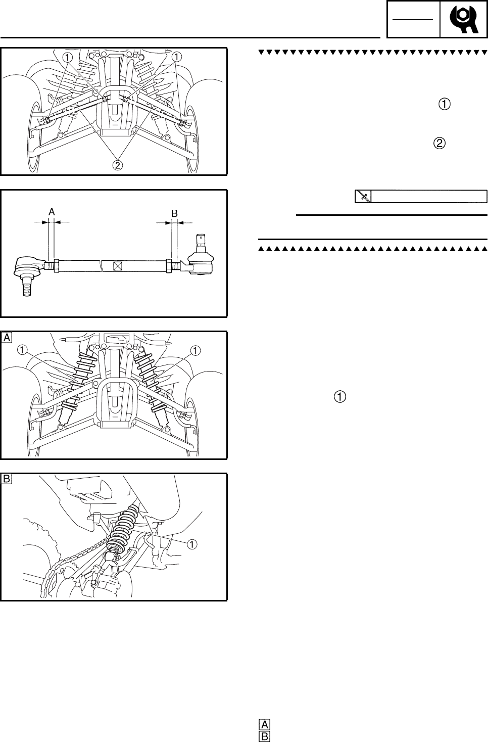
CHK
ADJ
3-38
a. Mark both tie-rods ends.
This reference point will be needed during
adjustment.
b. Loosen the locknuts (tie-rod end) of both
tie-rods.
c. The same number of turns should be given
to both the right and left tie-rods until the
specified toe-in is obtained. This is to keep
the length of the rods the same.
d. Tighten the rod end locknuts of both tie-
rods.
N
O
TE:N
O
TE:
Adjust the rod ends so that A and B are equal.
EBS00109
CHECKING THE FRONT AND REAR SHOCK
ABSORBERS
1. Place the machine on a level surface.
2. Check:
• damper rod
Bends/damage → Replace the front/rear
shock absorber assembly.
• oil leakage
Excessive oil leakage → Replace the front/
rear shock absorber assembly.
• cylinder
Damage → the front/rear shock absorber
assembly.
•spring
Fatigue → the front/rear shock absorber
assembly.
Refer to “FRONT ARMS AND FRONT
SHOCK ABSORBER ASSEMBLIES” and
“REAR SHOCK ABSORBER, SWINGARM
AND DRIVE CHAIN” in chapter 6.
3. Check:
• operation
Pump the shock absorbers up and down for
several times.
Unsmooth operation → Replace the front/
rear shock absorber assembly.
Refer to “ADJUSTING THE FRONT
SHOCK ABSORBERS” and “ADJUSTING
THE REAR SHOCK ABSORBER”.
Front shock absorber
Rear shock absorber
15 Nm (1.5 m•kg, 11 ft•lb)
ADJUSTING THE TOE-IN/CHECKING THE FRONT AND
REAR SHOCK ABSORBERS
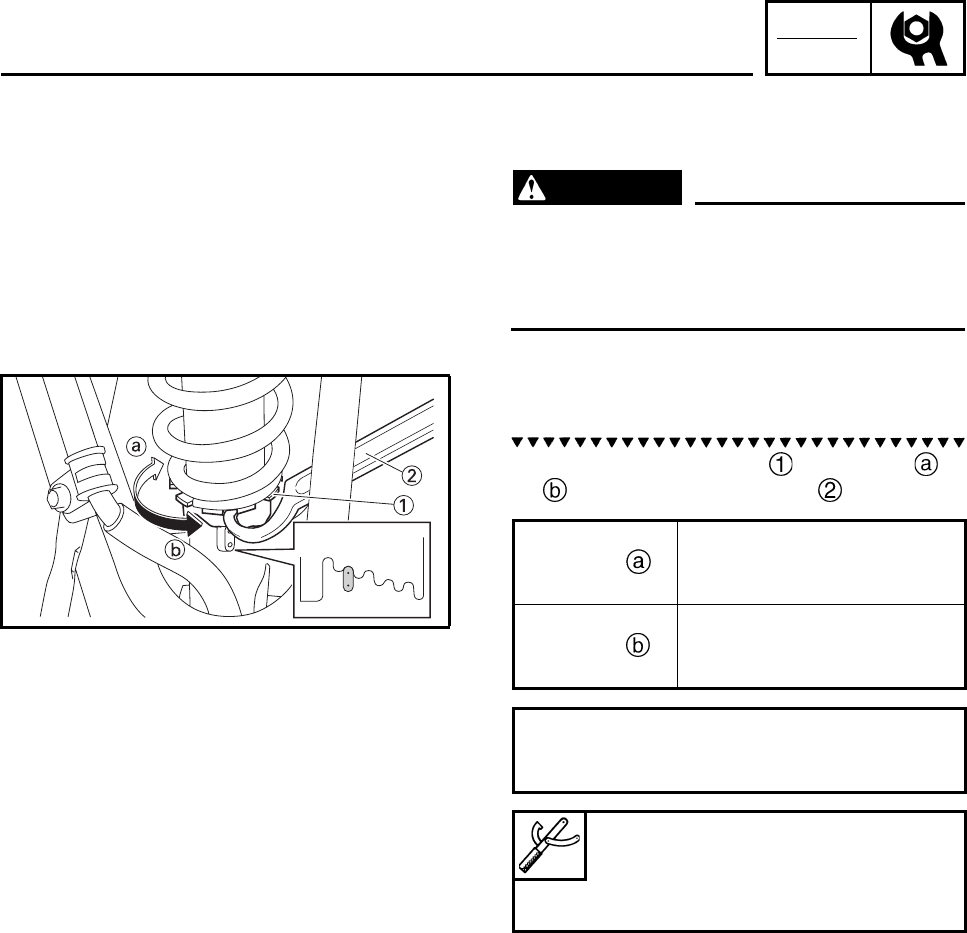
CHK
ADJ
3-39
EBS00111
ADJUSTING THE FRONT SHOCK
ABSORBERS
WARNING
Always adjust the spring preload of both
front shock absorbers to the same setting.
Uneven adjustment can result in poor han-
dling and loss of stability.
1. Adjust:
• spring preload
a. Turn the adjusting ring in direction or
with the spanner wrench .
12345Direction Spring preload is
increased (suspension is
harder).
Direction Spring preload is
decreased (suspension is
softer).
Standard position: 2
Minimum position: 1
Maximum position: 5
Ring nut wrench
90890-01268
Spanner wrench
YU-01268
ADJUSTING THE FRONT SHOCK ABSORBERS
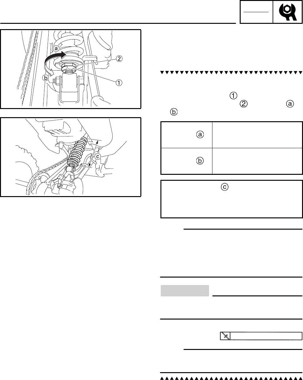
CHK
ADJ
3-40
EBS00111
ADJUSTING THE REAR SHOCK
ABSORBER
1. Adjust:
• spring preload
a. Elevate the rear wheels by placing a suit-
able stand under the frame.
b. Loosen the locknut .
c. Turn the adjusting nut in direction or
.
N
O
TE:N
O
TE:
• Be sure to remove all dirt and mud from
around the locknut and adjusting nut before
adjustment.
• The length of the spring (installed) changes
1.0 mm (0.04 in) per turn of the adjuster.
CAUTION:
Never attempt to turn the adjusting ring
beyond the maximum or minimum setting.
d. Tighten the locknut.
N
O
TE:N
O
TE:
Always tighten the locknut against the adjust-
ing nut, then torque it to specification.
Direction Spring preload is
increased (suspension is
harder).
Direction Spring preload is
decreased (suspension is
softer).
Adjusting length
Standard: 230 mm (9.06 in)
Minimum: 222 mm (8.74 in)
Maximum: 234 mm (9.21 in)
42 Nm (4.2 m•kg, 31 ft•lb)
ADJUSTING THE REAR SHOCK ABSORBER
CHK
ADJ
3-41
EBS00114
CHECKING THE TIRES
WARNING
This model is equipped with low pressure
tires. It is important that they be inflated
correctly and maintained at the proper
pressures.
• TIRE CHARACTERISTICS
1) Tire characteristics influence the han-
dling of ATVs. The tires listed below
have been approved by Yamaha Motor
Co., Ltd. for this model. If other tire com-
binations are used, they can adversely
affect your machine’s handling charac-
teristics and are therefore not recom-
mended.
• TIRE PRESSURE
1) Recommended tire pressure
Front 27.5 kPa (0.28 kg/cm2, 4.0 psi)
Rear 27.5 kPa (0.28 kg/cm2, 4.0 psi)
2) Tire pressure below the minimum speci-
fication could cause the tire to dislodge
from the rim under severe riding condi-
tions.
The following are minimums:
Front 24.5 kPa (0.25 kg/cm2, 3.6 psi)
Rear 24.5 kPa (0.25 kg/cm2, 3.6 psi)
3) Use no more than
Front 250 kPa (2.6 kg/cm2, 36 psi)
Rear 250 kPa (2.6 kg/cm2, 36 psi)
when seating the tire beads. Higher
pressures may cause the tire to burst.
Inflate the tires slowly and carefully.
Fast inflation could cause the tire to
burst.
• MAXIMUM LOADING LIMIT
1) Vehicle load limits: 100 kg (220 lb)
*Total weight of the cargo, rider, and
accessories.
Be extra careful of the machine balance
and stability when towing a trailer.
Manufacturer Size Type
Front DUNLOP AT20 ×
7-10 KT201
Rear DUNLOP AT19 ×
10-9 KT205A
CHECKING THE TIRES
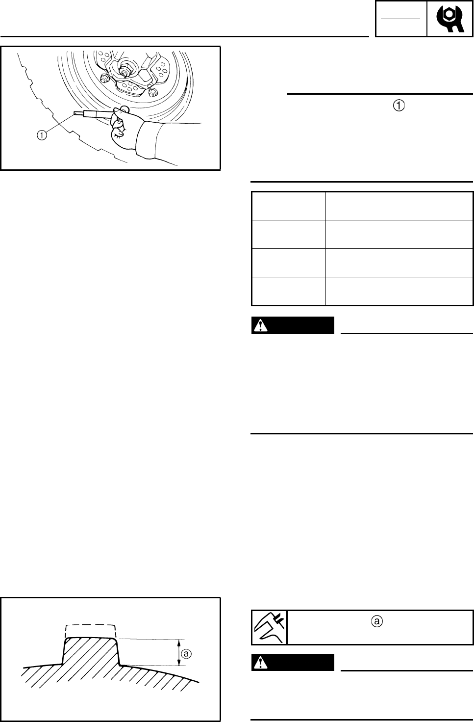
CHK
ADJ
3-42
1. Measure:
• tire pressure
Out of specification → Adjust.
N
O
TE:N
O
TE:
• The low-pressure tire gauge is included as
standard equipment.
• If dust or the like is stuck to this gauge, it will
not provide the correct readings. Therefore,
take two measurements of the tire’s pressure
and use the second reading.
WARNING
Uneven or improper tire pressure may
adversely affect the handling of this
machine and may cause loss of control.
• Maintain proper tire pressures.
• Set tire pressures when the tires are cold.
• Tire pressures must be equal in both front
tires and equal in both rear tires.
2. Check:
• tire surfaces
Wear/damage → Replace.
WARNING
It is dangerous to ride with a worn-out tire.
When tire wear is out of specification,
replace the tire immediately.
Cold tire
pressure Front/Rear
Standard 27.5 kPa
(0.28 kg/cm2, 4.0 psi)
Minimum 24.5 kPa
(0.25 kg/cm2, 3.6 psi)
Maximum 30.5 kPa
(0.31 kg/cm2, 4.4 psi)
Tire wear limit
Front and rear: 3.0 mm (0.12 in)
CHECKING THE TIRES
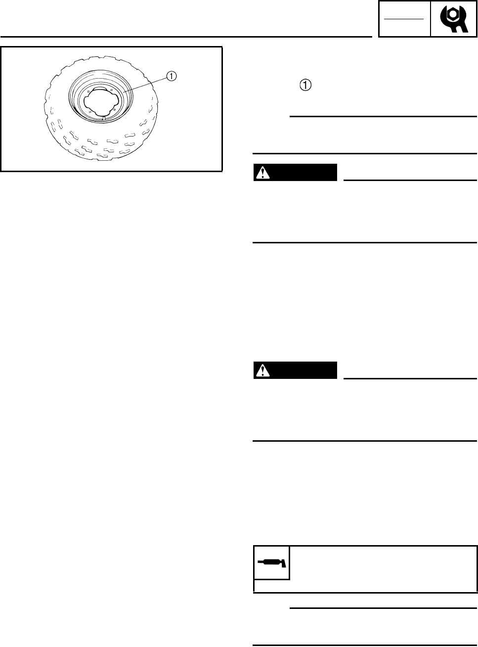
CHK
ADJ
3-43
EBS00116
CHECKING THE WHEELS
1. Check:
• wheel
Damage/bends → Replace.
N
O
TE:N
O
TE:
Always balance the wheel when a tire or wheel
has been changed or replaced.
WARNING
• Never attempt even small repairs to the
wheel.
• Ride conservatively after installing a tire
to allow it to seat itself properly on the rim.
EBS00117
CHECKING AND LUBRICATING THE
CABLES
WARNING
A damaged cable sheath may cause corro-
sion and interfere with the cable movement.
An unsafe condition may result so replace
a damaged cable as soon as possible.
1. Check:
• cable sheath
Damage → Replace.
2. Check:
• cable operation
Unsmooth operation → Lubricate or
replace.
N
O
TE:N
O
TE:
Hold the cable end up and apply several drops
of lubricant to the cable.
3. Apply:
• Lithium-soap-based grease
(onto end of the cable)
Recommended lubricant
Yamaha chain and cable lube or
engine oil
CHECKING THE WHEELS/CHECKING AND
LUBRICATING THE CABLES

CHK
ADJ
3-44
EBS00118
LUBRICATING THE LEVERS AND PEDALS
Lubricate the pivoting point and metal-to-metal
moving parts of the levers and pedal.
Recommended lubricants
Brake lever
Silicone grease
Clutch lever and brake pedal
Lithium-soap-based grease
LUBRICATING THE LEVERS AND PEDALS
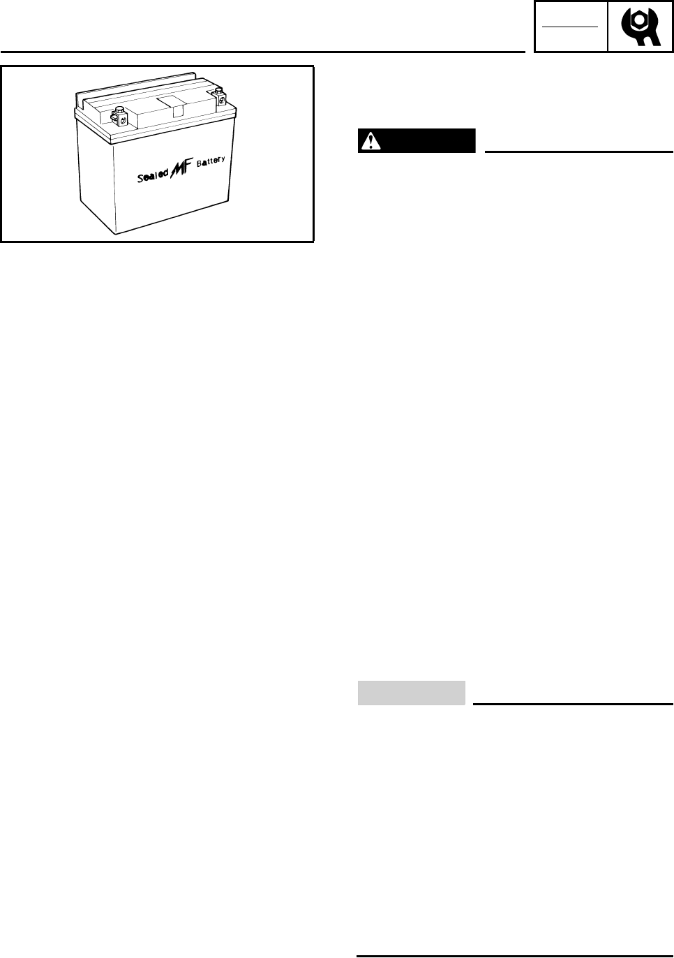
CHK
ADJ
3-45
EBS00120
ELECTRICAL SYSTEM
CHECKING AND CHARGING THE BATTERY
WARNING
Batteries generate explosive hydrogen gas
and contain electrolyte which is made of
poisonous and highly caustic sulfuric acid.
Therefore, always follow these preventive
measures:
• Wear protective eye gear when handling
or working near batteries.
• Charge batteries in a well-ventilated area.
• Keep batteries away from fire, sparks or
open flames (e.g., welding equipment,
lighted cigarettes).
• DO NOT SMOKE when charging or han-
dling batteries.
• KEEP BATTERIES AND ELECTROLYTE
OUT OF REACH OF CHILDREN.
• Avoid bodily contact with electrolyte as it
can cause severe burns or permanent eye
injury.
FIRST AID IN CASE OF BODILY CONTACT:
EXTERNAL
• Skin — Wash with water.
• Eyes — Flush with water for 15 minutes
and get immediate medical attention.
INTERNAL
• Drink large quantities of water or milk fol-
lowed with milk of magnesia, beaten egg
or vegetable oil. Get immediate medical
attention.
CAUTION:
• This is a sealed battery. Never remove the
sealing caps because the balance
between cells will not be maintained and
battery performance will deteriorate.
• Charging time, charging amperage and
charging voltage for an MF battery are dif-
ferent from those of conventional batter-
ies. The MF battery should be charged as
explained in the charging method illustra-
tions. If the battery is overcharged, the
electrolyte level will drop considerably.
Therefore, take special care when charg-
ing the battery.
CHECKING AND CHARGING THE BATTERY
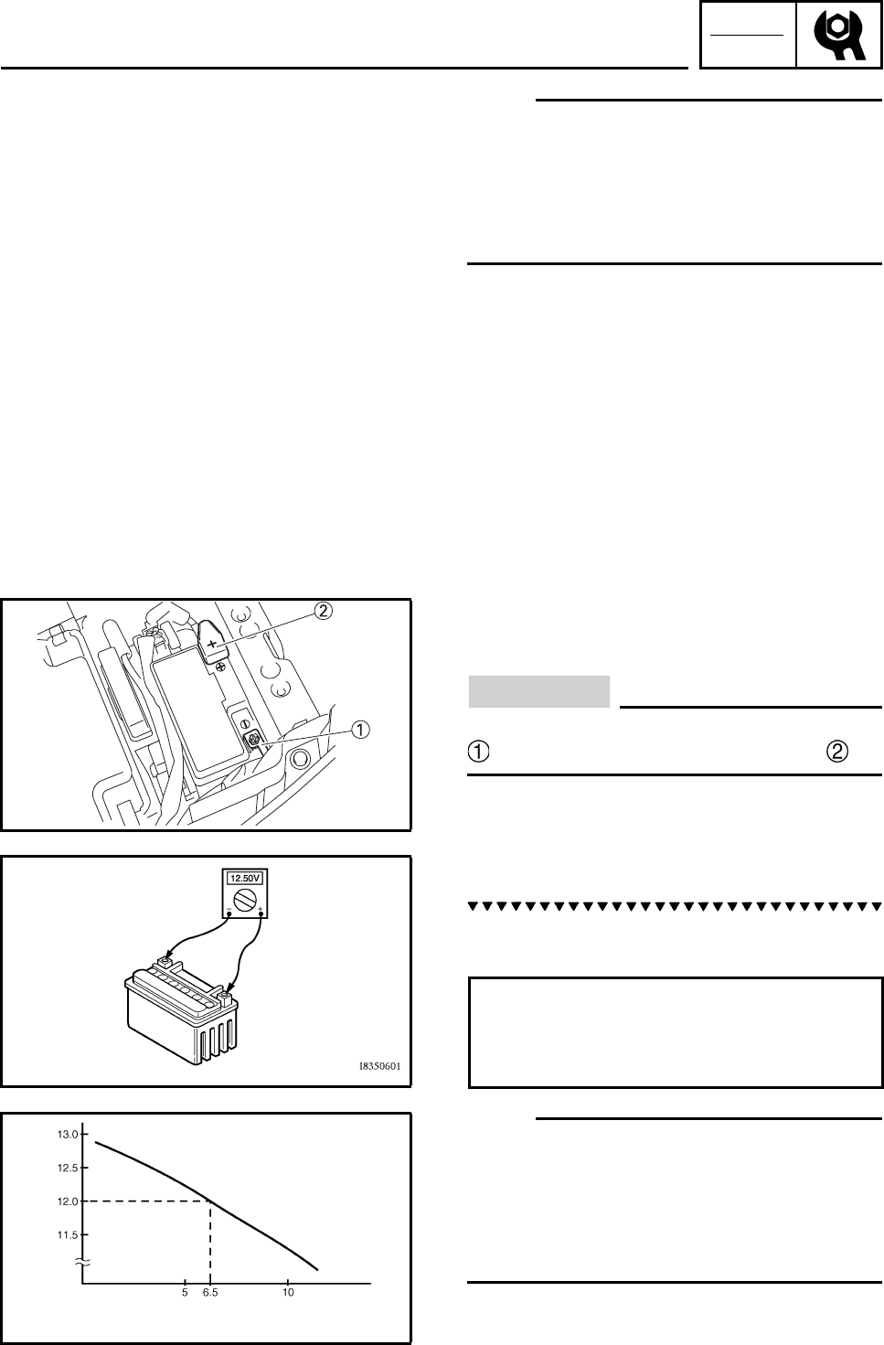
CHK
ADJ
3-46
N
O
TE:N
O
TE:
Since MF batteries are sealed, it is not possi-
ble to check the charge state of the battery by
measuring the specific gravity of the electro-
lyte. Therefore, the charge of the battery has to
be checked by measuring the voltage at the
battery terminals.
1. Remove:
• seat
• battery cover
Refer to “SEAT, FENDERS AND FUEL
TANK”.
2. Disconnect:
• battery leads
(from the battery terminals)
CAUTION:
First, disconnect the negative battery lead
, and then the positive battery lead .
3. Remove:
• battery
4. Check:
• battery charge
a. Connect a pocket tester to the battery ter-
minals.
N
O
TE:N
O
TE:
• The charge state of an MF battery can be
checked by measuring its open-circuit voltage
(i.e., the voltage when the positive terminal is
disconnected).
• No charging is necessary when the open-cir-
cuit voltage equals or exceeds 12.8 V.
b. Check the charge of the battery, as shown
in the charts and the following example.
Positive tester probe →
positive battery terminal
Negative tester probe →
negative battery terminal
Relationship between the open-circuit voltage
and the charging time at 20 °C (68 °F)
Charging time (hours)
These values vary with the temperature, the condition of
the battery plates, and the electrolyte level.
Open-circuit voltage (V)
CHECKING AND CHARGING THE BATTERY
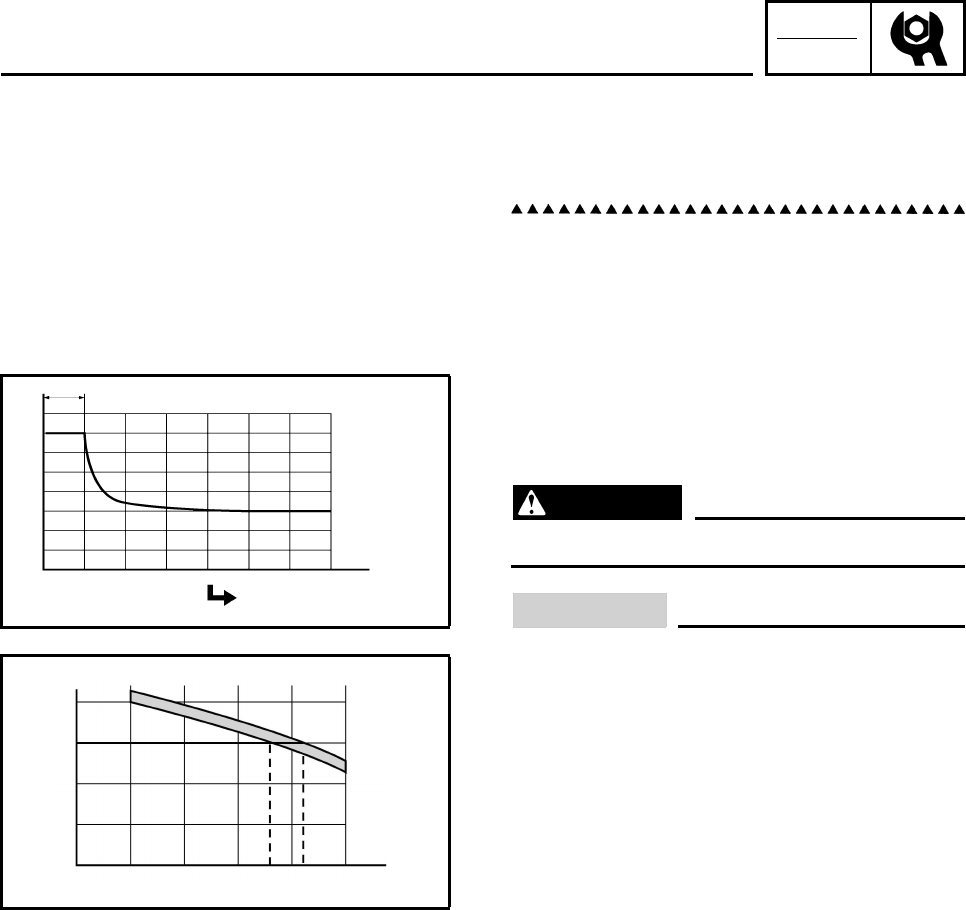
CHK
ADJ
3-47
Example
c. Open-circuit voltage = 12.0 V
d. Charging time = 6.5 hours
e. Charge of the battery = 20 ~ 30%
5. Charge:
• battery
(refer to the appropriate charging method
illustration)
WARNING
Do not quick charge a battery.
CAUTION:
• Never remove the MF battery sealing caps.
• Do not use a high-rate battery charger
since it forces a high-amperage current
into the battery quickly and can cause bat-
tery overheating and battery plate dam-
age.
• If it is impossible to regulate the charging
current on the battery charger, be careful
not to overcharge the battery.
• When charging a battery, be sure to
remove it from the machine. (If charging
has to be done with the battery mounted
on the machine, disconnect the negative
battery lead from the battery terminal.)
• To reduce the chance of sparks, do not
plug in the battery charger until the bat-
tery charger leads are connected to the
battery.
• Before removing the battery charger lead
clips from the battery terminals, be sure to
turn off the battery charger.
• Make sure the battery charger lead clips
are in full contact with the battery terminal
and that they are not shorted. A corroded
battery charger lead clip may generate
heat in the contact area and a weak clip
spring may cause sparks.
• If the battery becomes hot to the touch at
any time during the charging process, dis-
connect the battery charger and let the
battery cool before reconnecting it. Hot
batteries can explode!
Charging
Open-circuit voltage (V)
Ambient temperature
20°C (68°F)
Check the open-circuit
voltage.
Time (minutes)
6020 5040
15
13
11
18
10
12
14
16
17
10030
Ambient
temperature
20°C (68°F)
Charging condition of the battery (%)
Open-circuit voltage (V)
13
11
10
12
14
100 75 50 30 25 20 0
CHECKING AND CHARGING THE BATTERY

CHK
ADJ
3-48
• As shown in the following illustration, the
open-circuit voltage of an MF battery sta-
bilizes about 30 minutes after charging
has been completed. Therefore, wait 30
minutes after charging is completed
before measuring the open-circuit voltage.
CHECKING AND CHARGING THE BATTERY
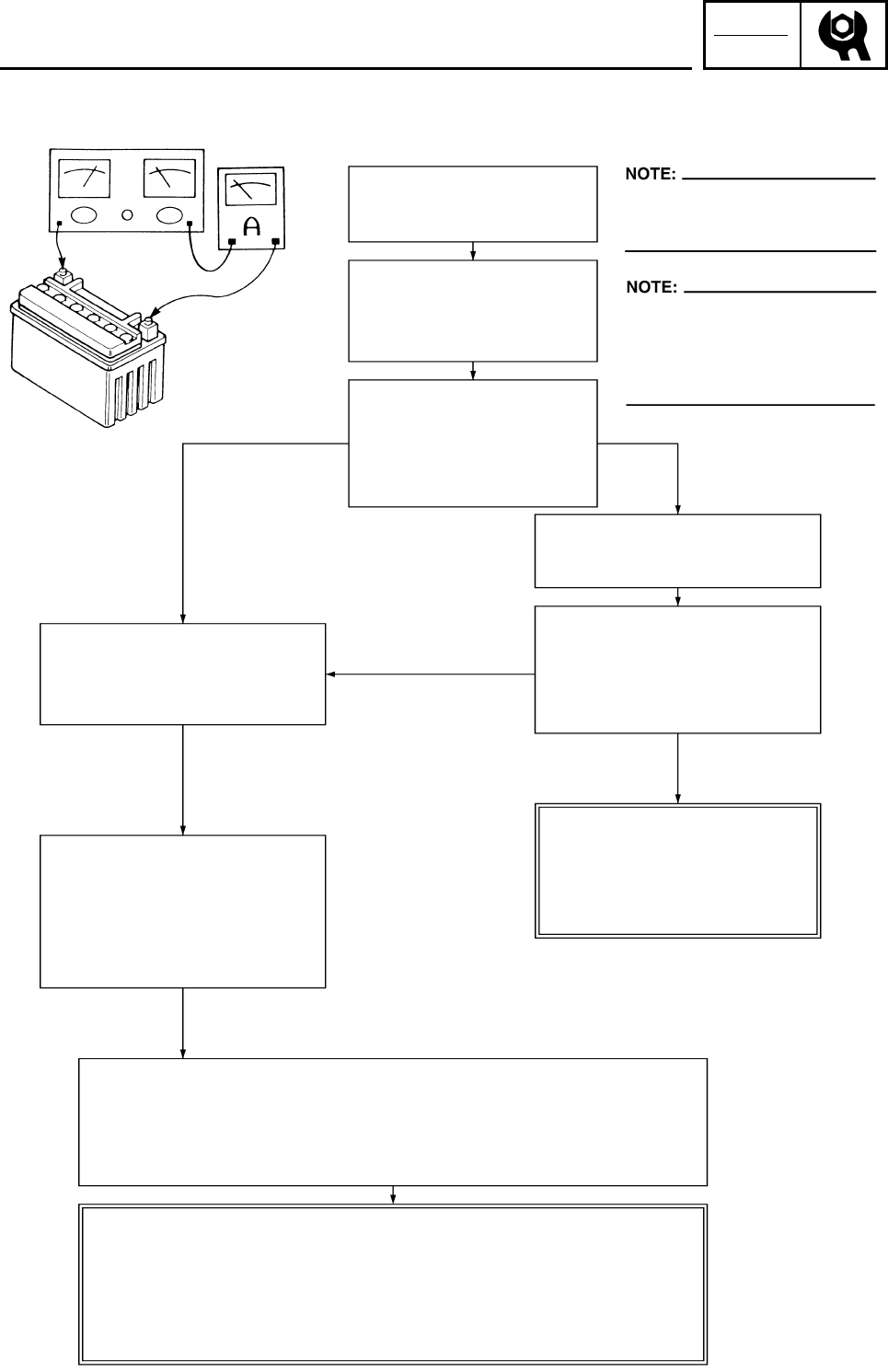
CHK
ADJ
3-49
Charging method using a variable-current (voltage) charger
Measure the open-circuit
voltage prior to charging.
Connect a charger and
ammeter to the battery
and start charging.
Is the amperage higher
than the standard charg-
ing amperage written on
the battery?
Leave the battery unused for
more than 30 minutes before
measuring its open-circuit voltage.
Adjust the voltage to obtain
the standard charging amper-
age.
Monitor the amperage for 3 ~ 5
minutes. Is the standard charg-
ing amperage exceeded?
Adjust the charging voltage
to 20 ~ 25 V.
If the amperage does not
exceed the standard charg-
ing amperage after 5 min-
utes, replace the battery.
Set the timer to the charging
time determined by the open-
circuit voltage.
Refer to “CHECKING AND
CHARGING THE BATTERY”.
If the required charging time exceeds 5 hours, it is advisable to
check the charging amperage after 5 hours. If there is any change in
the amperage, readjust the voltage to obtain the standard charging
amperage.
Leave the battery unused for more than 30 minutes before measur-
ing its open-circuit voltage.
12.8 V → Charging is complete.
12.0 ~ 12.7 V → Recharging is required.
Under 12.0 V → Replace the battery.
Charger Ammeter
Set the charging voltage to 16 ~
17 V. (If the charging voltage is
lower, charging will be insufficient,
if it is higher, the battery will be
over-charged.)
YES
YES
NO
NO
CHECKING AND CHARGING THE BATTERY
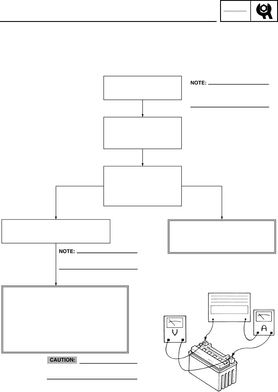
CHK
ADJ
3-50
Charging method using a constant voltage charger
Measure the open-circuit
voltage prior to charging.
Connect a charger and
ammeter to the battery
and start charging.
Charge the battery until the charging
voltage reaches 15 V.
Leave the battery unused for more
than 30 minutes before measuring
its open-circuit voltage.
This type of battery charger cannot
charge an MF battery. A variable-
voltage charger is recommended.
Set the charging time to a maxi-
mum of 20 hours.
Constant amperage chargers are not
suitable for charging MF batteries.
Leave the battery unused for more than 30
minutes before measuring its open-circuit
voltage.
12.8 V → Charging is complete.
12.0 ~ 12.7 V → Recharging is required.
Under 12.0 V → Replace the battery.
Is the amperage higher
than the standard charg-
ing amperage written on
the battery?
Charger
Ammeter
Voltmeter
CHECKING AND CHARGING THE BATTERY
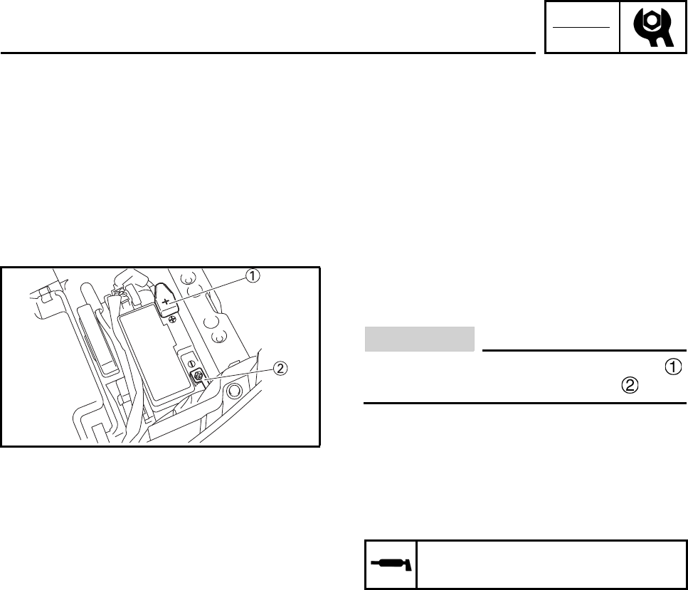
CHK
ADJ
3-51
6. Install:
• battery
7. Connect:
• battery leads
(to the battery terminals)
CAUTION:
First, connect the positive battery lead ,
and then the negative battery lead .
8. Check:
• battery terminals
Dirt → Clean with a wire brush.
Loose connection → Connect properly.
9. Lubricate:
• battery terminals
10.Install:
• battery cover
• seat
Refer to “SEAT, FENDERS AND FUEL
TANK”.
Recommended lubricant
Dielectric grease
CHECKING AND CHARGING THE BATTERY
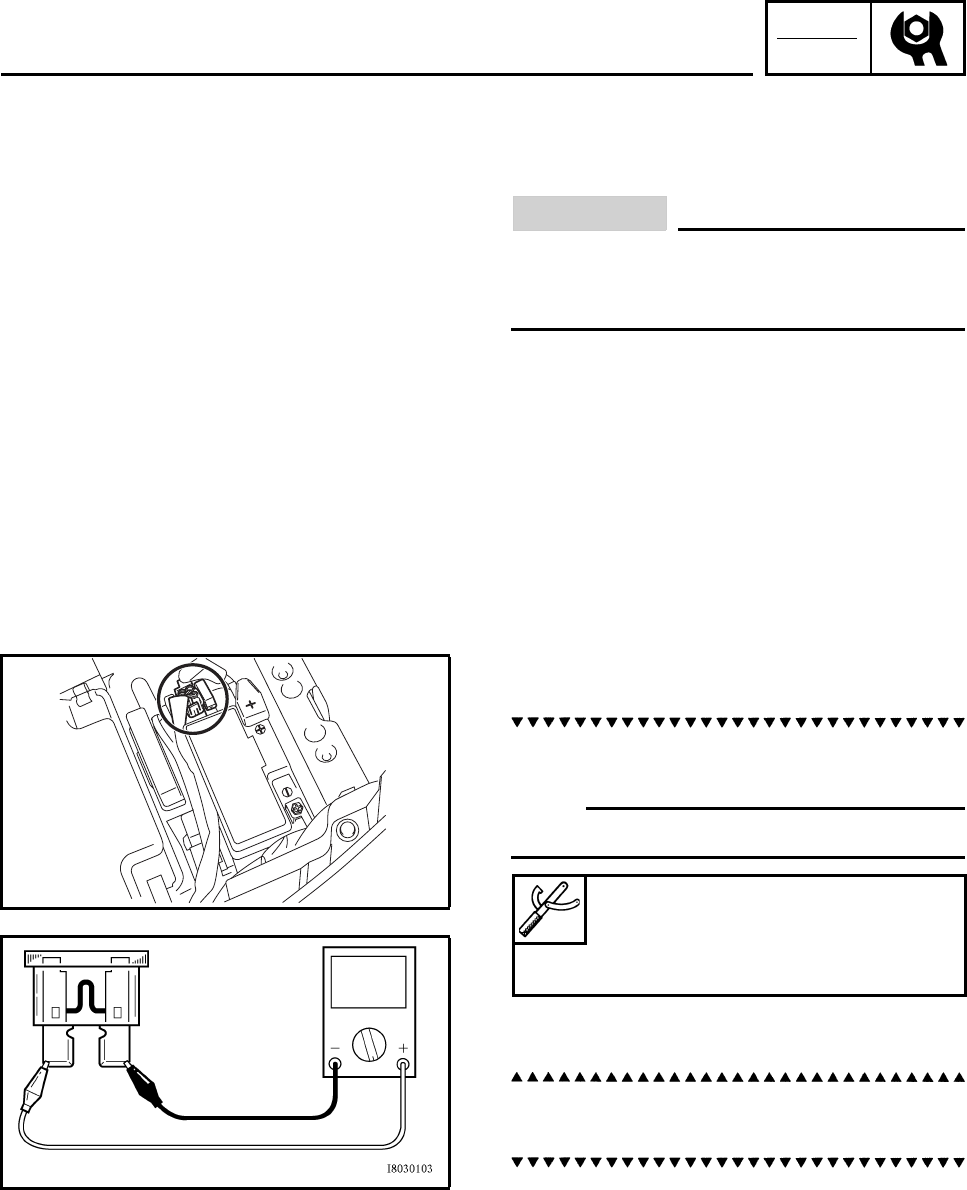
CHK
ADJ
3-52
EBS00121
CHECKING THE FUSES
The following procedure applies to all of the
fuses.
CAUTION:
To avoid a short circuit, always set the main
switch to “OFF” when checking or replac-
ing a fuse.
1. Remove:
• seat
• battery cover
Refer to “SEAT, FENDERS AND FUEL
TANK”.
2. Check:
•fuse
a. Connect the pocket tester to the fuse and
check the continuity.
N
O
TE:N
O
TE:
Set the pocket tester selector to “Ω × 1”.
b. If the pocket tester indicates “•”, replace the
fuse.
3. Replace:
• blown fuse
a. Set the main switch to “OFF”.
b. Install a new fuse of the correct amperage.
c. Set on the switches to verify if the electrical
circuit is operational.
d. If the fuse immediately blows again, check
the electrical circuit.
Pocket tester
90890-03112
Analog pocket tester
YU-03112-C
CHECKING THE FUSES
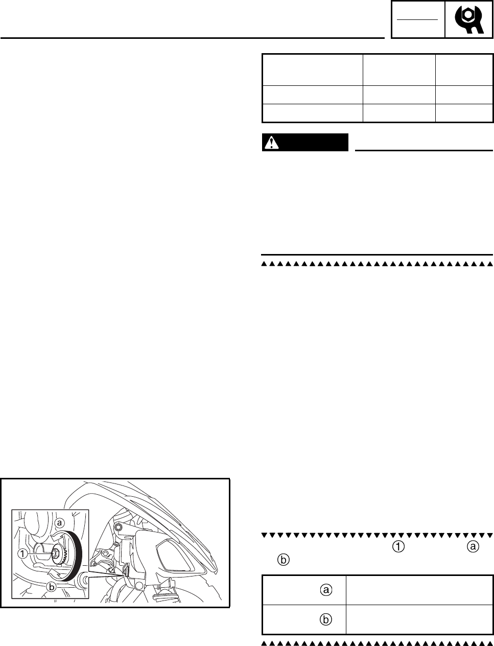
CHK
ADJ
3-53
WARNING
Never use a fuse with an amperage rating
other than that specified. Improvising or
using a fuse with the wrong amperage rat-
ing may cause extensive damage to the
electrical system, cause the lighting and
ignition systems to malfunction and could
possibly cause a fire.
4. Install:
• battery cover
• seat
Refer to “SEAT, FENDERS AND FUEL
TANK”.
EBS00122
ADJUSTING THE HEADLIGHT BEAM
1. Adjust:
• headlight beam (vertically)
a. Turn the adjusting bolt in direction or
.
Items Amperage
rating Q’ty
Main 15 A 1
Reserve 15 A 1
Direction Headlight beam is
raised.
Direction Headlight beam is
lowered.
CHECKING THE FUSES/
ADJUSTING THE HEADLIGHT BEAM
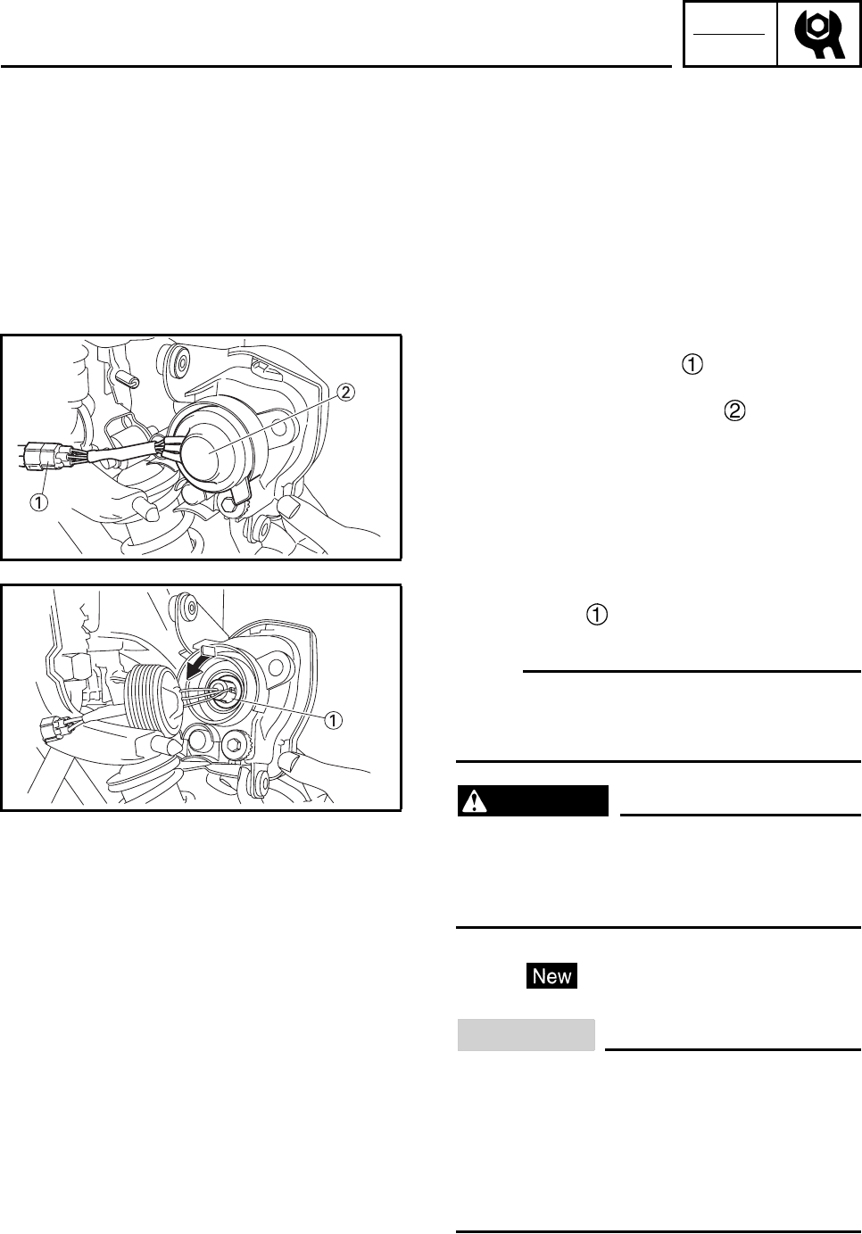
CHK
ADJ
3-54
EBS00124
REPLACING A HEADLIGHT BULB
1. Remove:
• headlight
Refer to “SEAT, FENDERS AND FUEL
TANK”.
2. Disconnect:
• headlight lead coupler
3. Remove:
• headlight bulb holder cover
4. Remove:
• bulb holder
•bulb
N
O
TE:N
O
TE:
Push the headlight bulb holder inward, turn it
counterclockwise and remove the defective
bulb.
WARNING
Keep flammable products and your hands
away from the bulb while it is on. since it
will be hot. Do not touch the bulb until it
cools down.
5. Install:
•bulb
Secure the new bulb with the headlight unit.
CAUTION:
Avoid touching the glass part of the bulb.
Keep it free from oil; otherwise, the trans-
parency of the glass, life of the bulb, and
luminous flux will be adversely affected. If
oil gets on the bulb, thoroughly clean it
with a cloth moistened with alcohol or lac-
quer thinner.
REPLACING A HEADLIGHT BULB
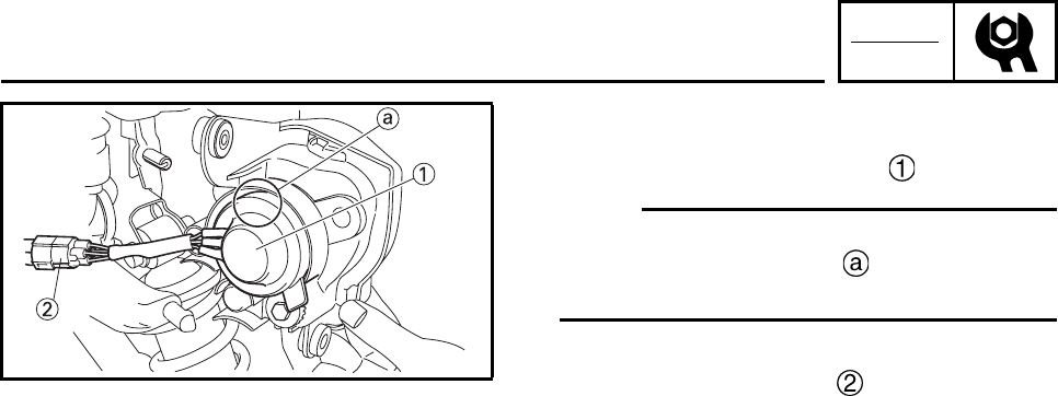
CHK
ADJ
3-55
6. Install:
• bulb holder
• headlight bulb holder cover
N
O
TE:N
O
TE:
After installing the bulb holder cover, make
sure that the “TOP” mark is in the position
shown.
7. Connect:
• headlight lead coupler
8. Install:
• headlight
Refer to “SEAT, FENDERS AND FUEL
TANK”.
REPLACING A HEADLIGHT BULB
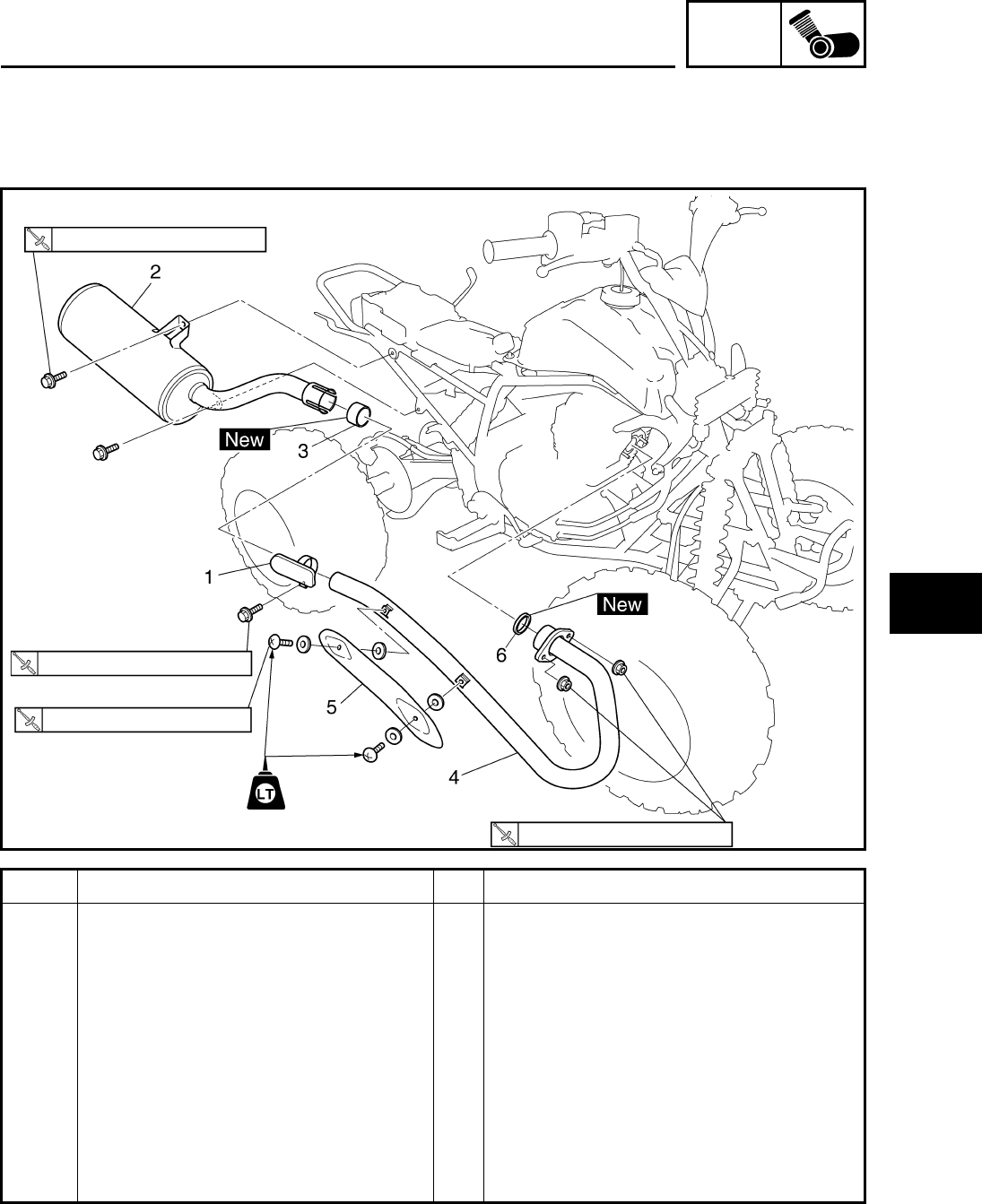
ENG
4-1
1
2
3
4
5
6
7
8
ENGINE
ENGINE REMOVAL
MUFFLER AND EXHAUST PIPE
Order Job/Parts to remove Q’ty Remarks
Removing the muffler and exhaust
pipe Remove the parts in the order listed.
Seat/front panel/fender Refer to “SEAT, FENDERS AND FUEL
TANK” in chapter 3.
1 Clamp 1 Loosen
2 Muffler 1
3Gasket 1
4 Exhaust pipe 1
5 EXhaust pipe protector 1
6Gasket 1
For installation, reverse the removal
procedure.
34 Nm (3.4 m•kg, 25 ft•lb)
20 Nm (2.0 m•kg, 15 ft•lb)
8 Nm (0.8 m•kg, 5.9 ft•lb)
18 Nm (1.8 m•kg, 13 ft•lb)
ENGINE REMOVAL
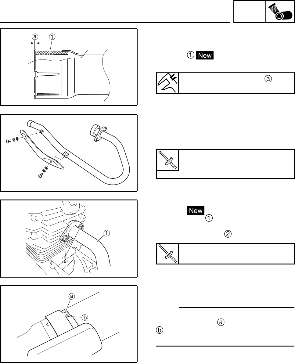
ENG
4-2
INSTALLING THE EXHAUST PIPE AND
MUFFLER
1. Install:
• gasket
(to muffler)
2. Install:
• exhaust pipe protector
3. Tighten:
• exhaust pipe protector screws
4. Install:
• gasket
• exhaust pipe
5. Tighten:
• nuts (exhaust pipe)
6. Install:
•clamp
N
O
TE:N
O
TE:
Slide the clamp onto the end of the muffler and
insert the projection of the clamp into a slot
in the muffler. Tighten the clamp after
installing the muffler.
Installed depth of gasket
3.5 mm (0.14 in)
Screw
8 Nm (0.8 m•kg, 5.9 ft•lb)
LOCTITE®
Exhaust pipe nut
18 Nm (1.8 m•kg, 13 ft•lb)
ENGINE REMOVAL
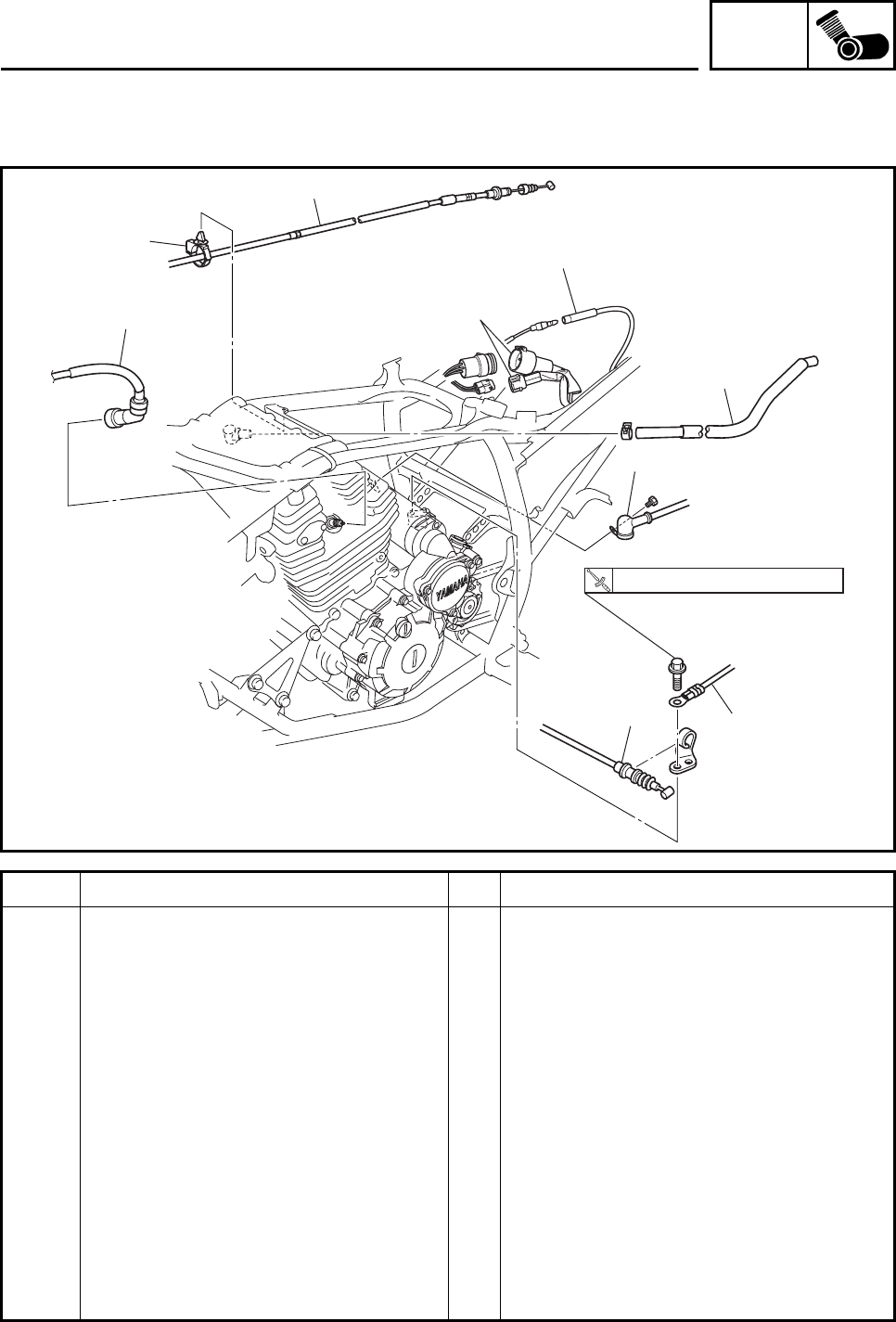
ENG
4-3
LEADS, CABLES AND HOSES
Order Job/Parts to remove Q’ty Remarks
Removing the leads, cables and
hoses Remove the parts in the order listed.
Engine oil Drain.
Oil cooler hose 1, 2 Refer to “CLUTCH”.
Carburetor Refer to “CARBURETOR” in chapter 5.
Drive sprocket/drive chain Refer to “REAR SHOCK ABSORBER,
SWINGARM AND DRIVE CHAIN” in
chapter 6.
1 Ignition coil spark plug lead 1
2 Air filter case breather hose 1
3 Starter motor lead 1 Disconnect.
4 Battery negative lead 1 Disconnect.
5Clutch cable 1
6 Plastic band 1 Disconnect.
7 Parking brake cable 1
8 AC magneto coupler 2 Disconnect.
6
7
3
1
2
9
8
4
5
10 Nm (1.0 m•kg, 7.4 ft•lb)
ENGINE REMOVAL
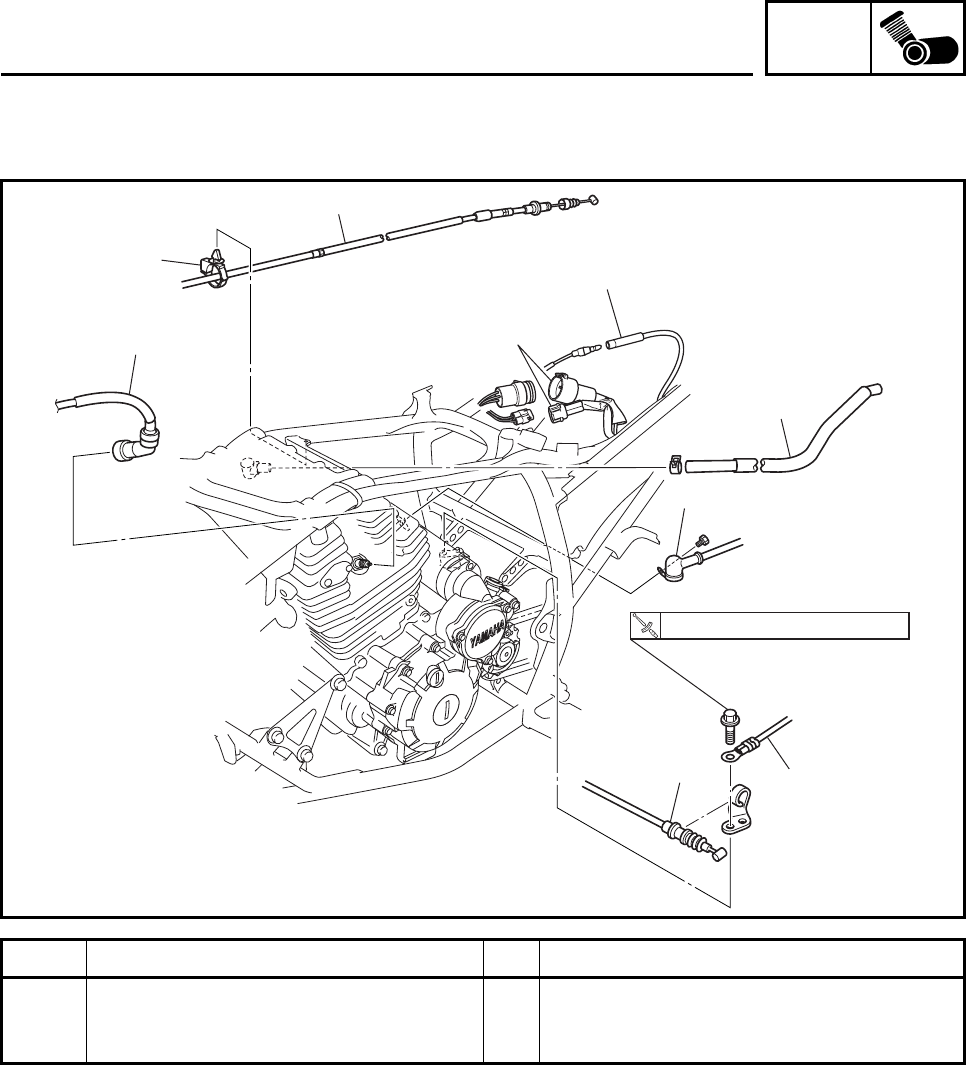
ENG
4-4
Order Job/Parts to remove Q’ty Remarks
9 Neutral switch connector 1 Disconnect.
For installation, reverse the removal
procedure.
6
7
3
1
2
9
8
4
5
10 Nm (1.0 m•kg, 7.4 ft•lb)
ENGINE REMOVAL
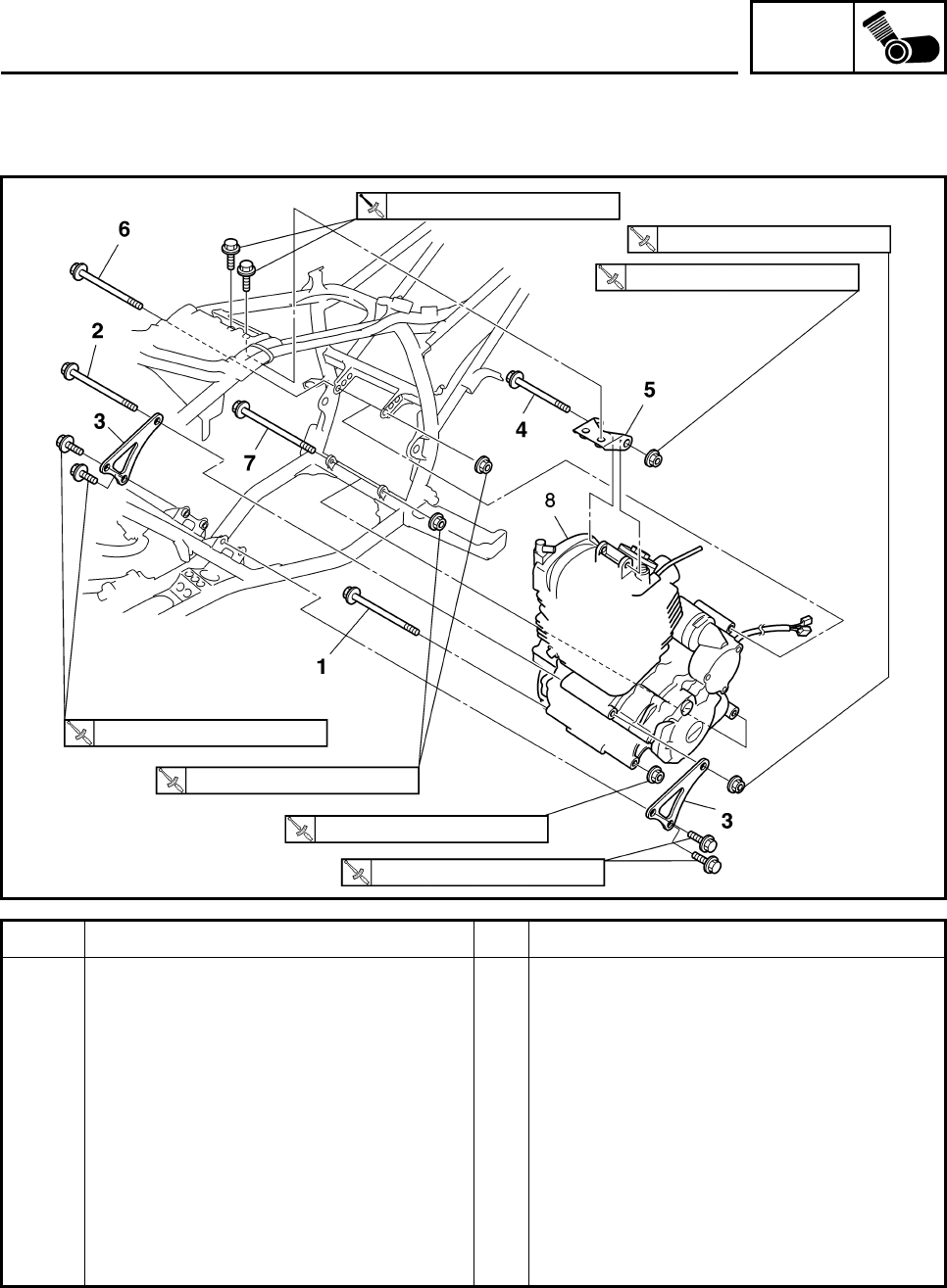
ENG
4-5
ENGINE MOUNTING BOLTS
Order Job/Parts to remove Q’ty Remarks
Removing the engine mounting
bolts Remove the parts in the order listed.
1 Crankcase bolt 1
2 Engine mounting bolt (front) 1
3 Engine bracket (left and right) 2
4 Engine mounting bolt (upper) 1
5 Engine bracket (upper) 1
6 Engine mounting bolt (rear upper) 1
7 Engine mounting bolt (rear lower) 1
8 Engine assembly 1
For installation, reverse the removal
procedure.
66 Nm (6.6 m•kg, 49 ft•lb)
33 Nm (3.3 m•kg, 24 ft•lb)
33 Nm (3.3 m•kg, 24 ft•lb)
66 Nm (6.6 m•kg, 49 ft•lb)
33 Nm (3.3 m•kg, 24 ft•lb)
40 Nm (4.0 m•kg, 30 ft•lb)
40 Nm (4.0 m•kg, 30 ft•lb)
ENGINE REMOVAL
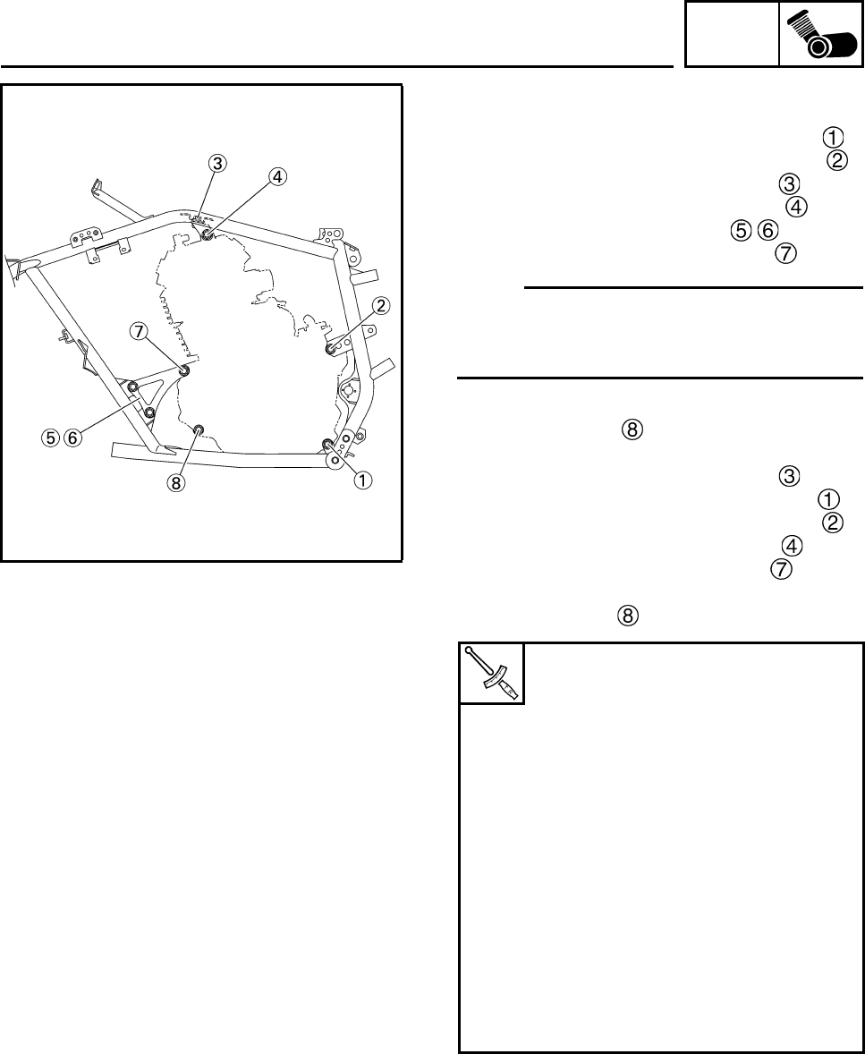
ENG
4-6
INSTALLING THE ENGINE
1. Install:
• Engine mounting bolt (rear lower side)
• Engine mounting bolt (rear upper side)
• Engine bracket bolts (upper side)
• Engine mounting bolt (upper side)
• Engine brackets (front side)
• Engine mounting bolt (front side)
N
O
TE:N
O
TE:
• The direction of the bolt insertion is made
from the right side of the body.
• Do not fully tighten the bolts and nuts.
2. Install:
• Crankcase bolt
3. Tighten:
• Engine bracket bolts (upper side)
• Engine mounting nut (rear lower side)
• Engine mounting nut (rear upper side)
• Engine mounting nut (upper side)
• Engine mounting nut (front side)
• Engine bracket bolts (front side)
• Crankcase nut
40 Nm (4.0 m
Engine bracket bolt (upper side)
33 Nm (3.3 m•kg, 24 ft•lb)
Engine mounting nut (rear lower
side)
66 Nm (6.6 m•kg, 49 ft•lb)
Engine mounting nut (rear upper
side)
66 Nm (6.6 m•kg, 49 ft•lb)
Engine mounting nut (upper side)
66 Nm (6.6 m•kg, 49 ft•lb)
Engine mounting nut (front lower
side)
40 Nm (4.0 m•kg, 30 ft•lb)
Engine bracket bolt (M8)
33 Nm (3.3 m•kg, 24 ft•lb)
Crankcase nut
40 Nm (4.0 m•kg, 30 ft•lb)
ENGINE REMOVAL
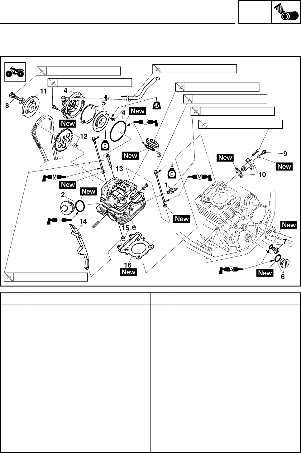
ENG
4-7
CYLINDER HEAD
Order Job/Parts to remove Q’ty Remarks
Removing the cylinder head
Seat/front fender/fuel tank/fuel tank
shield Refer to “SEAT, FENDERS AND FUEL
TANK” in chapter 3.
Muffler and exhaust pipe Refer to “MUFFLER AND EXHAUST
PIPE”.
Carburetor Refer to “CARBURETOR” in chapter 5.
Ignition coil spark plug lead Refer to “LEADS, CABLES AND HOSES”.
Engine bracket (upper side) Refer to “ENGINE MOUNTING BOLTS”.
1 Spark plug 1
2 Cylinder head cover 1/O-ring 1/1
3 Cylinder head cover 2/O-ring 1/1
4 Cylinder head cover 3/O-ring 1/1
5 Breather pipe 1/Gasket 1/1
6 Crankshaft end accessing screw/
O-ring 1/1
7 Timing mark accessing screw/O-ring 1/1
8 Camshaft sprocket bolt 1 Loosen.
20 Nm (2.0 m•kg, 15 ft•lb)
60 Nm (6.0 m•kg, 44 ft•lb)
10 Nm (1.0 m•kg, 7.4 ft•lb)
10 Nm (1.0 m•kg, 7.4 ft•lb)
18 Nm (1.8 m•kg, 13 ft•lb)
24 Nm (2.4 m•kg, 18 ft•lb)
18 Nm (1.8 m•kg, 13 ft•lb)
10 Nm (1.0 m•kg, 7.4 ft•lb)
CYLINDER HEAD
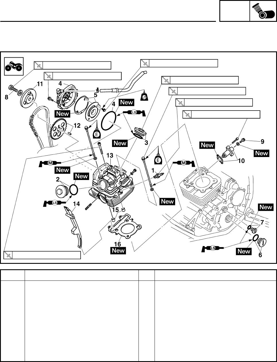
ENG
4-8
Order Job/Parts to remove Q’ty Remarks
9 Cap bolt 1 Loosen.
10 Timing chain tensioner/gasket 1/1
11 Breather pipe 2 1
12 Camshaft sprocket/dowel pin 1/1
13 Cylinder head 1
14 Timing chain guide 1
15 Dowel pin 2
16 Cylinder head gasket 1
For installation, reverse the removal
procedure.
20 Nm (2.0 m•kg, 15 ft•lb)
60 Nm (6.0 m•kg, 44 ft•lb)
10 Nm (1.0 m•kg, 7.4 ft•lb)
10 Nm (1.0 m•kg, 7.4 ft•lb)
18 Nm (1.8 m•kg, 13 ft•lb)
24 Nm (2.4 m•kg, 18 ft•lb)
18 Nm (1.8 m•kg, 13 ft•lb)
10 Nm (1.0 m•kg, 7.4 ft•lb)
CYLINDER HEAD
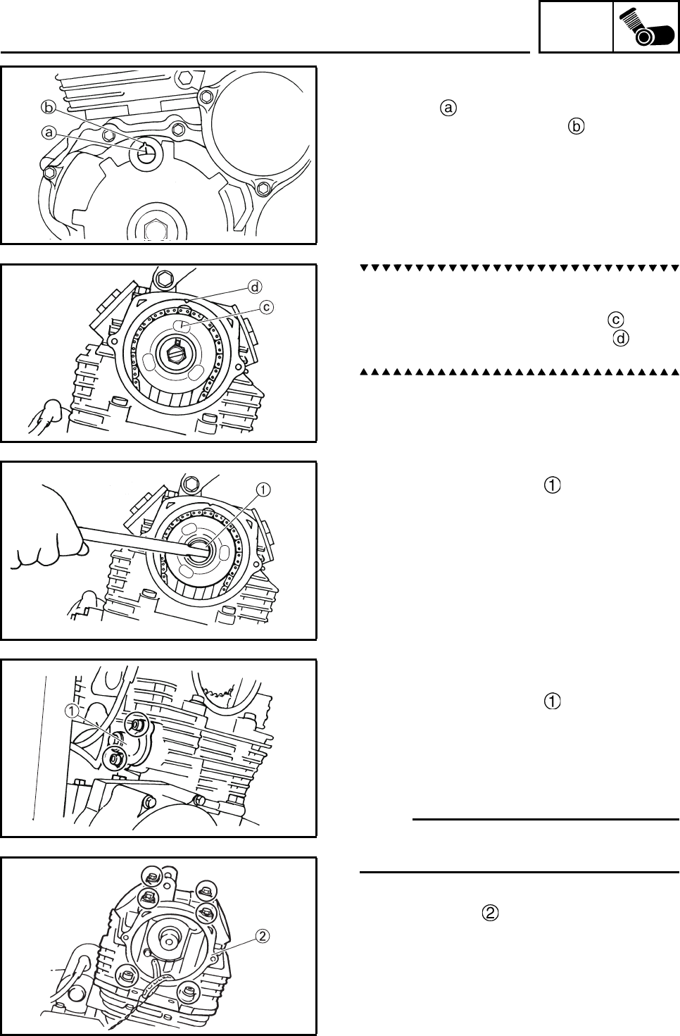
ENG
4-9
REMOVING THE CYLINDER HEAD
1. Align:
• “I” mark on the Pickup coil rotor
(with the stationary pointer on the crank-
case cover)
a. Turn the Pickup coil rotor counterclockwise.
b. When the piston is at TDC on the compres-
sion stroke, align the “I” mark on the
camshaft sprocket with the mark on the
cylinder head.
2. Loosen:
• Camshaft sprocket bolt
3. Remove:
• Timing chain tensioner cap
• Timing chain tensioner
(along with the gasket)
• Camshaft sprocket bolt
• Breather plate 2
• Camshaft sprocket
• Timing chain
N
O
TE:N
O
TE:
To prevent the timing chain from falling into the
crankcase, fasten it with a wire.
4. Remove:
• Cylinder head
CYLINDER HEAD
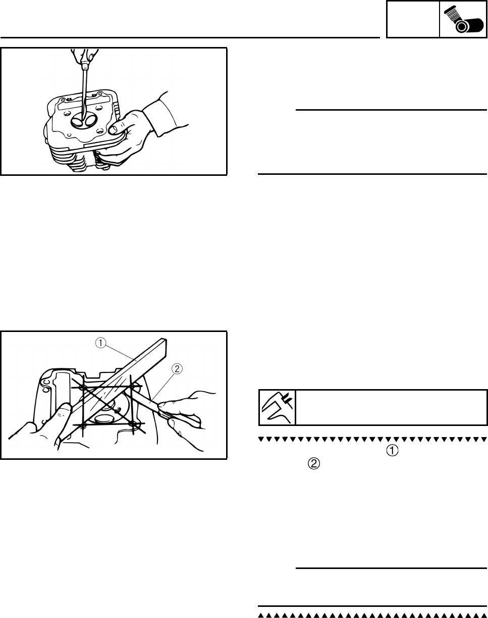
ENG
4-10
CHECKING THE CYLINDER HEAD
1. Eliminate:
• Combustion chamber carbon deposits
(with a rounded scraper)
N
O
TE:
Do not use a sharp instrument to avoid damag-
ing or scratching:
• Spark plug bore threads
• Valve seats
2. Check:
• Cylinder head
Damage/scratches → Replace.
3. Measure:
• Cylinder head warpage
Out of specification → Resurface the cylin-
der head.
a. Place a straightedge and a thickness
gauge across the cylinder head.
b. Measure the warpage.
c. If the limit is exceeded, resurface the cylin-
der head as follows.
d. Place a 400–600 grit wet sandpaper on the
surface plate and resurface the cylinder
head using a figure-eight sanding pattern.
N
O
TE:N
O
TE:
To ensure an even surface, rotate the cylinder
head several times.
Warpage limit
0.05 mm (0.0020 in)
CYLINDER HEAD
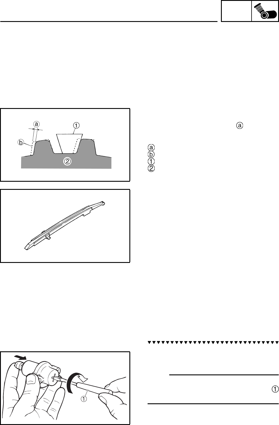
ENG
4-11
CHECKING THE TIMING CHAIN GUIDES
The following procedure applies to the cam-
shaft sprockets and timing chain guides.
1. Check:
• Timing chain
Damage/stiffness → Replace the timing
chain and camshaft sprocket and crank-
shaft sprocket as a set.
2. Check:
• Camshaft sprocket
More than 1/4 tooth wear → Replace
the timing chain and camshaft sprocket and
crankshaft sprocket as a set.
1/4 tooth
Correct
Timing chain
Camshaft sprocket
3. Check:
• Timing chain guide (exhaust side)
CHECKING THE TIMING CHAIN
TENSIONERS
1. Check:
• Timing chain tensioner
Cracks/damage → Replace.
2. Check:
• One-way cam operation
Rough movement → Replace the timing
chain tensioner housing.
a. Lightly press the timing chain tensioner rod
into the timing chain tensioner housing by
hand.
N
O
TE:N
O
TE:
While pressing the timing chain tensioner rod,
wind it clockwise with a thin screwdriver
until it stops.
CYLINDER HEAD
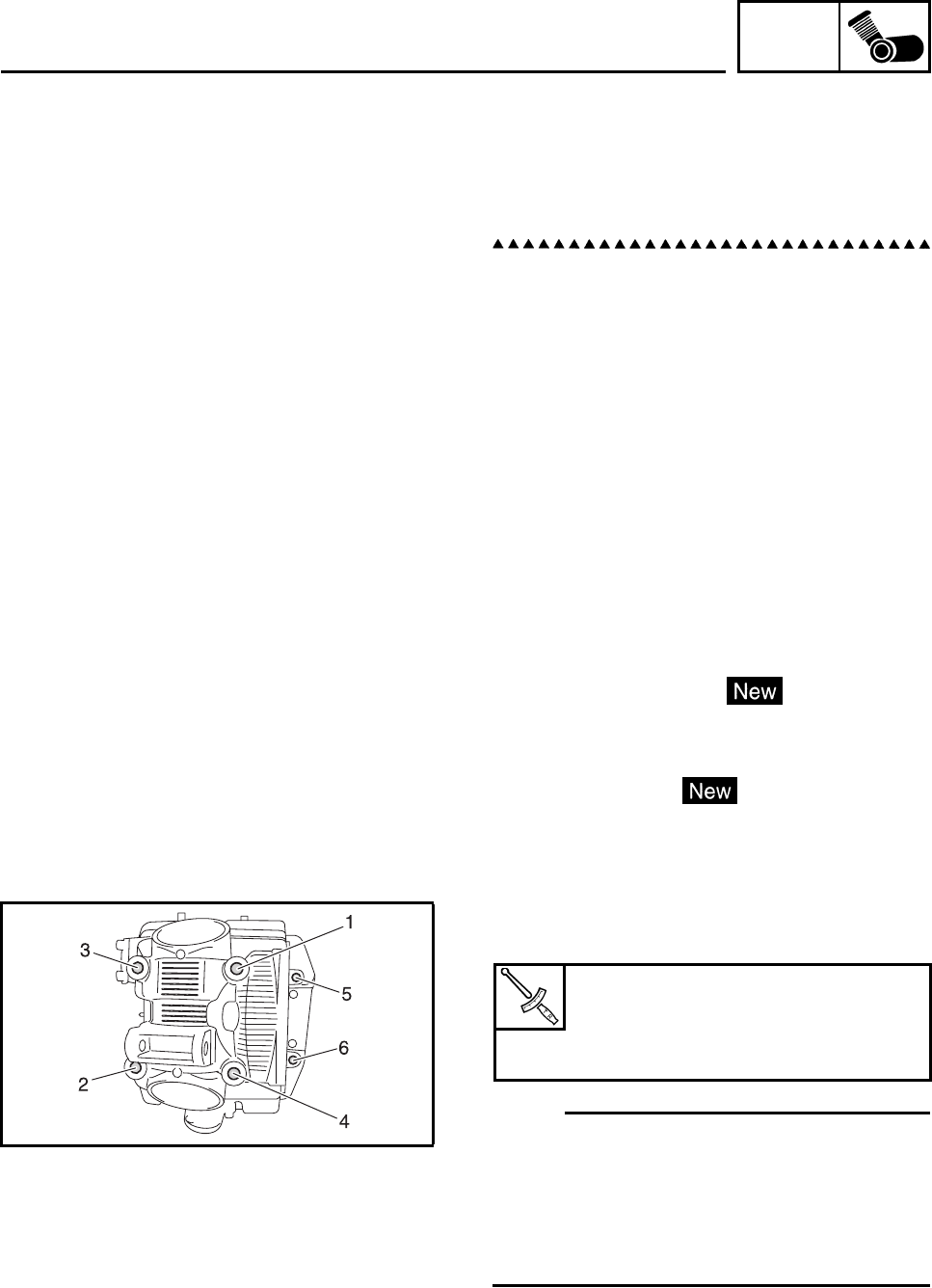
ENG
4-12
b. Remove the screwdriver and slowly release
the timing chain tensioner rod.
c. Make sure that the timing chain tensioner
rod comes out of the timing chain tensioner
housing smoothly. If there is rough move-
ment, replace the timing chain tensioner.
3. Check:
• Cap bolt
• Copper washer
•Spring
•One-way cam
• Timing chain tensioner rod
Damage/wear → Replace the defective
part(s).
INSTALLING THE CYLINDER HEAD
1. Install:
• Cylinder head gasket
• Dowel pins
2. Install:
• Cylinder head
• Copper washers
• Cylinder head bolts
3. Tighten:
• Cylinder head bolts
N
O
TE:N
O
TE:
• Apply oil to the bearing surface of (upper) cyl-
inder head bolt.
Further, apply molybdenum disulfide grease
to thread part.
• Tighten the cylinder head bolts in the proper
tightening sequence as shown.
4. Install:
• Camshaft sprocket
• Dowel pin
• Timing chain
Cylinder head bolt 226 mm (8.90 in)
24 Nm (2.4 m•kg, 18 ft•lb)
Cylinder head bolt 45 mm (1.77 in)
20 Nm (2.0 m•kg, 15 ft•lb)
CYLINDER HEAD
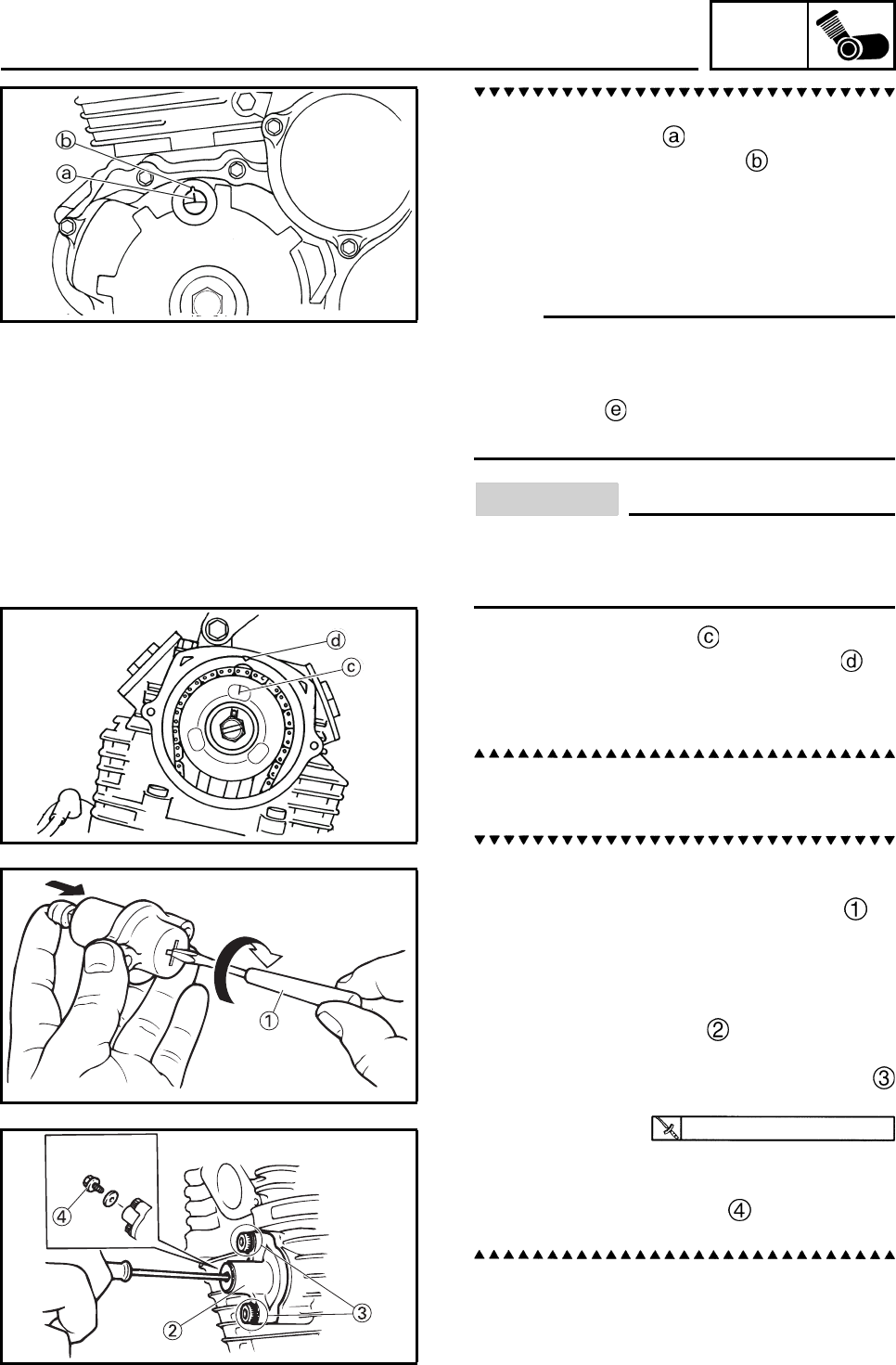
ENG
4-13
a. Turn the Pickup coil rotor counterclockwise.
b. Align the “I” mark on the Pickup coil rotor
with the stationary pointer on the crank-
case cover.
c. Remove the wire from the timing chain.
d. Install the timing chain onto the camshaft
sprocket, and then install the camshaft
sprocket onto the camshaft.
N
O
TE:N
O
TE:
• When installing the camshaft sprocket, be
sure to keep the timing chain as tight as pos-
sible on the exhaust side.
• Align the pin on the camshaft with the slot
in the camshaft sprocket.
CAUTION:
Do not turn the crankshaft when installing
the camshaft(s) to avoid damage or
improper valve timing.
e. Align the “I” mark on the camshaft
sprocket with the stationary pointer on
the cylinder head.
f. While holding the camshaft, temporarily
tighten the camshaft sprocket bolts.
5. Install:
• Timing chain tensioner
a. While lightly pressing the timing chain ten-
sioner rod by hand, turn the tensioner rod
fully clockwise with a thin screwdriver .
b. With the timing chain tensioner rod turned
all the way into the timing chain tensioner
housing (with the thin screwdriver still
installed), install the new gasket and the
timing chain tensioner onto the body cyl-
inder.
c. Tighten the timing chain tensioner bolts
to the specified torque.
d. Remove the screwdriver, make sure that
the timing chain tensioner rod releases, and
then tighten the cap bolt to the specified
torque.
10 Nm (1.0 m•kg, 7.4 ft•lb)
CYLINDER HEAD
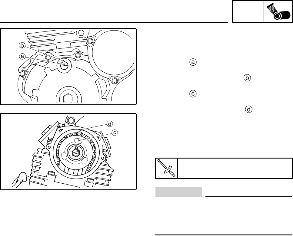
ENG
4-14
6. Turn:
• Crankshaft
(several turns counterclockwise)
7. Check:
• “I” mark
Align the “I” mark on the pickup coil rotor
with the stationary pointer on the crank-
case cover.
• “I” mark
Align the “I” mark on the camshaft sprocket
with the stationary pointer on the cylin-
der head.
Out of alignment → Correct.
Refer to the installation steps above.
8. Tighten:
• Camshaft sprocket bolt
CAUTION:
Be sure to tighten the camshaft sprocket
bolts to the specified torque to avoid the
possibility of the bolts coming loose and
damaging the engine.
9. Measure:
• Valve clearance
Out of specification → Adjust.
Refer to “ADJUSTING THE VALVE CLEAR-
ANCE” in chapter 3.
Camshaft sprocket bolt
60 Nm (6.0 m•kg, 44 ft•lb)
CYLINDER HEAD
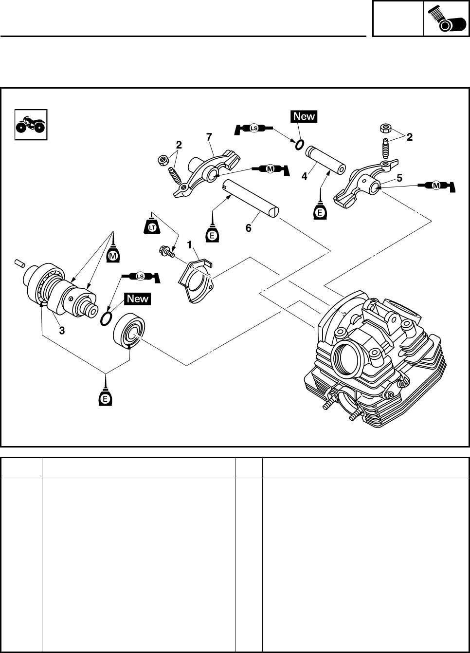
ENG
4-15
ROCKER ARM, CAMSHAFT
Order Job/Parts to remove Q’ty Remarks
Removing the rocker arms and cam-
shaft Remove the parts in the order listed.
Cylinder head Refer to “CYLINDER HEAD”.
1 Lock plate 1
2 Locknut/valve clearance adjusting
screw 2/2
3Camshaft 1
4 Intake rocker arm shaft 1
5 Intake rocker arm 1
6 Exhaust rocker arm shaft 1
7 Exhaust rocker arm 1
For installation, reverse the removal
procedure.
ROCKER ARM, CAMSHAFT
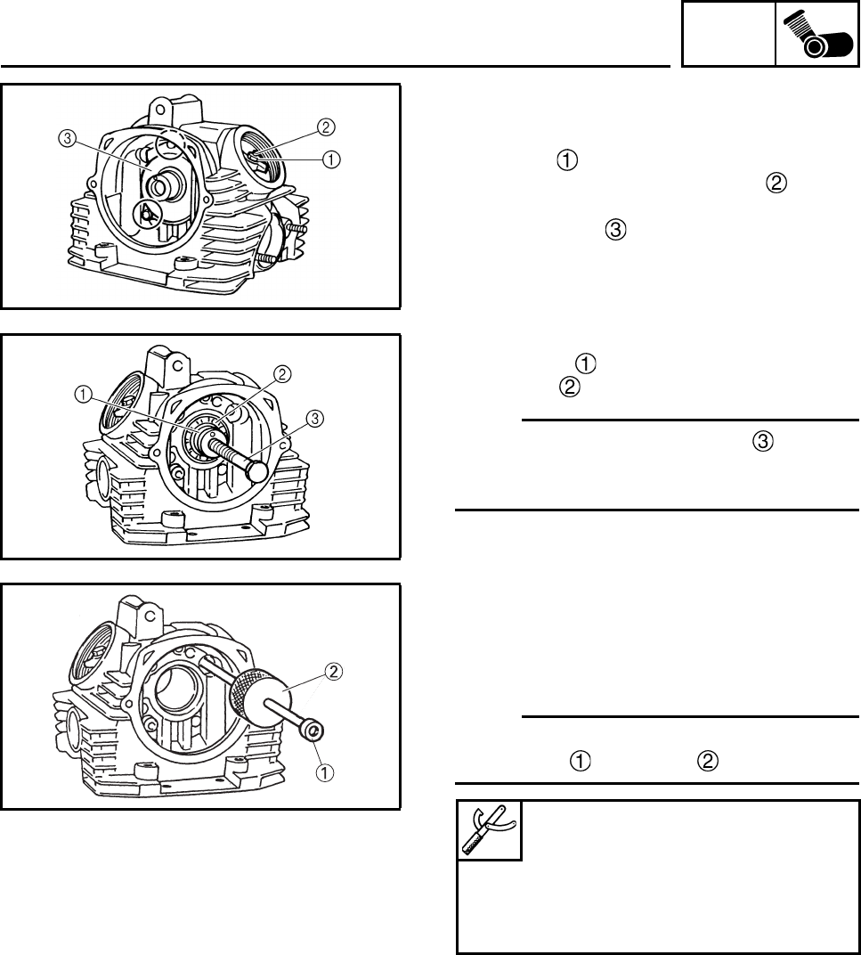
ENG
4-16
REMOVING THE ROCKER ARMS AND
CAMSHAFT
1. Loosen:
• Locknut
• Valve clearance adjusting screw
2. Remove:
• Stopper plate
3. Remove:
• Camshaft
• Bearing
N
O
TE:N
O
TE:
Screw 10 mm (0.396 in) bolt into the
threaded end of the camshaft and then pull out
the camshaft.
4. Remove:
• Intake rocker arm shaft
• Exhaust rocker arm shaft
• Intake rocker arm
• Exhaust rocker arm
N
O
TE:N
O
TE:
Remove the rocker arm shafts with the slide
hammer bolt and weight .
Slide hammer bolt
90890-01083
Slide hammer bolt 6 mm
YU-01083-1
Weight
90890-01084, YU-01083-3
ROCKER ARM, CAMSHAFT
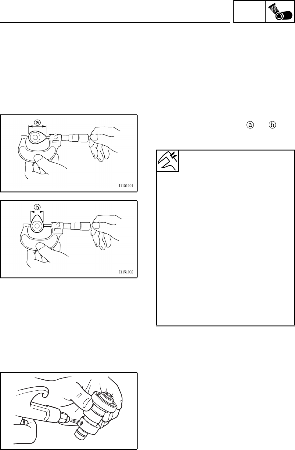
ENG
4-17
CHECKING THE CAMSHAFT
1. Check:
• Bearing
Damage/wear → Replace.
2. Check:
• Camshaft lobes
Blue discoloration/pitting/scratches →
Replace the camshaft.
3. Measure:
• Camshaft lobe dimensions and
Out of specification → Replace the cam-
shaft.
4. Check:
• Camshaft oil passage
Obstruction → Blow out with compressed
air.
Camshaft lobe dimension
Intake A
36.890 ~ 36.990 mm
(1.4524 ~ 1.4563 in)
Limit
36.790 mm (1.4484 in)
Intake B
30.111 ~ 30.211 mm
(1.1855 ~ 1.1894 in)
Limit
30.011 mm (1.1815 in)
Exhaust A
36.891 ~ 36.991 mm
(1.4524 ~ 1.4563 in)
Limit
36.791 mm (1.4485 in)
Exhaust B
30.092 ~ 30.192 mm
(1.1847 ~ 1.1887 in)
Limit
29.992 mm (1.1808 in)
ROCKER ARM, CAMSHAFT
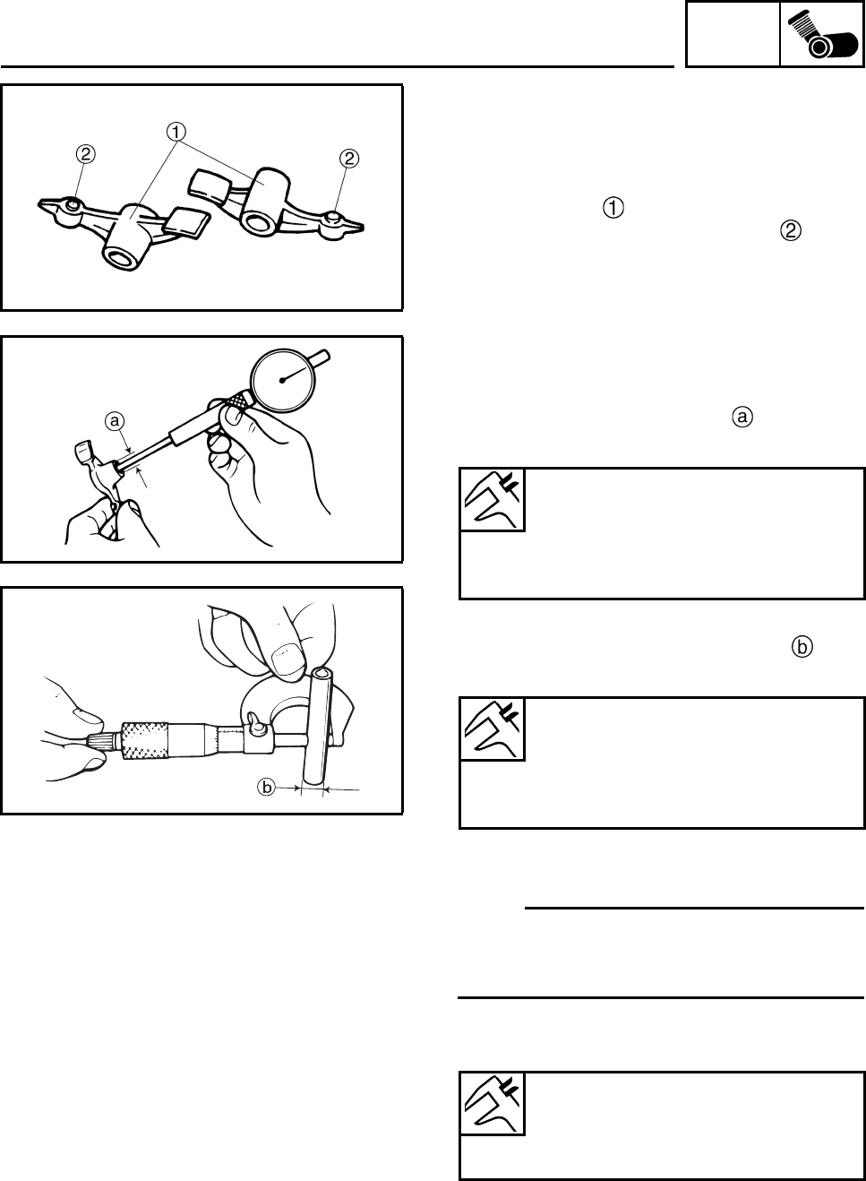
ENG
4-18
CHECKING THE ROCKER ARMS AND
ROCKER ARM SHAFTS
The following procedure applies to all of the
rocker arms and rocker arm shafts.
1. Check:
• Rocker arms
• Valve clearance adjusting screws
Damage/wear → Replace.
2. Check:
• Rocker arm shaft
Blue discoloration/excessive wear/pitting/
scratches → Replace or check the lubrica-
tion system.
3. Measure:
• Rocker arm inside diameter
Out of specification → Replace.
4. Measure:
• Rocker arm shaft outside diameter
Out of specification → Replace.
5. Calculate:
• Rocker-arm-to-rocker-arm-shaft clearance
N
O
TE:N
O
TE:
Calculate the clearance by subtracting the
rocker arm shaft outside diameter from the
rocker arm inside diameter.
Out of specification → Replace the defec-
tive part(s).
Rocker arm inside diameter
12.000 ~ 12.018 mm
(0.4724 ~ 0.4731 in)
Limit
12.036 mm (0.4739 in)
Rocker arm shaft outside diameter
11.981 ~ 11.991 mm
(0.4717 ~ 0.4721 in)
Limit
11.950 mm (0.4705 in)
Rocker-arm-to-rocker-arm-shaft
clearance
0.009 ~ 0.037 mm
(0.0004 ~ 0.0015 in)
ROCKER ARM, CAMSHAFT
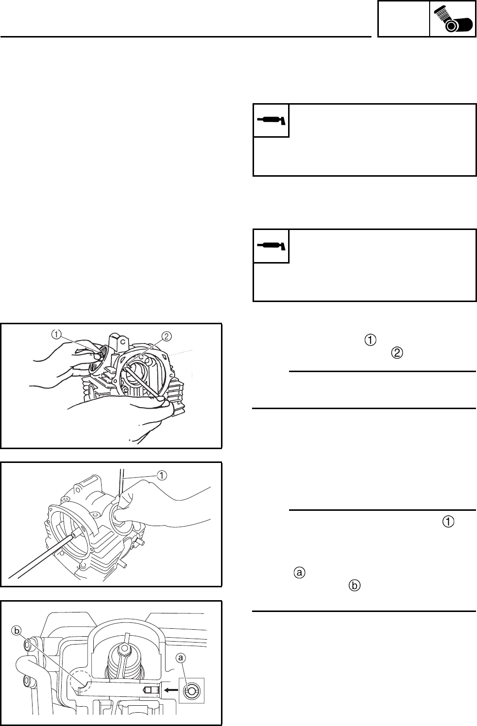
ENG
4-19
INSTALLING THE CAMSHAFT AND
ROCKER ARMS
1. Lubricate:
•Camshaft
2. Lubricate:
• Rocker arm
• Rocker arm shaft
3. Install:
• Exhaust rocker arm
• Exhaust rocker arm shaft
N
O
TE:N
O
TE:
Make sure the exhaust rocker arm shaft is
completely pushed into the cylinder head.
4. Install:
• Intake rocker arm
• Intake rocker arm shaft
N
O
TE:N
O
TE:
• Insert a cylinder head bolt (226 mm) into
the hole in the cylinder head and the intake
rocker arm shaft as shown.
• Install the intake rocker arm shaft so that
groove is horizontal and aligning the notch
of the pointed end with the hole in the cyl-
inder head.
Recommended lubricant
Camshaft
Molybdenum disulfide oil
Camshaft bearing
Engine oil
Recommended lubricant
Rocker arm
Molybdenum disulfide oil
Rocker arm shaft
Engine oil
ROCKER ARM, CAMSHAFT
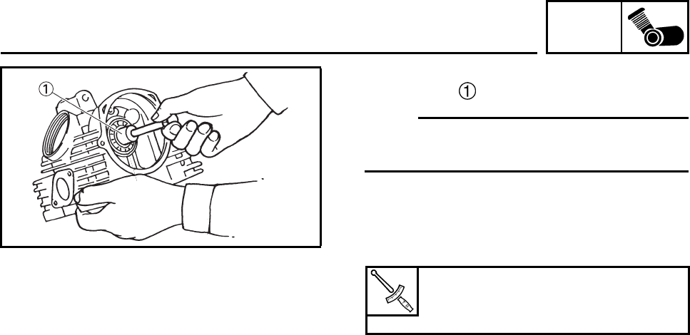
ENG
4-20
5. Install:
• Camshaft
N
O
TE:N
O
TE:
Screw a 10 mm bolt into the threaded end of
the camshaft and then install the camshaft.
6. Install:
• Lock plate
7. Tighten:
• Lock plate bolts
Lock plate bolt
8 Nm (0.8 m•kg, 5.9 ft•lb)
LOCTITE®
ROCKER ARM, CAMSHAFT
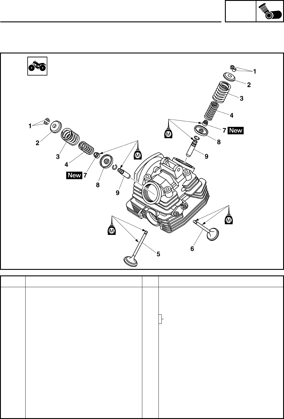
ENG
4-21
VALVES AND VALVE SPRINGS
Order Job/Parts to remove Q’ty Remarks
Removing the valves and valve
springs Remove the parts in the order listed.
Cylinder head Refer to “CYLINDER HEAD”.
Rocker arm
Camshaft
1 Valve cotter 4
2 Valve spring retainer 2
3 Outer valve spring 2
4 Inner valve spring 2
5 Intake valve 1
6 Exhaust valve 1
7 Valve stem seal 2
8 Valve spring seat 2
9 Valve guide 2
For installation, reverse the removal
procedure.
VALVES AND VALVE SPRINGS
Refer to “ROCKER ARM, CAMSHAFT”.
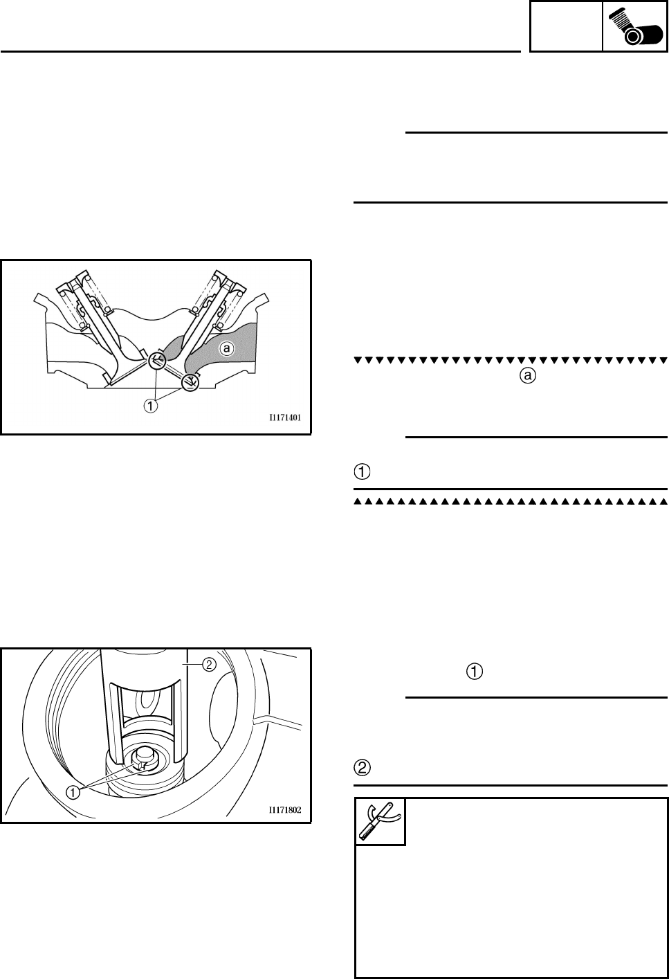
ENG
4-22
REMOVING THE VALVES
The following procedure applies to all of the
valves and related components.
N
O
TE:N
O
TE:
Before removing the internal parts of the cylin-
der head (e.g., valves, valve springs, valve
seats), make sure the valves properly seal.
1. Check:
• Valve sealing
Leakage at the valve seat → Check the
valve face, valve seat, and valve seat width.
Refer to “CHECKING THE VALVE SEATS”.
a. Pour a clean solvent into the intake and
exhaust ports.
b. Check that the valves properly seal.
N
O
TE:N
O
TE:
There should be no leakage at the valve seat
.
.
2. Remove:
• Valve cotters
N
O
TE:N
O
TE:
Remove the valve cotters by compressing the
valve spring with the valve spring compressor
and the valve spring compressor attachment
.
Valve spring compressor
90890-04019
YM-04019
Valve spring compressor
attachment
90890-01243
Valve spring compressor adapter
(26 mm)
YM-01253-1
VALVES AND VALVE SPRINGS
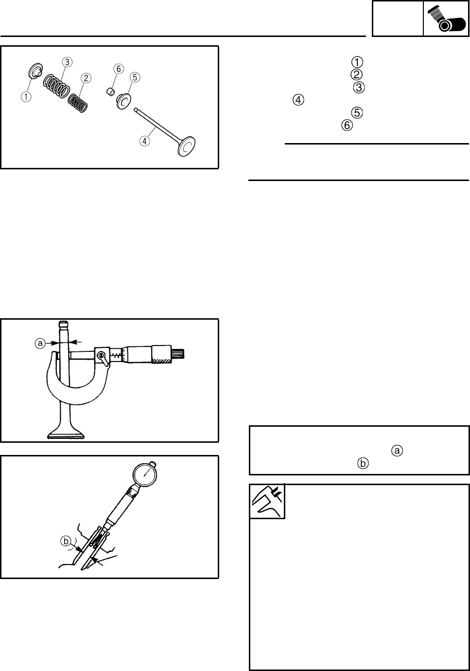
ENG
4-23
3. Remove:
• Upper spring seat
• Inner valve spring
• Outer valve spring
•Valve
• Lower spring seat
• Valve stem seal
N
O
TE:N
O
TE:
Identify the position of each part very carefully
so that it can be reinstalled in its original place.
CHECKING THE VALVES AND VALVE
GUIDES
The following procedure applies to all of the
valves and valve guides.
1. Measure:
• Valve-stem-to-valve-guide clearance
Out of specification → Replace the valve
guide.
Valve-stem-to-valve-guide clearance =
Valve guide inside diameter -
Valve stem diameter
Valve-stem-to-valve-guide
clearance
Valve-stem-to-valve-guide
clearance (intake)
0.010 ~ 0.037 mm
(0.0004 ~ 0.0015 in)
Limit
0.080 mm (0.003 in)
Valve-stem-to-valve-guide
clearance (exhaust)
0.025 ~ 0.052 mm
(0.0010 ~ 0.0020 in)
Limit
0.100 mm (0.004 in)
VALVES AND VALVE SPRINGS
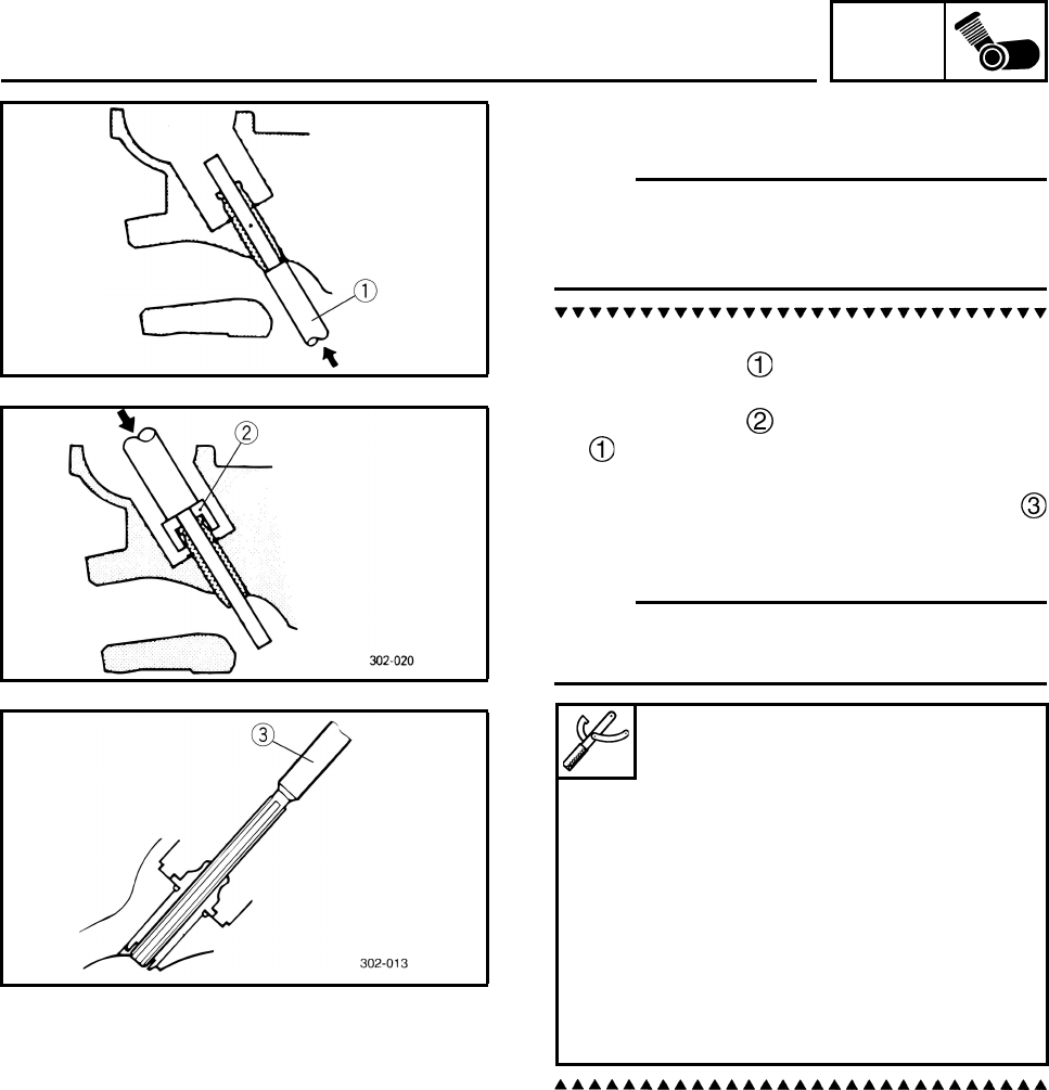
ENG
4-24
2. Replace:
• Valve guide
N
O
TE:N
O
TE:
To ease valve guide removal and installation,
and to maintain the correct fit, heat the cylinder
head to 100°C (212°F) in an oven.
a. Remove the valve guide with the valve
guide remover .
b. Install the new valve guide with the valve
guide installer and valve guide remover
.
c. After installing the valve guide, bore the
valve guide with the valve guide reamer
to obtain the proper valve-stem-to-valve-
guide clearance.
N
O
TE:N
O
TE:
After replacing the valve guide, reface the
valve seat.
3. Eliminate:
• Carbon deposits
(from the valve face and valve seat)
4. Check:
•Valve face
Pitting/wear → Grind the valve face.
• Valve stem end
Mushroom shape or diameter larger than
the body of the valve stem → Replace the
valve.
Valve guide remover (ø6)
90890-04064
Valve guide remover (6.0 mm)
YM-04064-A
Valve guide installer (ø6)
90890-04065
Valve guide installer (6.0 mm)
YM-04065-A
Valve guide reamer (ø6)
90890-04066
Valve guide reamer (6.0 mm)
YM-04066
VALVES AND VALVE SPRINGS
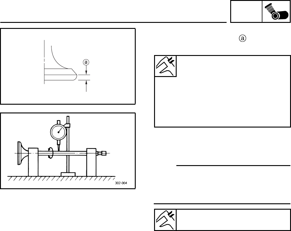
ENG
4-25
5. Measure:
• Valve margin thickness D
Out of specification → Replace the valve.
6. Measure:
• Valve stem runout
Out of specification → Replace the valve.
N
O
TE:N
O
TE:
• When installing a new valve, always replace
the valve guide.
• If the valve is removed or replaced, always
replace the oil seal.
CHECKING THE VALVE SEATS
The following procedure applies to all of the
valves and valve seats.
1. Eliminate:
• Carbon deposits
(from the valve face and valve seat)
2. Check:
• Valve seat
Pitting/wear → Replace the cylinder head.
Valve margin thickness
Valve margin thickness D (intake)
0.80 ~ 1.20 mm
(0.0315 ~ 0.0472 in)
Valve margin thickness D
(exhaust)
0.80 ~ 1.20 mm
(0.0315 ~ 0.0472 in)
Valve stem runout
0.01 mm (0.0004 in)
VALVES AND VALVE SPRINGS
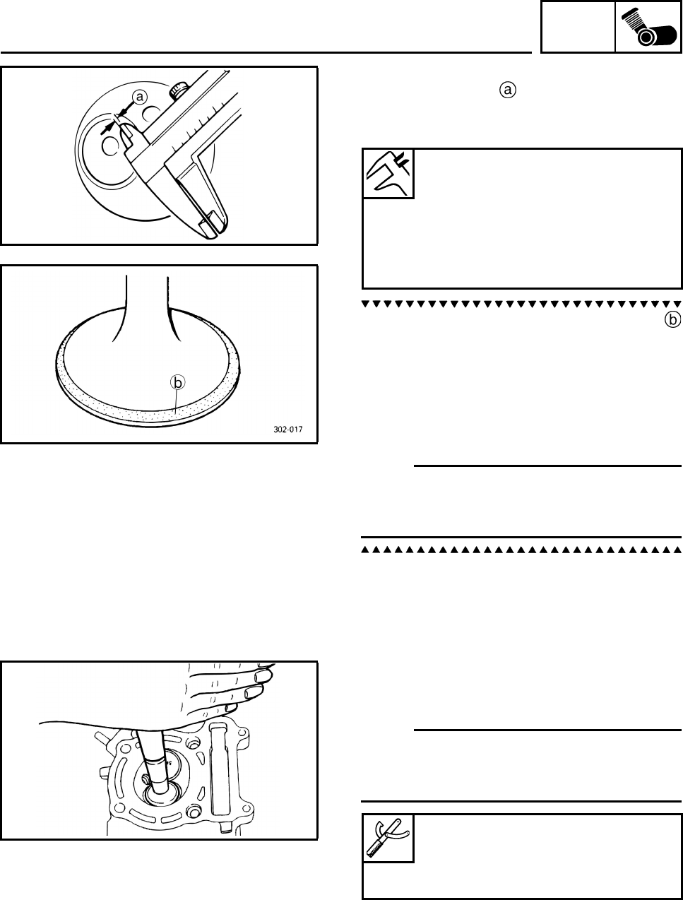
ENG
4-26
3. Measure:
• Valve seat width
Out of specification → Replace the cylinder
head.
a. Apply Mechanic’s blueing dye (Dykem)
onto the valve face.
b. Install the valve into the cylinder head.
c. Press the valve through the valve guide and
onto the valve seat to make a clear impres-
sion.
d. Measure the valve seat width.
N
O
TE:N
O
TE:
Where the valve seat and valve face contacted
one another, the blueing will have been
removed.
4. Lap:
•Valve face
• Valve seat
N
O
TE:N
O
TE:
After replacing the cylinder head or replacing
the valve and valve guide, the valve seat and
valve face should be lapped.
Valve seat width
Valve seat width C (intake)
0.90 ~ 1.10 mm
(0.0354 ~ 0.0433 in)
Valve seat width C (exhaust)
0.90 ~ 1.10 mm
(0.0354 ~ 0.0433 in)
Valve lapper
90890-04101
Valve lapping tool
YM-A8998
VALVES AND VALVE SPRINGS
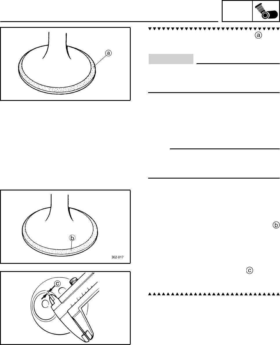
ENG
4-27
a. Apply a coarse lapping compound to the
valve face.
CAUTION:
Do not let the lapping compound enter the
gap between the valve stem and the valve
guide.
b. Apply molybdenum disulfide oil onto the
valve stem.
c. Install the valve into the cylinder head.
d. Turn the valve until the valve face and valve
seat are evenly polished, then clean off all
of the lapping compound.
N
O
TE:N
O
TE:
For the best lapping results, lightly tap the
valve seat while rotating the valve back and
forth between your hands.
e. Apply a fine lapping compound to the valve
face and repeat the above steps.
f. After every lapping procedure, be sure to
clean off all of the lapping compound from
the valve face and valve seat.
g. Apply Mechanic’s blueing dye (Dykem)
onto the valve face.
h. Install the valve into the cylinder head.
i. Press the valve through the valve guide and
onto the valve seat to make a clear impres-
sion.
j. Measure the valve seat width again. If
the valve seat width is out of specification,
reface and lap the valve seat.
VALVES AND VALVE SPRINGS
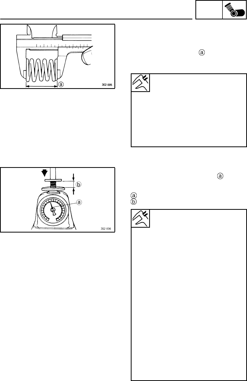
ENG
4-28
CHECKING THE VALVE SPRINGS
The following procedure applies to all of the
valve springs.
1. Measure:
• Valve spring free length
Out of specification → Replace the valve
spring.
2. Measure:
• Compressed valve spring force
Out of specification → Replace the valve
spring.
Compressed valve spring force
Installed length
Inner spring
Free length (intake)
36.17 mm (1.42 in)
Free length (exhaust)
36.17 mm (1.42 in)
Outer spring
Free length (intake)
36.63 mm (1.44 in)
Free length (exhaust)
36.63 mm (1.44 in)
Inner spring
Installed compression spring
force (intake)
75.00 ~ 91.70 N (7.65 ~
9.35 kg) (16.86 ~ 20.62 lb)
Installed compression spring
force (exhaust)
75.00 ~ 91.70 N (7.65 ~
9.35 kg) (16.86 ~ 20.62 lb)
Installed length (intake)
30.50 mm (1.20 in)
Installed length (exhaust)
30.50 mm (1.20 in)
Outer spring
Installed compression spring
force (intake)
128.50 ~ 157.90 N (13.10 ~
16.10 kg) (28.89 ~ 35.50 lb)
Installed compression spring
force (exhaust)
128.50 ~ 157.90 N (13.10 ~
16.10 kg) (28.89 ~ 35.50 lb)
Installed length (intake)
32.00 mm (1.26 in)
Installed length (exhaust)
32.00 mm (1.26 in)
VALVES AND VALVE SPRINGS
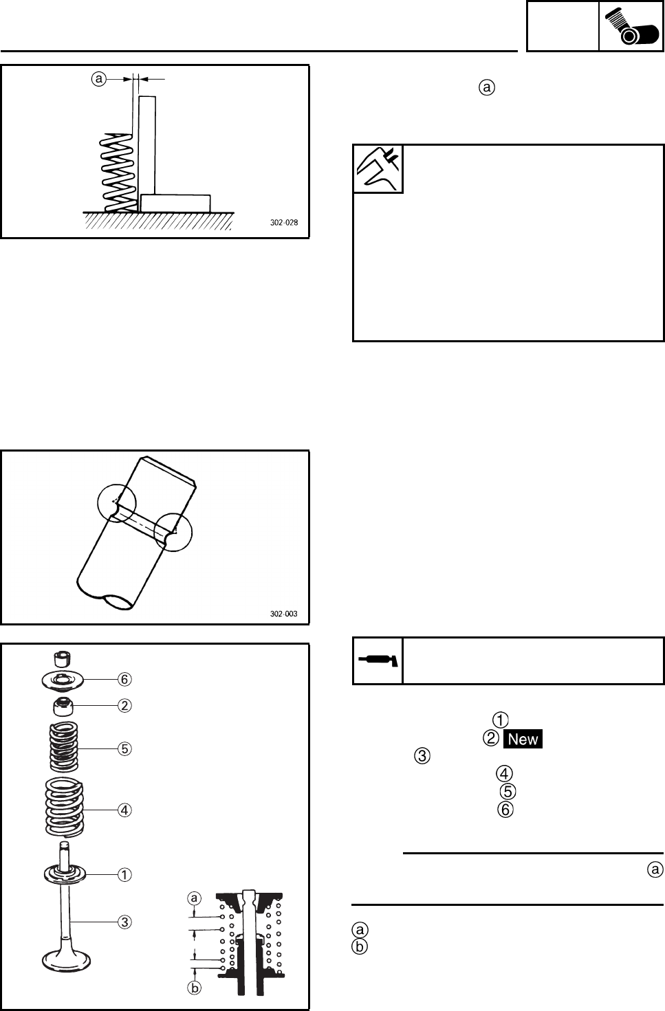
ENG
4-29
3. Measure:
• Valve spring tilt
Out of specification → Replace the valve
spring.
INSTALLING THE VALVES
The following procedure applies to all of the
valves and related components.
1. Deburr:
• Valve stem end
(with an oil stone)
2. Lubricate:
• Valve stem
• Valve stem seal
(with the recommended lubricant)
3. Install:
• Valve spring seat
• Valve stem seal
•Valve
• Inner valve spring
• Outer valve spring
• Upper spring seat
(into the cylinder head)
N
O
TE:N
O
TE:
Install the valve springs with the larger pitch
facing up.
Larger pitch
Smaller pitch
Inner spring
Spring tilt (intake)
2.5°/1.60 mm (2.5°/0.063 in)
Spring tilt (exhaust)
2.5°/1.60 mm (2.5°/0.063 in)
Outer spring
Spring tilt (intake)
2.5°/1.60 mm (2.5°/0.063 in)
Spring tilt (exhaust)
2.5°/1.60 mm (2.5°/0.063 in)
Recommended lubricant
Molybdenum disulfide oil
VALVES AND VALVE SPRINGS
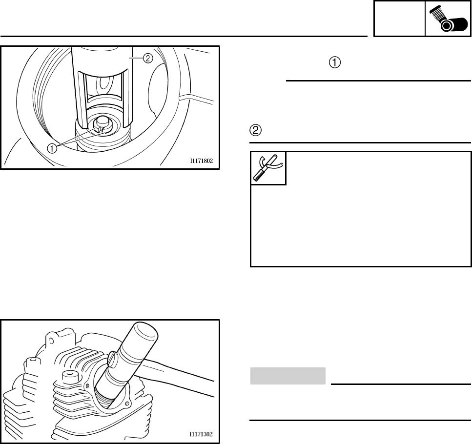
ENG
4-30
4. Install:
• Valve cotters
N
O
TE:N
O
TE:
Install the valve cotters by compressing the
valve spring with the valve spring compressor
and the valve spring compressor attachment
.
5. To secure the valve cotters onto the valve
stem, lightly tap the valve tip with a soft-
face hammer.
CAUTION:
Hitting the valve tip with excessive force
could damage the valve.
Valve spring compressor
90890-04019, YM-04019
Valve spring compressor
attachment
90890-01243
Valve spring compressor adapter
(26 mm)
YM-01253-1
VALVES AND VALVE SPRINGS
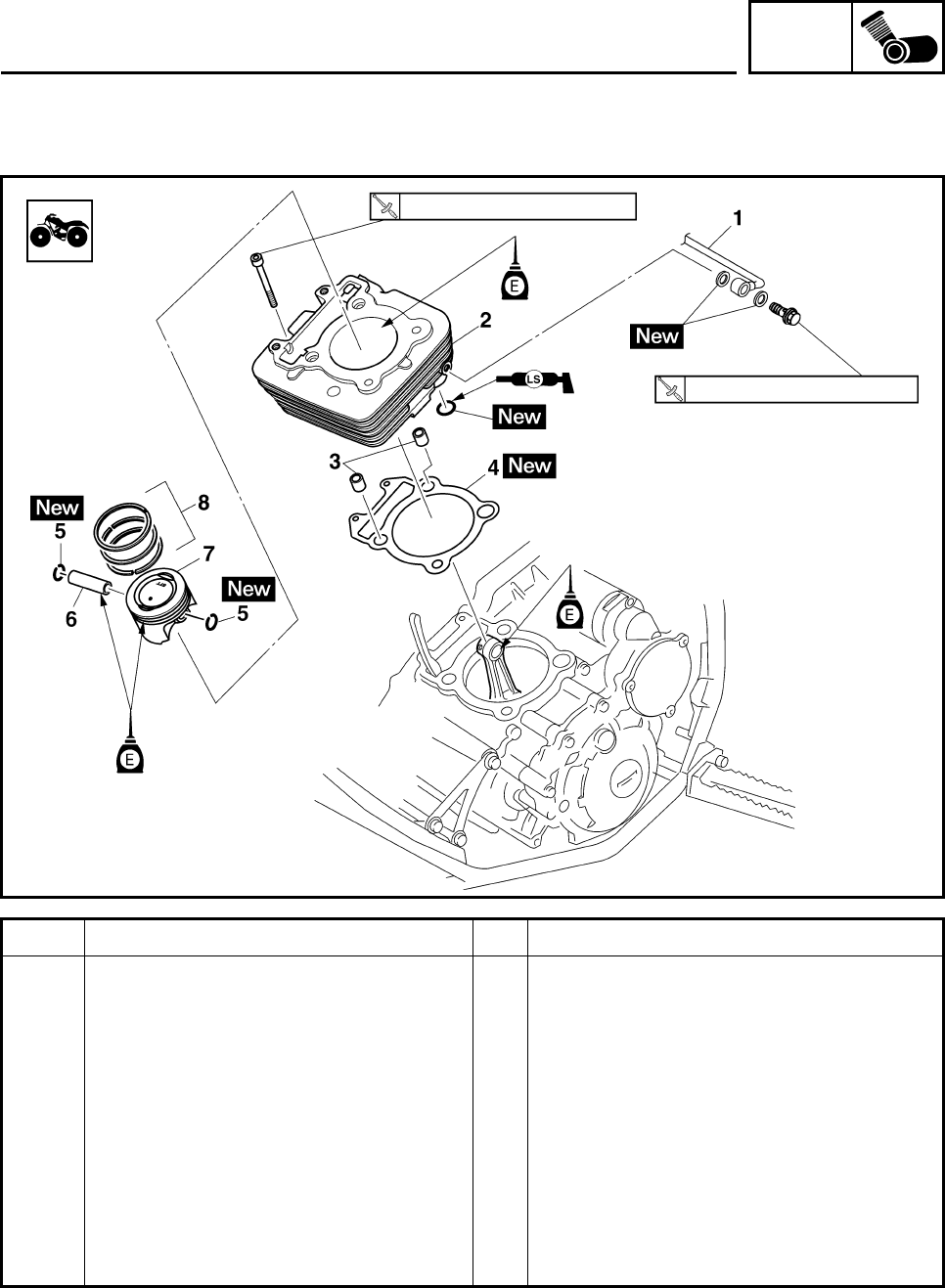
ENG
4-31
CYLINDER AND PISTON
Order Job/Parts to remove Q’ty Remarks
Removing the cylinder and piston Remove the parts in the order listed.
Cylinder head Refer to “CYLINDER HEAD”.
1 Oil delivery pipe 1
2Cylinder 1
3 Dowel pin 2
4 Cylinder gasket 1
5 Piston pin clip 2
6 Piston pin 1
7Piston 1
8 Piston ring set 1
For installation, reverse the removal
procedure.
10 Nm (1.0 m•kg, 7.4 ft•lb)
17 Nm (1.7 m•kg, 13 ft•lb)
CYLINDER AND PISTON
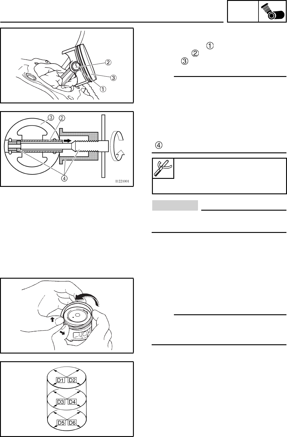
ENG
4-32
+REMOVING THE PISTON
1. Remove:
• Piston pin clips
• Piston pin
•Piston
N
O
TE:N
O
TE:
• Before removing the piston pin clip, cover the
crankcase opening with a clean rag to pre-
vent the piston pin clip from falling into the
crankcase.
• Before removing each piston pin, deburr the
clip groove and pin hole area. If the piston pin
groove is deburred and the piston pin is still
difficult to remove, use the piston pin puller
.
CAUTION:
Do not use a hammer to drive the piston
pin out.
2. Remove:
• Top ring
• 2nd ring
•Oil ring
N
O
TE:N
O
TE:
When removing a piston ring, open the end
gap with your fingers and lift the other side of
the ring over the piston crown.
CHECKING THE CYLINDER AND PISTON
1. Check:
•Piston wall
• Cylinder wall
Vertical scratches → Rebore or replace the
cylinder, and replace the piston and piston
rings as a set.
2. Measure:
• Piston-to-cylinder clearance
Piston pin puller set
90890-01304
Piston pin puller
YU-01304
CYLINDER AND PISTON
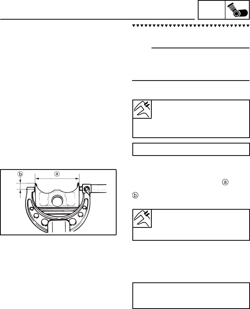
ENG
4-33
a. Measure cylinder bore “C” with the cylinder
bore gauge.
N
O
TE:N
O
TE:
Measure cylinder bore “C” by taking side-to-
side and front-to-back measurements of the
cylinder. Then, find the average of the mea-
surements.
b. If out of specification, rebore or replace the
cylinder, and replace the piston and piston
rings as a set.
c. Measure piston skirt diameter D with the
micrometer.
5 mm (0.20 in) from the bottom edge of the pis-
ton
d. If out of specification, replace the piston
and piston rings as a set.
e. Calculate the piston-to-cylinder clearance
with the following formula.
Bore “C”
74.000 ~ 74.016 mm
(2.9134 ~ 2.9140 in)
Wear limit
74.100 mm (2.9173 in)
“C” = maximum of D1 ~ D6
Piston size diameter “D”
Standard
73.983 ~ 73.998 mm
(2.9127 ~ 2.9133 in)
Piston-to-cylinder clearance =
Cylinder bore “C” -
Piston skirt diameter “D”
CYLINDER AND PISTON
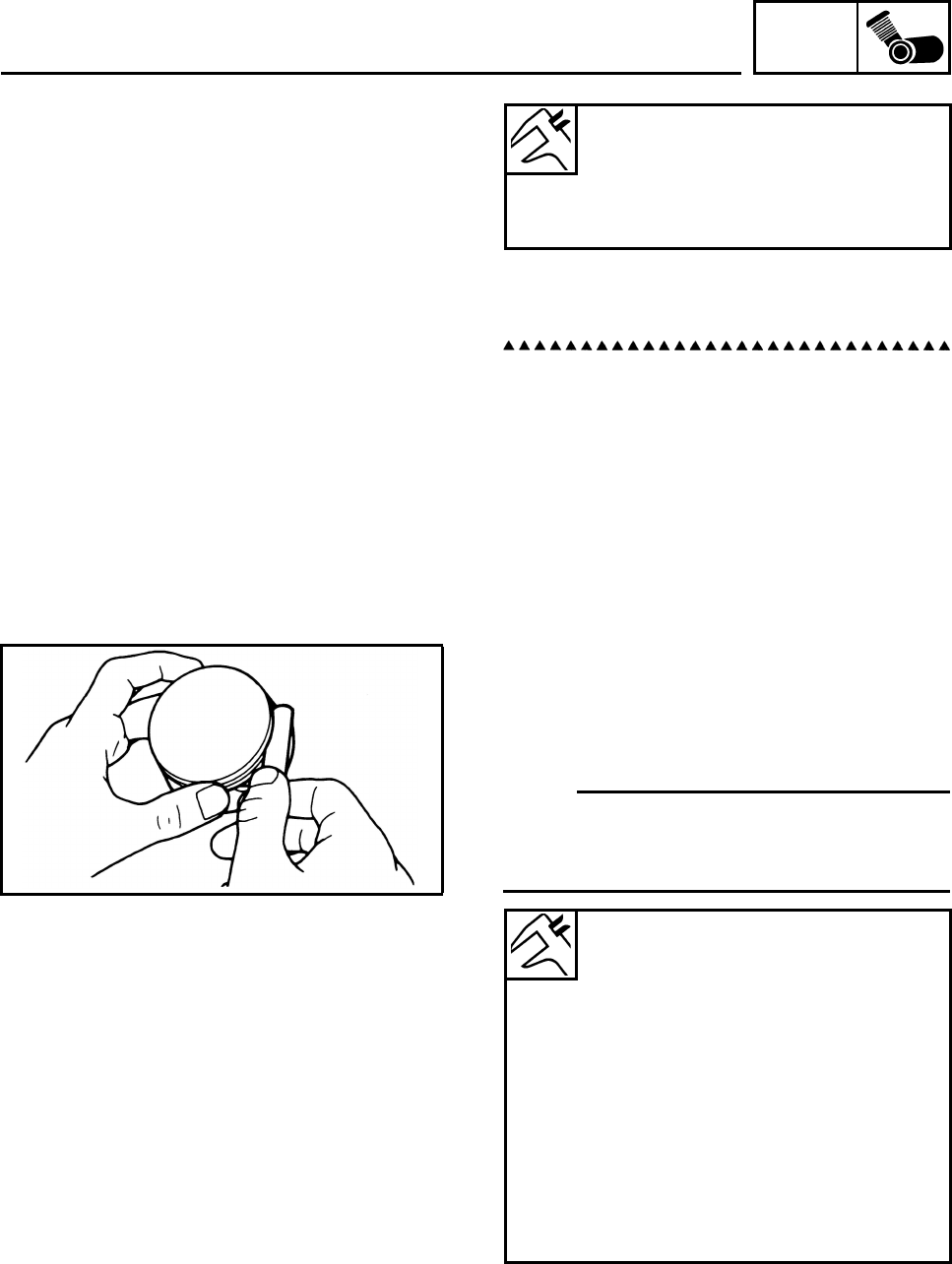
ENG
4-34
f. If out of specification, rebore or replace the
cylinder, and replace the piston and piston
rings as a set.
CHECKING THE PISTON RINGS
1. Measure:
• Piston ring side clearance
Out of specification → Replace the piston
and piston rings as a set.
N
O
TE:N
O
TE:
Before measuring the piston ring side clear-
ance, eliminate any carbon deposits from the
piston ring grooves and piston rings.
Piston-to-cylinder clearance
0.010 ~ 0.025 mm
(0.0004 ~ 0.0010 in)
Limit
0.15 mm (0.006 in)
Piston ring
Top ring
Ring side clearance
0.030 ~ 0.065 mm
(0.0012 ~ 0.0026 in)
Limit
0.115 mm (0.0045 in)
2nd ring
Ring side clearance
0.020 ~ 0.055 mm
(0.0008 ~ 0.0022 in)
Limit
0.115 mm (0.0045 in)
CYLINDER AND PISTON
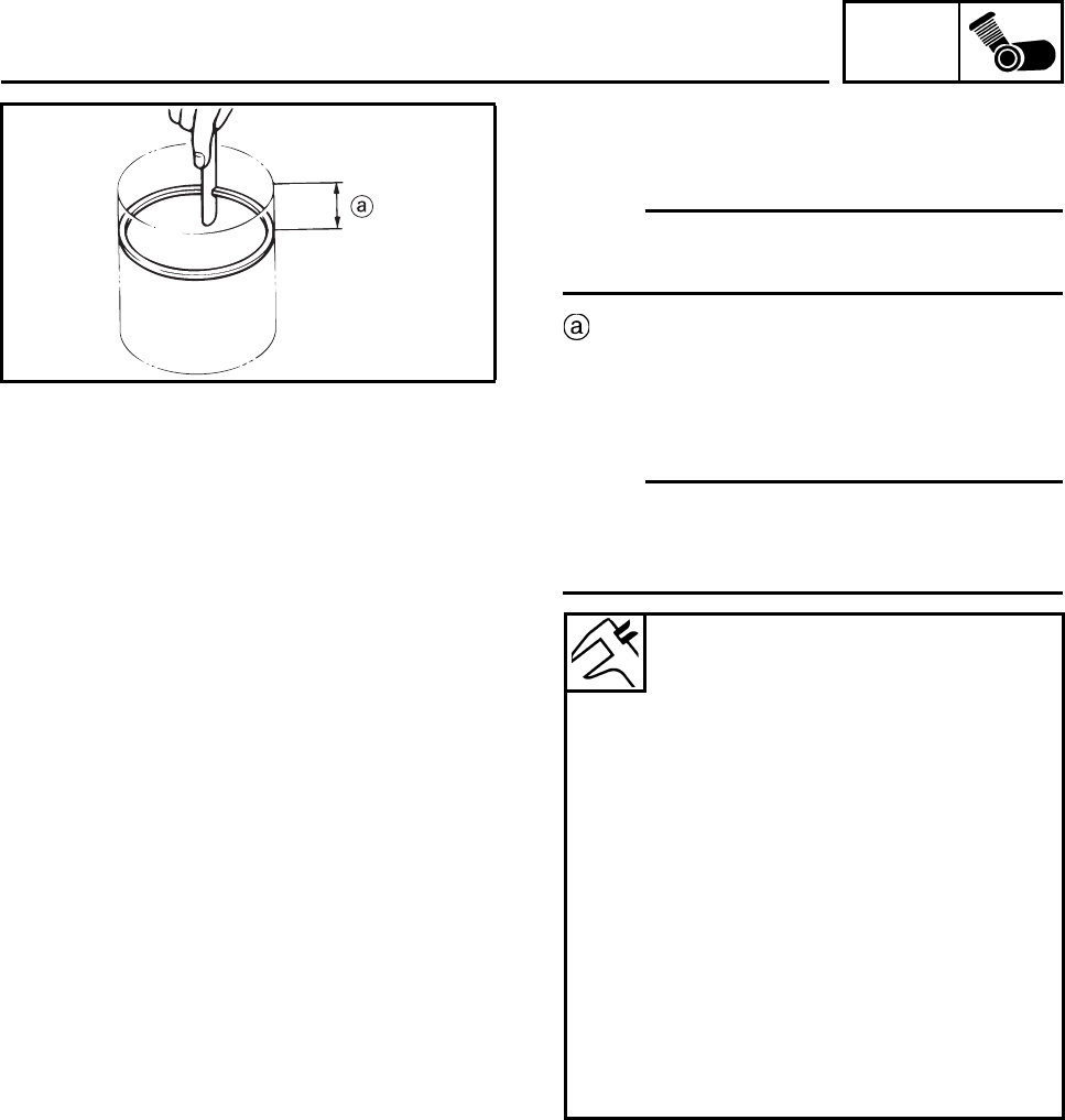
ENG
4-35
2. Install:
•Piston ring
(into the cylinder)
N
O
TE:N
O
TE:
Level the piston ring into the cylinder with the
piston crown.
40 mm (1.476 in)
3. Measure:
• Piston ring end gap
Out of specification → Replace the piston
ring.
N
O
TE:N
O
TE:
The oil ring expander spacer’s end gap cannot
be measured. If the oil ring rail’s gap is exces-
sive, replace all three piston rings.
Piston ring
Top ring
End gap (installed)
0.19 ~ 0.31 mm
(0.007 ~ 0.012 in)
Limit
0.56 mm (0.022 in)
2nd ring
End gap (installed)
0.30 ~ 0.45 mm
(0.012 ~ 0.018 in)
Limit
0.80 mm (0.032 in)
Oil ring
End gap (installed)
0.10 ~ 0.35 mm
(0.004 ~ 0.014 in)
CYLINDER AND PISTON
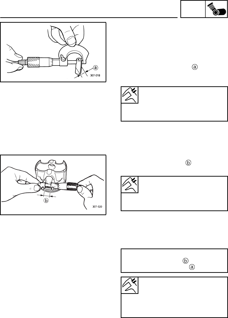
ENG
4-36
CHECKING THE PISTON PIN
1. Check:
• Piston pin
Blue discoloration/grooves → Replace the
piston pin and then check the lubrication
system.
2. Measure:
• Piston pin outside diameter
Out of specification → Replace the piston
pin.
3. Measure:
• Piston pin bore diameter
Out of specification → Replace the piston.
4. Calculate:
• Piston-pin-to-piston-pin-bore clearance
Out of specification → Replace the piston
pin and piston as a set.
Piston pin outside diameter
16.991 ~ 17.000 mm
(0.6689 ~ 0.6693 in)
Limit
16.971 mm (0.6681 in)
Piston pin bore inside diameter
17.002 ~ 17.013 mm
(0.6694 ~ 0.6698 in)
Limit
17.043 mm (0.6710 in)
Piston-pin-to-piston-pin-bore clearance =
Piston pin bore diameter -
Piston pin outside diameter
Piston-pin-to-piston-pin-bore
clearance
0.002 ~ 0.022 mm
(0.0001 ~ 0.0009 in)
Limit
0.072 mm (0.0028 in)
CYLINDER AND PISTON
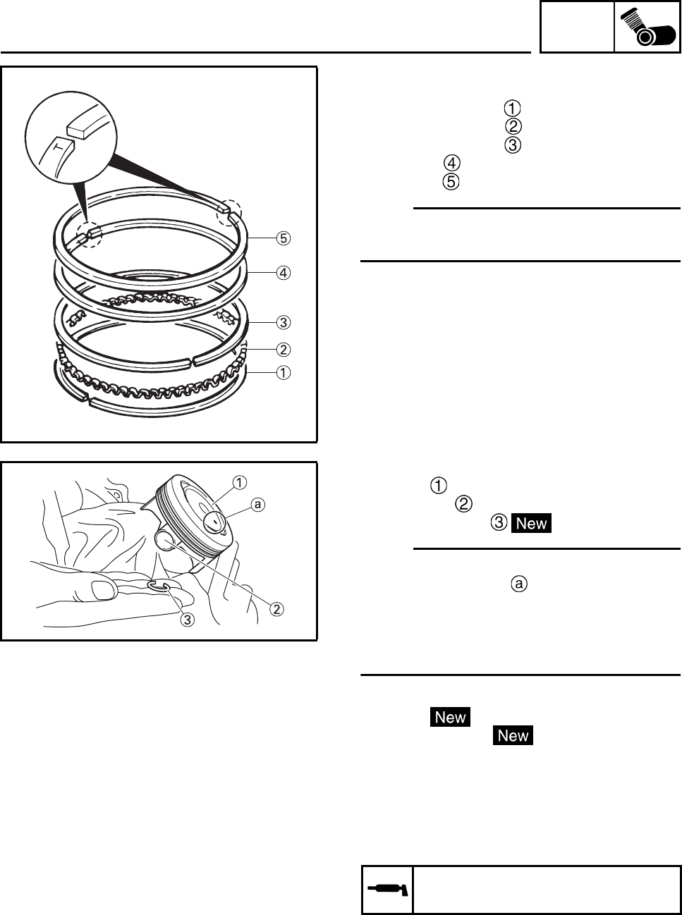
ENG
4-37
INSTALLING THE PISTON AND CYLINDER
1. Install:
• Lower oil ring rail
• Oil ring expander
• Upper oil ring rail
• 2nd ring
• Top ring
N
O
TE:N
O
TE:
Be sure to install the piston rings so that the
“T” marks or numbers face up.
2. Install:
•Piston
• Piston pin
• Piston pin clips
N
O
TE:N
O
TE:
• Apply engine oil the piston pin.
• Make sure the dot on the piston points
towards the exhaust side of the cylinder.
• Before installing the piston pin clip, cover the
crankcase opening with a clean rag to pre-
vent the clip from falling into the crankcase.
3. Install:
• O-ring
• Cylinder gasket
• Dowel pins
4. Lubricate:
•Piston
•Piston rings
• Cylinder
(with the recommended lubricant)
New
Recommended lubricant
Engine oil
CYLINDER AND PISTON
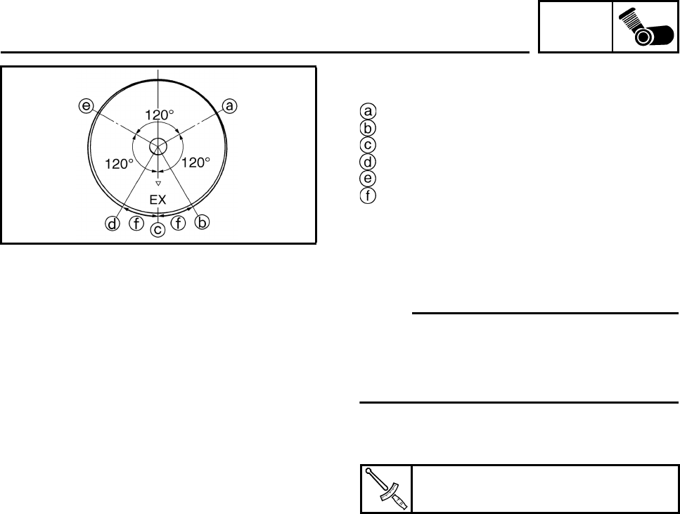
ENG
4-38
5. Offset:
• Piston ring end gaps
Top ring
Upper oil ring rail
Oil ring expander
Lower oil ring rail
2nd ring
20 mm
6. Install:
• Cylinder
N
O
TE:N
O
TE:
• While compressing the piston rings with one
hand, install the cylinder with the other hand.
• Pass the timing chain and timing chain guide
(exhaust side) through the timing chain cavity.
7. Tighten:
• Cylinder bolts
Cylinder bolt
10 Nm (1.0 m•kg, 7.4 ft•lb)
CYLINDER AND PISTON
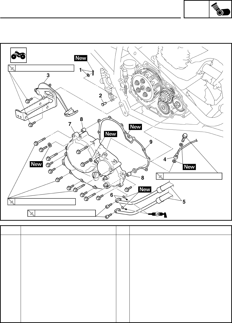
ENG
4-39
CLUTCH
Order Job/Parts to remove Q’ty Remarks
Removing the clutch cover Remove the parts in the order listed.
Engine oil Drain.
1 Cotter pin/Washer 1/1
2Clevis pin 1
3 Brake pedal/Footrest 1/1
4 Oil delivery pipe 1
5 Oil cooler hose 2
6O-ring 2
7 Right crankcase cover 1
8 Dowel pin 2
9 Crankcase cover gasket 1
For installation, reverse the removal
procedure.
73 Nm (7.3 m•kg, 54 ft•lb)
10 Nm (1.0 m•kg, 7.4 ft•lb)
10 Nm (1.0 m•kg, 7.4 ft•lb)
20 Nm (2.0 m•kg, 15 ft•lb)
CLUTCH
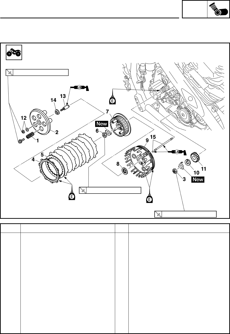
ENG
4-40
Order Job/Parts to remove Q’ty Remarks
Removing the clutch Remove the parts in the order listed.
1 Clutch spring 5
2 Pressure plate 1
3 Primary drive gear nut 1
4 Friction plate 6
5 Clutch plate 5
6 Clutch boss nut 1
7Clutch boss 1
8 Thrust washer 1
9 Clutch housing 1
10 Claw washer 1
11 Primary drive gear 1
12 Locknut/Washer 1/1
13 Push rod1 1
14 Push plate 1
80 Nm (8.0 m•kg, 59 ft•lb)
8 Nm (0.8 m•kg, 5.9 ft•lb)
75 Nm (7.5 m•kg, 55 ft•lb)
CLUTCH
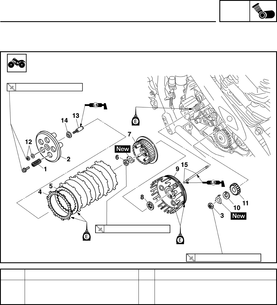
ENG
4-41
Order Job/Parts to remove Q’ty Remarks
15 Push rod 2/Ball 1/1 For installation, reverse the removal
procedure.
80 Nm (8.0 m•kg, 59 ft•lb)
8 Nm (0.8 m•kg, 5.9 ft•lb)
75 Nm (7.5 m•kg, 55 ft•lb)
CLUTCH
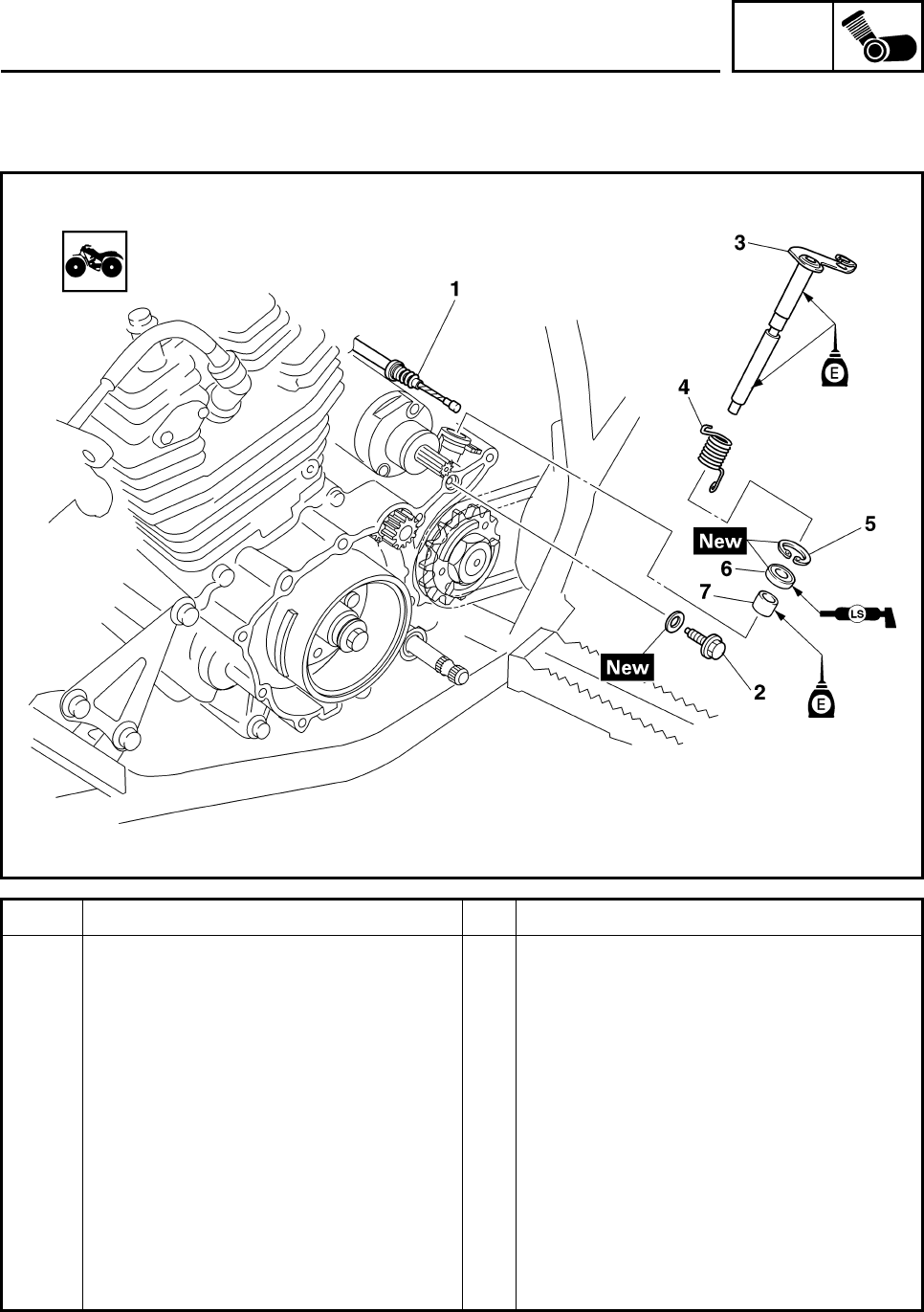
ENG
4-42
Order Job/Parts to remove Q’ty Remarks
Removing the push lever shaft Remove the parts in the order listed.
Shift pedal Refer to “SHIFT SHAFT”.
Left crankcase cover Refer to “PICK UP COIL ROTOR AND
STARTER CLUTCH”.
Clutch assembly
1Clutch cable 1
2Bolt 1
3 Push lever shaft 1
4 Torsion spring 1
5Circlip 1
6 Oil seal 1
7 Bearing 1
For installation, reverse the removal
procedure.
CLUTCH
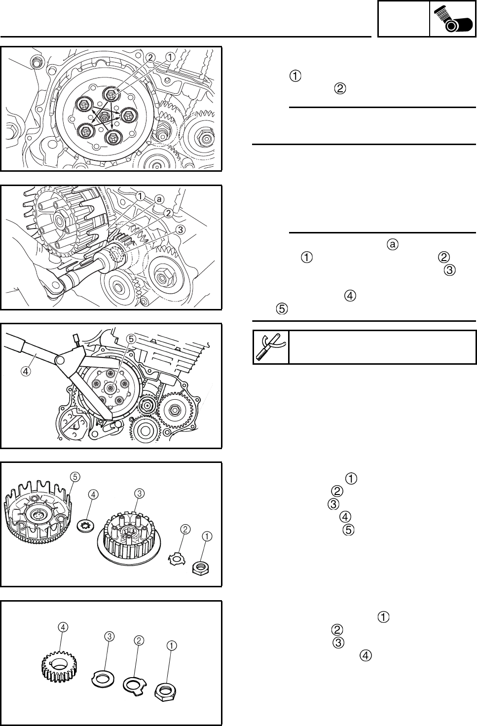
ENG
4-43
REMOVING THE CLUTCH
1. Remove:
•Bolt
• Clutch spring
N
O
TE:N
O
TE:
Loosen the bolts in stages and in a crisscross
pattern.
2. Straighten the lock washer tab.
3. Loosen:
• Primary drive gear nut
• Clutch boss nut
N
O
TE:N
O
TE:
• Place the aluminum plate between clutch
housing and primary drive gear , and
then loosen the primary drive gear nut .
• While holding the clutch boss with the univer-
sal clutch holder , loosen the clutch boss
nut .
4. Remove:
• Clutch boss nut
• Lock washer
• Clutch boss
• Thrust washer
• Clutch housing
5. Remove:
• Primary drive gear nut
• Lock washer
• Claw washer
• Primary drive gear
Universal clutch holder
90890-04086, YM-91042
CLUTCH
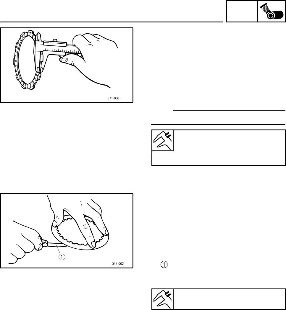
ENG
4-44
CHECKING THE FRICTION PLATES
The following procedure applies to all of the
friction plates.
1. Check:
• Friction plate
Damage/wear → Replace the friction plate.
2. Measure:
• Friction plate thickness
Out of specification → Replace the friction
plate.
N
O
TE:N
O
TE:
Measure the friction plate at four places.
CHECKING THE CLUTCH PLATES
The following procedure applies to all of the
clutch plates.
1. Check:
• Clutch plate
Damage → Replace the clutch plate.
2. Measure:
• Clutch plate warpage
(with a surface plate and thickness gauge
)
Out of specification → Replace the clutch
plate.
Friction plate thickness
2.9 ~ 3.1 mm (0.114 ~ 0.122 in)
Wear limit
2.8 mm (0.110 in)
Warpage limit
0.2 mm (0.0079 in)
CLUTCH
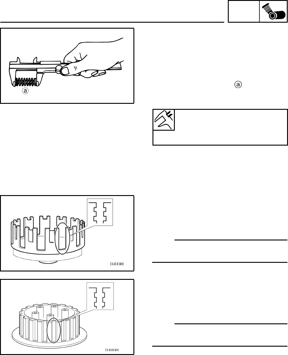
ENG
4-45
CHECKING THE CLUTCH SPRINGS
The following procedure applies to all of the
clutch springs.
1. Check:
•Clutch spring
Damage → Replace the clutch spring.
2. Measure:
• Clutch spring free length
Out of specification → Replace the clutch
spring.
CHECKING THE CLUTCH HOUSING
1. Check:
• Clutch housing dogs
Damage/pitting/wear → Deburr the clutch
housing dogs or replace the clutch housing.
N
O
TE:N
O
TE:
Pitting on the clutch housing dogs will cause
erratic clutch operation.
CHECKING THE CLUTCH BOSS
1. Check:
• Clutch boss splines
Damage/pitting/wear → Replace the clutch
boss.
N
O
TE:N
O
TE:
Pitting on the clutch boss splines will cause
erratic clutch operation.
CHECKING THE PRESSURE PLATE
1. Check:
• Pressure plate
Cracks/damage → Replace.
Clutch spring free length
47.80 mm (1.88 in)
Minimum length
46.50 mm (1.83 in)
CLUTCH
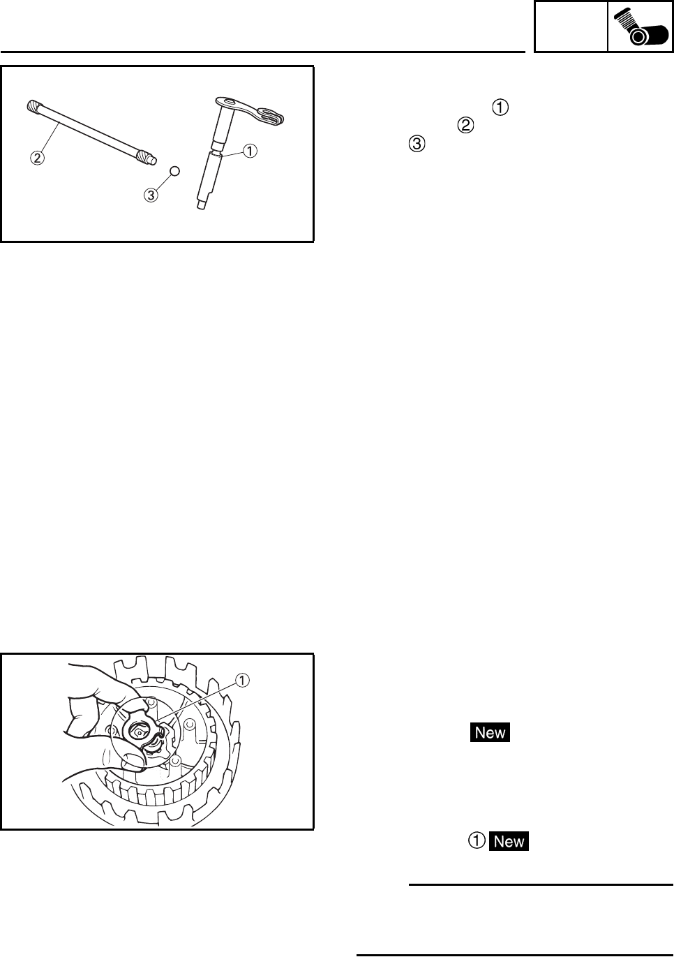
ENG
4-46
CHECKING THE CLUTCH PUSH RODS
1. Check:
• Push lever shaft
• Push rod 2
• Ball
Cracks/damage/wear → Replace the
defective part(s).
CHECKING THE PRIMARY DRIVE GEAR
1. Check:
• Primary drive gear
Damage/wear → Replace the primary drive
and primary driven gears as a set.
Excessive noise during operation →
Replace the primary drive and primary
driven gears as a set.
2. Check:
• Primary-drive-gear-to-primary-driven-gear
free play
Free play exists → Replace the primary
drive and primary driven gears as a set.
INSTALLING THE CLUTCH
1. Install:
• Primary drive gear
• Claw washer
• Lock washer
• Primary drive gear nut
2. Install:
• Clutch housing
• Thrust washer
• Clutch boss
• Lock washer
• Clutch boss nut
N
O
TE:N
O
TE:
Make sure the teeth on the lock washer are
correctly aligned with the grooves on the clutch
boss.
CLUTCH
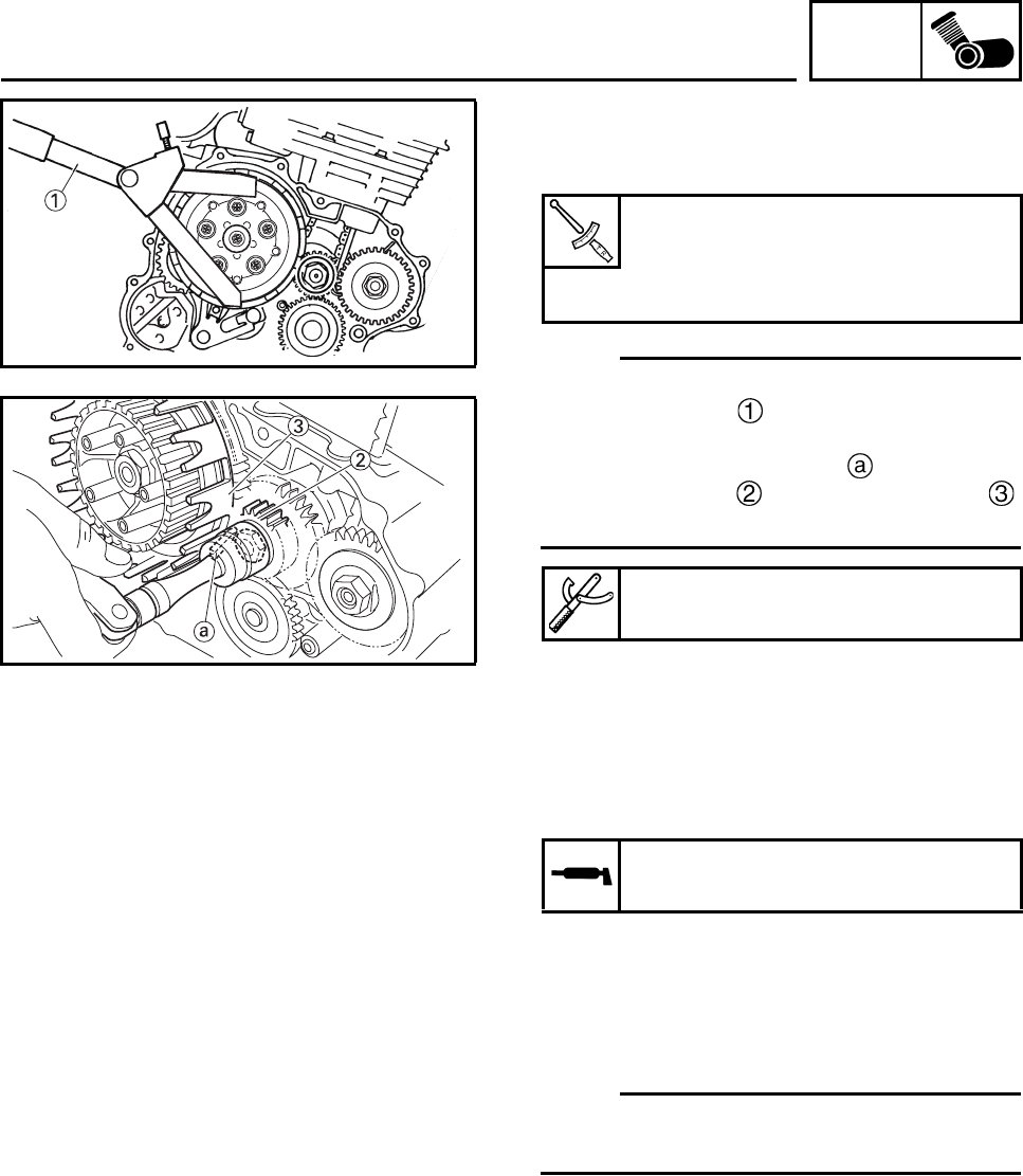
ENG
4-47
3. Tighten:
• Clutch boss nut
• Primary drive gear nut
N
O
TE:N
O
TE:
• While holding the clutch boss with the univer-
sal clutch holder , tighten the clutch boss
nut.
• Place the aluminum plate between pri-
mary drive gear and clutch housing ,
and then tighten the primary drive gear nut.
4. Bend the lock washer tab along a flat side
of the nut.
5. Lubricate:
• Friction plates
• Clutch plates
(with the recommended lubricant)
)
6. Install:
• Friction plates (6 piece)
• Clutch plates (5 piece)
N
O
TE:N
O
TE:
First, install a friction plate and then alternate
between a clutch plate and a friction plate.
Clutch boss nut
75 Nm (7.5 m•kg, 55 ft•lb)
Primary drive gear nut
80 Nm (8.0 m•kg, 59 ft•lb)
Universal clutch holder
90890-04086, YM-91042
Recommended lubricant
Engine oil
CLUTCH

ENG
4-48
7. Install:
• Bearing
•Oil seal
•Circlip
• Torsion spring
• Push lever shaft
•Bolt
•Clutch cable
N
O
TE:N
O
TE:
After installing the clutch cable, bend the push
lever shaft tab along a flat side of the nut.
8. Install:
• Push rod 2
•Ball
• Push rod 1
• Push plate
• Washer
• Locknut
• Pressure plate
• Clutch spring
•Bolt
9. Tighten:
• Clutch spring bolt
• Locknut
N
O
TE:N
O
TE:
Tighten the clutch spring bolts in stages and in
a crisscross pattern.
10.Check:
• Push lever position
Push lever mark and crankcase mark
not aligned → Correct.
N
O
TE:N
O
TE:
Push the push lever in direction and make
sure the marks are aligned.
Clutch spring bolt
8 Nm (0.8 m•kg, 5.9 ft•lb)
Locknut
8 Nm (0.8 m•kg, 5.9 ft•lb)
CLUTCH
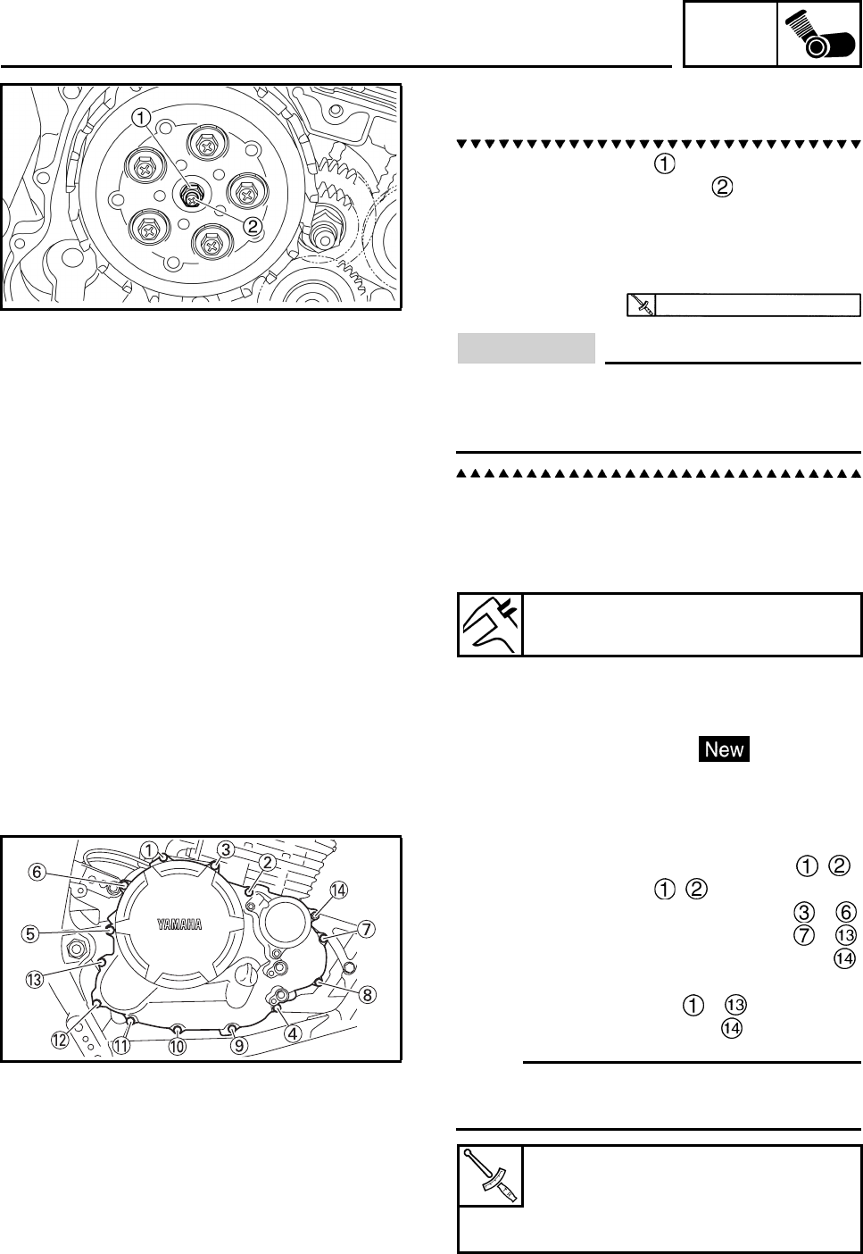
ENG
4-49
11.Adjust:
• Push lever position
a. Loosen the locknut .
b. Turn the adjusting screw in or out until
the marks are aligned.
c. Hold the adjusting screw to prevent it from
moving and then tighten the locknut to
specification.
CAUTION:
Do not overtighten the locknut since this
will remove the free play between both
push rods.
12.Check:
• Clutch cable free play
Refer to “ADJUSTING THE CLUTCH
CABLE FREE PLAY” in chapter 3.
13.Install:
•Spacer
• Dowel pin
• Crankcase cover gasket
14.Install:
• Right crankcase cover
15.Install:
• Crankcase cover bolts M6 × 50 mm ,
• Copper washers to ,
• Crankcase cover bolts M6 × 40 mm ~
• Crankcase cover bolts M6 × 25 mm ~
• Oil filter element cover bolt M6 × 70 mm
16.Tighten:
• Crankcase cover bolts ~
• Oil filter element cover bolt
N
O
TE:N
O
TE:
Tighten the bolts in stages, using a crisscross
pattern.
8 Nm (0.8 m•kg, 5.9 ft•lb)
Clutch lever free play
5 ~ 10 mm (0.20 ~ 0.39 in)
Crankcase cover bolt
10 Nm (1.0 m•kg, 7.4 ft•lb)
Oil filter element cover bolt
10 Nm (1.0 m•kg, 7.4 ft•lb)
CLUTCH
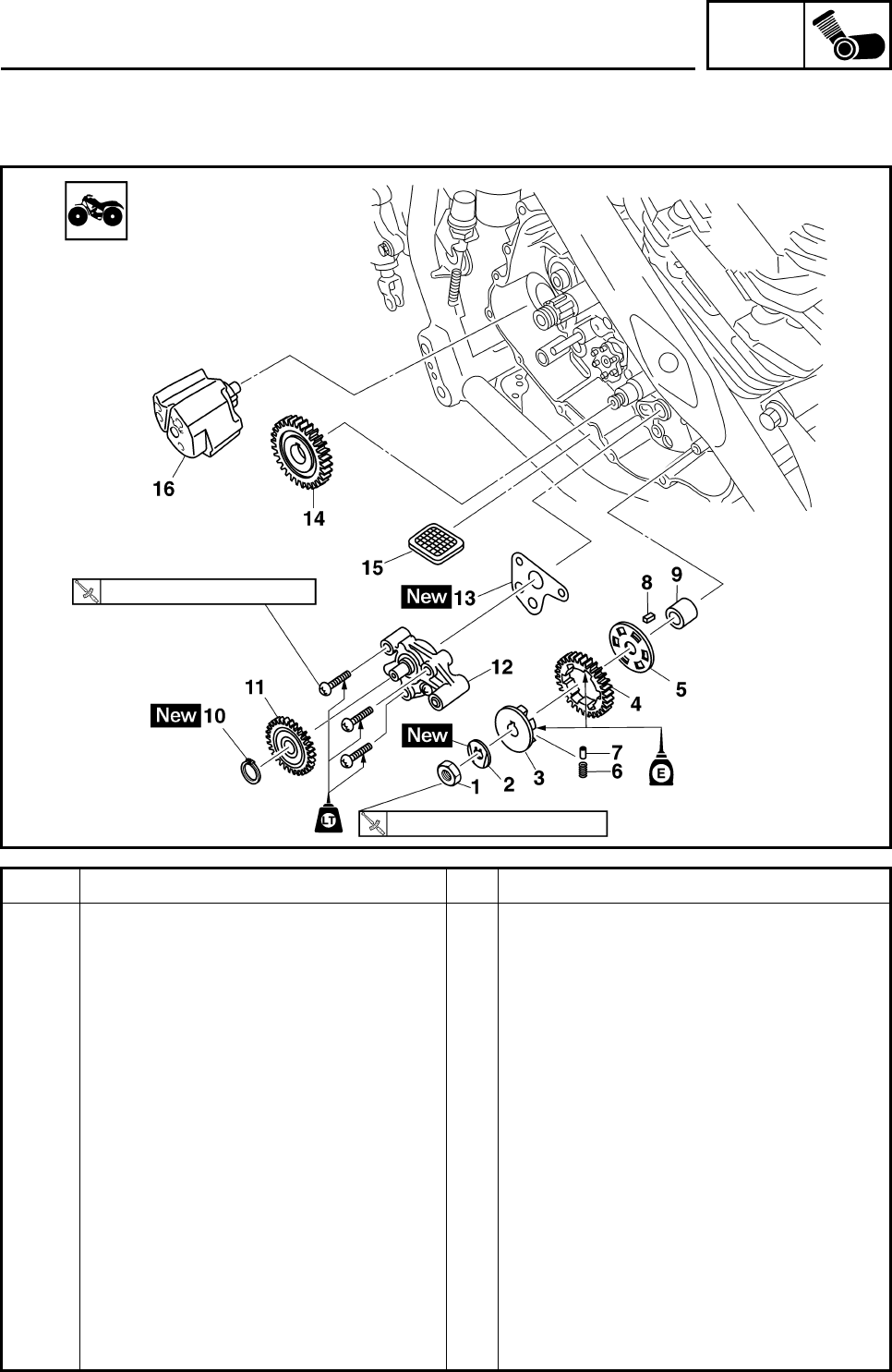
ENG
4-50
OIL PUMP AND BLANCER WEIGHT GEAR
Order Job/Parts to remove Q’ty Remarks
Removing the oil pump and bal-
ancer weight gear Remove the parts in the order listed.
Right crankcase cover Refer to “CLUTCH”.
Clutch
Primary drive gear
1 Balancer weight gear nut 1
2 Lock washer 1
3 Buffer boss 1
4 Balancer weight gear 1
5 Absorber plate 1
6 Compression spring 6
7 Dowel pin 3
8 Straight key 1
9 Spacer 1
10 Circlip 1
11 Oil pump driven gear 1
12 Oil pump assembly 1
13 Gasket 1
6 Nm (0.6 m•kg, 4.4 ft•lb)
55 Nm (5.5 m•kg, 41 ft•lb)
OIL PUMP AND BLANCER WEIGHT GEAR
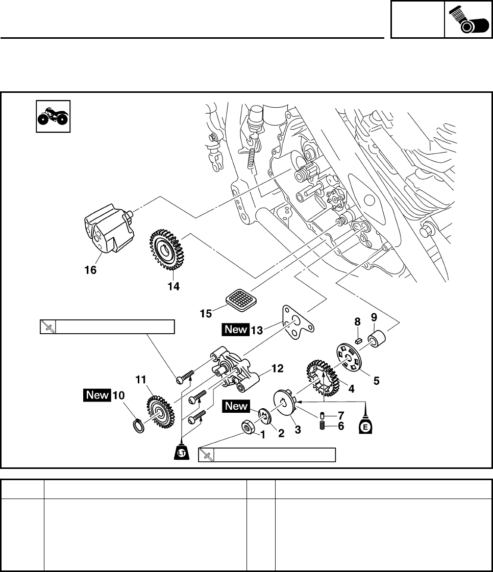
ENG
4-51
Order Job/Parts to remove Q’ty Remarks
14 Balancer drive gear 1
15 Oil strainer 1
16 Spacer 1
For installation, reverse the removal
procedure.
6 Nm (0.6 m•kg, 4.4 ft•lb)
55 Nm (5.5 m•kg, 41 ft•lb)
OIL PUMP AND BLANCER WEIGHT GEAR
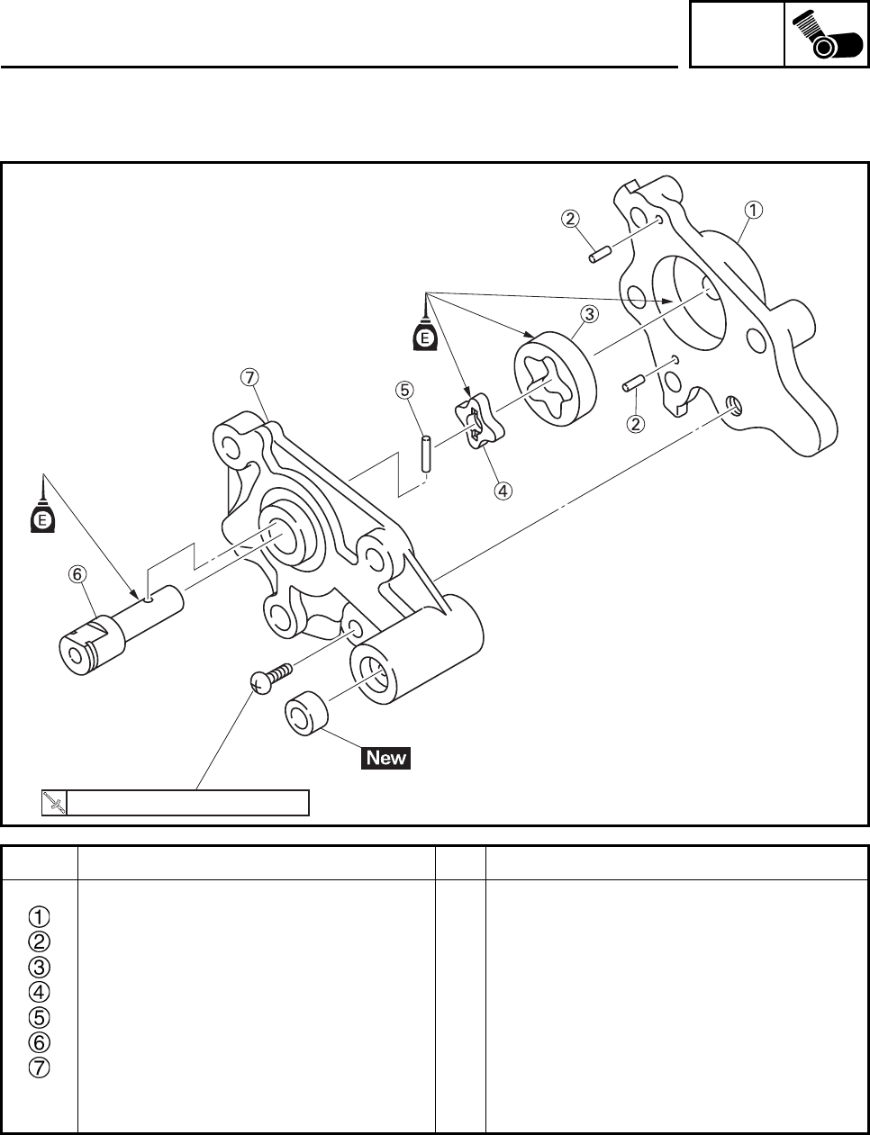
ENG
4-52
Order Job/Parts to remove Q’ty Remarks
Disassembling the oil pump Remove the parts in the order listed.
Oil pump housing 1
Dowel pin 2
Outer rotor 1
Inner rotor 1
Dowel pin 1
Shaft 1
Oil pump cover 1
For assembly, reverse the disassembly
procedure.
7 Nm (0.7 m•kg, 5.0 ft•lb)
OIL PUMP AND BLANCER WEIGHT GEAR
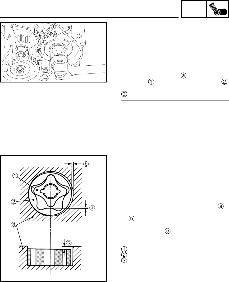
ENG
4-53
REMOVING THE BALANCER WEIGHT
GEAR AND OIL PUMP
1. Straighten the lock washer tab.
2. Remove:
• Balancer weight gear nut
• Lock washer
• Balancer weight gear
N
O
TE:N
O
TE:
Place the aluminum plate between balancer
drive gear and balancer weight gear ,
and then loosen the balancer weight gear nut
.
3. Remove:
• Oil pump assembly
CHECKING THE OIL PUMP
1. Check:
• Oil pump driven gear
• Oil pump housing
• Oil pump cover
Cracks/damage/wear → Replace the
defective part(s).
2. Measure:
• Inner-rotor-to-outer-rotor-tip clearance
• Outer-rotor-to-oil-pump-housing clearance
• Oil-pump-housing-to-inner-rotor-and-outer-
rotor clearance
Out of specification → Replace the oil
pump.
Inner rotor
Outer rotor
Oil pump housing
OIL PUMP AND BLANCER WEIGHT GEAR
ENG
4-54
3. Check:
• Oil pump operation
Rough movement → Repeat steps (1) and
(2) or replace the defective part(s).
CHECKING THE BALANCER WEIGHT
GEAR
1. Check:
• Balancer weight gear
• Buffer boss
• Compression spring
• Dowel pin
• Cracks/damage/wear → Replace.
Inner-rotor-to-outer-rotor-tip
clearance
0.150 mm (0.0059 in)
Limit
0.23 mm (0.0091 in)
Outer-rotor-to-oil-pump-housing
clearance
0.100 ~ 0.151 mm
(0.0039 ~ 0.0059 in)
Limit
0.22 mm (0.0087 in)
Oil-pump-housing-to-inner-and-
outer-rotor clearance
0.04 ~ 0.09 mm
(0.0016 ~ 0.0035 in)
Limit
0.16 mm (0.0063 in)
OIL PUMP AND BLANCER WEIGHT GEAR
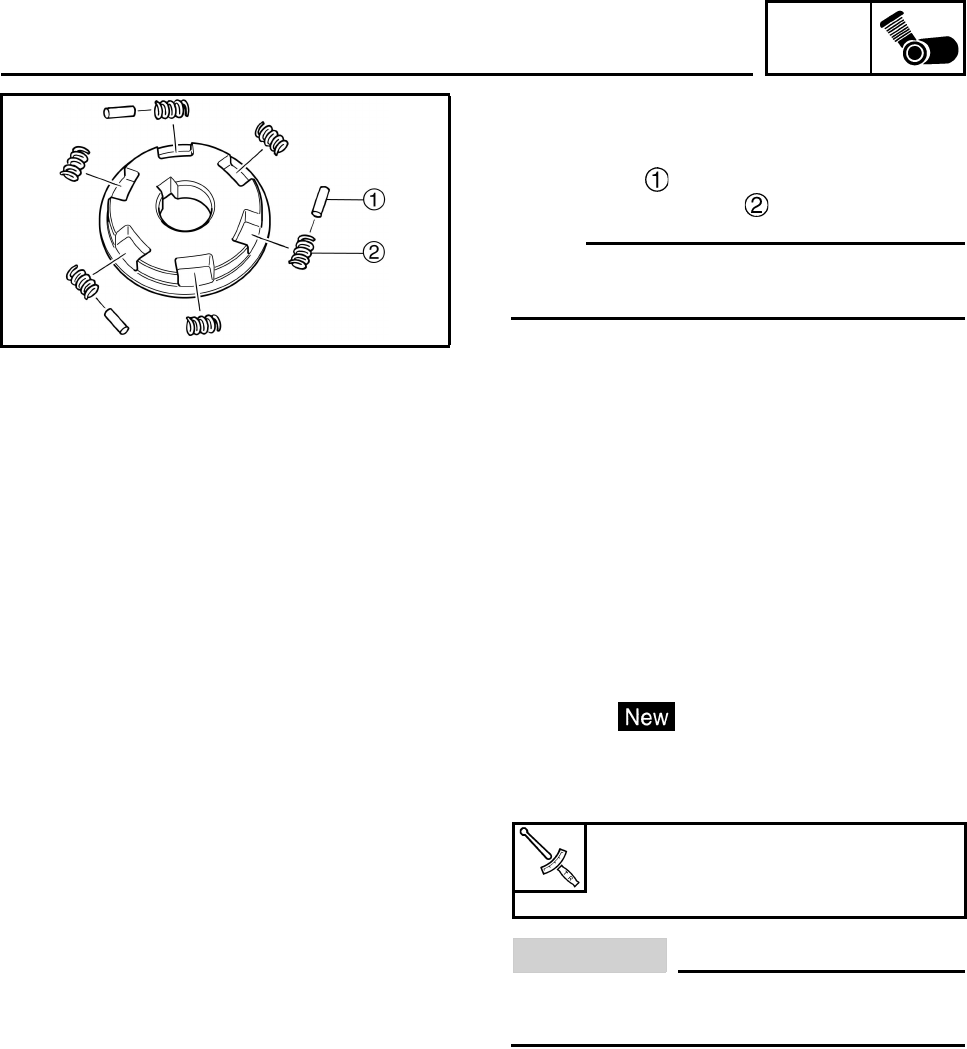
ENG
4-55
ASSENBLING THE BALANCER DRIVE
GEAR
1. Assemble:
• Dowel pin
• Compression spring
N
O
TE:N
O
TE:
Install the dowel pins and compression springs
alternately as shown as.
2. Assemble:
• Buffer boss
INSTALLING THE OIL PUMP
1. Install:
•Gasket
• Oil pump
2. Tighten:
• Oil pump bolts
CAUTION:
After tightening the bolts, make sure the oil
pump turns smoothly.
Oil pump bolt
6 Nm (0.6 m•kg, 4.4 ft•lb)
LOCTITE®
OIL PUMP AND BLANCER WEIGHT GEAR
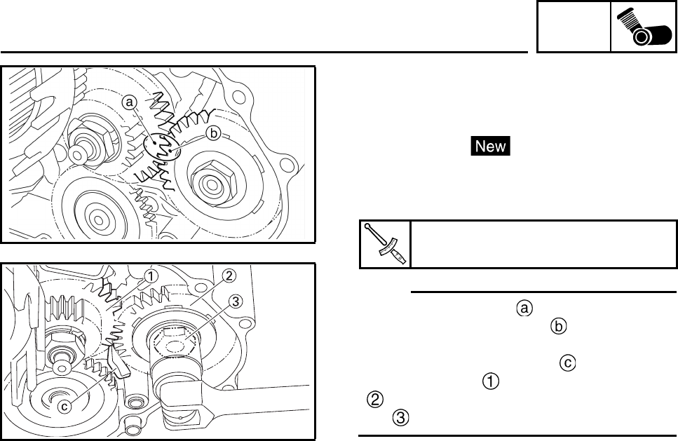
ENG
4-56
INSTALLING THE BALANCER WEIGHT
GEAR
1. Install:
• Balancer weight gear
• Lock washer
• Balancer weight gear nut
2. Tighten:
• Balancer weight gear nut
N
O
TE:N
O
TE:
• Align the punch mark in the balancer drive
gear with the punch mark in the balancer
weight gear.
• Place the aluminum plate between bal-
ancer drive gear and balancer weight gear
, and then tighten the balancer weight gear
nut .
3. Bend the lock washer tab along a flat side
of the nut.
Balancer weight gear nut
55 Nm (5.5 m•kg, 41 ft•lb)
OIL PUMP AND BLANCER WEIGHT GEAR
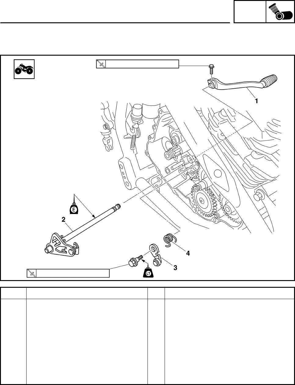
ENG
4-57
SHIFT SHAFT
Order Job/Parts to remove Q’ty Remarks
Removing the shift shaft and
stopper lever Remove the parts in the order listed.
Right crankcase cover Refer to “CLUTCH”.
Clutch
1 Shift pedal 1
2 Shift shaft assembly 1
3 Stopper lever 1
4 Torsion spring 1
For installation, reverse the removal
procedure.
10 Nm (1.0 m•kg, 7.4 ft•lb)
10 Nm (1.0 m•kg, 7.4 ft•lb)
SHIFT SHAFT
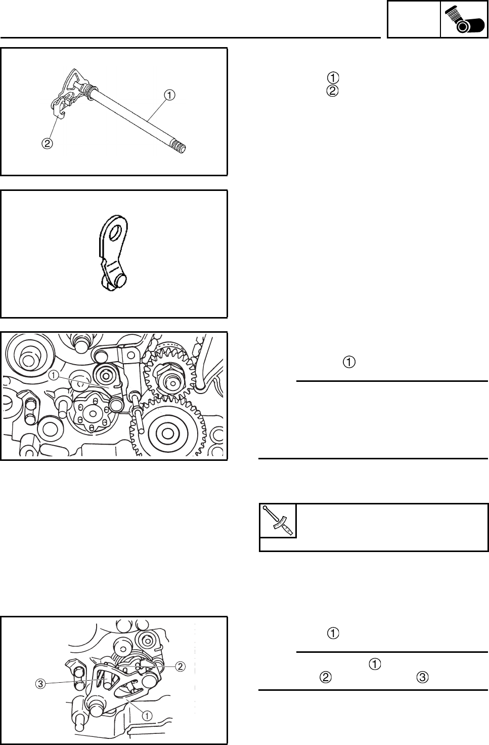
ENG
4-58
CHECKING THE SHIFT SHAFT
1. Check:
• Shift shaft
• Shift lever
Bends/damage/wear → Replace.
• Shift lever spring
Damage/wear → Replace.
CHECKING THE STOPPER LEVER
1. Check:
• Stopper lever
Bends/damage → Replace.
Roller turns roughly → Replace the stopper
lever.
• Torsion spring
Damage/wear → Replace.
INSTALLING THE SHIFT SHAFT
1. Install:
• Stopper lever
N
O
TE:N
O
TE:
• Hook the ends of the stopper lever spring
onto the stopper lever and the crankcase
boss.
• Mesh the stopper lever with the shift drum
segment assembly.
2. Tighten:
• Stopper lever bolt
3. Install:
• Shift shaft
N
O
TE:N
O
TE:
Install the shift shaft by aligning the shift
shaft spring with the stopper .
Stopper lever bolt
10 Nm (1.0 m•kg, 7.4 ft•lb)
LOCTITE®
SHIFT SHAFT
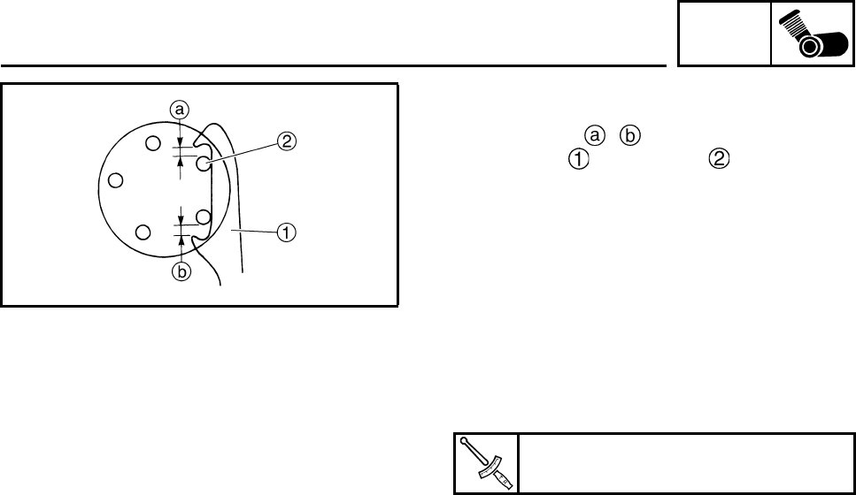
ENG
4-59
4. Check:
• When the gear position is in Neutral, check
the length ( , ) between the tip of the
shift lever and dowel pin are equal.
If not → Replace the shift shaft.
5. Install:
• Shift pedal
6. Tighten:
• Shift pedal bolt
7. Adjust:
• Shift pedal height
Refer to “ADJUSTING THE SHIFT PEDAL”
in chapter 3.
Shift pedal bolt
10 Nm (1.0 m•kg, 7.4 ft•lb)
SHIFT SHAFT
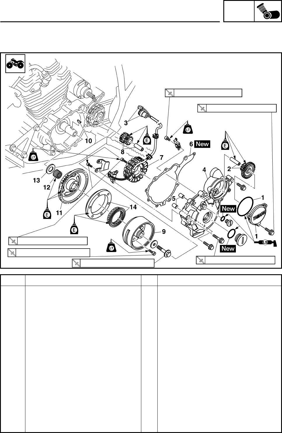
ENG
4-60
PICKUP COIL ROTOR AND STARTER CLUTCH
Order Job/Parts to remove Q’ty Remarks
Removing the pickup coil rotor and
starter clutch Remove the parts in the order listed.
Engine oil Drain.
Shift pedal Refer to “SHIFT SHAFT”.
Drive sprocket cover Refer to “REAR SHOCK ABSORBER,
SWINGARM AND DRIVE CHAIN” in
chapter 6.
1 Starter idle gear cover/O-ring 1/1
2 Starter idler gear 1/shaft 1/1
3 Pickup coil rotor lead coupler 2 Disconnect.
4 Left crankcase cover 1
5 Dowel pin 2
6 Crank case cover gasket 1
7 Stator coil assembly/pickup coil 1/1
8 Starter idler gear 2/shaft 1/1
9 Pickup coil rotor 1
10 Woodruff key 1
11 Starter wheel gear 1
30 Nm (3.0 m•kg, 22 ft•lb)
10 Nm (1.0 m•kg, 7.4 ft•lb)
10 Nm (1.0 m•kg, 7.4 ft•lb)
60 Nm (6.0 m•kg, 44 ft•lb) 10 Nm (1.0 m•kg, 7.4 ft•lb)
7 Nm (0.7 m•kg, 5.2 ft•lb)
PICKUP COIL ROTOR AND STARTER CLUTCH
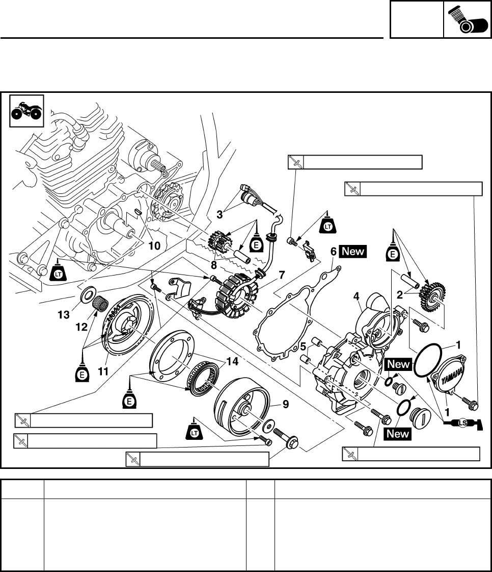
ENG
4-61
Order Job/Parts to remove Q’ty Remarks
12 Bearing 1
13 Washer 1
14 Starter clutch assembly 1
For installation, reverse the removal
procedure.
30 Nm (3.0 m•kg, 22 ft•lb)
10 Nm (1.0 m•kg, 7.4 ft•lb)
10 Nm (1.0 m•kg, 7.4 ft•lb)
60 Nm (6.0 m•kg, 44 ft•lb) 10 Nm (1.0 m•kg, 7.4 ft•lb)
7 Nm (0.7 m•kg, 5.2 ft•lb)
PICKUP COIL ROTOR AND STARTER CLUTCH
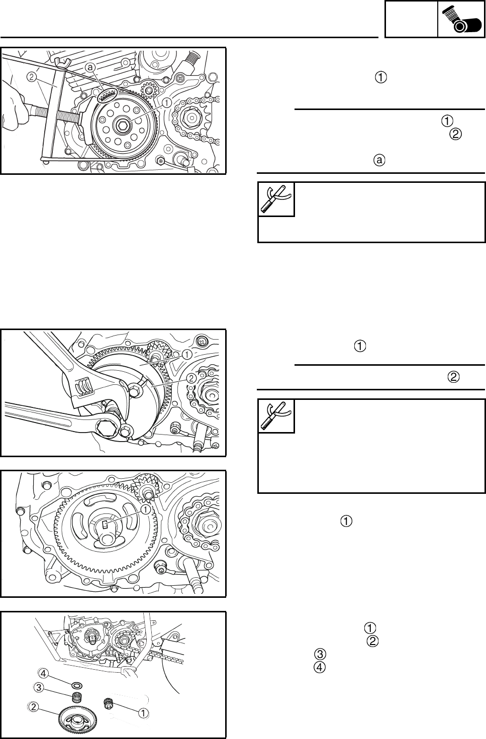
ENG
4-62
REMOVING THE PICKUPCOIL ROTOR
1. Remove:
• Pickup coil rotor bolt
• Washer
N
O
TE:N
O
TE:
• Loosen the pickup coil rotor bolt while
holding the rotor with a sheave holder .
• Do not allow the sheave holder to touch the
projection on the rotor .
2. Remove:
• Pickup coil rotor
N
O
TE:N
O
TE:
Remove the rotor using flywheel puller .
3. Remove:
• Woodruff key
4. Remove:
• Starter idle gear 2
• Starter wheel gear
• Bearing
• Washer
Sheave holder
90890-01701
Primary clutch holder
YS-01880-A
Flywheel puller
90890-01362
Heavy duty puller
YU-33270-B
Bolt (M8 × 80 mm)
90890-01359
PICKUP COIL ROTOR AND STARTER CLUTCH
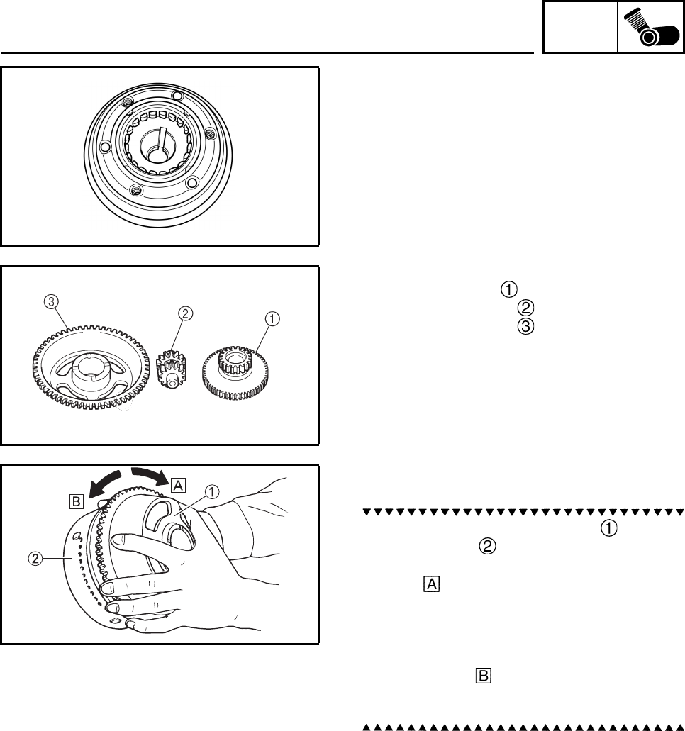
ENG
4-63
CHECKING THE STARTER CLUTCH
1. Check:
• Starter clutch rollers
Damage/wear → Replace the starter
clutch.
2. Check:
• Starter idle gear
• Starter wheel gear
• Starter clutch gear
Burrs/chips/roughness/wear → Replace
the defective part(s).
3. Check:
• Starter clutch gear’s contacting surfaces
Damage/pitting/wear → Replace the
starter clutch gear.
4. Check:
• Starter clutch operation
a. Install the starter wheel gear onto the
starter clutch and hold the starter clutch.
b. When turning the starter wheel gear clock-
wise , the starter clutch and the starter
wheel gear should engage, otherwise the
starter clutch is faulty and must be
replaced.
c. When turning the starter wheel gear coun-
terclockwise , it should turn freely, other-
wise the starter clutch is faulty and must be
replaced.
5. Check:
•Shaft
Damage/fatigue/wear → Replace the
defective part(s).
PICKUP COIL ROTOR AND STARTER CLUTCH
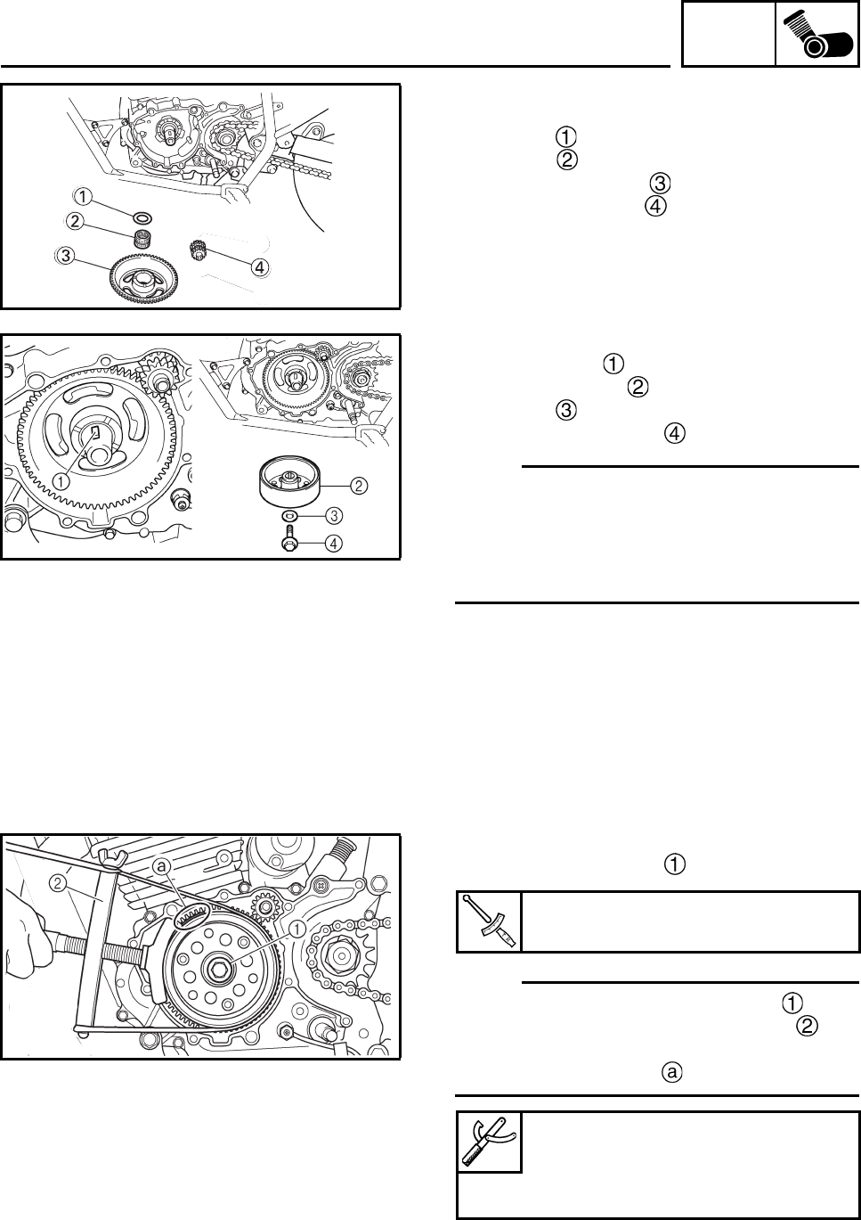
ENG
4-64
INSTALLING THE PICKUP COIL ROTOR
1. Install:
• Washer
• Bearing
• Starter wheel gear
• Starter idle gear 2
2. Install:
• Woodruff key
• Pickup coil rotor
• Washer
• Pickup coil rotor bolt
N
O
TE:N
O
TE:
• Clean the tapered portion of the crankshaft
and the rotor hub.
• When installing the rotor, make sure the woo-
druff key is properly seated in the key way of
the crankshaft.
3. Tighten:
• Pickup coil rotor bolt
N
O
TE:N
O
TE:
• Tighten the pickup coil rotor bolt while
holding the rotor with a sheave holder .
• Do not allow the sheave holder to touch the
projection on the rotor .
Pickup coil rotor bolt
60 Nm (6.0 m•kg, 44 ft•lb)
Sheave holder
90890-01701
Primary clutch holder
YS-01880-A
PICKUP COIL ROTOR AND STARTER CLUTCH
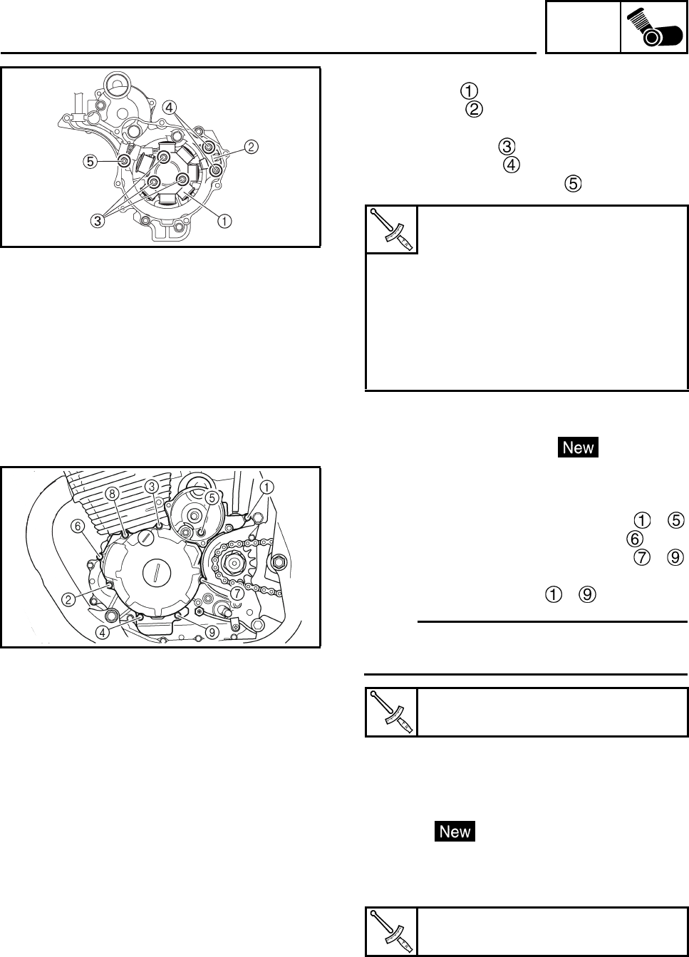
ENG
4-65
4. Install:
• Stater coil
• Pickup coil
5. Tighten:
• Stater coil bolts
• Pickup coil bolts
• Left crankcase cover bolt
6. Install:
• Dowel pin
• Crankcase cover gasket
7. Install:
• Left crankcase cover
8. Install:
• Crankcase cover bolts M6 × 30 mm ~
• Crankcase cover bolt M6 × 45 mm
• Crankcase cover bolts M6 × 40 mm ~
9. Tighten:
• Crankcase cover bolts ~
N
O
TE:N
O
TE:
Tighten the bolts in stages and in a crisscross
pattern as shown.
10.Install:
• Starter idle gear 1
•Shaft
11.Install:
• O-ring
• Starter idle gear cover
12.Tighten:
• Starter idle gear cover bolt
Stater coil bolt
10 Nm (1.0 m•kg, 7.4 ft•lb)
LOCTITE®
Pickup coil bolt
10 Nm (1.0 m•kg, 7.4 ft•lb)
LOCTITE®
Left crankcase cover bolt
7 Nm (0.7 m•kg, 5.2 ft•lb)
LOCTITE®
Crankcase cover bolt
10 Nm (1.0 m•kg, 7.2 ft•lb)
Starter idle gear cover bolt
10 Nm (1.0 m•kg, 7.4 ft•lb)
PICKUP COIL ROTOR AND STARTER CLUTCH
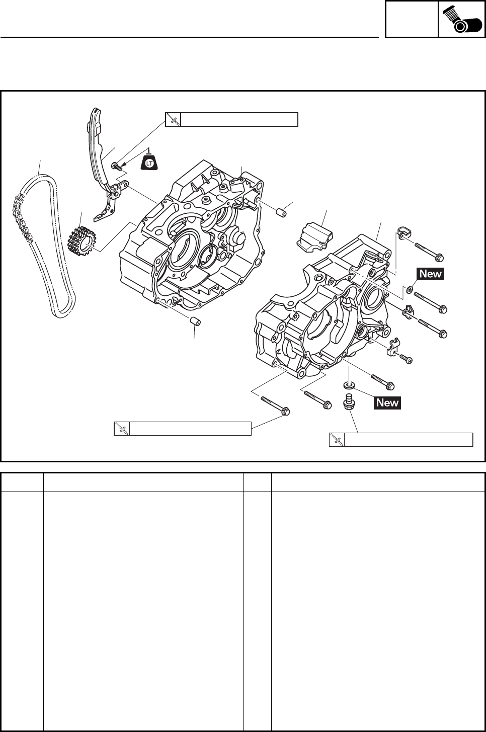
ENG
4-66
CRANKCASE
Order Job/Parts to remove Q’ty Remarks
Separating the crankcase Remove the parts in the order listed.
Engine Refer to “ENGINE REMOVAL”.
Cylinder head Refer to “CYLINDER HEAD”.
Cylinder Refer to “CYLINDER AND PISTON”.
Clutch Refer to “CLUTCH”.
Oil pump Refer to “OIL PUMP AND BLANCER
WEIGHT GEAR”.
Balancer weight gear
Shift shaft Refer to “SHIFT SHAFT”.
Pickup coil rotor Refer to “PICKUP COIL ROTOR AND
STARTER CLUTCH”.
1 Timing chain guide (intake side) 1
2 Timing chain 1
3 Crankshaft sprocket 1
4 Right crankcase 1
5 Dowel pin 2
6 Left crankcase 1
1
2
3
4
5
5
6
7
8 Nm (0.8 m•kg, 5.9 ft•lb)
20 Nm (2.0 m•kg, 15 ft•lb)
10 Nm (1.0 m•kg, 7.4 ft•lb)
CRANKCASE
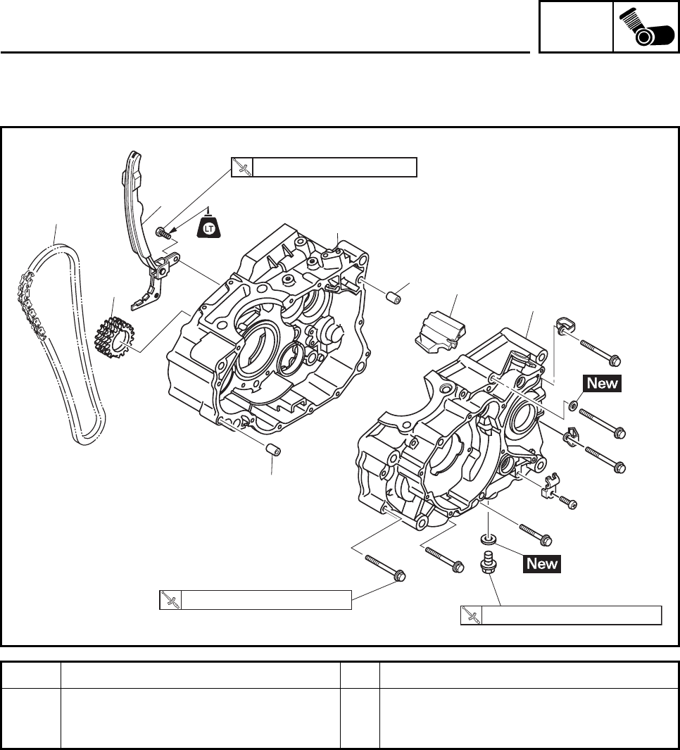
ENG
4-67
Order Job/Parts to remove Q’ty Remarks
7 Spacer 1
For installation, reverse the removal
procedure.
1
2
3
4
5
5
6
7
8 Nm (0.8 m•kg, 5.9 ft•lb)
20 Nm (2.0 m•kg, 14.8 ft•lb)
10 Nm (1.0 m•kg, 7.4 ft•lb)
CRANKCASE
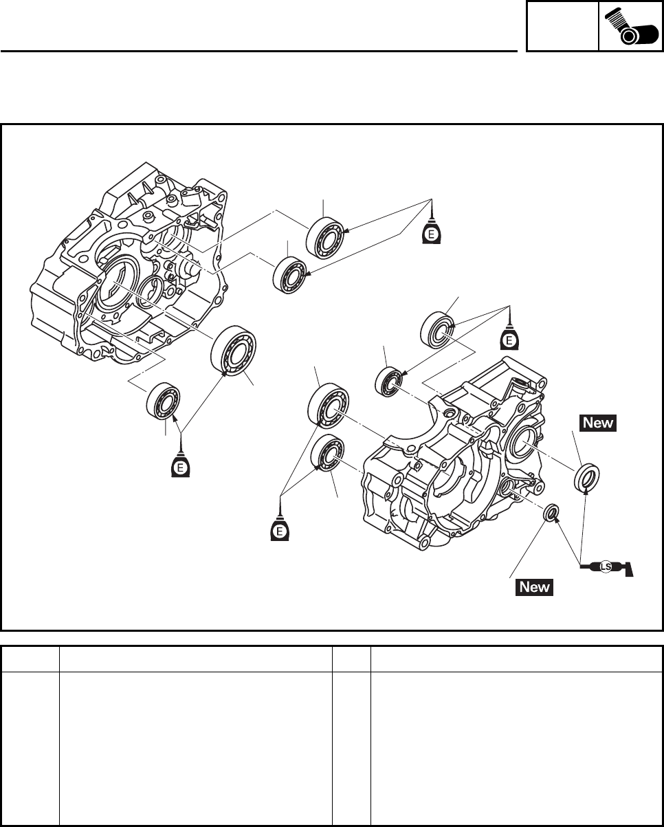
ENG
4-68
Order Job/Parts to remove Q’ty Remarks
Removing the bearing Remove the parts in the order listed.
Crankshaft assembly Refer to “CRANKSHAFT ASSEMBLY”.
Main axle assembly/drive axle assem-
bly Refer to “TRANSMISSION”.
1 Oil seal 2
2 Bearing 8
For installation, reverse the removal
procedure.
2
2
2
2
1
2
2
2
1
2
CRANKCASE
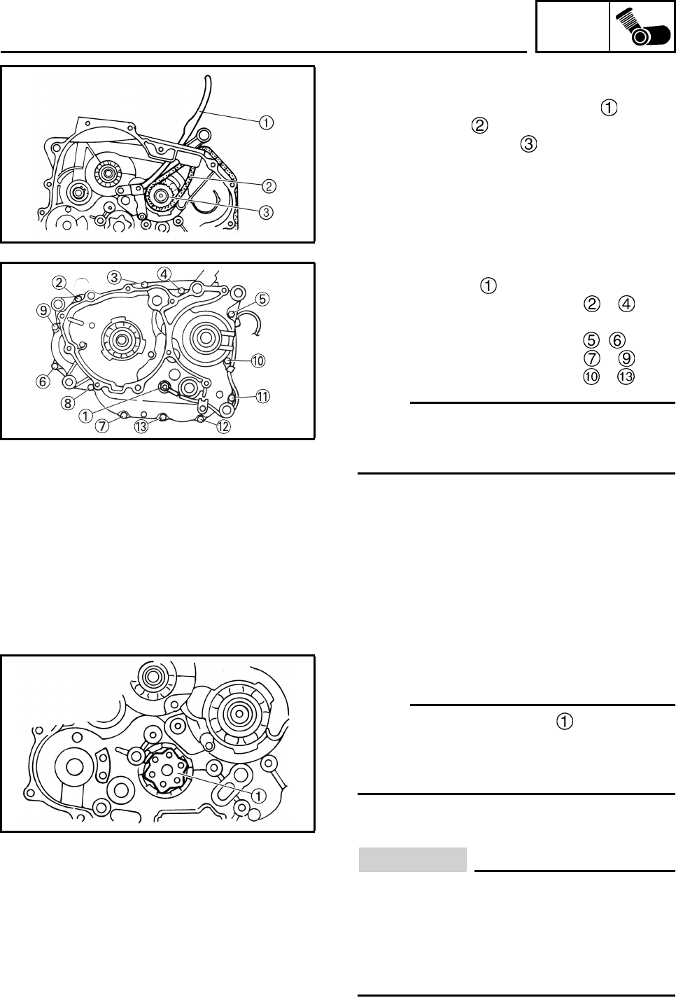
ENG
4-69
DISASSEMBLING THE CRANKCASE
1. Remove:
• Timing chain guide (intake side)
• Timing chain
• Crankshaft sprocket
2. Remove:
• Neutral switch
• Crankcase bolts M6 × 70 mm ~
• Copper washers
• Crankcase bolts M6 × 60 mm ,
• Crankcase bolts M6 × 55 mm ~
• Crankcase bolts M6 × 45 mm ~
N
O
TE:N
O
TE:
Loosen each bolt 1/4 of a turn at a time, in
stages and in a crisscross pattern. After all of
the bolts are fully loosened, remove them.
3. Turn:
• Shift drum segment
N
O
TE:N
O
TE:
Turn the shift drum segment to the position
shown in the illustration. In this position, the
shift drum segment’s teeth will not contact the
crankcase during crankcase separation.
4. Remove:
• Right crankcase
CAUTION:
• First check that the shift drum segment’s
teeth and the drive axle circlip are prop-
erly positioned, then remove the right
crankcase.
• Do not damage the crankcase mating sur-
faces.
CRANKCASE
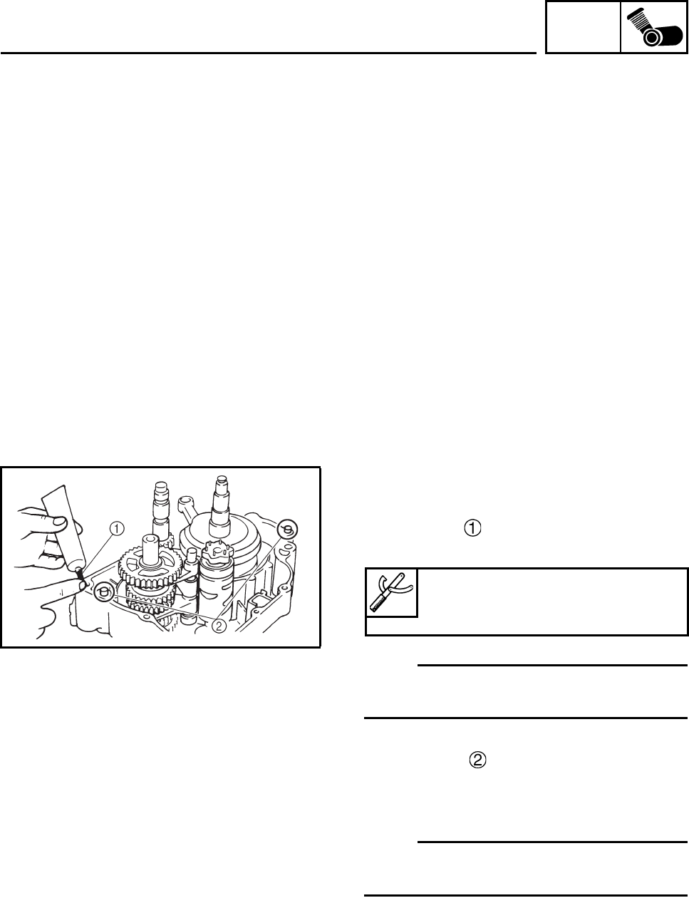
ENG
4-70
CHECKING THE CRANKCASE
1. Thoroughly wash the crankcase halves in a
mild solvent.
2. Thoroughly clean all the gasket surfaces
and crankcase mating surfaces.
3. Check:
•Crankcase
Cracks/damage → Replace.
• Oil delivery passages
Obstruction → Blow out with compressed
air.
ASSEMBLING THE CRANKCASE
1. Apply:
• Yamaha bond No.1215 (Three Bond
No.1215®)
(onto the crankcase mating surfaces)
N
O
TE:N
O
TE:
Do not allow any sealant to come into contact
with the oil gallery.
2. Install:
• Dowel pins
3. Install:
• Right crankcase
(onto the left crankcase)
N
O
TE:N
O
TE:
Tap lightly on the right crankcase with a soft-
face hammer.
Yamaha bond No.1215
(Three Bond No.1215®)
90890-85505
CRANKCASE
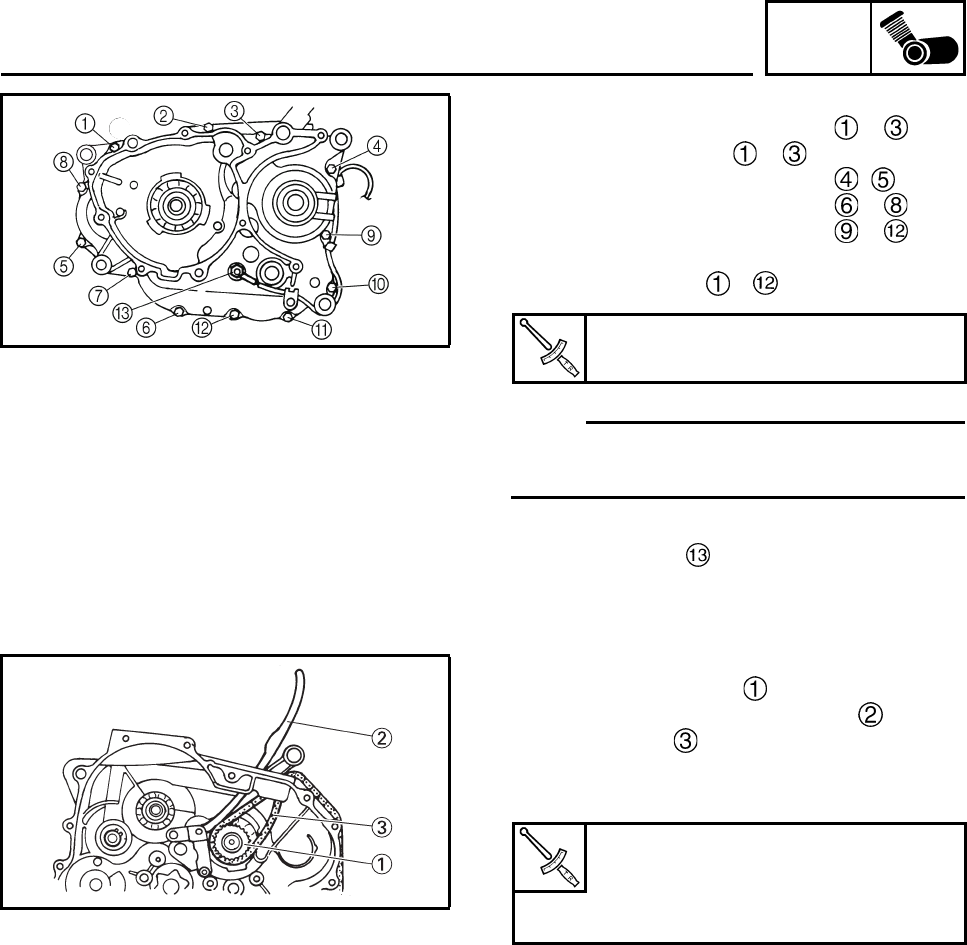
ENG
4-71
4. Install:
• Crankcase bolts M6 × 70 mm ~
• Copper washers to ~ .
• Crankcase bolts M6 × 60 mm ,
• Crankcase bolts M6 × 55 mm ~
• Crankcase bolts M6 × 45 mm ~
5. Tighten:
• Crankcase bolts ~
N
O
TE:N
O
TE:
Tighten each bolt 1/4 of a turn at a time, in
stages and in a crisscross pattern.
6. Install:
• Neutral switch
7. Install:
• Crankshaft sprocket
• Timing chain guide (intake side)
• Timing chain
8. Tighten:
• Timing chain guide (intake side) bolt
9. Apply:
• Engine oil
(onto the crankshaft pins bearings and oil
delivery holes)
10.Check:
• Crankshaft and transmission operation
Rough movement → Repair.
Crankcase bolt
10 Nm (1.0 m•kg, 7.4 ft•lb)
Timing chain guide (intake side)
bolt
8 Nm (0.8 m•kg, 5.9 ft•lb)
LOCTITE®
CRANKCASE
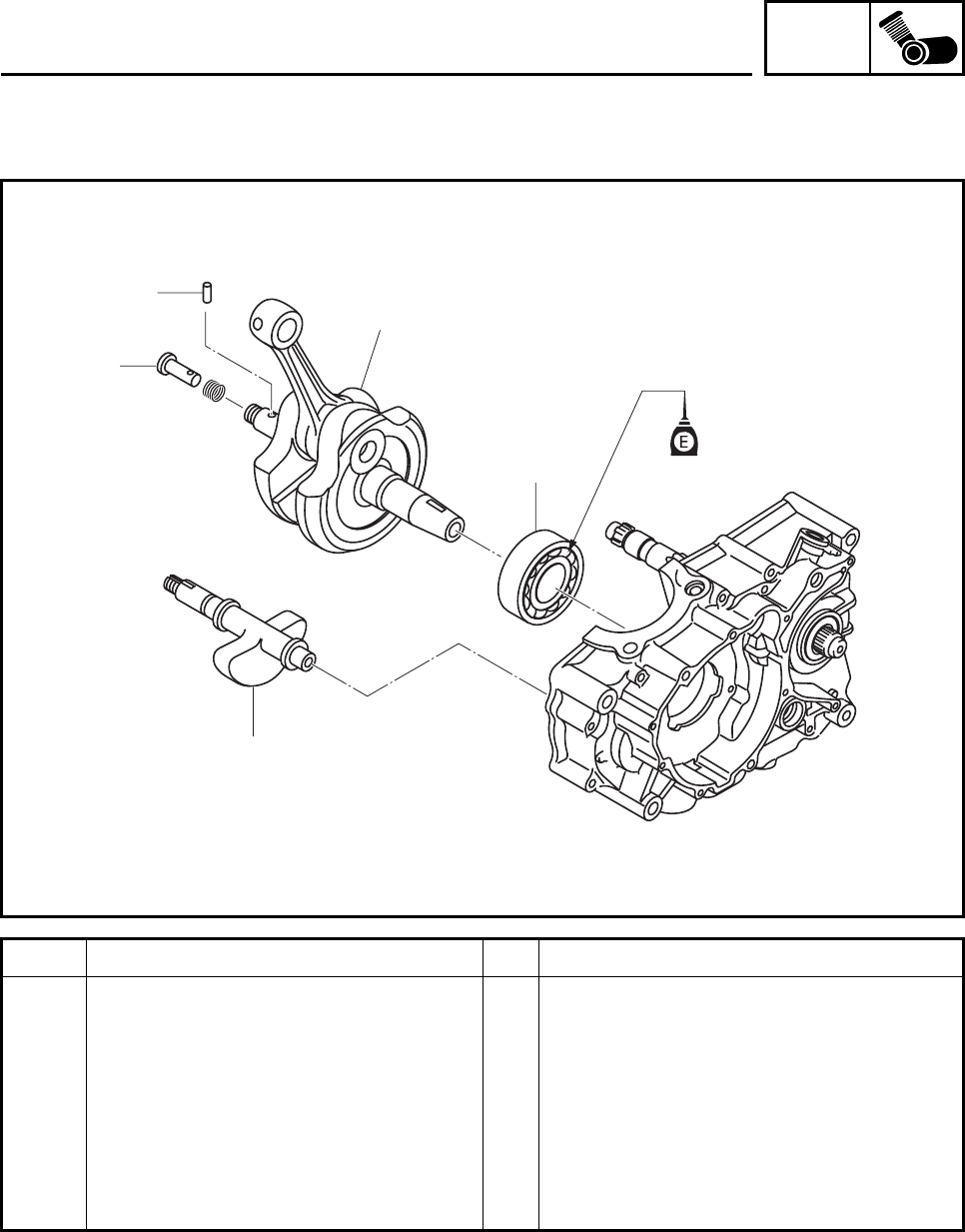
ENG
4-72
CRANKSHAFT ASSEMBLY
Order Job/Parts to remove Q’ty Remarks
Removing the crankshaft assembly Remove the parts in the order listed.
Crankcase Refer to “CRANKCASE”.
1 Balancer weight 1
2 Crankshaft assembly 1
3 Dowel pin 1
4 Plunger seal 1
5 Bearing 1
For installation, reverse the removal
procedure.
3
4
2
5
1
CRANKSHAFT ASSEMBLY
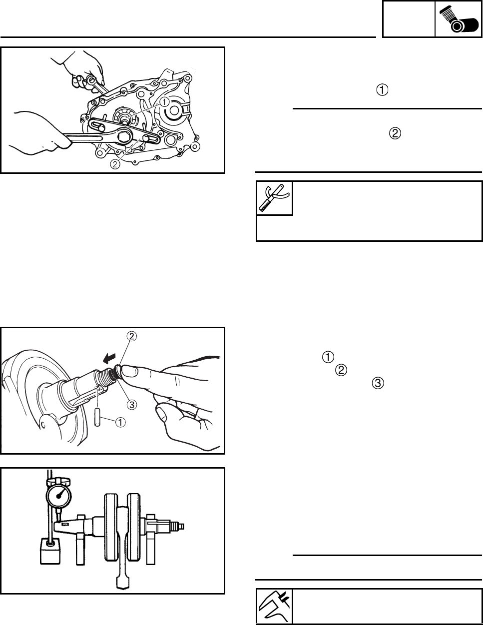
ENG
4-73
REMOVING THE CRANKSHAFT ASSEMBLY
1. Remove:
• Balancer weight
• Crankshaft assembly
N
O
TE:N
O
TE:
• Remove the crankshaft assembly with the
crankcase separating tool .
• Make sure the crankcase separating tool is
centered over the crankshaft assembly.
REMOVING THE PLUNGER SEAL
1. Remove:
• Dowel pin
• Plunger seal
• Compression spring
Remove the plunger seal and compression
spring, push the plunger seal lightly and
remove the dowel pin.
CHECKING THE CRANKSHAFT AND
CONNECTING ROD
1. Measure:
• Crankshaft runout
Out of specification → Replace the crank-
shaft, bearing or both.
N
O
TE:N
O
TE:
Turn the crankshaft slowly.
Crankcase separating tool
90890-01135
Crankcase separator
YU-01135-B
Runout limit C
0.03 mm (0.0012 in)
CRANKSHAFT ASSEMBLY
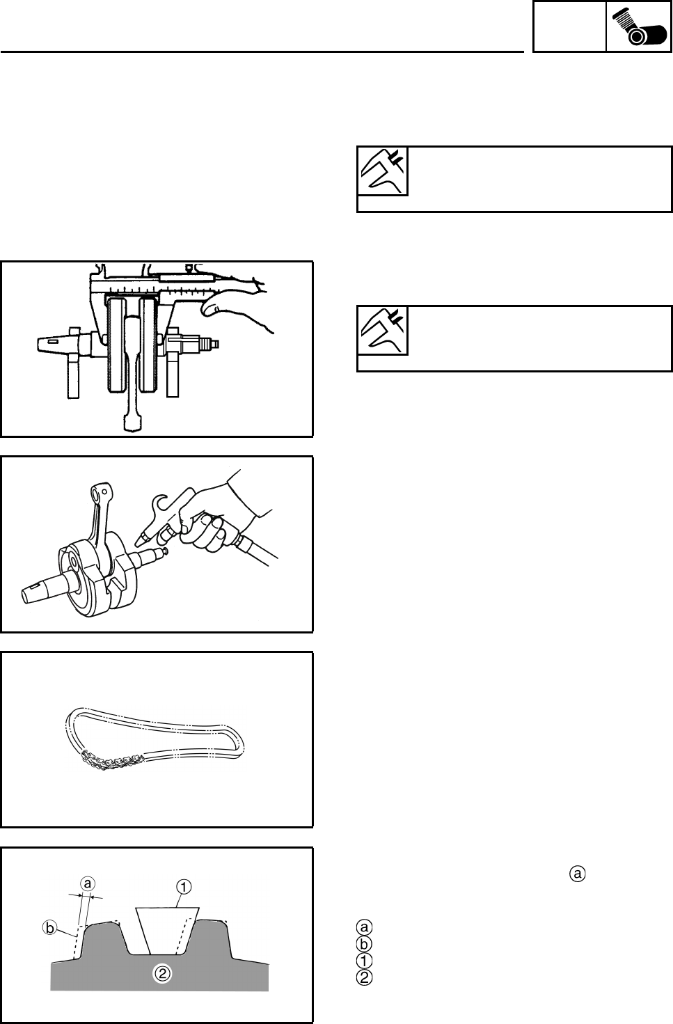
ENG
4-74
2. Measure:
• Big end side clearance
Out of specification → Replace the big end
bearing, crankshaft pin, or connecting rod.
3. Measure:
• Crankshaft width
Out of specification → Replace the crank-
shaft.
4. Check:
• Crankshaft sprocket
Damage/wear → Replace the crankshaft.
• Bearing
Cracks/damage/wear → Replace the
crankshaft.
5. Check:
• Crankshaft journal oil passage
Obstruction → Blow out with compressed
air.
CHECKING THE TIMING CHAIN,
CRANKSHAFT SPROCKET AND TIMING
CHAIN GUIDE
The following procedure applies to all of the
camshaft sprockets and timing chain guides.
1. Check:
• Timing chain
Damage/stiffness → Replace the timing
chain and camshaft sprocket and crank-
shaft sprocket as a set.
2. Check:
• Crankshaft sprocket
More than 1/4 tooth wear → Replace
the timing chain and camshaft sprocket and
crankshaft sprocket as a set.
1/4 tooth
Correct
Timing chain roller
Crankshaft sprocket
Big end side clearance D
0.350 ~ 0.650 mm
(0.0138 ~ 0.0256 in)
Width A
69.25 ~ 69.30 mm
(2.726 ~ 2.728 in)
CRANKSHAFT ASSEMBLY
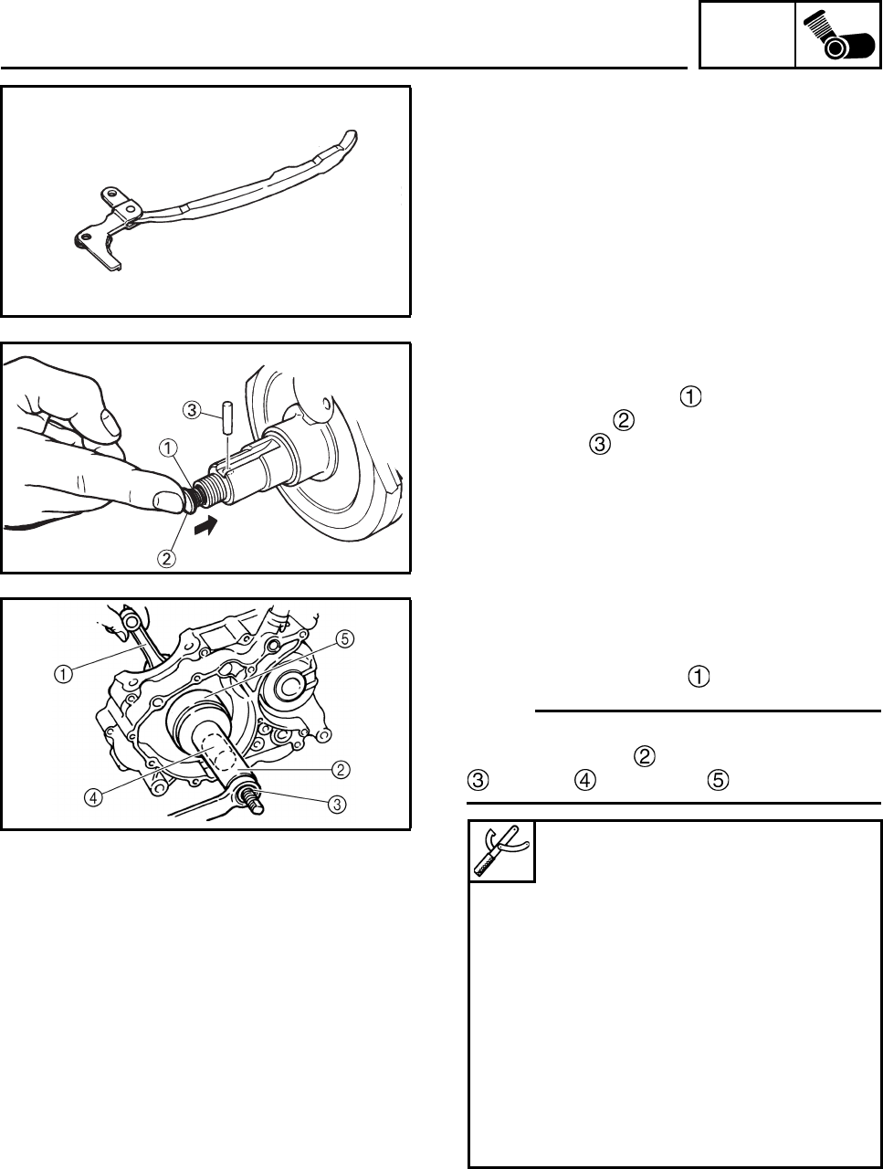
ENG
4-75
3. Check:
• Timing chain guide (intake side)
Damage/wear → Replace the timing chain
guide (intake side)
INSTALLING THE PLUNGER SEAL
1. Install:
• Compression spring
• Plunger seal
• Dowel pin
Check the plunger seal smooth operation
pushing the plunger seal by your finger.
INSTALLING THE CRANKSHAFT
ASSEMBLY
1. Install:
• Crankshaft assembly
N
O
TE:N
O
TE:
Install the crankshaft assembly with the crank-
shaft installer pot , crankshaft installer bolt
, adapter and spacer .
Crankshaft installer pot
90890-01274
Installing pot
YU-90058
Crankshaft installer bolt
90890-01275
Bolt
YU-90060
Spacer
90890-01288
Adapter (M10)
90890-01383
Adapter #2
YU-90062
CRANKSHAFT ASSEMBLY

ENG
4-76
CAUTION:
To avoid scratching the crankshaft and to
ease the installation procedure, lubricate
the oil seal lips with lithium-soap-based
grease and each bearing with engine oil.
N
O
TE:N
O
TE:
Hold the connecting rod at top dead center
(TDC) with one hand while turning the nut of
the crankshaft installer bolt with the other. Turn
the crankshaft installer bolt until the crankshaft
assembly bottoms against the bearing.
2. Install:
• Balancer weight
To the right crank case.
CRANKSHAFT ASSEMBLY
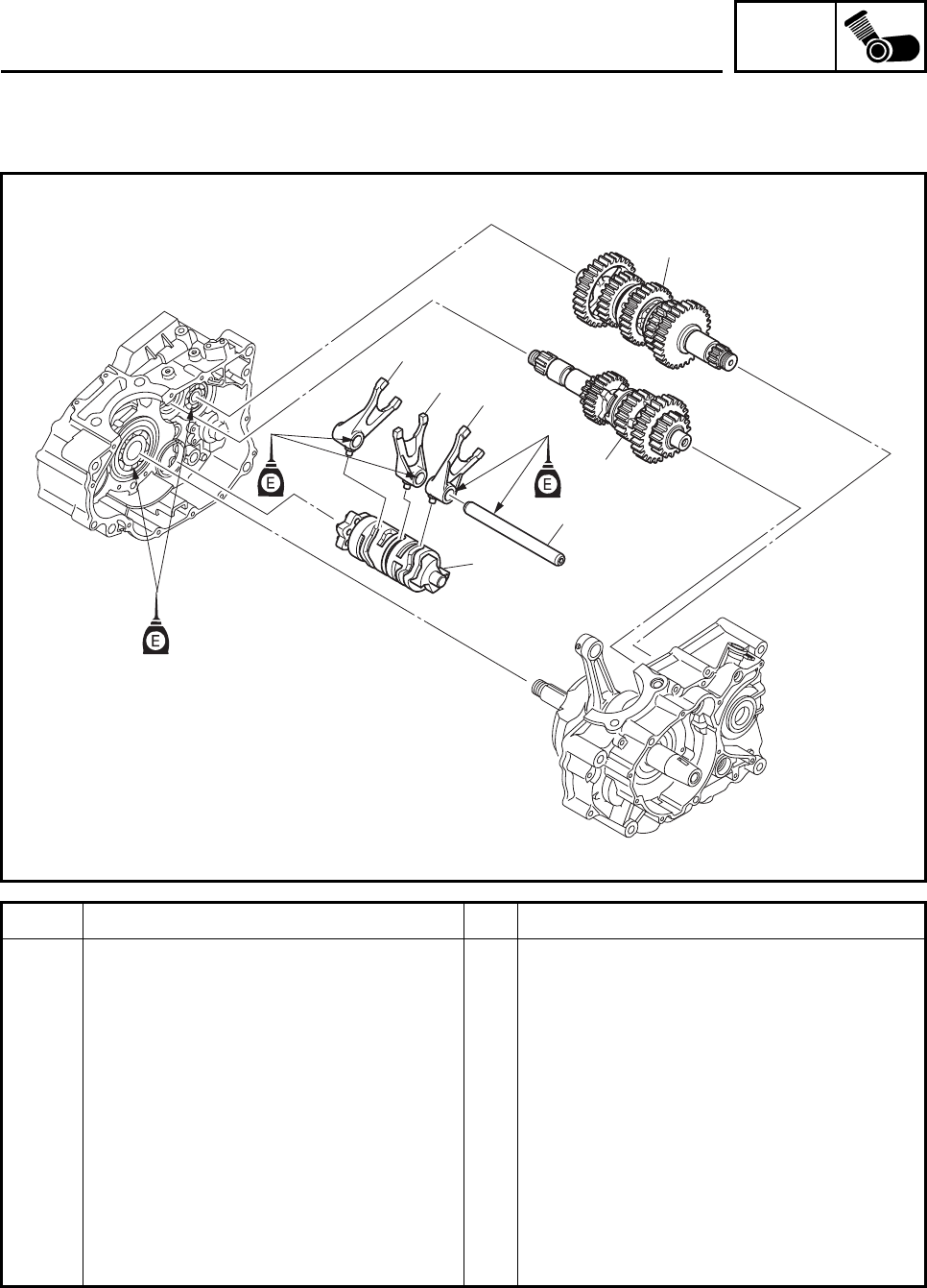
ENG
4-77
TRANSMISSION
Order Job/Parts to remove Q’ty Remarks
Removing the transmission, shift
drum assembly, and shift forks Remove the parts in the order listed.
Crankcase Separate.
Refer to “CRANKCASE”.
1 Shift fork guide bar 1
2 Shift drum assembly 1
3 Shift fork-3 (R) 1
4 Shift fork-2 (C) 1
5 Shift fork-1 (L) 1
6 Main axle assembly 1
7 Drive axle assembly 1
For installation, reverse the removal
procedure.
1
3
45
2
6
7
TRANSMISSION
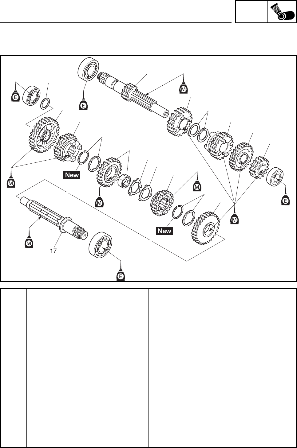
ENG
4-78
Order Job/Parts to remove Q’ty Remarks
Disassembling the transmission Remove the parts in the order listed.
1 2nd pinion gear 1
2 5th pinion gear 1
3 3rd pinion gear 1
4 Circlip/washer 1/1
5 4th pinion gear 1
6 Main axle 1
7 Plain washer 1
8 1st wheel gear 1
9 4th wheel gear 1
10 Circlip/washer 1/1
11 3rd wheel gear/collar 1/1
12 Claw washer 1 1
13 Claw washer 2 1
14 5th wheel gear 1
15 Circlip/washer 1/1
16 2nd wheel gear 1
7
8
9
10
11
12 13 14
15
1
2
5
4
3
6
16
TRANSMISSION
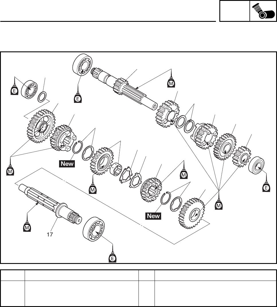
ENG
4-79
Order Job/Parts to remove Q’ty Remarks
17 Drive axle 1
For installation, reverse the removal
procedure.
7
8
9
10
11
12 13 14
15
1
2
5
4
3
6
16
TRANSMISSION
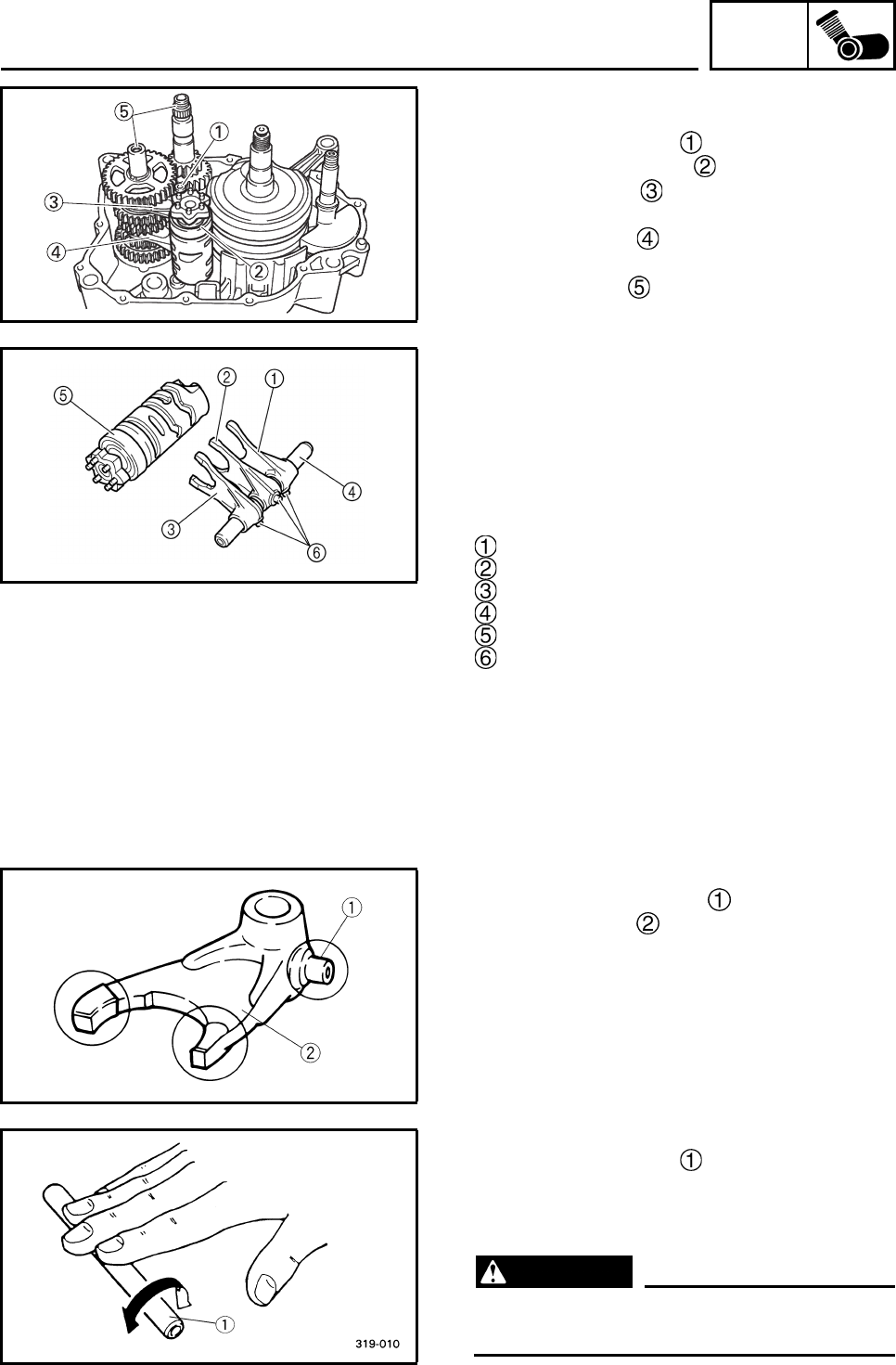
ENG
4-80
REMOVING THE TRANSMISSION
1. Remove:
• Shift fork guide bar
• Shift drum assembly
• Shift fork 3 (R)
• Shift fork 2 (C)
• Shift fork 1 (L)
2. Remove:
• Transmission
CHECKING THE SHIFT FORKS
The following procedure applies to all of the
shift forks.
1. Check:
• Shift fork movement
(along the shift fork guide bar)
Rough movement → Replace the shift forks
and shift fork guide bar as a set.
Shift fork 3 (R)
Shift fork 2 (C)
Shift fork 1 (L)
Shift fork guide bar
Shift drum assembly
Shift fork cam follower
2. Check:
• Shift fork cam follower
• Shift fork pawl
Bends/damage/scoring/wear → Replace
the shift fork.
3. Check:
• Shift fork guide bar
Roll the shift fork guide bar on a flat sur-
face.
Bends → Replace.
WARNING
Do not attempt to straighten a bent shift
fork guide bar.
TRANSMISSION
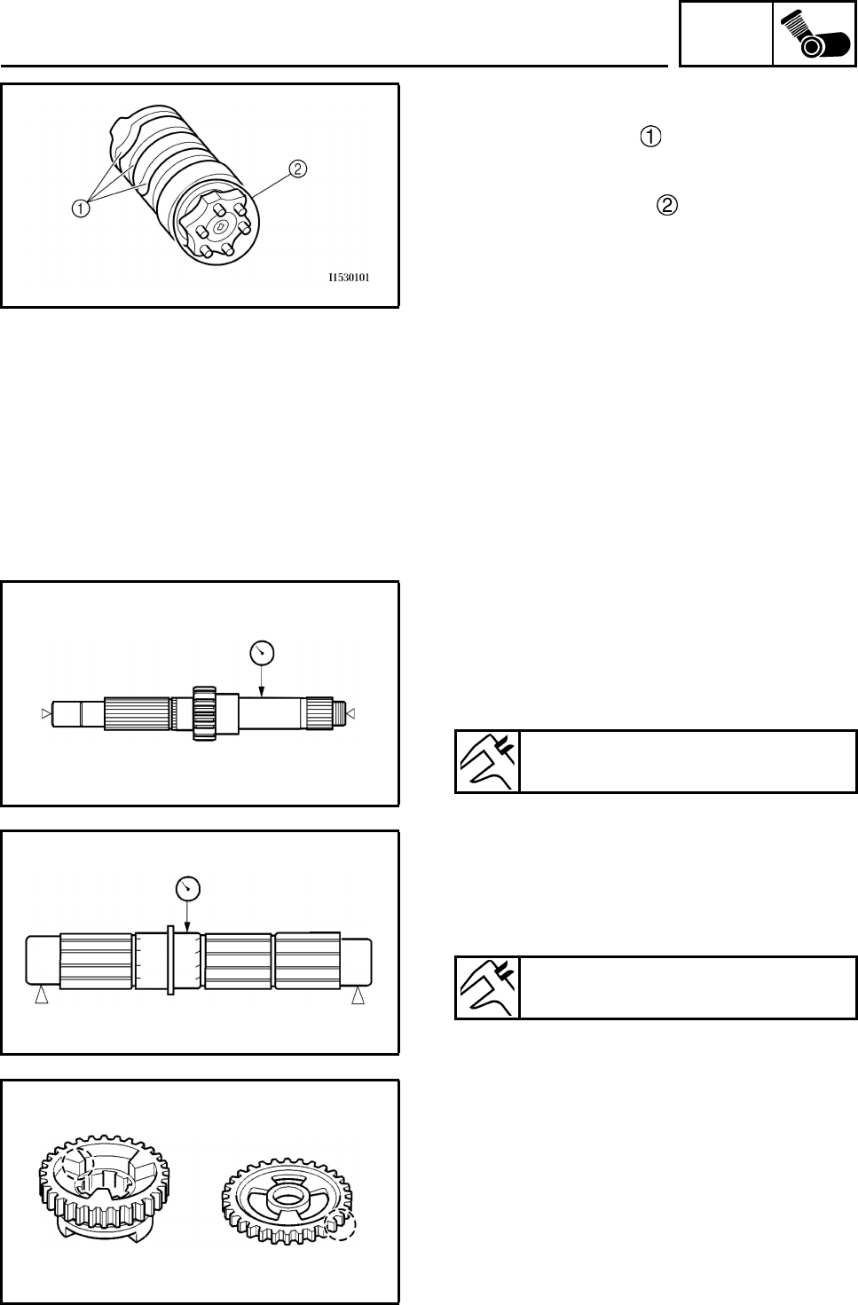
ENG
4-81
CHECKING THE SHIFT DRUM ASSEMBLY
1. Check:
• Shift drum groove
Damage/scratches/wear → Replace the
shift drum assembly.
• Shift drum segment
Damage/wear → Replace the shift drum
assembly.
• Shift drum bearing
Damage/pitting → Replace the shift drum
assembly.
CHECKING THE TRANSMISSION
1. Measure:
• Main axle runout
(with a centering device and dial gauge)
Out of specification → Replace the main
axle.
2. Measure:
• Drive axle runout
(with a centering device and dial gauge)
Out of specification → Replace the drive
axle.
3. Check:
• Transmission gears
Blue discoloration/pitting/wear → Replace
the defective gear(s).
• Transmission gear dogs
Cracks/damage/rounded edges →
Replace the defective gear(s).
Main axle runout limit
0.06 mm (0.0024 in)
Drive axle runout limit
0.06 mm (0.0024 in)
TRANSMISSION
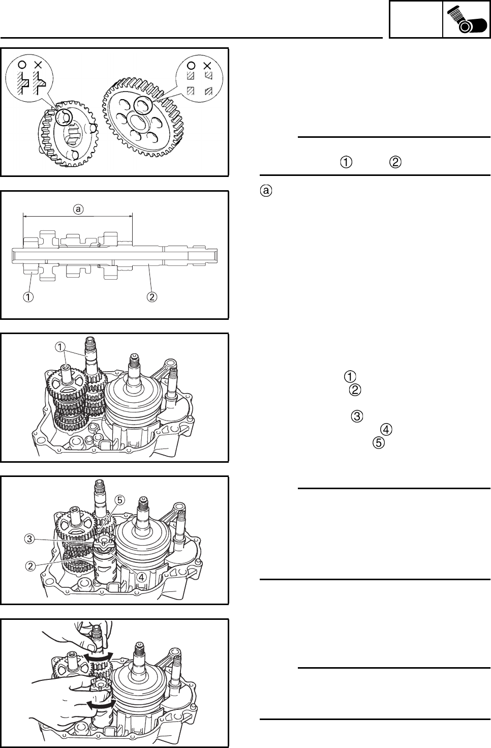
ENG
4-82
4. Check:
• Transmission gear engagement
(each pinion gear to its respective wheel
gear)
Incorrect → Reassemble the transmission
axle assemblies.
N
O
TE:N
O
TE:
When reassembling the main axle, press the
2nd pinion gear onto it as shown.
102.2 ~ 102.4 mm (4.02 ~ 4.03 in)
5. Check:
• Transmission gear movement
Rough movement → Replace the defective
part(s).
6. Check:
•Circlips
Bends/damage/looseness → Replace.
INSTALLING THE SHIFT FORKS AND SHIFT
DRUM ASSEMBLY
1. Install:
• Transmission
• Shift fork 1 (L)
• Shift fork 2 (C)
• Shift fork 3 (R)
• Shift drum assembly
• Shift fork guide bar
•Spacer
• Right crankcase
N
O
TE:N
O
TE:
• The embossed marks on the shift forks
should face towards the left side of the engine
and be in the following sequence: “L”, “C”, “R”.
• The grooved side of the shift fork guide bar
should face towards the right side of the
engine.
2. Check:
• Shift cam operation
Unsmoothy operation → Repair.
N
O
TE:N
O
TE:
Check the transmission and shift forks for
smooth operation by turning the shift cam with
your hand.
TRANSMISSION
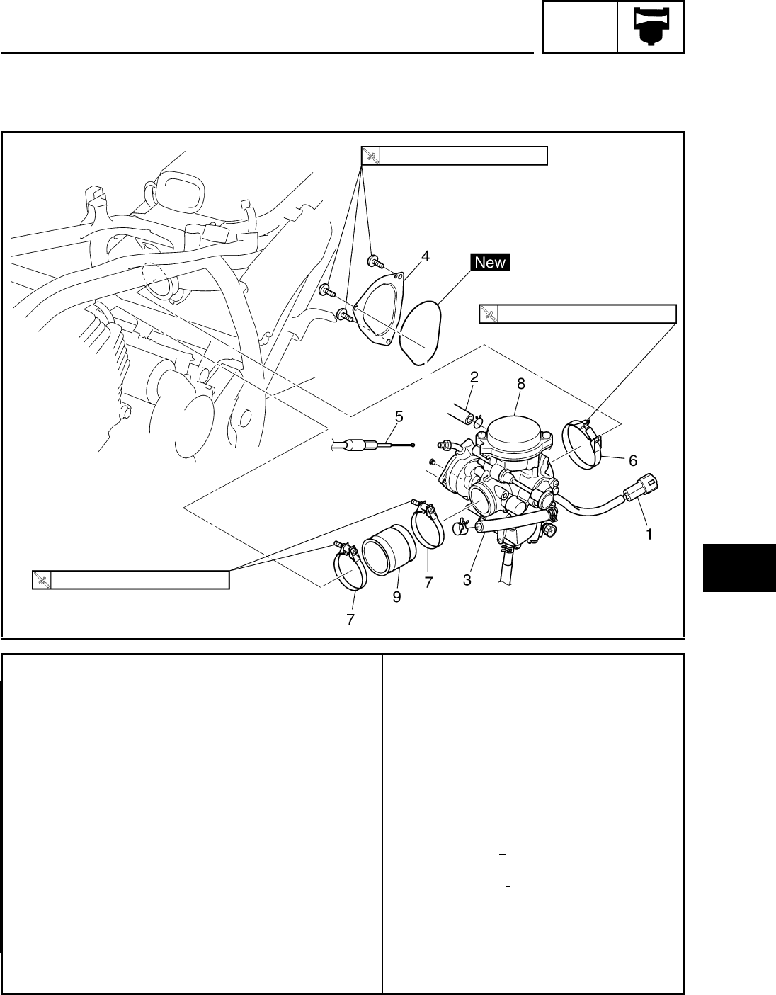
CARB
5-1
1
2
3
4
5
6
7
8
EBS00141 CARBURETOR
CARBURETOR
Order Job/Part Q’ty Remarks
Removing a carburetor Remove the parts in the order listed.
Seat/front fender/rear fender/air filter
case Refer to “SEAT, FENDERS AND FUEL
TANK” in chapter 3.
1 Carburetor warmer coupler 1 Disconnect.
2 Air vent hose 1 Disconnect.
3 Fuel hose (carburetor side) 1
4 Throttle cable cover 1
5 Throttle cable 1
6 Clamp 1 Loosen.
7 Clamp 2 Loosen.
8Carburetor 1
9 Carburetor joint 1
For installation, reverse the removal
procedure.
2 Nm (0.2 m•kg, 1.5 ft•lb)
3.5 Nm (0.4 m•kg, 2.6 ft•lb)
3.5 Nm (0.4 m•kg, 2.6 ft•lb)
Refer to “INSTALLING
THE CARBURETOR
JOINT” and “INSTALL-
ING THE CARBURE-
TOR”.
CARBURETOR
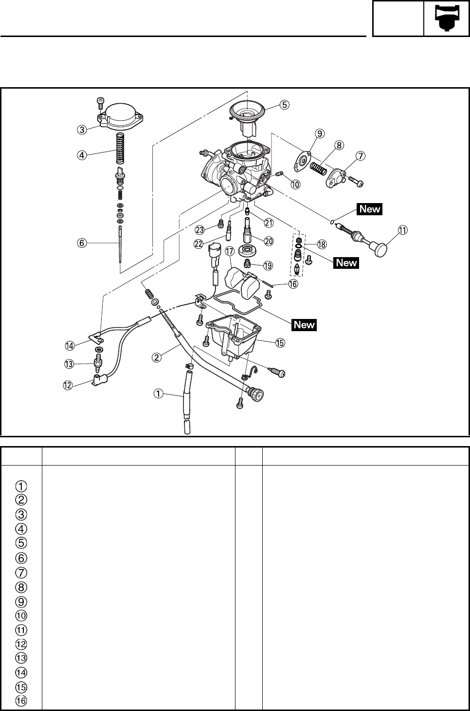
CARB
5-2
EBS00144
Order Job/Part Q’ty Remarks
Disassembling the carburetor Remove the parts in the order listed.
Drain hose 1
Throttle stop screw 1
Cover 1
Diaphragm spring 1
Piston valve 1
Jet needle 1
Cover 1
Spring 1
Coasting enricher diaphragm 1
Coasting enricher jet (P. A. J. 2) 1
Starter plunger 1
Carburetor warmer positive lead 1
Carburetor warmer 1
Carburetor warmer negative lead 1
Float chamber 1
Float pin 1
CARBURETOR
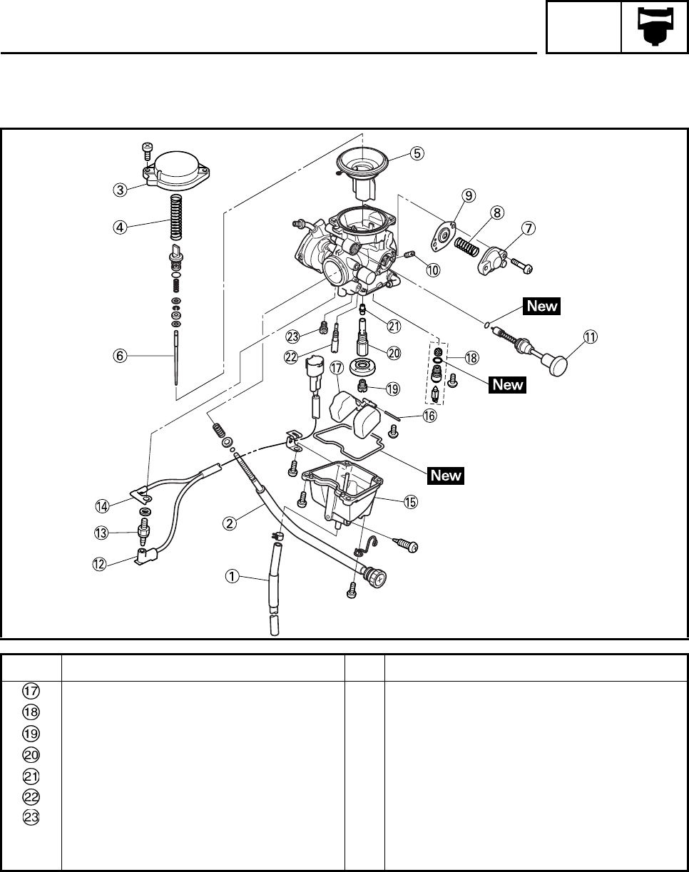
CARB
5-3
Order Job/Part Q’ty Remarks
Float 1
Needle valve seat set 1
Main jet 1
Needle jet holder 1
Needle jet 1
Pilot jet 1
Starter jet 1
For assembly, reverse the disassembly
procedure.
CARBURETOR
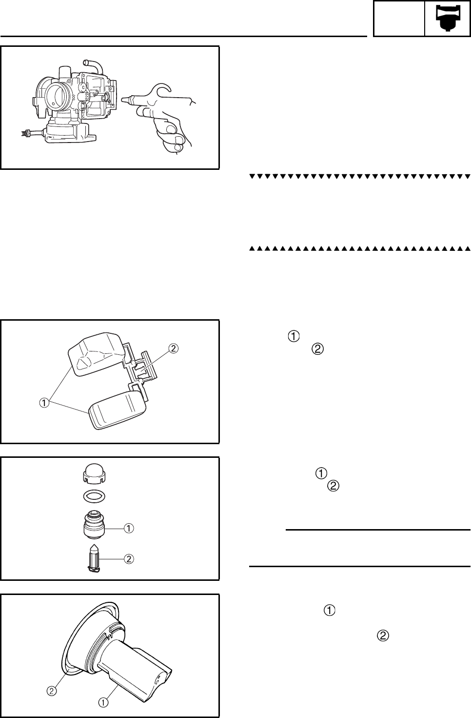
CARB
5-4
EBS00148
CHECKING THE CARBURETOR
1. Check:
• carburetor body
• float chamber
Cracks/damage → Replace.
• fuel passage
Contamination → Clean as indicated.
• fuel chamber body
Contamination → Clean.
a. Wash the carburetor in a petroleum based
solvent. Do not use any caustic carburetor
cleaning solution.
b. Blow out all of the passages and jets with
compressed air.
2. Check:
• float
• float tang
Damage → Replace.
3. Check:
• valve seat
• needle valve
Contamination → Clean.
Wear/damage → Replace as a set.
N
O
TE:N
O
TE:
Always replace the valve seat, needle valve
and O-ring as a set.
4. Check:
• piston valve
Scratches/wear/damage → Replace.
• piston valve diaphragm
Cracks/tears → Replace.
CARBURETOR
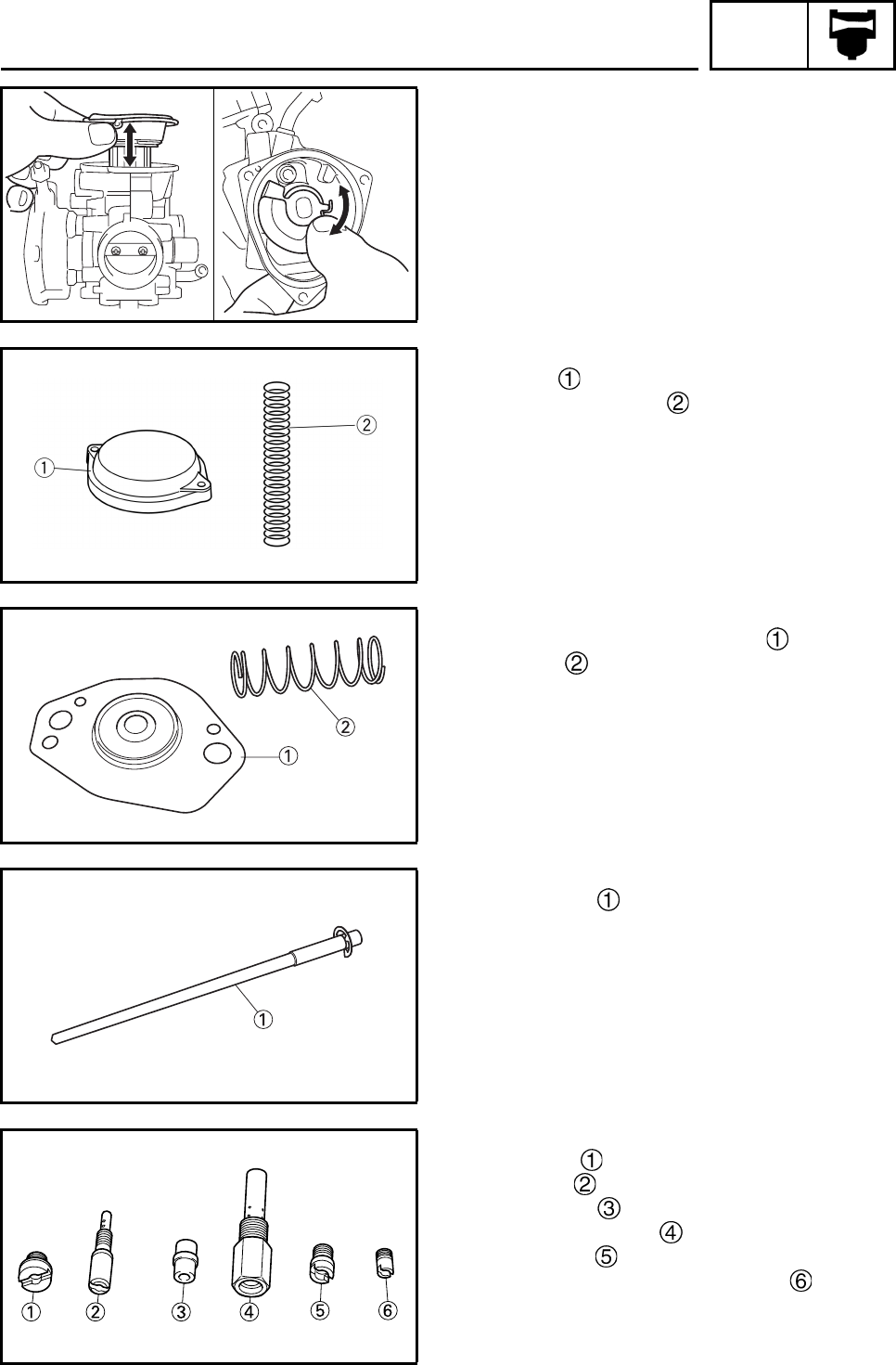
CARB
5-5
5. Check:
• piston valve movement
Sticks → Replace.
Insert the piston valve into the carburetor
body, and check for free movement.
6. Check:
• throttle valve movement
Sticks → Replace.
7. Check:
•cover
• diaphragm spring
Cracks/damage → Replace.
8. Check:
• coasting enricher diaphragm
• spring
Cracks/damage → Replace.
9. Check:
• jet needle
Bends/wear/damage → Replace.
• clip groove
Free play/wear → Replace.
10.Check:
• main jet
• pilot jet
• needle jet
• needle jet holder
• starter jet
• coasting enricher jet (P. A. J. 2)
Bends/wear/damage → Replace.
Blockage → Blow out the jets with com-
pressed air.
CARBURETOR
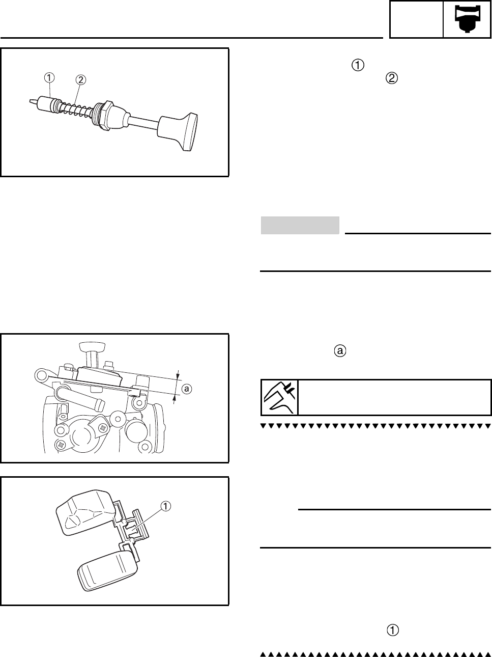
CARB
5-6
11.Check:
• starter plunger
• starter plunger spring
Bends/cracks/damage → Replace.
EBS00150
ASSEMBLING THE CARBURETOR
CAUTION:
Before reassembling, wash all of the parts
in a clean petroleum based solvent.
1. Measure:
• float height
Out of specification → Adjust.
a. Hold the carburetor in an upside down posi-
tion.
b. Measure the distance from the front mating
surface of the float chamber (gasket
removed) to the top of the float.
N
O
TE:N
O
TE:
The float arm should be resting on the needle
valve, but not compressing it.
c. If the float height is not within the specifica-
tion, check the valve seat and needle valve.
d. If either is worn, replace the valve seat,
needle valve and O-ring as a set.
e. If both are fine, adjust the float height by
bending the float tang on the float.
f. Recheck the float height.
Float height (F.H)
13.0 mm (0.51 in)
CARBURETOR
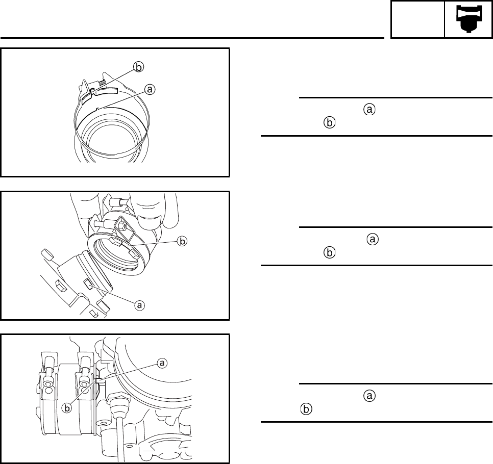
CARB
5-7
INSTALLING THE CARBURETOR JOINT
1. Install:
•clamp
N
O
TE:N
O
TE:
Align the projection on the carburetor joint
with the slot in the clamp.
2. Install:
• carburetor joint
N
O
TE:N
O
TE:
Align the projection on the cylinder head
with the slot in the carburetor joint.
INSTALLING THE CARBURETOR
1. Install:
•carburetor
N
O
TE:N
O
TE:
Align the projection on the carburetor with
the slot in the carburetor joint.
2. Install:
• throttle cable
• throttle cable cover
3. Adjust:
• throttle lever free play
Refer to “ADJUSTING THE THROTTLE
LEVER FREE PLAY” in chapter 3.
4. Adjust:
• engine idling speed
Refer to “ADJUSTING THE ENGINE
IDLING SPEED” in chapter 3.
CARBURETOR
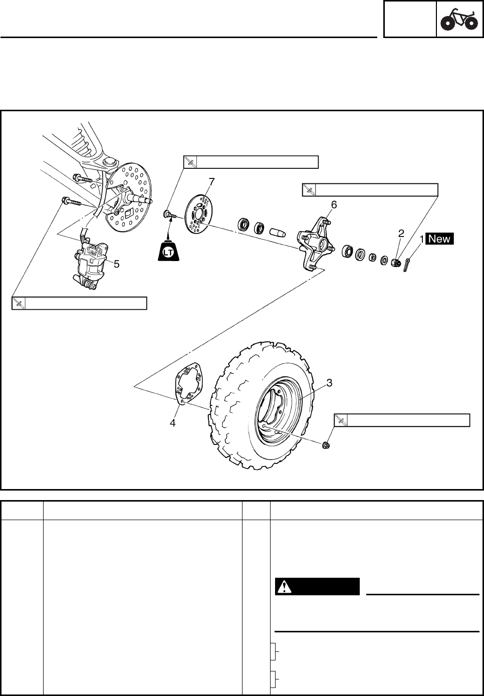
CHAS
6-1
EBS00378 CHASSIS
FRONT AND REAR WHEELS
FRONT WHEELS
Order Job/Part Q’ty Remarks
Removing the front wheels Remove the parts in the order listed.
The following procedure applies to both of
the front wheels.
Place the machine on a level surface.
WARNING
Securely support the machine so there
is no danger of it falling over.
1 Cotter pin 1
2Axle nut 1
3 Front wheel 1
4 Brake disc guard (outer) 1
28 Nm (2.8 m•kg, 21 ft•lb)
28 Nm (2.8 m•kg, 21 ft•lb)
70 Nm (7.0 m•kg, 52 ft•lb)
45 Nm (4.5 m•kg, 33 ft•lb)
Refer to “INSTALLING THE WHEEL
HUBS”.
Refer to “INSTALLING THE FRONT
WHEELS”.
FRONT AND REAR WHEELS
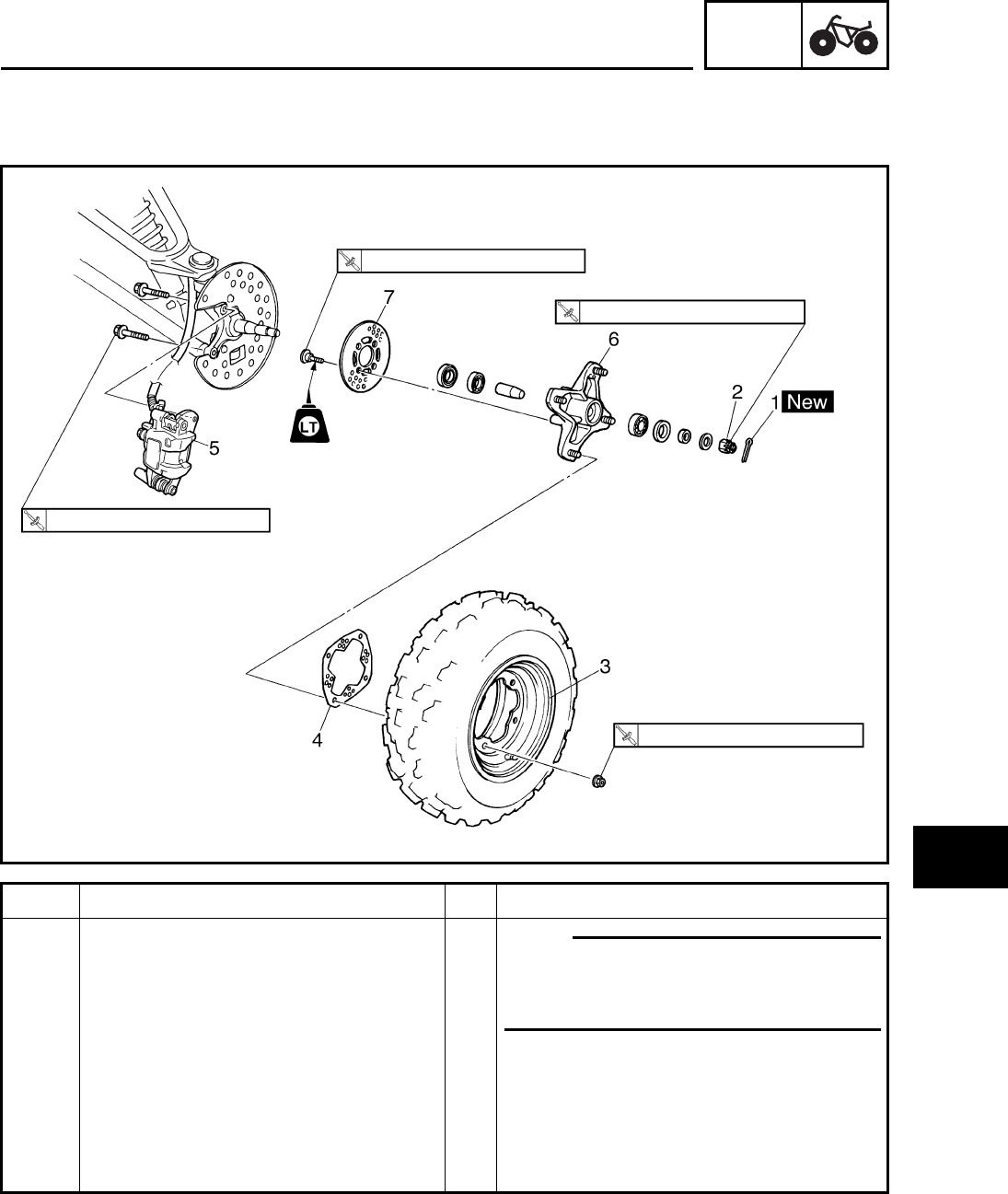
CHAS
6-2
1
2
3
4
5
6
7
8
Order Job/Part Q’ty Remarks
5 Brake caliper assembly 1 N
O
TE:N
O
TE:
Do not squeeze the brake lever when the
brake caliper is off of the brake discs as
the brake pads will be forced shut.
6 Wheel hub 1 Refer to “INSTALLING THE WHEEL HUB
BEARINGS”.
7 Brake disc 1 Rear to “INSTALLING FRONT BRAKE
DISCS”.
For installation, reverse the removal
procedure.
28 Nm (2.8 m•kg, 21 ft•lb)
28 Nm (2.8 m•kg, 21 ft•lb)
70 Nm (7.0 m•kg, 52 ft•lb)
45 Nm (4.5 m•kg, 33 ft•lb)
FRONT AND REAR WHEELS
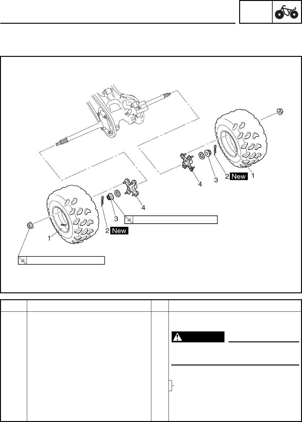
CHAS
6-3
REAR WHEELS
Order Job/Part Q’ty Remarks
Removing the rear wheels Remove the parts in the order listed.
Place the machine on a level surface.
WARNING
Securely support the machine so there
is no danger of it falling over.
1 Rear wheel 2
2 Cotter pin 2
3Axle nut 2
4 Wheel hub 2
For installation, reverse the removal
procedure.
45 Nm (4.5 m•kg, 33 ft•lb)
120 Nm (12.0 m•kg, 89 ft•lb)
Refer to “INSTALLING THE WHEEL
HUBS”.
FRONT AND REAR WHEELS
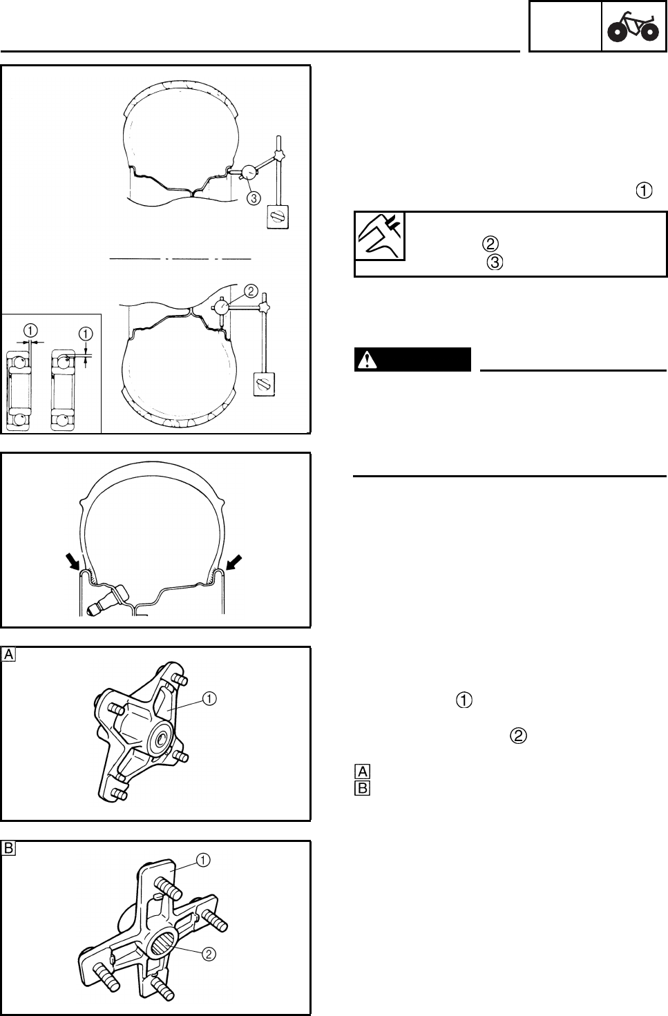
CHAS
6-4
EBS00383
CHECKING THE WHEELS
1. Check:
• wheels
2. Measure:
• wheel runout
Over the specified limit → Replace the
wheel or check the wheel bearing play .
3. Check:
• wheel balance
Out of balance → Adjust.
WARNING
After replacing the tire, ride conservatively
to allow the tire to be properly seated in the
rim. Failure to do so may cause an accident
resulting in machine damage and possible
operator injury.
EBS00385
CHECKING THE WHEEL HUBS
1. Check:
• wheel hubs
Cracks/damage → Replace.
• splines (wheel hub)
Wear/damage → Replace the wheel hub.
Front
Rear
Wheel runout limit
Radial : 2.0 mm (0.08 in)
Lateral : 2.0 mm (0.08 in)
FRONT AND REAR WHEELS
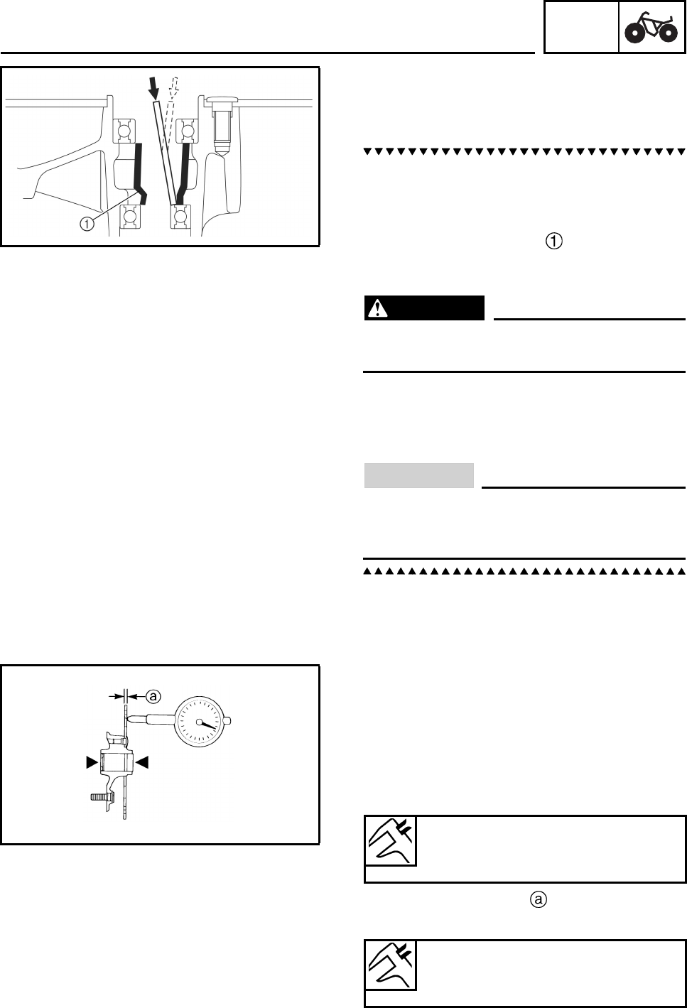
CHAS
6-5
2. Check:
• wheel bearings
Wheel hub play/wheel turns roughly →
Replace.
a. Clean wheel hub exterior.
b. Drive bearing out by pushing spacer aside
and tapping around perimeter of bearing
inner race. Use soft metal drift punch and
hammer. The spacer “floats” between
bearings. Remove both bearings as
described.
WARNING
Eye protection is recommended when
using striking tools.
c. To install the wheel bearings, reverse the
above sequence. Use a socket that
matches outside diameter of bearing outer
race to drive in bearing.
CAUTION:
Do not strike the center race or balls of the
bearing. Contact should be made only with
the outer race.
EBS00389
CHECKING THE BRAKE DISCS
1. Check:
• brake discs
Galling/damage → Replace.
2. Measure:
• brake disc deflection
Out of specification → Replace.
• brake disc thickness
Out of specification → Replace.
Brake disc maximum deflection
Front: 0.15 mm (0.006 in)
Rear: 0.15 mm (0.006 in)
Brake disc minimum thickness
Front: 3 mm (0.12 in)
Rear: 3.5 mm (0.14 in)
FRONT AND REAR WHEELS
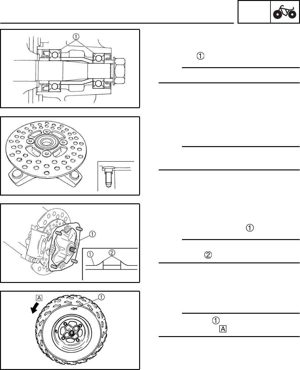
CHAS
6-6
INSTALLING THE FRONT WHEEL HUB
BEARINGS
1. Install:
• bearings
N
O
TE:N
O
TE:
Face the oil seal side of the bearing inward.
INSTALLING THE FRONT BRAKE DISCS
1. Install:
•brake discs
N
O
TE:N
O
TE:
Install the brake disc with its spot-faced side
facing the bolt heads.
EBS00392
INSTALLING THE FRONT WHEELS
1. Install:
• brake disc guards (outer)
N
O
TE:N
O
TE:
Install the brake disc guard (outer) with
punched burrs on the wheel hub side.
2. Install:
• wheels
N
O
TE:N
O
TE:
The arrow mark on the must point in the
direction of rotation of the wheel.
FRONT AND REAR WHEELS
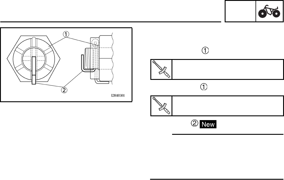
CHAS
6-7
EBS00390
INSTALLING THE WHEEL HUBS
1. Install:
• front axle nuts
• rear axle nuts
• cotter pins
N
O
TE:N
O
TE:
• Do not loosen the axle nut after torquing it. If
the axle nut groove is not aligned with the cot-
ter pin hole, align the groove with the hole by
tightening the axle nut.
• Bend the longer cotter pin up.
Front axle nut
70 Nm (7.0 m•kg, 52 ft•lb)
Rear axle nut
120 Nm (12.0 m•kg, 89 ft•lb)
FRONT AND REAR WHEELS
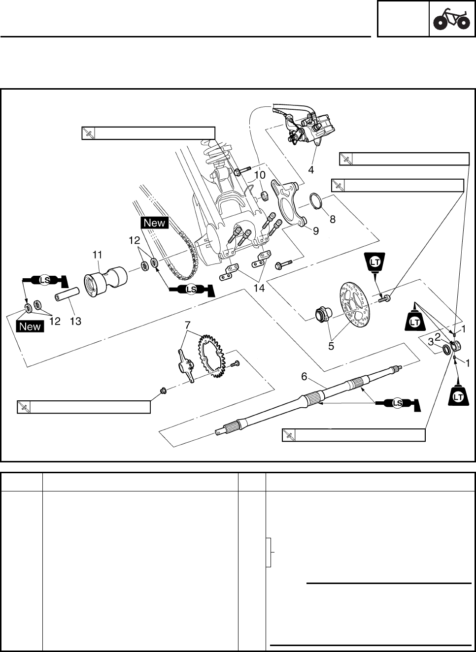
CHAS
6-8
EBS00382
REAR AXLE AND REAR AXLE HUB
Order Job/Part Q’ty Remarks
Removing the rear axle and rear axle
hub Remove the parts in the order listed.
Rear wheels/rear wheel hubs Refer to “FRONT AND REAR WHEELS”.
1Bolt 2
2Nut 1
3 Conical spring washer 1
4 Brake caliper 1 N
O
TE:N
O
TE:
Do not apply the brake pedal and do not
use the parking brake when the brake cal-
iper is off of the brake disc as the brake
pad will be force shut.
34 Nm (3.4 m•kg, 25 ft•lb)
7 Nm (0.7 m•kg, 5.2 ft•lb)
28 Nm (2.8 m•kg, 21 ft•lb)
55 Nm (5.5 m•kg, 41 ft•lb)
140 Nm (14.0 m•kg, 103 ft•lb)
Refer to “REMOVING THE REAR
AXLE” and “INSTALLING THE REAR
AXLE”.
REAR AXLE AND REAR AXLE HUB
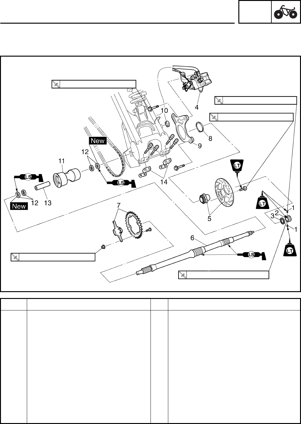
CHAS
6-9
Order Job/Part Q’ty Remarks
5 Brake disc/brake disc bracket 1/1
6 Rear axle 1 Refer to “REMOVING THE REAR AXLE”.
7 Driven sprocket/sprocket bracket 1/1 Refer to “INSTALLING THE DRIVEN
SPROCKET”.
8Circlip 1
9 Brake caliper bracket 1
10 Collar 1
11 Rear axle hub 1
12 Bearing/oil seal 2/2
13 Spacer 1
14 Dust cover 1
For installation, reverse the removal
procedure.
34 Nm (3.4 m•kg, 25 ft•lb)
7 Nm (0.7 m•kg, 5.2 ft•lb)
28 Nm (2.8 m•kg, 21 ft•lb)
55 Nm (5.5 m•kg, 41 ft•lb)
140 Nm (14.0 m•kg, 103 ft•lb)
REAR AXLE AND REAR AXLE HUB
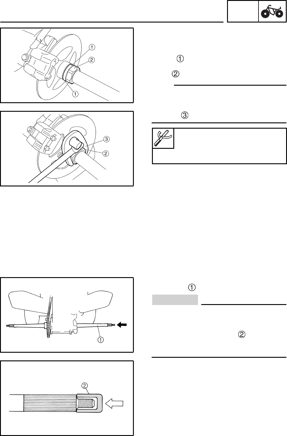
CHAS
6-10
EBS00393
REMOVING THE REAR AXLE
1. Place the machine on a level surface.
2. Loosen:
• bolts
3. Remove:
•nut
N
O
TE:N
O
TE:
• Apply the brake pedal so that the rear axle
does not turn, when loosening the nut.
• Use the PTT wrench 46 or axle nut wrench
(46 mm) .
4. Elevate the rear wheels by placing the suit-
able stand under the frame.
5. Remove:
• rear wheels
• wheel hubs
•nuts
• washers
6. Remove:
• rear axle
CAUTION:
• Never directly tap the axle end with a ham-
mer, since this will result in damage to the
axle thread and spline.
• Attach a suitable socket on the axle
end and tap it with a soft hammer, then
pull out the rear axle to the right.
PTT wrench 46
90890-06588
Axle nut wrench (46 mm)
YM-37134
REAR AXLE AND REAR AXLE HUB
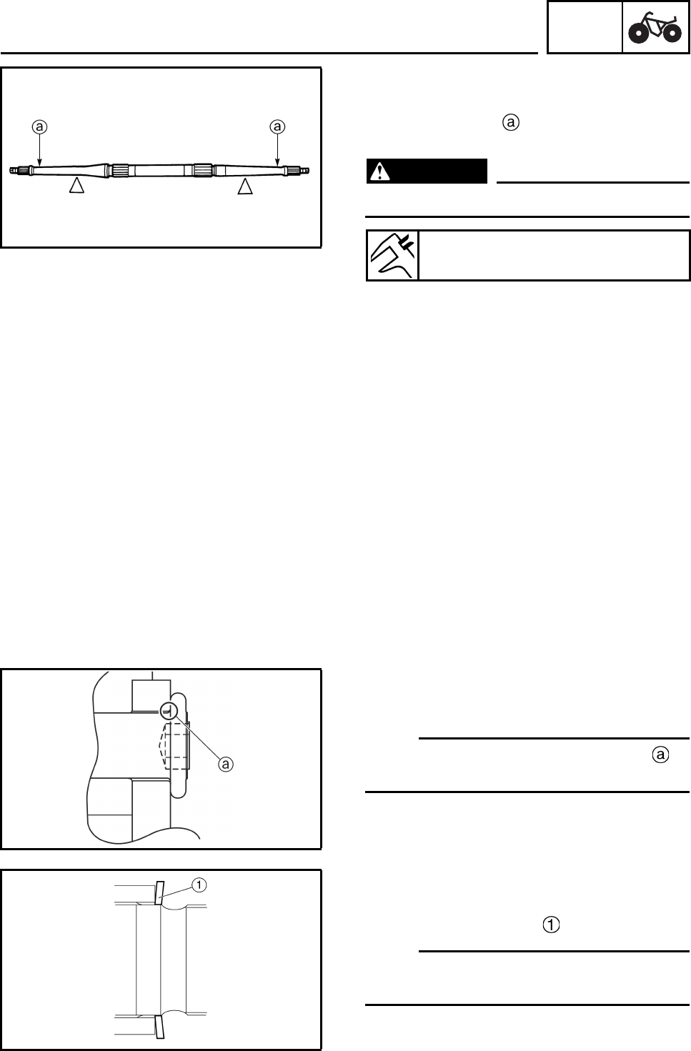
CHAS
6-11
EBS00395
CHECKING THE REAR AXLE
1. Check:
• rear axle runout
Out of specification → Replace.
WARNING
Do not attempt to straighten a bent axle.
CHECKING THE DRIVEN SPROCKET
1. Check:
• driven sprocket
Refer to “REAR SHOCK ABSORBER,
SWINGARM AND DRIVE CHAIN”.
CHECKING THE BRAKE DISC
1. Check:
•brake disc
Refer to “FRONT AND REAR WHEELS”.
INSTALLING THE DRIVEN SPROCKET
1. Install:
• driven sprocket
N
O
TE:N
O
TE:
Make sure that the blunt-edged corner of
the driven sprocket is facing outward.
EBS00397
INSTALLING THE REAR AXLE
1. Install:
• conical spring washer
N
O
TE:N
O
TE:
Install the conical spring washer with the con-
vex side of the washer facing inward as shown.
Rear axle runout limit
1.5 mm (0.06 in)
REAR AXLE AND REAR AXLE HUB
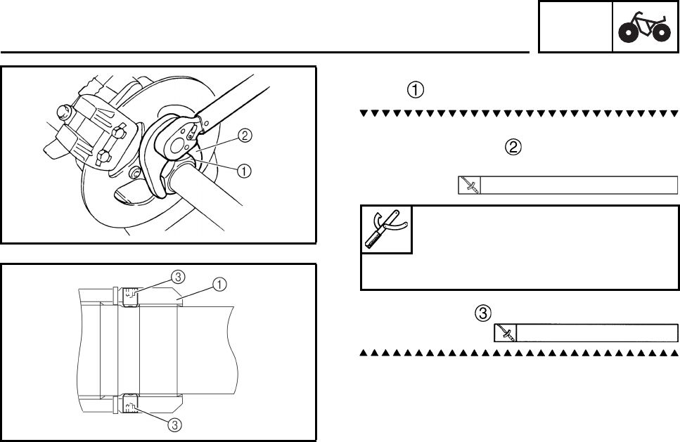
CHAS
6-12
2. Tighten:
•nut
a. Tighten the nut with PTT wrench 46 or rear
axle nut wrench to specification while
holding the rear axle.
b. Tighten bolts .
140 Nm (14.0 m•kg, 103 ft•lb)
PTT wrench 46
90890-06588
Axle nut wrench (46 mm)
YM-37134
7 Nm (0.7 m•kg, 5.2 ft•lb)
REAR AXLE AND REAR AXLE HUB
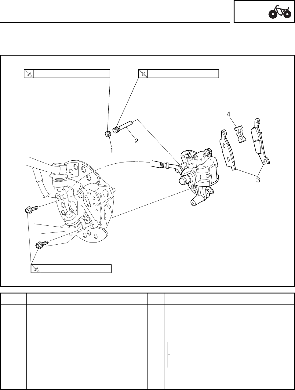
CHAS
6-13
EBS00400
FRONT AND REAR BRAKES
FRONT BRAKE PADS
Order Job/Part Q’ty Remarks
Removing the front brake pads Remove the parts in the order listed.
The following procedure applies to both of
the front brake calipers.
Front wheel Refer to “FRONT AND REAR WHEELS”.
1Bolt 1
2 Brake pad retaining bolt 1
3 Brake pad 2
4 Brake pad spring 1
For installation, reverse the removal
procedure.
2.5 Nm (0.25 m•kg, 1.8 ft•lb) 17 Nm (1.7 m•kg, 13 ft•lb)
28 Nm (2.8 m•kg, 21 ft•lb)
Refer to “REPLACING THE FRONT
BRAKE PADS”.
FRONT AND REAR BRAKES
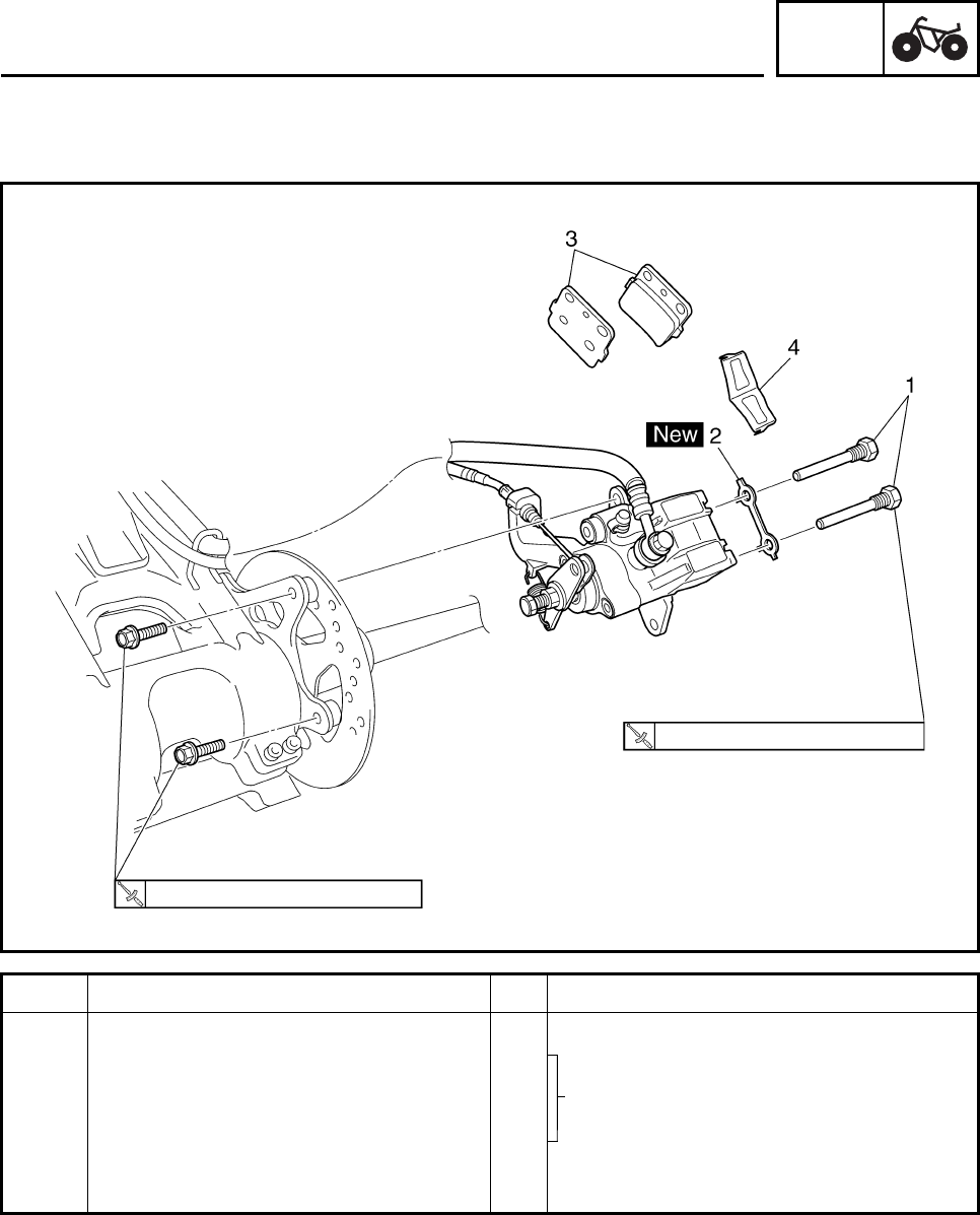
CHAS
6-14
EBS00401
REAR BRAKE PADS
Order Job/Part Q’ty Remarks
Removing the rear brake pads Remove the parts in the order listed.
1 Brake pad retaining bolt 2
2 Lock washer 1
3 Brake pad 2
4 Brake pad spring 1
For installation, reverse the removal
procedure.
34 Nm (3.4 m•kg, 25 ft•lb)
17 Nm (1.7 m•kg, 13 ft•lb)
FRONT AND REAR BRAKES
Refer to “REPLACING THE REAR
BRAKE PADS”.
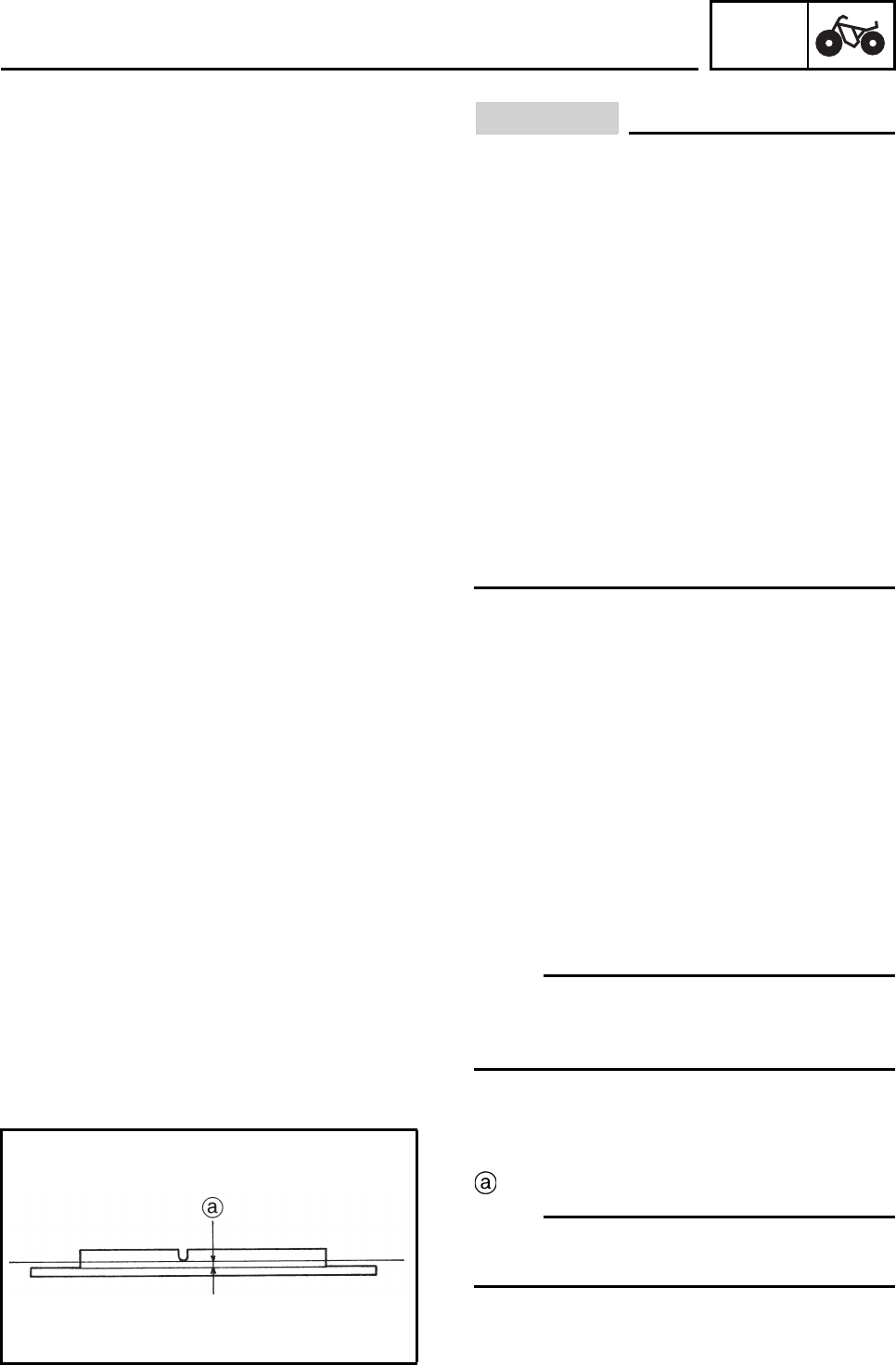
CHAS
6-15
EBS00402
CAUTION:
Disc brake components rarely require dis-
assembly.
DO NOT:
• disassemble components unless abso-
lutely necessary;
• use solvents on internal brake compo-
nents;
• use spent brake fluid for cleaning; (use
only clean brake fluid)
• allow brake fluid to come in contact with
the eyes, as this may cause eye injury;
• splash brake fluid onto painted surfaces
or plastic parts, as this may cause dam-
age;
• disconnect any hydraulic connection, as
this would require the entire brake system
to be disassembled, drained, cleaned,
properly filled and bled after reassembly.
EBS00404
REPLACING THE FRONT BRAKE PADS
The following procedure applies to both of the
front brake calipers.
N
O
TE:N
O
TE:
It is not necessary to disassemble the brake
calipers and brake hoses to replace the brake
pads.
1. Remove:
• brake pads
Wear limit
N
O
TE:N
O
TE:
Replace the brake pads as a set if either is
found to be worn to the wear limit.
FRONT AND REAR BRAKES
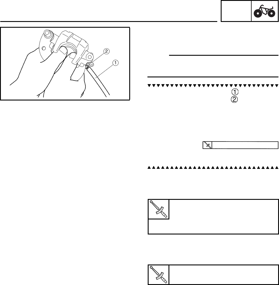
CHAS
6-16
2. Install:
• brake pads
• brake pad spring
N
O
TE:N
O
TE:
Always install new brake pads and brake pad
spring as a set.
a. Connect a suitable hose tightly to the
brake caliper bleed screw . Put the other
end of this hose into an open container.
b. Loosen the brake caliper bleed screw and,
using a finger, push the caliper piston into
the brake caliper.
c. Tighten the brake caliper bleed screw.
d. Install new brake pads and a new brake
pad spring.
3. Install:
• brake pad retaining bolt
• bolt
4. Install:
• brake caliper
• brake caliper mounting bolts
5. Check:
• brake fluid level
Refer to “CHECKING THE BRAKE FLUID
LEVEL” in chapter 3.
6. Check:
• brake lever operation
Soft or spongy feeling → Bleed the brake
system.
Refer to “BLEEDING THE HYDRAULIC
BRAKE SYSTEM” in chapter 3.
5 Nm (0.5 m•kg, 3.7 ft•lb)
Brake pad retaining bolt
17 Nm (1.7 m•kg, 13 ft•lb)
Bolt
3 Nm (0.3 m•kg, 2 ft•lb)
Brake caliper mounting bolt
28 Nm (2.8 m•kg, 21 ft•lb)
FRONT AND REAR BRAKES
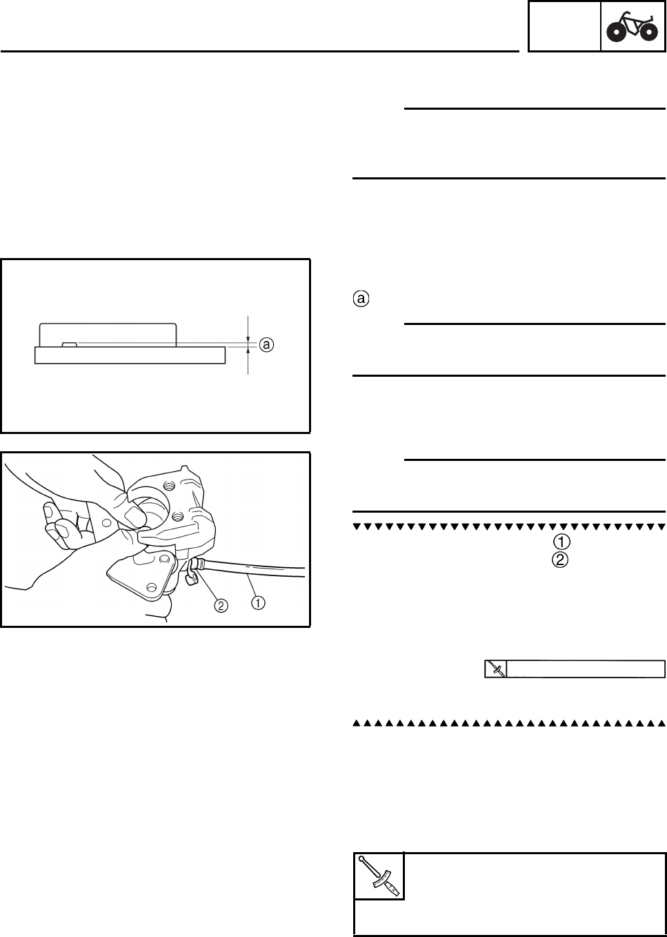
CHAS
6-17
EBS00405
REPLACING THE REAR BRAKE PADS
N
O
TE:N
O
TE:
It is not necessary to disassemble the brake
caliper and brake hose to replace the brake
pads.
1. Remove:
• brake pads
wear limit
N
O
TE:N
O
TE:
Replace the brake pads as a set if either is
found to be worn to the wear limit.
2. Install:
• brake pads
• brake pad spring
N
O
TE:N
O
TE:
Always install new brake pads and brake pad
spring as a set.
a. Connect a suitable hose tightly to the
brake caliper bleed screw . Put the other
end of this hose into an open container.
b. Loosen the brake caliper bleed screw and,
using a finger, push the caliper piston into
the brake caliper.
c. Tighten the brake caliper bleed screw.
d. Install a new brake pad spring and new
brake pads.
3. Install:
• brake pad retaining bolts
(Bend the lock washer tabs along a flat side
of the bolts)
• brake caliper
• brake caliper mounting bolts
4. Check:
• brake fluid level
Refer to “CHECKING THE BRAKE FLUID
LEVEL” in chapter 3.
5 Nm (0.5 m•kg, 3.7 ft•lb)
Brake pad retaining bolt
17 Nm (1.7 m•kg, 13 ft•lb)
Brake caliper mounting bolt
34 Nm (3.4 m•kg, 25 ft•lb)
FRONT AND REAR BRAKES

CHAS
6-18
5. Check:
• brake lever or brake pedal operation
Soft or spongy feeling → Bleed the brake
system.
Refer to “BLEEDING THE HYDRAULIC
BRAKE SYSTEM” in chapter 3.
FRONT AND REAR BRAKES
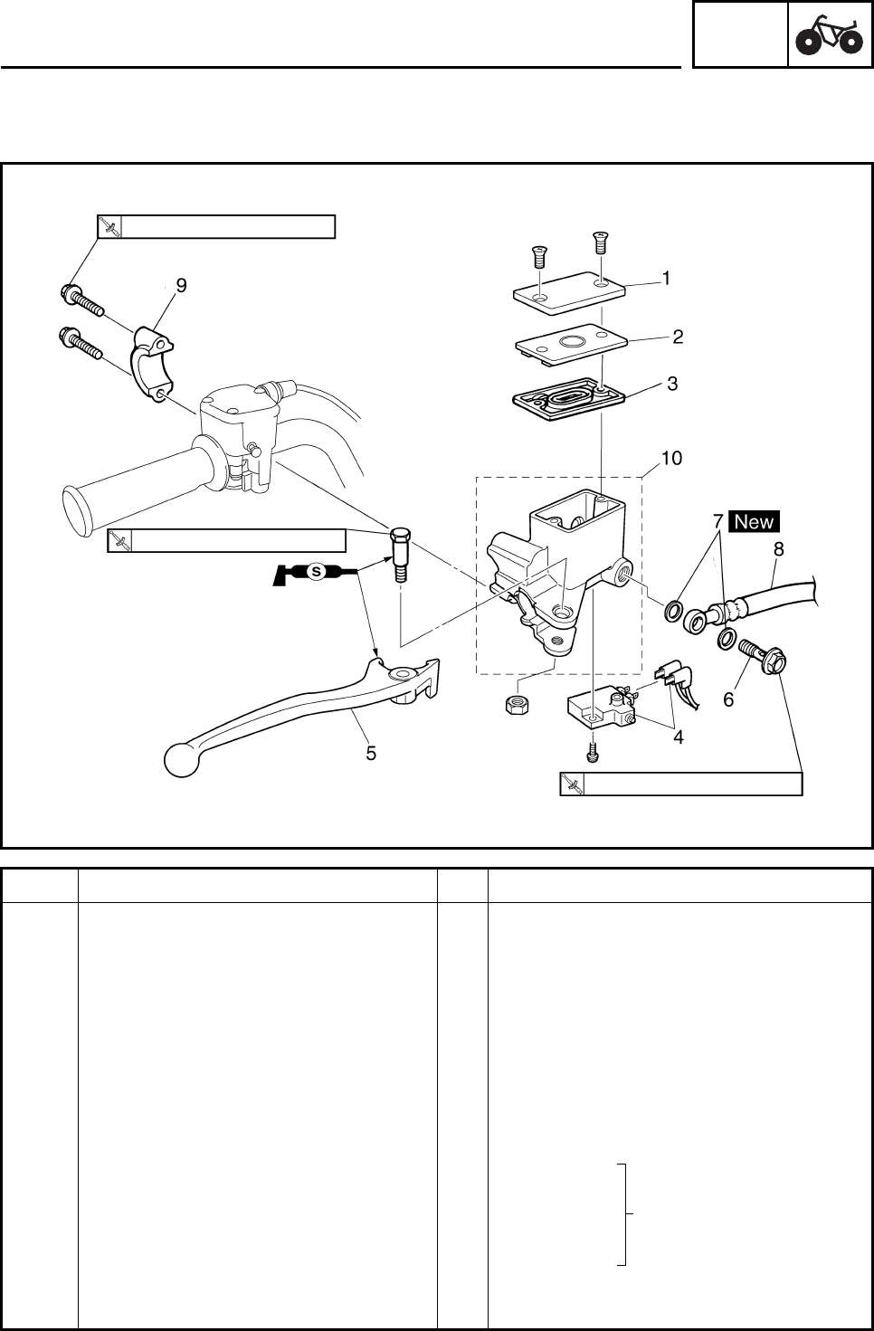
CHAS
6-19
EBS00407
FRONT BRAKE MASTER CYLINDER
Order Job/Part Q’ty Remarks
Removing the front brake master
cylinder Remove the parts in the order listed.
Brake fluid Drain.
Refer to “BLEEDING THE HYDRAULIC
BRAKE SYSTEM” in chapter 3.
1 Brake fluid reservoir cap 1
2 Brake fluid reservoir diaphragm plate 1
3 Brake fluid reservoir diaphragm 1
4 Front brake light switch 1
5Brake lever 1
6 Union bolt 1
7 Copper washer 2
8 Brake hose 1 Disconnect.
9 Brake master cylinder bracket 1
10 Brake master cylinder 1
For installation, reverse the removal
procedure.
7 Nm (0.7 m•kg, 5.2 ft•lb)
6 Nm (0.6 m•kg, 4.4 ft•lb)
27 Nm (2.7 m•kg, 20 ft•lb)
Refer to “INSTALLING
THE FRONT BRAKE
MASTER CYLINDER”.
FRONT AND REAR BRAKES
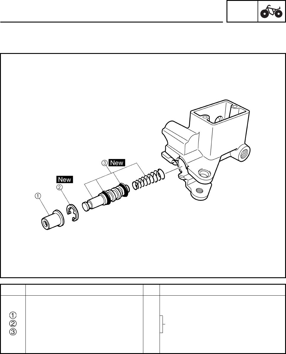
CHAS
6-20
EBS00409
Order Job/Part Q’ty Remarks
Disassembling the front brake
master cylinder Remove the parts in the order listed.
Dust boot 1
Circlip 1
Brake master cylinder kit 1
For assembly, reverse the disassembly
procedure.
Refer to “ASSEMBLING THE FRONT
BRAKE MASTER CYLINDER”.
FRONT AND REAR BRAKES
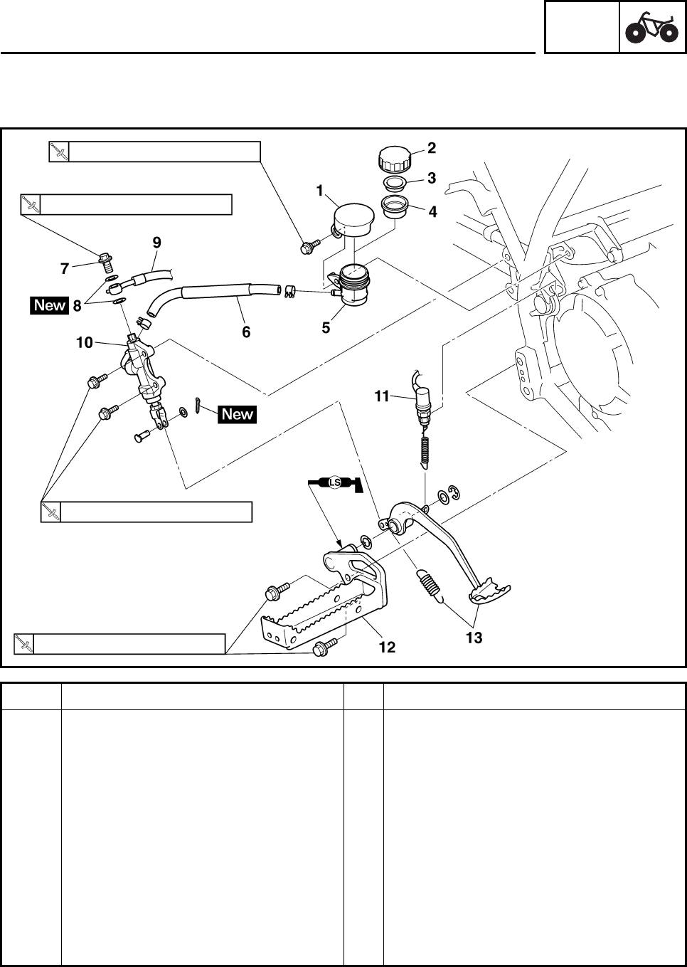
CHAS
6-21
EBS00410
REAR BRAKE MASTER CYLINDER
Order Job/Part Q’ty Remarks
Removing the rear brake master
cylinder Remove the parts in the order listed.
Right foot protector Refer to “SEAT, FENDERS AND FUEL
TANK” in chapter 3.
Brake fluid Drain.
Refer to “BLEEDING THE HYDRAULIC
BRAKE SYSTEM” in chapter 3.
1 Brake fluid reservoir cover 1
2 Brake fluid reservoir cap 1
3 Brake fluid reservoir diaphragm holder 1
4 Brake fluid reservoir diaphragm 1
5 Brake fluid reservoir 1
6 Brake fluid reservoir hose 1
7 Nm (0.7 m•kg, 5.2 ft•lb)
31 Nm (3.1 m•kg, 23 ft•lb)
20 Nm (2.0 m•kg, 15 ft•lb)
73 Nm (7.3 m•kg, 54 ft•lb)
FRONT AND REAR BRAKES
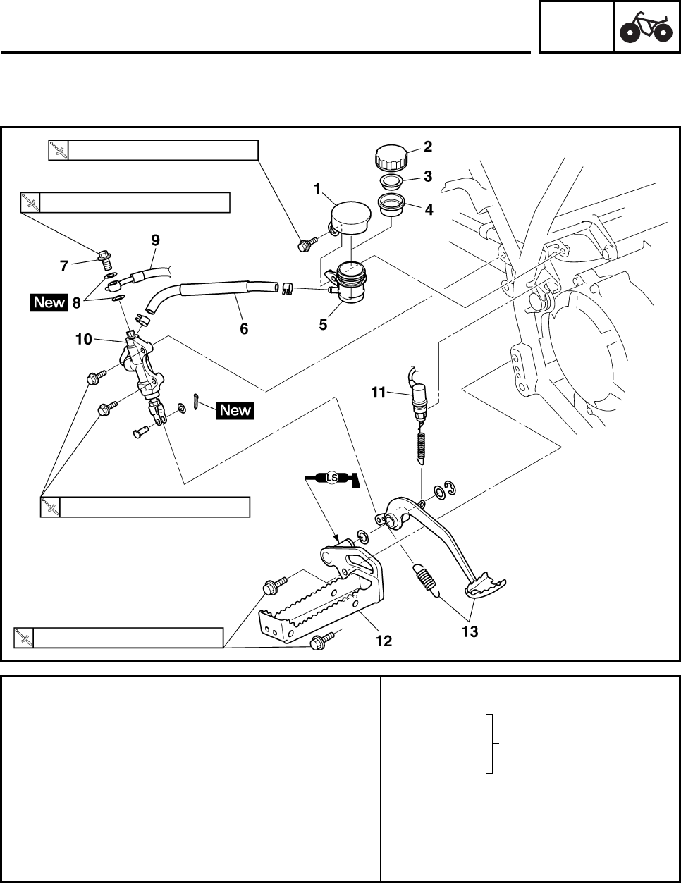
CHAS
6-22
Order Job/Part Q’ty Remarks
7 Union bolt 1
8 Copper washer 2
9 Brake hose 1 Disconnect.
10 Brake master cylinder 1
11 Rear brake light switch 1
12 Right footrest 1
13 Brake pedal/spring 1/1
For installation, reverse the removal
procedure.
7 Nm (0.7 m•kg, 5.2 ft•lb)
31 Nm (3.1 m•kg, 23 ft•lb)
20 Nm (2.0 m•kg, 15 ft•lb)
73 Nm (7.3 m•kg, 54 ft•lb)
Refer to “INSTALLING
THE REAR BRAKE
MASTER CYLINDER”.
FRONT AND REAR BRAKES
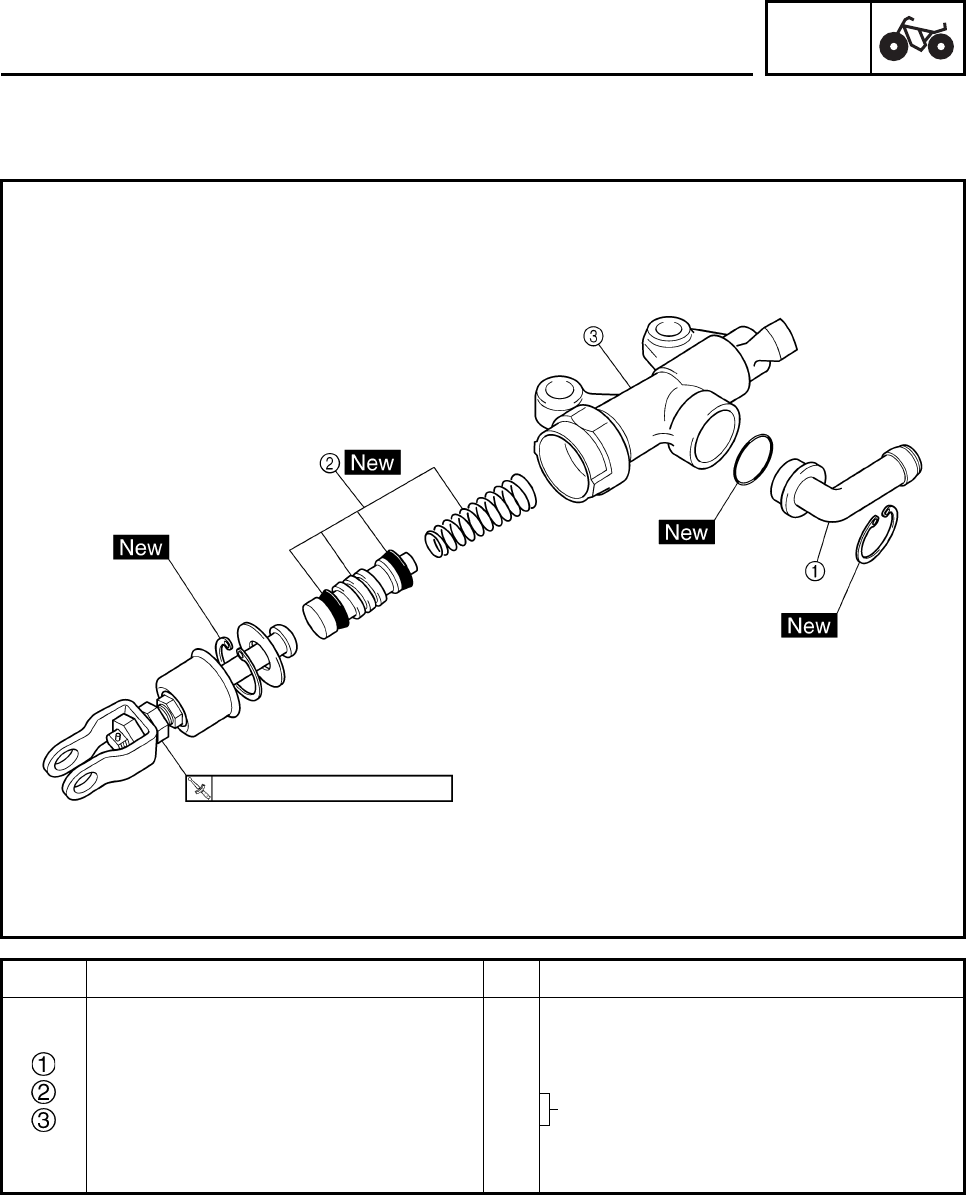
CHAS
6-23
EBS00411
Order Job/Part Q’ty Remarks
Disassembling the rear brake
master cylinder Remove the parts in the order listed.
Hose joint 1
Brake master cylinder kit 1
Brake master cylinder 1
For assembly, reverse the disassembly
procedure.
17 Nm (1.7 m•kg, 13 ft•lb)
Refer to “ASSEMBLING THE REAR
BRAKE MASTER CYLINDER”.
FRONT AND REAR BRAKES
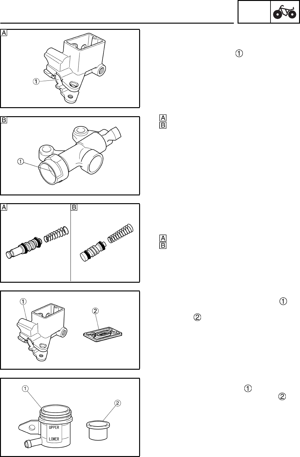
CHAS
6-24
EBS00413
CHECKING THE MASTER CYLINDERS
1. Check:
• brake master cylinder
Wear/scratches → Replace the brake mas-
ter cylinder assembly.
• brake master cylinder body
Cracks/damage → Replace.
• brake fluid delivery passage
(brake master cylinder body)
Blockage → Blow out with compressed air.
Front
Rear
2. Check:
• brake master cylinder kit
Scratches/wear/damage → Replace as a
set.
Front
Rear
3. Check:
• front brake master cylinder reservoir
• front brake master cylinder reservoir dia-
phragm
Cracks/damage → Replace.
4. Check:
• rear brake fluid reservoir
• rear brake fluid reservoir diaphragm
Cracks/damage → Replace.
FRONT AND REAR BRAKES
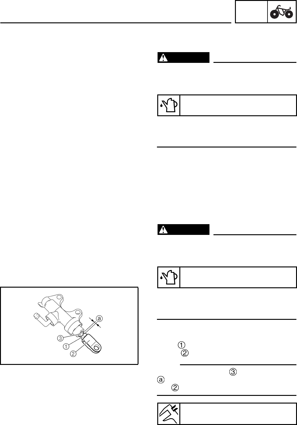
CHAS
6-25
EBS00415
ASSEMBLING THE FRONT BRAKE
MASTER CYLINDER
WARNING
• All internal brake components should be
cleaned and lubricated with new brake
fluid only before installation.
• Whenever a master cylinder is disassem-
bled, replace the piston seals and dust
seals.
EBS00416
ASSEMBLING THE REAR BRAKE MASTER
CYLINDER
WARNING
• All internal brake components should be
cleaned and lubricated with new brake
fluid only before installation.
• Whenever a master cylinder is disassem-
bled, replace the piston seals and dust
seals.
1. Install:
• brake master cylinder kit
•nut
•joint
N
O
TE:N
O
TE:
Turn the adjusting bolt until the clearance
is within the specified limits when install the
joint .
Recommended brake fluid
DOT 4
Recommended brake fluid
DOT 4
Clearance
2.2 ~ 3.2 mm (0.09 ~ 0.13 in)
FRONT AND REAR BRAKES
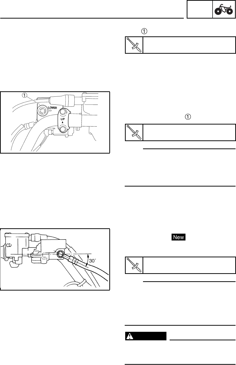
CHAS
6-26
2. Tighten:
•nut
EBS00418
INSTALLING THE FRONT BRAKE MASTER
CYLINDER
1. Install:
• brake master cylinder
N
O
TE:N
O
TE:
• The “UP” mark on the brake master cylinder
bracket should face up.
• Install the brake master cylinder so that the
gaps between the brake master cylinder and
the brake master cylinder bracket are equal.
2. Install:
• copper washers
•brake hose
• union bolt
N
O
TE:N
O
TE:
• Tighten the union bolt while holding the brake
hose as shown.
• Turn the handlebar to the left and to the right
to check that the brake hose does not touch
other parts (throttle cable, wire harness,
leads, etc.). Correct if necessary.
WARNING
Proper brake hose routing is essential to
insure safe machine operation. Refer to
“CABLE ROUTING” in chapter 2.
Nut
17 Nm (1.7 m•kg, 13 ft•lb)
Brake master cylinder holder bolt
7 Nm (0.7 m•kg, 5.1 ft•lb)
Union bolt
27 Nm (2.7 m•kg, 20 ft•lb)
FRONT AND REAR BRAKES
CHAS
6-27
3. Fill:
• brake fluid reservoir
CAUTION:
Brake fluid may damage painted surfaces
or plastic parts. Always clean up spilled
brake fluid immediately.
WARNING
• Use only the designated quality brake
fluid: other brake fluids may deteriorate
the rubber seals, causing leakage and
poor brake performance.
• Refill with the same type of brake fluid:
mixing brake fluids may result in a harm-
ful reaction and lead to poor brake perfor-
mance.
• Be careful that water does not enter the
brake master cylinder when refilling.
Water will significantly lower the boiling
point of the brake fluid and may result in
vapor lock.
4. Air bleed:
• brake system
Refer to “BLEEDING THE HYDRAULIC
BRAKE SYSTEM” in chapter 3.
5. Check:
• brake fluid level
Brake fluid level is under the “LOWER” level
line → Add the recommended brake fluid to
the proper level.
Refer to “CHECKING THE BRAKE FLUID
LEVEL” in chapter 3.
Recommended brake fluid
DOT 4
FRONT AND REAR BRAKES
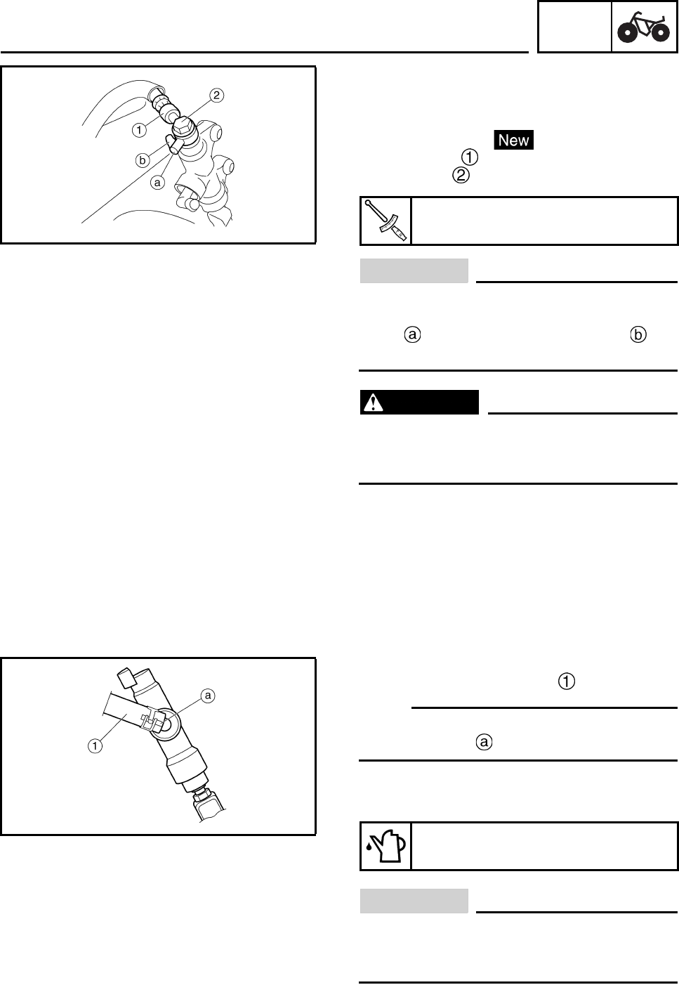
CHAS
6-28
EBS00419
INSTALLING THE REAR BRAKE MASTER
CYLINDER
1. Install:
• copper washers
•brake hose
• union bolt
CAUTION:
When installing the brake hose onto the
brake master cylinder, make sure the brake
pipe touches the projection as
shown.
WARNING
Proper brake hose routing is essential to
insure safe machine operation. Refer to
“CABLE ROUTING” in chapter 2.
2. Install:
• brake fluid reservoir hose
N
O
TE:N
O
TE:
Install the brake fluid reservoir hose with the
white paint mark facing up as shown.
3. Fill:
• brake fluid reservoir
CAUTION:
Brake fluid may damage painted surfaces
or plastic parts. Always clean up spilled
brake fluid immediately.
Union bolt
31 Nm (3.1 m•kg, 23 ft•lb)
Recommended brake fluid
DOT 4
FRONT AND REAR BRAKES

CHAS
6-29
WARNING
• Use only the designated quality brake
fluid: other brake fluids may deteriorate
the rubber seals, causing leakage and
poor brake performance.
• Refill with the same type of brake fluid:
mixing brake fluids may result in a harm-
ful chemical reaction and lead to poor
brake performance.
• Be careful that water does not enter the
brake master cylinder when refilling.
Water will significantly lower the boiling
point of the brake fluid and may result in
vapor lock.
4. Air bleed:
• brake system
Refer to “BLEEDING THE HYDRAULIC
BRAKE SYSTEM” in chapter 3.
5. Check:
• brake fluid level
Brake fluid level is under the “LOWER” level
line → Add the recommended brake fluid to
the proper level.
Refer to “CHECKING THE BRAKE FLUID
LEVEL” in chapter 3.
FRONT AND REAR BRAKES
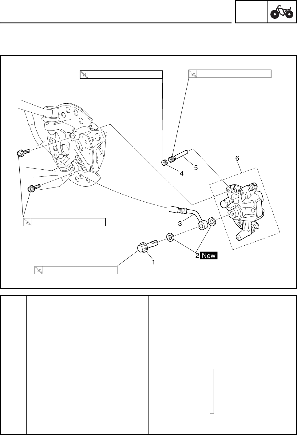
CHAS
6-30
EBS00421
FRONT BRAKE CALIPERS
Order Job/Part Q’ty Remarks
Removing the front brake calipers Remove the parts in the order listed.
The following procedure applies to both of
the front brake calipers.
Brake fluid Drain.
Refer to “BLEEDING THE HYDRAULIC
BRAKE SYSTEM” in chapter 3.
Front wheel Refer to “FRONT AND REAR WHEELS”.
1 Union bolt 1
2 Copper washer 2
3 Brake hose 1 Disconnect.
4Bolt 1
5 Brake pad retaining bolt 2 Loosen.
6 Brake caliper assembly 1
For installation, reverse the removal
procedure.
2.5 Nm (0.25 m•kg, 1.8 ft•lb) 17 Nm (1.7 m•kg, 13 ft•lb)
28 Nm (2.8 m•kg, 21 ft•lb)
27 Nm (2.7 m•kg, 20 ft•lb)
Refer to “INSTALLING
THE FRONT BRAKE
CALIPERS”.
FRONT AND REAR BRAKES
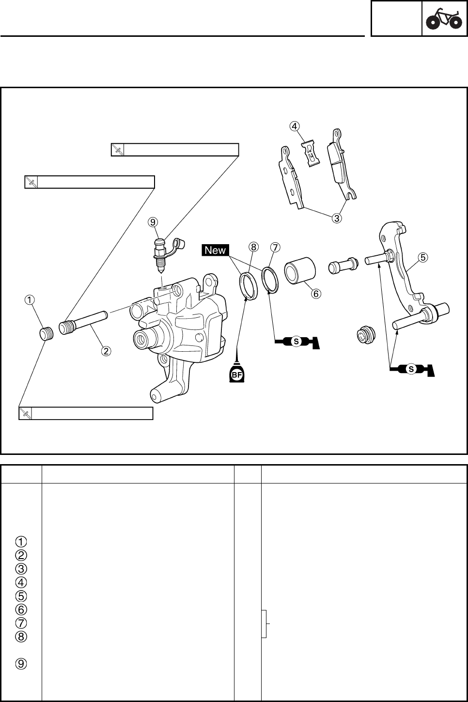
CHAS
6-31
EBS00423
Order Job/Part Q’ty Remarks
Disassembling the front brake
calipers Remove the parts in the order listed.
The following procedure applies to both of
the front brake calipers.
Bolt 1
Brake pad retaining bolt 1
Brake pad 2
Brake pad spring 1
Caliper bracket 1
Caliper piston 1
Dust seal 1
Caliper piston seal 1
Bleed screw 1
For assembly, reverse the disassembly
procedure.
5 Nm (0.5 m•kg, 3.7 ft•lb)
17 Nm (1.7 m•kg, 13 ft•lb)
2.5 Nm (0.25 m•kg, 1.8 ft•lb)
Refer to “DISASSEMBLING THE
FRONT AND REAR BRAKE CALIPERS”
and “ASSEMBLING THE FRONT
BRAKE CALIPERS”.
FRONT AND REAR BRAKES
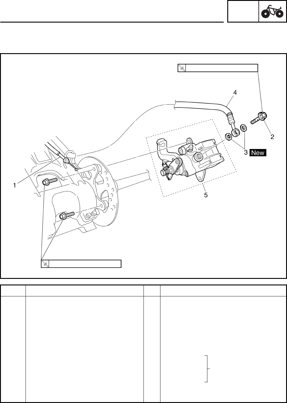
CHAS
6-32
EBS00424
REAR BRAKE CALIPER
Order Job/Part Q’ty Remarks
Removing the rear brake caliper Remove the parts in the order listed.
Brake fluid Drain.
Refer to “BLEEDING THE HYDRAULIC
BRAKE SYSTEM” in chapter 3.
1 Parking brake cable 1 Disconnect.
Refer to “REMOVING THE PARKING
BRAKE CABLE”.
2 Union bolt 1
3 Copper washer 2
4 Brake hose 1 Disconnect.
5 Brake caliper assembly 1
For installation, reverse the removal
procedure.
31 Nm (3.1 m•kg, 23 ft•lb)
34 Nm (3.4 m•kg, 25 ft•lb)
Refer to “INSTALLING
THE REAR BRAKE
CALIPER”.
FRONT AND REAR BRAKES
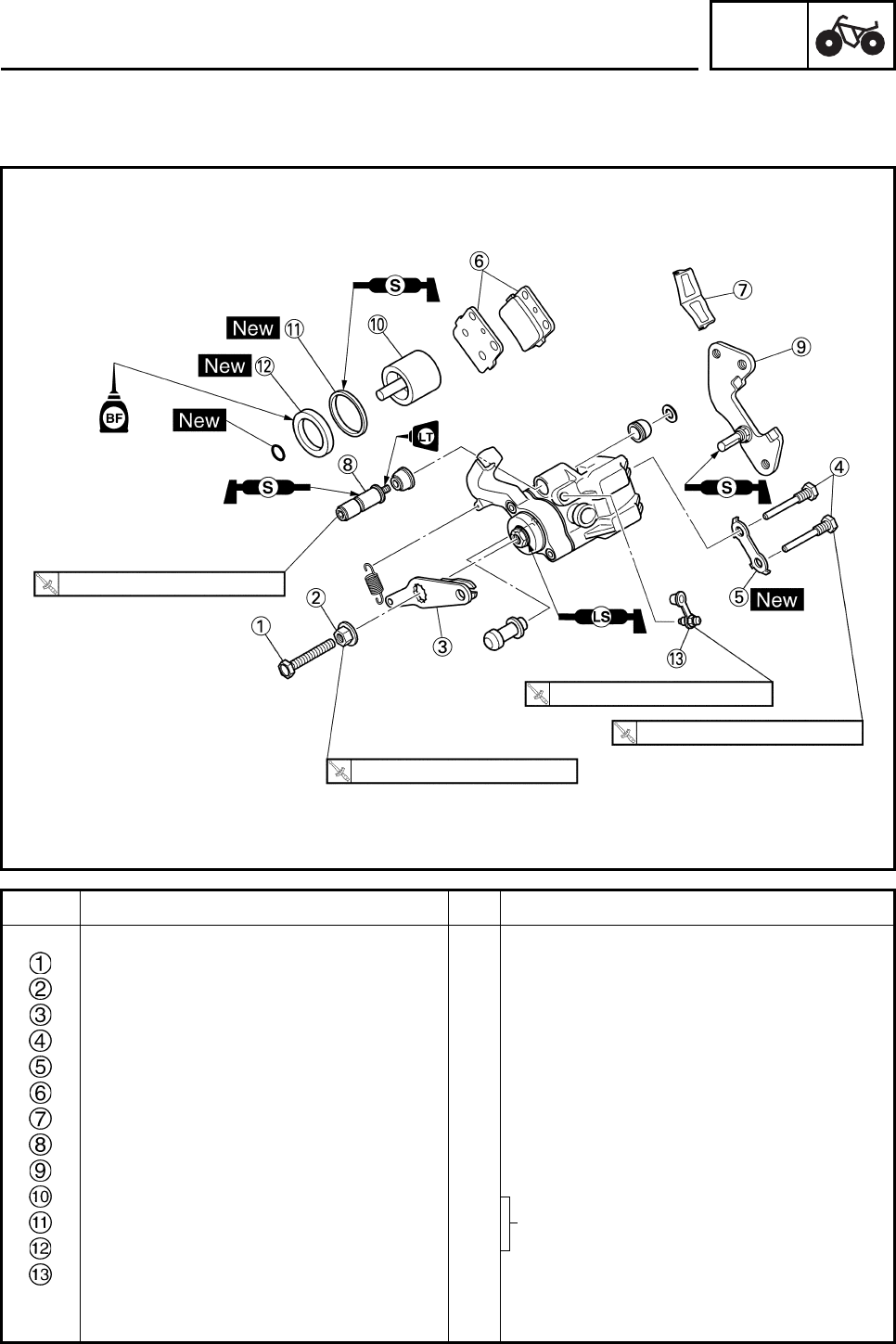
CHAS
6-33
EBS00425
Order Job/Part Q’ty Remarks
Disassembling the rear brake caliper Remove the parts in the order listed.
Adjusting bolt 1
Locknut 1
Parking brake arm 1
Brake pad retain bolt 2
Lock washer 1
Brake pad 2
Brake pad spring 1
Retaining bolt 1
Caliper bracket 1
Brake caliper piston 1
Dust seal 1
Caliper piston seal 1
Bleed screw 1
For assembly, reverse the disassembly
procedure.
17 Nm (1.7 m•kg, 13 ft•lb)
5 Nm (0.5 m•kg, 3.7 ft•lb)
17 Nm (1.7 m•kg, 13 ft•lb)
15 Nm (1.5 m•kg, 11 ft•lb)
FRONT AND REAR BRAKES
Refer to “DISASSEMBLING THE
FRONT AND REAR BRAKE
CALIPERS” and “ASSEMBLING THE
REAR BRAKE CALIPER”.
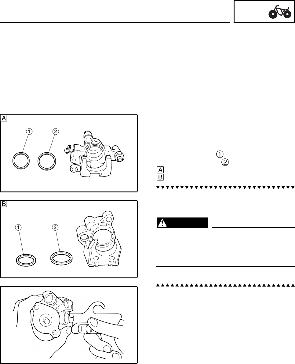
CHAS
6-34
REMOVING THE PARKING BRAKE CABLE
1. Loosen:
•nut
• adjusting bolt
2. Disconnect:
• parking brake cable
(from parking brake lever)
3. Disconnect:
• parking brake cable
(from rear brake)
EBS00427
DISASSEMBLING THE FRONT AND REAR
BRAKE CALIPERS
1. Remove:
• brake caliper piston
• caliper dust seal
• caliper piston seal
Front
Rear
a. Blow compressed air into the hose joint
opening to force out the caliper piston from
the brake caliper body.
WARNING
• Never try to pry out the caliper piston.
• Cover the caliper piston with a rag. Be
careful not to get injured when the piston
is expelled from the caliper cylinder.
b. Remove the caliper piston seal.
FRONT AND REAR BRAKES
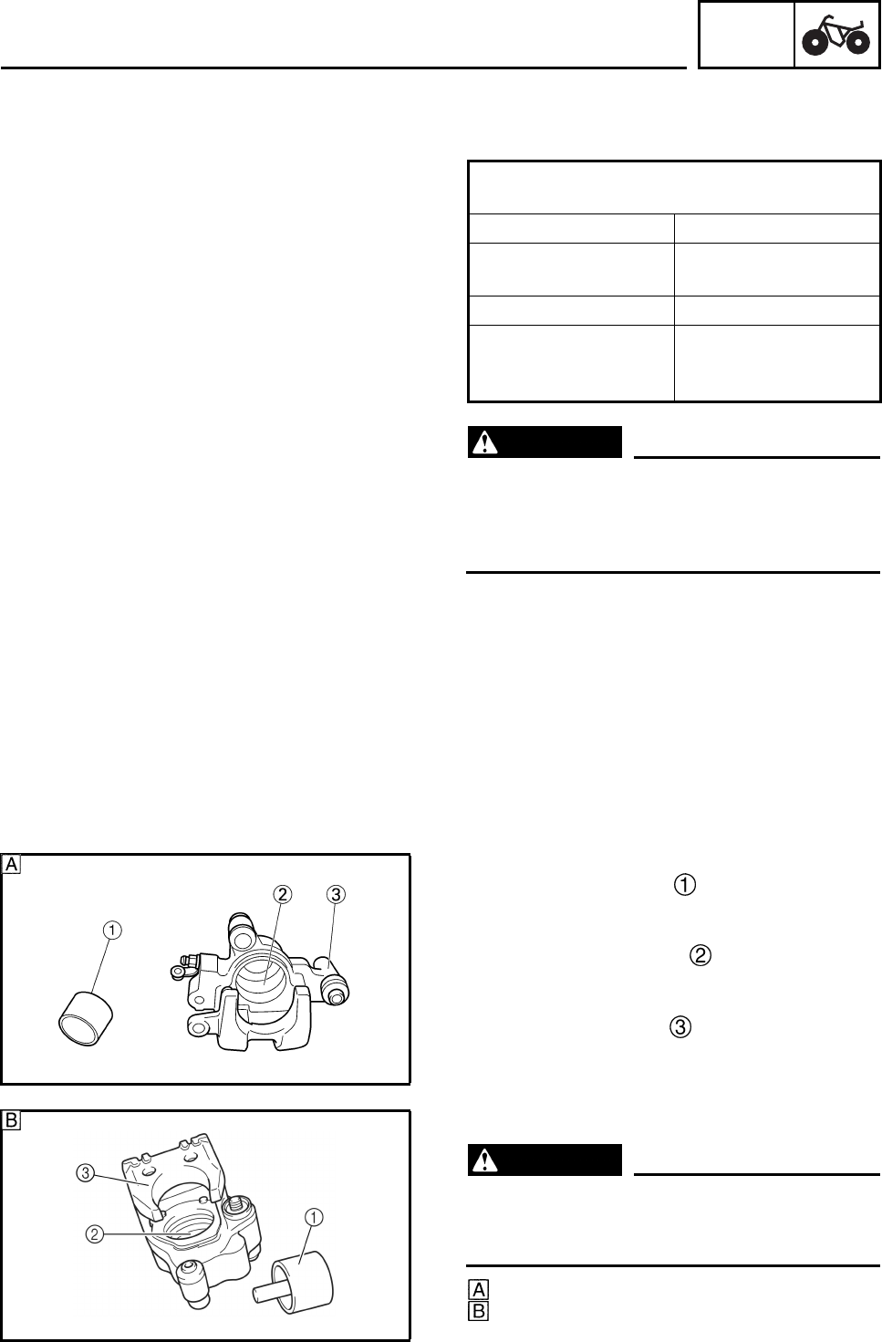
CHAS
6-35
EBS00429
CHECKING THE FRONT AND REAR BRAKE
CALIPERS
WARNING
All internal brake components should be
cleaned in new brake fluid only. Do not use
solvents as they will cause seals to swell
and distort.
1. Check:
• brake caliper piston
Scratches/rust/wear → Replace the brake
caliper assembly.
• brake caliper cylinder
Wear/scratches → Replace the brake cali-
per assembly.
• brake caliper body
Cracks/damage → Replace.
• brake fluid delivery passage
(brake caliper body)
Blockage → Blow out with compressed air.
WARNING
Replace the caliper piston seal and dust
seal whenever the brake caliper is disas-
sembled.
Front
Rear
Recommended brake component
replacement schedule
Brake pads As required
Piston seals, dust
seals Every two years
Brake hoses Every four years
Brake fluid Replace when
brakes are
disassembled.
FRONT AND REAR BRAKES
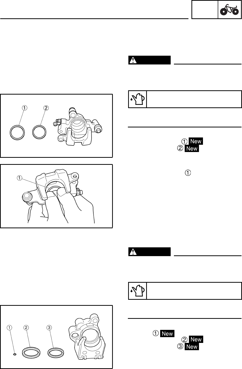
CHAS
6-36
EBS00431
ASSEMBLING THE FRONT BRAKE
CALIPERS
The following procedure applies to both of the
front brake calipers.
WARNING
• All internal brake components should be
cleaned and lubricated with new brake
fluid only before installation.
• Replace the caliper piston seal whenever
a brake caliper is disassembled.
1. Install:
• caliper piston seal
• caliper dust seal
2. Install:
• brake caliper piston
EBS00432
ASSEMBLING THE REAR BRAKE CALIPER
WARNING
• All internal brake components should be
cleaned and lubricated with new brake
fluid only before installation.
• Replace the caliper piston seal whenever
a brake caliper is disassembled.
1. Install:
• O-ring
• caliper piston seal
• caliper dust seal
Recommended brake fluid
DOT 4
Recommended brake fluid
DOT 4
FRONT AND REAR BRAKES
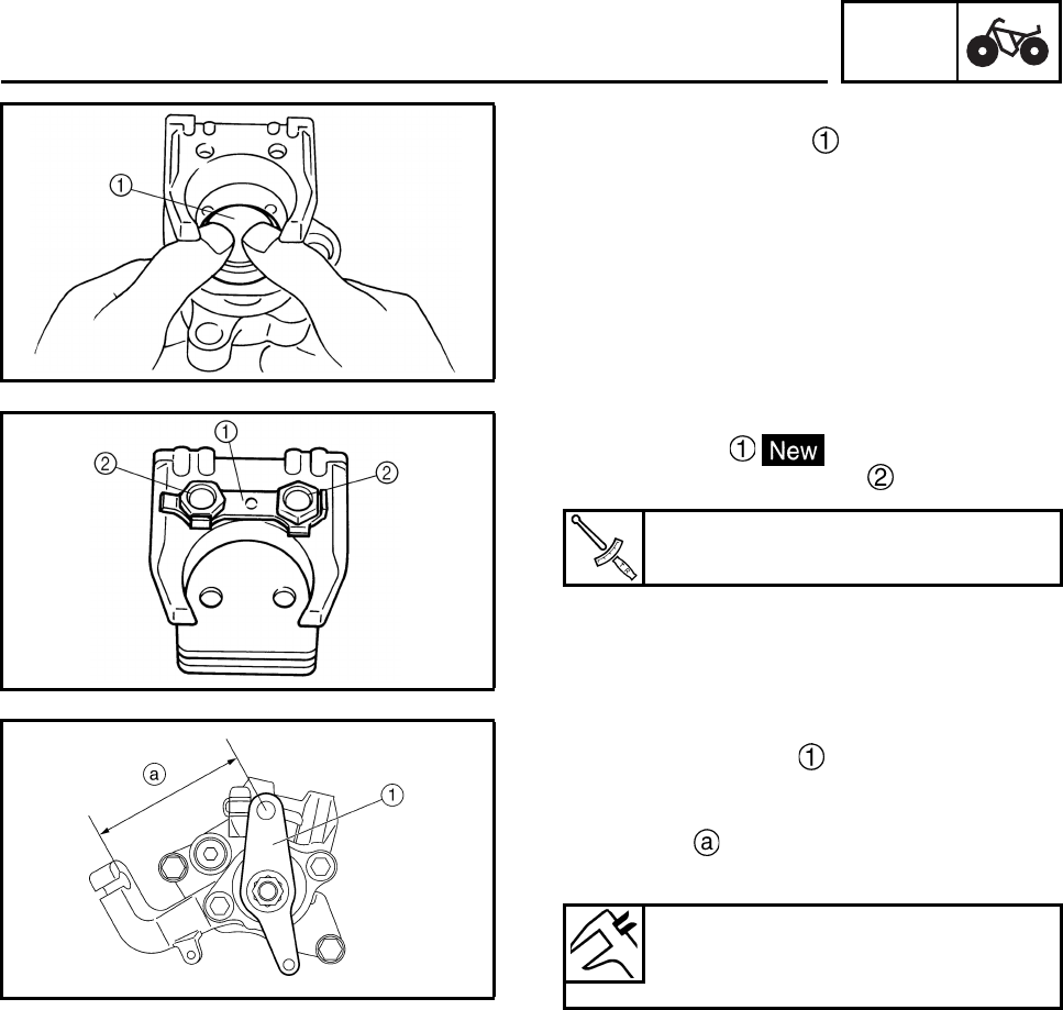
CHAS
6-37
2. Install:
• brake caliper piston
3. Install:
• lock washer
• brake pad retaining bolts
4. Bend the lock washer tabs along a flat side
of the bolts.
5. Install:
• parking brake arm
6. Measure:
• parking brake arm to parking brake bracket
distance
Out of specification → Adjust.
Brake pad retaining bolt
17 Nm (1.7 m•kg, 13 ft•lb)
Parking brake arm to parking
brake bracket distance
73.3 mm (2.89 in)
FRONT AND REAR BRAKES
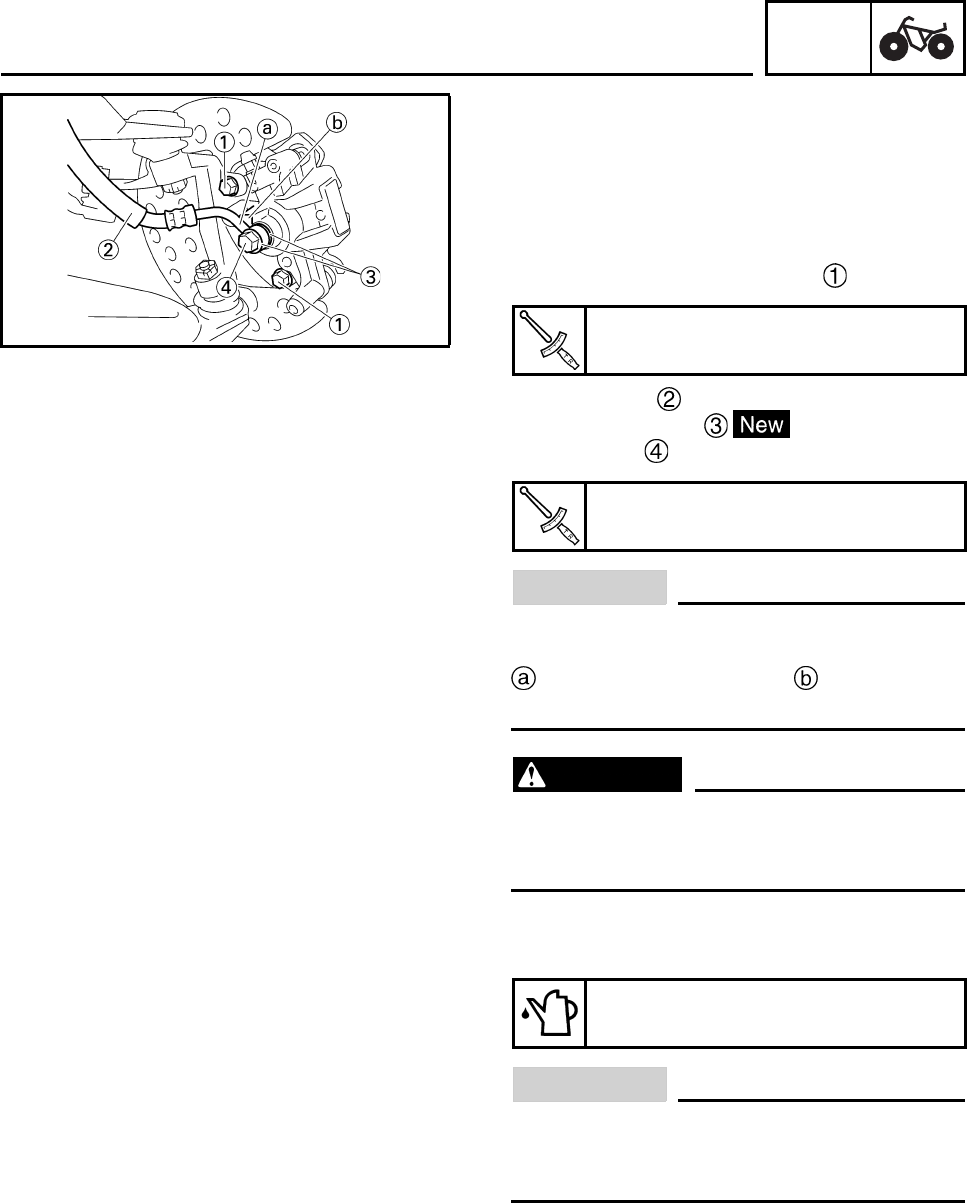
CHAS
6-38
EBS00434
INSTALLING THE FRONT BRAKE
CALIPERS
The following procedure applies to both of the
front brake calipers.
1. Install:
• brake caliper assembly
• brake caliper mounting bolts
•brake hose
• copper washers
• union bolt
CAUTION:
When installing the brake hose on the
brake caliper, make sure that the brake pipe
touches the projection on the brake
caliper.
WARNING
Proper brake hose routing is essential to
insure safe machine operation. Refer to
“CABLE ROUTING” in chapter 2.
2. Fill:
•brake reservoir
CAUTION:
Brake fluid may damage painted surfaces
or plastic parts. Always clean up spilled
brake fluid immediately.
Brake caliper mounting bolt
28 Nm (2.8 m•kg, 21 ft•lb)
Union bolt
27 Nm (2.7 m•kg, 20 ft•lb)
Recommended brake fluid
DOT 4
FRONT AND REAR BRAKES

CHAS
6-39
WARNING
• Use only the designated quality brake
fluid: other brake fluids may deteriorate
the rubber seals, causing leakage and
poor brake performance.
• Refill with the same type of brake fluid:
mixing brake fluids may result in a harm-
ful chemical reaction and lead to poor
brake performance.
• Be careful that water does not enter the
master cylinder when refilling. Water will
significantly lower the boiling point of the
brake fluid and may result in vapor lock.
3. Air bleed:
• brake system
Refer to “BLEEDING THE HYDRAULIC
BRAKE SYSTEM” in chapter 3.
4. Check:
• brake fluid level
Brake fluid level is below the “LOWER” level
line → Add the recommended brake fluid to
the proper level.
Refer to “CHECKING THE BRAKE FLUID
LEVEL” in chapter 3.
FRONT AND REAR BRAKES
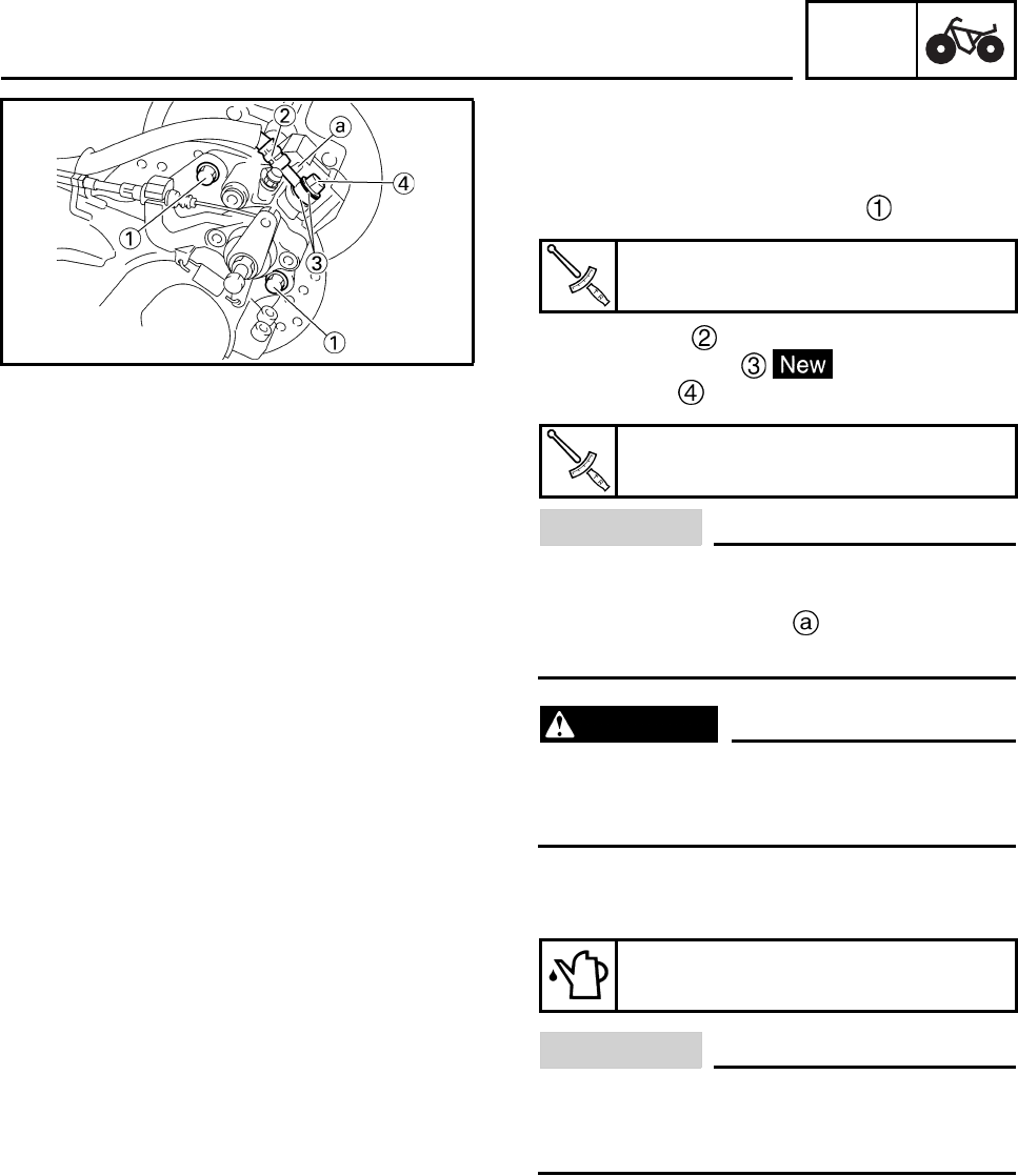
CHAS
6-40
EBS00436
INSTALLING THE REAR BRAKE CALIPER
1. Install:
• brake caliper assembly
• brake caliper mounting bolts
•brake hose
• copper washers
• union bolt
CAUTION:
When installing the brake hose on the
brake caliper, make sure that the brake pipe
touches the projection on the brake cali-
per.
WARNING
Proper brake hose routing is essential to
insure safe machine operation. Refer to
“CABLE ROUTING” in chapter 2.
2. Fill:
•brake reservoir
CAUTION:
Brake fluid may damage painted surfaces
or plastic parts. Always clean up spilled
brake fluid immediately.
Brake caliper mounting bolt
34 Nm (3.4 m•kg, 25 ft•lb)
Union bolt
31 Nm (3.1 m•kg, 23 ft•lb)
Recommended brake fluid
DOT 4
FRONT AND REAR BRAKES
CHAS
6-41
WARNING
• Use only the designated quality brake
fluid: other brake fluids may deteriorate
the rubber seals, causing leakage and
poor brake performance.
• Refill with the same type of brake fluid:
mixing brake fluids may result in a harm-
ful chemical reaction and lead to poor
brake performance.
• Be careful that water does not enter the
master cylinder when refilling. Water will
significantly lower the boiling point of the
brake fluid and may result in vapor lock.
3. Air bleed:
• brake system
Refer to “BLEEDING THE HYDRAULIC
BRAKE SYSTEM” in chapter 3.
4. Check:
• brake fluid level
Brake fluid level is below the “LOWER” level
line → Add the recommended brake fluid to
the proper level.
Refer to “CHECKING THE BRAKE FLUID
LEVEL” in chapter 3.
5. Adjust:
• parking brake cable end length
Refer to “ADJUSTING THE PARKING
BRAKE” in chapter 3.
FRONT AND REAR BRAKES
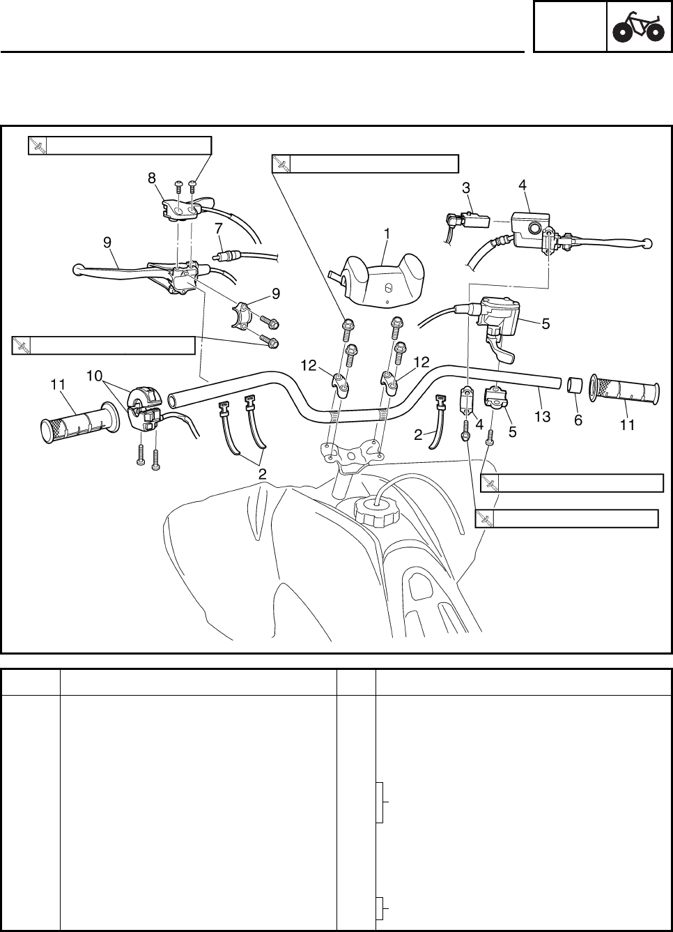
CHAS
6-42
EBS00444
STEERING SYSTEM
HANDLEBAR
Order Job/Part Q’ty Remarks
Removing the handlebar Remove the parts in the order listed.
1 Handlebar protecter 1
2 Band 3
3 Front brake light switch 1
4 Brake master cylinder/bracket 1/1
5 Throttle lever assembly/bracket 1/1
6 Spacer 1
7 Clutch switch 1 Refer to “REMOVING THE CLUTCH
SWITCH”.
8 Parking brake lever 1
9 Clutch lever/bracket 1/1
10 Handlebar switch 1
4 Nm (0.4 m•kg, 3.0 ft•lb)
7 Nm (0.7 m•kg, 5.2 ft•lb)
20 Nm (2.0 m•kg, 15 ft•lb)
4 Nm (0.4 m•kg, 3.0 ft•lb)
7 Nm (0.7 m•kg, 5.2 ft•lb)
STEERING SYSTEM
Refer to “INSTALLING THE BRAKE
MASTER CYLINDER”.
Refer to “INSTALLING THE CLUTCH
LEVER”.
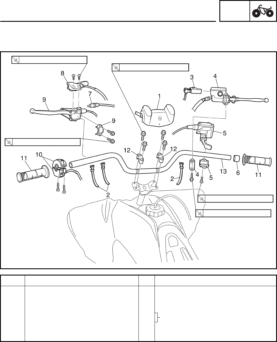
CHAS
6-43
Order Job/Part Q’ty Remarks
11 Handlebar grip 2 Refer to “REMOVING THE HANDLEBAR
GRIPS” and “INSTALLING THE
HANDLEBAR GRIPS”.
12 Handlebar holder 2
13 Handlebar 1
For installation, reverse the removal
procedure.
4 Nm (0.4 m•kg, 3.0 ft•lb)
7 Nm (0.7 m•kg, 5.2 ft•lb)
20 Nm (2.0 m•kg, 15 ft•lb)
4 Nm (0.4 m•kg, 3.0 ft•lb)
7 Nm (0.7 m•kg, 5.2 ft•lb)
STEERING SYSTEM
Refer to “INSTALLING THE
HANDLEBAR”.
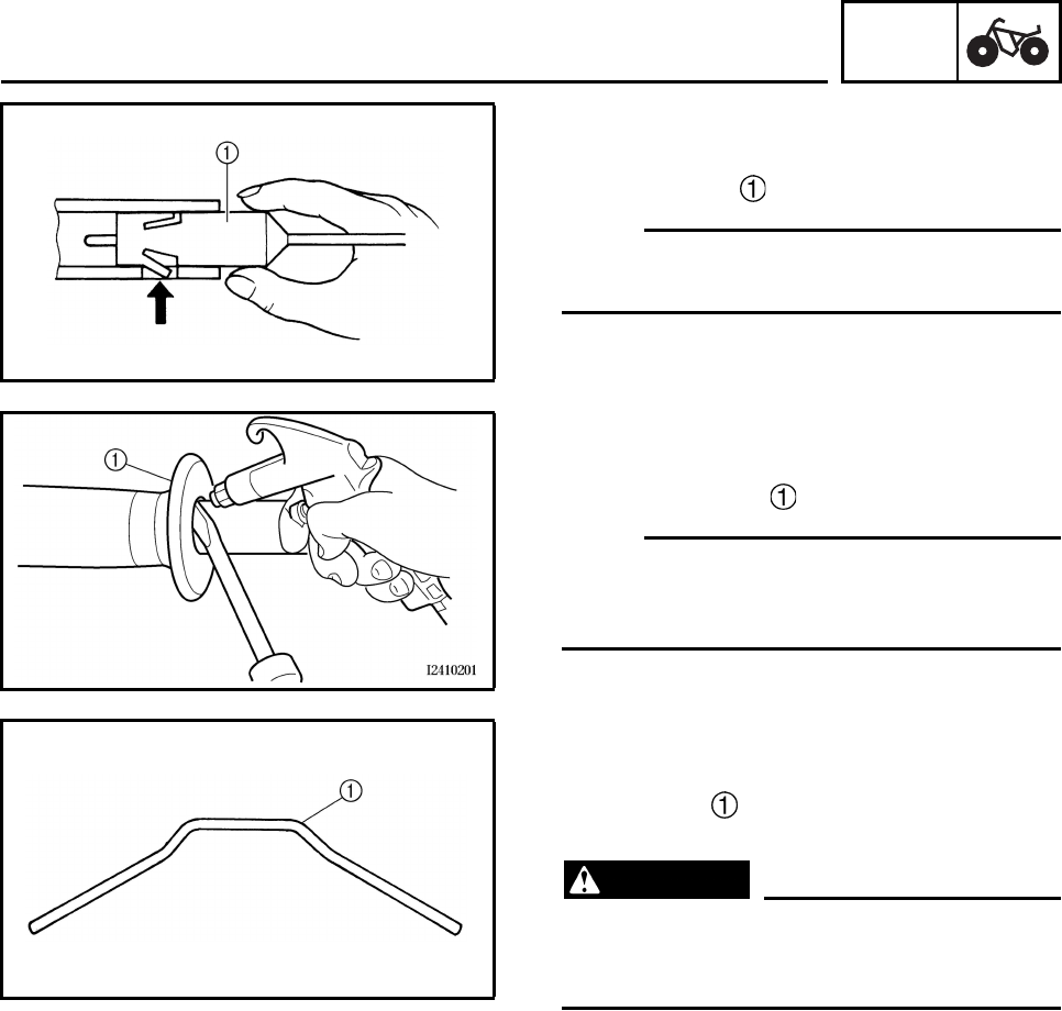
CHAS
6-44
EBS00446
REMOVING THE CLUTCH SWITCH
1. Remove:
• clutch switch
N
O
TE:N
O
TE:
Push the fastener when removing the clutch
switch out of the clutch lever holder.
EBS00447
REMOVING THE HANDLEBAR GRIPS
1. Remove:
• handlebar grips
N
O
TE:N
O
TE:
Blow compressed air between the handlebar
and handlebar grip, and gradually push the
grip off the handlebar.
EBS00448
CHECKING THE HANDLEBAR
1. Check:
• handlebar
Bends/cracks/damage → Replace.
WARNING
Do not attempt to straighten a bent handle-
bar as this may dangerously weaken the
handlebar.
STEERING SYSTEM
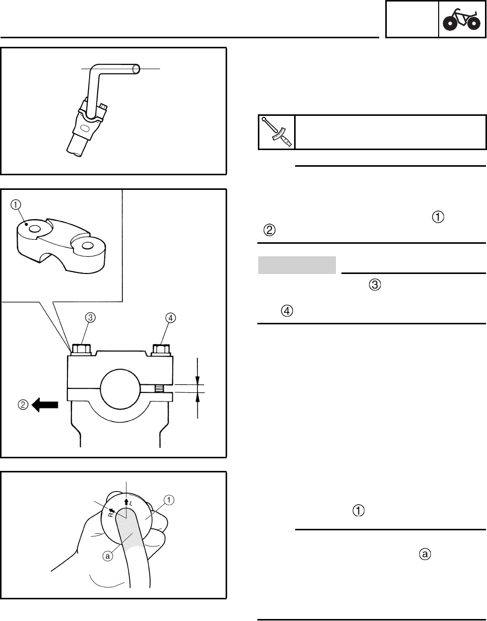
CHAS
6-45
EBS00449
INSTALLING THE HANDLEBAR
1. Install:
• handlebar
• handlebar holders
N
O
TE:N
O
TE:
• Install the handlebar horizontally shown in the
illustration.
• The upper handlebar holder should be
installed with the punched mark forward
.
CAUTION:
First tighten the bolt on the front side of
the handlebar holder, and then tighten the
bolt on the rear side.
EBS00450
INSTALLING THE HANDLEBAR GRIPS
1. Install:
• handlebar grips
N
O
TE:N
O
TE:
• Before applying the adhesive, wipe off grease
or oil on the handlebar surface with a lac-
quer thinner.
• Install the handlebar grips so that the “L”
arrow on the left grip and “R” arrow on the
right grip are placed vertically.
Handleber holder
20 Nm (2.0 m•kg, 15 ft•lb)
STEERING SYSTEM
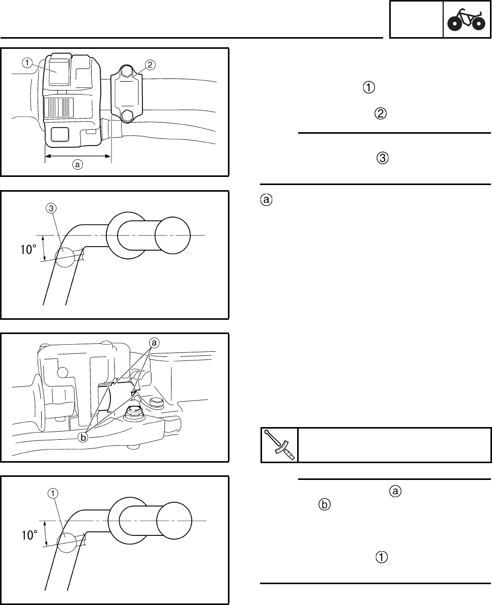
CHAS
6-46
EBS00452
INSTALLING THE CLUTCH LEVER
1. Install:
• handlebar switch
•clutch lever
• clutch lever bracket
N
O
TE:N
O
TE:
• Install the clutch lever bracket as shown.
• Install the clutch lever at 10 degrees angle
as shown.
53 ~ 54 mm (2.09 ~ 2.13 in)
EBS00453
INSTALLING THE BRAKE MASTER
CYLINDER
1. Install:
• throttle lever assembly
• spacer
• brake master cylinder
N
O
TE:N
O
TE:
• Engage the indentations in the spacer with
the lobes on the throttle lever assembly
and brake master cylinder.
• The “UP” mark on the brake master cylinder
bracket should face up.
• Install the brake lever at 10 degrees angle
as shown.
Brake master cylinder bracket
7 Nm (0.7 m•kg, 5.2 ft•lb)
STEERING SYSTEM
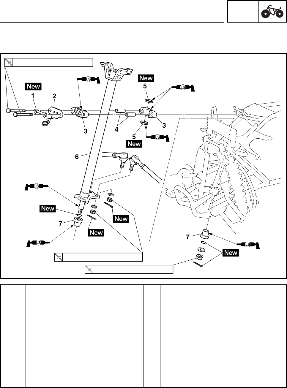
CHAS
6-47
EBS00454
STEERING STEM
Order Job/Part Q’ty Remarks
Removing the steering stem Remove the parts in the order listed.
Front fender Refer to “SEAT, FENDERS AND FUEL
TANK” in chapter 3.
1 Lock washer 1 Refer to “INSTALLING THE LOCK
WASHER”.
2 Bracket 1
3 Steering stem bushing 2
4 Spacer 2
5 Oil seal 2
6 Steering stem 1
7 Bushing 2
23 Nm (2.3 m•kg, 17 ft•lb)
25 Nm (2.5 m•kg, 18 ft•lb)
35 Nm (3.5 m•kg, 26 ft•lb)
STEERING SYSTEM
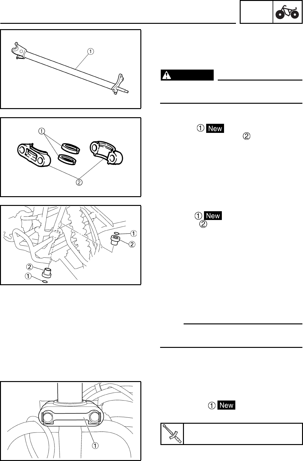
CHAS
6-48
EBS00456
CHECKING THE STEERING STEM
1. Check:
• steering stem
Bends/damage → Replace.
WARNING
Do not attempt to straighten a bent stem;
this may dangerously weaken the stem.
2. Check:
• oil seals
• steering stem bushings
Wear/damage → Replace.
3. Check
• O-rings
• bushings
Wear/damage → Replace.
INSTALLING THE STEERING STEM
1. Install:
• steering stem
N
O
TE:N
O
TE:
Pass the throttle cable through the cable guide.
Refer to “CABLE ROUTING” in chapter 2.
EBS00459
INSTALLING THE LOCK WASHER
1. Install:
• lock washer
• bolts
2. Bend the lock washer tab along a flat side
of the bolt.
Bolt
23 Nm (2.3 m•kg, 17 ft•lb)
STEERING SYSTEM
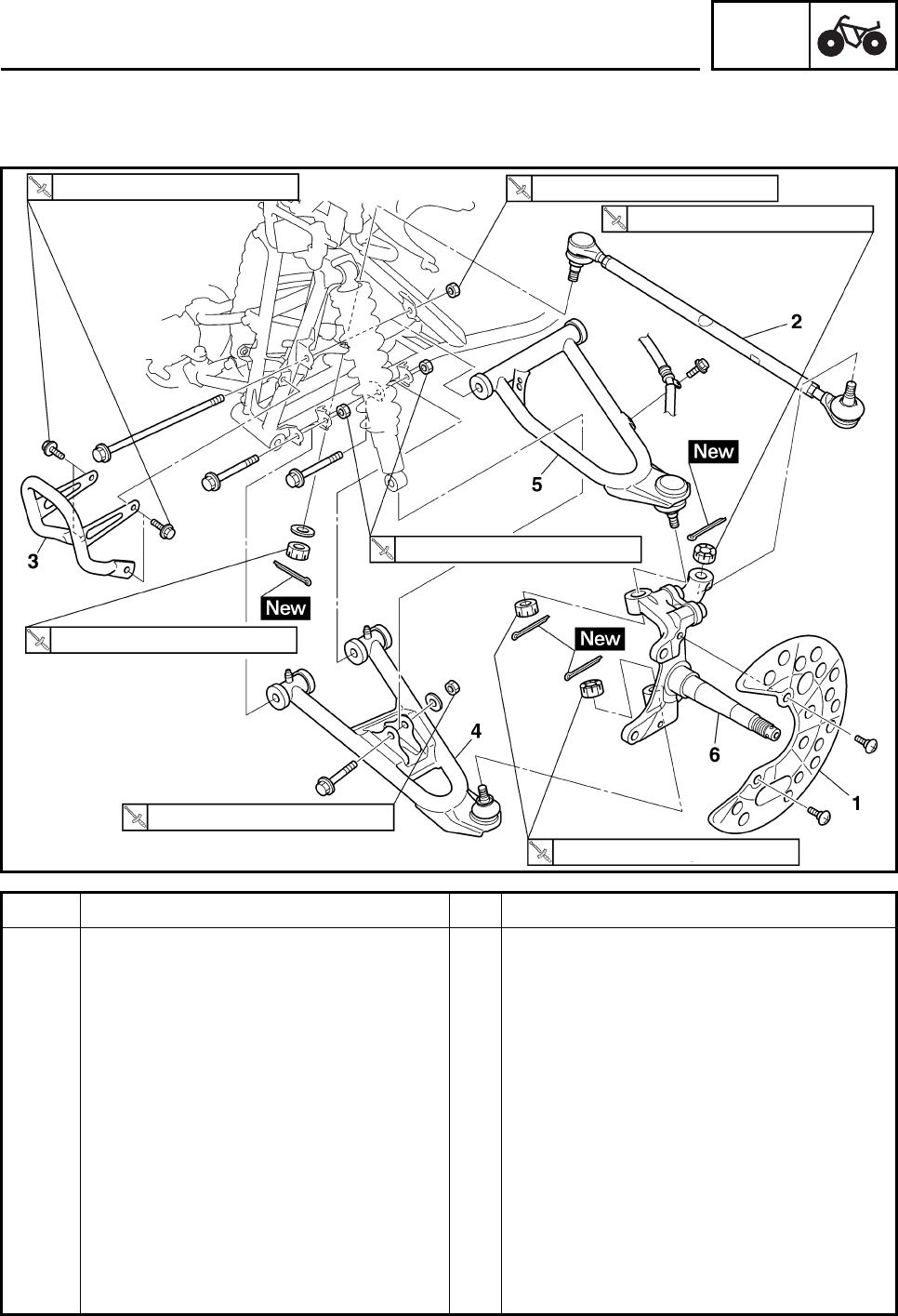
CHAS
6-49
EBS00460
TIE-RODS AND STEERING KNUCKLES
Order Job/Part Q’ty Remarks
Removing the tie-rods and steering
knuckles Remove the parts in the order listed.
The following procedure applies to both of
the tie-rods and steering knuckles.
Front wheel/brake disc Refer to “FRONT AND REAR WHEELS”.
Front brake caliper Refer to “FRONT AND REAR BRAKES”.
1 Brake disc guard (inner) 1
2 Tie-rod 1 Refer to “INSTALLING THE TIE-RODS”.
3 Front bumper 1
4 Lower front arm 1
5 Upper front arm 1
6 Steering knuckle 1 Refer to “REMOVING THE STEERING
KNUCKLES”.
For installation, reverse the removal
procedure.
31 Nm (3.1 m•kg, 23 ft•lb) 45 Nm (4.5 m•kg, 33 ft•lb)
25 Nm (2.5 m•kg, 18 ft•lb)
45 Nm (4.5 m•kg, 33 ft•lb)
25 Nm (2.5 m•kg, 18 ft•lb)
25 Nm (2.5 m•kg, 18 ft•lb)
48 Nm (4.8 m•kg, 35 ft•lb)
STEERING SYSTEM
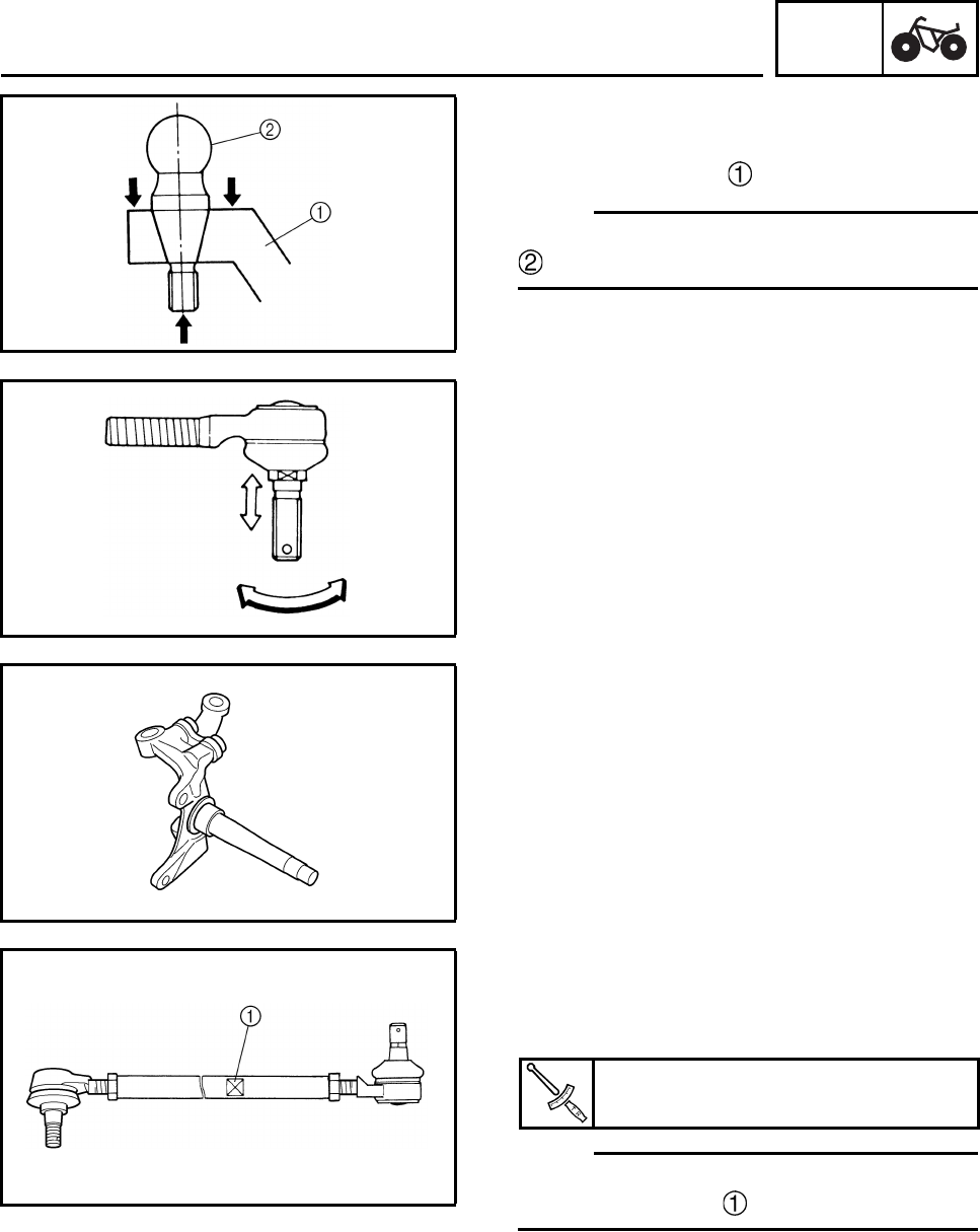
CHAS
6-50
EBS00461
REMOVING THE STEERING KNUCKLES
1. Remove:
• steering knuckles
N
O
TE:N
O
TE:
Use a general puller to separate the ball joint
and steering knuckle.
EBS00462
CHECKING THE TIE-RODS
1. Check:
• tie-rod free play and movement
Free play → Replace the tie-rod end.
Turns roughly → Replace the tie-rod end.
2. Check:
• tie-rods
Bends/damage → Replace.
EBS00464
CHECKING THE STEERING KNUCKLES
1. Check:
• steering knuckles
Damage/pitting → Replace.
EBS00465
INSTALLING THE TIE-RODS
1. Install:
• tie-rods (left and right)
N
O
TE:N
O
TE:
The tie-rod side which must be installed on the
outside has grooves .
2. Adjust:
• toe-in
Refer to “ADJUSTING THE TOE-IN” in
chapter 3.
Ball joint nut
25 Nm (2.5 m•kg, 18 ft•lb)
STEERING SYSTEM
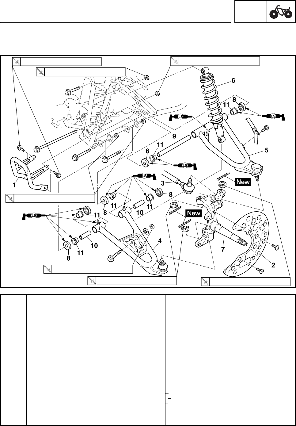
CHAS
6-51
EBS00468
FRONT ARMS AND FRONT SHOCK ABSORBER ASSEMBLIES
Order Job/Part Q’ty Remarks
Removing the front arms and front
shock absorber assemblies Remove the parts in the order listed.
The following procedure applies to both of
the front arms and front shock absorber
assemblies.
Front wheel/brake disc Refer to “FRONT AND REAR WHEELS”.
Front brake caliper Refer to “FRONT AND REAR BRAKES”.
1 Front bumper 1
2 Brake disc guard (inner) 1
3 Tie-rod 1 Disconnect.
4Lower front arm 1
5 Upper front arm 1
6 Front shock absorber 1
7 Steering knuckle 1
31 Nm (3.1 m•kg, 23 ft•lb) 45 Nm (4.5 m•kg, 33 ft•lb)
45 Nm (4.5 m•kg, 33 ft•lb)
25 Nm (2.5 m•kg, 18 ft•lb) 25 Nm (2.5 m•kg, 18 ft•lb)
48 Nm (4.8 m•kg, 35 ft•lb)
48 Nm (4.8 m•kg, 35 ft•lb)
FRONT ARMS AND FRONT SHOCK ABSORBER
ASSEMBLIES
Refer to “REMOVING THE FRONT ARMS”
and “INSTALLING THE FRONT ARMS”.
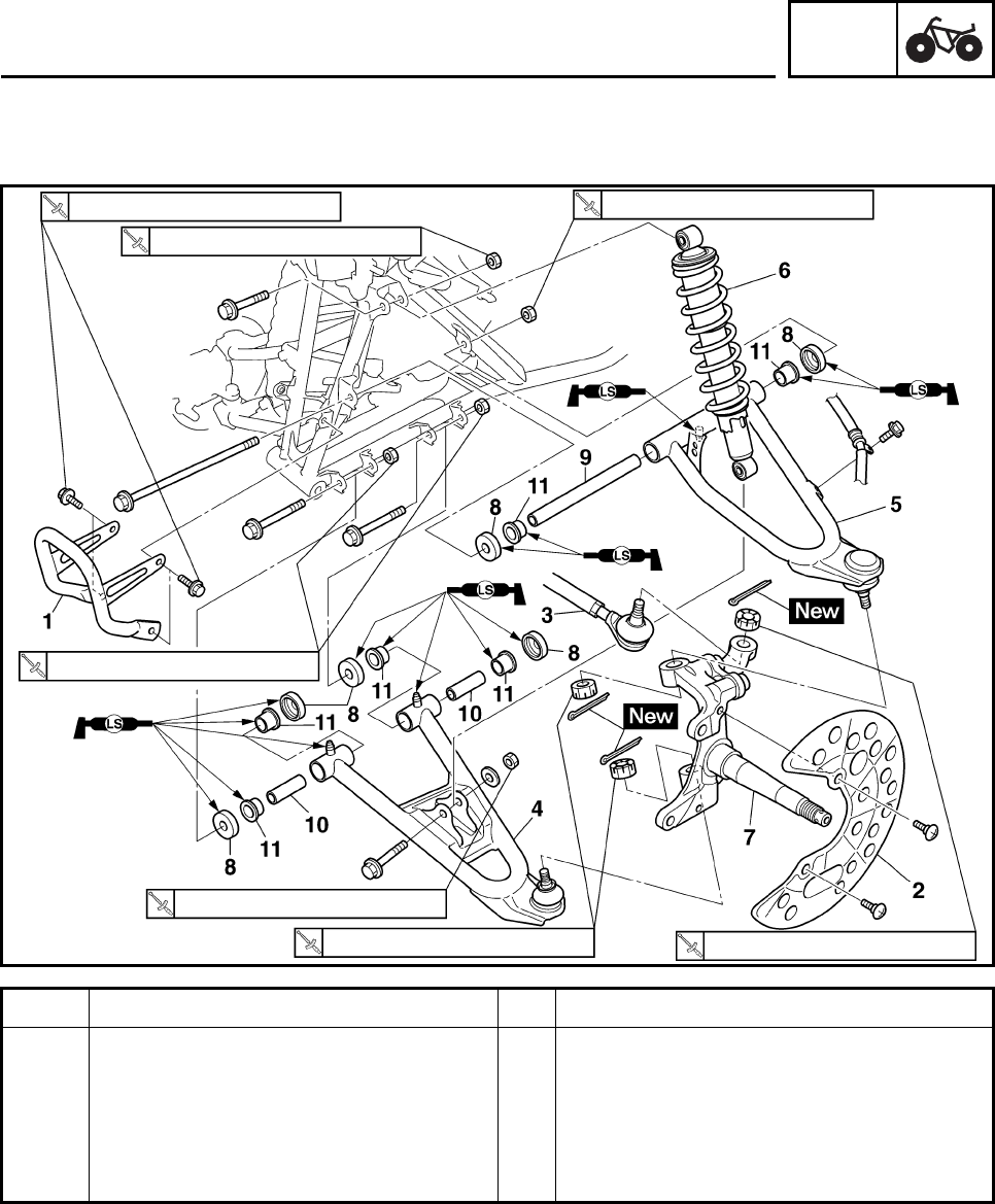
CHAS
6-52
Order Job/Part Q’ty Remarks
8Dust cover 6
9 Spacer 1
10 Spacer 2
11 Bushing 6
For installation, reverse the removal
procedure.
31 Nm (3.1 m•kg, 23 ft•lb) 45 Nm (4.5 m•kg, 33 ft•lb)
45 Nm (4.5 m•kg, 33 ft•lb)
25 Nm (2.5 m•kg, 18 ft•lb) 25 Nm (2.5 m•kg, 18 ft•lb)
48 Nm (4.8 m•kg, 35 ft•lb)
48 Nm (4.8 m•kg, 35 ft•lb)
FRONT ARMS AND FRONT SHOCK ABSORBER
ASSEMBLIES
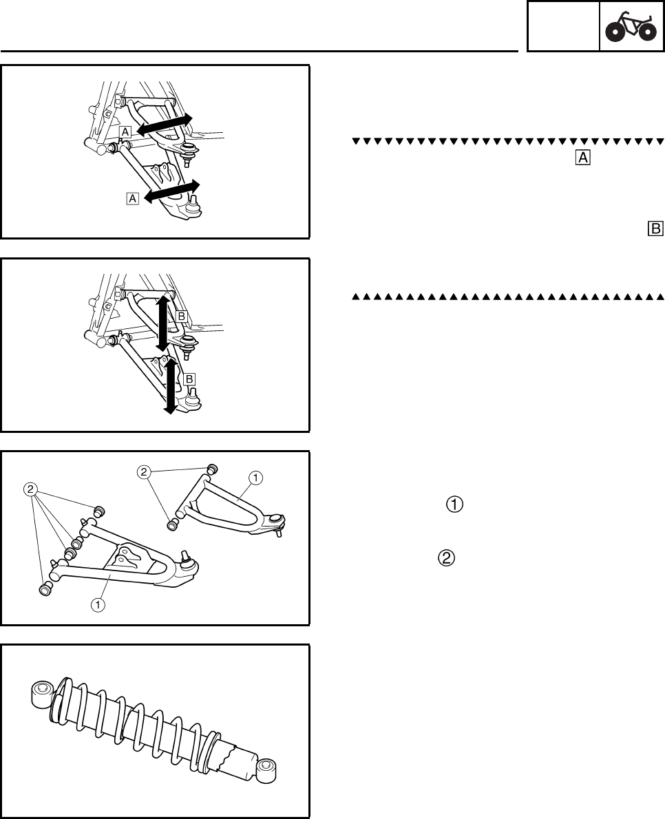
CHAS
6-53
EBS00469
REMOVING THE FRONT ARMS
1. Check:
• front arm free play
a. Check the front arm side play by moving
it from side to side.
If side play is noticeable, check the bush-
ings.
b. Check the front arm vertical movement
by moving it up and down.
If the vertical movement is tight or rough, or
if there is binding, check the bushings.
2. Remove:
• front arm
EBS00470
CHECKING THE FRONT ARMS
1. Check:
• front arms
Bends/damage → Replace.
2. Check:
• bushings
Wear/damage → Replace.
EBS00488
CHECKING THE FRONT SHOCK
ABSORBERS
The following procedure applies to both of the
front shock absorber assemblies.
1. Check:
• shock absorber
Oil leaks → Replace the front shock
absorber assembly.
• shock absorber rod
Bends/damage → Replace the front shock
absorber assembly.
•spring
Fatigue → Replace the front shock
absorber assembly.
Move the spring up and down.
FRONT ARMS AND FRONT SHOCK ABSORBER
ASSEMBLIES
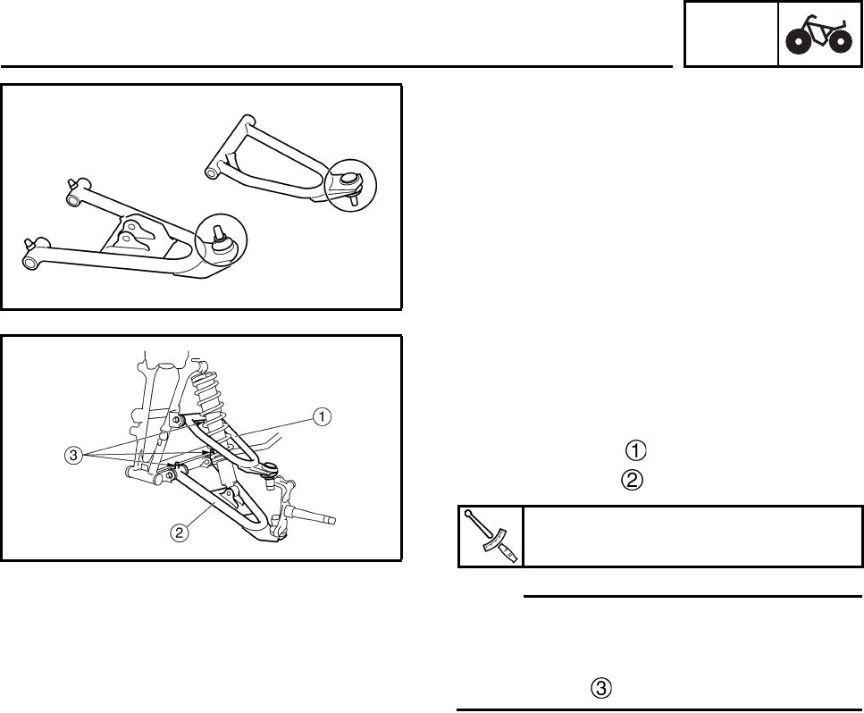
CHAS
6-54
EBS00472
CHECKING THE BALL JOINTS
The following procedure applies to both of the
front arm ball joints.
1. Check:
• ball joint
Damage/pitting → Replace the front arm.
Free play → Replace the front arm.
Turns roughly → Replace the front arm.
EBS00473
INSTALLING THE FRONT ARMS
The following procedure applies to both of the
front arms.
1. Install:
• upper front arm
• lower front arm
N
O
TE:N
O
TE:
• Be sure to position the bolts (upper and
lower) so that the bolt head faces forward.
• Apply lithium-soap-based grease to the
grease nipple .
Front arm (upper, lower)
45 Nm (4.5 m•kg, 33 ft•lb)
FRONT ARMS AND FRONT SHOCK ABSORBER
ASSEMBLIES
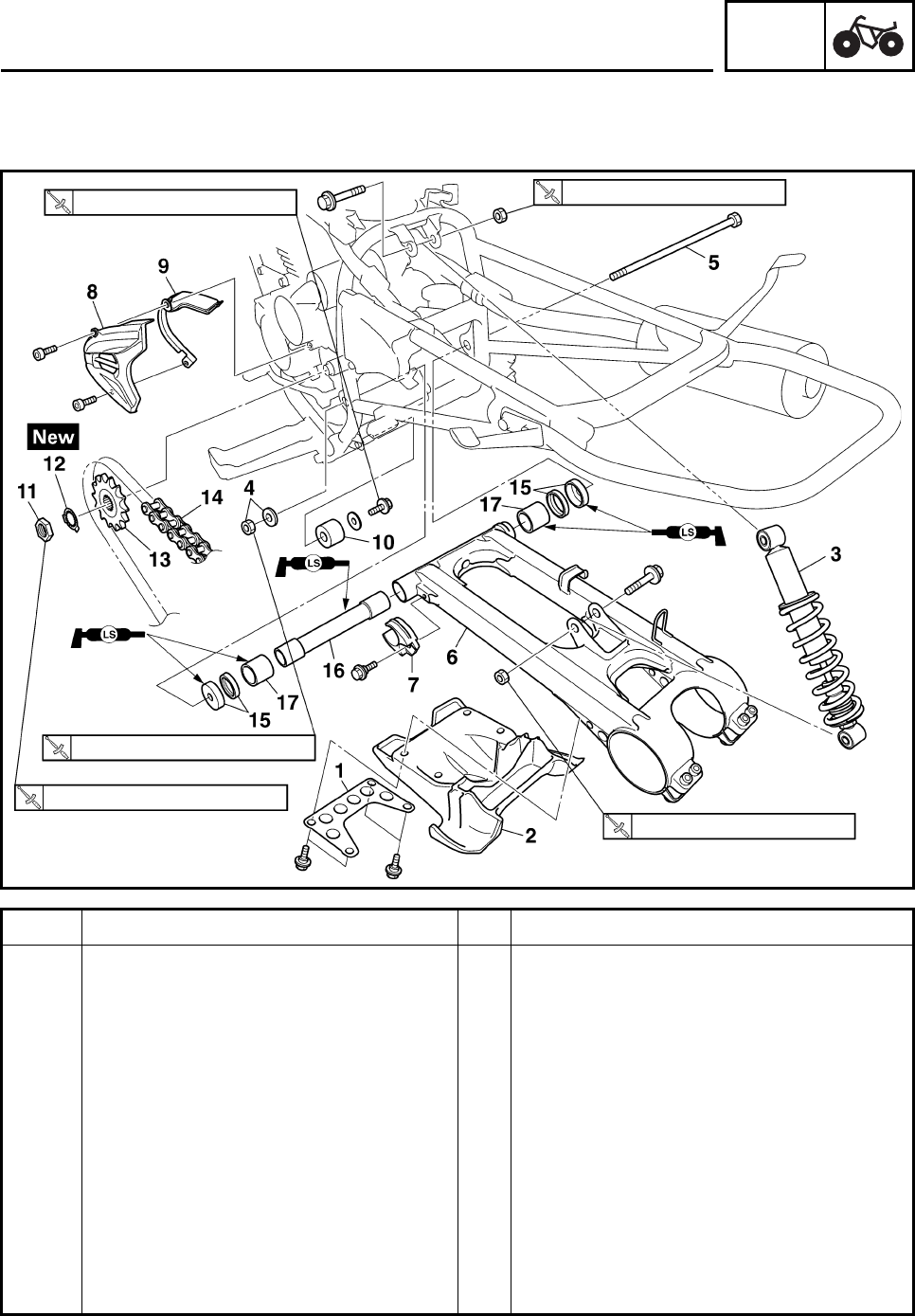
CHAS
6-55
REAR SHOCK ABSORBER, SWINGARM AND DRIVE CHAIN
Order Job/Part Q’ty Remarks
Removing the rear shock absorber,
swingarm and drive chain Remove the parts in the order listed.
Seat/rear fender/air filter case Refer to “SEAT, FENDERS AND FUEL
TANK” in chapter 3.
Rear axle hub Refer to “REAR AXLE AND REAR AXLE
HUB”.
1Plate 1
2 Swingarm end cover 1
3 Rear shock absorber 1
4 Pivot shaft nut/washer 1/1
5 Pivot shaft 1
6 Swingarm 1
7 Drive chain guide 1 1
8 Drive sprocket cover 1
23 Nm (2.3 m•kg, 17 ft•lb) 55 Nm (5.5 m•kg, 41 ft•lb)
100 Nm (10.0 m•kg, 74 ft•lb)
110 Nm (11.0 m•kg, 81 ft•lb)
55 Nm (5.5 m•kg, 41 ft•lb)
REAR SHOCK ABSORBER, SWINGARM AND
DRIVE CHAIN
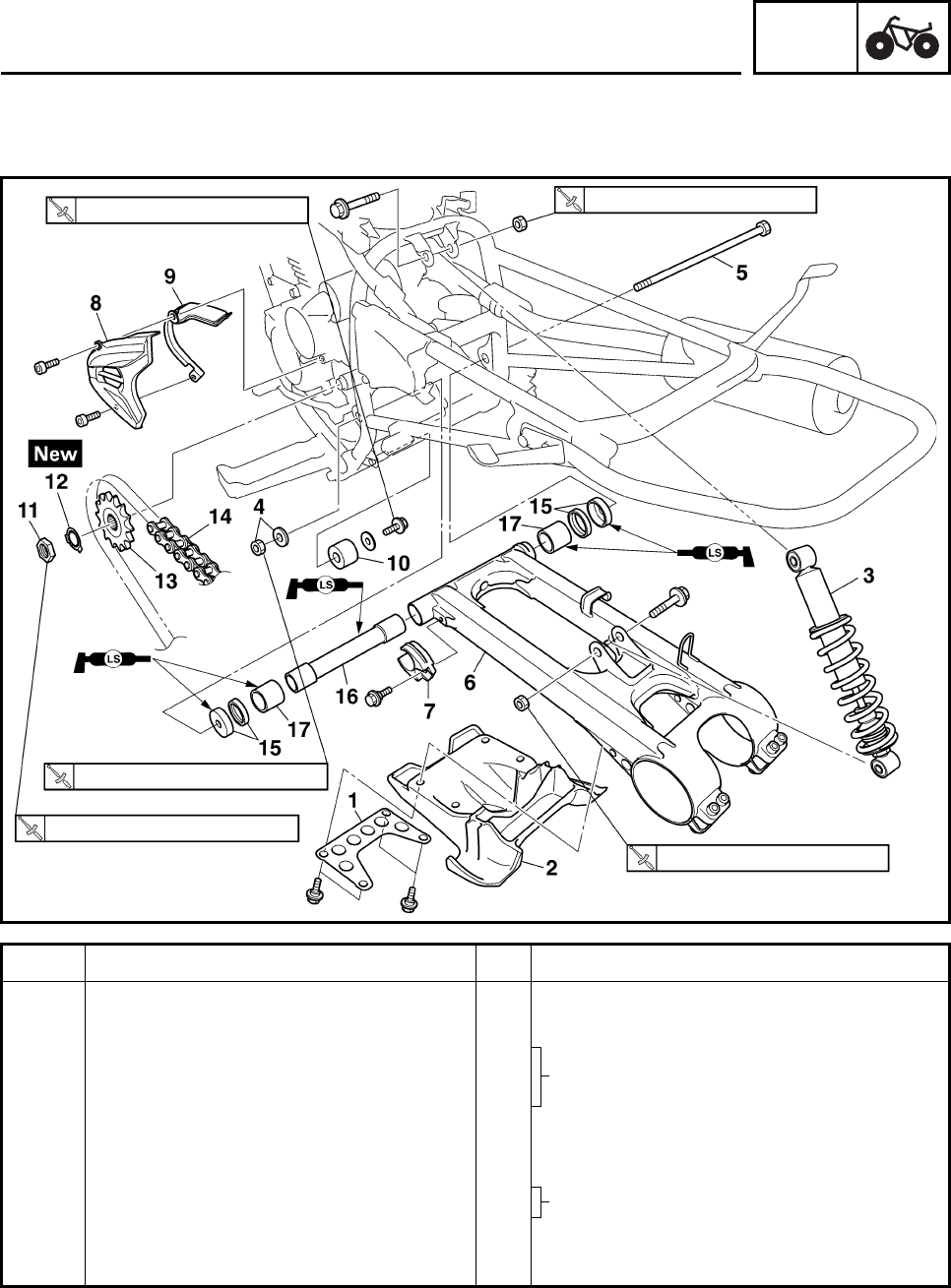
CHAS
6-56
Order Job/Part Q’ty Remarks
9Drive chain guide 2 1
10 Drive chain guide 3 1
11 Nut 1
12 Lock washer 1
13 Drive sprocket 1
14 Drive chain 1
15 Dust cover/oil seal 2/2
16 Spacer 1
17 Bearing 2
For installation, reverse the removal
procedure.
23 Nm (2.3 m•kg, 17 ft•lb) 55 Nm (5.5 m•kg, 41 ft•lb)
100 Nm (10.0 m•kg, 74 ft•lb)
110 Nm (11.0 m•kg, 81 ft•lb)
55 Nm (5.5 m•kg, 41 ft•lb)
REAR SHOCK ABSORBER, SWINGARM AND
DRIVE CHAIN
Refer to “INSTALLING THE
SWINGARM”.
Refer to “INSTALLING THE DRIVE
SPROCKET”.
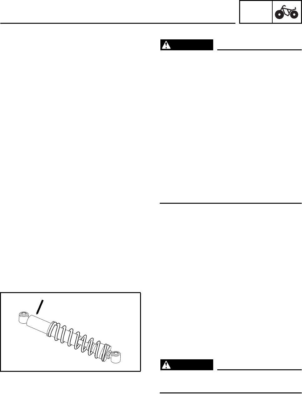
CHAS
6-57
HANDLING THE REAR SHOCK ABSORBER
WARNING
This rear shock absorber contains highly
compressed nitrogen gas. Before handling
the rear shock absorber read and make
sure you understand the following informa-
tion. The manufacturer cannot be held
responsible for property damage or per-
sonal injury that may result from improper
handling of the rear shock absorber.
• Do not tamper or attempt to open the rear
shock absorber.
• Do not subject the rear shock absorber to
an open flame or any other source of high
heat. High heat can cause an explosion
due to excessive gas pressure.
• Do not deform or damage the rear shock
absorber in any way. If the rear shock
absorber is damaged, damping perfor-
mance will suffer.
DISPOSING OF A REAR SHOCK
ABSORBER
Gas pressure must be released before dispos-
ing of a rear shock absorber. To release the
gas pressure, drill a 2 ~ 3 mm (0.08 ~ 0.12 in)
hole through the rear shock absorber at point
15 ~ 20 mm (0.59 ~ 0.79 in) from its end as
shown.
WARNING
Wear eye protection to prevent eye damage
from released gas or metal chips.
REAR SHOCK ABSORBER, SWINGARM AND
DRIVE CHAIN
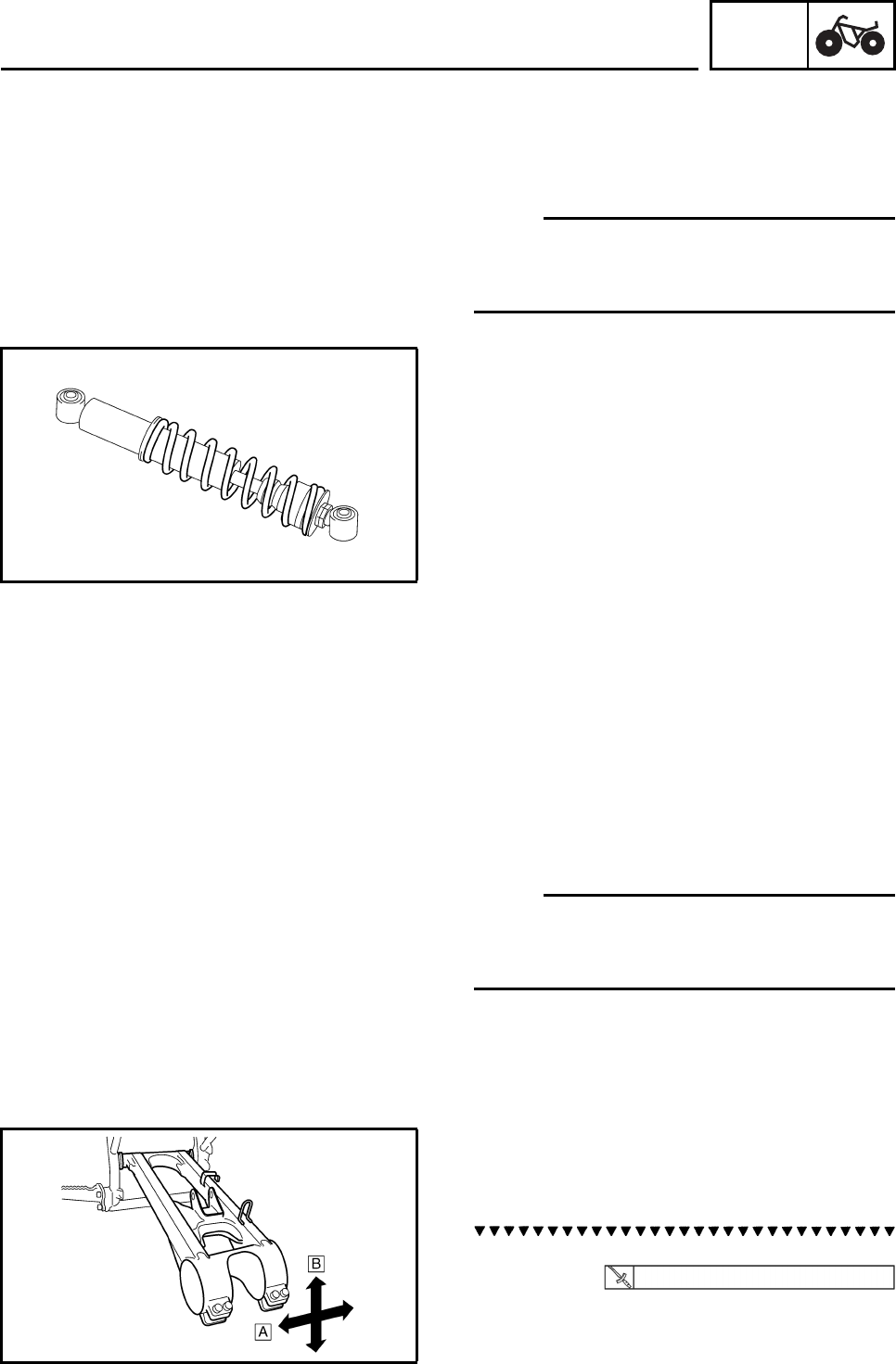
CHAS
6-58
EBS00487
REMOVING THE REAR SHOCK ABSORBER
1. Remove:
• rear shock absorber lower bolt
• rear shock absorber upper bolt
N
O
TE:N
O
TE:
While removing the rear shock absorber lower
bolt, hold the swingarm so that it does not drop
down.
EBS00488
CHECKING THE REAR SHOCK ABSORBER
1. Check:
• shock absorber
Gas leaks/oil leaks → Replace the rear
shock absorber assembly.
• shock absorber rod
Bends/damage → Replace the rear shock
absorber assembly.
•spring
Fatigue → Replace the rear shock absorber
assembly.
Move the spring up and down.
EBS00493
N
O
TE:N
O
TE:
Before removing the drive chain and the
sprockets, measure the drive chain slack and a
15-link section of the drive chain.
EBS00494
REMOVING THE SWINGARM
1. Check:
• swingarm free play
a. Check the tightening torque of the pivot
shaft nut. 100 Nm (10.0 m•kg, 74 ft•lb)
REAR SHOCK ABSORBER, SWINGARM AND
DRIVE CHAIN
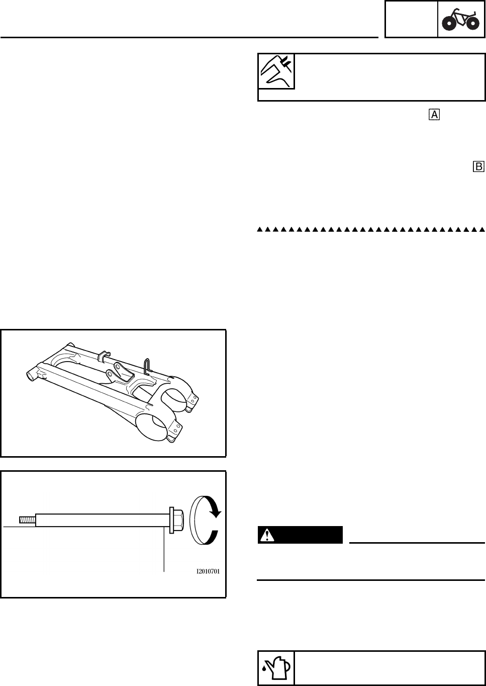
CHAS
6-59
b. Check the swingarm side play by mov-
ing it from side to side.
If side play is noticeable, check the spacer,
bearings and frame pivot.
c. Check the swingarm vertical movement
by moving it up and down.
If vertical movement is tight or rough, or if
there is binding, check the spacer, bearings
and frame pivot.
2. Remove:
• pivot shaft nut
• washer
• pivot shaft
• swingarm
EBS00495
CHECKING THE SWINGARM
1. Check:
• swingarm
Bends/cracks/damage → Replace.
2. Check:
• pivot shaft
Roll the axle on a flat surface.
Bends → Replace.
WARNING
Do not attempt to straighten a bent pivot
shaft.
3. Clean:
• pivot shaft
• spacer
• bearings
Swingarm free play limit
(at the end of the swingarm)
1.0 mm (0.04 in)
Recommended cleaning solvent
Kerosene
REAR SHOCK ABSORBER, SWINGARM AND
DRIVE CHAIN
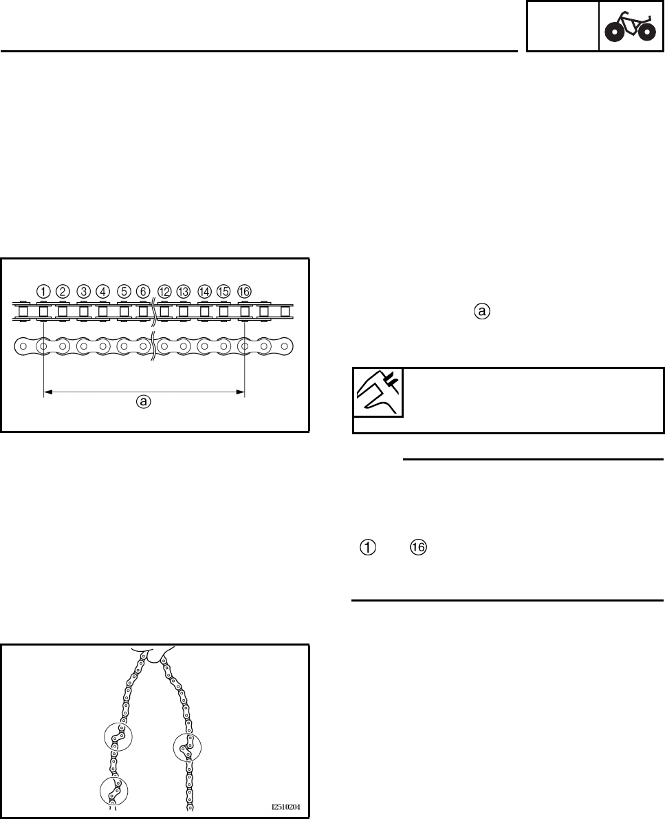
CHAS
6-60
4. Check:
• oil seals
Damage/wear → Replace.
• bearings
Damage/pitting → Replace.
EBS00496
CHECKING THE DRIVE CHAIN
1. Measure:
• 15-link section of the drive chain
Out of specification → Replace the drive
chain.
N
O
TE:N
O
TE:
• While measuring the 15-link section, push
down on the drive chain to increase its ten-
sion.
• Measure the length between drive chain roller
and as shown.
• Perform this measurement at two or three dif-
ferent places.
2. Check:
•drive chain
Stiffness → Clean and lubricate or replace.
15-link drive chain section limit
(maximum)
239.3 mm (9.42 in)
REAR SHOCK ABSORBER, SWINGARM AND
DRIVE CHAIN
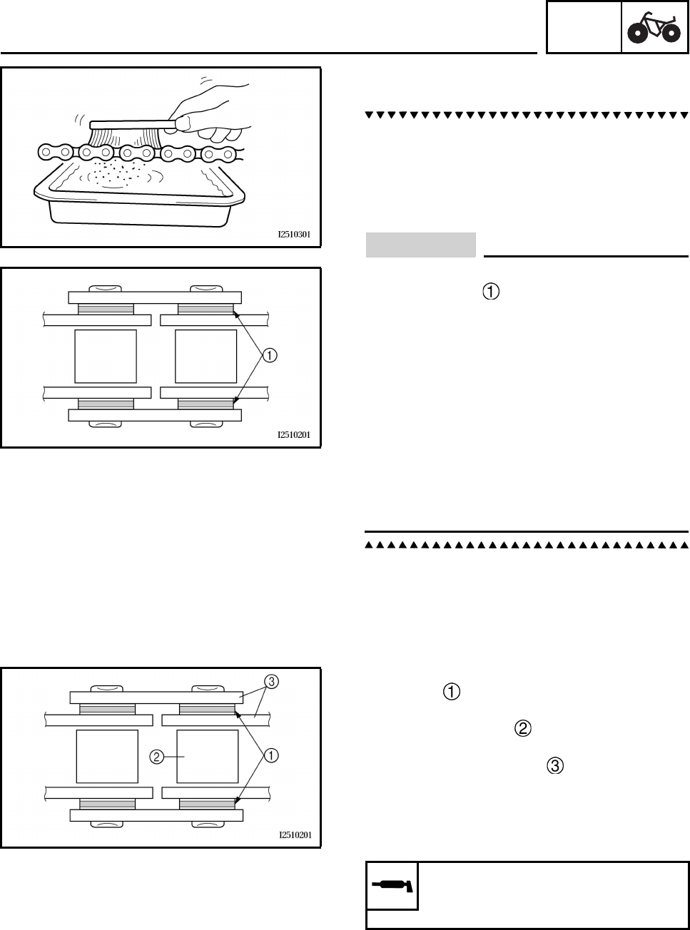
CHAS
6-61
3. Clean:
•drive chain
a. Wipe the drive chain with a clean cloth.
b. Put the drive chain in kerosene and remove
any remaining dirt.
c. Remove the drive chain from the kerosene
and completely dry it.
CAUTION:
This machine has a drive chain with small
rubber O-rings between the drive chain
side plates. Never use high-pressure water
or air, steam, gasoline, certain solvents
(e.g., benzine), or a coarse brush to clean
the drive chain. High-pressure methods
could force dirt or water into the drive
chain’s internal parts, and solvents will
deteriorate the O-rings. A coarse brush can
also damage the O-rings. Therefore, use
only kerosene to clean the drive chain.
Don’t soak the drive chain in kerosene for
more than ten minutes. Kerosene will dam-
age the O-rings.
4. Check:
• O-rings
Damage → Replace the drive chain.
• drive chain rollers
Damage/wear → Replace the drive chain.
• drive chain side plates
Cracks/damage/wear → Replace the drive
chain.
5. Lubricate:
•drive chain
Recommended lubricant
Engine oil or chain lubricant
suitable for O-ring chains
REAR SHOCK ABSORBER, SWINGARM AND
DRIVE CHAIN
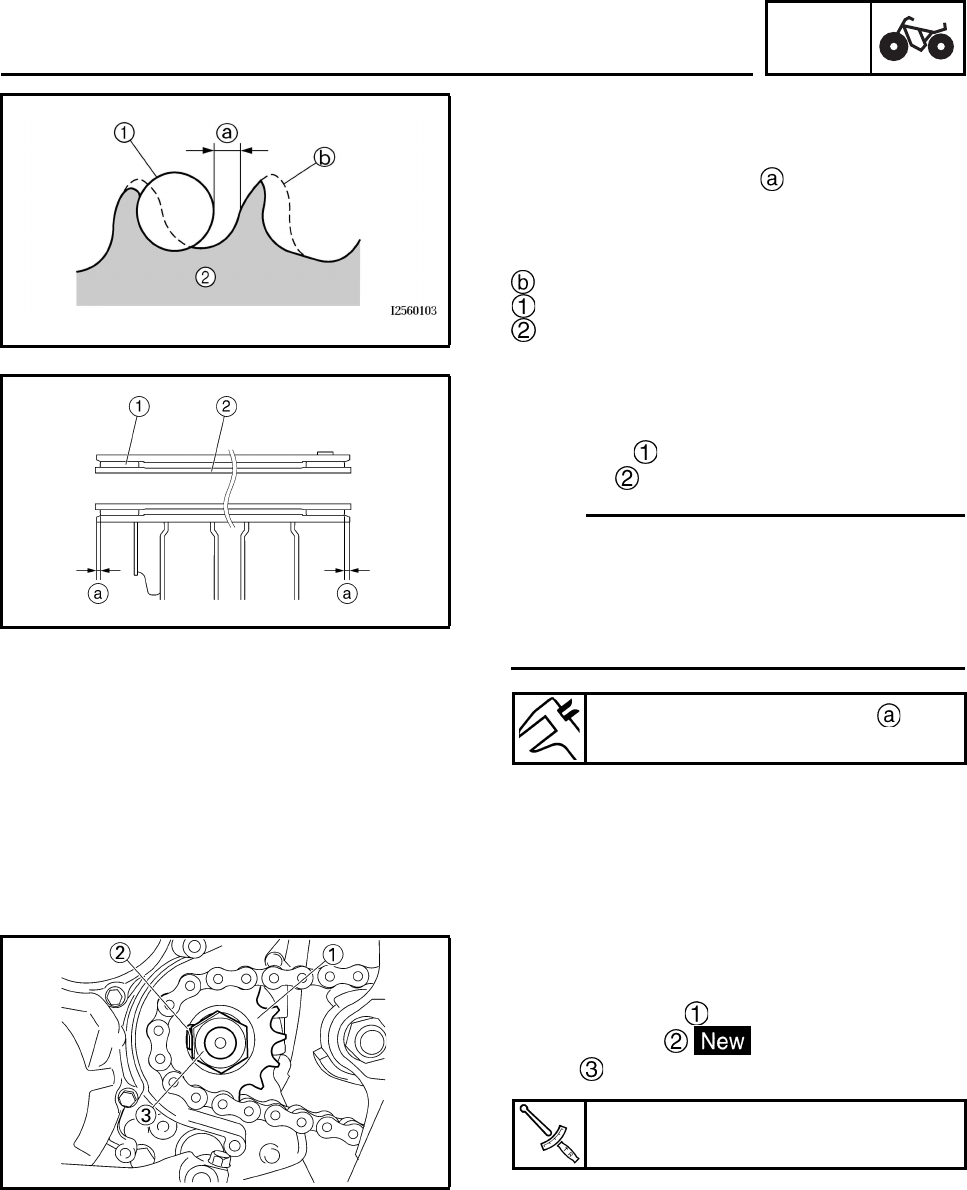
CHAS
6-62
6. Check:
• drive sprocket
• driven sprocket
More than 1/4 tooth wear → Replace
the drive chain sprockets as a set.
Bent teeth → Replace the drive chain
sprockets as a set.
Correct
Drive chain roller
Drive chain sprocket
EBS00497
INSTALLING THE SWINGARM
1. Install:
• bearings
• spacer
N
O
TE:N
O
TE:
• Inject the bearing with the character stamp
turned outward. Apply the lithium-soap-based
grease to inside.
• Apply the lithium-soap-based grease on the
spacer when installing.
EBS00498
INSTALLING THE DRIVE SPROCKET
1. Install:
• drive sprocket
• lock washer
•nut
2. Bend the lock washer tab along a flat side
of the nut.
Installed depth of bearing
1 ~ 2 mm (0.04 ~ 0.08 in)
Drive sprocket nut
110 Nm (11.0 m•kg, 81 ft•lb)
REAR SHOCK ABSORBER, SWINGARM AND
DRIVE CHAIN
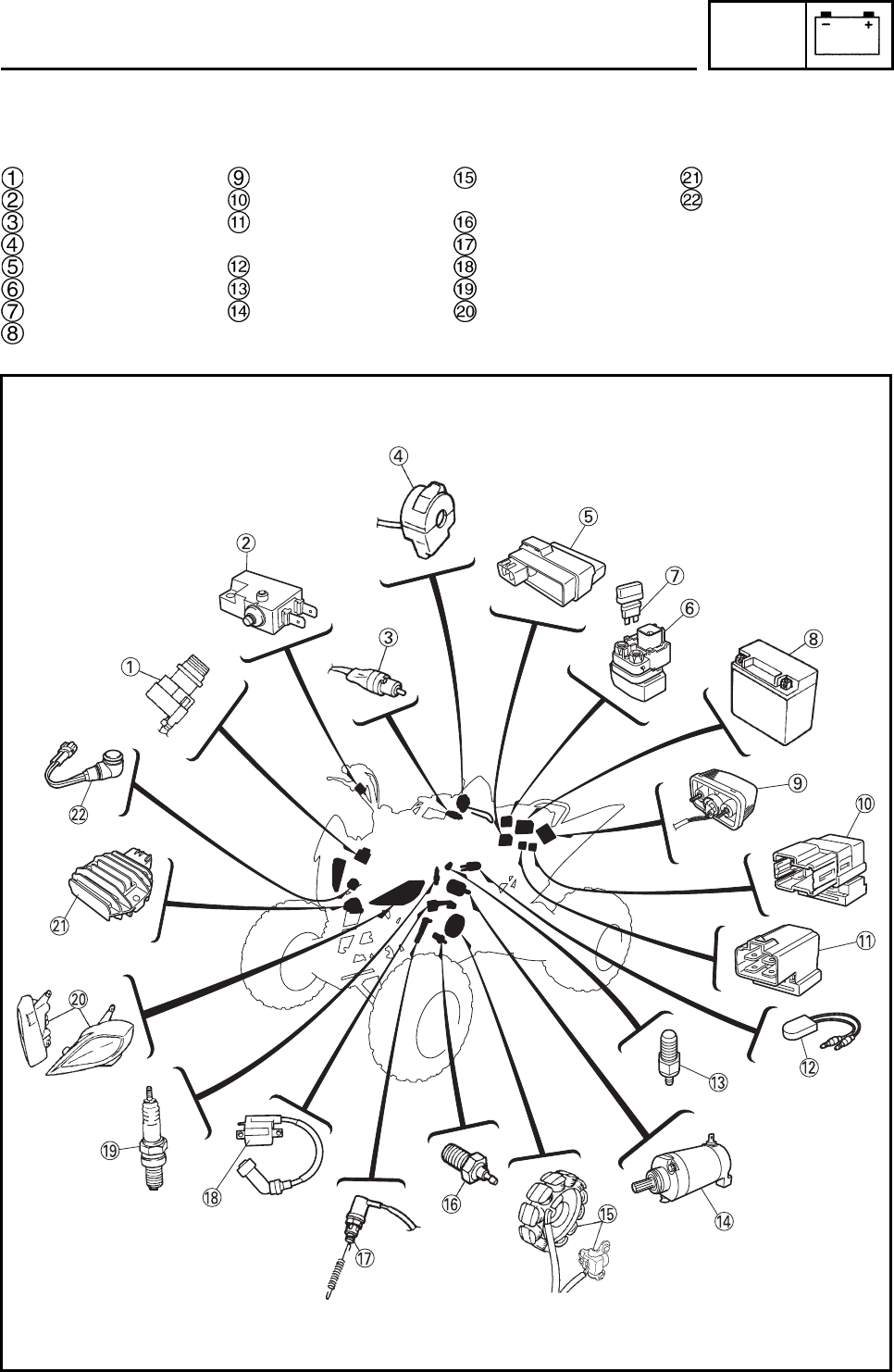
ELEC
7-1
EBS00500 ELECTRICAL
ELECTRICAL COMPONENTS
Main switch
Front brake light switch
Clutch switch
Handlebar switch
CDI unit
Starter relay
Fuse
Battery
Tail/brake light
Headlight relay
Starting circuit cut-off
relay
Thermo switch
Carburetor warmer
Starter motor
Pickup coil/stator
assembly
Neutral switch
Rear brake light switch
Ignition coil
Spark plug
Headlight
Rectifier/regulator
Neutral indicator light
ELECTRICAL COMPONENTS
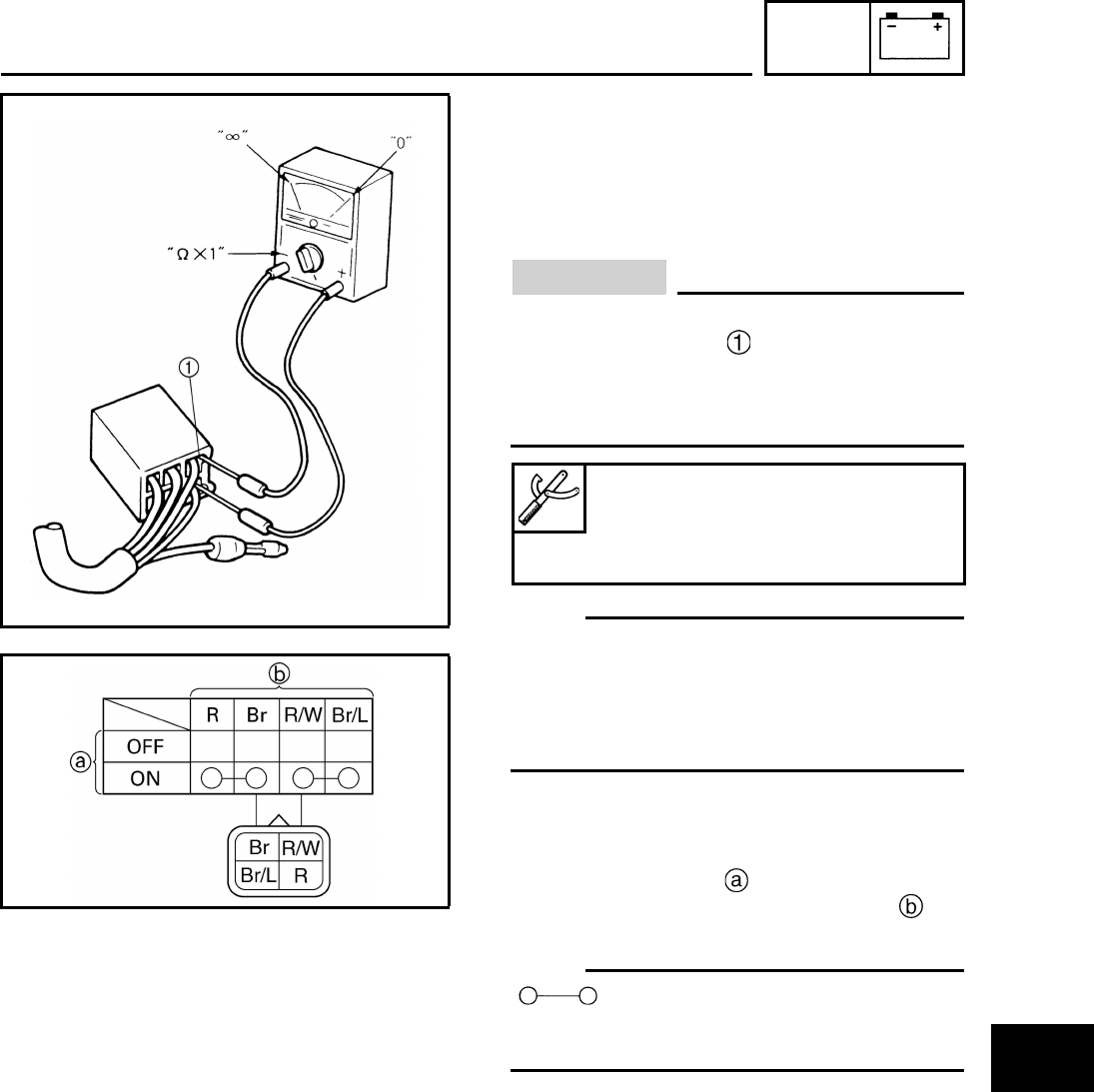
ELEC
7-2
1
2
3
4
5
6
7
8
EBS01028
CHECKING SWITCH CONTINUITY
Check each switch for continuity with the
pocket tester. If the continuity reading is incor-
rect, check the wiring connections and if nec-
essary, replace the switch.
CAUTION:
Never insert the tester probes into the cou-
pler terminal slots . Always insert the
probes from the opposite end of the cou-
pler, taking care not to loosen or damage
the leads.
N
O
TE:N
O
TE:
• Before checking for continuity, set the pocket
tester to “0” and to the “Ω × 1” range.
• When checking for continuity, switch back and
forth between the switch positions a few
times.
The terminal connections for switches (e.g.,
main switch, engine stop switch) are shown in
an illustration similar to the one on the left.
The switch positions are shown in the far
left column and the switch lead colors are
shown in the top row in the switch illustration.
N
O
TE:N
O
TE:
“ ” indicates a continuity of electricity
between switch terminals (i.e., a closed circuit
at the respective switch position).
The example illustration on the left shows
that:
There is continuity between the switch termi-
nals for the red and brown switch leads and
between the switch terminals for the red/white
and brown/blue switch leads when the switch
is set to “ON”.
Pocket tester
90890-03112
Analog pocket tester
YU-03112-C
CHECKING SWITCH CONTINUITY
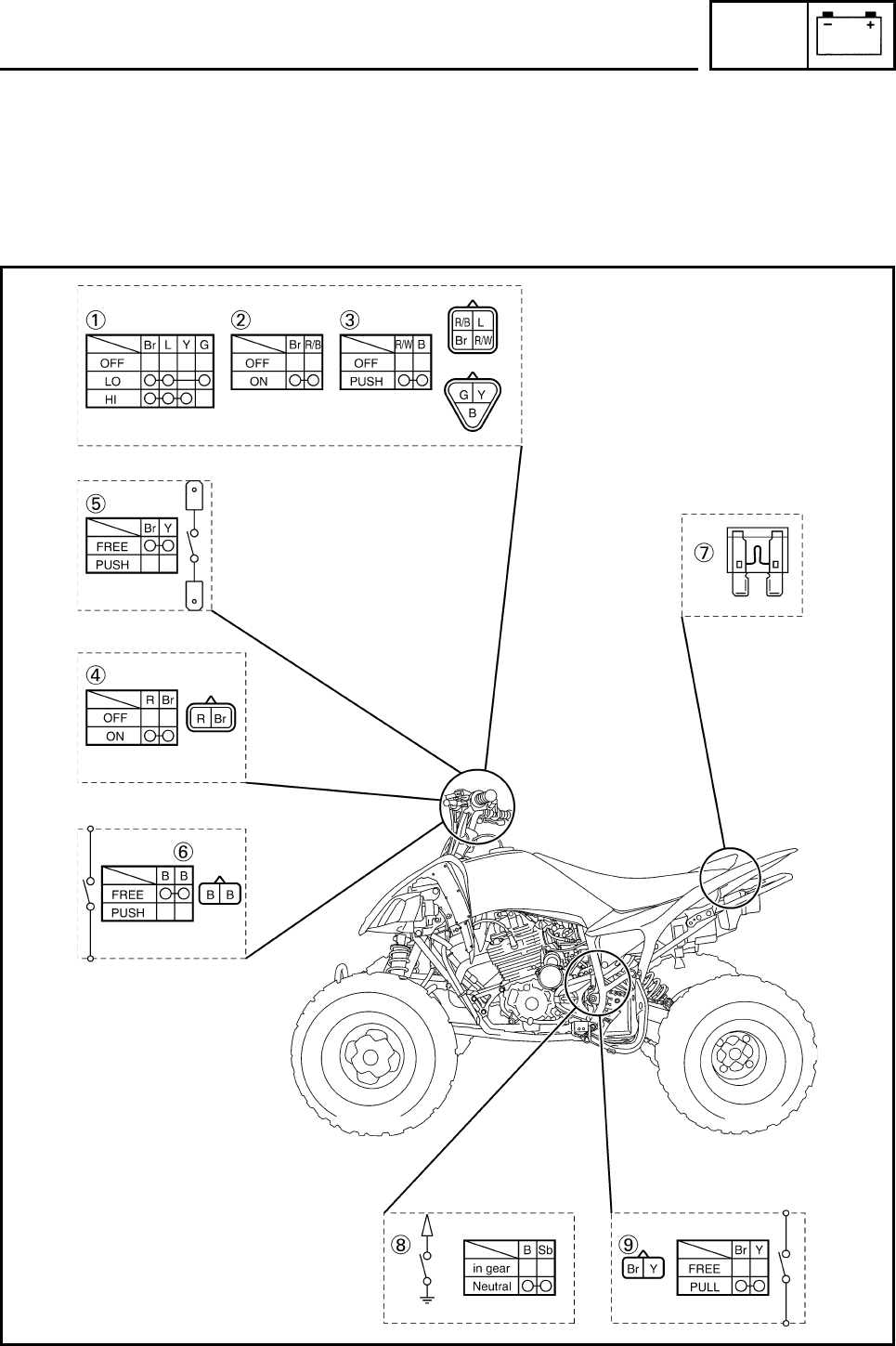
ELEC
7-3
EBS01029
CHECKING THE SWITCHES
Check each switch for damage or wear, proper connections, and also for continuity between the ter-
minals. Refer to “CHECKING SWITCH CONTINUITY”.
Damage/wear → Repair or replace.
Improperly connected → Properly connect.
Incorrect continuity reading → Replace the switch.
CHECKING THE SWITCHES
ELEC
7-4
Light switch
Engine stop switch
Start switch
Main switch
Front brake light switch
Clutch switch
Fuse
Neutral switch
Rear brake light switch
CHECKING THE SWITCHES
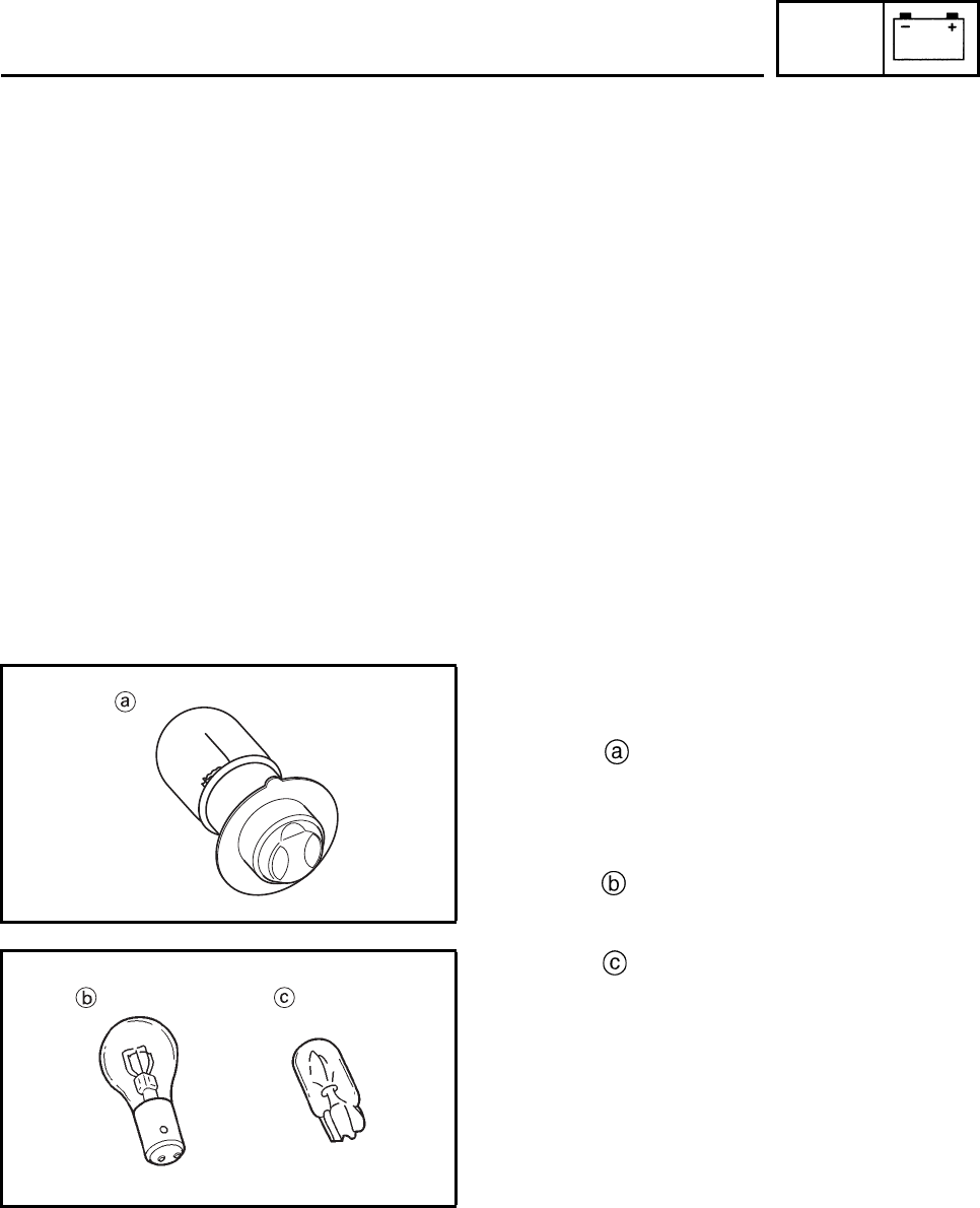
ELEC
7-5
EBS01030
CHECKING THE BULBS AND
BULB SOCKETS
Check each bulb and bulb socket for damage
or wear, proper connections, and also for conti-
nuity between the terminals.
Damage/wear → Repair or replace the
bulb, bulb socket or both.
Improperly connected → Properly connect.
No continuity → Repair or replace the bulb,
bulb socket or both.
TYPES OF BULBS
The bulbs used on this machine are shown in
the illustration on the left.
• Bulb is used for the headlight and can
be pulled out by turning counterclockwise
while pushing the bulb holder and remov-
ing.
After this, you can remove the bulb.
• Bulb is used for tail/ brake lights and can
be removed from the socket by pushing and
turning the bulb counterclockwise.
• Bulb is used for indicator lights and can
be removed from their respective socket by
carefully pulling them out.
CHECKING THE CONDITION OF THE
BULBS
The following procedure applies to all of the
bulbs.
1. Remove:
•bulb
CHECKING THE BULBS AND BULB SOCKETS
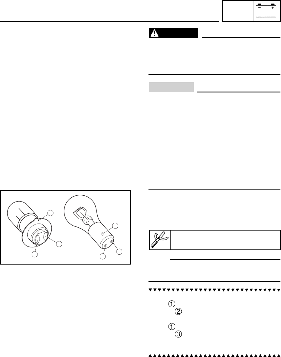
ELEC
7-6
WARNING
Since the headlight bulb gets extremely
hot, keep flammable products and your
hands away from the bulb until it has
cooled down.
CAUTION:
• Be sure to hold the socket firmly when
removing the bulb. Never pull the lead,
otherwise it may be pulled out of the ter-
minal in the coupler.
• Avoid touching the glass part of the head-
light bulb to keep it free from oil, other-
wise the transparency of the glass, the life
of the bulb, and the luminous flux will be
adversely affected. If the headlight bulb
gets soiled, thoroughly clean it with a
cloth moistened with alcohol or lacquer
thinner.
2. Check:
• bulb (for continuity)
(with the pocket tester)
No continuity → Replace.
N
O
TE:N
O
TE:
Before checking for continuity, set the pocket
tester to “0” and to the “Ω × 1” range.
a. Connect the positive tester probe to termi-
nal and the negative tester probe to ter-
minal , and check the continuity.
b. Connect the positive tester probe to termi-
nal and the negative tester probe to ter-
minal , and check the continuity.
c. If either of the readings indicate no continu-
ity, replace the bulb.
Pocket tester
90890-03112, YU-03112-C
1
1
2
2
3
3
CHECKING THE BULBS AND BULB SOCKETS
ELEC
7-7
CHECKING THE CONDITION OF THE BULB
SOCKETS
The following procedure applies to all of the
bulb sockets.
1. Check:
• bulb socket (for continuity)
(with the pocket tester)
No continuity → Replace
N
O
TE:N
O
TE:
Check each bulb socket for continuity in the
same manner as described in the bulb section;
however, note the following.
a. Install a good bulb into the bulb socket.
b. Connect the pocket tester probes to the
respective leads of the bulb socket.
c. Check the bulb socket for continuity. If any
of the readings indicate no continuity,
replace the bulb socket.
Pocket tester
90890-03112
Analog pocket tester
YU-03112-C
CHECKING THE BULBS AND BULB SOCKETS
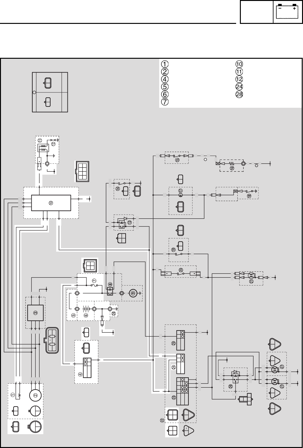
ELEC
7-8
EBS00503
IGNITION SYSTEM
CIRCUIT DIAGRAM
A
A
B/Y
B
RBrRBr
ON
OFF
OFF
LO
HI
OFF
ON
OFF
PUSH
R/B
L
Br
R/W
GY
B
R/B
L
Br
L/B
Y
B
RR
L/BY/B
B/Y
B
BB
O
O
B/Y
B
Y/BB/Y
R/B
Sb
GY
B
GY
B
GY
B
GY
B
W
WW
WR
W/L W/R
W
WW
L
Y
BGY
R/B
BWW
O
W/LW/R
W
Br Sb BrSbYBr Y Br
SUB-WIRE HARNESS
A
WIRE HARNESS
RB
W
W
W
W/R
W/L
W
W
W
W
W
WB
R
R/B
WWW
B
B
R
Br B
RR
RR
R
R
Y/B
L/B
B
B
Y/B B/Y
R/B Sb
BY
B
Br
Br
Br
Sb BY
BY
BY
BY
B
B
B
B
Sb
Y
L
Y
Y
Br
L/B
R/B
Br
B
Y
L
B
G
L
YY
GYGY
BB
W/R
W/L
#
#
Pickup coil
Stator coil
Main switch
Battery positive lead
Battery
Fuse
CDI unit
Ignition coil
Spark plug
Engine stop switch
Ground
IGNITION SYSTEM
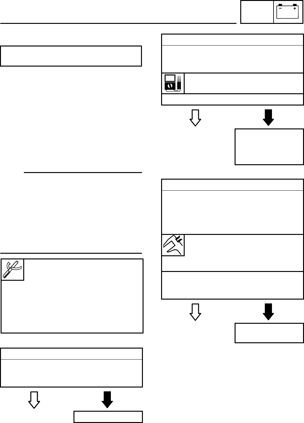
ELEC
7-9
EBS01045
TROUBLESHOOTING
Check:
1. fuse
2. battery
3. spark plug
4. ignition spark gap
5. ignition coil resistance
6. main switch
7. engine stop switch
8. pickup coil resistance
9. wiring connections (of the entire ignition
system)
N
O
TE:N
O
TE:
• Before troubleshooting, remove the following
part(s):
1. seat
2. front panel
3. front fender
4. rear fender
5. side cover
• Troubleshoot with the following special
tool(s).
EBS01043
EBS01044
EBS01032
The ignition system fails to operate (no
spark or intermittent spark).
1. Fuse
• Check the fuse for continuity.
Refer to “CHECKING THE SWITCHES”.
• Is the fuse OK?
YES NO
Replace the fuse.
Ignition checker
90890-06754
Opama pet-4000 spark checker
YM-34487
Pocket tester
90890-03112
Analog pocket tester
YU-03112-C
2. Battery
• Check the condition of the battery.
Refer to “CHECKING AND CHARGING
THE BATTERY” in chapter 3.
Minimum open-circuit voltage
12.8 V or more at 20°C (68°F)
• Is the battery OK?
YES NO
• Clean the battery
terminals.
• Recharge or replace
the battery.
3. Spark plug
• Check the condition of the spark plug.
• Check the spark plug type.
• Measure the spark plug gap.
Refer to “CHECKING THE SPARK PLUG”
in chapter 3.
Standard spark plug
DR7EA (NGK)
Spark plug gap
0.6 ~ 0.7 mm (0.024 ~ 0.028 in)
• Is the spark plug in good condition, is it of
the correct type, and is its gap within speci-
fication?
YES NO
Re-gap or replace
the spark plug.
IGNITION SYSTEM
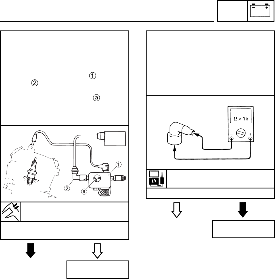
ELEC
7-10
EBS01034 EAS00745
4. Ignition spark gap
The following procedure applies to all of the
spark plugs.
• Disconnect the spark plug cap from the
spark plug.
• Connect the ignition checker and spark
plug cap as shown.
• Set the main switch to “ON”.
• Measure the ignition spark gap .
• Crank the engine by pushing the starter
switch and gradually increase the spark gap
until a misfire occurs.
Minimum ignition spark gap
6 mm (0.24 in)
• Is there a spark and is the spark gap within
specification?
NO YES
The ignition system
is OK.
1
a
2
5. Spark plug cap resistance
The following procedure applies to all of the
spark plug caps.
• Remove the spark plug cap from the spark
plug lead.
• Connect the pocket tester (Ω × 1k) to the
spark plug cap as shown.
• Measure the spark plug cap resistance.
Spark plug cap resistance
10 kΩ at 20°C (68°F)
• Is the spark plug cap OK?
YES NO
Replace the spark
plug cap.
IGNITION SYSTEM
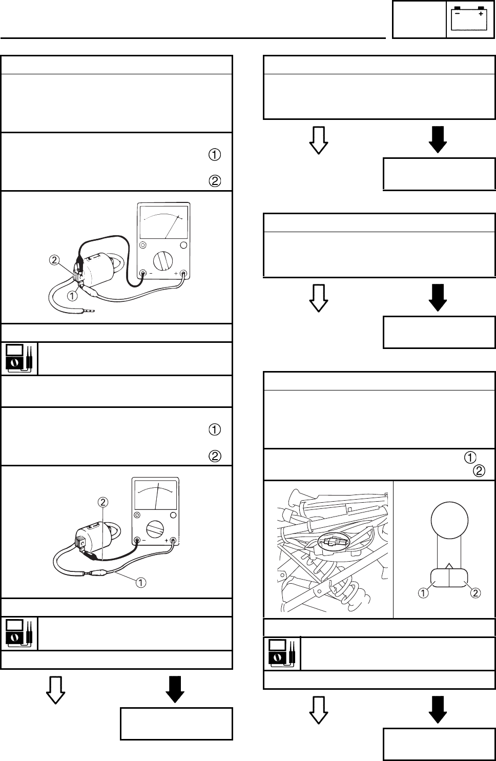
ELEC
7-11
EBS01038 EBS01041
EBS01042
EBS01040
6. Ignition coil resistance
• Disconnect the ignition coil coupler from the
ignition coil.
• Connect the pocket tester (Ω × 1) to the
ignition coil as shown.
Positive tester probe →
orange lead terminal
Negative tester probe →
ignition coil base
• Measure the primary coil resistance.
Primary coil resistance
0.18 ~ 0.28 Ω at 20°C (68°F)
• Connect the pocket tester (Ω × 1k) to the
ignition coil as shown.
Positive tester probe →
high tension code
Negative tester probe →
orange lead terminal
• Measure the secondary coil resistance.
Secondary coil resistance
6.32 ~ 9.48 kΩ at 20°C (68°F)
• Is the ignition coil OK?
YES NO
Replace the ignition
coil.
7. Main switch
• Check the main switch for continuity.
Refer to “CHECKING THE SWITCHES”.
• Is the main switch OK?
YES NO
Replace the main
switch.
8. Engine stop switch
• Check the engine stop switch for continuity.
Refer to “CHECKING THE SWITCHES”.
• Is the engine stop switch OK?
YES NO
Replace the handle-
bar switch.
9. Pickup coil resistance
• Disconnect the pickup coil coupler from the
wire harness.
• Connect the pocket tester (Ω × 100) to the
pickup coil terminal as shown.
Positive tester probe → red terminal
Negative tester probe → white terminal
• Measure the pickup coil resistance.
Pickup coil resistance
248 ~ 372 Ω at 20°C (68°F)
• Is the pickup coil OK?
YES NO
Replace the pickup
coil/stator assembly.
RW
(BLACK)
IGNITION SYSTEM

ELEC
7-12
EBS01047
10. Wiring
• Check the entire ignition system’s wiring.
Refer to “CIRCUIT DIAGRAM”.
• Is the ignition system’s wiring properly con-
nected and without defects?
YES NO
Replace the CDI
unit. Properly connect or
repair the ignition
system’s wiring.
IGNITION SYSTEM
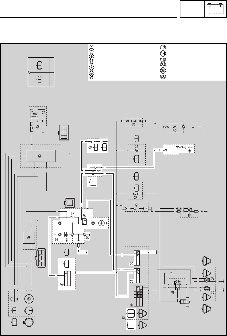
ELEC
7-13
EBS00506
ELECTRIC STARTING SYSTEM
CIRCUIT DIAGRAM
A
A
B/Y
B
RBrRBr
ON
OFF
OFF
LO
HI
OFF
ON
OFF
PUSH
R/B
L
Br
R/W
GY
B
R/B
L
Br
L/B
Y
B
RR
L/BY/B
B/Y
B
BB
B/Y
B
Y/BB/Y
R/B
Sb
GY
B
GY
B
GY
B
GY
B
W
WW
WR
W/L W/R
W
WW
L
Y
BGY
R/B
BWW
O
W/LW/R
W
Br Sb BrSbYBr Y Br
SUB-WIRE HARNESS
A
WIRE HARNESS
RB
WWW
W/R
W/L
W
W
W
W
W
W
R
Br B
RR
RR
OO
B
R
W/R
W/L
R/B
WWW
B
B
R
R
Y/B
L/B
B
B
Y/B B/Y
R/B Sb
BY
B
Br
Br
Sb BY
BY
BY
BY
B
B
B
Sb
Br
B
Y
L
Y
Y
Br
L/B
R/B
Br
B
Y
L
B
G
L
YY
GYGY
BB
Main switch
Battery positive lead
Battery
Fuse
Starter relay
Starter motor
Starting circuit cut-off relay
Clutch switch
Neutral switch
Engine stop switch
Start switch
Ground
ELECTRIC STARTING SYSTEM
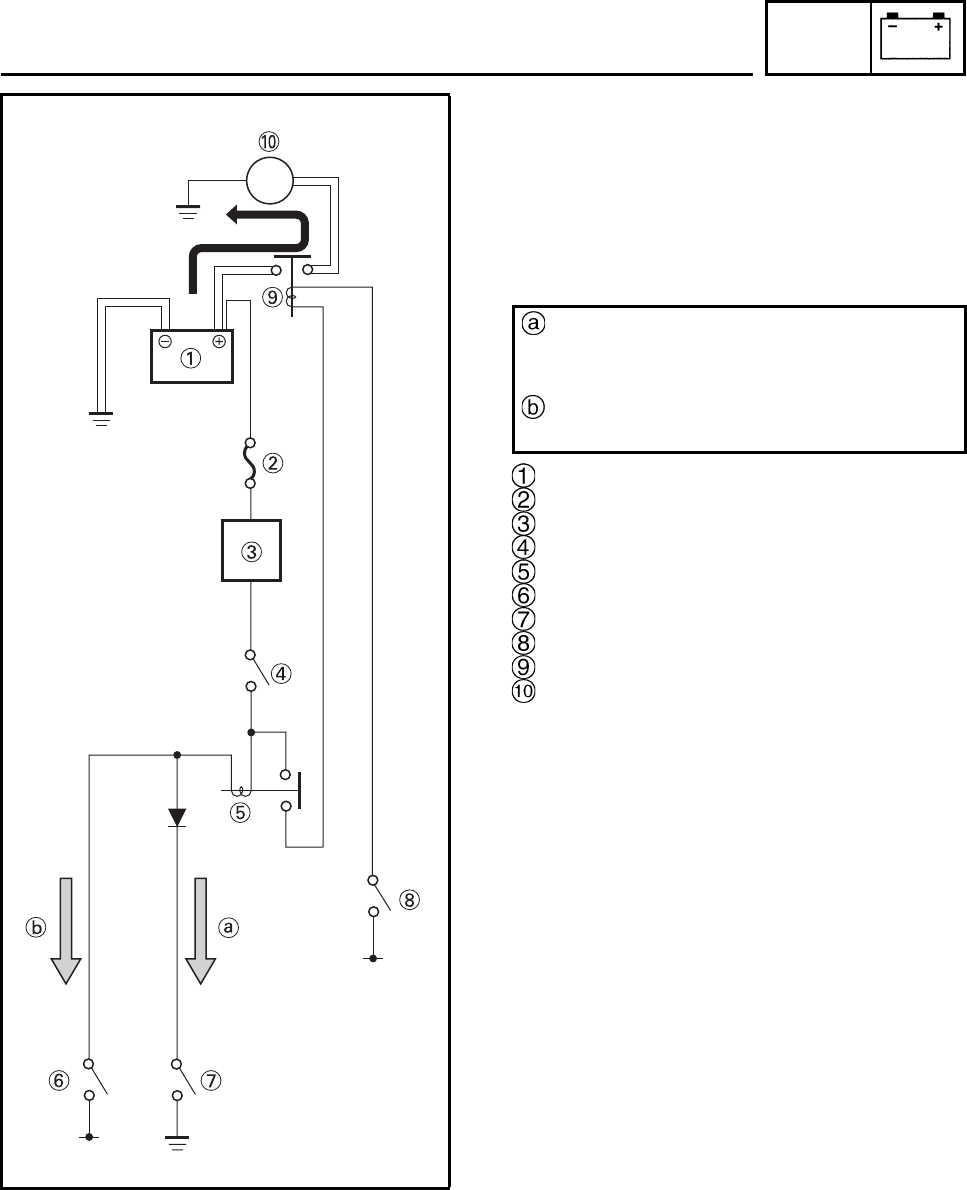
ELEC
7-14
EBS00508
STARTING CIRCUIT CUT-OFF SYSTEM
OPERATION
The starting circuit on this model consists of
the starter motor, starter relay, clutch switch,
and neutral switch. If the main switch is on and
the engine stop switch is in the RUN position,
the starter motor can be operated only if:
Battery
Fuse
Main switch
Engine stop switch
Starting circuit cut-off relay
Clutch switch
Neutral switch
Start switch
Starter relay
Starter motor
M
The transmission is in neutral (the neutral
switch is closed) or
You pull in the clutch lever (the clutch
switch is closed).
ELECTRIC STARTING SYSTEM
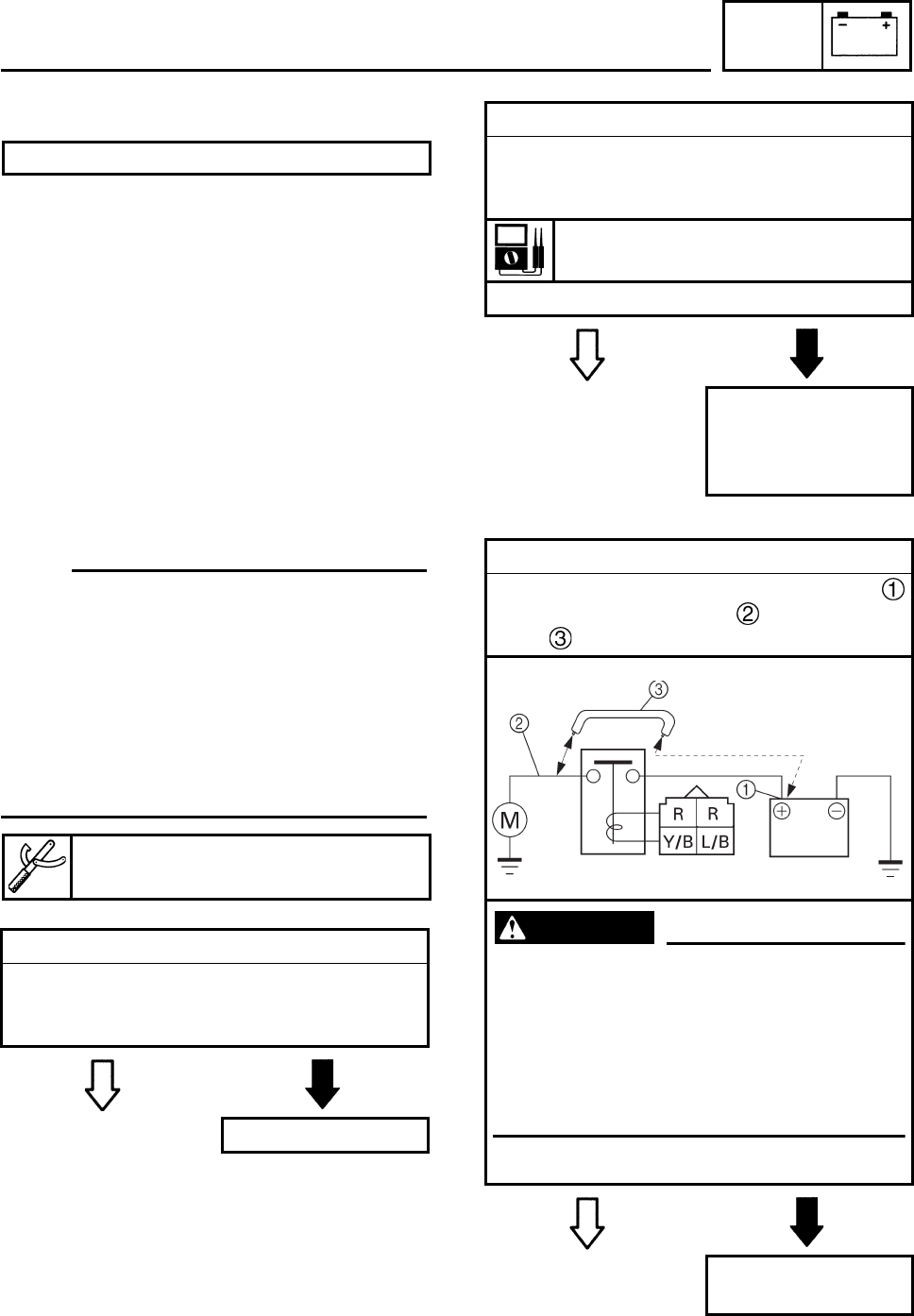
ELEC
7-15
EBS01050
TROUBLESHOOTING
Check:
1. fuse
2. battery
3. starter motor
4. starting circuit cut-off relay
5. starting circuit cut-off relay (diode)
6. starter relay
7. main switch
8. engine stop switch
9. neutral switch
10.clutch switch
11.start switch
12.wiring connections
(of the entire starting system)
N
O
TE:N
O
TE:
• Before troubleshooting, remove the following
part(s):
1. seat
2. front panel
3. front fender
4. rear fender
5. side cover
• Troubleshoot with the following special
tool(s).
EBS01043
EBS01044
EBS01051
1. Fuse
• Check the fuse for continuity.
Refer to “CHECKING THE SWITCHES”.
• Is the fuse OK?
YES NO
Replace the fuse.
The starter motor fails to turn.
Pocket tester
90890-03112, YU-03112-C
2. Battery
• Check the condition of the battery.
Refer to “CHECKING AND CHARGING
THE BATTERY” in chapter 3.
Minimum open-circuit voltage
12.8 V or more at 20°C (68°F)
• Is the battery OK?
YES NO
• Clean the battery
terminals.
• Recharge or replace
the battery.
3. Starter motor
• Connect the positive battery terminal
and starter motor lead with a jumper
lead .
WARNING
• A wire that is used as a jumper lead
must have at least the same capacity or
more as that of the battery lead, other-
wise the jumper lead may burn.
• This check is likely to produce sparks,
therefore make sure nothing flammable
is in the vicinity.
• Does the starter motor turn?
YES NO
Repair or replace
the starter motor.
ELECTRIC STARTING SYSTEM
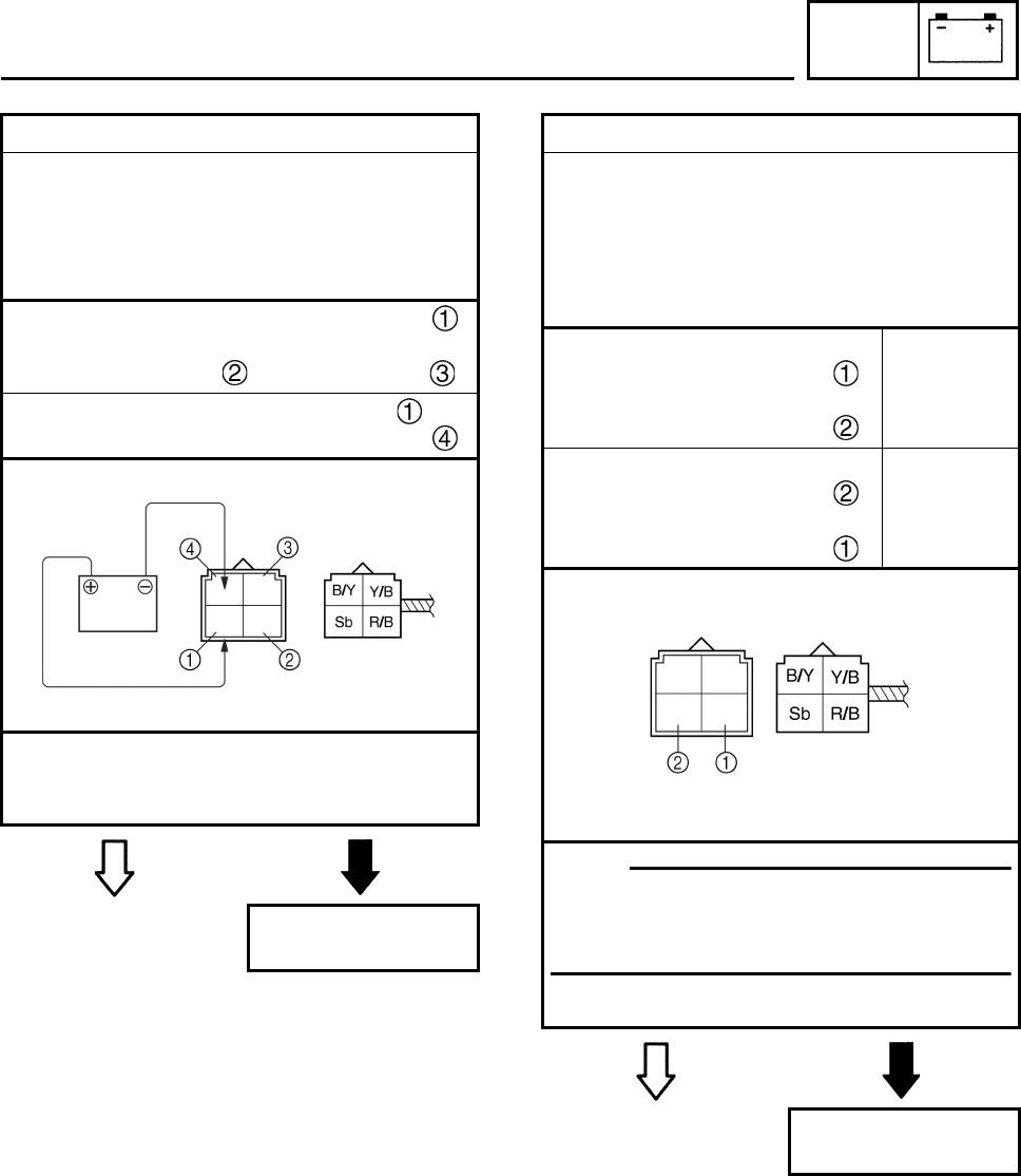
ELEC
7-16
EBS01052 EBS01053
4. Starting circuit cut-off relay
• Remove the starting circuit cut-off relay
from the wire harness.
• Connect the pocket tester (Ω × 1) and bat-
tery (12 V) to the starting circuit cut-off relay
as shown.
Positive battery terminal → red/black
Negative battery terminal →
sky blue or black/yellow
Positive tester probe → red/black
Negative tester probe → yellow/black
• Does the starting circuit cut-off relay have
continuity between red/black and yellow/
black?
YES NO
Replace the starting
circuit cut-off relay.
5. Starting circuit cut-off relay (diode)
• Remove the starting circuit cut-off relay
from the wire harness.
• Connect the pocket tester (Ω × 1) to the
starting circuit cut-off relay as shown.
• Measure the starting circuit cut-off relay for
continuity as follows.
Positive tester probe →
sky blue
Negative tester probe →
red/black
Continuity
Positive tester probe →
red/black
Negative tester probe →
sky blue
No
continuity
N
O
TE:N
O
TE:
When you switch the tester’s positive and
negative probes, the readings in the above
chart will be reversed.
• Are the testing readings correct?
YES NO
Replace the starting
circuit cut-off relay.
ELECTRIC STARTING SYSTEM
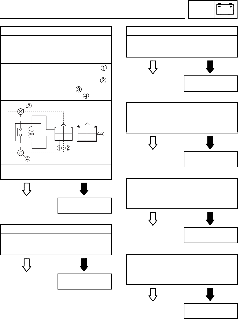
ELEC
7-17
EBS01054
EBS01041
EBS01042
EBS01046
EBS01056
EBS01057
6. Starter relay
• Disconnect the starter relay coupler from
the wire harness.
• Connect the pocket tester (Ω × 1) and bat-
tery (12 V) to the starter relay as shown.
Positive battery terminal → blue/black
Negative battery terminal →
yellow/black
Positive tester probe → red
Negative tester probe → black
• Does the starter relay have continuity
between red and black?
YES NO
Replace the starter
relay.
7. Main switch
• Check the main switch for continuity.
Refer to “CHECKING THE SWITCHES”.
• Is the main switch OK?
YES NO
Replace the main
switch.
R
B
RR
Y/BL/B
8. Engine stop switch
• Check the engine stop switch for continuity.
Refer to “CHECKING THE SWITCHES”.
• Is the engine stop switch OK?
YES NO
Replace the handle-
bar switch.
9. Neutral switch
• Check the neutral switch for continuity.
Refer to “CHECKING THE SWITCHES”.
• Is the neutral switch OK?
YES NO
Replace the neutral
switch.
10.Clutch switch
• Check the clutch switch for continuity.
Refer to “CHECKING THE SWITCHES”.
• Is the clutch switch OK?
YES NO
Replace the clutch
switch.
11.Start switch
• Check the start switch for continuity.
Refer to “CHECKING THE SWITCHES”.
• Is the start switch OK?
YES NO
Replace the handle-
bar switch.
ELECTRIC STARTING SYSTEM
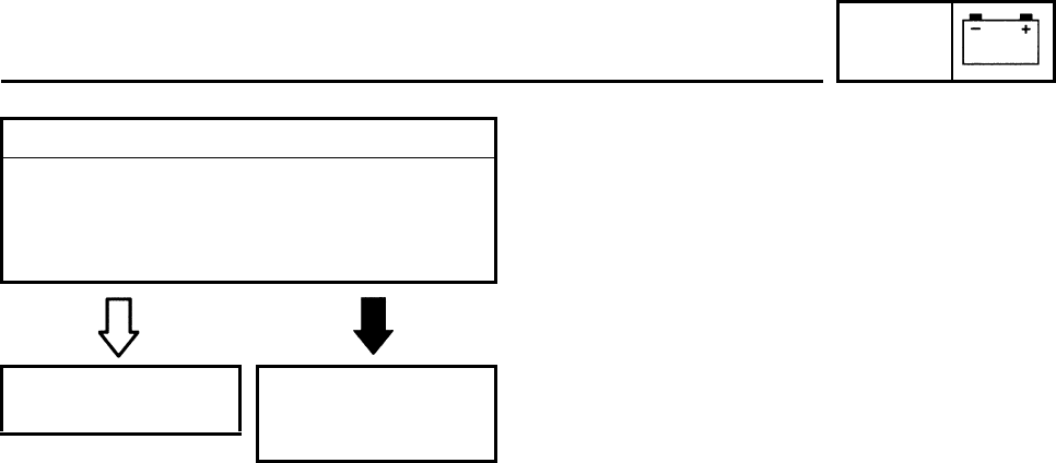
ELEC
7-18
EBS01059
12. Wiring
• Check the entire starting system’s wiring.
Refer to “CIRCUIT DIAGRAM”.
• Is the starting system’s wiring properly con-
nected and without defects?
YES NO
The starting system
circuit is OK. Properly connect or
repair the starting
system’s wiring.
ELECTRIC STARTING SYSTEM
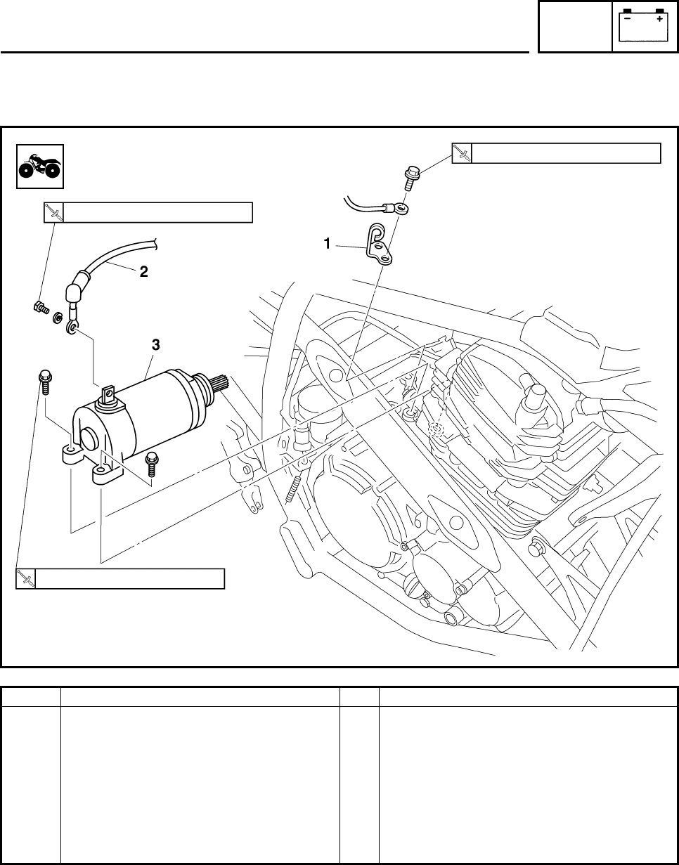
ELEC
7-19
EBS01061
STARTER MOTOR
Order Job/Part Q’ty Remarks
Removing the starter motor Remove the parts in the order listed.
Exhaust pipe
Idle gear cover and idle gear Refer to “ENGINE REMOVAL” in chapter
4.
1 Clutch cable holder 1
2 Starter motor lead 1 Disconnect.
3 Starter motor 1
For installation, reverse the removal
procedure.
7 Nm (0.7 m•kg, 5.2 ft•lb)
10 Nm (1.0 m•kg, 7.4 ft•lb)
10 Nm (1.0 m•kg, 7.4 ft•lb)
STARTER MOTOR
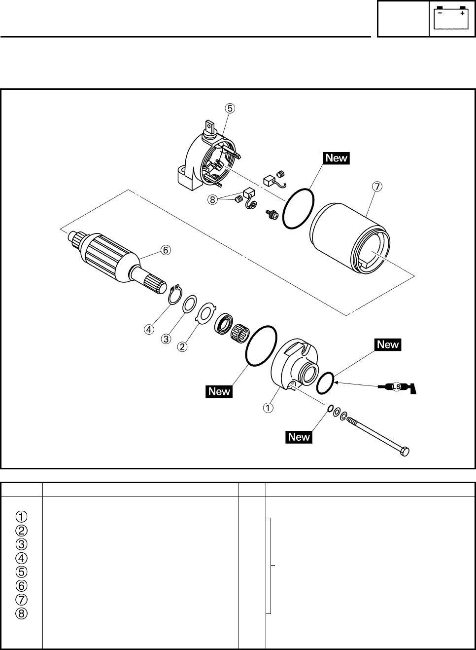
ELEC
7-20
EBS01062
Order Job/Part Q’ty Remarks
Disassembling the starter motor Remove the parts in the order listed.
Front bracket 1
Tang washer 1
Plate washer 1
Circlip 1
Rear bracket/Brush 1/1
Armature assembly 1
Starter motor yoke 1
Brush/spring 2/2
For assembly, reverse the disassembly
procedure.
STARTER MOTOR
Refer to “ASSEMBLING THE STARTER
MOTOR”.
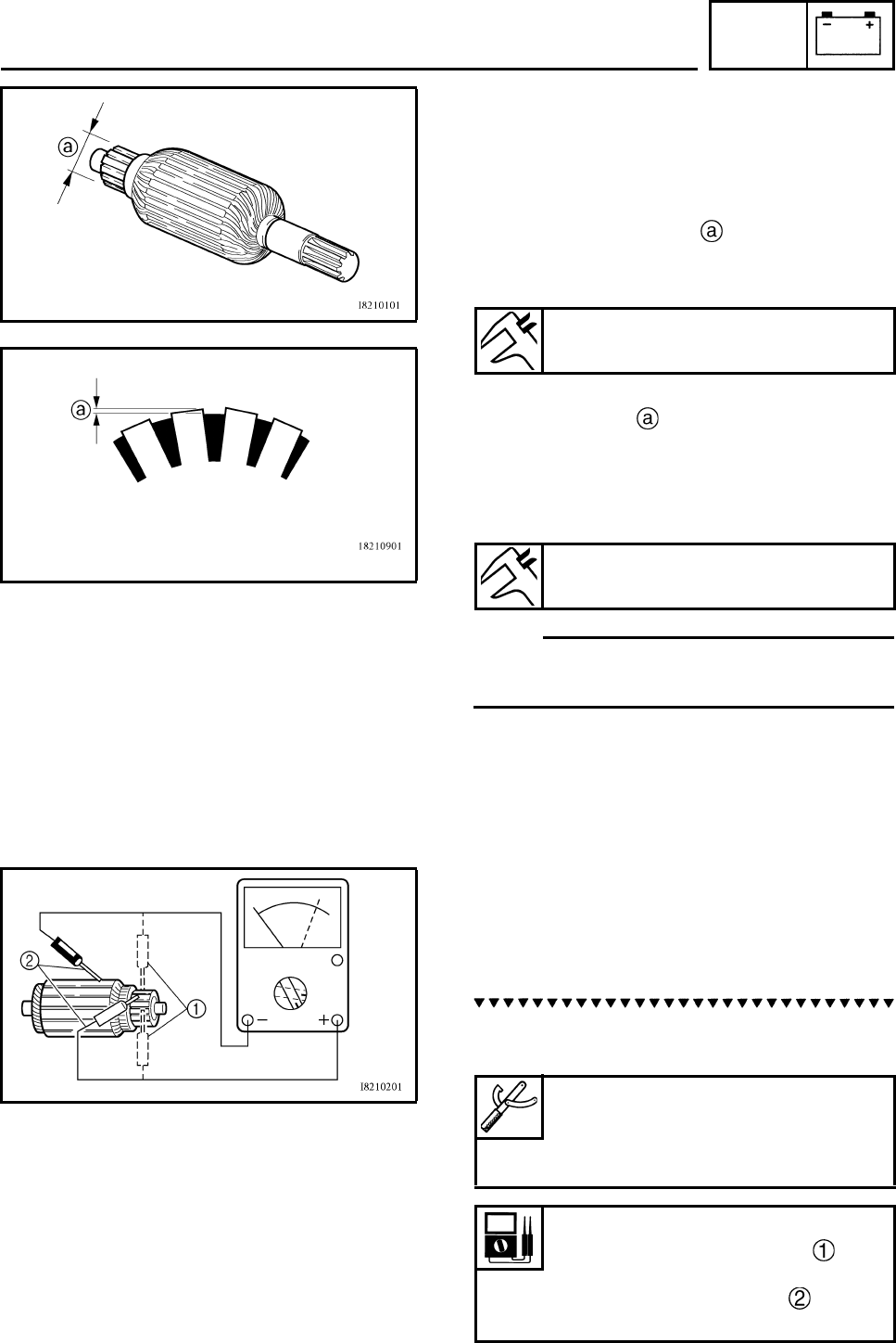
ELEC
7-21
EBS01064
CHECKING THE STARTER MOTOR
1. Check:
•commutator
Dirt → Clean with 600-grit sandpaper.
2. Measure:
• commutator diameter
Out of specification → Replace the starter
motor.
3. Measure:
• mica undercut
Out of specification → Scrape the mica to
the proper measurement with a hacksaw
blade that has been grounded to fit the
commutator.
N
O
TE:N
O
TE:
The mica of the commutator must be undercut
to ensure proper operation of the commutator.
4. Measure:
• armature assembly resistances
(commutator and insulation)
Out of specification → Replace the starter
motor.
a. Measure the armature assembly resis-
tances with the pocket tester.
Commutator wear limit
21 mm (0.83 in)
Mica undercut
1.5 mm (0.06 in)
Pocket tester
90890-03112
Analog pocket tester
YU-03112-C
Armature coil
Commutator resistance
0.013 ~ 0.015 Ω at 20°C (68°F)
Insulation resistance
Above 1 MΩ at 20°C (68°F)
STARTER MOTOR
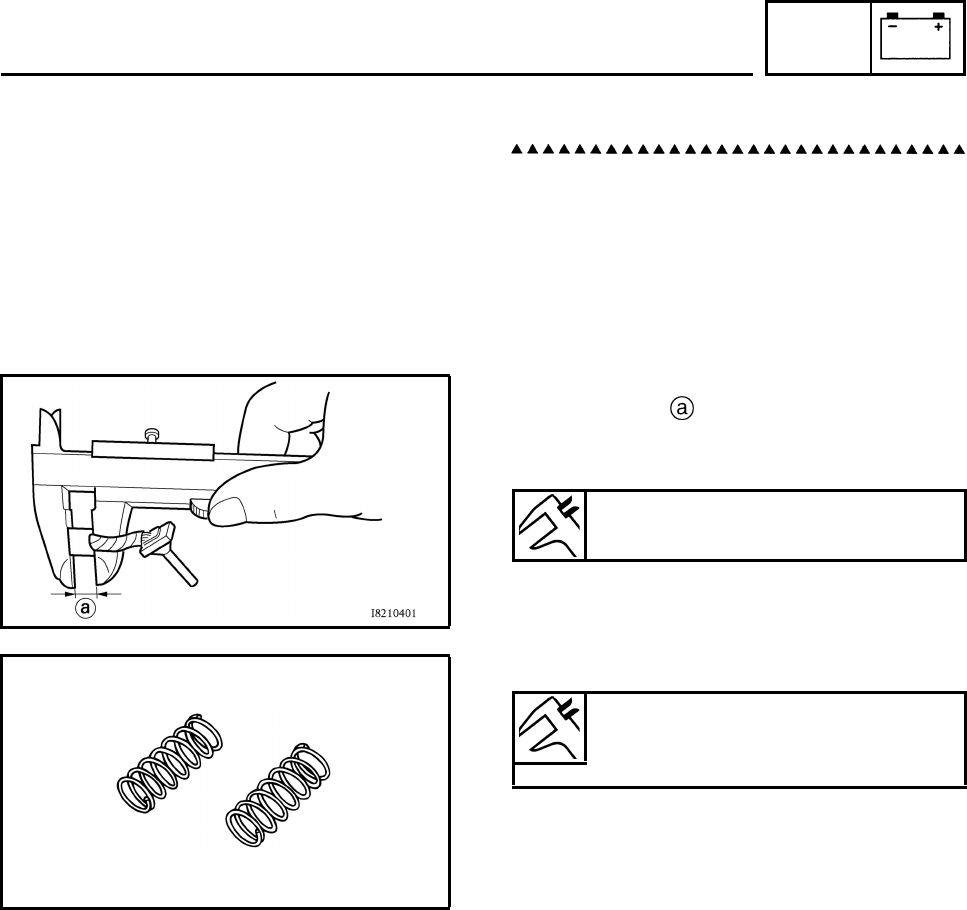
ELEC
7-22
b. If any resistance is out of specification,
replace the starter motor.
5. Measure:
• brush length
Out of specification → Replace the brushes
as a set.
6. Measure:
• brush spring force
Out of specification → Replace the brush
springs as a set.
7. Check:
• gear teeth
Damage/wear → Replace the gear.
8. Check:
• bushing
• bearing
• oil seal
Damage/wear → Replace the defective
part(s).
Brush length wear limit
3.5 mm (0.14 in)
Brush spring force
5.52 ~ 8.28 N
(563 ~ 844 gf, 19.85 ~ 29.78 oz)
STARTER MOTOR
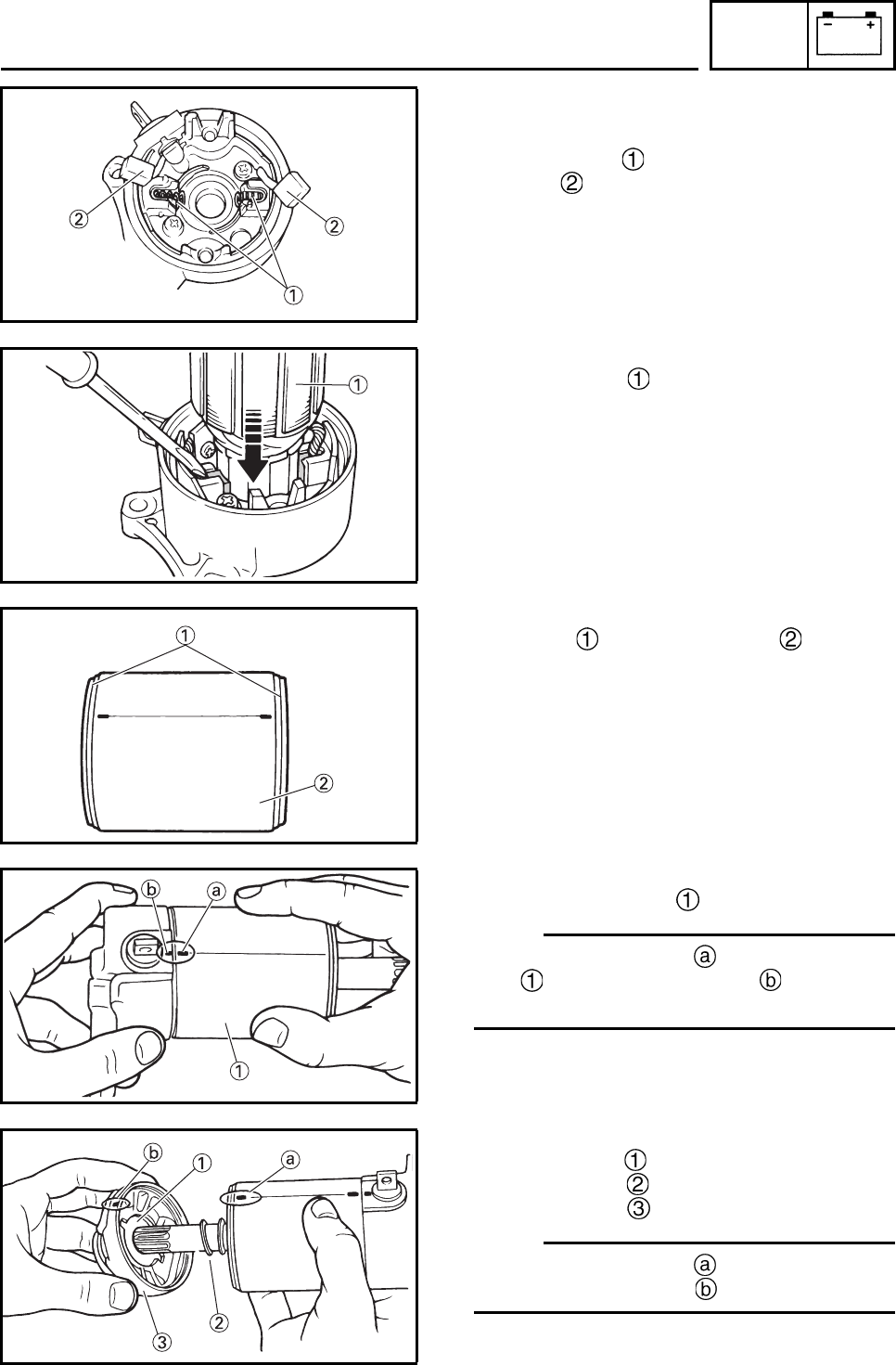
ELEC
7-23
EBS00515
ASSEMBLING THE STARTER MOTOR
1. Install:
• brush spring
•brush
2. Install:
• armature coil
3. Install
• O-rings to starter motor yoke .
4. Install
• Starter motor yoke
N
O
TE:N
O
TE:
Align the match marks on the starter motor
york with the match marks on the rear
bracket.
5. Install
• Tang washer
• Plate washer
• Front bracket
N
O
TE:N
O
TE:
Align the match marks on the starter motor
york with the match marks on the front bracket.
2
1
2
1
1
2
1
a
b
1
2
3
a
b
STARTER MOTOR
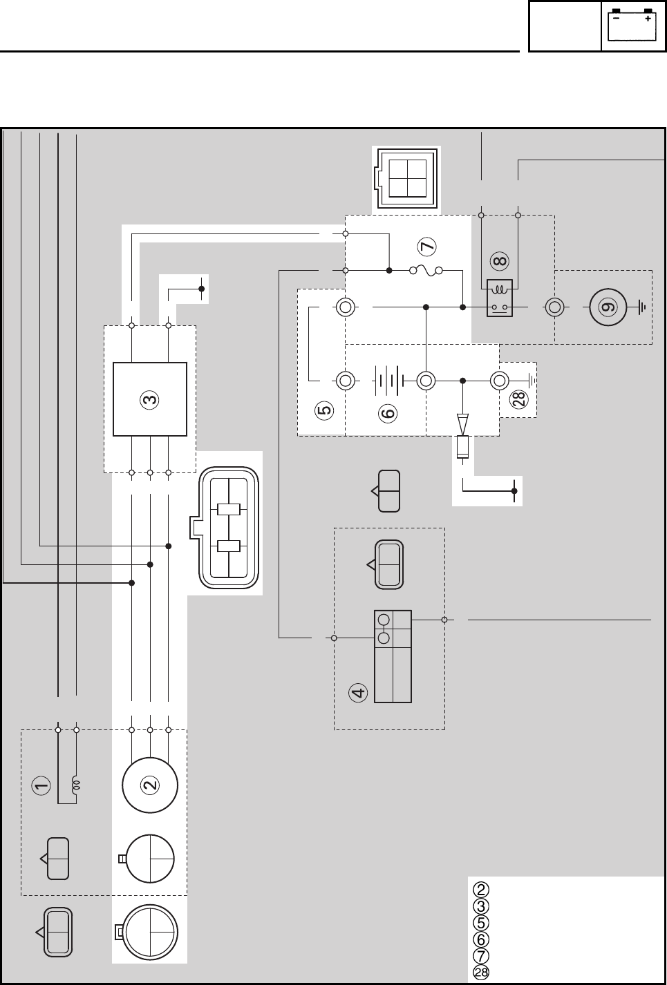
ELEC
7-24
EBS00516
CHARGING SYSTEM
CIRCUIT DIAGRAM
RBrRBr
ON
OFF RR
L/BY/B
W
WW
WR
W/L W/R
W
WW
R
-
B
WWW
W/R
W/L
W
W
W
W
W
WB
R
R
B
RR
RR
R
R
Br
Y/B
L/B
B
B
Stator coil
Rectifier/regulator
Battery positive lead
Battery
Fuse
Ground
CHARGING SYSTEM
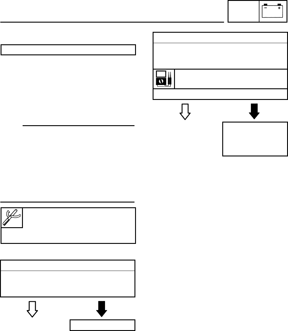
ELEC
7-25
EBS01065
TROUBLESHOOTING
Check:
1. fuse
2. battery
3. charging voltage
4. stator coil resistance
5. wiring connections
(of the entire charging system)
N
O
TE:N
O
TE:
• Before troubleshooting, remove the following
part(s):
1. seat
2. front panel
3. front fender
4. rear fender
5. side cover
• Troubleshoot with the following special
tool(s).
EBS01043
EBS01044
1. Fuse
• Check the fuse for continuity.
Refer to “CHECKING THE SWITCHES”.
• Is the fuse OK?
YES NO
Replace the fuse.
The battery is not being charged.
Pocket tester
90890-03112
Analog pocket tester
YU-03112-C
2. Battery
• Check the condition of the battery.
Refer to “CHECKING AND CHARGING
THE BATTERY” in chapter 3.
Minimum open-circuit voltage
12.8 V or more at 20°C (68°F)
• Is the battery OK?
YES NO
• Clean the battery
terminals.
• Recharge or replace
the battery.
CHARGING SYSTEM
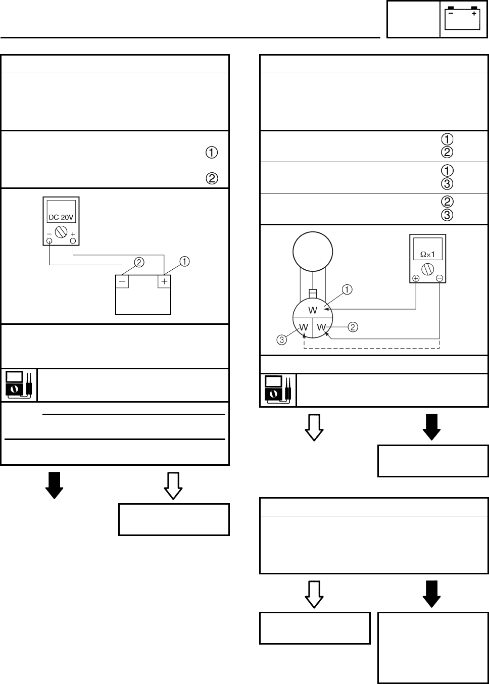
ELEC
7-26
EBS01066 EBS01100
3. Charging voltage
• Connect the engine tachometer to on to the
ignition coil.
• Connect the pocket tester (DC 20 V) to the
battery as shown.
Positive tester probe →
positive battery terminal
Negative tester probe →
negative battery terminal
• Start the engine and let it run at approxi-
mately 5,000 r/min.
• Measure the charging voltage.
Charging voltage
14 V at 5,000 r/min
N
O
TE:N
O
TE:
Make sure the battery is fully charged.
• Is the charging voltage within specification?
NO YES
The charging circuit
is OK.
4. Stator coil resistance
• Disconnect the AC magneto coupler from
the wire harness.
• Connect the pocket tester (Ω × 1) to the
charging coils.
Tester (+) lead → White terminal
Tester (–) lead → White terminal
Tester (+) lead → White terminal
Tester (–) lead → White terminal
Tester (+) lead → White terminal
Tester (–) lead → White terminal
• Measure the stator coil resistance.
Charging coil resistance:
0.688 ~ 1.032 Ω at 20°C (68°F)
YES NO
Replace the pickup
coil/stator assembly.
5. Wiring
• Check the entire charging system’s wiring.
Refer to “CIRCUIT DIAGRAM”.
• Is the charging system’s wiring properly
connected and without defects?
YES NO
Replace the rectifier/
regulator. Replace the diode
and properly con-
nect or repair the
charging system’s
wiring.
CHARGING SYSTEM
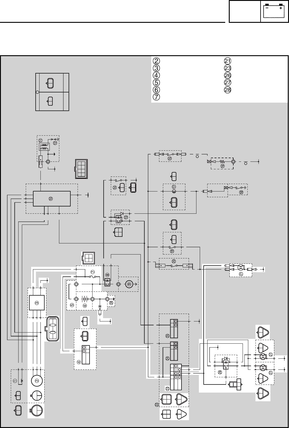
ELEC
7-27
EBS00518
LIGHTING SYSTEM
CIRCUIT DIAGRAM
A
A
B/Y
B
RBrRBr
ON
OFF
OFF
LO
HI
OFF
ON
OFF
PUSH
R/B
L
Br
R/W
GY
B
R/B
L
Br
L/B
Y
B
RR
L/BY/B
B/Y
B
BB
B/Y
B
Y/BB/Y
R/B
Sb
GY
B
GY
B
GY
B
GY
B
W
WW
WR
W/L W/R
W
WW
L
Y
BGY
R/B
BWW
O
W/LW/R
W
Br Sb BrSbYBr Y Br
SUB-WIRE HARNESS
A
WIRE HARNESS
RB
WWW
W/R
W/L
W
W
W
W
W
WB
R
WWW
B
R
Br B
RR
RR
R
R
Br
BY
BY
BY
BY
B
B
B
B
OO
W/R
W/L
R/B
B
Y/B
L/B
B
B
Y/B B/Y
R/B Sb
BY
B
Br
Sb
Sb
Br
Br
Y
L
Y
Y
Br
L/B
R/B
B
Y
L
B
G
L
YY
GYGY
BB
Stator coil
Rectifier/regulator
Main switch
Battery positive lead
Battery
Fuse
Tail/brake light
Light switch
Headlight relay
Headlight
Ground
LIGHTING SYSTEM
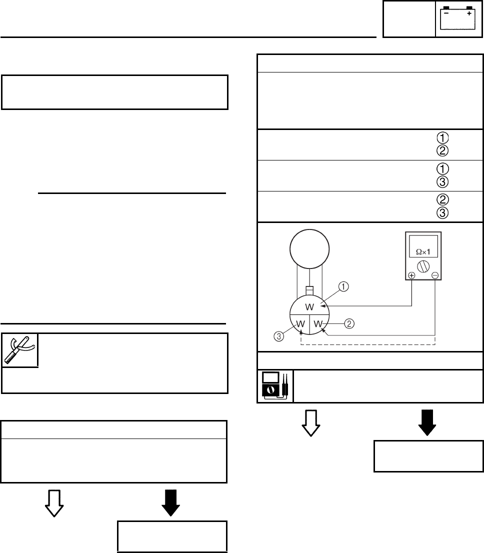
ELEC
7-28
EBS01067
TROUBLESHOOTING
Check:
1. light switch
2. Stator coil resistance
3. wiring connections
(of the entire lighting system)
N
O
TE:N
O
TE:
• Before troubleshooting, remove the following
part(s):
1. seat
2. front panel
3. front fender
4. rear fender
5. side cover
• Troubleshoot with the following special
tool(s).
EAS00783
EAS00776
1. Light switch
• Check the light switch for continuity.
Refer to “CHECKING THE SWITCHES”.
• Is the light switch OK?
YES NO
Replace the handle-
bar switch.
Any of the following fail to light: head-
light, tail/brake light.
Pocket tester
90890-03112
Analog pocket tester
YU-03112-C
2. Stator coil resistance
• Disconnect the AC magneto coupler from
the wire harness.
• Connect the pocket tester (Ω × 1) to the
charging coils.
Tester (+) lead → White terminal
Tester (–) lead → White terminal
Tester (+) lead → White terminal
Tester (–) lead → White terminal
Tester (+) lead → White terminal
Tester (–) lead → White terminal
• Measure the stator coil resistance.
Charging coil resistance:
0.688 ~ 1.032 Ω at 20°C (68°F)
YES NO
Replace the pickup
coil/stator assembly.
LIGHTING SYSTEM
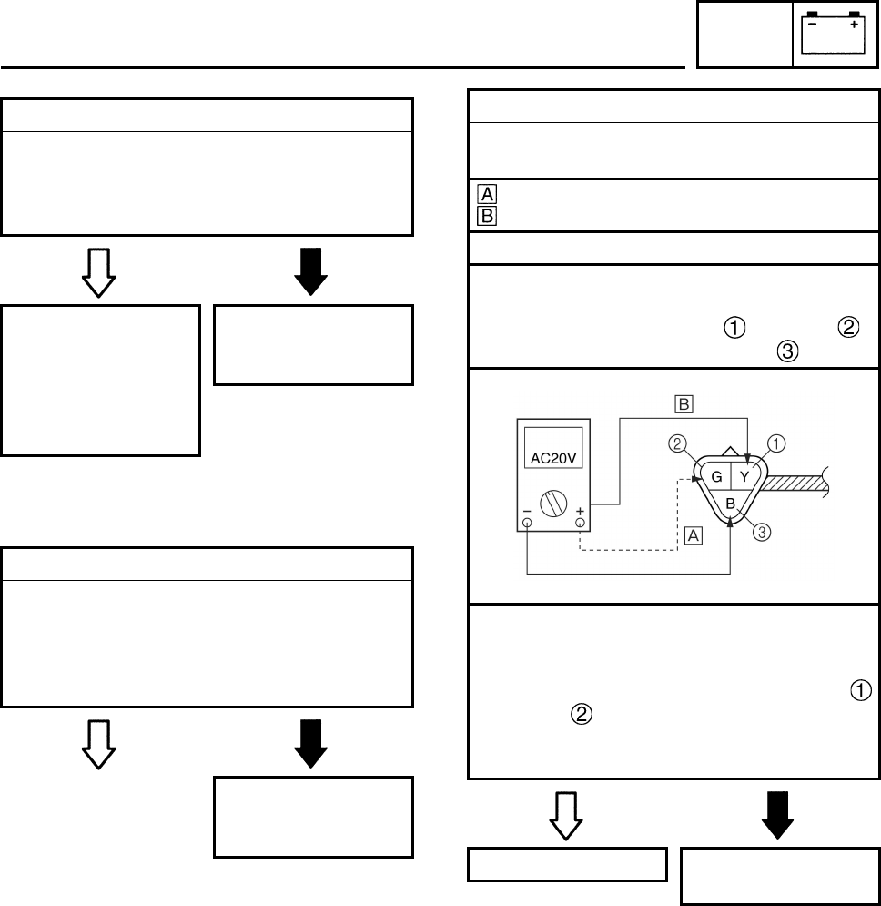
ELEC
7-29
EBS01069
EBS01070
CHECKING THE LIGHTING SYSTEM
1. The headlights fail to come on.
3. Wiring
• Check the entire lighting system’s wiring.
Refer to “CIRCUIT DIAGRAM”.
• Is the lighting system’s wiring properly con-
nected and without defects?
YES NO
Check the condition
of each of the light-
ing system’s circuits.
Refer to “CHECK-
ING THE LIGHT-
ING SYSTEM”.
Properly connect or
repair the lighting
system’s wiring.
1. Headlight bulb and socket
• Check the headlight bulb and socket for
continuity.
Refer to “CHECKING THE BULBS AND
BULB SOCKETS”.
• Are the headlight bulb and socket OK?
YES NO
Replace the head-
light bulb, socket or
both.
2. Voltage
• Connect the pocket tester (AC 20 V) to the
headlight couplers as shown.
When the light switch is set to “LO”
When the light switch is set to “HI”
Headlight coupler (wire harness side)
Headlight
Positive tester probe →
yellow or green
Negative tester probe → black
• Set the main switch to “ON”.
• Start the engine.
• Set the light switch to “LO” or “HI”.
• Measure the voltage (AC 12 V) of yellow
or green on the headlight coupler (wire
harness side).
• Is the voltage within specification?
YES NO
This circuit is OK. Replace the rectifier/
regulator.
LIGHTING SYSTEM
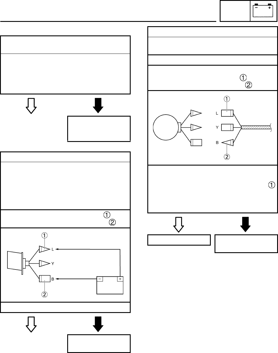
ELEC
7-30
2. The tail/brake light fails to come on.
1. Tail/brake light bulb and bulb socket
(4D31)
• Check the tail/brake light bulb and socket
for continuity.
Refer to “CHECKING THE BULBS AND
BULB SOCKETS”.
• Are the tail/brake light bulb and socket OK?
YES NO
Replace the tail/brake
light bulb, socket or
both.
2. Tail/brake light (4D35, 4D39)
• Disconnect the tail/brake light coupler.
• Connect the battery (12 V) to the tail/brake
light coupler terminals as shown.
• When the jumper leads are connected to
the terminals, the tail/brake light should illu-
minate.
Positive battery terminal → blue
Negative battery terminal → black
• Is the tail/brake light OK?
YES NO
Replace the tail/
brake light.
3. Voltage
• Connect the pocket tester (AC 20 V) to the
tail/brake light coupler as shown.
Tail/brake light coupler (wire harness side)
Tail/brake light
Positive tester probe → blue
Negative tester probe → black
• Set the main switch to “ON”.
• Start the engine.
• Measure the voltage (AC 12 V) of blue
on the tail/brake light coupler (wire harness
side).
• Is the voltage within specification?
YES NO
This circuit is OK. Replace the rectifier/
regulator.
LIGHTING SYSTEM
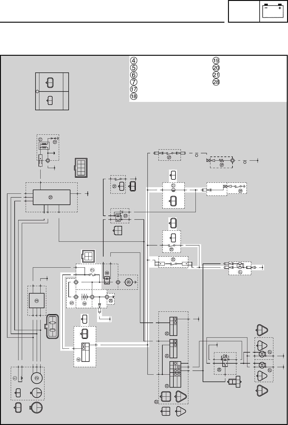
ELEC
7-31
EBS00521
SIGNAL SYSTEM
CIRCUIT DIAGRAM
A
A
B/Y
B
RBrRBr
ON
OFF
OFF
LO
HI
OFF
ON
OFF
PUSH
R/B
L
Br
R/W
GY
B
R/B
L
Br
L/B
Y
B
RR
L/BY/B
B/Y
B
BB
B/Y
B
Y/BB/Y
R/B
Sb
GY
B
GY
B
GY
B
GY
B
W
WW
WR
W/L W/R
W
WW
L
Y
BGY
R/B
BWW
O
W/LW/R
W
Br Sb BrSbYBr Y Br
SUB-WIRE HARNESS
A
WIRE HARNESS
RB
WWW
R
Br B
RR
RR
R
OO
W/R
W/L
R/B
WWW
B
B
R
Y/B
L/B
Y/B B/Y
R/B Sb
BY
B
Br
Br
Br
Sb BY
BY
BY
BY
B
B
B
B
Sb
Y
L
Y
Y
Br
W/R
W/L
W
W
W
W
W
WB
R
B
B
L/B
R/B
Br
B
Y
L
B
G
L
YY
GYGY
BB
Main switch
Battery positive lead
Battery
Fuse
Neutral indicator light
Neutral switch
Rear brake light switch
Front brake light switch
Tail/brake light
Ground
SIGNAL SYSTEM
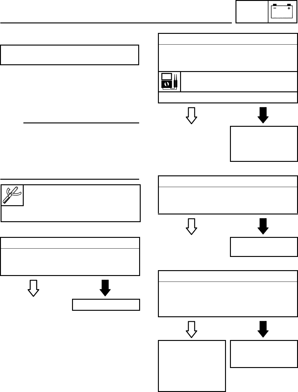
ELEC
7-32
EBS01073
TROUBLESHOOTING
Check:
1. fuse
2. battery
3. main switch
4. wiring connections
(of the entire signaling system)
N
O
TE:N
O
TE:
• Before troubleshooting, remove the following
part(s):
1. seat
2. front fender
• Troubleshoot with the following special
tool(s).
EBS01043
EBS01044
EBS01041
EBS01074
Any of the following fail to light: brake
light or an indicator light.
1. Fuse
• Check the fuse for continuity.
Refer to “CHECKING THE SWITCHES”.
• Is the fuse OK?
YES NO
Replace the fuse.
Pocket tester
90890-03112
Analog pocket tester
YU-03112-C
2. Battery
• Check the condition of the battery.
Refer to “CHECKING AND CHARGING
THE BATTERY” in chapter 3.
Minimum open-circuit voltage
12.8 V or more at 20°C (68°F)
• Is the battery OK?
YES NO
• Clean the battery
terminals.
• Recharge or replace
the battery.
3. Main switch
• Check the main switch for continuity.
Refer to “CHECKING THE SWITCHES”.
• Is the main switch OK?
YES NO
Replace the main
switch.
4. Wiring
• Check the entire signal system’s wiring.
Refer to “CIRCUIT DIAGRAM”.
• Is the signaling system’s wiring properly
connected and without defects?
YES NO
Check the condition
of each of the signal-
ing system’s circuits.
Refer to “CHECK-
ING THE SIGNAL-
ING SYSTEM”.
Properly connect or
repair the signaling
system’s wiring.
SIGNAL SYSTEM
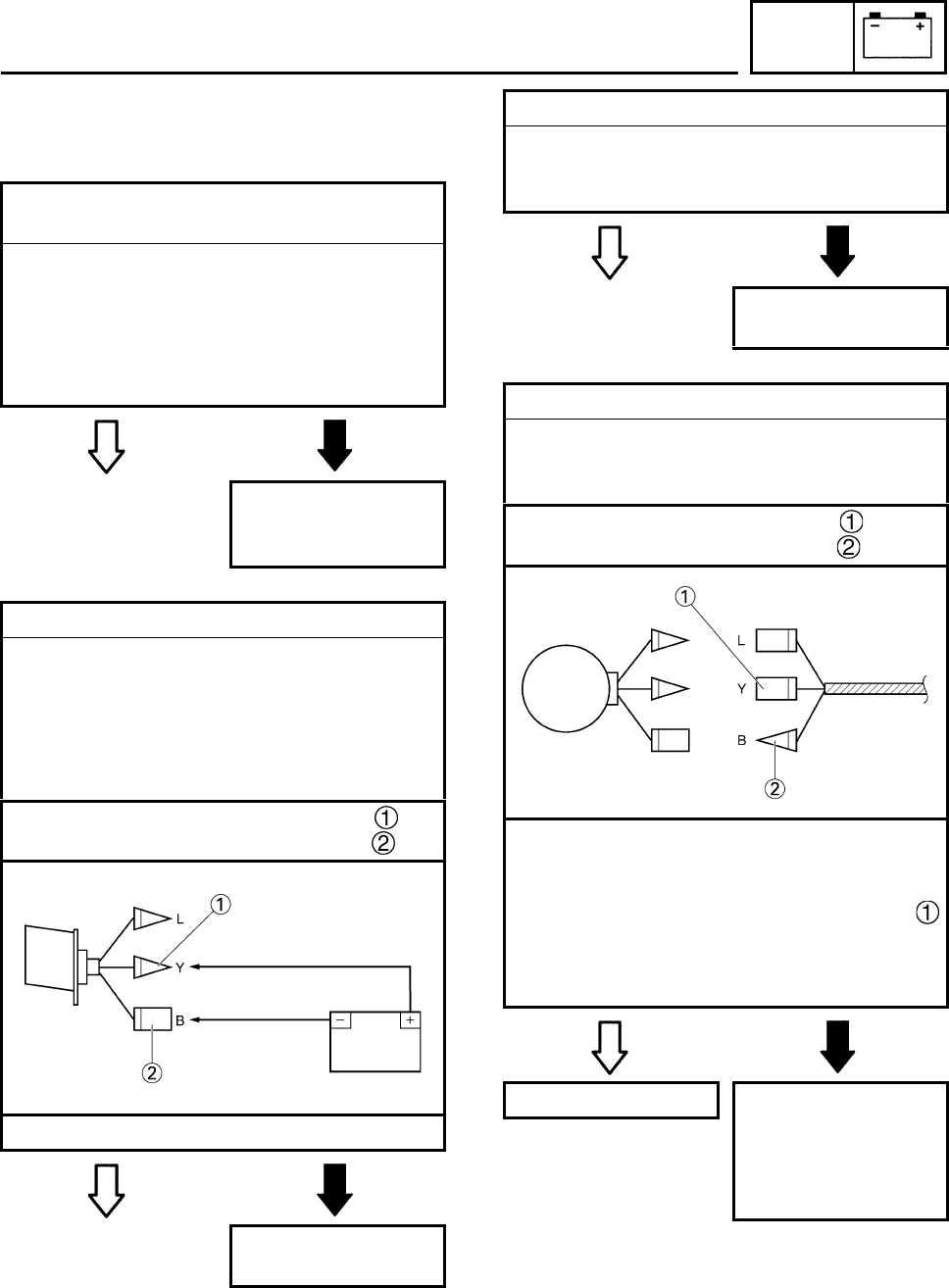
ELEC
7-33
EBS01075
CHECKING THE SIGNALING SYSTEM
EBS01076
1. The tail/brake light fails to come on.
1. Tail/brake light bulb and bulb socket
(4D31)
• Check the tail/brake light bulb and bulb
socket for continuity.
Refer to “CHECKING THE BULBS AND
BULB SOCKETS”.
• Are the tail/brake light bulb and bulb socket
OK?
YES NO
Replace the tail/
brake light bulb, bulb
socket or both.
2. Tail/brake light (4D35, 4D39)
• Disconnect the tail/brake light coupler.
• Connect the battery (12 V) to the tail/brake
light coupler terminals as shown.
• When the jumper leads are connected to
the terminals, the tail/brake light should illu-
minate.
Positive battery terminal → yellow
Negative battery terminal → black
• Is the tail/brake light OK?
YES NO
Replace the tail/
brake light.
3. Brake light switches
• Check the brake light switches for continuity.
Refer to “CHECKING THE SWITCHES”.
• Is the brake light switch OK?
YES NO
Replace the brake
light switch.
4. Voltage
• Connect the pocket tester (DC 20 V) to the
tail/brake light coupler (wire harness side)
as shown.
Positive tester probe → yellow
Negative tester probe → black
• Set the main switch to “ON”.
• Pull in the brake lever or push down on the
brake pedal.
• Measure the voltage (DC 12 V) of yellow
on the tail/brake light coupler (wire harness
side).
• Is the voltage within specification?
YES NO
This circuit is OK. The wiring circuit
from the main switch
to the tail/brake light
coupler is faulty and
must be repaired.
SIGNAL SYSTEM
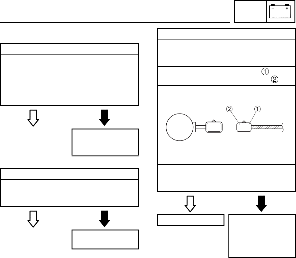
ELEC
7-34
EBS01077
2. The neutral indicator light fails to come on.
1. Neutral indicator light bulb and socket
• Check the neutral indicator light bulb and
socket for continuity.
Refer to “CHECKING THE BULBS AND
BULB SOCKETS”.
• Are the neutral indicator light bulb and
socket OK?
YES NO
Replace the neutral
indicator light bulb,
socket or both.
2. Neutral switch
• Check the neutral switch for continuity.
Refer to “CHECKING THE SWITCHES”.
• Is the neutral switch OK?
YES NO
Replace the neutral
switch.
3. Voltage
• Connect the pocket tester (DC 20 V) to the
indicator light coupler (wire harness side)
as shown.
Positive tester probe → brown
Negative tester probe → sky blue
• Set the main switch to “ON”.
• Measure the voltage (DC 12 V).
• Is the voltage within specification?
YES NO
This circuit is OK. The wiring circuit
from the main switch
to the indicator light
coupler is faulty and
must be repaired.
Br Sb BrSb
SIGNAL SYSTEM
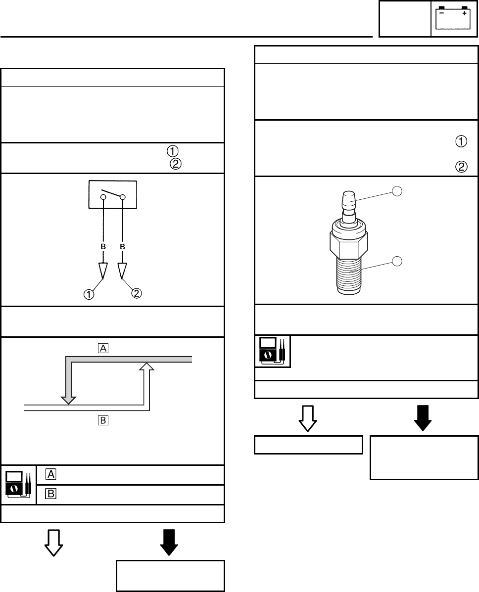
ELEC
7-35
EBS01083
3. The carburetor heater fails to come on.
1. Thermo switch
• Disconnect the thermo switch from the wire-
harness.
• Connect the pocket tester (Ω × 1) to the
thermo switch lead.
Tester positive probe → black
Tester negative probe → black
• Check the thermo switch for continuity at
the temperatures indicated below.
COOL DOWN
HEAT UP
• Does the thermo switch operated properly?
YES NO
Replace the thermo
switch.
OFF
ON
11°C±3°C
(51.8°F±5.4°F) 16°C±3°C
(60.8°F±5.4°F)
2. Carburetor warmer
• Remove the carburetor heating element
from the carburetor.
• Connect the pocket tester (Ω × 1) to the car-
buretor heating element.
Tester positive probe →
heating element
Tester negative probe →
heating element body
• Measure the carburetor heating element
resistance.
Carburetor heating element resis-
tance:
6 ~ 12 Ω (20°C)
• Is the carburetor heating element OK?
YES NO
This circuit is OK. Replace the carbu-
retor warmer ele-
ment.
1
2
SIGNAL SYSTEM

TRBL
SHTG
8-1
1
2
3
4
5
6
7
8
EBS00537
TROUBLESHOOTING
N
O
TE:
The following troubleshooting does not cover all the possible causes of trouble. It should be helpful,
however, as a guide to troubleshooting. Refer to the relative procedure in this manual for check,
adjustment and replacement of parts.
STARTING FAILURE/HARD STARTING
FUEL SYSTEM
Fuel tank
•Empty
• Clogged fuel strainer
• Clogged fuel tank breather hose
• Deteriorated or contaminated fuel
Fuel cock
• Clogged fuel hose
Carburetor
• Deteriorated or contaminated fuel
• Clogged pilot jet
• Clogged pilot air passage
• Sucked-in air
• Deformed float
• Worn needle valve
• Improperly sealed valve seat
• Improperly adjusted fuel level
• Improperly set pilot jet
• Clogged starter jet
• Choke valve malfunction
Air filter
• Clogged air filter element
ELECTRICAL SYSTEM
Spark plug
• Improper plug gap
• Worn electrodes
• Wire between terminals broken
• Improper heat range
Ignition coil
• Broken or shorted primary/secondary
• Faulty ignition coil lead
• Broken body
CDI system
• Faulty CDI unit
• Faulty pickup coil
• Faulty lighting coil
• Faulty charging coil
• Broken woodruff key
Switches and wiring
• Faulty main switch
• Faulty engine stop switch
• Broken or shorted wiring
• Faulty neutral switch
• Faulty start switch
• Faulty clutch switch
• Faulty throttle switch
• Faulty carburetor switch
• Loose connections
Starter motor
• Faulty starter motor
• Faulty starter relay
• Faulty starting circuit cut-off relay
• Faulty starter clutch
• Faulty torque limiter
Battery
• Faulty battery
• Discharged battery
STARTING FAILURE/HARD STARTING

TRBL
SHTG
8-2
COMPRESSION SYSTEM
Cylinder and cylinder head
• Loose spark plug
• Loose cylinder head or cylinder
• Broken cylinder head gasket
• Broken cylinder gasket
• Worn, damaged or seized cylinder
Valve and camshaft
• Improperly sealed valve
• Improperly contacted valve and valve seat
• Improper valve timing
• Broken valve spring
• Seized camshaft
Piston and piston rings
• Improperly installed piston ring
• Worn, fatigued or broken piston ring
• Seized piston ring
• Seized or damaged piston
Crankcase and crankshaft
• Improperly seated crankcase
• Seized crankshaft
Valve train
• Improperly adjusted valve clearance
• Improperly adjusted valve timing
EBS00538
POOR IDLE SPEED PERFORMANCE
POOR IDLE SPEED PERFORMANCE
Carburetor
• Improperly returned choke
• Loose or clogged pilot jet
• Loose or clogged pilot air jet
• Improperly adjusted idle speed
(throttle stop screw)
• Improper throttle cable play
• Flooded carburetor
Intake manifold
• Loosen carburetor joint
Electrical system
• Faulty battery
• Faulty CDI unit
• Faulty pickup coil
• Faulty ignition coil
Valve train
• Improperly adjusted valve clearance
Air filter
• Clogged air filter element
• Loosen air filter joint
EBS00539
POOR MEDIUM AND HIGH-SPEED PERFORMANCE
POOR MEDIUM AND HIGH-SPEED PERFORMANCE
Refer to “STARTING FAILURE/HARD STARTING” and “POOR IDLE SPEED PERFORMANCE—
Valve train”.
Carburetor
• Improper jet needle clip position
• Improperly adjusted fuel level
• Clogged or loose main jet
• Deteriorated or contaminated fuel
Air filter
• Clogged air filter element
STARTING FAILURE/HARD STARTING/POOR IDLE SPEED
PERFORMANCE/POOR MEDIUM AND HIGH-SPEED PERFORMANCE

TRBL
SHTG
8-3
EBS00541
FAULTY GEAR SHIFTING
HARD SHIFTING
Refer to “CLUTCH DRAGGING”.
SHIFT PEDAL DOES NOT MOVE
Shift shaft
• Bent shift shaft
Shift drum and shift forks
• Groove jammed with impurities
• Seized shift fork
• Bent shift fork guide bar
Transmission
• Seized transmission gear
• Jammed impurities
• Incorrectly assembled transmission
Shift guide
• Broken shift guide
JUMPS OUT GEAR
Shift shaft
• Improperly adjusted shift lever position
• Improperly returned stopper lever
Shift forks
• Worn shift fork
Shift drum
• Improper thrust play
• Worn shift drum groove
Transmission
• Worn gear dog
EBS00545
CLUTCH SLIPPING/DRAGGING
CLUTCH SLIPPING
Clutch
• Loose clutch spring
• Fatigued clutch spring
• Worn friction plate
• Worn clutch plate
• Incorrectly assembled clutch
Engine oil
•Low oil level
• Improper quality (low viscosity)
• Deterioration
CLUTCH DRAGGING
Clutch
• Warped pressure plate
• Unevenly tensioned clutch springs
• Loose clutch boss nut
• Burnt primary driven gear bushing
• Bent clutch plate
• Swollen friction plate
• Broken clutch boss
Engine oil
• High oil level
• Improper quality (high viscosity)
• Deterioration
FAULTY GEAR SHIFTING/
CLUTCH SLIPPING/DRAGGING

TRBL
SHTG
8-4
EBS00547
OVERHEATING
OVERHEATING
Ignition system
• Improper spark plug gap
• Improper spark plug heat range
• Faulty CDI unit
Fuel system
• Improper carburetor main jet
(improper setting)
• Improper fuel level
• Clogged air filter element
Compression system
• Heavy carbon deposit
Engine oil
• Improper oil level
• Improper oil viscosity
• Inferior oil quality
Brake
•Brake drag
EBS00550
FAULTY BRAKE
POOR BRAKING EFFECT
Disc brake
• Worn brake pads
• Worn disc
• Air in brake fluid
• Leaking brake fluid
• Faulty master cylinder kit cup
• Faulty caliper kit seal
• Loose union bolt
• Broken brake hose and pipe
• Oily or greasy disc/brake pads
• Improper brake fluid level
EBS00551
SHOCK ABSORBER MALFUNCTION
MALFUNCTION
• Bent or damaged damper rod
• Damaged oil seal lip
• Fatigued shock absorber spring
• Leaking oil or gas
OVERHEATING/FAULTY BRAKE/
SHOCK ABSORBER MALFUNCTION

TRBL
SHTG
8-5
EBS00552
UNSTABLE HANDLING
UNSTABLE HANDLING
Handlebar
• Improperly installed or bent
Steering
• Incorrect toe-in
• Bent steering stem
• Improperly installed steering stem
• Damaged bearing or bearing race
• Bent tie-rods
• Deformed steering knuckles
Tires
• Uneven tire pressures on both sides
• Incorrect tire pressure
• Uneven tire wear
Wheels
• Deformed wheel
• Loose bearing
• Bent or loose wheel axle
• Excessive wheel runout
Frame
• Bent
• Damaged frame
Swingarm
• Worn bearing or bushing
• Bent or damaged
EBS00553
LIGHTING SYSTEM
HEADLIGHT DOES NOT COME ON
• Improper bulb
• Too many electric accessories
• Hard charging (broken stator coil and/or
faulty rectifier/regulator)
• Incorrect connection
• Improperly grounded
• Poor contacts (main or light switch)
• Bulb life expired
TAIL/BRAKE LIGHT DOES NOT LIGHT
• Wrong tail/brake light bulb
• Too many electrical accessories
• Hard charging (broken stator coil and/or
faulty rectifier/regulator)
• Incorrect connection
• Improperly grounded
• Poor contacts (main or light switch)
• Burnt-out tail/brake light bulb
BULB BURNT OUT
• Improper bulb
• Faulty battery
• Faulty rectifier/regulator
• Improperly grounded
• Faulty main and/or light switch
• Bulb life expired
TAIL/BRAKE LIGHT BULB BURNT OUT
• Wrong tail/brake light bulb
• Faulty battery
• Faulty rectifier/regulator
• Improperly grounded
• Faulty main and/or light switch
• Incorrectly adjusted rear brake light switch
• Tail/brake light bulb life expired
UNSTABLE HANDLING/
LIGHTING SYSTEM

YAMAHA MOTOR CO., LTD.
2500 SHINGAI IWATA SHIZUOKA JAPAN
PRINTED IN U.S.A.
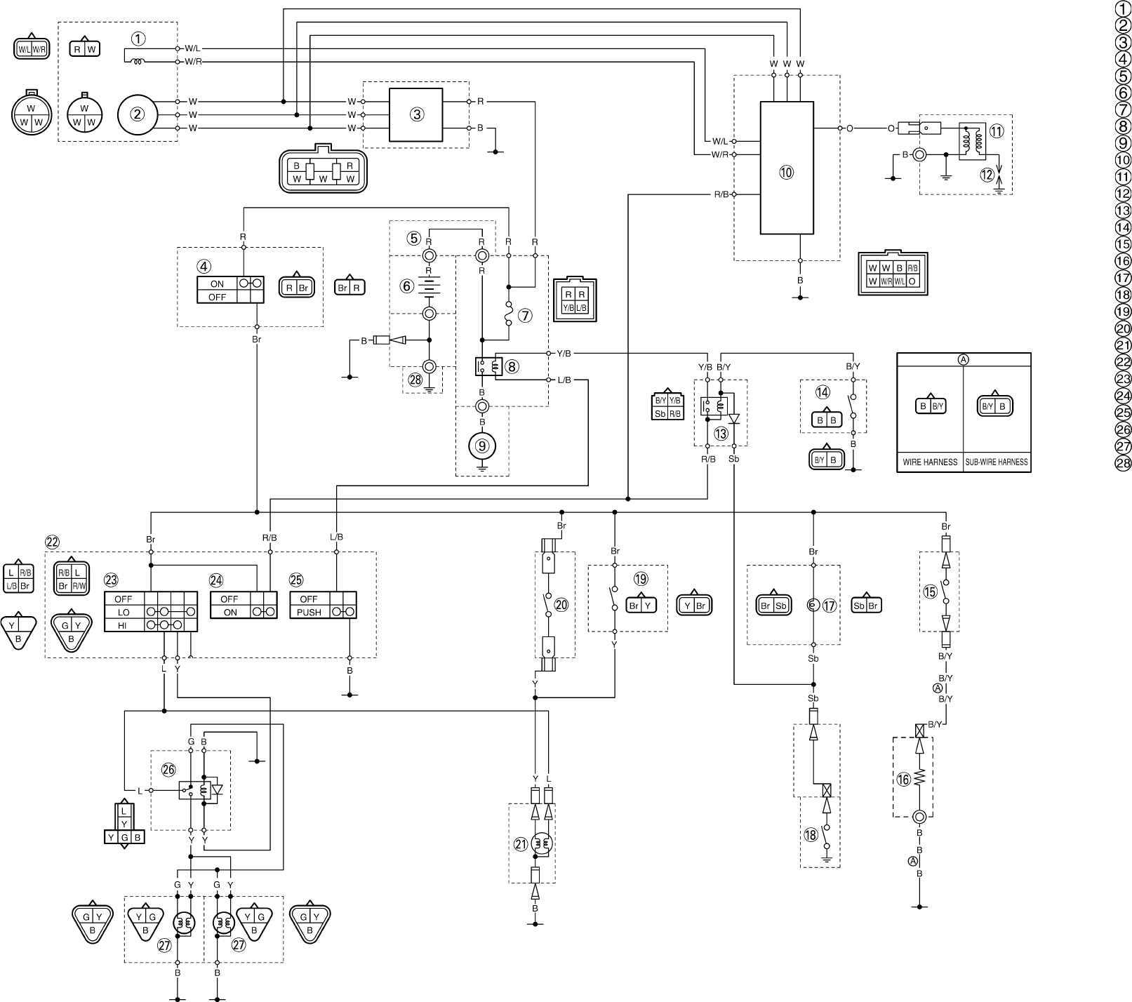
YFM250RX WIRING DIAGRAM Pickup coil
Stator coil
Rectifier/regulator
Main switch
Battery positive lead
Battery
Fuse
Starter relay
Starter motor
CDI unit
Ignition coil
Spark plug
Starting circuit cut-off relay
Clutch switch
Thermo switch
Carburetor warmer
Neutral indicator light
Neutral switch
Rear brake light switch
Front brake light switch
Tail/brake light
Handlebar switch
Light switch
Engine stop switch
Start switch
Headlight relay
Headlight
Ground
COLOR CODE
B. . . . . . .Black
Br . . . . . .Brown
G . . . . . .Green
L . . . . . . .Blue
O . . . . . .Orange
R. . . . . . .Red
Sb . . . . . Sky blue
W . . . . . White
Y . . . . . . Yellow
B/Y . . . . Black/Yellow
L/B . . . . Blue/Black
R/B . . . . Red/Black
R/W . . . . Red/White
W/L . . . . White/Blue
W/R . . . . White/Red
Y/B. . . . . Yellow/Black
