2009 Polaris Sportsman XP 850 Service Manual
User Manual: 2009 Polaris Sportsman XP 850 Service Manual
Open the PDF directly: View PDF ![]() .
.
Page Count: 381 [warning: Documents this large are best viewed by clicking the View PDF Link!]
- 9921850_Chapter_01.pdf
- 9921850_Chapter_02
- 9921850_Chapter_03
- ELECTRONIC FUEL INJECTION
- SPECIAL TOOLS
- Part Numbers / Descriptions
- Fuel Pressure Gauge Kit - PU-43506-A
- Fuel Pressure Gauge Adaptor - PS-48762
- Throttle Position Sensor Tester Kit - 2201519
- Digital Wrench™ Diagnostic Software PU-47063
- Digital Wrench™ SmartLink Module Kit - PU-47471
- Digital Wrench™ - Diagnostic Connector
- Digital Wrench™ - Download Website
- FUEL TANK
- FUEL LINE
- EFI SERVICE NOTES
- EFI SYSTEM LAYOUT
- EFI COMPONENTS
- ELECTRONIC FUEL INJECTION
- ELECTRONIC CONTROL UNIT (ECU)
- FUEL PUMP
- FUEL PRESSURE REGULATOR
- FUEL INJECTORS
- CRANKSHAFT POSITION SENSOR (CPS)
- TEMP / MANIFOLD ABSOLUTE PRESSURE SENSOR (T-MAP)
- IDLE AIR CONTROL VALVE (IAC)
- THROTTLE POSITION SENSOR (TPS)
- ENGINE COOLANT TEMPERATURE SENSOR (ECT)
- IGNITION COIL
- EFI DIAGNOSTICS
- FUEL SYSTEM TROUBLESHOOTING
- EFI SYSTEM BREAK-OUT DIAGRAMS
- Fuel Injector Circuit (PTO)
- Fuel Injector Circuit (MAG)
- Idle Air Control (IAC) Circuit
- Crankshaft Position Sensor (CPS) Circuit
- Fuel Pump / Fuel Level Sensor Circuit
- Fuel Pump Circuit
- Fuel Gauge Circuit
- Engine Coolant Temperature Sensor (ECT) Circuit
- Throttle Position Sensor (TPS) Circuit
- Intake Air Temperature / Manifold Absolute Pressure Sensor (T-MAP) Circuit
- Diagnostic Connector Circuit
- Diagnostic Connector Circuit (EPS Models)
- SPECIAL TOOLS
- ELECTRONIC FUEL INJECTION
- 9921850_Chapter_04
- 9921850_Chapter_05
- ENGINE
- GENERAL INFORMATION - ENGINE
- ENGINE ASSEMBLY VIEWS AND TORQUE VALUES
- Torque & Torque Sequence - Main Engine Components
- Valve Cover / Breather Valve
- Camshaft Carrier / Camshaft / Rocker Arm
- Cylinder Head / Valve / IAFM
- Valve & Spring Height Detail
- Piston / Connecting Rod
- Crankshaft
- Crankcase
- Crankcase - Upper
- Balance Shaft / Balance Shaft Timing
- Crankcase (Lower) With Oil Pump
- Water Pump Coupler
- Water Pump / Water Pump Coupler / Stator / Flywheel
- Drive Coupler (Rear) / Starter Gear
- ENGINE SERVICE
- ENGINE DISASSEMBLY AND INSPECTION
- Valve Cover / Breather Valve
- Rocker Carrier / Camshaft Removal
- Rocker Arm / Rocker Arm Shaft Inspection
- Camshaft / Camshaft Bore Inspection
- Cylinder Head Removal
- Cylinder Head Cleaning
- Cylinder Head Warp Inspection
- Cylinder Head
- Valve Inspection
- Combustion Chamber
- Valve Guide Removal / Installation
- Valve Seat Reconditioning
- Cylinder Head Assembly
- Valve Sealing Test
- Cylinder Head Installation
- Camshaft / Carrier Assembly
- Camshaft / Camshaft Carrier Installation
- Camshaft Timing
- Cam Chain Tensioner Installation
- Camshaft Timing - Quick Reference
- Crankcase Disassembly
- Crankcase (Lower) / Oil Pump Disassembly
- Crankcase Disassembly (Upper)
- Piston / Connecting Rod Removal
- Counterbalance Shaft Removal / Inspection
- Counterbalance Split Gear Replacement
- Crankshaft / Cam Chain Removal
- Cam Chain / Sprocket Inspection
- Crankcase Inspection (Lower)
- Crankshaft Inspection
- Connecting Rod Inspection
- Connecting Rod Big End Bearing Selection
- Piston / Piston Ring Inspection
- Piston Ring Removal
- Piston Ring Installed Gap
- Piston Pin Bore Inspection
- Cylinder Inspection
- Piston-to-Cylinder Clearance
- Honing - Important Information
- ENGINE ASSEMBLY
- Crankcase Preparation - Upper
- Piston Ring Installation
- Piston / Connecting Rod Assembly
- Piston / Connecting Rod Installation
- Crankshaft Installation
- Oil Passage Tube
- Crankcase Assembly - Upper
- Balance Shaft Installation
- Balance Shaft Timing
- Crankcase Preparation (Lower)
- Crankcase Sealant and Torque Values
- Crankcase Assembly
- WATER PUMP
- TROUBLESHOOTING
- ENGINE
- 9921850_Chapter_06
- 9921850_Chapter_07
- 9921850_Chapter_08
- 9921850_Chapter_09
- 9921850_Chapter_10
- 9921850_Chapter_11
- 9921850_Chapter_12
- ELECTRICAL
- General Information
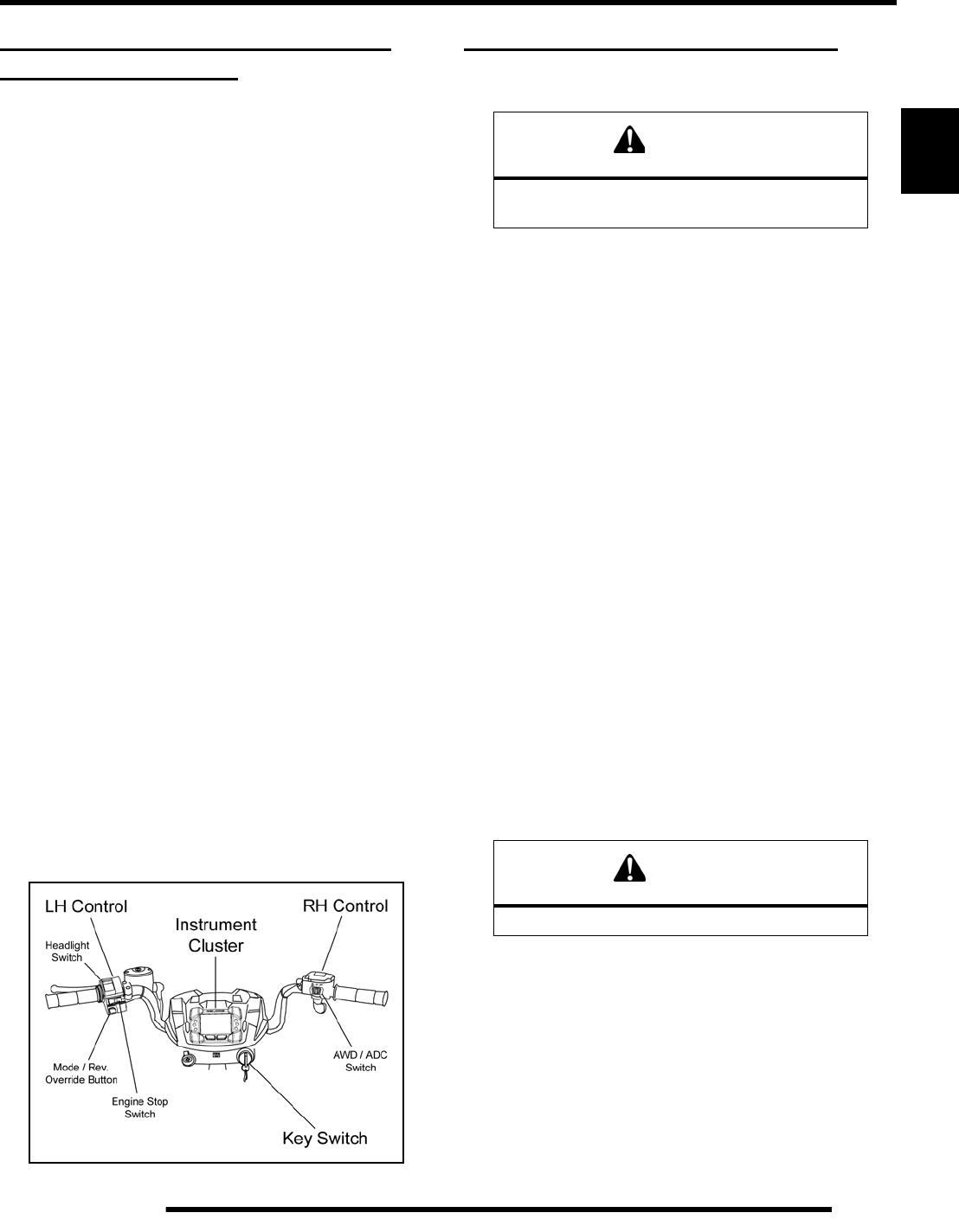
- Instrument Cluster
- Ignition Switch
- ADC / 4x4 / 2x4 Switch
- Off / Run LH Switch
- Reverse Override / Mode Button
- Head Lamp Switch
- Electronic Throttle Control (ETC) Switch
- Gear Selector Switch
- Speed Sensor
- Brake Switch
- AWD / ADC Coils
- Relays
- Fuses
- Fuse Box Layout
- Lights
- Charging System
- Battery Service
- Starter Motor
- Instrument Cluster Troubleshooting
- Electronic Power Steering (EPS)
- Electrical BreakOut Diagrams
- Battery Charging Circuits
- Constant Power Circuits
- Key-On Power Circuits
- Chassis Power Circuits
- Head Lamp Circuits
- Brake Lamp Circuits
- Engine Start Command Circuits
- ECM Wake-Up Command Circuits
- AWD / ADC Circuits
- AWD / ADC Function Tests
- Radiator Fan Circuit
- Gear Selector Switch Circuit
- Ground Speed Sensor Circuit
- Reverse Override Circuit
- Controller Area Network (CAN)
- ELECTRICAL
- 9921850_Wire_Diagrams_Intl
- 9921850_Wire_Diagrams_r01

GENERAL INFORMATION
1.1
CHAPTER 1
GENERAL INFORMATION 1
VEHICLE IDENTIFICATION . . . . . . . . . . . . . . . . . . . . . . . . . . . . . . . . . . . . . . . . . . . . . . . 1.2
MODEL IDENTIFICATION . . . . . . . . . . . . . . . . . . . . . . . . . . . . . . . . . . . . . . . . . . . . . . . . 1.2
ENGINE DESIGNATION NUMBER . . . . . . . . . . . . . . . . . . . . . . . . . . . . . . . . . . . . . . . . . 1.2
VEHICLE IDENTIFICATION NUMBER (VIN). . . . . . . . . . . . . . . . . . . . . . . . . . . . . . . . . . 1.2
VEHICLE AND ENGINE SERIAL NUMBER LOCATIONS. . . . . . . . . . . . . . . . . . . . . . . . 1.2
VEHICLE INFORMATION . . . . . . . . . . . . . . . . . . . . . . . . . . . . . . . . . . . . . . . . . . . . . . . . . 1.3
PUBLICATION NUMBERS. . . . . . . . . . . . . . . . . . . . . . . . . . . . . . . . . . . . . . . . . . . . . . . . 1.3
REPLACEMENT KEYS . . . . . . . . . . . . . . . . . . . . . . . . . . . . . . . . . . . . . . . . . . . . . . . . . . 1.3
SPECIAL TOOLS . . . . . . . . . . . . . . . . . . . . . . . . . . . . . . . . . . . . . . . . . . . . . . . . . . . . . . . 1.3
SPECIFICATIONS. . . . . . . . . . . . . . . . . . . . . . . . . . . . . . . . . . . . . . . . . . . . . . . . . . . . . . . 1.4
GENERAL: 2009 SPORTSMAN XP 850 . . . . . . . . . . . . . . . . . . . . . . . . . . . . . . . . . . . . . 1.4
GENERAL: 2009 SPORTSMAN XP 850 EPS . . . . . . . . . . . . . . . . . . . . . . . . . . . . . . . . . 1.4
DETAILED: 2009 SPORTSMAN XP 850 / XP 850 EPS. . . . . . . . . . . . . . . . . . . . . . . . . . 1.5
MISC. SPECIFICATIONS AND CHARTS . . . . . . . . . . . . . . . . . . . . . . . . . . . . . . . . . . . . . 1.6
CONVERSION TABLE . . . . . . . . . . . . . . . . . . . . . . . . . . . . . . . . . . . . . . . . . . . . . . . . . . . 1.6
STANDARD TORQUE SPECIFICATIONS. . . . . . . . . . . . . . . . . . . . . . . . . . . . . . . . . . . . 1.7
SAE TAP / DRILL SIZES . . . . . . . . . . . . . . . . . . . . . . . . . . . . . . . . . . . . . . . . . . . . . . . . . 1.8
METRIC TAP / DRILL SIZES . . . . . . . . . . . . . . . . . . . . . . . . . . . . . . . . . . . . . . . . . . . . . . 1.8
DECIMAL EQUIVALENTS . . . . . . . . . . . . . . . . . . . . . . . . . . . . . . . . . . . . . . . . . . . . . . . . 1.8
GLOSSARY OF TERMS. . . . . . . . . . . . . . . . . . . . . . . . . . . . . . . . . . . . . . . . . . . . . . . . . . 1.9
PartShark.com
877-999-5686
1.2
GENERAL INFORMATION
VEHICLE IDENTIFICATION
Model Identification
The machine model number must be used with any correspondence regarding warranty or service.
Engine Designation Number
EH085OLE.............................................................Twin Cylinder, 4-Cycle SOHC, Liquid Cooled, Electric Start
Vehicle Identification Number (VIN)
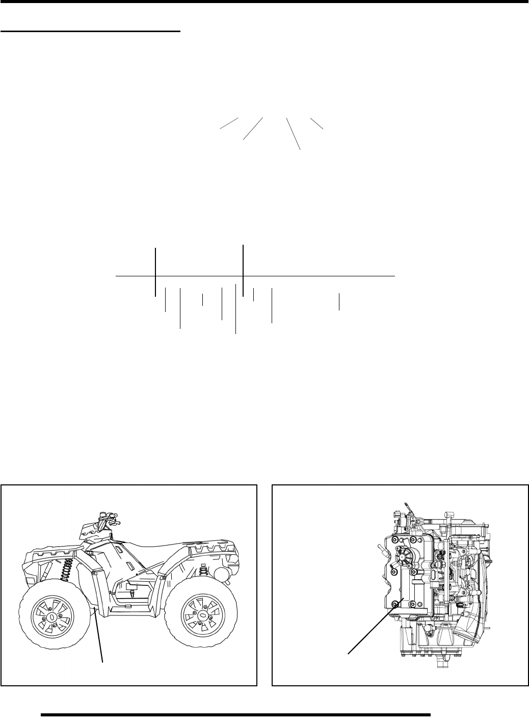
Vehicle and Engine Serial Number Locations
Whenever corresponding about a Polaris ATV, be sure to refer to the vehicle identification number (VIN) and
the engine serial number.
The VIN can be found stamped on the lower frame rail on the front LH side of the ATV (see Figure 1-1).
The engine serial number can be found on top of the engine located on the valve cover (see Figure 1-2).
}
Machine Model Number Identification
}
}
Year Designation
Basic Chassis
Designation Engine Designation
Emissions &
Model Option
A 0 9 Z N 8 5 A L
}
4 X A Z N 8 5 A * 9 P 0 0 0 0 0 0
}
1 2 3 4 5 6 7 8 9 10 11 12 13 14 15 16 17
World
Mfg. ID
Engine
Vehicle Descriptor Vehicle Identifier
}
Check Digit
Model
Year
Body Style
Plant No
Individual Serial Number
* This could be either
a number or a letter
Powertrain
Emissions
VIN
Figure 1-1
Engine Serial
Number
Figure 1-2
PartShark.com
877-999-5686

1.3
GENERAL INFORMATION
1
VEHICLE INFORMATION
Publication Numbers
NOTE: Additional Polaris factory publications can be found at www.polarisindustries.com or purchased from
www.purepolaris.com.
Replacement Keys
Replacement keys can be made from the original key. To identify which series the key is, take the first two digits on the original key
and refer to the chart to the right for the proper part number. Should both keys become lost, replacement of the ignition switch
assembly is necessary.
Special Tools
Special tools may be required while servicing this vehicle. Some of the tools listed or depicted are mandatory, while other tools
maybe substituted with a similar tool, if available. Polaris recommends the use of Polaris Special Tools when servicing any Polaris
product. Dealers may order special tools through Polaris’ official tool supplier, SPX Corporation, by phone at 1-800-328-6657 or
on-line at http://polaris.spx.com/.
YEAR MODEL MODEL NO. OWNER’S MANUAL PN PARTS MANUAL PN
2009 SPORTSMAN XP 850 A09ZN85AL, AQ,
AS, AT, AX, FL
9921973
9922173 (INT’L)
9921857
9922081 (INT’L)
2009 SPORTSMAN XP 850 EPS A09ZX85AG, AL,
AQ, AR, AS, AX, FS
9921973
9922173 (INT’L)
9921977
9922085 (INT’L)
Series # Part Number
20 4010278
21 4010278
22 4010321
23 4010321
27 4010321
28 4010321
31 4110141
32 4110148
67 4010278
68 4010278
Key Series
Number
KEY COVER
P/N 5533534
PartShark.com
877-999-5686
1.4
GENERAL INFORMATION
SPECIFICATIONS
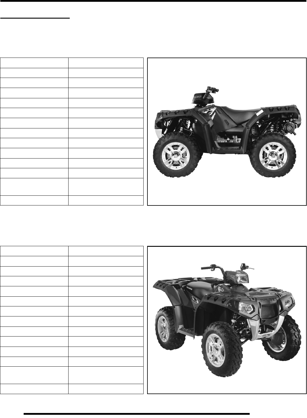
MODEL: 2009 SPORTSMAN XP 850
MODEL NUMBER:. . . . . . . . . A09ZN85AL, AQ, AS, AT, AX, FL
ENGINE MODEL:. . . . . . . . . . EH085OLE
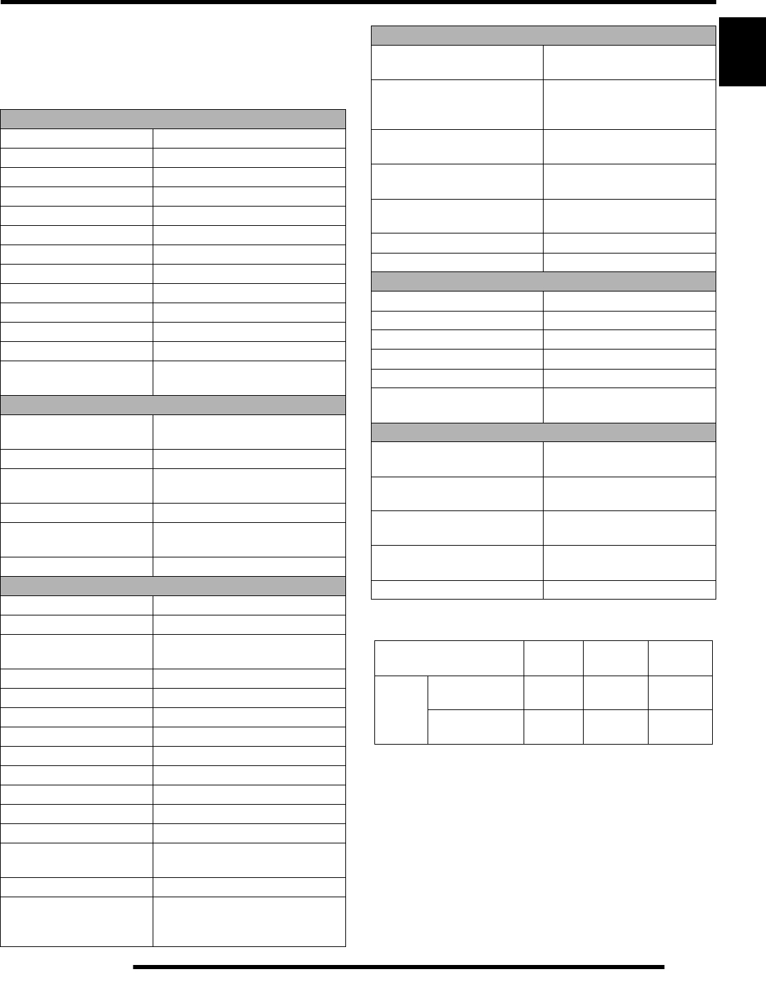
MODEL: 2009 SPORTSMAN XP 850 EPS
MODEL NUMBER:. . . . . . . . . A09ZX85AG, AL, AQ, AR, AS, AX, FS
ENGINE MODEL:. . . . . . . . . . EH085OLE
* Data based on EU Directive 76/432/EEC
Category Dimension
Length 83.25 in. / 211.5 cm
Width 47.6 in. / 121 cm
Height 50.75 in. / 129 cm
Wheel Base 53 in. / 135 cm
Ground Clearance 11.6 in. / 29.5 cm
Turning Radius 84 in. / 213 cm (unloaded)
Dry Weight 784 lbs. / 356 kg
Front Rack Capacity 120 lbs. / 54 kg
Rear Rack Capacity 240 lbs. / 109 kg
Max. Weight Capacity 575 lbs. / 261 kg
Towing Capacity 1500 lbs. / 680 kg
Unbraked Trailer
Towing Capacity (EU)* 1913.6 lbs. / 868 kg
Hitch Tongue Weight 150 lbs. / 68 kg
Category Dimension
Length 83.25 in. / 211.5 cm
Width 47.6 in. / 121 cm
Height 50.75 in. / 129 cm
Wheel Base 53 in. / 135 cm
Ground Clearance 11.6 in. / 29.5 cm
Turning Radius 84 in. / 213 cm (unloaded)
Dry Weight 796 lbs. / 361 kg
Front Rack Capacity 120 lbs. / 54 kg
Rear Rack Capacity 240 lbs. / 109 kg
Max. Weight Capacity 575 lbs. / 261 kg
Towing Capacity 1500 lbs. / 680 kg
Unbraked Trailer
Towing Capacity (EU)* 1913.6 lbs. / 868 kg
Hitch Tongue Weight 150 lbs. / 68 kg
PartShark.com
877-999-5686
1.5
GENERAL INFORMATION
1
2009 SPORTSMAN XP 850 / XP 850 EPS
XP MODELS: A09ZN85AL,AQ,AS,AT,AX,FL
XP EPS MODELS: A09ZX85AG,AL,AQ,AR,AS,AX,FS
ENGINE MODEL: EH085OLE
CLUTCH CHART
Engine
Platform Domestic Twin Cylinder, 4-Cycle
Engine Model Number EH085OLE011
Engine Displacement 850 cc
Number of Cylinders 2
Bore & Stroke (mm) 87 x 71.5 mm
Compression Ratio 11.0:1
Compression Pressure 210 - 250 psi
Engine Idle Speed 1200 ± 50 RPM
Cooling System / Cap. Liquid Cooled / 2 qt. (1.9 l)
Overheat Warning Instrument Cluster Indicator
Lubrication Pressurized Wet Sump
Engine Oil Requirement PS-4 Plus / 2 qt. (1.9 l)
Exhaust System Stainless Steel Dual Header Pipe
w/ Dual Outlet Silencer
Fuel System
Fuel System Type Bosch Multi-Port Sequential
Electronic Fuel Injection
Throttle Body / Size Mikuni Dual Bore / 40 mm
Fuel Delivery Electronic Fuel Pump
(in tank)
Fuel Pressure 43 psi
Fuel Capacity XP: 5.25 gal. (20 l)
XP EPS: 4.5 gal. (17 l)
Fuel Requirements 87 Octane (minimum)
Electrical
Alternator Output 475 W @ 1200 RPM / Peak 575 W
Voltage Regulator 3-Phase / 32 Amp
Head Lights Pod: 12V / 50 Watts
Bumper: 12V / 50 Watts x 2
Brake Light 12V / 27 Watts
Tail Light 12V / 7 Watts
Starting System Electric
Ignition System Bosch EFI (ECU Controlled)
Ignition Timing 6° ± 5° BTDC @ 1200 RPM
Spark plug / Gap REA8MCL / .035 in. (.90 mm)
Battery / Model / AH / CCA Deka / ETX30L / 30 AH / 365
Instrumentation Multifunction Instrument Cluster
DC Outlet Standard
Relays
(Located in Relay/Fuse Box)
Chassis / Start Solenoid / Fan /
EFI / Bumper Lights
Circuit Breaker Fan Motor: 20A
Fuses
(Located in Relay/Fuse Box)
Lights: 20A / Drive: 20A /
Accessory: 20A / EFI: 20A /
Unswitched: 10A / EPS: 30A
Drivetrain
Transmission Type Automatic PVT
In-Line H-L-N-R-P
Transmission
Fluid Type / Fluid Capacity
Synthetic Sportsman XP
Transmission Fluid /
32 oz. (946 ml)
Front Gearcase
Fluid Type / Fluid Capacity
Premium LT Demand Drive
Fluid / 9.3 oz. (275 ml)
Front Gearcase
ADC Reservoir Fluid Type
Premium ADC
Front Drive Fluid
Rear Gearcase
Fluid Type / Fluid Capacity
ATV Angle Drive Fluid /
7.1 oz. (210 ml)
Clutch Type PVT w/EBS
Belt 3211123
Steering / Suspension
Toe Out 0-1/16 in. (0-.159 mm)
Front Suspension Dual A-arm
Front Travel 9.2 in. / 23.4 cm
Rear Suspension Dual A-arm w/Rolled IRS
Rear Travel 10.2 in. / 25.9 cm
Shock Preload Adjustment
Front / Rear Cam Adjustable
Wheels / Brakes
Front Wheel Size / Bolt Pattern
Tire Model / Size
14 x 6 / 4-156
Carlisle Terrathon / 26 x 8 - 14
Rear Wheel Size / Bolt Pattern
Tire Model / Size
14 x 8 / 4-156
Carlisle Terrathon / 26 x 10 - 14
Tire Air Pressure Front: 7 psi (48 kPa)
Rear: 5 psi (34.5 kPa)
Brakes - Front & Rear Single Control
Hydraulic 4-Wheel Disc
Brake Fluid Polaris DOT 4 Brake Fluid
Altitude Shift
Weight
Drive
Spring
Driven
Spring
Meters
(Feet)
0-1800
(0-6000)
24-63
5632215
Red / Wht
7043349
Red / Wht
3235621
1800-3700
(6000 - 12000)
24-60
5632216
Red / Wht
7043349
Red / Wht
3235621
PartShark.com
877-999-5686
1.6
GENERAL INFORMATION
MISC. SPECIFICATIONS AND CHARTS
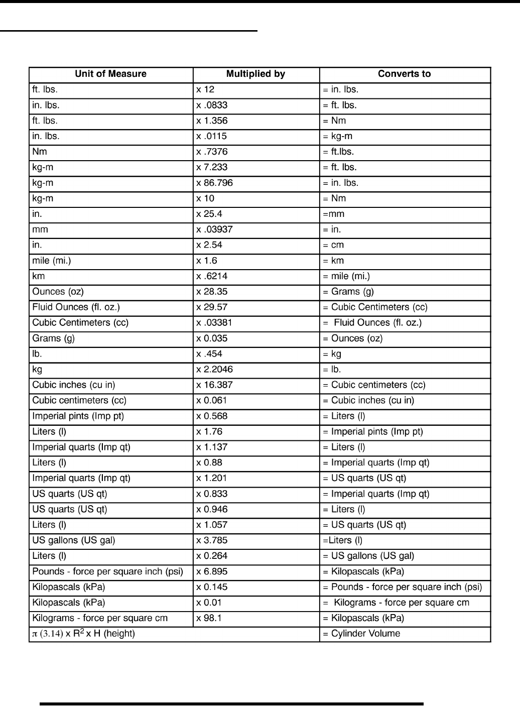
Conversion Table
°C to °F: 9/5(°C + 32) = °F °F to °C: 5/9(°F - 32) = °C
PartShark.com
877-999-5686
1.7
GENERAL INFORMATION
1
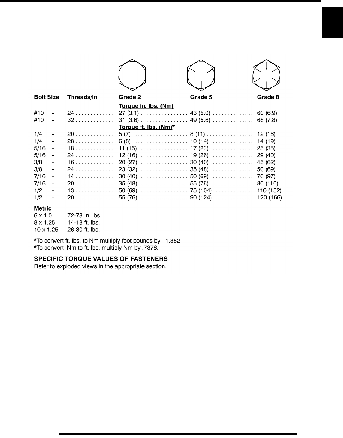
Standard Torque Specifications
The following torque specifications are to be used only as a general guideline. There are exceptions in the
steering, suspension, and engine areas. Always consult the exploded views or each manual section for torque
values of fasteners before using standard torque.
PartShark.com
877-999-5686
1.8
GENERAL INFORMATION
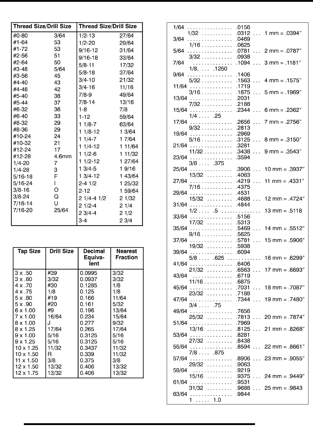
SAE Tap / Drill Sizes
Metric Tap / Drill Sizes
Decimal Equivalents
PartShark.com
877-999-5686

1.9
GENERAL INFORMATION
1
Glossary of Terms
ABDC: After bottom dead center.
ACV: Alternating current voltage.
Alternator: Electrical generator producing voltage alternating current.
ATDC: After top dead center.
BBDC: Before bottom dead center.
BDC: Bottom dead center.
BTDC: Before top dead center.
CC: Cubic centimeters.
Center Distance: Distance between center of crankshaft and center of driven clutch shaft.
Chain Pitch: Distance between chain link pins (No. 35 = 3/8" or 1 cm). Polaris measures chain length in number of pitches.
CI: Cubic inches.
Clutch Buttons: Plastic bushings which aid rotation of the movable sheave in the drive and driven clutch.
Clutch Offset: Drive and driven clutches are offset so that drive belt will stay nearly straight as it moves along the clutch face.
Clutch Weights: Three levers in the drive clutch which relative to their weight, profile and engine RPM cause the drive clutch to
close and grip the drive belt.
Crankshaft Run-Out: Run-out or "bend" of crankshaft measured with a dial indicator while crankshaft is supported between centers
on V blocks or resting in crankcase. Measure at various points especially at PTO.
DCV: Direct current voltage
CVT: Centrifugal Variable Transmission (Drive Clutch System)
DCV: Direct current voltage.
Dial Bore Gauge: A cylinder measuring instrument which uses a dial indicator. Good for showing taper and out-of-round in the
cylinder bore.
Electrical Open: Open circuit. An electrical circuit which isn't complete.
Electrical Short: Short circuit. An electrical circuit which is completed before the current reaches the intended load. (i.e. a bare wire
touching the chassis).
End Seals: Rubber seals at each end of the crankshaft.
Engagement RPM: Engine RPM at which the drive clutch engages to make contact with the drive belt.
ft.: Foot/feet.
Foot Pound: Ft. lb. A force of one pound at the end of a lever one foot in length, applied in a rotational direction.
g: Gram. Unit of weight in the metric system.
gal.: Gallon.
ID: Inside diameter.
in.: Inch/inches.
Inch Pound: In. lb. 12 in. lbs. = 1 ft. lb.
kg/cm²: Kilograms per square centimeter.
kg-m: Kilogram meters.
Kilogram/meter: A force of one kilogram at the end of a lever one meter in length, applied in a rotational direction.
l or ltr: Liter.
lbs/in²: Pounds per square inch.
Left or Right Side: Always referred to based on normal operating position of the driver.
m: Meter/meters.
Mag: Magneto.
Magnetic Induction: As a conductor (coil) is moved through a magnetic field, a voltage will be generated in the windings.
Mechanical energy is converted to electrical energy in the stator.
mi.: Mile/miles.
mm: Millimeter. Unit of length in the metric system. 1 mm = approximately .040".
Nm: Newton meters.
OD: Outside diameter.
Ohm: The unit of electrical resistance opposing current flow.
oz.: Ounce/ounces.
Piston Clearance: Total distance between piston and cylinder wall.
psi.: Pounds per square inch.
PTO: Power take off.
PVT: Polaris Variable Transmission (Drive Clutch system)
qt.: Quart/quarts.
Regulator: Voltage regulator. Regulates battery charging system output at approx. 14.5 DCV as engine RPM increases.
Reservoir Tank: The fill tank in the liquid cooling system.
Resistance: In the mechanical sense, friction or load. In the electrical sense, ohms, resulting in energy conversion to heat.
RPM: Revolutions per minute.
Seized Piston: Galling of the sides of a piston. Usually there is a transfer of aluminum from the piston onto the cylinder wall.
Possible causes: 1) improper lubrication; 2) excessive temperatures; 3) insufficient piston clearance; 4) stuck piston rings.
Stator Plate: The plate mounted under the flywheel supporting the battery charging coils.
TDC: Top dead center. Piston's most outward travel from crankshaft.
Volt: The unit of measure for electrical pressure of electromotive force. Measured by a voltmeter in parallel with the circuit.
Watt: Unit of electrical power. Watts = amperes x volts.
WOT: Wide open throttle.
PartShark.com
877-999-5686

NOTES
GENERAL INFORMATION
1.10
PartShark.com
877-999-5686

MAINTENANCE
2.1
CHAPTER 2
MAINTENANCE 2
PERIODIC MAINTENANCE CHART. . . . . . . . . . . . . . . . . . . . . . . . . . . . . . . . . . . . . . . . . 2.2
BREAK-IN PERIOD / MAINTENANCE CHART KEY . . . . . . . . . . . . . . . . . . . . . . . . . . . . 2.2
MAINTENANCE INTERVALS. . . . . . . . . . . . . . . . . . . . . . . . . . . . . . . . . . . . . . . . . . . . . . 2.3
GREASE LUBRICATION POINTS . . . . . . . . . . . . . . . . . . . . . . . . . . . . . . . . . . . . . . . . . . 2.5
MAINTENANCE QUICK REFERENCE . . . . . . . . . . . . . . . . . . . . . . . . . . . . . . . . . . . . . . 2.6
MAINTENANCE QUICK REFERENCE, CONTINUED..... . . . . . . . . . . . . . . . . . . . . . . . . 2.7
LUBRICANTS / SERVICE PRODUCTS . . . . . . . . . . . . . . . . . . . . . . . . . . . . . . . . . . . . . . 2.8
GENERAL VEHICLE INSPECTION AND MAINTENANCE. . . . . . . . . . . . . . . . . . . . . . . . 2.9
FUEL SYSTEM AND AIR INTAKE . . . . . . . . . . . . . . . . . . . . . . . . . . . . . . . . . . . . . . . . . . 2.9
FUEL LINES . . . . . . . . . . . . . . . . . . . . . . . . . . . . . . . . . . . . . . . . . . . . . . . . . . . . . . . . . . .2.9
FUEL FILTERS / VENT LINE . . . . . . . . . . . . . . . . . . . . . . . . . . . . . . . . . . . . . . . . . . . . . 2.10
THROTTLE OPERATION / ETC SWITCH / THROTTLE CABLE ADJUSTMENT . . . . . 2.10
AIR FILTER / PRE-FILTER SERVICE . . . . . . . . . . . . . . . . . . . . . . . . . . . . . . . . . . . . . . 2.11
ENGINE . . . . . . . . . . . . . . . . . . . . . . . . . . . . . . . . . . . . . . . . . . . . . . . . . . . . . . . . . . . . . . 2.12
ENGINE OIL LEVEL / OIL AND FILTER CHANGE . . . . . . . . . . . . . . . . . . . . . . . . . . . . 2.12
ENGINE BREATHER HOSE / BREATHER ASSEMBLY . . . . . . . . . . . . . . . . . . . . . . . . 2.13
VALVE CLEARANCE ADJUSTMENT . . . . . . . . . . . . . . . . . . . . . . . . . . . . . . . . . . . . . . 2.14
COMPRESSION AND LEAKDOWN TESTS . . . . . . . . . . . . . . . . . . . . . . . . . . . . . . . . . 2.15
EXHAUST SILENCER CLEANING. . . . . . . . . . . . . . . . . . . . . . . . . . . . . . . . . . . . . . . . . 2.16
ENGINE MOUNT FASTENER TORQUE . . . . . . . . . . . . . . . . . . . . . . . . . . . . . . . . . . . . 2.16
TRANSMISSION AND GEARCASES . . . . . . . . . . . . . . . . . . . . . . . . . . . . . . . . . . . . . . . 2.17
TRANSMISSION LUBRICATION . . . . . . . . . . . . . . . . . . . . . . . . . . . . . . . . . . . . . . . . . . 2.17
FRONT GEARCASE LUBRICATION . . . . . . . . . . . . . . . . . . . . . . . . . . . . . . . . . . . . . . . 2.18
FRONT GEARCASE ADC FLUID. . . . . . . . . . . . . . . . . . . . . . . . . . . . . . . . . . . . . . . . . . 2.19
REAR GEARCASE LUBRICATION . . . . . . . . . . . . . . . . . . . . . . . . . . . . . . . . . . . . . . . . 2.20
COOLING SYSTEM. . . . . . . . . . . . . . . . . . . . . . . . . . . . . . . . . . . . . . . . . . . . . . . . . . . . . 2.21
COOLANT LEVEL INSPECTION . . . . . . . . . . . . . . . . . . . . . . . . . . . . . . . . . . . . . . . . . . 2.21
COOLING SYSTEM HOSES / COOLANT STRENGTH / COOLANT TYPE . . . . . . . . . 2.22
PVT / FINAL DRIVE / WHEEL AND TIRE . . . . . . . . . . . . . . . . . . . . . . . . . . . . . . . . . . . . 2.23
PVT DRYING / DRIVE BELT REMOVAL . . . . . . . . . . . . . . . . . . . . . . . . . . . . . . . . . . . . 2.23
DRIVE SHAFT BOOT INSPECTION . . . . . . . . . . . . . . . . . . . . . . . . . . . . . . . . . . . . . . . 2.23
WHEEL AND HUB TORQUE TABLE . . . . . . . . . . . . . . . . . . . . . . . . . . . . . . . . . . . . . . . 2.24
WHEEL REMOVAL / INSTALLATION . . . . . . . . . . . . . . . . . . . . . . . . . . . . . . . . . . . . . . 2.24
TIRE PRESSURE / TIRE INSPECTION. . . . . . . . . . . . . . . . . . . . . . . . . . . . . . . . . . . . . 2.25
ELECTRICAL AND IGNITION SYSTEM . . . . . . . . . . . . . . . . . . . . . . . . . . . . . . . . . . . . . 2.25
BATTERY MAINTENANCE . . . . . . . . . . . . . . . . . . . . . . . . . . . . . . . . . . . . . . . . . . . . . . 2.25
BATTERY REMOVAL / INSTALLATION . . . . . . . . . . . . . . . . . . . . . . . . . . . . . . . . . . . . 2.26
SPARK PLUG SERVICE . . . . . . . . . . . . . . . . . . . . . . . . . . . . . . . . . . . . . . . . . . . . . . . . 2.26
ENGINE / CHASSIS GROUND . . . . . . . . . . . . . . . . . . . . . . . . . . . . . . . . . . . . . . . . . . . 2.27
STEERING . . . . . . . . . . . . . . . . . . . . . . . . . . . . . . . . . . . . . . . . . . . . . . . . . . . . . . . . . . . 2.28
STEERING INSPECTION. . . . . . . . . . . . . . . . . . . . . . . . . . . . . . . . . . . . . . . . . . . . . . . . 2.28
POWER STEERING UNIT (EPS MODELS). . . . . . . . . . . . . . . . . . . . . . . . . . . . . . . . . . 2.28
TIE ROD END / STEERING INSPECTION / TOE ALIGNMENT . . . . . . . . . . . . . . . . . . 2.29
TOE ALIGNMENT ADJUSTMENT . . . . . . . . . . . . . . . . . . . . . . . . . . . . . . . . . . . . . . . . . 2.30
SUSPENSION . . . . . . . . . . . . . . . . . . . . . . . . . . . . . . . . . . . . . . . . . . . . . . . . . . . . . . . . . 2.30
SUSPENSION INSPECTION / SUSPENSION SPRING PRE-LOAD ADJUSTMENT . . 2.30
BRAKE SYSTEM. . . . . . . . . . . . . . . . . . . . . . . . . . . . . . . . . . . . . . . . . . . . . . . . . . . . . . . 2.31
BRAKE FLUID / BRAKE PAD / HOSE / FITTING INSPECTION . . . . . . . . . . . . . . . . . . 2.31
AUXILIARY BRAKE PEDAL . . . . . . . . . . . . . . . . . . . . . . . . . . . . . . . . . . . . . . . . . . . . . . 2.32
MAINTENANCE LOG . . . . . . . . . . . . . . . . . . . . . . . . . . . . . . . . . . . . . . . . . . . . . . . . . . . 2.33
PartShark.com
877-999-5686

2.2
MAINTENANCE
PERIODIC MAINTENANCE CHART
Periodic Maintenance Overview
Inspection, adjustment and lubrication of important components are explained in the periodic maintenance chart.
Inspect, clean, lubricate, adjust and replace parts as necessary. When inspection reveals the need for replacement parts, use
genuine Pure Polaris parts available from your Polaris dealer.
NOTE: Service and adjustments are critical. If you’re not familiar with safe service and adjustment
procedures, have a qualified dealer perform these operations.
Maintenance intervals in the following chart are based upon average riding conditions and an average vehicle speed of approximately
10 miles per hour. Vehicles subjected to severe use must be inspected and serviced more frequently.
Severe Use Definition
• Frequent immersion in mud, water or sand
• Racing or race-style high RPM use
• Prolonged low speed, heavy load operation
• Extended idle
• Short trip cold weather operation
Pay special attention to the oil level. A rise in oil level during cold weather can indicate contaminants collecting in the oil sump or
crankcase. Change oil immediately if the oil level begins to rise. Monitor the oil level, and if it continues to rise, discontinue use
and determine the cause or see your dealer.
Break-In Period
The break-in period consists of the first 20 hours of operation. Careful treatment of a new engine and drive components will result
in more efficient performance and longer life for these components.
• Drive vehicle slowly at first while varying the throttle position. Do not operate at sustained idle.
• Pull only light loads.
• Perform regular checks on fluid levels and other areas outlined on the daily pre-ride inspection checklist.
• Change both the engine oil and filter after 20 hours or one month.
• See “Owner’s Manual” for additional break-in information.
Maintenance Chart Key
The following symbols denote potential items to be aware of during maintenance:
= CAUTION: Due to the nature of these adjustments, it is recommended this service be performed by an
authorized Polaris dealer.
= SEVERE USE ITEM: See information provided above.
E = Emission Control System Service (California).
NOTE: Inspection may reveal the need for replacement parts. Always use genuine Polaris parts.
WARNING
Improperly performing the procedures marked could result in component failure and lead to serious injury or death.
Have an authorized Polaris dealer perform these services.
PartShark.com
877-999-5686

2.3
MAINTENANCE
2
Maintenance Intervals
Item
Maintenance Interval
(whichever comes first) Remarks
Hours Calendar Miles
(KM)
Steering - Pre-Ride -
Inspect and make adjustments as needed.
See Pre-Ride Checklist later in this chapter.
Front Suspension - Pre-Ride -
Rear Suspension - Pre-Ride -
Tires - Pre-Ride -
Brake Fluid Level - Pre-Ride -
Brake Lever Travel - Pre-Ride -
Brake System - Pre-Ride -
Wheels / Fasteners - Pre-Ride -
Frame Fasteners - Pre-Ride -
Engine Oil Level - Pre-Ride -
EAir Filter, Pre-filter - Daily - Inspect;clean often
Coolant - Daily - Check level daily, change coolant every two
years
ADC Fluid - Daily - Check level daily, add as needed
Power Steering Unit
(if equipped) - Daily - Inspect daily, clean often
Head Lights / Tail Lights - Daily - Check operation; apply dielectric grease if
replacing
EAir Filter (main element) - Weekly - Inspect; replace as needed
Brake Pad Wear 10 H Monthly 100 (160) Inspect periodically
Battery 20 H Monthly 200 (320) Check terminals; clean; test
EEngine Oil Change
(Break-in Period) 20 H 1 M - Perform a break-in oil change at one month or
20 hours, whichever comes first
Front Gearcase Fluid 25 H Monthly 250 (400) Inspect level
Rear Gearcase Fluid 25 H Monthly 250 (400) Inspect level
Transmission Fluid 25 H Monthly 250 (400) Inspect level
Perform these procedures more often for vehicles subjected to severe use.
E Emission Control System Service (California)
Have an authorized Polaris dealer perform these services.
PartShark.com
877-999-5686

2.4
MAINTENANCE
Item
Maintenance Interval
(whichever comes first) Remarks
Hours Calendar Miles
(KM)
General Lubrication 50 H 3 M 500 (800) Lubricate all fittings, pivots, cables, etc.
EThrottle Cable /
ETC Switch 50 H 6 M 500 (800) Inspect; adjust; lubricate; replace if
necessary
EThrottle Body Intake
Duct 50 H 6 M 500 (800) Inspect ducts for proper sealing / air leaks
Drive belt 50 H 6 M 500 (800) Inspect; replace as needed
Cooling System 50 H 6 M 500 (800) Inspect coolant strength seasonally;
pressure test system yearly
Radiator 50 H 6 M 500 (800) Inspect; clean external surfaces
Cooling Hoses 50 H 6 M 500 (800) Inspect for leaks
Engine Oil Change 100 H 6 M 1000 (1600) Perform a break-in oil change at 20 hours or
after one month of operation; change more
frequently during cold weather operation
Oil Filter Change 100 H 6 M 1000 (1600) Replace with oil change
Front Gearcase Fluid - 12 M 1000 (1600) Change Fluid
Rear Gearcase Fluid - 12 M 1000 (1600) Change Fluid
Transmission Fluid - 12 M 1000 (1600) Change Fluid
EFuel System 100 H 12 M 1000 (1600) Check for leaks at tank cap, fuel lines, fuel
pump; replace lines every two years
Engine Mounts 100 H 12 M 1000 (1600) Inspect
Exhaust Pipe / Silencer 100 H 12 M 1000 (1600) Inspect
ESpark Plug 100 H 12 M 1000 (1600) Inspect; replace as needed
Wiring 100 H 12 M 1000 (1600) Inspect for wear, routing, security; apply
dielectric grease to connectors subjected to
water, mud, etc.
Clutches
(Drive and Driven) 100 H 12 M 1000 (1600) Inspect; clean; replace worn parts
Front Wheel Bearings 100 H 12 M 1000 (1600) Inspect; replace as needed
Brake Fluid 200 H 24 M 2000 (3200) Change every two years
ADC Fluid 200 H 24 M 2000 (3200) Change every two years
Spark Arrestor
(if applicable) 300 H 36 M 3000 (4800) Clean out; or remove clean out plug
EValve Clearance 1000 H - 10000 (16000) Inspect; adjust
Toe Adjustment - Inspect periodically; adjust as needed
Headlight Aim - Adjust as needed
Perform these procedures more often for vehicles subjected to severe use.
E Emission Control System Service (California)
Have an authorized Polaris dealer perform these services.
PartShark.com
877-999-5686
2.5
MAINTENANCE
2
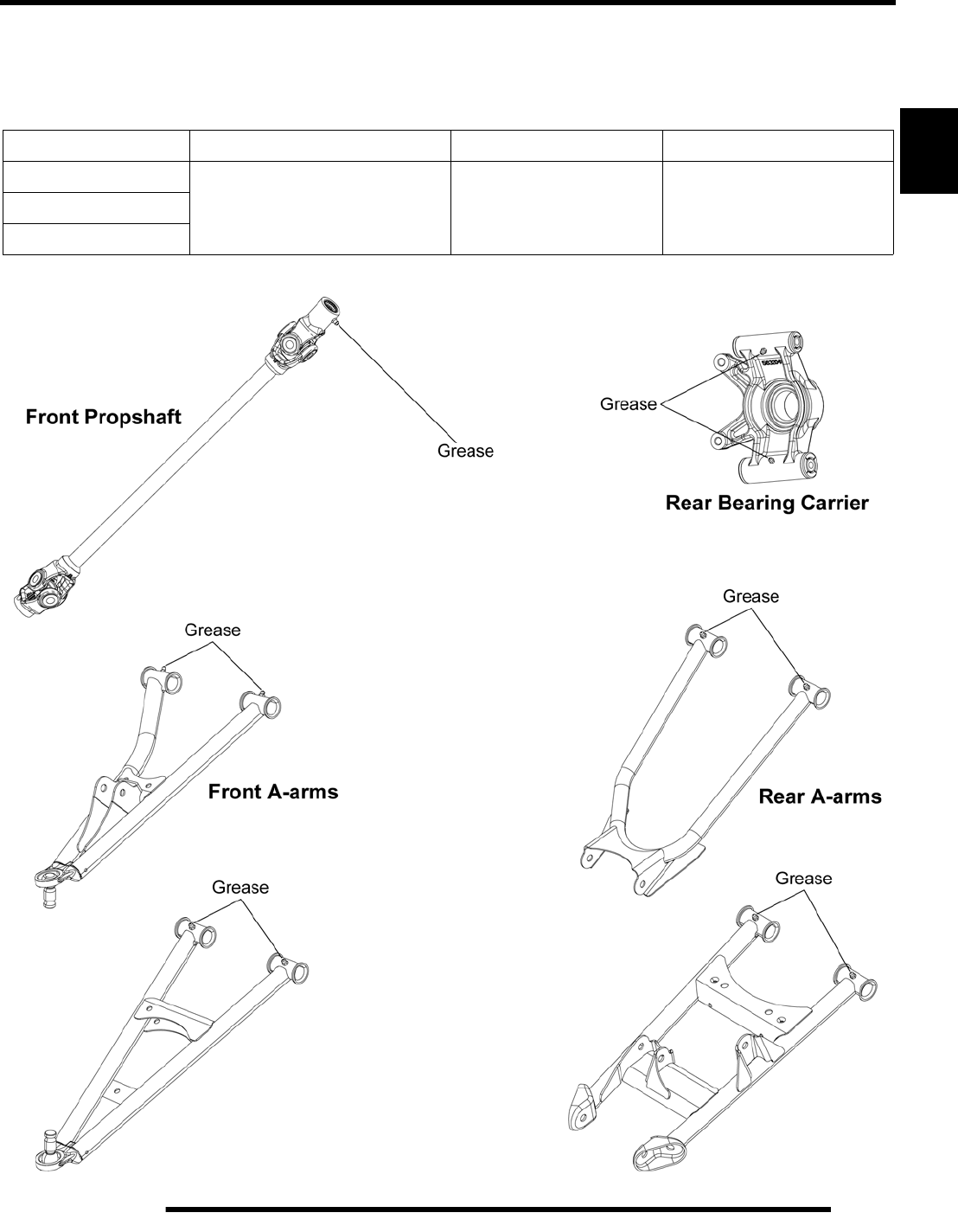
Grease Lubrication Points
There are grease fittings on each upper and lower front and rear A-arms, each rear bearing carrier, and on the front propshaft yoke.
Apply a maximum of 3 pumps of grease at each of these areas.
Item Recommended Lube Method Frequency
Front Propshaft Yoke
Polaris Premium U-Joint Grease Grease fittings
(3 pumps maximum)
every 500 miles (800 km).
Grease before long periods
of storage, and after
pressure washing or
submerging the ATV.
Front & Rear A-Arms
Rear Bearing Carrier
PartShark.com
877-999-5686
2.6
MAINTENANCE
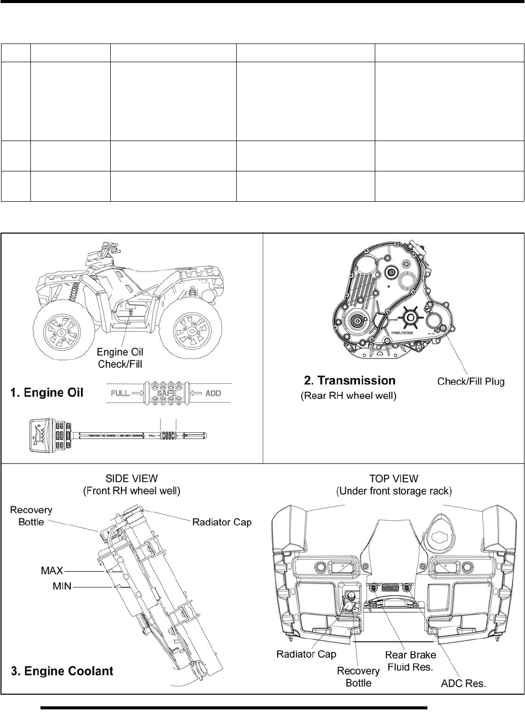
Maintenance Quick Reference
* More often under severe use, such as operated in water or under severe loads.
III. # Item Lube Rec. Method Frequency*
1Engine Oil Polaris PS-4 PLUS 2W-50
Performance Synthetic Add oil to proper level on
dipstick
Change after 1st month or first
20 hours of operation, 100
hours thereafter; Change more
often (25 hours) in severe duty
conditions or short trip cold
weather operation
2 Transmission Synthetic Sportsman XP
Transmission Fluid Add fluid until it is visible at
the fill hole threads Check level every 25 hours;
change fluid yearly
3 Engine Coolant Polaris 60/40 Coolant Maintain coolant level in
coolant reservoir bottle. Check level daily, change
coolant every 2 years
PartShark.com
877-999-5686
2.7
MAINTENANCE
2
Maintenance Quick Reference, Continued.....
* More often under severe use, such as operated in water or under severe loads.
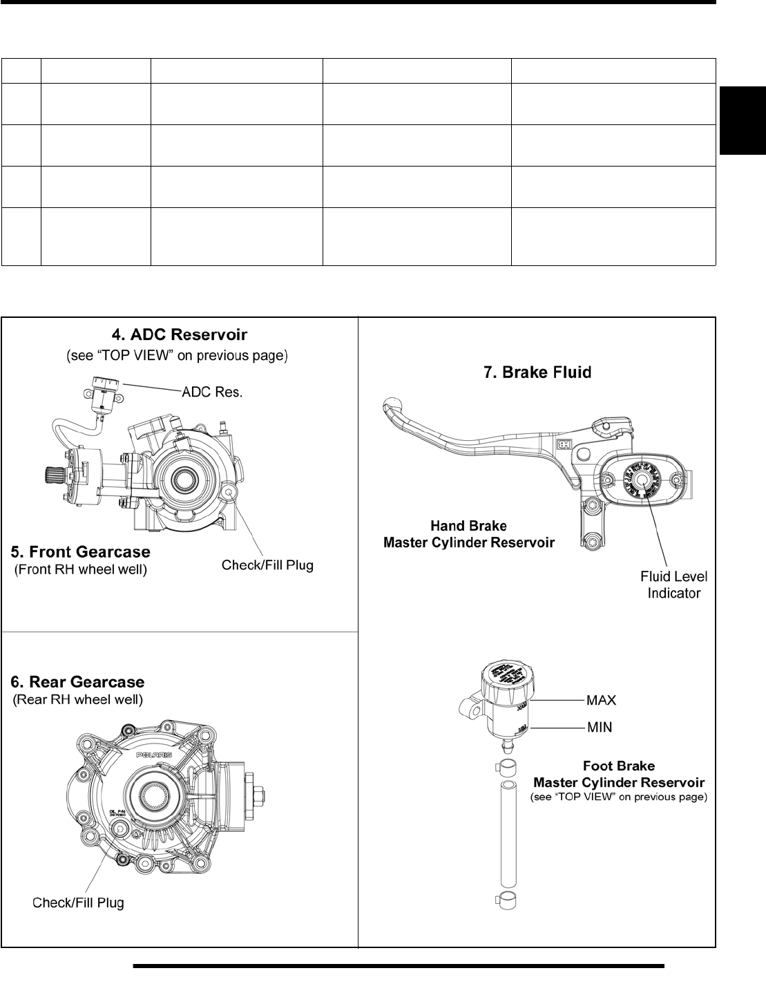
III. # Item Lube Rec. Method Frequency*
4Front Gearcase
ADC Reservoir Polaris Premium ADC
Front Drive Fluid Maintain fluid level in ADC
Reservoir to indicated level Check level every 25 hours;
change fluid every two years
5 Front Gearcase Polaris Premium LT
Demand Drive Fluid Add fluid until it is visible at
the fill hole threads Check level every 25 hours;
change fluid yearly or 1000 mi.
6 Rear Gearcase Polaris ATV Angle Drive
Fluid (ADF) Add fluid until it is visible at
the fill hole threads Check level every 25 hours;
change fluid yearly
7 Brake Fluid Polaris DOT 4 Brake Fluid Maintain fluid level in both
master cylinder reservoirs to
indicated levels
Check level during pre-ride
inspection; change fluid every
two years
PartShark.com
877-999-5686
2.8
MAINTENANCE
LUBRICANTS / SERVICE PRODUCTS
Polaris Lubricants,Maintenance and Service
Products
NOTE: Each item can be purchased separately at
your local Polaris dealer.
NOTE: The number count indicated by each part
number in the table above indicates the number of
units that are shipped with each order.
Part No. Description
Engine / Transmission Lubricant
2870791 Fogging Oil (12 oz. Aerosol)
2876244 PS-4 PLUS 2W-50 Performance Synthetic
4-Cycle Engine Oil (Quart)
2876245 PS-4 PLUS 2W-50 Performance Synthetic
4-Cycle Engine Oil (Gallon)
Gearcase Lubricants
2877606 Synthetic Sportsman XP
Transmission Fluid (Quart)
2876251 Premium LT Demand Drive Fluid
(Quart) (12 count)
2872277 Premium Demand Drive Hub Fluid
(2.5 Gallon) (2 count)
2876160 ATV Angle Drive Fluid
(Quart) (12 count)
2872276 ATV Angle Drive Fluid
(2.5 Gallon) (2 Count)
2870465 Pump for Gallon Jug
Coolant
2871534 60/40 Coolant (Quart) (12 count)
2871323 60/40 Coolant (Gallon) (6 count)
Grease / Specialized Lubricants
2871312 Grease Gun Kit
2871322 Premium All Season Grease
(3 oz. cartridge) (24 Count)
2871423 Premium All Season Grease
(14 oz. cartridge) (10 Count)
2871460 Starter Drive Grease (12 Count)
2871515 Premium U-Joint Lube (3 oz.) (24 Count)
2871551 Premium U-Joint Lube (14 oz.) (10 Count)
2871329 Dielectric Grease (Nyogel™)
Additives / Sealants / Thread Locking Agents / Misc.
2870585 Loctite™ Primer N, Aerosol, 25 g
2871956 Loctite™ Thread Sealant 565
(50 ml.) (6 Count)
2871949 Loctite™ Threadlock 242
(50 ml.) (10 Count)
2871950 Loctite™ Threadlock 242
(6 ml.) (12 Count)
2871951 Loctite™ Threadlock 262
(50 ml.) (10 Count)
2871952 Loctite™ Threadlock 262
(6 ml.) (12 Count)
2871953 Loctite™ Threadlock 271
(6 ml.) (12 Count)
2871954 Loctite™ Threadlock 271
(36 ml.) (6 Count)
2870584 Loctite™ 680-Retaining Compound
(10 ml.)
2870587 Loctite™ 518 Gasket Eliminator / Flange
Sealant (50 ml.) (10 Count)
2871326 Premium Carbon Clean
(12 oz.) (12 Count)
2870652 Fuel Stabilizer (16 oz.) (12 Count)
2872189 DOT 4 Brake Fluid (12 Count)
2871557 Crankcase Sealant, 3-Bond 1215 (5oz.)
2872893 Engine Degreaser (12oz.) (12 Count)
PartShark.com
877-999-5686
2.9
MAINTENANCE
2
GENERAL VEHICLE INSPECTION
AND MAINTENANCE
Pre-ride / Daily Inspection
Perform the following pre-ride inspection daily, and when
servicing the vehicle at each scheduled maintenance.
• Tires - check condition and tire pressure
• Fuel and oil - fill both to their proper level; do not
overfill
• All brakes - check operation (includes auxiliary brake)
• Throttle - check for free operation
• Headlight / Taillight / Brakelight - check operation of
all indicator lights and switches
• Engine stop switch (key switch) - check for proper
function
• Wheels - check for loose wheel nuts
• Air cleaner element - check for dirt or water; clean or
replace
• Steering - check for free operation, noting any unusual
looseness in any area
• Loose parts - visually inspect vehicle for any damaged
or loose nuts, bolts or other fasteners
• Engine coolant - check for proper level at the recovery
bottle
Frame, Nuts, Bolts, Fasteners
Periodically inspect the torque of all fasteners in accordance
with the maintenance schedule. Check that all cotter pins are in
place. Refer to specific fastener torques listed in each chapter.
Controls
Check handlebar controls for proper operation, positioning and
adjustment.
FUEL SYSTEM AND AIR INTAKE
Fuel System
• Always stop the engine and refuel outdoors or in a well
ventilated area.
• Do not smoke or allow open flames or sparks in or near
the area where refueling is performed or where gasoline
is stored.
• Do not overfill the tank. Do not fill the tank neck.
• If you get gasoline in your eyes or if you swallow
gasoline, seek medical attention immediately.
• If you spill gasoline on your skin or clothing,
immediately wash it off with soap and water and
change clothing.
• Never start the engine or let it run in an enclosed area.
Engine exhaust fumes are poisonous and can result loss
of consciousness or death in a short time.
• Never drain the fuel when the engine is hot. Severe
burns may result.
Fuel Lines
1. Check fuel lines for signs of wear, deterioration, damage,
or leakage. Replace if necessary.
2. Be sure fuel lines are routed properly and secured with
cable ties where applicable.
3. Replace all fuel lines every two years.
WARNING
Gasoline is extremely flammable and explosive
under certain conditions.
CAUTION
Make sure lines are not kinked or pinched
PartShark.com
877-999-5686
2.10
MAINTENANCE
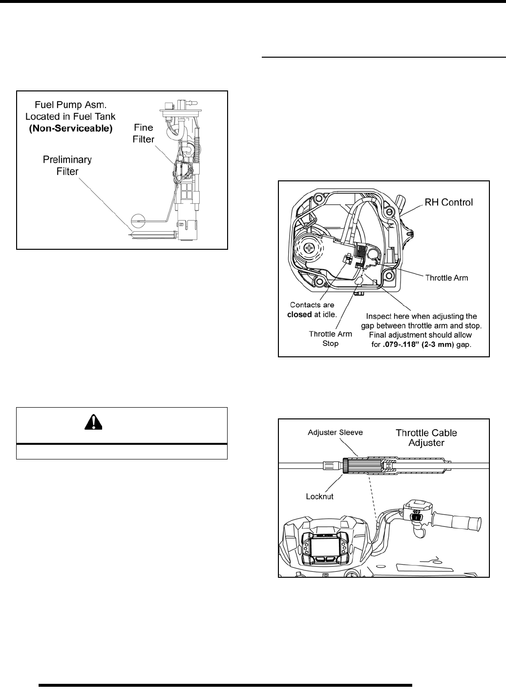
Fuel Filters
There are two fuel filters located within the fuel pump assembly.
The fuel pump is non-serviceable. If the internal fuel pump
filters require service, the fuel pump and fuel tank must be
replaced as an assembly.
NOTE: See the “Electronic Parts Catalog” for more
information. For all other information related to the EFI
System, refer to Chapter 3.
Vent Line
1. Check the vent line from the fuel tank for signs of wear,
deterioration, damage or leakage. Replace the line every
two years.
2. Verify vent line is routed properly and secured with an
appropriate number of cable ties.
Throttle Operation
Check for smooth throttle opening and closing in all handlebar
positions. Throttle lever operation should be smooth and lever
must return freely without binding.
1. Place the gear selector in neutral.
2. Set parking brake.
3. Start the engine and let it idle.
4. Turn handlebars from full right to full left. If idle speed
increases at any point in the turning range, inspect throttle
cable routing and condition. If cable is routed properly and
in good condition, no adjustment is required.
5. Replace the throttle cable if worn, kinked, or damaged.
Electronic Throttle Control Switch (ETC) /
Throttle Cable Adjustment
NOTE: Sportsman XP requires a new adjustment procedure.
1. Slide the boot back far enough to expose the inline cable
adjuster sleeve and loosen the adjuster locknut.
2. Remove the (4) screws and cover from the RH control.
3. With handlebars centered and wheels pointing forward,
slowly turn the adjuster sleeve counter-clockwise (out) just
until the gap is removed between the throttle arm and the
throttle arm stop (see illustration below).
NOTE: While moving the adjuster sleeve, “flip” the
throttle lever slightly to remove slack in the cable.
4. Turn the cable adjuster sleeve clockwise (in) 1.5 - 2 turns;
tighten locknut and reinstall boot. After this adjustment
there should be .079-.118” (2-3 mm) gap between throttle
arm and throttle arm stop.
5. Reinstall the RH control cover and ensure the O-ring is
properly in place. Securely tighten the (4) screws.
6. Place the vehicle in PARK and start the engine. Turn the
handlebars from full left to full right while listening for any
change in engine speed. If engine speed changes, loosen
the locknut and turn the adjuster sleeve clockwise (in) an
additional 1/2 turn and repeat this step.
CAUTION
Make sure lines are not kinked or pinched
PartShark.com
877-999-5686
2.11
MAINTENANCE
2
Air Filter / Pre-Filter Service
It is advisable to replace the filter when it is dirty. However, in
an emergency, it is permissible to clean the main filter if you
observe the following practices.
• Never immerse the filter in water since dirt can be
transferred to the clean air side of the filter.
• If compressed air is used never exceed a pressure of 40
PSI. Always use a dispersion type nozzle to prevent
filter damage and clean from the inside to the outside.
It is recommended that the air filter and pre filter be replaced
annually. When riding in extremely dusty conditions,
replacement is required more often.
Removal:
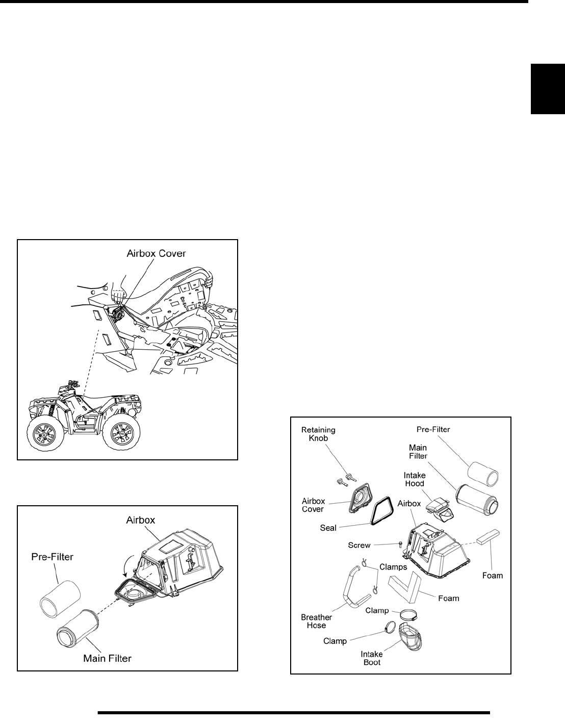
1. Remove the seat to access the airbox cover.
2. Unscrew the two knobs retaining the airbox cover and open
the cover.
3. Remove the air filter assembly from the airbox.
Cleaning:
4. Slip the pre-filter screen off of main element. Clean the pre-
filter with hot soapy water.
5. Rinse and dry thoroughly.
6. Inspect pre-filter screen for tears or damage.
7. Inspect main filter and replace if necessary. If the filter has
been soaked with fuel or oil it must be replaced.
Installation:
8. Inspect airbox cover seal for damage. It should adhere
tightly to the cover and seal all the way around. Replace
seal as needed.
9. Reinstall pre-filter screen over main filter. Be sure the
screen covers entire surface of main filter without folds,
creases, or gaps.
NOTE: Apply a small amount of general purpose grease
to the sealing edges of the filter before reinstalling.
10. Install air filter assembly into the airbox and position it
correctly before closing the airbox cover.
NOTE: Proper placement of the air filter is important to
prevent air leaks.
11. Close airbox cover and secure cover by tightening the
retaining knobs.
12. Check the intake boot for cracks, deterioration, abrasion, or
leaks. Replace as needed.
PartShark.com
877-999-5686
2.12
MAINTENANCE
ENGINE
Engine Oil Level
Polaris recommends the use of Polaris PS-4 PLUS synthetic
engine oil. Always use PS-4 PLUS engine oil. Oil may need to
be changed more frequently if Polaris engine oil is not used.
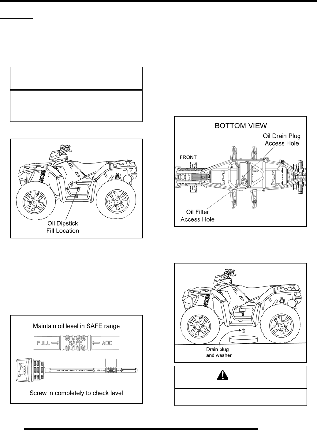
1. Locate the engine oil dipstick on the left side of the ATV.
2. Position the ATV on a level surface.
3. Stop engine and remove the dipstick. Wipe it dry with a
clean cloth.
4. Reinstall and tighten the dipstick.
NOTE: The dipstick must be screwed in completely
to ensure an accurate measurement.
5. Remove the dipstick and check the oil level.
6. Maintain the oil level in the safe range. Do not overfill.
Engine Oil and Filter Change
Always change engine oil and filter at the intervals outlined in
the Periodic Maintenance Chart. Always change the oil filter
whenever changing the engine oil.
1. Position the ATV on a level surface.
2. Place the transmission in park.
3. Start engine and allow it to run for two to three minutes until
the engine is warm.
4. Stop the engine.
5. Clean the area around the drain plug.
6. Place a drain pan beneath the engine crankcase.
7. Using a 6 mm Hex socket, remove the drain plug and allow
the engine oil to drain completely.
8. Replace the sealing washer on the drain plug.
CAUTION
Mixing brands or using a non-recommended
engine oil may cause serious engine damage.
Always use the recommended engine oil. Never
substitute or mix engine oil brands.
WARNING
Hot oil can cause serious burns to skin.
Do not allow hot oil to contact skin.
PartShark.com
877-999-5686
2.13
MAINTENANCE
2
NOTE: The sealing surfaces on the drain plug and
crankcase should be clean and free of burrs, nicks
or scratches.
9. Reinstall drain plug and torque to 12 ft. lbs. (16 Nm).
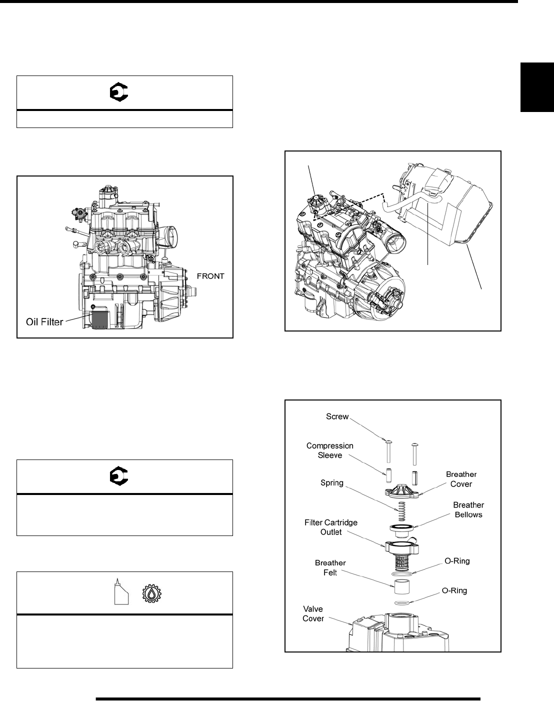
10. Locate oil filter through access hole in the skid plate. Place
shop towels beneath the oil filter. Using oil filter wrench
(PU-50105) turn oil filter counterclockwise to remove it.
11. Use a clean dry towel to clean the filter sealing surface on
the crankcase.
12. Check to make sure the O-ring on the new oil filter is in
good condition. Lubricate O-ring on new filter with a film
of fresh engine oil.
13. Install new oil filter and turn by hand until filter gasket
contacts the sealing surface, then turn it and additional 1/2
turn.
14. Remove dipstick and fill engine with 1.75 qts. (1.66 L) of
the recommended engine oil.
15. Start the engine and allow it to idle for one to two minutes.
16. Stop the engine and check for leaks.
17. Re-check the oil level on the dipstick and add oil as
necessary to bring the level to the upper mark on the
dipstick.
18. Dispose of used oil and filter properly.
Engine Breather Hose
Be sure engine breather hose is routed properly and secured in
place. CAUTION: Make sure line is not kinked or pinched.
Engine Breather Assembly
The engine breather assembly is located on top of the valve
cover. Inspect and service the breather components as required.
= T
Engine Drain Plug: 12 ft. lbs. (16 Nm)
= T
Oil Filter Torque:
Turn by hand until filter gasket contacts sealing
surface, then turn an additional 1/2 turn.
=
Recommended Engine Oil:
PS-4 PLUS Synthetic 4-Cycle Engine Oil
(PN 2876244) (Quart)
Inspect
Breather
Airbox
PartShark.com
877-999-5686
2.14
MAINTENANCE
Valve Clearance Adjustment
1. Remove the seat and both upper side panels.
2. Disconnect the shift linkage from the shift lever.
3. Remove the (2) screws retaining the lower portion of the
air box.
4. Remove the hose from the breaker valve located on top of
the valve cover.
5. Remove the push rivets retaining the right-hand portion of
the rear cab to gain access to the bolts retaining the upper
right-hand frame support.
6. Remove the (4) bolts retaining the frame support. Pull the
support forward and down to remove it from the vehicle.
7. Remove the (2) Torx-head screws retaining the upper
portion of the air box to the front cab.
8. Carefully disconnect the ECU by pulling the tab out while
pulling down on the connector.
9. Loosen the hose clamp retaining the intake boot to the
intake plenum and remove the boot.
10. Lift up on the air box and turn it sideways to gain access to
the valve cover bolts.
11. Remove the spark plug wires and spark plugs.
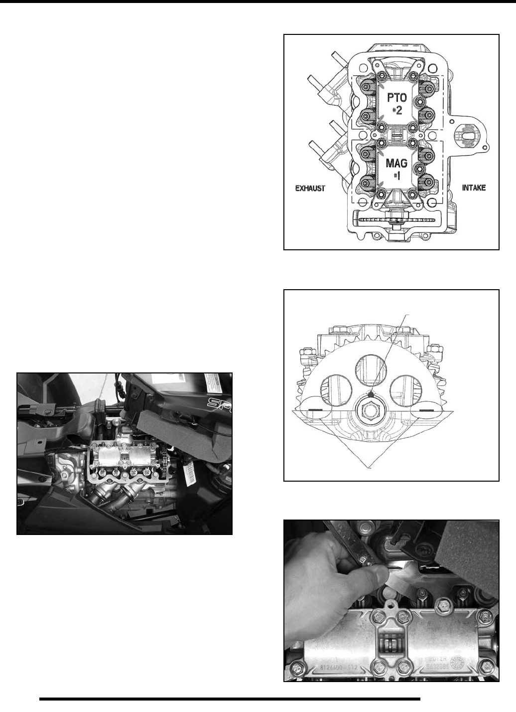
12. Remove the (6) valve cover bolts and valve cover.
13. Remove PVT cover so the engine can be rotated (see “Drive
Belt Removal” procedure within this chapter).
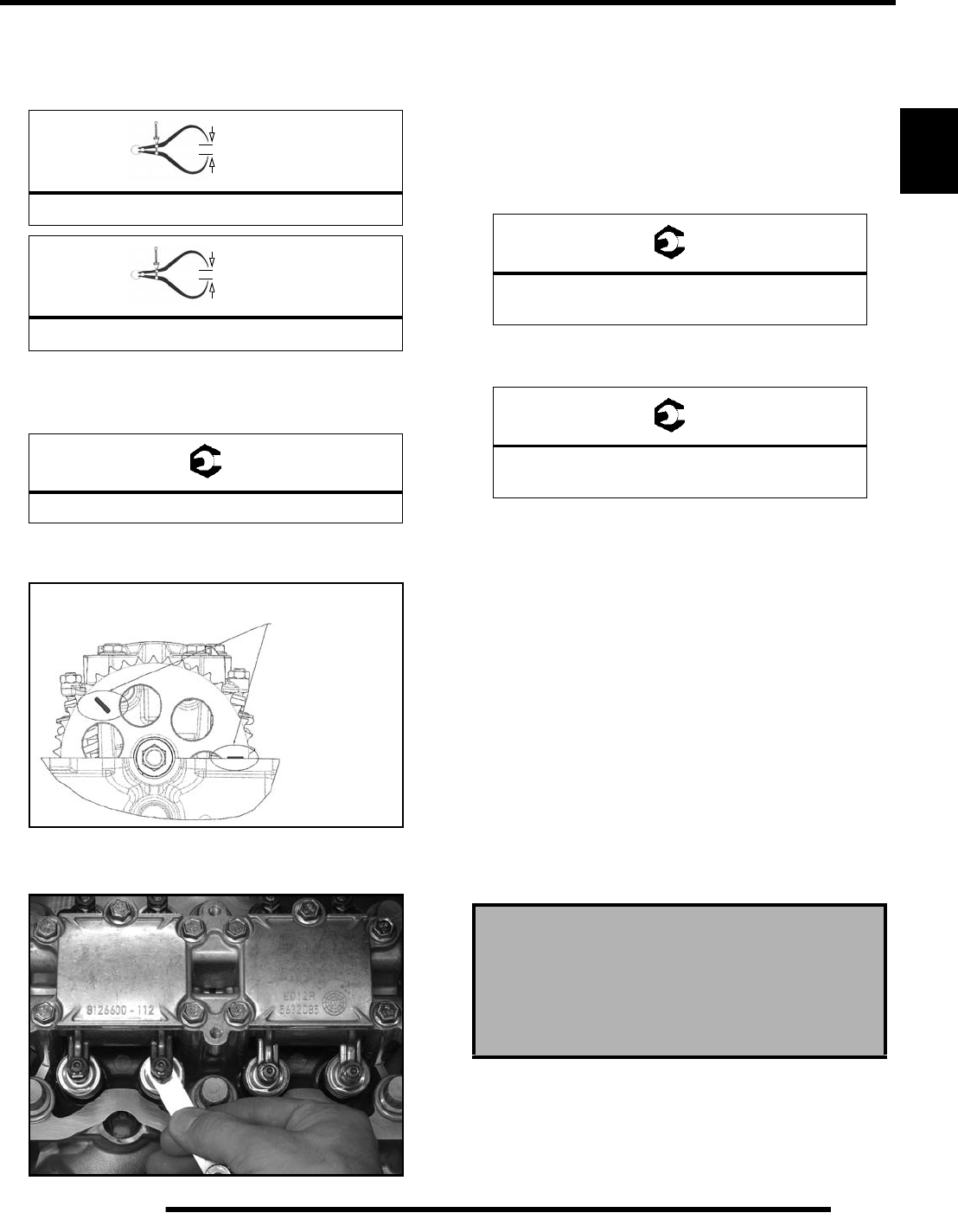
MAG & PTO ADJUSTMENT PROCEDURE
14. Turn the drive clutch counter-clockwise until the cam
sprocket is in the MAG (#1) Adjustment Position.
15. Set the MAG cylinder valve lash by placing the feeler gauge
blade between the lash adjuster and valve as shown.
MAG (#1)
Adjustment Position Timing Pin in Vertical Position
TDC #1 (MAG) Cylinder
Timing Marks Lined Up With Top of Head
at MAG (#1) Adjustment Position
MAG (#1)
PartShark.com
877-999-5686
2.15
MAINTENANCE
2
16. Loosen the jam nut and turn the lash adjuster until the valve
lash is correct.
17. Set the intake and exhaust valve lash to specification.
18. Hold adjuster and torque the jam nut using a torque wrench
w/10 mm crow’s foot adaptor. Verify clearance is still
correct after tightening the jam nut.
19. Turn the drive clutch counter-clockwise to rotate the cam
sprocket 225° to the PTO (#2) Adjustment Position.
20. Set the PTO cylinder valve lash by placing the feeler gauge
blade between the lash adjuster and valve as shown.
21. Repeat steps 16-18.
22. Clean sealing surfaces of the cylinder head and valve cover.
23. Inspect the condition of the valve cover bolt rubber
isolators. If rubber has become hardened or cracked,
replace them.
24. Install a new valve cover seal and install the valve cover.
Torque the cover bolts to specification.
25. Install the upper right-hand frame support and torque the
(4) mounting bolts to specification.
26. Reassemble vehicle by reversing this procedure. Start the
engine to ensure proper valve adjustment was performed.
Compression and Leakdown Tests
NOTE: This engine does NOT have decompression
components. Compression readings will vary in
proportion to cranking speed during the test.
Smooth idle generally indicates good compression. Low engine
compression is rarely a factor in running condition problems
above idle speed. Abnormally high compression can be caused
by worn or damaged exhaust cam lobes.
A cylinder leak-down test is the best indication of engine
condition. Follow tester manufacturer’s instructions to perform
a cylinder leak-down test. (Never use high pressure leakage
testers as crankshaft seals may dislodge and leak).
= In. / mm.
Intake Valve Clearance: .006 in. (.15 mm)
= In. / mm.
Exhaust Valve Clearance: .009 in. (.23 mm)
= T
Rocker Jam Nut: 71-89 in. lbs. (8-10 Nm)
PTO (#2)
Adjustment Position Timing Marks at PTO (#2)
Adjustment Position
PTO (#2)
= T
Valve Cover Bolts:
89 in. lbs. (10 Nm)
= T
Upper Right-Hand Frame Support Bolts:
36 ft. lbs. (49 Nm)
Measured Cylinder Compression
210-250 psi (full throttle)
Cylinder Leakage Service Limit: 10%
(Inspect for cause if leakage exceeds 10%)
PartShark.com
877-999-5686
2.16
MAINTENANCE
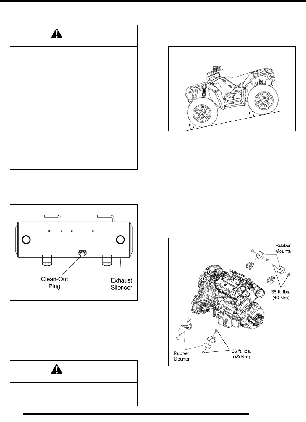
Exhaust Silencer Cleaning
The exhaust silencer must be periodically purged of
accumulated carbon as follows:
1. Remove the clean out plug on the bottom of the silencer.
2. Place the transmission in park, and start the engine.
3. Purge accumulated carbon from the exhaust system by
momentarily revving the engine several times.
4. If some carbon is expelled, cover the exhaust outlets and
lightly tap on the silencer around the clean out plug with a
rubber mallet while revving the engine several more times.
5. If particles are still suspected to be in the silencer, back the
machine onto an incline so the rear of the machine is 1 ft.
(30.5 cm) higher than the front. Place the transmission in
park and block the wheels. Repeat steps 3 and 4 (see
WARNING).
6. If particles are still suspected to be in the silencer, drive the
machine onto the incline so the front of the machine is 1 ft.
(30.5 cm) higher than the rear. Place the transmission in
park and block the wheels. Repeat Steps 3 and 4 (see
WARNING).
7. Stop the engine and allow the silencer to cool. Reinstall the
clean out plug.
Engine Mount Fastener Torque
Check engine mounting fasteners and ensure they are tight.
Also inspect the condition of the rubber mounts. If rubber
mounts are cracked or show signs of fatigue, replace them.
WARNING
Do not perform clean out immediately after the
engine has been run, as the exhaust system
becomes very hot. Serious burns could result
from contact with exhaust components.
To reduce fire hazard, make sure that there are
no combustible materials in the area when
purging the exhaust silencer.
Wear eye protection.
Do not stand behind or in front of the vehicle
while purging the carbon from the silencer.
Never run the engine in an enclosed area.
Exhaust contains poisonous carbon monoxide.
Do not go under the machine while it is inclined.
Set the hand brake and block the wheels to
prevent roll back.
Failure to heed these warnings could result in
serious personal injury or death.
CAUTION
Wear protective gloves when covering the
exhaust outlets. Serious burns could result from
contact with exhaust components.
1 ft.
PartShark.com
877-999-5686
2.17
MAINTENANCE
2
TRANSMISSION AND GEARCASES
Transmission Lubrication
NOTE: It is important to follow the transmission
maintenance intervals described in the Periodic
Maintenance Chart. Regular fluid level inspections
should be performed as well.
The transmission fluid level should be checked and changed in
accordance with the maintenance schedule.
• Be sure vehicle is positioned on a level surface when
checking or changing the fluid.
• Check vent hose to be sure it is routed properly and
unobstructed.
Transmission Fluid Level Check
The fill plug is located on the right-hand side of the
transmission. Access the fill plug through the rear right-hand
wheel well. Maintain the fluid level even with the bottom
threads of the fill plug hole.
1. Position vehicle on a level surface.
2. Remove the fill plug and check the fluid level.
3. If fluid level is not even with the bottom threads, add the
recommended fluid as needed. Do not overfill.
4. Reinstall the fill plug and torque to specification.
Transmission Fluid Change
Access the drain plug through the rear right-hand wheel well.
The plastic skid plate can be removed for better access to the
drain plug.
1. Remove the fill plug (refer to “Transmission Fluid Level
Check”).
2. Place a drain pan under the transmission drain plug.
3. Remove the drain plug and allow fluid to drain completely.
4. Clean the drain plug magnetic surface.
5. Reinstall drain plug with a new O-ring and torque to
specification.
6. Add the recommended amount of fluid through the fill plug
hole. Maintain the fluid level at the bottom of the fill plug
hole when filling the transmission. Do not overfill.
7. Reinstall fill plug with a new O-ring and torque to
specification.
8. Check for leaks. Dispose of used fluid properly.
= T
Drain/Fill Plug Torque:
10-14 ft. lbs. (14-19 Nm)
Fill Plug
Transmission fluid
flush with the bottom
of thread area.
10-14 ft. lbs.
(14-19 Nm)
=
Recommended Transmission Lubricant:
Synthetic Sportsman XP Transmission Fluid
(PN 2877606) (Quart)
Capacity: 32 oz. (946 ml)
= T
Drain/Fill Plug Torque:
10-14 ft. lbs. (14-19 Nm)
Drain Plug
10-14 ft. lbs. (14-19 Nm)
Fill Plug
10-14 ft. lbs.
(14-19 Nm)
PartShark.com
877-999-5686
2.18
MAINTENANCE
Front Gearcase Lubrication
NOTE: It is important to follow the front gearcase
maintenance intervals described in the Periodic
Maintenance Chart. Regular fluid level inspections
should be performed as well.
The front gearcase fluid level should be checked and changed in
accordance with the maintenance schedule.
• Be sure vehicle is positioned on a level surface when
checking or changing the fluid.
• Check vent hose to be sure it is routed properly and
unobstructed.
Front Gearcase Fluid Level Check
The fill plug is located on the right side of the front gearcase.
Access the fill plug through the front right-hand wheel well or
through the front lower bumper. Maintain the fluid level even
with the bottom threads of the fill plug hole.
1. Position vehicle on a level surface.
2. Remove the fill plug and check the fluid level.
3. If fluid level is not even with the bottom threads, add the
recommended fluid as needed. Do not overfill.
4. Reinstall the fill plug and torque to specification.
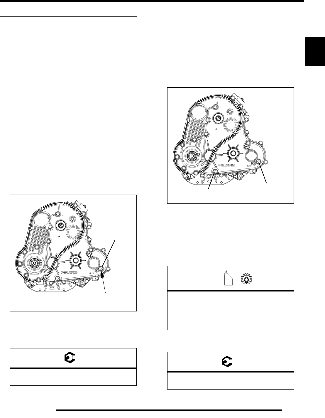
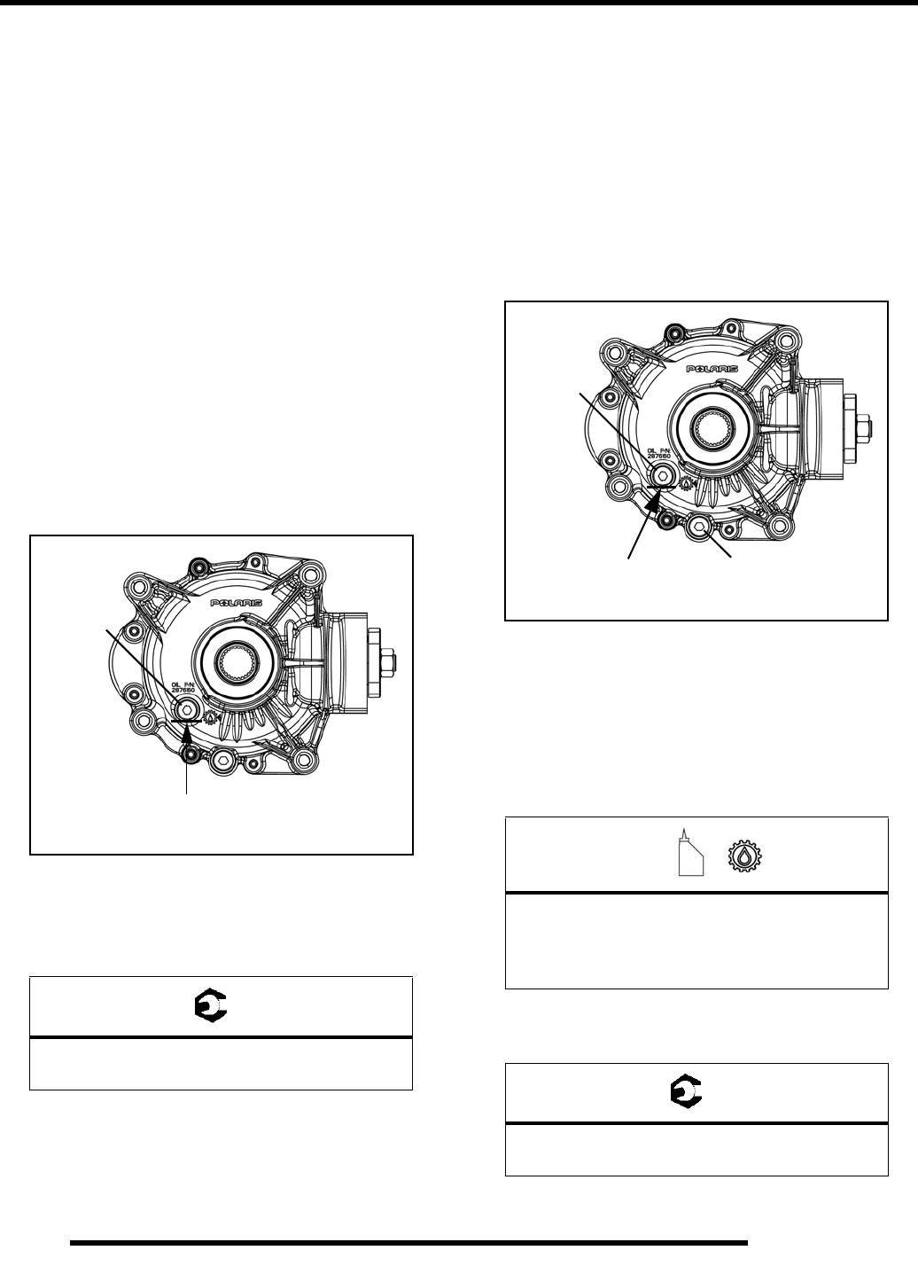
Front Gearcase Fluid Change:
The drain plug is located on the bottom side of the front
gearcase. Access the drain plug through the access hole in the
front skid plate.
1. Remove the fill plug (refer to “Front Gearcase Fluid Level
Check”).
2. Place a drain pan under the front gearcase drain plug.
3. Remove the drain plug and allow fluid to drain completely.
4. Clean the drain plug magnetic surface.
5. Reinstall drain plug with a new O-ring and torque to
specification.
6. Add the recommended amount of fluid through the fill hole.
Maintain the fluid level even with the bottom threads of the
fill plug hole.
7. Reinstall fill plug with a new O-ring and torque to
specification.
8. Check for leaks. Dispose of used fluid properly.
= T
Drain / Fill Plug Torque:
8-10 ft. lbs. (11-14 Nm)
Fill Plug
8-10 ft. lbs.
Gearcase fluid
flush with the bottom
of thread area.
(11-14 Nm)
=
Recommended Front Gearcase Fluid:
Premium LT Demand Drive Fluid
(PN 2876251) (Quart)
Capacity: 9.3 oz. (275 ml)
= T
Drain / Fill Plug Torque:
8-10 ft. lbs. (11-14 Nm)
Fill Plug
8-10 ft. lbs.
(11-14 Nm)
Drain Plug
8-10 ft. lbs.
(11-14 Nm)
PartShark.com
877-999-5686
2.19
MAINTENANCE
2
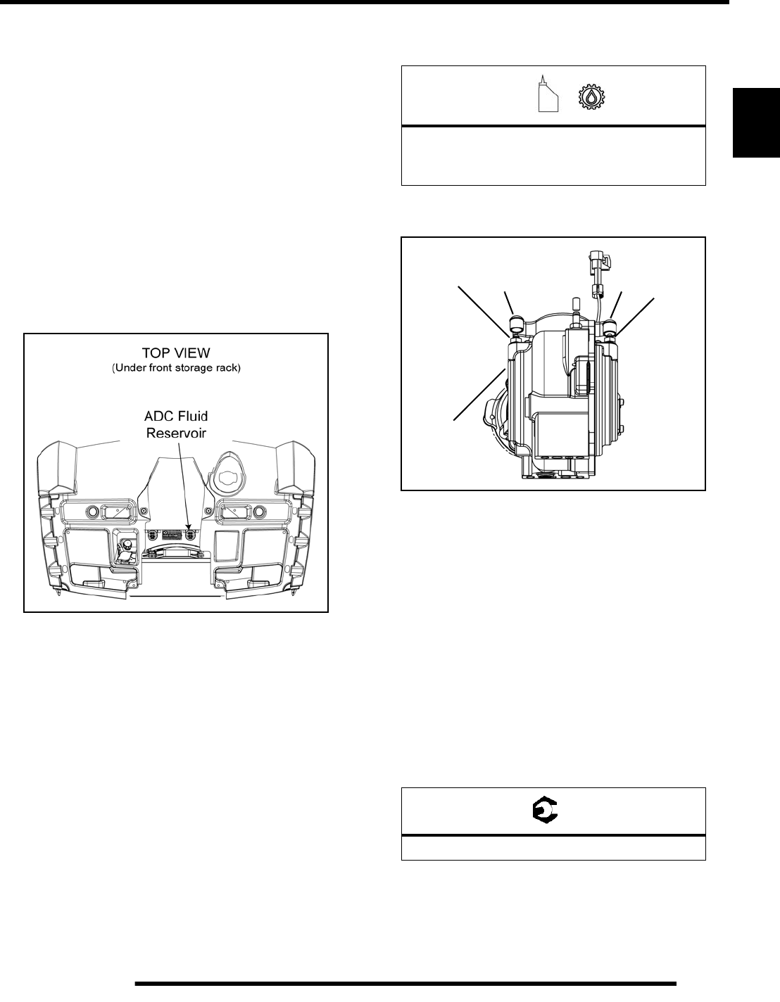
Front Gearcase ADC Fluid
NOTE: It is important to follow the front gearcase
maintenance intervals described in the Periodic
Maintenance Chart. Regular fluid level inspections
should be performed as well.
The front gearcase ADC fluid level should be checked and
changed in accordance with the maintenance schedule.
Front Gearcase ADC Fluid Level Check
The ADC fluid reservoir is located underneath the front rack as
shown below. Maintain the fluid level between the “MIN” and
“MAX” levels indicated on the reservoir.
1. Disengage the anchors and remove front rack assembly.
2. Check the fluid level of the ADC reservoir.
3. If fluid level is below the minimum mark on the reservoir,
remove the cap and add the recommended fluid.
4. Reinstall the cap and front rack assembly.
Front Gearcase ADC Fluid Change:
1. Position the vehicle on a level surface and allow the
vehicle to sit for at least 30 minutes.
2. Thoroughly clean the areas around the ADC reservoir and
bleeder valves.
3. Remove the reservoir cap and diaphragm assembly.
4. Make sure the fluid inside the reservoir is free of debris. If
any debris is found, use a clean shop towel or suction device
to remove it from the reservoir.
NOTE: Debris in the reservoir may result in
inadequate bleeding and reduced performance of
the system.
5. Begin the bleeding process by filling reservoir to the
“MAX” level with clean ADC Front Drive Fluid.
6. Locate bleeder valves found on each side of the front
gearcase and remove the protective caps.
7. Attach a clean clear hose to one of the bleeder valves.
8. Slowly loosen the valve (counter-clockwise) and allow
fluid and trapped air to flow from the fitting.
IMPORTANT: Do not allow ADC fluid in reservoir to
drop below the “MIN” fill line. Close bleeder valve
before the fluid level drops below the “MIN” fill line.
Refilling an empty reservoir will result in air pockets
becoming trapped.
9. Close the valve when clean (bubble-free) fluid begins to
flow from the valve.
10. Repeat steps 7-9 on the remaining bleeder valve.
11. Torque the bleeder valves to specification and reinstall the
protective caps.
12. Fill reservoir to a level midway between “MAX” and
“MIN” fill lines. Verify no debris is found in reservoir
fluid.
13. Install the reservoir cap and diaphragm securely and wipe
clean any fluid residue.
=
Recommended ADC Fluid:
Premium ADC Front Drive Fluid
(PN 2876144) (Quart)
= T
Bleeder Valve Torque: 80 in. lbs. (9 Nm)
Bleeder
Valve Bleeder
Valve
CapCap
Front
Gearcase
PartShark.com
877-999-5686
2.20
MAINTENANCE
Rear Gearcase Lubrication
NOTE: It is important to follow the rear gearcase
maintenance intervals described in the Periodic
Maintenance Chart. Regular fluid level inspections
should be performed as well.
The rear gearcase fluid level should be checked and changed in
accordance with the maintenance schedule.
• Be sure vehicle is positioned on a level surface when
checking or changing the fluid.
• Check vent hose to be sure it is routed properly and
unobstructed.
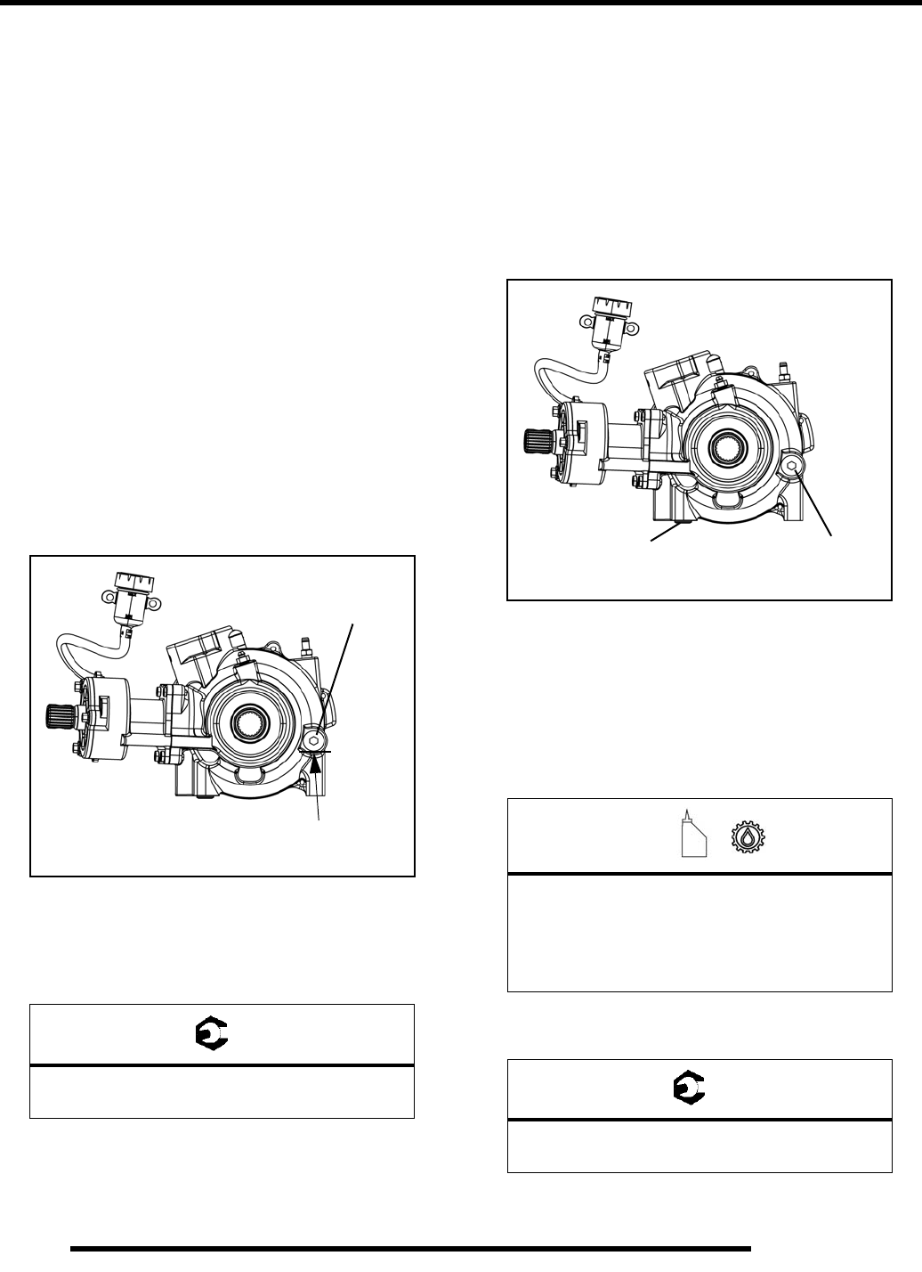
Rear Gearcase Fluid Level Check:
The fill plug is located on the right side of the rear gearcase.
Maintain the fluid level even with the bottom threads of the fill
plug hole.
1. Position the vehicle on a level surface.
2. Remove the fill plug and check the fluid level.
3. If fluid level is not even with the bottom threads, add the
recommended fluid as needed. Do not overfill.
4. Reinstall fill plug and torque to specification.
Rear Gearcase Fluid Change:
The drain plug is located on the bottom right-hand side of the
rear gearcase. Access the drain plug from the rear right-hand
side of the ATV.
1. Remove the fill plug (refer to “Rear Gearcase Fluid Level
Check”).
2. Place a drain pan under the rear gearcase drain plug.
3. Remove the drain plug and allow the fluid to drain
completely.
4. Clean the drain plug magnetic surface.
5. Reinstall drain plug with a new O-ring and torque to
specification.
6. Add the recommended amount of fluid through the fill hole.
Maintain the fluid level even with the bottom threads of the
fill plug hole.
7. Reinstall fill plug with a new O-ring and torque to
specification.
8. Check for leaks. Dispose of used fluid properly.
= T
Drain / Fill Plug Torque:
10-14 ft. lbs. (14-19 Nm)
Fill Plug
10-14 ft. lbs.
(14-19 Nm)
Gearcase fluid
flush with the bottom
of thread area. =
Recommended Rear Gearcase Lubricant:
ATV Angle Drive Fluid (PN 2871653)
Capacity: 7.1 oz. (210 ml)
= T
Drain / Fill Plug Torque:
10-14 ft. lbs. (14-19 Nm)
Fill Plug
10-14 ft. lbs.
(14-19 Nm)
Drain Plug
10-14 ft. lbs.
(14-19 Nm)
Gearcase fluid
flush with the bottom
of thread area.
PartShark.com
877-999-5686
2.21
MAINTENANCE
2
COOLING SYSTEM
Cooling System Overview
The engine coolant level is controlled, or maintained, by the
recovery system. The recovery system components are the
recovery bottle, radiator filler neck, radiator pressure cap and
connecting hose.
As coolant operating temperature increases, the expanding
(heated) excess coolant is forced out of the radiator past the
pressure cap and into the recovery bottle. As engine coolant
temperature decreases the contracting (cooled) coolant is drawn
back up from the bottle, past the pressure cap, and into the
radiator.
NOTE: Some coolant level drop on new vehicles is
normal as the system is purging itself of trapped air.
Observe coolant level often during the break-in
period.
Polaris recommends the use of Polaris Premium 60/40 anti-
freeze/coolant or a 50/50 mixture of high quality aluminum
compatible anti-freeze/coolant and distilled water.
NOTE: Polaris Premium 60/40 is already premixed
and ready to use. Do not dilute with water.
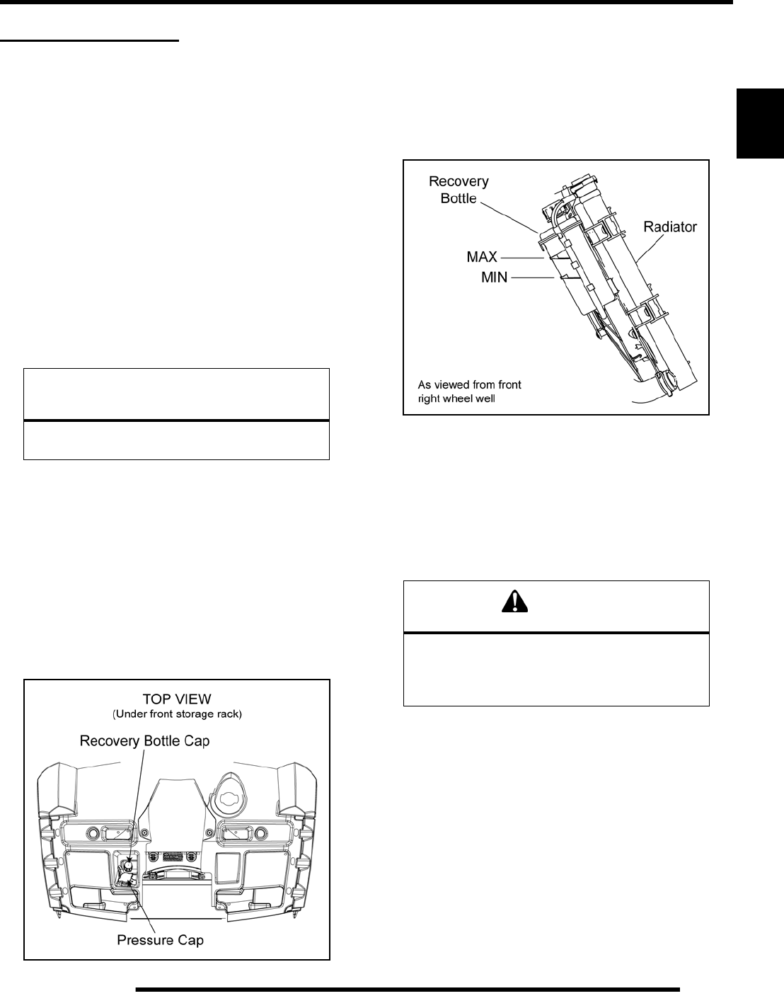
Coolant Level Inspection
The pressure cap and recovery bottle are located underneath the
front rack as shown below. Maintain the coolant level between
the “MIN” and “MAX” levels indicated on the recovery bottle.
With the engine at operating temperature, the coolant level
should be between the MAX and MIN marks on the coolant
recovery bottle. If not, perform the following procedure.
1. Position the vehicle on a level surface.
2. View the coolant level in the recovery bottle. The coolant
level can be viewed from inside the front right wheel well.
3. If the coolant level is below the “MIN” line on the bottle,
remove the front rack assembly to access the radiator
pressure cap and recovery bottle cap.
NOTE: If overheating is evident, allow system to
cool completely and check coolant level in the
radiator and inspect for signs of trapped air in
system.
4. Remove the pressure cap. Using a funnel, add coolant to
the top of the radiator filler neck.
5. Reinstall the pressure cap.
NOTE: Use of a non-standard pressure cap will not
allow the recovery system to function properly.
6. Remove recovery bottle cap and add coolant using a funnel.
7. Fill recovery bottle to “MAX” level with Polaris Premium
60/40 Anti-Freeze/Coolant or a 50/50 mixture of anti-
freeze/coolant and distilled water as required for freeze
protection in your area.
8. Reinstall the recovery bottle cap.
CAUTION
Overheating of engine could occur if air is not
fully purged from system.
WARNING
Never remove the pressure cap when the
engine is warm or hot. Escaping steam can
cause severe burns. The engine must be cool
before removing the pressure cap.
PartShark.com
877-999-5686
2.22
MAINTENANCE
9. If coolant was required, start engine and check for leaks.
Make sure radiator fins are clean to prevent overheating.
10. Add coolant as needed. Maintain the coolant level between
the “MIN” and “MAX” marks on the bottle.
11. Reinstall the front rack assembly.
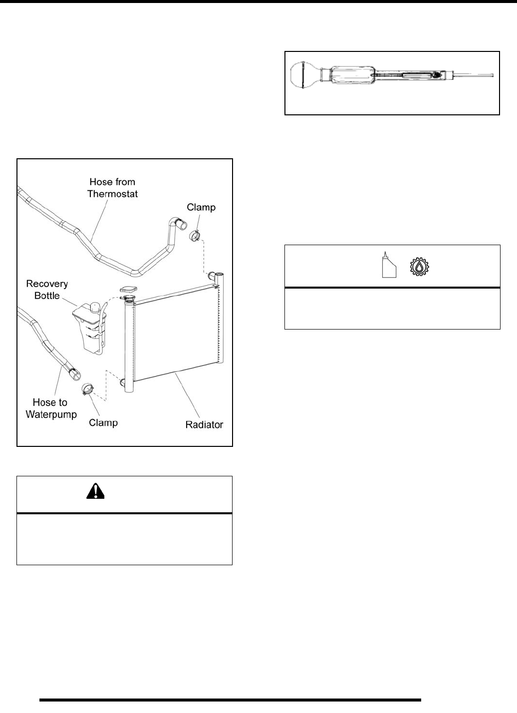
Cooling System Hoses
1. Inspect all hoses for cracks, deterioration, abrasion or
leaks. Replace if necessary.
2. Check tightness of all hose clamps.
Coolant Strength / Type
Test the strength of the coolant using an antifreeze hydrometer.
• A 50/50 or 60/40 mixture of antifreeze and distilled
water will provide the optimum cooling, corrosion
protection, and antifreeze protection.
• Do not use tap water, straight antifreeze, or straight
water in the system. Tap water contains minerals and
impurities which build up in the system.
• Straight water or antifreeze may cause the system to
freeze, corrode, or overheat.
NOTE: For further information on the engine cooling
system, refer to Chapter 4.
CAUTION
Do not over-tighten hose clamps at radiator, or
radiator fitting may distort, causing a restriction
to coolant flow. Radiator hose clamp torque is
36 in. lbs. (4 Nm).
=
Recommended Anti-Freeze/Coolant:
Polaris 60/40 Anti-Freeze/Coolant
(PN 2871534) (Quart)
Antifreeze Hydrometer
PartShark.com
877-999-5686
2.23
MAINTENANCE
2
PVT / FINAL DRIVE / WHEEL AND TIRE
PVT Drying
NOTE: If operating the ATV through water, be sure
to check the PVT system components for water
ingestion. After operating in water, the ATV should
be checked immediately.
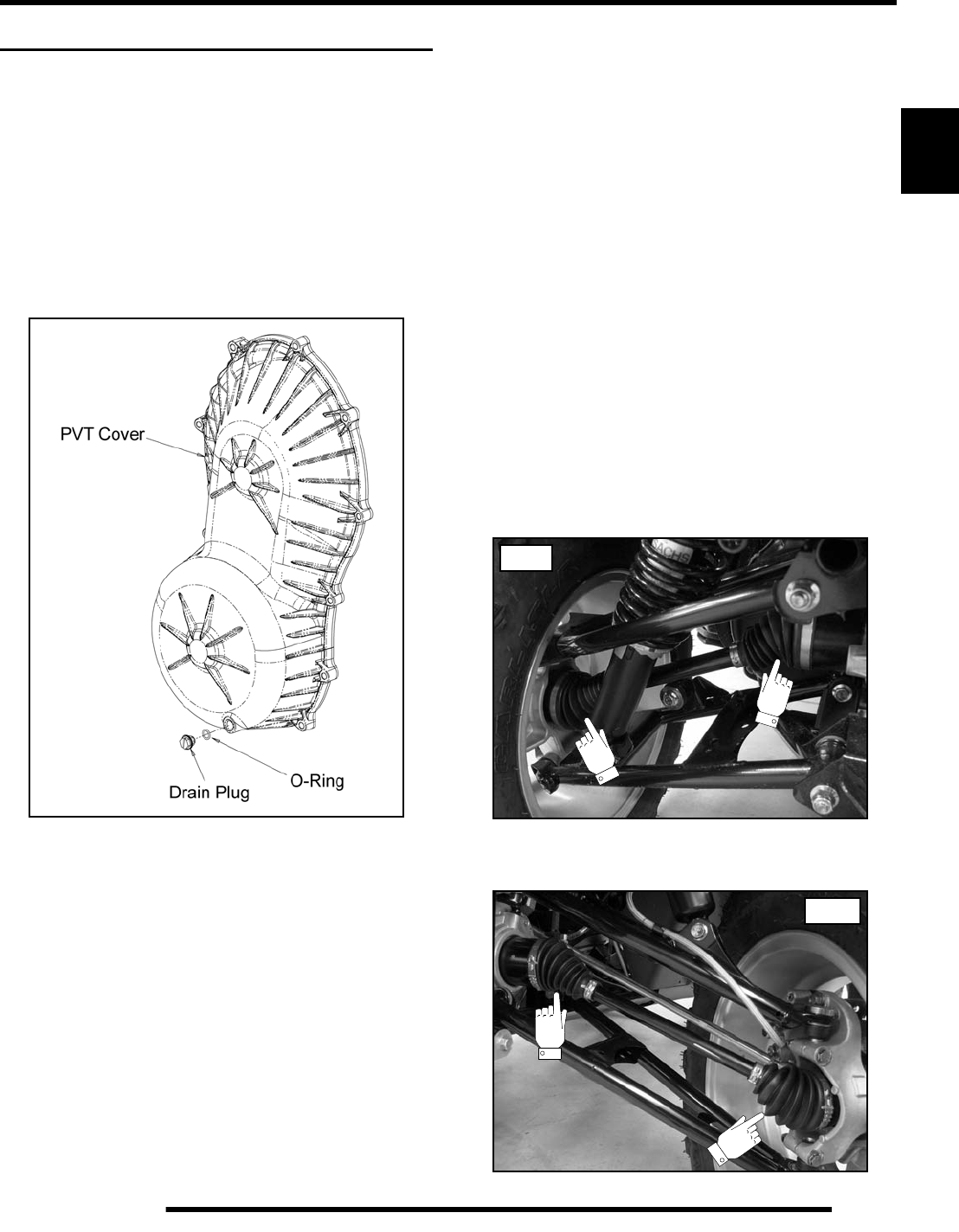
1. Access the PVT drain plug on the bottom of the PVT cover
using a long flat blade screwdriver between the frame and
left-hand lower control arm from the rear of the ATV.
2. Remove the PVT drain plug and O-ring.
3. Allow the water to drain out completely.
4. Reinstall the drain plug and O-ring.
5. Start the engine and shift into park.
6. Apply varying throttle for 10-15 seconds to expel the
moisture and air-dry the belt and clutches.
NOTE: Do not hold the throttle wide open for more
than 10 seconds.
7. Allow the engine RPM to return to idle, then shift into low
gear.
8. Test the PVT system for belt slippage. If the belt slips,
repeat the process.
Drive Belt Removal
Refer to Chapter 7 “Clutching (PVT)” for more detail.
1. Elevate vehicle and remove the left rear wheel.
2. Remove the lower left-hand frame support.
3. Remove the (11) screws retaining the outer PVT cover.
Pull the PVT cover out the LH wheel well.
4. Insert the belt removal tool PN 2877408 into the driven
clutch (tool included with vehicle’s tool kit).
NOTE: Make sure the tool is square with the
moveable sheave surface of the driven clutch.
5. Rotate the tool to open the driven clutch.
6. Walk the belt out of the driven clutch and drive clutch, and
remove the belt from the vehicle.
Drive Shaft Boot Inspection
Inspect the front and rear drive shaft boots for damage, tears,
wear, or leaking grease. If the rubber boots exhibit any of these
symptoms, replace the boot(s). Refer to Chapter 8 for drive
shaft boot replacement.
NOTE: Remove the CV boot shield from the front
lower A-arms to inspect the front outer CV boots.
Rear
Front
PartShark.com
877-999-5686
2.24
MAINTENANCE
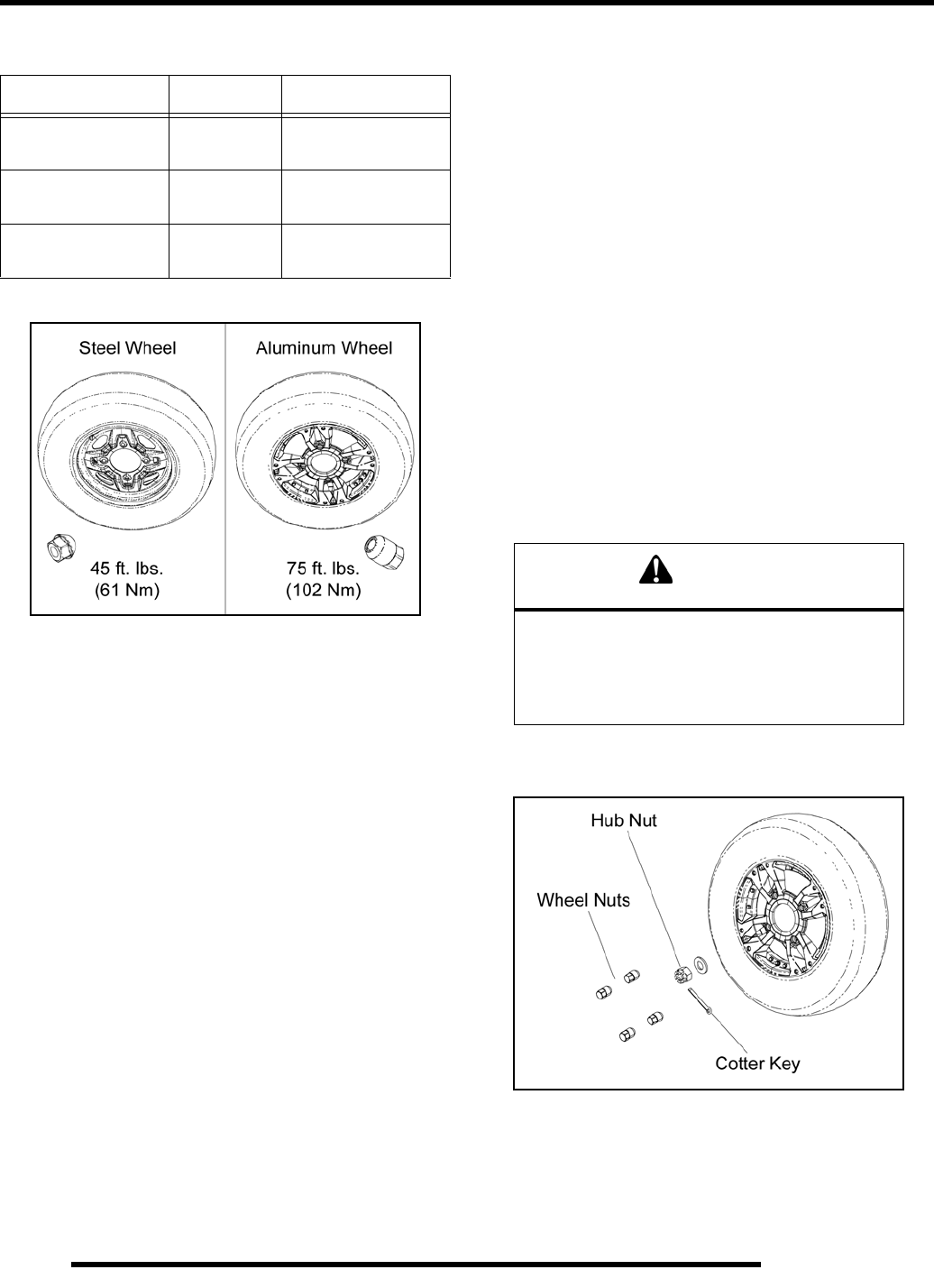
Wheel and Hub Torque Table
Wheel Removal
1. Position the vehicle on a level surface.
2. Stop the engine, place the transmission in PARK and lock
the parking brake.
3. Loosen the wheel nuts slightly. If wheel hub removal is
required, remove the cotter key and loosen the hub nut
slightly.
4. Elevate the appropriate side of the vehicle by placing a
suitable stand under the footrest frame.
5. Remove the wheel nuts and remove the wheel.
6. If hub removal is required, remove the hub nut and washers.
Wheel Installation
1. Verify the transmission is still in PARK and the parking
brake is locked.
2. Install the wheel hub, washers, and hub nut, if previously
removed.
3. Place the wheel in the correct position on the wheel hub.
Be sure the valve stem is toward the outside and rotation
arrows on the tire point toward forward rotation.
4. Install the wheel nuts and finger tighten them to align the
center of the wheel holes with the center of the tapered nuts.
IMPORTANT: It is possible to torque the wheel nut on
a steel rim without the nut being centered in the hole.
Be sure to center the wheel nuts before applying
torque to prevent wheel nuts from coming loose.
5. Carefully lower the vehicle to the ground.
6. Torque the wheel nuts and/or hub nut to the proper torque
specification listed in the “Wheel and Hub Torque Table”.
7. If the hub nut was removed, install a new cotter pin after
the hub nut has been tightened.
Item Nut Type Specification
Aluminum Wheels Tapered Nut
(Long) 75 ft. lbs. (102 Nm)
Steel Wheels Tapered Nut
(Short) 45 ft. lbs. (61 Nm)
Hub Retaining Nuts
(Front & Rear) - 80 ft. lbs. (108 Nm)
CAUTION
Improperly installed wheels could affect vehicle
handling and tire wear. On vehicles with tapered
rear wheel nuts, make sure tapered end of nut
goes into taper on wheel. Be sure to properly
torque and install all wheel nuts.
PartShark.com
877-999-5686
2.25
MAINTENANCE
2
Tire Pressure
Tire Inspection
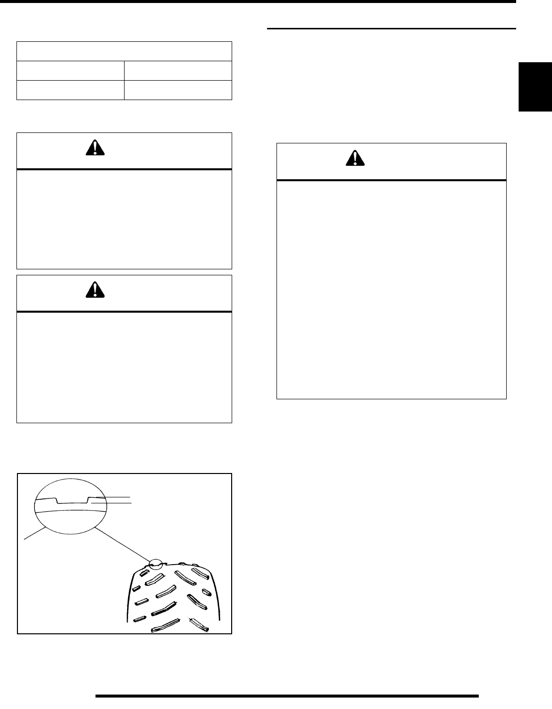
Tire Tread Depth
Always replace tires when tread depth is worn to 1/8” (3 mm) or
less.
ELECTRICAL AND IGNITION SYSTEM
Battery Maintenance
Keep battery terminals and connections free of corrosion. If
cleaning is necessary, remove the corrosion with a stiff wire
brush. Wash with a solution of one tablespoon baking soda and
one cup water. Rinse well with tap water and dry off with clean
shop towels. Coat the terminals with dielectric grease or
petroleum jelly.
NOTE: Absorbed Glass Mat (AGM) batteries are
permanently sealed at the time of manufacture.
AGM batteries are designed to minimize gassing and
water loss, but can vent if overcharged.
IMPORTANT: Never attempt to open the battery. If the
seal is broken, the battery will be ruined and will fail
within a few weeks.
NOTE: If battery voltage is below 12.6V, fully charge
the battery before putting into service. Charge for 3-
5 hours at a voltage not to exceed 14.6V or 10 Amps.
Voltage should reach at least 14.4V before end of
charge.
Tire Pressure Inspection (PSI - Cold)
Front Rear
7 psi (48 kPa) 5 psi (34.5 kPa)
WARNING
Operating an ATV with worn tires will increase
the possibility of the vehicle skidding and
possible loss of control.
Worn tires can cause an accident.
Always replace tires when the tread depth
measures 1/8” (.3 cm) or less.
CAUTION
Maintain proper tire pressure.
Refer to the warning tire pressure decal
applied to the vehicle.
Improper tire inflation may affect
ATV maneuverability.
When replacing a tire always use original
equipment size and type.
The use of non-standard size or type tires may
affect ATV handling.
Tread
Depth 1/8” (3 mm)
WARNING
Battery electrolyte is poisonous. It contains sulfuric
acid. Serious burns can result from contact with
skin, eyes or clothing. Antidote:
External: Flush with water.
Internal: Drink large quantities of water or milk.
Follow with milk of magnesia, beaten egg, or
vegetable oil. Call physician immediately.
Eyes: Flush with water for 15 minutes and get
prompt medical attention.
Batteries produce explosive gases. Keep sparks,
flame, cigarettes, etc. away. Ventilate when
charging or using in an enclosed space. Always
shield eyes when working near batteries. KEEP
OUT OF REACH OF CHILDREN.
PartShark.com
877-999-5686
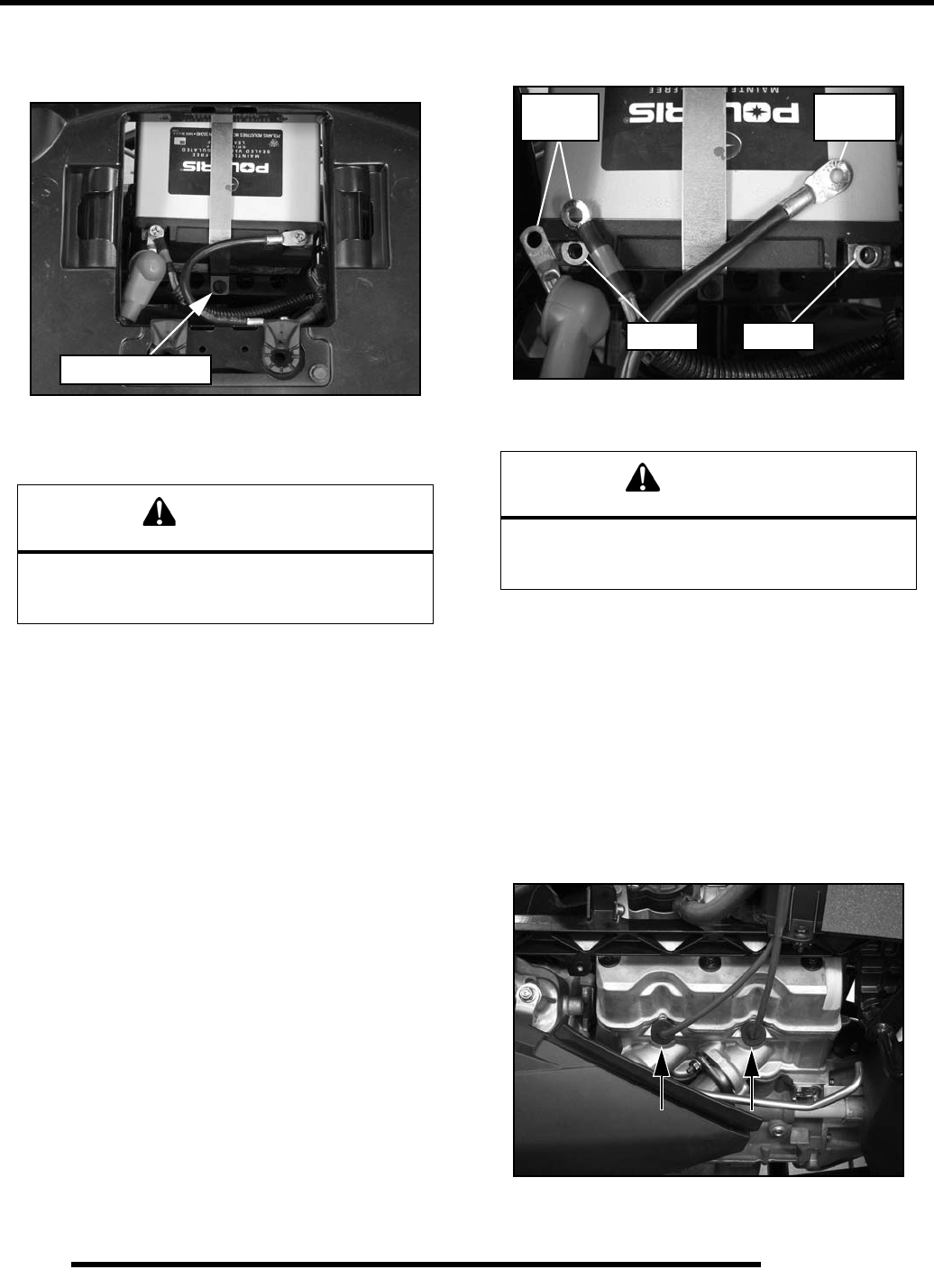
2.26
MAINTENANCE
Battery Removal
1. Remove the seat to access the battery.
2. Disconnect battery negative (-) (black) cable first, followed
by the positive (+) (red) cables.
3. Remove the screw retaining the hold-down strap near the
bottom front portion of the battery and remove the strap.
4. Lift the battery out of the ATV.
Battery Installation
IMPORTANT: Using a new battery that is not fully
charged can damage the battery, resulting in a short
battery life and can hinder performance. Follow the
battery charging procedure before installation.
1. Ensure the battery is fully charged (see Chapter 12).
2. Place the battery into the ATV on its side with the positive
(+) terminal towards the right side of the ATV.
3. Install the hold-down strap and the retaining screw.
4. Coat the battery terminals and bolt threads with Dielectric
Grease (PN 2871329) or petroleum jelly.
5. Place the spacers on top of the battery terminals. Be sure
they are placed between the battery terminal and cable(s).
6. Connect and tighten the positive (+) (red) battery cable first,
followed by the negative (-) (black) battery cable.
7. Verify cables are properly routed and fasteners are tight.
NOTE: The cables should be safely tucked away at
the front of the battery.
8. Reinstall the seat.
Spark Plug Service
1. Remove the seat and upper right-hand side panel.
2. Disconnect the shift linkage from the shift lever.
3. Remove the spark plug caps. Clean plug area so no dirt and
debris can fall into engine when plugs are removed.
4. Using a 14 mm deep-well socket with an extension, remove
the spark plug.
CAUTION
To reduce the chance of sparks: Whenever
removing the battery, disconnect the negative
(black) cable first.
Retaining Screw
CAUTION
To reduce the chance of sparks: Whenever
installing the battery, install the
negative (black) cable last.
SpacerSpacer
Negative
Cable
Positive
Cables
PartShark.com
877-999-5686
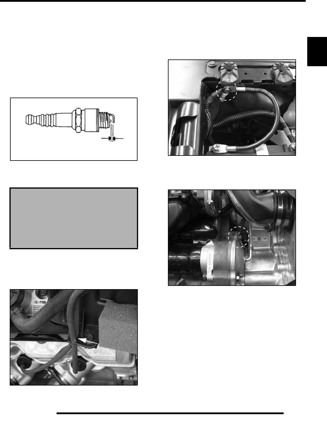
2.27
MAINTENANCE
2
Spark Plug Inspection / Installation
1. Inspect electrodes for wear and carbon buildup. Look for
a sharp outer edge with no rounding or erosion of the
electrodes.
2. Clean with electrical contact cleaner or a glass bead spark
plug cleaner only. CAUTION: A wire brush or coated
abrasive should not be used.
3. Measure gap with a wire gauge. Refer to specifications in
the following illustration for proper spark plug type and
gap. Adjust gap if necessary by carefully bending the side
electrode.
4. If necessary, replace spark plug with proper type.
CAUTION: Severe engine damage may occur if the
incorrect spark plug is used.
5. Apply a small amount of anti-seize compound to the spark
plug threads.
6. Install spark plugs and torque to specification.
7. Make sure the high tension leads are retained by the airbox.
8. Reinstall the shift linkage, upper right-hand side panel, and
seat.
Engine / Chassis Ground
Periodically inspect the electrical ground cable attachments.
Cables and connections should be tight and corrosion-free.
Inspect the battery-to-chassis connection underneath the seat.
This connection allows the chassis to provide a ground path.
Inspect the chassis-to-engine connection on the left side of the
engine attached to the engine/transmission housing. This
connection allows the engine to provide a ground path.
Recommended Spark Plug
Champion REA6MC or REA8MCL
Spark Plug Torque:
18 ± 1.5 ft. lbs. (25 ± 2 Nm)
Spark Plug Gap
Gap - .035" (0.90 mm)
PartShark.com
877-999-5686
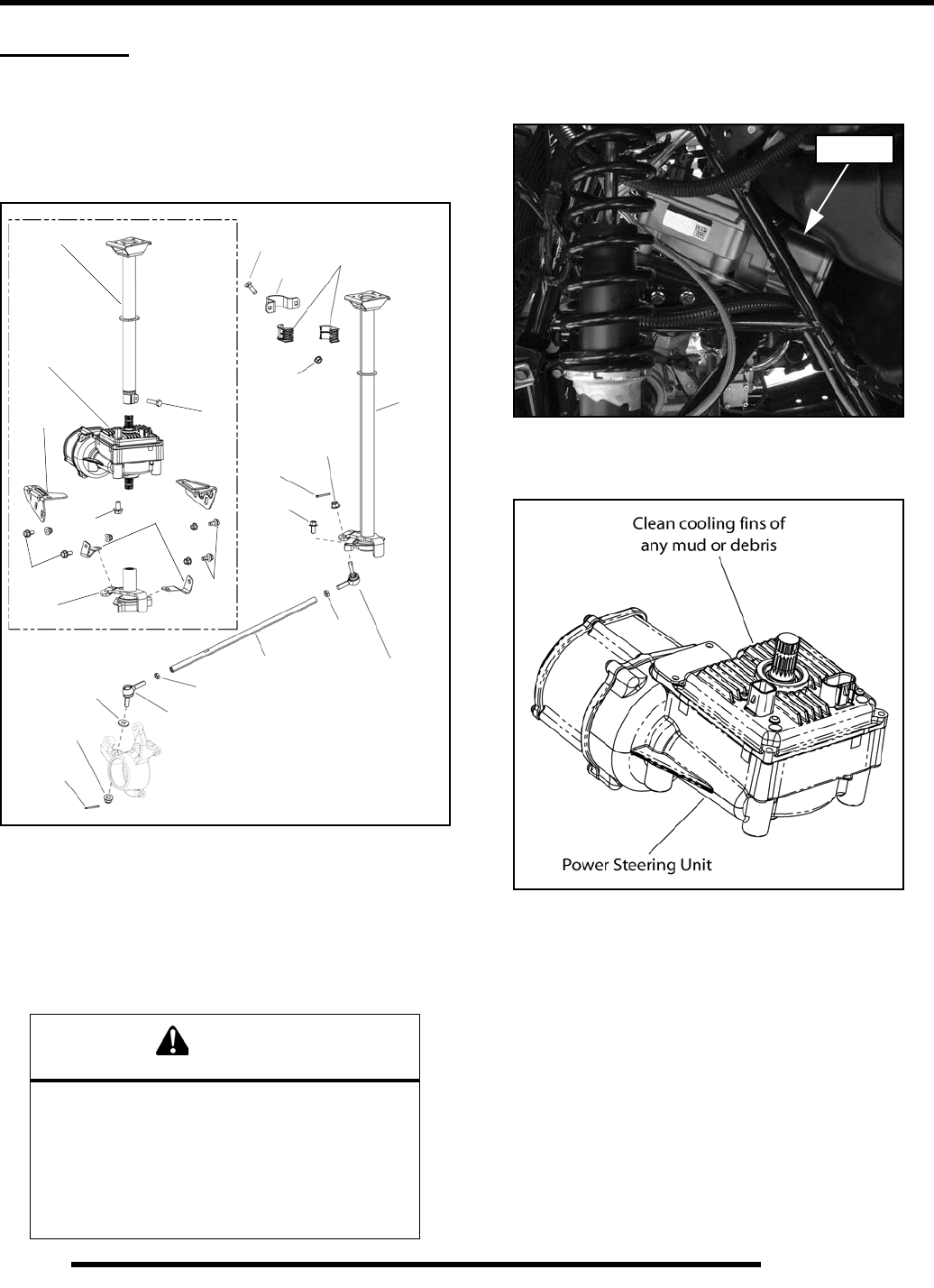
2.28
MAINTENANCE
STEERING
Steering Inspection
The steering components should be checked periodically for
loose fasteners, worn tie rod ends, and damage. Also check to
make sure all cotter pins are in place. If cotter pins are removed,
they must not be re-used. Always use new cotter pins.
Replace any worn or damaged steering components. Steering
should move freely through entire range of travel without
binding. Check routing of all cables, hoses, and wiring to be sure
the steering mechanism is not restricted or limited.
NOTE: Whenever steering components are
replaced, check front end alignment. Use only
genuine Polaris parts.
Power Steering Unit (EPS Models)
The power steering unit can be accessed through the front left
wheel well by removing the mud guard.
Frequently clean the areas around and on top of the power
steering unit to allow for proper cooling.
IMPORTANT: Be sure to clean these areas thoroughly
after riding through muddy conditions.
WARNING
Due to the critical nature of the procedures
outlined in this chapter, Polaris recommends
steering component repair and adjustment be
performed by an authorized Polaris Dealer. Only
a qualified technician should replace worn or
damaged steering parts. Use only genuine
Polaris replacement parts.
Carriage
Bracket
Steering
Rod End
Tie Rod
Cotter
Washer
Nut
Screw
Bolt Bushings
Jam Nut
Rod End
Nut
Cotter
Pin
Nut
Jam Nut
Post
Pin
Upper Post
Lower
PS Unit
Steering
Drive
Bolt
Bracket
Brackets
Post
Bolts Bolts
Bolt
PS Unit
PartShark.com
877-999-5686
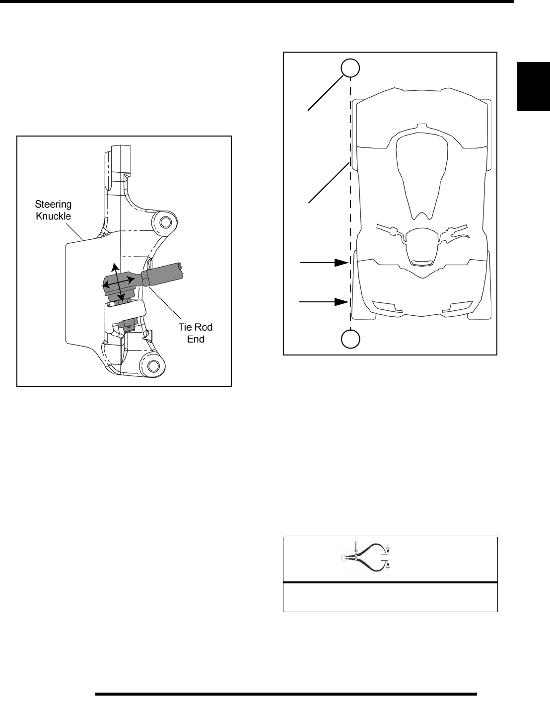
2.29
MAINTENANCE
2
Tie Rod End / Steering Inspection
To check for play in the tie rod end, grasp the steering tie rod,
pull in all directions feeling for movement.
• Repeat inspection for inner tie rod end (on steering
post).
• Replace any worn steering components. Steering should
move freely through entire range of travel without
binding.
• Elevate front end of machine so front wheels are off the
ground. Check for any looseness in front hub / wheel
assembly by grasping the tire firmly at top and bottom
first, and then at front and rear. Try to move the wheel
and hub by pushing inward and pulling outward.
• If abnormal movement is detected, inspect the hub and
wheel assembly to determine the cause.
Toe Alignment
Use the following procedure to check the toe alignment of the
vehicle. The recommended toe alignment is 1/8”-1/4” (3-6 mm)
toe out.
1. Position the vehicle on a smooth level surface.
2. Set handlebars in a straight ahead position and secure
handlebars in this position.
NOTE: The steering post frog can be used as an
indicator of whether the handlebars are straight. The
frog should always point straight back from the
steering post.
3. Tie a length of string between two stands as shown in the
following illustration. Position the stands so the string is
flush or parallel with the side of the rear tire.
NOTE: If available, you may use a long straight-edge
instead of a string.
4. Measure the distance from the string to the rim at the front
(1) and rear (2) of the front rim. The rear measurement
should be 1/16”-1/8” (2-3 mm) more than the front
measurement on each side of the vehicle to obtain the
recommended 1/8”-1/4” (3-6 mm) toe out alignment.
5. Repeat the measurement procedure on the other side of the
vehicle.
NOTE: If you discover improper alignment, refer to
“Toe Alignment Adjustment” procedure.
= In. / mm.
Wheel Toe-out Alignment:
1/8 - 1/4” (3 - 6 mm)
Stand
String
1
2
PartShark.com
877-999-5686
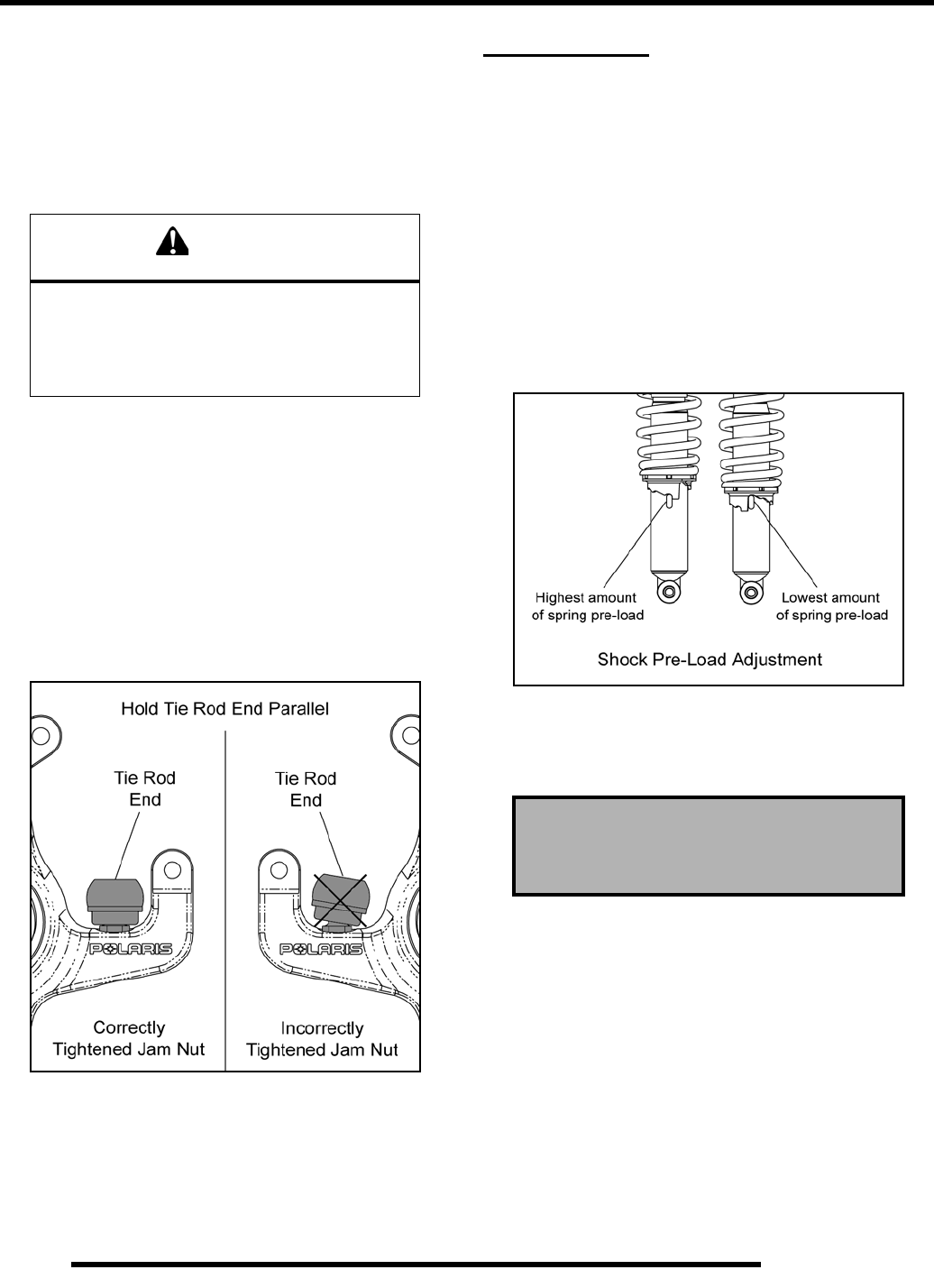
2.30
MAINTENANCE
Toe Alignment Adjustment
If toe alignment is incorrect, measure the distance between
vehicle center and each wheel. This will tell you which tie rod
needs adjusting.
NOTE: Be sure handlebars are straight ahead before
determining which tie rod(s) need adjustment.
To adjust toe alignment:
• Hold tie rod end to keep it from rotating.
• Loosen jam nuts at both ends of the tie rod.
• Shorten or lengthen the tie rod until alignment is as
required to achieve the proper toe out setting.
• Important: When tightening the tie rod end jam nuts,
the rod ends must be held parallel to prevent rod end
damage and premature wear. Damage may not be
immediately apparent if done incorrectly. See
illustration.
SUSPENSION
Suspension Inspection
Compress and release the suspension. Damping should be
smooth throughout the range of travel.
• Check all suspension components and mounting
fasteners for wear or damage.
• Inspect each shock body for leakage.
Suspension Spring Pre-Load Adjustment
The front and rear shock absorber springs are adjustable. Rotate
the adjuster cam either direction to increase or decrease spring
tension. Always adjust both sides equally.
Operator weight and vehicle loading affect suspension spring
pre-load requirements. Use Spanner Wrench (PN 2870872) to
adjust pre-load as necessary to avoid bottoming of the shocks.
CAUTION
During tie rod adjustment, it is very important that
the following precautions be taken when
tightening tie rod end jam nuts.
If the rod end is positioned incorrectly it will not
pivot, and may break
Shock Spanner Wrench
(PN 2870872)
PartShark.com
877-999-5686
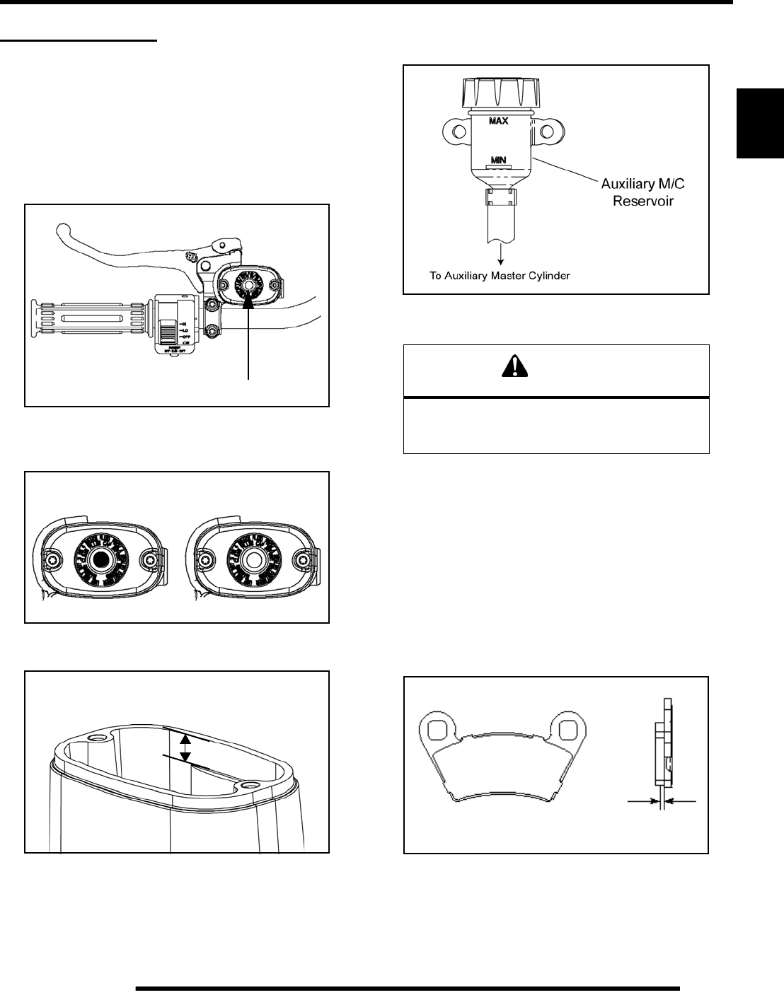
2.31
MAINTENANCE
2
BRAKE SYSTEM
Brake Fluid Inspection
The following checks are recommended to keep the brake
system in good operating condition. Service life of brake system
components depends on operating conditions. Inspect brakes in
accordance with the maintenance schedule and before each ride.
• Keep fluid level in the hand master cylinder reservoir to
the indicated level inside reservoir.
• Check the fluid level “eye”. If it is clear, it is an
indication that fluid is needed or the brake pads may be
worn, which can reduce the fluid level.
• If required, add brake fluid to .25” - .30” (6 - 8 mm)
from the top of the reservoir.
• Check the fluid level of the auxiliary brake master
cylinder reservoir. Add fluid to the indicated level.
• Use Polaris DOT 4 Brake Fluid (PN 2872189).
• Check brake system for fluid leaks, excessive travel or
spongy feel.
• Check brake pads for wear, damage or looseness.
• Check surface condition of the disc.
• Inspect thickness of brake pad friction material.
Brake Pad Inspection
Inspect brake pad friction material for excessive wear.
Hose / Fitting Inspection
Check brake system hoses and fittings for cracks, deterioration,
abrasion, and leaks.Tighten any loose fittings and replace any
worn or damaged parts.
Fluid Level “Eye”
Full Low
.25” - .30” (6 - 8 mm)
From the Top of Reservoir
CAUTION
DO NOT OVERFILL!
Excess brake fluid may cause brake drag.
Fill to the indicated fill line or specification.
Figure 2-31
Brake Pad Inspection
Brake Pad
Measure
Thickness
Service Limit - .040” (1 mm)
PartShark.com
877-999-5686
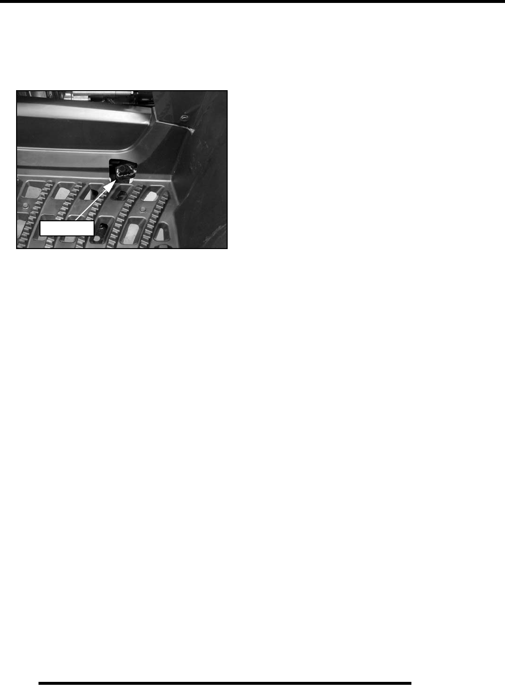
2.32
MAINTENANCE
Auxiliary Brake Pedal
The hydraulic auxiliary brake system requires no adjustment.
Frequently check the brake fluid level for the auxiliary brake
system by viewing the level in the master cylinder reservoir
located underneath the front rack assembly (see Figure 2-31).
• Check the effectiveness of the auxiliary brake by
applying approximately 50 lbs. (23 kg) of downward
force on the pedal.
• If brake pedal requires an excessive amount of travel to
operate, inspect brake pads, pedal, linkage springs, rear
master cylinder and hoses for wear, damage or leakage.
Replace components as needed.
Foot Brake
PartShark.com
877-999-5686

2.33
MAINTENANCE
2
MAINTENANCE LOG
Service Date Hours / Miles (km) Service Performed / Comments Dealer / Technician
20 Hours / 1 Month
(Break-In)
100 / 6 Months
PartShark.com
877-999-5686

NOTES
MAINTENANCE
2.34
PartShark.com
877-999-5686

ELECTRONIC FUEL INJECTION
3.1
CHAPTER 3
ELECTRONIC FUEL INJECTION
3
SPECIAL TOOLS . . . . . . . . . . . . . . . . . . . . . . . . . . . . . . . . . . . . . . . . . . . . . . . . . . . . . . . 3.2
FUEL TANK . . . . . . . . . . . . . . . . . . . . . . . . . . . . . . . . . . . . . . . . . . . . . . . . . . . . . . . . . . . . 3.4
FUEL LINE. . . . . . . . . . . . . . . . . . . . . . . . . . . . . . . . . . . . . . . . . . . . . . . . . . . . . . . . . . . . . 3.5
EFI SERVICE NOTES . . . . . . . . . . . . . . . . . . . . . . . . . . . . . . . . . . . . . . . . . . . . . . . . . . . . 3.5
EFI SYSTEM LAYOUT . . . . . . . . . . . . . . . . . . . . . . . . . . . . . . . . . . . . . . . . . . . . . . . . . . . 3.6
EFI COMPONENTS. . . . . . . . . . . . . . . . . . . . . . . . . . . . . . . . . . . . . . . . . . . . . . . . . . . . . . 3.7
ELECTRONIC FUEL INJECTION . . . . . . . . . . . . . . . . . . . . . . . . . . . . . . . . . . . . . . . . . . . 3.9
ELECTRONIC CONTROL UNIT (ECU). . . . . . . . . . . . . . . . . . . . . . . . . . . . . . . . . . . . . . 3.10
ECU SERVICE . . . . . . . . . . . . . . . . . . . . . . . . . . . . . . . . . . . . . . . . . . . . . . . . . . . . . . . . 3.10
ECU REMOVAL / REPLACEMENT . . . . . . . . . . . . . . . . . . . . . . . . . . . . . . . . . . . . . . . . 3.11
FUEL PUMP . . . . . . . . . . . . . . . . . . . . . . . . . . . . . . . . . . . . . . . . . . . . . . . . . . . . . . . . . . 3.11
FUEL SENDER / PUMP TEST . . . . . . . . . . . . . . . . . . . . . . . . . . . . . . . . . . . . . . . . . . . . 3.12
FUEL PUMP / FUEL TANK REMOVAL . . . . . . . . . . . . . . . . . . . . . . . . . . . . . . . . . . . . . 3.13
FUEL PUMP / FUEL TANK INSTALLATION . . . . . . . . . . . . . . . . . . . . . . . . . . . . . . . . . 3.14
FUEL PRESSURE REGULATOR . . . . . . . . . . . . . . . . . . . . . . . . . . . . . . . . . . . . . . . . . . 3.14
FUEL INJECTORS . . . . . . . . . . . . . . . . . . . . . . . . . . . . . . . . . . . . . . . . . . . . . . . . . . . . . 3.14
FUEL INJECTOR SERVICE. . . . . . . . . . . . . . . . . . . . . . . . . . . . . . . . . . . . . . . . . . . . . . 3.14
FUEL INJECTOR TEST / REPLACEMENT . . . . . . . . . . . . . . . . . . . . . . . . . . . . . . . . . . 3.15
CRANKSHAFT POSITION SENSOR (CPS) . . . . . . . . . . . . . . . . . . . . . . . . . . . . . . . . . . 3.16
CPS TEST / REPLACEMENT . . . . . . . . . . . . . . . . . . . . . . . . . . . . . . . . . . . . . . . . . . . . 3.16
TEMP / MANIFOLD ABSOLUTE PRESSURE SENSOR (T-MAP) . . . . . . . . . . . . . . . . . 3.17
T-MAP TEST / REPLACEMENT. . . . . . . . . . . . . . . . . . . . . . . . . . . . . . . . . . . . . . . . . . . 3.17
IDLE AIR CONTROL VALVE (IAC) . . . . . . . . . . . . . . . . . . . . . . . . . . . . . . . . . . . . . . . . . 3.17
IAC TEST . . . . . . . . . . . . . . . . . . . . . . . . . . . . . . . . . . . . . . . . . . . . . . . . . . . . . . . . . . . .3.17
IAC REPLACEMENT . . . . . . . . . . . . . . . . . . . . . . . . . . . . . . . . . . . . . . . . . . . . . . . . . . . 3.18
THROTTLE POSITION SENSOR (TPS) . . . . . . . . . . . . . . . . . . . . . . . . . . . . . . . . . . . . . 3.19
TPS RESISTANCE TESTS / TPS TESTER KIT. . . . . . . . . . . . . . . . . . . . . . . . . . . . . . . 3.19
CHECKING TPS READING . . . . . . . . . . . . . . . . . . . . . . . . . . . . . . . . . . . . . . . . . . . . . . 3.20
TPS ADJUSTMENT . . . . . . . . . . . . . . . . . . . . . . . . . . . . . . . . . . . . . . . . . . . . . . . . . . . . 3.21
TPS REPLACEMENT. . . . . . . . . . . . . . . . . . . . . . . . . . . . . . . . . . . . . . . . . . . . . . . . . . . 3.22
ENGINE COOLANT TEMPERATURE SENSOR (ECT) . . . . . . . . . . . . . . . . . . . . . . . . . 3.22
ECT SENSOR TEST . . . . . . . . . . . . . . . . . . . . . . . . . . . . . . . . . . . . . . . . . . . . . . . . . . . 3.22
ECT SENSOR REPLACEMENT. . . . . . . . . . . . . . . . . . . . . . . . . . . . . . . . . . . . . . . . . . . 3.23
IGNITION COIL . . . . . . . . . . . . . . . . . . . . . . . . . . . . . . . . . . . . . . . . . . . . . . . . . . . . . . . . 3.23
IGNITION COIL TESTS . . . . . . . . . . . . . . . . . . . . . . . . . . . . . . . . . . . . . . . . . . . . . . . . . 3.23
IGNITION COIL AND HT LEAD REPLACEMENT . . . . . . . . . . . . . . . . . . . . . . . . . . . . . 3.24
EFI DIAGNOSTICS . . . . . . . . . . . . . . . . . . . . . . . . . . . . . . . . . . . . . . . . . . . . . . . . . . . . . 3.25
INSTRUMENT CLUSTER TROUBLE CODE DISPLAY. . . . . . . . . . . . . . . . . . . . . . . . . 3.25
FUEL SYSTEM TROUBLESHOOTING. . . . . . . . . . . . . . . . . . . . . . . . . . . . . . . . . . . . . . 3.28
EFI SYSTEM BREAK-OUT DIAGRAMS . . . . . . . . . . . . . . . . . . . . . . . . . . . . . . . . . . . . . 3.29
FUEL INJECTOR CIRCUITS . . . . . . . . . . . . . . . . . . . . . . . . . . . . . . . . . . . . . . . . . . . . . 3.30
IDLE AIR CONTROL (IAC) CIRCUIT . . . . . . . . . . . . . . . . . . . . . . . . . . . . . . . . . . . . . . . 3.31
CRANKSHAFT POSITION SENSOR (CPS) CIRCUIT. . . . . . . . . . . . . . . . . . . . . . . . . . 3.31
FUEL PUMP / FUEL LEVEL SENSOR CIRCUIT . . . . . . . . . . . . . . . . . . . . . . . . . . . . . . 3.32
FUEL PUMP CIRCUIT . . . . . . . . . . . . . . . . . . . . . . . . . . . . . . . . . . . . . . . . . . . . . . . . . . 3.33
FUEL GAUGE CIRCUIT . . . . . . . . . . . . . . . . . . . . . . . . . . . . . . . . . . . . . . . . . . . . . . . . . 3.33
ENGINE COOLANT TEMPERATURE SENSOR (ECT) CIRCUIT . . . . . . . . . . . . . . . . . 3.34
THROTTLE POSITION SENSOR (TPS) CIRCUIT. . . . . . . . . . . . . . . . . . . . . . . . . . . . . 3.34
TEMP / MANIFOLD ABSOLUTE PRESSURE SENSOR (T-MAP) CIRCUIT. . . . . . . . . 3.35
DIAGNOSTIC CONNECTOR CIRCUIT . . . . . . . . . . . . . . . . . . . . . . . . . . . . . . . . . . . . . 3.35
DIAGNOSTIC CONNECTOR CIRCUIT (EPS MODELS). . . . . . . . . . . . . . . . . . . . . . . . 3.36
PartShark.com
877-999-5686
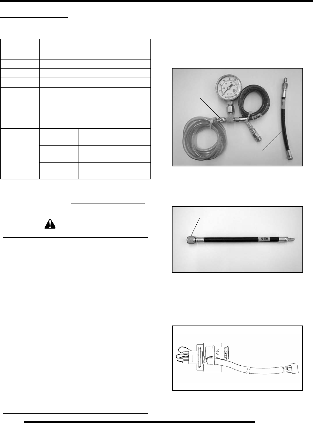
3.2
ELECTRONIC FUEL INJECTION
SPECIAL TOOLS
Part Numbers / Descriptions
IMPORTANT: For the most recent information on
Digital Wrench™ software and fileset downloads
please visit the website: www.polaris.diagsys.com
Fuel Pressure Gauge Kit - PU-43506-A
IMPORTANT: The EFI fuel system remains under high
pressure, even when the engine is not running.
Before attempting to service any part of the fuel
system, the pressure must be relieved. The Fuel
Pressure Gauge Kit has an integrated pressure relief
valve that can be used to bleed off pressure.
Fuel Pressure Gauge Adaptor - PS-48762
Used in conjunction with PU-43506-A to check fuel pressure.
Throttle Position Sensor Tester Kit - 2201519
This tester allows the use of a digital multi-meter to test TPS
function and perform the “TPS Adjustment” procedure. Polaris
Dealers can order special tools from SPX Corporation.
PART
NUMBER TOOL DESCRIPTION
PU-43506-A Fuel Pressure Gauge Kit
PS-48762 Fuel Pressure Gauge Adaptor
2201519 Throttle Position Sensor Tester Kit
PU-47063 Digital Wrench™ Diagnostic Software
(Includes most recent version of software
and a serial number)
PU-47471 Digital Wrench™ SmartLink Module Kit
(PU-47470, PU-47469, PU-47468)
PU-47470 Digital Wrench™
PC Interface Cable
PU-47469 Digital Wrench™
Vehicle Interface Cable
PU-47468 Digital Wrench™
SmartLink Module
WARNING
* Gasoline is extremely flammable and explosive
under certain conditions.
* EFI components are under high pressure. Verify
system pressure has been relieved before
disassembly.
* Never drain the fuel system when the engine is hot.
Severe burns may result .
* Do not overfill the tank. The tank is at full capacity
when the fuel reaches the bottom of the filler neck.
Leave room for expansion of fuel.
* Never start the engine or let it run in an enclosed
area. Gasoline powered engine exhaust fumes are
poisonous and can cause loss of consciousness and
death in a short time.
* Do not smoke or allow open flames or sparks in or
near the area where refueling is performed or where
g a so l i ne i s st o r ed .
* If you get gasoline in your eyes or if you should
swallow gasoline, seek medical attention immediately.
* If you spill gasoline on your skin or clothing,
immediately wash with soap and water and change
c l o t h i n g .
* Always stop the engine and refuel outdoors or in a
well ventilated area.
Relief Valve
Adaptor shown is
included with kit.
7/16-20 Schrader
PartShark.com
877-999-5686
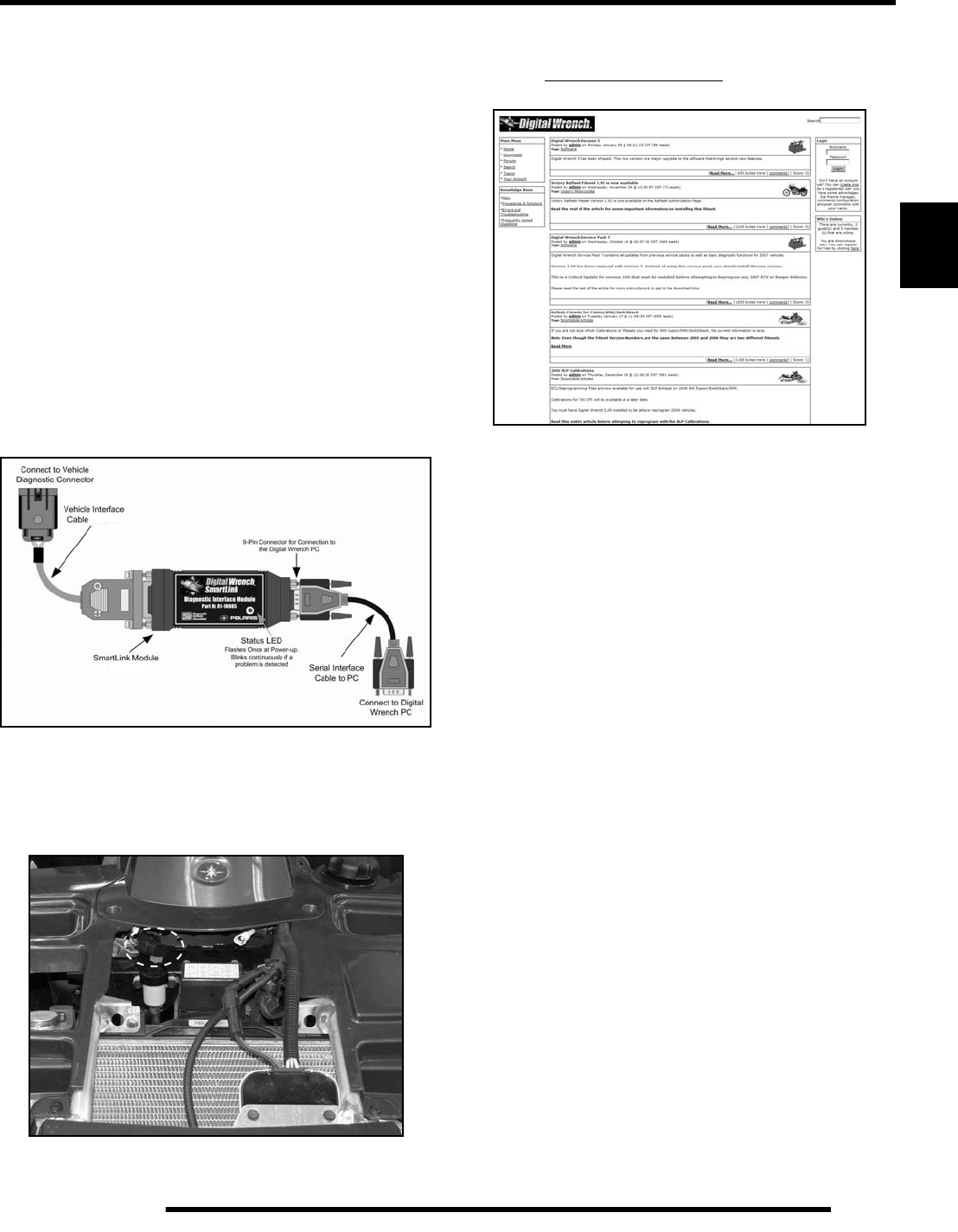
3.3
ELECTRONIC FUEL INJECTION
3
Digital Wrench™ Diagnostic Software
PU-47063
This dealer-only software installs on laptop computers equipped
with a CD drive and serial port connection, and is designed to
replace multiple shop tools often used to test EFI components.
It also includes step-by-step diagnostic procedures to aid
technician repair and troubleshooting.
Digital Wrench™
SmartLink Module Kit - PU-47471
This module kit contains the necessary cables and hardware to
communicate between the vehicle ECU and the Digital
Wrench™ diagnostic software. Polaris dealers can also order
the following separately: SmartLink Module PU-47468,
Vehicle Interface Cable PU-47469 and PC Interface Cable PU-
47470. This kit is available to Polaris dealers through our tool
supplier, SPX (1-800-328-6657).
Digital Wrench™ - Diagnostic Connector
The diagnostic connector is located under the front rack, near the
fuse box and rear brake reservoir.
Digital Wrench™ - Download Website
Located at: www.polaris.diagsys.com
PU-47468
PU-47469
PU-47470
PartShark.com
877-999-5686
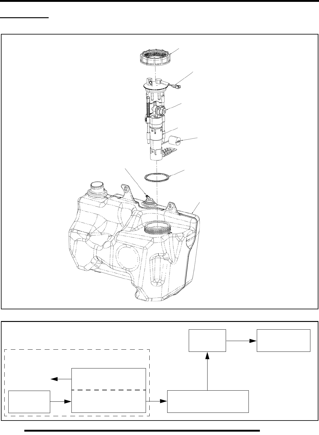
3.4
ELECTRONIC FUEL INJECTION
FUEL TANK
Exploded View
*NOTE: Fuel Pump is NOT Serviceable
PFA Nut
Pressure Regulator
PFA Gasket
Fuel Tank Assembly
Tank Vent
Electrical Connector
Fuel Pump*
Float Arm
Rollover Valve
Fuel Flow
Fuel Filters Fuel Pump Assembly Quick Connect Fuel Line
Fuel Rail Fuel Injectors
Pressure Regulator
Fuel Tank
PartShark.com
877-999-5686
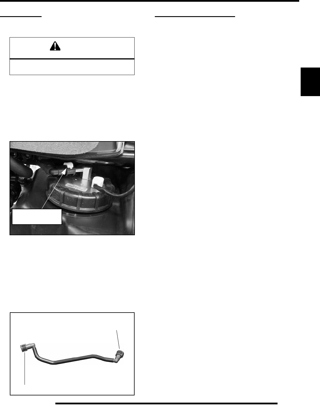
3.5
ELECTRONIC FUEL INJECTION
3
FUEL LINE
Quick Connect Removal / Installation
All EFI models use quick connect fuel lines. Refer to the
following steps for fuel line removal / installation:
1. Thoroughly clean the connector and place a shop towel
around the fuel line to catch any dripping fuel.
2. Squeeze the connector tabs together and lift up on the white
retainer. NOTE: Use an O-ring pick or similar tool to
disengage the inner white tab if the fuel tank is installed.
3. Pull out on the fuel line and remove it from the pump outlet.
4. To install the line, verify the connector and fuel pump outlet
are clean and free of debris.
5. Place the connector end over the fuel pump outlet and push
the white retainer and tabs back into place.
NOTE: Confirm attachment by pulling on the fuel line.
6. Repeat this process when removing the fuel line from the
fuel rail.
EFI SERVICE NOTES
For more convenient and accurate testing of EFI components, it
is recommended dealers utilize the Digital Wrench™
Diagnostic Software (dealer only), or limited testing may be
done manually using the procedures provided.
80% of all EFI problems are caused by wiring harness
connections. Follow a common sense approach when
diagnosing a potential EFI issue:
1. Disconnect the harness at the suspected sensor connector.
2. Inspect the connector ends for damage or contamination. If
damaged, repair; if contaminated, clean. Reconnect and
check function.
3. If problem persists, perform a sensor bench test according
to the specific sensor requirements (if applicable).
4. If the sensor bench tests pass, disconnect the connector at
the ECU and perform a continuity check between the sensor
connector and the appropriate pin at the ECU connector (all
connections for that sensor). Wiring resistance should be
less than one (1) ohm.
5. If the resistance is high (or open), a wiring harness
inspection is required (including a thorough inspection of
the ECU connector for contamination or damage).
6. If the sensor passes and the wiring passes inspection, and
reconnecting the ECU does not resolve the issue, then at
that point a known-good ECU (from another Polaris 850)
may be used to test for problem resolution.
• Never attempt to service any fuel system component
while engine is running or ignition switch "on".
•USE CARE when removing or installing the ECU
connector, as well as all other harness connections on
the unit. Properly connect and disconnect the ECU
harness to minimize damage to the connector pins and
locking mechanism.
• Although every precaution has been taken to prevent
water intrusion failure, avoid direct water or spray
contact with system components.
• Do not disconnect or reconnect the wiring harness
connector to the ECU or any individual components
with the ignition "on." This can send a damaging
voltage spike through the ECU.
• Do not allow battery cables to touch opposite terminals.
• Never start the engine when the cables are loose or
poorly connected to the battery terminals.
• Never disconnect battery while engine is running.
• Always unplug ECU from the wire harness before
performing any welding on the unit.
CAUTION
Verify fuel system has been depressurized
before performing this procedure.
Lift white retainer
before removing
Fuel Pump
Outlet
Fuel Rail
PartShark.com
877-999-5686
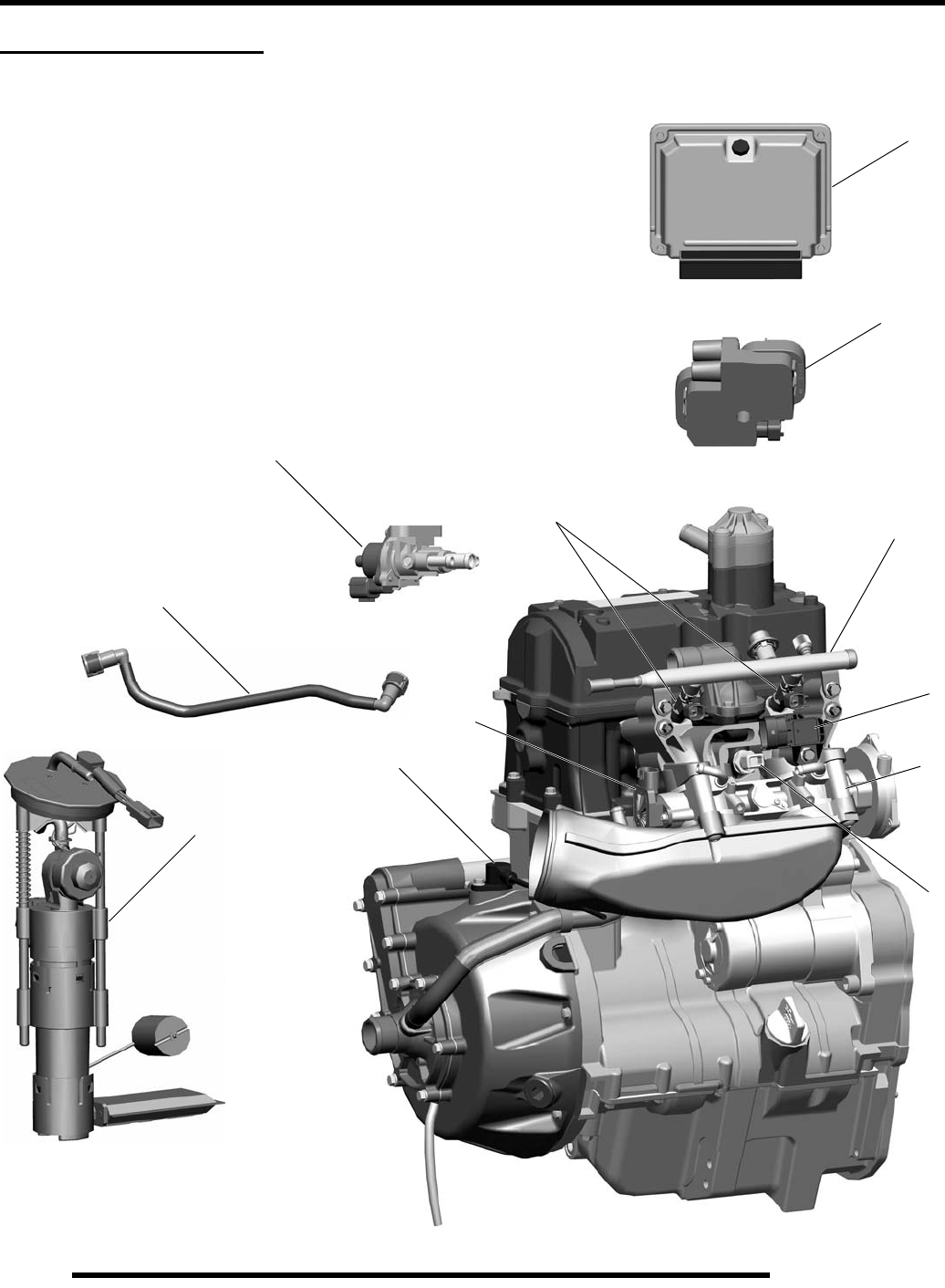
3.6
ELECTRONIC FUEL INJECTION
EFI SYSTEM LAYOUT
Exploded View
1. Electronic Control Unit (ECU)
2. Temperature / Manifold Absolute Pressure Sensor (T-MAP)
3. Idle Air Control (IAC)
4. Crankshaft Position Sensor (CPS)
5. Fuel Injectors
6. Fuel Rail
7. Fuel Line (quick connect)
8. Fuel Pump / Regulator / Fuel Gauge Sender (inside fuel tank)
9. Engine Coolant Temperature Sensor (ECT)
10. Throttle Position Sensor (TPS)
11. Throttle Body
12. Ignition Coil
1
2
3
4
56
9
11
10
8
7
Located in the
Fuel Tank Asm.
12
PartShark.com
877-999-5686
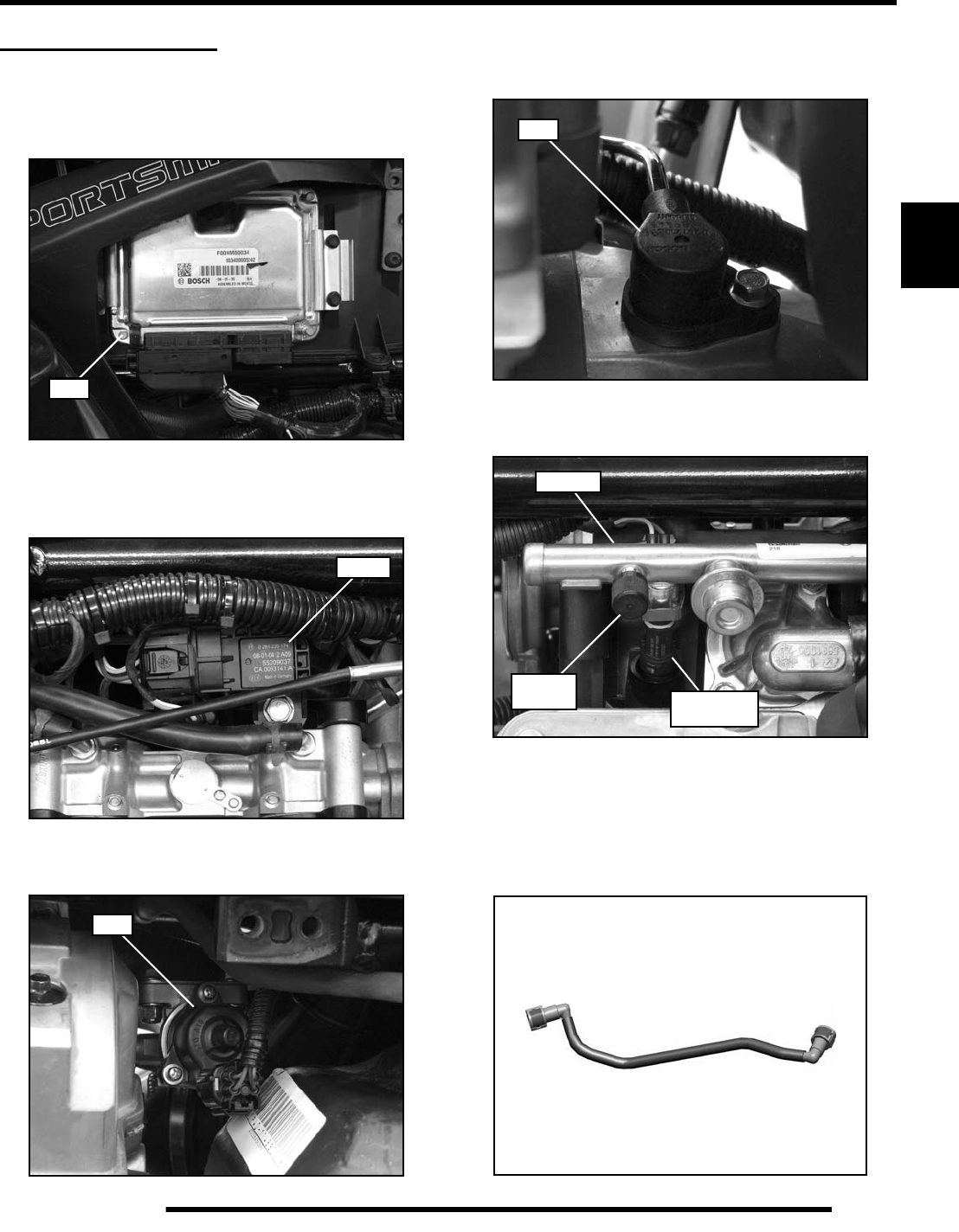
3.7
ELECTRONIC FUEL INJECTION
3
EFI COMPONENTS
Identification / Location
1. Electronic Control Unit (ECU)
- Attached to the air box, located behind the LH side panel.
2. Temperature and Manifold Absolute Pressure Sensor
(T-MAP)
- Located in the Integrated Air Fuel Manifold (IAFM).
3. Idle Air Control (IAC)
- Located in front of the engine behind the frame support.
4. Crankshaft Position Sensor (CPS)
- Located in the top portion of the magneto cover on the
front of the engine.
5. Fuel Injectors
- Located in the Integrated Air Fuel Manifold (IAFM).
6. Fuel Rail / Fuel Pressure Valve
- Attached to the top portion of the fuel injectors.
- Located on the PTO end of the fuel rail.
7. Fuel Line (Quick Connect)
- Located between the injector fuel rail and the fuel tank.
ECU
T-MAP
IAC
CPS
Pressure
Fuel Rail
Valve PTO
Fuel Injector
4 & 7
2
9 & 10
3
PartShark.com
877-999-5686
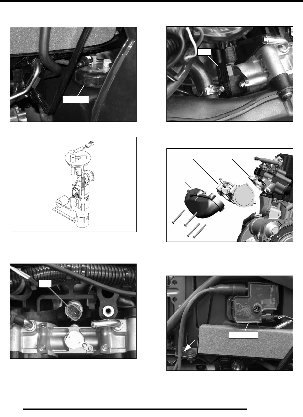
3.8
ELECTRONIC FUEL INJECTION
8. Fuel Pump / Regulator / Fuel Gauge Sender Assembly
- Located behind the right-hand side panel.
- Located in the fuel tank as an assembly.
9. Engine Coolant Temperature Sensor (ECT)
- Located in the cylinder head below the thermostat
housing, just above the throttle body.
10. Throttle Position Sensor (TPS)
- Located on the MAG end (front) of the throttle body.
11. Throttle Body
- Attached between the IAFM and the intake plenum.
12. Ignition Coil
- Located on the RH side of the airbox. The high tension
leads are retained by the airbox.
Fuel Pump
Fuel Pump Assembly
ECT
TPS
Throttle Body
Intake
IAFM
Plenum
Ignition Coil
PartShark.com
877-999-5686

3.9
ELECTRONIC FUEL INJECTION
3
ELECTRONIC FUEL INJECTION
General Information
The Electronic Fuel Injection (EFI) system is a complete engine
fuel and ignition management design. This system includes the
following principal components:
• Fuel Pump / Fuel Filters / Pressure Regulator
• Fuel Line
• Fuel Rail
• Fuel Injectors
• Throttle Body / lntegrated Air Fuel Manifold (IAFM)
• Electronic Control Unit (ECU)
• Ignition Coil
• Engine Coolant Temperature Sensor (ECT)
• Throttle Position Sensor (TPS)
• Crankshaft Position Sensor (CPS)
• Intake Air Temperature / Manifold Absolute
Pressure Sensor (T-MAP)
• Idle Air Control (IAC)
• Wire Harness Assembly
EFI Operation Overview
The EFI system is designed to provide peak engine performance
with optimum fuel efficiency and lowest possible emissions.
The ignition and injection functions are electronically
controlled, monitored and continually corrected during
operation to maintain peak performance.
The central component of the system is the Bosch Engine
Control Unit (ECU) which manages system operation,
determining the best combination of fuel mixture and ignition
timing for the current operating conditions.
An in-tank electric fuel pump is used to move fuel from the tank,
through the fuel line, to the fuel rail. The in-tank fuel pressure
regulator maintains a system operating pressure of 43 psi and
returns any excess fuel to the tank. At the engine, fuel is fed
through the fuel rail and into the injectors, which inject into the
intake ports. The ECU controls the amount of fuel by varying the
length of time that the injectors are "on." This can range from
1.5-8.0 milliseconds depending on fuel requirements. The
controlled injection of the fuel occurs every other crankshaft
revolution, or once for each 4-stroke cycle. The total amount of
fuel needed for one firing of a cylinder is injected during each
cycle. When the intake valve opens, the fuel/air mixture is
drawn into the combustion chamber, ignited and burned.
The ECU controls the amount of fuel being injected and the
ignition timing by monitoring the primary sensor signals for
intake air temperature, manifold absolute pressure (load),
engine temperature, speed (RPM), and throttle position. These
primary signals are compared to the programming in the ECU
computer chip, and the ECU adjusts the fuel delivery and
ignition timing to match the values.
During operation the ECU has the ability to re-adjust
temporarily, providing compensation for changes in overall
engine condition and operating environment, so it will be able
to maintain the ideal air/fuel ratio.
During certain operating periods such as cold starts, warm up,
acceleration, etc., a richer air / fuel ratio is automatically
calculated by the ECU.
Initial Priming / Starting Procedure
NOTE: The injection system must be purged of all
air prior to the initial start up, and / or any time the
system has been disassembled.
If the EFI system is completely empty of fuel or has been
disassembled and repaired:
1. Cycle the key switch from “OFF” to “ON” 6 times,
waiting for approximately 3 seconds at each “ON” cycle to
allow the fuel pump to cycle and shut down.
2. Once step 1 is completed, turn the key switch to “START”
until the engine starts or 5 seconds has passed.
3. If the engine failed to start, repeat step 1 for 2 more cycles
and attempt to start the engine.
If the engine fails to start, a problem may still exist, and should
be diagnosed.
NOTE: Accurate testing of EFI components is
recommended utilizing the Digital Wrench™
Diagnostic Software (dealer only).
PartShark.com
877-999-5686
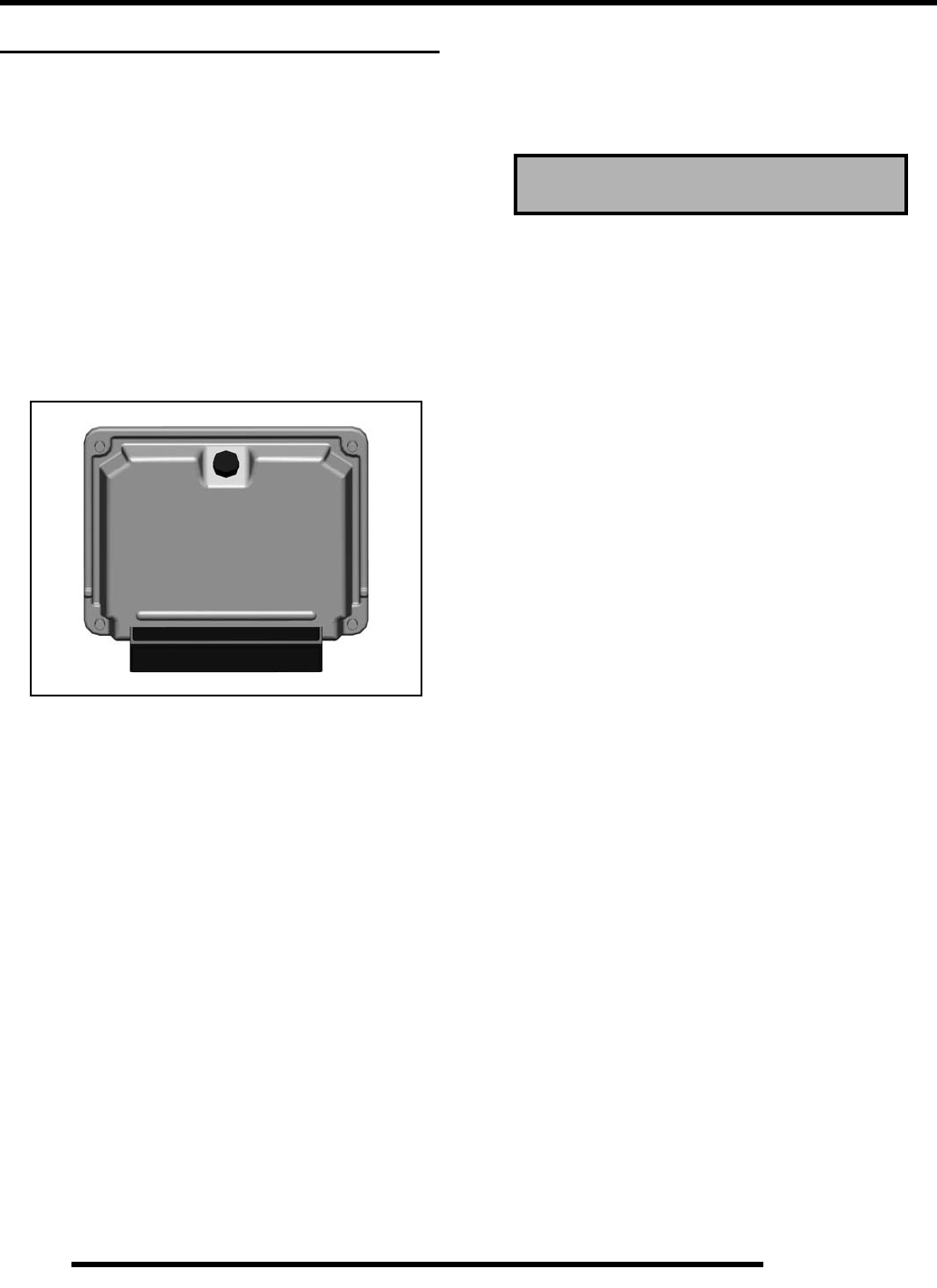
3.10
ELECTRONIC FUEL INJECTION
ELECTRONIC CONTROL UNIT (ECU)
Operation Overview
The ECU is the brain or central processing computer of the
entire EFI fuel/ignition management system. During operation,
sensors continuously gather data which is relayed through the
wiring harness to input circuits within the ECU. Signals to the
ECU include: ignition (on/off), crankshaft position and speed
(RPM), throttle position, engine coolant temperature, intake air
temperature, intake manifold air pressure and battery voltage.
The ECU compares the input signals to the programmed maps
in its memory and determines the appropriate fuel and spark
requirements for the immediate operating conditions. The ECU
then sends output signals to set the injector duration and ignition
timing.
During operation, the ECU continually performs a diagnostic
check of itself, each of the sensors, and system performance. If
a fault is detected, the ECU turns on the “Check Engine” light
in the speedometer and stores the fault code in its fault memory.
Depending on the significance or severity of the fault, normal
operation may continue, or "Fail-Safe" operation (slowed speed,
richer running) may be initiated. A technician can determine the
cause of the “Check Engine” light by initiating the “Blink Code”
sequence or by using Digital Wrench™. The ECU requires a
minimum of 7.0 volts to operate. The memory in the ECU is
operational the moment the battery cables are connected.
To prevent engine over-speed and possible failure, an RPM-
limiting feature is programmed into the ECU. If the maximum
RPM limit (8000) is exceeded, the ECU suppresses the injection
signals, cutting off the fuel flow. This process repeats it self in
rapid succession, limiting operation to the preset maximum.
SPORTSMAN XP 850 RPM Limit:
Hard Limit - Fuel injector suppression occurs
• All Gears: 8000 RPM
Soft Limit - Spark timing suppression occurs
• All Gears: 7500 RPM
ECU Service
Never attempt to disassemble the ECU. It is sealed to prevent
damage to internal components. Warranty is void if the case is
opened or tampered with in any way.
All operating and control functions within the ECU are pre-set.
No internal servicing or readjustment may be performed. If a
problem is encountered, and you determine the ECU to be
faulty, contact the Polaris Service Department for specific
handling instructions. Do not replace the ECU without factory
authorization.
The relationship between the ECU and the throttle position
sensor (TPS) is very critical to proper system operation. If the
TPS is faulty, or the mounting position of the TPS to the throttle
body is altered, the TPS must be adjusted.
For the purpose of troubleshooting, a known-good ECU from
another Polaris Sportsman XP 850 of the same model may be
used without system or engine component damage.
Maximum RPM Limit: 8000
PartShark.com
877-999-5686
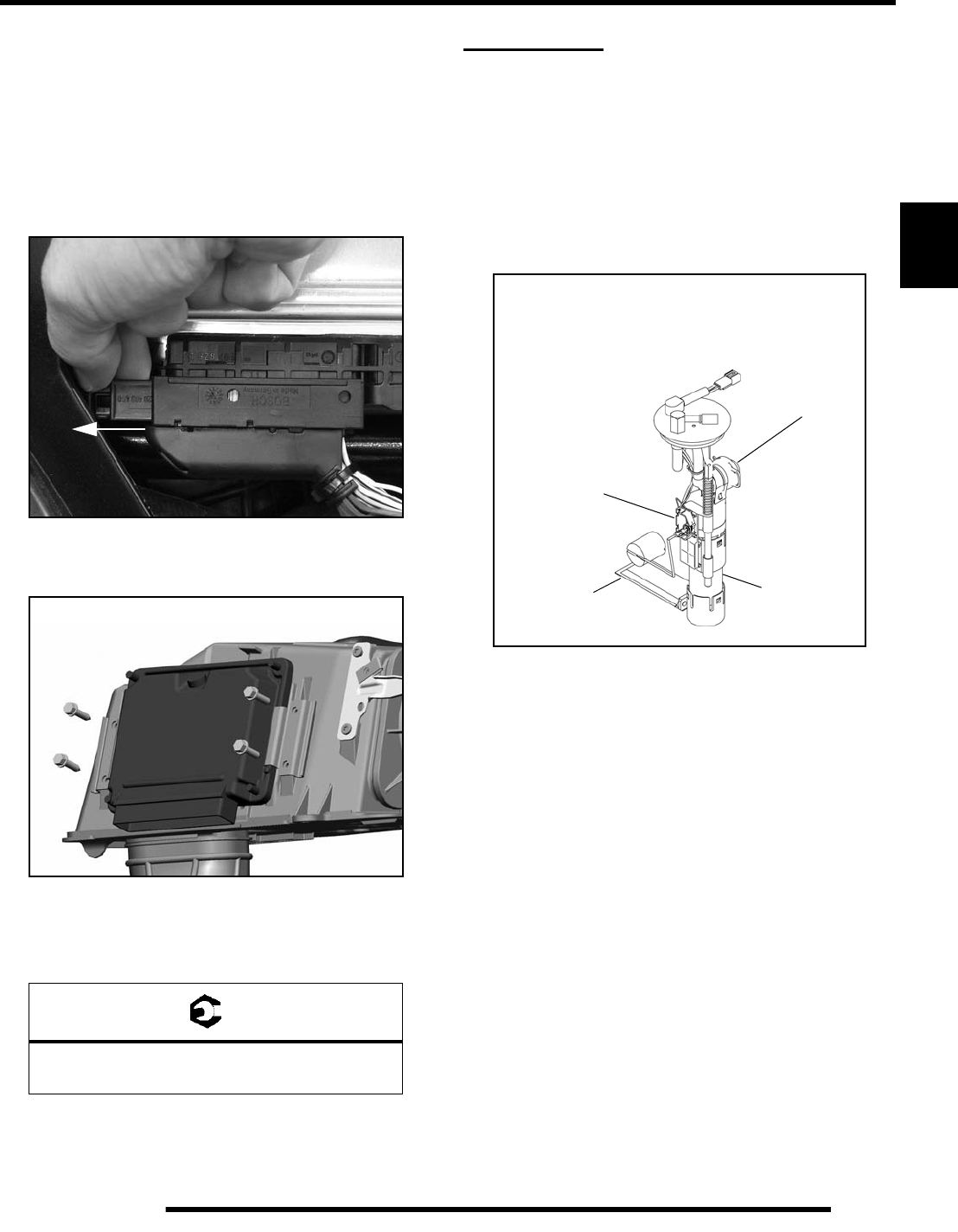
3.11
ELECTRONIC FUEL INJECTION
3
ECU Removal / Replacement
1. Remove the seat and upper left-hand side panel (see
Chapter 9 “Seat and Side Panels”).
2. With the ignition turned off, disconnect the wire harness
from the ECU by pulling the black slider out away from the
ECU while pulling down on the connector. Once the slider
is fully extended, pull the connector from the ECU, using
care not to damage the connector or locking mechanism.
3. Remove the (4) screws retaining the ECU to the airbox and
remove the ECU.
4. To install, reverse the previous steps. DO NOT apply
dielectric grease to the connector, as it is a sealed connector.
Tighten screws to 10 in. lbs. (1.1 Nm).
IMPORTANT: If replacing the ECU, you must reflash
the new ECU with the correct calibration upon
installation and prior to attempting to start the vehicle.
FUEL PUMP
Operation
NOTE: All EFI units utilize quick connect fuel lines.
An electric fuel pump assembly is used to transfer fuel to the EFI
system from inside the fuel tank. This assembly includes the fuel
pump, regulator and fuel gauge sender. The pump is rated for a
minimum output of 25 liters per hour at 43 psi and has a non-
serviceable preliminary 65-micron filter.
When the key switch is turned to "ON", the ECU activates the
fuel pump, which pressurizes the system for start-up.
The ECU switches off the pump preventing the continued
delivery of fuel in these instances:
• If the key switch is not promptly turned to the "start"
position.
• If the engine fails to start.
• If the engine is stopped with the key switch "ON" (as in
the case of an accident).
= T
ECU Retaining Screws
10 in. lbs. (1.1 Nm)
Fuel pump is not
serviceable, picture
for reference only.
Fuel Pump
Preliminary Filter
65-micron
Regulator
Fuel Gauge
Sender
PartShark.com
877-999-5686
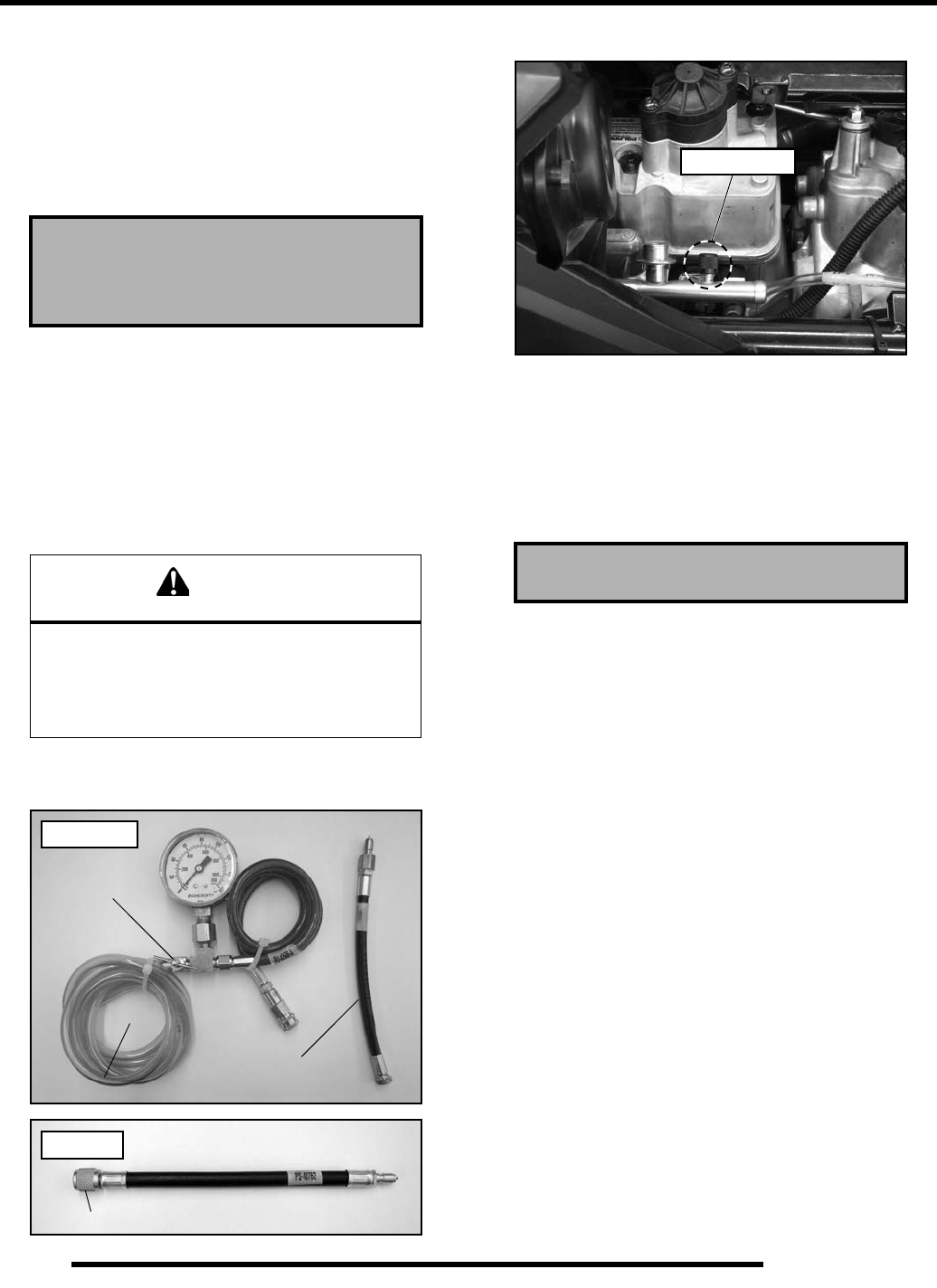
3.12
ELECTRONIC FUEL INJECTION
Fuel Sender Test
If the fuel gauge reading on the instrument cluster is not
working, or if the display reading differs in large comparison to
the fuel in the tank, perform a resistance test on the fuel sender.
Disconnect the fuel pump / sending unit connection and measure
the resistance between the Purple and Brown wires. If out of
specification, replace the fuel pump / tank assembly.
Fuel Pump Test
NOTE: The fuel pump / tank assembly is a non-
serviceable assembly and must be replaced if
determined to be faulty. If a fuel delivery problem is
suspected, make certain the pump is being activated
by the ECU and EFI relay, all electrical connections
are properly secured, the 20A EFI fuse is good, and a
minimum of 7.0 volts is being supplied.
1. Couple the Fuel Pressure Gauge Adaptor (PS-48762) to
the Fuel Pressure Gauge Kit (PU-43506-A).
2. Locate the fuel pressure valve attached to the fuel rail.
3. Remove the black cap and attach the fuel pressure gauge
kit and adaptor to the pressure valve. Route the clear hose
into a portable gasoline container or the vehicle’s fuel tank.
4. Turn on the key switch to activate the pump and check the
system pressure on the gauge. If system pressure of 43 psi
± 3 is observed, turn the key switch “off” and depress the
valve button on the tester to relieve the system pressure.
NOTE: If the fuel pressure is out of specification,
replace the fuel pump / tank assembly.
5. If the pump did not activate (Step 4), disconnect the plug
from the fuel pump. Connect a DC voltmeter across
terminals “A” and “C” in the plug on the vehicle harness
side. Turn on the key switch and observe voltage to ensure
a minimum of 7 volts is present.
NOTE: If the voltage was below 7 VDC, test battery,
ignition switch, EFI relay and wiring harness.
6. If the reading is between 7 and 14 volts, turn key switch off
and connect an ohmmeter between the terminals “A” and
“C”' in the plug on the pump harness to check for continuity
within the fuel pump.
NOTE: If there was no continuity between the pump
terminals, replace the fuel pump / tank assembly.
7. If voltage at the plug was within the specified range, and
there was continuity across the pump terminals, reconnect
the plug to the pump, making sure you have clean
connections. Turn on the key switch and listen for the pump
to activate.
NOTE: If the pump starts, verify you have the
correct amount of fuel pressure.
8. If the pump still does not operate, check ECU operation by
plugging in a known-good ECU of the same model.
NOTE: If the pump still does not operate, replace the
fuel pump / tank assembly.
Fuel Sender Resistance Specifications:
Full: 6 Ω
Empty: 90 Ω
CAUTION
Fuel is extremely flammable and may cause
severe burns, injury, or death.
Do not use any device that produces a flame or
electrical devices that may spark around
fuel or fuel vapors.
Relief Valve
Adaptor shown is
included with kit.
PU-43506-A
PS-48762
7/16-20 Schrader
Fuel Pump Pressure: 43 psi ± 3
Pressure Valve
PartShark.com
877-999-5686
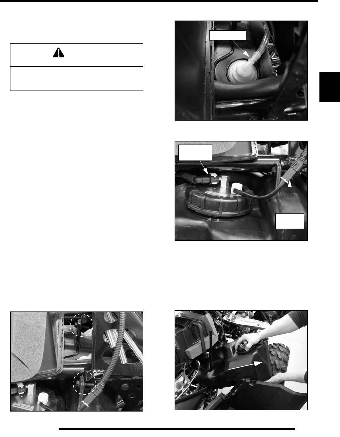
3.13
ELECTRONIC FUEL INJECTION
3
Fuel Pump / Fuel Tank Removal
IMPORTANT: Syphon as much fuel from the tank as
possible before attempting to remove it from the ATV.
NOTE: The fuel pump cannot be replaced as an
individual component, the entire fuel pump and fuel
tank must be replaced as an assembly. Refer to the
“Electronic Parts Catalog” for the proper part
number.
1. Remove the seat and both upper side panels (see Chapter 9
“Seat and Side Panels”).
2. Disconnect the negative battery cable.
3. Remove the (4) push rivets from each front mud guard and
remove the guards from the vehicle (see Chapter 9 “Mud
Guards”).
4. Remove the front rack assembly (see Chapter 9 “Front
Rack”).
5. Remove the front cab assembly (see Chapter 9 “Front
Cab”).
IMPORTANT: Be sure to cover the fuel tank inlet with
a shop towel prior to front cab and fuel tank removal
(see Chapter 9 “Front Cab”).
6. Remove the (4) screws from the bottom of the right-hand
footwell.
7. Remove the (2) fuel tank mounting screws located on the
upper portion of the fuel tank.
8. Remove the vent line from the fitting on top of the fuel tank.
9. Disconnect the fuel pump electrical harness.
10. While holding a shop towel over the fuel line connector,
disconnect the quick connect fuel line from the fuel pump.
NOTE: A small amount of fuel may come out of the
fuel line or tank. Properly drain fuel into a suitable
container.
11. Carefully pull the fuel tank out the right side of the ATV.
WARNING
Always wear safety goggles when working with
high pressure or flammable fluids. Failure to do
so could result in serious injury or complications.
Vent Fitting
Pump
Fuel Line
Connector
Harness
PartShark.com
877-999-5686
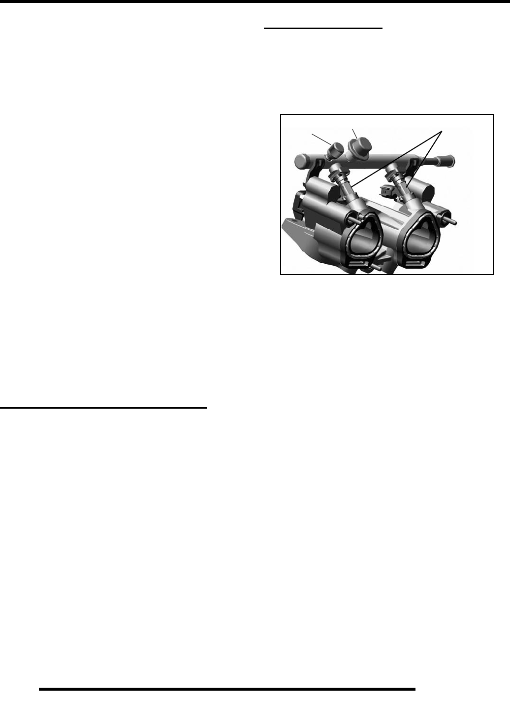
3.14
ELECTRONIC FUEL INJECTION
Fuel Pump / Fuel Tank Installation
1. Reinstall the fuel tank assembly through the right side.
2. Connect the fuel line to the fuel pump outlet and connect
the fuel pump electrical harness.
3. Reinstall the vent line to the tank fitting.
4. Install the (2) fuel tank mounting screws and tighten
securely.
5. Install the (4) screws into the bottom portion of the right-
hand footwell.
6. Install the front cab assembly (see Chapter 9 “Front Cab”).
7. Remove the shop towel from the fuel tank inlet, reconnect
the fuel fill hose and tighten hose clamp securely.
8. Install the front rack assembly (see Chapter 9 “Front
Rack”).
9. Install the front mud guards (see Chapter 9 “Mud Guards”).
10. Reconnect the negative cable to the battery.
11. Install the upper side panels and seat (see Chapter 9 “Seat
and Side Panels”).
12. Test the fuel pump by turning on the key and listening for
the pump to activate.
FUEL PRESSURE REGULATOR
Operation Overview
The fuel pressure regulator maintains the required operating
system pressure of 43 psi ± 3 psi. A rubber-fiber diaphragm
divides the regulator into two separate sections, the fuel
chamber and the pressure regulating chamber. The pressure
regulating spring presses against the valve holder (part of the
diaphragm), pressing the valve against the valve seat. The
combination of atmospheric pressure and regulating spring
tension equals the desired operating pressure. Any time the fuel
pressure against the bottom of the diaphragm exceeds the
desired (top) pressure, the valve opens, relieving the excess
pressure, returning the excess fuel back to the tank.
Fuel Pressure Regulator Test
Refer to the “Fuel Pump Test” procedure.
Fuel Pressure Regulator Replacement
The regulator is a sealed, non-serviceable assembly. If it is
faulty, the fuel tank assembly must be replaced. Refer to the
“Fuel Pump / Tank Assembly Replacement” procedure.
FUEL INJECTORS
Operation Overview
The fuel injectors mount into the Integrated Air Fuel Manifold
(IAFM), and the fuel rail attaches to the top end of them.
Replaceable O-rings on both ends of the injector prevent
external fuel leaks and also insulate it from heat and vibration.
When the key switch is on, the fuel rail is pressurized, and the
EFI relay provides voltage to the injectors. During engine
operation, the ECU completes the ground circuit, energizing the
injectors. The valve needle in the injector is opened
electromagnetically, and the pressure in the fuel rail forces fuel
down through the inside. The “director plate” at the tip of the
injector contains a series of calibrated openings which directs
the fuel into the intake port in a cone-shaped spray pattern.
The amount of fuel injected is controlled by the ECU and
determined by the length of time the valve needle is held open,
also referred to as the “injection duration” or “pulse width”. It
may vary in length depending on the speed and load
requirements of the engine.
Fuel Injector Service
Injector problems typically fall into three general categories-
electrical, dirty / clogged, or leakage. An electrical problem
usually causes one or both of the injectors to stop functioning.
Several methods may be used to check if the injectors are
operating.
NOTE: Do not apply voltage directly to the fuel
injectors. Excessive voltage will burn out the
injectors. Do not ground the injectors with the
ignition on. The injectors will open if the EFI relay is
energized.
If an injector is not operating, it can indicate either a bad injector,
or a wiring/electrical connection problem. Check as follows:
Fuel Injectors
Pressure Damper
Valve
PartShark.com
877-999-5686
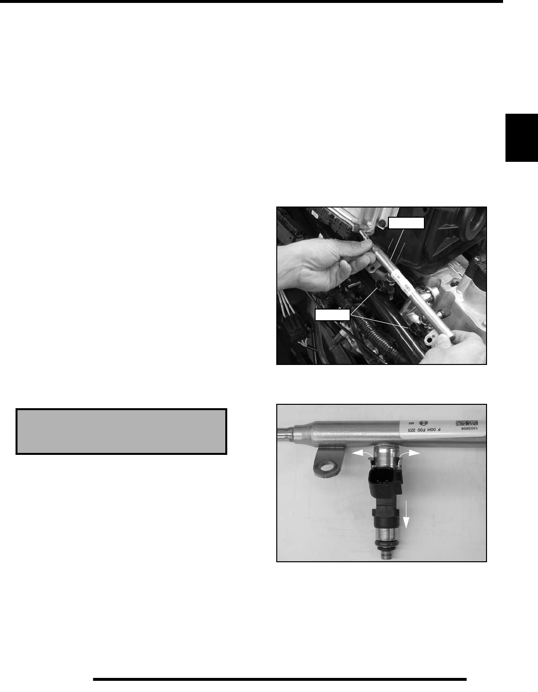
3.15
ELECTRONIC FUEL INJECTION
3
Injector leakage is very unlikely, but in rare instances it can be
internal (past the tip of the valve needle), or external (weeping
around the injector body). The loss of system pressure from the
leakage can cause hot restart problems and longer cranking
times.
Injector problems due to dirt or clogging are unlikely due to the
design of the injectors, the high fuel pressure, the use of filters
and the detergent additives in the gasoline. Symptoms that could
be caused by dirty/clogged injectors include rough idle,
hesitation/stumble during acceleration, or triggering of fault
codes related to fuel delivery. Injector clogging is usually caused
by a buildup of deposits on the director plate, restricting the flow
of fuel, resulting in a poor spray pattern. Some contributing
factors to injector clogging include; dirty air filters, higher than
normal operating temperatures, short operating intervals and
dirty, incorrect, or poor quality fuel. Cleaning of clogged
injectors is not recommended; they should be replaced.
Additives and higher grades of fuel can be used as a preventative
measure if clogging has been a problem.
Fuel Injector Test
If an injector is not operating, it can indicate either a bad injector,
or a wiring/electrical connection problem. Check as follows:
• Remove the seat, left-hand side panel, and disconnect
the fuel injector(s).
• Using an ohmmeter, test for continuity by placing the
test leads on each pin of the injector.
• Resistance specification is 13.8Ω - 15.2Ω (20°C, 68°F)
Fuel Injector Replacement
NOTE: Engine must be cool. Depressurize the fuel
system if possible.
1. Remove the seat and both upper side panels (see Chapter 9
“Seat and Side Panels”).
2. Remove the (2) screws retaining the lower portion of the
air box.
3. Remove the hose from the breaker valve located on top of
the valve cover.
4. Remove the spark plug wires.
5. Remove the (2) Torx-head screws retaining the upper
portion of the air box to the front cab.
6. Carefully disconnect the ECU by pulling the tab out while
pulling down on the connector.
7. Loosen the hose clamp retaining the intake boot to the
intake plenum and remove the boot.
8. Lift up on the air box and turn it sideways to gain access to
the fuel rail and fuel injectors.
9. Thoroughly clean the area around the fuel rail and injectors.
10. Disconnect the “quick connect” fuel line from the fuel rail.
11. Disconnect the harness from both fuel injectors.
12. Using a 10 mm wrench, remove the fuel rail mounting
screws.
13. Carefully pull up on the fuel rail and fuel injectors and
remove them from the vehicle as an assembly.
14. Pry the two injector retaining tabs open and remove the
injector(s) from the fuel rail.
NOTE: Use new O-rings (included with new injector)
any time an injector is removed.
15. Lubricate the O-rings lightly with soapy water to aid
installation.
16. Install the new injector and torque the fuel rail mounting
screws to 6 - 9 ft. lbs. (8 - 12 Nm).
Fuel Injector Resistance Specification:
13.8Ω - 15.2Ω (20°C, 68°F)
Injectors
Fuel Rail
PartShark.com
877-999-5686
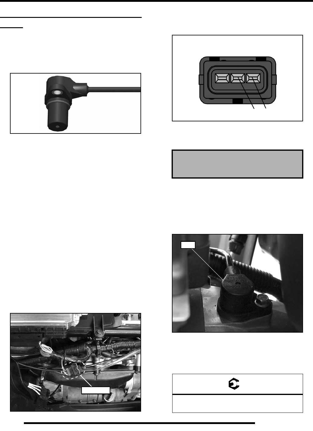
3.16
ELECTRONIC FUEL INJECTION
CRANKSHAFT POSITION SENSOR
(CPS)
Operation Overview
The engine speed sensor is essential to engine operation,
constantly monitoring the rotational speed (RPM) and position
of the crankshaft.
A ferromagnetic 60-tooth ring gear with two consecutive teeth
missing is mounted on the flywheel. The inductive speed sensor
is mounted 1.0 ± 0.26 mm (0.059 ± 0.010 in.) away from the
ring gear. During rotation, an AC pulse is created within the
sensor for each passing tooth. The ECU calculates engine speed
from the time interval between the consecutive pulses. The two-
tooth gap creates an “interrupt” input signal, corresponding to
specific crankshaft position. This signal serves as a reference for
the control of ignition timing by the ECU. Synchronization of
the CPS and crankshaft position takes place during the first two
revolutions each time the engine is started. This sensor must be
properly connected at all times. If the sensor fails or becomes
disconnected for any reason, the engine will stop running.
CPS Test
The crankshaft position sensor is a sealed, non-serviceable
assembly. If fault code diagnosis indicates a problem with the
CPS, test and correct as follows:
1. Remove the seat and left-hand side panel.
2. Locate and disconnect the CPS harness connector on the
left side of the vehicle just below the ECU.
3. Connect an ohmmeter between the pin terminals as shown.
A resistance value of 860 Ω ± 10% at room temperature
(20° C, 68° F) should be obtained.
4. If resistance is correct, check the mounting, toothed ring
gear (damage, runout, etc.), and flywheel key.
CPS Replacement
1. Disconnect sensor harness connector (see “CPS Test”).
2. Using a 6 mm hex wrench, remove the retaining bolt and
remove the sensor from the magneto cover.
3. Install the new sensor using a light coating of oil on the O-
ring to aid installation.
4. Torque the retaining bolt to specification.
CPS
“Removed”
Disconnect
Crankshaft Position Sensor:
860Ω ± 10% (20° C, 68° F)
= T
CPS Retaining Bolt Torque:
7 ft. lbs. (10 Nm)
Measure resistance
at these two pins
CPS Connector
CPS
PartShark.com
877-999-5686
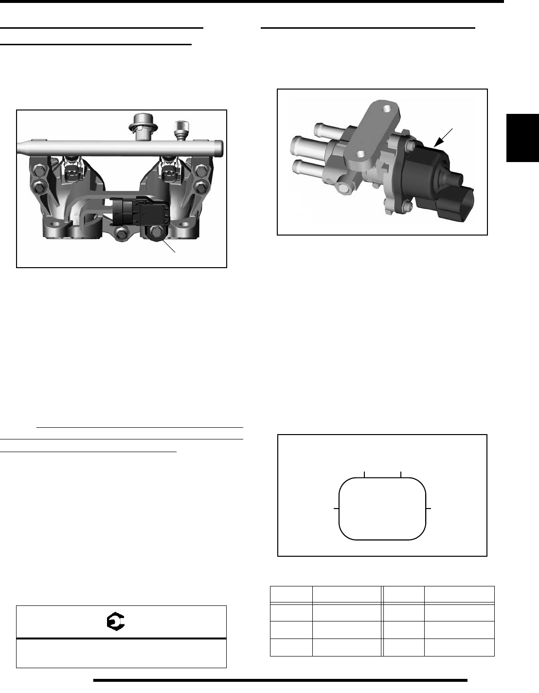
3.17
ELECTRONIC FUEL INJECTION
3
TEMP / MANIFOLD ABSOLUTE
PRESSURE SENSOR (T-MAP)
Operation Overview
Mounted on the (IAFM), the temperature and manifold absolute
pressure sensor (T-MAP) performs two functions in one unit.
Air passing through the intake is measured by the T-MAP and
relayed to the ECU. These signals, comprised of separate air
temperature and manifold absolute pressure readings, are
processed by the ECU and compared to its programming for
determining the fuel and ignition requirements during
operation.
T-MAP Test
The temperature and manifold absolute pressure sensor
(T-MAP) is a non-serviceable item. If it is faulty, it must be
replaced. This sensor requires a 5 Vdc input to operate, therefore
the T-MAP sensor should only be tested using the Digital
Wrench™ Diagnostic Software (dealer only).
T-MAP Replacement
1. Disconnect the sensor from the main harness.
2. Using a 10 mm wrench, remove the retaining bolt and
sensor.
3. Install the new sensor using a light coating of oil on the O-
ring to aid installation.
4. Torque the retaining bolt to specification.
IDLE AIR CONTROL VALVE (IAC)
Operation Overview
The Idle Air Control (IAC) is used to stabilize the idle quality of
the engine at cold start-up and after warm-up operations.
Mounted in front of the engine, the IAC contains 1 stepper motor
which receives varying voltage signal pulses from the ECU.
These pulses determine the IAC plunger setting, thereby
controlling the amount of air bypassing the closed throttle body
for idle control. If the IAC is disconnected or inoperative, it will
remain at it’s last operated position.
IAC Test
The IAC is a non-serviceable item. If it is faulty, it must be
replaced. It can be ‘bench tested’ using the following method:
Set your meter to read Ohms. Check the resistance values at
each of the following pin locations of the IAC. If any of the
readings are out of specification, replace the IAC
= T
T-MAP Retaining Bolt Torque:
35-53 in. lbs. (4-6 Nm)
T-MAP
IAC Resistance Readings
Pins Resistance Pins Resistance
1 - 2 30Ω ± 1.2Ω4 - 5 30Ω ± 1.2Ω
2 - 3 30Ω ± 1.2Ω5 - 6 30Ω ± 1.2Ω
1 - 3 60Ω ± 2.4Ω4 - 6 60Ω ± 2.4Ω
IAC
123
456
IAC Valve Connector
PartShark.com
877-999-5686
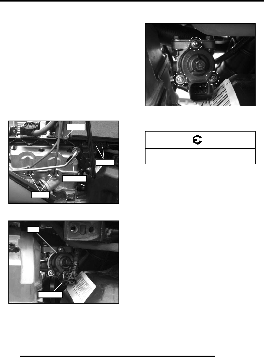
3.18
ELECTRONIC FUEL INJECTION
IAC Replacement
1. Remove the seat and upper right-hand side panel (see
Chapter 9 “Seat and Side Panels”).
2. Disconnect the shift linkage from the shift lever.
3. Remove the spark plug wires.
4. Remove the retaining screw from the lower right-hand side
of the airbox.
5. Remove the push rivets retaining the right-hand portion of
the rear cab to gain access to the bolts retaining the upper
right-hand frame support.
6. Remove the (4) bolts retaining the upper right-hand frame
support. Pull the support forward and down to remove it
from the vehicle.
7. Disconnect vehicle harness from IAC.
8. Remove the (3) Phillips-head mounting screws and remove
the IAC from the housing.
9. Install the new IAC and torque the mounting screws to 17.7
in. lbs. (2 Nm).
10. Reconnect vehicle harness to IAC.
11. Reinstall the throttle body and securely tighten the hose
clamps.
12. Reinstall the side panel and seat.
Remove
Remove
Remove
Disconnect
IAC
Disconnect
= T
IAC Mounting Screw Torque:
17.7 in. lbs. (2 Nm)
PartShark.com
877-999-5686
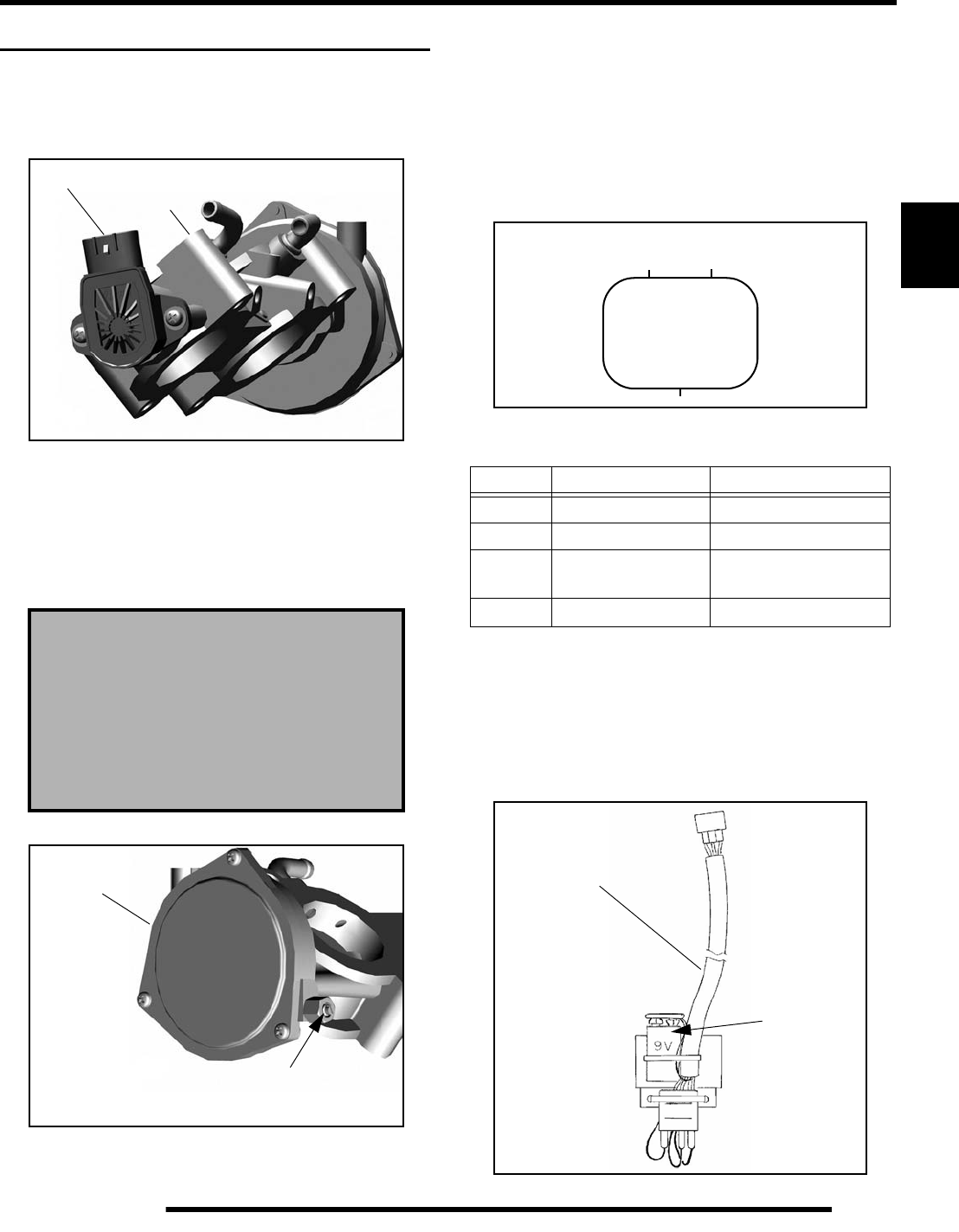
3.19
ELECTRONIC FUEL INJECTION
3
THROTTLE POSITION SENSOR (TPS)
Operation Overview
The throttle position sensor (TPS) is used to indicate throttle
plate angle to the ECU.
Mounted on the throttle body and operated directly off the end
of the throttle shaft, the TPS works like a rheostat, varying the
voltage signal to the ECU in direct correlation to the angle of the
throttle plate. This signal is processed by the ECU and compared
to the internal pre-programmed “maps” to determine the
required fuel and ignition settings for the amount of engine load.
TPS Resistance Tests
The throttle position sensor (TPS) is a non-serviceable item. If
it is faulty, it must be replaced. It can be tested using the
following method:
Using an Ohm Meter:
With the test leads connected and the meter set to the ohms scale,
observe the reading at the following pin locations of the TPS:
TPS Tester Kit
The throttle position sensor (TPS) reading can be checked by
using the TPS Tester Kit (2201519).
Set-up the TPS Tester Kit (2201519), according to the
instructions that accompanied the tester. Make sure the 9 volt
battery is new.
The correct position of the throttle body
stop screw is established and set at the
factory. DO NOT remove the tamper proof
cap to adjust the throttle body stop screw or
alter its position in any manner. The stop
screw controls the air flow calibration
of the throttle body.
Throttle
TPS Body
Stop Screw
(Factory Set)
DO NOT ADJUST
Throttle
Body
TPS Resistance Readings
Pins Throttle Position Resistance
d-GND ----- ∞
c-dClosed 4kΩ - 5kΩ (reference)
c-dOpen 1150Ω - 1250Ω
(reference)
c-e----- 4kΩ − 6kΩ
123
TPS Connector
TPS Tester
P/N - 2201519
Use a New
9V Battery
PartShark.com
877-999-5686
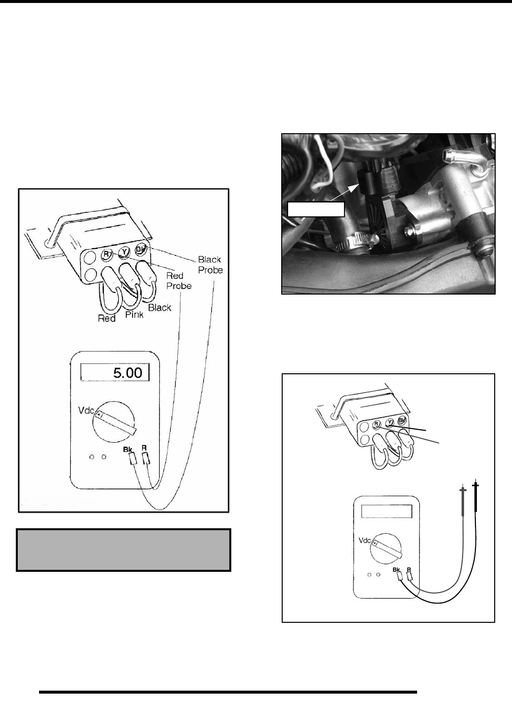
3.20
ELECTRONIC FUEL INJECTION
Verify TPS Tester Reference Voltage
A 5 volt reference voltage signal from the TPS Tester harness is
required for the TPS test to be accurate. Refer to the instructions
provided with the TPS Tester Kit (2201519) or follow the bullet
point steps below to check reference voltage.
Reference Voltage Test:
• Insert black voltmeter probe into the “Bk” test port.
• Connect the red voltmeter probe into the “R” test port
and verify the voltage is 4.99-5.01 Vdc. If this reading
is low, verify the 9 volt battery is good or try a new 9
volt battery.
IMPORTANT: Always use a fresh 9 Volt battery.
Checking TPS Reading
1. Remove the seat and upper left-hand side panel (see
Chapter 9 “Seat and Side Panels”).
2. Assemble the TPS Tester according to the instructions.
Refer to “TPS Tester Kit” for proper set-up and testing.
Verify the 9 volt tester battery is new.
3. Disconnect vehicle harness from TPS.
4. Plug the TPS Tester harness in the TPS harness.
5. Set your voltmeter to read Vdc. Connect the red voltmeter
probe into the “R” test port and the black voltmeter probe
into the “Y” test port (see Figure 3-20).
6. Move the throttle open and closed slowly while reading the
display. The voltage should increase and decrease
smoothly without any “jumps” when the throttle is applied.
TPS Reference Voltage
5 Vdc Input
Disconnect
Should Read
.700
Black Probe
Red Pink Black
Red Probe
.700 ± .050 Vdc
2201519 Tester
Figure 3-20
PartShark.com
877-999-5686
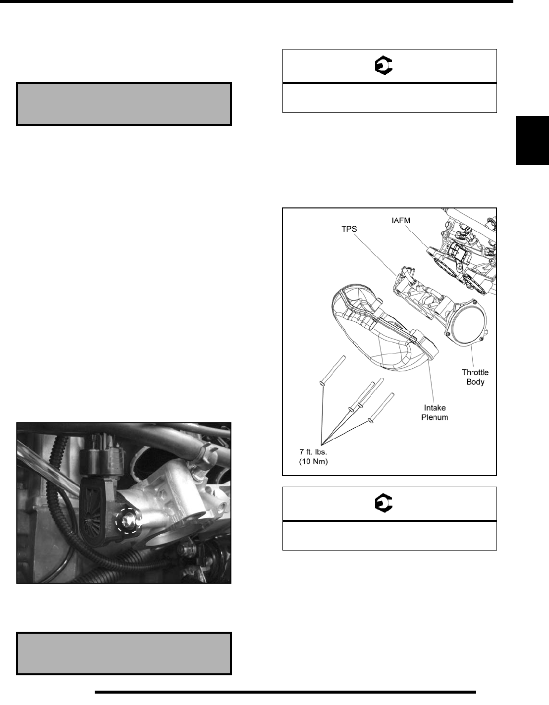
3.21
ELECTRONIC FUEL INJECTION
3
7. If voltage varies with throttle movement, continue on to the
next step. If the sensor did not function correctly, replace it.
8. Allow the throttle lever to rest in the idle position. The
voltmeter should read .700 ± .050 volts.
9. If the voltage does not read within the specification,
proceed to the “TPS Adjustment” procedure. If the
voltage reading is within specification, no adjustment is
required.
TPS Adjustment
NOTE: This procedure should be performed after
you have checked the TPS reading. Refer to
“Checking TPS Reading” procedure before making
any adjustments.
1. Loosen the hose clamp retaining the intake boot to the
intake plenum.
2. Remove the (4) bolts retaining the intake plenum and
throttle body.
3. Position the throttle body to access the TPS screws.
4. Make sure the TPS Tester harness is still connected to the
TPS harness.
5. Loosen the TPS mounting screws.
6. Rotate the TPS until your voltmeter reads .700 ± .050 volts
(see Figure 3-20).
7. Retighten TPS mounting screws and torque to
specification.
8. Verify voltage reading did not change. If voltage reading
changed, repeat steps 5 - 7.
9. Reconnect the vehicle harness to the TPS.
10. Reinstall the throttle body and intake plenum. Torque bolts
to specification.
11. Install intake boot to intake plenum and securely tighten the
hose clamp.
12. Reinstall the left-hand side panel and seat.
13. Start engine and test operation.
TPS Output Reading
.700 ± .050 Vdc
TPS Output Reading
.700 ± .050 Vdc
= T
TPS Mounting Screws:
17.7 in. lbs. (2 Nm)
= T
Intake Plenum Bolts:
7 ft. lbs. (10 Nm)
PartShark.com
877-999-5686
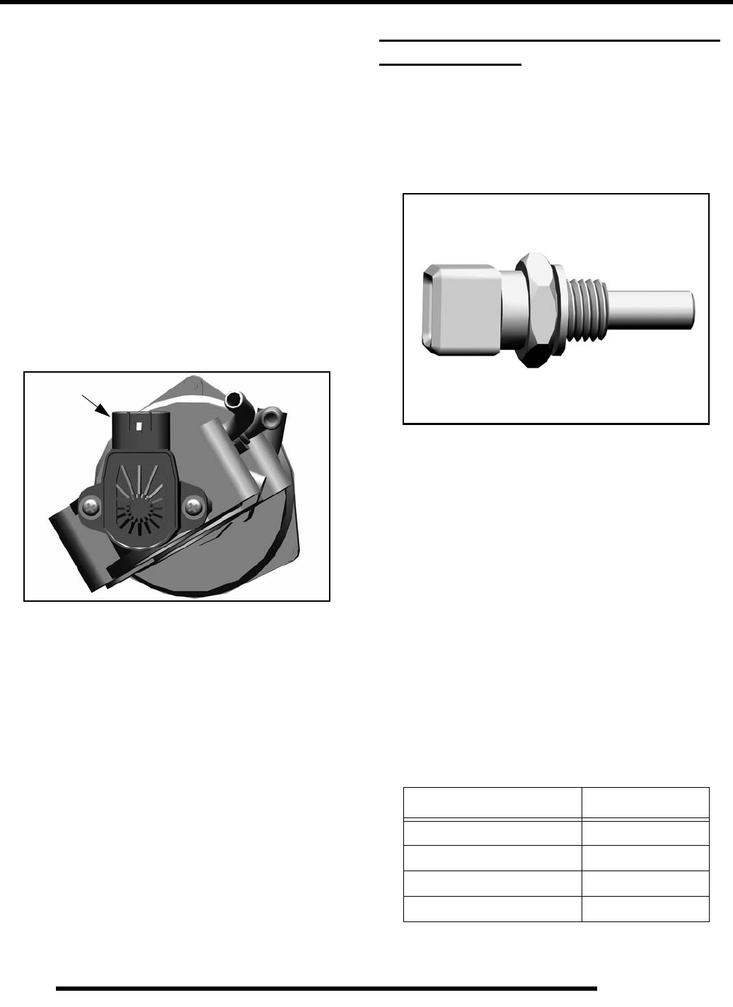
3.22
ELECTRONIC FUEL INJECTION
TPS Replacement
NOTE: The correct position of the TPS angle on the
throttle body is established and set at the factory. If
the TPS is replaced, repositioned or loosened it
must be recalibrated. Refer to the “TPS Adjustment”
procedure.
1. Remove the seat and upper left-hand side panel (see
Chapter 9 “Seat and Side Panels”).
2. Loosen the hose clamp retaining the intake boot to the
intake plenum.
3. Remove the (4) bolts retaining the intake plenum and
throttle body.
4. Position the throttle body to access the TPS harness and
mounting screws.
5. Disconnect the harness from the TPS.
6. Remove the (2) Phillips-head mounting screws and replace
the TPS.
IMPORTANT: If replacing the TPS or throttle body,
you must perform the “TPS Adjustment” procedure.
7. Refer to “TPS Adjustment” for setting the TPS voltage.
ENGINE COOLANT TEMPERATURE
SENSOR (ECT)
Operation Overview
The engine coolant temperature sensor measures coolant
temperature. The engine temperature sensor is a Negative
Temperature Coefficient (NTC) type sensor, as the temperature
increases the resistance decreases.
Coolant passes through the cylinder and by the sensor probe,
varying a resistance reading which is relayed to the ECU. This
signal is processed by the ECU and compared to its
programming for determining the fuel and ignition
requirements during operation. The ECU also uses this signal to
determine when to activate the fan during operation.
ECT Sensor Test
To quickly rule out other components and wiring related to the
ECT, disconnect the harness from the ECT sensor and start the
engine. After a few seconds, the fan should turn on and the
“Over Temp” indicator should display on the instrument cluster.
This indicates all other components are working properly.
Refer to Chapter 4 for additional ECT information. Polaris
dealers can test the sensor by using the Digital Wrench™
Diagnostic Software (dealer only).
Disconnect
ECT Sensor Resistance Readings
Temperature °F (°C) Resistance
32 °F (0 °C) 5.9k Ω ± 5%
68 °F (20 °C) 2.5k Ω ± 5%
176 °F (80 °C) 323 Ω ± 5%
212 °F (100 °C) 186 Ω ± 5%
PartShark.com
877-999-5686
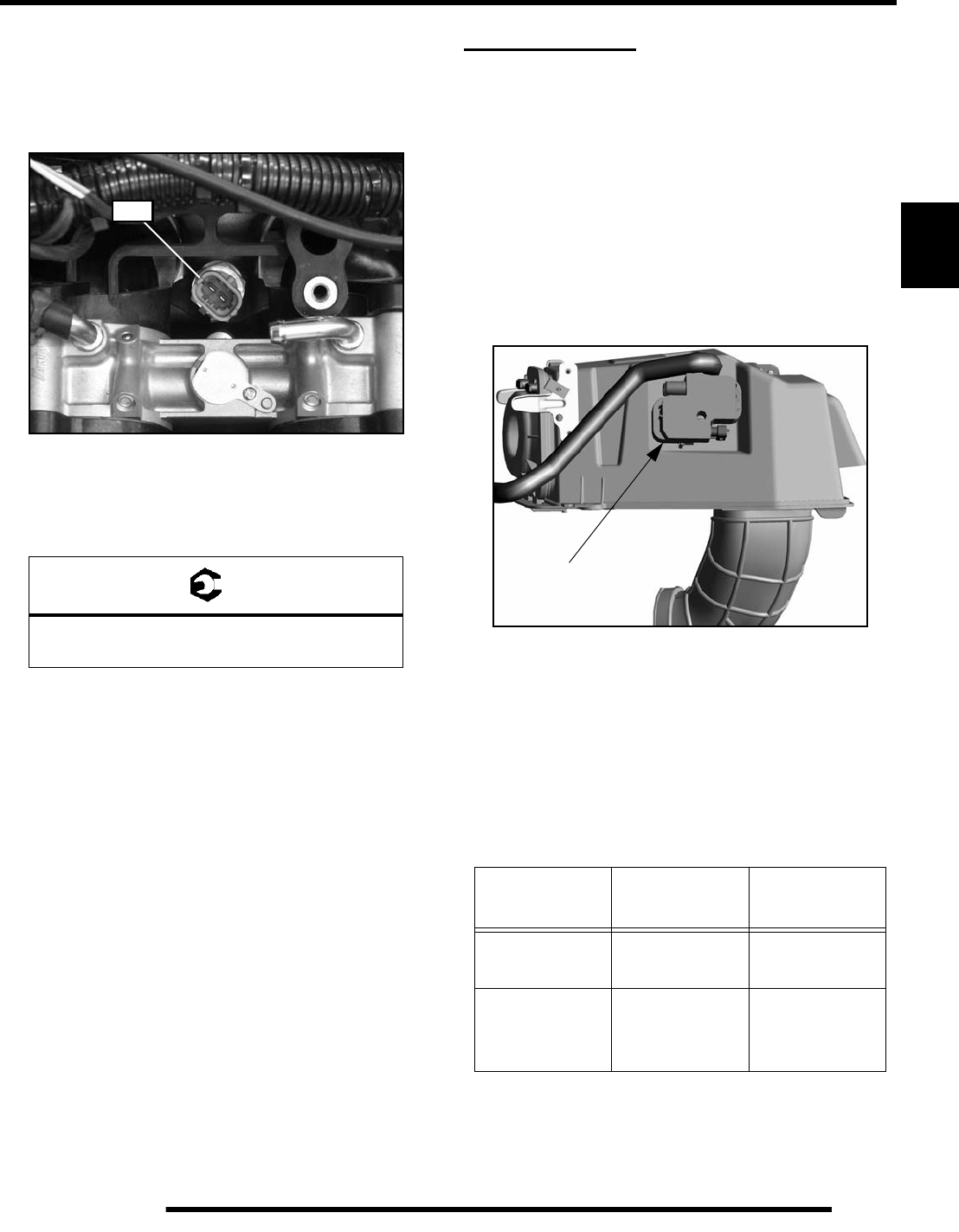
3.23
ELECTRONIC FUEL INJECTION
3
ECT Sensor Replacement
1. Drain coolant to level below sensor.
2. Disconnect the ECT sensor from engine harness. Remove
the T-MAP sensor to allow access to the ECT sensor.
3. Remove and replace the sensor, applying a light coating of
thread sealant to aid installation.
4. Torque the ECT sensor to specification.
IGNITION COIL
Operation Overview
The ignition coil is used to provide high voltage to fire the spark
plugs. When the ignition key is on, DC voltage is present in
primary side of the ignition coil windings. During engine
rotation, an AC pulse is created within the crankshaft position
sensor for each passing tooth on the flywheel. The two-tooth
gap creates an “interrupt” input signal, corresponding to specific
crankshaft position. This signal serves as a reference for the
control of ignition timing. The ECU then calculates the time
interval between the consecutive pulses, and determines when
to trigger the voltage spike that induces the voltage from the
primary to the secondary coil windings to fire the spark plugs.
Ignition Coil Tests
The ignition coil can be tested by using an ohm meter. Use the
following illustrations and specification table to test the ignition
coil.
Remove the seat and upper right-hand side panel to access the
ignition coil.
= T
ECT Sensor Torque:
17 ft. lbs. (23 Nm)
ECT
Ignition Coil Resistance Readings
Test Pin
Connection Resistance
Primary Between 1 & 2
Between 3 & 2 0.4 Ω
Secondary Between
High Tension
Lead Ends 5 k Ω
Ignition Coil
RH Side
of Airbox
PartShark.com
877-999-5686
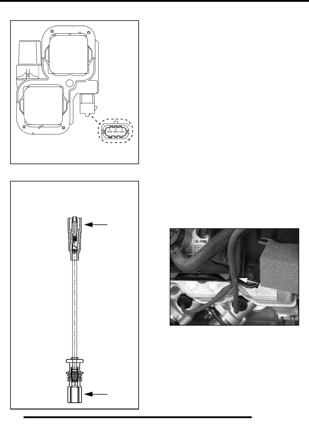
3.24
ELECTRONIC FUEL INJECTION
Primary Test
Secondary Test
Ignition Coil and HT Lead Replacement
NOTE: The plug caps or coil ends are not
removable. The high tension lead (coil wire) must be
replaced as an assembly.
1. Remove the seat and upper right-hand side panel to access
the ignition coil (see Chapter 9 “Seat and Side Panels”).
2. Disconnect the shift linkage and remove the high tension
lead caps from the spark plugs.
3. Remove the high tension leads from the airbox.
4. Disconnect the harness from the ignition coil.
5. Using a T20 driver, remove the screw retaining the ignition
coil to the airbox.
6. Remove the coil assembly and disconnect the high tension
leads by pulling on the coil side end caps.
7. Install the new high tension leads.
NOTE: Be sure to install the PTO (long) wire on the
coil terminal nearest the airbox.
8. Install the coil assembly and securely tighten the mounting
screw.
9. Upon assembly, make sure the high tension leads are
retained by the airbox.
10. Reinstall the shift linkage, upper right-hand side panel and
the seat.
Measure Between
Connector Pins 1 & 2, 2 & 3
0.4 Ω
Measure Between End Caps
MAG (Short) Wire: 1390 Ω ± 2 %
PTO (Long) Wire: 1545 Ω ± 2 %
PartShark.com
877-999-5686
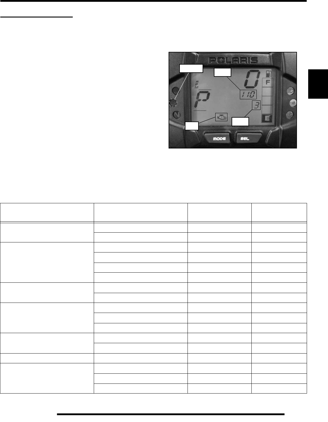
3.25
ELECTRONIC FUEL INJECTION
3
EFI DIAGNOSTICS
Instrument Cluster Trouble Code Display
Use the following procedure to display diagnostic trouble codes
logged in the ECU if the Check Engine (MIL) icon is
illuminated on the instrument cluster.
NOTE: In order to view the diagnostic codes on the
instrument cluster, the Check Engine (MIL) icon
must be illuminated.
1. Place the transmission in PARK.
2. Turn the ignition switch to the “ON” position.
3. Toggle through the LCD display using the “SELECT”
button until the Check Engine (MIL) icon begins flashing.
4. When the Check Engine (MIL) icon is flashing, a set of two
numbers will appear on the LCD.
5. The first number is located in the information area and can
be 2 to 6 digits in length. This number represents the
Suspect Parameter Number (SPN).
6. The second number is located in the clock area and can be
1 to 2 digits in length. This number represents the Failure
Mode Identifier (FMI).
7. Use the “Diagnostic Trouble Code Table” as a reference.
8. Press and hold the “MODE” button to cycle through all
currently active trouble codes.
NOTE: On vehicles equipped with power steering,
the power steering (MIL) LED will illuminate and
blink in place of the Check Engine (MIL) if there is a
diagnostic problem with the power steering system.
FMI
SPN
MIL
PS MIL
DIAGNOSTIC TROUBLE CODE TABLE
Component Condition SPN
Suspect Parameter Number
FMI
Failure Mode Indentifier
Throttle Position Sensor (TPS) Voltage Too High 51 3
Voltage Too Low 51 4
Engine Temperature Sensor (ECT)
Voltage Too High 110 3
Voltage Too Low 110 4
Temperature Too High 110 16
Engine Overheat Shutdown 110 0
Intake Air Temperature (T-MAP)
Voltage Too High 105 3
Voltage Too Low 105 4
Manifold Absolute Pressure Sensor
(T-MAP)
Voltage Too High 102 3
Voltage Too Low 102 4
Signal Out of Range 102 2
Crankshaft Position Sensor (CPS) Circuit Fault 636 8
Plausibility Fault 636 2
Vehicle Speed Signal Plausibility Fault 84 2
Gear Sensor Signal
Voltage Too Low 523 4
Voltage Too High 523 3
Signal Fault 523 2
PartShark.com
877-999-5686

3.26
ELECTRONIC FUEL INJECTION
Injector 1 (MAG)
Driver Circuit Open / Grounded 651 5
Driver Circuit Short to B+ 651 3
Driver Circuit Grounded 651 4
Injector 2 (PTO)
Driver Circuit Open / Grounded 652 5
Driver Circuit Short to B+ 652 3
Driver Circuit Grounded 652 4
Ignition Coil Primary Driver 1 (MAG) Driver Open / Grounded 1268 3
Ignition Coil Primary Driver 2 (PTO) Driver Circuit Short to B+ 1269 3
Fuel Pump Driver Circuit
Driver Circuit Open / Grounded 1347 5
Driver Circuit Short to B+ 1347 3
Driver Circuit Grounded 1347 4
Fan Relay Driver Circuit
Driver Circuit Open / Grounded 1071 5
Driver Circuit Short to B+ 1071 3
Driver Circuit Grounded 1071 4
Idle Air Control (IAC)
Driver Circuit Open / Grounded 634 5
Driver Circuit Short to B+ 634 3
Driver Circuit Grounded 634 4
Position Out of Range 634 7
Starter Enable Circuit
Driver Circuit Open / Grounded 1321 5
Driver Circuit Short to B+ 1321 3
Driver Circuit Grounded 1321 4
Chassis Relay
Driver Circuit Open / Grounded 520208 5
Driver Circuit Short to B+ 520208 3
Driver Circuit Grounded 520208 4
All Wheel Drive Control (AWD)
Driver Circuit Open / Grounded 520207 5
Driver Circuit Short to B+ 520207 3
Driver Circuit Grounded 520207 4
System Power Voltage Too High 168 3
Voltage Too Low 168 4
Throttle Safety Signal
Voltage Too High 520194 3
Voltage Too Low 520194 4
Signal Out of Range 520194 2
Throttle Stuck 520194 7
Active Descent Control (ADC)
Driver Circuit Open / Grounded 520203 5
Driver Circuit Short to B+ 520203 3
Driver Circuit Grounded 520203 4
DIAGNOSTIC TROUBLE CODE TABLE
Component Condition SPN
Suspect Parameter Number
FMI
Failure Mode Indentifier
PartShark.com
877-999-5686

3.27
ELECTRONIC FUEL INJECTION
3
Idle Speed Speed Too High 520211 3
Speed Too Low 520211 4
Calibration Checksum/CRC Error 630 13
Steering Over Current Shut Down Current Above Normal or Grounded 520221 6
Steering Excessive Current Error Current Above Normal or Grounded 520222 6
Steering Torque or Speed Sensor
Partial Failure Condition Exists 520223 31
Steering Torque or Speed Sensor
Full Failure Condition Exists 520224 31
EPAS Inverter Temperature Greater than 110° C (230° F) 520225 16
Greater than 120° C (248° F) 520225 0
EPAS CAN Communications
Receive Error No RX Message for 2 Seconds 520226 2
EPAS CAN Communications
Transmit Error No TX Message for 2 Seconds 520227 2
Vehicle Speed (This is applicable
when the EPAS module gets the
vehicle speed from the ECM)
Received Vehicle Speed Has Error 84 19
Engine Speed (This is applicable
when the EPAS module gets the
engine speed from the ECM)
Received Engine Speed Has Error 190 19
Battery Voltage Too High 168 3
Too Low 168 4
Position Encoder Error 520228 11
EPAS Software Error
Software Error Illegal Memory Access 520229 12
Software Error Stack Overrun 520229 12
Software Error Illegal Peripheral
Interrupt 520229 12
IC CAN Communication with EPAS EPAS Off Line (EPAS DM1 not seen) 520230 31
EEProm: Read/Write Failure 628 12
DIAGNOSTIC TROUBLE CODE TABLE
Component Condition SPN
Suspect Parameter Number
FMI
Failure Mode Indentifier
PartShark.com
877-999-5686

3.28
ELECTRONIC FUEL INJECTION
FUEL SYSTEM TROUBLESHOOTING
Fuel Starvation / Lean Mixture
Symptoms: Hard start or no start, bog, backfire, popping
through intake / exhaust, hesitation, detonation, low power,
spark plug erosion, engine runs hot, surging, high idle, idle
speed erratic.
• No fuel in tank
• Restricted tank vent, or routed improperly
• Fuel lines or fuel injectors restricted
• Fuel pump inoperative
• Air leak in system
• Intake air leak (throttle shaft, intake boot, gasket or
grommet)
• Throttle stop screw tampering
• Failed sensor or disconnected wiring
Rich Mixture
Symptoms: Fouls spark plugs, black, sooty exhaust smoke,
rough idle, poor fuel economy, engine runs rough/ misses, poor
performance, bog, engine loads up, backfire.
• Air intake restricted (inspect intake duct)
• Air filter dirty/plugged
• Poor fuel quality (old fuel)
• Fouled spark plug
• TPS setting incorrect
• Injector failure
• Failed sensor or disconnected wiring
• Throttle stop screw tampering
Poor Idle
Symptom: Idle Too High (If greater than 1400 RPM when
engine is warm)
• Throttle stop screw tampering
• Throttle cable sticking, improperly adjusted, routed
incorrectly
• Failed sensor or disconnected wiring
• IAC stuck or inoperative
• Intake air leak
Symptom: Idle Too Low (if less than 1100 RPM when engine
is warm)
• Plugged air filter
• Leaking injector (rich condition)
• Belt dragging
• Throttle stop screw tampering
• Failed sensor or disconnected wiring
Symptom: Erratic Idle
• Throttle cable incorrectly adjusted
• Air Leaks, dirty injector
• TPS damaged or misadjusted
• Tight valves
• Belt dragging
• Dirty air cleaner
•Engine worn
• Spark Plug fouled
• Throttle stop screw tampering
• Failed sensor or disconnected wiring
The correct position of the throttle body
stop screw is established and set at the
factory. DO NOT remove the tamper proof
cap to adjust the throttle body stop screw or
alter its position in any manner. The stop
screw controls the air flow calibration
of the throttle body.
PartShark.com
877-999-5686
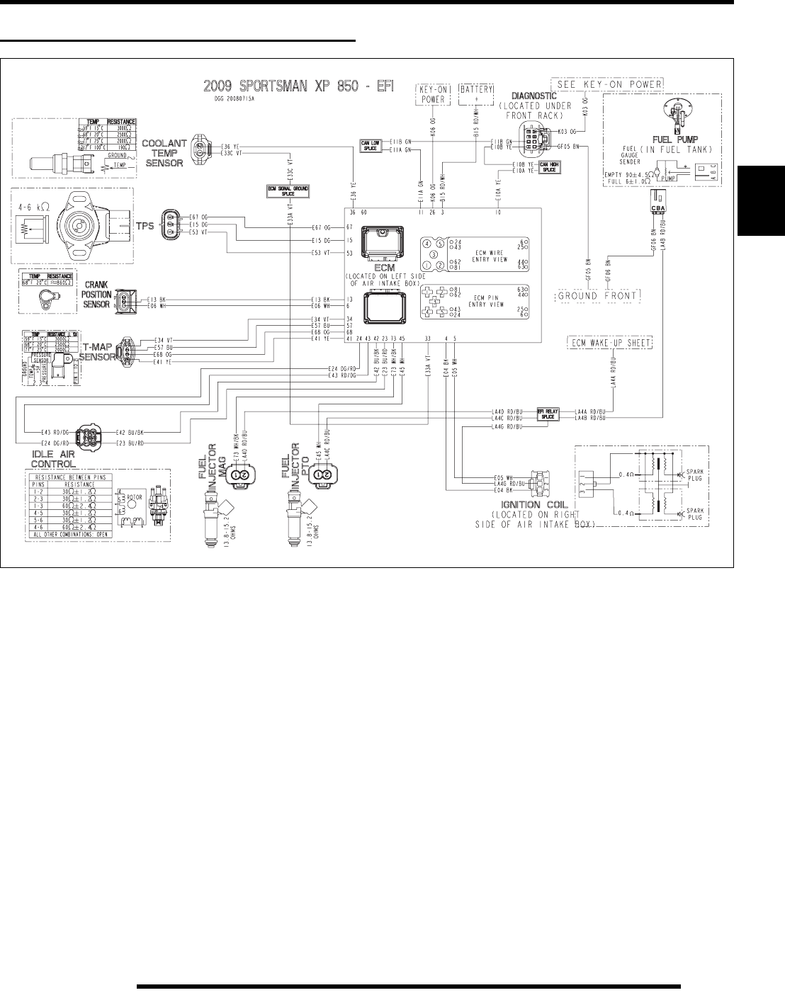
3.29
ELECTRONIC FUEL INJECTION
3
EFI SYSTEM BREAK-OUT DIAGRAMS
PartShark.com
877-999-5686
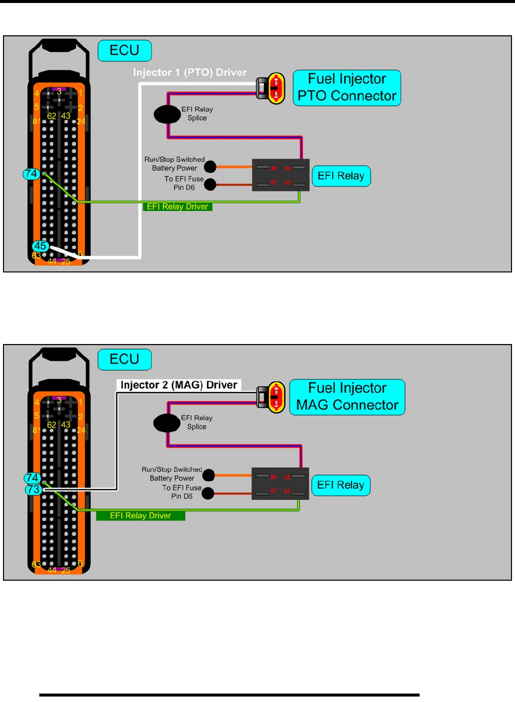
3.30
ELECTRONIC FUEL INJECTION
Fuel Injector Circuit (PTO)
Fuel Injector Circuit (MAG)
PartShark.com
877-999-5686
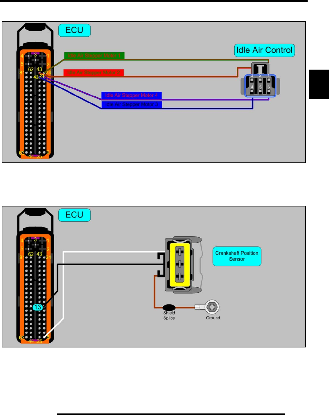
3.31
ELECTRONIC FUEL INJECTION
3
Idle Air Control (IAC) Circuit
Crankshaft Position Sensor (CPS) Circuit
PartShark.com
877-999-5686
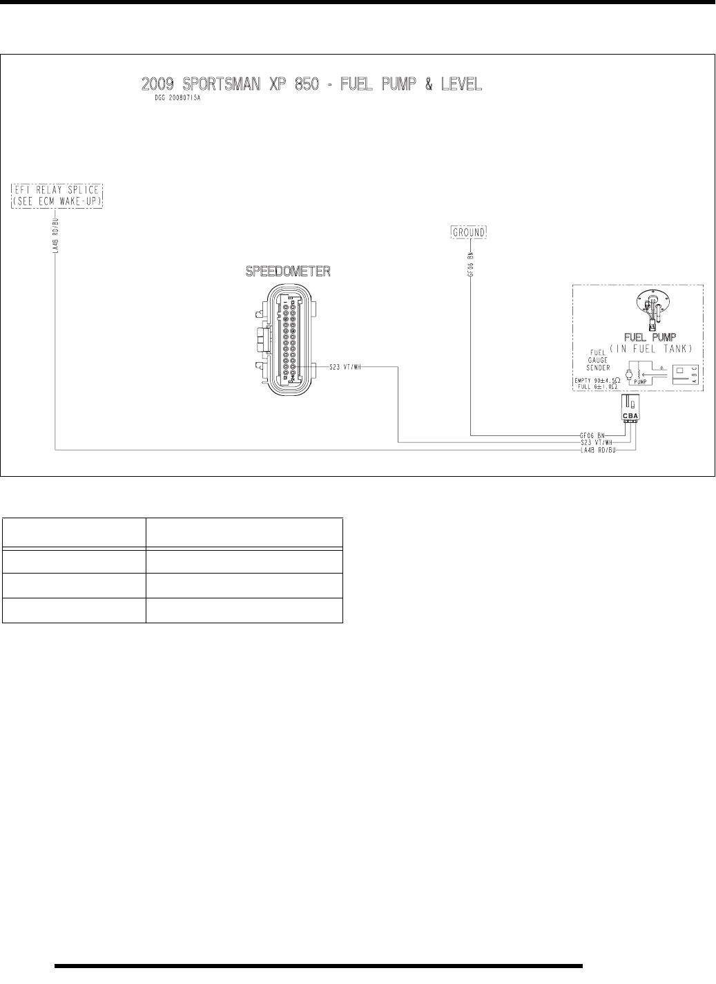
3.32
ELECTRONIC FUEL INJECTION
Fuel Pump / Fuel Level Sensor Circuit
Wire Color Functions
Wire Color Function
BROWN Ground
VT / WHT Fuel Level Sender Signal
RED / BLUE EFI Relay Output Battery Voltage
PartShark.com
877-999-5686
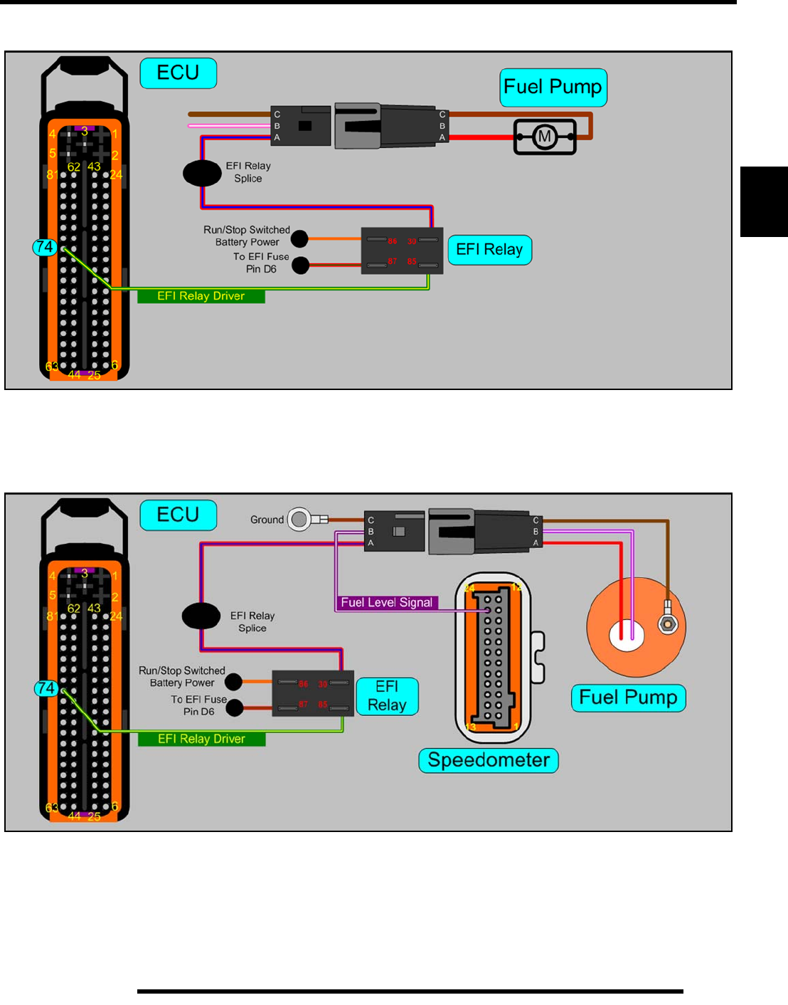
3.33
ELECTRONIC FUEL INJECTION
3
Fuel Pump Circuit
Fuel Gauge Circuit
PartShark.com
877-999-5686
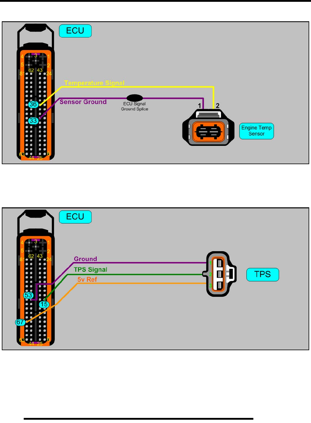
3.34
ELECTRONIC FUEL INJECTION
Engine Coolant Temperature Sensor (ECT) Circuit
Throttle Position Sensor (TPS) Circuit
PartShark.com
877-999-5686
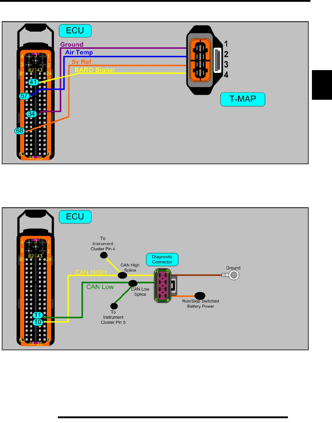
3.35
ELECTRONIC FUEL INJECTION
3
Intake Air Temperature / Manifold Absolute Pressure Sensor (T-MAP) Circuit
Diagnostic Connector Circuit
PartShark.com
877-999-5686
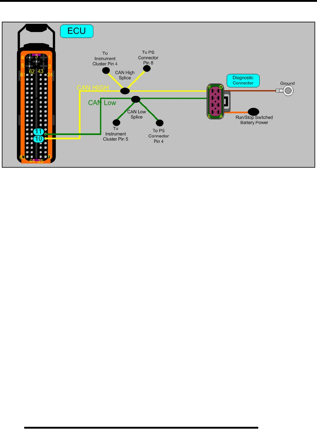
3.36
ELECTRONIC FUEL INJECTION
Diagnostic Connector Circuit (EPS Models)
PartShark.com
877-999-5686

4.1
CHAPTER 4
COOLING SYSTEM
4
COOLING SYSTEM
SPECIAL TOOLS . . . . . . . . . . . . . . . . . . . . . . . . . . . . . . . . . . . . . . . . . . . . . . . . . . . . . . . 4.2
TORQUE SPECIFICATIONS. . . . . . . . . . . . . . . . . . . . . . . . . . . . . . . . . . . . . . . . . . . . . . . 4.2
COOLING SYSTEM. . . . . . . . . . . . . . . . . . . . . . . . . . . . . . . . . . . . . . . . . . . . . . . . . . . . . . 4.2
COOLING SYSTEM LAYOUT AND TESTING. . . . . . . . . . . . . . . . . . . . . . . . . . . . . . . . . 4.2
COOLING SYSTEM SPECIFICATIONS. . . . . . . . . . . . . . . . . . . . . . . . . . . . . . . . . . . . . . 4.3
COOLING SYSTEM BLEEDING PROCEDURE . . . . . . . . . . . . . . . . . . . . . . . . . . . . . . . 4.4
RADIATOR . . . . . . . . . . . . . . . . . . . . . . . . . . . . . . . . . . . . . . . . . . . . . . . . . . . . . . . . . . . . 4.4
RADIATOR CLEANING . . . . . . . . . . . . . . . . . . . . . . . . . . . . . . . . . . . . . . . . . . . . . . . . . . 4.4
COOLANT DRAIN / RADIATOR REMOVAL . . . . . . . . . . . . . . . . . . . . . . . . . . . . . . . . . . 4.4
WATER PUMP SERVICE . . . . . . . . . . . . . . . . . . . . . . . . . . . . . . . . . . . . . . . . . . . . . . . . . 4.6
WATER PUMP IMPELLER REMOVAL . . . . . . . . . . . . . . . . . . . . . . . . . . . . . . . . . . . . . . 4.6
WATER PUMP MECHANICAL SEAL REPLACEMENT. . . . . . . . . . . . . . . . . . . . . . . . . . 4.7
WATER PUMP SHAFT & BEARING REPLACEMENT . . . . . . . . . . . . . . . . . . . . . . . . . . 4.8
STATOR COVER INSTALLATION. . . . . . . . . . . . . . . . . . . . . . . . . . . . . . . . . . . . . . . . . . 4.9
WATER PUMP ASSEMBLY / TORQUE SPECIFICATIONS . . . . . . . . . . . . . . . . . . . . . 4.10
STATOR COVER ASSEMBLY TORQUE SPECIFICATIONS . . . . . . . . . . . . . . . . . . . . 4.11
THERMOSTAT . . . . . . . . . . . . . . . . . . . . . . . . . . . . . . . . . . . . . . . . . . . . . . . . . . . . . . . . 4.12
REMOVAL / INSTALLATION . . . . . . . . . . . . . . . . . . . . . . . . . . . . . . . . . . . . . . . . . . . . . 4.12
TROUBLESHOOTING. . . . . . . . . . . . . . . . . . . . . . . . . . . . . . . . . . . . . . . . . . . . . . . . . . . 4.12
PartShark.com
877-999-5686
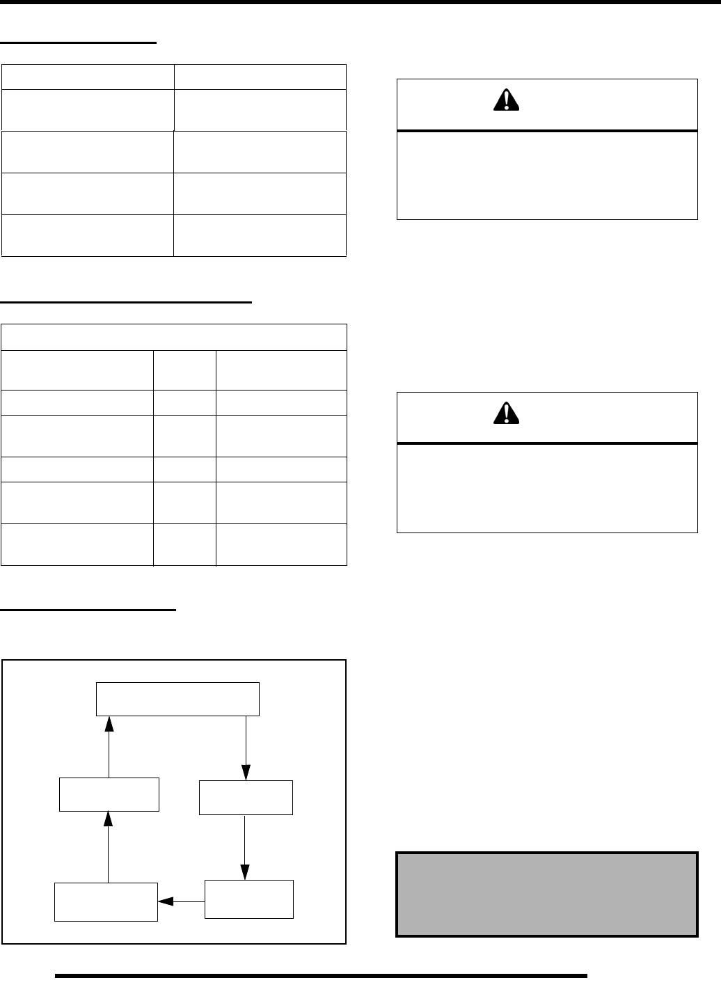
4.2
COOLING SYSTEM
SPECIAL TOOLS
TORQUE SPECIFICATIONS
COOLING SYSTEM
Cooling System Layout and Testing
Cooling System Pressure Test
1. Remove the front rack (see Chapter 9 “Front Rack”).
2. Remove the pressure cap from the radiator and pressure test
the cooling system using a commercially available tester.
3. The system must retain 10 psi for five minutes or longer.
If pressure loss is evident within five minutes, check the
radiator, all cooling system hoses, hose clamps and water
pump seal for leakage.
Radiator Cap Pressure Test
1. Remove radiator pressure cap and test using a cap tester
(commercially available).
2. The radiator cap relief pressure is 13 lbs. Replace cap if it
does not meet this specification.
Recommended Coolant
Use only high quality antifreeze/coolant mixed with distilled
water in a 50/50 or 60/40 ratio, depending on freeze protection
required in your area.
IMPORTANT: Using tap water in the cooling system
will lead to a buildup of deposits which may restrict
coolant flow and reduce heat dissipation, resulting in
possible engine damage. Polaris Premium 60/40
Antifreeze/Coolant is recommended for use in all
cooling systems, and comes pre-mixed and ready to
use.
PART NUMBER TOOL DESCRIPTION
2870975 Mity Vac™ Pressure
Test Tool
PA-44995-A Water Pump
Mechanical Seal Installer
PA-49378 Water Pump Bearing and
Coupler Press Tool
PA-49316 Water Pump Drive Nut /
Flywheel Puller
TORQUE SPECIFICATIONS
Fastener Size EH085OLE
Torque
Thermostat Housing 6 mm 89 in. lbs. (10 Nm)
Water Pump
Impeller Bolt 6 mm 10 ft. lbs. (13.5 Nm)
Water Pump Cover 6 mm 89 in. lbs. (10 Nm)
Engine Temperature
Sensor (ECT) 3/8 NPT 17 ft. lbs. (23 Nm)
Stator / Magneto
Cover Bolts 6 mm 89 in. lbs. (10 Nm)
Radiator
Water Pump
Cylinder
Thermostat
FLOW
Cylinder
Head
WARNING
Never remove radiator cap when engine is
warm or hot. The cooling system is under
pressure and serious burns may result.
Allow the engine and cooling system to
cool before servicing.
WARNING
Never remove radiator cap when engine is
warm or hot. The cooling system is under
pressure and serious burns may result.
Allow the engine and cooling system to
cool before servicing.
Polaris Premium Antifreeze
2871534 - Quart
2871323 - Gallon
PartShark.com
877-999-5686
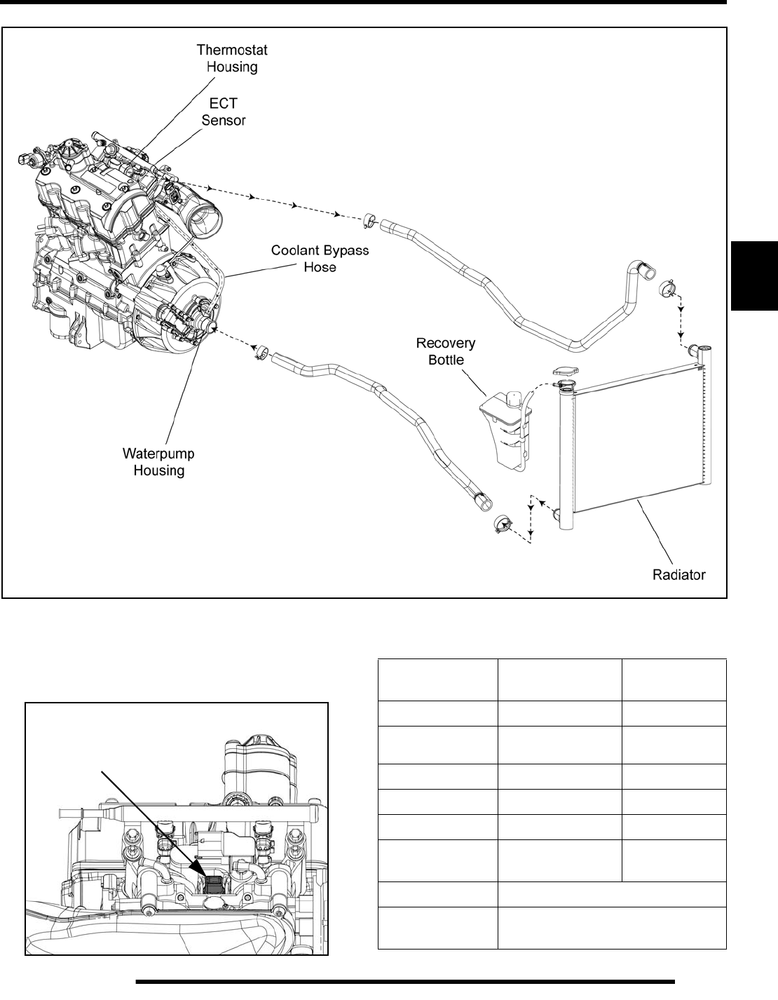
4.3
COOLING SYSTEM
4
Cooling System Specifications
The engine coolant temperature sensor is located in the engine
cylinder head below the thermostat housing (see Chapter 3 for
further information).
850cc ENGINE COOLANT FLOW
ECT Sensor
17 ft. lbs.
(23 Nm)
Resistance Reading @ Idle
Condition Approx. Reading
(Ohms) Temperature
Engine Shut Off 70 Ω ± 3% 284° F (140° C)
Hot Lamp On
(engine misfire above idle) 90 Ω ± 3% 266° F (130° C)
Hot Lamp Blinking 100 Ω ± 3% 257° F (125° C)
Fan On 215 Ω ± 3% 203° F (95° C)
Fan Off 240 Ω ± 3% 192° F (89° C)
Room
Temperature 2.5k Ω ± 3% 68° F (20° C)
System Capacity 2 qts. (1.9 l)
Radiator Cap
Relief Pressure 13 PSI
PartShark.com
877-999-5686
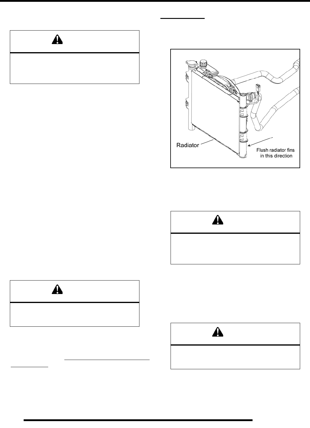
4.4
COOLING SYSTEM
Cooling System Bleeding Procedure
1. Place the vehicle in PARK.
2. Remove the front rack to access the radiator pressure cap
and recovery bottle.
3. Remove the pressure cap and top off coolant. Leave the
pressure cap off at this point.
4. Remove recovery bottle fill cap and fill the bottle to the
“MAX” line. Reinstall the recovery bottle cap.
NOTE: If the coolant level is LOW in the radiator, or
if there are leaks in the system, the coolant system
will not draw coolant from the recovery bottle.
5. Start the engine and allow it to idle for 5-10 minutes until
the thermostat opens and allows coolant to travel through
the entire system.
NOTE: When the thermostat opens the radiator
coolant level will drop significantly.
6. Squeeze the coolant lines to help purge the system of air.
7. With the engine still idling, top off the radiator with Polaris
Premium Antifreeze. If no air bubbles are seen at the
radiator filler neck, the system should be purged of air.
8. Reinstall the radiator pressure cap
9. Stop the engine and allow it to cool. Top off the radiator
with coolant. If you hear or see a “glug” at the filler neck
or the coolant level drops indicating that coolant has been
pulled into the system, fill the radiator first before filling the
recovery bottle.
10. Any air remaining in the system should continue to bleed
out through the recovery bottle
11. Repeat this procedure if you are still having difficulty
bleeding the system.
RADIATOR
Radiator Cleaning
1. Check radiator air passages for restrictions or damage.
2. Carefully straighten any bent radiator fins.
3. Remove any obstructions with compressed air or low
pressure water.
Coolant Drain / Radiator Removal
Coolant Drain
1. Remove the front rack to access the pressure cap (see
Chapter 9 “Front Rack”).
2. Slowly remove the pressure cap to relieve any cooling
system pressure.
3. Place a suitable drain pan underneath the radiator on the
right-hand side of the vehicle.
CAUTION
Be sure the engine has cooled and there is no
pressure built up in the cooling system before
removing the radiator cap. The coolant may be
hot and could cause severe injury or burns.
WARNING
Be sure to install the radiator pressure
cap before shutting off the engine.
Coolant may spit out of the radiator.
CAUTION
Washing the vehicle with a high-pressure
washer could damage the radiator fins and
impair the radiators effectiveness. Use of a
high-pressure washer is not recommended.
WARNING
Never drain the coolant when the engine and
radiator are warm or hot. Hot coolant can cause
severe burns. Allow engine and radiator to cool.
PartShark.com
877-999-5686
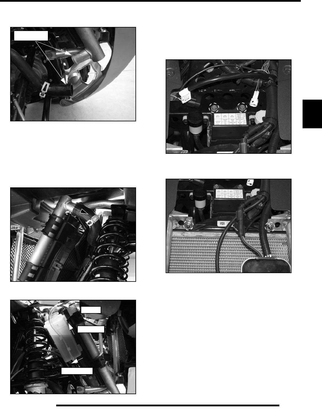
4.5
COOLING SYSTEM
4
4. Drain the coolant from the radiator by removing the coolant
hose from the lower right-hand portion of the radiator.
5. Completely drain the coolant and properly dispose of it.
Radiator Removal
1. Drain coolant from the radiator (see previous procedure).
2. Remove the front rack (see Chapter 9 “Front Rack”).
3. Remove the hose from the left-hand portion of the radiator.
4. Remove the recovery bottle return line from the radiator.
5. Carefully pull rearward on the lower portion of the recovery
bottle to disengage the lower tab. Then lift up on the bottle
and remove it from the radiator fan shroud.
6. Remove the (2) screws retaining the fuse/relay box to the
frame to allow enough room for the radiator to tilt back
during removal.
7. Remove the (2) fasteners retaining the upper portion of the
radiator to the frame.
8. Disconnect the fan motor.
9. Tilt the radiator back and lift upward to allow the lower
grommets to clear the frame support holes. Remove the
radiator from the vehicle out the right-hand side through the
wheel well. Take care not to damage the cooling fins during
removal.
10. Reverse procedure for installation. When installing the
recovery bottle, insert the upper portion of the bottle into
the shroud first, then push the lower tab on the bottle into
the shroud until it snaps into place.
11. After installation and reassembly, remove the pressure cap
and fill the radiator and recovery bottle with coolant.
12. Refer to the “Cooling System Bleeding Procedure” in this
chapter.
Drain Here
1st- Pull Back
2nd- Lift Up
Remove
PartShark.com
877-999-5686
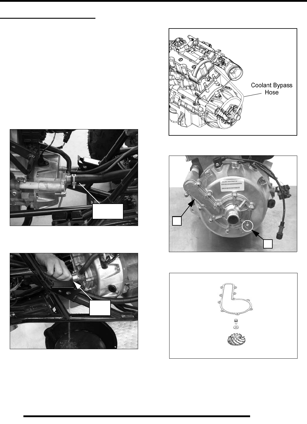
4.6
COOLING SYSTEM
WATER PUMP SERVICE
Water Pump Impeller Removal
NOTE: The water pump impeller, mechanical seal,
drive coupler, pump shaft, and pump shaft bearing
can be serviced without removing the engine.
1. Remove the fuel tank (see Chapter 3).
2. Remove the (4) screws retaining the engine skid plate and
remove the plate from the vehicle.
3. Place a drain pan under the front portion of the engine.
4. Slide the spring clamp back and remove the coolant inlet
hose from the water pump housing.
5. Slowly drain the coolant into the drain pan. Dispose of used
coolant properly.
6. Remove the coolant by-pass hose from the water pump
cover fitting.
7. Remove the (10) cover screws (A) and pump cover (B).
8. Remove gasket, impeller bolt, washer, and impeller.
Coolant
Inlet Hose
Drain
HERE
A
B
Shown with engine
removed for clarity.
PartShark.com
877-999-5686
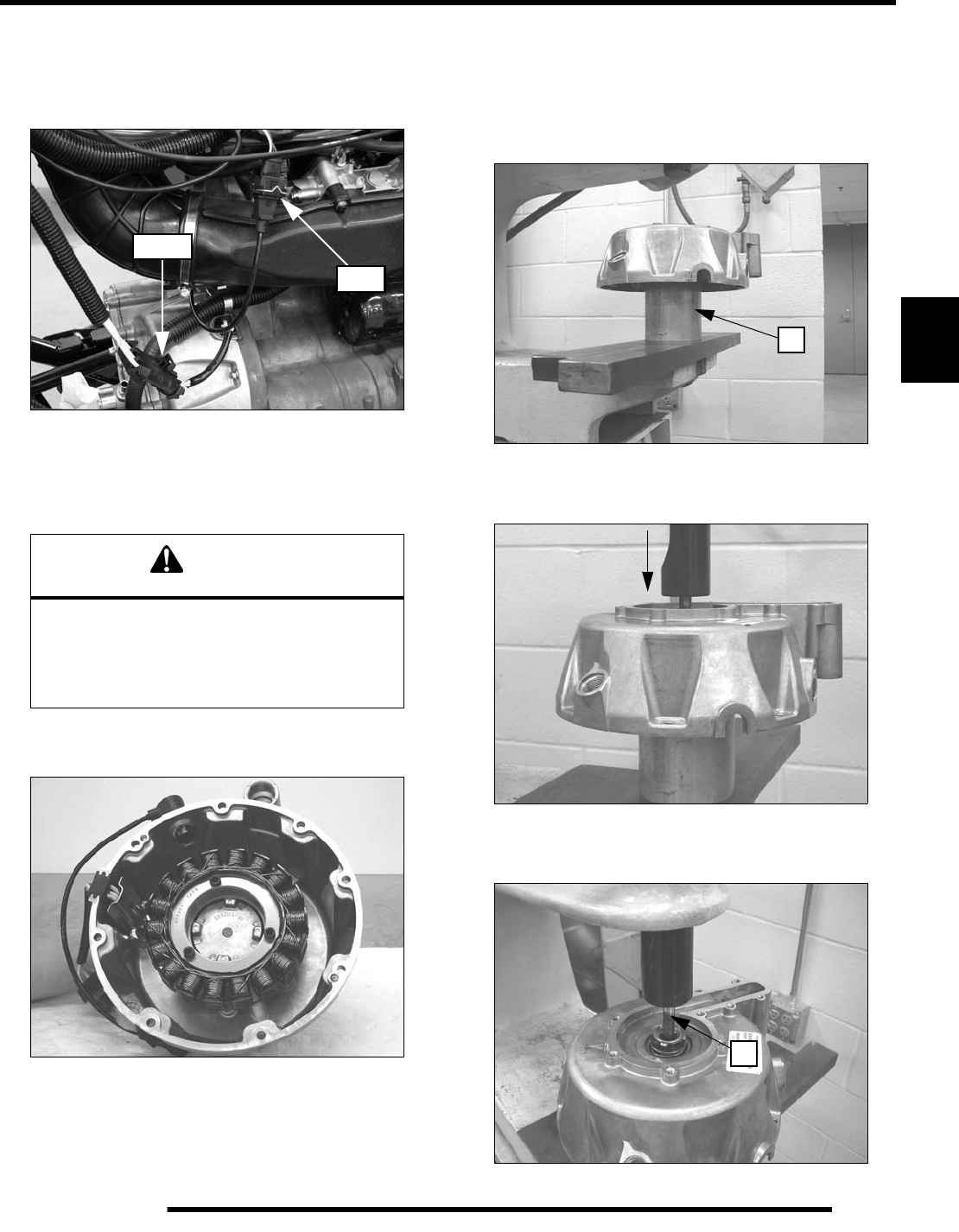
4.7
COOLING SYSTEM
4
Water Pump Mechanical Seal Replacement
Perform the “Water Pump Impeller Removal” procedure.
1. Disconnect the stator and CPS wire harnesses.
2. Remove the (8) stator cover screws.
3. Carefully remove the stator cover taking care not to damage
the plastic coolant pipe.
4. Remove the CPS, stator wire guide, and stator from the
cover.
5. Support the stator cover by the stator mounting boss, using
an aluminum or PVC pipe section or other suitable support
block (C) positioned inside the stator housing as shown.
Do not attempt to press water pump shaft out of stator
housing without first supporting the cover by the stator
boss, or cover may be damaged.
6. Press shaft down until flush with end of mechanical seal or
until the seal spring starts to compress.
7. Select a suitable arbor (D) and press the shaft through the
seal until the shaft assembly is removed.
CAUTION
The flywheel contains powerful magnets. Use
caution when removing the stator cover.
DO NOT place fingers between cover and
crankcase at any time during the removal
process or injury could result.
Stator
CPS
C
D
PartShark.com
877-999-5686
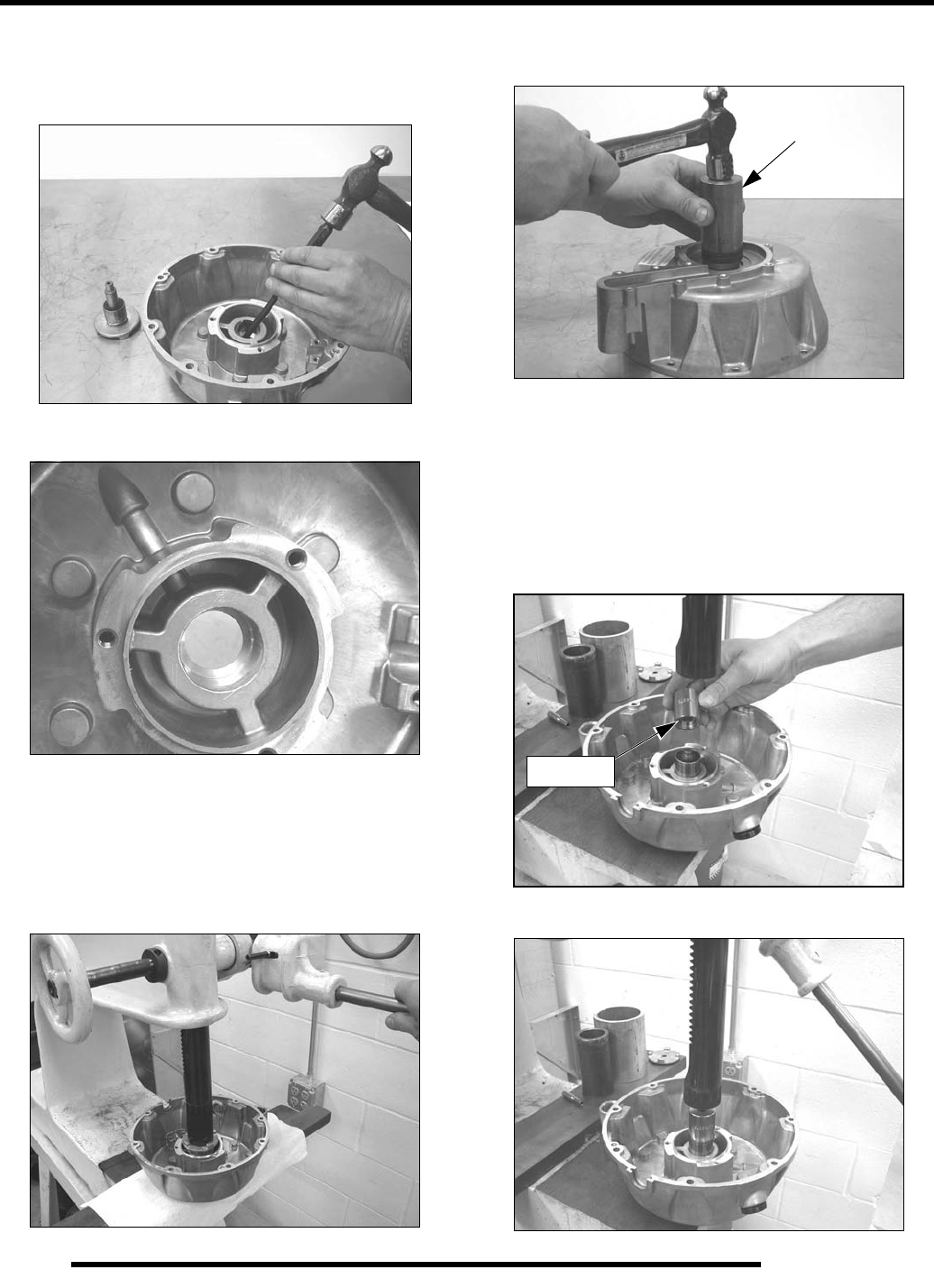
4.8
COOLING SYSTEM
Water Pump Mechanical Seal Replacement (Cont.)
8. Protect water pump cover gasket surface and turn cover
over. Drive mechanical seal out from stator side of cover.
9. Clean housing thoroughly.
If pump shaft assembly (shaft, drive coupler hub, and bearing(
is in good condition, proceed to the next step. If any of these
parts require replacement, refer to the “Water Pump Coupler
Shaft & Bearing Replacement” procedure.
10. Press pump shaft / bearing assembly into housing until
firmly seated.
11. Turn cover over and drive new mechanical seal squarely
into housing using seal installer.
12. Install impeller. Torque bolt to 10 lb-ft. (13.5 Nm)
13. Rotate impeller and check for smooth rotation.
Water Pump Shaft & Bearing Replacement
1. Press new shaft / bearing assembly from kit into cover
from stator side as shown, using the recessed end of
Bearing and Coupler Press Tool PA-49378.
2. Press until bearing is fully seated in cover.
PA-44995-A
PA-49378
PartShark.com
877-999-5686
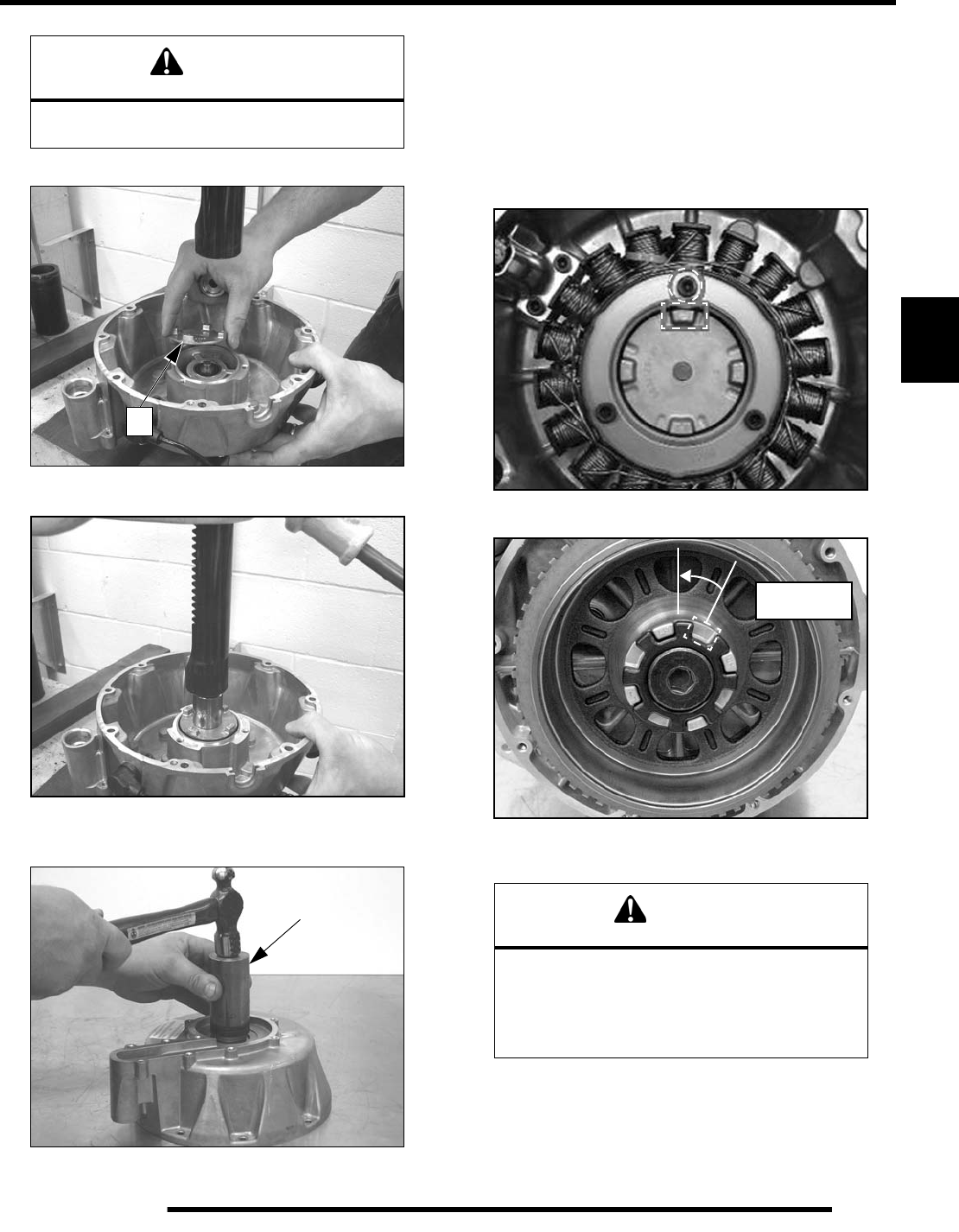
4.9
COOLING SYSTEM
4
3. Install new coupler hub (A) from kit onto shaft.
4. Press coupler squarely onto shaft until fully seated.
5. Turn cover over and drive new mechanical seal squarely
into housing using seal installer.
6. Install impeller. Torque bolt to 10 lb-ft. (13.5 Nm).
7. Rotate impeller and check for smooth rotation.
8. Refer to the following pages for water pump assembly and
torque information.
Stator Cover Installation
1. Orientate the pump shaft tab to line up with the stator
mounting bolt closest to the CPS sensor.
2. Rotate flywheel so coupler nut slot is in the 12:00 position.
3. Install new O-rings on the plastic coolant pipe. Lubricate
the O-rings with P80 (rubber lubricant) or lithium grease.
4. Carefully install the stator cover.
5. Check the water pump coupler engagement by turning the
impeller bolt with a ratchet and 10 mm deep-well socket.
6. Refer to the following pages for stator cover assembly and
torque information.
CAUTION
Be sure bearing is fully seated in cover after
Step 2, or severe crankshaft damage will result.
A
PA-44995-A CAUTION
The flywheel contains powerful magnets. Use
caution when installing the stator cover.
DO NOT place fingers between cover and
crankcase at any time during the installation
process or injury could result.
Rotate slot to
12:00 position
PartShark.com
877-999-5686
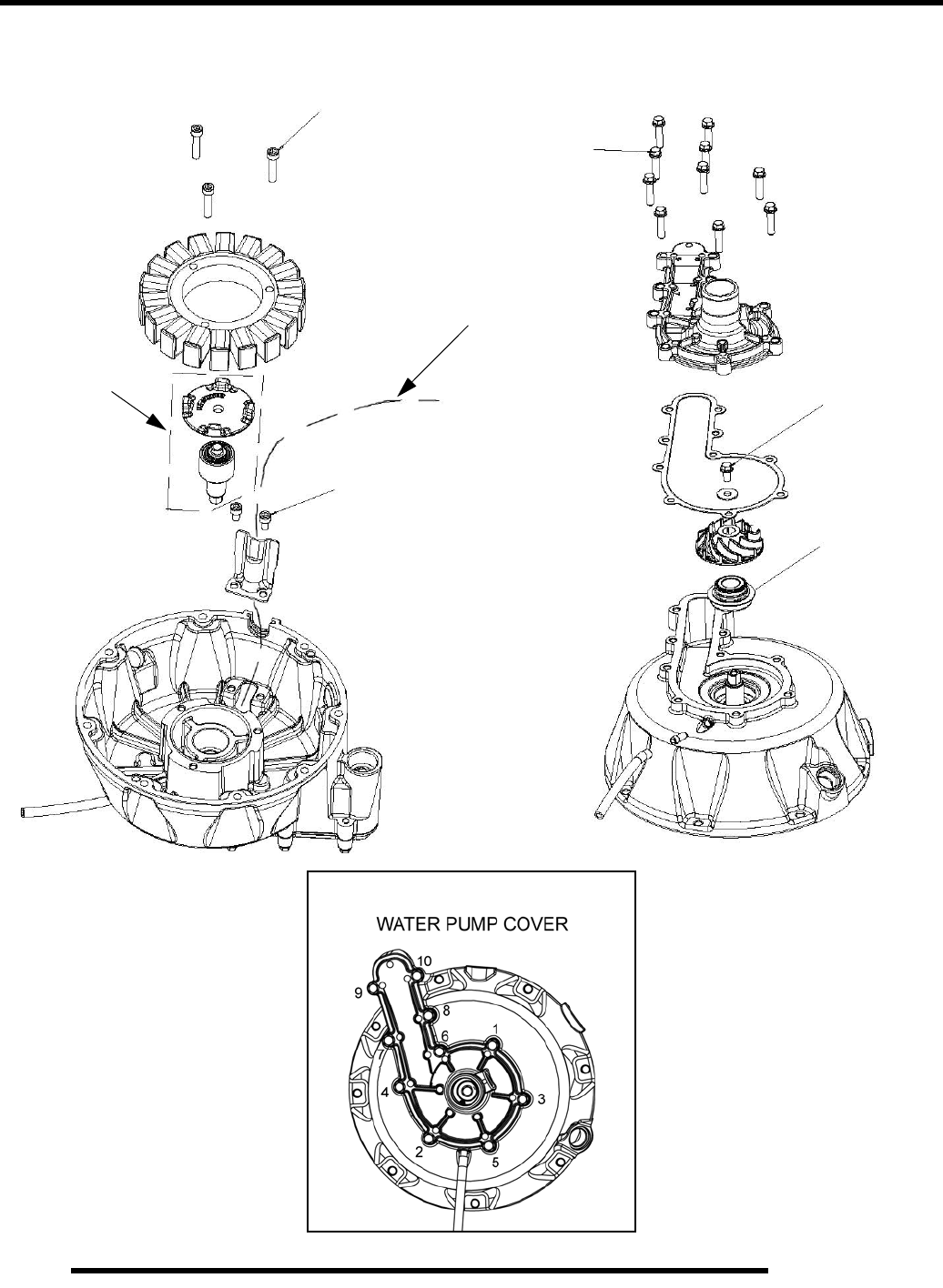
4.10
COOLING SYSTEM
Water Pump Assembly / Torque Specifications
10 ft. lbs.
89 in. lbs. (10 Nm)
Stator wire routing
See procedure
89 in. lbs. (10 Nm)
(13.5 Nm)
89 in. lbs. (10 Nm)
See procedure
TORQUE SEQUENCE
PartShark.com
877-999-5686
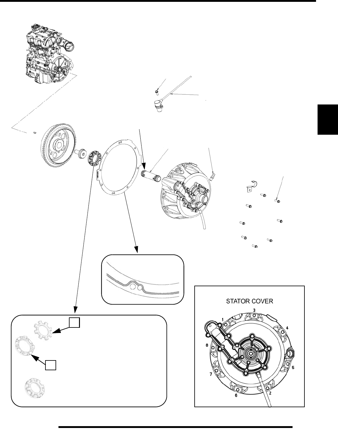
4.11
COOLING SYSTEM
4
Stator Cover Assembly Torque Specifications
Use weather strip or contact cement
to hold damper rubber (A) on water
pump coupler nut (B) during stator
cover installation.
A
B
Crankshaft Position Sensor (CPS)
89 in. lbs.
(10 Nm)
Coolant
Fitting
1/8 NPTF
Coolant
Pipe
TORQUE SEQUENCE
89 in. lbs.
(10 Nm)
Lubricate
New O-Rings
PartShark.com
877-999-5686
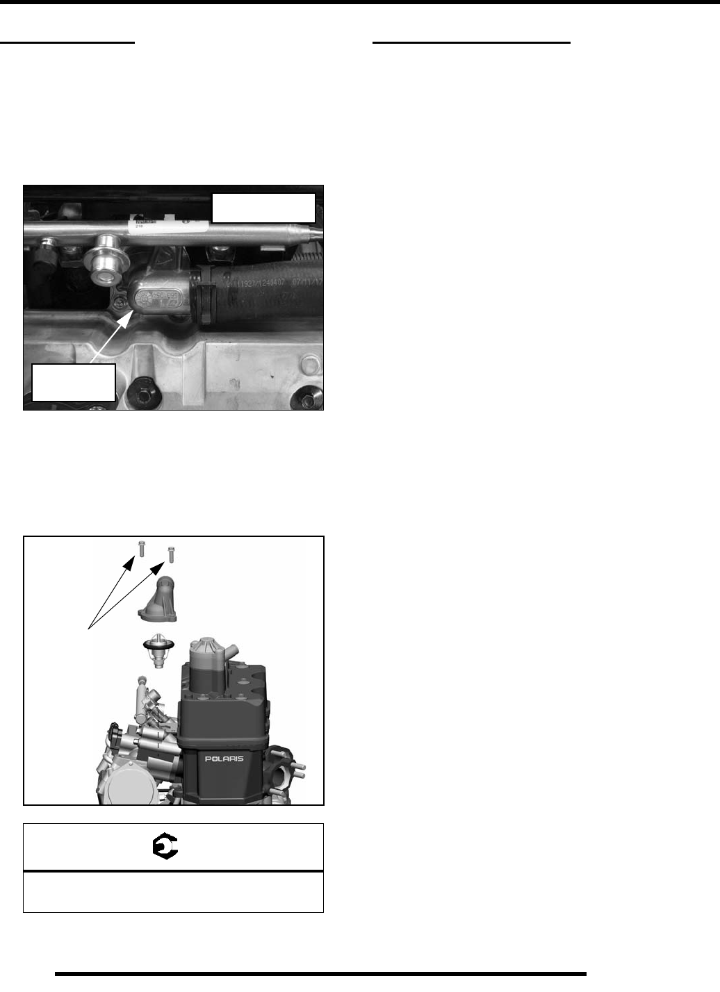
4.12
COOLING SYSTEM
THERMOSTAT
Removal (Engine Installed)
1. Drain coolant so the coolant level is below the thermostat
housing (see “Coolant Drain / Radiator Removal”).
2. Remove the (2) screws from the rear portion of the air box.
3. Locate the thermostat housing on the left side of the valve
cover next to the fuel rail.
4. Remove the (2) screws and lift the housing up far enough
to remove the thermostat with the coolant line still attached.
Installation
1. Install the thermostat, thermostat cover, and the (2) screws.
Torque screws to specification.
2. If servicing while the engine is in the vehicle, perform the
“Cooling System Bleeding Procedure”.
TROUBLESHOOTING
Cooling System
Overheating
• Low coolant level
• Air in cooling system
• Wrong type/mix of coolant
• Faulty pressure cap or system leaks
• Restricted system (mud or debris in radiator fins
causing restriction to air flow, passages blocked in
radiator, lines, pump, or water jacket, accident damage)
• Lean mixture (fuel system restriction)
• Fuel pump output weak
• Electrical malfunction
• Water pump failure/ Loose impeller
• Engine Coolant Temperature Sensor failure
• Cooling fan inoperative or turning too slowly (perform
current draw test)
• Low oil level
• Spark plug incorrect heat range
• Faulty hot lamp circuit
• Thermostat stuck closed or not opening completely
Temperature Too Low
• Thermostat stuck open
Leak at Water Pump Weep Hole
• Faulty water pump mechanical seal
• Worn pump shaft or pump shaft bearing
= T
Thermostat Housing Screws:
89 in. lbs. (10 Nm)
Thermostat
Shown with air box
removed for clarity.
Housing
89 in. lbs.
(10 Nm)
PartShark.com
877-999-5686

5.1
CHAPTER 5
ENGINE
5
ENGINE
GENERAL INFORMATION - ENGINE. . . . . . . . . . . . . . . . . . . . . . . . . . . . . . . . . . . . . . . . 5.3
SPECIAL TOOLS . . . . . . . . . . . . . . . . . . . . . . . . . . . . . . . . . . . . . . . . . . . . . . . . . . . . . . . 5.3
ENGINE LUBRICATION SPECIFICATIONS . . . . . . . . . . . . . . . . . . . . . . . . . . . . . . . . . . 5.3
OIL PRESSURE TEST. . . . . . . . . . . . . . . . . . . . . . . . . . . . . . . . . . . . . . . . . . . . . . . . . . . 5.3
OIL FLOW DIAGRAM. . . . . . . . . . . . . . . . . . . . . . . . . . . . . . . . . . . . . . . . . . . . . . . . . . . . 5.4
ENGINE SPECIFICATIONS - EH085OLE-011. . . . . . . . . . . . . . . . . . . . . . . . . . . . . . . . . 5.5
ENGINE ASSEMBLY VIEWS AND TORQUE VALUES . . . . . . . . . . . . . . . . . . . . . . . . . . 5.7
TORQUE & TORQUE SEQUENCE - MAIN ENGINE COMPONENTS . . . . . . . . . . . . . . 5.7
VALVE COVER / BREATHER VALVE . . . . . . . . . . . . . . . . . . . . . . . . . . . . . . . . . . . . . . . 5.8
CAMSHAFT CARRIER / CAMSHAFT / ROCKER ARM. . . . . . . . . . . . . . . . . . . . . . . . . . 5.9
CYLINDER HEAD / VALVE / IAFM. . . . . . . . . . . . . . . . . . . . . . . . . . . . . . . . . . . . . . . . . 5.10
VALVE & SPRING HEIGHT DETAIL . . . . . . . . . . . . . . . . . . . . . . . . . . . . . . . . . . . . . . . 5.11
PISTON / CONNECTING ROD . . . . . . . . . . . . . . . . . . . . . . . . . . . . . . . . . . . . . . . . . . . 5.12
CRANKSHAFT . . . . . . . . . . . . . . . . . . . . . . . . . . . . . . . . . . . . . . . . . . . . . . . . . . . . . . . . 5.13
CRANKCASE . . . . . . . . . . . . . . . . . . . . . . . . . . . . . . . . . . . . . . . . . . . . . . . . . . . . . . . . . 5.14
CRANKCASE - UPPER . . . . . . . . . . . . . . . . . . . . . . . . . . . . . . . . . . . . . . . . . . . . . . . . . 5.15
BALANCE SHAFT / BALANCE SHAFT TIMING . . . . . . . . . . . . . . . . . . . . . . . . . . . . . . 5.16
CRANKCASE (LOWER) WITH OIL PUMP. . . . . . . . . . . . . . . . . . . . . . . . . . . . . . . . . . . 5.17
WATER PUMP COUPLER . . . . . . . . . . . . . . . . . . . . . . . . . . . . . . . . . . . . . . . . . . . . . . . 5.18
WATER PUMP / WATER PUMP COUPLER / STATOR / FLYWHEEL . . . . . . . . . . . . . 5.19
DRIVE COUPLER (REAR) / STARTER GEAR . . . . . . . . . . . . . . . . . . . . . . . . . . . . . . . 5.20
ENGINE SERVICE . . . . . . . . . . . . . . . . . . . . . . . . . . . . . . . . . . . . . . . . . . . . . . . . . . . . . 5.21
ACCESSIBLE ENGINE COMPONENTS . . . . . . . . . . . . . . . . . . . . . . . . . . . . . . . . . . . . 5.21
TOP-END SERVICE (ENGINE IN CHASSIS) . . . . . . . . . . . . . . . . . . . . . . . . . . . . . . . . 5.21
CRANKCASE CYLINDER SERVICE INFORMATION . . . . . . . . . . . . . . . . . . . . . . . . . . 5.21
ENGINE REMOVAL . . . . . . . . . . . . . . . . . . . . . . . . . . . . . . . . . . . . . . . . . . . . . . . . . . . . 5.21
ENGINE INSTALLATION NOTES . . . . . . . . . . . . . . . . . . . . . . . . . . . . . . . . . . . . . . . . . 5.25
ENGINE DISASSEMBLY AND INSPECTION . . . . . . . . . . . . . . . . . . . . . . . . . . . . . . . . . 5.26
VALVE COVER / BREATHER VALVE . . . . . . . . . . . . . . . . . . . . . . . . . . . . . . . . . . . . . . 5.26
ROCKER CARRIER / CAMSHAFT REMOVAL . . . . . . . . . . . . . . . . . . . . . . . . . . . . . . . 5.26
ROCKER ARM / ROCKER ARM SHAFT INSPECTION . . . . . . . . . . . . . . . . . . . . . . . . 5.27
CAMSHAFT / CAMSHAFT BORE INSPECTION . . . . . . . . . . . . . . . . . . . . . . . . . . . . . . 5.28
CYLINDER HEAD REMOVAL . . . . . . . . . . . . . . . . . . . . . . . . . . . . . . . . . . . . . . . . . . . . 5.28
CYLINDER HEAD CLEANING . . . . . . . . . . . . . . . . . . . . . . . . . . . . . . . . . . . . . . . . . . . . 5.28
CYLINDER HEAD WARP INSPECTION . . . . . . . . . . . . . . . . . . . . . . . . . . . . . . . . . . . . 5.29
CYLINDER HEAD DISASSEMBLY . . . . . . . . . . . . . . . . . . . . . . . . . . . . . . . . . . . . . . . . 5.29
VALVE INSPECTION . . . . . . . . . . . . . . . . . . . . . . . . . . . . . . . . . . . . . . . . . . . . . . . . . . . 5.30
COMBUSTION CHAMBER. . . . . . . . . . . . . . . . . . . . . . . . . . . . . . . . . . . . . . . . . . . . . . . 5.31
VALVE GUIDE REMOVAL / INSTALLATION. . . . . . . . . . . . . . . . . . . . . . . . . . . . . . . . . 5.31
VALVE SEAT RECONDITIONING . . . . . . . . . . . . . . . . . . . . . . . . . . . . . . . . . . . . . . . . . 5.32
CYLINDER HEAD ASSEMBLY . . . . . . . . . . . . . . . . . . . . . . . . . . . . . . . . . . . . . . . . . . . 5.34
VALVE SEALING TEST . . . . . . . . . . . . . . . . . . . . . . . . . . . . . . . . . . . . . . . . . . . . . . . . . 5.34
CYLINDER HEAD INSTALLATION . . . . . . . . . . . . . . . . . . . . . . . . . . . . . . . . . . . . . . . . 5.35
CAMSHAFT / CARRIER ASSEMBLY. . . . . . . . . . . . . . . . . . . . . . . . . . . . . . . . . . . . . . . 5.36
CAMSHAFT / CAMSHAFT CARRIER INSTALLATION . . . . . . . . . . . . . . . . . . . . . . . . . 5.36
CAMSHAFT TIMING. . . . . . . . . . . . . . . . . . . . . . . . . . . . . . . . . . . . . . . . . . . . . . . . . . . . 5.37
CAM CHAIN TENSIONER INSTALLATION . . . . . . . . . . . . . . . . . . . . . . . . . . . . . . . . . . 5.38
CAMSHAFT TIMING - QUICK REFERENCE. . . . . . . . . . . . . . . . . . . . . . . . . . . . . . . . . 5.39
CRANKCASE DISASSEMBLY . . . . . . . . . . . . . . . . . . . . . . . . . . . . . . . . . . . . . . . . . . . . 5.40
CRANKCASE (LOWER) / OIL PUMP DISASSEMBLY . . . . . . . . . . . . . . . . . . . . . . . . . 5.41
CRANKCASE DISASSEMBLY (UPPER) . . . . . . . . . . . . . . . . . . . . . . . . . . . . . . . . . . . . 5.43
PISTON / CONNECTING ROD REMOVAL . . . . . . . . . . . . . . . . . . . . . . . . . . . . . . . . . . 5.43
COUNTERBALANCE SHAFT REMOVAL / INSPECTION. . . . . . . . . . . . . . . . . . . . . . . 5.44
COUNTERBALANCE SPLIT GEAR REPLACEMENT . . . . . . . . . . . . . . . . . . . . . . . . . . 5.44
PartShark.com
877-999-5686

5.2
ENGINE
CRANKSHAFT / CAM CHAIN REMOVAL . . . . . . . . . . . . . . . . . . . . . . . . . . . . . . . . . . . 5.46
CAM CHAIN / SPROCKET INSPECTION . . . . . . . . . . . . . . . . . . . . . . . . . . . . . . . . . . . 5.46
CRANKCASE INSPECTION (LOWER) . . . . . . . . . . . . . . . . . . . . . . . . . . . . . . . . . . . . . 5.46
CRANKSHAFT INSPECTION . . . . . . . . . . . . . . . . . . . . . . . . . . . . . . . . . . . . . . . . . . . . 5.46
CONNECTING ROD INSPECTION . . . . . . . . . . . . . . . . . . . . . . . . . . . . . . . . . . . . . . . . 5.47
CONNECTING ROD BIG END BEARING SELECTION . . . . . . . . . . . . . . . . . . . . . . . . 5.48
PISTON / PISTON RING INSPECTION. . . . . . . . . . . . . . . . . . . . . . . . . . . . . . . . . . . . . 5.48
PISTON RING REMOVAL . . . . . . . . . . . . . . . . . . . . . . . . . . . . . . . . . . . . . . . . . . . . . . . 5.48
PISTON RING INSTALLED GAP . . . . . . . . . . . . . . . . . . . . . . . . . . . . . . . . . . . . . . . . . . 5.49
PISTON PIN BORE INSPECTION . . . . . . . . . . . . . . . . . . . . . . . . . . . . . . . . . . . . . . . . . 5.49
CYLINDER INSPECTION. . . . . . . . . . . . . . . . . . . . . . . . . . . . . . . . . . . . . . . . . . . . . . . . 5.49
PISTON-TO-CYLINDER CLEARANCE . . . . . . . . . . . . . . . . . . . . . . . . . . . . . . . . . . . . . 5.50
HONING - IMPORTANT INFORMATION. . . . . . . . . . . . . . . . . . . . . . . . . . . . . . . . . . . . 5.50
ENGINE ASSEMBLY. . . . . . . . . . . . . . . . . . . . . . . . . . . . . . . . . . . . . . . . . . . . . . . . . . . . 5.51
CRANKCASE PREPARATION - UPPER. . . . . . . . . . . . . . . . . . . . . . . . . . . . . . . . . . . . 5.51
PISTON RING INSTALLATION . . . . . . . . . . . . . . . . . . . . . . . . . . . . . . . . . . . . . . . . . . . 5.51
PISTON / CONNECTING ROD ASSEMBLY . . . . . . . . . . . . . . . . . . . . . . . . . . . . . . . . . 5.52
PISTON / CONNECTING ROD INSTALLATION . . . . . . . . . . . . . . . . . . . . . . . . . . . . . . 5.52
CRANKSHAFT INSTALLATION. . . . . . . . . . . . . . . . . . . . . . . . . . . . . . . . . . . . . . . . . . . 5.53
OIL PASSAGE TUBE . . . . . . . . . . . . . . . . . . . . . . . . . . . . . . . . . . . . . . . . . . . . . . . . . . . 5.53
CRANKCASE ASSEMBLY - UPPER . . . . . . . . . . . . . . . . . . . . . . . . . . . . . . . . . . . . . . . 5.54
BALANCE SHAFT INSTALLATION . . . . . . . . . . . . . . . . . . . . . . . . . . . . . . . . . . . . . . . . 5.55
BALANCE SHAFT TIMING. . . . . . . . . . . . . . . . . . . . . . . . . . . . . . . . . . . . . . . . . . . . . . . 5.56
CRANKCASE PREPARATION (LOWER) . . . . . . . . . . . . . . . . . . . . . . . . . . . . . . . . . . . 5.57
CRANKCASE SEALANT AND TORQUE VALUES . . . . . . . . . . . . . . . . . . . . . . . . . . . . 5.58
CRANKCASE ASSEMBLY. . . . . . . . . . . . . . . . . . . . . . . . . . . . . . . . . . . . . . . . . . . . . . . 5.59
WATER PUMP . . . . . . . . . . . . . . . . . . . . . . . . . . . . . . . . . . . . . . . . . . . . . . . . . . . . . . . . 5.59
WATER PUMP IMPELLER REMOVAL . . . . . . . . . . . . . . . . . . . . . . . . . . . . . . . . . . . . . 5.59
MECHANICAL SEAL / COUPLER SHAFT & BEARING REPLACEMENT . . . . . . . . . . 5.59
TROUBLESHOOTING. . . . . . . . . . . . . . . . . . . . . . . . . . . . . . . . . . . . . . . . . . . . . . . . . . . 5.60
ENGINE . . . . . . . . . . . . . . . . . . . . . . . . . . . . . . . . . . . . . . . . . . . . . . . . . . . . . . . . . . . . .5.60
PartShark.com
877-999-5686
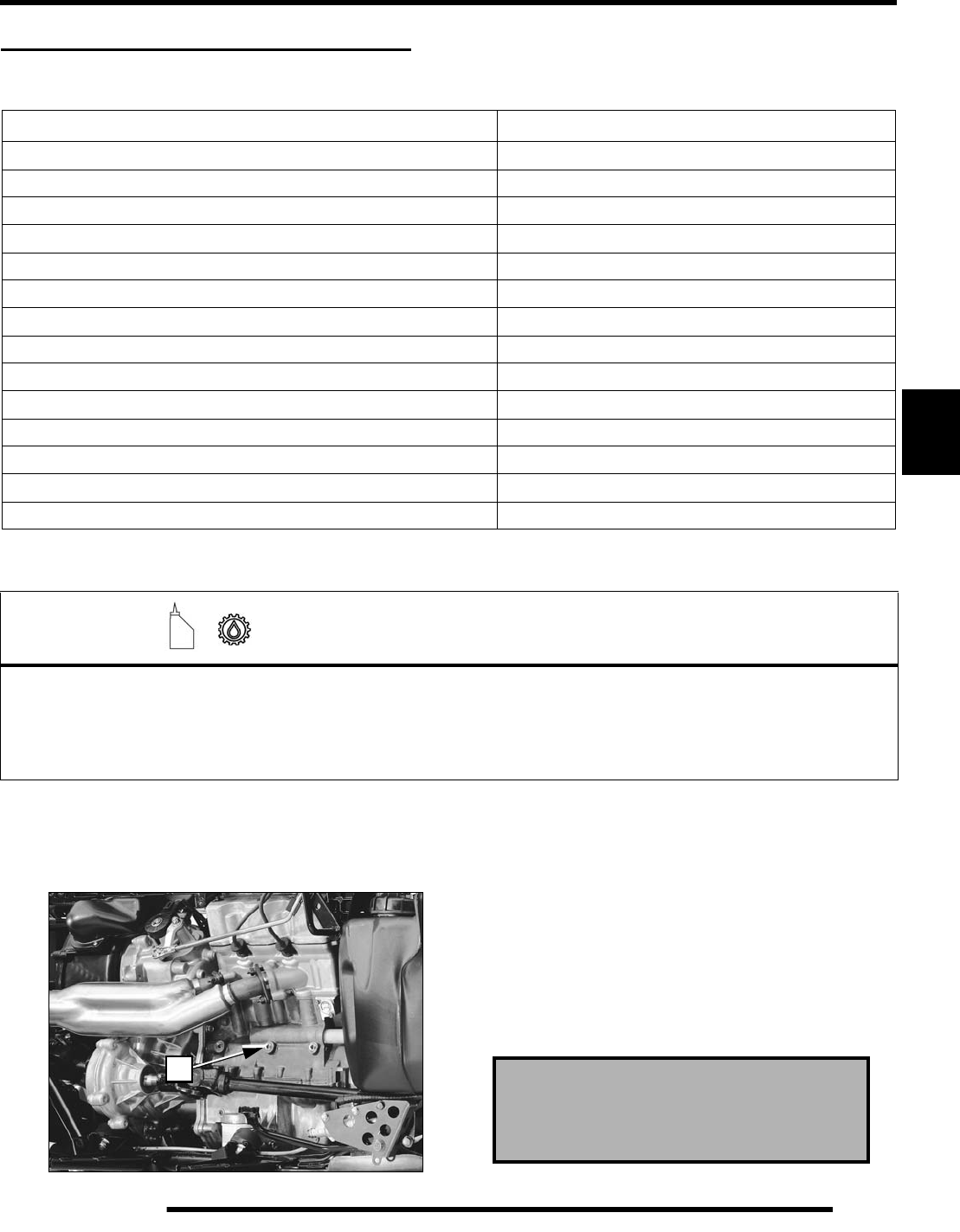
5.3
ENGINE
5
GENERAL INFORMATION - ENGINE
Special Tools
Engine Lubrication Specifications
Oil Pressure Test
1. Remove center Main Oil Gallery plug (A) from right side
of upper crankcase. 2. Insert a 1/4” NPT oil pressure gauge adaptor and oil
pressure gauge.
3. Start engine and allow it to reach operating temperature,
monitoring gauge indication.
NOTE: Test results are based on the use of the
recommended engine oil at operating temperature,
and may vary considerably if any other oil is used or
if engine is not up to temperature.
Tool Description Part Number
CRANKSHAFT HOLDING TOOL PA-49318
CRANKSHAFT SEAL INSTALLER PA-49320
FLYWHEEL / WATER PUMP DRIVE NUT PULLER PA-49316
FUEL PRESSURE TEST ADAPTOR PS-48762
MITY VAC‘ PRESSURE TEST TOOL 2870975
OIL FILTER WRENCH PU-50105
PISTON RING COMPRESSOR PLIERS PV-43570-1
PISTON RING COMPRESSOR BAND - 87mm PV-43570-3
UNIVERSAL DRIVER HANDLE PU-45543
VALVE SPRING COMPRESSOR PV-1253 or PV-4019 (Quick Release)
VALVE SPRING COMPRESSOR ADAPTOR PV-43513-A
WATER PUMP BEARING AND COUPLER PRESS PA-49378
WATER PUMP DRIVE NUT / FLYWHEEL PULLER PA-49316
WATER PUMP MECHANICAL SEAL INSTALLER PA-44995-A
=
Capacity - Approximately 2 U.S. Quarts (1.9 l)
Oil Type - Polaris PS4 Plus 2W-50 Synthetic
Filter Wrench - PV-43527 or equivalent
Oil Pressure Specification - 10-25 PSI @ Idle RPM (using Polaris PS4 Plus 2W-50 Synthetic), Engine at
operating temperature.
AOil Pressure at Idle RPM (Engine Hot):
Standard: 25 PSI
Minimum: 10 PSI
PartShark.com
877-999-5686
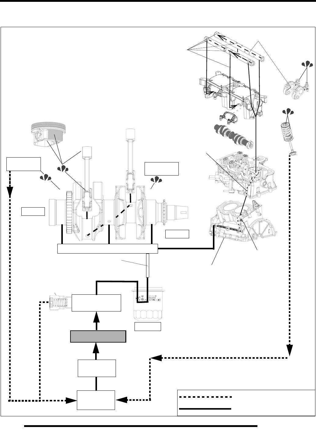
5.4
ENGINE
Oil Flow Diagram
Pressure Lubrication Circuit
Gravity & Splash Lubrication
Oil Pressure
Regulator
(+ 85 PSI)
Oil Sump
Oil Filter
Pickup
Screen
Oil Pump
Passage in
lower crankcase
Connecting Tube
(lower crankcase to
upper crankcase)
PTO End
MAG End
Balance Shaft
Bearings
Mag end cylinder head
bolt passage (exhaust side)
Holes in rocker arm shafts
feed rocker arms and rollers
Balance Shaft
Bearings
Upper crankcase
Upper Crankcase Main Oil Gallery Cam chain tensioner
Carrier bolt passages
feed Center and PTO
camshaft main journals
PartShark.com
877-999-5686

5.5
ENGINE
5
Engine Specifications - EH085OLE-011
CYLINDER HEAD (IN. / MM)
Camshaft
Cam Lobe Height - Intake (Standard) 0.897" (22.795 mm)
Cam Lobe Height - Exhaust (Standard) 0.908" (23.067 mm)
Camshaft Journal Outer Diameter - (All) .8632" ± 0.0004" (21.925 ± 0.01 mm)
Camshaft Journal Bore Inner Diameter - (All) .8661" ± 0.0004" (22.000 ± 0.01 mm)
Camshaft Oil Clearance 0.0034" ± 0.0008" (0.086 ± 0.02 mm)
Camshaft End Play 0.008" ± 0.004" (0.20 ± 0.10 mm)
Rocker Arm and
Shaft
Rocker Shaft O.D. (Intake and Exhaust) 0.5501" (13.973 - 13.984 mm)
Rocker Arm I.D. (Intake and Exhaust) 0.5514" - 0.5525" (14.006 - 14.033 mm)
Rocker Shaft Bore I.D. (Intake and Exhaust) 0.5514" - 0.5525" (14.006 - 14.033 mm)
Cylinder Head Cylinder Head - Surface warp limit 0.004" (0.1 mm)
Cylinder Head - Standard height 3.611" (91.71 mm)
Valve Seat
Valve Seat - Contacting Width - Intake 0.047" ± 0.008" - 0.0039"
(1.20 ± 0.20 mm)
Valve Seat - Contacting Width - Exhaust 0.047" ± 0.008" - 0.0039"
(1.20 ± 0.20 mm)
Valve Seat Angle 45.5° ± 0.25°
Valve Guide
Valve Guide Inner diameter 0.217" + .0005" - 0.0 (5.52 + .012 - 0.0 mm)
Valve Guide Protrusion Above Head - Intake 0.361" ± 0.010" (9.18 ± 0.25 mm)
Valve Guide Protrusion Above Head - Exhaust 0.276" ± 0.010" (7.00 ± 0.25 mm)
Valve
Valve Lash (Cold) - Intake 0.006" (.152 mm ± 0.025 mm)
Valve Lash (Cold) - Exhaust 0.009" (.228 mm ± 0.025 mm)
Valve Margin Thickness - Intake 0.016" (.41 mm)
Valve Margin Thickness - Exhaust 0.023" (.59 mm)
Valve Stem Diameter - Intake 0.2163" ± 0.0003" (5.495 ± 0.0075 mm)
Valve Stem Diameter - Exhaust 0.2159" ± 0.0003" (5.485 ± 0.0075 mm)
Valve Stem Oil Clearance - Intake 0.0014" ± 0.0005" (0.035 ± 0.0135 mm)
Valve Stem Oil Clearance - Exhaust 0.0018" ± 0.0005" (0.045 ± 0.0135 mm)
Valve Stem Overall Length - Intake 4.6681" ± 0.012" (118.57 ± 0.30 mm)
Valve Stem Overall Length - Exhaust 4.5649" ± .012" (115.95 ± 0.30 mm)
Valve Spring
Valve Spring Free Length 1.861" (47.26 mm)
Valve Spring Installed Height Intake - 1.650" (41.91 mm)
Exhaust - 1.650" (41.91 mm)
PartShark.com
877-999-5686
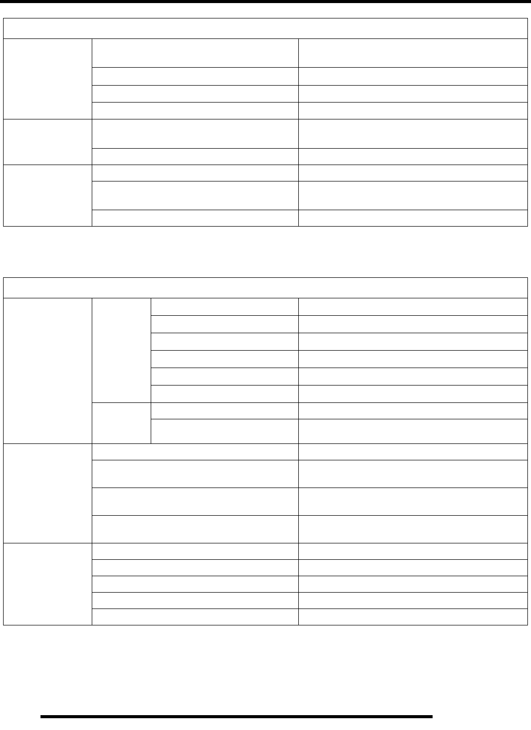
5.6
ENGINE
CYLINDER / PISTON (IN. / MM)
Cylinder
Cylinder - Surface warp limit
(mating with cylinder head) 0.004" (0.10 mm)
Cylinder Bore - Standard 3.4252" ± .0005 (87 mm ± .01mm)
Cylinder Out of Round Limit 0.0003" (0.0075 mm)
Cylinder to Piston Clearance .0021" ± .0013" (.053 ± .03mm)
Piston
Piston - Standard O.D. - Measured 90 degrees to
pin, 1.3 in. (33.0 mm) down from piston crown. 3.4231" ± .0008" (86.947 ± .02 mm)
Piston Pin Bore I.D. (Standard) 0.7877" ± .0002" (20.007 ± .004 mm)
Piston Pin
Piston Pin Outside Diameter 0.7873" ± .0001" (19.9975 ± .0025 mm)
Piston Pin - Standard Clearance - Piston Pin to
Pin Bore 0.0004" ± .0002" (0.0095 ± 0.0065 mm)
Piston Pin - Degree of Fit Piston pin must be a push fit (by hand) at 68° F (20° C)
PISTON / RINGS / CONNECTING ROD / CRANKSHAFT (IN. / MM)
Piston Ring
Installed
Gap
Top Ring - Standard 0.008” - 0.014” (0.20 - 0.36 mm)
Top Ring - Service Limit 0.016” (0.41 mm)
Second Ring - Standard 0.014” - 0.024” (0.36 - 0.61 mm)
Second Ring - Service Limit 0.032” (0.81 mm)
Oil Ring Rails - Standard 0.020” ± 0.010” (0.51 ± 0.25 mm)
Oil Ring Rails - Service Limit 0.032” (0.81 mm)
Ring to
Groove
Clearance
Top Ring - Standard 0.0024” ± 0.0008” (0.060 ± 0.020 mm)
Second Ring - Standard 0.0028” ± 0.0008” (0.070 ± 0.020 mm)
Connecting Rod
Connecting Rod Small End I.D. 0.7886” + 0.000 / - .015” (20.030 + 0.000 / - .015 mm)
Connecting Rod Small End
Diametral Clearance 0.00098” ± .0004” (0.025 ± 0.010 mm)
Connecting Rod Big End
Side Clearance 0.012” ± 0.0039” (0.30 ± .10 mm)
Connecting Rod Big End
Diametral Clearance 0.0098” - .0023” (0.025 - .059 mm)
Crankshaft
Crankshaft Runout Limit (See procedure)
PTO End Less than .001” (0.025 mm)
MAG End Less than .001” (0.025 mm)
Main Journal Diameter (Standard) 2.1642” - 2.1649” (54.97 - 54.99 mm)
Connecting Rod Journal Diameter (Standard) 1.7718” - 1.7726” (45.005 - 45.025 mm)
PartShark.com
877-999-5686
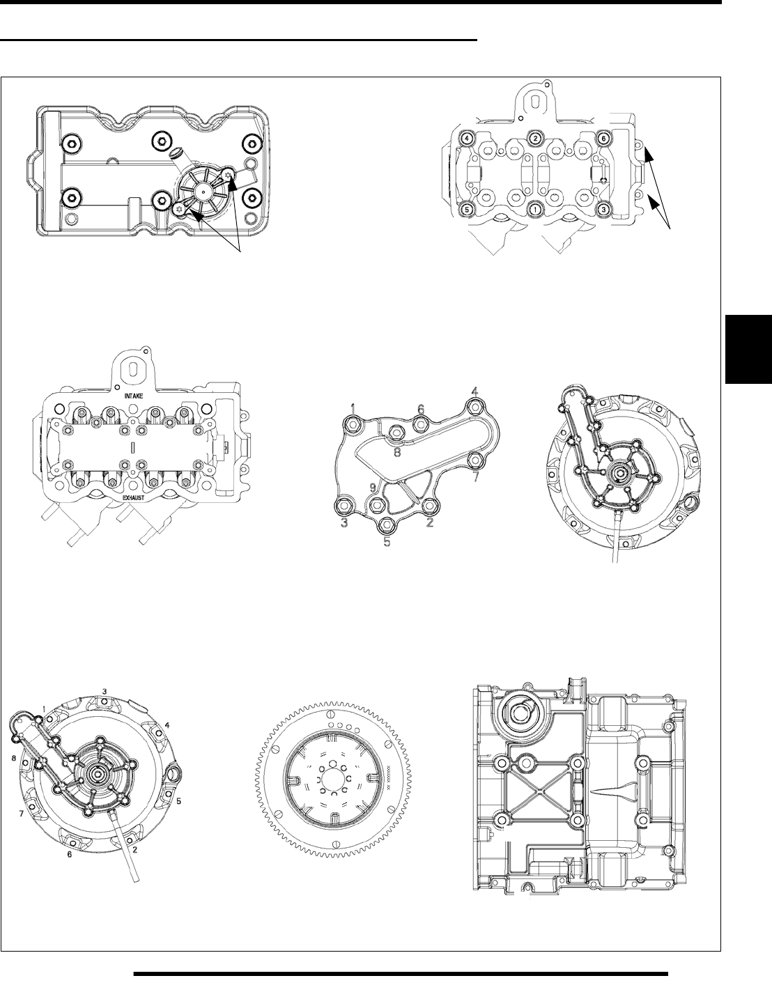
5.7
ENGINE
5
ENGINE ASSEMBLY VIEWS AND TORQUE VALUES
Torque & Torque Sequence - Main Engine Components
1
3
2
4
5
6
VALVE COVER CYLINDER HEAD
CAMSHAFT CARRIER OIL PUMP COVER WATER PUMP COVER
STATOR COVER STARTER GEAR
12
34
5
67
8
910
1
2
3
4
5
6
7
8
9
10
89 lb-in. (10 Nm)
14 lb-ft. (19 Nm)
13 lb-ft. (18 Nm)
89 lb-in. (10 Nm)
9 lb-ft. (12 Nm)
89 lb-in.
(10 Nm)
26 lb-ft. (35 Nm) + 90
°
(see procedure)
13 lb-ft. (18 Nm)
89 lb-in. (10 Nm)
1
2
34
5
6
7
8
16 14
11 1715 13
12 10
9
8
6
5
18
4
3
2
1
CRANKCASE
M9 = 26 lb-ft. (35 Nm)
M6 = 89 lb-in. (10 Nm)
7
19
20
6
5
4
3
2
1
PartShark.com
877-999-5686
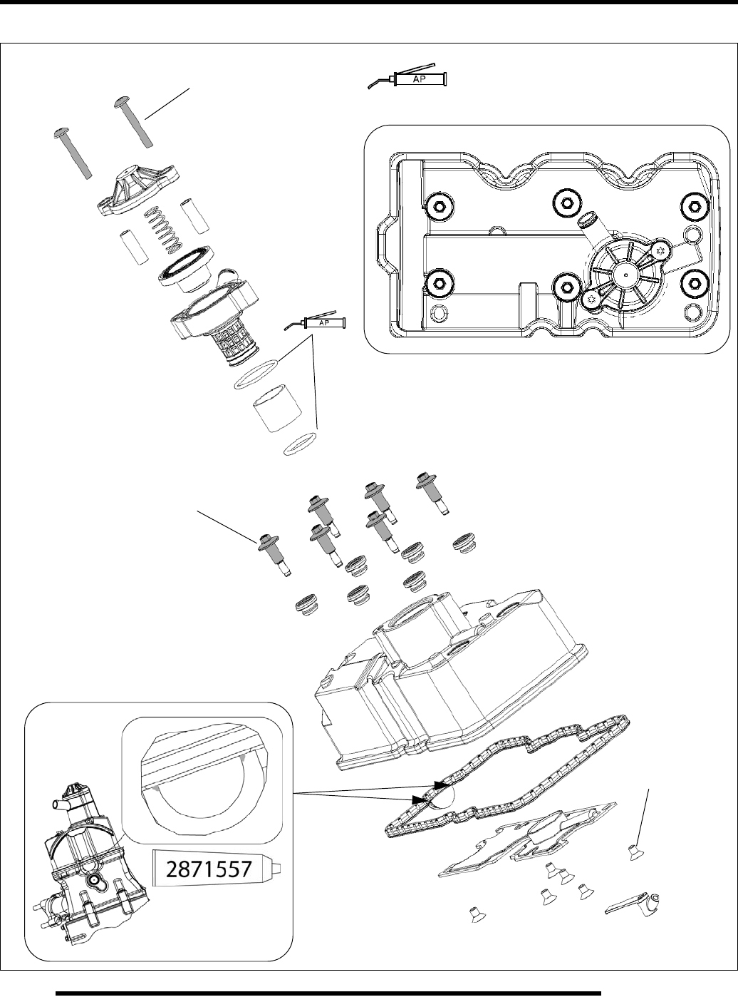
5.8
ENGINE
Valve Cover / Breather Valve
1
2
3
4
5
6
89 lb-in (10 Nm) = Apply All Purpose Grease
Torque Pattern
89 lb-in (10 Nm)
44 lb-in (5 Nm)
PartShark.com
877-999-5686
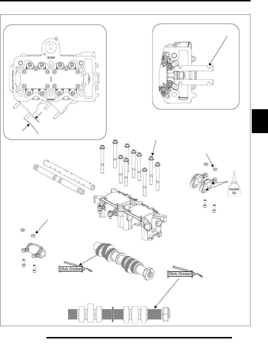
5.9
ENGINE
5
Camshaft Carrier / Camshaft / Rocker Arm
3. Snug all bolts
Torque Pattern
26 mm +/- 1 mm 4. Torque to 13 lb-ft. (18 Nm)
Slots must be vertical and face OUT
89.0 lb-in (10 Nm)
12
34
5
67
8
910
following torque pattern
1. Crankshaft at TDC MAG cylinder
2. Camshaft pin at 10:00 position
89.0 lb-in (10 Nm)
PartShark.com
877-999-5686
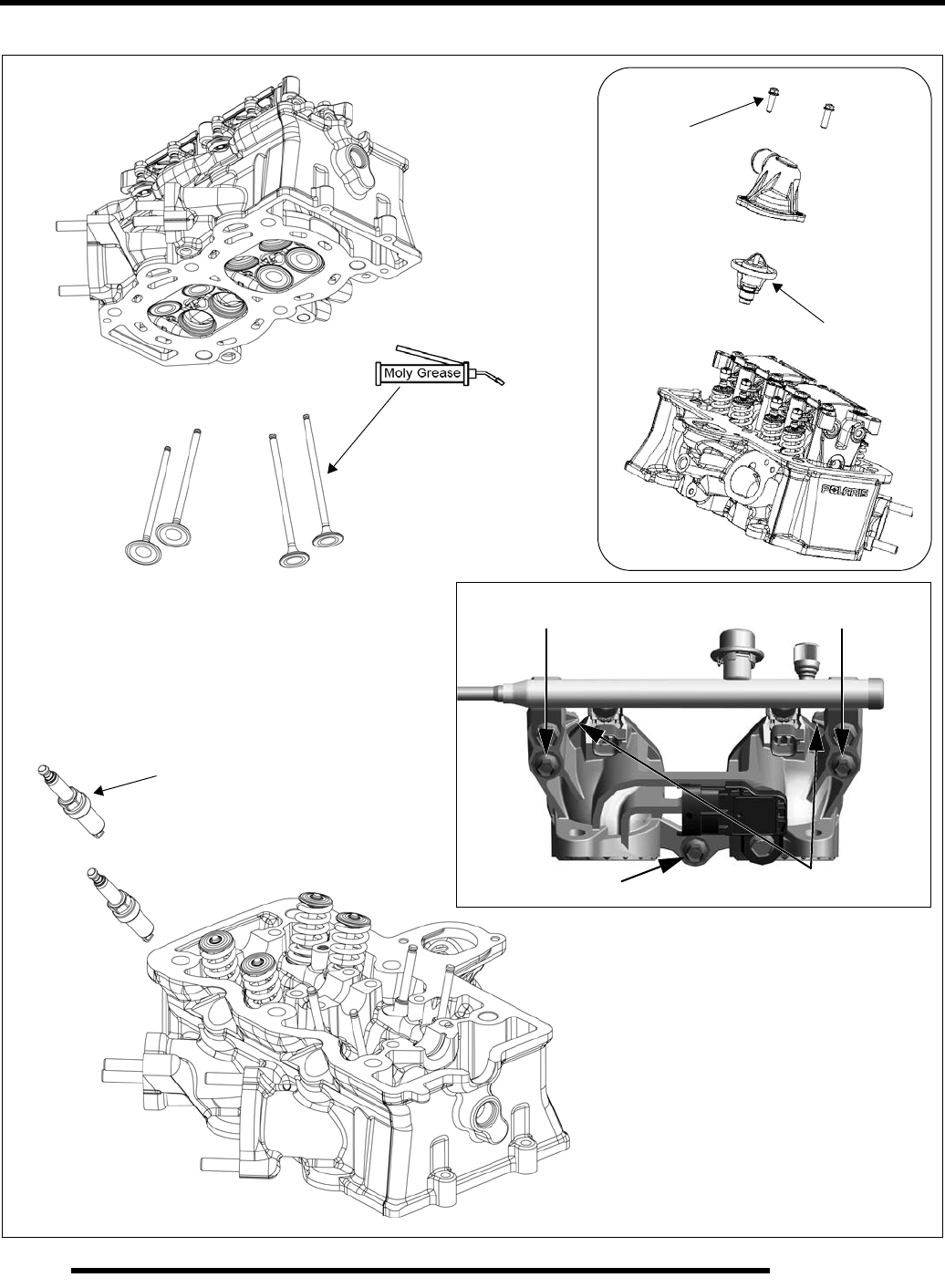
5.10
ENGINE
Cylinder Head / Valve / IAFM
Thermostat
89 lb-in.
(10 Nm)
18 ± 1.5 lb-ft.
(25 ± 2 Nm)
Step 2 - 18 lb-in. (2 Nm) Step 1 - Align dowel locators to
Step 5 - 89 lb-in. (10 Nm)
Step 3 - 18 lb-in. (2 Nm)
Step 6 - 89 lb-in. (10 Nm) Step 4 - 18 lb-in. (2 Nm)
Step 7 - 89 lb-in. (10 Nm)
cylinder head holes
IAFM
Torque
Sequence
PartShark.com
877-999-5686
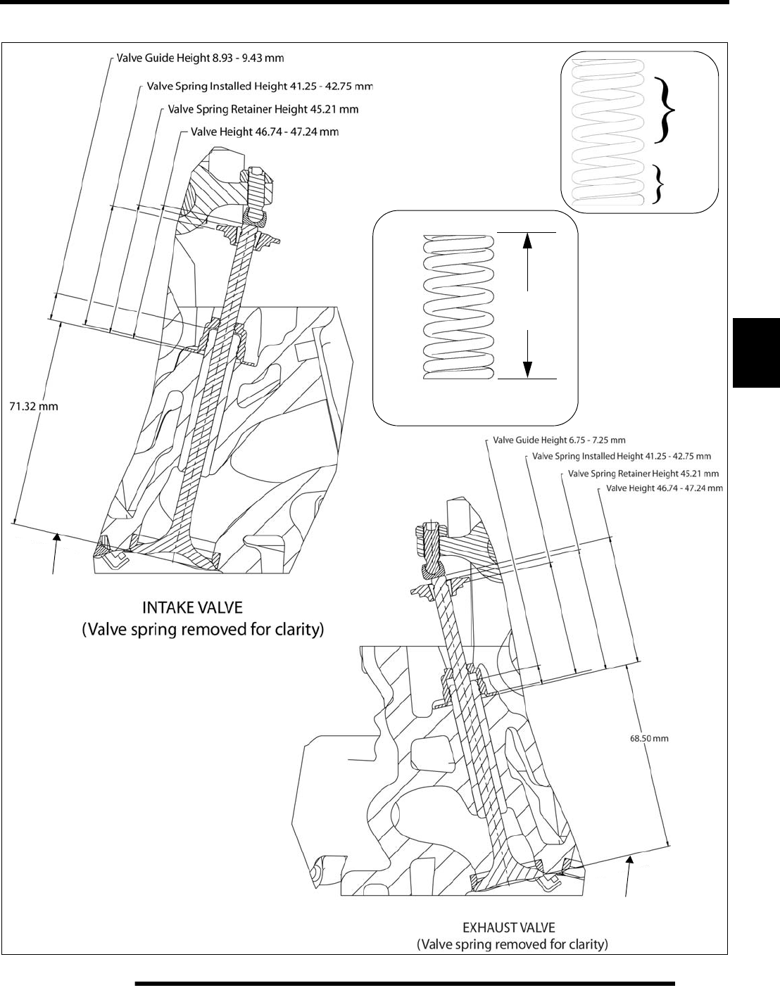
5.11
ENGINE
5
Valve & Spring Height Detail
Free Length
(47.26 mm)
1.861 in.
Combustion
chamber top
Combustion
chamber top
Top
Bottom
PartShark.com
877-999-5686
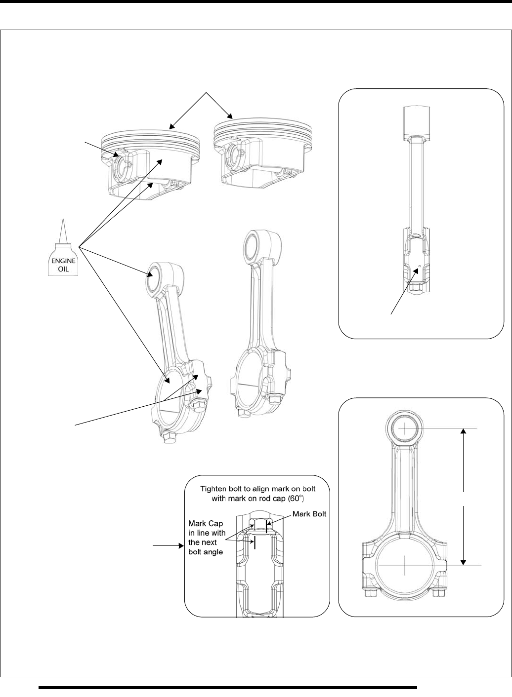
5.12
ENGINE
Piston / Connecting Rod
Place circlip
1. Torque bolts to 24 lb-ft (33 Nm)
2. Tighten bolts an additional 60°
120 mm
Paint tolerance mark (see text)
gap at top
Install NEW rod bolts if disassembled
Match stamp on rod and cap.
or rear of engine
Rod stamp can face front
(Rod has no offset)
or bottom
NOTE: Pistons can be installed in either
orientation as they are symmetric.
PartShark.com
877-999-5686
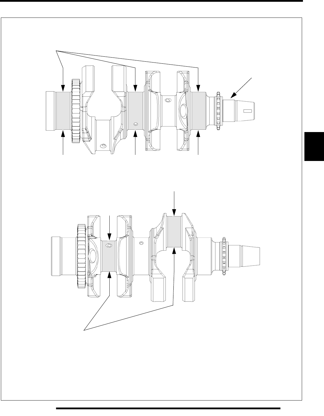
5.13
ENGINE
5
Crankshaft
Main Journal O.D.
Connecting Rod Journal O.D.
45.015 mm ± .01 (1.7722" ± .0004)
Runout Limit
.001" (.025 mm)
54.98 mm ± .01
(2.1646" ± .0004)
Refer to bearing selection procedure and
chart on page 5.48.
PartShark.com
877-999-5686
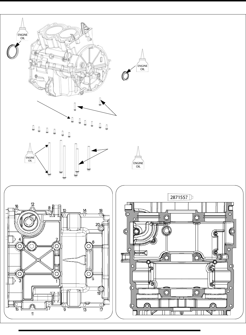
5.14
ENGINE
Crankcase
Torque Pattern
89 lb-in.
(10 Nm)
M6 x 20
89 lb-in.
(10 Nm)
M6 x 35
26 lb-ft.
(35 Nm)
M9 x 115**
Sealant Application
** Apply light film of engine oil to flange
and threads of all M9 crankcase bolts
26 lb-ft.
(35 Nm)
M9 x 160**
PartShark.com
877-999-5686
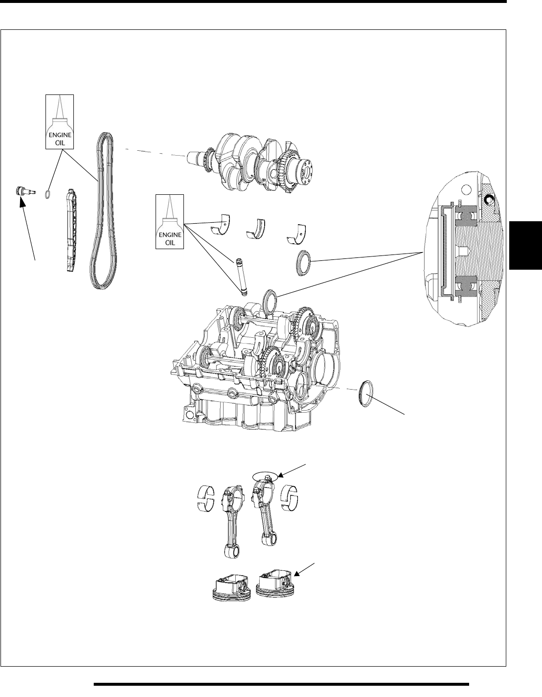
5.15
ENGINE
5
Crankcase - Upper
89 lb-in.
See procedure
(10 Nm)
Detail - balance
shaft end cap
Use tool PA-49320
and bearing
See removal procedure.
Piston must be removed / installed
through top of cylinder as an assembly,
with connecting rod attached.
PartShark.com
877-999-5686
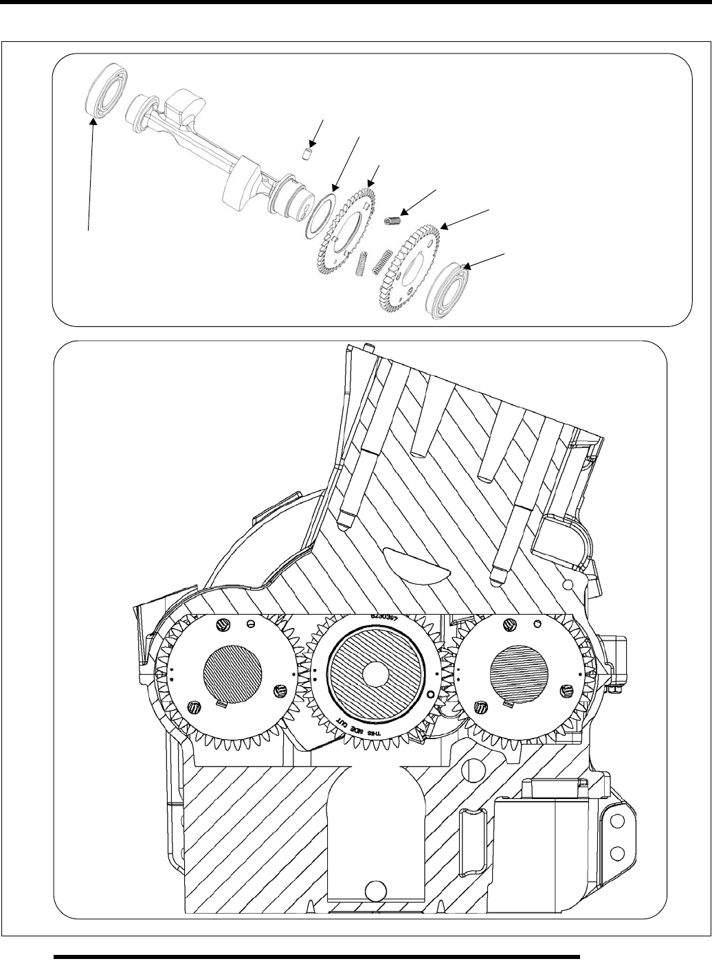
5.16
ENGINE
Balance Shaft / Balance Shaft Timing
Balance Shaft Timing at
TDC on MAG Cylinder
Pin
Washer (Install before pin)
Split Gear
Springs
Drive Gear
Bearing (retaining ring OUT)
Press on inner race only
Replace if removed
Bearing - Press on inner race only
Replace if removed
PartShark.com
877-999-5686
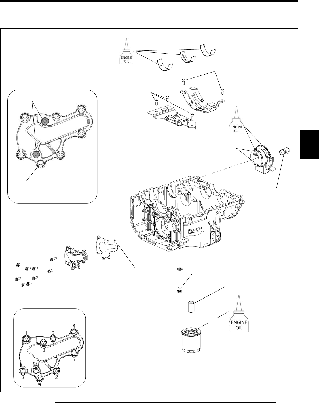
5.17
ENGINE
5
Crankcase (Lower) With Oil Pump
See “Crankcase (Lower) / Oil Pump Disassembly” on page 5.41
Torque Pattern
106 lb-in. (12 Nm)
M6x16
(all outer screws)
M6x20 106 lb-in. (12 Nm)
21 lb-ft.
(28 Nm)
Oil Pump Cover
Ensure tab is visible
Install new gasket.
to verify assembly. 21 lb-ft. (28 Nm)
6-8 lb-in. (.69-.89 Nm)
M3 end cap screws
12 lb-ft.
(16 Nm)
Fill
89 lb-in. (10 Nm)
89 lb-in. (10 Nm)
PartShark.com
877-999-5686
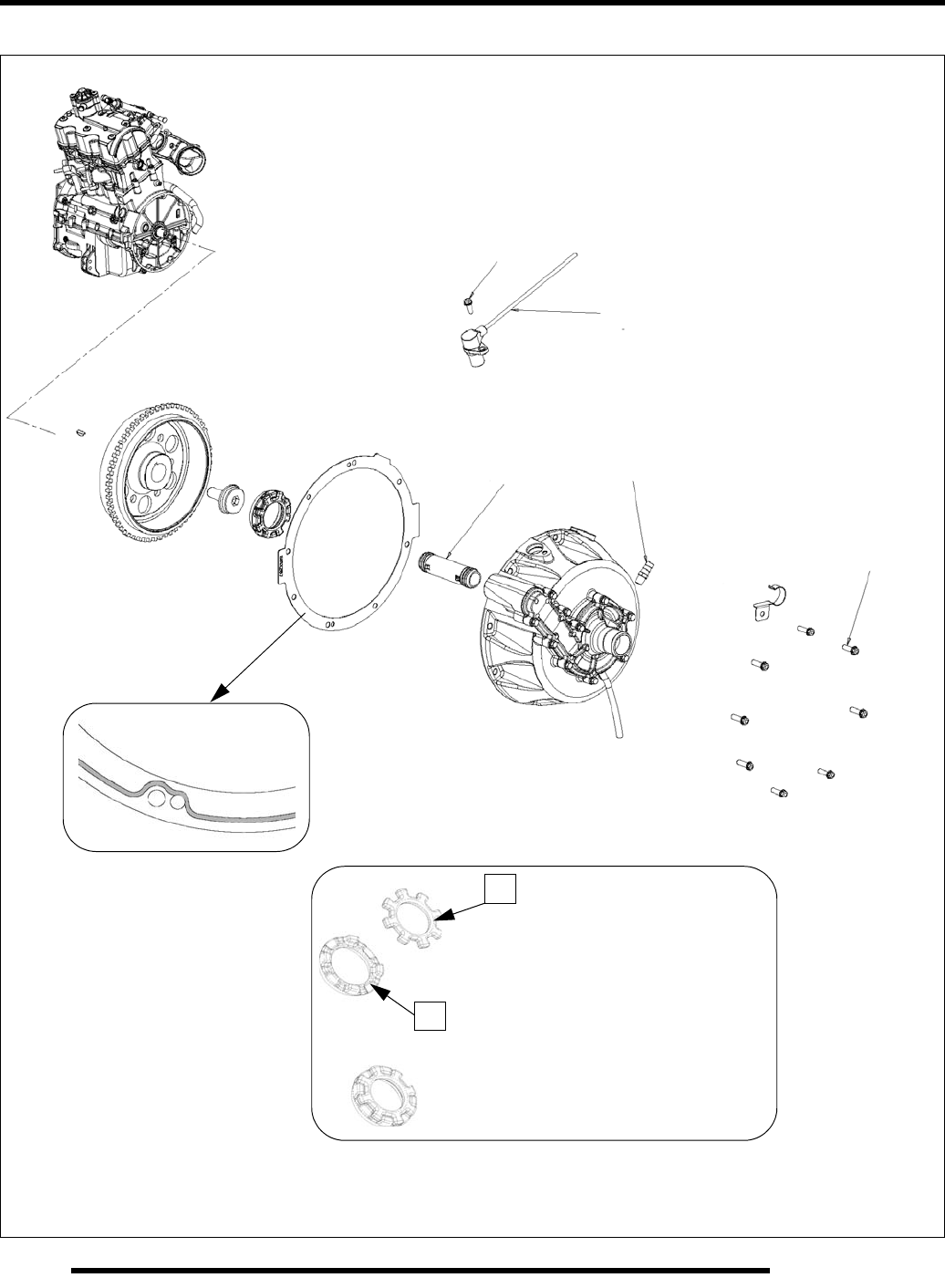
5.18
ENGINE
Water Pump Coupler
Use weather strip or contact cement
to hold damper rubber (A) on water
pump coupler nut (B) during stator
cover installation.
A
B
74 lb-ft. (100 Nm)
35 lb-in. (4 Nm)
Crankshaft Position Sensor (CPS)
89 lb-in.
(10 Nm)
M6 x 16
89 lb-in.
(10 Nm)
M6 x 20
Key
Coolant
89 lb-in.
(10 Nm)
Fitting
O-Ring
1/8 NPTF
Coolant
Pipe
Sealant bead should
face the cover.
PartShark.com
877-999-5686
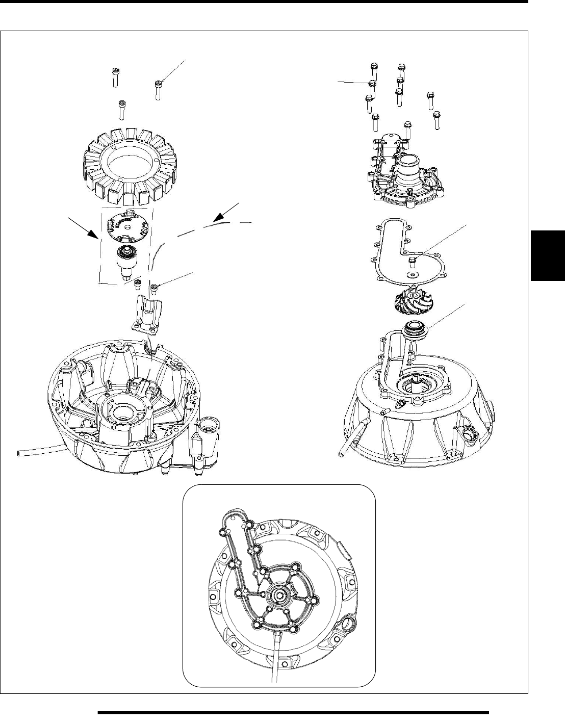
5.19
ENGINE
5
Water Pump / Water Pump Coupler / Stator / Flywheel
10 lb-ft.
89 lb-in. (10 Nm)
Stator wire routing
See procedure
89 lb-in. (10 Nm)
(13.5 Nm)
89 lb-in. (10 Nm)
See procedure
Torque Sequence
1
2
3
4
5
6
7
8
9
10
PartShark.com
877-999-5686
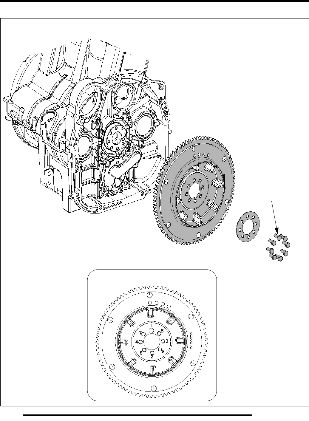
5.20
ENGINE
Drive Coupler (Rear) / Starter Gear
Torque Sequence
14 lb-ft. (19 Nm)
PartShark.com
877-999-5686
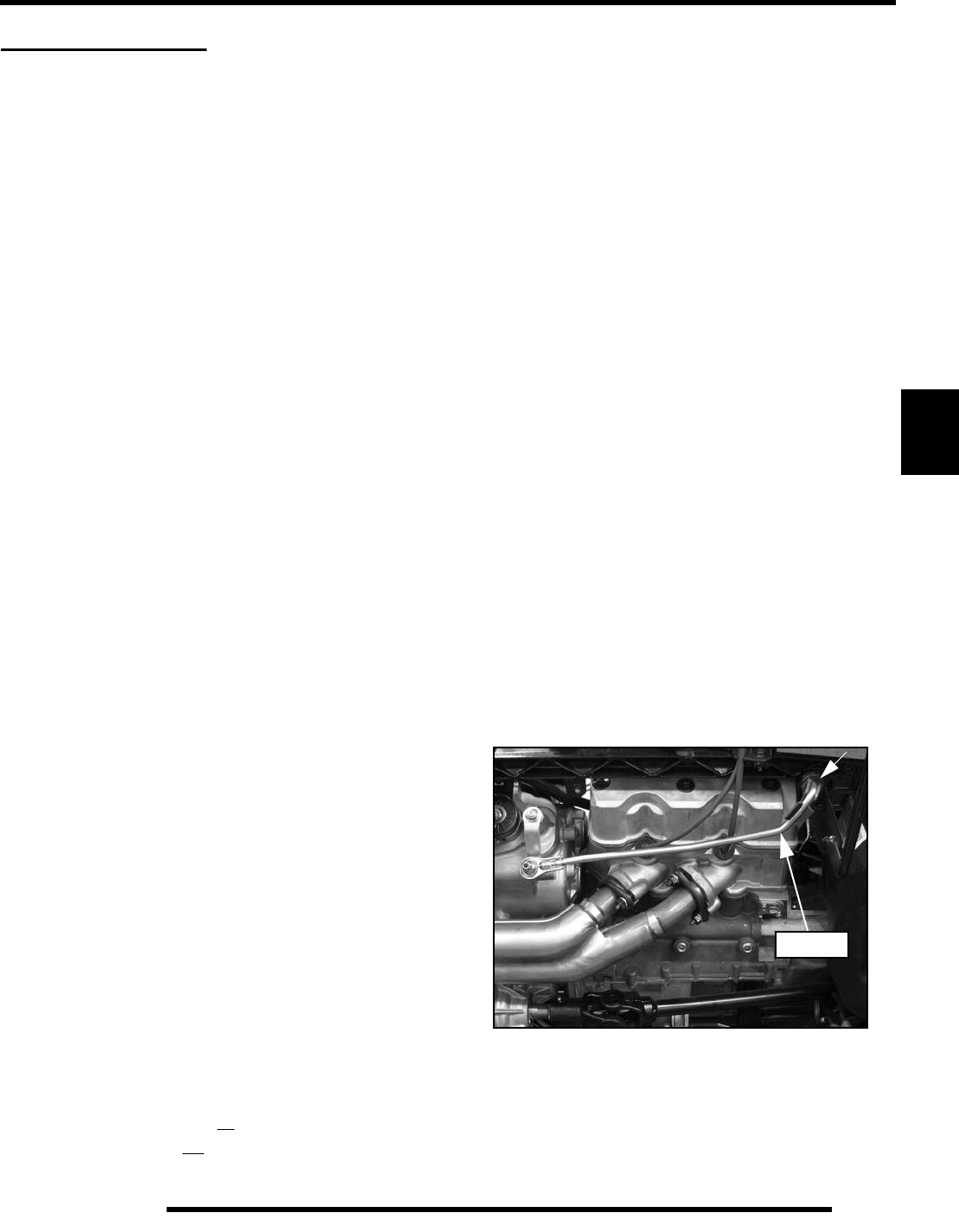
5.21
ENGINE
5
ENGINE SERVICE
Accessible Engine Components
Components serviceable with engine installed:
• Flywheel
• Alternator (Stator)
• Starter Motor/Drive
• Cylinder Head / Valves
• Camshaft / Camshaft Carrier
•Rocker Arms
• Water Pump
Components that require engine removal for service:
• Counterbalance Shaft(s)
• Piston / Rings
• Connecting Rod
• Crankshaft / Main Bearings
•Oil Pump
• Crankcase
• Crankshaft End Seals (Use Driver PA-49320)
Top-End Service (Engine in Chassis)
The top-end of the engine can be serviced while the engine is
mounted in the chassis. A removable upper right-hand frame
support allows access to the valve cover and cylinder head.
To service the top-end of the engine refer to the “Valve
Clearance Adjustment” procedure in Chapter 2, which provides
detailed steps to access the valve cover.
Crankcase Cylinder Service Information
IMPORTANT: Identify which engine you are servicing
before replacing components such as the pistons.
It is important to note that two types of engine crankcases were
produced for the 2009 Sportsman XP 850. Some of the engines
produced have NiCaSil plated cylinder walls, while others have
iron lined cylinder walls.
The crankcase differences can be easily recognized by their
physical appearance.
• A dull, dark gray color identifies the NiCaSil plated.
• A shinny metallic color identifies the iron lined.
The crankcase differences can also be identified by viewing the
engine designation portion of the vehicle’s model number.
• NiCaSil Plated: A09ZN85
• Iron Lined: A09ZN8X.
Engine Removal
IMPORTANT: Some engine repair procedures can be
performed without removing the engine from the
vehicle. Refer to “Accessible Engine Components”
for further information.
NOTE: Upon engine removal, use a mechanical lift
or have an assistant help remove the engine from
the vehicle to prevent personal injury or damage to
vehicle components.
1. If vehicle was recently operated, allow it to cool down
before attempting to perform any work.
2. Thoroughly clean the engine and chassis.
3. Clean your work area
4. Drain the engine oil (see Chapter 2 “Maintenance”).
5. Remove the following body components. Refer to Chapter
9 “Body / Frame” for component removal.
• Seat
• Side Panels (upper and lower)
• Footwells
• Mud Guards (both sides)
6. Disconnect negative (-) battery cable.
7. Pull the shift linkage rod straight outward while pushing on
the two ears of the snap retainer to disconnect the rod from
the shift lever. Allow the linkage to hang down out of the
way.
Linkage
PartShark.com
877-999-5686
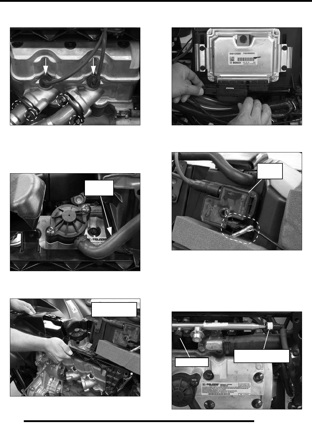
5.22
ENGINE
8. Remove the high tension leads from the engine and remove
the (2) nuts from each exhaust flange at the engine.
9. Remove the exhaust springs retaining the exhaust pipe to
the silencer and remove the pipe from the vehicle. Insert a
clean shop towel into the engine exhaust ports.
10. Remove the breather line from the valve cover breather.
11. Using an 8 mm Allen socket, remove the (4) bolts and upper
right-hand frame support to allow engine removal.
12. Disconnect the ECU from the main harness. Pull down on
the connector while pulling the connector tab out.
13. Disconnect the harness and ground wire from the ignition
coil located on the right side of the air box.
14. Remove the (2) screws from the rear portion of the air box,
disconnect the intake boot from the intake plenum and
remove the air box from the vehicle.
15. Depressurize the fuel system at the fuel valve. Disconnect
the fuel line fitting from the fuel rail and remove the fuel
tank (see Chapter 3 “Fuel Pump / Fuel Tank Removal”).
Breather
Line
Torque bolts to:
36 ft. lbs. (49 Nm)
Ignition
Coil
Push in and up on white
tabs to release fuel line
Fuel Valve
PartShark.com
877-999-5686
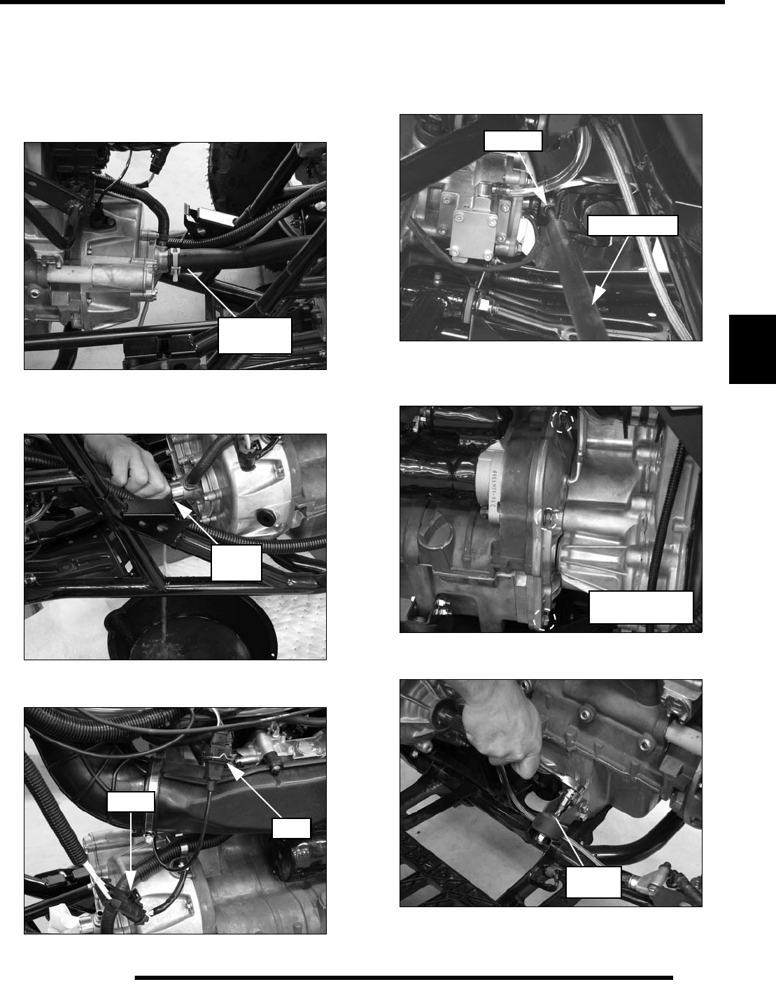
5.23
ENGINE
5
16. Remove the (4) screws retaining the engine skid plate and
remove the plate from the vehicle.
17. Place a drain pan under the front portion of the engine.
18. Slide the clamp back and remove the coolant inlet hose
from the water pump housing.
19. Slowly drain the coolant into the drain pan. Dispose of used
coolant properly.
20. Disconnect the stator and CPS wire harnesses.
21. Use the Roll Pin Removal Tool (PN 2872608), to drive out
the roll pin from the front propshaft. Pull the shaft back
towards the transmission to remove it from the front
gearcase input shaft, then pull it forward to remove it from
the transmission output shaft.
22. Remove all bolts from both sides retaining the engine to the
transmission.
23. Remove the top bolt from the RH engine isolator mount.
Coolant
Inlet Hose
Drain
HERE
Stator
CPS
Roll Pin
PN 2872608
Torque bolts to:
18 ft. lbs. (24 Nm)
36 ft. lbs.
(49 Nm)
PartShark.com
877-999-5686
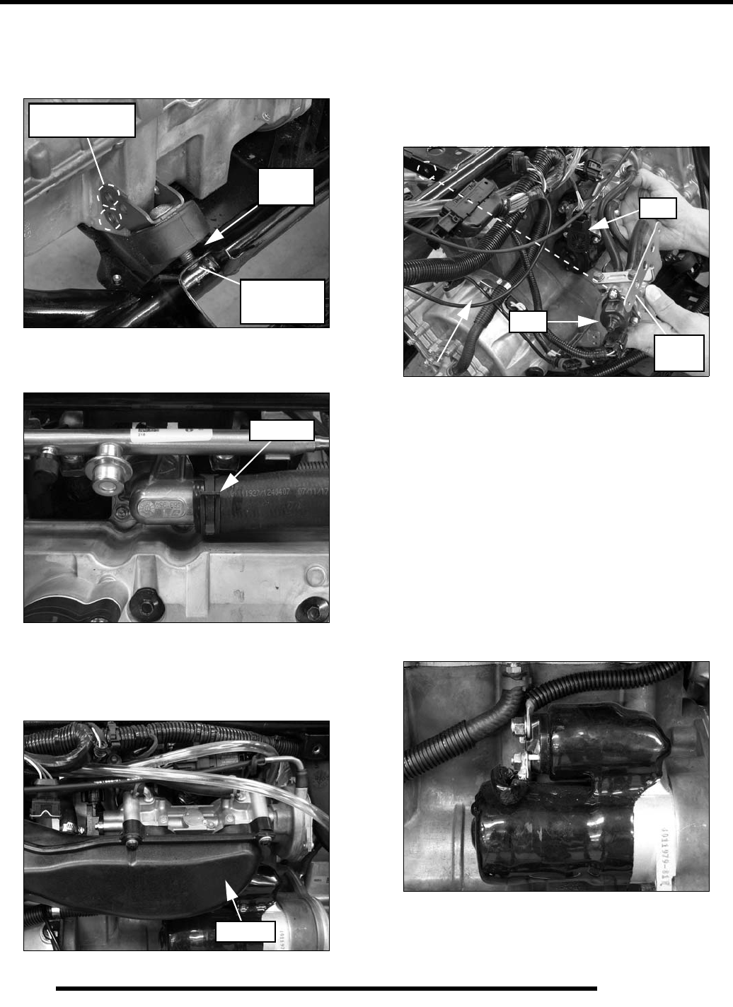
5.24
ENGINE
24. Remove the (2) through-bolt fasteners retaining the LH
engine isolator mount to the engine and remove the lower
nut from the mount. Pry up between the frame and isolator
mount and remove the mount assembly from the frame.
25. Remove the upper radiator hose from the thermostat
housing. Insert a clean shop towel into the outlet.
26. Remove the intake plenum from the throttle body by
removing the (4) T27 Torx-head screws. Reinstall the
screws into the throttle body to hold it in place until
removed later in this procedure.
27. Remove the (2) screws retaining the IAC mount plate to the
frame at the front of the engine.
28. Disconnect the wire harness from the IAC and TPS located
on the throttle body. Remove the throttle body and IAC
mount plate as an assembly with the throttle cable still
attached to the throttle body.
NOTE: Do not allow throttle body to hang from the
throttle cable.
29. Set the assembly on top of the front cab support. Insert a
clean shop towel into each intake track of the engine to
prevent debris from entering.
30. Disconnect the fuel injectors at the fuel rail and disconnect
the engine coolant temperature sensor located below the
thermostat housing on the left side of the engine.
31. Disconnect and remove the T-MAP sensor from the intake
track to prevent damage upon engine removal.
32. Remove the single spade wire (white/red) and battery cable
from the starter motor solenoid.
Pry Up
HERE
Torque bolts to:
18 ft. lbs. (24 Nm)
Torque nut to:
36 ft. lbs.
(49 Nm)
Remove
Plenum
IAC
TPS
Mount
Plate
PartShark.com
877-999-5686
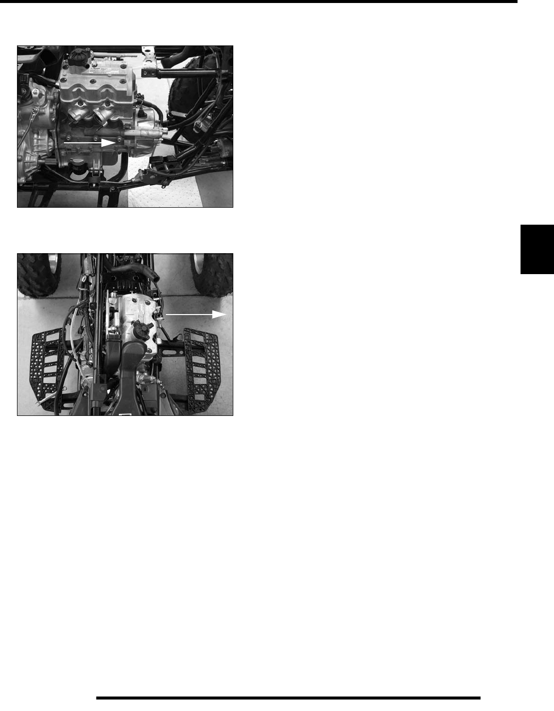
5.25
ENGINE
5
33. Pull the engine toward the front of the vehicle to disengage
the engine/transmission coupler.
34. Remove the engine through the right side of the chassis and
place on a work bench to begin engine disassembly.
Engine Installation Notes
After the engine is installed in the frame, review this checklist
and perform all steps that apply:
General Items
1. Repeat steps in reverse order in the “Engine Removal”
section above to reinstall the engine.
2. Install previously removed components using new gaskets,
seals, and fasteners where applicable.
3. Perform regular checks on fluid levels, controls, and all
important areas on the vehicle as outlined in the Daily Pre-
ride Inspection Checklist and in the Periodic Maintenance
Table (refer to Chapter 2 “Maintenance”).
Exhaust
1. Replace exhaust seals before installation.
2. Install the exhaust pipe assembly into the cylinder head and
exhaust silencer.
3. Install the nuts and finger tighten only!
4. Install the springs retaining the pipe to the silencer.
5. Torque the exhaust retaining nuts to specification.
Bleed Cooling System
1. Remove radiator cap and slowly add coolant to top of filler
neck.
2. Fill coolant reservoir tank to full mark.
3. Install radiator cap and squeeze coolant lines to force air out
of system.
4. Again remove radiator cap and slowly add coolant to top
of fill neck.
5. Alternately elevate the front and back of the vehicle to
allow additional air to vent from the system.
6. Start engine and observe coolant level in the radiator.
Allow air to purge and top off as necessary. Reinstall
radiator cap securely and bring engine to operating temp.
Check coolant level in reservoir tank after engine has
cooled and add if necessary.
Engine Break In Period
The engine break-in period is defined as the first 20 hours of
engine operation or 2 full tanks of fuel.
1. Use only Polaris PS-4 Plus 2W-50 Synthetic engine oil.
Never substitute or mix oil brands. Serious engine damage
can result.
2. Use fuel with a minimum octane of 87 (R+M)/2 method.
3. Change break-in oil and filter at 25 hours.
REMOVE
PartShark.com
877-999-5686
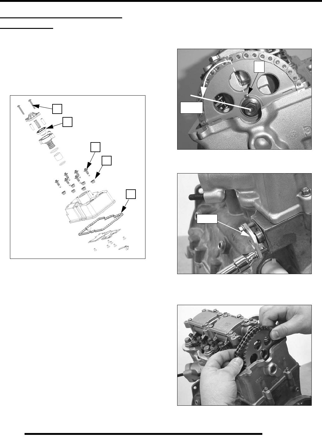
5.26
ENGINE
ENGINE DISASSEMBLY AND
INSPECTION
Valve Cover / Breather Valve
1. Remove (2) breather housing bolts (A). Inspect bellows
(B) for cracks (not required for valve cover removal).
2. Remove (6) rocker cover bolts (C) and isolators (D).
3. Replace isolators and gasket (E) if oil leaks are evident.
Rocker Carrier / Camshaft Removal
1. Rotate engine in direction of rotation until pin (A) is facing
UP. Rotate cam another 60° to the 10:00 position to relieve
valve spring pressure from camshaft lobes.
2. Remove cam chain tensioner bolts evenly and remove
tensioner. Note “TOP” marked on plate for assembly.
3. Remove sprocket bolt and lift chain and sprocket off
camshaft. Secure cam chain with a wire (if cylinder head
will not be removed).
4. Loosen all cam carrier bolts evenly and lift carrier / rocker
arm assembly from cylinder head.
A
C
B
D
E
A
10:00
“TOP”
PartShark.com
877-999-5686
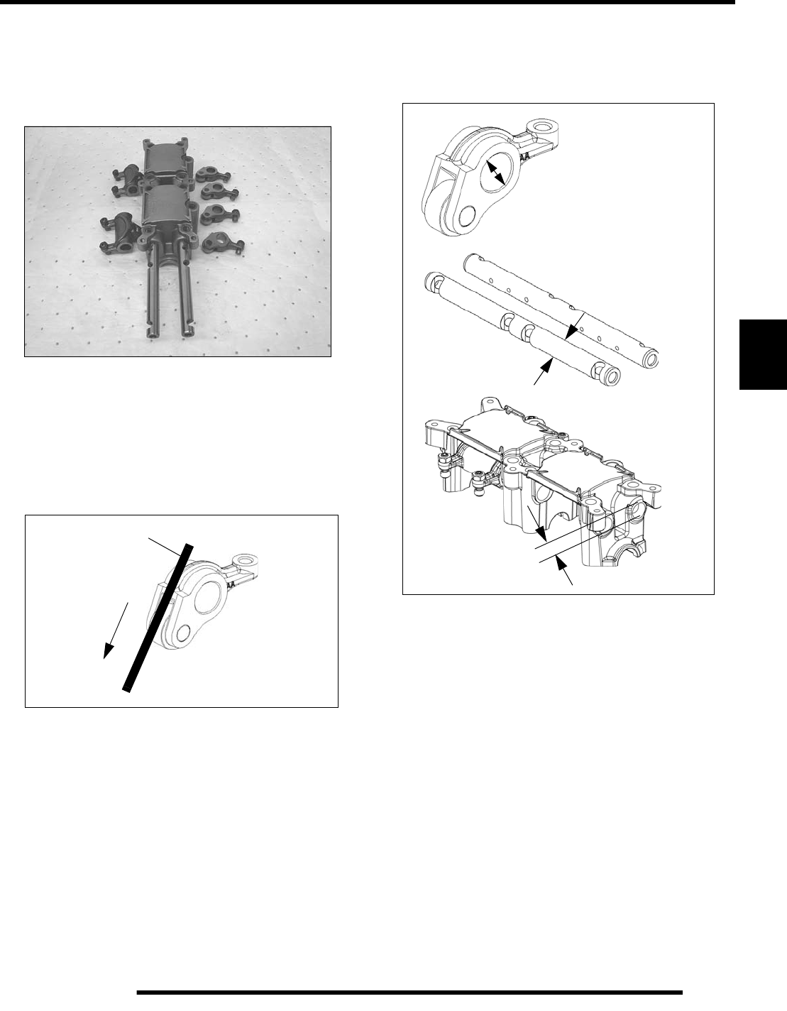
5.27
ENGINE
5
Rocker Arm / Rocker Arm Shaft Inspection
1. Mark or tag rocker arms and shafts to keep them in their
respective locations for assembly.
2. Slide rocker arm shafts from carrier.
3. Inspect each rocker arm roller. Roller surface should be
smooth and radial movement should be minimal. Roll a
smooth flat rod across the roller, applying firm downward
pressure on roller while observing roller movement. Roller
should turn smoothly without binding. Replace rocker arm
if roller surface is damaged, or if roller does not turn
smoothly.
4. Measure I.D. of rocker arms and O.D. of rocker arm shafts.
Measure shaft bore in cam carrier. Compare to
specifications (See “Engine Specifications - EH085OLE-
011” on page 5.5).
Flat stock
PartShark.com
877-999-5686
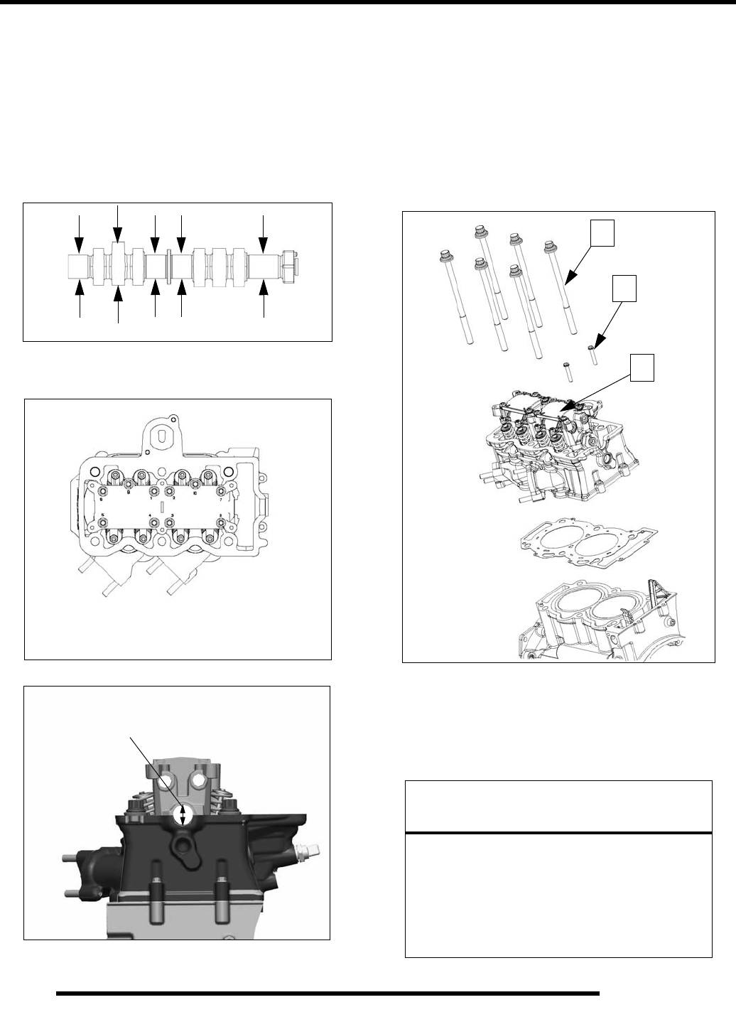
5.28
ENGINE
Camshaft / Camshaft Bore Inspection
1. After camshaft carrier is removed, lift camshaft from
cylinder head. Inspect all main journals and cam lobes as
described below and compare to specifications (See
“Engine Specifications - EH085OLE-011” on page 5.5).
Replace if worn beyond service limit or if any surface is
pitted or damaged.
2. Measure all cam lobe heights from base circle to highest
point on lobe.
3. Temporarily install camshaft carrier as shown below to
measure the camshaft bore. Replace cylinder head if worn.
Cylinder Head Removal
1. Loosen two outer bolts (A), then loosen all head bolts (B)
evenly, 1/8 turn at a time following the pattern below (6, 5,
etc.) until all are loose. Remove all bolts, cylinder head,
and gasket.
NOTE: Head can be removed from cylinder /
crankcase without removing cam carrier (C) but the
center two cylinder head bolts cannot be removed
from the head unless carrier is removed.
Cylinder Head Cleaning
Thoroughly clean cylinder head surface to remove all traces of
gasket material and carbon.
3. Measure
1. Snug all bolts
2. Torque in sequence
NOTICE
Use care not to damage gasket sealing surface.
All gasket surfaces must be clean, dry, and free
of any oil or grease upon assembly.
Clean sealing surfaces with rubbing alcohol,
electrical contact cleaner or a brake cleaner that
does not leave a solvent residue. Do not touch
sealing surfaces of the new head gasket.
A
B
C
PartShark.com
877-999-5686
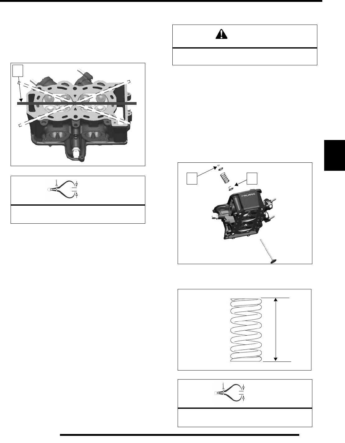
5.29
ENGINE
5
Cylinder Head Warp Inspection
1. Lay a straight edge (A) across surface of cylinder head at
several different points and measure warp by inserting a
feeler gauge between the straight edge and the cylinder
head surface. If warp exceeds the service limit, replace the
cylinder head.
Cylinder Head Disassembly
NOTE: Keep mated parts together for assembly. It is
important to put cylinder head parts back in the
same location. Mark parts or place them in a rack as
you remove them.
Valve Spring Compressor: PV-1253 (or PV-4019 with
adapter PV-43513-A)
1. Compress valve spring and remove split keepers (B).
2. Remove compressor, then remove top retainer, spring, and
seal (C). Discard seals. Repeat for all remaining valves.
3. Clean combustion chamber and head gasket surface.
4. Measure free length of each spring with a Vernier caliper
and compare to specification.
= In. / mm.
Cylinder Head Warp Limit:
.004" (.10 mm) max
A
WARNING
Wear eye protection when removing and installing
valve springs.
= In. / mm.
Valve Spring Free Length:
Std: 1.861" (47.26 mm)
B C
PartShark.com
877-999-5686
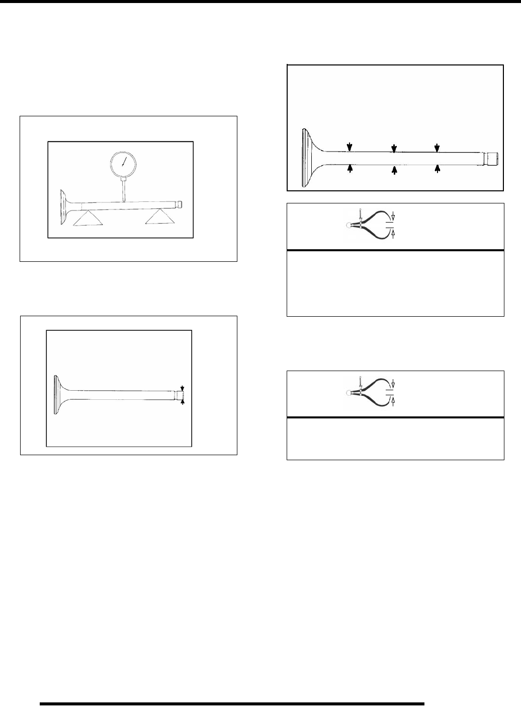
5.30
ENGINE
Valve Inspection
1. Remove all carbon from valves with a soft wire wheel or
brush.
2. Check valve face for runout, pitting, and burnt spots. To
check for bent valve stems, mount valve in a drill or use “V”
blocks and a dial indicator.
3. Check end of valve stem for flaring, pitting, wear or
damage.
4. Inspect split keeper groove for wear or flaring of the keeper
seat area.
NOTE: The valves can be re-faced or end ground, if
necessary. They must be replaced if extensively
worn, burnt, bent, or damaged.
5. Measure diameter of valve stem with a micrometer in three
places, then rotate 90 degrees and measure again (six
measurements total). Compare to specifications.
6. Measure valve guide inside diameter at the top middle and
end of the guide using a small hole gauge and a micrometer.
Measure in two directions.
7. Subtract valve stem measurement from the valve guide
measurement to obtain stem to guide clearance. NOTE: The
valve guides cannot be replaced. Be sure to measure each
guide and valve combination individually.
= In. / mm.
Valve Stem Diameter:
Intake: 0.2356" + 0.00039"
(5.985 + 0.01 mm)
Exhaust: 0.2351" + 0.00039"
(5.972 + 0.01 mm)
= In. / mm.
Valve Guide I.D.:
0.23672" + 0.000295"
(6.0617 + 0.0075 mm)
Measure valve stem in several places.
Rotate the valve 90 degrees and measure
for wear.
PartShark.com
877-999-5686
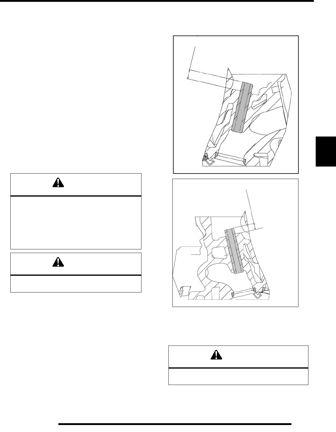
5.31
ENGINE
5
Combustion Chamber
1. Clean all accumulated carbon deposits from combustion
chamber and valve seat area.
NOTE: Carbon Clean Fuel Treatment (2871326) can
be used to help remove carbon deposits.
IMPORTANT: Do not use a metal scraper, a coarse
wire brush, or abrasive cleaners to clean the cylinder
head. Damage may result.
2. Visually inspect cylinder head gasket surface and
combustion chamber for cracks or damage. Pay close
attention to the areas around spark plug and valve seats.
Valve Guide Removal / Installation
1. Support cylinder head and place valve guide remover into
valve guide from the combustion chamber side.
2. Drive or press old valve guides out of cylinder head.
3. Apply 90 weight oil to outside of new valve guides.
4. Drive or press new guides from camshaft side of head to
proper installed height. Note difference between intake and
exhaust guide height below.
5. Ream or hone new valve guides to size to obtain specified
stem-to-guide clearance. Ream from combustion chamber
side of head.
6. Clean cylinder head thoroughly with clean solvent.
7. Inspect valve seats and recondition if necessary.
CAUTION
Replacement of valve guides requires an oven,
special equipment and experience to do the job
correctly. If you are unsure of your ability to do
the repair professionally it is best to sublet the
labor to a competent machinist.
Valve seat reconditioning is required when
valve guides are replaced.
CAUTION
The cylinder head can be easily damaged if the
procedure is done carelessly.
CAUTION
Do not tilt the reamer while reaming the guide. Always
rotate the reamer in a clockwise direction.
Exhaust Valve Guide Height: 6.75 - 7.25 mm
Intake Valve Guide Height: 8.93 - 9.43 mm
PartShark.com
877-999-5686
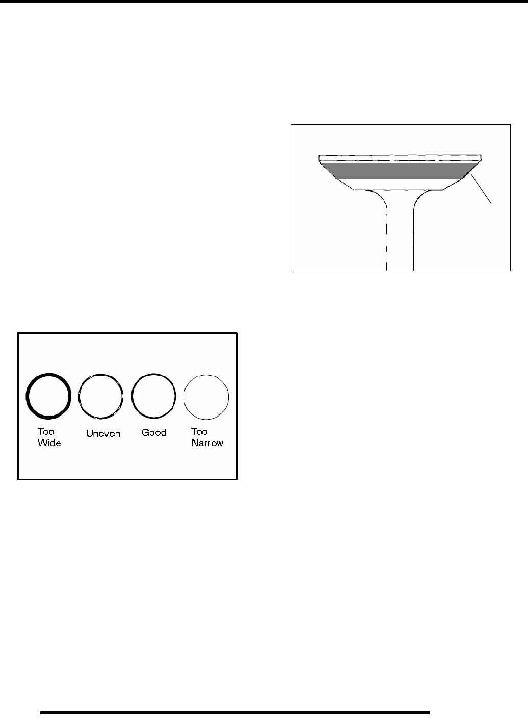
5.32
ENGINE
Valve Seat Reconditioning
Valve seat reconditioning should be performed by a technician
proficient in cylinder head reconditioning techniques.
Reconditioning techniques vary, so follow the instructions
provided by the valve reconditioning equipment manufacturer.
Do not grind seats more than necessary to provide proper seat
surface, width, and contact point on valve face.
Valve Seat Inspection
Inspect valve seat in cylinder head for pitting, burnt spots,
roughness, and uneven surface. If any of the above conditions
exist, the valve seat must be reconditioned. If the valve seat is
cracked the cylinder head must be replaced.
Valve seat width and point of contact on the valve face is very
important for proper sealing. The valve must contact the valve
seat over the entire circumference of the seat, and the seat must
be the proper width all the way around. If the seat is uneven,
compression leakage will result. If the seat is too wide, seat
pressure is reduced, causing carbon accumulation and possible
compression loss. If the seat is too narrow, heat transfer from
valve to seat is reduced. The valve may overheat and warp,
resulting in burnt valves.
1. Install pilot into valve guide.
2. Apply cutting oil to valve seat and cutter.
3. Place 46° cutter on the pilot and make a light cut.
4. Inspect the cut area of the seat:
* If the contact area is less than 75% of the circumference of the
seat, rotate the pilot 180° and make another light cut.
* If the cutter now contacts the uncut portion of the seat, check
the pilot. Look for burrs, nicks, or runout. If the pilot is bent it
must be replaced.
* If the contact area of the cutter is in the same place, the valve
guide is distorted from improper installation
* If the contact area of the initial cut is greater than 75%,
continue to cut the seat until all pits are removed and a new seat
surface is evident. NOTE: Remove only the amount of material
necessary to repair the seat surface.
5. To check the contact area of the seat on the valve face, apply
a thin coating of Prussian Blue™ paste to the valve seat. If
using an interference angle (46°) apply black permanent
marker to the entire valve face (A).
6. Insert valve into guide and tap valve lightly into place a few
times.
7. Remove valve and check where the Prussian Blue™
indicates seat contact on the valve face. The valve seat
should contact the middle of the valve face or slightly
above, and must be the proper width.
* If the indicated seat contact is at the top edge of the valve face
and contacts the margin area (B) it is too high on the valve face.
Use the 30° cutter to lower the valve seat.
* If too low, use the 60° cutter to raise the seat. When contact
area is centered on the valve face, measure seat width.
* If the seat is too wide or uneven, use both top and bottom
cutters to narrow the seat.
* If the seat is too narrow, widen using the 45° cutter and re-
check contact point on the valve face and seat width after each
cut.
A
PartShark.com
877-999-5686
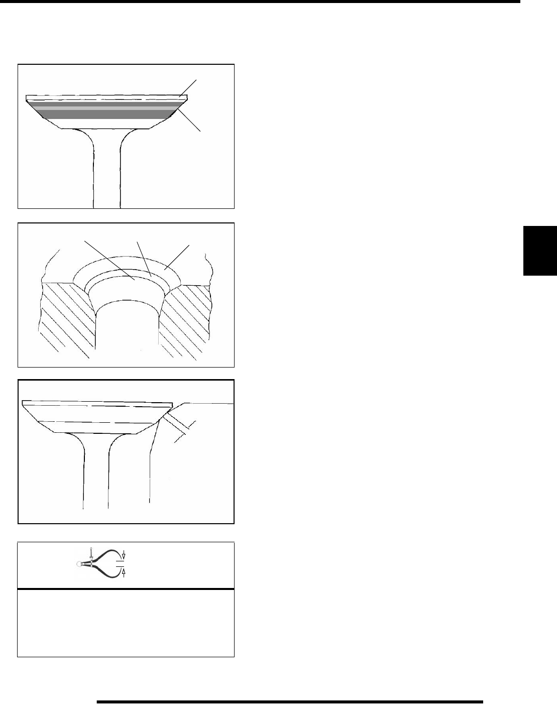
5.33
ENGINE
5
NOTE: When using an interference angle, the seat
contact point on the valve will be very narrow, and is
a normal condition. Look for an even and continuous
contact point all the way around the valve face (A).
8. Clean all filings from the area with hot soapy water. Rinse
and dry with compressed air.
9. Lubricate the valve guides with clean engine oil, and apply
oil or water based lapping compound to the face of the
valve.
NOTE: Lapping not required if an interference angle
reconditioning method is used.
10. Insert the valve into its respective guide and lap using a
lapping tool or a section of fuel line connected to the valve
stem.
11. Rotate the valve rapidly back and forth until the cut sounds
smooth. Lift the valve slightly off of the seat, rotate 1/4
turn, and repeat the lapping process. Do this four to five
times until the valve is fully seated, and repeat process for
the other valve(s).
12. Thoroughly clean cylinder head and valves.
= In. / mm.
Valve Seat Width:
Intake Std: .028" (.7 mm)
Limit: .055" (1.4 mm)
Exhaust Std: .039I (1.0 mm)
Limit: .071" (1.8 mm)
B
A
Proper Seat Contact
on Valve Face
Bottom 60°Seat 45°Top 30°
Seat
Width
PartShark.com
877-999-5686
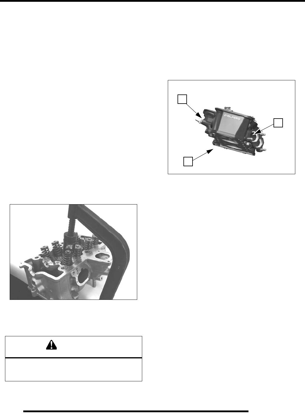
5.34
ENGINE
Cylinder Head Assembly
NOTE: Assemble valves one at a time to maintain
proper order.
1. Apply engine oil to valve guides and seats.
2. Coat valve stem with Premium Starter Grease (2871460).
3. Install valve in guide.
4. Valve seals should be installed after the valves are in the
head to avoid valve seal damage. Install NEW valve seals
on valve guides carefully with a rotating motion.
5. Dip valve spring and retainer in clean engine oil.
6. Install spring with tight wind facing DOWN (toward head).
7. Place top retainer on spring.
8. Compress spring.
9. Install split keepers with gap even on both sides.
NOTE: To prevent damage to the valve seals, do not
compress the valve spring more than necessary to
install the keepers. A small magnet can be used to
aid installation.
10. Repeat procedure for remaining valves. When all valves are
installed, tap lightly with soft faced hammer on the end of
the valves to seat the split keepers.
Valve Sealing Test
1. Clean and dry the combustion chamber area (A).
2. Pour a small amount of clean solvent into each intake port
(B) and check for leakage around the valves. The valve
seats should hold fluid with no seepage.
3. Repeat for exhaust valves by pouring fluid into each
exhaust port (C).
WARNING
Do not tap on the top retainer or split keepers could
dislodge, causing serious injury. Tap only on the
end of the valve stem.
A
B
C
PartShark.com
877-999-5686
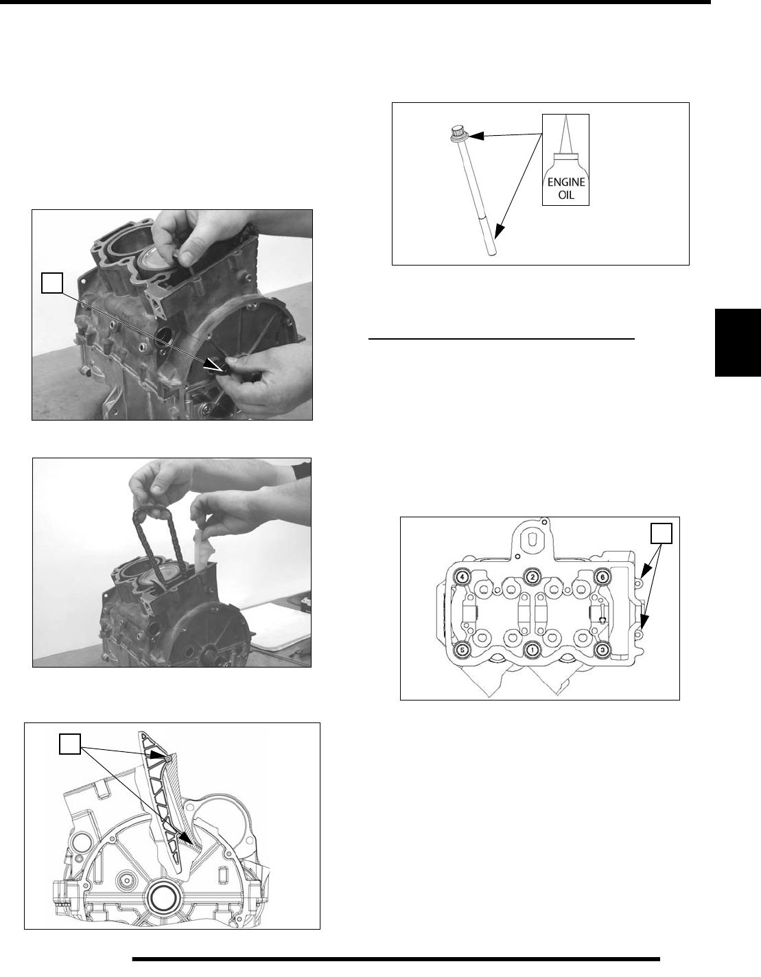
5.35
ENGINE
5
Cylinder Head Installation
1. Prepare cylinder head gasket sealing surfaces by cleaning
thoroughly to remove all residue. The head gasket must be
installed clean and dry, free from oil or grease.
NOTE: Do not touch sealing surfaces of gasket.
2. Reinstall (2) head alignment pins in upper crankcase.
3. Install cam chain tensioner blade in upper crankcase. Install
a new O-ring on pivot bolt and lubricate with engine oil.
Torque bolt (A) to specification.
4. Lift cam chain and install chain guide.
5. Be sure tabs (B) are engaged in slots. Secure cam chain with
a wire so it will not fall into crankcase.
6. Thread cam chain through a new head gasket and install
gasket, locating it on the alignment pins.
7. Set cylinder head in place on alignment pins. Apply engine
oil to threads and flange of the (6) main cylinder head bolts.
8. Tighten main head bolts finger tight, then install the two
6mm outer bolts.
CYLINDER HEAD TORQUE PROCEDURE
• Tighten (6) main head bolts snug.
• Torque (6) main head bolts in sequence shown below to
43.5 lb-ft. (59 Nm).
• Tighten each main head bolt an additional 90 degrees
(1/4 turn) following torque sequence.
• Install (2) M6 outer head bolts (C) and torque to
specification.
90 lb-in.
(10 Nm)
A
B
C
PartShark.com
877-999-5686
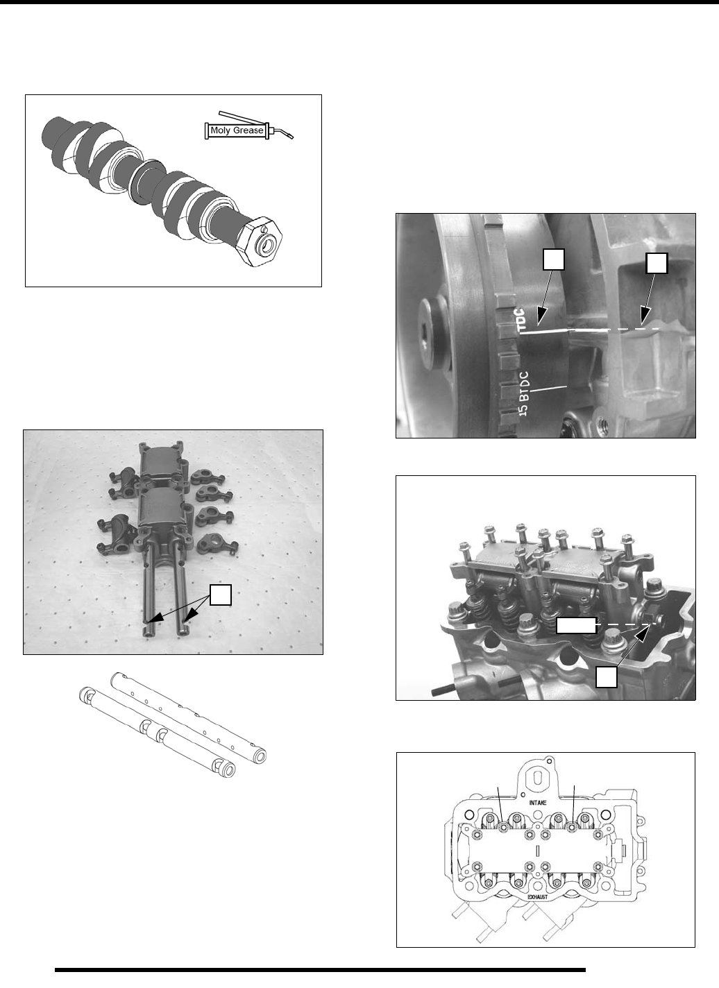
5.36
ENGINE
Camshaft / Carrier Assembly
1. Lubricate all camshaft lobes and bearing journal surfaces
with Premium Starter Grease (PN 2871460).
2. Place camshaft in cylinder head.
3. Lubricate rocker arms, rollers, and shafts with engine oil.
Lay out in proper location as marked upon disassembly.
4. Assemble camshaft carrier with rocker arms and shafts.
Slots (A) must face outward of carrier to allow bolt
installation and to properly orient the oiler holes in shafts.
Camshaft / Camshaft Carrier Installation
1. Loosen all valve adjuster lock nuts.
2. Turn adjuster screws out (counterclockwise) until they
lightly seat against rocker arm.
NOTE: DO NOT force screws against rocker arm.
The adjuster pivot ball may be damaged if forced.
3. Rotate crankshaft in direction of rotation until Top Dead
Center mark (B) on flywheel is aligned with crankcase
parting line (C). This is TDC for MAG side cylinder.
4. Rotate camshaft until pin (D) is in 10:00 position.
5. Install camshaft carrier onto camshaft and install all carrier
bolts snug. Torque in two steps following sequence shown.
A
BC
D
10:00
12
345
6
8
7
10
9
12.5 lb-ft. (17 Nm)
Torque:
PartShark.com
877-999-5686
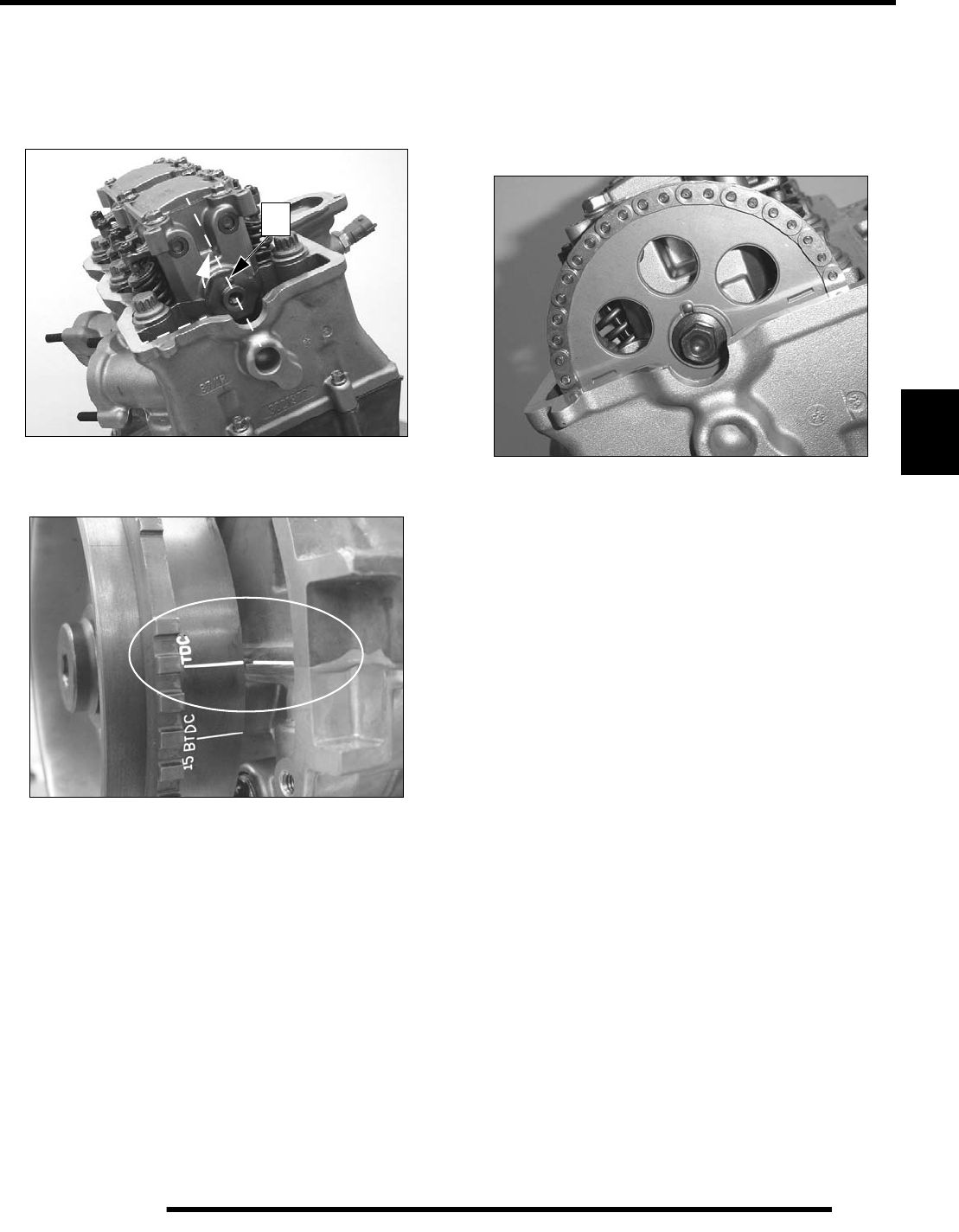
5.37
ENGINE
5
Camshaft Timing
Also refer to Camshaft Timing Quick Reference (page 5.39).
1. Rotate camshaft clockwise until pin (A) is facing UP (use
a wrench across the flats on the sprocket end).
2. Verify TDC mark on flywheel is aligned with crankcase
parting line.
3. Pull cam chain upward, making sure it is engage with the
drive sprocket on the crankshaft.
4. Place the sprocket (with marks facing out) on the chain and
engage all teeth.
5. Align two sprocket marks with valve cover gasket surface.
6. Slide sprocket onto camshaft, aligning slot in sprocket with
pin.
7. Screw in the sprocket bolt finger tight. Sprocket bolt must
be tightened fully after cam chain tensioner is installed.
8. Verify flywheel TDC mark is still aligned (be sure the
crankshaft has not rotated from TDC) and that sprocket
marks are aligned with gasket surface (note that cam chain
tensioner installation may change the alignment slightly).
9. If marks are not aligned, remove sprocket bolt and correct
alignment.
10. Proceed to Cam Chain Tensioner Installation (page 5.38).
A
PartShark.com
877-999-5686
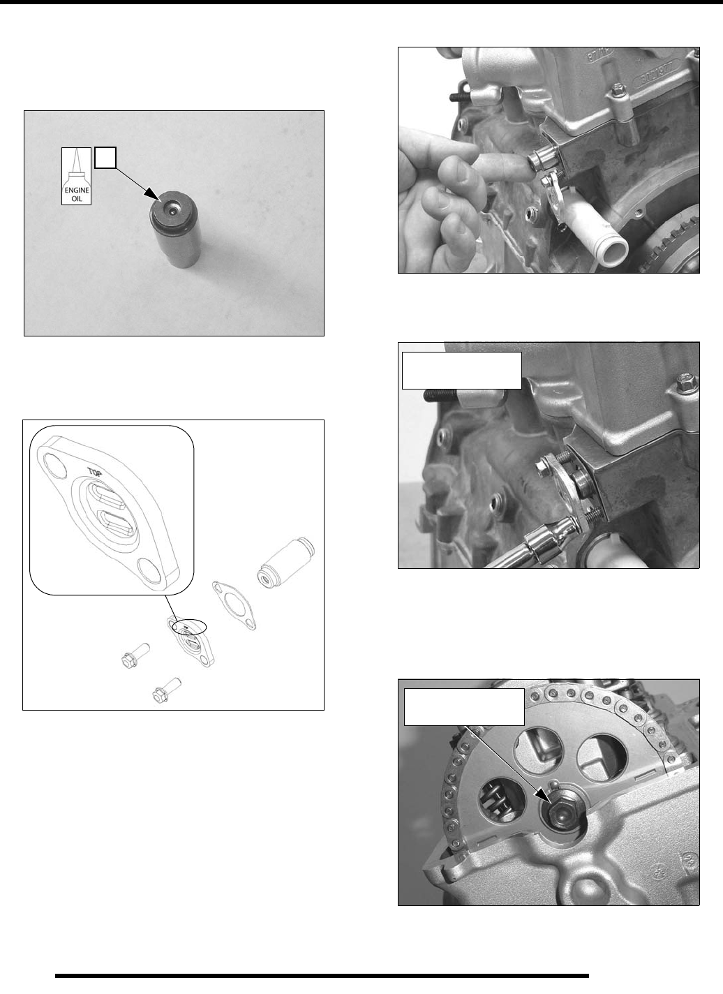
5.38
ENGINE
Cam Chain Tensioner Installation
1. Lubricate tensioner plunger and install in tensioner bore
with check valve end of plunger (B) facing OUT (toward
cap plate).
2. Start outer tensioner bolt through cap plate and new gasket.
Start bolt about 5 threads into outer hole.
NOTE: “Top” mark on tensioner cap plate faces UP.
3. Push tensioner plunger in and hold.
4. Rotate plate and gasket into position and start the inner bolt.
5. Slowly draw bolts evenly until snug.
6. Torque tensioner cap bolts.
7. Rotate crankshaft through two revolutions and verify
camshaft timing is correct.
8. Torque camshaft sprocket bolt.
9. Adjust valve clearance on all valves (refer to Chapter 2
“Maintenance”).
B
89 lb-in. (10 Nm)
Torque:
28 lb-ft. (38 Nm)
Torque:
PartShark.com
877-999-5686
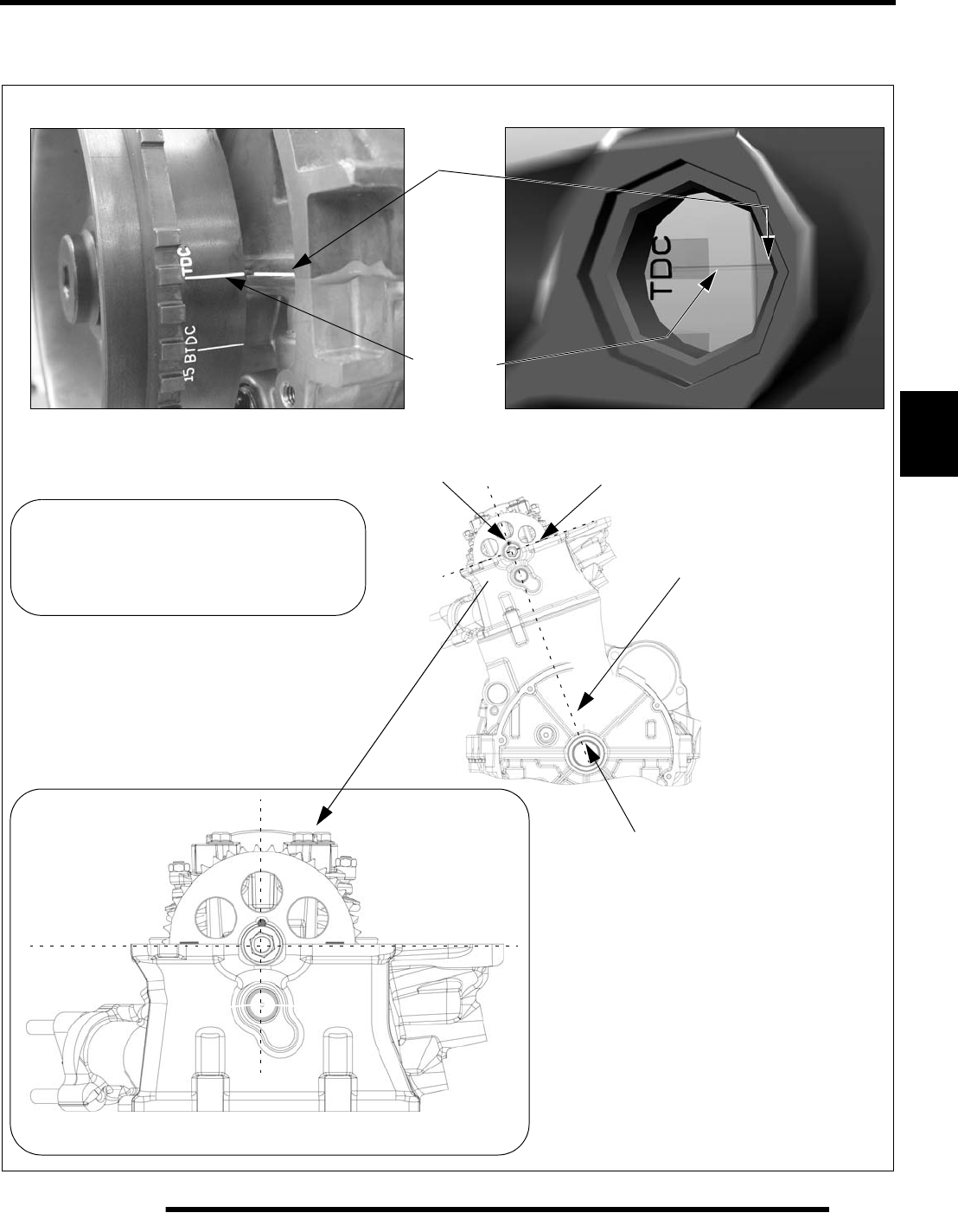
5.39
ENGINE
5
Camshaft Timing - Quick Reference
Crankcase
TDC Mark
Sprocket marks aligned
with surface of head
Pin facing UP
Line
View Through Timing Plug
View With Stator Cover Removed
Parting
Flywheel
Crankshaft / Camshaft Center line
Tensioner Installed
Crankshaft at TDC, MAG Cylinder
Flywheel key UP (in line with
crankshaft / camshaft centerline) or
if flywheel is installed use TDC mark.
IMPORTANT!
Valve and / or piston damage can
occur if engine is rotated with
camshaft incorrectly timed.
PartShark.com
877-999-5686
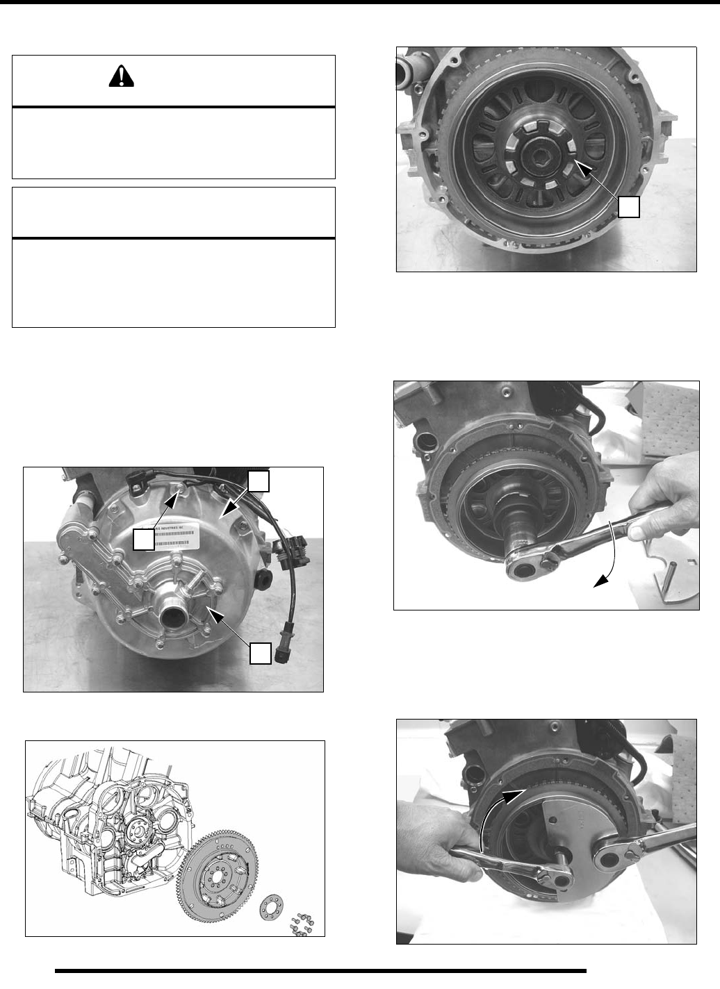
5.40
ENGINE
Crankcase Disassembly
1. Remove cylinder head (beginning on page 5.26).
2. Remove all water pump cover screws (A) and stator cover
screws (B), noting location of wire clamp (C).
NOTE: Water pump cover removal is not required unless
water pump or cover gasket service will be performed.
Water pump service is described on page 5.59.
3. Remove starter gear / drive coupler bolts, plate, and gear.
4. Remove water pump drive coupler damper (D).
5. Use the end of Flywheel Puller PA-49316 to remove
coupler nut.
NOTE: The water pump drive coupler nut has a
LEFT HAND THREAD. Turn CLOCKWISE to remove.
6. Hold flywheel with Crankshaft Holding Tool PA-49318,
and remove flywheel bolt.
NOTE: The flywheel bolt has a LEFT HAND THREAD.
Turn CLOCKWISE to remove.
CAUTION
The rotor contains powerful magnets. Use caution when
removing and installing the stator cover. DO NOT place
fingers between cover and crankcase at any time during
the removal / installation process or injury could result.
NOTICE
Do not attempt to lift the upper crankcase / cylinder from
the lower crankcase for piston / ring access without first
removing the lower crankcase and connecting rod caps
from the crankshaft. Pistons must be removed through
the top of the cylinders with the connecting rod attached.
B
A
C
D
PartShark.com
877-999-5686
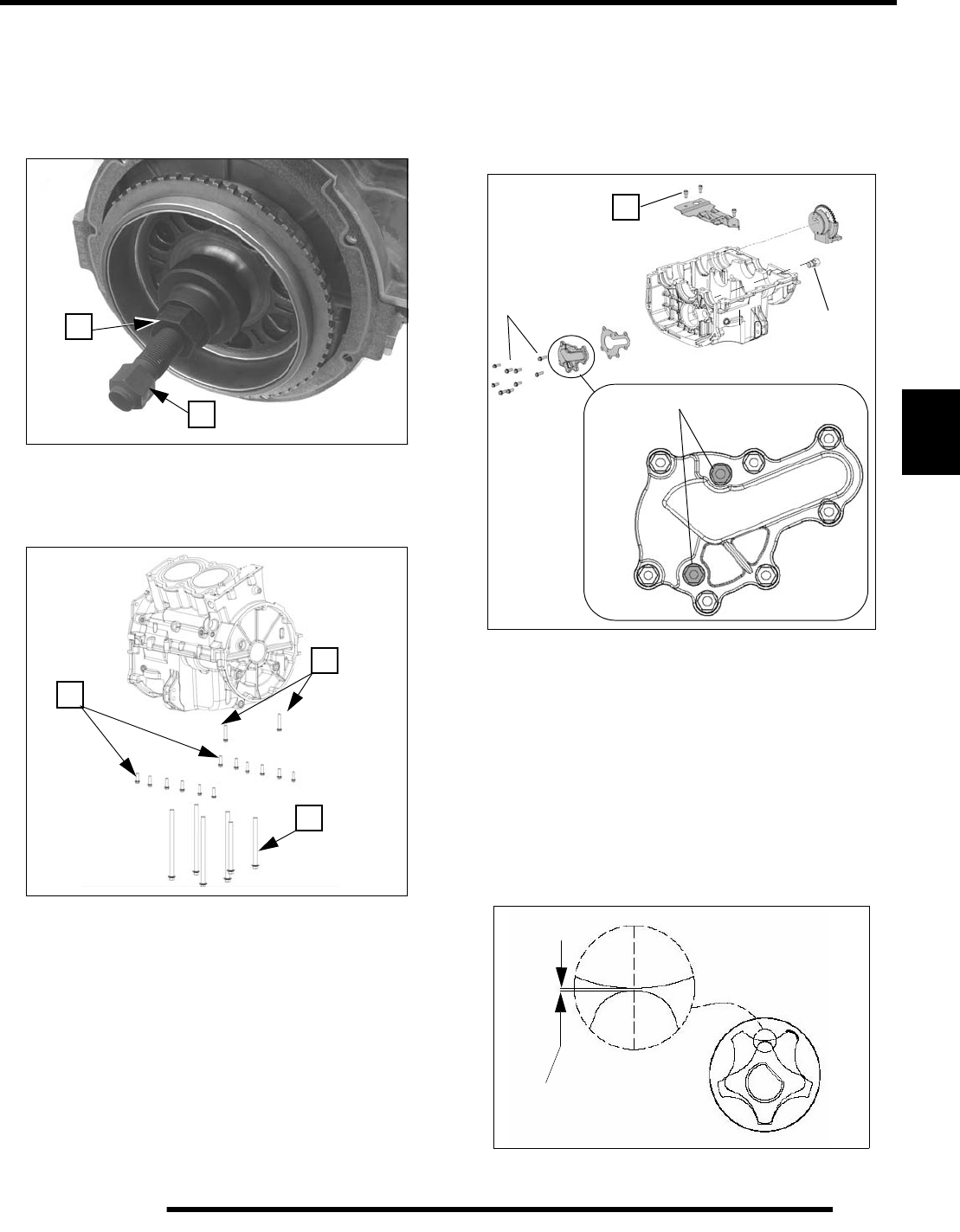
5.41
ENGINE
5
7. Fully install Flywheel Puller PA-49316 on threads of
flywheel (left hand thread - turn flywheel puller
COUNTERCLOCKWISE to install on flywheel).
8. Hold puller body (A) and tighten center bolt (B) to remove
flywheel.
9. Loosen (12) outer crankcase bolts (C) evenly 1/2 turn, then
loosen (2) longer case bolts (D), then the (6) main crankcase
bolts (E). Remove all.
10. Tap lower crankcase in reinforced areas with a soft faced
hammer to loosen, then lift straight upward to remove.
Crankcase (Lower) / Oil Pump Disassembly
1. Remove oil pump cover plate screws. Note location of two
longer (M6x20) screws for assembly. These screws secure
the pump.
2. Remove three baffle plate screws (A) and plate.
3. Slide pump off mounting boss in crankcase.
4. Visually inspect pump rotors and drive gear for damage or
debris.
NOTE: Replace oil pump as an assembly and
pressure relief valve if debris has entered pump or if
pump damage is evident.
5. Rotate pump gear until rotors are positioned as shown
below. Use a feeler gauge to measure tip clearance.
Clearance should not exceed 0.006" (.15mm).
B
A
C
E
D
M6x20
96 lb-in. (12 Nm)
90 lb-in.
21 lb-ft.
(28 Nm)
A
(10 Nm)
M6x16
(all outer screws)
0.006” (0.15 mm)
PartShark.com
877-999-5686
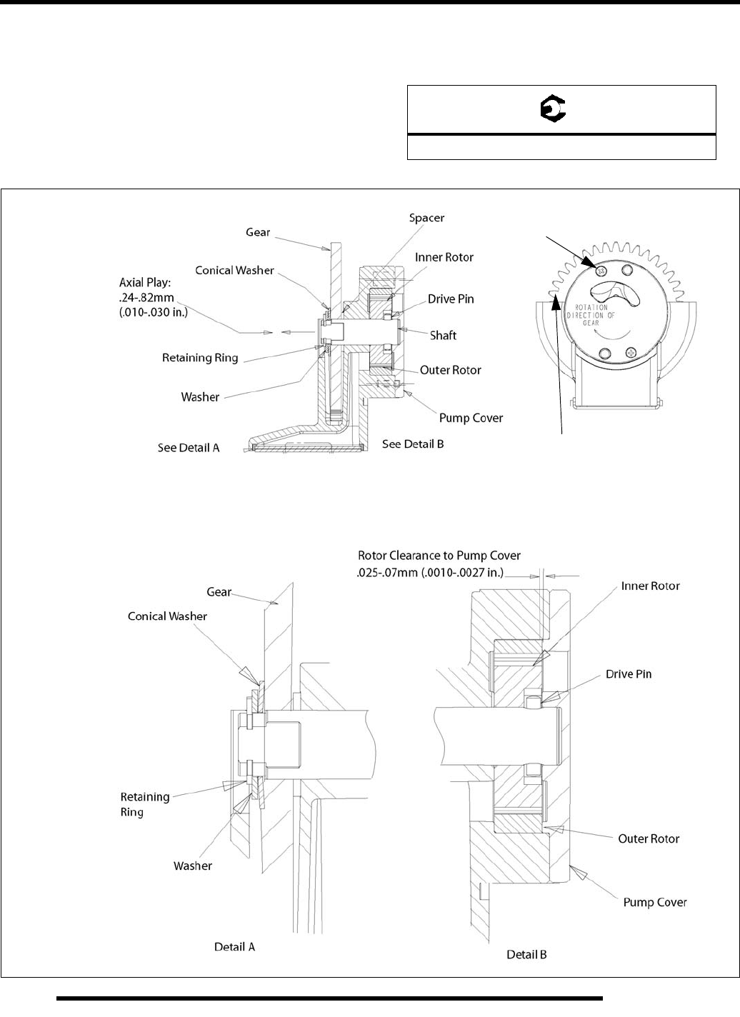
5.42
ENGINE
6. Measure pump rotor clearance to pump cover plate with a
feeler gauge through the pump outlet window and compare
to specification.
7. Measure shaft axial (end) free play and compare to
specification.
8. Inspect inner rotor drive pin for wear or damage.
9. Remove oil pressure relief from crankcase. Replace if
debris has entered, or if oil pressure was outside of specified
range.
= T
20 ± 2 ft. lbs. (27 ± 3 Nm)
OIL PUMP DETAIL 6-8 lb-in. (.69-.89 Nm)
M3 end cap screws
Gear must turn freely
after assembly
PartShark.com
877-999-5686
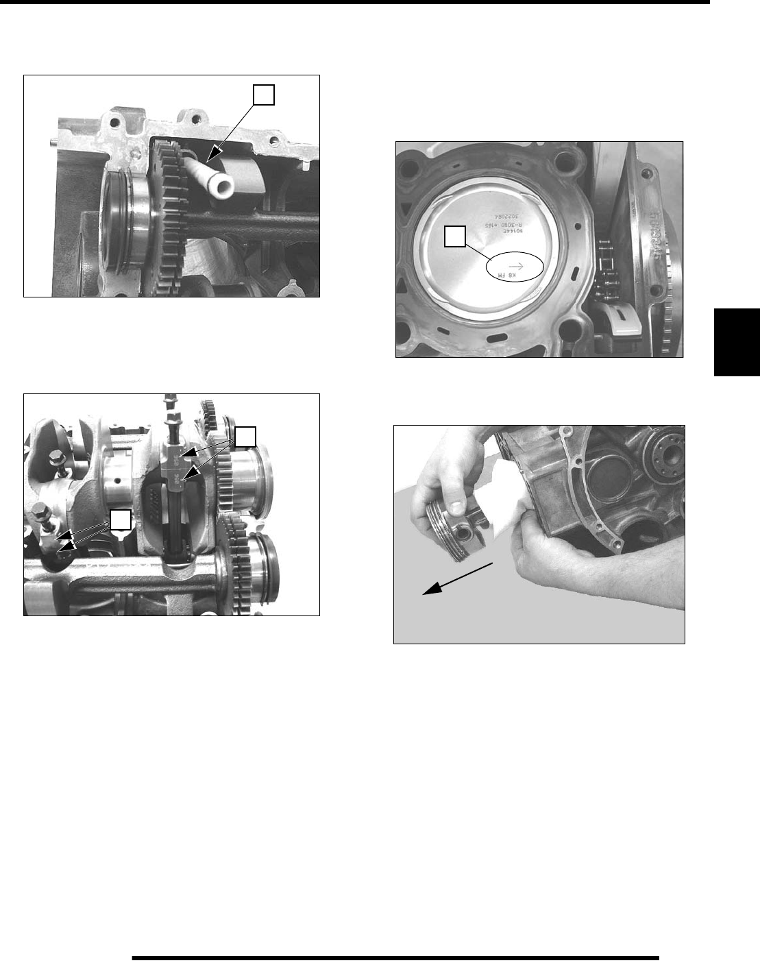
5.43
ENGINE
5
Crankcase Disassembly (Upper)
1. Remove the oil passage connecting tube (F) with O-rings.
2. Note connecting rod and cap marks so they can be oriented
properly and assembled in the same manner as matched sets
on proper rod journal (G). New rods can be installed with
marks to front or rear. Rods have no offset.
Piston / Connecting Rod Removal
1. Some pistons may have an orientation marking. Note the
arrow (A) should face the MAG end of crankshaft.
NOTE: Replacement pistons can be installed in
either orientation as they are symmetric.
2. Push connecting rod / piston assembly out through top of
cylinder bore of upper crankcase.
NOTE: If pistons are to be reused, mark them for
assembly in same cylinder.
3. See “Piston / Piston Ring Inspection” on page 5.48
F
G
G
A
PartShark.com
877-999-5686
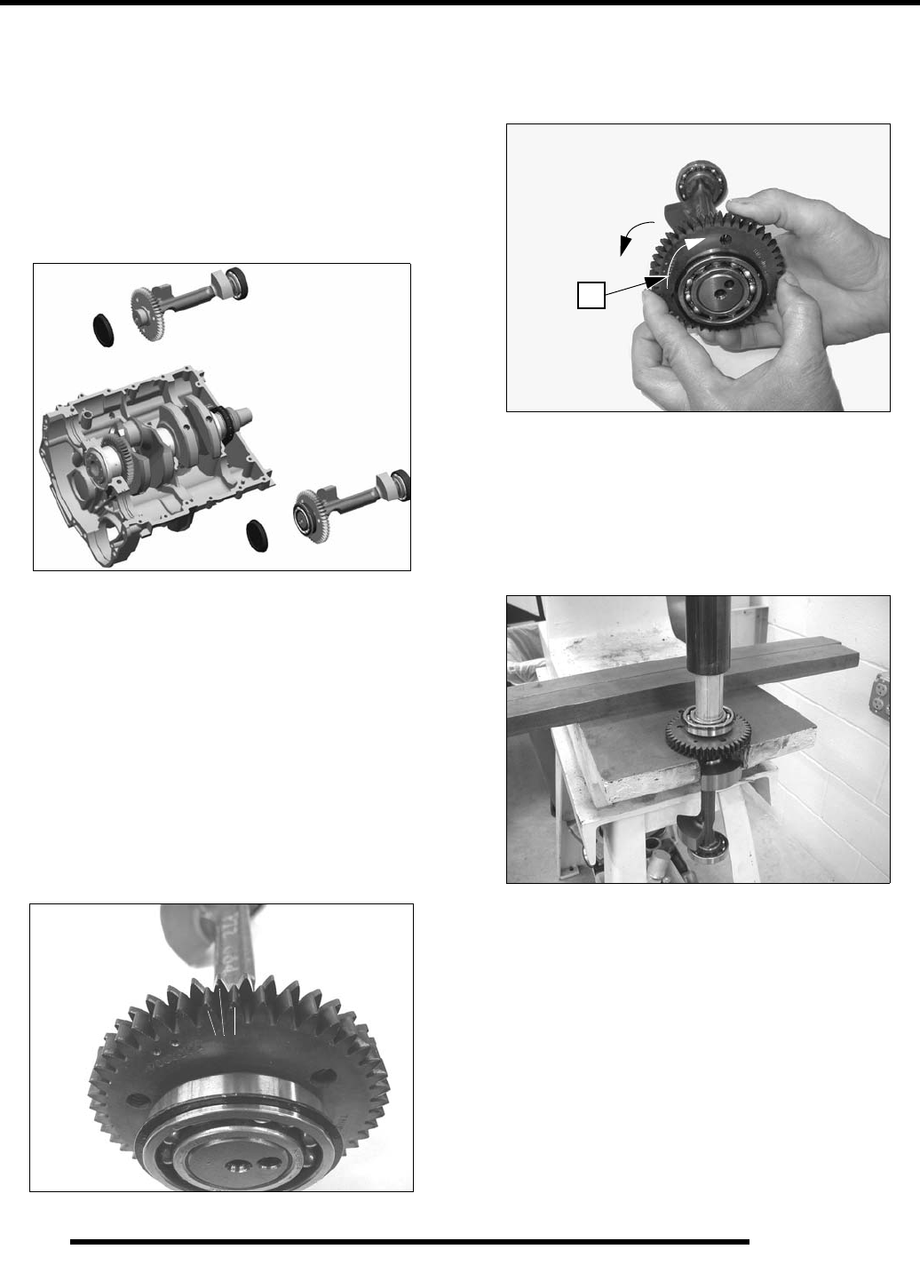
5.44
ENGINE
Counterbalance Shaft Removal / Inspection
1. Note timing marks on balance shaft drive gears and
crankshaft drive gear. Shafts must be properly timed upon
assembly.
2. Mark each shaft location for assembly (starter side or oil
pipe side).
3. Lift both balance shafts from upper crankcase and remove
end plugs.
4. Inspect both counterbalance shaft bearings.
NOTE: Due to extremely close tolerances,
counterbalance shaft bearings must be inspected
visually, and by feel. Look for signs of discoloration,
scoring, galling, or contamination from moisture or
dirt. Turn bearings on shaft. Bearings should turn
smoothly and quietly. The outer race should be firm
with minimal side to side movement and no
detectable up and down movement. Replace
bearings if any of the above are present.
5. Inspect gear teeth for damage. Normal split gear alignment
is approximately 1/2 tooth in the relaxed position as shown.
6. Hold main gear (A) and rotate split gear counterclockwise
(viewed from gear end) to compress springs. Split gear
should rotate and return freely and completely without
binding.
Counterbalance Split Gear Replacement
1. Set shaft upright in a press with gear fully supported on
each side with a flat press plate. Select a suitable arbor
(slightly smaller than the O.D. of the shaft), and press shaft
out of bearing and then out of gear assembly.
NOTE: Do not attempt to press off the thrust washer
with the split gear. The washer is positioned behind
the alignment pin and can only be replaced if the pin
is removed (see the following illustration).
A
PartShark.com
877-999-5686
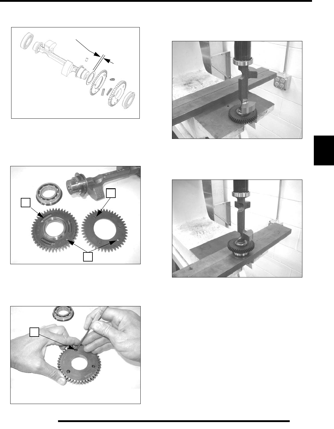
5.45
ENGINE
5
2. Visually inspect thrust washer. Remove pin and replace
washer if damaged or worn to less than 1.15 mm (.045 in.).
3. Lubricate and install (3) new springs (A) in new drive gear.
Small holes (B) must be aligned upon assembly.
4. Place split gear on drive gear with tabs (B) of split gear
toward springs of drive gear, and holes (C) aligned.
5. Hold gear assembly together. Turn over on workbench.
Working through access holes (D), push back each spring
until all three tabs of split gear are engaged and split gear
seats to drive gear.
6. Lay gear assembly on press plate with split gear side UP.
7. Carefully align pin of balance shaft with slot in gear. Press
shaft into gear assembly until seated against washer.
8. Lay new bearing (retaining ring side down) on open press
plate so both inner and outer races are supported.
9. Press shaft assembly into bearing until seated.
1.15-1.35 mm (.045 - .053 in.)
C
AB
D
PartShark.com
877-999-5686
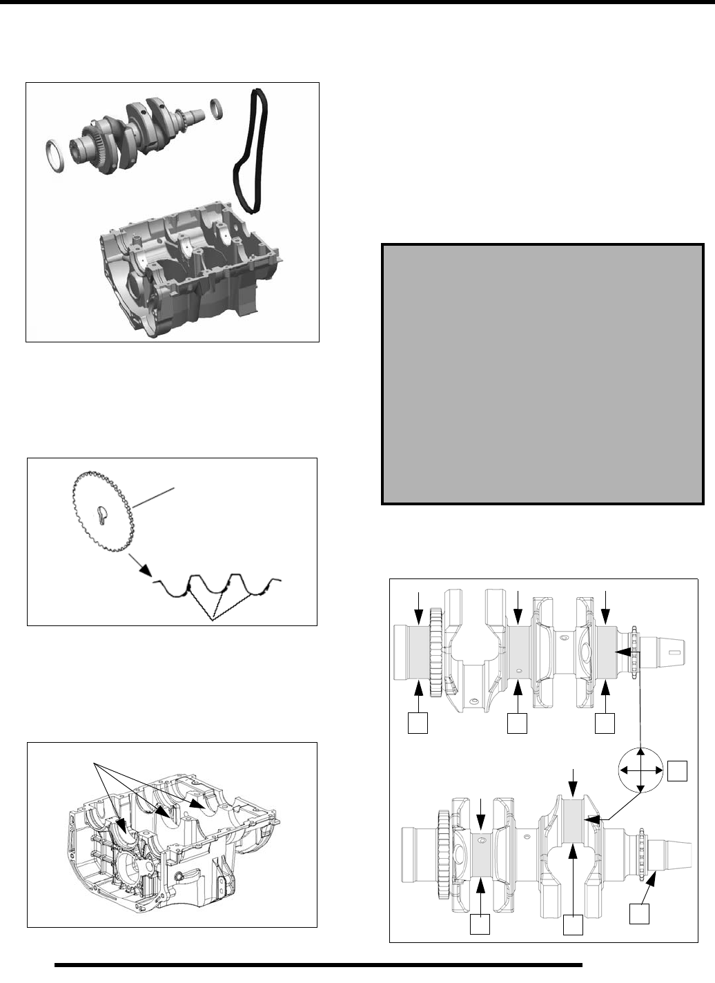
5.46
ENGINE
Crankshaft / Cam Chain Removal
1. Remove crankshaft with cam chain and end seals.
Cam Chain / Sprocket Inspection
1. Cam chain should be replaced if damage is evident or if
sprockets show visible signs of wear. Inspect drive and
driven sprocket as shown below.
Crankcase Inspection (Lower)
1. Remove main bearing inserts from lower crankcase half.
Replace the crankcase assembly if a bearing bore is galled
or if bearing inserts have rotated in the case.
Crankshaft Inspection
1. Visually inspect surface of crankshaft main and
connecting rod journals. Replace crankshaft if any journal
is scratched or pitted.
2. Measure each main journal (A) and rod journal (B) in two
locations, 90 degrees apart. Record measurements for
bearing selection on page 5.48. Calculate the difference
between the two measurements for each journal to
determine concentricity (C). Replace crankshaft if any
journal is worn below the minimum diameter specification
or if journal out-of-round exceeds maximum specification.
3. Support crankshaft on V-blocks or on-centers in a
crankshaft stand or lathe. Measure crankshaft runout (E)
and replace if runout exceeds maximum listed above.
A - Crankshaft Main Journal Diameter:
2.1642 - 2.1650 (54.970 - 54.990 mm)
C - Crankshaft Main Journal Concentricity:
< 0.00027" (0.007 mm) Out Of Round
B - Connecting Rod Journal Diameter:
1.7718 - 1.7726 " (45.005 - 45.025 mm)
C - Connecting Rod Journal Concentricity:
< 0.00027" (0.007 mm) Out Of Round
D - Maximum Runout:
.001 " (.025 mm)
AA A
B
BD
C
PartShark.com
877-999-5686
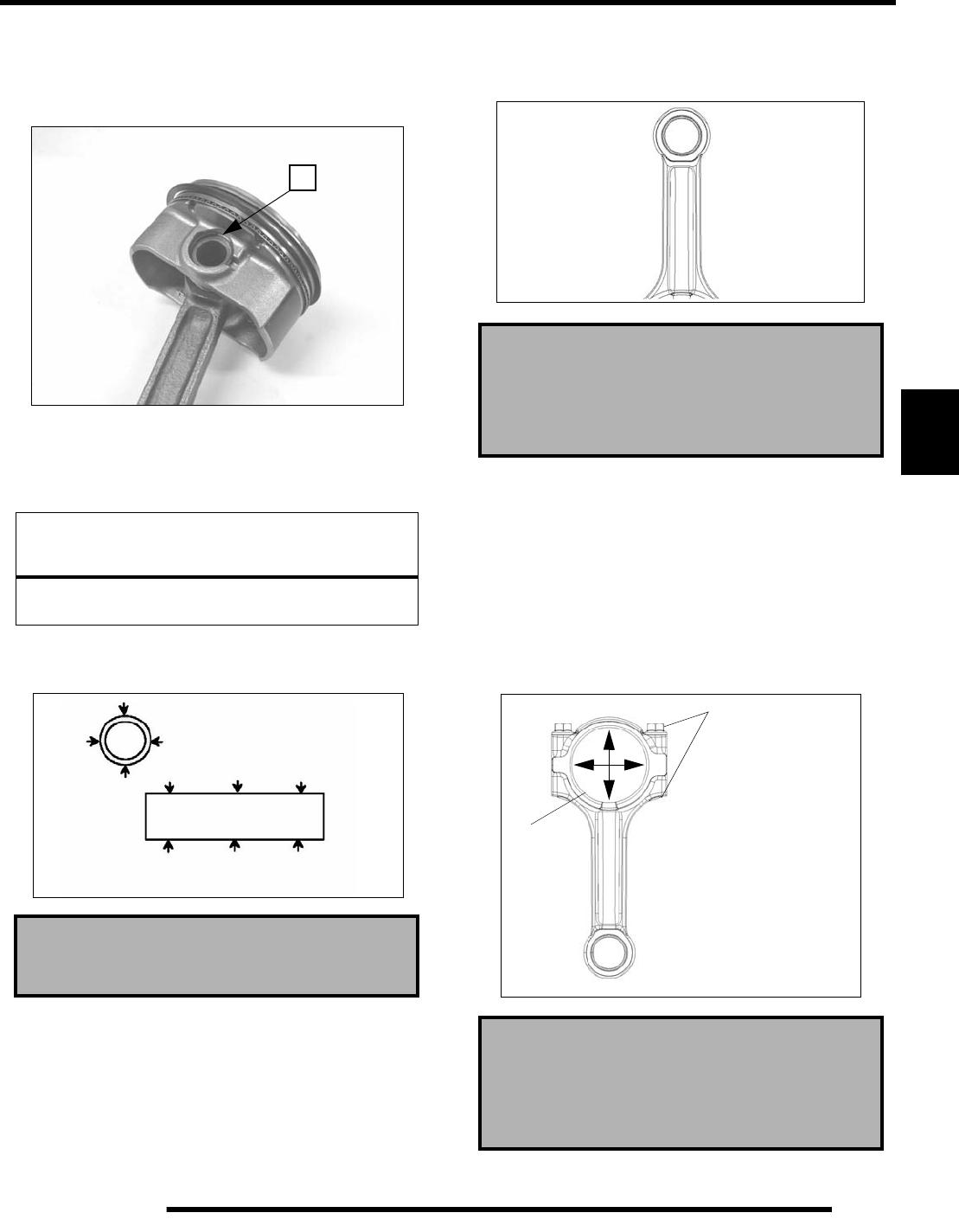
5.47
ENGINE
5
Connecting Rod Inspection
1. Secure connecting rod lightly in a soft jawed vise.
2. Note location of the piston circlip gap (A) at top.
3. Remove piston circlip.
4. Push piston pin out of piston. If necessary, heat crown of
piston slightly with a propane torch or heat gun.
5. Measure piston pin O.D. in two directions and 3 locations
on the length.
6. Inspect small end and big end of connecting rod (and
matching rod cap) for damage, galling of surface or pitting.
7. Measure small end I.D. in two directions as shown. Record
measurements. Difference between measurements is
concentricity. Compare to specifications.
8. Install matching rod cap on connecting rod (without
bearings) and install bolts.
9. Tighten bolts snug, then torque to 24 lb-ft (33 Nm).
10. Using a dial bore gauge, measure big end I.D. in two
directions shown. Record measurements. Difference
between measurements is concentricity. Compare to
specifications.
11. Select appropriate bearing insert (color) from table
(page 5.48).
NOTICE
Do not apply heat to piston rings or a loss of radial
tension could result.
Piston Pin O.D. :
0.7873" ± .0001" (19.9975 ± .0025 mm)
A
Connecting Rod (Small End) Diameter:
0.7886 + 0.0 / - .015" (20.03 + 0.0 / - .015 mm)
Connecting Rod (Small End) Concentricity:
< 0.00027" (0.007 mm) Out Of Round
Connecting Rod (Big End) Diameter:
1.8892 - 1.8902" (47.987 - 48.011 mm)
Connecting Rod (Big End) Concentricity:
< 0.00047" (0.012 mm)
Install New
1. Tighten snug
2. Torque 24 lb-ft. (33 Nm)
Remove
bearings
PartShark.com
877-999-5686
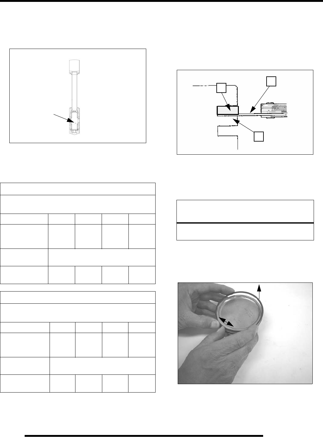
5.48
ENGINE
Connecting Rod Big End Bearing Selection
1. If using NEW connecting rods, install the bearing color
that matches the color marked on the connecting rod cap as
shown below.
2. If re-installing the original connecting rod, select the
appropriate bearing from the table below based on
connecting rod big end I.D. measurements (page 5.47).
Piston / Piston Ring Inspection
1. Measure piston ring to ring land clearance with a thickness
gauge (A) inserted between bottom edge of ring (B) and
piston ring land (C). Replace both piston and rings if
clearance exceeds service limit.
2. Repeat for 2nd ring.
Piston Ring Removal
1. Carefully remove top compression ring by hand or using a
ring removal pliers.
Piston ring pliers: Carefully expand ring and lift it off the
piston.
By hand: Placing both thumbs as shown, spread the ring open
and push up on opposite side. Do not scratch ring lands.
2. Repeat procedure for second ring.
3. Remove (3 piece) oil control ring. Remove top rail first,
then bottom rail, then the expander.
Bearing Size Selection Chart In Millimeters
Connecting rod journal must be within standard size limits as
determined by crankshaft measurements (See page 5.46).
Con Rod Mark Red White Blue Yellow
Con Rod Big End
Bore Diameter
47.987mm
-
47.993mm
47.993mm
-
47.999mm
47.999mm
-
48.005mm
48.005mm
-
48.011mm
Target Oil Clearance
(Con Rod Bearing) .023 mm - .057 mm
Bearing color to
install Red White Blue Yellow
Bearing Size Selection Chart In Inches
Connecting rod journal must be within standard size limits as
determined by crankshaft measurements (See page 5.46).
Con Rod Mark Red White Blue Yellow
Con Rod Big End
Bore Diameter
1.8892 in.
-
1.8895 in.
1.8895 in.
-
1.8897 in.
1.8897 in.
-
1.8899 in.
1.8899 in.
-
1.8902 in.
Target Oil Clearance
(Con Rod Bearing) .0009 in. - .0022 in.
Bearing color to
install Red White Blue Yellow
Paint mark
NOTICE
Do not expand the ring more than necessary to remove
it from piston or ring may break or lose radial tension.
A
B
C
PartShark.com
877-999-5686
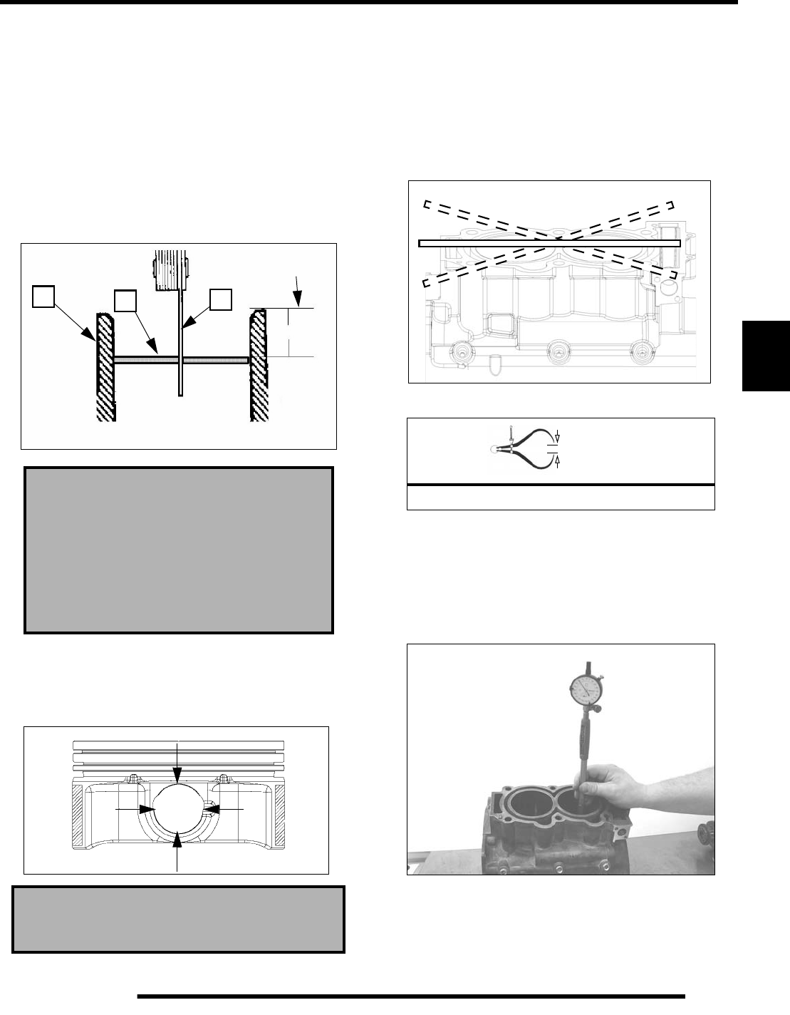
5.49
ENGINE
5
Piston Ring Installed Gap
1. Place each piston ring (A) inside the cylinder (B) (from
cylinder head side of crankcase). Use the piston to push the
ring squarely into cylinder, as shown below.
2. Measure installed gap with a feeler gauge (C) at both the
top and bottom of the cylinder.
IMPORTANT: A difference between top and bottom
end gap measurements is a general indication of
cylinder taper (wear). The cylinder should be
measured for taper and out of round.
Piston Pin Bore Inspection
1. Measure piston pin bore.
Cylinder Inspection
1. Remove all gasket material from gasket surface.
2. Lay a straight edge across cylinders (upper crankcase).
3. Use a thickness gauge to measure gap between straightedge
and gasket surface. Measure at outer edges and center,
repeating measurements with straightedge laid diagonally.
4. Inspect cylinder for wear, scratches, or damage.
IMPORTANT: DO NOT hone the cylinders or attempt
to repair a damaged cylinder by honing. See “Honing
- Important Information” on page 5.50
5. Inspect taper and out of round with a dial bore gauge.
Piston Ring Installed Gap
Top: 0.014" ± 0.008" (0.36 ± 0.20 mm)
Second: 0.014" ± 0.008" (0.36 ± 0.20 mm)
Oil Control Rails:
0.0196" ± 0.010" (0.50 ± 0.25mm)
Piston Pin Bore:
0.7877" ± .0002" (20.007 ± .004 mm)
25-50 mm
A
BC
Head gasket
surface
= In. / mm.
Cylinder Warp: .002" (0.05 mm) Max.
PartShark.com
877-999-5686
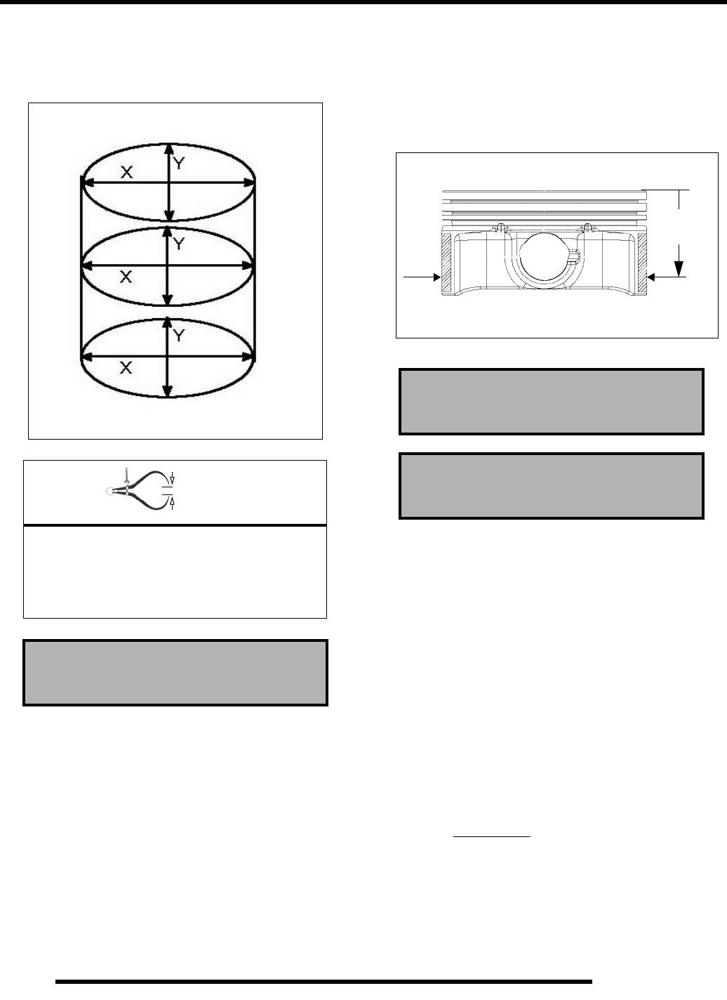
5.50
ENGINE
6. Measure in two directions (front to back and side to side)
on three levels and record measurements. If cylinder is
tapered or out of round beyond .001", the crankcase must
be replaced.
Piston-to-Cylinder Clearance
Measure piston outside diameter at a point 33 mm down from
piston crown, at a right angle to piston pin bore.
Subtract measurement from maximum measurement obtained
in Step 6 of Cylinder Inspection.
Honing - Important Information
The NiCaSil cylinders have a cross-hatch pattern of
approximately 45 degrees to ensure piston ring seating, reduce
ring vibration, and to aid in lubrication retention. The factory
applied crosshatch is good for the service life of the cylinder and
honing IS NOT required when installing new pistons and / or
piston rings.
DO NOT attempt to hone the NiCaSil cylinders. A special
process is required, and improper honing or use of the wrong
type of abrasive stone will result in irreversible cylinder wall
damage.
Any change in surface finish should be followed by cylinder
measurement and an inspection for wear. If cylinders are
damaged or worn beyond the service limit, they can be re-plated
with NiCaSil one time only by a NiCaSil plating specialist.
If cylinder damage is excessive, or if cylinders have been
replated before, it will be necessary to replace the cylinder /
crankcase assembly.
= In. / mm.
Cylinder Taper Limit:
.001" (.025mm) Maximum
Cylinder Out of Round:
Limit: .001" (.025 mm) Maximum
Standard Bore Size
3.4252" ± .0005 (87 mm ± .01mm)
1/2” Up From Bottom
1/2” Down From Top
Piston to Cylinder Clearance:
.0021" ± .0013" (.053mm ± .03mm)
Piston O.D. (Standard):
3.4231" ± .0008" (86.947 ± .02 mm)
(33.0 mm)
1.30 in.
PartShark.com
877-999-5686
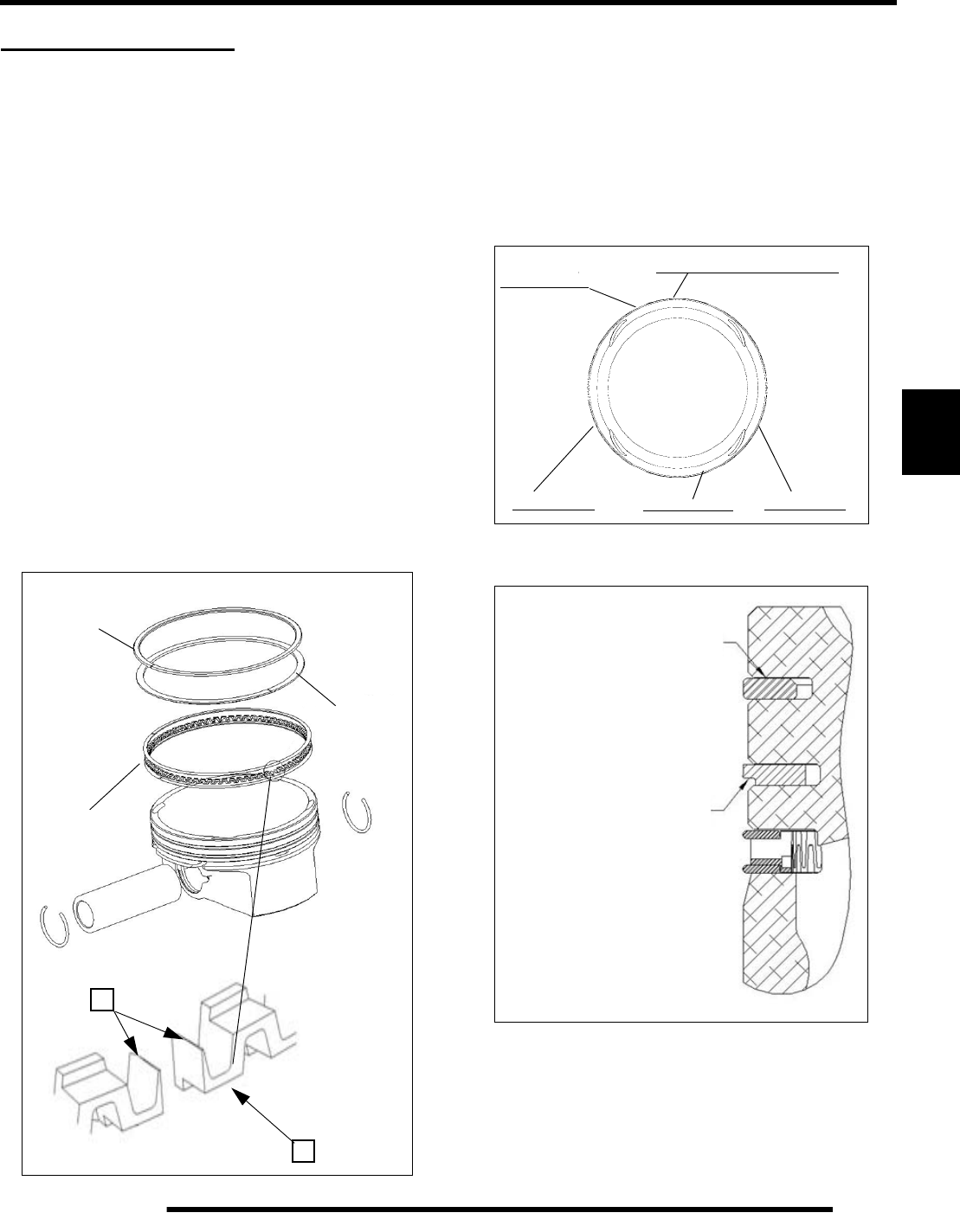
5.51
ENGINE
5
ENGINE ASSEMBLY
Crankcase Preparation - Upper
1. Refer to Oil Flow Diagram (page 5.4) and trace the oil
path through the upper crankcase / cylinder. Flush all oil
passages with solvent and then warm soapy water. Rinse
with clear, warm water and dry with compressed air. Be
sure passages are clean and dry before assembling the
upper crankcase.
Piston Ring Installation
Apply clean engine oil to rings. Check installed gap before
installing on piston. Clean accumulated carbon from ring
grooves and oil ring lube holes if piston has been in service.
1. Place oil control ring expander in oil ring groove. Tips of
expander gap (A) must face piston crown so scraper edge
(B) of expander faces piston skirt.
2. Rotate expander in groove until butt ends are on intake
side of piston. Ends must butt squarely together and must
not overlap.
3. Install bottom rail first, then top rail with end gap located
as shown at right.
4. Install second ring with undercut facing bottom of piston.
Rotate ring to place end gap generally toward (intake) side
of piston as shown below.
5. Install top ring with “0” mark facing up (toward piston
crown) and rotate to position the gap generally at the front
as shown below.
6. Be sure top and second rings rotate freely in their grooves
and do not bind when compressed by hand.
B
Oil Control Ring Installation
Top Rail
Bottom Rail
Expander
A
Top ring gap
2nd ring gap Oil ring expander butt end
Oil ring rail Oil ring rail
Intake
Exhaust
MAG
PTO
“0” mark on top
Undercut facing down
(piston skirt)
Barrel face
Notched face
PartShark.com
877-999-5686
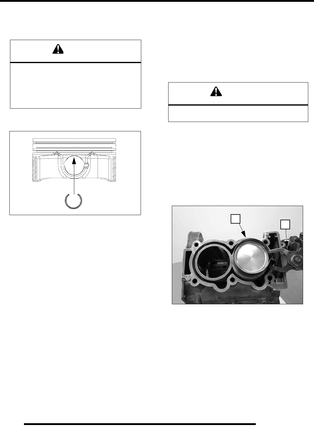
5.52
ENGINE
Piston / Connecting Rod Assembly
1. Lubricate connecting rod small end, piston pin bore, and
piston pin with engine oil.
2. Install a new circlip on one side of piston with gap UP (at
the 12:00) or DOWN (at the 6:00) position.
NOTE: If re-installing connecting rods, orient the
marks on rod caps the same as when removed. Be
aware of this direction when installing pistons to
rods. If new connecting rods are being installed,
they can be installed either way (there is no piston
pin offset in the rod) however it is recommended
they be installed with marks on both rods facing the
same direction.
3. Place piston on connecting rod. Replacement pistons can
be installed in either orientation as they are symmetrical.
4. Push piston pin through rod and piston until it seats against
the installed circlip.
IMPORTANT: Do not tap on pin or cause any sideways
force to connecting rod. Warm piston crown with a
heat gun if pin cannot be installed by hand, or use a
piston pin installation tool. DO NOT apply heat
directly to piston rings or a loss of radial tension could
result.
5. Install the remaining circlip with gap at the top or bottom.
Push the piston pin in both directions to make sure the clips
are properly seated in the groove.
IMPORTANT: Never re-use a circlip that has been
installed.
6. Check to be sure rings rotate freely in the grooves.
Piston / Connecting Rod Installation
1. Apply clean engine oil to piston assembly and cylinder
walls of upper crankcase.
2. Be sure ring end gaps are positioned at least 120 degrees
apart. Oil ring rails at least 60 degrees apart. (See “Piston
Ring Installation” on page 5.51).
3. Apply engine oil to ring compressor band and install band
(A) over piston rings.
4. Fully compress piston rings using compressor pliers (B) on
band.
Piston Ring Compressor Band, 87mm: PV-43570-3
Piston Ring Compressor Pliers: PV-43570-1
5. Apply tape to the sides of connecting rods to protect
cylinder from damage.
6. Align piston with bore and push into cylinder until all rings
are captive. Remove ring compressor.
CAUTION
Do not re-use circlips. Circlips become deformed
during the removal process.
Do not compress the new clip more than
necessary to prevent loss of radial tension.
Severe engine damage may result if circlips are
re-used or deformed during installation.
CAUTION
Be sure compressor band end gap does not align
with any ring end gap when compressing the rings.
AB
PartShark.com
877-999-5686
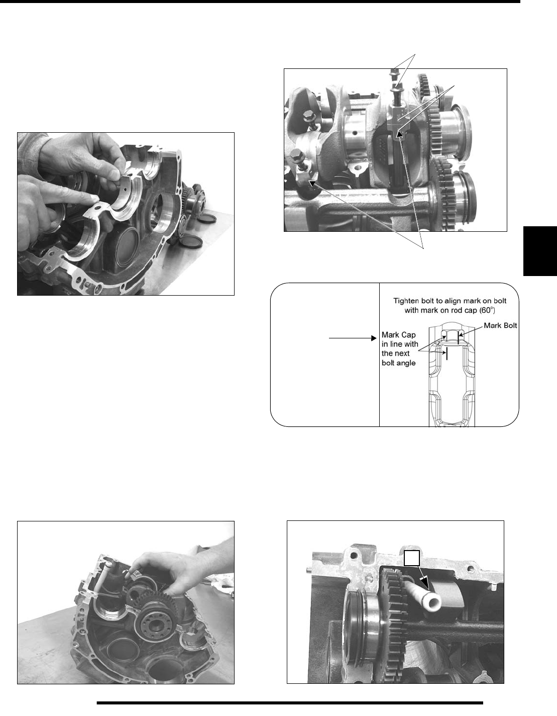
5.53
ENGINE
5
Crankshaft Installation
Refer to illustration Crankcase Assembly (Upper) page 5.54.
1. Clean the bearing bore surfaces of upper crankcase (main
bearings), connecting rods, and connecting rod caps.
2. Align tab of a new main bearing with the slot in main
bearing bore of crankcase. Press bearing insert firmly into
place. Repeat for all main bearings, connecting rods, and
connecting rod caps.
3. Apply Premium Starter Grease (2871460) to each main and
rod bearing journal of crankshaft.
4. Loop cam chain over crankshaft sprocket.
5. Apply engine oil to new crankshaft seals and install seals
on both ends of crankshaft with spring side of seal facing
IN (toward crankshaft).
6. Carefully lower crankshaft into upper crankcase. Guide
connecting rods onto rod journals of crankshaft as
necessary.
7. Adjust crankshaft seals so each is flush with end of
crankcase.
8. Clean threads of bolts and threads in connecting rod to
remove all oil, grease, or assembly lubricant.
9. Apply Loctite 262 (Red) to the end 5 threads of rod bolts.
10. Install rod caps on rods with marks aligned.
11. Install new bolts and tighten evenly until snug.
12. Torque bolts using the following procedure:
Oil Passage Tube
1. Replace O-rings (A) on both ends of the oil supply tube.
2. Apply a light film of engine oil to O-rings.
3. Push oil tube into upper crankcase.
Install New
1. Torque to 24 lb-ft. (33 Nm)
2. Tighten an additional 60°
Match marks
Marked side of rods
facing same direction
Connecting Rod Bolt
Torque Procedure:
(see image)
A
PartShark.com
877-999-5686
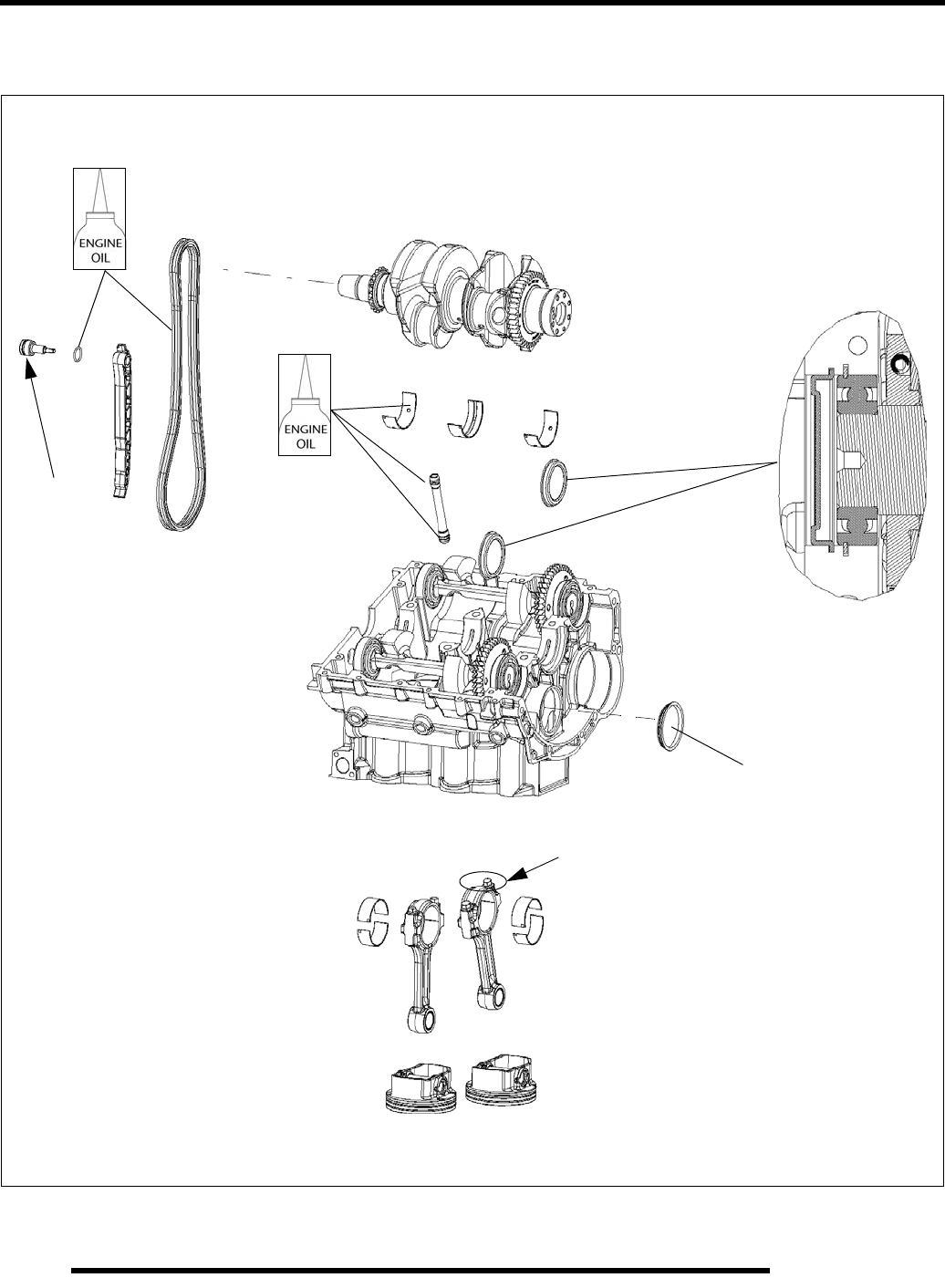
5.54
ENGINE
Crankcase Assembly - Upper
89 lb-in.
See procedure
(10 Nm)
Detail - balance
shaft end cap
Use tool PA-49320
and bearing
PartShark.com
877-999-5686
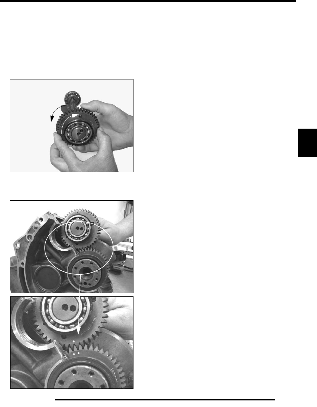
5.55
ENGINE
5
Balance Shaft Installation
See “Balance Shaft Timing” on page 5.56.
1. Balance shafts are identical but should be installed in the
same location as removed.
2. Rotate crankshaft until the two alignment dots crankshaft
gear are visible (page 5.56).
3. As viewed from gear end, rotate split gear counter
clockwise until teeth are aligned and hold in position.
4. Install balance shaft, placing tooth with single dot between
two dots on crankshaft gear. Align bearing locating ring in
groove on crankcase and fully seat the shaft.
5. Rotate crankshaft until SINGLE dot on crankshaft gear is
visible.
6. Align single dot of drive gear between two dots of balance
gear.
7. Align bearing locating ring in groove on crankcase and
fully seat the shaft.
8. Verify balance shaft timing is correct by comparing to
illustration (page 5.56).
9. Place balance shaft end plugs in upper crankcase.
PartShark.com
877-999-5686
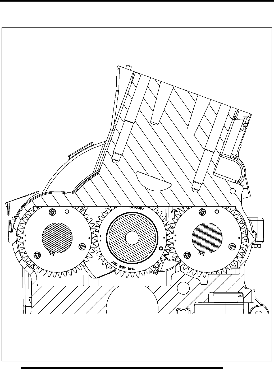
5.56
ENGINE
Balance Shaft Timing
PartShark.com
877-999-5686
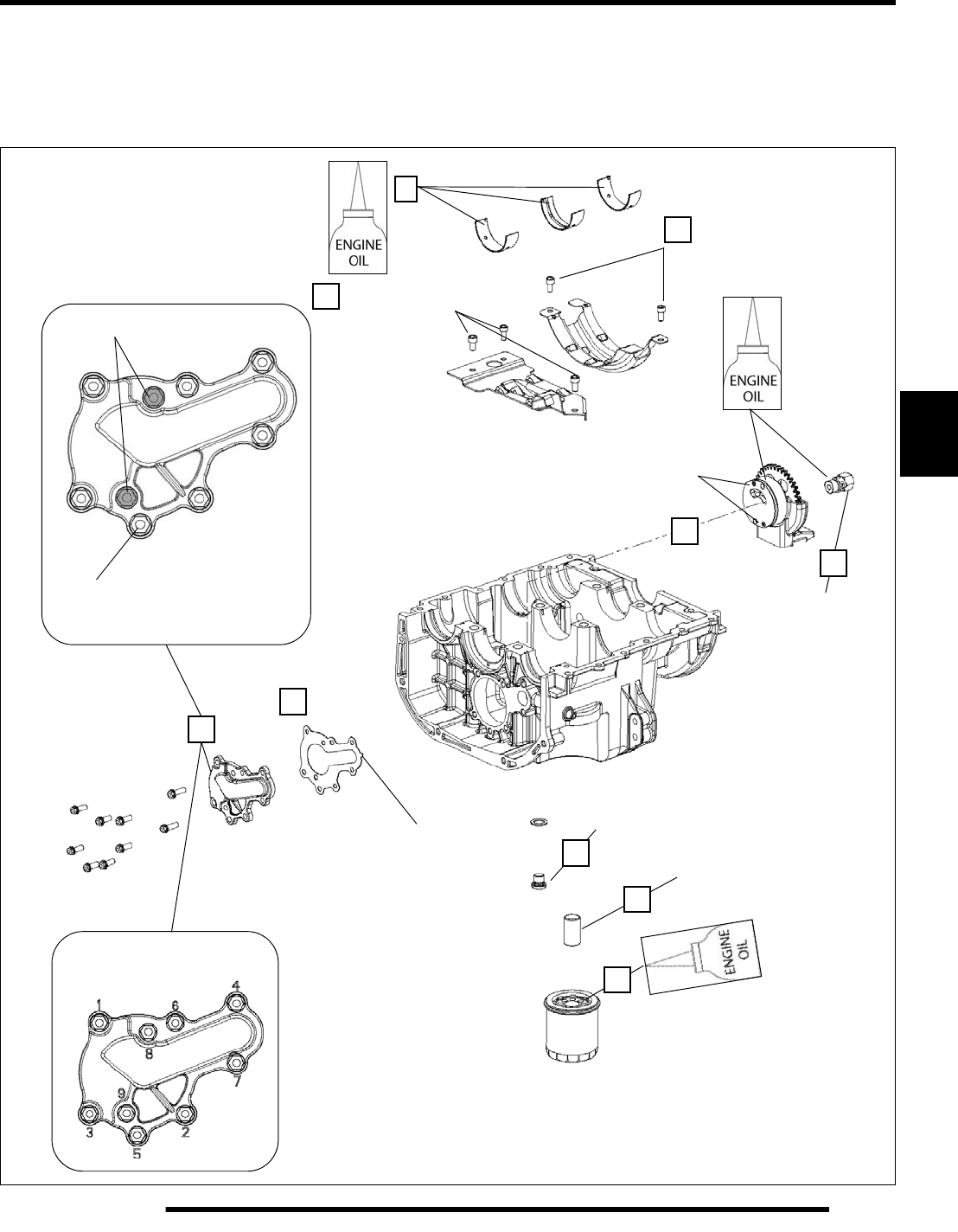
5.57
ENGINE
5
Crankcase Preparation (Lower)
Clean lower crankcase gasket sealing surfaces. Refer to Oil Flow Diagram (page 5.4) and trace the oil path from the through the lower
crankcase. Flush all passages with solvent and then warm soapy water. Rinse with clear warm water and dry with compressed air.
Be sure passages are clean and dry before assembling the lower crankcase. Assemble parts in order A-J.
Torque Pattern
106 lb-in. (12 Nm)
M6x16
(all outer screws)
M6x20 106 lb-in. (12 Nm)
21 lb-ft.
(28 Nm)
Oil Pump Cover
Ensure tab is visible
to verify assembly. 21 lb-ft. (28 Nm)
6-8 lb-in. (.69-.89 Nm)
M3 end cap screws
12 lb-ft.
(16 Nm)
89 lb-in. (10 Nm)
89 lb-in. (10 Nm)
A
B
D
E
F
C
G
H
I
J
PartShark.com
877-999-5686
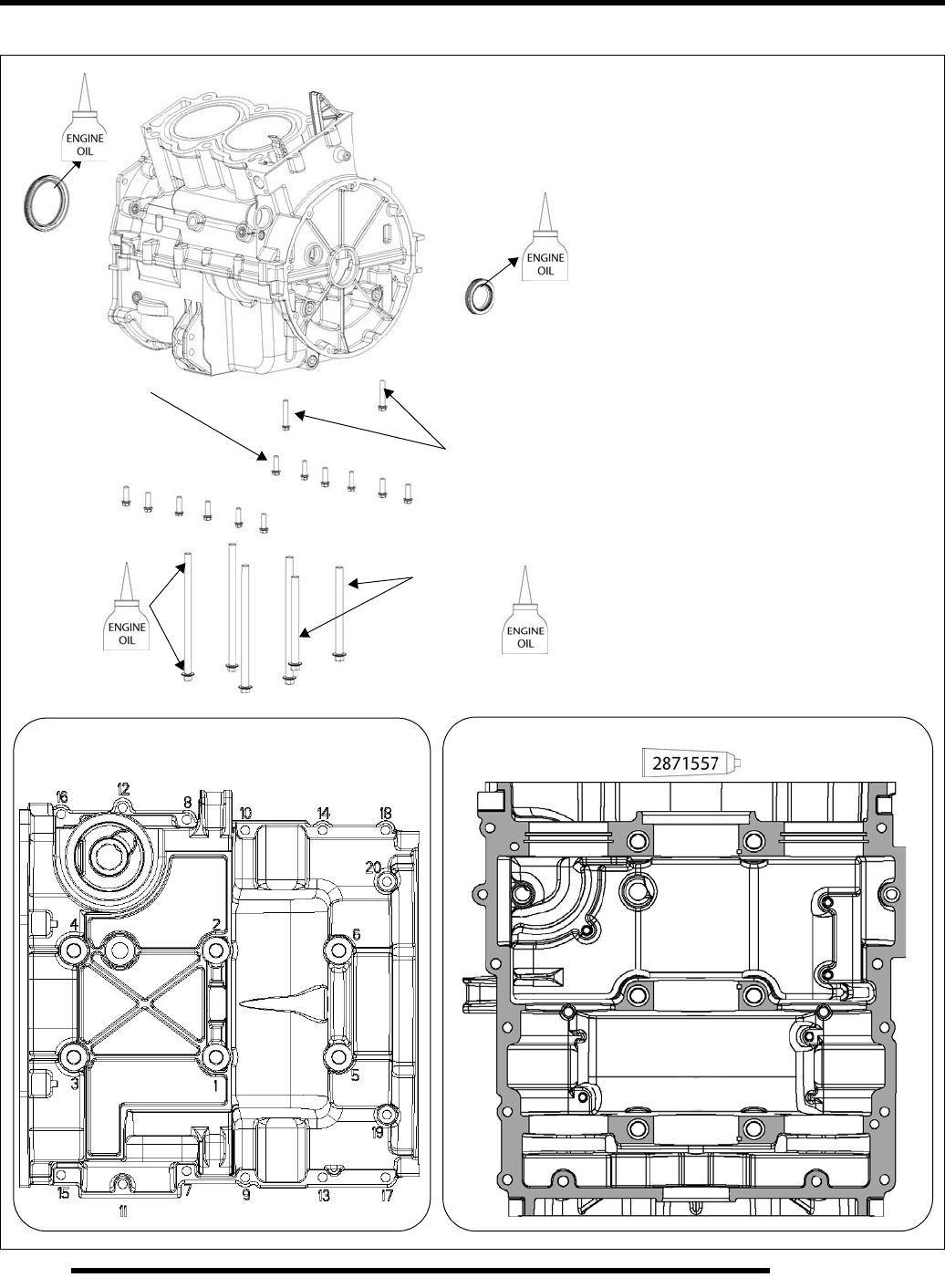
5.58
ENGINE
Crankcase Sealant and Torque Values
Torque Pattern
89 lb-in.
(10 Nm)
M6 x 20
89 lb-in.
(10 Nm)
M6 x 35
26 lb-ft.
(35 Nm)
M9 x 115**
26 lb-ft.
(35 Nm)
M9 x 160**
Sealant Application
** Apply a light film of engine oil to flange
and threads of M9 crankcase bolts.
PartShark.com
877-999-5686

5.59
ENGINE
5
Crankcase Assembly
1. Prepare upper and lower crankcase and install all
components as described on page 5.51 through page 5.57.
2. Inspect crankshaft seals to be sure they are aligned flush
with ends of crankcase.
3. Be sure balance shaft end plugs are installed with retaining
flange fitted in the grooves of crankcase.
4. Be sure oil passage tube is installed with new O-rings
(page 5.53).
5. Clean crankcase mating surfaces to remove all oil and
grease.
6. Apply a thin, continuous film of crankcase sealant PN
2871557 to upper and lower crankcase mating surfaces as
shown on page 5.58. Do not allow sealant to dry before
assembly.
7. Apply engine oil to crankshaft main bearings in the lower
crankcase half.
8. Carefully place lower crankcase on upper case, making sure
the oil supply tube and oil pump drive gear are aligned.
9. Tap with a rubber hammer to seat cases together.
10. Install all crankcase bolts and tighten all lightly by hand.
11. Inspect mating surfaces to be sure they are joined properly.
Investigate the cause of any gaps.
12. Torque all crankcase in sequence shown on page 5.58 to
final torque value, then repeat the sequence to verify final
torque.
13. Install cylinder head (page 5.35).
WATER PUMP
Water Pump Impeller Removal
IMPORTANT: Water pump impeller removal is not
required to remove the stator cover. If engine service
does not include water pump repair, leave the water
pump cover assembled to the stator cover and
remove as an assembly.
NOTE: The water pump impeller can be removed
without removing the engine.
See Chapter 4 “Cooling System” for procedure.
Water Pump Mechanical Seal Replacement /
Coupler Shaft & Bearing Replacement
IMPORTANT: Water pump mechanical seal removal is
not required to service the engine or to remove the
stator cover. If engine service does not include water
pump repair, remove the stator cover as an assembly.
NOTE: The water pump mechanical seal, coupler
shaft, and bearing can be serviced without removing
the engine.
See Chapter 4 “Cooling System” for procedure.
PartShark.com
877-999-5686

5.60
ENGINE
TROUBLESHOOTING
Engine
Spark Plug Fouling
• Restricted air filter (main or pre-cleaner) or breather
system
• Improperly assembled air intake system
• Restricted engine breather system
• Oil contaminated with fuel
• Fuel quality poor (old) or octane too high
• PVT system calibrated incorrectly/ components worn or
mis-adjusted
• Restricted exhaust
• Spark plug cap loose or faulty
• Incorrect spark plug heat range or gap
• Weak ignition (loose coil ground, faulty coil, or stator)
• Low compression
Engine Turns Over But Fails To Start
•No fuel
• Dirt in fuel line, filter, or injectors
• Fuel pump inoperative/restricted
• Fuel valve off or restricted flow
• Tank vent plugged or pinched
• Engine flooded
• Low compression (high cylinder leakage)
• No CPS signal (debris on CPS pole, damaged CPS
causing incorrect air gap)
• No spark (spark plug fouled) ignition component failure
Engine Does Not Turn Over
• Dead battery
• Starter motor does not turn
• Engine seized, rusted, or mechanical failure
Engine Runs But Will Not Idle
• Restricted fuel system
• Low compression (valves incorrectly adjusted)
• Crankcase breather restricted
Engine Idles But Will Not Accelerate
• Spark plug fouled / weak spark
• Broken throttle cable
• Air intake obstructed
• Air box removed (reinstall all intake components)
• Reverse speed limiter limiting speed
• Incorrect ignition timing
• Restricted exhaust system
• Camshaft worn excessively
• PVT not operating properly
Engine Has Low Power
• Spark plug fouled
• Cylinder, piston, ring, or valve wear or damage (check
compression)
• PVT not operating properly
• Restricted exhaust muffler
• Camshaft worn excessively
Piston Failure - Scoring
• Lack of lubrication
• Dirt entering engine through cracks in air filter or ducts
• Engine oil dirty or contaminated (water)
Excessive Smoke and Carbon Buildup
• Excessive piston-to-cylinder clearance
• Worn rings, piston, or cylinder
• Worn valve guides or seals
• Restricted breather
• Air filter dirty or contaminated
PartShark.com
877-999-5686

5.61
ENGINE
5
Low Compression
• No valve clearance
• Valve not seating properly (bent valve or carbon / debris
accumulated on sealing surface)
• Cylinder head gasket leak
• Cylinder or piston worn
• Piston rings worn, leaking, broken, or sticking
• Bent valve or stuck valve
• Valve spring broken or weak
• Rocker arm sticking
Backfiring
• Fouled spark plug or incorrect plug or plug gap
• Speed limiter system malfunction
• Exhaust system air leaks
• Ignition system faulty:
Spark plug cap cracked / broken
Ignition coil faulty
Ignition switch circuit faulty
Poor connections in ignition system
Ignition timing incorrect
Sheared flywheel key
• Valve sticking
PartShark.com
877-999-5686

NOTES
ENGINE
5.62
PartShark.com
877-999-5686

TRANSMISSION
6.1
CHAPTER 6
TRANSMISSION
6
TRANSMISSION SPECIFICATIONS. . . . . . . . . . . . . . . . . . . . . . . . . . . . . . . . . . . . . . . . . 6.2
TORQUE SPECIFICATIONS . . . . . . . . . . . . . . . . . . . . . . . . . . . . . . . . . . . . . . . . . . . . . . 6.2
LUBRICATION SPECIFICATIONS. . . . . . . . . . . . . . . . . . . . . . . . . . . . . . . . . . . . . . . . . . 6.2
SHIFT LINKAGE / GEAR SELECTOR . . . . . . . . . . . . . . . . . . . . . . . . . . . . . . . . . . . . . . . 6.2
SHIFT LINKAGE INSPECTION . . . . . . . . . . . . . . . . . . . . . . . . . . . . . . . . . . . . . . . . . . . . 6.2
GEAR SELECTOR REMOVAL. . . . . . . . . . . . . . . . . . . . . . . . . . . . . . . . . . . . . . . . . . . . . 6.2
TRANSMISSION SERVICE. . . . . . . . . . . . . . . . . . . . . . . . . . . . . . . . . . . . . . . . . . . . . . . . 6.3
TRANSMISSION REMOVAL . . . . . . . . . . . . . . . . . . . . . . . . . . . . . . . . . . . . . . . . . . . . . . 6.3
TRANSMISSION DISASSEMBLY . . . . . . . . . . . . . . . . . . . . . . . . . . . . . . . . . . . . . . . . . . 6.4
TRANSMISSION SHAFT SERVICE. . . . . . . . . . . . . . . . . . . . . . . . . . . . . . . . . . . . . . . . . 6.8
TRANSMISSION ASSEMBLY . . . . . . . . . . . . . . . . . . . . . . . . . . . . . . . . . . . . . . . . . . . . 6.10
TRANSMISSION INSTALLATION . . . . . . . . . . . . . . . . . . . . . . . . . . . . . . . . . . . . . . . . . 6.14
TRANSMISSION EXPLODED VIEW . . . . . . . . . . . . . . . . . . . . . . . . . . . . . . . . . . . . . . . 6.16
TROUBLESHOOTING. . . . . . . . . . . . . . . . . . . . . . . . . . . . . . . . . . . . . . . . . . . . . . . . . . . 6.18
PartShark.com
877-999-5686
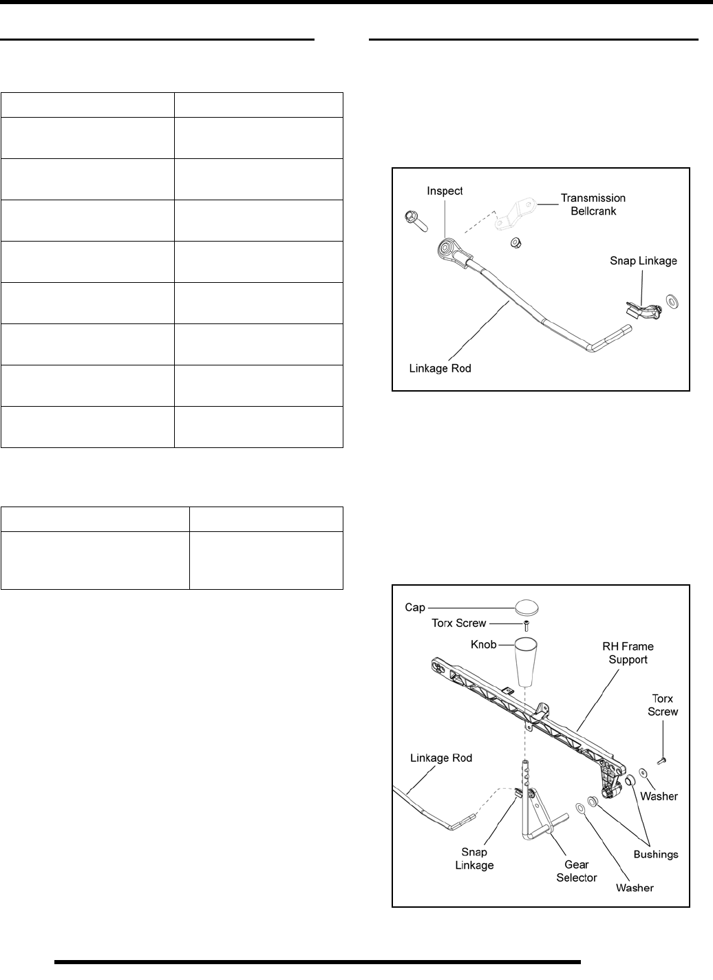
6.2
TRANSMISSION
TRANSMISSION SPECIFICATIONS
Torque Specifications
Lubrication Specifications
SHIFT LINKAGE / GEAR SELECTOR
Shift Linkage Inspection
1. Remove the seat and upper RH side panel (see Chapter 9).
2. Inspect the linkage rod pivot end attached to the
transmission bellcrank and the snap linkage attached to the
gear selector.
NOTE: Linkage rod length and angle is preset.
3. Replace any components that appear worn or damaged.
Gear Selector Removal
1. Remove the seat and upper RH side panel (see Chapter 9).
2. Push linkage rod out of the snap linkage at the gear selector.
3. Remove the retaining screw from the back side and pull the
gear selector out from the frame support as an assembly.
NOTE: Remove RH frame support to ease removal.
ITEM TORQUE VALUE
Transmission Fill Plug 10-14 ft. lbs.
(14-19 Nm)
Transmission Drain Plug 10-14 ft. lbs.
(14-19 Nm)
Transmission Case
Screws 15-20 ft. lbs.
(20-27 Nm)
Oil Deflector Plate Screws 7-10 ft. lbs.
(9-14 Nm)
Bell Housing Screws 50-60 ft. lbs.
(68-81 Nm)
Bellcrank Nut 12-18 ft. lbs.
(16-24 Nm)
Shift Detent Plug 17-23 ft. lbs.
(23-31 Nm)
Transmission Coupler Nut 115-125 ft. lbs.
(156-170 Nm)
TRANSMISSION CAPACITY
Synthetic Sportsman XP
Transmission Fluid
(PN 2877606) (Quart) 32 oz. (946 ml)
PartShark.com
877-999-5686
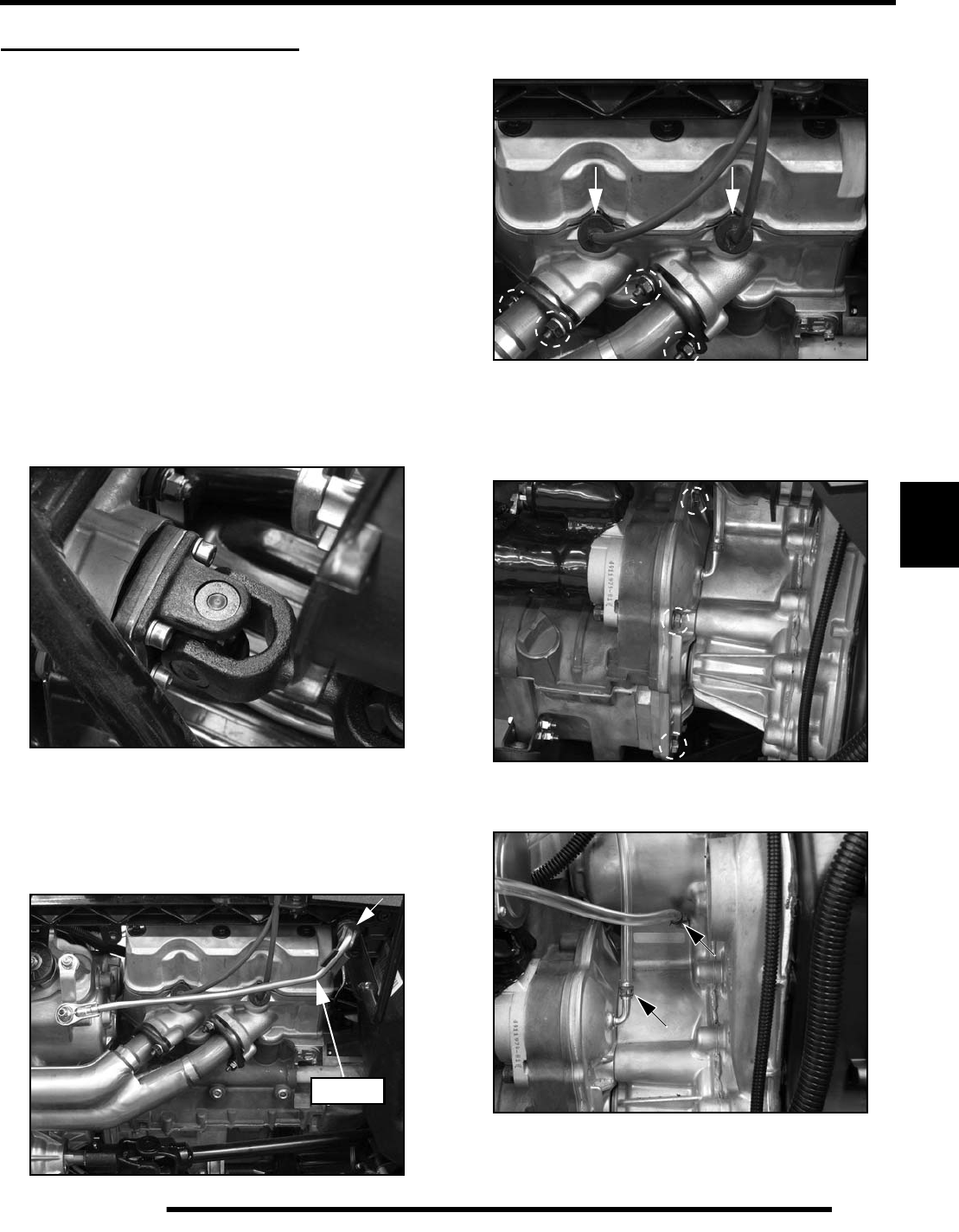
6.3
TRANSMISSION
6
TRANSMISSION SERVICE
Transmission Removal
1. Position the vehicle on a level surface.
2. Remove the seat and side panels (see Chapter 9).
3. Disconnect the negative (-) battery cable (see Chapter 2).
4. Remove the rear cab and footwells (see Chapter 9).
5. Thoroughly clean the engine, transmission and chassis.
6. Drain the transmission fluid (see Chapter 2).
7. Remove the left rear wheel, lower left-hand frame support
and outer PVT cover (see Chapter 7 “DRIVE BELT - Belt
Removal”).
8. Remove the PVT intake duct from the transmission, and the
PVT outlet duct from the inner PVT cover (see Chapter 7).
9. Remove the (4) bolts retaining the rear propshaft to the rear
gearcase input shaft. Slide the shaft off the transmission
output shaft and out from the vehicle.
10. Disconnect the wheel speed sensor located on the lower
right-hand side of the transmission.
11. Disconnect the gear selector switch from the top of the
transmission.
12. Disconnect the linkage rod from the gear selector.
13. Remove the high tension leads from the engine and remove
the (2) nuts from each exhaust flange at the engine.
14. Remove the exhaust springs retaining the exhaust pipe to
the silencer and remove the pipe from the vehicle.
15. Remove the (7) bolts retaining the transmission to the
engine.
16. Remove the (2) vent lines from the top left portion of the
transmission.
17. Remove the lower right airbox retaining screw.
Linkage
PartShark.com
877-999-5686
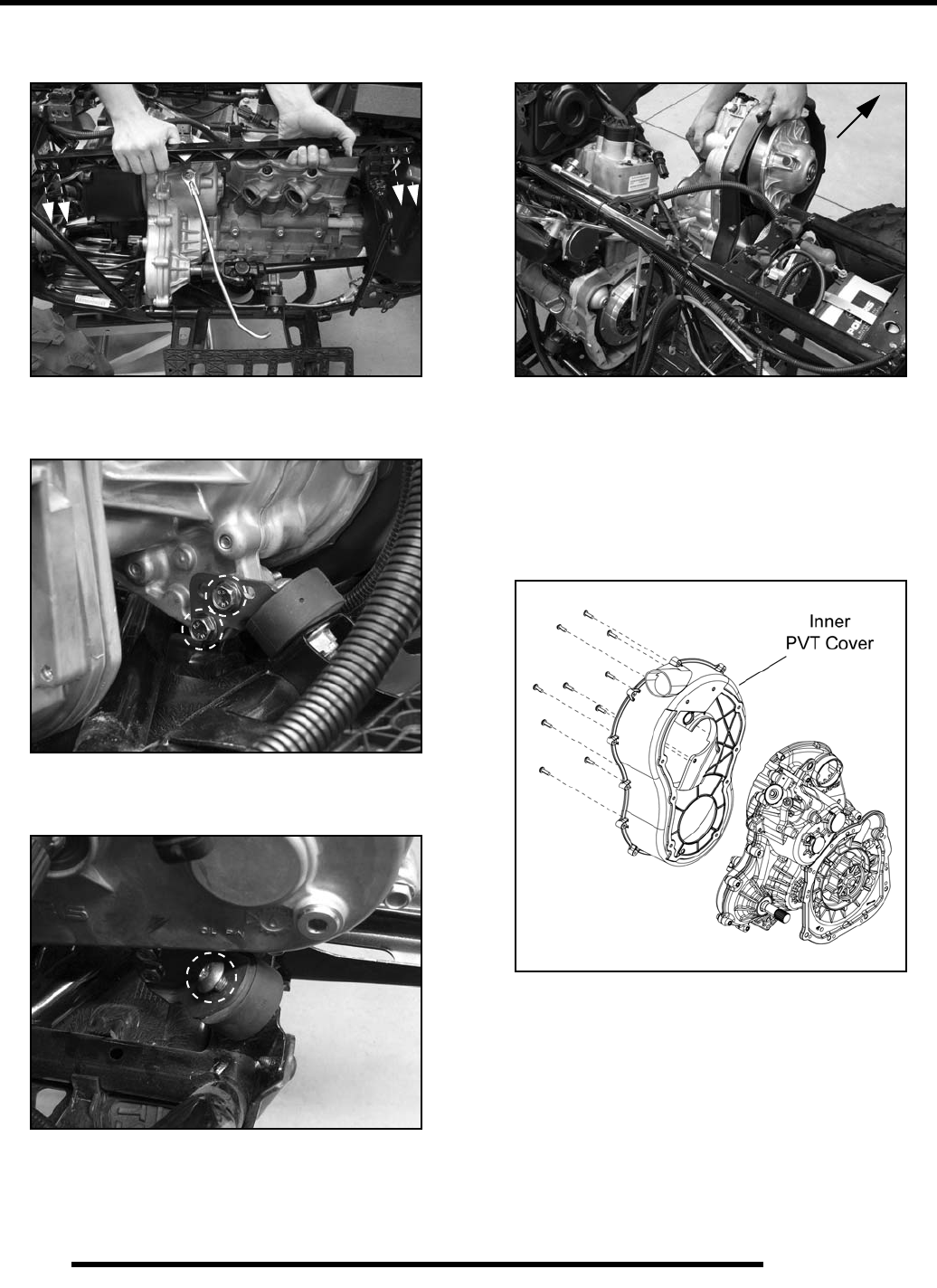
6.4
TRANSMISSION
18. Remove the (4) bolts securing the right-hand frame support
and remove the support from the vehicle.
19. Remove the (2) through-bolt fasteners that mount the
transmission to the isolator mount on the lower LH side.
20. Using a T45 driver, remove the screw from the top of the
isolator mount on the lower RH side.
21. Carefully slide the transmission away from the engine and
remove the front propshaft from the transmission shaft.
22. Once you have cleared the coupler, carefully lift the
transmission assembly out the right side the of vehicle.
Transmission Disassembly
1. Remove the drive belt, drive clutch and driven clutch (see
Chapter 7 “PVT SYSTEM SERVICE - Disassembly”).
2. Remove the (10) screws that secure the inner PVT cover to
the transmission case and remove the cover.
3. Remove (2) retaining bolts from the transmission cover
(see Step 7). These are thread forming bolts that can be used
to hold the coupler during removal and installation.
PartShark.com
877-999-5686
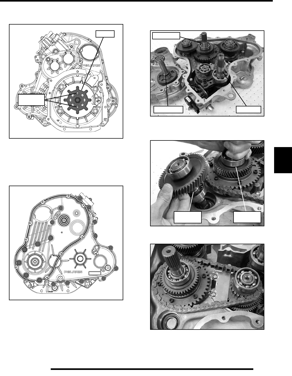
6.5
TRANSMISSION
6
4. Thread the (2) bolts into the transmission case pin holes to
hold the coupler.
5. Remove the retaining nut and transmission coupler.
6. Place the transmission in neutral by moving the bellcrank.
7. Lay the transmission down with the cover facing up and
remove the bolts retaining the transmission cover.
8. Carefully lift up on the cover. Use a soft-faced hammer to
tap on the input shaft and rear output shaft to ease cover
removal.
9. Lift up on the rear output shaft assembly and remove the
front output shaft assembly.
10. Remove the (2) screws retaining the oil deflector plate.
Thread bolts
in pin holes.
Coupler
Primary Shaft Input Shaft
Output Shaft
Rear
Output Shaft
Front
Output Shaft
PartShark.com
877-999-5686
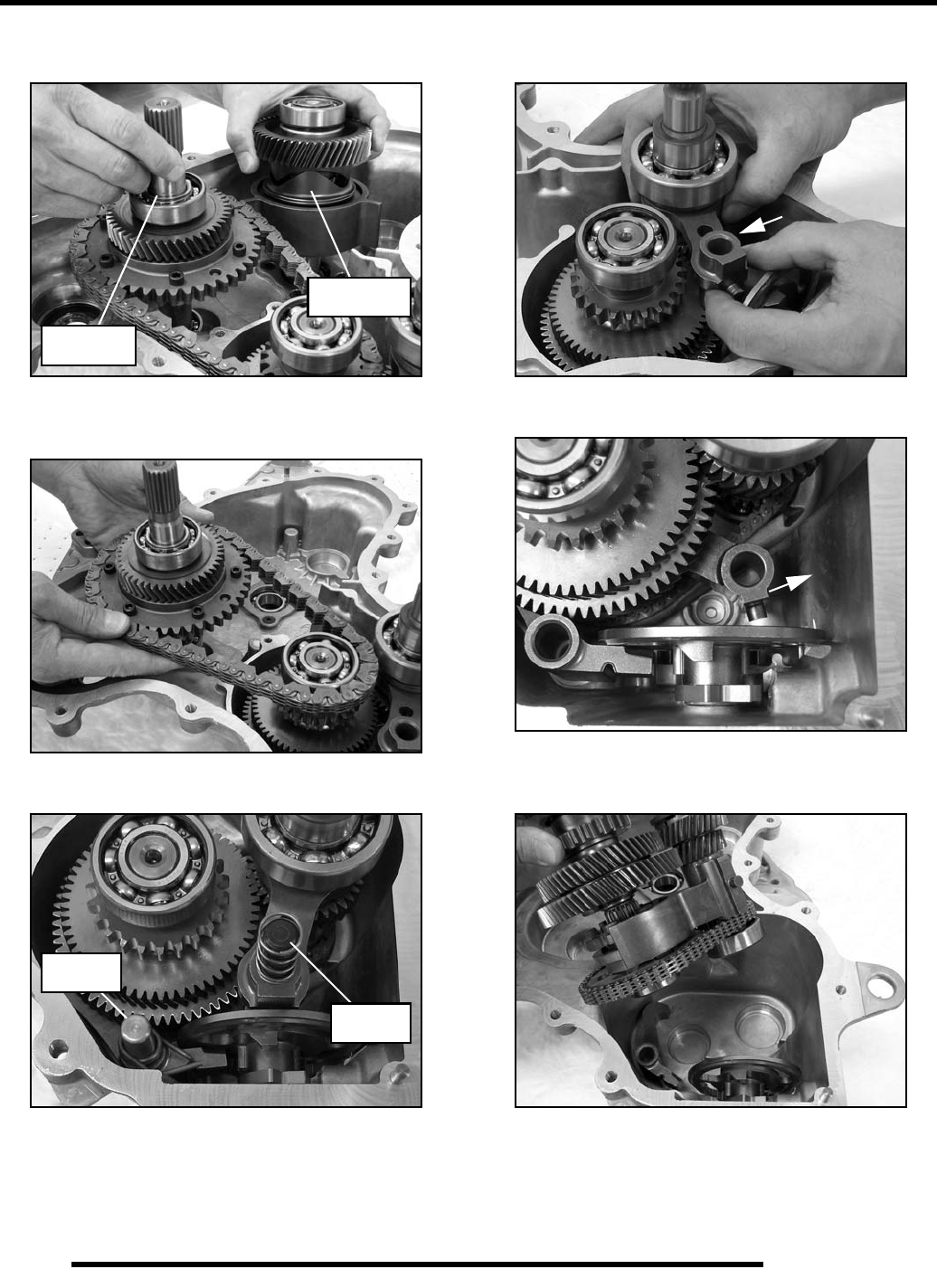
6.6
TRANSMISSION
11. Lift up on the rear output shaft assembly enough to remove
the compensator assembly.
12. Remove the rear output shaft assembly and silent chain
from the transmission.
13. Remove the springs, shift shaft rail and park shaft rail.
14. Lift up on each end of the shift fork and rotate the fork out
of the shift shaft cam.
15. Repeat the previous step to remove the lower shift fork.
16. Remove the input shaft assembly and reverse shaft
assembly together from the transmission.
17. If servicing either shaft assembly, remove the reverse silent
chain and separate the shaft assemblies.
Compensator
Assembly
Rear
Output Shaft
Park Shaft
Rail
Shift Shaft
Rail
PartShark.com
877-999-5686

6.7
TRANSMISSION
6
18. Inspect all bearings, gear teeth, engagement dogs and silent
chain.
19. Remove the detent plug, snap ring, washer and gear selector
switch.
20. Remove the retaining ring and washer from the cam shift
shaft. Remove the nut, bellcrank and washer from the
bellcrank shift shaft.
21. Remove both shift shafts from the transmission as an
assembly. Lightly tap on each shaft to ease removal.
Washer Snap Ring
Detent
Plug
Bellcrank
Washer
Washer
Retaining
Ring
PartShark.com
877-999-5686
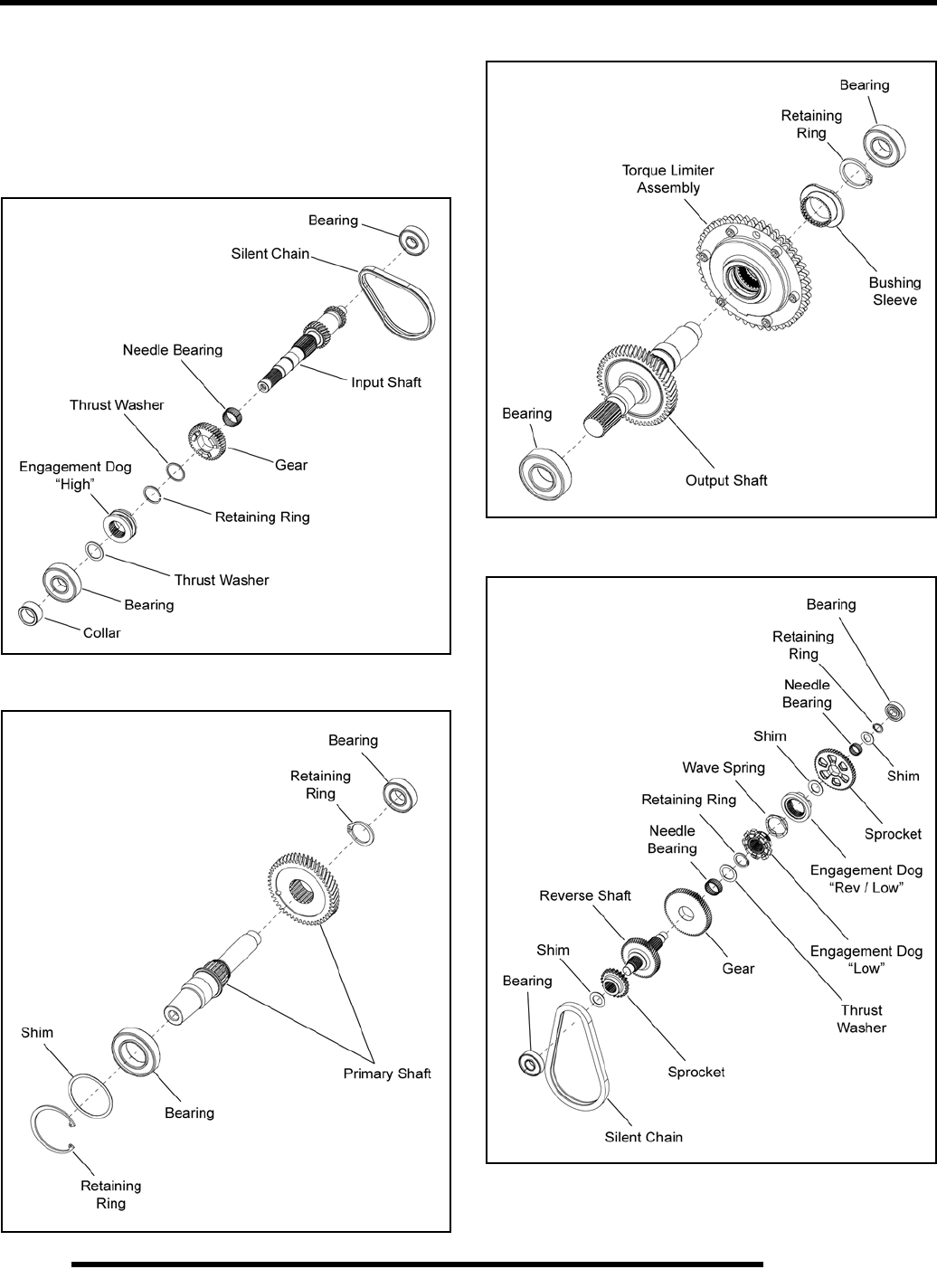
6.8
TRANSMISSION
Transmission Shaft Service
Use the exploded views within this section when servicing the
transmission shafts.
Shaft bearings can be serviced using an arbor press.
Input Shaft
Primary Shaft
Rear Output Shaft
Reverse Shaft
PartShark.com
877-999-5686
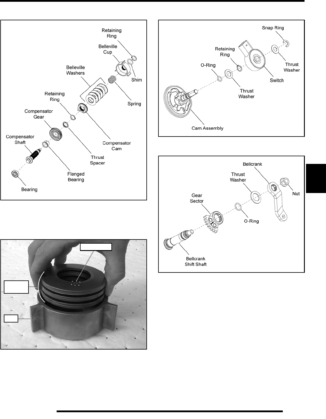
6.9
TRANSMISSION
6
Compensator Shaft
NOTE: Stack the belleville washers and place them
into the belleville cup upon assembly as shown. The
“UP” stamping on each washer should face out
when assembling the washer stack.
Cam Shift Shaft
Bellcrank Shift Shaft
Belleville
Washers
“UP” Marking
Cup
PartShark.com
877-999-5686
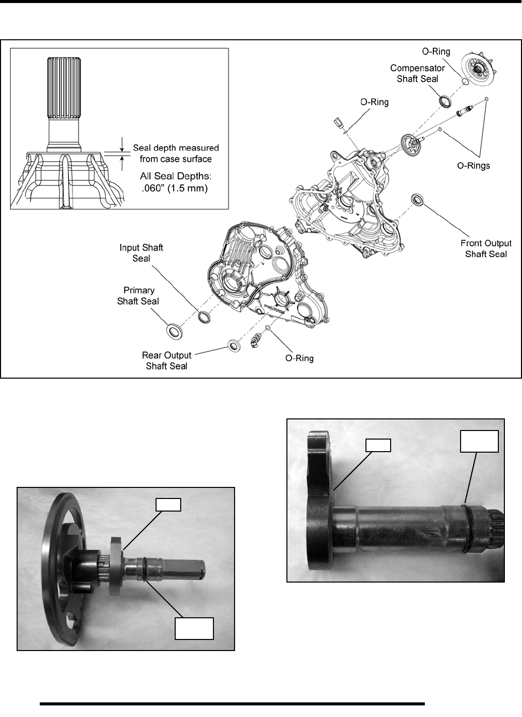
6.10
TRANSMISSION
Transmission Assembly
1. Thoroughly clean the transmission case halves and shafts.
2. Inspect all seals and O-rings for damage. If transmission
was disassembled, seal and O-ring replacement is
recommended (see exploded view above).
3. If the cam shift shaft was disassembled, install the detent
gear with the step facing the O-ring.
NOTE: Both shift shafts have skip-tooth keyed
splines for assembly purposes.
4. If the bellcrank shift shaft was disassembled, install the gear
sector with the step facing the O-ring.
5. Install new O-rings on both shift shafts and lubricate prior
to installation.
Step
Replace
O-Ring
Step Replace
O-Ring
PartShark.com
877-999-5686
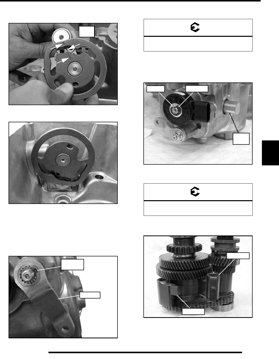
6.11
TRANSMISSION
6
6. Align the timing marks on the cam shift shaft and bellcrank
shift shaft.
7. Place the two shafts into the transmission as an assembly.
IMPORTANT: Gently rock or twist the shift shafts
upon installation to prevent from damaging the new
O-rings. Forcing the shift shafts straight into the
transmission housing may cut the O-rings.
8. Install the washer over the bellcrank shift shaft and install
the bellcrank by aligning the skip-tooth splines.
9. Install the retaining nut and torque to specification.
10. Install the washer and a new retaining ring onto the cam
shift shaft. The retaining ring should be tight on the shaft.
11. Install the transmission switch, washer and snap ring.
12. Install the detent plug and torque to specification.
13. Assemble the input shaft and reverse shaft with the lower
shift fork and park pawl installed.
14. Place the assembly into the transmission housing making
sure to move the park pawl arm behind the shift shaft cam
during installation.
Align
Marks
Skip-Tooth
Splines
Bellcrank
= T
Bellcrank Retaining Nut:
15 ft. lbs. (20 Nm)
= T
Detent Plug:
17-23 ft. lbs. (23-31 Nm)
Washer Snap Ring
Detent
Plug
Shift Fork
Park Pawl
PartShark.com
877-999-5686
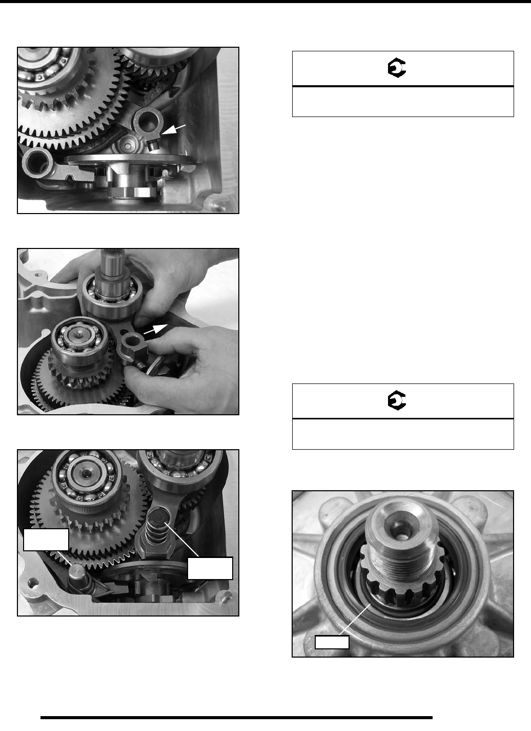
6.12
TRANSMISSION
15. Lift up on the lower shift fork and rotate the end into the
cam.
16. Install the upper shift fork and rotate the end into the cam.
17. Install both rails and springs.
NOTE: Make sure the spring is flush with the top of
the shift shaft rail. If not flush, the rail may not be
fully seated.
18. Install the oil deflector plate and install new retaining
screws. Torque screws to specification.
19. Install the rear output shaft assembly and silent chain.
20. Lubricate all seal lips to prevent damage upon assembly.
21. Lift up slightly on the rear output shaft and install the
compensator shaft and front output shaft assemblies.
22. If primary shaft was serviced, reinstall shaft assembly into
the transmission case. Apply grease to the primary shaft
shim(s) and place them into the transmission cover.
23. Carefully install the transmission cover onto the
transmission. Apply even pressure to cover while setting
into place. A soft-faced hammer can be used once the cover
is started and aligned.
IMPORTANT: Take care not to damage seals during
cover installation.
24. Install the retaining bolts and torque to specification. Leave
(2) bolts out to use later when tightening the coupler.
25. Install a new O-ring onto the compensator shaft prior to
installing the transmission coupler.
IMPORTANT: Be sure to install the O-ring all the way
down onto the shaft, past the groove.
Park Shaft
Rail
Shift Shaft
Rail
= T
Deflector Plate Retaining Screws:
7-10 ft. lbs. (9-14 Nm)
= T
Transmission Cover Bolts:
15-20 ft. lbs. (20-27 Nm)
O-Ring
PartShark.com
877-999-5686
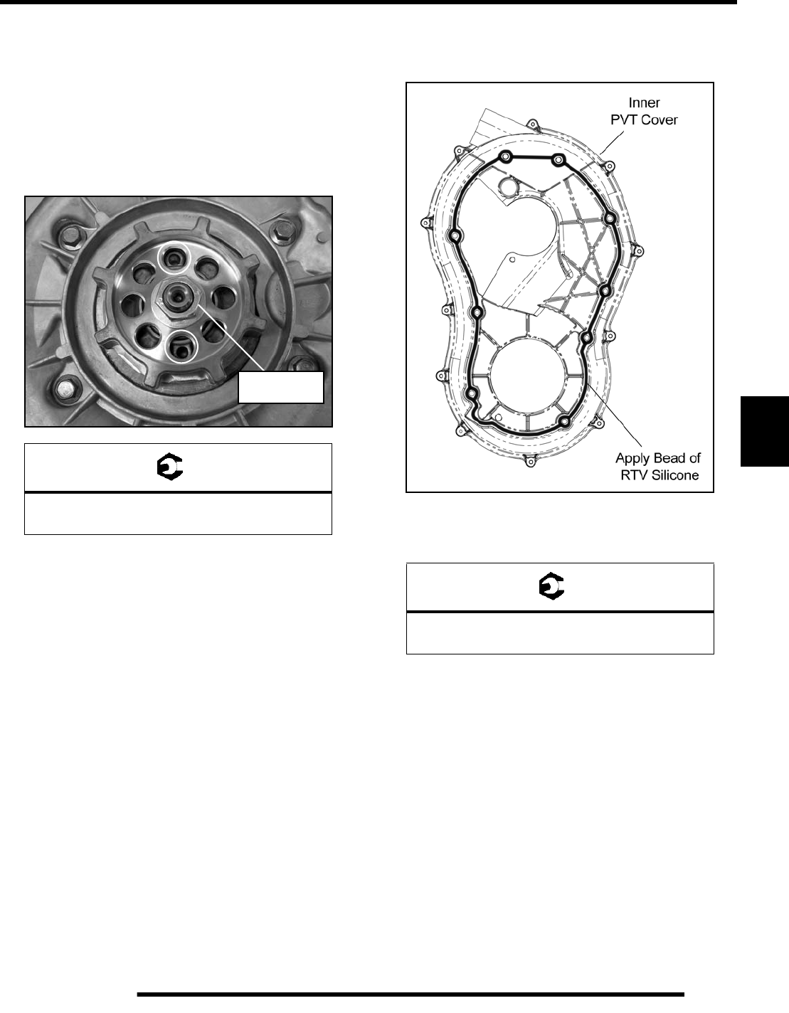
6.13
TRANSMISSION
6
26. Install the transmission coupler and cone washer (dome
facing up).
27. Apply Loctite™ 2760 to the shaft threads and install the
coupler retaining nut.
28. Hold the transmission coupler using the (2) transmission
cover bolts that were left out. Thread the bolts into the
transmission case and torque the coupler nut to
specification.
29. Remove the (2) bolts holding the coupler and install them
in the transmission cover. Torque the bolts to specification
(see Step 24).
30. Remove the old silicone material from the inner PVT cover
and transmission case using a wire brush. Clean both
surfaces thoroughly in preparation for assembly
31. Inspect the inner PVT cover. Replace if cracked or
damaged. The mating surface must be clean to ensure
adhesion of new silicone sealant.
32. Be sure to “flame treat” the inner PVT cover prior to
applying silicone to ensure good adhesion. Pass the flame
of a propane torch back and forth quickly over the area
where the silicone is to be applied (2-3 inches from the
flame tip is recommended). Do not hold the torch too close
to the surface. Keep the torch moving to prevent damage.
33. Apply RTV silicone sealant to the outside edge of the inner
PVT cover to ensure a water tight fit between the cover and
the transmission.
34. Install the cover and torque the inner PVT cover screws to
specification.
35. Wipe away any excess silicone sealant.
36. Install the drive clutch, driven clutch and drive belt (see
Chapter 7 “PVT SYSTEM SERVICE - Disassembly”).
= T
Transmission Coupler Retaining Nut:
115-125 ft. lbs. (156-170 Nm)
115-125 ft. lbs.
(156-170 Nm)
= T
Inner PVT Cover Screws:
6-8 ft. lbs. (8-11 Nm)
PartShark.com
877-999-5686
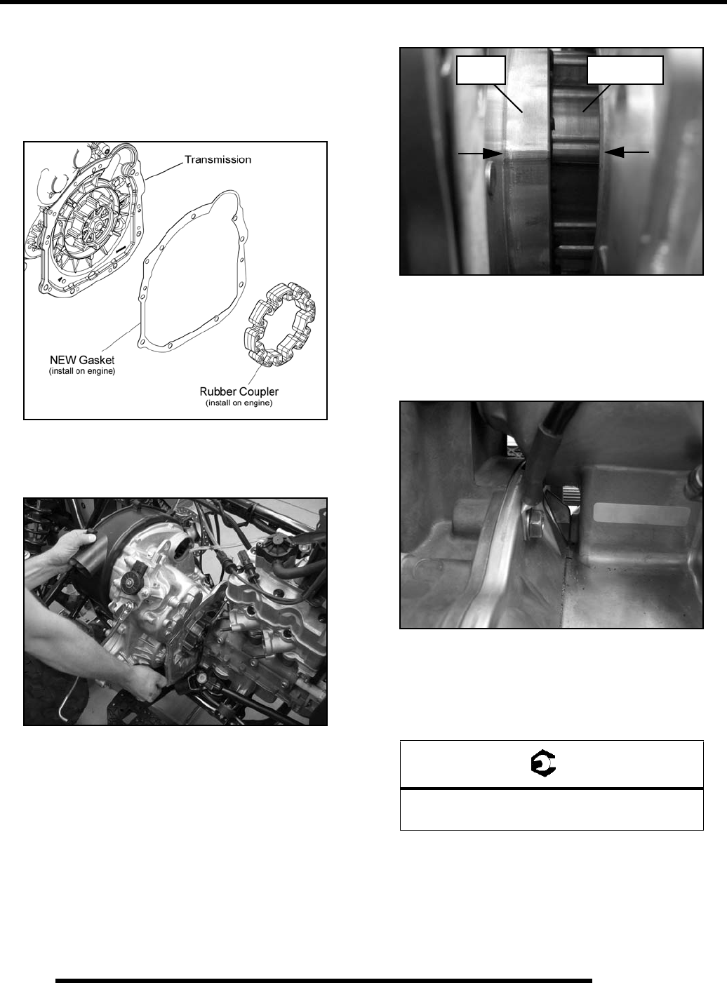
6.14
TRANSMISSION
Transmission Installation
1. Remove the rubber coupler and inspect it for signs of
excessive wear or damage. Replace as needed.
2. Install the rubber coupler into the engine coupler. Be sure
rubber coupler is properly mounted.
3. Install a new gasket onto the engine mounting surface.
4. Carefully place the transmission assembly into the chassis.
5. Slide the propshaft onto the transmission shaft.
6. Line up the engine and transmission couplers as shown.
7. Slide the transmission forward to engage the couplers.
NOTE: Be sure the front propshaft is still attached to
the transmission shaft before installing the bolts.
8. Start the (7) bolts that retain the transmission to the engine.
NOTE: Mount the engine-to-chassis ground with
bolt as shown.
9. Torque the transmission to engine bolts in two steps to the
specified torque value using a criss-cross pattern.
= T
Transmission-to-Engine Retaining Bolts:
18 ft. lbs. (24 Nm)
Transmission
Coupler
Engine
Coupler
PartShark.com
877-999-5686
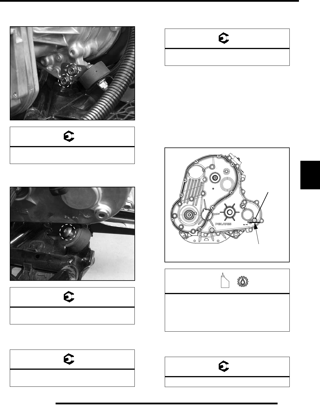
6.15
TRANSMISSION
6
10. Install the (2) through-bolt fasteners on the lower LH side
and torque to specification.
11. Install a new T45 mounting screw in the isolator mount on
the lower RH side and torque to specification.
12. Install the upper RH frame support and torque fasteners to
specification.
13. Install the rear propshaft and torque the retaining bolts to
specification.
14. Reverse the transmission removal procedure to complete
the installation.
15. Clean the drain plug magnetic surface.
16. Reinstall drain plug with a new O-ring and torque to
specification.
17. Add the recommended amount of lubricant through the fill
plug hole. Maintain the lubricant level at the bottom of the
fill plug hole when filling the transmission. Do not overfill.
18. Reinstall fill plug with a new O-ring and torque to
specification.
= T
Transmission Through-Bolt Fasteners:
18 ft. lbs. (24 Nm)
= T
Transmission Torx-Head Mounting Screw:
36 ft. lbs. (49 Nm)
= T
Upper Right-Hand Frame Support Bolts:
36 ft. lbs. (49 Nm)
= T
Rear Propshaft Bolts:
18 ft. lbs. (24 Nm)
=
Recommended Transmission Lubricant:
Synthetic Sportsman XP Transmission Fluid
(PN 2877606) (Quart)
Capacity: 32 oz. (946 ml)
= T
Drain/Fill Plug Torque: 10-14 ft. lbs. (14-19 Nm)
Fill Plug
Gearcase lubricant
flush with the bottom
of thread area.
10-14 ft. lbs.
(14-19 Nm)
PartShark.com
877-999-5686
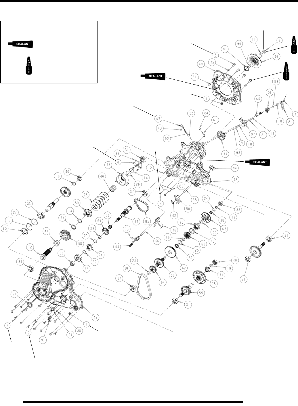
6.16
TRANSMISSION
Transmission Exploded View
FOR REASSEMBLY
Apply Polaris
Crankcase Sealant.
Apply LoctiteTM 2760
to the bolt threads.
115-125 ft. lbs.
(156-170 Nm)
7-10 ft. lbs.
(9-14 Nm)
10-14 ft. lbs.
(14-19 Nm)
15 ft. lbs.
(20 Nm)
10-14 ft. lbs.
(14-19 Nm)
15-20 ft. lbs.
(20-27 Nm)
10-14 ft. lbs.
(14-19 Nm)
50-60 ft. lbs.
(68-81 Nm)
7-10 ft. lbs.
(9-14 Nm)
17-23 ft. lbs.
(23-31 Nm)
PartShark.com
877-999-5686

6.17
TRANSMISSION
6
Exploded View, Continued.
Ref. Qty. Description Ref. Qty. Description
1. 2 Plug, M18 48. 1 Gearcase, Main
2. 1 Plug w/Magnet, M18 49. 1 Bell Housing
3. 19 Screw, M8 50. 1 Park Pawl
4. 2 Screw, M6 51. 1 Gear, Sector 38T
5. 4 Screw, M10 52. 1 Detent Bullet
6. 4 Screw, M6 53. 1 Cup, Belleville
7. 1 Nut, Nylon Lock, 5/16-24 54. 1 Trust Spacer, Compensator
8. 1 Nut, M18 55. 1 Output Shaft
9. 1 Washer, Thrust 56. 1 Reverse Shaft, 53T
10. 1 Washer, Thrust 57. 1 Input Shaft, 25T
11. 1 Washer, Belleville 58. 1 Gear, Compensator
12. 2 Dowel Pin 59. 1 Cam, Compensator
13. 1 E-Ring 60. 1 Gear, Helical, 42T
14. 2 Retaining Ring 61. 2 Vent Tube
15. 1 Retaining Ring 62. 1 Gear, 67T
16. 1 Retaining Ring 63. 1 Sprocket, 48T
17. 1 Retaining Ring 64. 1 Sprocket, 23T
18. 1 Retaining Ring 65. 1 Shift Shaft, Bellcrank
19. 1 Retaining Ring 66. 1 Rail, Shift Shaft
20. 1 Retaining Ring 67. 1 Detent Plug
21. 1 Washer, Thrust 68. 1 Rail, Park Shaft
22. 1 Washer, Thrust 69. 1 Engagement Dog, Low
23. 2 Shim 70. 1 Engagement Dog, Reverse/Low
24. 1 Shim 71. 1 Bushing Sleeve
25. 1 Washer, Thrust 72. 1 Shaft, Compensator
26. 1 Shim 73. 1 Shift Fork
27. 1 Shim 74. 1 Engagement Dog, High
28. 6 Washer, Belleville 75. 2 Pipe, Knock
29. 1 Washer, Thrust 76. 1 Shift Fork
30. 1 Collar 77. 1 Switch Shaft
31. 3 Ball Bearing 78. 1 PTL, Subassembly
32. 1 Ball Bearing 81. 1 Bellcrank, 15T Spline
33. 1 Ball Bearing 82. 1 Oil Deflector
34. 1 Ball Bearing 83. 1 Bearing Cover
35. 1 Ball Bearing 85. 1 Silent Chain
36. 1 Needle Bearing 86. 1 Silent Chain
37. 1 Ball Bearing 87. 1 Switch, Rotary
38. 1 Needle Bearing 88. 1 O-Ring
39. 1 Needle Bearing 89. 1 O-Ring
40. 1 Ball Bearing 90. 1 O-Ring
41. 1 Flanged Bearing 91. 2 Seal, Triple Lip
42. 1 Torsion Spring, Park Pawl 92. 1 O-Ring
43. 1 Compression Spring 93. 1 O-Ring
44. 1 Compression Spring 94. 2 Seal, Triple Lip
45. 1 Wave Spring 95. 1 Seal, Triple Lip
46. 1 Compression Spring 97. 1 Speed Sensor
47. 1 Gearcase, Cover 98. 1 Coupler
PartShark.com
877-999-5686

6.18
TRANSMISSION
TROUBLESHOOTING
Troubleshooting Checklist
Check the following items when shifting difficulty is
encountered.
• Engine idle speed is above specification
• Transmission fluid type/quality
• Loose or worn snap linkage bushings
• Worn linkage rod pivot end at the transmission
bellcrank
• Bent bellcrank
• Worn, broken or damaged internal transmission
components
NOTE: To determine if shifting difficulty is caused
by an internal transmission problem, isolate the
transmission by disconnecting linkage rod from
transmission bellcrank. Manually select each gear
range at the transmission bellcrank and test ride
vehicle. If it functions properly, the problem is
outside the transmission.
If transmission problem remains, disassemble
transmission and inspect all gear dogs for wear
(rounding), or damage. Inspect all bearings, circlips,
thrust washers and shafts for wear.
PartShark.com
877-999-5686

CLUTCHING (PVT)
7.1
CHAPTER 7
CLUTCHING (PVT)
7
SPECIAL TOOLS AND SUPPLIES . . . . . . . . . . . . . . . . . . . . . . . . . . . . . . . . . . . . . . . . . . 7.2
TORQUE SPECIFICATIONS. . . . . . . . . . . . . . . . . . . . . . . . . . . . . . . . . . . . . . . . . . . . . . . 7.2
PVT SYSTEM OVERVIEW . . . . . . . . . . . . . . . . . . . . . . . . . . . . . . . . . . . . . . . . . . . . . . . . 7.2
GENERAL OPERATION. . . . . . . . . . . . . . . . . . . . . . . . . . . . . . . . . . . . . . . . . . . . . . . . . . 7.2
DRIVE CLUTCH OPERATION . . . . . . . . . . . . . . . . . . . . . . . . . . . . . . . . . . . . . . . . . . . . . 7.2
SHIFT WEIGHTS . . . . . . . . . . . . . . . . . . . . . . . . . . . . . . . . . . . . . . . . . . . . . . . . . . . . . . . 7.3
DRIVEN CLUTCH OPERATION. . . . . . . . . . . . . . . . . . . . . . . . . . . . . . . . . . . . . . . . . . . . 7.3
PVT BREAK-IN (DRIVE BELT / CLUTCHES) . . . . . . . . . . . . . . . . . . . . . . . . . . . . . . . . . 7.3
MAINTENANCE / INSPECTION. . . . . . . . . . . . . . . . . . . . . . . . . . . . . . . . . . . . . . . . . . . . 7.3
OVERHEATING / DIAGNOSIS. . . . . . . . . . . . . . . . . . . . . . . . . . . . . . . . . . . . . . . . . . . . . 7.4
PVT SYSTEM SERVICE . . . . . . . . . . . . . . . . . . . . . . . . . . . . . . . . . . . . . . . . . . . . . . . . . . 7.5
PVT SEALING AND DUCTING COMPONENTS . . . . . . . . . . . . . . . . . . . . . . . . . . . . . . . 7.5
DISASSEMBLY. . . . . . . . . . . . . . . . . . . . . . . . . . . . . . . . . . . . . . . . . . . . . . . . . . . . . . . . . 7.6
ASSEMBLY . . . . . . . . . . . . . . . . . . . . . . . . . . . . . . . . . . . . . . . . . . . . . . . . . . . . . . . . . . . 7.7
DRIVE BELT . . . . . . . . . . . . . . . . . . . . . . . . . . . . . . . . . . . . . . . . . . . . . . . . . . . . . . . . . . . 7.9
BELT REMOVAL . . . . . . . . . . . . . . . . . . . . . . . . . . . . . . . . . . . . . . . . . . . . . . . . . . . . . . . 7.9
BELT INSPECTION . . . . . . . . . . . . . . . . . . . . . . . . . . . . . . . . . . . . . . . . . . . . . . . . . . . . 7.10
BELT INSTALLATION . . . . . . . . . . . . . . . . . . . . . . . . . . . . . . . . . . . . . . . . . . . . . . . . . . 7.10
PVT BREAK-IN (DRIVE BELT / CLUTCHES) . . . . . . . . . . . . . . . . . . . . . . . . . . . . . . . . 7.10
DRIVE CLUTCH SERVICE . . . . . . . . . . . . . . . . . . . . . . . . . . . . . . . . . . . . . . . . . . . . . . . 7.11
SPRING SPECIFICATIONS . . . . . . . . . . . . . . . . . . . . . . . . . . . . . . . . . . . . . . . . . . . . . . 7.11
EXPLODED VIEW . . . . . . . . . . . . . . . . . . . . . . . . . . . . . . . . . . . . . . . . . . . . . . . . . . . . . 7.12
CLUTCH DISASSEMBLY. . . . . . . . . . . . . . . . . . . . . . . . . . . . . . . . . . . . . . . . . . . . . . . . 7.12
SPIDER REMOVAL . . . . . . . . . . . . . . . . . . . . . . . . . . . . . . . . . . . . . . . . . . . . . . . . . . . . 7.13
ROLLER, PIN, AND THRUST WASHER INSPECTION. . . . . . . . . . . . . . . . . . . . . . . . . 7.14
BUTTON TO TOWER CLEARANCE INSPECTION. . . . . . . . . . . . . . . . . . . . . . . . . . . . 7.14
SHIFT WEIGHT INSPECTION . . . . . . . . . . . . . . . . . . . . . . . . . . . . . . . . . . . . . . . . . . . . 7.14
BEARING INSPECTION. . . . . . . . . . . . . . . . . . . . . . . . . . . . . . . . . . . . . . . . . . . . . . . . . 7.15
CLUTCH INSPECTION . . . . . . . . . . . . . . . . . . . . . . . . . . . . . . . . . . . . . . . . . . . . . . . . . 7.15
MOVEABLE SHEAVE BUSHING INSPECTION . . . . . . . . . . . . . . . . . . . . . . . . . . . . . . 7.16
BUSHING SERVICE. . . . . . . . . . . . . . . . . . . . . . . . . . . . . . . . . . . . . . . . . . . . . . . . . . . . 7.17
CLUTCH ASSEMBLY. . . . . . . . . . . . . . . . . . . . . . . . . . . . . . . . . . . . . . . . . . . . . . . . . . . 7.19
DRIVEN CLUTCH SERVICE. . . . . . . . . . . . . . . . . . . . . . . . . . . . . . . . . . . . . . . . . . . . . . 7.20
CLUTCH DISASSEMBLY. . . . . . . . . . . . . . . . . . . . . . . . . . . . . . . . . . . . . . . . . . . . . . . . 7.20
BUSHING SERVICE. . . . . . . . . . . . . . . . . . . . . . . . . . . . . . . . . . . . . . . . . . . . . . . . . . . . 7.22
CLUTCH ASSEMBLY. . . . . . . . . . . . . . . . . . . . . . . . . . . . . . . . . . . . . . . . . . . . . . . . . . . 7.24
EXPLODED VIEW . . . . . . . . . . . . . . . . . . . . . . . . . . . . . . . . . . . . . . . . . . . . . . . . . . . . . 7.27
TROUBLESHOOTING. . . . . . . . . . . . . . . . . . . . . . . . . . . . . . . . . . . . . . . . . . . . . . . . . . . 7.28
PartShark.com
877-999-5686
7.2
CLUTCHING (PVT)
SPECIAL TOOLS AND SUPPLIES
TORQUE SPECIFICATIONS
PVT System Fastener Torques
PVT SYSTEM OVERVIEW
General Operation
The Polaris Variable Transmission (PVT) consists of three
major assemblies:
1) The Drive Clutch
2) The Driven Clutch
3) The Drive Belt
The internal components of the drive clutch and driven clutch
control engagement (initial vehicle movement), clutch upshift
and backshift. During the development of a Polaris ATV, the
PVT system is matched first to the engine power curve; then to
average riding conditions and the vehicle’s intended usage.
Therefore, modifications or variations of components at random
are never recommended. Proper clutch setup and careful
inspection of existing components must be the primary
objective when troubleshooting and tuning.
Drive Clutch Operation
Drive clutches primarily sense engine RPM. The two major
components which control its shifting function are the shift
weights and the coil spring. Whenever engine RPM is
increased, centrifugal force is created, causing the shift
weights to push against rollers on the moveable sheave, which
is held open by coil spring preload. When this force becomes
higher than the preload in the spring, the outer sheave moves
inward and contacts the drive belt. This motion pinches the
drive belt between the spinning sheaves and causes it to rotate,
which in turn rotates the driven clutch.
At lower RPM, the drive belt rotates low in the drive clutch
sheaves. As engine RPM increases, centrifugal force causes the
drive belt to be forced upward on drive clutch sheaves.
TOOL DESCRIPTION PART NUMBER
Drive Clutch Puller (Short) PA-48595
Clutch Holding Wrench 9314177
Clutch Holding Fixture 2871358-A
Drive Clutch Spider Removal and
Installation Tool 2870341
Roller Pin Tool 2870910
Clutch Bushing Replacement Tool Kit 2871226
Piston Pin Puller 2870386
Clutch Compression Tool 8700220
Clutch Bushing Replacement Tool Kit 2871025
SPECIAL SUPPLIES PART NUMBER
Loctite™ 609 N/A
RTV Silicone Sealer 8560054
ITEM TORQUE VALUE
Drive Clutch Spider 200 ft. lbs. (271 Nm)
Drive Clutch Retaining Bolt 47 ft. lbs. (64 Nm)
Left Hand Thread
Driven Clutch Retaining Bolt 13 ft. lbs. (18 Nm)
Drive Clutch Cover Bolts 100 in. lbs. (11 Nm)
Inner PVT Cover Screws 6-8 ft. lbs. (8-11 Nm)
Outer PVT Cover Screws 45-50 in. lbs. (5-5.6 Nm)
Drive Clutch Weight Pins 15-25 in. lbs. (2-3 Nm)
WARNING
All PVT maintenance or repairs should be performed by
a certified Polaris Master Service Dealer (MSD)
technician who has received the proper training and
understands the procedures outlined in this manual.
Because of the critical nature and precision balance
incorporated into the PVT components, it is
absolutely essential that no disassembly or repair
be made without factory authorized special tools
and service procedures.
PartShark.com
877-999-5686

7.3
CLUTCHING (PVT)
7
Shift Weights
Shift weights have many factors designed into them for
controlling engagement RPM and shifting patterns. Shift
weights should not be changed or altered without first having a
thorough understanding of their positioning and the effects they
may have on belt to sheave clearance, clutch balance and
shifting pattern.
Driven Clutch Operation
Driven clutches primarily sense torque, opening and closing
according to the forces applied to it from the drive belt and the
transmission input shaft. If the torque resistance at the trans-
mission input shaft is greater than the load from the drive belt,
the drive belt is kept at the outer diameter of the driven clutch
sheaves.
As engine RPM and horsepower increase, the load from the
drive belt increases, resulting in the belt rotating up toward the
outer diameter of the drive clutch sheaves and downward into
the sheaves of the driven clutch. This action, which increases
the driven clutch speed, is called upshifting.
Should the throttle setting remain the same and the vehicle is
subjected to a heavier load, the drive belt rotates back up toward
the outer diameter of the driven clutch and downward into the
sheaves of the drive clutch. This action, which decreases the
driven clutch speed, is called backshifting.
In situations where loads vary (such as uphill and downhill) and
throttle settings are constant, the drive and driven clutches are
continually shifting to maintain optimum engine RPM. At full
throttle a perfectly matched PVT system should hold engine
RPM at the peak of the power curve. This RPM should be
maintained during clutch upshift and backshift. In this respect,
the PVT system is similar to a power governor. Rather than vary
throttle position, as a conventional governor does, the PVT
system changes engine load requirements by either upshifting or
backshifting.
PVT Break-In (Drive Belt / Clutches)
A proper break-in of the clutches and drive belt will ensure a
longer life and better performance. Break in the clutches and
drive belt by operating at slower speeds during the 10 hour
break-in period as recommended (see Chapter 5 “Engine
Break-In Period” for break-in example). Pull only light loads.
Avoid aggressive acceleration and high speed operation during
the break-in period.
Maintenance / Inspection
Under normal use the PVT system will provide years of trouble
free operation. Periodic inspection and maintenance is required
to keep the system operating at peak performance. The
following list of items should be inspected and maintained to
ensure maximum performance and service life of PVT
components. Refer to the troubleshooting checklist at the end of
this chapter for more information.
• Belt Inspection
• Drive and Driven Clutch Buttons and Bushings
• Drive Clutch Shift Weights and Pins
• Drive Clutch Spider Rollers and Roller Pins
• Drive and Driven Clutch Springs
• Sheave Faces (clean and inspect for wear)
• PVT System Sealing. Refer to appropriate illustrations
on the following pages. The PVT system is air cooled
by fins on the drive clutch stationary sheave. The fins
create a low pressure area in the crankcase casting,
drawing air into the system through an intake duct. The
opening for this intake duct is located at a high point on
the vehicle (location varies by model). The intake duct
draws fresh air through a vented cover. All connecting
air ducts (as well as the PVT cover) must be properly
sealed to ensure clean air is being used for cooling the
PVT system and also to prevent water and other
contaminants from entering the PVT area. This is
especially critical on units subjected to frequent water
forging.
PartShark.com
877-999-5686

7.4
CLUTCHING (PVT)
Overheating / Diagnosis
During routine maintenance, or whenever PVT system overheating is evident, it’s important to check the inlet and outlet ducting
for obstructions. Obstructions to air flow through the ducts will significantly increase PVT system operating temperatures. The
vehicle should be operated in Low when plowing or pulling heavy loads, or if extended low speed operation is anticipated.
IMPORTANT: Using High Gear when pulling heavy loads, operating on hilly terrain, or in wet, muddy conditions
will increase the chance of drive belt damage.
CLUTCH DRIVE BELT & COVER RELATED ISSUES: DIAGNOSIS
Possible Causes Solutions / What to do
Loading the vehicle into a truck or tall
trailer when in high range. Shift transmission to Low during loading of the vehicle to prevent belt burning.
Starting out going up a steep incline from
a stopped position. When starting out on an incline, use Low, or dismount the vehicle after first
applying the park brake and perform the “K” turn.
Driving at low RPM or low ground speed
(at approximately 3-7 MPH). Drive at higher speed or use Low. The use of Low is highly recommended
for cooler PVT operating temperatures and longer component life.
Insufficient warm-up of Utility Task
Vehicles™ exposed to low ambient
temperatures.
Warm engine at least 5 min., then with transmission in neutral, advance
throttle to approx. 1/8 throttle in short bursts, 5 to 7 times. The belt will
become more flexible and prevent belt burning.
Slow and easy clutch engagement. Fast, effective use of the throttle for efficient engagement.
Towing/Pushing at low RPM/low ground
speed. Use Low only.
Plowing snow, dirt, etc./utility use. Use Low only.
Stuck in mud or snow. Shift the transmission to Low, carefully use fast, aggressive throttle
application to engage clutch. WARNING: Excessive throttle may cause loss
of control and vehicle overturn.
Climbing over large objects from a
stopped position.
Shift the transmission to Low, carefully use fast, aggressive, brief throttle
application to engage clutch. WARNING: Excessive throttle may cause loss
of control and vehicle overturn.
Belt slippage from water or snow
ingestion into the PVT system.
Shift the transmission to neutral. Using the throttle, vary the engine rpm from
idle to full throttle. Repeat several times as required. During this procedure,
the throttle should not be held at the full position for more than 10 seconds.
Clutch seals should be inspected for damage if repeated leaking occurs.
Clutch malfunction. For inspection of clutch components, please contact your Polaris dealer. Shift
transmission to Low during loading of the vehicle to prevent belt burning.
Poor engine performance. Fouled plugs, foreign material in gas tank, fuel lines, or carburetor. Contact
you dealer for further service information.
GENERAL RANGE OPERATION
GUIDELINES:
Low: Heavy pulling, basic operational speeds less than 7 MPH, riding
through rough terrain (swamps, mountains, ect.), low ground speeds.
High: High ground speeds, speeds above 7 MPH.
PartShark.com
877-999-5686
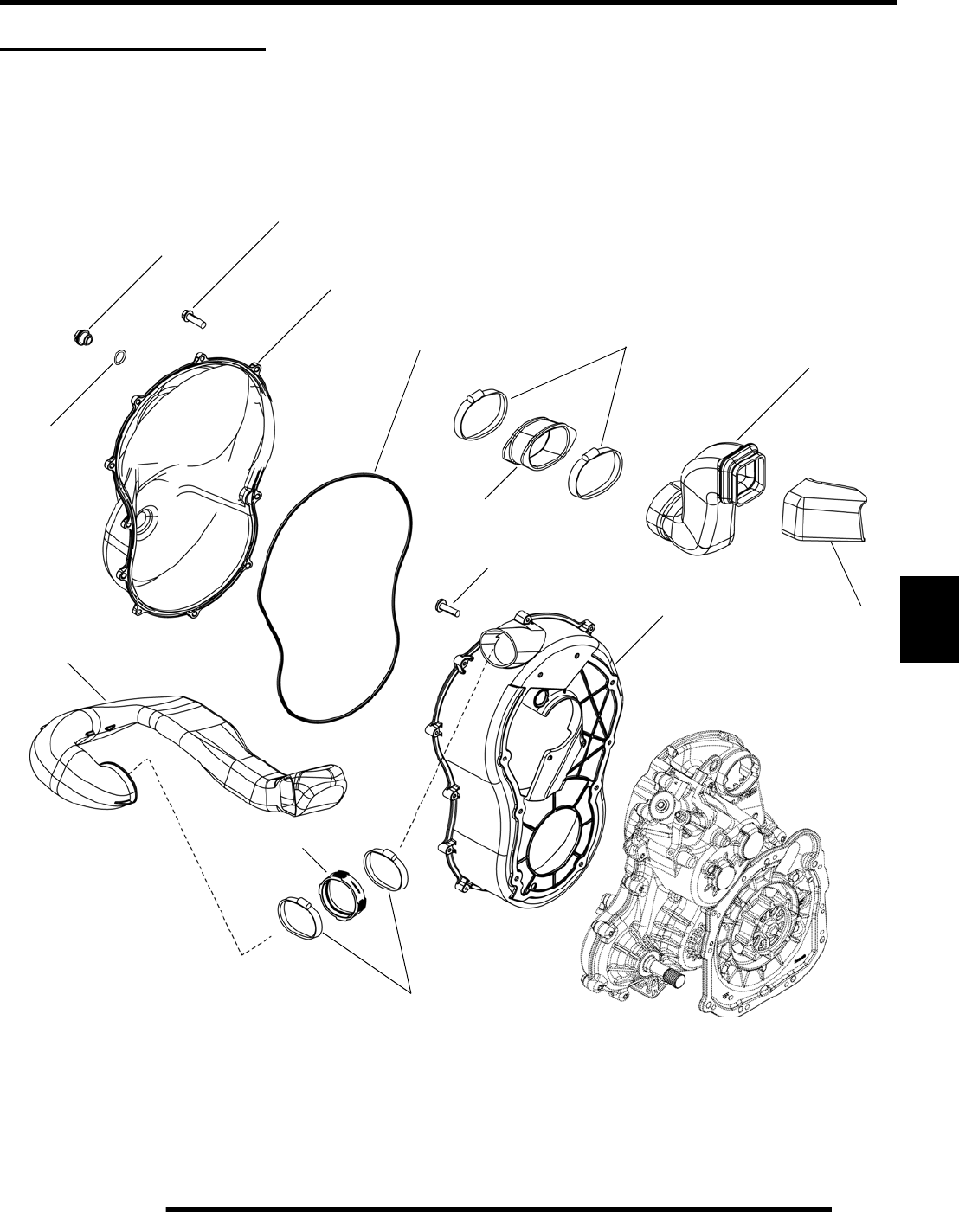
7.5
CLUTCHING (PVT)
7
PVT SYSTEM SERVICE
PVT Sealing and Ducting Components
Outer
Clutch Cover
Inner
Clutch Cover
Drain Plug
O-Ring
Outer Seal Clamps
Cover Screws
Outlet Duct
Air Inlet Duct
Boot
Boot
Boot
Clamps
Screws
PartShark.com
877-999-5686
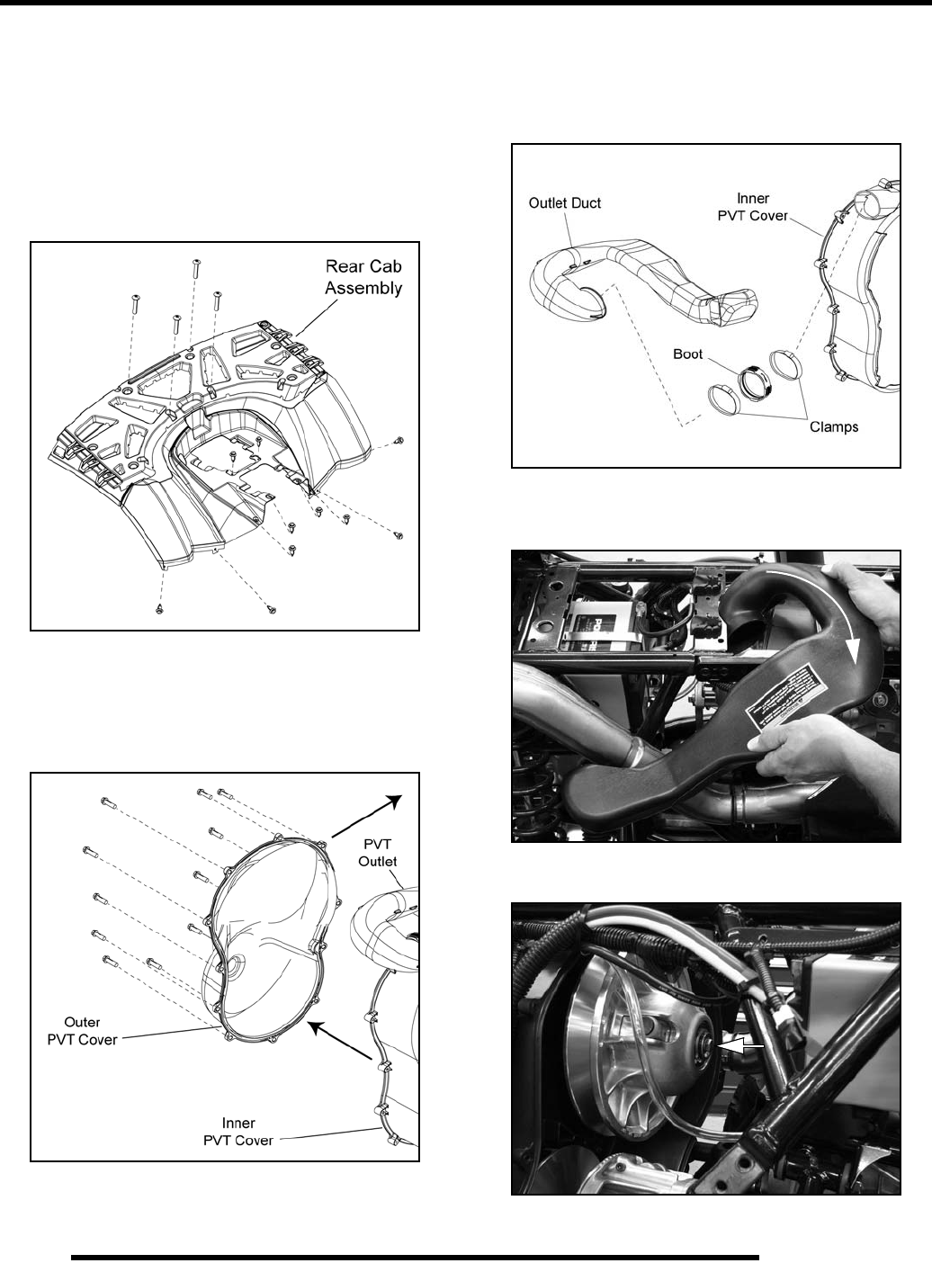
7.6
CLUTCHING (PVT)
Disassembly
Some fasteners and procedures will vary. Refer to the
appropriate parts manual for proper fastener placement.
1. Remove the left rear wheel and lower left-hand frame
support (see “DRIVE BELT - Belt Removal”, steps 1-4).
2. Remove the (10) push rivets and (4) Torx-headed screws
retaining the rear cab assembly.
3. Remove the tail light bulbs from the tail lamps, disconnect
the tail light harnesses from the rear cab, and remove the
rear cab to allow access to the PVT system for disassembly.
4. Remove the (11) screws retaining the outer PVT cover.
5. Using care, pull the outer PVT cover out the left-hand
wheel well.
6. Mark the drive belt direction of rotation and remove drive
belt (see “DRIVE BELT - Belt Removal”, steps 8-10).
7. Loosen the clamps and remove the PVT outlet duct from
the inner PVT cover.
8. Rotate and remove the PVT outlet duct from the vehicle to
allow for driven clutch removal.
9. Remove the driven clutch retaining bolt and driven clutch.
PartShark.com
877-999-5686

7.7
CLUTCHING (PVT)
7
10. Install the Drive Clutch Holder (PN 9314177) onto the
drive clutch.
11. Remove the drive clutch retaining bolt by turning the bolt
in a clockwise direction.
NOTE: The drive clutch retaining bolt has left-hand
threads. Turn the bolt clockwise to remove it.
12. Insert the Drive Clutch Puller (PA-48595) into the drive
clutch and use it to remove the clutch from the shaft.
13. Remove the (10) screws that retain the inner PVT cover to
the transmission case and remove the cover.
14. Remove the old silicone material from the inner PVT cover
and transmission case using a wire brush. Clean both
surfaces thoroughly in preparation for assembly.
Assembly
1. Inspect the inner PVT cover. Replace if cracked or
damaged. The mating surface must be clean to ensure
adhesion of new silicone sealant.
2. Be sure to “flame treat” the inner PVT cover prior to
applying silicone to ensure good adhesion. Pass the flame
of a propane torch back and forth quickly over the area
where the silicone is to be applied (2-3 inches from the
flame tip is recommended). Do not hold the torch too close
to the surface. Keep the torch moving to prevent damage.
3. Apply RTV silicone sealant to the outside edge of the inner
PVT cover to ensure a water tight fit between the cover and
the transmission.
Drive Clutch Holder (9314177)
Drive Clutch Puller ( PA-48595)
PA-48595
Inner
Clutch Cover
PartShark.com
877-999-5686
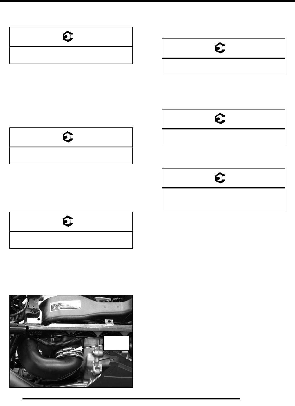
7.8
CLUTCHING (PVT)
4. Install the cover and torque the inner PVT cover screws to
specification.
5. Wipe away any excess silicone sealant.
6. Clean the splines inside the driven clutch and on the
transmission input shaft.
7. Apply a light film of grease to the splines on the shaft.
8. Install the driven clutch, cup washer, lock washer, and
retaining bolt. Torque retaining bolt to specification.
9. Clean end of taper on crankshaft and the taper bore inside
drive clutch using a tapered reamer.
10. Install the drive clutch, bushing, washer, lock washer, and
the left-hand threaded retaining bolt. Torque retaining bolt
to specification.
11. Install drive belt noting direction of rotation if the belt is
being reused (see “DRIVE BELT - Belt Installation”, steps
1-3).
12. Install the PVT outlet duct. Align the duct with the inner
PVT cover properly before tightening the hose clamps.
13. Replace the outer PVT cover seal.
14. Reinstall outer PVT cover and secure with screws. Torque
screws to specification.
15. Reinstall the rear cab, tail light bulbs, and fasteners.
16. Reinstall the lower left-hand frame support and torque bolts
to specification.
17. Install the left rear wheel and torque wheel nuts to
specification.
18. Lower the ATV, start the engine, and test the operation of
the PVT system.
= T
Inner PVT Cover Screws:
6-8 ft. lbs. (8-11 Nm)
= T
Driven Clutch Retaining Bolt:
13 ft. lbs. (18 Nm)
= T
Drive Clutch Retaining Bolt:
47 ft. lbs. (64 Nm)
Tighten
Clamps
= T
Outer PVT Cover Screws:
45-50 in. lbs. (5-5.6 Nm)
= T
Lower Left-Hand Frame Support Bolts:
36 ft. lbs. (49 Nm)
= T
Wheel Nuts:
Steel: 45 ft. lbs. (61 Nm)
Aluminum: 75 ft. lbs. (102 Nm)
PartShark.com
877-999-5686
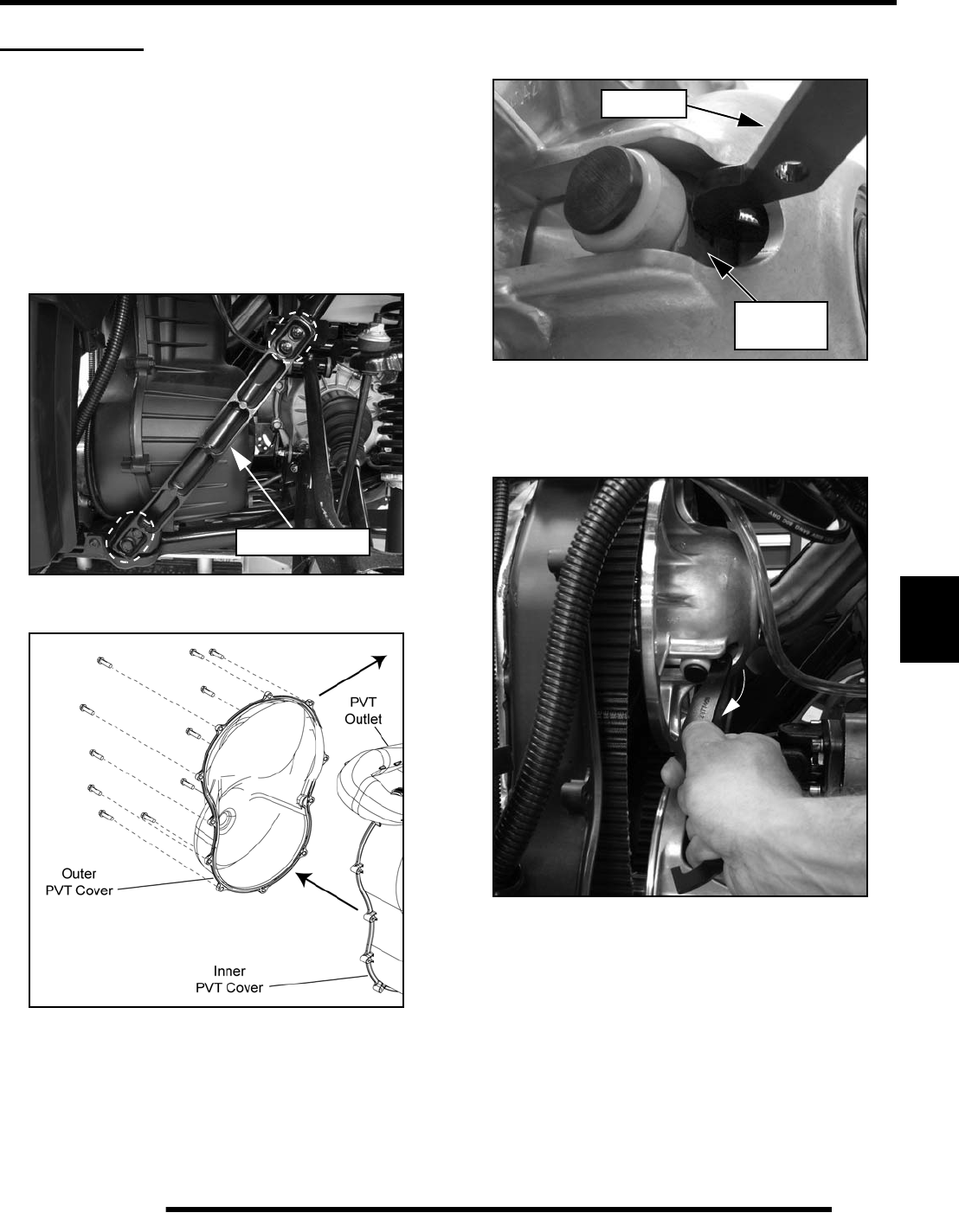
7.9
CLUTCHING (PVT)
7
DRIVE BELT
Belt Removal
1. Position the vehicle on a level surface and place the
transmission in Park.
2. Elevate and safely support the rear of the vehicle.
3. Remove the left rear wheel from the vehicle.
4. Remove the (4) bolts retaining the lower left-hand frame
support and remove it from the frame.
5. Remove the (11) screws retaining the PVT cover.
6. Using care, pull the PVT cover out the left-hand wheel well.
7. Mark the drive belt direction of rotation so that it can be
installed in the same direction.
8. Insert the belt removal tool PN 2877408 into the driven
clutch as shown (tool included with vehicle’s tool kit).
NOTE: Make sure the tool is square with the
moveable sheave surface of the driven clutch.
9. Rotate the tool towards the clutch to open the sheaves.
10. Walk the belt out of the driven clutch and drive clutch, and
remove it from the vehicle.
IMPORTANT: Leave the Belt Removal Tool installed
for belt installation.
Frame Support
2877408
Moveable
Sheave
PartShark.com
877-999-5686
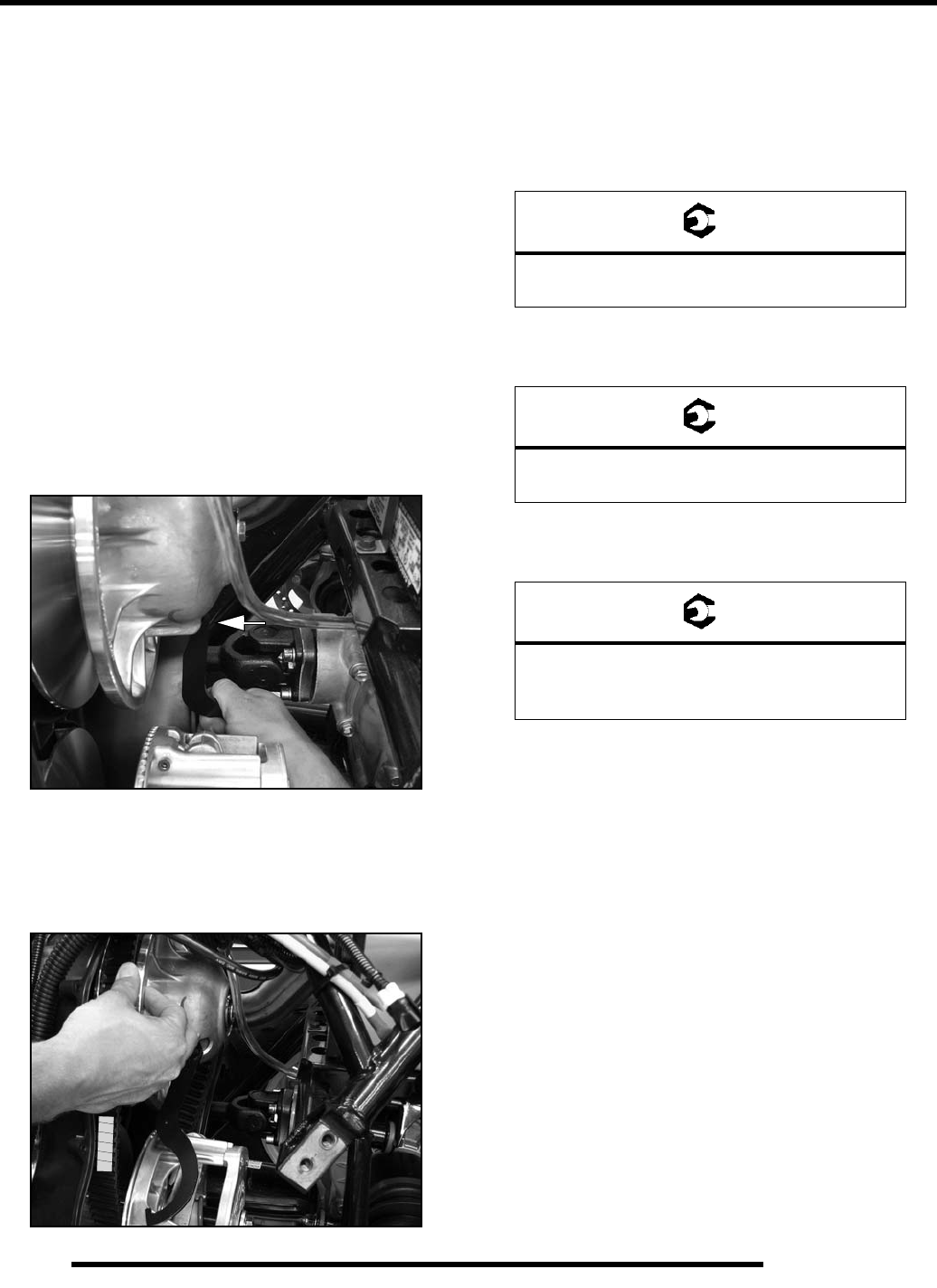
7.10
CLUTCHING (PVT)
Belt Inspection
1. Inspect belt for hour glassing (extreme circular wear in at
least one spot and on both sides of the belt). Hour glassing
occurs when the drive train does not move and the drive
clutch engages the belt.
2. Inspect belt for loose cords, missing cogs, cracks,
abrasions, thin spots, or excessive wear. Compare belt
measurements with a new drive belt. Replace if necessary.
3. Belts with thin spots, burn marks, etc., should be replaced
to eliminate noise, vibration, or erratic PVT operation. See
the Troubleshooting Chart at the end of this chapter for
possible causes.
Belt Installation
1. If the Belt Removal Tool was removed without the belt
installed, you must rotate the clutch and insert the tool at
the 6 o’clock position.
2. With the Belt Removal Tool installed, loop the belt over the
drive clutch and over top of the driven sheaves.
NOTE: Be sure to install the drive belt as shown, so
the “Polaris” label can be read .
3. Rotate the driven sheave and walk the belt into the driven
clutch.
4. Replace the outer PVT cover seal.
5. Reinstall outer PVT cover and secure with screws. Torque
screws to specification.
6. Reinstall the lower left-hand frame support and torque bolts
to specification.
7. Install the left rear wheel and torque wheel nuts to
specification.
8. Lower the ATV, start the engine, and test the operation of
the PVT system.
PVT Break-In (Drive Belt / Clutches)
A proper break-in of the clutches and drive belt will ensure a
longer life and better performance. Break in the clutches and
drive belt by operating at slower speeds during the 10 hour
break-in period as recommended (see Chapter 5 “Engine
Break-In Period” for break-in example). Pull only light loads.
Avoid aggressive acceleration and high speed operation during
the break-in period.
POLARIS
= T
Outer PVT Cover Screws:
45-50 in. lbs. (5-5.6 Nm)
= T
Lower Left-Hand Frame Support Bolts:
36 ft. lbs. (49 Nm)
= T
Wheel Nuts:
Steel: 45 ft. lbs. (61 Nm)
Aluminum: 75 ft. lbs. (102 Nm)
PartShark.com
877-999-5686
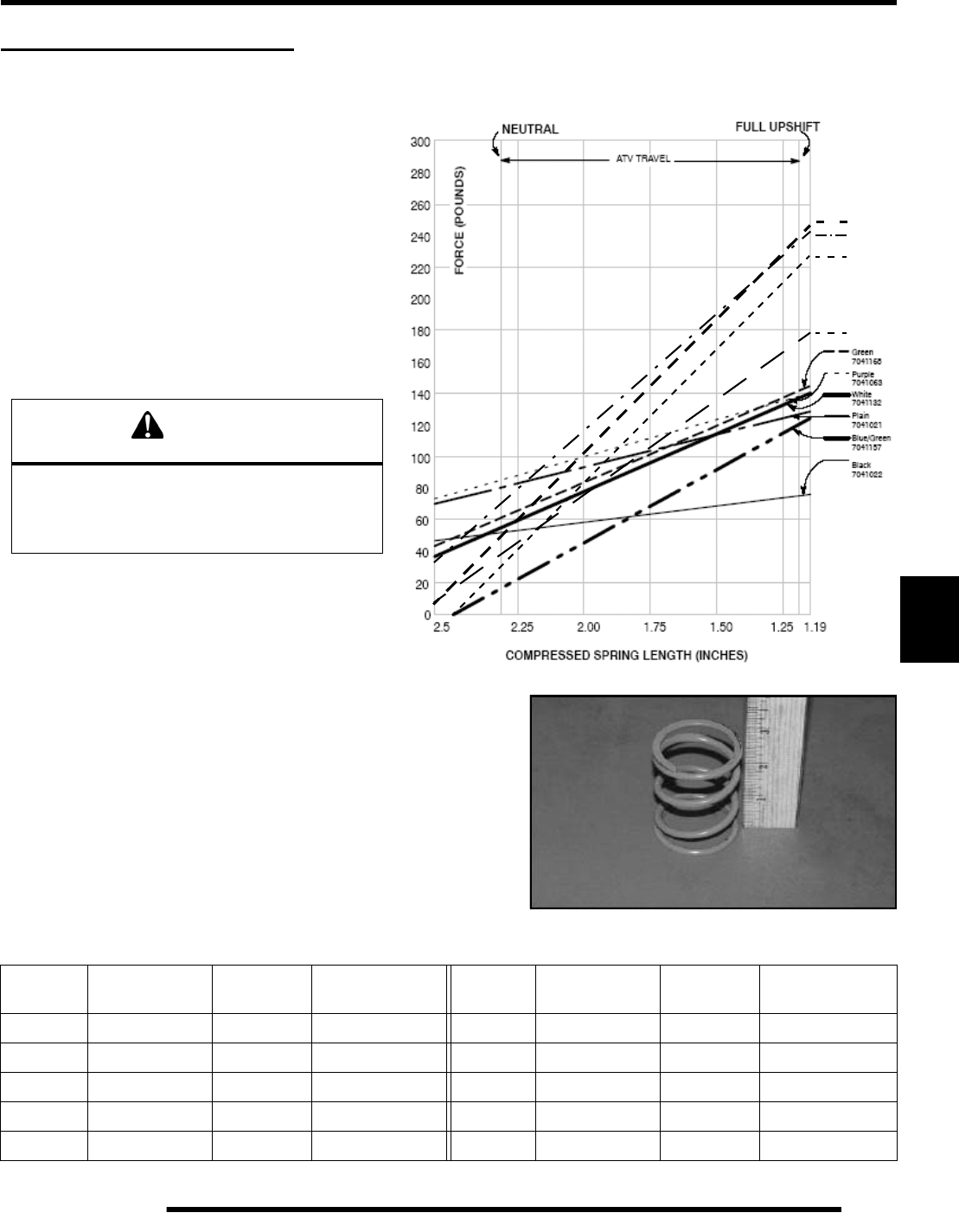
7.11
CLUTCHING (PVT)
7
DRIVE CLUTCH SERVICE
Spring Specifications
The drive clutch spring has two primary functions:
1. To control clutch engagement RPM. The springs,
which have a higher rate when the clutch is in
neutral, will increase clutch engagement RPM.
2. To control the rate at which the drive belt moves
upward in the drive clutch sheaves. This is referred
to as drive clutch upshift.
There are other components which control upshift, but the
spring is one of the primary components in insuring
optimum performance. It is very important that the spring
is of the correct design and is in good condition.
The drive clutch spring is one of the most critical components of the PVT
system. It is also one of the easiest to service. Due to the severe relaxation the
spring is subject to during operation, it should always be inspected for
tolerance limits during any clutch operation diagnosis or repair.
With the spring resting on a flat surface, measure its free length from the outer
coil surfaces as shown. Refer to the spring specification chart for specific free
length measurements and tolerances. Also check to see that spring coils are
parallel to one another. Distortion of the spring indicates stress fatigue,
requiring replacement.
CAUTION
Never shim a drive clutch spring to increase its
compression rate. This may result in complete
stacking of the coils and subsequent clutch
cover failure.
Primary Clutch Springs
PART
NUMBER COLOR CODE WIRE
DIAMETER FREE LENGTH
± .125” PART
NUMBER COLOR CODE WIRE
DIAMETER FREE LENGTH
± .125”
7041021 Plain .157" 4.38" 7041168 Green .177" 3.05"
7041022 Black .140" 4.25" 7043349 Red / White .200" 2.58"
7041063 Purple .168" 4.37" 7043372 Red / Blue .187" 2.56"
7041132 White .177" 2.92" 7043382 Red / Green .177" 2.63"
7041157 Blue / Green .177" 2.53" 7043500 Red / Black .200" 2.82"
Red/White
7043349
Red/Blue
7043372
Red/Green
7043382
Red/Black
7043500
PartShark.com
877-999-5686
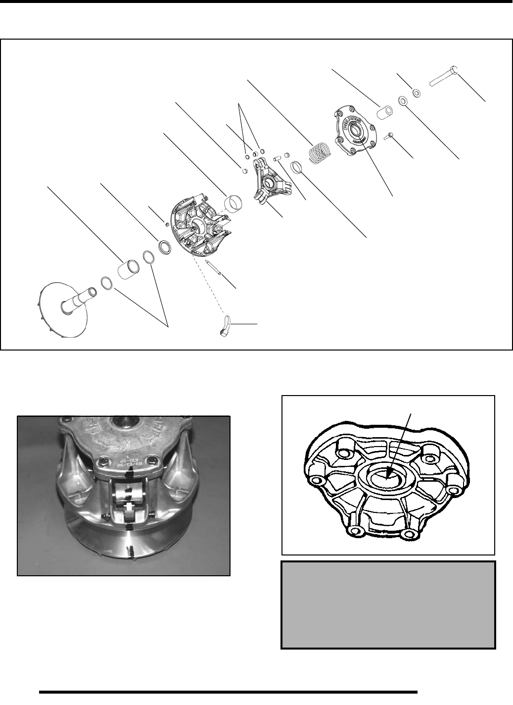
7.12
CLUTCHING (PVT)
Exploded View
Clutch Disassembly
1. Using a permanent marker, mark the cover, spider, and
moveable and stationary sheaves for reference, as the cast
in X's may not have been in alignment before disassembly.
2. Mark the stationary sheave and clutch shaft to verify the
shaft has not turned in the sheave after tightening the spider
during clutch assembly.
3. Remove cover bolts evenly in a cross pattern and remove
cover plate.
4. Inspect cover bushing (A). The outer cover bushing is
manufactured with a Teflon coating. Wear is determined
by the amount of Teflon remaining on the bushing.
Washers
Bearing
Spring
Cover
Bearing
Bushing Lock
Washer
Bolt
Flat
Washer
Cover
Bolts
Pin
Washers
Roller
Nut
Shift
Weight
Bolt
One-Way
Bearing Spacer
Spider
Buttons
Limiter
Cover Bushing Inspection:
Replace the cover bushing if more
brass than Teflon is visible on
the bushing. Refer to bushing
replacement in this chapter.
A
PartShark.com
877-999-5686
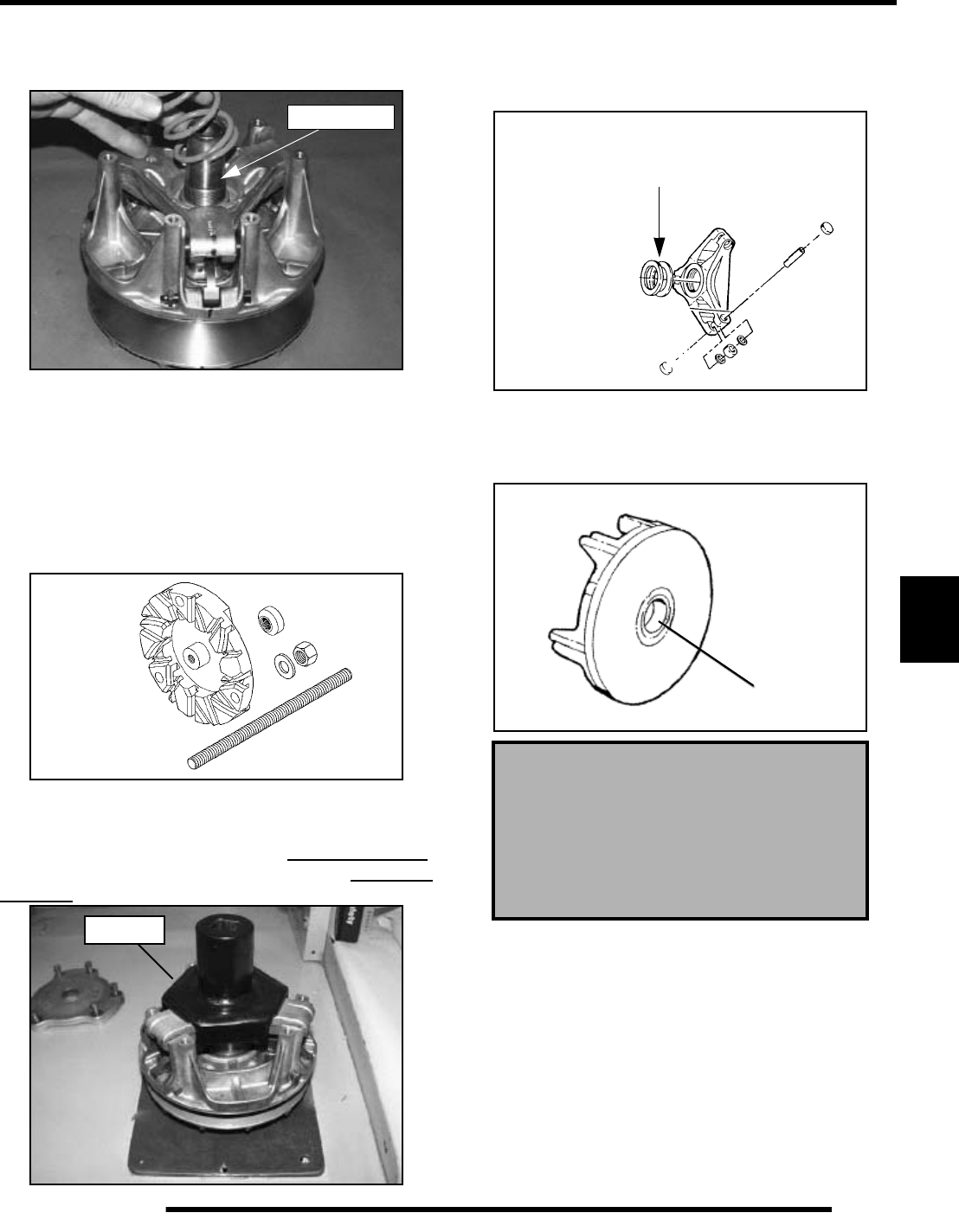
7.13
CLUTCHING (PVT)
7
5. Inspect area on shaft where bushing rides for wear, galling,
nicks, or scratches. Replace clutch assembly if worn or
damaged.
6. Remove and inspect the clutch spring. See “Drive Clutch
Spring Specifications” for spring inspection.
Spider Removal
1. Remove the limiter spacer from the shaft.
2. Install clutch in holding fixture (PN 2871358-A).
NOTE: This updated holding fixture is required to fit
the new drive clutch with a curved rib design.
3. Loosen the spider (clockwise) using Clutch Spider
Removal Tool (PN 2870341).
IMPORTANT: The clutch shaft has left-hand threads.
Be sure to turn the Spider Removal Tool in a clockwise
direction to remove.
NOTE: It is important that the same number and
thickness of washers are reinstalled beneath the
spider during assembly. Be sure to note the number
and thickness of these washers.
Moveable Sheave Bushing Inspection
4. Inspect the Teflon™ coating on the moveable sheave
bushing.
Inspect Shaft
2871358-A
Image is for
reference only.
Actual holding
fixture looks
different than
what is shown.
2870341
Moveable Sheave Bushing Inspection:
Replace the cover bushing if more brass
than Teflon is visible on the bushing.
Refer to bushing replacement
in this chapter.
To maintain proper clutch balance and
belt-to-sheave clearance, be sure to
reinstall original quantity and thickness
washers.
TeflonTM
PartShark.com
877-999-5686
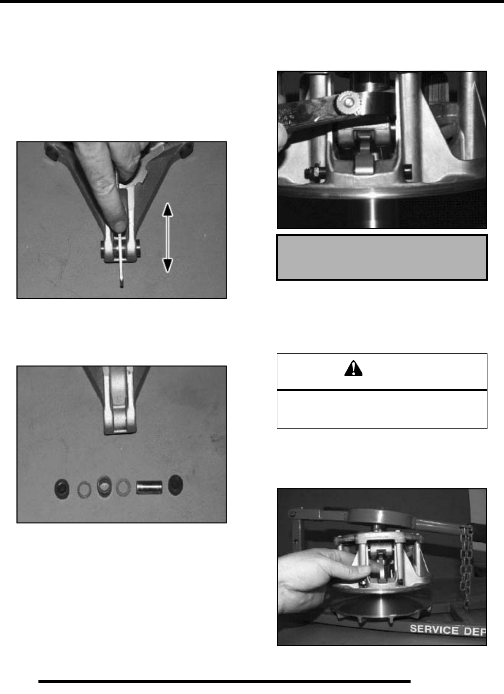
7.14
CLUTCHING (PVT)
Roller, Pin, and Thrust Washer Inspection
1. Inspect all rollers, bushings and roller pins by pulling a flat
metal rod across the roller. Turn roller with your finger. If
you notice resistance, galling, or flat spots, replace rollers,
pins and thrust washers in sets of three. Also inspect to see
if roller and bushing are separating. Bushing must fit
tightly in roller. Use the Roller Pin Tool (PN 2870910) to
replace rollers and pins. Take care not to damage roller
bushing or bearing surface of the new pin during
installation.
2. Rubber backed buttons can be used in all clutches if the
hollow roller pin is changed to the solid roller pin.
NOTE: The rubber side of the button is positioned
toward the solid roller pin.
Button To Tower Clearance Inspection
1. Inspect for any clearance between spider button to tower.
If clearance exists, replace all buttons and inspect surface
of towers. See “Spider Removal” procedure.
2. Inspect sheave surfaces. Replace the entire clutch if worn,
damaged or cracked.
Shift Weight Inspection
1. If clutch is not disassembled, inspect as shown, using a
clutch holding tool to compress the moveable sheave. The
contact surface of the weight should be smooth and free of
dents or gall marks.
Button to Tower Clearance:
000-.001”
WARNING
The clutch assembly is a precisely balanced
unit. Never replace parts with used parts from
another clutch assembly!
PartShark.com
877-999-5686
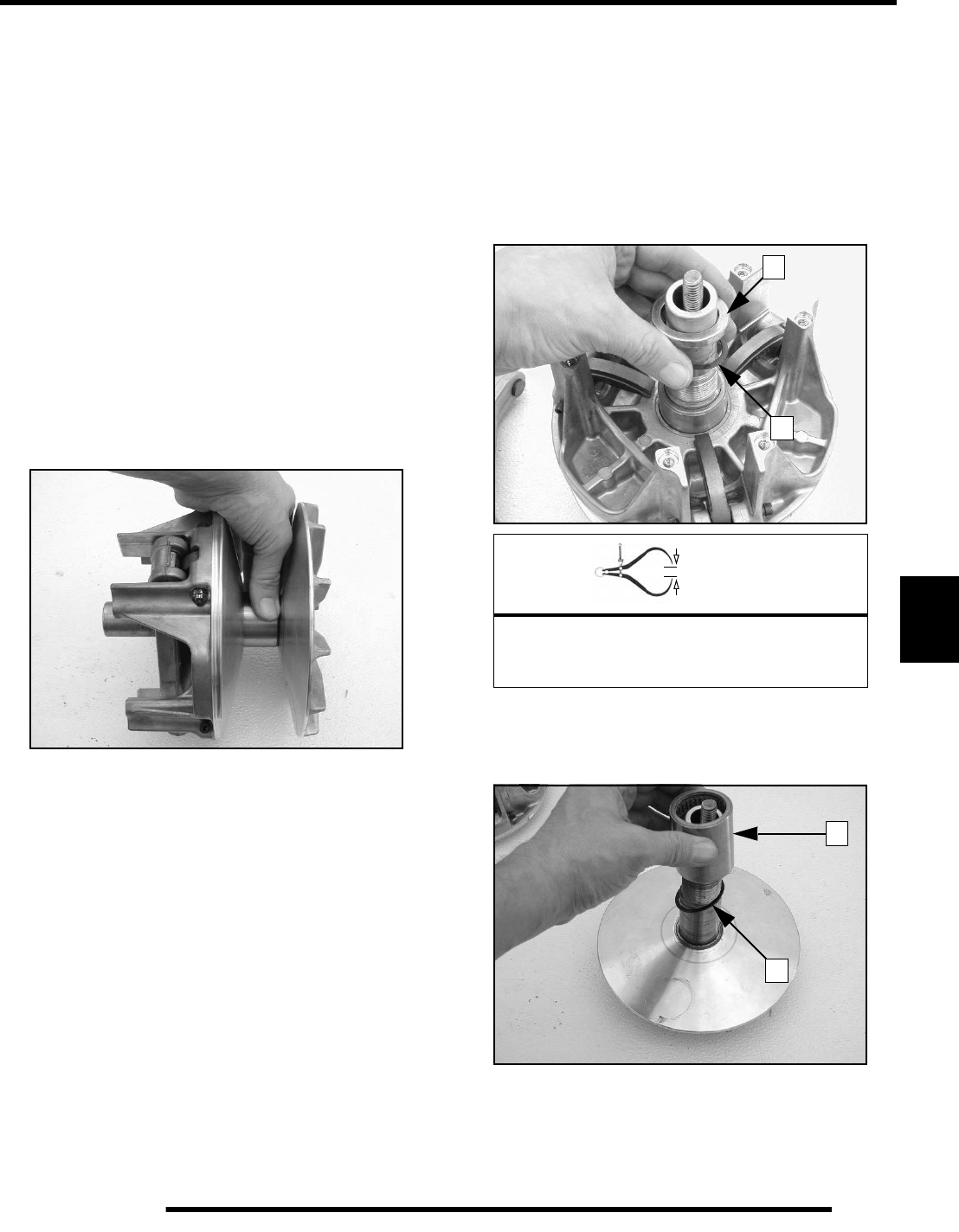
7.15
CLUTCHING (PVT)
7
2. Remove shift weight bolts and weights. Inspect the contact
surface of the weight. The surface should be smooth and
free of dents or gall marks. Inspect the weight pivot bore
and pivot bolts for wear or galling. If weights or bolts are
worn or broken, replace in sets of three with new bolts.
NOTE: A damaged shift weight is usually caused by
a damaged or stuck roller in the spider assembly.
See “Roller, Pin and Thrust Washer Inspection”.
Bearing Inspection
1. Rotate the clutch bearing in both clockwise and counter-
clockwise directions. The one-way bearing should rotate
counter-clockwise (when viewed from cover plate side)
with only a slight amount of drag. When rotated clockwise
the one-way bearing should lock to the shaft without
slipping.
2. Verify there is no binding or rough spots. If problems are
noted continue with disassembly.
Clutch Inspection
NOTE: Remove cover, spring, and spider following
instructions for drive clutch removal, then proceed
as follows:
1. Remove the moveable sheave spacer sleeve (1) and the
thrust washer (2). Visually inspect the washer for damage.
2. Measure the thickness and compare to specification.
Replace if worn or damaged.
3. Remove the moveable clutch sheave.
4. Lift bearing (3) and thrust washer (4) off shaft. Replace as
an assembly if worn, damaged, or if problems were noted.
= In. / mm.
Thrust Washer Thickness
Standard: .030” (.76mm)
Service Limit: .025” (.64mm)
1
2
3
4
PartShark.com
877-999-5686
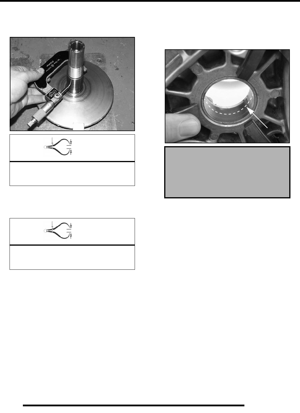
7.16
CLUTCHING (PVT)
5. Inspect surface of shaft for pitting, grooves, or damage.
Measure the outside diameter and compare to
specifications. Replace the drive clutch assembly if shaft
is worn or damaged.
6. Visually inspect PTFE thrust washer for damage. Measure
the thickness and compare to specification. Replace if
worn or damaged.
Moveable Sheave Bushing Inspection
Inspect the Teflon coating (arrow) on the moveable sheave
bushing. Inspect both sheaves for signs of wear, grooving or
cracking. De-glaze sheave surfaces with a 3M Scotch-Brite
Pad if needed.
= In. / mm.
Shaft Diameter:
Standard: 1.3745 - 1.375 (
Service Limit: 1.3730”
= In. / mm.
PTFE Washer Thickness
Standard: .030” (.76mm)
Service Limit: .025” (.64mm)
Moveable Sheave Bushing Inspection:
Replace the cover bushing if more brass
than Teflon is visible on the bushing.
Refer to bushing replacement
in this chapter.
PartShark.com
877-999-5686
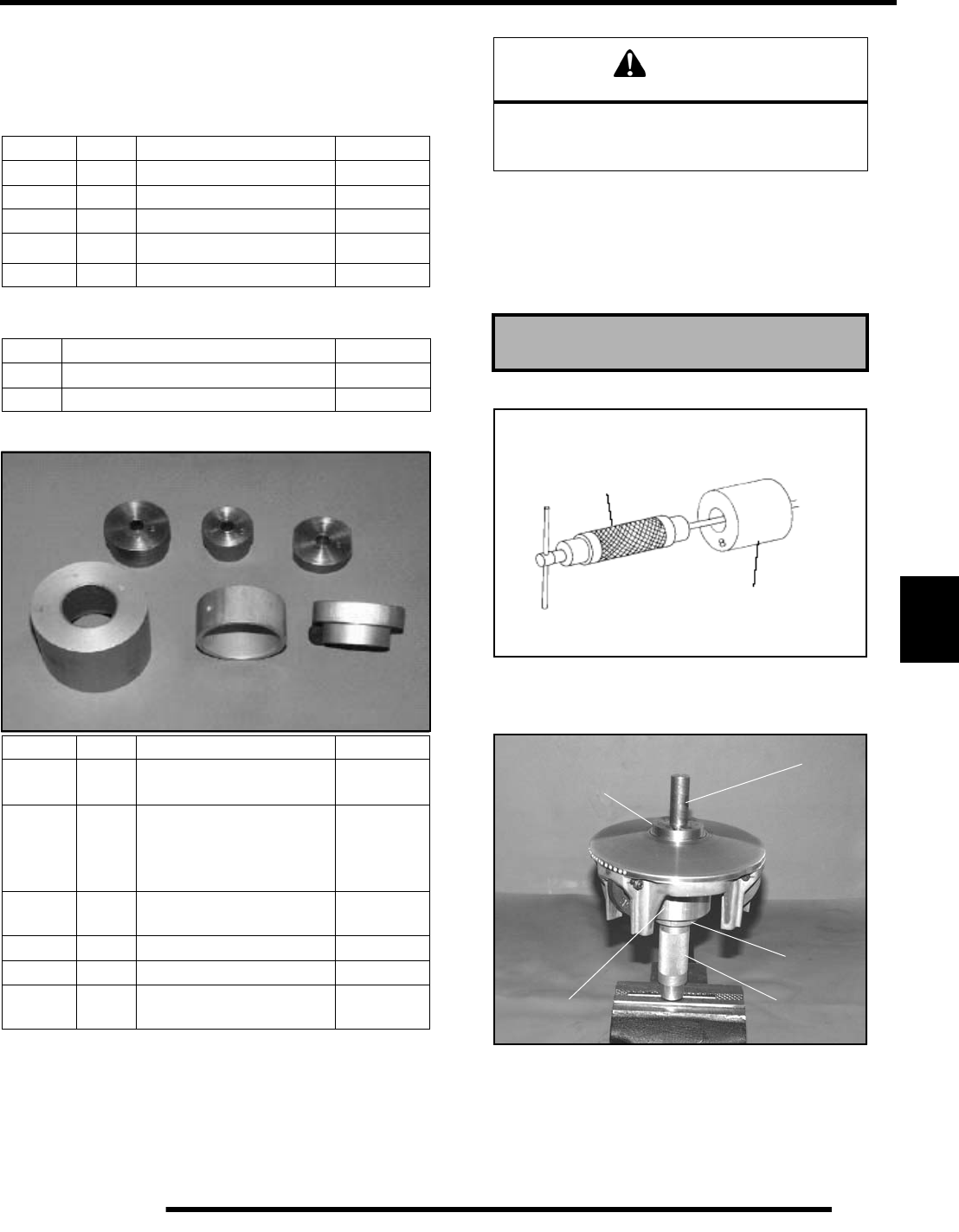
7.17
CLUTCHING (PVT)
7
Bushing Service
IMPORTANT: Special Tools Required
*Clutch Bushing Replacement Tool Kit (PN 2871226)
NOTE: Bushings are installed at the factory using
Loctite 609. In order to remove bushings it will be
necessary to apply heat evenly to the area around
each bushing. Clean all residual Loctite from
bushing bore prior to installing new bushing.
Moveable Sheave - Bushing Removal
1. Remove clutch as outlined previously in this chapter.
2. Install handle end of the Piston Pin Puller (PN 2870386)
securely into bench vise and lightly grease puller threads.
3. Remove nut from puller rod and set aside.
4. Install puller adapter (Item 10 from kit PN 2871226).
5. Install main adapter (Item D) onto puller.
6. With towers pointing toward the vise, slide sheave onto
puller rod.
7. Install removal tool (Item A, B) into center of sheave with
“A side" toward sheave.
EBS Clutch Bushing Tool Kit - 2201379
Item Qty. Part Description Part #
A, B 1 EBS Puller Tool 5132027
C 1 EBS Puller Nut 5132501
D 1 EBS Main Adapter 5132029
E1
EBS Bushing Removal Tool 5132028
-- 1 Instructions 9915111
Additional Special Tools
Qty. Part Description Part #
1 Clutch Bushing Replacement Tool Kit 2871226
1 Piston Pin Puller 2870386
Item Qty. Part Description Part #
#2 1 P-90 Drive/Driven Clutch
Bushing Install Tool 5020628
#3 1
Drive Clutch Cover
Bushing Removal/
Installation Tool (all
clutches)
5020629
#5 1 P-90 Driven Clutch Cover
Bushing Removal Tool 5020631
#8 1 Main Puller Adapter 5020632
#9 1 Adapter Reducer 5010279
#10 1 Number Two Puller
Adapter 5020633
#2 #3 #5
#8
#9
#10
CAUTION
Clutch components will be hot! In order to avoid
serious burns, wear insulated gloves during the
removal process.
Piston Pin Puller (PN 2870386)
Piston Pin Puller
(PN 2870386)
Main Puller Adaptor (#8)
(PN 5020632)
Puller Tool (A,B)
Side “A” toward
sheave
Nut (C)
Main
Adapter (D)
Puller
Adapter (10)
Piston Pin
Puller
PartShark.com
877-999-5686
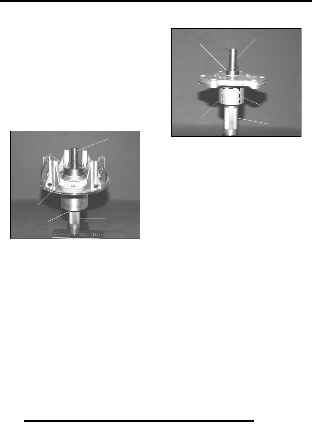
7.18
CLUTCHING (PVT)
NOTE: Use Bushing Tool PA-47336.
8. Install nut (C) onto end of puller rod and hand tighten. Turn
puller barrel to increase tension on sheave if needed. Using
a hand held propane torch, apply heat around outside of
bushing until tiny smoke tailings appear.
9. Turn sheave counterclockwise on puller rod until it comes
free. Lift sheave off puller.
10. Remove nut from puller rod and set aside.
11. Pull bushing removal tool and adapter from puller rod.
Remove bushing from tool and discard.
Drive Clutch Bushing Installation
1. Place main adapter (Item 8) on puller.
2. Apply Loctite 609 evenly to bushing bore inside
moveable sheave.
3. Set bushing in place on sheave.
4. Insert installation puller tool (Item A/B) with “A” side
down, into center of bushing.
NOTE: Some models use Bushing Tool PA-47336.
5. With towers pointing upward, slide sheave, bushing and
tool onto puller rod.
6. Install nut on puller rod and hand tighten. Turn barrel to
apply additional tension if needed.
7. Turn sheave counterclockwise, making sure bushing is
drawn straight into bore. Continue until bushing is seated.
8. Remove nut from puller rod and set aside.
9. Remove sheave from puller.
10. Remove installation tool.
Cover Bushing Removal
1. Install main adapter (Item 8) on puller.
2. Install adapter reducer (Item 9).
3. From outside of clutch cover, insert removal tool (Item 3)
into cover bushing.
4. With inside of cover toward vise, slide cover onto puller.
5. Install nut onto puller rod and hand tighten. Turn puller
barrel to increase tension as needed.
6. Turn clutch cover counterclockwise on puller rod until
bushing is removed and cover comes free.
7. Remove nut from puller rod and set aside.
8. Remove bushing and bushing removal tool from puller.
Discard bushing.
Cover Bushing Installation
1. Apply Loctite 609 evenly to bushing bore in cover.
2. Working from inside of cover, insert new bushing and
bushing installation tool into center of clutch cover.
3. With main adapter on puller, insert cover onto puller rod,
placing outside of cover toward vise.
4. Install nut on rod and hand tighten. Turn puller barrel to
apply more tension if needed.
5. Turn clutch cover counterclockwise on puller rod until
bushing is seated.
6. Remove nut from puller rod. Take installation tool and
clutch cover off rod.
Puller Tool (A,B)
Side “A” toward
sheave
Nut (C)
Bushing
Main Adapter
(8)
Piston Pin
Puller
Removal Tool
(3) Nut (C)
Adapter Reducer
(9)
Piston Pin
Puller
Main
Adapter (8)
PartShark.com
877-999-5686
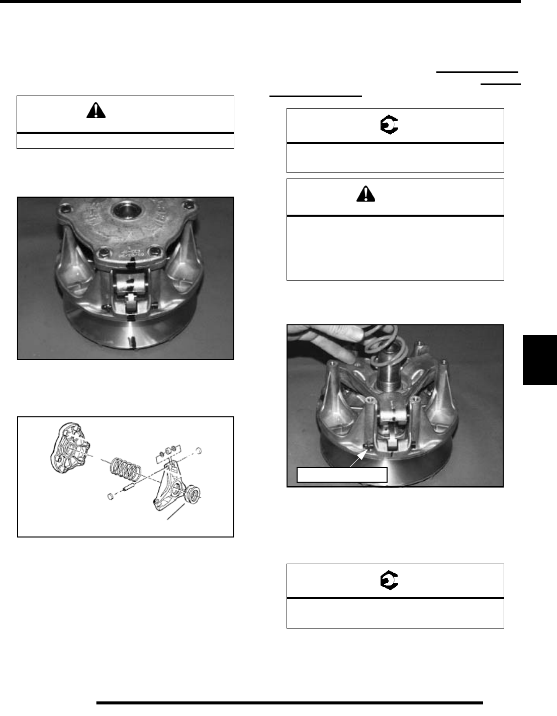
7.19
CLUTCHING (PVT)
7
Clutch Assembly
NOTE: It is important that the same number and
thickness of washers are reinstalled beneath the
spider during assembly. The Teflon bushings are
self-lubricating.
Reassemble the drive clutch in the sequence provided below. Be
sure the “X”, or the marks that were made earlier are aligned
during each phase of assembly.
1. Install moveable sheave onto fixed sheave.
2. Install spider spacers. Use same quantity and thickness as
were removed.
3. Compress spider buttons for each tower and install spider,
making sure that “X”, or the marks that were made earlier,
on spider aligns with “X”, or the marks that were made
earlier, in moveable sheave.
4. Torque the spider (counter-clockwise) to specification
using the holding fixture and spider tool. Torque with
smooth motion to avoid damage to the stationary sheave.
IMPORTANT: The clutch shaft has left-hand threads.
Be sure to turn the Spider Removal Tool in a counter-
clockwise direction to reinstall.
5. Install the limiter spacer over the shaft and on top of spider.
6. Install shift weights using new lock nuts on the bolts.
7. Reinstall clutch spring.
8. Reinstall cover, aligning “X” mark with other marks.
9. Torque cover bolts evenly to specification.
CAUTION
Do not apply oil or grease to the bushings.
Spacer washers
= T
Spider Torque:
200 ft. lbs. (271 Nm)
CAUTION
Be sure the spider spacer washers are fully
seated in the recessed area in the spider.
Any misalignment will alter clutch balance.
Inverting the clutch while initially tightening the
spider will help position the washers.
= T
Cover Bolt Torque:
100 in. lbs. (11 Nm)
Use new lock nuts
PartShark.com
877-999-5686
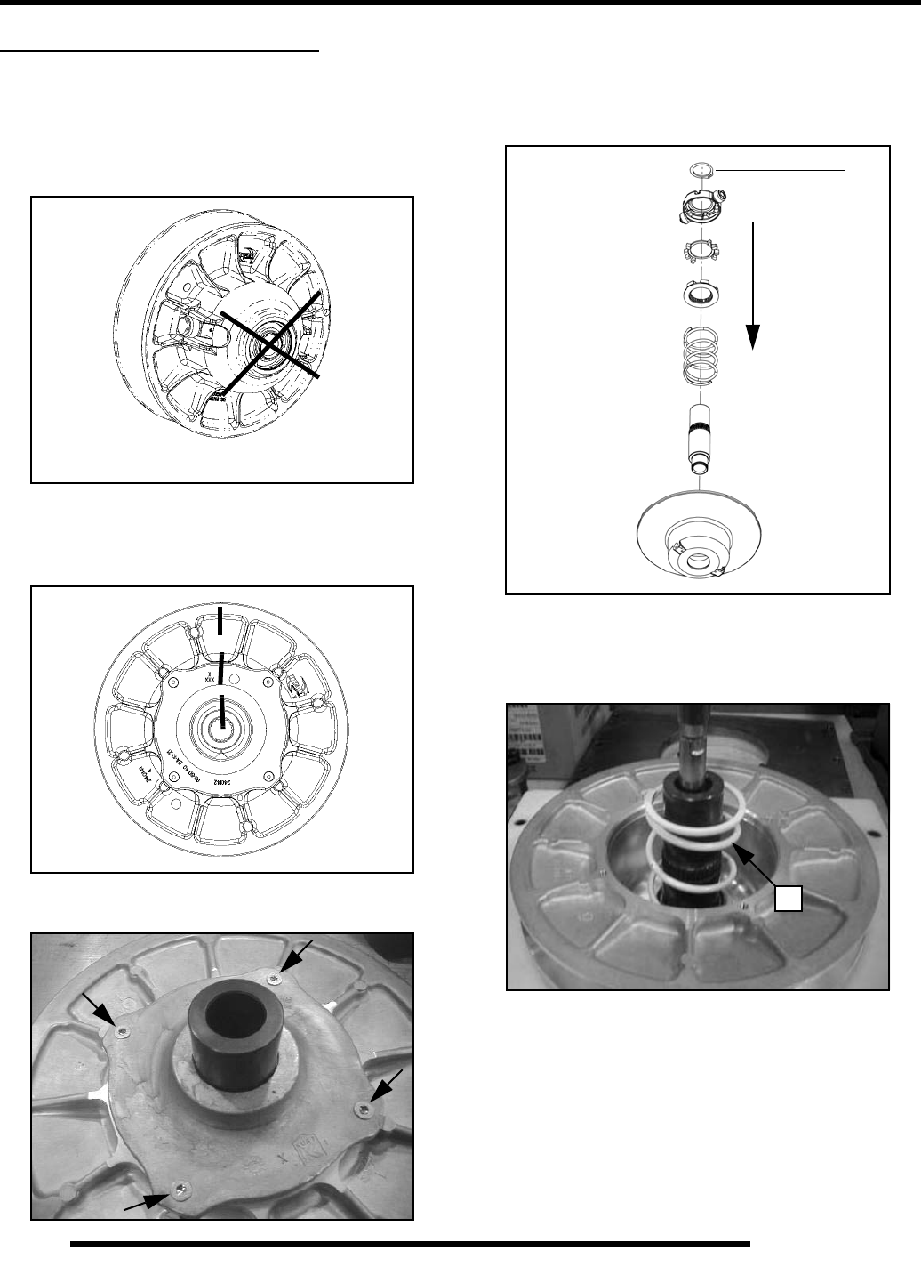
7.20
CLUTCHING (PVT)
DRIVEN CLUTCH SERVICE
Clutch Disassembly
1. Remove driven clutch from the transmission input shaft.
Do not attempt disassembly of the driven clutch from the
outside snap ring. The driven clutch must be disassembled
from the helix side.
2. It is important to mark the position of the shaft, cam cover,
and sheave before disassembly or use the X’s on the
components for reference. This will aid in reassembly and
helps to maintain clutch balance after reassembly.
3. Remove the four screws that secure the cam (helix)
assembly using a T25 Torx driver.
4. Place the clutch into the Clutch Compression Tool PN
8700220. Using Compression Extensions PN PS-45909,
press down on top of the spider assembly, compressing the
spider onto the shaft. Remove snap ring (A) and slowly
release the assembly.
5. Remove the spider assembly and spring (B).
NOTE: Spring is compression only and has no
torsional wind.
Do not disassemble from this side
Press down
on spider
A
B
PartShark.com
877-999-5686
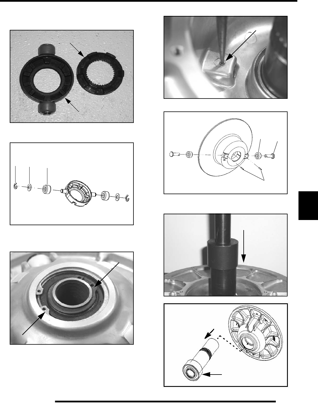
7.21
CLUTCHING (PVT)
7
6. Remove the inside spider plate (D) and spider dampener
(E). Inspect the spider dampener (E) for wear and replace
if needed.
7. Remove the E-clips (F), washers (G), and the clutch rollers
(H). Inspect the rollers for wear; replace if worn.
8. Remove the clutch assembly from the holding tool.
Remove the large outer retaining ring (I) and the inner
retaining ring (J).
9. Press out the spring pins (K) in the inner sheave.
10. Pull out the clutch roller pins (L) and rollers (M).
11. Press the shaft and bearing out of the outer sheave using a
press.
E
D
H
G
F
I
J
K
K
ML
Press Shaft and
Bearing Out
Inspect Bearing
PartShark.com
877-999-5686
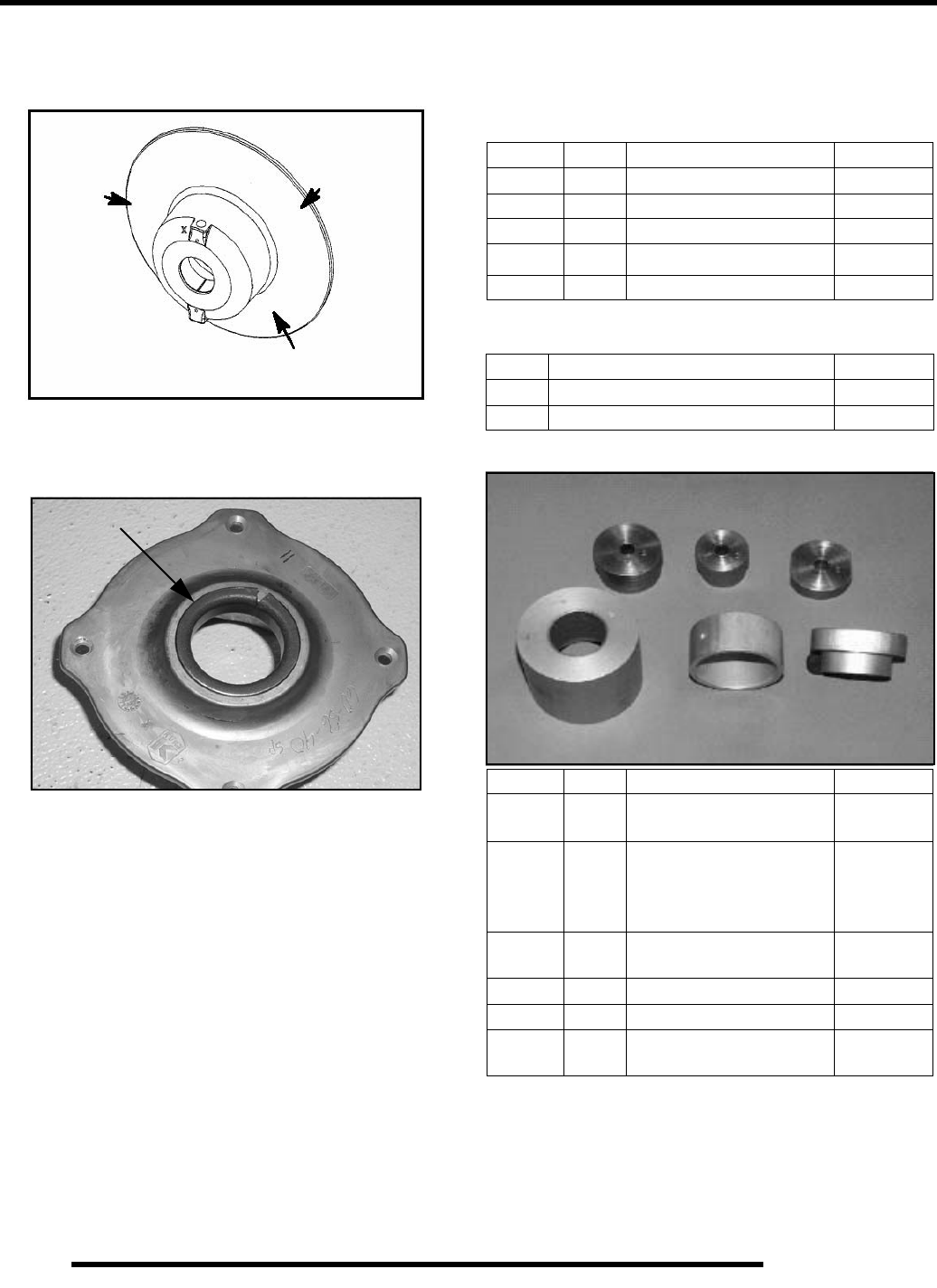
7.22
CLUTCHING (PVT)
12. Inspect the bearing for wear. Spin the bearing, if the
bearing does not spin smoothly, replace it. To remove the
bearing, press the bearing off the shaft.
13. Inspect the cam (helix) assembly bushing for wear. If the
bushing is worn or the shaft does not fit snug into the
bushing, replace the cam (helix) assembly.
Bushing Service
IMPORTANT: Special Tools Required
*Clutch Bushing Replacement Tool Kit (PN 2871226)
NOTE: Bushings are installed at the factory using
Loctite 609. In order to remove bushings it will be
necessary to apply heat evenly to the area around
each bushing. Clean all residual Loctite from
bushing bore prior to installing new bushing.
Inspect Sheave Surface
Inspect Bushing
EBS Clutch Bushing Tool Kit - 2201379
Item Qty. Part Description Part #
A, B 1 EBS Puller Tool 5132027
C 1 EBS Puller Nut 5132501
D 1 EBS Main Adapter 5132029
E1
EBS Bushing Removal Tool 5132028
-- 1 Instructions 9915111
Additional Special Tools
Qty. Part Description Part #
1 Clutch Bushing Replacement Tool Kit 2871226
1 Piston Pin Puller 2870386
Item Qty. Part Description Part #
#2 1 P-90 Drive/Driven Clutch
Bushing Install Tool 5020628
#3 1
Drive Clutch Cover
Bushing Removal/
Installation Tool (all
clutches)
5020629
#5 1 P-90 Driven Clutch Cover
Bushing Removal Tool 5020631
#8 1 Main Puller Adapter 5020632
#9 1 Adapter Reducer 5010279
#10 1 Number Two Puller
Adapter 5020633
#2 #3 #5
#8
#9
#10
PartShark.com
877-999-5686
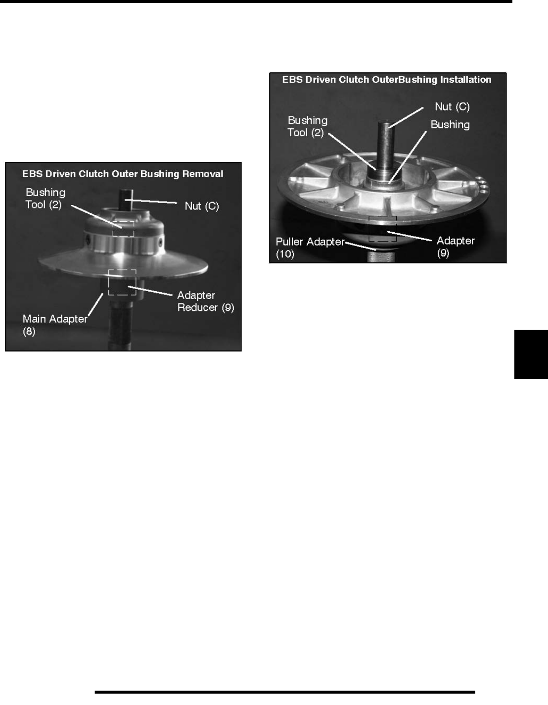
7.23
CLUTCHING (PVT)
7
Clutch Bushing Removal
1. Install main puller adapter (Item 8) onto puller.
2. Install adapter reducer (Item 9).
3. Using a hand held propane torch, apply heat around outside
of bushing until tiny smoke tailings appear.
4. Flip sheave over so bushing faces downward and install
onto puller.
5. Install bushing tool (Item 2).
6. Install left hand nut (C) and spacer onto puller rod and
tighten by hand. Turn puller barrel for further tension if
needed.
7. Turn clutch sheave counterclockwise until bushing is
removed and sheave comes free.
8. Remove nut (C) (left hand thread) from puller rod and set
aside.
9. Remove adapters from puller.
10. Remove bushing and removal tool from adapters. Discard
bushing.
Clutch Bushing Installation
1. Install puller adapter (Item 10) onto puller.
2. Install adapter (Item 9) onto puller.
3. Apply Loctite 609 evenly to bushing bore inside
moveable sheave.
4. Install sheave face down on puller.
5. Install new bushing on installation tool (Item 2) and install
assembly into sheave.
6. Install left hand thread nut (C) onto puller rod and hand
tighten against installation tool.
7. Turn clutch sheave counterclockwise, making sure bushing
is drawn straight into bore. Continue until bushing is
seated.
8. Remove nut (C) from puller rod and set aside.
9. Remove installation tool and clutch sheave from puller.
PartShark.com
877-999-5686
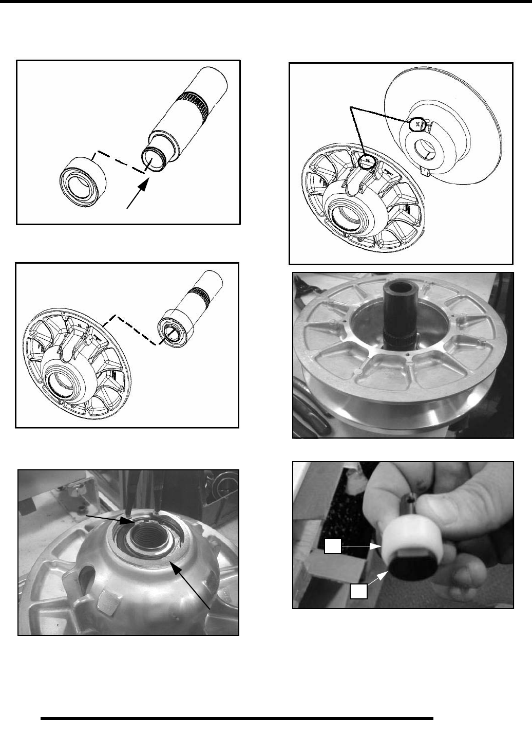
7.24
CLUTCHING (PVT)
Clutch Assembly
1. Install a new bearing onto the output shaft using a press.
2. Install the shaft/bearing into the outer sheave.
3. Install the small and large retaining rings into the outer
sheave above the bearing.
4. Line up the “X” on the moveable sheave with the “X” on
the stationary sheave or use the marks previously used. Put
the sheaves together.
5. Install the roller (A) onto the roller pin (B) on both sides.
Align X’s
A
B
PartShark.com
877-999-5686
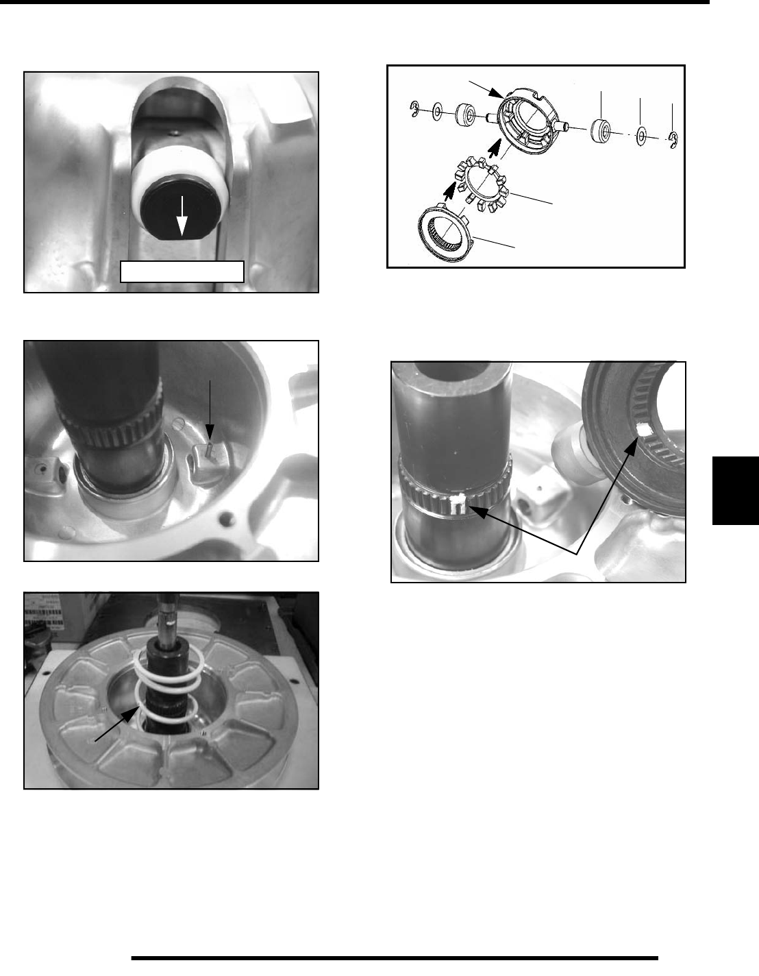
7.25
CLUTCHING (PVT)
7
6. Install the roller pin into the sheave assembly on both sides.
The flat side of the roller pin faces downward when the
shaft side is laying flat on the bench.
7. Install the spring pins (C) to secure the roller pins. Install
until flush with sheave surface.
8. Install the spring over the shaft.
9. Install the clutch rollers (D) onto each side of the outside
spider. Install the washers (E) and E-clips (F) to secure the
rollers. The rollers should spin freely.
10. Install the spider dampener (G) inside the outer spider and
install the inside spider plate (H).
11. Install the spider assembly onto the shaft with the retaining
ring on top of the spider. NOTE: Use the marks previously
made to align the skip tooth spider, or use the “X” on top
of the spider and align it with the skip tooth on the shaft.
Flat Side Down
C
Outer Spider
H
G
DEF
Align Marks
PartShark.com
877-999-5686
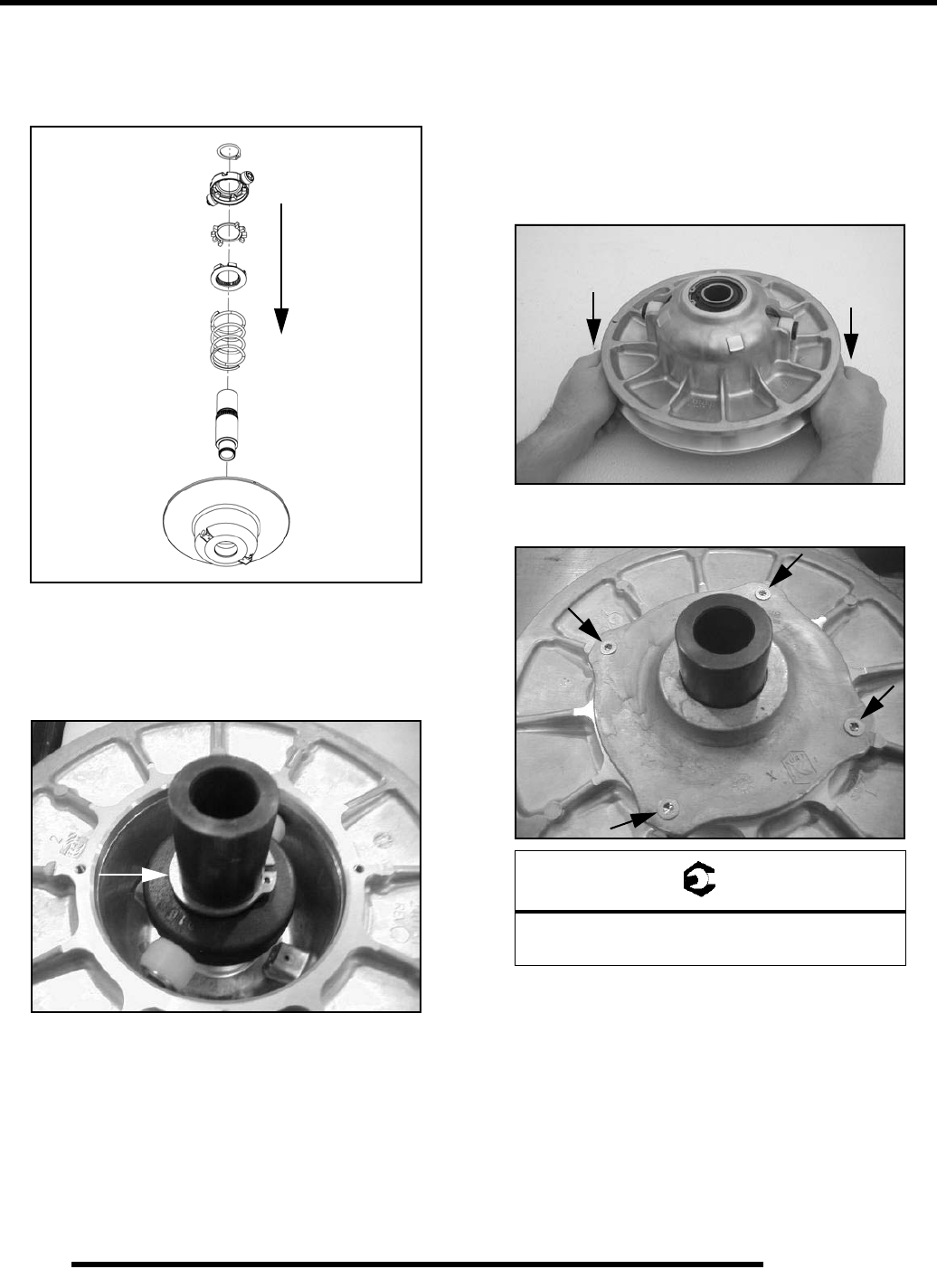
7.26
CLUTCHING (PVT)
12. Place the clutch into Clutch Compression Tool PN
8700220. Using Compression Extensions PN PS-45909,
press down on the top of the spider assembly, pushing the
spider onto the shaft.
13. Slowly compress the spider into place. If the spider appears
to bind while compressing, stop and make sure the skip
tooth on the shaft and the spider are aligned. Once the
spider passes the retaining ring notch on the shaft, install
the retaining ring.
14. Install the cam (helix) assembly over the shaft. Line up the
“X” on the cam, “X” on spider, and “X” on the stationary
sheave or use the marks previously made before
disassembly. NOTE: If the cam assembly (helix) is
difficult to install, be sure the sheaves are aligned. To align
the sheaves place the clutch assembly on a flat surface with
the cam assembly (helix) side down. Press down on the
moveable sheave belt face with both hands and the helix
will release.
15. Use a T25 Torx driver to install the four screws and torque
to specification.
Press down
on spider
= T
T25 Torx:
42-52 in. lbs. (4.75 - 5.88 Nm)
Press Down to Loosen Helix
PartShark.com
877-999-5686
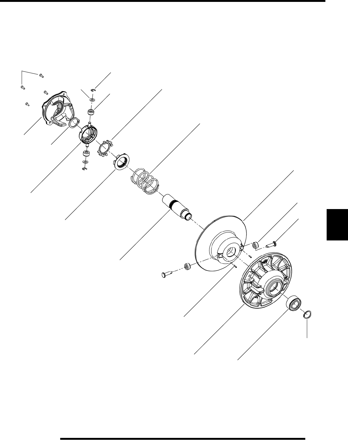
7.27
CLUTCHING (PVT)
7
Exploded View
Compression
Thrust
Washer
Cam
(Helix)
T25
Retaining
Ring
Roller
Pin
Slotted
Ball
E-Ring
Spring
Spider
Dampener
Outer
Spider
Spider
Insert
Stationary
Sheave Bearing
Spring Pin
Moveable
Sheave
Clutch
Shaft
Roller
Retaining
Ring
Screws
PartShark.com
877-999-5686

7.28
CLUTCHING (PVT)
TROUBLESHOOTING
Situation Probable Cause Remedy
Engine RPM below
specified operating
range, although
engine is properly
tuned.
-Wrong or broken drive clutch spring.
-Drive clutch shift weight too heavy.
-Driven clutch spring broken or installed in wrong
helix location.
-Replace with recommended spring.
-Install correct shift weight kit to match engine
application.
-Replace spring; refer to proper installation location.
Erratic engine
operating RPM
during acceleration or
load variations.
-Drive clutch binding.
-Belt worn unevenly - thin / burnt spots.
-Driven clutch malfunction.
-Sheave face grooved.
A. Disassemble drive clutch; inspect shift weights for
wear and free operation.
B. Clean and polish stationary shaft hub; reassemble
clutch without spring to determine problem area.
Replace belt.
Inspect movable sheave for excessive bushing
clearance.
-Replace the clutch.
Engine RPM above
specified operating
range.
-Incorrect drive clutch spring (too high spring rate).
-Drive clutch shift weights incorrect for application
(too light).
-Drive clutch binding.
-Driven clutch binding.
-Clutch sheaves greasy; belt slipage.
-Install correct recommended spring.
-Install correct recommended shift weights.
-Disassemble and clean clutch, inspecting shift weights
and rollers. Reassemble without the spring and move
sheaves through entire range to further determine
probable cause.
-Disassemble, clean, and inspect driven clutch.
-Clean sheaves with denatured alcohol or brake cleaner,
install new belt.
Harsh drive clutch
engagement.
-Drive belt worn too narrow.
-Excessive belt / sheave clearance with new belt.
-Replace belt.
-Perform belt / sheave clearance adjustment with shim
washers beneath spider.
Drive belt turns over -Wrong belt for application. -Replace with correct belt.
Belt burnt, thin spots
-Abuse (continued throttle application when
vehicle is stationary, excess load)
-Dragging brake
-Slow, easy clutch engagement
-Caution operator to operate machine within guidelines.
-Vehicle operated with parking brake on. Inspect brake
system.
-Fast, effective use of throttle for efficient engagement.
PartShark.com
877-999-5686

7.29
CLUTCHING (PVT)
7
Troubleshooting, Continued.....
Situation Probable Cause Remedy
PVT cover
overheating (melting)
-Plugged air intake or outlet.
-Belt slippage due to water, oil, grease, etc., rubbing
on cover.
-High vs. low range.
-Clear obstruction
-Inspect system. Clean , repair or replace as necessary.
Seal PVT system ducts.
-Instruct operator on guidelines for operation in proper
driving range for different terrain as outlined in Owner’s
Safety and Maintenance Manual.
Water ingestion
-Cover seal or ducts leaking
-Operator error
-Find leak and repair as necessary.
-Instruct operator on guidelines for operation in wet
terrain as outlined in Owner’s Safety and Maintenance
Manual.
Belt slippage
-Belt worn out
-Water ingestion
-Belt contaminated with oil or grease
-Replace belt.
-Inspect and seal PVT system.
-Inspect and clean.
PVT noise
-Belt worn or separated, thin spots, loose belt
-Broken or worn clutch components, cover hitting
clutches
-Replace belt.
-Inspect and repair as necessary.
Engagement
erratic or stabby
-Thin spots on belt, worn belt
-Drive clutch bushings stick
-Replace belt. Refer to belt burnt troubleshooting and
instruct operator.
-Inspect and repair clutches.
PartShark.com
877-999-5686

NOTES
CLUTCHING (PVT)
7.30
PartShark.com
877-999-5686

FINAL DRIVE
8.1
CHAPTER 8
FINAL DRIVE
8
GENERAL SPECIFICATIONS. . . . . . . . . . . . . . . . . . . . . . . . . . . . . . . . . . . . . . . . . . . . . . 8.2
TORQUE SPECIFICATIONS / SPECIAL TOOLS . . . . . . . . . . . . . . . . . . . . . . . . . . . . . . 8.2
WHEELS . . . . . . . . . . . . . . . . . . . . . . . . . . . . . . . . . . . . . . . . . . . . . . . . . . . . . . . . . . . . . . 8.2
REMOVAL / INSTALLATION . . . . . . . . . . . . . . . . . . . . . . . . . . . . . . . . . . . . . . . . . . . . . . 8.2
WHEEL HUBS . . . . . . . . . . . . . . . . . . . . . . . . . . . . . . . . . . . . . . . . . . . . . . . . . . . . . . . . . . 8.3
FRONT BEARING CARRIER . . . . . . . . . . . . . . . . . . . . . . . . . . . . . . . . . . . . . . . . . . . . . . 8.4
INSPECTION / REMOVAL . . . . . . . . . . . . . . . . . . . . . . . . . . . . . . . . . . . . . . . . . . . . . . . . 8.4
BEARING REPLACEMENT . . . . . . . . . . . . . . . . . . . . . . . . . . . . . . . . . . . . . . . . . . . . . . . 8.5
INSTALLATION . . . . . . . . . . . . . . . . . . . . . . . . . . . . . . . . . . . . . . . . . . . . . . . . . . . . . . . . 8.6
FRONT DRIVE SHAFT . . . . . . . . . . . . . . . . . . . . . . . . . . . . . . . . . . . . . . . . . . . . . . . . . . . 8.7
REMOVAL . . . . . . . . . . . . . . . . . . . . . . . . . . . . . . . . . . . . . . . . . . . . . . . . . . . . . . . . . . . .8.7
INSTALLATION . . . . . . . . . . . . . . . . . . . . . . . . . . . . . . . . . . . . . . . . . . . . . . . . . . . . . . . . 8.8
FRONT PROPSHAFT . . . . . . . . . . . . . . . . . . . . . . . . . . . . . . . . . . . . . . . . . . . . . . . . . . . . 8.9
REMOVAL / INSTALLATION . . . . . . . . . . . . . . . . . . . . . . . . . . . . . . . . . . . . . . . . . . . . . . 8.9
PROPSHAFT U-JOINT SERVICE. . . . . . . . . . . . . . . . . . . . . . . . . . . . . . . . . . . . . . . . . . . 8.9
DISASSEMBLY. . . . . . . . . . . . . . . . . . . . . . . . . . . . . . . . . . . . . . . . . . . . . . . . . . . . . . . . . 8.9
ASSEMBLY . . . . . . . . . . . . . . . . . . . . . . . . . . . . . . . . . . . . . . . . . . . . . . . . . . . . . . . . . . 8.10
FRONT GEARCASE - CENTRALIZED HILLIARD . . . . . . . . . . . . . . . . . . . . . . . . . . . . . 8.11
EXPLODED VIEW . . . . . . . . . . . . . . . . . . . . . . . . . . . . . . . . . . . . . . . . . . . . . . . . . . . . . 8.11
AWD OPERATION . . . . . . . . . . . . . . . . . . . . . . . . . . . . . . . . . . . . . . . . . . . . . . . . . . . . . 8.12
ADC OPERATION . . . . . . . . . . . . . . . . . . . . . . . . . . . . . . . . . . . . . . . . . . . . . . . . . . . . . 8.13
AWD DIAGNOSIS. . . . . . . . . . . . . . . . . . . . . . . . . . . . . . . . . . . . . . . . . . . . . . . . . . . . . . 8.14
GEARCASE REMOVAL . . . . . . . . . . . . . . . . . . . . . . . . . . . . . . . . . . . . . . . . . . . . . . . . . 8.15
GEARCASE DISASSEMBLY / INSPECTION. . . . . . . . . . . . . . . . . . . . . . . . . . . . . . . . . 8.16
GEARCASE ASSEMBLY . . . . . . . . . . . . . . . . . . . . . . . . . . . . . . . . . . . . . . . . . . . . . . . . 8.20
SETTING RING GEAR BACKLASH. . . . . . . . . . . . . . . . . . . . . . . . . . . . . . . . . . . . . . . . 8.22
GEARCASE INSTALLATION . . . . . . . . . . . . . . . . . . . . . . . . . . . . . . . . . . . . . . . . . . . . . 8.23
ADC SYSTEM FLUID BLEEDING . . . . . . . . . . . . . . . . . . . . . . . . . . . . . . . . . . . . . . . . . 8.25
REAR BEARING CARRIER. . . . . . . . . . . . . . . . . . . . . . . . . . . . . . . . . . . . . . . . . . . . . . . 8.26
INSPECTION / REMOVAL . . . . . . . . . . . . . . . . . . . . . . . . . . . . . . . . . . . . . . . . . . . . . . . 8.26
BEARING REPLACEMENT . . . . . . . . . . . . . . . . . . . . . . . . . . . . . . . . . . . . . . . . . . . . . . 8.27
BUSHING REPLACEMENT . . . . . . . . . . . . . . . . . . . . . . . . . . . . . . . . . . . . . . . . . . . . . . 8.28
INSTALLATION . . . . . . . . . . . . . . . . . . . . . . . . . . . . . . . . . . . . . . . . . . . . . . . . . . . . . . . 8.28
REAR DRIVE SHAFT . . . . . . . . . . . . . . . . . . . . . . . . . . . . . . . . . . . . . . . . . . . . . . . . . . . 8.30
REMOVAL . . . . . . . . . . . . . . . . . . . . . . . . . . . . . . . . . . . . . . . . . . . . . . . . . . . . . . . . . . . 8.30
INSTALLATION . . . . . . . . . . . . . . . . . . . . . . . . . . . . . . . . . . . . . . . . . . . . . . . . . . . . . . . 8.31
DRIVE SHAFT SERVICE . . . . . . . . . . . . . . . . . . . . . . . . . . . . . . . . . . . . . . . . . . . . . . . . 8.32
DRIVE SHAFT / CV JOINT HANDLING TIPS . . . . . . . . . . . . . . . . . . . . . . . . . . . . . . . . 8.32
OUTER CV JOINT / BOOT REPLACEMENT. . . . . . . . . . . . . . . . . . . . . . . . . . . . . . . . . 8.32
INNER PLUNGING JOINT / BOOT REPLACEMENT . . . . . . . . . . . . . . . . . . . . . . . . . . 8.34
DRIVE SHAFT EXPLODED VIEW . . . . . . . . . . . . . . . . . . . . . . . . . . . . . . . . . . . . . . . . . 8.36
REAR PROPSHAFT . . . . . . . . . . . . . . . . . . . . . . . . . . . . . . . . . . . . . . . . . . . . . . . . . . . . 8.37
REMOVAL / INSTALLATION . . . . . . . . . . . . . . . . . . . . . . . . . . . . . . . . . . . . . . . . . . . . . 8.37
REAR GEARCASE . . . . . . . . . . . . . . . . . . . . . . . . . . . . . . . . . . . . . . . . . . . . . . . . . . . . . 8.38
GEARCASE REMOVAL . . . . . . . . . . . . . . . . . . . . . . . . . . . . . . . . . . . . . . . . . . . . . . . . . 8.38
GEARCASE DISASSEMBLY AND INSPECTION . . . . . . . . . . . . . . . . . . . . . . . . . . . . . 8.40
GEARCASE BEARING AND SEAL REPLACEMENT . . . . . . . . . . . . . . . . . . . . . . . . . . 8.41
GEARCASE ASSEMBLY . . . . . . . . . . . . . . . . . . . . . . . . . . . . . . . . . . . . . . . . . . . . . . . . 8.42
GEARCASE INSTALLATION . . . . . . . . . . . . . . . . . . . . . . . . . . . . . . . . . . . . . . . . . . . . . 8.43
GEARCASE EXPLODED VIEW . . . . . . . . . . . . . . . . . . . . . . . . . . . . . . . . . . . . . . . . . . . 8.44
PartShark.com
877-999-5686
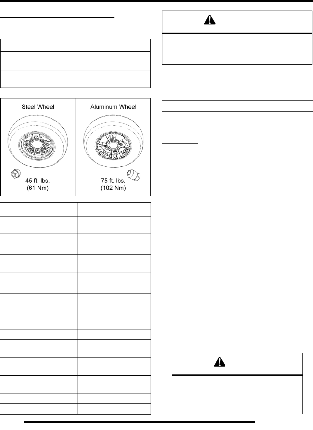
8.2
FINAL DRIVE
GENERAL SPECIFICATIONS
Torque Specifications
Special Tools
WHEELS
Removal
1. Position the vehicle on a level surface.
2. Stop the engine, place the transmission in PARK and lock
the parking brake.
3. Loosen the wheel nuts slightly.
4. Elevate the appropriate side of the vehicle by placing a
suitable stand under the footrest frame.
5. Remove the wheel nuts and remove the wheel.
Installation
1. Verify the transmission is still in PARK and the parking
brake is locked.
2. Place the wheel in the correct position on the wheel hub.
Be sure the valve stem is toward the outside and rotation
arrows on the tire point toward forward rotation.
3. Install the wheel nuts and finger tighten them to align the
center of the wheel holes with the center of the tapered nuts.
IMPORTANT: It is possible to torque the wheel nut on
a steel rim without the nut being centered in the hole.
Be sure to center the wheel nuts before applying
torque to prevent wheel nuts from coming loose.
4. Carefully lower the vehicle to the ground.
5. Torque the wheel nuts to the proper torque specification.
Item Nut Type Specification
Aluminum Wheels Tapered Nut
(Long) 75 ft. lbs. (102 Nm)
Steel Wheels Taper ed Nut
(Short) 45 ft. lbs. (61 Nm)
Item Specification
Wheel Hub Retaining Nuts
(front and rear) 80 ft. lbs. (108 Nm)
Steering Post to Bulkhead 20 ft. lbs. (27 Nm)
Steering Post to Gearcase 22 ft. lbs. (30 Nm)
Tie Rod to Bearing Carrier
Tie Rod to Steering Frog 44 ft. lbs. (60 Nm)
Brake Caliper Mount Bolts 37 ft. lbs. (50 Nm)
Shock Mounting Bolts 37 ft. lbs. (50 Nm)
Front Ball Joint Pinch Bolts
(upper and lower) 21 ft. lbs. (28 Nm)
Front A-arm to Frame Bolts
(upper and lower) 40 ft. lbs. (54 Nm)
Front Gearcase Mount Bolts 36 ft. lbs. (49 Nm)
Rear A-arm to Frame Bolts
(upper and lower) 45 ft. lbs. (61 Nm)
Rear Upper A-Arm to
Bearing Carrier Bolts 40 ft. lbs. (54 Nm)
Rear Lower A-Arm to
Bearing Carrier Bolts 45 ft. lbs. (61 Nm)
Rear Propshaft Bolts 18 ft. lbs. (24 Nm)
Rear Gearcase Mount Bolts 40 ft. lbs. (54 Nm)
CAUTION
Locking nuts, and bolts with pre-applied locking agent
should be replaced if removed.
The self-locking properties of the nut or bolt
are reduced or destroyed during removal
Part Number Tool Description
2872608 Roller Pin Removal Tool
PU-48951 Axle Boot Clamp Tool
CAUTION
Improperly installed wheels could affect vehicle
handling and tire wear. On vehicles with tapered
rear wheel nuts, make sure tapered end of nut
goes into taper on wheel. Be sure to properly
torque and install all wheel nuts.
PartShark.com
877-999-5686
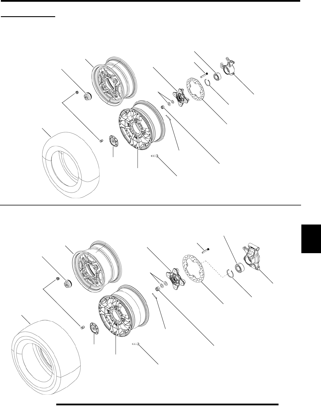
8.3
FINAL DRIVE
8
WHEEL HUBS
Front Hub Exploded View
Rear Hub Exploded View
Wheel Nuts
Front
Valve
Castle Nut
Cotter Pin
Cone
Wheel Hub Stud
Brake Disc
Retaining
Sealed
Ball Bearing
Bearing Carrier
Front Tire
Washers
See Page 8.2
for Torque Value
80 ft. lbs.
(108 Nm)
Ring
Aluminum Rim
Front
Steel Rim
Hub Cover
Dust Cover
Wheel Nuts
Rear
Valve
Castle Nut
Cotter Pin
Cone
Wheel Hub Stud
Brake Disc Retaining
Sealed
Ball Bearing
Bearing Carrier
Rear Tire
Washers
See Page 8.2
for Torque Value
80 ft. lbs.
(108 Nm)
Ring
Aluminum Rim
Rear
Steel Rim
Hub Cover
Dust Cover
PartShark.com
877-999-5686
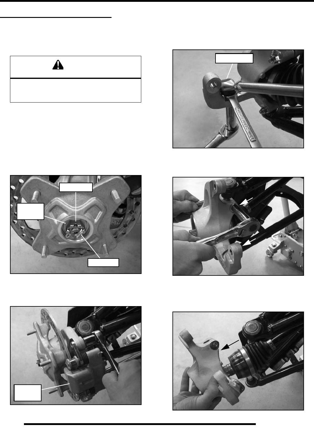
8.4
FINAL DRIVE
FRONT BEARING CARRIER
Inspection / Removal
1. Elevate front of vehicle and safely support machine under
the frame area.
2. Check bearings for side play by grasping the top and bottom
of the tire firmly and checking for movement. The tire
should rotate smoothly without binding or rough spots.
3. Remove the (4) wheel nuts and remove the front wheel (see
“Wheel Removal”).
4. Remove the cotter pin and loosen the front wheel hub castle
nut. Remove the nut and (2) cone washers from the front
wheel hub assembly.
5. Remove the (2) brake caliper mounting bolts and caliper.
CAUTION: Do not hang the caliper by the brake line. Use
wire to hang caliper to prevent damage to the brake line.
6. Remove the front wheel hub assembly.
7. Remove the cotter pin from the bottom of the tie rod end.
8. Hold the top of the rod end with a 13 mm open-end wrench
and remove the nut from the bottom.
9. Remove the steering tie rod from the bearing carrier.
10. Remove the upper and lower ball joint pinch bolts.
11. Using a soft faced hammer, lightly tap on the bearing carrier
while removing the upper and lower ball joint ends.
12. Remove the bearing carrier from the front drive shaft.
CAUTION
Serious injury may result if machine tips or falls.
Be sure machine is secure before beginning this
service procedure. Always wear eye protection.
Castle Nut
Cotter Pin
Cone
Washers
Remove
Caliper
Tie Rod End
PartShark.com
877-999-5686
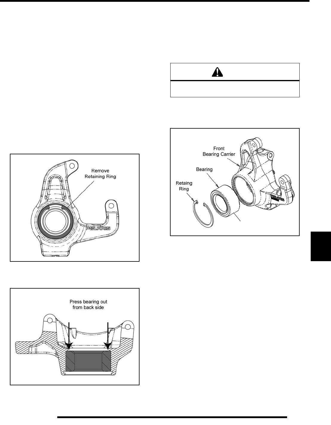
8.5
FINAL DRIVE
8
13. Rotate bearing by hand and check for smooth rotation.
Visually inspect bearing for moisture, dirt, or corrosion.
NOTE: Due to extremely close tolerances and
minimal wear, the bearings must be inspected
visually, and by feel. While rotating bearings by
hand, inspect for rough spots, discoloration, or
corrosion. The bearings should turn smoothly and
quietly, with no detectable up and down movement
and minimal movement sideways between inner and
outer race.
14. Replace bearing if moisture, dirt, corrosion, or roughness
is evident.
Bearing Replacement
Bearing Removal
1. Remove the outer retaining ring from the bearing carrier.
2. Support the bearing carrier in an arbor press and remove the
bearing by pressing it out from the back side.
3. Inspect the bearing carrier housing for scratches, wear or
damage. Replace front bearing carrier if damaged.
Bearing Installation
4. Thoroughly clean the front bearing carrier housing and the
outer race on the new bearing. Be sure that all oil residue
has been removed from each surface.
5. Support the bottom of the bearing carrier housing.
6. Apply Loctite® 603™ retaining compound to the outer
circumference of the new bearing race and carefully press
the new bearing into the bearing carrier housing.
NOTE: Use care to not allow any of the Loctite®
compound to get in the bearing.
7. Wipe the housing clean of any excess compound and install
the snap ring.
CAUTION
Use an arbor and press only on the outer race
or bearing damage may occur.
Apply
Loctite® 603™
PartShark.com
877-999-5686
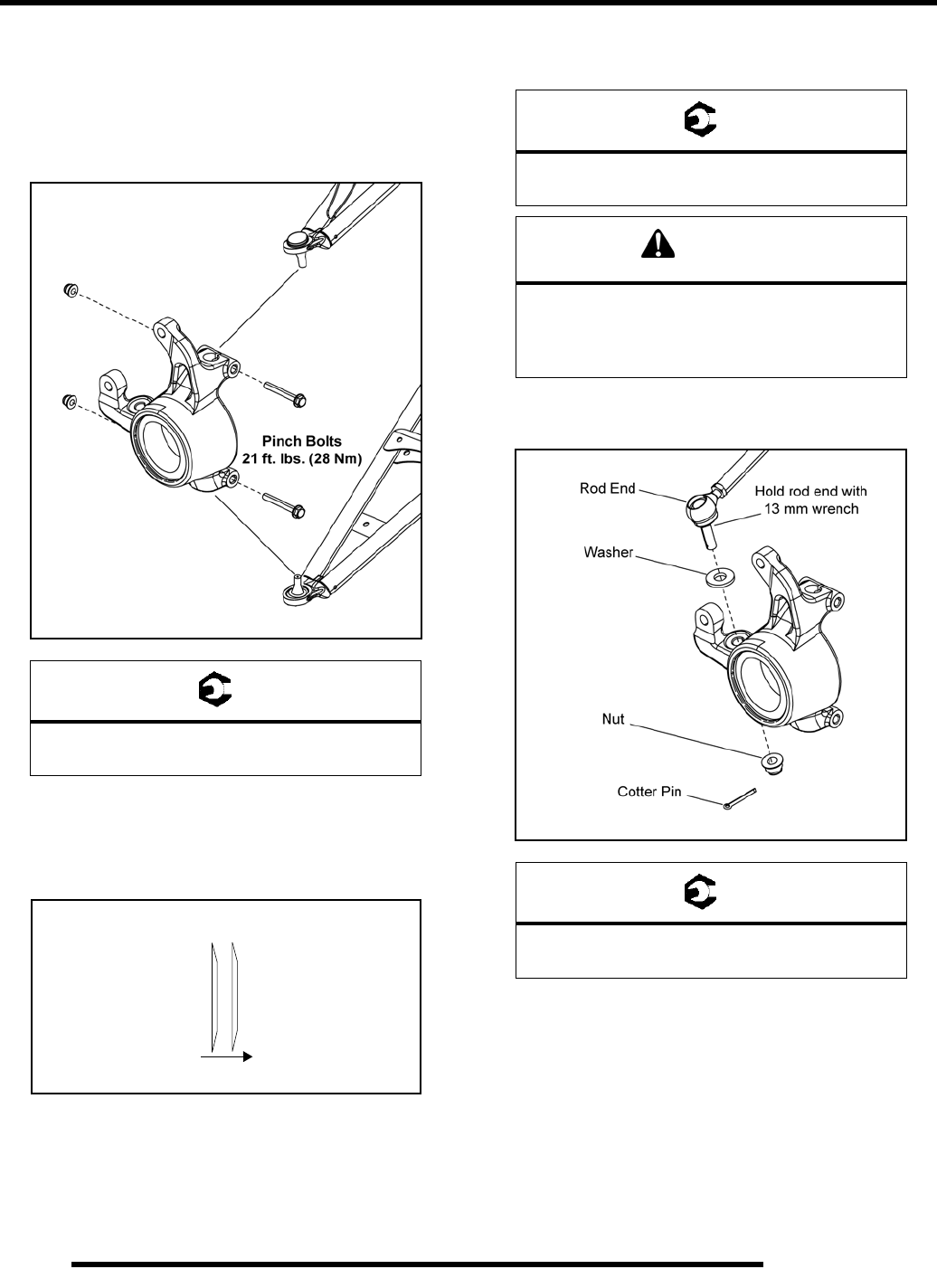
8.6
FINAL DRIVE
Installation
1. Install the drive shaft axle through the backside of the
bearing carrier.
2. Install the upper and lower ball joint ends into the bearing
carrier. Install the pinch bolts and torque to specification.
3. Apply grease to drive shaft axle splines.
4. Install the front wheel hub assembly, cone washers, and
hand tighten the castle nut. Install washers with domed side
facing out toward the castle nut.
5. Install the brake caliper and torque the new mounting bolts
to specification.
6. Install the steering tie rod end onto the front bearing carrier.
Torque fastener to specification and install a new cotter pin.
= T
Pinch Bolts:
21 ft. lbs. (28 Nm)
Out
Cone Washers
Wheel
Hub Castle
Nut
= T
Front Caliper Mounting Bolts:
37 ft. lbs. (50 Nm)
CAUTION
New bolts have a pre-applied locking agent
which is destroyed upon removal. Always use
new brake caliper mounting bolts
upon assembly.
= T
Tie Rod End Fastener:
44 ft. lbs. (60 Nm)
PartShark.com
877-999-5686
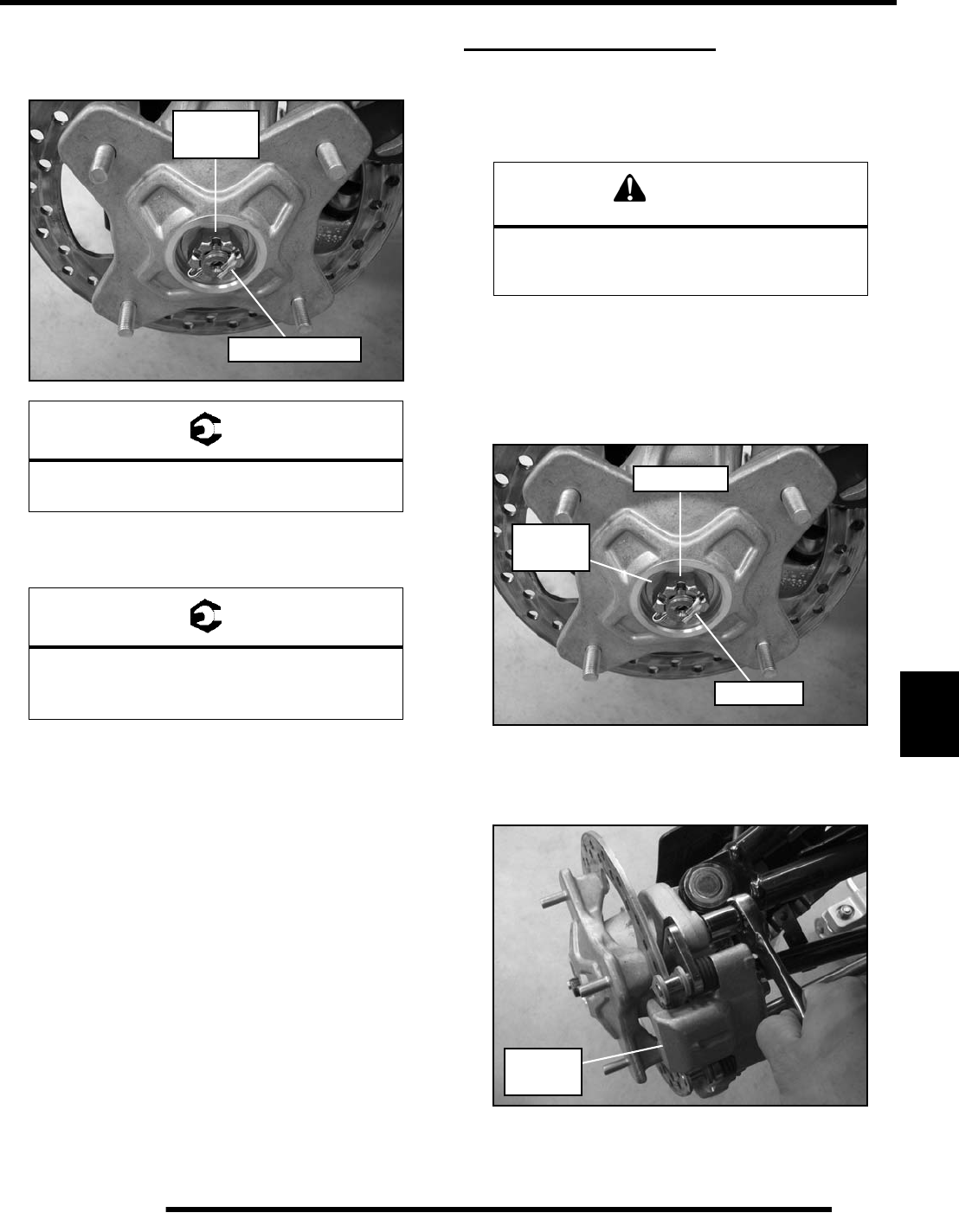
8.7
FINAL DRIVE
8
7. Torque the wheel hub castle nut to specification and install
a NEW cotter pin. Tighten nut slightly if necessary to align
cotter pin holes.
8. Install the front wheel and (4) wheel nuts. Torque wheel
nuts to specification.
9. Rotate wheel and check for smooth operation. Bend both
ends of cotter pin around end of spindle in different
directions.
FRONT DRIVE SHAFT
Removal
1. Elevate front of vehicle and safely support machine under
the frame area.
2. Remove the (4) wheel nuts and remove the front wheel (see
“Wheel Removal”).
3. Remove the cotter pin and loosen the front wheel hub castle
nut. Remove the nut and (2) cone washers from the front
wheel hub assembly.
4. Remove the (2) brake caliper mounting bolts and caliper.
CAUTION: Do not hang the caliper by the brake line. Use
wire to hang caliper to prevent damage to the brake line.
5. Remove the front wheel hub assembly.
= T
Wheel Hub Castle Nut:
80 ft. lbs. (108 Nm)
= T
Wheel Nuts:
Steel Wheels: 45 ft. lbs. (61 Nm)
Aluminum Wheels: 75 ft. lbs. (102 Nm)
80 ft. lbs.
(108 Nm)
NEW Cotter Pin
CAUTION
Serious injury may result if machine tips or falls.
Be sure machine is secure before beginning this
service procedure. Always wear eye protection.
Castle Nut
Cotter Pin
Cone
Washers
Remove
Caliper
PartShark.com
877-999-5686
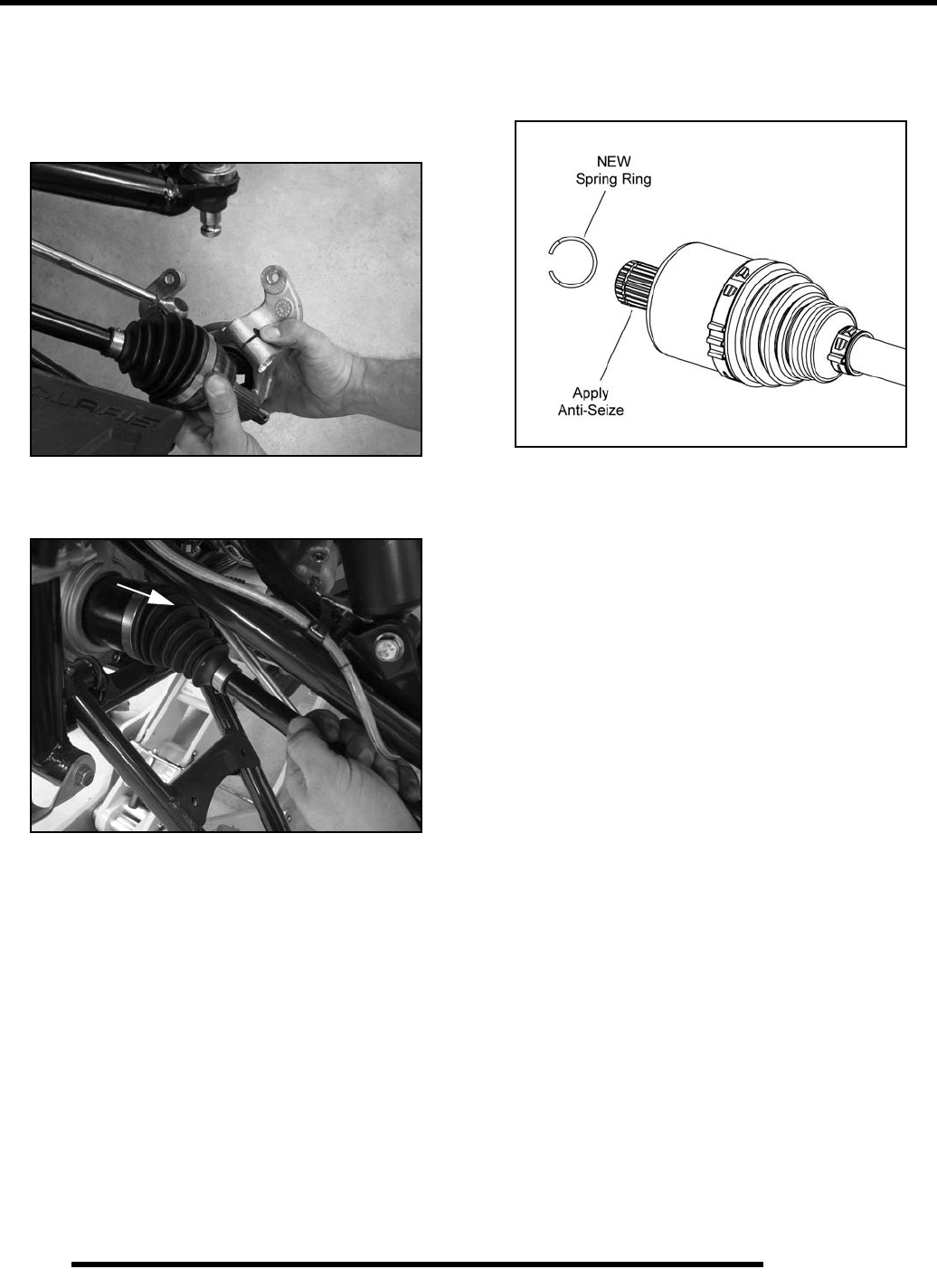
8.8
FINAL DRIVE
6. Remove the upper ball joint pinch bolt.
7. Using a soft faced hammer, lightly tap on the upper A-arm
to remove it from the bearing carrier.
8. Remove the drive shaft from the front bearing carrier.
9. With a short, sharp jerk, remove drive shaft from the front
gearcase.
10. Refer to the “DRIVE SHAFT SERVICE” procedure if
repairing the drive shaft.
Installation
1. Install a new spring ring on the end of the drive shaft and
apply an anti-seize compound to the splines.
2. Align the splines of the drive shaft with the front gearcase
and reinstall the drive shaft. Use a rubber mallet to tap on
the outboard end of the drive shaft if necessary.
3. Install the drive shaft into the front bearing carrier.
4. Refer to the “FRONT BEARING CARRIER - Installation”
procedure within this chapter to properly reassemble the
vehicle.
PartShark.com
877-999-5686
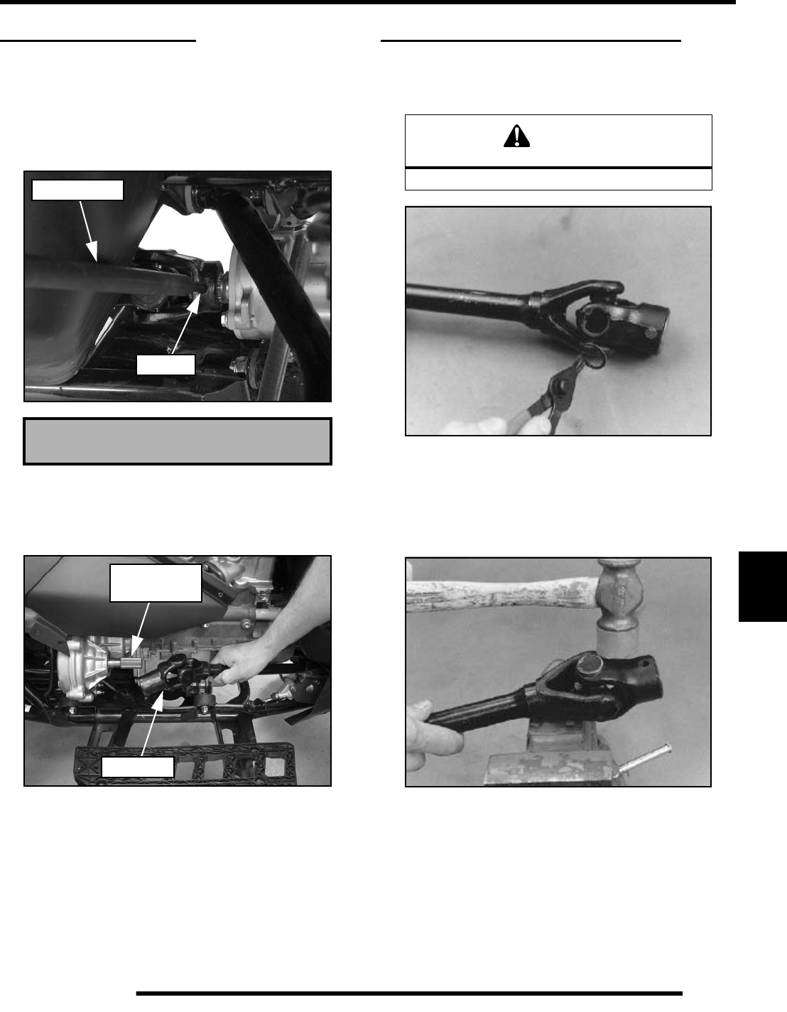
8.9
FINAL DRIVE
8
FRONT PROPSHAFT
Removal
1. Locate the front propshaft roll pin through the right front
wheel well. Position the vehicle for roll pin removal.
2. Use the Roll Pin Removal Tool (PN 2872608), to drive out
the roll pin from the front propshaft.
3. Remove the seat, upper right side panel and right footwell.
4. Pull the shaft back towards the transmission to remove it
from the front gearcase input shaft, then pull it forward to
remove it from the transmission output shaft.
Installation
1. Apply anti-seize compound to all splines. Slide propshaft
back onto the transmission output shaft, then slide it up
onto the front gearcase input shaft, verify pin holes are
aligned.
2. Using Roll Pin Tool (PN 2872608), install a NEW roll pin
(spring pin) into the propshaft.
3. Reinstall the footwell, side panel and seat (see Chapter 9).
PROPSHAFT U-JOINT SERVICE
Disassembly
1. Remove internal or external snap ring from bearing caps.
NOTE: If yoke or bearing is removed, cross bearing
must be replaced. Note orientation of grease fitting
and mark inner and outer yoke for correct re-
positioning during installation.
2. Support inner yoke as shown and drive outer yoke down
(bearing cap out) with a soft face hammer.
Roll Pin Removal Tool (PN 2872608)
PN 2872608
Roll Pin
Transmission
Input Shaft
Propshaft
CAUTION
Always wear eye protection.
PartShark.com
877-999-5686
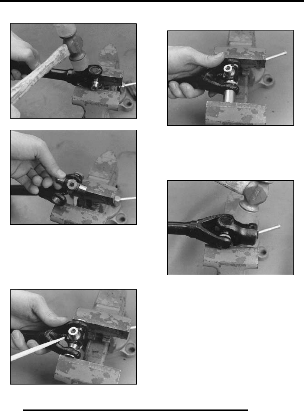
8.10
FINAL DRIVE
3. Support U-joint in vise as shown and drive inner yoke down
to remove remaining bearing caps.
4. Force U-joint cross to one side and lift out of inner yoke.
Assembly
1. Install new bearing caps in yoke by hand. Carefully install
U-joint cross with grease fitting properly positioned
inward toward center of shaft. Take care not to dislodge
needle bearings upon installation of cross joint.
2. Tighten vise to force bearing caps in.
3. Using a suitable arbor, fully seat the bearing cap in one side.
Continually check for free movement of bearing cross as
bearing caps are assembled.
4. Install snap ring to contain bearing cap just installed.
Repeat procedure for other side.
5. Install outer yoke, aligning marks made at disassembly and
repeat Steps 1-3 to install bearing caps on outer yoke.
6. Seat all bearing caps against snap rings by supporting cross
shaft and tapping on each corner as shown.
7. When installation is complete, yokes must pivot freely in
all directions without binding. If the joint is stiff or binding,
tap the yoke lightly to center the joint until it pivots freely.
PartShark.com
877-999-5686
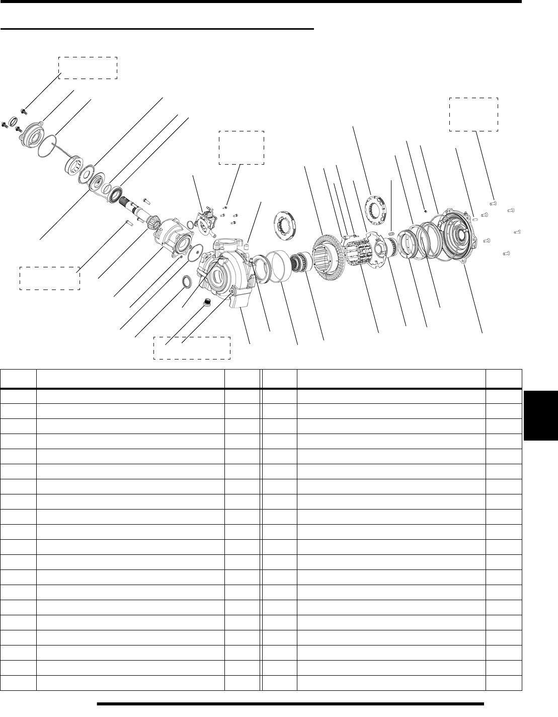
8.11
FINAL DRIVE
8
FRONT GEARCASE - CENTRALIZED HILLIARD
Exploded View
REF#DESCRIPTION QTY REF#DESCRIPTION QTY
1 O-Ring 1 21 Gearcase Housing 1
2 O-Ring 3 22 Pinion Neck Housing 1
3 O-Ring 1 23 Clutch Housing 1
4 Dowel Pin 1 24 Roll Cage Assembly 1
5 Expander 1 25 Hub Assembly (female) 1
6 Bearing 3 26 Hub Assembly (male) 1
7 Bushing 1 27 Cam 1
8 Bushing 1 28 Roller 20
9 Bushing 1 29 H-Clip Spring 20
10Oil Seal 230Bleeder Screw 2
11 Cap Plug 2 31 Thrust Button Assembly 1
12 Bolt, M6 3 32 Thrust Plate 1
13 Screw, M6 6 33 Pinion Gear 1
14 Fill Plug 1 34 Armature Plate (AWD) 1
15 Cap Screw, M6 4 35 Armature Plate (ADC) 1
16Screw, M4 436AWD Coil 1
17 Set Screw, M6 1 37 Piston 2
18 Cover Housing 1 38 Pump Assembly 1
19 Pinion Cover 1 39 Vent 1
20 Clutch Pack Assembly 2 40 Drain Plug, Magnetic 1
3
7
4
5
8
9
10
12
18
14
16
17
19
20
15
25
11
6
13
40
31
27
33
34
7-11 ft. lbs.
(9-15 Nm)
1
2
7-11 ft. lbs.
(9-15 Nm)
7-11 ft. lbs.
(9-15 Nm)
15 in. lbs.
(1.7 Nm)
21
22
23
24 26
29
28
32
30
35
36
37
39
38
8-10 ft. lbs.
(11-14 Nm)
PartShark.com
877-999-5686
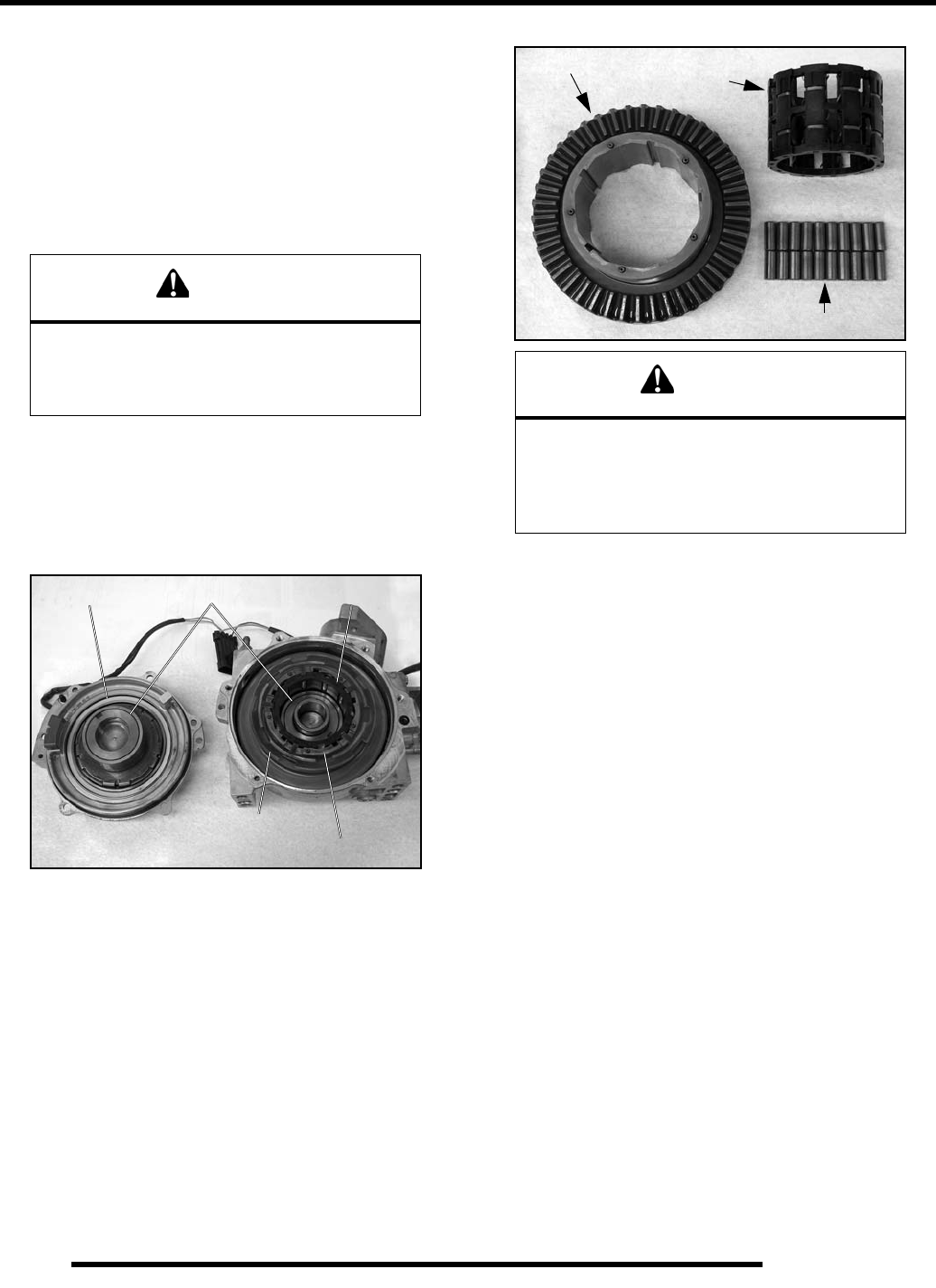
8.12
FINAL DRIVE
AWD Operation
The AWD switch may be turned on or off while the vehicle is
moving, however, AWD will not enable until the engine RPM
drops below 3100. Once the AWD is enabled, it remains
enabled until the switch is turned off.
Engage the AWD switch before getting into conditions where
the front wheel drive may be needed. If the rear wheels are
spinning, release the throttle before switching to AWD.
With the AWD switch off, the vehicle drives through the rear
wheels only (2 wheel drive). When the AWD is enabled, the
front drive acts as an on-demand AWD system. This means, the
front drive will engage once the rear wheels have lost traction,
and will remain engaged until the torque requirement goes away
(i.e. rear wheels regain traction).
AWD Engagement: When the AWD switch is activated, the
AWD coil is powered by a 12 Vdc input which creates a
magnetic field. This magnetic field attracts an armature plate
that is keyed to the roll cage. When the ring gear and roll cage
are spinning (vehicle is moving), the energized coil and
armature plate will apply drag to the roll cage that indexes the
rollers inside the ring gear to an engagement position. While in
the engagement position, the front drive will be in an “over-
running” condition (not engaged), until the rear wheels lose
traction. Once the rear wheels begin to lose traction, the front
drive will engage by coupling the output hubs to the ring gear via
the rollers. The front drive will remain engaged until the torque
requirement goes away (i.e. rear wheels regain traction).
AWD Disengagement: Once the rear wheels regain traction,
the front wheels will return to the “over-running” condition.
The vehicle is now back to rear wheel drive until the next loss
of rear wheel traction occurs.
CAUTION
Switching to AWD while the rear wheels are
spinning may cause severe drive shaft and
gearcase damage. Always switch to AWD while
the rear wheels have traction or are at rest.
Output Hubs
Armature Plate
Roll Cage
Ring Gear
Magnetic Coil
CAUTION
If the rear wheels are spinning, release the
throttle before turning the AWD switch on.
If AWD is engaged while the wheels are
spinning, severe drive shaft and
clutch damage could result.
Rollers
Roll Cage
Ring Gear
PartShark.com
877-999-5686
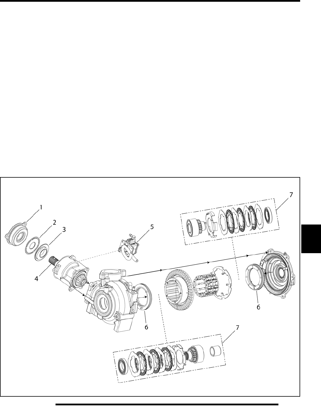
8.13
FINAL DRIVE
8
ADC Operation
Engaging the Front Gearcase: Active Descent Control (ADC)
is controlled by the ECU and will not enable until the following
conditions are met:
• Vehicle speed is below 15 mph (24 kph)
• Throttle Position Sensor (TPS) is at idle position
• The AWD switch is switched to the “ADC” position
Once the conditions are met for engagement, ADC remains
engaged as long as the conditions are met.
With the AWD switch set to “2x4”, the vehicle drives only the
rear wheels (2 wheel drive). When the AWD switch is set to
“4x4”, the vehicle drives all four wheels (4 wheel drive). When
the AWD switch is set to “4x4/ADC”, the vehicle drives all four
wheels and, in addition to the rear wheel engine braking, the
ADC coil provides front wheel engine braking at speeds less
than 15 mph (24 kph) with the TPS at idle position.
ADC Engagement: When the AWD switch is set to “4x4/
ADC”, a 12 Vdc current is present at the input shaft coil (1).
Operation is controlled by the ECU grounding and ungrounding
the coil. The coil’s magnetic field attracts a splined armature
plate (2) on the pinion (input) shaft (4). The energized splined
armature plate attracts the unsplined eccentric cam (3), which
begins to turn with the input shaft. The eccentric cam drives a
hydraulic piston/pump assembly (5). The pressure created by
the pump assembly forces hydraulic fluid through passages to
the piston assemblies (6) located in each case half. Hydraulic
pressure forces the piston assemblies inward to compress the
splined clutch packs (7) forming a dynamic coupling to each
front drive axle, resulting in true all-wheel EBS operation upon
deceleration.
Disengagement: Current to the ADC coil is turned off by the
ECU anytime the following conditions are met:
• Throttle Position Sensor (TPS) moves off idle position
• The AWD switch is switched to “4x4” or “2x4”
• Vehicle speed is above 15 mph (24 kph)
Hydraulic pressure stops and the pistons release, disengaging
the ADC function.
PartShark.com
877-999-5686
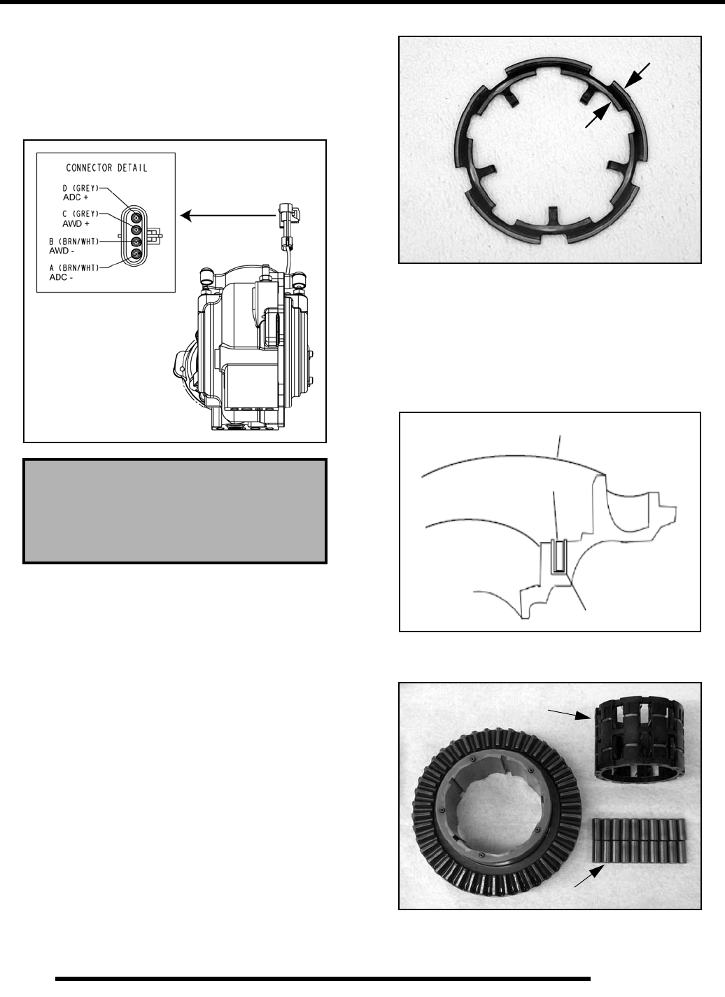
8.14
FINAL DRIVE
AWD Diagnosis
Symptom: AWD Will Not Engage
1. Check the gearcase AWD coil resistance. Measure
between the Grey (C) and Brown/White (B) wires. The
resistance value should be within specification.
2. Turn on the ignition switch and AWD switch and place gear
selector in High or Low gear. Check for minimum battery
voltage at the chassis-side of the AWD/ADC connector.
Measure between the Gray (C) and Brown/White (C)
chassis wires that power the AWD coil. A minimum of 11
Vdc should be present.
3. If electrical tests are within specification, remove the front
gearcase (see “Gearcase Removal”) and inspect the internal
components.
4. Inspect the armature plate for a consistent wear pattern.
There should be two distinct wear bands (one band inside
the other). If only one band of wear is present or if there is
wear between the two bands, inspect the coil area as
indicated in Step 5. A wear band with an interrupted wear
mark may indicate a warped plate, which may cause
intermittent operation.
5. Check to make sure the AWD coil is seated in the U-shaped
insert that is pressed into the gearcase cover. The top of the
coil should be seated below the U-shaped insert. If the top
of the coil is above the surface of the U-shaped insert it
raises the armature plate, thereby increasing pole gap. If the
pole gap increases, the coil will not be strong enough to
engage the AWD system. If this is found, replace the cover
plate assembly.
6. Inspect the rollers for nicks and scratches. The rollers must
slide freely within the roll cage and H-springs.
7. Inspect the roll cage assembly for cracks or excessive wear.
If damaged, replace the roll cage assembly.
Front Gearcase Coil Resistance:
AWD (Pin B to Pin C): 24 Ω
ADC (Pin A to Pin D: 12 Ω
Armature Plate
Check for Wear Bands
Gearcase Cover Plate Asm.
Coil
U-shaped insert
Cutaway View
Rollers
Roll Cage
Assembly
PartShark.com
877-999-5686
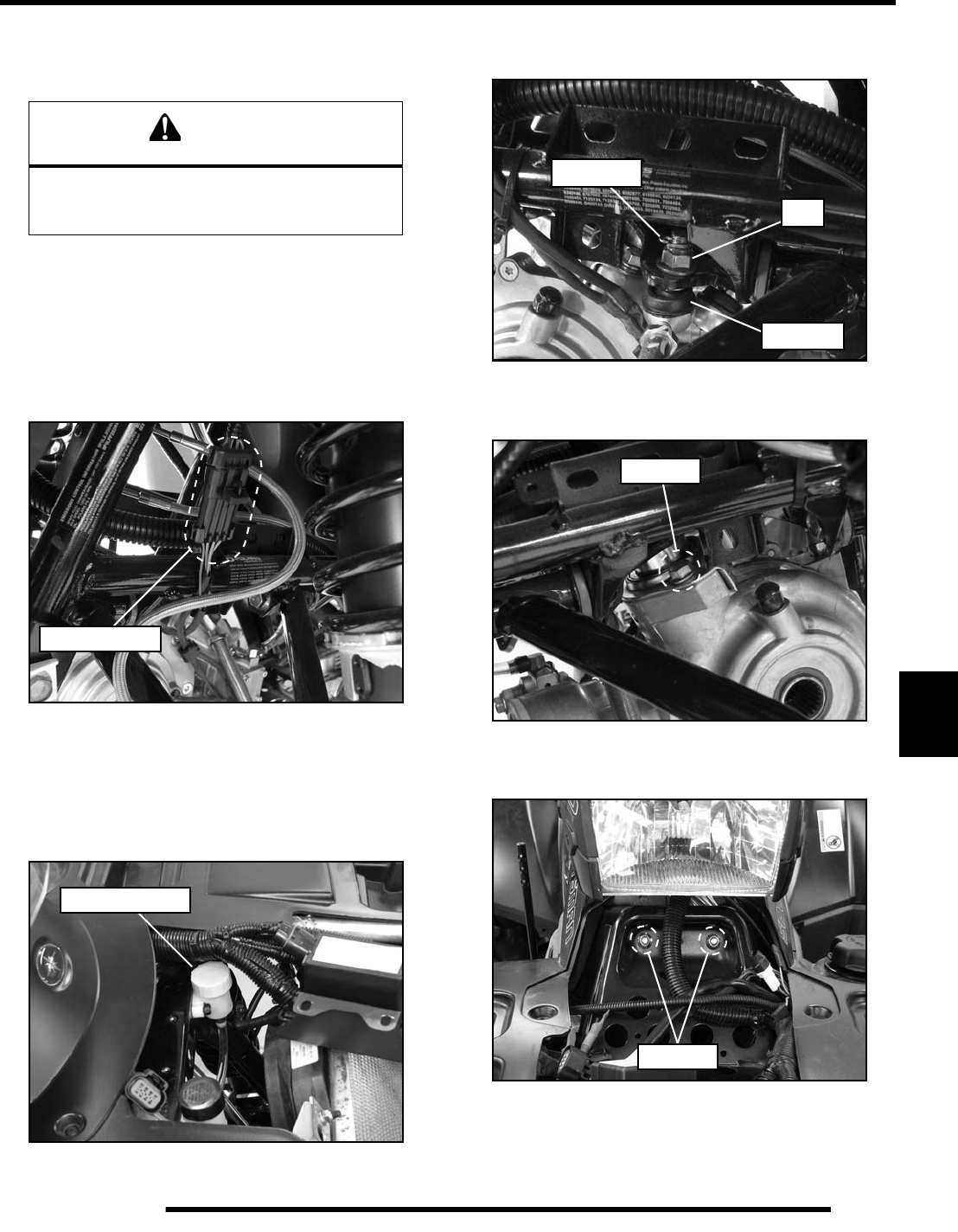
8.15
FINAL DRIVE
8
Gearcase Removal
1. Stop engine and place gear selector in Park.
2. Remove both front drive shafts from the front gearcase (see
“FRONT DRIVE SHAFT - Removal”).
3. Remove the front propshaft from the front gearcase input
shaft (see “FRONT PROPSHAFT - Removal”).
4. Disconnect the wire harness above the front gearcase and
remove the plastic tie strap retaining the wires to the frame.
5. Remove the front rack and remove the fuse/relay box from
the frame to gain access to the ADC reservoir.
6. Remove the (2) screws retaining the ADC reservoir to the
frame and pull the reservoir and clear hose out from the
frame so it can be removed with the front gearcase.
7. Remove the cotter pin and nut from each tie rod end at the
steering post frog.
8. Remove the (2) bolts retaining the lower steering post
bracket to the front gearcase.
9. Remove the front cover and remove the (2) fasteners
retaining the upper steering post bushing bracket.
10. Lift the steering post assembly up from the front gearcase.
Position the steering post toward the center of the vehicle
to allow enough room for gearcase removal.
CAUTION
Serious injury may result if machine tips or falls.
Be sure machine is secure before beginning this
service procedure. Always wear eye protection.
AWD Harness
ADC Reservoir
Nut
Cotter Pin
Rod End
Remove
Remove
PartShark.com
877-999-5686
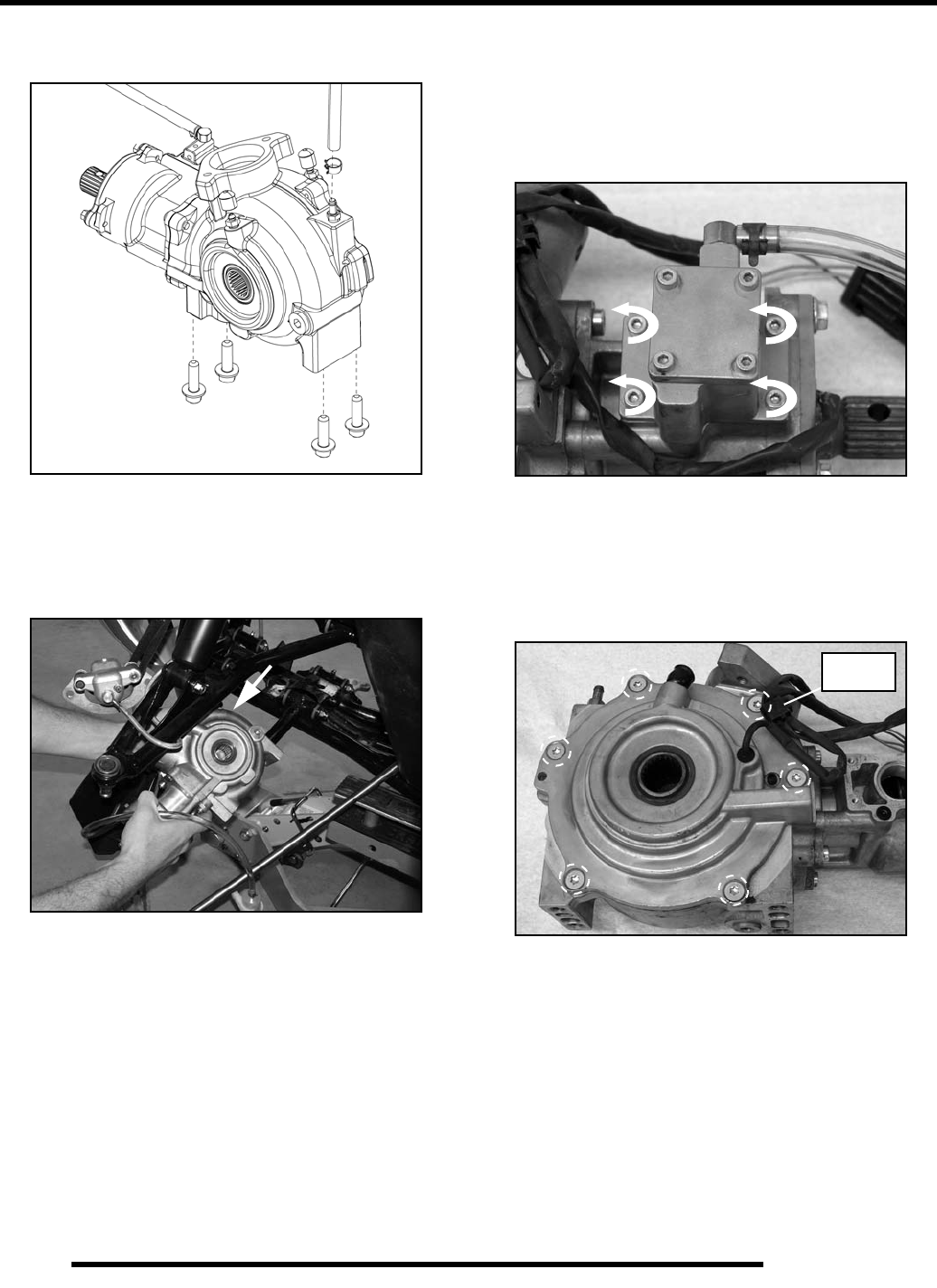
8.16
FINAL DRIVE
11. Remove the vent line and the (4) bolts securing the front
gearcase to frame.
12. Lay the gearcase on its side (vent side up) and rotate it in
the frame so the input shaft is facing you.
13. Remove the gearcase from the front LH wheel well area and
carefully slide it between the upper and lower A-arms.
Gearcase Disassembly / Inspection
1. Drain and properly dispose of used lubricant. Remove any
metal particles from the drain plug magnet.
2. Remove the (4) screws retaining the piston pump assembly
to the gearcase and remove the pump.
NOTE: Piston pump assembly is a non-serviceable
item and should not be disassembled. Replace as an
assembly if found to be damaged or non-working.
3. Remove the (6) screws retaining the cover plate assembly
and open the wire retaining clip.
Retaining
Clip
PartShark.com
877-999-5686
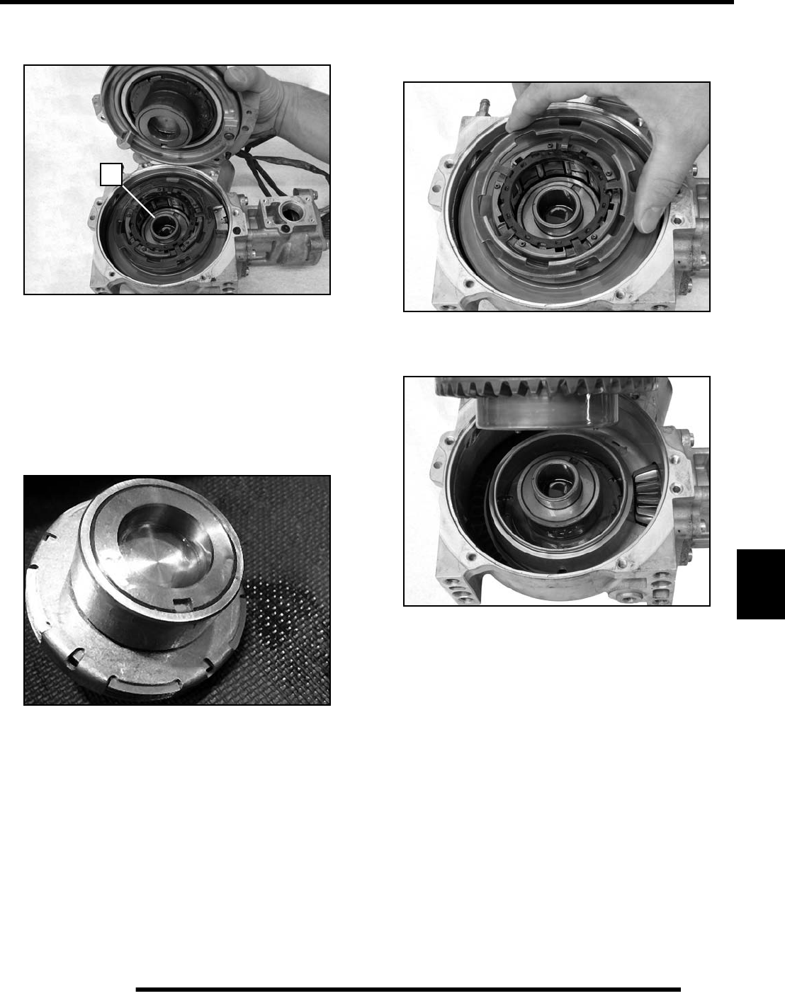
8.17
FINAL DRIVE
8
4. Remove the cover plate assembly. Inspect the thrust
bearing (A) for wear.
NOTE: Thrust bearing (A) located between the two
output assemblies is pressed into the clutch pack
and is not removable.
5. Remove the female output hub assembly. Inspect the
bearings, contact surfaces and splines for signs of wear or
damage. Visually inspect the clutch plate area. If plates are
steel-on-steel, or if the friction material is worn, the
assembly must be replaced.
NOTE: Excessive noise coming from the front drive
on deceleration are key indicators of burnt or broken
down front drive fluid.
6. Remove the armature plate. Inspect the armature plate for
distortion or other damage (see “AWD Diagnosis”).
Replace as required.
7. Remove the ring gear and roll cage from the gearcase as an
assembly.
8. Remove the male output hub assembly. Inspect the
bearings, contact surfaces and splines for signs of wear or
damage. Visually inspect the clutch plate area. If plates are
steel-on-steel, or if the friction material is worn, the
assembly must be replaced.
9. Place a shop towel over the ring gear assembly and slowly
remove the roll cage and rollers from the ring gear.
A
PartShark.com
877-999-5686
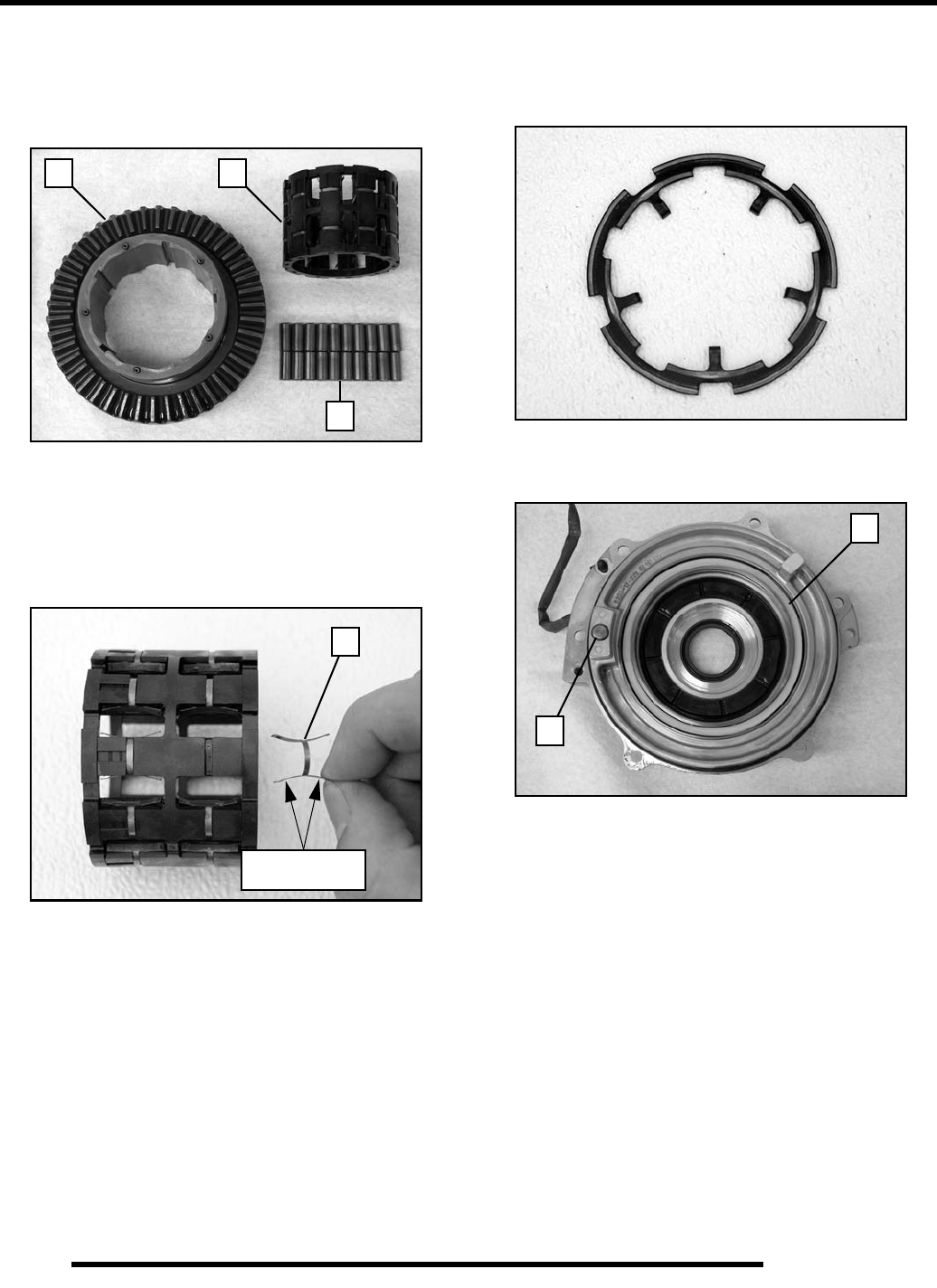
8.18
FINAL DRIVE
10. Inspect the rollers (B) for nicks, scratches and flat spots.
Inspect the roll cage (C) for damage or cracks. The rollers
must slide up and down freely within the roll cage surfaces.
Inspect the ring gear (D) for consistent wear patterns.
Surfaces should be free of nicks or burrs.
11. Inspect roll cage sliding surfaces. These surfaces must be
clean and free of nicks, burrs or scratches.
12. Remove and inspect the H-springs (E). If the spring legs
appear to be flattened or damaged, replace the roll cage and
H-springs as an assembly.
IMPORTANT: Refer to the “Electronic Parts Catalog”
for individual part availability. Most parts are to be
replaced as an assembly or as a complete kit.
13. Inspect the armature plate for a consistent wear pattern.
Uneven wear of the armature plate indicates a warped plate,
which may cause intermittent operation (refer to “AWD
Diagnosis” for inspection).
14. Inspect the magnetic coil (F) in the cover plate assembly
(refer to “AWD Diagnosis” for inspection).
15. Inspect the backlash thrust button (G) and thrust pad for
excessive wear.
NOTE: Ring gear backlash is set at the factory. No
adjustment is required unless the front cover is
replaced or the backlash thrust pad screw is
removed. Refer to “Setting Ring Gear Backlash”
later in this chapter for details on backlash setting.
B
C
D
E
Legs should be
arched as shown
F
G
PartShark.com
877-999-5686
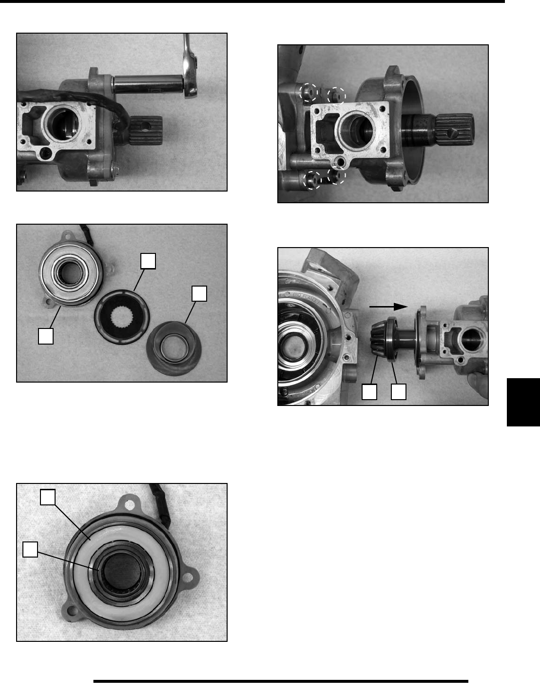
8.19
FINAL DRIVE
8
16. Remove the (3) bolts retaining the input cover.
17. Remove the cover (H), armature plate (J) and cam (K).
18. Inspect the armature plate (J) and cam (K) for excessive
wear or damage. If replacement is required, replace the
armature plate and cam as an assembly.
19. Inspect the magnetic coil (L) and needle bearing (M)
located in the input cover assembly. If replacement is
required, replace the input cover as an assembly.
20. Remove the (4) screws that retain the pump neck assembly
to the main gearcase.
21. Remove the neck and input shaft assembly from the main
gearcase.
22. Inspect the pinion gear (N) for chipped, broken, or missing
teeth. Inspect the input shaft bearing (P) for signs of wear.
The bearing can be replaced separate from the input shaft.
IMPORTANT: Refer to the “Electronic Parts Catalog”
for individual part availability. Most parts are to be
replaced as an assembly or as a complete kit.
H
J
K
L
M
NP
PartShark.com
877-999-5686
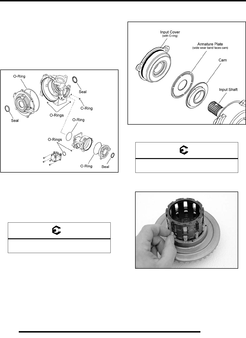
8.20
FINAL DRIVE
Gearcase Assembly
NOTE: Refer to the photos used in the “Gearcase
Disassembly / Inspection” procedure when needed,
while assembling the front gearcase.
1. Thoroughly clean all gearcase components before
beginning reassembly.
2. Install new seals and O-rings as shown (included in the Seal
Repair Kit).
3. Apply assembly grease to the seal lips to prevent from
damaging the seals upon assembly.
4. Install the input shaft assembly.
5. Install the neck onto the main gearcase using new O-rings.
Torque the screws to specification.
6. Install the cam, armature plate and input cover assembly
with a new O-ring.
7. Torque the input cover screws to specification.
8. Install the roll cage and rollers into the ring gear. Insert the
rollers as the roll cage is installed.
9. Install the male output hub assembly into the main
gearcase.
IMPORTANT: Take care not to damage the seal lip or
seal spring while installing the output hub.
10. Place the ring gear and roll cage assembly into the main
gearcase.
= T
Gearcase Neck Retaining Screws:
7-11 ft. lbs. (9-15 Nm)
= T
Input Cover Screws:
7-11 ft. lbs. (9-15 Nm)
PartShark.com
877-999-5686
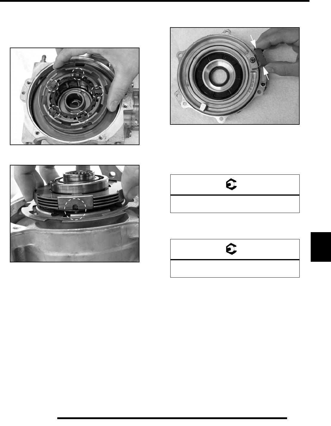
8.21
FINAL DRIVE
8
NOTE: Rotate the ring gear to align the locating pins
and holes during installation.
11. Install the armature plate. Verify the armature plate tabs
align with tab recesses in the roll cage.
12. Install the female output hub assembly into the roll cage.
NOTE: Rotate the output hub to align the locating
pins and holes during installation.
13. Install the large O-ring onto the cover plate and small O-
ring onto the main gearcase.
14. Lightly crimp the thrust pad to hold the pad on the cover
plate during installation.
15. Place the cover plate assembly on the main gearcase and
install the (6) screws. Torque screws to specification.
IMPORTANT: Take care not to damage the seal lip or
seal spring while installing the cover plate.
16. Install the piston pump assembly with new O-rings.
Torque the screws to specification.
IMPORTANT: If the cover plate was replaced or if the
backlash set screw was repositioned, proceed to the
“Setting Ring Gear Backlash” procedure.
= T
Cover Plate Screws:
7-11 ft. lbs. (9-15 Nm)
= T
Pump Assembly Screws:
15 in. lbs. (1.7 Nm)
PartShark.com
877-999-5686
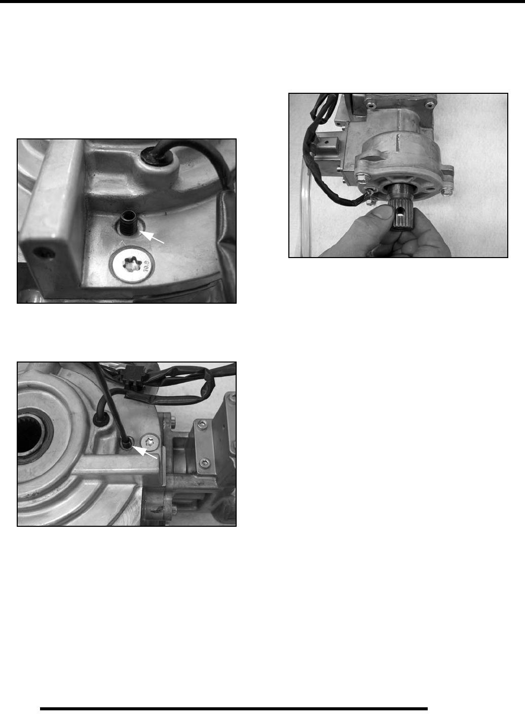
8.22
FINAL DRIVE
Setting Ring Gear Backlash
NOTE: Ring gear backlash is set at the factory. No
adjustment is required, unless the front cover is
replaced or the backlash screw has been tampered
with.
1. The backlash screw has locking agent that holds it into
place. Use a heat gun to lightly heat up the locking agent
on the screw.
2. Using an Allen wrench, turn the backlash screw out 3-4
turns. Re-apply Loctite 262™ onto the bottom screw
threads.
3. Turn the screw in until it is lightly seated, then turn the
screw out 1/4 turn.
4. Set the gearcase upright. Rotate the input shaft at least 4
times. This ensures the ring gear completes one full
rotation.
5. If a tight spot is felt during rotation, loosen the backlash
screw another 1/8 turn and perform step 4 again. Repeat
this procedure until the pinion shaft rotates smoothly 4
times (1 revolution of ring gear).
PartShark.com
877-999-5686
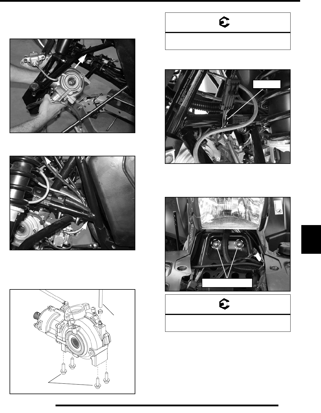
8.23
FINAL DRIVE
8
Gearcase Installation
1. Install the gearcase back into the vehicle through the front
left wheel well, between the upper and lower A-arms.
2. Route the ADC reservoir and clear hose up through the
center of the chassis. Do not allow hose to become pinched.
3. Mount the reservoir to the frame using the (2) previously
removed screws.
4. Install the vent line and the (4) bolts that secure the front
gearcase to frame. Torque bolts to specification.
5. Connect and route the AWD wire harness along the frame
and install a plastic tie strap to attach it to the frame.
6. Place the steering post and bearing into the front gearcase.
7. Reinstall the upper steering post bushing bracket and torque
the (2) fasteners to specification.
36 ft. lbs.
Install
Vent Line
(49 Nm)
= T
Front Gearcase Mounting Bolts:
36 ft. lbs. (49 Nm)
= T
Steering Post to Bulkhead Bolts:
20 ft. lbs. (27 Nm)
Tie Strap
20 ft. lbs. (27 Nm)
PartShark.com
877-999-5686
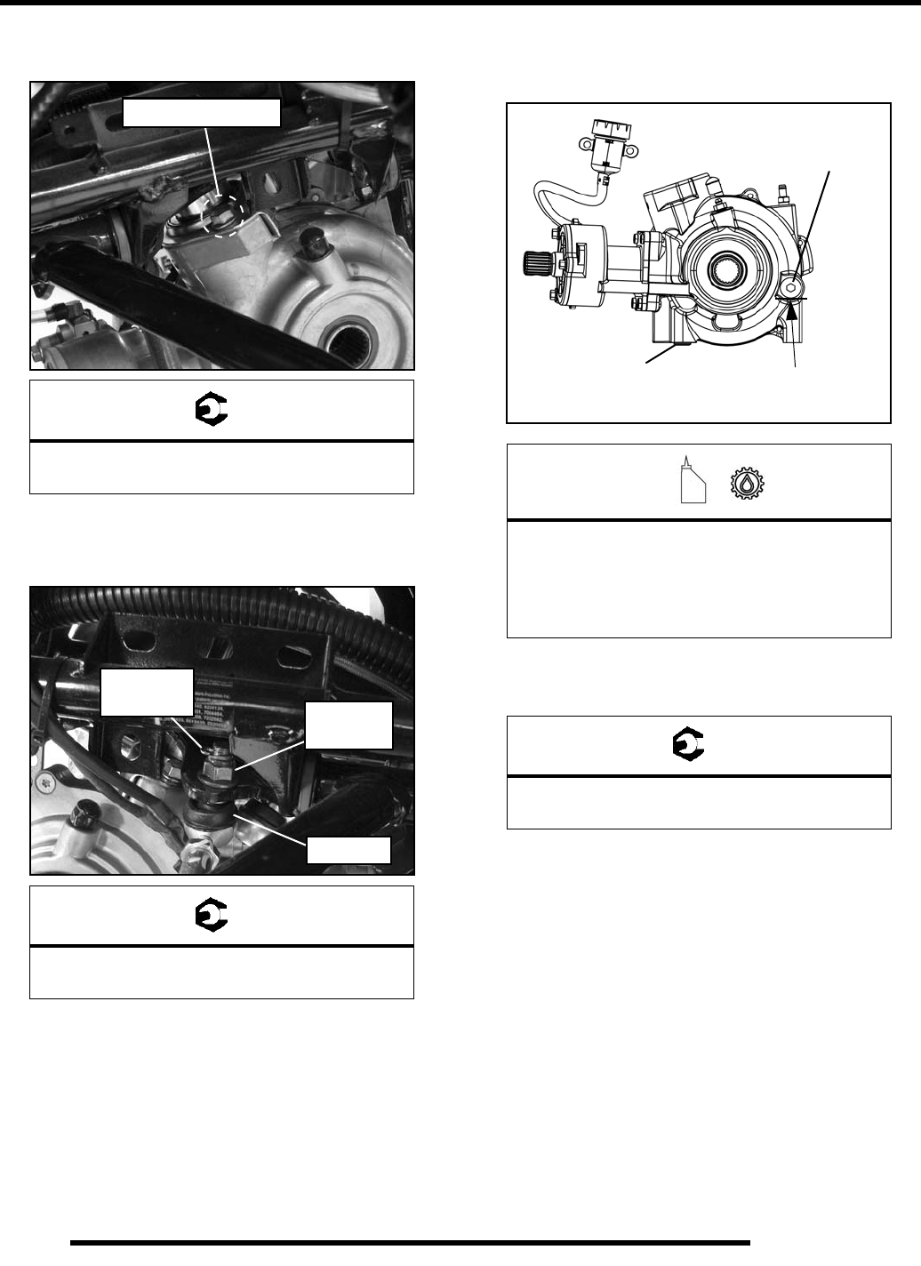
8.24
FINAL DRIVE
8. Install the (2) bolts securing the lower portion of the
steering post to the gearcase and torque to specification.
9. Install the steering tie rod ends into the steering frog.
Torque the tie rod end fasteners to specification and install
new cotter pins.
10. Install the front cover and front rack (see Chapter 9).
11. Install the front propshaft onto the front gearcase input shaft
(see “FRONT PROPSHAFT - Installation”).
12. Install both front drive shafts into the front gearcase (see
“FRONT DRIVE SHAFT - Installation”).
13. Reinstall the front gearcase drain plug with a new O-ring
and torque to specification.
14. Add the recommended amount of fluid through the fill hole.
Maintain the fluid level even with the bottom threads of the
fill plug hole.
15. Reinstall fill plug with a new O-ring and torque to
specification.
16. Check for external leaks.
17. If the ADC system was serviced, it must be properly bled
(see “ADC System Fluid Bleeding”).
= T
Steering Post to Gearcase Bolts:
22 ft. lbs. (30 Nm)
= T
Tie Rod to Steering Frog:
44 ft. lbs. (60 Nm)
22 ft. lbs. (30 Nm)
44 ft. lbs.
NEW
Rod End
(60 Nm)
Cotter Pin
=
Recommended Front Gearcase Fluid:
Premium LT Demand Drive Fluid
(PN 2876251) (Quart)
Capacity: 9.3 oz. (275 ml)
= T
Drain / Fill Plug Torque:
8-10 ft. lbs. (11-14 Nm)
Fill Plug
8-10 ft. lbs.
Gearcase fluid
flush with the bottom
of thread area.
(11-14 Nm)
Drain Plug
8-10 ft. lbs.
(11-14 Nm)
PartShark.com
877-999-5686
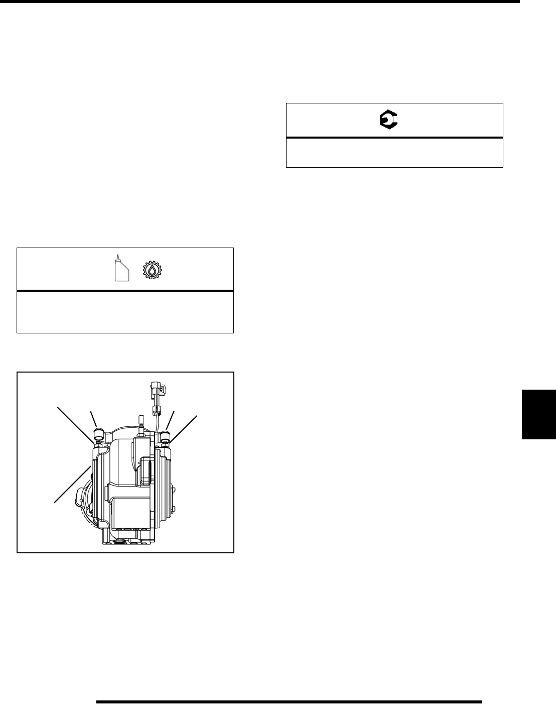
8.25
FINAL DRIVE
8
ADC System Fluid Bleeding
1. Position the vehicle on a level surface and allow the
vehicle to sit for at least 30 minutes.
2. Thoroughly clean the areas around the ADC reservoir and
bleeder valves.
3. Remove the reservoir cap and diaphragm assembly.
4. Make sure the fluid inside the reservoir is free of debris. If
any debris is found, use a clean shop towel or suction device
to remove it from the reservoir.
NOTE: Debris in the reservoir may result in
inadequate bleeding and reduced performance of
the system.
5. Begin the bleeding process by filling reservoir to the
“MAX” level with clean ADC Front Drive Fluid.
6. Locate bleeder valves found on each side of the front
gearcase and remove the protective caps.
7. Attach a clean clear hose to one of the bleeder valves.
8. Slowly loosen the valve (counter-clockwise) and allow
fluid and trapped air to flow from the fitting.
IMPORTANT: Do not allow ADC fluid in reservoir to
drop below the “MIN” fill line. Close bleeder valve
before the fluid level drops below the “MIN” fill line.
Refilling an empty reservoir will result in air pockets
becoming trapped.
9. Close the valve when clean (bubble-free) fluid begins to
flow from the valve.
10. Repeat steps 7-9 on the remaining bleeder valve.
11. Torque the bleeder valves to specification and reinstall the
protective caps.
12. Fill reservoir to a level midway between “MAX” and
“MIN” fill lines. Verify no debris is found in reservoir
fluid.
13. Install the reservoir cap and diaphragm securely and wipe
clean any fluid residue.
=
Recommended ADC Fluid:
Premium ADC Front Drive Fluid
(PN 2876144) (Quart)
Bleeder
Valve Bleeder
Valve
CapCap
Front
Gearcase
= T
Bleeder Valve Torque:
80 in. lbs. (9 Nm)
PartShark.com
877-999-5686
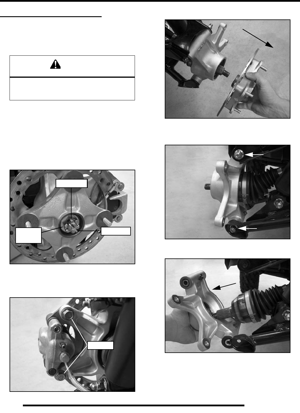
8.26
FINAL DRIVE
REAR BEARING CARRIER
Inspection / Removal
1. Elevate rear of vehicle and safely support machine under
the frame area.
2. Check bearings for side play by grasping the top and bottom
of the tire firmly and checking for movement. The tire
should rotate smoothly without binding or rough spots.
3. Remove the (4) wheel nuts and remove the rear wheel.
4. Remove the cotter pin and loosen the rear wheel hub castle
nut. Remove the nut, and (2) cone washers from the rear
wheel hub assembly.
5. Remove the two brake caliper mounting bolts.
CAUTION: Do not hang the caliper by the brake line. Use
wire to hang caliper to prevent damage to the brake line.
6. Remove the rear wheel hub assembly.
7. Remove the bolts that attach the rear bearing carrier to the
upper and lower A-arms.
8. Remove the bearing carrier from the rear drive shaft.
9. Rotate bearing by hand and check for smooth rotation.
Visually inspect bearing for moisture, dirt, or corrosion.
CAUTION
Serious injury may result if machine tips or falls.
Be sure machine is secure before beginning this
service procedure. Always wear eye protection.
Castle Nut
Cotter Pin
Cone
Washers
Remove
PartShark.com
877-999-5686
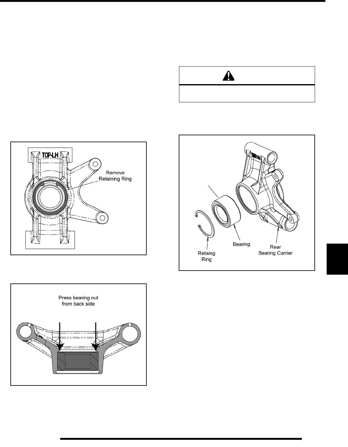
8.27
FINAL DRIVE
8
NOTE: Due to extremely close tolerances and
minimal wear, the bearings must be inspected
visually, and by feel. While rotating bearings by
hand, inspect for rough spots, discoloration, or
corrosion. The bearings should turn smoothly and
quietly, with no detectable up and down movement
and minimal movement sideways between inner and
outer race.
10. Replace bearing if moisture, dirt, corrosion, or roughness
is evident.
Bearing Replacement
Bearing Removal
1. Remove the outer retaining ring from the bearing carrier.
2. Support the bearing carrier in an arbor press and remove the
bearing by pressing it out from the back side.
3. Inspect the bearing carrier housing for scratches, wear or
damage. Replace rear bearing carrier if damaged.
Bearing Installation
4. Thoroughly clean the rear bearing carrier housing and the
outer race on the new bearing. Be sure that all oil residue
has been removed from each surface.
5. Support the bottom of the bearing carrier housing.
6. Apply Loctite® 603™ retaining compound to the outer
circumference of the new bearing race and carefully press
the new bearing into the bearing carrier housing.
NOTE: Use care to not allow any of the Loctite®
compound to get in the bearing.
7. Wipe the housing clean of any excess compound and install
the snap ring.
CAUTION
Use an arbor and press only on the outer race
or bearing damage may occur.
Apply
Loctite® 603™
PartShark.com
877-999-5686
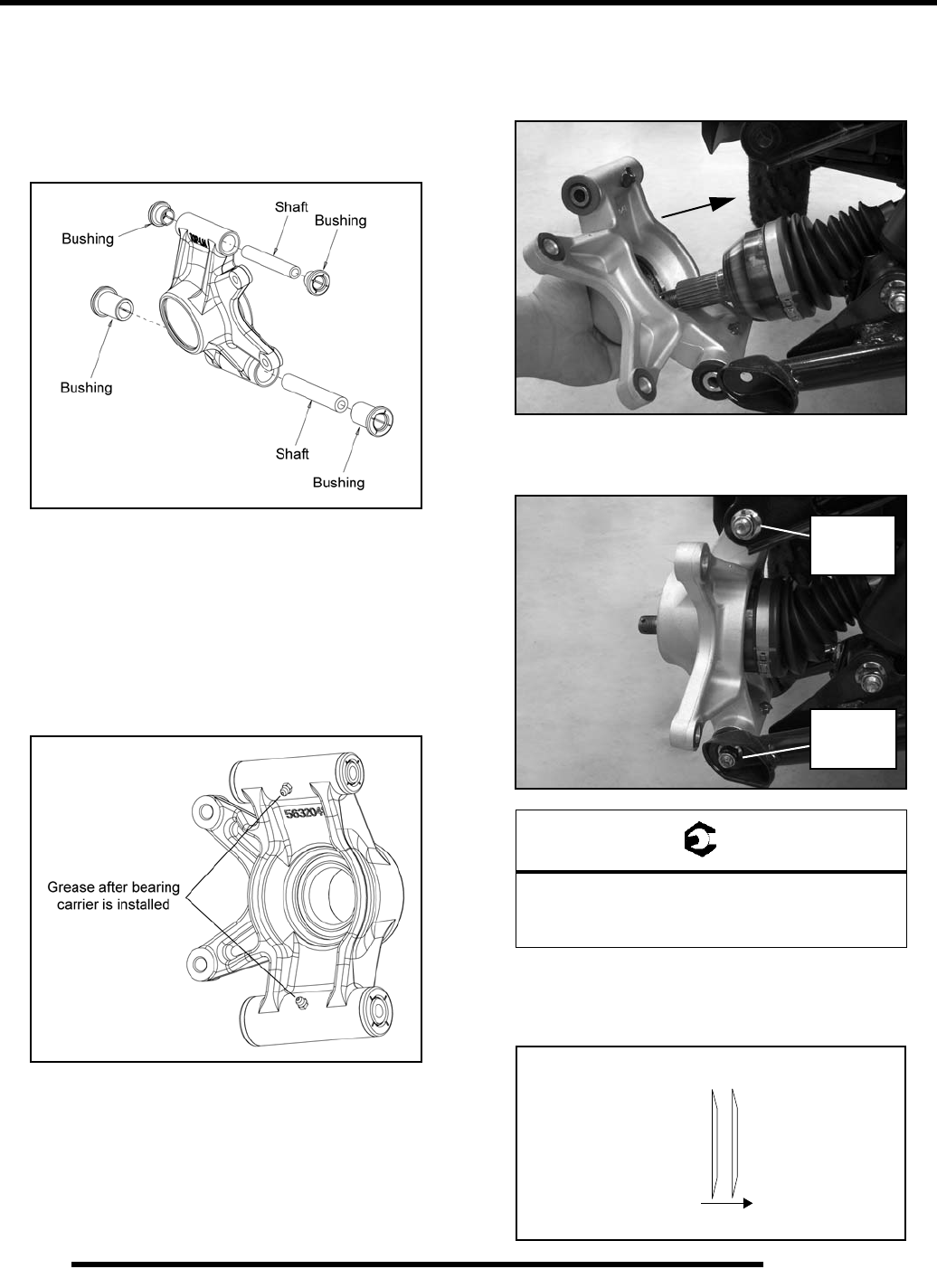
8.28
FINAL DRIVE
Bushing Replacement
1. Check bearing carrier bushings and shafts for excessive
wear or damage.
2. If replacement is required, slide shafts out and remove the
bushings with a drift punch.
3. Thoroughly clean the bearing carrier and inspect for
excessive wear or damage. Replace rear bearing carrier if
damaged.
4. Install new shafts and bushings. Press the bushings into the
bearing carrier until they are flush with the mating surface.
5. Grease the the rear bearing carrier fittings after it has been
installed and the rear A-arms have been attached.
Installation
1. Install drive shaft axle through the backside of the bearing
carrier. Be sure bushings and pivot tubes are installed.
2. Install the fasteners that attach the rear bearing carrier to the
upper and lower A-arms. Torque bolts to specification.
3. Apply grease to drive shaft axle splines.
4. Install rear wheel hub assembly, cone washers, and hand
tighten the castle nut. Install washers with domed side out.
= T
Rear Bearing Carrier Bolts:
Upper: 40 ft. lbs. (54 Nm)
Lower: 45 ft. (61 Nm)
Short Bolt
40 ft. lbs.
(54 Nm)
Long Bolt
45 ft. lbs.
(61 Nm)
Out
Cone Washers
Wheel
Hub
PartShark.com
877-999-5686
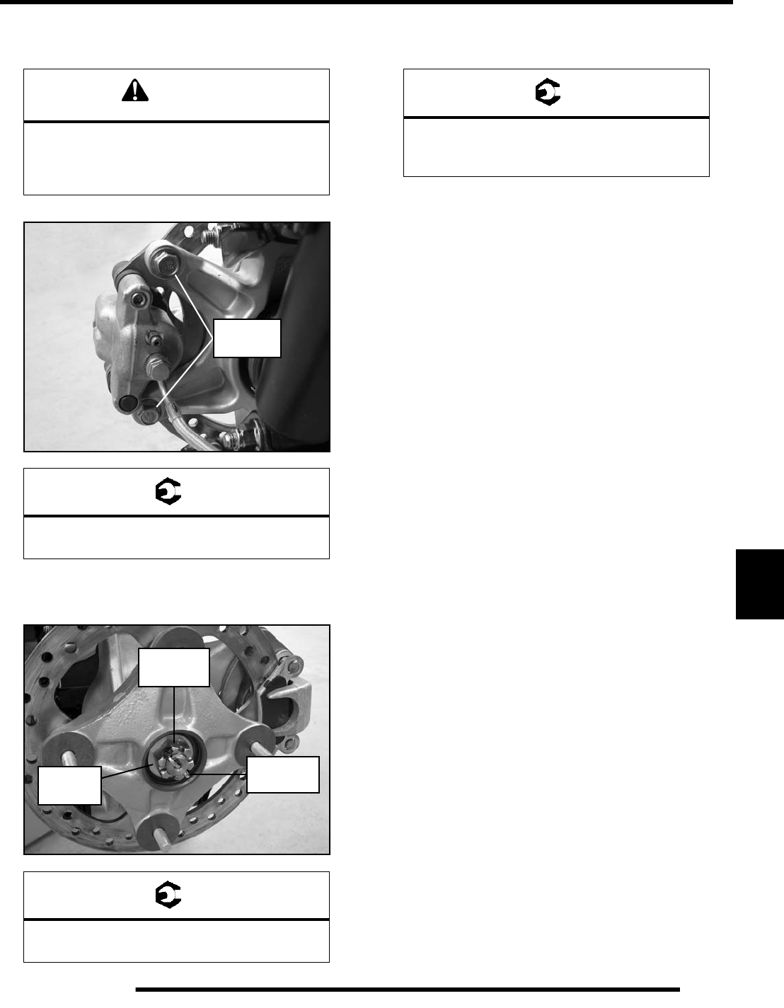
8.29
FINAL DRIVE
8
5. Install the brake caliper and torque the new mounting bolts
to specification.
6. Torque wheel hub nut to specification and install a new
cotter pin. Tighten nut slightly if necessary to align cotter
pin holes.
7. Install the rear wheel and (4) wheel nuts. Torque wheel nuts
to specification.
8. Rotate wheel and check for smooth operation. Bend both
ends of cotter pin around end of spindle in different
directions.
CAUTION
New bolts have a pre-applied locking agent
which is destroyed upon removal. Always use
new brake caliper mounting bolts
upon assembly.
= T
Rear Caliper Mounting Bolts:
37 ft. lbs. (50 Nm)
= T
Wheel Hub Castle Nut:
80 ft. lbs. (108 Nm)
37 ft. lbs.
(50 Nm)
NEW
Cone
Washers
80 ft. lbs.
(108 Nm)
Cotter Pin
= T
Wheel Nuts:
Steel Wheels: 45 ft. lbs. (61 Nm)
Aluminum Wheels: 75 ft. lbs. (102 Nm)
PartShark.com
877-999-5686
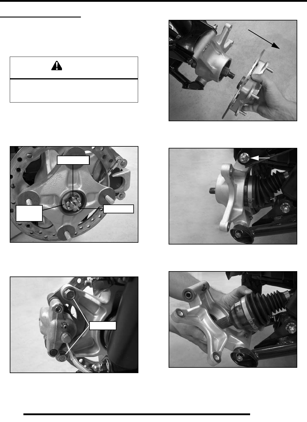
8.30
FINAL DRIVE
REAR DRIVE SHAFT
Removal
1. Elevate rear of vehicle and safely support machine under
the frame area.
2. Remove the (4) wheel nuts and remove the rear wheel.
3. Remove the cotter pin and loosen the rear wheel hub castle
nut. Remove the nut, and (2) cone washers from the rear
wheel hub assembly.
4. Remove the two brake caliper mounting bolts.
CAUTION: Do not hang the caliper by the brake line. Use
wire to hang caliper to prevent damage to the brake line.
5. Remove the rear wheel hub assembly.
6. Remove the bolt that attaches the upper A-arm to the rear
bearing carrier.
7. Tilt the top portion of the bearing carrier down and pull the
rear drive shaft out from the bearing carrier.
CAUTION
Serious injury may result if machine tips or falls.
Be sure machine is secure before beginning this
service procedure. Always wear eye protection.
Castle Nut
Cotter Pin
Cone
Washers
Remove
PartShark.com
877-999-5686
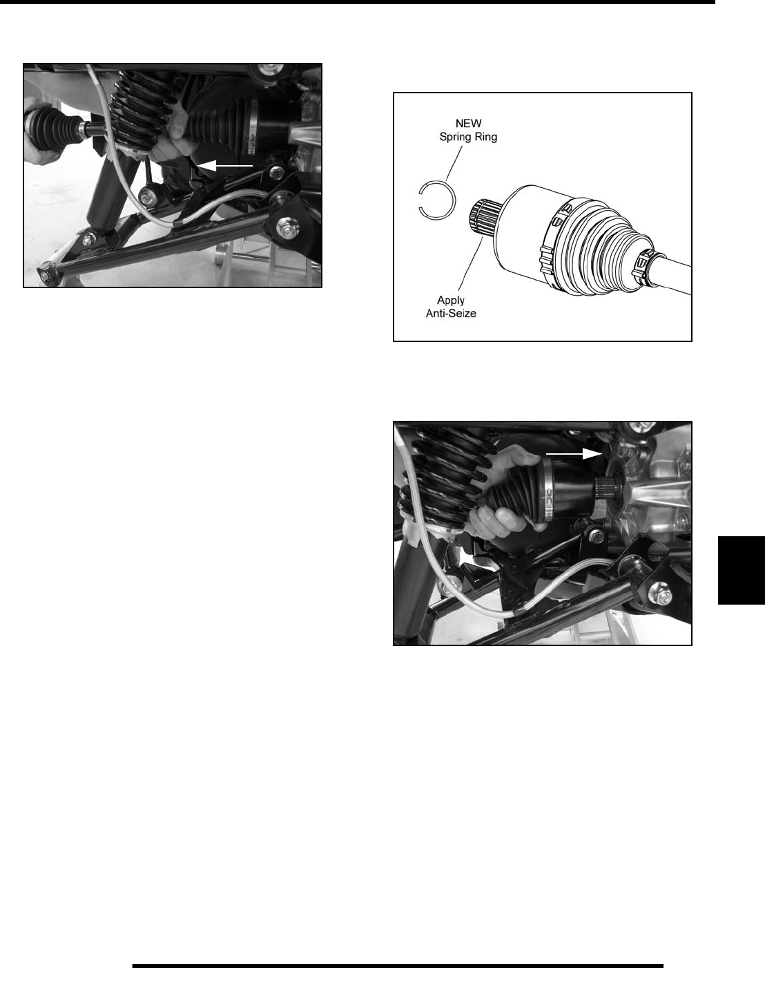
8.31
FINAL DRIVE
8
8. Grasp the rear drive shaft and pull sharply outward on the
shaft to disengage it from the rear gearcase.
9. Inspect the axle splines and CV boots for any damage.
10. Refer to the “DRIVE SHAFT SERVICE” procedure if
repairing the drive shaft.
Installation
1. Install a new spring ring on the end of the drive shaft and
apply an anti-seize compound to the splines.
2. Align the splines of the drive shaft with the rear gearcase
and reinstall the drive shaft. Use a rubber mallet to tap on
the outboard end of the drive shaft if necessary.
3. Install the drive shaft into the rear bearing carrier.
4. Refer to the “REAR BEARING CARRIER - Installation”
procedure within this chapter to properly reassemble the
vehicle.
PartShark.com
877-999-5686
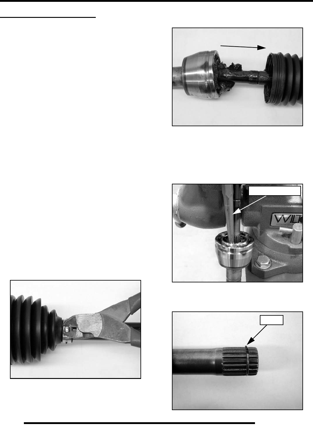
8.32
FINAL DRIVE
DRIVE SHAFT SERVICE
Drive Shaft / CV Joint Handling Tips
Care should be exercised during drive shaft removal or when
servicing CV joints. Drive shaft components are precision parts.
Cleanliness and following these instructions is very important to
ensure proper shaft function and a normal service life.
• The complete drive shaft and joint should be handled by
getting hold of the interconnecting shaft to avoid
disassembly or potential damage to the drive shaft
joints.
• Over-angling of joints beyond their capacity could
result in boot or joint damage.
• Make sure surface-ground areas and splines of shaft are
protected during handling to avoid damage.
• Do not allow boots to come into contact with sharp
edges or hot engine and exhaust components.
• The drive shaft is not to be used as a lever arm to
position other suspension components.
• Never use a hammer or sharp tools to remove or to
install boot clamps.
• Be sure joints are thoroughly clean and that the proper
amount and type of grease is used to refill when joint
boots are replaced and when joints are cleaned. Refer
to text for grease capacity of CV joints and CV joint
boots.
Outer CV Joint / Boot Replacement
1. Using a side cutters, cut away and discard the boot clamps.
2. Remove the large end of the boot from the CV joint and
slide the boot down the shaft.
3. Clean the grease from the face of the joint.
4. Place the drive shaft in a soft-jawed vise.
5. Using a soft-faced hammer, or brass drift, strike the inner
race of the joint to drive the joint off the drive shaft. Be
sure to tap evenly around the joint to avoid binding.
IMPORTANT: Tap on inner race only!
6. Make sure the circlip is on the shaft and not left in the joint.
Brass Drift Shown
Circlip
PartShark.com
877-999-5686
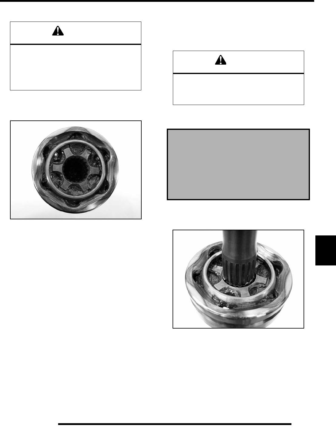
8.33
FINAL DRIVE
8
7. Remove the CV boot from the shaft.
IMPORTANT: If the grease in the joint is obviously
contaminated with water and/or dirt, the joint should
be replaced.
8. Thoroughly clean the joint with an appropriate solvent and
dry the joint to prevent any residual solvent from being left
in the joint upon reassembly.
9. Visually inspect the joint by tilting the inner race to one side
to expose each ball. Severe pitting, galling, play between
the ball and its cage window, any cracking or damage to the
cage, pitting or galling or chips in raceways call for joint
replacement.
NOTE: Shiny areas in ball tracks and on the cage
spheres are normal. Do not replace CV joints
because parts have polished surfaces. Replace CV
joint only if components are cracked, broken, worn
or otherwise unserviceable.
10. Clean the splines on the end of the shaft and apply a light
coat of grease prior to reassembly.
11. Slide the small boot clamp and boot (small end first) onto
the drive shaft and position the boot in it’s groove machined
in the shaft.
12. Install a NEW circlip on the end of the shaft.
13. Grease the joint with the special CV joint grease provided
in the boot replacement kit. Fill the cavity behind the balls
and the splined hole in the joint’s inner race. Pack the ball
tracks and outer face flush with grease. Place any
remaining grease into the boot.
NOTE: The amount of grease that’s provided is pre-
measured, so use all the grease.
14. Slide the joint onto the drive shaft splines and align the
circlip with the lead-in chamfer on the inner race of the
joint.
15. Use a soft-faced hammer to tap the joint onto the drive shaft
until it locks into place.
16. Pull on the joint to make sure it is securely locked in place.
17. Remove excess grease from the CV joint's external surfaces
and place the excess grease in the boot.
18. Pull the boot over the joint and position the boot lips into
the grooves on the joint housing and shaft. Make sure the
boot is not dimpled or collapsed.
CAUTION
Complete disassembly of the CV joint is NOT
recommended. The internal components are a
precision fit and develop their own characteristic
wear patterns. Intermixing the internal
components could result in looseness, binding,
and/or premature failure of the joint.
CAUTION
The grease provided in the replacement kit is
specially formulated for wear resistance and
durability. DO NOT use substitutes
or mix with other lubricants.
Boot Replacement Grease Requirements:
Grease Only Service Kits
PN 1350059 - 20g / PN 1350046 - 30g / PN 1350047 - 50g
Outer CV Joint Capacity:
Front - 80g / Rear - 90g
PartShark.com
877-999-5686
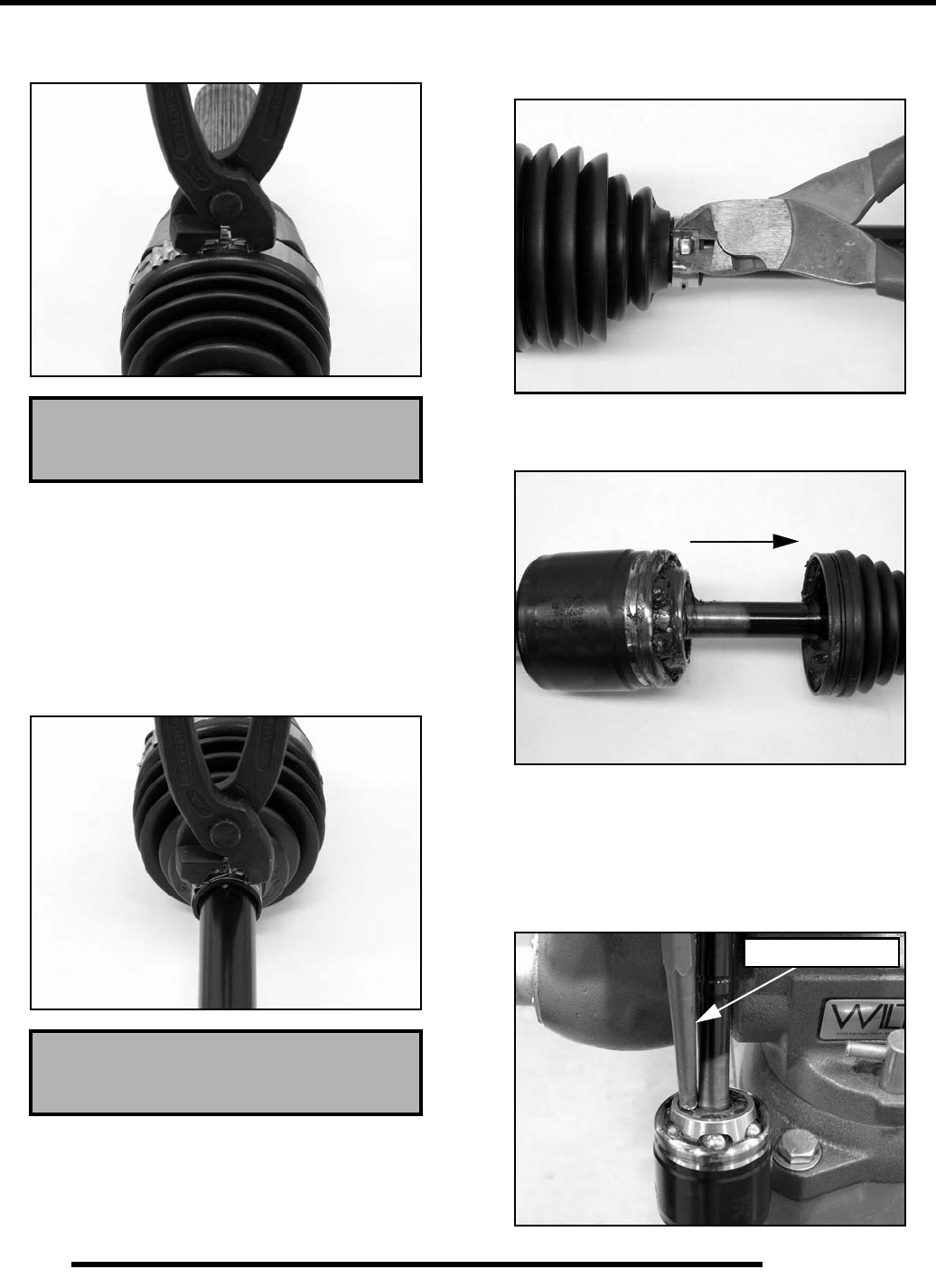
8.34
FINAL DRIVE
19. Install and tighten the large clamp using the Axle Boot
Clamp Tool (PU-48951).
20. While pulling out on the CV shaft, fully extend the CV joint
and slide a straight O-ring pick or a small slotted screw
driver between the small end of the boot and the shaft. This
will allow the air pressure to equalize in the CV boot in the
position that the joint will spend most of its life. Before you
remove your instrument, be sure the small end of the boot
is in its correct location on the shaft.
21. Install and tighten the small clamp on the boot using the
Axle Boot Clamp Tool (PU-48951).
Inner Plunging Joint / Boot Replacement
1. Using a side cutters, cut away and discard the boot clamps.
2. Remove the large end of the boot from the plunging joint
and slide the boot down the shaft.
3. Clean the grease from the face of the joint.
4. Place the drive shaft in a soft-jawed vise.
5. Using a soft-faced hammer, or brass drift, strike the inner
race of the joint to drive the joint off the drive shaft. Be
sure to tap evenly around the joint to avoid binding.
Axle Boot Clamp Tool
PU-48951
Axle Boot Clamp Tool
PU-48951
Brass Drift Shown
PartShark.com
877-999-5686
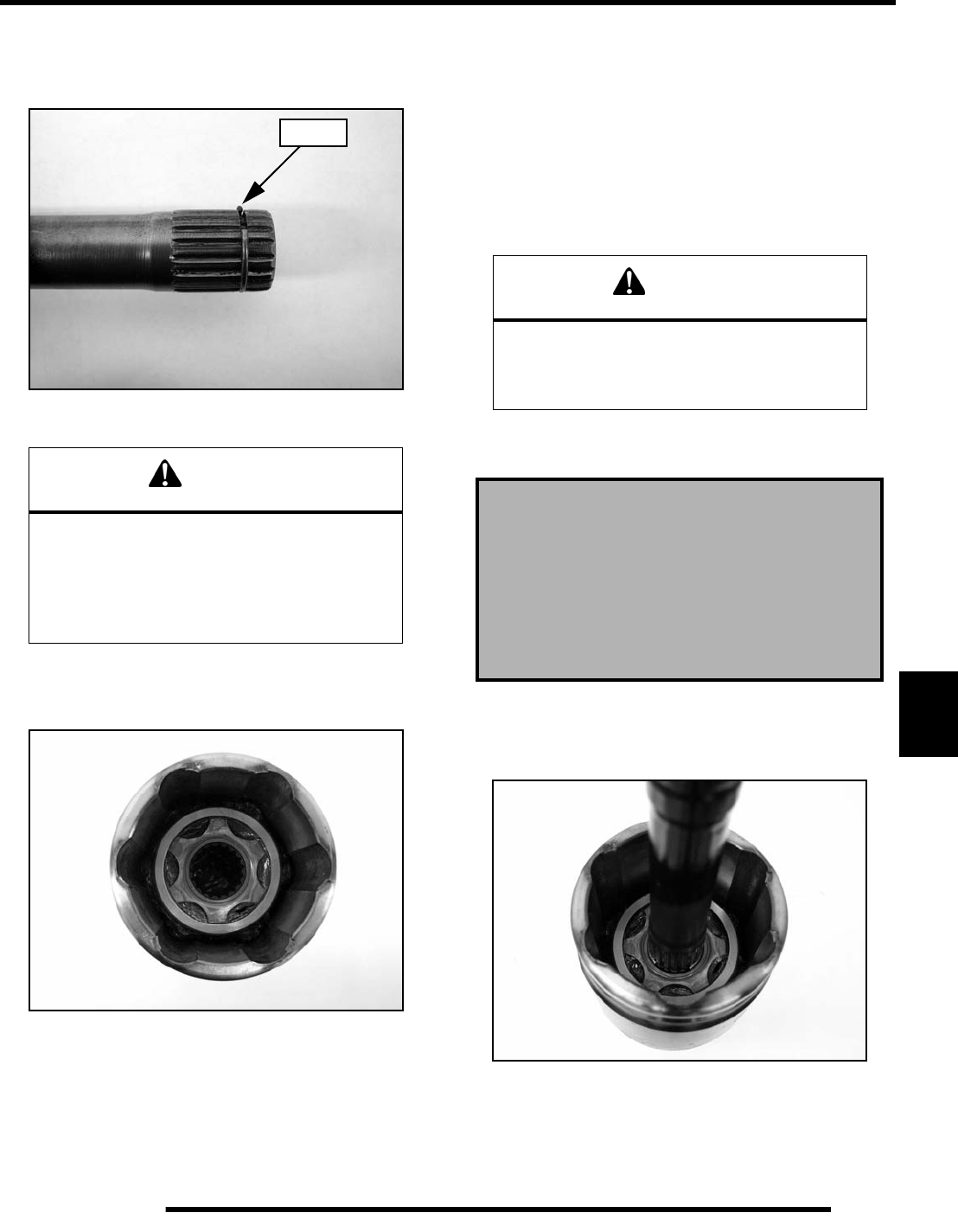
8.35
FINAL DRIVE
8
IMPORTANT: Tap on inner race only!
6. Make sure the circlip is still on the shaft and not left in the
joint.
7. Remove the boot from the shaft.
IMPORTANT: If the grease in the joint is obviously
contaminated with water and/or dirt, the joint should
be replaced.
8. Thoroughly clean the joint with an appropriate solvent and
dry the joint to prevent any residual solvent from being left
in the joint upon reassembly.
9. Visually inspect the joint for damage. Replace if needed.
10. Clean the splines on the end of the shaft and apply a light
coat of grease prior to reassembly.
11. Slide the small boot clamp and boot (small end first) onto
the drive shaft and position the boot in its groove machined
in the shaft.
12. Install a NEW circlip on the end of the shaft.
13. Grease the joint with the special CV joint grease provided
in the boot replacement kit. Fill the cavity behind the balls
and the splined hole in the joint’s inner race. Pack the ball
tracks and outer face flush with grease. Place any
remaining grease into the boot.
NOTE: The amount of grease that’s provided is pre-
measured, so use all the grease.
14. Fully compress the joint and push the drive shaft firmly into
the inner race.
15. Align the circlip with the lead-in chamfer.
16. Use a soft-faced hammer to tap the joint onto the drive shaft
until you reach the end of the splines and the joint locks in
place.
CAUTION
Complete disassembly of the plunging joint is
NOT recommended. The internal components
are a precision fit and develop their own
characteristic wear patterns. Intermixing the
internal components could result in looseness,
binding, and/or premature failure of the joint.
Circlip
CAUTION
The grease provided in the replacement kit is
specially formulated for wear resistance and
durability. DO NOT use substitutes
or mix with other lubricants.
Boot Replacement Grease Requirements:
Grease Only Service Kits
PN 1350059 - 20g / PN 1350046 - 30g / PN 1350047 - 50g
Inner Plunging Joint Capacity:
Front - 60g / Rear - 90g
PartShark.com
877-999-5686
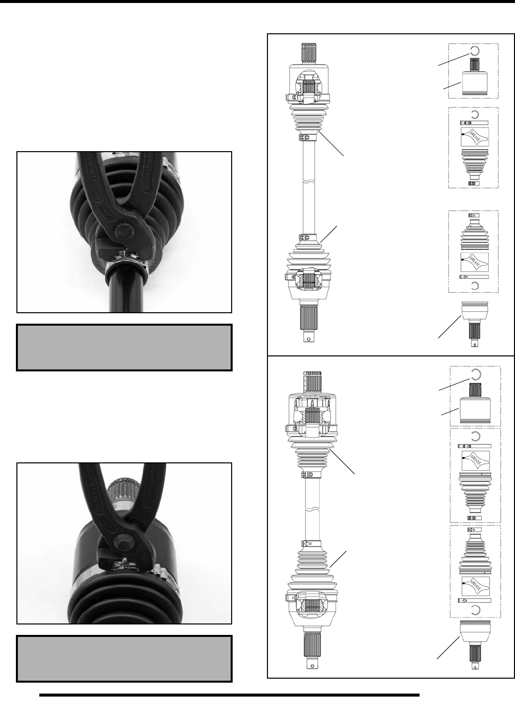
8.36
FINAL DRIVE
17. Pull on the joint to test that the circlip is seated and that the
joint is securely fastened to the shaft.
18. Remove excess grease from the plunging joint’s external
surfaces and place the excess grease in the boot.
19. Pull the boot over the joint and position the boot lips into
the grooves on the joint housing and shaft. Make sure the
boot is not dimpled or collapsed.
20. Install and tighten the small clamp using the Axle Boot
Clamp Tool (PU-48951).
21. Pull out on the drive shaft to center the joint in the housing.
Slide a straight O-ring pick or a small slotted screw driver
between the large end of the boot and the joint housing and
lift up to equalize the air pressure in the boot.
22. Position the boot lip in its groove. Install and tighten the
large clamp using the Axle Boot Clamp Tool (PU-48951).
Drive Shaft Exploded View
Axle Boot Clamp Tool
PU-48951
Axle Boot Clamp Tool
PU-48951
REAR SHAFT
Grease Capacity
80 Grams
Grease Capacity
60 Grams
CV Joint
Plunging
Spring Ring
Gear Side
Boot Kit
Wheel Side
Boot Kit
Joint
FRONT SHAFT
Grease Capacity
90 Grams
Grease Capacity
90 Grams
CV Joint
Plunging
Spring Ring
Gear Side
Boot Kit
Wheel Side
Boot Kit
Joint
PartShark.com
877-999-5686
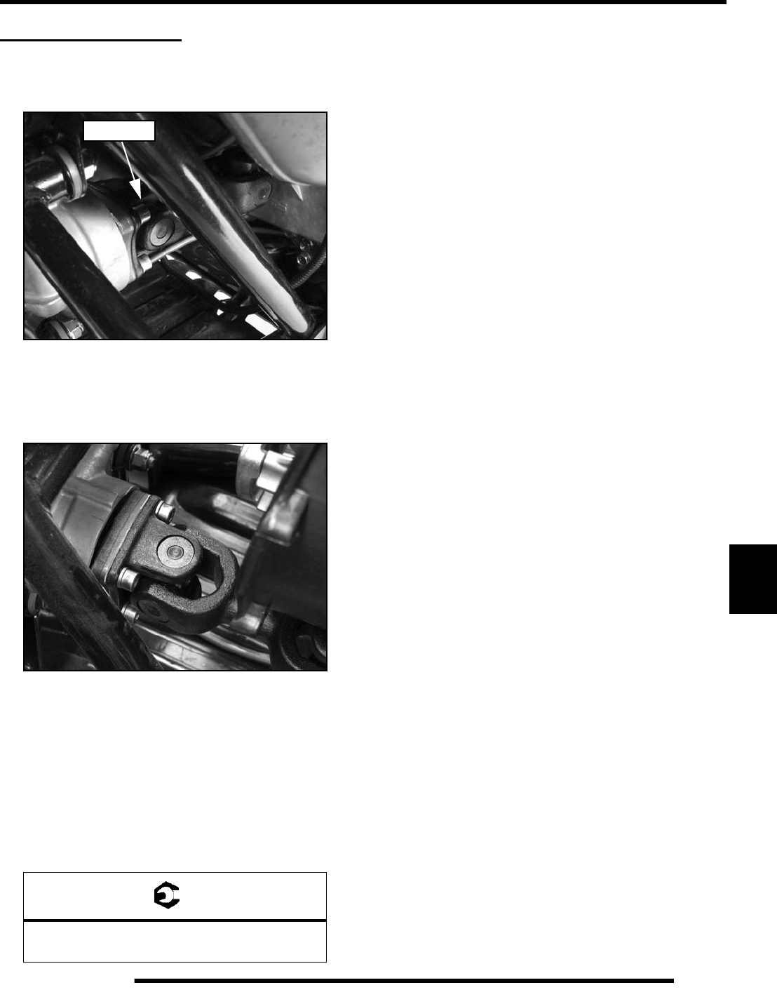
8.37
FINAL DRIVE
8
REAR PROPSHAFT
Removal
1. Locate the rear propshaft through the right rear wheel well.
NOTE: If needed, remove the right rear wheel to gain
better access to the rear propshaft bolts.
2. Remove the (4) bolts retaining the rear propshaft to the rear
gearcase input shaft coupler.
3. Slide the shaft towards the transmission and pivot the
propshaft down. Slide the propshaft off the transmission
output shaft and out from the vehicle.
Installation
1. Apply anti-seize compound to all splines. Slide propshaft
back onto the transmission output shaft, and then lift it up
and align it with the rear gearcase input shaft coupler.
2. Install the (4) bolts and torque to specification.
= T
Rear Propshaft Bolts:
18 ft. lbs. (24 Nm)
Propshaft
PartShark.com
877-999-5686
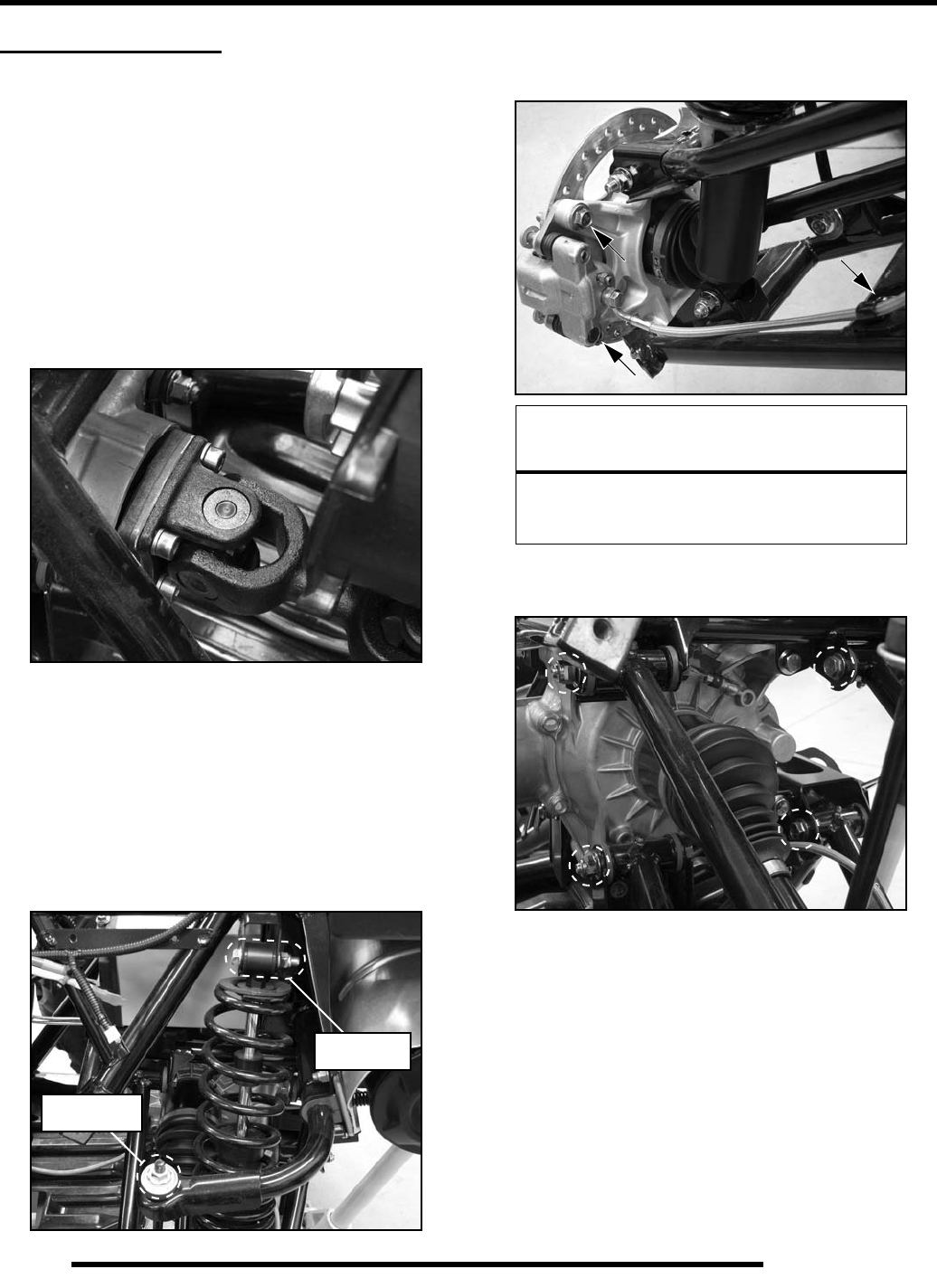
8.38
FINAL DRIVE
REAR GEARCASE
Gearcase Removal
1. Position the vehicle on a level surface and remove the seat.
2. Drain the rear gearcase lubricant (see Chapter 2).
3. Remove the rear cab (see Chapter 9).
4. Remove the left rear wheel, lower left-hand frame support
and outer PVT cover (see Chapter 7 “DRIVE BELT - Belt
Removal”).
5. Remove the (4) bolts retaining the rear propshaft to the rear
gearcase input shaft.
6. Slide the shaft towards the transmission and pivot the
propshaft down. Slide the propshaft off the transmission
output shaft and out from the vehicle.
7. Remove the PVT outlet duct, driven clutch, drive clutch
and inner PVT cover (see Chapter 7 “PVT SYSTEM
SERVICE - Disassembly”).
8. Remove the top retaining nut from each stabilizer bar
linkage and rotate the stabilizer bar back out of the way.
9. Remove the upper shock mounts from each side.
10. Remove the brake line retainer and left rear brake caliper.
11. Remove the (4) through-bolt fasteners retaining the left rear
upper and lower A-arms to the frame.
Linkage
Retaining Nut
Upper
Shock Mount
CAUTION
Do not hang the brake caliper by the brake line.
Use mechanics wire to hang the caliper to
prevent from damaging the brake line.
PartShark.com
877-999-5686
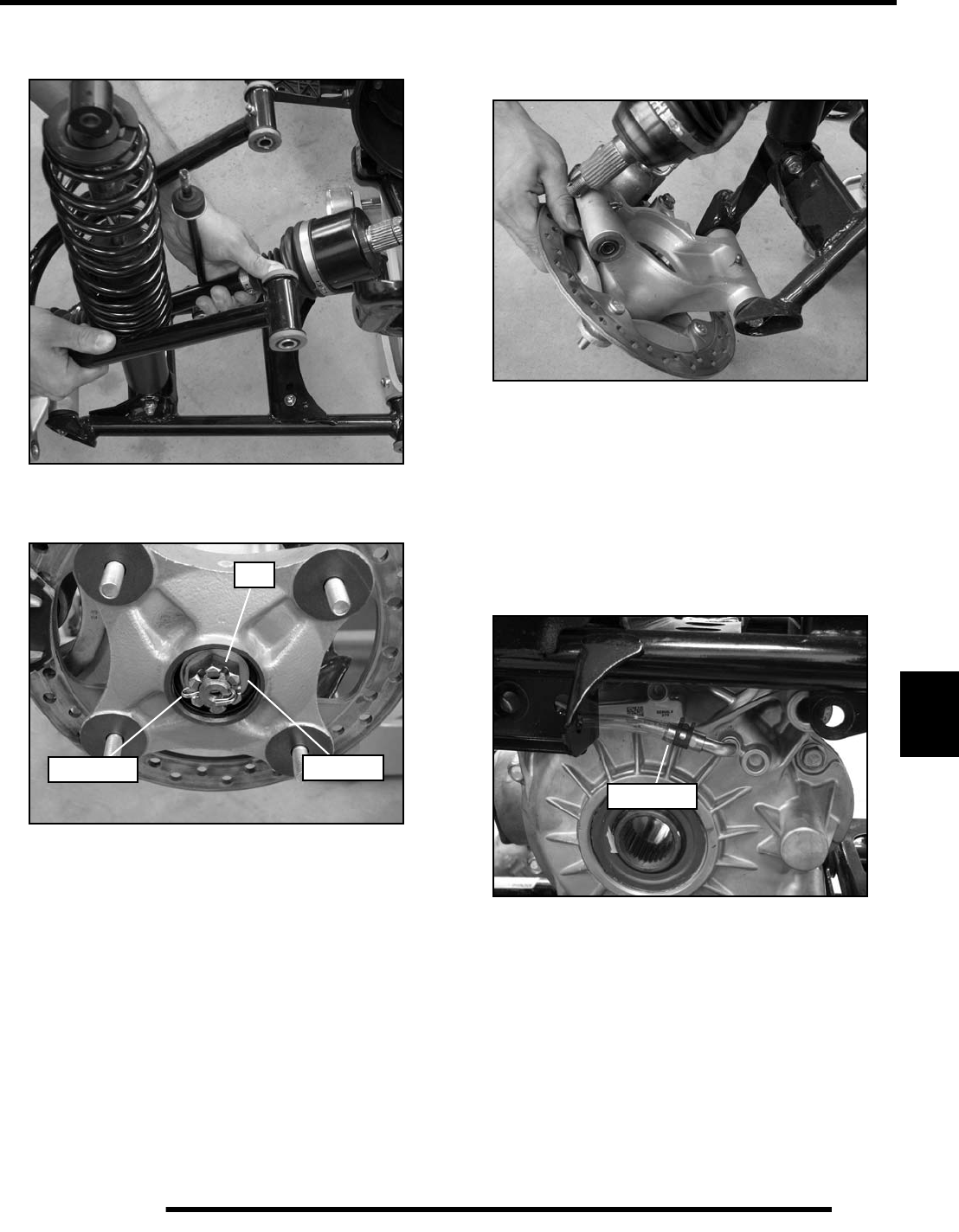
8.39
FINAL DRIVE
8
12. Remove the left rear suspension and drive shaft from the
vehicle as an assembly.
13. Remove the right rear wheel. Remove the cotter pin, nut and
washers retaining the drive shaft at the wheel hub.
14. Remove the through-bolt fastener retaining the upper A-
arm to the bearing carrier. Pivot the wheel hub and bearing
carrier down to remove the drive shaft.
IMPORTANT: Take care not to stretch the brake line
while removing the drive shaft.
15. Remove the drive shaft from the rear gearcase by pulling
sharply.
16. Remove the (4) through-bolts retaining the rear gearcase to
the frame.
17. Remove the vent line from the rear gearcase.
18. Pull the rear gearcase out between the transmission and the
frame.
Cotter Pin Washers
Nut
Vent Line
PartShark.com
877-999-5686
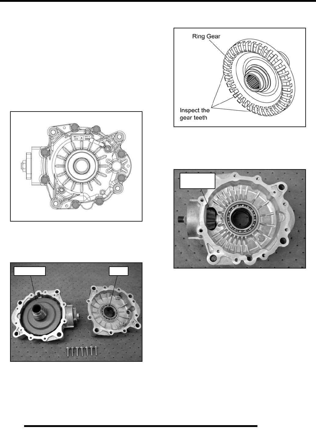
8.40
FINAL DRIVE
Gearcase Disassembly and Inspection
IMPORTANT: Pinion and ring gear shimming
information is NOT provided. The components are
matched at the factory which requires special OEM
tooling in order to properly assemble and shim the
gears.
In the event damage to the gears or housing requires
replacement, the entire assembly must be replaced.
1. Drain and properly dispose of used gearcase lubricant.
2. Remove the (8) screws from the rear gearcase cover.
3. Lift the gearcase cover off the main gearcase half and note
the shim between the cover and the ring gear.
4. Remove the ring gear from the main gearcase half.
5. Inspect the ring gear teeth for chipped, worn, or broken
teeth.
6. Inspect the pinion shaft by rotating the assembly in the
gearcase housing while checking for any looseness or
roughness. Inspect the pinion gear teeth for chipped, worn,
or broken teeth.
NOTE: In the event damage to the gears or housing
requires replacement, the entire assembly must be
replaced.
7. Inspect the gearcase bearings and seals. Proceed to
“Gearcase Bearing and Seal Replacement” if components
require service.
ShimRing Gear
Inspect the
gear teeth
PartShark.com
877-999-5686
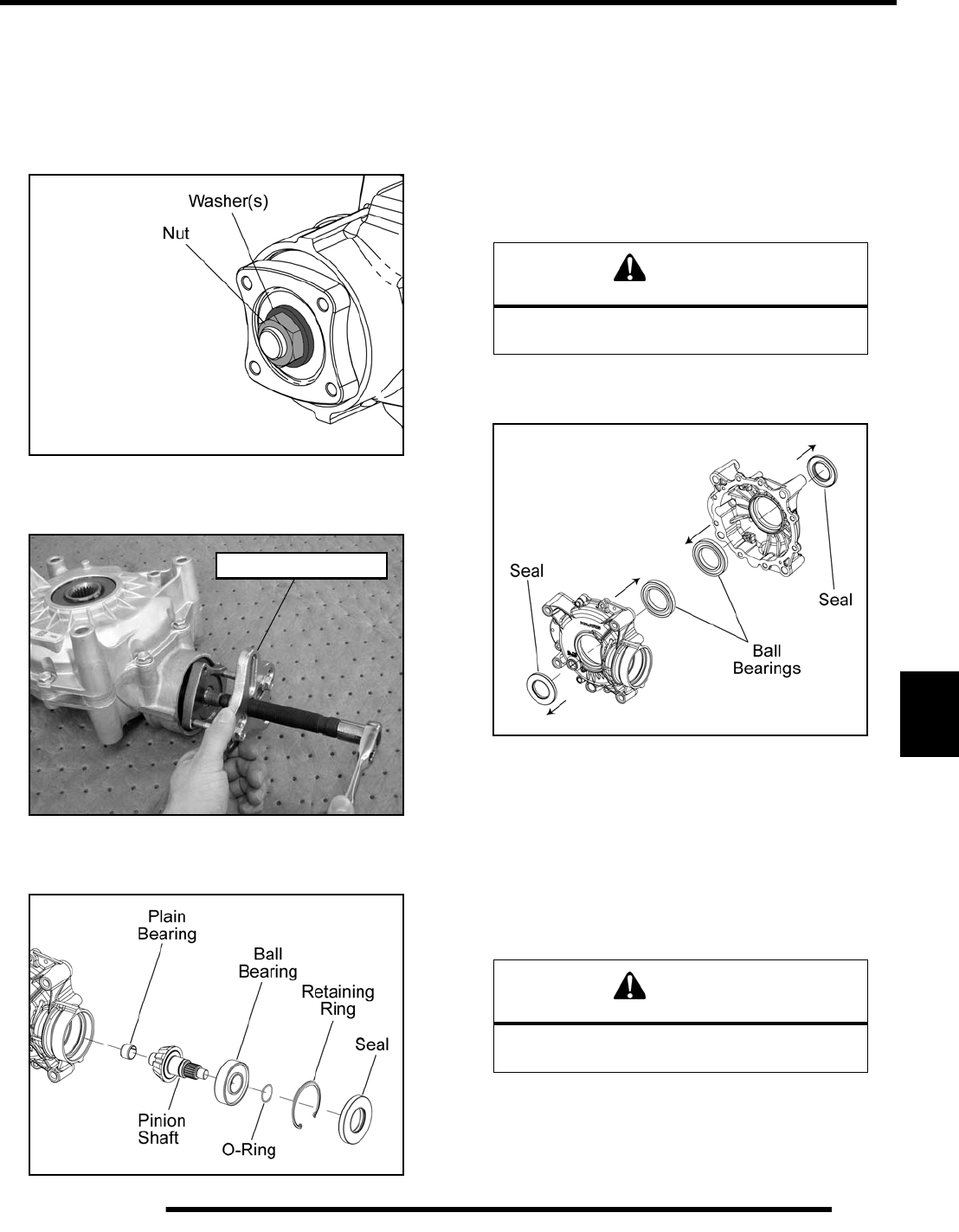
8.41
FINAL DRIVE
8
Gearcase Bearing and Seal Replacement
1. If the gearcase is completely assembled, perform the
“Gearcase Disassembly and Inspection” procedure.
2. Remove the nut and locking washer(s) from the pinion shaft
(nut was loosened during “Gearcase Removal”).
3. Using a universal bolt-grip puller kit, remove the coupler
from the pinion shaft.
4. Remove the seal above the pinion shaft using a seal puller
or other suitable method (see Figure 8-27).
5. Remove the retaining ring and lift the pinion shaft and
bearing from the main gearcase (see Figure 8-27).
6. Support the pinion shaft and press the bearing off the shaft
(see Figure 8-27).
7. Thoroughly clean the pinion shaft.
8. Support the pinion shaft and carefully press the new bearing
on the shaft and install a NEW O-ring (see Figure 8-27).
9. Remove the seals from each case half using a seal puller or
other suitable method (see Figure 8-28).
10. Support the gearcase cover and press the bearing out.
Repeat this procedure on the main gearcase half (see Figure
8-28).
11. Thoroughly clean the gearcase halves.
12. Support the gearcase cover and carefully press in the new
bearing. Repeat this procedure on the main gearcase half
(see Figure 8-28).
180° Bolt-Grip Puller
Figure 8-27
WARNING
Wear appropriate safety equipment while
installing bearings to reduce the risk of injury.
WARNING
Wear appropriate safety equipment while
installing bearings to reduce the risk of injury.
Figure 8-28
PartShark.com
877-999-5686
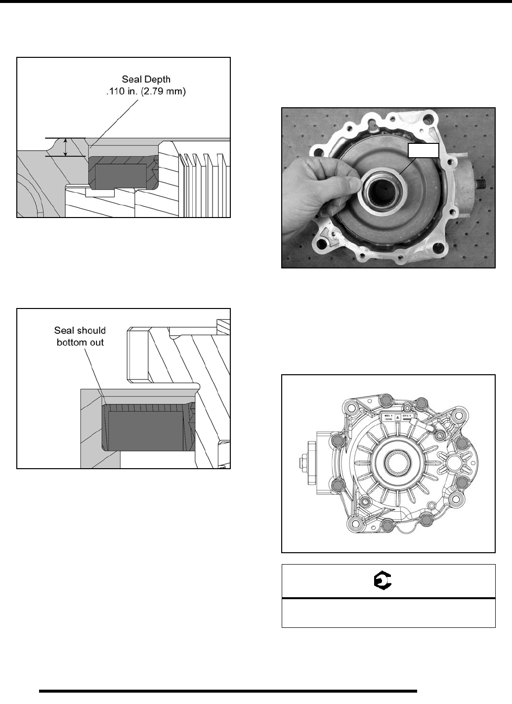
8.42
FINAL DRIVE
13. Install the seals into the case halves using a standard seal
installer or other suitable method. Seal depth should be
approximately .110 in. (2.79 mm) from the main surface.
14. Install the pinion shaft into the main gearcase and secure
with a NEW retaining ring.
15. Install the seal into the main gearcase half using a standard
seal installer or other suitable method. Press seal into the
gearcase until it bottoms out in the housing.
Gearcase Assembly
1. Grease all seals with Polaris All Season Grease (PN
2871322) upon assembly to prevent from damaging seals.
2. Install the ring gear into the main gearcase.
3. Install the shim previously removed onto the ring gear.
4. Thoroughly clean the gearcase mating surfaces and be sure
the alignment pins are in place.
5. Apply Crankcase Sealant (PN 2871557) to mating surfaces.
6. Install the gearcase cover onto the main gearcase half.
7. Install the cover screws and torque to specification.
8. Proceed to “Gearcase Installation” before installing the
coupler, locking washer(s), and retaining nut. Doing so will
allow you to properly torque the coupler retaining nut.
= T
Cover Screw Torque:
15-20 ft. lbs. (20-27 Nm)
Shim
PartShark.com
877-999-5686
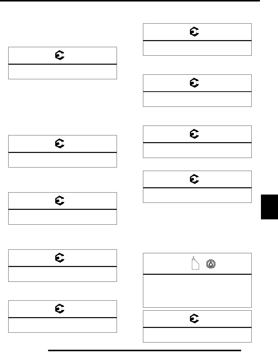
8.43
FINAL DRIVE
8
Gearcase Installation
1. Install the coupler onto the pinion shaft splines.
2. Install the locking washer(s) and retaining nut.
3. Torque the retaining nut to specification.
4. Install the rear gearcase by reversing the “Gearcase
Removal” procedure at the beginning of this section. Refer
to the following steps for torque specifications.
5. Install the gearcase through-bolt mounting fasteners and
torque to specification.
NOTE: Use the longer bolts (150 mm) in the top and
the shorter bolts (125 mm) in the bottom.
6. Install the right rear drive shaft and the upper A-arm onto
the bearing carrier. Torque through-bolt fastener to
specification.
7. Install the cone washers (dome facing retaining nut) and
right rear hub retaining nut. Torque to specification and
install a new cotter pin.
8. Install the left rear drive shaft and suspension assembly.
Torque the upper and lower A-arms to specification.
9. Install the left rear brake caliper and brake line retainer.
Torque brake caliper mounting bolts to specification.
10. Install the rear upper shock through-bolts. Torque bolts to
specification.
11. Install the rear stabilizer bar onto the linkage rods. Torque
the linkage retaining nuts to specification.
12. Install the rear propshaft and torque bolts to specification.
13. Reassemble the PVT system (see Chapter 7 “PVT
SYSTEM SERVICE - Assembly”).
14. Install the rear wheels and torque wheel nuts to
specification (see Page 8.2).
15. Add Polaris ATV Angle Drive Fluid to rear gearcase (see
Chapter 2). Torque drain and fill plugs to specification.
= T
Coupler Retaining Nut Torque:
90-110 ft. lbs. (122-149 Nm)
= T
Gearcase Mounting Fasteners:
40 ft. lbs. (54 Nm)
= T
Rear Upper A-arm to Bearing Carrier:
40 ft. lbs. (54 Nm)
= T
Rear Hub Retaining Nut:
80 ft. lbs. (108 Nm)
= T
Rear Upper & Lower A-arms to Frame:
45 ft. lbs. (61 Nm)
= T
Brake Caliper Mounting Bolts:
37 ft. lbs. (50 Nm)
= T
Rear Upper Shock Bolts:
37 ft. lbs. (50 Nm)
= T
Stabilizer Bar Linkage Retaining Nuts:
17 ft. lbs. (23 Nm)
= T
Rear Propshaft Bolts:
18 ft. lbs. (24 Nm)
=
Rear Gearcase Capacity:
7.1 fl. oz. (210 ml)
or to bottom of fill plug hole threads
See Chapter 2 “Maintenance”
= T
Drain / Fill Plug:
10-14 ft. lbs. (14-19 Nm)
PartShark.com
877-999-5686
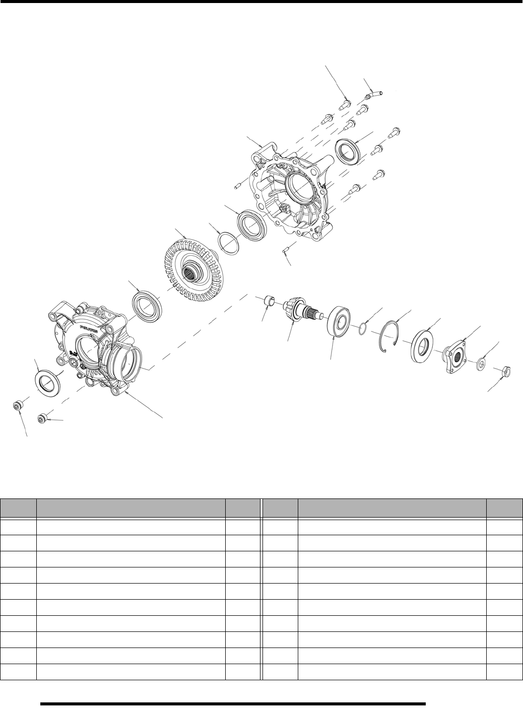
8.44
FINAL DRIVE
Gearcase Exploded View
REF# DESCRIPTION QTY REF# DESCRIPTION QTY
1 Fill Plug with O-ring 1 11 Ball Bearing 2
2 Drain Plug with O-ring, Magnetic 1 12 Main Case, Machined 1
3 Screw 8 13 Cover, Machined 1
4 Nut 1 14 Pinion Shaft, 10T Straight Bevel 1
5 Locking Washer 1 15 Ring Gear, 37T Straight Bevel 1
6 Dowel Pin 2 16 Vent Tube 1
7 Retaining Ring 1 17 Coupler 1
8 Shim 1 18 Triple Lip Seal 2
9 Plain Bearing 1 19 Triple Lip Seal 1
10 Ball Bearing 1 20 O-Ring 1
1
2
3
4
5
7
8
9
10
13
14
15
16
17
18
19
20
12
10-14 ft. lbs.
(14-19 Nm)
6
90-110 ft. lbs.
(122-149 Nm)
15-20 ft. lbs.
(20-27 Nm)
11
11
18
10-14 ft. lbs.
(14-19 Nm)
PartShark.com
877-999-5686

BODY / FRAME
9.1
CHAPTER 9
BODY / FRAME
9
TORQUE SPECIFICATIONS. . . . . . . . . . . . . . . . . . . . . . . . . . . . . . . . . . . . . . . . . . . . . . . 9.2
DECAL REPLACEMENT. . . . . . . . . . . . . . . . . . . . . . . . . . . . . . . . . . . . . . . . . . . . . . . . . . 9.2
SPECIAL TOOLS . . . . . . . . . . . . . . . . . . . . . . . . . . . . . . . . . . . . . . . . . . . . . . . . . . . . . . . 9.2
PLASTIC PUSH RIVET REMOVAL . . . . . . . . . . . . . . . . . . . . . . . . . . . . . . . . . . . . . . . . . 9.2
MULTI-FUNCTION PLIERS . . . . . . . . . . . . . . . . . . . . . . . . . . . . . . . . . . . . . . . . . . . . . . . 9.2
SEAT AND SIDE PANELS . . . . . . . . . . . . . . . . . . . . . . . . . . . . . . . . . . . . . . . . . . . . . . . . 9.3
REMOVAL / INSTALLATION . . . . . . . . . . . . . . . . . . . . . . . . . . . . . . . . . . . . . . . . . . . . . . 9.3
FRONT RACK . . . . . . . . . . . . . . . . . . . . . . . . . . . . . . . . . . . . . . . . . . . . . . . . . . . . . . . . . . 9.3
REMOVAL / INSTALLATION . . . . . . . . . . . . . . . . . . . . . . . . . . . . . . . . . . . . . . . . . . . . . . 9.3
FRONT BUMPER . . . . . . . . . . . . . . . . . . . . . . . . . . . . . . . . . . . . . . . . . . . . . . . . . . . . . . . 9.4
REMOVAL / INSTALLATION . . . . . . . . . . . . . . . . . . . . . . . . . . . . . . . . . . . . . . . . . . . . . . 9.4
MUD GUARDS . . . . . . . . . . . . . . . . . . . . . . . . . . . . . . . . . . . . . . . . . . . . . . . . . . . . . . . . . 9.4
REMOVAL / INSTALLATION . . . . . . . . . . . . . . . . . . . . . . . . . . . . . . . . . . . . . . . . . . . . . . 9.4
FOOTWELLS. . . . . . . . . . . . . . . . . . . . . . . . . . . . . . . . . . . . . . . . . . . . . . . . . . . . . . . . . . . 9.4
REMOVAL / INSTALLATION . . . . . . . . . . . . . . . . . . . . . . . . . . . . . . . . . . . . . . . . . . . . . . 9.4
FRONT CAB . . . . . . . . . . . . . . . . . . . . . . . . . . . . . . . . . . . . . . . . . . . . . . . . . . . . . . . . . . . 9.5
REMOVAL . . . . . . . . . . . . . . . . . . . . . . . . . . . . . . . . . . . . . . . . . . . . . . . . . . . . . . . . . . . .9.5
INSTALLATION . . . . . . . . . . . . . . . . . . . . . . . . . . . . . . . . . . . . . . . . . . . . . . . . . . . . . . . . 9.5
REAR RACK . . . . . . . . . . . . . . . . . . . . . . . . . . . . . . . . . . . . . . . . . . . . . . . . . . . . . . . . . . . 9.6
REMOVAL / INSTALLATION . . . . . . . . . . . . . . . . . . . . . . . . . . . . . . . . . . . . . . . . . . . . . . 9.6
REAR BUMPER COVERS . . . . . . . . . . . . . . . . . . . . . . . . . . . . . . . . . . . . . . . . . . . . . . . . 9.6
REMOVAL / INSTALLATION . . . . . . . . . . . . . . . . . . . . . . . . . . . . . . . . . . . . . . . . . . . . . . 9.6
REAR CAB . . . . . . . . . . . . . . . . . . . . . . . . . . . . . . . . . . . . . . . . . . . . . . . . . . . . . . . . . . . . 9.6
REMOVAL / INSTALLATION . . . . . . . . . . . . . . . . . . . . . . . . . . . . . . . . . . . . . . . . . . . . . . 9.6
HEADLIGHT POD . . . . . . . . . . . . . . . . . . . . . . . . . . . . . . . . . . . . . . . . . . . . . . . . . . . . . . . 9.7
DISASSEMBLY / REMOVAL . . . . . . . . . . . . . . . . . . . . . . . . . . . . . . . . . . . . . . . . . . . . . . 9.7
ASSEMBLY / INSTALLATION . . . . . . . . . . . . . . . . . . . . . . . . . . . . . . . . . . . . . . . . . . . . . 9.7
MAIN FRAME . . . . . . . . . . . . . . . . . . . . . . . . . . . . . . . . . . . . . . . . . . . . . . . . . . . . . . . . . . 9.8
FRAME SUPPORT EXPLODED VIEW . . . . . . . . . . . . . . . . . . . . . . . . . . . . . . . . . . . . . . 9.8
CHASSIS . . . . . . . . . . . . . . . . . . . . . . . . . . . . . . . . . . . . . . . . . . . . . . . . . . . . . . . . . . . . . . 9.9
BODY PLASTIC REMOVED VIEW . . . . . . . . . . . . . . . . . . . . . . . . . . . . . . . . . . . . . . . . . 9.9
PartShark.com
877-999-5686
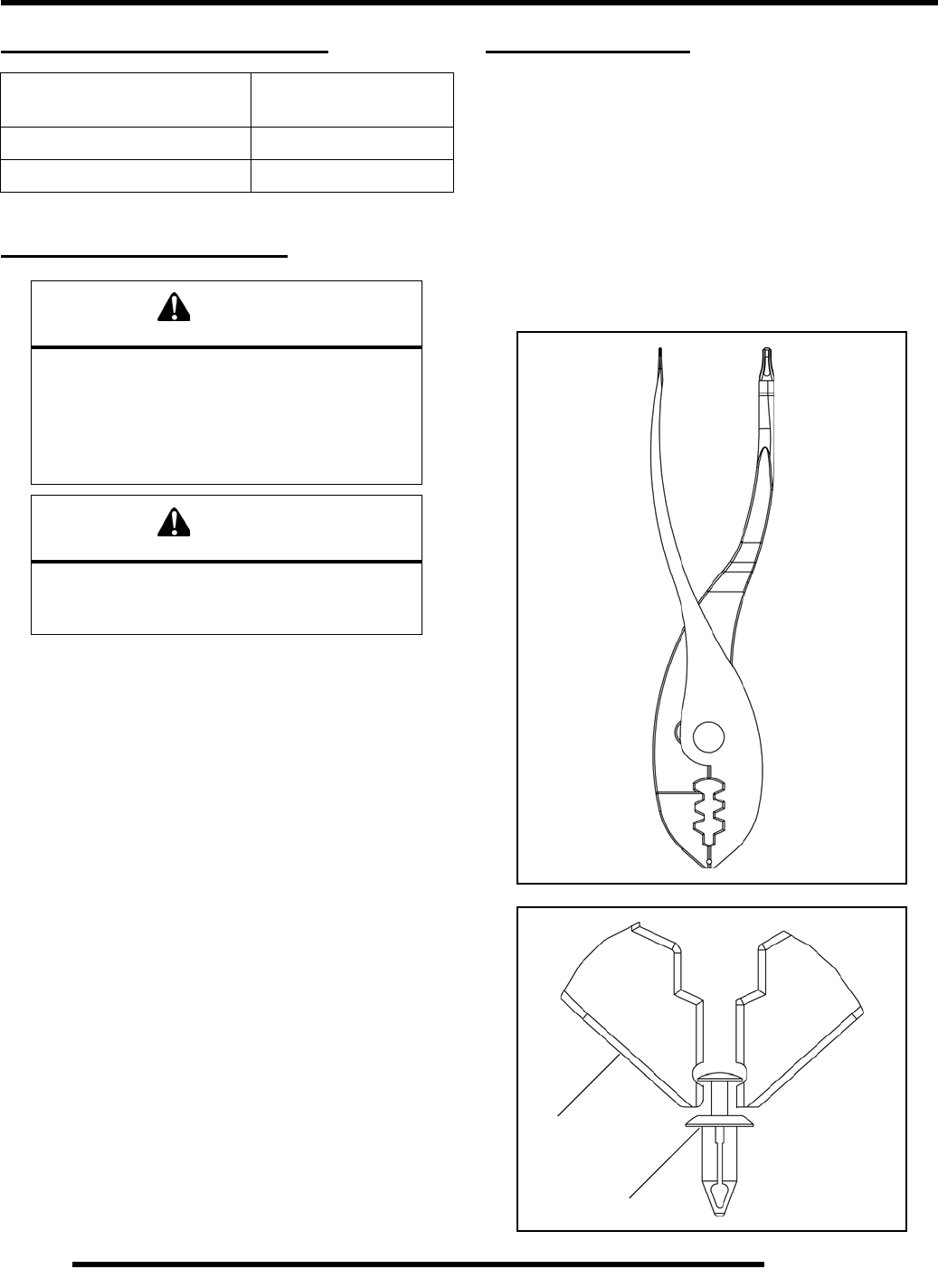
9.2
BODY / FRAME
TORQUE SPECIFICATIONS
DECAL REPLACEMENT
The side panels, front and rear fender cabs are plastic
polyethylene material. Therefore, they must be “flame treated”
prior to installing a decal to ensure good adhesion. A bonus of
the flame treating procedure is it can be used to reduce or
eliminate the whitish stress marks that are sometimes left after
a fender or cab is bent, flexed, or damaged.
To flame treat the decal area:
1. Pass the flame of a propane torch back and forth quickly
over the area where the decal is to be applied until the
surface appears slightly glossy. This should occur after just
a few seconds of flame treating. Do not hold the torch too
close to the surface (2-3 inches from the flame tip is
recommended). Keep the torch moving to prevent damage.
2. Apply the decal on one edge first. Slowly lay down
remainder of the decal while rubbing lightly over the decal
surface to eliminate any air bubbles during the application.
SPECIAL TOOLS
Plastic Push Rivet Removal
Polaris ATVs use a two piece plastic push rivet to fasten most
body components. Using the “Multi-Function Pliers” eases
removal and prevents from damaging the push rivets and body
components.
Multi-Function Pliers
Included in the tool kit, the multi-function pliers is designed to
remove the plastic push rivets used to fasten body components.
ITEM TORQUE VALUE
ft.lbs. (Nm)
Upper RH Frame Support 30 ft. lbs. (41 Nm)
Lower LH Frame Support 30 ft. lbs. (41 Nm)
WARNING
The following procedure involves the use of an
open flame. Perform this procedure in a well
ventilated area, away from gasoline or other
flammable materials. Be sure the area to be
flame treated is clean and free of gasoline
or flammable residue.
WARNING
Do not flame treat components that are installed
on the vehicle. Remove the component from the
vehicle before flame treating.
Pliers
Push Rivet
PartShark.com
877-999-5686
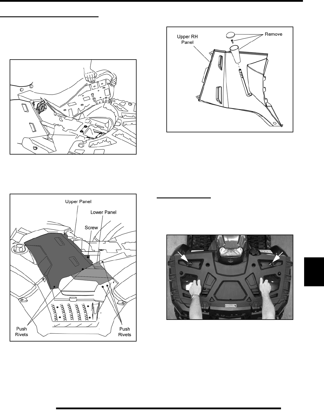
9.3
BODY / FRAME
9
SEAT AND SIDE PANELS
Removal / Installation
1. Grasp one side of the seat near the rear edge.
2. Pull upward abruptly to disengage the under-seat fasteners.
3. Remove the seat.
4. Remove the screws and push rivets securing the side panels
on each side (see illustration).
5. If removing the right-hand side panel, remove the gear shift
selector cap, retaining screw and knob to allow removal.
6. Reverse this procedure to reinstall components.
7. When installing the seat, start the front portion first, then
follow by installing the rear portion. Be sure the under-seat
fasteners are fully engaged upon installation.
FRONT RACK
Removal / Installation
1. Release the front rack latches and remove the rack as an
assembly.
2. To reinstall the rack, hold the rack as shown in the previous
photo. Position the front edge in the tabs, then push the rack
downward and secure the latches.
Left side
shown
PartShark.com
877-999-5686
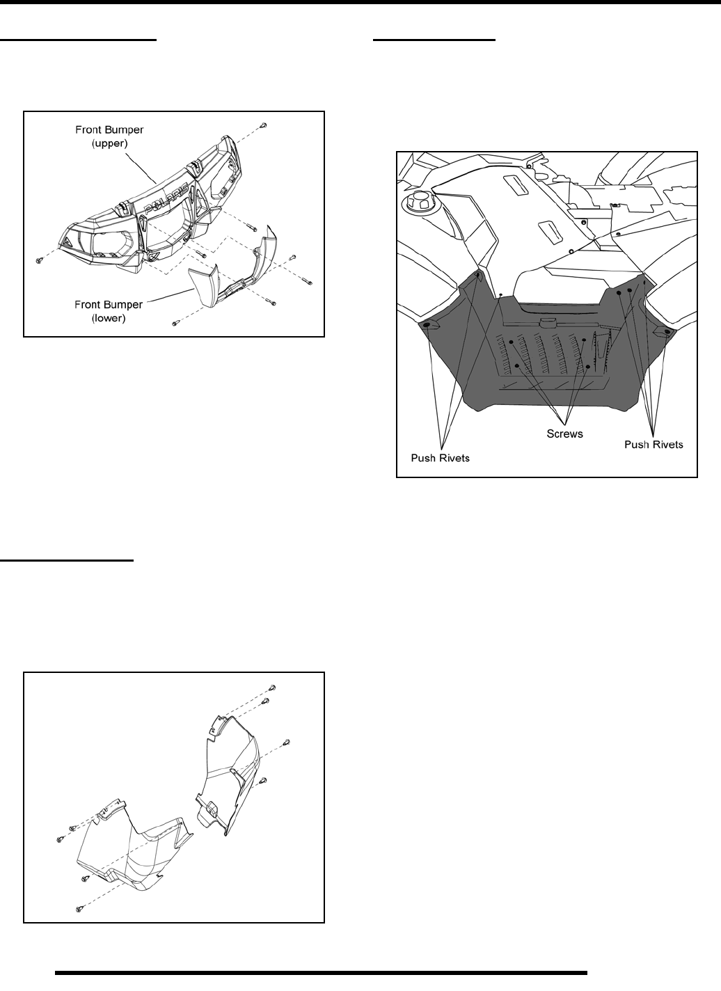
9.4
BODY / FRAME
FRONT BUMPER
Removal / Installation
1. Remove the (2) push rivets from each side of the bumper.
2. Remove the (4) bolts retaining the upper front bumper to
the frame.
3. Remove the bulbs from the head lights by turning the bulbs
90° counterclockwise and remove the upper front bumper
from the vehicle.
4. If removing the lower front bumper, remove the (2) bolts
from each side retaining the bumper to the frame.
5. Reverse this procedure to reinstall the front bumper.
MUD GUARDS
Removal / Installation
1. Locate the mud guards in the front wheel well area.
2. Remove the (4) push rivets from each mud guard and
remove from them from the wheel well.
3. Reverse this procedure to reinstall the mud guards.
FOOTWELLS
Removal / Installation
1. Remove the seat and upper side panel (see “SEAT AND
SIDE PANELS”).
2. Remove the push rivets and screws that retain the footwell.
3. Repeat this procedure to remove the other footwell.
4. Reverse this procedure to reinstall the footwells.
NOTE: Be sure to properly align the cab ends into
the footwells upon reassembly.
PartShark.com
877-999-5686
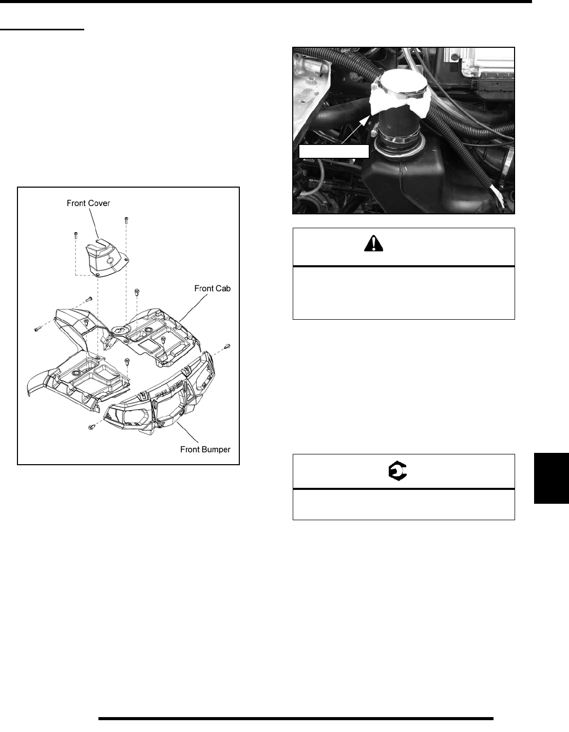
9.5
BODY / FRAME
9
FRONT CAB
Removal
1. Remove the seat and upper side panels (see “SEAT AND
SIDE PANELS”).
2. Remove the mud guards (see “MUD GUARDS”).
3. Remove the (4) push rivets retaining the front cab to the
footwells on each side.
4. Remove the (2) screws retaining the front cover to the front
cab and remove the cover.
5. Remove the (2) screws retaining the rear portion of the front
cab to the airbox.
6. Remove the (4) push rivets retaining the front cab to the
frame.
7. Thoroughly clean the area around the fuel tank fill hose
located in the left front wheel well.
8. Loosen the upper clamp retaining the fuel fill hose to the
front cab.
9. Carefully lift up on the front cab to disengage the fuel fill
hose.
10. Using a clean shop rag or towel, cover the fuel fill hose inlet
to prevent dirt or debris from entering the fuel tank.
11. Carefully lift up and pull the front cab toward the rear of
the ATV to clear in the headlight pod.
Installation
1. Carefully install the front cab onto the frame.
2. Uncover the fuel fill hose inlet and attach the hose to the
front cab. Torque the upper hose clamp to specification.
3. Install the push rivets retaining the front cab to the frame.
4. Install the screws retaining the front cab to the airbox.
5. Install the front cover.
6. Install the push rivets retaining the front cab to the
footwells.
7. Install the mud guards, upper side panels and seat.
CAUTION
Failure to cover the fuel fill hose inlet by allowing
dirt or debris to enter the fuel tank could lead to
premature fuel pump failure. Always take care
to not allow anything to enter the fuel tank.
= T
Upper Fuel Fill Hose Clamp:
24 in. lbs. (2.7 Nm)
Fill Hose Inlet
PartShark.com
877-999-5686
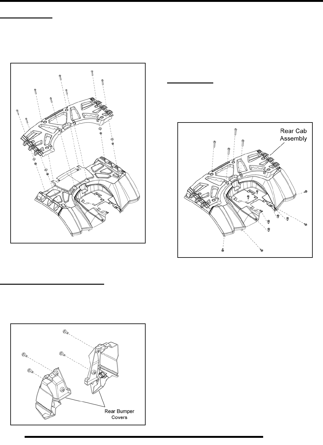
9.6
BODY / FRAME
REAR RACK
Removal / Installation
1. Remove the (8) Torx-headed fasteners as shown below.
2. Remove the rear rack and rack support from the rear cab.
3. Reverse this procedure to reinstall.
REAR BUMPER COVERS
Removal / Installation
1. Open the rear storage compartment and remove the (4)
bolts retaining the rear bumper covers.
2. Remove the (4) screws retaining the rear cab to the frame
(see “REAR CAB”).
3. Lift up on the rear cab and remove the bumper covers by
sliding them off the rear bumper.
4. Reverse this procedure to reinstall the covers.
REAR CAB
Removal / Installation
1. Remove the (10) push rivets and (4) Torx-headed screws
retaining the rear cab assembly.
2. Remove the tail light bulbs from the tail lamps, disconnect
the tail light harnesses from the rear cab, and remove the
rear cab as an assembly.
3. Reverse this procedure to reinstall. Be sure to lock the tail
light bulbs in place by turning them 90° clockwise.
PartShark.com
877-999-5686
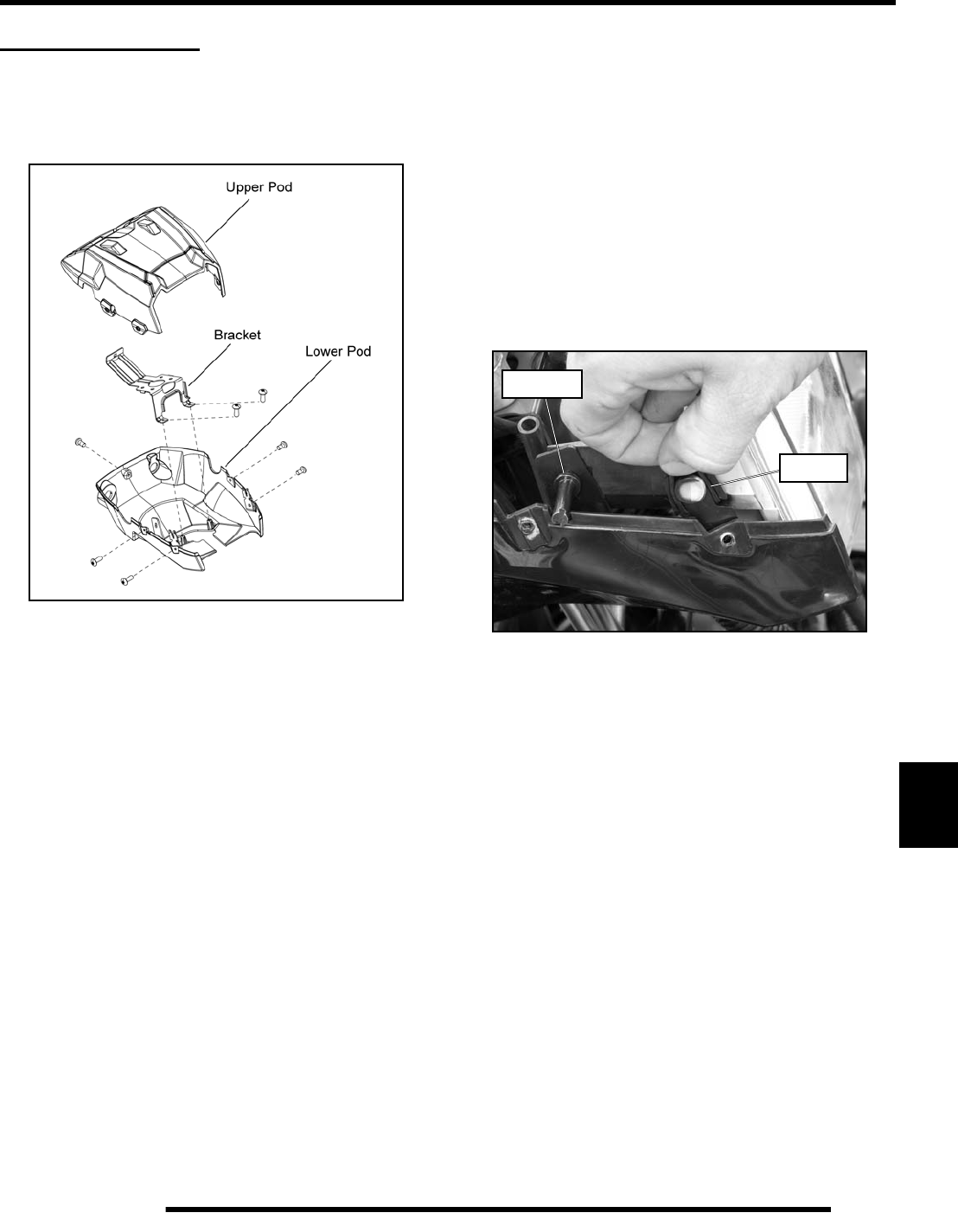
9.7
BODY / FRAME
9
HEADLIGHT POD
Disassembly / Removal
1. Remove the (5) Torx-headed screws retaining the upper
and lower headlight pods.
2. If removing the instrument cluster, unplug the two
harnesses and push the instrument cluster out from the
upper pod.
3. Disconnect and remove the headlight assembly from the
lower pod.
4. Remove the (2) Torx-headed screws retaining the lower
headlight pod to the mount bracket.
5. Disconnect the key switch and 12V outlet. If replacing the
lower pod, remove the key switch and 12V outlet.
IMPORTANT: Take note of all vent line, wire harness
and throttle cable routing for reassembly purposes.
6. Remove the lower pod from the vehicle.
Assembly / Installation
1. Reverse the “Disassembly / Removal” procedure.
NOTE: Make sure to route all vent lines, wire
harness and throttle cable correctly into the lower
headlight pod.
2. When installing the headlight into the lower pod, be sure
to install the O-rings prior to installing the headlight.
3. Place the headlight into the lower pod mounting tabs and
press firmly until the headlight snaps into place.
4. Lift the O-ring up and over the headlight mounting tab to
secure it.
5. Reinstall the adjustment screw.
6. Properly align the upper headlight after reassembly.
Adjuster
O-Ring
PartShark.com
877-999-5686
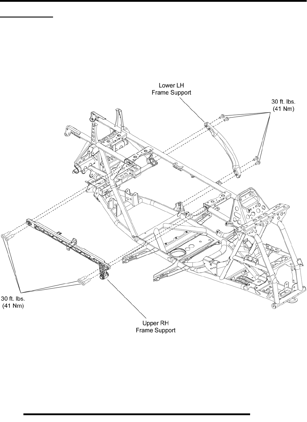
9.8
BODY / FRAME
MAIN FRAME
Frame Support Exploded View
PartShark.com
877-999-5686
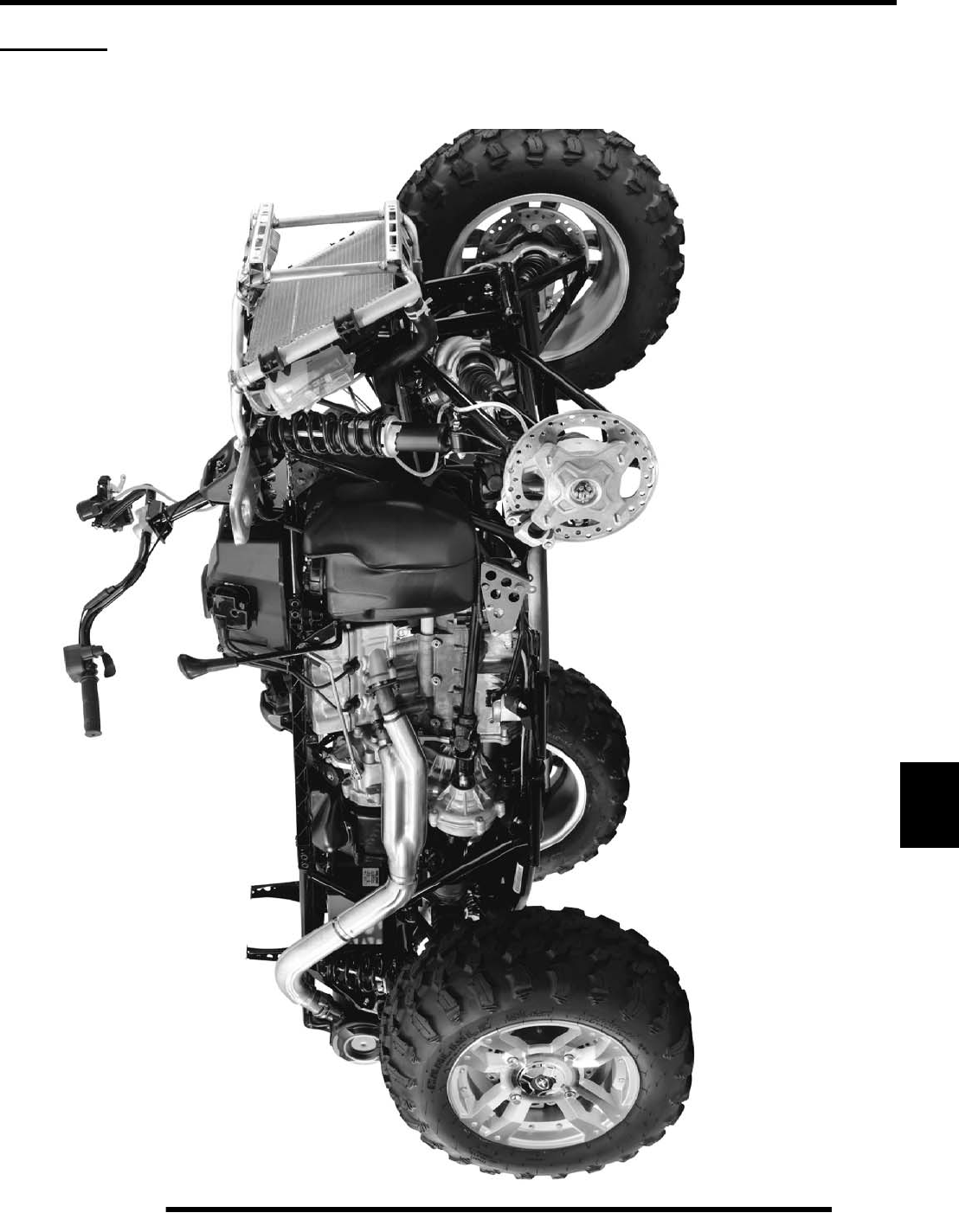
9.9
BODY / FRAME
9
CHASSIS
Body Plastic Removed View
PartShark.com
877-999-5686

NOTES
BODY / FRAME
9.10
PartShark.com
877-999-5686

STEERING / SUSPENSION
10.1
CHAPTER 10
STEERING / SUSPENSION
10
GENERAL SPECIFICATIONS. . . . . . . . . . . . . . . . . . . . . . . . . . . . . . . . . . . . . . . . . . . . . 10.2
TORQUE SPECIFICATIONS . . . . . . . . . . . . . . . . . . . . . . . . . . . . . . . . . . . . . . . . . . . . . 10.2
HANDLEBAR. . . . . . . . . . . . . . . . . . . . . . . . . . . . . . . . . . . . . . . . . . . . . . . . . . . . . . . . . . 10.2
REMOVAL / REPLACEMENT . . . . . . . . . . . . . . . . . . . . . . . . . . . . . . . . . . . . . . . . . . . . 10.2
INSTALLATION . . . . . . . . . . . . . . . . . . . . . . . . . . . . . . . . . . . . . . . . . . . . . . . . . . . . . . . 10.3
STEERING . . . . . . . . . . . . . . . . . . . . . . . . . . . . . . . . . . . . . . . . . . . . . . . . . . . . . . . . . . . 10.3
STEERING POST REMOVAL . . . . . . . . . . . . . . . . . . . . . . . . . . . . . . . . . . . . . . . . . . . . 10.3
STEERING POST INSTALLATION . . . . . . . . . . . . . . . . . . . . . . . . . . . . . . . . . . . . . . . . 10.4
STEERING EXPLODED VIEW. . . . . . . . . . . . . . . . . . . . . . . . . . . . . . . . . . . . . . . . . . . . 10.5
STEERING (EPS MODELS) . . . . . . . . . . . . . . . . . . . . . . . . . . . . . . . . . . . . . . . . . . . . . . 10.6
UPPER STEERING POST REMOVAL / INSTALLATION . . . . . . . . . . . . . . . . . . . . . . . 10.6
POWER STEERING UNIT REMOVAL. . . . . . . . . . . . . . . . . . . . . . . . . . . . . . . . . . . . . . 10.7
POWER STEERING UNIT INSTALLATION. . . . . . . . . . . . . . . . . . . . . . . . . . . . . . . . . . 10.8
STEERING EXPLODED VIEW (EPS MODELS) . . . . . . . . . . . . . . . . . . . . . . . . . . . . . 10.10
STEERING TIE ROD. . . . . . . . . . . . . . . . . . . . . . . . . . . . . . . . . . . . . . . . . . . . . . . . . . . 10.11
TIE ROD / TIE ROD END REPLACEMENT . . . . . . . . . . . . . . . . . . . . . . . . . . . . . . . . . 10.11
FRONT A-ARMS . . . . . . . . . . . . . . . . . . . . . . . . . . . . . . . . . . . . . . . . . . . . . . . . . . . . . . 10.12
EXPLODED VIEW . . . . . . . . . . . . . . . . . . . . . . . . . . . . . . . . . . . . . . . . . . . . . . . . . . . . 10.12
REMOVAL / REPLACEMENT . . . . . . . . . . . . . . . . . . . . . . . . . . . . . . . . . . . . . . . . . . . 10.13
BALL JOINT SERVICE . . . . . . . . . . . . . . . . . . . . . . . . . . . . . . . . . . . . . . . . . . . . . . . . . 10.14
REMOVAL . . . . . . . . . . . . . . . . . . . . . . . . . . . . . . . . . . . . . . . . . . . . . . . . . . . . . . . . . . 10.14
INSTALLATION . . . . . . . . . . . . . . . . . . . . . . . . . . . . . . . . . . . . . . . . . . . . . . . . . . . . . . 10.15
REAR A-ARMS . . . . . . . . . . . . . . . . . . . . . . . . . . . . . . . . . . . . . . . . . . . . . . . . . . . . . . . 10.16
EXPLODED VIEW . . . . . . . . . . . . . . . . . . . . . . . . . . . . . . . . . . . . . . . . . . . . . . . . . . . . 10.16
REMOVAL / INSTALLATION . . . . . . . . . . . . . . . . . . . . . . . . . . . . . . . . . . . . . . . . . . . . 10.17
REAR STABILIZER BAR. . . . . . . . . . . . . . . . . . . . . . . . . . . . . . . . . . . . . . . . . . . . . . . . 10.18
EXPLODED VIEW . . . . . . . . . . . . . . . . . . . . . . . . . . . . . . . . . . . . . . . . . . . . . . . . . . . . 10.18
LINKAGE REMOVAL / INSTALLATION . . . . . . . . . . . . . . . . . . . . . . . . . . . . . . . . . . . . 10.19
STABILIZER BAR REMOVAL / INSTALLATION . . . . . . . . . . . . . . . . . . . . . . . . . . . . . 10.19
SHOCKS / SPRINGS. . . . . . . . . . . . . . . . . . . . . . . . . . . . . . . . . . . . . . . . . . . . . . . . . . . 10.20
EXPLODED VIEW . . . . . . . . . . . . . . . . . . . . . . . . . . . . . . . . . . . . . . . . . . . . . . . . . . . . 10.20
SHOCK REMOVAL / INSTALLATION . . . . . . . . . . . . . . . . . . . . . . . . . . . . . . . . . . . . . 10.20
SHOCK / SPRING REPLACEMENT . . . . . . . . . . . . . . . . . . . . . . . . . . . . . . . . . . . . . . 10.20
PartShark.com
877-999-5686
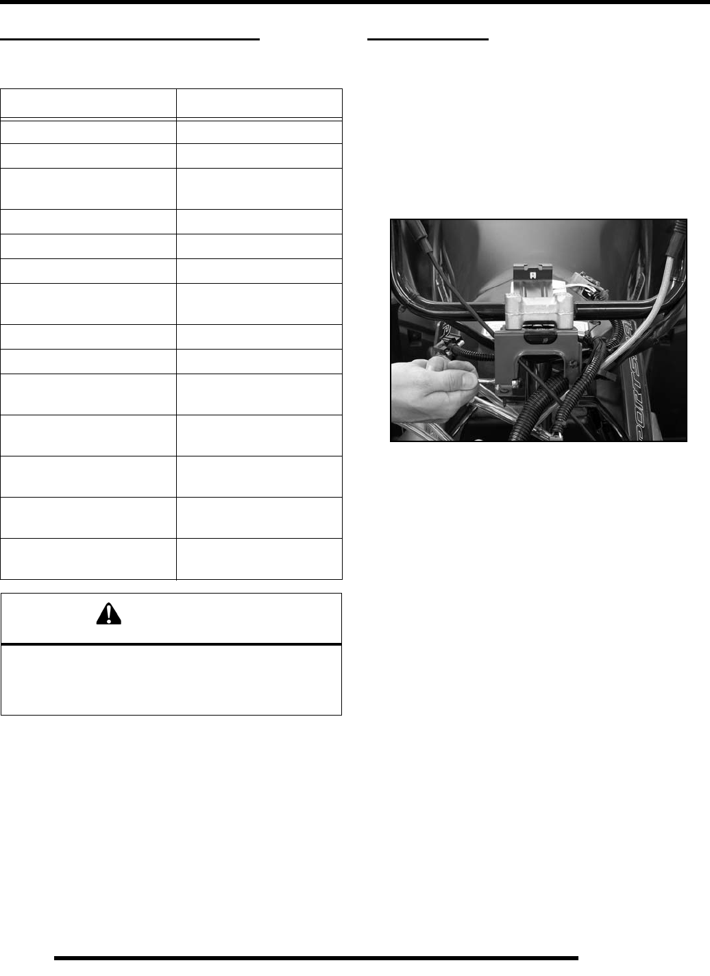
10.2
STEERING / SUSPENSION
GENERAL SPECIFICATIONS
Torque Specifications
NOTE: Refer to exploded views throughout this
chapter for more torque specifications, component
identification, and location of components.
HANDLEBAR
Removal / Replacement
1. Remove the upper and lower headlight pods from the
handlebar bracket (see Chapter 9).
IMPORTANT: Take note of all vent line, wire harness
and throttle cable routing for reassembly purposes.
2. Remove the (4) fasteners retaining the handlebar bracket
and block to the steering post.
3. Remove the handlebar assembly from the steering post
IMPORTANT: Take care not to bend the throttle cable
or brake line while the handlebar is removed.
4. If replacing the handlebar:
• Remove the RH and LH controls
• Remove the hand grips
• Pry open the upper and lower handlebar blocks and
remove them from the handlebar
Item Specification
Aluminum Wheels 75 ft. lbs. (102 Nm)
Steel Wheels 45 ft. lbs. (61 Nm)
Wheel Hub Retaining Nuts
(front and rear) 80 ft. lbs. (108 Nm)
Steering Post to Bulkhead 20 ft. lbs. (27 Nm)
Steering Post to Gearcase 22 ft. lbs. (30 Nm)
Tie Rod Jam Nuts 12 ft. lbs. (16 Nm)
Tie Rod to Bearing Carrier
Tie Rod to Steering Frog 44 ft. lbs. (60 Nm)
Handlebar Block Bolts 14 ft. lbs. (19 Nm)
Shock Mounting Bolts 37 ft. lbs. (50 Nm)
Front Ball Joint Pinch Bolts
(upper and lower) 21 ft. lbs. (28 Nm)
Front A-arm to Frame Bolts
(upper and lower) 40 ft. lbs. (54 Nm)
Rear A-arm to Frame Bolts
(upper and lower) 45 ft. lbs. (61 Nm)
Rear Upper A-Arm to
Bearing Carrier Bolts 40 ft. lbs. (54 Nm)
Rear Lower A-Arm to
Bearing Carrier Bolts 45 ft. lbs. (61 Nm)
CAUTION
Locking nuts, and bolts with pre-applied locking agent
should be replaced if removed.
The self-locking properties of the nut or bolt
are reduced or destroyed during removal
PartShark.com
877-999-5686
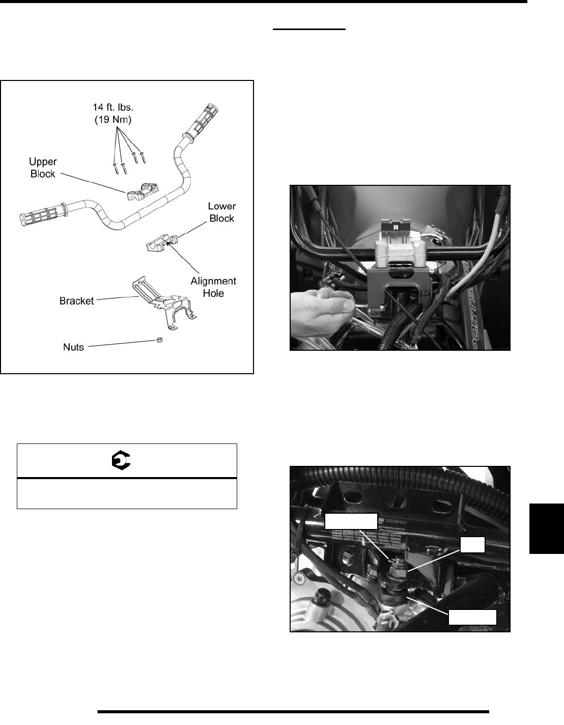
10.3
STEERING / SUSPENSION
10
Installation
1. Locate the the alignment pin on the bottom side of the
upper block. The pin should line up with the alignment
hole in the lower block and should face the front.
2. Position the handlebar properly and install the (4) bolts.
3. Evenly tighten the pin side (front) bolts first. Torque the
(2) front bolts to specification.
4. Install the rear bolts and tighten evenly. Torque the (2) rear
bolts to specification.
NOTE: There will be a slight gap on the backside of
the handlebar blocks after installation.
5. If handlebar was replaced:
• Install the hand grips
• Install the RH and LH controls
6. Reassemble the headlight pod (see Chapter 9) .
NOTE: Make sure to route all vent lines, wire
harness and throttle cable correctly into the lower
headlight pod.
STEERING
Steering Post Removal
1. Remove the front rack and front cover (see Chapter 9).
2. Remove the upper and lower headlight pods from the
handlebar bracket (see Chapter 9).
IMPORTANT: Take note of all vent line, wire harness
and throttle cable routing for reassembly purposes.
3. Remove the (4) fasteners retaining the handlebar bracket
and block to the steering post.
4. Carefully remove the handlebar assembly from the steering
post and place it on the front cab.
IMPORTANT: Take care not to bend the throttle cable
or brake line while the handlebar is removed.
5. Remove the cotter pin and nut from each tie rod end at the
steering post frog.
= T
Handlebar Bolts:
14 ft. lbs. (19 Nm)
Nut
Cotter Pin
Rod End
PartShark.com
877-999-5686
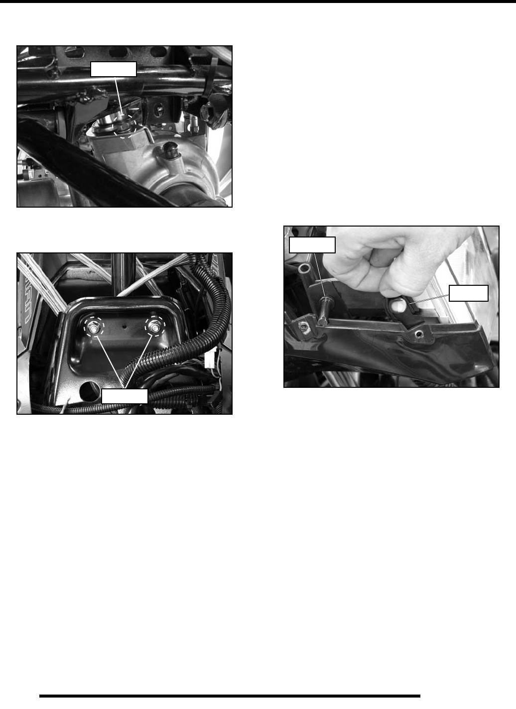
10.4
STEERING / SUSPENSION
6. Remove the (2) bolts retaining the lower steering post
bracket to the front gearcase.
7. Remove the (2) fasteners retaining the upper steering post
bushing bracket.
8. Lift the steering post assembly up from the front gearcase
and carefully remove it from the chassis.
Steering Post Installation
1. Reverse the “Steering Post Removal” procedure to
reinstall the steering post. Refer to the “Steering Exploded
View” for torque values.
NOTE: Make sure to route all vent lines, wire
harness and throttle cable correctly into the lower
headlight pod.
2. When installing the headlight into the lower pod, be sure
to install the O-rings prior to installing the headlight.
3. Place the headlight into the lower pod mounting tabs and
press firmly until the headlight snaps into place.
4. Lift the O-ring up and over the headlight mounting tab to
secure it.
5. Reinstall the adjustment screw and be sure to adjust the
upper headlight after reassembly.
NOTE: Refer to Chapter 9 when reassembling the
upper and lower headlight pods.
Remove
Remove
Adjuster
O-Ring
PartShark.com
877-999-5686
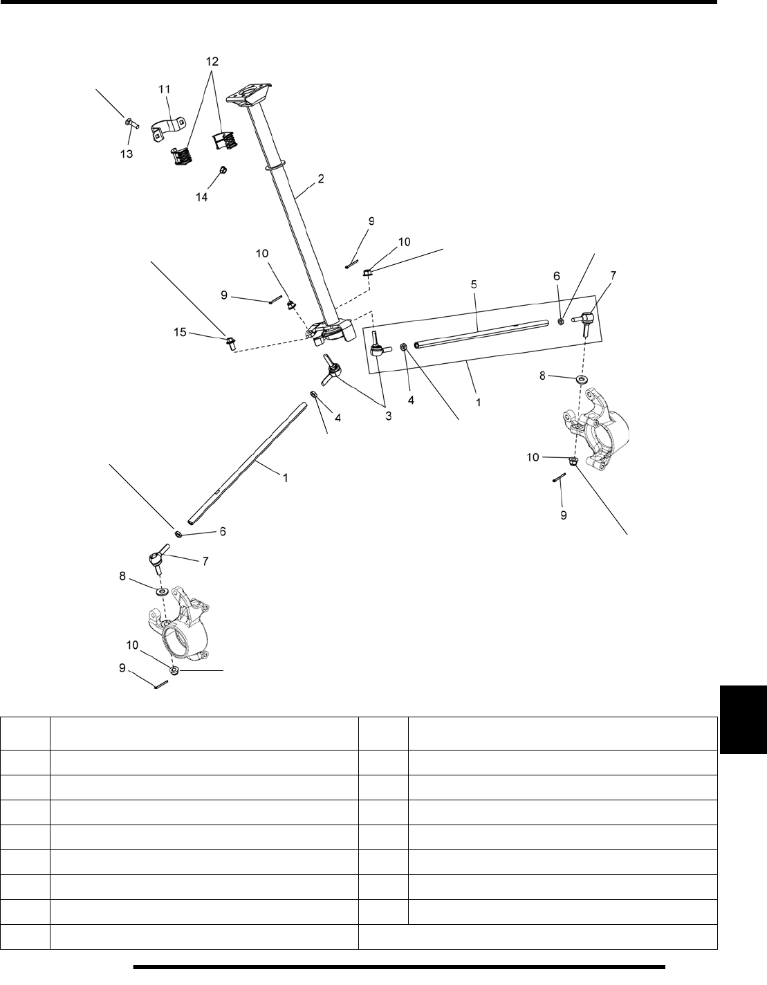
10.5
STEERING / SUSPENSION
10
Steering Exploded View
REF.DESCRIPTION REF.DESCRIPTION
1 Tie Rod 9 Cotter Pin
2 Steering Post 10 Nut
3 Rod End, RH 11 Upper Steering Bracket
4 Jam Nut, RH 12 Upper Steering Bushing
5 Tie Rod Assembly 13 Carriage Bolt
6 Jam Nut LH 14 Nut
7 Rod End, LH 15 Bolt
8 Washer
20 ft. lbs.
(27 Nm)
22 ft. lbs.
(30 Nm)
12 ft. lbs.
(16 Nm)
44 ft. lbs.
(60 Nm)
12 ft. lbs.
(16 Nm)
44 ft. lbs.
(60 Nm)
44 ft. lbs.
(60 Nm)
12 ft. lbs.
(16 Nm) 12 ft. lbs.
(16 Nm)
PartShark.com
877-999-5686
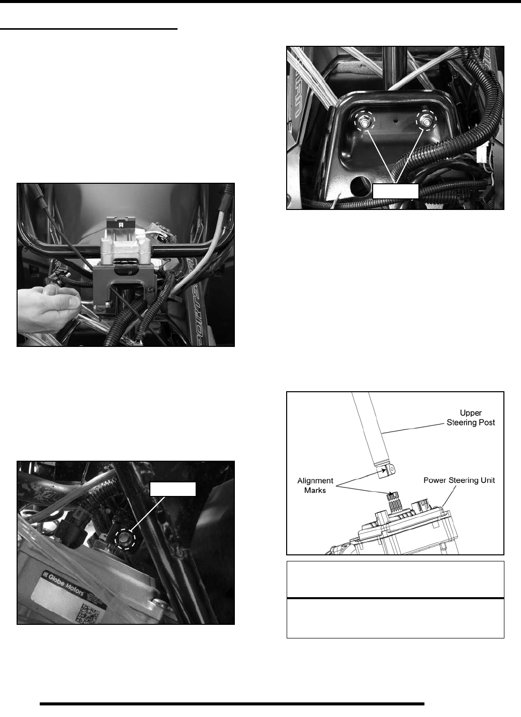
10.6
STEERING / SUSPENSION
STEERING (EPS MODELS)
Upper Steering Post Removal
1. Remove the front rack and front cover (see Chapter 9).
2. Remove the upper and lower headlight pods from the
handlebar bracket (see Chapter 9).
IMPORTANT: Take note of all vent line, wire harness
and throttle cable routing for reassembly purposes.
3. Remove the (4) fasteners retaining the handlebar bracket
and block to the steering post.
4. Carefully remove the handlebar assembly from the steering
post and place it on the front cab.
IMPORTANT: Take care not to bend the throttle cable
or brake line while the handlebar is removed.
5. Remove the bolt retaining the upper steering post to the
power steering unit.
6. Remove the (2) fasteners retaining the upper steering post
bushing bracket.
7. Lift the upper steering post up from the power steering unit
remove it from the chassis.
Upper Steering Post Installation
1. Reverse the “Upper Steering Post Removal” procedure to
reinstall the steering post.
2. Apply anti-seize to the shaft splines to aid assembly.
3. Align the mark on the upper steering post with the skip
tooth spline on the upper power steering shaft upon
installation.
4. Refer to “Steering Exploded View (EPS Models)” for
torque values.
Remove
CAUTION
Striking the steering post can permanently
damage the EPS unit and cause
a Power Steering Fault.
Remove
PartShark.com
877-999-5686
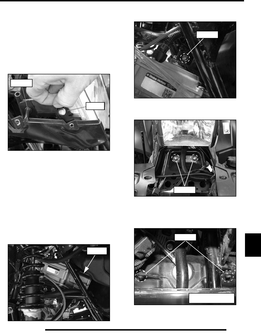
10.7
STEERING / SUSPENSION
10
NOTE: Make sure to route all vent lines, wire
harness and throttle cable correctly into the lower
headlight pod.
5. When installing the headlight into the lower pod, be sure
to install the O-rings prior to installing the headlight.
6. Place the headlight into the lower pod mounting tabs and
press firmly until the headlight snaps into place.
7. Lift the O-ring up and over the headlight mounting tab to
secure it.
8. Reinstall the adjustment screw and be sure to adjust the
upper headlight after reassembly.
NOTE: Refer to Chapter 9 when reassembling the
upper and lower headlight pods.
Power Steering Unit Removal
1. Remove the front rack and front cover (see Chapter 9).
2. Remove both front mud guards and right-hand footwell
(see Chapter 9).
3. Locate the power steering unit through the front left wheel
well area.
4. Remove the bolt retaining the upper steering post to the
power steering unit.
5. Remove the (2) fasteners retaining the upper steering post
bushing bracket.
6. Lift the upper steering post up from the power steering unit.
7. Locate and remove the two fuel tank mounting screws
through the steering post opening.
8. Disconnect the fuel line and wire harness from the fuel
pump (see Chapter 3).
Adjuster
O-Ring
PS Unit
Remove
Remove
Remove
Shown with steering post
removed for clarity.
PartShark.com
877-999-5686
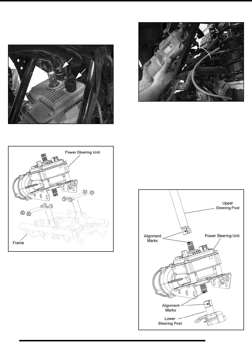
10.8
STEERING / SUSPENSION
9. Loosen the hose clamp and remove the fuel inlet hose from
the fuel tank. Cover the tank inlet and remove the fuel tank
assembly out the right side (see Chapter 3).
10. Disconnect the (2) electrical harnesses from the power
steering unit.
11. Remove the (4) mounting fasteners that retain the power
steering unit to the frame.
12. Carefully lift the power steering unit up to disengage the
lower steering coupler and remove it from the chassis.
Power Steering Unit Installation
1. Position the vehicle so the front wheels are pointing
straight forward.
2. Clean the lower steering post so the alignment mark is
visible. Mark the skip tooth spline on the lower power
steering shaft.
3. Apply anti-seize to the shaft splines to aid assembly.
4. Align the two marks and install the power steering unit (see
Figure 10-1).
Figure 10-1
PartShark.com
877-999-5686
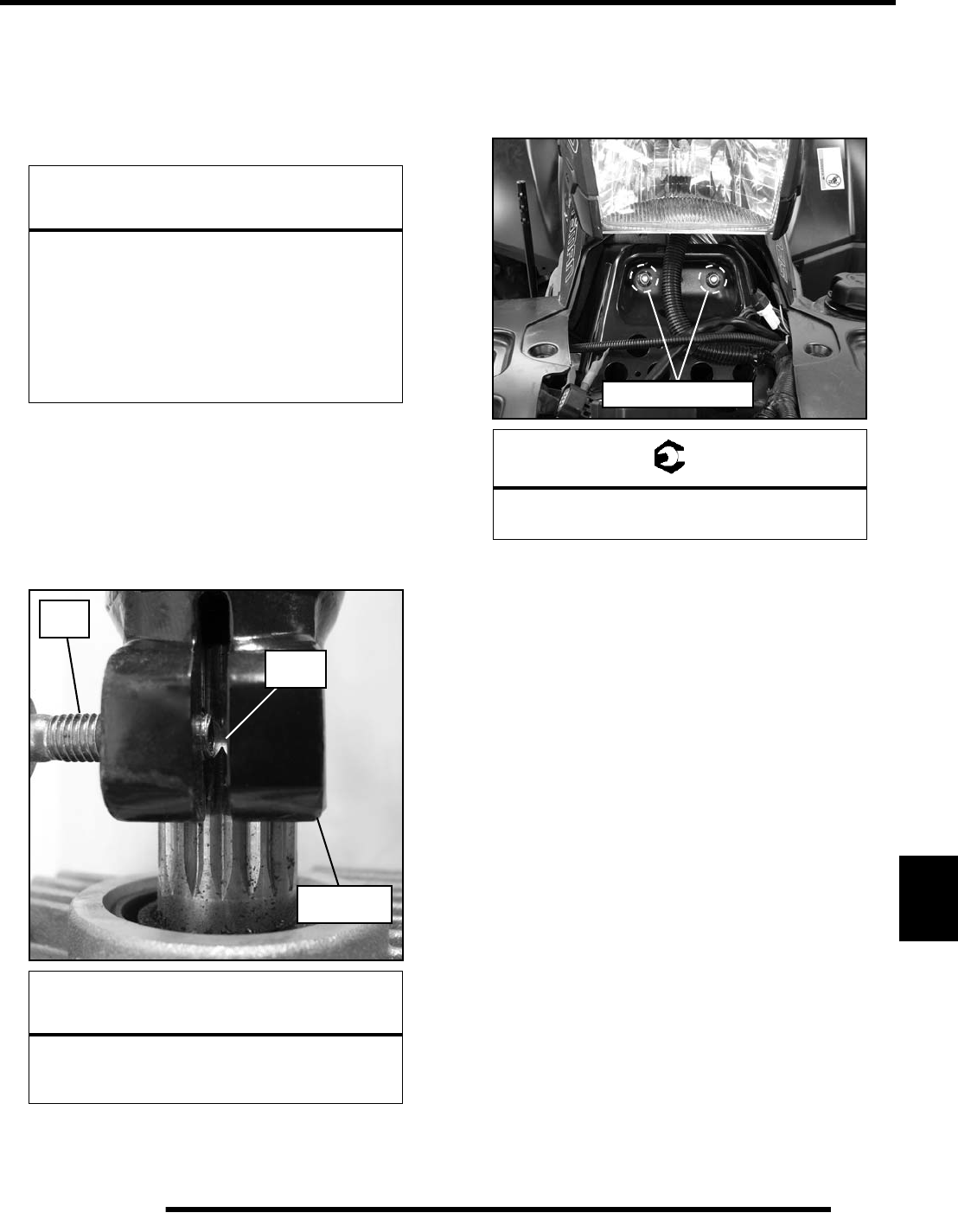
10.9
STEERING / SUSPENSION
10
5. Install the (4) mounting fasteners and torque fasteners to
specification. Refer to “Steering Exploded View (EPS
Models)”.
6. Reconnect the (2) electrical harnesses to the power steering
unit.
7. Align the mark on the upper steering post with the skip
tooth spline on the upper power steering shaft upon
installation (see Figure 10-1).
8. Apply anti-seize to the shaft splines to aid assembly.
9. Position the upper steering post on the shaft so the pinch
bolt is aligned with the recess in the power steering shaft.
10. Install the pinch bolt and torque to specification. Refer to
“Steering Exploded View (EPS Models)”.
11. Install the fuel tank assembly, fuel line and reconnect the
fuel pump harness (see Chapter 3).
12. Reinstall the upper steering post bushing bracket and torque
the (2) fasteners to specification.
13. Turn the ignition key to the “ON” position and move the
handlebar from left to right several times to ensure the
power steering doesn’t bind. If binding occurs:
• Loosen the (4) mounting fasteners
• Move handlebars from left to right several times to
position the power steering unit
• Torque the (4) mounting fasteners to specification and
check the steering operation for binding again
• If no binding is present, proceed; if binding is still
present, repeat this procedure.
14. Install both front mud guards and right-hand footwell (see
Chapter 9).
15. Install the front rack and front cover (see Chapter 9).
CAUTION
The 8-way connector, two rows of four pins,
does not have a channeled lock on both sides,
allowing it to be installed 180° from its intended
position. The connector will not positively
engage or snap into place while in the wrong
position, but can still be installed.
If the connector is not installed correctly, the
Power Steering Unit will not function.
CAUTION
Striking the steering post can permanently
damage the EPS unit and cause
a Power Steering Fault.
Shaft
Recess
Pinch
Bolt
Upper
Steering Post
= T
Steering Post to Bulkhead Bolts:
20 ft. lbs. (27 Nm)
20 ft. lbs. (27 Nm)
PartShark.com
877-999-5686
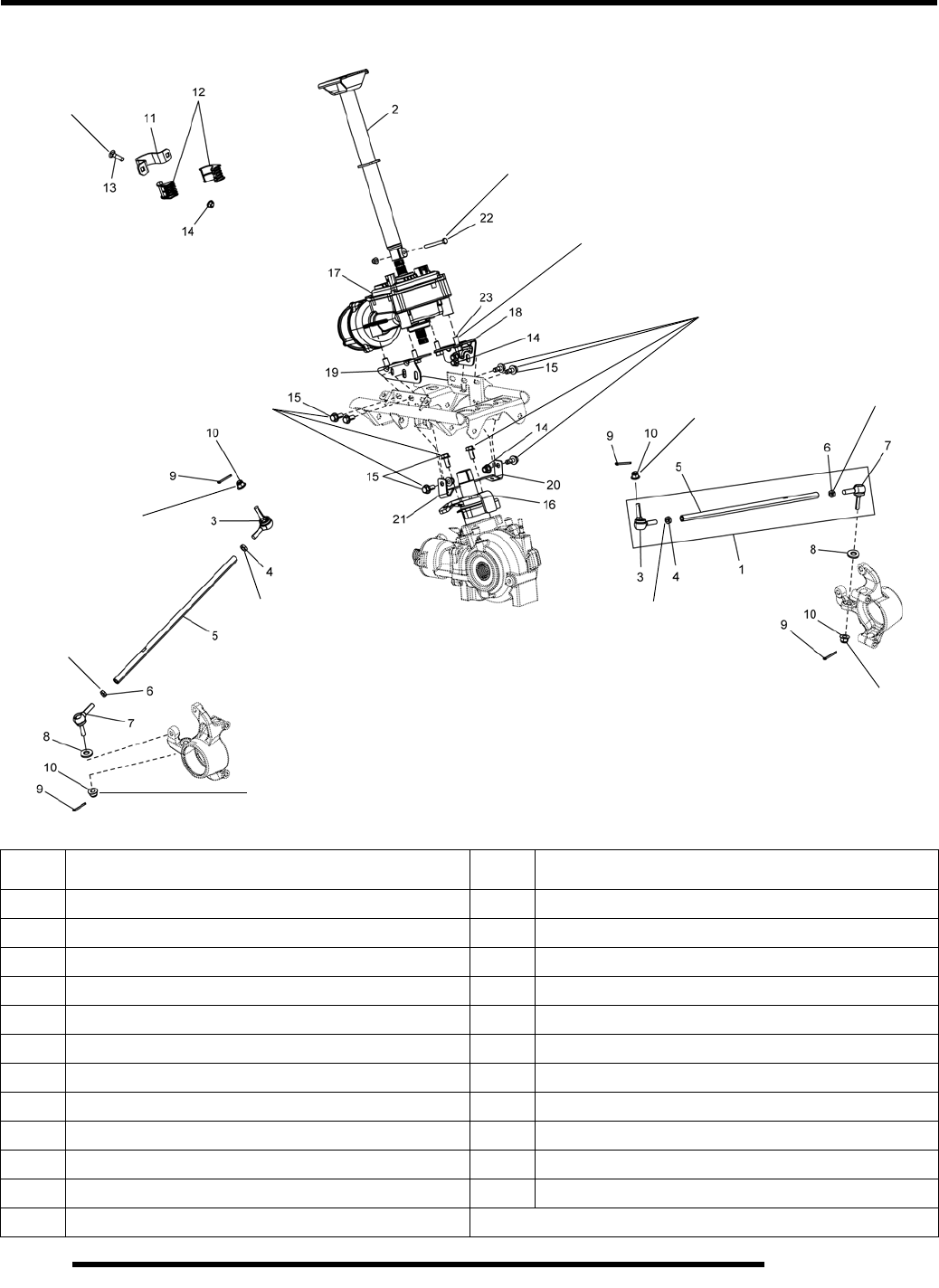
10.10
STEERING / SUSPENSION
Steering Exploded View (EPS Models)
REF.DESCRIPTION REF.DESCRIPTION
1 Tie Rod Assembly 13 Carriage Bolt
2 Upper Steering Post 14 Nut
3 Rod End, RH 15 Bolt
4 Jam Nut, RH 16 Lower Steering Post
5 Tie Rod 17 Power Steering Assembly
6 Jam Nut, LH 18 Power Steering Bracket, LH
7 Rod End, LH 19 Power Steering Bracket, RH
8 Washer 20 Front Drive Bracket, LH
9 Cotter Pin 21 Front Drive Bracket, RH
10 Nut 22 Bolt
11 Upper Steering Bracket 23 Bolt
12 Upper Steering Bushing
20 ft. lbs.
(27 Nm)
22 ft. lbs.
(30 Nm)
12 ft. lbs.
(16 Nm)
44 ft. lbs.
(60 Nm)
12 ft. lbs.
(16 Nm)
44 ft. lbs.
(60 Nm)
44 ft. lbs.
(60 Nm)
12 ft. lbs.
(16 Nm)
12 ft. lbs.
(16 Nm)
44 ft. lbs.
(60 Nm)
22 ft. lbs.
(30 Nm)
15 ft. lbs.
(20 Nm)
30 ft. lbs.
(41 Nm)
PartShark.com
877-999-5686
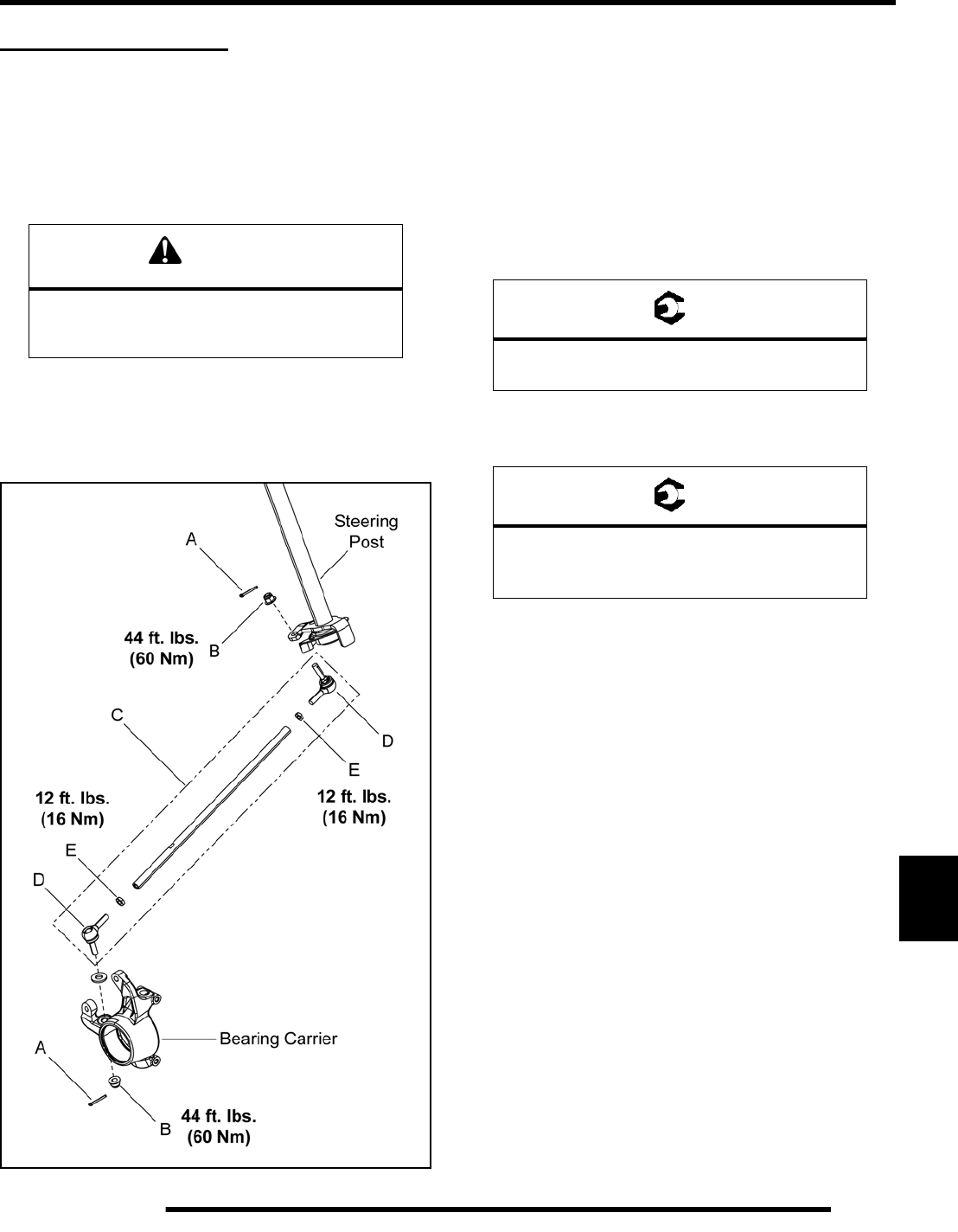
10.11
STEERING / SUSPENSION
10
STEERING TIE ROD
Tie Rod / Tie Rod End Replacement
Use the following procedure to replace the tie rod assembly or
tie rod ends.
1. Elevate front of vehicle and safely support machine under
the frame area.
2. Remove the (4) wheel nuts and remove the front wheel(s).
3. Remove the cotter pins (A) and tie rod end fasteners (B).
4. Remove the tie rod assembly (C).
• If replacing just the tie rod end (D), loosen the jam nut
(E) and remove the rod end.
• Install new rod end and torque jam nuts to specification.
5. Install the new tie rod assembly (C).
6. Install the rod ends and fasteners (B) in the proper
orientation (see illustration).
7. Torque the tie rod end fasteners to specification and install
new cotter pins.
8. Install the front wheel(s) and wheel nuts. Torque wheel
nuts to specification.
9. Check wheel toe alignment and adjust as necessary (see
Chapter 2).
CAUTION
Serious injury may result if machine tips or falls.
Be sure machine is secure before beginning this
service procedure. Always wear eye protection.
= T
Tie Rod End Fastener:
44 ft. lbs. (60 Nm)
= T
Wheel Nuts:
Steel Wheels: 45 ft. lbs. (61 Nm)
Aluminum Wheels: 75 ft. lbs. (102 Nm)
PartShark.com
877-999-5686
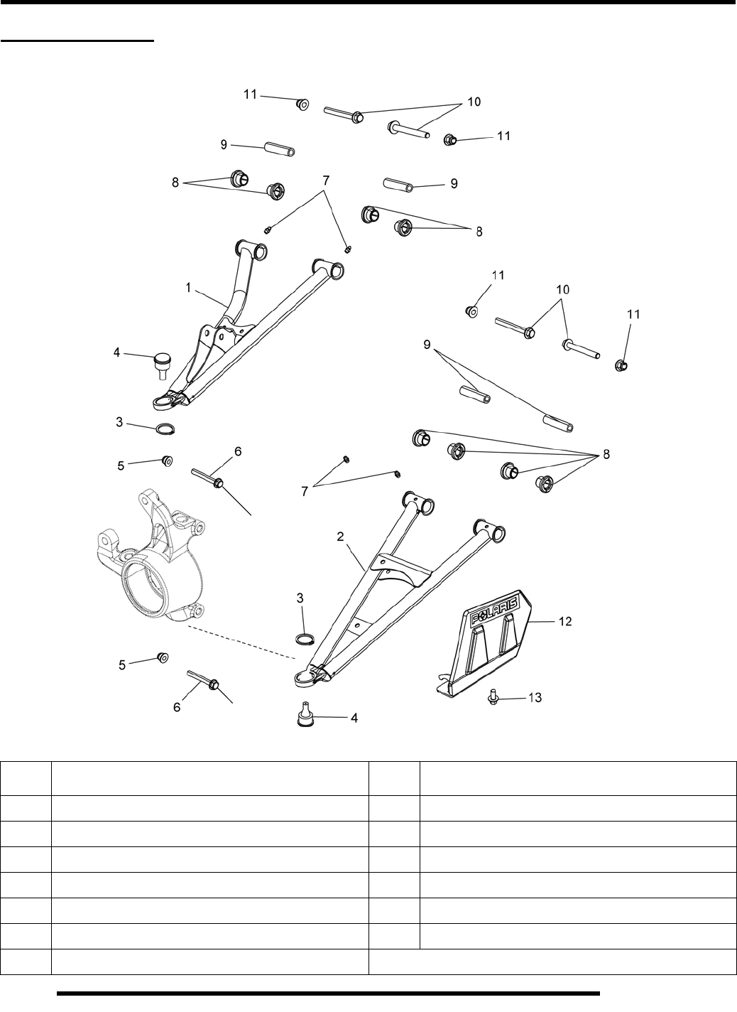
10.12
STEERING / SUSPENSION
FRONT A-ARMS
Exploded View
REF.DESCRIPTION REF.DESCRIPTION
1 Upper A-arm 8 Bushing
2 Lower A-arm 9 Pivot Shaft
3 Retaining Ring 10 Bolt
4 Ball Joint 11 Nut
5 Nut 12 CV Shield
6 Bolt 13 Screw
7 Grease Fitting
40 ft. lbs.
(54 Nm)
21 ft. lbs.
(28 Nm)
40 ft. lbs.
(54 Nm)
21 ft. lbs.
(28 Nm)
PartShark.com
877-999-5686
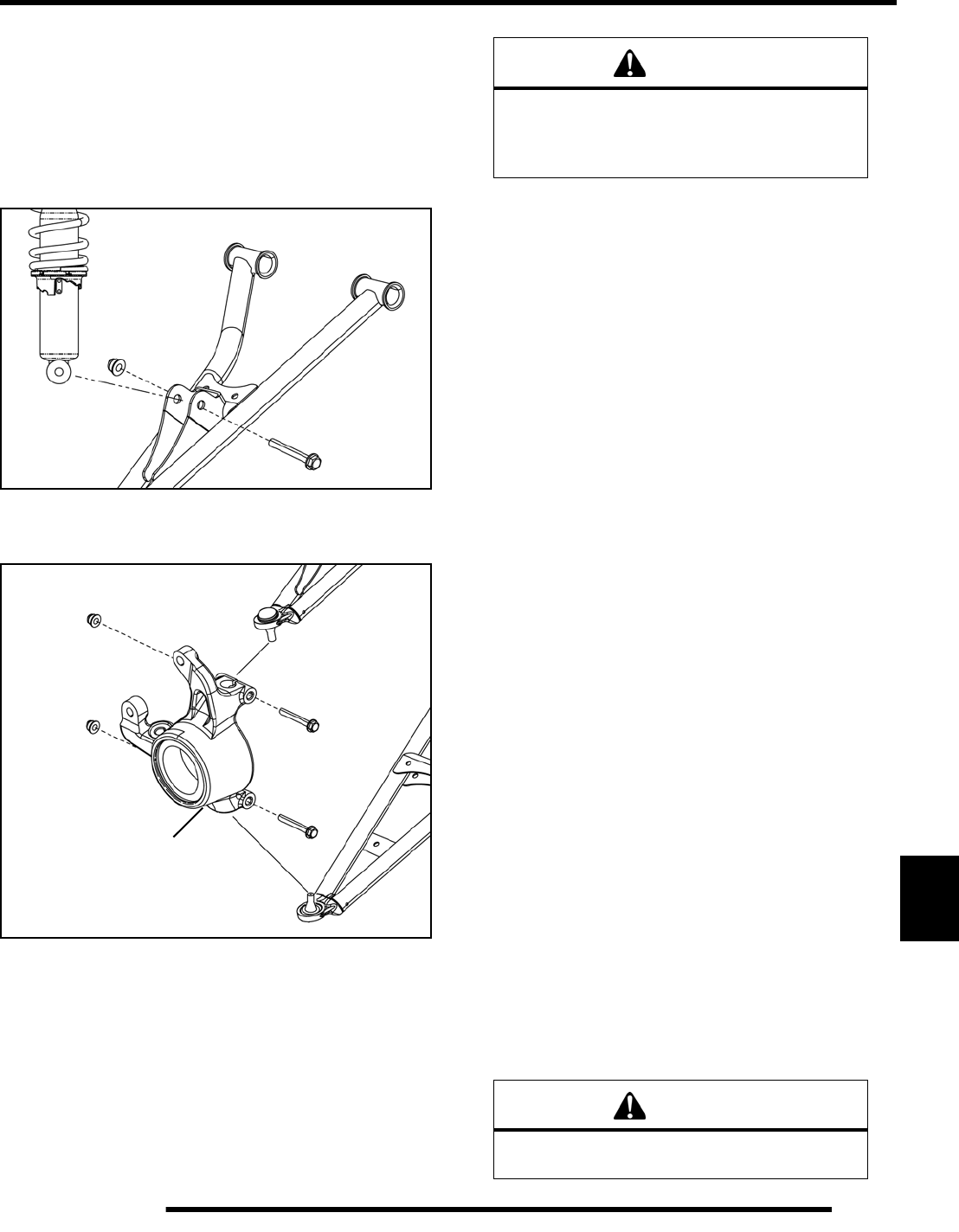
10.13
STEERING / SUSPENSION
10
Removal / Replacement
The following procedure details upper and lower A-arm
removal and replacement on one side of the vehicle.
1. Elevate and safely support the front of the vehicle and
remove the front wheel.
2. Remove the lower shock fastener from the upper A-arm.
3. Remove the upper ball joint pinch bolt from the front
bearing carrier (see Figure 10-2).
4. Remove the brake line retainer from the upper A-arm.
5. Using a soft face hammer, tap on bearing carrier to loosen
the upper ball joint end while lifting upward on the upper
A-arm. Completely remove the ball joint end from the
bearing carrier.
6. Remove the upper A-arm through-bolt fasteners and
remove the A-arm from the vehicle (see “Exploded View”).
7. Examine A-arm bushings and pivot shafts (see “Exploded
View”). Replace if worn and discard the hardware.
8. If not replacing the A-arm, thoroughly clean the A-arm and
pivot shafts.
9. Install new ball joint into A-arm. Refer to “Ball Joint
Replacement” section.
10. Insert new bushings and pivot shafts into the new A-arm.
11. Install new upper A-arm assembly onto vehicle frame.
Torque new bolts to 40 ft. lbs. (54 Nm).
12. Insert upper A-arm ball joint end into the bearing carrier.
Install the upper ball joint pinch bolt into the bearing carrier
and torque bolt to 21 ft. lbs. (28 Nm).
13. Attach shock to A-arm with new fastener. Torque lower
shock bolt to 37 ft. lbs. (50 Nm).
14. Remove the lower ball joint pinch bolt from the front
bearing carrier (see Figure 10-2).
15. Using a soft face hammer, tap on bearing carrier to loosen
the lower A-arm ball joint end while pushing downward on
the lower A-arm. Completely remove the ball joint end
from the bearing carrier.
16. Remove the lower A-arm through-bolt fasteners and
remove the lower A-arm from the vehicle.
17. Examine A-arm bushings and pivot shafts (see “Exploded
View”). Replace if worn and discard the hardware.
18. If not replacing the A-arm, thoroughly clean the A-arm and
pivot shafts.
19. Install new ball joint into A-arm. Refer to “Ball Joint
Replacement” section.
20. Insert new bushings and pivot shafts into the new A-arm.
21. Install new lower A-arm assembly onto vehicle frame.
Torque new bolts to 40 ft. lbs. (54 Nm).
22. Insert lower A-arm ball joint end into the bearing carrier.
Install the lower ball joint pinch bolt into the bearing carrier
and torque bolt to 21 ft. lbs. (28 Nm).
23. Grease all (4) A-arm grease fittings after reassembly.
Figure 10-2
Front
Bearing Carrier
WARNING
The locking agent on the existing bolts was
destroyed during removal. DO NOT reuse old
hardware. Serious injury or death could result if
fasteners come loose during operation.
WARNING
Upon A-arm installation completion, test vehicle
at low speeds before putting into service.
PartShark.com
877-999-5686
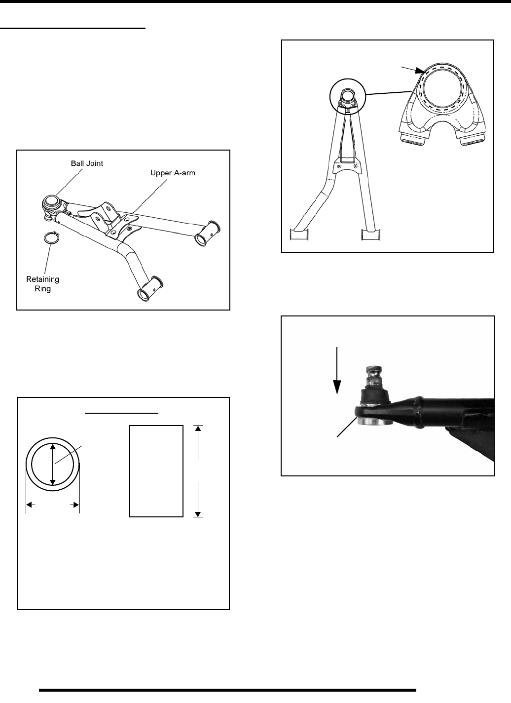
10.14
STEERING / SUSPENSION
BALL JOINT SERVICE
Removal
IMPORTANT: Do not reuse a ball joint if it has been
removed for any reason. If removed, it must be
replaced. Use this removal procedure only when
replacing the ball joint.
1. The A-arm must be removed to perform this procedure
(see “FRONT A-ARMS - Removal / Replacement”).
2. Remove the retaining ring from the ball joint.
3. A driver must be used for the removal of the ball joint. Use
the dimensions below to fabricate or locate the correct size
driver to use in the following process.
4. Use a press and correct size driver to remove the ball joint
from the A-arm.
NOTE: The driver must fit the ball joint housing in
the A-arm. This will allow the ball joint to be properly
pressed out of the A-arm without damaging the A-
arm.
Installation
1. Place the A-arm in the correct position for ball joint
installation. Face the A-arm end flat on top of the driver.
Carefully drive the ball joint into place until the ball joint
1.75 in.
1.375 in.
(3.49 cm)
3 in.
(7.62 cm)
Driver Dimensions
- Outside diameter of driver cannot be any
larger than 1.75 in. (4.45 cm).
- Inside diameter cannot be any smaller than
1.375 in. (3.49 cm).
- Driver must be at least 3 in. (7.62 cm) tall.
(4.45 cm)
Correct
Driver Placement
The driver must fit the
inside diameter of the
Upper A-arm Shown
A-arm end.
Press out of the A-arm
in this direction
Upper A-arm Shown
Place driver HERE
to support A-arm
PartShark.com
877-999-5686
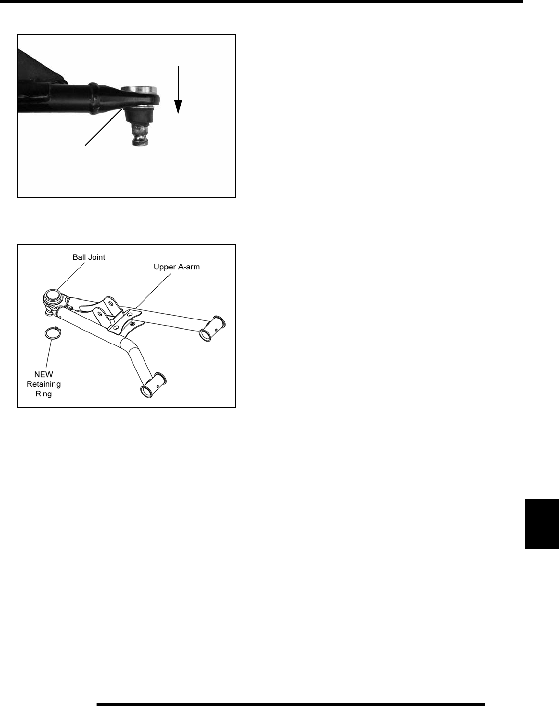
10.15
STEERING / SUSPENSION
10
is properly seated.
2. After the new ball joint is installed into the A-arm, install
a new retaining ring.
3. Reinstall the A-arm (see “FRONT A-ARMS - Removal /
Replacement”).
4. Repeat the ball joint service procedure for any additional
A-arm ball joint replacements.
Press into the A-arm
in this direction
Upper A-arm Shown
Place driver HERE
to support A-arm
PartShark.com
877-999-5686
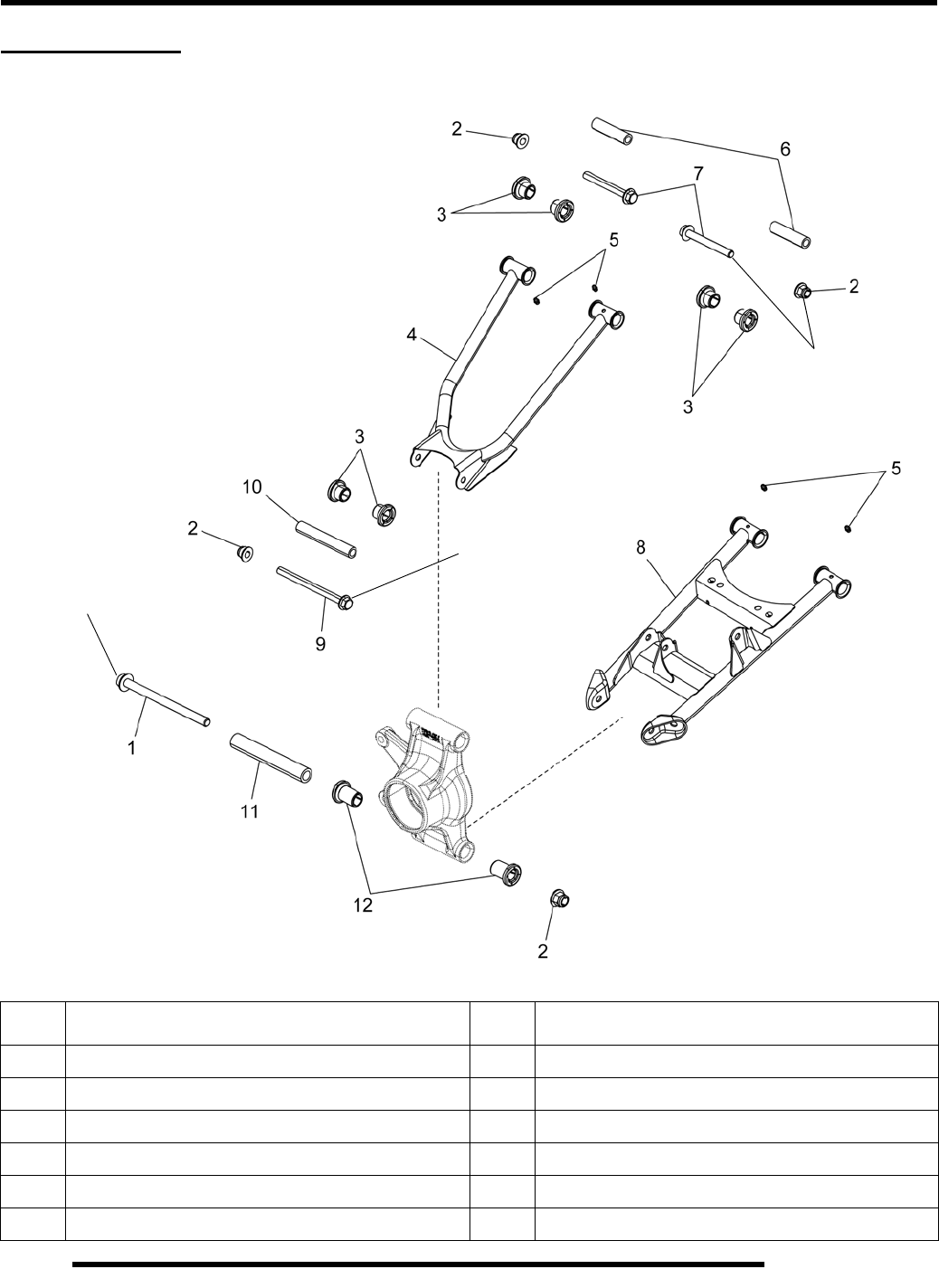
10.16
STEERING / SUSPENSION
REAR A-ARMS
Exploded View
REF.DESCRIPTION REF.DESCRIPTION
1Bolt 7Bolt
2 Nut 8 Lower A-arm
3 Bushing 9 Bolt
4 Upper A-arm 10 Pivot Shaft, Upper
5 Grease Fitting 11 Pivot Shaft, Lower
6 Pivot Shaft 12 Bushing, Lower
45 ft. lbs.
(61 Nm)
40 ft. lbs.
(54 Nm)
45 ft. lbs.
(61 Nm)
PartShark.com
877-999-5686
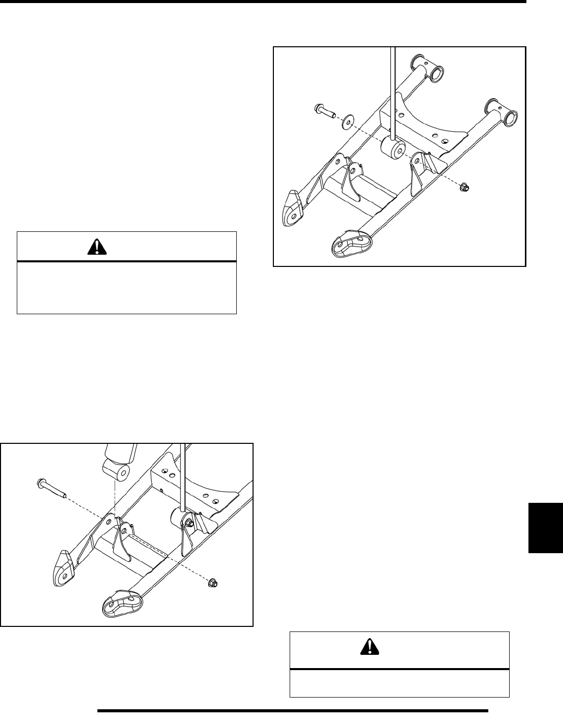
10.17
STEERING / SUSPENSION
10
Removal
The following procedure details upper and lower A-arm
removal and replacement on one side of the vehicle.
1. Elevate and safely support the rear of the vehicle and
remove the rear wheel.
Upper A-arm Removal
2. Remove the through-bolt fastener attaching the upper A-
arm to the bearing carrier (see “Exploded View”).
3. Remove the through-bolt fasteners attaching the upper A-
arm to the frame and remove the A-arm from the vehicle.
4. Examine A-arm and bearing carrier bushings and pivot
shafts (see “Exploded View”). Replace if worn and discard
the hardware.
5. If not replacing the A-arm, thoroughly clean the a-arm and
pivot shafts.
6. Insert new bushings and pivot shafts into the new A-arm.
Lower A-arm Removal
7. Remove the through-bolt fastener attaching the lower A-
arm to the bearing carrier (see “Exploded View”).
8. Remove the lower shock fastener from the lower A-arm.
9. Remove the brake line retainer from the lower A-arm.
10. Remove the fastener retaining the stabilizer linkage to the
lower A-arm.
11. Remove the through-bolt fasteners attaching the lower A-
arm to the frame and remove the A-arm from the vehicle.
12. Examine A-arm and bearing carrier bushings and pivot
shafts (see “Exploded View”). Replace if worn and discard
the hardware.
13. If not replacing the A-arm, thoroughly clean the a-arm and
pivot shafts.
14. Insert new bushings and pivot shafts into the new A-arm.
Installation
1. Install upper and lower A-arm assemblies onto the vehicle
frame. Torque new fasteners to 45 ft. lbs. (61 Nm).
2. Grease all (4) A-arm grease fittings after reassembly.
3. Attach lower A-arm to bearing carrier. Torque new
fastener to 45 ft. lbs. (61 Nm).
4. Attach upper A-arm to bearing carrier. Torque new
fasteners to 40 ft. lbs. (54 Nm).
5. Grease both rear bearing carrier fittings after reassembly.
6. Route brake line on top of lower A-arm and install retainer.
7. Reinstall the lower portion of the shock and lower portion
of the stabilizer linkage to the lower A-arm. Torque
mounting fasteners to 37 ft. lbs. (50 Nm).
8. Install wheel and torque wheel nuts to specification.
WARNING
The locking agent on the existing bolts was
destroyed during removal. DO NOT reuse old
hardware. Serious injury or death could result if
fasteners come loose during operation.
WARNING
Upon A-arm installation completion, test vehicle
at low speeds before putting into service.
PartShark.com
877-999-5686
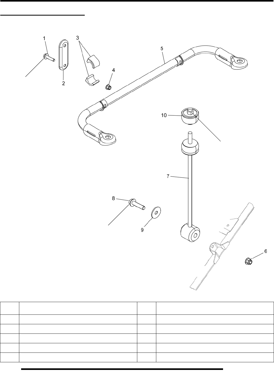
10.18
STEERING / SUSPENSION
REAR STABILIZER BAR
Exploded View
REF.DESCRIPTION REF.DESCRIPTION
1Bolt 6Nut
2 Stabilizer Bar Bracket 7 Linkage, Stabilizer Bar
3 Bushing, Stabilizer Bar 8 Bolt
4Nut 9Flat Washer
5 Stabilizer Bar 10 Bushing, Linkage
17 ft. lbs.
(23 Nm)
22 ft. lbs.
(30 Nm)
37 ft. lbs.
(50 Nm)
PartShark.com
877-999-5686
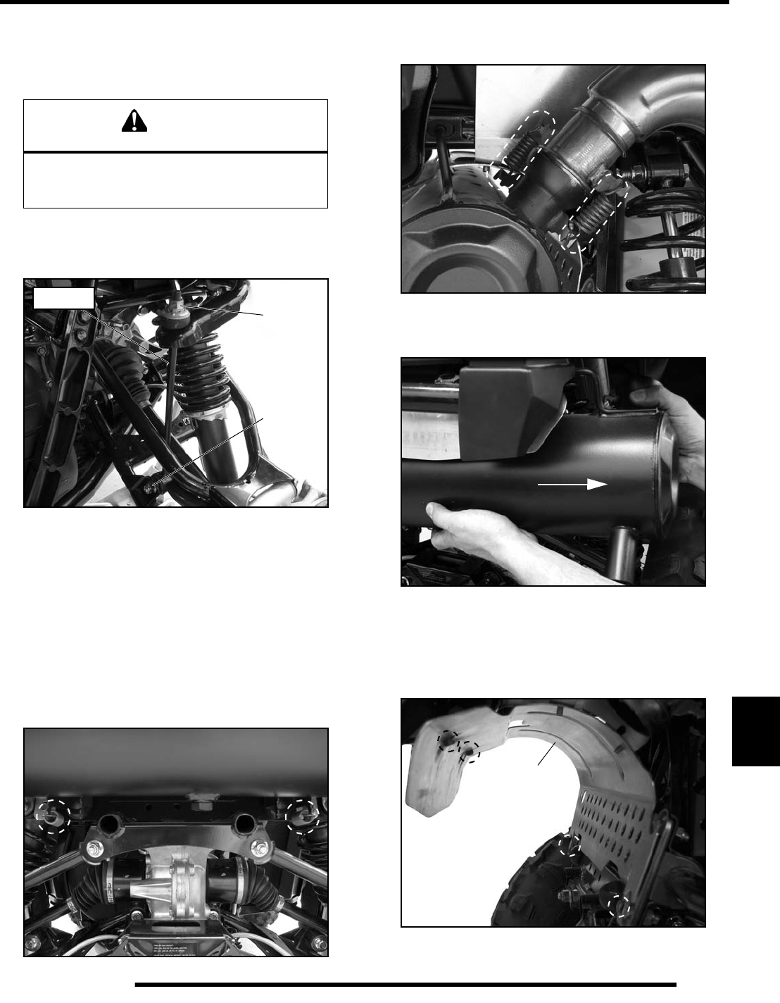
10.19
STEERING / SUSPENSION
10
Linkage Removal / Installation
1. Elevate rear of vehicle and safely support machine under
the frame area.
2. Remove the (4) wheel nuts and remove the rear wheel.
3. Remove the upper linkage bushing.
4. Remove the lower linkage fastener and remove the
stabilizer linkage.
5. Reverse this procedure to reinstall the stabilizer linkage.
Refer to the “REAR STABILIZER BAR - Exploded View”
for torque values.
Stabilizer Bar Removal / Installation
1. Remove the (2) exhaust springs from the rear portion of the
exhaust silencer.
2. Remove the (2) exhaust springs that retain the exhaust pipe
to the silencer.
3. Remove the exhaust silencer from the vehicle through the
right rear wheel well.
NOTE: Lift upward slightly on the exhaust pipe to
allow for enough clearance to remove the silencer.
4. Remove the (4) screws retaining the exhaust heat shield and
remove the shield from the chassis.
CAUTION
Serious injury may result if machine tips or falls.
Be sure machine is secure before beginning this
service procedure. Always wear eye protection.
Upper
Bushing
Lower
Fastener
Linkage
Heat
Shield
PartShark.com
877-999-5686
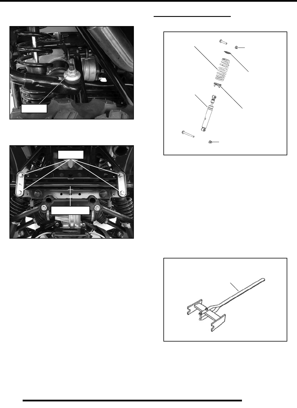
10.20
STEERING / SUSPENSION
5. Remove the upper bushing from the stabilizer linkage on
each side of the vehicle.
6. Remove the (4) fasteners retaining the stabilizer bar bracket
to the frame.
7. Remove the stabilizer bar from the frame.
8. Inspect the stabilizer bar for straightness. Inspect the
bushings and replace if needed.
9. Inspect the rubber bushings on the stabilizer linkage(s) and
replace if needed.
10. Reverse this procedure to reinstall the stabilizer bar. Refer
to the “REAR STABILIZER BAR - Exploded View” for
torque values.
SHOCKS / SPRINGS
Exploded View
Shock Removal / Installation
1. Elevate the vehicle off the ground to relieve the suspension
load.
2. Remove the upper and lower fasteners retaining the shock
and remove the shock from the vehicle.
3. Reverse the procedure to reinstall the shock. Torque new
fasteners to 37 ft. lbs. (50 Nm).
Shock / Spring Replacement
1. Using a spring compressor, compress the shock spring far
enough to remove the spring retainer.
2. Remove the spring and adjusting cam from the existing
shock and install components onto the new shock.
3. Compress the shock spring and install the spring retainer.
4. Reinstall the shock onto the vehicle and torque new
fasteners to 37 ft. lbs. (50 Nm).
Remove
Remove
Stabilizer Bar
Spring
Spring
Adjusting Cam
Shock
37 ft. lbs.
(50 Nm)
Retainer
37 ft. lbs.
(50 Nm)
Shock Spring
Compressor Tool
2870623
PartShark.com
877-999-5686

BRAKES
11.1
CHAPTER 11
BRAKES
11
SPECIFICATIONS. . . . . . . . . . . . . . . . . . . . . . . . . . . . . . . . . . . . . . . . . . . . . . . . . . . . . . 11.2
GENERAL BRAKE SPECIFICATIONS. . . . . . . . . . . . . . . . . . . . . . . . . . . . . . . . . . . . . . 11.2
GENERAL TORQUE SPECIFICATIONS . . . . . . . . . . . . . . . . . . . . . . . . . . . . . . . . . . . . 11.2
SPECIAL TOOLS / BRAKE FLUID. . . . . . . . . . . . . . . . . . . . . . . . . . . . . . . . . . . . . . . . . 11.2
BRAKE SYSTEM SERVICE NOTES. . . . . . . . . . . . . . . . . . . . . . . . . . . . . . . . . . . . . . . . 11.3
BRAKE NOISE TROUBLESHOOTING . . . . . . . . . . . . . . . . . . . . . . . . . . . . . . . . . . . . . . 11.3
HYDRAULIC BRAKE SYSTEM OPERATION. . . . . . . . . . . . . . . . . . . . . . . . . . . . . . . . . 11.4
BRAKE SYSTEM EXPLODED VIEW . . . . . . . . . . . . . . . . . . . . . . . . . . . . . . . . . . . . . . . 11.4
BRAKE CALIPER EXPLODED VIEW. . . . . . . . . . . . . . . . . . . . . . . . . . . . . . . . . . . . . . . 11.5
HAND MASTER CYLINDER EXPLODED VIEW . . . . . . . . . . . . . . . . . . . . . . . . . . . . . . 11.5
BRAKE BLEEDING . . . . . . . . . . . . . . . . . . . . . . . . . . . . . . . . . . . . . . . . . . . . . . . . . . . . . 11.6
FLUID REPLACEMENT . . . . . . . . . . . . . . . . . . . . . . . . . . . . . . . . . . . . . . . . . . . . . . . . . 11.6
BLEEDING PROCEDURE . . . . . . . . . . . . . . . . . . . . . . . . . . . . . . . . . . . . . . . . . . . . . . . 11.6
HAND BRAKE MASTER CYLINDER . . . . . . . . . . . . . . . . . . . . . . . . . . . . . . . . . . . . . . . 11.8
REMOVAL / DISASSEMBLY / INSTALLATION . . . . . . . . . . . . . . . . . . . . . . . . . . . . . . . 11.8
BRAKE SWITCH REPLACEMENT. . . . . . . . . . . . . . . . . . . . . . . . . . . . . . . . . . . . . . . . . 11.8
FOOT BRAKE MASTER CYLINDER. . . . . . . . . . . . . . . . . . . . . . . . . . . . . . . . . . . . . . . . 11.9
FOOT MASTER CYLINDER REMOVAL / INSTALLATION . . . . . . . . . . . . . . . . . . . . . . 11.9
BRAKE PEDAL REMOVAL / INSTALLATION . . . . . . . . . . . . . . . . . . . . . . . . . . . . . . . . 11.9
BRAKE PADS . . . . . . . . . . . . . . . . . . . . . . . . . . . . . . . . . . . . . . . . . . . . . . . . . . . . . . . . 11.10
PAD REMOVAL / INSPECTION / INSTALLATION . . . . . . . . . . . . . . . . . . . . . . . . . . . 11.10
BRAKE BURNISHING PROCEDURE . . . . . . . . . . . . . . . . . . . . . . . . . . . . . . . . . . . . . 11.11
CALIPER SERVICE. . . . . . . . . . . . . . . . . . . . . . . . . . . . . . . . . . . . . . . . . . . . . . . . . . . . 11.11
CALIPER REMOVAL / DISASSEMBLY . . . . . . . . . . . . . . . . . . . . . . . . . . . . . . . . . . . . 11.11
CALIPER INSPECTION . . . . . . . . . . . . . . . . . . . . . . . . . . . . . . . . . . . . . . . . . . . . . . . . 11.12
CALIPER REASSEMBLY / INSTALLATION. . . . . . . . . . . . . . . . . . . . . . . . . . . . . . . . . 11.13
BRAKE DISC SERVICE . . . . . . . . . . . . . . . . . . . . . . . . . . . . . . . . . . . . . . . . . . . . . . . . 11.14
DISC INSPECTION / REMOVAL / REPLACEMENT . . . . . . . . . . . . . . . . . . . . . . . . . . 11.14
TROUBLESHOOTING. . . . . . . . . . . . . . . . . . . . . . . . . . . . . . . . . . . . . . . . . . . . . . . . . . 11.16
PartShark.com
877-999-5686

11.2
BRAKES
SPECIFICATIONS
General Brake Specifications
General Torque Specifications
Special Tools / Brake Fluid
FRONT BRAKES
Item Standard Service Limit
Brake Pad Thickness -- .040” / 1 mm
Brake Disc Thickness .187” / 4.75 mm .167” / 4.24 mm
Brake Disc Thickness Variance Between Measurement -- .002” / .051 mm
Brake Disc Runout -- .010” / .254 mm
Caliper Piston Diameter 1.186” / 30.12 mm 1.184” / 30.07 mm
Caliper Bore Diameter 1.192” / 30.28 mm 1.194” / 30.33 mm
REAR BRAKES
Item Standard Service Limit
Brake Pad Thickness -- .040” / 1 mm
Brake Disc Thickness .187” / 4.75 mm .167” / 4.24 mm
Brake Disc Thickness Variance Between Measurements -- .002” / .051 mm
Brake Disc Runout -- .010” / .254 mm
Caliper Piston Diameter 1.250” / 31.75 mm 1.246” / 31.65 mm
Caliper Bore Diameter 1.254” / 31.85 mm 1.256” / 31.90 mm
TORQUE SPECIFICATIONS
Item Torque ft. lbs. (in. lbs.) Torque (Nm)
Caliper Mounting Bolts 37 50
Handlebar Master Cylinder Clamp Bolts (70 in. lbs.) 7-9
Hand Master Cylinder Reservoir Cover (7 in. lbs.) 0.8
Brake Line Flare Fitting 12 - 15 16 - 20
Brake Line Banjo Bolt Fitting 15 20
Bleeder Screw (47 in. lbs.) 5.3
SPECIAL TOOLS
Part Number Tool Description
2870975 Mity Vac™
2872189 DOT 4 Brake Fluid
PartShark.com
877-999-5686
11.3
BRAKES
11
BRAKE SYSTEM SERVICE NOTES
Disc brake systems are light weight, low maintenance, and perform well in the conditions this vehicle will routinely encounter. There
are a few things to remember when replacing disc brake pads or performing brake system service to ensure proper system function
and maximum pad service life.
• Do not over-fill the master cylinder fluid reservoir(s).
• Make sure the brake lever / pedal returns freely and completely.
• Adjust stop pin on calipers after pad service.
• Check and adjust master cylinder reservoir fluid level after pad service.
• Make sure atmospheric vent on reservoir is unobstructed.
• Test for brake drag after any brake system service and investigate cause if brake drag is evident.
• Make sure caliper moves freely on guide pins (where applicable).
• Inspect caliper piston seals for foreign material that could prevent caliper pistons from returning freely.
• Perform a brake burnishing procedure after installing new pads to maximize service life.
• DO NOT lubricate or clean the brake components with aerosol or petroleum products. Use only approved brake cleaning
products.
• DO NOT allow brake cleaning products to contact painted surfaces. Paint damage will occur as a result.
BRAKE NOISE TROUBLESHOOTING
Dirt or dust buildup on the brake pads and disc is the most common cause of brake noise (squeal caused by vibration). If cleaning
does not reduce the occurrence of brake noise, Permatex™ Disc Brake Quiet can be applied to the back of the pads. Follow directions
on the package. This will keep pads in contact with caliper piston(s) to reduce the chance of squeaks caused by dirt or dust.
Brake Noise Troubleshooting
Possible Cause Remedy
Dirt, dust, or imbedded material on pads or disc Spray disc and pads with CRC Brakeleen™ or an equivalent
non-flammable aerosol brake cleaner. Remove pads and/or disc
hub to clean imbedded material from disc or pads.
Pad(s) dragging on disc (noise or premature pad wear) because
of improper adjustment
Master cylinder reservoir overfilled
Master cylinder compensating port restricted
Master cylinder piston not returning completely
Caliper piston not returning
Operator error (riding the brake)
Adjust pad stop
Set to proper level
Clean compensating port
Clean, inspect, and repair as necessary
Clean piston seals and inspect the seal grooves
Educate operator
Loose wheel hub or bearings Check wheel and hub for abnormal movement (see Chapter 8).
Brake disc warped or excessively worn Replace disc
Brake disc misaligned or loose Inspect and repair as necessary
Noise is from other source (axle, hub, disc or wheel) If noise does not change when brake is applied check other
sources. Inspect and repair as necessary
PartShark.com
877-999-5686
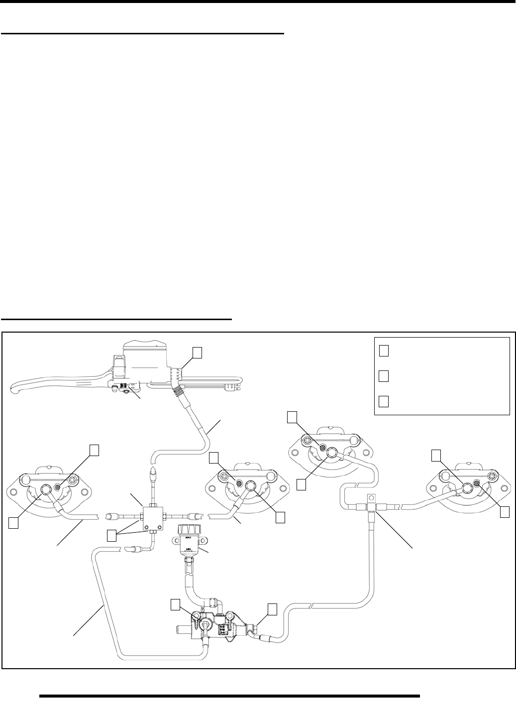
11.4
BRAKES
HYDRAULIC BRAKE SYSTEM OPERATION
The brake system consists of the following components or assemblies: hand brake master cylinder w/lever, foot brake master cylinder
w/pedal, brake fluid reservoirs, brake lines, brake calipers, brake pads, and brake discs, which are secured to the drive line.
When the brake lever or pedal is applied, it moves the hydraulic piston within the master cylinder. As the master cylinder piston
moves inward it closes a small opening (compensating port) within the cylinder and starts to build pressure within the brake system.
As the pressure within the system is increased, the pistons located in the brake calipers move outward and apply pressure to the
moveable brake pads. These pads contact the brake discs and move the calipers in their floating bracket, pulling the stationary side
pads into the brake discs. The resulting friction reduces brake disc and vehicle speed.
The friction applied to the brake pads will cause the pads to wear. As these pads wear, the piston within the caliper moves further
outward and becomes self adjusting. Fluid from the reservoir fills the additional area created when the caliper piston moves outward.
Brake fluid level is critical to proper system operation. Too little fluid will allow air to enter the system and cause the brakes to feel
spongy. Too much fluid could cause brakes to drag due to fluid expansion.
Located within the master cylinder is the compensating port which is opened and closed by the master cylinder piston assembly. As
the temperature within the hydraulic system changes, this port compensates for fluid expansion or contraction. Due to the high
temperatures created within the system during heavy braking, it is very important that the master cylinder reservoir have adequate
space to allow for fluid expansion. Never overfill the reservoir! Do not fill the reservoir beyond the MAX LEVEL line!
When servicing Polaris brake systems use only Polaris DOT 4 Brake Fluid (PN 2872189). WAR NING : Once a bottle is opened,
use what is necessary and discard the rest in accordance with local laws. Do not store or use a partial bottle of brake fluid. Brake
fluid is hygroscopic, meaning it rapidly absorbs moisture. This causes the boiling temperature of the brake fluid to drop, which can
lead to early brake fade and the possibility of serious injury.
BRAKE SYSTEM EXPLODED VIEW
Caliper Banjo Style Fittings:
15 ft. lbs. (20 Nm).
All Caliper Bleed Screws:
47 in. lbs. (5.3 Nm)
Foot Master Cylinder
Cross
Rear Caliper
Brake Line Assembly
RH Front
Brake Line
Front
Brake
LH Front
Front
Brake Line
1
2
2
1
3All Flare Style Fittings:
12-15 ft. lbs. (16-20 Nm)
3
2
Fitting
Switch
Hand Master Cylinder
Reservoir
3
Rear MC
Brake Line
1
1
1
1
Front MC
Brake Line
LH Caliper RH Caliper
Rear
RH Caliper
Rear
LH Caliper
2
1
2
PartShark.com
877-999-5686
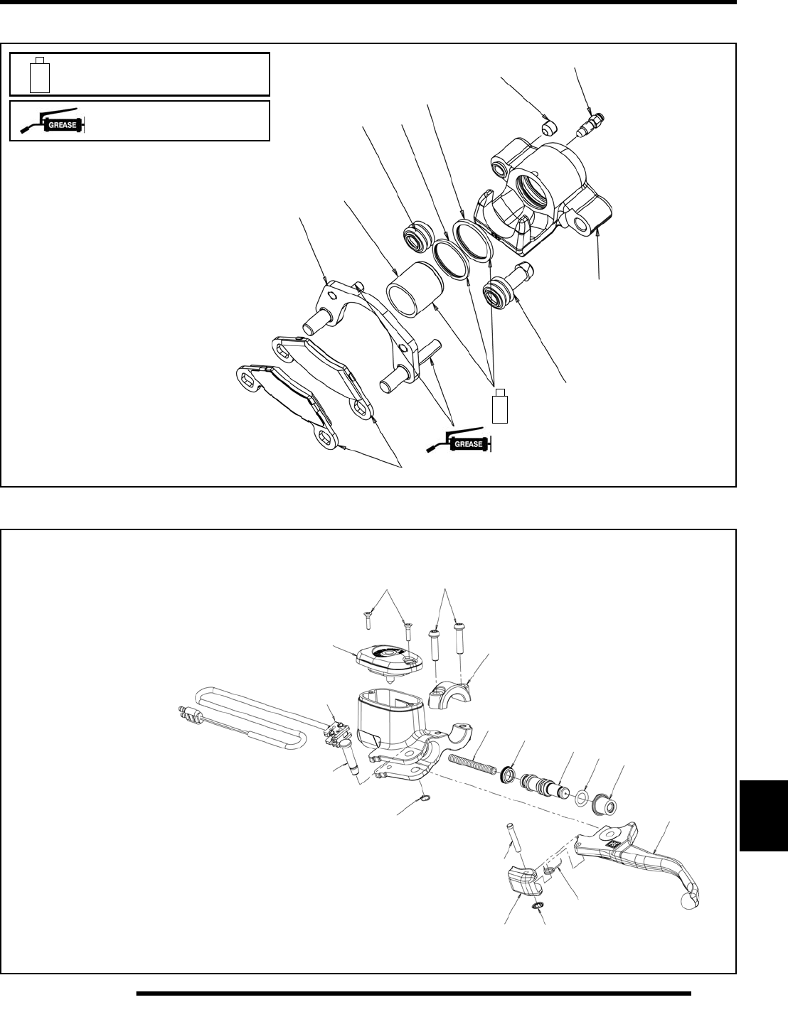
11.5
BRAKES
11
Brake Caliper Exploded View
Hand Master Cylinder Exploded View
A
B
C
D
E
F
G
H
J
K
A. Caliper Mount
B. Brake Pads
C. Piston
D. Caliper Assy.
E. Square O-ring (thick)
F. Square O-ring (thin)
G. Boot, Pin Bushing
H. Boot, Pin Seal
J. Bleeder Screw
K. Adjustment Set Screw
Apply Polaris All Purpose
Grease
Apply Polaris DOT 4 Brake Fluid
to Component 47 in. lbs.
(5.3 Nm)
A
B
C
DE
F
G
H
J
K
A. Lever
B. Piston
C. Locking Lever
D. Primary Cup
E. O-ring
F. Reservoir Cover
G. Pivot Pin
H. Piston Return Spring
J. Dust Boot
K. Lever Return Spring
L. Clamp
M. Retaining Ring
N. Locking Push On
P. Torx Screws
Q. Cover Screws
R. Brake Switch
G
L
M
N
P
Q70 in. lbs.
(8 Nm)
7 in. lbs.
(0.8 Nm)
R
PartShark.com
877-999-5686
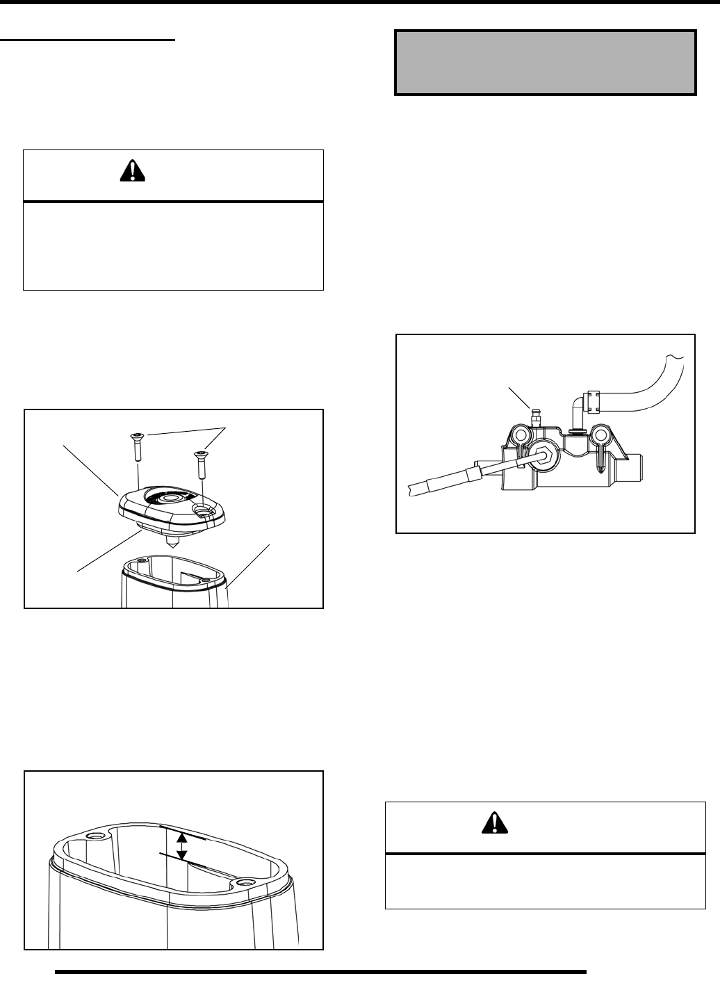
11.6
BRAKES
BRAKE BLEEDING
Fluid Replacement
NOTE: When bleeding the brakes or replacing the
fluid, always start with the caliper farthest from the
master cylinder.
This procedure should be used to change fluid or bleed brakes
during regular maintenance.
1. Clean reservoir cover thoroughly.
2. Remove screws, cover and diaphragm from master cylinder
reservoir.
3. Inspect vent slots in cover and remove any debris or
blockage.
4. If changing fluid, remove old fluid from reservoir and lines
at the bleeders with a Mity Vac™ or similar tool.
NOTE: Do not move brake lever when reservoir fluid
level is low.
5. Add brake fluid to .25” - .30” (6 - 8 mm) from the top of
the reservoir.
Bleeding Procedure
Front Brake System Bleeding
1. Remove the reservoir cover from the hand brake master
cylinder and verify fluid is at specified level.
2. If fluid level is low, add brake fluid to .25” - .30” (6 - 8 mm)
from the top of the reservoir.
3. Install a box end wrench on foot master cylinder bleeder
screw. Attach a clean, clear hose to fitting and place the
other end in a container. Be sure the hose fits tightly on
fitting.
NOTE: Install diaphragm and cover onto the hand
master cylinder reservoir to prevent spills. Do not
tighten the cover.
4. Slowly pump the hand brake lever until pressure builds and
holds.
5. While maintaining lever pressure, open bleeder screw.
6. Close bleeder screw and release brake lever
NOTE: Do not release lever before bleeder screw is
tight or air may be drawn into caliper.
7. Repeat procedure until clean fluid appears in bleeder hose
and all air has been purged. Add fluid as necessary to
maintain level in reservoir.
8. Tighten bleeder screw securely and remove bleeder hose.
Torque the bleeder screw to 47 in. lbs. (5.3 Nm).
CAUTION
Always wear safety glasses during
these procedures.
Brake fluid will damage finished surfaces.
Do not allow brake fluid to come in contact with
finished surfaces.
Screws
Cover
Diaphragm
Master
Cylinder
.25” - .30” (6 - 8 mm)
From Top of Reservoir
Polaris DOT 4 Brake Fluid
PN: 2872189
CAUTION
Maintain at least 1/2” (1.27 cm) of brake fluid
in the reservoir to prevent air from
entering the master cylinder.
Bleeder
Screw
Foot Master Cylinder
PartShark.com
877-999-5686
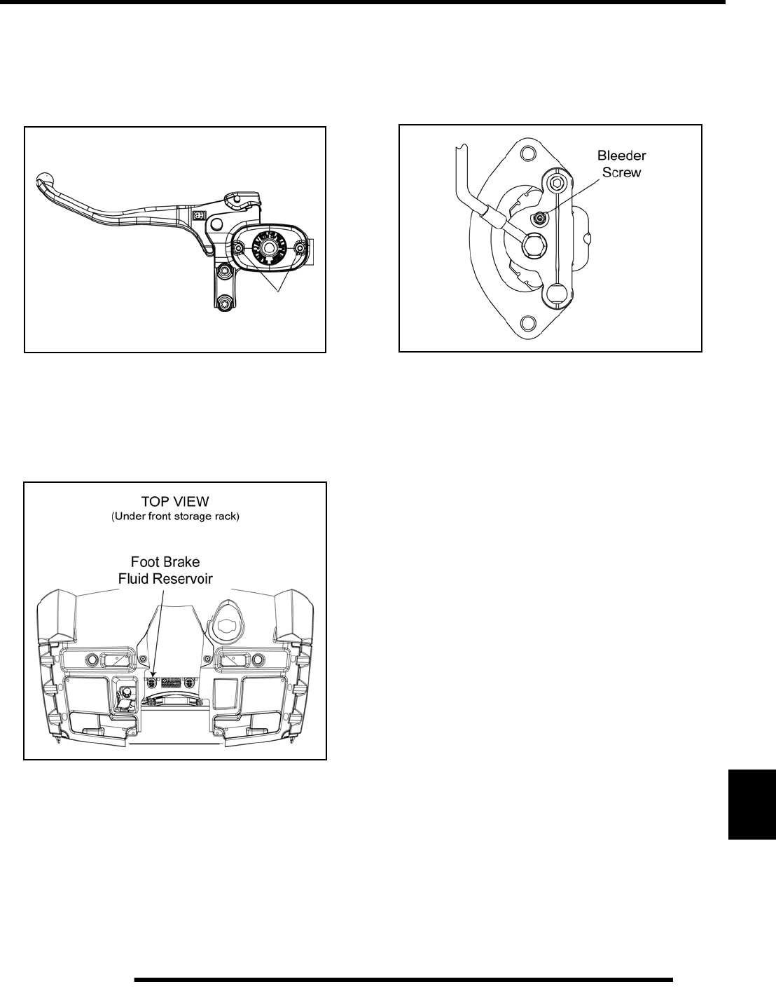
11.7
BRAKES
11
9. Repeat the procedure on the two remaining front calipers.
10. Add DOT 4 brake fluid to .25” - .30” (6 - 8 mm) from the
top of the reservoir.
11. Install diaphragm, cover and screws. Torque the screws to
7 in. lbs. (0.8 Nm).
12. Proceed to “Rear Brake System Bleeding” to complete
bleeding procedure.
Rear Brake System Bleeding
Remove the front rack and locate the foot brake fluid reservoir
for the foot master cylinder (see the following illustration).
1. Thoroughly clean the fluid reservoir cover before removal.
2. Remove the cap and diaphragm from the reservoir and
verify fluid level is at the MAX level mark.
3. If changing fluid, remove old fluid from reservoir with a
Mity Vac™ (PN 2870975) or similar tool.
4. Using a funnel, add brake fluid to the MAX level mark on
the reservoir.
5. Install a box end wrench on the rear caliper bleeder screw.
Attach a clean, clear hose to fitting and place the other end
in a container. Be sure the hose fits tightly on fitting.
6. Slowly pump the foot brake pedal until pressure builds and
holds.
7. While maintaining pedal pressure, open bleeder screw.
8. Close bleeder screw and release brake pedal.
NOTE: Do not release pedal before bleeder screw is
tight or air may be drawn into caliper.
9. Repeat procedure until clean fluid appears in bleeder hose
and all air has been purged. Add fluid as necessary to
maintain level in reservoir.
10. Tighten bleeder screw securely and remove bleeder hose.
Torque the bleeder screw to 47 in. lbs. (5.3 Nm).
11. Repeat the procedure on the remaining rear caliper.
12. Using a funnel, add brake fluid to the MAX level mark on
the reservoir.
13. Field test machine at low speed before putting into service.
Check for proper braking action and lever reserve. With
lever firmly applied, lever reserve should be no less than 1/
2”, (1.3 cm) from handlebar.
14. Check brake system for fluid leaks and inspect all hoses and
lines for wear or abrasion. Replace hose if wear or abrasion
is found.
7 in. lbs.
(0.8 Nm)
Hand Master Cylinder
PartShark.com
877-999-5686
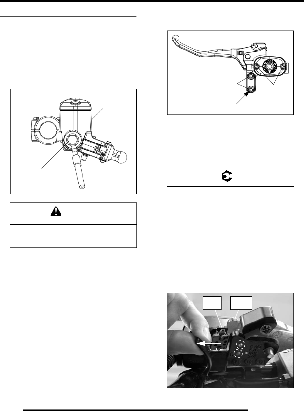
11.8
BRAKES
HAND BRAKE MASTER CYLINDER
Removal
1. Clean master cylinder and reservoir assembly. Make sure
you have a clean work area to disassemble brake
components.
2. Place a shop towel or suitable catch container under the
master cylinder brake line connection. Remove the banjo
bolt fitting that connects the brake line to the master
cylinder. Discard the sealing washers.
3. Remove the Torx screws from the master cylinder clamp.
4. Hold master cylinder upright and lift the master cylinder
from the handlebars. Cover brake line orifice to avoid
spilling fluid.
Disassembly
The hand master cylinder is a serviceable component. Polaris
offers a number of service kits to rebuild this style of master
cylinder. Refer to the Polaris Electronic Parts Catalog.
Installation
NOTE: Use only OEM parts that were designed for
the model ATV being serviced. There are different
hand master cylinders for the different Polaris ATV
models. Refer to the Electronic Parts Catalog.
NOTE: Some master cylinders are not serviceable
and are replaced only as an assembly.
1. Install master cylinder on handlebars. Torque bolt furthest
from the reservoir first, followed by the bolt closest to the
reservoir. Torque clamp bolts to 70 in. lbs. (8 Nm).
NOTE: Speed up brake bleeding by purging air
before brake line is attached. Fill with DOT 4 Brake
Fluid and pump lever slowly 2 to 3 times with finger
over the outlet end to purge master cylinder of air.
2. Place new sealing washers on each side of banjo line and
torque banjo bolt to specification.
3. Fill reservoir with DOT 4 brake fluid (PN 2872189).
4. Follow brake bleeding procedures. Check all connections
for leaks and repair if necessary.
Brake Switch Replacement
1. Set the parking brake lock and locate the brake switch
behind the hand brake lever.
2. Using a small screwdriver or similar tool, push up on the
mounting tabs through the holes on the bottom side while
rotating the switch to disengage the tabs from the holes.
3. Install the new switch. The tabs should snap in place.
CAUTION
Brake fluid will damage finished surfaces.
Do not allow brake fluid to come in
contact with finished surfaces.
Remove
Banjo Fitting
Master
Cylinder
= T
Brake Line Banjo Bolt:
15 ft. lbs. (20 Nm)
70 in. lbs.
(8 Nm) 7 in. lbs.
(0.8 Nm)
Torque Bolt First
Brake
Switch Master
Cylinder
PartShark.com
877-999-5686
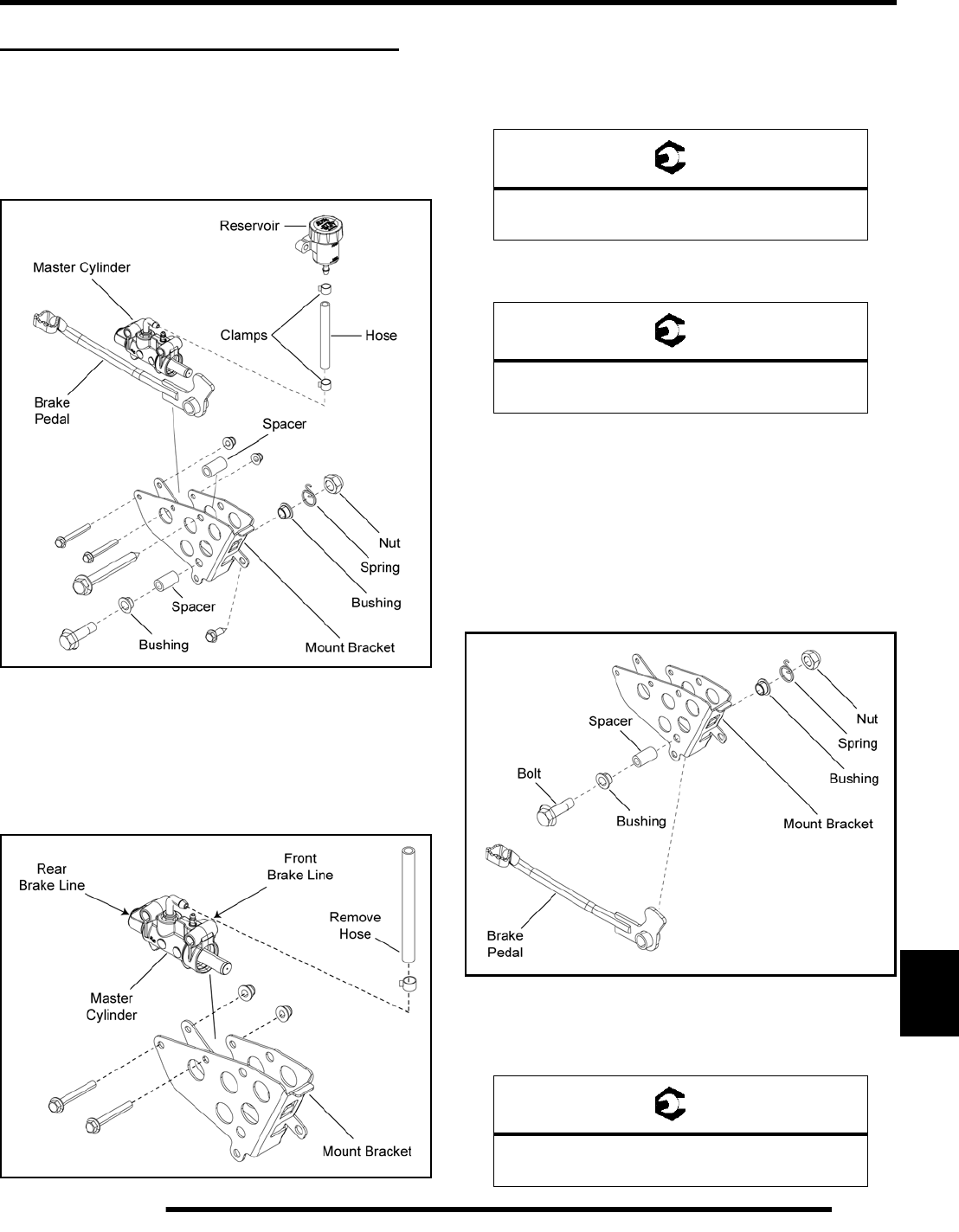
11.9
BRAKES
11
FOOT BRAKE MASTER CYLINDER
Operation Overview
When the brake pedal is applied it contacts the piston of the foot
brake master cylinder. As the pressure within the system is
increased, the pistons located in the rear brake calipers move
outward and apply equal pressure to the brake pads.
Foot Master Cylinder Removal / Installation
1. Remove the RH mud guard and footwell (see Chapter 9).
2. Remove the front and rear brake line from the master
cylinder. Use a suitable container to catch the brake fluid.
Dispose of brake fluid properly.
3. Remove the (2) through-bolts retaining the master cylinder
to the mount bracket. Replace components as needed.
4. Reverse this procedure when reinstalling and torque
mounting fasteners to specification.
5. Reinstall the brake line and torque the banjo bolt (with new
sealing washers installed) to specification.
6. Bleed the master cylinder following the procedure outlined
in the “Brake Bleeding” section of this chapter.
Brake Pedal Removal / Installation
1. Remove the RH mud guard and footwell (see Chapter 9).
2. Remove the through-bolt retaining the brake pedal to the
mount bracket.
3. Remove the bolt, bushings, spacer, spring and brake lever.
4. Inspect and replace components as needed.
5. Reverse this procedure when reinstalling and torque
mounting fastener to specification.
= T
Master Cylinder Mounting Fasteners:
8 ft. lbs. (11 Nm)
= T
Brake Line Banjo Bolts:
15 ft. lbs. (20 Nm)
= T
Brake Pedal Mounting Fastener:
38 ft. lbs. (52 Nm)
PartShark.com
877-999-5686
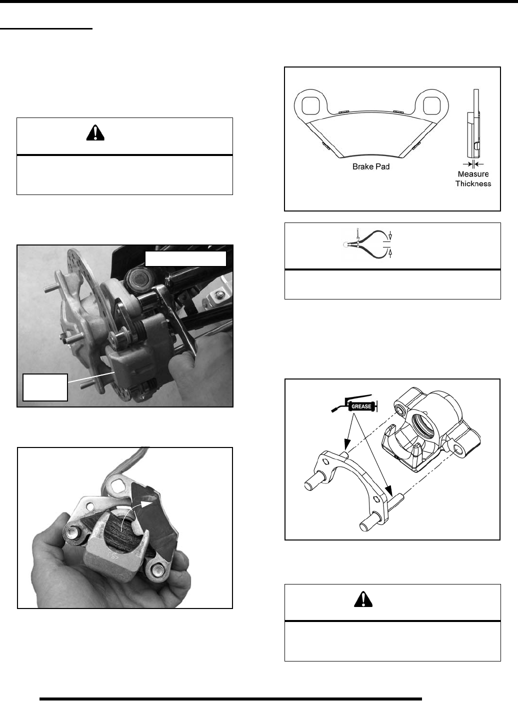
11.10
BRAKES
BRAKE PADS
Pad Removal
1. Loosen the (4) wheel nuts.
2. Elevate and support the side of the ATV in which the
caliper brake pads are being serviced.
3. Remove the wheel nuts and wheel.
4. Remove the (2) brake caliper mounting bolts and caliper.
5. Push mounting bracket inward and slip the outer brake pad
past the edge of the pin. Remove the inner brake pad.
Pad Inspection
1. Measure the thickness of the pad material. Replace pads if
worn beyond the service limit.
Pad Installation
1. Lubricate mounting bracket pins and external slide pin
O-ring with a light film of Polaris Premium All Season
Grease (PN 2871423).
2. Compress mounting bracket. Install pads with friction
material facing each other.
CAUTION
Use care when supporting vehicle so that it does
not tip or fall. Severe injury may occur if
machine tips or falls.
Remove
Caliper
Front Caliper Shown
= In. / mm.
Brake Pad Material Thickness
Service Limit: .040” (1 mm)
WARNING
If the brake pads are contaminated with grease,
oil, or liquid soaked do not use the pads.
Use only new clean brake pads.
PartShark.com
877-999-5686
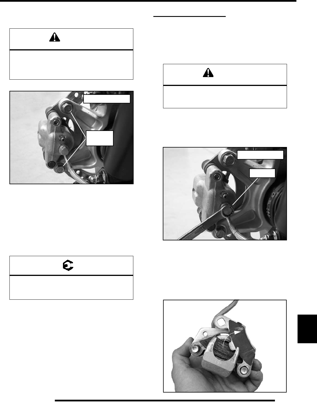
11.11
BRAKES
11
3. Install the caliper and torque new mounting bolts to
specification.
4. Slowly pump the brake lever/pedal until pressure has been
built up. Maintain at least 1/2, (12.7 mm) of brake fluid in
the reservoir to prevent air from entering the brake system.
5. Verify fluid level in reservoir is at specified level inside
reservoir and install reservoir cap.
6. Install the wheel(s) and wheel nuts. Torque wheel nuts to
specification.
Brake Burnishing Procedure
It is required that a burnishing procedure be performed after
installation of new brake pads to extend service life and reduce
noise.
Start machine and slowly increase speed to 30 mph. Gradually
apply brakes to stop machine. Allow pads and disc to cool
sufficiently during the procedure. Do not allow pads or disc to
become hot or warping may result. Repeat this procedure 10
times.
CALIPER SERVICE
Caliper Removal
1. Loosen the (4) wheel nuts.
2. Elevate and support the side of the ATV in which the caliper
is being serviced.
3. Remove the wheel nuts and wheel.
4. Place a suitable container under the caliper to catch brake
fluid draining from brake line. Using a wrench, loosen and
remove brake line from the caliper.
5. Remove (2) caliper mounting bolts and remove the caliper
assembly from the bearing carrier.
Caliper Disassembly
1. Push mounting bracket inward and slip the outer brake pad
past the edge of the pin. Remove the inner brake pad.
CAUTION
New bolts have a pre-applied locking agent
which is destroyed upon removal. Always use
new brake caliper mounting bolts
upon assembly.
= T
Wheel Nuts:
Steel Wheels: 45 ft. lbs. (61 Nm)
Aluminum Wheels: 75 ft. lbs. (102 Nm)
37 ft. lbs.
(50 Nm)
Rear Caliper Shown
CAUTION
Use care when supporting vehicle so that it does
not tip or fall. Severe injury may occur if
machine tips or falls.
Rear Caliper Shown
Remove
PartShark.com
877-999-5686
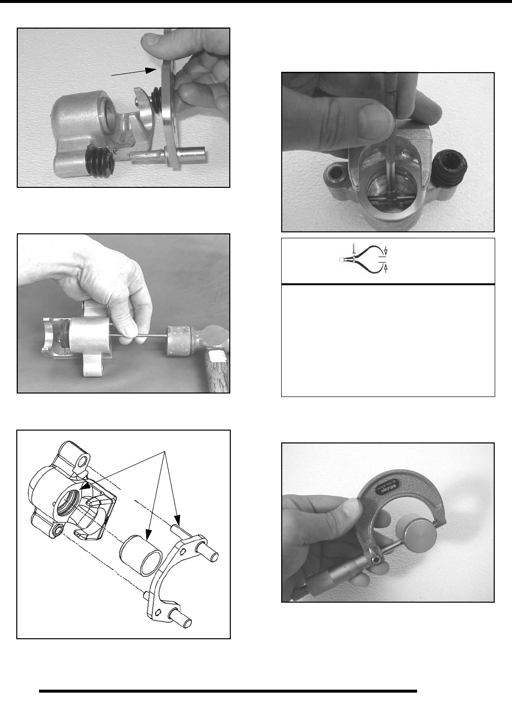
11.12
BRAKES
2. Remove mounting bracket, pin assembly and dust boot.
3. Using a hammer and a small punch, remove the piston from
the caliper body, then remove the square O-rings (see
“BRAKE CALIPER - Exploded View”).
4. Clean the caliper body, piston, and mounting bracket with
brake cleaner or denatured alcohol.
NOTE: Be sure to thoroughly clean the seal grooves
in the caliper body.
Caliper Inspection
1. Inspect caliper body for nicks, scratches or wear. Measure
bore size and compare to specifications. Replace if damage
is evident or if worn beyond service limit.
2. Inspect piston for nicks, scratches, wear or damage.
Measure diameter and replace if damaged or worn beyond
service limit.
3. Inspect the brake pad and disc as outlined in this chapter
(see “Pad Inspection” and “Brake Disc Inspection”).
Clean Components
= In. / mm.
Front Calipers:
Caliper Bore I.D.
Std: 1.192” (30.28 mm)
Service Limit: 1.194” (30.33 mm)
Rear Calipers:
Caliper Bore I.D.
Std: 1.254” (31.85 mm)
Service Limit: 1.256” (31.90 mm)
PartShark.com
877-999-5686
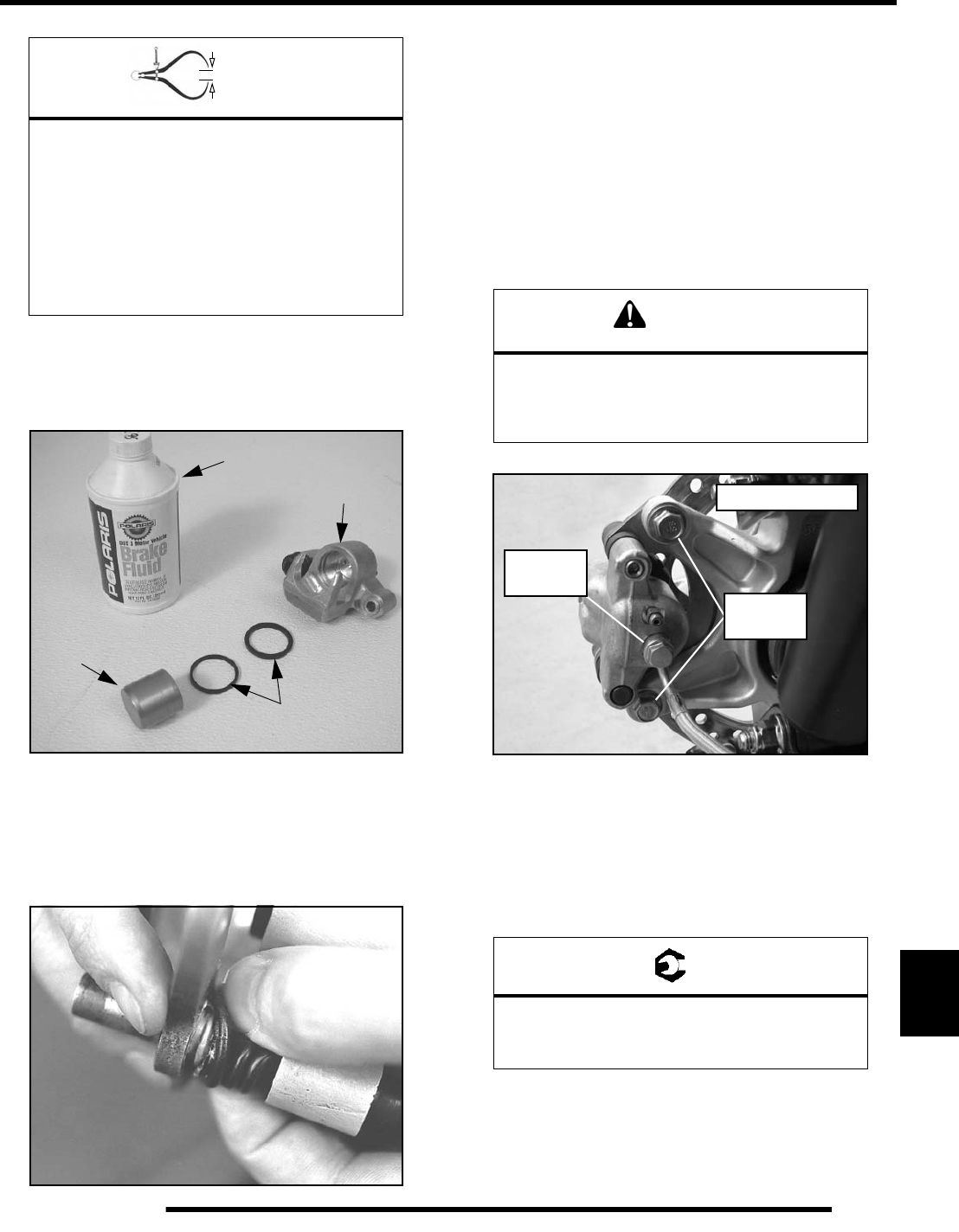
11.13
BRAKES
11
Caliper Reassembly
1. Install new O-rings (A) in the caliper body (B). Be sure
grooves are clean or brakes may drag upon assembly.
2. Coat piston with DOT 4 Brake Fluid (C). Install piston (D)
with a twisting motion while pushing inward. Piston should
slide in and out of the bore smoothly, with light resistance.
3. Lubricate the mounting bracket pins with Polaris Premium
All Season Grease (PN 2871423), and install the rubber
dust seal boots.
4. Compress the mounting bracket and make sure the dust
seals are fully seated.
5. Install the brake pads.
6. Clean the disc and pads with brake parts cleaner or
denatured alcohol to remove any dirt, oil or grease.
Caliper Installation
1. Install caliper assembly over the brake disc and onto the
bearing carrier. Torque mounting bolts to specification.
2. Install brake line and torque the banjo bolt fitting to
specification.
3. Perform brake bleeding procedure as outlined earlier in this
chapter.
4. Install the wheel and (4) wheel nuts. Torque wheel nuts to
specification.
= In. / mm.
Front Calipers:
Caliper Piston O.D.
Std: 1.186” (30.12 mm)
Service Limit: 1.184” (30.07 mm)
Rear Calipers:
Caliper Piston O.D.
Std: 1.250” (31.75 mm)
Service Limit: 1.246” (31.65 mm)
A
B
C
D
CAUTION
New bolts have a pre-applied locking agent
which is destroyed upon removal. Always use
new brake caliper mounting bolts
upon assembly.
= T
Wheel Nuts:
Steel Wheels: 45 ft. lbs. (61 Nm)
Aluminum Wheels: 75 ft. lbs. (102 Nm)
37 ft. lbs.
(50 Nm)
Rear Caliper Shown
15 ft. lbs.
(20 Nm)
PartShark.com
877-999-5686
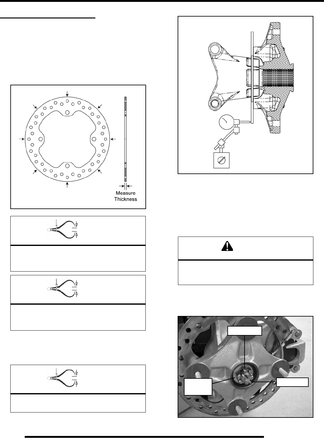
11.14
BRAKES
BRAKE DISC SERVICE
Disc Inspection
1. Visually inspect the brake disc for scoring, scratches, or
gouges. Replace the disc if any deep gouges are evident.
Measure the disc thickness at 8 different points around the pad
contact surface using a 0–1” micrometer. Replace disc if worn
beyond service limit.
2. Mount a dial indicator as shown and measure disc runout.
Slowly rotate the disc and read total runout on the dial
indicator. Replace the disc if runout exceeds specification.
Disc Removal / Replacement
1. Loosen the (4) wheel nuts.
2. Elevate and support the side of the ATV in which the brake
disc is being serviced.
3. Remove the wheel nuts and wheel.
4. Remove the cotter pin, castle nut and cone washers.
= In. / mm.
Brake Disc Thickness
New: .187” (4.75 mm)
Service Limit: .167” (4.24 mm)
= In. / mm.
Brake Disc Thickness Variance
Service Limit: .002” (.051 mm)
(difference between measurements)
= In. / mm.
Brake Disc Runout
Service Limit: 010” (.254 mm)
CAUTION
Use care when supporting vehicle so that it does
not tip or fall. Severe injury may occur if
machine tips or falls.
Image shown is
for reference only.
Castle Nut
Cotter Pin
Cone
Washers
PartShark.com
877-999-5686
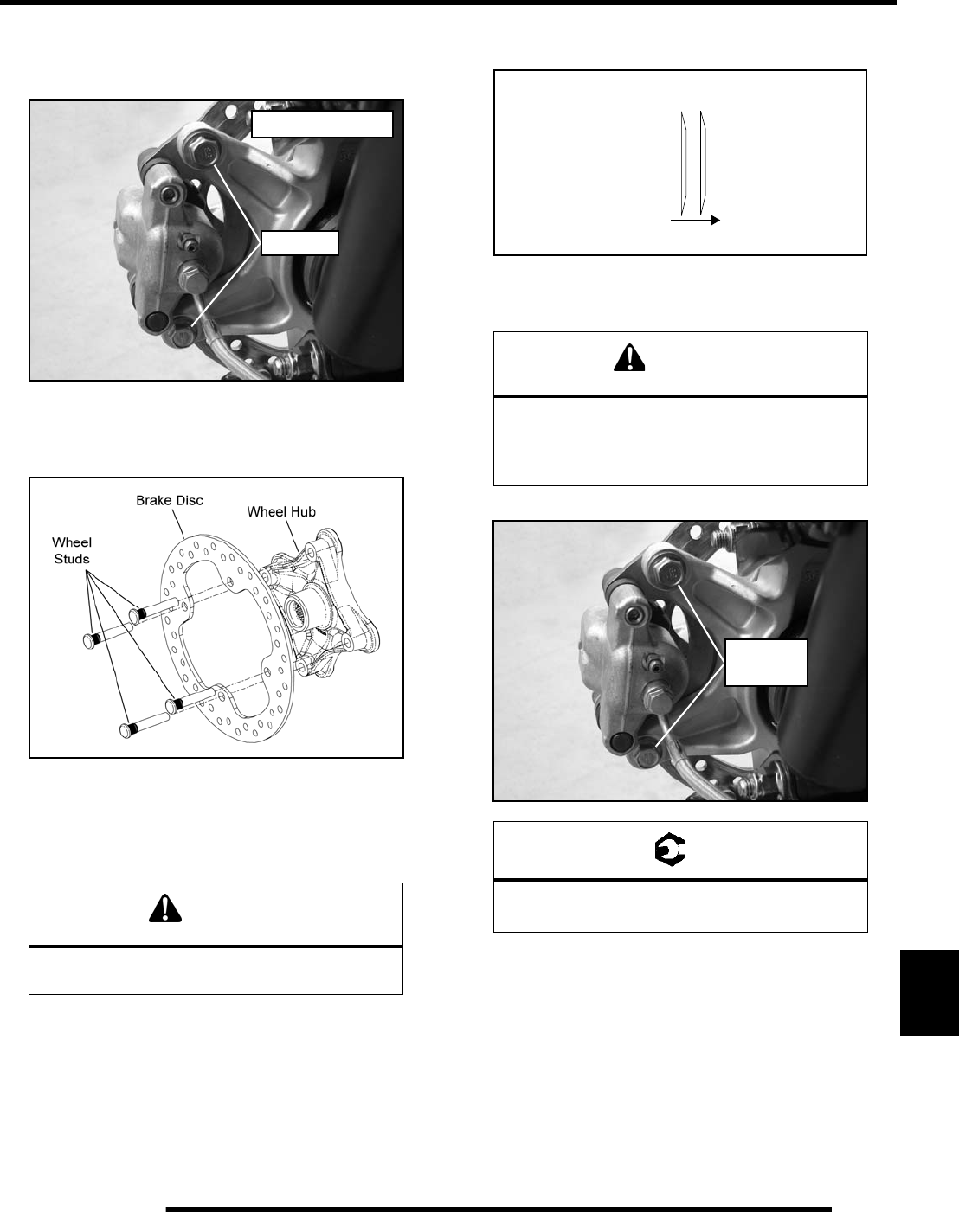
11.15
BRAKES
11
5. Remove the two brake caliper mounting bolts.
CAUTION: Do not hang the caliper by the brake line. Use
wire to hang caliper to prevent damage to the brake line.
6. Remove the wheel hub assembly from the bearing carrier.
7. Press out the wheel studs and remove the brake disc.
8. Clean the wheel hub mating surface
9. Install the new disc and press new wheel studs into the hub
until they are flush with the mating surface.
10. Install wheel hub assembly, cone washers, and hand tighten
the castle nut. Install washers with domed side out.
11. Install the brake caliper and torque the new mounting bolts
to specification.
CAUTION
Always use new wheel studs if removed from the
wheel hub assembly.
Remove
Rear Caliper Shown
CAUTION
New bolts have a pre-applied locking agent
which is destroyed upon removal. Always use
new brake caliper mounting bolts
upon assembly.
= T
Caliper Mounting Bolts:
37 ft. lbs. (50 Nm)
Out
Cone Washers
Wheel
Hub
37 ft. lbs.
(50 Nm)
PartShark.com
877-999-5686
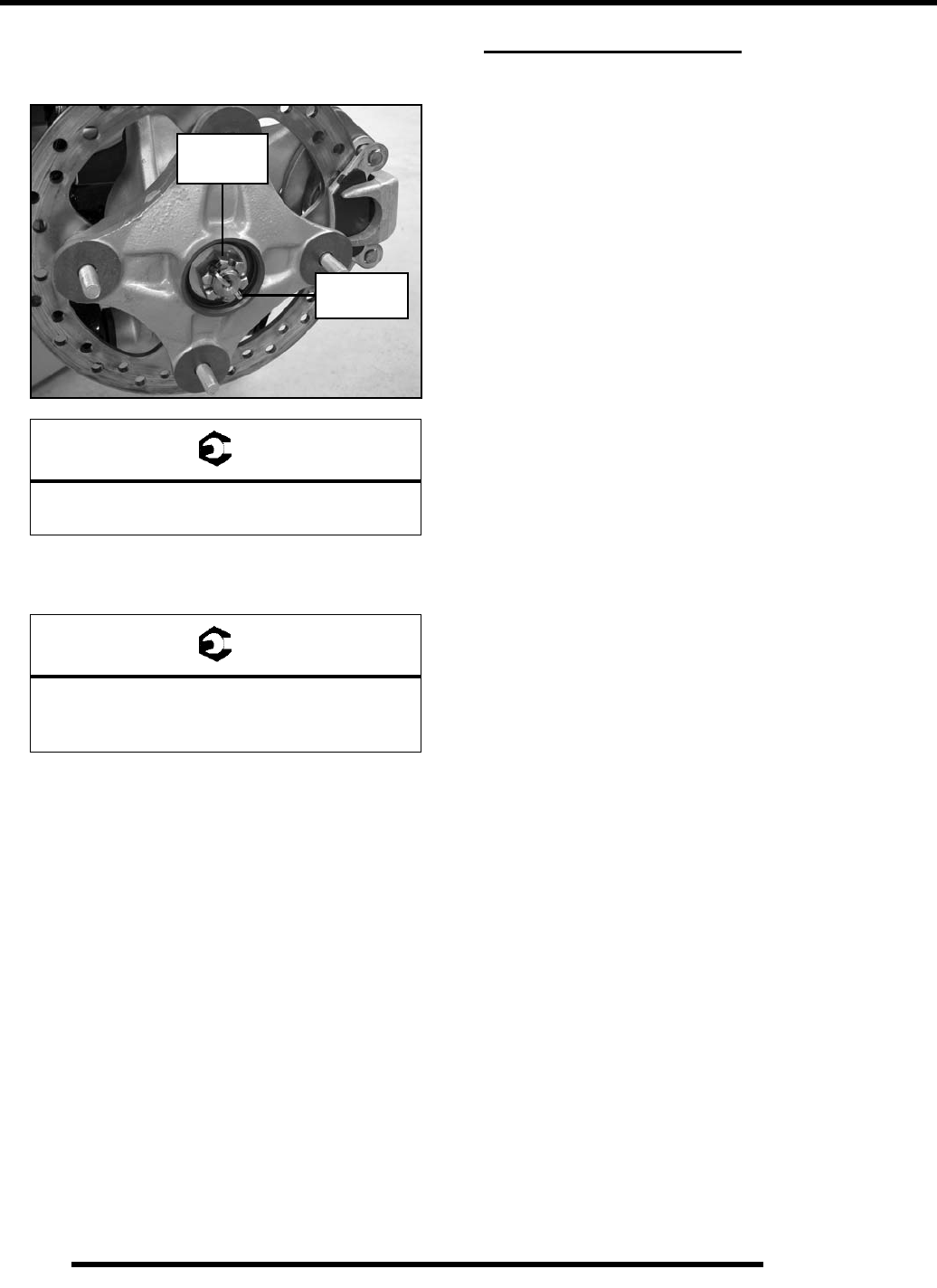
11.16
BRAKES
12. Torque wheel hub nut to specification and install a new
cotter pin. Tighten nut slightly if necessary to align cotter
pin holes.
13. Install the wheel and (4) wheel nuts. Torque wheel nuts to
specification.
14. Field test the ATV for proper braking action before putting
into service. Inspect for fluid leaks and firm brakes. Make
sure the brake is not dragging when lever is released. If the
brake drags, re-check assembly and installation.
TROUBLESHOOTING
Brake Squeal
• Dirty/contaminated friction pads
• Improper alignment
• Worn disc
• Worn caliper
• Glazed brake pads
Poor Brake Performance
• Air in system
• Water in system (brake fluid contaminated)
• Caliper/disc misaligned
• Caliper dirty or damaged
• Brake line damaged or lining ruptured
• Worn disc and/or friction pads
• Incorrectly adjusted stationary pad
• Worn or damaged master cylinder or components
Lever / Pedal Vibration
• Disc damaged
• Disc worn / warped (runout or thickness variance
exceeds service limit)
Caliper Overheats (Brakes Drag)
• Compensating port plugged
• Brake lever or pedal binding or unable to return fully
• Parking brake left on
• Residue build up under caliper seals
• Operator riding brakes
Brakes Lock
• Alignment of caliper to disc
• Reservoir is overfilled with fluid
• Master cylinder compensating port plugged
• Caliper piston is stuck
• Parking brake left on
= T
Wheel Hub Castle Nut:
80 ft. lbs. (108 Nm)
= T
Wheel Nuts:
Steel Wheels: 45 ft. lbs. (61 Nm)
Aluminum Wheels: 75 ft. lbs. (102 Nm)
NEW
80 ft. lbs.
(108 Nm)
Cotter Pin
PartShark.com
877-999-5686

ELECTRICAL
12.1
CHAPTER 12
ELECTRICAL
12
GENERAL INFORMATION . . . . . . . . . . . . . . . . . . . . . . . . . . . . . . . . . . . . . . . . . . . . . . . 12.3
SPECIAL TOOLS / ELECTRICAL SERVICE NOTES . . . . . . . . . . . . . . . . . . . . . . . . . . 12.3
COMPONENT LOCATIONS. . . . . . . . . . . . . . . . . . . . . . . . . . . . . . . . . . . . . . . . . . . . . . 12.3
INSTRUMENT CLUSTER . . . . . . . . . . . . . . . . . . . . . . . . . . . . . . . . . . . . . . . . . . . . . . . . 12.4
RIDER INFORMATION DISPLAY . . . . . . . . . . . . . . . . . . . . . . . . . . . . . . . . . . . . . . . . . 12.5
SPEED INFORMATION / INFORMATION DISPLAY AREA . . . . . . . . . . . . . . . . . . . . . 12.6
DIAGNOSTIC MODE . . . . . . . . . . . . . . . . . . . . . . . . . . . . . . . . . . . . . . . . . . . . . . . . . . . 12.8
INSTRUMENT CLUSTER PINOUTS . . . . . . . . . . . . . . . . . . . . . . . . . . . . . . . . . . . . . . . 12.9
IGNITION SWITCH . . . . . . . . . . . . . . . . . . . . . . . . . . . . . . . . . . . . . . . . . . . . . . . . . . . . . 12.9
ADC / 4X4 / 2X4 SWITCH . . . . . . . . . . . . . . . . . . . . . . . . . . . . . . . . . . . . . . . . . . . . . . . 12.10
OFF / RUN LH SWITCH . . . . . . . . . . . . . . . . . . . . . . . . . . . . . . . . . . . . . . . . . . . . . . . . 12.10
REVERSE OVERRIDE / MODE BUTTON . . . . . . . . . . . . . . . . . . . . . . . . . . . . . . . . . . 12.11
HEAD LAMP SWITCH. . . . . . . . . . . . . . . . . . . . . . . . . . . . . . . . . . . . . . . . . . . . . . . . . . 12.11
ELECTRONIC THROTTLE CONTROL (ETC) SWITCH . . . . . . . . . . . . . . . . . . . . . . . . 12.12
GEAR SELECTOR SWITCH . . . . . . . . . . . . . . . . . . . . . . . . . . . . . . . . . . . . . . . . . . . . . 12.12
SPEED SENSOR. . . . . . . . . . . . . . . . . . . . . . . . . . . . . . . . . . . . . . . . . . . . . . . . . . . . . . 12.13
BRAKE SWITCH . . . . . . . . . . . . . . . . . . . . . . . . . . . . . . . . . . . . . . . . . . . . . . . . . . . . . . 12.14
AWD / ADC COILS . . . . . . . . . . . . . . . . . . . . . . . . . . . . . . . . . . . . . . . . . . . . . . . . . . . . 12.14
RELAYS. . . . . . . . . . . . . . . . . . . . . . . . . . . . . . . . . . . . . . . . . . . . . . . . . . . . . . . . . . . . . 12.15
CHASSIS / FAN / EFI RELAY. . . . . . . . . . . . . . . . . . . . . . . . . . . . . . . . . . . . . . . . . . . . 12.15
BUMPER LIGHTS / START SOLENOID / POWER STEERING RELAY . . . . . . . . . . . 12.16
FUSES. . . . . . . . . . . . . . . . . . . . . . . . . . . . . . . . . . . . . . . . . . . . . . . . . . . . . . . . . . . . . . 12.17
FUSE BOX LAYOUT . . . . . . . . . . . . . . . . . . . . . . . . . . . . . . . . . . . . . . . . . . . . . . . . . . . 12.17
LIGHTS . . . . . . . . . . . . . . . . . . . . . . . . . . . . . . . . . . . . . . . . . . . . . . . . . . . . . . . . . . . . . 12.18
HEADLIGHT / BUMPER LAMP ADJUSTMENT. . . . . . . . . . . . . . . . . . . . . . . . . . . . . . 12.18
HEADLIGHT / BUMPER LAMP REPLACEMENT . . . . . . . . . . . . . . . . . . . . . . . . . . . . 12.19
TAIL / BRAKE BULB REPLACEMENT. . . . . . . . . . . . . . . . . . . . . . . . . . . . . . . . . . . . . 12.19
CHARGING SYSTEM . . . . . . . . . . . . . . . . . . . . . . . . . . . . . . . . . . . . . . . . . . . . . . . . . . 12.20
CHARGING SYSTEM DIAGRAM / TESTING . . . . . . . . . . . . . . . . . . . . . . . . . . . . . . . 12.20
CURRENT DRAW - KEY OFF . . . . . . . . . . . . . . . . . . . . . . . . . . . . . . . . . . . . . . . . . . . 12.20
BATTERY CHARGE TEST. . . . . . . . . . . . . . . . . . . . . . . . . . . . . . . . . . . . . . . . . . . . . . 12.20
STATOR / ALTERNATOR TESTS . . . . . . . . . . . . . . . . . . . . . . . . . . . . . . . . . . . . . . . . 12.20
STATOR / ALTERNATOR REMOVAL . . . . . . . . . . . . . . . . . . . . . . . . . . . . . . . . . . . . . 12.21
STATOR / ALTERNATOR INSTALLATION . . . . . . . . . . . . . . . . . . . . . . . . . . . . . . . . . 12.22
BATTERY SERVICE . . . . . . . . . . . . . . . . . . . . . . . . . . . . . . . . . . . . . . . . . . . . . . . . . . . 12.23
BATTERY REMOVAL / INSTALLATION . . . . . . . . . . . . . . . . . . . . . . . . . . . . . . . . . . . 12.23
BATTERY OFF SEASON STORAGE. . . . . . . . . . . . . . . . . . . . . . . . . . . . . . . . . . . . . . 12.23
BATTERY TESTING. . . . . . . . . . . . . . . . . . . . . . . . . . . . . . . . . . . . . . . . . . . . . . . . . . . 12.23
OCV / LOAD TEST . . . . . . . . . . . . . . . . . . . . . . . . . . . . . . . . . . . . . . . . . . . . . . . . . . . . 12.24
CHARGING PROCEDURE. . . . . . . . . . . . . . . . . . . . . . . . . . . . . . . . . . . . . . . . . . . . . . 12.24
STARTER MOTOR . . . . . . . . . . . . . . . . . . . . . . . . . . . . . . . . . . . . . . . . . . . . . . . . . . . . 12.25
STARTER / STARTER LOCKOUT SYSTEM DIAGRAM . . . . . . . . . . . . . . . . . . . . . . . 12.25
TROUBLESHOOTING . . . . . . . . . . . . . . . . . . . . . . . . . . . . . . . . . . . . . . . . . . . . . . . . . 12.25
VOLTAGE DROP TESTING. . . . . . . . . . . . . . . . . . . . . . . . . . . . . . . . . . . . . . . . . . . . . 12.25
STARTER MOTOR REMOVAL / REPLACEMENT . . . . . . . . . . . . . . . . . . . . . . . . . . . 12.26
INSTRUMENT CLUSTER TROUBLESHOOTING . . . . . . . . . . . . . . . . . . . . . . . . . . . . 12.27
INSTRUMENT CLUSTER - KEY OFF / NO POWER. . . . . . . . . . . . . . . . . . . . . . . . . . 12.27
INSTRUMENT CLUSTER - KEY ON / NO POWER. . . . . . . . . . . . . . . . . . . . . . . . . . . 12.28
INSTRUMENT CLUSTER - NO HIGH BEAM INDICATOR . . . . . . . . . . . . . . . . . . . . . 12.29
INSTRUMENT CLUSTER - NO / INCORRECT FUEL LEVEL . . . . . . . . . . . . . . . . . . . 12.30
INSTRUMENT CLUSTER CIRCUIT. . . . . . . . . . . . . . . . . . . . . . . . . . . . . . . . . . . . . . . 12.31
PartShark.com
877-999-5686

12.2
ELECTRICAL
ELECTRONIC POWER STEERING (EPS). . . . . . . . . . . . . . . . . . . . . . . . . . . . . . . . . . 12.32
ELECTRONIC POWER STEERING (EPS) CIRCUITS . . . . . . . . . . . . . . . . . . . . . . . . 12.32
EPS OPERATION . . . . . . . . . . . . . . . . . . . . . . . . . . . . . . . . . . . . . . . . . . . . . . . . . . . . 12.32
EPS 8-WAY WIRE HARNESS CONNECTOR . . . . . . . . . . . . . . . . . . . . . . . . . . . . . . . 12.33
EPS TROUBLESHOOTING . . . . . . . . . . . . . . . . . . . . . . . . . . . . . . . . . . . . . . . . . . . . . 12.33
ELECTRICAL BREAKOUT DIAGRAMS . . . . . . . . . . . . . . . . . . . . . . . . . . . . . . . . . . . . 12.34
BATTERY CHARGING CIRCUITS. . . . . . . . . . . . . . . . . . . . . . . . . . . . . . . . . . . . . . . . 12.34
CONSTANT POWER CIRCUITS . . . . . . . . . . . . . . . . . . . . . . . . . . . . . . . . . . . . . . . . . 12.36
KEY-ON POWER CIRCUITS . . . . . . . . . . . . . . . . . . . . . . . . . . . . . . . . . . . . . . . . . . . . 12.38
CHASSIS POWER CIRCUITS . . . . . . . . . . . . . . . . . . . . . . . . . . . . . . . . . . . . . . . . . . . 12.39
HEAD LAMP CIRCUITS. . . . . . . . . . . . . . . . . . . . . . . . . . . . . . . . . . . . . . . . . . . . . . . . 12.40
BRAKE LAMP CIRCUITS. . . . . . . . . . . . . . . . . . . . . . . . . . . . . . . . . . . . . . . . . . . . . . . 12.41
ENGINE START COMMAND CIRCUITS . . . . . . . . . . . . . . . . . . . . . . . . . . . . . . . . . . . 12.42
ECM WAKE-UP COMMAND CIRCUITS . . . . . . . . . . . . . . . . . . . . . . . . . . . . . . . . . . . 12.44
AWD / ADC CIRCUITS. . . . . . . . . . . . . . . . . . . . . . . . . . . . . . . . . . . . . . . . . . . . . . . . . 12.45
AWD / ADC FUNCTION TESTS. . . . . . . . . . . . . . . . . . . . . . . . . . . . . . . . . . . . . . . . . . 12.47
RADIATOR FAN CIRCUIT . . . . . . . . . . . . . . . . . . . . . . . . . . . . . . . . . . . . . . . . . . . . . . 12.48
GEAR SELECTOR SWITCH CIRCUIT . . . . . . . . . . . . . . . . . . . . . . . . . . . . . . . . . . . . 12.50
GROUND SPEED SENSOR CIRCUIT. . . . . . . . . . . . . . . . . . . . . . . . . . . . . . . . . . . . . 12.52
REVERSE OVERRIDE CIRCUIT . . . . . . . . . . . . . . . . . . . . . . . . . . . . . . . . . . . . . . . . . 12.53
CONTROLLER AREA NETWORK (CAN). . . . . . . . . . . . . . . . . . . . . . . . . . . . . . . . . . . 12.54
OVERVIEW . . . . . . . . . . . . . . . . . . . . . . . . . . . . . . . . . . . . . . . . . . . . . . . . . . . . . . . . . 12.54
CAN TROUBLESHOOTING. . . . . . . . . . . . . . . . . . . . . . . . . . . . . . . . . . . . . . . . . . . . . 12.54
PartShark.com
877-999-5686
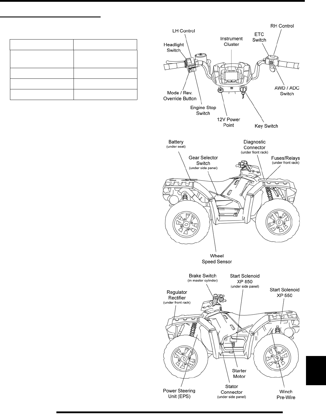
12.3
ELECTRICAL
12
GENERAL INFORMATION
Special Tools
Electrical Service Notes
Keep the following notes in mind when diagnosing an electrical
problem.
• Refer to wiring diagram for stator and electrical
component resistance specifications.
• When measuring resistance of a component that has a
low resistance value (under 10 Ohms), remember to
subtract meter lead resistance from the reading.
Connect the leads together and record the resistance.
The resistance of the component is equal to tested value
minus the lead resistance.
• Become familiar with the operation of your meter. Be
sure leads are in the proper jack for the test being
performed (i.e. 10A jack for current readings). Refer to
the Owner’s Manual included with your meter for more
information.
• Voltage, amperage, and resistance values included in
this manual are obtained with a Fluke™ 77 Digital
Multimeter (PV-43568). This meter is acceptable for
use when diagnosing electrical problems. Readings
obtained with other meters may differ.
• Pay attention to the prefix on the multimeter reading (K,
M, etc.) and the position of the decimal point.
• For resistance readings, isolate the component to be
tested. Disconnect it from the wiring harness or power
supply.
Component Locations
PART NUMBER TOOL DESCRIPTION
PV-43568 Fluke™77 Digital
Multimeter
2870836 Battery Hydrometer
2870630 Timing Light
PA-49466 Test Relay
PartShark.com
877-999-5686
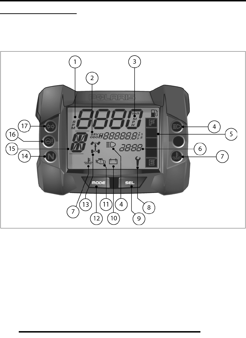
12.4
ELECTRICAL
INSTRUMENT CLUSTER
Overview
The instrument cluster displays critical vehicle information to the user. Reference the following page for display functions and
descriptions.
NOTE: Some features are not applicable to all models.
PartShark.com
877-999-5686

12.5
ELECTRICAL
12
Rider Information Display
The rider information display is located in the instrument
cluster. All segments will light up for 1 second at start-up.
NOTE: If the instrument cluster fails to illuminate, a
battery over-voltage may have occurred and the
instrument cluster may have shut off to protect the
electronic speedometer.
1. RPM / Vehicle Speed Display - LCD display of either
engine RPM or vehicle speed in MPH or km/h.
2. Information Area - Service / Odometer / Engine Hours
/ Tripmeter Display - LCD display of the service hour
interval, total vehicle miles or km., total engine hours, and
two separate trip odometers.
3. MPH / km/h Display - MPH is displayed when the
instrument cluster is in the “Standard” mode. Km/h is
displayed when the instrument cluster is in the “Metric”
mode.
4. High Beam Indicator LED and LCD icon illuminate
whenever the LH control headlamp switch is in the high
beam position.
5. Fuel Level Indicator - LCD bar graph indicating current
fuel level. All segments will flash when the last segment is
cleared indicating a low fuel warning.
6. Clock - Displays current time in either 12-hour or 24-hour
formats.
7. Engine Temperature Indicator - LED and LCD icons
illuminate when the ECU determines the engine is
overheating. The indicators will initially flash to indicate
the engine is overheating. The indicators will stay lit and
not flash if a severe overheating condition exists.
8. Service Interval Indicator - Preset at the factory at 50
hours and adjustable by the user, the icon will illuminate at
engine start-up for 10 seconds when the engine hours meet
the hour threshold indicating when maintenance should be
performed.
9. Select Button - Press and release to toggle through the
information area fields. The fields are: Odometer, tripmeter
1 / tripmeter 2, engine hours, and service interval. The
information area will also display any current Diagnostic
Trouble Codes (DTC) if applicable.
NOTE: Select button locked out when vehicle speed
is above 15 MPH.
10. Battery Voltage Indicator - LCD icon is displayed when
the battery voltage is either too low (less than 10V) or too
high (greater than 16V) as determined by the ECU.
11. Check Engine MIL - Illuminated when the ECU has
detected a Diagnostic Trouble Code in the engine
management system. Icon will flash when DTC display
mode is active.
12. Mode Button - Press and release to toggle between engine
RPM or vehicle speed displays. The mode button is also
used to change units, reset the tripmeters, enter clock set
mode, enter service interval update, toggle through DTCs,
and display the clock with key out of ignition.
NOTE: Mode button locked out when vehicle speed
is above 15 MPH.
13. AWD Indicator - Illuminated when the RH control switch
is in either AWD or ADC AWD mode.
14. Neutral Gear Indicator - LED illuminated when gear
selector is in the neutral (N) position.
15. Gear Position Indicator - Displays gear selector position.
H = High
L = Low
N = Neutral
R = Reverse
P = Park
-- = Error (shifter stuck between gears)
16. Power Steering System MIL - LED illuminates when a
fault has occurred with the power steering system. The LED
will illuminate when DTC display mode is active.
17. Turn Signal / Hazard Lamp Indicator - (International
Models Only) LED illuminates whenever the LH, RH or
hazard lamps are activated.
PartShark.com
877-999-5686
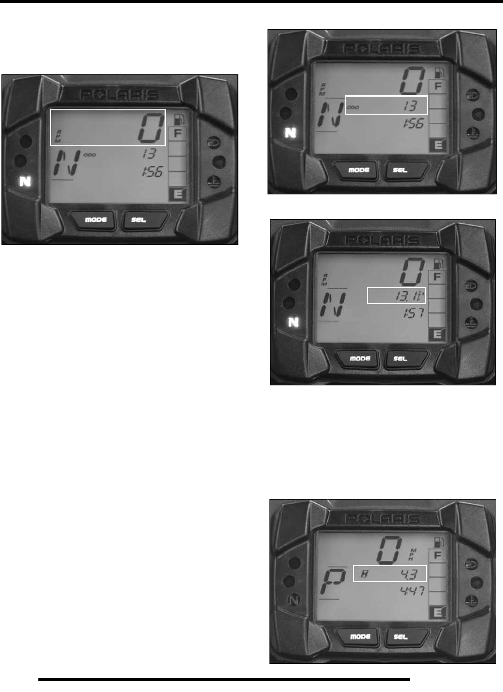
12.6
ELECTRICAL
Speed Information
The top section of the instrument cluster is dedicated to
displaying either vehicle speed or engine RPM.
1. Select N or P gear position. Function will not work through
REVERSE OVERRIDE button when reverse gear is
selected.
2. Press and release the MODE button on the instrument
cluster or press and hold the LH control REVERSE
OVERRIDE button for more than 1/2 second to toggle
between vehicle speed and engine RPM displays.
NOTE: Mode button on instrument cluster is locked
out when vehicle speed is above 15 MPH.
Information Display Area
The center of the LCD is the information display area.
Information displayed in this area includes: Odometer,
tripmeter 1 / tripmeter 2, engine hours, service interval, engine
Diagnostic Trouble Codes (DTCs), and power steering DTCs.
1. Press and release the SELECT button on the instrument
cluster or press and release the LH control REVERSE
OVERRIDE button to toggle between the information
displays.
NOTE: DTC display modes can only be accessed
using the SELECT button on the instrument cluster.
Select button on instrument cluster is locked out
when vehicle speed is above 15 MPH.
Odometer
Trip Meters 1 and 2
The trip meters record the miles traveled by the ATV on each
trip. To reset a particular trip meter:
1. Toggle the SELECT button to either TRIP1 or TRIP2.
2. To reset to 0, push and hold the MODE button until the
distance display changes to 0.
Engine Hours
PartShark.com
877-999-5686
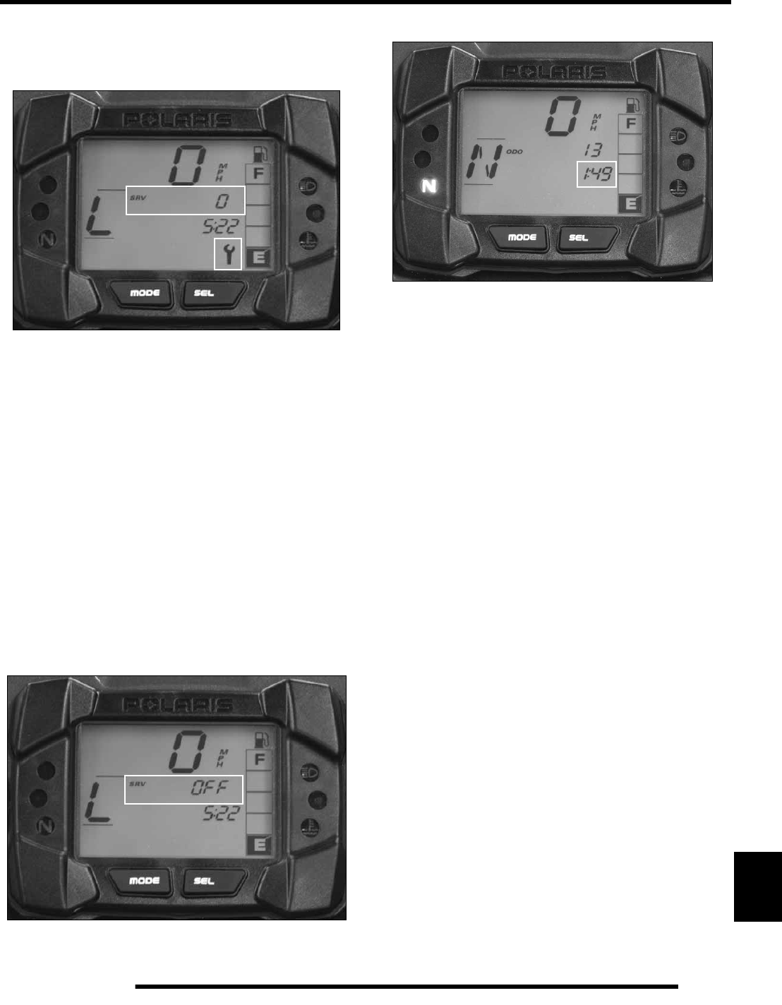
12.7
ELECTRICAL
12
Engine hours are logged anytime the engine is running. Total
hours are not re-settable.
Programmed Service Interval
The initial factory service interval setting is 50 hours. Each time
the engine is started, the engine hours are subtracted from the
service interval hours. When the service interval reaches 0, the
LCD wrench icon will illuminate for approximately 10 seconds
each time the engine is started.
To change the hour setting or reset the function, follow these
steps:
1. Toggle the SELECT button until SRV is displayed in the
information area.
2. Press and hold the MODE button until the information
display area begins to flash.
3. Toggle the SELECT button to increase the service interval
hours in 5 hour increments to a maximum of 100 hours.
4. To turn off the service interval function, toggle the
SELECT button until “OFF” is displayed.
Clock
The clock displays the time in a 12-hour or 24-hour format
depending on whether the instrument cluster units are set to
Standard or Metric on early-build vehicles.
On later build vehicles, change between 12-hour and 24-hour
formats by performing the following procedure:
1. Press and hold the MODE button until RPM is displayed.
2. Toggle the SELECT button until the odometer is displayed.
3. Press and hold the MODE button until the clock displays
the new hour format.
To view the clock when the key is out of the ignition switch,
press the MODE button. The current time will be displayed for
approximately 10 seconds.
There are two methods for setting the clock.
Method 1
1. Toggle the SELECT button until engine hours is
displayed.
2. Press and hold the MODE button until the clock begins to
flash.
3. Press and release the SELECT button to change the hours.
4. Press and release the MODE button to move to the next
position. The minutes are set in the same manner.
5. When the time is no longer flashing, the clock has been set.
PartShark.com
877-999-5686
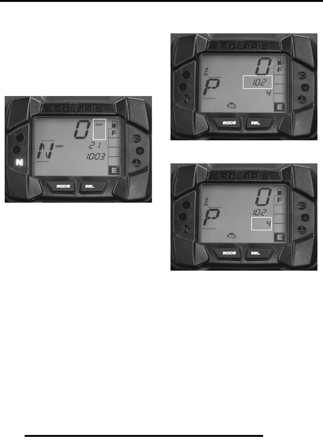
12.8
ELECTRICAL
Method 2
1. With the ignition key in the OFF position, press and hold
the MODE button.
2. While still pressing the MODE button, turn the ignition key
to the ON position. Continue holding the MODE button
until the time begins to flash.
3. Follow steps 3 - 5 in METHOD 1 to set the clock.
Units of Measurement
To change between Standard and Metric units of measurement,
follow these steps:
1. Toggle the MODE button until the vehicle speed is
displayed on the screen.
2. Toggle the SELECT button until the odometer is displayed
in the information area.
3. Press and hold the MODE button until the units of
measurement in the speedometer area change (MPH to km/
h or km/h to MPH).
4. Release the button when the desired setting is achieved. All
units including vehicle speed, odometer/ trip meters, and
clock will be set to the desired Standard or Metric units.
Diagnostic Mode
Use the following procedure to display diagnostic trouble codes
logged in the ECU if the check engine MIL is illuminated on the
instrument cluster.
1. Place the transmission in PARK.
2. Push and release the SELECT button to toggle through the
LCD display until the check engine MIL icon is flashing.
3. When the check engine MIL icon is flashing, a set of two
numbers will appear on the LCD.
4. The first number is located in the information area and can
be 2 to 6 digits in length. This number equates to the
suspected area of fault.
5. The second number will appear in the clock area and can 1
to 2 digits in length. This number equates to the fault mode.
6. Use the trouble code reference table in the EFI Chapter for
a description of each code.
7. Press and hold the MODE button to cycle through all
currently active codes.
NOTE: On vehicles equipped with power steering,
the power steering MIL LED will illuminate and blink
in place of the check engine MIL if there is a
diagnostic problem with the power steering system.
PartShark.com
877-999-5686
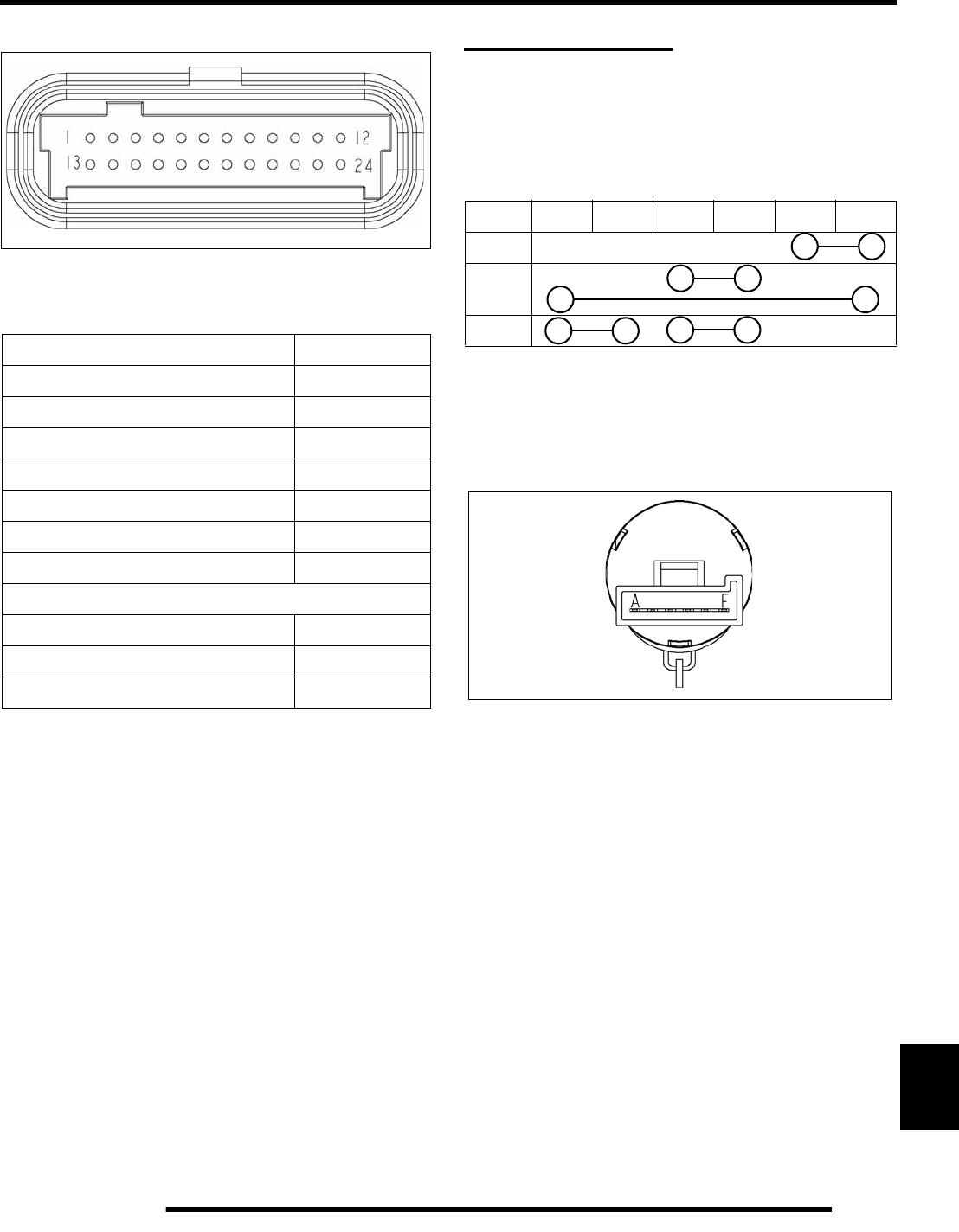
12.9
ELECTRICAL
12
Instrument Cluster Pinouts
NOTE: Some functions not found on all models.
IGNITION SWITCH
Function Test
Use a multimeter to test for continuity between the 3 sets of
ignition switch outputs (OFF / ON / START).
Turn the key to ON. There should be continuity between pins C
and D / A and F.
Turn the key to START. There should be continuity between
pins A and B / C and D.
If any of the tests fail, replace ignition switch assembly.
Instrument Cluster Pinouts
FUNCTION PIN
Battery Voltage (Vdc) 1
Ground 2
Run / Stop Switch 3
CAN High 4
CAN Low 5
High Beam Input 20
Fuel Level Sensor 23
International Models Only
Hazard Warning 10
Left Turn Signal 21
Right Turn Signal 22
Ignition Switch Test
ABCDEF
OFF
ON
START
PartShark.com
877-999-5686
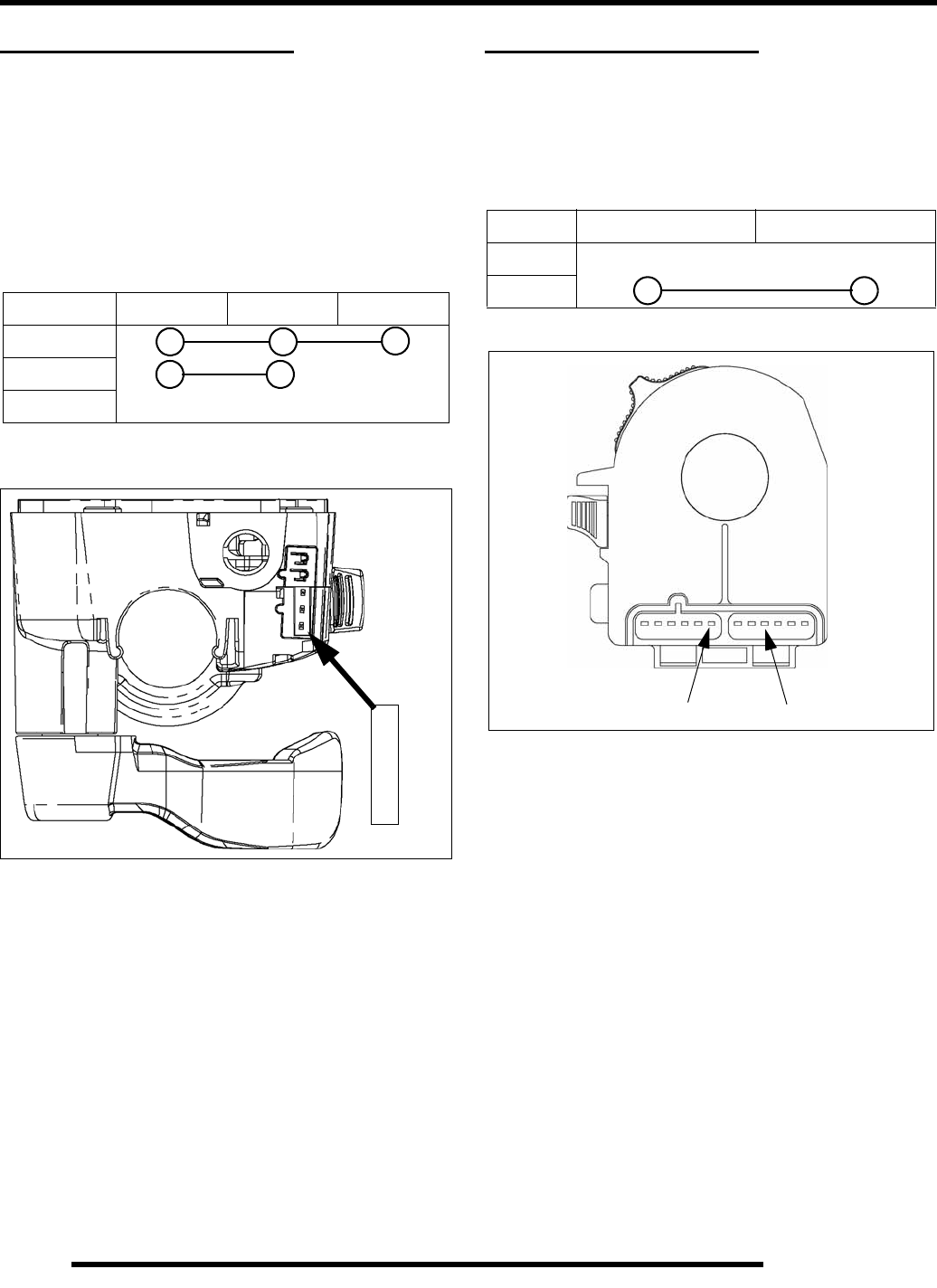
12.10
ELECTRICAL
ADC / 4X4 / 2X4 SWITCH
Function Test
Use a multimeter to test for continuity between the 2 sets of
switch outputs (ADC / 4x4).
NOTE: Selecting 2x4 drive mode does not complete
any circuits. All circuits should be OL when 2x4 is
selected.
Move the drive selector switch to each drive mode, and then test
for continuity.
If any of the tests fail, replace the RH throttle / switch assembly.
OFF / RUN LH SWITCH
Function Test
Use a multimeter to test for continuity when the LH switch is
moved to the RUN position.
Move the switch to the RUN position and test.
If the test fails, replace the LH control assembly.
ADC / AWD / 2x4 Switch Test
345
4x4 ADC
4x4 (AWD)
2x4
3
4
5
Off / Run Switch Test
F (Left Connector) C (Right Connector)
OFF
RUN
FC
PartShark.com
877-999-5686
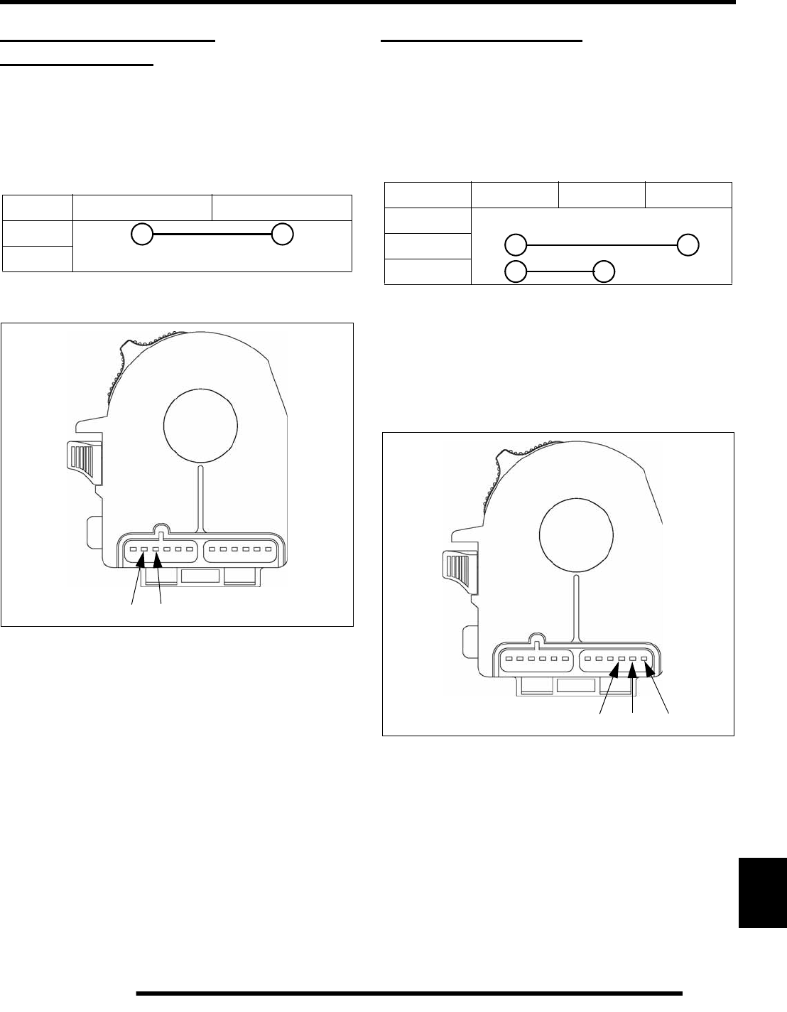
12.11
ELECTRICAL
12
REVERSE OVERRIDE /
MODE BUTTON
Function Test
Use a multimeter to test for continuity when pressing the
Reverse Override / Mode button.
Push the Reverse Override / Mode button. There should be
continuity between pins B and C.
If the test fails, replace the LH control assembly.
HEAD LAMP SWITCH
Function Test
Use a multimeter to test for continuity with the 3 head lamp
control outputs (OFF / LOW / HIGH) in the LH control
assembly.
There should be no continuity on any pin when the headlamp
switch is in the OFF position.
Move the switch to LOW. There should be continuity between
pins D and F.
Move the switch to HIGH. There should be continuity between
pins D and E.
If any of the tests fail, replace the LH control assembly.
Reverse Override / Mode Button Test
BC
FREE
PUSH
BC
Headlamp Switch Test
DEF
OFF
LOW
HIGH
DEF
PartShark.com
877-999-5686
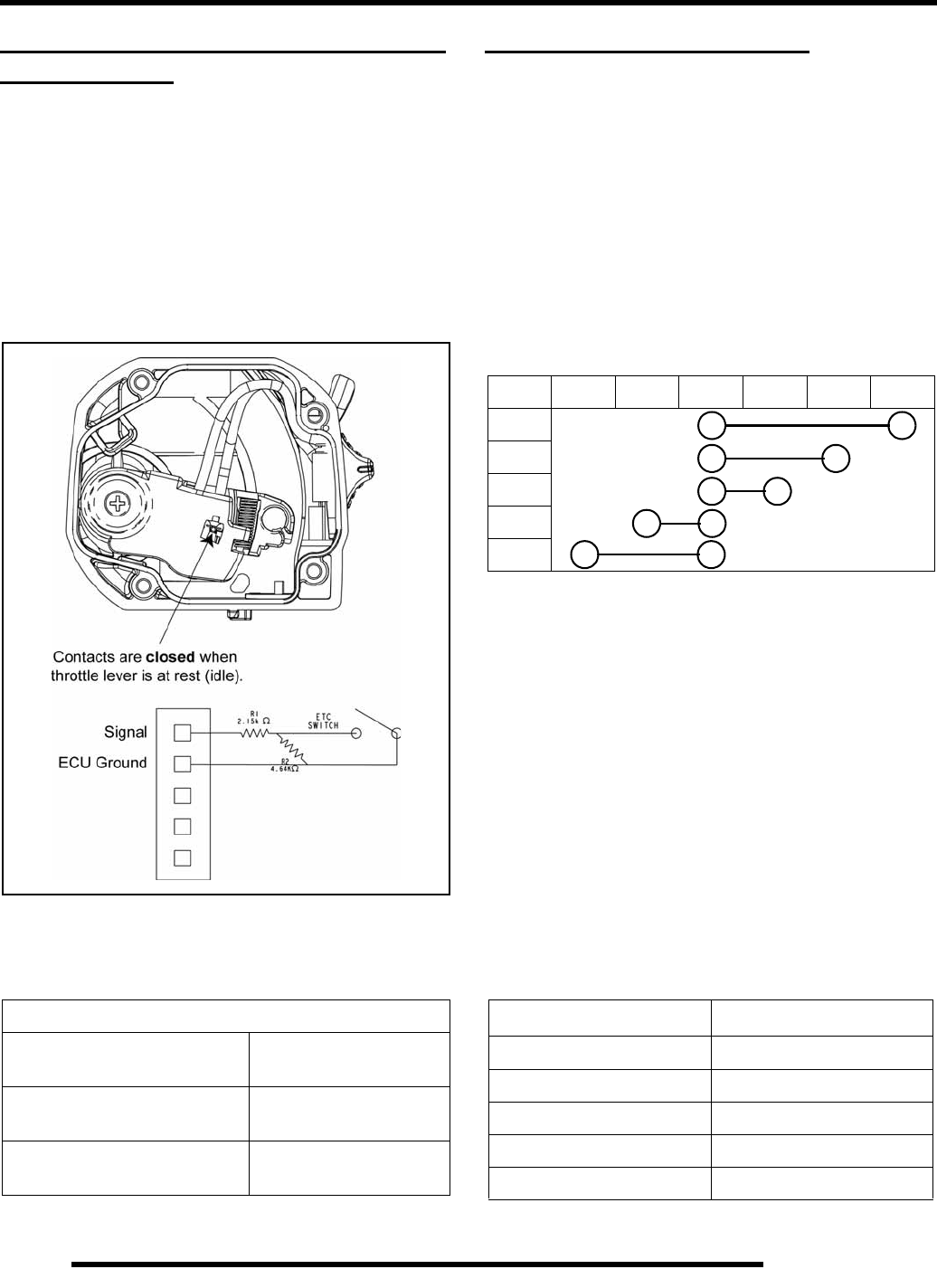
12.12
ELECTRICAL
ELECTRONIC THROTTLE CONTROL
(ETC) SWITCH
Electronic Throttle Control (ETC) Switch
The Electronic Throttle Control (ETC) switch is designed to
close during throttle movement in the event the throttle cable
sticks or breaks.
When the throttle lever is at idle position, the ETC switch
contacts should be closed (touching). When the throttle lever is
moved the contacts will open and allow normal operation. If the
contacts remain closed or become closed during throttle
movement, the ECU will limit engine RPM.
IMPORTANT: The throttle cable must have the proper
amount of free-play adjustment. Refer to Chapter 2
“Throttle Cable Adjustment” procedure.
GEAR SELECTOR SWITCH
Selector Switch Function Test
1. Locate the gear selector switch on the transmission.
Remove the wiring harness connector and insert the
multimeter probes into the switch.
2. Move the gear selector handle to each of the 5 drive
positions (HIGH, LOW, NEUTRAL, REV, or PARK).
3. Test for continuity between the switch contacts and
connector leads. Replace the switch if no continuity or high
resistance is found in any of the gear positions.
Resistor Module Function Test
The resistor module relays a different resistance reading to the
ECU depending on which gear is selected by the operator. If the
module fails, the ECU will not be able to determine what gear
the transmission is in.
NOTE: Reference Chapter 3: EFI for pin locations.
1. Disconnect the ECU harness connector from the ECU.
Locate pins 8 (WHITE) and 33 (VIOLET).
2. Set the multimeter to register OHMS (resistance). Insert the
RED probe into pin 8 and the BLACK probe into pin 33.
3. Reference the Resistance Table for specifications. If any of
the tests fail, replace the resistor module.
ETC Switch - Contact Positions
Throttle Lever at Rest (idle) ETC is CLOSED.
Pins 1 and 2 Ω = 2.15k
Normal Operation (throttle
open or above idle) ETC is OPEN.
Pins 1 and 2 Ω = 6.76k
Throttle Cable Stuck ETC is CLOSED
Pins 1 and 2 Ω = 2.15k
Gear Selector Switch Testing
ABCDEF
HIGH
LOW
NEU
REV
PARK
Module Resistance +/- 5%
Gear Position OHMS Ω
HIGH 620
LOW 300
NEUTRAL 160
REVERSE 75
PARK 24
PartShark.com
877-999-5686
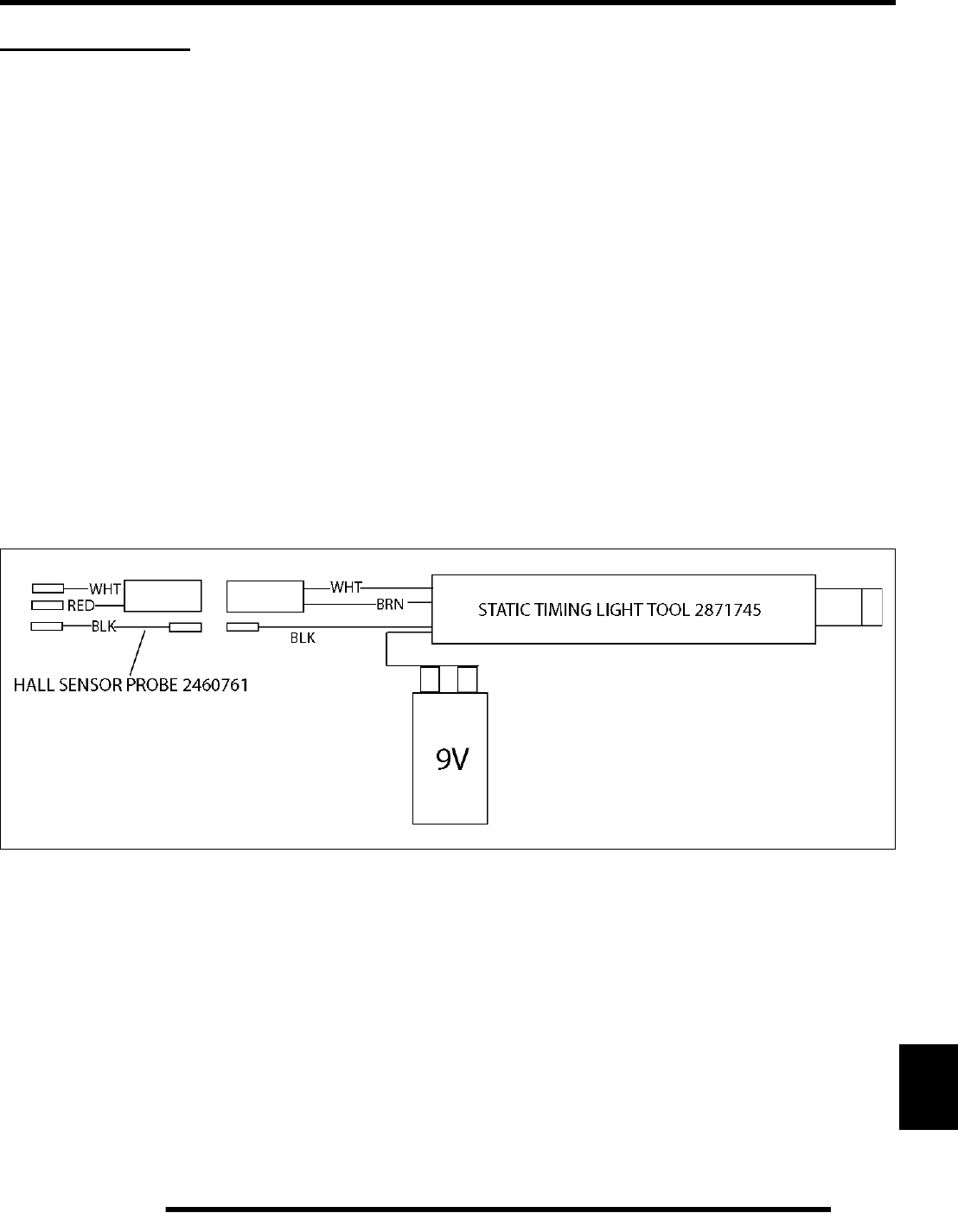
12.13
ELECTRICAL
12
SPEED SENSOR
Vehicle Speed Sensor
The vehicle speed sensor is mated to the transmission housing and reads the speed of the transmission output gear.
Battery voltage is supplied to the sensor on the ORANGE circuit and is energized when the OFF/RUN and ignition switches are in
the RUN and ON positions.
To test the circuit:
1. Turn the ignition key to the “ON” position and move the OFF/RUN switch to “RUN”.
2. Verify there is battery voltage present on the ORANGE circuit. If voltage is not found, inspect the ORANGE splices / circuits,
LH control assembly, and ignition switch.
3. If voltage is found, test the BROWN ground circuit. Verify there is continuity between the circuit and chassis ground.
4. If all circuits function, remove the speed sensor from the transmission. Verify the sensor is not damaged.
5. Test the speed sensor using the following tools:
• Hall Sensor Probe: PN 2460761
• Static Timing Light Tool: PN 2871745
6. Connect the tools together as shown below.
7. Insert the sensor probe’s 3 terminals into the speed sensor as follows:
• WHITE wire into pin C.
• BLACK wire into pin B.
• RED wire into pin A.
8. Verify a good 9V battery is connected to the timing light tool.
9. Pass the blade of a screwdriver back and forth across the sensor tip. The timing light tool LED should illuminate each time the
blade passes the sensor face.
10. If the test fails, replace the speed sensor.
PartShark.com
877-999-5686
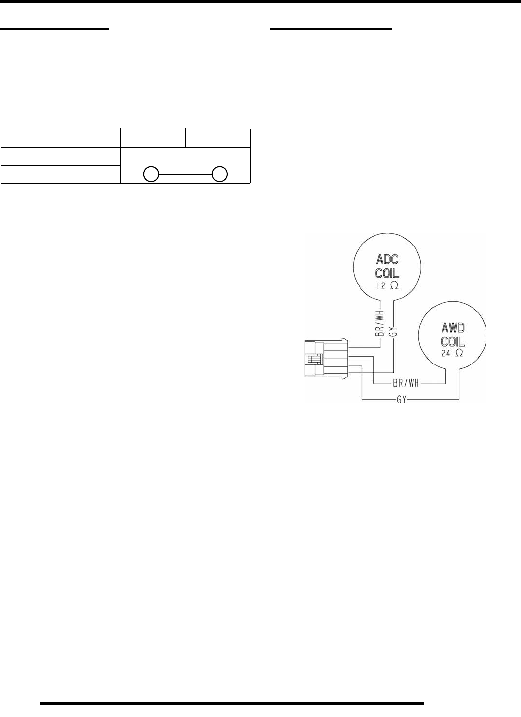
12.14
ELECTRICAL
BRAKE SWITCH
Function Test
Applying the brakes closes a switch to activate the brake lamps.
Use a multimeter to test for continuity when the brakes are
applied.
Replace the brake switch if function does not pass test.
AWD / ADC COILS
Operation Overview
• Battery voltage is always present at the AWD and ADC
coils when the CHASSIS relay is active.
• AWD and ADC coil voltage is protected by the 20A
DRIVE fuse.
• Battery voltage is always present at the ADC / 4x4 / 2x4
RH switch assembly whenever the CHASSIS relay is
active. The circuit is also protected by the 20A DRIVE
fuse.
• The ECU controls all ADC and AWD functions.
Diagnosing System Failures
• Verify the ADC/AWD switch is functional and that a
minimum of 11 volts is present at the hub coil
connection.
• Verify the ADC/AWD hub coil is functional. Test the
AWD hub coil using a multimeter.
• Verify the wiring harness, wiring, connectors,
connector pins and grounds are undamaged, clean and
connected properly.
• Verify continuity of wire connections with a known
good volt/ohm meter.
• Verify the coil wires are not connected or shorted to
ground.
IMPORTANT: Verify all wires and wiring connections
have been tested properly with a known good volt/
ohm meter before suspecting a component failure.
80% of all electrical issues are caused by bad
connections and/or grounds.
Brake Switch Test
Pin 1 Pin 2
Brakes Not Applied
Brakes Applied
PartShark.com
877-999-5686
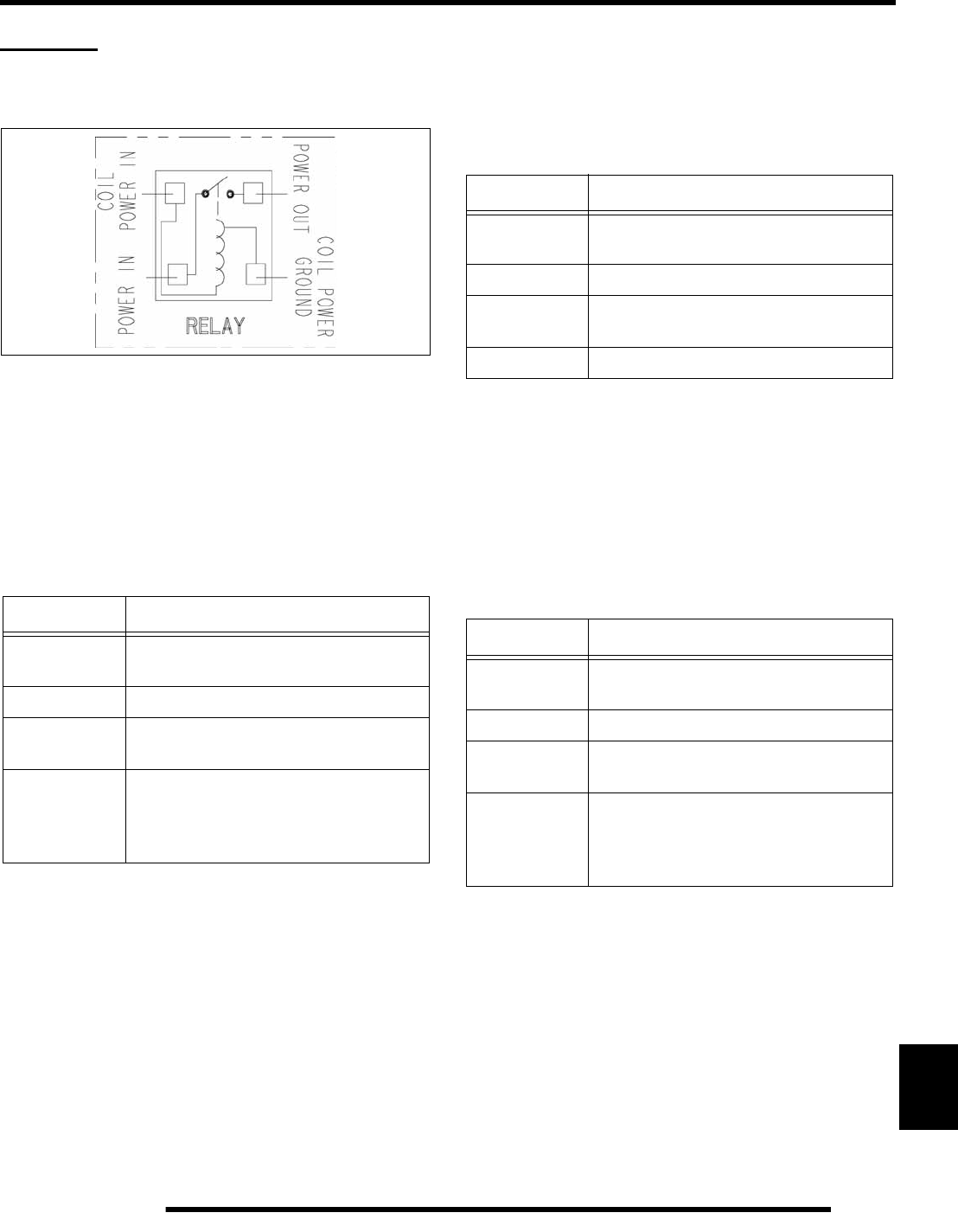
12.15
ELECTRICAL
12
RELAYS
Relay Overview
Each relay leg, or corner, performs the same function.
Chassis Relay
The chassis relay provides power to the following systems:
• Head Lights / Tail Lights / Brake Light
• AWD Coil / ADC Coil / RH Drive Switch
• Accessory Power Points
Fan Relay
The fan relay provides power to the following system:
•Fan Motor
EFI Relay
The EFI relay provides power to the following system:
• Ignition Coil Power
• Fuel Pump Power
• Fuel Injector Power
Chassis Relay
Color Function
RD Fuse link-protected 12 Vdc battery
voltage.
DB / RD ECU relay control circuit for relay coil.
ORG LH RUN switch supplied 12 Vdc battery
voltage to relay coil.
WHT
12 Vdc Bus bar for:
-Lights 20A Fuse
-Drive 20A Fuse
-Accessory 20A Fuse
Fan Relay
Color Function
RD / WHT 20A Circuit breaker-protected 12 Vdc
battery voltage.
ORG / YEL ECU relay control circuit for relay coil.
RD / WHT Constant 12 Vdc battery voltage to
relay coil.
ORG / BLK Fan motor power 12 Vdc.
EFI RELAY
Color Function
RD / GRN 20A fuse-protected 12 Vdc battery
voltage.
BRN Ground for relay coil.
ORG LH RUN switch supplied 12 Vdc battery
voltage to relay coil.
RD / BLU
12 Vdc power splice for:
-Ignition coil pack
-Fuel Pump
-Fuel Injectors
PartShark.com
877-999-5686

12.16
ELECTRICAL
Bumper Lights Relay
The bumper lights relay provides power to the following
system:
• Front Bumper Head Lights
Start Solenoid Relay
The start solenoid relay provides power to the following system:
• Starter Motor Solenoid
Power Steering Relay
NOTE: The power steering relay is not located
inside the fuse box.
The power steering relay provides power to the following
system:
• Power Steering Drive Motor
Bumper Lights Relay
Color Function
RD / BRN 20A fuse-protected 12 Vdc battery
voltage.
BRN Ground for relay coil.
DG Hi/Low LH control 12 Vdc battery
voltage to relay coil.
DG LH / RH front bumper lights power.
Start Solenoid Relay
Color Function
RD / WHT 20A circuit breaker-protected 12 Vdc
battery voltage.
BRN / WHT ECU relay control for relay coil.
WHT / RD Starter solenoid power.
BLU / RD Key-switched (START) relay coil power
12 Vdc battery voltage.
Power Steering Relay
Color Function
ORG (85) LH RUN switch supplied 12 Vdc battery
voltage to relay coil.
BRN Relay coil ground.
ORG (87) Power steering 12 Vdc battery power.
RD 30A fuse-protected 12 Vdc battery
voltage.
PartShark.com
877-999-5686
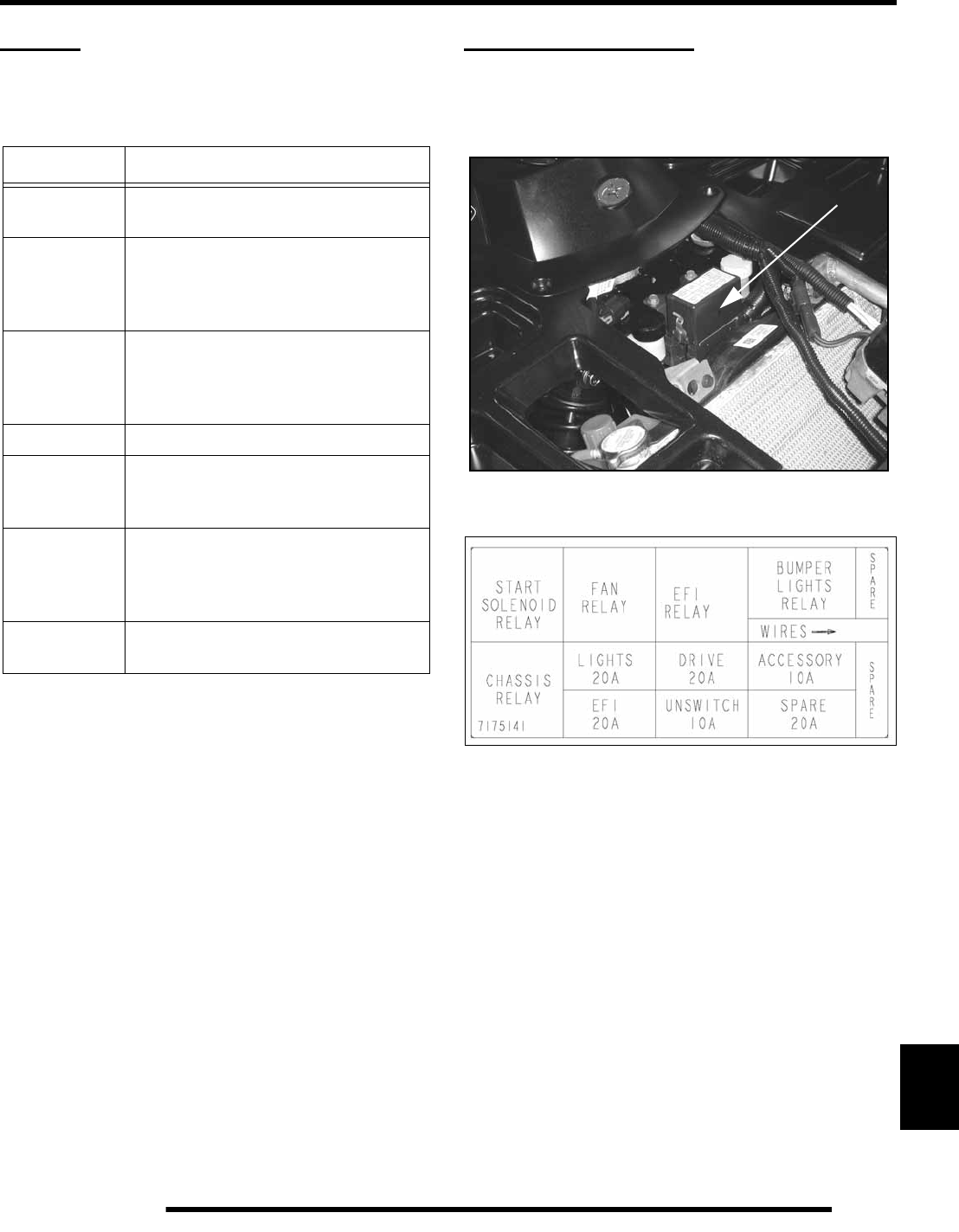
12.17
ELECTRICAL
12
FUSES
Protected Circuits
FUSE BOX LAYOUT
The fuse box is located under the front rack assembly.
To gain access, remove the front rack assembly by unlatching
the two rack interlocks.
The fuse box cover label identifies the location of each relay and
fuse.
Fuse Table
Fuse Protected Circuits
20A Circuit
Breaker Fan Motor
Starter Solenoid
20A EFI
EFI Relay-controlled circuits:
-Ignition coil pack
-Fuel Pump
-Fuel Injectors
10A
Unswitched
Power
ECU
Fan Relay Driver
Ignition Switch
Instrument Cluster
30A EPAS Power Steering Relay / Motor
20A Lights Front and rear tail lights
Brake lights
Head lights
20A Drive
AWD Coil
ADC Coil
RH AWD / ADC switch
Winch Switch Power
20A
Accessory All accessory power point pigtails.
FUSE BOX
PartShark.com
877-999-5686
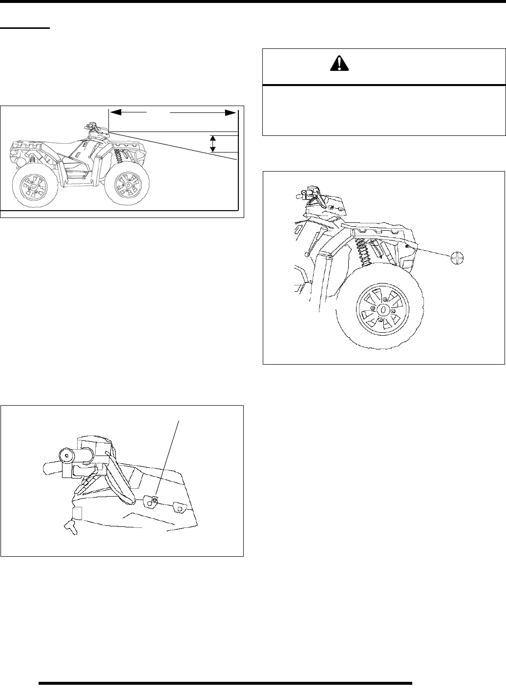
12.18
ELECTRICAL
LIGHTS
Headlight Adjustment
The headlight beam is adjustable.
1. Place the vehicle on a level surface with the headlight
approximately 25 ft. (7.6 m) from a wall.
2. Place the transmission in neutral and lock the parking
brake.
3. Measure the distance from the floor to the center of the
headlight and make a mark on the wall at the same height.
NOTE: Rider weight must be included on the seat
while performing this procedure.
4. Start the engine and turn the headlight switch to high beam.
5. Observe the headlight aim on the wall. The most intense
part of the headlight beam should be aimed 2 in. (5 cm)
below the mark placed on the wall in Step 3.
6. Loosen the adjustment screw at the rear of the headlamp.
7. Adjust the beam to desired position. Repeat the procedure
to adjust the other headlight.
Bumper Lamp Adjustment
1. Loosen the Phillips screw located at the rear of the lamp.
2. Tilt the lamp upward or downward.
3. Tighten the screw.
2 in.
25 ft.
(7.6 m)
(5 cm)
ADJUSTMENT SCREW
WARNING
Due to the nature of ATVs and where they are operated,
headlight lenses become dirty. Frequent washing is
necessary to maintain lighting quality. Riding with poor
lighting can result in severe injury or death.
PartShark.com
877-999-5686
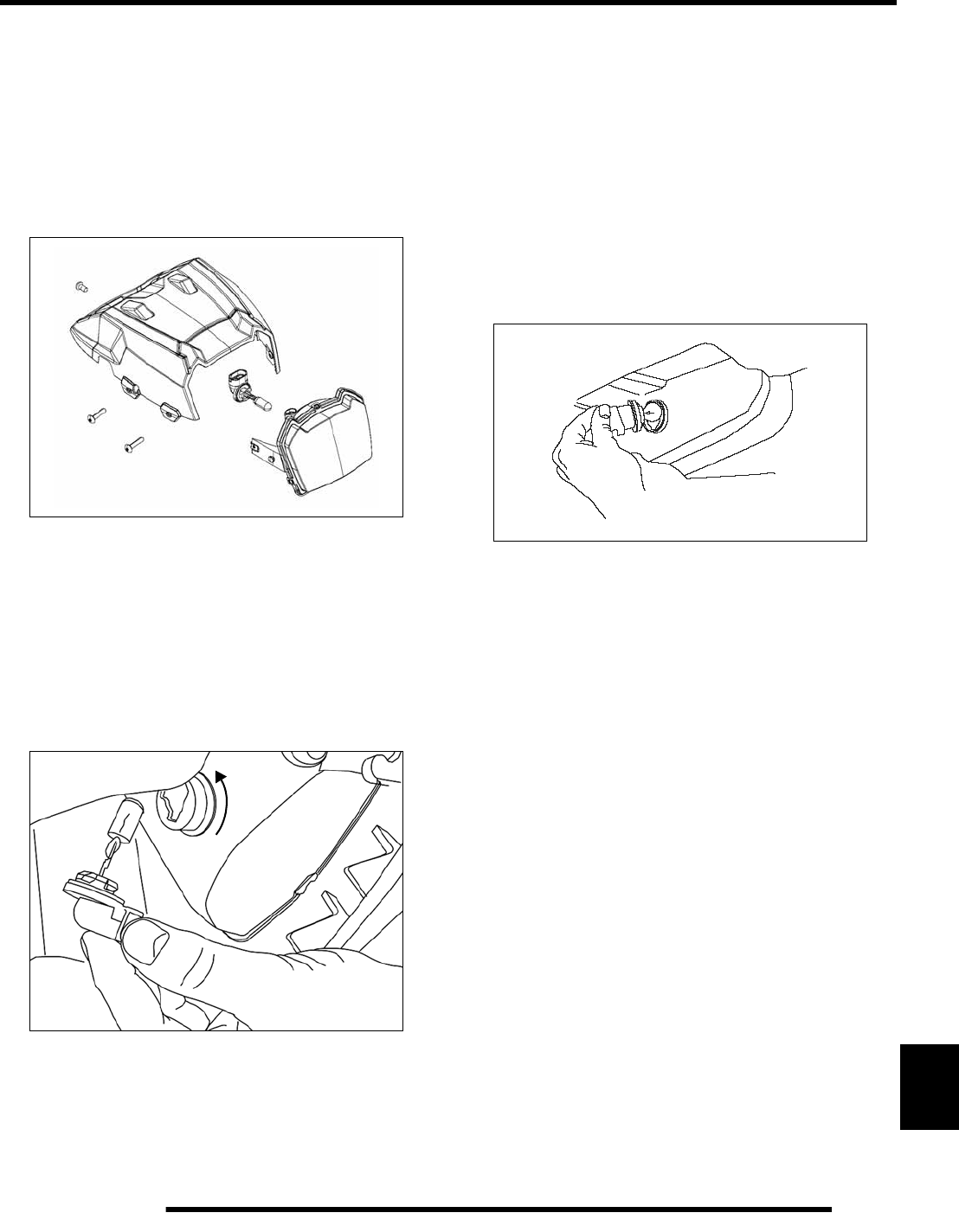
12.19
ELECTRICAL
12
Headlight Replacement
1. Remove the 4 side-mounted pod screws.
2. Carefully remove the headlight lens from the pod.
3. Unplug the headlight from the harness and remove the bulb.
4. Install a new bulb, and install the lens back into the pod.
5. Reinstall the mounting screws.
Bumper Lamp Replacement
Before replacing the lamp, use a digital multimeter to test the
harness to ensure the lamp is receiving 12 volts and that a ground
path is present.
1. Disconnect the headlight lamp from the wiring harness.
Be sure to pull on the connector, not on the wiring.
2. Turn the lamp counterclockwise to remove it.
3. Insert new the new lamp and turn it clockwise to secure it.
Reinstall the wire harness to the lamp.
NOTE: Make sure the tab on the lamp locates
properly in the housing.
Tail / Brake Bulb Replacement
Before replacing the bulb, use a digital multimeter to test the
harness to ensure the lamp is receiving 12 volts and that a ground
path is present.
If a tail light, brake light, or work light does not work the bulb
may need to be replaced.
1. Remove bulb by turning the rubber base 1/4 turn and
pulling the bulb out. Replace it with recommended bulb.
Apply Dielectric Grease (PN 2871329) to the connection.
2. Test the tail light, and brake light, to verify it is working
properly.
PartShark.com
877-999-5686
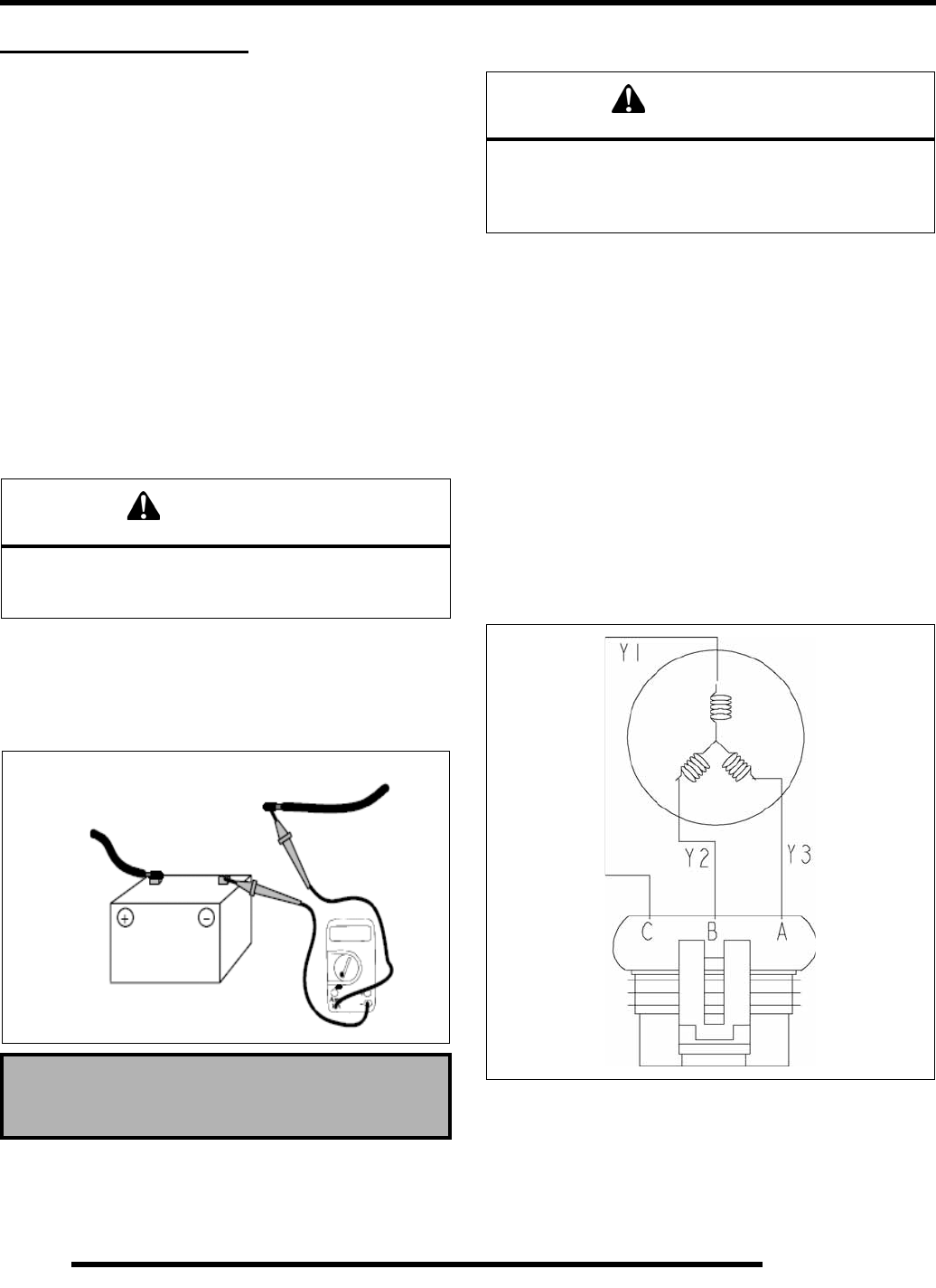
12.20
ELECTRICAL
CHARGING SYSTEM
Charging System Diagram
The charging system consists of:.
• Battery
• Stator / Alternator
• Rectifier / Regulator
The rectifier / regulator is responsible for converting AC voltage
to DC voltage.
Charging System Testing
Perform the following tests if charging system problems are
suspected:
Current Draw - Key Off
Connect an ammeter in series with the negative battery cable.
Check for current draw with the key off. If the draw is excessive,
loads should be disconnected from the system one by one until
the draw is eliminated. Check component wiring as well as the
component for partial shorts to ground to eliminate the draw.
Battery Charge Test
1. Verify the battery is fully charged and in good condition.
2. With the engine running, connect the multimeter to the
positive and negative battery terminals.
3. Test for Vdc with the multimeter.
4. The meter display should read approximately 14.0 - 14.4
Vdc at idle.
5. If the voltage is lower than 14.0 - 14.4 Vdc, the alternator
should be tested.
Stator / Alternator Tests
Three tests can be performed using a multimeter to determine
the condition of the stator (alternator).
CAUTION
Do not connect or disconnect the battery cable or
ammeter with the engine running. Damage will occur to
electrical components.
Current Draw - Key Off:
Maximum of .01 DCA (10 mA)
Current Draw Inspection
Key Off
CAUTION
Do not allow the battery cables to become disconnected
with the engine running. Follow the steps below as
outlined to reduce the chance of damage to electrical
components.
PartShark.com
877-999-5686
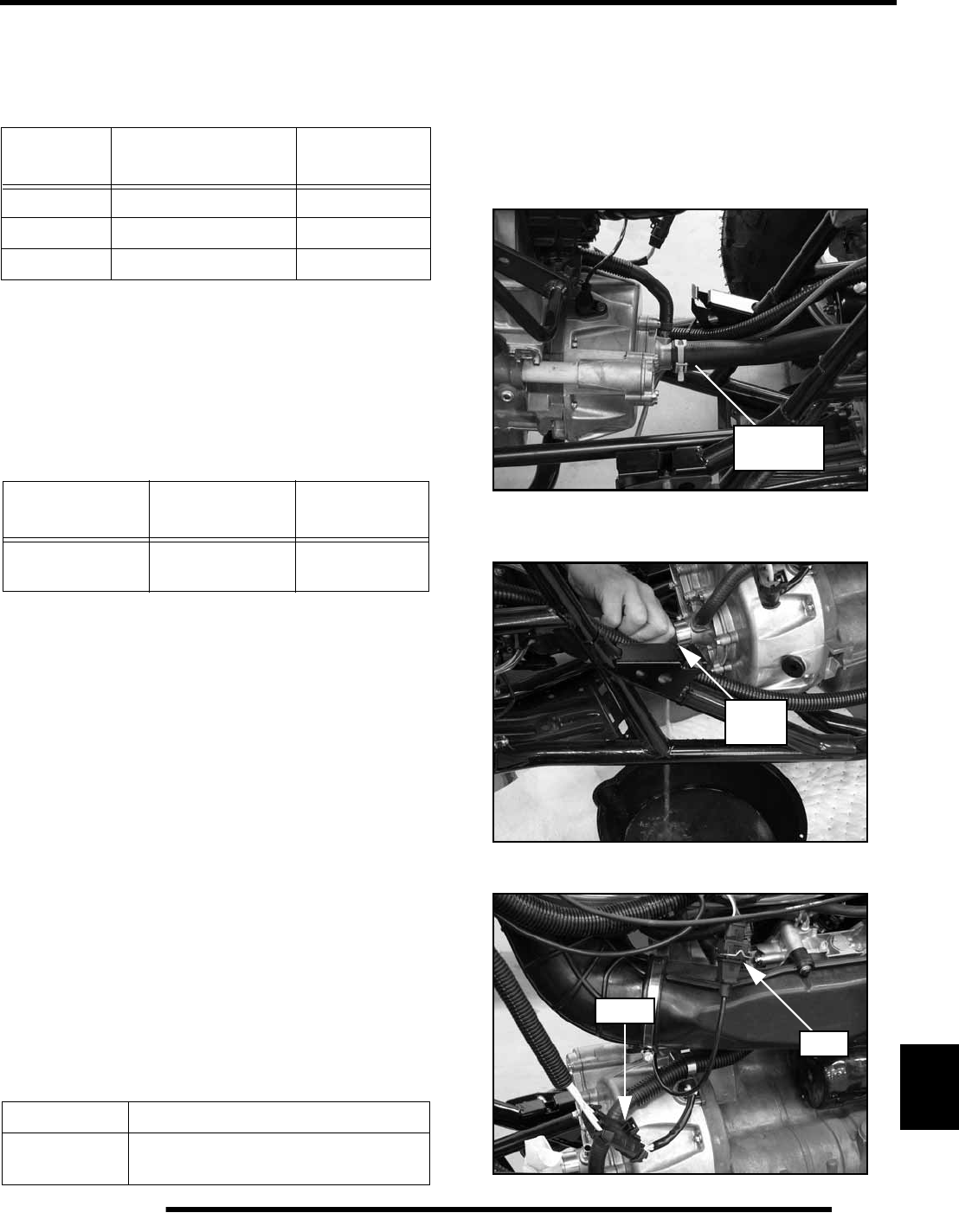
12.21
ELECTRICAL
12
TEST 1: Resistance Value of Each Stator Leg
1. Measure the resistance value of each of the three stator
legs.
NOTE: If there are any significant variations in ohm
readings between the three legs, one of the three
stator legs may be weak or failed.
TEST 2: Resistance Value of Each Stator Leg to Ground
1. Measure the resistance value of each of the stator legs to
ground.
NOTE: Any measurement other than Infinity (open)
will indicate a failed or shorted stator leg.
TEST 3: Measure AC Voltage Output of Each Stator Leg at
Charging RPM
1. Set your multimeter meter to measure AC Voltage.
2. Disconnect the 3-wire stator connector near the voltage
rectifier/regulator.
3. Start the engine and let it idle.
4. While holding the engine at a specified RPM, separately
measure the voltage across each ‘leg’ of the stator by
connecting the meter leads to the wires leading from the
stator (Y1 to Y2, Y1 to Y3, Y2 to Y3).
5. Refer to the following table for approximate AC Voltage
readings according to RPM. Test each leg at the specified
RPM in the table.
NOTE: If one or more of the stator leg output AC
voltage varies significantly from the specified value,
the stator may need to be replaced.
Stator / Alternator Removal
1. Remove the fuel tank (see Chapter 3).
2. Remove the (4) screws retaining the engine skid plate and
remove the plate from the vehicle.
3. Place a drain pan under the front portion of the engine.
4. Remove the coolant hose from the water pump housing.
5. Slowly drain the coolant into the drain pan. Dispose of used
coolant properly.
6. Disconnect the stator and CPS wire harnesses.
Test Connect Meter
Leads To: Ohms Reading
Charge Coil Y1 to Y2 (Pin B to C) 0.19Ω ± 15%
Charge Coil Y1 to Y3 (Pin A to C) 0.19Ω ± 15%
Charge Coil Y2 to Y3 (Pin A to B) 0.19Ω ± 15%
Test Connect Meter
Leads To: Ohms Reading
Battery Charge
Coil Y1, Y2, or Y3
to Ground Open Line
(Infinity)
RPM Reading AC Voltage Reading
6000 115 Vac ± 10 % (Nominal)
171 Vac ± 10 % (Peak)
Coolant
Inlet Hose
Drain
HERE
Stator
CPS
PartShark.com
877-999-5686
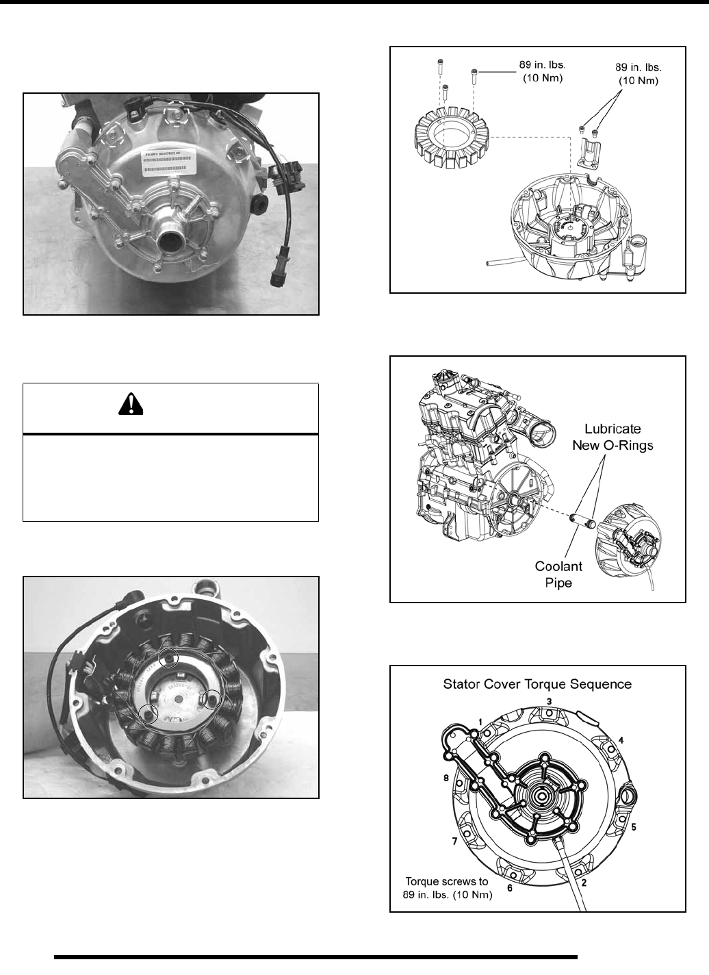
12.22
ELECTRICAL
7. Remove the coolant by-pass hose from the water pump
cover fitting.
8. Remove the (8) screws retaining the stator cover.
9. Carefully remove the stator cover taking care not to damage
the plastic coolant pipe.
10. Remove the CPS, stator wire guide, and stator from the
cover.
Stator / Alternator Installation
1. Reverse the “Stator / Alternator Removal” procedure to
reinstall the stator.
2. Use the following steps to ensure proper assembly.
3. Torque the stator and wire guide bolts to specification.
4. Install new O-rings on the coolant pipe and lightly lubricate
for ease of installation.
5. Torque the (8) stator cover bolts to specification using the
torque sequence provided.
CAUTION
The flywheel contains powerful magnets. Use
caution when removing and installing the stator
cover. DO NOT place fingers between cover and
crankcase at any time during the removal /
installation process or injury could result.
Shown with engine
removed for clarity.
PartShark.com
877-999-5686
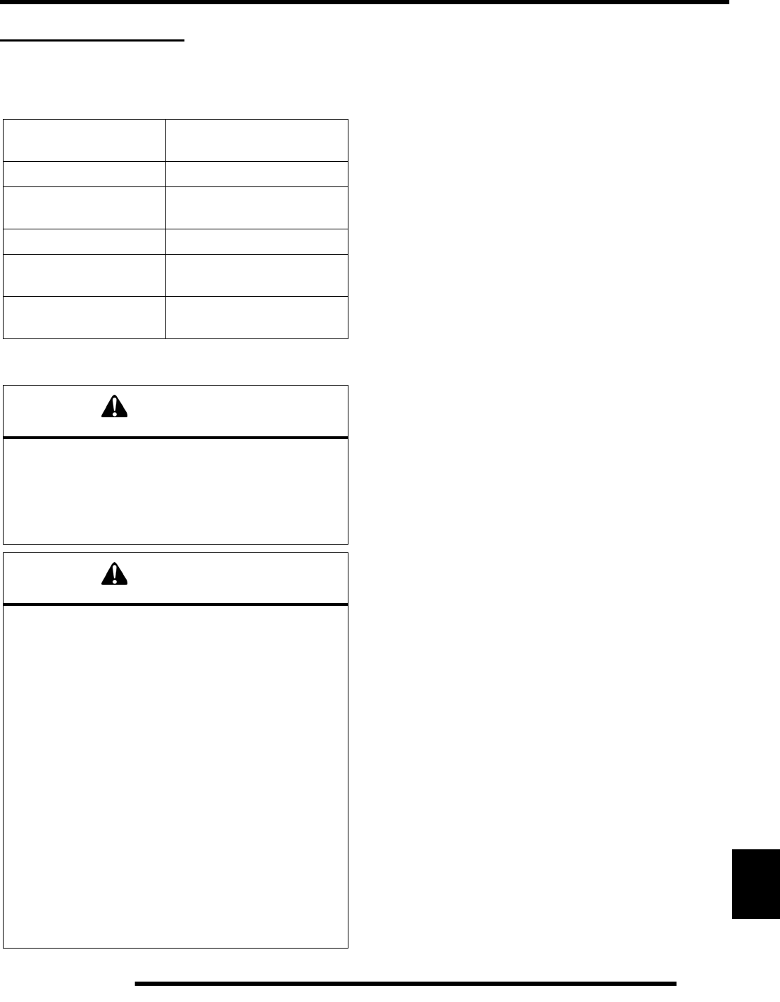
12.23
ELECTRICAL
12
BATTERY SERVICE
Battery Specifications
General Battery Information
1. Check battery voltage with a volt/ohm meter. A fully
charged battery should be 12.8 V or higher.
2. If the voltage is below 12.6 V, the battery will need to be
recharged (see “Charging Procedure”).
NEVER attempt to open the battery. If the seal is broken, the
battery will be ruined and will fail within a few weeks.
To service a Maintenance Free battery:
1. Remove battery from the vehicle (see Chapter 2).
2. Test battery with a voltage meter or load tester to determine
battery condition. This will determine the length of time
required to charge the battery to full capacity. Refer to OCV
table (see “OCV - Open Circuit Voltage Test”).
3. Charge the battery as recommended (see “Charging
Procedure”).
Battery Removal / Installation
See Chapter 2 “Maintenance” for battery removal and
installation procedures.
Battery Off Season Storage
Whenever the vehicle is not used for a period of three months or
more, remove the battery from the vehicle, ensure that it's fully
charged, and store it out of the sun in a cool, dry place. Check
battery voltage each month during storage and recharge as
needed to maintain a full charge.
NOTE: Battery charge can be maintained by using a
Polaris battery tender charger or by charging once a
month to make up for normal self-discharge. Battery
tenders can be left connected during the storage
period, and will automatically charge the battery if
the voltage drops below a pre-determined point.
Battery Testing
Whenever a service complaint is related to either the starting or
charging systems, the battery should be checked first.
Following are two tests which can easily be made on a sealed
Maintenance Free battery to determine its condition: OCV Test
and a Load Test.
Battery PN 4011224
Type Polaris / Deka ETX30L
Sealed - Maintenance Free
Voltage 12 Vdc
Nominal Capacity
@ 10 HR Rate 26
CCA 365
Nominal Open Circuit
Voltage 12.8 Vdc or more.
Recommended
Charging Rate 14.3 - 14.6 Vdc
WARNING
CALIFORNIA PROPOSITION 65 WARNING:
Batteries, battery posts, terminals and related
accessories contain lead and lead compounds, and
other chemicals known to the State of California to
cause cancer and birth defects or other reproductive
harm. WASH HANDS AFTER HANDLING.
WARNING
Battery electrolyte is poisonous. It contains acid!
Serious burns can result from contact with the skin,
eyes, or clothing.
ANTIDOTE:
External: Flush with water.
Internal: Drink large quantities of water or milk. Follow
with milk of magnesia, beaten egg, or vegetable oil.
Call a physician immediately.
Eyes: Flush with water for 15 minutes and get prompt
medical attention.
Batteries produce explosive gases. Keep sparks,
flame, cigarettes, etc. away. Ventilate when charging
or using in closed space. Always shield eyes when
working near batteries.
Keep out of reach of children.
PartShark.com
877-999-5686
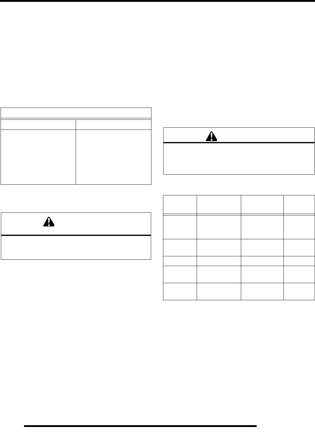
12.24
ELECTRICAL
OCV - Open Circuit Voltage Test
Battery voltage should be checked with a digital multitester.
Readings of 12.6 volts or less require further battery testing and
charging. See the following chart and “Load Test”.
NOTE: Maintenance Free batteries should be kept at
a high state of charge during storage. If the battery
is stored or used at a low state of charge, hard
crystal sulfation will form on the plates, reducing the
efficiency and service life of the battery.
NOTE: Use a volt/ohm meter to test battery voltage.
Load Test
A battery may indicate a full charge condition in the OCV test,
but still may not have the storage capacity necessary to properly
function in the electrical system. For this reason, a battery
capacity or load test should be conducted whenever poor battery
performance is encountered.
To perform this test, use a load testing device that has an
adjustable load. Apply a load of three times the ampere-hour
rating. At 14 seconds into the test, check battery voltage. A
good 12V battery will have at least 10.5 volts. If the reading is
low, charge the battery and retest.
Charging Procedure
If battery voltage is 12.6 Vdc or less, the battery may need
recharging. When using an automatic charger, refer to the
charger manufacturer’s instructions for recharging.
Do not exceed 10 amps when charging the 4011224 battery.
NOTE: Charge the battery using an automatic
charger that will not exceed 14.6 Vdc. An automatic
charger will signal when charging is complete.
NOTE: Allow the battery to stand disconnected for
several hours after being properly charged. If the
voltage drops below 12.6 volts, charging was
ineffective or the battery needs to be replaced.
Battery Charging Reference Table
NOTE: Follow the charger instructions supplied by
the manufacture regarding the order or connections,
switch positions and when to connect the charger to
an outlet.
OPEN CIRCUIT VOLTAGE
State of Charge Maintenance Free
100% 12.8 V and up
75% Charged 12.6 V
50% Charged 12.3 V
25% Charged 12.0 V
0% Charged 11.8 V or less
CAUTION
To prevent shock or component damage, remove spark
plug high tension leads and connect securely to
engine ground before proceeding.
WARNING
An overheated battery could explode, causing severe
injury or death. Always watch charging times carefully.
Stop charging if the battery becomes very warm to the
touch. Allow it to cool before resuming charging.
State of
Charge Voltage (DC) Action Charge
Time
100% 12.8 or more None, check
again in 3
months
None
Required
75% - 100% 12.6 - 12.8 May need
slight charge 3 - 6 hrs
50% - 75% 12.3 - 12.6 Needs Charge 5 - 11 hrs
25% - 50% 12.0 - 12.3 Needs Charge At least
13 hrs
0% - 25% 12.0 or less Needs Charge At least
20 hrs
PartShark.com
877-999-5686
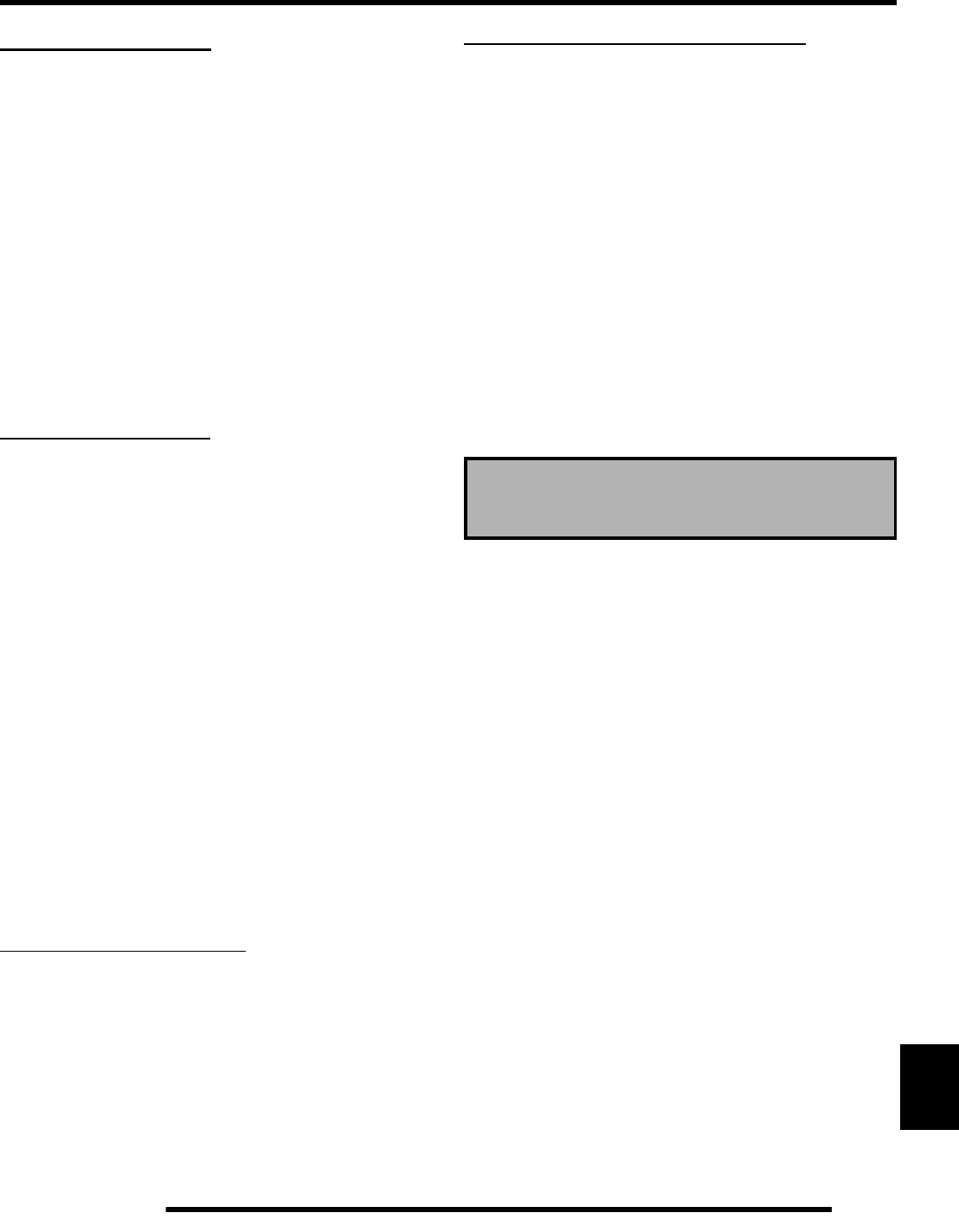
12.25
ELECTRICAL
12
STARTER MOTOR
Starter / Starter Lockout System Diagram
The starter and starter lockout system consists of:
• Battery / Fuse or Circuit Breaker
• Key Switch / Off/Run Switch
• Starter Solenoid
• Brake Switch / Transmission (Neutral) Switch
• Start Diode
•Starter Motor
Troubleshooting
Starter Motor Does Not Run
• Battery discharged
• Loose or faulty battery cables or corroded connections
(see Voltage Drop Tests)
• Related wiring loose, disconnected, or corroded
• Poor ground connections at battery cable, starter motor
or starter solenoid (see Voltage Drop Tests)
• Faulty key switch or Off/Run Switch
• Faulty transmission switch
• Faulty Start Diode(s). Use a digital multi-meter to test
diode operation. Locate the diode(s) in the main
harness under the hi-temp conduit and measure between
the diode connections. Continuity should flow one
direction only.
• Faulty starter solenoid or starter motor
• Engine problem - seized or binding (can engine be
rotated easily)
Starter Motor Turns Over Slowly
• Battery discharged
• Excessive circuit resistance - poor connections (see
Voltage Drop Test)
• Engine problem - seized or binding (can engine be
rotated easily)
• Faulty or worn brushes in starter motor
Starter Motor Turns - Engine Does Not Rotate
• Faulty starter drive
• Faulty starter drive gears or starter motor gear
• Faulty flywheel gear or loose flywheel
Voltage Drop Testing
The Voltage Drop Test is used to test for bad connections. When
performing the test, you are testing the amount of voltage drop
through the connection. A poor or corroded connection will
appear as a high voltage reading. Voltage shown on the meter
when testing connections should not exceed 0.1 VDC per
connection or component.
To perform the test, place the meter on DC volts and place the
meter leads across the connection to be tested. Refer to the chart
on 9.35 to perform voltage drop tests on the starter system.
Voltage should not exceed 0.1 Vdc
per connection.
PartShark.com
877-999-5686
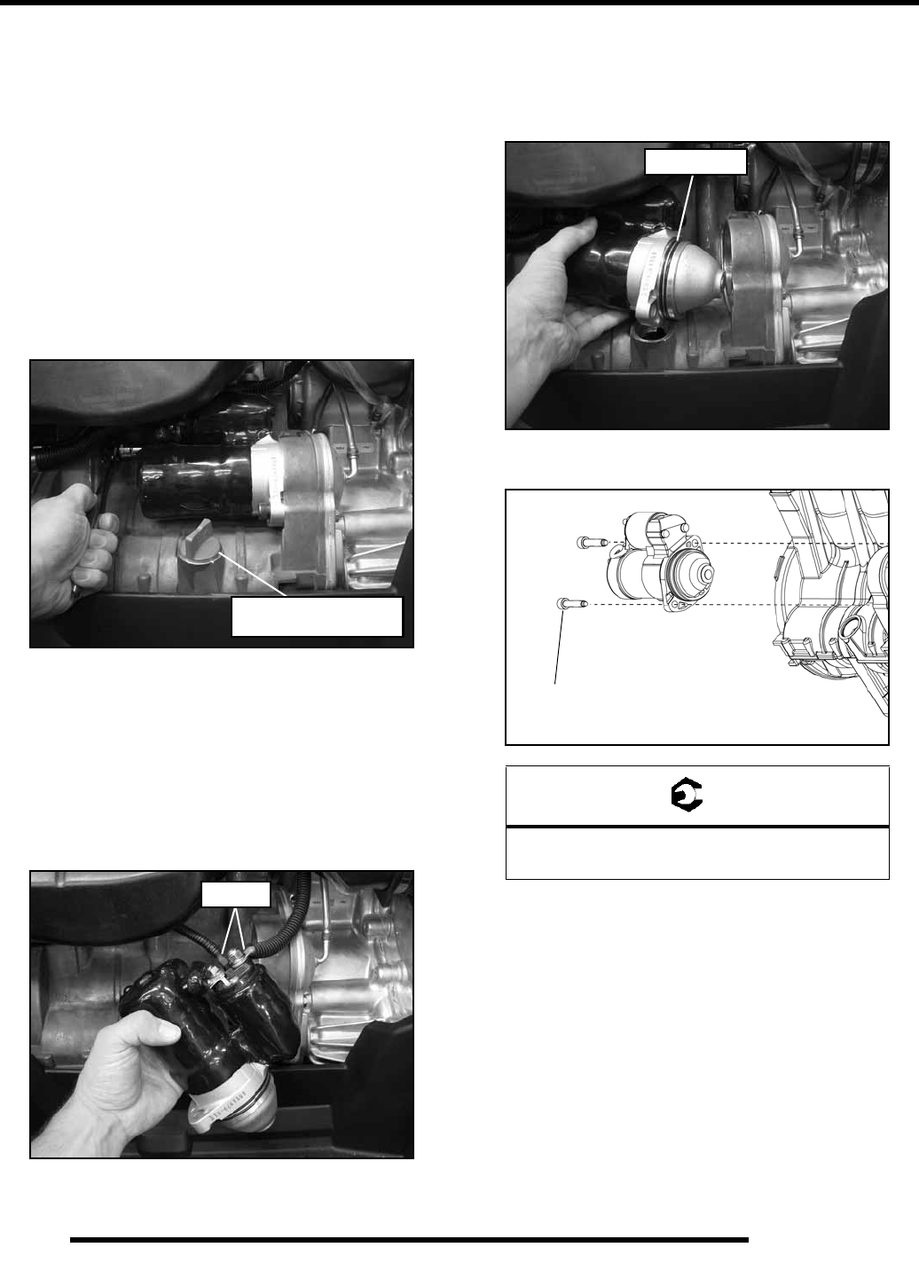
12.26
ELECTRICAL
Starter Motor Removal / Replacement
IMPORTANT: The starter motor and solenoid can not
be serviced. Removing the black protective coating
from the components will allow for premature
component failure. Replace the starter motor and
solenoid as an assembly.
1. Remove the seat and the upper and lower LH side panels.
2. Disconnect the battery negative (-) cable.
3. Clean the area around the starter motor.
4. Using an 8 mm allen socket, with an extension, remove the
(2) bolts retaining the starter motor.
5. Remove the engine oil dipstick to allow for starter motor
removal.
6. Remove the starter motor from the crankcase housing.
Reinstall the engine oil dipstick.
7. Remove the key switch energize wire and battery cable
from the starter solenoid. Remove the starter motor
assembly from the chassis.
8. Install the new starter motor assembly by reversing this
procedure.
9. Be sure to install new O-rings on the starter motor bell
housing.
10. Torque the mounting bolts to specification.
Remove dipstick to allow
for starter motor removal
Remove
= T
Starter Motor Mounting Bolts:
20 ft. lbs. (27 Nm)
NEW O-Rings
20 ft. lbs.
(27 Nm)
PartShark.com
877-999-5686
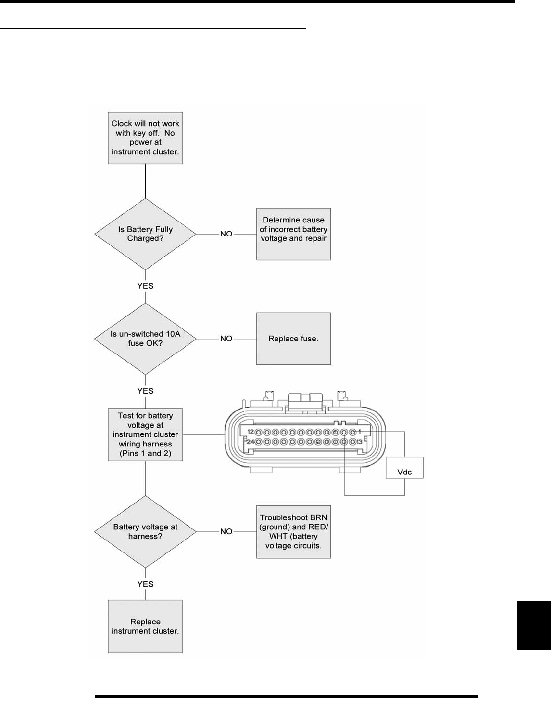
12.27
ELECTRICAL
12
INSTRUMENT CLUSTER TROUBLESHOOTING
The following 4 diagnostic tests can be performed without using Digital Wrench. Troubleshooting functions not listed here can be
found using Digital Wrench Guided Diagnostics.
Instrument Cluster - Key OFF / No Power
PartShark.com
877-999-5686
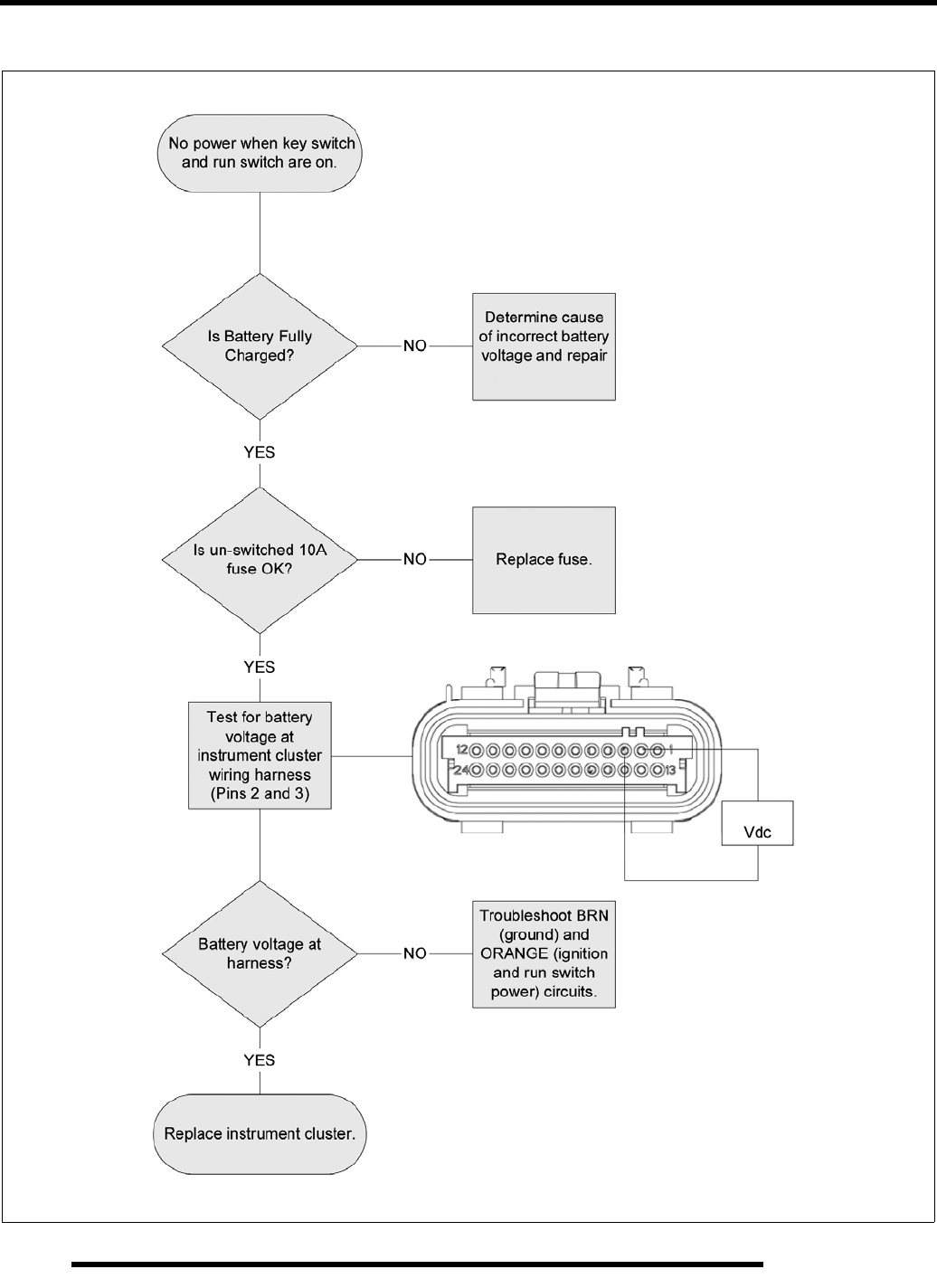
12.28
ELECTRICAL
Instrument Cluster - Key ON / No Power
PartShark.com
877-999-5686
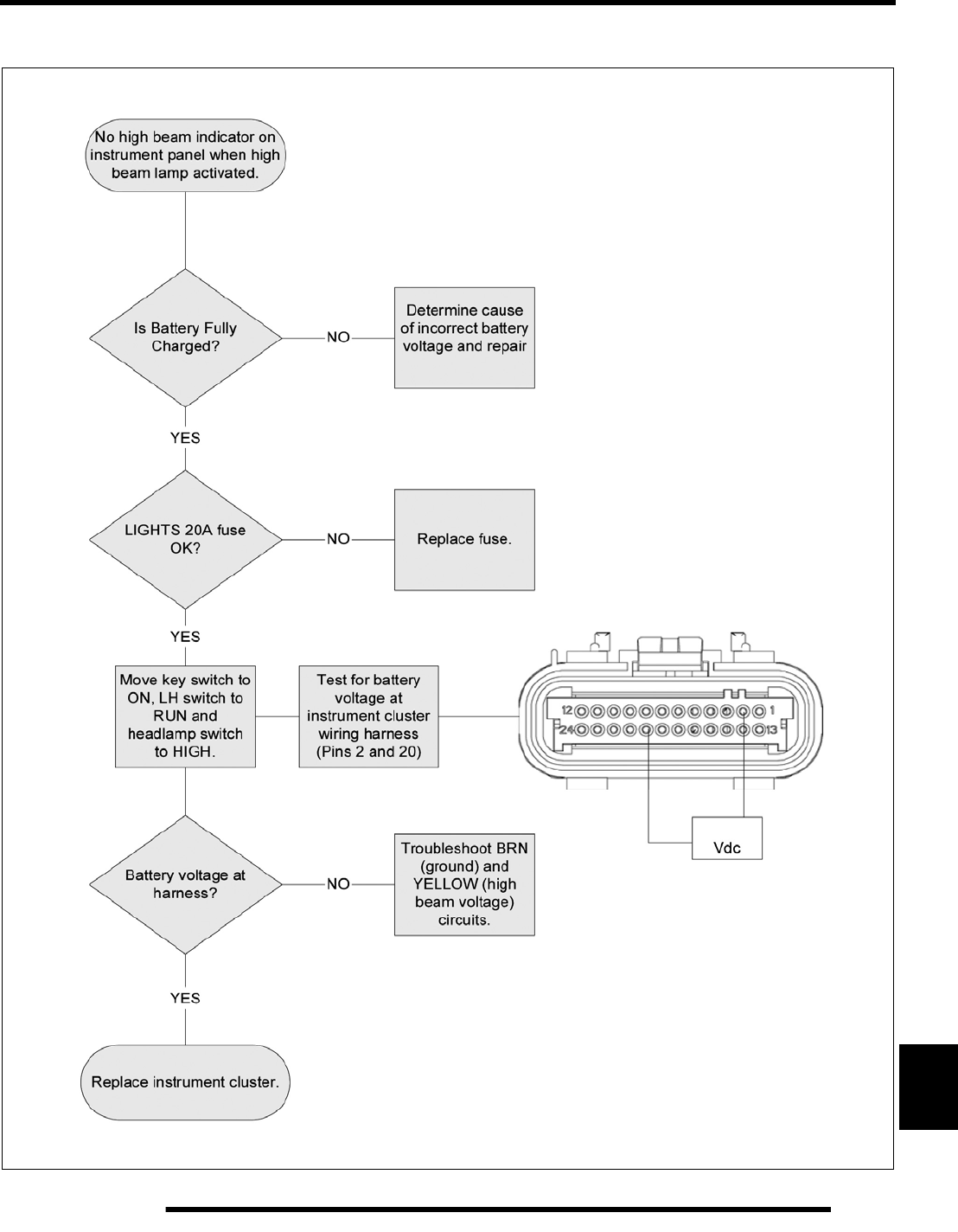
12.29
ELECTRICAL
12
Instrument Cluster - No High Beam Indicator
PartShark.com
877-999-5686
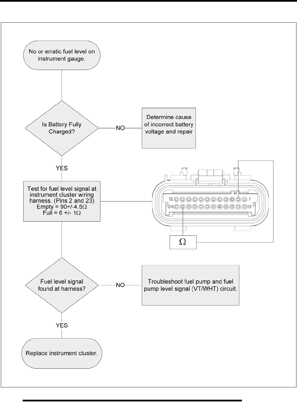
12.30
ELECTRICAL
Instrument Cluster - No / Incorrect Fuel Level
PartShark.com
877-999-5686
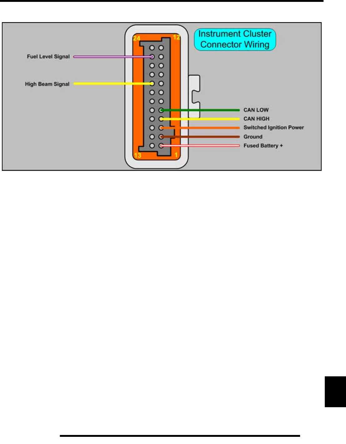
12.31
ELECTRICAL
12
Instrument Cluster Circuit
PartShark.com
877-999-5686
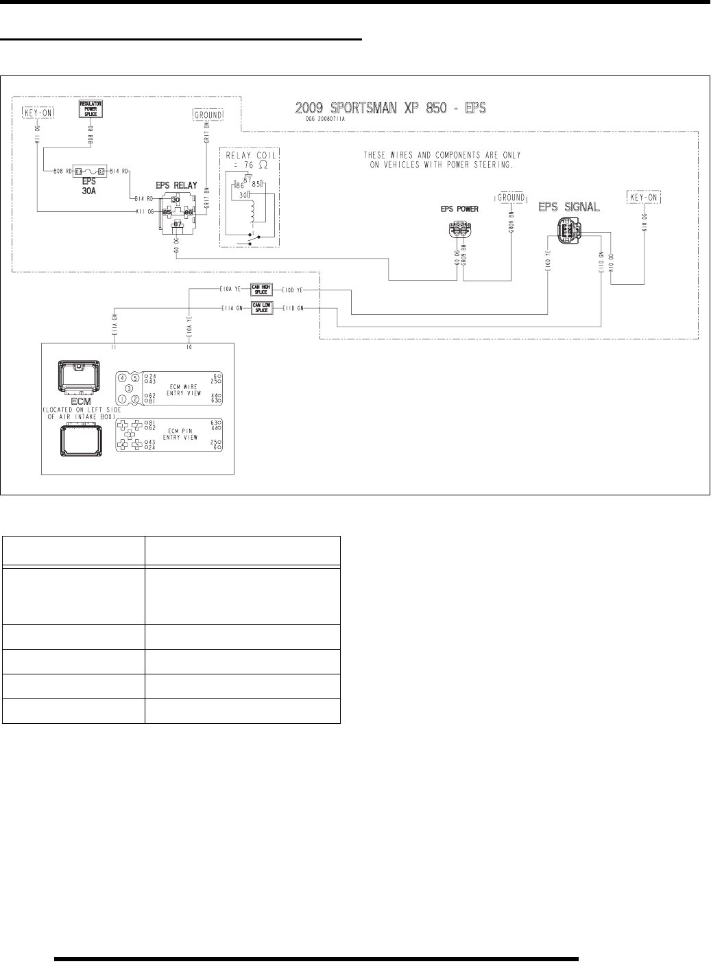
12.32
ELECTRICAL
ELECTRONIC POWER STEERING (EPS)
Electronic Power Steering (EPS) Circuits
EPS Operation
The EPS module is an intelligent electronic power steering
system that operates off of the vehicle’s 12V electrical system.
It calculates steering assist by sensing the difference between
the input torque of the steering post and the output torque
required to turn the wheels, and then provides assist by
energizing an electric motor. The process provides a smooth,
seamless assist.
The system is continuously running diagnostic checks and
monitoring factors such as battery voltage, ground speed and
engine speed. In the event an internal or external issue that
affects the EPS system is detected, the system will illuminate a
fault indicator and transition to a normal mechanically coupled
steering system. The system is Polaris Digital Wrench™
compatible for simplified diagnostics and system
troubleshooting through the vehicle’s diagnostic port.
With the engine off and the key on, the power steering unit will
operate for up to five minutes. After the five minutes, you will
need to either cycle the key switch or start the engine to regain
power steering operation.
The Power Steering 30A Fuse.
• If the fuse fails, the Power Steering Malfunction
Indicator Light (MIL) on the instrument cluster will
illuminate. During this time, the vehicle will have no
power steering operation. You will be able to connect
and communicate with the vehicle’s Engine Controller,
but not the Power Steering Controller, while using
Digital Wrench™.
Wire Color Functions
Wire Color Function
ORANGE Key-On / Run Switch On Battery
Voltage
EPS Power
RED Battery Voltage
BROWN Ground
YELLOW CAN High Signal
GREEN CAN Low Signal
PartShark.com
877-999-5686
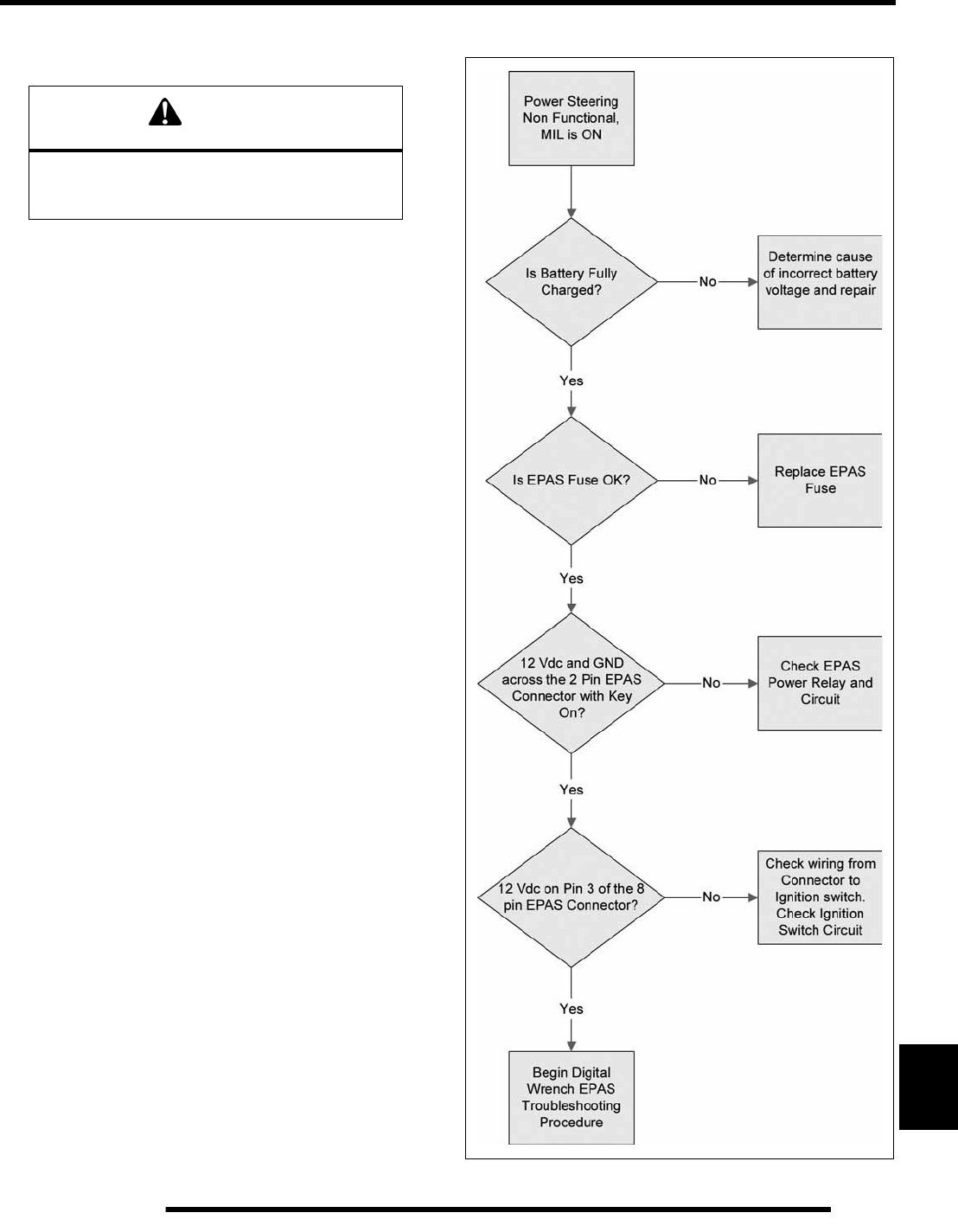
12.33
ELECTRICAL
12
NOTE: DO NOT SPLICE OR CUT INTO THE CAN
CIRCUITS.
NOTE: Refer to Chapter 10 “Steering / Suspension”
for power steering unit removal and installation
procedures.
EPS 8-Way Wire Harness Connector
The 8-way connector, two rows of four pins, does not have a
channeled lock on both sides, allowing it to be installed 180°
from its intended position. The connector will not positively
engage or snap into place while in the wrong position, but can
still be installed. If the connector is not installed correctly on a
Sportsman XP, the Power Steering Unit will not function. This
situation can be avoided by paying close attention when
installing the 8-way connector. If the 8-way is connected
properly, the vehicle should have assist with the key on.
EPS Troubleshooting
WARNING
Electronic Power Steering (EPS) units are not
interchangeable between ATV and RANGER
product lines.
PartShark.com
877-999-5686
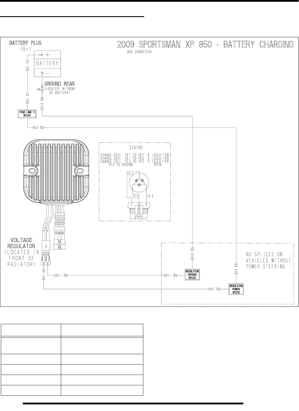
12.34
ELECTRICAL
ELECTRICAL BREAKOUT DIAGRAMS
Battery Charging Circuits
NOTE: If the temperature of the regulator / rectifier
exceeds 194°F (90°C), the unit will turn itself off to
cool down. The unit will turn on at approximately
167°F (75°C).
If the regulator / rectifier turns off, verify the housing
cooling fins are clean and free from debris and
adequate airflow is present.
Wire Color Functions
Wire Color Function
RED Battery Voltage
EPS Fuse-Protected Voltage
BROWN Ground
YELLOW Stator AC Voltage Wires
GRAY Fusible Link
BLACK Starter Motor Ground
PartShark.com
877-999-5686
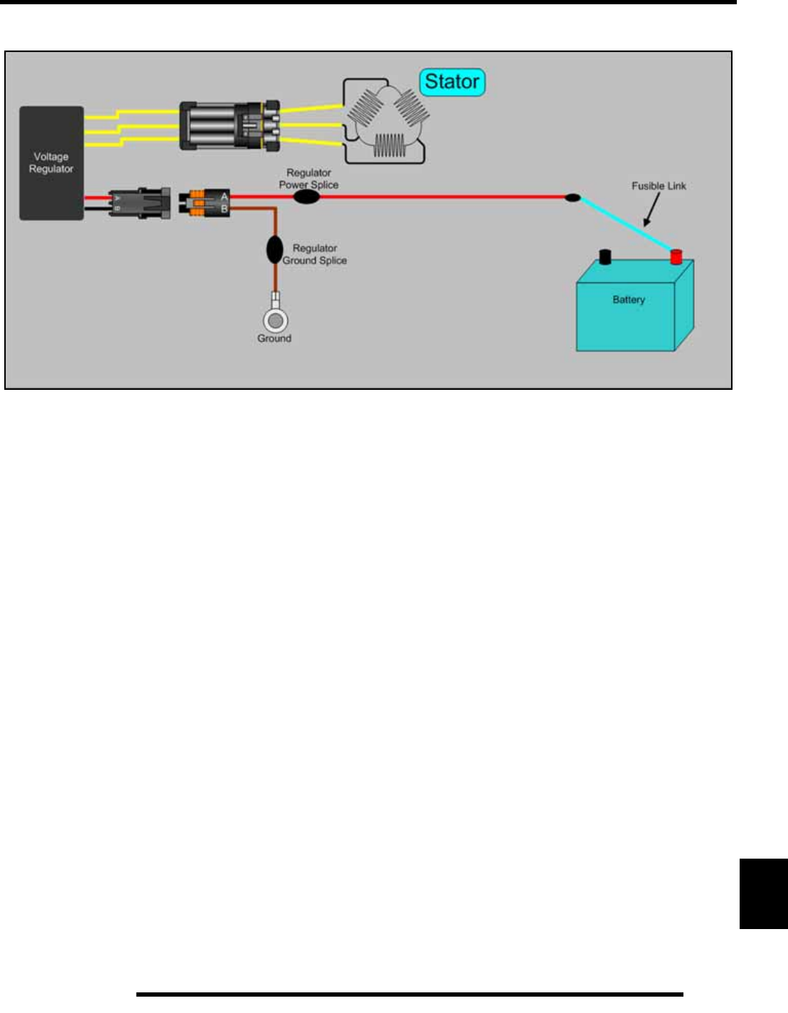
12.35
ELECTRICAL
12
Battery Charging Circuits
PartShark.com
877-999-5686
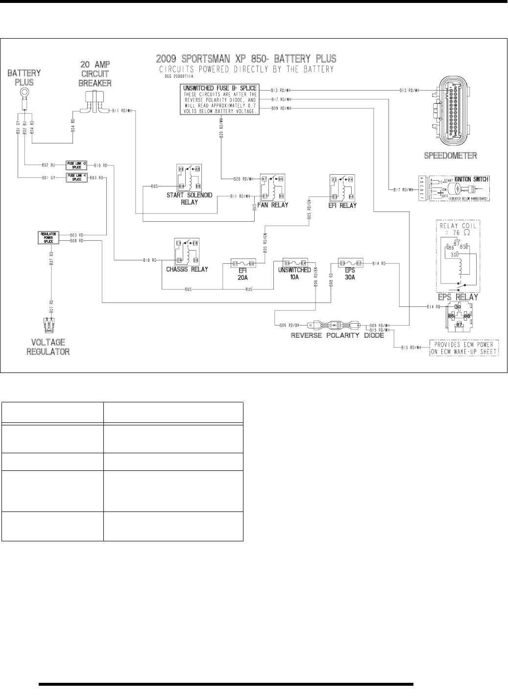
12.36
ELECTRICAL
Constant Power Circuits
Wire Color Functions
Wire Color Function
RED Battery Voltage
EPS Fuse-Protected Voltage
RED / WHT Constant Battery Voltage
RED / BLK Unswitched Fuse / Circuit
Breaker-Protected Battery
Voltage
RED / GRN EFI Fuse-Protected Battery
Voltage
PartShark.com
877-999-5686
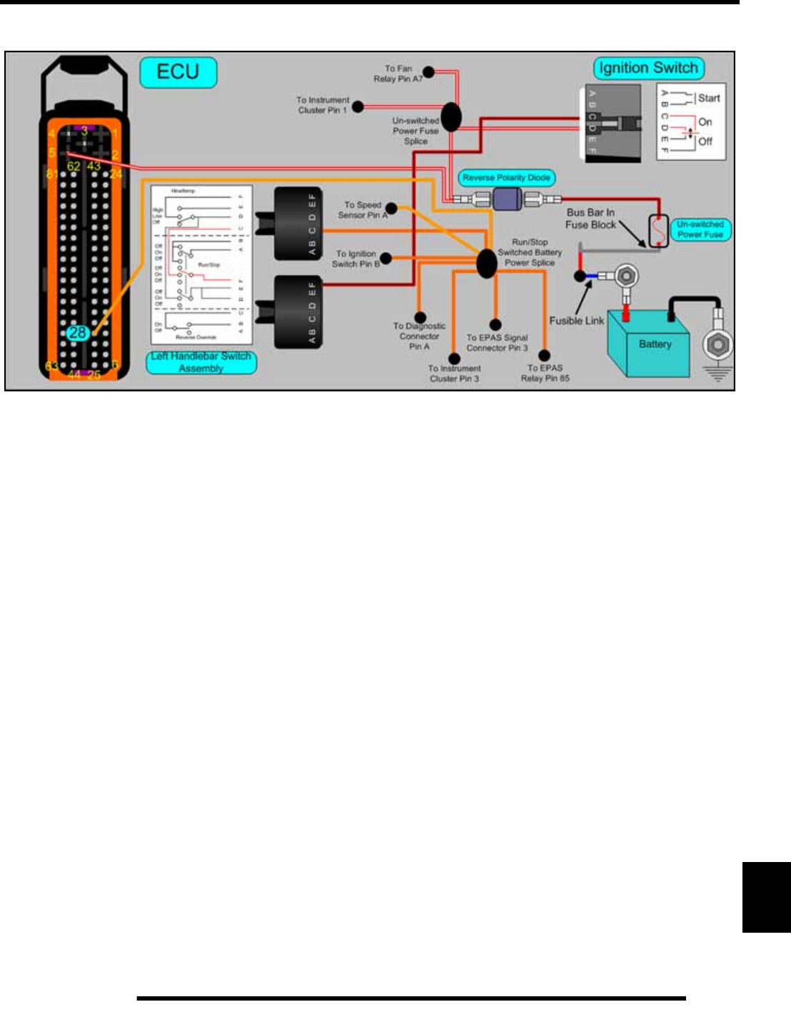
12.37
ELECTRICAL
12
Constant Power Circuits
PartShark.com
877-999-5686
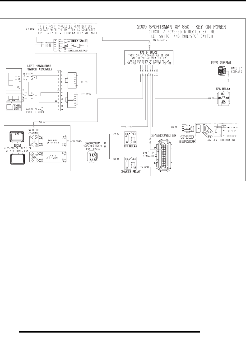
12.38
ELECTRICAL
Key-On Power Circuits
Wire Color Functions
Wire Color Function
RED / BLK Key-On Battery Voltage
ORANGE Key-On / Run Switch On Battery
Voltage
RED / WHT Constant Battery Voltage
PartShark.com
877-999-5686
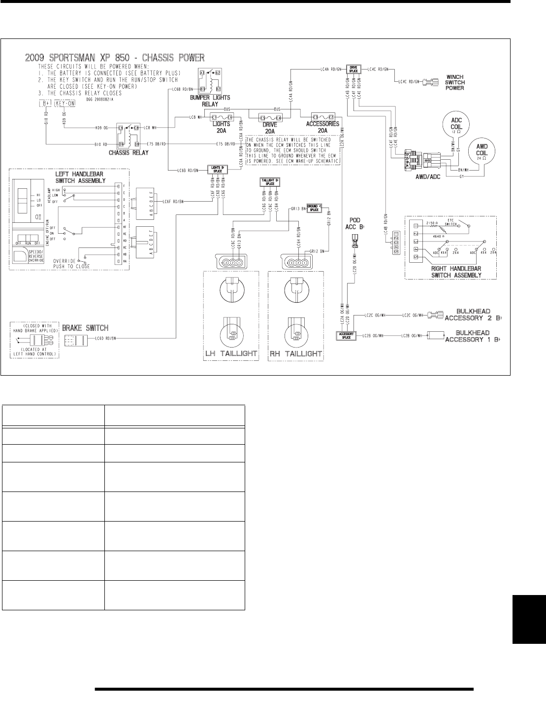
12.39
ELECTRICAL
12
Chassis Power Circuits
Wire Color Functions
Wire Color Function
RED Battery Voltage
BROWN Ground
ORANGE Key-ON / Run Switch On
Battery Voltage
RED / BRN Lights Fuse-Protected Battery
Voltage
WHITE Chassis Relay Output Battery
Voltage
RED / GRN Drive Fuse-Protected Battery
Voltage
ORG / WHT Accessory Fuse-Protected
Battery Voltage
PartShark.com
877-999-5686
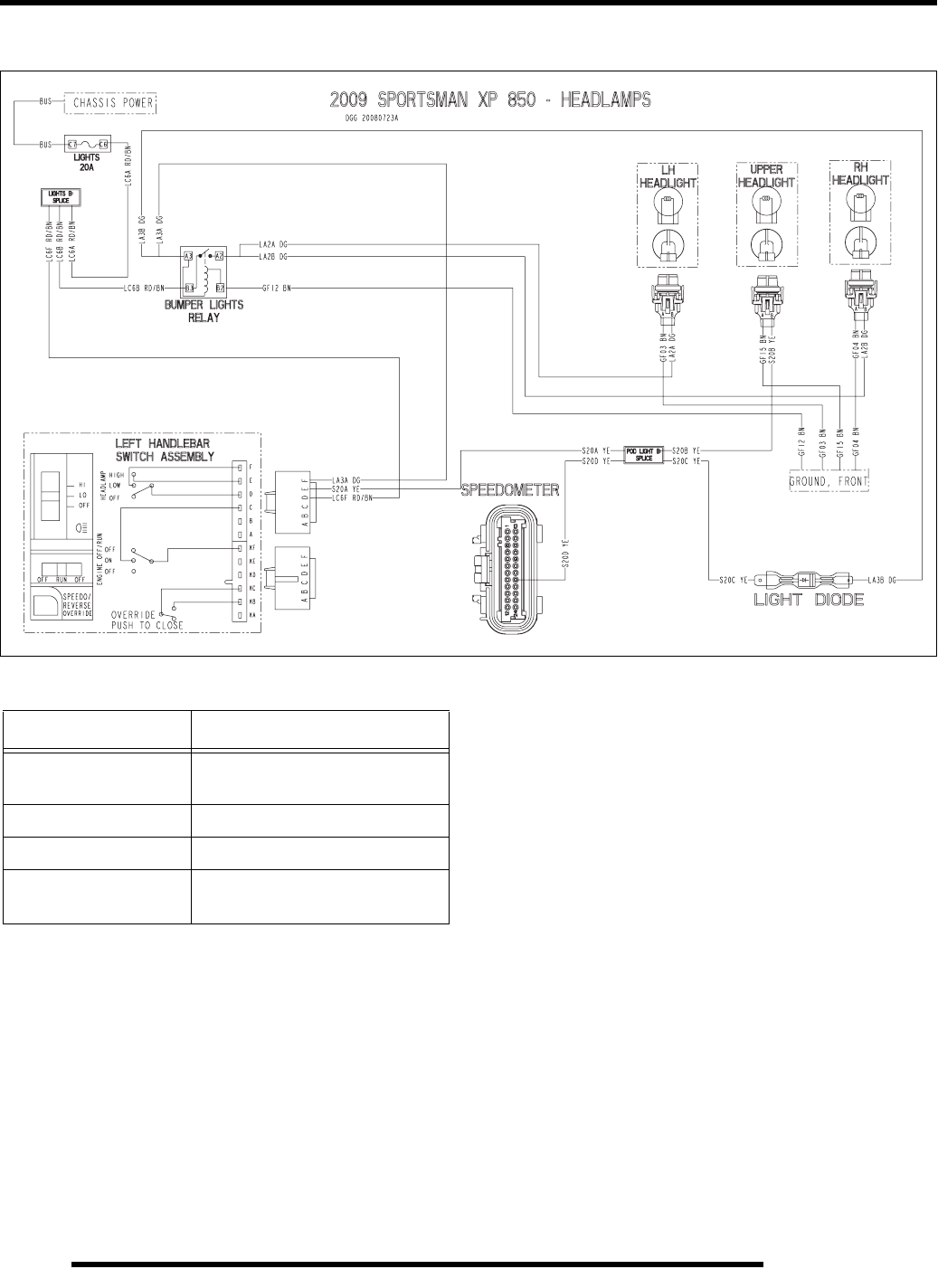
12.40
ELECTRICAL
Head Lamp Circuits
NOTE: THE BUMPER LIGHTS RELAY IS ALWAYS
ACTIVE WHEN THE HEADLAMP SWITCH IS IN LOW
OR HIGH.
Wire Color Functions
Wire Color Function
RED / BRN Lights Fuse-Protected Battery
Voltage
BROWN Ground
DARK GREEN Bumper Lights Power
YELLOW Pod Light Power
High Beam Indicator Power
PartShark.com
877-999-5686
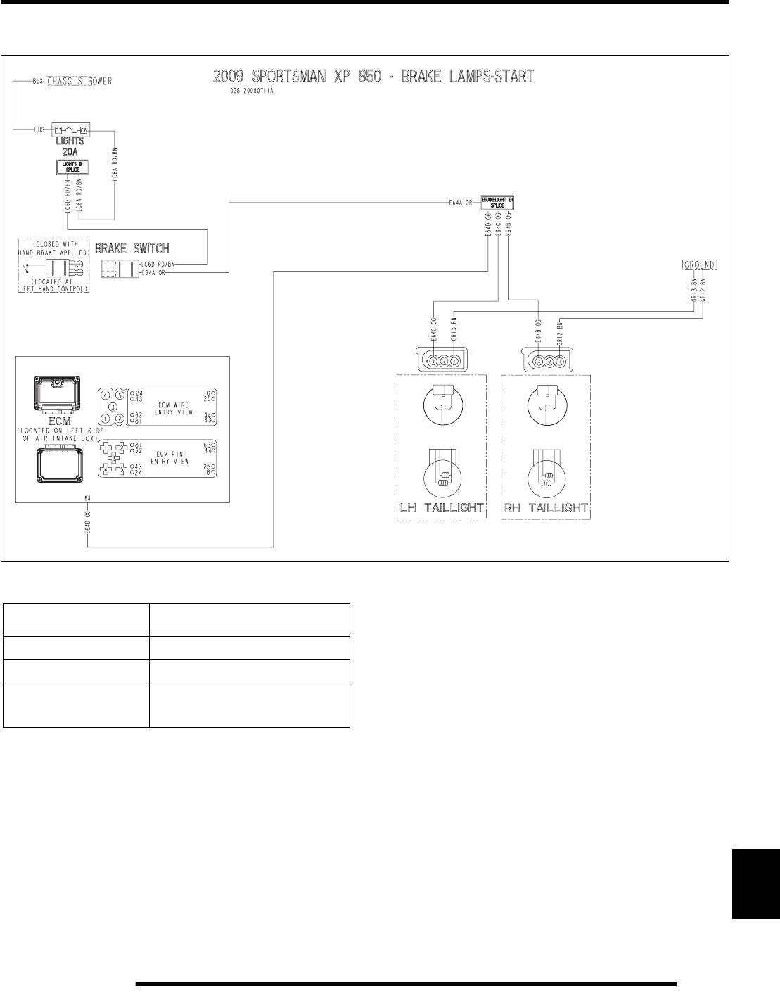
12.41
ELECTRICAL
12
Brake Lamp Circuits
Wire Color Functions
Wire Color Function
ORANGE Brake Signal Voltage
BROWN Ground
RED / BRN Lights Fuse-Protected Battery
Voltage
PartShark.com
877-999-5686
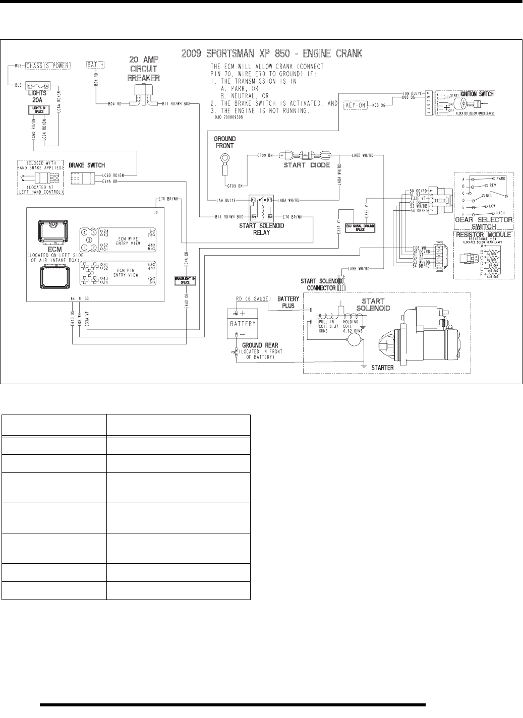
12.42
ELECTRICAL
Engine Start Command Circuits
Wire Color Functions
Wire Color Function
RED Battery Voltage
BROWN Ground
ORANGE Key-On / Run Switch On Battery
Voltage
WHT / RED Ignition Key Start Solenoid
Battery Voltage
DG / WHT ECU Start Solenoid Ground
Command Line
WHITE Gear Selector Return Signal
VIOLET ECU Sensor Ground
PartShark.com
877-999-5686
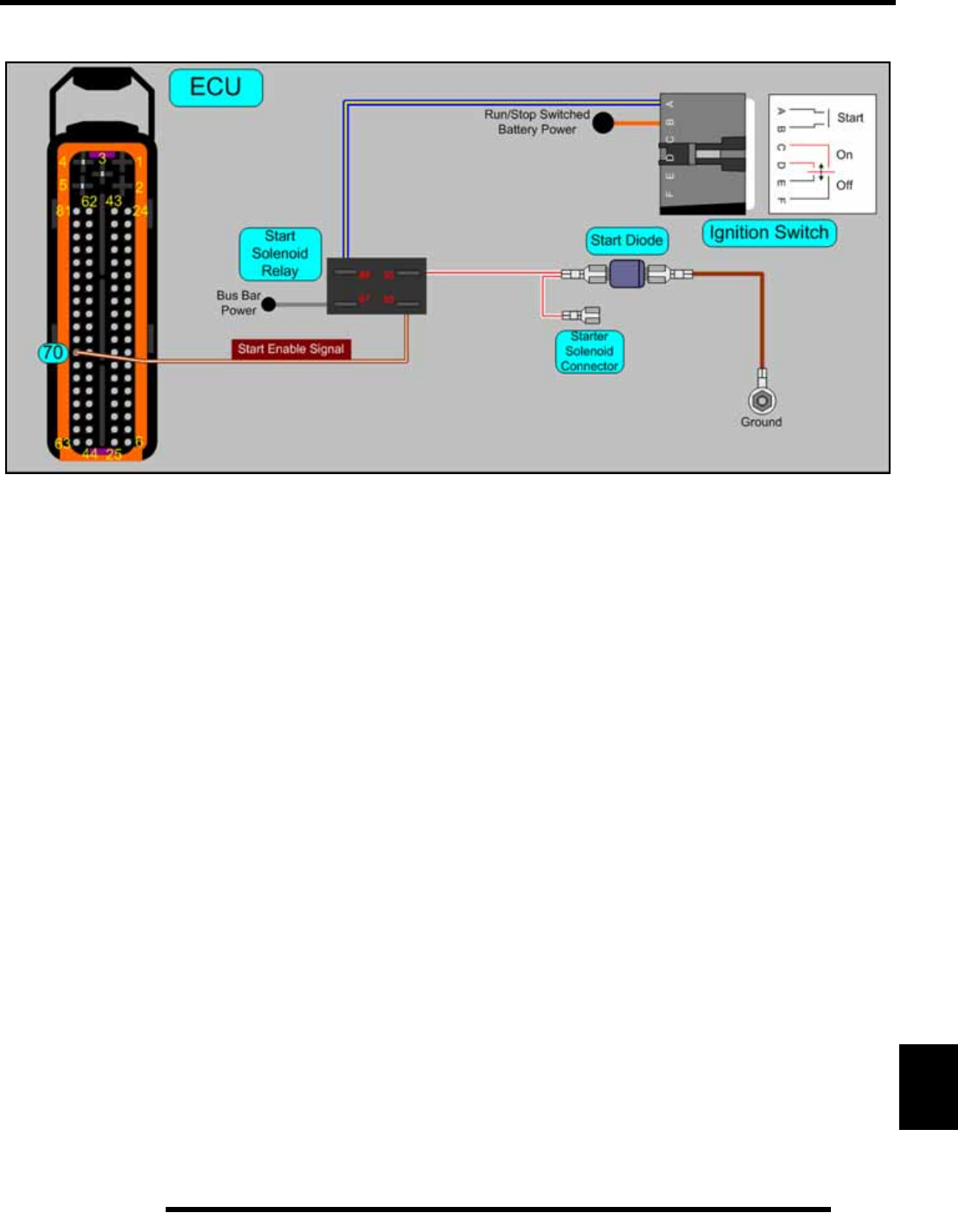
12.43
ELECTRICAL
12
Engine Start Command Circuits
PartShark.com
877-999-5686
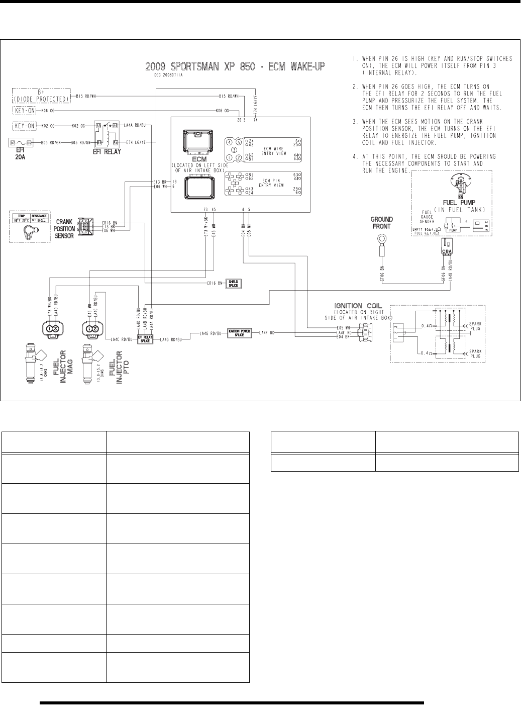
12.44
ELECTRICAL
ECM Wake-Up Command Circuits
Wire Color Functions
Wire Color Function
ORANGE Key-On / Run Switch On Battery
Voltage
RED / GRN EFI Fuse-Protected Battery
Voltage
RED / BLU EFI Relay Output Battery
Voltage
GRN / YEL ECM - EFI Relay Coil Ground
Command Line
RED / YEL ECM - ECM Relay Coil Ground
Command Line
BLACK ECM Ignition Coil Ground Line
CPS Ground
BROWN Ground
WHITE Ignition Coil Battery Voltage
CPS AC Generator Voltage
WHT / BLK Fuel Injector ECM Ground Line
Wire Color Functions
Wire Color Function
PartShark.com
877-999-5686
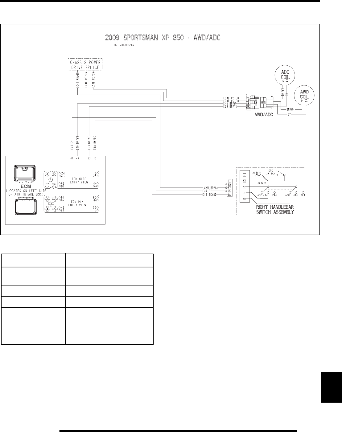
12.45
ELECTRICAL
12
AWD / ADC Circuits
NOTE: WHEN ADC IS SELECTED, THE ADC AND
AWD SIGNALS ARE SENT TO THE ECU.
Wire Color Functions
Wire Color Function
RED / GRN Drive Fuse-Protected Battery
Voltage
BRN / WHT ECM - AWD Coil Ground Line
BRN / YEL ECM - ADC Coil Ground Line
GRAY RH Control 4x4 Command
Signal
BLK / RED RH Control ADC Command
Signal
PartShark.com
877-999-5686
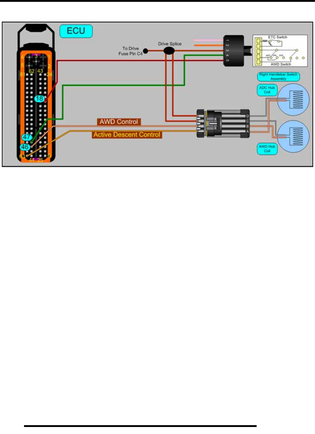
12.46
ELECTRICAL
AWD / ADC Circuits
PartShark.com
877-999-5686
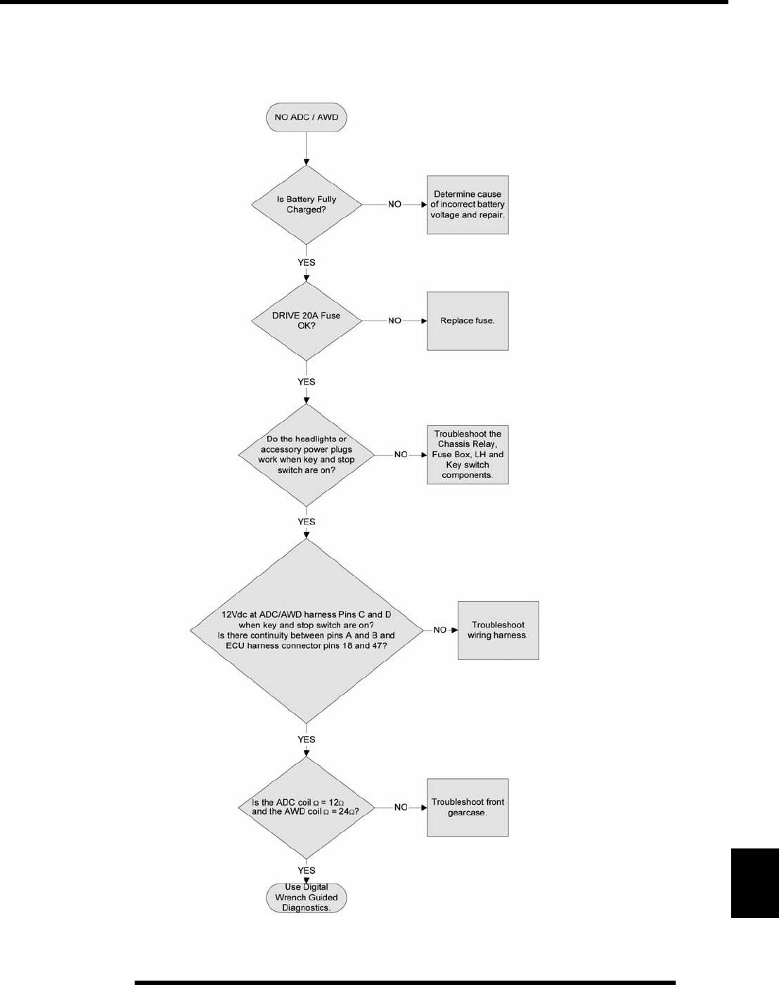
12.47
ELECTRICAL
12
AWD / ADC Function Tests
The following diagnostic test can be performed before using Digital Wrench. Troubleshooting functions not listed here can be found
using Digital Wrench Guided Diagnostics.
PartShark.com
877-999-5686
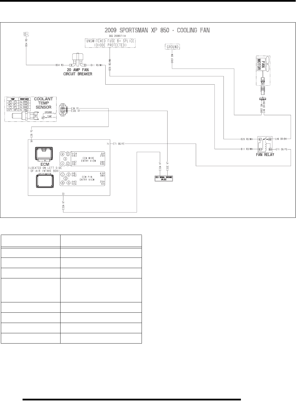
12.48
ELECTRICAL
Radiator Fan Circuit
Wire Color Functions
Wire Color Function
BLACK Ground
BROWN Ground
RED Battery Voltage
RED / WHT Constant Battery Voltage
10 AMP Circuit Breaker-
Protected Battery Voltage
ORG / BLK Relay Output Fan Power
YELLOW Coolant Temp. Sensor Signal
VIOLET ECM Sensor Ground
ORG / YEL ECM - Fan Relay Coil Ground
PartShark.com
877-999-5686
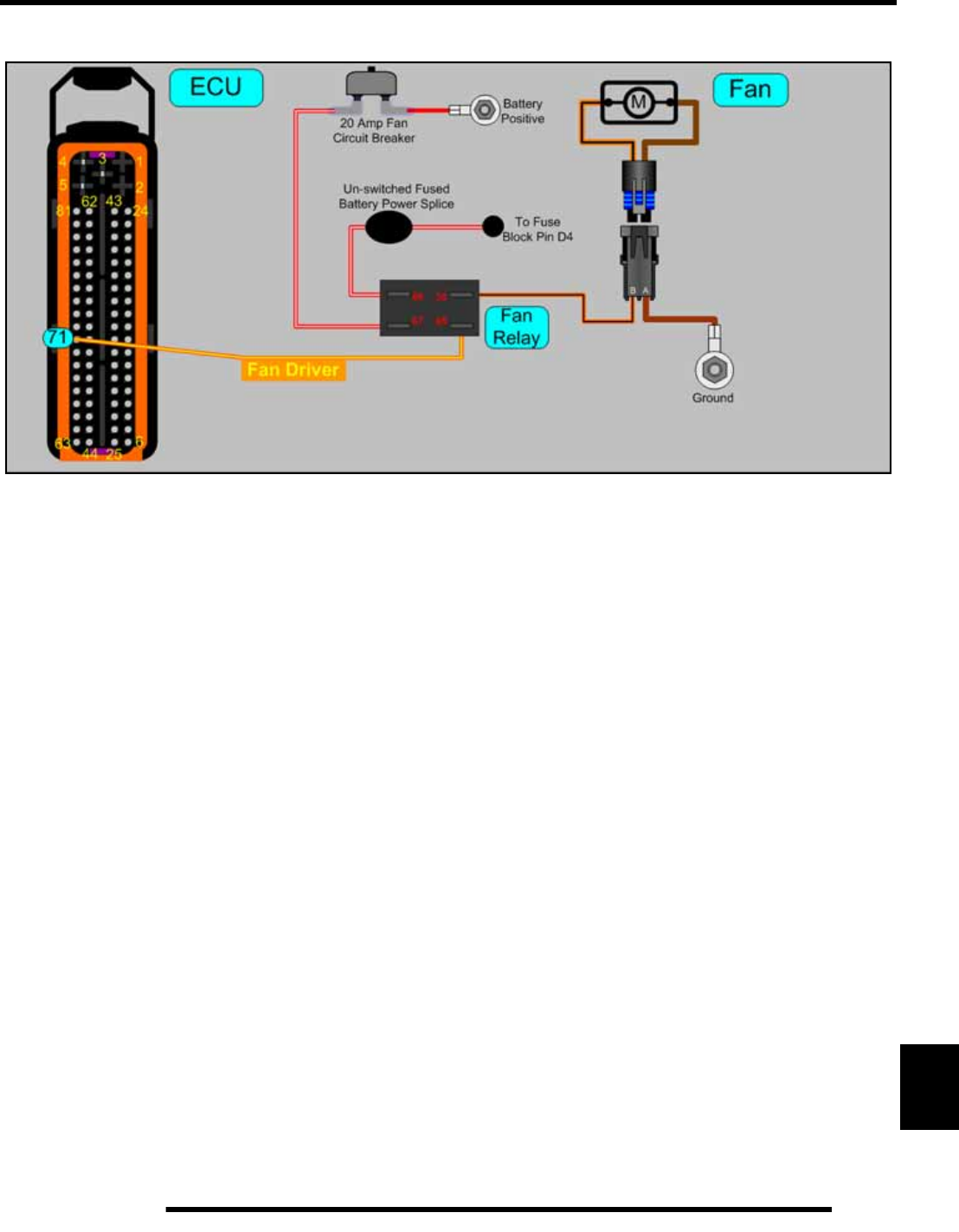
12.49
ELECTRICAL
12
Radiator Fan Circuit
PartShark.com
877-999-5686
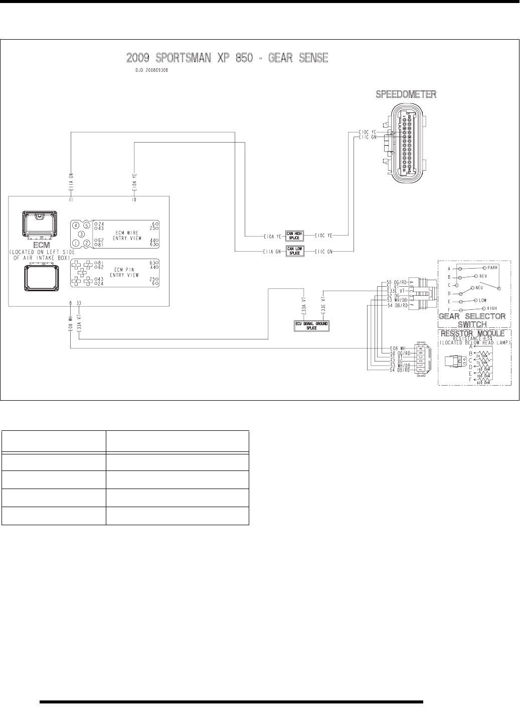
12.50
ELECTRICAL
Gear Selector Switch Circuit
NOTE: DO NOT SPLICE OR CUT INTO THE CAN
CIRCUITS.
Wire Color Functions
Wire Color Function
YELLOW CAN High Signal
GREEN CAN Low Signal
VIOLET ECM Sensor Ground
WHITE Gear Selector Return Signal
PartShark.com
877-999-5686
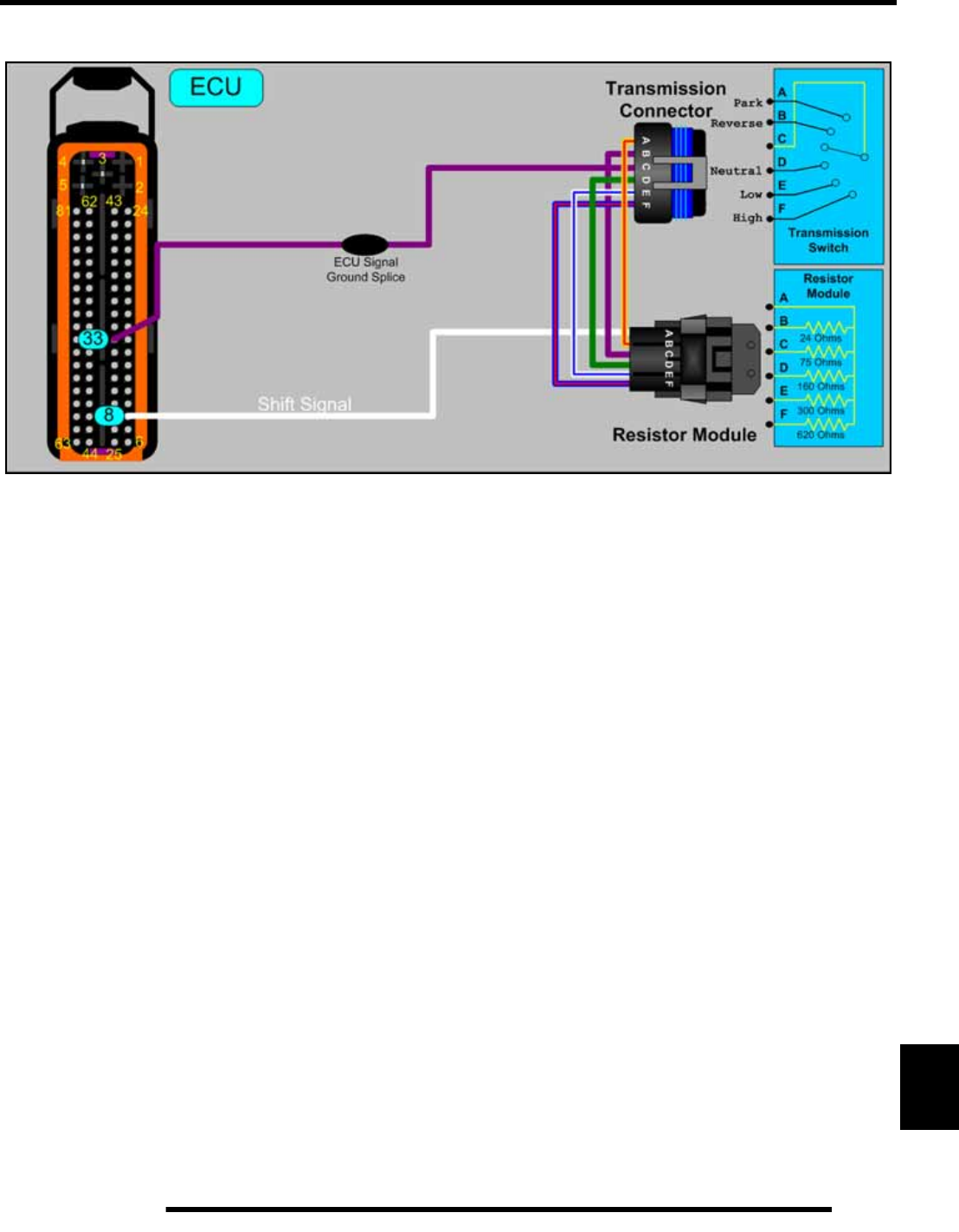
12.51
ELECTRICAL
12
Gear Selector Switch Circuit
PartShark.com
877-999-5686
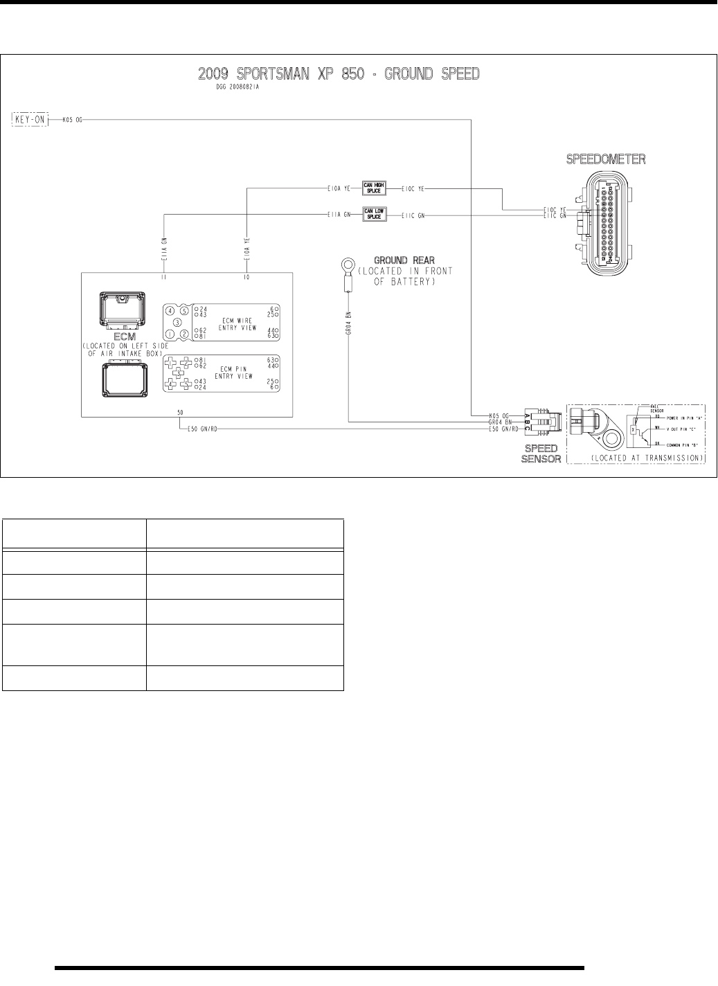
12.52
ELECTRICAL
Ground Speed Sensor Circuit
NOTE: DO NOT SPLICE OR CUT INTO THE CAN
CIRCUITS.
Wire Color Functions
Wire Color Function
YELLOW CAN High Signal
GREEN CAN Low Signal
BROWN Ground
ORANGE Key-On / Run Switch On Battery
Voltage
GRN / RED Speed Sensor Return Signal
PartShark.com
877-999-5686
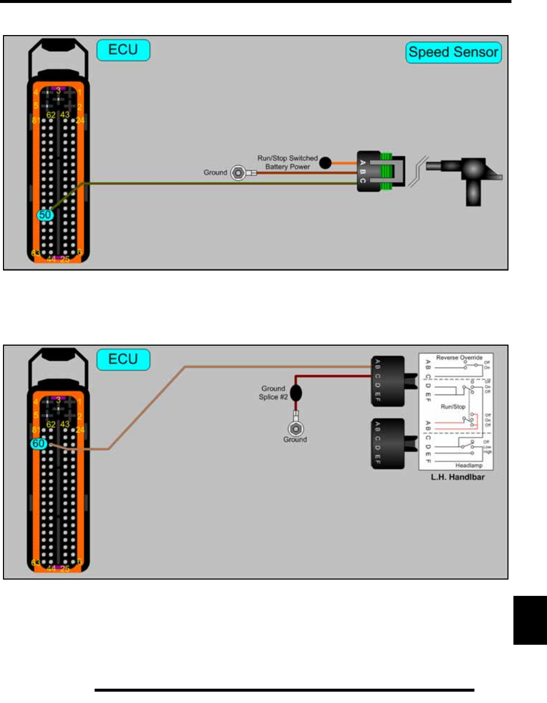
12.53
ELECTRICAL
12
Ground Speed Sensor Circuit
Reverse Override Circuit
PartShark.com
877-999-5686

12.54
ELECTRICAL
CONTROLLER AREA NETWORK (CAN)
Overview
This vehicle uses a Controller Area Network (CAN) to perform
some functions. Similar to a computer network, CAN
establishes a communication network between the ECU and
several on-board components.
The Sportsman XP 850 CAN network includes:
•ECU
• Instrument Cluster
• Digital Wrench Diagnostic Plug
• Electronic Power Steering (EPS models only)
NOTE: DO NOT SPLICE OR CUT INTO THE CAN
YELLOW OR GREEN WIRE CIRCUITS.
CAN Troubleshooting
No CAN functionality can be indicated by the following items
not working on the instrument cluster:
• No engine speed displayed
• No vehicle speed displayed
• No gear position displayed
• Odometer / Tripmeters not working
• Reverse override button does not toggle between
display modes
• ECU-monitored inputs are not displayed when DTCs or
problems exist, i.e. check engine LED, engine overheat
LED, etc.
• There is power at the Smart Link connector, but it
cannot connect to Digital Wrench
To test the CAN circuit, turn the ignition key to OFF, and then
use a multimeter to verify there is 60 +/- 10 ohms between the
CAN High (YELLOW) and CAN Low (GREEN) wires on the
diagnostic connector.
If 120 ohms is measured at the connector, there is a break
somewhere within the CAN circuit.
PartShark.com
877-999-5686
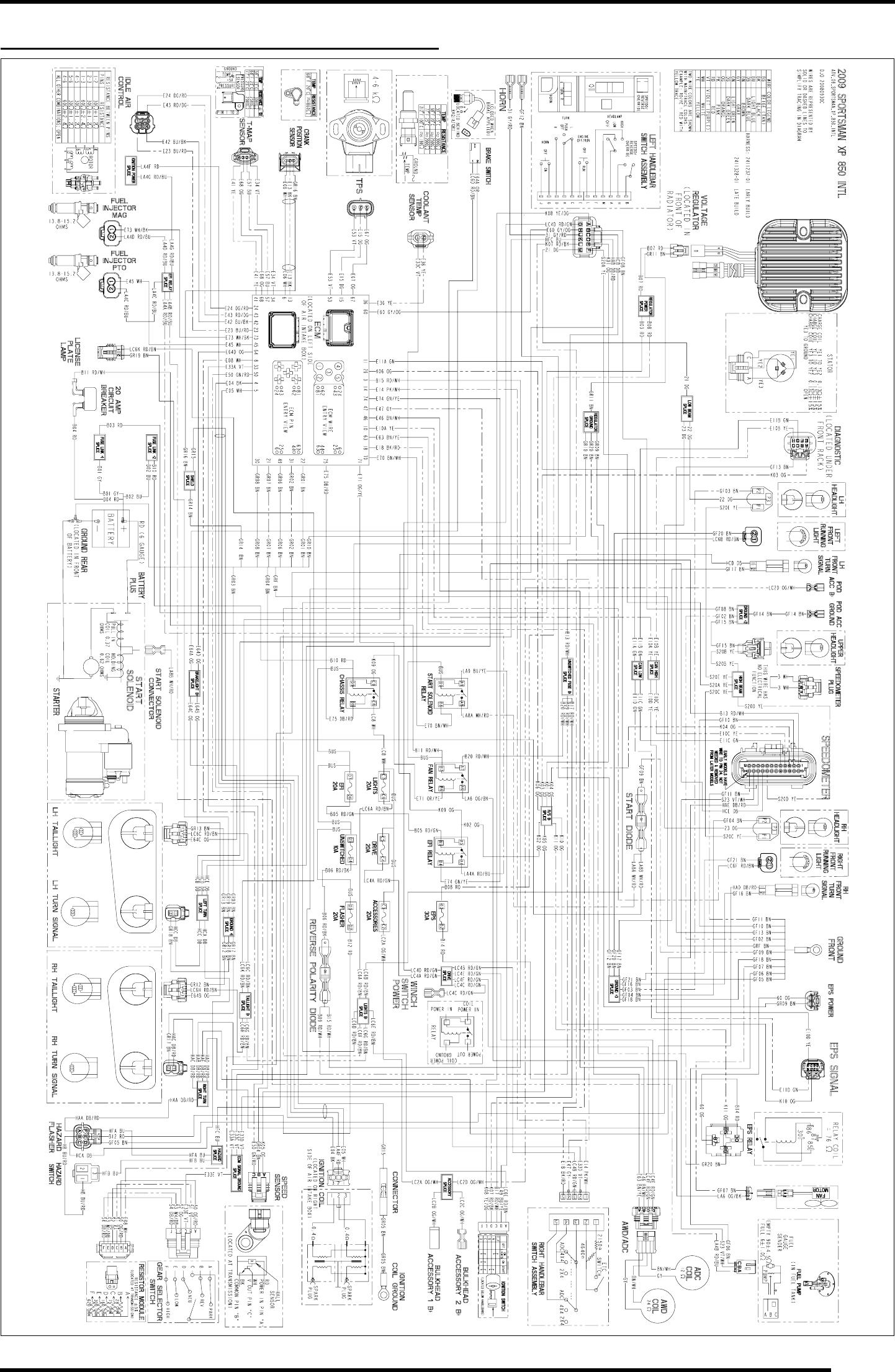
WD-3
WIRE DIAGRAM
2009 SPORTSMAN XP 850 INTL (PAGE 1 OF 2)
PartShark.com
877-999-5686
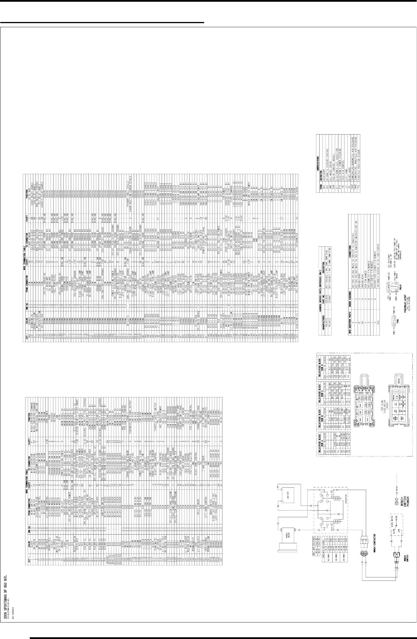
WD-4
WIRE DIAGRAM
2009 SPORTSMAN XP 850 INTL (PAGE 2 OF 2)
PartShark.com
877-999-5686
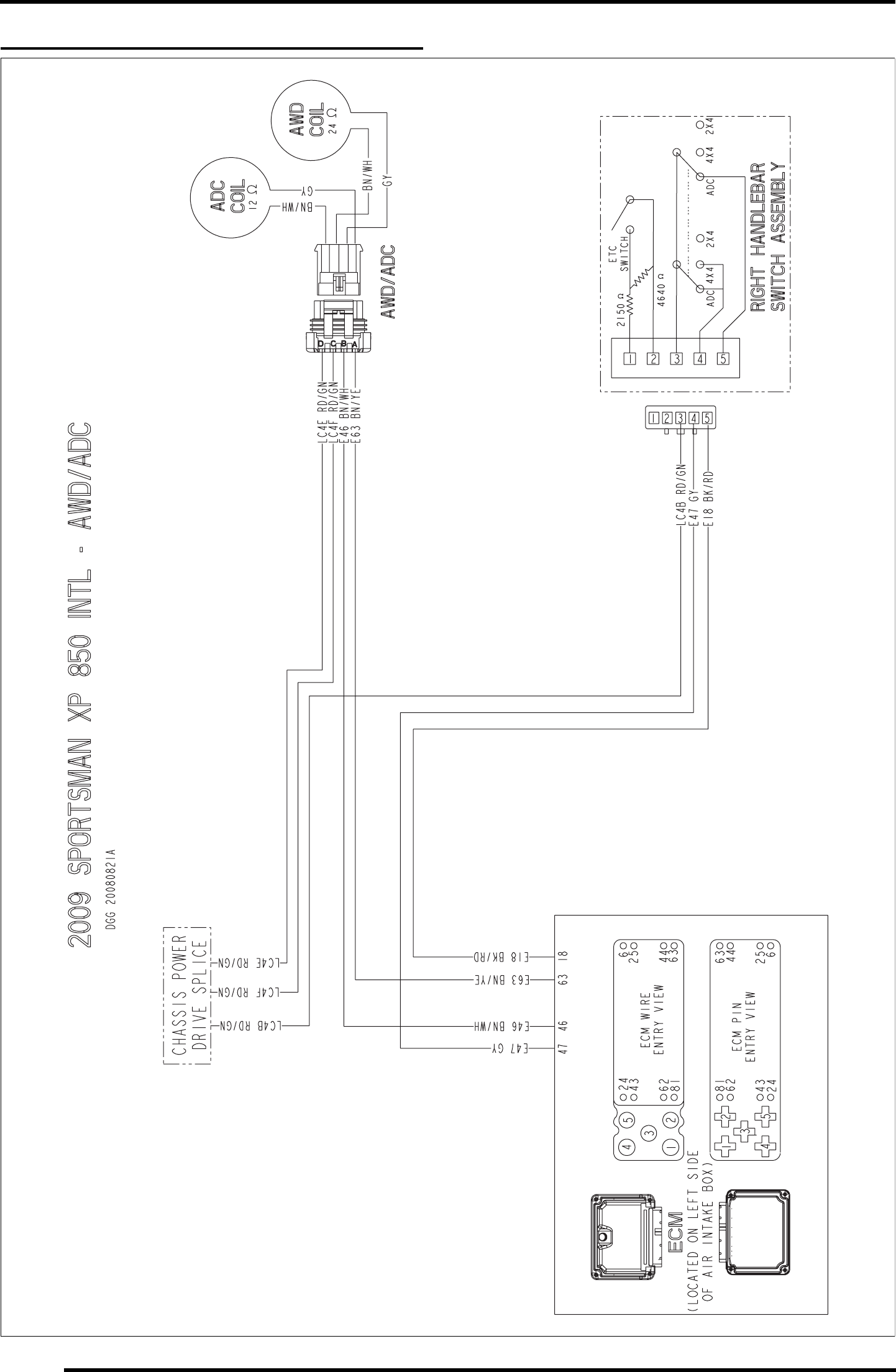
WD-6
WIRE DIAGRAM
2009 SPORTSMAN XP 850 INTL (AWD / ADC)
PartShark.com
877-999-5686
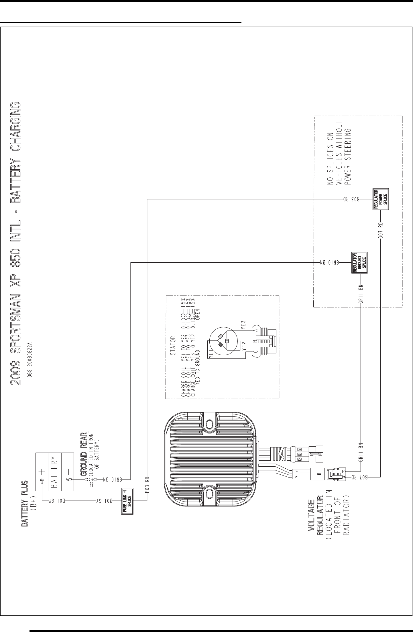
WD-8
WIRE DIAGRAM
2009 SPORTSMAN XP 850 INTL (BATTERY CHARGING)
PartShark.com
877-999-5686
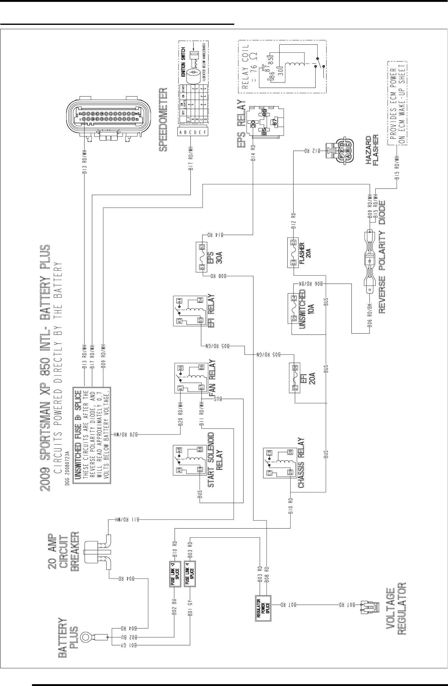
WD-10
WIRE DIAGRAM
2009 SPORTSMAN XP 850 INTL (BATTERY PLUS)
PartShark.com
877-999-5686
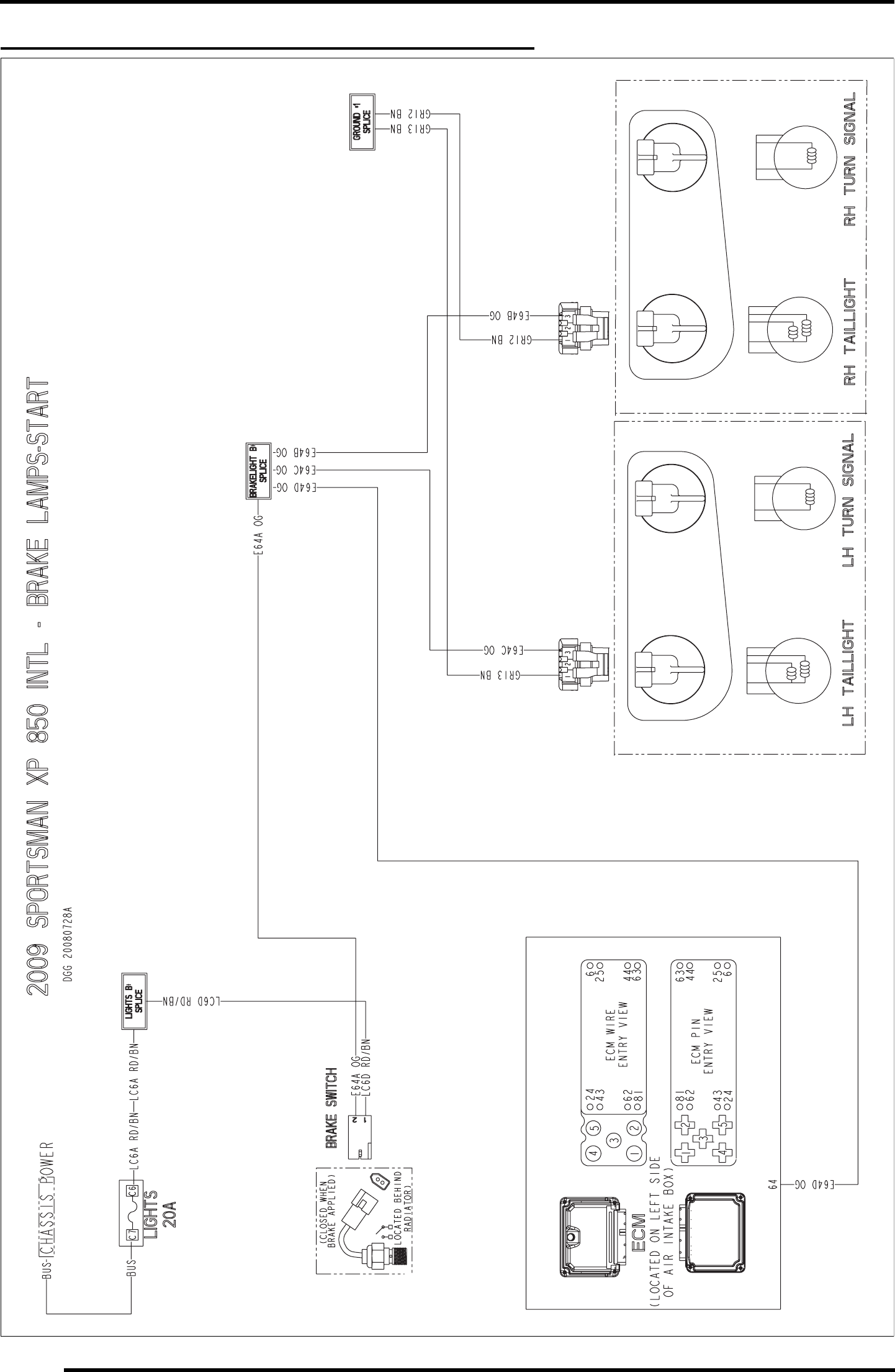
WD-12
WIRE DIAGRAM
2009 SPORTSMAN XP 850 INTL (BRAKE LAMPS-START)
PartShark.com
877-999-5686
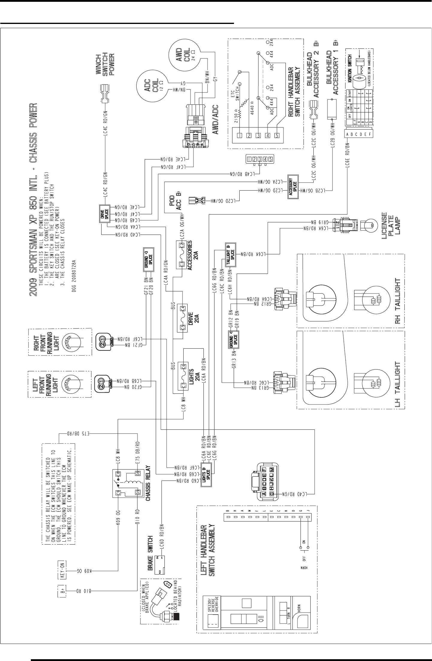
WD-14
WIRE DIAGRAM
2009 SPORTSMAN XP 850 INTL (CHASSIS POWER)
PartShark.com
877-999-5686
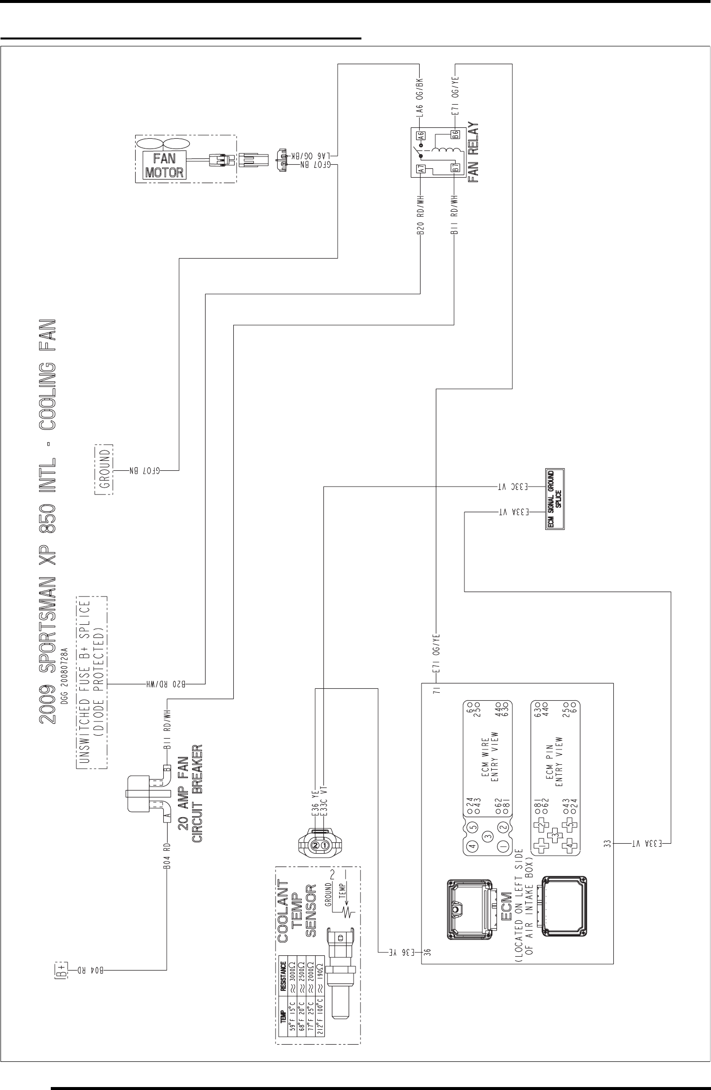
WD-16
WIRE DIAGRAM
2009 SPORTSMAN XP 850 INTL (COOLING FAN)
PartShark.com
877-999-5686
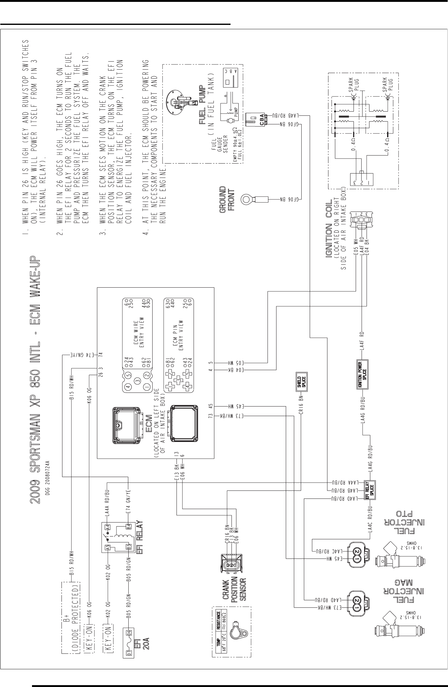
WD-18
WIRE DIAGRAM
2009 SPORTSMAN XP 850 INTL (ECM WAKE-UP)
PartShark.com
877-999-5686
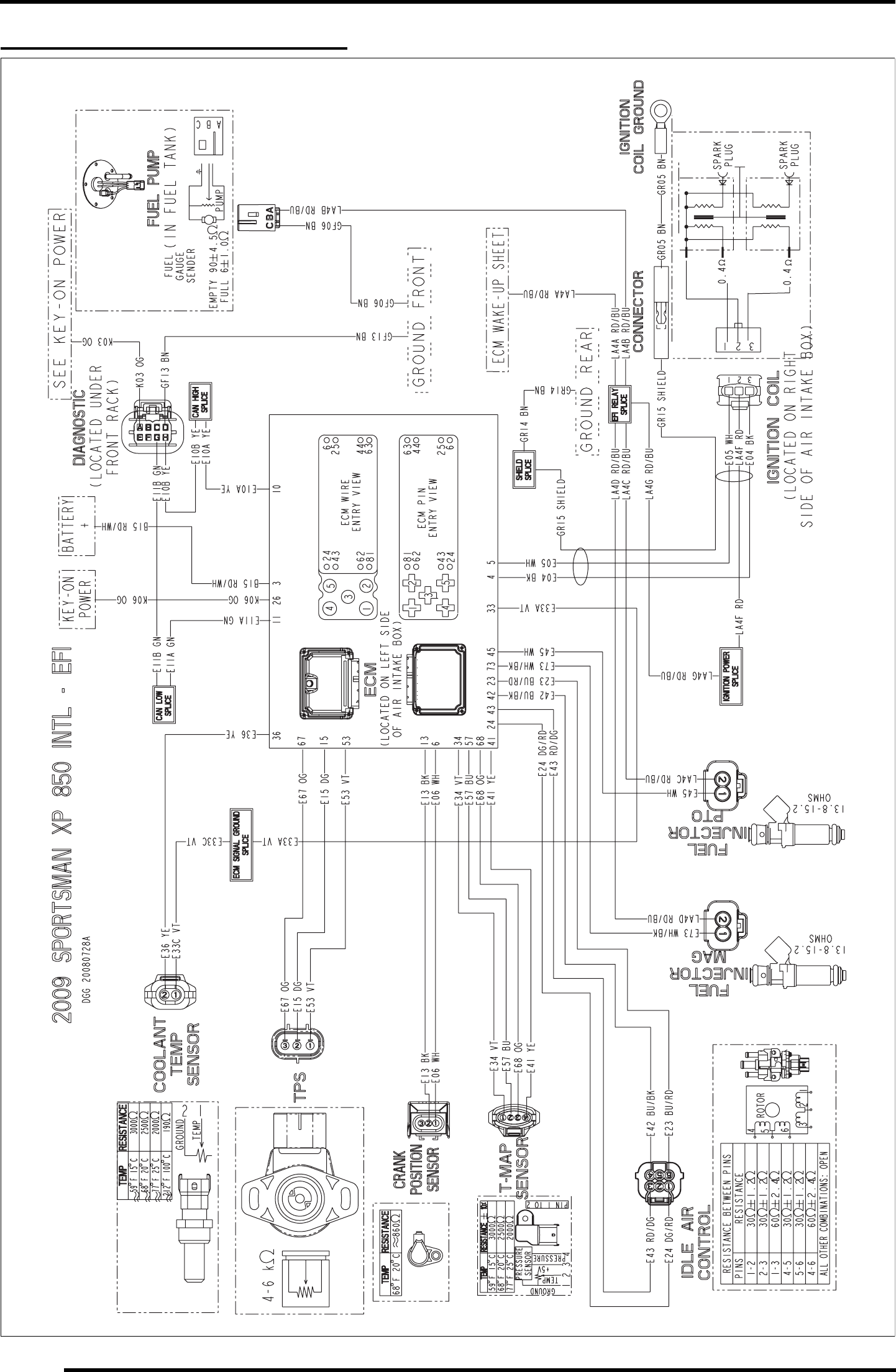
WD-20
WIRE DIAGRAM
2009 SPORTSMAN XP 850 INTL (EFI)
PartShark.com
877-999-5686
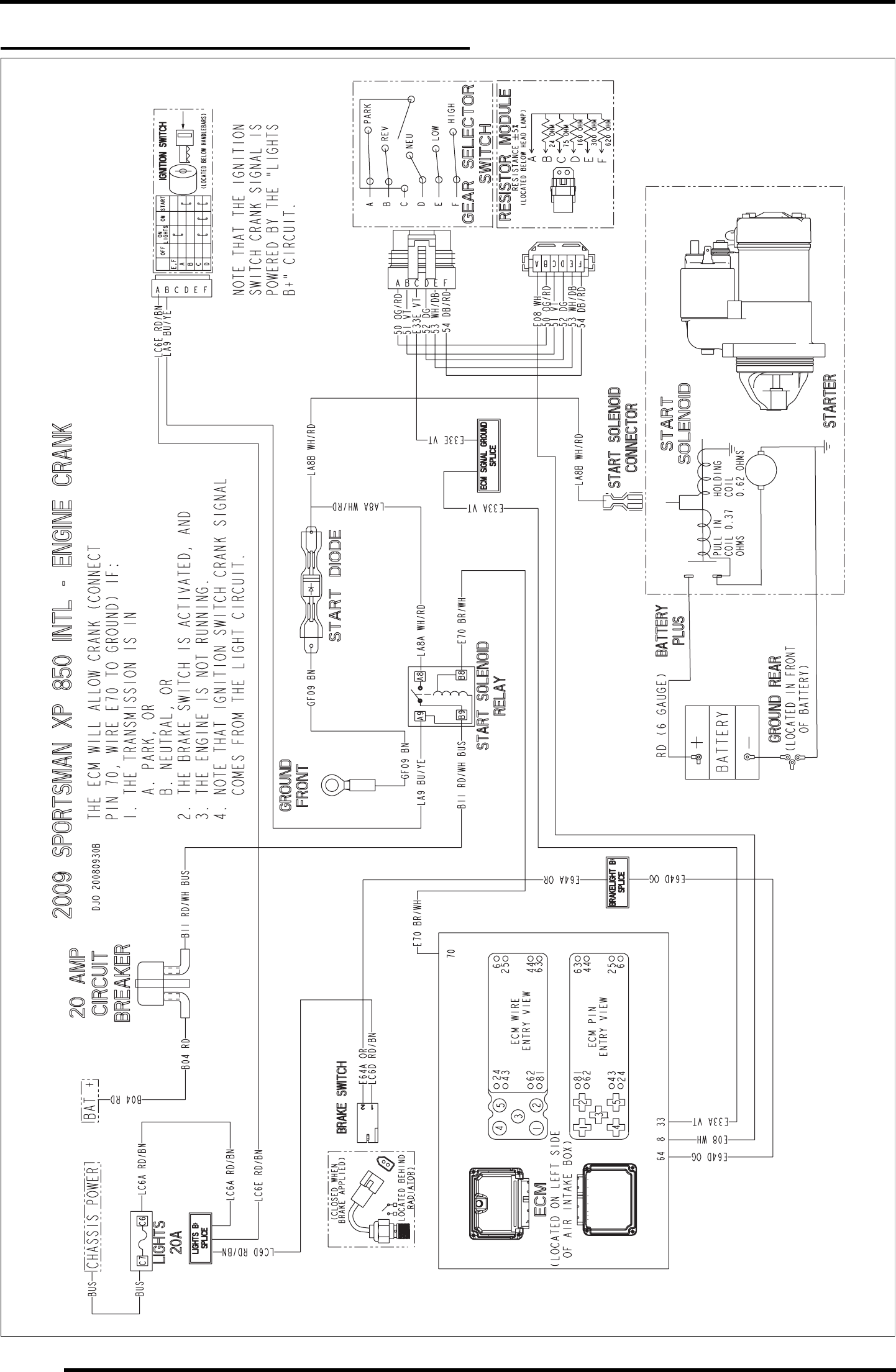
WD-22
WIRE DIAGRAM
2009 SPORTSMAN XP 850 INTL (ENGINE CRANK)
PartShark.com
877-999-5686
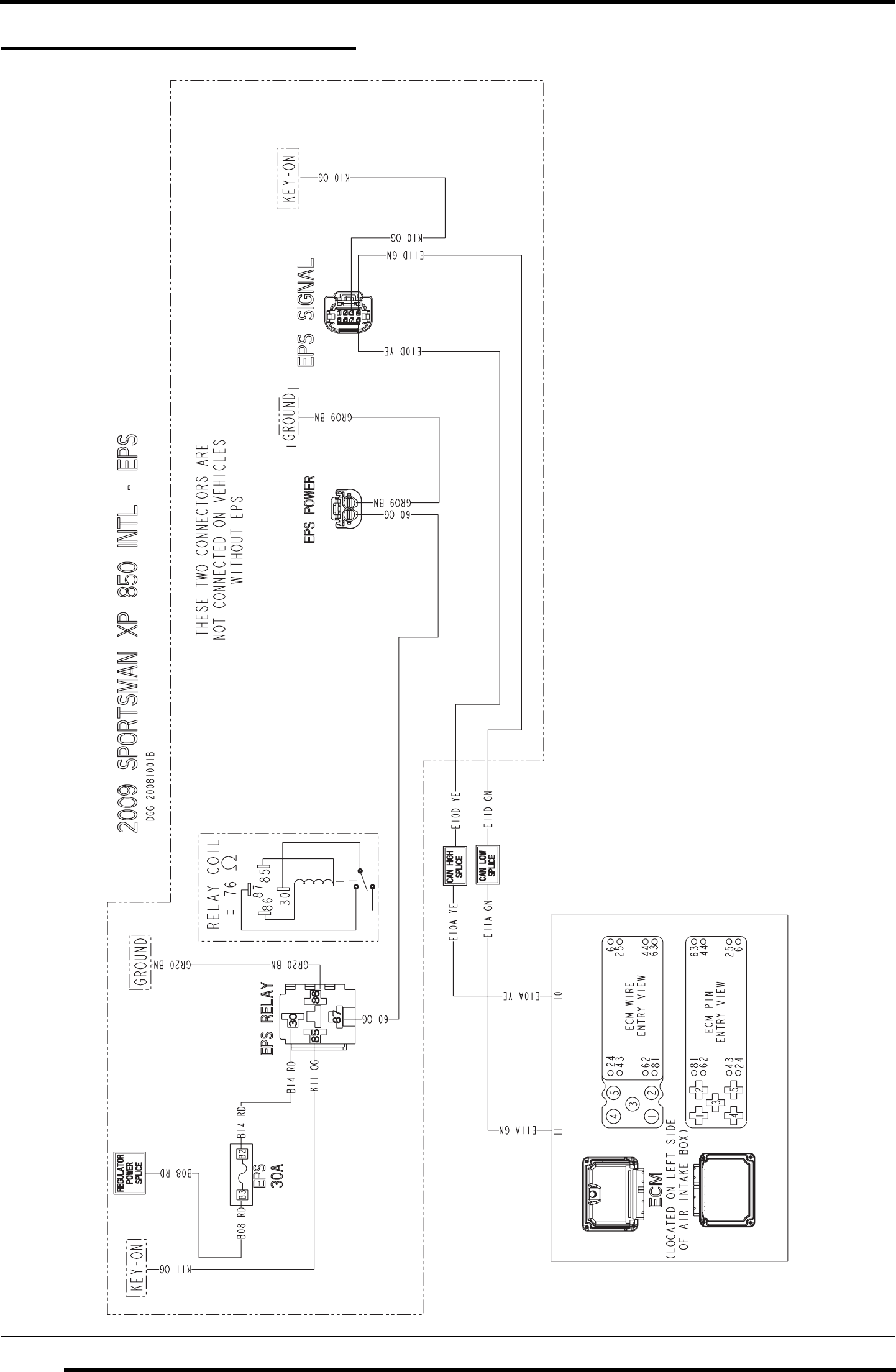
WD-24
WIRE DIAGRAM
2009 SPORTSMAN XP 850 INTL (EPS)
PartShark.com
877-999-5686
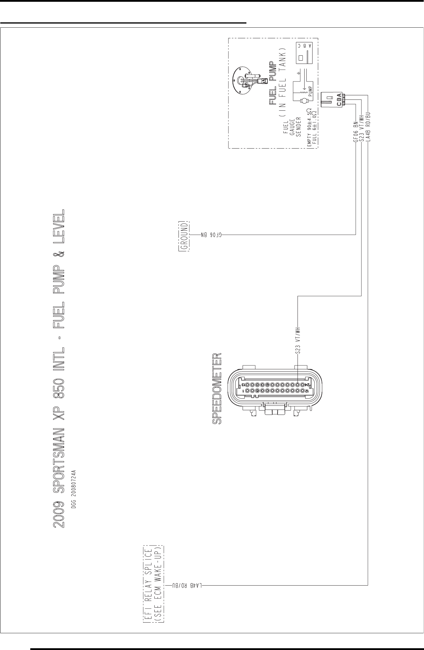
WD-26
WIRE DIAGRAM
2009 SPORTSMAN XP 850 INTL (FUEL PUMP & LEVEL)
PartShark.com
877-999-5686
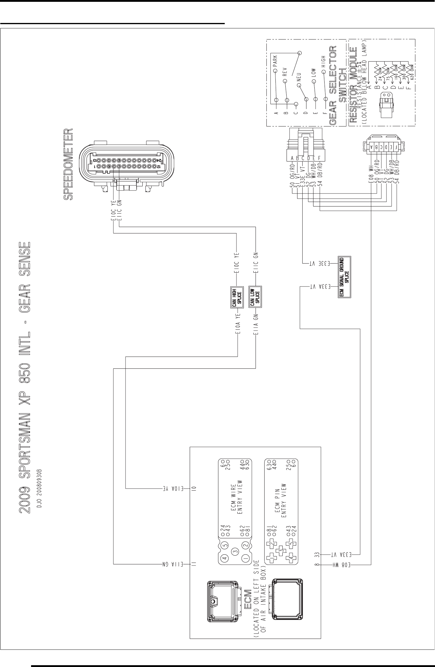
WD-28
WIRE DIAGRAM
2009 SPORTSMAN XP 850 INTL (GEAR SENSOR)
PartShark.com
877-999-5686
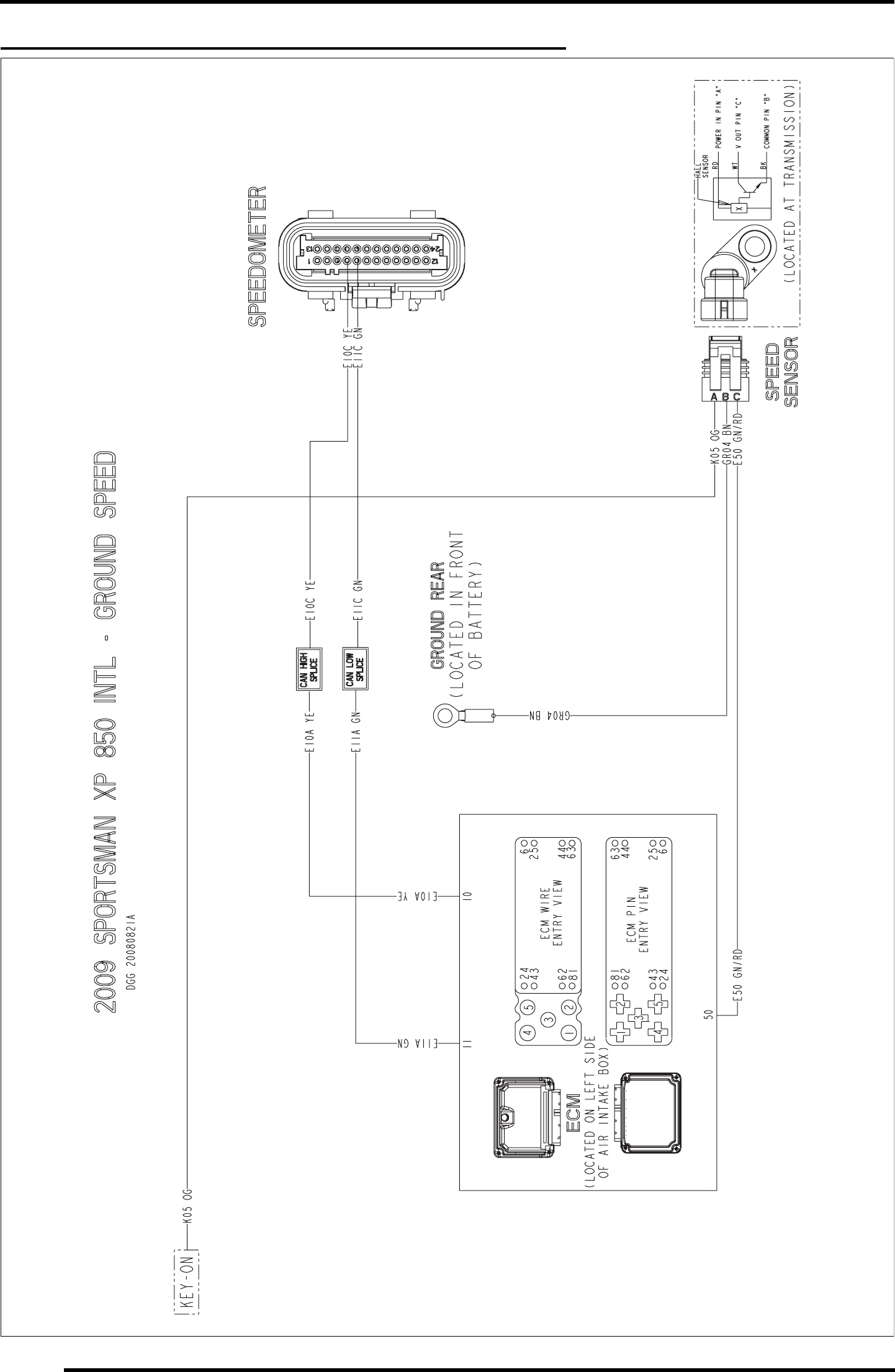
WD-30
WIRE DIAGRAM
2009 SPORTSMAN XP 850 INTL (GROUND SPEED SENSOR)
PartShark.com
877-999-5686
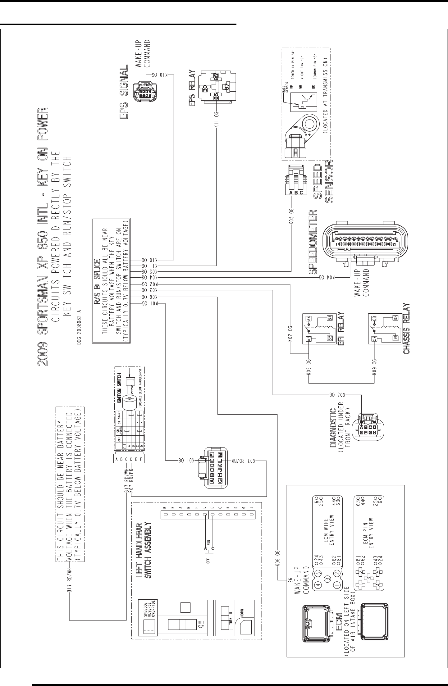
WD-32
WIRE DIAGRAM
2009 SPORTSMAN XP 850 INTL (KEY ON POWER)
PartShark.com
877-999-5686
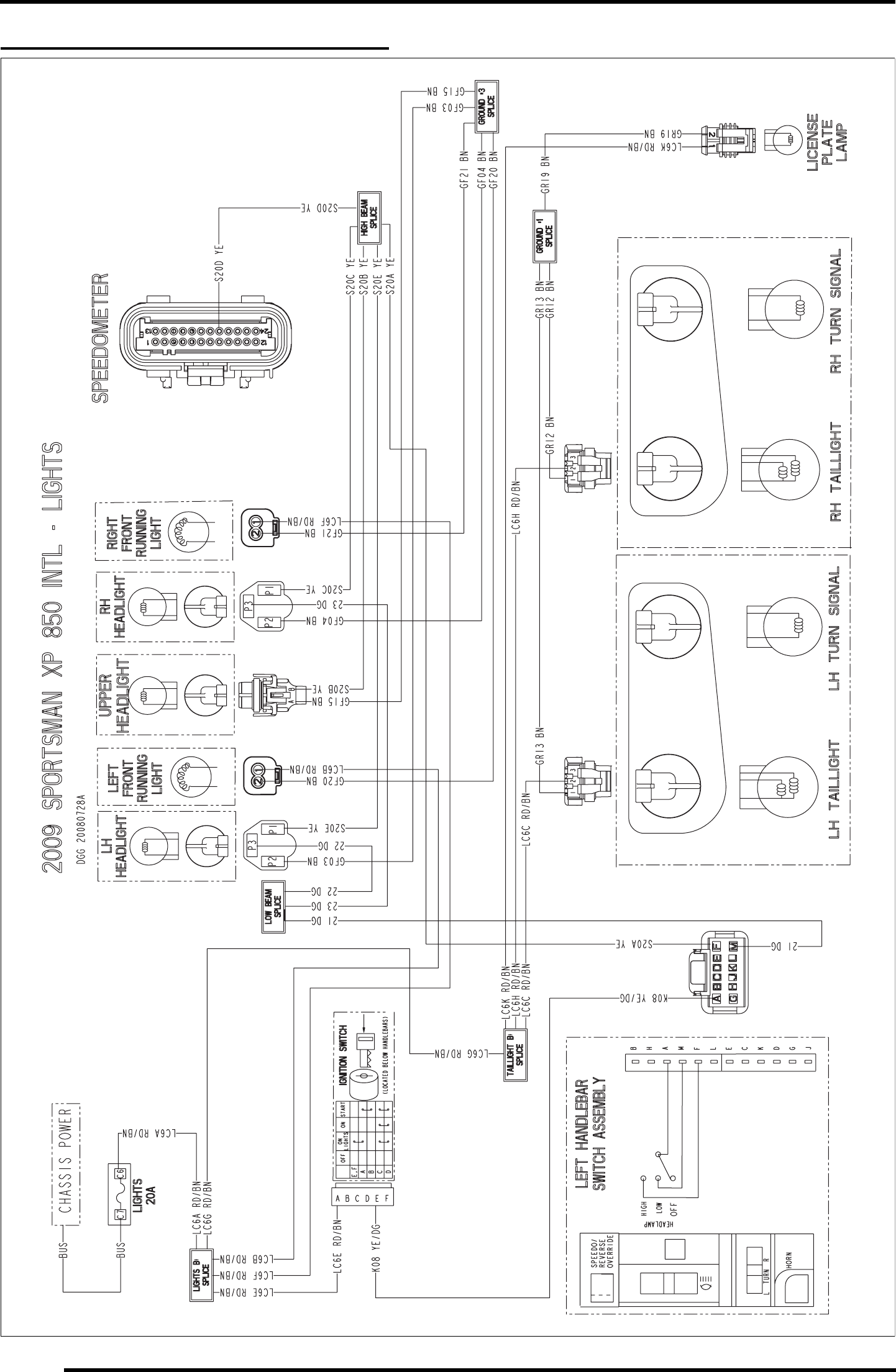
WD-34
WIRE DIAGRAM
2009 SPORTSMAN XP 850 INTL (LIGHTS)
PartShark.com
877-999-5686
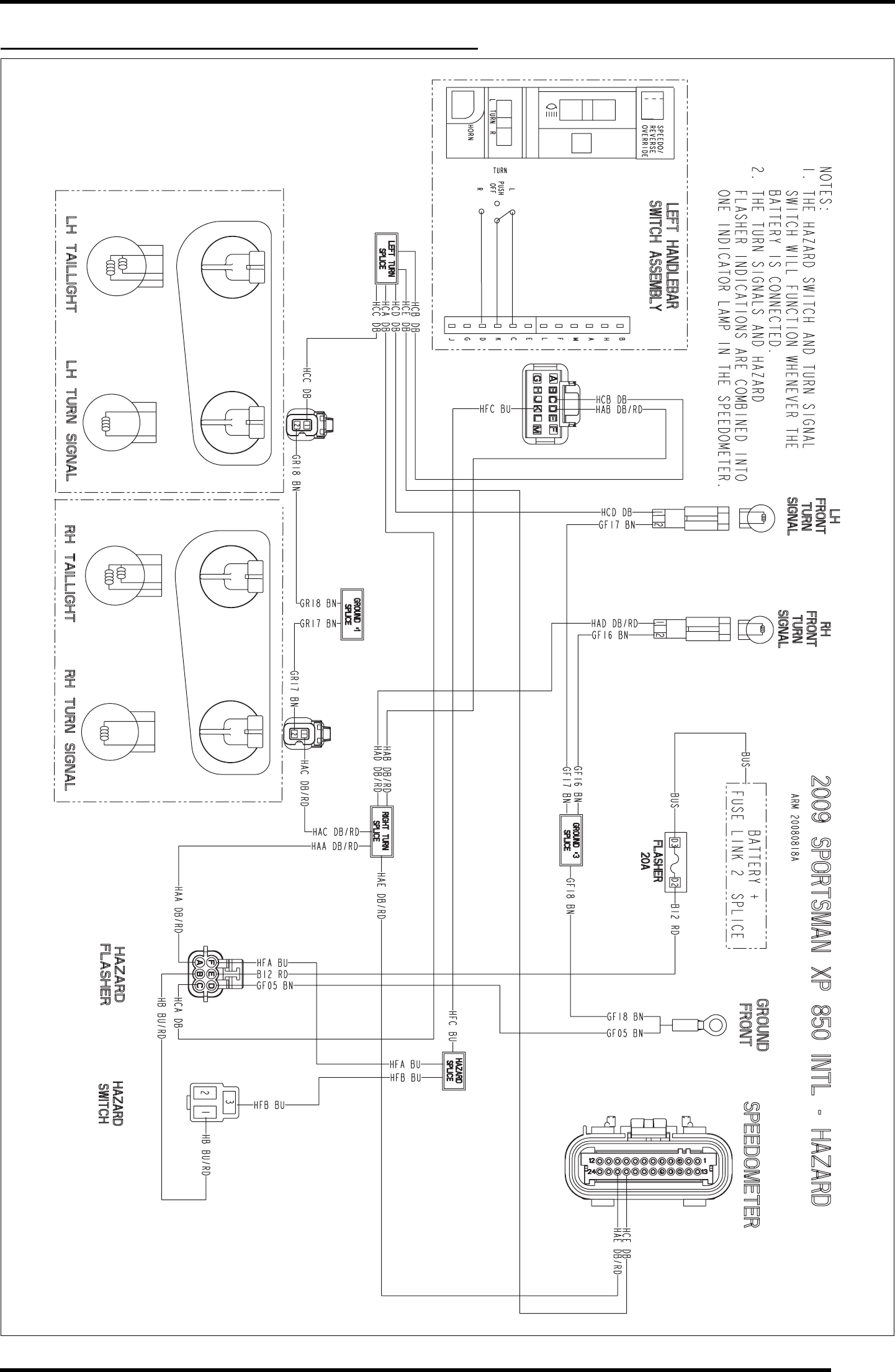
WD-35
WIRE DIAGRAM
2009 SPORTSMAN XP 850 INTL (HAZARD LIGHTS)
PartShark.com
877-999-5686
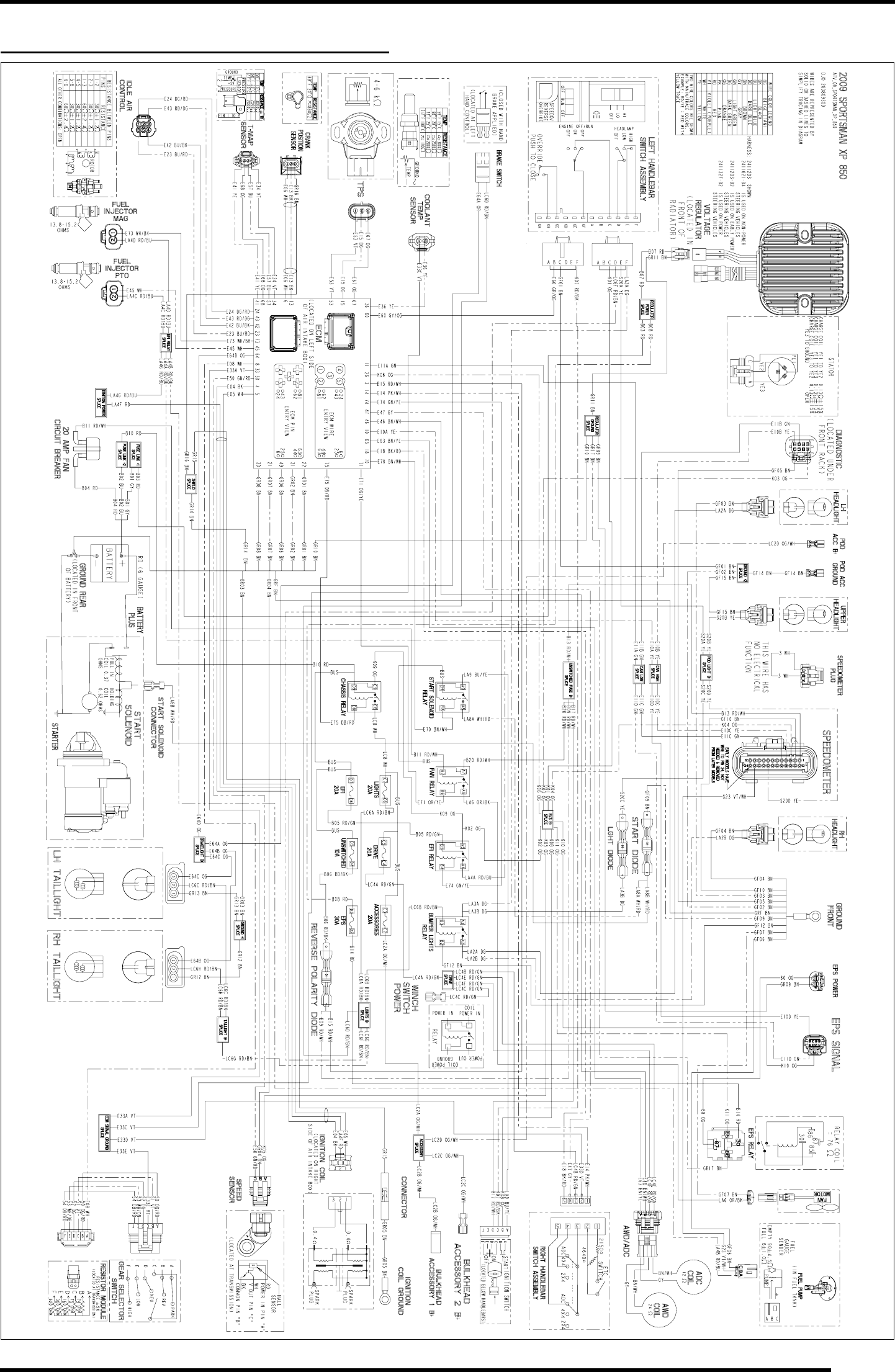
WD-1
WIRE DIAGRAM
2009 SPORTSMAN XP 850 (PAGE 1 OF 2)
PartShark.com
877-999-5686
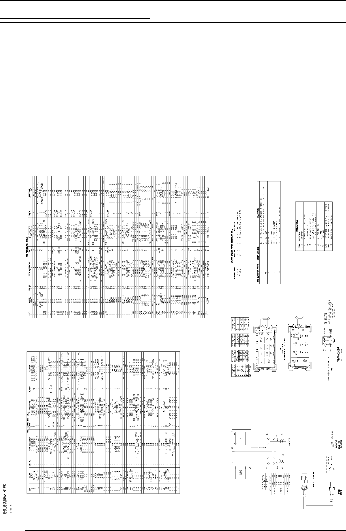
WD-2
WIRE DIAGRAM
2009 SPORTSMAN XP 850 (PAGE 2 OF 2)
PartShark.com
877-999-5686
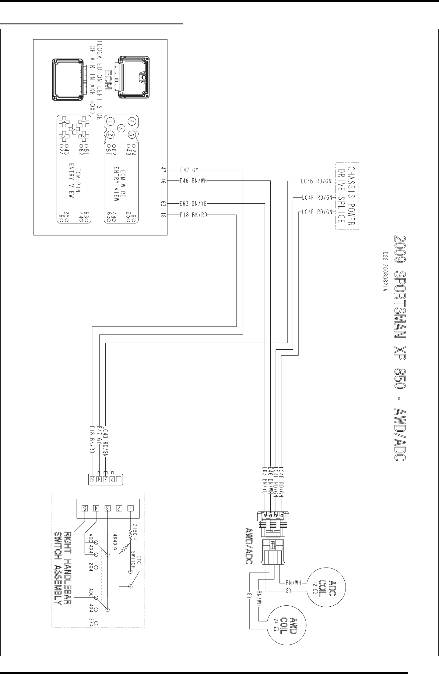
WD-5
WIRE DIAGRAM
2009 SPORTSMAN XP 850 (AWD / ADC)
PartShark.com
877-999-5686
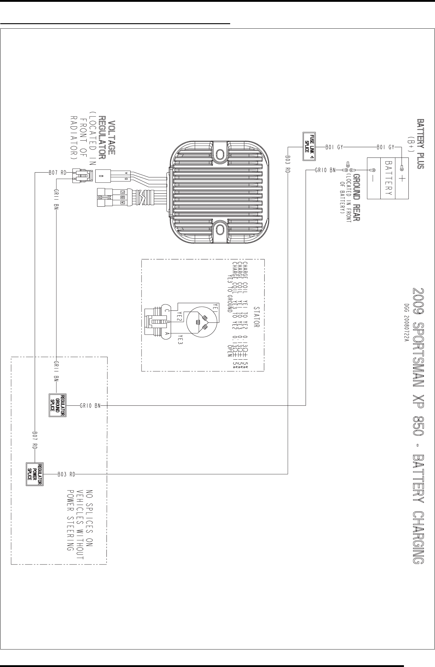
WD-7
WIRE DIAGRAM
2009 SPORTSMAN XP 850 (BATTERY CHARGING)
PartShark.com
877-999-5686
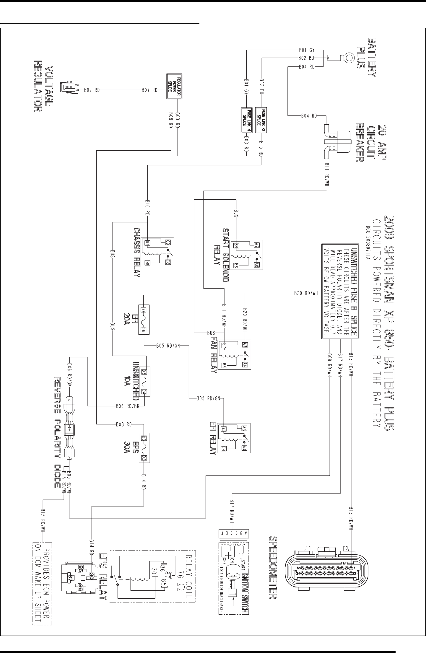
WD-9
WIRE DIAGRAM
2009 SPORTSMAN XP 850 (BATTERY PLUS)
PartShark.com
877-999-5686
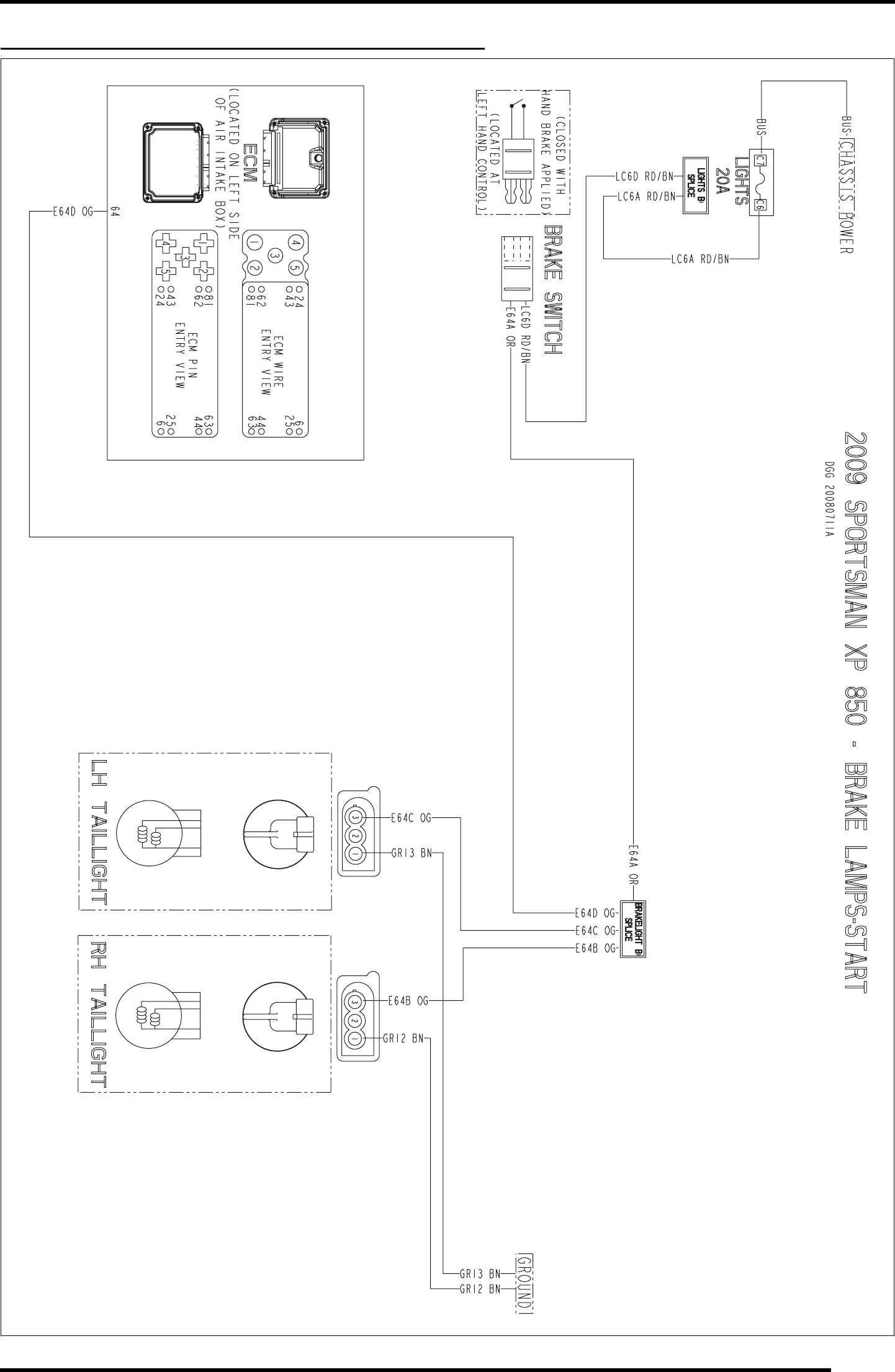
WD-11
WIRE DIAGRAM
2009 SPORTSMAN XP 850 (BRAKE LAMPS-START)
PartShark.com
877-999-5686
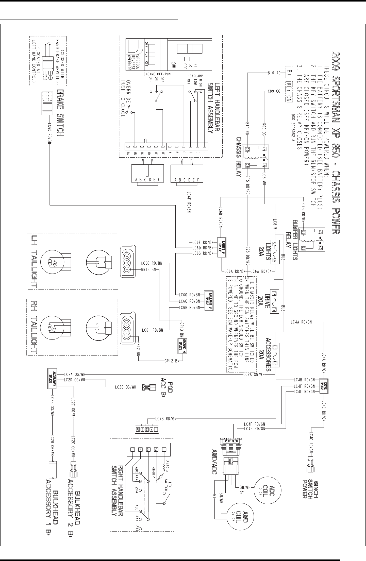
WD-13
WIRE DIAGRAM
2009 SPORTSMAN XP 850 (CHASSIS POWER)
PartShark.com
877-999-5686
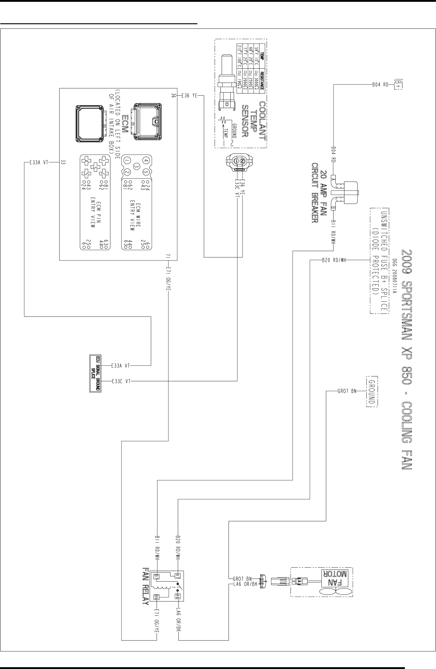
WD-15
WIRE DIAGRAM
2009 SPORTSMAN XP 850 (COOLING FAN)
PartShark.com
877-999-5686
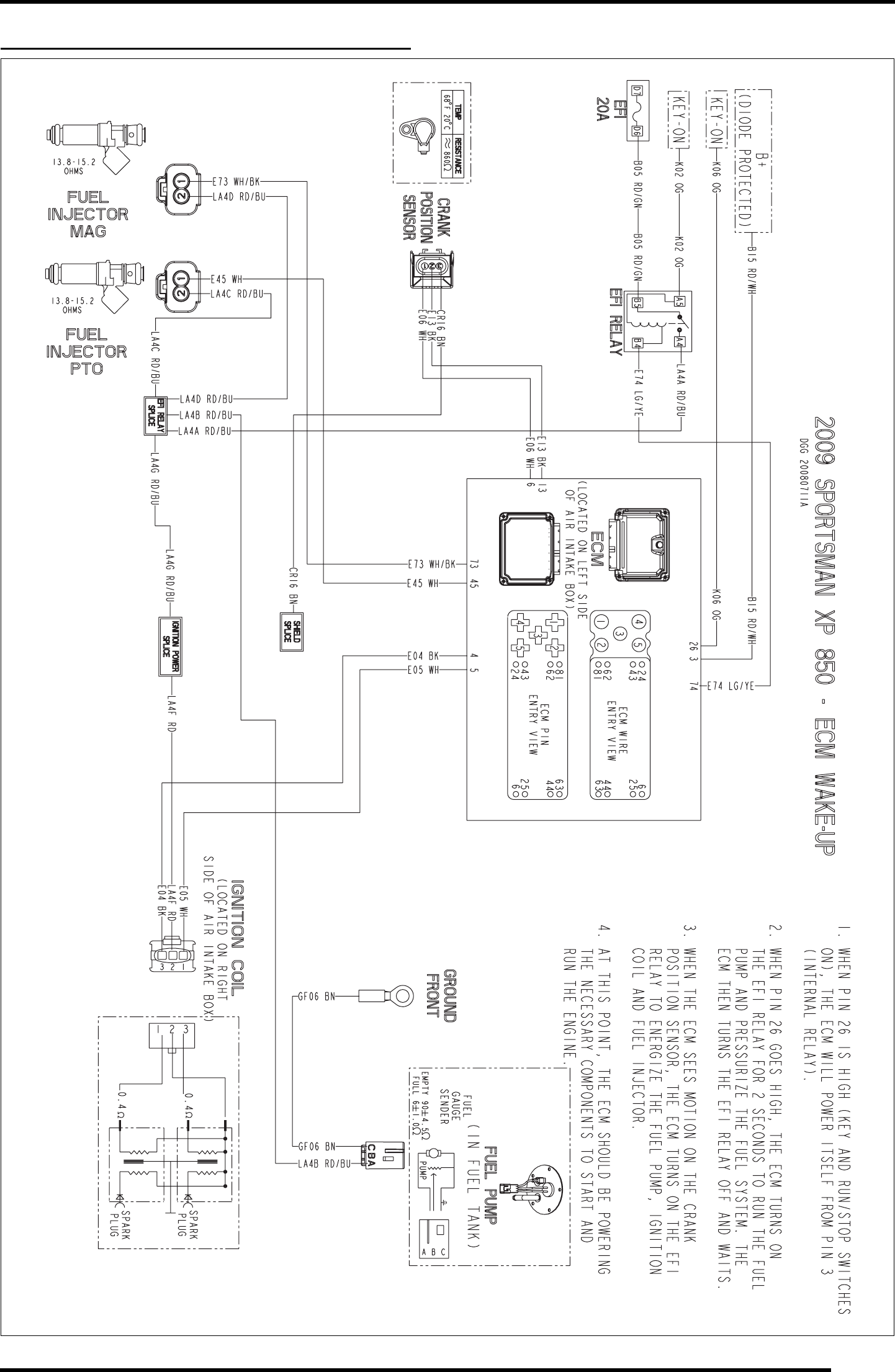
WD-17
WIRE DIAGRAM
2009 SPORTSMAN XP 850 (ECM WAKE-UP)
PartShark.com
877-999-5686
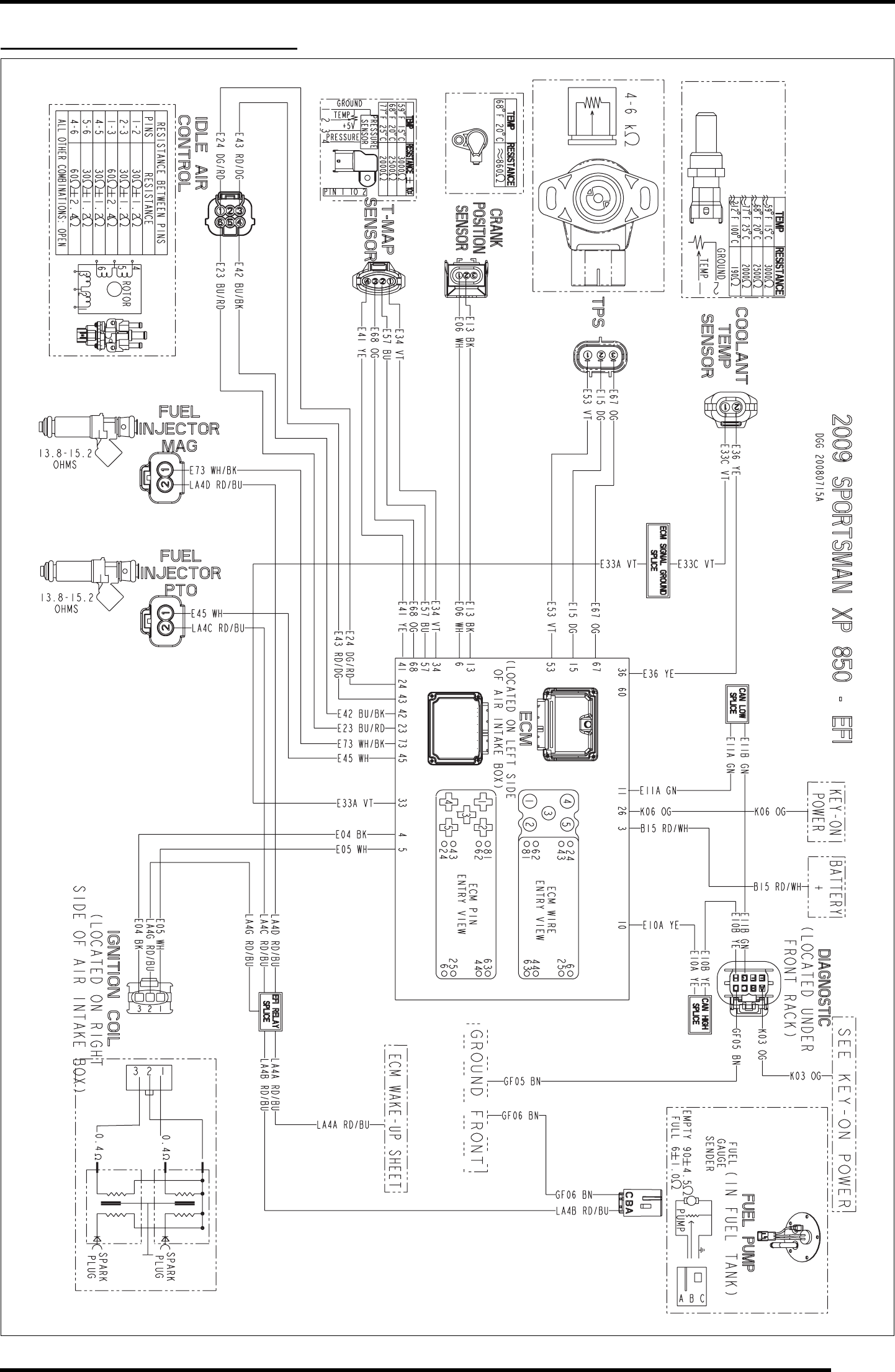
WD-19
WIRE DIAGRAM
2009 SPORTSMAN XP 850 (EFI)
PartShark.com
877-999-5686
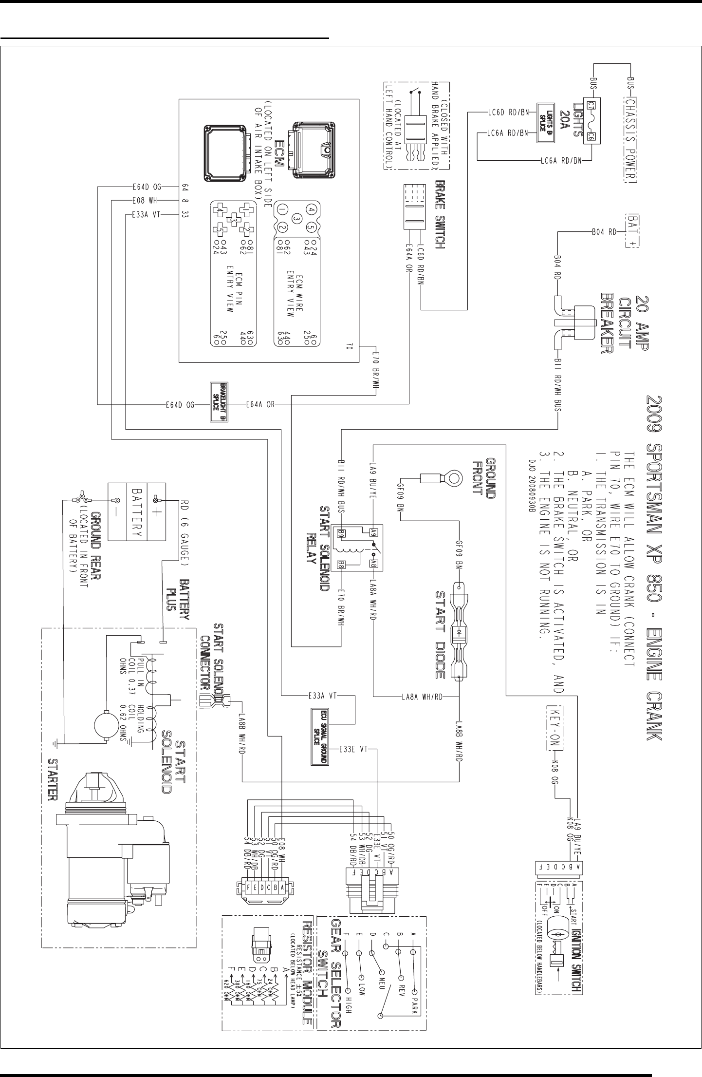
WD-21
WIRE DIAGRAM
2009 SPORTSMAN XP 850 (ENGINE CRANK)
PartShark.com
877-999-5686
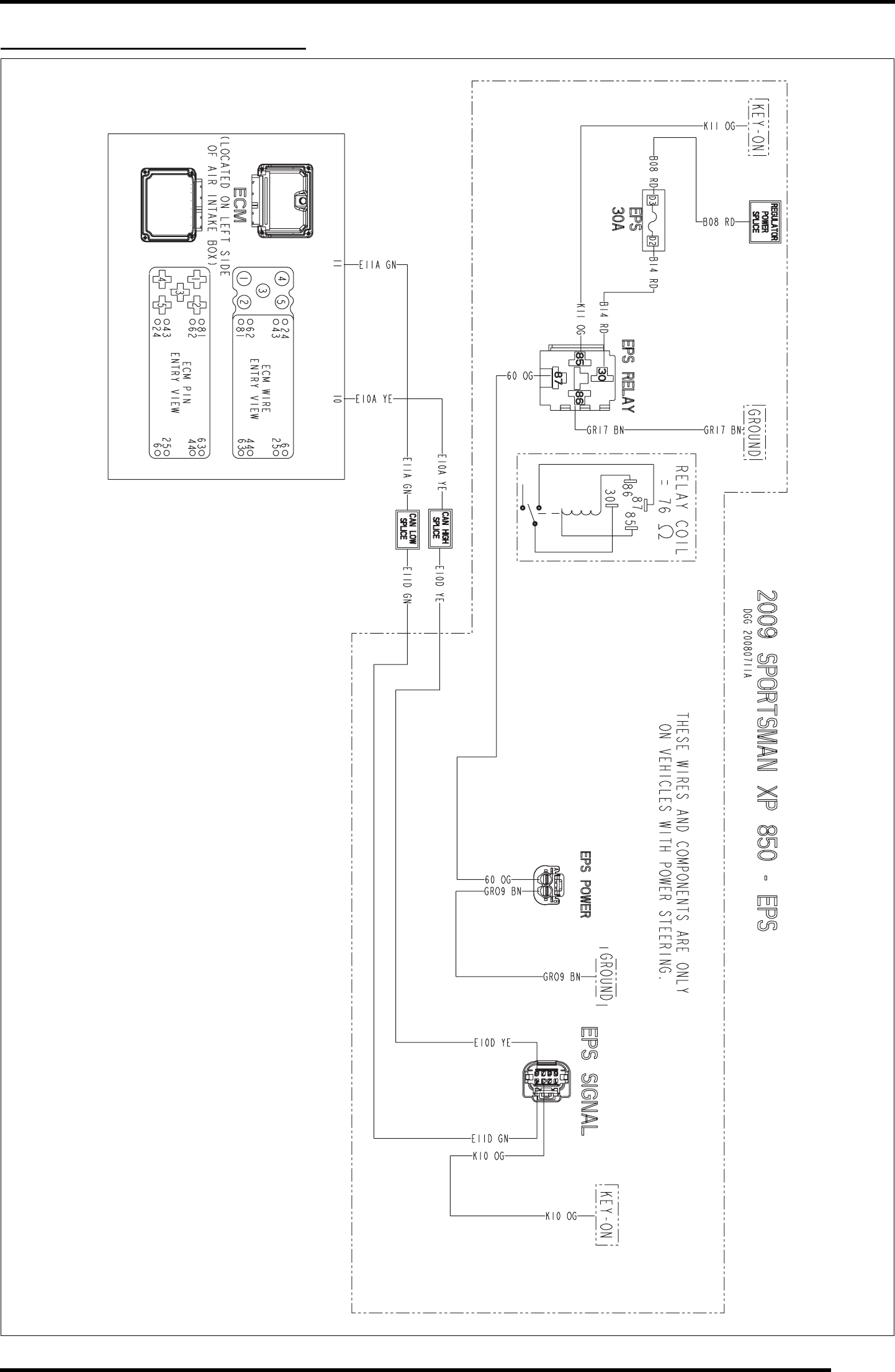
WD-23
WIRE DIAGRAM
2009 SPORTSMAN XP 850 (EPS)
PartShark.com
877-999-5686
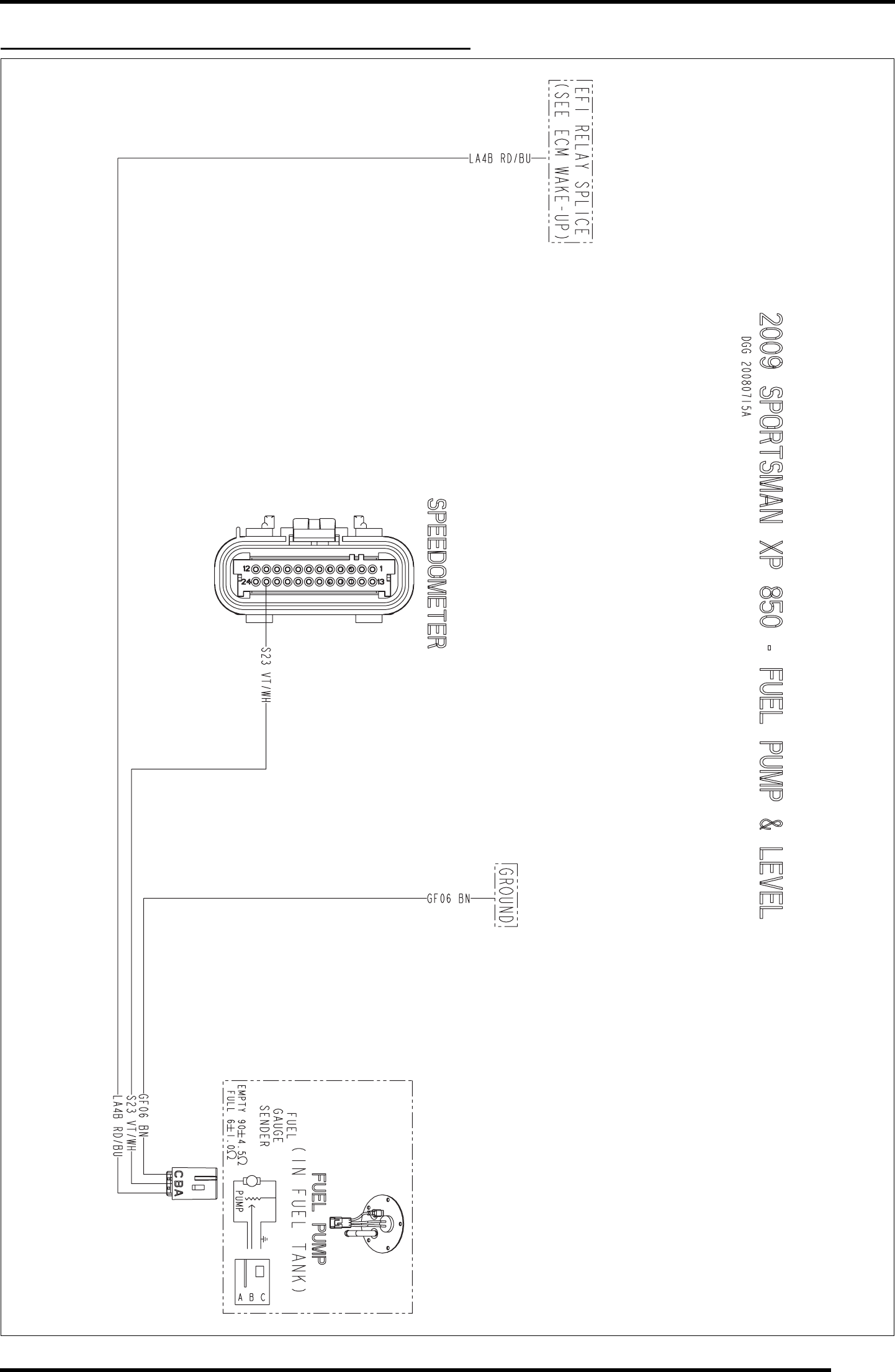
WD-25
WIRE DIAGRAM
2009 SPORTSMAN XP 850 (FUEL PUMP & LEVEL)
PartShark.com
877-999-5686
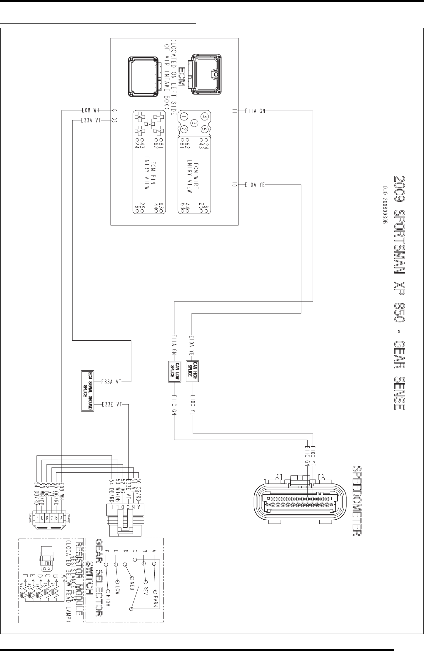
WD-27
WIRE DIAGRAM
2009 SPORTSMAN XP 850 (GEAR SENSOR)
PartShark.com
877-999-5686
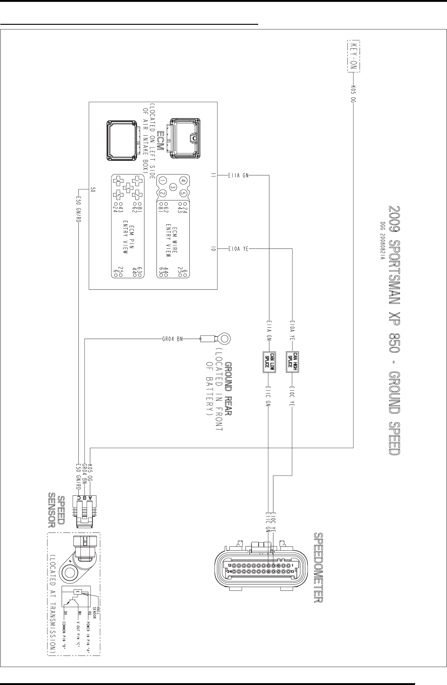
WD-29
WIRE DIAGRAM
2009 SPORTSMAN XP 850 (GROUND SPEED SENSOR)
PartShark.com
877-999-5686
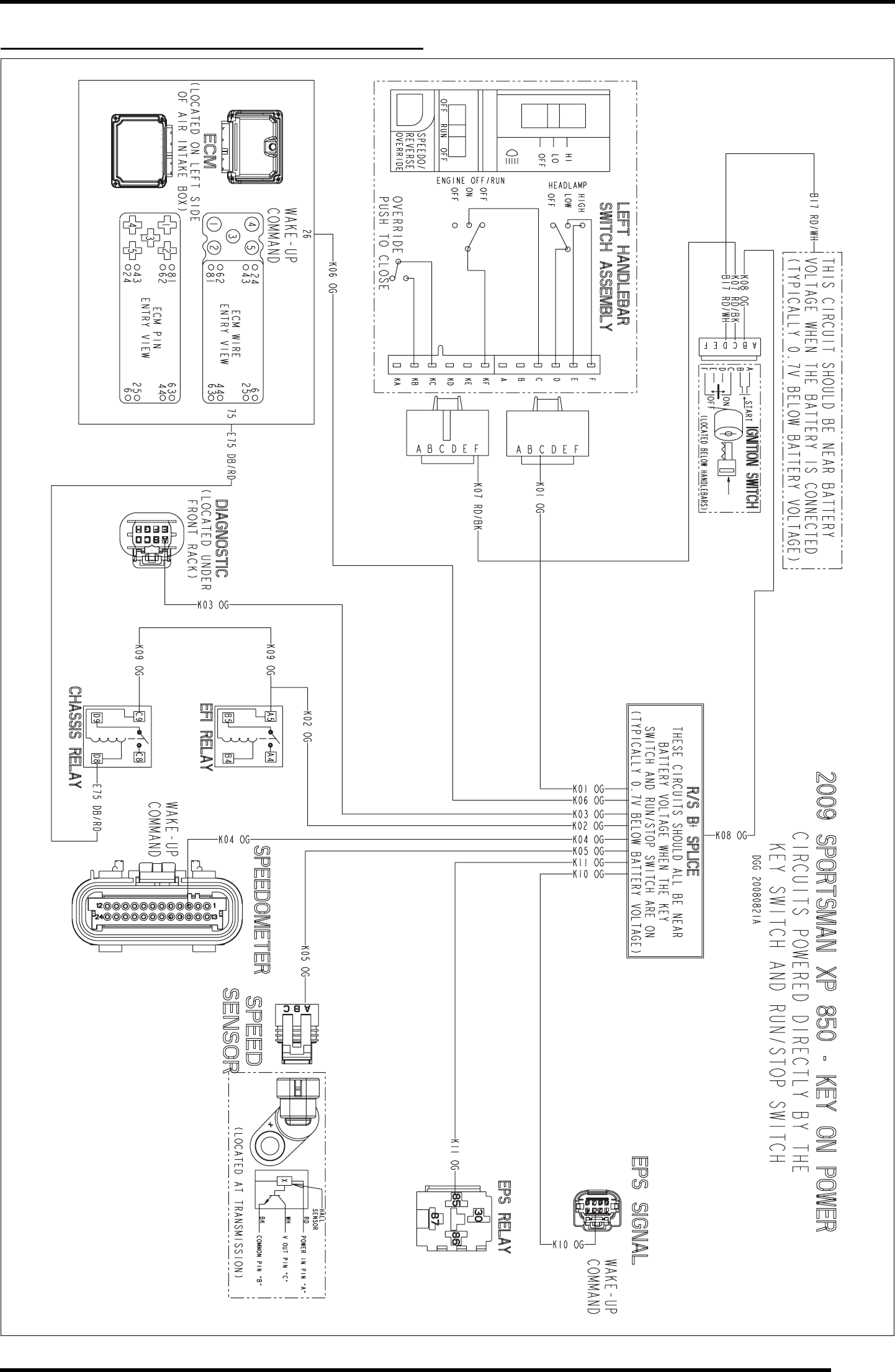
WD-31
WIRE DIAGRAM
2009 SPORTSMAN XP 850 (KEY ON POWER)
PartShark.com
877-999-5686
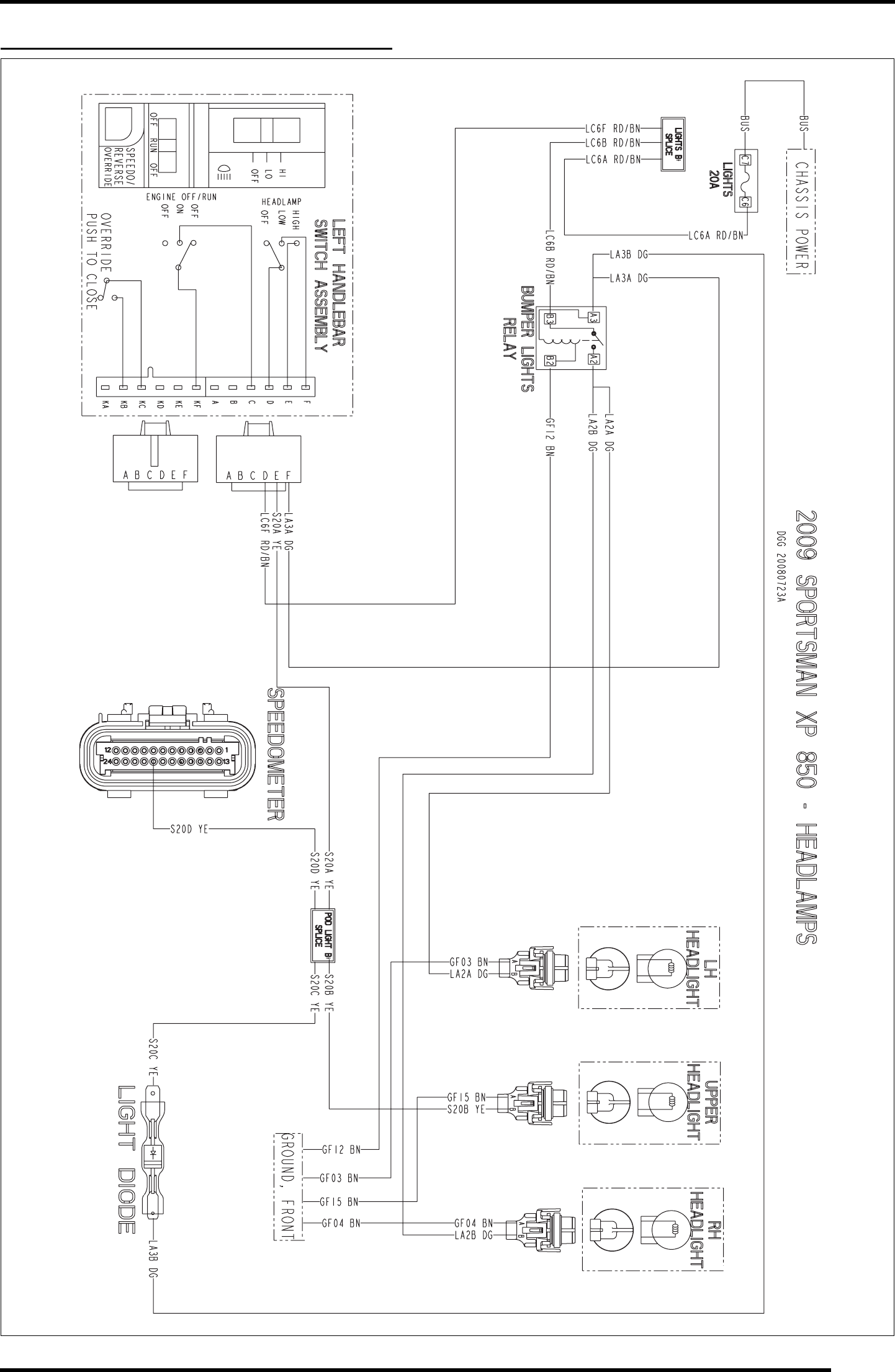
WD-33
WIRE DIAGRAM
2009 SPORTSMAN XP 850 (HEADLAMPS)
PartShark.com
877-999-5686
