White Rodgers_catalog_R 4320 3L09 2010 Cat Pg 034 74 Heating
User Manual: 3L09
Open the PDF directly: View PDF ![]() .
.
Page Count: 41

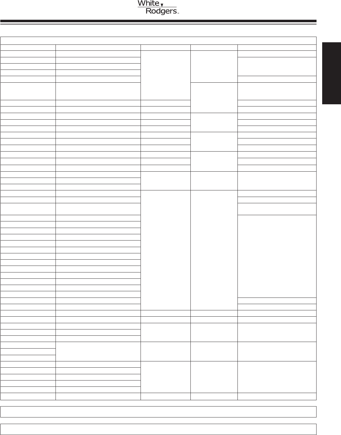
INDEXFURNACE SECTION
GAS VALVES 35 – 39
Description Model(s) Page(s)
Standing Pilot / HSI / DSI / Intermittent Pilot / Cycle Pilot /
Thermocouple Pilot Safety Valves ................................................................. 36C / 36E / 36H / 36J / 764 ................................... 35 – 39
IGNITION MODULES 40 – 52
Description Model(s) Page(s)
Universal HSI Integrated Two Stage with Nitride Upgrade ............................ 21M51U-843 / 21V51U-843 / Cross Reference .. 40 – 43
Universal HSI Integrated Single Stage with Nitride Upgrade ........................ 50M56U-843 / Cross Reference ........................... 44 – 45
Integrated HSI Modules ................................................................................. 50A55 / 50T35 / 50A62 / 50A65 ............................ 46 – 49
Non-Integrated HSI Modules ......................................................................... 50E47 ..................................................................... 50
DirectSparkModules/ProvenPilot .............................................................. 50D50 .................................................................... 51
PilotRelite/ReliteLockoutTimer/IgnitionElectrodes ................................. 5059 / 50A22 / 760 ................................................ 52
MERCURY FLAME SENSORS 61 – 63
Description Model(s) Page(s)
Mercury Flame Sensors ................................................................................ 3049 / 3098 ............................................................ 61 – 62
Mercury Flame Sensors and Cross Reference ............................................. 3046 / 30A46 / CROSS REFERENCE .................. 63
WARM AIR FAN CONTROLS/SNAP DISC FAN AND LIMITS 64 – 69
Description Model(s) Page(s)
Flush Mount Limit / Attic Fan / Duct Temperature Controls ........................... 758 / 775 / 230 ...................................................... 64
Fan / Limit Controls and Board Mount Limits ................................................ 5D51 / 3L09 ........................................................... 65
Snap Disc Fan Controls................................................................................. 3F01 ....................................................................... 66
Snap Disc Fan / Limit Controls ...................................................................... 3L01 / 3L02 / 3L03 ................................................ 67
AdjustableSnapDiscFanandLimitControls ............................................... 3F05 / 3L05 ............................................................ 68
Bimetal Disc Thermostats .............................................................................. 3F11 / 3L11 ............................................................ 69
ELECTRIC HEAT PRODUCTS 70 – 71
Description Model(s) Page(s)
Level-Temp Low Voltage Control Systems for Electric Heat ......................... 24A00 Series ......................................................... 70
ElectricHeatSequencers .............................................................................. 24A34 Series ......................................................... 71
DUAL PURPOSE AIR SWITCH 72
Description Model(s) Page(s)
Positive / Negative / Differential Air Switch .................................................... 770 ......................................................................... 72
OIL BURNER CONTROLS 73
Description Model(s) Page(s)
OilBurnerandKwik-SensorCadCellRelay/FlameDetector...................... 668 / 956 ................................................................ 73
GAS VALVE CONVERSION KITS / HEATING PARTS AND ACCESSORIES 74
IGNITORS 53 – 57
Description Model(s) Page(s)
Nitride Upgrade Kit, Hot Surface Flame Sensor / Silicon Nitride Ignitors ...... 21D64 / 768A / 760 ................................................ 53
Silicon Carbide Ignitors / Cross Reference.................................................... 767A ...................................................................... 54 – 57
THERMOCOUPLES / GENERATORS 58 – 60
Description Model(s) Page(s)
Thermocouples .............................................................................................. H06E / H06F .......................................................... 58
Generators / Pilot Generators / Pilot Couples ............................................... 101934 / G01A / PG9............................................. 59
Thermocouples Pilot Burners ........................................................................ PCA / PCB ............................................................. 60
www.white-rodgers.com
34
HEATING
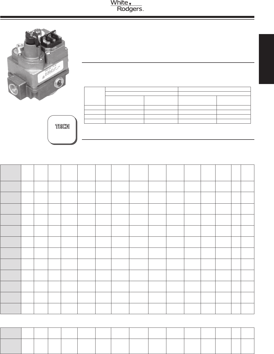
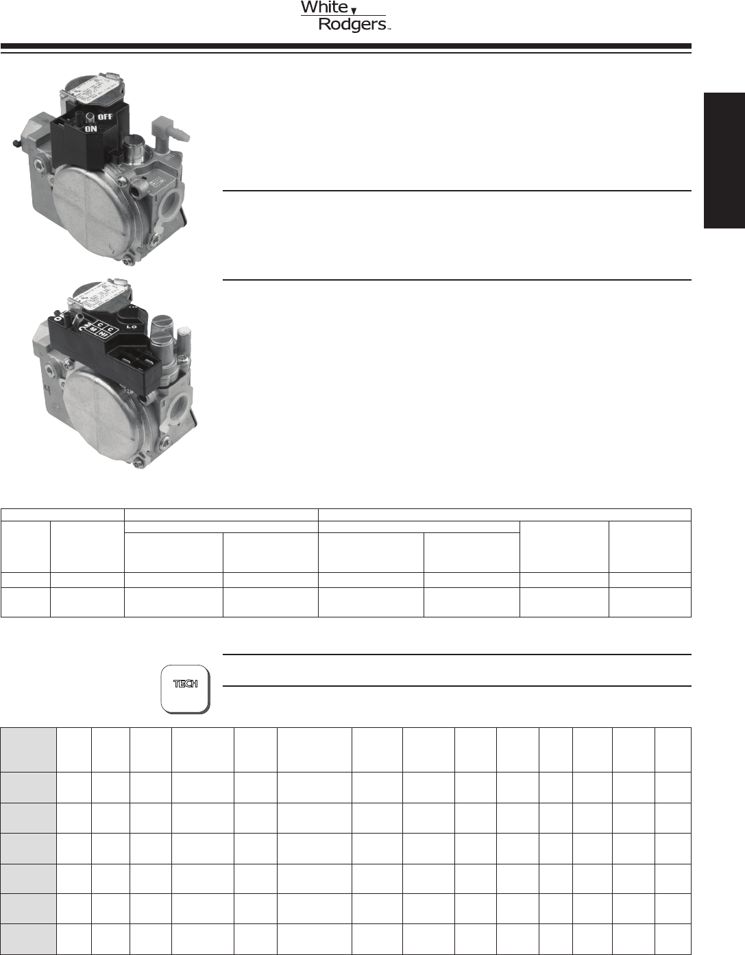
36C STANDING PILOT SNAP OPEN, STEP OPEN, HSI,
DSI, AND INTERMITTENT IGNITION GAS VALVES
A Wide Range of Replacement Valves for the Professional Installer
SPECIFICATIONS
Electrical Rating . . . . . . . . . . . . . . . . . . . . . . . . 0.23 amps
Ambient Operating Range ................ -40 to +175°F (-40 to 79°C)
Maximum Pressure Rating ................ 1/2 PSI (14.0” W.C.)
Pilot Gas Connection .................... 1/4”compressiontting
Pressure Tap .......................... 1/8” N.P.T.
36C Series
PARTS AND ACCESSORIES See end of this section for parts and accessories
36C SERIES
GAS VALVE
GAS BURNER
CONTROLS
STD. NAT GAS LP GAS STD. NAT GAS LP GAS
Pipe Size 1000 BTU/CU. FT. 2500 BTU/CU. FT. 1000 BTU/CU. FT. 2500 BTU/CU. FT.
1/2 X 3/8 100,000 162,000 15,000-100,000 15,000-162,000
1/2 X 1/2 230,000 372,600 30,000-290,000 30,000-469,000
1/2 X 3/4 230,000 372,600 30,000-290,000 30,000-469,000
3/4 X 3/4 280,000 453,600 50,000-400,000 50,000-648,000
1” Pressure Drop Capacity Rated Range of Regulation
BTU/HR BTU/HR
Universal
Universal
➀ Wiring diagrams – see pages 171-174 Indicates Canadian Model Number
SNAP OPEN, SINGLE FUNCTION, STANDING PILOT GAS VALVES
36C74-913 Step 24VAC Natural 3/4 x 3/4 Step 0.9”/3.5” 2.5”-5.0” No No No Str. Thru Yes Yes No 5
Open
36C94-303 24VAC 1/2 x 3/4 Delay 3.5” 2.5”-5.0” Yes Yes No Str. Thru No Yes No 15
Slow 7.0”-12.0”
HSI/DSI VALVES
Intermit-
tent
Ignition
Systems
?
WIRIING
171-174
LP Internal
Opening Regulator Conversion Reducer Inlet Wiring
Model Typical Coil Gas Pipe Character- Regulator Adjustment Convertible Kit Line Flow Bushing Pressure Side See
Number App. Voltage Type Size ristic Setting Range Nat. / LP Included Interrupter Direction Kit Tap Taps Figure ➀
36C01-405 Snap 24VAC 3/4 x 3/4 Fast Open 3.5” 2.5”-5.0” Yes Yes No Str. Thru Yes No No 1
Open
36C01A-405 Snap 120VAC 3/4 x 3/4 Fast Open 3.5” 2.5”-5.0” Yes Yes No Str. Thru Yes No No 3
Open
36C03-300 Standing 24VAC 1/2 x 3/4 Fast Open 3.5” 2.5”-5.0” Yes Yes Yes Str. Thru Yes No No 1
Pilot
36C03-333 Standing 24VAC 1/2 x 3/4 Fast Open 3.5” 2.5”-5.0” Yes Yes Yes Str. Thru Yes No Yes 1
Pilot
36C03-400 Standing 24VAC 3/4 x 3/4 Fast Open 3.5” 2.5”-5.0” Yes Yes Yes Str. Thru Yes No No 1
Pilot
36C03-433 Standing 24VAC 3/4 x 3/4 Fast Open 3.5” 2.5”-5.0” Yes Yes Yes Str. Thru Yes Yes Yes 1
Pilot
36C03A-410 Standing 120VAC 3/4 x 3/4 Fast Open 3.5” 2.5”-5.0” Yes Yes Yes Str. Thru Yes No No 3
Pilot
36C03U-333 Standing 750mV 1/2 x 3/4 Fast Open 3.5” 2.5”-5.0” Yes Yes Yes Str. Thru Yes Yes Yes 2
Pilot
36C03U-433 Standing 750mV 3/4 x 3/4 Fast Open 3.5” 2.5”-5.0” Yes Yes Yes Str. Thru Yes Yes Yes 2
Pilot
36C04U-438 Standing 750mV Natural 3/4 x 3/4 Step Open 0.7 / 3.5” 2.5”-5.0” No No Yes Str. Thru Yes No No 2
Pilot 0.7”
36C53-418 Standing 24VAC 3/4 x 3/4 Slow Open 3.5” 2.5”-5.0” Yes No Yes Str. Thru Yes No No 1
Pilot
36C03-258 Standing 24VAC Natural 1/2 x 1/2 Fast Open 3.5” 2.5”-5.0” No No Yes Str. Thru No Yes No 1
Pilot
Natural
or
LP
Natural
or
LP
Natural
or
LP
Natural
or
LP
Natural
or
LP
Natural
or
LP
Natural
or
LP
Natural
or
LP
Natural
or
LP
Natural
or
LP
Natural
or
LP
HEATING
www.white-rodgers.com 35
?
764 / 36C SERIES
GAS VALVES
GAS BURNER
CONTROLS
36C CYCLE PILOT GAS VALVES
With Redundant Pilot Solenoid Main Gas Regulator, Integral Gas
Pressure Switch and Electrical Connection on the Gas Valve for
Mercury Flame Sensor Connection.
SPECIFICATIONS
Electrical Rating . . . . . . . . . . . . . . . . . . . . 0.6 amps
End to End Dimensions . . . . . . . . . . . . . . 3
15/16”
Ambient Operating Range . . . . . . . . . . . . -40 to +175°F (-40 to 79°C)
Maximum Pressure Rating . . . . . . . . . . . . 1/2 PSI (14.0” W.C.)
Agency . . . . . . . . . . . . . . . . . . . . . . . . . . . C.S.A. approved
PARTS AND ACCESSORIES See end of this section for parts and accessories
36C84-912
TECHNICAL HELP
Wiring Diagrams. . . . . . . . . . . . . . . . . . . . . . See pages 171-174
STD. NAT GAS LP GAS STD. NAT GAS LP GAS
Pipe Size 1000 BTU/CU. FT. 2500 BTU/CU. FT. 1000 BTU/CU. FT. 2500 BTU/CU. FT.
1/2 X 3/8 100,000 162,000 15,000-100,000 15,000-162,000
1/2 X 1/2 230,000 372,600 30,000-290,000 30,000-469,000
1/2 X 3/4 230,000 372,600 30,000-290,000 30,000-469,000
3/4 X 3/4 280,000 453,600 50,000-400,000 50,000-648,000
1” Pressure Drop Capacity Rated Range of Regulation
BTU/HR BTU/HR
LP Internal
Regulator Conversion Reducer Inlet Wiring
Model Coil Gas Pipe Opening Regulator Adjustment Convertible Kit Line Flow Bushing Pressure Side See
Number Voltage Type Size Characteristic Setting Range Nat. / LP Included Interrupter Direction Kit Tap Taps Figure ➀
36C84-912 24 VAC Nat./LP 3/4 x 3/4 Fast Open 3.5” 2.5”–5.0” Yes Yes No Str. Thru Yes Yes No 7
36C84-913 24 VAC Nat./LP 3/4 x 3/4 Fast Open 3.5” 2.5”–5.0” Yes Yes No Str. Thru Yes Yes No 12
36C84-921 24 VAC Nat./LP 3/4 x 3/4 Fast Open 3.5” 2.5”–5.0” Yes Yes No Str. Thru Yes Yes No 7
36C84-923 24 VAC Nat./LP 3/4 x 3/4 Fast Open 3.5” 2.5”–5.0” No No No Str. Thru No Yes No 14
36C84-926 24 VAC Natural 3/4 x 3/4 Fast Open 3.5” 2.5”–5.0” No No No Str. Thru Yes No No 4
36C84-945 24 VAC Nat./LP 3/4 x 3/4 Fast Open 3.5” 2.5”–5.0” Yes Yes No Str. Thru Yes Yes No 8
36C94-906 24 VAC Natural 3/4 x 3/4 Slow Open 3.5” 2.5”–5.0” No No No Str. Thru Yes No No 7
36C94-907 24 VAC Nat./LP 3/4 x 3/4 Slow Open 3.5” 2.5”–5.0” Yes Yes No Str. Thru Yes No No 4
➀ Wiring diagrams – see pages 171-174 NOTE: -9XX series replaces -4XX series. Knob replaced with an ON-OFF switch.
PAGES
171-174
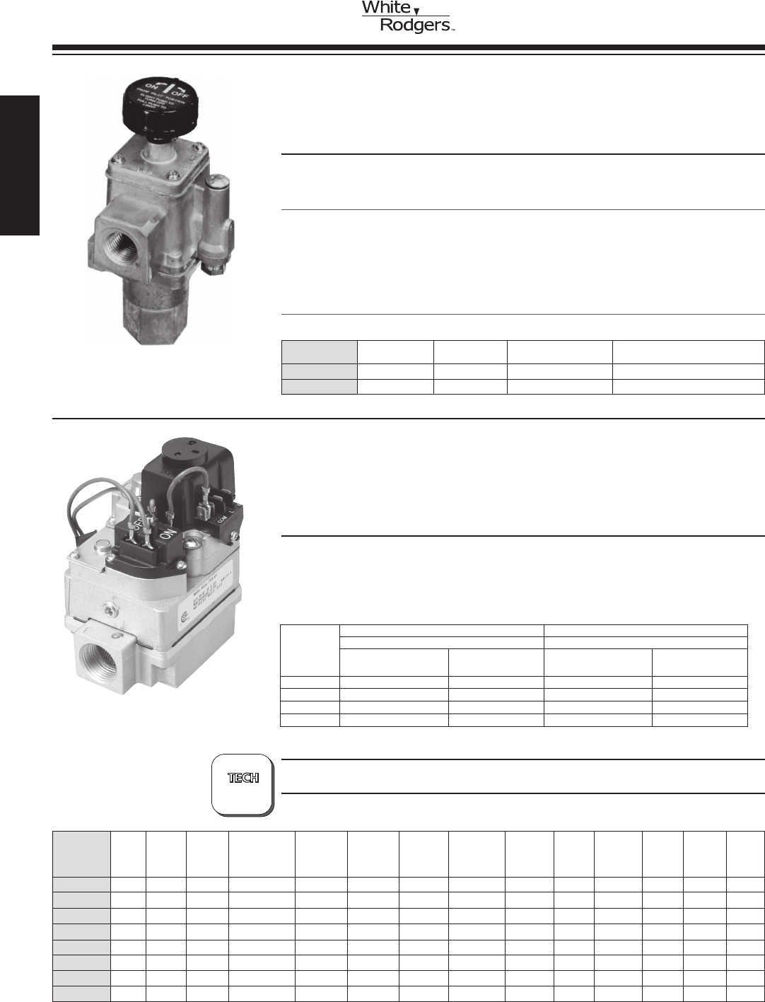
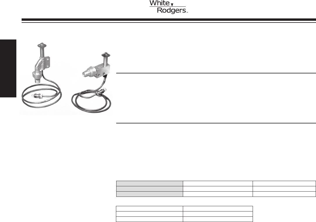
764 SERIES THERMOCOUPLE OPERATED
GAS PILOT SAFETY/GAS FIREPLACE VALVES
In Line Appliance Control with 100% Shut Off.
FEATURES / SPECIFICATIONS / PART AND ACCESSORIES
•Redesignedtoinclude100PSIprotection,inletscreenandinletpipestop.
•Optionalrearinlettappedandplugged.
•Maybemountedhorizontal,verticaland90°fromhorizontal(multipoise).
Electrical Rating . . . . . . . . . . . . . . . . . . . . 20 to 30 mV (Thermocouple)
RegulatorAdjustmentRange . . . . . . . . . . Non-regulated
Maximum Pressure Rating . . . . . . . . . . . . 1/2 PSI (14.0” W.C.)
Ambient Operating Range . . . . . . . . . . . . 32 to 175°F
Swing Radius . . . . . . . . . . . . . . . . . . . . . . 2.5”
Agency . . . . . . . . . . . . . . . . . . . . . . . . . . . C.S.A. approved
764-702
•F42-0895—Replacementknob
Model Coil Inlet-Outlet Capacity A.G.A.
Number Voltage Size Standard Gas ➀ Electrical Connection
764-702 20 to 30 mV 3/8” x 3/8” 132,000 Thermocouple
764-742 20 to 30 mV 1/2” x 1/2” 142,000 Thermocouple
➀ See page 414 for capacities of other gases
www.white-rodgers.com
36
HEATING
?
PAGE
175
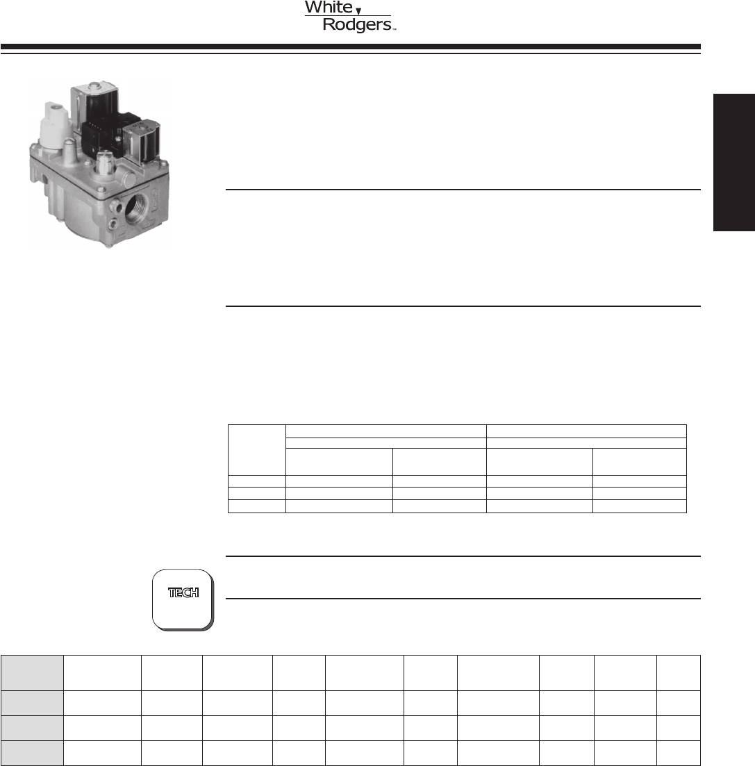
36E SERIES
GAS VALVES
36E SERIES GAS VALVES
ForusewithIntermittentIgnitionSystems(ProvenPilot,DirectSpark
Ignition and Hot Surface Ignition) (36E38 types) and Cycle Pilot
Systems (36E86)
36E86-302
GAS BURNER
CONTROLS
FEATURES
•Poppetstylemanualvalve(capableofwithstandinghighinletpressures).
•Conicalinletandoutletscreensprotectedfrompipedamage.
•Directactingsolenoidvalvewithhighsealingforce.
•Controlledgasketclinchbetweencastingstowithstandhighinletpressures.
•Maybemountedhorizontal,verticaland90°fromhorizontal.
SPECIFICATIONS
Electrical Rating . . . . . . . . . . . . . . . . . . . . 0.54 amps
RegulatorAdjustmentRange . . . . . . . . . . Natural gas, 2.5 to 5.0” W.C.
L.P. gas, 7.5 to 12.0” W.C.
Maximum Pressure Rating ............ 1/2 PSI (14.0” W.C.)
Ambient Operating Range ............ -40 to +175°F (-40 to +79°C)
Swing Radius . . . . . . . . . . . . . . . . . . . . . . 3
9/16”
Agency . . . . . . . . . . . . . . . . . . . . . . . . . . . C.S.A. approved
PARTS AND ACCESSORIES See end of this section for parts and accessories
TECHNICAL HELP
Wiring Diagram....................... See page 175
Electrical Reducer Inlet
Model Coil Inlet-Outlet Connection Regulator Opening Gas System Bushing Pressure Side
Number Voltage Size (see Fig #)➁ Setting Characteristic Type Usage Kit Tap Taps
36E38-301 ➀ 24 VAC, 60 Hz 1/2” x 3/4” 2 3.5” W.C. 1.2” W.C. Natural Proven Pilot, Yes Yes Yes
Step Only HSI and DSI
36E38-302 ➀ 24 VAC, 60 Hz 1/2” x 3/4” 2 10.0” W.C. 2.5” W.C. L.P. Proven Pilot, Yes Yes Yes
Step Only HSI and DSI
36E86-302 24 VAC, 60 Hz 1/2” x 3/4” 5 3.5” W.C. Fast Open Natural Cycle Pilot Yes No Yes
No Step Only
➀ Pilotttingsincludedwithvalves
➁ Wiring diagrams see page 175
STD. NAT GAS LP GAS STD. NAT GAS LP GAS
Pipe Size 1000 BTU/CU. FT. 2500 BTU/CU. FT. 1000 BTU/CU. FT. 2500 BTU/CU. FT.
1/2 X 1/2 140,000 226,800 20,000-210,000 25,000-340,000
1/2 X 3/4 140,000 226,800 20,000-210,000 25,000-340,000
1/2 X 3/4 125,000 202,500 20,000-210,000 25,000-340,000
1” Pressure Drop Capacity Rated Range of Regulation
BTU/HR BTU/HR
HEATING
www.white-rodgers.com 37
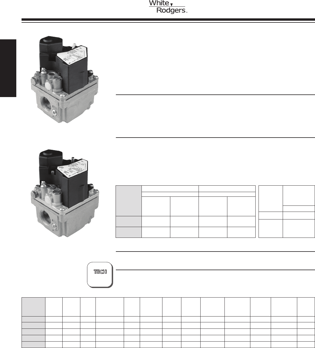
Convertible Reducer Inlet &
Model Type of Pipe Opening Proven Standing Intermittent Nat/LP Bushing Outlet Side
Number Voltage Gas Size Characteristic Stages HSI/DSI Pilot Pilot Pilot Kit Included Kit Pressure Tap Taps
36H32-304* 24 Volt Nat./LP 1/2 x 3/4 Fast 1 Yes Yes No Yes Yes Yes Yes No
36H32-423* 24 Volt Nat./LP 3/4 x 3/4 Fast 1 Yes Yes No Yes Yes Yes Yes No
36H33-412* 24 VAC Nat./LP 3/4 x 3/4 Slow 1 Yes Yes No Yes Yes Yes Yes No
36H64-463* 24 VAC Nat./LP 3/4 x 3/4 Fast 2 Yes Yes No Yes Yes Yes Yes No
36H65-401* 24 VAC Nat./LP 3/4 x 3/4 Slow 2 Yes Yes No No Yes Yes Yes No
*Tomeasureoutletpressureonvalves,loosenoutletpressuretapscrewonequarterturnandputmanometerhoseoverthetopoftheoutletpressuretap.
Wiring diagrams – see page 176
36H SERIES GAS VALVES
Combination Multi-function Controls for a Wide Range of Applications.
The 36H Combination Gas Control Valve is a Versatile Multifunction
ControlDesignedtoMeettheRequirementsforUsewithIntermittent
Ignition Systems (Direct Ignition, Proven Pilot, HSI). 36H is our
Highest Capacity Combination Gas Valve.
FEATURES
•Adjustableregulator.
•Quietoperationredundantdesign.
•Inlet/outletscreens.
•Tamperresistantscrews.
SPECIFICATIONS
Electrical Rating (36H) . . . . . . . . . . . . 0.41 amps (Single stage)
0.54 amps (Two stage)
Ambient Temp................... -40° to 175°F (-40° to 79°C)
Pressure Rating ................. 1/2 PSI (14.0” W.C.)
Voltage . . . . . . . . . . . . . . . . . . . . . . . . 24 VAC
Frequency...................... 50/60 Hz
36H SERIES
GAS VALVES
GAS BURNER
CONTROLS
Pipe Size
(36 H)
1” PD Capacity Rated Range of Regulation
BTU/HR BTU/HR
Std. Gas .64
Sp. Gr. (1000
BTU/CU FT)
Std. Gas
1.53
Sp. Gr. (2500
BTU/CU FT)
Std. Gas .64
Sp. Gr. (1000
BTU/CU FT)
Std. Gas
1.53
Sp. Gr. (2500
BTU/CU FT)
3/4” x 3/4” 300,000 486,000 50,000 to
400,000
81,000 to
648,000
1/2” x 3/4” 230,000 372,600 30,000 to
290,000
81,000 to
648,000
Valve
Stages
Regulator
Adjustment
Range
Nat. Gas
Single 2.5” to 5.0”
Two-Stage 1.0”-3.5” Low
2.5”-5.0” High
PARTS AND ACCESSORIES See end of this section for parts and accessories
TECHNICAL HELP
Wiring Diagram....................... See page 176
36H32-423
36H64-463
?
PAGE
176
www.white-rodgers.com
38
HEATING
LP Internal
Regulator Conversion Reducer Inlet Outlet Wiring
Model Coil Gas Pipe Opening Regulator Adjustment Convertible Kit Flow Bushing Filter Pressure Pressure See
Number Voltage Type Size Characteristic Setting Range Nat. / LP Included Direction Kit Screen Tap Taps Figure ➀
36J22-214* 24 VAC 1/2 x 1/2 Fast Opening 3.5” Nat. 2.5”- 5.0” Yes Yes Str. Thru Yes Yes Yes Yes 1
L.P. 7.0”- 12.0”
36J24-214* 24 VAC 1/2 x 1/2 Slow Opening 3.5” Nat. 2.5”- 5.0” Yes Yes Str. Thru Yes Yes Yes Yes 1
L.P. 7.0”- 12.0”
36J54-214* 24 VAC 1/2 x 1/2 2 Stage LO 1.5” Nat. 2.5”- 5.0” Yes Yes Str. Thru Yes Yes Yes Yes 2
Fast Opening HI 3.5” L.P. 6.0”- 12.0”
36J55-214* 24 VAC 1/2 x 1/2 2 Stage LO 1.5” Nat. 2.5”- 5.0” Yes Yes Str. Thru Yes Yes Yes Yes 2
Slow Opening HI 3.5” L.P. 6.0”- 12.0”
36J24-614* 24 VAC 1/2 x 1/2 2 Stage 3.5” Nat. 2.5”- 5.0” Yes Yes No Yes Yes Yes 2
Slow Opening L.P. 7.0”- 12.0”
36J55-614* 24 VAC 1/2 x 1/2 2 Stage 3.5” Nat. 2.5”- 5.0” Yes Yes No Yes Yes Yes 2
Slow Opening L.P. 6.0”- 12.0”
36J SERIES GAS VALVES
The 36J is a Combination Gas Control Valve Designed for use with
Non-Piloted Intermittent Ignition Systems. The Control is Designed to
meetToday’sMaximumCapacity,SmallerSizeandHighEfciency
Gas Systems.
FEATURES
•Inletandoutletscreens.
•Quietredundant.
•Built-inpressuretap.
•Quick-connectterminals(1/4”).
SPECIFICATIONS
Ambient Temperature ................ -40 to 175°F
Maximum Pressure Rating ............ 1/2” PSI (14.0” W.C.)
Capacity (1” P.D.)................... Natural 140,000 Btu/Hr.
L.P. 226,800 Btu/Hr.
Electrical Rating . . . . . . . . . . . . . . . . . . . . Single stage 24V, 50 / 60Hz at .3A
Two stage at .43A
Swing Radius . . . . . . . . . . . . . . . . . . . . . . 2.75”
Mounting.......................... Any position
Agency . . . . . . . . . . . . . . . . . . . . . . . . . . . C.S.A. approved
36J SERIES
GAS VALVES
GAS BURNER
CONTROLS
1” Pressure Drop Capacity Range of Regulation
BTU/HR BTU/HR
Std Gas LP Gas Std Gas LP Gas Adjustment Adjustment
Valve .64 Sp. Gr. 1.53 Sp. Gr. .64 Sp. Gr. 1.53 Sp. Gr. Range Range
(Stages) Pipe Size (1000 BTU/CU. FT.) (2500 BTU/FT.) (1000 BTU/CU. FT.) (2500 BTU/FT.) (Nat. IN. W.C.) (L.P. IN. W.C.)
Single 1/2” x 1/2”NPT 140,000 BTU/HR 226,800 BTU/HR 40,000-210,000 60,000-340,000 2.5”-5.0” 7.0”-12.0”
Two 1/2” x 1/2”NPT 140,000 BTU/HR 226,800 BTU/HR 20,000 Low- 32,000 Low- 1.0”-4.0” Low 4.0”-10.0” Low
210,000 High 340,000 High 2.0”-5.0” High 6.0”-12.0” High
PARTS AND ACCESSORIES See end of this section for parts and accessories
TECHNICAL HELP
Wiring Diagrams...................... See page 177
?
36J Series
*Tomeasureoutletpressureonvalves,loosenoutletpressuretapscrewonequarterturnandputmanometerhoseoverthetopoftheoutletpressuretap.
➀ Wiring diagrams – see page 177
90o
Bottom
Outlet
90o
Bottom
Outlet
PAGE
177
Natural
or
LP
Natural
or
LP
Natural
or
LP
Natural
or
LP
Natural
or
LP
Natural
or
LP
HEATING
www.white-rodgers.com 39
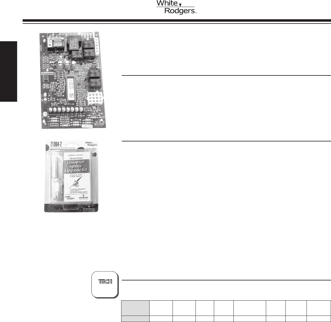
21M51U-843 Kit
Includes:
•Module
•IgnitorKit
21M51U-843 KIT REPLACES:
White-Rodgers 50M51-242 and 50M61-XXX's Two-Stage HSI Sys-
tems with 80V or 120V Ignitors.
FEATURES
•120VAC3-speedPSC(PermanentSplitCapacitor)circulatoroutput,two-speed
inducer output, 2-stage gas valve output.
•Pushbuttonfaulthistoryretrieval.
•FurnacestatusLED–tri-color(green,redandamber).
•Heatfanoffdelay(dipswitchselectable),fanondelayforcooling.
•Autosecondstagedelay(dipswitchselectable).
•120VAChumidieroutput/120VACelectronicaircleaneroutput.
SPECIFICATIONS
Electrical Rating:
Input Voltage.................... 24VAC,60Hz(ClassIItransformerrequired)
Nom. Input Current @ 24 VAC ...... 530 mA + MV
Relay Load Ratings:
Gas Valve Relays ................ 1.5 amps @ 24 VAC, 60 Hz
Inducer Relays . . . . . . . . . . . . . . . . . . 2.2 FLA – 3.5 LRA @ 120 VAC
Circulator Relays ................ 14.5 FLA – 25.0 LRA @ 120 VAC
HumidierLoad ................. 1.0 amp max. @ 120 VAC
Electronic Air Cleaner Load ........ 1.0 amp max. @ 120 VAC
Ignitor Relay .................... 4.0 amps max. @ 132 VAC, 60 Hz
FlameCurrentRequirements:
Minimumcurrenttoinsureamedetection 0.3 µa DC*
Maximum current for non-detection . . 0.1 µa DC*
Maximumallowableleakageresistance100Mohms
*Measured with a DC microameter in the flame probe lead
Operating Temperature Range...... -40o to 175oF (-40 to 80oC)
Humidity Range ................. 5% to 93% relative humidity (non-condensing)
Flame Failure Response Time . . . . . . 2.0 sec. max. @ 60Hz
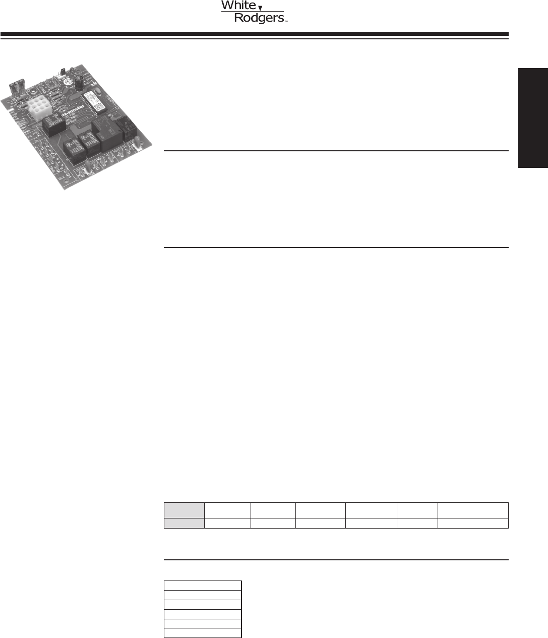
IGNITION MODULE/CIRCULATOR
FURNACE CONTROL KIT WITH
NITRIDE IGNITOR
UNIVERSAL TWO-STAGE HSI
INTEGRATED 3-SPEED (PSC)
TECHNICAL HELP
Wiring Diagram/Operation .............. See pages 178-188
Model
Number Pre-Purge
Ignitor
Warm-Up Retries
Heat
Delay to
Fan ON
Heat Delay
to Fan OFF
Cool
Delay to
Fan ON
Cool
Delay to
Fan OFF
Automatic
Reset
Time
21M51U-843 15 17 2 45 90/120/150/180 5 60 60 minutes
?
PAGES
178-188
www.white-rodgers.com
40
HEATING
21M51U-843 Cross Reference Application Data
Module Model Number Furnace Model Ignitor Furnace OEM
18M3401
G60DF(X) or
G60UH(X)
21D64-2*
Lennox
20300001 N/A Goodman
20300003 N/A
46M9901 G61MP Lennox
50M51-242 FC9T
Use existing or
21D64-2 Coleman/Evcon/Luxaire/York
50M51-242 FL9T
50M51-242 PT9A
50M51-242 PT9B
50M51-242 PT9C
50M51-242 PT9D
50M51-242 GM9T
50M51-242 FC8T
50M51-242 FL8T
50M51-242 LC8T
50M51-242 LL8T
50M51-242 PT8A
50M61-120 G61MPV
21D64-2*
Lennox
50M61-288 N/A Amana/Goodman
50M61-289 N/A
50M61-480 50M61-480 White-Rodgers Standard
50M61-495 XL80 American Standard/Trane
50M61-843 N/A White-Rodgers Standard
83L9301 N/A Lennox
CNT03077 XL80 Trane
X13650839010 XL80
Note: Installer may have to modify existing ignitor hole to accommodate the new 21D64-2, with ceramic diameter (.394”).
*21D64-2 Ignitor Note: In these applications, the existing 80V ignitor must be replaced by the 120V 21D64-2 ignitor.
21M51U-843
CROSS
REFERENCE
HEATING
www.white-rodgers.com 41
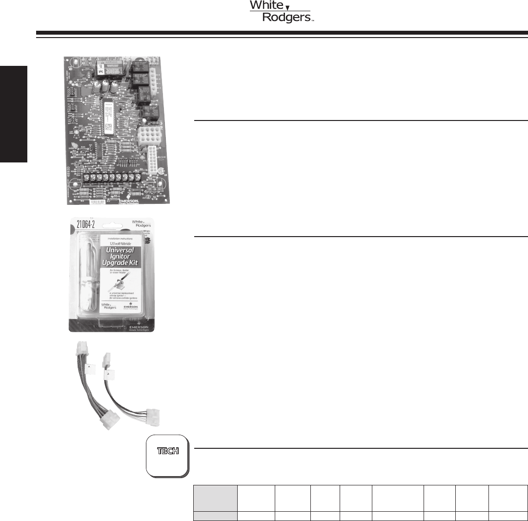
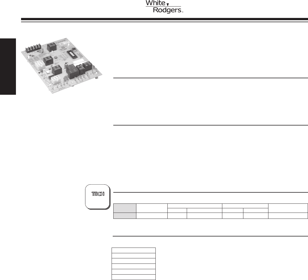
IGNITION MODULE/CIRCULATOR
FURNACE CONTROL KIT WITH
NITRIDE IGNITOR
UNIVERSAL TWO-STAGE HSI
INTEGRATED VARIABLE
SPEED (ECM)
21V51U-843 KIT REPLACES:
White-Rodgers 50V51-XXX's and 50V61-XXX's Two-Stage HSI
Systems with 80V or 120V Ignitors.
FEATURES
•16-pinvariablespeedcirculatoroutputforECM(ElectronicallyCommutatedMotor),
dipswitch selectable for OEM applications two-speed inducer output, 2-stage gas
valve output
•Pushbuttonfaulthistoryretrieval.
•FurnacestatusLED–tri-color(green,redandamber).
•Heatfanoffdelay(dipswitchselectable),fanondelayforcooling.
•Autosecondstagedelay(dipswitchselectable).
•120VAChumidieroutput/120VACelectronicaircleaneroutput.
SPECIFICATIONS
Electrical Rating:
Input Voltage.................... 24VAC,60Hz(ClassIItransformerrequired)
Nom. Input Current @ 24 VAC ...... 595 mA + MV
Relay Load Ratings:
Gas Valve Relays ................ 1.5 amps @ 24 VAC, 60 Hz
Inducer Relays . . . . . . . . . . . . . . . . . . 2.2 FLA – 3.5 LRA @ 120 VAC
HumidierLoad ................. 1.0 amp max. @ 120 VAC
Electronic Air Cleaner Load ........ 1.0 amp max. @ 120 VAC
Ignitor Relay .................... 4.0 amps max. @ 132 VAC, 60 Hz
FlameCurrentRequirements:
Minimumcurrenttoinsureamedetection 0.3 µa DC*
Maximum current for non-detection . . 0.1 µa DC*
Maximumallowableleakageresistance100Mohms
*Measured with a DC microameter in the flame probe lead
Operating Temperature Range...... -40o to 175oF (-40 to 80oC)
Humidity Range ................. 5% to 93% relative humidity (non-condensing)
Flame Failure Response Time . . . . . . 2.0 sec. max. @ 60Hz
TECHNICAL HELP
Wiring Diagram/Operation .............. See pages 178-188
Model
Number Pre-Purge
Ignitor
Warm-Up Retries
Heat
Delay to
Fan ON
Heat Delay
to Fan OFF
Cool
Delay to
Fan ON
Cool
Delay to
Fan OFF
Automatic
Reset
Time
21V51U-843 15 17 2 45 90/120/150/180 5 60 60 minutes
?
PAGES
178-188
21V51U-843
Includes:
•Module
•IgnitorKit
•WiringHarness
www.white-rodgers.com
42
HEATING
21V51U-843
CROSS
REFERENCE
21V51U-843 Cross Reference Application Data
Module Model Number Furnace Model Harness Ignitor Furnace OEM
18M9901 G60DFV (X) or G60UHV
Nonerequired
21D64-2*
Lennox
20300002 N/A
Amana/Goodman20300004 N/A
20300006 Same as 50V61-289
49M5901 G60UHV or G61MPV Lennox
50V51-243
FC8V, FC9V, FL8V, FL9V, GM8V,
GM9V, LC8V, LL8V, LM8V,
PV8A, PV9A or PV9B Use existing
or 21D64-2
Coleman/Evcon/Luxaire/York
50V51-243 FL9V Nonerequired Coleman/Evcon/Luxaire/York
50V51-243 PV9B Nonerequired Coleman/Evcon/Luxaire/York
50V51-243 GM9V Nonerequired Use existing
or 21D64-2
Coleman/Evcon/Luxaire/York
50V51-243 PV9B Nonerequired Coleman/Evcon/Luxaire/York
50V51-243 GM8V Nonerequired Coleman/Evcon/Luxaire/York
50V51-243 LM8V Nonerequired Use existing
or 21D64-2
Coleman/Evcon/Luxaire/York
50V51-243 FC8V Nonerequired Coleman/Evcon/Luxaire/York
50V51-243 FL8V Nonerequired Coleman/Evcon/Luxaire/York
50V51-243 LC8V Nonerequired Use existing
or 21D64-2
Coleman/Evcon/Luxaire/York
50V51-243 LL8V Nonerequired Coleman/Evcon/Luxaire/York
50V51-243 PV8A Nonerequired Coleman/Evcon/Luxaire/York
50V51-288 N/A
A, B Use existing
or 21D64-2 Amana/Goodman50V51-289 N/A
50V51-290 N/A
50V51-507 XV80 or XV80i
Nonerequired 21D64-2*
American Standard/Trane
50V61-120 G60DFV (X) or G60UHV or G61MPV Lennox
50V61-143 CDX1-75N, CDX1-100N, CDX1-125N,
CHX1-75N, CHX1-100N or CHX1-125N Thermo Pride
50V61-288 N/A
Amana/Goodman
50V61-289 AMV91155DXA
50V61-289 AMV81155CXA
50V61-289 ADV80703BXA
50V61-289 ADV80905CXA
50V61-289 AMV90453BXA
50V61-289 AMV90704CXA
50V61-289 AMV90905DXA
50V61-289 AMV80703BXA
50V61-289 AMV80905CXA
50V61-289 AMV80704BXA
50V61-289 ADV81155CXA
50V61-289 AMV80704CXA
2030006S Same as 50V61-289 Amana/Goodman
50V61-507 XV80 or XV80i American Standard/Trane
50V61-480 50V61-480 21V51U-843 Trane American Standard/Trane
50V61-486 50V61-486 21V51U-843 Trane American Standard/Trane
B1809925 N/A
A, B Use existing
or 21D64-2 Amana/GoodmanB1809927 N/A
B1809927S N/A
CNT03078
XV80 or XV80i Nonerequired 21D64-2* American Standard/TraneD156245P01
D34142P01
PCB00106 N/A
A, B Use existing
or 21D64-2 Amana/Goodman
PCB00106S N/A
PCBBF106 N/A
PCBBF106S N/A
PCBBF107S N/A
X13650840010 XV80 or XV80i Nonerequired 21D64-2* American Standard/Trane
Note: Installer may have to modify existing ignitor hole to accommodate the new 21D64-2, with ceramic diameter (.394”).
*21D64-2 Ignitor Note: In these applications, the existing 80V ignitor must be replaced by the 120V 21D64-2 ignitor.
HEATING
www.white-rodgers.com 43
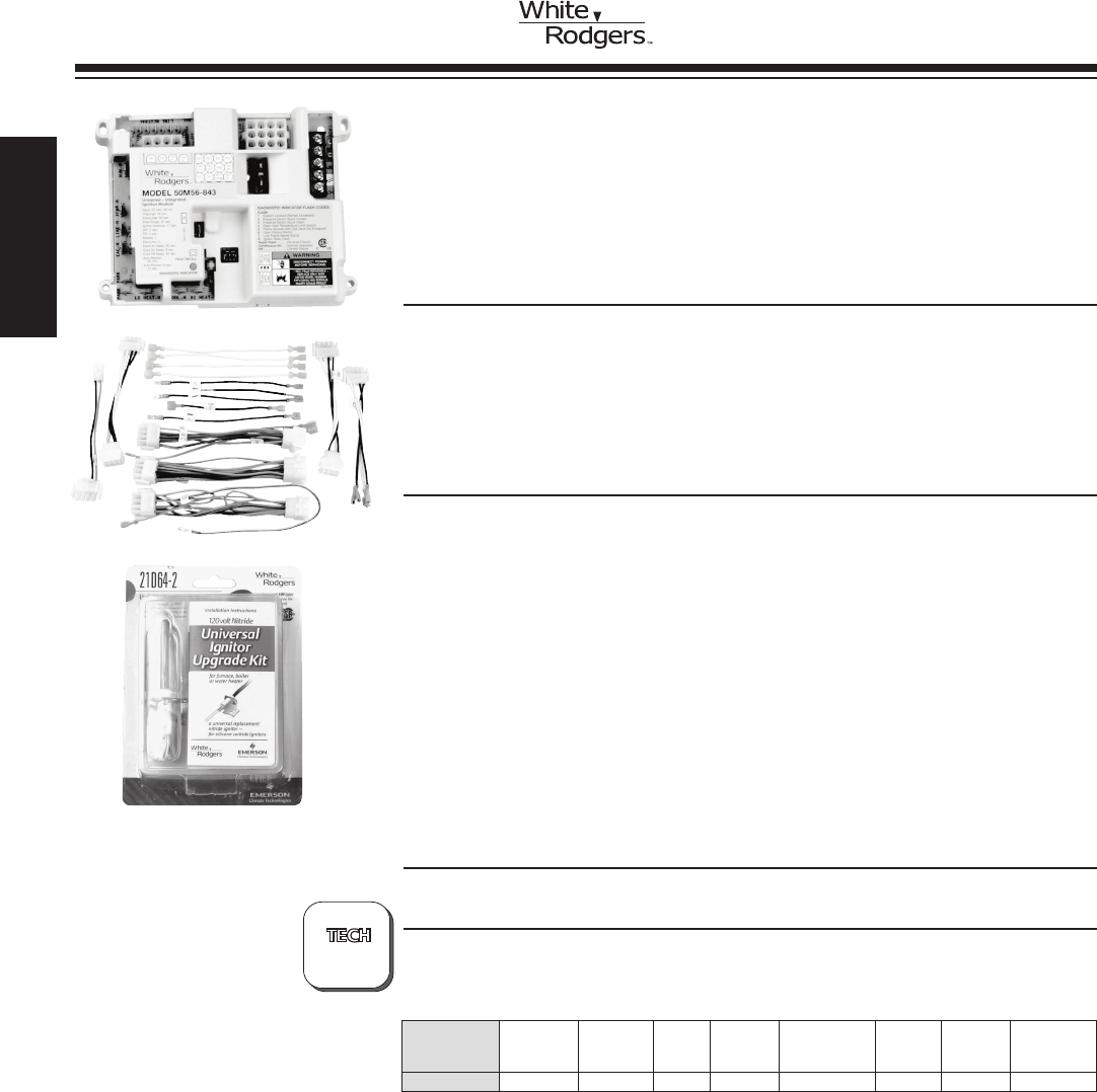
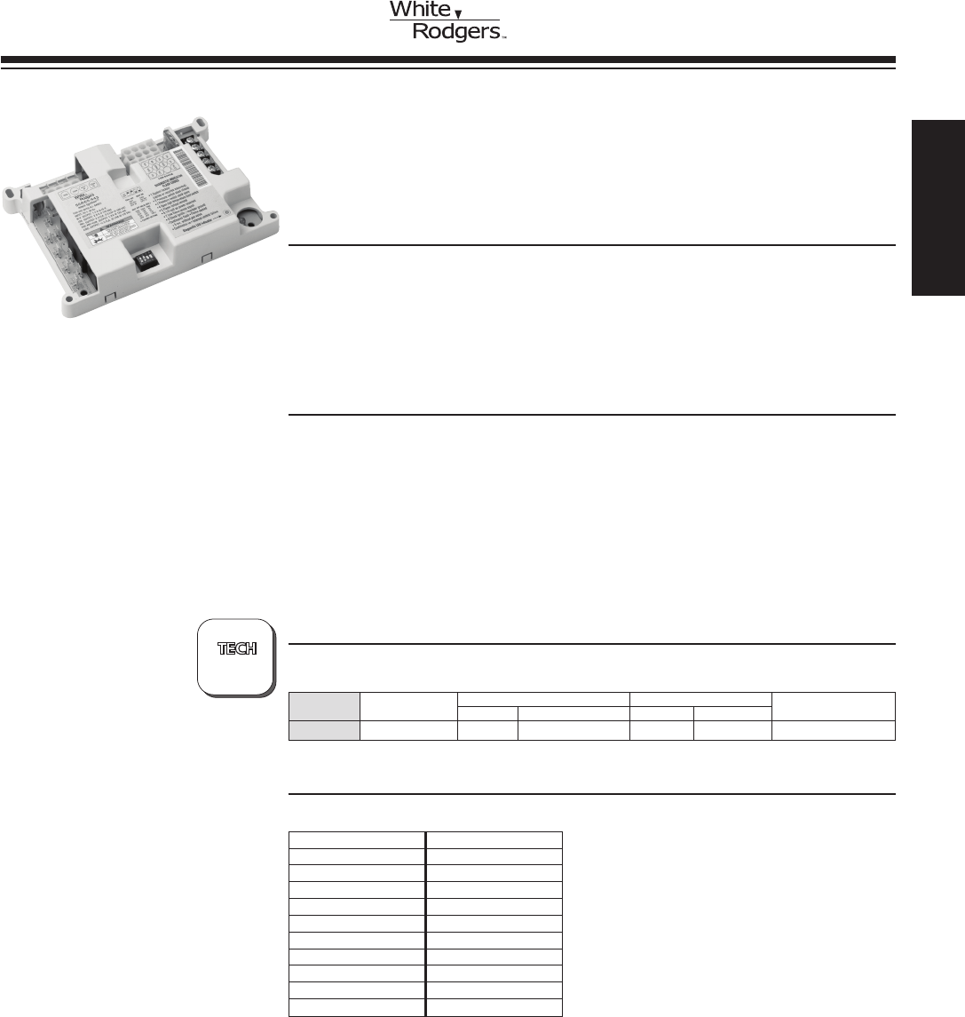
SINGLE STAGE HOT SURFACE
IGNITION CONTROLS (HSI)
INTEGRATED
FURNACE CONTROL
50M56U-843 KIT REPLACES:
Virtually All White-Rodgers and Competitive Single Stage Carbide
and Nitride HSI Systems. Replaces All OEM Models – 80 Volts or 120
Volts Ignitor Applications.
Replaces More Models Than Honeywell S9200U1000.
FEATURES
•3FanSpeeds–cool,lowheat&highheatspeeds.
•Universalnitrideignitorkit–21D64-2.
•9quick-select/quick-connectwiringharnesses.
•RedLEDdiagnosticashcodeswithstoredfaultrecall.
•Lowvoltagefuseprotection,3Areplaceableautomotivetype.
•Humidier&ElectronicAirCleanerconnections(optional).
SPECIFICATIONS
Electrical Rating:
Input Voltage.................... 25 VAC 50/60 Hz
Max. Input Current ............... 25 VAC: 0.45 amp
Gas Valve Relays ................ 1.5 amp @ 25 VAC 50/60 Hz
Inducer Relay ................... 2.2 FLA–3.5 LRA @ 120 VAC
Circulator Relay ................. 14.5 FLA–25.0 LRA @ 120 VAC
Ignitor Relay .................... 6.0 amp @ 120 VAC 50/60 Hz (resistive)
FlameCurrentRequirements:
Minimum current to insure flame detection 1μaDC*
Maximum current for non-detection . . 0.1μaDC*
Maximumallowableleakageresistance100Mohms
*Measured with a DC microameter in the flame probe lead
Operating Temperature Range...... -40° to 176°F (-40° to 80°C)
Flame Failure Response Time . . . . . . 2.0 sec
PARTS AND ACCESSORIES See end of this section for parts and accessories
TECHNICAL HELP
Wiring Diagram....................... See pages 209-212
Model
Number Pre-Purge
Ignitor
Warm-Up Retries
Heat
Delay to
Fan ON
Heat Delay
to Fan OFF
Cool
Delay to
Fan ON
Cool
Delay to
Fan OFF
Automatic
Reset
Time
50M56U-843 30 17 2 30 100/150 6 45 60 minutes
?
PAGES
209-212
50M56U-843
Includes:
•Module
•IgnitorKit
•WiringHarness
www.white-rodgers.com
44
HEATING
SINGLE STAGE HOT SURFACE
IGNITION CONTROLS (HSI)
CROSS
REFERENCE
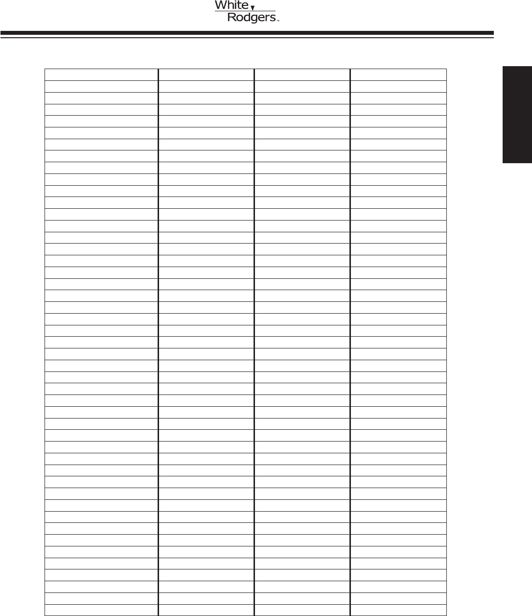
50M56U-843 Replaces:
031-00662 1380-699 50A50-473 62-24268-03
031-00662-000 265901 50A50-474 624557
031-00662-700 265902 50A50-475 6245570
031-01250-000 3101250000 50A50-571 624564
031-01250-700 3101973000 50A55143 6245640
031-01266-000 32M88 50A55-143 624591
031-01266-700 32M8801 50A55-241 624591-x
031-01284-000 331-01933-000 50A55-245 624628
031-09166-000 33101972200 50A55-250 624628-0
031-09167-000 331-09167-000 50A55-285 6246310
100925-03 350486 50A55-286 624631-0
1010806 350836 50A55-288 624631A
1012-83-9336AHSC1 41F-5 50A55-289 695-200
1012-83-9337A 50A50-110 50A55-474 69M08
1012-925A 50A50-111 50A55-476 6DT-1
1012-925B 50A50-112 50A55-571 6DT-2
1012-925C 50A50-113 50A55-843 710128A
1012933D 50A50-130 50A56-242 8068561
1012-933D 50A50-131 50A56-243 8068563
10207701 50A50-142 50A65 902378
10207702 50A50-143 50A65-120 902696
102077-02 50A50-205 50A65-121 903106
10207703 50A50-206 50A65-143 99958174
102077-03 50A50-207 50A65-288 99958175
10207704 50A50-208 50A65-289 CNT03740
102077-04 50A50-209 50A65-474 CNT03742
10207706 50A50-210 50A65-475 CNT04664
102077-06 50A50-215 50A65-476 D330927P01
102077-09 50A50-216 50A65-843 D330930P01
10207710 50A50-229 50M56-289 D330934P01
102077-10 50A50-230 50T35-730 D340035P01
10207714 50A50-240 50T35-743 D340354P01
102077-14 50A50-241 50T55-289 D340774P01
10207717 50A50-245 52537074000 D341213P01
102077-17 50A50-285 52537077000 D341396P01
10207719 50A50-286 5253733900 G951ADB1401
102077-19 50A50-288 56L84 G951ADB1401C
10207720 50A50-295 56L8401 G951ADB-1401C
10207720S 50A50-296 61F3 G951ADB1402
10M93 50A50-298 62-22694-xx G951ADB-1402
10M9301 50A50-405 62-22732-xx G951ADB-1403
1214201 50A50-406 62-24044-xx G951AEB-1403
12L6901 50A50-407 62-24045-01 ICM280
1380686 50A50-408 62-24046-01 P03101267001
1380-686 50A50-438 62-24084-82 P031-01267-001
1380698 50A50-471 62-24268-01 X4459
1380699 50A50-472 62-24268-02 X445901
HEATING
www.white-rodgers.com 45
50A55-843 Replaces:
031-00662 1380699 50A50-240 50A55-286
031-00662-000 1380-699 50A50-241 50A55-288
031-00662-700 350486 50A50-245 50A55-438
03101250000 3XA75 50A50-285 50A55-474
031-01250-000 4DG53 50A50-286 50A55-571
031-01250-700 4DG54 50A50-288 50A55-843
031-01266-000 4DG55 50A50-295 52537074000
031-01266-700 4DG56 50A50-296 52537077000
031-01284-000 50A50-110 50A50-298 5253733900
1010806 50A50-111 50A50-405 8068142
10207701 50A50-112 50A50-406 8068561
10207702 50A50-113 50A50-407 8068563
102077-02 50A50-130 50A50-408 99958174
10207703 50A50-131 50A50-438 99958175
102077-03 50A50-142 50A50-471 CNT03740
10207704 50A50-143 50A50-472 D330927P01
102077-04 50A50-205 50A50-473 D330930P01
10207706 50A50-206 50A50-474 D330934P01
102077-09 50A50-207 50A50-475 D340035P01
10207710 50A50-208 50A50-571 D340354P01
10207714 50A50-209 50A55143 D340774P01
10207719 50A50-210 50A55-143 X13120666010
10334901 50A50-215 50A55-241 X445901
1380686 50A50-216 50A55-245
1380-686 50A50-229 50A55-250
1380698 50A50-230 50A55-285
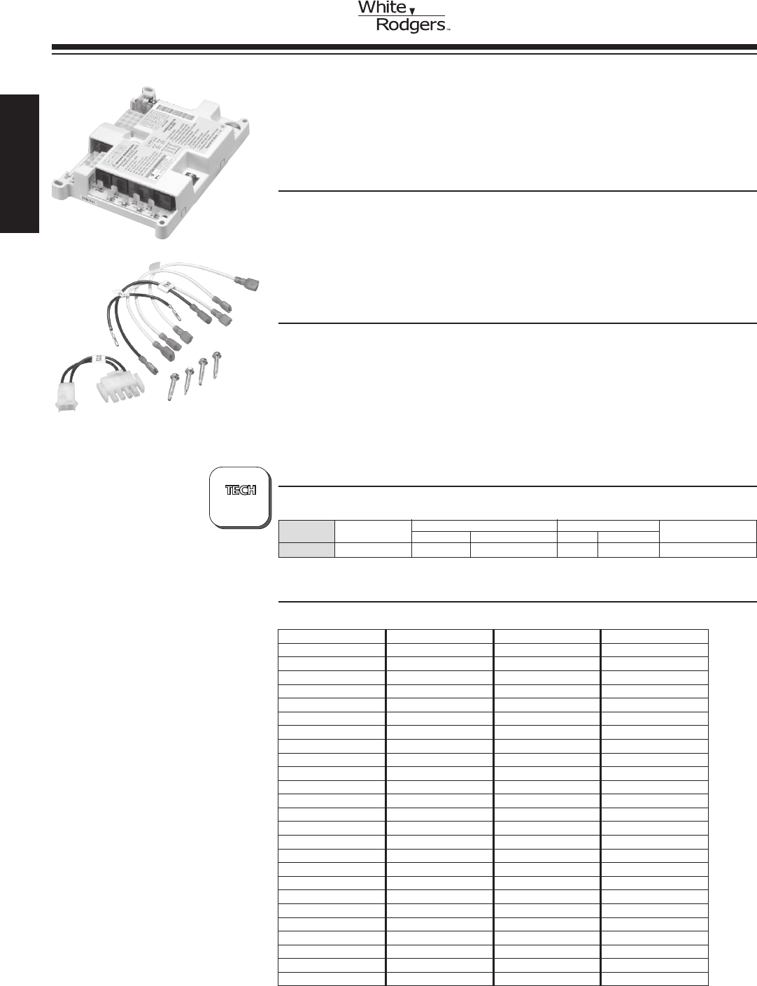
50A55-843 UNIVERSAL SILICON CARBIDE
INTEGRATED FURNACE CONTROL
ControlsGasValve,Ignitor,Blower,Inducer,HumidierandAirCleaner.
ReplacesMostTrane,York,ICPandAmanaWhite-Rodgersmodels.
FEATURES
•Includesashcodediagnostics.
•Replaces50A50and50A55controls(consultIntegratedSiliconCarbideModule
Reference Chart below).
•Fusedtoprotectlowvoltagesystemtransformers.
•Includesmountingholetemplate.
•Adjustableblowerrelay.
SPECIFICATIONS
Input Voltage..................... 25 VAC 50 / 60 Hz
Maximum Input Current @ 25 VAC ... 0.45 amp
Valve Relay...................... 1.5 amp @ 25 VAC 50 / 60 Hz 0.6 pf
Ignitor Relay ..................... 6.0 amp @ 120 VAC 50 / 60 Hz (resistive)
Inducer Relay .................... 2.2 FLA – 3.5 LRA @ 120 VAC
Circulator Relay .................. 14.5 FLA – 25.0 LRA @ 120 VAC
Operating Temperature Range....... -40 to +175°F (-40 to +79°C)
Humidity Range .................. 5% to 93% relative humidity (non-condensing)
INTEGRATED
FURNACE CONTROL
UNIVERSAL HOT SURFACE
IGNITION CONTROLS (HSI)
TECHNICAL HELP
Wiring/conguration/troubleshooting see pages 189-197
CROSS REFERENCE
?
PAGES
189-197 Model Delay Heat Delay Cool
Number Pre-purge ON OFF ON OFF Auto Reset
50A55-843 30 sec. 30 / 45 60 / 90 / 120 / 180 5 45 / 90 60 minutes
www.white-rodgers.com
46
HEATING
50T35-743 Replaces:
1012-933D
41F-5
50T35-730
50T35-743
B1809913
CNT04664
50T35-743 SILICON CARBIDE INTEGRATED
FURNACE CONTROL
Controls Gas Valve, Ignitor, Two Speed Blower Motor, Inducer,
Humidier(Both120v&24vInput),andAirCleaner.ReplacesOEM
Goodman, UTEC and TI Models
FEATURES
•Includesashcodediagnostics.
•Twinning.
•Includesmountingholetemplate.
•Fusedtoprotectlowvoltagesystemtransformers.
•Adjustableblowerrelay.
•90+furnaceoption.
SPECIFICATIONS
Operating Temperature................... -40 to 176°F
Humidity Range ........................ 95% RH (non-condensing)
Mounting.............................. Plastic standoffs
Electrical Ratings @ 77°F (25°C)
Input Voltage........................... 20-30 VAC RMS 50 / 60 Hz
Maximum Input Current @ 30 VAC ......... 0.35 amp
Relay Load Ratings
Valve Relay............................ 1.5 amp @ 30 VAC 50 / 60 Hz 0.6 pf
Ignitor Relay ........................... 5.0 amp @ 120 VAC 50 / 60 Hz
Inducer Relay .......................... 4.0 FLA-8.0 LRA @ 120 VAC
Circulator Relay ........................ 14.5 FLA-25.0 LRA @ 120 VAC
FlameCurrentRequirements
Minimumcurrenttoinsureamedetection.... 75 uA DC
Maximum current for non-detection ......... 0.10 uA DC
Maximumallowableleakageresistance...... 100 M ohms
Timing Spec @ 60 Hz
Flame establishing time .................. n/a
Flame failure response time ............... 2.0 seconds maximum
NOTE:At50Hz,alltimingspecicationsshouldbeincreasedby20%.
Model Prepurge Heat Heat Delay Cool Delay Cool Delay Post
Number Time Delay On Off Sec. On Sec. Off Sec. Purge
50T35-743 15 seconds 30 90 / 120 / 150 5 60 25 sec (29 w/ 90+)
50T35-743
INTEGRATED MODULE
SILICON CARBIDE
FURNACE CONTROL
50T35-743
CROSS REFERENCE
HEATING
www.white-rodgers.com 47
50A62-820 Replaces:
24L8501
50A62-121
50A62-820
56L8301
97L4801
CNT03741
INTEGRATED
FURNACE CONTROLS
NITRIDE HOT SURFACE
IGNITION CONTROLS (HSI)
50A62-820 NITRIDE IGNITION
INTEGRATED FURNACE CONTROL
ControlsGasValve,Ignitor,Blower,Inducer,HumidierandAir
Cleaner. Replaces Lennox models
FEATURES
•Includesdiagnosticindicatorashcodes.
•Replaces50A62-121.
•Remoteamesense.
•OEMtestmode.
•DiagnosticLEDindicatorsoffduringmicrocomputerself-check.
SPECIFICATIONS
Input Voltage..................... 25 VAC 50 / 60 Hz
Maximum Input Current @ 25 VAC ... 0.45 amp
Valve Relay...................... 1.5 amp @ 25 VAC 50 / 60 Hz 0.6 pf
Ignitor Relay ..................... 6.0 amp @ 120 VAC 50 / 60 Hz (resistive)
Inducer Relay .................... 2.2 FLA – 3.5 LRA @ 120 VAC
Circulator Relay .................. 14.5 FLA – 25.0 LRA @ 120 VAC
Operating Temperature Range....... -40 to +175°F (-40 to +79°C)
Humidity Range .................. 5% to 93% relative humidity (non-condensing)
TECHNICAL HELP
Wiringandconguration............ see pages 198-201
Model Delay Heat Delay Cool
Number Pre-purge ON OFF ON OFF Auto Reset
50A62-820 15 45 60 / 90 / 120 / 180 0 0 60 minutes
CROSS REFERENCE
?
PAGES
198-201
www.white-rodgers.com
48
HEATING
50A65-843 UNIVERSAL NITRIDE IGNITION
INTEGRATED FURNACE CONTROL
ControlGasValve,Ignitor,Blower,Inducer,HumidierandAir
Cleaner.ReplacesOEM,Trane,York,ICPandAmanamodels.
FEATURES
•Includesdiagnosticindicatorashcodes.
•Replaces50A65-120,-143,-288,-474,-475controls(consultIntegratedNitride
Module Reference Chart below).
•Replaceable3Afuse.
•60minuteautoreset.
•Singlechannelamesense.
SPECIFICATIONS
Input Voltage..................... 25 VAC 50 / 60 Hz
Maximum Input Current @ 25 VAC ... 0.45 amp
Valve Relay...................... 1.5 amp @ 25 VAC 50 / 60 Hz 0.6 pf
Ignitor Relay ..................... 6.0 amp @ 120 VAC 50 / 60 Hz (resistive)
Inducer Relay .................... 2.2 FLA – 3.5 LRA @ 120 VAC
Circulator Relay .................. 14.5 FLA – 25.0 LRA @ 120 VAC
ElectronicAirCleanerandHumidier.. 1 A @ 120 VAC
Operating Temperature Range....... -40 to +175°F (-40 to +79°C)
Humidity Range .................. 5% to 93% relative humidity (non-condensing)
Model Delay Heat Delay Cool
Number Pre-purge ON OFF ON OFF Auto Reset
50A65-843 30 sec. 30 / 45 60 / 90 / 120 / 180 5 45 / 90 60 minutes
TECHNICAL HELP
Wiringandconguration............ see pages 202-203
INTEGRATED
FURNACE CONTROLS
NITRIDE HOT SURFACE
IGNITION CONTROLS (HSI)
CROSS REFERENCE
?
PAGES
202-203
50A65-843
50A65-843 Replaces:
10207717 50A65-288
10207720 50A65-289
10207720S 50A65-474
10M9301 50A65-475
12L6901 50A65-843
32M8801 56L8401
350836 CNT03742
3XA76 D341213P01
50A65-120 D341396P01
50A65-121 X13120667010
50A65-143
HEATING
www.white-rodgers.com 49
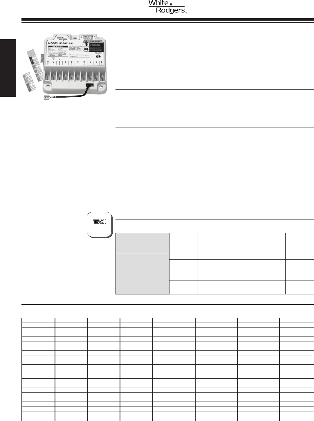
UNIVERSAL 50E47-843 NON-INTEGRATED HSI
IGNITION MODULE
The Universal 50E47-843 Replaces White-Rodgers 50E47 Modules
and Many Competitive Silicon Carbide, Non-Integrated Modules.
Includes a Complete Module Cross Reference and Program Keys for
Fast and Accurate Replacement.
FEATURES
•Programkeysformultipletimingselections.
•Tri-coloredLEDindicatorfordiagnostics.
•Directandindirectamesensecompatible.
•Universaldesignformaximumversatility.
SPECIFICATIONS
Dimensions.................. 4.13”W x 4.13”H x 1.5”D
Electrical rating............... Input 18 to 30 VAC, 25 VAC nominal,
Max. input current @ 25 VAC; .250mA @ 28 VAC
Relay load settings ............ Valve relay: 1.5 amps @ 28 VAC, 50 / 60 Hz, .6 pf
Ignitor relay: 1.52A, 120 VAC, 50 / 60 Hz resistive
Operating temperature ......... -40° to +175°F (-40° to +80°C)
Humidity range ............... 95% RH (non-condensing) max.
Mounting.................... Surface mount or 4”x4junctionbox
Applications ................. For use with all gases
Flamecurrentrequirements ..... Min.currenttoinsureame:2µADC
Min. current for non-detection: 0.2 µADC
Max.allowableleakageresistance:100MOhms
Agency . . . . . . . . . . . . . . . . . . . . . A.G.A.andC.G.A.designcertied
50E47-843
NON-INTEGRATED
FURNACE CONTROL
HOT SURFACE IGNITION
CONTROLS (HSI)
TECHNICAL HELP
Wiring operation and troubleshooting...... See pages 204-207
PROGRAM TRIAL
Model KEY FOR IGNITOR
Number (COLOR) IGNITION RETRIES PREPURGE WARMUP
A (blue) 4 Sec. 0 30 Sec. 45 Sec.
B (red) 4 Sec. 2 30 Sec. 45 Sec.
50E47-843 C (green) 7 Sec. 0 30 Sec. 45 Sec.
D (violet) 7 Sec. 2 30 Sec. 45 Sec.
E (orange) 4 Sec. 2 30 Sec. 17 Sec.
F (yellow) 7 Sec. 2 30 Sec. 17 Sec.
CROSS REFERENCE
?
PAGES
204-207
50E47-843 Replaces:
0050050 50D47-160 50E47-120 50F47-101 780-910 HS780-17NR-312A HS780-34PL-106A S89C1004
025-25436-000 50D47-161 50E47-130 50F47-140 832-002 HS780-17PL-106A HS780-34PL-108A S89C1012
02525436700 50D47-170 50E47-140 50F47-160 832-005 HS780-17PL-108A HS780-34PL-304A S89C1046
025-25436-700 50D47-20 50E47-150 50F47-40 833-002 HS780-17PL-304A HS780-34PL-306A S89C1079
1001346 50D47-260 50E47-160 50F47-60 995395 HS780-17PL-306A HS780-34PL-308A S89C1087
10376732 50D47-270 50E47-161 50G47-1 99796380 HS780-17PL-308A HS780-34PR-106A S89C1103
120-08027 50D47-40 50E47-170 50G47-130 99905232 HS780-17PR-104A HS780-34PR-108A S89D1002
1300-4928 50D47-50 50E47-20 50G47-140 C6411102 HS780-17PR-108A HS780-34PR-304A S89G1005
1380694 50D47-60 50E47-260 50G47-150 CNT03776 HS780-17PR-306A HS780-34PR-306A S89G1013
2076-0184 50D47-70 50E47-30 50G47-160 CNT03794 HS780-34NL-106A HS780-34PR-308A S89G1021
350760 50D47-905 50E47-40 50G47-40 HS780-17NL-104A HS780-34NL-108A S8610U1000 S89G1047
3591-1306 50D47-915 50E47-50 50G47-60 HS780-17NL-106A HS780-34NL-304A S890C1007 S89H1003
3XA74 50D47-925 50E47-560 6279527 HS780-17NL-108A HS780-34NL-306A S890D1006 S89H1011
4CZ50 50D47-935 50E47-60 780-780 HS780-17NL-304A HS780-34NL-308A S890G1003 S89H1029
4E954 50D47-945 50E47-70 780-783 HS780-17NL-306A HS780-34NL-312A S890G1011 S89J1008
4E955 50D47-955 50E47-841 780-784 HS780-17NL-308A HS780-34NR-104A S890G1029 X13130437070
4E956 50D47-965 50E47-843 780-785 HS780-17NR-104A HS780-34NR-106A S890G1037 X13130437080
50D47-1 50D47-975 50E47-850 780-786 HS780-17NR-106A HS780-34NR-304A S890H1002 X324601
50D47-101 50E47-1 50E47-851 780-787 HS780-17NR-108A HS780-34NR-306A S890H1010
50D47-120 50E47-10 50E47-860 780-788 HS780-17NR-304A HS780-34NR-308A S890H1028
50D47-140 50E47-101 50E47-861 780-789 HS780-17NR-306A HS780-34NR-312A S8910U
50D47-150 50E47-110 50E47-870 780-790 HS780-17NR-308A HS780-34PL-104A S8910U1000
www.white-rodgers.com
50
HEATING
?
PAGE
208
?
PAGE
208
UNIVERSAL PROVEN PILOT SPARK CONTROL
FOR ALL GASES
Microcomputer Based Gas Ignition & Primary Safety Control Designed for Interrupted
SparkandBurnerSupervisionofAllGasesUsedinGasFiredApplianceApplications.
FEATURES
•FieldservicereplacementformostHoneywell,Robertshaw,JohnsonControlsand
UTEC Intermittent Pilot Ignition Controls.
•Providesignition,proofofignitionandprecisetiming. • ColorLEDindicator
•Workswithsinglerodordualrodremotesensor. fordiagnostics.
SPECIFICATIONS
Electrical Ratings .................. Input 18-30 VAC, 25 VAC nominal
Maximum Input Current @ 25 VAC .... 0.2A + MV + PV @ 25°C
Flame Out Recognition Time ......... 8 seconds
Ambient Operating Range ........... -40° to +176°F (-40° to +80°C)
Dimensions....................... 4.13”L x 4.13”W x 1.5”H
Agency Approvals.................. CSA USA/CANADA
SPARK IGNITION
DIRECT SPARK
PROVEN PILOT CONTROL
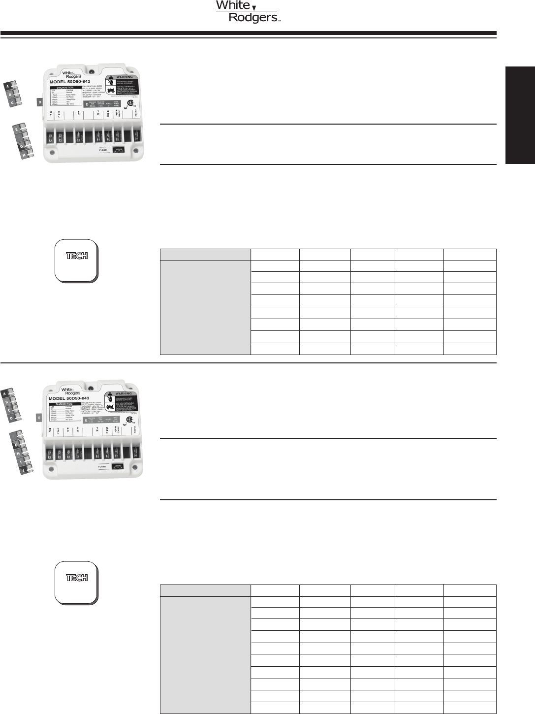
UNIVERSAL DIRECT SPARK IGNITION CONTROL
FOR ALL GASES
The 50D50-842 is a Microprocessor Based Gas Ignition Control for Heating
Appliance Using Either Natural or LP Gas. Proof of Flames is Accomplished.
TheUnitisDesignedasaDirectSparkIgnitionSource
FEATURES
•ColorLEDindicatorfordiagnostics. • Programkeys.
•1/4” and 3/16”quickconnectterminals. • Damperinterface.
SPECIFICATIONS
Electrical Ratings .................. Input 18-30 VAC, 25 VAC nominal
Maximum Input Current @ 25 VAC .... 0.2A + MV @ 25°C
Ambient Operating Range ........... -40° to +175°F
Flame Establishment Time ........... .8 sec
Mounting......................... Multipoise
Agency Approvals.................. CSA USA / CANADA
Model Number Key Trial for Ignition Prepurge Retries Interpurge
A 4 0 2 90 sec.
B 4 30 2 90 sec.
C 7 0 2 90 sec.
D 7 30 2 90 sec.
50D50-842 E 7 0 0 N/A
F 7 30 0 N/A
G 11 0 0 N/A
H 11 30 0 N/A
50D50-843
50D50-842
Model Number Key Reset Time Prepurge Retries Safety Time
A 300 0 Continuous 90
B 300 30 Continuous 90
C 300 0 Continuous 30
D 300 30 Continuous 30
50D50-843 E 300 0 2 60
F 300 30 2 60
G 300 0 Continuous 15
H N/A 30 N/A Continuous
I 300 0 Continuous 4
J 300 30 Continuous 4
50D50-843 CONFIGURATION OPTIONS (All Times in Seconds)
50D50-842 CONFIGURATION OPTIONS (All Times in Seconds)
HEATING
www.white-rodgers.com 51
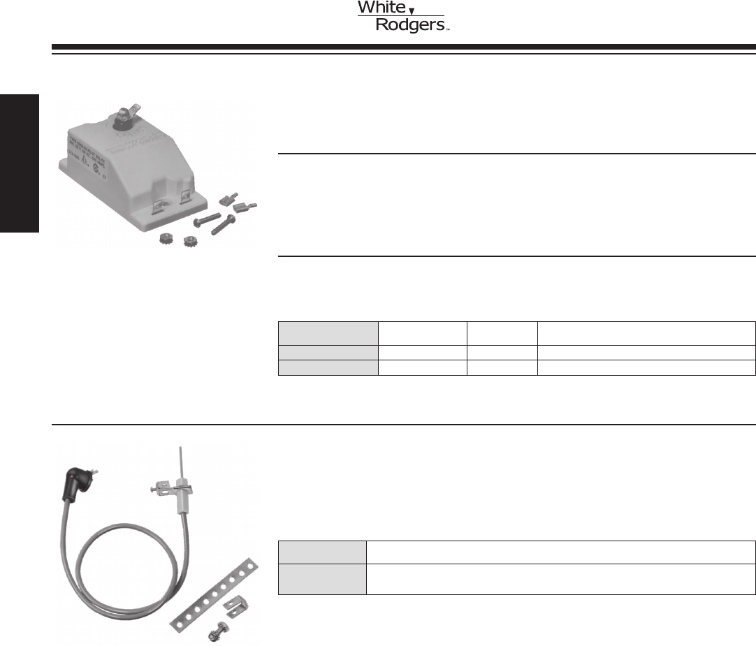
760-56
IGNITION ELECTRODE ASSEMBLIES
Use Type 760-56 to Replace Cycle-Pilot® Ignition Electrodes and
Cable Assemblies
Model
Number Description
760-56 24”leadwithsliponbracket.Alsoincludesperforatedmountingstrapforvarying
applications
SPECIFICATIONS
Agency . . . . . . . . . . . . . . . . . . . . . . C.S.A. approved
Model Input Electrical
Number Voltage Rating Description
5059-23 24VAC 0.03amps Sparkplugand1/4” spade connectors
5059-134 24VAC 0.03amps Spikeconnector
PILOT RELITE CONTROLS 5059
GeneratesSparkUntilaPilotFlameisSensed
FEATURES
•Generatessparkpulseuntilameissensedthroughsparkelectrode.
•Beginssparkingimmediatelyifameextinguishes.
•Ruggedsolidstatemoduledesign.
•Sparkplugorspikeoutputcongurationsavailable.
5059-23
Pilot Relite Control
PILOT RELITE AND
LOCKOUT TIMERS SPARK IGNITION
www.white-rodgers.com
52
HEATING
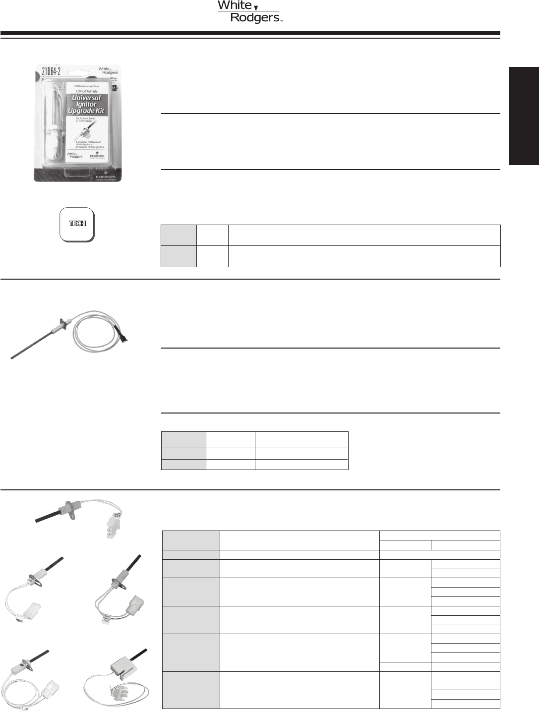
UNIVERSAL NITRIDE IGNITOR UPGRADE KIT
120V Nitride Upgrade Kit for Conversion of Silicon Carbide
(Flat or Spiral).
FEATURES
•RobustIgnitorDesign-forlongerlifeandfewercallbacks-3yearwarranty
•NitrideIgnitorwith15.5”leads
•“Universal”mountingbracketandscrewandceramicwirenuts
SPECIFICATIONS
Input Voltage...................... 102-132 VAC, 60 Hz
Max. Load Current ................. 3.0 A @ 132 VAC, 25°C
Timing Rating ..................... 17 sec. minimum
Load Insulation Temp. Rating......... 250oC
21D64-2
CARBIDE TO NITRIDE
IGNITOR UPGRADE KIT
HOT SURFACE
IGNITION (HSI)
FLAME SENSOR FOR
HOT SURFACE IGNITION (H.S.I.) SYSTEMS
Flame Sensors can be Mounted Remotely on Multiple Burners.
FEATURES
•HighqualityAluminaceramicinsulator.
•HightemperatureKanthalamerodmaterialthatcanwithstand1800°F.
•Teoninsulated(250°Crating)leadwire.
•Singlescrew,platedsteelmountingbracket.
SPECIFICATIONS
Agency . . . . . . . . . . . . . . . . . . . . . . . . . . . C.S.A approved
Model
Number Lead Length Electrical Connection
760-40130” 1/4” female spade terminal
760-802 ➀ 30” 1/4” female spade terminal
➀ Exact replacement for O.E.M. model
760-401
Flame Sensor
768A-815 (New)
Model
Number
Lead
Length
Description
21D64-2 15.5”Kitincludesnitrideignitor,powersupplymodule,universalmountingbracket,
connection harness and furnace label
NITRIDE IGNITOR
OEM Replacement for Nitride Ignitors
Manufacturer OEM #
Suggested Replacement
Carbide Nitride Upgrade
Model Number Terminal Type Replace OEM Models
768A-815 2terminalAMPreceptacle,.083femalesockets Trane A341947P01
768A-015
768A-842 2terminalAMPreceptacle,.093femalesockets Amana
11111701
768A-2
768A-842
768A-843 2terminalAMPreceptacle,.084femalesockets Thermo
Products
380650
768A-843
768A-843
768A-844 2terminalAMPreceptacle,.084femalesockets
Lennox
Industries
41K5601
768A-4
768A-844
Rheem 62-24134-02
768A-845 2terminalAMPreceptacle,.084femalesockets Trane
768A-5
768A-845
IGN00104
X13130524010
?
See page 56-57
for Ignitor Cross
Reference
768A-842 768A-843
768A-844 768A-845
New!
HEATING
www.white-rodgers.com 53
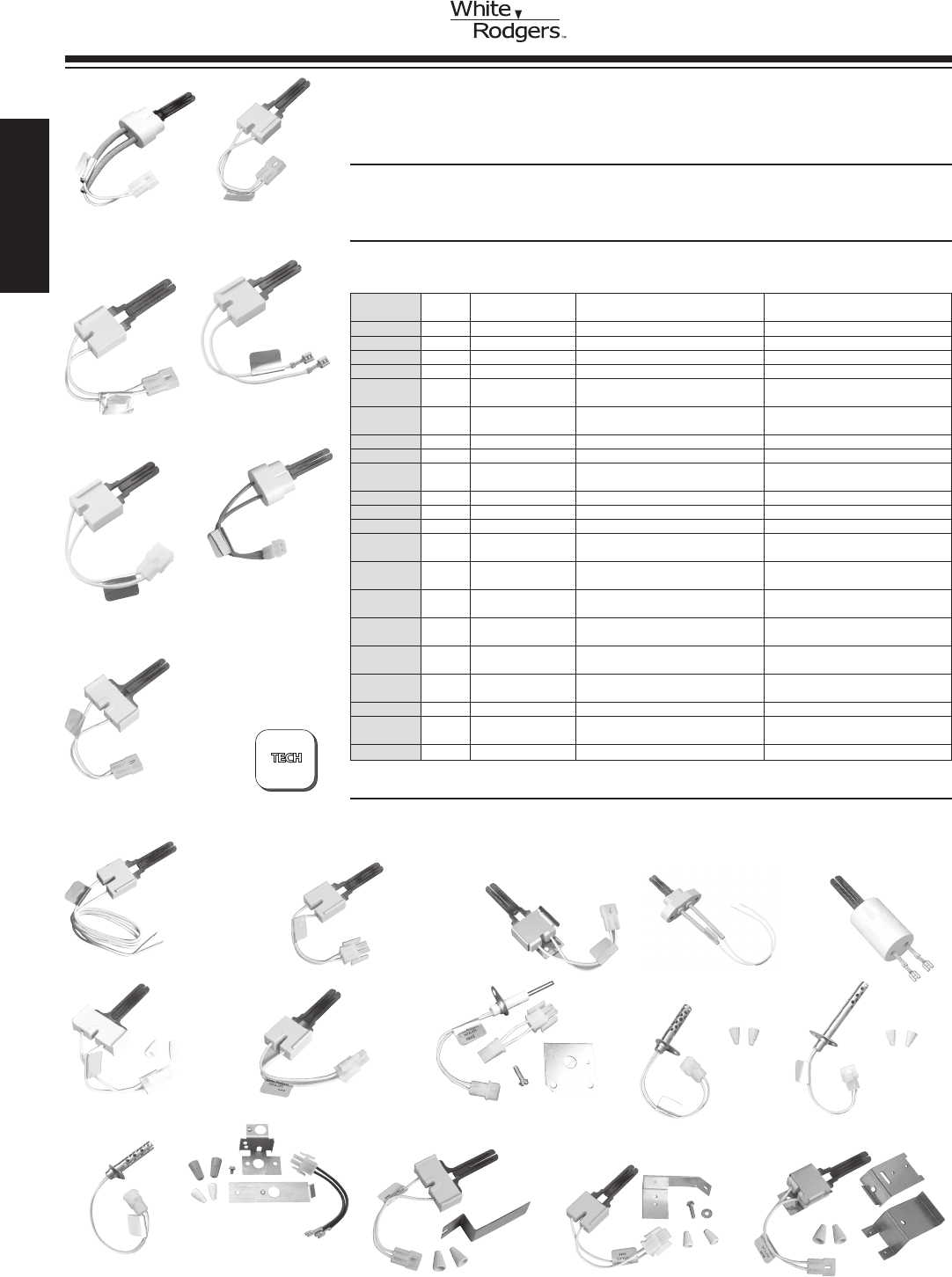
SILICON CARBIDE HOT SURFACE IGNITOR
Highly Reliable Ignition Source
FEATURES
• Multiplemountingstyles.
• Workswith15,17or45secondHSIsystems.
SPECIFICATIONS
Electrical Rating . . . . . . . . . . . . . . . . . . . . . . . . 120 VAC, 60 Hz
Agency . . . . . . . . . . . . . . . . . . . . . . . . . . . . . . . C.S.A. approved
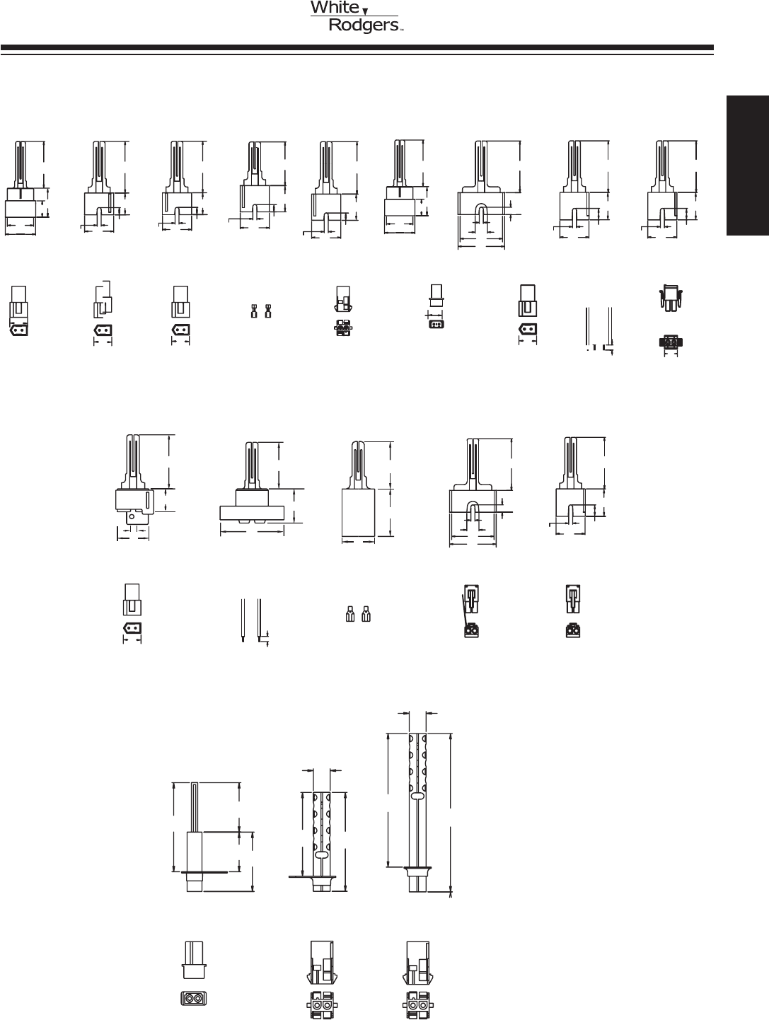
Model Lead Lead Insulation Electrical Ceramic Insulator & Electrical
Number Length Temp. Rating Connection Connections (See Fig.)
767A-356 6” 200°C Receptacle with .093” Male Pins A
767A-357 5.25” 200°C Receptacle with .093” Male Pins B
767A-361 5.25” 200°C Receptacle with .093” Male Pins C
767A-365 5.688” 200°C 1/4” Female Spade Terminals D
767A-366 5.313” 200°C AMP 1-480699-0 Electrical Conn. E
Receptacle with .093” Male Pins
767A-369 5.5” 200°C Molex Internally Keyed Connector F
with .093” Male Pins
767A-370 5.25” 200°C Receptacle with .093” Male Pins G
767A-371 19.125” 200°C Stripped Ends H
767A-372 5.25” 200°C MolexSideLockConnector I
with .092” Male Pins
767A-373 5.25” 200°C Receptacle with .093” Male Pins J
767A-374 11” 200°C Stripped Ends K
767A-375 1.375” 200°C 1/4” Female Spade Terminals L
767A-376 4.5” 200°C MolexFrontLockConnector M
with .092” Male Pins
767A-377 4.5” 200°C MolexFrontLockConnector N
with .092” Male Pins
767A-378 5.125” 200°C Electrical Connector matches O
AMANA #20165702
767A-379 7.5” 200°C Electrical Connector matches P
YORK #025-33421-000
767A-380 6.125” 200°C Electrical Connector matches Q
ARMSTRONG #44744-2
767A-381 7.5” 200°C Electrical Connector matches P
YORK #473-20937-001
767A-382 5.25” 200°C Receptacle with .093” Male Pins G
767A-383 5.25” 200°C MolexSideLockConnector I
with .092” Male Pins
767A-384 5.25” 200°C Receptacle with .093” Male Pins J
767A-356
767A-357
767A-361
767A-366
767A-365
SILICON CARBIDE
HOT SURFACE IGNITION
CONTROLS (HSI)
767A-369
767A-370
767A-372
767A-371
767A-373 767A-374
767A-375
TECHNICAL HELP
Dimension drawings ............... see next page
Ignitor cross reference ............. see pages 56-57
767A-376 767A-377
767A-382 767A-383 767A-384
767A-378 767A-379
767A-380
767A-381
?
See pages 56-57
for Ignitor Cross
Reference
www.white-rodgers.com
54
HEATING
SILICON CARBIDE
HOT SURFACE IGNITION
CONTROLS (HSI)
053.1
055.1
526.
526.
1
767A-356
407. 000.2
052.1 052.1 0
52.1
0
52.1
521.10
52.2
023.
767A-357
.NIM081.
.NIM081.
.NIM081.
.NIM071.
.NIM081.
767A-361
578.1
521.1
521.1
767A-365 767A-366
052.1
053.1
055.1
526.1
767A-369 767A-371767A-370/767A-382
407. 000.2
052.1
521.10
52.2
023.
023.
023.
052
.2
052
.2
0
52.1
812.2
000.2
739. 010.+
020.-
.312
.170
028.1
025.
.FER
294.
081.1
.NIM071.
767A-372/767A-384
052
.2
0
52.1
294.
081.1
ABCDEF GH I
.093 Dia. Male
Pin Te rminals
526.
.093 Dia. Male
Pin Te rminals
526.
.093 Dia. Male
Pin Te rminals
Uninsulated .250 Female
Spade Te rminals
AMP Type 1-480699-0
.093 Dia. Male
Pin Te rminals
.093 Dia. Male
Pin Te rminals
022.
Lead Length
5.25
Lead Length
6.0
Lead Length
5.25
.500
.093 Dia. Male
Pin Te rminals
Lead Length
5.50
Lead Length
5.688
Lead Length
5.313
Lead Length
19.125
526.
Lead Length
5.25
Lead Length
5.25
.550
2.250
.
1180
526.
.093 DIA. MALE
PIN TERMINALS
MOLEX
CONNECTOR
MOLEX
CONNECTOR
Lead Length
5.25
Lead Length
11.00
Lead Length
1.375
Lead Length
5.00
Lead Length
5.25
02
2.
767A-375
767A-374
767A-373/767A-384
JKL
.NIM071.
767A-377
052
.2
0
52
.1
294.
081.1
N
767A-376
812.2
000.2
739. 010.+
020.-
.312
.170
028.1
025.
.FER
M
1.939
2.00
1.25
1.35
1.25
.170
2.666
2.00
OP
Q
Lead Length
5.125
Lead Length
7.500
Lead Length
6.125
1.25 0
1.00 0
1.500
2.250
2.500
2.120
.425
767-379/
767A-381
767A-380
767A-378
3.37 5
4.000
.425
HEATING
www.white-rodgers.com 55

SILICON CARBIDE / NITRIDE
UPGRADE IGNITOR
CROSS REFERENCE
OEM # Manufacturer
Suggested Replacement
Carbide
Nitride or
Nitride
Upgrade Kit
0230K00001 Goodman/Janitrol 767A-382 21D64-2
025-25435-000 York 767A-365 21D64-2
025-27766-000 York 767A-361 21D64-2
025-27774-000 York 767A-361 21D64-2
025-29043-000 York 767A-361 21D64-2
025-29050-000 York 767A-361 21D64-2
02532625000 York/Luxaire None 21D64-2
025-32625-000 Evcon Coleman None 21D64-2
025-33421-000 York 767A-379
09050 Williamson, Hupp Industries 767A-371 21D64-2
10041601 Amana 767A-369
1009604 Intercity 767A-373 21D64-2
10399 Enerco Tech 767A-371 21D64-2
105141000 Nordyne 767A-371 21D64-2
10735003A Amana 767A-371 21D64-2
108803-G1 Perfection Schwank 767A-374 21D64-2
1096048 Arco Air, Comfort Maker,
Heil, Inter City, Tempstar 767A-384 21D64-2
11111701 Amana None 768A-842
120-07549 LB White 767A-371 21D64-2
1380654 Snyder General 767A-370 21D64-2
1380672 Snyder General 767A-370 21D64-2
1380680 Arco Air 767A-384 21D64-2
1474-051 Coleman/Evcon 767A-371 21D64-2
1474-052 Coleman/Evcon 767A-371 21D64-2
150114-04-01 Comfort Zone 767A-374 21D64-2
1EFX2 W. W. Grainger None 21D64-2
20015201 Ducane 767A-370 21D64-2
201 Norton 767A-370 21D64-2
20165702 Amana 767A-378 21D64-2
20165703 Amana 767A-382 21D64-2
201657-03 Amana 767A-382 21D64-2
20165703S Amana 767A-382 21D64-2
201A Norton 767A-369
201D Norton and Detroit Radiant 767A-361 21D64-2
201J Norton 767A-374 21D64-2
201K Norton 767A-371 21D64-2
201L Norton 767A-371 21D64-2
201M Norton 767A-374 21D64-2
201N Norton/Metzger 767A-371 21D64-2
201R Norton 767A-371 21D64-2
201W Norton, American Road
Equip, Metzger 767A-371 21D64-2
201Y Norton. 767A-374 21D64-2
20834 DMO Industries 767A-371 21D64-2
21D64-1 White-Rodgers None 21D64-2
21D64-2 White-Rodgers None 21D64-2
2532625000 Luxaire/Moncrief 767A-371 21D64-2
2600-359 Trianco-Heatmaker 767A-369
271 Norton 767A-370 21D64-2
271A Norton 767A-369
271B American Appliance 767A-374 21D64-2
271M Norton 767A-374 21D64-2
271N Norton 767A-371 21D64-2
271NM Norton 767A-384 21D64-2
271P Norton 767A-361 21D64-2
271W Norton, Dornback Furnace 767A-371 21D64-2
OEM # Manufacturer
Suggested Replacement
Carbide
Nitride or
Nitride
Upgrade Kit
271Y Norton 767A-374 21D64-2
3200580 Mor-Flo 767A-374 21D64-2
3200618 Mor-Flo 767A-371 21D64-2
3210401 Mor-Flo 767A-374 21D64-2
340039P01 Trane None 21D64-2
380650 Thermo Products None 768A-843
38322B001 Armstrong Air 767A-371 21D64-2
3XA73 W. W. Grainger None 21D64-2
41-401 Robertshaw 767A-369
41-402 Robertshaw 767A-371 21D64-2
41-403 Robertshaw 767A-370 21D64-2
41-404 Robertshaw 767A-382 21D64-2
41-405 Robertshaw 767A-361 21D64-2
41-406 Robertshaw 767A-374 21D64-2
41-407 Robertshaw 767A-376 21D64-2
41-408 Robertshaw 767A-372 21D64-2
41-409 Robertshaw 767A-370 21D64-2
41-410 Robertshaw 767A-377 21D64-2
41-411 Robertshaw 767A-383 21D64-2
41-412 Robertshaw 767A-373 21D64-2
41-413 Robertshaw 767A-375 21D64-2
41-414 Robertshaw 767A-384 21D64-2
41-418 Robertshaw None 21D64-2
41-602 Robertshaw 767A-378 21D64-2
41-603 Robertshaw 767A-379
41-604 Robertshaw 767A-380
41-605 Robertshaw 767A-381
41K5601 Lennox Industries None 768A-844
50018 HB Smith 767A-361 21D64-2
511-330-139 Weil-Mclain 767A-370 21D64-2
511-330-188 Weil-Mclain 767A-374 21D64-2
511-330-190 Weil-Mclain 767A-382 21D64-2
511-330-193 Weil-Mclain 767A-370 21D64-2
5E809 White-Rodgers 767A-356
5E810 White-Rodgers 767A-357 21D64-2
5E811 White-Rodgers 767A-361
5E812 Ww Grainger 767A-365 21D64-2
5E813 Ww Grainger 767A-366 21D64-2
5H76032A Modine None 21D64-2
600915 Raypak 767A-370 21D64-2
601 Amana 767A-382 21D64-2
62-22441-01 Rheem None 21D64-2
62-22868-02 Rheem/Ruud 767A-371 21D64-2
62-22868-82 Rheem 767A-383 21D64-2
62-22868-93 Rheem/Ruud 767A-371 21D64-2
62-24134-02 Rheem None 768A-844
62821-001 Wayne Home Equipment 767A-371 21D64-2
62821-002 Wayne Home Equipment 767A-371 21D64-2
632-0770 Nordyne 767A-371 21D64-2
632-0880 Nordyne 767A-371 21D64-2
75-92-104 Majestic. 767A-371 21D64-2
75-92-105 Majestic. 767A-371 21D64-2
767A-301 White-Rodgers 767A-361 21D64-2
767A-303 White-Rodgers 767A-357 21D64-2
767A-306 White-Rodgers 767A-361 21D64-2
767A-309 White-Rodgers 767A-356
www.white-rodgers.com
56
HEATING
OEM # Manufacturer
Suggested Replacement
Carbide
Nitride or
Nitride
Upgrade Kit
767A-310 White-Rodgers 767A-365 21D64-2
767A-311 White-Rodgers 767A-366 21D64-2
767A-350 White-Rodgers 767A-361 21D64-2
767A-353 White-Rodgers 767A-357 21D64-2
767A-354 White-Rodgers 767A-361 21D64-2
767A-356 White-Rodgers 767A-356
767A-357 White-Rodgers 767A-357 21D64-2
767A-361 White-Rodgers 767A-361 21D64-2
767A-364 White-Rodgers 767A-366 21D64-2
767A-365 White-Rodgers 767A-365 21D64-2
767A-366 White-Rodgers 767A-366 21D64-2
767A-369 White-Rodgers 767A-369
767A-370 White-Rodgers 767A-370 21D64-2
767A-371 White-Rodgers 767A-371 21D64-2
767A-372 White-Rodgers 767A-372 21D64-2
767A-373 White-Rodgers 767A-373 21D64-2
767A-374 White-Rodgers 767A-374 21D64-2
767A-375 White-Rodgers 767A-375 21D64-2
767A-376 White-Rodgers 767A-376 21D64-2
767A-377 White-Rodgers 767A-377 21D64-2
767A-378 White-Rodgers 767A-378 21D64-2
767A-379 White-Rodgers 767A-379
767A-380 White-Rodgers 767A-380
767A-381 White-Rodgers 767A-381
767A-382 White-Rodgers 767A-382 21D64-2
767A-383 White-Rodgers 767A-383 21D64-2
767A-384 White-Rodgers 767A-384 21D64-2
768A-143 Thermo Products None 768A-843
768A-15 Trane None 768A-815
768A-2 Amana None 768A-842
768A-4 Lennox Industries None 768A-844
768A-5 Trane None 768A-845
768A-815 White-Rodgers None 768A-815
768A-842 Amana None 768A-842
768A-843 Thermo Products None 768A-843
768A-844 Lennox Industries None 768A-844
768A-845 Trane None 768A-845
87197S Carlin 767A-375 21D64-2
902661A Nordyne None 21D64-2
903110A Nordyne None 21D64-2
903758 Nordyne None 21D64-2
90434300 Roberts Gordon 767A-370 21D64-2
90436600 Roberts Gordon 767A-371 21D64-2
91X2201 Lennox Industries None 21D64-2
OEM # Manufacturer
Suggested Replacement
Carbide
Nitride or
Nitride
Upgrade Kit
9302-094 Viessman 767A-361 21D64-2
94851 Superior Fireplace 767A-371 21D64-2
99796417 White-Rodgers 767A-361 21D64-2
99911563 White-Rodgers 767A-365 21D64-2
99911564 White-Rodgers 767A-366 21D64-2
A341947P01 Trane None 768A-815
B1336102 Amana 767A-369
B138196P01 Trane 767A-370 21D64-2
B1401009 Goodman 767A-373 21D64-2
B1401015S Goodman/Janitrol 767A-384 21D64-2
B1401018 Goodman None 21D64-2
B1401018S Goodman/Janitrol 767A-384 21D64-2
B140109S Goodman/Janitrol 767A-384 21D64-2
B144676P01 Trane 767A-377 21D64-2
B144676P02 Trane 767A-376 21D64-2
B340039P01 Trane 767A-372 21D64-2
C-238 Claire Brothers 767A-371 21D64-2
C-242 Claire Brothers 767A-371 21D64-2
D9918202A Amana 767A-369
F767A-356 White-Rodgers 767A-356
F767A-357 White-Rodgers 767A-357 21D64-2
F767A-361 White-Rodgers 767A-361 21D64-2
IGN00023 Trane 767A-371 21D64-2
IGN00026 Trane 767A-370 21D64-2
IGN00030 Trane 767A-376 21D64-2
IGN00034 Trane 767A-372 21D64-2
IGN00054 Trane 767A-374 21D64-2
IGN00104 Trane None 768A-845
IGN00115 Trane None 21D64-2
IGN00134 Trane None 21D64-2
LH33ZG002 Carrier/Bryant/Payne None 21D64-2
LH33ZS001 Carrier/Bryant/Payne None 21D64-2
LH33ZS001A Carrier Corp. 767A-370 21D64-2
LH33ZS002 Carrier Corp. 767A-370 21D64-2
LH33ZS002A Carrier/Bryant/Payne None 21D64-2
LH33ZS003 Carrier/Bryant/Payne None 21D64-2
LH33ZS003A Carrier/Bryant/Payne None 21D64-2
LH33ZS004 Carrier Corp. 767A-370 21D64-2
Q3200U Honeywell None 21D64-2
Q3200U1004 Honeywell None 21D64-2
X13120661010 Trane None 21D64-2
X13130524010 Trane None 768A-845
X928101 Lennox Industries None 21D64-2
SILICON CARBIDE/NITRIDE
UPGRADE IGNITOR
CROSS REFERENCE
HEATING
www.white-rodgers.com 57
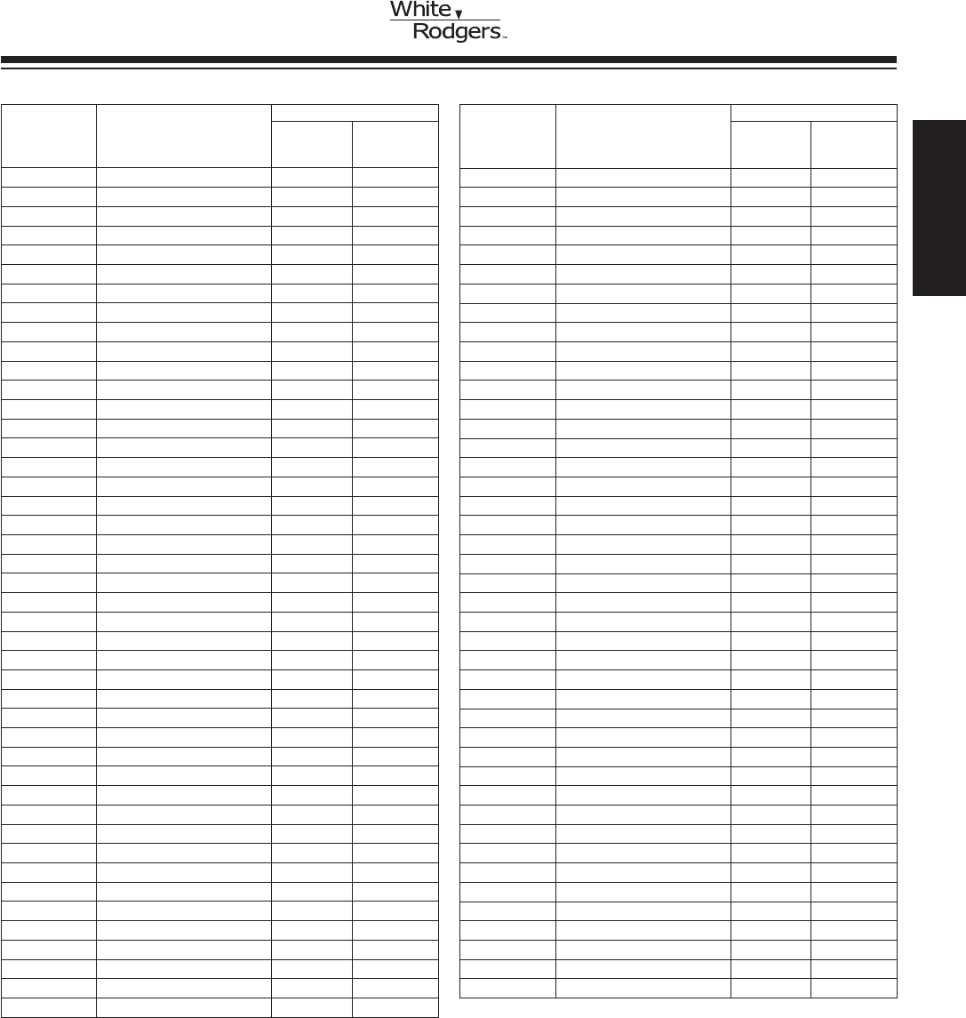
UNIVERSAL REPLACEMENT THERMOCOUPLES
Specially Designed for Universal Replacement.
Thermocouples are priced individually, order only in multiples of 10.
FEATURES
•Stainlesssteelelementconstructionforprolongedthermocouplelife.
•Eachkitindividuallyenclosedinplastic.
•Universaladapterttingsincludedwitheachkitforreplacingthermocoupleinmost
types of pilot burners.
•Visibleinstructionsforquick,easyinstallation.
•Availableinavarietyof10-packsindesiredthermocouplelengths.
•Standardthermocouple11/32” double lead thread.
• ReplacesHoneywellQ34A,JohnsonK19,Robershaw1980andWhite-RodgersH06E
H06E
Model Number
Standard ➀ Description
H06E-18 18” thermocouple
H06E-30 30” thermocouple
H06E-36 36” thermocouple
H06E-48 48” thermocouple
THERMOCOUPLES
➀Hotjunctionmaximumtemperaturerating:1450°F
GAS BURNER
CONTROLSTHERMOCOUPLES
H06E THERMOCOUPLE CROSS REFERENCE
Model
Replaced
Suggested
Replacement
1155 H06E-48
100240 H06E-18
100243 H06E-36
1466242 H06E-48
6210304 H06E-18
6210306 H06E-30
6321820 H06E-18
6321840 H06E-30
6321850 H06E-36
6321860 H06E-48
99724217 H06E-36
99795807 H06E-36
52537081000 H06E-36
52537082000 H06E-48
2E141 H06E-30
2E142 H06E-36
2E166 H06E-18
00-497302-00001 H06E-524
07-1009 H06E-18
099538-01 H06E-18
18T H06E-18
1970-018 H06E-18
1970-030 H06E-30
1970-036 H06E-36
1970-048 H06E-48
Model
Replaced
Suggested
Replacement
1980-012 H06E-18
1980-018 H06E-18
1980-030 H06E-30
1980-036 H06E-36
1980-048 H06E-48
2E337 H06E-48
2E525 H06E-36
2E720 H06E-18
2E721 H06E-30
3000MG18 H06E-18
3000MG30 H06E-30
3000MG36 H06E-36
3000MG48 H06E-48
32P7401 H06E-18
32P7601 H06E-36
32P7701 H06E-48
511-724-253 H06E-48
571-724-253 H06E-48
62-25113-01 H06E-18
632-1820 H06E-18
632-1840 H06E-30
632-1850 H06E-36
632-1860 H06E-48
BTU-018 H06E-18
BTU-030 H06E-30
Model
Replaced
Suggested
Replacement
BTU-036 H06E-36
BTU-048 H06E-48
COPR-18 H06E-18
COPR-30 H06E-30
COPR-36 H06E-36
COPR-48 H06E-48
GTC-18 H06E-18
GTC-30 H06E-30
GTC-36 H06E-36
GTC-48 H06E-48
H06E-18 H06E-18
H06E-30 H06E-30
H06E-36 H06E-36
H06E-48 H06E-48
H06E-518 H06E-518
H06E-524 H06E-524
H06E-530 H06E-530
H06E-536 H06E-536
H06E-548 H06E-548
K19AT-18 H06E-18
K19AT-30 H06E-30
K19AT-36 H06E-36
K19AT-48 H06E-48
Q340A1066 H06E-18
Q340A1082 H06E-30
Model
Replaced
Suggested
Replacement
Q340A1090 H06E-36
Q340A1108 H06E-48
Q340A1132 H06E-18
Q390A1053 H06E-30
Q390A1061 H06E-36
Q390A1095 H06E-18
Q390A1103 H06E-48
RMP-122-00860 H06E-48
T-18 H06E-18
TCP00090 H06E-18
TCP00092 H06E-30
TCP00093 H06E-36
TCP00094 H06E-48
TH-1-0 H06E-18
UT 18 H06E-18
UT 30 H06E-30
UT 36 H06E-36
UT 48 H06E-48
X13790173010 H06E-18
X13790173030 H06E-30
X13790173040 H06E-36
X13790173050 H06E-48
Y540A1004 H06E-536
Model
Number Description
H06F-36 36” Coiled Thermocouple
JUNCTION BOX THERMOCOUPLE
WITH ENERGY CUT-OFF (ECO)
www.white-rodgers.com
58
HEATING
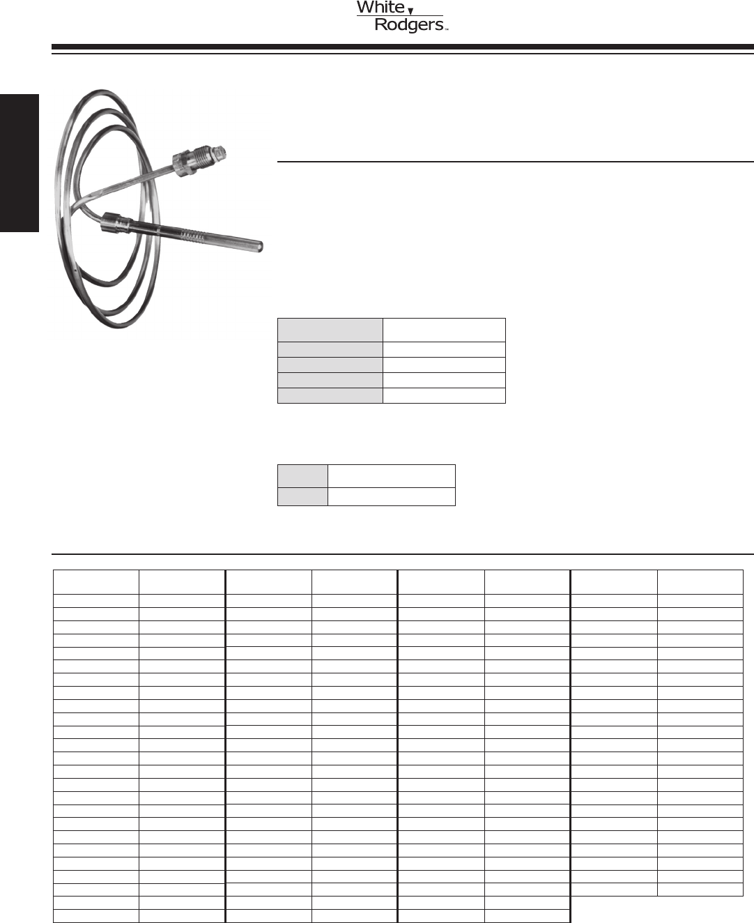
750 MILLIVOLT POWER GENERATOR
Provides Power for 750 Millivolt Self-Generation Control Systems
FEATURES
•Forreplacementofsimilarscrew-intypegeneratorsnowineldorforusewith
type E31-12 pilot burner.
•G01A-332has36incharmoredcableleadswithsplit-spadeterminals.
•PG9adapterincludedwitheachG01A-332.PG9adapteralsoofferedindividually.
•101934F32/101934R32designedforusewithPG9.
G01A-332
GAS BURNER
CONTROLS GENERATORS
G01A-501
Indicates Canadian Model Number: call 1-800-305-6953 to order
750 MV
Model
Number
MV
Output Length
Fiberglass
Cable Leads
Armored
Cable Leads
PG9
Adapter Clip
Connector
Type
101934R32 750 32 X R Bushing
G01A-332 750 36 X X X F Spade Terminal
G01A-502 750 36 X X F Spade Terminal
G01A-512 750 36 X X X F Spade Terminal
G01A-132 750 36 X X X F Spade Terminal
750 MV
Model
Number
MV
Output Length
Fiberglass
Cable Leads
Connector
Type
101934F32 750 32 X F Spade Terminal
G01A-501 750 36 X F Spade Terminal
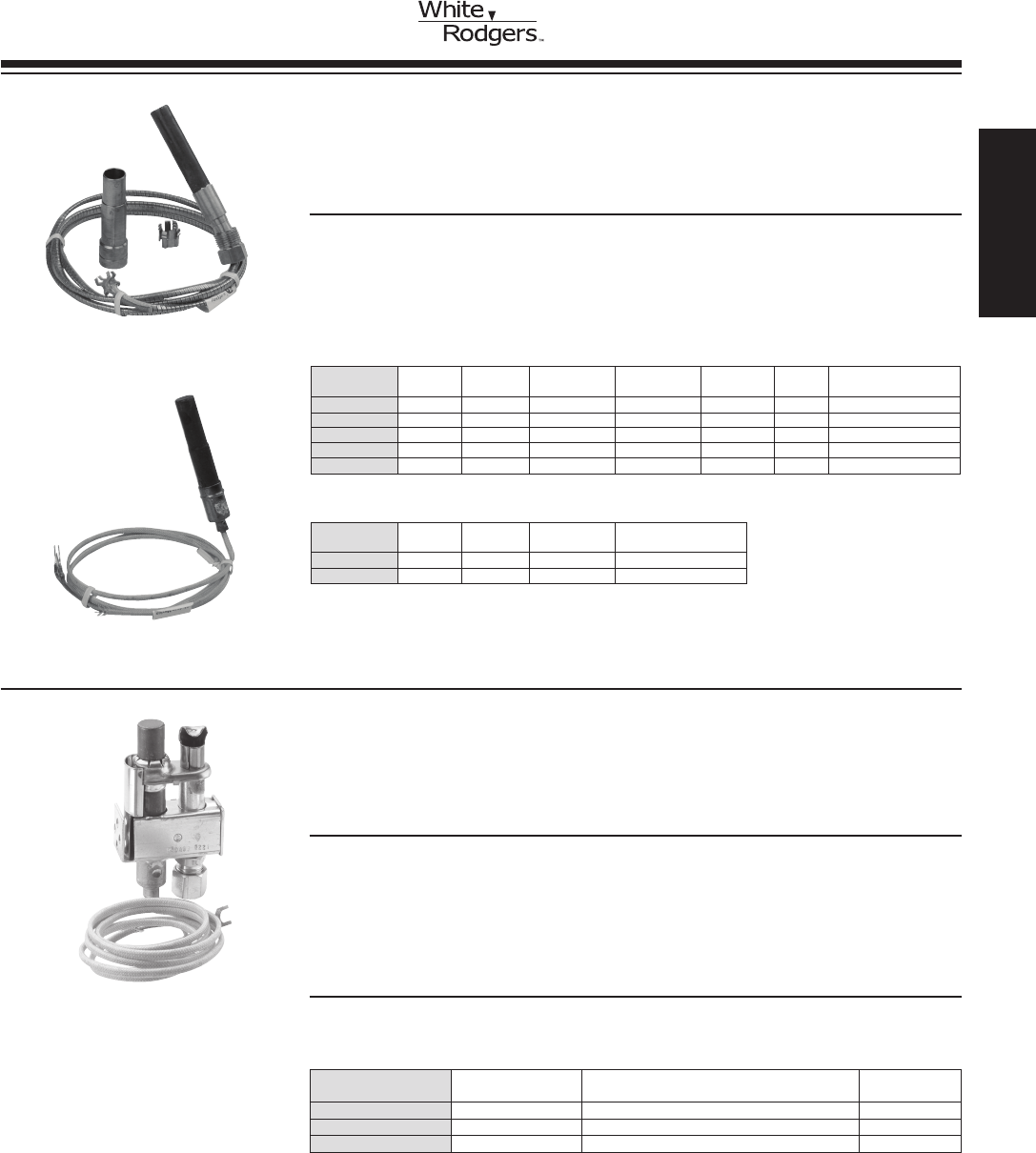
PG9 PILOT GENERATORS
Provides a Pilot Flame for Igniting Gas Burners while Generating
Millivolt Output to Operate Gas Valves and Relays
FEATURES
•Singleblueameburnerforquietoperationandmaximumamestability.
•“Snorkel”primaryairpathincineratesdusteliminatinglintingproblems.
•AllmodelsprovidedwithoricebasettingsforNaturalandLP.
•Flameringsurroundinggeneratorensureshighoutputandextendedgeneratorlife.
•Hightemperaturestainlesssteelgeneratorcover.
SPECIFICATIONS
Output Voltage ..................... 750 millivolts nominal, open circuit
Agency . . . . . . . . . . . . . . . . . . . . . . . . . . . IAScertied
PG9A41JT20
Model
Number Head Type Porting Orice ➁
PG9A27JTL22 ➀ Channel Type 90° right & 90° left, 3/4” head width .022
PG9A41JTL20 ➀ Cobra 90° left .020
PG9A42JTL20 ➀ Cobra 90° right .020
➀UniversalreplacementincludesextrabasettingforLPgasapplication(lessferruleandnut)
➁Suitableforusewithnaturalgas.Seebasettings,partno.101094/101095(nextpage)forotheravailable
orices
HEATING
www.white-rodgers.com 59
THERMOCOUPLES /
PILOT BURNERS
PC UNIVERSAL PILOT COUPLE
UniversalReplacement,Modied4-PortPilotBurner/Thermocouple
Combination
FEATURES
•Reliableignitionofgasburners.
•Stableamepatternvirtuallyunaffectedbydraftsandpressurevariations.
•Gbushingconnectorforsinglethermocouplethermopilotvalvesandrelays.
•Verticalorhorizontalinlettubingconnectionavailable.
•Longlifestainlesssteelcasing,inletlterscreen,andoricesfornaturalorLP.
SPECIFICATIONS
Output............................ 13 millivolts nominal, open circuit
Port.............................. 50 (universal replacement)
Connector......................... G Bushing
BaseOriceFitting .................. 1/4” tube, external thread, straight
Mounting.......................... Horizontal or vertical
Gas Consumption................... 500 Btu/hr, approximately
Agency . . . . . . . . . . . . . . . . . . . . . . . . . . . IAScertied
Model Number Inlet Lead
PCA50L14L48 Vertical 48”
PCB50L14L48 Horizontal 48”
PC Universal Pilot Couples
Vertical (PCA) and Horizontal (PCB)
Gas Type Orice
Natural and Mixed TL .014
L.P.G. TL .010
GAS BURNER
CONTROLS
www.white-rodgers.com
60
HEATING
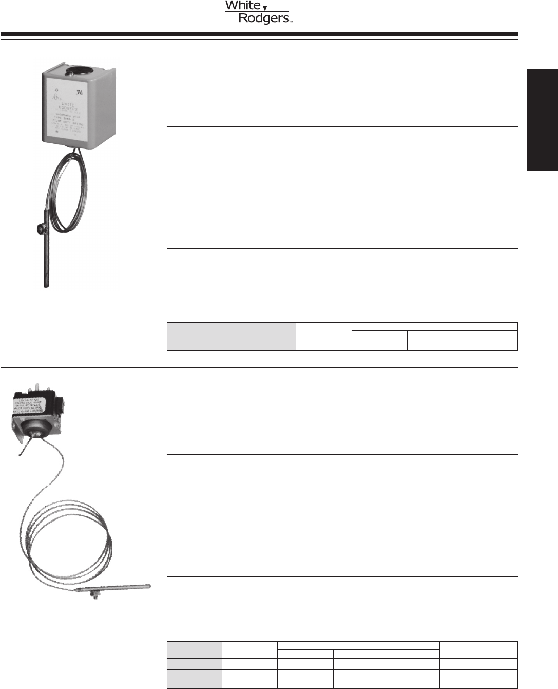
MERCURY FLAME SENSORS
Prevent Gas Flow to Main Burner if Pilot Flame is Not Burning or is
InsufcienttoProperlyIgniteMainBurner
FEATURES
•ThesesensorscombinearuggedSnap-Actionswitchandpowerfulmercury
actuated thermal element.
•Maybeusedwithnatural,manufacturedormixedgasesandwithLPgaseswhere
means are provided for obtaining automatic pilot gas shut-off.
•Switchmaybeconvenientlymountedinanyposition.
•Coveriseasilyremoved,makingswitchterminalsreadilyaccessible.
•Nobuttontodepress–Sensorsarerecyclingtypewhichrequirerelightingor
possible restoration of proper gas pressure to return to operation.
SPECIFICATIONS
Timing............................ Contacts close approximately 60 seconds
after pilot is ignited; open approximately
40secondsafterameisextinguished
Agency . . . . . . . . . . . . . . . . . . . . . . . . . . . U.L. recognized and C.S.A. approved
Dimension......................... 23/4”H x 21/16” W x 17/8”D
Model Element Electrical Rating
Number Length 120 VAC 240 VAC 30 VAC
3046-5 48” 125 VA 125 VA 90 VA
PLUG-IN TYPE MERCURY FLAME SENSORS
Designed for use with White-Rodgers Diaphragm, “Cushioned Power”
or “Silent Knight” Gas Valves having Plug-In Receptacle
FEATURES
•Plug-infeaturerequiresnoadditionalelectricalconnectionsormountingdevices.
•SensorcombinesaruggedSnap-ActionSPDTswitchandpowerfulmercury
actuated thermal element.
•Maybeusedwithnatural,manufacturedormixedgasesandwithLPgaseswhere
means are provided for obtaining automatic pilot gas shut-off.
•Nobuttontodepress–Sensorsarerecyclingtypewhichrequirerelightingor
possible restoration of proper gas pressure to return to operation.
•TheSPDTswitchcanenergizeignitorcircuittorelightpilot(aswithrooftopunits).
SPECIFICATIONS
Timing............................ Contacts close approximately 60 seconds
after pilot is ignited; open approximately
40secondsafterameisextinguished
Agency . . . . . . . . . . . . . . . . . . . . . . . . . . . C.S.A. approved
Model Element Electrical Rating
Number Length 120 VAC 240 VAC 30 VAC Comments
30A46-5 48” 125 VA 125 VA 90 VA stud mount element
30A46-105 12” 125 VA 125 VA 90 VA sleeve over element,
no stud mount
30A46-5
3046-5
GAS BURNER
CONTROLS
HEATING
www.white-rodgers.com 61
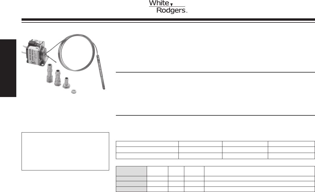
Model Element Panel Bulb
Number Length Type Style Description
3049-115 ➀ 48” D #20 Replaces bulb styles #17 or #18
3098-134 ➀ 48” E #19 Replaces bulb styles #9 or #13
3098-156 ➀ 48” E #20 Replaces bulb styles #17 or #18
SPECIFICATIONS
Agency . . . . . . . . . . . . . . . . . . . . . . . . . . . C.S.A. approved
Maximum temperature . . . . . . . . . . . . . . . 1450°F at bulb tip
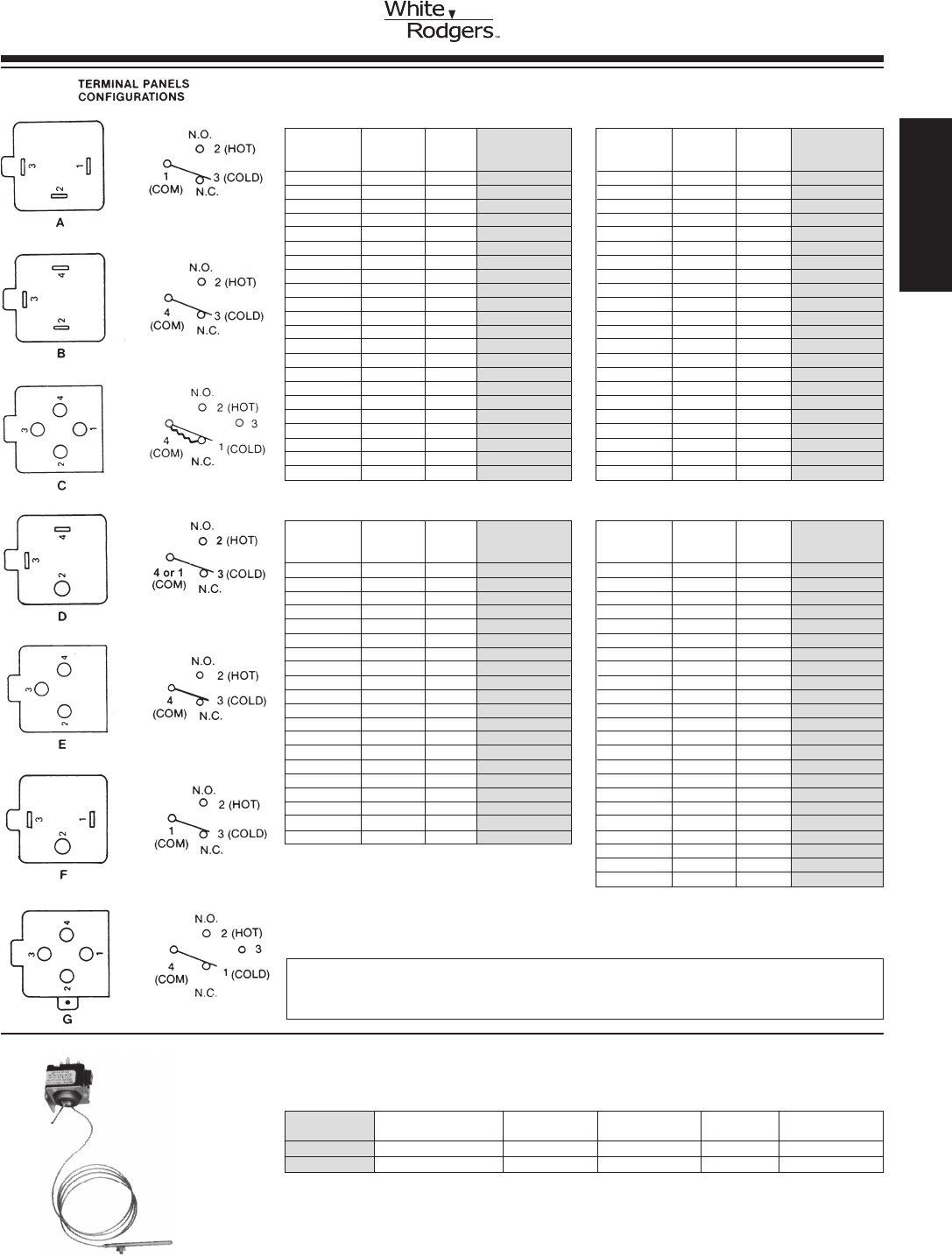
MERCURY FLAME SENSORS
For Proving Pilot Flame and Controlling Main Valve in
Cycle Pilot Applications
FEATURES
•BulbstylesaredesignedtotwithvariousOEMapplications.
•SeeCrossReferencetoOEMcontroltypenumbersonnextpage.
•Adapterttingstoallowuseofthesemercuryamesensorswithcompetitive
burnersarepackedwithcontrolsidentiedwith➀.
3098-134
Model Number 30VAC 120VAC 240VAC
3098-522 30VA 125VA 125VA
All others listed 3A 1A 0.5A
ELECTRICAL RATINGS
GAS BURNER
CONTROLS
➀ Includesadapterttings.
CONTRACTOR TIP:Mercuryame
sensors can only be replaced by cross
referencingtheoriginalmercuryame
sensor model number. They can not be
replaced by gas valve model number.
See next page.
www.white-rodgers.com
62
HEATING
Original Original Suggested
O.E.M. Capillary Panel Replacement
Number Length Types➁ Type Number
3094-102 30” C ➂ None
3094-111 30” C ➂ None ➀
3094-118 48” C ➂ None
3094-122 30” C ➂ None ➀
3094-123 30” G None
3094-127 48” C ➂ None
3094-131 22” C ➂ None ➀
3098-111 30” E 3098-134
3098-117 24” E None ➀
3098-120 30” E None ➀
3098-122 30” E 3098-156
3098-126 30” E 3098-156
3098-127 24” E 3098-156
3098-130 24” E 3098-156
3098-131 30” E 3098-156
3098-134 48” E 3098-134
3098-135 48” E None ➀
3098-136 30” E 3098-134
3098-137 12” E None ➀
3098-139 36” E None ➀
MERCURY FLAME SENSOR
CROSS REFERENCE
Original Original
O.E.M. Capillary Panel Suggested
Number Length Types➁ Replacement
3049-1 30 or 48” A None
3049-3 26” A None
3049-4 33” A None
3049-5 48” B None
3049-6 12” B None
3049-7 24” B None
3049-11 24” B None ➀
3049-15 33” A None
3049-18 30 or 33” D None
3049-20 42” B None ➀
3049-29 20” B None
3049-31 12” B None
3049-32 12” B None
3049-33 24” B None
3049-36 48” B None
3049-37 30” B None
3049-41 24 or 48” B None
3049-49 42” B None
3049-52 30” B, D 3049-115
3049-54 30” B 3049-115
3049-55 30” A, D 3049-115
3049-58 30” B None
TYPES WITH SPADE TERMINALS
Original Original
O.E.M. Capillary Panel Suggested
Number Length Types➁ Replacement
3049-59 30” B None ➀
3049-61 24” B None
3049-62 18” B None ➀
3049-64 48” D None
3049-66 30” B 3049-115
3049-68 30” B 3049-115
3049-70 30” B None ➀
3049-71 30” B None
3049-72 30” E None ➀
3049-101 24” B None ➀
3049-105 42” B 3049-115
3049-106 24” D 3049-115
3049-107 12” B, D 3049-115
3049-111 24” B, D 3049-115
3049-112 18” B, D 3049-115
3049-114 30” D 3049-115
3049-115 48” D 3049-115
3049-119 24” B 3049-115
3049-120 30” B 3049-115
3049-121 18 or 42” B 3049-115
3049-537 30” B None ➀
3049-561 24” B None ➀
PLUG-IN TYPES
Original Original Suggested
O.E.M. Capillary Panel Replacement
Number Length Types➁ Type Number
3098-141 48” E 3098-134
3098-142 30” E 3098-156
3098-143 36” E 3098-156
3098-147 18” E 3098-134
3098-148 48” E None ➀
3098-149 24 or 42” E 3098-156
3098-151 26 or 33” E None ➀
3098-153 24” E 3098-156
3098-156 48” E 3098-156
3098-161 24 or 30” E 3098-134
3098-165 48” E 3098-134
3098-168 48” E 3098-156
3098-169 27” E 3098-134
3098-171 30 or 42” E 3098-156
3094-174 36” E 3098-156
3098-175 18” E 3098-156
3098-177 24” E None ➀
3098-178 30” E None ➀
3098-182 24 or 42” E 3098-156
3098-183 12” E None ➀
3098-184 42” E 3098-134
3098-522 30” E None
3098-536 30” E None ➀
➀ ConsulttheO.E.M.forreplacementorretrot.
➁ Suggestedreplacementtypemayhavedifferentpanelconguration.Somecontrolsexperienced
modication.DetermineproperwiringwiththeaidofpaneldiagramsAthroughG.
➂ Note:PaneltypeCfeaturedanElectricalQuickShut-OffResistor(seediagram)
FLAME SENSORS
Model Type Valve Cap
Number Gas Type Terminations Length Comments
3046-5 Natural ➂ ➀ Screw 48” Recycling
30A46-5 Natural ➂ ➁ Plug-in 48” Recycling
FLAME SENSORS
➀ Screw terminals inside cover switch-case for use with any standard 24 / 120 / 240 VAC solenoid or
diaphragm gas valve
➁ Plug-in switch-case for use with White-Rodgers “Silent Knight” (25G01 series) and “Cushioned Power”
(25D46 series) solenoid valves
➂ Types 3046-5 and 30A46-5 can be used on LP gases only if an external means for automatic pilot gas
shut-off is provided
30A46-5
CONTRACTOR TIP:Mercuryamesensorscanonlybereplacedbycrossreferencingthe
originalmercuryamesensormodelnumber.Theycannotbereplacedbygasvalvemodel
number.
HEATING
www.white-rodgers.com 63
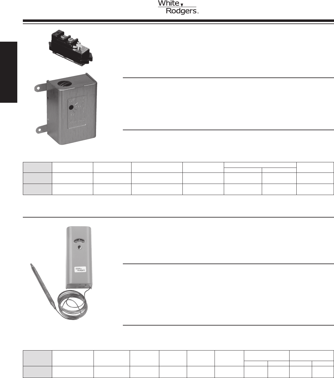
WARM AIR
CONTROLS
TEMPERATURE CONTROLS FOR HEATING
ProvideRegulationofDuctTemperaturesinConjunctionwithAirHandlingUnitsor
Control of Circulator for Indoor-Outdoor Regulation from a Remote Point
FEATURES
• Hydraulicactionelement–Unaffectedbyvibration.
• Switchcasemountsinanyposition–Nolevelingrequired.Includesbulbmountingclip.
• Highelectricalratingpermitsoperationofmostequipmentwithoutuseofrelays
or motor starters.
• Dustproofsteelcase–Dialvisibleandcanbeadjustedthroughcover.Casehas
knockoutsontopandbottom.
• Temperaturedialgraduatedin°Fand°C.
230-22
SPECIFICATIONS
Dimensions............................ 5
3/4”H x 25/16” W x 29/16”D
Finish ................................ Grey
Agency . . . . . . . . . . . . . . . . . . . . . . . . . . . . . . . U.L. listed and C.S.A. approved
Full Motor Rating Resistive
Model Capillary Bulb Switch Electrical (Full Load) (Non-inductive)
Number Range Differential Length Size Action Rating 120 VAC 240 VAC 120 VAC 240 VAC
230-22 ➀ 20to120°F Adj.4to30°F 8ft. 61/4 x 3/8” Open on FG 14.0A 7.0A 25.0A 22.0A
(-6 to +49°C) (2.2 to 17°C) Rise See page 416
➀U.L.approvedadjustabledialstop,factorysetat90°Fmaximum.
FLUSH MOUNT FAN OR LIMIT CONTROLS /
ATTIC FAN CONTROL
Ideal for Replacement of Similar Type Controls
FEATURES
•Forusewherespaceislimited.
•Smallbimetalsensingelement.
•Snap-Actionswitch.
•Fancontrolhasadjustablerangewithdirectreadingtemperaturedial.
•758 hasadjustablelimitsetting.
SPECIFICATIONS
Dimensions for 758.................. 1”H x 3”W x 11/4”D
Dimensions for 775.................. 2.8”H x 3.59”W x 2.02”D
775-1
Model Switch Motor Rating – Full Load Pilot
Number Description Range Differential Action 120 VAC 240 VAC Duty
758-1 Limit 110 to 200°F ➀ Fixed 25°F Open on Rise 8.0 A 4.0 A 125 VA
(43 to 93°C) (14°C)
775-1 Attic Fan Control 60 to 120°F ➁ Fixed10°F CloseonRise 9.0A — —
with Thermal Limiter (15 to 49°C) (6°C)
➀ Cut-out setting (cut-in is cut-out setting minus the differential)
➁ Thermal limiter opens at 183°F (84°C)
758-1
FAN / LIMIT
www.white-rodgers.com
64
HEATING
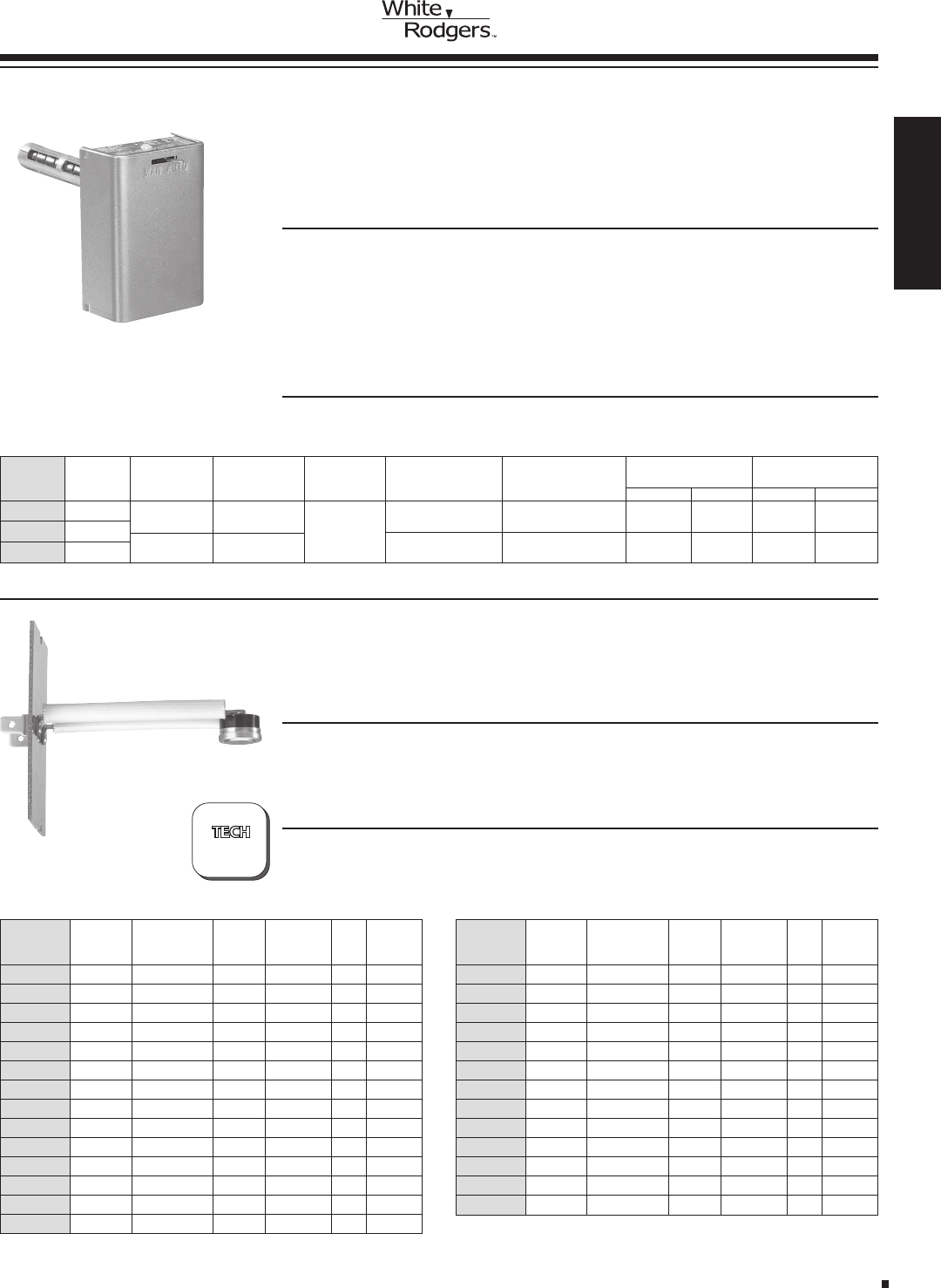
BOARD MOUNT LIMIT CONTROLS
1/2” Bimetal Disc with Ranges for Your System Needs
FEATURES
•Provenreliabilityinacompact,versatile,cost-effectivedesign.
•Provideshigh-speedcontactseparation.
•OEMreplacementforcompetitivemodels.
TECHNICAL HELP
Dimensiondrawingsandspecications.................. Seepages214-216
SPECIFICATIONS
Agency........................... U.L.recognizedandC.S.A.approved
Dimensions........................ 2.9”Wx4.3”Hx1.6”D
FAN AND LIMIT CONTROLS FOR
UNIvERSAL REPLACEMENT
SingleElementTypeforApplicationswithNarrowSpaceLimitations.
RegulatesFanorBlowerOperation&ActsasHighLimitSafetyControl
FEATURES
•Slottedmountingholesforeasyinstallation.
•Longterminalscrewsforwiring—Junctionscanbemadeonterminalblock.
•Dialhasindividualpointersforfancut-inandcut-outsettings.
•Removablesolidcopperjumperbetweenfanandlimitswitches.
•Summerfanswitchforventilationwithoutchangingcontrolsettings.Hassamefan
andlimitswitchmechanism.
5D51-35
WARM AIR
CONTROLS
FAN/LIMIT
Figure Construction Opens/
Model (pages (pages Closes Length TOD TOD
Number 214-216) 214-216) (°F) (in inches) Type Style
3L09-1 1 140/100 1.87 36T 612700
3L09-2 1 170/130 1.87 36T 612708
3L09-3 2 A 140/110 3.12 36T 612701
3L09-4 2 C 150/130 3.12 36T 612703
3L09-5 2 C 160/140 3.12 36T 612706
3L09-6 2 B 170/130 3.12 36T 612710
3L09-7 2 A 175/145 3.12 36T 612711
3L09-8 2 B 180/140 3.12 36T 612714
3L09-9 2 C 190/170 3.12 36T 612715
3L09-10 2 B 200/160 3.12 36T 612718
3L09-11 2 B 210/170 3.12 36T 612719
3L09-12 2 B 220/180 3.12 36T 612722
3L09-13 2 A 240/210 3.12 36T 612723
3L09-14 2 B 250/210 3.12 36T 612725
Figure Construction Opens/
Model (pages (pages Closes Length TOD TOD
Number 214-216) 214-216) (°F) (in inches) Type Style
3L09-15 2 A 260/230 3.12 36T 612727
3L09-16 3 A 150/130 3.12 36T 612704
3L09-17 3 A 250/225 3.12 36T 612726
3L09-18 3 B 155/125 7.12 36T 612705
3L09-19 3 B 175/145 7.12 36T 612712
3L09-20 3 B 240/210 7.12 36T 612724
3L09-22 4 A 160/140 3.12 36T 612707
3L09-23 4 A 170/150 3.12 36T 612709
3L09-24 4 B 190/170 3.12 36T 612716
3L09-25 4 B 200/180 3.12 36T 612717
3L09-26 5 180/160 1.87 36T 612713
3L09-27 5 220/200 1.87 36T 612721
3L09-28 6 210/180 3.12 36T 612720
Full Motor Rating Valves and
Model Element Switch Electrical (Full Load) Relays
Number Length Description Range Differential Action Rating 120 VAC 240 VAC 24 VAC 0.3-12v DC
Fan 50to265°F Adjustable CloseonRise HT 14.0A 7.0A 5.6A —
(10to129°C) 15°Fminimum Seepage416
Limit 100to300°F Fixed25°F OpenonRise HTV 10.0A 6.0A 6.0A 1.0A
(38to149°C) Seepage416
5D51-355”
5D51-908”
5D51-78 11”
?
PAGES
214-216
HEATING
www.white-rodgers.com 65
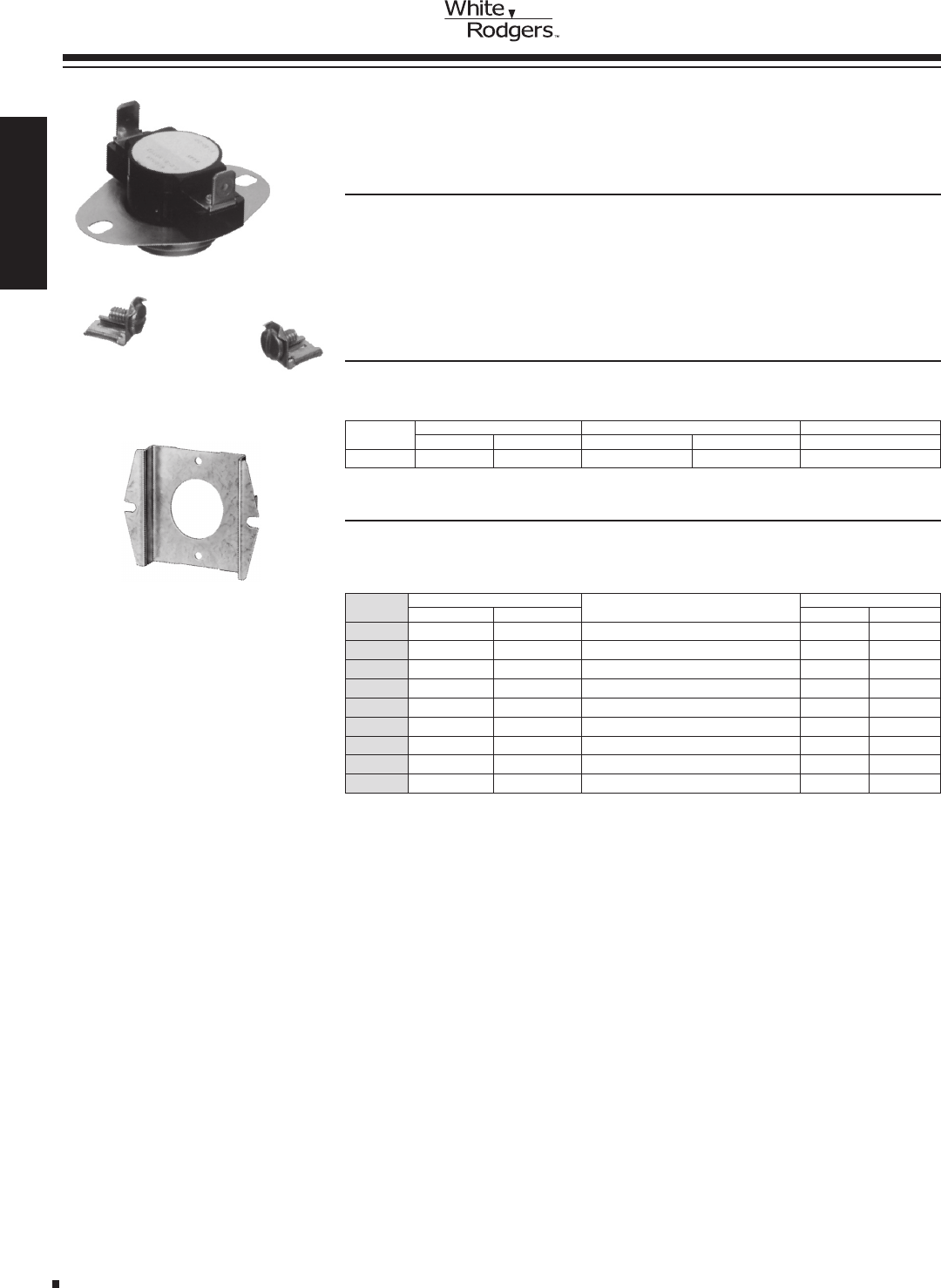
SPECIFICATIONS
Maximum ambient .................. 350°F
SNAP DISC FAN CONTROLS
For Regulation of Fan or Blower Control
FEATURES
•Designedforquickon-jobreplacement.
•Easytoremembertypenumbers—“L”forLimit—“F”forFan.
•Lastthreenumbersindicatecut-outtemperaturesonlimitsandcut-intemperatures
onfancontrols.
•Mountingholesmatchstandard¾”snapdiscs.
•Tab-to-screwterminaladaptersfurnished.
3F01-140
Motor Rating (Full Load) Resistive (Non-Inductive) Pilot Duty
Model 120VAC 240VAC 120/240VAC 277VAC 120/240/277VAC
3F01, 3F02 10.0A 5.0A 25.0A 21.6A 125 VA
ELECTRICAL RATINGS
Model Fixed Temperature Settings Switch Therm-O-Disc
Number Cut-in Cut-out Action Style Type
3F01-110 110°F(43°C) 90°F(32°C) CloseonRise 60T12 610044
3F01-120 120°F(49°C) 110°F(43°C) CloseonRise 60T12 610046
3F01-130 130°F(54°C) 115°F(46°C) CloseonRise 60T12 610047
3F01-140 140°F(60°C) 120°F(49°C) CloseonRise 60T12 610049
3F01-150 150°F(66°C) 130°F(54°C) CloseonRise 60T12 610050
3F01-160 160°F(71°C) 140°F(60°C) CloseonRise 60T12 610064
3F01-180 180°F(82°C) 160°F(71°C) CloseonRise 60T12 610065
3F01-200 200°F(93°C) 180°F(82°C) CloseonRise 60T12 610066
3F01-350 350°F(177°C) 320°F(160°C) CloseonRise 60T12 610067
FAN CONTROLS
SNAP DISC
CONTROLS3F01 SERIES
F6-1798 (1 per pack)
PARTS AND ACCESSORIES
•F6-1798Adapterplates(Orderseparately)—1perpack
www.white-rodgers.com
66
HEATING
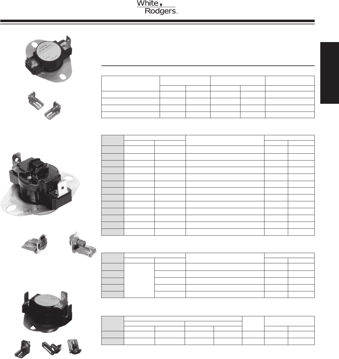
Model Fixed Temperature Settings Switch Therm-O-Disc
Number Cut-in Cut-out Action Style Type
3L01-120 110°F (43°C) 120°F (49°C) Open on Rise 60T11 610000
3L01-130 115°F (46°C) 130°F (54°C) Open on Rise 60T11 610002
3L01-140 100°F (38°C) 140°F (60°C) Open on Rise 60T11 610006
3L01-150 110°F (43°C) 150°F (66°C) Open on Rise 60T11 610009
3L01-165 125°F (52°C) 165°F (74°C) Open on Rise 60T11 610069
3L01-170 130°F (54°C) 170°F (77°C) Open on Rise 60T11 610012
3L01-180 140°F (60°C) 180°F (82°C) Open on Rise 60T11 610013
3L01-190 150°F (66°C) 190°F (88°C) Open on Rise 60T11 610015
3L01-200 160°F (71°C) 200°F (93°C) Open on Rise 60T11 610016
3L01-230 190°F (88°C) 230°F (110°C) Open on Rise 60T11 610021
3L01-250 210°F (99°C) 250°F (121°C) Open on Rise 60T11 610023
3L01-300 250°F (121°C) 300°F (149°C) Open on Rise 60T11 610026
3L01-350 310°F (154°C) 350°F (177°C) Open on Rise 60T11 610068
SNAP DISC
CONTROLS 3L SERIES
SPECIFICATIONS
SNAP DISC FAN OR LIMIT CONTROLS
For Regulation of Fan, Blower or High Limit Safety Control
3L02-190
Electrical Rating Motor Rating Resistive Pilot
(AC) for (Full Load) (Non-Inductive) Duty
Model Numbers 120VAC 240VAC 120/240VAC 277VAC 120/240/277VAC
3L01 10.0A 5.0A 25.0A 21.6A 125 VA
3L02 10.0A 5.0A 25.0A 21.6A 125 VA
3L03: 1&2CloseonRise 5.8A 2.9A — — 125VA
3L03: 1 & 3 Open on Rise 10.0A 5.0A 25.0A 21.6A 125 VA
ELECTRICAL RATINGS
LIMIT CONTROLS
Model Fixed Temperature Settings Switch Therm-O-Disc
Number Cut-in Cut-out Action Style Type
3L02-160 160°F (71°C) Open on Rise 60T15 330534
3L02-170 170°F (77°C) Open on Rise 60T15 330535
3L02-180 Manual 180°F (82°C) Open on Rise 60T15 330536
3L02-190 Reset 190°F (88°C) Open on Rise 60T15 330537
3L02-200 200°F (93°C) Open on Rise 60T15 330538
LIMIT CONTROLS — MANUAL RESET
Fixed Temperature Settings
Model Terminal 1 & 3 Terminal 1 & 2 Switch Therm-O-Disc
Number Cut-in Cut-out Cut-in Cut-out Action Style Type
3L03-140 140°F (60°C) 120°F (49°C) 190°F (88°C) 170°F (77°C) SPDT 60T13 611015
3L03-190 190°F (88°C) 170°F (77°C) 140°F (60°C) 120°F (49°C) SPDT 60T13 611014
SPDT CONTROLS
3L01-180
3L03-140
HEATING
www.white-rodgers.com 67
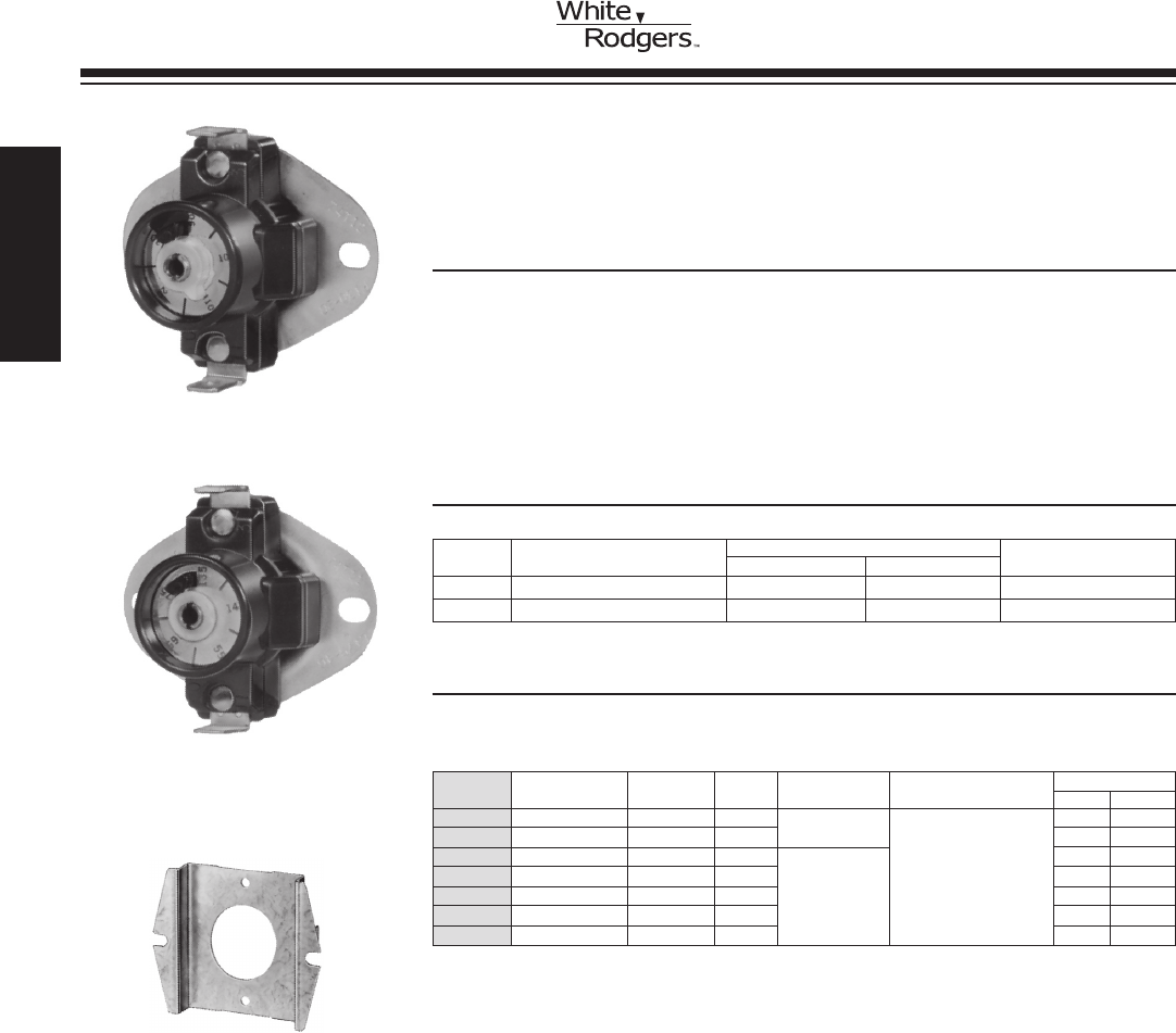
SNAP DISC
CONTROLS3F05 / 3L05 SERIES
Model Temperature Switch Therm-O-Disc
Number Range Differential Action Function Accessories Style Type
3F05-1 90 to 130°F 20°F SPST Fan Controls Includes thermostat 74T12 310708
3F05-2 140 to 180°F 20°F SPST (Close on Rise) and tab-to-screw 74T12 310709
3L05-1 135 to 175°F 40°F SPST Limit Controls terminals. 74T11 310710
3L05-2 175 to 215°F 40°F SPST (Open on Rise) 74T11 310711
3L05-3 210 to 250°F 40°F SPST 74T11 310712
3L05-10 135 to 175°F 20°F SPST 74T11 310724
3L05-13 250 to 290°F 40°F SPST 74T11 310730
SPECIFICATIONS
ADJUSTABLE SNAP DISC FAN & LIMIT CONTROLS
AdjustableSnapDiscThermostatAllowsYoutoSettheTemperature
SetPointtoMatchYourSpecicNeedsWhichSimpliesInventory
FEATURES
•¼”quickconnectterminalsarestandard.
•Reducesinventorywhileprovidingcoverageforawiderangeoftemperature
applications.
•Replacesthemajorityofxeddiscthermostatsnowonheatingequipmentand
various appliances.
•2adjustablefancontrolmodelsreplace7xedsnapdiscmodels.
•5adjustablelimitcontrolmodelsreplace10xedsnapdiscmodels.
PARTS AND ACCESSORIES
3F05-1
•F6-1798Adapterplates(Orderseparately)—1perpack
3L05-1
F6-1798 (1 per pack)
Resistive Motor Rating (Inductive)
VAC (Non-Inductive) Full Load Locked Rotor Pilot Duty
120 25.0A 14.0A 72.0A 125 VA
240 25.0A 10.0A 60.0A 125 VA
ELECTRICAL RATINGS
www.white-rodgers.com
68
HEATING
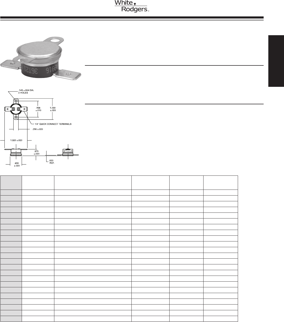
3L11 / 3F11 SERIES
1/2” BIMETAL DISC THERMOSTATS
22 New Bimetal Disc Thermostats for Appliance and HVAC
FEATURES
•Loosering,stainlesssteelmountingbrackets.
•1/4”quickconnectterminations.
•Automaticreset.
•Aluminumdisccup.
3L11 / 3F11
SERIES
BIMETAL DISC
THERMOSTATS
SPECIFICATIONS
Single pole, single throw
Available in either open or close on temperature rise
Electrical Ratings
Resistive ....... 15A @ 120VAC, 10A @ 240VAC
Inductive ....... 3.0FLA, 12.0LRA @ 120VAC; 1.5FLA, 6.0LRA @ 240 VAC
Pilot Duty ....... 125VA
Dimensions....... Length (1.23”), case width (1.32”), height (.37”)
Weight .......... 0.2 oz.
Agency . . . . . . . . . . UL Recognized File #E19279
CSACertiedFile#LR19988
VDE Lic. 81669
Model Differential Therm-O-Disc Therm-O-Disc
Number Description Temperature °F / °C °F / °C Type Style
3L11-60 Open on rise 55 to 65 (°F), 13 to 18 (°C) 20 (°F), 12 (°C) 36T21 10842
3L11-85 Open on rise 80 to 90 (°F), 27 to 32 (°C) 15 (°F), 8 (°C) 36T21 10843
3F11-100 Close on rise 93 to 107 (°F), 34 to 42 (°C) 30 (°F), 17 (°C) 36T22 10844
3L11-110 Open on rise 105 to 115 (°F), 41 to 46 (°C) 30 (°F), 17 (°C) 36T21 10845
3L11-120 Open on rise 115 to 125 (°F), 46 to 52 (°C) 30 (°F), 17 (°C) 36T21 10846
3F11-120 Close on rise 113 to 127 (°F), 45 to 53 (°C) 30 (°F), 17 (°C) 36T22 10847
3L11-140 Open on rise 135 to 145 (°F), 57 to 63 (°C) 30 (°F), 17 (°C) 36T21 10848
3F11-140 Close on rise 133 to 147 (°F), 56 to 64 (°C) 30 (°F), 17 (°C) 36T22 10849
3L11-150 Open on rise 145 to 155 (°F), 63 to 68 (°C) 30 (°F), 17 (°C) 36T21 10850
3L11-160 Open on rise 155 to 165 (°F), 68 to 74 (°C) 30 (°F), 17 (°C) 36T21 10851
3L11-170 Open on rise 165 to 175 (°F), 74 to 79 (°C) 30 (°F), 17 (°C) 36T21 10852
3F11-170 Close on rise 162 to 178 (°F), 72 to 81 (°C) 30 (°F), 17 (°C) 36T22 10853
3L11-175 Open on rise 170 to 180 (°F), 77 to 82 (°C) 15 (°F), 8 (°C) 36T21 10854
3L11-180 Open on rise 175 to 185 (°F), 79 to 85 (°C) 30 (°F), 17 (°C) 36T21 10855
3F11-180 Close on rise 172 to 188 (°F), 78 to 87 (°C) 30 (°F), 17 (°C) 36T22 10856
3L11-190 Open on rise 185 to 195 (°F), 85 to 91 (°C) 30 (°F), 17 (°C) 36T21 10857
3L11-210 Open on rise 204 to 216 (°F), 96 to 102 (°C) 30 (°F), 17 (°C) 36T21 10858
3L11-220 Open on rise 214 to 226 (°F), 101 to 108 (°C) 30 (°F), 17 (°C) 36T21 10859
3F11-225 Close on rise 217 to 232 (°F), 103 to 111 (°C) 30 (°F), 17 (°C) 36T22 10860
3L11-230 Open on rise 224 to 236 (°F), 107 to 113 (°C) 30 (°F), 17 (°C) 36T21 10861
3F11-240 Close on rise 229 to 251 (°F), 109 to 122 (°C) 100 (°F), 56 (°C) 36T22 10862
3L11-250 Open on rise 224 to 256 (°F), 118 to 124(°C) 30 (°F), 17 (°C) 36T21 10863
3L11-325 Open on rise 315 to 335 (°F), 157 to 169 (°C) 50 (°F), 28 (°C) 36T21 10864
HEATING
www.white-rodgers.com 69
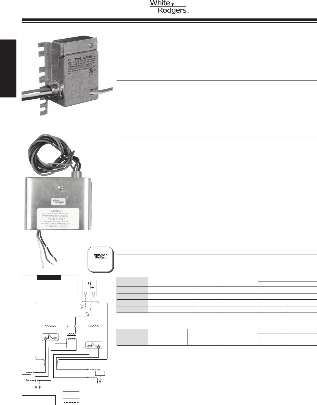
R
W
Type 24A06 Dual Level T e mp
White
Bimetal
Heater #1
Switch #1
Switch #2
Bimetal
Heater #2
T r ansformer
2-Wire
Heating
Thermostat
Black w/ Red Stripe
Red w/ Black Stripe
L1
Line
L2
L1
Line
L2
Heating
Load #2
Heating
Load #1
Red
Black
Blue
Black w/
White Stripe
Red
Line Voltage
Low Voltage
Line Voltage Field
Low Voltage Field
WIRING
LEVEL-TEMP LOW VOLTAGE
CONTROL SYSTEMS FOR ELECTRIC HEAT
Provides Silent Operation and Narrow Differential Control for Heating
or Cooling Installations for use with a 2-Wire 24 Volt Thermostat
SPECIFICATIONS
Dimensions Models 24A01 / 05 ........ 1
7/8”H x 41/2”W x 27/16”D
Dimensions Model 24A06............. 3
13/16”H x 413/16”W x 21/8”D
Dimensions Model 24A07............. 1
7/8”H x 49/16”W x 129/32”D
Single Level Temp
Switch Action ...................... SPST normally open
Average Time Delay ................. 45 seconds
Lead length........................ 18 inches
Ambient temperature range ........... -20 to +140°F
Dual Level Temp
Switch Action ...................... Two independent: SPST normally open
Average Time Delay ................. 45 seconds
Lead length........................ 18 inches
Ambient temperature range ........... -20 to +120°F
Agency . . . . . . . . . . . . . . . . . . . . . . . . . . . U.L. listed and C.S.A. approved. Design
complies with U.L. 873 T.I.R.E. standard
(TemperatureIndicating&RegulatingEquipment)
FEATURES
•Level-Tempallowslowvoltage2-wirethermostattocontrollinevoltageloadssuch
as baseboard heaters.
•Conduithuborscrewmounting.
•Idealforalltypesofelectricalheat.
•Non-criticalmountingangle.Universalbreak-offmountingtabs.
•DualLevel-Tempcapableofcontrollingtwoseparateloads.
24A01G-3
Model Input Thermostat A.C. Resistive ➀ A.C. Motor Rating (Inductive)
Number Voltage / Frequency Current (Non-inductive) Full Load Locked Rotor
24A06G-1 240 VAC / 60 Hz 0.2A per switch 25A, 6000W, 240v 12A, 240v 72A, 240v
DUAL LEVEL TEMPS – Controls Two Independent Loads – Normally Open
➀ Electrical ratings apply to each switch load
NOTE: Delay approximately 30 seconds opening and 60 seconds closing
REPLACES HONEYWELL R841 SERIES
24A06G-1
Using Two-wire Heating Thermostat to
Operate Two Separate Heating Loads
ELECTRIC HEAT
PRODUCTS
TECHNICAL HELP
Wiring and Dimension Drawing, 24A01 / 24A05 ... page 213
MAKE L1 “HOT”
ON 120V MODELS
NOTE
Use thermostat with a .4A
xed heater, or set adjustable
heater in thermostat at .4 A.
Indicates Canadian Model Number: call 1-800-305-6953 to order
Model Input Thermostat A.C. Resistive A.C. Motor Rating (Inductive)
Number Voltage / Frequency Current (Non-inductive) Full Load Locked Rotor
24A01G-3 240 VAC / 60 Hz 0.2A 25A, 6000W, 240v 12A, 240v 72A, 240v
24A01Z-10 347 VAC / 60 Hz 0.2A 17A, 5900W, 347v – –
24A05A-1 120 VAC / 60 Hz 0.2A 25A, 3000W, 120v 16A, 120v 96A, 120v
24A05E-1 208 VAC / 60 Hz 0.2A 22A, 5200W, 208v 12A, 208v 72A, 208v
SINGLE LEVEL TEMPS – Normally Open
?
PAGE
213
www.white-rodgers.com
70
HEATING
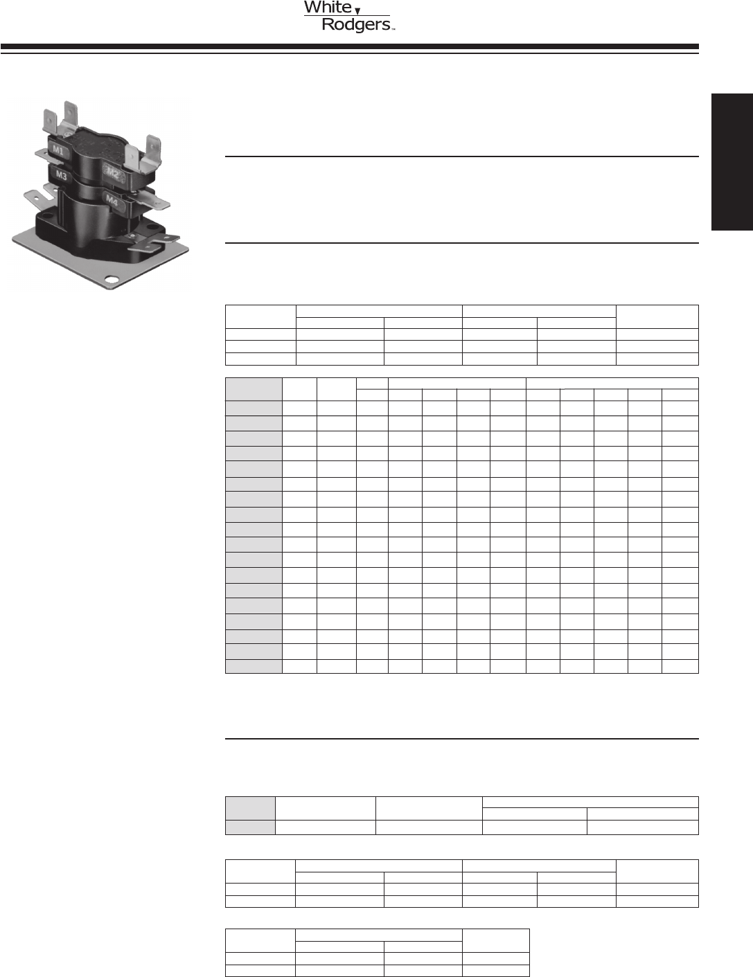
Model Timings – ON Timings – OFF
Number Timings Switches M1-M2 M3-M4 M5-M6 M7-M8 M9-M10 M1-M2 M3-M4 M5-M6 M7-M8 M9-M10
24A34-1 1 1 1-20 – – – – 40-110 – – – –
24A34-2 1 1 – – 30-90 – – – – 1-30 – –
24A34-3 ➀ 1 2 1-20 1-20 – – – 40-110 40-110 – – –
24A34-4 1 2 – – 30-90 30-90 – – – 1-30 1-30 –
24A34-5 ➀ 2 3 1-110 1-110 1-110 – – 1-110 1-110 1-110 – –
24A34-6 ➀ 2 4 1-110 1-110 1-110 1-110 – 1-110 1-110 1-110 1-110 –
24A34-14➀➁ 4 5 1-160 1-160 1-160 1-160 1-160 1-160 1-160 1-160 1-160 1-160
24A34-21 1 1 1-20 – – – – 1-50 – – – –
24A34-22 1 1 15-45 – – – – 1-30 – – – –
24A34-23 1 1 25-55 – – – – 15-45 – – – –
24A34-24 1 1 30-75 – – – – 1-40 – – – –
24A34-25 1 1 40-90 – – – – 1-30 – – – –
24A34-26 2 2 1-20 30-90 – – – 40-90 1-30 – – –
24A34-27 2 2 1-160 1-160 – – – 1-160 1-160 – – –
24A34-28 ➂ 2 2 1-160 1-160 – – – 1-160 1-160 – – –
24A34-29 1 1 15-35 – – – – 25-55 – – – –
24A34-36 2 2 1-20 30-45 – – – 45-110 1-30 – – –
24A34-37 1 1 1-110 – – – – 1-110 – – – –
MODEL 24A34 ELECTRIC HEAT SEQUENCERS
DirectReplacementforMostFan/HeatSequencingFunctions.
TerminalMarkingsareEquivalenttoCompetitiveTypes
FEATURES
•ReplacesHoneywell,MARS,TOD,
GEMLINE, Klixon (Texas Instruments).
•24Vinputcontrol.
•Multi-poisemounting.
Resistive (Non-Inductive) Motor Ratings (Inductive)
VAC Watts Amps Full Load Locked Rotor Pilot Duty
120 3000 25.0 14.0A 72.0A 125 VA
240 6000 25.0 7.0A 42.0A 125 VA
480 6000 12.5 – – 480 VA
ELECTRICAL RATINGS – SINGLE LOAD CONTACT RATINGS (ALL MODELS)
•Anycontacts(exceptM1&M2)canbe
used as auxiliary contacts.
•Doublequick-connectterminalsfor
combination loads.
SPECIFICATIONS
Ambient Temperature Rating .......... -50 to +165°F
Agency . . . . . . . . . . . . . . . . . . . . . . . . . . . U.L. component recognized
TABLE NOTES:
➀ M1-M2andM3-M4arealwaysrstswitches
to turn ON and last to turn OFF. All other
switches are random ON and random OFF
➁ 24A34-14 Switch contacts designated
F
1 - F2 instead of M1 - M2
➂ 24A34-28 is 2 pole double throw
♦ These contacts switch simultaneously
NOTE:UnderwritersLaboratoriesrequiresa
faninterlockcircuittoinsuretheblower
remains operating whenever more than one
sequencerisused.Thefaninterlockshould
be the M1 / M2 contacts of the second or third
sequencer.
All M1 / M2 contacts are wired to the blower mo-
torsothatanysequencerthatisenergizedwill
keeptheblowerON.
COMBINED LOAD RATING TABLE
(ALL MODELS)
30A @ 240 VAC – TOTAL,
23A Non-Inductive + 7 FLA / 42 LRA Inductive,
ONTime: Elapsedtimetomakecontactsafter
heater is energized (min. to max.)
OFFTime: Elapsedtimetobreakcontactsafter
heater is de-energized (min. to max.)
♦
♦
♦
♦
♦
♦
♦
♦
♦
♦
♦
♦
24A34-3
Model Timings
Number Timings Switches ON 1-3 OFF 1-3
24A34-15 1 1 1-60 75-95
24A34-15 HEAT PUMP CONTROL
FEATURES
•Usedinheatpumpairhandlerapplications.
•Providesadelayofftotheblowermotorincoolingmode.
•Singlepoledoublethrow.
Resistive (Non-Inductive) Motor Ratings (Inductive)
VAC Watts Amps Full Load Locked Rotor Pilot Duty
120 3000 25.0 14.0A 72.0A 125 VA
240 6000 25.0 7.0A 42.0A 125 VA
ELECTRICAL RATINGS – NORMALLY OPEN CONTACTS 1-3
Resistive (Non-Inductive)
VAC Watts Amps Pilot Duty
120 1200 10.0 125 VA
240 1200 5.0 125 VA
ELECTRICAL RATINGS – NORMALLY CLOSED CONTACTS 1-2
ELECTRIC HEAT
PRODUCTS
Indicates Canadian Model Number: call 1-800-305-6953 to order
HEATING
www.white-rodgers.com 71
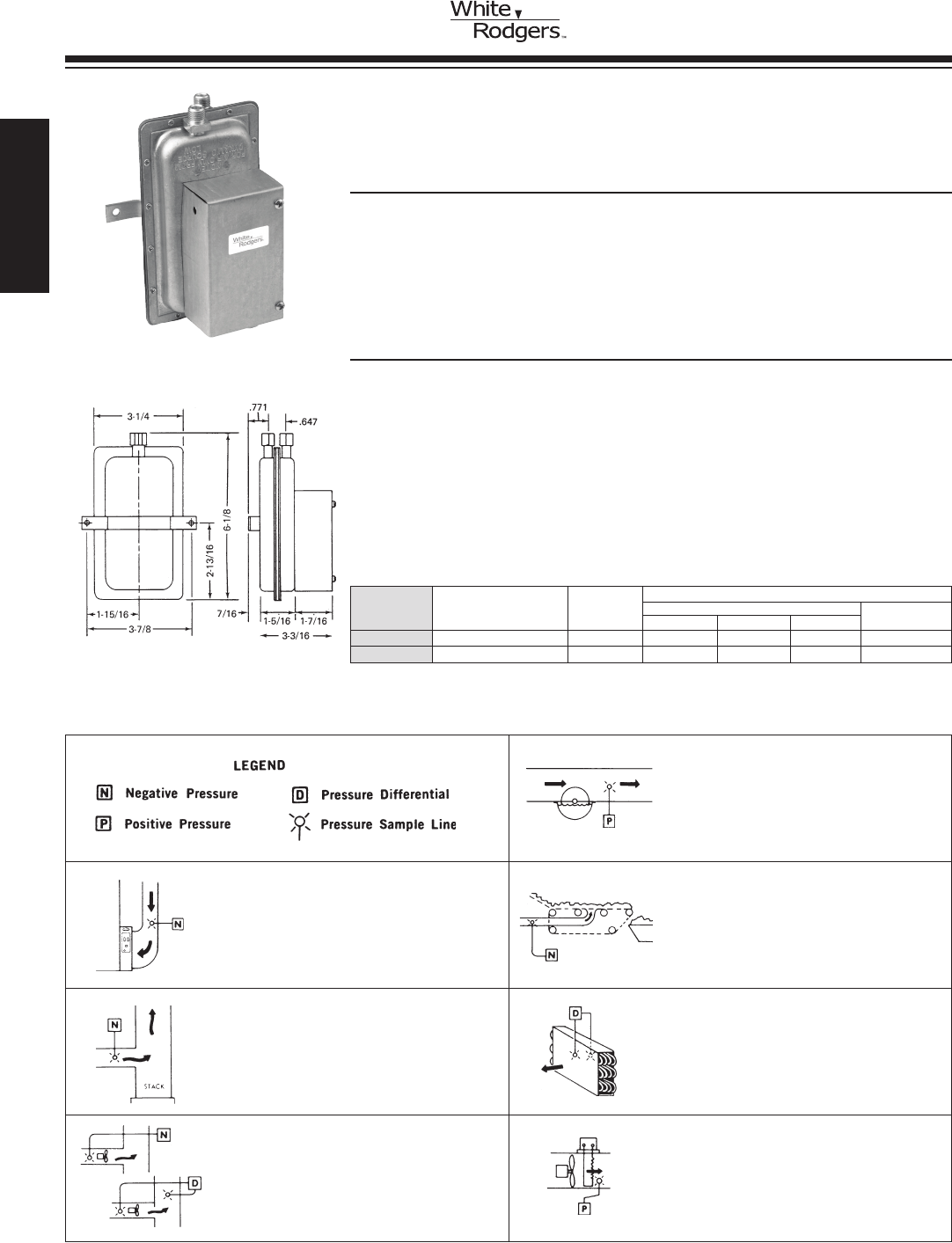
Electrical Ratings
Model Adjustable Switch Resistive (Non-Inductive)
Number Operating Range Action 120 VAC 240 VAC 277 VAC 125-277 VAC
770-1 0.05 to 12.0 W.C. SPDT 15.0A 15.0A 15.0A 300 VA
770-3 0.05 to 12.0 W.C. SPDT 15.0A 15.0A 15.0A 300 VA
DUAL PURPOSE AIR SWITCH
Responds to Positive, Negative or Differential Air Pressure
FEATURES
•Designeliminates“uttering”ormalfunctionduetoshockorvibrationnormally
encountered with “sail switches.”
•Wideoperatingrange.
•Furnishedwithone12” piece 1/4”O.D.exibletubing,nutsandferrules.
•Canbemountedinanypositionexceptupsidedown.
•Encloseddiaphragm.
SPECIFICATIONS
Ambient Temperature ................ -40 to +180°F
Maximum Pressure.................. 1/2 PSI
Agency . . . . . . . . . . . . . . . . . . . . . . . . . . . U.L. listed and C.S.A. approved
1/2 HP @ 125 VAC
770-1
AIR SWITCH APPLICATIONS
ELECTRONIC AIR CLEANERS
Switch permits power to cleaner whenever
blower of system is operating.
PROCESS DRYING
Switch monitors negative pressure to stop
conveyor or process and provides alarm
signalonfanfailure.Idealforbulk
chemicals, food processing, grain drying.
POWER HUMIDIFIERS
Switch permits unit to operate whenever
there is proper air movement.
NATURAL DRAFT BURNERS
Switchsignalsinsufcientdraft,provides
safetylimittostopringonlackofdraft,
startsagainonsufcientdraft.
REFRIGERATION EQUIPMENT
Switch responds to pressure drop across
refrigeration coils to signal alarm condition
or automatically initiate or terminate
defrost cycle.
INDUCED DRAFT BURNERS
Proves operation of I.D. fan by sampling
draftorairow.Shutsoffringequipment
on fan failure.
DUCT STRIP HEATERS
Switch proves air movement across
heaters by positive pressure to prevent
burn-outoninsufcientairow.
DUAL PURPOSE
AIR SWITCH
Indicates Canadian Model Number: call 1-800-305-6953 to order
www.white-rodgers.com
72
HEATING
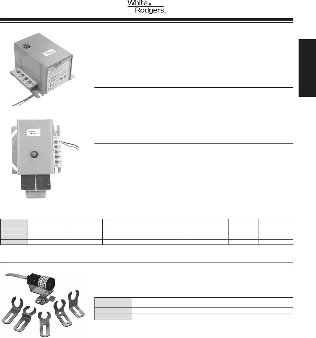
OIL BURNER
CONTROLS
Indicates Canadian Model Number: call 1-800-305-6953 to order
668 SERIES KWIK-SENSOR CAD CELL RELAYS
ReplacesIntermittentIgnitionKwik-SensorCADCellRelaysonOil
Burner Systems with 30 or 45 Second Safety Timing. Certain Types
haveUniqueSignal-LiteFeaturewhichGlowsWheneverSafetyLock-
Out Occurs
FEATURES
•Greymetalenclosure.
•Linevoltagesafetyswitcheliminatesburnerrun-onineventmotorrelaycontacts
weld closed.
•Solidstateamedetectioncircuitryisnotaffectedbyvibrationorhighorlow
ambient temperatures. Suitable for use from – 40 to 150°F (– 40 to 66°C)
•Recyclesuponmomentaryamefailureorpowerinterruption.
SPECIFICATIONS
Input Voltage....................... 120 VAC, 60 Hz
Control Voltage ..................... 24 VAC
Motor Relay Contacts Rating . . . . . . . . . . Full 10 FLA, 60 LRA, 120 VAC
Ignition Transformer Rating ........... 360 VA (3.0A)
Mounting.......................... 10” useable leads, mounts to
4 x 4”junctionbox
668-401
668-451
FLAME DETECTORS
Solid State Electronic Flame Detector which Utilizes Light Intensity to
SensethePresenceofaFlameinOilBurningHeatingEquipment
Model
Number Description
956-1 Standardamedetectorwithstraightbracket.48½” leads.
956-154 Universalamedetectorwith6brackets.60” leads.
956-154
Model Thermostat Safety Manual Integral Time Start
Number Safety Timing Thermostat Type Anticipator Setting Lock-Out Lamp Lock-Out Lever Transformer Fan Switch
668-401 45 seconds 2-Wire 0.4A No No No No
668-451 ➀ 45 seconds 2-Wire 0.4A No No 40VA C-W
668-515 30 seconds 2 or 3-Wire 0.4A Yes Yes No No
➀ Models with external transformer have safety switch contacts in motor relay (low voltage) circuit.
HEATING
www.white-rodgers.com 73
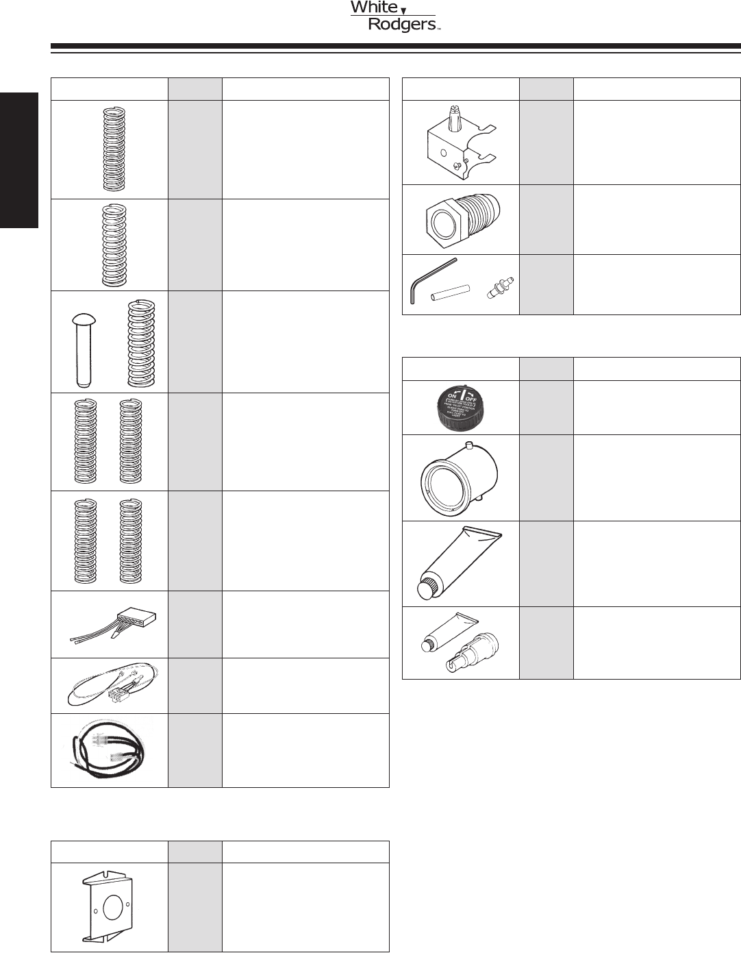
F115-0100 Harness assembly for HSI systems
with 36E gas valves; connects the
767A ignitor with the 50E47 or the
50F47 ignition module.
Item Model
Number Number Description
F92-0656 L.P.tonaturalgasconversionkit
for 36C, 36D, 36E, 36F and 36G
gas valves with regulation range of
2.5 to 5” W.C.
F92-0659 Natural to regulated L.P. gas
conversionkitfor36C,36D,36E,
36F and 36G gas valves with regula-
tion range of 7.5 to 12.0” W.C.
F92-0737 Natural to unregulated L.P. gas
conversionkitfor36Cgasvalves.
F92-1008 NEW-natural to regulated L.P. gas
conversionkitforuseontwostage
36G, H, J valves. Regulation range
4.0”to10.0”W.C.lowre,6.0”to
12.0”W.C.highre.
F115-0064 36” replacement harness assembly
for connection of 5059-23 to
36C84-426 in the 21D18-3 Cycle-
Pilot®retrotkit.
F92-1011 NEW-regulated L.P. to natural gas
conversionkitforuseontwostage
36G, H, J valves. Regulation range
1.0”to4.0”W.C.lowre,2.0”to
5.0”W.C.highre.
F115-0087 36” replacement harness assembly
for connection of 5059-23 to
36E86-302 in the 21D18-14 Cycle-
Pilot®retrotkit.
COMBINATION GAS MANIFOLD VALVES – 3600 SERIES
PARTS AND
ACCESSORIES
Item Model
Number Number Description
F6-1794 BracketforBryantpilotswhen
retrottingwithCycle-Pilot®.
F69-0727 1/4”brasscompressionttingfor
pilot line connections.
OIL CONTROLS, 764 KNOB & RELAYS 600–700–800 SERIES
FAN OR LIMITS — 300 SERIES
Item Model
Number Number Description
F6-1798 Mounting adapter for 3F01 / 3L01 /
3L02 / 3F02 / 3L03 / 3F05 / 3L05
series controls.
Item Model
Number Number Description
F42-0895 Replacement Knob for 764 series
valve.
F145-0163 Heat transfer compound.
F145-0650 Well adaptor and heat transfer
compound.
F63-0485 Cadcellforoldstyleamedetector.
F92-1003 Adapterkitforthe36G/36Jgas
valves. Kit includes: connector (5/16”
to 1/4” hose barb), tube (5/16” O.D.)
and hex wrench (3/32”).
Figure 2. Contents of kit
5/16" Hose
3/32" Hex Wrench
Connector
Indicates Canadian Model Number: call 1-800-305-6953 to order
www.white-rodgers.com
74
HEATING
