Clean Architecture: A Craftsman's Guide To Software Structure And Design (Robert C. Martin Series) 2017 Architecture Robert
2017-Martin%20Fowler-Clean%20Architecture%20A%20Craftsman's%20Guide
User Manual:
Open the PDF directly: View PDF ![]() .
.
Page Count: 429 [warning: Documents this large are best viewed by clicking the View PDF Link!]
- Cover
- Copyright
- Contents
- Foreword
- Preface
- Acknowledgments
- About the Author
- PART I Introduction
- PART II Starting with the Bricks: Programming Paradigms
- PART III Design Principles
- PART IV Component Principles
- PART V Architecture
- 15 What Is Architecture?
- 16 Independence
- 17 Boundaries: Drawing Lines
- 18 Boundary Anatomy
- 19 Policy and Level
- 20 Business Rules
- 21 Screaming Architecture
- 22 The Clean Architecture
- 23 Presenters and Humble Objects
- 24 Partial Boundaries
- 25 Layers and Boundaries
- 26 The Main Component
- 27 Services: Great and Small
- 28 The Test Boundary
- 29 Clean Embedded Architecture
- PART VI Details
- PART VII Appendix
- Index
About This E-Book
EPUB is an open, industry-standard format for e-books. However, support for EPUB
and its many features varies across reading devices and applications. Use your
device or app settings to customize the presentation to your liking. Settings that you
can customize often include font, font size, single or double column, landscape or
portrait mode, and figures that you can click or tap to enlarge. For additional
information about the settings and features on your reading device or app, visit the
device manufacturer’s Web site.
Many titles include programming code or configuration examples. To optimize the
presentation of these elements, view the e-book in single-column, landscape mode
and adjust the font size to the smallest setting. In addition to presenting code and
configurations in the reflowable text format, we have included images of the code
that mimic the presentation found in the print book; therefore, where the reflowable
format may compromise the presentation of the code listing, you will see a “Click
here to view code image” link. Click the link to view the print-fidelity code image.
To return to the previous page viewed, click the Back button on your device or app.

Clean Architecture
A CRAFTSMAN’S GUIDE TO SOFTWARE STRUCTURE
AND DESIGN
Robert C. Martin
Boston • Columbus • Indianapolis • New York • San Francisco • Amsterdam • Cape
Town Dubai • London • Madrid • Milan • Munich • Paris • Montreal • Toronto •
Delhi • Mexico City São Paulo • Sydney • Hong Kong • Seoul • Singapore • Taipei •
Tokyo

Many of the designations used by manufacturers and sellers to distinguish their
products are claimed as trademarks. Where those designations appear in this book,
and the publisher was aware of a trademark claim, the designations have been
printed with initial capital letters or in all capitals.
The author and publisher have taken care in the preparation of this book, but make
no expressed or implied warranty of any kind and assume no responsibility for errors
or omissions. No liability is assumed for incidental or consequential damages in
connection with or arising out of the use of the information or programs contained
herein.
For information about buying this title in bulk quantities, or for special sales
opportunities (which may include electronic versions; custom cover designs; and
content particular to your business, training goals, marketing focus, or branding
interests), please contact our corporate sales department at
corpsales@pearsoned.com or (800) 382-3419.
For government sales inquiries, please contact governmentsales@pearsoned.com.
For questions about sales outside the U.S., please contact intlcs@pearson.com.
Visit us on the Web: informit.com
Library of Congress Control Number: 2017945537
Copyright © 2018 Pearson Education, Inc.
All rights reserved. Printed in the United States of America. This publication is
protected by copyright, and permission must be obtained from the publisher prior to
any prohibited reproduction, storage in a retrieval system, or transmission in any
form or by any means, electronic, mechanical, photocopying, recording, or likewise.
For information regarding permissions, request forms and the appropriate contacts
within the Pearson Education Global Rights & Permissions Department, please visit
www.pearsoned.com/permissions/.
ISBN-13: 978-0-13-449416-6
ISBN-10: 0-13-449416-4
1 17
This book is dedicated to my lovely wife, my four spectacular children, and their
families, including my quiver full of five grandchildren—who are the dessert of my
life.
CONTENTS
Foreword
Preface
Acknowledgments
About the Author
PART I Introduction
Chapter 1 What Is Design and Architecture?
The Goal?
Case Study
Conclusion
Chapter 2 A Tale of Two Values
Behavior
Architecture
The Greater Value
Eisenhower’s Matrix
Fight for the Architecture
PART II Starting with the Bricks: Programming Paradigms
Chapter 3 Paradigm Overview
Structured Programming
Object-Oriented Programming
Functional Programming
Food for Thought
Conclusion
Chapter 4 Structured Programming
Proof
A Harmful Proclamation
Functional Decomposition
No Formal Proofs
Science to the Rescue
Tests
Conclusion
Chapter 5 Object-Oriented Programming
Encapsulation?
Inheritance?
Polymorphism?
Conclusion
Chapter 6 Functional Programming
Squares of Integers
Immutability and Architecture
Segregation of Mutability
Event Sourcing
Conclusion
PART III Design Principles
Chapter 7 SRP: The Single Responsibility Principle
Symptom 1: Accidental Duplication
Symptom 2: Merges
Solutions
Conclusion
Chapter 8 OCP: The Open-Closed Principle
A Thought Experiment
Directional Control
Information Hiding
Conclusion
Chapter 9 LSP: The Liskov Substitution Principle
Guiding the Use of Inheritance
The Square/Rectangle Problem
LSP and Architecture
Example LSP Violation
Conclusion
Chapter 10 ISP: The Interface Segregation Principle
ISP and Language
ISP and Architecture
Conclusion
Chapter 11 DIP: The Dependency Inversion Principle
Stable Abstractions
Factories
Concrete Components
Conclusion
PART IV Component Principles
Chapter 12 Components
A Brief History of Components
Relocatability
Linkers
Conclusion
Chapter 13 Component Cohesion
The Reuse/Release Equivalence Principle
The Common Closure Principle
The Common Reuse Principle
The Tension Diagram for Component Cohesion
Conclusion
Chapter 14 Component Coupling
The Acyclic Dependencies Principle
Top-Down Design
The Stable Dependencies Principle
The Stable Abstractions Principle
Conclusion
PART V Architecture
Chapter 15 What Is Architecture?
Development
Deployment
Operation
Maintenance
Keeping Options Open
Device Independence
Junk Mail
Physical Addressing
Conclusion
Chapter 16 Independence
Use Cases
Operation
Development
Deployment
Leaving Options Open
Decoupling Layers
Decoupling Use Cases
Decoupling Mode
Independent Develop-ability
Independent Deployability
Duplication
Decoupling Modes (Again)
Conclusion
Chapter 17 Boundaries: Drawing Lines
A Couple of Sad Stories
FitNesse
Which Lines Do You Draw, and When Do You Draw Them?
What About Input and Output?
Plugin Architecture
The Plugin Argument
Conclusion
Chapter 18 Boundary Anatomy
Boundary Crossing
The Dreaded Monolith
Deployment Components
Threads
Local Processes
Services
Conclusion
Chapter 19 Policy and Level
Level
Conclusion
Chapter 20 Business Rules
Entities
Use Cases
Request and Response Models
Conclusion
Chapter 21 Screaming Architecture
The Theme of an Architecture
The Purpose of an Architecture
But What About the Web?
Frameworks Are Tools, Not Ways of Life
Testable Architectures
Conclusion
Chapter 22 The Clean Architecture
The Dependency Rule
A Typical Scenario
Conclusion
Chapter 23 Presenters and Humble Objects
The Humble Object Pattern
Presenters and Views
Testing and Architecture
Database Gateways
Data Mappers
Service Listeners
Conclusion
Chapter 24 Partial Boundaries
Skip the Last Step
One-Dimensional Boundaries
Facades
Conclusion
Chapter 25 Layers and Boundaries
Hunt the Wumpus
Clean Architecture?
Crossing the Streams
Splitting the Streams
Conclusion
Chapter 26 The Main Component
The Ultimate Detail
Conclusion
Chapter 27 Services: Great and Small
Service Architecture?
Service Benefits?
The Kitty Problem
Objects to the Rescue
Component-Based Services
Cross-Cutting Concerns
Conclusion
Chapter 28 The Test Boundary
Tests as System Components
Design for Testability
The Testing API
Conclusion
Chapter 29 Clean Embedded Architecture
App-titude Test
The Target-Hardware Bottleneck
Conclusion
PART VI Details
Chapter 30 The Database Is a Detail
Relational Databases
Why Are Database Systems So Prevalent?
What If There Were No Disk?
Details
But What about Performance?
Anecdote
Conclusion
Chapter 31 The Web Is a Detail
The Endless Pendulum
The Upshot
Conclusion
Chapter 32 Frameworks Are Details
Framework Authors
Asymmetric Marriage
The Risks
The Solution
I Now Pronounce You …
Conclusion
Chapter 33 Case Study: Video Sales
The Product
Use Case Analysis
Component Architecture
Dependency Management
Conclusion
Chapter 34 The Missing Chapter
Package by Layer
Package by Feature
Ports and Adapters
Package by Component
The Devil Is in the Implementation Details
Organization versus Encapsulation
Other Decoupling Modes
Conclusion: The Missing Advice


FOREWORD
What do we talk about when we talk about architecture?
As with any metaphor, describing software through the lens of architecture can hide
as much as it can reveal. It can both promise more than it can deliver and deliver
more than it promises.
The obvious appeal of architecture is structure, and structure is something that
dominates the paradigms and discussions of software development—components,
classes, functions, modules, layers, and services, micro or macro. But the gross
structure of so many software systems often defies either belief or understanding—
Enterprise Soviet schemes destined for legacy, improbable Jenga towers reaching
toward the cloud, archaeological layers buried in a big-ball-of-mud slide. It’s not
obvious that software structure obeys our intuition the way building structure does.
Buildings have an obvious physical structure, whether rooted in stone or concrete,
whether arching high or sprawling wide, whether large or small, whether
magnificent or mundane. Their structures have little choice but to respect the physics
of gravity and their materials. On the other hand—except in its sense of seriousness
—software has little time for gravity. And what is software made of? Unlike
buildings, which may be made of bricks, concrete, wood, steel, and glass, software is
made of software. Large software constructs are made from smaller software
components, which are in turn made of smaller software components still, and so on.
It’s coding turtles all the way down.
When we talk about software architecture, software is recursive and fractal in nature,
etched and sketched in code. Everything is details. Interlocking levels of detail also
contribute to a building’s architecture, but it doesn’t make sense to talk about
physical scale in software. Software has structure—many structures and many kinds
of structures—but its variety eclipses the range of physical structure found in
buildings. You can even argue quite convincingly that there is more design activity
and focus in software than in building architecture—in this sense, it’s not
unreasonable to consider software architecture more architectural than building
architecture!
But physical scale is something humans understand and look for in the world.
Although appealing and visually obvious, the boxes on a PowerPoint diagram are not
a software system’s architecture. There’s no doubt they represent a particular view of
an architecture, but to mistake boxes for the big picture—for the architecture—is to
miss the big picture and the architecture: Software architecture doesn’t look like
anything. A particular visualization is a choice, not a given. It is a choice founded on
a further set of choices: what to include; what to exclude; what to emphasize by
shape or color; what to de-emphasize through uniformity or omission. There is
nothing natural or intrinsic about one view over another.
Although it might not make sense to talk about physics and physical scale in
software architecture, we do appreciate and care about certain physical constraints.
Processor speed and network bandwidth can deliver a harsh verdict on a system’s
performance. Memory and storage can limit the ambitions of any code base.
Software may be such stuff as dreams are made on, but it runs in the physical world.
This is the monstrosity in love, lady, that the will is infinite, and the execution confined;
that the desire is boundless, and the act a slave to limit.
—William Shakespeare
The physical world is where we and our companies and our economies live. This
gives us another calibration we can understand software architecture by, other less
physical forces and quantities through which we can talk and reason.
Architecture represents the significant design decisions that shape a system, where
significant is measured by cost of change.
—Grady Booch
Time, money, and effort give us a sense of scale to sort between the large and the
small, to distinguish the architectural stuff from the rest. This measure also tells us
how we can determine whether an architecture is good or not: Not only does a good
architecture meet the needs of its users, developers, and owners at a given point in
time, but it also meets them over time.
If you think good architecture is expensive, try bad architecture.
—Brian Foote and Joseph Yoder
The kinds of changes a system’s development typically experiences should not be
the changes that are costly, that are hard to make, that take managed projects of their
own rather than being folded into the daily and weekly flow of work.
That point leads us to a not-so-small physics-related problem: time travel. How do
we know what those typical changes will be so that we can shape those significant
decisions around them? How do we reduce future development effort and cost
without crystal balls and time machines?
Architecture is the decisions that you wish you could get right early in a project, but that
you are not necessarily more likely to get them right than any other.
—Ralph Johnson
Understanding the past is hard enough as it is; our grasp of the present is slippery at
best; predicting the future is nontrivial.
This is where the road forks many ways.
Down the darkest path comes the idea that strong and stable architecture comes from
authority and rigidity. If change is expensive, change is eliminated—its causes
subdued or headed off into a bureaucratic ditch. The architect’s mandate is total and
totalitarian, with the architecture becoming a dystopia for its developers and a
constant source of frustration for all.
Down another path comes a strong smell of speculative generality. A route filled
with hard-coded guesswork, countless parameters, tombs of dead code, and more
accidental complexity than you can shake a maintenance budget at.
The path we are most interested is the cleanest one. It recognizes the softness of
software and aims to preserve it as a first-class property of the system. It recognizes
that we operate with incomplete knowledge, but it also understands that, as humans,
operating with incomplete knowledge is something we do, something we’re good at.
It plays more to our strengths than to our weaknesses. We create things and we
discover things. We ask questions and we run experiments. A good architecture
comes from understanding it more as a journey than as a destination, more as an
ongoing process of enquiry than as a frozen artifact.
Architecture is a hypothesis, that needs to be proven by implementation and measurement.
—Tom Gilb
To walk this path requires care and attention, thought and observation, practice and
principle. This might at first sound slow, but it’s all in the way that you walk.
The only way to go fast, is to go well.
—Robert C. Martin
Enjoy the journey.
—Kevlin Henney
May 2017

PREFACE
The title of this book is Clean Architecture. That’s an audacious name. Some would
even call it arrogant. So why did I choose that title, and why did I write this book?
I wrote my very first line of code in 1964, at the age of 12. The year is now 2016, so
I have been writing code for more than half a century. In that time, I have learned a
few things about how to structure software systems—things that I believe others
would likely find valuable.
I learned these things by building many systems, both large and small. I have built
small embedded systems and large batch processing systems. I have built real-time
systems and web systems. I have built console apps, GUI apps, process control apps,
games, accounting systems, telecommunications systems, design tools, drawing
apps, and many, many others.
I have built single-threaded apps, multithreaded apps, apps with few heavy-weight
processes, apps with many light-weight processes, multiprocessor apps, database
apps, mathematical apps, computational geometry apps, and many, many others.
I’ve built a lot of apps. I’ve built a lot of systems. And from them all, and by taking
them all into consideration, I’ve learned something startling.
The architecture rules are the same!
This is startling because the systems that I have built have all been so radically
different. Why should such different systems all share similar rules of architecture?
My conclusion is that the rules of software architecture are independent of every
other variable.
This is even more startling when you consider the change that has taken place in
hardware over the same half-century. I started programming on machines the size of
kitchen refrigerators that had half-megahertz cycle times, 4K of core memory, 32K
of disk memory, and a 10 character per second teletype interface. I am writing this
preface on a bus while touring in South Africa. I am using a MacBook with four i7
cores running at 2.8 gigahertz each. It has 16 gigabytes of RAM, a terabyte of SSD,
and a 2880×1800 retina display capable of showing extremely high-definition video.
The difference in computational power is staggering. Any reasonable analysis will
show that this MacBook is at least 1022 more powerful than those early computers
that I started using half a century ago.
Twenty-two orders of magnitude is a very large number. It is the number of
angstroms from Earth to Alpha-Centuri. It is the number of electrons in the change in
your pocket or purse. And yet that number—that number at least—is the
computational power increase that I have experienced in my own lifetime.
And with all that vast change in computational power, what has been the effect on
the software I write? It’s gotten bigger certainly. I used to think 2000 lines was a big
program. After all, it was a full box of cards that weighed 10 pounds. Now, however,
a program isn’t really big until it exceeds 100,000 lines.
The software has also gotten much more performant. We can do things today that we
could scarcely dream about in the 1960s. The Forbin Project, The Moon Is a Harsh
Mistress, and 2001: A Space Odyssey all tried to imagine our current future, but
missed the mark rather significantly. They all imagined huge machines that gained
sentience. What we have instead are impossibly small machines that are still … just
machines.{xx}
And there is one thing more about the software we have now, compared to the
software from back then: It’s made of the same stuff. It’s made of if statements,
assignment statements, and while loops.
Oh, you might object and say that we’ve got much better languages and superior
paradigms. After all, we program in Java, or C#, or Ruby, and we use object-oriented
design. True—and yet the code is still just an assemblage of sequence, selection, and
iteration, just as it was back in the 1960s and 1950s.
When you really look closely at the practice of programming computers, you realize
that very little has changed in 50 years. The languages have gotten a little better. The
tools have gotten fantastically better. But the basic building blocks of a computer
program have not changed.
If I took a computer programmer from 1966 forward in time to 2016 and put her1 in
front of my MacBook running IntelliJ and showed her Java, she might need 24 hours
to recover from the shock. But then she would be able to write the code. Java just
isn’t that different from C, or even from Fortran.
And if I transported you back to 1966 and showed you how to write and edit PDP-8
code by punching paper tape on a 10 character per second teletype, you might need
24 hours to recover from the disappointment. But then you would be able to write the
code. The code just hasn’t changed that much.
That’s the secret: This changelessness of the code is the reason that the rules of
software architecture are so consistent across system types. The rules of software
architecture are the rules of ordering and assembling the building blocks of
programs. And since those building blocks are universal and haven’t changed, the
rules for ordering them are likewise universal and changeless.
Younger programmers might think this is nonsense. They might insist that
everything is new and different nowadays, that the rules of the past are past and
gone. If that is what they think, they are sadly mistaken. The rules have not changed.
Despite all the new languages, and all the new frameworks, and all the paradigms,
the rules are the same now as they were when Alan Turing wrote the first machine
code in 1946.
But one thing has changed: Back then, we didn’t know what the rules were.
Consequently, we broke them, over and over again. Now, with half a century of
experience behind us, we have a grasp of those rules.
And it is those rules—those timeless, changeless, rules—that this book is all about.
Register your copy of Clean Architecture on the InformIT site for convenient
access to updates and/or corrections as they become available. To start the
registration process, go to informit.com/register and log in or create an account.
Enter the product ISBN (9780134494166) and click Submit. Look on the
Registered Products tab for an Access Bonus Content link next to this product,
and follow that link to access the bonus materials.
1. And she very likely would be female since, back then, women made up a large fraction of
programmers.

ACKNOWLEDGMENTS
The people who played a part in the creation of this book—in no particular order:
{xxiii}
Chris Guzikowski
Chris Zahn
Matt Heuser
Jeff Overbey
Micah Martin
Justin Martin
Carl Hickman
James Grenning
Simon Brown
Kevlin Henney
Jason Gorman
Doug Bradbury
Colin Jones
Grady Booch
Kent Beck
Martin Fowler
Alistair Cockburn
James O. Coplien
Tim Conrad
Richard Lloyd
Ken Finder
Kris Iyer (CK)
Mike Carew
Jerry Fitzpatrick
Jim Newkirk
Ed Thelen
Joe Mabel
Bill Degnan
And many others too numerous to name.
In my final review of this book, as I was reading the chapter on Screaming
Architecture, Jim Weirich’s bright-eyed smile and melodic laugh echoed through my
mind. Godspeed, Jim!
ABOUT THE AUTHOR
Robert C. Martin (Uncle Bob) has been a programmer since 1970. He is the co-
founder of cleancoders.com, which offers online video training for software
developers, and is the founder of Uncle Bob Consulting LLC, which offers software
consulting, training, and skill development services to major corporations
worldwide. He served as the Master Craftsman at 8th Light, Inc., a Chicago-based
software consulting firm. He has published dozens of articles in various trade
journals and is a regular speaker at international conferences and trade shows. He
served three years as the editor-in-chief of the C++ Report and served as the first
chairman of the Agile Alliance.
Martin has authored and edited many books, including The Clean Coder, Clean
Code, UML for Java Programmers, Agile Software Development, Extreme
Programming in Practice, More C++ Gems, Pattern Languages of Program Design
3, and Designing Object Oriented C++ Applications Using the Booch Method.

I
INTRODUCTION
It doesn’t take a huge amount of knowledge and skill to get a program working. Kids
in high school do it all the time. Young men and women in college start billion-
dollar businesses based on scrabbling together a few lines of PHP or Ruby. Hoards
of junior programmers in cube farms around the world slog through massive
requirements documents held in huge issue tracking systems to get their systems to
“work” by the sheer brute force of will. The code they produce may not be pretty;
but it works. It works because getting something to work—once—just isn’t that hard.
Getting it right is another matter entirely. Getting software right is hard. It takes
knowledge and skills that most young programmers haven’t yet acquired. It requires
thought and insight that most programmers don’t take the time to develop. It requires
a level of discipline and dedication that most programmers never dreamed they’d
need. Mostly, it takes a passion for the craft and the desire to be a professional.
And when you get software right, something magical happens: You don’t need
hordes of programmers to keep it working. You don’t need massive requirements
documents and huge issue tracking systems. You don’t need global cube farms and
24/7 programming.
When software is done right, it requires a fraction of the human resources to create
and maintain. Changes are simple and rapid. Defects are few and far between. Effort
is minimized, and functionality and flexibility are maximized.
Yes, this vision sounds a bit utopian. But I’ve been there; I’ve seen it happen. I’ve
worked in projects where the design and architecture of the system made it easy to
write and easy to maintain. I’ve experienced projects that required a fraction of the
anticipated human resources. I’ve worked on systems that had extremely low defect
rates. I’ve seen the extraordinary effect that good software architecture can have on a
system, a project, and a team. I’ve been to the promised land.
But don’t take my word for it. Look at your own experience. Have you experienced
the opposite? Have you worked on systems that are so interconnected and intricately
coupled that every change, regardless of how trivial, takes weeks and involves huge
risks? Have you experienced the impedance of bad code and rotten design? Has the
design of the systems you’ve worked on had a huge negative effect on the morale of
the team, the trust of the customers, and the patience of the managers? Have you
seen teams, departments, and even companies that have been brought down by the
rotten structure of their software? Have you been to programming hell?
I have—and to some extent, most of the rest of us have, too. It is far more common
to fight your way through terrible software designs than it is to enjoy the pleasure of
working with a good one.
1
WHAT IS DESIGN AND ARCHITECTURE?
There has been a lot of confusion about design and architecture over the years. What
is design? What is architecture? What are the differences between the two?
One of the goals of this book is to cut through all that confusion and to define, once
and for all, what design and architecture are. For starters, I’ll assert that there is no
difference between them. None at all.
The word “architecture” is often used in the context of something at a high level that
is divorced from the lower-level details, whereas “design” more often seems to
imply structures and decisions at a lower level. But this usage is nonsensical when
you look at what a real architect does.
Consider the architect who designed my new home. Does this home have an

architecture? Of course it does. And what is that architecture? Well, it is the shape of
the home, the outward appearance, the elevations, and the layout of the spaces and
rooms. But as I look through the diagrams that my architect produced, I see an
immense number of low-level details. I see where every outlet, light switch, and light
will be placed. I see which switches control which lights. I see where the furnace is
placed, and the size and placement of the water heater and the sump pump. I see
detailed depictions of how the walls, roofs, and foundations will be constructed.
In short, I see all the little details that support all the high-level decisions. I also see
that those low-level details and high-level decisions are part of the whole design of
the house.
And so it is with software design. The low-level details and the high-level structure
are all part of the same whole. They form a continuous fabric that defines the shape
of the system. You can’t have one without the other; indeed, no clear dividing line
separates them. There is simply a continuum of decisions from the highest to the
lowest levels.
THE GOAL?
And the goal of those decisions? The goal of good software design? That goal is
nothing less than my utopian description:
The goal of software architecture is to minimize the human resources required to build and
maintain the required system.
The measure of design quality is simply the measure of the effort required to meet
the needs of the customer. If that effort is low, and stays low throughout the lifetime
of the system, the design is good. If that effort grows with each new release, the
design is bad. It’s as simple as that.
CASE STUDY
As an example, consider the following case study. It includes real data from a real
company that wishes to remain anonymous.
First, let’s look at the growth of the engineering staff. I’m sure you’ll agree that this
trend is very encouraging. Growth like that shown in Figure 1.1 must be an
indication of significant success!

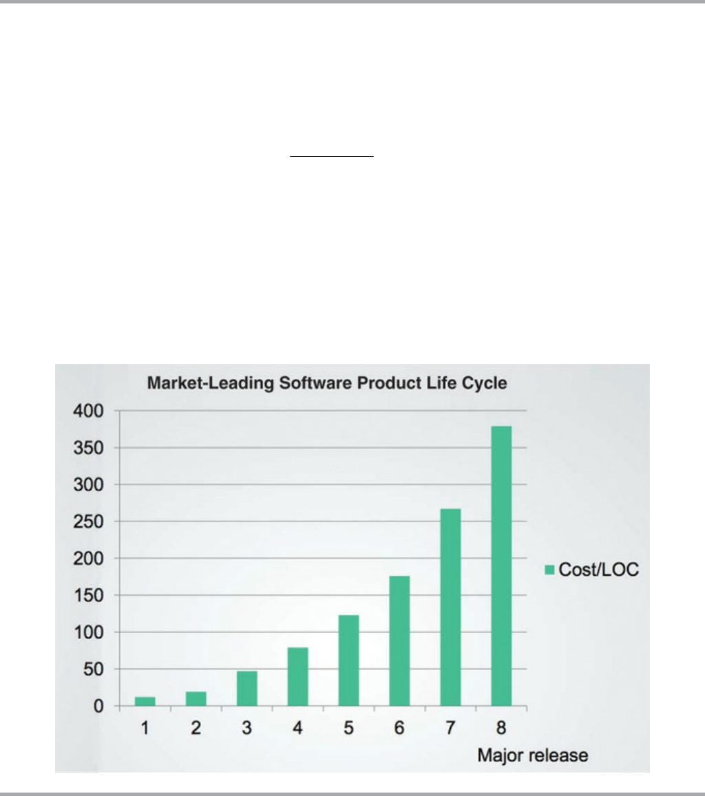
Figure 1.2 Productivity over the same period of time
Clearly something is going wrong here. Even though every release is supported by
an ever-increasing number of developers, the growth of the code looks like it is
approaching an asymptote.
Now here’s the really scary graph: Figure 1.3 shows how the cost per line of code
has changed over time.
These trends aren’t sustainable. It doesn’t matter how profitable the company might
be at the moment: Those curves will catastrophically drain the profit from the
business model and drive the company into a stall, if not into a downright collapse.
What caused this remarkable change in productivity? Why was the code 40 times
more expensive to produce in release 8 as opposed to release 1?
Figure 1.3 Cost per line of code over time
THE SIGNATURE OF A MESS
What you are looking at is the signature of a mess. When systems are thrown
together in a hurry, when the sheer number of programmers is the sole driver of
output, and when little or no thought is given to the cleanliness of the code or the
structure of the design, then you can bank on riding this curve to its ugly end.
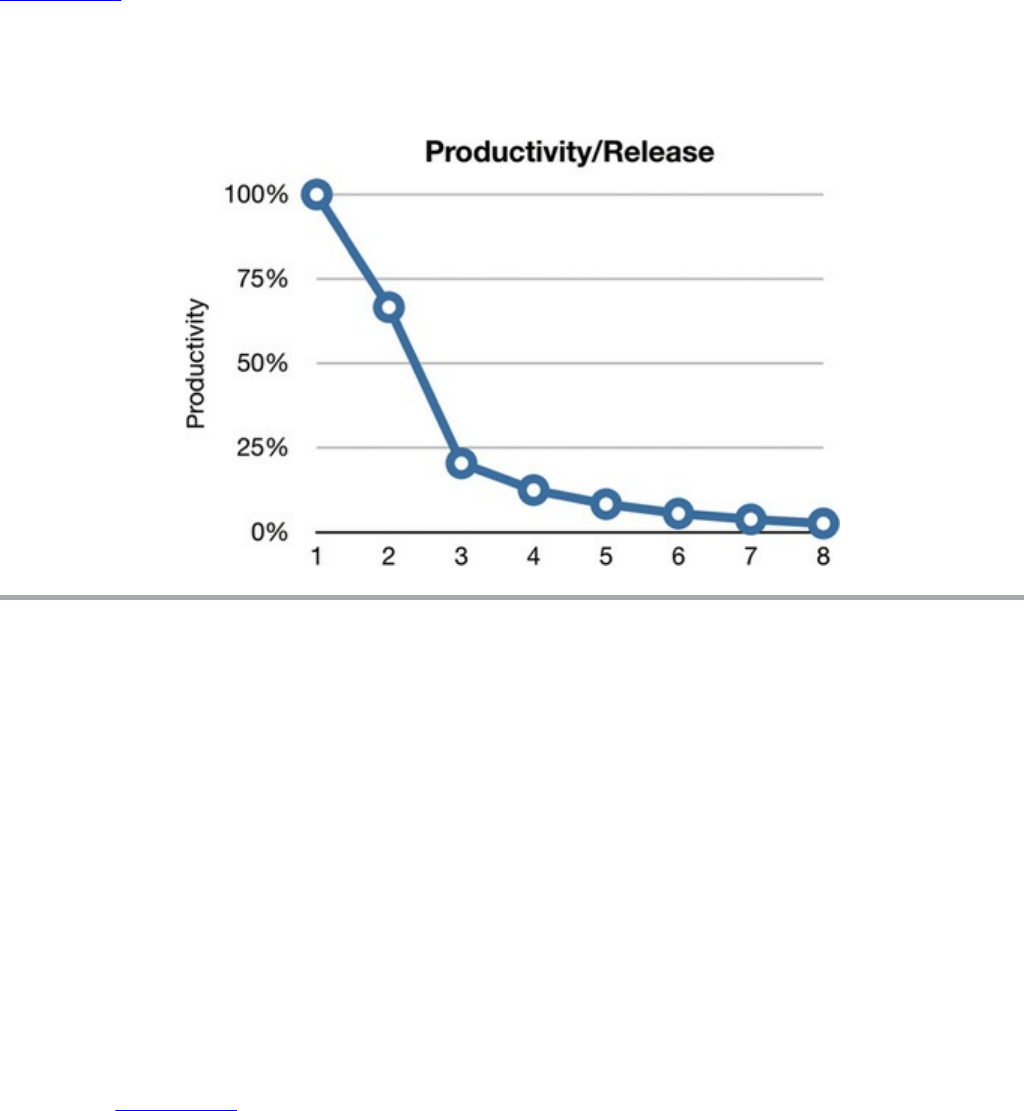
Figure 1.4 shows what this curve looks like to the developers. They started out at
nearly 100% productivity, but with each release their productivity declined. By the
fourth release, it was clear that their productivity was going to bottom out in an
asymptotic approach to zero.
Figure 1.4 Productivity by release
From the developers’ point of view, this is tremendously frustrating, because
everyone is working hard. Nobody has decreased their effort.
And yet, despite all their heroics, overtime, and dedication, they simply aren’t
getting much of anything done anymore. All their effort has been diverted away from
features and is now consumed with managing the mess. Their job, such as it is, has
changed into moving the mess from one place to the next, and the next, and the next,
so that they can add one more meager little feature.
THE EXECUTIVE VIEW
If you think that’s bad, imagine what this picture looks like to the executives!
Consider Figure 1.5, which depicts monthly development payroll for the same
period.
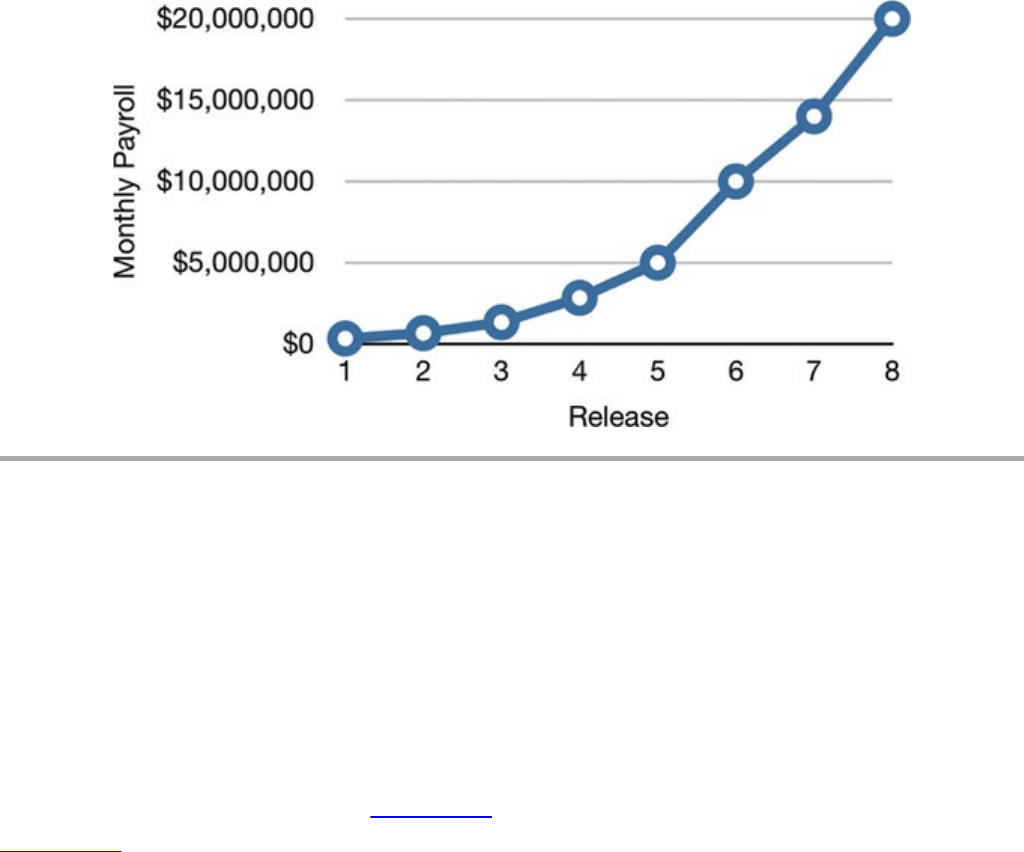
Figure 1.5 Monthly development payroll by release
Release 1 was delivered with a monthly payroll of a few hundred thousand dollars.
The second release cost a few hundred thousand more. By the eighth release monthly
payroll was $20 million, and climbing.
Just this chart alone is scary. Clearly something startling is happening. One hopes
that revenues are outpacing costs and therefore justifying the expense. But no matter
how you look at this curve, it’s cause for concern.
But now compare the curve in Figure 1.5 with the lines of code written per release in
Figure 1.2. That initial few hundred thousand dollars per month bought a lot of
functionality—but the final $20 million bought almost nothing! Any CFO would
look at these two graphs and know that immediate action is necessary to stave off
disaster.
But which action can be taken? What has gone wrong? What has caused this
incredible decline in productivity? What can executives do, other than to stamp their
feet and rage at the developers?
WHAT WENT WRONG?
Nearly 2600 years ago, Aesop told the story of the Tortoise and the Hare. The moral
of that story has been stated many times in many different ways:
• “Slow and steady wins the race.”
• “The race is not to the swift, nor the battle to the strong.”

• “The more haste, the less speed.”
The story itself illustrates the foolishness of overconfidence. The Hare, so confident
in its intrinsic speed, does not take the race seriously, and so naps while the Tortoise
crosses the finish line.
Modern developers are in a similar race, and exhibit a similar overconfidence. Oh,
they don’t sleep—far from it. Most modern developers work their butts off. But a
part of their brain does sleep—the part that knows that good, clean, well-designed
code matters.
These developers buy into a familiar lie: “We can clean it up later; we just have to
get to market first!” Of course, things never do get cleaned up later, because market
pressures never abate. Getting to market first simply means that you’ve now got a
horde of competitors on your tail, and you have to stay ahead of them by running as
fast as you can.
And so the developers never switch modes. They can’t go back and clean things up
because they’ve got to get the next feature done, and the next, and the next, and the
next. And so the mess builds, and productivity continues its asymptotic approach
toward zero.
Just as the Hare was overconfident in its speed, so the developers are overconfident
in their ability to remain productive. But the creeping mess of code that saps their
productivity never sleeps and never relents. If given its way, it will reduce
productivity to zero in a matter of months.
The bigger lie that developers buy into is the notion that writing messy code makes
them go fast in the short term, and just slows them down in the long term.
Developers who accept this lie exhibit the hare’s overconfidence in their ability to
switch modes from making messes to cleaning up messes sometime in the future, but
they also make a simple error of fact. The fact is that making messes is always
slower than staying clean, no matter which time scale you are using.
Consider the results of a remarkable experiment performed by Jason Gorman
depicted in Figure 1.6. Jason conducted this test over a period of six days. Each day
he completed a simple program to convert integers into Roman numerals. He knew
his work was complete when his predefined set of acceptance tests passed. Each day
the task took a little less than 30 minutes. Jason used a well-known cleanliness
discipline named test-driven development (TDD) on the first, third, and fifth days.
On the other three days, he wrote the code without that discipline.
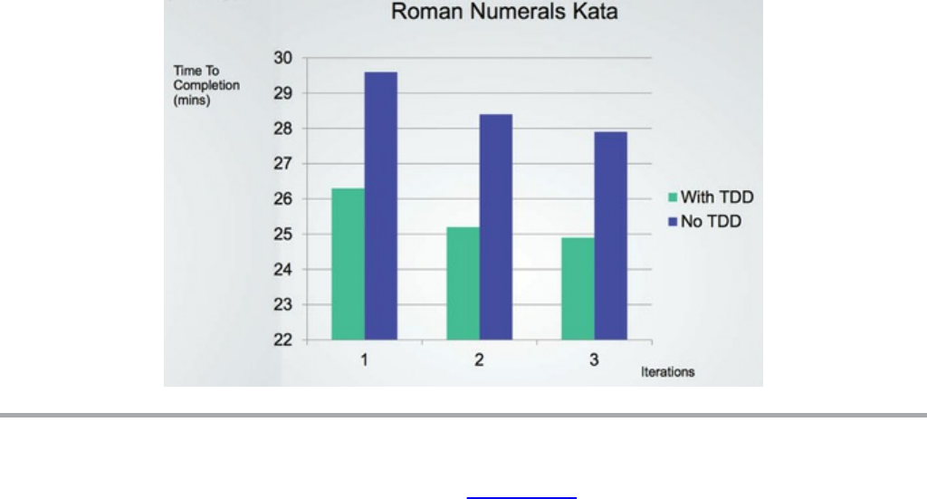
Figure 1.6 Time to completion by iterations and use/non-use of TDD
First, notice the learning curve apparent in Figure 1.6. Work on the latter days is
completed more quickly than the former days. Notice also that work on the TDD
days proceeded approximately 10% faster than work on the non-TDD days, and that
even the slowest TDD day was faster than the fastest non-TDD day.
Some folks might look at that result and think it’s a remarkable outcome. But to
those who haven’t been deluded by the Hare’s overconfidence, the result is expected,
because they know this simple truth of software development:
The only way to go fast, is to go well.
And that’s the answer to the executive’s dilemma. The only way to reverse the
decline in productivity and the increase in cost is to get the developers to stop
thinking like the overconfident Hare and start taking responsibility for the mess that
they’ve made.
The developers may think that the answer is to start over from scratch and redesign
the whole system—but that’s just the Hare talking again. The same overconfidence
that led to the mess is now telling them that they can build it better if only they can
start the race over. The reality is less rosy:
Their overconfidence will drive the redesign into the same mess as the original project.
CONCLUSION
In every case, the best option is for the development organization to recognize and
avoid its own overconfidence and to start taking the quality of its software
architecture seriously.
To take software architecture seriously, you need to know what good software
architecture is. To build a system with a design and an architecture that minimize
effort and maximize productivity, you need to know which attributes of system
architecture lead to that end.
That’s what this book is about. It describes what good clean architectures and
designs look like, so that software developers can build systems that will have long
profitable lifetimes.
2
A TALE OF TWO VALUES
Every software system provides two different values to the stakeholders: behavior
and structure. Software developers are responsible for ensuring that both those
values remain high. Unfortunately, they often focus on one to the exclusion of the
other. Even more unfortunately, they often focus on the lesser of the two values,
leaving the software system eventually valueless.
BEHAVIOR
The first value of software is its behavior. Programmers are hired to make machines
behave in a way that makes or saves money for the stakeholders. We do this by
helping the stakeholders develop a functional specification, or requirements
document. Then we write the code that causes the stakeholder’s machines to satisfy
those requirements.
When the machine violates those requirements, programmers get their debuggers out
and fix the problem.
Many programmers believe that is the entirety of their job. They believe their job is
to make the machine implement the requirements and to fix any bugs. They are sadly
mistaken.
ARCHITECTURE
The second value of software has to do with the word “software”—a compound
word composed of “soft” and “ware.” The word “ware” means “product”; the word
“soft”… Well, that’s where the second value lies.
Software was invented to be “soft.” It was intended to be a way to easily change the
behavior of machines. If we’d wanted the behavior of machines to be hard to change,
we would have called it hardware.
To fulfill its purpose, software must be soft—that is, it must be easy to change.
When the stakeholders change their minds about a feature, that change should be
simple and easy to make. The difficulty in making such a change should be
proportional only to the scope of the change, and not to the shape of the change.
It is this difference between scope and shape that often drives the growth in software
development costs. It is the reason that costs grow out of proportion to the size of the
requested changes. It is the reason that the first year of development is much cheaper
than the second, and the second year is much cheaper than the third.
From the stakeholders’ point of view, they are simply providing a stream of changes
of roughly similar scope. From the developers’ point of view, the stakeholders are
giving them a stream of jigsaw puzzle pieces that they must fit into a puzzle of ever-
increasing complexity. Each new request is harder to fit than the last, because the
shape of the system does not match the shape of the request.
I’m using the word “shape” here in a unconventional way, but I think the metaphor
is apt. Software developers often feel as if they are forced to jam square pegs into
round holes.
The problem, of course, is the architecture of the system. The more this architecture

prefers one shape over another, the more likely new features will be harder and
harder to fit into that structure. Therefore architectures should be as shape agnostic
are practical.
THE GREATER VALUE
Function or architecture? Which of these two provides the greater value? Is it more
important for the software system to work, or is it more important for the software
system to be easy to change?
If you ask the business managers, they’ll often say that it’s more important for the
software system to work. Developers, in turn, often go along with this attitude. But
it’s the wrong attitude. I can prove that it is wrong with the simple logical tool of
examining the extremes.
• If you give me a program that works perfectly but is impossible to change, then it
won’t work when the requirements change, and I won’t be able to make it work.
Therefore the program will become useless.
• If you give me a program that does not work but is easy to change, then I can make
it work, and keep it working as requirements change. Therefore the program will
remain continually useful.
You may not find this argument convincing. After all, there’s no such thing as a
program that is impossible to change. However, there are systems that are practically
impossible to change, because the cost of change exceeds the benefit of change.
Many systems reach that point in some of their features or configurations.
If you ask the business managers if they want to be able to make changes, they’ll say
that of course they do, but may then qualify their answer by noting that the current
functionality is more important than any later flexibility. In contrast, if the business
managers ask you for a change, and your estimated costs for that change are
unaffordably high, the business managers will likely be furious that you allowed the
system to get to the point where the change was impractical.
EISENHOWER’S MATRIX
Consider President Dwight D. Eisenhower’s matrix of importance versus urgency
(Figure 2.1). Of this matrix, Eisenhower said:
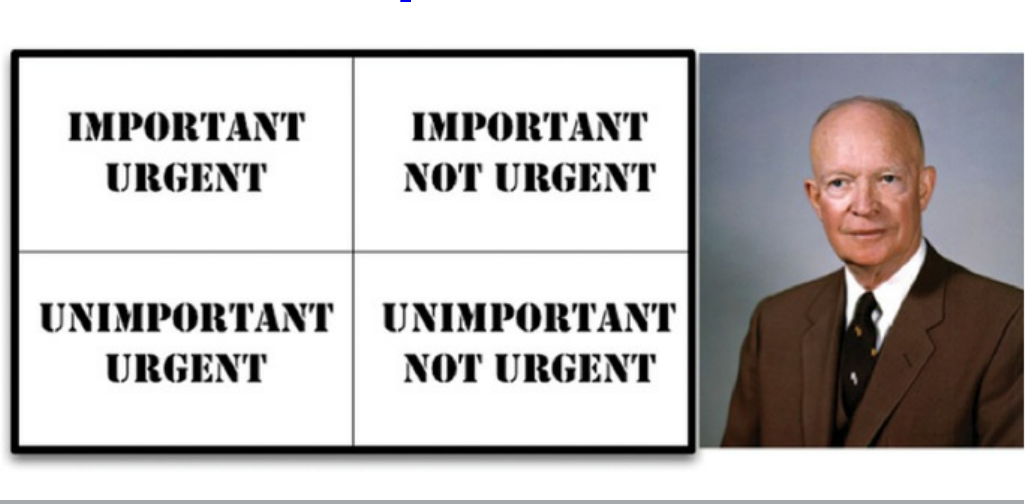
I have two kinds of problems, the urgent and the important. The urgent are not important,
and the important are never urgent.1
Figure 2.1 Eisenhower matrix
There is a great deal of truth to this old adage. Those things that are urgent are rarely
of great importance, and those things that are important are seldom of great urgency.
The first value of software—behavior—is urgent but not always particularly
important.
The second value of software—architecture—is important but never particularly
urgent.
Of course, some things are both urgent and important. Other things are not urgent
and not important. Ultimately, we can arrange these four couplets into priorities:
1. Urgent and important
2. Not urgent and important
3. Urgent and not important
4. Not urgent and not important
Note that the architecture of the code—the important stuff—is in the top two
positions of this list, whereas the behavior of the code occupies the first and third
positions.
The mistake that business managers and developers often make is to elevate items in

position 3 to position 1. In other words, they fail to separate those features that are
urgent but not important from those features that truly are urgent and important. This
failure then leads to ignoring the important architecture of the system in favor of the
unimportant features of the system.
The dilemma for software developers is that business managers are not equipped to
evaluate the importance of architecture. That’s what software developers were hired
to do. Therefore it is the responsibility of the software development team to assert
the importance of architecture over the urgency of features.
FIGHT FOR THE ARCHITECTURE
Fulfilling this responsibility means wading into a fight—or perhaps a better word is
“struggle.” Frankly, that’s always the way these things are done. The development
team has to struggle for what they believe to be best for the company, and so do the
management team, and the marketing team, and the sales team, and the operations
team. It’s always a struggle.
Effective software development teams tackle that struggle head on. They
unabashedly squabble with all the other stakeholders as equals. Remember, as a
software developer, you are a stakeholder. You have a stake in the software that you
need to safeguard. That’s part of your role, and part of your duty. And it’s a big part
of why you were hired.
This challenge is doubly important if you are a software architect. Software
architects are, by virtue of their job description, more focused on the structure of the
system than on its features and functions. Architects create an architecture that
allows those features and functions to be easily developed, easily modified, and
easily extended.
Just remember: If architecture comes last, then the system will become ever more
costly to develop, and eventually change will become practically impossible for part
or all of the system. If that is allowed to happen, it means the software development
team did not fight hard enough for what they knew was necessary.
1. From a speech at Northwestern University in 1954.

II
STARTING WITH THE BRICKS:
PROGRAMMING PARADIGMS
Software architecture begins with the code—and so we will begin our discussion of
architecture by looking at what we’ve learned about code since code was first
written.
In 1938, Alan Turing laid the foundations of what was to become computer
programming. He was not the first to conceive of a programmable machine, but he
was the first to understand that programs were simply data. By 1945, Turing was
writing real programs on real computers in code that we would recognize (if we
squinted enough). Those programs used loops, branches, assignment, subroutines,
stacks, and other familiar structures. Turing’s language was binary.
Since those days, a number of revolutions in programming have occurred. One
revolution with which we are all very familiar is the revolution of languages. First, in
the late 1940s, came assemblers. These “languages” relieved the programmers of the
drudgery of translating their programs into binary. In 1951, Grace Hopper invented
A0, the first compiler. In fact, she coined the term compiler. Fortran was invented in
1953 (the year after I was born). What followed was an unceasing flood of new
programming languages—COBOL, PL/1, SNOBOL, C, Pascal, C++, Java, ad
infinitum.
Another, probably more significant, revolution was in programming paradigms.
Paradigms are ways of programming, relatively unrelated to languages. A paradigm
tells you which programming structures to use, and when to use them. To date, there
have been three such paradigms. For reasons we shall discuss later, there are unlikely
to be any others.
3
PARADIGM OVERVIEW
The three paradigms included in this overview chapter are structured programming,
object-orient programming, and functional programming.
STRUCTURED PROGRAMMING
The first paradigm to be adopted (but not the first to be invented) was structured
programming, which was discovered by Edsger Wybe Dijkstra in 1968. Dijkstra
showed that the use of unrestrained jumps (goto statements) is harmful to program
structure. As we’ll see in the chapters that follow, he replaced those jumps with the
more familiar if/then/else and do/while/until constructs.
We can summarize the structured programming paradigm as follows:
Structured programming imposes discipline on direct transfer of control.
OBJECT-ORIENTED PROGRAMMING
The second paradigm to be adopted was actually discovered two years earlier, in
1966, by Ole Johan Dahl and Kristen Nygaard. These two programmers noticed that
the function call stack frame in the ALGOL language could be moved to a heap,
thereby allowing local variables declared by a function to exist long after the
function returned. The function became a constructor for a class, the local variables
became instance variables, and the nested functions became methods. This led
inevitably to the discovery of polymorphism through the disciplined use of function
pointers.
We can summarize the object-oriented programming paradigm as follows:
Object-oriented programming imposes discipline on indirect transfer of control.
FUNCTIONAL PROGRAMMING
The third paradigm, which has only recently begun to be adopted, was the first to be
invented. Indeed, its invention predates computer programming itself. Functional
programming is the direct result of the work of Alonzo Church, who in 1936
invented l-calculus while pursuing the same mathematical problem that was
motivating Alan Turing at the same time. His l-calculus is the foundation of the LISP
language, invented in 1958 by John McCarthy. A foundational notion of l-calculus is
immutability—that is, the notion that the values of symbols do not change. This
effectively means that a functional language has no assignment statement. Most
functional languages do, in fact, have some means to alter the value of a variable, but
only under very strict discipline.
We can summarize the functional programming paradigm as follows:
Functional programming imposes discipline upon assignment.
FOOD FOR THOUGHT
Notice the pattern that I’ve quite deliberately set up in introducing these three
programming paradigms: Each of the paradigms removes capabilities from the
programmer. None of them adds new capabilities. Each imposes some kind of extra
discipline that is negative in its intent. The paradigms tell us what not to do, more
than they tell us what to do.
Another way to look at this issue is to recognize that each paradigm takes something
away from us. The three paradigms together remove goto statements, function
pointers, and assignment. Is there anything left to take away?
Probably not. Thus these three paradigms are likely to be the only three we will see
—at least the only three that are negative. Further evidence that there are no more
such paradigms is that they were all discovered within the ten years between 1958
and 1968. In the many decades that have followed, no new paradigms have been
added.
CONCLUSION
What does this history lesson on paradigms have to do with architecture?
Everything. We use polymorphism as the mechanism to cross architectural
boundaries; we use functional programming to impose discipline on the location of
and access to data; and we use structured programming as the algorithmic foundation
of our modules.
Notice how well those three align with the three big concerns of architecture:
function, separation of components, and data management.
4
STRUCTURED PROGRAMMING
Edsger Wybe Dijkstra was born in Rotterdam in 1930. He survived the bombing of
Rotterdam during World War II, along with the German occupation of the
Netherlands, and in 1948 graduated from high school with the highest possible
marks in math, physics, chemistry, and biology. In March 1952, at the age of 21 (and
just 9 months before I was born), Dijkstra took a job with the Mathematical Center
of Amsterdam as the Netherlands’ very first programmer.
In 1955, having been a programmer for three years, and while still a student, Dijkstra
concluded that the intellectual challenge of programming was greater than the
intellectual challenge of theoretical physics. As a result, he chose programming as
his long-term career.
In 1957, Dijkstra married Maria Debets. At the time, you had to state your profession
as part of the marriage rites in the Netherlands. The Dutch authorities were unwilling
to accept “programmer” as Dijkstra’s profession; they had never heard of such a
profession. To satisfy them, Dijkstra settled for “theoretical physicist” as his job title.
As part of deciding to make programming his career, Dijkstra conferred with his
boss, Adriaan van Wijngaarden. Dijkstra was concerned that no one had identified a
discipline, or science, of programming, and that he would therefore not be taken
seriously. His boss replied that Dijkstra might very well be one of the people who
would discover such disciplines, thereby evolving software into a science.
Dijkstra started his career in the era of vacuum tubes, when computers were huge,
fragile, slow, unreliable, and (by today’s standards) extremely limited. In those early
years, programs were written in binary, or in very crude assembly language. Input
took the physical form of paper tape or punched cards. The edit/compile/test loop
was hours—if not days—long.
It was in this primitive environment that Dijkstra made his great discoveries.
PROOF
The problem that Dijkstra recognized, early on, was that programming is hard, and
that programmers don’t do it very well. A program of any complexity contains too
many details for a human brain to manage without help. Overlooking just one small
detail results in programs that may seem to work, but fail in surprising ways.
Dijkstra’s solution was to apply the mathematical discipline of proof. His vision was
the construction of a Euclidian hierarchy of postulates, theorems, corollaries, and
lemmas. Dijkstra thought that programmers could use that hierarchy the way
mathematicians do. In other words, programmers would use proven structures, and
tie them together with code that they would then prove correct themselves.
Of course, to get this going, Dijkstra realized that he would have to demonstrate the
technique for writing basic proofs of simple algorithms. This he found to be quite
challenging.
During his investigation, Dijkstra discovered that certain uses of goto statements
prevent modules from being decomposed recursively into smaller and smaller units,
thereby preventing use of the divide-and-conquer approach necessary for reasonable
proofs.
Other uses of goto, however, did not have this problem. Dijkstra realized that these
“good” uses of goto corresponded to simple selection and iteration control structures
such as if/then/else and do/while. Modules that used only those kinds of control
structures could be recursively subdivided into provable units.
Dijkstra knew that those control structures, when combined with sequential
execution, were special. They had been identified two years before by Böhm and
Jacopini, who proved that all programs can be constructed from just three structures:
sequence, selection, and iteration.
This discovery was remarkable: The very control structures that made a module
provable were the same minimum set of control structures from which all programs
can be built. Thus structured programming was born.
Dijkstra showed that sequential statements could be proved correct through simple
enumeration. The technique mathematically traced the inputs of the sequence to the
outputs of the sequence. This approach was no different from any normal
mathematical proof.
Dijkstra tackled selection through reapplication of enumeration. Each path through
the selection was enumerated. If both paths eventually produced appropriate
mathematical results, then the proof was solid.
Iteration was a bit different. To prove an iteration correct, Dijkstra had to use
induction. He proved the case for 1 by enumeration. Then he proved the case that if
N was assumed correct, N + 1 was correct, again by enumeration. He also proved the
starting and ending criteria of the iteration by enumeration.
Such proofs were laborious and complex—but they were proofs. With their
development, the idea that a Euclidean hierarchy of theorems could be constructed
seemed reachable.
A HARMFUL PROCLAMATION
In 1968, Dijkstra wrote a letter to the editor of CACM, which was published in the
March issue. The title of this letter was “Go To Statement Considered Harmful.” The
article outlined his position on the three control structures.
And the programming world caught fire. Back then we didn’t have an Internet, so
people couldn’t post nasty memes of Dijkstra, and they couldn’t flame him online.
But they could, and they did, write letters to the editors of many published journals.
Those letters weren’t necessarily all polite. Some were intensely negative; others
voiced strong support for his position. And so the battle was joined, ultimately to last
about a decade.
Eventually the argument petered out. The reason was simple: Dijkstra had won. As
computer languages evolved, the goto statement moved ever rearward, until it all but
disappeared. Most modern languages do not have a goto statement—and, of course,
LISP never did.
Nowadays we are all structured programmers, though not necessarily by choice. It’s
just that our languages don’t give us the option to use undisciplined direct transfer of
control.
Some may point to named breaks in Java or exceptions as goto analogs. In fact,
these structures are not the utterly unrestricted transfers of control that older
languages like Fortran or COBOL once had. Indeed, even languages that still support
the goto keyword often restrict the target to within the scope of the current function.
FUNCTIONAL DECOMPOSITION
Structured programming allows modules to be recursively decomposed into provable
units, which in turn means that modules can be functionally decomposed. That is,
you can take a large-scale problem statement and decompose it into high-level
functions. Each of those functions can then be decomposed into lower-level
functions, ad infinitum. Moreover, each of those decomposed functions can be
represented using the restricted control structures of structured programming.
Building on this foundation, disciplines such as structured analysis and structured
design became popular in the late 1970s and throughout the 1980s. Men like Ed
Yourdon, Larry Constantine, Tom DeMarco, and Meilir Page-Jones promoted and
popularized these techniques throughout that period. By following these disciplines,
programmers could break down large proposed systems into modules and
components that could be further broken down into tiny provable functions.
NO FORMAL PROOFS
But the proofs never came. The Euclidean hierarchy of theorems was never built.
And programmers at large never saw the benefits of working through the laborious
process of formally proving each and every little function correct. In the end,
Dijkstra’s dream faded and died. Few of today’s programmers believe that formal
proofs are an appropriate way to produce high-quality software.
Of course, formal, Euclidian style, mathematical proofs are not the only strategy for
proving something correct. Another highly successful strategy is the scientific
method.
SCIENCE TO THE RESCUE
Science is fundamentally different from mathematics, in that scientific theories and
laws cannot be proven correct. I cannot prove to you that Newton’s second law of
motion, F = ma, or law of gravity, F = Gm1m2/r2, are correct. I can demonstrate these
laws to you, and I can make measurements that show them correct to many decimal
places, but I cannot prove them in the sense of a mathematical proof. No matter how
many experiments I conduct or how much empirical evidence I gather, there is
always the chance that some experiment will show that those laws of motion and
gravity are incorrect.
That is the nature of scientific theories and laws: They are falsifiable but not
provable.
And yet we bet our lives on these laws every day. Every time you get into a car, you
bet your life that F = ma is a reliable description of the way the world works. Every
time you take a step, you bet your health and safety that F = Gm1m2/r2 is correct.
Science does not work by proving statements true, but rather by proving statements
false. Those statements that we cannot prove false, after much effort, we deem to be
true enough for our purposes.
Of course, not all statements are provable. The statement “This is a lie” is neither
true nor false. It is one of the simplest examples of a statement that is not provable.
Ultimately, we can say that mathematics is the discipline of proving provable
statements true. Science, in contrast, is the discipline of proving provable statements
false.
TESTS
Dijkstra once said, “Testing shows the presence, not the absence, of bugs.” In other
words, a program can be proven incorrect by a test, but it cannot be proven correct.
All that tests can do, after sufficient testing effort, is allow us to deem a program to
be correct enough for our purposes.
The implications of this fact are stunning. Software development is not a
mathematical endeavor, even though it seems to manipulate mathematical constructs.
Rather, software is like a science. We show correctness by failing to prove
incorrectness, despite our best efforts.
Such proofs of incorrectness can be applied only to provable programs. A program
that is not provable—due to unrestrained use of goto, for example—cannot be
deemed correct no matter how many tests are applied to it.
Structured programming forces us to recursively decompose a program into a set of
small provable functions. We can then use tests to try to prove those small provable
functions incorrect. If such tests fail to prove incorrectness, then we deem the
functions to be correct enough for our purposes.
CONCLUSION
It is this ability to create falsifiable units of programming that makes structured
programming valuable today. This is the reason that modern languages do not
typically support unrestrained goto statements. Moreover, at the architectural level,
this is why we still consider functional decomposition to be one of our best practices.
At every level, from the smallest function to the largest component, software is like a
science and, therefore, is driven by falsifiability. Software architects strive to define
modules, components, and services that are easily falsifiable (testable). To do so,
they employ restrictive disciplines similar to structured programming, albeit at a
much higher level.
It is those restrictive disciplines that we will study in some detail in the chapters to
come.
5
OBJECT-ORIENTED PROGRAMMING
As we will see, the basis of a good architecture is the understanding and application
of the principles of object-oriented design (OO). But just what is OO?
One answer to this question is “The combination of data and function.” Although
often cited, this is a very unsatisfying answer because it implies that o.f() is
somehow different from f(o). This is absurd. Programmers were passing data
structures into functions long before 1966, when Dahl and Nygaard moved the
function call stack frame to the heap and invented OO.
Another common answer to this question is “A way to model the real world.” This is
an evasive answer at best. What does “modeling the real world” actually mean, and
why is it something we would want to do? Perhaps this statement is intended to
imply that OO makes software easier to understand because it has a closer

relationship to the real world—but even that statement is evasive and too loosely
defined. It does not tell us what OO is.
Some folks fall back on three magic words to explain the nature of OO:
encapsulation, inheritance, and polymorphism. The implication is that OO is the
proper admixture of these three things, or at least that an OO language must support
these three things.
Let’s examine each of these concepts in turn.
ENCAPSULATION?
The reason encapsulation is cited as part of the definition of OO is that OO
languages provide easy and effective encapsulation of data and function. As a result,
a line can be drawn around a cohesive set of data and functions. Outside of that line,
the data is hidden and only some of the functions are known. We see this concept in
action as the private data members and the public member functions of a class.
This idea is certainly not unique to OO. Indeed, we had perfect encapsulation in C.
Consider this simple C program:
Click here to view code image
point.h
struct Point;
struct Point* makePoint(double x, double y);
double distance (struct Point *p1, struct Point *p2);
Click here to view code image
point.c
#include "point.h"
#include <stdlib.h>
#include <math.h>
struct Point {
double x,y;
};
struct Point* makepoint(double x, double y) {
struct Point* p = malloc(sizeof(struct Point));
p->x = x;
p->y = y;
return p;
}
double distance(struct Point* p1, struct Point* p2) {
double dx = p1->x - p2->x;
double dy = p1->y - p2->y;
return sqrt(dx*dx+dy*dy);
}
The users of point.h have no access whatsoever to the members of struct Point.
They can call the makePoint() function, and the distance() function, but they have
absolutely no knowledge of the implementation of either the Point data structure or
the functions.
This is perfect encapsulation—in a non-OO language. C programmers used to do this
kind of thing all the time. We would forward declare data structures and functions in
header files, and then implement them in implementation files. Our users never had
access to the elements in those implementation files.
But then came OO in the form of C++—and the perfect encapsulation of C was
broken.
The C++ compiler, for technical reasons,1 needed the member variables of a class to
be declared in the header file of that class. So our Point program changed to look
like this:
Click here to view code image
point.h
class Point {
public:
Point(double x, double y);
double distance(const Point& p) const;
private:
double x;
double y;
};
Click here to view code image

point.cc
#include "point.h"
#include <math.h>
Point::Point(double x, double y)
: x(x), y(y)
{}
double Point::distance(const Point& p) const {
double dx = x-p.x;
double dy = y-p.y;
return sqrt(dx*dx + dy*dy);
}
Clients of the header file point.h know about the member variables x and y! The
compiler will prevent access to them, but the client still knows they exist. For
example, if those member names are changed, the point.cc file must be recompiled!
Encapsulation has been broken.
Indeed, the way encapsulation is partially repaired is by introducing the public,
private, and protected keywords into the language. This, however, was a hack
necessitated by the technical need for the compiler to see those variables in the
header file.
Java and C# simply abolished the header/implementation split altogether, thereby
weakening encapsulation even more. In these languages, it is impossible to separate
the declaration and definition of a class.
For these reasons, it is difficult to accept that OO depends on strong encapsulation.
Indeed, many OO languages2 have little or no enforced encapsulation.
OO certainly does depend on the idea that programmers are well-behaved enough to
not circumvent encapsulated data. Even so, the languages that claim to provide OO
have only weakened the once perfect encapsulation we enjoyed with C.
INHERITANCE?
If OO languages did not give us better encapsulation, then they certainly gave us
inheritance.

Well—sort of. Inheritance is simply the redeclaration of a group of variables and
functions within an enclosing scope. This is something C programmers3 were able to
do manually long before there was an OO language.
Consider this addition to our original point.h C program:
Click here to view code image
namedPoint.h
struct NamedPoint;
struct NamedPoint* makeNamedPoint(double x, double y, char* name);
void setName(struct NamedPoint* np, char* name);
char* getName(struct NamedPoint* np);
Click here to view code image
namedPoint.c
#include "namedPoint.h"
#include <stdlib.h>
struct NamedPoint {
double x,y;
char* name;
};
struct NamedPoint* makeNamedPoint(double x, double y, char* name)
{
struct NamedPoint* p = malloc(sizeof(struct NamedPoint));
p->x = x;
p->y = y;
p->name = name;
return p;
}
void setName(struct NamedPoint* np, char* name) {
np->name = name;
}
char* getName(struct NamedPoint* np) {
return np->name;
}
Click here to view code image

main.c
#include "point.h"
#include "namedPoint.h"
#include <stdio.h>
int main(int ac, char** av) {
struct NamedPoint* origin = makeNamedPoint(0.0, 0.0, "origin");
struct NamedPoint* upperRight = makeNamedPoint (1.0, 1.0,
"upperRight");
printf("distance=%f\n",
distance(
(struct Point*) origin,
(struct Point*) upperRight));
}
If you look carefully at the main program, you’ll see that the NamedPoint data
structure acts as though it is a derivative of the Point data structure. This is because
the order of the first two fields in NamedPoint is the same as Point. In short,
NamedPoint can masquerade as Point because NamedPoint is a pure superset of
Point and maintains the ordering of the members that correspond to Point.
This kind of trickery was a common practice4 of programmers prior to the advent of
OO. In fact, such trickery is how C++ implements single inheritance.
Thus we might say that we had a kind of inheritance long before OO languages were
invented. That statement wouldn’t quite be true, though. We had a trick, but it’s not
nearly as convenient as true inheritance. Moreover, multiple inheritance is a
considerably more difficult to achieve by such trickery.
Note also that in main.c, I was forced to cast the NamedPoint arguments to Point. In
a real OO language, such upcasting would be implicit.
It’s fair to say that while OO languages did not give us something completely brand
new, it did make the masquerading of data structures significantly more convenient.
To recap: We can award no point to OO for encapsulation, and perhaps a half-point
for inheritance. So far, that’s not such a great score.
But there’s one more attribute to consider.

POLYMORPHISM?
Did we have polymorphic behavior before OO languages? Of course we did.
Consider this simple C copy program.
Click here to view code image
#include <stdio.h>
void copy() {
int c;
while ((c=getchar()) != EOF)
putchar(c);
}
The function getchar() reads from STDIN. But which device is STDIN? The
putchar() function writes to STDOUT. But which device is that? These functions are
polymorphic—their behavior depends on the type of STDIN and STDOUT.
It’s as though STDIN and STDOUT are Java-style interfaces that have implementations
for each device. Of course, there are no interfaces in the example C program—so
how does the call to getchar() actually get delivered to the device driver that reads
the character?
The answer to that question is pretty straightforward. The UNIX operating system
requires that every IO device driver provide five standard functions:5 open, close,
read, write, and seek. The signatures of those functions must be identical for every
IO driver.
The FILE data structure contains five pointers to functions. In our example, it might
look like this:
Click here to view code image
struct FILE {
void (*open)(char* name, int mode);
void (*close)();
int (*read)();
void (*write)(char);
void (*seek)(long index, int mode);
};

The IO driver for the console will define those functions and load up a FILE data
structure with their addresses—something like this:
Click here to view code image
#include "file.h"
void open(char* name, int mode) {/*...*/}
void close() {/*...*/};
int read() {int c;/*...*/ return c;}
void write(char c) {/*...*/}
void seek(long index, int mode) {/*...*/}
struct FILE console = {open, close, read, write, seek};
Now if STDIN is defined as a FILE*, and if it points to the console data structure, then
getchar() might be implemented this way:
Click here to view code image
extern struct FILE* STDIN;
int getchar() {
return STDIN->read();
}
In other words, getchar() simply calls the function pointed to by the read pointer of
the FILE data structure pointed to by STDIN.
This simple trick is the basis for all polymorphism in OO. In C++, for example,
every virtual function within a class has a pointer in a table called a vtable, and all
calls to virtual functions go through that table. Constructors of derivatives simply
load their versions of those functions into the vtable of the object being created.
The bottom line is that polymorphism is an application of pointers to functions.
Programmers have been using pointers to functions to achieve polymorphic behavior
since Von Neumann architectures were first implemented in the late 1940s. In other
words, OO has provided nothing new.
Ah, but that’s not quite correct. OO languages may not have given us polymorphism,
but they have made it much safer and much more convenient.
The problem with explicitly using pointers to functions to create polymorphic

behavior is that pointers to functions are dangerous. Such use is driven by a set of
manual conventions. You have to remember to follow the convention to initialize
those pointers. You have to remember to follow the convention to call all your
functions through those pointers. If any programmer fails to remember these
conventions, the resulting bug can be devilishly hard to track down and eliminate.
OO languages eliminate these conventions and, therefore, these dangers. Using an
OO language makes polymorphism trivial. That fact provides an enormous power
that old C programmers could only dream of. On this basis, we can conclude that OO
imposes discipline on indirect transfer of control.
THE POWER OF POLYMORPHISM
What’s so great about polymorphism? To better appreciate its charms, let’s
reconsider the example copy program. What happens to that program if a new IO
device is created? Suppose we want to use the copy program to copy data from a
handwriting recognition device to a speech synthesizer device: How do we need to
change the copy program to get it to work with those new devices?
We don’t need any changes at all! Indeed, we don’t even need to recompile the copy
program. Why? Because the source code of the copy program does not depend on
the source code of the IO drivers. As long as those IO drivers implement the five
standard functions defined by FILE, the copy program will be happy to use them.
In short, the IO devices have become plugins to the copy program.
Why did the UNIX operating system make IO devices plugins? Because we learned,
in the late 1950s, that our programs should be device independent. Why? Because we
wrote lots of programs that were device dependent, only to discover that we really
wanted those programs to do the same job but use a different device.
For example, we often wrote programs that read input data from decks of cards,6 and
then punched new decks of cards as output. Later, our customers stopped giving us
decks of cards and started giving us reels of magnetic tape. This was very
inconvenient, because it meant rewriting large portions of the original program. It
would be very convenient if the same program worked interchangeably with cards or
tape.
The plugin architecture was invented to support this kind of IO device independence,
and has been implemented in almost every operating system since its introduction.
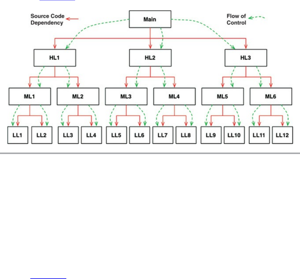
Even so, most programmers did not extend the idea to their own programs, because
using pointers to functions was dangerous.
OO allows the plugin architecture to be used anywhere, for anything.
DEPENDENCY INVERSION
Imagine what software was like before a safe and convenient mechanism for
polymorphism was available. In the typical calling tree, main functions called high-
level functions, which called mid-level functions, which called low-level functions.
In that calling tree, however, source code dependencies inexorably followed the flow
of control (Figure 5.1).
Figure 5.1 Source code dependencies versus flow of control
For main to call one of the high-level functions, it had to mention the name of the
module that contained that function In C, this was a #include. In Java, it was an
import statement. In C#, it was a using statement. Indeed, every caller was forced to
mention the name of the module that contained the callee.
This requirement presented the software architect with few, if any, options. The flow
of control was dictated by the behavior of the system, and the source code
dependencies were dictated by that flow of control.
When polymorphism is brought into play, however, something very different can
happen (Figure 5.2).
Figure 5.2 Dependency inversion
In Figure 5.2, module HL1 calls the F() function in module ML1. The fact that it calls
this function through an interface is a source code contrivance. At runtime, the
interface doesn’t exist. HL1 simply calls F() within ML1.7
Note, however, that the source code dependency (the inheritance relationship)
between ML1 and the interface I points in the opposite direction compared to the flow
of control. This is called dependency inversion, and its implications for the software
architect are profound.
The fact that OO languages provide safe and convenient polymorphism means that
any source code dependency, no matter where it is, can be inverted.
Now look back at that calling tree in Figure 5.1, and its many source code
dependencies. Any of those source code dependencies can be turned around by
inserting an interface between them.
With this approach, software architects working in systems written in OO languages
have absolute control over the direction of all source code dependencies in the
system. They are not constrained to align those dependencies with the flow of
control. No matter which module does the calling and which module is called, the
software architect can point the source code dependency in either direction.
That is power! That is the power that OO provides. That’s what OO is really all
about—at least from the architect’s point of view.
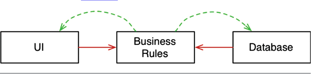
What can you do with that power? As an example, you can rearrange the source code
dependencies of your system so that the database and the user interface (UI) depend
on the business rules (Figure 5.3), rather than the other way around.
Figure 5.3 The database and the user interface depend on the business rules
This means that the UI and the database can be plugins to the business rules. It
means that the source code of the business rules never mentions the UI or the
database.
As a consequence, the business rules, the UI, and the database can be compiled into
three separate components or deployment units (e.g., jar files, DLLs, or Gem files)
that have the same dependencies as the source code. The component containing the
business rules will not depend on the components containing the UI and database.
In turn, the business rules can be deployed independently of the UI and the database.
Changes to the UI or the database need not have any effect on the business rules.
Those components can be deployed separately and independently.
In short, when the source code in a component changes, only that component needs
to be redeployed. This is independent deployability.
If the modules in your system can be deployed independently, then they can be
developed independently by different teams. That’s independent developability.
CONCLUSION
What is OO? There are many opinions and many answers to this question. To the
software architect, however, the answer is clear: OO is the ability, through the use of
polymorphism, to gain absolute control over every source code dependency in the
system. It allows the architect to create a plugin architecture, in which modules that
contain high-level policies are independent of modules that contain low-level details.
The low-level details are relegated to plugin modules that can be deployed and
developed independently from the modules that contain high-level policies.

1. The C++ compiler needs to know the size of the instances of each class.
2. For example, Smalltalk, Python, JavaScript, Lua, and Ruby.
3. Not just C programmers: Most languages of that era had the capability to masquerade one data
structure as another.
4. Indeed it still is.
5. UNIX systems vary; this is just an example.
6. Punched cards—IBM Hollerith cards, 80 columns wide. I’m sure many of you have never even
seen one of these, but they were commonplace in the 1950s, 1960s, and even 1970s.
7. Albeit indirectly.
6
FUNCTIONAL PROGRAMMING
In many ways, the concepts of functional programming predate programming itself.
This paradigm is strongly based on the l-calculus invented by Alonzo Church in the
1930s.
SQUARES OF INTEGERS
To explain what functional programming is, it’s best to examine some examples.
Let’s investigate a simple problem: printing the squares of the first 25 integers.
In a language like Java, we might write the following:
Click here to view code image

public class Squint {
public static void main(String args[]) {
for (int i=0; i<25; i++)
System.out.println(i*i);
}
}
In a language like Clojure, which is a derivative of Lisp, and is functional, we might
implement this same program as follows:
Click here to view code image
(println (take 25 (map (fn [x] (* x x)) (range))))
If you don’t know Lisp, then this might look a little strange. So let me reformat it a
bit and add some comments.
Click here to view code image
(println ;___________________ Print
(take 25 ;_________________ the first 25
(map (fn [x] (* x x)) ;__ squares
(range)))) ;___________ of Integers
It should be clear that println, take, map, and range are all functions. In Lisp, you
call a function by putting it in parentheses. For example, (range) calls the range
function.
The expression (fn [x] (* x x)) is an anonymous function that calls the multiply
function, passing its input argument in twice. In other words, it computes the square
of its input.
Looking at the whole thing again, it’s best to start with the innermost function call.
• The range function returns a never-ending list of integers starting with 0.
• This list is passed into the map function, which calls the anonymous squaring
function on each element, producing a new never-ending list of all the squares.
• The list of squares is passed into the take function, which returns a new list with
only the first 25 elements.
• The println function prints its input, which is a list of the first 25 squares of
integers.
If you find yourself terrified by the concept of never-ending lists, don’t worry. Only
the first 25 elements of those never-ending lists are actually created. That’s because
no element of a never-ending list is evaluated until it is accessed.
If you found all of that confusing, then you can look forward to a glorious time
learning all about Clojure and functional programming. It is not my goal to teach you
about these topics here.
Instead, my goal here is to point out something very dramatic about the difference
between the Clojure and Java programs. The Java program uses a mutable variable
—a variable that changes state during the execution of the program. That variable is
i—the loop control variable. No such mutable variable exists in the Clojure
program. In the Clojure program, variables like x are initialized, but they are never
modified.
This leads us to a surprising statement: Variables in functional languages do not
vary.
IMMUTABILITY AND ARCHITECTURE
Why is this point important as an architectural consideration? Why would an
architect be concerned with the mutability of variables? The answer is absurdly
simple: All race conditions, deadlock conditions, and concurrent update problems are
due to mutable variables. You cannot have a race condition or a concurrent update
problem if no variable is ever updated. You cannot have deadlocks without mutable
locks.
In other words, all the problems that we face in concurrent applications—all the
problems we face in applications that require multiple threads, and multiple
processors—cannot happen if there are no mutable variables.
As an architect, you should be very interested in issues of concurrency. You want to
make sure that the systems you design will be robust in the presence of multiple
threads and processors. The question you must be asking yourself, then, is whether
immutability is practicable.
The answer to that question is affirmative, if you have infinite storage and infinite
processor speed. Lacking those infinite resources, the answer is a bit more nuanced.
Yes, immutability can be practicable, if certain compromises are made.
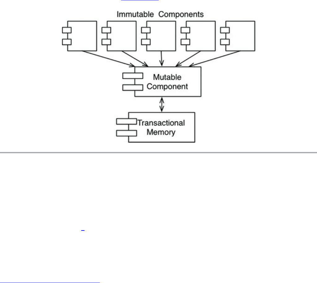
Let’s look at some of those compromises.
SEGREGATION OF MUTABILITY
One of the most common compromises in regard to immutability is to segregate the
application, or the services within the application, into mutable and immutable
components. The immutable components perform their tasks in a purely functional
way, without using any mutable variables. The immutable components communicate
with one or more other components that are not purely functional, and allow for the
state of variables to be mutated (Figure 6.1).
Figure 6.1 Mutating state and transactional memory
Since mutating state exposes those components to all the problems of concurrency, it
is common practice to use some kind of transactional memory to protect the mutable
variables from concurrent updates and race conditions.
Transactional memory simply treats variables in memory the same way a database
treats records on disk.1 It protects those variables with a transaction- or retry-based
scheme.
A simple example of this approach is Clojure’s atom facility:
Click here to view code image
(def counter (atom 0)) ; initialize counter to 0
(swap! counter inc) ; safely increment counter.
In this code, the counter variable is defined as an atom. In Clojure, an atom is a
special kind of variable whose value is allowed to mutate under very disciplined
conditions that are enforced by the swap! function.
The swap! function, shown in the preceding code, takes two arguments: the atom to
be mutated, and a function that computes the new value to be stored in the atom. In
our example code, the counter atom will be changed to the value computed by the
inc function, which simply increments its argument.
The strategy used by swap! is a traditional compare and swap algorithm. The value
of counter is read and passed to inc. When inc returns, the value of counter is
locked and compared to the value that was passed to inc. If the value is the same,
then the value returned by inc is stored in counter and the lock is released.
Otherwise, the lock is released, and the strategy is retried from the beginning.
The atom facility is adequate for simple applications. Unfortunately, it cannot
completely safeguard against concurrent updates and deadlocks when multiple
dependent variables come into play. In those instances, more elaborate facilities can
be used.
The point is that well-structured applications will be segregated into those
components that do not mutate variables and those that do. This kind of segregation
is supported by the use of appropriate disciplines to protect those mutated variables.
Architects would be wise to push as much processing as possible into the immutable
components, and to drive as much code as possible out of those components that
must allow mutation.
EVENT SOURCING
The limits of storage and processing power have been rapidly receding from view.
Nowadays it is common for processors to execute billions of instructions per second
and to have billions of bytes of RAM. The more memory we have, and the faster our
machines are, the less we need mutable state.
As a simple example, imagine a banking application that maintains the account
balances of its customers. It mutates those balances when deposit and withdrawal

transactions are executed.
Now imagine that instead of storing the account balances, we store only the
transactions. Whenever anyone wants to know the balance of an account, we simply
add up all the transactions for that account, from the beginning of time. This scheme
requires no mutable variables.
Obviously, this approach sounds absurd. Over time, the number of transactions
would grow without bound, and the processing power required to compute the totals
would become intolerable. To make this scheme work forever, we would need
infinite storage and infinite processing power.
But perhaps we don’t have to make the scheme work forever. And perhaps we have
enough storage and enough processing power to make the scheme work for the
reasonable lifetime of the application.
This is the idea behind event sourcing.2 Event sourcing is a strategy wherein we
store the transactions, but not the state. When state is required, we simply apply all
the transactions from the beginning of time.
Of course, we can take shortcuts. For example, we can compute and save the state
every midnight. Then, when the state information is required, we need compute only
the transactions since midnight.
Now consider the data storage required for this scheme: We would need a lot of it.
Realistically, offline data storage has been growing so fast that we now consider
trillions of bytes to be small—so we have a lot of it.
More importantly, nothing ever gets deleted or updated from such a data store. As a
consequence, our applications are not CRUD; they are just CR. Also, because neither
updates nor deletions occur in the data store, there cannot be any concurrent update
issues.
If we have enough storage and enough processor power, we can make our
applications entirely immutable—and, therefore, entirely functional.
If this still sounds absurd, it might help if you remembered that this is precisely the
way your source code control system works.
CONCLUSION

To summarize:
• Structured programming is discipline imposed upon direct transfer of control.
• Object-oriented programming is discipline imposed upon indirect transfer of
control.
• Functional programming is discipline imposed upon variable assignment.
Each of these three paradigms has taken something away from us. Each restricts
some aspect of the way we write code. None of them has added to our power or our
capabilities.
What we have learned over the last half-century is what not to do.
With that realization, we have to face an unwelcome fact: Software is not a rapidly
advancing technology. The rules of software are the same today as they were in
1946, when Alan Turing wrote the very first code that would execute in an electronic
computer. The tools have changed, and the hardware has changed, but the essence of
software remains the same.
Software—the stuff of computer programs—is composed of sequence, selection,
iteration, and indirection. Nothing more. Nothing less.
1. I know... What’s a disk?
2. Thanks to Greg Young for teaching me about this concept.
III
DESIGN PRINCIPLES
Good software systems begin with clean code. On the one hand, if the bricks aren’t
well made, the architecture of the building doesn’t matter much. On the other hand,
you can make a substantial mess with well-made bricks. This is where the SOLID
principles come in.
The SOLID principles tell us how to arrange our functions and data structures into
classes, and how those classes should be interconnected. The use of the word “class”
does not imply that these principles are applicable only to object-oriented software.
A class is simply a coupled grouping of functions and data. Every software system
has such groupings, whether they are called classes or not. The SOLID principles
apply to those groupings.
The goal of the principles is the creation of mid-level software structures that:
• Tolerate change,
• Are easy to understand, and
• Are the basis of components that can be used in many software systems.
The term “mid-level” refers to the fact that these principles are applied by
programmers working at the module level. They are applied just above the level of
the code and help to define the kinds of software structures used within modules and
components.
Just as it is possible to create a substantial mess with well-made bricks, so it is also
possible to create a system-wide mess with well-designed mid-level components. For
this reason, once we have covered the SOLID principles, we will move on to their
counterparts in the component world, and then to the principles of high-level
architecture.
The history of the SOLID principles is long. I began to assemble them in the late
1980s while debating software design principles with others on USENET (an early
kind of Facebook). Over the years, the principles have shifted and changed. Some
were deleted. Others were merged. Still others were added. The final grouping
stabilized in the early 2000s, although I presented them in a different order.
In 2004 or thereabouts, Michael Feathers sent me an email saying that if I rearranged
the principles, their first words would spell the word SOLID—and thus the SOLID
principles were born.
The chapters that follow describe each principle more thoroughly. Here is the
executive summary:
• SRP: The Single Responsibility Principle
An active corollary to Conway’s law: The best structure for a software system is
heavily influenced by the social structure of the organization that uses it so that
each software module has one, and only one, reason to change.
• OCP: The Open-Closed Principle
Bertrand Meyer made this principle famous in the 1980s. The gist is that for
software systems to be easy to change, they must be designed to allow the behavior
of those systems to be changed by adding new code, rather than changing existing
code.
• LSP: The Liskov Substitution Principle
Barbara Liskov’s famous definition of subtypes, from 1988. In short, this principle
says that to build software systems from interchangeable parts, those parts must
adhere to a contract that allows those parts to be substituted one for another.
• ISP: The Interface Segregation Principle
This principle advises software designers to avoid depending on things that they
don’t use.
• DIP: The Dependency Inversion Principle
The code that implements high-level policy should not depend on the code that
implements low-level details. Rather, details should depend on policies.
These principles have been described in detail in many different publications1 over
the years. The chapters that follow will focus on the architectural implications of
these principles instead of repeating those detailed discussions. If you are not already
familiar with these principles, what follows is insufficient to understand them in
detail and you would be well advised to study them in the footnoted documents.
1. For example, Agile Software Development, Principles, Patterns, and Practices, Robert C. Martin,
Prentice Hall, 2002, http://www.butunclebob.com/ArticleS.UncleBob.PrinciplesOfOod, and
https://en.wikipedia.org/wiki/SOLID_(object-oriented_design) (or just google SOLID).
7
SRP: THE SINGLE RESPONSIBILITY
PRINCIPLE
Of all the SOLID principles, the Single Responsibility Principle (SRP) might be the
least well understood. That’s likely because it has a particularly inappropriate name.
It is too easy for programmers to hear the name and then assume that it means that
every module should do just one thing.
Make no mistake, there is a principle like that. A function should do one, and only
one, thing. We use that principle when we are refactoring large functions into
smaller functions; we use it at the lowest levels. But it is not one of the SOLID
principles—it is not the SRP.
Historically, the SRP has been described this way:

A module should have one, and only one, reason to change.
Software systems are changed to satisfy users and stakeholders; those users and
stakeholders are the “reason to change” that the principle is talking about. Indeed,
we can rephrase the principle to say this:
A module should be responsible to one, and only one, user or stakeholder.
Unfortunately, the words “user” and “stakeholder” aren’t really the right words to
use here. There will likely be more than one user or stakeholder who wants the
system changed in the same way. Instead, we’re really referring to a group—one or
more people who require that change. We’ll refer to that group as an actor.
Thus the final version of the SRP is:
A module should be responsible to one, and only one, actor.
Now, what do we mean by the word “module”? The simplest definition is just a
source file. Most of the time that definition works fine. Some languages and
development environments, though, don’t use source files to contain their code. In
those cases a module is just a cohesive set of functions and data structures.
That word “cohesive” implies the SRP. Cohesion is the force that binds together the
code responsible to a single actor.
Perhaps the best way to understand this principle is by looking at the symptoms of
violating it.
SYMPTOM 1: ACCIDENTAL DUPLICATION
My favorite example is the Employee class from a payroll application. It has three
methods: calculatePay(), reportHours(), and save() (Figure 7.1).
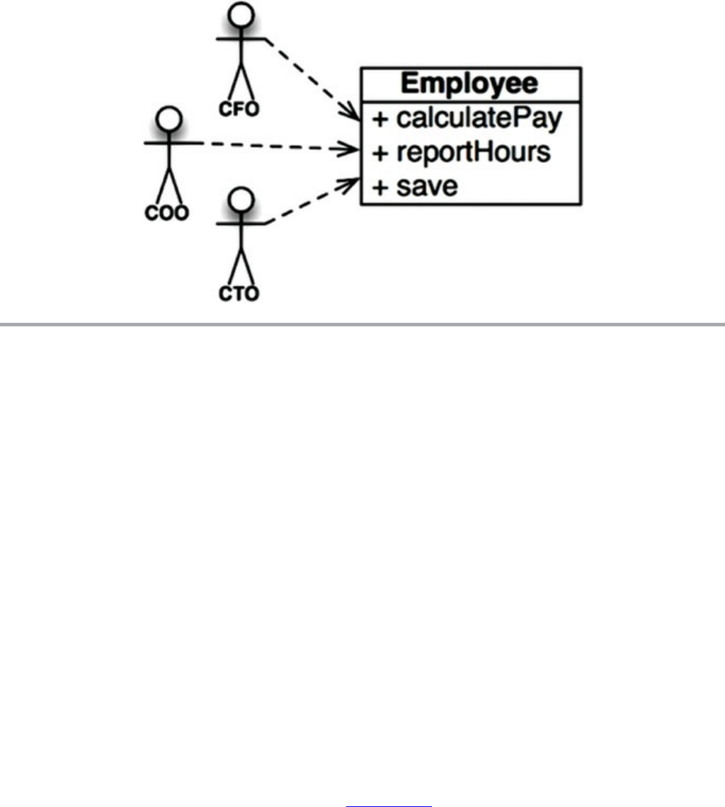
Figure 7.1 The Employee class
This class violates the SRP because those three methods are responsible to three very
different actors.
• The calculatePay() method is specified by the accounting department, which
reports to the CFO.
• The reportHours() method is specified and used by the human resources
department, which reports to the COO.
• The save() method is specified by the database administrators (DBAs), who report
to the CTO.
By putting the source code for these three methods into a single Employee class, the
developers have coupled each of these actors to the others. This coupling can cause
the actions of the CFO’s team to affect something that the COO’s team depends on.
For example, suppose that the calculatePay() function and the reportHours()
function share a common algorithm for calculating non-overtime hours. Suppose
also that the developers, who are careful not to duplicate code, put that algorithm
into a function named regularHours() (Figure 7.2).
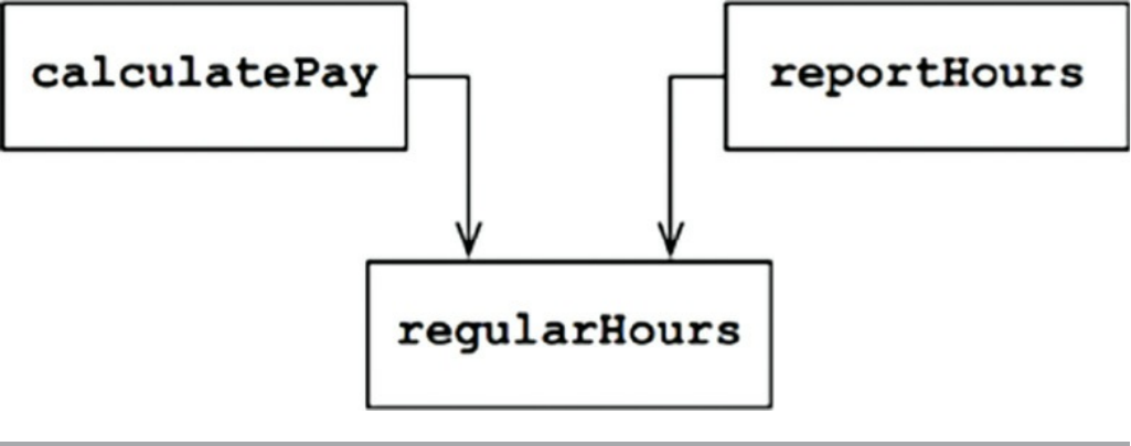
Figure 7.2 Shared algorithm
Now suppose that the CFO’s team decides that the way non-overtime hours are
calculated needs to be tweaked. In contrast, the COO’s team in HR does not want
that particular tweak because they use non-overtime hours for a different purpose.
A developer is tasked to make the change, and sees the convenient regularHours()
function called by the calculatePay() method. Unfortunately, that developer does
not notice that the function is also called by the reportHours() function.
The developer makes the required change and carefully tests it. The CFO’s team
validates that the new function works as desired, and the system is deployed.
Of course, the COO’s team doesn’t know that this is happening. The HR personnel
continue to use the reports generated by the reportHours() function—but now they
contain incorrect numbers. Eventually the problem is discovered, and the COO is
livid because the bad data has cost his budget millions of dollars.
We’ve all seen things like this happen. These problems occur because we put code
that different actors depend on into close proximity. The SRP says to separate the
code that different actors depend on.
SYMPTOM 2: MERGES
It’s not hard to imagine that merges will be common in source files that contain
many different methods. This situation is especially likely if those methods are
responsible to different actors.

For example, suppose that the CTO’s team of DBAs decides that there should be a
simple schema change to the Employee table of the database. Suppose also that the
COO’s team of HR clerks decides that they need a change in the format of the hours
report.
Two different developers, possibly from two different teams, check out the Employee
class and begin to make changes. Unfortunately their changes collide. The result is a
merge.
I probably don’t need to tell you that merges are risky affairs. Our tools are pretty
good nowadays, but no tool can deal with every merge case. In the end, there is
always risk.
In our example, the merge puts both the CTO and the COO at risk. It’s not
inconceivable that the CFO could be affected as well.
There are many other symptoms that we could investigate, but they all involve
multiple people changing the same source file for different reasons.
Once again, the way to avoid this problem is to separate code that supports different
actors.
SOLUTIONS
There are many different solutions to this problem. Each moves the functions into
different classes.
Perhaps the most obvious way to solve the problem is to separate the data from the
functions. The three classes share access to EmployeeData, which is a simple data
structure with no methods (Figure 7.3). Each class holds only the source code
necessary for its particular function. The three classes are not allowed to know about
each other. Thus any accidental duplication is avoided.
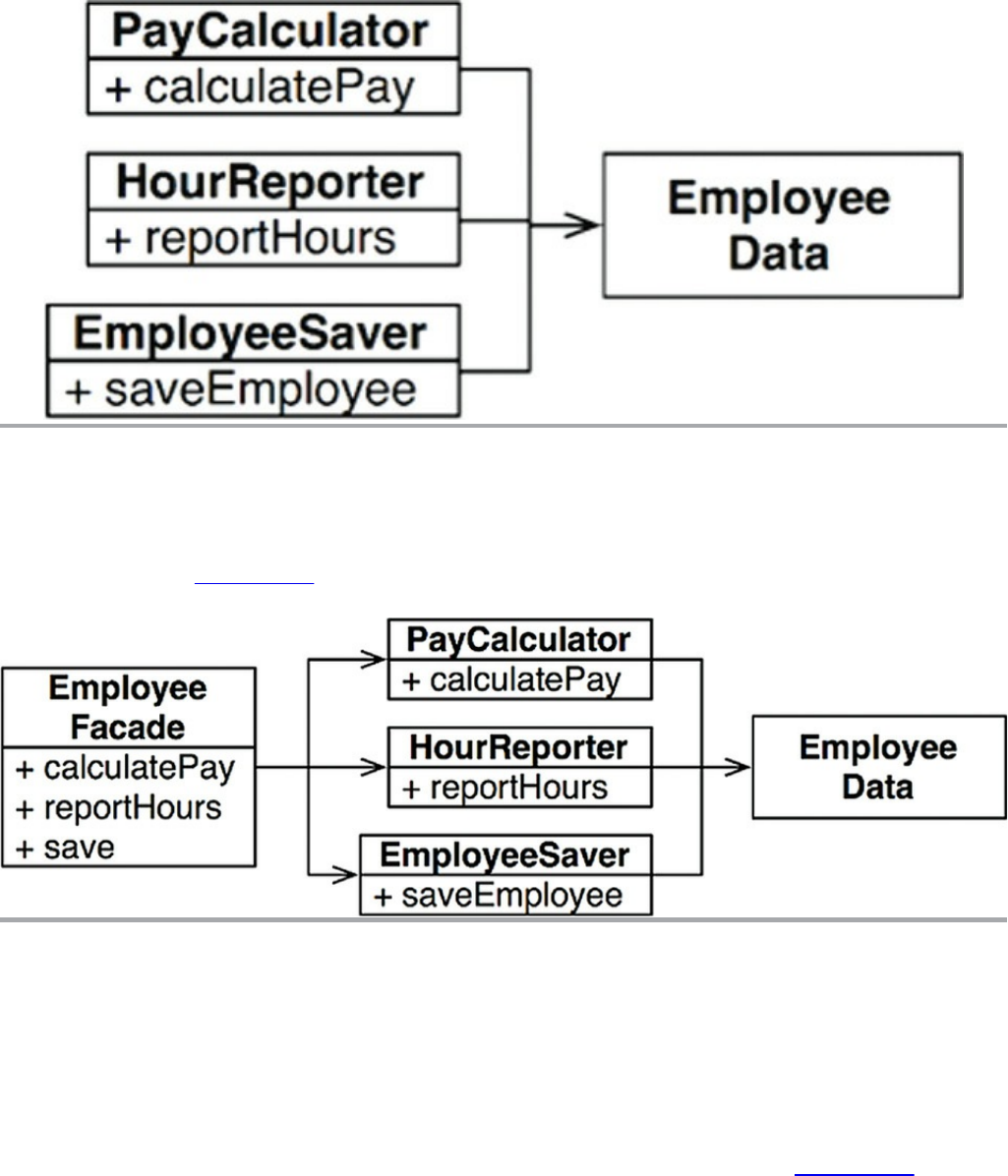
Figure 7.3 The three classes do not know about each other
The downside of this solution is that the developers now have three classes that they
have to instantiate and track. A common solution to this dilemma is to use the
Facade pattern (Figure 7.4).
Figure 7.4 The Facade pattern
The EmployeeFacade contains very little code. It is responsible for instantiating and
delegating to the classes with the functions.
Some developers prefer to keep the most important business rules closer to the data.
This can be done by keeping the most important method in the original Employee
class and then using that class as a Facade for the lesser functions (Figure 7.5).
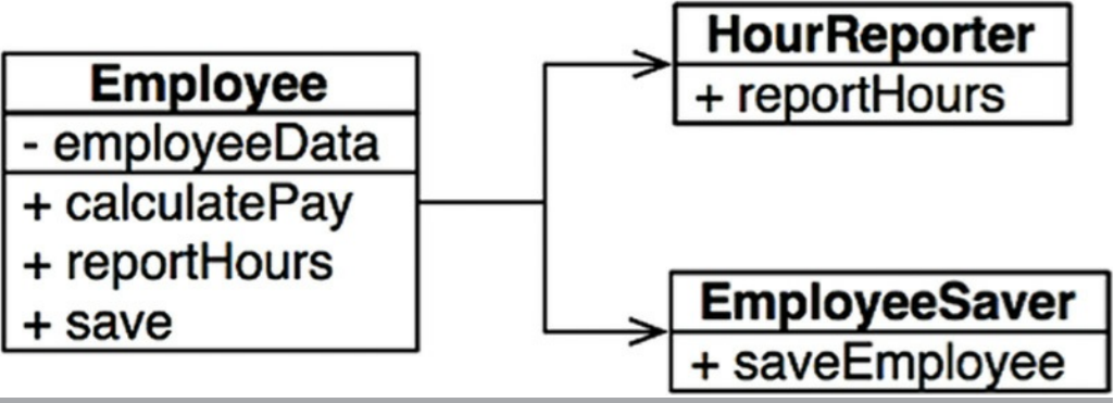
Figure 7.5 The most important method is kept in the original Employee class and used as a Facade
for the lesser functions
You might object to these solutions on the basis that every class would contain just
one function. This is hardly the case. The number of functions required to calculate
pay, generate a report, or save the data is likely to be large in each case. Each of
those classes would have many private methods in them.
Each of the classes that contain such a family of methods is a scope. Outside of that
scope, no one knows that the private members of the family exist.
CONCLUSION
The Single Responsibility Principle is about functions and classes—but it reappears
in a different form at two more levels. At the level of components, it becomes the
Common Closure Principle. At the architectural level, it becomes the Axis of Change
responsible for the creation of Architectural Boundaries. We’ll be studying all of
these ideas in the chapters to come.
8
OCP: THE OPEN-CLOSED PRINCIPLE
The Open-Closed Principle (OCP) was coined in 1988 by Bertrand Meyer.1 It says:
A software artifact should be open for extension but closed for modification.
In other words, the behavior of a software artifact ought to be extendible, without
having to modify that artifact.
This, of course, is the most fundamental reason that we study software architecture.
Clearly, if simple extensions to the requirements force massive changes to the
software, then the architects of that software system have engaged in a spectacular
failure.
Most students of software design recognize the OCP as a principle that guides them
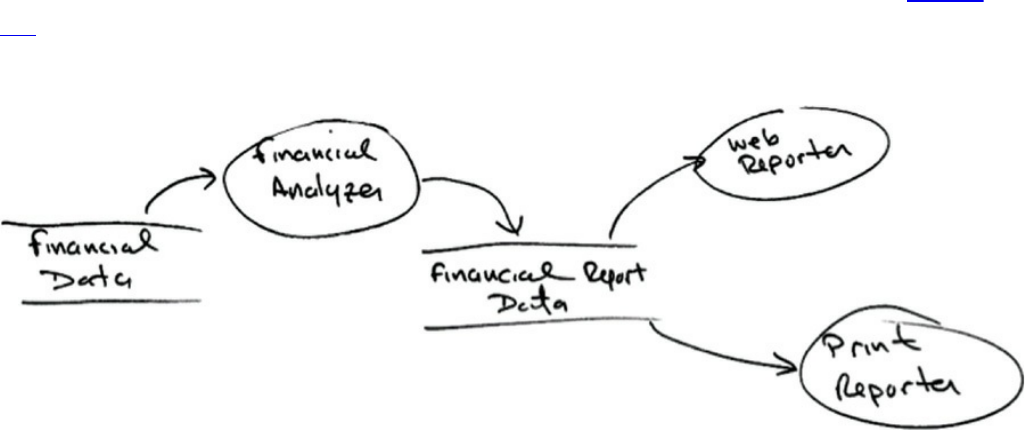
in the design of classes and modules. But the principle takes on even greater
significance when we consider the level of architectural components.
A thought experiment will make this clear.
A THOUGHT EXPERIMENT
Imagine, for a moment, that we have a system that displays a financial summary on a
web page. The data on the page is scrollable, and negative numbers are rendered in
red.
Now imagine that the stakeholders ask that this same information be turned into a
report to be printed on a black-and-white printer. The report should be properly
paginated, with appropriate page headers, page footers, and column labels. Negative
numbers should be surrounded by parentheses.
Clearly, some new code must be written. But how much old code will have to
change?
A good software architecture would reduce the amount of changed code to the barest
minimum. Ideally, zero.
How? By properly separating the things that change for different reasons (the Single
Responsibility Principle), and then organizing the dependencies between those things
properly (the Dependency Inversion Principle).
By applying the SRP, we might come up with the data-flow view shown in Figure
8.1. Some analysis procedure inspects the financial data and produces reportable
data, which is then formatted appropriately by the two reporter processes.

Figure 8.1 Applying the SRP
The essential insight here is that generating the report involves two separate
responsibilities: the calculation of the reported data, and the presentation of that data
into a web- and printer-friendly form.
Having made this separation, we need to organize the source code dependencies to
ensure that changes to one of those responsibilities do not cause changes in the other.
Also, the new organization should ensure that the behavior can be extended without
undo modification.
We accomplish this by partitioning the processes into classes, and separating those
classes into components, as shown by the double lines in the diagram in Figure 8.2.
In this figure, the component at the upper left is the Controller. At the upper right,
we have the Interactor. At the lower right, there is the Database. Finally, at the
lower left, there are four components that represent the Presenters and the Views.
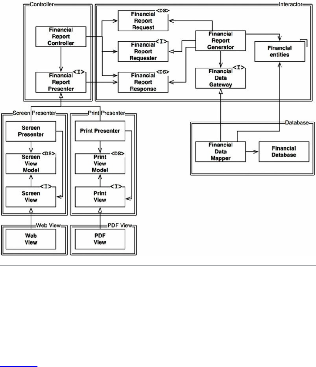
Figure 8.2 Partitioning the processes into classes and separating the classes into components
Classes marked with <I> are interfaces; those marked with <DS> are data structures.
Open arrowheads are using relationships. Closed arrowheads are implements or
inheritance relationships.
The first thing to notice is that all the dependencies are source code dependencies.
An arrow pointing from class A to class B means that the source code of class A
mentions the name of class B, but class B mentions nothing about class A. Thus, in
Figure 8.2, FinancialDataMapper knows about FinancialDataGateway through an
implements relationship, but FinancialGateway knows nothing at all about
FinancialDataMapper.
The next thing to notice is that each double line is crossed in one direction only. This
means that all component relationships are unidirectional, as shown in the
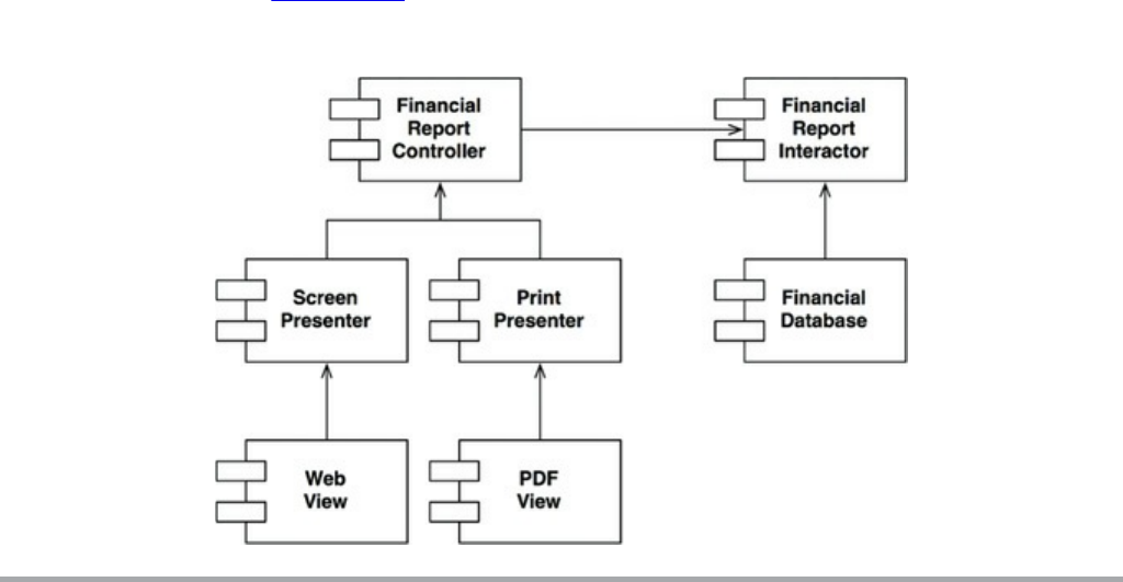
component graph in Figure 8.3. These arrows point toward the components that we
want to protect from change.
Figure 8.3 The component relationships are unidirectional
Let me say that again: If component A should be protected from changes in
component B, then component B should depend on component A.
We want to protect the Controller from changes in the Presenters. We want to
protect the Presenters from changes in the Views. We want to protect the Interactor
from changes in—well, anything.
The Interactor is in the position that best conforms to the OCP. Changes to the
Database, or the Controller, or the Presenters, or the Views, will have no impact on
the Interactor.
Why should the Interactor hold such a privileged position? Because it contains the
business rules. The Interactor contains the highest-level policies of the application.
All the other components are dealing with peripheral concerns. The Interactor deals
with the central concern.
Even though the Controller is peripheral to the Interactor, it is nevertheless central
to the Presenters and Views. And while the Presenters might be peripheral to the
Controller, they are central to the Views.
Notice how this creates a hierarchy of protection based on the notion of “level.”
Interactors are the highest-level concept, so they are the most protected. Views are
among the lowest-level concepts, so they are the least protected. Presenters are
higher level than Views, but lower level than the Controller or the Interactor.
This is how the OCP works at the architectural level. Architects separate
functionality based on how, why, and when it changes, and then organize that
separated functionality into a hierarchy of components. Higher-level components in
that hierarchy are protected from the changes made to lower-level components.
DIRECTIONAL CONTROL
If you recoiled in horror from the class design shown earlier, look again. Much of the
complexity in that diagram was intended to make sure that the dependencies between
the components pointed in the correct direction.
For example, the FinancialDataGateway interface between the
FinancialReportGenerator and the FinancialDataMapper exists to invert the
dependency that would otherwise have pointed from the Interactor component to the
Database component. The same is true of the FinancialReportPresenter interface,
and the two View interfaces.
INFORMATION HIDING
The FinancialReportRequester interface serves a different purpose. It is there to
protect the FinancialReportController from knowing too much about the internals
of the Interactor. If that interface were not there, then the Controller would have
transitive dependencies on the FinancialEntities.
Transitive dependencies are a violation of the general principle that software entities
should not depend on things they don’t directly use. We’ll encounter that principle
again when we talk about the Interface Segregation Principle and the Common
Reuse Principle.
So, even though our first priority is to protect the Interactor from changes to the
Controller, we also want to protect the Controller from changes to the Interactor by
hiding the internals of the Interactor.
CONCLUSION

The OCP is one of the driving forces behind the architecture of systems. The goal is
to make the system easy to extend without incurring a high impact of change. This
goal is accomplished by partitioning the system into components, and arranging
those components into a dependency hierarchy that protects higher-level components
from changes in lower-level components.
1. Bertrand Meyer. Object Oriented Software Construction, Prentice Hall, 1988, p. 23.
9
LSP: THE LISKOV SUBSTITUTION
PRINCIPLE
In 1988, Barbara Liskov wrote the following as a way of defining subtypes.
What is wanted here is something like the following substitution property: If for each object
o1 of type S there is an object o2 of type T such that for all programs P defined in terms of
T, the behavior of P is unchanged when o1 is substituted for o2 then S is a subtype of T.1
To understand this idea, which is known as the Liskov Substitution Principle (LSP),
let’s look at some examples.
GUIDING THE USE OF INHERITANCE
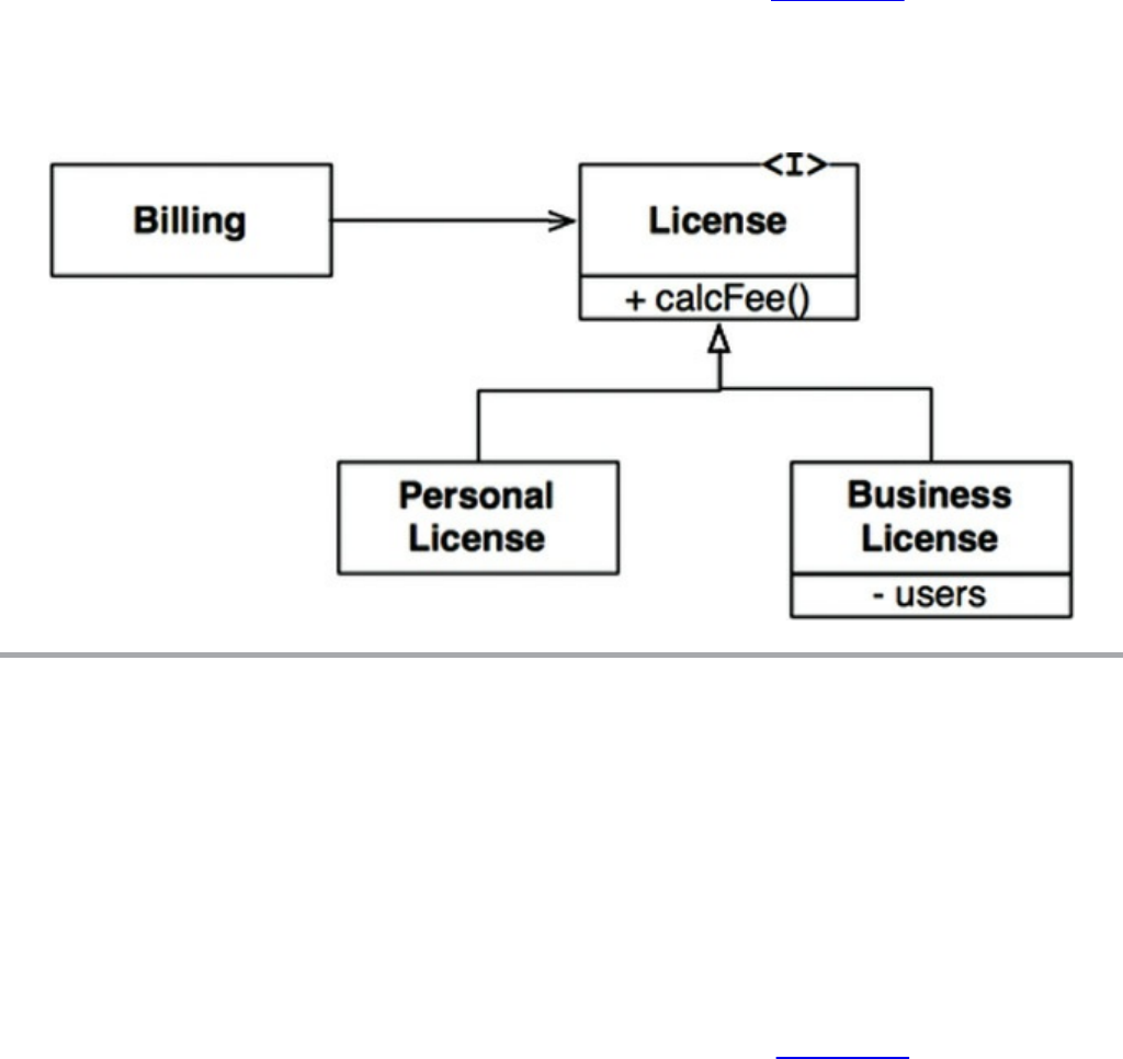
Imagine that we have a class named License, as shown in Figure 9.1. This class has
a method named calcFee(), which is called by the Billing application. There are
two “subtypes” of License: PersonalLicense and BusinessLicense. They use
different algorithms to calculate the license fee.
Figure 9.1 License, and its derivatives, conform to LSP
This design conforms to the LSP because the behavior of the Billing application
does not depend, in any way, on which of the two subtypes it uses. Both of the
subtypes are substitutable for the License type.
THE SQUARE/RECTANGLE PROBLEM
The canonical example of a violation of the LSP is the famed (or infamous,
depending on your perspective) square/rectangle problem (Figure 9.2).
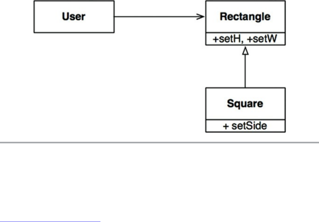
Figure 9.2 The infamous square/rectangle problem
In this example, Square is not a proper subtype of Rectangle because the height and
width of the Rectangle are independently mutable; in contrast, the height and width
of the Square must change together. Since the User believes it is communicating
with a Rectangle, it could easily get confused. The following code shows why:
Click here to view code image
Rectangle r = …
r.setW(5);
r.setH(2);
assert(r.area() == 10);
If the … code produced a Square, then the assertion would fail.
The only way to defend against this kind of LSP violation is to add mechanisms to
the User (such as an if statement) that detects whether the Rectangle is, in fact, a
Square. Since the behavior of the User depends on the types it uses, those types are
not substitutable.
LSP AND ARCHITECTURE
In the early years of the object-oriented revolution, we thought of the LSP as a way
to guide the use of inheritance, as shown in the previous sections. However, over the
years the LSP has morphed into a broader principle of software design that pertains
to interfaces and implementations.
The interfaces in question can be of many forms. We might have a Java-style
interface, implemented by several classes. Or we might have several Ruby classes
that share the same method signatures. Or we might have a set of services that all
respond to the same REST interface.
In all of these situations, and more, the LSP is applicable because there are users
who depend on well-defined interfaces, and on the substitutability of the
implementations of those interfaces.
The best way to understand the LSP from an architectural viewpoint is to look at
what happens to the architecture of a system when the principle is violated.
EXAMPLE LSP VIOLATION
Assume that we are building an aggregator for many taxi dispatch services.
Customers use our website to find the most appropriate taxi to use, regardless of taxi
company. Once the customer makes a decision, our system dispatches the chosen
taxi by using a restful service.
Now assume that the URI for the restful dispatch service is part of the information
contained in the driver database. Once our system has chosen a driver appropriate for
the customer, it gets that URI from the driver record and then uses it to dispatch the
driver.
Suppose Driver Bob has a dispatch URI that looks like this:
Click here to view code image
purplecab.com/driver/Bob
Our system will append the dispatch information onto this URI and send it with a
PUT, as follows:
Click here to view code image
purplecab.com/driver/Bob

/pickupAddress/24 Maple St.
/pickupTime/153
/destination/ORD
Clearly, this means that all the dispatch services, for all the different companies,
must conform to the same REST interface. They must treat the pickupAddress,
pickupTime, and destination fields identically.
Now suppose the Acme taxi company hired some programmers who didn’t read the
spec very carefully. They abbreviated the destination field to just dest. Acme is the
largest taxi company in our area, and Acme’s CEO’s ex-wife is our CEO’s new wife,
and … Well, you get the picture. What would happen to the architecture of our
system?
Obviously, we would need to add a special case. The dispatch request for any Acme
driver would have to be constructed using a different set of rules from all the other
drivers.
The simplest way to accomplish this goal would be to add an if statement to the
module that constructed the dispatch command:
Click here to view code image
if (driver.getDispatchUri().startsWith("acme.com"))…
But, of course, no architect worth his or her salt would allow such a construction to
exist in the system. Putting the word “acme” into the code itself creates an
opportunity for all kinds of horrible and mysterious errors, not to mention security
breaches.
For example, what if Acme became even more successful and bought the Purple
Taxi company. What if the merged company maintained the separate brands and the
separate websites, but unified all of the original companies’ systems? Would we
have to add another if statement for “purple”?
Our architect would have to insulate the system from bugs like this by creating some
kind of dispatch command creation module that was driven by a configuration
database keyed by the dispatch URI. The configuration data might look something
like this:
Click here to view code image

URI Dispatch Format
Acme.com /pickupAddress/%s/pickupTime/%s/dest/%s
*.* /pickupAddress/%s/pickupTime/%s/destination/%s
And so our architect has had to add a significant and complex mechanism to deal
with the fact that the interfaces of the restful services are not all substitutable.
CONCLUSION
The LSP can, and should, be extended to the level of architecture. A simple violation
of substitutability, can cause a system’s architecture to be polluted with a significant
amount of extra mechanisms.
1. Barbara Liskov, “Data Abstraction and Hierarchy,” SIGPLAN Notices 23, 5 (May 1988).

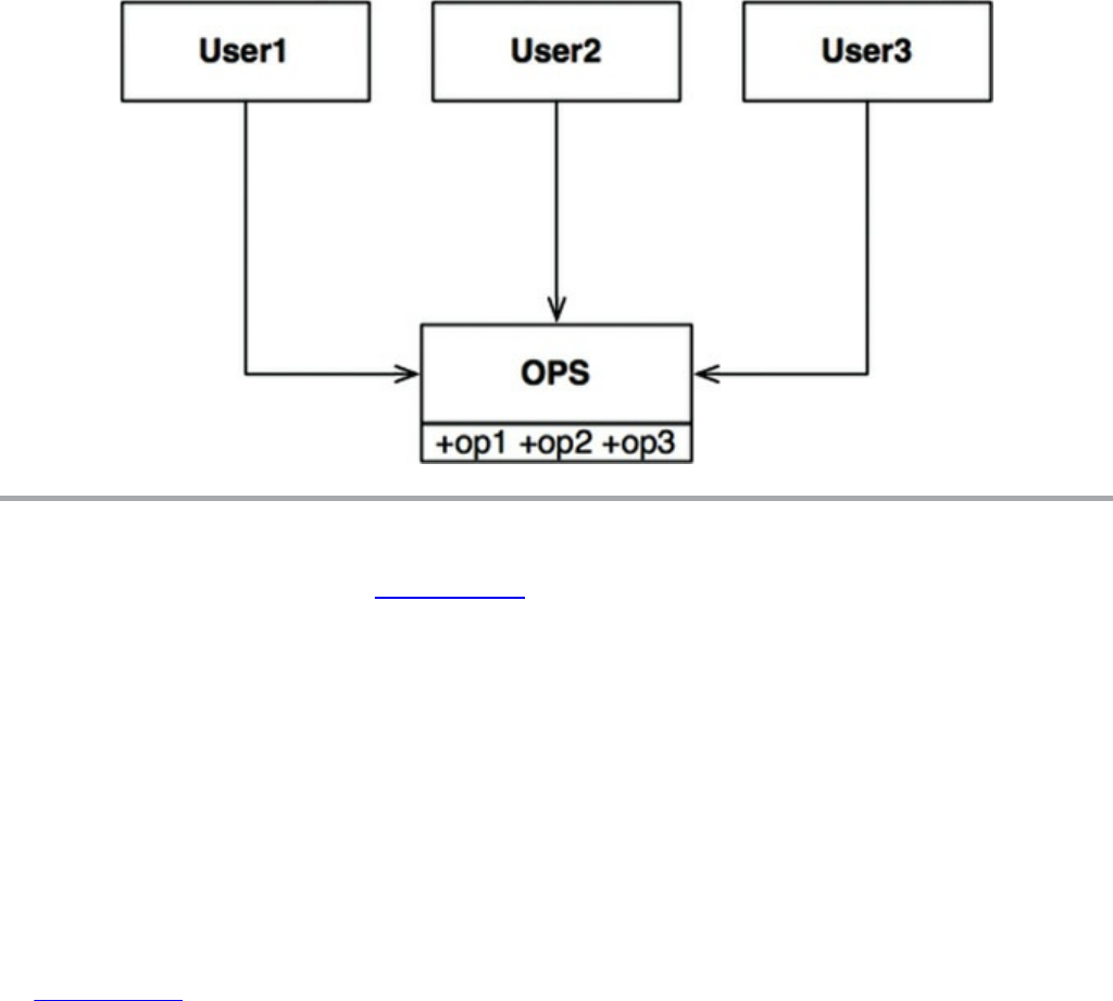
Figure 10.1 The Interface Segregation Principle
In the situation illustrated in Figure 10.1, there are several users who use the
operations of the OPS class. Let’s assume that User1 uses only op1, User2 uses only
op2, and User3 uses only op3.
Now imagine that OPS is a class written in a language like Java. Clearly, in that case,
the source code of User1 will inadvertently depend on op2 and op3, even though it
doesn’t call them. This dependence means that a change to the source code of op2 in
OPS will force User1 to be recompiled and redeployed, even though nothing that it
cared about has actually changed.
This problem can be resolved by segregating the operations into interfaces as shown
in Figure 10.2.
Again, if we imagine that this is implemented in a statically typed language like
Java, then the source code of User1 will depend on U1Ops, and op1, but will not
depend on OPS. Thus a change to OPS that User1 does not care about will not cause
User1 to be recompiled and redeployed.
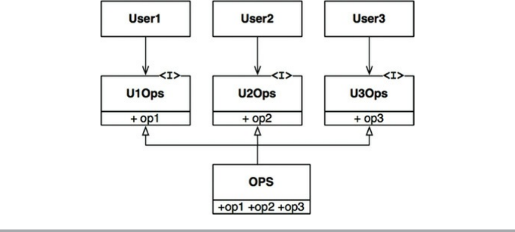
Figure 10.2 Segregated operations
ISP AND LANGUAGE
Clearly, the previously given description depends critically on language type.
Statically typed languages like Java force programmers to create declarations that
users must import, or use, or otherwise include. It is these included declarations in
source code that create the source code dependencies that force recompilation and
redeployment.
In dynamically typed languages like Ruby and Python, such declarations don’t exist
in source code. Instead, they are inferred at runtime. Thus there are no source code
dependencies to force recompilation and redeployment. This is the primary reason
that dynamically typed languages create systems that are more flexible and less
tightly coupled than statically typed languages.
This fact could lead you to conclude that the ISP is a language issue, rather than an
architecture issue.
ISP AND ARCHITECTURE
If you take a step back and look at the root motivations of the ISP, you can see a
deeper concern lurking there. In general, it is harmful to depend on modules that
contain more than you need. This is obviously true for source code dependencies that
can force unnecessary recompilation and redeployment—but it is also true at a much
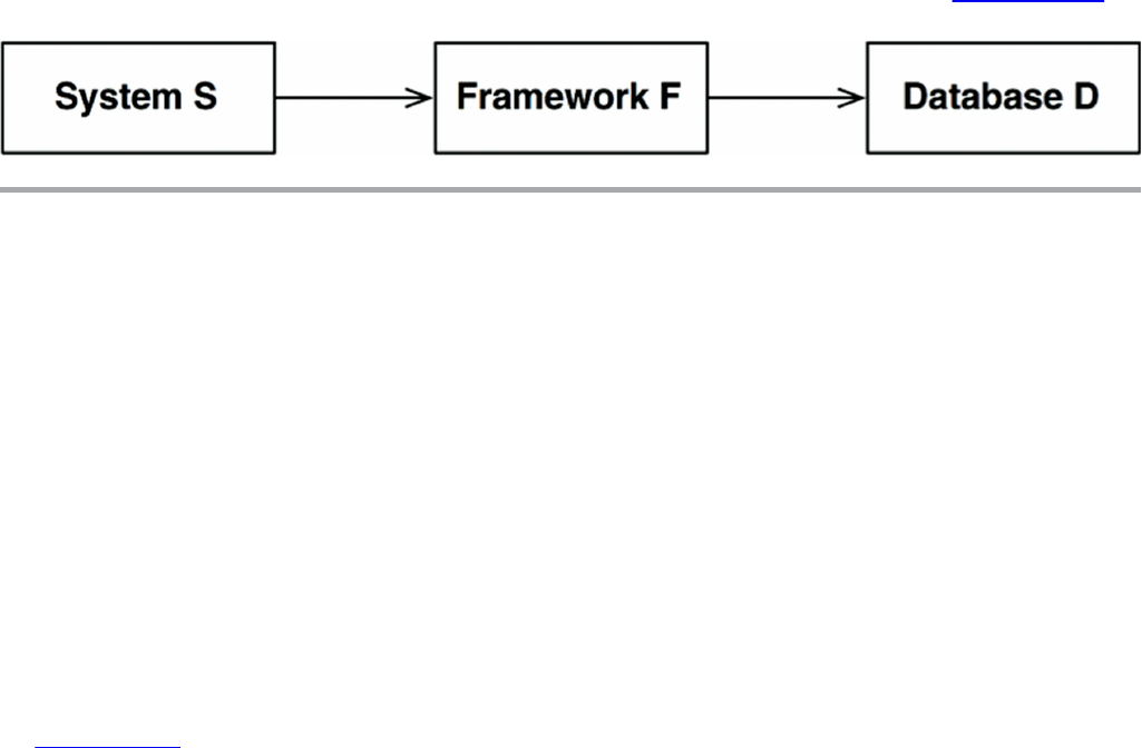
higher, architectural level.
Consider, for example, an architect working on a system, S. He wants to include a
certain framework, F, into the system. Now suppose that the authors of F have bound
it to a particular database, D. So S depends on F. which depends on D (Figure 10.3).
Figure 10.3 A problematic architecture
Now suppose that D contains features that F does not use and, therefore, that S does
not care about. Changes to those features within D may well force the redeployment
of F and, therefore, the redeployment of S. Even worse, a failure of one of the
features within D may cause failures in F and S.
CONCLUSION
The lesson here is that depending on something that carries baggage that you don’t
need can cause you troubles that you didn’t expect.
We’ll explore this idea in more detail when we discuss the Common Reuse Principle
in Chapter 13, “Component Cohesion.”
11
DIP: THE DEPENDENCY INVERSION
PRINCIPLE
The Dependency Inversion Principle (DIP) tells us that the most flexible systems are
those in which source code dependencies refer only to abstractions, not to
concretions.
In a statically typed language, like Java, this means that the use, import, and
include statements should refer only to source modules containing interfaces,
abstract classes, or some other kind of abstract declaration. Nothing concrete should
be depended on.
The same rule applies for dynamically typed languages, like Ruby and Python.
Source code dependencies should not refer to concrete modules. However, in these
languages it is a bit harder to define what a concrete module is. In particular, it is any
module in which the functions being called are implemented.
Clearly, treating this idea as a rule is unrealistic, because software systems must
depend on many concrete facilities. For example, the String class in Java is
concrete, and it would be unrealistic to try to force it to be abstract. The source code
dependency on the concrete java.lang.string cannot, and should not, be avoided.
By comparison, the String class is very stable. Changes to that class are very rare
and tightly controlled. Programmers and architects do not have to worry about
frequent and capricious changes to String.
For these reasons, we tend to ignore the stable background of operating system and
platform facilities when it comes to DIP. We tolerate those concrete dependencies
because we know we can rely on them not to change.
It is the volatile concrete elements of our system that we want to avoid depending
on. Those are the modules that we are actively developing, and that are undergoing
frequent change.
STABLE ABSTRACTIONS
Every change to an abstract interface corresponds to a change to its concrete
implementations. Conversely, changes to concrete implementations do not always, or
even usually, require changes to the interfaces that they implement. Therefore
interfaces are less volatile than implementations.
Indeed, good software designers and architects work hard to reduce the volatility of
interfaces. They try to find ways to add functionality to implementations without
making changes to the interfaces. This is Software Design 101.
The implication, then, is that stable software architectures are those that avoid
depending on volatile concretions, and that favor the use of stable abstract interfaces.
This implication boils down to a set of very specific coding practices:
• Don’t refer to volatile concrete classes. Refer to abstract interfaces instead. This
rule applies in all languages, whether statically or dynamically typed. It also puts
severe constraints on the creation of objects and generally enforces the use of
Abstract Factories.

• Don’t derive from volatile concrete classes. This is a corollary to the previous
rule, but it bears special mention. In statically typed languages, inheritance is the
strongest, and most rigid, of all the source code relationships; consequently, it
should be used with great care. In dynamically typed languages, inheritance is less
of a problem, but it is still a dependency—and caution is always the wisest choice.
• Don’t override concrete functions. Concrete functions often require source code
dependencies. When you override those functions, you do not eliminate those
dependencies—indeed, you inherit them. To manage those dependencies, you
should make the function abstract and create multiple implementations.
• Never mention the name of anything concrete and volatile. This is really just a
restatement of the principle itself.
FACTORIES
To comply with these rules, the creation of volatile concrete objects requires special
handling. This caution is warranted because, in virtually all languages, the creation
of an object requires a source code dependency on the concrete definition of that
object.
In most object-oriented languages, such as Java, we would use an Abstract Factory
to manage this undesirable dependency.
The diagram in Figure 11.1 shows the structure. The Application uses the
ConcreteImpl through the Service interface. However, the Application must
somehow create instances of the ConcreteImpl. To achieve this without creating a
source code dependency on the ConcreteImpl, the Application calls the makeSvc
method of the ServiceFactory interface. This method is implemented by the
ServiceFactoryImpl class, which derives from ServiceFactory. That
implementation instantiates the ConcreteImpl and returns it as a Service.
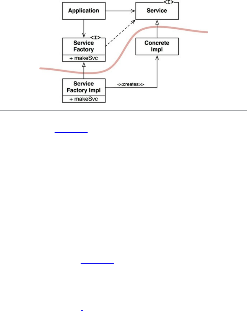
Figure 11.1 Use of the Abstract Factory pattern to manage the dependency
The curved line in Figure 11.1 is an architectural boundary. It separates the abstract
from the concrete. All source code dependencies cross that curved line pointing in
the same direction, toward the abstract side.
The curved line divides the system into two components: one abstract and the other
concrete. The abstract component contains all the high-level business rules of the
application. The concrete component contains all the implementation details that
those business rules manipulate.
Note that the flow of control crosses the curved line in the opposite direction of the
source code dependencies. The source code dependencies are inverted against the
flow of control—which is why we refer to this principle as Dependency Inversion.
CONCRETE COMPONENTS
The concrete component in Figure 11.1 contains a single dependency, so it violates
the DIP. This is typical. DIP violations cannot be entirely removed, but they can be
gathered into a small number of concrete components and kept separate from the rest
of the system.
Most systems will contain at least one such concrete component—often called main
because it contains the main1 function. In the case illustrated in Figure 11.1, the main
function would instantiate the ServiceFactoryImpl and place that instance in a
global variable of type ServiceFactory. The Application would then access the

factory through that global variable.
CONCLUSION
As we move forward in this book and cover higher-level architectural principles, the
DIP will show up again and again. It will be the most visible organizing principle in
our architecture diagrams. The curved line in Figure 11.1 will become the
architectural boundaries in later chapters. The way the dependencies cross that
curved line in one direction, and toward more abstract entities, will become a new
rule that we will call the Dependency Rule.
1. In other words, the function that is invoked by the operating system when the application is first
started up.

IV
COMPONENT PRINCIPLES
If the SOLID principles tell us how to arrange the bricks into walls and rooms, then
the component principles tell us how to arrange the rooms into buildings. Large
software systems, like large buildings, are built out of smaller components.
In Part IV, we will discuss what software components are, which elements should
compose them, and how they should be composed together into systems.
12
COMPONENTS
Components are the units of deployment. They are the smallest entities that can be
deployed as part of a system. In Java, they are jar files. In Ruby, they are gem files.
In .Net, they are DLLs. In compiled languages, they are aggregations of binary files.
In interpreted languages, they are aggregations of source files. In all languages, they
are the granule of deployment.
Components can be linked together into a single executable. Or they can be
aggregated together into a single archive, such as a .war file. Or they can be
independently deployed as separate dynamically loaded plugins, such as.jar or .dll
or .exe files. Regardless of how they are eventually deployed, well-designed
components always retain the ability to be independently deployable and, therefore,
independently developable.

A BRIEF HISTORY OF COMPONENTS
In the early years of software development, programmers controlled the memory
location and layout of their programs. One of the first lines of code in a program
would be the origin statement, which declared the address at which the program was
to be loaded.
Consider the following simple PDP-8 program. It consists of a subroutine named
GETSTR that inputs a string from the keyboard and saves it in a buffer. It also has a
little unit test program to exercise GETSTR.
Click here to view code image
*200
TLS
START, CLA
TAD BUFR
JMS GETSTR
CLA
TAD BUFR
JMS PUTSTR
JMP START
BUFR, 3000
GETSTR, 0
DCA PTR
NXTCH, KSF
JMP -1
KRB
DCA I PTR
TAD I PTR
AND K177
ISZ PTR
TAD MCR
SZA
JMP NXTCH
K177, 177
MCR, -15
Note the *200 command at the start of this program. It tells the compiler to generate
code that will be loaded at address 2008.
This kind of programming is a foreign concept for most programmers today. They
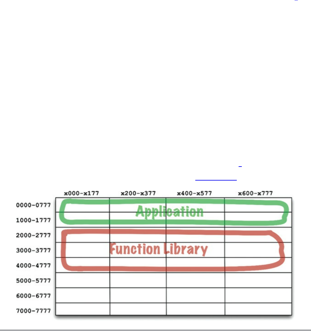
rarely have to think about where a program is loaded in the memory of the computer.
But in the early days, this was one of the first decisions a programmer needed to
make. In those days, programs were not relocatable.
How did you access a library function in those olden days? The preceding code
illustrates the approach used. Programmers included the source code of the library
functions with their application code, and compiled them all as a single program.1
Libraries were kept in source, not in binary.
The problem with this approach was that, during this era, devices were slow and
memory was expensive and, therefore, limited. Compilers needed to make several
passes over the source code, but memory was too limited to keep all the source code
resident. Consequently, the compiler had to read in the source code several times
using the slow devices.
This took a long time—and the larger your function library, the longer the compiler
took. Compiling a large program could take hours.
To shorten the compile times, programmers separated the source code of the function
library from the applications. They compiled the function library separately and
loaded the binary at a known address—say, 20008. They created a symbol table for
the function library and compiled that with their application code. When they wanted
to run an application, they would load the binary function library,2 and then load the
application. Memory looked like the layout shown in Figure 12.1.
Figure 12.1 Early memory layout
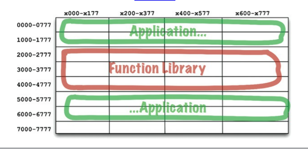
This worked fine so long as the application could fit between addresses 00008 and
17778. But soon applications grew to be larger than the space allotted for them. At
that point, programmers had to split their applications into two address segments,
jumping around the function library (Figure 12.2).
Figure 12.2 Splitting the application into two address segments
Obviously, this was not a sustainable situation. As programmers added more
functions to the function library, it exceeded its bounds, and they had to allocate
more space for it (in this example, near 70008). This fragmentation of programs and
libraries necessarily continued as computer memory grew.
Clearly, something had to be done.
RELOCATABILITY
The solution was relocatable binaries. The idea behind them was very simple. The
compiler was changed to output binary code that could be relocated in memory by a
smart loader. The loader would be told where to load the relocatable code. The
relocatable code was instrumented with flags that told the loader which parts of the
loaded data had to be altered to be loaded at the selected address. Usually this just
meant adding the starting address to any memory reference addresses in the binary.
Now the programmer could tell the loader where to load the function library, and
where to load the application. In fact, the loader would accept several binary inputs
and simply load them in memory one right after the other, relocating them as it
loaded them. This allowed programmers to load only those functions that they
needed.
The compiler was also changed to emit the names of the functions as metadata in the
relocatable binary. If a program called a library function, the compiler would emit
that name as an external reference. If a program defined a library function, the
compiler would emit that name as an external definition. Then the loader could link
the external references to the external definitions once it had determined where it had
loaded those definitions.
And the linking loader was born.
LINKERS
The linking loader allowed programmers to divide their programs up onto separately
compilable and loadable segments. This worked well when relatively small programs
were being linked with relatively small libraries. However, in the late 1960s and
early 1970s, programmers got more ambitious, and their programs got a lot bigger.
Eventually, the linking loaders were too slow to tolerate. Function libraries were
stored on slow devices such a magnetic tape. Even the disks, back then, were quite
slow. Using these relatively slow devices, the linking loaders had to read dozens, if
not hundreds, of binary libraries to resolve the external references. As programs
grew larger and larger, and more library functions accumulated in libraries, a linking
loader could take more than an hour just to load the program.
Eventually, the loading and the linking were separated into two phases. Programmers
took the slow part—the part that did that linking—and put it into a separate
application called the linker. The output of the linker was a linked relocatable that a
relocating loader could load very quickly. This allowed programmers to prepare an
executable using the slow linker, but then they could load it quickly, at any time.
Then came the 1980s. Programmers were working in C or some other high-level
language. As their ambitions grew, so did their programs. Programs that numbered
hundreds of thousands of lines of code were not unusual.
Source modules were compiled from .c files into .o files, and then fed into the
linker to create executable files that could be quickly loaded. Compiling each

individual module was relatively fast, but compiling all the modules took a bit of
time. The linker would then take even more time. Turnaround had again grown to an
hour or more in many cases.
It seemed as if programmers were doomed to endlessly chase their tails. Throughout
the 1960s, 1970s, and 1980s, all the changes made to speed up workflow were
thwarted by programmers’ ambitions, and the size of the programs they wrote. They
could not seem to escape from the hour-long turnaround times. Loading time
remained fast, but compile-link times were the bottleneck.
We were, of course, experiencing Murphy’s law of program size:
Programs will grow to fill all available compile and link time.
But Murphy was not the only contender in town. Along came Moore,3 and in the late
1980s, the two battled it out. Moore won that battle. Disks started to shrink and got
significantly faster. Computer memory started to get so ridiculously cheap that much
of the data on disk could be cached in RAM. Computer clock rates increased from 1
MHz to 100 MHz.
By the mid-1990s, the time spent linking had begun to shrink faster than our
ambitions could make programs grow. In many cases, link time decreased to a matter
of seconds. For small jobs, the idea of a linking loader became feasible again.
This was the era of Active-X, shared libraries, and the beginnings of .jar files.
Computers and devices had gotten so fast that we could, once again, do the linking at
load time. We could link together several .jar files, or several shared libraries in a
matter of seconds, and execute the resulting program. And so the component plugin
architecture was born.
Today we routinely ship .jar files or DLLs or shared libraries as plugins to existing
applications. If you want to create a mod to Minecraft, for example, you simply
include your custom .jar files in a certain folder. If you want to plug Resharper into
Visual Studio, you simply include the appropriate DLLs.
CONCLUSION
These dynamically linked files, which can be plugged together at runtime, are the
software components of our architectures. It has taken 50 years, but we have arrived
at a place where component plugin architecture can be the casual default as opposed

to the herculean effort it once was.
1. My first employer kept several dozen decks of the subroutine library source code on a shelf.
When you wrote a new program, you simply grabbed one of those decks and slapped it onto the
end of your deck.
2. Actually, most of those old machines used core memory, which did not get erased when you
powered the computer down. We often left the function library loaded for days at a time.
3. Moore’s law: Computer speed, memory, and density double every 18 months. This law held from
the 1950s to 2000, but then, at least for clock rates, stopped cold.
13
COMPONENT COHESION
Which classes belong in which components? This is an important decision, and
requires guidance from good software engineering principles. Unfortunately, over
the years, this decision has been made in an ad hoc manner based almost entirely on
context.
In this chapter we will discuss the three principles of component cohesion:
• REP: The Reuse/Release Equivalence Principle
• CCP: The Common Closure Principle
• CRP: The Common Reuse Principle
THE REUSE/RELEASE EQUIVALENCE
PRINCIPLE
The granule of reuse is the granule of release.
The last decade has seen the rise of a menagerie of module management tools, such
as Maven, Leiningen, and RVM. These tools have grown in importance because,
during that time, a vast number of reusable components and component libraries
have been created. We are now living in the age of software reuse—a fulfillment of
one of the oldest promises of the object-oriented model.
The Reuse/Release Equivalence Principle (REP) is a principle that seems obvious, at
least in hindsight. People who want to reuse software components cannot, and will
not, do so unless those components are tracked through a release process and are
given release numbers.
This is not simply because, without release numbers, there would be no way to
ensure that all the reused components are compatible with each other. Rather, it also
reflects the fact that software developers need to know when new releases are
coming, and which changes those new releases will bring.
It is not uncommon for developers to be alerted about a new release and decide,
based on the changes made in that release, to continue to use the old release instead.
Therefore the release process must produce the appropriate notifications and release
documentation so that users can make informed decisions about when and whether to
integrate the new release.
From a software design and architecture point of view, this principle means that the
classes and modules that are formed into a component must belong to a cohesive
group. The component cannot simply consist of a random hodgepodge of classes and
modules; instead, there must be some overarching theme or purpose that those
modules all share.
Of course, this should be obvious. However, there is another way to look at this issue
that is perhaps not quite so obvious. Classes and modules that are grouped together
into a component should be releasable together. The fact that they share the same
version number and the same release tracking, and are included under the same
release documentation, should make sense both to the author and to the users.
This is weak advice: Saying that something should “make sense” is just a way of

waving your hands in the air and trying to sound authoritative. The advice is weak
because it is hard to precisely explain the glue that holds the classes and modules
together into a single component. Weak though the advice may be, the principle
itself is important, because violations are easy to detect—they don’t “make sense.” If
you violate the REP, your users will know, and they won’t be impressed with your
architectural skills.
The weakness of this principle is more than compensated for by the strength of the
next two principles. Indeed, the CCP and the CRP strongly define the this principle,
but in a negative sense.
THE COMMON CLOSURE PRINCIPLE
Gather into components those classes that change for the same reasons and at the same
times. Separate into different components those classes that change at different times and
for different reasons.
This is the Single Responsibility Principle restated for components. Just as the SRP
says that a class should not contain multiples reasons to change, so the Common
Closure Principle (CCP) says that a component should not have multiple reasons to
change.
For most applications, maintainability is more important than reusability. If the code
in an application must change, you would rather that all of the changes occur in one
component, rather than being distributed across many components.1 If changes are
confined to a single component, then we need to redeploy only the one changed
component. Other components that don’t depend on the changed component do not
need to be revalidated or redeployed.
The CCP prompts us to gather together in one place all the classes that are likely to
change for the same reasons. If two classes are so tightly bound, either physically or
conceptually, that they always change together, then they belong in the same
component. This minimizes the workload related to releasing, revalidating, and
redeploying the software.
This principle is closely associated with the Open Closed Principle (OCP). Indeed, it
is “closure” in the OCP sense of the word that the CCP addresses. The OCP states
that classes should be closed for modification but open for extension. Because 100%
closure is not attainable, closure must be strategic. We design our classes such that
they are closed to the most common kinds of changes that we expect or have
experienced.
The CCP amplifies this lesson by gathering together into the same component those
classes that are closed to the same types of changes. Thus, when a change in
requirements comes along, that change has a good chance of being restricted to a
minimal number of components.
SIMILARITY WITH SRP
As stated earlier, the CCP is the component form of the SRP. The SRP tells us to
separate methods into different classes, if they change for different reasons. The CCP
tells us to separate classes into different components, if they change for different
reasons. Both principles can be summarized by the following sound bite:
Gather together those things that change at the same times and for the same reasons.
Separate those things that change at different times or for different reasons.
THE COMMON REUSE PRINCIPLE
Don’t force users of a component to depend on things they don’t need.
The Common Reuse Principle (CRP) is yet another principle that helps us to decide
which classes and modules should be placed into a component. It states that classes
and modules that tend to be reused together belong in the same component.
Classes are seldom reused in isolation. More typically, reusable classes collaborate
with other classes that are part of the reusable abstraction. The CRP states that these
classes belong together in the same component. In such a component we would
expect to see classes that have lots of dependencies on each other.
A simple example might be a container class and its associated iterators. These
classes are reused together because they are tightly coupled to each other. Thus they
ought to be in the same component.
But the CRP tells us more than just which classes to put together into a component:
It also tells us which classes not to keep together in a component. When one
component uses another, a dependency is created between the components. Perhaps
the using component uses only one class within the used component—but that still
doesn’t weaken the dependency. The using component still depends on the used
component.

Because of that dependency, every time the used component is changed, the using
component will likely need corresponding changes. Even if no changes are necessary
to the using component, it will likely still need to be recompiled, revalidated, and
redeployed. This is true even if the using component doesn’t care about the change
made in the used component.
Thus when we depend on a component, we want to make sure we depend on every
class in that component. Put another way, we want to make sure that the classes that
we put into a component are inseparable—that it is impossible to depend on some
and not on the others. Otherwise, we will be redeploying more components than is
necessary, and wasting significant effort.
Therefore the CRP tells us more about which classes shouldn’t be together than
about which classes should be together. The CRP says that classes that are not tightly
bound to each other should not be in the same component.
RELATION TO ISP
The CRP is the generic version of the ISP. The ISP advises us not to depend on
classes that have methods we don’t use. The CRP advises us not to depend on
components that have classes we don’t use.
All of this advice can be reduced to a single sound bite:
Don’t depend on things you don’t need.
THE TENSION DIAGRAM FOR
COMPONENT COHESION
You may have already realized that the three cohesion principles tend to fight each
other. The REP and CCP are inclusive principles: Both tend to make components
larger. The CRP is an exclusive principle, driving components to be smaller. It is the
tension between these principles that good architects seek to resolve.
Figure 13.1 is a tension diagram2 that shows how the three principles of cohesion
interact with each other. The edges of the diagram describe the cost of abandoning
the principle on the opposite vertex.
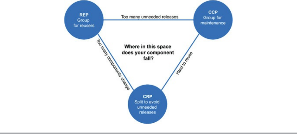
Figure 13.1 Cohesion principles tension diagram
An architect who focuses on just the REP and CRP will find that too many
components are impacted when simple changes are made. In contrast, an architect
who focuses too strongly on the CCP and REP will cause too many unneeded
releases to be generated.
A good architect finds a position in that tension triangle that meets the current
concerns of the development team, but is also aware that those concerns will change
over time. For example, early in the development of a project, the CCP is much more
important than the REP, because develop-ability is more important than reuse.
Generally, projects tend to start on the right hand side of the triangle, where the only
sacrifice is reuse. As the project matures, and other projects begin to draw from it,
the project will slide over to the left. This means that the component structure of a
project can vary with time and maturity. It has more to do with the way that project
is developed and used, than with what the project actually does.
CONCLUSION
In the past, our view of cohesion was much simpler than the REP, CCP, and CRP
implied. We once thought that cohesion was simply the attribute that a module
performs one, and only one, function. However, the three principles of component
cohesion describe a much more complex variety of cohesion. In choosing the classes
to group together into components, we must consider the opposing forces involved in
reusability and develop-ability. Balancing these forces with the needs of the

application is nontrivial. Moreover, the balance is almost always dynamic. That is,
the partitioning that is appropriate today might not be appropriate next year. As a
consequence, the composition of the components will likely jitter and evolve with
time as the focus of the project changes from develop-ability to reusability.
1. See the section on “The Kitty Problem” in Chapter 27, “Services: Great and Small.“
2. Thanks to Tim Ottinger for this idea.
14
COMPONENT COUPLING
The next three principles deal with the relationships between components. Here
again we will run into the tension between develop-ability and logical design. The
forces that impinge upon the architecture of a component structure are technical,
political, and volatile.
THE ACYCLIC DEPENDENCIES
PRINCIPLE
Allow no cycles in the component dependency graph.
Have you ever worked all day, gotten some stuff working, and then gone home, only
to arrive the next morning to find that your stuff no longer works? Why doesn’t it
work? Because somebody stayed later than you and changed something you depend
on! I call this “the morning after syndrome.”
The “morning after syndrome” occurs in development environments where many
developers are modifying the same source files. In relatively small projects with just
a few developers, it isn’t too big a problem. But as the size of the project and the
development team grow, the mornings after can get pretty nightmarish. It is not
uncommon for weeks to go by without the team being able to build a stable version
of the project. Instead, everyone keeps on changing and changing their code trying to
make it work with the last changes that someone else made.
Over the last several decades, two solutions to this problem have evolved, both of
which came from the telecommunications industry. The first is “the weekly build,”
and the second is the Acyclic Dependencies Principle (ADP).
THE WEEKLY BUILD
The weekly build used to be common in medium-sized projects. It works like this:
All the developers ignore each other for the first four days of the week. They all
work on private copies of the code, and don’t worry about integrating their work on a
collective basis. Then, on Friday, they integrate all their changes and build the
system.
This approach has the wonderful advantage of allowing the developers to live in an
isolated world for four days out of five. The disadvantage, of course, is the large
integration penalty that is paid on Friday.
Unfortunately, as the project grows, it becomes less feasible to finish integrating the
project on Friday. The integration burden grows until it starts to overflow into
Saturday. A few such Saturdays are enough to convince the developers that
integration should really begin on Thursday—and so the start of integration slowly
creeps toward the middle of the week.
As the duty cycle of development versus integration decreases, the efficiency of the
team decreases, too. Eventually this situation becomes so frustrating that the
developers, or the project managers, declare that the schedule should be changed to a
biweekly build. This suffices for a time, but the integration time continues to grow
with project size.
Eventually, this scenario leads to a crisis. To maintain efficiency, the build schedule

has to be continually lengthened—but lengthening the build schedule increases
project risks. Integration and testing become increasingly harder to do, and the team
loses the benefit of rapid feedback.
ELIMINATING DEPENDENCY CYCLES
The solution to this problem is to partition the development environment into
releasable components. The components become units of work that can be the
responsibility of a single developer, or a team of developers. When developers get a
component working, they release it for use by the other developers. They give it a
release number and move it into a directory for other teams to use. They then
continue to modify their component in their own private areas. Everyone else uses
the released version.
As new releases of a component are made available, other teams can decide whether
they will immediately adopt the new release. If they decide not to, they simply
continue using the old release. Once they decide that they are ready, they begin to
use the new release.
Thus no team is at the mercy of the others. Changes made to one component do not
need to have an immediate affect on other teams. Each team can decide for itself
when to adapt its own components to new releases of the components. Moreover,
integration happens in small increments. There is no single point in time when all
developers must come together and integrate everything they are doing.
This is a very simple and rational process, and it is widely used. To make it work
successfully, however, you must manage the dependency structure of the
components. There can be no cycles. If there are cycles in the dependency structure,
then the “morning after syndrome” cannot be avoided.
Consider the component diagram in Figure 14.1. It shows a rather typical structure of
components assembled into an application. The function of this application is
unimportant for the purpose of this example. What is important is the dependency
structure of the components. Notice that this structure is a directed graph. The
components are the nodes, and the dependency relationships are the directed edges.
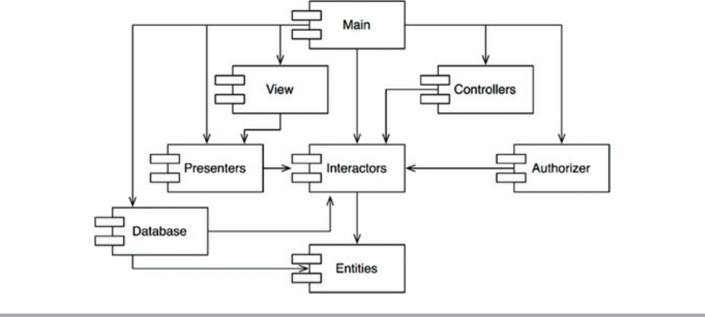
Figure 14.1 Typical component diagram
Notice one more thing: Regardless of which component you begin at, it is impossible
to follow the dependency relationships and wind up back at that component. This
structure has no cycles. It is a directed acyclic graph (DAG).
Now consider what happens when the team responsible for Presenters makes a new
release of their component. It is easy to find out who is affected by this release; you
just follow the dependency arrows backward. Thus View and Main will both be
affected. The developers currently working on those components will have to decide
when they should integrate their work with the new release of Presenters.
Notice also that when Main is released, it has utterly no effect on any of the other
components in the system. They don’t know about Main, and they don’t care when it
changes. This is nice. It means that the impact of releasing Main is relatively small.
When the developers working on the Presenters component would like to run a test
of that component, they just need to build their version of Presenters with the
versions of the Interactors and Entities components that they are currently using.
None of the other components in the system need be involved. This is nice. It means
that the developers working on Presenters have relatively little work to do to set up
a test, and that they have relatively few variables to consider.
When it is time to release the whole system, the process proceeds from the bottom
up. First the Entities component is compiled, tested, and released. Then the same is
done for Database and Interactors. These components are followed by
Presenters, View, Controllers, and then Authorizer. Main goes last. This process
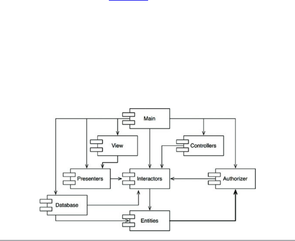
is very clear and easy to deal with. We know how to build the system because we
understand the dependencies between its parts.
THE EFFECT OF A CYCLE IN THE COMPONENT
DEPENDENCY GRAPH
Suppose that a new requirement forces us to change one of the classes in Entities
such that it makes use of a class in Authorizer. For example, let’s say that the User
class in Entities uses the Permissions class in Authorizer. This creates a
dependency cycle, as shown in Figure 14.2.
This cycle creates some immediate problems. For example, the developers working
on the Database component know that to release it, the component must be
compatible with Entities. However, with the cycle in place, the Database
component must now also be compatible with Authorizer. But Authorizer depends
on Interactors. This makes Database much more difficult to release. Entities,
Authorizer, and Interactors have, in effect, become one large component—which
means that all of the developers working on any of those components will experience
the dreaded “morning after syndrome.” They will be stepping all over one another
because they must all use exactly the same release of one another’s components.
Figure 14.2 A dependency cycle
But this is just part of the trouble. Consider what happens when we want to test the
Entities component. To our chagrin, we find that we must build and integrate with
Authorizer and Interactors. This level of coupling between components is
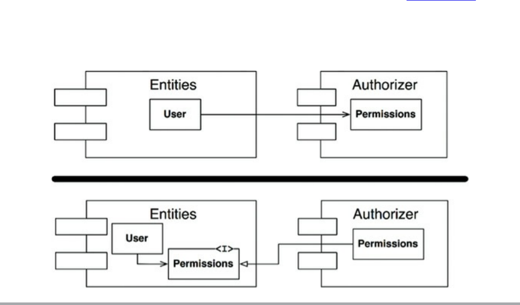
troubling, if not intolerable.
You may have wondered why you have to include so many different libraries, and so
much of everybody else’s stuff, just to run a simple unit test of one of your classes. If
you investigate the matter a bit, you will probably discover that there are cycles in
the dependency graph. Such cycles make it very difficult to isolate components. Unit
testing and releasing become very difficult and error prone. In addition, build issues
grow geometrically with the number of modules.
Moreover, when there are cycles in the dependency graph, it can be very difficult to
work out the order in which you must build the components. Indeed, there probably
is no correct order. This can lead to some very nasty problems in languages like Java
that read their declarations from compiled binary files.
BREAKING THE CYCLE
It is always possible to break a cycle of components and reinstate the dependency
graph as a DAG. There are two primary mechanisms for doing so:
1. Apply the Dependency Inversion Principle (DIP). In the case in Figure 14.3, we
could create an interface that has the methods that User needs. We could then put
that interface into Entities and inherit it into Authorizer. This inverts the
dependency between Entities and Authorizer, thereby breaking the cycle.
Figure 14.3 Inverting the dependency between Entities and Authorizer
2. Create a new component that both Entities and Authorizer depend on. Move
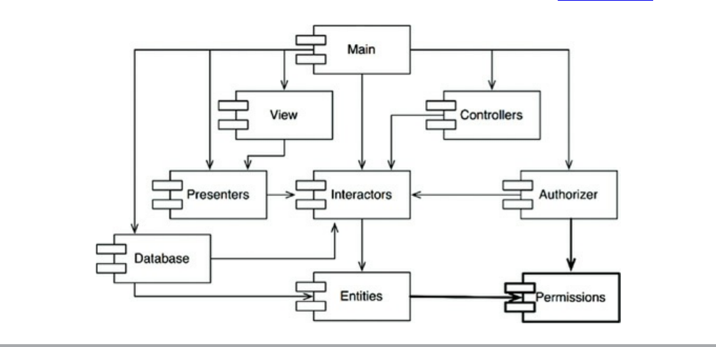
the class(es) that they both depend on into that new component (Figure 14.4).
Figure 14.4 The new component that both Entities and Authorizer depend on
THE “JITTERS”
The second solution implies that the component structure is volatile in the presence
of changing requirements. Indeed, as the application grows, the component
dependency structure jitters and grows. Thus the dependency structure must always
be monitored for cycles. When cycles occur, they must be broken somehow.
Sometimes this will mean creating new components, making the dependency
structure grow.
TOP-DOWN DESIGN
The issues we have discussed so far lead to an inescapable conclusion: The
component structure cannot be designed from the top down. It is not one of the first
things about the system that is designed, but rather evolves as the system grows and
changes.
Some readers may find this point to be counterintuitive. We have come to expect that
large-grained decompositions, like components, will also be high-level functional
decompositions.
When we see a large-grained grouping such as a component dependency structure,
we believe that the components ought to somehow represent the functions of the
system. Yet this does not seem to be an attribute of component dependency
diagrams.
In fact, component dependency diagrams have very little do to with describing the
function of the application. Instead, they are a map to the buildability and
maintainability of the application. This is why they aren’t designed at the beginning
of the project. There is no software to build or maintain, so there is no need for a
build and maintenance map. But as more and more modules accumulate in the early
stages of implementation and design, there is a growing need to manage the
dependencies so that the project can be developed without the “morning after
syndrome.” Moreover, we want to keep changes as localized as possible, so we start
paying attention to the SRP and CCP and collocate classes that are likely to change
together.
One of the overriding concerns with this dependency structure is the isolation of
volatility. We don’t want components that change frequently and for capricious
reasons to affect components that otherwise ought to be stable. For example, we
don’t want cosmetic changes to the GUI to have an impact on our business rules. We
don’t want the addition or modification of reports to have an impact on our highest-
level policies. Consequently, the component dependency graph is created and
molded by architects to protect stable high-value components from volatile
components.
As the application continues to grow, we start to become concerned about creating
reusable elements. At this point, the CRP begins to influence the composition of the
components. Finally, as cycles appear, the ADP is applied and the component
dependency graph jitters and grows.
If we tried to design the component dependency structure before we designed any
classes, we would likely fail rather badly. We would not know much about common
closure, we would be unaware of any reusable elements, and we would almost
certainly create components that produced dependency cycles. Thus the component
dependency structure grows and evolves with the logical design of the system.
THE STABLE DEPENDENCIES PRINCIPLE
Depend in the direction of stability.
Designs cannot be completely static. Some volatility is necessary if the design is to

be maintained. By conforming to the Common Closure Principle (CCP), we create
components that are sensitive to certain kinds of changes but immune to others.
Some of these components are designed to be volatile. We expect them to change.
Any component that we expect to be volatile should not be depended on by a
component that is difficult to change. Otherwise, the volatile component will also be
difficult to change.
It is the perversity of software that a module that you have designed to be easy to
change can be made difficult to change by someone else who simply hangs a
dependency on it. Not a line of source code in your module need change, yet your
module will suddenly become more challenging to change. By conforming to the
Stable Dependencies Principle (SDP), we ensure that modules that are intended to be
easy to change are not depended on by modules that are harder to change.
STABILITY
What is meant by “stability”? Stand a penny on its side. Is it stable in that position?
You would likely say “no.” However, unless disturbed, it will remain in that position
for a very long time. Thus stability has nothing directly to do with frequency of
change. The penny is not changing, but it is difficult to think of it as stable.
Webster’s Dictionary says that something is stable if it is “not easily moved.”
Stability is related to the amount of work required to make a change. On the one
hand, the standing penny is not stable because it requires very little work to topple it.
On the other hand, a table is very stable because it takes a considerable amount of
effort to turn it over.
How does this relate to software? Many factors may make a software component
hard to change—for example, its size, complexity, and clarity, among other
characteristics. We will ignore all those factors and focus on something different
here. One sure way to make a software component difficult to change, is to make lots
of other software components depend on it. A component with lots of incoming
dependencies is very stable because it requires a great deal of work to reconcile any
changes with all the dependent components.
The diagram in Figure 14.5 shows X, which is a stable component. Three
components depend on X, so it has three good reasons not to change. We say that X is
responsible to those three components. Conversely, X depends on nothing, so it has
no external influence to make it change. We say it is independent.
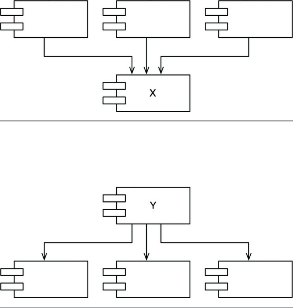
Figure 14.5 X: a stable component
Figure 14.6 shows Y, which is a very unstable component. No other components
depend on Y, so we say that it is irresponsible. Y also has three components that it
depends on, so changes may come from three external sources. We say that Y is
dependent.
Figure 14.6 Y: a very unstable component
STABILITY METRICS
How can we measure the stability of a component? One way is to count the number
of dependencies that enter and leave that component. These counts will allow us to
calculate the positional stability of the component.
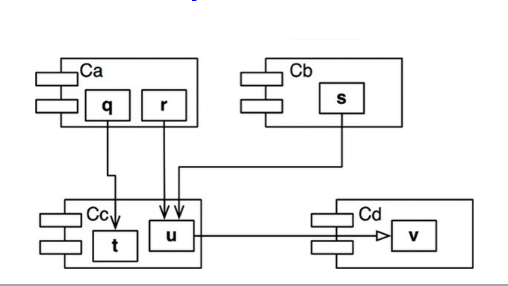
• Fan-in: Incoming dependencies. This metric identifies the number of classes
outside this component that depend on classes within the component.
• Fan-out: Outgoing depenencies. This metric identifies the number of classes inside
this component that depend on classes outside the component.
• I: Instability: I = Fan-out , (Fan-in + Fan-out). This metric has the range [0, 1]. I =
0 indicates a maximally stable component. I = 1 indicates a maximally unstable
component.
The Fan-in and Fan-out metrics1 are calculated by counting the number of classes
outside the component in question that have dependencies with the classes inside the
component in question. Consider the example in Figure 14.7.
Figure 14.7 Our example
Let’s say we want to calculate the stability of the component Cc. We find that there
are three classes outside Cc that depend on classes in Cc. Thus, Fan-in = 3.
Moreover, there is one class outside Cc that classes in Cc depend on. Thus, Fan-out =
1 and I = 1/4.
In C++, these dependencies are typically represented by #include statements.
Indeed, the I metric is easiest to calculate when you have organized your source code
such that there is one class in each source file. In Java, the I metric can be calculated
by counting import statements and qualified names.
When the I metric is equal to 1, it means that no other component depends on this
component (Fan-in = 0), and this component depends on other components (Fan-out
> 0). This situation is as unstable as a component can get; it is irresponsible and
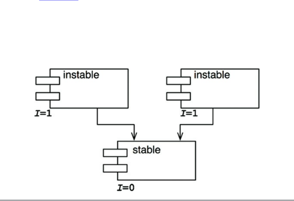
dependent. Its lack of dependents gives the component no reason not to change, and
the components that it depends on may give it ample reason to change.
In contrast, when the I metric is equal to 0, it means that the component is depended
on by other components (Fan-in > 0), but does not itself depend on any other
components (Fan-out = 0). Such a component is responsible and independent. It is as
stable as it can get. Its dependents make it hard to change the component, and its has
no dependencies that might force it to change.
The SDP says that the I metric of a component should be larger than the I metrics of
the components that it depends on. That is, I metrics should decrease in the direction
of dependency.
NOT ALL COMPONENTS SHOULD BE STABLE
If all the components in a system were maximally stable, the system would be
unchangeable. This is not a desirable situation. Indeed, we want to design our
component structure so that some components are unstable and some are stable. The
diagram in Figure 14.8 shows an ideal configuration for a system with three
components.
The changeable components are on top and depend on the stable component at the
bottom. Putting the unstable components at the top of the diagram is a useful
convention because any arrow that points up is violating the SDP (and, as we shall
see later, the ADP).
Figure 14.8 An ideal configuration for a system with three components
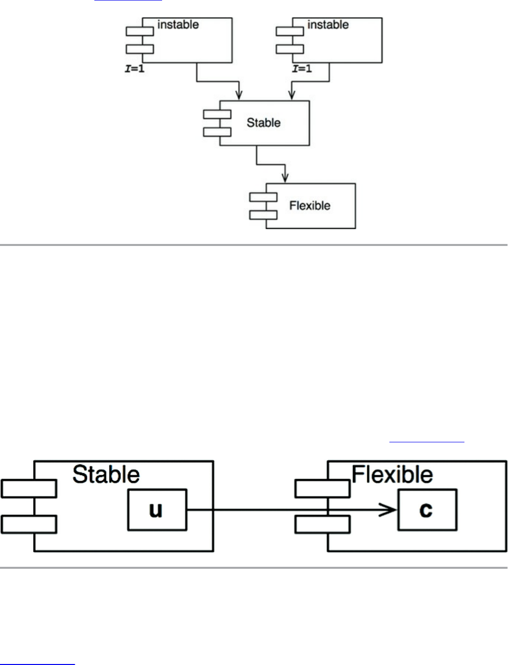
The diagram in Figure 14.9 shows how the SDP can be violated.
Figure 14.9 SDP violation
Flexible is a component that we have designed to be easy to change. We want
Flexible to be unstable. However, some developer, working in the component
named Stable, has hung a dependency on Flexible. This violates the SDP because
the I metric for Stable is much smaller than the I metric for Flexible. As a result,
Flexible will no longer be easy to change. A change to Flexible will force us to
deal with Stable and all its dependents.
To fix this problem, we somehow have to break the dependence of Stable on
Flexible. Why does this dependency exist? Let’s assume that there is a class C
within Flexible that another class U within Stable needs to use (Figure 14.10).
Figure 14.10 U within Stable uses C within Flexible
We can fix this by employing the DIP. We create an interface class called US and put
it in a component named UServer. We make sure that this interface declares all the
methods that U needs to use. We then make C implement this interface as shown in
Figure 14.11. This breaks the dependency of Stable on Flexible, and forces both
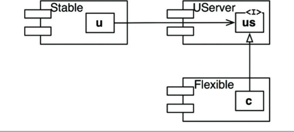
components to depend on UServer. UServer is very stable (I = 0), and Flexible
retains its necessary instability (I = 1). All the dependencies now flow in the
direction of decreasing I.
Figure 14.11 C implements the interface class US
Abstract Components
You may find it strange that we would create a component—in this example,
UService—that contains nothing but an interface. Such a component contains no
executable code! It turns out, however, that this is a very common, and necessary,
tactic when using statically typed languages like Java and C#. These abstract
components are very stable and, therefore, are ideal targets for less stable
components to depend on.
When using dynamically typed languages like Ruby and Python, these abstract
components don’t exist at all, nor do the dependencies that would have targeted
them. Dependency structures in these languages are much simpler because
dependency inversion does not require either the declaration or the inheritance of
interfaces.
THE STABLE ABSTRACTIONS PRINCIPLE
A component should be as abstract as it is stable.
WHERE DO WE PUT THE HIGH-LEVEL POLICY?
Some software in the system should not change very often. This software represents
high-level architecture and policy decisions. We don’t want these business and
architectural decisions to be volatile. Thus the software that encapsulates the high-
level policies of the system should be placed into stable components (I = 0).
Unstable components (I = 1) should contain only the software that is volatile—
software that we want to be able to quickly and easily change.
However, if the high-level policies are placed into stable components, then the
source code that represents those policies will be difficult to change. This could
make the overall architecture inflexible. How can a component that is maximally
stable (I = 0) be flexible enough to withstand change? The answer is found in the
OCP. This principle tells us that it is possible and desirable to create classes that are
flexible enough to be extended without requiring modification. Which kind of
classes conform to this principle? Abstract classes.
INTRODUCING THE STABLE ABSTRACTIONS
PRINCIPLE
The Stable Abstractions Principle (SAP) sets up a relationship between stability and
abstractness. On the one hand, it says that a stable component should also be abstract
so that its stability does not prevent it from being extended. On the other hand, it
says that an unstable component should be concrete since it its instability allows the
concrete code within it to be easily changed.
Thus, if a component is to be stable, it should consist of interfaces and abstract
classes so that it can be extended. Stable components that are extensible are flexible
and do not overly constrain the architecture.
The SAP and the SDP combined amount to the DIP for components. This is true
because the SDP says that dependencies should run in the direction of stability, and
the SAP says that stability implies abstraction. Thus dependencies run in the
direction of abstraction.
The DIP, however, is a principle that deals with classes—and with classes there are
no shades of gray. Either a class is abstract or it is not. The combination of the SDP
and the SAP deals with components, and allows that a component can be partially
abstract and partially stable.
MEASURING ABSTRACTION
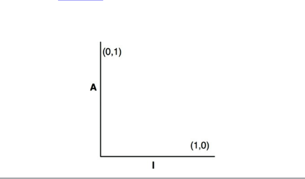
The A metric is a measure of the abstractness of a component. Its value is simply the
ratio of interfaces and abstract classes in a component to the total number of classes
in the component.
• Nc: The number of classes in the component.
• Na: The number of abstract classes and interfaces in the component.
• A: Abstractness. A = Na ÷ Nc.
The A metric ranges from 0 to 1. A value of 0 implies that the component has no
abstract classes at all. A value of 1 implies that the component contains nothing but
abstract classes.
THE MAIN SEQUENCE
We are now in a position to define the relationship between stability (I) and
abstractness (A). To do so, we create a graph with A on the vertical axis and I on the
horizontal axis (Figure 14.12). If we plot the two “good” kinds of components on
this graph, we will find the components that are maximally stable and abstract at the
upper left at (0, 1). The components that are maximally unstable and concrete are at
the lower right at (1, 0).
Figure 14.12 The I/A graph
Not all components fall into one of these two positions, because components often
have degrees of abstraction and stability. For example, it is very common for one
abstract class to derive from another abstract class. The derivative is an abstraction
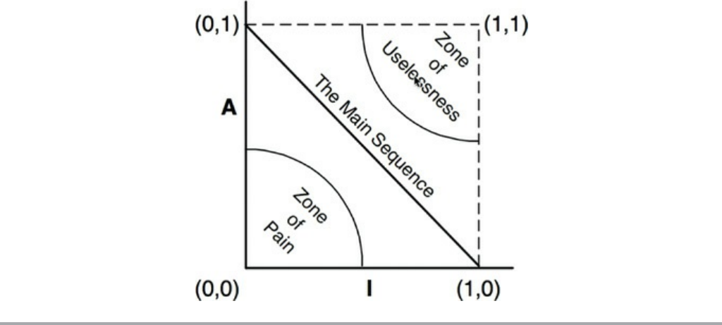
that has a dependency. Thus, though it is maximally abstract, it will not be
maximally stable. Its dependency will decrease its stability.
Since we cannot enforce a rule that all components sit at either (0, 1) or (1, 0), we
must assume that there is a locus of points on the A/I graph that defines reasonable
positions for components. We can infer what that locus is by finding the areas where
components should not be—in other words, by determining the zones of exclusion
(Figure 11.13).
Figure 14.13 Zones of exclusion
The Zone of Pain
Consider a component in the area of (0, 0). This is a highly stable and concrete
component. Such a component is not desirable because it is rigid. It cannot be
extended because it is not abstract, and it is very difficult to change because of its
stability. Thus we do not normally expect to see well-designed components sitting
near (0, 0). The area around (0, 0) is a zone of exclusion called the Zone of Pain.
Some software entities do, in fact, fall within the Zone of Pain. An example would
be a database schema. Database schemas are notoriously volatile, extremely
concrete, and highly depended on. This is one reason why the interface between OO
applications and databases is so difficult to manage, and why schema updates are
generally painful.
Another example of software that sits near the area of (0, 0) is a concrete utility
library. Although such a library has an I metric of 1, it may actually be nonvolatile.

Consider the String component, for example. Even though all the classes within it
are concrete, it is so commonly used that changing it would create chaos. Therefore
String is nonvolatile.
Nonvolatile components are harmless in the (0, 0) zone since they are not likely to
be changed. For that reason, it is only volatile software components that are
problematic in the Zone of Pain. The more volatile a component in the Zone of Pain,
the more “painful” it is. Indeed, we might consider volatility to be a third axis of the
graph. With this understanding, Figure 14.13 shows only the most painful plane,
where volatility = 1.
The Zone of Uselessness
Consider a component near (1, 1). This location is undesirable because it is
maximally abstract, yet has no dependents. Such components are useless. Thus this
area is called the Zone of Uselessness.
The software entities that inhabit this region are a kind of detritus. They are often
leftover abstract classes that no one ever implemented. We find them in systems
from time to time, sitting in the code base, unused.
A component that has a position deep within the Zone of Uselessness must contain a
significant fraction of such entities. Clearly, the presence of such useless entities is
undesirable.
AVOIDING THE ZONES OF EXCLUSION
It seems clear that our most volatile components should be kept as far from both
zones of exclusion as possible. The locus of points that are maximally distant from
each zone is the line that connects (1, 0) and (0, 1). I call this line the Main
Sequence.2
A component that sits on the Main Sequence is not “too abstract” for its stability, nor
is it “too unstable” for its abstractness. It is neither useless nor particularly painful. It
is depended on to the extent that it is abstract, and it depends on others to the extent
that it is concrete.
The most desirable position for a component is at one of the two endpoints of the
Main Sequence. Good architects strive to position the majority of their components
at those endpoints. However, in my experience, some small fraction of the

components in a large system are neither perfectly abstract nor perfectly stable.
Those components have the best characteristics if they are on, or close, to the Main
Sequence.
DISTANCE FROM THE MAIN SEQUENCE
This leads us to our last metric. If it is desirable for components to be on, or close, to
the Main Sequence, then we can create a metric that measures how far away a
component is from this ideal.
• D3: Distance. D = |A+I–1| . The range of this metric is [0, 1]. A value of 0 indicates
that the component is directly on the Main Sequence. A value of 1 indicates that
the component is as far away as possible from the Main Sequence.
Given this metric, a design can be analyzed for its overall conformance to the Main
Sequence. The D metric for each component can be calculated. Any component that
has a D value that is not near zero can be reexamined and restructured.
Statistical analysis of a design is also possible. We can calculate the mean and
variance of all the D metrics for the components within a design. We would expect a
conforming design to have a mean and variance that are close to zero. The variance
can be used to establish “control limits” so as to identify components that are
“exceptional” in comparison to all the others.
In the scatterplot in Figure 14.14, we see that the bulk of the components lie along
the Main Sequence, but some of them are more than one standard deviation (Z = 1)
away from the mean. These aberrant components are worth examining more closely.
For some reason, they are either very abstract with few dependents or very concrete
with many dependents.
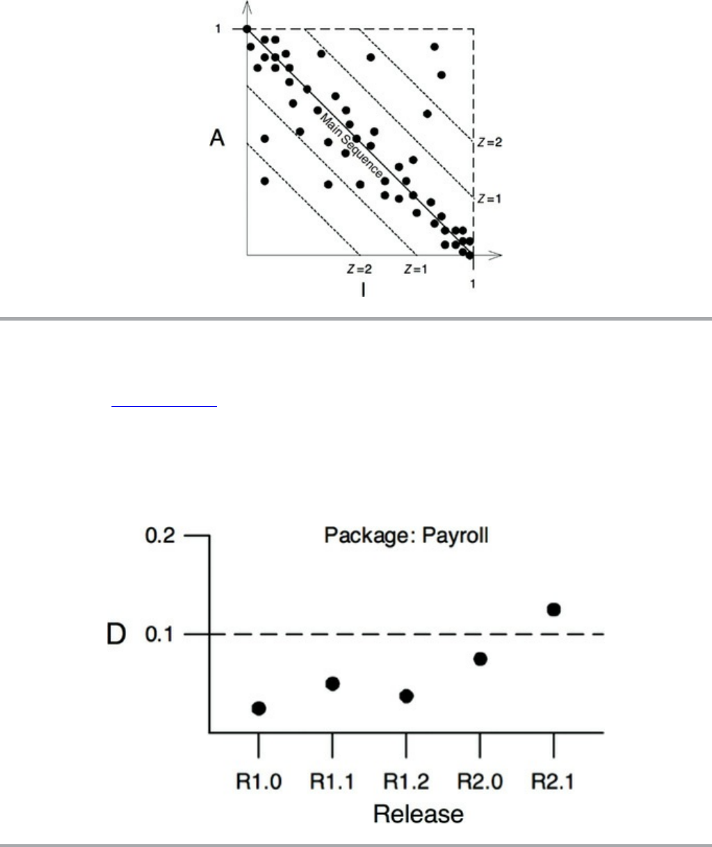
Figure 14.14 Scatterplot of the components
Another way to use the metrics is to plot the D metric of each component over time.
The graph in Figure 14.15 is a mock-up of such a plot. You can see that some
strange dependencies have been creeping into the Payroll component over the last
few releases. The plot shows a control threshold at D = 0.1. The R2.1 point has
exceeded this control limit, so it would be worth our while to find out why this
component is so far from the main sequence.
Figure 14.15 Plot of D for a single component over time
CONCLUSION

The dependency management metrics described in this chapter measure the
conformance of a design to a pattern of dependency and abstraction that I think is a
“good” pattern. Experience has shown that certain dependencies are good and others
are bad. This pattern reflects that experience. However, a metric is not a god; it is
merely a measurement against an arbitrary standard. These metrics are imperfect, at
best, but it is my hope that you find them useful.
1. In previous publications, I used the names Efferent and Afferent couplings (Ce and Ca) for Fan-
out and Fan-in, respectively. That was just hubris on my part: I liked the metaphor of the central
nervous system.
2. The author begs the reader’s indulgence for the arrogance of borrowing such an important term
from astronomy.
3. In previous publications, I called this metric D′. I see no reason to continue that practice.

V
ARCHITECTURE
15
WHAT IS ARCHITECTURE?
The word “architecture” conjures visions of power and mystery. It makes us think of
weighty decisions and deep technical prowess. Software architecture is at the
pinnacle of technical achievement. When we think of a software architect, we think
of someone who has power, and who commands respect. What young aspiring
software developer has not dreamed of one day becoming a software architect?
But what is software architecture? What does a software architect do, and when does
he or she do it?
First of all, a software architect is a programmer; and continues to be a programmer.
Never fall for the lie that suggests that software architects pull back from code to
focus on higher-level issues. They do not! Software architects are the best
programmers, and they continue to take programming tasks, while they also guide
the rest of the team toward a design that maximizes productivity. Software architects
may not write as much code as other programmers do, but they continue to engage in
programming tasks. They do this because they cannot do their jobs properly if they
are not experiencing the problems that they are creating for the rest of the
programmers.
The architecture of a software system is the shape given to that system by those who
build it. The form of that shape is in the division of that system into components, the
arrangement of those components, and the ways in which those components
communicate with each other.
The purpose of that shape is to facilitate the development, deployment, operation,
and maintenance of the software system contained within it.
The strategy behind that facilitation is to leave as many options open as possible, for as
long as possible.
Perhaps this statement has surprised you. Perhaps you thought that the goal of
software architecture was to make the system work properly. Certainly we want the
system to work properly, and certainly the architecture of the system must support
that as one of its highest priorities.
However, the architecture of a system has very little bearing on whether that system
works. There are many systems out there, with terrible architectures, that work just
fine. Their troubles do not lie in their operation; rather, they occur in their
deployment, maintenance, and ongoing development.
This is not to say that architecture plays no role in supporting the proper behavior of
the system. It certainly does, and that role is critical. But the role is passive and
cosmetic, not active or essential. There are few, if any, behavioral options that the
architecture of a system can leave open.
The primary purpose of architecture is to support the life cycle of the system. Good
architecture makes the system easy to understand, easy to develop, easy to maintain,
and easy to deploy. The ultimate goal is to minimize the lifetime cost of the system
and to maximize programmer productivity.
DEVELOPMENT
A software system that is hard to develop is not likely to have a long and healthy
lifetime. So the architecture of a system should make that system easy to develop, for
the team(s) who develop it.
Different team structures imply different architectural decisions. On the one hand, a
small team of five developers can quite effectively work together to develop a
monolithic system without well-defined components or interfaces. In fact, such a
team would likely find the strictures of an architecture something of an impediment
during the early days of development. This is likely the reason why so many systems
lack good architecture: They were begun with none, because the team was small and
did not want the impediment of a superstructure.
On the other hand, a system being developed by five different teams, each of which
includes seven developers, cannot make progress unless the system is divided into
well-defined components with reliably stable interfaces. If no other factors are
considered, the architecture of that system will likely evolve into five components—
one for each team.
Such a component-per-team architecture is not likely to be the best architecture for
deployment, operation, and maintenance of the system. Nevertheless, it is the
architecture that a group of teams will gravitate toward if they are driven solely by
development schedule.
DEPLOYMENT
To be effective, a software system must be deployable. The higher the cost of
deployment, the less useful the system is. A goal of a software architecture, then,
should be to make a system that can be easily deployed with a single action.
Unfortunately, deployment strategy is seldom considered during initial development.
This leads to architectures that may make the system easy to develop, but leave it
very difficult to deploy.
For example, in the early development of a system, the developers may decide to use
a “micro-service architecture.” They may find that this approach makes the system
very easy to develop since the component boundaries are very firm and the interfaces
relatively stable. However, when it comes time to deploy the system, they may
discover that the number of micro-services has become daunting; configuring the
connections between them, and the timing of their initiation, may also turn out to be
a huge source of errors.
Had the architects considered deployment issues early on, they might have decided
on fewer services, a hybrid of services and in-process components, and a more
integrated means of managing the interconnections.
OPERATION
The impact of architecture on system operation tends to be less dramatic than the
impact of architecture on development, deployment, and maintenance. Almost any
operational difficulty can be resolved by throwing more hardware at the system
without drastically impacting the software architecture.
Indeed, we have seen this happen over and over again. Software systems that have
inefficient architectures can often be made to work effectively simply by adding
more storage and more servers. The fact that hardware is cheap and people are
expensive means that architectures that impede operation are not as costly as
architectures that impede development, deployment, and maintenance.
This is not to say that an architecture that is well tuned to the operation of the system
is not desirable. It is! It’s just that the cost equation leans more toward development,
deployment, and maintenance.
Having said that, there is another role that architecture plays in the operation of the
system: A good software architecture communicates the operational needs of the
system.
Perhaps a better way to say this is that the architecture of a system makes the
operation of the system readily apparent to the developers. Architecture should
reveal operation. The architecture of the system should elevate the use cases, the
features, and the required behaviors of the system to first-class entities that are
visible landmarks for the developers. This simplifies the understanding of the system
and, therefore, greatly aids in development and maintenance.
MAINTENANCE
Of all the aspects of a software system, maintenance is the most costly. The never-
ending parade of new features and the inevitable trail of defects and corrections
consume vast amounts of human resources.
The primary cost of maintenance is in spelunking and risk. Spelunking is the cost of
digging through the existing software, trying to determine the best place and the best
strategy to add a new feature or to repair a defect. While making such changes, the
likelihood of creating inadvertent defects is always there, adding to the cost of risk.
A carefully thought-through architecture vastly mitigates these costs. By separating
the system into components, and isolating those components through stable
interfaces, it is possible to illuminate the pathways for future features and greatly
reduce the risk of inadvertent breakage.
KEEPING OPTIONS OPEN
As we described in an earlier chapter, software has two types of value: the value of
its behavior and the value of its structure. The second of these is the greater of the
two because it is this value that makes software soft.
Software was invented because we needed a way to quickly and easily change the
behavior of machines. But that flexibility depends critically on the shape of the
system, the arrangement of its components, and the way those components are
interconnected.
The way you keep software soft is to leave as many options open as possible, for as
long as possible. What are the options that we need to leave open? They are the
details that don’t matter.
All software systems can be decomposed into two major elements: policy and
details. The policy element embodies all the business rules and procedures. The
policy is where the true value of the system lives.
The details are those things that are necessary to enable humans, other systems, and
programmers to communicate with the policy, but that do not impact the behavior of
the policy at all. They include IO devices, databases, web systems, servers,
frameworks, communication protocols, and so forth.
The goal of the architect is to create a shape for the system that recognizes policy as
the most essential element of the system while making the details irrelevant to that
policy. This allows decisions about those details to be delayed and deferred.
For example:
• It is not necessary to choose a database system in the early days of development,
because the high-level policy should not care which kind of database will be used.
Indeed, if the architect is careful, the high-level policy will not care if the database
is relational, distributed, hierarchical, or just plain flat files.
• It is not necessary to choose a web server early in development, because the high-
level policy should not know that it is being delivered over the web. If the high-
level policy is unaware of HTML, AJAX, JSP, JSF, or any of the rest of the
alphabet soup of web development, then you don’t need to decide which web
system to use until much later in the project. Indeed, you don’t even have to decide
if the system will be delivered over the web.
• It is not necessary to adopt REST early in development, because the high-level
policy should be agnostic about the interface to the outside world. Nor is it
necessary to adopt a micro-services framework, or a SOA framework. Again, the
high-level policy should not care about these things.
• It is not necessary to adopt a dependency injection framework early in
development, because the high-level policy should not care how dependencies are
resolved.
I think you get the point. If you can develop the high-level policy without
committing to the details that surround it, you can delay and defer decisions about
those details for a long time. And the longer you wait to make those decisions, the
more information you have with which to make them properly.
This also leaves you the option to try different experiments. If you have a portion of
the high-level policy working, and it is agnostic about the database, you could try
connecting it to several different databases to check applicability and performance.
The same is true with web systems, web frameworks, or even the web itself.
The longer you leave options open, the more experiments you can run, the more
things you can try, and the more information you will have when you reach the point
at which those decisions can no longer be deferred.
What if the decisions have already been made by someone else? What if your
company has made a commitment to a certain database, or a certain web server, or a
certain framework? A good architect pretends that the decision has not been made,
and shapes the system such that those decisions can still be deferred or changed for
as long as possible.
A good architect maximizes the number of decisions not made.

DEVICE INDEPENDENCE
As an example of this kind of thinking, let’s take a trip back to the 1960s, when
computers were teenagers and most programmers were mathematicians or engineers
from other disciplines (and-one third or more were women).
In those days we made a lot of mistakes. We didn’t know they were mistakes at the
time, of course. How could we?
One of those mistakes was to bind our code directly to the IO devices. If we needed
to print something on a printer, we wrote code that used the IO instructions that
would control the printer. Our code was device dependent.
For example, when I wrote PDP-8 programs that printed on the teleprinter, I used a
set of machine instructions that looked like this:
Click here to view code image
PRTCHR, 0
TSF
JMP .-1
TLS
JMP I PRTCHR
PRTCHR is a subroutine that prints one character on the teleprinter. The beginning
zero was used as the storage for the return address. (Don’t ask.) The TSF instruction
skipped the next instruction if the teleprinter was ready to print a character. If the
teleprinter was busy, then TSF just fell through to the JMP .-1 instruction, which just
jumped back to the TSF instruction. If the teleprinter was ready, then TSF would skip
to the TLS instruction, which sent the character in the A register to the teleprinter.
Then the JMP I PRTCHR instruction returned to the caller.
At first this strategy worked fine. If we needed to read cards from the card reader, we
used code that talked directly to the card reader. If we needed to punch cards, we
wrote code that directly manipulated the punch. The programs worked perfectly.
How could we know this was a mistake?
But big batches of punched cards are difficult to manage. They can be lost,
mutilated, spindled, shuffled, or dropped. Individual cards can be lost and extra cards
can be inserted. So data integrity became a significant problem.
Magnetic tape was the solution. We could move the card images to tape. If you drop
a magnetic tape, the records don’t get shuffled. You can’t accidentally lose a record,
or insert a blank record simply by handing the tape. The tape is much more secure.
It’s also faster to read and write, and it is very easy to make backup copies.
Unfortunately, all our software was written to manipulate card readers and card
punches. Those programs had to be rewritten to use magnetic tape. That was a big
job.
By the late 1960s, we had learned our lesson—and we invented device
independence. The operating systems of the day abstracted the IO devices into
software functions that handled unit records that looked like cards. The programs
would invoke operating system services that dealt with abstract unit-record devices.
Operators could tell the operating system whether those abstract services should be
connected to card readers, magnetic tape, or any other unit-record device.
Now the same program could read and write cards, or read and write tape, without
any change. The Open–Closed Principle was born (but not yet named).
JUNK MAIL
In the late 1960s, I worked for a company that printed junk mail for clients. The
clients would send us magnetic tapes with unit records containing the names and
addresses of their customers, and we would write programs that printed nice
personalized advertisements.
You know the kind:
Hello Mr. Martin,
Congratulations!
We chose YOU from everyone else who lives on Witchwood Lane to participate in
our new fantastic one-time-only offering…
The clients would send us huge rolls of form letters with all the words except the
name and address, and any other element they wanted us to print. We wrote
programs that extracted the names, addresses, and other elements from the magnetic
tape, and printed those elements exactly where they needed to appear on the forms.
These rolls of form letters weighed 500 pounds and contained thousands of letters.
Clients would send us hundreds of these rolls. We would print each one individually.
At first, we had an IBM 360 doing the printing on its sole line printer. We could
print a few thousand letters per shift. Unfortunately, this tied up a very expensive
machine for a very long time. In those days, IBM 360s rented for tens of thousands
of dollars per month.
So we told the operating system to use magnetic tape instead of the line printer. Our
programs didn’t care, because they had been written to use the IO abstractions of the
operating system.
The 360 could pump out a full tape in 10 minutes or so—enough to print several
rolls of form letters. The tapes were taken outside of the computer room and
mounted on tape drives connected to offline printers. We had five of them, and we
ran those five printers 24 hours per day, seven days per week, printing hundreds of
thousands of pieces of junk mail every week.
The value of device independence was enormous! We could write our programs
without knowing or caring which device would be used. We could test those
programs using the local line printer connected to the computer. Then we could tell
the operating system to “print” to magnetic tape and run off hundreds of thousands
of forms.
Our programs had a shape. That shape disconnected policy from detail. The policy
was the formatting of the name and address records. The detail was the device. We
deferred the decision about which device we would use.
PHYSICAL ADDRESSING
In the early 1970s, I worked on a large accounting system for a local truckers union.
We had a 25MB disk drive on which we stored records for Agents, Employers, and
Members. The different records had different sizes, so we formatted the first few
cylinders of the disk so that each sector was just the size of an Agent record. The
next few cylinders were formatted to have sectors that fit the Employer records. The
last few cylinders were formatted to fit the Member records.
We wrote our software to know the detailed structure of the disk. It knew that the
disk had 200 cylinders and 10 heads, and that each cylinder had several dozen
sectors per head. It knew which cylinders held the Agents, Employers, and Members.
All this was hard-wired into the code.
We kept an index on the disk that allowed us to look up each of the Agents,
Employers, and Members. This index was in yet another specially formatted set of
cylinders on the disk. The Agent index was composed of records that contained the
ID of an agent, and the cylinder number, head number, and sector number of that
Agent record. Employers and Members had similar indices. Members were also kept in
a doubly linked list on the disk. Each Member record held the cylinder, head, and
sector number of the next Member record, and of the previous Member record.
What would happen if we needed to upgrade to a new disk drive—one with more
heads, or one with more cylinders, or one with more sectors per cylinder? We had to
write a special program to read in the old data from the old disk, and then write it out
to the new disk, translating all of the cylinder/head/sector numbers. We also had to
change all the hard-wiring in our code—and that hard-wiring was everywhere! All
the business rules knew the cylinder/head/sector scheme in detail.
One day a more experienced programmer joined our ranks. When he saw what we
had done, the blood drained from his face, and he stared aghast at us, as if we were
aliens of some kind. Then he gently advised us to change our addressing scheme to
use relative addresses.
Our wiser colleague suggested that we consider the disk to be one huge linear array
of sectors, each addressable by a sequential integer. Then we could write a little
conversion routine that knew the physical structure of the disk, and could translate
the relative address to a cylinder/head/sector number on the fly.
Fortunately for us, we took his advice. We changed the high-level policy of the
system to be agnostic about the physical structure of the disk. That allowed us to
decouple the decision about disk drive structure from the application.
CONCLUSION
The two stories in this chapter are examples, in the small, of a principle that
architects employ in the large. Good architects carefully separate details from policy,
and then decouple the policy from the details so thoroughly that the policy has no
knowledge of the details and does not depend on the details in any way. Good
architects design the policy so that decisions about the details can be delayed and
deferred for as long as possible.
16
INDEPENDENCE
As we previously stated, a good architecture must support:
• The use cases and operation of the system.
• The maintenance of the system.
• The development of the system.
• The deployment of the system.
USE CASES
The first bullet—use cases—means that the architecture of the system must support
the intent of the system. If the system is a shopping cart application, then the

architecture must support shopping cart use cases. Indeed, this is the first concern of
the architect, and the first priority of the architecture. The architecture must support
the use cases.
However, as we discussed previously, architecture does not wield much influence
over the behavior of the system. There are very few behavioral options that the
architecture can leave open. But influence isn’t everything. The most important thing
a good architecture can do to support behavior is to clarify and expose that behavior
so that the intent of the system is visible at the architectural level.
A shopping cart application with a good architecture will look like a shopping cart
application. The use cases of that system will be plainly visible within the structure
of that system. Developers will not have to hunt for behaviors, because those
behaviors will be first-class elements visible at the top level of the system. Those
elements will be classes or functions or modules that have prominent positions
within the architecture, and they will have names that clearly describe their function.
Chapter 21, “Screaming Architecture,” will make this point much clearer.
OPERATION
Architecture plays a more substantial, and less cosmetic, role in supporting the
operation of the system. If the system must handle 100,000 customers per second,
the architecture must support that kind of throughput and response time for each use
case that demands it. If the system must query big data cubes in milliseconds, then
the architecture must be structured to allow this kind of operation.
For some systems, this will mean arranging the processing elements of the system
into an array of little services can be run in parallel on many different servers. For
other systems, it will mean a plethora of little lightweight threads sharing the address
space of a single process within a single processor. Still other systems will need just
a few processes running in isolated address spaces. And some systems can even
survive as simple monolithic programs running in a single process.
As strange as it may seem, this decision is one of the options that a good architect
leaves open. A system that is written as a monolith, and that depends on that
monolithic structure, cannot easily be upgraded to multiple processes, multiple
threads, or micro-services should the need arise. By comparison, an architecture that
maintains the proper isolation of its components, and does not assume the means of
communication between those components, will be much easier to transition through
the spectrum of threads, processes, and services as the operational needs of the
system change over time.
DEVELOPMENT
Architecture plays a significant role in supporting the development environment.
This is where Conway’s law comes into play. Conway’s law says:
Any organization that designs a system will produce a design whose structure is a copy of
the organization’s communication structure.
A system that must be developed by an organization with many teams and many
concerns must have an architecture that facilitates independent actions by those
teams, so that the teams do not interfere with each other during development. This is
accomplished by properly partitioning the system into well-isolated, independently
developable components. Those components can then be allocated to teams that can
work independently of each other.
DEPLOYMENT
The architecture also plays a huge role in determining the ease with which the
system is deployed. The goal is “immediate deployment.” A good architecture does
not rely on dozens of little configuration scripts and property file tweaks. It does not
require manual creation of directories or files that must be arranged just so. A good
architecture helps the system to be immediately deployable after build.
Again, this is achieved through the proper partitioning and isolation of the
components of the system, including those master components that tie the whole
system together and ensure that each component is properly started, integrated, and
supervised.
LEAVING OPTIONS OPEN
A good architecture balances all of these concerns with a component structure that
mutually satisfies them all. Sounds easy, right? Well, it’s easy for me to write that.
The reality is that achieving this balance is pretty hard. The problem is that most of
the time we don’t know what all the use cases are, nor do we know the operational
constraints, the team structure, or the deployment requirements. Worse, even if we
did know them, they will inevitably change as the system moves through its life
cycle. In short, the goals we must meet are indistinct and inconstant. Welcome to the
real world.
But all is not lost: Some principles of architecture are relatively inexpensive to
implement and can help balance those concerns, even when you don’t have a clear
picture of the targets you have to hit. Those principles help us partition our systems
into well-isolated components that allow us to leave as many options open as
possible, for as long as possible.
A good architecture makes the system easy to change, in all the ways that it must
change, by leaving options open.
DECOUPLING LAYERS
Consider the use cases. The architect wants the structure of the system to support all
the necessary use cases, but does not know what all those use cases are. However,
the architect does know the basic intent of the system. It’s a shopping cart system, or
it’s a bill of materials system, or it’s an order processing system. So the architect can
employ the Single Responsibility Principle and the Common Closure Principle to
separate those things that change for different reasons, and to collect those things
that change for the same reasons—given the context of the intent of the system.
What changes for different reasons? There are some obvious things. User interfaces
change for reasons that have nothing to do with business rules. Use cases have
elements of both. Clearly, then, a good architect will want to separate the UI portions
of a use case from the business rule portions in such a way that they can be changed
independently of each other, while keeping those use cases visible and clear.
Business rules themselves may be closely tied to the application, or they may be
more general. For example, the validation of input fields is a business rule that is
closely tied to the application itself. In contrast, the calculation of interest on an
account and the counting of inventory are business rules that are more closely
associated with the domain. These two different kinds of rules will change at
different rates, and for different reasons—so they should be separated so that they
can be independently changed.
The database, the query language, and even the schema are technical details that
have nothing to do with the business rules or the UI. They will change at rates, and
for reasons, that are independent of other aspects of the system. Consequently, the
architecture should separate them from the rest of the system so that they can be
independently changed.
Thus we find the system divided into decoupled horizontal layers—the UI,
application-specific business rules, application-independent business rules, and the
database, just to mention a few.
DECOUPLING USE CASES
What else changes for different reasons? The use cases themselves! The use case for
adding an order to an order entry system almost certainly will change at a different
rate, and for different reasons, than the use case that deletes an order from the
system. Use cases are a very natural way to divide the system.
At the same time, use cases are narrow vertical slices that cut through the horizontal
layers of the system. Each use case uses some UI, some application-specific business
rules, some application-independent business rules, and some database functionality.
Thus, as we are dividing the system in to horizontal layers, we are also dividing the
system into thin vertical use cases that cut through those layers.
To achieve this decoupling, we separate the UI of the add-order use case from the UI
of the delete-order use case. We do the same with the business rules, and with the
database. We keep the use cases separate down the vertical height of the system.
You can see the pattern here. If you decouple the elements of the system that change
for different reasons, then you can continue to add new use cases without interfering
with old ones. If you also group the UI and database in support of those use cases, so
that each use case uses a different aspect of the UI and database, then adding new
use cases will be unlikely to affect older ones.
DECOUPLING MODE
Now think of what all that decoupling means for the second bullet: operations. If the
different aspects of the use cases are separated, then those that must run at a high
throughput are likely already separated from those that must run at a low throughput.
If the UI and the database have been separated from the business rules, then they can
run in different servers. Those that require higher bandwidth can be replicated in
many servers.
In short, the decoupling that we did for the sake of the use cases also helps with
operations. However, to take advantage of the operational benefit, the decoupling
must have the appropriate mode. To run in separate servers, the separated
components cannot depend on being together in the same address space of a
processor. They must be independent services, which communicate over a network
of some kind.
Many architects call such components “services” or “micro-services,” depending
upon some vague notion of line count. Indeed, an architecture based on services is
often called a service-oriented architecture.
If that nomenclature set off some alarm bells in your mind, don’t worry. I’m not
going to tell you that SoA is the best possible architecture, or that micro-services are
the wave of the future. The point being made here is that sometimes we have to
separate our components all the way to the service level.
Remember, a good architecture leaves options open. The decoupling mode is one of
those options.
Before we explore that topic further, let’s look to the other two bullets.
INDEPENDENT DEVELOP-ABILITY
The third bullet was development. Clearly when components are strongly decoupled,
the interference between teams is mitigated. If the business rules don’t know about
the UI, then a team that focuses on the UI cannot much affect a team that focuses on
the business rules. If the use cases themselves are decoupled from one another, then
a team that focuses on the addOrder use case is not likely to interfere with a team
that focuses on the deleteOrder use case.
So long as the layers and use cases are decoupled, the architecture of the system will
support the organization of the teams, irrespective of whether they are organized as
feature teams, component teams, layer teams, or some other variation.
INDEPENDENT DEPLOYABILITY
The decoupling of the use cases and layers also affords a high degree of flexibility in
deployment. Indeed, if the decoupling is done well, then it should be possible to hot-
swap layers and use cases in running systems. Adding a new use case could be a
simple as adding a few new jar files or services to the system while leaving the rest
alone.
DUPLICATION
Architects often fall into a trap—a trap that hinges on their fear of duplication.
Duplication is generally a bad thing in software. We don’t like duplicated code.
When code is truly duplicated, we are honor-bound as professionals to reduce and
eliminate it.
But there are different kinds of duplication. There is true duplication, in which every
change to one instance necessitates the same change to every duplicate of that
instance. Then there is false or accidental duplication. If two apparently duplicated
sections of code evolve along different paths—if they change at different rates, and
for different reasons—then they are not true duplicates. Return to them in a few
years, and you’ll find that they are very different from each other.
Now imagine two use cases that have very similar screen structures. The architects
will likely be strongly tempted to share the code for that structure. But should they?
Is that true duplication? Or it is accidental?
Most likely it is accidental. As time goes by, the odds are that those two screens will
diverge and eventually look very different. For this reason, care must be taken to
avoid unifying them. Otherwise, separating them later will be a challenge.
When you are vertically separating use cases from one another, you will run into this
issue, and your temptation will be to couple the use cases because they have similar
screen structures, or similar algorithms, or similar database queries and/or schemas.
Be careful. Resist the temptation to commit the sin of knee-jerk elimination of
duplication. Make sure the duplication is real.
By the same token, when you are separating layers horizontally, you might notice
that the data structure of a particular database record is very similar to the data
structure of a particular screen view. You may be tempted to simply pass the
database record up to the UI, rather than to create a view model that looks the same
and copy the elements across. Be careful: This duplication is almost certainly
accidental. Creating the separate view model is not a lot of effort, and it will help
you keep the layers properly decoupled.
DECOUPLING MODES (AGAIN)
Back to modes. There are many ways to decouple layers and use cases. They can be
decoupled at the source code level, at the binary code (deployment) level, and at the
execution unit (service) level.
• Source level. We can control the dependencies between source code modules so
that changes to one module do not force changes or recompilation of others (e.g.,
Ruby Gems).
In this decoupling mode the components all execute in the same address space, and
communicate with each other using simple function calls. There is a single
executable loaded into computer memory. People often call this a monolithic
structure.
• Deployment level. We can control the dependencies between deployable units
such as jar files, DLLs, or shared libraries, so that changes to the source code in
one module do not force others to be rebuilt and redeployed.
Many of the components may still live in the same address space, and
communicate through function calls. Other components may live in other processes
in the same processor, and communicate through interprocess communications,
sockets, or shared memory. The important thing here is that the decoupled
components are partitioned into independently deployable units such as jar files,
Gem files, or DLLs.
• Service level. We can reduce the dependencies down to the level of data structures,
and communicate solely through network packets such that every execution unit is
entirely independent of source and binary changes to others (e.g., services or
micro-services).
What is the best mode to use?
The answer is that it’s hard to know which mode is best during the early phases of a
project. Indeed, as the project matures, the optimal mode may change.
For example, it’s not difficult to imagine that a system that runs comfortably on one
server right now might grow to the point where some of its components ought to run
on separate servers. While the system runs on a single server, the source-level
decoupling might be sufficient. Later, however, it might require decoupling into
deployable units, or even services.
One solution (which seems to be popular at the moment) is to simply decouple at the
service level by default. A problem with this approach is that it is expensive and
encourages coarse-grained decoupling. No matter how “micro” the micro-services
get, the decoupling is not likely to be fine-grained enough.
Another problem with service-level decoupling is that it is expensive, both in
development time and in system resources. Dealing with service boundaries where
none are needed is a waste of effort, memory, and cycles. And, yes, I know that the
last two are cheap—but the first is not.
My preference is to push the decoupling to the point where a service could be
formed. should it become necessary; but then to leave the components in the same
address space as long as possible. This leaves the option for a service open.
With this approach, initially the components are separated at the source code level.
That may be good enough for the duration of the project’s lifetime. If, however,
deployment or development issues arise, driving some of the decoupling to a
deployment level may be sufficient—at least for a while.
As the development, deployment, and operational issues increase, I carefully choose
which deployable units to turn into services, and gradually shift the system in that
direction.
Over time, the operational needs of the system may decline. What once required
decoupling at the service level may now require only deployment-level or even
source-level decoupling.
A good architecture will allow a system to be born as a monolith, deployed in a
single file, but then to grow into a set of independently deployable units, and then all
the way to independent services and/or micro-services. Later, as things change, it
should allow for reversing that progression and sliding all the way back down into a
monolith.
A good architecture protects the majority of the source code from those changes. It
leaves the decoupling mode open as an option so that large deployments can use one
mode, whereas small deployments can use another.
CONCLUSION
Yes, this is tricky. And I’m not saying that the change of decoupling modes should
be a trivial configuration option (though sometimes that is appropriate). What I’m
saying is that the decoupling mode of a system is one of those things that is likely to
change with time, and a good architect foresees and appropriately facilitates those
changes.
17
BOUNDARIES: DRAWING LINES
Software architecture is the art of drawing lines that I call boundaries. Those
boundaries separate software elements from one another, and restrict those on one
side from knowing about those on the other. Some of those lines are drawn very
early in a project’s life—even before any code is written. Others are drawn much
later. Those that are drawn early are drawn for the purposes of deferring decisions
for as long as possible, and of keeping those decisions from polluting the core
business logic.
Recall that the goal of an architect is to minimize the human resources required to
build and maintain the required system. What it is that saps this kind of people-
power? Coupling—and especially coupling to premature decisions.
Which kinds of decisions are premature? Decisions that have nothing to do with the

business requirements—the use cases—of the system. These include decisions about
frameworks, databases, web servers, utility libraries, dependency injection, and the
like. A good system architecture is one in which decisions like these are rendered
ancillary and deferrable. A good system architecture does not depend on those
decisions. A good system architecture allows those decisions to be made at the latest
possible moment, without significant impact.
A COUPLE OF SAD STORIES
Here’s the sad story of company P, which serves as a warning about making
premature decisions. In the 1980s the founders of P wrote a simple monolithic
desktop application. They enjoyed a great deal of success and grew the product
through the 1990s into a popular and successful desktop GUI application.
But then, in the late 1990s, the web emerged as a force. Suddenly everybody had to
have a web solution, and P was no exception. P’s customers clamored for a version
of the product on the web. To meet this demand, the company hired a bunch of
hotshot twenty-something Java programmers and embarked upon a project to webify
their product.
The Java guys had dreams of server farms dancing in their heads, so they adopted a
rich three-tiered “architecture”1 that they could distribute through such farms. There
would be servers for the GUI, servers for the middleware, and servers for the
database. Of course.
The programmers decided, very early on, that all domain objects would have three
instantiations: one in the GUI tier, one in the middleware tier, and one in the
database tier. Since these instantiations lived on different machines, a rich system of
interprocessor and inter-tier communications was set up. Method invocations
between tiers were converted to objects, serialized, and marshaled across the wire.
Now imagine what it took to implement a simple feature like adding a new field to
an existing record. That field had to be added to the classes in all three tiers, and to
several of the inter-tier messages. Since data traveled in both directions, four
message protocols needed to be designed. Each protocol had a sending and receiving
side, so eight protocol handlers were required. Three executables had to be built,
each with three updated business objects, four new messages, and eight new
handlers.
And think of what those executables had to do to implement the simplest of features.
Think of all the object instantiations, all the serializations, all the marshaling and de-
marshaling, all the building and parsing of messages, all the socket communications,
timeout managers, retry scenarios, and all the other extra stuff that you have to do
just to get one simple thing done.
Of course, during development the programmers did not have a server farm. Indeed,
they simply ran all three executables in three different processes on a single machine.
They developed this way for several years. But they were convinced that their
architecture was right. And so, even though they were executing in a single machine,
they continued all the object instantiations, all the serializations, all the marshaling
and de-marshaling, all the building and parsing of messages, all the socket
communications, and all the extra stuff in a single machine.
The irony is that company P never sold a system that required a server farm. Every
system they ever deployed was a single server. And in that single server all three
executables continued all the object instantiations, all the serializations, all the
marshaling and de-marshaling, all the building and parsing of messages, all the
socket communications, and all the extra stuff, in anticipation of a server farm that
never existed, and never would.
The tragedy is that the architects, by making a premature decision, multiplied the
development effort enormously.
The story of P is not isolated. I’ve seen it many times and in many places. Indeed, P
is a superposition of all those places.
But there are worse fates than P.
Consider W, a local business that manages fleets of company cars. They recently
hired an “Architect” to get their rag-tag software effort under control. And, let me
tell you, control was this guy’s middle name. He quickly realized that what this little
operation needed was a full-blown, enterprise-scale, service-oriented
“ARCHITECTURE.” He created a huge domain model of all the different
“objects” in the business, designed a suite of services to manage these domain
objects, and put all the developers on a path to Hell. As a simple example, suppose
you wanted to add the name, address, and phone number of a contact person to a
sales record. You had to go to the ServiceRegistry and ask for the service ID of the
ContactService. Then you had to send a CreateContact message to the
ContactService. Of course, this message had dozens of fields that all had to have

valid data in them—data to which the programmer had no access, since all the
programmer had was a name, address, and phone number. After faking the data, the
programmer had to jam the ID of the newly created contact into the sales record and
send the UpdateContact message to the SaleRecordService.
Of course, to test anything you had to fire up all the necessary services, one by one,
and fire up the message bus, and the BPel server, and … And then, there were the
propagation delays as these messages bounced from service to service, and waited in
queue after queue.
And then if you wanted to add a new feature—well, you can imagine the coupling
between all those services, and the sheer volume of WSDLs that needed changing,
and all the redeployments those changes necessitated …
Hell starts to seem like a nice place by comparison.
There’s nothing intrinsically wrong with a software system that is structured around
services. The error at W was the premature adoption and enforcement of a suite of
tools that promised SoA—that is, the premature adoption of a massive suite of
domain object services. The cost of those errors was sheer person-hours—person-
hours in droves—flushed down the SoA vortex.
I could go on describing one architectural failure after another. But let’s talk about
an architectural success instead.
FITNESSE
My Son, Micah, and I started work on FitNesse in 2001. The idea was to create a
simple wiki that wrapped Ward Cunningham’s FIT tool for writing acceptance tests.
This was back in the days before Maven “solved” the jar file problem. I was adamant
that anything we produced should not require people to download more than one jar
file. I called this rule, “Download and Go.” This rule drove many of our decisions.
One of the first decisions was to write our own web server, specific to the needs of
FitNesse. This might sound absurd. Even in 2001 there were plenty of open source
web servers that we could have used. Yet writing our own turned out to be a really
good decision because a bare-bones web server is a very simple piece of software to
write and it allowed us to postpone any web framework decision until much later.2
Another early decision was to avoid thinking about a database. We had MySQL in
the back of our minds, but we purposely delayed that decision by employing a design
that made the decision irrelevant. That design was simply to put an interface between
all data accesses and the data repository itself.
We put the data access methods into an interface named WikiPage. Those methods
provided all the functionality we needed to find, fetch, and save pages. Of course, we
didn’t implement those methods at first; we simply stubbed them out while we
worked on features that didn’t involve fetching and saving the data.
Indeed, for three months we simply worked on translating wiki text into HTML. This
didn’t require any kind of data storage, so we created a class named MockWikiPage
that simply left the data access methods stubbed.
Eventually, those stubs became insufficient for the features we wanted to write. We
needed real data access, not stubs. So we created a new derivative of WikiPage
named InMemoryPage. This derivative implemented the data access method to
manage a hash table of wiki pages, which we kept in RAM.
This allowed us to write feature after feature for a full year. In fact, we got the whole
first version of the FitNesse program working this way. We could create pages, link
to other pages, do all the fancy wiki formatting, and even run tests with FIT. What
we couldn’t do was save any of our work.
When it came time to implement persistence, we thought again about MySQL, but
decided that wasn’t necessary in the short term, because it would be really easy to
write the hash tables out to flat files. So we implemented FileSystemWikiPage,
which just moved the functionality out to flat files, and then we continued
developing more features.
Three months later, we reached the conclusion that the flat file solution was good
enough; we decided to abandon the idea of MySQL altogether. We deferred that
decision into nonexistence and never looked back.
That would be the end of the story if it weren’t for one of our customers who decided
that he needed to put the wiki into MySQL for his own purposes. We showed him
the architecture of WikiPages that had allowed us to defer the decision. He came
back a day later with the whole system working in MySQL. He simply wrote a
MySqlWikiPage derivative and got it working.
We used to bundle that option with FitNesse, but nobody else ever used it, so
eventually we dropped it. Even the customer who wrote the derivative eventually
dropped it.
Early in the development of FitNesse, we drew a boundary line between business
rules and databases. That line prevented the business rules from knowing anything at
all about the database, other than the simple data access methods. That decision
allowed us to defer the choice and implementation of the database for well over a
year. It allowed us to try the file system option, and it allowed us to change direction
when we saw a better solution. Yet it did not prevent, or even impede, moving in the
original direction (MySQL) when someone wanted it.
The fact that we did not have a database running for 18 months of development
meant that, for 18 months, we did not have schema issues, query issues, database
server issues, password issues, connection time issues, and all the other nasty issues
that raise their ugly heads when you fire up a database. It also meant that all our tests
ran fast, because there was no database to slow them down.
In short, drawing the boundary lines helped us delay and defer decisions, and it
ultimately saved us an enormous amount of time and headaches. And that’s what a
good architecture should do.
WHICH LINES DO YOU DRAW, AND WHEN
DO YOU DRAW THEM?
You draw lines between things that matter and things that don’t. The GUI doesn’t
matter to the business rules, so there should be a line between them. The database
doesn’t matter to the GUI, so there should be a line between them. The database
doesn’t matter to the business rules, so there should be a line between them.
Some of you may have rejected one or more of those statements, especially the part
about the business rules not caring about the database. Many of us have been taught
to believe that the database is inextricably connected to the business rules. Some of
us have even been convinced that the database is the embodiment of the business
rules.
But, as we shall see in another chapter, this idea is misguided. The database is a tool
that the business rules can use indirectly. The business rules don’t need to know
about the schema, or the query language, or any of the other details about the
database. All the business rules need to know is that there is a set of functions that
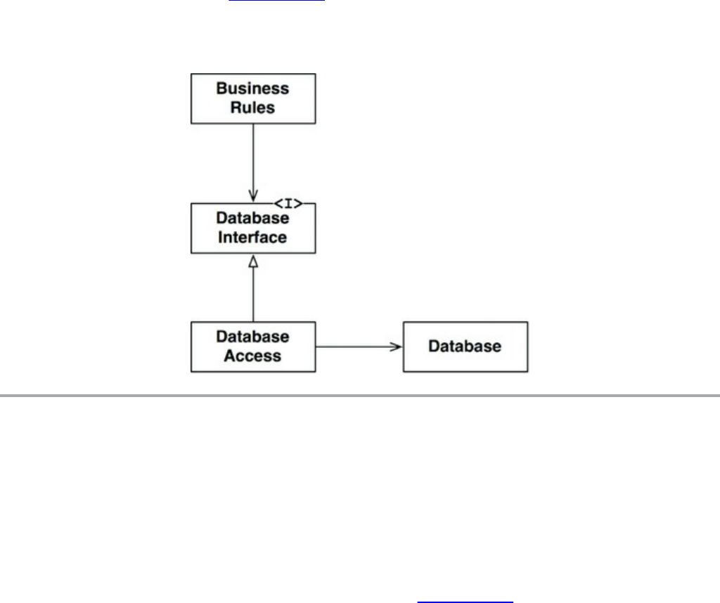
can be used to fetch or save data. This allows us to put the database behind an
interface.
You can see this clearly in Figure 17.1. The BusinessRules use the
DatabaseInterface to load and save data. The DatabaseAccess implements the
interface and directs the operation of the actual Database.
Figure 17.1 The database behind an interface
The classes and interfaces in this diagram are symbolic. In a real application, there
would be many business rule classes, many database interface classes, and many
database access implementations. All of them, though, would follow roughly the
same pattern.
Where is the boundary line? The boundary is drawn across the inheritance
relationship, just below the DatabaseInterface (Figure 17.2).
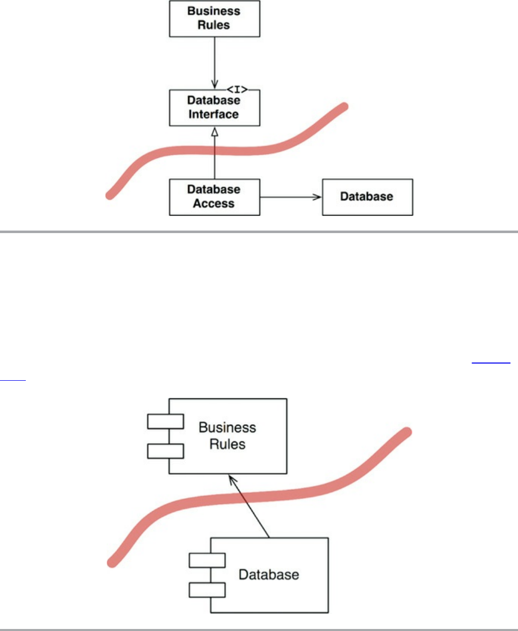
Figure 17.2 The boundary line
Note the two arrows leaving the DatabaseAccess class. Those two arrows point
away from the DatabaseAccess class. That means that none of these classes knows
that the DatabaseAccess class exists.
Now let’s pull back a bit. We’ll look at the component that contains many business
rules, and the component that contains the database and all its access classes (Figure
17.3).
Figure 17.3 The business rules and database components
Note the direction of the arrow. The Database knows about the BusinessRules. The
BusinessRules do not know about the Database. This implies that the

DatabaseInterface classes live in the BusinessRules component, while the
DatabaseAccess classes live in the Database component.
The direction of this line is important. It shows that the Database does not matter to
the BusinessRules, but the Database cannot exist without the BusinessRules.
If that seems strange to you, just remember this point: The Database component
contains the code that translates the calls made by the BusinessRules into the query
language of the database. It is that translation code that knows about the
BusinessRules.
Having drawn this boundary line between the two components, and having set the
direction of the arrow toward the BusinessRules, we can now see that the
BusinessRules could use any kind of database. The Database component could be
replaced with many different implementations—the BusinessRules don’t care.
The database could be implemented with Oracle, or MySQL, or Couch, or Datomic,
or even flat files. The business rules don’t care at all. And that means that the
database decision can be deferred and you can focus on getting the business rules
written and tested before you have to make the database decision.
WHAT ABOUT INPUT AND OUTPUT?
Developers and customers often get confused about what the system is. They see the
GUI, and think that the GUI is the system. They define a system in terms of the GUI,
so they believe that they should see the GUI start working immediately. They fail to
realize a critically important principle: The IO is irrelevant.
This may be hard to grasp at first. We often think about the behavior of the system in
terms of the behavior of the IO. Consider a video game, for example. Your
experience is dominated by the interface: the screen, the mouse, the buttons, and the
sounds. You forget that behind that interface there is a model—a sophisticated set of
data structures and functions—driving it. More importantly, that model does not
need the interface. It would happily execute its duties, modeling all the events in the
game, without the game ever being displayed on the screen. The interface does not
matter to the model—the business rules.
And so, once again, we see the GUI and BusinessRules components separated by a
boundary line (Figure 17.4). Once again, we see that the less relevant component
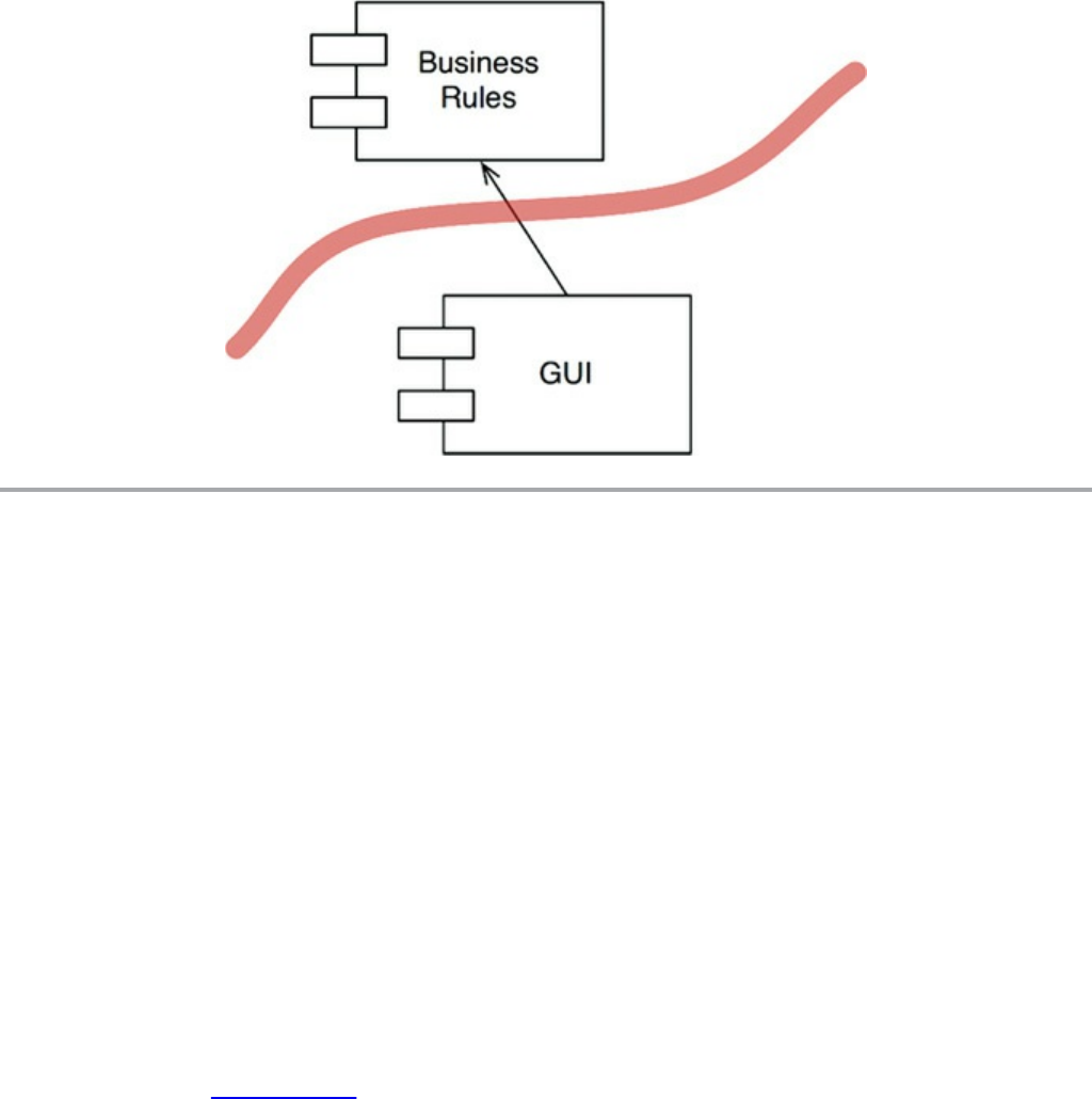
depends on the more relevant component. The arrows show which component knows
about the other and, therefore, which component cares about the other. The GUI cares
about the BusinessRules.
Figure 17.4 The boundary between GUI and BusinessRules components
Having drawn this boundary and this arrow, we can now see that the GUI could be
replaced with any other kind of interface—and the BusinessRules would not care.
PLUGIN ARCHITECTURE
Taken together, these two decisions about the database and the GUI create a kind of
pattern for the addition of other components. That pattern is the same pattern that is
used by systems that allow third-party plugins.
Indeed, the history of software development technology is the story of how to
conveniently create plugins to establish a scalable and maintainable system
architecture. The core business rules are kept separate from, and independent of,
those components that are either optional or that can be implemented in many
different forms (Figure 17.5).
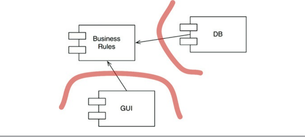
Figure 17.5 Plugging in to the business rules
Because the user interface in this design is considered to be a plugin, we have made
it possible to plug in many different kinds of user interfaces. They could be web
based, client/server based, SOA based, Console based, or based on any other kind of
user interface technology.
The same is true of the database. Since we have chosen to treat it as a plugin, we can
replace it with any of the various SQL databases, or a NOSQL database, or a file
system-based database, or any other kind of database technology we might deem
necessary in the future.
These replacements might not be trivial. If the initial deployment of our system was
web-based, then writing the plugin for a client-server UI could be challenging. It is
likely that some of the communications between the business rules and the new UI
would have to be reworked. Even so, by starting with the presumption of a plugin
structure, we have at very least made such a change practical.
THE PLUGIN ARGUMENT
Consider the relationship between ReSharper and Visual Studio. These components
are produced by completely different development teams in completely different
companies. Indeed, JetBrains, the maker of ReSharper, lives in Russia. Microsoft, of
course, resides in Redmond, Washington. It’s hard to imagine two development
teams that are more separate.
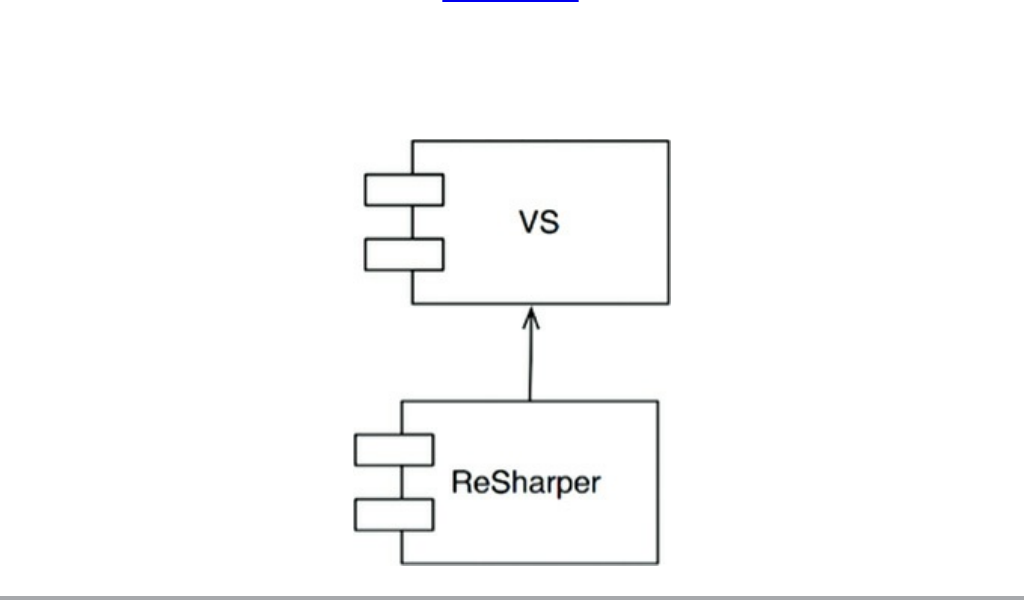
Which team can damage the other? Which team is immune to the other? The
dependency structure tells the story (Figure 17.6). The source code of ReSharper
depends on the source code of Visual Studio. Thus there is nothing that the
ReSharper team can do to disturb the Visual Studio team. But the Visual Studio team
could completely disable the ReSharper team if they so desired.
Figure 17.6 ReSharper depends on Visual Studio
That’s a deeply asymmetric relationship, and it is one that we desire to have in our
own systems. We want certain modules to be immune to others. For example, we
don’t want the business rules to break when someone changes the format of a web
page, or changes the schema of the database. We don’t want changes in one part of
the system to cause other unrelated parts of the system to break. We don’t want our
systems to exhibit that kind of fragility.
Arranging our systems into a plugin architecture creates firewalls across which
changes cannot propagate. If the GUI plugs in to the business rules, then changes in
the GUI cannot affect those business rules.
Boundaries are drawn where there is an axis of change. The components on one side
of the boundary change at different rates, and for different reasons, than the
components on the other side of the boundary.
GUIs change at different times and at different rates than business rules, so there
should be a boundary between them. Business rules change at different times and for
different reasons than dependency injection frameworks, so there should be a
boundary between them.

This is simply the Single Responsibility Principle again. The SRP tells us where to
draw our boundaries.
CONCLUSION
To draw boundary lines in a software architecture, you first partition the system into
components. Some of those components are core business rules; others are plugins
that contain necessary functions that are not directly related to the core business.
Then you arrange the code in those components such that the arrows between them
point in one direction—toward the core business.
You should recognize this as an application of the Dependency Inversion Principle
and the Stable Abstractions Principle. Dependency arrows are arranged to point from
lower-level details to higher-level abstractions.
1. The word “architecture” appears in quotes here because three-tier is not an architecture; it’s a
topology. It’s exactly the kind of decision that a good architecture strives to defer.
2. Many years later we were able to slip the Velocity framework into FitNesse.
18
BOUNDARY ANATOMY
The architecture of a system is defined by a set of software components and the
boundaries that separate them. Those boundaries come in many different forms. In
this chapter we’ll look at some of the most common.
BOUNDARY CROSSING
At runtime, a boundary crossing is nothing more than a function on one side of the
boundary calling a function on the other side and passing along some data. The trick
to creating an appropriate boundary crossing is to manage the source code
dependencies.
Why source code? Because when one source code module changes, other source

code modules may have to be changed or recompiled, and then redeployed.
Managing and building firewalls against this change is what boundaries are all about.
THE DREADED MONOLITH
The simplest and most common of the architectural boundaries has no strict physical
representation. It is simply a disciplined segregation of functions and data within a
single processor and a single address space. In a previous chapter, I called this the
source-level decoupling mode.
From a deployment point of view, this amounts to nothing more than a single
executable file—the so-called monolith. This file might be a statically linked C or
C++ project, a set of Java class files bound together into an executable jar file, a set
of .NET binaries bound into a single .EXE file, and so on.
The fact that the boundaries are not visible during the deployment of a monolith does
not mean that they are not present and meaningful. Even when statically linked into a
single executable, the ability to independently develop and marshal the various
components for final assembly is immensely valuable.
Such architectures almost always depend on some kind of dynamic polymorphism1
to manage their internal dependencies. This is one of the reasons that object-oriented
development has become such an important paradigm in recent decades. Without
OO, or an equivalent form of polymorphism, architects must fall back on the
dangerous practice of using pointers to functions to achieve the appropriate
decoupling. Most architects find prolific use of pointers to functions to be too risky,
so they are forced to abandon any kind of component partitioning.
The simplest possible boundary crossing is a function call from a low-level client to
a higher-level service. Both the runtime dependency and the compile-time
dependency point in the same direction, toward the higher-level component.
In Figure 18.1, the flow of control crosses the boundary from left to right. The
Client calls function f() on the Service. It passes along an instance of Data. The
<DS> marker simply indicates a data structure. The Data may be passed as a function
argument or by some other more elaborate means. Note that the definition of the
Data is on the called side of the boundary.
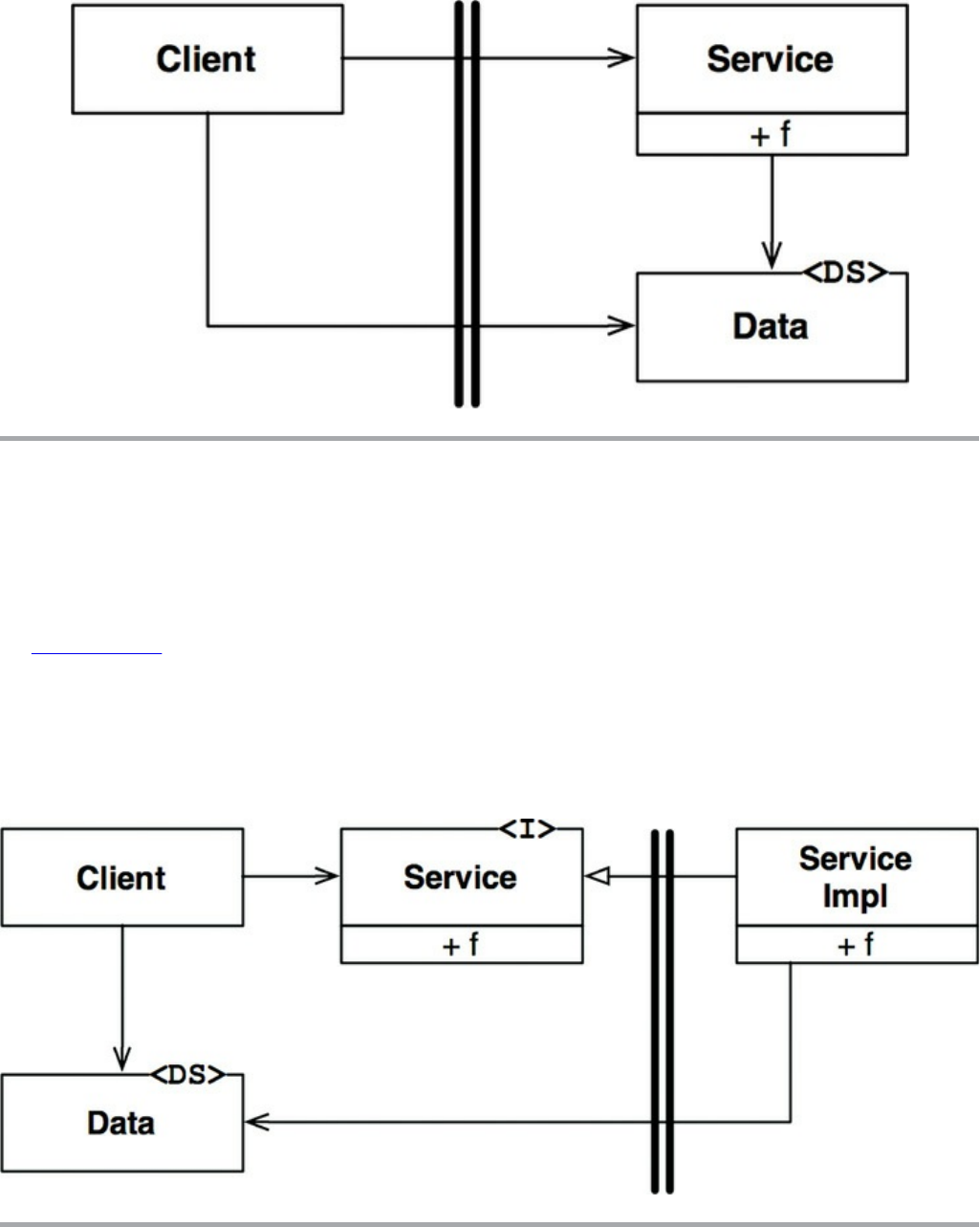
Figure 18.1 Flow of control crosses the boundary from a lower level to a higher level
When a high-level client needs to invoke a lower-level service, dynamic
polymorphism is used to invert the dependency against the flow of control. The
runtime dependency opposes the compile-time dependency.
In Figure 18.2, the flow of control crosses the boundary from left to right as before.
The high-level Client calls the f() function of the lower-level ServiceImpl through
the Service interface. Note, however, that all dependencies cross the boundary from
right to left toward the higher-level component. Note, also, that the definition of the
data structure is on the calling side of the boundary.
Figure 18.2 Crossing the boundary against the flow of control
Even in a monolithic, statically linked executable, this kind of disciplined

partitioning can greatly aid the job of developing, testing, and deploying the project.
Teams can work independently of each other on their own components without
treading on each other’s toes. High-level components remain independent of lower-
level details.
Communications between components in a monolith are very fast and inexpensive.
They are typically just function calls. Consequently, communications across source-
level decoupled boundaries can be very chatty.
Since the deployment of monoliths usually requires compilation and static linking,
components in these systems are typically delivered as source code.
DEPLOYMENT COMPONENTS
The simplest physical representation of an architectural boundary is a dynamically
linked library like a .Net DLL, a Java jar file, a Ruby Gem, or a UNIX shared
library. Deployment does not involve compilation. Instead, the components are
delivered in binary, or some equivalent deployable form. This is the deployment-
level decoupling mode. The act of deployment is simply the gathering of these
deployable units together in some convenient form, such as a WAR file, or even just
a directory.
With that one exception, deployment-level components are the same as monoliths.
The functions generally all exist in the same processor and address space. The
strategies for segregating the components and managing their dependencies are the
same.2
As with monoliths, communications across deployment component boundaries are
just function calls and, therefore, are very inexpensive. There may be a one-time hit
for dynamic linking or runtime loading, but communications across these boundaries
can still be very chatty.
THREADS
Both monoliths and deployment components can make use of threads. Threads are
not architectural boundaries or units of deployment, but rather a way to organize the
schedule and order of execution. They may be wholly contained within a component,
or spread across many components.
LOCAL PROCESSES
A much stronger physical architectural boundary is the local process. A local process
is typically created from the command line or an equivalent system call. Local
processes run in the same processor, or in the same set of processors within a
multicore, but run in separate address spaces. Memory protection generally prevents
such processes from sharing memory, although shared memory partitions are often
used.
Most often, local processes communicate with each other using sockets, or some
other kind of operating system communications facility such as mailboxes or
message queues.
Each local process may be a statically linked monolith, or it may be composed of
dynamically linked deployment components. In the former case, several monolithic
processes may have the same components compiled and linked into them. In the
latter, they may share the same dynamically linked deployment components.
Think of a local process as a kind of uber-component: The process consists of lower-
level components that manage their dependencies through dynamic polymorphism.
The segregation strategy between local processes is the same as for monoliths and
binary components. Source code dependencies point in the same direction across the
boundary, and always toward the higher-level component.
For local processes, this means that the source code of the higher-level processes
must not contain the names, or physical addresses, or registry lookup keys of lower-
level processes. Remember that the architectural goal is for lower-level processes to
be plugins to higher-level processes.
Communication across local process boundaries involve operating system calls, data
marshaling and decoding, and interprocess context switches, which are moderately
expensive. Chattiness should be carefully limited.
SERVICES
The strongest boundary is a service. A service is a process, generally started from the
command line or through an equivalent system call. Services do not depend on their
physical location. Two communicating services may, or may not, operate in the same

physical processor or multicore. The services assume that all communications take
place over the network.
Communications across service boundaries are very slow compared to function calls.
Turnaround times can range from tens of milliseconds to seconds. Care must be
taken to avoid chatting where possible. Communications at this level must deal with
high levels of latency.
Otherwise, the same rules apply to services as apply to local processes. Lower-level
services should “plug in” to higher-level services. The source code of higher-level
services must not contain any specific physical knowledge (e.g., a URI) of any
lower-level service.
CONCLUSION
Most systems, other than monoliths, use more than one boundary strategy. A system
that makes use of service boundaries may also have some local process boundaries.
Indeed, a service is often just a facade for a set of interacting local processes. A
service, or a local process, will almost certainly be either a monolith composed of
source code components or a set of dynamically linked deployment components.
This means that the boundaries in a system will often be a mixture of local chatty
boundaries and boundaries that are more concerned with latency.
1. Static polymorphism (e.g., generics or templates) can sometimes be a viable means of
dependency management in monolithic systems, especially in languages like C++. However, the
decoupling afforded by generics cannot protect you from the need for recompilation and
redeployment the way dynamic polymorphism can.
2. Although static polymorphism is not an option in this case.

19
POLICY AND LEVEL
Software systems are statements of policy. Indeed, at its core, that’s all a computer
program actually is. A computer program is a detailed description of the policy by
which inputs are transformed into outputs.
In most nontrivial systems, that policy can be broken down into many different
smaller statements of policy. Some of those statements will describe how particular
business rules are to be calculated. Others will describe how certain reports are to be
formatted. Still others will describe how input data are to be validated.
Part of the art of developing a software architecture is carefully separating those
policies from one another, and regrouping them based on the ways that they change.
Policies that change for the same reasons, and at the same times, are at the same
level and belong together in the same component. Policies that change for different

reasons, or at different times, are at different levels and should be separated into
different components.
The art of architecture often involves forming the regrouped components into a
directed acyclic graph. The nodes of the graph are the components that contain
policies at the same level. The directed edges are the dependencies between those
components. They connect components that are at different levels.
Those dependencies are source code, compile-time dependencies. In Java, they are
import statements. In C#, they are using statements. In Ruby, they are require
statements. They are the dependencies that are necessary for the compiler to
function.
In a good architecture, the direction of those dependencies is based on the level of
the components that they connect. In every case, low-level components are designed
so that they depend on high-level components.
LEVEL
A strict definition of “level” is “the distance from the inputs and outputs.” The
farther a policy is from both the inputs and the outputs of the system, the higher its
level. The policies that manage input and output are the lowest-level policies in the
system.
The data flow diagram in Figure 19.1 depicts a simple encryption program that reads
characters from an input device, translates the characters using a table, and then
writes the translated characters to an output device. The data flows are shown as
curved solid arrows. The properly designed source code dependencies are shown as
straight dashed lines.
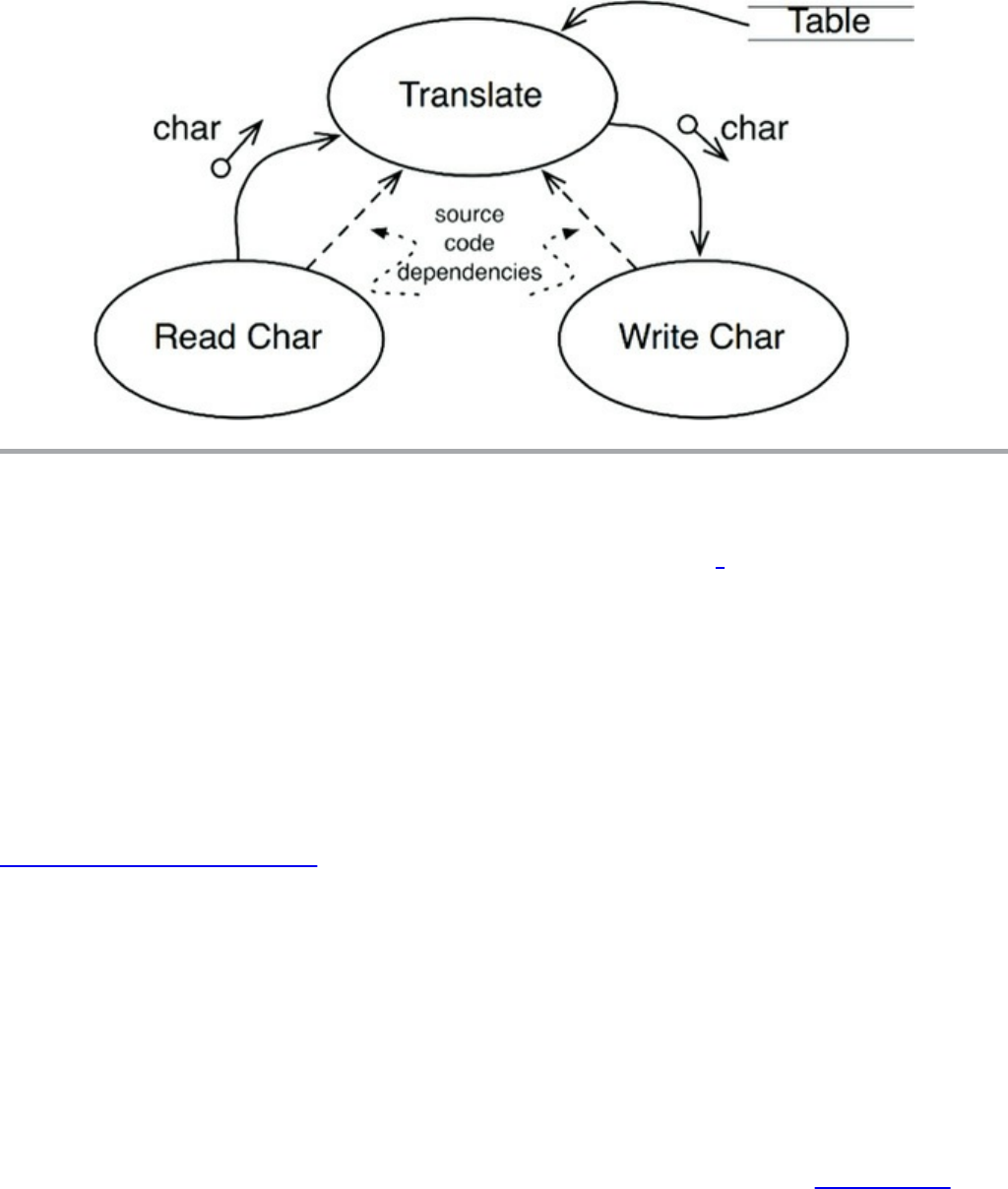
Figure 19.1 A simple encryption program
The Translate component is the highest-level component in this system because it
is the component that is farthest from the inputs and outputs.1
Note that the data flows and the source code dependencies do not always point in the
same direction. This, again, is part of the art of software architecture. We want
source code dependencies to be decoupled from data flow and coupled to level.
It would be easy to create an incorrect architecture by writing the encryption
program like this:
Click here to view code image
function encrypt() {
while(true)
writeChar(translate(readChar()));
}
This is incorrect architecture because the high-level encrypt function depends on the
lower-level readChar and writeChar functions.
A better architecture for this system is shown in the class diagram in Figure 19.2.
Note the dashed border surrounding the Encrypt class, and the CharWriter and
CharReader interfaces. All dependencies crossing that border point inward. This unit
is the highest-level element in the system.
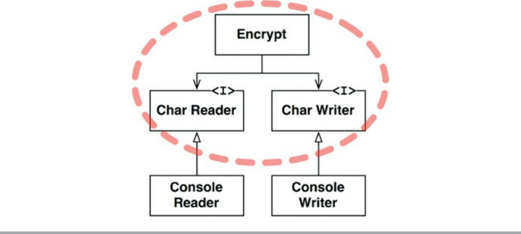
Figure 19.2 Class diagram showing a better architecture for the system
ConsoleReader and ConsoleWriter are shown here as classes. They are low level
because they are close to the inputs and outputs.
Note how this structure decouples the high-level encryption policy from the lower-
level input/output policies. This makes the encryption policy usable in a wide range
of contexts. When changes are made to the input and output policies, they are not
likely to affect the encryption policy.
Recall that policies are grouped into components based on the way that they change.
Policies that change for the same reasons and at the same times are grouped together
by the SRP and CCP. Higher-level policies—those that are farthest from the inputs
and outputs—tend to change less frequently, and for more important reasons, than
lower-level policies. Lower-level policies—those that are closest to the inputs and
outputs—tend to change frequently, and with more urgency, but for less important
reasons.
For example, even in the trivial example of the encryption program, it is far more
likely that the IO devices will change than that the encryption algorithm will change.
If the encryption algorithm does change, it will likely be for a more substantive
reason than a change to one of the IO devices.
Keeping these policies separate, with all source code dependencies pointing in the
direction of the higher-level policies, reduces the impact of change. Trivial but
urgent changes at the lowest levels of the system have little or no impact on the
higher, more important, levels.
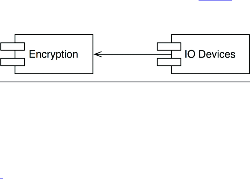
Another way to look at this issue is to note that lower-level components should be
plugins to the higher-level components. The component diagram in Figure 19.3
shows this arrangement. The Encryption component knows nothing of the
IODevices component; the IODevices component depends on the Encryption
component.
Figure 19.3 Lower-level components should plug in to higher-level components
CONCLUSION
At this point, this discussion of policies has involved a mixture of the Single
Responsibility Principle, the Open-Closed Principle, the Common Closure Principle,
the Dependency Inversion Principle, the Stable Dependencies Principle, and the
Stable Abstractions Principle. Look back and see if you can identify where each
principle was used, and why.
1. Meilir Page-Jones called this component the “Central Transform” in his book The Practical
Guide to Structured Systems Design, 2nd ed. (Yourdon Press, 1988).
20
BUSINESS RULES
If we are going to divide our application into business rules and plugins, we’d better
get a good grasp on just what business rules actually are. It turns out there are several
different kinds.
Strictly speaking, business rules are rules or procedures that make or save the
business money. Very strictly speaking, these rules would make or save the business
money, irrespective of whether they were implemented on a computer. They would
make or save money even if they were executed manually.
The fact that a bank charges N% interest for a loan is a business rule that makes the
bank money. It doesn’t matter if a computer program calculates the interest, or if a
clerk with an abacus calculates the interest.
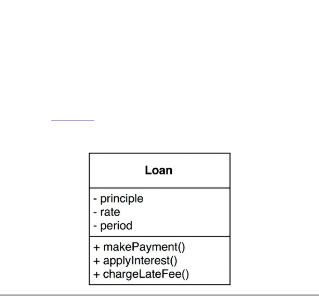
We shall call these rules Critical Business Rules, because they are critical to the
business itself, and would exist even if there were no system to automate them.
Critical Business Rules usually require some data to work with. For example, our
loan requires a loan balance, an interest rate, and a payment schedule.
We shall call this data Critical Business Data. This is the data that would exist even
if the system were not automated.
The critical rules and critical data are inextricably bound, so they are a good
candidate for an object. We’ll call this kind of object an Entity.1
ENTITIES
An Entity is an object within our computer system that embodies a small set of
critical business rules operating on Critical Business Data. The Entity object either
contains the Critical Business Data or has very easy access to that data. The interface
of the Entity consists of the functions that implement the Critical Business Rules that
operate on that data.
For example, Figure 20.1 shows what our Loan entity might look like as a class in
UML. It has three pieces of Critical Business Data, and presents three related Critical
Business Rules at its interface.
Figure 20.1 Loan entity as a class in UML

When we create this kind of class, we are gathering together the software that
implements a concept that is critical to the business, and separating it from every
other concern in the automated system we are building. This class stands alone as a
representative of the business. It is unsullied with concerns about databases, user
interfaces, or third-party frameworks. It could serve the business in any system,
irrespective of how that system was presented, or how the data was stored, or how
the computers in that system were arranged. The Entity is pure business and nothing
else.
Some of you may be concerned that I called it a class. Don’t be. You don’t need to
use an object-oriented language to create an Entity. All that is required is that you
bind the Critical Business Data and the Critical Business Rules together in a single
and separate software module.
USE CASES
Not all business rules are as pure as Entities. Some business rules make or save
money for the business by defining and constraining the way that an automated
system operates. These rules would not be used in a manual environment, because
they make sense only as part of an automated system.
For example, imagine an application that is used by bank officers to create a new
loan. The bank may decide that it does not want the loan officers to offer loan
payment estimates until they have first gathered, and validated, contact information
and ensured that the candidate’s credit score is 500 or higher. For this reason, the
bank may specify that the system will not proceed to the payment estimation screen
until the contact information screen has been filled out and verified, and the credit
score has been confirmed to be greater than the cutoff.
This is a use case.2 A use case is a description of the way that an automated system
is used. It specifies the input to be provided by the user, the output to be returned to
the user, and the processing steps involved in producing that output. A use case
describes application-specific business rules as opposed to the Critical Business
Rules within the Entities.
Figure 20.2 shows an example of a use case. Notice that in the last line it mentions
the Customer. This is a reference to the Customer entity, which contains the Critical
Business Rules that govern the relationship between the bank and its customers.
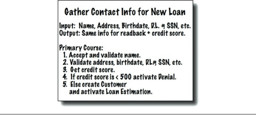
Figure 20.2 Example use case
Use cases contain the rules that specify how and when the Critical Business Rules
within the Entities are invoked. Use cases control the dance of the Entities.
Notice also that the use case does not describe the user interface other than to
informally specify the data coming in from that interface, and the data going back
out through that interface. From the use case, it is impossible to tell whether the
application is delivered on the web, or on a thick client, or on a console, or is a pure
service.
This is very important. Use cases do not describe how the system appears to the user.
Instead, they describe the application-specific rules that govern the interaction
between the users and the Entities. How the data gets in and out of the system is
irrelevant to the use cases.
A use case is an object. It has one or more functions that implement the application-
specific business rules. It also has data elements that include the input data, the
output data, and the references to the appropriate Entities with which it interacts.
Entities have no knowledge of the use cases that control them. This is another
example of the direction of the dependencies following the Dependency Inversion
Principle. High-level concepts, such as Entities, know nothing of lower-level
concepts, such as use cases. Instead, the lower-level use cases know about the
higher-level Entities.
Why are Entities high level and use cases lower level? Because use cases are specific
to a single application and, therefore, are closer to the inputs and outputs of that
system. Entities are generalizations that can be used in many different applications,
so they are farther from the inputs and outputs of the system. Use cases depend on
Entities; Entities do not depend on use cases.
REQUEST AND RESPONSE MODELS
Use cases expect input data, and they produce output data. However, a well-formed
use case object should have no inkling about the way that data is communicated to
the user, or to any other component. We certainly don’t want the code within the use
case class to know about HTML or SQL!
The use case class accepts simple request data structures for its input, and returns
simple response data structures as its output. These data structures are not dependent
on anything. They do not derive from standard framework interfaces such as
HttpRequest and HttpResponse. They know nothing of the web, nor do they share
any of the trappings of whatever user interface might be in place.
This lack of dependencies is critical. If the request and response models are not
independent, then the use cases that depend on them will be indirectly bound to
whatever dependencies the models carry with them.
You might be tempted to have these data structures contain references to Entity
objects. You might think this makes sense because the Entities and the
request/response models share so much data. Avoid this temptation! The purpose of
these two objects is very different. Over time they will change for very different
reasons, so tying them together in any way violates the Common Closure and Single
Responsibility Principles. The result would be lots of tramp data, and lots of
conditionals in your code.
CONCLUSION
Business rules are the reason a software system exists. They are the core
functionality. They carry the code that makes, or saves, money. They are the family
jewels.
The business rules should remain pristine, unsullied by baser concerns such as the
user interface or database used. Ideally, the code that represents the business rules

should be the heart of the system, with lesser concerns being plugged in to them. The
business rules should be the most independent and reusable code in the system.
1. This is Ivar Jacobson’s name for this concept (I. Jacobson et al., Object Oriented Software
Engineering, Addison-Wesley, 1992).
2. Ibid.
21
SCREAMING ARCHITECTURE
Imagine that you are looking at the blueprints of a building. This document, prepared
by an architect, provides the plans for the building. What do these plans tell you?
If the plans you are viewing are for a single-family residence, then you’ll likely see a
front entrance, a foyer leading to a living room, and perhaps a dining room. There
will likely be a kitchen a short distance away, close to the dining room. Perhaps there
is a dinette area next to the kitchen, and probably a family room close to that. When
you looked at those plans, there would be no question that you were looking at a
single family home. The architecture would scream: “HOME.”
Now suppose you were looking at the architecture of a library. You would likely see
a grand entrance, an area for check-in/out clerks, reading areas, small conference
rooms, and gallery after gallery capable of holding bookshelves for all the books in
the library. That architecture would scream: “LIBRARY.”
So what does the architecture of your application scream? When you look at the top-
level directory structure, and the source files in the highest-level package, do they
scream “Health Care System,” or “Accounting System,” or “Inventory Management
System”? Or do they scream “Rails,” or “Spring/Hibernate,” or “ASP”?
THE THEME OF AN ARCHITECTURE
Go back and read Ivar Jacobson’s seminal work on software architecture: Object
Oriented Software Engineering. Notice the subtitle of the book: A Use Case Driven
Approach. In this book Jacobson makes the point that software architectures are
structures that support the use cases of the system. Just as the plans for a house or a
library scream about the use cases of those buildings, so should the architecture of a
software application scream about the use cases of the application.
Architectures are not (or should not be) about frameworks. Architectures should not
be supplied by frameworks. Frameworks are tools to be used, not architectures to be
conformed to. If your architecture is based on frameworks, then it cannot be based
on your use cases.
THE PURPOSE OF AN ARCHITECTURE
Good architectures are centered on use cases so that architects can safely describe
the structures that support those use cases without committing to frameworks, tools,
and environments. Again, consider the plans for a house. The first concern of the
architect is to make sure that the house is usable—not to ensure that the house is
made of bricks. Indeed, the architect takes pains to ensure that the homeowner can
make decisions about the exterior material (bricks, stone, or cedar) later, after the
plans ensure that the use cases are met.
A good software architecture allows decisions about frameworks, databases, web
servers, and other environmental issues and tools to be deferred and delayed.
Frameworks are options to be left open. A good architecture makes it unnecessary to
decide on Rails, or Spring, or Hibernate, or Tomcat, or MySQL, until much later in
the project. A good architecture makes it easy to change your mind about those
decisions, too. A good architecture emphasizes the use cases and decouples them
from peripheral concerns.
BUT WHAT ABOUT THE WEB?
Is the web an architecture? Does the fact that your system is delivered on the web
dictate the architecture of your system? Of course not! The web is a delivery
mechanism—an IO device—and your application architecture should treat it as such.
The fact that your application is delivered over the web is a detail and should not
dominate your system structure. Indeed, the decision that your application will be
delivered over the web is one that you should defer. Your system architecture should
be as ignorant as possible about how it will be delivered. You should be able to
deliver it as a console app, or a web app, or a thick client app, or even a web service
app, without undue complication or change to the fundamental architecture.
FRAMEWORKS ARE TOOLS, NOT WAYS
OF LIFE
Frameworks can be very powerful and very useful. Framework authors often believe
very deeply in their frameworks. The examples they write for how to use their
frameworks are told from the point of view of a true believer. Other authors who
write about the framework also tend to be disciples of the true belief. They show you
the way to use the framework. Often they assume an all-encompassing, all-
pervading, let-the-framework-do-everything position.
This is not the position you want to take.
Look at each framework with a jaded eye. View it skeptically. Yes, it might help, but
at what cost? Ask yourself how you should use it, and how you should protect
yourself from it. Think about how you can preserve the use-case emphasis of your
architecture. Develop a strategy that prevents the framework from taking over that
architecture.
TESTABLE ARCHITECTURES
If your system architecture is all about the use cases, and if you have kept your
frameworks at arm’s length, then you should be able to unit-test all those use cases
without any of the frameworks in place. You shouldn’t need the web server running
to run your tests. You shouldn’t need the database connected to run your tests. Your
Entity objects should be plain old objects that have no dependencies on frameworks
or databases or other complications. Your use case objects should coordinate your
Entity objects. Finally, all of them together should be testable in situ, without any of
the complications of frameworks.
CONCLUSION
Your architecture should tell readers about the system, not about the frameworks you
used in your system. If you are building a health care system, then when new
programmers look at the source repository, their first impression should be, “Oh, this
is a heath care system.” Those new programmers should be able to learn all the use
cases of the system, yet still not know how the system is delivered. They may come
to you and say:
“We see some things that look like models—but where are the views and
controllers?”
And you should respond:
“Oh, those are details that needn’t concern us at the moment. We’ll decide about
them later.”
22
THE CLEAN ARCHITECTURE
Over the last several decades we’ve seen a whole range of ideas regarding the
architecture of systems. These include:
• Hexagonal Architecture (also known as Ports and Adapters), developed by Alistair
Cockburn, and adopted by Steve Freeman and Nat Pryce in their wonderful book
Growing Object Oriented Software with Tests
• DCI from James Coplien and Trygve Reenskaug
• BCE, introduced by Ivar Jacobson from his book Object Oriented Software
Engineering: A Use-Case Driven Approach
Although these architectures all vary somewhat in their details, they are very similar.
They all have the same objective, which is the separation of concerns. They all
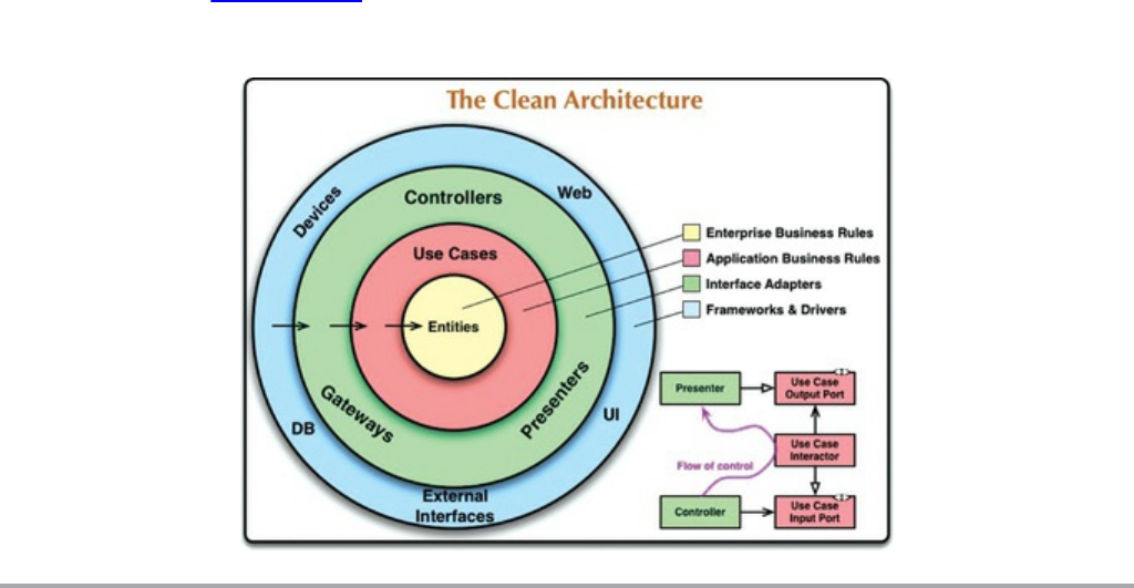
achieve this separation by dividing the software into layers. Each has at least one
layer for business rules, and another layer for user and system interfaces.
Each of these architectures produces systems that have the following characteristics:
• Independent of frameworks. The architecture does not depend on the existence of
some library of feature-laden software. This allows you to use such frameworks as
tools, rather than forcing you to cram your system into their limited constraints.
• Testable. The business rules can be tested without the UI, database, web server, or
any other external element.
• Independent of the UI. The UI can change easily, without changing the rest of the
system. A web UI could be replaced with a console UI, for example, without
changing the business rules.
• Independent of the database. You can swap out Oracle or SQL Server for Mongo,
BigTable, CouchDB, or something else. Your business rules are not bound to the
database.
• Independent of any external agency. In fact, your business rules don’t know
anything at all about the interfaces to the outside world.
The diagram in Figure 22.1 is an attempt at integrating all these architectures into a
single actionable idea.
Figure 22.1 The clean architecture
THE DEPENDENCY RULE

The concentric circles in Figure 22.1 represent different areas of software. In
general, the further in you go, the higher level the software becomes. The outer
circles are mechanisms. The inner circles are policies.
The overriding rule that makes this architecture work is the Dependency Rule:
Source code dependencies must point only inward, toward higher-level policies.
Nothing in an inner circle can know anything at all about something in an outer
circle. In particular, the name of something declared in an outer circle must not be
mentioned by the code in an inner circle. That includes functions, classes, variables,
or any other named software entity.
By the same token, data formats declared in an outer circle should not be used by an
inner circle, especially if those formats are generated by a framework in an outer
circle. We don’t want anything in an outer circle to impact the inner circles.
ENTITIES
Entities encapsulate enterprise-wide Critical Business Rules. An entity can be an
object with methods, or it can be a set of data structures and functions. It doesn’t
matter so long as the entities can be used by many different applications in the
enterprise.
If you don’t have an enterprise and are writing just a single application, then these
entities are the business objects of the application. They encapsulate the most general
and high-level rules. They are the least likely to change when something external
changes. For example, you would not expect these objects to be affected by a change
to page navigation or security. No operational change to any particular application
should affect the entity layer.
USE CASES
The software in the use cases layer contains application-specific business rules. It
encapsulates and implements all of the use cases of the system. These use cases
orchestrate the flow of data to and from the entities, and direct those entities to use
their Critical Business Rules to achieve the goals of the use case.
We do not expect changes in this layer to affect the entities. We also do not expect
this layer to be affected by changes to externalities such as the database, the UI, or

any of the common frameworks. The use cases layer is isolated from such concerns.
We do, however, expect that changes to the operation of the application will affect
the use cases and, therefore, the software in this layer. If the details of a use case
change, then some code in this layer will certainly be affected.
INTERFACE ADAPTERS
The software in the interface adapters layer is a set of adapters that convert data from
the format most convenient for the use cases and entities, to the format most
convenient for some external agency such as the database or the web. It is this layer,
for example, that will wholly contain the MVC architecture of a GUI. The
presenters, views, and controllers all belong in the interface adapters layer. The
models are likely just data structures that are passed from the controllers to the use
cases, and then back from the use cases to the presenters and views.
Similarly, data is converted, in this layer, from the form most convenient for entities
and use cases, to the form most convenient for whatever persistence framework is
being used (i.e., the database). No code inward of this circle should know anything at
all about the database. If the database is a SQL database, then all SQL should be
restricted to this layer—and in particular to the parts of this layer that have to do with
the database.
Also in this layer is any other adapter necessary to convert data from some external
form, such as an external service, to the internal form used by the use cases and
entities.
FRAMEWORKS AND DRIVERS
The outermost layer of the model in Figure 22.1 is generally composed of
frameworks and tools such as the database and the web framework. Generally you
don’t write much code in this layer, other than glue code that communicates to the
next circle inward.
The frameworks and drivers layer is where all the details go. The web is a detail. The
database is a detail. We keep these things on the outside where they can do little
harm.
ONLY FOUR CIRCLES?

The circles in Figure 22.1 are intended to be schematic: You may find that you need
more than just these four. There’s no rule that says you must always have just these
four. However, the Dependency Rule always applies. Source code dependencies
always point inward. As you move inward, the level of abstraction and policy
increases. The outermost circle consists of low-level concrete details. As you move
inward, the software grows more abstract and encapsulates higher-level policies. The
innermost circle is the most general and highest level.
CROSSING BOUNDARIES
At the lower right of the diagram in Figure 22.1 is an example of how we cross the
circle boundaries. It shows the controllers and presenters communicating with the
use cases in the next layer. Note the flow of control: It begins in the controller,
moves through the use case, and then winds up executing in the presenter. Note also
the source code dependencies: Each points inward toward the use cases.
We usually resolve this apparent contradiction by using the Dependency Inversion
Principle. In a language like Java, for example, we would arrange interfaces and
inheritance relationships such that the source code dependencies oppose the flow of
control at just the right points across the boundary.
For example, suppose the use case needs to call the presenter. This call must not be
direct because that would violate the Dependency Rule: No name in an outer circle
can be mentioned by an inner circle. So we have the use case call an interface
(shown in Figure 22.1 as “use case output port”) in the inner circle, and have the
presenter in the outer circle implement it.
The same technique is used to cross all the boundaries in the architectures. We take
advantage of dynamic polymorphism to create source code dependencies that oppose
the flow of control so that we can conform to the Dependency Rule, no matter which
direction the flow of control travels.
WHICH DATA CROSSES THE BOUNDARIES
Typically the data that crosses the boundaries consists of simple data structures. You
can use basic structs or simple data transfer objects if you like. Or the data can
simply be arguments in function calls. Or you can pack it into a hashmap, or
construct it into an object. The important thing is that isolated, simple data structures
are passed across the boundaries. We don’t want to cheat and pass Entity objects or
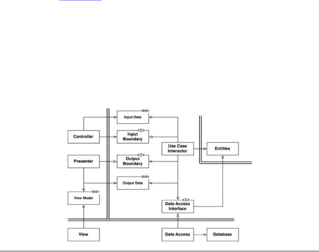
database rows. We don’t want the data structures to have any kind of dependency
that violates the Dependency Rule.
For example, many database frameworks return a convenient data format in response
to a query. We might call this a “row structure.” We don’t want to pass that row
structure inward across a boundary. Doing so would violate the Dependency Rule
because it would force an inner circle to know something about an outer circle.
Thus, when we pass data across a boundary, it is always in the form that is most
convenient for the inner circle.
A TYPICAL SCENARIO
The diagram in Figure 22.2 shows a typical scenario for a web-based Java system
using a database. The web server gathers input data from the user and hands it to the
Controller on the upper left. The Controller packages that data into a plain old
Java object and passes this object through the InputBoundary to the
UseCaseInteractor. The UseCaseInteractor interprets that data and uses it to
control the dance of the Entities. It also uses the DataAccessInterface to bring
the data used by those Entities into memory from the Database. Upon completion,
the UseCaseInteractor gathers data from the Entities and constructs the
OutputData as another plain old Java object. The OutputData is then passed through
the OutputBoundary interface to the Presenter.
Figure 22.2 A typical scenario for a web-based Java system utilizing a database
The job of the Presenter is to repackage the OutputData into viewable form as the
ViewModel, which is yet another plain old Java object. The ViewModel contains
mostly Strings and flags that the View uses to display the data. Whereas the
OutputData may contain Date objects, the Presenter will load the ViewModel with
corresponding Strings already formatted properly for the user. The same is true of
Currency objects or any other business-related data. Button and MenuItem names are
placed in the ViewModel, as are flags that tell the View whether those Buttons and
MenuItems should be gray.
This leaves the View with almost nothing to do other than to move the data from the
ViewModel into the HTML page.
Note the directions of the dependencies. All dependencies cross the boundary lines
pointing inward, following the Dependency Rule.
CONCLUSION
Conforming to these simple rules is not difficult, and it will save you a lot of
headaches going forward. By separating the software into layers and conforming to
the Dependency Rule, you will create a system that is intrinsically testable, with all
the benefits that implies. When any of the external parts of the system become
obsolete, such as the database, or the web framework, you can replace those obsolete
elements with a minimum of fuss.
23
PRESENTERS AND HUMBLE OBJECTS
In Chapter 22, we introduced the notion of presenters. Presenters are a form of the
Humble Object pattern, which helps us identify and protect architectural boundaries.
Actually, the Clean Architecture in the last chapter was full of Humble Object
implementations.
THE HUMBLE OBJECT PATTERN
The Humble Object pattern1 is a design pattern that was originally identified as a
way to help unit testers to separate behaviors that are hard to test from behaviors that
are easy to test. The idea is very simple: Split the behaviors into two modules or
classes. One of those modules is humble; it contains all the hard-to-test behaviors
stripped down to their barest essence. The other module contains all the testable
behaviors that were stripped out of the humble object.
For example, GUIs are hard to unit test because it is very difficult to write tests that
can see the screen and check that the appropriate elements are displayed there.
However, most of the behavior of a GUI is, in fact, easy to test. Using the Humble
Object pattern, we can separate these two kinds of behaviors into two different
classes called the Presenter and the View.
PRESENTERS AND VIEWS
The View is the humble object that is hard to test. The code in this object is kept as
simple as possible. It moves data into the GUI but does not process that data.
The Presenter is the testable object. Its job is to accept data from the application and
format it for presentation so that the View can simply move it to the screen. For
example, if the application wants a date displayed in a field, it will hand the
Presenter a Date object. The Presenter will then format that data into an appropriate
string and place it in a simple data structure called the View Model, where the View
can find it.
If the application wants to display money on the screen, it might pass a Currency
object to the Presenter. The Presenter will format that object with the appropriate
decimal places and currency markers, creating a string that it can place in the View
Model. If that currency value should be turned red if it is negative, then a simple
boolean flag in the View model will be set appropriately.
Every button on the screen will have a name. That name will be a string in the View
Model, placed there by the presenter. If those buttons should be grayed out, the
Presenter will set an appropriate boolean flag in the View model. Every menu item
name is a string in the View model, loaded by the Presenter. The names for every
radio button, check box, and text field are loaded, by the Presenter, into appropriate
strings and booleans in the View model. Tables of numbers that should be displayed
on the screen are loaded, by the Presenter, into tables of properly formatted strings in
the View model.
Anything and everything that appears on the screen, and that the application has
some kind of control over, is represented in the View Model as a string, or a boolean,
or an enum. Nothing is left for the View to do other than to load the data from the
View Model into the screen. Thus the View is humble.

TESTING AND ARCHITECTURE
It has long been known that testability is an attribute of good architectures. The
Humble Object pattern is a good example, because the separation of the behaviors
into testable and non-testable parts often defines an architectural boundary. The
Presenter/View boundary is one of these boundaries, but there are many others.
DATABASE GATEWAYS
Between the use case interactors and the database are the database gateways.2 These
gateways are polymorphic interfaces that contain methods for every create, read,
update, or delete operation that can be performed by the application on the database.
For example, if the application needs to know the last names of all the users who
logged in yesterday, then the UserGateway interface will have a method named
getLastNamesOfUsersWhoLoggedInAfter that takes a Date as its argument and
returns a list of last names.
Recall that we do not allow SQL in the use cases layer; instead, we use gateway
interfaces that have appropriate methods. Those gateways are implemented by
classes in the database layer. That implementation is the humble object. It simply
uses SQL, or whatever the interface to the database is, to access the data required by
each of the methods. The interactors, in contrast, are not humble because they
encapsulate application-specific business rules. Although they are not humble, those
interactors are testable, because the gateways can be replaced with appropriate stubs
and test-doubles.
DATA MAPPERS
Going back to the topic of databases, in which layer do you think ORMs like
Hibernate belong?
First, let’s get something straight: There is no such thing as an object relational
mapper (ORM). The reason is simple: Objects are not data structures. At least, they
are not data structures from their users’ point of view. The users of an object cannot
see the data, since it is all private. Those users see only the public methods of that
object. So, from the user’s point of view, an object is simply a set of operations.

A data structure, in contrast, is a set of public data variables that have no implied
behavior. ORMs would be better named “data mappers,” because they load data into
data structures from relational database tables.
Where should such ORM systems reside? In the database layer of course. Indeed,
ORMs form another kind of Humble Object boundary between the gateway
interfaces and the database.
SERVICE LISTENERS
What about services? If your application must communicate with other services, or if
your application provides a set of services, will we find the Humble Object pattern
creating a service boundary?
Of course! The application will load data into simple data structures and then pass
those structures across the boundary to modules that properly format the data and
send it to external services. On the input side, the service listeners will receive data
from the service interface and format it into a simple data structure that can be used
by the application. That data structure is then passed across the service boundary.
CONCLUSION
At each architectural boundary, we are likely to find the Humble Object pattern
lurking somewhere nearby. The communication across that boundary will almost
always involve some kind of simple data structure, and the boundary will frequently
divide something that is hard to test from something that is easy to test. The use of
this pattern at architectural boundaries vastly increases the testability of the entire
system.
1. xUnit Patterns, Meszaros, Addison-Wesley, 2007, p. 695.
2. Patterns of Enterprise Application Architecture, Martin Fowler, et. al., Addison-Wesley, 2003, p.
466.
24
PARTIAL BOUNDARIES
Full-fledged architectural boundaries are expensive. They require reciprocal
polymorphic Boundary interfaces, Input and Output data structures, and all of the
dependency management necessary to isolate the two sides into independently
compilable and deployable components. That takes a lot of work. It’s also a lot of
work to maintain.
In many situations, a good architect might judge that the expense of such a boundary
is too high—but might still want to hold a place for such a boundary in case it is
needed later.
This kind of anticipatory design is often frowned upon by many in the Agile
community as a violation of YAGNI: “You Aren’t Going to Need It.” Architects,
however, sometimes look at the problem and think, “Yeah, but I might.” In that case,

they may implement a partial boundary.
SKIP THE LAST STEP
One way to construct a partial boundary is to do all the work necessary to create
independently compilable and deployable components, and then simply keep them
together in the same component. The reciprocal interfaces are there, the input/output
data structures are there, and everything is all set up—but we compile and deploy all
of them as a single component.
Obviously, this kind of partial boundary requires the same amount of code and
preparatory design work as a full boundary. However, it does not require the
administration of multiple components. There’s no version number tracking or
release management burden. That difference should not be taken lightly.
This was the early strategy behind FitNesse. The web server component of
FitNesse was designed to be separable from the wiki and testing part of FitNesse.
The idea was that we might want to create other web-based applications by using
that web component. At the same, we did not want users to have to download two
components. Recall that one of our design goals was “download and go.” It was our
intent that users would download one jar file and execute it without having to hunt
for other jar files, work out version compatibilities, and so on.
The story of FitNesse also points out one of the dangers of this approach. Over time,
as it became clear that there would never be a need for a separate web component,
the separation between the web component and the wiki component began to
weaken. Dependencies started to cross the line in the wrong direction. Nowadays, it
would be something of a chore to re-separate them.
ONE-DIMENSIONAL BOUNDARIES
The full-fledged architectural boundary uses reciprocal boundary interfaces to
maintain isolation in both directions. Maintaining separation in both directions is
expensive both in initial setup and in ongoing maintenance.
A simpler structure that serves to hold the place for later extension to a full-fledged
boundary is shown in Figure 24.1. It exemplifies the traditional Strategy pattern. A
ServiceBoundary interface is used by clients and implemented by ServiceImpl
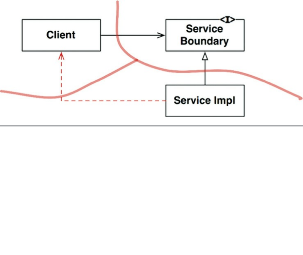
classes.
Figure 24.1 The Strategy pattern
It should be clear that this sets the stage for a future architectural boundary. The
necessary dependency inversion is in place in an attempt to isolate the Client from
the ServiceImpl. It should also be clear that the separation can degrade pretty
rapidly, as shown by the nasty dotted arrow in the diagram. Without reciprocal
interfaces, nothing prevents this kind of backchannel other than the diligence and
discipline of the developers and architects.
FACADES
An even simpler boundary is the Facade pattern, illustrated in Figure 24.2. In this
case, even the dependency inversion is sacrificed. The boundary is simply defined by
the Facade class, which lists all the services as methods, and deploys the service
calls to classes that the client is not supposed to access.
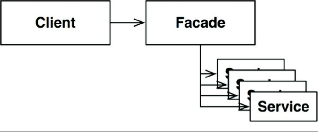
Figure 24.2 The Facade pattern
Note, however, that the Client has a transitive dependency on all those service
classes. In static languages, a change to the source code in one of the Service classes
will force the Client to recompile. Also, you can imagine how easy backchannels
are to create with this structure.
CONCLUSION
We’ve seen three simple ways to partially implement an architectural boundary.
There are, of course, many others. These three strategies are simply offered as
examples.
Each of these approaches has its own set of costs and benefits. Each is appropriate,
in certain contexts, as a placeholder for an eventual full-fledged boundary. Each can
also be degraded if that boundary never materializes.
It is one of the functions of an architect to decide where an architectural boundary
might one day exist, and whether to fully or partially implement that boundary.
25
LAYERS AND BOUNDARIES
It is easy to think of systems as being composed of three components: UI, business
rules, and database. For some simple systems, this is sufficient. For most systems,
though, the number of components is larger than that.
Consider, for example, a simple computer game. It is easy to imagine the three
components. The UI handles all messages from the player to the game rules. The
game rules store the state of the game in some kind of persistent data structure. But
is that all there is?
HUNT THE WUMPUS
Let’s put some flesh on these bones. Let’s assume that the game is the venerable
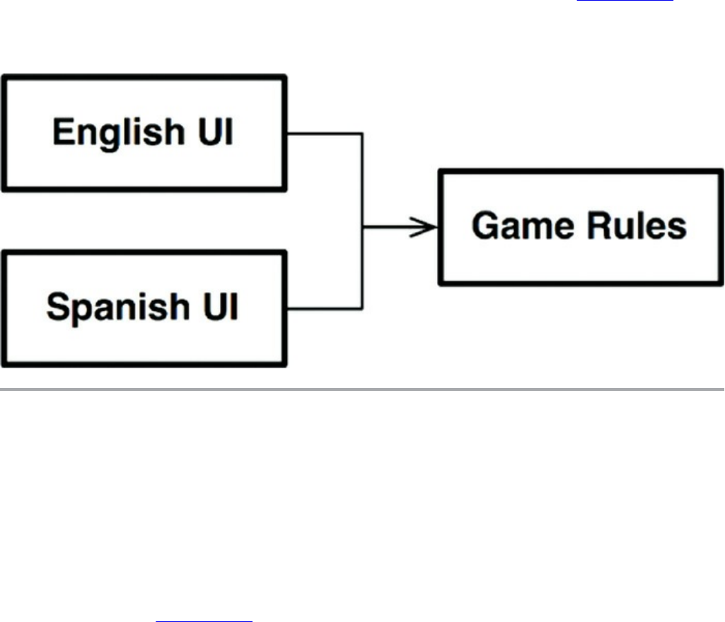
Hunt the Wumpus adventure game from 1972. This text-based game uses very
simple commands like GO EAST and SHOOT WEST. The player enters a
command, and the computer responds with what the player sees, smells, hears, and
experiences. The player is hunting for a Wumpus in a system of caverns, and must
avoid traps, pits, and other dangers lying in wait. If you are interested, the rules of
the game are easy to find on the web.
Let’s assume that we’ll keep the text-based UI, but decouple it from the game rules
so that our version can use different languages in different markets. The game rules
will communicate with the UI component using a language-independent API, and the
UI will translate the API into the appropriate human language.
If the source code dependencies are properly managed, as shown in Figure 25.1, then
any number of UI components can reuse the same game rules. The game rules do not
know, nor do they care, which human language is being used.
Figure 25.1 Any number of UI components can reuse the game rules
Let’s also assume that the state of the game is maintained on some persistent store—
perhaps in flash, or perhaps in the cloud, or maybe just in RAM. In any of those
cases, we don’t want the game rules to know the details. So, again, we’ll create an
API that the game rules can use to communicate with the data storage component.
We don’t want the game rules to know anything about the different kinds of data
storage, so the dependencies have to be properly directed following the Dependency
Rule, as shown in Figure 25.2.
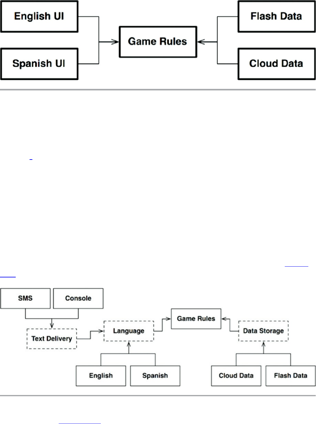
Figure 25.2 Following the Dependency Rule
CLEAN ARCHITECTURE?
It should be clear that we could easily apply the clean architecture approach in this
context,1 with all the use cases, boundaries, entities, and corresponding data
structures. But have we really found all the significant architectural boundaries?
For example, language is not the only axis of change for the UI. We also might want
to vary the mechanism by which we communicate the text. For example, we might
want to use a normal shell window, or text messages, or a chat application. There are
many different possibilities.
That means that there is a potential architectural boundary defined by this axis of
change. Perhaps we should construct an API that crosses that boundary and isolates
the language from the communications mechanism; that idea is illustrated in Figure
25.3.
Figure 25.3 The revised diagram
The diagram in Figure 25.3 has gotten a little complicated, but should contain no

surprises. The dashed outlines indicate abstract components that define an API that is
implemented by the components above or below them. For example, the Language
API is implemented by English and Spanish.
GameRules communicates with Language through an API that GameRules defines and
Language implements. Language communicates with TextDelivery using an API
that Language defines but TextDelivery implements. The API is defined and owned
by the user, rather than by the implementer.
If we were to look inside GameRules, we would find polymorphic Boundary
interfaces used by the code inside GameRules and implemented by the code inside
the Language component. We would also find polymorphic Boundary interfaces used
by Language and implemented by code inside GameRules.
If we were to look inside of Language, we would find the same thing: Polymorphic
Boundary interfaces implemented by the code inside TextDelivery, and
polymorphic Boundary interfaces used by TextDelivery and implemented by
Language.
In each case, the API defined by those Boundary interfaces is owned by the upstream
component.
The variations, such as English, SMS, and CloudData, are provided by polymorphic
interfaces defined in the abstract API component, and implemented by the concrete
components that serve them. For example, we would expect polymorphic interfaces
defined in Language to be implemented by English and Spanish.
We can simplify this diagram by eliminating all the variations and focusing on just
the API components. Figure 25.4 shows this diagram.
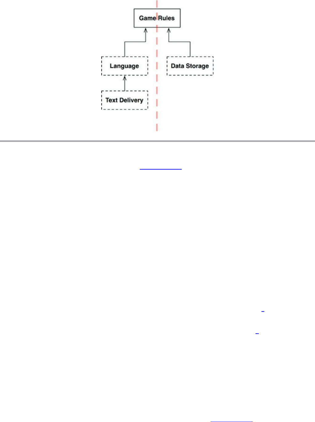
Figure 25.4 Simplified diagram
Notice that the diagram is oriented in Figure 25.4 so that all the arrows point up.
This puts GameRules at the top. This orientation makes sense because GameRules is
the component that contains the highest-level policies.
Consider the direction of information flow. All input comes from the user through
the TextDelivery component at the bottom left. That information rises through the
Language component, getting translated into commands to GameRules. GameRules
processes the user input and sends appropriate data down to DataStorage at the
lower right.
GameRules then sends output back down to Language, which translates the API back
to the appropriate language and then delivers that language to the user through
TextDelivery.
This organization effectively divides the flow of data into two streams.2 The stream
on the left is concerned with communicating with the user, and the stream on the
right is concerned with data persistence. Both streams meet at the top3 at GameRules,
which is the ultimate processor of the data that goes through both streams.
CROSSING THE STREAMS
Are there always two data streams as in this example? No, not at all. Imagine that we
would like to play Hunt the Wumpus on the net with multiple players. In this case,
we would need a network component, like that shown in Figure 25.5. This
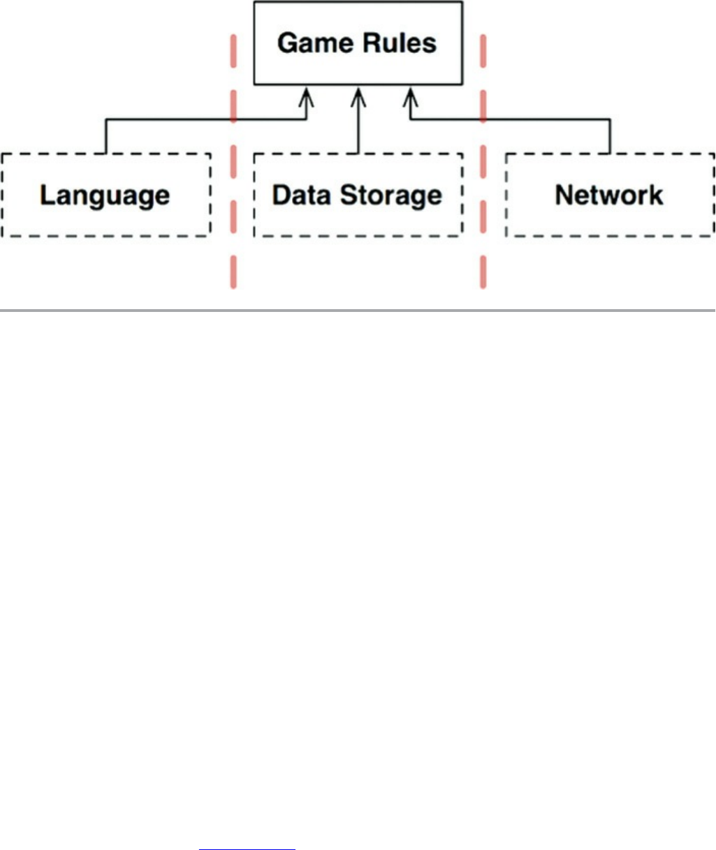
organization divides the data flow into three streams, all controlled by the
GameRules.
Figure 25.5 Adding a network component
So, as systems become more complex, the component structure may split into many
such streams.
SPLITTING THE STREAMS
At this point you may be thinking that all the streams eventually meet at the top in a
single component. If only life were so simple! The reality, of course, is much more
complex.
Consider the GameRules component for Hunt the Wumpus. Part of the game rules
deal with the mechanics of the map. They know how the caverns are connected, and
which objects are located in each cavern. They know how to move the player from
cavern to cavern, and how to determine the events that the player must deal with.
But there is another set of policies at an even higher level—policies that know the
health of the player, and the cost or benefit of a particular event. These policies could
cause the player to gradually lose health, or to gain health by discovering food. The
lower-level mechanics policy would declare events to this higher-level policy, such
as FoundFood or FellInPit. The higher-level policy would then manage the state of
the player (as shown in Figure 25.6). Eventually that policy would decide whether
the player wins or loses.
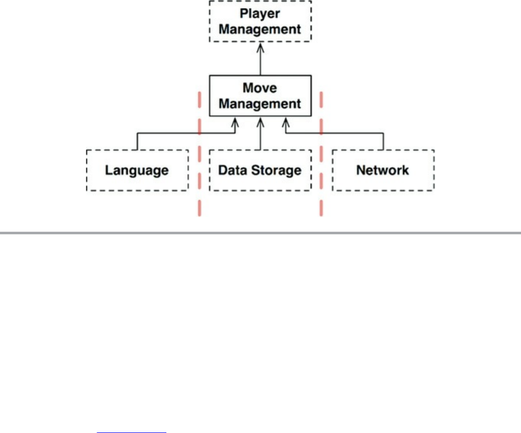
Figure 25.6 The higher-level policy manages the player
Is this an architectural boundary? Do we need an API that separates MoveManagement
from PlayerManagement? Well, let’s make this a bit more interesting and add micro-
services.
Let’s assume that we’ve got a massive multiplayer version of Hunt the Wumpus.
MoveManagement is handled locally within the player’s computer, but
PlayerManagement is handled by a server. PlayerManagement offers a micro-service
API to all the connected MoveManagement components.
The diagram in Figure 25.7 depicts this scenario in a somewhat abbreviated fashion.
The Network elements are a bit more complex than depicted—but you can probably
still get the idea. A full-fledged architectural boundary exists between
MoveManagement and PlayerManagement in this case.
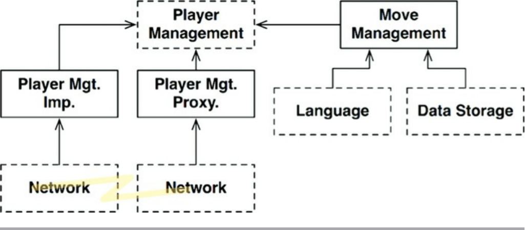
Figure 25.7 Adding a micro-service API
CONCLUSION
What does all this mean? Why have I taken this absurdly simply program, which
could be implemented in 200 lines of Kornshell, and extrapolated it out with all these
crazy architectural boundaries?
This example is intended to show that architectural boundaries exist everywhere.
We, as architects, must be careful to recognize when they are needed. We also have
to be aware that such boundaries, when fully implemented, are expensive. At the
same time, we have to recognize that when such boundaries are ignored, they are
very expensive to add in later—even in the presence of comprehensive test-suites
and refactoring discipline.
So what do we do, we architects? The answer is dissatisfying. On the one hand,
some very smart people have told us, over the years, that we should not anticipate
the need for abstraction. This is the philosophy of YAGNI: “You aren’t going to
need it.” There is wisdom in this message, since over-engineering is often much
worse than under-engineering. On the other hand, when you discover that you truly
do need an architectural boundary where none exists, the costs and risks can be very
high to add such a boundary.
So there you have it. O Software Architect, you must see the future. You must guess
—intelligently. You must weigh the costs and determine where the architectural
boundaries lie, and which should be fully implemented, and which should be

partially implemented, and which should be ignored.
But this is not a one-time decision. You don’t simply decide at the start of a project
which boundaries to implement and which to ignore. Rather, you watch. You pay
attention as the system evolves. You note where boundaries may be required, and
then carefully watch for the first inkling of friction because those boundaries don’t
exist.
At that point, you weigh the costs of implementing those boundaries versus the cost
of ignoring them—and you review that decision frequently. Your goal is to
implement the boundaries right at the inflection point where the cost of
implementing becomes less than the cost of ignoring.
It takes a watchful eye.
1. It should be just as clear that we would not apply the clean architecture approach to something as
trivial as this game. After all, the entire program can probably be written in 200 lines of code or
less. In this case, we’re using a simple program as a proxy for a much larger system with
significant architectural boundaries.
2. If you are confused by the direction of the arrows, remember that they point in the direction of
source code dependencies, not in the direction of data flow.
3. In days long past, we would have called that top component the Central Transform. See Practical
Guide to Structured Systems Design, 2nd ed., Meilir Page-Jones, 1988.
26
THE MAIN COMPONENT
In every system, there is at least one component that creates, coordinates, and
oversees the others. I call this component Main.
THE ULTIMATE DETAIL
The Main component is the ultimate detail—the lowest-level policy. It is the initial
entry point of the system. Nothing, other than the operating system, depends on it. Its
job is to create all the Factories, Strategies, and other global facilities, and then hand
control over to the high-level abstract portions of the system.
It is in this Main component that dependencies should be injected by a Dependency
Injection framework. Once they are injected into Main, Main should distribute those

dependencies normally, without using the framework.
Think of Main as the dirtiest of all the dirty components.
Consider the following Main component from a recent version of Hunt the Wumpus.
Notice how it loads up all the strings that we don’t want the main body of the code to
know about.
Click here to view code image
public class Main implements HtwMessageReceiver {
private static HuntTheWumpus game;
private static int hitPoints = 10;
private static final List<String> caverns = new ArrayList<>();
private static final String[] environments = new String[]{
"bright",
"humid",
"dry",
"creepy",
"ugly",
"foggy",
"hot",
"cold",
"drafty",
"dreadful"
};
private static final String[] shapes = new String[] {
"round",
"square",
"oval",
"irregular",
"long",
"craggy",
"rough",
"tall",
"narrow"
};
private static final String[] cavernTypes = new String[] {
"cavern",
"room",
"chamber",
"catacomb",
"crevasse",
"cell",
"tunnel",

"passageway",
"hall",
"expanse"
};
private static final String[] adornments = new String[] {
"smelling of sulfur",
"with engravings on the walls",
"with a bumpy floor",
"",
"littered with garbage",
"spattered with guano",
"with piles of Wumpus droppings",
"with bones scattered around",
"with a corpse on the floor",
"that seems to vibrate",
"that feels stuffy",
"that fills you with dread"
};
Now here’s the main function. Notice how it uses the HtwFactory to create the game.
It passes in the name of the class, htw.game.HuntTheWumpusFacade, because that
class is even dirtier than Main. This prevents changes in that class from causing Main
to recompile/redeploy.
Click here to view code image
public static void main(String[] args) throws IOException {
game = HtwFactory.makeGame("htw.game.HuntTheWumpusFacade",
new Main());
createMap();
BufferedReader br =
new BufferedReader(new InputStreamReader(System.in));
game.makeRestCommand().execute();
while (true) {
System.out.println(game.getPlayerCavern());
System.out.println("Health: " + hitPoints + " arrows: " +
game.getQuiver());
HuntTheWumpus.Command c = game.makeRestCommand();
System.out.println(">");
String command = br.readLine();
if (command.equalsIgnoreCase("e"))
c = game.makeMoveCommand(EAST);
else if (command.equalsIgnoreCase("w"))
c = game.makeMoveCommand(WEST);
else if (command.equalsIgnoreCase("n"))

c = game.makeMoveCommand(NORTH);
else if (command.equalsIgnoreCase("s"))
c = game.makeMoveCommand(SOUTH);
else if (command.equalsIgnoreCase("r"))
c = game.makeRestCommand();
else if (command.equalsIgnoreCase("sw"))
c = game.makeShootCommand(WEST);
else if (command.equalsIgnoreCase("se"))
c = game.makeShootCommand(EAST);
else if (command.equalsIgnoreCase("sn"))
c = game.makeShootCommand(NORTH);
else if (command.equalsIgnoreCase("ss"))
c = game.makeShootCommand(SOUTH);
else if (command.equalsIgnoreCase("q"))
return;
c.execute();
}
}
Notice also that main creates the input stream and contains the main loop of the
game, interpreting the simple input commands, but then defers all processing to
other, higher-level components.
Finally, notice that main creates the map.
Click here to view code image
private static void createMap() {
int nCaverns = (int) (Math.random() * 30.0 + 10.0);
while (nCaverns-- > 0)
caverns.add(makeName());
for (String cavern : caverns) {
maybeConnectCavern(cavern, NORTH);
maybeConnectCavern(cavern, SOUTH);
maybeConnectCavern(cavern, EAST);
maybeConnectCavern(cavern, WEST);
}
String playerCavern = anyCavern();
game.setPlayerCavern(playerCavern);
game.setWumpusCavern(anyOther(playerCavern));
game.addBatCavern(anyOther(playerCavern));
game.addBatCavern(anyOther(playerCavern));
game.addBatCavern(anyOther(playerCavern));
game.addPitCavern(anyOther(playerCavern));
game.addPitCavern(anyOther(playerCavern));
game.addPitCavern(anyOther(playerCavern));
game.setQuiver(5);
}
// much code removed…
}
The point is that Main is a dirty low-level module in the outermost circle of the clean
architecture. It loads everything up for the high level system, and then hands control
over to it.
CONCLUSION
Think of Main as a plugin to the application—a plugin that sets up the initial
conditions and configurations, gathers all the outside resources, and then hands
control over to the high-level policy of the application. Since it is a plugin, it is
possible to have many Main components, one for each configuration of your
application.
For example, you could have a Main plugin for Dev, another for Test, and yet another
for Production. You could also have a Main plugin for each country you deploy to,
or each jurisdiction, or each customer.
When you think about Main as a plugin component, sitting behind an architectural
boundary, the problem of configuration becomes a lot easier to solve.
27
SERVICES: GREAT AND SMALL
Service-oriented “architectures” and micro-service “architectures” have become very
popular of late. The reasons for their current popularity include the following:
• Services seem to be strongly decoupled from each other. As we shall see, this is
only partially true.
• Services appear to support independence of development and deployment. Again,
as we shall see, this is only partially true.
SERVICE ARCHITECTURE?
First, let’s consider the notion that using services, by their nature, is an architecture.
This is patently untrue. The architecture of a system is defined by boundaries that
separate high-level policy from low-level detail and follow the Dependency Rule.
Services that simply separate application behaviors are little more than expensive
function calls, and are not necessarily architecturally significant.
This is not to say that all services should be architecturally significant. There are
often substantial benefits to creating services that separate functionality across
processes and platforms—whether they obey the Dependency Rule or not. It’s just
that services, in and of themselves, do not define an architecture.
A helpful analogy is the organization of functions. The architecture of a monolithic
or component-based system is defined by certain function calls that cross
architectural boundaries and follow the Dependency Rule. Many other functions in
those systems, however, simply separate one behavior from another and are not
architecturally significant.
So it is with services. Services are, after all, just function calls across process and/or
platform boundaries. Some of those services are architecturally significant, and some
aren’t. Our interest, in this chapter, is with the former.
SERVICE BENEFITS?
The question mark in the preceding heading indicates that this section is going to
challenge the current popular orthodoxy of service architecture. Let’s tackle the
benefits one at a time.
THE DECOUPLING FALLACY
One of the big supposed benefits of breaking a system up into services is that
services are strongly decoupled from each other. After all, each service runs in a
different process, or even a different processor; therefore those services do not have
access to each other’s variables. What’s more, the interface of each service must be
well defined.
There is certainly some truth to this—but not very much truth. Yes, services are
decoupled at the level of individual variables. However, they can still be coupled by
shared resources within a processor, or on the network. What’s more, they are
strongly coupled by the data they share.
For example, if a new field is added to a data record that is passed between services,
then every service that operates on the new field must be changed. The services must
also strongly agree about the interpretation of the data in that field. Thus those
services are strongly coupled to the data record and, therefore, indirectly coupled to
each other.
As for interfaces being well defined, that’s certainly true—but it is no less true for
functions. Service interfaces are no more formal, no more rigorous, and no better
defined than function interfaces. Clearly, then, this benefit is something of an
illusion.
THE FALLACY OF INDEPENDENT DEVELOPMENT
AND DEPLOYMENT
Another of the supposed benefits of services is that they can be owned and operated
by a dedicated team. That team can be responsible for writing, maintaining, and
operating the service as part of a dev-ops strategy. This independence of
development and deployment is presumed to be scalable. It is believed that large
enterprise systems can be created from dozens, hundreds, or even thousands of
independently developable and deployable services. Development, maintenance, and
operation of the system can be partitioned between a similar number of independent
teams.
There is some truth to this belief—but only some. First, history has shown that large
enterprise systems can be built from monoliths and component-based systems as
well as service-based systems. Thus services are not the only option for building
scalable systems.
Second, the decoupling fallacy means that services cannot always be independently
developed, deployed, and operated. To the extent that they are coupled by data or
behavior, the development, deployment, and operation must be coordinated.
THE KITTY PROBLEM
As an example of these two fallacies, let’s look at our taxi aggregator system again.
Remember, this system knows about many taxi providers in a given city, and allows
customers to order rides. Let’s assume that the customers select taxis based on a
number of criteria, such as pickup time, cost, luxury, and driver experience.
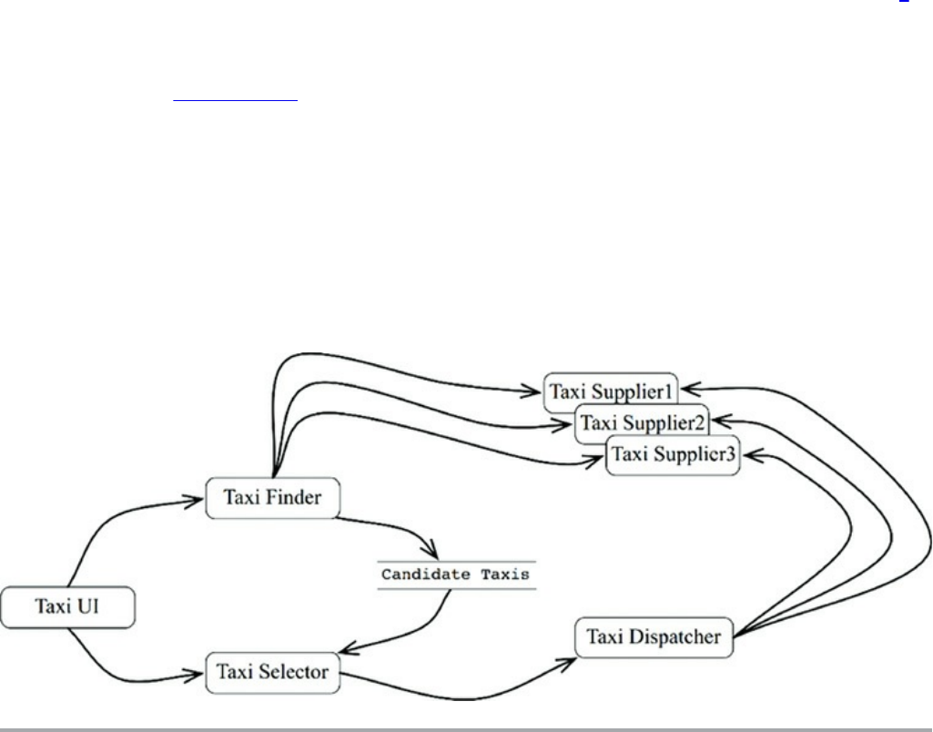
We wanted our system to be scalable, so we chose to build it out of lots of little
micro-services. We subdivided our development staff into many small teams, each of
which is responsible for developing, maintaining, and operating a correspondingly1
small number of services.
The diagram in Figure 27.1 shows how our fictitious architects arranged services to
implement this application. The TaxiUI service deals with the customers, who use
mobile devices to order taxis. The TaxiFinder service examines the inventories of
the various TaxiSuppliers and determines which taxies are possible candidates for
the user. It deposits these into a short-term data record attached to that user. The
TaxiSelector service takes the user’s criteria of cost, time, luxury, and so forth, and
chooses an appropriate taxi from among the candidates. It hands that taxi off to the
TaxiDispatcher service, which orders the appropriate taxi.
Figure 27.1 Services arranged to implement the taxi aggregator system
Now let us suppose that this system has been in operation for more than a year. Our
staff of developers have been happily developing new features while maintaining
and operating all these services.
One bright and cheerful day, the marketing department holds a meeting with the
development team. In this meeting, they announce their plans to offer a kitten
delivery service to the city. Users can order kittens to be delivered to their homes or
to their places of business.
The company will set up several kitten collection points across the city. When a
kitten order is placed, a nearby taxi will be selected to collect a kitten from one of
those collection points, and then deliver it to the appropriate address.
One of the taxi suppliers has agreed to participate in this program. Others are likely
to follow. Still others may decline.
Of course, some drivers may be allergic to cats, so those drivers should never be
selected for this service. Also, some customers will undoubtedly have similar
allergies, so a vehicle that has been used to deliver kittens within the last 3 days
should not be selected for customers who declare such allergies.
Look at that diagram of services. How many of those services will have to change to
implement this feature? All of them. Clearly, the development and deployment of the
kitty feature will have to be very carefully coordinated.
In other words, the services are all coupled, and cannot be independently developed,
deployed, and maintained.
This is the problem with cross-cutting concerns. Every software system must face
this problem, whether service oriented or not. Functional decompositions, of the kind
depicted in the service diagram in Figure 27.1, are very vulnerable to new features
that cut across all those functional behaviors.
OBJECTS TO THE RESCUE
How would we have solved this problem in a component-based architecture? Careful
consideration of the SOLID design principles would have prompted us to create a set
of classes that could be polymorphically extended to handle new features.
The diagram in Figure 27.2 shows the strategy. The classes in this diagram roughly
correspond to the services shown in Figure 27.1. However, note the boundaries. Note
also that the dependencies follow the Dependency Rule.
Much of the logic of the original services is preserved within the base classes of the
object model. However, that portion of the logic that was specific to rides has been
extracted into a Rides component. The new feature for kittens has been placed into a
Kittens component. These two components override the abstract base classes in the
original components using a pattern such as Template Method or Strategy.
Note again that the two new components, Rides and Kittens, follow the
Dependency Rule. Note also that the classes that implement those features are
created by factories under the control of the UI.
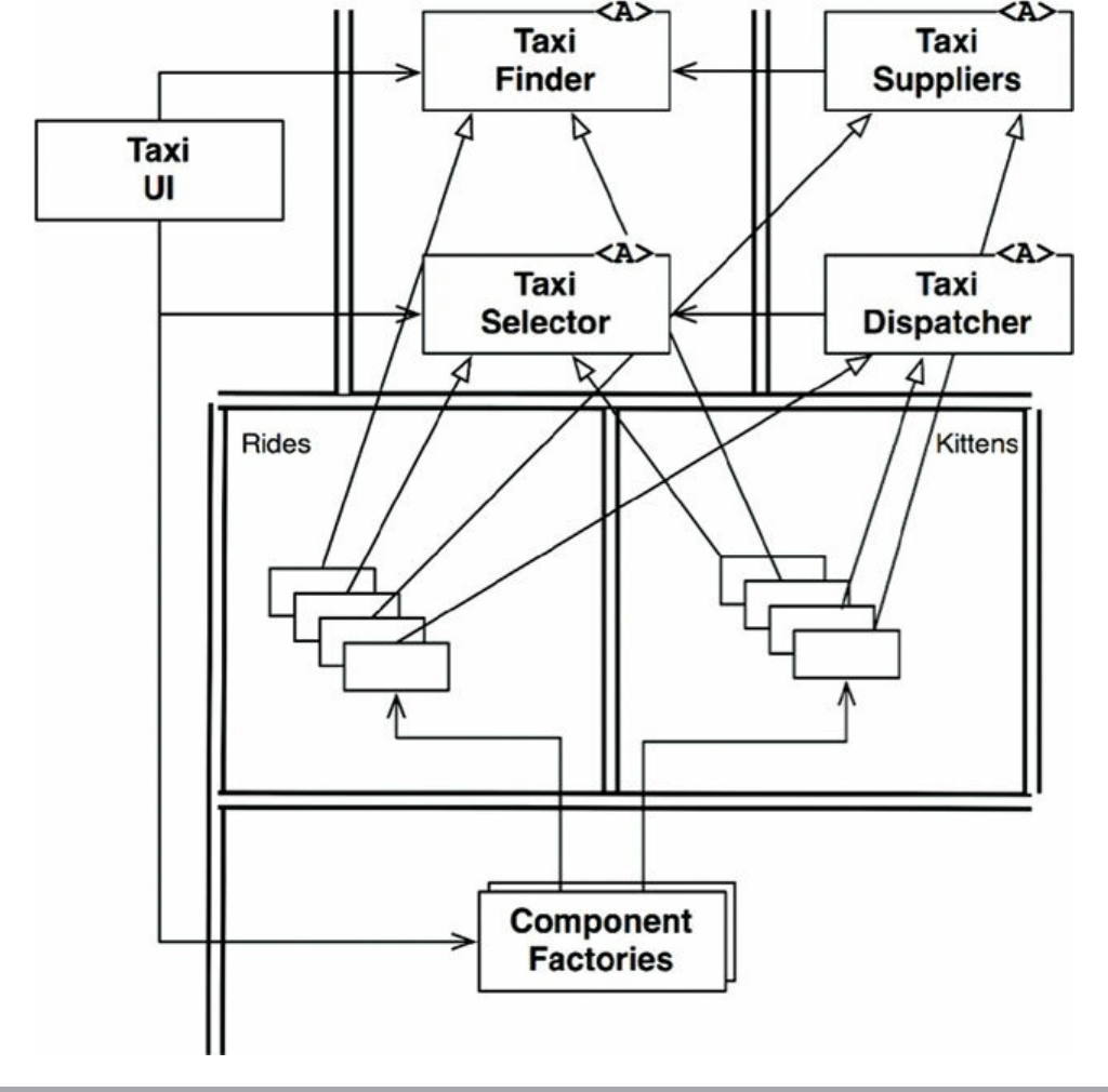
Clearly, in this scheme, when the Kitty feature is implemented, the TaxiUI must
change. But nothing else needs to be changed. Rather, a new jar file, or Gem, or
DLL is added to the system and dynamically loaded at runtime.
Thus the Kitty feature is decoupled, and independently developable and deployable.
Figure 27.2 Using an object-oriented approach to deal with cross-cutting concerns
COMPONENT-BASED SERVICES
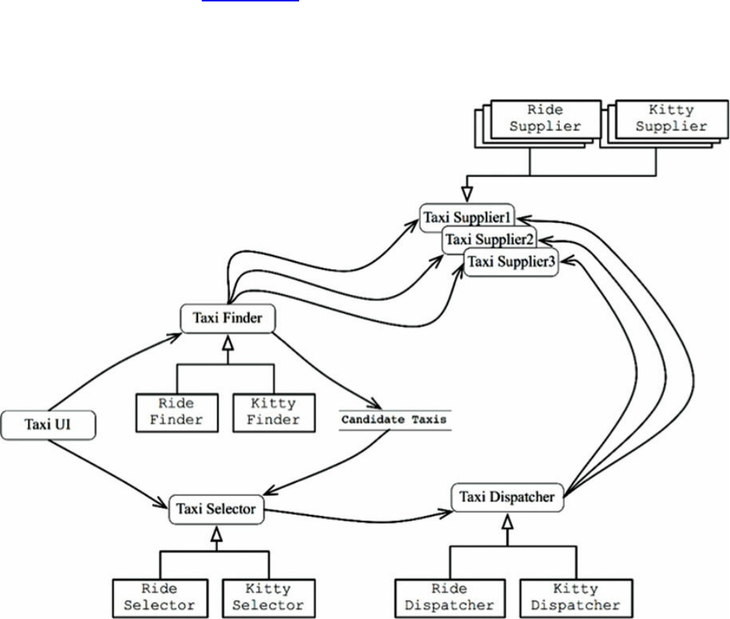
The obvious question is: Can we do that for services? And the answer is, of course:
Yes! Services do not need to be little monoliths. Services can, instead, be designed
using the SOLID principles, and given a component structure so that new
components can be added to them without changing the existing components within
the service.
Think of a service in Java as a set of abstract classes in one or more jar files. hink of
each new feature or feature extension as another jar file that contains classes that
extend the abstract classes in the first jar files. Deploying a new feature then
becomes not a matter of redeploying the services, but rather a matter of simply
adding the new jar files to the load paths of those services. In other words, adding
new features conforms to the Open-Closed Principle.
The service diagram in Figure 27.3 shows the structure. The services still exist as
before, but each has its own internal component design, allowing new features to be
added as new derivative classes. Those derivative classes live within their own
components.
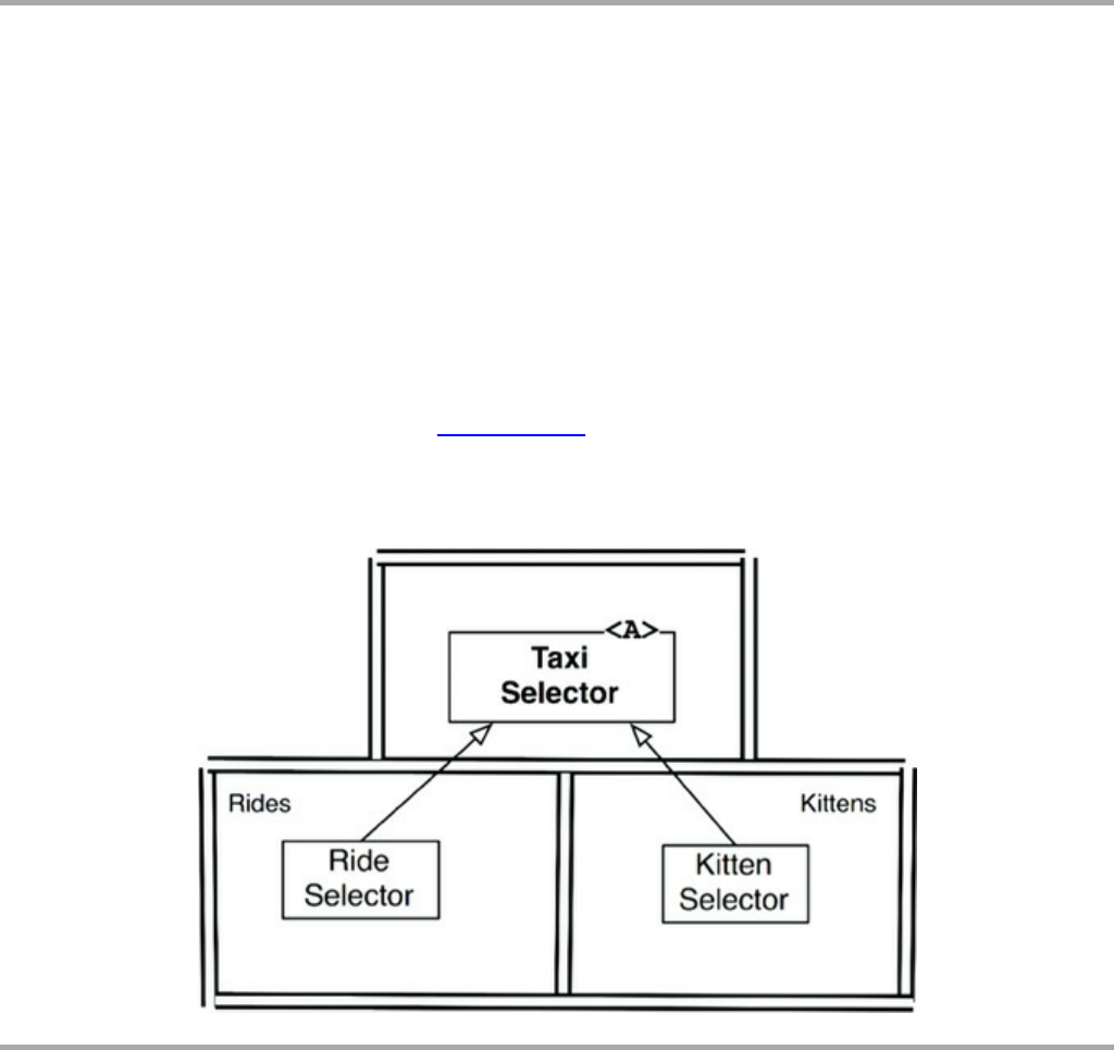
Figure 27.3 Each service has its own internal component design, enabling new features to be added
as new derivative classes
CROSS-CUTTING CONCERNS
What we have learned is that architectural boundaries do not fall between services.
Rather, those boundaries run through the services, dividing them into components.
To deal with the cross-cutting concerns that all significant systems face, services
must be designed with internal component architectures that follow the Dependency
Rule, as shown in the diagram in Figure 27.4. Those services do not define the
architectural boundaries of the system; instead, the components within the services
do.
Figure 27.4 Services must be designed with internal component architectures that follow the
Dependency Rule
CONCLUSION
As useful as services are to the scalability and develop-ability of a system, they are
not, in and of themselves, architecturally significant elements. The architecture of a
system is defined by the boundaries drawn within that system, and by the
dependencies that cross those boundaries. That architecture is not defined by the
physical mechanisms by which elements communicate and execute.
A service might be a single component, completely surrounded by an architectural
boundary. Alternatively, a service might be composed of several components
separated by architectural boundaries. In rare2 cases, clients and services may be so
coupled as to have no architectural significance whatever.
1. Therefore the number of micro-services will be roughly equal to the number of programmers.
2. We hope they are rare. Unfortunately, experience suggests otherwise.
28
THE TEST BOUNDARY
Yes, that’s right: The tests are part of the system, and they participate in the
architecture just like every other part of the system does. In some ways, that
participation is pretty normal. In other ways, it can be pretty unique.
TESTS AS SYSTEM COMPONENTS
There is a great deal of confusion about tests. Are they part of the system? Are they
separate from the system? Which kinds of tests are there? Are unit tests and
integration tests different things? What about acceptance tests, functional tests,
Cucumber tests, TDD tests, BDD tests, component tests, and so on?
It is not the role of this book to get embroiled in that particular debate, and
fortunately it isn’t necessary. From an architectural point of view, all tests are the
same. Whether they are the tiny little tests created by TDD, or large FitNesse,
Cucumber, SpecFlow, or JBehave tests, they are architecturally equivalent.
Tests, by their very nature, follow the Dependency Rule; they are very detailed and
concrete; and they always depend inward toward the code being tested. In fact, you
can think of the tests as the outermost circle in the architecture. Nothing within the
system depends on the tests, and the tests always depend inward on the components
of the system.
Tests are also independently deployable. In fact, most of the time they are deployed
in test systems, rather than in production systems. So, even in systems where
independent deployment is not otherwise necessary, the tests will still be
independently deployed.
Tests are the most isolated system component. They are not necessary for system
operation. No user depends on them. Their role is to support development, not
operation. And yet, they are no less a system component than any other. In fact, in
many ways they represent the model that all other system components should follow.
DESIGN FOR TESTABILITY
The extreme isolation of the tests, combined with the fact that they are not usually
deployed, often causes developers to think that tests fall outside of the design of the
system. This is a catastrophic point of view. Tests that are not well integrated into
the design of the system tend to be fragile, and they make the system rigid and
difficult to change.
The issue, of course, is coupling. Tests that are strongly coupled to the system must
change along with the system. Even the most trivial change to a system component
can cause many coupled tests to break or require changes.
This situation can become acute. Changes to common system components can cause
hundreds, or even thousands, of tests to break. This is known as the Fragile Tests
Problem.
It is not hard to see how this can happen. Imagine, for example, a suite of tests that
use the GUI to verify business rules. Such tests may start on the login screen and
then navigate through the page structure until they can check particular business
rules. Any change to the login page, or the navigation structure, can cause an
enormous number of tests to break.
Fragile tests often have the perverse effect of making the system rigid. When
developers realize that simple changes to the system can cause massive test failures,
they may resist making those changes. For example, imagine the conversation
between the development team and a marketing team that requests a simple change
to the page navigation structure that will cause 1000 tests to break.
The solution is to design for testability. The first rule of software design—whether
for testability or for any other reason—is always the same: Don’t depend on volatile
things. GUIs are volatile. Test suites that operate the system through the GUI must
be fragile. Therefore design the system, and the tests, so that business rules can be
tested without using the GUI.
THE TESTING API
The way to accomplish this goal is to create a specific API that the tests can use to
verify all the business rules. This API should have superpowers that allow the tests
to avoid security constraints, bypass expensive resources (such as databases), and
force the system into particular testable states. This API will be a superset of the
suite of interactors and interface adapters that are used by the user interface.
The purpose of the testing API is to decouple the tests from the application. This
decoupling encompasses more than just detaching the tests from the UI: The goal is
to decouple the structure of the tests from the structure of the application.
STRUCTURAL COUPLING
Structural coupling is one of the strongest, and most insidious, forms of test
coupling. Imagine a test suite that has a test class for every production class, and a
set of test methods for every production method. Such a test suite is deeply coupled
to the structure of the application.
When one of those production methods or classes changes, a large number of tests
must change as well. Consequently, the tests are fragile, and they make the
production code rigid.
The role of the testing API is to hide the structure of the application from the tests.
This allows the production code to be refactored and evolved in ways that don’t
affect the tests. It also allows the tests to be refactored and evolved in ways that
don’t affect the production code.
This separation of evolution is necessary because as time passes, the tests tend to
become increasingly more concrete and specific. In contrast, the production code
tends to become increasingly more abstract and general. Strong structural coupling
prevents—or at least impedes—this necessary evolution, and prevents the production
code from being as general, and flexible, as it could be.
SECURITY
The superpowers of the testing API could be dangerous if they were deployed in
production systems. If this is a concern, then the testing API, and the dangerous parts
of its implementation, should be kept in a separate, independently deployable
component.
CONCLUSION
Tests are not outside the system; rather, they are parts of the system that must be
well designed if they are to provide the desired benefits of stability and regression.
Tests that are not designed as part of the system tend to be fragile and difficult to
maintain. Such tests often wind up on the maintenance room floor—discarded
because they are too difficult to maintain.
29
CLEAN EMBEDDED ARCHITECTURE
By James Grenning
A while ago I read an article entitled “The Growing Importance of Sustaining
Software for the DoD”1 on Doug Schmidt’s blog. Doug made the following claim:
“Although software does not wear out, firmware and hardware become obsolete, thereby
requiring software modifications.”
It was a clarifying moment for me. Doug mentioned two terms that I would have
thought to be obvious—but maybe not. Software is this thing that can have a long
useful life, but firmware will become obsolete as hardware evolves. If you have
spent any time in embedded systems development, you know the hardware is
continually evolving and being improved. At the same time, features are added to the
new “software,” and it continually grows in complexity.
I’d like to add to Doug’s statement:
Although software does not wear out, it can be destroyed from within by unmanaged
dependencies on firmware and hardware.
It is not uncommon for embedded software to be denied a potentially long life due to
being infected with dependencies on hardware.
I like Doug’s definition of firmware, but let’s see which other definitions are out
there. I found these alternatives:
• “Firmware is held in non-volatile memory devices such as ROM, EPROM, or flash
memory.” (https://en.wikipedia.org/wiki/Firmware)
• “Firmware is a software program or set of instructions programmed on a hardware
device.” (https://techterms.com/definition/firmware)
• “Firmware is software that is embedded in a piece of hardware.”
(https://www.lifewire.com/what-is-firmware-2625881)
• Firmware is “Software (programs or data) that has been written onto read-only
memory (ROM).” (http://www.webopedia.com/TERM/F/firmware.html)
Doug’s statement makes me realize that these accepted definitions of firmware are
wrong, or at least obsolete. Firmware does not mean code lives in ROM. It’s not
firmware because of where it is stored; rather, it is firmware because of what it
depends on and how hard it is to change as hardware evolves. Hardware does evolve
(pause and look at your for phone for evidence), so we should structure our
embedded code with that reality in mind.
I have nothing against firmware, or firmware engineers (I’ve been known to write
some firmware myself). But what we really need is less firmware and more software.
Actually, I am disappointed that firmware engineers write so much firmware!
Non-embedded engineers also write firmware! You non-embedded developers
essentially write firmware whenever you bury SQL in your code or when you spread
platform dependencies throughout your code. Android app developers write
firmware when they don’t separate their business logic from the Android API.
I’ve been involved in a lot of efforts where the line between the product code (the
software) and the code that interacts with the product’s hardware (the firmware) is

fuzzy to the point of nonexistence. For example, in the late 1990s I had the fun of
helping redesign a communications subsystem that was transitioning from time-
division multiplexing (TDM) to voice over IP (VOIP). VOIP is how things are done
now, but TDM was considered the state of the art from the 1950s and 1960s, and was
widely deployed in the 1980s and 1990s.
Whenever we had a question for the systems engineer about how a call should react
to a given situation, he would disappear and a little later emerge with a very detailed
answer. “Where did he get that answer?” we asked. “From the current product’s
code,” he’d answer. The tangled legacy code was the spec for the new product! The
existing implementation had no separation between TDM and the business logic of
making calls. The whole product was hardware/technology dependent from top to
bottom and could not be untangled. The whole product had essentially become
firmware.
Consider another example: Command messages arrive to this system via serial port.
Unsurprisingly, there is a message processor/dispatcher. The message processor
knows the format of messages, is able to parse them, and can then dispatch the
message to the code that can handle the request. None of this is surprising, except
that the message processor/dispatcher resides in the same file as code that interacts
with a UART2 hardware. The message processor is polluted with UART details. The
message processor could have been software with a potentially long useful life, but
instead it is firmware. The message processor is denied the opportunity to become
software—and that is just not right!
I’ve known and understood the need for separating software from hardware for a
long time, but Doug’s words clarified how to use the terms software and firmware in
relationship to each other.
For engineers and programmers, the message is clear: Stop writing so much
firmware and give your code a chance at a long useful life. Of course, demanding it
won’t make it so. Let’s look at how we can keep embedded software architecture
clean to give the software a fighting chance of having a long and useful life.
APP-TITUDE TEST
Why does so much potential embedded software become firmware? It seems that
most of the emphasis is on getting the embedded code to work, and not so much
emphasis is placed on structuring it for a long useful life. Kent Beck describes three

activities in building software (the quoted text is Kent’s words and the italics are my
commentary):
1. “First make it work.” You are out of business if it doesn’t work.
2. “Then make it right.” Refactor the code so that you and others can understand it
and evolve it as needs change or are better understood.
3. “Then make it fast.” Refactor the code for “needed” performance.
Much of the embedded systems software that I see in the wild seems to have been
written with “Make it work” in mind—and perhaps also with an obsession for the
“Make it fast” goal, achieved by adding micro-optimizations at every opportunity. In
The Mythical Man-Month, Fred Brooks suggests we “plan to throw one away.” Kent
and Fred are giving virtually the same advice: Learn what works, then make a better
solution.
Embedded software is not special when it comes to these problems. Most non-
embedded apps are built just to work, with little regard to making the code right for a
long useful life.
Getting an app to work is what I call the App-titude test for a programmer.
Programmers, embedded or not, who just concern themselves with getting their app
to work are doing their products and employers a disservice. There is much more to
programming than just getting an app to work.
As an example of code produced while passing the App-titude test, check out these
functions located in one file of a small embedded system:
Click here to view code image
ISR(TIMER1_vect) { ... }
ISR(INT2_vect) { ... }
void btn_Handler(void) { ... }
float calc_RPM(void) { ... }
static char Read_RawData(void) { ... }
void Do_Average(void) { ... }
void Get_Next_Measurement(void) { ... }
void Zero_Sensor_1(void) { ... }
void Zero_Sensor_2(void) { ... }
void Dev_Control(char Activation) { ... }
char Load_FLASH_Setup(void) { ... }
void Save_FLASH_Setup(void) { ... }
void Store_DataSet(void) { ... }

float bytes2float(char bytes[4]) { ... }
void Recall_DataSet(void) { ... }
void Sensor_init(void) { ... }
void uC_Sleep(void) { ... }
That list of functions is in the order I found them in the source file. Now I’ll separate
them and group them by concern:
• Functions that have domain logic
Click here to view code image
float calc_RPM(void) { ... }
void Do_Average(void) { ... }
void Get_Next_Measurement(void) { ... }
void Zero_Sensor_1(void) { ... }
void Zero_Sensor_2(void) { ... }
• Functions that set up the hardware platform
Click here to view code image
ISR(TIMER1_vect) { ... }*
ISR(INT2_vect) { ... }
void uC_Sleep(void) { ... }
Functions that react to the on off button press
void btn_Handler(void) { ... }
void Dev_Control(char Activation) { ... }
A Function that can get A/D input readings from the hardware
static char Read_RawData(void) { ... }
• Functions that store values to the persistent storage
Click here to view code image
char Load_FLASH_Setup(void) { ... }
void Save_FLASH_Setup(void) { ... }
void Store_DataSet(void) { ... }
float bytes2float(char bytes[4]) { ... }
void Recall_DataSet(void) { ... }
• Function that does not do what its name implies
Click here to view code image
void Sensor_init(void) { ... }
Looking at some of the other files in this application, I found many impediments to
understanding the code. I also found a file structure that implied that the only way to

test any of this code is in the embedded target. Virtually every bit of this code knows
it is in a special microprocessor architecture, using “extended” C constructs3 that tie
the code to a particular tool chain and microprocessor. There is no way for this code
to have a long useful life unless the product never needs to be moved to a different
hardware environment.
This application works: The engineer passed the App-titude test. But the application
can’t be said to have a clean embedded architecture.
THE TARGET-HARDWARE BOTTLENECK
There are many special concerns that embedded developers have to deal with that
non-embedded developers do not—for example, limited memory space, real-time
constraints and deadlines, limited IO, unconventional user interfaces, and sensors
and connections to the real world. Most of the time the hardware is concurrently
developed with the software and firmware. As an engineer developing code for this
kind of system, you may have no place to run the code. If that’s not bad enough,
once you get the hardware, it is likely that the hardware will have its own defects,
making software development progress even slower than usual.
Yes, embedded is special. Embedded engineers are special. But embedded
development is not so special that the principles in this book are not applicable to
embedded systems.
One of the special embedded problems is the target-hardware bottleneck. When
embedded code is structured without applying clean architecture principles and
practices, you will often face the scenario in which you can test your code only on
the target. If the target is the only place where testing is possible, the target-hardware
bottleneck will slow you down.
A CLEAN EMBEDDED ARCHITECTURE IS A
TESTABLE EMBEDDED ARCHITECTURE
Let’s see how to apply some of the architectural principles to embedded software
and firmware to help you eliminate the target-hardware bottleneck.
Layers
Layering comes in many flavors. Let’s start with three layers, as shown in Figure
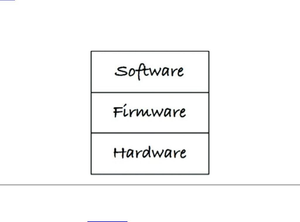
29.1. At the bottom, there is the hardware. As Doug warns us, due to technology
advances and Moore’s law, the hardware will change. Parts become obsolete, and
new parts use less power or provide better performance or are cheaper. Whatever the
reason, as an embedded engineer, I don’t want to have a bigger job than is necessary
when the inevitable hardware change finally happens.
Figure 29.1 Three layers
The separation between hardware and the rest of the system is a given—at least once
the hardware is defined (Figure 29.2). Here is where the problems often begin when
you are trying to pass the App-titude test. There is nothing that keeps hardware
knowledge from polluting all the code. If you are not careful about where you put
things and what one module is allowed to know about another module, the code will
be very hard to change. I’m not just talking about when the hardware changes, but
when the user asks for a change, or when a bug needs to be fixed.
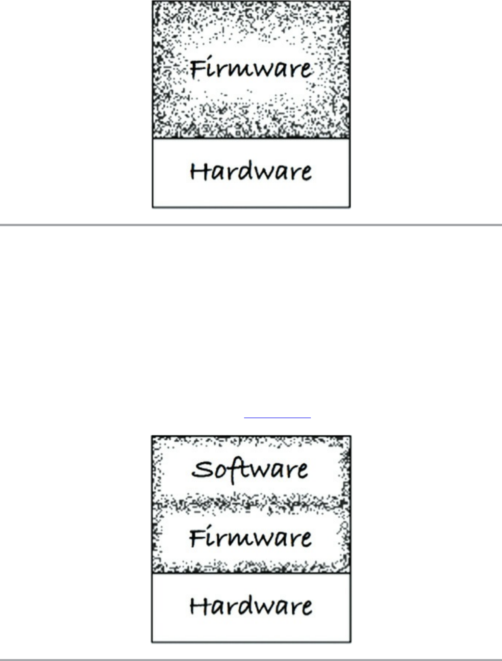
Figure 29.2 Hardware must be separated from the rest of the system
Software and firmware intermingling is an anti-pattern. Code exhibiting this anti-
pattern will resist changes. In addition, changes will be dangerous, often leading to
unintended consequences. Full regression tests of the whole system will be needed
for minor changes. If you have not created externally instrumented tests, expect to
get bored with manual tests—and then you can expect new bug reports.
The Hardware Is a Detail
The line between software and firmware is typically not so well defined as the line
between code and hardware, as shown in Figure 29.3.
Figure 29.3 The line between software and firmware is a bit fuzzier than the line between code and
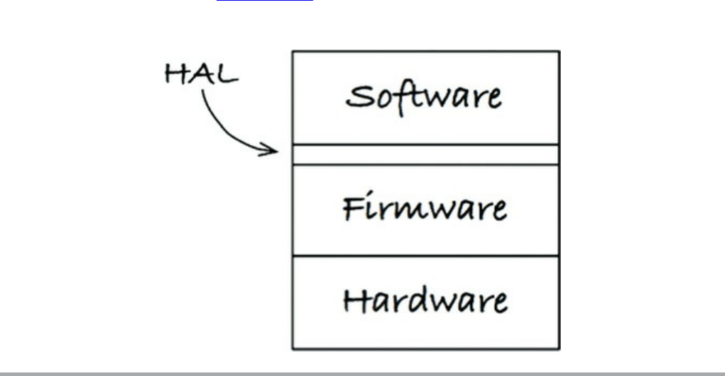
hardware
One of your jobs as an embedded software developer is to firm up that line. The
name of the boundary between the software and the firmware is the hardware
abstraction layer (HAL) (Figure 29.4). This is not a new idea: It has been in PCs
since the days before Windows.
Figure 29.4 The hardware abstraction layer
The HAL exists for the software that sits on top of it, and its API should be tailored
to that software’s needs. As an example, the firmware can store bytes and arrays of
bytes into flash memory. In contrast, the application needs to store and read
name/value pairs to some persistence mechanism. The software should not be
concerned that the name/value pairs are stored in flash memory, a spinning disk, the
cloud, or core memory. The HAL provides a service, and it does not reveal to the
software how it does it. The flash implementation is a detail that should be hidden
from software.
As another example, an LED is tied to a GPIO bit. The firmware could provide
access to the GPIO bits, where a HAL might provide Led_TurnOn(5). That is a
pretty low-level hardware abstraction layer. Let’s consider raising the level of
abstraction from a hardware perspective to the software/product perspective. What is
the LED indicating? Suppose that it indicated low battery power. At some level, the
firmware (or a board support package) could provide Led_TurnOn(5), while the
HAL provides Indicate_LowBattery(). You can see the HAL expressing services
needed by the application. You can also see that layers may contain layers. It is more
of a repeating fractal pattern than a limited set of predefined layers. The GPIO

assignments are details that should be hidden from the software.
DON’T REVEAL HARDWARE DETAILS TO THE USER
OF THE HAL
A clean embedded architecture’s software is testable off the target hardware. A
successful HAL provides that seam or set of substitution points that facilitate off-
target testing.
The Processor Is a Detail
When your embedded application uses a specialized tool chain, it will often provide
header files to <i>help you</i>.4 These compilers often take liberties with the C
language, adding new keywords to access their processor features. The code will
look like C, but it is no longer C.
Sometimes vendor-supplied C compilers provide what look like global variables to
give access directly to processor registers, IO ports, clock timers, IO bits, interrupt
controllers, and other processor functions. It is helpful to get access to these things
easily, but realize that any of your code that uses these helpful facilities is no longer
C. It won’t compile for another processor, or maybe even with a different compiler
for the same processor.
I would hate to think that the silicon and tool provider is being cynical, tying your
product to the compiler. Let’s give the provider the benefit of a doubt by assuming
that it is truly trying to help. But now it’s up to you to use that help in a way that
does not hurt in the future. You will have to limit which files are allowed to know
about the C extensions.
Let’s look at this header file designed for the ACME family of DSPs—you know,
the ones used by Wile E. Coyote:
Click here to view code image
#ifndef _ACME_STD_TYPES
#define _ACME_STD_TYPES
Click here to view code image

#if defined(_ACME_X42)
typedef unsigned int Uint_32;
typedef unsigned short Uint_16;
typedef unsigned char Uint_8;
typedef int Int_32;
typedef short Int_16;
typedef char Int_8;
#elif defined(_ACME_A42)
typedef unsigned long Uint_32;
typedef unsigned int Uint_16;
typedef unsigned char Uint_8;
typedef long Int_32;
typedef int Int_16;
typedef char Int_8;
#else
#error <acmetypes.h> is not supported for this environment
#endif
#endif
The acmetypes.h header file should not be used directly. If you do, your code gets
tied to one of the ACME DSPs. You are using an ACME DSP, you say, so what is
the harm? You can’t compile your code unless you include this header. If you use the
header and define _ACME_X42 or _ACME_A42, your integers will be the wrong size if
you try to test your code off-target. If that is not bad enough, one day you’ll want to
port your application to another processor, and you will have made that task much
more difficult by not choosing portability and by not limiting what files know about
ACME.
Instead of using acmetypes.h, you should try to follow a more standardized path and
use stdint.h. But what if the target compiler does not provide stdint.h? You can
write this header file. The stdint.h you write for target builds uses the acmetypes.h
for target compiles like this:
Click here to view code image
#ifndef _STDINT_H_
#define _STDINT_H_
#include <acmetypes.h>

typedef Uint_32 uint32_t;
typedef Uint_16 uint16_t;
typedef Uint_8 uint8_t;
typedef Int_32 int32_t;
typedef Int_16 int16_t;
typedef Int_8 int8_t;
#endif
Having your embedded software and firmware use stdint.h helps keep your code
clean and portable. Certainly, all of the software should be processor independent,
but not all of the firmware can be. This next code snippet takes advantage of special
extensions to C that gives your code access to the peripherals in the micro-controller.
It’s likely your product uses this micro-controller so that you can use its integrated
peripherals. This function outputs a line that says "hi" to the serial output port. (This
example is based on real code from the wild.)
Click here to view code image
void say_hi()
{
IE = 0b11000000;
SBUF0 = (0x68);
while(TI_0 == 0);
TI_0 = 0;
SBUF0 = (0x69);
while(TI_0 == 0);
TI_0 = 0;
SBUF0 = (0x0a);
while(TI_0 == 0);
TI_0 = 0;
SBUF0 = (0x0d);
while(TI_0 == 0);
TI_0 = 0;
IE = 0b11010000;
}
There are lots of problems with this small function. One thing that might jump out at
you is the presence of 0b11000000. This binary notation is cool; can C do that?
Unfortunately, no. A few other problems relate to this code directly using the custom
C extensions:
IE: Interrupt enable bits.

SBUF0: Serial output buffer.
TI_0: Serial transmit buffer empty interrupt. Reading a 1 indicates the buffer is
empty.
The uppercase variables actually access micro-controller built-in peripherals. If you
want to control interrupts and output characters, you must use these peripherals. Yes,
this is convenient—but it’s not C.
A clean embedded architecture would use these device access registers directly in
very few places and confine them totally to the firmware. Anything that knows about
these registers becomes firmware and is consequently bound to the silicon. Tying
code to the processor will hurt you when you want to get code working before you
have stable hardware. It will also hurt you when you move your embedded
application to a new processor.
If you use a micro-controller like this, your firmware could isolate these low-level
functions with some form of a processor abstraction layer (PAL). Firmware above
the PAL could be tested off-target, making it a little less firm.
The Operating System Is a Detail
A HAL is necessary, but is it sufficient? In bare-metal embedded systems, a HAL
may be all you need to keep your code from getting too addicted to the operating
environment. But what about embedded systems that use a real-time operating
system (RTOS) or some embedded version of Linux or Windows?
To give your embedded code a good chance at a long life, you have to treat the
operating system as a detail and protect against OS dependencies.
The software accesses the services of the operating environment through the OS. The
OS is a layer separating the software from firmware (Figure 29.5). Using an OS
directly can cause problems. For example, what if your RTOS supplier is bought by
another company and the royalties go up, or the quality goes down? What if your
needs change and your RTOS does not have the capabilities that you now require?
You’ll have to change lots of code. These won’t just be simple syntactical changes
due to the new OS’s API, but will likely have to adapt semantically to the new OS’s
different capabilities and primitives.
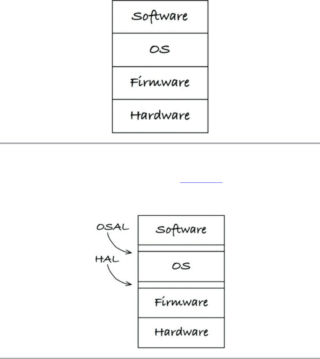
Figure 29.5 Adding in an operating system
A clean embedded architecture isolates software from the operating system, through
an operating system abstraction layer (OSAL) (Figure 29.6). In some cases,
implementing this layer might be as simple as changing the name of a function. In
other cases, it might involve wrapping several functions together.
Figure 29.6 The operating system abstraction layer
If you have ever moved your software from one RTOS to another, you know it is
painful. If your software depended on an OSAL instead of the OS directly, you
would largely be writing a new OSAL that is compatible with the old OSAL. Which
would you rather do: modify a bunch of complex existing code, or write new code to
a defined interface and behavior? This is not a trick question. I choose the latter.
You might start worrying about code bloat about now. Really, though, the layer
becomes the place where much of the duplication around using an OS is isolated.
This duplication does not have to impose a big overhead. If you define an OSAL,
you can also encourage your applications to have a common structure. You might
provide message passing mechanisms, rather than having every thread handcraft its
concurrency model.
The OSAL can help provide test points so that the valuable application code in the
software layer can be tested off-target and off-OS. A clean embedded architecture’s
software is testable off the target operating system. A successful OSAL provides that
seam or set of substitution points that facilitate off-target testing.
PROGRAMMING TO INTERFACES AND
SUBSTITUTABILITY
In addition to adding a HAL and potentially an OSAL inside each of the major layers
(software, OS, firmware, and hardware), you can—and should—apply the principles
described throughout this book. These principles encourage separation of concerns,
programming to interfaces, and substitutability.
The idea of a layered architecture is built on the idea of programming to interfaces.
When one module interacts with another though an interface, you can substitute one
service provider for another. Many readers will have written their own small version
of printf for deployment in the target. As long as the interface to your printf is the
same as the standard version of printf, you can override the service one for the
other.
One basic rule of thumb is to use header files as interface definitions. When you do
so, however, you have to be careful about what goes in the header file. Limit header
file contents to function declarations as well as the constants and struct names that
are needed by the function.
Don’t clutter the interface header files with data structures, constants, and typedefs
that are needed by only the implementation. It’s not just a matter of clutter: That
clutter will lead to unwanted dependencies. Limit the visibility of the implementation
details. Expect the implementation details to change. The fewer places where code
knows the details, the fewer places where code will have to be tracked down and
modified.
A clean embedded architecture is testable within the layers because modules interact
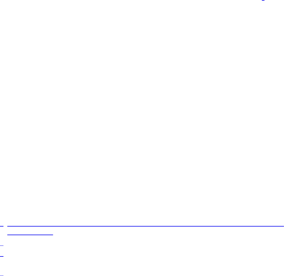
through interfaces. Each interface provides that seam or substitution point that
facilitates off-target testing.
DRY CONDITIONAL COMPILATION DIRECTIVES
One use of substitutability that is often overlooked relates to how embedded C and
C++ programs handle different targets or operating systems. There is a tendency to
use conditional compilation to turn on and off segments of code. I recall one
especially problematic case where the statement #ifdef BOARD_V2 was mentioned
several thousand times in a telecom application.
This repetition of code violates the Don’t Repeat Yourself (DRY) principle.5 If I see
#ifdef BOARD_V2 once, it’s not really a problem. Six thousand times is an extreme
problem. Conditional compilation identifying the target-hardware’s type is often
repeated in embedded systems. But what else can we do?
What if there is a hardware abstraction layer? The hardware type would become a
detail hidden under the HAL. If the HAL provides a set of interfaces, instead of
using conditional compilation, we could use the linker or some form of runtime
binding to connect the software to the hardware.
CONCLUSION
People who are developing embedded software have a lot to learn from experiences
outside of embedded software. If you are an embedded developer who has picked up
this book, you will find a wealth of software development wisdom in the words and
ideas.
Letting all code become firmware is not good for your product’s long-term health.
Being able to test only in the target hardware is not good for your product’s long-
term health. A clean embedded architecture is good for your product’s long-term
health.
1. https://insights.sei.cmu.edu/sei_blog/2011/08/the-growing-importance-of-sustaining-software-
for-thedod.html
2. The hardware device that controls the serial port.
3. Some silicon providers add keywords to the C language to make accessing the registers and IO
ports simple from C. Unfortunately, once that is done, the code is no longer C.
4. This statement intentionally uses HTML.

5. Hunt and Thomas, The Pragmatic Programmer.

VI
DETAILS
30
THE DATABASE IS A DETAIL
From an architectural point of view, the database is a non-entity—it is a detail that
does not rise to the level of an architectural element. Its relationship to the
architecture of a software system is rather like the relationship of a doorknob to the
architecture of your home.
I realize that these are fighting words. Believe me, I’ve had the fight. So let me be
clear: I am not talking about the data model. The structure you give to the data
within your application is highly significant to the architecture of your system. But
the database is not the data model. The database is piece of software. The database is
a utility that provides access to the data. From the architecture’s point of view, that
utility is irrelevant because it’s a low-level detail—a mechanism. And a good
architect does not allow low-level mechanisms to pollute the system architecture.
RELATIONAL DATABASES
Edgar Codd defined the principles of relational databases in 1970. By the mid-1980s,
the relational model had grown to become the dominant form of data storage. There
was a good reason for this popularity: The relational model is elegant, disciplined,
and robust. It is an excellent data storage and access technology.
But no matter how brilliant, useful, and mathematically sound a technology it is, it is
still just a technology. And that means it’s a detail.
While relational tables may be convenient for certain forms of data access, there is
nothing architecturally significant about arranging data into rows within tables. The
use cases of your application should neither know nor care about such matters.
Indeed, knowledge of the tabular structure of the data should be restricted to the
lowest-level utility functions in the outer circles of the architecture.
Many data access frameworks allow database rows and tables to be passed around
the system as objects. Allowing this is an architectural error. It couples the use cases,
business rules, and in some cases even the UI to the relational structure of the data.
WHY ARE DATABASE SYSTEMS SO
PREVALENT?
Why are software systems and software enterprises dominated by database systems?
What accounts for the preeminence of Oracle, MySQL, and SQL Server? In a word:
disks.
The rotating magnetic disk was the mainstay of data storage for five decades.
Several generations of programmers have known no other form of data storage. Disk
technology has grown from huge stacks of massive platters 48 inches in diameter
that weighed thousands of pounds and held 20 megabytes, to single thin circles, 3
inches in diameter, that weigh just a few grams and hold a terabyte or more. It’s been
a wild ride. And throughout that ride programmers have been plagued by one fatal
trait of disk technology: Disks are slow.
On a disk, data is stored within circular tracks. Those tracks are divided into sectors
that hold a convenient number of bytes, often 4K. Each platter may have hundreds of
tracks, and there can be a dozen or so platters. If you want to read a particular byte
off the disk, you have to move the head to the proper track, wait for the disk to rotate
to the proper sector, read all 4K of that sector into RAM, and then index into that
RAM buffer to get the byte you want. And all that takes time—milliseconds of
times.
Milliseconds might not seem like a lot, but a millisecond is a million times longer
than the cycle time of most processors. If that data was not on a disk, it could be
accessed in nanoseconds, instead of milliseconds.
To mitigate the time delay imposed by disks, you need indexes, caches, and
optimized query schemes; and you need some kind of regular means of representing
the data so that these indexes, caches, and query schemes know what they are
working with. In short, you need a data access and management system. Over the
years these systems have split into two distinct kinds: file systems and relational
database management systems (RDBMS).
File systems are document based. They provide a natural and convenient way to
store whole documents. They work well when you need to save and retrieve a set of
documents by name, but they don’t offer a lot of help when you’re searching the
content of those documents. It’s easy to find a file named login.c, but it’s hard, and
slow, to find every .c file that has a variable named x in it.
Database systems are content based. They provide a natural and convenient way to
find records based on their content. They are very good at associating multiple
records based on some bit of content that they all share. Unfortunately, they are
rather poor at storing and retrieving opaque documents.
Both of these systems organize the data on disk so that it can be stored and retrieved
in as efficient a way as possible, given their particular access needs. Each has their
own scheme for indexing and arranging the data. In addition, each eventually brings
the relevant data into RAM, where it can be quickly manipulated.
WHAT IF THERE WERE NO DISK?
As prevalent as disks once were, they are now a dying breed. Soon they will have
gone the way of tape drives, floppy drives, and CDs. They are being replaced by
RAM.
Ask yourself this question: When all the disks are gone, and all your data is stored in
RAM, how will you organize that data? Will you organize it into tables and access it
with SQL? Will you organize it into files and access it through a directory?
Of course not. You’ll organize it into linked lists, trees, hash tables, stacks, queues,
or any of the other myriad data structures, and you’ll access it using pointers or
references—because that’s what programmers do.
In fact, if you think carefully about this issue, you’ll realize that this is what you
already do. Even though the data is kept in a database or a file system, you read it
into RAM and then you reorganize it, for your own convenience, into lists, sets,
stacks, queues, trees, or whatever data structure meets your fancy. It is very unlikely
that you leave the data in the form of files or tables.
DETAILS
This reality is why I say that the database is a detail. It’s just a mechanism we use to
move the data back and forth between the surface of the disk and RAM. The
database is really nothing more than a big bucket of bits where we store our data on a
long-term basis. But we seldom use the data in that form.
Thus, from an architectural viewpoint, we should not care about the form that the
data takes while it is on the surface of a rotating magnetic disk. Indeed, we should
not acknowledge that the disk exists at all.
BUT WHAT ABOUT PERFORMANCE?
Isn’t performance an architectural concern? Of course it is—but when it comes to
data storage, it’s a concern that can be entirely encapsulated and separated from the
business rules. Yes, we need to get the data in and out of the data store quickly, but
that’s a low-level concern. We can address that concern with low-level data access
mechanisms. It has nothing whatsoever to do with the overall architecture of our
systems.
ANECDOTE
In the late 1980s, I led a team of software engineers at a startup company that was
trying to build and market a network management system that measured the
communications integrity of T1 telecommunication lines. The system retrieved data
from the devices at the endpoints of those lines, and then ran a series of predictive
algorithms to detect and report problems.
We were using UNIX platforms, and we stored our data in simple random access
files. We had no need of a relational database because our data had few content-
based relationships. It was better kept in trees and linked lists in those random access
files. In short, we kept the data in a form that was most convenient to load into RAM
where it could be manipulated.
We hired a marketing manager for this startup—a nice and knowledgeable guy. But
he immediately told me that we had to have a relational database in the system. It
wasn’t an option and it wasn’t an engineering issue—it was a marketing issue.
This made no sense to me. Why in the world would I want to rearrange my linked
lists and trees into a bunch of rows and tables accessed through SQL? Why would I
introduce all the overhead and expense of a massive RDBMS when a simple random
access file system was more than sufficient? So I fought him, tooth and nail.
We had a hardware engineer at this company who took up the RDBMS chant. He
became convinced that our software system needed an RDBMS for technical
reasons. He held meetings behind my back with the executives of the company,
drawing stick figures on the whiteboard of a house balancing on a pole, and he
would ask the executives, “Would you build a house on a pole?” His implied
message was that an RDBMS that keeps its tables in random access files was
somehow more reliable than the random access files that we were using.
I fought him. I fought the marketing guy. I stuck to my engineering principles in the
face of incredible ignorance. I fought, and fought, and fought.
In the end, the hardware developer was promoted over my head to become the
software manager. In the end, they put a RDBMS into that poor system. And, in the
end, they were absolutely right and I was wrong.
Not for engineering reasons, mind you: I was right about that. I was right to fight
against putting an RDBMS into the architectural core of the system. The reason I
was wrong was because our customers expected us to have a relational database.
They didn’t know what they would do with it. They didn’t have any realistic way of
using the relational data in our system. But it didn’t matter: Our customers fully
expected an RDBMS. It had become a check box item that all the software
purchasers had on their list. There was no engineering rationale—rationality had
nothing to do with it. It was an irrational, external, and entirely baseless need, but it
was no less real.
Where did that need come from? It originated from the highly effective marketing
campaigns employed by the database vendors at the time. They had managed to
convince high-level executives that their corporate “data assets” needed protection,
and that the database systems they offered were the ideal means of providing that
protection.
We see the same kind of marketing campaigns today. The word “enterprise” and the
notion of “Service-Oriented Architecture” have much more to do with marketing
than with reality.
What should I have done in that long-ago scenario? I should have bolted an RDBMS
on the side of the system and provided some narrow and safe data access channel to
it, while maintaining the random access files in the core of the system. What did I
do? I quit and became a consultant.
CONCLUSION
The organizational structure of data, the data model, is architecturally significant.
The technologies and systems that move data on and off a rotating magnetic surface
are not. Relational database systems that force the data to be organized into tables
and accessed with SQL have much more to do with the latter than with the former.
The data is significant. The database is a detail.
31
THE WEB IS A DETAIL
Were you a developer in the 1990s? Do you remember how the web changed
everything? Do you remember how we looked at our old client–server architectures
with disdain in the face of the shiny new technology of The Web?
Actually the web didn’t change anything. Or, at least, it shouldn’t have. The web is
just the latest in a series of oscillations that our industry has gone through since the
1960s. These oscillations move back and forth between putting all the computer
power in central servers and putting all computer power out at the terminals.
We’ve seen several of these oscillations just in the last decade or so since the web
became prominent. At first we thought all the computer power would be in server
farms, and the browsers would be stupid. Then we started putting applets in the
browsers. But we didn’t like that, so we moved dynamic content back to the servers.
But then we didn’t like that, so we invented Web 2.0 and moved lots of processing
back into the browser with Ajax and JavaScript. We went so far as to create whole
huge applications written to execute in the browsers. And now we’re all excited
about pulling that JavaScript back into the server with Node.
(Sigh.)
THE ENDLESS PENDULUM
Of course, it would be incorrect to think that those oscillations started with the web.
Before the web, there was client–server architecture. Before that, there were central
minicomputers with arrays of dumb terminals. Before that, there were mainframes
with smart green-screen terminals (that were very much analogous to modern-day
browsers). Before that, there were computer rooms and punched cards …
And so the story goes. We can’t seem to figure out where we want the computer
power. We go back and forth between centralizing it and distributing it. And, I
imagine, those oscillations will continue for some time to come.
When you look at it in the overall scope of IT history, the web didn’t change
anything at all. The web was simply one of many oscillations in a struggle that began
before most of us were born and will continue well after most of us have retired.
As architects, though, we have to look at the long term. Those oscillations are just
short-term issues that we want to push away from the central core of our business
rules.
Let me tell you the story of company Q. Company Q built a very popular personal
finance system. It was a desktop app with a very useful GUI. I loved using it.
Then came the web. In its next release, company Q changed the GUI to look, and
behave, like a browser. I was thunderstruck! What marketing genius decided that
personal finance software, running on a desktop, should have the look and feel of a
web browser?
Of course, I hated the new interface. Apparently everyone else did, too—because
after a few releases, company Q gradually removed the browser-like feel and turned
its personal finance system back into a regular desktop GUI.
Now imagine you were a software architect at Q. Imagine that some marketing
genius convinces upper management that the whole UI has to change to look more
like the web. What do you do? Or, rather, what should you have done before this
point to protect your application from that marketing genius?
You should have decoupled your business rules from your UI. I don’t know whether
the Q architects had done that. One day I’d love to hear their story. Had I been there
at the time, I certainly would have lobbied very hard to isolate the business rules
from the GUI, because you never know what the marketing geniuses will do next.
Now consider company A, which makes a lovely smartphone. Recently it released
an upgraded version of its “operating system” (it’s so strange that we can talk about
the operating system inside a phone). Among other things, that “operating system”
upgrade completely changed the look and feel of all the applications. Why? Some
marketing genius said so, I suppose.
I’m not an expert on the software within that device, so I don’t know if that change
caused any significant difficulties for the programmers of the apps that run in
company A’s phone. I do hope the architects at A, and the architects of the apps,
keep their UI and business rules isolated from each other, because there are always
marketing geniuses out there just waiting to pounce on the next little bit of coupling
you create.
THE UPSHOT
The upshot is simply this: The GUI is a detail. The web is a GUI. So the web is a
detail. And, as an architect, you want to put details like that behind boundaries that
keep them separate from your core business logic.
Think about it this way: The WEB is an IO device. In the 1960s, we learned the value
of writing applications that were device independent. The motivation for that
independence has not changed. The web is not an exception to that rule.
Or is it? The argument can be made that a GUI, like the web, is so unique and rich
that it is absurd to pursue a device-independent architecture. When you think about
the intricacies of JavaScript validation or drag-and-drop AJAX calls, or any of the
plethora of other widgets and gadgets you can put on a web page, it’s easy to argue
that device independence is impractical.
To some extent, this is true. The interaction between the application and the GUI is
“chatty” in ways that are quite specific to the kind of GUI you have. The dance
between a browser and a web application is different from the dance between a
desktop GUI and its application. Trying to abstract out that dance, the way devices
are abstracted out of UNIX, seems unlikely to be possible.
But another boundary between the UI and the application can be abstracted. The
business logic can be thought of as a suite of use cases, each of which performs some
function on behalf of a user. Each use case can be described based on the input data,
the processing preformed, and the output data.
At some point in the dance between the UI and the application, the input data can be
said to be complete, allowing the use case to be executed. Upon completion, the
resultant data can be fed back into the dance between the UI and the application.
The complete input data and the resultant output data can be placed into data
structures and used as the input values and output values for a process that executes
the use case. With this approach, we can consider each use case to be operating the
IO device of the UI in a device-independent manner.
CONCLUSION
This kind of abstraction is not easy, and it will likely take several iterations to get
just right. But it is possible. And since the world is full of marketing geniuses, it’s
not hard to make the case that it’s often very necessary.
32
FRAMEWORKS ARE DETAILS
Frameworks have become quite popular. Generally speaking, this is a good thing.
There are many frameworks out there that are free, powerful, and useful.
However, frameworks are not architectures—though some try to be.
FRAMEWORK AUTHORS
Most framework authors offer their work for free because they want to be helpful to
the community. They want to give back. This is laudable. However, regardless of
their high-minded motives, those authors do not have your best interests at heart.
They can’t, because they don’t know you, and they don’t know your problems.
Framework authors know their own problems, and the problems of their coworkers
and friends. And they write their frameworks to solve those problems—not yours.
Of course, your problems will likely overlap with those other problems quite a bit. If
this were not the case, frameworks would not be so popular. To the extent that such
overlap exists, frameworks can be very useful indeed.
ASYMMETRIC MARRIAGE
The relationship between you and the framework author is extraordinarily
asymmetric. You must make a huge commitment to the framework, but the
framework author makes no commitment to you whatsoever.
Think about this point carefully. When you use a framework, you read through the
documentation that the author of that framework provides. In that documentation, the
author, and other users of that framework, advise you on how to integrate your
software with the framework. Typically, this means wrapping your architecture
around that framework. The author recommends that you derive from the
framework’s base classes, and import the framework’s facilities into your business
objects. The author urges you to couple your application to the framework as tightly
as possible.
For the framework author, coupling to his or her own framework is not a risk. The
author wants to couple to that framework, because the author has absolute control
over that framework.
What’s more, the author wants you to couple to the framework, because once
coupled in this way, it is very hard to break away. Nothing feels more validating to a
framework author than a bunch of users willing to inextricably derive from the
author’s base classes.
In effect, the author is asking you to marry the framework—to make a huge, long-
term commitment to that framework. And yet, under no circumstances will the
author make a corresponding commitment to you. It’s a one-directional marriage.
You take on all the risk and burden; the framework author takes on nothing at all.
THE RISKS
What are the risks? Here are just a few for you to consider.
• The architecture of the framework is often not very clean. Frameworks tend to
violate he Dependency Rule. They ask you to inherit their code into your business
objects—your Entities! They want their framework coupled into that innermost
circle. Once in, that framework isn’t coming back out. The wedding ring is on your
finger; and it’s going to stay there.
• The framework may help you with some early features of your application.
However, as your product matures, it may outgrow the facilities of the framework.
If you’ve put on that wedding ring, you’ll find the framework fighting you more
and more as time passes.
• The framework may evolve in a direction that you don’t find helpful. You may be
stuck upgrading to new versions that don’t help you. You may even find old
features, which you made use of, disappearing or changing in ways that are
difficult for you to keep up with.
• A new and better framework may come along that you wish you could switch to.
THE SOLUTION
What is the solution?
Don’t marry the framework!
Oh, you can use the framework—just don’t couple to it. Keep it at arm’s length.
Treat the framework as a detail that belongs in one of the outer circles of the
architecture. Don’t let it into the inner circles.
If the framework wants you to derive your business objects from its base classes, say
no! Derive proxies instead, and keep those proxies in components that are plugins to
your business rules.
Don’t let frameworks into your core code. Instead, integrate them into components
that plug in to your core code, following the Dependency Rule.
For example, maybe you like Spring. Spring is a good dependency injection
framework. Maybe you use Spring to auto-wire your dependencies. That’s fine, but
you should not sprinkle @autowired annotations all throughout your business
objects. Your business objects should not know about Spring.
Instead, you can use Spring to inject dependencies into your Main component. It’s
OK for Main to know about Spring since Main is the dirtiest, lowest-level component
in the architecture.
I NOW PRONOUNCE YOU …
There are some frameworks that you simply must marry. If you are using C++, for
example, you will likely have to marry STL—it’s hard to avoid. If you are using
Java, you will almost certainly have to marry the standard library.
That’s normal—but it should still be a decision. You must understand that when you
marry a framework to your application, you will be stuck with that framework for
the rest of the life cycle of that application. For better or for worse, in sickness and in
health, for richer, for poorer, forsaking all others, you will be using that framework.
This is not a commitment to be entered into lightly.
CONCLUSION
When faced with a framework, try not to marry it right away. See if there aren’t
ways to date it for a while before you take the plunge. Keep the framework behind
an architectural boundary if at all possible, for as long as possible. Perhaps you can
find a way to get the milk without buying the cow.
33
CASE STUDY: VIDEO SALES
Now it’s time to put these rules and thoughts about architecture together into a case
study. This case study will be short and simple, yet will depict both the process a
good architect uses and the decisions that such an architect makes.
THE PRODUCT
For this case study, I’ve chosen a product with which I am rather intimately familiar:
the software for a website that sells videos. Of course, it is reminiscent of
cleancoders.com, the site where I sell my software tutorial videos.
The basic idea is trivial. We have a batch of videos we want to sell. We sell them, on
the web, to both individuals and businesses. Individuals can pay one price to stream

the videos, and another, higher price to download those videos and own them
permanently. Business licenses are streaming only, and are purchased in batches that
allow quantity discounts.
Individuals typically act as both the viewers and the purchasers. Businesses, in
contrast, often have people who buy the videos that other people will watch.
Video authors need to supply their video files, written descriptions, and ancillary
files with exams, problems, solutions, source code, and other materials.
Administrators need to add new video series, add and delete videos to and from the
series, and establish prices for various licenses.
Our first step in determining the initial architecture of the system is to identify the
actors and use cases.
USE CASE ANALYSIS
Figure 33.1 shows a typical use-case analysis.
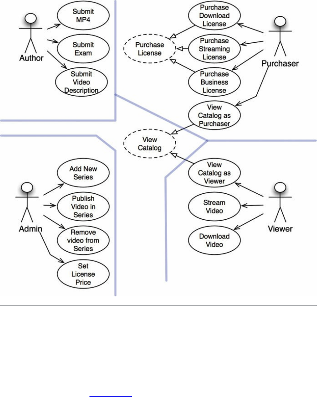
Figure 33.1 A typical use-case analysis
The four main actors are evident. According to the Single Responsibility Principle,
these four actors will be the four primary sources of change for the system. Every
time some new feature is added, or some existing feature is changed, that step will be
taken to serve one of these actors. Therefore we want to partition the system such
that a change to one actor does not affect any of the other actors.
The use cases shown in Figure 33.1 are not a complete list. For example, you won’t
find log-in or log-out use cases. The reason for this omission is simply to manage the
size of the problem in this book. If I were to include all the different use cases, then

this chapter would have to turn into a book in its own right.
Note the dashed use cases in the center of Figure 33.1. They are abstract1 use cases.
An abstract use case is one that sets a general policy that another use case will flesh
out. As you can see, the View Catalog as Viewer and View Catalog as Purchaser use
cases both inherit from the View Catalog abstract use case.
On the one hand, it was not strictly necessary for me to create that abstraction. I
could have left the abstract use case out of the diagram without compromising any of
the features of the overall product. On the other hand, these two use cases are so
similar that I thought it wise to recognize the similarity and find a way to unify it
early in the analysis.
COMPONENT ARCHITECTURE
Now that we know the actors and use cases, we can create a preliminary component
architecture (Figure 33.2).
The double lines in the drawing represent architectural boundaries as usual. You can
see the typical partitioning of views, presenters, interactors, and controllers. You can
also see that I’ve broken each of those categories up by their corresponding actors.
Each of the components in Figure 33.2 represents a potential .jar file or .dll file.
Each of those components will contain the views, presenters, interactors, and
controllers that have been allocated to it.
Note the special components for the Catalog View and the Catalog Presenter.
This is how I dealt with the abstract View Catalog use case. I assume that those
views and presenters will be coded into abstract classes within those components,
and that the inheriting components will contain view and presenter classes that will
inherit from those abstract classes.
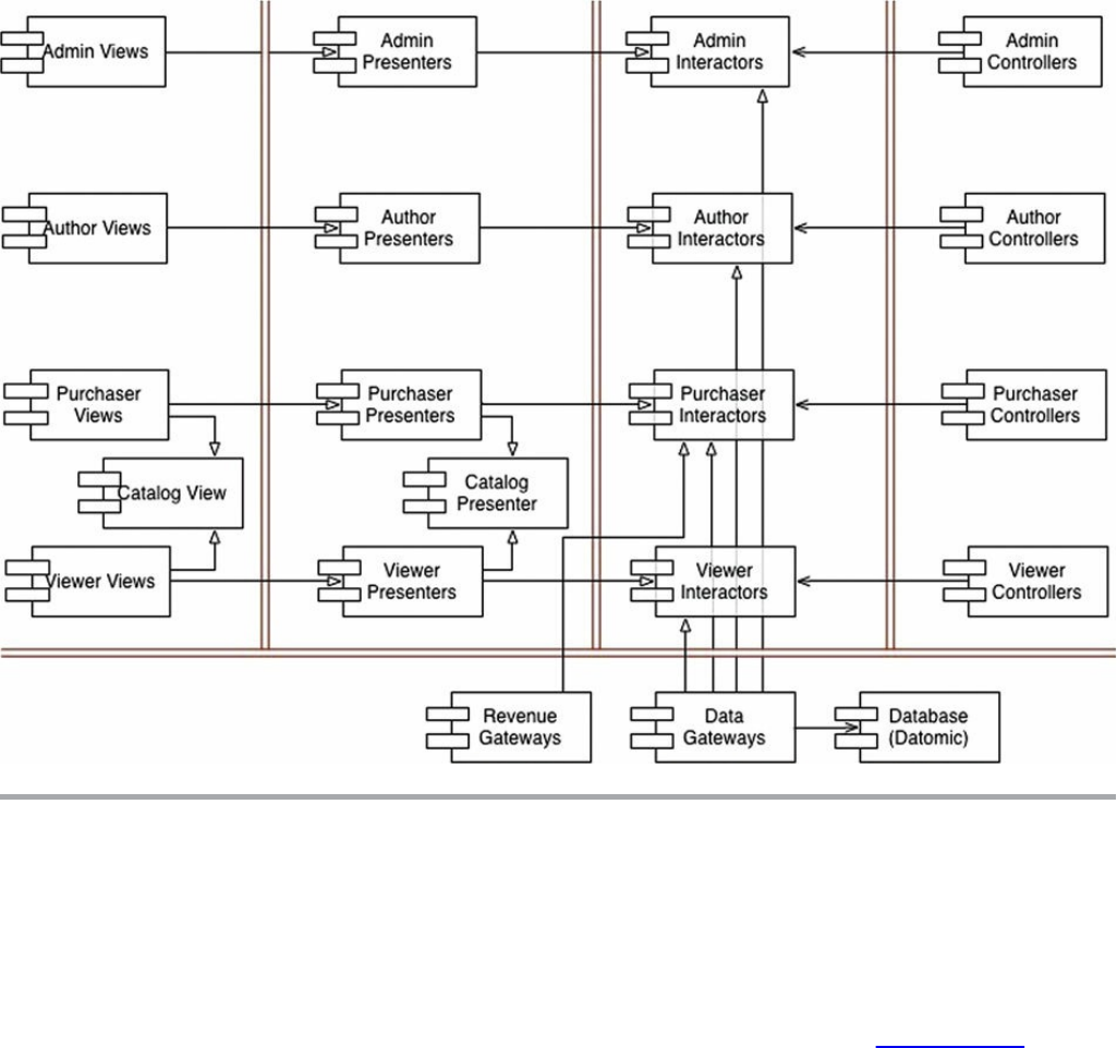
Figure 33.2 A preliminary component architecture
Would I really break the system up into all these components, and deliver them as
.jar or .dll files? Yes and no. I would certainly break the compile and build
environment up this way, so that I could build independent deliverables like that. I
would also reserve the right to combine all those deliverables into a smaller number
of deliverables if necessary. For example, given the partitioning in Figure 33.2, it
would be easy to combine them into five .jar files—one for views, presenters,
interactors, controllers, and utilities, respectively. I could then independently deploy
the components that are most likely to change independently of each other.
Another possible grouping would be to put the views and presenters together into the
same .jar file, and put the interactors, controllers, and utilities in their own .jar
file. Still another, even more primitive, grouping would be to create two .jar files,
with views and presenters in one file, and everything else in the other.
Keeping these options open will allow us to adapt the way we deploy the system
based on how the system changes over time.

DEPENDENCY MANAGEMENT
The flow of control in Figure 33.2 proceeds from right to left. Input occurs at the
controllers, and that input is processed into a result by the interactors. The presenters
then format the results, and the views display those presentations.
Notice that the arrows do not all flow from the right to the left. In fact, most of them
point from left to right. This is because the architecture is following the Dependency
Rule. All dependencies cross the boundary lines in one direction, and they always
point toward the components containing the higher-level policy.
Also notice that the using relationships (open arrows) point with the flow of control,
and that the inheritance relationships (closed arrows) point against the flow of
control. This depicts our use of the Open–Closed Principle to make sure that the
dependencies flow in the right direction, and that changes to low-level details do not
ripple upward to affect high-level policies.
CONCLUSION
The architecture diagram in Figure 33.2 includes two dimensions of separation. The
first is the separation of actors based on the Single Responsibility Principle; the
second is the Dependency Rule. The goal of both is to separate components that
change for different reasons, and at different rates. The different reasons correspond
to the actors; the different rates correspond to the different levels of policy.
Once you have structured the code this way, you can mix and match how you want
to actually deploy the system. You can group the components into deployable
deliverables in any way that makes sense, and easily change that grouping when
conditions change.
1. This is my own notation for “abstract” use cases. It would have been more standard to use a UML
stereotype such as <<abstract>>, but I don‘t find adhering to such standards very useful
nowadays.
34
THE MISSING CHAPTER
By Simon Brown
All of the advice you’ve read so far will certainly help you design better software,
composed of classes and components with well-defined boundaries, clear
responsibilities, and controlled dependencies. But it turns out that the devil is in the
implementation details, and it’s really easy to fall at the last hurdle if you don’t give
that some thought, too.
Let’s imagine that we’re building an online book store, and one of the use cases
we’ve been asked to implement is about customers being able to view the status of
their orders. Although this is a Java example, the principles apply equally to other
programming languages. Let’s put the Clean Architecture to one side for a moment
and look at a number of approaches to design and code organization.

PACKAGE BY LAYER
The first, and perhaps simplest, design approach is the traditional horizontal layered
architecture, where we separate our code based on what it does from a technical
perspective. This is often called “package by layer.” Figure 34.1 shows what this
might look like as a UML class diagram.
In this typical layered architecture, we have one layer for the web code, one layer for
our “business logic,” and one layer for persistence. In other words, code is sliced
horizontally into layers, which are used as a way to group similar types of things. In
a “strict layered architecture,” layers should depend only on the next adjacent lower
layer. In Java, layers are typically implemented as packages. As you can see in
Figure 34.1, all of the dependencies between layers (packages) point downward. In
this example, we have the following Java types:
• OrdersController: A web controller, something like a Spring MVC controller,
that handles requests from the web.
• OrdersService: An interface that defines the “business logic” related to orders.
• OrdersServiceImpl: The implementation of the orders service.1
• OrdersRepository: An interface that defines how we get access to persistent order
information.
• JdbcOrdersRepository: An implementation of the repository interface.
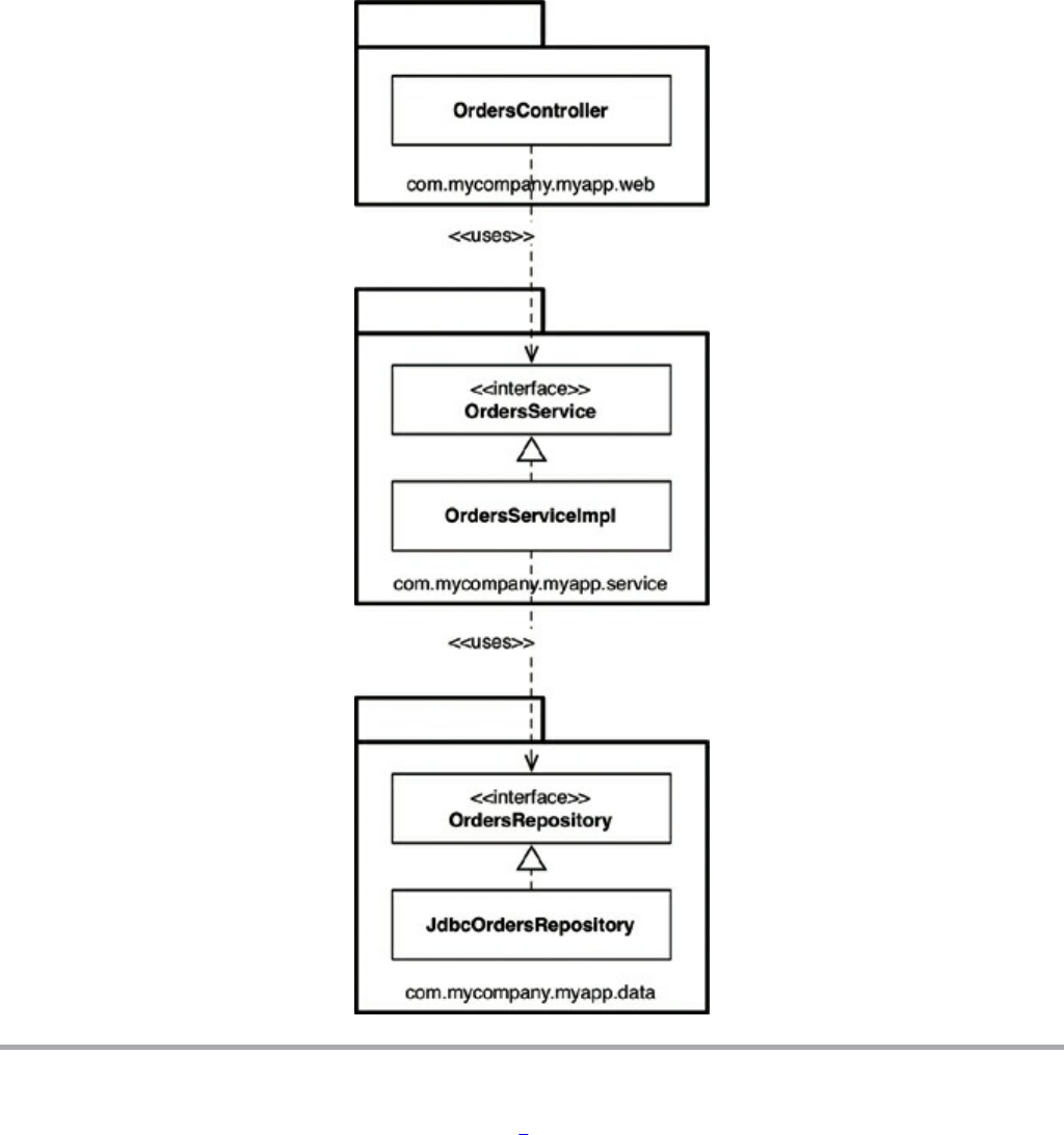
Figure 34.1 Package by layer
In “Presentation Domain Data Layering,”2 Martin Fowler says that adopting such a
layered architecture is a good way to get started. He’s not alone. Many of the books,
tutorials, training courses, and sample code you’ll find will also point you down the
path of creating a layered architecture. It’s a very quick way to get something up and
running without a huge amount of complexity. The problem, as Martin points out, is
that once your software grows in scale and complexity, you will quickly find that
having three large buckets of code isn’t sufficient, and you will need to think about
modularizing further.

Another problem is that, as Uncle Bob has already said, a layered architecture
doesn’t scream anything about the business domain. Put the code for two layered
architectures, from two very different business domains, side by side and they will
likely look eerily similar: web, services, and repositories. There’s also another huge
problem with layered architectures, but we’ll get to that later.
PACKAGE BY FEATURE
Another option for organizing your code is to adopt a “package by feature” style.
This is a vertical slicing, based on related features, domain concepts, or aggregate
roots (to use domain-driven design terminology). In the typical implementations that
I’ve seen, all of the types are placed into a single Java package, which is named to
reflect the concept that is being grouped.
With this approach, as shown in Figure 34.2, we have the same interfaces and classes
as before, but they are all placed into a single Java package rather than being split
among three packages. This is a very simple refactoring from the “package by layer”
style, but the top-level organization of the code now screams something about the
business domain. We can now see that this code base has something to do with
orders rather than the web, services, and repositories. Another benefit is that it’s
potentially easier to find all of the code that you need to modify in the event that the
“view orders” use case changes. It’s all sitting in a single Java package rather than
being spread out.3
I often see software development teams realize that they have problems with
horizontal layering (“package by layer”) and switch to vertical layering (“package by
feature”) instead. In my opinion, both are suboptimal. If you’ve read this book so far,
you might be thinking that we can do much better—and you’re right.
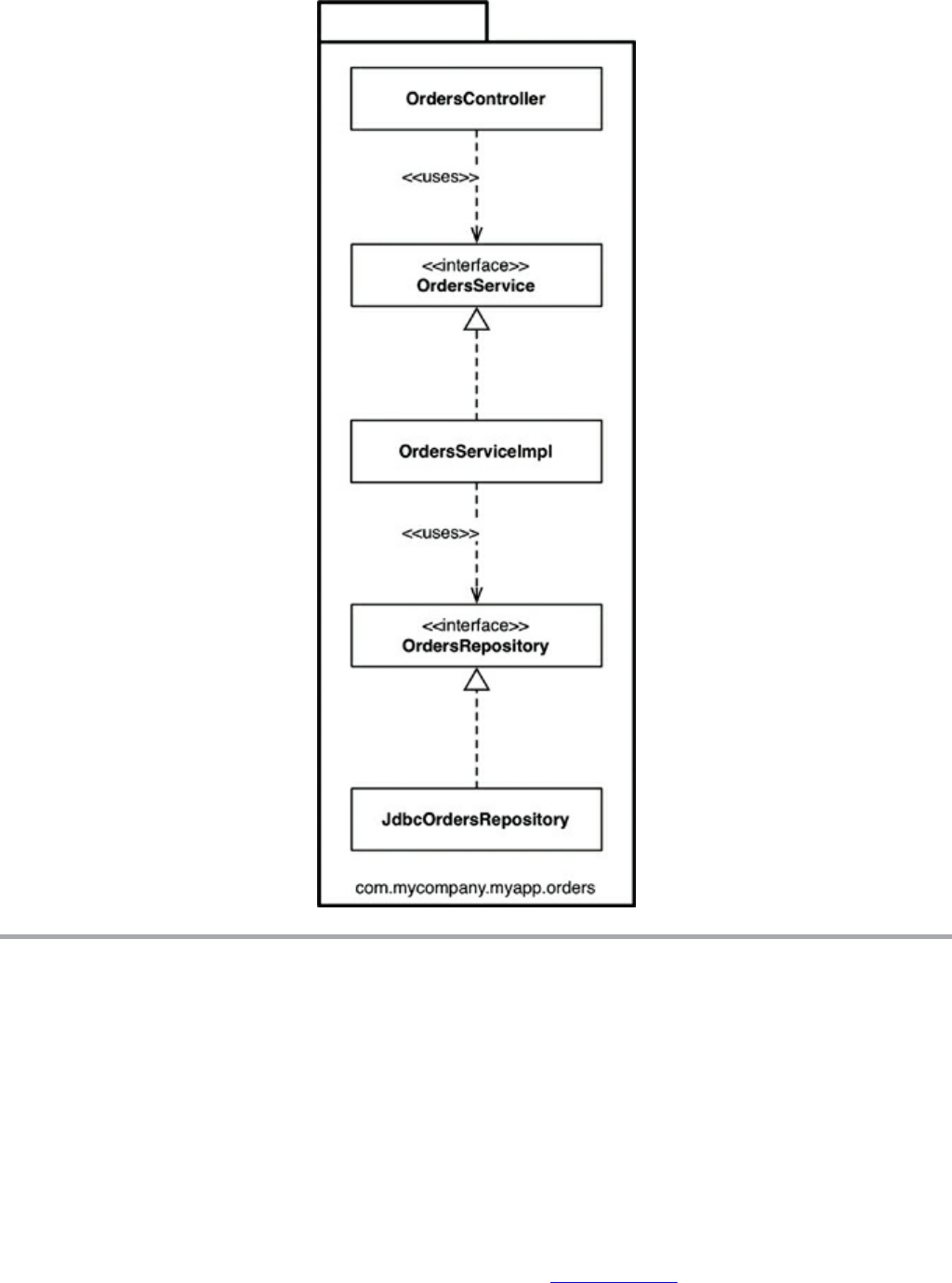
Figure 34.2 Package by feature
PORTS AND ADAPTERS
As Uncle Bob has said, approaches such as “ports and adapters,” the “hexagonal
architecture,” “boundaries, controllers, entities,” and so on aim to create
architectures where business/domain-focused code is independent and separate from
the technical implementation details such as frameworks and databases. To
summarize, you often see such code bases being composed of an “inside” (domain)
and an “outside” (infrastructure), as suggested in Figure 34.3.
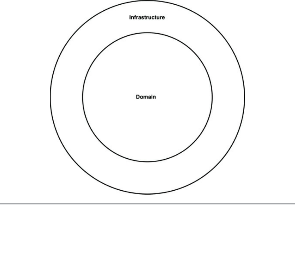
Figure 34.3 A code base with an inside and an outside
The “inside” region contains all of the domain concepts, whereas the “outside”
region contains the interactions with the outside world (e.g., UIs, databases, third-
party integrations). The major rule here is that the “outside” depends on the
“inside”—never the other way around. Figure 34.4 shows a version of how the “view
orders” use case might be implemented.
The com.mycompany.myapp.domain package here is the “inside,” and the other
packages are the “outside.” Notice how the dependencies flow toward the “inside.”
The keen-eyed reader will notice that the OrdersRepository from previous diagrams
has been renamed to simply be Orders. This comes from the world of domain-driven
design, where the advice is that the naming of everything on the “inside” should be
stated in terms of the “ubiquitous domain language.” To put that another way, we
talk about “orders” when we’re having a discussion about the domain, not the
“orders repository.”
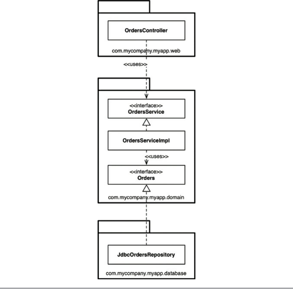
Figure 34.4 View orders use case
It’s also worth pointing out that this is a simplified version of what the UML class
diagram might look like, because it’s missing things like interactors and objects to
marshal the data across the dependency boundaries.
PACKAGE BY COMPONENT
Although I agree wholeheartedly with the discussions about SOLID, REP, CCP, and
CRP and most of the advice in this book, I come to a slightly different conclusion

about how to organize code. So I’m going to present another option here, which I
call “package by component.” To give you some background, I’ve spent most of my
career building enterprise software, primarily in Java, across a number of different
business domains. Those software systems have varied immensely, too. A large
number have been web-based, but others have been client–server4, distributed,
message-based, or something else. Although the technologies differed, the common
theme was that the architecture for most of these software systems was based on a
traditional layered architecture.
I’ve already mentioned a couple of reasons why layered architectures should be
considered bad, but that’s not the whole story. The purpose of a layered architecture
is to separate code that has the same sort of function. Web stuff is separated from
business logic, which is in turn separated from data access. As we saw from the
UML class diagram, from an implementation perspective, a layer typically equates to
a Java package. From a code accessibility perspective, for the OrdersController to
be able to have a dependency on the OrdersService interface, the OrdersService
interface needs to be marked as public, because they are in different packages.
Likewise, the OrdersRepository interface needs to be marked as public so that it
can be seen outside of the repository package, by the OrdersServiceImpl class.
In a strict layered architecture, the dependency arrows should always point
downward, with layers depending only on the next adjacent lower layer. This comes
back to creating a nice, clean, acyclic dependency graph, which is achieved by
introducing some rules about how elements in a code base should depend on each
other. The big problem here is that we can cheat by introducing some undesirable
dependencies, yet still create a nice, acyclic dependency graph.
Suppose that you hire someone new who joins your team, and you give the
newcomer another orders-related use case to implement. Since the person is new, he
wants to make a big impression and get this use case implemented as quickly as
possible. After sitting down with a cup of coffee for a few minutes, the newcomer
discovers an existing OrdersController class, so he decides that’s where the code
for the new orders-related web page should go. But it needs some orders data from
the database. The newcomer has an epiphany: “Oh, there’s an OrdersRepository
interface already built, too. I can simply dependency-inject the implementation into
my controller. Perfect!” After a few more minutes of hacking, the web page is
working. But the resulting UML diagram looks like Figure 34.5.
The dependency arrows still point downward, but the OrdersController is now
additionally bypassing the OrdersService for some use cases. This organization is
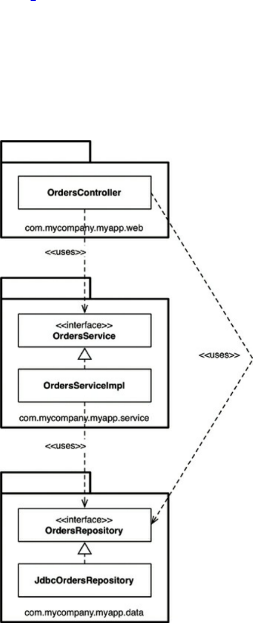
often called a relaxed layered architecture, as layers are allowed to skip around their
adjacent neighbor(s). In some situations, this is the intended outcome—if you’re
trying to follow the CQRS5 pattern, for example. In many other cases, bypassing the
business logic layer is undesirable, especially if that business logic is responsible for
ensuring authorized access to individual records, for example.
While the new use case works, it’s perhaps not implemented in the way that we were
expecting. I see this happen a lot with teams that I visit as a consultant, and it’s
usually revealed when teams start to visualize what their code base really looks like,
often for the first time.

Figure 34.5 Relaxed layered architecture
What we need here is a guideline—an architectural principle—that says something
like, “Web controllers should never access repositories directly.” The question, of
course, is enforcement. Many teams I’ve met simply say, “We enforce this principle
through good discipline and code reviews, because we trust our developers.” This
confidence is great to hear, but we all know what happens when budgets and
deadlines start looming ever closer.
A far smaller number of teams tell me that they use static analysis tools (e.g.,
NDepend, Structure101, Checkstyle) to check and automatically enforce architecture
violations at build time. You may have seen such rules yourself; they usually
manifest themselves as regular expressions or wildcard strings that state “types in
package **/web should not access types in **/data”; and they are executed after the
compilation step.
This approach is a little crude, but it can do the trick, reporting violations of the
architecture principles that you’ve defined as a team and (you hope) failing the build.
The problem with both approaches is that they are fallible, and the feedback loop is
longer than it should be. If left unchecked, this practice can turn a code base into a
“big ball of mud.”6 I’d personally like to use the compiler to enforce my architecture
if at all possible.
This brings us to the “package by component” option. It’s a hybrid approach to
everything we’ve seen so far, with the goal of bundling all of the responsibilities
related to a single coarse-grained component into a single Java package. It’s about
taking a service-centric view of a software system, which is something we’re seeing
with micro-service architectures as well. In the same way that ports and adapters
treat the web as just another delivery mechanism, “package by component” keeps the
user interface separate from these coarse-grained components. Figure 34.6 shows
what the “view orders” use case might look like.
In essence, this approach bundles up the “business logic” and persistence code into a
single thing, which I’m calling a “component.” Uncle Bob presented his definition of
“component” earlier in the book, saying:
Components are the units of deployment. They are the smallest entities that can be
deployed as part of a system. In Java, they are jar files.
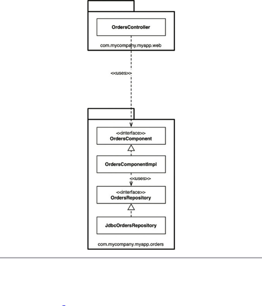
Figure 34.6 View orders use case
My definition of a component is slightly different: “A grouping of related
functionality behind a nice clean interface, which resides inside an execution
environment like an application.” This definition comes from my “C4 software
architecture model,”7 which is a simple hierarchical way to think about the static
structures of a software system in terms of containers, components, and classes (or
code). It says that a software system is made up of one or more containers (e.g., web
applications, mobile apps, stand-alone applications, databases, file systems), each of
which contains one or more components, which in turn are implemented by one or
more classes (or code). Whether each component resides in a separate jar file is an
orthogonal concern.
A key benefit of the “package by component” approach is that if you’re writing code
that needs to do something with orders, there’s just one place to go—the
OrdersComponent. Inside the component, the separation of concerns is still
maintained, so the business logic is separate from data persistence, but that’s a
component implementation detail that consumers don’t need to know about. This is
akin to what you might end up with if you adopted a micro-services or Service-
Oriented Architecture—a separate OrdersService that encapsulates everything
related to handling orders. The key difference is the decoupling mode. You can think
of well-defined components in a monolithic application as being a stepping stone to
a micro-services architecture.
THE DEVIL IS IN THE IMPLEMENTATION
DETAILS
On the face of it, the four approaches do all look like different ways to organize code
and, therefore, could be considered different architectural styles. This perception
starts to unravel very quickly if you get the implementation details wrong, though.
Something I see on a regular basis is an overly liberal use of the public access
modifier in languages such as Java. It’s almost as if we, as developers, instinctively
use the public keyword without thinking. It’s in our muscle memory. If you don’t
believe me, take a look at the code samples for books, tutorials, and open source
frameworks on GitHub. This tendency is apparent, regardless of which architectural
style a code base is aiming to adopt—horizontal layers, vertical layers, ports and
adapters, or something else. Marking all of your types as public means you’re not
taking advantage of the facilities that your programming language provides with
regard to encapsulation. In some cases, there’s literally nothing preventing somebody
from writing some code to instantiate a concrete implementation class directly,
violating the intended architecture style.
ORGANIZATION VERSUS
ENCAPSULATION
Looking at this issue another way, if you make all types in your Java application
public, the packages are simply an organization mechanism (a grouping, like

folders), rather than being used for encapsulation. Since public types can be used
from anywhere in a code base, you can effectively ignore the packages because they
provide very little real value. The net result is that if you ignore the packages
(because they don’t provide any means of encapsulation and hiding), it doesn’t really
matter which architectural style you’re aspiring to create. If we look back at the
example UML diagrams, the Java packages become an irrelevant detail if all of the
types are marked as public. In essence, all four architectural approaches presented
earlier in this chapter are exactly the same when we overuse this designation (Figure
34.7).
Take a close look at the arrows between each of the types in Figure 34.7: They’re all
identical regardless of which architectural approach you’re trying to adopt.
Conceptually the approaches are very different, but syntactically they are identical.
Furthermore, you could argue that when you make all of the types public, what you
really have are just four ways to describe a traditional horizontally layered
architecture. This is a neat trick, and of course nobody would ever make all of their
Java types public. Except when they do. And I’ve seen it.
The access modifiers in Java are not perfect,8 but ignoring them is just asking for
trouble. The way Java types are placed into packages can actually make a huge
difference to how accessible (or inaccessible) those types can be when Java’s access
modifiers are applied appropriately. If I bring the packages back and mark (by
graphically fading) those types where the access modifier can be made more
restrictive, the picture becomes pretty interesting (Figure 34.8).
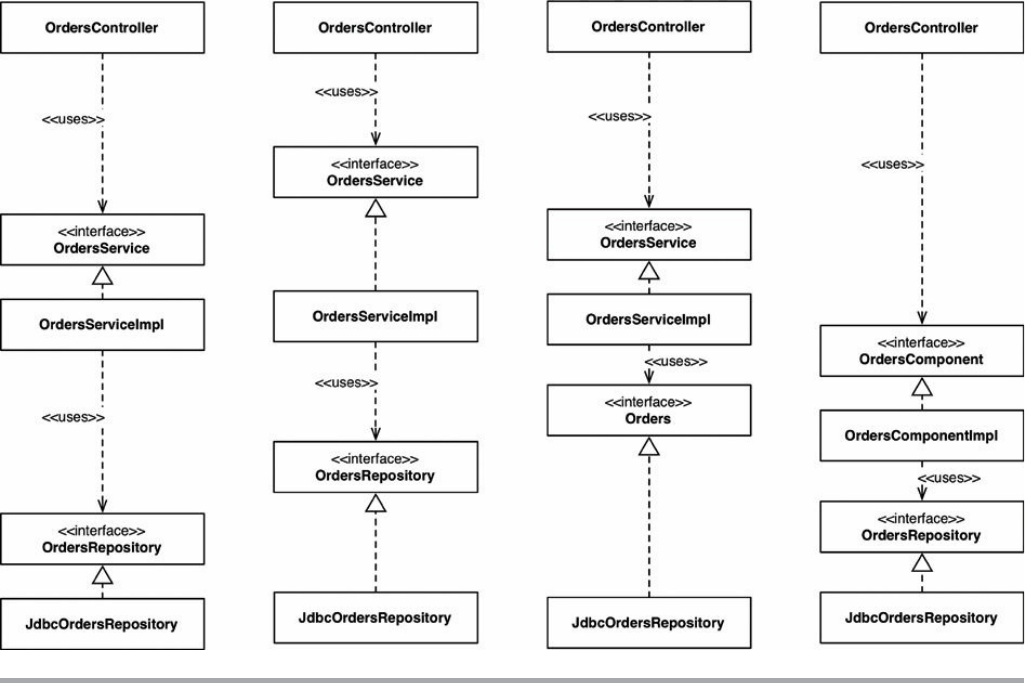
Figure 34.7 All four architectural approaches are the same
Moving from left to right, in the “package by layer” approach, the OrdersService
and OrdersRepository interfaces need to be public, because they have inbound
dependencies from classes outside of their defining package. In contrast, the
implementation classes (OrdersServiceImpl and JdbcOrdersRepository) can be
made more restrictive (package protected). Nobody needs to know about them; they
are an implementation detail.
In the “package by feature” approach, the OrdersController provides the sole entry
point into the package, so everything else can be made package protected. The big
caveat here is that nothing else in the code base, outside of this package, can access
information related to orders unless they go through the controller. This may or may
not be desirable.
In the ports and adapters approach, the OrdersService and Orders interfaces have
inbound dependencies from other packages, so they need to be made public. Again,
the implementation classes can be made package protected and dependency injected
at runtime.
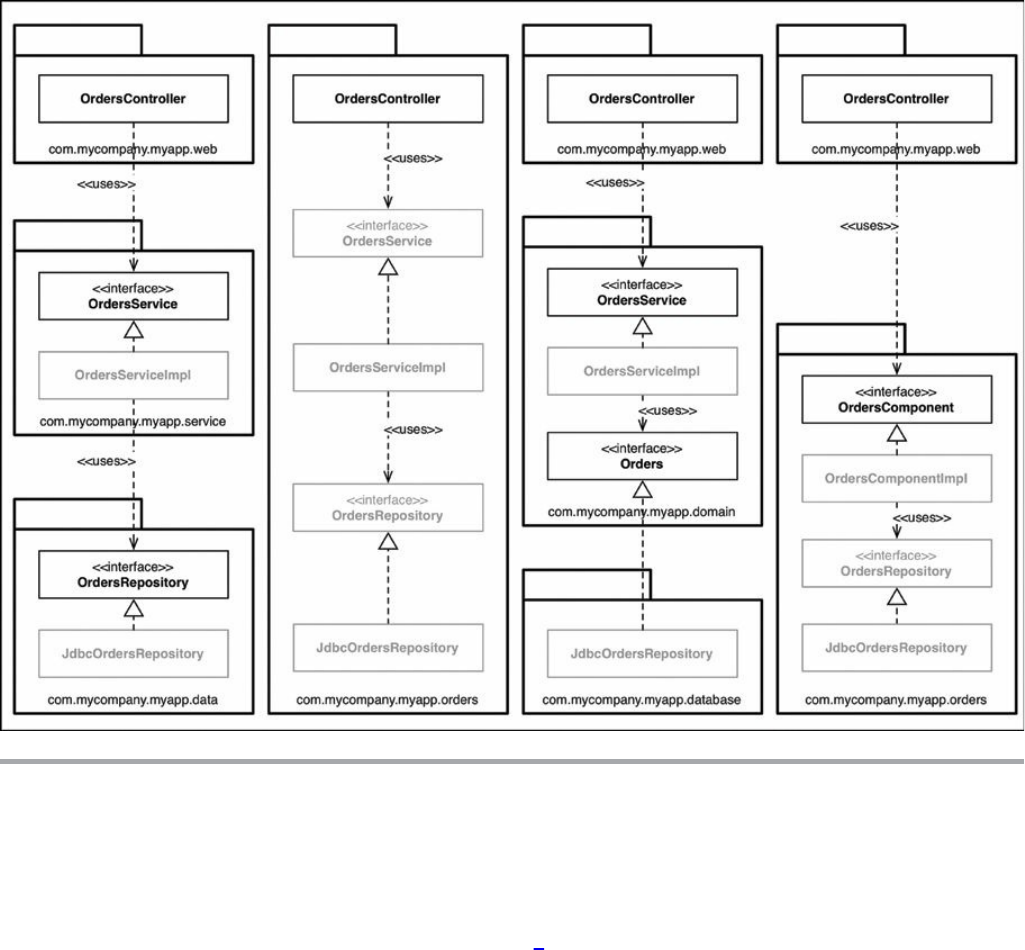
Figure 34.8 Grayed-out types are where the access modifier can be made more restrictive
Finally, in the “package by component” approach, the OrdersComponent interface
has an inbound dependency from the controller, but everything else can be made
package protected. The fewer public types you have, the smaller the number of
potential dependencies. There’s now no way9 that code outside this package can use
the OrdersRepository interface or implementation directly, so we can rely on the
compiler to enforce this architectural principle. You can do the same thing in .NET
with the internal keyword, although you would need to create a separate assembly
for every component.
Just to be absolutely clear, what I’ve described here relates to a monolithic
application, where all of the code resides in a single source code tree. If you are
building such an application (and many people are), I would certainly encourage you
to lean on the compiler to enforce your architectural principles, rather than relying on
self-discipline and post-compilation tooling.

OTHER DECOUPLING MODES
In addition to the programming language you’re using, there are often other ways
that you can decouple your source code dependencies. With Java, you have module
frameworks like OSGi and the new Java 9 module system. With module systems,
when used properly, you can make a distinction between types that are public and
types that are published. For example, you could create an Orders module where all
of the types are marked as public, but publish only a small subset of those types for
external consumption. It’s been a long time coming, but I’m enthusiastic that the
Java 9 module system will give us another tool to build better software, and spark
people’s interest in design thinking once again.
Another option is to decouple your dependencies at the source code level, by
splitting code across different source code trees. If we take the ports and adapters
example, we could have three source code trees:
• The source code for the business and domain (i.e., everything that is independent of
technology and framework choices): OrdersService, OrdersServiceImpl, and
Orders
• The source code for the web: OrdersController
• The source code for the data persistence: JdbcOrdersRepository
The latter two source code trees have a compile-time dependency on the business
and domain code, which itself doesn’t know anything about the web or the data
persistence code. From an implementation perspective, you can do this by
configuring separate modules or projects in your build tool (e.g., Maven, Gradle,
MSBuild). Ideally you would repeat this pattern, having a separate source code tree
for each and every component in your application. This is very much an idealistic
solution, though, because there are real-world performance, complexity, and
maintenance issues associated with breaking up your source code in this way.
A simpler approach that some people follow for their ports and adapters code is to
have just two source code trees:
• Domain code (the “inside”)
• Infrastructure code (the “outside”)
This maps on nicely to the diagram (Figure 34.9) that many people use to summarize
the ports and adapters architecture, and there is a compile-time dependency from the
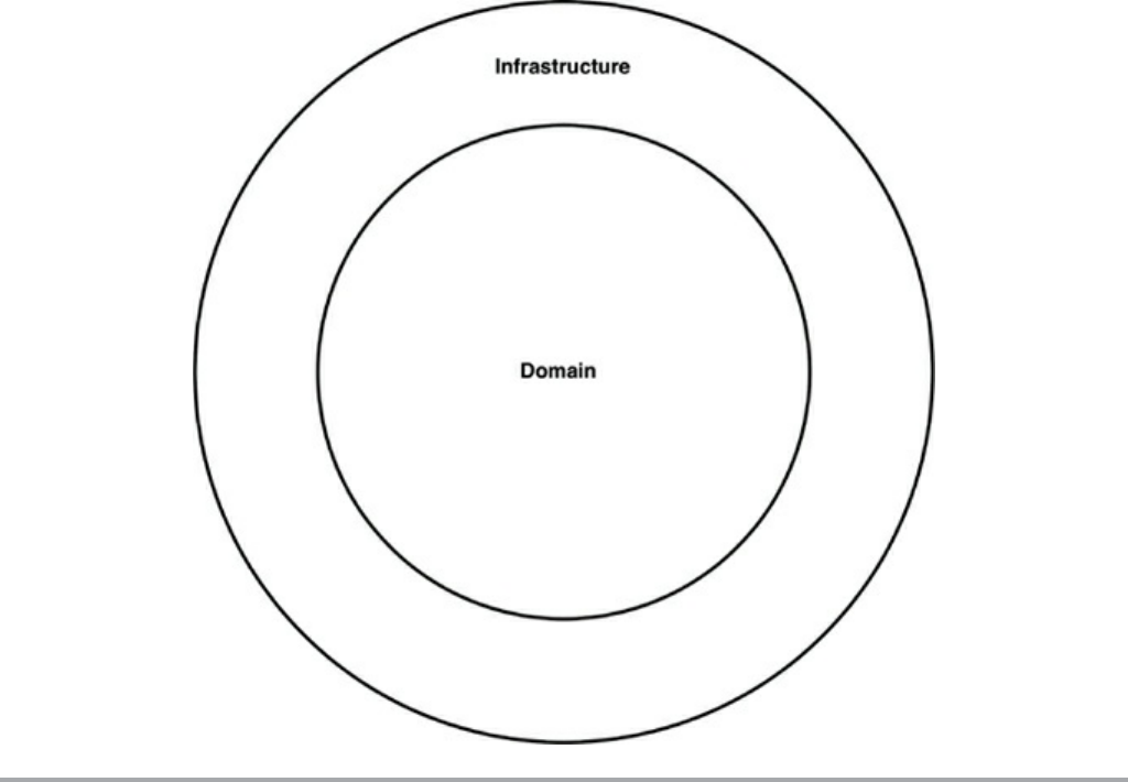
infrastructure to the domain.
Figure 34.9 Domain and infrastructure code
This approach to organizing source code will also work, but be aware of the potential
trade-off. It’s what I call the “Périphérique anti-pattern of ports and adapters.” The
city of Paris, France, has a ring road called the Boulevard Périphérique, which allows
you to circumnavigate Paris without entering the complexities of the city. Having all
of your infrastructure code in a single source code tree means that it’s potentially
possible for infrastructure code in one area of your application (e.g., a web
controller) to directly call code in another area of your application (e.g., a database
repository), without navigating through the domain. This is especially true if you’ve
forgotten to apply appropriate access modifiers to that code.
CONCLUSION: THE MISSING ADVICE
The whole point of this chapter is to highlight that your best design intentions can be
destroyed in a flash if you don’t consider the intricacies of the implementation
strategy. Think about how to map your desired design on to code structures, how to
organize that code, and which decoupling modes to apply during runtime and
compile-time. Leave options open where applicable, but be pragmatic, and take into
consideration the size of your team, their skill level, and the complexity of the
solution in conjunction with your time and budgetary constraints. Also think about
using your compiler to help you enforce your chosen architectural style, and watch
out for coupling in other areas, such as data models. The devil is in the
implementation details.
1. This is arguably a horrible way to name a class, but as we’ll see later, perhaps it doesn’t really
matter.
2. https://martinfowler.com/bliki/PresentationDomainDataLayering.html.
3. This benefit is much less relevant with the navigation facilities of modern IDEs, but it seems
there has been a renaissance moving back to lightweight text editors, for reasons I am clearly too
old to understand.
4. My first job after graduating from university in 1996 was building client–server desktop
applications with a technology called PowerBuilder, a super-productive 4GL that exceled at
building database-driven applications. A couple of years later, I was building client–server
applications with Java, where we had to build our own database connectivity (this was pre-JDBC)
and our own GUI toolkits on top of AWT. That’s “progress“ for you!
5. In the Command Query Responsibility Segregation pattern, you have separate patterns for
updating and reading data.
6. http://www.laputan.org/mud/
7. See https://www.structurizr.com/help/c4 for more information.
8. In Java, for example, although we tend to think of packages as being hierarchical, it’s not
possible to create access restrictions based on a package and subpackage relationship. Any
hierarchy that you create is in the name of those packages, and the directory structure on disk,
only.
9. Unless you cheat and use Java’s reflection mechanism, but please don’t do that!

VII
Appendix
A
ARCHITECTURE ARCHAEOLOGY
To unearth the principles of good architecture, let’s take a 45-year journey through
some of the projects I have worked on since 1970. Some of these projects are
interesting from an architectural point of view. Others are interesting because of the
lessons learned and because of how they fed into subsequent projects.
This appendix is somewhat autobiographical. I’ve tried to keep the discussion
relevant to the topic of architecture; but, as in anything autobiographical, other
factors sometimes intrude. ;-)
UNION ACCOUNTING SYSTEM
In the late 1960s, a company by the name of ASC Tabulating signed a contract with
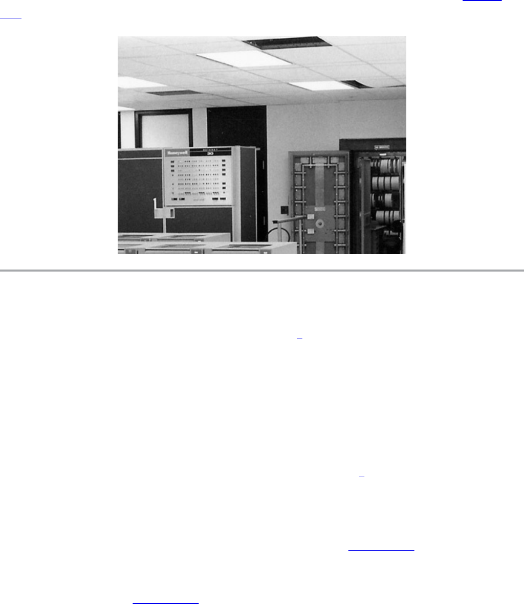
Local 705 of the Teamsters Union to provide an accounting system. The computer
ASC chose to implement this system on was a GE Datanet 30, as shown in Figure
A.1.
Figure A.1 GE Datanet 30
Courtesy Ed Thelen, ed-thelen.org
As you can see from the picture, this was a huge1 machine. It filled a room, and the
room needed strict environmental controls.
This computer was built in the days before integrated circuits. It was built out of
discrete transistors. There were even some vacuum tubes in it (albeit only in the
sense amplifiers of the tape drives).
By today’s standards the machine was huge, slow, small, and primitive. It had 16K ×
18 bits of core, with a cycle time of about 7 microseconds.2 It filled a big,
environmentally controlled room. It had 7 track magnetic tape drives and a disk drive
with a capacity of 20 megabytes or so.
That disk was a monster. You can see it in the picture in Figure A.2—but that
doesn’t quite give you the scale of the beast. The top of that cabinet was over my
head. The platters were 36 inches in diameter, and 3/8 of an inch thick. One of the
platters is pictured in Figure A.3.
Now count the platters in that first picture. There are more than a dozen. Each one
had its own individual seek arm that was driven by pneumatic actuators. You could
watch those seek heads move across the platters. The seek time was probably about
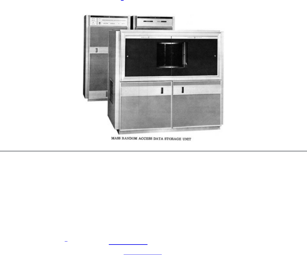
half a second to a second.
When this beast was turned on, it sounded like a jet engine. The floor would rumble
and shake until it got up to speed.3
Figure A.2 The data storage unit with its platters
Courtesy Ed Thelen, ed-thelen.org
The great claim to fame of the Datanet 30 was its capability to drive a large number
of asynchronous terminals at relatively high speed. That’s exactly what ASC needed.
ASC was based in Lake Bluff, Illinois, 30 miles north of Chicago. The Local 705
office was in downtown Chicago. The union wanted a dozen or so of their data entry
clerks to use CRT4 terminals (Figure A.4) to enter data into the system. They would
print reports on ASR35 teletypes (Figure A.5).
Figure A.3 One platter of that disk: 3/8 inch thick, 36 inches in diameter
Courtesy, Ed Thelen, ed-thelen.org
The CRT terminals ran at 30 characters per second. This was a pretty good rate for
the late 1960s because modems were relatively unsophisticated in those days.
ASC leased a dozen or so dedicated phone lines and twice that number of 300 baud
modems from the phone company to connect the Datanet 30 to these terminals.
These computers did not come with operating systems. They didn’t even come with
file systems. What you got was an assembler.
If you needed to store data on the disk, you stored data on the disk. Not in a file. Not
in a directory. You figured out which track, platter, and sector to put the data into,
and then you operated the disk to put the data there. Yes, that means we wrote our
own disk driver.
Figure A.4 Datapoint CRT terminal
Courtesy of Bill Degnan, vintagecomputer.net
The Union Accounting system had three kinds of records: Agents, Employers, and
Members. The system was a CRUD system for these records, but also included
operations for posting dues, computing changes in the general ledger, and so on.
The original system was written in assembler by a consultant who somehow
managed to cram the whole thing into 16K.
As you might imagine, that big Datanet 30 was an expensive machine to operate and
maintain. The software consultant who kept the software running was expensive, too.
What’s more, minicomputers were becoming popular, and were much cheaper.
Figure A.5 ASR35 teletype
Joe Mabel, with permission
In 1971, when I was 18 years old, ASC hired me and two of my geeky friends to
replace the whole union accounting system with one that was based on a Varian
620/f minicomputer (Figure A.6). The computer was cheap. We were cheap. So it
seemed like a good deal for ASC.
The Varian machine had a 16-bit bus and 32K * 16 core memory. It had a cycle time
of about 1 microsecond. It was much more powerful than the Datanet 30. It used
IBM’s wildly successful 2314 disk technology, allowing us to store 30 megabytes on
platters that were only 14 inches in diameter and could not explode through concrete
block walls!
Of course, we still had no operating system. No file system. No high-level language.
All we had was an assembler. But we made do.
Figure A.6 Varian 620/f minicomputer
The Minicomputer Orphanage
Instead of trying to cram the whole system into 32K, we created an overlay system.
Applications would be loaded from disk into a block of memory dedicated to
overlays. They would be executed in that memory, and preemptively swapped back
out onto disk, with their local RAM, to allow other programs to execute.
Programs would get swapped into the overlay area, execute enough to fill the output
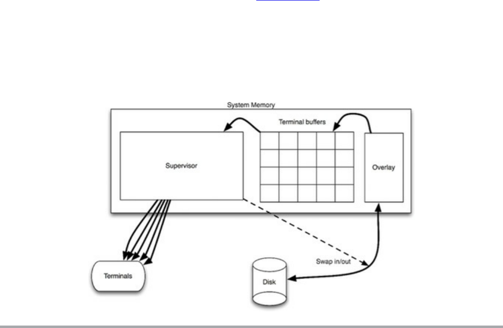
buffers, and then get swapped out so that another program could be swapped in.
Of course, when your UI runs at 30 characters per second, your programs spend a lot
of time waiting. We had plenty of time to swap the programs in and off the disk to
keep all of the terminals running as fast as they could go. Nobody ever complained
of response time issues.
We wrote a preemptive supervisor that managed the interrupts and IO. We wrote the
applications; we wrote the disk drivers, the terminal drivers, the tape drivers, and
everything else in that system. There was not a single bit in that system that we did
not write. Though it was a struggle involving far too many 80-hour weeks, we got
the beast up and running in a matter of 8 or 9 months.
The architecture of the system was simple (Figure A.7). When an application was
started, it would generate output until its particular terminal buffer was full. Then the
supervisor would swap the application out, and swap a new application in. The
supervisor would continue to dribble out the contents of the terminal buffer at 30 cps
until it was nearly empty. Then it would swap the application back in to fill the
buffer again.
Figure A.7 The system architecture
There are two boundaries in this system. The first is the character output boundary.
The applications had no idea that their output was going to a 30-cps terminal. Indeed,
the character output was entirely abstract from the applications’ point of view. The
applications simply passed strings to the supervisor, and the supervisor took care of
loading the buffers, sending the characters to the terminals, and swapping the
applications in and out of memory.
This boundary was dependency normal—that is, dependencies pointed with the flow
of control. The applications had compile-time dependencies on the supervisor, and
the flow of control passed from the applications to the supervisor. The boundary
prevented the applications from knowing which kind of device the output was going
to.
The second boundary was dependency inverted. The supervisor could start the
applications, but had no compile-time dependencies upon them. The flow of control
passed from the supervisor to the applications. The polymorphic interface that
inverted the dependency was simply this: Every application was started by jumping
to the exact same memory address within the overlay area. The boundary prevented
the supervisor from knowing anything about the applications other than the starting
point.
LASER TRIM
In 1973, I joined a company in Chicago called Teradyne Applied Systems (TAS).
This was a division of Teradyne Inc., which was headquartered in Boston. Our
product was a system that used relatively high-powered lasers to trim electronic
components to very fine tolerances.
Back in those days, manufacturers would silk-screen electronic components onto
ceramic substrates. Those substrates were on the order of 1 inch square. The
components were typically resistors—devices that resist the flow of current.
The resistance of a resistor depends on a number of factors, including its
composition and its geometry. The wider the resistor, the less resistance it has.
Our system would position the ceramic substrate in a harness that had probes that
made contact with the resistors. The system would measure the resistance of the
resistors, and then use a laser to burn off parts of the resistor, making it thinner and
thinner until it reached the desired resistance value within a tenth of a percent or so.
We sold these systems to manufacturers. We also used some in-house systems to
trim relatively small batches for small manufacturers.
The computer was an M365. This was in the days when many companies built their
own computers: Teradyne built the M365 and supplied it to all its divisions. The

M365 was an enhanced version of a PDP-8—a popular minicomputer of the day.
The M365 controlled the positioning table, which moved the ceramic substrates
under the probes. It controlled the measurement system and the laser. The laser was
positioned using X-Y mirrors that could rotate under program control. The computer
could also control the power setting of the laser.
The development environment of the M365 was relatively primitive. There was no
disk. Mass storage was on tape cartridges that looked like old 8-track audio tape
cassettes. The tapes and drives were made by Tri-Data.
Like the 8-track audio cassettes of the day, the tape was oriented in a loop. The drive
moved the tape in only one direction—there was no rewind! If you wanted to
position the tape at the beginning, you had to send it forward to its “load point.”
The tape moved at a speed of approximately 1 foot per second. Thus, if the tape loop
was 25 feet long, it could take as long as 25 seconds to send it to the load point. For
this reason Tridata made cartridges in several lengths, ranging from 10 feet to 100
feet.
The M365 had a button on the front that would load memory with a little bootstrap
program and execute it. This program would read the first block of data from the
tape, and execute that. Typically this block held a loader that loaded the operating
system that lived on the rest of the tape.
The operating system would prompt the user for the name of a program to run.
Those programs were stored on the tape, just after the operating system. We would
type in the name of the program—for example, the ED-402 Editor—and the
operating system would search the tape for that program, load it, and execute it.
The console was an ASCII CRT with green phosphors, 72 characters wide5 by 24
lines. The characters were all uppercase.
To edit a program, you would load the ED-402 Editor, and then insert the tape that
held your source code. You would read one tape block of that source code into
memory, and it would be displayed on the screen. The tape block might hold 50 lines
of code. You would make your edits by moving the cursor around on the screen and
typing in a manner similar to vi. When you were done, you would write that block
onto a different tape, and read the next block from the source tape. You kept on
doing this until you were done.
There was no scrolling back to previous blocks. You edited your program in a
straight line, from beginning to end. Going back to the beginning forced you to finish
copying the source code onto the output tape and then start a new editing session on
that tape. Perhaps not surprisingly, given these constraints, we printed our programs
out on paper, marked all the edits by hand in red ink, and then edited our programs
block by block by consulting our markups on the listing.
Once the program was edited, we returned to the OS and invoked the assembler. The
assembler read the source code tape, and wrote a binary tape, while also producing a
listing on our data products line printer.
The tapes weren’t 100% reliable, so we always wrote two tapes at the same time.
That way, at least one of them had a high probability of being free of errors.
Our program was approximately 20,000 lines of code, and took nearly 30 minutes to
compile. The odds that we would get a tape read error during that time were roughly
1 in 10. If the assembler got a tape error, it would ring the bell on the console and
then start printing a stream of errors on the printer. You could hear this maddening
bell all across the lab. You could also hear the cursing of the poor programmer who
just learned that the 30-minute compile needed to start over.
The architecture of the program was typical for those days. There was a Master
Operating Program, appropriately called “the MOP.” Its job was to manage basic IO
functions and provide the rudiments of a console “shell.” Many of the divisions of
Teradyne shared the MOP source code, but each had forked it for its own uses.
Consequently, we would send source code updates around to each other in the form
of marked-up listings that we would then integrate manually (and very carefully).
A special-purpose utility layer controlled the measurement hardware, the positioning
tables, and the laser. The boundary between this layer and the MOP was muddled at
best. While the utility layer called the MOP, the MOP had been specifically modified
for that layer, and often called back into it. Indeed, we didn’t really think of these
two as separate layers. To us, it was just some code that we added to the MOP in a
highly coupled way.
Next came the isolation layer. This layer provided a virtual machine interface for the
application programs, which were written in a completely different domain-specific
data-driven language (DSL). The language had operations for moving the laser,
moving the table, making cuts, making measurements, and so on. Our customers
would write their laser trimming application programs in this language, and the
isolation layer would execute them.
This approach was not intended to create a machine-independent laser trim language.
Indeed, the language had many idiosyncrasies that were deeply coupled to the layers
below. Rather, this approach gave the application programmers a “simpler” language
than M356 assembler in which to program their trim jobs.
Trim jobs could be loaded from tape and executed by the system. Essentially, our
system was an operating system for trim applications.
The system was written in M365 assembler and compiled in a single compilation
unit that produced absolute binary code.
The boundaries in this application were soft at best. Even the boundary between the
system code and the applications written in the DSL was not well enforced. There
were couplings everywhere.
But that was typical of software in the early 1970s.
ALUMINUM DIE-CAST MONITORING
In the middle of the 1970s, while OPEC was placing an embargo on oil, and gasoline
shortages were causing angry drivers to get into fights at gas stations, I began
working at Outboard Marine Corporation (OMC). This is the parent company of
Johnson Motors and Lawnboy lawnmowers.
OMC maintained a huge facility in Waukegan, Illinois, for creating die-cast
aluminum parts for all of the company’s motors and products. Aluminum was melted
down in huge furnaces, and then carried in large buckets to dozens upon dozens of
individually operated aluminum die-cast machines. Each machine had a human
operator responsible for setting the molds, cycling the machine, and extracting the
newly cast parts. These operators were paid based on how many parts they produced.
I was hired to work on a shop-floor automation project. OMC had purchased an IBM
System/7—which was IBM’s answer to the minicomputer. They tied this computer
to all the die-cast machines on the floor, so that we could count, and time, the cycles
of each machine. Our role was to gather all that information and present it on 3270
green-screen displays.
The language was assembler. And, again, every bit of code that executed in this
computer was code that we wrote. There was no operating system, no subroutine
libraries, and no framework. It was just raw code.
It was also interrupt-driven real-time code. Every time a die-cast machine cycled, we
had to update a batch of statistics, and send messages to a great IBM 370 in-the-sky,
running a CICS-COBOL program that presented those statistics on the green screens.
I hated this job. Oh, boy, did I. Oh, the work was fun! But the culture … Suffice it to
say that I was required to wear a tie.
Oh, I tried. I really did. But I was clearly unhappy working there, and my colleagues
knew it. They knew it because I couldn’t remember critical dates or manage to get up
early enough to attend important meetings. This was the only programming job I was
ever fired from—and I deserved it.
From an architectural point of view, there’s not a lot to learn here except for one
thing. The System/7 had a very interesting instruction called set program interrupt
(SPI). This allowed you to trigger an interrupt of the processor, allowing it to handle
any other queued lower-priority interrupts. Nowadays, in Java we call this
Thread.yield().
4-TEL
In October 1976, having been fired from OMC, I returned to a different division of
Teradyne—a division I would stay with for 12 years. The product I worked on was
named 4-TEL. Its purpose was to test every telephone line in a telephone service
area, every night, and produce a report of all lines requiring repair. It also allowed
telephone test personnel to test specific telephone lines in detail.
This system started its life with the same kind of architecture as the Laser Trim
system. It was a monolithic application written in assembly language without any
significant boundaries. But at the time I joined the company, that was about to
change.
The system was used by testers located in a service center (SC). A service center
covered many central offices (CO), each of which could handle as many as 10,000
phone lines. The dialing and measurement hardware had to be located inside the CO.
So that’s where the M365 computers were put. We called those computers the
central office line testers (COLTs). Another M365 was placed at the SC; it was

called the service area computer (SAC). The SAC had several modems that it could
use to dial up the COLTs and communicate at 300 baud (30 cps).
At first, the COLT computers did everything, including all the console
communication, menus, and reports. The SAC was just a simple multiplexor that
took the output from the COLTs and put it on a screen.
The problem with this setup was that 30 cps is really slow. The testers didn’t like
watching the characters trickle across the screen, especially since they were only
interested in a few key bits of data. Also, in those days, the core memory in the
M365 was expensive, and the program was big.
The solution was to separate the part of the software that dialed and measured lines
from the part that analyzed the results and printed the reports. The latter would be
moved into the SAC, and the former would remain behind in the COLTs. This would
allow the COLT to be a smaller machine, with much less memory, and would greatly
speed up the response at the terminal, since the reports would be generated in the
SAC.
The result was remarkably successful. Screen updates were very fast (once the
appropriate COLT had been dialed), and the memory footprint of the COLTs shrank
a lot.
The boundary was very clean and highly decoupled. Very short packets of data were
exchanged between the SAC and COLT. These packets were a very simple form of
DSL, representing primitive commands like “DIAL XXXX” or “MEASURE.”
The M365 was loaded from tape. Those tape drives were expensive and weren’t very
reliable—especially in the industrial environment of a telephone central office. Also,
the M365 was an expensive machine relative to the rest of the electronics within the
COLT. So we embarked upon a project to replace the M365 with a microcomputer
based on an 8085 µprocessor.
The new computer was composed of a processor board that held the 8085, a RAM
board that held 32K of RAM, and three ROM boards that held 12K of read-only
memory apiece. All these boards fit into the same chassis as the measurement
hardware, thereby eliminating the bulky extra chassis that had housed the M365.
The ROM boards held 12 Intel 2708 EPROM (Erasable Programmable Read-Only
Memory) chips.6 Figure A.8 shows an example of such a chip. We loaded those
chips with software by inserting them into special devices called PROM burners that
were driven by our development environment. The chips could be erased by
exposing them to high-intensity ultraviolet light.7
My buddy CK and I translated the M365 assembly language program for the COLT
into 8085 assembly language. This translation was done by hand and took us about 6
months. The end result was approximately 30K of 8085 code.
Our development environment had 64K of RAM and no ROM, so we could quickly
download our compiled binaries into RAM and test them.
Once we got the program working, we switched to using the EPROMs. We burned
30 chips and inserted them into just the right slots in the three ROM boards. Each
chip was labeled so we could tell which chip went into which slot.
The 30K program was a single binary, 30K long. To burn the chips, we simply
divided that binary image into 30 different 1K segments, and burned each segment
onto the appropriately labeled chip.
Figure A.8 EPROM chip
This worked very well, and we began to mass-produce the hardware and deploy the
system into the field.
But software is soft.8 Features needed to be added. Bugs needed to be fixed. And as
the installed base grew, the logistics of updating the software by burning 30 chips
per installation, and having field service people replace all 30 chips at each site
became a nightmare.
There were all kinds of problems. Sometimes chips would be mislabeled, or the
labels would fall off. Sometimes the field service engineer would mistakenly replace
the wrong chip. Sometimes the field service engineer would inadvertently break a
pin off one of the new chips. Consequently, the field engineers had to carry extras of
all 30 chips with them.
Why did we have to change all 30 chips? Every time we added or removed code
from our 30K executable, it changed the addresses in which each instruction was
loaded. It also changed the addresses of the subroutines and functions that we called.
So every chip was affected, no matter how trivial the change.
One day, my boss came to me and asked me to solve that problem. He said we
needed a way to make a change to the firmware without replacing all 30 chips every
time. We brainstormed this issue for a while, and then embarked upon the
“Vectorization” project. It took me three months.
The idea was beautifully simple. We divided the 30K program into 32 independently
compilable source files, each less than 1K. At the beginning of each source file, we
told the compiler in which address to load the resulting program (e.g., ORG C400 for
the chip that was to be inserted into the C4 position).
Also at the beginning of each source file, we created a simple, fixed-size data
structure that contained all the addresses of all the subroutines on that chip. This data
structure was 40 bytes long, so it could hold no more than 20 addresses. This meant
that no chip could have more than 20 subroutines.
Next, we created a special area in RAM known as the vectors. It contained 32 tables
of 40 bytes—exactly enough RAM to hold the pointers at the start of each chip.
Finally, we changed every call to every subroutine on every chip into an indirect call
through the appropriate RAM vector.
When our processor booted, it would scan each chip and load the vector table at the
start of each chip into the RAM vectors. Then it would jump into the main program.
This worked very well. Now, when we fixed a bug, or added a feature, we could
simply recompile one or two chips, and send just those chips to the field service
engineers.
We had made the chips independently deployable. We had invented polymorphic
dispatch. We had invented objects.
This was a plugin architecture, quite literally. We plugged those chips in. We
eventually engineered it so that a feature could be installed into our products by
plugging the chip with that feature into one of the open chip sockets. The menu
control would automatically appear, and the binding into the main application would
happen automatically.
Of course, we didn’t know about object-oriented principles at the time, and we knew
nothing about separating user interface from business rules. But the rudiments were
there, and they were very powerful.
One unexpected side benefit of the approach was that we could patch the firmware
over a dial-up connection. If we found a bug in the firmware, we could dial up our
devices and use the on-board monitor program to alter the RAM vector for the faulty
subroutine to point to a bit of empty RAM. Then we’d enter the repaired subroutine
into that RAM area, by typing it in machine code, in hexadecimal.
This was a great boon to our field service operation, and to our customers. If they
had a problem, they didn’t need us to ship new chips and schedule an urgent field
service call. The system could be patched, and a new chip could be installed at the
next regularly scheduled maintenance visit.
THE SERVICE AREA COMPUTER
The 4-TEL service area computer (SAC) was based on an M365 minicomputer. This
system communicated with all the COLTs out in the field, through either dedicated
or dial-up modems. It would command those COLTs to measure telephone lines,
would receive back the raw results, and would then perform a complex analysis of
those results to identify and locate any faults.
DISPATCH DETERMINATION
One of the economic foundations for this system was based on the correct allocation
of repair craftsmen. Repair craft were separated, by union rules, into three
categories: central office, cable, and drop. CO craftsmen fixed problems inside the
central office. Cable craftsmen fixed problems in the cable plant that connected the
CO to the customer. Drop craftsmen fixed problems inside the customer’s premises,
and in the lines connecting the external cable to that premises (the “drop”).
When a customer complained about a problem, our system could diagnose that
problem and determine which kind of craftsman to dispatch. This saved the phone
companies lots of money because incorrect dispatches meant delays for the customer
and wasted trips for the craftsmen.
The code that made this dispatch determination was designed and written by
someone who was very bright, but a terrible communicator. The process of writing
the code has been described as “Three weeks of staring at the ceiling and two days of
code pouring out of every orifice of his body—after which he quit.”
Nobody understood this code. Every time we tried to add a feature or fix a defect, we
broke it in some way. And since it was upon this code that one of the primary
economic benefits our system rested, every new defect was deeply embarrassing to
the company.
In the end, our management simply told us to lock that code down and never modify
it. That code became officially rigid.
This experience impressed upon me the value of good, clean code.
ARCHITECTURE
The system was written in 1976 in M365 assembler. It was a single, monolithic
program of roughly 60,000 lines. The operating system was a home-grown,
nonpreemptive, task-switcher based on polling. We called it MPS for
multiprocessing system. The M365 computer had no built-in stack, so task-specific
variables were kept in a special area of memory and swapped out at every context
switch. Shared variables were managed with locks and semaphores. Reentrancy
issues and race conditions were constant problems.
There was no isolation of device control logic, or UI logic, from the business rules of
the system. For example, modem control code could be found smeared throughout
the bulk of the business rules and UI code. There was no attempt to gather it into a
module or abstract the interface. The modems were controlled, at the bit level, by
code that was scattered everywhere around the system.
The same was true for the terminal UI. Messages and formatting control code were
not isolated. They ranged far and wide throughout the 60,000-line code base.
The modem modules we were using were designed to be mounted on PC boards. We
bought those units from a third party, and integrated them with other circuitry onto a
board that fit into our custom backplane. These units were expensive. So, after a few
years, we decided to design our own modems. We, in the software group, begged the
hardware designer to use the same bit formats for controlling the new modem. We
explained that the modem control code was smeared everywhere, and that our
system would have to deal with both kinds of modems in the future. So, we begged
and cajoled, “Please make the new modem look just like the old modem from a
software control point of view.”
But when we got the new modem, the control structured was entirely different. It
was not just a little different. It was entirely, and completely, different.
Thanks, hardware engineer.
What were we to do? We were not simply replacing all the old modems with new
modems. Instead, we were mixing old and new modems in our systems. The
software needed to be able to handle both kinds of modems at the same time. Were
we doomed to surround every place in the code that manipulated the modems with
flags and special cases? There were hundreds of such places!
In the end, we opted for an even worse solution.
One particular subroutine wrote data to the serial communication bus that was used
to control all our devices, including our modems. We modified that subroutine to
recognize the bit patterns that were specific to the old modem, and translate them
into the bit patterns needed by the new modem.
This was not straightforward. Commands to the modem consisted of sequences of
writes to different IO addresses on the serial bus. Our hack had to interpret these
commands, in sequence, and translate them into a different sequence using different
IO addresses, timings, and bit positions.
We got it to work, but it was the worst hack imaginable. It was because of this fiasco
that I learned the value of isolating hardware from business rules, and of abstracting
interfaces.
THE GRAND REDESIGN IN THE SKY
By the time the 1980s rolled around, the idea of producing your own minicomputer
and your own computer architecture was beginning to fall out of fashion. There were
many microcomputers on the market, and getting them to work was cheaper and
more standard then continuing to rely on proprietary computer architectures from the
late 1960s. That, plus the horrible architecture of the SAC software, induced our
technical management to start a complete re-architecture of the SAC system.
The new system was to be written in C using a UNIX O/S on disk, running on an
Intel 8086 microcomputer. Our hardware guys started working on the new computer
hardware, and a select group of software developers, “The Tiger Team,” was
commissioned with the rewrite.
I won’t bore you with the details of the initial fiasco. Suffice it to say that the first
Tiger Team failed entirely after burning two or three man-years on a software project
that never delivered anything.
A year or two later, probably 1982, the process was started again. The goal was the
total and complete redesign of the SAC in C and UNIX on our own, newly designed,
impressively powerful 80286 hardware. We called that computer “Deep Thought.”
It took years, then more years, and then even more years. I don’t know when the first
UNIX-based SAC was finally deployed; I believe I had left the company by then
(1988). Indeed, I’m not at all sure it ever was deployed.
Why the delay? In short, it is very difficult for a redesign team to catch up with a
large staff of programmers who are actively maintaining the old system. Here’s just
one example of the difficulties they encountered.
EUROPE
At about the same time that the SAC was being redesigned in C, the company started
to expand sales into Europe. They could not wait for the redesigned software to be
finished, so of course, they deployed the old M365 systems into Europe.
The problem was that the phone systems in Europe were very different from the
phone systems in the United States. The organization of the craft and of the
bureaucracies were different as well. So one of our best programmers was sent to the
United Kingdom to lead a team of U.K. developers to modify the SAC software to
deal with all these European issues.
Of course, no serious attempt was made to integrate these changes into the U.S.-
based software. This was long before networks made it feasible to transmit large
code bases across the ocean. These U.K. developers simply forked the U.S.-based
code and modified it as needed.
This, of course, caused difficulties. Bugs were found on both sides of the Atlantic
that needed repair on the other side. But the modules had changed significantly, so it
was very difficult to determine whether the fix made in the United States would
work in the United Kingdom.
After a few years of heartburn, and the installation of a high-throughput line
connecting the U.S. and U.K. offices, a serious attempt was made to integrate these
two forks back together again, making the differences a matter of configuration. This
effort failed the first, second, and third times it was tried. The two code bases,
though remarkably similar, were still too different to reintegrate—especially in the
rapidly changing market environment that existed at that time.
Meanwhile, the “Tiger Team,” trying to rewrite everything in C and UNIX, realized
that it also had to deal with this European/US dichotomy. And, of course, that did
nothing to accelerate their progress.
SAC CONCLUSION
There are many other stories I could tell you about this system, but it’s just too
depressing for me to continue. Suffice it to say that many of the hard lessons of my
software life were learned while immersed in the horrible assembler code of the
SAC.
C LANGUAGE
The 8085 computer hardware that we used in the 4-Tel Micro project gave us a
relatively low-cost computing platform for many different projects that could be
embedded into industrial environments. We could load it up with 32K of RAM and
another 32K of ROM, and we had an extremely flexible and powerful scheme for
controlling peripherals. What we did not have was a flexible and convenient
language with which to program the machine. The 8085 assembler was simply not
fun to write code in.
On top of that, the assembler we were using was written by our own programmers. It
ran on our M365 computers, using the cartridge tape operating system described in
the “Laser Trim” section.

As fate would have it, our lead hardware engineer convinced our CEO that we
needed a real computer. He didn’t actually know what he would do with it, but he
had a lot of political clout. So we purchased a PDP-11/60.
I, a lowly software developer at the time, was ecstatic. I knew precisely what I
wanted to do with that computer. I was determined that this was going to be my
machine.
When the manuals arrived, many months before the delivery of the machine, I took
them home and devoured them. By the time the computer was delivered, I knew how
to operate both the hardware and the software at an intimate level—at least, as
intimate as home study can make it.
I helped to write the purchase order. In particular, I specified the disk storage that the
new computer would have. I decided we should buy two disk drives that could take
removable disk packs that held 25 megabytes each.9
Fifty megabytes! The number seemed infinite! I remember walking through the halls
of the office, late at night, cackling like the Wicked Witch of the West: “Fifty
megabytes! Hahahahahahahahahah!”
I had the facilities manager build a little room that would house six VT100 terminals.
I decorated it with pictures from space. Our software developers would use this room
to write and compile code.
When the machine arrived, I spent several days setting it up, wiring all the terminals,
and getting everything to work. It was a joy—a labor of love.
We purchased standard assemblers for the 8085 from Boston Systems Office, and we
translated the 4-Tel Micro code into that syntax. We built a cross-compilation system
that allowed us to download compiled binaries from the PDP-11 to our 8085
development environments, and ROM burners. And—Bob’s your Uncle—it all
worked like a champ.
C
But that left us with the problem of still using 8085 assembler. That was not a
situation that I was happy with. I had heard that there was this “new” language that
was heavily used at Bell Labs. They called it “C.” So I purchased a copy of The C
Programming Language by Kernighan and Ritchie. Like the PDP-11 manuals a few

months before, I inhaled this book.
I was astounded by the simple elegance of this language. It sacrificed none of the
power of assembly language, and provided access to that power with a much more
convenient syntax. I was sold.
I purchased a C compiler from Whitesmiths, and got it running on the PDP-11. The
output of the compiler was assembler syntax that was compatible with the Boston
Systems Office 8085 compiler. So we had a pathway to go from C to the 8085
hardware! We were in business.
Now the only problem was convincing a group of embedded assembly language
programmers that they should be using C. But that’s a nightmare tale for another
time …
BOSS
Our 8085 platform had no operating system. My experience with the MPS system of
the M365, and the primitive interrupt mechanisms of the IBM System 7, convinced
me that we needed a simple task switcher for the 8085. So I conceived of BOSS:
Basic Operating System and Scheduler.10
The vast majority of BOSS was written in C. It provided the ability to create
concurrent tasks. Those tasks were not preemptive—task switching did not take
place based on interrupts. Instead, and just like with the MPS system on the M365,
tasks were switched based on a simple polling mechanism. The polling happened
whenever a task blocked for an event.
The BOSS call to block a task looked like this:
block(eventCheckFunction);
This call suspended the current task, placed the eventCheckFunction in the polling
list, and associated it with the newly blocked task. It then waited in the polling loop,
calling each of the functions in the polling list until one of them returned true. The
task associated with that function was then allowed to run.
In other words, as I said before, it was a simple, nonpreemptive task switcher.
This software became the basis for a vast number of projects over the following
years. But one of the first was the pCCU.
pCCU
The late 1970s and early 1980s were a tumultuous time for telephone companies.
One of the sources of that tumult was the digital revolution.
For the preceding century, the connection between the central switching office and
the customer’s telephone had been a pair of copper wires. These wires were bundled
into cables that spread in a huge network across the countryside. They were
sometimes carried on poles, and sometimes buried underground.
Copper is a precious metal, and the phone company had tons (literally tons) of it
covering the country. The capital investment was enormous. Much of that capital
could be reclaimed by transporting the telephone conversation over digital
connections. A single pair of copper wires could carry hundreds of conversations in
digital form.
In response, the phone companies embarked upon the process of replacing their old
analog central switching equipment with modern digital switches.
Our 4-Tel product tested copper wires, not digital connections. There were still
plenty of copper wires in a digital environment, but they were much shorter than
before, and they were localized near the customer’s telephones. The signal would be
carried digitally from the central office to a local distribution point, where it would
be converted back to an analog signal and distributed to the customer over standard
copper wires. This meant that our measurement device needed to be located out
where the copper wires began, but our dialing device needed to remain at the central
office. The problem was that all our COLTs embodied both dialing and measurement
in the same device. (We could have saved ourselves a fortune had we recognized that
obvious architectural boundary a few years earlier!)
Thus we conceived of a new product architecture: the CCU/CMU (the COLT control
unit and the COLT measurement unit). The CCU would be located at the central
switching office, and would handle the dialing of the phone lines to be tested. The
CMU would be located at the local distribution points, and would measure the
copper wires that led to the customer’s phone.
The problem was that for each CCU, there were many CMUs. The information about
which CMU should be used for each phone number was held by the digital switch
itself. Thus the CCU had to interrogate the digital switch to determine which CMU
to communicate with and control.
We promised the phone companies that we would have this new architecture
working in time for their transition. We knew they were months, if not years away,
so we did not feel rushed. We also knew that it would take several man-years to
develop this new CCU/CMU hardware and software.
THE SCHEDULE TRAP
As time went on, we found that there were always urgent matters that required us to
postpone development of the CCU/CMU architecture. We felt safe about this
decision because the phone companies were consistently delaying the deployment of
digital switches. As we looked at their schedules, we felt confident that we had
plenty of time, so we consistently delayed our development.
Then came the day that my boss called me into his office and said: “One of our
customers is deploying a digital switch next month. We have to have a working
CCU/CMU by then.”
I was aghast! How could we possibly do man-years of development in a month? But
my boss had a plan …
We did not, in fact, need a full CCU/CMU architecture. The phone company that
was deploying the digital switch was tiny. They had only one central office, and only
two local distribution points. More importantly, the “local” distribution points were
not particularly local. They actually had regular-old analog switches in them that
switched to several hundred customers. Better yet, those switches were of a kind that
could be dialed by a normal COLT. Better even still, the customer’s phone number
contained all the information necessary to decide which local distribution point to
use. If the phone number had a 5, 6, or 7 in a certain position, it went to distribution
point 1; otherwise, it went to distribution point 2.
So, as my boss explained to me, we did not actually need a CCU/CMU. What we
needed was a simple computer at the central office connected by modem lines to two
standard COLTs at the distribution points. The SAC would communicate with our
computer at the central office, and that computer would decode the phone number
and then relay the dialing and measurement commands to the COLT at the
appropriate distribution point.
Thus was born the pCCU.
This was the first product written in C and using BOSS that was deployed to a
customer. It took me about a week to develop. There is no deep architectural
significance to this tale, but it makes a nice preface to the next project.
DLU/DRU
In the early 1980s, one of our customers was a telephone company in Texas. They
had large geographic areas to cover. In fact, the areas were so large that a single
service area required several different offices from which to dispatch craftsmen.
Those offices had test craftspeople who needed terminals into our SAC.
You might think that this was a simple problem to solve—but remember that this
story takes place in the early 1980s. Remote terminals were not very common. To
make matters worse, the hardware of the SAC presumed that all the terminals were
local. Our terminals actually sat on a proprietary, high-speed, serial bus.
We had remote terminal capability, but it was based on modems, and in the early
1980s modems were generally limited to 300 bits per second. Our customers were
not happy with that slow speed.
High-speed modems were available, but they were very expensive, and they needed
to run on “conditioned” permanent connections. Dial-up quality was definitely not
good enough.
Our customers demanded a solution. Our response was DLU/DRU.
DLU/DRU stood for “Display Local Unit” and “Display Remote Unit.” The DLU
was a computer board that plugged into the SAC computer chassis and pretended to
be a terminal manager board. Instead of controlling the serial bus for local terminals,
however, it took the character stream and multiplexed it over a single 9600-bps
conditioned modem link.
The DRU was a box placed at the customer’s remote location. It connected to the
other end of the 9600-bps link, and had the hardware to control the terminals on our
proprietary serial bus. It demultiplexed the characters received from the 9600-bps
link and sent them to the appropriate local terminals.
Strange, isn’t it? We had to engineer a solution that nowadays is so ubiquitous we
never even think about it. But back then …
We even had to invent our own communications protocol because, in those days,
standard communications protocols were not open source shareware. Indeed, this
was long before we had any kind of Internet connection.
ARCHITECTURE
The architecture of this system was very simple, but there are some interesting
quirks I want to highlight. First, both units used our 8085 technology, and both were
written in C and used BOSS. But that’s where the similarity ended.
There were two of us on the project. I was the project lead, and Mike Carew was my
close associate. I took on the design and coding of the DLU; Mike did the DRU.
The architecture of the DLU was based on a dataflow model. Each task did a small
and focused job, and then passed its output to the next task in line, using a queue.
Think of a pipes and filters model in UNIX. The architecture was intricate. One task
might feed a queue that many others would service. Other tasks would feed a queue
that just one task would service.
Think of an assembly line. Each position on the assembly line has a single, simple,
highly focused job to perform. Then the product moves to the next position in line.
Sometimes the assembly line splits into many lines. Sometimes those lines merge
back into a single line. That was the DLU.
Mike’s DRU used a remarkably different scheme. He created one task per terminal,
and simply did the entire job for that terminal in that task. No queues. No data flow.
Just many identical large tasks, each managing its own terminal.
This is the opposite of an assembly line. In this case the analogy is many expert
builders, each of whom builds an entire product.
At the time I thought my architecture was superior. Mike, of course, thought his was
better. We had many entertaining discussions about this. In the end, of course, both
worked quite well. And I was left with the realization that software architectures can
be wildly different, yet equally effective.
VRS
As the 1980s progressed, newer and newer technologies appeared. One of those
technologies was the computer control of voice.
One of the features of the 4-Tel system was the ability of the craftsman to locate a
fault in a cable. The procedure was as follows:
• The tester, in the central office, would use our system to determine the approximate
distance, in feet, to the fault. This would be accurate to within 20% or so. The
tester would dispatch a cable repair craftsman to an appropriate access point near
that position.
• The cable repair craftsman, upon arrival, would call the tester and ask to begin the
fault location process. The tester would invoke the fault location feature of the 4-
Tel system. The system would begin measuring the electronic characteristics of
that faulty line, and would print messages on the screen requesting that certain
operations be performed, such as opening the cable or shorting the cable.
• The tester would tell the craftsman which operations the system wanted, and the
craftsman would tell the tester when the operation was complete. The tester would
then tell the system that the operation was complete, and the system would
continue with the test.
• After two or three such interactions, the system would calculate a new distance to
the fault. The cable craftsman would then drive to that location and begin the
process again.
Imagine how much better that would be if the cable craftsmen, up on the pole or
standing at a pedestal, could operate the system themselves. And that is exactly what
the new voice technologies allowed us to do. The cable craftsmen could call directly
into our system, direct the system with touch tones, and listen to the results being
read back to them in a pleasant voice.
THE NAME
The company held a little contest to select a name for the new system. One of the
most creative of the names suggested was SAM CARP. This stood for “Still Another
Manifestation of Capitalist Avarice Repressing the Proletariat.” Needless to say, that
wasn’t selected.
Another was the Teradyne Interactive Test System. That one was also not selected.
Still another was Service Area Test Access Network. That, too, was not selected.
The winner, in the end, was VRS: Voice Response System.
ARCHITECTURE
I did not work on this system, but I heard about what happened. The story I am going
to relate to you is second-hand, but for the most part, I believe it to be correct.
These were the heady days of microcomputers, UNIX operating systems, C, and
SQL databases. We were determined to use them all.
From the many database vendors out there, we eventually chose UNIFY. UNIFY
was a database system that worked with UNIX, which was perfect for us.
UNIFY also supported a new technology called Embedded SQL. This technology
allowed us to embed SQL commands, as strings, right into our C code. And so we
did—everywhere.
I mean, it was just so cool that you could put your SQL right into your code,
anywhere you wanted. And where did we want to? Everywhere! And so there was
SQL smeared throughout the body of that code.
Of course, in those days SQL was hardly a solid standard. There were lots of special
vendor-specific quirks. So the special SQL and special UNIFY API calls were also
smeared throughout the code.
This worked great! The system was a success. The craftsmen used it, and the
telephone companies loved it. Life was all smiles.
Then the UNIFY product we were using was cancelled.
Oh. Oh.
So we decided to switch to SyBase. Or was it Ingress? I don’t remember. Suffice it
to say, we had to search through all that C code, find all the embedded SQL and
special API calls, and replace them with corresponding gestures for the new vendor.
After three months of effort or so, we gave up. We couldn’t make it work. We were
so coupled to UNIFY that there was no serious hope of restructuring the code at any
practical expense.

So, we hired a third party to maintain UNIFY for us, based on a maintenance
contract. And, of course, the maintenance rates went up year after year after year.
VRS CONCLUSION
This is one of the ways that I learned that databases are details that should be
isolated from the overall business purpose of the system. This is also one of the
reasons that I don’t like strongly coupling to third-party software systems.
THE ELECTRONIC RECEPTIONIST
In 1983, our company sat at the confluence of computer systems,
telecommunications systems, and voice systems. Our CEO thought this might be a
fertile position from which to develop new products. To address this goal, he
commissioned a team of three (which included me) to conceive, design, and
implement a new product for the company.
It didn’t take us long to come up with The Electronic Receptionist (ER).
The idea was simple. When you called a company, ER would answer and ask you
who you wanted to speak with. You would use touch tones to spell the name of that
person, and ER would then connect you. The users of ER could dial in and, by using
simple touch-tone commands, tell it which phone number the desired person could
be reached at, anywhere in the world. In fact, the system could list several alternate
numbers.
When you called ER and dialed RMART (my code), ER would call the first number
on my list. If I failed to answer and identify myself, it would call the next number,
and the next. If I still wasn’t reached, ER would record a message from the caller.
ER would then, periodically, try to find me to deliver that message, and any other
message left for me by anyone else.
This was the first voice mail system ever, and we11 held the patent to it.
We built all the hardware for this system—the computer board, the memory board,
the voice/telecom boards, everything. The main computer board was Deep Thought,
the Intel 80286 processor that I mentioned earlier.
The voice boards each supported one telephone line. They consisted of a telephone
interface, a voice encoder/decoder, some memory, and an Intel 80186
microcomputer.
The software for the main computer board was written in C. The operating system
was MP/M-86, an early command-line–driven, multiprocessing, disk operating
system. MP/M was the poor man’s UNIX.
The software for the voice boards was written in assembler, and had no operating
system. Communication between Deep Thought and the voice boards occurred
through shared memory.
The architecture of this system would today be called service oriented. Each
telephone line was monitored by a listener process running under MP/M. When a
call came in, an initial handler process was started and the call was passed to it. As
the call proceeded from state to state, the appropriate handler process would be
started and take control.
Messages were passed between these services through disk files. The currently
running service would determine what the next service should be; would write the
necessary state information into a disk file; would issue the command line to start
that service; and then would exit.
This was the first time I had built a system like this. Indeed, this was the first time I
had been the principal architect of an entire product. Everything having to do with
software was mine—and it worked like a champ.
I would not say that the architecture of this system was “clean” in the sense of this
book; it was not a “plugin” architecture. However, it definitely showed signs of true
boundaries. The services were independently deployable, and lived within their own
domain of responsibility. There were high-level processes and low-level processes,
and many of the dependencies ran in the right direction.
ER DEMISE
Unfortunately, the marketing of this product did not go very well. Teradyne was a
company that sold test equipment. We did not understand how to break into the
office equipment market.
After repeated attempts over two years, our CEO gave up and—unfortunately—
dropped the patent application. The patent was picked up by the company that filed
three months after we filed; thus we surrendered the entire voice mail and electronic
call-forwarding market.
Ouch!
On the other hand, you can’t blame me for those annoying machines that now plague
our existence.
CRAFT DISPATCH SYSTEM
ER had failed as a product, but we still had all this hardware and software that we
could use to enhance our existing product lines. Moreover, our marketing success
with VRS convinced us that we should offer a voice response system for interacting
with telephone craftsmen that did not depend on our test systems.
Thus was born CDS, the Craft Dispatch System. CDS was essentially ER, but
specifically focused on the very narrow domain of managing the deployment of
telephone repairmen in the field.
When a problem was discovered in a phone line, a trouble ticket was created in the
service center. Trouble tickets were kept in an automated system. When a repairman
in the field finished a job, he would call the service center for the next assignment.
The service center operator would pull up the next trouble ticket and read it off to the
repairman.
We set about to automate that process. Our goal was for the repairman in the field to
call into CDS and ask for the next assignment. CDS would consult the trouble ticket
system, and read off the results. CDS would keep track of which repairman was
assigned to which trouble ticket, and would inform the trouble ticket system of the
status of the repair.
There were quite a few interesting features of this system having to do with
interacting with the trouble ticket system, the plant management system, and any
automated testing systems.
The experience with the service-oriented architecture of ER made me want to try the
same idea more aggressively. The state machine for a trouble ticket was much more
involved than the state machine for handling a call with ER. I set about to create
what would now be called a micro-service architecture.

Every state transition of any call, no matter how insignificant, caused the system to
start up a new service. Indeed, the state machine was externalized into a text file that
the system read. Each event coming into the system from a phone line turned into a
transition in that finite state machine. The existing process would start a new process
dictated by the state machine to handle that event; then the existing process would
either exit or wait on a queue.
This externalized state machine allowed us to change the flow of the application
without changing any code (the Open-Closed Principle). We could easily add a new
service, independently of any of the others, and wire it into the flow by modifying
the text file that contained the state machine. We could even do this while the system
was running. In other words we had hot-swapping and an effective BPEL (Business
Process Execution Language).
The old ER approach of using disk files to communicate between services was too
slow for this much more rapid flip-flopping of services, so we invented a shared
memory mechanism that we called the 3DBB.12 The 3DBB allowed data to be
accessed by name; the names we used were names assigned to each state machine
instance.
The 3DBB was great for storing strings and constants, but couldn’t be used for
holding complex data structures. The reason for this is technical but easy to
understand. Each process in MP/M lived in its own memory partition. Pointers to
data in one memory partition had no meaning in another memory partition. As a
consequence, the data in the 3DBB could not contain pointers. Strings were fine, but
trees, linked lists, or any data structure with pointers would not work.
The trouble tickets in the trouble ticket system came from many different sources.
Some were automated, and some were manual. The manual entries were created by
operators who were talking to customers about their troubles. As the customers
described their problems, the operators would type in their complaints and
observations in a structured text stream. It looked something like this:
Click here to view code image
/pno 8475551212 /noise /dropped-calls
You get the idea. The / character started a new topic. Following the slash was a
code, and following the code were parameters. There were thousands of codes, and
an individual trouble ticket could have dozens of them in the description. Worse,
since they were manually entered, they were often misspelled or improperly
formatted. They were meant for humans to interpret, not for machines to process.
Our problem was to decode these semi-free-form strings, interpret and fix any errors,
and then turn them into voice output so we could read them to the repairman, up on a
pole, listening with a handset. This required, among other things, a very flexible
parsing and data representation technique. That data representation had to be passed
through the 3DBB, which could handle only strings.
And so, on an airplane, flying between customer visits, I invented a scheme that I
called FLD: Field Labeled Data. Nowadays we would call this XML or JSON. The
format was different, but the idea was the same. FLDs were binary trees that
associated names with data in a recursive hierarchy. FLDs could be queried by a
simple API, and could be translated to and from a convenient string format that was
ideal for the 3DBB.
So, micro-services communicating through shared memory analog of sockets using
an XML analog—in 1985.
There is nothing new under the Sun.
CLEAR COMMUNICATIONS
In 1988, a group of Teradyne employees left the company to form a startup named
Clear Communications. I joined them a few months later. Our mission was to build
the software for a system that would monitor the communications quality of T1 lines
—the digital lines that carried long-distance communications across the country. The
vision was a huge monitor with a map of the United States crisscrossed by T1 lines
flashing red if they were degrading.
Remember, graphical user interfaces were brand new in 1988. The Apple Macintosh
was only five years old. Windows was a joke back then. But Sun Microsystems was
building Sparcstations that had credible X-Windows GUIs. So we went with Sun—
and therefore with C and UNIX.
This was a startup. We worked 70 to 80 hours per week. We had the vision. We had
the motivation. We had the will. We had the energy. We had the expertise. We had
equity. We had dreams of being millionaires. We were full of shit.
The C code poured out of every orifice of our bodies. We slammed it here, and
shoved it there. We constructed huge castles in the air. We had processes, and
message queues, and grand, superlative architectures. We wrote a full seven-layer
ISO communications stack from scratch—right down to the data link layer.
We wrote GUI code. GOOEY CODE! OMG! We wrote GOOOOOEY code.
I personally wrote a 3000-line C function named gi(); its name stood for Graphic
Interpreter. It was a masterpiece of goo. It was not the only goo I wrote at Clear, but
it was my most infamous.
Architecture? Are you joking? This was a startup. We didn’t have time for
architecture. Just code, dammit! Code for your very lives!
So we coded. And we coded. And we coded. But, after three years, what we failed to
do was sell. Oh, we had an installation or two. But the market was not particularly
interested in our grand vision, and our venture capital financiers were getting pretty
fed up.
I hated my life at this point. I saw all my effort and dreams crashing down. I had
conflicts at work, conflicts at home because of work, and conflicts with myself.
And then I got a phone call that changed everything.
THE SETUP
Two years before that phone call, two things of significance happened.
First, I managed to set up a uucp connection to a nearby company that had a uucp
connection to another facility that was connected to the Internet. These connections
were dial-up, of course. Our main Sparcstation (the one on my desk) used a 1200-bps
modem to call up our uucp host twice per day. This gave us email and Netnews (an
early social network where people discussed interesting issues).
Second, Sun released a C++ compiler. I had been interested in C++ and OO since
1983, but compilers were difficult to come by. So when the opportunity presented
itself, I changed languages right away. I left the 3000-line C functions behind, and
started to write C++ code at Clear. And I learned …
I read books. Of course, I read The C++ Programming Language and The Annotated
C++ Reference Manual (The ARM) by Bjarne Stroustrup. I read Rebecca Wirfs-
Brock’s lovely book on responsibility-driven design: Designing Object Oriented

Software. I read OOA and OOD and OOP by Peter Coad. I read Smalltalk-80 by
Adele Goldberg. I read Advanced C++ Programming Styles and Idioms by James O.
Coplien. But perhaps most significantly of all, I read Object Oriented Design with
Applications by Grady Booch.
What a name! Grady Booch. How could anyone forget a name like that. What’s
more, he was the Chief Scientist at a company called Rational! How I wanted to be a
Chief Scientist! And so I read his book. And I learned, and I learned, and I learned …
As I learned, I also began debating on Netnews, the way people now debate on
Facebook. My debates were about C++ and OO. For two years, I relieved the
frustrations that were building at work by debating with hundreds of folks on Usenet
about the best language features and the best principles of design. After a while, I
even started making a certain amount of sense.
It was in one of those debates that the foundations of the SOLID principles were
laid.
And all that debating, and perhaps even some of the sense, got me noticed …
UNCLE BOB
One of the engineers at Clear was a young fellow by the name of Billy Vogel. Billy
gave nicknames to everyone. He called me Uncle Bob. I suspect, despite my name
being Bob, that he was making an offhand reference to J. R. “Bob” Dobbs (see
https://en.wikipedia.org/wiki/File:Bobdobbs.png).
At first I tolerated it. But as the months went by, his incessant chattering of “Uncle
Bob, … Uncle Bob,” in the context of the pressures and disappointments of the
startup, started to wear pretty thin.
And then, one day, the phone rang.
THE PHONE CALL
It was a recruiter. He had gotten my name as someone who knew C++ and object-
oriented design. I’m not sure how, but I suspect it had something to do with my
Netnews presence.
He said he had an opportunity in Silicon Valley, at a company named Rational. They
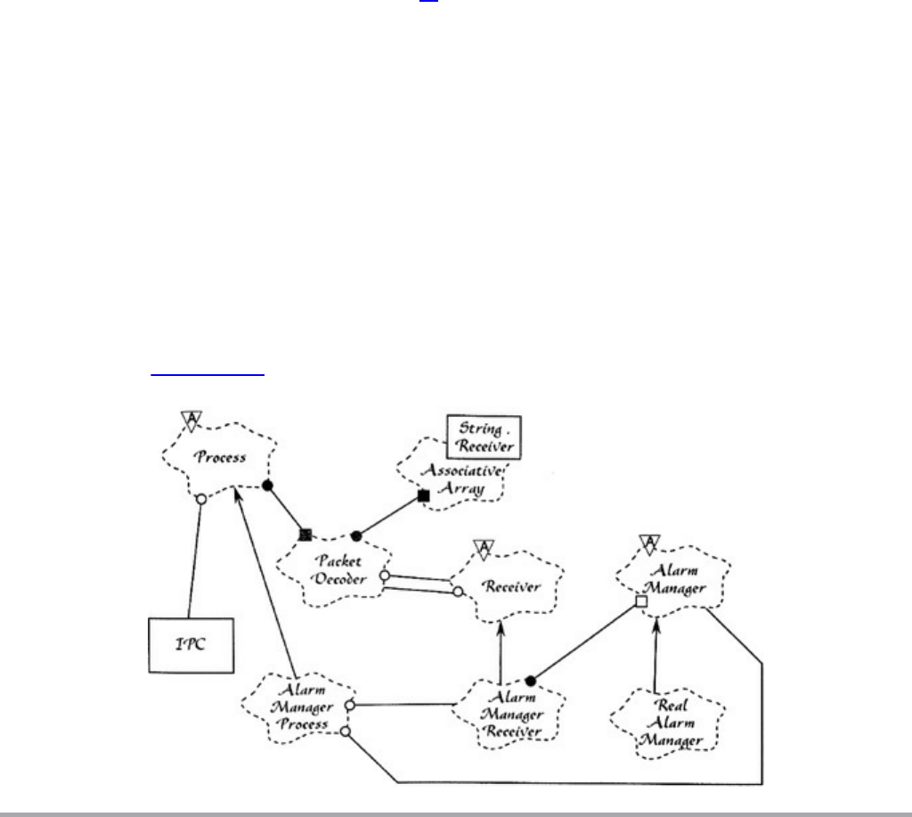
were looking for help building a CASE13 tool.
The blood drained from my face. I knew what this was. I don’t know how I knew,
but I knew. This was Grady Booch’s company. I saw before me the opportunity to
join forces with Grady Booch!
ROSE
I joined Rational, as a contract programmer, in 1990. I was working on the ROSE
product. This was a tool that allowed programmers to draw Booch diagrams—the
diagrams that Grady had written about in Object-Oriented Analysis and Design with
Applications (Figure A.9 shows an example).
Figure A.9 A Booch diagram
The Booch notation was very powerful. It presaged notations like UML.
ROSE had an architecture—a real architecture. It was constructed in true layers, and
the dependencies between layers were properly controlled. The architecture made it
releasable, developable, and independently deployable.
Oh, it wasn’t perfect. There were a lot of things we still didn’t understand about
architectural principles. We did not, for example, create a true plugin structure.
We also fell for one of the most unfortunate fads of the day—we used a so-called
object-oriented database.
But, overall, the experience was a great one. I spent a lovely year and a half working
with the Rational team on ROSE. This was one of the most intellectually stimulating
experiences of my professional life.
THE DEBATES CONTINUED
Of course, I did not stop debating on Netnews. In fact, I drastically increased my
network presence. I started writing articles for C++ Report. And, with Grady’s help,
I started working on my first book: Designing Object-Oriented C++ Applications
Using the Booch Method.
One thing bothered me. It was perverse, but it was true. No one was calling me
“Uncle Bob.” I found that I missed it. So I made the mistake of putting “Uncle Bob”
in my email and Netnews signatures. And the name stuck. Eventually I realized that
it was a pretty good brand.
... BY ANY OTHER NAME
ROSE was a gigantic C++ application. It was composed of layers, with a strictly
enforced dependency rule. That rule is not the rule that I have described in this book.
We did not point our dependencies toward high-level policies. Rather, we pointed
our dependencies in the more traditional direction of flow control. The GUI pointed
at the representation, which pointed at the manipulation rules, which pointed at the
database. In the end, it was this failure to direct our dependencies toward policy that
aided the eventual demise of the product.
The architecture of ROSE was similar to the architecture of a good compiler. The
graphical notation was “parsed” into an internal representation; that representation
was then manipulated by rules and stored in an object-oriented database.
Object-oriented databases were a relatively new idea, and the OO world was all
abuzz with the implications. Every object-oriented programmer wanted to have an
object-oriented database in his or her system. The idea was relatively simple, and
deeply idealistic. The database stores objects, not tables. The database was supposed
to look like RAM. When you accessed an object, it simply appeared in memory. If
that object pointed to another object, the other object would appear in memory as
soon as you accessed it. It was like magic.
That database was probably our biggest practical mistake. We wanted the magic, but
what we got was a big, slow, intrusive, expensive third-party framework that made
our lives hell by impeding our progress on just about every level.
That database was not the only mistake we made. The biggest mistake, in fact, was
over-architecture. There were many more layers than I have described here, and each
had its own brand of communications overhead. This served to significantly reduce
the productivity of the team.
Indeed, after many man-years of work, immense struggles, and two tepid releases,
the whole tool was scrapped and replaced with a cute little application written by a
small team in Wisconsin.
And so I learned that great architectures sometimes lead to great failures.
Architecture must be flexible enough to adapt to the size of the problem.
Architecting for the enterprise, when all you really need is a cute little desktop tool,
is a recipe for failure.
ARCHITECTS REGISTRY EXAM
In the early 1990s, I became a true consultant. I traveled the world teaching people
what this new OO thing was. My consulting was focused strongly on the design and
architecture of object-oriented systems.
One of my first consulting clients was Educational Testing Service (ETS). It was
under contract with the National Council of Architects Registry Board (NCARB) to
conduct the registration exams for new architect candidates.
Anyone desiring to be a registered architect (the kind who design buildings) in the
United States or Canada must pass the registration exam. This exam involved having
the candidate solve a number of architectural problems involving building design.
The candidate might be given a set of requirements for a public library, or a
restaurant, or a church, and then asked to draw the appropriate architectural
diagrams.
The results would be collected and saved until such time as a group of senior
architects could be gathered together as jurors, to score the submissions. These
gatherings were big, expensive events and were the source of much ambiguity and
delay.
NCARB wanted to automate the process by having the candidates take the exams
using a computer, and then have another computer do the evaluation and scoring.
NCARB asked ETS to develop that software, and ETS hired me to gather a team of
developers to produce the product.
ETS had broken the problem down into 18 individual test vignettes. Each would
require a CAD-like GUI application that the candidate would use to express his or
her solution. A separate scoring application would take in the solutions and produce
scores.
My partner, Jim Newkirk, and I realized that these 36 applications had vast amounts
of similarity. The 18 GUI apps all used similar gestures and mechanisms. The 18
scoring applications all used the same mathematical techniques. Given these shared
elements, Jim and I were determined to develop a reusable framework for all 36
applications. Indeed, we sold this idea to ETS by saying that we’d spend a long time
working on the first application, but then the rest would just pop out every few
weeks.
At this point you should be face-palming or banging your head on this book. Those
of you who are old enough may remember the “reuse” promise of OO. We were all
convinced, back then, that if you just wrote good clean object-oriented C++ code,
you would just naturally produce lots and lots of reusable code.
So we set about to write the first application—which was the most complicated of
the batch. It was called Vignette Grande.
The two of us worked full time on Vignette Grande with an eye toward creating a
reusable framework. It took us a year. At the end of that year we had 45,000 lines of
framework code and 6000 lines of application code. We delivered this product to
ETS, and they contracted with us to write the other 17 applications post-haste.
So Jim and I recruited a team of three other developers and we began to work on the
next few vignettes.
But something went wrong. We found that the reusable framework we had created
was not particularly reusable. It did not fit well into the new applications being
written. There were subtle frictions that just didn’t work.
This was deeply discouraging, but we believed we knew what to do about it. We
went to ETS and told them that there would be a delay—that the 45,000-line
framework needed to be rewritten, or at least readjusted. We told them that it would
take a while longer to get that done.
I don’t need to tell you that ETS was not particularly happy with this news.
So we began again. We set the old framework aside and began writing four new
vignettes simultaneously. We would borrow ideas and code from the old framework
but rework them so that they fit into all four without modification. This effort took
another year. It produced another 45,000-line framework, plus four vignettes that
were on the order of 3000 to 6000 lines each.
Needless to say, the relationship between the GUI applications and the framework
followed the Dependency Rule. The vignettes were plugins to the framework. All the
high-level GUI policy was in the framework. The vignette code was just glue.
The relationship between the scoring applications and the framework was a bit more
complex. The high-level scoring policy was in the vignette. The scoring framework
plugged into the scoring vignette.
Of course, both of these applications were statically linked C++ applications, so the
notion of plugin was nowhere in our minds. And yet, the way the dependencies ran
was consistent with the Dependency Rule.
Having delivered those four applications, we began on the next four. And this time
they started popping out the back end every few weeks, just as we had predicted. The
delay had cost us nearly a year on our schedule, so we hired another programmer to
speed the process along.
We met our dates and our commitments. Our customer was happy. We were happy.
Life was good.
But we learned a good lesson: You can’t make a reusable framework until you first
make a usable framework. Reusable frameworks require that you build them in
concert with several reusing applications.
CONCLUSION
As I said at the start, this appendix is somewhat autobiographical. I’ve hit the high
points of the projects that I felt had an architectural impact. And, of course, I
mentioned a few episodes that were not exactly relevant to the technical content of
this book, but were significant nonetheless.
Of course, this was a partial history. There were many other projects that I worked

on over the decades. I also purposely stopped this history in the early 1990s—
because I have another book to write about the events of the late 1990s.
My hope is that you enjoyed this little trip down my memory lane; and that you were
able to learn some things along the way.
1. One of the stories we heard about the particular machine at ASC was that it was shipped in a
large semi-trailer truck along with a household of furniture. On the way, the truck hit a bridge at
high speed. The computer was fine, but it slid forward and crushed the furniture into splinters.
2. Today we would say that it had a clock rate of 142 kHz.
3. Imagine the mass of that disk. Imagine the kinetic energy! One day we came in and saw little
metal shavings dropping out from the button of the cabinet. We called the maintenance man. He
advised us to shut the unit down. When he came to repair it, he said that one of the bearings had
worn out. Then he told us stories about how these disks, if not repaired, could tear loose from
their moorings, plow through concrete block walls, and embed themselves into cars in the parking
lot.
4. Cathode ray tube: monochrome, green-screen, ASCII displays.
5. The magic number 72 came from Hollerith punched cards, which held 80 characters each. The
last 8 characters were “reserved” for sequence numbers in case you dropped the deck.
6. Yes, I understand that’s an oxymoron.
7. They had a little clear plastic window that allowed you to see the silicon chip inside, and allowed
the UV to erase the data.
8. Yes, I know that when software is burned into ROM, it’s called firmware—but even firmware is
really still soft.
9. RKO7.
10. This was later renamed as Bob’s Only Successful Software.
11. Our company held the patent. Our employment contract made it clear that anything we invented
belonged to our company. My boss told me: “You sold it to us for one dollar, and we didn’t pay
you that dollar.”
12. Three-Dimensional Black Board. If you were born in the 1950s, you likely get this reference:
Drizzle, Drazzle, Druzzle, Drone.
13. Computer Aided Software Engineering

INDEX
Numbers
3DBB shared memory system, Craft Dispatch System archaeology project, 363
4-TEL, archaeology projects
BOSS, 351–352
C language, 349–351
DLU/DRU, 354–356
overview of, 339–344
pCCU, 352–354
SAC (service area computer), 344–349
VRS, 357–359
8085 computer, archaeological projects
4-TEL, 341
BOSS, 351
C language and, 349–351
DLU/DRU, 356
8086 Intel microcomputer, SAC archaeology project, 347–348
A
Abstract classes
conclusion, 132
Dependency Inversion Principle and, 87
leftover in Zone of Uselessness, 129–130
placing high-level policy, 126–128
services in Java as set of, 246
Abstract components, 125–126

Abstract Factories, 89–90
Abstractions
principle of stable. See SAP (Stable Abstractions Principle)
source code dependencies and, 87
stable, 88–89
Access modifiers, architectural packages, 316–319
Accidental duplication, 154–155
Actors, 62–65
Address segments, relocatable binaries, 99–100
ADP (Acyclic Dependencies Principle)
breaking cycle, 117–118
component dependency graph effected by, 118
effect of cycle in component dependency graph, 115–117
eliminating dependency cycles, 113–115
jitters, 118
overview of, 112
weekly build, 112–113
Aluminum die-cast monitoring, archaeology project, 338–339
APIs, testing, 252–253
App-titude test, 258–261
Application-specific business rules, use cases, 192–193, 204
Architects
goal to minimize human resources, 160
registry exam archaeology project, 370–373
separate details from policy, 142
Architecture
clean. See Clean architecture
clean embedded. See Clean embedded architecture
design vs., 4
in DLU/DRU archaeology project, 356
Eisenhower’s matrix of importance vs. urgency, 16–17
getting software right, 2
immutability and, 52
independence. See Independence
ISP and, 86
LSP and, 80
plugin, 170–171
in ROSE archaeology product, 368–370
in SAC archaeology project, 345–347
as senior to function, 18
as software value, 14–15
stability, 122–126
testing, 213
three big concerns in, 24
value of function vs., 15–16
in VRS archaeology project, 358–359
Architecture archaeology projects
4-TEL, 339–344
aluminum die-cast monitoring, 338–339
architects registry exam, 370–373
by author since 1970, 325–326
Basic Operating System and Scheduler, 351–352
C language, 349–351
conclusion, 373
Craft Dispatch System, 361–367
DLU/DRU, 354–356
Electronic Receptionist, 359–361
Laser Trim, 334–338
pCCU, 352–354
ROSE product, 368–370
service area computer, 344–349
Union Accounting system, 326–334
VRS, 357–359
Architecture, defining
conclusion, 146
deployment, 138
development, 137–138
device independence, 142–143
junk mail example, 144–145
keeping options open, 140–142
maintenance, 139–140
operation, 138–139
physical addressing example, 145–146
understanding, 135–137

Architecture, screaming
about the web, 197–198
conclusion, 199
frameworks as tools, not ways of life, 198
overview of, 195–196
purpose of, 197
testable architectures, 198
theme, 196–197
Archives, as aggregation of components, 96
Artifacts, OCP, 70
ASC Tabulating, Union Accounting archaeology project, 326–334
Assignment, and functional programming, 23
Asymmetric marriage, to framework authors, 292–293
Authors, framework, 292–293
Automated systems, business rules, 191–192
B
Base classes, frameworks, 293
BCE system architecture, 202
Beck, Kent, 258–261
Behavior (function)
architecture supports system, 137, 148
Eisenhower’s matrix of importance vs. urgency, 16–17
fighting for seniority of architecture over function, 18
keeping options open, 140–142
as software value, 14
value of function vs. architecture, 15–16
Binaries, relocatability, 99–100
Booch, Grady
introduction to, 366
working for, 367
working on ROSE product, 368–369
BOSS (Basic Operating System and Scheduler)
archaeology project, 351–352
in DLU/DRU archaeology project, 356
Boundaries

in 4-TEL archaeology project, 340–341
conclusion, 173
dividing services into components, 246
in Electronic Receptionist archaeology project, 361
FitNesse program, 163–165
input and output, 169–170
in Laser Trim archaeology project, 338
layers and. See Layers and boundaries
overview of, 159–160
partial, 218–220
plugin architecture, 170–171
plugin argument, 172–173
sad stories of architectural failures, 160–163
services as function calls across, 240
test, 249–253
Union Accounting system archaeology project, 333–334
which lines to draw, and when, 165–169
Boundary anatomy
boundary crossing, 176
conclusion, 181
deployment components, 178–179
dreaded monolith, 176–178
local processes, 179–180
services, 180–181
threads, 179
Boundary crossing
in clean architecture, 206
clean architecture scenario, 207–208
creating appropriate, 176
Dependency Rule for data in, 207
Breaking cycle, Acyclic Dependencies Principle, 117–118
Business managers
Eisenhower’s matrix of importance vs. urgency, 17
preference for function vs. architecture, 15–16
Business rules
boundaries between GUI and, 169–170
clean architecture for, 202–203

conclusion, 194
creating Entities, 190–191
decoupling from UI, 287–289
decoupling layers, 152–153
decoupling use cases, 153
designing for testability, 251
in Hunt the Wumpus adventure game, 222–223
independent developability, 47
keeping close to data, 67
plugging into, 170–173
policy statements calculating, 184
request/response models and, 193–194
in SAC archaeology project, 346–347
separating components with boundary lines, 165–169
understanding, 189–190
use cases for, 191–193, 204
C
C++ language
inheritance in, 40
learning, 366
marrying STL framework in, 293
polymorphism in, 42
ROSE application, 369–370
weakening encapsulation, 36–37
C language
BOSS archaeology project using, 351–352
DLU/DRU archaeology project using, 356
encapsulation in, 34–36
inheritance in, 38–40
polymorphism in, 40–42
redesigning SAC in, 347–348
C language, archaeology project, 349–351
C# programming language
abstract components in, 125
dependency inversion, 45

using statements for dependencies, 184
weakening encapsulation, 36–37
C Programming Language (Kernighan & Ritchie), 351
C4 software architecture model, 314–315
Carew, Mike, 356
CASE (Computer Aided Software Engineering) tool, 368
Case study. See Video sales case study
Cathode ray tube (CRT) terminals, Union Accounting archaeology project, 328–329
CCP (Common Closure Principle)
decoupling layers, 152
grouping policies into components, 186–187
keeping changes localized, 118
overview of, 105–107
Stable Dependencies Principle and, 120
tension diagram, 108–110
CCU/CMU (COLT control unit/COLT measurement unit), pCCU archaeology
project, 353–354
CDS (Craft Dispatch System), archaeology project
overview of, 361–363
Central office line testers. See COLTs (central office line testers)
Central offices (COs), 4-TEL archaeology project, 339–340
Change, ease of software, 14–15
Church, Alonzo, 22–23, 50
CICS-COBOL program, aluminum die-cast archaeology project, 339
Classes
abstract. See Abstract classes
Common Reuse Principle, 107–108
DIP and, 89
LSP use in guiding inheritance, 78
partitioning processes into, 71–72
Reuse/Release Equivalence Principle, 105
SRP examples, 67
Clean architecture
characteristics of, 201–203
conclusion, 209
Dependency Rule, 203–207
frameworks tend to violate, 293
typical scenario, 208
using layers and boundaries, 223–226
Clean embedded architecture
app-titude test, 258–261
conclusion, 273
don’t reveal hardware details to user of HAL, 265–269
DRY conditional compilation directives, 272
hardware is detail, 263–264
is testable embedded architecture, 262
layers, 262–263
operating system is detail, 269–271
overview of, 255–258
programming to interfaces and substitutability, 271–272
target-hardware bottleneck, 261
Cleancoders.com, 297
Clear Communications, 364–367
phone call, 367
setup, 366
Uncle Bob, 367
Clojure, 50–51, 53–54
Codd, Edgar, 278
Code
in aluminum die-cast archaeology project, 338–339
decreasing productivity/increased cost of, 5–7
foolishness of overconfidence, 9–12
rising costs of development payroll, 8–9
in SAC archaeology project, 345
signature of messy, 7–8
source code dependencies. See Source code dependencies
Code organization
conclusion, 321
devil is in the details, 315–316
other decoupling modes, 319–320
overview of, 303–304
package by component, 310–315
package by feature, 306–307
package by layer, 304–306
ports and adapters, 308–310
vs. encapsulation, 316–319
Cohesion, Single Responsibility Principle, 63
COLTs (central office line testers)
in 4-TEL archaeology project, 340–344
pCCU archaeology project, 352–354
in service area computer archaeology project, 344–349
Common Closure Principle. See CCP (Common Closure Principle)
Common Reuse Principle. See CRP (Common Reuse Principle)
Communications
across deployment component boundaries, 179
across local process boundaries, 180
across service boundaries, 180–181
across source-level decoupled boundaries, 178
Conway’s law, 149
as function calls between components in monoliths, 178
in types of decoupling modes, 155–157
Compare and swap algorithm, 54
Compiled languages, 96
Compilers
enforce architectural principles with, 319
location of source code, 97–98
relocatable binaries, 99–100
Component architecture, video sales case study, 300–302
Component-based systems
building scalable, 241
designing services using SOLID, 245–246
function calls, 240
OO approach for cross-cutting concerns, 244–245
Component cohesion
Common Closure Principle, 105–107
Common Reuse Principle, 107–108
conclusion, 110
overview of, 104
Reuse/Release Equivalence Principle, 104–105
tension diagram, 108–110
Component coupling

ADP. See ADP (Acyclic Dependencies Principle)
conclusion, 132
Fragile Tests Problem, 251
overview of, 111
Stable Abstractions Principle. See SAP (Stable Abstractions Principle)
Stable Dependencies Principle, 120–126
top-down design, 118–119
Component dependency graph
break cycle of components/reinstate as DAG, 117–118
effect of cycle in, 115–117
Component-per-team architecture, 137–138
Components
concrete, 91
deployment of, 178–179
history of, 96–99
linkers, 100–102
overview of, 96
package by, 313–315
partitioning processes into classes/separating classes into, 71–72
principles, 93
relocatability, 99–100
tests as system, 250
Computer Aided Software Engineering (CASE) tool, 368
Concrete components, Dependency Inversion Principle, 91
Concurrent tasks, BOSS archaeology project, 351–352
Concurrent updates, 52–53
Constantine, Larry, 29
Control, flow of. See Flow of control
Control structures, program, 27–28
Control, transfer of, 22
Controllers
in clean architecture, 203, 205
clean architecture scenario, 207–208
crossing circle boundaries, 206
Conway’s law, 149
Copper wires, pCCU archaeology project, 352–354
Core code, avoid frameworks in, 293

COs (central offices), 4-TEL archaeology project, 339–340
Coupling. See also Component coupling
avoid allowing framework, 293
to premature decisions, 160
Craft Dispatch System. See CDS (Craft Dispatch System), archaeology project
Critical Business Data, 190–191
Critical Business Rules, 190–193
Cross-cutting concerns
designing services to deal with, 247
object-oriented approach to, 244–245
Crossing data streams, 226
CRP (Common Reuse Principle)
influencing composition of components, 118
overview of, 107–108
tension diagram, 108–110
CRT (cathode ray tube) terminals, Union Accounting archaeology project, 328–329
Cycles
breaking, 117–118
effect of in dependency graph, 115–117
eliminating dependency, 113–115
weekly build issues, 112–113
D
D metric, distance from Main Sequence, 130–132
DAGs (directed acyclic graphs)
architectural framework for policy, 184
breaking cycle of components, 117–118
defined, 114
Dahl, Ole Johan, 22
Data
clean architecture scenario, 207–208
Dependency Rule for crossing boundaries, 207
management concerns in architecture, 24
mappers, 214–215
separating from functions, 66
Data model, database vs., 278
Data storage
in Laser Trim archaeology project, 335
prevalence of database systems due to disks, 279–280
in Union Accounting archaeology project, 327–328
Database
clean architecture independent from, 202
clean architecture scenario, 207–208
creating testable architecture without, 198
decoupling layers, 153
decoupling use cases, 153
Dependency Rule, 205
drawing boundary line between business rules and, 165
gateways, 214
in Hunt the Wumpus adventure game, 222–223
independent developability, 47
leaving options open in development, 141, 197
plugin architecture, 171
relational, 278
schema in Zone of Pain, 129
separating components with boundary lines, 165–169
Database is detail
anecdote, 281–283
conclusion, 283
details, 281
if there were no disks, 280–281
overview of, 277–278
performance, 281
relational databases, 278
why database systems are so prevalent, 279–280
DCI system architecture, 202
Deadlocks, from mutable variables, 52
Decoupling
as fallacy of services, 240–241
independent deployment, 154, 241
independent development, 153–154, 241
kitty problem example, 242–243
layers, 151–152
modes, 153, 155–158
OO approach for cross-cutting concerns, 244–245
purpose of testing API, 252–253
source code dependencies, 319
use cases, 152
DeMarco, Tom, 29
Dependencies
ADP. See ADP (Acyclic Dependencies Principle)
architectural framework for policy, 184
calculating stability metrics, 123
case study. See Video sales case study
Common Reuse Principle and, 107–108
DIP. See DIP (Dependency Inversion Principle)
in Laser Trim archaeology project, 338
managing undesirable, 89–90
OCP example, 72
in package by layer, 304–306, 310–311
software destroyed by unmanaged, 256
stable. See SDP (Stable Dependencies Principle)
transitive, 75
understanding component, 121
in Union Accounting archaeology project, 333–334
Dependency graph, 115–118
Dependency Injection framework, Main component, 232
Dependency inversion, 44–47
Dependency management
metrics. See ADP (Acyclic Dependencies Principle)
via full-fledged architectural boundaries, 218
via polymorphism in monolithic systems, 177
video sales case study, 302
Dependency Rule
clean architecture and, 203–206
clean architecture scenario, 207–208
crossing boundaries, 206
defined, 91
dependency management, 302
designing services to follow, 247

Entities, 204
frameworks and drivers, 205
frameworks tending to violate, 293
in Hunt the Wumpus adventure game, 223
interface adapters, 205
OO approach for cross-cutting concerns, 244–245
services may follow, 240
tests following, 250
use cases, 204
which data crosses boundaries, 207
Deployment
architecture determines ease of, 150
components, 178–180
components as units of, 96
impact of architecture on, 138
tests use independent, 250
Deployment-level decoupling mode, 156–157, 178–179
Design
approaches to. See Code organization
architecture vs., 4
decreasing productivity/increases cost of code, 5–7
getting it right, 2
goal of good, 4–5
reducing volatility of interfaces, 88
signature of a mess, 7–8
SOLID principles of, 57–59
for testability, 251
Designing Object-Oriented C++ Applications Using the Booch Method, 369
Detail
database is. See Database is detail
don’t reveal hardware, to user of HAL, 265–269
framework is, 291–295
hardware is, 263–264
separating from policy, 140–142
story of architectural success, 163–165
web is, 285–289
Developers

decreasing productivity/increasing cost of code, 5–7
Eisenhower’s matrix of importance vs. urgency, 17
foolishness of overconfidence, 9–12
preference for function vs. architecture, 15–16
scope vs. shape in determining cost of change, 15
signature of a mess, 8–9
as stakeholders, 18
Development
impact of architecture on, 137–138
independent. See Independent developability
role of architecture in supporting, 149–150
role of test to support, 250
Device independence
defined, 142–143
IO device of UI as, 288–289
junk mail example, 144–145
physical addressing example, 145–146
in programming, 44
Digital revolution, and telephone companies, 352–354
Dijkstra, Edsger Wybe
applying discipline of proof to programming, 27
discovery of structured programming, 22
history of, 26
proclamation on goto statements, 28–29
on testing, 31
DIP (Dependency Inversion Principle)
breaking cycle of components, 117–118
conclusion, 91
concrete components, 91
crossing circle boundaries, 206
defined, 59
drawing boundary lines, 173
Entities without knowledge of use cases as, 193
factories, 89–90
in good software architecture, 71
not all components should be stable, 125
overview of, 87–88

stable abstractions, 88–89
Stable Abstractions Principle, 127
Directed acyclic graph. See DAGs (directed acyclic graphs)
Directional control, Open-Closed Principle, 74
Disks
if there were no, 280–281
prevalence of database systems due to, 279–280
in Union Accounting archaeology project, 326–330
Dispatch code, service area computer project, 345
Display local unit/display remote unit (DLU/DRU) archaeology project, 354–356
DLU/DRU (display local unit/display remote unit), archaeology project, 354–356
Do/while/until statements, 22, 27
Don’t Repeat Yourself (DRY) principle, conditional compilation directives, 272
Drawing lines. See Boundaries
Drivers, Dependency Rule, 205
DRY (Don’t Repeat Yourself) principle, conditional compilation directives, 272
DSL (domain-specific data-driven language), Laser Trim archaeology project, 337
Duplication
accidental, 63–65
true vs. accidental, 154–155
Dynamic polymorphism, 177–178, 206
Dynamically linked libraries, as architectural boundaries, 178–179
Dynamically typed languages
DIP and, 88
ISP and, 85
E
Editing, Laser Trim archaeology project, 336
Educational Testing Service (ETS), 370–372
Eisenhower, matrix of importance vs. urgency, 16–17
Embedded architecture. See Clean embedded architecture
Encapsulation
in defining OOP, 35–37
organization vs., 316–319
overuse of public and, 316
Entities

business rules and, 190–191
clean architecture scenario, 207–208
creating testable architecture, 198
Dependency Rule for, 204
risks of frameworks, 293
use cases vs., 191–193
Enumeration, Dijkstra’s proof for sequence/selection, 28
EPROM (Erasable Programmable Read-Only Memory) chips, 4-TEL archaeology
project, 341–343
ER (Electronic Receptionist)
archaeology project, 359–361
Craft Dispatch System was, 362–364
ETS (Educational Testing Service), 370–372
Europe, redesigning SAC for US and, 347–348
Event sourcing, storing transactions, 54–55
Executables
deployment of monoliths, 176–178
linking components as, 96
External agency, clean architecture independence from, 202
External definition, compilers, 100
External reference, compilers, 100
F
Facade pattern, partial boundaries, 220
Fan-in/fan-out metrics, component stability, 122–123
Feathers, Michael, 58
File systems, mitigating time delay, 279–280
Firewalls, boundary crossings via, 176
Firmware
in 4-TEL archaeology project, 343–344
definitions of, 256–257
eliminating target-hardware bottleneck, 262–263
fuzzy line between software and, 263–264
obsolete as hardware evolves, 256
stop writing so much, 257–258
FitNesse program
overview of, 163–165

partial boundary, 218–219
FLD (Field Labeled Data), Craft Dispatch System archaeology project, 363
Flow of control
crossing circle boundaries, 206
dependency management, case study, 302
dynamic polymorphism, 177–178
in Union Accounting archaeology project, 334
Fowler, Martin, 305–306
Fragile Tests Problem, 251
Frameworks
avoid basing architecture on, 197
clean architecture independent from, 202
creating testable architecture without, 198
Dependency Rule for, 205
as option to be left open, 197
as tools, not a way of life, 198
Frameworks are details
asymmetric marriage and, 292–293
conclusion, 295
framework authors, 292
frameworks you must simply marry, 295
popularity of, 292
risks, 293–294
solution, 294
Function calls, services as, 240
Functional decomposition
programming best practice, 32
in structured programming, 29
Functional pointers, OOP, 22, 23
Functional programming
conclusion, 56
event sourcing, 54–55
history of, 22–23
immutability, 52
overview of, 50
segregation of mutability, 52–54

squares of integers example, 50–51
Functions
avoid overriding concrete, 89
breaking down into parts (functional decomposition), 29
one of three big concerns in architecture, 24
principle of doing one thing, 62
separating from data, 66
SRP examples, 67
G
Gateways, database, 214
GE Datanet 30 computer, Union Accounting archaeology project, 326–330
Goto statements
Dijkstra replaces with iteration control structures, 27
Dijkstra’s proclamation on harmfulness of, 28–29
history of structured programming, 22
removed in structured programming, 23
Growing Object Oriented Software with Tests (Freeman & Pryce), 202
GUI (graphical user interface). See also UI (user interface)
decoupling business rules from, 287–289
designing for testability, 251
developing architects registry exam, 371–372
input/output and boundary lines, 169–170
plugin architecture, 170–171
plugin argument, 172–173
separating from business rules with boundaries, 165–169
unit testing, 212
web is, 288
H
HAL (hardware abstraction layer)
avoid revealing hardware details to user of, 265–269
as boundary line between software/firmware, 264
DRY conditional compilation directives, 272
operating system is detail and, 269–271
Hardware

eliminating target-hardware bottleneck with layers, 262–263
firmware becomes obsolete through evolution of, 256
in SAC archaeology project, 346–347
Header files, programming to interfaces with, 272
Hexagonal Architecture (Ports and Adapters), 202
High-level policy
decoupling from lower level input/output policies, 185–186
separating details from, 140–142
splitting data streams, 227–228
where to place, 126
Human resources, goal of architect to minimize, 160
Humble Object pattern
data mappers, 214–215
database getaways, 214
Presenters and Views, 212–213
Presenters as form of, 212
testing and architecture, 213
understanding, 212
Hunt the Wumpus game
layers and boundaries. See Layers and boundaries
Main component from, 232–237
I
IBM System/7, aluminum die-cast archaeology project, 338–339
If/then/else statements, 22, 27
Immutability, 52–54
Implementation strategy. See Code organization
Importance, urgency vs. Eisenhower’s matrix of, 16–17
Incoming dependencies, stability metrics, 122–123
Independence
conclusion, 158
decoupling layers, 151–152
decoupling mode, 153
decoupling use cases, 152
deployment, 150
development, 149–150

duplication, 154–155
independent deployability, 154
independent developability, 153–154
leaving options open, 150–151
operation, 149
overview of, 147–148
types of decoupling modes, 155–158
use cases, 148
Independent components
calculating stability metrics, 123
understanding, 121
Independent deployability
in 4-TEL archaeology project, 344
as fallacy of services, 241
kitty problem example, 242–243
in OO approach for cross-cutting concerns, 244–245
overview of, 154
Independent developability
as fallacy of services, 241
kitty problem example, 242–243
in OO approach for cross-cutting concerns, 244–245
overview of, 153–154
of UI and database, 47
Induction, Dijkstra’s proof related to iteration, 28
Information hiding, Open-Closed Principle, 74–75
Inheritance relationships
crossing circle boundaries, 206
defining OOP, 37–40
dependency inversion, 46
dependency management, 302
guiding use of, 78
Input/output
business rules for use cases, 193–194
decoupling higher-level policy from lower level, 185–187
policy level defined as distance from, 184
separating components with boundary lines, 169–170
Integers, functional programming example, 50–51

Integration, weekly build issues, 112–113
Interface adapters, Dependency Rule for, 205
Interface Segregation Principle. See ISP (Interface Segregation Principle)
IO device
UNIX functions, 41–44
web is, 288–289
Isolation, test, 250–251
ISP (Interface Segregation Principle)
architecture and, 86
Common Reuse Principle compared with, 108
conclusion, 86
defined, 59
language type and, 85
overview of, 84–85
Iteration, 27–28
J
Jacobson, Ivar, 196, 202
Jar files
component architecture, 301
components as, 96
creating partial boundary, 219
defining function of components, 313
designing component-based services, 245–246
Download and Go rule for, 163
in source-level decoupling mode, 176
Java
abstract components in, 125
code organization approaches in. See Code organization
components as jar files in, 96
DIP and, 87
import statements for dependencies, 184
ISP example, 84–85
marrying standard library framework in, 293
module frameworks in, 319
package by layer in, 304–306
squares of integers example in, 50–51
weakening encapsulation, 36–37
Jitters, breaking cycle of components, 118
Junk mail example, 144–145
K
Kitty problem example, 242–245
L
Languages
clean architecture and, 223–226
Hunt the Wumpus adventure game, 222–223
Laser Trim, archaeology project
4-TEL project, 339
overview of, 334–338
Layered architecture
package by layer code organization, 304–306
relaxed, 311–312
why it is considered bad, 310–311
Layers
approach to code organization, 304–306
clean architecture using, 202–203
decoupling, 151–152
duplication of, 155
eliminating target-hardware bottleneck, 262–263
independent developability, 154
Layers and boundaries
clean architecture, 223–226
conclusion, 228
crossing streams, 226
Hunt the Wumpus adventure game, 222–223
overview of, 221–222
splitting streams, 227–228
Leiningen tool, module management, 104
Level
hierarchy of protection and, 74

policy and, 184–187
Libraries
location of source code, 97–98
relocatable binaries, 99–100
Life cycle, architecture supports system, 137
Linkers, separating from loaders, 100–102
Liskov, Barbara, 78
Liskov Substitution Principle (LSP). See LSP (Liskov Substitution Principle)
LISP langauge, functional programming, 23
Lisp language, squares of integers example, 50–51
Loaders
linking, 100–102
relocatable binaries, 99–100
Local process boundaries, 179–180
LSP (Liskov Substitution Principle)
architecture and, 80
conclusion, 82
defined, 59
guiding use of inheritance, 78
overview of, 78
square/rectangle example problem, 79
violation of, 80–82
M
M365 computer
4-TEL archaeology project, 340–341
Laser Trim archaeology project, 335–338
SAC archaeology project, 345–347
Mailboxes, local processes communicate via, 180
Main component
conclusion, 237
as concrete component, 91
defined, 232
object-oriented programming, 40
polymorphism, 45
small impact of releasing, 115

as ultimate detail, 232–237
Main Sequence
avoiding Zones of Exclusion via, 130
defining relationship between abstraction/stability, 127–128
measuring distance from, 130–132
Zone of Pain, 129
Zone of Uselessness, 129–130
Maintenance, impact of architecture on, 139–140
Marketing campaigns, database vendor, 283
Master Operating Program (MOP), Laser Trim archaeology project, 336
Mathematics
contrasting science with, 30
discipline of proof, 27–28
Maven tool, module management, 104
McCarthy, John, 23
Memory
early layout of, 98–99
local processes and, 179
RAM. See RAM
Merges, SRP examples, 65
Message queues, local processes communicate via, 180
Metrics
abstraction, 127
distance from Main Sequence, 130–132
Meyer, Bertrand, 70
Micro-service architecture
in Craft Dispatch System archaeology project, 362–363
decoupling mode, 153
deployment strategy, 138
popularity of, 239
Modems, SAC archaeology project, 346–347
Modules
Common Reuse Principle, 107–108
defined, 62
management tools, 104
public types vs. published types, 319
Reuse/Release Equivalence Principle, 105

Monoliths
building scalable systems, 241
deployment-level components vs., 179
deployment of, 176–178
function calls, 240
local processes as statically linked, 180
threads, 179
Moore’s Law, 101
MOP (Master Operating Program), Laser Trim archaeology project, 336
Morning after syndrome
eliminating dependency cycles to solve, 113–115
managing dependencies to prevent, 118
overview of, 112
weekly build issues, 112–113
MPS (multiprocessing system), SAC archaeology project, 345–346
Mutability, 52–54
Mutable variables, 51, 54–55
N
National Council of Architects Registry Board (NCARB), 370–372
.NET, components as DLLs, 96
NetNews, presence of author on, 367–369
Newkirk, Jim, 371–372
Nygaard, Kristen, 22
O
Object-oriented databases, ROSE product, 368–370
Object Oriented Design with Applications (Booch), 366, 368
Object-oriented programming
conclusion, 47
for cross-cutting concerns, 244–245
dependency inversion, 44–47
deployment of monoliths, 177
encapsulation, 35–37
history of, 22
inheritance, 37–40

overview of, 34–35
polymorphism, 40–43
power of polymorphism, 43–44
Object Oriented Software Engineering (Jacobson), 196, 202
Object relational mappers (ORMs), 214–215
Objects, invented in 4-TEL archaeology project, 344
OCP (Open-Closed Principle)
birth of, 142
Common Closure Principle compared with, 106
conclusion, 75
in Craft Dispatch System archaeology project, 363
defined, 59
dependency management, 302
designing component-based services, 246
directional control, 74
information hiding, 74–75
overview of, 70
thought experiment, 71–74
OMC (Outboard Marine Corporation), aluminum die-cast archaeology project,
338–339
One-dimensional boundaries, 219
Open-Closed Principle. See OCP (Open-Closed Principle)
Operating system abstraction layer (OSAL), clean embedded architecture, 270–271
Operating system (OS), is detail, 269–271
Operations
architecture supports system, 138–139, 149
decoupling use cases for, 153
use cases affected by changes in, 204
Options, keeping open
good architecture makes system easy to change, 150–151
operational architecture, 149
purpose of architecture, 140–142, 197
via decoupling mode, 153
Organization vs. encapsulation, 316–319
ORMs (object relational mappers), 214–215
OS (operating system), is detail, 269–271
OSAL (operating system abstraction layer), clean embedded architecture, 270–271

Oscillations, web as one of many, 285–289
Outgoing dependencies, stability metrics, 122–123
Overconfidence, foolishness of, 9–12
P
Package by component, 310–315, 318
Package by feature, 306–307, 317
Package by layer
access modifiers, 317–318
horizontal layering of code, 304–306
why it is considered bad, 310–311
Packages, organization vs. encapsulation, 316–319
Page-Jones, Meilir, 29
Partial boundaries
conclusion, 220
facades, 220
one-dimensional boundaries, 219
reasons to implement, 217–218
skip last step, 218–219
Patches, in 4-TEL archaeology project, 344
PCCU, archaeology project, 352–354
PDP-11/60 computer, 349–351
Performance, as low-level concern, 281
Périphérique anti-pattern of ports and adapters, 320–321
Physical addressing example, 145–146
Plugin architecture
in 4-TEL archaeology project, 344
for device independence, 44
drawing boundaries for axis of change, 173
of lower-level components into higher-level components, 187
Main component as, 237
start with presumption of, 170–171
Pointers
in creating polymorphic behavior, 43
functional, 22–23
Policy
in clean architecture, 203
high-level. See High-level policy
overview of, 183–184
software systems as statements of, 183
splitting data streams, 227–228
Polymorphic dispatch, 4-TEL archaeology project, 344
Polymorphism
crossing circle boundaries with dynamic, 206
dependency inversion, 44–47
flow of control in dynamic, 177–178
in object-oriented programming, 22, 40–43
power of, 43–44
Ports and adapters
access modifiers, 318
approach to code organization, 308–310
decouple dependencies with source code trees, 319–320
Périphérique anti-pattern of, 320–321
Positional stability, component, 122–123
Premature decisions, coupling to, 160–163
“Presentation Domain Data Layering” (Fowler), 305–306
Presenters
in clean architecture, 203, 205
clean architecture scenario, 207–208
component architecture, 301
crossing circle boundaries, 206
Presenters and humble objects
conclusion, 215
data mappers, 214–215
database getaways, 214
Humble Object pattern, 212
overview of, 211–212
Presenters and Views, 212–213
service listeners, 215
testing and architecture, 213
Processes, partitioning into classes/separating classes, 71–72
Processor
is detail, 265–269

mutability and, 52
Product, video sales case study, 298
Productivity
decreasing, increasing cost of code, 5–7
signature of a mess, 8–9
Programming languages
abstract components in, 125–126
components, 96
dynamically typed, 88
ISP and, 85
statically typed, 87
variables in functional languages, 51
Programming paradigms
functional programming. See Functional programming
history of, 19–20
object-oriented programming. See Object-oriented programming
overview of, 21–24
structured programming. See Structured programming
Proof
discipline of, 27–28
structured programming lacking, 30–31
Proxies, using with frameworks, 293
Public types
misuse of, 315–316
vs. types that are published in modules, 319
Python
DIP and, 88
ISP and, 85
R
Race conditions
due to mutable variables, 52
protecting against concurrent updates and, 53
RAM
4-TEL archaeology project, 341, 343–344
replacing disks, 280–281

Rational (company), 367, 368
RDBMS (relational database management systems), 279–283
Real-time operating system (RTOS) is detail, 269–271
Relational database management systems (RDBMS), 279–283
Relational databases, 278, 281–283
Relaxed layered architecture, 311–312
Releases
effect of cycle in component dependency graph, 115–117
eliminating dependency cycles, 113–115
numbering new component, 113
Reuse/Release Equivalence Principle for new, 104–105
Remote terminals, DLU/DRU archaeology project, 354–356
REP (Reuse/Release Equivalence Principle), 104–105, 108–110
Request models, business rules, 193–194
ReSharper, plugin argument, 172–173
Response models, business rules, 193–194
REST, leave options open in development, 141
Reusability. See CRP (Common Reuse Principle)
Reuse/Release Equivalence Principle (REP), 104–105, 108–110
Risks
architecture should mitigate costs of, 139–140
of frameworks, 293–294
ROM boards, 4-TEL archaeology project, 341
ROSE product, archaeology project, 368–370
RTOS (real-time operating system) is detail, 269–271
Ruby
components as gem files, 96
DIP and, 88
ISP and, 85
RVM tool, module management, 104
S
SAC (service area computer), archaeology project
4-TEL using, 340–341
architecture, 345–347
conclusion, 349

dispatch determination, 345
DLU/DRU archaeology project, 354–356
Europe, 348–349
grand redesign, 347–348
overview of, 344
SAP (Stable Abstractions Principle)
avoiding zones of exclusion, 130
distance from main sequence, 130–132
drawing boundary lines, 173
introduction to, 126–127
main sequence, 127–130
measuring abstraction, 127
where to put high-level policy, 126
SC (service center), 4-TEL archaeology project, 339–340
Scalability
kitty problem and services, 242–243
services not only option for building, 241
Schmidt, Doug, 256–258
Scientific methods, proving statements false, 30–31
Scope, of changing architecture, 15
Screaming architecture. See Architecture, screaming
SDP (Stable Dependencies Principle)
abstract components, 125–126
not all components should be, 124–125
not all components should be stable, 123–125
overview of, 120
stability, 120–121
stability metrics, 122–123
Stable Abstractions Principle, 127
Security, testing API, 253
Selection, as program control structure, 27–28
Separation of components, as big concern in architecture, 24
Sequence, as program control structure, 27–28
Serial communication bus, SAC archaeology project, 347
Service area computer. See SAC (service area computer), archaeology project
Service center (SC), 4-TEL archaeology project, 339–340
Service-level decoupling mode, 153, 156–157

Services
component-based, 245–246
conclusion, 247
cross-cutting concerns, 246–247
decoupling fallacy, 240–241
as function calls vs. architecture, 240
Humble Object boundaries for, 214–215
independent development/deployment fallacy, 241
kitty problem, 242–243
objects to the rescue, 244–245
overview of, 239
as strongest boundary, 180–181
Set program interrupt (SPI) instruction, aluminum die-cast archaeology project, 339
Shape, of change, 15
Single Responsibility Principle. See SRP (Single Responsibility Principle)
SOA (service-oriented architecture)
decoupling mode, 153
in Electronic Receptionist archaeology project, 360–361
reasons for popularity of, 239
Sockets, local processes communicate via, 180
Software
clean embedded architecture isolates OS from, 270
components. See Components
eliminating target-hardware bottleneck with layers, 262–263
fuzzy line between firmware and, 263–264
getting it right, 1–2
SOLID principles, 58
value of architecture vs. behavior, 14–18
Software development
fighting for architecture over function, 18
like a science, 31
Software reuse
Common Reuse Principle, 107–108
reusable components and, 104
Reuse/Release Equivalence Principle, 104–105
SOLID principles
Dependency Inversion Principle. See DIP (Dependency Inversion Principle)

designing component-based services using, 245–246
history of, 57–59
Interface Segregation Principle. See ISP (Interface Segregation Principle)
Liskov Substitution Principle. See LSP (Liskov Substitution Principle)
OO approach for cross-cutting concerns, 244–245
Open-Closed Principle. See OCP (Open-Closed Principle)
Single Responsibility Principle. See SRP (Single Responsibility Principle)
Source code, compiling, 97–98
Source code dependencies
creating boundary crossing via, 176
crossing circle boundaries, 206
decoupling, 184–185, 319
dependency inversion, 44–47
local processes as, 180
OCP example, 72
referring only to abstractions, 87–88
UI components reuse game rules via, 222–223
Source code trees, decoupling dependencies, 319–321
Source-level decoupling mode, 155–157, 176–178
Spelunking, architecture mitigates costs of, 139–140
SPI (set program interrupt) instruction, aluminum die-cast archaeology project, 339
Splitting data streams, 227–228
Square/rectangle problem, LSP, 79
Squares of integers, functional programming, 50–51
SRP (Single Responsibility Principle)
accidental duplication example, 63–65
Common Closure Principle vs., 106–107
conclusion, 66–67
decoupling layers, 152
defined, 59
dependency management, 302
in good software architecture, 71
grouping policies into components, 186–187
keeping changes localized, 118
merges, 65
overview of, 61–63
solutions, 66–67
use case analysis, 299
where to draw boundaries, 172–173
Stability, component
measuring, 122–123
relationship between abstraction and, 127–130
SAP. See SAP (Stable Abstractions Principle)
understanding, 120–121
Stable Abstractions Principle. See SAP (Stable Abstractions Principle)
Stable components
abstract components as, 125–126
as harmless in Zone of Pain, 129
not all components should be, 123–125
placing high-level policies in, 126
Stable Abstractions Principle, 126–127
Stable Dependencies Principle. See SDP (Stable Dependencies Principle)
Stakeholders
scope vs. shape for cost of change, 15
seniority of architecture over function, 18
values provided by software systems, 14
State
concurrency issues from mutation, 53
storing transactions but not, 54–55
Static analysis tools, architecture violations, 313
Static vs. dynamic polymorphism, 177
Strategy pattern
creating one-dimensional boundaries, 219
OO approach for cross-cutting concerns, 244–245
Streams, data
clean architecture and, 224–226
crossing, 226
splitting, 227–228
Structural coupling, testing API, 252
Structure. See Architecture
Structured programming
Dijkstra’s proclamation on goto statements, 28–29
discipline of proof, 27–28
functional decomposition in, 29

history of, 22
lack of formal proofs, 30
overview of, 26
role of science in, 30–31
role of tests in, 31
value of, 31–32
Substitution
LSP. See LSP (Liskov Substitution Principle)
programming to interfaces and, 271–272
Subtypes, defining, 78
T
Target-hardware bottleneck, 261, 262–272
TAS (Teradyne Applied Systems), 334–338, 339–344
Template Method pattern, OO approach for cross-cutting concerns, 244–245
Test boundary
conclusion, 253
designing for testability, 251
Fragile Tests Problem, 251
overview of, 249–250
testing API, 252–253
tests as system components, 250
Testable architecture
clean architecture creating, 202
clean embedded architecture as, 262–272
overview of, 198
Testing
and architecture, 213
Presenters and Views, 212–213
in structured programming, 31
unit. See Unit testing
via Humble Object pattern, 212
Threads
mutability and, 52
schedule/order of execution, 179
Three-tiered “architecture” (as topology), 161
Top-down design, component structure, 118–119
Transactional memory, 53
Transactions, storing, 54–55
Transitive dependencies, violating software principles, 75
Trouble tickets, CDS archaeology project, 362–364
True duplication, 154–155
Turning, Alan, 23
U
UI (user interface). See also GUI (graphical user interface)
applying LSP to, 80
clean architecture independent from, 202
crossing circle boundaries, 206
decoupling business rules from, 287–289
decoupling layers, 152–153
decoupling use cases, 153
Hunt the Wumpus adventure game, 222–223
independent developability, 47, 154
Interface Segregation Principle, 84
programming to, 271–272
reducing volatility of, 88
SAC archaeology project, 346
UML class diagram
package by layer, 304–305, 310
ports and adapters, 308–310
relaxed layered architecture, 311–312
Uncle Bob, 367, 369
UNIFY database system, VRS archaeology project, 358–359
Union Accounting system, archaeology project, 326–334
Unit testing
creating testable architecture, 198
effect of cycle in component dependency graph, 116–117
via Humble Object pattern, 212
UNIX, IO device driver functions, 41–44
Upgrades, risks of frameworks, 293
Urgency, Eisenhower’s matrix of importance vs., 16–17
Use cases
architecture must support, 148
business rules for, 191–194
clean architecture scenario, 207–208
coupling to premature decisions with, 160
creating testable architecture, 198
crossing circle boundaries, 206
decoupling, 152
decoupling mode, 153
Dependency Rule for, 204
duplication of, 155
good architecture centered on, 196, 197
independent developability and, 154
video sales case study, 298–300
User interface
GUI. See GUI (graphical user interface)
UI. See UI (user interface)
Utility library, Zone of Pain, 129
Uucp connection, 366
V
Values, software system
architecture (structure), 14–15
behavior, 14
Eisenhower’s matrix of importance vs. urgency, 16–17
fighting for seniority of architecture, 18
function vs. architecture, 15–16
overview of, 14
Variables, functional language, 51
Varian 620/f minicomputer, Union Accounting archaeology project, 331–334
Video sales case study
component architecture, 300–302
conclusion, 302
dependency management, 302
on process/decisions of good architect, 297–298
product, 298

use case analysis, 298–300
View Model, Presenters and Views, 213
Views
component architecture, 301
Presenters and, 212–213
Vignette Grande, architects registry exam, 371–372
Visual Studio, plugin argument, 172–173
Voice technologies, archaeology projects
Electronic Receptionist, 359–361
Voice Response System, 357–359
Volatile components
dependency graph and, 118
design for testability, 251
placing in volatile software, 126
as problematic in Zone of Pain, 129
Stable Dependencies Principle and, 120
Von Neumann, 34
VRS (Voice Response System), archaeology projects, 357–359, 362–363
W
Web
as delivery system for your application, 197–198
Dependency Rule for, 205
is detail, 285–289
Web servers
creating testable architecture without, 198
as option to be left open, 141, 197
writing own, 163–165
Weekly build, 112–113
Wiki text, architectural success story, 164
Y
Yourdon, Ed, 29
Z
Zones of exclusion


Code Snippets

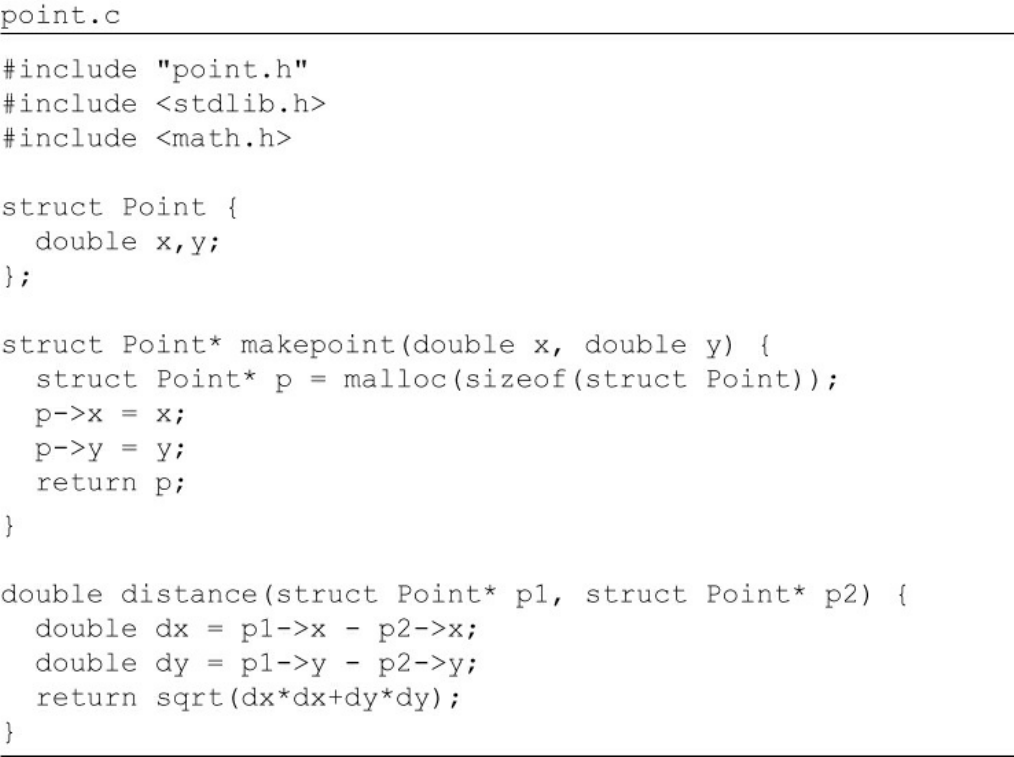
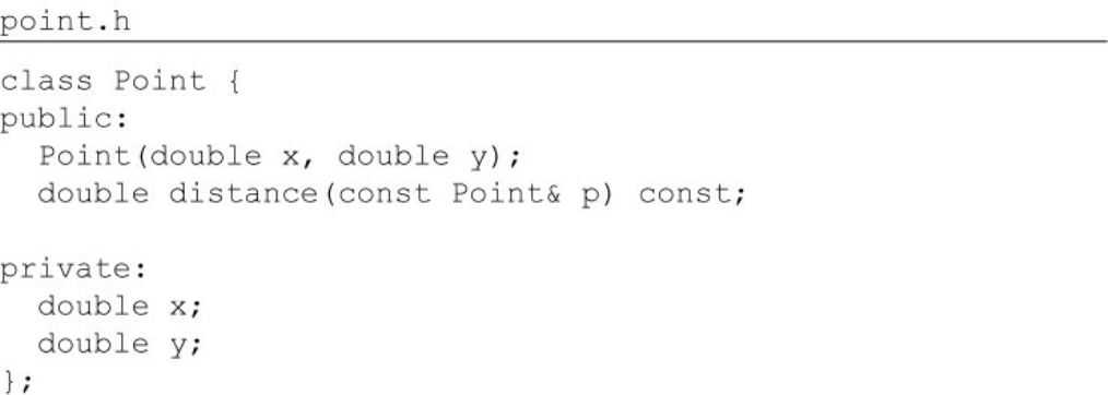


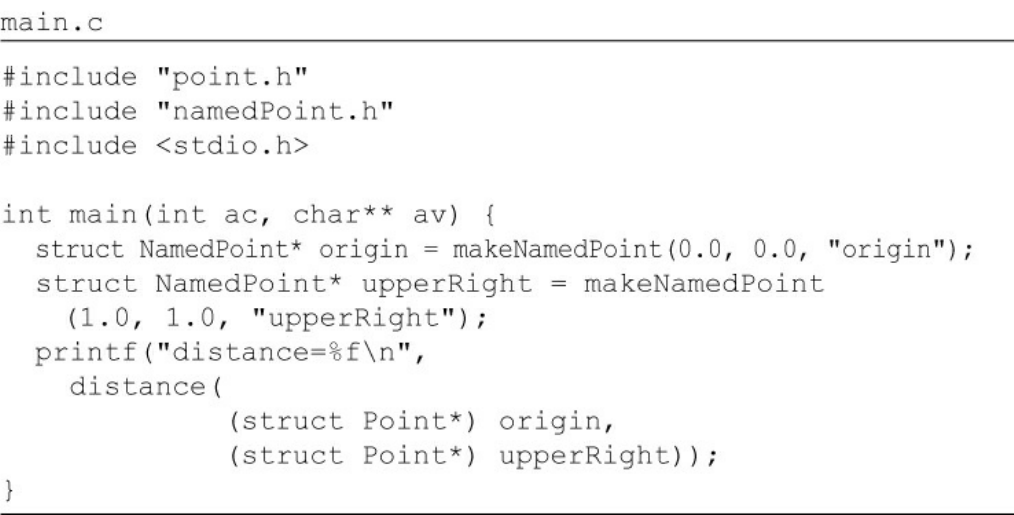


Code Snippets


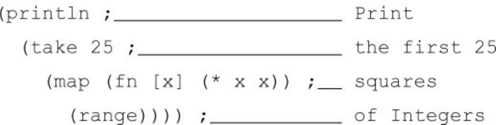

Code Snippets


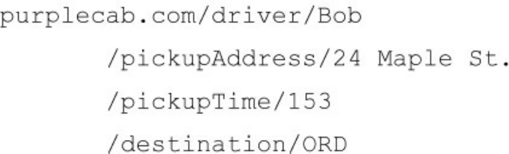


Code Snippets
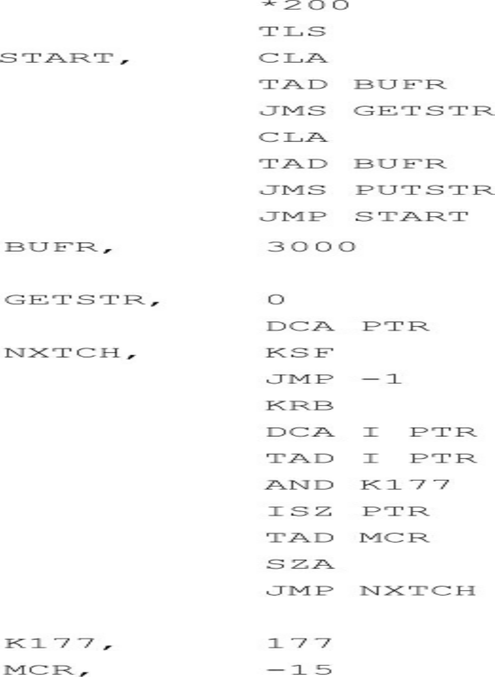
Code Snippets

Code Snippets

Code Snippets


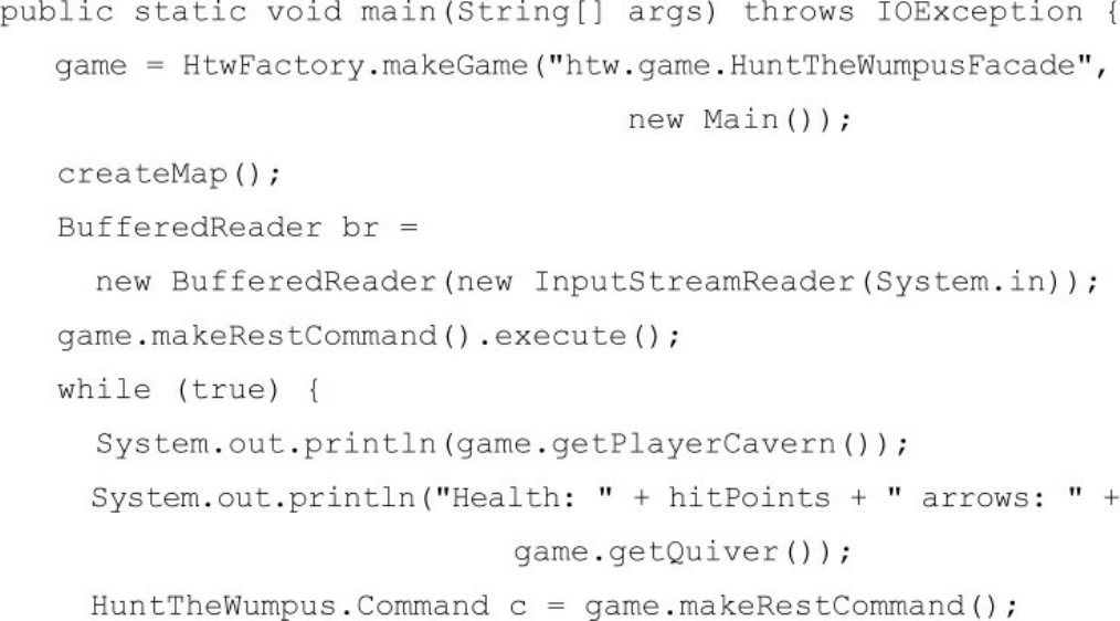
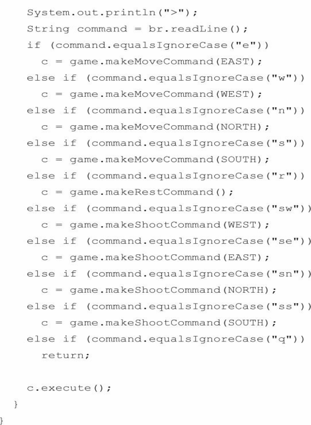
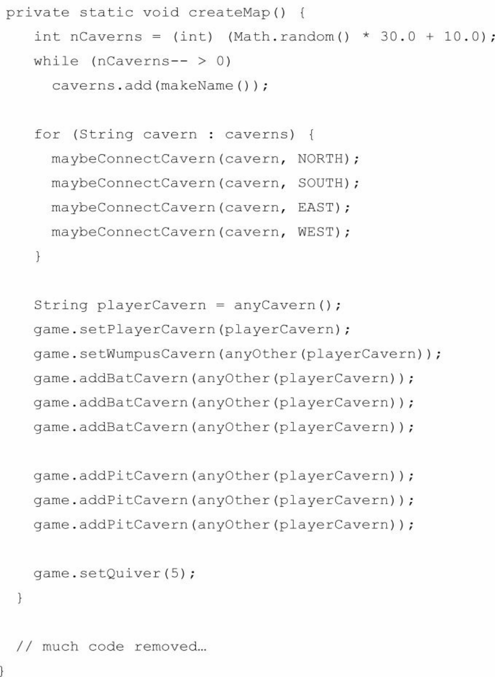
Code Snippets
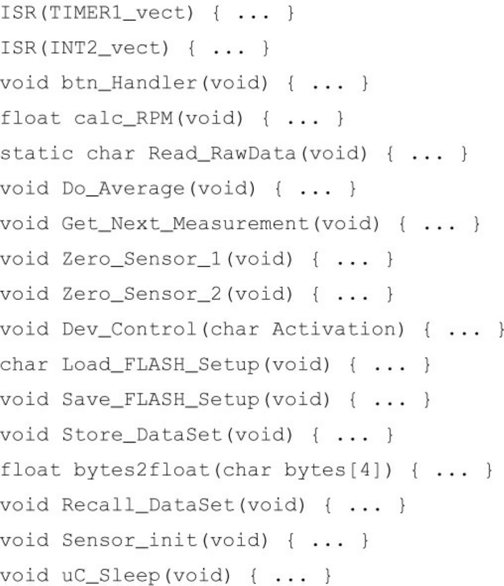
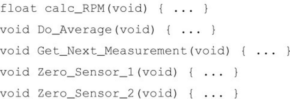


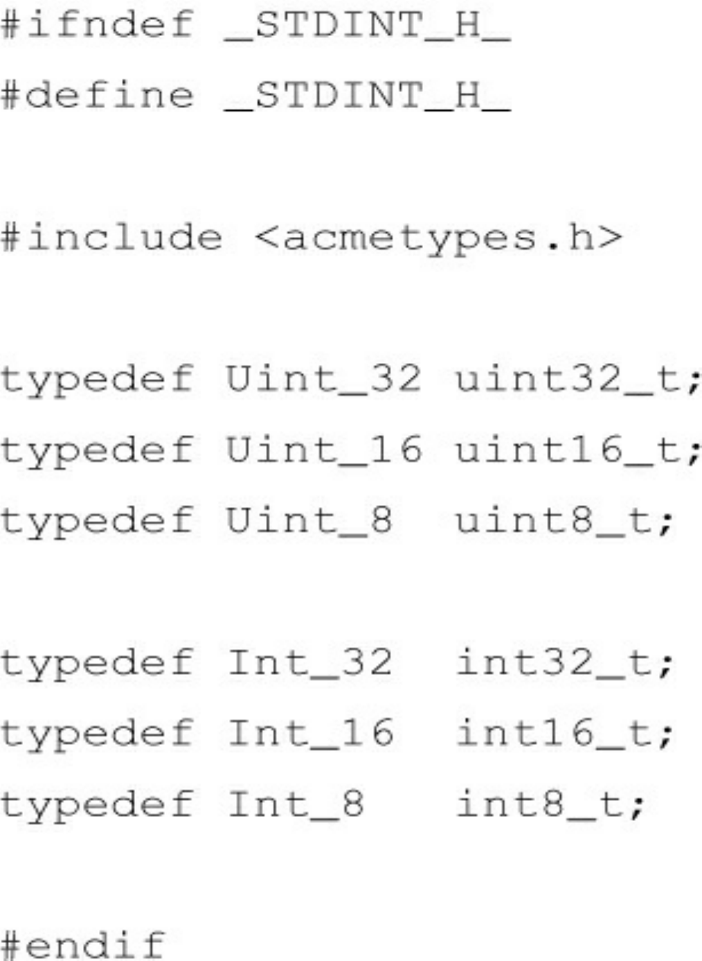
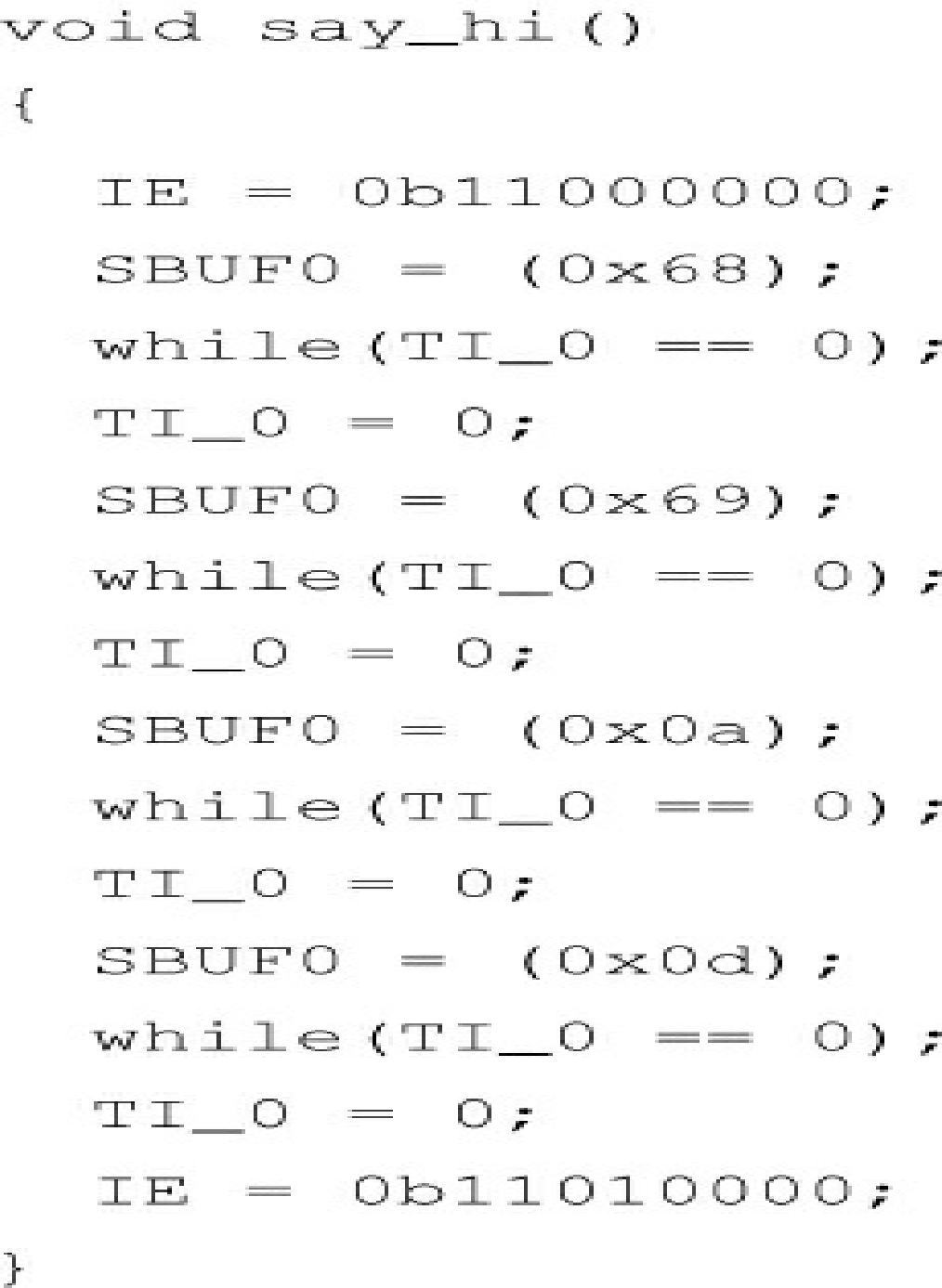
Code Snippets

